
Wet Dog Glass 2021 Equipment Manual v.1
65
Wet Dog Glass LLC. 2019 Equipment Manual 1 Wet Dog Glass 2021 Equipment Manual v.1
-
Upload
khangminh22 -
Category
Documents
-
view
2 -
download
0
Transcript of Wet Dog Glass 2021 Equipment Manual v.1
Wet Dog Glass LLC. 2019 Equipment Manual
1
Wet Dog Glass
2021 Equipment Manual v.1

Wet Dog Glass LLC. 2019 Equipment Manual
2
3) Notes, Warnings, and conventions
4) Safety Precautions
7) Warning Symbols
9) Receiving and Installation
12) Component Overviews
19) Components in Depth
35) Initial Setup
37) Startup and Tuning for Combustion Furnaces
46) Startup and Tuning for Combustion Glory Holes
48) Startup and Tuning for Combustion Pipewarmers and Garages
50) Installing Molybdenum Elements in Electric Furnaces
58) Charging and Melting
61) Maintenance and Servicing
Table of Contents
Wet Dog Glass LLC. 2019 Equipment Manual
3
Notes on Handling User Manuals
• Please hand over user manuals to your end users so that they can have them on hand for con-
venient reference.
• Please read the user manuals thoroughly before using the product.
• The purpose of these user manuals is not to warrant that the product is well suited to any partic-
ular purpose, but rather to describe the functional details of the product.
• Wet Dog Glass reserves the right to make improvements in the user manuals and product at any
time, without notice or obligation.
• If you have any questions or find mistakes or omissions in the user manuals, please contact Wet
Dog Glass, LLC.
910-428-4111
100C Russell Drive
Star, NC 27356
Warnings and Disclaimers
The product is provided on an “as is” basis. Wet Dog Glass, LLC shall have neither liability nor re-
sponsibility to any person or entity with respect to any direct or indirect loss or damage arising from
using the product or any defect of the product that Wet Dog Glass, LLC can not predict in advance.
Drawing Conventions
• Some drawings in the user manual may be partially emphasized, simplified, or omitted, for the
convenience of description.
• Note that images in user manuals may be slightly different from the actual equipment and com-
ponents and/or show only example images.
Notes, Warnings, Disclaimers, and conventions
Wet Dog Glass LLC. 2019 Equipment Manual
4
WARNING: If you do not follow these instructions exactly, a fire or explosion may result causing
property damage, personal injury or loss of life
Safety, Protection, and Modification of Products
In order to protect the product and the system controlled by the product, and to ensure safe opera-
tion, observe the safety precautions described in this user’s manual. We assume no liability for safe-
ty if users fail to observe these instructions when operating the product.
• You must use this product according to the instructions described in user manuals. If not, protec-
tive functions of this product may not work as expected.
• If any protection or safety circuit is required for the system(s) controlled by the product or for the
product itself, prepare it separately.
• Be sure to use the parts approved by Wet Dog Glass, LLC when replacing parts or consumables.
• Modification of the product is strictly prohibited.
• The symbol families on Page 6-7 are used on the product and in this user manual to indicate that
safety precautions are required.
Do not use this appliance if any part has been under water. Immediately call a qualified service tech-
nician to inspect the appliance and to replace any part of the control system and any gas control
which has been under water
Use only your hand to push in or turn the gas control knob. Never use tools. If the knob will not
push in or turn by hand, do not try to repair it, call a qualified service technician. Force or attempted
repair may result in a fire or explosion.
Lid Safety Lock
The Lift safety feature will engage and lock as the lid rises, preventing sudden free fall in the unlikely
event of a suspension component failure. After the lid is raised to the required working height, oper-
ators must lower the lid until it is resting safely on the locks to minimize wear on suspension compo-
nents. Once the locks are engaged, the lid has to be raised slightly in order to release the safety
locks (push or pull on lever).
Safety Precautions
Wet Dog Glass LLC. 2019 Equipment Manual
5
FOR YOUR SAFETY READ BEFORE OPERATING GAS APPLIANCES
Some of our gas fired products must be ignited by hand. For those that are ignited automatically, do not attempt to ignite them by hand.
BEFORE OPERATING GAS APPLIANCES
Smell all around the appliance area for gas. Be sure to smell next to the floor because some gas is heavier than air and will settle on the floor. Read the safety information above. Use lockout/tagout procedures.
WHAT TO DO IF YOU SMELL GAS
•Do not try to light any appliance.
•Do not touch any electric switch; do not use any phone in your building.
•Immediately call your gas supplier from a neighbor's phone. Follow the gas supplier's instructions.
•If you cannot reach your gas supplier, call the fire department.
Any time adjustments have been made to a gas fired unit, exercise care when opening the door. If there is excess gas inside the unit, there can be a blast of fire that shoots out when that gas finds ox-ygen due to the opening of the door. Keep yourself behind the door with your head back away from the door as you expect something to jump out at you—this is basically what the blast will do—jump out at you with less than a split-second’s notice. Also keep yourself low to the floor as opposed to standing up straight.
Material Safety
Unfortunately some of the best insulating products available for high temperature applications are made from materials that can negatively affect the health of those people who use or handle the material casually and excessively. The refractory materials in our high temperature products contain crystalline silica. When abraded, the dust will become airborne and consequently be inhaled. Please be aware of this hazard and wear a NIOSH approved respirator if performing maintenance or otherwise creating dust. This crystalline silica is known to cause silicosis in humans and animals.
**Wear a respirator and rubber gloves and ventilate the space well when working with ceramic fiber. Please read MSDS sheets on the Wet Dog Glass website for more information.
Safety Precautions

Wet Dog Glass LLC. 2019 Equipment Manual
6
Lock Out/Tag Out
Purpose
Lock Out, Tag Out (LOTO), is a safety procedure used in industry and research settings to ensure that
dangerous machines are properly shut off and not able to be started up again prior to the comple-
tion of maintenance or repair work. This prevents a piece of equipment from being turned on while
maintenance is being performed.
Responsibility
The responsibility for seeing that this procedure is followed is binding upon all employees. All em-
ployees shall be instructed in the safety significance of the lockout procedure by designated individ-
ual(s). Each new or transferred affected employee shall be instructed by designated individual(s) in
the purpose and use of the lockout procedure.
Preparation for Lock Out
Employees authorized to perform lockout shall be certain as to which switch, valve, or other energy
isolating devices apply to the equipment being locked out. More than one energy source (electrical,
mechanical, or others) may be involved. Any questionable identification of sources shall be cleared
by the employees with their supervisors. Before lockout commences, job authorization should be
obtained.
Sequence of Lock Out Procedure
Notify all affected employees that a lockout is required and the reason therefore. If the equipment is
operating, shut it down by the normal stopping procedure (such as: depress stop button, open tog-
gle switch). Operate the switch, valve, or other energy isolating devices so that the energy source(s)
(electrical, mechanical, hydraulic, other) is disconnected or isolated from the equipment. Lockout
energy isolating devices with an assigned individual lock. Stored energy, such as that in capacitors,
springs, elevated machine members, rotating fly wheels, hydraulic systems, and air, gas, steam or
water pressure, must also be dissipated or restrained by methods such as grounding, repositioning,
blocking, bleeding down. After ensuring that no personnel are exposed and as a check on having dis-
connected the energy sources, operate the push button or other normal operating controls to make
certain the equipment will not operate.
Safety Precautions
Wet Dog Glass LLC. 2019 Equipment Manual
7
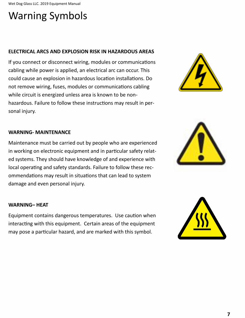
ELECTRICAL ARCS AND EXPLOSION RISK IN HAZARDOUS AREAS
If you connect or disconnect wiring, modules or communications
cabling while power is applied, an electrical arc can occur. This
could cause an explosion in hazardous location installations. Do
not remove wiring, fuses, modules or communications cabling
while circuit is energized unless area is known to be non-
hazardous. Failure to follow these instructions may result in per-
sonal injury.
WARNING- MAINTENANCE
Maintenance must be carried out by people who are experienced
in working on electronic equipment and in particular safety relat-
ed systems. They should have knowledge of and experience with
local operating and safety standards. Failure to follow these rec-
ommendations may result in situations that can lead to system
damage and even personal injury.
WARNING– HEAT
Equipment contains dangerous temperatures. Use caution when
interacting with this equipment. Certain areas of the equipment
may pose a particular hazard, and are marked with this symbol.
Warning Symbols

Wet Dog Glass LLC. 2019 Equipment Manual
8
CAUTION- RADIO FREQUENCY INTERFERENCE
Most electronic equipment is influenced by Radio Frequency In-
terference. Caution should be exercised with regard to the use of
portable communications equipment around such equipment.
Signs should be posted in the vicinity of the equipment caution-
ing against the use of portable communications equipment.
CAUTION- HEAT DISSIPATION AND ENCLOSURE POSITION
System and field power consumption by modules and termina-
tion assemblies is dissipated as heat; e.g. enclosures exposed to
continuous sunlight will have a higher internal temperature that
could affect the operating temperature of the modules. Modules
operating at the extremes of the temperature band for a continu-
ous period can have a reduced reliability
CAUTION– CRUSH RISK
Parts of equipment can pose a crush and/or entanglement risk.
Observe caution and best practices. Only trained technicians
may remove safety covers while observing Lock Out Tag Out pro-
cedures.
SPECIAL INSTRUCTIONS- A MANUAL IS PROVIDED
Do not attempt to operate or maintain this Equipment(s) until
you have read and thoroughly understand all of the safety infor-
mation contained in this manual.
Warning Symbols
Wet Dog Glass LLC. 2019 Equipment Manual
9
Unpacking
Inspect the packaging prior to accepting shipment/package. Report any damage to the appli-
ance as soon as possible, before the driver/delivery person leaves the site. Take pictures and docu-
ment and damages and for posterity.
A hammer, pry bar, tin snips, and a Phillips screwdriver will be required to remove the crating
from the pallet. Use a 1/2” and/or 9/16” socket wrench to remove the lag screws that hold the ap-
pliance to its pallet. Lift equipment off of pallet with fork lift or similar machinery. Once the appli-
ance is off of the pallet, begin to remove any shrink wrap, being sure to collect any hardware that
may have shaken loose and was captured by the shrink wrap. There may be many items that are
packed on the crate, be aware that everything is accounted for. (This includes thermocouples, door
handle, levelers, related hardware, kiln shelves, etc.)
Installation
The appliance should be set in place using a pallet jack or forklift. Install and adjust the level-
ing bolts to set the appliance at the desired height and to level the equipment. Do not, however,
raise furnaces more than 1” and other equipment more than 2” as you will run the risk of the level-
ing bolt coming out of the threaded hole. If your appliance is equipped with earthquake floor
mounts, it should be anchored to the floor with appropriate concrete anchors. Any adjustments
made after rigid utility connections to the equipment may cause damage to components. Refer to
spec sheets for weights and dimensions.
This appliance shall be installed by a qualified service agency in accordance with the manu-
facturer’s instructions and all applicable codes and requirements of the authority having jurisdic-
tion. If the information in these instructions is not followed exactly, a fire, an explosion or produc-
tion of carbon monoxide may result causing property damage, personal injury or loss of life. The
qualified service agency is responsible for the proper installation of this appliance. The installation is
not proper and complete until the operation of the appliance is checked as specified in the manu-
facturer’s instructions supplied with the appliance.
Receiving and Installation
Wet Dog Glass LLC. 2019 Equipment Manual
10
Installation continued
Caution: The gas supply shall be shut off prior to disconnecting the electrical power, before
proceeding with the installation.
•Follow industry standard procedures for proper leak testing and torqueing of the appliance prior to
placing it into operation.
•Check to verify that the manifold pressure is correct in accordance with the data tag.
•Check to verify the inlet pressure is within the acceptable range specified by the data tag.
•The appliance and its individual shutoff valve must be disconnected from the gas supply piping sys-
tem during any pressure testing of that system at test pressures in excess of 5 psi.
•The appliance must be isolated from the gas supply piping system by closing its individual manual
shutoff valve during any pressure testing of the gas supply piping system at test pressures equal to
or less than 2 psi.
•Provisions for adequate combustion and ventilation air shall be made prior to starting up the appli-
ance. See spec sheet for recommendations.
•High temperature limit setting shall not exceed the data tag rating.
•The installer shall inform and demonstrate to the user the correct operation and maintenance of
the appliance.
•The installer shall also inform the user of the hazards of flammable liquids and vapors and shall re-
move such liquids and vapors from the vicinity of the appliance.
•Please provide minimal clearance of 2.5 feet from combustible surfaces and 6 inches from non-
combustible surfaces
•Please provide adequate clearances for servicing and proper operation. See the example on the
page. Clearances for each piece of equipment can be found on their respective spec sheets. Cus-
tom configuration clearances will be provided by our design department, but spec sheets can be
taken as an example.
Receiving and Installation

Wet Dog Glass LLC. 2019 Equipment Manual
11
Receiving and Installation
Generally 24” clearance is required for any component that requires servicing, maintenance , or ad-
justment. This includes clean outs, junction boxes, plumbing, burners, etc. 36” clearance is required
for control panel clearance, and recommended for any component that needs regular interaction,
gas valves and adjustments, plugs, etc. Any access to live electrical components can require 42” of
clearance depending on jurisdiction. See example below.

Wet Dog Glass LLC. 2019 Equipment Manual
12
Components that make up Wet Dog Glass Equipment
The following pages are an overview of major components you will find in Wet Dog Glass equip-
ment, and in many kinds of heating applications. Models, brands, and types change regularly to im-
prove price, quality, or add features. Many of these components are functionally interchangeable.
Check your equipment and wiring schematic for the exact component you have. Component manu-
als can be found through the Wet Dog Glass Tech portal, on our website www.wdg-us.com
Component Overview

Wet Dog Glass LLC. 2019 Equipment Manual
13
Power Controllers and Relays for Electric Heating Systems
Power controllers (SCRs, SSRs, and thyristors) are typically used for proportional control as they al-low the temperature controller to use any output percentage from 0% to 100%. These are all solid state controllers, meaning they have no moving parts.
Power controllers typically function in either with either “on/off” or “phase angle” control logic. On/Off involves switching on and off at the zero-cross portion of the AC/DC sine wave, resulting in low electrical noise. This is often used with wire elements. Because phase angle systems switch at any point on the sine wave, there can be significant electrical noise, typically restricting its use to certain heating element materials such as molybdenum disilicide and silicon carbide, because their resistance changes significantly with temperature and age respectively.
Because there are no moving parts, these power controllers can switch on and off faster than any other type of switch. The result is better, “proportional” control and longer element life. As long as the power controller stays cool enough, it will last longer than most other types of relays as well.
Component Overview

Wet Dog Glass LLC. 2019 Equipment Manual
14
Electric Heating Systems
Contactors
Contactors are used to physical-ly disconnect power to maintain user safety or for a specific func-tion. The contactors in our equipment, referred to as Defi-nite Purpose Contactors (DPC), disconnect the power when the doors are opened, or when the temperature passes a high limit.
Safety Relays
These relays are used to monitor and trigger several actions in the equipment. Most commonly they will cause the DPC to open when the door switch or high limit are tripped.
Circuit Breakers
These are very similar to what you find in your service panel at home. Circuit breakers cut the power when a high current is detected, protecting the user and the equipment. Circuit breakers are most often found on large equipment with several heating circuits or zones.
Component Overview

Wet Dog Glass LLC. 2019 Equipment Manual
15
Electric Heating Systems
Fuses and Fuse Holders Fuses are used to protect cer-tain components inside the con-trol panel. Small fuses are used to protect the control circuit (Watlow controller, safety relay, etc) and large fuses may be used on the power circuit to protect large and expensive power con-trollers, such as Din-a-mites and ePower’s. They also protect equipment and the user in the same way as circuit breakers, but are often faster reacting and more sensitive.
Door Switch
The door switches senses when the door has been opened and causes the DPC to trigger and cut power while you are gather-ing (Electric Furnace) or entering an oven to prevent electrical shock.
Component Overview

Wet Dog Glass LLC. 2019 Equipment Manual
16
Pressure Regulator
Used to reduce and maintain stable pressure at a level that is safe for the operation of components downstream such as safety shutoff valves and proportionating regulators. We do not provide these unless requested. The customers gas fitter/company often provides them.
Proportionator - Used for Nozzle Mix Burners (Usually Furnaces)
Also known as a ratio regulator, this device uses an air impulse line to maintain an appropriate gas/air ratio over the operational range of the combustion system. It is used to adjust the ratio of air to gas throughout the whole range. This is often the same component, installed differently, as the zero governor.
Zero Governor - Used for Pre-mix burners (Usually Glory Holes)
Also known as a Balance Zero Regulator (BZR), this device adjusts gas pressure downstream to atmospheric pressure so that a vac-uum from a mixer installed downstream can pull the volume of gas required for efficient combustion. The Zero Governor should not have an air impulse line. It is used to adjust the ratio of air to gas throughout the whole range. This is often the same compo-nent, installed differently, as the proportionator.
ALO/AOGC (Adjustable Limiting Orifice/Adjustable Orifice Gas Cock) - High Fire Gas Adjustment
This valve is used to limit the maximum amount of gas allowed into the burner at high fire. It allows far finer control than a ball valve.
Low Fire Bypass Fitting, attached to the Proportionator.
This valve is used to fine tune the gas flow at Low fire. It allows gas to bypass the proportionator, letting a minimum amount to always reach the burner
Component Overview

Wet Dog Glass LLC. 2019 Equipment Manual
17
Variable Speed Blower (VSB) Most combustion equipment from Wet Dog Glass, LLC is sup-plied with a variable speed blow-er which receives a 0-10VDC in-put signal from the temperature controller. The blower speeds up when the set point temperature is above the actual temperature and slows down when the set point temperature is below the actual temperature. Variable Frequency Drive (VFD) For blowers that do not have built in variable speed control, a VFD is used to adjust the speed of the blower. This is typically used on larger combustion equipment only, such as a GH30 custom built furnace. Manual Butterfly Valve This valve is used to regulate the volume and pressure of the com-bustion air flowing to the burner. The wider open this valve is, the higher volume of air will flow, but the pressure upstream of the valve will drop. Generally larger equipment will be set ½ to ¾ open, while smaller equipment will be set ¼ to ½ open.
Component Overview

Wet Dog Glass LLC. 2019 Equipment Manual
18
Flame Supervision Electronic flame supervision is required on all combustion equip-ment over 150,000 BTU’s by NFPA 86. Up until 2015 we used Veri-Flame and have since switched to the MPA. These units monitor various safety sensors and moderate the combustion operation including startup and shut down procedures.
Dual Valves The dual valves are two solenoid valves that work together to en-sure safety. When the MPA detects a fault from one of the sen-sors, it will close the valves. When the fault has been corrected and the system is reset, the MPA will open the valves and allow gas to the burner after the startup sequence. UV Scanner The UV scanner detects when flame is present and relays this information to the MPA. This can also be accomplished by a flame rod, which is less expensive but requires more frequent replacement and maintenance. Air Pressure Switch The air pressure switch detects whether the air line has pressure and relays this information to the MPA. No pressure indicates the butterfly valve has been closed or the blower is not function-ing. Gas Pressure Switches The high and low gas pressure detect if the gas pressure is above or below their set points and relays this information to the MPA.
Component Overview
Wet Dog Glass LLC. 2019 Equipment Manual
19
Critical Components In Depth
KDI Dual Valve Assembly
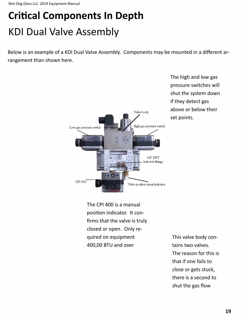
Below is an example of a KDI Dual Valve Assembly. Components may be mounted in a different ar-
rangement than shown here.
The CPI 400 is a manual
position indicator. It con-
firms that the valve is truly
closed or open. Only re-
quired on equipment
400,00 BTU and over
The high and low gas
pressure switches will
shut the system down
if they detect gas
above or below their
set points.
This valve body con-
tains two valves.
The reason for this is
that if one fails to
close or gets stuck,
there is a second to
shut the gas flow
Wet Dog Glass LLC. 2019 Equipment Manual
20
Critical Components In Depth
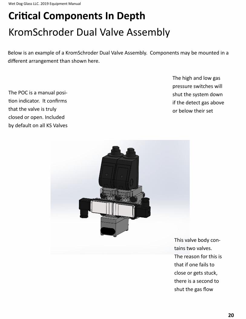
KromSchroder Dual Valve Assembly
Below is an example of a KromSchroder Dual Valve Assembly. Components may be mounted in a
different arrangement than shown here.
The POC is a manual posi-
tion indicator. It confirms
that the valve is truly
closed or open. Included
by default on all KS Valves
The high and low gas
pressure switches will
shut the system down
if the detect gas above
or below their set
This valve body con-
tains two valves.
The reason for this is
that if one fails to
close or gets stuck,
there is a second to
shut the gas flow
Wet Dog Glass LLC. 2019 Equipment Manual
21
Critical Components In Depth
Temperature Controllers
Temperature controllers are the component you will most often use on your equipment. Watlow controllers are what we primarily use, and what you will see most often on glass equipment. These are called PID controllers. They look at the temperature you want to get to, called setpoint, and the temperature the equipment is currently at, called process value, and figures out the most efficient way to do that. If you’re only a few degrees low, you don’t want the burner to blast to 100%. While these controller have many settings in them that the average user will never need to adjust, here are a few that will help you understand what it’s doing, and that you may want to change de-pending on your use. Manual vs. Auto Control Mode The control mode is something you may never change on an electric oven, but is often used when tuning combustion equipment. When in auto you tell the controller the set point, and it de-cides what % to be at to get there or maintain that temperature. When in manual you set that % di-rectly. For tuning this keeps the blower at the same speed, which lets you adjust the gas to be a good neutral flame. The other option in this setting is Off, which will stop the controller entirely. On electric equip-ment this is the same as 0%, but on combustion equipment this will turn the blower off entirely (0% for a blower is still on, just barely). Proportional Band This is the setting that decides how big of a range the controller ramp powers in when not at
0% or 100%. For example, with a proportional band of 50 degrees whenever the process value is
more than 50 degrees from set point the controller will be at 0% or 100%. When within 50 it will
begin ramping up (or down) so that it does not overshoot the setpoint. With too small a proportion-
al band your equipment will bounce around too much as it tries to maintain the setpoint. When too
large, the equipment will be slow to go up or down because it doesn’t stay at 0% or 100% for long
enough.
Wet Dog Glass LLC. 2019 Equipment Manual
22
Critical Components In Depth
Temperature Controllers
Wet Dog Glass LLC. 2019 Equipment Manual
23
Critical Components In Depth
Temperature Controllers
Wet Dog Glass LLC. 2019 Equipment Manual
24
Critical Components In Depth
Temperature Controllers
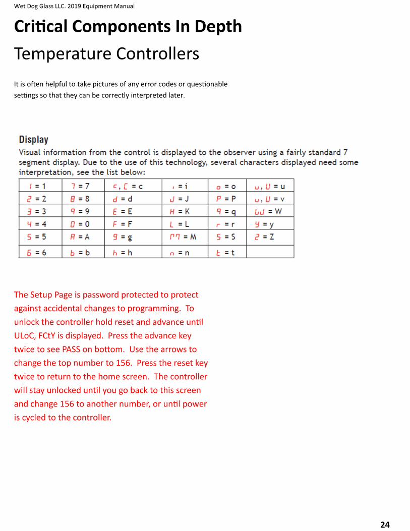
It is often helpful to take pictures of any error codes or questionable
settings so that they can be correctly interpreted later.
The Setup Page is password protected to protect
against accidental changes to programming. To
unlock the controller hold reset and advance until
ULoC, FCtY is displayed. Press the advance key
twice to see PASS on bottom. Use the arrows to
change the top number to 156. Press the reset key
twice to return to the home screen. The controller
will stay unlocked until you go back to this screen
and change 156 to another number, or until power
is cycled to the controller.
Wet Dog Glass LLC. 2019 Equipment Manual
25
Critical Components In Depth
Temperature Controllers
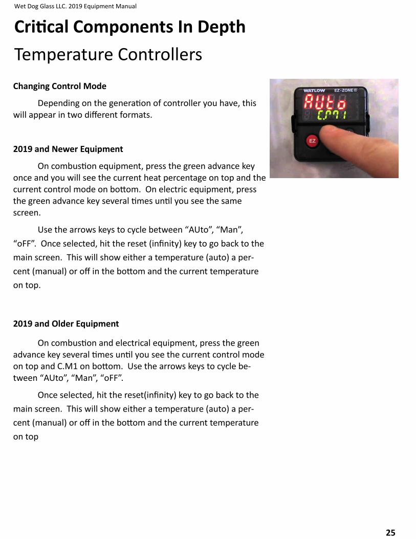
Changing Control Mode
Depending on the generation of controller you have, this will appear in two different formats.
2019 and Newer Equipment
On combustion equipment, press the green advance key once and you will see the current heat percentage on top and the current control mode on bottom. On electric equipment, press the green advance key several times until you see the same screen.
Use the arrows keys to cycle between “AUto”, “Man”,
“oFF”. Once selected, hit the reset (infinity) key to go back to the
main screen. This will show either a temperature (auto) a per-
cent (manual) or off in the bottom and the current temperature
on top.
2019 and Older Equipment
On combustion and electrical equipment, press the green advance key several times until you see the current control mode on top and C.M1 on bottom. Use the arrows keys to cycle be-tween “AUto”, “Man”, “oFF”.
Once selected, hit the reset(infinity) key to go back to the
main screen. This will show either a temperature (auto) a per-
cent (manual) or off in the bottom and the current temperature
on top
Wet Dog Glass LLC. 2019 Equipment Manual
26
Critical Components In Depth
Temperature Controllers
Writing a Profile
There are several important things to understand before starting on writing profiles.
•Watlow PM controllers have 40 possible “steps” split into 4 profiles of 10 steps each
•Profile 1 uses steps 1-10, profile 2 uses steps 11-20, profile 3 is steps 21-30, profile 4 is steps 31-40.
•Always attend a piece of equipment when running a profile for the first time or after changes, to be sure it is doing what you want.
While profiles can become very complicated, 3 kinds of steps are primarily used; Soak, Time and End. All steps default to unused (UStP) and should be set to this when not wanted.
Soak (SoAh) holds the current set point for the amount of time you specify before moving onto the next step
Time (ti) moves the set point from its current value to the temperature you specify over the amount of time you specify.
End ends the profile, and allows you to choose what happens to the set point once the profile is over.
Use the chart on the next page to plan your profile, and refer to it as you enter the profile into the controller. The profile shown is the basic annealer profile preload onto oven controllers.
Wet Dog Glass LLC. 2019 Equipment Manual
27
Critical Components In Depth
Temperature Controllers—Example Profile
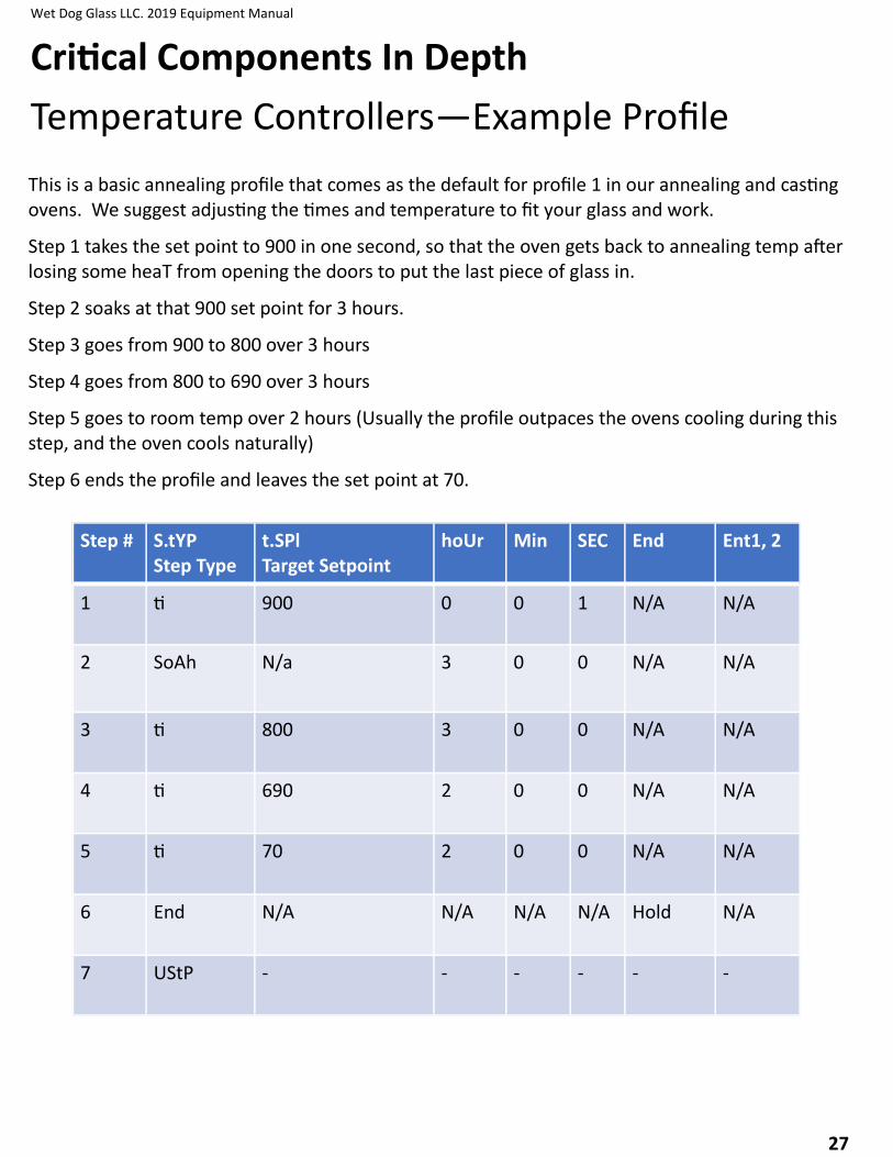
This is a basic annealing profile that comes as the default for profile 1 in our annealing and casting ovens. We suggest adjusting the times and temperature to fit your glass and work.
Step 1 takes the set point to 900 in one second, so that the oven gets back to annealing temp after losing some heaT from opening the doors to put the last piece of glass in.
Step 2 soaks at that 900 set point for 3 hours.
Step 3 goes from 900 to 800 over 3 hours
Step 4 goes from 800 to 690 over 3 hours
Step 5 goes to room temp over 2 hours (Usually the profile outpaces the ovens cooling during this step, and the oven cools naturally)
Step 6 ends the profile and leaves the set point at 70.
Step # S.tYP Step Type
t.SPl Target Setpoint
hoUr Min SEC End Ent1, 2
1 ti 900 0 0 1 N/A N/A
2 SoAh N/a 3 0 0 N/A N/A
3 ti 800 3 0 0 N/A N/A
4 ti 690 2 0 0 N/A N/A
5 ti 70 2 0 0 N/A N/A
6 End N/A N/A N/A N/A Hold N/A
7 UStP - - - - - -

Wet Dog Glass LLC. 2019 Equipment Manual
28
Critical Components In Depth
Temperature Controllers
Entering a Profile into the controller
Begin by holding the green button until you see P1 on top and ProF on bottom. The arrow keys will cycle you through P1-P4. Select the profile to be edited, and press the green button
You’ll now see 1 on top and P1(or P2,3,4) on bottom. The top number is the step selected. Use the arrows to select the step to be edited and press the green button.
This is the final menu level where settings are changed. The green button cycles through the available settings on the bottom screen, and the arrows change the setting on the top screen. Using the example profile, the display after selecting P1, and Step 1 should be S.tYP on bottom, and SoAh on top. The arrows change the step type, and the green button advances to the next option. When all the parameters of the step are set, press the reset button to return to the step selection screen.
It often helps when writing a new profile to set all steps for 10 seconds, so the profile can be run and tested to make sure it is working properly, then change the times to the correct amounts.
Starting, ending, and pausing a Profile
From the main screen, press the advance key (green) until P.St 1 (Profile Start) appears on bottom and a number on top. The number on top is the profile or step to be started, pasued, or ended.
Press the advance key to move on to P.AC 1 (Profile Action). Select ProF on the top screen to start profile 1-4. Select StEP to start at step 1-40. PAUS will pause the currently running profile at its current step and set point, rESU resumes it. End ends the currently running profile. When the ac-tion has been selected on the top screen, press reset to return to the home screen. A graph icon on the right side of the screen indicates a profile is running.
When a profile is running, the current step type, and time remaining (CSP, S.tYP, hour, min, sec), can be seen by cycling through the home screen with the green key, only on controllers in 2019 equipment and newer.

Wet Dog Glass LLC. 2019 Equipment Manual
29
Critical Components In Depth
Temperature Controllers
Watlow F4T touchscreen Controller The Watlow F4T has very similar workings to a Watlow PM controller. Profiles work the same way, all the settings are identical, etc. The F4T uses real words rather than abbreviations, and allows for equipment with multiple heating zones far more conveniently than the PM controller. All of the information in the previous section still applies. The F4T is also password protected. Because of the ease of use, it is also far easier to change settings that should not be changed. The F4T will come with a USB containing WDG’s base configuration. Its suggested to leave this as is, in case of a setting change that causes any problems. Files can be exported and imported, allowing a profile written on one controller to be transferred to several others.
First level of access: UwP Second Level of access: MUP

Wet Dog Glass LLC. 2019 Equipment Manual
30
Critical Components In Depth
Flame Supervision
Eclipse “Veri-Flame” and Dungs “MPA”
The Veri-Flame and MPA flame supervision modules are inte-gral to the flame supervision process. Wet Dog Glass used the Veri-Flame exclusively from 1996 into 2015, eventually replacing it with the KDI MPA when it became important to comply with regulations internationally and to communicate with them remotely. These units monitor various safety sensors and moderate the combustion opera-tion including startup and shut down procedures. The typical user will rarely interact with these to units other than to reset them or read status or error codes.
The general sequence of operations is as follows:
1) System check: Safety shutoff valves should be closed, air pressure switch should be open (no a pressure detected), UV signal should not exist, and interlocks loop (consisting of high and low gas pressure switches, high limit switch, and any other switches such as a ventilation interlock or CO sensor)
2) Pre-purge: The blower alone is energized and purges the combustion chamber including ports and flues to clear any gas from the atmosphere. During this phase, the air pressure switch must sense air and close. The default pre-purge duration is 30 seconds, but essentially the entire interior vol-ume of the equipment must be replaced 4-5 times (depending on regional codes) with fresh air during this period.
3) Trial-for-Ignition (TFI): If present, a pilot safety valve opens while the spark plug is energized: to ignite the flam, and the UV scanner is expected to detect a flame within 5-15 seconds depend-ing on regional codes. If no pilot valve is used, the main safety shutoff valves will open at this time. In some cases, ignition is per-formed manually during the TFI. If no flame is detected within the TFI period, the system shuts down and must be reset.
4) Operation: If a flame is detected during the TFI, the main safety shutoff valves open, and the sys-tem will fire until it is interrupted by either the operator or the flame supervisor due to any system sensors becoming unsatisfied. If the flame signal is too weak or lost at any point, the system will shut down within 1-3 seconds depending on regional codes.
5) Shutdown: The Veri-Flame’s LED indicators and MPA’s digital display will indicate system status or error codes which can be cross-referenced in the troubleshooting section of this manual.
Wet Dog Glass LLC. 2019 Equipment Manual
31
Critical Components In Depth
Flame Supervision
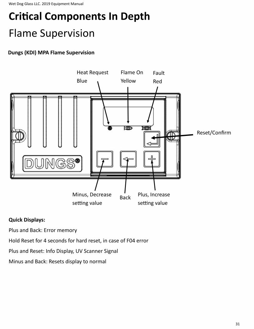
Dungs (KDI) MPA Flame Supervision
Reset/Confirm
Minus, Decrease
setting value
Plus, Increase
setting value Back
Quick Displays:
Plus and Back: Error memory
Hold Reset for 4 seconds for hard reset, in case of F04 error
Plus and Reset: Info Display, UV Scanner Signal
Minus and Back: Resets display to normal
Heat Request
Blue
Flame On
Yellow
Fault
Red
Wet Dog Glass LLC. 2019 Equipment Manual
32
Critical Components In Depth
Flame Supervision
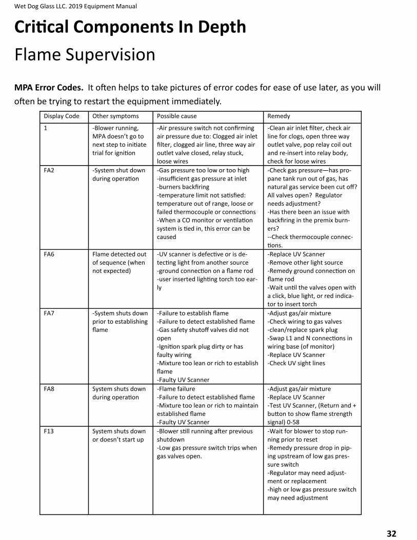
MPA Error Codes. It often helps to take pictures of error codes for ease of use later, as you will
often be trying to restart the equipment immediately.
Display Code Other symptoms Possible cause Remedy
1 -Blower running, MPA doesn’t go to next step to initiate trial for ignition
-Air pressure switch not confirming air pressure due to: Clogged air inlet filter, clogged air line, three way air outlet valve closed, relay stuck, loose wires
-Clean air inlet filter, check air line for clogs, open three way outlet valve, pop relay coil out and re-insert into relay body, check for loose wires
FA2 -System shut down during operation
-Gas pressure too low or too high -insufficient gas pressure at inlet -burners backfiring -temperature limit not satisfied: temperature out of range, loose or failed thermocouple or connections -When a CO monitor or ventilation system is tied in, this error can be caused
-Check gas pressure—has pro-pane tank run out of gas, has natural gas service been cut off? All valves open? Regulator needs adjustment? -Has there been an issue with backfiring in the premix burn-ers? --Check thermocouple connec-tions.
FA6 Flame detected out of sequence (when not expected)
-UV scanner is defective or is de-tecting light from another source -ground connection on a flame rod -user inserted lighting torch too ear-ly
-Replace UV Scanner -Remove other light source -Remedy ground connection on flame rod -Wait until the valves open with a click, blue light, or red indica-tor to insert torch
FA7 -System shuts down prior to establishing flame
-Failure to establish flame -Failure to detect established flame -Gas safety shutoff valves did not open -Ignition spark plug dirty or has faulty wiring -Mixture too lean or rich to establish flame -Faulty UV Scanner
-Adjust gas/air mixture -Check wiring to gas valves -clean/replace spark plug -Swap L1 and N connections in wiring base (of monitor) -Replace UV Scanner -Check UV sight lines
FA8 System shuts down during operation
-Flame failure -Failure to detect established flame -Mixture too lean or rich to maintain established flame -Faulty UV Scanner
-Adjust gas/air mixture -Replace UV Scanner -Test UV Scanner, (Return and + button to show flame strength signal) 0-58
F13 System shuts down or doesn’t start up
-Blower still running after previous shutdown -Low gas pressure switch trips when gas valves open.
-Wait for blower to stop run-ning prior to reset -Remedy pressure drop in pip-ing upstream of low gas pres-sure switch -Regulator may need adjust-ment or replacement -high or low gas pressure switch may need adjustment

Wet Dog Glass LLC. 2019 Equipment Manual
33
Critical Components In Depth
Flame Supervision
FAA Air flow detected out of sequence (when not ex-pected)
-Air pressure switch defective -Blower has not stopped turning completely after shut down -Air flow from another source -Air pressure switch set incorrectly
-Replace air pressure switch -Wait for blower to stop com-pletely -Restrict air flow from other source -Set air pressure switch correct-ly
FAb Air Failure -blower filter is clogged -valve in air piping is closed -air piping has a major leak -control signal to blower is interrupt-ed or insufficient -power to blower is interrupted or insufficient -blower rotor is locked -Air blower has failed
-Clean filter -open valve (not the butterfly valve unless it has fully closed.—look for another valve to open) -repair leak in air piping -restore control signal -restore power supply -remove debris to unlock rotor -replace blower
Fb6 At startup, gas safe-ty shutoff valves never open or they open then shut
-Proof of Closure switch not satisfied -safety shutoff valve failure -power to safety shutoff valve inter-rupted -wires have come loose
-check power to safety shutoff valve during trial for ignition -reconnect/tighten any loose wires in the safety shutoff valve assembly -check adjustment of micro-switch in Proof of Closure mod-ule on valve
MPA Error Codes continued:

Wet Dog Glass LLC. 2019 Equipment Manual
34
Critical Components In Depth
Thermocouples
A thermocouple is an electrical device consisting of two dissimilar electrical conductors form-ing electrical junctions at differing temperatures. A thermocouple produces a temperature-dependent voltage as a result of the thermoelectric effect, and this voltage can be interpreted to measure temperature. Thermocouples are a widely used type of temperature sensor.
The most commonly used types of thermocouples in glass equipment are Type K, and Type R/S.
Type K thermocouples are good up to 1350 Celcius, but fare poorly in reduction. Hydrogen formed in reduction atmospheres causes oxidation and reduces the accuracy of the thermocouple and causes them to read low. As some hydrogen is always present in gas fired systems, type K ther-mocouples are not the best choice. They can be used, but will age quickly, have temperature drift, and need regular replacement.
Wet Dog Glass uses Type K thermocouples in electric ovens, and in gas equipment such as garages that are less temperature critical.
Type R/S thermocouples are far more stable than type K and will not age and degrade quickly in reduction. They can be used up to 1600 Celsius. While expensive, the expense is primarily in the metals used in construction, so broken or non-functional thermocouples can be returned to the manufacturer for a steep discount on new thermocouples.
When installing or servicing thermocouples, remember that different types are not inter-changeable and if they are wired backwards, the temperature will read backwards.

Wet Dog Glass LLC. 2019 Equipment Manual
35
Electrical and gas connections are required to be made by the customers licensed tradespersons.
Combustion Systems:
Most combustion systems require 120v supply. Inside the control panel are 3 terminals labeled “L, N, PE”. The licensed tradesperson will connect to these terminals. All supply, distribu-tion, and control to various components (Blower, valves, etc) is built into the equipment. The required/designed for voltage, phase, frequency, and current usage can be found on the data tag.
The BTU/hr and inlet pressure ratings can be found on the data tag on the control panel. Gas supply must meet these requirements. Regulators are often needed to step down LP tank pres-sure to a usable range.
Electrical Systems:
Most electrical systems require 240v 1ph, 208v 3 ph, or higher voltages. Inside the control panel is a distribution block labeled “L1, L2, L3” and a ground-ing lug with the PE symbol. The licensed tradesperson will connect here. All supply, distribution, and con-trol to various components (Elements, controller, fans. Etc.) is built into the equipment. The required/designed for voltage, phase, frequency, and current usage can be found on the data tag.
Remote Mounted Control Panels:
When a remote mounted control system is requested, the set-up becomes more customized per system. Details of the con-nections required can be found in the wiring schematic for the equipment.
Initial Setup and Turn On
Electrical and Gas Connections

Wet Dog Glass LLC. 2019 Equipment Manual
36
Electric Furnaces require more setup than other Equipment. Once the furnace, control panel, and transformer are in place, electrical connections must be made. Power must be supplied to the con-trol panel from the customers supply. Power wires a run between the control panel and transform-er, and then from transformer to the furnace’s element junction box. Control wiring for the Air pres-sure switch, cooling blower, door switch, and thermocouples is run between the control panel and the furnace’s control junction box.
THESE CONNECTIONS MUST BE MADE BY A LICENSED ELECTRICIAN, AND IN ACCORDANCE TO THE SPECIFICATIONS IN THE FURNACE WIRING SCHEMATIC. DEVIATION FROM THIS WIRING SCHEMAT-IC CAN CAUSE DAMAGE TO THE FURNACE AND LEAD TO UNSAFE CONDITIONS.
Torque all power circuit connections. Existing connections should be torqued once. New connec-tions made by your electrician should be torqued twice, with 48 hours in between torqueing.
Initial Setup and Turn On
Electric Furnaces

Wet Dog Glass LLC. 2019 Equipment Manual
37
Wet Dog Glass Furnaces most often use a nozzle mix burner in tandem with a variable speed blower and temperature controller. The user assigns a set point temperature, and the controller will ramp the blower up and down to achieve that temperature. The user has four adjustment points to bal-ance the gas and air: FRG (Gas/Air proportionator), the Adjustable Limiting Orifice or Needle Valve, the low fire bypass, and the butteryfly valve for air.
FRG: Also called the proportionator or ratio regulator. Primarily use to change the amount of gas in the low-fire and mid-fire range. Remove the small black cap and adjust with flathead screw-driver. Clockwise allows more gas through, counter-clockwise allows less.
Low Fire Bypass: Located on the side of the FRG, small flat head under black cover. This al-lows a small amount of gas through without the influence of the FRG, used for low fire adjustment. Clockwise for less gas, counter-clockwise for more gas.
ALO, Needle Valve: This valve is located just before the burner and limits the maximum amount of gas at high-fire. Remove the cap to find a recessed flathead screw. Clockwise decrease gas, counter-clockwise increases gas (Opposite of FRG)
Butterfly Valve: This valve is located on the cold air line just before the recuperator. While it primarily allows more or less air through, it also affects the amount of gas allowed into the system by the FRG. Small changes here have a very large effect. Closing the valve decreases the air but also increases the gas, and vice-versa. The butteryfly valve should be set to 1/2 for startup, and only ad-justed in necessary. You will likely never adjust it again.
Start up for Combustion Furnaces
Control Components Overview
Wet Dog Glass LLC. 2019 Equipment Manual
38
Start with the FRG at about half (Factory setting), the ALO valve open a half turn, and the butterfly valve half way open (45 mark on new butteryfly valves). To set the ALO, close it entirely, then open a half turn, this will be closer to a full turn on large furnaces (RDT1000). Air will need to be bled from the lines the first time, and the equipment may need to run through its startup se-quence several times to do so. Set the Watlow controller to manual and set to 15%
The blower will run for a 30 second purge, then the DSSOV (Dual Safety Shut-off Valves) will click open. KDI Valves have indicators that turn red when the valves open. Kromschroder valves have blue lights that indicate open. When the valves open, the spark plug will begin sparking inside the nozzle to ignite the burner. If the system does not start within the allotted time the valves close and an error is displayed on the MPA. Press reset to begin the ignition procedure again.
When the Furnace is lit, adjust the ALO clockwise towards less gas until you reach the small-est stable flame possible. Look through the peep sight on the burner to observe the flame as you turn. The Watlow controller will be kept at 15% throughout the heat up process. The first hour will go faster than the schedule. Furnaces usually after an hour or two between 200-300F, at which point proceed below.
As the furnace heats up, follow this warm up schedule manually by opening the ALO slightly each time the furnace slows down or stalls out. A very slight turn (1/8th) will accomplish this, with larger turns needed as the furnace gets hotter. You should reach ~1900 without changing the blow-er speed. This process is done manually and cannot be accomplished by a profile. If turning the ALO no longer causes adequate temperature increases, you can also increase the gas flow by turning both the FRG and ALO. This is sometimes needed above 1000F.
For pre-fired castings: (All WDG Furnaces): 25 degree an hour rise. It is acceptable to go fast-er and slower than this and average 25 an hour. The most critical period to go no more than 25 an hour is 1000-1300 F.
Once you reach 1900-2100, the furnace can be tuned for the first time. The tuning will change as we get to your normal working range, and will change once some glass is in the pot. For the initial tune, the furnace should be able to heat up when the blower is set to 100% and cool down when set to 0%, with no large amounts of reduction at any point. Do not spend too much time with this first tune, as things will change as your temp increases. We recommend doing the initial tune quickly, and tweaking it over the following week as you get glass in the pot and go through a few cy-cles.
Start up for Combustion Furnaces
Heat Up Process and Schedule

Wet Dog Glass LLC. 2019 Equipment Manual
39
Tuning is the process of balancing the air and gas so the flame is close to neutral, neither too much gas nor too much air. A neutral flame is the most efficient. Extra gas (Fatty) causes reduction and wastes gas. Extra air (Lean) counteracts heat, putting unneeded cold air into the furnace.
The temperature controller automatically controls the amount of heat going into the furnace by changing the blower speed. The FRG (proportionator) increases or decrease the amount of gas ac-cording to the amount of air. A small impulse line carries air pressure from the cold air line before the butteryfly valve to the proportionator. This air pressure pushes down a diaphragm that is attached to a valve inside the FRG. The more the diaphragm is pushed down, the more the valve opens, letting more gas through. This is the primary control process that keeps the flame near neu-tral, whether at low fire (minimal blower speed and small flame) or at high fire (maximum blower speed and large flame) and everywhere in between.
The FRG does not provide perfect ratio control however, which leads to the tuning process and multiple components to adjust gas flow.
The FRG has an adjustment screw that will causes a spring to press more or less on the diaphragm, biasing the FRG towards more or less gas throughout the whole range from low fire to high fire. Clockwise (CW) is more gas, Counter Clockwise (CCW) is less gas. This is opposite of the other ad-justments.
The low fire bypass mounted on the side of the FRG bypasses a small amount of gas around the FRG, allowing more or less gas to the burner unaffected by the FRG. This is used for adjusting gas in low fire, and has very little affect to the flame over 20% blower speed. Clockwise (CW) is less gas, Counter Clockwise (CCW) is more gas.
The ALO (Needle Valve) is the last component before the burner, and thus limits the maximum amount of gas that the FRG provides to the burner. This is used to increase or decrease the amount of gas at high fire only. Clockwise (CW) is less gas, Counter Clockwise (CCW) is more gas.
The Butteryfly Valve changes the amount of air going to the burner, but it also changes the amount of air pressure going to the FRG. When the butteryfly valve is opened, more air goes to the burner but the impulse line pressure decreases causing the FRG to let less gas through. When the butteryfly valve is closed, less air goes to the burner but the impulse line pressure increases causing the FRG to let more gas through. The butterfly should only be changed from 1/2 open if the other adjustments are not adequate for the following tuning process.
Start up for Combustion Furnaces
Tuning Overview
Wet Dog Glass LLC. 2019 Equipment Manual
40
When performing the initial tuning for startup of a furnace, be aware of your temperature. It is best to get the furnace above 2000 and stabilize it there manually. Let it soak for several hours so heat can soak into the castings. Tuning too quickly and having the temperature jump dramatically during startup can lead to cracked castings. If temp is getting out of hand, turn the % down to 0-10% and let the furnace stabilize back to ~2100.
Changes to gas and air take 5-30 seconds to be apparent, quickly at high fire and slowly at low fire. Always pause between adjustments to wait and check for the result. A neutral flame is achieved by increasing the gas until you see a small amount of flame from the door or flue, then decreasing the gas until that flame just goes away. If you have a tight fitting door, try opening the door and watching for a small amount of flame that appears when the door is opened and then disappears. If these flames are small and go away quickly, you are close to a neutral flame.
Step 1 (Tuning during initial startup) — Change the Blower speed on the Watlow controller to 30%. Turn the ALO counter clockwise for more gas 4 full turns. The ALO will no longer be limiting the gas flow. If you see any flame from the door or flue, turn the FRG (proportionator) counter clockwise by 1 full turn increments, waiting for ~20 seconds between turns and checking for flame. When the flame goes away, stop. If you don’t see flame, turn the FRG (proportionator) clockwise by 1 full turn increments, waiting for ~20 seconds between turns and checking for flame. Once you see flame, turn counterclockwise until the flame goes away. This process will get the proportionator close to it’s final adjustments. The temp should now be going up faster than before.
Step 2 — Change the blower speed to 0%. If there is flame out the door or flue, turn the low fire by-pass clockwise to decrease gas. Use 1 full turn increments, waiting ~20 seconds between turns and checking for flame, stop when the flame goes away. If there is no flame out the door, turn the low-fire bypass counter clockwise to increase gas. Once you see a lick of flame, back off the gas slightly until the flame goes away. If the low-fire bypass becomes maxed in either direction, you can adjust the proportionator (FRG) to achieve more or less gas. Make sure the temperature drops when the blower is at 0%, if the temp is not dropping, or dropping very slowly, decrease the amount of gas.
Start up for Combustion Furnaces
First Tuning
Wet Dog Glass LLC. 2019 Equipment Manual
41
Step 3 — Change the blower percentage to again stabilize the furnace at ~2100. 50% should in-crease the temp and 0% should decrease the temp. This step involves taking the furnace to high fire and should be done quickly to not shock the castings during their first time hot. Tweaking can be done later on to finalize this tuning. At high fire (100% blower speed), changes made to gas take effect quickly.
Change the blower speed to 100%. If there is flame out the door or flue, turn the ALO clock-wise to decrease gas until the flames go away. If there is no flame out the door or flue, turn the ALO counterclockwise to increase gas. Once you see a small amount of flame, decrease the gas until the flame just goes away. The temperature should be rising rapidly. Change the blower to 0% to stop the temperature rise.
Step 4 — Change the blower percentage to again stabilize the furnace at ~2100. Once stabilized, change the blower percentage to 50% and observe for flame from the door or flue. If you see any flame from the door or flue, turn the FRG (proportionator) counter clockwise by 1 full turn incre-ments, waiting for ~20 seconds between turns and checking for flame. When the flame goes away, stop. If you don’t see flame, turn the FRG (proportionator) clockwise by 1 full turn increments, waiting for ~20 seconds between turns and checking for flame. Once you see flame, turn counter-clockwise until the flame goes away. Change the blower percentage to again stabilize the furnace at ~2100.
Step 5 — Now that the tuning is approximately correct, change the Control Mode to AUTO. Change the setpoint to 2150, or 50 degrees above your current temp. Press the green button on the con-troller will allow you to see the percentage of the blower as the furnace goes to the set point. Take note of how long the furnace takes to get to the specified temp and the % it uses. Let the furnace maintain the temp for ~10 minutes to stabilize. The % should slowly drop as the castings warm up. Change the set point back to 2100, or 50 degrees below current temp. This step is to confirm that the furnace can rise or lower to its setpoints and maintain its setpoints without issue.
Start up for Combustion Furnaces
First Tuning
Wet Dog Glass LLC. 2019 Equipment Manual
42
Start up for Combustion Furnaces
First Tuning
Step 6 — With the furnace now able to run in auto, drop temp, raise temp, and maintain; It’s time to start adding in glass. We recommend starting with very small charges, ~10 lb’s, until you have about an inch of glass in the bottom of the pot. You can then add larger charges, but make sure they are small enough to keep the cold charge in the center of the pot without touching the walls. We rec-ommend using preheated glass for these first few charges to lessen heat shock on the pot. Future charges will always have a layer of hot glass between them and the crucible, providing a barrier be-tween direct contact of cold glass and the crucible. As the furnace fills with glass and the castings reach a stable level of heat, the tuning may shift and need tweaks. Pay close attention to the furnace in its first few weeks running and make adjustments as needed to maintain a good neutral flame. Follow the next Tuning Walkthrough for a simplified version to be performed any time.
We recommend tuning in the morning, so you can observe the furnace throughout the day. Try
running the furnace through a shortened charge, melt, squeeze, work cycle. This will help you
spot issues, such as not cooling quickly enough (Make the low fire leaner) or heavy reduction at
certain percentages (If in the middle range, decrease gas at the FRG. If at high-fire decrease gas at
ALO)
Follow the “First Charge” Procedure in the Charging and Melting section of this manual. It is im-
portant start slowly to prevent stress to the liner or crucible.
Wet Dog Glass LLC. 2019 Equipment Manual
43
Start up for Combustion Furnaces
Further Tuning Simplified
The following is a simplified version of tuning, for use outside of the first time tuning a furnace.
Step 1 (Tuning outside initial startup) On the Watlow controller, press the advance key until you see “CM1” or a percentage and “AUto, MAn, or OFF” and set the control mode to manual . Press the reset key, then set the output percentage in the lower display to 100%. This percentage directly re-flects the Blowers speed. 100% is maximum, 0% is the lowest the blower can go without turning off.
Step 2 – Adjust the ALO or AOGC needle valve (located on the gas line just upstream of the burner). Clockwise (CW) rotation decreases gas while counter-clockwise (CCW) increases gas. Increase the gas until you see reduction flames coming out from under and around the door, then decrease the gas until these flames are only about 1” long and fairly difficult to see. The temperature should be rising very quickly at this setting
Step 3 – Adjust the controller output to 20% and again, look for reduction flames around the door.
Adjust the proportionator CW for more gas and CCW for less gas. Once you see the reduction
flames, decrease the gas until they disappear.
Step 4 – Adjust the controller output to 0% and adjust the low fire bypass on the side of the propor-
tional regulator. Look for the reduction flames to appear, then make them disappear by decreasing
gas. At this low output setting, the flames may take 15-20 seconds to build up while the door is
closed. When you open the door, you may see a finger of a flame appear then go away. This is be-
cause the excess gas in the furnace found oxygen when you opened the door. Decrease gas using the
bypass fitting screw until you can open the door after 15 seconds and not see that flame.
Wet Dog Glass LLC. 2019 Equipment Manual
44
Start up for Combustion Furnaces
Further Tuning Simplified
Step 5 — If throughout the whole range there is either always too much gas, or too little, adjust the
butteryfly valve. The default is half open. Opening the butteryfly valve will increase the air and de-
crease the gas. Closing the butterfly valve will decrease the air and increase the gas. When the
butterfly valve is changed, it has a drastic effect on the tuning. Opening the valve allows more air,
but also decreases the impulse line pressure, decreasing the amount of gas the proportionator lets
through, and vice versa. A small change to the butterfly valve makes a very large difference, and re-
quires readjusting all other settings. The butterfly should only be changed if a good range of lean
and gassy is not obtainable otherwise.
Step 6 – Adjust the proportionator at other output levels such as 30% and 60%. Cycle back through
100%, 20% and 0%, making fine adjustments at the same points you did in steps two through four.
Step 7 – Press the advance key and set the control mode to auto . Press the reset key and set a tem-
perature set point in the lower display. The furnace should now be able to maintain this set point.
Once the output percentage stabilizes with a furnace full of glass, you may have just a little more fi-
ne tuning to do for charging temps or squeezing temps, and you can use the same steps above, es-
pecially steps three through five.
We recommend tuning in the morning, so you can observe the furnace throughout the day. Try
running the furnace through a shortened charge, melt, squeeze, work cycle. This will help you
spot issues, such as not cooling quickly enough (Make the low fire leaner) or heavy reduction at
certain percentages.

Wet Dog Glass LLC. 2019 Equipment Manual
45
Step 1 — Empty all glass from the crucible or liner.
Step 2 — Change the control mode to manual and set the blower to 15%. Setting the blower to 15% rather than 0% will keep a flow of hot air moving through the furnace, helping things cool even-ly.
Step 3 — Begin decreasing the amount of gas entering the furnace by turning the ALO clockwise. This first adjustment will take several full turns to make an effect. Subsequent turns will be small. When decreased adequately the temperature will begin to slowly drop. If you track how many turns are made, you can then set the ALO to the exact same place once the furnace is hot again.
Step 4 — Follow a cool down schedule of 25F per hour. It is acceptable to have faster hours and slower hours, as long as the average is ~25F an hour or less. Close the ALO a little more when you need to drop faster, or open it slightly if you are dropping too quickly.
Step 3 — At some point, likely below ~1000F, you will have fully closed the ALO and the flame will go out, causing an error on the Flame Safety system.. Close the drain valve at the bottom of the blower enclosure to ensure no hot air feeds back into the blower. The furnace will now cool down naturally.
Step 5 — At this point the furnace will likely be cooling at an acceptable rate naturally. If it is too fast, cover the flue exit with a brick or kiln shelf and make sure the door is closed tightly. Iff to slow, uncover the flue exit. Be wary of having the flue uncovered and the door cracked open. This can cause a draft of cold air to be pulled through the furnace, shoking the crucible or liner and castings.
IMPORTANT: Whether doing a full turn down, or if the furnace is off due to error, power outage, etc, always be sure to close the 3-way ball valve at the bottom of the blower enclosure whenever the blower in not running. When the blower is not running, hot air can move from the recupera-tor back through the airline and damage the blower.
Start up for Combustion Furnaces
Turn Down

Wet Dog Glass LLC. 2019 Equipment Manual
46
Wet Dog Glass Glory Holes most often use a proportional mixer in tandem with a variable speed blower and temperature controller. The user assigns a set point temperature, and the controller will ramp the blower up and down to achieve that temperature. The user has two adjustment points to balance the gas and air: FRG (Zero Governor) and the Needle Valve.
FRG: Primarily changes the amount of gas in the low-fire and mid-fire range. Remove the small black cap and adjust with flathead screwdriver. Clockwise allows more gas through, counter-clockwise allows less.
Needle Valve: This valve is usually built onto the mixer, and limits the maximum amount of gas at high-fire. Remove the acorn cap to find a flathead screw and lock nut. Clockwise decreases gas, counter-clockwise increases gas (Opposite of FRG)
Start with the FRG at about half (Factory setting), and the needle valve open just a few turns. Air will need to be bled from the lines the first time, and the equipment will need to run through its startup sequence several times to do so. Change the set point of the controller to 2100F and then change the controller to manual. For single burner glory holes, set the blower to 30%. For two burner Glory Holes, set the blower to 70%. Open the doors of the Glory Hole.
The blower will run for a 30 second purge, then the DSSOV (Dual Safety Shut-off Valves) will click open. KDI Valves have indicators on the bottom that turn red when the valves open. Kromschroder have blue lights that indicate open. When the valves open, use a MAP gas torch or similar inserted into the lighting hole beneath the front burner to light the burners. Keep the troch running until you hear the burner catch. If the system does not start within the allotted time (Usually 10 Seconds) the valves close and an error is displayed on the MPA. Press reset to begin the ignition procedure again.
If the Glory Hole does not light after 2-3 attempts, the needle valve may need adjusted. Turn the needle valve as you light the burner with a torch until the burner catches. In two burner Glory Holes the front burner will light the back burner.
Start up for Combustion Glory Holes
Overview

Wet Dog Glass LLC. 2019 Equipment Manual
47
When the Glory Hole is lit adjust the needle valve to achieve a stable neutral flame. On Two burner Glory Holes, first change the blower speed to 30%, then adjust for a stable flame. Close the doors.
The first time heating up a Glory hole we recommend going slowly so any moisture still in the mortar, brick, or castable is driven out slowly. Leave the controller in manual and the blower speed set to 30%. You should reach 1000F in 1-4 hours.
At 1000F increase the blower speed to 50%. Adjust the needle valve for a stable neutral flame. In 1-2 hours you will likely be above 1500F.
After 2 Hours or at 1500F increase the blower speed to 100%. Adjust the needle valve for a stable neutral flame.
When the Glory Hole reaches 2000F change the controller to Auto. It will retain the 2100F setpoint entered earlier. When in Auto, you can view the current blower speed by pressing the green button to go to the control mode screen. As the Glory Hole nears 2100, the blower will begin to slow down. To adjust the flame when the blower is below 100%, use the FRG. Increase the amount of gas until you see a small amount of reduction from the doors, flue, or out the lighting hole. Then decrease the gas by 1/2 to 1 turn until the flame just goes away. Leave the Glory Hole set to your working temp for the rest of the day. This will also harden the castable diaper.
After the first slow heat up, the Glory hole can be left set to the working temp. Just hit the off button to turn it off at the end of the day, and the on button to turn it on in the morning. It will start at high fire and go straight to your working temperature.
For further tuning, adjust the needle valve when you first light the glory hole. The closer to neutral the flame is, the faster the glory will heat up. Increase gas at the needle valve until you see a small amount of reduction flame from the flue, doors, or lighting hole. Then decrease the gas un-til those flames just go away. Once the Glory hole is at working temp, and the blower begins to slow down, adjust the flame with the FRG.
Start up for Combustion Glory Holes
Heat Up Process, Schedule, and Tuning
Wet Dog Glass LLC. 2019 Equipment Manual
48
Start up for Combustion Pipewarmers/Garages
Overview
Venturi systems work by generating negative pressure to entrain air to mix with the gas in the at-
mospheric injector. The gas coming out of a small orifice pulls air with it (Primary air), and mixes in
the venturi and the piping to the burner. Air is pulled in again (Secondary) when the flame comes
out of the burner head. For this reason, Venturi’s should always be in open ports, not sealed tight
around the burner head.
With Venturis, there is no need for a combustion air blower. This is a basic system that is most often
controlled manually and used on simple equipment such as pipe warmers and garages. The gas
pressure regulator maintains stable pressure over the operating range.
Most WDG venturi systems use a smartvalve and ignitor combination. A hot face ignitor will warm
up and begin to glow. The smartvalve allows a small amount of gas to the pilot burner, which is ig-
nited by the hot surface. A small thermocouple (TC) is heated by the pilot flame. Once this TC is
hot, the smartvalve. As along as the pilot flame stays on and the TC is above a certain temperature
the system stays on. If the pilot goes out and the TC cools down, the system will shut down and
attempt to restart. Once the pilot is lit, the main gas is allowed into the venturi, and then to the
burner. The pilot lights the main burner.
Needle Valve is located at the inlet of the venturi and is covered by a green acorn nut. Tighten the
locknut after the needle valve is in the correct position to prevent accidental changes. Open coun-
ter clockwise to increase gas. Close clockwise to decrease gas.
Air Shutter is located next to the needle valve. This is a large knurled disc on a threaded rod. Open
counter clockwise to increase air. Close clockwise to decrease air. In most situations it is best to
have this fully open.
Wet Dog Glass LLC. 2019 Equipment Manual
49
Start up for Combustion Pipewarmers/Garages
Startup and Tuning
Step 1 -- Open the lid or doors.
Step 2 — Open the air shutter completely.
Step 3 — Remove the large green acorn nut that covers the gas adjustment screw, then loosen the
brass locknut on the gas needle valve. Turn the needle valve clockwise until it is closed off com-
pletely.
Step 7 — Press the green “System On” button to start the system. The button will illuminate. You
will first see the hot face ignitor begin to glow, then hear the pilot gas start to flow. The hot ignitor
will ignite the pilot flame, which heats the small thermocouple.
Step 8— Shortly after the pilot lights you will hear the click of the main valves opening. Once this
happens, slowly open the needle valve until the burner lights and you achieve a stable flame. Close
the lid or doors and continue adjusting the needle valve to achieve the desired flame. Turn the
equipment on and off several times to ensure the pilot and main flames light reliably.
Step 9 — If the Equipment doesn’t get hot enough, add more gas to the mixture. If it gets too hot,
reduce the gas in the mixture.
Step 10 — Close the air shutter down until you see the flame begin to go yellow, produce smoke, or
the flame get fluttery. Open the air until these effects just go away.
Step 11 — Adjust the pressure regulator as necessary to increase or decrease the temperature
range. More pressure will allow you a higher range (Clockwise). Less pressure will give you a lower
range. (Counter clockwise)

Wet Dog Glass LLC. 2019 Equipment Manual
50
Installing Molybdenum Elements
Assembling the pieces
Elements are fragile. Handle with care. See Illustration on next page.
Step 1 — Support the hot end of the element with the foam that came with the elements to mini-
mize stress.
Step 2 — Begin by passing the element leads through the passage brick. The end of the passage
brick that has been dipped in mortar (dark side) should be facing the hot end of the element
Step 3 — Slide the lower gasket on, then the air nozzle and then the upper gasket. (This only ap-
plies to furnaces built before 2020 that use ceramic and metal air nozzles.)
Step 4 — Slide the ceramic element clamp onto the element leads and
snug the fastener with your fingers. Do not tighten it yet.
Step 5 — Loosen the element strap fasteners so that they are in the wide open position. Remove
the plastic retaining cylinder. Slide each element strap onto the leads by twisting and pushing the
strap down the element leads (two straps per lead) with the nut facing the cooling tube inlet. The
top of the second strap on each lead should flush with the top of the element, and the straps
should be snug against each other.
Step 6 — After all four straps are installed on each element, lightly tighten the fasteners but not so
much that the strap cannot rotate on the element lead. Orient the element straps so that they
point in the approximate direction as they will when installed into the furnace. Next, curl the straps
as seen in the illustration. This will help the elements slide into the crown without striking any oth-
er objects on the way in.
Step 7 — Once all components are installed on the element leads, you can tighten the ceramic ele-
ment clamp in place to set the distance as specified by dimension “A” In the figure on the next
pages, this is the distance between the end of the element lead and cold face of the passage brick.
Step 8 — Furnaces built during and after 2020. The cold face of the passage brick has a counter
bore around each element lead. Pack bulk fiber into this void until it is flush with the top of the
passage brick. Work around the lead evenly as you fill and pack to avoid stressing the element.
Torque strap connections and clamps to 45 in/lbs (5 newton meters). Torque transformer <—>
Furnace connections to 500 in/lb (56 newton meters). Retorque all connections after 2 days.

Wet Dog Glass LLC. 2019 Equipment Manual
51
Installing Molybdenum Elements
Assembling the pieces (Pre-2020)
Element
Leads
Hot Face
Passage
Brick
Lower Gasket
Element
Straps
A
Element Clamp
Air Nozzle
Upper Gasket
A= 4” for 6/12 elements (Leads are 12mm Diameter)
A= 5.5” for 9/18 elements (Leads are 18mm Diameter)

Wet Dog Glass LLC. 2019 Equipment Manual
52
Installing Molybdenum Elements
Assembling the pieces (Post 2020)
Element
Leads
Hot Face
Passage
Brick
Element
Straps
A
Element Clamp
Air Nozzle
A= 4.5” for 9/18 elements (Leads are 18mm Diameter)
Omit Ceramic Air Nozzle
Air Nozzle Port
Packed Fiber

Wet Dog Glass LLC. 2019 Equipment Manual
53
Installing Molybdenum Elements
Assembling the pieces
Line In Connections
(L1, L2, L3, Ground)
Molybdenum Elements
Passage Brick
Clamps and Cooling Assembly Aluminum Bus Bars
Air Pressure
Switch
Cooling Blower
and Air Delivery
Top Ring
Wet Dog Glass LLC. 2019 Equipment Manual
54
Installing Molybdenum Elements
Placing the Elements
***Prior to this work, please follow shut down and lockout/tagout procedures specified in the beginning of this manual***
Installing element assemblies will require you to stand with your waist above the top furnace ring. Have an assistant hand you each element assembly to avoid climbing up and down the ladder with these fragile components. You will need the following items before you start:
- Stable ladder or small platform
-¼” socket wrench with 10 mm hex socket -10 mm wrench -Conductive grease (provided by WDG) -Small flux brush for applying grease -Thin wood shims approximately ¼” thick x 2” wide x 12-16” long
for stuffing fiber wool into void between passage brick and fiber blanket on crown of furnace
-HTZ fiber wool (provided by WDG) -Stainless 10mm hardware for assembling element straps and bus bars:10mm bolts, hex nuts,
flat washers & external tooth washers (provided by WDG)
Step 1 — Remove the cover from the top of the furnace and set aside on the floor.
Step 2 — Use care as you pick up the element assembly by the passage brick or have an assistant
carefully hand you the element assembly after you stabilize yourself on the ladder or platform.
Step 3 — Lower the element into the element passage brick hole, be careful not to hit or bump the
element on the passage slot rim or superstructure walls of the interior of the furnace. Have an as-
sistant place their arm inside the furnace (only if furnace is off and at room temperature) and gently
guide the element tip as you lower it in.
Step 4 — Gently seat the assembly into its recessed slot on the top of the cast crown before letting
go to prevent the assembly dropping into place which may damage the element.
Step 5 — When installing element assemblies in certain slots, you may have to move the door posi-
tion slightly.
Wet Dog Glass LLC. 2019 Equipment Manual
55
Installing Molybdenum Elements
Fiber Packing
Packing the voids between the passage bricks and fiber blanket covering the crown can take a long
time but it is worth it. Not packing these voids properly can result in a significant heat loss and can
damage straps, insulation and elements.
With a slim wooden wedge gently stuff fiber little by little until you have filled the voids on all four
sides of each element passage brick. All sides eveny as you add more fiber, packing just one side
first can cause the element to hang at an angle.
Desired spacing inside the furnace between element and the superstructure wall is one inch
(2.54cm.)
Elements should hang vertically and not at an angle. If your element is hanging at an angle inside
the furnace, adjust the fiber around the passage brick. Another factor that might be causing a slight
lean is that the element straps could be pulling or pushing the element a little in the passage brick.
To adjust the vertical alignment, support the element leads from above, then gently bend the ele-
ment straps. This adjustment should relieve any bind or tension and allow the element to hang ver-
tically in the furnace.

Wet Dog Glass LLC. 2019 Equipment Manual
56
Installing Molybdenum Elements
Element Strap Connections
Element Strap to Strap Hardware Order:
10mm Stainless Hex Bolt, M6 30mm Long
10mm Stainless Belleville Washer (Domed)
Aluminum Strap
Apply Electrical grease between contacting surfaces of straps
Aluminum Strap
10mm Stainless Belleville Washer (Domed)
10mm Stainless Hex Nut
Tighten and wipe away excess grease.
Element Strap to Bus Bar Hardware Order:
10mm Stainless Hex Bolt, M6 30mm Long
10mm Stainless Belleville Washer (Domed)
Aluminum Strap
Apply Electrical grease between contacting surfaces.
Bus Bar
Apply Electrical grease between contacting surfaces. (Not always present)
Aluminum Strap (Not always present)
10mm Stainless Belleville Washer (Domed)
10mm Stainless Hex Nut
Tighten and wipe away excess grease.

Wet Dog Glass LLC. 2019 Equipment Manual
57
Installing Molybdenum Elements
Example Strap and Bus Bar Layout
Below is a common element and bus bar layout. The elements are wired in Series Delta on a 3
phase furnace. This is seen on EFSP400, ERDT400, among others. The wiring schematic that accom-
panies the furnace will have this layout specific to your furnace.
Element Assembly
Element Strap
Element Junction
Box
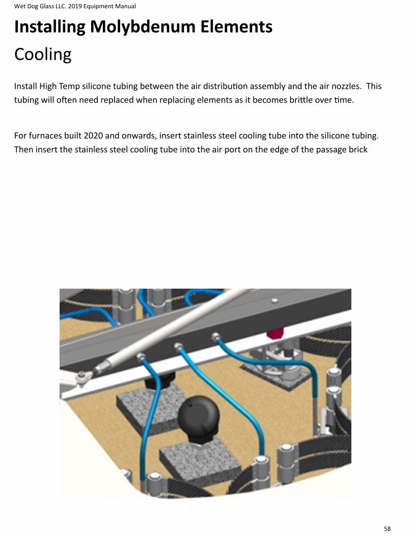
Wet Dog Glass LLC. 2019 Equipment Manual
58
Installing Molybdenum Elements
Cooling
Install High Temp silicone tubing between the air distribution assembly and the air nozzles. This
tubing will often need replaced when replacing elements as it becomes brittle over time.
For furnaces built 2020 and onwards, insert stainless steel cooling tube into the silicone tubing.
Then insert the stainless steel cooling tube into the air port on the edge of the passage brick

Wet Dog Glass LLC. 2019 Equipment Manual
59
Installing Molybdenum Elements
Replacements
Always measure your elements before ordering replacements. Some furnaces and some electrical
supplies require non-standard elements.
Wet Dog Glass LLC. 2019 Equipment Manual
60
Charging and Melt Cycles
First Charge
When a charging a new furnace for the first time (and similarly for the first charge in any furnace) it
is important to follow several guidelines to avoid stress on the liner or crucible as much as possible.
When a furnace already has glass in it, the glass acts as a barrier between cold charges and the cru-
cible, avoiding heat shock directly to it. When first charging a furnace after heating up, cold glass
will be contacting the crucible directly. To minimize stress, follow this procedure:
Step 1 — Let the furnace soak at a steady temperature for 2-3 hours before the first charge. We
recommend about 2100, it is not necessary to be at normal charging and melting temps for the first
charge. This allows heat to soak into the castings and equalize.
Step 2 — Pre-heat the first few charges in an oven to 600-900F if at all possible. This will decrease
the temperature difference between crucible and glass, decreasing stress.
Step 3 — Start with a small charge, 10-25 lb’s. Again, the goal is to decrease stress from tempera-
ture differences as much as possible. When the charge has flattened out (1 hour), add another
small charge, keeping the glass in the center and away from the crucible sides. Repeat small charg-
es until the bottom of the crucible has 2-4 inches of glass. This will act as a thermal barrier, pro-
tecting the crucible from major temperature stresses.
Step 4 — The furnace can now be taken up to charging temperature, or you may continue charging
at a lower temp. Begin adding full charges (~50 lb’s), keeping the glass in the center of the crucible
with NONE touching the side of the crucible. Allow charge to melt and flatten completely before
adding another. Small furnaces may require smaller charges to accomplish this.
Charging (getting the batch or cullet into the furnace) can best be done with a chute or a shovel.
Keep in mind that the faster you get all of one charge into the furnace, the less the furnace temper-
ature drops. If you can charge 15% of your reservoir’s capacity in one or two scoops, charging can
be a pleasant experience. If you must use a shovel, you will most likely have to open and close the
door 10 times, spill glass on the sill, on the floor, and loose lots of valuable heat from the furnace.
The best idea is to find, make or hire someone to make a steel or stainless steel chute that will hold
the lesser of either 15% of your reservoir’s capacity or as much as you can handle comfortably. This
chute should be about 7-1/2” wide, 6” tall and 48” long so that it fits through the furnace door and
can be tilted to let the glass out without getting the handle too close to the heat. Stainless Steel is
more expensive, but minimizes rust and cleaning.

Wet Dog Glass LLC. 2019 Equipment Manual
61
Charging and Melt Cycles
Overview and Sample Schedule
When charging the furnace, it is wise not to charge more than 50lbs per charge. Larger charges can
shock the liner and cause it to crack. The objective is to create a mounded layer of fresh batch on
the top of the molten glass in the center, with as little as possible touching the liner, and with NONE
touching the walls above the liner. Allow each charge to melt and flatten completely before adding
another. It usually takes an hour to an hour and 30 minutes before any cold spots are completely
melted in. As the glass level nears the top of the crucible, your last one or two charges may be
smaller so as to avoid mounding glass up onto the superstructure walls or flowing over the lip of the
crucible.
As with any furnace, any batch, and any user, experimentation is necessary to find the most efficient
way to melt glass in each furnace. Melting glass is a science, more than it is an art. It is important to
change only one variable at a time while searching for the ideal parameters and keep good notes on
time and temperature. Once these parameters are found, stick to them.
• Saving clear cullet to add to charge will result in material savings as well as a potentially quicker
melting cycle.
Sample Melt Cycle:
Step 1 — Turn the furnace up to melting temperature (usually 2350ºF to 2400ºF, lower for cullet).
Step 2 — Once the furnace has reached this temperature, charge about 15 % of the total capacity.
Step 3 — Let the charge flatten out before charging again.
Step 4 — Repeat these steps until the crucible is full.
Step 5 — Let the glass cook at the charging temperature until bubbles in glass sample are pin head
size and a ¼” apart (typically 4-8 hours).
Step 6 — Turn the temperature down to blowing temperature.
Some studios “squeeze” the glass. This entails lowering the furnace temperature to about 100 de-
grees F below working temperature after charging.
The bubbles that remain in the glass when the temperature is lowered will contain mostly oxygen
and will be absorbed into the glass by a chemical reaction. It will happen faster
Wet Dog Glass LLC. 2019 Equipment Manual
62
Charging and Melt Cycles
Finding the Ideal Temperature and Schedule
Finding the Ideal Melting Temperature
Step 1 — First start with clean, seedless glass.
Step 2 — Turn the temperature up to a set-point ~25F below the estimated melting temperature
recommended by the batch or cullet manufacturer
Step 3 — After this temperature is reached, take a sample of glass by gathering and dribbling it onto
the marver. Inspect for seeds.
Step 4 — If there are no seeds, turn the temperature up 10 degrees and after a 1/2 hour, take an-
other sample.
Step 5 — Repeat step 4 until the sample has seeds. Your ideal melting temperature is 15 to 20 de-
grees below where the seeds developed.
Finding the Ideal Melting Time (the time the glass cooks at the ideal temperature)
Step 1 — With the crucible full of glass and at the ideal melting temperature, wait about 3 hours
and take a sample. This sample will have many seeds in it. These seeds are the result of chemicals
reacting to each other and liberating gases.
Step 2 — Take a sample each half hour - eventually you will see fewer seeds and they will be larger
than before. Continue taking samples until the seeds are the size of a pin head and ¼ inch apart.
Step 3 — Make a note of how long the glass cooked before the sample reached this stage. This is
your ideal melt time. Configure the temperature and time you have found into your temperature
controller profile 1 for repeatable high quality melts.
If the furnace will not be used for several days, turning the temperature down will save fuel. Some-
where between 1950°F and 2000°F is a good temperature to idle at when not in active use. Any
lower can harm refractory materials as the glass stiffens.
Wet Dog Glass LLC. 2019 Equipment Manual
63
Maintenance and Servicing
Electrical
6 Month Maintenance: Disconnect all power before servicing equipment and use lockout/tagout
procedure detailed in the safety section. **All electrical connections are to be done by qualified
technician.**
All electrical terminals must be torqued on the equipment every 6 months. Torque specifications
can be found on a tag inside the door of the control panel, or in the component manuals. Lack of
torqueing can cause loose connections that arc, melting and burning terminals and components.
Apply suitable electrical grease to terminals and bus bar connections on equipment with Molyb-
denum Disilicide heaters.
Inspect elements and element junction box. Elements coming out of their grooves can cause a
short circuit against racks or other metal inside an oven and damage the oven. Elements outside
their grooves will warp, stretch, and degrade much quicker. Connections in the element junction
box must be inspected for corrosion and heat damage.
Confirm all safety systems are functioning properly. When the door is opened, the door switch
should trip causing the “Interlocks Closed” Light to turn off, and the Contactor inside the panel to
“thunk” open. Adjust door switch mounting as needed so that it trips before there is enough room
for an arm or punty to enter the equipment. Disconnect the “High Limit” Thermocouple, the
“Interlocks Closed” Light should turn off, and the Contactor inside the panel should “Thunk” open.
Clean and repaint metal showing wear. Paint wears off with use and heat, and metal will degrade
much more quickly without paint.
Replace gaskets strips of the door seal and adjust door fit as needed. Worn gaskets will make your
oven less efficient and cause damage to door switches and other components mounted around the
doors.
Check all fans are functioning inside the control panel, and clean filters when present.
Check element cooling blower on electric furnaces is functioning, and air delivery hoses have not
cracked or become disconnected. Lack of airflow to molybdenum elements can cause corrosion and
degradation very quickly.

Wet Dog Glass LLC. 2019 Equipment Manual
64
Maintenance and Servicing
Combustion
6 Month Maintenance: Disconnect all power before servicing equipment and use lockout/tagout
procedure detailed in the safety section. **All electrical connections are to be done by qualified
technician.**
Confirm all safety systems are functioning properly. Disconnect the “High Limit” Thermocouple,
the Flame Safety should shut down the system and show an FA2 or Interlocks open error. Remove
the back two sections of the UV Scanner during operation. The Flame Safety should shut down the
system with an FA8 or Flame Failure error. Close the valve at the bottom of the blower enclosure.
The Flame Safety should shut the system down with an Fab or FAA Air Failure. Adjust the High Gas
Pressure Switch below your incoming gas pressure, the Flame Safety should shut down the system
and show an FA2 or Interlocks Open error. Adjust the Low Gas Pressure Switch above your incoming
gas pressure, the Flame Safety should shut down the system and show an FA2 or Interlocks Open
error.
Clean and repaint metal showing wear. Paint wears off with use and heat, and metal will degrade
much more quickly without paint.
Adjust the door for a tight fit on furnaces, and to a 1/4” on glory holes. This prevents excessive
heat from escaping and making the equipment inefficient or damaging the equipment.
Clean and replace blower filters as necessary. This may need to be done more often depending on
environment.
Inspect the flue cleanout blocks and the recuperator of furnaces and recuperated Glory Holes.
Some build up is normal, but there should not be a significant blockage of flow. Cleanout out with a
wire chimney brush or similar, or with hook and torch for glass buildup.
Inspect refractory for cracks. This is most common on the door portal and flue blocks. Patch with
mortar, or fiber soaked in mortar. Contact WDG for replacement castings.
In Free Standing Pot Furnaces open the front cleanout port and inspect for glass buildup around
the pot. If to much builds up, it can seep around castings and destroy the fiber backing.
Inspect thermocouple ports for wear. Add fiber/mortar as needed to prevent excess heat to ther-
mocouple head.

Wet Dog Glass LLC. 2019 Equipment Manual
65
Maintenance and Servicing
Combustion – Continued
6 Month Maintenance: Disconnect all power before servicing equipment and use lockout/tagout
procedure detailed in the safety section. **All electrical connections are to be done by qualified
technician.**
Replace glory hole diapers as needed to prevent damage to the brick. Diapers are insulating casta-
ble spread dry in the GH bottom and sprayed lightly with water.
Inspect Furnace Crucibles for cracks and damage. Free standing crucibles should be replaced as
soon as possible to prevent excessive glass buildup in the tank and spillway. Day Tank crucibles
should be patched as soon as possible or during the next shut down to slow the spread of the crack
and the amount of glass working its way through the crucible to the backing castable. Patch can be
ordered from WDG. Grind out as much glass as possible before patching, any remaining glass under
the patch will significantly decreases the life of the patch. A WDG Day Tank can run for many years
after a crack appears in the pot, and more with good maintenance and patching.