Wei X.X., Wang L.X., and Chau K.T. (2009) “Nonlinear seismic torsional pounding between an...
27
Nonlinear Seismic Torsional Pounding Between an Asymmetric Tower and a Barrier X. X. Wei, a) L. X. Wang, b),c) and K. T. Chau c) Seismic torsional pounding between an asymmetric single-story tower and a neighboring barrier under harmonic ground excitation is modeled as the nonlinear Hertz contact in this paper. The governing equations of motion are numerically solved using the fourth-order Runge-Kutta method with an adaptive step size control. An analytical solution is obtained for the first time for a special case of periodic torsional pounding. Results of our numerical simulations reveal that torsional pounding tends to be much more complex and unpredictable than translational pounding, and most of them are either multiple or chaotic impacts. The maximum torsional impact velocity tends to be insensitive to the changes of separation distance and eccentricity as long as impact is developed. Although the analytical solution fails to predict the exact impact velocity of multiple torsional pounding, it does provide some useful insights into this complex phenomenon. The analytical solution succeeds in predicting the overall patterns as well as the abrupt jump of torsional impact velocity spectra. DOI: 10.1193/1.3207177 INTRODUCTION Pounding between adjacent structures (such as buildings or bridges) or between dif- ferent parts of a same structure during major earthquakes has been identified as one of the causes of damages and, in some rare cases as, a primary cause for the initiation of collapse (Anagnostopoulos 1994). For example, pounding was observed in over 15% of the 330 collapsed or severely damaged structures during the 1985 Mexico City earth- quake (Rosenblueth and Meli 1986). During the 1989 Loma Prieta earthquake, there were over 200 pounding occurrences involving more than 500 buildings in San Fran- cisco, Oakland, Santa Cruz, and Watsonville (Kasai and Maison 1997). Pounding hazard may be especially severe in highly populated and crowded metropolitan regions such as Hong Kong. In the last few decades, a large number of investigations have been conducted on modeling seismic pounding between adjacent structures. The problem of pounding be- tween single-degree-of-freedom (SDOF) systems has been studied (for example, Miller a) Professor, State Key Laboratory of Explosion Science and Technology, Beijing Institute of Technology, Beijing 100081, China b) Earthquake Administration of Guangdong Province, Guangzhou 510070, China c) Chair Professor, Department of Civil and Structural Engineering, The Hong Kong Polytechnic University, Hung Hom, Kowloon, Hong Kong, China 899 Earthquake Spectra, Volume 25, No. 4, pages 899–925, November 2009; © 2009, Earthquake Engineering Research Institute
Transcript of Wei X.X., Wang L.X., and Chau K.T. (2009) “Nonlinear seismic torsional pounding between an...

Nonlinear Seismic Torsional PoundingBetween an Asymmetric Towerand a Barrier
X. X. Wei,a) L. X. Wang,b),c) and K. T. Chauc)
Seismic torsional pounding between an asymmetric single-story tower anda neighboring barrier under harmonic ground excitation is modeled as thenonlinear Hertz contact in this paper. The governing equations of motion arenumerically solved using the fourth-order Runge-Kutta method with anadaptive step size control. An analytical solution is obtained for the first timefor a special case of periodic torsional pounding. Results of our numericalsimulations reveal that torsional pounding tends to be much more complex andunpredictable than translational pounding, and most of them are eithermultiple or chaotic impacts. The maximum torsional impact velocity tends tobe insensitive to the changes of separation distance and eccentricity as long asimpact is developed. Although the analytical solution fails to predict the exactimpact velocity of multiple torsional pounding, it does provide some usefulinsights into this complex phenomenon. The analytical solution succeeds inpredicting the overall patterns as well as the abrupt jump of torsional impactvelocity spectra. �DOI: 10.1193/1.3207177�
INTRODUCTION
Pounding between adjacent structures (such as buildings or bridges) or between dif-ferent parts of a same structure during major earthquakes has been identified as one ofthe causes of damages and, in some rare cases as, a primary cause for the initiation ofcollapse (Anagnostopoulos 1994). For example, pounding was observed in over 15% ofthe 330 collapsed or severely damaged structures during the 1985 Mexico City earth-quake (Rosenblueth and Meli 1986). During the 1989 Loma Prieta earthquake, therewere over 200 pounding occurrences involving more than 500 buildings in San Fran-cisco, Oakland, Santa Cruz, and Watsonville (Kasai and Maison 1997). Pounding hazardmay be especially severe in highly populated and crowded metropolitan regions such asHong Kong.
In the last few decades, a large number of investigations have been conducted onmodeling seismic pounding between adjacent structures. The problem of pounding be-tween single-degree-of-freedom (SDOF) systems has been studied (for example, Miller
a) Professor, State Key Laboratory of Explosion Science and Technology, Beijing Institute of Technology, Beijing100081, China
b) Earthquake Administration of Guangdong Province, Guangzhou 510070, Chinac) Chair Professor, Department of Civil and Structural Engineering, The Hong Kong Polytechnic University, Hung
Hom, Kowloon, Hong Kong, China899Earthquake Spectra, Volume 25, No. 4, pages 899–925, November 2009; © 2009, Earthquake Engineering Research Institute

900 X.WEI, L.WANG, AND K. CHAU
1980, Jing and Young 1991, Davis 1992). The case of several buildings standing in a rowsubjected to pounding has also been investigated (Anagnostopoulos 1988). Among them,the pounding model by Davis (1992), which incorporates the nonlinear Hertz contactlaw, appears to be more realistic, since seismic poundings are seldom linear. In addition,an analytical solution was obtained for the case of rigid impact between a SDOF oscil-lator and a neighboring barrier. Chau and Wei (2001) extended the model of Davis(1992) to consider poundings between two SDOF oscillators and obtained an analyticalsolution for the case of rigid impact. Both of these analytical solutions agree qualita-tively with numerical simulations.
Jankowski (2005) proposed a nonlinear visco-elastic model, which modified theHertz contact law by introducing a nonlinear damper during the approach period of col-lision in order to simulate the energy dissipation. Muthukumar and DesRoches (2006)compared various pounding models, including the stereomechanical model, linear springmodel, Kelvin model, Hertz model, and Hertz model with a nonlinear damper (theHertz-damp model). The results show that the Hertz model provides adequate results atlow PGA �0.1–0.3 g� levels of ground shaking, and the Hertzdamp model performs betterat moderate �0.4–0.6 g� and high �0.7–0.9 g� PGA levels, for energy loss during impactbeing more significant at higher levels of PGA.
Most of these studies mentioned above assume a two-dimensional behavior, and onlytranslational pounding is considered. However, actual structures may undergo torsionalvibrations when subjected to earthquake excitations due to asymmetric structural layouts(Sedarat 1989). Even when adjacent buildings are nominally symmetric, the impact be-tween them, as indicated by Leibovich et al. (1996), is not likely to be symmetric. Thisis because the gap between them may be closed or narrowed at arbitrary points by ac-cumulated debris, and the centers of stiffness of the two buildings are, more often thannot, not aligned along the direction of ground shaking (Leibovich et al. 1996). There-fore, torsional pounding may be more commonly observed than unidirectional poundingduring real earthquakes.
Leibovich et al. (1996) studied possible eccentric pounding between two symmetricsingle-story structures using the coefficient of restitution. Papadrakakis et al. (1996) de-veloped a three-dimensional finite element model to simulate pounding between two ormore adjacent buildings using the Lagrange multiplier method. More recently, Mouzakisand Papadrakakis (2004) investigated the three-dimensional pounding between two ad-jacent buildings based on the impulse-momentum relation. Gong and Hao (2005) stud-ied the torsional pounding between an asymmetric system and a symmetric one-storysystem subjected to bidirectional ground motion.
However, the more realistic Hertz contact law has not been used to model torsionalpounding between asymmetrical structures. Therefore, the main objective of this paper isto consider the seismic torsional pounding between an asymmetrical structure and aneighboring barrier using the Hertz contact law, by extending the models of Davis(1992) and Chau and Wei (2001). An analytical solution is derived for periodic singleimpact. The results will be compared with numerical simulations.

NONLINEAR SEISMIC TORSIONAL POUNDING BETWEEN AN ASYMMETRIC TOWER AND A BARRIER 901
Although Hertz contact law can capture the nonlinearity due to contact at the impactpoint, inelastic nature of impact cannot be taken into consideration (i.e., no energy lossis accounted for). For example, a simple visco-elastic impact element (composing of alinear spring and a viscous dashpot) has been used to model energy loss at impact pointby introducing a coefficient of restitution (e.g., Anagnostopoulos 2004). However, thecoefficient of restitution must be determined experimentally. Its magnitude may varywith the magnitude of impact force, the duration of contact, the damage states at thecontact point; and thus uncertainty is inevitable. Such consideration is, however, out ofthe scope of the present study.
FORMULATION AND NUMERICAL SIMULATION
The torsional pounding between an asymmetric single-story tower (Tower A) and aneighboring barrier shown in Figure 1 is considered in this study. Tower A is supportedby four identical square columns at its four corners. Its center of mass (CM) is offsetfrom its center of stiffness (CS), which is also the geometric center of the tower. Forsimplicity, only eccentricity along the y direction �ey�� is considered here. The groundmotion is perpendicular to the direction of eccentricity so that torsional response can betriggered. The motion of the tower is denoted by a translation u��� and a rotation ���� atCM as shown in Figure 1b, where � is the time.
Following Davis (1992), two different cases of the neighboring barrier are consid-ered, that is:
Case 1: The barrier is stationary, representing a very flexible and long period neigh-boring structure. The input excitation is characterized by a constant displacement am-plitude as ug���=Ag sin ��.
e′yl′
w′D
C
CM
CS
)(τu
C
D
a′
xy
( )gu τ
Barrier
(b) Plan view
Tower A
)(τθ
CSCM
a′
w′
e′yl′
Tower Am, c, 4k
Barrier
C
D
( )gu τ
xy
(a) 3D view
Figure 1. Sketch of an asymmetric tower and a neighboring barrier. With an eccentricity ey�between its center of stiffness (CS) and center of mass (CM), Tower A is supported by fouridentical columns at its four corners. As shown by the dashed line in the plan view, torsionalimpact may occur at either Corner C or Corner D under unidirectional ground excitations.

902 X.WEI, L.WANG, AND K. CHAU
Case 2: The barrier is locked to the ground motion, representing a very stiff andshort period neighboring structure. The input excitation is characterized by a constantacceleration amplitude as ug���=Ag sin ��.
For these excitations, Ag and � are the amplitude and circular frequency of the inputrespectively. These two cases represent limits of response which are possible in the ac-tual neighboring structure (Davis 1992). For both cases, the equations of motion ofTower A can be expressed as
� mu��� + cu��� + 4ku��� + 4key����� = Fx� + G�ug����
I���� + c����� + 4key�u��� + �l�2 + w�2 + 4ey�2�k���� = T��
� �1�
where m and I� are the mass and moment of inertia of Tower A, c and c� are the trans-lational and rotational damping coefficients respectively. As discussed by Clough andPenzien (1993), both c and c� can be determined by free vibration test (such as hammertest). That is, the structure can be set to free vibrations by applying a hammer blow, ei-ther in translational and rotational motions. The magnitude of the successive decrease infree vibration magnitude can be used to determine the coefficient of damping (both cand c�). The lateral stiffness of each column of the tower is denoted by k, l� and w� arethe dimensions of the tower along the y and x directions respectively, ey� is the eccen-tricity, Fx� and T�� are the force and torque on Tower A caused by pounding, and G�ug����denotes the forcing function which takes different forms for the two cases,
Case 1: G�ug���� = 4kug��� + cug��� �2�
Case 2: G�ug���� = − mug��� �3�Note that in the above three equations, the displacement u��� is the absolute dis-
placement of the tower for Case 1 condition, and it is the relative displacement of thetower to the ground motion for Case 2 condition. Following Davis (1992), the same sym-bol u��� is used for both Case 1 and Case 2 for their mathematical similarity.
For both cases, the impact force between the tower and the barrier can be representedas
Fx� = �− ���ui − a� +w�
2��
for ui � a� +w�
2 �i = C,D�
0 for ui � a� +w�
2 �i = C,D� � �4�
where ui�i=C ,D� is the displacement of either Corner C or Corner D of the tower, a� isthe separation distance, �� is the impact stiffness, and � is the impact force component,which is equal to �=3/2 when the Hertz contact is assumed.
If we normalize the displacement as x���=u��� /Ag and the time as t=��x, where�x= 4k /m is the translational natural frequency of Tower A along the x-direction, Equation1 can be rewritten in a dimensionless form as:

NONLINEAR SEISMIC TORSIONAL POUNDING BETWEEN AN ASYMMETRIC TOWER AND A BARRIER 903
�x�t� + 2�xx�t� + x�t� + ���t� = Fx + G�xg�t��
��t� + 2����t� + xx�t� + ����t� = T�
� �5�
Note that the superimposed dots in the above equations denote the derivatives withrespect to the normalized time t. In addition, the following definitions have been used:
�x = c/�2m�x�, �� = c�/�2I��x�, � = ey�/Ag, �� = ��2/�x
2,
��2 = �l�2 + w�2 + 4ey�
2�k/I�, x = mey�Ag/I�, Fx = Fx�/�mAg�x2�, T� = T��/�I��x
2� ,
p = �x/� = T/Tx ey = ey�/Ag, a = a�/Ag, l = l�/Ag, w = w�/Ag, I = I�/Ag2 �6�
where T and Tx denote the periods of the input and of the tower respectively, and p is theratio between them. The impact stiffness is normalized as �=�� / �4k�Ag
1−���. After thenormalization, the forcing function G�xg�t�� becomes
G�xg�t�� = E1 sin�t/p� + E2 cos�t/p� �7�
where E1=1 and E2=2�x /p for Case 1 condition, and E1=1 and E2=0 for Case 2condition.
The torsional pounding between the tower and the barrier is described by Equation 5,which is numerically solved using the fourth-order Runge-Kutta method with an adap-tive step size control here. In the numerical calculations, in order to search for continu-ous impacts, the approach used by Davis (1992) and Chau and Wei (2001) is adoptedhere. In particular, the numerical integrations are first performed for 40 excitation cyclesand all impacts occurred in the next eight cycles are reported. Through extensive nu-merical simulations, we found this approach also appears to be reasonable for thepresent problem.
Analytical Solution For Periodic Impacts
Besides the numerical simulations, analytic solution is possible for this problemwhen the impact is rigid (i.e., ��→� in Equation 4). For rigid impact, the contact timecan be assumed to be zero and the rebound velocity is exactly equal to the negative ofthe impact velocity. For this special case, a closed-form solution is obtained for periodictorsional pounding between the tower and the barrier by modifying the solution proce-dure for translational pounding by Davis (1992) and Chau and Wei (2001). Compared tothese two previous studies, the mathematical problem here becomes more challengingwith the inclusion of the ��t� variable.
BOUNDARY CONDITIONS FOR PERIODIC IMPACT
Suppose a periodic pounding exists between the tower and the barrier. The rigid im-pact between them is governed by the law of conservation of translational momentum aswell as the law of conservation of angular momentum. Between two consecutive im-pacts, the tower is in free response motion, and thus the impact force and the impacttorque in Equation 5 are all zero. When periodic pounding occurs, we can assume t

904 X.WEI, L.WANG, AND K. CHAU
= t0 is the time right after an impact (i.e., the beginning of the free response motion) andt= t0+2n p is the time just before the next impact to occur, where 2n p represents thenormalized time duration of the free response motion and n is a positive integer. Recall-ing that p denotes the excitation period measured in units of the natural period of thetower �p=T /Tx�, the term 2n p represents there are n ground excitation cycles betweentwo consecutive impacts.
We preliminarily assume the periodic impacts occur at Corner C of Tower A asshown in Figure 1b. The boundary conditions for the free response motion can be ex-pressed as
xC�t0� = a + w/2 �8�
xC�t0 + 2n p� = a + w/2 �9�
��t0� = ��t0 + 2n p� �10�
x�t0� = − x�t0 + 2n p� �11�
��t0� = − ��t0 + 2n p� �12�
where x�t� and ��t� are the normalized translation and rotation of the center of massrespectively, and xC�t� is the translation of Corner C, which can be expressed in the formof x�t� and ��t� as
xC�t� = x�t� + w/2 − �l/2 − ey���t� �13�Equations 8 and 9 impose that Corner C will touch with the neighboring barrier
when impacts occur. If we define h= l /2−ey and substitute Equation 13 into Equations 8and 9, we can express all the boundary conditions in terms of the motion of the center ofmass (i.e., x�t� and ��t�):
x�t0� − h��t0� = a �14�
x�t0 + 2n p� − h��t0 + 2n p� = a �15�Thus, Equations 10–12, 14, and 15 constitute five independent boundary conditions
for the free response motion of the tower.
GENERAL SOLUTION FOR FREE RESPONSE MOTION
By simply letting the impact force Fx and the torque T� to be zero in Equation 5, wecan get the equations of motion for the free response motion of the tower. From the firstequation in Equation 5, we have
��t� = �G�xg�t�� − x�t� − 2�xx�t� − x�t��/� �16�Substituting it into the second formula in Equation 5, we can get

NONLINEAR SEISMIC TORSIONAL POUNDING BETWEEN AN ASYMMETRIC TOWER AND A BARRIER 905
x�t� + 2��x + ���x��t� + �1 + 4�x�� + ���x�t� + 2��� + ���x�x�t� + ��� − x��x�t�
= H1 sin�t/p� + H2 cos�t/p� �17�
where the two parameters H1 and H2 are equal to
H1 = −E1
p2 − 2��
E2
p+ ��E1, H2 = −
E2
p2 + 2��
E1
p+ ��E2 �18�
To get the particular solution for Equation 17, first we assume the following solutionform:
x�t� = D1 sin�t/p� + D2 cos�t/p� �19�After substituting it into Equation 17 and letting the right and left sides to be equal,
finally we can get the expressions for D1 and D2 as:
D1 =H1H3 − H2H4
H32 + H4
2 , D2 =H1H4 + H2H3
H32 + H4
2 �20�
where
H3 =1
p4 −1 + 4�x�� + ��
p2 + �� − x�, H4 =2��x + ���
p3 −2��� + ���x�
p�21�
To get the homogeneous solution, we have to solve the following characteristicequation:
s4 + 2��x + ���s3 + �1 + 4�x�� + ���s2 + 2��� + ���x�s + ��� − x�� = 0 �22�Suppose that the roots of the above equation in the forms s=�j± i�j (j=1 ,2 and i
= −1), we can get the following general solution for Equation 17:
x�t� = e�1�t−t0��c1 sin �1�t − t0� + c2 cos �1�t − t0��
+ e�2�t−t0��c3 sin �1�t − t0� + c4 cos �1�t − t0�� + D1 sin�t/p� + D2 cos�t/p��23�
where ci �i=1,2 ,3 ,4� are four unknown parameters to be determined by boundary con-ditions. Substituting Equation 23 into Equation 16, we can get the following expressionfor the rotation ��� of the center of mass:
��t� = e�1�t−t0����1c1 + �2c2�sin �1�t − t0� + �− �2c1 + �1c2�cos �1�t − t0��
+ e�2�t−t0����3c3 + �4c4�sin �1�t − t0� + �− �4c3 + �3c4�cos �1�t − t0��
+ �5 sin�t/p� + �6 cos�t/p� �24�
where
�1 = − ��12 − �1
2 + 2�x�1 + 1�/�, �2 = 2�1��1 + �x�/� �25a�

906 X.WEI, L.WANG, AND K. CHAU
�3 = − ��22 − �2
2 + 2�x�2 + 1�/�, �4 = 2�2��2 + �x�/� �25b�
�5 = �E1 + D1/p2 + 2�xD2/p − D1�/� �25c�
�6 = �E2 + D2/p2 − 2�xD1/p − D2�/� �25d�
DETERMINATION OF UNKNOWN PARAMETERS
The five unknowns, including ci �i=1,2 ,3 ,4� and t0 (the onset time of the periodicimpacts), will be determined uniquely using the five independent boundary conditions inEquations 10–12, 14, and 15.
Substituting Equations 23 and 24 into Equation 14 and letting t= t0, we get
c2 + c4 + D1 sin�t0/p� + D2 cos�t0/p� − h��1c2 − �2c1� − h��3c4 − �4c3� − h�5 sin�t0/p�
− h�6 cos�t0/p� = a �26�Substitution of Equations 23 and 24 into Equation 15 with some simple transforma-
tions leads to
q1c1 + q2c2 + q3c3 + q4c4 = �h�5 − D1�sin�t0/p� + �h�6 − D2�cos�t0/p� + a �27�
where qi �i=1 ,2 ,3 ,4� are defined as follows:
q1 = ��1 − h�1�sin�2n p�1� + h�2 cos�2n p�1��e2n p�1 �28a�
q2 = ��1 − h�1�cos�2n p�1� − h�2 sin�2n p�1��e2n p�1 �28b�
q3 = ��1 − h�3�sin�2n p�2� + h�4 cos�2n p�2��e2n p�2 �28c�
q4 = ��1 − h�3�cos�2n p�2� − h�4 sin�2n p�2��e2n p�2 �28d�Similarly, substitution of Equation 24 into Equation 10 leads to
q5c1 + q6c2 + q7c3 + q8c4 = 0 �29�
where
q5 = �2 + ��1 sin�2n p�1� − �2 cos�2n p�1��e2n p�1 �30a�
q6 = − �1 + ��2 sin�2n p�1� + �1 cos�2n p�1��e2n p�1 �30b�
q7 = �4 + ��3 sin�2n p�2� − �4 cos�2n p�2��e2n p�2 �30c�
q8 = − �3 + ��4 sin�2n p�2� + �3 cos�2n p�2��e2n p�2 �30d�Then, by differentiating Equation 23 and substituting it into Equation 11, we obtain
q9c1 + q10c2 + q11c3 + q12c4 = − 2D1 cos�t0/p�/p + 2D2 sin�t0/p�/p �31�
where

NONLINEAR SEISMIC TORSIONAL POUNDING BETWEEN AN ASYMMETRIC TOWER AND A BARRIER 907
q9 = �1 + ��1 sin�2n p�1� + �1 cos�2n p�1��e2n p�1 �32a�
q10 = �1 + �− �1 sin�2n p�1� + �1 cos�2n p�1��e2n p�1 �32b�
q11 = �2 + ��2 sin�2n p�2� + �2 cos�2n p�2��e2n p�2 �32c�
q12 = �2 + �− �2 sin�2n p�2� + �2 cos�2n p�2��e2n p�2 �32d�Similarly differentiating Equation 24 and substituting it into Equation 12, we have
q13c1 + q14c2 + q15c3 + q16c4 = − 2�5 cos�t0/p�/p + 2�6 sin�t0/p�/p �33�
where
q13 = − �1�2 + �1�1 + ���1�1 + �1�2�sin�2n p�1�
+ �− �1�2 + �1�1�cos�2n p�1��e2n p�1 �34a�
q14 = �1�1 + �1�2 + ���1�2 − �1�1�sin�2n p�1� + ��1�1 + �1�2�cos�2n p�1��e2n p�1
�34b�
q15 = − �2�4 + �2�3 + ���2�3 + �2�4�sin�2n p�2�
+ �− �2�4 + �2�3�cos�2n p�2��e2n p�2 �34c�
q16 = �2�3 + �2�4 + ���2�4 − �2�3�sin�2n p�2� + ��2�3 + �2�4�cos�2n p�2��e2n p�2
�34d�Rearranging Equation 26, the following equation is obtained:
q17c1 + q18c2 + q19c3 + q20c4 = �h�5 − D1�sin�t0/p� + �h�6 − D2�cos�t0/p� + a �35�
where
q17 = h�2, q18 = 1 − h�1, q19 = h�4, q20 = 1 − h�3 �36�Subtracting Equation 27 from Equation 35 leads to
�q17 − q1�c1 + �q18 − q2�c2 + �q19 − q3�c3 + �q20 − q4�c4 = 0 �37�Finally, Equations 37, 29, 31, and 33 constitute a system of linear equations for ci
�i=1,2 ,3 ,4�, and these four equations can be expressed in a matrix form as
Q>
c> = b> �38�
where
Q>
= �q17 − q1 q18 − q2 q19 − q3 q20 − q4
q5 q6 q7 q8
q9 q10 q11 q12
q q q q� �39a�
13 14 15 16

908 X.WEI, L.WANG, AND K. CHAU
c> = �c1
c2
c3
c4
� b> =�0
0
− 2D1
pcos t0
p + 2
D2
psin t0
p
− 2�5
pcos t0
p + 2
�6
psin t0
p � �39b�
Let � to be the determinant of the matrix Q>
. Then, according to Cramer’s rule, if��0, Equation 38 has an unique solution with the following form:
ci =�i
��i = 1,2,3,4� �40�
where �i is the corresponding determinant obtained by replacing the ith column of � bythe vector b> . Since the first two elements of vector b> are zeros, we can further rewrite �i as:
�i = �3i�−2D1
pcos t0
p +
2D2
psin t0
p� + �4i�−
2�5
pcos t0
p +
2�6
psin t0
p�
�41�
where �3i and �4i are the cofactors of the entries �3, i� and �4, i� in the determinant �i
respectively (Strang 2003). Then Equation 40 can be rewritten as
ci =�3i
��−
2D1
pcos t0
p +
2D2
psin t0
p� +
�4i
��−
2�5
pcos t0
p +
2�6
psin t0
p�
�42�Substituting the above formula into Equation 27, we get an equation for t0:
W1 sin t0
p + W2 cos t0
p = a �43�
where
W1 = D1 − h�5 +2
p��i=1
4
qi�D2�3i + �6�4i� �44a�
W2 = D2 − h�6 −2
p��i=1
4
qi�D1�3i + �5�4i� �44b�
Finally, the unknown t0 can be solved from Equation 44a and 44b as
t0
p= sin−1 a
W12 + W2
2 − tan−1W2
W1 �45�

NONLINEAR SEISMIC TORSIONAL POUNDING BETWEEN AN ASYMMETRIC TOWER AND A BARRIER 909
From Equation 45, the first condition that is required to ensure the existence of validsolutions is that the normalized separation distance a� W1
2+W22. Since multiple
branches exist for both sin−1 and tan−1 functions, attention should be paid to the selection ofappropriate solutions. Only those solutions for which t0 /p lies between 0 and 2n and forwhich the impact velocity is positive should be accepted.
The obtained value of t0 then can be used to calculate the other four unknowns ci
through Equation 42, and further to find the translation �x� and rotation ��� of the centerof mass from Equations 23 and 24. The translational and rotational velocities can be ob-tained from the corresponding differentials.
The above solution procedure is for the case when Corner C impacts onto the neigh-boring barrier. Similar procedure is also applicable for the other case when Corner Dimpacts periodically onto the barrier and the details will not be shown here. In this study,impacts at both Corner C and Corner D will be tried for any specified input parametersand the corner which can bring out valid solutions will be deemed as the actual impactpoint.
Note that the proposed analytical solution only provides a possible solution forpounding which occurs periodically at one single corner of the tower. The actual tor-sional pounding between the asymmetric tower and the neighboring barrier may bemuch more complicated. As will be shown in our numerical simulations, the poundingmay be group periodic or chaotic, and may happen at the two corners consecutively. Tocapture these phenomena, more sophisticated models are needed, but these are out of thescope of the present paper.
RESULTS AND DISCUSSIONS
COMPARISON OF TRANSLATIONAL AND TORSIONAL POUNDINGS
The obtained analytical solution is utilized to investigate effects of input parameters,structural characteristics and separation distances on torsional pounding. The results willbe compared with numerical simulations. Without loss of generality, only positive ec-centricities (i.e. the center of mass of the tower is situated closer to Corner C than toCorner D as shown in Figure 1) are considered here.
Figure 2 shows the normalized impact velocity spectra V / �Ag�x� versus the excita-tion periods T /Tx for both translational �ey / l=0� and torsional �ey / l=0.1� poundings un-der Case 1 condition. The other parameters are �x=0.10, ��=0.10, w / l=0.55, a=1.0 andn=1 (i.e., one impact per one cycle). The curves of translational pounding (the solid lines)are modified from Figure 11 of Davis (1992). Note that here invalid solutions are eliminatedfrom these curves. Actually, Davis (1992) has pointed out that at some excitation periods,multiple impacts occur and the trajectories given by the analytical solution exceed the posi-tion of the neighboring barrier at least once in the middle of the free response motion period.Since it is assumed that no impact occurs during free response motion in the analytical so-lution, obviously those solutions should be removed.
Note that the impact velocity of torsional pounding shown in Figure 2 (the dashedlines) is the velocity at the impact point, which may be either Corner C or Corner D.

910 X.WEI, L.WANG, AND K. CHAU
Compared to the spectrum of translation pounding, there is an abrupt jump in that oftorsional pounding. This is caused by the transition of the impact point from Corner D toCorner C as sketched in the figure. This unique characteristic suggests that torsionalpounding tend to be more complex than translational pounding. Slight change of the ex-citation periods may induce quite different impact patterns.
Except for the abrupt jump, the impact velocity spectra of translational and torsionalpoundings have similar overall patterns and similar impact-occurring excitation periodranges around T /Tx=1.0. The impact-occurring excitation period range means the range ofexcitation period during which impact is developed, which is T /Tx=0.53−1.43 for torsionalpounding and T /Tx=0.57−1.45 for translational pounding. However, at longer excitationperiods �T /Tx�1.5�, solutions exist for translational pounding whereas no valid solution ex-ists for torsional pounding.
The analytical solutions for both translational and torsional poundings shown in Fig-ure 2 are compared with numerical simulations (of �=1000 and �=3/2) in Figures 3aand 3b respectively. The numerical results are denoted by solid dots and each dot denotes oneimpact occurring within the 40–48th excitation cycles. The three small diagrams I, II and IIIshow the enlarged views of three selected period ranges. Comparing the numerical resultsshown in Figures 3a and 3b, torsional pounding appears to be much more complex thantranslational pounding. Almost all the torsional impacts are either multiple impacts (i.e.,group periodic pounding) or chaotic impacts (for example, those around T /Tx=1.5). Thediagram III shows an example of the transition between periodic impacts and chaotic im-pacts.
0 1 2 3 40
1
2
3
4
C
CM
/ xT T
/( )g xV A ω
ey/l = 0.0ey/l = 0.1Jump
D
CM
CC impact
Dimpact
C impact
D impactD
Figure 2. Comparison of normalized impact velocity for torsional �ey / l=0.1� and translational�ey / l=0.0� poundings from analytical solutions. The solid lines are modified from Figure 11 ofDavis (1992). Other parameters are �x=0.10, ��=0.10, a=1.0, �=1000, n=1 and Case 1 condi-tion. Note that for torsional pounding there is a sudden jump between T /Tx=0.74 and 0.75, whichis caused by the impact point changing from Corner D to Corner C as sketched in the figure.

NONLINEAR SEISMIC TORSIONAL POUNDING BETWEEN AN ASYMMETRIC TOWER AND A BARRIER 911
The analytical solutions agree well with the numerical results for translationalpounding as shown in Figure 3a, whereas it is not so good for torsional pounding inFigure 3b, which indicates the insufficiency of the simple analytical solution for thecomplex torsional pounding phenomenon. Most of torsional poundings are multiple im-pacts (either group periodic or chaotic), whereas single periodic impact is assumed inour analytical solution.
However, although large discrepancies exist between the analytical solution and nu-merical simulation for torsional pounding, they have similar overall patterns within theexcitation range of T /Tx=0.53−1.43. What is more important is that the analytical solutionsucceeds in predicting the abrupt jump in the numerical results as shown in the diagram II.As discussed previously, this abrupt jump is caused by the transition of the impact point fromone corner to the other. Therefore, although this simple analytical solution can not predict theexact impact velocities of torsional pounding, it does provide some useful insights into thiscomplicated problem.
1 2 30
2
4
NumericalAnalytical
1 2 30
2
4
NumericAnalytic
0.4 3.00.0
4.5
0.5 1.00.0
5.5
1.60 1.620.0
1.6
/( )g xV A ω
/ xT T
/ xT T
(a) ey/l = 0.0
(b) ey/l = 0.1III
/ xT Tθ
II
II
I I
Jump
Analytical
1.04 1.080.0
4.5
III
NumericalAnalytical
Figure 3. Relative impact velocity spectra by analytical and numerical solutions for both trans-lational and torsional poundings (�x=0.10, ��=0.10, a=1.0, �=1000, n=1 and Case 1 condi-tion): (a) translational pounding when ey / l=0.0; (b) torsional pounding when ey / l=0.1. The foursmall diagrams show the translational analytical solution and the enlarged views of the regimes I, IIand III.
912 X.WEI, L.WANG, AND K. CHAU
EFFECT OF SEPARATION DISTANCE
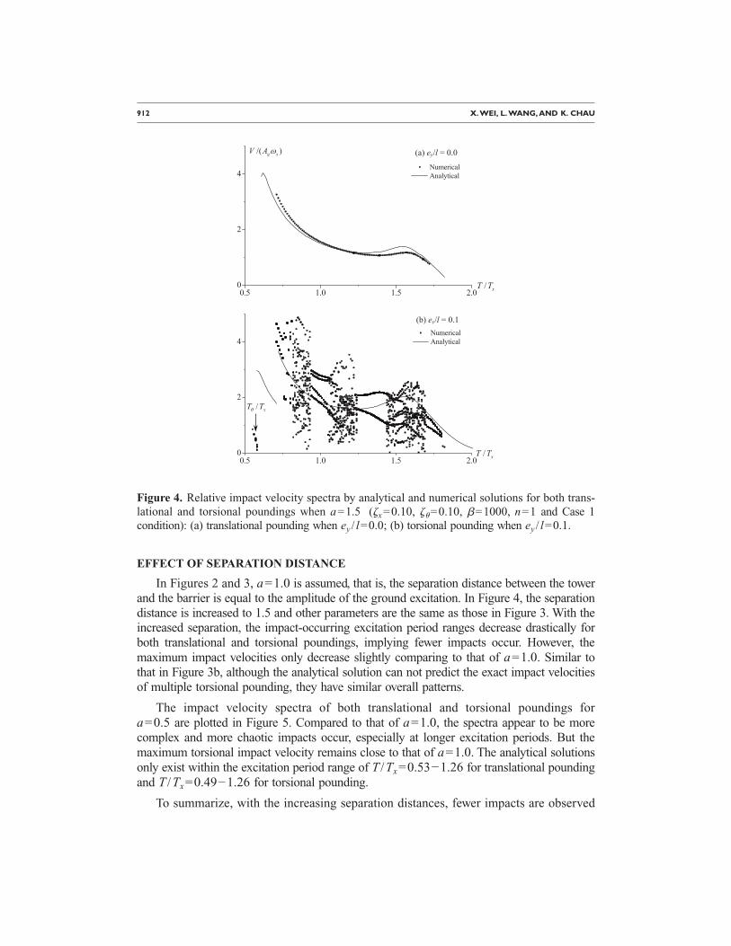
In Figures 2 and 3, a=1.0 is assumed, that is, the separation distance between the towerand the barrier is equal to the amplitude of the ground excitation. In Figure 4, the separationdistance is increased to 1.5 and other parameters are the same as those in Figure 3. With theincreased separation, the impact-occurring excitation period ranges decrease drastically forboth translational and torsional poundings, implying fewer impacts occur. However, themaximum impact velocities only decrease slightly comparing to that of a=1.0. Similar tothat in Figure 3b, although the analytical solution can not predict the exact impact velocitiesof multiple torsional pounding, they have similar overall patterns.
The impact velocity spectra of both translational and torsional poundings fora=0.5 are plotted in Figure 5. Compared to that of a=1.0, the spectra appear to be morecomplex and more chaotic impacts occur, especially at longer excitation periods. But themaximum torsional impact velocity remains close to that of a=1.0. The analytical solutionsonly exist within the excitation period range of T /Tx=0.53−1.26 for translational poundingand T /Tx=0.49−1.26 for torsional pounding.
To summarize, with the increasing separation distances, fewer impacts are observed
0.5 1.0 1.5 2.00
2
4NumericalAnalytical
0.5 1.0 1.5 2.00
2
4NumericalAnalytical
/( )g xV A ω
/ xT T
/ xT T
(a) ey/l = 0.0
(b) ey/l = 0.1
/ xT Tθ
Figure 4. Relative impact velocity spectra by analytical and numerical solutions for both trans-lational and torsional poundings when a=1.5 (�x=0.10, ��=0.10, �=1000, n=1 and Case 1condition): (a) translational pounding when ey / l=0.0; (b) torsional pounding when ey / l=0.1.

NONLINEAR SEISMIC TORSIONAL POUNDING BETWEEN AN ASYMMETRIC TOWER AND A BARRIER 913
and the impact-occurring excitation period ranges become narrower. In addition, the im-pact velocity spectra tend to be less complex, implying the interaction between the struc-ture and the barrier becomes weaker. However, the maximum impact velocity appears tobe not too sensitive to the variation of separation distance as long as pounding occurs.Similar phenomena have been found for translational pounding between two SDOF os-cillators (Chau and Wei 2001).
EFFECT OF CONTACT STIFFNESS AND FORCE EXPONENT
In Figures 3–5, the normalized contact stiffness ��� have been set to be 1000, whichrepresents a relatively stiff contact (Davis 1992). In Figure 6, the contact stiffness is re-duced to 100 and the other parameters are the same as those used in Figure 5. Note thatthe analytical solutions shown in Figure 6 are exactly the same as shown in Figure 5.Comparing the numerical results in these two figures, it is seen that reducing the contactstiffness by an order of magnitude has little effect on the spectrum of translationalpounding, whereas the maximum chaotic impact velocity of torsional pounding in-creases by as large as 74% for the softer contact ��=100�.
1 2 30
2
4
6
NumericalAnalytical
1 2 30
2
4
6
NumericalAnalytical
/( )g xV A ω
/ xT T
/ xT T
(a) ey/l = 0.0
(b) ey/l = 0.1/ xT Tθ
Figure 5. Relative impact velocity spectra by analytical and numerical solutions for both trans-lational and torsional poundings when a=0.5 (�x=0.10, ��=0.10, �=1000, n=1 and Case 1condition): (a) translational pounding when ey / l=0.0; (b) torsional pounding when ey / l=0.1.
We further reduce the normalized contact stiffness to 1.0 in Figure 7 and all the other

914 X.WEI, L.WANG, AND K. CHAU
parameters remain unchanged. Comparing to the spectra shown in Figures 5 and 6 forstiffer contact, the maximum velocities occur at excitation periods closer to T /Tx=1.0for both translational and torsional pounding. In addition, both spectra become much lesscomplex. This implies that for very soft contact the effect of the barrier diminishes and theimpact velocity spectrum becomes similar to that of a stand-alone structure (for which themaximum response occurs at T /Tx=1.0). Similar phenomenon has also been found by Davis(1992). For this soft contact, the analytical solutions are quite different from the numericalresults. This is expected since rigid impact is assumed in the analytical solution.
The Hertz contact ��=3/2� is assumed in all of the previous figures. In Figure 8, thisforce component is increased to 5.0 and all of the other parameters are the same as thosein Figure 7. It is seen that the spectrum of translational pounding is similar to that of�=3/2, except for an abrupt discontinuity occurred as shown in Figure 8a, which isprobably caused by the highly nonlinear nature of the contact law (Davis 1992). Theoverall spectrum pattern of torsional pounding in Figure 8b does not change signifi-cantly, but the maximum velocity resulted from chaotic impacts is larger than that of theHertz contact.
1 2 30
4
8
NumericalAnalytical
1 2 30
2
4
6
NumericalAnalytical
/( )g xV A ω
/ xT T
/ xT T
(a) ey/l = 0.0
(b) ey/l = 0.1/ xT Tθ
Figure 6. Relative impact velocity spectra by analytical and numerical solutions for both trans-lational and torsional poundings when a=0.5 and �=100 (�x=0.10, ��=0.10, n=1 and Case 1condition): (a) translational pounding when ey / l=0; (b) torsional pounding when ey / l=0.1.

NONLINEAR SEISMIC TORSIONAL POUNDING BETWEEN AN ASYMMETRIC TOWER AND A BARRIER 915
To summarize, the change of the contact stiffness and force component (i.e. the de-tails of the contact law) appears to have little effect on the maximum impact velocity oftranslational pounding, consistent with the conclusions by Davis (1992) and Chau andWei (2001). However, the maximum impact velocity of chaotic torsional pounding maychange significantly for different contact stiffness and force component. Thus, chaotictorsional pounding appears to be more sensitive to the details of the contact law. For softcontact, the effect of the neighboring barrier diminishes and the impact velocity spec-trum appears to be less complex and more closely resembles that of a non-impactingstructure.
As mentioned in the Introduction, inelastic contact is out of the scope of the presentstudy; note, however, that the effect of inelastic deformation at the contact point can beinterpreted approximately by decreasing the normalized contact stiffness �. It is becauseinelastic deformation inevitably reduces the contact stiffness. Therefore, the results inFigure 6 suggest that even if inelastic deformation is incorporated in the analysis (pro-vided that the softening at contact point is not too strong), the impact velocity responsespectrum will not change significantly and the relative impact velocity may actually in-crease. But, when the inelastic contact leads to very soft contact behavior between the
1 2 30
2
4
6 NumericalAnalytical
1 2 30
2
4
6
NumericalAnalytical
/( )g xV A ω
/ xT T
/ xT T
(a) ey/l = 0.0
(b) ey/l = 0.1
/ xT Tθ
Figure 7. Relative impact velocity spectra by analytical and numerical solutions for both trans-lational and torsional poundings when a=0.5 and �=1 (�x=0.10, ��=0.10, n=1 and Case 1 con-dition): (a) translational pounding when ey / l=0.0; (b) torsional pounding when ey / l=0.1.

916 X.WEI, L.WANG, AND K. CHAU
adjacent structures, Figure 7 suggests that the impact velocity spectrum will change andthe structural response is less chaotic and more resemble of that of a single oscillator.Therefore, the response of the structures depends strongly on the exact inelastic contactlaw used at the contact point.
EFFECT OF DAMPING RATIO
In all the previous figures, both the translational and rotational damping ratios (�x
and ��) of Tower A have been set to be 0.10. In Figure 9, the translational damping ratiois reduced to 0.05 and all the other parameters are the same as those in Figure 3. Forsmaller translational damping, the maximum impact velocities increase as expected forboth translational and torsional pounding. In addition, the velocity spectra at longer ex-citation periods are more complex and more chaotic impacts occur. However, the overallpatterns of those spectra remain similar to that shown in Figure 3. The analytical solu-tion provides a better prediction for those single translational impacts than for thosemultiple torsional impacts.
In Figure 10, we reduce the rotational damping ratio ���� to 0.05 and remain the
1 2 30
4
8NumericalAnalytical
1 2 30
2
4
6
NumericalAnalytical
/( )g xV A ω
/ xT T
/ xT T
(a) ey/l = 0.0
(b) ey/l = 0.1
/ xT Tθ
Figure 8. Relative impact velocity spectra by analytical and numerical solutions for both trans-lational and torsional poundings when �=1 and �=5.0 (a=0.5, �x=0.10, ��=0.10, n=1 andCase 1 condition): (a) translational pounding when ey / l=0.0; (b) torsional pounding when ey / l=0.1.

NONLINEAR SEISMIC TORSIONAL POUNDING BETWEEN AN ASYMMETRIC TOWER AND A BARRIER 917
1 2 30
4
8 NumericalAnalytical
1 2 30
4
8NumericalAnalytical
/( )g xV A ω
/ xT T
/ xT T
(a) ey/l = 0.0
(b) ey/l = 0.1
/ xT Tθ
Figure 9. Relative impact velocity spectra by analytical and numerical solutions for both trans-lational and torsional poundings when a=1.0 and �x=0.05 (��=0.10, �=1000, n=1 and Case 1
condition): (a) translational pounding when ey / l=0.0; (b) torsional pounding when ey / l=0.1.1 2 30
2
4
6 NumericalAnalytical
/ xT T
ey/l = 0.1
/ xT Tθ
Figure 10. Relative impact velocity spectra by analytical and numerical solutions for bothtranslational and torsional poundings when a=1.0 and ��=0.05 (�x=0.10, �=1000, n=1 and
Case 1 condition) and ey / l=0.1.
918 X.WEI, L.WANG, AND K. CHAU
translational damping at 0.10. Note that parameters used in Figure 10 are exactly thesame as those for Figure 3a except for zero eccentricity (i.e., ey / l=0.0). Comparing Fig-ure 10 with Figures 3a and 3b, it is seen that again more complex responses are observed.However, reducing the rotational damping ratio by half only results in a slight increase of themaximum impact velocity. Therefore, the rotational damping appears to have a less signifi-cant effect on torsional pounding than the translational damping.
All the previous figures are for Case 1 condition, that is, the neighboring barrier isstationary and absolute displacement is used in analysis. As described previously, Case 2condition is also considered in this study, which means the barrier is locked to theground motion and relative displacement is used in analysis. For translational pounding,Davis (1992) has shown that the results for Case 1 condition remain almost the same asthose for Case 2 condition, as long as relative motion rather than absolute motion of thestructure is used to interpret the results. Actually, the only difference of Case 1 and Case2 conditions in the governing equations is the forcing function G�xg�t��, in whichE2=2�x /p for Case 1 and E2=1 for Case 2 condition (see Equation 7). Thus, the forcingfunction changes only slightly for the two cases as long as the damping �x is small andthe excitation period p=T /Tx is not small.
In Figure 11a, the impact velocity spectra of torsional pounding �ey / l=0.1� are com-pared for Case 1 and Case 2 conditions. The input parameters are the same as those used inFigure 3. Figure 11b shows an enlarged view within the excitation period range of T /Tx
=0.6−1.5. Note that in this figure the impact velocity should be interpreted as the absolutevelocity for Case 1 condition and as the relative velocity for Case 2 condition. It can be seenthat the velocity spectra are very similar for these two cases. The relatively large differencesoccur for several chaotic impacts within the excitation period range of T /Tx=1.0−1.1.
All previous numerical calculations are for non-zero separation between structures.In many big cities in the world, many adjacent buildings are actually built standing side-by-side with little or without any separation (i.e., a=0.0). Therefore, it is worthwhile tofurther examine pounding phenomenon for such cases. Figures 12 and 13 show the results ofboth translational and torsional poundings of Case 2 condition for a=0.2 and 0.0 respec-tively. The other parameters are the same as those in Figure 3. Note that here the impact ve-locity is plotted versus the normalized excitation frequency � /�x rather than the excitationperiod T /Tx in order to make the short-period response more visible. As discussed above, thedifference of the forcing functions for Case 1 and Case 2 conditions can be relatively largefor short excitation frequencies. The analytical solutions forn=1, 2 and 3 are also plotted in the figures. The number n represents there are n groundexcitation cycles between two neighboring impacts.
Comparing the numerical results in Figures 12 and 13, the maximum impact velocityof chaotic torsional pounding is almost double that of translation pounding. In addition,torsional pounding appears to be much more complex and chaotic. The analytical solu-tions provide close estimations to the numerical results in those ranges where single im-pacts occur. The discrepancy becomes large when group periodic or chaotic impacts oc-cur, especially for torsional pounding. Comparisons of Figures 3, 12, and 13 reveal thatthe relative impact velocity increases significantly when the separation is small or zero

NONLINEAR SEISMIC TORSIONAL POUNDING BETWEEN AN ASYMMETRIC TOWER AND A BARRIER 919
and when torsional response is not negligible. Therefore, the common practice of build-ing asymmetric structures standing right next to one and other in downtown areas shouldbe abandoned.
EFFECT OF ECCENTRICITY
In all the previous figures on torsional pounding, an eccentricity of 0.1 has been as-sumed for Tower A (i.e., ey / l=0.1). In Figure 14a, we change the eccentricity toey / l=0.2 and keep all the other parameters the same as those used in Figure 3b. It is seenthat the analytical solution provides a fairly good estimation to the maximum impact veloci-ties in those ranges where single or group periodic impacts occur. In addition, the analyticalsolution succeeds in predicting the abrupt jump of impact velocity at short excitation periodsin the numerical results.
In Figure 14b, the numerical impact velocity spectrum of ey / l=0.2 is compared tothat of ey / l=0.1. The two spectra have similar overall patterns. But the chaotic impactswithin the excitation period range of T /Tx=1.0−2.0 yield much larger impact velocities for
0.5 1.0 1.5 2.0 2.5 3.00
2
4
6
Case 1Case 2
/( )g xV A ω
/ xT T
/ xT T
(a)
(b)
0.6 0.8 1.0 1.2 1.40
2
4
6
Case 1Case 2
/ xT Tθ
Figure 11. Relative impact velocity spectra for torsional �ey / l=0.1� pounding when a=1.0(�x=0.10, ��=0.10, �=1000 and n=1): (a) Case 1 vs. Case 2 conditions; (b) an enlarged view.

920 X.WEI, L.WANG, AND K. CHAU
ey / l=0.2. Except for these chaotic impacts, the doubled eccentricity does not change the ve-locity spectrum significantly. This may be due to the constraint on rotation from the neigh-boring barrier.
MAXIMUM STAND-OFF DISTANCE
As shown in Equation 45, the sin−1 function has been used in calculating the unknownt0 (the onset time of the periodic impacts) in the analytical solution. To make the argument ofthe sin−1 function lie between −1.0 and +1.0, we have to constrain the normalized separationdistance a as:
a � W12 + W2
2 �46�
where W1 and W2 are defined in Equation 44a and 44b. The above equation is a neces-sary but not sufficient condition to ensure the existence of valid analytical solution. Inother words, Equation 46 provides an upper bound on the value of a, only below whichimpact is possible. The upper bounds of a obtained in this way are plotted versus theexcitation frequencies � /� for both translational �e / l=0.0� and torsional �e / l=0.1�
0 1 2 3 4 50
2
4
6
8Numericaln=1n=2n=3
0 1 2 3 4 50
2
4Numericaln=1n=2n=3
/( )g xV A ω
/ xω ω
/ xω ω
(a) ey/l = 0.0
(b) ey/l = 0.1/ xθω ω
Figure 12. Relative impact velocity spectra by analytical and numerical solutions for bothtranslational and torsional poundings when a=0.2 (�x=0.10, ��=0.10, �=1000, n=1 and Case 2condition): (a) translational pounding when ey / l=0.0; (b) torsional pounding wheney / l=0.1.
x y y

NONLINEAR SEISMIC TORSIONAL POUNDING BETWEEN AN ASYMMETRIC TOWER AND A BARRIER 921
pounding of Case 2 condition in Figure 15. All the other parameters are the same as thoseused in Figure 3.
The numerical results for the maximum stand-off distances between the tower andthe barrier are also plotted as solid dots in Figure 15. The numerical calculations aredone for all � /�x from 0.01 to 3.0 in steps of 0.05 and for all a from 0 to 10 in steps of0.25. If continuous impacts occur at a particular frequency � /�x and separation distancea, a dot is plotted.
For excitation frequencies lower than 2.0, the analytical bound provides a close upperlimit to the numerical results for both translational and torsional pounding. But largediscrepancies exist for frequencies close to and higher than 2.0, implying the insuffi-ciency of the condition in Equation 46 at higher excitation frequencies. Comparing thenumerical results for translational in Figure 15a and torsional poundings in Figure 15b,the maximum stand-off distance both occurs at the natural frequency of the structure��x�, but a local peak also occurs at the torsional natural frequency ���� of the structurefor torsional pounding. This local peak is a unique characteristic of torsional poundingand can not be predicted by the analytical solution in Figure 15b. To summarize, the
0 1 2 3 4 5 60
2
4Numericaln=1n=2n=3
0 1 2 3 4 5 60
2
4
6
8Numericaln=1n=2n=3
/( )g xV A ω
/ xω ω
/ xω ω
(a) ey/l = 0.0
(b) ey/l = 0.1/ xθω ω
Figure 13. Relative impact velocity spectra by analytical and numerical solutions for bothtranslational and torsional poundings when a=0.0 (�x=0.10, ��=0.10, �=1000, n=1 and Case 2condition): (a) translational pounding when ey / l=0.0; (b) torsional pounding when ey / l=0.1.

922 X.WEI, L.WANG, AND K. CHAU
upper bound from the analytical solution provides a conservative estimation to the maxi-mum stand-off distance, except for those excitation frequencies near the torsional fre-quency of the structure.
CONCLUSIONS
In this paper, the torsional pounding between an asymmetric single-story tower anda neighboring barrier was modeled using the nonlinear Hertz contact law. The resultinggoverning equations were numerically solved. For periodic rigid impacts, an analyticalsolution was obtained for the first time. The analytical solution was compared with thenumerical simulations through extensive parametric studies. The results of translationaland torsional poundings were also compared.
Generally, torsional pounding tends to be much more complex than translationalpounding. Most of torsional impacts are either group periodic or chaotic. Normally themaximum impact velocity occurs at excitation period near half the natural period of thestructure, except for the case of very soft contact. This is similar to the conclusion on
1 2 30
2
4
6
1 2 30
2
4
6 NumericalAnalytical
/( )g xV A ω
/ xT T
/ xT T
(a) ey/l = 0.2
ey/l = 0.1ey/l = 0.2
(b)
/ xT Tθ
/ xT Tθ
Figure 14. Relative impact velocity spectra: (a) analytical and numerical solutions for torsionalpounding when ey / l=0.2; (b) numerical results when ey / l=0.1 [same as Figure 3b] and 0.2 respec-tively. Other parameters are a=1.0, �x=0.10, ��=0.10, �=1000, n=1 and Case 1 condition.

NONLINEAR SEISMIC TORSIONAL POUNDING BETWEEN AN ASYMMETRIC TOWER AND A BARRIER 923
translational pounding by Davis (1992). However, for torsional pounding, the maximumimpact velocity may also occur at other periods where chaotic impacts occur (for ex-ample, when ey / l=0.2 in Figure 14).
For translational pounding, Davis (1992) found that the impact velocity in the cha-otic regions appears to be bounded, and thus it is believed that the chaotic response is oflimited interest from an earthquake engineering standpoint. However, this conclusiondoes not always hold for torsional pounding, for which the chaotic impacts seem not tobe bounded and in some cases may yield the maximum impact velocity. Therefore, tor-sional pounding appears to be more unpredictable.
The maximum torsional impact velocity appears to be insensitive to the change ofseparation distance as long as impact is developed, consistent with the conclusions ontranslation pounding by Davis (1992) and Chau and Wei (2001). The translational damp-ing has a more significant effect on torsional pounding than the rotational damping. Inaddition, torsional pounding appears not to be significantly influenced by the change ofeccentricity.
0 1 2 30
2
4
6NumericalAnalytical
0 1 2 30
2
4
6 NumericalAnalytical
/ xω ω
/ xω ω
(a) ey/l = 0.0
(b) ey/l = 0.1
/ xθω ω
Maximumstand-offdistance
Maximumstand-offdistance
No impact
No impactNo impact
No impact
Figure 15. Envelopes of the maximum stand-off distance by analytical and numerical predic-tions for translational and torsional poundings: (a) translational pounding when ey / l=0.0; (b)torsional pounding when ey / l=0.1. Other parameters are �x=0.10, ��=0.10, n=1 and Case 2 con-dition. Each dot in the numerical solutions represents an impact occurring at a particular frequency� /�x and stand-off distance a.

924 X.WEI, L.WANG, AND K. CHAU
The proposed analytical solution provides a possible solution for periodic single im-pacts between the asymmetric tower and the neighboring barrier. Although it can notpredict the exact impact velocity of multiple torsional pounding, this simple solutiondoes provide some useful insights into this complex phenomenon. In general, it succeedsin predicting the overall patterns as well as the abrupt jump of torsional impact velocityspectra.
In addition, when the neighboring barrier is stationary (Case 1), it represents ahighly flexible structure; when it is locked to the ground motion (Case 2), it represents avery stiff structure. Therefore, the present solution embraces the most extreme cases ofboth stiff and flexible barriers, and thus provides a useful benchmark for gauging themore complicated numerical analysis of seismic torsional pounding between two adja-cent flexible towers. As demonstrated in Figure 15, the present solution provides a veryreliable estimate of the maximum stand-off distance as a function of the ground excita-tion frequency, the translational natural frequency, the torsional natural frequency, thedamping ratio. This stand-off distance is very useful in preventing the occurrence ofseismic torsional poundings.
ACKNOWLEDGMENTS
This work was fully supported by the Research Grants Council of the Hong KongSpecial Administrative Region, China through Project No. PolyU 5035/02E, and par-tially supported by New Chair Professor Fund 1-BBZF.
REFERENCES
Anagnostopoulos, S. A., 1988. Pounding of buildings in series during earthquakes, EarthquakeEng. Struct. Dyn. 16, 443–456.
––—, 1994. Earthquake induced pounding: State of the art, Proceedings of the 10th EuropeanConference on Earthquake Engineering, vol. 2, Vienna, Austria, pp. 897–905.
––—, 2004. Equivalent viscous damping for modeling inelastic impacts in earthquake poundingproblems, Earthquake Eng. Struct. Dyn. 33, 897–902.
Chau, K. T., and Wei, X. X., 2001. Pounding of structures modeled as nonlinear impacts of twooscillators, Earthquake Eng. Struct. Dyn. 30, 633–651.
Clough, R. W., and Penzien, J., 1993. Dynamics of Structures, 2nd edition, McGraw-Hill, NewYork, 738 pp.
Davis, R. O., 1992. Pounding of buildings modeled by an impact oscillator, Earthquake Eng.Struct. Dyn. 21, 253–274.
Gong, L., and Hao, H., 2005. Analysis of coupled lateral-torsional-pounding responses of one-storey asymmetric adjacent structures subjected to bidirectional ground motions—Part I:Uniform ground motion input, Adv. Struct. Eng. 8, 463–479.

NONLINEAR SEISMIC TORSIONAL POUNDING BETWEEN AN ASYMMETRIC TOWER AND A BARRIER 925
Jankowski, R., 2005. Non-linear viscoelastic modeling of earthquake-induced structural pound-ing, Earthquake Eng. Struct. Dyn. 34, 595–611.
Jing, H. S., and Young, M. H., 1991. Impact interactions between two vibration systems underrandom excitation, Earthquake Eng. Struct. Dyn. 20, 667–681.
Kasai, K., and Maison, B. F., 1997. Building pounding damage during the 1989 Loma PrietaEarthquake, Eng. Struct. 19, 195–207.
Leibovich, E., Rutenberg, A., and Yankelevsky, D. Z., 1996. On eccentric seismic pounding ofsymmetric buildings, Earthquake Eng. Struct. Dyn. 25, 219–233.
Miller, R. K., 1980. Steady vibroimpact at a seismic joint between adjacent structures, Pro-ceedings of the 7th World Conference of Earthquake Engineering, vol. 6, Istanbul, pp. 57–64.
Mouzakis, H. P., and Papadrakakis, M., 2004. Three dimensional nonlinear building poundingwith friction during earthquakes, J. Earthquake Eng. 8, 107–132.
Muthukumar, S., and DesRoches, R., 2006. A Hertz contact model with non-linear damping forpounding simulation, Earthquake Eng. Struct. Dyn. 35, 811–828.
Papadrakakis, M., Apostolopoulou, C., Zacharopoulos, A., and Bitzarakis, S., 1996. Three-dimensional simulation of structural pounding during earthquakes, J. Eng. Mech. 122, 423–431.
Rosenblueth, E., and Meli, R., 1986. The 1985 earthquake: causes and effects in Mexico City,Concr. Int. 8, 23–34.
Sedarat, H., 1989. Effects of torsion on the seismic response of structures, Ph.D. thesis, Uni-versity of California, Berkeley.
Strang, G., 2003. Introduction to Linear Algebra, Wellesley, MA, Wellesley-Cambridge, 568 pp.
(Received 11 January 2008; accepted 13 January 2009�