Analytical solution of thermal magnetization on memory stabilizer structures
Upload
independentCategory
view
3download
0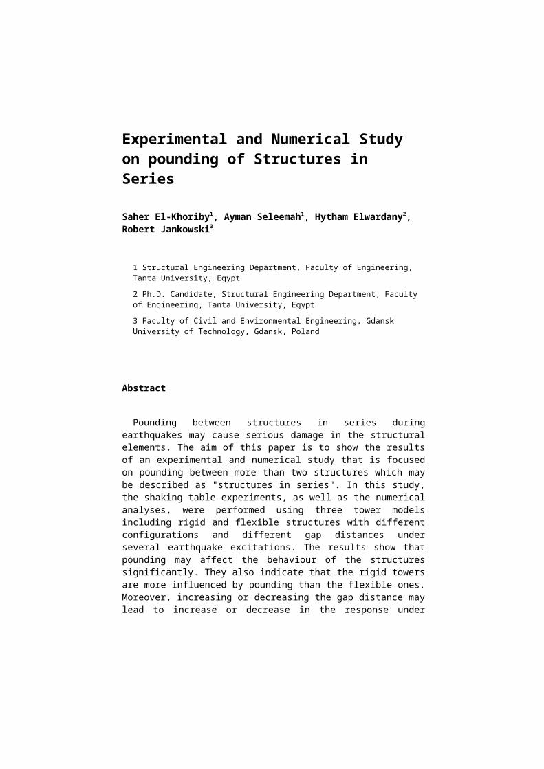
Experimental and Numerical Study on pounding of Structures in Series
Saher El-Khoriby1, Ayman Seleemah1, Hytham Elwardany2, Robert Jankowski3
1 Structural Engineering Department, Faculty of Engineering, Tanta University, Egypt
2 Ph.D. Candidate, Structural Engineering Department, Faculty of Engineering, Tanta University, Egypt
3 Faculty of Civil and Environmental Engineering, Gdansk University of Technology, Gdansk, Poland
Abstract
Pounding between structures in series duringearthquakes may cause serious damage in the structuralelements. The aim of this paper is to show the resultsof an experimental and numerical study that is focusedon pounding between more than two structures which maybe described as "structures in series". In this study,the shaking table experiments, as well as the numericalanalyses, were performed using three tower modelsincluding rigid and flexible structures with differentconfigurations and different gap distances underseveral earthquake excitations. The results show thatpounding may affect the behaviour of the structuressignificantly. They also indicate that the rigid towersare more influenced by pounding than the flexible ones.Moreover, increasing or decreasing the gap distance maylead to increase or decrease in the response under
2
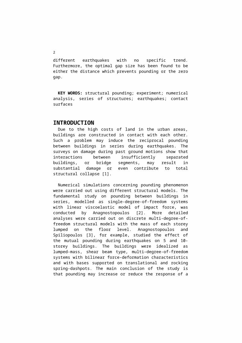
different earthquakes with no specific trend.Furthermore, the optimal gap size has been found to beeither the distance which prevents pounding or the zerogap.
KEY WORDS: structural pounding; experiment; numericalanalysis, series of structures; earthquakes; contactsurfaces
INTRODUCTIONDue to the high costs of land in the urban areas,
buildings are constructed in contact with each other.Such a problem may induce the reciprocal poundingbetween buildings in series during earthquakes. Thesurveys on damage during past ground motions show thatinteractions between insufficiently separatedbuildings, or bridge segments, may result insubstantial damage or even contribute to totalstructural collapse [1].
Numerical simulations concerning pounding phenomenonwere carried out using different structural models. Thefundamental study on pounding between buildings inseries, modelled as single-degree-of-freedom systemswith linear viscoelastic model of impact force, wasconducted by Anagnostopoulos [2]. More detailedanalyses were carried out on discrete multi-degree-of-freedom structural models with the mass of each storeylumped on the floor level. Anagnostopoulos andSpiliopoulos [3], for example, studied the effect ofthe mutual pounding during earthquakes on 5 and 10-storey buildings. The buildings were idealized aslumped-mass, shear beam type, multi–degree-of-freedomsystems with bilinear force-deformation characteristicsand with bases supported on translational and rockingspring-dashpots. The main conclusion of the study isthat pounding may increase or reduce the response of a
3
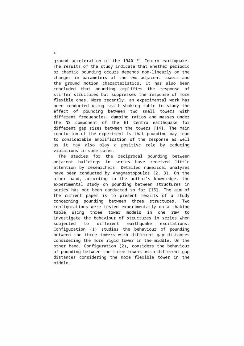
given building in a block, depending primarily upon itsperiod and mass, in relation to the period and mass ofthe building (or buildings) next to it, and on whetherthe collisions are at one or two sides. It has alsobeen concluded that, when the masses of two interactingbuildings are similar, the response of the stifferbuilding may be amplified because of pounding.Moreover, if there are large differences in the massesof the colliding buildings, then pounding can causehigh over stresses in the structure with smaller mass.Discrete multi-degree-of-freedom structural models,with the mass of each storey lumped on the floor level,were also used by other researchers [4, 5, 6, 7].Further studies were conducted using more accuratestructural models. Abdel Raheem [8] studied the effectof impact between two adjacent steel moment resistantframe buildings of 8 and 13 storeys. Such study usedcontact force-based model with both linear andnonlinear springs. In addition, a nonlinear contactmodel accounting for energy dissipation was alsoutilized to model impact. Finite element (FE) models ofcolliding buildings were employed in the analysiscarried out by Papadrakakis et al. [9], in which floorsof structures were modelled by single four-node planestress elements and walls by four linear beam-columnelements. The detailed non-linear analysis ofinteractions between two buildings using finite elementmethod (FEM) was also conducted in [10, 11, 12].
On the contrary to numerical analyses, the results ofexperimental studies on pounding under earthquakeexcitations are very limited. Most of the experimentalstudies were conducted between two adjacent buildingsonly. For example, Chau et al. [13] carried out ashaking table experiment to investigate the poundingphenomena between two steel towers with equal height of2.0 m with different natural frequencies and dampingratios. The towers were subjected to sinusoidal wavesof various magnitudes and frequencies as well as the
4
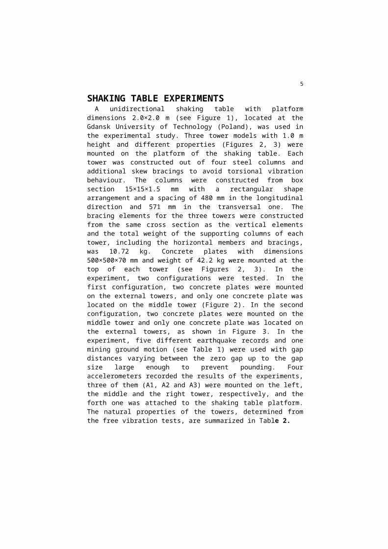
ground acceleration of the 1940 El Centro earthquake.The results of the study indicate that whether periodicor chaotic pounding occurs depends non-linearly on thechanges in parameters of the two adjacent towers andthe ground motion characteristics. It has also beenconcluded that pounding amplifies the response ofstiffer structures but suppresses the response of moreflexible ones. More recently, an experimental work hasbeen conducted using small shaking table to study theeffect of pounding between two small towers withdifferent frequencies, damping ratios and masses underthe NS component of the El Centro earthquake fordifferent gap sizes between the towers [14]. The mainconclusion of the experiment is that pounding may leadto considerable amplification of the response as wellas it may also play a positive role by reducingvibrations in some cases. The studies for the reciprocal pounding between
adjacent buildings in series have received littleattention by researchers. Detailed numerical analyseshave been conducted by Anagnastopoulos [2, 3]. On theother hand, according to the author’s knowledge, theexperimental study on pounding between structures inseries has not been conducted so far [15]. The aim ofthe current paper is to present results of a studyconcerning pounding between three structures. Twoconfigurations were tested experimentally on a shakingtable using three tower models in one raw toinvestigate the behaviour of structures in series whensubjected to different earthquake excitations.Configuration (1) studies the behaviour of poundingbetween the three towers with different gap distancesconsidering the more rigid tower in the middle. On theother hand, Configuration (2), considers the behaviourof pounding between the three towers with different gapdistances considering the more flexible tower in themiddle.
5
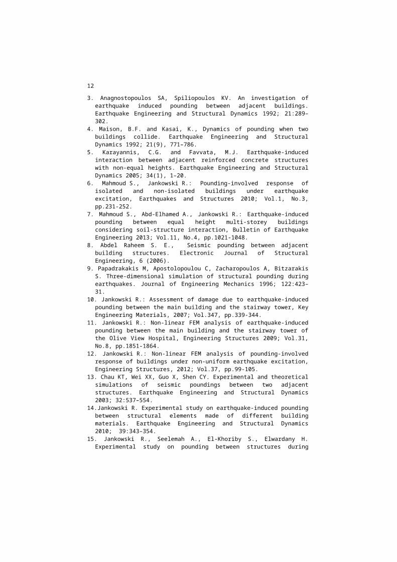
SHAKING TABLE EXPERIMENTSA unidirectional shaking table with platform
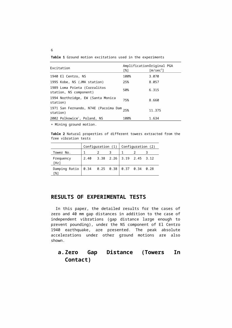
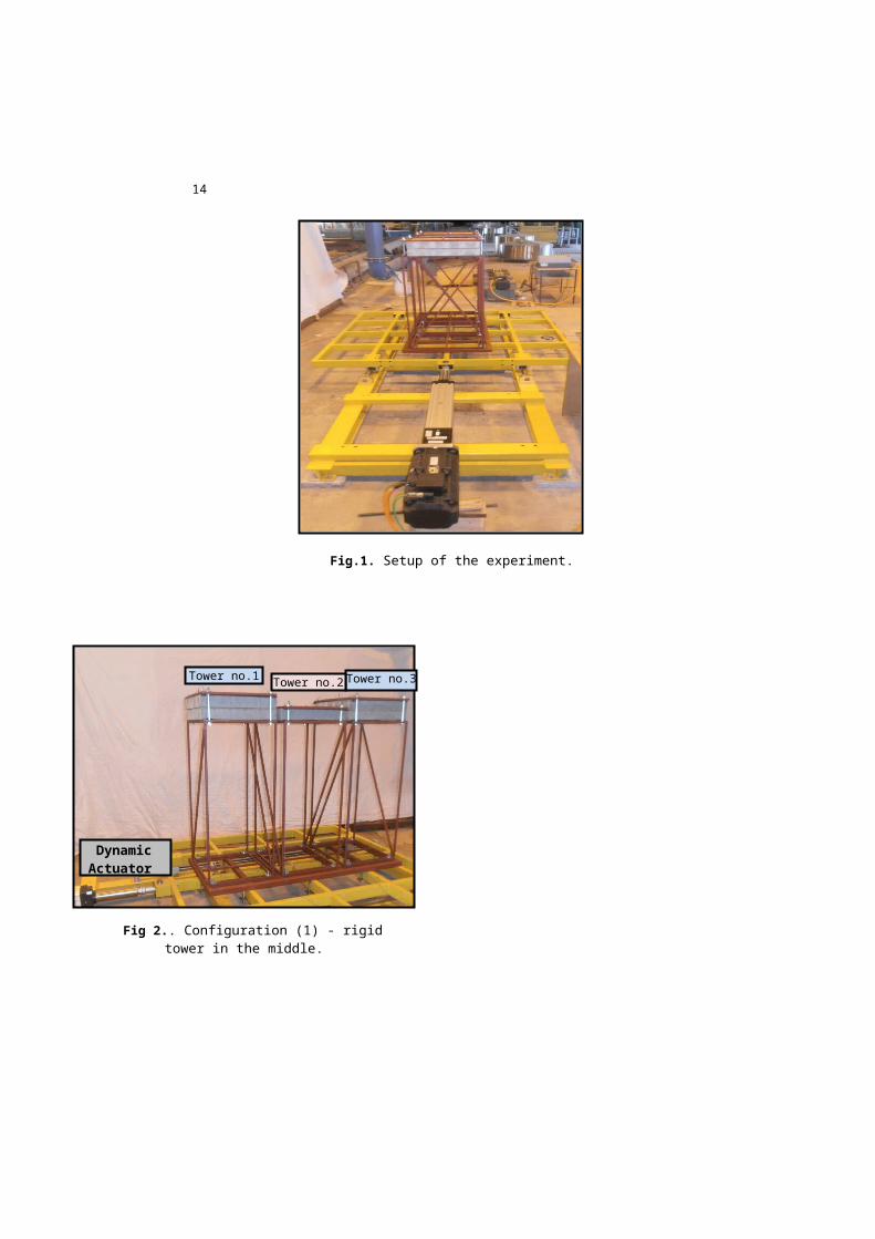
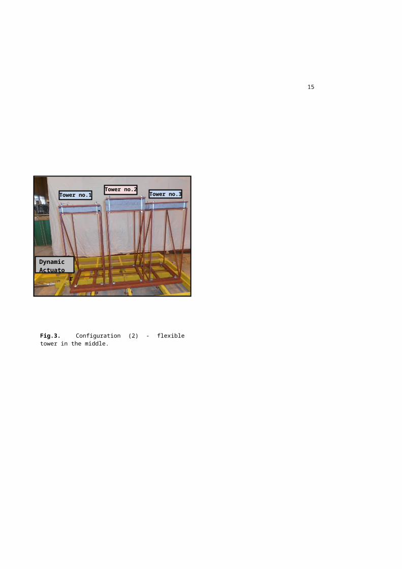
dimensions 2.0×2.0 m (see Figure 1), located at theGdansk University of Technology (Poland), was used inthe experimental study. Three tower models with 1.0 mheight and different properties (Figures 2, 3) weremounted on the platform of the shaking table. Eachtower was constructed out of four steel columns andadditional skew bracings to avoid torsional vibrationbehaviour. The columns were constructed from boxsection 15×15×1.5 mm with a rectangular shapearrangement and a spacing of 480 mm in the longitudinaldirection and 571 mm in the transversal one. Thebracing elements for the three towers were constructedfrom the same cross section as the vertical elementsand the total weight of the supporting columns of eachtower, including the horizontal members and bracings,was 10.72 kg. Concrete plates with dimensions500×500×70 mm and weight of 42.2 kg were mounted at thetop of each tower (see Figures 2, 3). In theexperiment, two configurations were tested. In thefirst configuration, two concrete plates were mountedon the external towers, and only one concrete plate waslocated on the middle tower (Figure 2). In the secondconfiguration, two concrete plates were mounted on themiddle tower and only one concrete plate was located onthe external towers, as shown in Figure 3. In theexperiment, five different earthquake records and onemining ground motion (see Table 1) were used with gapdistances varying between the zero gap up to the gapsize large enough to prevent pounding. Fouraccelerometers recorded the results of the experiments,three of them (A1, A2 and A3) were mounted on the left,the middle and the right tower, respectively, and theforth one was attached to the shaking table platform.The natural properties of the towers, determined fromthe free vibration tests, are summarized in Table 2.
6
Table 1 Ground motion excitations used in the experiments
Excitation Amplification[%]
Original PGA [m/sec2]
1940 El Centro, NS 100% 3.0701995 Kobe, NS (JMA station) 25% 8.0571989 Loma Prieta (Corralitos station, NS component) 50% 6.315
1994 Northridge, EW (Santa Monica station) 75% 8.660
1971 San Fernando, N74E (Pacoima Damstation) 25% 11.375
2002 Polkowice+, Poland, NS 100% 1.634+ Mining ground motion.
Table 2 Natural properties of different towers extracted from thefree vibration tests
Configuration (1) Configuration (2)Tower No. 1 2 3 1 2 3Frequency [Hz]
2.40 3.38 2.26 3.19 2.45 3.12
Damping Ratio[%]
0.34 0.25 0.38 0.37 0.34 0.28
RESULTS OF EXPERIMENTAL TESTS
In this paper, the detailed results for the cases ofzero and 40 mm gap distances in addition to the case ofindependent vibrations (gap distance large enough toprevent pounding), under the NS component of El Centro1940 earthquake, are presented. The peak absoluteaccelerations under other ground motions are alsoshown.
a.Zero Gap Distance (Towers InContact)

7
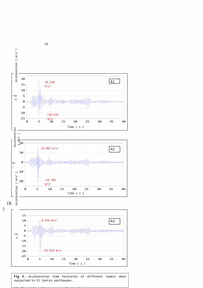
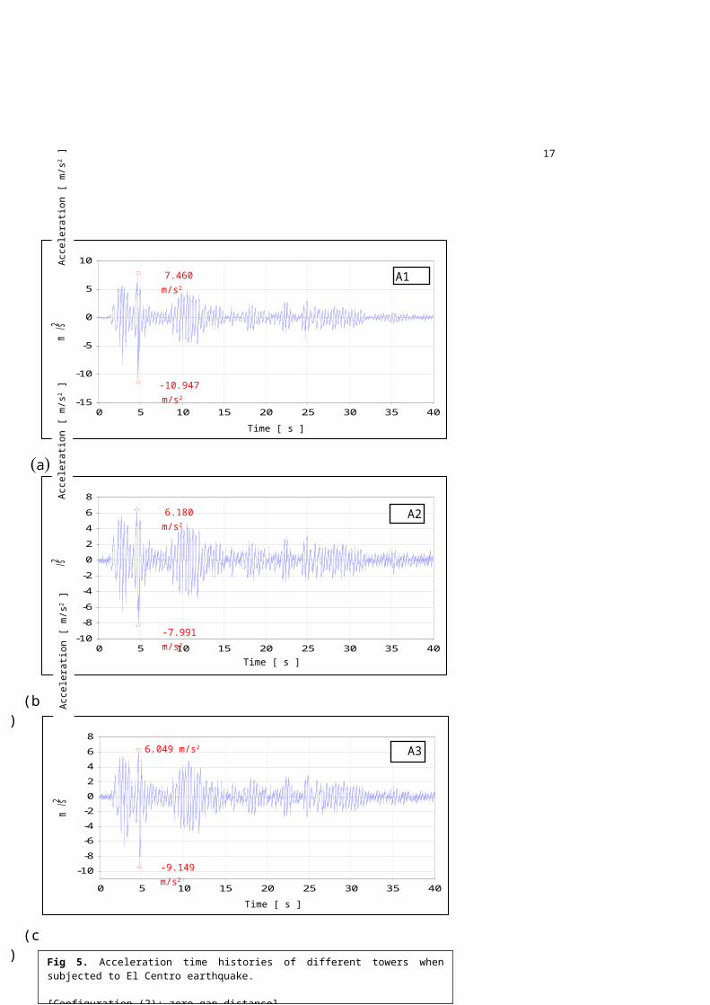
Figures 4 and 5 show the experimental accelerationtime histories of the three towers for Configuration(1) and Configuration (2), respectively. The generalshape of acceleration time history for eachconfiguration is more or less similar except for theregion around 5th sec. This suggests that the threetowers acted more or less as one structure. Calculatingthe natural frequencies of the towers, assuming thatthey are connected, results in frequencies of 2.60 and2.86 Hz for Configurations (1) and (2), respectively.Counting the number of cycles per second recordedexperimentally gives frequencies of nearly 2.50 Hz and2.90 Hz, for Configuration (1) and (2), respectively.This close matching indicates that, for the case ofzero gap distance, the towers mostly behave as they areone unit with combined stiffness and mass. However, theexistence of some pounding is due to the fact that, thetowers are not fully connected and so little separationmay occur at the time of peak seismic excitation. For Configuration (1), comparing the maximum absolute
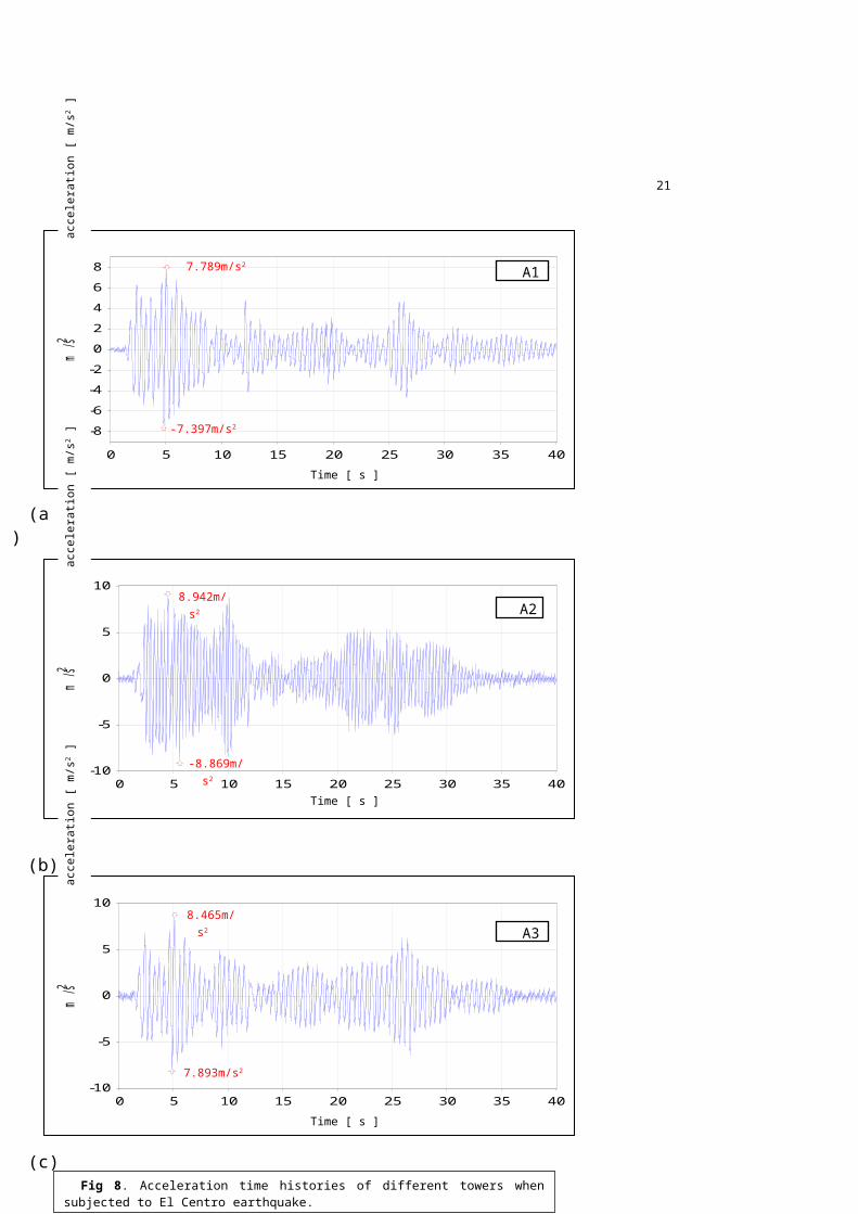
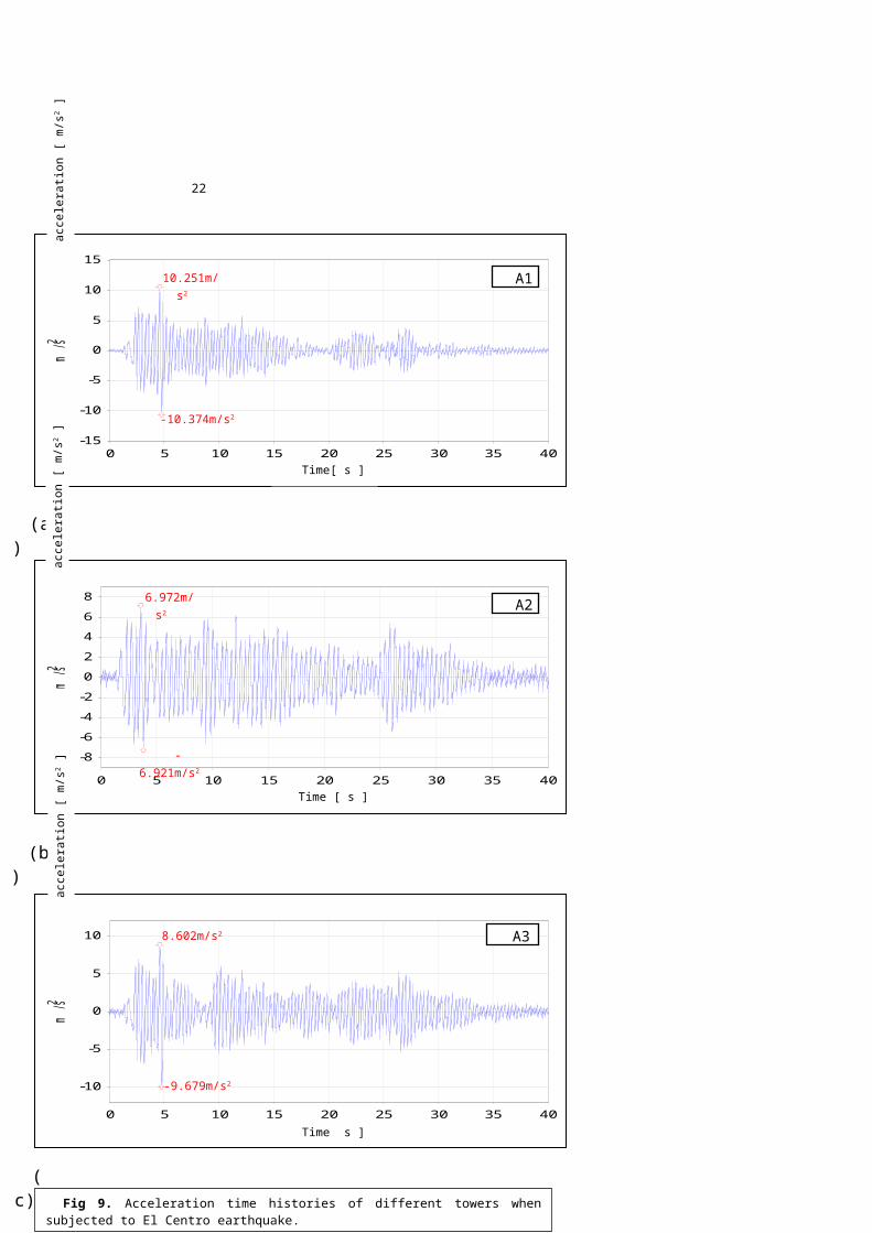
acceleration values shown in Figure 4 with thecorresponding values obtained for the case ofindependent vibrations (see Figure 8) indicates thatpounding increases the maximum absolute acceleration ofthe towers by factors reaching 135%. On the other handfor Configuration (2), comparing the maximum absoluteacceleration values shown in Figure 5 with thecorresponding values obtained for the case ofindependent vibrations (see Figure 9) indicates thatminor change in the accelerations due to pounding(between 5% to 15%) has been obtained. This behaviourcan be explained. For Configuration (1), at the instantof separation between the towers, existence of theflexible towers on the left and right sides gave themthe chance to vibrate more freely in the out-worddirection gaining in displacement and velocity. Intheir way back they collided with the rigid tower inthe middle which acted as a stopper for them. While,
8
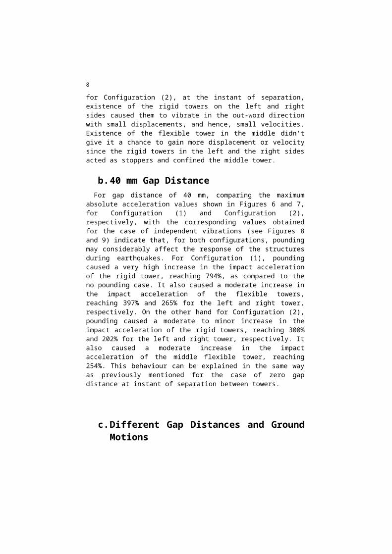
for Configuration (2), at the instant of separation,existence of the rigid towers on the left and rightsides caused them to vibrate in the out-word directionwith small displacements, and hence, small velocities.Existence of the flexible tower in the middle didn'tgive it a chance to gain more displacement or velocitysince the rigid towers in the left and the right sidesacted as stoppers and confined the middle tower.
b.40 mm Gap Distance For gap distance of 40 mm, comparing the maximum
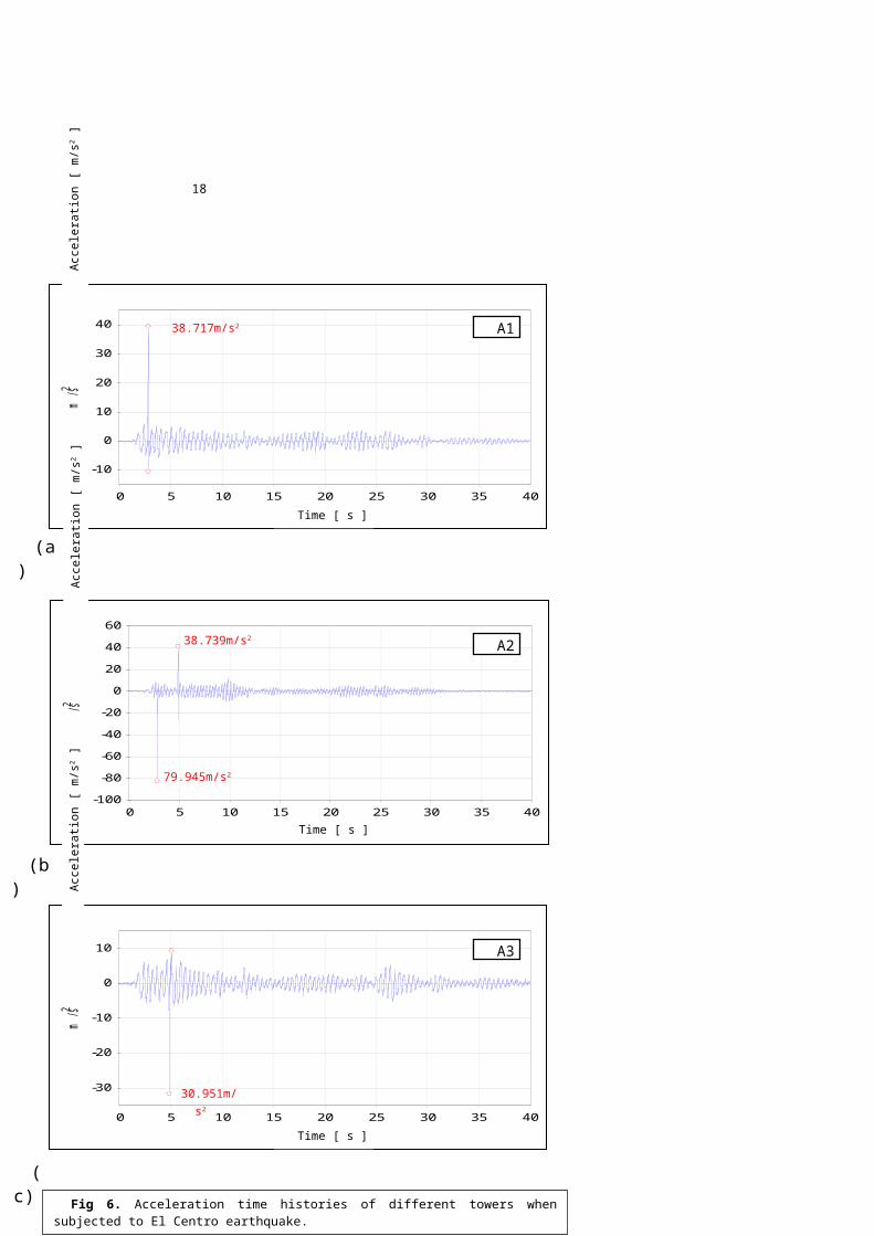
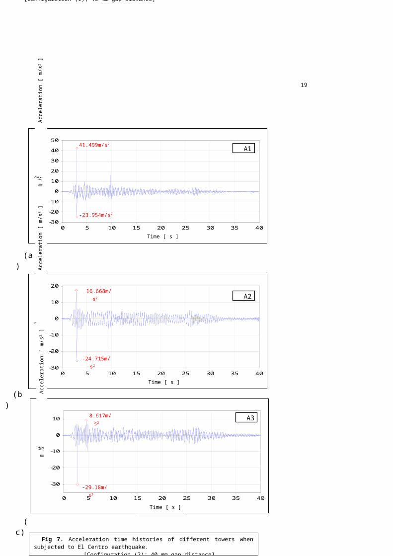
absolute acceleration values shown in Figures 6 and 7,for Configuration (1) and Configuration (2),respectively, with the corresponding values obtainedfor the case of independent vibrations (see Figures 8and 9) indicate that, for both configurations, poundingmay considerably affect the response of the structuresduring earthquakes. For Configuration (1), poundingcaused a very high increase in the impact accelerationof the rigid tower, reaching 794%, as compared to theno pounding case. It also caused a moderate increase inthe impact acceleration of the flexible towers,reaching 397% and 265% for the left and right tower,respectively. On the other hand for Configuration (2),pounding caused a moderate to minor increase in theimpact acceleration of the rigid towers, reaching 300%and 202% for the left and right tower, respectively. Italso caused a moderate increase in the impactacceleration of the middle flexible tower, reaching254%. This behaviour can be explained in the same wayas previously mentioned for the case of zero gapdistance at instant of separation between towers.
c.Different Gap Distances and GroundMotions
9
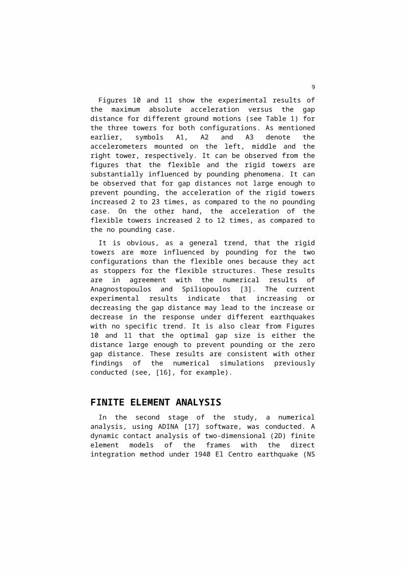
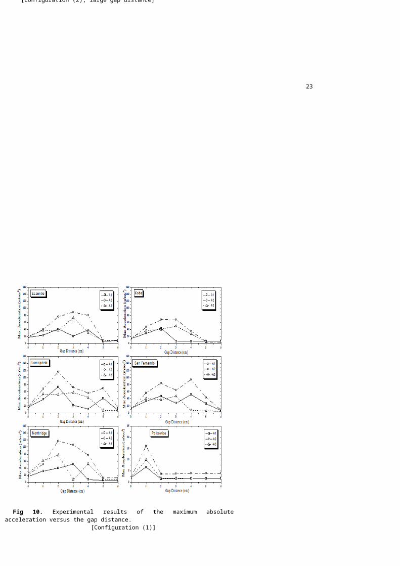
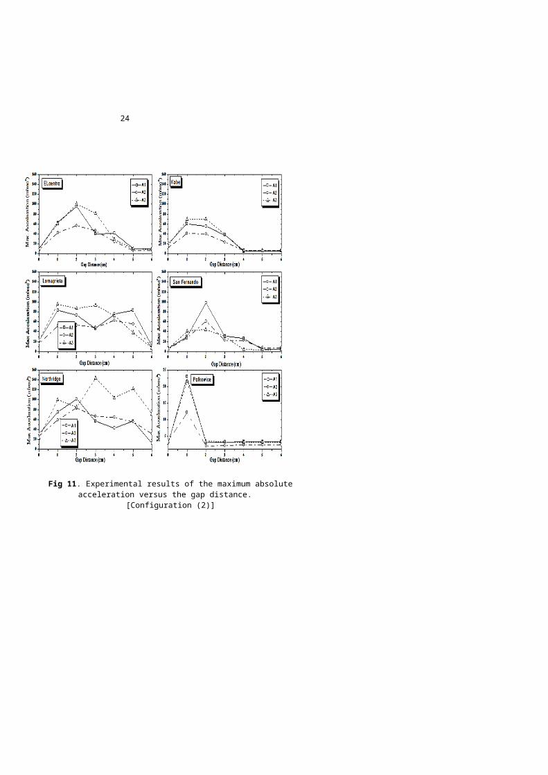
Figures 10 and 11 show the experimental results ofthe maximum absolute acceleration versus the gapdistance for different ground motions (see Table 1) forthe three towers for both configurations. As mentionedearlier, symbols A1, A2 and A3 denote theaccelerometers mounted on the left, middle and theright tower, respectively. It can be observed from thefigures that the flexible and the rigid towers aresubstantially influenced by pounding phenomena. It canbe observed that for gap distances not large enough toprevent pounding, the acceleration of the rigid towersincreased 2 to 23 times, as compared to the no poundingcase. On the other hand, the acceleration of theflexible towers increased 2 to 12 times, as compared tothe no pounding case. It is obvious, as a general trend, that the rigid
towers are more influenced by pounding for the twoconfigurations than the flexible ones because they actas stoppers for the flexible structures. These resultsare in agreement with the numerical results ofAnagnostopoulos and Spiliopoulos [3]. The currentexperimental results indicate that increasing ordecreasing the gap distance may lead to the increase ordecrease in the response under different earthquakeswith no specific trend. It is also clear from Figures10 and 11 that the optimal gap size is either thedistance large enough to prevent pounding or the zerogap distance. These results are consistent with otherfindings of the numerical simulations previouslyconducted (see, [16], for example).
FINITE ELEMENT ANALYSISIn the second stage of the study, a numerical
analysis, using ADINA [17] software, was conducted. Adynamic contact analysis of two-dimensional (2D) finiteelement models of the frames with the directintegration method under 1940 El Centro earthquake (NS
10
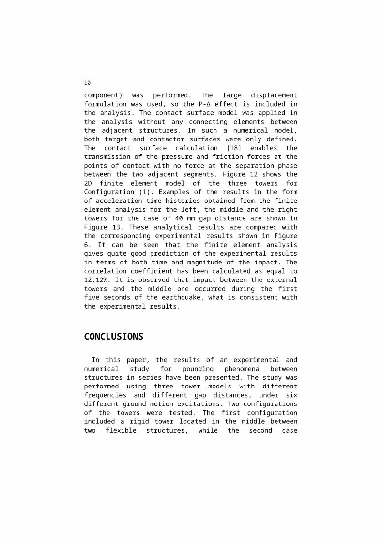
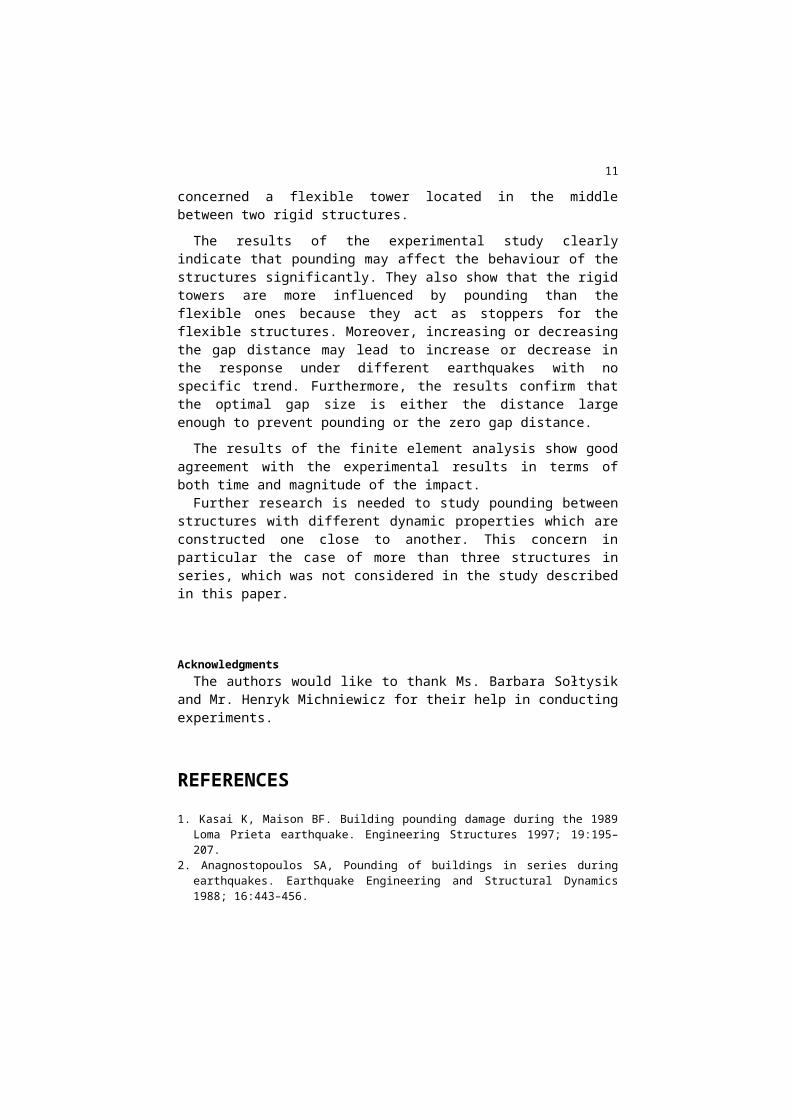
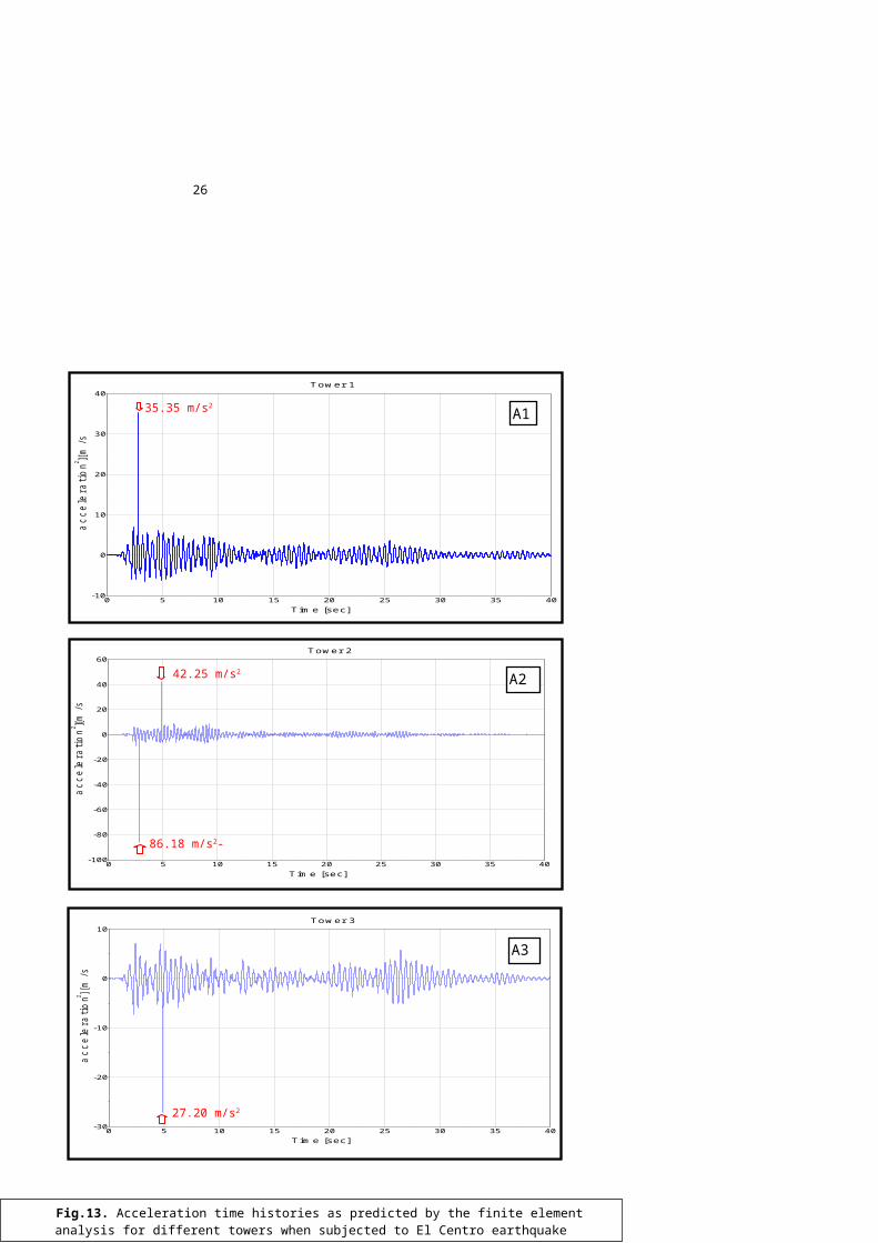
component) was performed. The large displacementformulation was used, so the P-∆ effect is included inthe analysis. The contact surface model was applied inthe analysis without any connecting elements betweenthe adjacent structures. In such a numerical model,both target and contactor surfaces were only defined.The contact surface calculation [18] enables thetransmission of the pressure and friction forces at thepoints of contact with no force at the separation phasebetween the two adjacent segments. Figure 12 shows the2D finite element model of the three towers forConfiguration (1). Examples of the results in the formof acceleration time histories obtained from the finiteelement analysis for the left, the middle and the righttowers for the case of 40 mm gap distance are shown inFigure 13. These analytical results are compared withthe corresponding experimental results shown in Figure6. It can be seen that the finite element analysisgives quite good prediction of the experimental resultsin terms of both time and magnitude of the impact. Thecorrelation coefficient has been calculated as equal to12.12%. It is observed that impact between the externaltowers and the middle one occurred during the firstfive seconds of the earthquake, what is consistent withthe experimental results.
CONCLUSIONS
In this paper, the results of an experimental andnumerical study for pounding phenomena betweenstructures in series have been presented. The study wasperformed using three tower models with differentfrequencies and different gap distances, under sixdifferent ground motion excitations. Two configurationsof the towers were tested. The first configurationincluded a rigid tower located in the middle betweentwo flexible structures, while the second case
11
concerned a flexible tower located in the middlebetween two rigid structures.The results of the experimental study clearly
indicate that pounding may affect the behaviour of thestructures significantly. They also show that the rigidtowers are more influenced by pounding than theflexible ones because they act as stoppers for theflexible structures. Moreover, increasing or decreasingthe gap distance may lead to increase or decrease inthe response under different earthquakes with nospecific trend. Furthermore, the results confirm thatthe optimal gap size is either the distance largeenough to prevent pounding or the zero gap distance.The results of the finite element analysis show good
agreement with the experimental results in terms ofboth time and magnitude of the impact.Further research is needed to study pounding between
structures with different dynamic properties which areconstructed one close to another. This concern inparticular the case of more than three structures inseries, which was not considered in the study describedin this paper.
Acknowledgments The authors would like to thank Ms. Barbara Sołtysik
and Mr. Henryk Michniewicz for their help in conductingexperiments.
REFERENCES1. Kasai K, Maison BF. Building pounding damage during the 1989
Loma Prieta earthquake. Engineering Structures 1997; 19:195–207.
2. Anagnostopoulos SA, Pounding of buildings in series duringearthquakes. Earthquake Engineering and Structural Dynamics1988; 16:443–456.
12
3. Anagnostopoulos SA, Spiliopoulos KV. An investigation ofearthquake induced pounding between adjacent buildings.Earthquake Engineering and Structural Dynamics 1992; 21:289–302.
4. Maison, B.F. and Kasai, K., Dynamics of pounding when twobuildings collide. Earthquake Engineering and StructuralDynamics 1992; 21(9), 771–786.
5. Karayannis, C.G. and Favvata, M.J. Earthquake-inducedinteraction between adjacent reinforced concrete structureswith non-equal heights. Earthquake Engineering and StructuralDynamics 2005; 34(1), 1–20.
6. Mahmoud S., Jankowski R.: Pounding-involved response ofisolated and non-isolated buildings under earthquakeexcitation, Earthquakes and Structures 2010; Vol.1, No.3,pp.231-252.
7. Mahmoud S., Abd-Elhamed A., Jankowski R.: Earthquake-inducedpounding between equal height multi-storey buildingsconsidering soil-structure interaction, Bulletin of EarthquakeEngineering 2013; Vol.11, No.4, pp.1021-1048.
8. Abdel Raheem S. E., Seismic pounding between adjacentbuilding structures. Electronic Journal of StructuralEngineering, 6 (2006).
9. Papadrakakis M, Apostolopoulou C, Zacharopoulos A, BitzarakisS. Three-dimensional simulation of structural pounding duringearthquakes. Journal of Engineering Mechanics 1996; 122:423–31.
10. Jankowski R.: Assessment of damage due to earthquake-inducedpounding between the main building and the stairway tower, KeyEngineering Materials, 2007; Vol.347, pp.339-344.
11. Jankowski R.: Non-linear FEM analysis of earthquake-inducedpounding between the main building and the stairway tower ofthe Olive View Hospital, Engineering Structures 2009; Vol.31,No.8, pp.1851-1864.
12. Jankowski R.: Non-linear FEM analysis of pounding-involvedresponse of buildings under non-uniform earthquake excitation,Engineering Structures, 2012; Vol.37, pp.99-105.
13. Chau KT, Wei XX, Guo X, Shen CY. Experimental and theoreticalsimulations of seismic poundings between two adjacentstructures. Earthquake Engineering and Structural Dynamics2003; 32:537–554.
14.Jankowski R. Experimental study on earthquake-induced poundingbetween structural elements made of different buildingmaterials. Earthquake Engineering and Structural Dynamics2010; 39:343–354.
15. Jankowski R., Seelemah A., El-Khoriby S., Elwardany H.Experimental study on pounding between structures during

13
damaging earthquakes. Key Engineering Materials Vol. 627(2015) pp 249-252.
16. Jankowski R, Wilde K, Fujino Y. Reduction of pounding effectsin elevated bridges during earthquakes. Earthquake Engineeringand Structural Dynamics 2000; 29:195–212.
17. ADINA R&D, Inc. "Automatic Dynamic Incremental NonlinearAnalysis" Reference Manual June 2010.
18. Bathe KJ, Chaudhary A. A solution method for planar andaxisymmetric contact problems. Int J Number Meth Eng 1985;(21): 65-88.
14
Fig.1. Setup of the experiment.
Fig 2.. Configuration (1) - rigid tower in the middle.
DynamicActuator
Tower no.3Tower no.2Tower no.1
15
Fig.3. Configuration (2) - flexibletower in the middle.
DynamicActuato
r
Tower no.3Tower no.2
Tower no.1
16
(a)
Fig 4. Acceleration time histories of different towers when subjected to El Centro earthquake.
[Configuration (1); zero gap distance]
m/s2
m/s2
0 5 10 15 20 25 30 35 40Seconds
-15
-10
-5
0
5
10
15
20
m/s2
m/s2
18.236 m/s2
-10.676 m/s2
Time [ s ]
Acce
lerati
on [
m/s
2 ]
A1
m/s2
m/s2
0 5 10 15 20 25 30 35 40Seconds
-20
-10
0
10
20
m/s2
m/s2
Time [ s ]
Acce
lerati
on
[ m/s2 ]
14.081 m/s2
-18.768 m/s2
A2
m/s2
m/s2
0 5 10 15 20 25 30 35 40Seconds
-25
-20
-15
-10
-5
0
5
10
15
m/s2
m/s2
Time [ s ]
Accele
rati
on [ m
/s2 ]
-19.919 m/s2
8.874 m/s2 A3
(b)
17
(c)
Fig 5. Acceleration time histories of different towers when subjected to El Centro earthquake.
[Configuration (2); zero gap distance]
(a)
m/s2
m/s2
0 5 10 15 20 25 30 35 40Seconds
-15
-10
-5
0
5
10
m/s2
m/s2
7.460 m/s2
-10.947 m/s2
Time [ s ]
Accele
rati
on [ m
/s2 ]
A1
(b)
m/s2
m/s2
0 5 10 15 20 25 30 35 40Seconds
-10-8-6-4-202468
m/s2
m/s2
A2
Time [ s ]
Acce
lera
tion
[ m
/s2 ]
6.180 m/s2
-7.991 m/s2
m/s2
m/s2
0 5 10 15 20 25 30 35 40Seconds
-10-8-6-4-202468
m/s2
m/s2
A3
Time [ s ]
Acce
lerati
on [
m/s
2 ]
-9.149 m/s2
6.049 m/s2
(c)
18
m/s2
m/s2
0 5 10 15 20 25 30 35 40Seconds
-10
0
10
20
30
40
m/s2
m/s2
m/s2
m/s2
0 5 10 15 20 25 30 35 40Seconds
-30
-20
-10
0
10
m/s2
m/s2
m/s2
m/s2
0 5 10 15 20 25 30 35 40Seconds
-100
-80
-60
-40
-20
0
20
40
60
m/s2
m/s2
Time [ s ]
Fig 6. Acceleration time histories of different towers when subjected to El Centro earthquake.
[Configuration (1); 40 mm gap distance]
(c)
(b)
(a)
A3
A2
A138.717m/s2
Accele
rati
on [ m
/s2 ]
Time [ s ]
79.945m/s2
38.739m/s2
Acce
lerati
on [
m/s
2 ]
30.951m/s2
Acce
lerati
on [
m/s
2 ]
Time [ s ]
19
m/s2
m/s2
0 5 10 15 20 25 30 35 40Seconds
-30
-20
-10
0
10
m/s2
m/s2
m/s2
m/s2
0 5 10 15 20 25 30 35 40Seconds
-30
-20
-10
0
10
20
m/s2
m/s2
m/s2
m/s2
0 5 10 15 20 25 30 35 40Seconds
-30
-20
-10
0
10
20
30
40
50
m/s2
m/s2
A3
A2
A1
(c)
(b)
(a)
Fig 7. Acceleration time histories of different towers when subjected to El Centro earthquake.
[Configuration (2); 40 mm gap distance]
41.499m/s2
Time [ s ]
-24.715m/s2
16.668m/s2
Acce
lera
tion
[ m/s
2 ]
Time [ s ]
-29.18m/s2
8.617m/s2
Acce
lerati
on [
m/s
2 ]
Time [ s ]
-23.954m/s2
Accele
rati
on [ m
/s2 ]
Fig 6. Acceleration time histories of different towers when subjected to El Centro earthquake.
[Configuration (1); 40 mm gap distance]

20
21
m/s2
m/s2
0 5 10 15 20 25 30 35 40Seconds
-10
-5
0
5
10
m/s2
m/s2
m/s2
m/s2
0 5 10 15 20 25 30 35 40Seconds
-10
-5
0
5
10
m/s2
m/s2
Time [ s ]
m/s2
m/s2
0 5 10 15 20 25 30 35 40Seconds
-8-6-4-202468
m/s2
m/s2
A3
A2
A1
(c)
(b)
(a)
Fig 8. Acceleration time histories of different towers when subjected to El Centro earthquake.
[Configuration (1); large gap distance]
-7.397m/s2
7.789m/s2
Time [ s ]
accelera
tion
[ m/s
2 ]
8.942m/s2
-8.869m/s2
accele
rati
on [ m
/s2 ]
8.465m/s2
7.893m/s2
accele
rati
on [
m/s
2 ]
Time [ s ]
22
`
m/s2
m/s2
0 5 10 15 20 25 30 35 40Seconds
-10
-5
0
5
10
m/s2
m/s2
m/s2
m/s2
0 5 10 15 20 25 30 35 40Seconds
-8-6-4-202468
m/s2
m/s2
m/s2
m/s2
0 5 10 15 20 25 30 35 40Seconds
-15
-10
-5
0
5
10
15
m/s2
m/s2
A3
A2
A1
(c)
(b)
(a)
Fig 9. Acceleration time histories of different towers when subjected to El Centro earthquake.
[Configuration (2); large gap distance]
-10.374m/s2
10.251m/s2
accelera
tion
[ m/s
2 ]
Time[ s ]
6.972m/s2
-6.921m/s2
acce
lera
tion
[ m/s
2 ]
Time [ s ]
-9.679m/s2
8.602m/s2
acce
lera
tion
[ m
/s2 ]
Time s ]
23
Fig 9. Acceleration time histories of different towers when subjected to El Centro earthquake.
[Configuration (2); large gap distance]
Fig 10. Experimental results of the maximum absolute acceleration versus the gap distance.
[Configuration (1)]
24
Fig 11. Experimental results of the maximum absolute acceleration versus the gap distance.
[Configuration (2)]

25
Fig 12. Finite element model of the three towers for Configuration (1).
26
Fig.13. Acceleration time histories as predicted by the finite element analysis for different towers when subjected to El Centro earthquake
[Configuration (1); 40 mm gap distance].
0 5 10 15 20 25 30 35 40-30
-20
-10
0
10
Tow er 3
acce
lera
tion
[m/s
2 ]
Tim e [sec]
27.20 m/s2
A3
0 5 10 15 20 25 30 35 40-100
-80
-60
-40
-20
0
20
40
60
T ow er 2
acce
lera
tion
[m/s
2 ]
Tim e [sec]
A242.25 m/s2
86.18 m/s2-
0 5 10 15 20 25 30 35 40-10
0
10
20
30
40
Tow er 1
acce
lera
tion
[m/s
2 ]
Tim e [sec]
A135.35 m/s2
Copyright © 2022 FDOKUMEN