Wear Characterization of Carbon Nanotubes Reinforced Acetal Spur, Helical, Bevel and Worm Gears...
8
Wear Characterization of Carbon Nanotubes Reinforced Acetal Spur, Helical, Bevel and Worm Gears Using a TS Universal Test Rig SAMY YOUSEF, 1,3 T.A. OSMAN, 2 ABDELRAHMAN H. ABDALLA, 2 and GAMAL A. ZOHDY 2 1.—Department of Production Engineering and Printing Technology, Akhbar Elyom Academy 6th of October, Giza, Egypt. 2.—Department of Mechanical Design and Production Engineering, Cairo University, Giza 12566, Egypt. 3.—e-mail: [email protected] Although the applications of nanotechnologies are increasing, there remains a significant barrier between nanotechnology and machine element applica- tions. This work aims to remove this barrier by blending carbon nanotubes (CNT) with common types of acetal polymer gears (spur, helical, bevel and worm). This was done by using adhesive oil (paraffin) during injection molding to synthesize a flange and short bars containing 0.02% CNT by weight. The flanges and short bars were machined using hobbing and milling machines to produce nanocomposite polymer gears. Some defects that surfaced in previous work, such as the appearance of bubbles and unmelted pellets during the injection process, were avoided to produce an excellent dispersion of CNT in the acetal. The wear resistances of the gears were measured by using a TS universal test rig using constant parameters for all of the gears that were fabricated. The tests were run at a speed of 1420 rpm and a torque of 4 Nm. The results showed that the wear resistances of the CNT/acetal gears were increased due to the addition of CNT, especially the helical, bevel and worm gears. INTRODUCTION Currently, efforts are being made to replace metallic materials with polymeric materials in many fields of science due to their ease of manu- facture, low cost, light weight and excellent tribo- logical performance in comparison to metallic materials. Polymers have been used in many mechanical applications such as in bearings and gears. POM, PA and PEEK were first employed in gear applications in the middle of the last century and have since been used in a large range of motion control (low load, temperature, noise and speed) applications. 1–6 Previous studies have focused on spur polymer gears because polymeric materials have a low strength. Other types of gears (helical, bevel and worm) generate an additional load, called axial load, which causes an overload on the polymer. Many researchers have used additives to improve the tribological and mechanical properties of poly- mer composite gears. For example, Pont added Zytel E50 to reinforce polyamide PA66 and Zytel 70G30 to generate glass fiber-reinforced PA66 (at 30% by weight of glass fiber). 7 Victrex created carbon fiber- reinforced PEEK 450CA30 containing 30% by weight of carbon fiber. 8 Duzcukoglu developed 66 driving polyamide gears blended with GFR30. 9 Meng et al. used a pin-on disc to investigate the friction and wear behavior of carbon nanotube- reinforced polyamide composites under dry sliding and water-lubricated conditions. The results showed that CNT improves wear resistance and reduces the friction coefficient. 10 Building on the results of Meng et al., Samy et al. produced polymer spur gears reinforced by a homogeneous dispersion of carbon nanotubes (CNT). 11 The results indicated that the wear resistance and strength were im- proved by adding 15% and 22%, respectively, by weight of CNT, although some defects were identi- fied, such as bubbles and unmelted pellets. Samy et al. designed a TS universal test rig to measure the wear rate of all command types of acetal gears JOM DOI: 10.1007/s11837-014-1268-5 Ó 2014 The Minerals, Metals & Materials Society
-
Upload
independent -
Category
Documents
-
view
1 -
download
0
Transcript of Wear Characterization of Carbon Nanotubes Reinforced Acetal Spur, Helical, Bevel and Worm Gears...
Wear Characterization of Carbon Nanotubes ReinforcedAcetal Spur, Helical, Bevel and Worm GearsUsing a TS Universal Test Rig
SAMY YOUSEF,1,3 T.A. OSMAN,2 ABDELRAHMAN H. ABDALLA,2 andGAMAL A. ZOHDY2
1.—Department of Production Engineering and Printing Technology, Akhbar Elyom Academy 6thof October, Giza, Egypt. 2.—Department of Mechanical Design and Production Engineering, CairoUniversity, Giza 12566, Egypt. 3.—e-mail: [email protected]
Although the applications of nanotechnologies are increasing, there remains asignificant barrier between nanotechnology and machine element applica-tions. This work aims to remove this barrier by blending carbon nanotubes(CNT) with common types of acetal polymer gears (spur, helical, bevel andworm). This was done by using adhesive oil (paraffin) during injection moldingto synthesize a flange and short bars containing 0.02% CNT by weight. Theflanges and short bars were machined using hobbing and milling machines toproduce nanocomposite polymer gears. Some defects that surfaced in previouswork, such as the appearance of bubbles and unmelted pellets during theinjection process, were avoided to produce an excellent dispersion of CNT inthe acetal. The wear resistances of the gears were measured by using a TSuniversal test rig using constant parameters for all of the gears that werefabricated. The tests were run at a speed of 1420 rpm and a torque of 4 Nm.The results showed that the wear resistances of the CNT/acetal gears wereincreased due to the addition of CNT, especially the helical, bevel and wormgears.
INTRODUCTION
Currently, efforts are being made to replacemetallic materials with polymeric materials inmany fields of science due to their ease of manu-facture, low cost, light weight and excellent tribo-logical performance in comparison to metallicmaterials. Polymers have been used in manymechanical applications such as in bearings andgears. POM, PA and PEEK were first employed ingear applications in the middle of the last centuryand have since been used in a large range of motioncontrol (low load, temperature, noise and speed)applications.1–6 Previous studies have focused onspur polymer gears because polymeric materialshave a low strength. Other types of gears (helical,bevel and worm) generate an additional load, calledaxial load, which causes an overload on the polymer.Many researchers have used additives to improvethe tribological and mechanical properties of poly-mer composite gears. For example, Pont added Zytel
E50 to reinforce polyamide PA66 and Zytel 70G30 togenerate glass fiber-reinforced PA66 (at 30% byweight of glass fiber).7 Victrex created carbon fiber-reinforced PEEK 450CA30 containing 30% byweight of carbon fiber.8 Duzcukoglu developed 66driving polyamide gears blended with GFR30.9
Meng et al. used a pin-on disc to investigate thefriction and wear behavior of carbon nanotube-reinforced polyamide composites under dry slidingand water-lubricated conditions. The resultsshowed that CNT improves wear resistance andreduces the friction coefficient.10 Building on theresults of Meng et al., Samy et al. produced polymerspur gears reinforced by a homogeneous dispersionof carbon nanotubes (CNT).11 The results indicatedthat the wear resistance and strength were im-proved by adding 15% and 22%, respectively, byweight of CNT, although some defects were identi-fied, such as bubbles and unmelted pellets. Samyet al. designed a TS universal test rig to measurethe wear rate of all command types of acetal gears
JOM
DOI: 10.1007/s11837-014-1268-5� 2014 The Minerals, Metals & Materials Society
(spur, helical, bevel and worm).12 This study takesadvantage of the increased strength and wearresistances previously reported in order to manu-facture nanocomposite polymer (CNT/acetal) spur,helical, bevel and worm gears with excellent dis-persion properties. In addition, we utilize a TSuniversal test rig to investigate the wear behavior ofthe CNT/acetal (spur, helical, bevel and worm)gears that are reinforced with CNT.
EXPERIMENTAL
Materials
The POM used in this study was from a com-mercial grade powder (KOCETAL� K700) suppliedby El-Slam, Cairo, Egypt. The CNT were synthe-sized using a fully automatic machine via the arc-discharge multi-electrode technique. The synthe-sized CNT had an average diameter of 10 nm andan average length of 2.5 lm.13
Synthesis of CNTs/Acetal Polymer MatrixComposite Flanges
Nanocomposite polymer flanges were synthesizedusing an injection molding die that was designed bythe authors11 to produce flanges with a diameter of134 mm and a thickness of 29 mm after shrinkage.Paraffin oil was used to adhere the CNT to the
acetal polymer pellets after stirring for approxi-mately 5 min.
The Following Steps are Followed for the Productionof the Flanges
(a) The CNTs/acetal pellets are poured or fed intoa 400-g capacity hopper.
(b) An electric heater increases the mixing chambertemperature to 175�C.
(c) When 175�C is reached, a screw thread begins torotate to push the melt granules along the heater.
(d) The liquid is injected into the molded die to formthe flange with a diameter of 140 mm and athickness of 30 mm.
(e) After cooling, the die mold is opened. The finalflanges produced have a diameter of 134 mmand a thickness of 30 mm due to shrinkage.
Synthesis of CNTs/Acetal Polymer MatrixComposite Short Rods
An injection molding die was designed and manu-factured to synthesize short nanocomposite polymerbars with diameters of 45 mm and lengths of80 mm. The production procedure of the short barswas the same as the production procedure of theflanges, differing only in the use of a 200-g injectionmolding hopper capacity and the use of the dieshown in Fig. 1.
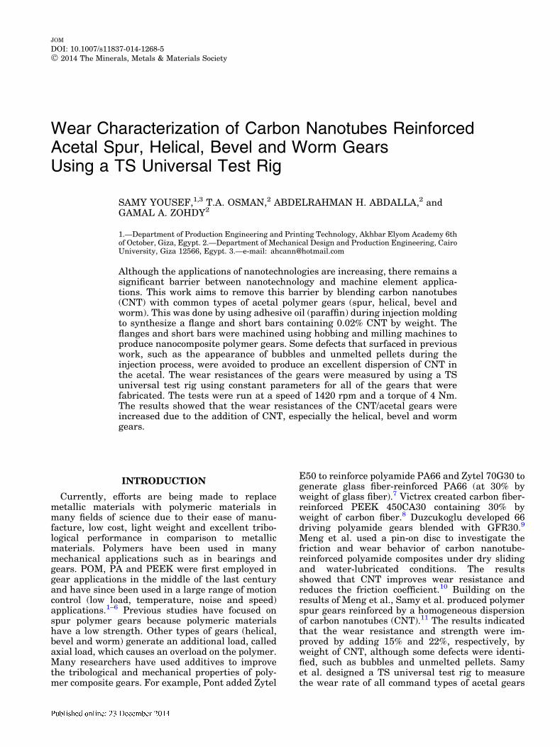
Fig. 1. Die design and a resulting short bar that was produced. (a) Schematic drawing of the short bar injection die. (b) Photograph of theinjection die. (c) A final produced acetal short bar.
Yousef, Osman, Abdalla, and Zohdy
Manufacturing of the Gears
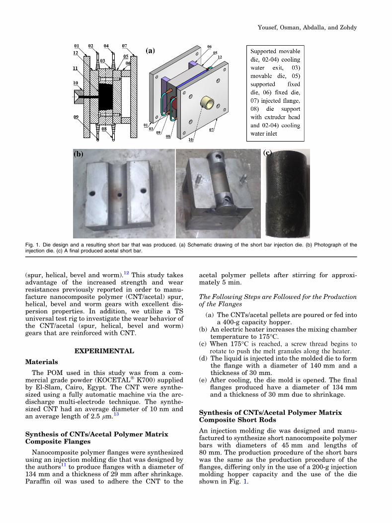
Hobbing and milling machines were used to pro-duce nanocomposite polymer flanges for fabricatingthe teeth of the nanocomposite acetal gears (spur,helical, bevel and wheel). Similarly, a nanocomposite
acetal short bar was machined to produce the teeth ofthe nanocomposite acetal worm gear. Metal sleeveswere fitted in the hubs of all the gears to preventcontact between the key and the hub (metal to poly-mer contact), as shown in Fig. 2, which may lead toincreased wear and inaccurate results. The specifi-cations of the gears are illustrated in Tables I, II, III,and IV. The geometry of the gears was selectedaccording to the TS universal test rig that was builtby the authors to measure the wear rate of the gears.
TS Universal Test Rig Design
Figure 3 shows the complete design and manu-facture of the universal test rig, which consists ofthe following items, as listed in Table V. The uni-versal test rig was built by Samy et al.12 to study the
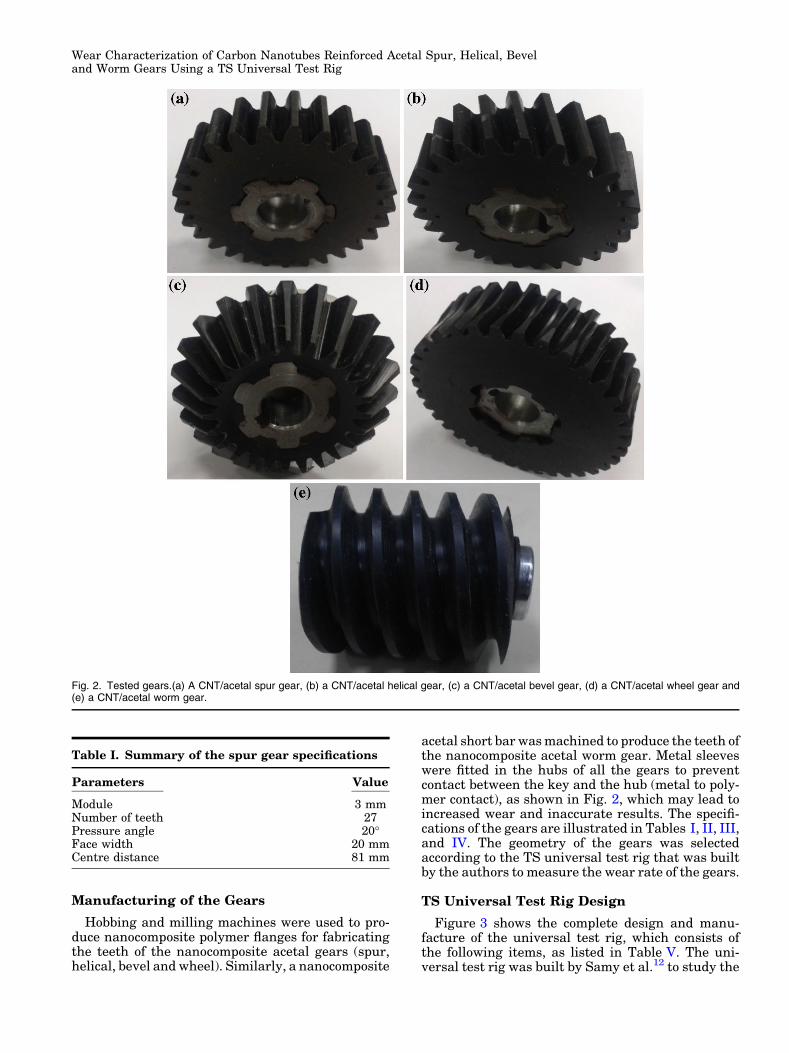
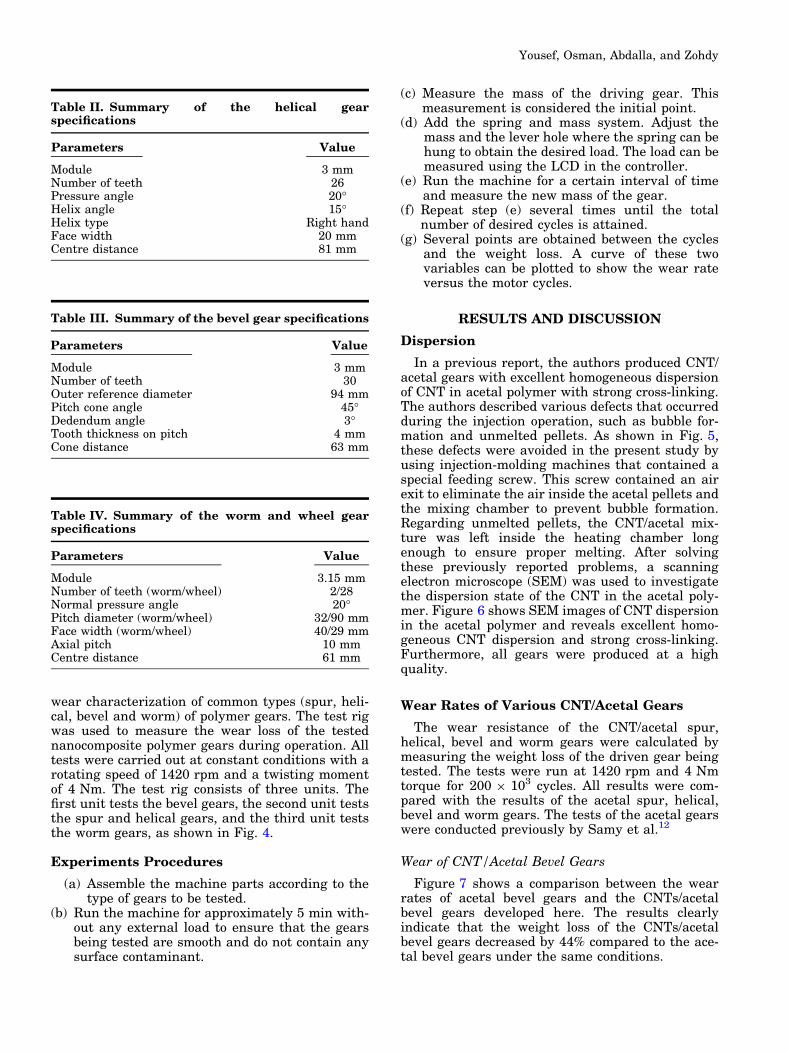
Table I. Summary of the spur gear specifications
Parameters Value
Module 3 mmNumber of teeth 27Pressure angle 20�Face width 20 mmCentre distance 81 mm
Fig. 2. Tested gears.(a) A CNT/acetal spur gear, (b) a CNT/acetal helical gear, (c) a CNT/acetal bevel gear, (d) a CNT/acetal wheel gear and(e) a CNT/acetal worm gear.
Wear Characterization of Carbon Nanotubes Reinforced Acetal Spur, Helical, Beveland Worm Gears Using a TS Universal Test Rig
wear characterization of common types (spur, heli-cal, bevel and worm) of polymer gears. The test rigwas used to measure the wear loss of the testednanocomposite polymer gears during operation. Alltests were carried out at constant conditions with arotating speed of 1420 rpm and a twisting momentof 4 Nm. The test rig consists of three units. Thefirst unit tests the bevel gears, the second unit teststhe spur and helical gears, and the third unit teststhe worm gears, as shown in Fig. 4.
Experiments Procedures
(a) Assemble the machine parts according to thetype of gears to be tested.
(b) Run the machine for approximately 5 min with-out any external load to ensure that the gearsbeing tested are smooth and do not contain anysurface contaminant.
(c) Measure the mass of the driving gear. Thismeasurement is considered the initial point.
(d) Add the spring and mass system. Adjust themass and the lever hole where the spring can behung to obtain the desired load. The load can bemeasured using the LCD in the controller.
(e) Run the machine for a certain interval of timeand measure the new mass of the gear.
(f) Repeat step (e) several times until the totalnumber of desired cycles is attained.
(g) Several points are obtained between the cyclesand the weight loss. A curve of these twovariables can be plotted to show the wear rateversus the motor cycles.
RESULTS AND DISCUSSION
Dispersion
In a previous report, the authors produced CNT/acetal gears with excellent homogeneous dispersionof CNT in acetal polymer with strong cross-linking.The authors described various defects that occurredduring the injection operation, such as bubble for-mation and unmelted pellets. As shown in Fig. 5,these defects were avoided in the present study byusing injection-molding machines that contained aspecial feeding screw. This screw contained an airexit to eliminate the air inside the acetal pellets andthe mixing chamber to prevent bubble formation.Regarding unmelted pellets, the CNT/acetal mix-ture was left inside the heating chamber longenough to ensure proper melting. After solvingthese previously reported problems, a scanningelectron microscope (SEM) was used to investigatethe dispersion state of the CNT in the acetal poly-mer. Figure 6 shows SEM images of CNT dispersionin the acetal polymer and reveals excellent homo-geneous CNT dispersion and strong cross-linking.Furthermore, all gears were produced at a highquality.
Wear Rates of Various CNT/Acetal Gears
The wear resistance of the CNT/acetal spur,helical, bevel and worm gears were calculated bymeasuring the weight loss of the driven gear beingtested. The tests were run at 1420 rpm and 4 Nmtorque for 200 9 103 cycles. All results were com-pared with the results of the acetal spur, helical,bevel and worm gears. The tests of the acetal gearswere conducted previously by Samy et al.12
Wear of CNT/Acetal Bevel Gears
Figure 7 shows a comparison between the wearrates of acetal bevel gears and the CNTs/acetalbevel gears developed here. The results clearlyindicate that the weight loss of the CNTs/acetalbevel gears decreased by 44% compared to the ace-tal bevel gears under the same conditions.
Table II. Summary of the helical gearspecifications
Parameters Value
Module 3 mmNumber of teeth 26Pressure angle 20�Helix angle 15�Helix type Right handFace width 20 mmCentre distance 81 mm
Table III. Summary of the bevel gear specifications
Parameters Value
Module 3 mmNumber of teeth 30Outer reference diameter 94 mmPitch cone angle 45�Dedendum angle 3�Tooth thickness on pitch 4 mmCone distance 63 mm
Table IV. Summary of the worm and wheel gearspecifications
Parameters Value
Module 3.15 mmNumber of teeth (worm/wheel) 2/28Normal pressure angle 20�Pitch diameter (worm/wheel) 32/90 mmFace width (worm/wheel) 40/29 mmAxial pitch 10 mmCentre distance 61 mm
Yousef, Osman, Abdalla, and Zohdy
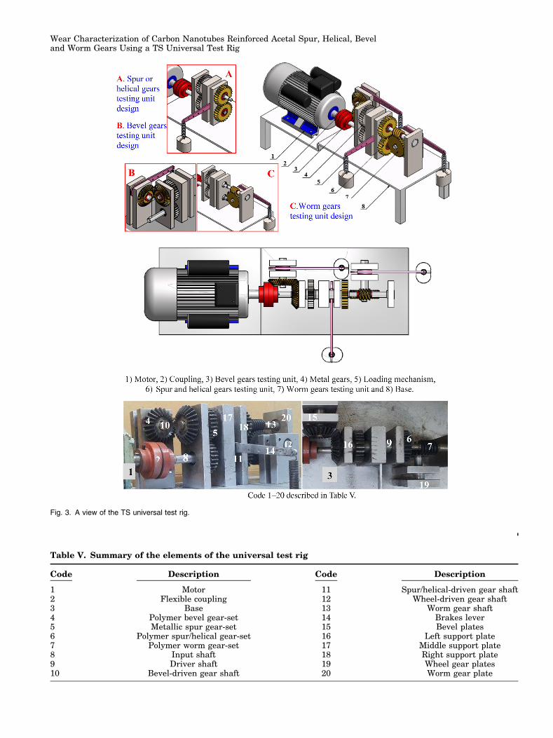
Table V. Summary of the elements of the universal test rig
Code Description Code Description
1 Motor 11 Spur/helical-driven gear shaft2 Flexible coupling 12 Wheel-driven gear shaft3 Base 13 Worm gear shaft4 Polymer bevel gear-set 14 Brakes lever5 Metallic spur gear-set 15 Bevel plates6 Polymer spur/helical gear-set 16 Left support plate7 Polymer worm gear-set 17 Middle support plate8 Input shaft 18 Right support plate9 Driver shaft 19 Wheel gear plates10 Bevel-driven gear shaft 20 Worm gear plate
Fig. 3. A view of the TS universal test rig.
Wear Characterization of Carbon Nanotubes Reinforced Acetal Spur, Helical, Beveland Worm Gears Using a TS Universal Test Rig
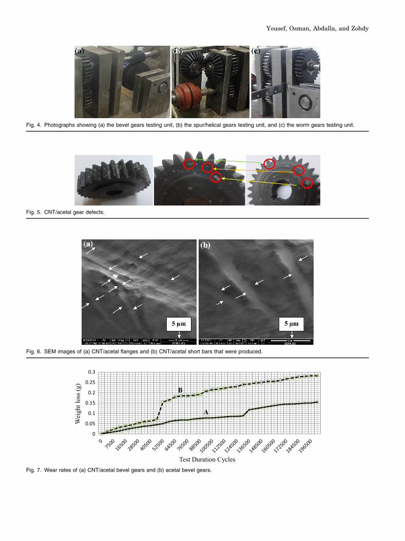
Fig. 4. Photographs showing (a) the bevel gears testing unit, (b) the spur/helical gears testing unit, and (c) the worm gears testing unit.
Fig. 5. CNT/acetal gear defects.
Fig. 6. SEM images of (a) CNT/acetal flanges and (b) CNT/acetal short bars that were produced.
0
0.05
0.1
0.15
0.2
0.25
0.3
Wei
ght l
oss (
g)
Test Duration Cycles
B
A
Fig. 7. Wear rates of (a) CNT/acetal bevel gears and (b) acetal bevel gears.
Yousef, Osman, Abdalla, and Zohdy
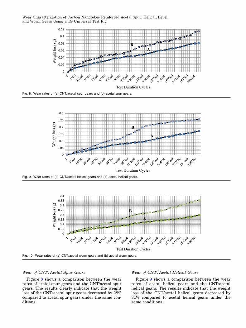
Wear of CNT/Acetal Spur Gears
Figure 8 shows a comparison between the wearrates of acetal spur gears and the CNT/acetal spurgears. The results clearly indicate that the weightloss of the CNT/acetal spur gears decreased by 28%compared to acetal spur gears under the same con-ditions.
Wear of CNT/Acetal Helical Gears
Figure 9 shows a comparison between the wearrates of acetal helical gears and the CNT/acetalhelical gears. The results indicate that the weightloss of the CNT/acetal helical gears decreased by31% compared to acetal helical gears under thesame conditions.
0
0.02
0.04
0.06
0.08
0.1
0.12
Wei
ght l
oss (
g)
Test Duration Cycles
BA
Fig. 8. Wear rates of (a) CNT/acetal spur gears and (b) acetal spur gears.
0
0.05
0.1
0.15
0.2
0.25
0.3
Wei
ght l
oss (
g)
Test Duration Cycles
B
A
Fig. 9. Wear rates of (a) CNT/acetal helical gears and (b) acetal helical gears.
00.050.1
0.150.2
0.250.3
0.350.4
Wei
ght l
oss (
g)
Test Duration Cycles
B
A
Fig. 10. Wear rates of (a) CNT/acetal worm gears and (b) acetal worm gears.
Wear Characterization of Carbon Nanotubes Reinforced Acetal Spur, Helical, Beveland Worm Gears Using a TS Universal Test Rig
Wear for CNT/Acetal Worm Gears
Figure 10 shows a comparison between the wearrates of acetal worm gears and the CNTs/acetalworm gears. The results clearly indicate that theweight loss of the CNT/acetal worm gears decreasedby 47% compared to acetal worm gears under thesame conditions.
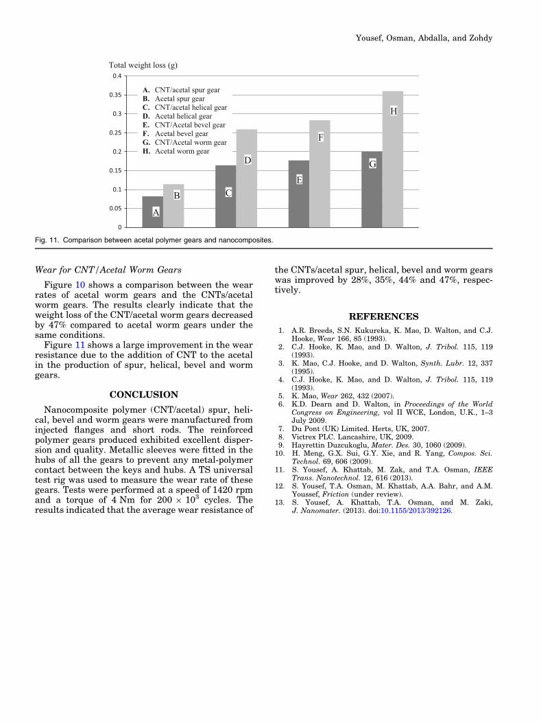
Figure 11 shows a large improvement in the wearresistance due to the addition of CNT to the acetalin the production of spur, helical, bevel and wormgears.
CONCLUSION
Nanocomposite polymer (CNT/acetal) spur, heli-cal, bevel and worm gears were manufactured frominjected flanges and short rods. The reinforcedpolymer gears produced exhibited excellent disper-sion and quality. Metallic sleeves were fitted in thehubs of all the gears to prevent any metal-polymercontact between the keys and hubs. A TS universaltest rig was used to measure the wear rate of thesegears. Tests were performed at a speed of 1420 rpmand a torque of 4 Nm for 200 9 103 cycles. Theresults indicated that the average wear resistance of
the CNTs/acetal spur, helical, bevel and worm gearswas improved by 28%, 35%, 44% and 47%, respec-tively.
REFERENCES
1. A.R. Breeds, S.N. Kukureka, K. Mao, D. Walton, and C.J.Hooke, Wear 166, 85 (1993).
2. C.J. Hooke, K. Mao, and D. Walton, J. Tribol. 115, 119(1993).
3. K. Mao, C.J. Hooke, and D. Walton, Synth. Lubr. 12, 337(1995).
4. C.J. Hooke, K. Mao, and D. Walton, J. Tribol. 115, 119(1993).
5. K. Mao, Wear 262, 432 (2007).6. K.D. Dearn and D. Walton, in Proceedings of the World
Congress on Engineering, vol II WCE, London, U.K., 1–3July 2009.
7. Du Pont (UK) Limited. Herts, UK, 2007.8. Victrex PLC. Lancashire, UK, 2009.9. Hayrettin Duzcukoglu, Mater. Des. 30, 1060 (2009).
10. H. Meng, G.X. Sui, G.Y. Xie, and R. Yang, Compos. Sci.Technol. 69, 606 (2009).
11. S. Yousef, A. Khattab, M. Zak, and T.A. Osman, IEEETrans. Nanotechnol. 12, 616 (2013).
12. S. Yousef, T.A. Osman, M. Khattab, A.A. Bahr, and A.M.Youssef, Friction (under review).
13. S. Yousef, A. Khattab, T.A. Osman, and M. Zaki,J. Nanomater. (2013). doi:10.1155/2013/392126.
0
0.05
0.1
0.15
0.2
0.25
0.3
0.35
0.4
A. CNT/acetal spur gearB. Acetal spur gearC. CNT/acetal helical gearD. Acetal helical gearE. CNT/Acetal bevel gearF. Acetal bevel gearG. CNT/Acetal worm gearH. Acetal worm gear
A
B
D
E
H
C
F
G
Total weight loss (g)
Fig. 11. Comparison between acetal polymer gears and nanocomposites.
Yousef, Osman, Abdalla, and Zohdy