
THE ELEMENT AND MODIFICATION OF BEVEL GEAR
7
INTERNATIONAL JOURNAL OF RESEARCH IN AERONAUTICAL AND MECHANICAL ENGINEERING ISSN (ONLINE): 2321-3051 Vol.2 Issue.11, November 2014. Pgs: 15-21 1 Satish Kumar Patel, 2 Rajendra Kumar Patre, 3 Shankar Dayal Patel, 4 Prakash Kumar Sen., 5 Shailendra Kumar Bohidar 15 THE ELEMENT AND MODIFICATION OF BEVEL GEAR 1 Satish Kumar Patel, 2 Rajendra Kumar Patre, 3 Shankar Dayal Patel, 4 Prakash Kumar Sen., 5 Shailendra Kumar Bohidar 1,2,3 Student,Bachelor of Engg. Mechanical Engineering Kirodimal Institute of Technology, Raigarh C.G. Raigarh, Chhattisgarh, INDIA 4,5 Faculty,Mechanical Engg. Department Kirodimal Institute of Technology, Raigarh C.G. Raigarh, Chhattisgarh, INDIA Abstract Thermal deformation and other factor, the bevel gear pair will appear serious phenomenon of meshing interference and impact and uneven load in meshing process, so it is necessary to design suitable modification tooth to improve gear pairs transmission performance and enhance its bearing capacity. A methodology, which facilities to analyze the operating of bevel gears under consideration of production-caused deviations. The bevel gears are widely used in aerospace, marine and other field. Keywords:-Bevel gear, gear teeth, gear drive. I. Introduction Bevel gears are widely employed in helicopter, automobiles, and engineering machinery for transmitting rotation and torque between intersected axis. The most important criteria for the quality meshing contact of bevel gear are low noise, and sufficient dimension and proper location of bearing contact. For the bevel gear with a conjugate gear tooth surface, when they are meshed under the condition of misalignments, these will be a relative motion and a large acceleration at the transfer point [1]. Because of its accurate transmission ratio, high transmission efficiency and big range of transmission power gear mechanism has become the most applied transmission mechanism [2]. Bevel gears are widely used in automobile differential and other parts of intersecting axis transmission. Its transmission quality will affect working performance of the part. There are many design of gear which is manufactured depending upon their functionally, system requirement and operating condition. These includes spur gear, hypoid gear, spiral and straight bevel gear.[3]. Many gear failure occur due to design errors, manufacturing faults, maintenance, inspection, inevitable respective stresses resulting in surface fatigue wear and deterioration of lubrication properties. In this study the cause of bevel gears in an engine train of an aircraft has been investigated to avoid future [4].
-
Upload
independent -
Category
Documents
-
view
3 -
download
0
Transcript of THE ELEMENT AND MODIFICATION OF BEVEL GEAR
INTERNATIONAL JOURNAL OF RESEARCH IN AERONAUTICAL AND MECHANICAL ENGINEERING
ISSN (ONLINE): 2321-3051
Vol.2 Issue.11,
November 2014.
Pgs: 15-21
1Satish Kumar Patel, 2Rajendra Kumar Patre, 3Shankar Dayal Patel, 4Prakash Kumar Sen., 5Shailendra Kumar Bohidar
15
THE ELEMENT AND MODIFICATION OF
BEVEL GEAR
1Satish Kumar Patel, 2Rajendra Kumar Patre, 3Shankar Dayal Patel, 4Prakash Kumar Sen., 5Shailendra Kumar Bohidar
1,2,3Student,Bachelor of Engg. Mechanical Engineering Kirodimal Institute of Technology, Raigarh C.G.
Raigarh, Chhattisgarh, INDIA 4,5Faculty,Mechanical Engg. Department
Kirodimal Institute of Technology, Raigarh C.G. Raigarh, Chhattisgarh, INDIA
Abstract
Thermal deformation and other factor, the bevel gear pair will appear serious phenomenon of meshing interference and impact and uneven load in meshing process, so it is necessary to design suitable modification tooth to improve gear pairs transmission performance and enhance its bearing capacity. A methodology, which facilities to analyze the operating of bevel gears under consideration of production-caused deviations. The bevel gears are widely used in aerospace, marine and other field. Keywords:-Bevel gear, gear teeth, gear drive.
I. Introduction
Bevel gears are widely employed in helicopter, automobiles, and engineering machinery for transmitting rotation and torque between intersected axis. The most important criteria for the quality meshing contact of bevel gear are low noise, and sufficient dimension and proper location of bearing contact. For the bevel gear with a conjugate gear tooth surface, when they are meshed under the condition of misalignments, these will be a relative motion and a large acceleration at the transfer point [1].
Because of its accurate transmission ratio, high transmission efficiency and big range of transmission power gear mechanism has become the most applied transmission mechanism [2]. Bevel gears are widely used in automobile differential and other parts of intersecting axis transmission. Its transmission quality will affect working performance of the part.
There are many design of gear which is manufactured depending upon their functionally, system requirement and operating condition. These includes spur gear, hypoid gear, spiral and straight bevel gear.[3]. Many gear failure occur due to design errors, manufacturing faults, maintenance, inspection, inevitable respective stresses resulting in surface fatigue wear and deterioration of lubrication properties. In this study the cause of bevel gears in an engine train of an aircraft has been investigated to avoid future [4].

INTERNATIONAL JOURNAL OF RESEARCH IN AERONAUTICAL AND MECHANICAL ENGINEERING
ISSN (ONLINE): 2321-3051
Vol.2 Issue.11,
November 2014.
Pgs: 15-21
1Satish Kumar Patel, 2Rajendra Kumar Patre, 3Shankar Dayal Patel, 4Prakash Kumar Sen., 5Shailendra Kumar Bohidar
16
II. The Modification of Bevel Gear
In order to avoid “edge effect", alleviate the meshing impact and reduce the influence degree of the transmission performance of bevel. Gear due to alternating load and assembly error. There are two kinds of modification method symmetric crowned modification and isometric modification to design tooth finally by comparing the comprehensive effect of these two modification methods.
II (I). Symmetric Crowned Modification
Symmetrical crowned modification was adopted only for planetary gear and the drum point was in the middle of tooth wide. The modification amount was determined by certain condition. The recommended symmetrical crowned modification gears formulas are follows [5].
Rc ���
�∆
Where, Rc are arc radius, b is tooth width & is amount of symmetric crowned modification. II (II). Isometric Modification
Isometric modification was adopted only for planetary gear that is along with the planetary gear original tooth surface normal direction equidistant stretched out new tooth surface which paralleled to original tooth surfaces the part of isometric modification maintenance the characteristic of involutes surface.[6,7].
III. Methodology for Requirement- Driven Tolerance Specification of Bevel Gear
Starting with the current product development process of bevel gears, a methodology was developed to
analyze the complex interrelationship mentioned in the first chapter. In addition to functional requirements, a user- friendly environment, the effort of time, the independence from existing software solution and the possibility for automation are important criteria for the implementation of a new methodology reveals a modular structure which can be seen on the process diagram below (fig.1)
INTERNATIONAL JOURNAL OF RESEARCH IN AERONAUTICAL AND MECHANICAL ENGINEERING
ISSN (ONLINE): 2321-3051
Vol.2 Issue.11,
November 2014.
Pgs: 15-21
1Satish Kumar Patel, 2Rajendra Kumar Patre, 3Shankar Dayal Patel, 4Prakash Kumar Sen., 5Shailendra Kumar Bohidar
17
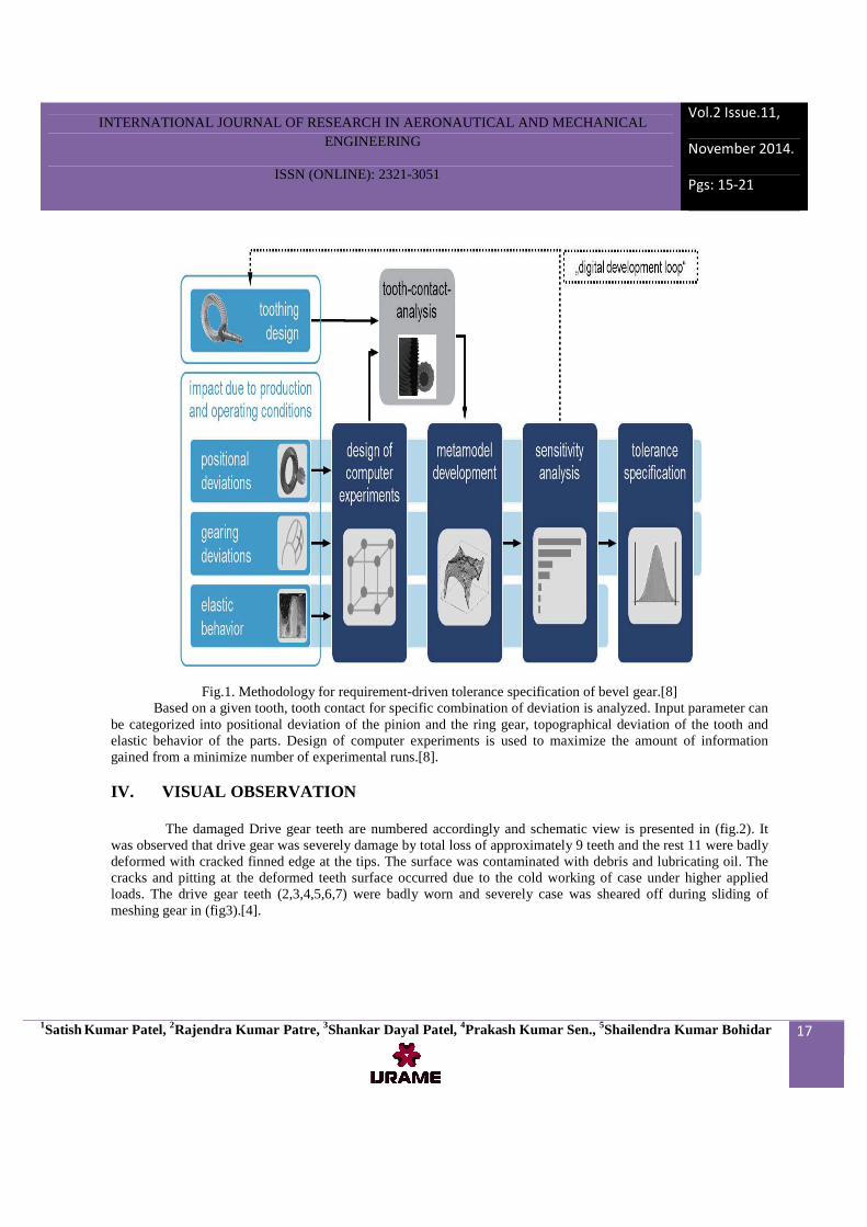
Fig.1. Methodology for requirement-driven tolerance specification of bevel gear.[8]
Based on a given tooth, tooth contact for specific combination of deviation is analyzed. Input parameter can be categorized into positional deviation of the pinion and the ring gear, topographical deviation of the tooth and elastic behavior of the parts. Design of computer experiments is used to maximize the amount of information gained from a minimize number of experimental runs.[8]. IV. VISUAL OBSERVATION
The damaged Drive gear teeth are numbered accordingly and schematic view is presented in (fig.2). It
was observed that drive gear was severely damage by total loss of approximately 9 teeth and the rest 11 were badly deformed with cracked finned edge at the tips. The surface was contaminated with debris and lubricating oil. The cracks and pitting at the deformed teeth surface occurred due to the cold working of case under higher applied loads. The drive gear teeth (2,3,4,5,6,7) were badly worn and severely case was sheared off during sliding of meshing gear in (fig3).[4].

INTERNATIONAL JOURNAL OF RESEARCH IN AERONAUTICAL AND MECHANICAL ENGINEERING
ISSN (ONLINE): 2321-3051
Vol.2 Issue.11,
November 2014.
Pgs: 15-21
1Satish Kumar Patel, 2Rajendra Kumar Patre, 3Shankar Dayal Patel, 4Prakash Kumar Sen., 5Shailendra Kumar Bohidar
18
Fig. 2 Schematic view of damaged drive gear (pairs of teeth are numbered from 1–10).[4]

INTERNATIONAL JOURNAL OF RESEARCH IN AERONAUTICAL AND MECHANICAL ENGINEERING
ISSN (ONLINE): 2321-3051
Vol.2 Issue.11,
November 2014.
Pgs: 15-21
1Satish Kumar Patel, 2Rajendra Kumar Patre, 3Shankar Dayal Patel, 4Prakash Kumar Sen., 5Shailendra Kumar Bohidar
19
Fig 3. Condition of severely deformed drive bevel gear teeth.[4]
V. Chemical Composition of Bevel of Gear Chemical composition of Drive and Driven Bevel Gear is given in Table 1.The composition of gear confirmed to AISI 8617 grade. No significant variation n composition was observed in both gears samples, V (I).SURFACE ANALYSIS (EDS)
The surface of drive gear was analyzed by (energy dispersive spectroscopy) EDS for contamination and any compositional variation; the result in ( fig,4). The surface was enriched with carbon validating the surface hardening through.
Table.1Chemical composition of Driven gear. Elements (wt %) Drive gear
Driven gear
Carbon ( C) 0.18 0.19 Manganese (Mn) 0.85 0.82
Silicon (Si) 0.24 0.24
Chromium ( Cr) 0.58 0.56 Molybdenum (Mo) 0.21 0.20
Nickel (Ni) 0.30 0.4
Sulfur (S) 0.02 0.052 Iron (Fe) Balance Balance

INTERNATIONAL JOURNAL OF RESEARCH IN AERONAUTICAL AND MECHANICAL ENGINEERING
ISSN (ONLINE): 2321-3051
Vol.2 Issue.11,
November 2014.
Pgs: 15-21
1Satish Kumar Patel, 2Rajendra Kumar Patre, 3Shankar Dayal Patel, 4Prakash Kumar Sen., 5Shailendra Kumar Bohidar
20
Fig. 4 EDS analysis of drive gear.
Carburizing process. The higher concentration of oxygen (O) and silicon (Si) at the surface of gear revealed the oxidation and contamination which may produce localized boundary lubrication condition ( BLC ) between the meshing gears and hence may cause wear and pitting. The increase in temperatures due to BLC caused the degradation of lubrication properties further and surface oxidation took place as depicted qualitative in EDS spectrum from high concentration of carbon and oxygen. This situation was aroused just after 81.2 flight hours since last total oil charge. The very thin layer of lubrication also promotes non uniform distribution of stress which may cause fracture of gear teeth [4]. VI. Conclusion
Analyzing the result of dynamic contact simulation and comparing the comprehensive of symmetric crowned modification with isometric modification. The conclusion can be made that these two modification method can all improve the meshing impact and avoid " end contact " in meshing process of gear pair. But the improvement of comprehensive properties of isometric modification is discussed above is more effective than symmetric crowned modification for bevel gear [9].

INTERNATIONAL JOURNAL OF RESEARCH IN AERONAUTICAL AND MECHANICAL ENGINEERING
ISSN (ONLINE): 2321-3051
Vol.2 Issue.11,
November 2014.
Pgs: 15-21
1Satish Kumar Patel, 2Rajendra Kumar Patre, 3Shankar Dayal Patel, 4Prakash Kumar Sen., 5Shailendra Kumar Bohidar
21
REFERENCES [1].So Jinzhan ,Frang Zongde, Cai Xianwei ohines Journals of Aeronatics (2013), 26 (5);1310-1316. [2].Sun H, Chen Zm: Theory of machines and mechanisms. Beijing : Higher Erucation Press; 19995. [3].Ramachandran V, Raghuram AC, Krishnan RV, Bhaumerhodologies and case histories. In: materials park, ohio: Asm international; 2005. [4]. Nauman A. Siddiqui, KM. oein, M. Zuban bhan, R. Ahmad case studies in engineering failure Analysis 1 (2013) 24-31. [5]. AIDA. Design and Manufacturing of gear. Beijing; Agriculture machinery press of china; 1983. [6]. Cui HY, Yang D, Tian XJ, etal. Research on Axial modification of Bevel Gear machine Design and research 20¹1; 27 (2) ; 33-36. [7]. Tian XJ. Research on tooth - modification Technology of fine- forming straight - tooth Bevel Gear. School of materials science , Engineering, Shandong University; 2009. [8]. Monfgomery DC. Design and Analysis of Experiments. 7th ed. Hobolcen, NJ: wiley, 2009,-inteenational student version. [9]. Fangyou Zhang' , Xije Tian, Huanyong Cui. IERI procedia 3 (2012) 52-59.