WE CONNECT TO PROTECT - K'ELECTRIC GmbH
123
5 PRODUCTS 2018 / 19 WE CONNECT TO PROTECT Our products protects people, buildings and facilities
-
Upload
khangminh22 -
Category
Documents
-
view
1 -
download
0
Transcript of WE CONNECT TO PROTECT - K'ELECTRIC GmbH

5
PRODUCTS
2018 / 19
WE CONNECT TO PROTECTOur products protects people, buildings and facilities

76
As an innovative manufacturer of fusesystem
components and measurement technology,
we know the requirements of high-tech today.
Perfect solutions and the highest quality in
technical safety are in demand of the
21 st century.
A big challenge, which we often manage with
surprisingly small products.
User-friendly, space-saving and 100 % reliable.
WELCOME TO THE WORLD OF K’ELECTRIC
Michael Sachs,
Managing Director

98
SAFETY SOLUTIONSFOR THE WORLD OF21ST. CENTURY
The product world of K’Electric can be found
wherever the latest brand technology is used.
We manufacture our products in accordance
with German quality standards, in a timely
and solution-optimized manner.
This guarantees the highest level of safety and
economic efficiency, the best possible user
friendliness and space-saving use.
Photovoltaics Aviation
Wind power Rail traffic
Control engineering Energy distribution

1110
PANCERO DEVICE-ADAPTER
The new and modular device adapter series for
the 60mm busbar system.
NH-VERTICAL FUSE SWITCH DISCONNECTOR VSD The new NH-vertical fuse switch disconnector VSD
can optionally be mounted within seconds with an
integrated quick-mounting system. The removal of
the upper part and additional mounting material is
not required.
Beside the VSD00 / 185 a version size in 00 in 160A
is available for direct mounting on 185mm system –
without additional adapters.
SAFETY MONITORING RJ-SYSTEM
Remote control of the fuse failure, temperature and
switching position of D0 and NH safety switching
devices by coupling the individual devices with RJ
connection cables. This creates an easy wiring of the
fault messages.
The interface is a MOD-Bus Gateway. Thus, fuse failure,
switching position and over temperature messages can
be read directly into a controller.
We are constantly strive to adapt to the
requirements of our customers and to adapt
their challenges in everyday life.
Thus, we make a valuable contribution for your
daily safety and an optimal economic level in
your company.
We are happy to answer your questions and
give detailed info on all new and available products.
NEW AT K’ELECTRIC
3-PHASE COMPACTS CURRENT TRANSFORMER FOR THE 60MM BUSBAR SYSTEM
The new 3-phase compact CT can be mounted directly
on the 60mm busbar system. Due to its special design,
it is fit for the panel and disappears ander the central
cover. Horizontal and vertically turned it fits perfectly
for rail system on mounting plate. The compact current
transformer has various primary currents from 100A up
630A.
UNIVERSAL EMPTY FIELD COVER 195MM
Due to a specially developed spring technology, the new
universal cover for empty feeld area is suitable for the
most common distribution boards on the market, with a
cutout of 195mm for the busbar system.
It is to be covered simply, cost effectively and efficiently
(and effectively). Whether as a reserve cover or to set
devices distance, the modular design, the aperture can
be divided into 9mm pieces.

1312
Our technical solutions are internationally accepted and
characterize us as a technology leader in the field of fuse
component systems.
COMPETENCE, THAT CONVINCES
OPTO-ELECTRONIC FLASHING INDICATOR AND PLUG-IN SYSTEM
PLUG TECHNOLOGY SAFE AND FAST
The patented OEFI is a very reliable state of the art visual indicator signaling fuse failure.
The blown fuse is immediately identifiable and remedial action for instantaneous reclosing
can be taken.
The plug-in system with extractable fuse
holders ensures continuous optimum con-
tact pressure. Screw cap designs which
can get loose, contribute to an avoidable
dissipation loss of up to 10VA.
A quick fuse swap is possible since no
cumbersome screwing-on is involved.
Plug-in and reclose. Additionally, operator
safety is enhanced. The fuse plug being
extractable, physical contact with the fuse,
which could have a temperature of 100° C
is averted.
The fuse bridges the electronic control circuit
In the event of a fault, the electronic circuit is triggered
On switching off, the bridged control circuit will also be disconnected
MAIN PROTECTION INTELLIGENT FUSE MONITORING
Our TYTAN® Main protection switch has
the capability of transmitting a floating
signal via a relay contact. This is in
addition to the visual opto-electronic
function. Consequently fuse failure can
be reliably identified and reported.

1514
D0-Fuse switch disconnector(for DIN rail mounting)
Cylindrical fuse holder
Busbar System 60mm
NH-Fuse switch disconnector's(for panel mounting)
Busbar System100 / 185mm
Fuse accessories
Supervisory relays
Digital electric meter
Accessories
OURPRODUCTS
MONITOR, PROTECT, MEASURE, SAVE

1716
Busbar System100 / 185 mm Accessories
Fuse accessories
D0-Fuse switch disconnector 18
66
76
100
Digital electric meter 90
30Cylindrical fuse holder
NH-Fuse switch disconnector 58
Supervisory relays 84
RANGE
34Busbar System60mm
OURPRODUCTS

1918
D0-Fuse switch disconnector (for DIN rail mounting)
TYTAN® II
TYTAN® II Main protection
TYTAN® II Flashing indicator plug and accessories
TYTAN® I
TYTAN® T
TYTAN® T4H Main protection
TYTAN® T Main protection
CORON® 2
IN-ON
D0-Fuse base E18
20
21
22
24
25
26
27
28
29
29

2120
✓
✓
✓
✓
✓
✓
✓
✓
✓
✓
Price list
Item Item-No. kg / Pc. PU
TYTAN II 1-pole 10 2651 0.12 12
TYTAN II 2-pole 10 2652 0.23 6
TYTAN II 3-pole 10 2653 0.35 4
TYTAN II 1-pole+N 10 2641 0.25 6
TYTAN II 3-pole+N 10 2643 0.48 3
TYTAN II 1-pole; with auxiliary switch for switching status 10 2851 0.17 6
TYTAN II 2-pole; with auxiliary switch for switching status 10 2852 0.28 4
TYTAN II 3-pole; with auxiliary switch for switching status 10 2853 0.40 3
TYTAN II 1-pole+N; with auxiliary switch for switching status 10 2841 0.30 4
TYTAN II 3-pole+N; with auxiliary switch for switching status 10 2843 0.53 2
TYTAN II 3-pole; 25A with fuses and fixed mounting dowels 10 2653.24ABF25 0.45 4
TYTAN II 3-pole; 35A with fuses and fixed mounting dowels 10 2653.24ABF35 0.45 4
TYTAN II 3-pole; 40A with fuses and fixed mounting dowels 10 2653.24ABF40 0.45 4
TYTAN II 3-pole; 50A with fuses and fixed mounting dowels 10 2653.24ABF50 0.45 4
TYTAN II 3-pole; with PEN-clamp 10 2649 0.48 3
TYTAN® IID0 – Fuse switch diconnector
Distinctive (Fool-proof) rated voltage with full coding (1-63A)
The TYTAN® colour coding system is
designed for all amperages.
It also caters to the new amperages
of 13, 32 and 40 A.
integrated flashing indicator (OEFI)
safety switch
codeable for ALL amperages
sealable
lockable
TYTAN® II Main protectionD0 – Fuse switch disconnector with supervisory relay
Distinctive (Fool-proof)rated voltage
with full coding (1-63A)
The TYTAN® colour coding system is
designed for all amperages.
It also caters tot he new amperages of
13, 32 and 40 A.
integrated flashing indicator (OEFI)
safety switch
codeable for ALL amperages
sealable
lockable
Item-No. 10 2653 Item-No. 10 2754
Item-No. 10 2751
Price list
Item Item-No. kg / Pc. PU
TYTAN II 1-pole; with fuse monitoring 60 – 230 / 400V AC 10 2751 0.18 6
TYTAN II 2-pole; with fuse monitoring 60 – 230 / 400V AC 10 2752 0.29 4
TYTAN II 3-pole; with fuse monitoring 60 – 230 / 400V AC 10 2753 0.41 3
TYTAN II 1-pole+N; with fuse monitoring 60 – 230 / 400V AC (N pre- / post lagging phase)
10 2741 0.31 4
TYTAN II 3-pole+N; with fuse monitoring 60 – 230 / 400V AC (N pre- / post lagging phase)
10 2743 0.54 2
TYTAN II 1-pole; with fuse monitoring 60 – 110V DC 10 2751 0.18 6
TYTAN II 2-pole; with fuse monitoring 60 – 220V DC 10 2752 0.29 4
TYTAN II 1-pole; with fuse monitoring 24 – 60V AC / DC 10 2711 0.18 6
TYTAN II 2-pole; with fuse monitoring 24 – 60V AC / DC 10 2712 0.29 4
TYTAN II 3-pole; with fuse monitoring 24 – 60V AC / DC 10 2713 0.41 3
Item-No. 10 2649
TYTAN® color coding system
D0-Fuse switch disconnector with supervisory relay D0-Fuse switch disconnector with supervisory relay

2322
✓
✓
TYTAN® II flashing
indicator plugD0 – Fuse plugs with built-in optoelectronic flashing indicator
for TYTAN® II-Fuse switch disconnectors
and main
protection switches
1 Set: 3 x plugs with fuses,
3 x coding inserts, spares in clip box
Item-No. 10 2653
Fuse plugs
Price list
Item Colour 60-400V AC Item-No.
24-250 V DCItem-No.
kg / Set PU
1 Set 1A orange 10 2601 10 2501 0.13 1 / 12
1 Set 2A pink 10 2602 10 2502 0.13 1 / 12
1 Set 4A brown 10 2604 10 2504 0.13 1 / 12
1 Set 6A green 10 2606 10 2506 0.13 1 / 12
1 Set 10A red 10 2610 10 2510 0.13 1 / 12
1 Set 13A ocher 10 2613 10 2513 0.13 1 / 12
1 Set 16A grey 10 2616 10 2516 0.13 1 / 12
1 Set 20A blue 10 2620 10 2520 0.13 1 / 12
1 Set 25A yellow 10 2625 10 2525 0.13 1 / 12
1 Set 32A purple 10 2632 10 2532 0.13 1 / 12
1 Set 35A black 10 2635 10 2535 0.13 1 / 12
1 Set 40A violet 10 2640 10 2540 0.13 1 / 12
1 Set 50A white 10 2650 10 2550 0.13 1 / 12
1 Set 63A copper 10 2663 10 2563 0.13 1 / 12
Price list
Item Item-No. kg / Set PU
Label: „Dummy plug“ 10 2300-1 0.20 1 / 12
Label: Warning triangle white 10 2300-2 0.20 1 / 12
Label: solid link 10 2300-3 0.20 1 / 12
Price list
Item Colour Item-No. kg / Set PU
Padlock 5A5 black 10 2007-1 0.09 1 / 12
Padlock 5A4 blue 10 2007-2 0.09 1 / 12
Padlock 5A3 green 10 2007-3 0.09 1 / 12
Padlock 5A1 yellow 10 2007-4 0.09 1 / 12
Padlock 5A2 red 10 2007-5 0.09 1 / 12
Plastic lock black 10 2008-1 0.06 1 / 12
Plastic lock blue 10 2008-2 0.06 1 / 12
Plastic lock green 10 2008-3 0.06 1 / 12
Plastic lock yellow 10 2008-4 0.06 1 / 12
Plastic lock red 10 2008-5 0.06 1 / 12
Price list
Item Item-No. kg / Pc. PU
TYTAN® II Dummy (empty fuse plug) 10 2300 0.01 1
Dummy
Re-switch blockin a clip box for DIN rails
Accessories Short circuit plug cut off element, 1 Set: 3 pcs.
D0-Fuse switch disconnector with supervisory relay D0-Fuse switch disconnector with supervisory relay

2524
✓
✓
✓
TYTAN® ID01 – Switch disconnector with fuses
integrated flashing indicator (OEFI)
universal fuse plug
compatible LS-switch
no gauge-piece/caterige-ring-adaptor-insert needed
Item-No. 10 1653 Item-No. 10 4213
Item-No. 10 1651 3 TYTAN® T each in the 12MW section
Item-No. 10 1643
Price list
Item Item-No. kg / Pc. PU
TYTAN I 1-pole 10 1651 0.09 12
TYTAN I 2-pole 10 1652 0.18 6
TYTAN I 3-pole 10 1653 0.27 4
TYTAN I 1-pole+N (N pre- / post lagging phase) 10 1641 0.17 6
TYTAN I 3-pole+N (N pre- / post lagging phase) 10 1643 0.35 3
✓
✓
✓
✓
Price list
Item Item-No. kg / Pc. PU
TYTAN® T, 400V~, D0: 2 … 63A, 10 x 38mm: 2 … 32A
3-pole 10 4213 0.40 3
3-pole+N (N pre- / post lagging phase) 10 4215 0.40 3
3-pole with aux. switch 5A / 250V for switching status 10 4217 0.40 3
TYTAN® T, 500V~, 10 x 38mm: 2 … 25A
3-pole 10 4383 0.40 3
3-pole+N (N pre- / post lagging phase) 10 4385 0.40 3
3-pole+N with aux. switch 5A / 250V for switching status 10 4387 0.40 3
Plugs and reducer springs from D02 to D01 and for fuses 10 x 38mm 10 1774 0.01 12
Padlock in the click box 10 4664 0.05 1
Short circuit plug as a disconnector 10 1780 0.01 3
TYTAN® TSwitch disconnector with fusesfor D0 and cylindrical fuses 10 x 38mm
only 4MW wide (72mm)
integrated flashing indicator (OEFI)
universal fuse plug
fuse monitoring and
temperature monitoring optional
✓
D0-Fuse switch disconnector with supervisory relay D0-Fuse switch disconnector with supervisory relay

2726
✓
✓
✓
✓
TYTAN® T4H, TYTAN® T4HP, TYTAN® T4HR Main ProtectionSwitch disconnector with fuse for D0and cylindrical fuses, 10 x 38mm
With reporting contract for fuse monitoring,
phase failure and overtemperature
only 4MW wide
integrated flashing indicator (OEFI)
universal fuse plug
potential-free changer contact for:
• fuse monitoring L1, L2, L3
• phase failure L1, L2, L3
• overtemperature
Item-No. 10 4233
Price list
Item Item-No. kg / Pc. PU
400V~, with reporting contract for fuse monitoring, Phase failure and overtemperature
TYTAN® T4H, 3-pole 10 4233 0.40 3
TYTAN® T4HP, 3-pole + N (N pre- / post lagging phase) 10 4235 0.45 3
400V~, with reporting contract for fuse monitoring, Phase failure and overtemperature
TYTAN® T4HR, 3-pole 10 4263 0.40 3
TYTAN® T4HR, 3-pole + N 10 4265 0.45 3
TYTAN® T4HR, 3-pole + Auxiliary contact for switching position 10 4267 0.45 3
TYTAN® T Accessories
Plugs and reducer springs from D02 to D01 and for fuses 10 x 38mm 10 1774 0.01 12
Padlock in the click box 10 4664 0.05 1
Short circuit plug as a disconnector 10 1780 0.01 3
Item-No. 10 4703
TYTAN® T Main ProtectionSwitch disconnector with fuse for D0 andcylindrical fuses, 10 x 38mm
Price list
Item Item-No. kg / Pc. PU
400V~, D0: 2 … 63A; 10 x 38: 2 … 32A
TYTAN TH1 3-pole 10 4703 0.50 3
TYTAN TH1 3-pole+N (pre- / post lagging phase), use DIN rail 35 x 15mm!
10 4705 0.50 3
Main protection relay Modules HR 11; 3 switch contacts (reports: blown fuse, excess temp., on / off)
10 3711 0.12 1
Main protection relay Modules HR 12; 2 switch contacts (reports: blown fuse, excess temp., on / off)
10 3712 0.12 1
Main protection relay Modules HR 13; 1 switch contacts (reports: blown fuse, excess temp., on / off)
10 3713 0.12 1
MOD-Bus-RTU-coupler with display; 2 changer (programmable) 10 3715 0.15 1
RJ-connection cable 200mm 10 3730 0.01 1
RJ-connection cable 500mm 10 3731 0.01 1
RJ-connection cable 1000mm, further lenghts at disposal! 10 3732 0.01 1
Mains adapter 100-240V AC / 24V DC 10W 10 3700 0.10 1
Mains adapter 100-240V AC / 24V DC 30W 10 3701 0.25 1
With temperature and fuse monitoring
TYTAN® Main protection signals cut-offs and
forwards them with an RJ-connection cable to
the externally fitted relay. At the same time a
dangerous overheating of the fuse plug is
displayed and logged. As an interface on the
relay part, a contact is available on each
potential-free changeover. Collective fault
message can be monitored by the serial
connecting of up 12 fuse plugs.
fuse monitoring and overtemperature
potential-free relay contacts
MOD-Bus RTU Gateway
✓
✓
✓
Item-No. 10 3711
D0-Fuse switch disconnector with supervisory relay D0-Fuse switch disconnector with supervisory relay

2928
✓
✓
✓
✓
✓
✓
✓
✓
CORON® 2D0-Fuse switch disconnector
integrated flashing indicator (OEFI)
universal-fuse plug
sealable
lockable with padlock
IN-OND0-Fuse switch disconnector, 1-pole
integrated flashing indicator (OEFI)
universal-fuse plug
sealable and lockable
release by push button
Item-No. 10 4653 Item-No. 10 1771
Item-No. 10 4013
Item-No. 10 4651
Item-No. 10 4643
Price list
Item Item-No. kg / Pc. PU
Coron® 2, 1-pole 10 4651 0.13 12
Coron® 2, 2-pole 10 4652 0.26 6
Coron® 2, 3-pole 10 4653 0.40 4
Coron® 2, 1-pole+N (N pre- / post lagging phase) 10 4641 0.26 6
Coron® 2, 3-pole+N (N pre- / post lagging phase) 10 4643 0.53 3
Plug-reducer spring from D02 to D01 10 4601 0.01 12
Padlock in the click box 10 4664 0.05 1
Coron® 2, 3-pole, 25A with security and dowel sleeves 10 4653AF25 0.45 4
Coron® 2, 3-pole, 35A with security and dowel sleeves 10 4653AF35 0.45 4
Coron® 2, 3-pole, 40A with security and dowel sleeves 10 4653AF40 0.45 4
Coron® 2, 3-pole, 50A with security and dowel sleeves 10 4653AF50 0.45 4
Price list
Item Item-No. kg / Pc. PU
IN-ON, 1-pole, integrated flashing indicator (OEFI), 63A 10 1771 0.03 12
IN-ON, 1-pole, integrated flashing indicator (OEFI), 10A fix sealable 10 1773 0.04 12
Plug-reducer spring from D02 to D01 10 1774 0.01 12
Short circuit plug as a disconnector 10 1780 0.01 3
✓
✓
Fuse baseD0-Fuse base E18
touch-protected version
easy inscription possible
Price list
Item Item-No. kg / Pc. PU
1-pole 10 4011 0.03 20
3-pole 10 4013 0.15 6
D0-Fuse switch disconnector with supervisory relay D0-Fuse switch disconnector with supervisory relay

3130
Fuse switch disconnector for cylindrical fuses
10 x 38mm
14 x 51mm
22 x 58mm
32
32
33

3332
✓
✓
✓
✓
Fuse switch disconnector forcylindrical fuses10 x 38mm,
14 x 51mm,
22 x 58mm
big clamping area
finger-safe
mounting on the DIN rail
high temperature resistance
Item-No. 25 1053
Price list
Item AC 690V Item-No. kg / Pc. PU
10 x 38 1-pole 25 1051 0.06 12
10 x 38 2-pole 25 1052 0.11 6
10 x 38 3-pole 25 1053 0.17 4
10 x 38 1-pole+N 25 1041 0.12 6
10 x 38 3-pole+N 25 1043 0.23 3
Price list
Item DC 1000 / 20A Item-No. kg / Pc. PU
10 x 38 1-pole 25 1055 0.06 12
Price list
Item AC690V Item-No. kg / Pc. PU
14 x 51 1-pole 25 1451 0.10 6
14 x 51 2-pole 25 1452 0.19 3
14 x 51 3-pole 25 1453 0.29 2
14 x 51 1-pole+N 25 1441 0.20 6
14 x 51 3-pole+N 25 1443 0.38 1
Price list
Item AC 690V Item-No. kg / Pc. PU
22 x 58 1-pole 25 2251 0.06 10
22 x 58 2-pole 25 2252 0.06 10
22 x 58 3-pole 25 2253 0.06 10
22 x 58 1-pole+N 25 2241 0.06 10
22 x 58 3-pole+N 25 2243 0.06 10
Item-No. 25 1051
Item-No. 25 2243
Fuse switch disconnector for cylindrical fuses Fuse switch disconnector for cylindrical fuses
3534
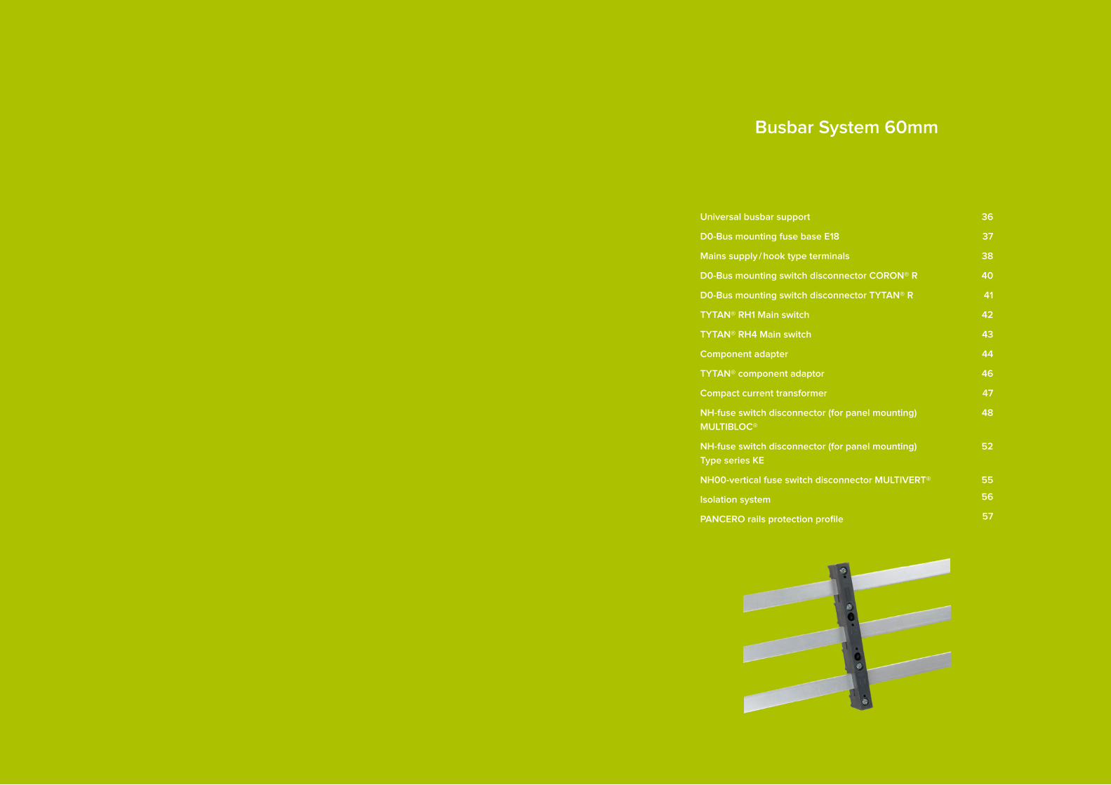
Busbar System 60mm
Universal busbar support
D0-Bus mounting fuse base E18
Mains supply / hook type terminals
D0-Bus mounting switch disconnector CORON® R
D0-Bus mounting switch disconnector TYTAN® R
TYTAN® RH1 Main switch
TYTAN® RH4 Main switch
Component adapter
TYTAN® component adaptor
Compact current transformer
NH-fuse switch disconnector (for panel mounting)
MULTIBLOC®
NH-fuse switch disconnector (for panel mounting)
Type series KE
NH00-vertical fuse switch disconnector MULTIVERT®
Isolation system
PANCERO rails protection profile
36
37
38
40
41
42
43
44
46
47
48
52
55
56
57
3736
✓
✓
✓
✓
Busbar support
base / lower part reversible
an extensive busbar program can
be realized with very few components
for busbars 12 – 30mm / 5 and 10mm
also fits ABB – "Striebel & John-cabinets"
Item-No. 10 6300 Item-No. 10 6028Item-No. 10 6023
Z-end cap, yellow, Item-No. 10 6308
Item-No. 10 6302
Fuse socket without cover,Item-No. 10 6022
Price list
Item Item-No. kg / Pc. PU
3-pole, 2-hole mounting inside; incl. spacer and fixing screws 10 6300 0.121 10
External fixing with item 10 6300; incl. fixing screws 10 6301 0.006 20
1-pole, fixed to 10 6300 or for 2-pole; incl.spacer and fixing screws
10 6302 0.048 10
1-pole, for single mounting; incl. spacer and fixing screws 10 6304 0.056 10
Combi joiner; fort the assembly of a2-pole busbar with 2 x 10 6302 10 6307 0.004 10
End cap 3-pole; yellow with warning traingle 10 6303 0.019 10
Z-end cap 3-pole; yellow with warning traingle 10 6308 0.024 10
End cap 1-pole 10 6310 0.006 10
Z-End cap 1-pole 10 6311 0.007 10
Busbar support 2-pole, 1 fixing hole 10 6004 0.08 10
Busbar support 2-pole, 2 fixing holes 10 6005 0.09 10
D0-Bus mounting fuse base E18
distinctive labeling on the base
low-loss stainless steel terminal clamps
contact protection shroud on the sides
clip on rear touch protection shroud
Price list
Item Item-No. kg / Pc. PU
Bus mounting fuse base 27mm, without cover 10 6022 0.15 10
Bus mounting fuse base 27mm, with cover 10 6023 0.17 10
Bus mounting fuse base 36mm, with cover and lateral extension 10 6028 0.19 10
Bus mounting fuse base 54mm, with cover and lateral extension 10 6029 0.21 10
Cover shroud 27mm 10 6011 0.02 10
Cover shroud 36mm, incl. extension 10 6012 0.03 10
Cover shroud 54mm, incl. extension 10 6013 0.05 10
Shroud pair 10 6016 0.05 10
Single left 10 6017 0.02 10
Single right 10 6018 0.02 10
Clip on touch protection shroud with back of hand protection 10 6026 0.01 10
✓
✓
✓
✓
Busbar support 60mm Busbar support 60mm

3938
Price list
Item Item-No. kg / Pc. PU
yellow
54mm wide, internal height 44mm, for clamps 16 … 50mm² 10 6090 0.11 2
108mm wide, internal height 44mm, for clamps 16 … 70mm² 10 6091 0.17 1
108mm wide, internal height 80mm, for clamps 16 … 185mm² 10 6092 0.22 1
grey
54mm wide, internal height 44mm, for clamps 16 … 50mm² 10 6096 0.11 2
108mm wide, internal height 44mm, for clamps 16 … 70mm² 10 6097 0.17 1
108mm wide, internal height 80mm, for clamps 16 … 185mm² 10 6098 0.22 1
Mains supply/hook type terminals
Connection clamps and protection covers with warning triangle including conductor and busbar protection cover
Price list
Item Item-No. kg / Pc. PU
54mm wide, internal height 44mm 10 6033 0.09 2
108mm wide, internal height 44mm 10 6034 0.12 1
108mm wide, internal height 80mm 10 6035 0.12 1
Busbar protection cover, grey
Pressure clamps with fixed pressure plate for Cu- / Al-conductor
Pressure clamps for direct connection of Al-conductor
Accessories Pressure clamps for Cu-conductors
Price list
Item Item-No. kg / Pc. PU
1,5 … 16mm², for 5mm² busbars 11 6051 0.03 100
4,0 … 35mm², for 5mm² busbars 11 6052 0.04 50
10 … 50mm², for 5mm² busbars 11 6053 0.05 50
16 … 70mm², for 5mm² busbars 11 6054 0.06 10
16 … 120mm², for 5mm² busbars 11 6055 0.09 10
50 … 185mm², for 5mm² busbars 11 6056 0.10 10
1,5 … 16mm², for 10mm² busbars 11 6061 0.03 100
4,0 … 35mm², for 10mm² busbars 11 6062 0.04 50
10 … 50mm², for 10mm² busbars 11 6063 0.05 50
16 … 70mm², for 10mm² busbars 11 6064 0.06 10
16 … 120mm², for 10mm² busbars 11 6065 0.09 10
50 … 185mm², for 10mm² busbars 11 6066 0.10 10
Price list
Item Item-No. kg / Pc. PU
1,5 … 16mm², for 5mm² busbars 11 6070 0.03 50
4,0 … 35mm², for 5mm² busbars 11 6071 0.04 50
16 … 70mm², for 5mm² busbars 11 6072 0.06 10
16 … 120mm², for 5mm² busbars 11 6073 0.09 10
50 … 185mm², for 5mm² busbars 11 6074 0.10 10
1,5 … 16mm², for 10mm² busbars 11 6080 0.03 50
4,0 … 35mm², for 10mm² busbars 11 6081 0.04 50
16 … 70mm², for 10mm² busbars 11 6082 0.06 10
16 … 120mm², for 10mm² busbars 11 6083 0.09 10
50 … 185mm², for 10mm² busbars 11 6084 0.10 10
Price list
Item Item-No. kg / Pc. PU
1,5 … 16mm², for 5mm² busbars 11 6089 0.03 40
4,0 … 35mm², for 5mm² busbars 11 6090 0.04 20
16 … 70mm², for 5mm² busbars 11 6091 0.06 10
16 … 120mm², for 5mm² busbars 11 6092 0.09 10
50 … 185mm², for 5mm² busbars 11 6093 0.10 10
1,5 … 16mm², for 10mm² busbars 11 6094 0.03 40
4,0 … 35mm², for 10mm² busbars 11 6095 0.04 20
16 … 70mm², for 10mm² busbars 11 6096 0.06 10
16 … 120mm², for 10mm² busbars 11 6097 0.09 10
50 … 185mm², for 10mm² busbars 11 6098 0.10 10
Busbar support 60mm Busbar support 60mm

4140
✓
✓
✓
✓
✓
✓
✓ ✓
✓ ✓
✓
✓
✓
CORON® RD0-Switch disconnector with fuses
flashing detectors
safety switch
width 27mm
lockable
compact and low form
optional widening
Item-No. 10 6901 Item-No. 10 6602
locking
Price list
Item Item-No. kg / Pc. PU
400V~, D0: 2 … 63A
3-pole 10 6901 0,28 4
extension set 9mm 10 6971 0.01 1
Plug reduction spring from D02 to D01 10 1774 0.01 12
Padlock in the click box 10 4664 0.05 1
3-pole, 20A with fuses and fixed mounting dowels 10 6920 0,32 4
3-pole, 25A with fuses and fixed mounting dowels 10 6925 0,32 4
3-pole, 35A with fuses and fixed mounting dowels 10 6935 0,32 4
3-pole, 50A with fuses and fixed mounting dowels 10 6950 0,32 4
3-pole, 63A with fuses and fixed mounting dowels 10 6963 0,32 4
CORON® R-flashing plug with Dummy 400V~ 63A 10 6981 0,001 10
TYTAN® RD0-Switch disconnector with fuses
Price list
Item Item-No. kg / Pc. PU
400V~, D0:2…63A; 10 x 38: 2…32A 400V~
TYTAN R 3-pole 10 6601 0,4 3
TYTAN R 3-pole+N 10 6602 0,4 3
TYTAN R 3-pole; with auxiliary switch for switch position 10 6603 0,4 3
TYTAN R 3-pole+N; with auxiliary switch for switch position 10 6604 0,4 3
500V~, 10 x 38: 2…25A
TYTAN R 3-pole 10 6631 0,4 3
TYTAN R 3-pole+N 10 6632 0,4 3
TYTAN R 3-pole; with auxiliary switch for switch position 10 6633 0,4 3
TYTAN R 3-pole+N; with auxiliary switch for switch position 10 6634 0,4 3
Accessories
Rear touch protection; plugin above and below 10 6626 0.01 10
Plug reduction spring from D02 to D01 10 1774 0.01 12
Padlock in the click box 10 4664 0.05 1
Short circuit plug as a disconnector 10 1780 0.01 3
TYTAN R Power measuring plug (1 piece) 10 6675 / 1 0.05 1
3-pole, 20A with fuses and fixed mounting dowels 10 6601.24ABF20 0,4 3
3-pole, 25A with fuses and fixed mounting dowels 10 6601.24ABF25 0,4 3
3-pole, 35A with fuses and fixed mounting dowels 10 6601.24ABF35 0,4 3
3-pole, 50A with fuses and fixed mounting dowels 10 6601.24ABF50 0,4 3
flashing detectors
switching all poles
fuse plug
width 27mm
lockable
optional current measurement in
the fuse plug
for 5 – 10mm thickness and
12 – 30mm wide rails fuse plug with current display
Item-No. 10 6601
widening
Busbar support 60mm Busbar support 60mm

4342
Item-No. 10 3711 Item-No. 10 6711Item-No. 10 6701
TYTAN® R Main protectionD0-Switch disconnector with fuses
With fuse and temperature control
TYTAN®-Main protection switch indicates fuse breaks
and has the capability of transmitting a floating signal
via an RJ-connection cable on the external relay.
A dangerous overheating of the fuse switch can be
reliably identified and reported.
The serial interface on each relay has floating signal
via a relay contact. For collective disturbance monito-
ring it is possible to put 12 fuse switches together.
fuse- and temperature monitoring
potential-free relay contacts
MOD-Bus RTU Gateway
✓
✓
✓ ✓
✓
✓
✓
✓
Price list
Item Item-No. kg / Pc. PU
400V~, D0:2…63A; 10 x 38: 2…32A
TYTAN RH1 3-pole 10 6701 0.40 2
TYTAN RH1 3-pole+N pre / post lagging phase 10 6702 0.50 2
500V~, 10 x 38: 2…25A
TYTAN RH1 3-pole 10 6731 0.40 2
TYTAN RH1 3-pole+N pre / post lagging phase 10 6732 0.50 2
Main portection – relay Modules HR 11; 3 switch contacts (reports: blown fuse, excess temperature, on / off)
10 3711 0.12 1
Main portection – relay Modules HR 12; 2 switch contacts (reports: blown fuse, excess temperature)
10 3712 0.12 1
Main portection – relay Modules HR 13; 1 switch contacts(reports: blown fuse, excess temperature)
10 3713 0.12 1
MOD-Bus-RTU-coupler with display; 2 changer (programmable) 10 3715 0.15 1
RJ-connection cable 200mm 10 3730 0.01 1
RJ-connection cable 500mm 10 3731 0.01 1
RJ-connection cable 1000mm, further lenghts at disposal 10 3732 0.01 1
Mains adapter 100 – 240V AC / 24V DC 10W 10 3700 0.10 1
Mains adapter 100 – 240V AC / 24V DC 30W 10 3701 0.25 1
TYTAN® RH4 Main protectionwith temperature- and security monitoring system
TYTAN®-Main protection switch indicates fuse breaks
and has one potential-free change over contact for
signaling. A dangerous overheating of the fuse switch
can be reliably identified and reported.
The TYTAN® RH4 needs no external power supply.
flashing indicator
self-power
safety switch
width 36mm
lockable
Price list
Item Item-No. kg / Pc. PU
400V~, D0: 2 … 63A; 10 x 38: 2 … 32A
TYTAN® RH4 3-pole 10 6711 0,43 2
TYTAN® RH4 3-pole+N pre / post lagging phase 10 6712 0,52 2
TYTAN® RH4 3-pole including switch position 10 6713 0,43 2
TYTAN® RH4 3-pole+N including switch position 10 6714 0,52 2
Busbar support 60mm Busbar support 60mm

4544
✓
✓
✓
Component adapter
support rail adjustable in mm
low loss dual contact
attachable widening
Item-No. 10 6528 + 10 6561
Item-No. 10 6560
Item-No. 10 6538
Price list
Item Mounting rail Item-No. PU
16 A; 2,5mm2; AWG 14
width: 45mm, length: 207mm 1 10 6520 2
25 A; 4mm2; AWG 12
width: 45mm, length: 207mm 1 10 6521 2
width: 45mm, length: 207mm 2 10 6522 2
width: 45mm, length: 260mm 2 10 6523 2
width: 90mm, length: 207mm 2 10 6524 2
32 A; 6mm2; AWG 10
width: 45mm, length: 207mm 1 10 6525 2
width: 54mm, length: 207mm 1 10 6526 2
width: 54mm, length: 207mm 2 10 6527 2
width: 54mm, length: 260mm 2 10 6528 2
width: 63mm, length: 207mm 1 10 6529 2
width: 72mm, length: 207mm 1 10 6530 2
width: 72mm, length: 260mm 2 10 6531 2
width: 81mm, length: 207mm 2 10 6532 2
Price list
Item Mounting rail Item-No. PU
63 A; 10mm2; AWG 8
width: 54mm, length: 207mm 1 10 6533 2
width: 54mm, length: 207mm 2 10 6534 2
width: 54mm, length: 260mm 2 10 6535 2
width: 63mm, length: 207mm 1 10 6536 2
width: 72mm, length: 207mm 1 10 6537 2
width: 72mm, length: 260mm 2 10 6538 2
width: 81mm, length: 207mm 2 10 6539 2
80 A; 16mm2; AWG 6
width: 72mm, length: 207mm 1 10 6543 2
width: 72mm, length: 260mm 2 10 6544 2
Zubehör
width: 9mm, length: 207mm widening 9mm 10 6561 10
width: 45mm PIN-rail 10 6560 10
width: 45mm Contract rail 10 6551 10
width: 54mm Contract rail 10 6552 10
width: 63mm Contract rail 10 6553 10
width: 72mm Contract rail 10 6554 10
width: 81mm Contract rail 10 6555 10
width: 90mm Contract rail 10 6556 10
Busbar support 60mm Busbar support 60mm

4746
TYTAN® component adaptorwith TYTAN® D0-fuse switch disconnector ready for mounting on a 60mm busbar adaptorincl. connections and protective shrouds
Item-No. 10 6232
Accessories TYTAN® II Main protection mounted on component adaptor
Price list
Item Design 100mm Item-No. 125mm Item-No. 150mm Item-No. kg / Pc. PU
TYTAN® II Mono 1 x 3-pole – 10 6275 10 6277 1,30 1
TYTAN® II Duo 2 x 3-pole – 10 6276 10 6278 1,75 1
TYTAN® II Mono 1 x 2-pole – 10 6285 – 0.70 1
TYTAN® II Duo 2 x 2-pole – 10 6289 – 0,98 1
Price list
Item Design 100mm Item-No. 125mm Item-No. 150mm Item-No. kg / Pc. PU
TYTAN® I Mono 1 x 3-pole 10 6201 10 6201 – 0,52 1
TYTAN® I Mono 3 x 1-pole 10 6203 10 6203 – 0,52 1
TYTAN® I Duo 2 x 3-pole 10 6202 10 6206 – 0,80 1
TYTAN® I Duo 6 x 1-pole 10 6204 10 6207 – 0,80 1
TYTAN® I Duo 3 x 1 + 1 x 3 10 6205 10 6208 – 0,80 1
TYTAN® II Mono 1 x 3-pole 10 6221 10 6221 10 6234 0,85 1
TYTAN® II Mono 3 x 1-pole 10 6223 10 6223 10 6235 0,85 1
TYTAN® II Duo 2 x 3-pole 10 6222 10 6226 10 6229 1,30 1
TYTAN® II Duo 6 x 1-pole 10 6224 10 6227 10 6230 1,30 1
TYTAN® II Duo 3 x 1 + 1 x 3 10 6225 10 6228 10 6231 1,30 1
TYTAN® II Mono 1 x 2-pole 10 6239 10 6239 – 0,46 1
TYTAN® II Mono 2 x 1-pole 10 6240 10 6240 – 0,46 1
TYTAN® II Duo 2 x 2-pole 10 6237 10 6232 – 0.70 1
TYTAN® II Duo 4 x 1-pole 10 6238 10 6233 – 0.70 1
Item-No. 10 6222 Item-No. 22 1013-...A
Compact current transformer 3-phase 5A, cl.1
hole center distance 60mm
for rail thicknesses of 12 x 5 – 30 x 10mm
overall width 54mm
circumferential contact protection of the busbars
Flexibly applicable in the distribution board and on mounting plate
Price list
Item Item-No. kg / Pc. PU
Rated current in A: 100A 22 1013-100 / 5A 0,3 1
Rated current in A: 150A 22 1013-150 / 5A 0,3 1
Rated current in A: 200A 22 1013-200 / 5A 0,3 1
Rated current in A: 250A 22 1013-250 / 5A 0,3 1
Rated current in A: 400A 22 1013-400 / 5A 0,3 1
Rated current in A: 600A 22 1013-600 / 5A 0,3 1
Rated current in A: 630A 22 1013-630 / 5A 0,3 1
✓
✓
✓
✓
✓
Busbar support 60mm Busbar support 60mm

4948
NH-fuse switch disconnector
(for panel mounting), MULTIBLOC®
drilled mounting
for busbars 12 – 30mm wide and 5 – 10mm thickness
integrated touch protection
lockable
✓
✓
✓
✓
Price list
Item Item-No. kg / Pc. PU
NH 000 RT, clamp strap 2,5 –50mm², output at bottom end
14 9010 0,60 1
NH 000 RT, clamp strap 2,5 – 50mm², output at top end
14 9011 0,60 1
Control switch indicating switching status 14 0643 0.01 1
Busbar touch protection 1 Set = 2 piece 14 0644 0.05 1
MULTIBLOC® NH 000 RT, 3-pole, 100A / 690V, 54mm width
Item-No. 14 9010
Price list
Item Item-No. kg / Pc. PU
NH 00 RT, 3 terminal screws M8, 3 clamp straps 4 – 70mm²
14 8010 0,88 1
NH 00 RT, 3 frame clamps 2,5 – 70mm² (Set = 3 piece) 14 8012 0,88 1
NH 00 RT, 3 terminal screws M8, 3 clamp straps 4 – 70mm² with elec. Fuse surveillance (monitoring)
14 8070 0,96 1
clamp Al / Cu 1,5 – 70mm² (Set = 3 piece) 14 0853 0,08 1
Monitoring switch for switching status 14 0852 0.01 1
Cabel termination protection cover (piece) 14 0147 0.05 1
Busbar touch protection 1 Set = 2 piece 14 0148 0.05 1
Covering for distributor installation, single, 123 x 190mm 14 0126 0.02 1
Covering for distributor installation, double, 231 x 190mm 14 0127 0.05 1
Covering for distributor installation, triple, 339 x 190mm 14 0128 0,07 1
Covering for distributor installation, single, 123 x 210mm 14 3431 0.03 1
Covering for distributor installation, double, 231 x 210mm 14 2874 0.05 1
Covering for distributor installation, triple, 339 x 210mm 14 2870 0.09 1
MULTIBLOC® NH 00 RT 3-pole, 160A / 690V
drilled mounting
for busbars 12 – 30mm wide and 5 – 10mm thickness
Optional top / bottom Cable connections
fuse surveillance – optional
lockable
Item-No. 14 8010
Item-No. 14 0147
✓
✓
✓
✓
✓
Busbar touch protection
Busbar support 60mm Busbar support 60mm

5150
MULTIBLOC® NH 1 RT 3-pole, 250A / 690V
snap mounting
for busbars 12 – 30mm wide and 5 – 10mm thickness
direction of cable terminal variable (top/bottom)
fuse surveillance – optional
lockable
Price list
Item Item-No. kg / Pc. PU
NH 1 RT with 3 terminal screws M10 14 8110 3,06 1
NH 1 RT with 3 terminal screws M10, with electronic fuse monitoring
14 8170 3,14 1
3 clamp straps 70 – 150mm² 14 0420 0.01 1
Monitoring switch for switching status 14 0852 0.01 1
Busbar touch protection 1 Set = 2piece 14 0355 0,16 1
Cable termination protection cover 1 Set = 2 piece 14 0382 0.25 1
Covering for distributor installation, single, 210 x 260mm 14 0353 0,07 1
Covering for distributor installation, single, 230 x 283mm 14 2351 0.09 1
Sealing equipment 14 0155 0.01 1
Item-No. 14 8110 Item-No. 14 8170
Item-No. 14 0155
✓
✓
✓
✓
✓
MULTIBLOC® NH 2 RT 3-pole, 400A / 690V
snap mounting
for busbars 12 – 30mm wide and 5 – 10mm thickness
direction of cable terminal variable (top/bottom)
fuse surveillance – optional
lockable
Price list
Item Item-No. kg / Pc. PU
NH 2 RT with 3 terminal screws M10 14 8210 4,50 1
NH 2 RT with 3 terminal screws M10, with electronic fuse monitoring
14 8270 4,58 1
3 clamp straps 120 – 240mm² (Set) 14 1237 0.25 1
Monitoring switch for switching status 14 0852 0.01 1
Busbar touch protection 1 Set = 2 piece 14 0862 / 1 0.23 1
Cable termination protection cover 1 Set = 2 piece 14 0861 0.22 1
Covering for distributor installation, single, 230 x 300mm 14 0863 0,08 1
Covering for distributor installation, single, 234 x 310mm 14 2352 0.11 1
Item-No. 14 8210 Item-No. 14 8270
✓
✓
✓
✓
✓
Busbar touch protection
Overlap protection
Busbar support 60mm Busbar support 60mm

5352
NH-fuse switch disconnector (for panel mounting), Type series KE
only 54mm wide
snap on assembly on 60mm busbars
for 12 – 30mm width and 5 – 10mm tickness
Integrated touch protection
lockable
fuse surveillance optional (not for NH000)
✓
✓
✓
✓
✓
Price list
Item Item-No. kg / Pc. PU
NH 000 RT, clamp strap 2,5 – 50mm² output at bottom end 20 9010 0,90 1
NH 000 RT, clamp strap 2,5 – 50mm² output at top end 20 9011 0,90 1
Monitoring switch for switching status 200852 / 000 0.03 1
NH 000 RT, 3-pole, 125A / 690V Type series KE
Item-No. 20 9010 Item-No. 20 8010 Item-No. 20 8070
Price list
Item Item-No. kg / Pc. PU
NH 00 RT, clamp strap 2,5 – 50mm² output at bottom end 20 8010 0,90 1
NH 00 RT, clamp strap 2,5 – 50mm² output at top end 20 8011 0,90 1
NH 00 RT, clamp strap 2,5 – 95mm² output at bottom end, with electronic fuse monitoring
20 8070 1,05 1
NH 00 RT, clamp strap 2,5 – 95mm² output at bottom end, with electronic fuse monitoring
20 8071 1,05 1
NH 00 RT, clamp strap 2,5 – 95mm² output at bottom end, with electronic fuse monitoring / RJ-interface for the all protection system
20 8076 1,05 1
NH 00 RT, clamp strap 2,5 – 95mm² output at top end, with electronic fuse monitoring / RJ-interface for the all protection system
20 8077 1,05 1
NH 00 RT, terminal screw M8 output at buttom end 20 8012 0,90 1
NH 00 RT, terminal screw M8 output at top end 20 8013 0,90 1
Attachable connection space extension 20 0148 0.02 1
Monitoring switch for switching status 20 0852 0.01 1
clamps Al / Cu 1,5 – 70mm² (Set = 3 piece) 20 8053 0,08 1
NH 00 RT, 3-pole, 160A / 690V Type series KE
✓
Busbar support 60mm Busbar support 60mm

5554
Price list
Item Item-No. kg / Pc. PU
NH 1 RT, terminal screw M10 output at bottom end 20 8110 2,50 1
NH 1 RT, terminal screw M10 output at top end 20 8111 2,50 1
Clamps straps 70 – 150mm² (Set) 20 0420 0.01 1
Attachable connection space extension 20 1148 0.02 1
Monitoring switch for switching status 20 1852 0.01 1
NH 1 RT, 3-pole, 250A / 690V
Price list
Item Item-No. kg / Pc. PU
NH 2 RT, terminal screw M10 output at bottom end 20 8210 4,50 1
NH 2 RT, terminal screw M10 output at top end 20 8211 4,50 1
Clamps straps 120 – 240mm² (Set) 20 1237 0.25 1
Attachable connection space extension 20 2148 0.02 1
Monitoring switch for switching status 20 1852 0.01 1
NH 2 RT, 3-pole, 400A / 690V
Item-No. 14 8050
NH-vertical fuse switch disconnector MULTIVERT® NH 00 MSL, 3-pole, 160A / 690V
for snap on mounting on 60mm busbar systems
optional top / bottom Cable connections
for busbars 20 – 30mm wide, 10mm thick
Price list
Item Item-No. kg / Pc. PU
NH 00 MSL with 3 connection screws M8, incl. cover shroud 14 8050 1,12 12
3 clamp straps Cu 4 – 70mm² (Set) 14 8051 0.04 4
3 clamp Al / Cu 1,5 – 70mm² (Set) 14 8053 0,08 1
Screw connection M8 (1 Set = 3 piece) 14 8052 0.03 1
✓
✓
✓
Price list
Item Item-No. kg / Pc. PU
NH 3 RT, terminal screw M10 output at bottom end
20 8310 5,90 1
NH 3 RT, terminal screw M10 output at top end
20 8311 5,90 1
Clamps straps (Set) 20 8310 In preparation
Attachable connection space extension 20 3148 0.02 1
Monitoring switch for switching status 20 1852 0.01 1
NH 3 RT, 3-pole, 630A / 690V
Item-No. 20 8310
Item-No. 20 8110 Item-No. 20 8210
Item-No. 14 8051
Item-No. 14 8053
Busbar support 60mm Busbar support 60mm

5756
Cover systemExtensive contact protection for the system 60
PANCERO
Rails protection profile
click fastener – only with tool to open
high temperature resistant plastic PA66
length 1.500mm (fewer coupage)
Price list
Item Item-No. kg / Pc. PU
1 Cover shroud for busbar support 10 6300 12 6070 0.06 10
2 Side cover for partition and shroud system 12 6071 0.03 10
3 Slitted shroud; 2000mm long 12 6072 0,47 5
4 Closed shroud; 2000mm long 12 6073 0.53 5
5 Panel mount; support edge 32mm 12 6074 0.04 10
6 Panel cover 1000mm long 12 6075 0,64 2
Price list
Item Item-No. kg / Pc. PU
PANCERO track protection 5mm, length 1.500mm 10 6335 0.232 16
PANCERO track protection 10mm, length 1.500mm 10 6340 0.225 10
Item-No. 10 6335
✓
✓
✓
1
2
3
4
5
6
Busbar support 60mm Busbar support 60mm

5958
NH-fuse switch disconnector (for panel mounting)
NH-fuse switch disconnector for panel mounting
MULTIBLOC®
NH-fuse switch disconnector for panel mounting
Type series KE
60
64

6160
NH-fuse switch disconnectorfor panel mountingMULTIBLOC®
construction width per pole 42mm
mounting on the mounting plate
modular system: cover can be extended as required
parking position of the cover
padlocking and cover sealing
Item-No. 14 3018Item-No. 14 3019 Item-No. 14 3090Item-No. 14 3010
MULTIBLOC® NH 00 AT, 1-pole, 2-pole, 160A / 690V
MULTIBLOC® NH 00 AT 3-pole, 160A / 690V
Price list
Item Item-No. kg / Pc. PU
NH 00 AT 1-pole with clamp straps 4 –70mm² 14 3019 0,32 1
NH 00 AT 2-pole with 4 terminal screws M8 14 3018 0,62 1
Cable termination cover 1 Set = 2 piece (1-pole) 14 0149 0.02 1
Fixing set for DIN-busbars 125mm 14 0151 0,08 1
Fixing set for DIN-busbars 150mm 14 0152 0.10 1
Sealing set 14 0155 0.01 1
Monitoring switch for switching status 14 0852 0.01 1
Terminal screws M8 (Set = 3 piece) 14 8052 0.03 1
Connection clamps AI / Cu 1,5 –70mm² (Set = 3 piece) 14 8053 0.04 1
Price list
Item Item-No. kg / Pc. PU
NH 00 AT with 6 clamp straps 4 –70mm² 14 3010 0,74 1
NH 00 AT with 6 clamp straps 4 –70mm²,with electronic fuse monitoring
14 3070 0,82 1
Monitoring switch for switching status 14 0852 0.01 1
Cabel termination cover 1 Set = 2 piece 14 0148 0.05 1
Fixing set for DIN- contract rail 125mm 14 0153 0,14 1
Fixing set for DIN- contract rail 150mm 14 0154 0,16 1
Covering for distributor installation, single, 123 x 190mm 14 0126 0.02 1
Covering for distributor installation, double, 231 x 190mm 14 0127 0.05 1
Covering for distributor installation, triple, 339 x 190mm 14 0128 0,07 1
Covering for distributor installation, single, 123 x 210mm 14 3431 0.03 1
Covering for distributor installation, double, 231 x 210mm 14 2874 0.05 1
Covering for distributor installation, triple, 339 x 210mm 14 2870 0.09 1
Price list
Item Item-No. kg / Pc. PU
NH 00 AT with connection screw M8 14 3090 1,1 1
Covering for distributor installation 14 2764 0.09 1
3-pole+N, 160A / 690V (incl. N-solid link)
Item-No. 14 0149
✓
✓
✓
✓
✓
NH-fuse switch disconnector (for panel mounting) NH-fuse switch disconnector (for panel mounting)

6362
Item-No. 14 3190 Item-No. 14 3310Item-No. 14 3119 Item-No. 14 3210
MULTIBLOC® NH 1 AT 1-pole, 2-pole, 250A / 690V
MULTIBLOC® NH 2 AT 3-pole, 400A / 690V
3-pole, 250A / 690V
MULTIBLOC® NH 3 AT 3-pole, 630A / 690V
3-pole+N, 250A / 690V
Price list
Item Item-No. kg / Pc. PU
NH 1 AT 1-pole with terminal screws M10 14 3119 1,02 1
NH 1 AT 2-pole with terminal screws M10 14 3118 2,06 1
Cabel termination cover 1 Set = 2 piece (1-pole) 14 0354 0.09 1
Fixing set for DIN-busbar 125mm 14 0402 0,28 1
Fixing set for DIN-busbar 150mm 14 0403 0,24 1
Sealing set 14 0155 0.01 1
Monitoring switch for connection screw 14 0852 0.01 1
Price list
Item Item-No. kg / Pc. PU
NH 1 AT with 6 terminal screws M10 14 3110 2,42 1
NH 1 AT with 6 terminal screws M10, with electronic fuse monitoring
14 3170 2,50 1
3 clamps straps 70 – 150mm² 14 0420 0.10 1
Monitoring switch for connection screw 14 0852 0.01 1
Cabel termination cover 1 Set = 2 piece 14 0382 0.25 1
Fixing set for DIN-busbar, single, 210 x 260 mm 14 0353 0,07 1
Fixing set for DIN-busbar, single, 230 x 283 mm 14 2351 0.09 1
Sealing set 14 0155 0.01 1
Busbar-adapter system on 100mm SaS-System 14 0491 1,23 1
Price list
Item Item-No. kg / Pc. PU
NH 1 AT with terminal screws M10 14 3190 3,55 1
Price list
Item Item-No. kg / Pc. PU
NH 2 AT with 6 terminal screws M10 14 3210 3,50 1
NH 2 AT with 6 terminal screws M10, with electronic fuse monitoring
14 3270 3,60 1
3 clamps straps 120 – 240mm² (Set) 14 1237 0.25 1
Monitoring switch for connection screw 14 0852 0.01 1
Cabel termination cover 1 Set = 2 piece 14 0861 0.22 1
Fixing set for DIN-busbar, single, 230 x 300mm 14 0863 0,08 1
Fixing set for DIN-busbar, single, 234 x 310mm 14 2352 0.11 1
Busbar-adapter system on 100mm SaS-System 14 0492 1,24 1
Price list
Item Item-No. kg / Pc. PU
NH 3 AT with 6 terminal screws M12 14 3310 4,94 1
NH 3 AT with 6 terminal screws M12,with electronic fuse monitoring
14 3370 5,23 1
3 clamps straps 150 – 300mm² (Set) 14 1238 0,32 1
Monitoring switch for connection screw 14 0852 0.01 1
Cabel termination cover 1 Set = 2 piece 14 0893 0,32 1
Busbar-adapter system on 60mm SaS-System 14 0490 1,17 1
Busbar-adapter system on 100mm SaS-System 14 0493 1,28 1
Cover panel for distrubutor installation, single 14 2353 0.09 1
NH-fuse switch disconnector (for panel mounting) NH-fuse switch disconnector (for panel mounting)

6564
NH-fuse switch disconnector for panel mounting, Type series KE
NH 000 AT , Type series KE, 3-pole, 125A / 690V
Price list
Item Item-No. kg / Pc. PU
NH 000 AT, clamps straps, 2,5 – 50mm² 20 2010 0,48 1
Attachable terminal space-extension 20 0148 0.02 1
Monitoring switch for switching status 20 0852 / 000 0.03 1
mounting kit for DIN rails in preparation
Price list
Item Item-No. kg / Pc. PU
NH 00 AT, with 6 clamps straps 4 – 70mm2 20 3010 0.70 1
NH 00 AT, with 6 terminal screws M8 20 3011 0.70 1
NH 00 AT, with V-Terminal screws 25 – 120mm2 at bottom end,clamps straps at top end
20 3015 1,05 1
NH 00 AT, with 6 Clamp straps 4 – 70mm2,with electronic fuse monitoring
20 3070 0,75 1
NH 00 AT, mit 6 Clamp straps 4 – 70mm2, with electronic fuse monitoring / RJ-interface for the main protection system
20 3076 0,75 1
Attachment set for DIN rail 125mm 20 0153 0.01 1
Attachment set for DIN rail 150mm 20 0154 0.01 1
Attachable terminal space-extension 20 0148 0.02 1
Monitoring switch for switching status 20 0852 0.01 1
NH 00 AT, Type series KE, 3-pole, 160A / 690V
NH 1 AT, Type series KE 3-pole, 250A / 690V
NH 2 AT, Type series KE 3-pole, 400A / 690V
Price list
Item Item-No. kg / Pc. PU
NH 1 AT, with terminal screws M10 20 3110 2,00 1
Clamp straps 70 – 150mm (Set) 20 0420 0.01 1
Attachable terminal space-extension 20 1148 0.02 1
Monitoring switch for switching status 20 1852 0.01 1
Price list
Item Item-No. kg / Pc. PU
NH 2 AT, with terminal screws M10 20 3210 3,00 1
Clamp straps 120 – 240mm (Set) 14 1237 0.25 1
Attachable terminal space-extension 20 2148 0.02 1
Monitoring switch for switching status 20 1852 0.01 1
Item-No. 20 3010 Item-No. 20 3210Item-No. 20 2010 Item-No. 20 3110
NH 3 AT, Type series KE 3-pole, 630A / 690V
Price list
Item Item-No. kg / Pc. PU
NH 3 AT, with terminal screws M12 20 3310 5,00 1
Clamp straps (Set) 20 0423 in preparation
Attachable terminal space-extension 20 3148 0.02 1
Monitoring switch for switching status 20 1852 0.01 1
Item-No. 20 3015
NH-fuse switch disconnector (for panel mounting) NH-fuse switch disconnector (for panel mounting)

6766
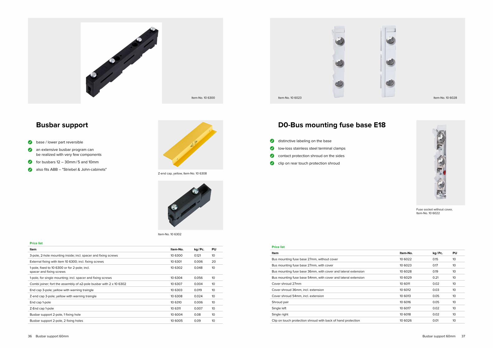
Busbar system 100 / 185 mm
Busbar support
NH-vertical fuse switch disconnector VSD Type series KE
NH-vertical fuse switch disconnector MULTIVERT®
Self-clinching nuts / nut insert press
Connection lugs
Direct connection V-frame clamps
Insulation caps
System rails
68
69
71
72
72
72
72
73
6968
✓
✓
✓
✓
Busbar supportfor the 100 and 185mm System
snap on busbar support mounting
busbar rail width 30 – 120mm (185mm System)
busbar rail width 30 – 60mm (100mm System)
busbar rail thickness: 10mm
Price list
Item Item-No. kg / Pc. PU
100mm busbar carrier 3-pole 18 8100 0,36 1
185mm busbar carrier 3-pole 18 8101 0,54 1
Busbar carrier 1-pole 18 8102 0.20 1
100mm end covering 3-pole 18 8103 0,07 1
185mm end covering 3-pole 18 8104 0.12 1
Deep angle-piece for Hager (1 Set = 2 piece) 18 8110 0.15 1 Set
100mm end covering
Item-No. 18 8102Item-No. 18 8101
Item-No. 18 8110
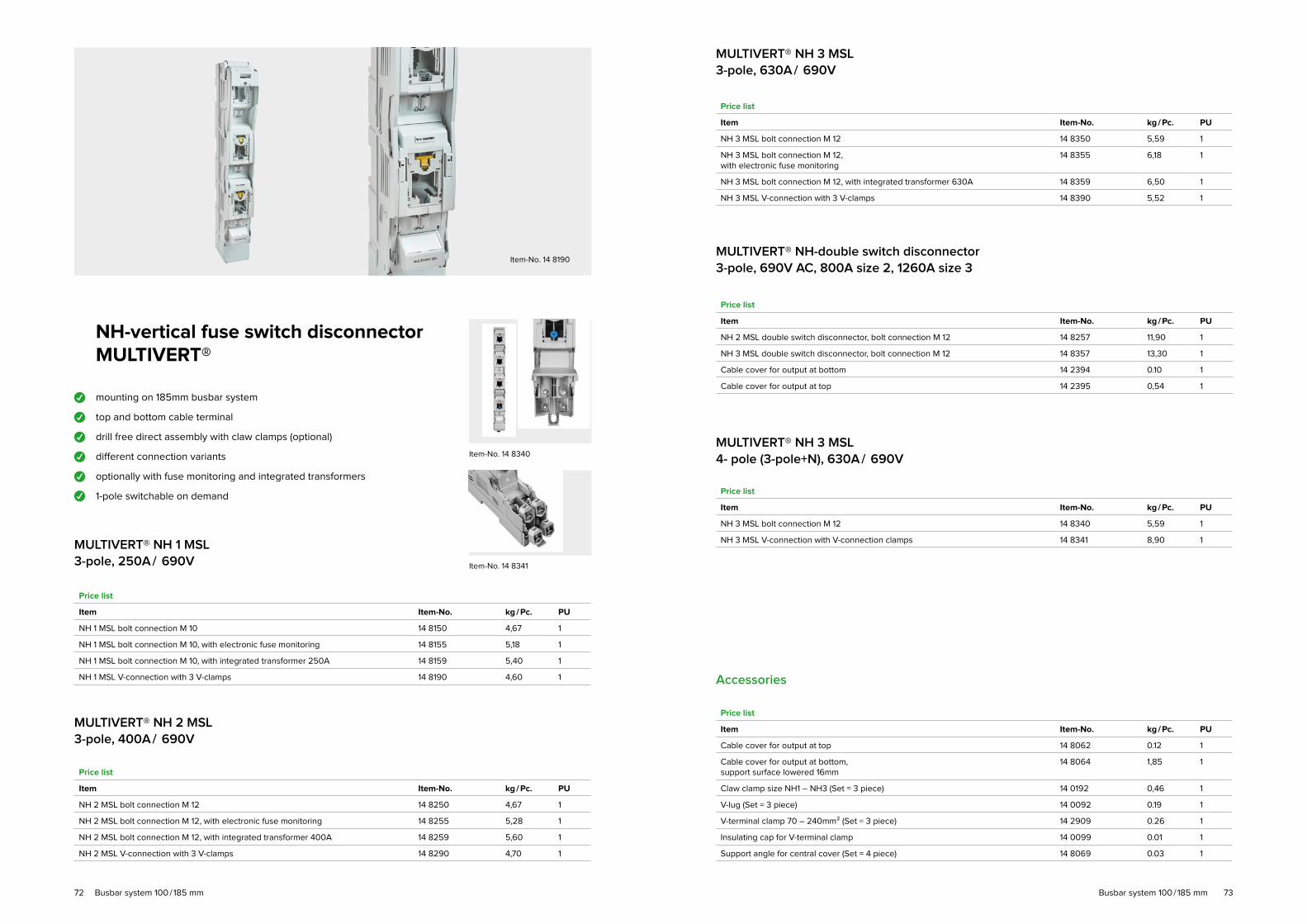
NH-vertical fuse switch disconnector
VSD, Type series KE
mounting on 185mm busbar system
top and bottom cable terminal, Top / bottom free selectable
drill free direct assembly with claw clamps (optional)
different connection variants
optional with integrated transducers
quick assembling by integrated fixing bolts (optional)
1-pole switchable on demand
removable cover
fuse-casing individually removable
✓
✓
✓
✓
✓
NH 00 VSD / 185mm 3-pole, 160A / 690V
Price list
Item Item-No. kg / Pc. PU
NH 00 VSD Clamp straps 4 – 70mm2 20 8080 2,10 1
NH 00 VSD V-connection with V-clamps 20 8081 2,30 1
Item-No. 20 8150Item-No. 20 8081
✓
✓
quick assembling VSD
✓
✓
Busbar system 100 / 185 mm Busbar system 100 / 185 mm

7170
✓
✓
NH-vertical fuse switch disconnector MULTIVERT®NH 00 MSL, 3-pole, 160A / 690V
assembly on 100mm
busbar system, cable outlet
top / bottom selectable
assembly on 185mm
busbar system with adapter,
cable outlet top / bottom selectable
Detail V-connection (Item-No. 14 8056)
Item-No. 14 8055
Price list
Item Item-No. kg / Pc. PU
NH 00 MSL with clamp straps 4 – 70mm² 14 8055 1,12 1
NH 00 MSL with V-conection (without V-terminals) 14 8056 1,12 1
V-clamp (piece) 14 2908 0.04 1
Claw cramp (Set) for directly assembly 14 8063 0.10 1
Single adapter for assembly on 185mm SS-System 14 8066 0.45 1
Double adapter for assembly on 185mm SS-System 14 8067 0,85 1
Single adapter for mounting on 185mm / claw cramp 14 8076 0,56 1
Double adapter for mounting on 185mm / claw cramp 14 8077 0.45 1
Cover shield, 2 parts 14 8061 0.45 1
Single adapter for power converter 14 0117 0,34 1
Double adapter for power converter 14 0119 0,58 1
Power converter adapter 100A, 1-phase 14 0121 0,51 1
Power converter adapter 100A, 3-phase 14 0122 0,78 1
Power converter adapter 150A, 1-phase 14 0123 0,52 1
Power converter adapter 150A, 3-phase 14 0124 0,81 1
primary pipe for adapter as distancing (Set = 3 piece) 14 0125 0,37 1
NH 1 VSD 3-pole, 250A / 690V
Price list
Item Item-No. kg / Pc. PU
NH 1 VSD terminal screws M 12 20 8150 4,67 1
NH 1 VSD terminal screws M 12, with integrated transformer 250A 20 8159 5,40 1
NH 1 VSD V-connection with 3 V-clamps 20 8190 4,70 1
NH 1 VSD terminal screws M 12 –quick assembling– 20 8152 5,90 1
NH 1 VSD V-connection with 3 V-clamps –quick assembling– 20 8192 6,00 1
Accessories
Price list
Item Item-No. kg / Pc. PU
Claw clamp size NH 00 (Set = 3 piece) 20 0191 0.10 1
Claw clamp size NH1-NH3 (Set = 3 piece) 20 0192 0,46 1
NH 2 VSD 3-pole, 400A / 690V
Price list
Item Item-No. kg / Pc. PU
NH 2 VSD terminal screws M 12 20 8250 4,67 1
NH 2 VSD terminal screws M 12, with integrated transformer 400A 20 8259 5,60 1
NH 2 VSD V-connection with 3 V-clamps 20 8290 4,70 1
NH 2 VSD terminal screws M 12 –quick assembling– 20 8252 5,90 1
NH 2 VSD V-connection with 3 V-clamps –quick assembling– 20 8292 6,00 1
NH 3 VSD 3-pole, 630A / 690V
Price list
Item Item-No. kg / Pc. PU
NH 3 VSD terminal screws M 12 20 8350 5,59 1
NH 3 VSD terminal screws M 12, with integrated transformer 630A 20 8359 6,50 1
NH 3 VSD V-connection with 3 V-clamps 20 8390 5,52 1
NH 3 VSD terminal screws M 12 –quick assembling– 20 8352 6.80 1
NH 3 VSD V-connection with 3 V-clamps –quick assembling– 20 8392 7,00 1
Busbar system 100 / 185 mm Busbar system 100 / 185 mm
7372
NH-vertical fuse switch disconnector MULTIVERT®
mounting on 185mm busbar system
top and bottom cable terminal
drill free direct assembly with claw clamps (optional)
different connection variants
optionally with fuse monitoring and integrated transformers
1-pole switchable on demand
Item-No. 14 8190
✓
✓
✓
✓
✓
MULTIVERT® NH 1 MSL
3-pole, 250A / 690V
Price list
Item Item-No. kg / Pc. PU
NH 1 MSL bolt connection M 10 14 8150 4,67 1
NH 1 MSL bolt connection M 10, with electronic fuse monitoring 14 8155 5,18 1
NH 1 MSL bolt connection M 10, with integrated transformer 250A 14 8159 5,40 1
NH 1 MSL V-connection with 3 V-clamps 14 8190 4,60 1
MULTIVERT® NH 2 MSL 3-pole, 400A / 690V
Price list
Item Item-No. kg / Pc. PU
NH 2 MSL bolt connection M 12 14 8250 4,67 1
NH 2 MSL bolt connection M 12, with electronic fuse monitoring 14 8255 5,28 1
NH 2 MSL bolt connection M 12, with integrated transformer 400A 14 8259 5,60 1
NH 2 MSL V-connection with 3 V-clamps 14 8290 4,70 1
MULTIVERT® NH 3 MSL3-pole, 630A / 690V
MULTIVERT® NH 3 MSL4- pole (3-pole+N), 630A / 690V
Price list
Item Item-No. kg / Pc. PU
NH 3 MSL bolt connection M 12 14 8350 5,59 1
NH 3 MSL bolt connection M 12, with electronic fuse monitoring
14 8355 6,18 1
NH 3 MSL bolt connection M 12, with integrated transformer 630A 14 8359 6,50 1
NH 3 MSL V-connection with 3 V-clamps 14 8390 5,52 1
Price list
Item Item-No. kg / Pc. PU
NH 3 MSL bolt connection M 12 14 8340 5,59 1
NH 3 MSL V-connection with V-connection clamps 14 8341 8,90 1
Accessories
Price list
Item Item-No. kg / Pc. PU
Cable cover for output at top 14 8062 0.12 1
Cable cover for output at bottom, support surface lowered 16mm
14 8064 1,85 1
Claw clamp size NH1 – NH3 (Set = 3 piece) 14 0192 0,46 1
V-lug (Set = 3 piece) 14 0092 0.19 1
V-terminal clamp 70 – 240mm² (Set = 3 piece) 14 2909 0.26 1
Insulating cap for V-terminal clamp 14 0099 0.01 1
Support angle for central cover (Set = 4 piece) 14 8069 0.03 1
✓
MULTIVERT® NH-double switch disconnector3-pole, 690V AC, 800A size 2, 1260A size 3
Price list
Item Item-No. kg / Pc. PU
NH 2 MSL double switch disconnector, bolt connection M 12 14 8257 11,90 1
NH 3 MSL double switch disconnector, bolt connection M 12 14 8357 13,30 1
Cable cover for output at bottom 14 2394 0.10 1
Cable cover for output at top 14 2395 0,54 1
Item-No. 14 8340
Item-No. 14 8341
Busbar system 100 / 185 mm Busbar system 100 / 185 mm

7574
self-clinching nuts / nut insert press
Price list
Item Item-No. kg / Pc. PU
Self-clinching nuts M8 20 0001 0,004 100
Self-clinching nuts M10 20 0002 0,0064 100
Self-clinching nuts M12 20 0003 0,0095 100
Connection lugs
Price list
Item Item-No. kg / Pc. PU
V-Connection lugs size 00, tinned 14 2907 / 1 0.03 100
V-Connection lugs size 2, tinned 14 2906 / 1 0.063 100
V-Double connection lugs size 00,2 x 50mm²
20 2911 0.115 1
Direct connection V-frame clamps
Price list
Item Item-No. kg / Pc. PU
V-connection clamps size 2,25 – 300mm²
14 2909 / 1 0.065 50
V-connection clamps-Set size 2, 25 – 300mm² (1 Set = 3 piece)
14 2909 / 3 0,2 1
V-connection clampssize 00, 10 – 95mm²
14 2908 0.042 30
V-connection clampssize 00, 10 – 120mm²
20 2900 0.044 40
V-double-connection clampsSize 2, for 2 cable 50 – 240mm²
14 2910 0,165 10
V-double-connection clampssize 00, for 2 cable 50 – 95mm²
14 2912 0,08 3
Insulation caps
Price list
Item Item-No. kg / Pc. PU
Insulation caps forV-connection clamps size 00
14 0098 0.01 200
Insulation caps for V-connection clamps size 2
14 0099 0.01 100
Hook-up panel for busbar system 185mm
for cable- and fairgroand cabinets
according to DIN EN 60439-1
tested according to VDE 0660 part 500
IEC 60439-1: 1999 + A1: 2004
connection and mounting on the 185mm busbar system
Price list, System rails (Type tested by CTI Vienna)
Item Item-No. PU
System rails D02 / 33x DIN rail 4,5 MW (for free assembly)
20 8000 1
System rails 4S4x SCHUKO socket 16A (RCD 40 / 4 / 0.03 + 4x B 16)
20 8001 1
System rails 2S / 1CEE16A, 5-Pol., 2 SCHUKO socket 16A (RCD 40 / 4 / 0.03 + 2x C 16 / 3 + 2x B 16)
20 8002 1
System rails 2x CEE 16A16A, 5-Pol. 400V (FI 40 / 4 / 0.03 + 2x C16 / 3)
20 8003 1
System rails 2x CEE 32A32A, 5-Pol. 400V (RCD 63 / 4 / 0.03 + 2x C32 / 3)
20 8004 1
System rails 1x CEE 63A63A, 5-Pol. 400V (RCD 63 / 4 / 0.03 + D02 / 3)
20 8005 1
Item-No. 20 8005
✓
✓
✓
✓
✓
Price list, System rails incl. electric meter
Item Item-No. PU
System rails 3S / Z3x SCHUKO socket + 3x digital AC meter certified
20 8006 1
System rails CEE 16 / Z1x CEE 16A + 1x digital AC meter certified
20 8007 1
System rails CEE 32 / Z1x CEE 32A + 1x digital AC meter certified
20 8008 1
Item-No. 20 8004Item-No. 20 8001Item-No. 20 8000
Busbar system 100 / 185 mm Busbar system 100 / 185 mm

7776
Fuse links / Accessory
D0-Fuse links
D0-Cartridge ring adaptor insert
D0-Screw cap
Spar click box
NH-Fuse links
Cylindrical Fuse-links
78
78
78
79
80
82

7978
D0-Fuse links
Price list
Item Item-No. kg / Pc. PU
D01 2A 10 0202 0,006 50
D01 4A 10 0204 0,006 50
D01 6A 10 0206 0,006 50
D01 10A 10 0210 0,006 50
D01 13A 10 0213 0,006 50
D01 16A 10 0216 0,006 50
D02 20A 10 0220 0.011 50
D02 25A 10 0225 0.012 50
D02 32A 10 0232 0.013 50
D02 35A 10 0235 0.013 50
D02 40A 10 0240 0.013 50
D02 50A 10 0250 0.013 50
D02 63A 10 0263 0.015 50
D0-Cartidge ring adapter insert
Price list
Item Item-No. kg / Pc. PU
D01 E14 2A 10 0302 0,001 50
D01 E14 4A 10 0304 0,001 50
D01 E14 6A 10 0306 0,001 50
D01 E14 10A 10 0310 0,001 50
D02 E18 2A 10 0402 0,001 50
D02 E18 4A 10 0404 0,001 50
D02 E18 6A 10 0406 0,001 50
D02 E18 10A 10 0410 0,001 50
D02 E18 16A 10 0416 0,001 50
D02 E18 20A 10 0420 0,001 50
D02 E18 25A 10 0425 0,001 50
D02 E18 35A 10 0435 0,001 50
D02 E18 50A 10 0450 0,001 50
D0-Screw cap / Accessories
Price list
Item Item-No. kg / Pc. PU
Cartidge ring adaptor wrench 10 1400 0.02 1 / 12
Screw cap D02 plastic with testing hole
12 6024 0.01 20
Screw cap D01 plastic with testing hole
12 6025 0.01 20
Adapter ring for D01 fuse links
12 1401 0.01 20
Screw cap D02 porcelain with testing hole 12 7024 0.01 20
Screw cap D01 porcelain with testing hole 12 7025 0.01 20
• D0-Fuse links 400V~ / 250V-
• DIN 49522 DIN VDE 0636 IEC 60269
• Lower power dissipation due to silver-plated contact caps
• DIN 49523
• DIN VDE 0636
• IEC 60269
• DIN EN 60269-1
• DIN VDE 0636-3
Spar click box
• The handy spare click box mounted in the distribution rack provides immediate swapping of fuses and reswitching
• Fits in the standard section of the distributor panel 3 MW wide (54mm)
Price list
Item Item-No. kg / Pc. PU
12 x 2A D01 in a box 1,5TE 10 1202 0.10 1 / 24
12 x 4A D01 in a box 1,5TE 10 1204 0.10 1 / 24
12 x 6A D01 in a box 1,5TE 10 1206 0.10 1 / 24
12 x 10A D01 in a box 1,5TE 10 1210 0.11 1 / 24
12 x 13A D01 in a box 1,5TE 10 1213 0.11 1 / 24
12 x 16A D01 in a box 1,5TE 10 1216 0.11 1 / 24
12 x 20A D02 in a box 3TE 10 1220 0,18 1 / 12
12 x 25A D02 in a box 3TE 10 1225 0,18 1 / 12
12 x 32A D02 in a box 3TE 10 1232 0.19 1 / 12
12 x 35A D02 in a box 3TE 10 1235 0.21 1 / 12
12 x 40A D02 in a box 3TE 10 1240 0.21 1 / 12
12 x 50A D02 in a box 3TE 10 1250 0.22 1 / 12
12 x 63A D02 in a box 3TE 10 1263 0.22 1 / 12
Complete range 13 x 12 fuse link sets 2 – 63A 10 1200 2,10 1
Servicebox for the distribution rack as reserve box for smal parts
Price list
Item Item-No. kg / Pc. PU
Reserve box pink 10 1102 0.04 1 / 12
Reserve box brown 10 1104 0.04 1 / 12
Reserve box green 10 1106 0.04 1 / 12
Reserve box red 10 1110 0.04 1 / 12
Reserve box grey 10 1116 0.04 1 / 12
Reserve box blue 10 1120 0.04 1 / 12
Reserve box yellow 10 1125 0.04 1 / 12
Reserve box black 10 1135 0.04 1 / 12
Reserve box white 10 1150 0.04 1 / 12
Reserve box ocher 10 1163 0.04 1 / 12
Securing material Securing material

8180
Price list
Item Item-No. kg / Pc. PU
Size 000 2A 14 0602 0.12 3
Size 000 4A 14 0604 0.12 3
Size 000 6A 14 0606 0.12 3
Size 000 10A 14 0610 0.12 3
Size 000 16A 14 0616 0.12 9
Size 000 20A 14 0620 0.12 9
Size 000 25A 14 0625 0.12 9
Size 000 32A 14 0632 0.12 9
Size 000 35A 14 0635 0.12 9
Size 000 40A 14 0640 0.12 9
Size 000 50A 14 0650 0.12 9
Size 000 63A 14 0663 0.12 9
Size 000 80A 14 0680 0.12 9
Size 000 100A 14 0690 0.12 9
Size 000 125A 14 0693 0.12 3
Size 00 125A 14 0691 0.19 3
Size 00 160A 14 0692 0.19 3
Size 1 500V~ / 440V-
Size 000 / 00 500V~ / 250V-
Price list
Item Item-No. kg / Pc. PU
Size 1 20A 14 1620 0,27 3
Size 1 25A 14 1625 0,27 3
Size 1 35A 14 1635 0,27 3
Size 1 50A 14 1650 0,27 3
Size 1 63A 14 1663 0,27 3
Size 1 80A 14 1680 0,27 3
Size 1 100A 14 1690 0,27 3
Size 1 125A 14 1691 0,27 3
Size 1 160A 14 1692 0.40 3
Size 1 200A 14 1693 0.40 3
Size 1 224A 14 1699 0.40 3
Size 1 250A 14 1694 0.40 3
Size 2 500V~ / 440V-
Price list
Item Item-No. kg / Pc. PU
Size 2 50A 14 2650 0,42 3
Size 2 63A 14 2663 0,42 3
Size 2 80A 14 2680 0,42 3
Size 2 100A 14 2690 0,42 3
Size 2 125A 14 2691 0,42 3
Size 2 160A 14 2692 0,42 3
Size 2 200A 14 2693 0,42 3
Size 2 224A 14 2699 0,42 3
Size 2 250A 14 2694 0,42 3
Size 2 300A 14 2695 0,61 3
Size 2 315A 14 2696 0,61 3
Size 2 355A 14 2698 0,61 3
Size 2 400A 14 2697 0,61 3
Size 3 500V~ / 440V-
Price list
Item Item-No. kg / Pc. PU
Size 3 125A 14 3690 0,62 3
Size 3 160A 14 3691 0,62 3
Size 3 200A 14 3692 0,62 3
Size 3 224A 14 3693 0,62 3
Size 3 250A 14 3694 0,62 3
Size 3 300A 14 3695 0,62 3
Size 3 315A 14 3696 0,62 3
Size 3 355A 14 3697 0,62 3
Size 3 400A 14 3698 0,97 3
Size 3 425A 14 3699 0,97 3
Size 3 450A 14 3628 0,97 3
Size 3 500A 14 3629 0,97 3
Size 3 630A 14 3630 0,98 3
NH-contact blades
With non-isolated gripping lugs
Price list
Item Item-No. kg / Pc. PU
Size 00 / 000 160A 14 1710 0,07 5
Size 1 250A 14 1711 0,14 5
Size 2 400A 14 1712 0.20 5
Size 3 630A 14 1713 0,27 5
NH-Fuse links
With non-isolated gripping lugs,
double indicator, contact blades,
(complying with) according DIN VDE 0632-2 Operating class (gl) gG
Securing material Securing material

8382
Price list
Item Item-No. kg / Pc. PU
10 x 38 0,5A 25 0605 0.01 10
10 x 38 1A 25 0601 0.01 10
10 x 38 2A 25 0602 0.01 10
10 x 38 4A 25 0604 0.01 10
10 x 38 6A 25 0606 0.01 10
10 x 38 8A 25 0608 0.01 10
10 x 38 10A 25 0610 0.01 10
10 x 38 12A 25 0612 0.01 10
10 x 38 16A 25 0616 0.01 10
10 x 38 20A 25 0620 0.01 10
10 x 38 25A 25 0625 0.01 10
10 x 38 32A 25 0632 0.01 10
IEC / EN 60269-1
10 x 38
400V AC; 100kA
Cylindrical fuse links
"gK" without indicator
Price list
Item Item-No. kg / Pc. PU
14 x 51 2A 25 1602 0.02 10
14 x 51 4A 25 1604 0.02 10
14 x 51 6A 25 1606 0.02 10
14 x 51 8A 25 1608 0.02 10
14 x 51 10A 25 1610 0.02 10
14 x 51 16A 25 1616 0.02 10
14 x 51 20A 25 1620 0.02 10
14 x 51 25A 25 1625 0.02 10
14 x 51 32A 25 1632 0.02 10
14 x 51 40A 25 1640 0.02 10
14 x 51 50A 25 1650 0.02 10
14 x 51
500V AC; 80kA
Price list
Item Item-No. kg / Pc. PU
22 x 58 16A 25 2616 0.06 10
22 x 58 20A 25 2620 0.06 10
22 x 58 25A 25 2625 0.06 10
22 x 58 32A 25 2632 0.06 10
22 x 58 40A 25 2640 0.06 10
22 x 58 50A 25 2650 0.06 10
22 x 58 63A 25 2663 0.06 10
22 x 58 80A 25 2680 0.06 10
22 x 58 100A 25 2690 0.06 10
22 x 58 125A 25 2691 0.06 10
22 x 58
500V AC; 80kA
Securing material Securing material

8584
Supervisory relay
Undervoltage measuring relay
Undervoltage / overvoltage monitoring relay
Phase display
Mains monitoring relay
86
88
89
89

8786
Undervoltage measuring relay
3-phase supervision for low voltage
and phase failure
monitoring of N conductor
overall width 17,8mm (1MW)
switching voltage 85%, delay 0,5 sec
accords to DIN EN 50172 (DIN VDE 108 – 100)
power consumption less than 1W
LED indication for phase and neutral faults
for 1-phase operation direct connection
via terminal L; N possible
Low voltage measuring relaywith switch back delayaccording to DIN VDE 100 – 718(emergency lighting installations)
3-phase supervision for low voltage and
phase failure
monitoring of N conductor
overall width 17,8mm (1MW)
switching voltage 85%, delay 0,5 sec
switch back delay 1min
power consumption less than 1W
LED indication for phase and neutral faults
for 1-phase operation direct connection
via terminal L; N possible
Undervoltage measuring relayWith phase sequence detection
3-phase supervision for low voltage
and phase failure
monitoring of N conductor
overall width 17,8mm (1MW)
switching voltage 85 %, delay 0,5 sec
accords to DIN EN 50172 (DIN VDE 108 – 100)
power consumption less than 1W
LED error display for rotating field, phase and N errors
push button, TEST-Function
for 1-phase operation direct connection
via terminal L; N possible
Low voltage measuring relay adjustable
3-phase monitoring for Undervoltage, phase failure and
phase sequence
monitoring of N conductor
overall width 17,8mm (1MW)
adjustable switching voltage
time delay adjustable
power consumption less than 1W
LED-error display
for 1-phase operation direct connection
via terminal L; N possible
Item-No. 10 3059 Item-No. 10 3062
Item-No. 10 3061 Item-No. 10 3066
Price list
Item Item-No. kg / Pc. PU
Undervoltage measuring relay 1 break contact 10 3059 0.10 1 / 18
Undervoltage measuring relay 2 break contacts 10 3060 0.10 1 / 18
Undervoltage measuring relay 2 change-over contacts with phase display 10 3069 0.10 1 / 18
✓
✓
✓
✓
✓
✓
✓
✓
✓
✓
✓
✓
✓
✓
✓
✓
✓
✓
✓
✓
✓
✓
✓
✓
✓
✓
✓
✓
✓
✓
✓
Price list
Item Item-No. kg / Pc. PU
Undervoltage measuring relay with phase sequence detection 2 break contacts 10 3061 0.10 1 / 18
Price list
Item Item-No. kg / Pc. PU
Low voltage measuring relay 2 break contacts 10 3062 0.10 1 / 18
Price list
Item Item-No. kg / Pc. PU
Undervoltage monitoring relay 2 change-over contacts
Us = 150 ... 220V ∆U = 5V
tV
= 0,5 ... 15s ∆t = 1s
10 3066 0.10 1 / 18
✓
✓
Supervisory relay Supervisory relay

8988
Under- / overvoltage measuring
relay 230 / 400V AC
3-phasen monitoring for Undervoltage, overvoltage,
phase failure and phase sequence
monitoring of N conductor
overall width 17,8mm (1MW)
adjustable Undervoltage / overvoltage
power consumption less than 1 W
LED error display
single-phase use possible
Phase display
display of all 3 phase with green LED (phase to N)
LED display at L1 with DC (L1+ / N-)
overall width 17,8mm (1MW)
power consumption less than 1 W
voltage range 85 – 690V AC / DC
Under- / overvoltage measuring
relay DC
Under- / overvoltage monitoring for DC
selectable voltage ranges: 24V / 60V / 110V / 220V DC
overall width 17,8mm (1MW)
adjustable Undervoltage / overvoltage
power consumption less than 1 W
LED error display for Ander- / overvoltage
Item-No. 10 3067 Item-No. 10 3009
Item-No. 10 3068
✓
✓
✓
✓
✓
✓
✓
✓
✓
✓
✓
✓
✓
✓
✓
✓
✓
✓
Price list
Item Item-No. kg / Pc. PU
Under- / overvoltage measuring relay 2 change-over contacts
Us = 150 ... 220V ∆U = 5V
USO
= 240 ... 275,5V ∆U = 2,5VtV
= 0,5s
10 3067 0.10 1 / 18
Price list
Item Item-No. kg / Pc. PU
Under- / overvoltage measuring relay 2 changeover contacts DC
Us = 65% ... 95% Ue ∆U = 2% Ue
USO
= 105% ... 120% Ue ∆U = 1% UetV
= 0,5s
10 3068 0.10 1 / 18
Price list
Item Item-No. kg / Pc. PU
Phase display 10 3009 0,1 1 / 18
Voltage monitoring relay
VMD
adjustable Undervoltage / overvoltage monitoring
adjustable switching hysteresis
adjustable frequency monitoring (AC)
adjustable asymmetry (AC)
adjustable mains form / operating voltage
adjustable time delay
2 changer contacts (individually adjustable)
Operation and display via graphic display Item-No. 13 3040
✓
✓
✓
✓
✓
✓
Price list
Item Item-No. kg / Pc. PU
Item AC – 160-500VAC
Voltage monitoring relay VMD3PN690x2 13 3040 0.10 1
Item DC – 24-800VDC
Voltage monitoring relay VMD3DCx2 13 3050 0.10 1
✓
✓
Supervisory relay Supervisory relay

9190
Digital electric meter
Digital current meter
Multifunction measuring instruments KRYPTON
Current transformer
Multifunction measuring instruments KRYPTON Plug'n wire
92
94
96
98

9392
Electric meters of the N- and W-Seriewith MID-certification
✓
✓
✓
✓
✓
✓
✓
✓
✓
✓
✓
✓
Item-No. 19 5651Item-No. 19 5550
digital One-Phase-AC meter up to 32A
direct measuring 1MW
digital three-phase meter up to
80A direct measuremnt 4MW
digital three-phase meter up to
125A direct measuremnt 6MW
digital three-phase transformer for 5A
display of active and reactive energy,
current active and reactive power
(consumption and supply)
with adjustable transformer ratio
(infinitely changeable)
double tariff meter HT / NT with tariff
switching input
S0-output for active and reactive energy
optional extension through communication
Modules
accuracy: active energy B (cl. 1),
reactive energy cl. 2
made in EU, with EU-wide valid
MID-certification
communication Modules mountable side by
side (KNX, M-Bus, MOD-Bus, LAN, SD-Card,
eVision)
Price list
Item Design Width Item-No. kg / Pc.
KE-N / 5 Transformer measurement 4 MW 19 5550 0,3
KE-N80 Direct measurement 4 MW 19 5551 0,4
KE-N125 Direct measurement 6 MW 19 5552 0,5
KE-W32 M, Wechsel Currentzähler Direct measurement 1 MW 19 5651 0,2
Kommu nikations module
M-Bus Modul 1 MW 19 5580 0,1
MOD-Bus Modul RTU Modul 1 MW 19 5581 0,1
LAN-Bus Gateway Modul 1 MW 19 5582 0,1
KNX Modul 1 MW 19 5583 0,1
SD-Card Modul (Data logger) 1 MW 19 5584 0,1
Netzpart für SD-Card Modul 1 MW 19 5585 0,1
eVision Modules with embedded web app 1 MW 19 5586 0,1
Three-phase meter of the S-Seriewith MID-certification
digital three-phase meter up to 63A direct measurement
digital three-phase transformer also for 5A and 1A
with adjustable transformer ratio (infinitely changeable)
resettable partial counter
double tariff meter HT / NT with tariff switching input
display of active energy (reference and delivery)
S0-output for active and reactive energy
adjustable S0-puls number and length
accuracy: active energy B (cl. 1)
made in EU, with EU-wide valid MID-certification
LAN-Server MOD-Bus /
TCP date concentrator
Performance characteristics
All date can be transferred via LAN / WLAN
using an HTTP interface in a web browser.
data is transmitted worldwide
via the TCP / IP protocol
maximum 31 measuring instruments via MOD-Bus
two gigabytes of memory are installed
only 4 MW wide (72mm)
Item-No. 19 5641
Item-No. 19 5701
✓
✓
✓
✓
✓
✓
✓
✓
✓
✓
✓
✓
✓
✓
Price list
Item Design Width Item-No. kg / Pc.
KE-S63 Direct measurement 4 MW 19 5631 0,4
KE-S / 5 Transformer measurement 4 MW 19 5641 0,3
KE-S63 + M-Bus Direct measurement 4 MW 19 5632 0,4
KE-S / 5 + M-Bus Transformer measurement 4 MW 19 5642 0,3
KE-S63 + MOD-Bus Direct measurement 4 MW 19 5633 0,4
KE-S / 5 + MOD-Bus Transformer measurement 4 MW 19 5643 0,3
Price list
Item Item-No. kg / Pc. PU
LAN Server MOD-Bus 19 5701 0,31 1
Digital electric meter Digital electric meter

9594
Multifunction meter
Krypton E3
3 Ø voltage (TRMS)
3 Ø current (TRMS)
frequency
operating hours counter
programmable current / voltage transformer (primary only)
additional bar graph display for the current in %
number of revolutions
Multifunction meter
Krypton E10
3 Ø voltage (TRMS)
3 Ø current (TRMS)
3 Ø power factor
3 Ø Active power, reactive power, apparent power
active energy, reactive energy, apparent energy
frequency
programmable current / voltage transformer
harmonic distortion factor
additional bar graph display for the current in %
with MOD-Bus RTU (RS485) Interface
with puls output
Multifunction meter
Krypton E5
3 Ø voltage (TRMS)
3 Ø current (TRMS)
3 Ø power factor
3 Ø active power, reactive power, apparent power
active energy
frequency
programmable current / voltage transformer
harmonic distortion factor
with pulse output
Multifunction meter
Krypton H10
3 Ø voltage (TRMS)
3 Ø current (TRMS)
3 Ø power factor
3 Ø Active power, reactive power, apparent power
active energy, reactive energy, apparent energy
frequency
programmable current / voltage transformer
with MOD-Bus RTU (RS485) interface
Item-No. 22 0009 Item-No. 22 0001
Item-No. 22 0000 Item-No. 22 0200
✓
✓
✓
✓
✓
✓
✓
✓
✓
✓
✓
✓
✓
✓
✓
✓
✓
✓
✓
✓
✓
✓
✓
✓
✓
✓
✓
✓
✓
✓
✓
✓
✓
✓
✓
Price list
Item Item-No.
Multifunction meter Krypton E3 22 0009
Price list
Item Item-No.
Multifunction meter Krypton E10 with S0 and RS485 (MOD-Bus RTU)
22 0001
Price list
Item Item-No.
Multifunction meter Krypton E5 with S0 interface
22 0000
Price list
Item Item-No.
Multifunction meter Krypton H10 with RS485 (MOD-Bus RTU)
22 0200
Digital electric meter Digital electric meter
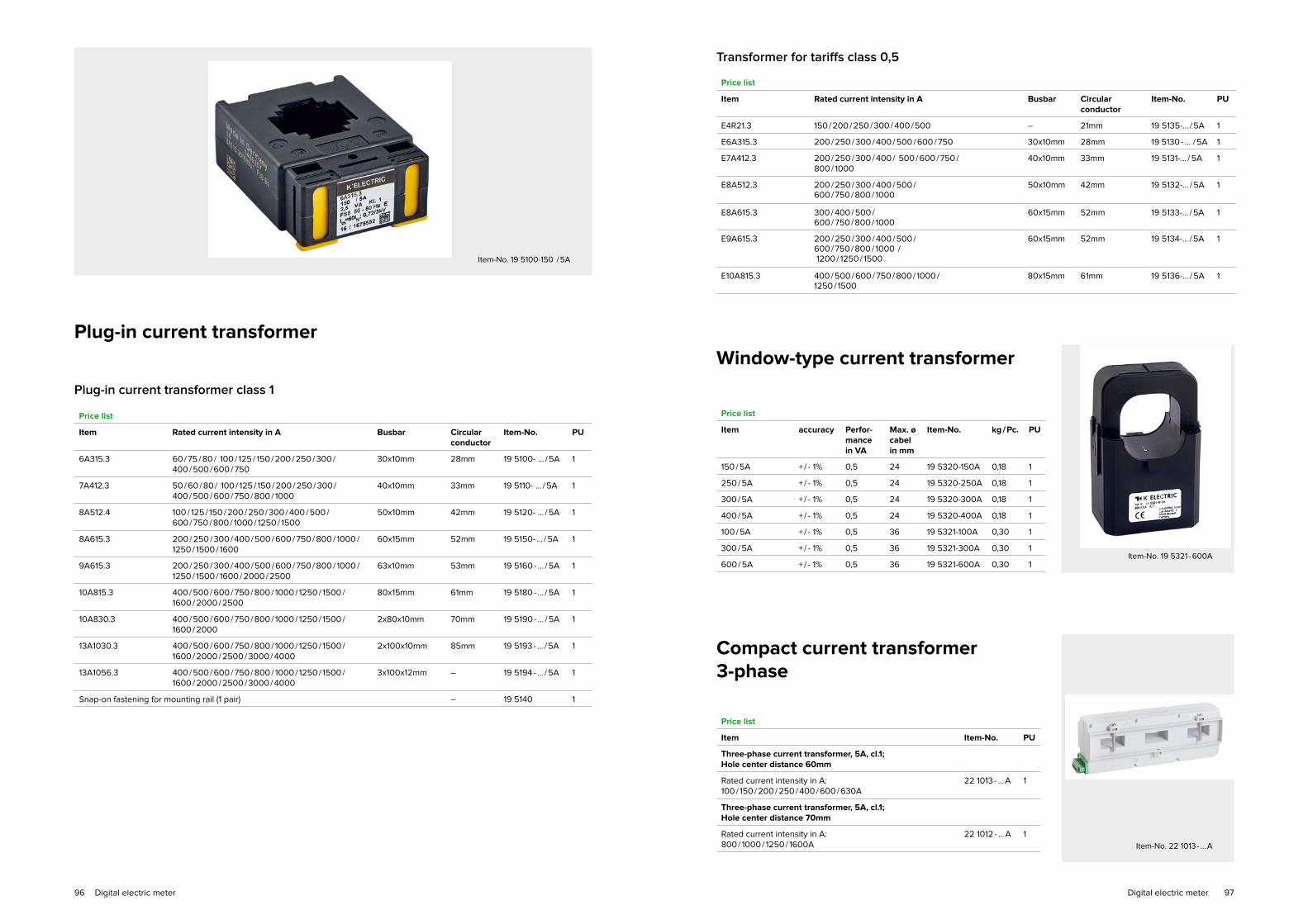
9796
Plug-in current transformer
Window-type current transformer
Compact current transformer3-phase
Item-No. 19 5100-150 / 5A
Item-No. 19 5321 - 600A
Item-No. 22 1013 - … A
Price list
Item Rated current intensity in A Busbar Circular conductor
Item-No. PU
6A315.3 60 / 75 / 80 / 100 / 125 / 150 / 200 / 250 / 300 / 400 / 500 / 600 / 750
30x10mm 28mm 19 5100- ... / 5A 1
7A412.3 50 / 60 / 80 / 100 / 125 / 150 / 200 / 250 / 300 / 400 / 500 / 600 / 750 / 800 / 1000
40x10mm 33mm 19 5110- ... / 5A 1
8A512.4 100 / 125 / 150 / 200 / 250 / 300 / 400 / 500 / 600 / 750 / 800 / 1000 / 1250 / 1500
50x10mm 42mm 19 5120- ... / 5A 1
8A615.3 200 / 250 / 300 / 400 / 500 / 600 / 750 / 800 / 1000 / 1250 / 1500 / 1600
60x15mm 52mm 19 5150- … / 5A 1
9A615.3 200 / 250 / 300 / 400 / 500 / 600 / 750 / 800 / 1000 / 1250 / 1500 / 1600 / 2000 / 2500
63x10mm 53mm 19 5160 - … / 5A 1
10A815.3 400 / 500 / 600 / 750 / 800 / 1000 / 1250 / 1500 / 1600 / 2000 / 2500
80x15mm 61mm 19 5180 - … / 5A 1
10A830.3 400 / 500 / 600 / 750 / 800 / 1000 / 1250 / 1500 / 1600 / 2000
2x80x10mm 70mm 19 5190 - … / 5A 1
13A1030.3 400 / 500 / 600 / 750 / 800 / 1000 / 1250 / 1500 / 1600 / 2000 / 2500 / 3000 / 4000
2x100x10mm 85mm 19 5193 - … / 5A 1
13A1056.3 400 / 500 / 600 / 750 / 800 / 1000 / 1250 / 1500 / 1600 / 2000 / 2500 / 3000 / 4000
3x100x12mm – 19 5194 - … / 5A 1
Snap-on fastening for mounting rail (1 pair) – 19 5140 1
Price list
Item Item-No. PU
Three-phase current transformer, 5A, cl.1; Hole center distance 60mm
Rated current intensity in A:100 / 150 / 200 / 250 / 400 / 600 / 630A
22 1013 - … A 1
Three-phase current transformer, 5A, cl.1; Hole center distance 70mm
Rated current intensity in A: 800 / 1000 / 1250 / 1600A
22 1012 - … A 1
Price list
Item Rated current intensity in A Busbar Circular conductor
Item-No. PU
E4R21.3 150 / 200 / 250 / 300 / 400 / 500 – 21mm 19 5135-… / 5A 1
E6A315.3 200 / 250 / 300 / 400 / 500 / 600 / 750 30x10mm 28mm 19 5130 - … / 5A 1
E7A412.3 200 / 250 / 300 / 400 / 500 / 600 / 750 / 800 / 1000
40x10mm 33mm 19 5131-… / 5A 1
E8A512.3 200 / 250 / 300 / 400 / 500 / 600 / 750 / 800 / 1000
50x10mm 42mm 19 5132-… / 5A 1
E8A615.3 300 / 400 / 500 / 600 / 750 / 800 / 1000
60x15mm 52mm 19 5133-… / 5A 1
E9A615.3 200 / 250 / 300 / 400 / 500 / 600 / 750 / 800 / 1000 / 1200 / 1250 / 1500
60x15mm 52mm 19 5134-… / 5A 1
E10A815.3 400 / 500 / 600 / 750 / 800 / 1000 / 1250 / 1500
80x15mm 61mm 19 5136-… / 5A 1
Plug-in current transformer class 1
Transformer for tariffs class 0,5
Price list
Item accuracy Perfor-mance in VA
Max. ø cabel in mm
Item-No. kg / Pc. PU
150 / 5A + / - 1% 0,5 24 19 5320-150A 0,18 1
250 / 5A + / - 1% 0,5 24 19 5320-250A 0,18 1
300 / 5A + / - 1% 0,5 24 19 5320-300A 0,18 1
400 / 5A + / - 1% 0,5 24 19 5320-400A 0,18 1
100 / 5A + / - 1% 0,5 36 19 5321-100A 0,30 1
300 / 5A + / - 1% 0,5 36 19 5321-300A 0,30 1
600 / 5A + / - 1% 0,5 36 19 5321-600A 0,30 1
Digital electric meter Digital electric meter

9998
Plug’n-Wire-Multifunction meter
Krypton E20 / H20
3 Ø voltage (TRMS)
3 Ø current (TRMS)
3 Ø power factor
3 Ø active power, reactive power, apparent power
Active energy, reactive energy, apparent energy
Frequency
Harmonic distortion factor (E20)
Operating hours counter (E20)
Programmable current / voltage transformer (primary only)
Additional bar chart display of current in % (E20)
with MOD-Bus RTU (RS485) interface
with pulse output (E20)
Three-phase current transformer
for the Plug’n-Wire-System
The three-phase current transformer has been developed
for use with the Plug´n-Wire system.
The integrated protection circuit automatically limits the
output voltage to a safe level. As a result, the current
transformer can also be operated ander load side on the
secondary side.
Item-No. 22 0201
Item-No. 22 0011 - … A
✓
✓
✓
✓
✓
✓
✓
✓
✓
✓
✓
✓
Price list
Item Item-No. PU
Krypton E20 control panel installation with S0 and RS485 (MOD-Bus RTU)
22 0002 1
Krypton H20 DIN-rail with S0 and RS485 (MOD-Bus RTU)
22 0201 1
Price list
Item Rated current intensity in A Item-No. PU
Three-phase current transformer, Hole center distance 35mm 60 / 100 / 125 / 160 / 200 / 250A 22 0010 - … A 1
Three-phase current transformer, Hole center distance 45mm 250 / 400 / 600 / 630A 22 0011 - … A 1
Three-phase current transformer, Hole center distance 60mm 100 / 150 / 200 / 250 / 400 / 600 / 630A
22 0013 - … A 1
Three-phase current transformer, Hole center distance 75mm 800 / 1000 / 1250 / 1600A 22 0012 - … A 1
RJ-connecting cable from measuring instrument to transformer 1,5m 22 0101 1
RJ-connecting cable from measuring instrument to transformer 2,0m 22 0102 1
RJ-connecting cable from measuring instrument to transformer 2,0m – flat plug – 22 0102-F 1
RJ-connecting cable from measuring instrument to transformer 3,0m 22 0103 1
RJ-connecting cable from measuring instrument to transformer 5,0m 22 0105 1
RJ-connecting cable from measuring instrument to transformer 10m 22 0106 1
Save time and money
The unique concept that drastically
reduces the wiring and installation
time of multifunction meters and
current transformers.
Your advantages
• considerable working time savings
• elimination of wiring errors
• increased security
• selection of various three-phase current transformers
• no need of measuring disconnects terminals
• reduced test times
• completely EMV-tested and CE-certified
Item-No. 22 0002
Digital electric meter Digital electric meter

101100
Accessories
Wiring rails
Cover protection for busbar system
Blind cover for distributor shroud
Cover strip for system covers
Cu-plate rails
Document pocket
Cable tidy holder
102
108
109
109
109
110
111

103102
Busbar connectors
TYTAN® I
Busbar system TYTAN® II, CORON® 2,D0-Fuse base E18
Cross section: 16mm2, Modules width: 17,8mm, length: 1.000mm, cutable to size, fork execution
Modules width: 27mm, length 1.000mm, cutable to size, bridge execution
For fixed lengths, no end caps necessary,cross section: 16mm2, Modules width: 17,8mm, not cutable
Price list (fixed price incl. metal surchages)
Item Item-No. End cap PU
1-phase: 90° hooked 11 1061 A11 10
2-phase 11 1062 A3 10
3-phase 11 1063 A3 10
End cap A3 11 1003 10
End cap A11 11 1011 10
Price list (fixed price incl. metal surchages)
Item Item-No. PU
12 x 1-phase, Length 210mm 11 1261 10
6 x 2-phase, Length 212mm 11 1262 10
4 x 3-phase, Length 212mm 11 1263 10
Price list (fixed price incl. metal surchages)
Item Item-No. PU
8 x 1-phase, 16mm2 11 1271 10
4 x 2-phase, 16mm2 11 1272 10
4 x 2-phase, 25mm2 11 1282 10
2 x 3-phase, 16mm2 11 1275 10
2 x 3-phase, 25mm2 11 1285 10
3 x 3-phase, 16mm2 11 1276 10
3 x 3-phase, 25mm2 11 1286 10
4 x 3-phase, 16mm2 11 1277 10
4 x 3-phase, 25mm2 11 1287 10
Price list (fixed price incl. metal surchages)
Item Item-No. No. of pegs Cross section End cap PU
1-phase, 90° hooked 11 1071 37 16mm2 A11 10
2-phase 11 1072 38 16mm2 A1 10
3-phase 11 1073 39 16mm2 A1 10
4-phase 11 1074 40 16mm2 A2 10
1-phase, 90° hooked 10 2021 37 25mm2 A11 10
2-phase 10 2022 38 25mm2 A26 10
3-phase 10 2023 39 25mm2 A26 10
4-phase 10 2024 40 25mm2 A26+A20 10
1-phase, 90° hooked 10 2031 37 35mm2 A20 10
2-phase 10 2032 38 35mm2 A26 10
3-phase 10 2033 39 35mm2 A26 10
4-phase 10 2034 40 35mm2 A26+A20 10
End cap A1 11 1001 10
End cap A2 11 1002 10
End cap A11 11 1011 10
End cap A20 11 1020 10
End cap A26 10 0262 10
For fixed lengths, Modules width: 27mm, not cutable
Double clamp for TYTAN® II, CORON® 2,D0-Fuse base E18
Price list
Item Item-No. Cross section PU
3-phase 10 2013 2x35mm2 4Item-No. 10 2013
Price list (prices plus metal surcharges)
Item Item-No. No. of pegs Cross section End cap PU
3-phase 11 1323 39 16mm2 A1 10
End cap A1 11 1001 10
Modules width: 27mm, length 1.000mm, cutable, fork execution
Accessories Accessories

105104
Busbar connectors
TYTAN® T
Modules width: 17,8mm, length 1.000mm, cutable to size, fork execution
Specifically, length, Modules width: 17,8mm, with end cap, fork execution
Price list (fixed price incl. metal surchages)
Item Item-No. PU
2 x 3-phase; 16mm2 11 1203 10
2 x 4-phase; 16mm2 11 1204 10
3 x 3-phase; 16mm2 11 1213 10
3 x 4-phase; 16mm2 11 1214 10
2 x 3-phase; 30mm2 11 1223 10
2 x 4-phase; 30mm2 11 1224 10
3 x 3-phase; 30mm2 11 1233 10
3 x 4-phase; 30mm2 11 1234 10
Price list (fixed price incl. metal surchages)
Item Item-No. No. of pegs Cross section End cap PU
3-phase 11 1056 42 16mm2 A5 10
4-phase 11 1055 56 16mm2 A2 10
3-phase 11 1053 42 30mm2 A6 10
4-phase 11 1054 56 30mm2 A6 10
End cap A2 11 1002 10
End cap A5 11 1005 10
End cap A6 11 1006 10
Busbar connectors, 3-pole
3-pole fork-wiring rails, Modules width: 17,8mm for circuit breaker
3-pole bridge-wiring rails, Modules width: 17,8mm for circuit breaker
Price list (prices plus metal surcharges)
Item Item-No. No. of pegs Cross section Length End cap PU
Fork 11 1243 12 10mm2 212mm - 10
Fork 11 1244 9 10mm2 159mm - 10
Fork 11 1245 6 10mm2 105mm - 10
Fork 11 1041 57 10mm2 1000mm A5 10
Fork 11 1045 60 10mm2 1060mm A1 10
End cap A1 11 1001 10
End cap A5 11 1005 10
Fork 11 1302 12 16mm2 212mm - 10
Fork 11 1303 60 16mm2 1060mm A1 10
End cap A1 11 1001 10
Price list (prices plus metal surcharges)
Item Item-No. No. of pegs Cross section Length End cap PU
Bridge 11 1248 6 10mm2 105mm - 10
Bridge 11 1247 9 10mm2 159mm - 10
Bridge 11 1246 12 10mm2 212mm - 10
Bridge 11 1042 57 10mm2 1000mm A5 10
End cap A5 11 1005 10
Accessories Accessories

107106
3-pole wiring rails for RCD / LS combination in fork (17,8mm), bridge (17,6mm) for ABB and Siemens / 1 RCD + 8 MCB
Price list (prices plus metal surcharges)
Item Item-No. No. of pegs Cross section Length End cap PU
Bridge 11 1250 11 10mm2 212mm - 10
Bridge (17,8mm) 11 1252 11 10mm2 212mm - 10
Bridge 11 1304 57 10mm2 1020mm A1 10
Bridge 11 1305 11 16mm2 212mm - 10
Bridge 11 1306 57 16mm2 1020mm A1 10
End cap A1 11 1001 10
Fork 11 1251 11 10mm2 212mm - 10
Fork 11 1307 57 10mm2 1020mm A1 10
Fork 11 1308 11 16mm2 212mm - 10
Fork 11 1309 57 16mm2 1020mm A1 10
End cap A1 11 1001 10
3- pole bridge-wiring rails,Modules width: 17,6mm for circuit breakers like ABB, Siemens
Price list (prices plus metal surcharges)
Item Item-No. No. of pegs Cross section Length End cap PU
Bridge 11 1240 12 10mm2 212mm - 10
Bridge 11 1241 9 10mm2 159mm - 10
Bridge 11 1242 6 10mm2 105mm - 10
Bridge 11 1040 57 10mm2 1000mm A5 10
End cap A5 11 1005 10
Bridge 11 1300 12 16mm2 212mm - 10
Bridge 11 1301 57 16mm2 1005mm A1 10
End cap A1 11 1001 10
3- pole wiring rails for RCD / LS combination in fork (17,8mm), bridge (17,6mm) for ABB and Siemens / 1 RCD + 8 MCB,the N-conductor at the RCD is left outside
Price list (prices plus metal surcharges)
Item Item-No. No. of pegs Cross section Length End cap PU
Bridge 11 1310 11 10mm2 195mm - 10
Fork 11 1311 11 10mm2 195mm - 10
4-pole wiring rails L1, L2, L3, N, Modules width: 17,6mm
Price list (prices plus metal surcharges)
Item Item-No. No. of pegs Cross section Length End cap PU
Bridge 11 1312 12 10mm2 212mm - 10
Bridge 11 1313 56 10mm2 1000mm A2 10
Bridge 11 1314 12 16mm2 212mm - 10
Bridge 11 1315 56 16mm2 1000mm A2 10
End cap A2 11 1002 10
4-pole wiring rails L1, L2, L3, N, Modules width: 17,8mm
Price list (prices plus metal surcharges)
Item Item-No. No. of pegs Cross section Length End cap PU
Fork 11 1258 12 10mm2 212mm - 10
Fork 11 1316 56 10mm2 1000mm A2 10
Fork 11 1259 12 16mm2 212mm - 10
Fork 11 1317 56 16mm2 1000mm A2 10
End cap A2 11 1002 10
4-pole wiring rails, RCD / MCB combination L1+N,L2+N,L3+N, Modules width: 17,6mm
Price list (prices plus metal surcharges)
Item Item-No. No. of pegs Cross section Length End cap PU
Bridge 11 1255 12 10mm2 212mm - 10
Bridge 11 1318 54 10mm2 1000mm A2 10
Bridge 11 1256 12 16mm2 212mm - 10
Bridge 11 1330 54 16mm2 1000mm A2 10
End cap A2 11 1002 10
4-pole wiring rails, RCD / MCB combination L1+N,L2+N,L3+N, Modules width: 17,8mm
Price list (prices plus metal surcharges)
Item Item-No. No. of pegs Cross section Length End cap PU
Fork 11 1319 12 10mm2 212mm - 10
Fork 11 1320 54 10mm2 1000mm A2 10
Fork 11 1321 12 16mm2 212mm - 10
Fork 11 1322 54 16mm2 1000mm A2 10
End cap A2 11 1002 10
Accessories Accessories
109108
12 place units, 220mm length
Blind cover fordistributor shroud
Price list
Item Item-No. PU
grey 11 1400 50 / 500
white 11 1401 50 / 500Item-No. 11 1400
Price list
Item Item-No. kg / Pc. PU
Cover strip 195x56mm grey 13 6078 0.04 10
Cover strip 195x56mm white 13 6079 0.04 10
Cover stripfor system covers universally applicable by spring technology, divisble in 9mm steps
Item-No. 13 6078
Cu-plate rails
tinned and roand-edged
Price list
Item Item-No. Cross section Length max. current-carrying capacity PU
12 x 5 15 6040 60mm2 2m 200A 5
15 x 5 15 6041 75mm2 2m 250A 5
20 x 5 15 6042 100mm2 2m 320A 5
30 x 5 15 6044 150mm2 2m 450A 5
20 x 10 15 6047 200mm2 2m 520A 5
30 x 10 15 6049 300mm2 2m 630A 5
The max. current carrying capacity refers to 35°C ambient temperature and a rail temperature of 65°C.
Item-No. 15 6042
Contact protectionfor wiring rails
Price list
Item Item-No. PU
Individually separablefor 5 MW
11 1249 10Item-No. 11 1249
2-pol. Phase rail L1-L2, L1-L2, Modules width 17,6mm, bridge execution
Price list (prices plus metal surcharges)
Item Item-No. No. of pegs Cross section Length End cap PU
2-pol. Bridge 11 1324 12 10mm2 212mm - 10
2-pol. Bridge 11 1325 56 10mm2 1000mm A1 10
2-pol. Bridge 11 1326 12 16mm2 212mm - 10
2-pol. Bridge 11 1327 56 16mm2 1000mm A1 10
End cap A1 11 1001 10
1-pol. Phase rail, 90° hooked, isolated, Modules width 17,6mm, bridge execution
Price list (prices plus metal surcharges)
Item Item-No. No. of pegs Cross section Length End cap PU
1-pol. Bridge 11 1328 57 10mm2 1000mm A11 10
End cap A11 11 1011 10
1- pol. Phase rail, 90° hooked, isolated, Modules width 17,8mm, bridge execution
Price list (prices plus metal surcharges)
Item Item-No. No. of pegs Cross section Length End cap PU
1-pol. Bridge 11 1329 57 10mm2 1015mm A38 10
End cap A38 11 1038 10
Accessories Accessories
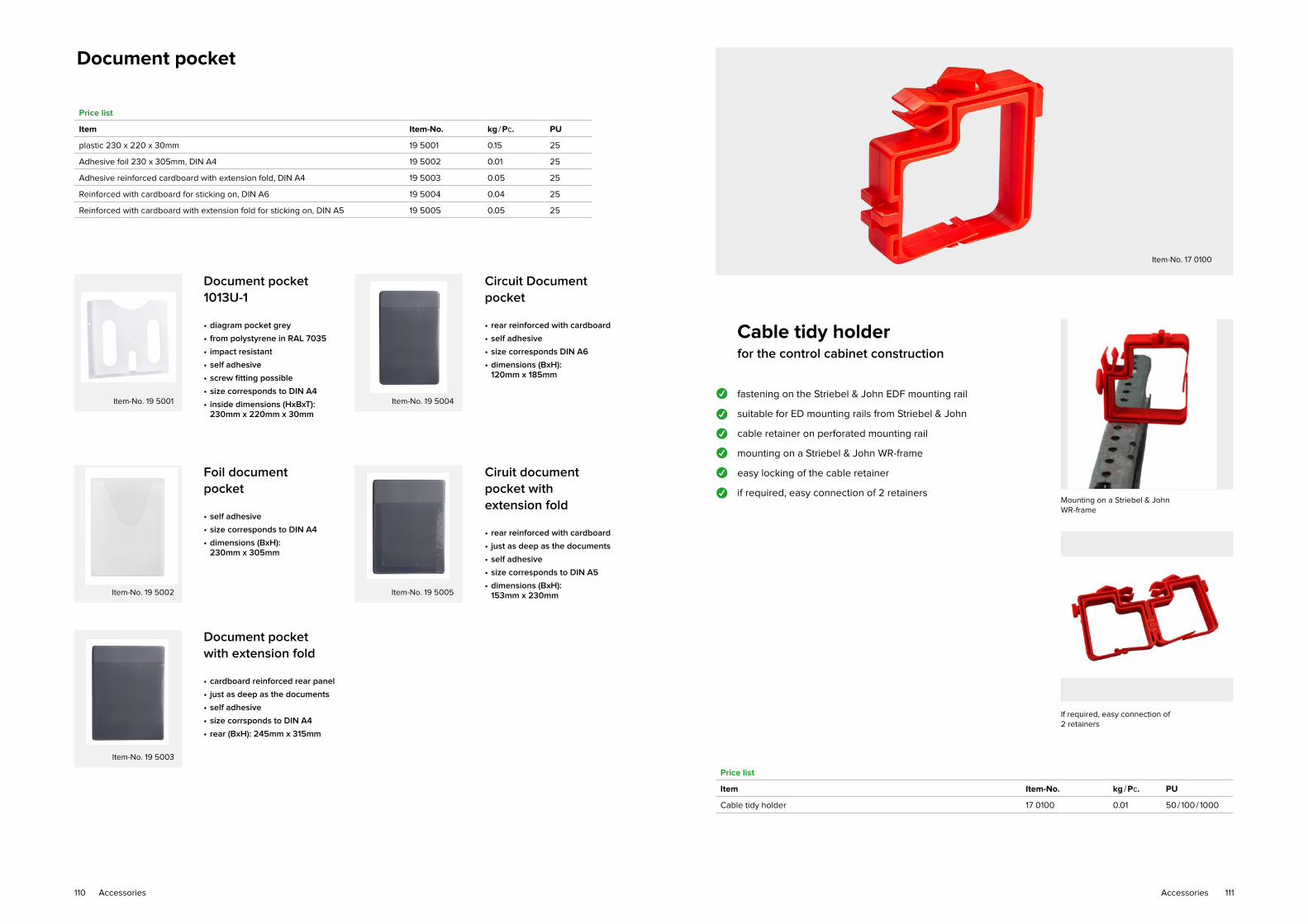
111110
Document pocket 1013U-1
• diagram pocket grey
• from polystyrene in RAL 7035
• impact resistant
• self adhesive
• screw fitting possible
• size corresponds to DIN A4
• inside dimensions (HxBxT): 230mm x 220mm x 30mm
Circuit Documentpocket
• rear reinforced with cardboard
• self adhesive
• size corresponds DIN A6
• dimensions (BxH): 120mm x 185mm
Foil documentpocket
• self adhesive
• size corresponds to DIN A4
• dimensions (BxH): 230mm x 305mm
Ciruit documentpocket withextension fold
• rear reinforced with cardboard
• just as deep as the documents
• self adhesive
• size corresponds to DIN A5
• dimensions (BxH): 153mm x 230mm
Document pocketwith extension fold
• cardboard reinforced rear panel
• just as deep as the documents
• self adhesive
• size corrsponds to DIN A4
• rear (BxH): 245mm x 315mm
Price list
Item Item-No. kg / Pc. PU
plastic 230 x 220 x 30mm 19 5001 0.15 25
Adhesive foil 230 x 305mm, DIN A4 19 5002 0.01 25
Adhesive reinforced cardboard with extension fold, DIN A4 19 5003 0.05 25
Reinforced with cardboard for sticking on, DIN A6 19 5004 0.04 25
Reinforced with cardboard with extension fold for sticking on, DIN A5 19 5005 0.05 25
Document pocket
Mounting on a Striebel & JohnWR-frame
If required, easy connection of2 retainers
Item-No. 17 0100
Cable tidy holderfor the control cabinet construction
fastening on the Striebel & John EDF mounting rail
suitable for ED mounting rails from Striebel & John
cable retainer on perforated mounting rail
mounting on a Striebel & John WR-frame
easy locking of the cable retainer
if required, easy connection of 2 retainers
Price list
Item Item-No. kg / Pc. PU
Cable tidy holder 17 0100 0.01 50 / 100 / 1000
✓
✓
✓
✓
✓
✓
Item-No. 19 5001 Item-No. 19 5004
Item-No. 19 5002 Item-No. 19 5005
Item-No. 19 5003
Accessories Accessories

113Technical data112 Technical data
TE
CH
NIC
AL
DA
TA
Technical data

115Technical data114 Technical data
TYTAN® IID0-Fuse switch disconnector for holding
TYTAN® II-Flashing plugs
TYTAN® II Main Touch protectionD0-Fuse switch disconnector with fuse monitoring for holding
TYTAN® II-Flashing plugs
Technical data
Approvals
DIN VDE 0660 Part 107, EN 60947, IEC 60947-3, DIN VDE 0636 Part 41, IEC 60269-3, DIN VDE 0638, DIN VDE 43880
Electrical data
Rated operational voltage AC 400V, DC 1-pole 110 V, DV 2-pole 220V
Rated operational current 63A
Continuous rated current 63A
Rated short circuit making current Icm
50KAeff
Rated impulse withstand voltage Uimp
6.000V
Utilization category AC 22B, DC 21B
Over voltage category / degree of pollution IV / 3 (DIN VDE 0110)
Max. permissible power loss of fuse-links Pn
5,5W
Dissipation loss per current pass without fuse le
1,1W
Mechanical data
Clamps Stainless steel terminal clamps, MD3Nm
Screw Pozidriv
Cross section 1,5 - 35mm2
Touch protection BGV A3
Temperature range IEC 60947-3 -25°C ... +40°C (Ambient air)≤ +35°C (24h Average)-25°C ... +60°C (Storage)
Fire classification UL94 / V0
Glow wire 960˚C
Plastic free of halogen, phosphor and silicone
Fitting DIN rail
Connection cable to main Touch protection relay
Breaking capacity 5A 250V AC
Switching function CO contacts
Number of CO contacts 1
Technical data
Approvals
IEC / EN 60947-1, IEC / EN 60947-3, IEC / EN 60269-1, IEC / EN 60269-3-1, DIN VDE 0636, DIN 49522
Electrical data
Rated operational voltage AC 60 – 400V, DC 1-pole 60 – 110V, DC 2-pole 60 – 220V
Rated operational current 63A
Continuous rated current 63A
Rated short circuit making current Icm
50KAeff
Rated impulse withstand voltage Uimp
6.000V
Rated insulation voltage Ui 690V
Utilization category AC 22B: 63A, DC 21B: 63A
Over voltage category IV
Comparative tracking index CTI 600
Max. permissible power loss of fuse-links Pn
5,5W
Dissipation loss per current pass without fuse le
1,1 W (L1, L2, L3)
Mechanical data
Clamps Stainless steel lift clamp (antimagnetic)
Screw PZ2 (Pozidriv)
Tightening torque Mn
3Nm
Cross section 1,5 – 35mm2
Degree of Touch protection (behind front panel with inserted safety plugs) IP20C Touch
Touch protection (finger and hand touch safe) BGV A3; ÖVE-EN 6
Temperature range IEC 60947-3 -25°C ... +40°C (Ambient air)≤ +35°C (24h Average)-25°C ... +60°C (Storage)
Fire classification V0 (to UL 94)
Glow wire 960°C (Insulating parts that fix current-carrying parts in position)
Climate resistance IEC 60068-2-78 IEC 60068-2-30
constant (damp heat)cyclical
Degree of pollution 3
Plastic free of halogen, phosphor and silicone
Monitoring electronic
Rated operational voltage range 24...250V AC / DC
Backup fuse 2...16A gL according to the line
Input at 24V, I = 42mA, 1 VAat 250V AC, I=5mA, 1,25 VA
Dimensions
Item-No. W (a) x H x D
10 2651 27 x 85 x 70mm
10 2652 54 x 85 x 70mm
10 2653 81 x 85 x 70mm
10 2641 54 x 85 x 70mm
10 2643 108 x 85 x 70mm
10 2851 54 x 85 x 70mm
10 2852 81 x 85 x 70mm
10 2853 108 x 85 x 70mm
10 2841 81 x 85 x 70mm
10 2843 135 x 85 x 70mm
• Construction width from 27mm per pole
• Fuse plug
• Integrated flashing indicator (OEFI)
• switching all poles
• Codeable for ALL amperages
• Safety plug with finger Touch protection
• lockable by system-compatible plug with key
• lockable
• Double-side supply
• Construction width from 27mm per pole
• 2 CO Changeover contacts for fuse failure
• 1 CO Changeover contacts for switch position
• Integrated flashing indicator (OEFI) switching all poles
• Codeable for ALL amperages
• Safety plug with finger Touch protection
• lockable by system-compatible plug with key lockable
• Double-side supply

117Technical data116 Technical data
Technical data
Relais
Function Terminal 21-22-24 1 CO contact Terminal 31-32-34 1 CO
Rated operational voltage/ current Ue / I
ecosφ=1, 250V / 5A, ACAC - 15, 240V / 0,75A, ACAC - 15, 120V / 1,5A, ACDC-13, 24V / 1A, DC
Dielectric strength Coil-contact circuit, 4 kVeff
Open contact circuit, 1 kVeff
Auxiliary switch
Function Terminal 13-14, 1 NO-contact
Rated operational voltage / current Ue / I
ecosφ=1, 250V / 10A, ACAC – 15, 240V / 1,5A, AC
Dimensions
Item-No. B (a) x H x T
10 2751 54 x 85 x 70mm
10 2752 81 x 85 x 70mm
10 2753 108 x 85 x 70mm
10 2741 81 x 85 x 70mm
10 2743 135 x 85 x 70mm
10 2711 54 x 85 x 70mm
10 2712 81 x 85 x 70mm
10 2713 108 x 85 x 70mm
Shematic picture Dimensions
Contact position
...resting state(no supply voltage)
...active state(with current)LED-UV flashes
...error stateLED fault light up
TYTAN® ID01-Fuse switch disconnector incl. fuse plug with flashing indicator
Technical data
Approvals
DIN VDE 0660 Part 107, IEC / EN 60947-3, DIN VDE 0636 Part 41, IEC 60269-3, IN VDE 0638, DIN VDE 43880
Electrical data
Rated operational voltage AC 400V, DC 1-pole 110V, DC 2-pole 220V
Rated operational current 16 A
Rated short circuit making current Icm
50KAeff
Rated impulse withstand voltage Uimp
6.000V
Utilization category AC 22B
Over voltage category/Degree of pollution IV / 3 (DIN VDE 0110)
Max. permissible power loss of fuse-links Pn
5,5W
Dissipation loss per current pass without fuse Ie
2,0W (L1, L2, L3) N=1W
Mechanical data
Clamps Built clamp, MD 3Nm
Screw Pozidriv
Cross section 1,5 – 25mm2
Touch Touch protection (finger and hand touch safe) IP 20
Temperature range IEC 60947-3 -25°C ... +40°C (Ambient air)≤ +35°C (24h Average)-25°C ... +60°C (Storage)
Fire classification UL94 / V0
Glow wire 960°C
Plastic free of halogen, phosphor and silicone
• Compatible MCB-switch
• Construction width from 18mm per pole
• optical fuse monitoring by flashing indicator
• switching all poles
• Easy fuse replacement by safety plug with finger Touch protection
• adjustable Coding of the fuse by coding spring
• automatic adjustment of the fuse by coding spring
• lockable
• Double-side supply
• no D0-cartidge ring adapter insert needed
• when removing the fuse plug, the foot contact is predicted against contact
Continuation TYTAN® II Main Touch protection
Circuit diagram

119Technical data118 Technical data
IN-OND0-Fuse switch disconnector, 1-pole
Technical data
Approvals
IEC / EN 60947-1, IEC / EN60947-3, IEC / EN 60269-1, IEC / EN 60269-3-1, DIN VDE 0636, DIN 49522
Electrical data
Pole numbers 1P
Rated operational voltage Ue
D0 400 VAC
Rated operational current Le
D0 63 A
Continuous rated current Lu
D0 63 A
Rated conditional short-circuit current 50KAeff
Rated short circuit making current lcm
50KAeff
Rated impulse withstand voltage Uimp
6 kV
Over voltage category IV
Comparative tracking index CTI 600
Utilization category AC 22B
Max. Power loss of Fuse-link Pn
5,5W
Dissipation loss per current pass without fuse at le
1,7 W
Mechanical data
Clamps Lift terminal, antimagnetischer EdelSteel
Screw PZ2 (Pozidriv)
Cross section 1,5-35mm2, AWG 2-16
Tightening torque Mn
3 Nm, max 4 Nm
Degree of Touch protection (behind front panel with inserted safety plugs) IP 20 / IP 40
Touch protection (finger and hand touch safe) BGV A3, ÖVE-EN 6
Temperature range IEC 60947-3 -25°C ... +40°C (Ambient air)≤ +35°C (24h Average)-25°C ... +60°C (Storage)
Fire classification UL94/V0
Glow wire 960 °C
Climate resistance IEC 60068-2-78 IEC 60068-2-30
constant (damp heat)cyclical
Degree of pollution 3
Plastic free of halogen, phosphor and silicone
• Universal-Fuse plug
• lockable and sealable
• Release by push button
Dimensions
Item-No. B (a) x H x T
10 1771 27 x 71 x 87mm
10 1773 27 x 71 x 87mm
Dimensions
Item-No. B (a) x H x T
10 4203 72 x 71 x 84mm
10 4205 72 x 71 x 84mm
10 4213 72 x 71 x 84mm
10 4215 72 x 71 x 84mm
10 4217 72 x 71 x 84mm
10 4283 72 x 71 x 84mm
10 4285 72 x 71 x 84mm
10 4287 72 x 71 x 84mm
TYTAN® TFuse switch disconnector for D0- and Cylindrical fuse-link 10 x 38mm
Technical data
Approvals
IEC / EN 60947-1, IEC / EN 60947-3, IEC / EN 60269-1, IEC / EN 60269-2-1, IEC / EN 60269-3-1, DIN VDE 0636, DIN 49522
Electrical data
Rated operational voltage D0 AC 400V, 10 x 38mm AC 400V
Rated operational current D0 63 A, 10 x 38mm 32 A
Rated short circuit making current Icm
50KAeff
Rated impulse withstand voltage Uimp
6.000V
Utilization category AC 22B
Over voltage category/Degree of pollution IV / 3 (DIN VDE 0110)
Dissipation loss per current pass without fuse at Ie
per Pol 1,8 W
Max. permissible power loss of fuse-links Pn
5,5W
Mechanical data
Clamps Stainless steel Lift terminal (antimagnetic), MD 3Nm
Screw Pozidriv PZ2
Cross section 1,5 – 25mm2
Touch protection BGV A3
Temperature range IEC 60947-3 -25°C ... +40°C (Ambient air)≤ +35°C (24h Average)-25°C ... +60°C (Storage)
Fire classification UL94/V0
Glow wire 960°C
Plastic free of halogen, phosphor and silicone
Climate resistance IEC 60068-2-78 constant (damp heat)
• Width from 72mm / 4 MW
• optical fuse monitoring by flashing indicator
• switching all poles
• Easy fuse replacement by safety plug with finger Touch protection
• lockable
• sealable
• Version with integrated auxiliary switch monitors ON / OFF - position of the switch
e1a4d923-8b41-4204-a20b-6b485fbfa30d Mechanical 7
TYTAN T Standard Version:
MECHANISCH / MECHANICAL PROPERTIES
Montage Werkzeuglos auf Hut-Schiene 35mmMounting Tool less onto Hat rail 35mm
Frontplattenausschnitt [mm] Cut-out for front plate
Für Hut-Schienen nach IEC/EN 60715 [mm]For Hat rail according to IEC/EN 60715
Abmessungen B x H x T 3P 72 x 84 x 76 mmDimensions W x H x D 3P+N 72 x 84 x 76 mm
3P+Hilfsschalter / +Auxiliary switch 72 x 84 x 76 mm
THERMISCHE ÜBERWACHUNG / THERMAL MONITORINGAnschluss Version Fast On 2,8 x 0,5 mmConnection 4203 Fast on
42054207
5/21/2015
DATENBLATT / DATA SHEET
45-60
3P
35
357n x 72
1 45 n
3P+N 3P+Hilfskontakt 3P+Auxiliary switch
3P 3P+N3P+Auxiliary contact

121Technical data120 Technical data
20938a75-c594-499e-9e86-94a1c6117865 Mechanical 7
TYTAN T4(H) Version:
MECHANISCH / MECHANICAL PROPERTIES
Montage Werkzeuglos auf Hut-Schiene 35mmMounting Tool less onto Hat rail 35mm
Frontplattenausschnitt [mm] Cut-out for front plate
Für Hut-Schienen nach IEC/EN 60715 [mm]For Hat rail according to IEC/EN 60715
Abmessungen B x H x T 3P 72 x 84 x 76 mmDimensions W x H x D 3P+N 72 x 84 x 76 mm
3P+Hilfsschalter / +Auxiliary switch 72 x 84 x 76 mm
TYTAN T4HÜBERWACHUNG / MONITORINGAnschluss Buchsenleiste Push-in 0,2...2,5 mm²Connection Female header push-in AWG 26-12
2/12/2015
DATENBLATT / DATA SHEET
45-60
3P
35
357n x 72
1 45 n
3P+N 3P+Hilfskontakt 3P+Auxiliary switch
TYTAN® T4HP / TYTAN® T4HSwitch disconnector for D0- and 10 x 38mm Fuse-link with
3 x Phase indication ( just T4HP), Flashing indicator and
STS-Error relay (Fuse-link blown; Overheat and Voltage failure)
Technical data
Approvals
IEC / EN 60947-1, IEC / EN60947-3 IEC / EN 60269-1, IEC / EN60269-2-1 IEC / EN 60269-3-1, DIN VDE 0636, DIN 49522
Electrical data
Rated operational voltage D0 AC 400V, 10 x 38mm AC 500V
Rated operational current D0 2–63 A, 10 x 38mm 2–25 A
Continuous rated current D0 2–63A, 10 x 38mm 2–25 A
Pole 3 P + N
Rated conditional short-circuit current: 50KAeff
Rated insulation voltage: 400V
Rated impulse withstand voltage Uimp
6.000V
Utilization category AC 22B
Over voltage category / Degree of pollution IV
Comparative tracking index CTI 600
Dissipation loss per current pass without fuse le
per Pol 1,8 W (L1; L2; L3) 1,1W (N)
Max. permissible power loss of fuse-links Pn
5,5 W
Connection Female header push-in 0,2...2,5mm2
Electronics
Supply self-sufficient
Rated operational voltage range 400 +/- 10% VAC
Input 3 x 176 mVA
Relais
Supply self-sufficient
Contact position Error / Operation Quiescent current principle
Function 1 CO contact
Rated operational voltage / current Ue / I
e250V / 5A AC (cosφ=1 85°C) 240V / 0,75A AC (AC-15) 120V / 1,5A DC (AC-15) 24V / 1A DC (DC-13)
Dielectric strength 4kV (Coil-contact circuit) 1kV (Open contact circuit)
• Width 72mm
• Easy fuse replacement by safety plug with finger Touch protection
• switching all poles
• lockable in OFF position
• sealing in both position
• optical Indication
• 3~ / trouble-free operation / green
• Fuse-link blown / red
• Device overheated/ yellow
Technical data
Mechanical data
Clamps Stainless steel Lift terminal (antimagnetic)
Screw Pozidriv PZ2
Tightening torque MD 2,5-3Nm
Cross section 1,5 – 25mm2
Degree of Touch protection (behind front panel with inserted safety plugs) IP20
Touch protection (finger and hand touch safe) BGV A3
Temperature range -25 / +40°C + 35°C (24h Average) -25 / +60°C (Storage)
Fire classification UL94 / V0
Glow wire (Insulating parts that fix current-carrying parts in position) 960 °C
Climate resistance IEC 60068-2-78 IEC 60068-2-30
constant (damp heat)cyclical
Degree of pollution 3
Plastic free of halogen, phosphor and silicone
Dimensions
Circuit diagram
TYTAN T4H TYTAN T4HP
3P
3P 3P+N3P+Auxiliary contact
3P+N3P+Auxiliary contact
TYTAN T4H

123Technical data122 Technical data
TYTAN® TH1Fuse switch disconnector for D0- and 10 x 38mm Fuse-link inclu-
ding signal relay for Fuse-link and Temperature monitoring
TYTAN® HR11 / HR12 / HR13Main Touch protection relay for individual monitoring and collected
fault monitoring of TYTAN® RH1 and TYTAN® TH1
Technical data
Approvals
IEC / EN 60947-1, IEC / EN 60947-3 IEC / EN 60269-1, IEC / EN 60269-2-1 IEC / EN 60269-3-1, DIN VDE 0636, DIN 49522
Electrical data
Rated operational voltage D0 AC 400V, 10 x 38mm AC 500V
Rated operational current D0 2–63 A, 10 x 38mm 2–25 A
Rated short circuit making current Icm
50KAeff
Rated impulse withstand voltage Uimp
6.000V
Utilization category AC 22B
Over voltage category / Degree of pollution IV
Comparative tracking index CTI 600
Dissipation loss per current pass without fuse le
per Pol 1,8 W (L1, L2, L3), N=1,0W, Electronics=1,0W
Max. permissible power loss of fuse-links Pn
5,5W
Mechanical data
Clamps Stainless steel Lift terminal (antimagnetic), MD 3Nm
Screw Pozidriv PZ2
Cross section 1,5 – 25mm2
Touch protection BGV A3
Temperature range -25˚C / +40˚C +35°C (24h Average) -25°C / +60°C (Storage)
Fire classification UL94 / V0
Glow wire 960˚C
Climate resistance IEC 60068-2-78 IEC 60068-2-30
constant (damp heat)cyclical
Degree of pollution 3
Plastic free of halogen-, silicone-, and phosphor
Connection cable to main Touch protection relay RJ10
Technical data
Approvals
DIN EN 61000 (EMV), IEC / EN 61000-4-2, IEC / EN 61000-4-4 EN 60255
Electrical data
Rated operational voltage DC 24V
Input 1,15W
Comparative tracking index 600 (CTI)
Vibration resistance (Function) 15 / 5G m/s2 (NO/NC contact)
Shock resistance (Destruction)
Relay contacts 3 Contacts
Rated operational voltage / current Ue / I
e250V / 5A (cosφ=1) 30V / 5A 300V / 0.25A
Minimum rated operational voltage / current Ue / I
e100mV / 10mA AC / DC
Dielectric strength 4 KVeff
(Coil-contact circuit) 1 KV
eff (Open contact circuit)
Rated impulse withstand voltage Uimp
4 KV
Over voltage category III
Mechanical data
Clamps Lift terminal
Tightening torque MN 0,5 Nm
Screw Pozidriv PZ1
Cross section 1 x 2,5mm2 (flexible) 1 x 4mm2 (solid) 2 x 1,5mm2 (solid)
Touch protection BGV A3
Temperature range -25˚C / +40˚C +35°C (24h Average) -25°C / +60°C (Storage)
Fire classification UL94/V0
Glow wire 960°C
Degree of pollution 3
Plastic free of halogen-, silicone-, and phosphor
Connection cable to main Touch protection relay RJ10
• up to 12 devices connected to a signal relay
• Width TYTAN® T = 72mm
• Width Including signal relay 17,8mm / 1MW
• Easy fuse replacement by safety plug with finger Touch protection
• switching all poles
• lockable
• sealing
• optical LED-Indication:
• Main Touch protection in operation/ green LED
• Thermal overloaded/ yellow LED
• Fuse-link blown / red LED
• Width from 17,8mm / 1 MW
efc5854d-b729-41b7-b52a-00234fcf53fe Mechanical 7
TYTAN TH1 Version:
MECHANISCH / MECHANICAL PROPERTIES
Montage Werkzeuglos auf Hut-Schiene 35mmMounting Tool less onto Hat rail 35mm
Frontplattenausschnitt [mm]Cut-out for front plate
Für Hut-Schienen nach IEC/EN 60715 [mm]For Hat rail according to IEC/EN 60715
Abmessungen B x H x T 3P 72 x 84 x 82 mmDimensions W x H x D 3P+N 73 x 84 x 82 mm
5/20/2014
DATENBLATT / DATA SHEET
45-60
3P 3P+N
35
3515n x 72
1 45 n
Dimensions
3P 3P+N
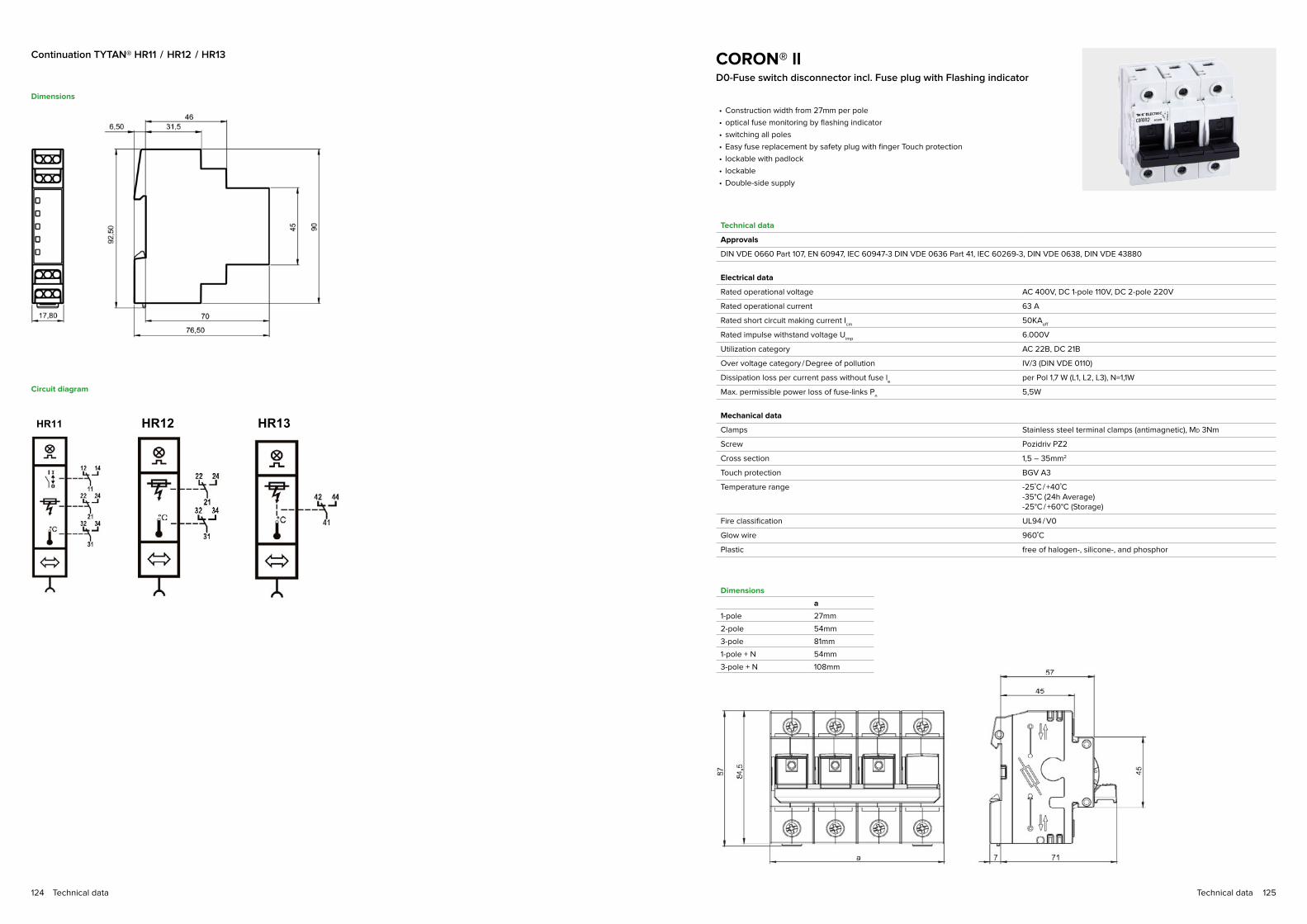
125Technical data124 Technical data
e53e3099-ac18-4548-a94a-aafa2fbeab9e Mechanical 9
TYTAN HR11, TYTAN HR12, TYTAN HR13 Version:
MECHANISCH / MECHANICAL PROPERTIES
Montage Werkzeuglos auf Hut-Schiene 35mmMounting Tool less onto Hat rail 35mm
Frontplattenausschnitt [mm]Cut-out for front plate
Für Hut-Schienen nach IEC/EN 60715 [mm]For Hat rail according to IEC/EN 60715
Abmessungen B x H x T 17,8 x 92,5 x 81,8 mmDimensions W x H x D
10/28/2014
DATENBLATT / DATA SHEET
48-67
35
35
n x 17,8
45 n
e53e3099-ac18-4548-a94a-aafa2fbeab9e Electrical 7
TYTAN HR11, TYTAN HR12, TYTAN HR13 Version:
SCHALTBILDER / CIRCUIT DIAGRAM
10/28/2014
DATENBLATT / DATA SHEET
HR11 HR12 HR13
e53e3099-ac18-4548-a94a-aafa2fbeab9e Electrical 7
TYTAN HR11, TYTAN HR12, TYTAN HR13 Version:
SCHALTBILDER / CIRCUIT DIAGRAM
10/28/2014
DATENBLATT / DATA SHEET
HR11 HR12 HR13
e53e3099-ac18-4548-a94a-aafa2fbeab9e Electrical 7
TYTAN HR11, TYTAN HR12, TYTAN HR13 Version:
SCHALTBILDER / CIRCUIT DIAGRAM
10/28/2014
DATENBLATT / DATA SHEET
HR11 HR12 HR13
Dimensions
Circuit diagram
CORON® llD0-Fuse switch disconnector incl. Fuse plug with Flashing indicator
Technical data
Approvals
DIN VDE 0660 Part 107, EN 60947, IEC 60947-3 DIN VDE 0636 Part 41, IEC 60269-3, DIN VDE 0638, DIN VDE 43880
Electrical data
Rated operational voltage AC 400V, DC 1-pole 110V, DC 2-pole 220V
Rated operational current 63 A
Rated short circuit making current Icm
50KAeff
Rated impulse withstand voltage Uimp
6.000V
Utilization category AC 22B, DC 21B
Over voltage category / Degree of pollution IV/3 (DIN VDE 0110)
Dissipation loss per current pass without fuse le
per Pol 1,7 W (L1, L2, L3), N=1,1W
Max. permissible power loss of fuse-links Pn
5,5W
Mechanical data
Clamps Stainless steel terminal clamps (antimagnetic), MD 3Nm
Screw Pozidriv PZ2
Cross section 1,5 – 35mm2
Touch protection BGV A3
Temperature range -25˚C / +40˚C -35°C (24h Average) -25°C / +60°C (Storage)
Fire classification UL94 / V0
Glow wire 960˚C
Plastic free of halogen-, silicone-, and phosphor
• Construction width from 27mm per pole
• optical fuse monitoring by flashing indicator
• switching all poles
• Easy fuse replacement by safety plug with finger Touch protection
• lockable with padlock
• lockable
• Double-side supply
3732124f-9b67-4b3a-b713-c5aec59f6250 Mechanical 6
CORON 2 Version:
MECHANISCH / MECHANICAL PROPERTIES
Montage Werkzeuglos auf Hut-Schiene 35mmMounting Tool less onto Hat rail 35mm
Frontplattenausschnitt [mm] Cut-out for front plate
Für Hut-Schienen nach IEC/EN 60715 [mm]For Hat rail according to IEC/EN 60715
Abmessungen B x H x T Type B / W H / H T / D [ ]Dimensions W x H x D 1P 27 87 78 mm
2P 54 87 78 mm3P 81 87 78 mm4P 108 87 78 mm1P+N 54 87 78 mm3P+N 108 87 78 mm
a
5/20/2015
DATENBLATT / DATA SHEET
45-60
35
357n x 27x poles
1 45 n
Dimensions
a
1-pole 27mm
2-pole 54mm
3-pole 81mm
1-pole + N 54mm
3-pole + N 108mm
3732124f-9b67-4b3a-b713-c5aec59f6250 Mechanical 6
CORON 2 Version:
MECHANISCH / MECHANICAL PROPERTIES
Montage Werkzeuglos auf Hut-Schiene 35mmMounting Tool less onto Hat rail 35mm
Frontplattenausschnitt [mm] Cut-out for front plate
Für Hut-Schienen nach IEC/EN 60715 [mm]For Hat rail according to IEC/EN 60715
Abmessungen B x H x T Type B / W H / H T / D [ ]Dimensions W x H x D 1P 27 87 78 mm
2P 54 87 78 mm3P 81 87 78 mm4P 108 87 78 mm1P+N 54 87 78 mm3P+N 108 87 78 mm
a
5/20/2015
DATENBLATT / DATA SHEET
45-60
35
357n x 27x poles
1 45 n
Continuation TYTAN® HR11 / HR12 / HR13

127Technical data126 Technical data
D0-Fuse base E18
Technical data
Approvals
IEC / EN 60269-1, IEC / EN 60269-3-1, DIN VDE 0636-301, DIN VDE 49522
Electrical data
Rated operational voltage AC 400V, DC 250V
Rated operational current 63 A
Rated short circuit making current Icm
50KAeff
Rated impulse withstand voltage Uimp
6000V
Over voltage category / Degree of pollution IV
Dissipation loss per current pass without fuse at Ie
per Pol 3 W
Max. permissible power loss of fuse-links Pn
5,5 W
Mechanical data
Clamps Lift terminal Stainless steel (antimagnetic), MD 3,5Nm
Screw Pozidriv PZ2
Cross section 1,5 mm – 35 mm2
Touch protection BGV A3
Temperature range -25˚C / +40˚C -35°C (24h Average) -25°C / +60°C (Storage)
Fire classification UL94/V0
Glow wire 960°C
Plastic free of halogen-, silicone-, and phosphor
• Construction width from 27mm per pole
• one-piece fuse base
• touch protected version
• easy inscription possible
• Mounting on the DIN rail
• Mounting on plate possible
• low loss stainless steel clamps
• lockable
Dimensions
Fuse switch disconnector forcylindrical Fuses10 x 38mm, 14 x 51mm, 22 x 58mm
• Big clamping area
• Finger-safe
• Mounting on the DIN rail
• High temperature resistance
Technical data
Electrical data
Size mm 13x38 DC 10x38 14x51 22x58
Rated operational current Ith (A)
Rated operational current gG 400V 32 32 50 125*
Rated operational current gG 500V 25 25 50 100
Rated operational current gG 690V 10 10 25 50
Rated operational current aM 400V – – 50 125*
Rated operational current aM 500V 16 16 40 100
Rated operational current aM 690V – – 25 50
Power loss W
Power loss gG fuse 3 3 5 9,5
Power loss aM fuse 1,2 1,2 3 7
Rated impulse withstand voltage Uimp
kV 6 6 8 8
Rated operational voltage Ue V~ 1000 Vdc 690 690 690
Utilization category DC-20 AC-22B AC-22B AC-21B
Mechanical data
Cross section mm2 min. 1x1,5
max. 1x252x10
min. 1x1,5
max. 1x252x10
min. 1x1,5
max. 1x352x16
min. 1x4
max. 1x502x25
Tightening torque Nm
2 – 2,5 2 – 2,5 2,5 – 3 2,5 – 3
Screw PZ2 0 5,5 – 6,5 5,5 – 6,5 5,5 – 6,5 5,5 – 6,5
Glow wire 960°C 960°C 960°C 960°C
*125A temporary load (100A Continuous load)
Dimensions 10x38mm

129Technical data128 Technical data
Mains supply/hook type terminalsConnection clamps and Touch protection covers with warning
triangle including conductor and busbar Touch protection cover
Technical data
General data
Fire classification UL94 / V0
Glow wire 960 °C
Plastic free of halogen, phosphor and silicone
• For supply of the 60mm busbar system
• for 5 and 10mm thick busbars
• Width of the busbar 12 – 30mm
• Cover hood marked with danger symbol (clearly visible feed-in field)
• easily removable cover
• Cables can be easily and quickly laid in the rail Touch protection plate
Dimensions
Continuation Fuse switch disconnector
for cylindrical Fuses
Dimensions 14x51mm
Dimensions 22x51mm

131Technical data130 Technical data
Connection terminals 16 – 185mm2
for Flat busbars 5mm / 10mm
Technical data
Approvals
DIN EN 60999-1:2000 (VDE 0609-1), DIN EN 60999-2:2003 (VDE 0609-101)
Electrical data
Max. Rated operational voltage 1000V AC / DC
Type of connection Sector wiresingle wiremulti wirefine wire (with Sleeve*)*Fine wire conductors can also be used without sleeve. Please refer to the national standards.
Terminal body Steel
Pressure body Steel zn-platet
Screw Steel
Spring Spring steel
Screw heads
116051 / 116061 Z2
116052 / 116062 Z3 / SW 13
116053 / 116063 Z3 / SW 13
116054 / 116064 Z3 / SW 13
116055 / 116065 Z4 / SW 17
116056 / 116066 Z4 / SW 17
In principle, the tightening torques specified. Where no limits are specified,
the tolerance on the tightening torque of screw and clamp connections may
be a maximum of +/- 10% of the nominal value.
Dimensions
Item-No. 11 6051 11 6052 11 6053 11 6054 11 6055 11 6056
A 11,5 16 16 20,5 23,2 28,5
B 27,1 31,5 35 39 46 52
C 42,5 54 57,5 61 76 85
D 25,5 26,5 26,5 28 29 29
Item-No. 11 6061 11 6062 11 6063 11 6064 11 6065 11 6066
A 11,5 16 16 20,5 23,2 28,5
B 28,5 36,5 40 46 51 56
C 44 58 62,5 68 81 89
D 25,5 26,5 26,5 28 29 29
Size in mm
Dimensions
Item-No. 11 6051 11 6061 11 6052 11 6062 11 6054 11 6064 11 6055 11 6065
Laminated x Width x ThicknessPieceCable cross-sectionTorque Secureness-Test Weight Passed Pull-Out-Test Force Passed
8 x 6 x 0,5 1 Piece 24mm2 3Nm 4,5kg YES 135N YES
8 x 6 x 0,5 1 Piece 24mm2 3Nm 4,5kg YES
135NYES
3 x 9 x 0,8 1 Piece 21,6mm2 10Nm 4,5kg YES 135N YES
3 x 9 x 0,8 1 Piece 21,6mm2 10Nm 4,5kg YES 135N YES
3 x 9 x 0,8 2 Piece 43,2mm2 10Nm
9,5kgYES
236NYES
3 x 9 x 0,8 2 Piece 43,2mm2 10Nm
9,5kgYES
351NYES
10 x 15,5 x 0,8 1 Piece 24mm2 3Nm
14kgYES
427NYES
3 x 9 x 0,8 2 Piece 124mm2 22Nm
14kgYES
427NYES
Laminated x Width x ThicknessPieceCable cross-sectionTorque Max. Secureness-Test Weight Passed Pull-Out-Test Force Passed
6 x 9 x 0,8 1 Piece 43,2mm2 10Nm 9,5kg YES 236N YES
6 x 9 x 0,8 1 Piece 43,2mm2 10Nm 9,5kg YES 236N YES
6 x 9 x 0,8 2 Piece 86,4mm2 10Nm
14kgYES
351NYES
6 x 9 x 0,8 2 Piece 86,4mm2 10Nm
14kgYES
351NYES
Laminated x Width x ThicknessPieceCable cross-sectionTorque Max. Secureness-Test Weight Passed Pull-Out-Test Force Passed
6 x 13 x 0,5 1 Piece 39mm2 10Nm
9,5kgYES
236NYES
6 x 13 x 0,5 1 Piece 39mm2 10Nm
9,5kgYES
236NYES

133Technical data132 Technical data
Connection terminalswith Separating sheet 35 – 185mm2
for Flat busbars 5mm / 10mm
• These terminals are suitable for connecting aluminum and copper wires
• When connecting from aluminum winches, the practice-oriented processing
guidelines must be observed
• The contact surfaces of the Alu-wire are to be cleaned, brushed and treated
with suitable grease
• The contact clamps must be tightened regularly
• In principle, the tightening torques specified.
• The deviation of the tightening torque from screw and clamp connections
may in this case be no more than +/- 10% of the nominal value
Technical data
Approvals
DIN EN 60999-1:2000 (VDE 0609-1), DIN EN 60999-2:2003 (VDE 0609-101), DIN EN 61439-1:2012
Electrical data
Max. Rated operational voltage 1000V AC / DC
Terminal body Steel zn-platet
Pressure body Steel nickel plated
Screw Steel zn-platet
Spring Spring steel
Separating sheet Spring bronze plated
Screw heads
116091 / 116095 Z3
116092 / 116096 Z3 / SW 13
116093 / 116097 Z4 / SW 17
116094 / 116098 Z4 / SW 17
Busbar supportBusbar support for the 60mm system
Technical data
Approvals
IEC / EN 60269-1, IEC / EN 60269-3-1, DIN VDE 0636-301, DIN VDE 49522
Electrical data
Rated operational voltage Ue
690V
Comparative tracking index 600 (CTI)
Fire classification UL94-V0
Temperature resistance 130°C
Glow wire 960°C
For Busbars 12, 15, 20, 25 and 30mm
Screw Screw 25mm
Plastic Halogen, phosphor, silicone, CFC-free, recyclable
• base / lower part reversible
• With just a few parts a comprehensive safety program can be realized
• for 12 – 30mm widths and 5 or 10mm thick copper
• also fits Striebel & John-cabinets
• built over
Short circuit diagram
Short circuit diagram after IEC 60439-1: 1999-09; DIN EN 60439 Part 1 (VDE 0660Part 500): 2000-08
Rated operational voltage Ue
690V
Rated frequency 50Hz

135Technical data134 Technical data
Dimensions
Assembly variant
D0-Bus mounting fuse base E18
Technical data
Approvals
IEC / EN 60269-1, IEC / EN 60269-3-1, DIN VDE 0636-3, DIN 49522
Electrical data
Rated operational voltage AC 400V 50 Hz, DC 250V
Rated operational current 63 A
Rated short circuit making current Icm
AC: 50KAeff
DC: 8 KV
Rated impulse withstand voltage Uimp
6000V
Over voltage category / Degree of pollution IV
Dissipation loss per current pass without fuse at Ie
per Pol 1,5 W
Max. permissible power loss of fuse-links Pn
5,5 W
Comparative tracking index CTI 600
Mechanical data
Clamps Stainless steel Lift terminal (antimagnetic), MD 3,5Nm
Screw Pozidriv PZ2
Cross section 1,5 – 25 mm2
Touch protection BGV A3
Temperature range -25°C / +40°C +35°C (24h Average) -25°C / +60°C (Storage)
Fire classification UL94 / V0
Glow wire 960°C
Plastic free of halogen-, silicone-, and phosphor
Climate resistance IEC 60068-2-78 IEC 60068-2-30
constant (damp heat)cyclical
Degree of pollution 3
• Width from 27mm
• Distinctive labeling on the base
• low-loss stainless steel terminal clamps
• contact Touch protection shroud on the sides
• clip on rear touch protection shroud
• for 12 – 30mm widths and 5 or 10mm thick copper
Dimensions
10 6022 10 6011 10 6012 10 6013 10 6017 10 6018 10 6016 (pair)
Continuation busbar support

137Technical data136 Technical data
CORON® RD0-Fuse switch disconnector
with fuse plug with Flashing indicator
Technical data
Approvals
IEC / EN 60947-1, IEC / EN 60947-3, IEC / EN 60269-1, IEC / EN 60269-2-1, IEC / EN 60269-3-1, DIN VDE 0636, DIN 49522
Electrical data
Rated operational voltage AC 400V 50 Hz
Rated operational current 63 A
Rated short circuit making current Icm
50KAeff
Rated impulse withstand voltage Uimp
6000V
Utilization category AC 22B
Over voltage category/Degree of pollution IV
Dissipation loss per current pass without fuse at Ie
per Pol 1,5 W
Max. permissible power loss of fuse-links Pn
5,5 W
Comparative tracking index CTI 600
Mechanical data
Clamps Stainless steel Lift terminal (antimagnetic), MD 3Nm
Screw Pozidriv PZ2
Cross section 1,5 – 25mm2
Touch protection BGV A3
Temperature range -25 / +40°C + 35°C (24h Average) -25 / +60°C (Storage)
Fire classification UL94/V0
Glow wire 960°C
Plastic free of halogen-, silicone-, and phosphor
Climate resistance IEC 60068-2-78 IEC 60068-2-30
constant (damp heat)cyclical
Degree of pollution 3
• Width from 27mm
• optical fuse monitoring by flashing indicator
• switching all poles
• Easy fuse replacement by safety plug with finger Touch protection
• lockable
• sealing
• compact and low form
• optional widening
• Mechanical indication contact position indication red / green
• for 12 – 30mm widths and 5 or 10mm thick cu-bars
Dimensions
Circuit diagram3P
3P
3-pole

139Technical data138 Technical data
TYTAN® RFuse switch disconnector for D0- and
10 x 38mm Fuse-link System 60
Technical data
Approvals
IEC / EN 60947-1, IEC / EN 60947-3, IEC / EN 60269-1, IEC / EN 60269-2-1, IEC / EN 60269-3-1, DIN VDE 0636, DIN 49522
Electrical data
Rated operational voltage D0: AC 400V, 10x38mm: AC 400V
Rated operational current D0: 63 A, 10x38mm: 32 A
Rated short circuit making current Icm
50KAeff
Rated impulse withstand voltage: Uimp
6000V
Utilization category AC 23B
Over voltage category / Degree of pollution IV
Comparative tracking index CTI 600
Dissipation loss per current pass without fuse at Ie
per Pol 1,5 W (L1, L2, L3) N=1,1 W
Max. permissible power loss of fuse-links Pn
5,5 W
Mechanical data
Clamps Stainless steel Lift terminal (antimagnetic) MD 3Nm
Screw Pozidriv PZ2
Cross section 1,5 – 35mm2
Touch protection BGV A3
Temperature range -25 / +40°C + 35°C (24h Average) -25 / +60°C (Storage)
Fire classification UL94/V0
Glow wire 960°C
Climate resistance IEC 60068-2-78 IEC 60068-2-30
constant (damp heat)cyclical
Degree of pollution 3
Plastic free of halogen-, silicone-, and phosphor
Auxiliary switch
Rated operational voltage / current Ue / I
ecosφ=1, 250V / 5A, AC
Connection Fast On, 2,8 x 0,5 mm
• Width from 27mm
• optical fuse monitoring by flashing indicator
• Easy fuse replacement by safety plug with finger Touch protection
• Mechanical indication contact position indication red / green
• Version with integrated auxiliary switch monitors ON / OFF - position of the switch
• For 12 – 30mm widths and 5 or 10mm thick cu-bars
• switching all poles
• lockable
• sealing
99c69379-57f7-43d1-8a94-4e00b0b324f5 Mechanical 7
TYTAN R Version:
MECHANISCH / MECHANICAL PROPERTIES
Montage Werkzeuglos auf 60mm SammelschienensystemMounting Tool less onto Bus bar system 60mm
Frontplattenausschnitt [mm]Cut-out for front plate
Für Cu-Schienen [mm]For Cu-bars
Abmessungen B x H x T 3P 27 x 226 x 102 mmDimensions W x H x D 3P+N 27 x 262 x 102 mm
5/20/2015
DATENBLATT / DATA SHEET
6060
3025201512 5 10x n x 27
1 n 195
34-50
3P 3P+NDimensions
Circuit diagram
3-pole 3-pole with N
with auxiliary switch
without auxiliary switch

141Technical data140 Technical data
Technical data
Measurement:
Rated current In AC AC 63A
Measuring range AC 0 – 75A
Max. Continuous load current IB
50A
Rated frequency fn
50Hz
Operating frequency 47 – 65Hz
Power-consumption < 2,1mVA
Measuring method AC True RMS
Measurement accuracy ±1% ±1 digit at In and reference temperature
Resolution 100mA (0.0...9.9A), 1A (10...99A)
Measured rate 1 Measurement / 1,4s
Reference temperature
Temperature range -25 / +40°C + 35°C (24h Average) -25 / +60°C (Storage)
Curve shape Symmetrical
General data
Rated voltage 400V
Plastic free of halogen-, silicone-, and phosphor
Fire classification UL94 / V0
Glow wire 960°C
Comparative tracking index CTI600
TYTAN® R Fuse plug with Current measurementFor attaching the TYTAN® R fuse switch disconnector and
measurement of the total current in the phases with measured
value memory for monitoring the current values.
• Can be retrofitted on all standard devices for D0-Fuse-link 2 ... 63A• Control over consumption growth
• retrievable values by pressing the button:
• IST: current instantaneous value
• MAX: Maximum current value
• MIN: Minimum current value
• AVG: Average current (measured over 24h)
shine-shaped truncated sinus square wave
TYTAN® RH4 Fuse switch disconnector for D0- and 10 x 38mm Fuse-link with
integrated auxiliary switch for fuse- and temperature monitoring
Technical data
Approvals
IEC / EN 60947-1, IEC / EN 60947-3, IEC / EN 60269-1, IEC / EN 60269-2-1, IEC / EN 60269-3-1, DIN VDE 0636, DIN 49522
Electrical data
Rated operational voltage Ue
D0: AC 400V, 10x38mm: AC 500V
Rated operational current Ie
D0: 2-63A, 10x38mm: 2-32 A
Continuous rated current IU
D0: 2-63A, 10x38mm: 2-32 A
Rated conditional short-circuit current 50KAeff
Rated insulation voltage Ui
500V
Rated impulse withstand voltage Uimp
6 kV
Over voltage category / Degree of pollution IV
Comparative tracking index CTI 600
Dissipation loss per current pass without fuse at Ie
per Pol 1,5 W (L1, L2, L3) N=1,1W
Max. permissible power loss of fuse-links Pn
5,5 W
Utilization category AC23B
Function 1 CO contact
Rated operational voltage / current Ue U
i250V / 5A AC (cos phi = 1 85°C) 240V / 0,75A AC (AC-15)120V / 1,5A AC (AC-15)24V / 1A DC (DC-13)
Dielectric strength 4 kVeff
(Coil-contact circuit) 1 kV
eff (Open contact circuit)
Mechanical data
Weight 432g (3P) 482g (3P+N)
Clamps Stainless steel Lift terminal (antimagnetic)
Screw Pozidriv PZ2
Cross section 1,5 – 35mm2
Tightening torque Mn
3Nm 2,5 – 3Nm (Area)
Degree of protection (behind front plate with inserted fuse-plugs) IP 20
Touch protection BGV A3, ÖVE-EN 6
Temperature range IEC 60947-3 -25°C / +40°C (Ambient air) < +35°C (24h Average) -25 to +60°C (Storage)
Fire classification to UL 94 VO
Glow wire 960* °C (*Parts of insulating material necessary to retain current-carrying parts in position)
Climate resistance IEC 60068-2-78: constant (damp heat) IEC 60068-2-30: cyclical
Degree of pollution 3
Plastic free of halogen, phosphor and silicone
• Width from 36mm
• Easy fuse replacement by safety plug with finger Touch protection
• Mechanical indication contact position indication red / green
• For 12 – 30mm widths and 5 or 10mm thick copper
• switching all poles
• lockable
• sealing
• optical Indication:
• Trouble-free operation / green LED
• Fuse-link overheated/ yellow LED
• Fuse-link blown / red LED

143Technical data142 Technical data
20938a75-c594-499e-9e86-94a1c6117865 Electrical 5
TYTAN T4(H) Version:
SCHALTBILDER / CIRCUIT DIAGRAM
TYTAN T4
TYTAN T4HP TYTAN T4H
SYMBOL / SYMBOLIEC 60947-3
2/12/2015
DATENBLATT / DATA SHEET
3P+N
3P+N 3P+Auxiliary switch3P
3P+N
Dimensions
Circuit diagram
R4H 3P
R4H 3P+N
TYTAN® RH1Fuse switch disconnector for D0- and 10 x 38mm Fuse-link with
auxiliary switch for fuse- and temperature monitoring
Technical data
Approvals
IEC / EN 60947-1, IEC / EN 60947-3 IEC / EN 60269-1, IEC / EN 60269-2-1 IEC / EN 60269-3-1, DIN VDE 0636, DIN 49522
Electrical data
Rated operational voltage D0: AC 400V, 10x38mm: AC 500V
Rated operational current D0: 2-63A, 10x38mm: 2-32 A
Rated short circuit making current Icm
50KAeff
Rated impulse withstand voltage Uimp
6000V
Utilization category AC 22B
Over voltage category/Degree of pollution IV
Comparative tracking index CTI 600
Dissipation loss per current pass without fuse at Ie
per Pol 1,5 W
Max. permissible power loss of fuse-links Pn
5,5 W
Mechanical data
Clamps Stainless steel Lift terminal (antimagnetic), MD 3Nm
Screw Pozidriv PZ2
Cross section 1,5 – 35mm2
Touch protection BGV A3
Temperature range -25 / +40°C + 35°C (24h Average) -25 / +60°C (Storage)
Fire classification UL94 / VO
Glow wire 960°C
Climate resistance IEC 60068-2-78: constant (damp heat) IEC 60068-2-30: cyclical
Degree of pollution 3
Plastic free of halogen, phosphor and silicone
Connection cable to Main protection relay RJ10
• Width from 36mm
• Easy fuse replacement by safety plug with finger Touch protection
• Mechanical indication contact position indication red / green
• For 12 – 30mm widths and 5 or 10mm thick copper
• switching all poles
• lockable
• sealing
• optical Indication:
• Main Touch protection in operation/ green LED
• Thermal overloaded/ yellow LED
• Fuse-link blown / red LED
Technical data for the relay model can be found on page 12
Continuation TYTAN® RH4
3-pole 3-pole with N

145Technical data144 Technical data
NH000-Fuse switch disconnectorMULTIBLOC® Size: 000 / 3-pole / 100A / 690V
Technical data
Approvals
EN / IEC 60947
Electrical data
Number of poles/phases 3
Size 000
Rated operational voltage 690V
Rated insulation voltage Ui
1000V
Rated frequency 50 ... 60 Hz
Rated operational voltage 100 A
Max. permissible power loss of fuse-links 7,5 W
Rated impulse withstand voltage Uimp
6000V
Utilization category AC 22 B (AC 690V / 100A), DC 21 B (DC 440V / 100A)
Rated conditional short-circuit current with fuse links 80 kA
Mechanical data
Degree of Touch protection IP 20
Degree of pollution 3
Busbar connection
Screw 4mm (Hexagon)
Tightening torque MD 4,5Nm
Departure terminal
Clamps Frame clamp
Tightening torque MD 4,5Nm
Screw 4mm (M6) (Hexagon)
Cross section 2,5 - 50mm2
• Width from 54mm
• Touch protection IP 20
• Lid lock and lid seal
• Wire connections: Frame clamp 2,5 – 50 mm2
• drilled mounting
• for Busbars with 12-30mm Width and 5-10mm Thickness
• integrated touch protection
• Indicator for switch door position – optional
• Cover for Cable connection – optional
Dimensions
Dimensions
Continuation TYTAN® RH1
3-pole 3-pole with N
Circuit diagram
RH1 3P
RH1 3P+N

147Technical data146 Technical data
NH00-Fuse switch disconnectorMULTIBLOC® NH 00 RT Size: 00 / 3-pole / 160A / 690V
Technical data
Approvals
EN / IEC 60947
Electrical data
Fitting RT
Number of poles/phases 3
Size 00
Rated operational voltage 690V
Conventional free air thermal current with NH-fuse links Ith
160 A
Rated insulation voltage Ui
1000V
Rated frequency 50 ... 60 Hz
Conventional free air thermal current with solid links PN: 200 A
Max. power dissipation of fuse links 12 W
Max. power dissipation of solid links 1,2 W
Rated impulse withstand voltage Uimp
8 kV
Power dissipation by Ith without NH-fuse links 10 W
Utilization category Ue: AC 400V; I
e = 160 A AC 23 B
Ue: AC 500V; I
e = 160 A AC 22 B
Ue: AC 690V; I
e = 125 A AC 21 B
Ue: DC 220V; I
e = 160 A DC 22 B
Ue: DC 440V; I
e = 100 A DC 21 B
Rated conditional short-circuit current with fuse links Ue: AC 400V; I
e = 160 A 80 kA
Ue: AC 500V; I
e = 160 A 80 kA
Ue: AC 690V; I
e = 125 A 80 kA
Mechanical data
Degree of Touch protection IP 30
Degree of pollution 3
Melt inserts size 00
• Width from 108mm
• Symmetrical switch - direction of cable terminal variable (top/bottom)
• Modular system: Covers can be extended as required
• Parking adjustment of the switch cover, also with inserted NH inserts
• drilled mounting on 60mm Busbar system
• Lid lock and lid seal
• for Busbars with 12-30mm Width and 5-10mm Thickness
Connections
Dimensions
3-pole
121
50
106,3
3-pole with EsÜ

149Technical data148 Technical data
NH1-Fuse switch disconnectorMULTIBLOC® NH 1 RT, for mounting on the
60mm / 40mm Busbar Size: 1 / 3-pole / 250A / 690V
Technical data
Approvals
EN / IEC 60947
Electrical data
Fitting RT
Number of poles/phases 3
Size 1
Rated operational voltage 690 V
Conventional free air thermal current with NH-fuse links Ith
250 A
Rated insulation voltage Ui
1000 V
Rated frequency 50 ... 60 Hz
Conventional free air thermal current with solid links 400 A
Max. power dissipation of fuse links 23 W
Max. power dissipation of solid links 2,6 W
Rated impulse withstand voltage Uimp
12 kV
Power dissipation by Ith without NH-fuse links 28 W
Rated operating mode Continuous operation
Rated short circuit making current with solid links 8,2 kAsw
Rated short-time withstand current 8 kA / 1s
Utilization category Ue: AC 400V; I
e = 250 A AC 23 B
Ue: AC 500V; I
e = 250 A AC 22 B
Ue: AC 690V; I
e = 200 A AC 21 B
Ue: DC 440V; I
e = 250 A DC 21 B
Rated conditional short-circuit current with fuse links Ue: AC 400V; I
e = 250 A 80 kA
Ue: AC 500V; I
e = 250 A 50 kA
Ue: AC 690V; I
e = 200 A 50 kA
Mechanical data
Degree of Touch protection IP 20
Degree of pollution 3
Melt inserts size 1
Busbar connection
60mm Busbar system 12-30mm Width 5-10mm Thickness
40mm Busbar system 12mm Width 5-10mm Thickness
• Width from 185mm
• Symmetrical switch - direction of cable terminal variable (top/bottom)
• drilled mounting
• For Busbars with 12-30mm Width and 5-10mm Thickness (60mm SaS-System)
• For Busbars with 12mm Width and 5-10mm Thickness (40mm SaS-System)
• Modular system: Covers can be extended as required
• Parking adjustment of the switch cover, also with inserted NH inserts
• Lid lock and lockable
Dimensions
Connections
185
50
154
312
90
50
90
185
50
154
312
90
50
90
3-pole
3-pole with EsÜ

151Technical data150 Technical data
NH2-Fuse switch disconnectorMULTIBLOC® NH 2 RT, for mounting on the
60mm/40mm Busbar Size: 2 / 3-pole / 400A / 690V
Technical data
Approvals
EN / IEC 60947
Electrical data
Fitting RT
Number of poles/phases 3
Rated operational voltage 690 V
Conventional free air thermal current with NH-fuse links Ith
400 A
Rated insulation voltage Ui
1000 V
Rated frequency 50 ... 60 Hz
Conventional free air thermal current with solid links 530 A
Max. power dissipation of fuse links 34 W
Max. power dissipation of solid links 9 W
Rated impulse withstand voltage Uimp
12 kV
Power dissipation by Ith without NH-fuse links 53 W
Rated operating mode Continuous operation
Rated short circuit making current with solid links 10,6 kAsw
Rated short-time withstand current 13 kA / 1s
Utilization category Ue: AC 400V; I
e = 400 A AC 23 B
Ue: AC 500V; I
e = 400 A AC 22 B
Ue: AC 690V; I
e = 315 A AC 21 B
Ue: DC 440V; I
e = 400 A DC 21 B
Rated conditional short-circuit current with fuse links Ue: AC 400V; I
e = 400 A 80 kA
Ue: AC 500V; I
e = 400 A 80 kA
Ue: AC 690V; I
e = 315 A 80 kA
Mechanical data
Degree of Touch protection IP 20
Degree of pollution 3
Melt inserts size 2
Busbar connection
60mm Busbar system 12-30mm Width 5-10mm Thickness
40mm Busbar system 12mm Width 5-10mm Thickness
• Width from 205mm
• Symmetrical switch - direction of cable terminal variable (top/bottom)
• drilled mounting
• For Busbars with 12-30mm Width and 5-10mm Thickness (60mm SaS-System)
• For Busbars with 12mm Width and 5-10mm Thickness (40mm SaS-System)
• Modular system: Covers can be extended as required
• Parking adjustment of the switch cover, also with inserted NH inserts
• Lid lock and lockable
Dimensions
Connections
3-pole
3-pole with EsÜ

153Technical data152 Technical data
EsÜ:
Electronic fuse monitoring
Technical data
General data
Fitting the electronic fuse monitoring is fixed with theSwitching device connected
Voltage range AC 380-525V, DC > 250V
Possibility of error forwarding 1 NC-contact / 1 NO-contact
Supply Self-sufficiency
Testing possibility Test button on site simulates errors
optical signaling on site 1 LED green for operation, 1 LED red flashing for error
Error of artifact Fuse failure, self-monitoring
Output relay 250V AC / 30V DC / 5A
Display Relay position
EsÜ OK Error Fallen (OK) Attracted (Error)
All Fuses ok X – X –
Fuse(s) defective – X – X
A fuse-link is missing X – X –
Voltage drops out – – X –
Opening the switch cover – – X –
NH00-Vertical fuse switch disconnectorMULTIVERT® NH 00 MSL Size: 00 / 3-pole / 160A / 690V
Technical data
Approvals
EN / IEC 60947
Electrical data
Fitting RT / Busbar
Number of poles/phases 3
Size 00
Conventional free air thermal current with NH-fuse links 160 A
Rated operational voltage 690 V
Conventional free air thermal current with solid links 250 A
Rated insulation voltage Ui
1 kV
Rated impulse withstand voltage Uimp
8 kV
Rated frequency 50 ... 60 Hz
Max. power dissipation of fuse links 12 W
Max. power dissipation of solid links 1,2 W
Power dissipation by Ith without NH-fuse links 20 W
Power dissipation by Ith without NH-contact blade 49 W
Rated operating mode Continuous operation
Rated short circuit making current with solid links Icm
4,5 kAsw
Rated short-time withstand current ICW
4,5 kA / 1s
Utilization category to IEC / EN 60947-3 Ue: AC 400V; I
e = 160 A AC 23 B
Ue: AC 500V; I
e = 160 A AC 22 B
Ue: AC 690V; I
e = 100 A AC 21 B
Rated conditional short-circuit current with fuse links Ue: AC 400V; I
e = 160 A 80 kA
Ue: AC 500V; I
e = 160 A 80 kA
Ue: AC 690V; I
e = 100 A 50 kA
Mechanical data
Degree of Touch protection IP 30
Degree of pollution 3
Melt inserts size 00
Cable connection
Standard cable terminal M8
for lug terminal Cu max. 70mm2
for lug terminal Al max. 70mm2
for copper plate rails with max. dimensions 20 x 5mm
Busbar connection
Standart busbar terminal Hooked clamps
Tightening torque 5 Nm
Hooked clamp for busbar with thickness 10mm
Busbar system 60mm
Busbar thickness (busbar system = 60 mm) 20...30mm
• Width from 50mm
• Top and bottom cable terminal, Top / bottom free selectable
• drilled mounting on the 60mm busbar system
• For busbars 20 – 30mm wide, 10mm thick
• Touch protection IP 30 with central cover
• Parking adjustment of the switch cover, also with inserted NH fuse-links inserts
• Lid lock and lid sealing

155Technical data154 Technical data
Dimensions
Connections
NH00-Fuse switch disconnectorMULTIBLOC® NH 00 AT, for panel mounting
Size: 00 / 1-pole, 2-pole, 3-pole, 3-pole with EsÜ, 4-pole / 160A / 690V
Technical data
Approvals
EN / IEC 60947
Electrical data
Fitting Bottom fitting
Number of poles/phases 1, 2, 3, 4
Size 00
Conventional free air thermal current with NH-fuse links Ith
160 A
Rated operational voltage 690 V
Rated insulation voltage Ui
1000 V
Rated impulse withstand voltage Uimp
8 kV
Rated frequency 50 ... 60 Hz
Conventional free air thermal current with solid links PN: 200 A
Max. power dissipation of fuse links 12 W
Max. power dissipation of solid links 1,2 W
Rated impulse withstand voltage Uimp
8 kV
Power dissipation by Ith without NH-fuse links 7 W
Utilization category to IEC / EN 60947-3 Ue: AC 400V; I
e = 160 A AC 23 B
Ue: AC 500V; I
e = 160 A AC 22 B
Ue: AC 690V; I
e = 125 A AC 21 B
Ue: AC 220V; I
e = 160 A DC 22 B (1-pole, 3-pole)
Ue: AC 440V; I
e = 100 A DC 21 B (3-pole)
Rated conditional short-circuit current with fuse links Ue: AC 400V; I
e = 160 A 80 kA
Ue: AC 500V; I
e = 160 A 80 kA
Ue: AC 690V; I
e = 125 A 80 kA
Mechanical data
Degree of Touch protection IP 30
Degree of pollution 3
Melt inserts size 00
• Width from 42mm, 84mm, 108mm, 150mm
• Bottom fitting
• Modular system: Covers can be extended as required
• Parking adjustment of the switch cover, also with inserted NH inserts
• Lid lock and lid seal
Connections
Continuation NH00-Vertical fuse switch disconnector

157Technical data156 Technical data
Dimensions
1-, 2-, 3-, 4-pole 1-pole
4-pole
2-pole
3-pole with EsÜ
3-pole
NH1-Fuse switch disconnectorMULTIBLOC® NH 1 AT, for panel mounting
Size: 1 / 1-pole, 2-pole, 3-pole, 3-pole with EsÜ, 4-pole / 250A / 690V
Technical data
Approvals
EN / IEC 60947
Electrical data
Fitting Bottom fitting
Number of poles/phases 1, 2, 3, 4
Size 1
Conventional free air thermal current with NH-fuse links 250 A
Rated operational voltage 690 V
Rated insulation voltage Ui
1000 V
Rated frequency 50 ... 60 Hz
Conventional free air thermal current with solid links Ith
400 A
Max. power dissipation of fuse links 23 W
Max. power dissipation of solid links 2,6 W
Rated impulse withstand voltage Uimp
12 kV
Rated short circuit making current with solid links Icm
8,2 kAsw
Power dissipation by Ith without NH-fuse links 3,5 W
Power dissipation by Ith without NH-contact blade 8 W
Rated operating mode Continuous operation
Utilization category Ue: AC 400V; I
e = 250 A AC 23 B
Ue: AC 500V; I
e = 250 A AC 22 B
Ue: AC 690V; I
e = 200 A AC 21 B
Ue: DC 220V; I
e = 250 A DC 22 B (1-pole, 2-pole)
Ue: DC 440V; I
e = 250 A DC 21 B (3-pole, 3-pole with EsÜ)
Rated conditional short-circuit current with fuse links Ue: AC 400V; I
e = 250 A 80 kA (1-pole, 2-pole, 3-pole,
3-pole with EsÜ, 4-pole)U
e: AC 500V; I
e = 250 A 80 kA (1-pole, 2-pole)/50kA (3-pole,
3-pole with EsÜ, 4-pole)U
e: AC 690V; I
e = 200 A 80 kA (1-pole, 2-pole)/50kA (3-pole,
3-pole with EsÜ, 4-pole)
Rated short-time withstand current Icw
8 kA / 1s
Mechanical data
Degree of Touch protection IP 30
Degree of pollution 3
Melt inserts size 1
• Width from 71mm, 142mm, 185mm, 256mm
• Bottom fitting
• Modular system: Covers can be extended as required
• Parking adjustment of the switch cover, also with inserted NH inserts
• Lid lock and lid seal
Continuation NH00-Fuse switch disconnector
48,5106
200
89,5108
202

159Technical data158 Technical data
Dimensions
Connections
3-pole with EsÜ3-pole
2-pole1-pole1-, 2-, 3-, 4-pole
185
50
129
65
287
164
50
90
185
50
129
65
287
164
50
90
NH2-Fuse switch disconnectorMULTIBLOC® NH 2 AT, for panel mounting
Size: 2 / 3-pole, 3-pole with EsÜ / 400A / 690V
Technical data
Approvals
EN / IEC 60947
Electrical data
Fitting Bottom fitting
Number of poles/phases 3-pole, 3-pole with EsÜ
Rated operational voltage 690 V
Conventional free air thermal current with NH-fuse links Ith
400 A
Rated insulation voltage Ui
1000 V
Rated frequency 50 ... 60 Hz
Conventional free air thermal current with solid links 630 A
Max. power dissipation of fuse links 34 W
Max. power dissipation of solid links 9 W
Rated impulse withstand voltage Uimp
12 kV
Power dissipation by Ith without NH-fuse links 20 W
Power dissipation by Ith without NH-contact blade 50 W
Rated operating mode Continuous operation
Rated short circuit making current with solid links 10,6 kAsw
Rated short-time withstand current 13 kA / 1s
Utilization category Ue: AC 400V; I
e = 400 A AC 23 B
Ue: AC 500V; I
e = 400 A AC 22 B
Ue: AC 690V; I
e = 315 A AC 21 B
Ue: DC 440V; I
e = 400 A DC 21 B
Rated conditional short-circuit current with fuse links Ue: AC 400V; I
e = 400 A 80 kA
Ue: AC 500V; I
e = 400 A 80 kA
Ue: AC 690V; I
e = 315 A 80 kA
Mechanical data
Degree of Touch protection IP 20
Degree of pollution 3
Melt inserts size 2
• Width from 205mm
• Bottom fitting
• Modular system: Covers can be extended as required
• Parking adjustment of the switch cover, also with inserted NH inserts
• Lid lock and lid seal
Continuation NH1-Fuse switch disconnector
4-pole

161Technical data160 Technical data
Dimensions
Connections
3-pole with EsÜ
NH3-Fuse switch disconnectorMULTIBLOC® NH 3 AT, for panel mounting
Size: 3 / 3-pole, 3-pole with EsÜ / 630A / 690V
Technical data
Approvals
EN / IEC 60947
Electrical data
Fitting Bottom fitting
Number of poles/phases 3
Rated operational voltage 690V
Conventional free air thermal current with NH-fuse links Ith
630 A
Rated insulation voltage Ui
1000 V
Rated frequency 50 ... 60 Hz
Conventional free air thermal current with solid links 780 A
Max. power dissipation of fuse links 48 W
Max. power dissipation of solid links 17,5 W
Rated impulse withstand voltage Uimp
12 kV
Power dissipation by Ith without NH-fuse links 40 W
Power dissipation by Ith without NH-contact blade 150 W
Rated operating mode Continuous operation
Rated short circuit making current with solid links 18,6 kAws
Rated short-time withstand current 18 kA / 1s
Utilization category Ue: AC 400V; I
e = 630 A AC 23 B
Ue: AC 500V; I
e = 630 A AC 22 B
Ue: AC 690V; I
e = 500 A AC 21 B
Rated conditional short-circuit current with fuse links Ue: AC 400V; I
e = 630 A 80 kA
Ue: AC 500V; I
e = 630 A 80 kA
Ue: AC 690V; I
e = 500 A 50 kA
Mechanical data
Degree of Touch protection IP 20
Degree of pollution 3
Melt inserts size 3
Cable connection
Standard - Cable connection M12
for lug terminal Cu max. 2 x 240mm2
for lug terminal Al max. 2 x 300mm2
for copper plate rails with max. dimensions 45 x 10mm
• Width from 256mm
• Bottom fitting
• Modular system: Covers can be extended as required
• Parking adjustment of the switch cover, also with inserted NH inserts
• Lid lock and lid seal
• Mounting on 60mm and 100mm Busbar system with adapter
Continuation NH2-Fuse switch disconnector
3-pole

163Technical data162 Technical data
NH00-Vertical fuse switch disconnectorfor mounting on the 100mm / 185mm Busbar systemMULTIVERT® NH 00 MSL Size: 00 / 3-pole / 160A / 690V
Technical data
Approvals
EN / IEC 60947-3
Electrical data
Fitting Direct mounting on the busbar M8
Number of poles/phases 3
Conventional free air thermal current with NH-fuse links 160 A
Rated operational voltage 690 V
Conventional free air thermal current with solid links 250 A
Rated insulation voltage Ui
1 kV
Rated impulse withstand voltage Uimp
8 kV
Rated frequency 50 ... 60 Hz
Max. power dissipation of fuse links 12 W
Max. power dissipation of solid links 1,2 W
Power dissipation by Ith without NH-fuse links 20 W
Power dissipation by Ith without NH-contact blade 49 W
Rated operating mode Continuous operation
Rated short circuit making current with solid links Icm
4,5 kAsw
Rated short-time withstand current ICW
4,5 kA / 1s
Utilization category to IEC / EN 60947-3 Ue: AC 400V; I
e = 160 A AC 23 B
Ue: AC 500V; I
e = 160 A AC 22 B
Ue: AC 690V; I
e = 100 A AC 21 B
Rated conditional short-circuit current with fuse links Ue: AC 400V; I
e = 160 A 80 kA
Ue: AC 500V; I
e = 160 A 80 kA
Ue: AC 690V; I
e = 100 A 50 kA
Mechanical data
Degree of Touch protection IP 30
Degree of pollution 3
Melt inserts size 00
• Width from 50mm
• Busbar systems with adapter top/bottom cable terminal
• Mounting on 100mm Busbar system
• Mounting on 185mm Busbar system with Adapter
• Touch protection IP 30 with central cover
• Parking adjustment of the switch cover, also with inserted NH fuse-links inserts
• Lid lock and lid sealing
Dimensions
Continuation NH3-Fuse switch disconnector
3-pole with EsÜ
Connections
3-pole

165Technical data164 Technical data
Dimensions
Mounting on 185mm System
• single adapter = 148066
• double adapter = 148067
• cover shield = 148061
NH000-AT-Fuse switch disconnectorType series KE, Size: 000 / 3-pole / 125A / 690V
Technical data
Approvals
IEC / EN 60947-1, IEC 60947-3
Electrical data
Number of poles/phases 3
Size 000
Rated operational voltage 690V
Rated insulation voltage Ui
1000V
Rated frequency 50 ... 60 Hz
Max. permissible power loss of fuse-links 9 W
Power dissipation by Ith without Fuse-link inserts 17 W
Rated impulse withstand voltage Uimp
6000V
Utilization category AC-21B, AC-23B, DC-22B
Rated operational voltage 690V, 400V, 250V
Rated operational current 125A, 125A, 100A
Rated short circuit making current 50kA, 50kA, 20kA (at 690V)50kA, 50kA, 20kA (at 500V)80kA, 80kA, 20kA (at 400V)
Rated conditional short-circuit current 80kA, 80kA, 20kA (at 690V)80kA, 80kA, 20kA (at 500V)80kA, 80kA, 20kA (at 400V)
Mechanical data
Degree of Touch protection IP 20
Degree of pollution 3
Mechanical durability 1600 Number of cycles
Electrical durability 200 Number of cycles
Departure terminal
Clamps Frame clamp
Tightening torque MD 6,0Nm
Screw M6 Phillips
Cross section 2,5 – 50mm2
• Width from 54mm
• Touch protection IP 20
• Lid lock and lid seal
• Wire connections: Frame clamp 2,5 – 50mm2
• Bottom fitting assembly
• integrated touch protection
• Indicator for switch door position – optional
• Lettering sign
Dimensions
Doppel Adapter
single adapter
Connections
Continuation NH00-Vertical fuse switch disconnector

167Technical data166 Technical data
Dimensions
NH00-AT-Fuse switch disconnectorType series KE, Size: 00 / 3-pole / 160A / 690V
Technical data
Approvals
IEC 60947-1, IEC 60947-3, HD 60269-2
Electrical data
Number of poles/phases 3
Size 00
Rated insulation voltage Ui
1 kV
Rated frequency 50 ... 60 Hz
Max. permissible power loss of fuse-links 7,5 W
Rated impulse withstand voltage Uimp
8 kV
Power dissipation by Ith without NH-fuse links 12 W
Utilization category AC-23B, DC-22B, DC-21B
Rated operational voltage 690V, 250V, 440V
Rated operational current 160A, 160A, 160A
Rated short circuit making current 80kA, 20kA, 20kA (at 690V)100kA, 20kA, 20kA (at 400V)
Rated short circuit withstand current 80kA, 20kA, 20kA (at 690V)100kA, 20kA, 20kA (at 400V)
Mechanical data
Degree of Touch protection IP 20
Melt inserts size 00
Environment temperature tolerance -25 °C to + 55 °C
Mechanical durability 1600 Number of cycles
Electrical durability 200 Number of cycles
• Width from 106mm
• Lid lock and lid seal
• integrated touch protection
• Bottom fitting
Connection screw M8 x 16 Torque Max.
Cross-section of conductors with Lug terminal 70mm2 10 Nm
Max. Width of the CU-rail 20mm 10 Nm
(Available as an accessory) S-bridge clamps Cu-Cable 2 x M5 x 16 Torque Max.
Cross-section of conductors 4 - 70mm2 3 Nm
Connections
Drilling plate
3-pole 3-pole with EsÜ

169Technical data168 Technical data
NH1-AT-Fuse switch disconnectorType series KE, Size: 1 / 3-pole / 250A / 690V
Technical data
Approvals
IEC 60947-1, IEC 60947-3, HD 60269-2
Electrical data
Number of poles/phases 3
Size 1
Rated insulation voltage Ui
1 kV
Rated frequency 50 ... 60 Hz
Rated impulse withstand voltage Uimp
8 kV
Power dissipation by Ith without NH-fuse links 32 W
Utilization category AC-23B, DC-22B
Rated operational voltage 690V, 250V
Rated operational current 250A
Rated short circuit making current 80kA, 25kA (at 690V)100kA, 25kA (at 400V)
Rated short circuit withstand current 80kA, 25kA (at 690V)100kA, 25kA (at 400V)
Mechanical data
Degree of Touch protection IP 30
Melt inserts size 1
Environment temperature tolerance -25°C to +55°C
Mechanical durability 1600 Number of cycles
Electrical durability 200 Number of cycles
Type of connection
Connection screw M10
• Width from 180mm
• Lid lock and lid seal
• integrated touch protection
• Bottom fitting
• optional signaling switch for switching control
Dimensions
3-pole
Dimensions
3-pole with EsÜ
Connections
Drilling plate
Connection screw M10 x 25 Torque Max.
Cross-section of conductors with Lug terminal 120mm2 20 Nm
Max. Width of the CU-rail 35mm 20 Nm
(Available as an accessory) S-bridge clamps Cu-Cable 2 x M8 x 30 Torque Max.
Cross-section of conductors 35 - 120mm2 10 Nm

171Technical data170 Technical data
Dimensions
NH2-AT-Fuse switch disconnectorType series KE, Size: 2 / 3-pole / 400A / 690V
Technical data
Approvals
IEC 60947-1, IEC 60947-3, HD 60269-2
Electrical data
Number of poles/phases 3
Size 2
Rated insulation voltage Ui
1 kV
Rated frequency 50 ... 60 Hz
Rated impulse withstand voltage Uimp
12 kV
Power dissipation by Ith without NH-fuse links 45 W
Utilization category AC-23B, DC-21B, DC-22B
Rated operational voltage 690V, 440V, 220V
Rated operational current 400A, 400A, 400A
Rated short circuit making current 80kA, 15kA, 20kA (at 690V)100kA, 15kA, 20kA (at 400V)
Rated short circuit withstand current 80kA, 15kA, 20kA (at 690V)100kA, 15kA, 20kA (at 400V)
Mechanical data
Degree of Touch protection IP 20
Melt inserts size 2
Environment temperature tolerance -25°C to +55°C
Mechanical durability 1000 Number of cycles
Electrical durability 200 Number of cycles
Type of connection
Connection screw M10
• Width from 208mm
• Lid lock and lid seal
• integrated touch protection
• Bottom fitting
• optional signaling switch for switching control
3-pole
Connections
Drilling plate
Connection screw M10 x 30 Torque Max.
Cross-section of conductors with Lug terminal 240mm2 20 Nm
Max. Width of the CU-rail 35mm 20 Nm
(Available as an accessory) S-bridge clamps Cu-Cable 2 x M8 x 35 Torque Max.
Cross-section of conductors 120 - 240mm2 8 Nm
3-pole with EsÜ

173Technical data172 Technical data
Dimensions
NH3-AT-Fuse switch disconnectorType series KE, Size: 3 / 3-pole / 630A / 690V
Technical data
Approvals
IEC 60947-1, IEC 60947-3, HD 60269-2
Electrical data
Number of poles/phases 3
Size 2
Rated insulation voltage Ui
1kV
Rated frequency 50 ... 60 Hz
Rated impulse withstand voltage Uimp
12kV
Utilization category AC-23B, DC-21B, DC-22B
Rated operational voltage 400V, 690V, 500V
Rated operational current 630A, 630A, 630A
Rated short circuit making current 80kA (at 690V)
Rated short circuit withstand current 80kA (at 690V)
Mechanical data
Degree of Touch protection IP 20
Melt inserts size 2
Environment temperature tolerance -25°C to +55°C
Mechanical durability 1000 Number of cycles
Electrical durability 200 Number of cycles
Type of connection
Connection screw M12
• Width from 180mm
• Lid lock and lid seal
• integrated touch protection
• Bottom fitting
• optional signaling switch for switching control
3-pole
NH000-RT-Fuse switch disconnectorType series KE, Size: 000 / 3-pole / 125A / 690V
Technical data
Approvals
IEC 60947-1, IEC 60947-3
Electrical data
Number of poles/phases 3
Size 000
Rated operational voltage 690V
Rated insulation voltage Ui
1000V
Rated frequency 50 ... 60 Hz
Max. permissible power loss of fuse-links 9 W
Power dissipation by Ith without Fuse-link inserts 19 W = Output at bottom end / 16,5W = Output at top end
Rated impulse withstand voltage Uimp
6000V
Utilization category AC-22B, AC-23B, DC-22B
Rated operational voltage 690V, 400V, 250V
Rated operational current 125A, 125A, 100A
Rated short circuit making current 35kA, 35kA, 20kA (at 690V)50kA, 50kA, 20kA (at 500V)80kA, 80kA, 20kA (at 400V)
Rated conditional short-circuit current 80kA, 80kA, 20kA (at 690V)80kA, 80kA, 20kA (at 500V)80kA, 80kA, 20kA (at 400V)
Mechanical data
Degree of Touch protection IP 20
Degree of pollution 3
Mechanical durability 1600 Number of cycles
Electrical durability 200 Number of cycles
Busbar connection
Screw M8 Hexagon 4mm
Tightening torque MD 6,0Nm
Departure terminal
Clamps Frame clamp
Tightening torque MD 6,0Nm
Screw M6 Phillips
Cross section 2,5 - 50mm2
• Width from 54mm
• Touch protection IP 20
• Lid lock and lid seal
• Wire connections : Frame clamp 2,5 - 50mm2
• drilled mounting
• for Busbars with 12-30mm Width and 5-10mm Thickness
• integrated touch protection
• Indicator for switch door position – optional
• Cover for Cable connection – optional
• Lettering sign

175Technical data174 Technical data
Dimensions
Continuation NH000-RT-Fuse switch disconnector
Connections
Frame clamp Torque Max.
Cross-section of conductors 2,5 – 50mm2 6 Nm
NH00-RT-Fuse switch disconnectorType series KE, Size: 00 / 3-pole / 160A / 690V
Technical data
Approvals
IEC 60947-1, IEC 60947-3
Electrical data
Number of poles/phases 3
Size 00
Rated operational voltage 690V
Rated insulation voltage Ui
1 kV
Rated frequency 50 ... 60 Hz
conventional thermal rated current Ith
160 A
Max. permissible power loss of fuse-links 12 W
Rated impulse withstand voltage Uimp
8 kV
Power dissipation by Ith without NH-fuse links 12 W
Utilization category AC-23B, AC-22B, DC-22BB
Rated operational voltage 400V, 690V, 250V
Rated operational current 160A, 160A, 160A
Rated short circuit making current 80kA, 80kA, 20kA (at 690V)100kA, 100kA, 20kA (at 400V)
Rated short circuit withstand current 80kA, 80kA, 20kA (at 690V)100kA, 100kA, 20kA (at 400V)
Mechanical data
Degree of Touch protection IP 20
Degree of pollution 3
Melt inserts size 00
Environment temperature tolerance -25°C to +55°C
Mechanical durability 1600 Number of cycles
Electrical durability 200 Number of cycles
Busbar connection
Screw Hexagon 4mm
Tightening torque MD 6Nm
Signaling switch
AC-15 Ue 230V ~ Ie 2,5A
DC-13 Ue 230V ~ Ie 0,3A
• Width from 106mm
• Built-in clamps provide fast installation on the 60mm busbar system
• Lid lock and lid seal
• integrated touch protection
• for Busbars with 12-30mm Width and 5-10mm Thickness
• EsÜ optional
3-pole

177Technical data176 Technical data
92
70°
140
109,5
70
241
32
Dimensions
Connections
Connection screw M8 x 16 Torque Max.
Cross-section of conductors with Lug terminal 70mm2 10 Nm
Max. Width of the CU-rail 20mm 10 Nm
Frame clamp Torque Max.
Cross-section of conductors 95mm2 6 Nm
Continuation NH00-RT-Fuse switch disconnector
3-pole
3-pole with EsÜ
NH1-RT-Fuse switch disconnectorType series KE, Size: 1 / 3-pole / 250A / 690V
Technical data
Approvals
IEC 60947-1, IEC 60947-3, HD 60269-2
Electrical data
Number of poles/phases 3
Size 1
Rated insulation voltage Ui
1 kV
Rated frequency 50 ... 60 Hz
Rated impulse withstand voltage Uimp
8 kV
Power dissipation by Ith without NH-fuse links 32 W
Utilization category AC-23B, AC-22B, DC-22B
Rated operational voltage 400V, 690V, 250V
Rated operational current 250A, 250A, 250V
Rated short circuit making current 80kA, 80kA, 25kA (at 690V)100kA, 15kA, 25kA (at 400V)
Rated short circuit withstand current 80kA, 80kA, 25kA (at 690V)100kA, 100kA, 25kA (at 400V)
Mechanical data
Degree of Touch protection IP 30
Melt inserts size 1
Environment temperature tolerance -25°C to +55°C
Mechanical durability 1600 Number of cycles
Electrical durability 200 Number of cycles
Busbar connection
Screw Hexagon 4mm
Tightening torque MD 10Nm
Type of connection
Connection screw M10
• Width from 180mm
• drilled mounting on the 60mm busbar system
• Lid lock and lid seal
• integrated touch protection
• optional signaling switch for switching control

179Technical data178 Technical data
Dimensions
Connection screw M10 x 25 Torque Max.
Cross-section of conductors with Lug terminal 120mm2 20 Nm
Max. Width of the CU-rail 35mm 20 Nm
(Available as an accessory) S-bridge clamps Cu-Cable 2 x M8 x 30 Torque Max.
Max. Cross-section of conductors 35 – 120mm2 10 Nm
Connections
Continuation NH1-RT-Fuse switch disconnector
3-pole
NH2-RT-Fuse switch disconnectorType series KE, Size: 2 / 3-pole / 400A / 690V
Technical data
Approvals
IEC 60947-1, IEC 60947-3, HD 60269-2
Electrical data
Number of poles/phases 3
Size 2
Rated insulation voltage Ui
1 kV
Rated frequency 50 ... 60 Hz
Rated impulse withstand voltage Uimp
12 kV
Power dissipation by Ith without NH-fuse links 45 W
Utilization category AC-23B, DC-21B, DC-22B
Rated operational voltage 690V, 440V, 220V
Rated operational current 400A, 400A, 400A
Rated short circuit making current 80kA, 15kA, 20kA (at 690V)100kA, 15kA, 20kA (at 400V)
Rated short circuit withstand current 80kA, 15kA, 20kA (at 690V)100kA, 15kA, 20kA (at 400V)
Mechanical data
Degree of Touch protection IP 20
Melt inserts size 2
Environment temperature tolerance -25°C to +55°C
Mechanical durability 1000 Number of cycles
Electrical durability 200 Number of cycles
Tightening torque on the Busbar 10 Nm
Type of connection
Connection screw M10
• Width from 208mm
• drilled mounting on the 60mm busbar system
• Lid lock and lid seal
• integrated touch protection
• optional signaling switch for switching control
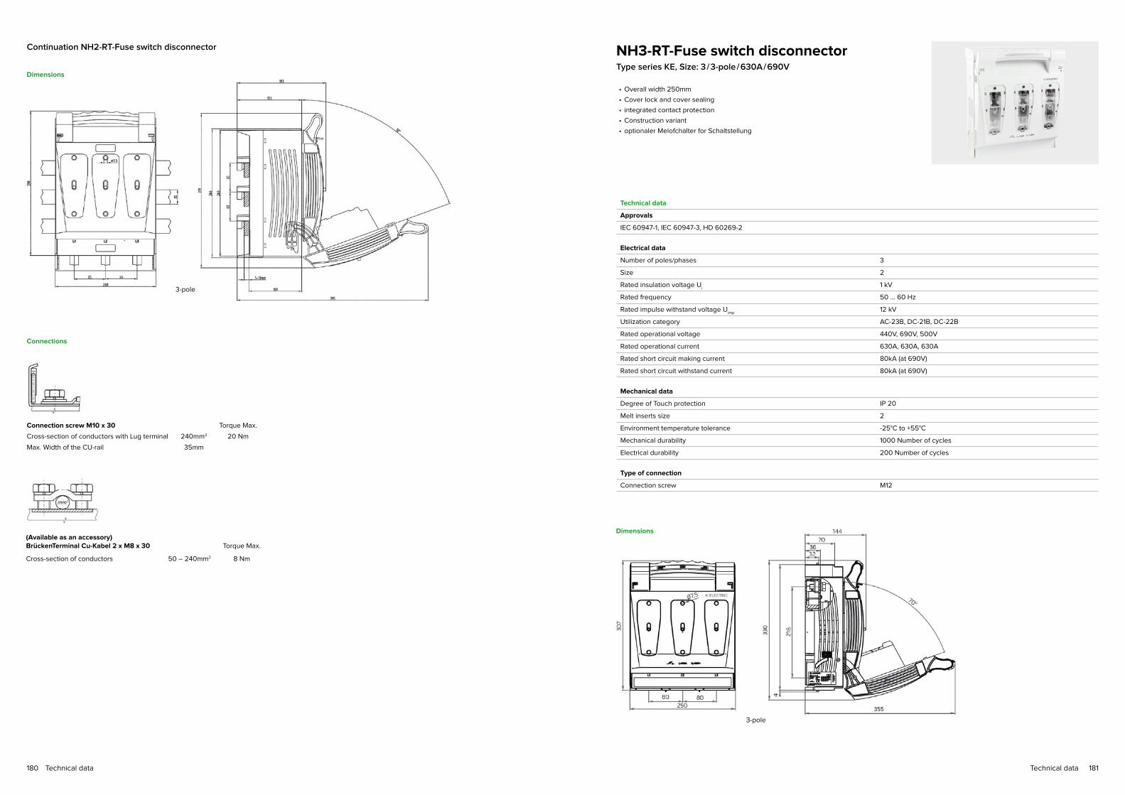
181Technical data180 Technical data
Dimensions
Connections
Connection screw M10 x 30 Torque Max.
Cross-section of conductors with Lug terminal 240mm2 20 Nm
Max. Width of the CU-rail 35mm
(Available as an accessory) BrückenTerminal Cu-Kabel 2 x M8 x 30 Torque Max.
Cross-section of conductors 50 – 240mm2 8 Nm
Continuation NH2-RT-Fuse switch disconnector
3-pole
NH3-RT-Fuse switch disconnectorType series KE, Size: 3 / 3-pole / 630A / 690V
Technical data
Approvals
IEC 60947-1, IEC 60947-3, HD 60269-2
Electrical data
Number of poles/phases 3
Size 2
Rated insulation voltage Ui
1 kV
Rated frequency 50 ... 60 Hz
Rated impulse withstand voltage Uimp
12 kV
Utilization category AC-23B, DC-21B, DC-22B
Rated operational voltage 440V, 690V, 500V
Rated operational current 630A, 630A, 630A
Rated short circuit making current 80kA (at 690V)
Rated short circuit withstand current 80kA (at 690V)
Mechanical data
Degree of Touch protection IP 20
Melt inserts size 2
Environment temperature tolerance -25°C to +55°C
Mechanical durability 1000 Number of cycles
Electrical durability 200 Number of cycles
Type of connection
Connection screw M12
• Overall width 250mm
• Cover lock and cover sealing
• integrated contact protection
• Construction variant
• optionaler Melofchalter for Schaltstellung
Dimensions
3-pole

183Technical data182 Technical data
NH00 / 185-Fuse switch disconnectorfor mounting on the 185mm Busbar systemType series KE / NH00 / 185 VSD, Size: 00 / 3-pole switchable / 160A / 690V
Technical data
Approvals
EN / IEC 60947-1, IEC 60947-3
Electrical data
Fitting RT
Number of poles/phases 3
Conventional free air thermal current with NH-fuse links 160 A
Rated operational voltage 690 V
Rated insulation voltage Ui
1 kV
Rated impulse withstand voltage Uimp
8 kV
Rated frequency 50 ... 60 Hz
Max. power dissipation of fuse links 12 W
Max. power dissipation of solid links 1,2 W
Rated operating mode Continuous operation
Utilization category to IEC / EN 60947-3 Ue: AC 400V; I
e = 160 A AC 23 B
Ue: AC 500V;
Ue: AC 690V; I
e = 160 A AC 21 B
Rated conditional short-circuit current with fuse links Ue: AC 400V; I
e = 160 A 100 kA
Ue: AC 500V;
Ue: AC 690V; I
e = 160 A 80 kA
Mechanical data
Degree of Touch protection IP 20
Degree of pollution 3
Melt inserts size 00
Cable connection
Standard cable connection Terminal clamp M8
Clamp straps 2xM5x25 4-70mm2
V-terminal clamps re 16-95mm², se 25-120mm²;rm 16-95mm², sm 25-120mm²
Busbar connection 185mm System
Standard Connection M8
60mm Busbar system 5...10mm
• Mounting on 185mm Busbar system
• Cable outlet top / bottom can be selected during installation
• drill free direct assembly with claw clamps (optional)
• different connection variants
• optional with integrated transducers
• optional quick assembling by integrated fixing bolts
• 1-pole switchable on demand
Dimensions
-M: Metric-connection -V: V-connection

185Technical data184 Technical data
NH1-Fuse switch disconnectorfor mounting on the 185mm Busbar systemType series KE NH1 VSD, Size: 1 / 3-pole switchable / 250A / 690V
Technical data
Approvals
EN / IEC 60947-1, IEC 60947-3
Electrical data
Fitting RT
Number of poles/phases 3
Conventional free air thermal current with NH-fuse links 250 A
Rated operational voltage 690 V
Rated insulation voltage Ui
1 kV
Rated impulse withstand voltage Uimp
12 kV
Rated frequency 50 ... 60 Hz
Max. power dissipation of fuse links 23 W
Max. power dissipation of solid links 2,6 W
Rated operating mode Continuous operation
Utilization category to IEC / EN 60947-3 Ue: AC 400V; I
e = 250 A AC 23 B
Ue: AC 500V;
Ue: AC 690V; I
e = 250 A AC 22 B
Rated conditional short-circuit current with fuse links Ue: AC 400V; I
e = 250 A 100 kA
Ue: AC 500V; I
e = 250 A 100 kA
Ue: AC 690V; I
e = 250 A 100 kA
Mechanical data
Degree of Touch protection IP 30
Degree of pollution 3
Melt inserts size 1
Cable connection
Standard Cable connection M12
for lug terminal Cu max. 300mm2
for lug terminal Al max. 300mm2
for copper plate rails with max. dimensions 40 x 10mm
V-connection lugs for V-clamp 35-300mm2
Busbar connection 185mm System
Standard Connection M12
60mm Busbar system 5...10mm
• Mounting on 185mm Busbar system
• Cable outlet top / bottom can be selected during installation
• drill free direct assembly with claw clamps (optional)
• different connection variants
• optional with integrated transducers
• optional quick assembling by integrated fixing bolts
• 1-pole switchable on demand
NH2-Fuse switch disconnectorfor mounting on the 185mm Busbar systemType series KE NH2 VSD, Size: 2 / 3-pole switchable / 400A / 690V
Technical data
Approvals
EN / IEC 60947-1, IEC 60947-3
Electrical data
Fitting RT
Number of poles/phases 3
Conventional free air thermal current with NH-fuse links 400 A
Rated operational voltage 690 V
Rated insulation voltage Ui
1 kV
Rated impulse withstand voltage Uimp
12 kV
Rated frequency 50 ... 60 Hz
Max. power dissipation of fuse links 34 W
Max. power dissipation of solid links 9 W
Rated operating mode Continuous operation
Utilization category to IEC / EN 60947-3 Ue: AC 400V; I
e =400 A AC 23 B
Ue: AC 500V;
Ue: AC 690V; I
e = 400 A AC 22 B
Rated conditional short-circuit current with fuse links Ue: AC 400V; I
e = 400 A 100 kA
Ue: AC 500V; I
e = 400 A 100 kA
Ue: AC 690V; I
e = 400 A 100 kA
Mechanical data
Degree of Touch protection IP 30
Degree of pollution 3
Melt inserts size 2
Cable connection
Standard Cable connection M12
for lug terminal Cu max. 300mm2
for lug terminal Al max. 300mm2
for copper plate rails with max. dimensions 40 x 10mm
V-connection lugs for V-clamp 35-300mm2
Busbar connection 185mm System
Standard Connection M12
60mm Busbar system 5...10mm
• Mounting on 185mm Busbar system
• Cable outlet top / bottom can be selected during installation
• drill free direct assembly with claw clamps (optional)
• different connection variants
• optional with integrated transducers
• optional quick assembling by integrated fixing bolts
• 1-pole switchable on demand

187Technical data186 Technical data
NH3-Fuse switch disconnectorfor mounting on the 185mm Busbar systemType series KE NH3 VSD, Size: 3 / 3-pole switchable / 630A / 690V
Technical data
Approvals
EN / IEC 60947-1, IEC 60947-3
Electrical data
Fitting RT
Number of poles/phases 3
Conventional free air thermal current with NH-fuse links 630 A
Rated operational voltage 690 V
Rated insulation voltage Ui
1 kV
Rated impulse withstand voltage Uimp
12 kV
Rated frequency 50 ... 60 Hz
Max. power dissipation of fuse links 43 W
Max. power dissipation of solid links 17,5 W
Rated operating mode Continuous operation
Utilization category to IEC / EN 60947-3 Ue: AC 400V; I
e = 630 A AC 23 B
Ue: AC 500V; I
e = 630 A AC 22 B
Ue: AC 690V; I
e = 250 A AC 21 B
Rated conditional short-circuit current with fuse links Ue: AC 400V; I
e = 250 A 100 kA
Ue: AC 500V; I
e = 250 A 100 kA
Ue: AC 690V; I
e = 250 A 100 kA
Mechanical data
Degree of Touch protection IP 30
Degree of pollution 3
Melt inserts size 3
Cable connection
Standard Cable connection M12
for lug terminal Cu max. 300mm2
for lug terminal Al max. 300mm2
for copper plate rails with max. dimensions 40 x 10mm
V-connection lugs for V-clamp 35-300mm2
Busbar connection 185mm System
Standard Connection M12
60mm Busbar system 5...10mm
• Mounting on 185mm Busbar system
• Cable outlet top / bottom can be selected during installation
• drill free direct assembly with claw clamps (optional)
• different connection variants
• optional with integrated transducers
• optional quick assembling by integrated fixing bolts
• 1-pole switchable on demand
Dimensions for VSD 1,2 and 3
Park position

189Technical data188 Technical data
NH1-Fuse switch disconnectorfor mounting on the 185mm Busbar systemMULTIVERT® NH 1 MSL, Size: 1 / 1-pole
and 3-pole switchable / 250A / 690V
Technical data
Approvals
EN / IEC 60947-3
Electrical data
Fitting RT
Number of poles/phases 3
Conventional free air thermal current with NH-fuse links 250 A
Rated operational voltage 690 V
Conventional free air thermal current with solid links 400 A
Rated insulation voltage Ui
1 kV
Rated impulse withstand voltage Uimp
8 kV
Rated frequency 50 ... 60 Hz
Max. power dissipation of fuse links 23 W
Max. power dissipation of solid links 2,6 W
Power dissipation by Ith without NH-fuse links 24 W
Power dissipation by Ith without NH-contact blade 65 W
Rated operating mode Continuous operation
Rated short circuit making current with solid links Icm
16 kAsw
Utilization category to IEC / EN 60947-3 Ue: AC 400V; I
e = 250 A AC 23 B
Ue: AC 500V; I
e = 250 A AC 23 B
Ue: AC 690V; I
e = 250 A AC 22 B
Rated conditional short-circuit current with fuse links Ue: AC 400V; I
e = 250 A 120 kA
Ue: AC 500V; I
e = 250 A 120 kA
Ue: AC 690V; I
e = 250 A 120 kA
Mechanical data
Degree of Touch protection IP 30
Degree of pollution 3
Melt inserts size 1
Cable connection
Standard Cable connection M12
for lug terminal Cu max. 300mm2
for lug terminal Al max. 300mm2
for copper plate rails with max. dimensions 40 x 10mm
V-connection lugs for V-clamp 35-240mm2
Busbar connection 185mm System
Standard Connection M12
40mm Busbar system 5...10mm
• Overall width 98mm
• Symmetricale vertical fuse switch disconnector / Cable outlet top /
bottom can be selected during installation
• Touch-protection IP 30 with central cover
• Park position of the switch cover, also with inserted NH fuse left
• Lid lock and lid bladthe
• Optional direct mounting by means of claw clamp possible
NH2-Fuse switch disconnectorfor mounting on the 185mm Busbar systemMULTIVERT® NH 2 MSL, Size: 2 / 1-pole
and 3-pole switchable / 400A / 690V
Technical data
Approvals
EN / IEC 60947
Electrical data
Fitting RT
Number of poles/phases 3
Conventional free air thermal current with NH-fuse links 400 A
Rated operational voltage 690 V
Conventional free air thermal current with solid links 630 A
Rated insulation voltage Ui
1 kV
Rated impulse withstand voltage Uimp
8 kV
Rated frequency 50 ... 60 Hz
Max. power dissipation of fuse links 34 W
Max. power dissipation of solid links 9 W
Power dissipation by Ith without NH-fuse links 46 W
Power dissipation by Ith without NH-contact blade 126 W
Rated operating mode Continuous operation
Rated short circuit making current with solid links Icm
16 kAsw
Utilization category to IEC / EN 60947-3 Ue: AC 400V; I
e = 400 A AC 23 B
Ue: AC 500V; I
e = 400 A AC 22 B
Ue: AC 690V; I
e = 400 A AC 21 B
Rated conditional short-circuit current with fuse links Ue: AC 400V; I
e = 400 A 120 kA
Ue: AC 500V; I
e = 400 A 120 kA
Ue: AC 690V; I
e = 315 A 120 kA
Ue: AC 690V; I
e = 400 A 100 kA
Mechanical data
Degree of Touch protection IP 30
Degree of pollution 3
Melt inserts size 2
Cable connection
Standard Cable connection M12
for lug terminal Cu max. 300mm2
for lug terminal Al max. 300mm2
for copper plate rails with max. dimensions 40 x 10mm
V-connection lugs for V-clamp 35-240mm2
Busbar connection 185mm System
Standard Connection M12
Hooked clamp for bus bar with thickness 5...10mm
• Overall width 98mm
• Symmetricale vertical fuse switch disconnector / Cable outlet top /
bottom can be selected during installation
• Touch-protection IP 30 with central cover
• Park position of the switch cover, also with inserted NH fuse left
• Lid lock and lid bladthe
• Optional direct mounting by means of claw clamp possible

191Technical data190 Technical data
NH3-Fuse switch disconnectorfor mounting on the 185mm Busbar systemMULTIVERT® NH 3 MSL, Size: 3 / 1-pole
and 3-pole switchable / 630A / 690V
Technical data
Approvals
EN / IEC 60947
Electrical data
Fitting RT
Number of poles/phases 3
Conventional free air thermal current with NH-fuse links 630 A
Rated operational voltage 690 V
Conventional free air thermal current with solid links 800 A
Rated insulation voltage Ui
1 kV
Rated impulse withstand voltage Uimp
8 kV
Rated frequency 50 ... 60 Hz
Max. power dissipation of fuse links 43 W
Max. power dissipation of solid links 17,5 W
Power dissipation by Ith without NH-fuse links 92 W
Power dissipation by Ith without NH-contact blade 161 W
Rated operating mode Continuous operation
Rated short circuit making current with solid links Icm
16 kAsw
Utilization category to IEC / EN 60947-3 Ue: AC 400V; I
e = 630 A AC 23 B
Ue: AC 500V; I
e = 630 A AC 22 B
Ue: AC 690V; I
e = 630 A AC 21 B
Rated conditional short-circuit current with fuse links Ue: AC 400V; I
e = 630 A 80 kA
Ue: AC 500V; I
e = 630 A 80 kA
Ue: AC 690V; I
e = 500 A 80 kA
Mechanical data
Degree of Touch protection IP 30
Degree of pollution 3
Melt inserts size 3
Cable connection
Standard Cable connection M12
for lug terminal Cu max. 300mm2
for lug terminal Al max. 300mm2
for copper plate rails with max. dimensions 40 x 10mm
V-connection lugs for V-clamp 35-240mm2
Busbar connection 185mm System
Standard Connection M12
Hooked clamp for bus bar with thickness 5...10mm
• Overall width 98mm
• Symmetricale vertical fuse switch disconnector / Cable outlet top /
bottom can be selected during installation
• Touch-protection IP 30 with central cover
• Park position of the switch cover, also with inserted NH fuse left
• Lid lock and lid bladthe
• Optional direct mounting by means of claw clamp possible
Dimensions for MULTIVERT® 1, 2 and 3
Direct mounting screws 3x1 pole
Direct mounting screws 1x3 pole

193Technical data192 Technical data
Connections
drill free direct assembly with claw clamps 3x1 pole
Continuation NH3-Fuse switch disconnector
Size in mm
Dimensions
Dimensions
H 700mm
B 100mm
T 165mm
Hook-up panel for busbar system 185 mm
Technical data
Approvals
EN 60439-1:1999 + A1:2004
Electrical data
Rated operational voltage AC 400V
Rated operational current 63A
• For cable- and fairgroand cabinets
• According to DIN EN 60439-1
• Tested according to VDE 0660 Part 500
• IEC 60439-1: 1999 + A1: 2004
• System rails for Cable- and Fairground cabinets
• connection and mounting on the 185mm busbar system
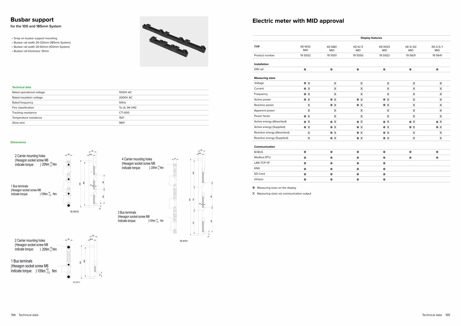
195Technical data194 Technical data
Busbar supportfor the 100 and 185mm System
Technical data
Rated operational voltage 1000V AC
Rated insulation voltage 2000V AC
Rated frequency 50Hz
Fire classification To UL 94 V40
Tracking resistance CTI 600
Temperature resistance 150°
Glow wire 960°
• Snap on busbar support mounting
• Busbar rail width 30-120mm (185mm System)
• Busbar rail width 30-60mm (100mm System)
• Busbar rail thickness: 10mm
Dimensions
Electric meter with MID approval
Display features
TYP KE-W32MID
KE-N80
MID
KE-N / 5
MID
KE-N125
MID
KE-S / 63
MID
KE-S-5 / 1
MID
Product number 19 5552 19 5551 19 5550 19 5552 19 5631 19 5641
Installation
DIN rail
Measuring sizes
Voltage
Current
Frequency
Active power
Reactive power
Apparent power
Power factor
Active energy (Absorbed)
Active energy (Supplied)
Reactive energy (Absorbed)
Reactive energy (Supplied)
Communication
M-BUS
Modbus RTU
LAN-TCP / IP
KNX
SD-Card
eVision
x x x x x xx x x x x xx x x x x xx x x x x x
x x x x xxx x x x x x
x x x x xxx x x x x xx x x x x x
x x xx x x
x xx x
xx
Measuring sizes on the display
Measuring sizes via communication outputx

197Technical data196 Technical data
Alternating current counter KE-W32 MIDElectronic single-phase-Alternating current counder
for recording the active consumption wiht MID
approval Accuracy class B (1%)
Technical data
Approvals
EN 50470-1, EN 50470-3 and EN 62053-31
Operating features
Connection 1-Phase: 2 Wires
Storage Configuration and energy values: yes
Tariffs for Active energy: 1 Tariff
Electrical data
Type of connection Direct measuring
Rated operational voltage Un
Phase-N: 230V AC
Operating supply voltage range 184..276V AC
Rated frequency 50 Hz
Frequency range 45 – 60 Hz
Rated power dissipation < 8VA / (0,6W)
Input waveform alternating
Reference current Iref
5A
Minimum current Imin
0.25A
Highest current Imax
32A
Current range 0.02...32A
Operational starting current Ist
20mA
Measurement accuracy: at 23 ± 1°C auf Nominalwert bezogen
Active energy and WirkPower to EN 50470-3 Class B
Overload
Voltage 276V AC (Continuous operation: Phase / N) 300V AC (Short operation for 1s)
Current 32A (Continuous operation) 960A (Short operation for 10ms)
Clamps
Screws of the Main current paths Pozidriv PZ1 / 1Nm
Screwdriver for tariff and communication terminals Pozidriv PZ0 / 0,8 Nm
Terminal capacity main current paths 1....16mm2 (solid) 1....16mm2 (flexible, with sleeve)
Terminal capacity for mains terminal M-Bus or S0 1....4mm2 (solid) 1....2,5mm2 (flexible, with sleeve)
• Overall width 17,8mm / 1 MW
• Independently applicable
• MID conformity rated( MID-calibrated)
• Double zero terminal for looping through the neutralwires
• Pulse output, S0-Interface for Active energy
• Pulse quantity: 1000imp. / kWh
• Pulse duration: 90ms
• LC-Display with 7 Digits, including 2 decimal places
• full display control
• Terminal cover sealable
• optional extension by communication Modules: M-BUS; Modbus RTU;
LAN-TCP / IP; KNX; SD-Card (optional alternating current counder to 63A available
195652)
Technical data
Safety
Protective class (EN 50470) Class II
AC voltage test (EN 50470-3, 7.2) 4kV
Degree of pollution 2
Housing material flame resistance UL94 V0
Safety-sealing between upper and lower housing part yes
Pulse outputs (S0 signals, acc. to IEC 62053-31)
Pulse output for Active energy: 1
Pulse number 1000 Imp / kWh
Pulse duration 90ms
Required Voltage (5...300VDC) min. – max. 5...230VAC ±5%
Permitted current Impuls ON (max. 230VAC): 90mA
Allowed current Impuls OFF (Fault current max. 230VAC / DC): 1μA
Lateral interface
For connection of communication Modules LAN-TCP / IP / M-Bus / Modbus RTU / KNX / SD-Card
Optical metrological LED
Front mounted red LED proportional to active imp/exp energy: 5000 Imp / kWh
Display
Display type LCD: 7 (2 Decimal)
Energy digits dimension 6,00 x 3mm
Active energy 1 Display, 5 digits + 2 decimal digits 0.00...999999,9 (kWh)
Display refresh period 1s
the following values are visible Imported active energy, Export active energy, imported activepower, exported active power, Firmware release, Firmware codechecksum, full display control
Environmental conditions
Temperature range -25...+70°C (Storage) -25...+55°C (In operation)
Mechanical environment M1
Electromagnetic environment E2
Installation for Indoor: yes
Altitude (max.) (max.) <2000m
Humidity < 75% (Yearly average, not condensing)) < 95% (on 30 days per year, not condensing)
Degree of Touch protection IP51* / IP20 (built-in front panel / clamps)*the metering equipment must be installed inside a cabinet with rating IP51 or better
Mounting on DIN-rail according to DIN EN 50022 (Ts35)
Dimensions Connections
A fuse of 63A is recommended. The N-Wire must be connected.

199Technical data198 Technical data
KE-N80Three-phase meter for direct measurement
For active- and eactive energy measurement with EU valid MID certification
Technical data
Approvals
EN 50470-1, EN 50470-3, EN 62053-23, EN 62053-31
Operating features
Connection 1-phase u. 3-phase (Numbers of Wire): 2-4
Storage Configuration and energy values: yes
Tariffs for Active- and Reactive energy: T1 and T2
Electrical data
Type of connection Direct measuring
Rated operational voltage Un
Phase-N: 230V AC Phase-Phase: 400V AC
Operating supply voltage range 110..276V AC / 190..480V AC
Rated power dissipation < 2VA / (0,6W) (Voltage circuit) < 0,7VA (Current circuit at I
max)
Voltage input waveform AC
Reference current Iref
5A
Minimum current Imin
0.25A
Highest current Imax
80A
Sttyping current for energy measurement Ist
0.015A
Rated frequency 50 Hz
Rated frequency 45 – 60 Hz
Certification Parameter to EN 50470-1 and EN50470-3
Accuracy class (to EN50470-3) Class B
Certification Measuring sizes → kWh T1; ←kWh T1 → kWh T2; ←kWh T2
Overload
Voltage 480V AC (Continuous operation: Phase / Phase) 800V AC (1 Second: Phase / Phase) 276V AC (Continuous operation: Phase / N) 300V AC (1 Second: Phase / N)
Current 80A (Continuous operation) 2400A (Short operation for 10ms)
• Overall width 72mm / 4 MW
• digital three-phase meter to 80A Direct measuring
• to measure active- and reactive energy and performance in both energy directions
(supplied and absorbed)
• Bar graph in % the Active power
• Double tariff meter HT/NT with tariff switching input
• 8-digits LC-Display with backlight
• Installation test with error detection
• 1 S0-Output for Imported active energy 500imp/ kWh
• 2 S0-Output for Reimported active energy 500imp/ kvarh
• sealable clamp covers
• Accuracy: Active energy Class B (1%)
• with Backstop
• Made in EU with EU-wide MID certification
• optional extension by communication Modules : M-BUS; Modbus RTU; LAN /
TCP, KNX; SD-Card
• optional as 125A counder with 6MW width available Item-no.: 19 5552
Technical data
Safety
Protective class (EN 50470) Class II
AC voltage test (EN 50470-3, 7.2) 4kV
Degree of pollution 2
Housing material flame resistance UL94 V0
Safety-sealing between upper and lower housing ptyp yes (mod. KE-N80)
Pulse outputs (S0 signals, acc. to IEC 62053-31)
Pulse output 1 (→) kWh: Imported active energy
Pulse output 2 (→) kvarh: Reimported active energy
Pulse quantity 500 imp / kWh – imp / kvarh (fixed)
Pulse duration 50 ± 2% (fixed)
Required Voltage min. – max. 5...33V AC / 5...70V DC
Permitted current Impuls ON: 90mA
Allowed current Impuls OFF: 1μA
Isolation class SELV
Optical metrological LED
Front mounted red LED (Meter constant) (←) kWh (→) 1000 imp / kWh
Display
Display type LCD: 8-digits Dimension of the Maindisplay: 6 x 3mm
Active energy, 6-digits + 2 Decimal) 0.01...999999.99 (kWh)
Reactive energy, 6-digits + 2 Decimal) 0.01...999999.99 (kvarh)
Instantaneous Active power (←and→), 3-digits 0...999 (MW; kW, W)
Instantaneous Reactive power (←and→), 3-digits 0...999 (Mvar; kvar, var)
Power bar graph, 10 Segments 0% – 10% – 20%... – 100%
Running tariff, 1 Digit T1 or T2
Display refresh period 1s
Clamps
Screws of the Main current paths Pozidriv PZ2
Screwdriver for tariff and communication terminals Slotted 0,8 x 3,5mm
Terminal capacity main current paths 1....35mm2 (solid)1....35mm2 (flexible, with sleeve)
Terminal capacity for mains terminal M-Bus or S0 1....4mm2 (solid)1....2,5mm2 (flexible, with sleeve)
Mechanical data
Housing 4 Modules (DIN 43880)
Mounting 35mm DIN rail (EN 60715)
Weight 424g
Temperature range -25...+70°C (Storage) -25...+55°C (In operation)
Mechanical environment M1
Electromagnetic environment E2
Installation for Indoor: yes
Altitude (max.) max. <2000m
Humidity <75% (Yearly average, not condensing)) <95% (on 30 days per year, not condensing)
Degree of Touch protection IP51* / IP20 (built-in front panel / clamps)*the metering equipment must be installed inside a cabinet with rating IP51 or better

201Technical data200 Technical data
Dimensions
Connections
A fuse of 63A is recommended. The N-Wire must be connected.
Continuation KE-N80 KE-N / 5 MIDThree-phase meter to direct measurement
For active- and eactive energy measurement with EU valid MID certification
Technical data
Approvals
EN 50470-1, EN 50470-3, EN 62053-23, EN 62053-31
Function
Connection 1-phase u. 3-phase (Numbers of Wire): 4
Storage Configuration and energy values: yes
Tariffs for Active- and Reactive energy: T1 and T2
Electrical data
Type of connection Direct measurement
Rated operational voltage Un
Phase-N: 230V AC Phase-Phase: 400V AC
Operating supply voltage range 110..276V AC / 190..480V AC
Rated power dissipation < 2VA / (0,6W) (Voltage circuit) < 0,5VA (Current circuit at I
max)
Voltage input waveform AC
Reference current Iref
5A
Minimum current Imin
0.05A
Highest current Imax
6A
Sttyping current for energy measurement Ist
0,003A
Rated frequency 50 Hz
Rated frequency 45 – 60 Hz
Certification Parameter to EN 50470-1 and EN50470-3
Accuracy class (to EN50470-3) Class B
Certification Measuring sizes → kWh T1; ←kWh T1 → kWh T2; ←kWh T2
Overload
Voltage 480V AC (Continuous operation: Phase / Phase) 800V AC (1 Second: Phase / Phase) 276V AC (Continuous operation: Phase / N) 300V AC (1 Second: Phase / N)
Current 6A (Continuous operation) 120A (Short operation for 10ms)
• Overall width 72mm / 4 MW
• for .. / 5A to 10000 / 5A Power converter
• to measure active- and reactive energy and performance in both energy
directions (supplied and absorbed)
• Bar graph in % the Active power
• Double tariff meter HT/NT with tariff switching input
• 8-digits LC-Display with backlight
• Installation test with error detection
• 1 S0-Output for Imported active energy 100 / 10 / 1imp / kWh
• 2 S0-Output for Reimported active energy 100 / 10 / 1imp / kvarh
• sealable clamp covers
• Accuracy: Active energy Class B (1%)
• with Backstop
• Made in EU with EU-wide MID certification
• optional extension by communication Modules : MBUS;
Modbus RTU; LAN / TCP, KNX; SD-Card
• optionally available as direct measurement 125A counder with 6TE width available
Item-no.: 19 5552

203Technical data202 Technical data
Technical data
Safety
Protective class (EN 50470) Class II
AC voltage test (EN 50470-3, 7.2) 4kV
Degree of pollution 2
Housing material flame resistance UL94 V0
Safety-sealing between upper and lower housing part yes
Pulse outputs (S0 signals, acc. to IEC 62053-31)
Pulse output 1 (→) kWh: Imported active energy
Pulse output 2 (→) kvarh: Reimported active energy
Pulse quantity 100 imp/kWh – imp/kvarh (5-300A) 10 imp/kWh – imp/kvarh (305 – 3000A) 1 imp/kWh – imp/kvarh (3005 – 10.000A)
Pulse duration 50 ± 2% (fixed)
Required Voltage min. – max. 5...33V AC / 5...70V DC
Permitted current Impuls ON: 90mA
Allowed current Impuls OFF: 1μA
Isolation class SELV
Optical metrological LED
Front mounted red LED (Meter constant) (←) kWh (→) 10.000 imp / kWh
Display
Display type LCD: 8-digits Dimension of the Maindisplay: 6 x 3mm
Active energy, 6-digits + 2 Decimal) 0.01...999999.99 (kWh)
Reactive energy, 6-digits + 2 Decimal) 0.01...999999.99 (kvarh)
Instantaneous Active power (←and→), 3-digits 0...999 (MW; kW, W)
Instantaneous Reactive power (←and→), 3-digits 0...999 (Mvar; kvar, var)
Power bar graph, 10 Segments 0% – 10% – 20%... – 100%
Running tariff, 1 Digit T1 or T2
Display refresh period 1s
Clamps
Screws of the Main current paths Pozidriv PZ1
Screwdriver for tariff and communication terminals Slotted 0,8 x 3,5mm
Terminal capacity main current paths 1....4mm2 (solid)1....4mm2 (flexible, with sleeve)
Terminal capacity for mains terminal M-Bus or S0 1....4mm2 (solid)1....2,5mm2 (flexible, with sleeve)
Mechanical data
Housing 4 Modules (DIN 43880)
Mounting 35mm DIN rail (EN 60715)
Weight 293g
Temperature range -25...+70°C (Storage) -25...+55°C (In operation)
Mechanical environment M1
Electromagnetic environment E2
Installation for Indoor: yes
Altitude (max.) max. <2000m
Humidity <75% (Yearly average, not condensing)) <95% (on 30 days per year, not condensing)
Degree of Touch protection IP51* / IP20 (built-in front panel / clamps)*the metering equipment must be installed inside a cabinet with rating IP51 or better
Continuation KE-N/5 MID Dimensions
Connections
A fuse of 63A is recommended. The N-Wire must be connected.

205Technical data204 Technical data
KE-N125 MIDThree-phase meter for direct measurement to 125A
For active- and eactive energy measurement with EU valid MID certification
Technical data
Approvals
EN 50470-1, EN 50470-3, EN 62053-23, EN 62053-31
Function
Connection 1-phase u. 3-phase (Numbers of Wire): 2-4
Storage Configuration and energy values: yes
Tariffs for Active- and Reactive energy: T1 and T2
Electrical data
Type of connection Direct measuring
Rated operational voltage Un
Phase-N: 230V AC Phase-Phase: 400V AC
Operating supply voltage range 110..276V AC / 190..480V AC
Rated power dissipation < 2VA / (0,6W) (Voltage circuit) < 1VA (Current circuit at I
max)
Voltage input waveform AC
Reference current Iref
5A
Minimum current Imin
0.25A
Highest current Imax
125A
Sttyping current for energy measurement Ist
0.020A
Rated frequency 50 Hz
Rated frequency 45 – 60 Hz
Certification Parameter to EN 50470-1 and EN50470-3
Accuracy class (to EN50470-3) Class B
Certification Measuring sizes → kWh T1; ←kWh T1 → kWh T2; ←kWh T2
Overload
Voltage 480V AC (Continuous operation: Phase / Phase) 800V AC (1 Second: Phase / Phase) 276V AC (Continuous operation: Phase / N) 300V AC (1 Second: Phase / N)
Current 125A (Continuous operation) 3750A (Short operation for 10ms)
• Overall width 108 mm / 6 MW
• digital three-phase meter to 125A Direct measuring
• to measure active- and reactive energy and performance in both energy directions
(supplied and absorbed)
• Bar graph in % the Active power
• Double tariff meter HT/NT with tariff switching input
• 8-digits LC-Display with backlight
• Installation test with error detection
• 1 S0-Output for Imported active energy 500imp/ kWh
• 2 S0-Output for Reimported active energy 500imp/ kvarh
• sealable clamp covers
• Accuracy: Active energy Class B (1%)
• with Backstop
• Made in EU with EU-wide MID certification
• optional extension by communication Modules : MBUS;
Modbus RTU; LAN / TCP, KNX; SD-Card
Technical data
Safety
Protective class (EN 50470) Class II
AC voltage test (EN 50470-3, 7.2) 4kV
Degree of pollution 2
Housing material flame resistance UL94 V0
Safety-sealing between upper and lower housing part Yes (mod. KE-N125)
Pulse outputs (S0 signals, acc. to IEC 62053-31)
Pulse output 1 (→) kWh: Imported active energy
Pulse output 2 (→) kvarh: Reimported active energy
Pulse quantity 500 imp/kWh – imp / kvarh (fixed)
Pulse duration 50 ± 2% (fixed)
Required Voltage min. – max. 5...33V AC / 5...70V DC
Permitted current Impuls ON: 90mA
Allowed current Impuls OFF: 1μA
Isolation class SELV
Optical metrological LED
Front mounted red LED (Meter constant) (←) kWh (→) 1000 imp / kWh
Display
Display type LCD: 8-digits Dimension of the Maindisplay: 6 x 3mm
Active energy, 6-digits + 2 Decimal) 0.01...999999.99 (kWh)
Reactive energy, 6-digits + 2 Decimal) 0.01...999999.99 (kvarh)
Instantaneous Active power (←and→), 3-digits 0...999 (MW; kW, W)
Instantaneous Reactive power (←and→), 3-digits 0...999 (Mvar; kvar, var)
Power bar graph, 10 Segments 0% – 10% – 20%... – 100%
Running tariff, 1 Digit T1 or T2
Display refresh period 1s
Clamps
Screws of the Main current paths Pozidriv PZ2
Screwdriver for tariff and communication terminals Slotted 0,8 x 3,5mm
Terminal capacity main current paths 1....50mm2 (solid)1....50mm2 (flexible, with sleeve)
Terminal capacity for mains terminal M-Bus or S0 1....4mm2 (solid)1....2,5mm2 (flexible, with sleeve)
Mechanical data
Housing 6 Modules (DIN 43880)
Mounting 35mm DIN rail (EN 60715)
Weight 700g
Temperature range -25...+70°C (Storage) -25...+55°C (In operation)
Mechanical environment M1
Electromagnetic environment E2
Installation for Indoor: yes
Altitude (max.) max. <2000m
Humidity <75% (Yearly average, not condensing)) <95% (on 30 days per year, not condensing)
Degree of Touch protection IP51* / IP20 (built-in front panel / clamps)*the metering equipment must be installed inside a cabinet with rating IP51 or better

207Technical data206 Technical data
Dimensions
Connections
A fuse of 63A is recommended. The N-Wire must be connected.w
KE-N-125
Continuation KE-N125 MID KE-S / 63Three-phase meter for direct measurement to 63A
For active energy measurement with EU-wide MID certification (Calibrated)
Technical data
Approvals
CLC/TR 50579, EN 50470-1, EN 50470-3, EN 62053-31
Function
Connection Three-phase network (Numbers of Wire): 4
Storage Configuration and energy values: yes
Tariffs for Active- and Reactive energy: T1 and T2
Electrical data
Rated operational voltage Un
Phase-N: 230V AC Phase-Phase: 400V AC
Operating supply voltage range 92...276V AC / 160...480V AC
Rated power dissipation < 2VA / (0,6W) (Voltage circuit) < 0,7VA (Current circuit at I
max)
Voltage input waveform AC
Reference current Iref
5A
Minimum current Imin
0.25A
Highest current Imax
63A
Sttyping current for energy measurement Ist
0.015A
Rated frequency 50 Hz
Frequency Area 45...65Hz
Numbers of phases (and wires) 3 (4)
Certification Parameter to EN 50470-1 and EN50470-3
Accuracy class (to EN50470-3) Class B
Certification Measuring sizes (→) kWh T1; (←) kWh T1 (→) kWh T2; (←) kWh T2
Overload
Voltage 480V AC (Continuous operation: Phase/Phase) 800V AC (1 Second: Phase/Phase) 276V AC (Continuous operation: Phase/N) 300V AC (1 Second: Phase/N)
Current 63A (Continuous operation) 1890A (Short operation for 10ms)
• Overall width 72mm / 4 MW
• digital three-phase meter to 63A Direct measuring
• for measurement and display of active energy in energy directions(supplied and absorbed) in
both Tariffs
• Secondary tariff meter T1 / T2 with tariff switching input
• Ptyp consumption of active energy in T1 and T2 measurable
• Display of the current rate, as well as the active phases
• 9 digitses LCD-Display
• Installation test with error detection
• 2 S0 outputs with the following output options:
• Active power: 1. S0 Absorbed / 2. S0 Supplied
• Active- + Reactive power: 1. S0 Active power absorbed / 2. S0 Reactive power absorbed
• Active power Tarifffs: 1. S0 Active power absorbed T1 / 2. S0 Active power absorbed T2
• adjustable number of pulses and length
• sealable clamp covers
• Accuracy: Active energy B (Cl.1)
• EU-far valid MID calibrated
• with Backstop
• Made in EU
• optional with M-BUS / Modbus

209Technical data208 Technical data
Technical data
Safety
Protective class (EN 50470) Class II
AC voltage test (EN 50470-3, 7.2) 4kV
Degree of pollution 2
Housing material flame resistance UL94 V0
Safety-sealing between upper and lower housing part yes
Pulse outputs (S0 signals, acc. to IEC 62053-31) / only at version without M-Bus / Modbus
Pulse output 1 adjustable: kWh (→); kWh (→) kWh (T1)
Pulse output 2 adjustable: kWh (→); kvarh (→) kWh (T2)
Pulse rate adjustable: 10...500 imp/kWh
Pulse duration adjustable: 30...100 ms
Required Voltage min. – max. 5...33V AC / 5...70V DC
Permitted current Impuls ON: 90mA
Allowed current Impuls OFF: 1μA
Isolation class SELV
Optical metrological LED
Front mounted red LED (Meter constant) 1000 imp / kWh
Display
Display type LCD: 9 (2 Decimal) Dimension of the Maindisplay: 6 x 3mm
Active energy, 7-digits + 2 Decimal) 0.01...9999999.99
Running tariff, 1 Digit T1 or T2
Display refresh period 1s
Clamps
Screws of the Main current paths Pozidriv PZ2
Dimensioning of torque 2Nm
Screwdriver for tariff and communication terminals Slotted 0,8 x 3,5mm
Dimensioning of torque 0,8 Nm
Terminal capacity main current paths 1,5...35mm2 (solid)1,5...35mm2 (flexible, with sleeve)
Terminal capacity for mains terminal M-Bus or S0 1....4mm2 (solid)1....2,5mm2 (flexible, with sleeve)
Mechanical data
Housing 4 Modules (DIN 43880)
Mounting 35mm DIN rail (EN 60715)
Weight 412g
Temperature range -25...+70°C (Storage) -25...+55°C (In operation)
Mechanical environment M1
Electromagnetic environment E2
Installation for Indoor: yes
Altitude (max.) max. <2000m
Humidity <75% (Yearly average, not condensing)) <95% (on 30 days per year, not condensing)
Degree of Touch protection IP51* / IP40 (Built-in device Front side / Clamps)*the metering equipment must be installed inside a cabinet with rating IP51 or better
Continuation KE-S / 63 Dimensions
Connections
KE-S-63-Modbus KE-S-63-M-Bus KE-S-63
Neutral wire must be connected to the meter! A Pre-fuse of 63A is recommended.

211Technical data210 Technical data
KE-S-5 / 1Three-phase meter to direct measurement
For active energy measurement with EU-wide MID certification (Calibrated)
Technical data
Approvals
CLC / TR 50579, EN 62059-32-1, EN 50470-1, EN 50470-3
Function
Connection Three-phase network (Numbers of Wire): 4
Storage Configuration and energy values: yes
Tariffs for Active- and Reactive energy: T1 and T2
Electrical data
Type of connection Power converter to 5A or 1A
Rated operational voltage Un
Phase-N: 230V AC Phase-Phase: 400V AC
Operating supply voltage range 92...276V AC / 160...480V AC
Rated power dissipation < 2VA / (0,6W) (Voltage circuit) < 0.25VA (Current circuit at I
max)
Voltage input waveform AC
Reference current Iref
1A
Minimum current Imin
0.01A
Highest current Imax
6A
Sttyping current for energy measurement Ist
0,001A
External CT 10.000 / 5A or 2.000 / 1A (Max. CT ratio) 5 or 1 (Ratio adjusting step)
Rated frequency 50 Hz
Frequency range 45 – 60 Hz
Numbers of phases (and wires) 3 (4)
Certification Parameter to EN 50470-1 and EN50470-3
Accuracy class (to EN50470-3) Class B
Certification Measuring sizes (→) kWh T1; (←) kWh T1 (→) kWh T2; (←) kWh T2
Overload
Voltage 480V AC (Continuous operation: Phase / Phase) 800V AC (1 Second: Phase / Phase) 276V AC (Continuous operation: Phase / N) 300V AC (1 Second: Phase / N)
Current 6A (Continuous operation) 120A (Short operation for 0,5ms)
• Overall width 72mm / 4 MW
• digital three-phase transformer
• for measurement and display of active energy in energy directions
(supplied and absorbed) in both Tariffs
• Secondary tariff meter T1 / T2 with tariff switching input
• Ptyp consumption of active energy in T1 and T2 measurable
• Display of the current rate, as well as the active phases
• 9 digitses LCD-Display
• Installation test with error detection
• 2 S0 outputs with the following output options:
• Active power: 1. S0 Absorbed / 2. S0 Supplied
• Active- + Reactive power: 1. S0 Active power absorbed / 2. S0 Reactive power absorbed
• Active power Tarifffs: 1. S0 Active power absorbed T1 / 2. S0 Active power absorbed T 2
• adjustable number of pulses and length
• sealable clamp covers
• Accuracy: Active energy B (Cl.1)
• EU-far valid MID calibrated
• with Backstop
• Made in EU
• optional with M-BUS or MOD-Bus
Technical data
Safety
Protective class (EN 50470) Class II
AC voltage test (EN 50470-3, 7.2) 4kV
Degree of pollution 2
Housing material flame resistance UL94 V0
Safety-sealing between upper and lower housing part yes
Pulse outputs (S0 signals, acc. to IEC 62053-31)
Pulse output 1 adjustable: kWh (→); kWh (→) kWh (T1)
Pulse output 2 adjustable: kWh (←); kvarh (→) kWh (T2)
Pulse rate adjustable: 1.... N (*) (*) N – depends on CT-ratio and pulse on time
Pulse duration adjustable: 30...100 ms
Required Voltage min. – max. 5...33V AC / 5...70V DC
Permitted current Impuls ON: 90mA
Allowed current Impuls OFF: 1μA
Isolation class SELV
Optical metrological LED
Front mounted red LED (Meter constant) 10.000 imp / kWh
Display
Display type LCD: 9 (2 Decimal) Dimension of the Maindisplay: 6 x 3mm
Active energy, 7-digits + 2 Decimal) 0.01...9999999.99
Running tariff, 1 Digit T1 or T2
Display refresh period 1s
Clamps
Screws of the Main current paths Pozidriv PZ1
Dimensioning of torque 1 Nm
Screwdriver for tariff and communication terminals Slotted 0,8 x 3,5mm
Dimensioning of torque 0,8 Nm
Terminal capacity main current paths 1....4mm2 (solid)1....4mm2 (flexible, with sleeve)
Terminal capacity for mains terminal M-Bus or S0 1....4mm2 (solid)1....4mm2 (flexible, with sleeve)
Mechanical data
Housing 4 Modules (DIN 43880)
Mounting 35mm DIN rail (EN 60715)
Weight 250g
Temperature range -25...+70°C (Storage) -25...+55°C (In operation)
Mechanical environment M1
Electromagnetic environment E2
Installation for Indoor: yes
Altitude (max.) max. <2000m
Humidity <75% (Yearly average, not condensing)) <95% (on 30 days per year, not condensing)
Degree of Touch protection IP51* / IP40 (Built-in device Front side / Clamps)*the metering equipment must be installed inside a cabinet with rating IP51 or better

213Technical data212 Technical data
Dimensions
Connections
Modbus M-bus
KE-S-5/1
Continuation KE-S-5 / 1 LAN Server Modbus/TCP data concentrator
All data can be transferred via LAN/WLAN/internet using an HTTP
interface in a web browser.
• Device coupler via Modbus (RTU)
• Data is transferred globally using the TCP/IP protocol
• maximum 31 measuring instruments cia modbus
• two gigabytes of memory are installed
• only 4 MW wide (72mm)
User interface
• selection of the individual device connected to the LAN server
• Display the readings
• Copy and separate memory the instantaneous measurement
values for possible editing
• Set the configuration (only via administrator)
• Selection of the storage period and data volumes
Readings
All parameters readable by the meter are available to the LAN server.
Plug and Play
The software number is attached to the device and entered. Thisenables the identification of a device at the installation site.
Date and time
The date and time are automatically synchronized.
Data protocol
Data communication between LAN-Server and PC is done
in 2 ways
• over the TCP / IP and HTTP Protocol for the internal connection
• via the Modbus / TCP Protocol, the LAN-Server connects to a
Supervisory PC
• the saved file can also be transferred via FTP protocok
Transmission speed
The data transmission speed is by the LAN characteristice. g. the Internet or the internal network restricted. The speed oftransmission of the data between the LAN server and the connecteddevices is higher and does not degrade the overall result..
Data storage
Address data of the devices and of the PC and the continuouslyobtained measured values are stored in the LAN server for a minimumof 10 years. A built-in micro SD card with 2 gigabytes of memory all thenecessary data.
• for example, if the entire data file of 5 connected devices
should be memorized for 1 minute each, the memory capacity is
about 2 years
Technical data
LAN Server Modbus / TCP
Memory intern 2 GB
LAN-HW Interface RJ 45
LAN-SW Protocol TCP / IP
LAN-Data transfer speed 10 / 100 Mbit / s
Protocol application level HTTP-FTP Modbus / TCP
Interface to instruments RS 485
HW Interface 3 Wire shielded
SW Protocol Modbus RTU and ASCII
Measuring devices can be connected directly 31
Housing DIN Ptypial units 4
To the general norm EN 60950
Dates to IEE 802.3 AS, IEC 60950, EN 61000-6-2, EN 61000-4-2 yes

215Technical data214 Technical data
Dimensions
Connections
Continuation LAN Server Modbus / TCP Data concentrator Undervoltage monitoring relay
Technical data
Control circuit (10 3059, 10 3060, 10 3069)
Rated voltage UN
230 / 400 V AC
Rated frequency 50 Hz
Switching voltage US
0,85 x UN V AC
Switching time delay tv
0,5 s
Duty cycle 100 %
Power consumption <1 VA
Rated impulse withstand voltage Uimp
2,5 kV (1,2 / 50) μs
Over voltage category III
• 3-phase supervision for undervoltage, overvoltage, phase failure and phase sequence
• Monitoring of the N-wire
• Overall width 17,8mm / 1 MW
• Switching voltage 85%, switching time delay 0,5 sec
• to DIN EN 50172 (DIN VDE 108-100)
• Power consumption less than 1 W
• LED indication for phase and neutral faults
• For 1-phase operation direct connection via terminal L; N possible
Functional description
undervoltage monitoring for AC in 3-phase Networks (each phase against N) with fixed adjusted switch level and fixed time delay. The relay is triggered off when the measured voltage of all connected phases exceeds the level of US . The green LED lights up. As soon as the voltage of one of the connected phases sinks below the set value for longer than 0,5 seconds, the relay falls back to its sttyping position and the corresponding red LED will blink. If the voltage exceeds the level again for at least 0,5 Seconds, the relay switches back to normal operation.
230 V 50 Hz
3x400 V 50 Hz
L312 14
11N
L2L1
U <
L
L312 14
11N
L2L1
U <
L
N230 V 50 Hz
3x400 V 50 Hz
N
L312 14
11N
22 24
21
L2L1
U <
L
L312 14
11N
22 24
21
L2L1
U <
L
230 V 50 Hz
3x400 V 50 Hz
L312 14
11N
L2L1
U <
L
L312 14
11N
L2L1
U <
L
N230 V 50 Hz
3x400 V 50 Hz
N
L312 14
11N
22 24
21
L2L1
U <
L
L312 14
11N
22 24
21
L2L1
U <
L
Use
10 3060, 10 3069 10 3059

217Technical data216 Technical data
Undervoltage monitoring relaywith phase sequence detection
Technical data
Control circuit (10 3061)
Rated voltage UN
230 / 400 V AC
Rated frequency 50 Hz
Switching voltage US
0,85 x UN V AC
Switching time delay tv
0,5 s
Duty cycle 100 %
Power consumption <1 VA
Rated impulse withstand voltage Uimp
2,5 kV (1,2 / 50) μs
Over voltage category III
• 3-phase supervision for undervoltage, overvoltage, phase failure and phase sequence
• Monitoring of the N-wire
• Overall width 17,8mm / 1 MW
• Switching voltage 85%, switching time delay 0,5 sec
• to DIN EN 50172 (DIN VDE 108-100)
• Power consumption less than 1 W
• LED error display for rotating field, phase and N errors
• Test key
Functional description
Undervoltage monitoring for AC in 3-phase Network (each phase against N) with fix adjustedswitch level and fixed time delay. The relay is triggered off when the measured voltage of allconnected phases exceeds the level of US . The green LED lights up. As soon as the voltageof one of the connected phases sinks below the set value for longer than 0.5 seconds, therelay falls back to its sttyping position and the corresponding red LED will flash. If the voltageexceeds the level again for at least 0,5 seconds, the relay switches back to normal operation.If the phase (left run) changes, the relay likewise falls back in the initial position. The LED forphase flashes.
US
0,5s 0,5stvtv
Use
3-phase
3 Phasig 1 Phasig
L312 14
11N
22 24
21
L2L1
U <
L
L312 14
11N
22 24
21
L2L1
U <
L
230 V 50 Hz
3x400 V 50 Hz
N
1-phase
Undervoltage monitoring relaywith Back delayed toDIN VDE 100-718 (Emergency lighting)
Technical data
Control circuit (10 3062)
Rated voltage UN
230 / 400 V AC
Rated frequency 50 Hz
Switching voltage US
0,85 x UN V AC
Back delayed 1 min
Duty cycle 100 %
Power consumption <1 VA
Rated impulse withstand voltage Uimp
2,5 kV (1,2 / 50) μs
Over voltage category III
• 3-phase supervision for Undervoltage, overvoltage, phase failure and phase sequence
• Monitoring of the N-wire
• Overall width 17,8mm / 1 MW
• Switching voltage 85%, switching time delay 0,5 sec;
• Back delayed 1 min
• Power consumption less than 1 W
• LED indication for phase and neutral faults
Functional description
Undervoltage monitoring for AC in 3-phase Network (each phase against N) with fixedadjusted switch level and fixed time delay. The relay is triggered off when the measuredvoltage of all connected phases exceeds the level of US . The green LED lights up. As soonas the voltage of one of the connected phases sinks below the set value for longer than 0.5seconds, the relay falls back to its sttyping positon and the corresponding red LED will flash.If the voltage exceeds the level again for at least 0.5 secends, the relay switches back tonormal operation.
0,5 s 0,5 stvtv
Use
230 V 50 Hz
3x400 V 50 Hz
N
L312 14
11N
22 24
21
L2L1
U <
L
L312 14
11N
22 24
21
L2L1
U <
L
3-phase 1-phase

219Technical data218 Technical data
Undervoltage monitoringrelay adjustable
Technical data
Control circuit (10 3066)
Rated voltage UN
230 / 400 V AC
Rated frequency 50 Hz
Switching voltage US
0,85 x UN V AC
Switching time delay tv
0,5 – 15 s
Duty cycle 100 %
Power consumption <1 VA
Rated impulse withstand voltage Uimp
2,5 kV (1,2 / 50) μs
Over voltage category III
• 3-phase supervision for Undervoltage, overvoltage, phase failure and phase sequence
• Monitoring of the N-wire
• Overall width 17,8mm / 1 MW
• Switching voltage adjustable
• Power consumption less than 1 W
• LED error display
• 1-phase Use possible
Functional description
Undervoltage monitoring for AC voltage in 3-phase networks (each phase against N) withfixed set threshold and fixed time delay. The relay picks up when the measured voltage of alllogically connected phases exceeds the switching threshold U
s. If the voltage of one of the
three connected phases drops below the set value, the relay falls back to its rest positionafter the set time delay has elapsed. If the voltage exceeds the switching threshold, the relayswitches back to normal operation.
US
0,5s 0,5stvtv
Use
3-phase 1-phase
3 Phasig 1 Phasig
L312 14
11N
22 24
21
L2L1
U <
L
L312 14
11N
22 24
21
L2L1
U <
L
230 V 50 Hz
3x400 V 50 Hz
N
Under/overvoltage monitoring relay230 / 400 V AC
Technical data
Control circuit (10 3067)
Rated voltage UN
230 / 400 V AC
Rated frequency 50 Hz
Switching voltage US
242,5 – 277,5 V AC
Switching voltage USU
150 – 220 V AC
Duty cycle 100 %
Rated impulse withstand voltage Uimp
2,5 kV (1,2/50) μs
Over voltage category III
• 3-phase supervision for Undervoltage, overvoltage, phase failure and phase sequence
• Monitoring of the N-wire
• Overall width 17,8mm / 1 MW
• Under/overvoltage adjustable
• Power consumption less than 1 W
• LED indication for phase and neutral faults
• 1-phase Use possible
Functional description
Under/overvoltage monitoring for AC voltage in 3-phase networks (each phase against N) withfixed set threshold and fixed time delay. The relay picks up when the measured voltage of alllogically connected phases exceeds the switching threshold U
su . If the voltage of one of the
three connected phases falls below the set value, the relay returns to its rest position after thetime delay of 0.5 seconds has elapsed. If the voltage exceeds the switching threshold, therelay switches back to normal operation.
0,5s 0,5s0,5s 0,5s
Use
3-phase 1-phase
3 Phasig 1 Phasig
L312 14
11N
22 24
21
L2L1
U <
L
L312 14
11N
22 24
21
L2L1
U <
L
230 V 50 Hz
3x400 V 50 Hz
N

221Technical data220 Technical data
Under/overvoltage monitoring relay24 / 60 / 110 / 220 V DC
• Under/overvoltage monitoring for DC
• Selectable voltage ranges: 24V/ 60V/ 110V / 220V DC
• Overall width 17,8mm / 1 MW
• Under/overvoltage adjustable
• Power consumption less than 1 W
• LED error display for rotating field, phase and N errors
Functional description
Under/overvoltage monitoring for DC voltage with adjustable switching thresholds and fixedtime delay. The voltage range should be selected when connecting the device. The relay picksup when the measured voltage exceeds the switching threshold U
SU . If the voltage falls below
the set value, the relay returns to its rest position. If the voltage exceeds the switchingthreshold again for at least 0.5 Seconds, the relay switches back to normal operation. If themeasured voltage rises above the set value U
SO, the relay also drops out and switches back
on again after falling below the threshold..
Technical data
Control circuit (10 3068)
Rated voltage UN
24 / 60 / 110 / 220 V DC
Rated frequency 50 Hz
Switching voltage US
150 – 220 %
Switching voltage USU
65 – 95 %
Duty cycle 100 %
Power consumption <1 VA
Rated impulse withstand voltage Uimp
2,5 kV (1,2 / 50) μs
Over voltage category III
0,5s 0,5s0,5s 0,5s
Use
GN
+11012 14
11
22 24
21
GND*2
U <
+60 +220
24 V DC
GN
+11012 14
11
22 24
21
GND*2
U <
+60 +220
110 V DC
60 V DC
GN
+11012 14
11
22 24
21
GND*2
U <
+60 +220
220 V DC
GN
+11012 14
11
22 24
21
GND*2
U <
+60 +220
GN
+11012 14
11
22 24
21
GND*2
U <
+60 +220
24 V DC
GN
+11012 14
11
22 24
21
GND*2
U <
+60 +220
110 V DC
60 V DC
GN
+11012 14
11
22 24
21
GND*2
U <
+60 +220
220 V DC
GN
+11012 14
11
22 24
21
GND*2
U <
+60 +220GN
+11012 14
11
22 24
21
GND*2
U <
+60 +220
24 V DC
GN
+11012 14
11
22 24
21
GND*2
U <
+60 +220
110 V DC
60 V DC
GN
+11012 14
11
22 24
21
GND*2
U <
+60 +220
220 V DC
GN
+11012 14
11
22 24
21
GND*2
U <
+60 +220
GN
+11012 14
11
22 24
21
GND*2
U <
+60 +220
24 V DC
GN
+11012 14
11
22 24
21
GND*2
U <
+60 +220
110 V DC
60 V DC
GN
+11012 14
11
22 24
21
GND*2
U <
+60 +220
220 V DC
GN
+11012 14
11
22 24
21
GND*2
U <
+60 +220
Phase indicator
• Under/overvoltage monitoring for DC
• Display all 3 phases by green LED (phase against N)
• Display the LED at L1 at DC (L1+ / N-)
• Overall width 17,8mm / 1 MW
• Power consumption less than 1 W
• Voltage range 85 – 690 V AC / DC
Technical data
Approvals (10 3009)
DIN EN 62094-1, DIN EN 60664-1, DIN EN 60669-2-1
Electrical data
Pole numbers 3P+N (1P+N)
Rated voltage UN
277 / 480 V AC
Rated frequency 50 / 60 Hz
Operating supply voltage range (L-L) 85 – 480 V AC
Operating supply voltage range (L-N) 85 – 300 V AC
Input at 400 V AC 3x23 mW
Duty cycle 100 %
Rated impulse withstand voltage Uimp
6 kV (1,2/50) μs
Over voltage category IV
Optische Display LED
Phase L1 has voltage green
Phase L2 has voltage green
Phase L3 has voltage green
Connections
3-phase 4 Wire
220 / 380 V AC230 / 400 V AC240 / 415 V AC260 / 440 V AC277 / 480 V AC
3-phase 3 Wire
200 V AC 347 V AC220 V AC 380 V AC230 V AC 400 V AC240 V AC 415 V AC260 V AC 440 V AC277 V AC 480 V AC
1-phase 2 Wire
85 – 300 V AC
DC Use
85 – 300 V DC

223Technical data222 Technical data
Relay contacts
Electrical endurance
Max. DC load breaking capacity
Under/overvoltage monitoring relay AC
Technical data
Approvals
DIN EN 61000 (EMC-interference immunity), IEC / EN 61000-4-2, IEC / EN 61000-4-4, IEC / EN 61000-4-5, IEC / EN 60255,DIN VDE 0435-300, DIN VDE 100-718 (103062), DIN EN 50172 / DIN VDE 108-100 (103059, 103060, 103068)
Technical data
Temperature range -25 / +60°C (Ambient and Storage)
Climate resistance (DIN EN 0160 / IEC 68) F / DIN 40040
Plastic Plastic halogen-, silicone- and phosphorfree
Glow wire 960°
Comparative tracking index CTI 600
Degree of Touch protection / Touch protection finger and hand back safe BGV A3
-Housing IP 40
-Clamps IP 20
Mounting 35mm DIN rail DIN EN 50022
Over voltage category (VDE 0100) lll
Degree of pollution 2
EMC-compatibility to IEC 801 Part 1-4
Supply
Rated operational voltage 230 / 400V AC
Power consumption < 1VA
Rated frequency 50-60 Hz
Rated short-circuit making capacity Uimp
4000V
Pre-fuse recommended 2A to 16A gG (gL)
Contact technology relay
Rated operational voltage / current 250V / 5A AC 30V AC / 5A DC300 / 0.25A DC
Minimum rated operational voltage / current 100mV / 10mA AC/DC
Connectivity technology
Rated cross-section 2,5mm2 (AWG14) flexible4,0mm2 (AWG12) solid
Tightening torque 0,5 Nm
225Technical data224 Technical data
Under/overvoltage monitoring relay DC
Technical data
Approvals
DIN EN 61000 (EMC-interference immunity), IEC / EN 61000-4-2, IEC / EN 61000-4-4, IEC / EN 61000-4-5, IEC / EN 60255,DIN VDE 0435-300
Technical data
Temperature range -25 / +60°C (Ambient and Storage)
Climate resistance (DIN EN 0160 / IEC 68) F / DIN 40040
Plastic Plastic halogen-, silicone- and phosphorfree
Glow wire 960°
Comparative tracking index CTI 600
Degree of Touch protection / Touch protection finger and hand back safe BGV A3
-Housing IP 40
-Clamps IP 20
Mounting 35mm DIN rail DIN EN 50022
Over voltage category (VDE 0100) ll
Degree of pollution 2
EMC-compatibility to IEC 801 Part 1-4
Supply
Rated operational voltage 24 / 60 / 110 / 220V DC
Power consumption < 1VA
Rated frequency 50-60 Hz
Rated short-circuit making capacity Uimp
2,5 kV (1,2 / 50)μs
Pre-fuse recommended 2A to 16A gG (gL)
Contact technology relay
Rated operational voltage / current 250V / 5A AC 30V AC / 5A DC300 / 0.25A DC
Minimum rated operational voltage / current 100mV / 10mA AC/DC
Connectivity technology
Rated cross-section 2,5mm2 (AWG14) flexible4,0mm2 (AWG12) solid
Tightening torque 0,5 Nm
Voltage monitoring relay AC
Technical data
Approvals (13 3040)
DIN EN 61000 (EMV), IEC / EN 61000-4-2, IEC / EN 61000-4-4, IEC / EN 61000-4-5; 61000-6-3; 61000-6-4
Control circuit
Rated voltage UN
230 / 400 V AC / 500 V AC
Max. Rated operational voltage 400 / 690 V AC
Rated frequency 50 Hz
Duty cycle 100 %
Power consumption <1 VA
Rated impulse withstand voltage Uimp
2,5 kV (1,2 / 50) μs
Over voltage category III (230 / 400V ACII (500V AC)
Rated short-circuit making capacity 4 kV
Adjustable Values
Mains types 230 / 400V AC
Overvoltage with Hysteresis L1-N, L-L, L1-L2-L3, L1-L2-L3-N
Undervoltage with Hysteresis except 690 V AC
Asymmetry with Hysteresis
Rotation field left-right-auto-off
Switching time delay On and off delay
Display
LCD graphic display with touch operation 36 x 72px – RGB
Relay contacts
Contacts 2 Contacts
Rated voltage and operating voltage / -Current 250 V AC / 3 A cos hi30 V DC / 3A
Dielectric strength
Coil-contact circuit 5 kV
Open Contacts 1 kV
Mechanical data
Weight 0,1 kg
Clamps Lift terminal
Cross section flexible 1 x 1,5mm²solid 2 x 1,5mm²
Tightening torque 0,4 Nm
Degree of Touch protection (behind front panel with inserted safety plugs) IP 40
Temperature range
Ambient -25 … + 60°C
Storage -40 … + 60°C
Fire classification UL 94 / V0
Degree of pollution 2
Plastic free of halogen-, silicone-, and phosphor
Assembly without tools on DIN rail 35mm
Dimensions 18mm x 90mm x 4mm
• adjustable Under/overvoltage monitoring
• adjustable Switching hysteresis
• adjustable Frequency monitoring
• adjustable Asymmetry
• adjustable mains voltage / Rated switching voltage
• adjustable Time delay
• 2 CO contracts
• Operation and display via graphic display

227Technical data226 Technical data
Adjustable Parameter
DE Arbeiten an elektrischen Anlagen dürfen nur von einer Elektrofachkraft (gemäß EN 50110) oder von unterwiesenem Personal unter Leitung und Auf-sicht einer Elektrofachkraft vorgenommen werden!
EN Work on electrical equipment may only be carried out by a skilled electri-cian (according to EN 50110) or by trained personnel under the management and supervision of a skilled electrician!
FR Toutes les interventions à réaliser sur les installations électriques doivent être exécutées exclusivement par un électricien (conformément à la norme EN 50110) ou par une personne formée sous la direction et la surveillance d’un électricien !
NL Werkzaamheden aan elektrische installaties mogen uitsluitend door bevoegd elektrotechnisch personeel (conform EN 50110) of opgeleid perso-neel onder leiding en toezicht van bevoegd elektrotechnisch personeel wor-den uitgevoerd.
SE Arbeten på elektriska anläggningar får endast utföras av en behörig elektriker (motsvarande EN 50110) eller av instruerad personal under ledning och översyn av en elektriker!
IT I lavori sull’impianto elettrico devono essere eseguiti esclusivamente da persona esperta (PES) (in conformità alla norma EN 50110) o da persona avvertita (PAV) dietro supervisione della persona esperta.
ES Los trabajos en una instalación eléctrica (según EN 50110) deben ser realizados sólo por personal técnico o por personal autorizado bajo la super-visión de un técnico.
FI Sähkölaitteille saavat suorittaa töitä vain sähköalan ammattilaiset (EN 50110 -standardin mukaisesti) tai perehdytetyt henkilöt sähköalan ammat-tilaisten ohjauksen ja valvonnan alaisina!
DK Udførelse af elektriske installationer må kun foretages af en autoriseret el-installatør i henhold til (EN 50110) eller af andet uddannet personale under ledelse/opsyn af en autoriseret el- installatør.
PL Prace przy urządzeniach elektrycznych mogą być wykonywane wy-łącznie przez elektryków (wg EN 50110) lub przez przeszkolony personel pod kierownictwem i nadzorem elektryka.
CZ Práce na elektrických zařízeních smí provádět jen kvalifi kovaný elek-trikář (podle normy ČSN EN 50110) nebo zaškolený personál pod vedením a dozorem kvalifi kovaného elektrikáře!
HU Az elektromos berendezéseken és eszközökön történő munkavégzést csak (az EN 50110 szerinti) elektromos szakember, vagy elektromos szakem-ber vezetésével és felügyelete mellett dolgozó beosztott végezheti!
RU Работы на электроустановках допускается проводить только спе-циалистам по электрике (согл. EN 50110) или обученному персоналу под надзором специалистов по электрике!
GR Οι εργασίες σε ηλεκτρικές εγκαταστάσεις επιτρέπεται να εκτελούνται μόνον από εκπαιδευμένο ηλεκτρολόγο (σύμφωνα με το EN 50110) ή από προ-σωπικό που έχει λάβει σχετική ενημέρωση και εργάζεται υπό τη διεύθυνση και επίβλεψη ηλεκτρολόγου!
RO Lucrările la instalațiile electrice pot fi realizate numai de un electrician califi cat (conform EN 50110) sau de personal instruit, sub îndrumarea � i supra-vegherea unui electrician califi cat!
HR Radove na elektroinstalacijama smije provoditi samo elektrotehničar (sukladno normi EN 50110) ili kvalifi cirano osoblje pod nadzorom elektroteh-
ničara!
VMD3PN690x2160-500VAC 50/60HzArt.-Nr.: 133040
K‘electric GmbHCarl-Benz-Strasse 795448 BayreuthGermany
PT O trabalho efetuado em sistemas elétricos deve ser feito por eletricistas autorizados e especializados (de acordo com a norma EN 50110) ou por técni-cos trabalhando sob supervisão!
0,4Nm
6mm
2x 0,5-1,5mm²
1x 0,5-1,5mm²
max. 4A12 11 14
22 21 24
L3 L22...16A
3P
+N
1P
+N
2P
3P
U f ASY
N
N L3 L2 L1
L1
L2
L3
L3 L2 L1
L1
L2
L3
L2 L1
L1
L2
N
N L1
L1
<% >%
N L1/L
Voreingestellt / presetUmin 85% off / 90% on
Umax 110% off / 107% onMöglich / available
Umin OFF, 50 - 94% UnUmax OFF, 106 - 173% Un
Voreingestellt / presetUmin 85% off / 90% on
Umax 110% off / 107% onMöglich / available
Umin OFF, 50 - 94% UnUmax OFF, 106 - 173% Un
Voreingestellt / presetUmin 85% off / 90% on
Umax 110% off / 107% onMöglich / available
Umin OFF, 50 - 94% UnUmax OFF, 106 - 173% Un
Voreingestellt / presetUmin 85% off / 90% on
Umax 110% off / 107% onMöglich / available
Umin OFF, 50 - 94% UnUmax OFF, 106 - 173% Un
Voreingestellt / presetfmin 45Hz off / 46Hz onfmax 55Hz off / 54Hz on
Möglich / availablefmin OFF, 35 - 48Hzfmax OFF, 52 - 65Hz
Voreingestellt / presetfmin 45Hz off / 46Hz onfmax 55Hz off / 54Hz on
Möglich / availablefmin OFF, 35 - 48Hzfmax OFF, 52 - 65Hz
Voreingestellt / presetfmin 45Hz off / 46Hz onfmax 55Hz off / 54Hz on
Möglich / availablefmin OFF, 35 - 48Hzfmax OFF, 52 - 65Hz
Voreingestellt / presetfmin 45Hz off / 46Hz onfmax 55Hz off / 54Hz on
Möglich / availablefmin OFF, 35 - 48Hzfmax OFF, 52 - 65Hz
Voreingestellt / preset12% off / 10% on
Möglich / availableOFF; 4 - 40%
Voreingestellt / preset12% off / 10% on
Möglich / availableOFF; 4 - 40%
Voreingestellt / presetL1 - L2 - L3
Möglich / availableOFF, L1-L2-L3L3-L2-L1, L-L-L
Voreingestellt / presetL1 - L2 - L3
Möglich / availableOFF, L1-L2-L3L3-L2-L1, L-L-L
montieren / mounting demontieren / demounting
nicht anwendbarnot applicable
nicht anwendbarnot applicable
nicht anwendbarnot applicable
nicht anwendbarnot applicable
PH1
3,5 x 0,5
ma_vmd_kel_v01.pdf
Voreingestellt / preset40° off / 35° on
Möglich / availableOFF, 5-45°
Hysterese fix 5%
Voreingestellt / preset40° off / 35° on
Möglich / availableOFF, 5-45°
Hysterese fix 5%
nicht anwendbarnot applicable
nicht anwendbarnot applicable
...°
DEGt
K1 / K2
Voreingestellt / presetK1 0,5secK2 0,5sec
Möglich / availableK1 0,1 - 20secK2 0,1 - 20sec
Voreingestellt / presetK1 0,5secK2 0,5sec
Möglich / availableK1 0,1 - 20secK2 0,1 - 20sec
Voreingestellt / presetK1 0,5secK2 0,5sec
Möglich / availableK1 0,1 - 20secK2 0,1 - 20sec
Voreingestellt / presetK1 0,5secK2 0,5sec
Möglich / availableK1 0,1 - 20secK2 0,1 - 20sec
...°<% >%
12/22
11/21 14/24
12/22
11/21 14/24
12/22
11/21 14/24
12/22
11/21 14/24
12/22
11/21 14/24
12/22
11/21 14/24
12/22
11/21 14/24
12/22
11/21 14/24
12/22
11/21 14/24
12/22
11/21 14/24
Connections
Continuation Voltage monitoring relay AC Voltage monitoring relay DC
Technical data
Approvals (13 3050)
DIN EN 61000 (EMV), IEC / EN 61000-4-2, IEC / EN 61000-4-4, IEC / EN 61000-4-5; 61000-6-3; 61000-6-4
Control circuit
Rated voltage UN
24 – 800 V DC
Duty cycle 100 %
Power consumption <1 VA
Rated impulse withstand voltage Uimp
2,5 kV (1,2/50) μs
Over voltage category II
Rated short-circuit making capacity 4 kV
Adjustable Values
Mains types DC V 24V / 36V / 48V / 60V / 80V / 110V / 220V / 400V
Switching time delay of Relay 1
Switching time delay of Relay 2
Undervoltage Umin
Relais 1 depending on the selected mains voltage
Overvoltage Umax
Relais 1 depending on the selected mains voltage
Undervoltage Umin
Relais 2 depending on the selected mains voltage
Overvoltage Umax
Relais 2 depending on the selected mains voltage
Display
LCD graphic display with touch operation 36 x 72px – RGB
Relay contacts
Contacts 2 Contacts
Rated voltage and operating voltage / -Current 250 V AC / 3 A cos hi30 V DC / 3A
Dielectric strength
Coil-contact circuit 5 kV
Open Contacts 1 kV
Mechanical data
Weight 0,1 kg
Clamps Lift terminal
Cross section flexible 1 x 1,5mm²solid 2 x 1,5mm²
Tightening torque 0,4 Nm
Degree of Touch protection (behind front panel with inserted safety plugs) IP 40
Temperature range
Ambient -25 … + 60°C
Storage -40 … + 60°C
Fire classification UL 94 / V0
Degree of pollution 2
Plastic free of halogen-, silicone-, and phosphor
Assembly without tools on DIN rail 35mm
Dimensions 18mm x 90mm x 4mm
• adjustable Under/overvoltage monitoring
• adjustable Switching hysteresis
• adjustable mains voltage / Rated switching voltage
• adjustable Time delay
• 2 CO contracts Contacts
• Operation and display via graphic display

229Technical data228 Technical data
Functional description
Under- / Overvoltage measuring relay for DC with adjustable switching delay of the individual relays. For each of the two relays, the respective under- and / or overvoltage can be selected. When connecting the device, the applied voltage level must be selected in the display. After confirming the setting, relay 1 picks up when the applied voltage is between the set USO and USO. (Display lights up green). If the voltage subsequently exceeds the USO value of the second relay, the second relay also picks up. If the voltage drops or exceeds one of the set values, the respective relay switches and the display is backlit in red. If the voltage moves out of this range, the relay switches back after the set switching delay.
Example application Battery charging and discharging a battery with 60V drops below 45V, at this voltage point the battery should be charged and at 62V the charger should be switched off. Now a switching time of 0,5s and a USU of 45V is set in the voltage monitoring relay for the relay 1, for the USO a voltage of 62V is set. If the battery voltage falls below 45V, the CO contract 1 (relay 1) switches on the charger. If the battery voltage reaches the 62V, the CO contract 1 (relay 1) switches of the char-ger after 0,5 seconds. Relay 2 can now be used as deep discharge protection, should the charger be defective.
ConnectionsAdjustable Parameter
Voltage level must be observed!!!
Continuation Voltage monitoring relay DC Multifunction meters of the Krypton series
Standard wiring Plug'n Wire
TYP KRYPTON E3
KRYPTON E5
KRYPTON E10
KRYPTON H10
KRYPTON E20
KRYPTON H20
Product number 22 0009 22 0000 22 0001 22 0200 22 0002 22 0201
Installation
Control panel
DIN rail
Display
3 Numbers
4 Numbers
7 / 8 Numbers (energy)
Bar chart
3 Lines
4 Lines
Measuring sizes
Voltage
Current
Frequency
Active power
Reactive power
Apparent power
Active energy
Reactive energy
Apparent energy
Power factor
Harmonic distortion factor (THD)
Communication
RS 485 Modbus RTU
S0-Interface

231Technical data230 Technical data
Dimensions
Terminal
Multifunction meters Krypton E3
Technical data
Input
Network type 3 0 – 3 / 4 Wire 2 0 – 3 Wire 1 0 – 2 Wire
Readings Voltage L-L / L-N (individually / Average) Current L 1, L2, L3 (individually / Average) Frequency In operating hours Numbers of revolutions
V A Hz H:M U/min
Display
Typ LCD with Backlight
Numbers 3x3 Numbers
Bar graph in the first 3 Lines (display of the respective current in %)
Unit in the first 3 Lines (Display the Uniten the Measuring sizes)
Display change auto / manuell (Sequenz programmable)
Resolution Current, Voltage, Frequency: auto(depending on the transformer ratios) Inoperating hours: 0,1h
Degree of Touch protection IP65 (Front)
• 3 Ø voltage (TRMS)
• 3 Ø current (TRMS)
• Frequency
• Operating hours counter
• Programmable current/voltage transformer (primary only)
• Additional bar chart display of current in %
• Numbers of revolutions
Connections
3P4W
Dimensions
Terminal
Multifunction meters Krypton E5
Technical data
Input
Network type 3 0 – 3 / 4 Wire 2 0 – 3 Wire 1 0 – 2 Wire
Readings Voltage L-L / L-N (individually / Average) Current L 1, L2, L3 (individually / Average) Frequency Active power (individually / total) Reactive power (individually / total) Apparent power (individually / total) Power factor (individually / Average) Harmonic distortion factor (individually / Average) Active energy (total)
V A Hz kW kVArkVAr%% kWh
Display
Typ LCD with Backlight (Auto-On / Off programmable)
Numbers 3x4 Numbers (Display U, I, F, P, PF) 1x8 Numbers (Display Energy)
Unit in all 4 lines (display of the units of the measured variables)
Display change auto / manuell (Sequenz programmable)
Area display 99999999 (for energy)
Memory 10 Years (for energy)
Resolution Current, Voltage, Frequency: auto Power factor: 0,001 Energy: 0,1K, 1K (depending on the transformer ratios)
Degree of Touch protection IP65 (Front)
• 3 Ø voltage (TRMS)
• 3 Ø current (TRMS)
• 3 Ø power factor
• 3 Ø active power, reactive power, apparent power
• Active energy
• Frequency
• Programmable current/voltage transformer (primary only)
• Harmonic distortion factor
• With pulse output
Connections
3Ø-4Wire, 3 Power converter

233Technical data232 Technical data
Dimensions
Terminal
Multimeter Krypton E10
Technical data
Input
Network type 3 0 – 3 / 4 Wire 2 0 – 3 Wire 1 0 – 2 Wire
Readings Voltage L-L / L-N (individually / Average) Current L 1, L2, L3 (individually / Average/Max.) Frequency Active power (individually / total) Reactive power (individually / total) Apparent power (individually / total) Power factor (individually / Average) Harmonic distortion factor (individually / Average) Active energy (total) Reactive energy (total) Apparent energy (total)
V A Hz kW kVArkVAr%% kWh kVArh kVAh
Display
Typ LCD with Backlight (Auto-On / Off programmable)
Numbers 4x4 Numbers (Display U, I, F, P, PF) 1x8 Numbers (Display Energy)
Bar graph in the first 3 lines (display of the respective current in %)
Unit in the first 5 lines (display of the units of the measured variables)
Display change auto / manuell (Sequenz programmable)
Area display 99999999 (for energy)
Memory 10 Years (for energy)
Resolution Current, Voltage, Frequency, Power: auto Power factor: 0,001 Energy: 0.01K, 0,1K, 1K, 0.01M, 0,1M, 1M, 10M (depending on the transformer ratios)
Degree of Touch protection IP65 (Front)
• 3 Ø voltage (TRMS)
• 3 Ø current (TRMS)
• 3 Ø power factor
• 3 Ø active power, reactive power, apparent power
• Active energy, reactive energy, apparent energy
• Frequency
• Harmonic distortion factor
• Programmable current/voltage transformer (primary only)
• Additional bar chart display of current in %
• With Modbus RTU (RS485) interface
• With pulse output
Connections
DimensionsTerminal
Multimeter Krypton H10
Technical data
Input
Network type 3 0 – 3 / 4 Wire 2 0 – 3 Wire 1 0 – 2 Wire
Readings Voltage L-L / L-N (individually / Average) Current L 1, L2, L3 (individually / Average/Max.) Frequency Active power (individually / total) Reactive power (individually / total) Apparent power (individually / total) Power factor (individually / Average) Active energy (total) Reactive energy (total) Apparent energy (total)
V A Hz kW kVArkVAr%kWh kVArh kVAh
Display
Typ LCD with Backlight (Auto-On / Off programmable)
Numbers 2x4 Numbers (Display U, I, F, P, PF) 1x7 / 8 Numbers (Display Energy)
Unit in all 3 lines (display of the units of the measured)
Display change auto / manuell (Sequenz programmable)
Area display 99999999 (for energy)
Memory 10 Years (for energy)
Resolution Current, Voltage, Frequency, Power: auto Power factor: 0.01 Energy: 0,1K, 0,1K, 1K, 0.01M, 0,1M, 1M (depending on the transformer ratios)
• 3 Ø voltage (TRMS)
• 3 Ø current (TRMS)
• 3 Ø power factor
• 3 Ø active power, reactive power, apparent power
• Active energy, reactive energy, apparent energy
• Frequency
• Programmable current/voltage transformer (primary only)
• With Modbus RTU (RS485) interface
Connections

235Technical data234 Technical data
Dimensions Connections
Plug'n Wire Multimeter Krypton E20
Technical data
Input
Network type 3 0 – 3 / 4 Wire 2 0 – 3 Wire 1 0 – 2 Wire
Readings Voltage L-L / L-N (individually / Average) Current L 1, L2, L3 (individually / Average/Max.) Frequency In operating hoursActive power (individually / total) Reactive power (individually / total) Apparent power (individually / total) Power factor (individually / Average) Harmonic distortion factor (individually / Average) Active energy (total) Reactive energy (total) Apparent energy (total)
V A Hz H:M kW kVArkVAr%% kWh kVArh kVAh
Display
Typ LCD with Backlight (Auto-On / Off programmable)
Numbers 4x4 Numbers (Display U, I, F, P, PF) 1x8 Numbers (Display Energy)
Bar graph in the first 3 lines (display of the respective current in %)
Unit in the first 5 lines (display of the units of the measured)
Display change auto / manuell (Sequenz programmable)
Area display 99999999 (for energy)
Memory 10 Years (for energy)
Resolution Current, Voltage, Frequency, Power: auto Power factor: 0,001 Energy: 0.01K, 0,1K, 1K, 0.01M, 0,1M, 1M, 10M (depending on the transformer ratios)
Degree of Touch protection IP65 (Front)
• 3 Ø voltage (TRMS)
• 3 Ø current (TRMS)
• 3 Ø power factor
• 3 Ø active power, reactive power, apparent power
• Active energy, reactive energy, apparent energy
• Frequency
• Harmonic distortion factor
• Operating hours coander
• Programmable current / voltage transformer (only primary)
• Additional bar chart display of current in %
• With Modbus RTU (RS485) interface
• With pulse output
Dimensions Connections
Plug'n Wire multimeter Krypton H20
Technical data
Input
Network type 3 0 – 3 / 4 Wire 2 0 – 3 Wire 1 0 – 2 Wire
Readings Voltage L-L / L-N (individually / Average) Current L 1, L2, L3 (individually / Average/Max.) Frequency Active power (individually / total) Reactive power (individually / total) Apparent power (individually / total) Power factor (individually / Average) Active energy (total) Reactive energy (total) Apparent energy (total)
V A Hz kW kVArkVAr%kWh kVArh kVAh
Display
Typ LCD with Backlight (Auto-On / Off programmable)
Numbers 2x4 Numbers (Display U, I, F, P, PF) 1x7 / 8 Numbers (Display Energy)
Unit in all 3 lines (display of the units of the measured)
Display change auto / manuell (Sequenz programmable)
Area display 99999999 (for energy)
Memory 10 Years (for energy)
Resolution Current, Voltage, Frequency, Power: auto Power factor: 0.01 Energy: 0.01K, 0,1K, 0,1K, 1K, 0.01M, 0,1M, 1M (depending on the transformer ratios)
• 3 Ø voltage (TRMS)
• 3 Ø current (TRMS)
• 3 Ø power factor
• 3 Ø active power, reactive power, apparent power
• Active energy, reactive energy, apparent energy
• Frequency
• Programmable current/voltage transformer (primary only)
• With Modbus RTU (RS485) interface
• With pulse output

237Technical data236 Technical data
Three phase current transformer for the Plug'n Wire System
Primary current 60A, 100A, 125A, 160A, 200A, 250A
Openings 3x21x25mm
Center distance 35mm
Accuracy class 1
Max. cable length from current transformer to counter
15m
Primary current 250A, 400A, 600A, 630A
Openings 3x31x31mm
Center distance 45mm
Accuracy class 1
Max. cable length from current transformer to counter
15m
Primary current 800A, 1000A, 1250A, 1600A
Openings 3x54x50mm
Center distance 70mm
Accuracy class 1
Max. cable length from current transformer to counter
15m
The three phase current transformer has been developed for
use with the Plug´n Wire system. It is 105mm wide, has three
21x25mm openings and is available for primary currents from
60 to 250A. The integrated protection circuit liwiths the output
voltage automatically to a safe level. Therefore, the current
transformer can be operated anthe load, although the secondary
side is not connected!
Hole size fit for the following circuit breakers:
Eaton (NZM 2), Siemens, ABB, OEZ and orrs.
The three phase current transformer has been developed for use
with the Plug´n Wire system. It is 140mm wide, has three 31x31mm
openings and is available for primary currents from 250 to
630A. The integrated protection circuit liwiths the output voltage
automatically to a safe level. Therefore, the current transformer
can be operated anthe load, although the secondary side is not
connected!
Hole size fit for the following circuit breakers:
Eaton (NZM 2), Siemens, ABB, OEZ and orrs.
The three phase current transformer has been developed for use
with the Plug´n Wire system. It is 215mm wide, has three 54x50mm
openings and is available for primary currents from 800 to
1600A. The integrated protection circuit liwiths the output voltage
automatically to a safe level. Therefore, the current transformer
can be operated anthe load, although the secondary side is not
connected!
Hole size fit for the following circuit breakers:
Eaton (NZM 2), Siemens, ABB, OEZ and orrs.
Dimensions
Cable split core current transformer
Technical data
Type 195320 – …
Accuracy class 1
Secondary current 5A
Burden < 0,5VA
Max. ø cable 24mm
Primary current 150A 250A 300A 400A
Type 195321
Accuracy class 1
Secondary current 5A
Burden < 0,5VA
Max. ø cable 36mm
Primary current 100A 300A 600A
The cable split core current transformers of the range KE are especially suited for
retrofitting, primary circuit must not be disconnected.
• ideal for retrofitting in existing systems
• simple and save installation
• converter closes audibly
• hinged hinge for long life
• Accuracy class 1
• 5A secondary current
• two different types

239Technical data238 Technical data
3-phase compact CT
Secondary current Primary current class VA
5A 100A 1 1VA
5A 150A 1 1,5VA
5A 200A 1 2,5VA
5A 250A 1 2,5VA
5A 400A 1 3,75VA
5A 600A 1 5VA
5A 630A 1 5VA
• hole center distance
• for rail thicknesses of 12x5mm – 30x10mm
• overall width 54mm
• all-roand contact protection of the busbars
• flexible applicable in the distribution board and on the mounting plate
Busbar connectorsTYTAN® II, CORON® 2, D0-Fuse Base
Dimensions
11 1073, 10 2023, 10 2033
11 1323

241Technical data240 Technical data
11 1251, 11 1307, 11 1308, 11 1309, 11 1055, 11 1056
11 1255, 11 1318, 11 1256, 11 1330
11 1258, 11 1259
11 1302, 11 1311
11 1305, 11 1250
11 1310
11 1240, 11 1241, 11 1242, 11 1040, 11 1301
11 1243, 11 1244, 11 1245, 11 1041, 11 1045, 11 1303
Busbar connectors (3-pole, 4-pole), Wiring tracks
Dimensions
11 1316, 11 1317, 11 1063
11 1312, 11 1313, 11 1314, 11 1315

243Technical data242 Technical data
11 1319, 11 1321
11 1320, 11 1331
11 1252, 11 1304, 11 1306
11 1042
Continuation of Wiring tracks (3-pole, 4-pole)
Dimensions
11 1062
Busbar connectors 2-pole
11 1324, 11 1326
11 1325, 11 1327
Dimensions

245Technical data244 Technical data
your notes
11 1249
Contact protection for busbar support
Dimensions
11 1061
11 1328
11 1329
Busbar connectors 1-pole
Dimensions

247Technical data246 Technical data
Michael Sachs
Managing director
Tel. +49 (0) 170 990 3387
Germany / Export
Tel. +49 (0) 921 151 26 78-0
Fax +49 (0) 921 151 26 78-20
You have a question or are looking for a contact?
We´ll happy to assist on any matters relating to K´ELECTRIC
products. Contact us using one of the options below.
We look forward to hear from you!
WE ARE EVERYWHERENEAR YOU
1
2
3
45
Andreas Silling
Sales / technology
Tel. +49 (0)170 899 1404
Peter Rassl
Sales / technology
Tel. +49 (0) 170 910 0331
Kevin Gebelein
Sales / technology
Tel. +49 (0) 171 300 4033
Manfred Itschner
Sales / technology
Tel. +49 (0) 170 931 6420
Austria
Manfred Payerl
Consulting & Distribution
Tel. +43 660 435 9764
1
2
3
4
5 6
6
your notes

248 Technical data
www.k-electric-gmbh.de
K’ELECTRIC GmbH
Carl-Benz-Straße 7
D-95448 Bayreuth
Tel. +49 (0) 921 151 26 78-0
Fax +49 (0) 921 151 26 78-20