
WCOP'99 - DiVA portal
82
Research Report 17/99 WCOP’99 Proceedings of the Fourth International Workshop on Component-Oriented Programming Edited by Jan Bosch, Clemens Szyperski and Wolfgang Weck Department of Computer Science and Software Engineering University of Karlskrona/Ronneby S-372 25 Ronneby Sweden ISSN 1103-1581 ISRN HK/R-RES 99/17 SE
-
Upload
khangminh22 -
Category
Documents
-
view
0 -
download
0
Transcript of WCOP'99 - DiVA portal

Research Report 17/99
WCOP'99Proceedings of the Fourth
International Workshop onComponent-Oriented Programming
Edited byJan Bosch, Clemens Szyperski
and Wolfgang Weck
Department ofComputer Science and Software EngineeringUniversity of Karlskrona/RonnebyS-372 25 RonnebySweden
ISSN 1103-1581ISRN HK/R-RES�99/17�SE

WCOP 99 - Proceedings of the Fourth International Workshop on Component-OrientedProgramming
Edited by Jan Bosch, Clemens Szyperski and Wolfgang Weck
ISSN 1103-1581ISRN HK/R-RES—99/17—SE
Copyright © 1999 Compilation: Dept. of Software Engineering and Computer ScienceAll rights reserved. Copyright © 1999 Individual chapters: Individual Chapters author(s)Printed by Psilanders Grafiska 1999

Table of contents
Dimensions of Component Based DevelopmentColin Atkinson, Thomas Kühne, Christian Bunse (Universität Kaiserslautern, D)
An Aspect-Oriented Design Framework for Concurrent SystemsConstantinos A. Constantinides, Atef Bader, Tzilla Elrad (Illinois Institute of Technology, Chicago, USAIL)
Correct Composition of Design ComponentsJing Dong, Paulo S. C. Alencar, Donald D. Cowan (University of Waterloo, CAN)
Specification of behaviour in component frameworksGünter Graw (University of Dortmund, D)
Coarse-Grained Components as an Alternative to Component FrameworksDavid Helton (Texas Tech University, USA)
COM Support in BETAOle Lehrmann Madsen (The Danish National Centre for IT Research, Århus University, Århus N, DK)
Proposal for tools supporting component based programmingHenrik Lykke Nielsen and René Elmstrøm, Danish Institute of Technology, Aarhus, DK
Three Features for Component FrameworksJames Noble (Microsoft Research Institute, Macquarie University, Sydney, AUS)
Black-Box Program SpecializationUlrik Pagh Schultz (Compose group of IRISA, F)
A Component-Based Dataflow Framework for Simulation and VisualizationAlexandru Telea (Eindhoven University of Technology, NL)
Component Trading: The basis for a Component-Oriented Development FrameworkS. Terzis and P. Nixon (University of Dublin, Trinity College, Dublin, IRL)

Summary of the Fourth International Workshop on
Component-Oriented Programming (WCOP 99)
Clemens SzyperskiMicrosoft Research
Redmond, Washington, [email protected]
Jan BoschUniversity of Karlskrona/Ronneby
Ronneby, [email protected]
Wolfgang WeckOberon microsystemsZurich, [email protected]
WCOP99, held together with ECOOP99 in Lisboa, Portugal, was the fourth
workshop in the successful series of workshops on component-oriented pro-
gramming. The previous workshops were held in conjunction with the
respective ECOOP conferences in Linz, Austria, Jyv�askyl�a, Finland, and
Brussels, Belgium. WCOP96 had focussed on the principal idea of software
components and worked towards de�nitions of terms. In particular, a high-
level de�nition of what a software component is was formed. WCOP97 con-
centrated on compositional aspects, architecture and gluing, substitutability,
interface evolution, and non-functional requirements. WCOP98 had a closer
look at issues arising in industrial practice and developed a major focus on
the issues of adaptation. WCOP'99 moved on to address issues of com-
ponent frameworks, structured architecture, and some bigger systems built
using components frameworks.
WCOP98 had been announced as follows:
WCOP'99 is the fourth event in a series of highly successful
workshops, which took place in conjunction with every ECOOP
since 1996, focusing on the important �eld of component-oriented
programming (COP).
COP has been described as the natural extension of object-
oriented programming to the realm of independently extensible
1

systems. Several important approaches have emerged over the
recent years, including CORBA, COM (COM+, DCOM, Ac-
tiveX, DirectX, ...), JavaBeans. A component is not an object,
but provides the resources to instantiate objects. Often, a sin-
gle component will provide interfaces to several closely related
classes. Hence, COP is about architecure and packaging, besides
interoperation between objects.
After WCOP'96 focused on the fundamental terminology of
COP, the subsequent workshops expanded into the many re-
lated facets of component software. WCOP'99 shall emphasis
architectural design and construction of component-based sys-
tems beyond ad-hoc reuse of unrelated components. To enable
lively and productive discussions, the workshop will be limited
to 25 participants. Depending on the actually submitted posi-
tions papers, the workshop will be organized into three or four
subsequent mini-sessions, each initiated by a presentation of two
or three selected positions and followed by discussions. Instead
of splitting the workshop into task forces, it is intended to pro-
voke lively discussion by preparing lists of critical questions and
some, perhaps provocative, statements (to be used on demand).
Position papers will be formally reviewed, each by at least
two independent reviewers. As an incentive for submission of
high quality statements, the best position statements will be
combined with transcripts of workshop results and published.
Last year's WCOP'98 report observed: \The call for contributions in
the area of systems rather than individual components and their pairwise
coupling was addressed in only a minority of the submissions. It can be
speculated that this is symptomatic for the relative youth of the compo-
nent software discipline." Interestingly, this has changed and WCOP'99 did
attract a large number of submissions in the area of component frameworks.
21 papers from nine countries were submitted to the workshop and for-
mally reviewed. Eleven papers were accepted for presentation at the work-
shop and publication in the proceedings. About 40 participants from around
the world participated in the workshop.
Based on the range of submissions and the relatively weak response from
attendees when asked to submit ahead of time topics for discussion, the
organizers decided to deviate from the announced workshop format. The
workshop was organized into two morning sessions with presentations, one
afternoon breakout session with four focus groups, and one �nal afternoon
2
session gathering reports form the breakout session and discussing future
direction.
1 Presentations
This section summarizes brie y the contributions of the eleven presenters.
Colin Atkinson (joint work with Thomas K�uhne and Christian Bunse)
pointed to what they call the \interface vicissitude problem." The obser-
vation is that the same logical operation requires di�erent levels of detail
at di�erent architectural levels, all of which are `real' in that they are ac-
tually realized in an implementation. An example is a write operation that
accepts some datum and writes it to a �le. At a high level this might be
architected as a method on a �le object: f.write(d). Within the �le sys-
tem implementation, the operation likely turns into fm.write(f,d), i.e., a
method on a �le manager object that takes both the datum and the �le as
arguments. Finally, on the level of an ORB the operation might be coded:
orb.request("write",f,d). Obviously, none of these levels is the only
\right" one|and, equally, none of the corresponding architectural views is
\better" than any of the others. Instead, it is useful to view such architec-
ture as strati�ed, where each strata corresponds to a particular re�nement
level. Colin and Thomas observed that re ective architectures are a special
case of strati�ed architectures.
Gnter Graw introduced an approach to the formalization of Catalysis,
aiming at the speci�cation of behaviour in component frameworks. His ap-
proach, called cTLA (compositional TLA) is based on Lamport's Temporal
Logic of Actions and supports constraints on processes, processes interact-
ing via joint actions, added exibility over TLA, structured veri�cation as
is required to support components, and a basis to build theorems. Relating
Gnter's work to the idea of architectural strata above, it was observed that
cTLA might be applied usefully to capture the mapping between strata as
a set of local re�nements with established properties.
Sotirios Terzis (in joint work with Paddy Nixon) observed that current
concepts of trading in distributed systems are largely based on syntactic
notions, which they perceive as insuÆcient for locating useful components.
Therefore, they propose a Component Description Language (CDL) that,
in conjunction with semantic trading, would allow to broaden the o�ering
a trader comes up with when requested to locate a matching component.
Attendants raised some concern whether such semantic trading was feasible.
Constantinos Constantinides (joint work with Atef Bader and Tzilla El-
3
rad) presented an aspect-oriented design framework for concurrent systems.
They view aspects and components as two orthogonal dimensions: aspects
cut across a system and cannot be encapsulated. Examples include syn-
chronization, persistence, error handling, and security. They propose a new
kind of \module" that itself cuts across traditional modules (or components).
Deviating from the standard \weaver" approach, which requires access to
source code and which tends to explode in complexity with the introduction
of new aspects, they propose to follow a moderator pattern. A moderator is
an object that moderates between components and aspects by coordinating
semantic interaction of components and aspects. Moderators aim to mingle
binary code instead of source code{some kind of \just in time" weaving.
To get moderators into the picture, all components have to be written to
include fully abstract calls to moderators at critical points.
James Noble aimed to characterize the nature of component frameworks.
Wondering about the di�erence between Brad Cox's \evolutionary program-
ming" and component frameworks (with their provision for controlled evo-
lution), James claims that the following three technical features are charac-
teristic of component frameworks:
1. Component containment|the representation and implementation of
a component is not exposed by its interfaces.
2. Multiple instances of interfaces|a single object (single identity) can
implement multiple interfaces.
3. Interface dispatch|each interface potentially needs its own state and
behaviour (the folding of interfaces with like-named methods, as in
Java, is not generally acceptable).
During the following discussion it became clear that James refered to com-
ponent models (such as COM) as component frameworks; his three charac-
teristic properties therefore really characterize components, not component
frameworks. Attendants wondered whether interface accessibility should be
linked to levels of re�nement (like architectural strata).
Alex Telea presented his Vission System, a component framework sup-
porting the construction of rich and diverse visualization and simulation sys-
tems. As a mechanism, Alex enhanced C++ with a data ow mechanism and
provided his Vission environment as a frontend. The approach combines the
advantages from object orientation (persistance, subtyping/polymorphism)
with advantages from data ow approaches (modularity, visual program-
ming). His components use inheritance to incorporate aspects. Using meta-
class wrapping, Vission can reuse the massive existing base of scienti�c and
4

visualization code|his presentation included a number of impressive exam-
ples.
Ole Madsen reported that he had been intrigued by a suggestion by
Clemens Szyperski at last year's WCOP, where Clemens suggested that
�rst-class COM support in Beta would be a good way to help Beta o�
its \island". Ole had followed through since then and reported about the
lessons learned from supporting COM in Beta. They used nested classes to
implement multiple interfaces, which worked well and which naturally allows
Beta to implement COM classes. While COM was found nice conceptually,
there are a number of messy details such as the parameter space. The rather
weak available \speci�cation" of COM IDL was seen as a major obstacle.
Ulrik Schultz discussed his idea of \blackbox program specialization."
Program specialization aims to con�gure a generic component to perform
well in a set of speci�c situations. Specialization operations require access to
the implementation, while the selection of a specialization operation depends
on the intended usage. Thus, in a component world, it is the component
implementer that understands how specialization can be applied and what
bene�ts can be gained, but it is the client using a component that knows
which particular specialization would be applied best. Ulrik therefore pro-
poses that components should implement extra interfaces that provide access
to specialization operations. These can then be called by the client in its
particular context.
Henrik Nielsen (joint work with Rene Elmstrom) pointed out that there
is a huge practical problem arising from the combination of blackbox ab-
straction and versioning. Fundamentally, with components one cannot trust
what cannot be locally veri�ed. Therefore, detailed (formal) documents and
guarding run-time checks (perhaps using wrappers) are all required. Further,
since component management is quite cumbersome, he suggests that bet-
ter tool support for dependency management among generations of groups
of components is needed. Henrik pointed out that there is a Danish na-
tional initiative that addresses some of these issues: the Centre for Object
Technology (www.cit.dk/cot).
Jing Dong (joint work with Paulo Alencar and Donald Cowan) focused
on design components and the question on how to compose these properly.
By \correct composition" he means that components don't gaine or lose
properties under composition. He illustrated his point by showing how the
iterator and the composite design pattern can be composed. To reason about
composition of design patterns, patterns need to be enriched by theories.
Composition then is theory composition and correctness of a composition
can then be proved by showing that all involved component theories still
5

hold. Jing claimed that this approach could be generalized to other (non-
design) components. When asked, Jing explained that his speci�cations deal
with aliasing explicitly and that state changes are restricted by speci�ed
constraints.
David Helton proposed the view that coarse-grained components actually
work in practice and could be seen as an alternative to �ner-grained ones em-
bedded in component frameworks. He pointed to Gio Wiederholt's CHMIS
project at Standord: a research system that uses coarse-grained components.
David emphasized that such coarse-grained components are reality today,
mentioning systems by SAP, Baan, and PeopleSoft as examples. Aiming for
a synthesis, he suggests that several concepts from the small-grained com-
ponent world should be questioned when considering coarse-grained ones
instead. For example, are classes, polymorphism, and other OO concepts
needed at this level? (He thought probably not!) He proposed to eliminate
at the highest level all of implementation and interface inheritance, polymor-
phism, and possibly even instantiation, and claimed that this was similar to
what was done in the CHMIS project.
Jan Bosch closed the morning presentations with a brief statement of his
own, entitled \Software Architecture / Product Line Architectures and the
real world." His presentation started with the identi�cation that compo-
nents can be reused at three levels, i.e., across versions of a product|which
is mostly understood, across product versions and a product family|the
current state of practice is learning this, and, �nally, across product versions
and product families and organizational boundaries|except for narrow, well
established domains, we are nowhere near learning this trick. His main ad-
vice to organizations interested in converting to component-based software
engineering was to �rst establish a culture in which intra-organizational
component reuse was appreciated, before proceeding with full-scale third
party component reuse. The main argument for this was that, in his ex-
perience with a number or industrial software development organizations,
establishing a software product-line, which is based on intra-organizational
component reuse, already results in so many problems that adding the ad-
ditional dimension of complexity caused by third party components may
exceed the ability of the organization. In addition, the bene�ts of a software
product line over traditional product-oriented development are already quite
substantial.
6

2 Breakout Session
The following �ve breakout groups were formed:
1. Architectural strata and re�nements.
2. Adaptation, aspect moderation, and trading.
3. Component frameworks.
4. Implementation problems with \real COM".
5. Practice versus theory/academia.
Most of the groups had between �ve and twelve members (one had only
three), all with a designated scribe and a designated moderator. The fol-
lowing subsections summarize each groups �ndings.
2.1 Architectural strata and re�nements
This group did not agree on interaction re�nement as the mechanism for
architectural re�nement, but did agree that interaction re�nement is an im-
portant concept. The group observed that strata re�nement is sometimes
automatic (as is the case with remoting infrastructure) and that in such cases
the strati�cation itself is abstracted into separate components. The group
wasn't clear whether there was a di�erence between interaction re�nement
and normal decomposition (and if there was a di�erence, which these di�er-
ences would be). They perceived a spectrum of solutions between \inlining"
and abstraction into separate components.
2.2 Adaptation, aspect moderation, and trading
This group came up with a taxonomy of adaptation levels:
� adaptation
{ system (adaptation from inside)
� collection of components (replace component)
� composition of components (rewire components) 1
1Two remarks: (a) Colin Atkinson observed that this distinction might be equivalent tothe system versus component distinction at the top-level, if properly applying interactionre�nements; (b) Walt Hill pointed out that it would be useful to separate the specializationof adapters from the rewiring/recon�guring step.
7

� topology
� semantics of connectors
{ component (adaptation from outside)
� appearance (interfaces)
� behavior
� properties (data)
� implementation/specialization (code)
They also noted further dimensions of adaptation:
� blackbox vs. whitebox
� functional vs. non-functional (perceived as a more diÆcult, less quan-
ti�able, and therefore unclear front of attack)
� when to adapt? (with a full spectrum between compile-time and fully
lazy - for safety and performace: do as early as possible)
� ORB vs. Trader vs. Specialization
2.3 Component frameworks
This group tried to apply the notion of architecture classi�cation (Atkinson
et al.) to the Vission framework (Telea). They observed a tension for archi-
tectural classi�cation: levels vs. layers. The traditional approach suggests
the following layering picture:
enduser
data ow manager GUI manager
meta classes
C++ classes
Unfortunately, this layer structure is disturbed by cross-layer relations
preventing any linear ordering of the bottom three layers. There are relations
between layer 3 and 2, layer 2 and 1, and layer 3 and 1.
The same architecture is described very di�erently when using architec-
tural strata. One stratum is assigned to each class of user of the system: one
for endusers, one for application designers, and one for component designers.
It is possible to understand strata top-down (similar to proper layers).
8
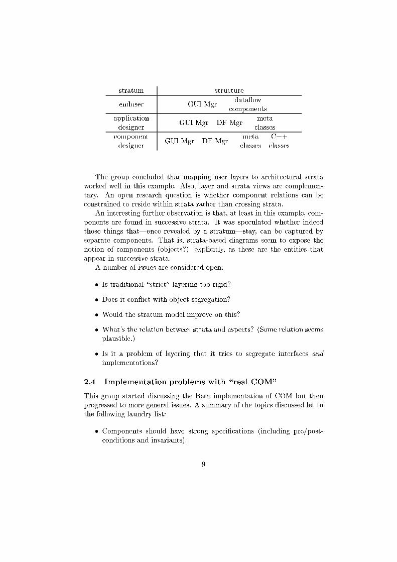
stratum structure
enduser GUI Mgrdata ow
components
application
designerGUI Mgr DF Mgr
meta
classes
component
designerGUI Mgr DF Mgr
meta C++
classes classes
The group concluded that mapping user layers to architectural strata
worked well in this example. Also, layer and strata views are complemen-
tary. An open research question is whether component relations can be
constrained to reside within strata rather than crossing strata.
An interesting further observation is that, at least in this example, com-
ponents are found in successive strata. It was speculated whether indeed
those things that|once revealed by a stratum|stay, can be captured by
separate components. That is, strata-based diagrams seem to expose the
notion of components (objects?) explicitly, as these are the entities that
appear in successive strata.
A number of issues are considered open:
� Is traditional \strict" layering too rigid?
� Does it con ict with object segregation?
� Would the stratum model improve on this?
� What's the relation between strata and aspects? (Some relation seems
plausible.)
� Is it a problem of layering that it tries to segregate interfaces and
implementations?
2.4 Implementation problems with \real COM"
This group started discussing the Beta implementation of COM but then
progressed to more general issues. A summary of the topics discussed let to
the following laundry list:
� Components should have strong speci�cations (including pre/post-
conditions and invariants).
9

� Making robust components on top of non-robust/not-well-de�ned plat-
forms is hard.
� Technology-independent components are an important research goal;
but this is very diÆcult. (Clari�cation: the independence looked for
is independence from platform-speci�c services and implementations.)
� Component technology vendors need to provide examples and expla-
nations which make it easier for implementers who are building com-
ponents.
A question from the audience as to how to teach people to get all these
things right was answered by one of the group members: \You don't. This
will remain largely the expertise of a few." (A pesimistic view indeed|
although backed by the industrial experience with other non-IT component
technologies: after initial shakeouts only a few champions remain in the
race, usually with a rich repertoir of proprietary expertise and technology.)
The suggestion that linguistic support for speci�cation aspects was re-
quired (such as pre/post-conditions) was seen as a good idea.
2.5 Practice versus theory/academia
This group considered the success factors for using theory in practice:
� Mature domains: creation of stable domain models is possible.
� Degree of criticality/complexity: there is a compelling reason to rea-
son.
� Organizational maturity level (in the CMM sense) required to get this
right.
� Scoped usage of theory: don't try to throw the biggest hammer at
everything. (This last point in particular requires great care. It is not
obvious how to contain the \spread" of a theory.)
In the context of components the group observed:
� Theory/formal methods can be naturally con�ned to speci�c compo-
nents, leading to a natural scoping approach.
� Components can bridge the gap between theory and practice: the
results of applying a particular theory in to a speci�c problem can be
reused in component form, helping to ammortize the initial investment.
10

There are two further issues:
� Politics/culture: component approach establishes new dependencies
inside and between organizations.
� Cost/bene�t: component approach requires an ammortization model.
3 Concluding remarks
Concluding, we are able to state that, on the one hand, also the fourth
workshop on component-oriented programming was a highly successful event
that was appreciated by the participants, but, on the other hand, that the
issues surrounding component-oriented programming have not been solved
and that future events remain necessary to further the state of the art.
One interesting trend that we have identi�ed over the years is a change
in focus. Whereas the �rst workshops aimed at the individual components,
especially during the last event there was a clear consensus that the fo-
cus should be on the component architecture, i.e., the cooperation between
components. In particular, not the component-'wiring' standards, such as
CORBA, COM and JavaBeans, but rather the system design level issues,
such as software architectures and component frameworks.
11

Dimensions of Component-based Development
Colin Atkinson Thomas Kühne Christian BunseUniversität Kaiserslautern Universität Kaiserslautern Fraunhofer Institute for
Fachbereich Informatik Fachbereich Informatik Experimental Software EngineeringAG Component Engineering AG Component Engineering Sauerwiesen 6
67653 Kaiserslautern 67653 Kaiserslautern 67661 KaiserslauternGermany Germany Germany
[email protected] [email protected] [email protected]
ABSTRACT
As the properties of components have gradually becomeclearer, attention has started to turn to the architecturalissues which govern their interaction and composition. Inthis paper we identify some of the major architecturalquestions affecting component-based software develop-ment and describe the predominant architecturaldimensions. Of these, the most interesting is the“architecture hierarchy” which we believe is needed toaddress the “interface vicissitude” problem that ariseswhenever interaction refinement is explicitly documentedwithin a component-based system. We present a solutionto this problem based on the concept of stratifiedarchitectures and object metamorphosis Finally, wedescribe how these concepts may assist in increasing thetailorability of component-based frameworks.
1 INTRODUCTIONMuch of the recent debate on component-orientedsoftware development has naturally revolved around thequestion: “what is a component?” Less attention has beengiven to the architectural issues related to the structure ofcomponent-based systems, and the nature of the keyrelationships which drive component-based development- in essence, to the question “where is a component”?Addressing this question we believe will not only helpestablish a cleaner and more general theory ofcomponents, but will also shed light on the “what”question by helping to clarify important characteristics ofcomponents.
We believe four fundamental hierarchies naturallydominate the structure of component-oriented softwaresystems.
1. Containment hierarchy
2. Type hierarchy
3. Meta-hierarchy
4. Architecture hierarchy
The term hierarchy is used in a general sense here torepresent a set of entities related by some transitive,partially ordered relationship.
The first three hierarchies may be termed “intrinsic”,since they contain the actual components themselves. In
other words, every component must be assigned a placein each of these hierarchies. This place is unique for eachcomponent and serves to define its properties andcharacteristics.
The fourth hierarchy, in contrast, can be thought of as“extrinsic” since it is not actually a hierarchy ofcomponents per se, but rather a hierarchy of“architectures” or “architectural strata.” In other words,it is not the components themselves which are partiallyordered, but the architectural strata in which they appear.This hierarchy therefore has more to do with describinghow a component is used than on defining the nature ofthe component itself1.
In the following sections we discuss each of thesedimensions in more detail: section 2 describes the role ofthe component hierarchy, section 3 briefly talks about thetype hierarchy, section 4 discusses the ramifications ofthe meta-level hierarchy, and finally section 5 introducesthe concept of the architecture hierarchy and describes itspotential benefits. Section 6 provides a summary of thekey points, and an analysis of their implications.
2 CONTAINMENT HIERARCHYThe containment relationship is probably the mostfundamental of those influencing the structure ofcomponent-based systems. It also has the largest numberof different names, including “aggregation”, “part-of”,“includes”, “embeds” and of course “composition”. Allthese terms are used to convey the same underlying ideaof “big” objects containing “small” objects. In fact, thevery name component is intended to reflect the idea ofcontainment.
Although simple in concept, containment is notoriouslydifficult to apply in practice. The problem is that 100%“pure” containment rarely occurs in the real word.Contained objects almost always have relationships toobjects other than their container or fellow containedobjects (i.e., they are shared by multiple containers ortemporary clients), and often these can also representsome form of containment. Most object-oriented systems
1 The containment hierarchy can actually can be thought of asplaying a dual role in this sense, because as well as determiningthe nature of a component’s interface it also plays a role indescribing how it is deployed.

2
typically contain a tangled web of inter-object links,making the identification of a clear containment tree anon-trivial problem. In particular, it is often difficult todisentangle “containment” relationships from “uses” or“peer” relationships where no containment is intended.
Why not therefore simply de-emphasize (or ignore) theidea of containment in the structuring of object-orientedand component-based systems? To a certain degree this isthe strategy adopted in the UML which viewsaggregation as a special case of association, and advisesdevelopers to use the latter whenever they are in anydoubt as to the applicability of the former. While it maybe possible to deemphasize containment betweenindividual comp onents, however, the idea of the eventual“system” containing the components from which it iscreated seems inescapable. This idea is as fundamental asthe word component itself.
This brings us to a critical question -
should the assembly of a system be viewed as adifferent activity (i.e. use different concepts andtechniques) from the assembly of a component?
In other words, should the application (or use) of acomponent be viewed as involving different concepts andtechniques than the creation of a component? Mostapproaches to component-based development do notexplicitly address this question, but their terminologyimplies that they view the two as different activities. Inother words, most approaches view a system as being adiffe rent kind of entity from a component.
We believe this to be fundamentally at odds with thephilosophy of component-based development. Thereseems to be no good reason why an assembly ofcomponents developed to meet the requirements for a“system” should not at a later stage also be viewable asan individual component, should their collective servicesbe useful in the creation of a larger system (i.e. as acomponent). However, if one accepts the metaphor:
“a system = a component”
one is compelled to provide a uniform component modelwhich treats all components in the same way regardlessof their location in the composition hierarchy or whetherthey are used as a system or as a part of a system. Theonly factor which should determine the activities andconcepts applied to a component should be relevant therequirements (functional or non-functional).
3 TYPE HIERARCHYAnother hierarchy that plays a fundamental role incomponent-based development is the type hierarchy. Asin object-oriented approaches, the basic idea of a type isto control the linking together and interaction ofcomponents based on some form of explicitly specifiedset of expectations (i.e. a contract). Like containment, theidea of a type also goes by various names, the chiefamong them being “role”, “class”, and “interface”. Theseconcepts all essentially serve to define a set ofexpectations that govern interactions and relationships
between objects. They also can placed into hierarchieswhich organize such “expectation specifications” interms of their commonalties and differences. Thesehierarchies also go by various different names, includingtype hierarchy, role hierarchy and interface hierarchy.
In most existing component technologies a componenttype (i.e. interface) is embodied by the set of operationsthat the component exports, and the information whichthese operations receive and return (i.e. parameters).Exception definitions are also sometimes included. Whilethis provides a rudimentary way of defining expectations,it leaves a lot of information missing. For example, thetypical interface specification says nothing about theexpected effects of operations, or the expectedinterleaving of operations. Guaranteed substitutability ofcomponents, which is the underlying motivation fortyping, requires that the client and supplier of a servicebe in complete agreement about the full nature of theexpectations to be satisfied.
The “system = component” metaphor mentioned in theprevious section, suggests one way of approaching thisproblem; namely, to model a component interface by asuite of UML diagrams as if the component were asystem. Various analysis/design methods present ways ofusing UML (or equivalent) diagrams to described therequirements satisfied by a system, so it would seemreasonable that these might also be useful for modelinginterfaces. At the Fraunhofer Institute for ExperimentalSoftware Engineering we are investigating an approachbased on the diagram suite defined in the Fusion method[1] as adapted for the UML by FuML [2].
4 META HIERARCHYMetamodeling has become fashionable. However, manyof the approaches which claim to be based on metamodeling fail to follow through with the fullimplications. The best example is the UML [3], whichostensibly assumes the four level modeling frameworkillustrated in Figure 1. Each layer, except the bottomlayer, represents a model (i.e. a class diagram)instantiated from the elements described in the layerabove. The exceptions to this rule are the bottom layer,which contains the actual objects embodying the data ofthe user, and the top layer which is regarded as aninstance of itself. Normal user class diagrams reside atthe second level, immediately above the bottom “data”layer.

3
instance_of
instance_of
instance_of
(M0)Data
(M1)Model
(M2)Meta-model
(UML Meta-Model)
(M3)Meta-meta-model
(MOF)
Figure 1. UML Model Framework
The main consequence of this approach for componentsis that elements in all but the bottom layer generally havethe properties of both an object and a class (i.e. they areclabjects [4]). This is because they represent a templatefor instantiating instances at the level below, and at thesame time they are themselves instances of templatesfrom the level above. This dual faceted view ofcomponents is depicted in figure 2.
Type (class) view Instance (object) view
Figure 2. Class/Object View of a Component
Most approaches that adopt such a multi-layered modelhierarchy, such as UML and OPEN, ignore this factbecause it leads to some awkward consequences.Ironically, however, this dual object/class facet couldactually help address a problem that has been central tothe component debate for some time; namely “is acomponent an object or a template (from which objectscan be created)”? Some authors, such as Orfali et. al.view a component as an object with certain additionalproperties [5], but others such as Szyperski, believe that acomponent is not an object, but can only be used toinstantiate objects [6]. If one accepts the class/objectduality implied by a rigorous multi-level modelingframework, the most general answer would be that acomponent is both.
The phrase “most general” is here because not allcomponents will necessarily have both facets all of thetime. However, the class/object duality occurs more oftenthan might be expected. For example, components whichare primarily intended to provide a template forinstantiating objects typically tend to have some “static”information, such as a serial number, which essentialcorresponds to attribute values in the object facet. In theUML, such attributes are called “tagged values”, while inprogramming languages they are called “static data
members”. The only difference from normal attributes isthat that they are not usually changed at run-time.
Similarly, components which are primarily intended toserve as objects (e.g. CORBA objects), often have anassociated reflection API which can be used to provideaccess to certain kinds of “static” information. Also,environments such as CORBA usually store “metainformation” about running objects, typically in interfacerepositories. These both essentially correspond to thetemplate facet of the components.
Even with existing component technologies, therefore,explicit class/object duality may provide a natural andclean unifying model for handling the various char-acteristics of components and the different, oftenseparated, pieces of information that are maintainedabout them. However, the possibility also remains that apure and fully object-oriented component model of thekind characterized by Smalltalk, in which every class hasan explicit run-time presence, may offer one of the bestlong term strategies for promoting component-basedsoftware development.
5 ARCHITECTURE HIERARCHYThe three “dimensions” described in the previoussections are fairly conventional, and in one form oranother appear in most existing component technologies.However, the fourth “dimension” described in thissection is much less conventional, and as far we areaware does not exist explicitly in any of the current orproposed component-based development technologies. Italso differs from the previous three hierarchies in that itis not a hierarchy of components per se. In order toexplain precisely what it is rather than what it is not, wefirst need to elaborate upon the problem that it is aimed atsolving.
5.1 The ProblemTo illustrate the problem we will consider the classicscenario of communication between remote entities in adistributed system. The example will be based on asimple client/server scenario in which a file manger(server) supports requests to read and write strings to andfrom files. We will consider both function-oriented andobject-oriented version of the system, in both localizedand distributed forms.
5.1.1 Localized File Management SystemAs might be expected, the localized, function-orientedversion of the system is the simplest. Figure 3 illustratesa client function, Writer, issuing a call to a server function,write.

4
Void Writer { … write (fn, d) …}
void write {File f, String data}
client
server
Figure 3. Localized Function-Oriented Form
The write function takes two parameters: a reference oftype File serving to identify the target file and a Stringrepresenting the data to be written to the file. The readserver function is similar, but obviously the Stringparameter would have to be passed by reference in orderto return the value. In this example, the actual filereference is fn and the actual string to be written is d.
In an object-oriented system all functions have to belongto objects. The basic difference in the object-orientedversion of the system, therefore, is that the write and writerfunctions have to be defined as part of a class definition,as illustrated in figure 4 (write becomes do_write ). Thebasic interaction is the same, however.
public class File_Manager { public void write (File f, String data); public void read (File f, &String data);{
public class Writer { File_Manager fm;
public void do_write { … fm.write(fn, d) … {{
clientserver
Figure 4. Localized Object-Oriented Form
The Writer and File_Manager classes in the object-orientedversion of the system can also be depicted graphically.Figure 5 is an equivalent UML collaboration diagramwhich indicates that an instance of Writer, called w, sendsa message write() to an instance of File_Manager called fm.
w : Writer
write (fn, d)
fm : File_Manager
Figure 5 Localized UML Collaboration Diagram
5.1.2 Distributed File Management SystemWhether written in a function-oriented or object-orientedstyle, if the client and server are on the same machine thecompiler can simply link all the appropriate componentsinto a single program, and the interaction between themwill be implemented directly as a normal, local function(or method) call.
However, if the file manager and writer need to executeon different machines, things get a little morecomplicated. It is now necessary to arrange for thecommunication to be implemented via the network.
void writer { write (f, d);}
void write { ... make_call(“write”, fn, d); ...}
void write (File f, String data)
void request_dispatcher { loop { ... write {fn, d); ... }}
client
stub
dispatcher
serverLogical interaction
Node A Node B
Figure 6. Distributed Function-Oriented Form
A well-known and widely used strategy forimplementing remote communication is to use a “stub, asdepicted in figure 6. Instead of calling the server functiondirectly, as in the localized system, the client insteadcalls the special “stub” which arranges for the interactionto be implemented in terms of the communicationservices supported by the network. Notice that the nameof the function to be called now has to be passed as aparameter to the remote dispatcher to enable it to decidewhich of its local functions to call. In somecircumstances such stubs can be generated automatically,but in others it may have to be coded by hand. In eithercase, the stub is linked into the client’s program insteadof the original implementation of the server function.
On the server’s side, some form of request dispatcher(a.k.a. entry port) is needed to receive incomingmessages and call the original server function on theremote client’s behalf. This is the request_dispatcherillustrated in figure 6. The job of this entity is to respondto incoming service request by decoding the message andinvoking the appropriate function.
This same idea can of course be applied in the object-oriented version of the system. In fact, this is the basis ofthe ubiquitous “request broker” technology underlyingCORBA and other distributed object environments.
public class Writer’ { ORB o;
public void request_write { orb.request (“write”, fn, d) }}
public class ORB { public request (String name
File, &String); ... }}
public class File_Manager { public void Write(File, String); public void read (File, &String);}
void request_dispatcher { loop { ... Fm.write {fn, s); ... }}
client
ORBDispatcher (ORB)
server
Node A Node B
Figure 7. Distributed Object-Oriented Form
As illustrated in figure 7, the job that previously fell tothe stub2 in the function-oriented version of the systemnow falls to a method of the ORB. In this example themethod is called request(). The body of this method is
2 Different distributed object technologies use words such as“stub” and “proxy” in non-standard ways. In this discussion weuse the word in a general sense, not in the technical sense ofany particular distributed object standard (e.g. COBRA, JavaRMI etc.).

5
essentially equivalent to the stub, and sends theappropriate information over the network in order toimplement the required interaction.
The job of the request dispatcher at the other end is alsoplayed by an orb. ORBs therefore play the general role ofmediators between remote objects which wish to interact.The example is a little artificial since the ORB methodshave parameters which are specific for this application,whereas in general of course they would be moregeneric. Figure 8 provides a UML interaction diagramfor the implementation illustrated in figure 7.
w 2: Writer2
make_call (“write”, fn, d)
fm : File_Manager
oc : ORB os : ORB
write (fn, d)request (“write”, fn, d)
Figure 8. Distributed UML Collaboration Diagram
5.1.3 Interface Vicissitude3
So what is the problem? The basic issue is that in theobject-oriented (and hence component-oriented) versionof the system, the interface between objects can changedepending on the level of abstraction at which theinteraction or relationship between them is described.This can be seen by comparing figures 4 and 7, or theirgraphical UML equivalents, 5 and 8. In figures 4 and 5,the client, Writer, has an interface with File_Manager inwhich it invokes the operation write(). In a distributedimplementation, this interaction might be referred to asthe logical interaction. However, in figures 5 and 8, bycontrast, the client, Writer, has no interface withFile_Manager at all, but instead has an interface withORB, in which it invokes the request() operation.
The phenomenon is not confined to the implementationof distributed communication, or to just two architecturelevels. On the contrary, it occurs whenever an abstractinteraction is refined into a more detailed descriptioninvolving lower level components and less abstractinteractions. Examples include transactions, security,persistence etc. - in fact, almost any service provided bycomponent-based environments such a CORBA. Theidea can also obviously be generalized to multiple levels.In fact, the interaction described in this example caneasily be generalized to a third level by viewing the type,File, as a “persistent” class type rather than as a simplereference type and treating the write() operation as amethod of this class rather than File_Manager. This wouldgive the following view of the interaction illustratedtextually in figure 9 and graphically in figure 10.
3 Vicissitude; n: regular change or succession of one thing toanother, alternation; mutual succession, interchange (Webster’sUnabridged Dictionary).
public class File {public void write (String data);public void read (&String data);
{
public class Writer {File fn;
public void do_write { …
fn.write(d); … {{
clientserver
Figure 9. “Persistent Class” Object-Oriented Form
w : Writer write (d)
fn : File
Figure 10. “Persistent Class” UML Collaboration Diagram
If we think of the structure and interactions described bythe preceding figures as representing the architecture ofthe system (which in essence is what is meant by“architecture”), this means that the system can beconsidered to have different architectures at differentlevels of abstraction. Figures 4 and 5 representdescriptions of the architecture of the system (the firsttextual, the second graphical) which are equally as validas figures 5 and 8 (and figures 9 and 10), the onlydifference is the level of abstraction at which theinteraction to write information to a file is described.This would perhaps not be such an issue if the propertiesof the component involved in each view remainedconstant, but this is not the case — the interface4 of theuser component Writer is completely different in eachcase. In other words, the interface of Writer changesdepending on which architectural perspective it is viewedfrom. This is what we refer to as “interface vicissitude”.
Why is this a problem? In this small example we haveshown three equally valid views of the architecture of thesystem, each with different interfaces for the Writercomponent. This begs the question as to which of thearchitectures is the correct (or best) one, or alternativelywhich of the interfaces of Writer is the correct (or best)one? If only one is to be considered the architecture,which one is it and how is it chosen?
Of course, it is always possible to place a wrapper aroundan ORB in the style of the Adapter pattern to make ithave the appearance of the final server. In this example,this would mean placing a “proxy” on the client side topresent the File_Manager interface to Writer instead of theORB interface. But this essentially represents an attemptto simulate one architecture in terms of another, andimplies that for some reason one architecture (orinterface) has been chosen as preferable to another.However, unless superior tools are available at the higherabstraction level, or the translation to the lower level is 4 The interface involved is often called the “required” or“imported” interface since it defines facilities used by thecomponent rather than services provided for use by others.

6
fully automated, inserting such proxies only serve tocomplicate the lower-level architecture and decrease itsefficiency. The issue is one of architecture modeling, orconceptualization, rather than interface adaptation.
It is interesting to consider why this problem does notarise in function-oriented software architecture. Thereason goes right to the heart of what differentiatesfunction-oriented approaches from object orientedapproaches; object identity. In the function-orientedversions of the system (figures 3 and 6) the interfacebetween the writer and the File_Manager is not at allaffected by the identity of the communicating partners.As a consequence, the real write() method can be replacedby a stub (to handle remote communication) without inany way affecting the original communicating parties.This facilitates the creation of layered architectures of thekind characterized by the ISO Open SystemsInterconnection model illustrated in figure 11. Becauseinteractions at a given level can be refined withoutaffecting the original communicating parties, clean layerscan be established in which each module occupies oneand only one layer.
presentation layer
session layer
transport layer
network layer
data layer
application layer
physical layer
presentation layer
session layer
transport layer
network layer
data layer
application layer
physical layer
logical
interface
physical interface
Figure 11. ISO OSI Model
In the object-oriented approach, in contrast, the identity(and hence the type) of the server object is bound up inthe definition of every client/server interface. This meansthat it is not possible to refine a high-level interaction bythe introduction of intermediary objects withoutchanging the interface of the client objects. This isillustrated in figure 12, which shows that in refining aninteraction between two objects X and Y, not only areadditional objects A and B introduced (as in the function-oriented approach) but the interface of the client X ischanged to that of X’.
X Y
YX’
A
Figure 12. Interaction Refinement
5.2 The SolutionFrom a practical perspective the architecture which is themost “real”, and which is normally regarded as thearchitecture, is the one that describes the system at thehighest level of abstraction that can be understood andmanipulated by automated tools. In other words, it is theone which describes the system in terms of conceptssupport directly by a high-level programming orinterface language. For example, a CORBA developerusually thinks in terms of an architecture that directlyinvolves ORBs and the other mediating elements thatmake up the OMG OMA.
Theoretically speaking, however, this particulararchitecture is no more “real” than any of the otherarchitectures at higher levels of abstraction. They eachrepresent an equally valid and complete description ofthe system. In fact, there are also often additionalarchitectures at (hidden) lower levels because mostcompilers insert additional “system” objects to supportthe implementation of the abstractions in theprogramming language. For example, the transformationfrom the “persistent class” architecture illustrated infigure 9 and 10, to the “File Manager” architectureillustrated in figures 3 and 4, is often performedautomatically by a compiler when implementingpersistent objects. Ult imately, interaction with the kernelitself can be thought of as a refinement of higher levelarchitectures.
For these reasons, we believe the only theoretically cleanway of handling the interface vicissitude problemoutlined above is to define a conceptual frameworkwhich makes all the important architectural levelsexplicitly visible by organizing them in a hiera rchy of theform illustrated in figure 11. This illustrates a conceptualarchitecture that was used within the MISSION project atthe University of Houston – Clear Lake to visualize thehighly complex system architectures needed for safetycritical, non-stop, distributed systems [7]. Each level inthis model defines a full object-oriented architecture,each providing a complete, and semantically equivalent,description of the system. An architecture at a givenlevel represents a refinement of the architecture at thelevel above. The compiler (and other automated tools)may only directly understand the bottom level, butexplicitly identifying and elaborating the more abstractlevels (and the relationships between them) isincreasingly being recognized as important forsupporting systematic development and traceability, andthus ultimately system quality [8].

7
…
Figure 11 Architectural Levels
5.2.1 Stratified ArchitecturesAlthough each of the levels in figure 11 represents anarchitecture in the sense that the term is usually used (i.e.a description of the elements, relationships andinteractions in a system), we believe it is not particularlyintuitive to think of a system as having multiplearchitectures. Instead, we prefer to stay with the conceptof a single architecture for a single system, but tointroduce the concept of multiple strata within a givenarchitecture. Thus, instead of saying that figure 11illustrates multiple architectures, we would say that itillustrates a single architecture consisting of multiplestrata.
It is important to realize that these strata are not layers inthe normal sense. This is because one stratum mayactually contain the same object as another stratum, butwith a different interface reflecting the effects of aninteraction refinement. In contrast, architectural elementin a conventional layered architecture such as the ISOOSI architecture illustrated in figure 11, appear in oneand only one layer. Of course, it is possible to define alink between the two concepts. Within a given level of astratified architecture it is possible to define layerscorresponding to the higher level strata, in whichelements are allocated to layers depending on theirstratum of first appearance.
It is also important to realize that these layers do notcorrespond to the usual analysis, design an implementa-tion descriptions of a system that are assumed in mostobject-oriented development methods. This is becauseeach architecture level describes “how” the system isorganized (as opposed to what it supposed to do foranalysis models), and each provides as full a descriptionof the system as any other.
5.2.2 Object MetamorphosisThe architecture strata concept addresses the interfacevicissitude issue from an “architectural” perspective, butit does not provide a good way of dealing with thephenomenon from the perspective of an individual objector class. For example, what is the nature of the
relationship between X and X’ in figure 12, or the Writerand Writer’ from figures 4 and 7 respectively.
A metaphor from real life which seems to reflect thephenomenon fairly accurately is the idea ofmetamorphosis. The relationship between X and X’ andWriter and Writer’ seems similar to the relationshipbetween a caterpillar and the butterfly which it eventuallybecomes. The caterpillar and the butterfly are the sameobject, but have totally different external forms andcharacteristics. This also ties in well with the idea ofarchitectural strata, since the concept of metamorphosis isalso applied in geology to the process which changes acertain kind of rock into another form.
In the context of a stratified architecture, therefore, wedescribe X’ as a metamorphosis of X, and Writer’ a s ametamorphosis of Writer. In figure 11, a black circlewithin an architectural stratum represents ametamorphosis of an object in the level above whereas awhite circle denotes an object newly introduced at agiven level.
5.2.3 Related ConceptsThe idea of viewing a component-based architecture ascontaining multiple strata, in which a given componentmay appear in numerous strata in different forms, seemsto have a relationship to several other areas of objecttechnology that are currently generating significant ofinterest. We mention the main ones briefly below.
ConnectorsThe idea of “connectors” is a recurring theme in abstractcomponent-based programming models. The goal isbasically to try to reify the connections betweencomponents, so that like components they also can betreated as first class citizens. However, most attemptshave run into problems in handling the large variety andform of “connectors” at a single level of abstraction. Theidea of explicitly defining multiple architecture levelsmay help address this problem by cleanly allowingobjects to be associated with connectors, albeit at a lowerarchitectural strata than the components they originallyconnect.
Reflective ArchitecturesA fashionable concept in recent years has been the ideaof reflective architectures, in which aspects of a system’sfunctionality related to the interaction of regularcomponents are separated into a distinct “meta” level. Ina sense, a stratified architecture can be viewed as ageneralization of such a reflective architecture, since italso provides a way of separating functionality related tocomponent interaction. However, we believe thestratified architecture concept to be more powerfulbecause not only can it be generalized to multipleabstraction levels, but it also requires the introduction offewer additional modeling concepts. In contrast,reflective architectures require quite a complex set ofadditional mechanisms.

8
FrameworksLast but not least, the stratified architecture concept mayprove useful in the creation of flexible componentframeworks. A framework is essentially a semi-completesoftware system which has been carefully parameterizedwith respect to the components that represent the mostvariable elements of the domain. A system can thus beinstantiated from the framework simply by providing thespecific components needed for the particular applica-tion.
The problem is that components (i.e. objects) are notnormally the most variable elements of a softwarearchitecture - the interactions (i.e. functions) betweencomponents are. Indeed, the validity of this statement isone of the main grounds given for the superiority of theobject-oriented approach over function orientedapproaches. By providing an explicit representation ofhigh-level interactions in terms of lower-level objects andinteractions, a stratified architecture can facilitatecomponent-based parameterization which much moreclosely matches the elements of highest variability in adomain. In other words, in contrast with a normalframework, based on a normal (single-level) architecture,a stratified framework can be parameterized with respectto components form various strata, not just the top level.
6 CONCLUSIONIn this paper we have identified some of the majorarchitectural issues affecting component-based softwaredevelopment, and have described what we believe to bethe four predominant architectural dimensions.
Two other dimensions are also worthy of mention, andplay a significant role in component-based development.The first of these is the dimension which deals withdifferent versions and releases of components. In a sensethis can be viewed as the time dimension, since versionsare created and exist over time. In the terminology usedpreviously this would be thought of as an intrinsicdimension since it involves the components themselves.
The second might best be thought of as the“representation” dimension, since it deals with thedifferent ways in which a given component can berepresented (e.g. graphically, textually etc.). As such itwould be an extrinsic dimension, since it does notinvolve the comp onents per se.
The architecture dimension explained in section 4handles one particular form of refinement, albeit one ofthe most important, which is interaction refinement.However, there are numerous other forms of refinementwhich exists between different descriptions of the samephenomenon at different levels of abstraction. Thesedifferent forms of refinement need to be distinguishedfrom translation which describes a given phenomenon ina different way but at the same level of abstraction.
Of the various dimensions presented, the mostunconventional is the architectural dimension which webelieve is needed to address the interface vicissitudeproblem that arises whenever interaction refinement is
explicitly documented within a component-based system.After describing the details of the problem, we presenteda solution based on the concepts of stratified architecturesand object metamorphosis. We also explained how thisapproach could help in other important object orientedtechnologies. In particular, we briefly discussed howstratified frameworks could be designed to provide amore optimal representation of the high variabilityelements (i.e. hot spots) in most software domains;namely those related to component interactions.
The main question which remains unanswered in thispaper is how these various dimensions relate to oneanother and which if any, is the most dominant. Thisquestion, as well as the other ideas presented in the paper,are the subject of ongoing research within the componentengineering group at the university of Kaiserslautern, andthe SOUND and KobrA projects at the FraunhoferInstitute for Experimental Software Engineering..
REFERENCES1. D. Coleman et. al., Object-Oriented Development:
The Fusion Method , Prentice Hall, 1994.
2. C. Atkinson. “Adapting the Fusion Process .” ObjectMagazine, pages 32–40, Nov. 1997.
3. C. Atkinson, “Supporting and Applying the UMLConceptual Framework,” Lecture Notes in ComputerScience, UML'98, Mullhouse, France. 1998.
4. C. Atkinson, “Metamodeling for Distributed ObjectEnvironments,” First International EnterpriseDistributed Object Computing Workshop(EDOC’97). Brisbane, Australia. 1997.
5. R. Orfali, D. Harkey and J. Edwards, “The EssentialDistributed Object Survival Guide”, Wiley and Sons,1996.
6. C. Szyperski, Component Software - Beyond Object-Oriented Programming, Addison-Wesley /ACMPress, 1998.
7. C. Atkinson and C. W. McKay, “A GenericArchitecture for Distributed, Non-Stop, Mission andSafety Critical Systems ,” Second IFAC Workshopon Safety and Reliability in Emerging ControlTechnologies, Daytona Beach, FL, November 1995.
8. D. D'Souza and A. C. Wills, Catalysis: Objects,Frameworks, and Components in UML, Addison-Wesley, 1998.

An Aspect-Oriented Design Framework for Concurrent Systems
Constantinos A. Constantinides, Atef Bader, Tzilla Elrad
Concurrent Programming Research CenterDepartment of Computer ScienceIllinois Institute of Technology
10 W. 31 St. Chicago IL 60616, U.S.A{conscon, elrad} @charlie.cns.iit.edu, [email protected]
Abstract
In Aspect-Oriented Programming we decompose aproblem into a number of functional components as wellas a number of aspects and then we compose thesecomponents and aspects to obtain system implementa-tions. The goal is to achieve an improved separation ofconcerns in both design, and implementation. Our workconcentrates on the aspectual decomposition of concur-rent object-oriented systems. Following the componenthierarchy within the object-oriented programmingparadigm we categorized aspects as intra-method, in-tra-object and intra-package according to their hierar-chical level of cross-cutting. We achieve composition ofconcerns, through the use of an object we call the mod-erator that coordinates the interaction of componentsand aspects while preserving the semantics of the over-all system. Since aspects can cut across components atevery level, we view the moderator is a recurring pat-tern from intra-method to intra-package. Our designframework provides an adaptable model and a compo-nent hierarchy using a design pattern. The moderatorpattern is an architecture that allows for an open lan-guage where new aspects (specifications) can be addedand their semantics can be delivered to the compilerthrough the moderator. In essence the moderator is aprogram that extends the language itself. Our goal is toachieve separation of concerns and retain this separa-tion without having to produce an intermingled sourcecode.
Keywords: Aspect-Oriented Programming, Concurrentprogramming, Open Implementation.
1. Introduction and statement of theproblem
There are numerous benefits from having an impor-tant concern of a software system being expressed welllocalized in a single code section. We can more easilyunderstand it, analyze it, modify it, extend it, debug it,
reuse it etc. The need for dealing with one importantissue at a time was coined as the principle of separationof concerns [6]. To date, the primary idea for organizingsoftware systems has been based on software decompo-sition, where a problem would be broken down into sub-problems that can be addressed relatively independ-ently. A component is defined as a modular unit offunctionality. Software decomposition and program-ming languages have been mutually supportive. Currentprogramming languages and paradigms support a num-ber of modular representations such as subroutines, pro-cedures, and objects. They further support compositionof modules into whole systems. At the same time, manysystems have properties that do not necessarily alignwith the system's functional components, and cannot belocalized to objects (or any other traditional modularunit). Example issues include resource allocation, per-formance optimizations, failure handling, synchroniza-tion, coordination, memory management, real-time con-straints, distribution of tasks, network reconfiguration,and scheduling policies. Aspects are defined as proper-ties that tend to cut across groups of functional compo-nents. In essence, an aspect is a new kind of program-ming construct that supports a new kind of module,where a cross-cutting concern is captured in a clear unit.While these aspects can be thought about and analyzedrelatively separately from the basic functionality, at theimplementation level they must be combined together.Programming them manually into the system’s func-tionality using current component-oriented languagestends to result in these aspects being spread throughoutthe code [9, 10]. This code tangling makes the sourcecode difficult to develop, understand, and evolve bydestroying modularity and reducing software quality. InObject-Oriented Programming (OOP) the major goalsare abstraction, modularity, and code reuse. Aspect-Oriented Programming (AOP) retains these goals andmanages to go a step further in order to avoid the prob-lem of code tangling. Although AOP is not bound toOOP, we can view it as an extension of OOP, and assuch it is more than a programming paradigm. In [11,14] AOP is viewed as a design framework for separat-

ing the concerns in a system. It is therefore not bound toprogramming only but rather should be viewed as ageneral modeling mechanism, which applies to allphases of the life cycle of the software. In fact, [13, 16]encourage aspectual decomposition from the very be-ginning. Current AOP approaches view components andaspects as two separate entities where the aspects areautomatically weaved into the functional behavior of thesystem in order to produce the overall system. In [14] itwas argued that generalized procedure languages do notprovide the right abstraction for the description of as-pects. The importance of having appropriate languagesfor the expression of aspects was also addressed and itwas argued that aspect languages, can make aspect codemore concise and easier to understand. If aspects areexpressed in domain-specific languages, one needs anaspect language for every type of aspect. The weaverimplements one (or more) aspect languages. Currentweavers are implemented bearing in mind the nature ofaspects, and weavers can only be produced for aspectswhere the interactions between the different aspects arewell understood. They are relatively difficult to under-stand, and they can for the moment only be built forspecialized purposes [13]. In [8] it is argued that it is theinteraction of components and aspects that makesweaving necessary. The necessity of the weaver is alsostressed in [5]. On the other hand [17] views weaving asa more general process that corresponds to componentcomposition rather than merging, with binding accord-ing to the normal rules of compile time inheritance.
One difference in the proposals for supporting AOPresides in the way in which aspects are weaved acrossthe functional components of the system: if the weavingis static or dynamic, and if there is code transformation.Additionally there are proposals of specific languagesfor the support and implementation of AOP versus ex-tensions to general-purpose languages, plus differencesin the level of abstraction of these implementations. Weargue that automatic weaver implementations and aspectlanguages impose a number of restrictions which wediscuss below:
Increased complexity of a general-purpose aspectlanguage. Where a general-purpose aspect language isimplemented, the introduction of new types of aspectswill require the language to be extended in order to pro-vide new constructs for their representations. As thenumber of these aspects increases, the complexity of theaspect language would also increase.
Expressiveness of general-purpose aspect languages.Can a general-purpose aspect language really be generalpurpose? We yet have to see real examples of express-ing different kinds of aspects such as synchronization,scheduling, fault tolerance, etc. in current proposals.
Restrictions imposed by static weaving, and lack ofsupport of dynamic weaving. In current implementa-tions, the weaving process is static. Aspects referencethe classes of those objects whose behavioral additionsdescribe, and define at which join point additions shouldbe made. Static weaving means to modify the sourcecode of a class by inserting aspect-specific statements atjoin points. In other words, aspect code is inlined intoclasses. The result is a highly optimized woven codewhose execution speed is comparable to that of codewritten without AOP. The aspect weaver delivered withAspectJ [10] is an example for a static weaver. How-ever, static weaving makes it difficult to later identifyaspect-specific statements in woven code. As a conse-quence, adapting or replacing aspects dynamically dur-ing run-time can be time consuming or not possible atall. An example where this would be beneficial is givenby [13] where a load balancing aspect could replace theload distribution strategy woven before with a better onedepending on the current load of managed servers. Cur-rently, automatic weaving is not a viable technology forimplementing aspects in a dynamic environment. Dy-namic weaving facilitates incremental weaving andmakes debugging easier. On the other hand, staticweaving has advantages over performance [4]. Ideally,an implementation should support both static and dy-namic weaving. A feasible approach to handle dynamicweaving is to implement aspects using meta-objects. Anumber of proposals address dynamic weaving throughthe use of meta-programming [12, 15].
Increased complexity of an automatic weaver. Theweaver confines itself to the nature of the aspects andthe constructs provided by the aspect language(s) it im-plements. The weaver must contain a specific interpreterfor each aspect description language. If a new type ofaspect of concern were to be added to the model, theweaver would have to be modified (extended) to adaptto the new model. As different aspect description lan-guages address different types of aspects, an increase inthe number of aspect language would result in an in-crease in the complexity of the weaver.
Aspect inter-relationships. An open problem remainsthe issue of aspect-aspect interaction. We can break thisdown into two areas: 1) relationship of orthogonal as-pects and 2) the existence of non-orthogonal aspects.The relationship of orthogonal aspects relies on theirorder of activation and on their validation and verifica-tion. Current aspect-oriented architectures have ad-dressed models where aspects are orthogonal and there-fore present a flat structure. There are cases where as-pects are not orthogonal, but they can cut across eachother. In these cases the overall structure is not flat butrather hierarchical. The issue of non-orthogonal aspectsstill remains an open problem, which we believe can be

attacked in either of two ways: 1) by language designand 2) by implementation.
Debugging and level of weaving. Current imple-mentations such as AspectJ, weaving is done beforecompile time. Of great interest remains the issue of de-bugging an aspect program. In current proposals, suchas AspectJ, the only way of thinking about and thereforebedugging a program is to examine the woven code. Webelieve that this should not be the case and the imple-mentor should not be constrained by the requirementthat there exist woven code that is readable by the pro-grammer. In [3] the author proposes a reflective archi-tecture where weaving is done at the metalevel so that toavoid the intermingling of component and aspect code.However, this approach suffers for a decrease of theperformance of the application.
2. Introduction to the Aspect ModeratorPattern
We believe that neither the use of aspect languagesnor an automatic weaver tool provides a necessity inorder to achieve separation of concerns. We shift theweaver’s responsibility to a class, which we call themoderator class that would coordinate aspects and com-ponents together (figure 1). The moderator class shouldbe extensible in order to make the overall system adapt-able to addition of new aspects. We also believe that theuse of a moderator class provides the flexibility to theprogrammer to retain the definition of aspects by currentprogramming languages. It also provides the basis for adesign framework that would make use of patterns. Theimportance of design patterns within the AO technologywas addressed in [11]. The moderator class defines thesemantic interaction between the components and theaspects. Further, the semantics of the model define theorder of activation of the aspects. We view a concurrent(shared) object as being decomposed into a set of ab-stractions that form a cluster of cooperating objects: afunctional behavior, synchronization, and scheduling.The behavior of a concurrent object can be reused, orextended. There are other issues that might also be in-volved, such as security and fault tolerance. We focuson the relationships between these abstractions withinthe cluster. We propose an aspect-oriented design pat-tern that we call the aspect moderator pattern. This pat-tern makes use of a class, which acts as a proxy to thefunctional component, and would moderate the func-tional behavior together with different aspects of con-cern, by handling their interdependencies. We stress thefact that the activation order of the aspects is the mostimportant part in order to verify the semantics of thesystem. Synchronization has to be verified beforescheduling. A possible reverse in the order of activation
may violate the semantics. If security is introduced to ashared object, we first need to verify the identity of thecaller and therefore we first have to handle security be-fore synchronization.
3. Architecture of the moderator pattern
A sequential object is comprised by functionalitycontrol and shared data. Access to this shared data iscontrolled by synchronization and scheduling abstrac-tions. Synchronization controls enable or disablemethod invocations for selection. The synchronizationabstraction is composed of guards and post-actions.During the precondition phase, guards will validate thesynchronization conditions. In the post-condition phase,post-actions will update the synchronization variables.The scheduling abstraction allows the specification ofscheduling restrictions and terminate-actions. At thepre-condition phase, scheduling restrictions use sched-uling counters to form the scheduling condition for eachmethod. At the post-condition phase, terminate actionsupdate the scheduling counters. The moderator class isderived from the functionality class. During the precon-dition phase, the synchronization constraints of the in-voked method are evaluated. If the current synchroniza-tion condition evaluates to TRUE, a RESUME value isreturned to the caller, and the scheduling constraints areevaluated; otherwise a BLOCKED value is returned. Theevaluation of the scheduling restrictions will also returnRESUME or BLOCKED. After executing the preconditionphase, the moderator will activate the method in thesequential object. During post-condition, synchroniza-tion variables and scheduling counters are updated uponmethod completion. This section addresses four issues:1) non-orthogonality of aspects, 2) the provision of anadaptable model, 3) the provision of a design and im-plementation hierarchy and 4) composition of aspects.
3.1 Non-orthogonal aspects
The moderator can handle the issue of non-orthogonal aspects by expressing the semantics of thedependencies between two non-orthogonal aspects. Forexample, during the pre-condition phase of the securityaspect, the moderator can include variables from anynon-orthogonal aspect to security.
3.2 Adaptability
Aspects can be replaced, or extended. One of theadvantages of this approach is that if a new aspect ofconcern would have to be added to the system, we donot need to modify the moderator. We can simply createa new class to inherit and re-define it, and reuse it for anew behavior. The inherited class can handle all previ-

ous aspects, together with the newly added aspect.Much like one can weave aspects on demand, such astracing aspects [3], our framework provides this optionby easily adding or ignoring an aspect of a componentwithin a cluster. Adaptability is also applied to compo-nents. This design framework addresses the complexityissue in the case where new aspects are introduced andwould have to be added. The aspect-moderator patterndoes not require some new syntactic structure for therepresentation of new aspects, but simply a new classfor the new aspect. Adaptability includes cases where anaspect will have to be removed from the overall system.
aspects functional behavior
method A
method B
synchronization
scheduling
moderator
OBJECT
Figure 1. The aspect moderator.
3.3 Design hierarchy
In [2] it is argued that it seems natural to chooseclasses (objects) as components in the OOP paradigm.We take this argument further and propose a hierarchyof components according to the component hierarchywithin the OOP paradigm. At the lowest level we have amethod. Methods are combined into objects where eachobject belongs to a class, and several classes can belongto a package. We can apply the moderator pattern to alllevels of this hierarchy since aspects can cut acrossevery member of this component hierarchy. One ormore aspects can cut across invocations within a singlemethod. We call these aspects, intra-method (or inter-invocation). Aspects can also cut across methods withina single object. We refer to these as intra-object aspects(or inter-method). Aspects can also cut across objectswithin the same package. We refer to these as intra-package aspects (or inter-object). The programmer hasto identify the aspects at each level and address themindependently. Since aspects can cut across componentsat every level, the moderator is a recurring pattern fromintra-method to intra-package. Our design frameworkwill be based on this hierarchy since we believe that it
provides a better aspectual analysis and design of asystem. Our approach follows a component design andimplementation hierarchy (figure 2). According to ourclassification of aspects, the moderator at the lowestlevel can therefore be referred to as intra-method. At thenext level the moderator is referred to as intra-object,and at the highest level it is referred to as intra-packagemoderator.
3.4 Composition of aspects
At each level of the hierarchy we can maintain anaspect bank, where the moderator of a cluster may ini-tially need to collect all the required aspects from. Theaspect bank (figure 3) is a hierarchical 2-Dimensionalcomposition of the system in terms of aspects and com-ponents. The moderator will initially consult the aspectbank in order to collect the required aspects.
method B
aspect 1
aspect 2
method A
invocation 1
invocation 2
intra-methodmoderator
intra-object
moderator
aspect 1
aspect 2
OBJECTfunctional behavior
aspects
Figure 2. Design hierarchy.
Synchronization
Scheduling
Security
Component 1
Component 2
Component 3
Component 4
Fault Tolerance
Figure 3. An example of an aspect bank.
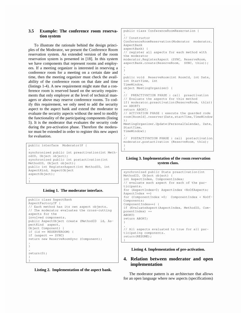
3.5 Example: The conference room reserva-tion system
To illustrate the rationale behind the design princi-ples of the Moderator, we present the Conference Roomreservation system. An extended version of the roomreservation system is presented in [18]. In this systemwe have components that represent rooms and employ-ees. If a meeting organizer is interested in reserving aconference room for a meeting on a certain date andtime, then the meeting organizer must check the avail-ability of the conference room on that date and time(listings 1-4). A new requirement might state that a con-ference room is reserved based on the security require-ments that only employee at the level of technical man-agers or above may reserve conference rooms. To cod-ify this requirement, we only need to add the securityaspect to the aspect bank and extend the moderator toevaluate the security aspects without the need to modifythe functionality of the participating components (listing5). It is the moderator that evaluates the security codeduring the pre-activation phase. Therefore the modera-tor must be extended in order to register this new aspectfor evaluation.
public interface ModeratorIF {.synchronized public int preactivation(int Meth-odID, Object object);synchronized public int postactivation(intMethodID, Object object);public int RegisterAspect(int MethodID, intAspectKind, AspectObjectaspectObject);.}
Listing 1. The moderator interface.
public class AspectBankAspectFactoryIF {// Each method has its own aspect objects.// The moderator evaluates the cross-cuttingaspects for theinvolved components.public AspectObject create (MethodID id, As-pectKind aspect,Object Component) {if (id == RESERVEROOM) {if (aspect == SYNC)return new ReserveRoomSync (Component);.}.return(0);}}
Listing 2. Implementation of the aspect bank.
public class ConferenceRoomReservation {.// ConstructorConferenceRoomReservation(Moderator moderator,AspectBankaspectBank) {// register all aspects for each method withthe moderatormoderator.RegisterAspect (SYNC, ReserveRoom,aspectBank.create(ReserveRoom, SYNC, this));.}.public void ReserveRoom(int RoomId, int Date,int StartTime, intTimeWindow,object MeetingOrganizer) {.// PREACTIVATION PHASE : call preactivation// Evaluate the aspects for this methodif( moderator.preactivation(ReserveRoom, this))== ABORT)return ABORT;// ACTIVATION PHASE : execute the guarded coderoom[RoomId].reserver(Date,startTime,TimeWindow);MeetingOrganizer.Update(PersonalCalendar, Date,StartTime,TimeWindow);.// POSTACTIVATION PHASE : call postactivationmoderator.postactivation (ReserveRoom, this);}}
Listing 3. Implementation of the room reservationsystem class.
synchronized public State preactivation(intMethodID, Object object) {int AspectIndex, ComponentIndex;// evaluate each aspect for each of the par-ticipants.for (AspectIndex=0; AspectIndex <NoOfAspects;AspectIndex ++)for (ComponentIndex =0; ComponentIndex < NoOf-Components;ComponentIndex++) {if (EvaluateAspect(AspectIndex, MethodID, Com-ponentIndex) ==ABORT)return ABORT;}.// All aspects evaluated to true for all par-ticipating components.return(RESUME);}
Listing 4. Implementation of pre-activation.
4. Relation between moderator and openimplementation
The moderator pattern is an architecture that allowsfor an open language where new aspects (specifications)

can be added and their semantics can be delivered to thecompiler through the moderator. In essence the mod-erator is a program that extends the language itself.
public class AspectBank2 extends AspectBank {.public AspectObject create(MethodID id, As-pectKind aspect, ObjectComponent){if(id == RESERVEROOM) {if (aspect == SECURITY)return new ReserveRoomSecurity(Component);.}// the aspect may be defined in the base classreturn(super. create(id, aspect, Component));}}
Listing 5. Extended aspect bank.
5. Comparison with other work
This section compares our proposal for a designframework using the moderator pattern, and currentapproaches that rely on the use of automatic weavers.Both the automatic weaver and the moderator ap-proaches provide the elegance of the original clean codeduring the analysis and design of the system. The differ-ences between using a weaver and using the moderatorpattern, are summarized by the following table:
Weaver: Combines two kinds of code (aspect andcomponent code) into one intermingled source code.Output of the weaver is the equivalent of traditionalapproach.
Moderator: Coordinates two kinds of code, retainingthe separation of concerns (aspect and componentcode). Avoid having to produce an intermingledsource code.
Weaver: One weaver combines all aspects and com-ponents together. There is no design hierarchy.
Moderator: a recurring design pattern. It provides anoverall system hierarchy, addressing intra-method,intra-object, and intra-package aspects in a systematicway.Weaver: Adding new aspect(s) will require either newaspect language(s) or new construct(s) within currentaspect languages.
Moderator: Adding new aspect(s) is done by inheri-tance, and by adding new pre-condition and post-condition.Weaver: Must gather contact points of emerging enti-ties.
Moderator: A design pattern hooks aspects and com-ponents: the moderator class defines the semantic in-teraction between components and aspects.Weaver: Two phases of compilation (weaving, com-piling).
Moderator: One compilation phase.
6. Conclusion
In AOP, the weaver combines components (func-tional behavior) and aspects into one unit, which is theoverall behavior of the system. In our design frameworkthe overall behavior is made up of 1) the functional be-havior, 2) the aspects, and 3) a moderator class that co-ordinates the interaction between aspects and compo-nents while observing the overall semantics. The Mod-erator approach partitions systems into a collection ofcooperating classes. The collaboration among the par-ticipants may have few aspects. Addressing these as-pects that cut-across the participating objects may pro-duce tightly coupled classes which may reduce reus-ability. The moderator approach attempts to separatethese aspects from the functional components in order topromote code reusability and make it easier to validatethe design and correctness of these systems. Thisframework can address non-orthogonal aspects, andprovide for an adaptable model with ease of modifica-tion. It further provides a component hierarchy, wherethe moderator is a recurring pattern. This design princi-ple manages to achieve separation of concerns. There isno difference in the way we separate the concerns. Westill have to think about them from the early stages ofthe software life cycle. We further like to pose the fol-lowing issues for discussion: 1) Aspect-Oriented Pro-gramming and Open Implementation, 2) weaver vs.moderator: (a) intermingled source code as output vs.intermingled code only at the executable level and (b)two phases of compilation vs. one phase of compilation,3) design hierarchy and 4) the capability of the mod-erator to observe the semantics of the system in order toaddress non-orthogonal aspects.
7. References
[1] Atef Bader and Tzilla Elrad. Framework and Design Pat-tern for Concurrent Passive Objects. In Proceedings ofIASTED/SE ’98.
[2] Daniel Bardou. Roles, Subjects, and Aspects. How do theyRelate? Position paper at the ECOOP ’98 workshop on As-pect-Oriented Programming.
[3] Kai Böllert. Aspect-Oriented Programming Case Study:System Management Application. Position paper at theECOOP ’98 workshop on Aspect-Oriented Programming.

[4] Kai Böllert. On Weaving Aspects. Position paper at theECOOP’99 workshop on Aspect-Oriented Programming.
[5] Wolfgang De Meuter. Monads as a Theoretical Founda-tion for AOP. Position paper at the ECOOP ’97 workshop onAspect-Oriented Programming.
[6] Edsger W. Dijkstra. A Discipline of Programming. Pren-tice-Hall, 1976.
[7] Gregor Kiczales, John Lamping, Anurag Mendhekar, ChrisMaeda, Cristina Lopes, Jean-Marc Loingtier, and John Irwin.Aspect-Oriented Programming. In Proceedings of ECOOP’97. LNCS 1241. Springer-Verlag, pp. 220-242. 1997.
[8] John Lamping. The Interaction of Components and As-pects. Position paper at the ECOOP ’97 workshop on Aspect-Oriented Programming.
[9] Cristina V. Lopes. D: A language Framework for Distrib-uted Programming. Ph.D. Thesis. Graduate School of theCollege of Computer Science. Northeastern University. Bos-ton, Massachusetts, 1997.
[10] Cristina Lopes and Gregor Kiczales. Recent Develop-ments in AspectJ. Position paper at the ECOOP ’98 workshopon Aspect-Oriented Programming.
[11] David H. Lorenz. Visitor Beans; An Aspect-OrientedPattern. Position paper at the ECOOP ’98 workshop on As-pect-Oriented Programming.
[12] Charlotte Pii Lunau. A Reflective Architecture for proc-ess Control Applications. In Proceedings of ECOOP ’97.Lecture Notes in Computer Science 1241. Pages 170-190.Springer-Verlag, 1997.
[13] Frank Matthijs, Wouter Joosen, Bart Vanhaute, BertRobben, and Pieere Verbaeten. Aspects Should not Die. Posi-tion paper at the ECOOP ’97 workshop on Aspect-OrientedProgramming.
[14] Kim Mens, Cristina Lopes, Badir Tekinerdogan, andGregor Kiczales. Aspect Oriented Programming; WorkshopReport of the ECOOP ’97 workshop on Aspect-Oriented Pro-gramming.
[15] Jane Pryor and Natalio Bastán. A Reflective Architecturefor the Support of Aspect-Oriented Programming in Smalltalk.Position paper at the ECOOP’99 workshop on Aspect-Oriented Programming.
[16] Bedir Tekinerdogan and Mehmet Aksit. Deriving DesignAspects from Canonical Models. Position paper at the ECOOP’97 workshop on Aspect-Oriented Programming.
[17] Michael VanHilst. Subcomponent Decomposition as aForm of Aspect-Oriented Programming. Position paper at theECOOP ’97 workshop on Aspect-Oriented Programming.
[18] A. Vogel and K. Duddy. JAVA Programming withCORBA. John Wiley. New York. 1998.

Correct Composition of Design Components�
Jing Dong, Paulo S.C. Alencar, Donald D. Cowan
Department of Computer Science
University of Waterloo
Waterloo, Ontario, Canada N2L 3G1
fjdong,palencar,[email protected]
Abstract
In this paper, we describe a method for the composi-tion of components that are correct under a particularcriterion. The notion of composition pattern is also in-troduced to reuse composition solutions to routine com-ponent composition problems. Once a composition pat-tern is proven correct, its instances can be reused manytimes. Thus, we propose reusing compositions as wellas reusing components. The main points are illustratedby an example of the composition of two design patternsas design components. A proof of the correctness of thecomposition of two design patterns is also provided.
1 Introduction
One of the main goals of component-based soft-ware development is to reduce costs, risks and time-to-market. The idea of composing pre-existing com-ponents saves time on developing these systems. Theprocess of building component-based software systemincludes searching for suitable components that satisfythe requirements, evaluating these components, adapt-ing or extending the selected components to �t intothe environment, gluing or integrating these compo-nents together, and maintaining the integrated system[6, 16].
Although free composition of reusable componentssaves time and expense, many experiences [9, 10] in-dicate that people will pay for this (free composition)sooner or later, sometimes even with higher price thanthe savings obtained from reusing components. A por-tion of the savings from reusing components should beallocated to the composition of components; that is,
�The work described here has been supported by the Nat-ural Sciences and Engineering Research Council of Canada(NSERC), the Communicationsand InformationTechnologyOn-
tario (CITO), and Sybase Inc.
we should pay for the composition before it is too lateand too high.
Therefore, ensuring correct composition of compo-nents is crucial to the success of component-based soft-ware development. The correctness of a composition isproven once, but the composition can be used manytimes. These proven compositions constitute the com-position patterns which can be applied without con-cerns on the inconsistency among their components.
We illustrate the correctness proof of compositionthrough design components [12]. Our approach doesnot restrict to design components. It is applicable toother components as well.
2 Basic Concepts and Notations
Before we can consider the correctness of the com-position of two components, we must �rst decide onthe meaning of the components. Suppose that we havea component A containing three parts, say (X, Y, P),and a component B also containing three parts, say(M, N, P), as shown in Figure 1. The parts P and Yin component A are related by a relation R. The partsM and P in component B are also related by R. Nowsuppose that we want to integrate the components Aand B using P as the overlapping part in the compo-sition as shown in Figure 2. If relation R is transitive,the parts Y and M will also be related by R in thecomposition of A and B. This derived relation is unde-sired in some situations because it results in an incon-sistency in the composition. For example, there maybe a case in which Y encapsulates the data of a man-ager who wants nobody but the system administratorP to have access to his data in component A. Thus,the relation R is de�ned as access right, that is, xRydenotes that x has the access right to y. In the com-ponent B, M has the access right to P. Suppose thataccess right is transitive. Therefore, the fact that Mhas the access right to Y can be derived in the compo-

sition of the components A and B. This fact contradictsthe constraint of component A that only P has the ac-cess right to Y1. Now, let's consider another example.Suppose relation S is inheritance relation, and it is re-quired, in component B, that P inherits only from N,i.e. S(N;P ) ^ S(N 0; P ) ) N = N 0. The compositionof components A and B results in multiple-inheritancewhich is undesired for component B in this case.
X
P
M
Y
P
N
Component A Component B
R
S
S
R
R
Figure 1. Two Components
X M
P
Y N
R
R RS
S
Figure 2. Composition of Component A andComponent B
Therefore, we make a completeness assumptionabout a given component. Informally, the assumptionis that, if a fact of a component is not explicitly speci-�ed or deducible from the component, then this fact isnot intended to be true of the component. For the �rstexample, it is not possible to infer the existence of arelation R between parts M and Y from the constraintsof component A or component B, so we assume thatthere should be no relation R between M and Y in thecomposition of component A and B. For the second ex-ample, it is also impossible to infer multiple-inheritancerelations from the constraints of component B. In gen-eral, a component can contain an unbounded number offacts. Composition is possible under the completenessassumption if certain syntactic constraints are satis�ed.
Because of the completeness assumption, we mustprove not only that no components lose any proper-ties after composition, but also that no new properties
1The derived relationR fromP to N in componentB is desiredbecause we assume that a component itself is correct and com-plete, and we only concern about the correctness of compositions.
about each component can be inferred from the com-position.
A composition is an association between the con-stants, functions, and predicates of all components andtheir composition. Let P1; P2; :::; Pn denote compo-nents, T denotes their composition, then the composi-tion mapping C is de�ned as C : P1�P2� :::�Pn! T .
Let � and �0 be the theories associated with a compo-nent and the composition of components, respectively.Let C be the composition mapping from � to �0. Then,we must have, for every sentence S,
if S 2 � then C(S) 2 �0 (1)
In order to require that the composition does not addnew facts to its components, we require that
if S 62 � then C(S) 62 �0 (2)
That is, if a sentence is not in a component, its imagethrough the composition mapping can not be in thecomposition system.
We call a composition with property (1) and (2) afaithful composition. Note that a composition can con-tain facts not related to its components. Therefore, acomposition can introduce new objects and new com-ponents.
3 Illustration of the Problem
Suppose that we want to compose two design pat-terns [8] as two design components. To illustrate thecorrectness problem, we focus on the composition ofthe Composite pattern and the Iterator pattern.
Component
Operation() oAdd(Component)Remove(Component)GetChild(int)
Operation()
children
g.Operation();forall g in children
Operation()Add(Component)Remove(Component)GetChild(int)
Leaf Composite
Figure 3. The Composite Pattern
A standard Composite pattern is depicted in Fig-ure 3. The Component class is an abstract class whichde�nes the interfaces of the pattern. The Compositeand the Leaf classes are concrete classes de�ning theattributes of the concrete components. The Composite

class can contain a group of children whereas the Leafclass can not. The Composite pattern is often used torepresent part-whole hierarchies of objects. The goal ofthis pattern is to treat compositions of objects and in-dividual objects in the composite structure uniformly.
Aggregate Iterator
CreateIterator()
ConcreteAggregate ConcreteIterator
CreateIterator()
return new ConcreteIterator(this)
o
First()Next()IsDone()CurrentItem()
Figure 4. The Iterator Pattern
Figure 4 shows the Iterator pattern. The Iterator
class is an abstract class which provides the interfacesof the operations, such as First, Next, IsDone, Cur-rentItem, to access the elements of an aggregate objectsequentially without exposing its underlying represen-tation. The ConcreteIterator class inherits the op-eration interfaces from the Iterator class and de�nesthe concrete operations which access the correspond-ing concrete aggregate. The Aggregate class de�nes acommon interface for all aggregates that the Iterator
accesses. The ConcreteAggregate class de�nes an op-eration to create the corresponding concrete Iterator.
The composition of the Iterator pattern and theComposite pattern is shown in Figure 5. Both patterns
share the CompositeAggregate class; that is, the com-position maps the Composite class in the Composite
pattern to the CompositeAggregate class, and it mapsthe ConcreteAggregate class in the Iterator patternto the CompositeAggregate class. We are interestedin the question: is this composition faithful underthe completeness assumption?
4 First-Order Logic Representation
We want to leave open the choice of the speci�cationlanguage for components and compositions. Therefore,we represent components and compositions as �rst-order theories, but our correctness of composition inno way depends on this choice.
The representations of the Composite pattern andthe Iterator pattern contain predicates for describing
classes, state variables, methods, and their relations.More precisely, the following sorts denote the �rst-class objects in a pattern: class and object. We alsomake use of sorts bool and int. The signature for theComposite pattern is:
Add: class ! boolRemove: class ! boolGetChild: class � int ! boolOperation: class ! boolVariable: class � object ! boolInherit: class � class ! bool
The signature for the Iterator pattern is:
CreateIterator: ! boolNew: class ! boolFirst: ! boolNext: ! boolIsDone: ! boolCurrentItem: ! boolVariable: class � object ! boolInherit: class � class ! bool
Table 1 contains (partial) theories associated withthe two patterns. �C denotes the theory of theComposite pattern and �I denotes the theory of theIterator pattern. The theory �C is divided into threeclass groups and one relation group. The �rst groupde�nes the abstract class Component and four methodinterfaces. The second group corresponds to the Leaf
class. The third group contains theories about theComposite class, which include the de�nition of a statevariable and the operations applied on it. The lastgroup de�nes two inheritance relations. The �rst classin each inheritance relation is the parent class and thesecond class is the child class. The theory �I is dividedinto �ve groups. The �rst four groups contain theo-ries about four classes in the pattern. The last groupcontains two inheritance relations. All these theoriesde�ne the constraints and properties of each pattern.
5 Composition Mapping
The name mapping is applied during the composi-tion of the two patterns. A name mapping associatesthe classes and objects declared in a pattern with theclasses and objects declared in the composition of thispattern and other patterns. The name mapping C1
from the Composite pattern is shown as following:
Composite 7! CompositeAggregate
The name mapping C2 from the Iterator pattern isshown as following:

Operation() o
Component
Operation()
children
g.Operation();forall g in children
Aggregate
Add(Component)Remove(Component)GetChild(int)CreateIterator() o return new CompositeIterator(this)
IteratorOperation()Add(Component)Remove(Component)GetChild(int)
CreateIterator() First()Next()IsDone()CurrentItem()
Leaf CompositeAggregate
CompositeIterator
Figure 5. Composition of the Iterator Pattern and the Composite Pattern
�C �I
AbstractClass(Component) AbstractClass(Aggregate)Operation(Component) CreateIteratorAdd(Component) Class(ConcreteAggregate)Remove(Component) CreateIterator!New(ConcreteIterator)GetChild(Component, int) AbstractClass(Iterator)
Class(Leaf) FirstOperation(Leaf) NextClass(Composite) IsDoneVariable(Component, Children) CurrentItemOperation(Composite)! [8g[Children(g)!Operation(g)]] Class(ConcreteIterator)8 v [ Add(v) ! Children(v)] Variable(Aggregate, aggregates)8 v [ Children(v) ! Remove(v)]9 v [ Children(v) ^ GetChild(v, int) ]
Inherit(Component, Leaf) Inherit(Aggregate, ConcreteAggregate)Inherit(Component, Composite) Inherit(Iterator, ConcreteIterator)
Table 1. Partial Composite Pattern and Iterator Pattern Theories

ConcreteAggregate 7! CompositeAggregateConcreteIterator 7! CompositeIterator
Let �0
Cbe the resulted theory by mapping C1 from
the Composite pattern. Let �0
Ibe the resulted theory
by mappingC2 from the Iterator pattern. The theoriesof the two patterns can be composed only in ways thatpreserve faithfulness. More precisely, if
C1 : �C ! �0
Cand C2 : �I ! �0
I
are faithful mappings, then we want
C1 [C2 : �C [ �I ! �0
C[ �0
I
to be a faithful mapping. (The union of two theories,denoted by [, is the deductive closure of the set unionof the theories)
This property requires the composition to satisfy thefollowing two general conditions:
1. The composition mapping must guarantee thatmapping C1 and C2 agree on shared objects andparts. For a sentence S, we require that
8S 2 �C \ �I �C1(S) = C2(S)
2. It must not be possible to infer new facts aboutthe Composite pattern and the Iterator patternfrom their composition. That is, for language LCof �C and LI of �I , if S is a sentence of LC [ LI ,and
�0
C [ �0
I ` C(S)
then we must prove that
C(�C) [C(�I ) ` C(S)
The proof of the �rst condition is straightforwardfor this case since there are no shared objects beforethe composition.
Table 2 shows the theories of the composition ofthe two patterns. It describes the structure shownin Figure 5. Through the name mapping, theComposite class in the Composite pattern and theConcreteAggregate class in the Iterator pattern aremapped to be one class, called CompositeAggregate.This causes the union of the theories about the meth-ods in the Composite class with the theories aboutthe methods in the ConcreteAggregate, shown in thethird group in Table 2. Since these two sets of theorieshave no common terms, there are no derived facts. Thecomposition mapping also results in the union of all in-heritance relations. These inheritance relations are allat two hierarchy levels, thus there is no transition in
these relations. It is worth mentioning that the com-position results in multiple inheritance relations of theCompositeAggregate class. Since there are no derivedfacts about the composition of the two patterns in thiscase, it is impossible to further infer new facts abouteach pattern. Therefore, the second condition holds.
6 Related Works
The work of C.A.R. Hoare is one of the majorsources of inspiration for the research described in thispaper. Hoare [11] applied relative correctness reason-ing into a logic framework. Hoare's technique involvesa proof of only theory interpretation, and not of faith-fulness. Moriconi et al [15] introduced the concept offaithfulness in reasoning about software architecturere�nement and composition. We recast these conceptsand designed a theory model in component-based soft-ware development.
Formalizing design patterns and architecture pat-terns has been proposed in [3, 14]. Although Mikko-nen [14] has discussed the composition of two designpatterns based on a formal method, his approach relieson a speci�c speci�cation language (DisCo). The cor-rectness depends on the re�nement correctness of thislanguage since the composition is achieved in terms ofre�nement. Our approach does not rely on any speci�-cation language. It does not restrict to �rst-order logicrepresentation either. Moreover, his approach focuseson formalizing design patterns, whereas our work hasmore general meanings in terms of design components[12]. Several formal approaches to component-basedsoftware development have been proposed, which focuson the consistent extension of components [13], on for-mal contract for components [5], and on the viewpointapproach to gluing components [4, 2]. Our approachproposed in this paper focuses on the correct composi-tion of components.
7 Conclusions
We have described a methodology for the compo-sition of components that are relatively correct undera particular completeness assumption. The notion offaithful composition was introduced to develop a the-ory of correct composition. We also introduced theconcept of composition pattern as the principal vehiclefor codifying reusable composition solutions to routinecomponent composition problems. Once a compositionpattern is proven correct, its instances can be used in aparticular application without further proof. As well asreusing components, we propose reusing compositions.

�
AbstractClass(Component)Operation(Component)Add(Component)Remove(Component)GetChild(Component, int)
Class(Leaf)Operation(Leaf)
Class(CompositeAggregate)Variable(Component, Children)Operation(CompositeAggregate) ! [8 g [ Children(g) ! Operation(g) ]]8 v [ Add(v) ! Children(v)]8 v [ Children(v) ! Remove(v)]9 v [ Children(v) ^ GetChild(v, int) ]CreateIterator ! New(CompositeIterator)
AbstractClass(Aggregate)CreateIterator
AbstractClass(Iterator)FirstNextIsDoneCurrentItem
Class(CompositeIterator)Variable(Aggregate, aggregates)
Inherit(Component, Leaf)Inherit(Aggregate, CompositeAggregate)Inherit(Component, CompositeAggregate)Inherit(Iterator, CompositeIterator)
Table 2. Composition Theory of Composite Pattern and Iterator Pattern

Although we approach the correct composition interms of examples on design patterns, the underly-ing principles are applicable to design components too.Moreover, the correctness of the composition of othercomponents can also be ensured when the structureand behavior properties of the components are rep-resented in formal theories. Although this may costhigher prices for complex components, the cost can beamortized in the usages of the components or o�settedby the safety requirement in critical software systems.In addition to an example of correct composition of twodesign patterns described in this paper, we have pre-sented an example of incorrect composition of designpatterns in [1].
An important premise behind our work is that atleast the dominant design patterns can be provencomposable or not composable. The composition ofpatterns can be generalized to transform on schema.Moreover, our approach can bene�t component evolu-tion and extension because the theories about the evo-lution of a component can be used to prove the correct-ness of the composition of the evolved component andother components. Also, component upgrading can bebene�ted. The theories of the old version of a compo-nent are replaced by the theories of the new version ofthe component. The correctness proof is carried in thesame way. Furthermore, the components in a compo-sition pattern can be included in a related componentsentry of component speci�cations such as the one dis-cussed in [7]. Although the idea of \plug and play" isappealing, many components can not easily achieve it.Therefore, correctness proof of composition clears theway towards \plug and play".
We will continue working on the dynamic aspects ofcorrect composition, and �nd ways towards automatedproofs of the correctness of compositions.
References
[1] Paulo Alencar, Donald Cowan, Jing Dong, andCarlos Lucena. A Pattern-Based Approach toStructural Design Composition. Proceedings of theIEEE 23rd Annual International Computer Soft-ware & Applications Conference (COMPSAC),October 1999. to appear.
[2] Paulo Alencar, Donald Cowan, Carlos Lucena,and Luis Nova. A Model for Gluing Components.Proceedings of the 3rd International Workshop onComponent-Oriented Programming, in conjunc-tion with ECOOP'98, pages 101{108, 1998.
[3] P.S.C. Alencar, D.D. Cowan, and C.J.P. Lucena.A Formal Approach to Architectural Design Pat-
terns. Proceedings of the Third International Sym-posium of Formal Methods Europe, pages 576{594,1996.
[4] P.S.C. Alencar, D.D. Cowan, and C.J.P. Lucena.A Logical Theory of Interfaces and Objects. toappear in IEEE Transactions on Software Engi-neering, 1999.
[5] Martin B�uchi and Emil Sekerinski. Formal Meth-ods for Component Software: The Re�nementCalculus Perspective. Proceedings of the SecondInternational Workshop on Component-OrientedProgramming, in conjunction with ECOOP'97,pages 23{32, 1997.
[6] John C. Dean and Mark R. Vigder. System Imple-mentation Using O�-the-Shelf Software. Proceed-ings of the 9th Annual Software Technology Con-ference, April 1997.
[7] Jing Dong, Paulo Alencar, and Donald Cowan.A Component Speci�cation Template for COTS-based Software Development. Proceedings of theFirst International Workshop on Ensuring Suc-cessful COTS Development, in conjunction withICSE-21, Los Angeles, USA, May 1999.
[8] Erich Gamma, Richard Helm, Ralph Johnson,and John Vlissides. Design Patterns, Elementsof Reusable Object-Oriented Software. Addison-Wesley Publishing Company, 1995.
[9] David Garlan, Robert Allen, and JohnOckerbloom. Architectural Mismatch or Why It'sHard to Build Systems out of Existing Parts. Pro-ceedings of the 17th International Conference onSoftware Engineering, pages 179{185, April 1995.
[10] Scott A. Hissam. Experience Report: Correct-ing System Failure in a COTS Information Sys-tem. Proceedings of the International Conferenceon Software Maintenance, Bethesda, USA, pages170{176, Nov. 1998.
[11] C. A. R. Hoare. Proof of correctness of data repre-sentations. Acta Informatica, 1(4):271{281, 1972.
[12] Rudolf K. Keller and Reinhard Schauer. DesignComponents: Towards Software Composition atthe Design Level. Proceedings of the 20th Interna-tional Conference on Software Engineering, pages302{311, 1998.
[13] Anna Mikhajlova. Consistent Extension of Com-ponents in Presence of Explicit Invariants. Pro-ceedings of the Third International Workshop on

Component-Oriented Programming, in conjunc-tion with ECOOP'98, pages 19{27, 1998.
[14] Tommi Mikkonen. Formalizing Design Pattern.Proceedings of the 20th International Conferenceon Software Engineering, pages 115{124, 1998.
[15] Mark Moriconi, Xiaolei Qian, and R.A. Riemen-schneider. Correct Architecture Re�nement. IEEETransactions on Software Engineering, 21(4):356{372, April 1995.
[16] Jim Q. Ning. A Component-Based Software De-velopment Model. Proceedings of the IEEE 20thAnnual International Computer Software & Appli-cations Conference, pages 389{394, August 1996.

$EVWUDFW7KLV�SDSHU�GHDOV�ZLWK�WKH�EHKDYLRXUDO�DVSHFWV�RI�FRPSRQHQWIUDPHZRUNV��7KHUHIRUH�WKH�VSHFLILFDWLRQ�PHWKRG�&DWDO\VLV�DQGF7/$�DUH�FRPELQHG�WR�IRUP�EHKDYLRXUDO�VSHFLILFDWLRQV�RIFRPSRQHQWV��$�VDPSOH�SURRI�LV�JLYHQ��WR�VKRZ�KRZ�FRPSRQHQWYHULILFDWLRQ�FDQ�LQFUHDVH�WKH�TXDOLW\�RI�FRPSRQHQWV�
I. INTRODUCTION
There are currently few approaches for the specification ofcomponents and component frameworks that exist.Catalysis [DW98] which has a strong relationship to theUML (Unified Modelling Language) has gained publicinterest and seems to have reached the maturity to beapplied in industrial component-based projects (e.g.COOL:Spex from Sterling Software). From an abstractviewpoint Catalysis defines an extensive method for thespecification of components and component frameworks.Similar to the UML Catalysis emphasises the specificationof functional and behavioural aspects of componentsoftware, but omits non-functional properties like timing.Catalysis is based on five key concepts for the specificationof component software. Firstly, the definition of typemodels is supported. Here, Catalysis focuses on behaviouralaspects specifying actions and invariants by the aid of OCL(Object Constraint Language) expressions. Secondly,collaborations of components describing how componentsin different roles interact can be specified. The concept ofrefinement for individual types as well as collaborations isused and the application of frameworks as a generic designor modelling unit is allowed. Finally, frameworkcollaborations which represent a particular kind offramework utilising placeholder types and generalisedactions that are used to support a flexible composition arealso possible.On the other hand formal methods could be usefulfor the specification of component behaviour [TV98] andfor proving that component frameworks meet theirrequirements. Concerning this aspect one result of theWCOP ´98 was that there is still research required forquality assurance for component frameworks. We see in theformal specification and verification of components andcomponent frameworks one approach to overcome thisdeficiency.
cTLA(compositional TLA) is based on L. LamportsTemporal Logic of Actions [L94] and refers to the conceptsof state transition systems, refinement mappings and theseparate definition of safety as well as liveness properties[HK94], [HK95]. Unlike TLA, the cTLA compositionprinciple is oriented at CCS and Lotos and applies theprinciple of superimposition. In comparison with [AL93],[AL95] the cTLA processes do not interact via sharedvariables but perform joint actions. This stateless way ofinteraction has different benefits. Constraint-orientedprocesses can be especially represented [VSS88] that arewell suited for the diagrams of the UML [GHK99].Furthermore, the language supports decompositional proofs.A system is the logical conjunction of its processes and thelanguage conventions assure the absence of contradictionsin the system formula. Thus process properties are directlyinherited to the system. The compositionality of cTLAsupports the transformation of Catalysis descriptions sinceeach Catalysis diagram can be modelled by a single cTLAprocess or a coupling of cTLA processes.Firstly, we want to show similarities between the conceptsof Catalysis and cTLA. Furthermore we will describe howspecifications from Catalysis can be transformed into cTLAto support formal rigor and correctness which is requiredfor the formal verification of components and componentframeworks.
$�� %HKDYLRXUDO�VSHFLILFDWLRQ�LQ�&DWDO\VLV
Catalysis uses type models for the specifications ofcomponents. 7\SH�PRGHOV are composed of a set ofDWWULEXWHV supporting the specification of the behaviour.Furthermore RSHUDWLRQV can be specified over theseattributes using SUH- and SRVWFRQGLWLRQV. The type modelcontains these attributes and operations. Finally it ispossible to specify LQYDULDQWV for a type model. Whereaspre- and postconditions have to hold in the beginningrespectively the end of an operation, invariants have to holdat any time. Pre- and postconditions as well as invariantsare expressed using the OCL which is a part of the UML[WK98].For higher levels of design it is necessary to consider allparticipants of an operation as the outcome normally affectsand depends on all of them. Thus DFWLRQV are introduced asabstractions for operations. Several participants exist for anaction. One of them is the initiator of the action. The pre-and postcondition specification of an action may reflect thestate of change of all its participants for each participantindividually.
Günter Graw
Universität Dortmund
Specification of behaviour in componentframeworks

A FROODERUDWLRQ defines a set of actions between typedobjects playing certain roles with respect to other objects inthat collaboration. The actions are specified in terms of atype model shared by all collaborators. These actions maybe MRLQW (responsibility not assigned to a role) or ORFDOLVHG(responsibility assigned), and may be external or internal tothe collaboration. Each UROH is a place for an object and isnamed relative to the other roles in the overallcollaboration. They may be UHILQHG by a more detailed setof actions and objects, either joint or localised.Furthermore frameworks (in the Catalysis sense) aresupported which are a means for the composition ofcollaborations. Each collaboration partially defines the jointactions of some set of objects. This partial character is thereason for the composition of different collaborations.In [DW98] Archone is defined as a sample componentarchitecture which permits to connect SRUWV of componentsby the aid of FRQQHFWRUV. According to this componentarchitecture a port may have a type specifying its behaviouralong a connector. Examples for port types are <<Event>>,<<Property>>, <<Transfer>>, <<Transaction>>.
Figure 1 represents a collaboration with the type models&RQVXPHU and 3URGXFHU modelling a system consisting ofa consumer and a producer. Firstly a consumer orders goodsfrom a producer. The goods are ordered by the consumervia the joint action RUGHU. Thereafter these goods aredelivered form the producer to the consumer via the jointaction GHOLYHU. Both type models contain the attributesVWRFN and JRRG to model the number of items of a particulargood. If goods are delivered the precondition of theconsumer part of the GHOLYHU action checks whether a goodis of the appropriate type. In the postcondition of the sameaction the number of goods is added to the variable VWRFN.Accordingly the number of goods is substracted from thevariable VWRFN of the producer in the postcondition of theconsumer part of the action GHOLYHU. Finally there is ahypothetical invariant concerning both types. This invariantspecifies that the number of items in the stock of&RQVXPHU is smaller than of 3URGXFHU. The invariant is
)LJXUH����&ROODERUDWLRQ�ZLWK�WKH�W\SH�PRGHOV�IRU3URGXFHU�DQG�&RQVXPHU
preserved by the action GHOLYHU, because this action changesthe amount of stock in both type models.In Figure 2 the composition of collaborating frameworks isdepicted. Here, the idea is to compose the consumer-producer collaboration with a collaboration from theshipping framework.
���������������
���������������
����������
����������
������������
������������
���������������
���������������
����������
����������
������������
������������
������������
������������
���������������
���������������
����������
����������
���������������
���������������
collaboration consumer
consumer-producer frameworkshipping framework
)LJXUH����&RPSRVLWLRQ�RI�IUDPHZRUNV�LQ�&DWDO\VLV
%�� 7KH�VSHFLILFDWLRQ�ODQJXDJH�F7/$
TLA formulas describe state transition systems with respectto their VDIHW\ and OLYHQHVV properties. The safety part of acanonical TLA-formula reflects a state machine. It definesthe set of initial states and the next state relation. The nextstate relation is the union of transition classes, the so-calledactions. The liveness part makes assumptions on thefairness of the scheduling of actions. In particular, TLAsupports formal correctness proofs of refinements withrespect to more abstract specifications. Both, the abstractspecification and the refinement are expressed by TLA-formulas. The refinement is correct, if the implication fromrefinement to specification can be deduced in the TLAcalculus. So-called refinement mappings support thepractical verification. Proving TLA-implications isequivalent to the proof of the existence of a mappingbetween state spaces.cTLA supports the explicit and modular description ofprocesses and process systems in order to accomplish thespecification and decompositional verification of complexevent-discrete systems like distributed applicationsconstructed from components. A process is described by aTLA formula. A process system is described by the logicalconjunction of the process formulas. Syntactical and static-semantical restrictions guarantee the consistency of thecompound. This facilitates the design of non-conflictingconstraints and opens valuable opportunities for thereduction of the complexity of proofs due to the so calledstructured verification.The syntax of cTLA-expressions and terms is oriented atthe writing of mathematical-logical formulas in TLA+. Thesyntax on module level is oriented at the programminglanguage Modula-2. Differently from TLA+ , in cTLA thecanonical parts of TLA formulas are hidden. So thedefinition of a process consists of four syntacticallyseparated parts. The variable declaration part lists the statevariables which model the private state space of theprocess. The initialisation part declares the so-called Init-condition which defines the set of starting states by meansof a predicate over the state variables. The action part liststhe definitions of the so-called actions, the transition classes
post consumer.stock += vpre consumer.good = good
Consumer :: deliver( v, good)
Consumer :: order ...
Producer :: deliver( v, good)
Producer :: order ...
deliver
order
Consumer
Invariant :: Consumer.stock < Producer.stock
Producer
stock : intgood:{"food"}
deliverorder
stock : intgood:{"food"}
orderdeliver
post consumer.stock -= vpre consumer.good = good

of the process. Each action is defined by a predicate logiccondition over state variables and primed state variables(the primed state variables refer to the successor state of atransition e.g. stock’). Furthermore fairness assumptions onactions can be listed which express liveness properties ofthe process.cTLA processes are instantiated form cTLA modules whichdefine process types. The figures 3-5 show the three cTLAprocesses 3URGXFHU, &RQVXPHU and ,QYDULDQW. Theprocesses &RQVXPHU and 3URGXFHU contain the variablesVWRFN and JRRG as well as the actions GHOLYHU and RUGHU.
463')77�'SRWYQIV:%6-%&0)7WXSGO���-RX�KSSH���_lJSSHz�����a-2-8WXSGO�!���
%'8-327HIPMZIV��Z��HIPCKSSH�!KSSH�!�HIPCKSSH�∧WXSGO�!�WXSGO���Z�
SVHIV��HEXI��Z������!
)2(�
)LJXUH���7KH�F7/$�SURFHVV�&RQVXPHU
463')77�4VSHYGIV:%6-%&0)7WXSGO���-RX�KSSH���_lJSSHz�����a-2-8WXSGO�!����
%'8-327
HIPMZIV��Z��HIPCKSSH�!KSSH�!�HIPCKSSH�∧WXSGO�!�WXSGO���Z�
SVHIV��HEXI��Z������!����
)2(�)LJXUH���7KH�F7/$�SURFHVVHV�3URGXFHU
In the process Invariant the action LQY has the predicate c +v < 5, because of the former invariant consumer.stock <producer.stock (initial value producer = 10). Each processcontributes to a system action by exactly one action. Thus,the system actions couple the processes in accordance withthe concept of joint actions. The set of processes interacts ina rendez-vous-like way by jointly performing actions, andthe data parameters of the actions can model thecommunication of values between processes. For the
description of system actions, in which only a subset ofprocesses interacts while others do not participate, the so-called stuttering action stutter is used.
463')77�-RZEVMERX:%6-%&0)7G���-RX�-2-8G�!���
%'8-327MRZ��Z���-RX�!G���Z� ���∧G�!�G���Z�
)2(�)LJXUH���7KH�F7/$�SURFHVVHV�,QYDULDQW
In connection with cTLA the so-called specificationoperations of cTLA are defined. Each operation has a set ofcTLA process type definitions as arguments and again mapsto a set of type definitions. Additional arguments may exist.The substitution corresponds to a state mapping thatintentionally has the properties of a refinement mapping.&RPSRVLWLRQ maps a set of process types, process instancedeclarations, and system action declarations to acompositional process type. The combination ofcomposition and refinement is called integration. Therefinement usually merges the processes of thecomposition. Process split is the reverse of a compositionoperation. It maps a list of variable allocations to acompositional process type.
&�� 7UDQVIRUPDWLRQ
In this section the transformation of the example from theprevious sections will be explained. Each type model froma Catalysis specification is transformed into a cTLAprocess. Attributes of a type model become variables in theaccording process of the specified type. An action ofCatalysis becomes a cTLA action with the same signature.The preconditions are transformed into predicates of cTLAactions. Furthermore each postcondition is transformed intoa transition. The last transformation steps can be performedeasily because cTLA and the OCL use postconditionsexpressed as predicates over the pre- and post-state. Finallythere is an additional process for each invariant. Theprocess &RQVXPHU3URGXFHU)UDPHZRUN (see Figure 6)describes the behaviour of a complete componentframework. In the PROCESSES section of this process forevery type model (component) a process is declared. Thereis also a process for the invariant. It is possible to addprocesses specifying the behaviour of ports, too.The joint actions of the already known collaboration aremodelled by the system actions &ROO��and�&RQ�. The action&ROO� conjuncts the GHOLYHU action from the processes FRQand SURG. Furthermore the invariant ,� is added to the

coupling description to assure that only permitted states arereached. An invariant can be regarded as a cTLAconstraint(restriction of behaviour). &RQ� models theinterchange of orders. Because we assume that the giveninvariant is meaningless in this system action, it performs astuttering step. This means the process variables of theprocess ,� remain unchanged. It is important to rememberthat all conjugated actions of a system action are enacted inthe same step. It is usual to model the coupling structure ofcTLA with diagrams which are similar to collaborationdiagrams as depicted in Figure 7.
'�� 3URRI�RI�WKH�LQYDULDQW
In this section a short overview proof for the invariant (consumer.stock < producer.stock) is given to demonstratethe technique of structured verification which allows todecompose systems using the constraint structure forverification purposes.
PROCESS ConsumerProducerFrameworkPROCESSES // Type models of Framework prod : Producer; con : Consumer; // Invariants I1 : Invariant;
ACTIONS
Coll1 = prod.deliver( v, del_good) ∧con.deliver( v, del_good) ∧I1.inv( v);
Con1 = prod.order( v, del_good) ∧con.order( v, del_good) ∧I1.stutter;
END;)LJXUH����7KH�F7/$�SURFHVV&RQVXPHU3URGXFHU)UDPHZRUN
A separate cTLA process (I1) was introduced to model thisinvariant. If the invariant is true for the subsystemconsisting of the processes &RQVXPHU, 3URGXFHU and ,� itis possible to deduce that the following weaker invariantshave to be true:
• Consumer.stock = I1.c for the subsystem whichconsists of the processes &RQVXPHU and ,�. (WI1)
• Consumer.stock + Producer.stock = 10 for thesubsystem consisting of the processes &RQVXPHU and3URGXFHU. (WI2)
• C < 5 for the process ,�. (WI3)
To proove an invariant in cTLA the technique of structuralinduction (similar to complete induction proofs inmathematics) is applied.
It is obvious that WI1 is true for the initial predicates of&RQVXPHU and 3URGXFHU. Then it has to be proven thatWI1 ∧ deliver ⇒ deliver‘ and WI1 ∧ inv ⇒ inv‘. The firstimplication is presented in detail:Consumer.stock = I1.c ∧ Consumer.stock‘ =Consumer.stock + v ⇒ Consumer.stock‘ = I1.c‘But we have I1.c + v = I1.c‘. The proof for the action LQYworks similarily:Consumer.stock = I1.c ∧ I1.c‘ = I1.c + v ⇒Consumer.stock‘ = I1.c‘.But we have Consumer.stock + v = Consumer.stock‘.Now WI2 is proven. To show the initial predicate fulfillsWI2 is trivial. Then WI2 ∧ deliver ⇒ deliver‘ for the&RQVXPHU as well as the 3URGXFHU process have to beproven:Consumer.stock + Producer.stock = 10 ∧ Consumer.stock‘= Consumer.stock + v ⇒Consumer.stock‘ + Producer.stock‘ = 10 andConsumer.stock + Producer.stock = 10 ∧ Producer.stock‘= Producer.stock - v ⇒Consumer.stock‘ + Producer.stock‘ = 10.The complete proof will be shown on the webpage of theauthor1.
)LJXUH����&RXSOLQJ�RI�WKH�F7/$�SURFHVVHV
Moreover this is not the only way to apply cTLA for theverification of diagrams used in Catalysis. Otherapplications of the structured verification are:• Liveness proofs• Refinement proofs• Proofs that are instances of theorems. This leads to the
reduction of proofs complexity.cTLA has successfully been applied for the verification oftelecommunication protocols (XTP, SNH) and theiraccording hardware and software components.
(�� &RPSDULVRQ�ZLWK�H[LVWLQJ�DSSURDFKHV
Of course, currently there exist many other approacheswhich support composability. DisCo [BS89] and UNITY[CM88] should be mentioned here. Here, DisCo and cTLAare compared. There is an excellent introduction into DisCoin [DisCoNut]. Furthermore a tutorial for Disco is availablein [DisCoTut]. Moreover, there will be another comparison
1 http://astwww.chemietechnik.uni-dortmund.de/~graw/wcop/proof.html
Con : Consumer Prod : Producer
deliver deliver
orderorder
inv
I1 : Invariant

of cTLA and DisCo in the PhD thesis of Tommi Mikkonen.DisCo and cTLA are both build on TLA. In the followingthe important properties of DisCo are listed:
• DisCo supports the principle of superimposition. Safetyis assured by construction in DisCo. In cTLA theprinciple of superimposition is supported for liveness,too.
• DisCo uses layers to structure a system intosubsystems. A layer describes an aspect of a subsystemconcerning to different points in the design of asoftware system. Between layers transformational rulesare defined. This is based on refinement. In cTLAsubsystems can be formed individually. This offersmore freedom to define subsystems and an accordingrefinement relation.
• It is possible to specify classes. Inheritance andassociations between classes are supported. In cTLAcurrently neither inheritance nor associations aresupported.
• Joint actions are used to couple objects. The attributesof objects may be used in these joint actions. This issimilar to cTLA, but not identical, because in cTLA theattributes of processes are private. Furthermore actionswith different signatures may be coupled in one systemaction. In cTLA the coupling of actions is moreflexible.
• In DisCo proofs on the basis of theorem proving (PVS)are supported whereas cTLA supports the technique ofstructured verification.
)�� &RQFOXVLRQ�DQG�SRVLWLRQV
In this position paper the concepts of Catalysis were shortlyintroduced with a main emphasis on behavioural aspects.Thereafter the concepts of cTLA were introduced.Furthermore the transformation from Catalysisspecifications into cTLA specifications was described. Todemonstrate the method of structured verification a sampleproof was sketched. Ongoing work concentrates on theapplication of cTLA specification operations andrefinement proofs for component designs.
• cTLA gives Catalysis a semantics on a soundmathematical foundation because of theircorresponding concepts especially the ability to dealwith partiality is of interest here. The UML is currentlynot precise enough to support verifications.
• Formalisation with cTLA allows structured verificationof Catalysis model fragments. This is useful becausecomplete proofs of large component based systems arenormally to expensive. Appropriate specificationfragments for proofs could be collaborations or typemodels.
• Refinement, safety and liveness proofs make sense forcomponent frameworks. This has already beenrecognised by the creators of Catalysis on an informallevel.
• Formal verification could be necessary to support theconstruction of high quality manufactured componentswhich can be sold by component vendors to componentusers. In order to establish component markets such akind of quality assurance is necessary.
References
[AL93] M. Abadi and L. Lamport . Composing specifications. $&07UDQVDFWLRQV�RQ�3URJUDPPLQJ�/DQJXDJHV�DQG�6\VWHPV, 15(1):73-132, Jan.1993.
[AL95] M. Abadi and L. Lamport . Conjoining Specifications. $&07UDQVDFWLRQV�RQ�3URJUDPPLQJ�/DQJXDJHV�DQG�6\VWHPV, 17(3):507-534,1995.
[BS89] R.J.R. Back and R. Kurki_Suonio. Decentralization of process netswith a centralized control. Distributed Computing, (3): 73-78, 1989.
[CM88] K.M. Chandy and J. Misra: Parallel Program Design - AFoundation. Addison Wesley, 1988.
[DW98] Desmond Francis D’Souza and Alan Cameron Wills: Objects,Components, and Frameworks With UML : The Catalysis Approach,$GGLVRQ�:HVOH\�2EMHFW�7HFKQRORJ\�6HULHV, 1998.
[DisCoNut]http://www.cs.tut.fi/laitos/DisCo/Nutshell.html
[DisCoTut]http://www.cs.tut.fi/laitos/DisCo/tutorial/Tutorial.DisCo92.html#Section1.2
[GHK99] G. Graw, P. Herrmann and H. Krumm: Constraint-OrientedFormal Modelling of OO-Systems.7R�DSSHDU�LQ��6HFRQG�,),3�:*�����,QWHUQDWLRQDO�:RUNLQJ�&RQIHUHQFH�RQ
'LVWULEXWHG
$SSOLFDWLRQV�DQG�,QWHURSHUDEOH�6\VWHPV��'$,6������+HOVLQNL��-XQH�-XO\
������.OXZHU�$FDGHPLF
3XEOLVKHU�
[HK94]�P. Herrmann and H. Krumm: Compositional Specification andVerification of High-SpeedTransfer Protocols. In: S. T. Vuong and S. T. Chanson, editors, ProtocolSpecification, Testing and VerificationXIV, pages 339-346, Vancouver, B.C., Canada, 1994. Chapman and Hall�
[HK95] P. Herrmann and H. Krumm: Re-Usable Verification Elements forHigh-Speed TransferProtocol Configurations . In: P. Dembinski and M. Sredniawa, editors,Protocol Specification, Testing and Verification XV, pages 171-186,Warsaw, Poland, June 1995. Chapman & Hall.
[L94] L. Lamport The Temporal Logic of Actions. $&0�7UDQVDFWLRQV�RQ
3URJUDPPLQJ�/DQJXDJHV�DQG�6\VWHPV, 16(3):872-923, May 1994.
[TV98] J.M. Troya and A. Vallecillo: Specifying reusable Controllers forsoftware components. http://apolo.lcc.uma.es/~av/publicaciones.html
[VSS88] C. A. Vissers, G. Scollo and M. van Sinderen. Architecture andspecification style in formal descriptions of distributed systems. In S.Agarwal and K. Sabnani, eds., 3URWRFRO�6SHFLILFDWLRQ��7HVWLQJ�DQG9HULILFDWLRQ, volume VIII, pages 189-204, Elsevier, 1999. IFIP.
[WK98] Jos B. Warmer and Anneke G. Kleppe, The Object ConstraintLanguage : Precise Modeling With UML, $GGLVRQ�:HVOH\�2EMHFW
7HFKQRORJ\�6HULHV, 1998.

Coarse-Grained Components as an Alternative to Component Frameworks
David HeltonInformation Systems Program, College of Business and Administration
University of Colorado at DenverDenver, CO 80202 USA
Abstract
Though component frameworks offer a promisingmodel for handling small-grained elements, recentresearch suggests that development using largecomponents requires a distinct approach. The purposeof this paper is to propose a conceptual model, basedupon a synthesis of research projects, for handlingcoarse-grained software components.
1. Introduction
The topics of interest announced for the FourthInternational Workshop on Component-OrientedProgramming (WCOP’99) focused upon componentframeworks, as effective mechanisms for component-based software development (CBSD). In discussingcomponent frameworks, Szyperski [18] notes that“examples of component software outside of graphicaluser interfaces and compound documents are still rare.”[p. 301]. Coarse-grained components (CGCs) offer thepotential of building applications quickly from a fewlarge modules rather than by composing hundreds oreven thousands of fine-grained components (FGCs).Component frameworks, however, have concentratedupon plug-ins of small granularity.
An examination of research projects and earlycommercial systems working with CGCs suggests thatthe demands for handling large components differ fromthose involved in managing fine-grained elements withincomponent frameworks. This work with CGCs includesCarnegie-Mellon University Software EngineeringInstitute (SEI) reports of development with commercial-off-the-shelf (COTS) systems [5], work at HarvardUniversity’s Brigham & Women’s Hospital on largecomponent imaging software [7], (3) Sun Microsystems’Enterprise JavaBeans (EJB) [19], (4) Enterpriseresource planning (ERP) vendors, such as SAP AG,offering alternate versions of their monolithicapplications, as a few coarse components [16], and
Stanford University’s CHAIMS project on very large-grained heterogeneous, distributed components [1].
The objective of this paper is to develop a conceptualmodel for handling large components, based upon asynthesis of this related research. Nunamaker et al. [12]developed a multi-stage software development researchmethodology with the initial conceptualization phasecomprised of the following steps: (1) state meaningfulresearch questions, (2) investigate system functionalitiesand requirements, and (3) formulate a conceptual model.The first step, articulating the research question, isstraightforward. What enhancements to the systemarchitecture of these early systems are possible?
2. System Functionalities and Requirements
The next step in building the conceptual model is toinvestigate system functionalities and requirements. Areview of the systems described above yields a picture ofgeneral demands of software featuring largecomponents. The rationale for using CGCs is thatassembling a few components of large granularity shouldenable quicker development of some complex systemsthan building them from numerous small components.This rationale, however, presupposes that the largecomponents are manageable elements that fit togetherreadily, an ideal that is difficult to attain. The CGCs inthe aforementioned systems, unfortunately, revealcomplexities that make them difficult to compose. Thestudy of these systems indicates the followingrequirements for improved large-component software:(1) streamlined components, (2) simple interfaces, (3)straightforward composition, (4) plug-and play-compatibility, and (5) standard distributioninfrastructure.
An examination of the aforesaid systems indicatesthat an improved system for handling large componentsrequires CGCs to be streamlined rather than furthercomplicated. Several of the systems (Enterprise
JavaBeans, SAP R/3, and the Harvard radiologyresearch) fail to subordinate adequately the details of
CGCs. These systems extend object orientation (OO) tothe highest level, rendering large components vulnerable

to enmeshment in baffling OO inheritance hierarchies.Review of the systems indicates that the intrinsiccomplexity of CGCs makes them difficult enough tomanipulate without adding further intricacies.
Study of systems using CGCs reveals that simpleinterfaces are another essential requirement to facilitatethe handling of large components. The same systems,listed above, further complicate CBSD by extending OOinheritance to interfaces of large components. Theresultant hierarchy of interfaces sometimes extends tothe point of giving direct external access to interfacesnested deeply within a large component’simplementation [8]. This violates the fundamentalnotion of elevating a large component to the degree ofabstraction where it may be viewed as a black box [18],with its implementation hidden and only accessible viathe interface in its specification.
A refined CGC system requires a practical, directmeans of connecting together large components.Assembly of large components is challenging in systemsthat overuse OO concepts, producing unwieldy CGC andinterface inheritance hierarchies. Once these OOexcesses are curtailed, a straightforward glue componentmay be created to connect the pre-built CGCs, aspracticed in the Stanford CHAIMS project. D’Souzaand Wills [8] also suggest a glue component to connectother large components.
The interchangeability of large components fromvarious vendors is another salient requirement for animproved approach to CBSD. Though the ERP systemspermit developers to add heterogeneous modules, forexample, none of the ERP products permit plug-and-playsubstitution of key software components fromcompetitors. Though vital for major applications,effective large component reuse is limited to vertical,i.e., single or restricted industry segments [18]. Smallcomponents, in contrast, theoretically have horizontalreuse potential, traversing industry boundaries. TheHarvard radiology research confirms these reuseprinciples, indicating that specific standards need to beestablished for large components for vertical areas [1].
The interchangeability of components frommultiple sources requires, foremost, standardization ofthe specification, i.e., the interface and relateddescriptions about the functionality of the CGC.Uniform implementations, that is, component innerstructures, are not required for plug-and-playcompatibility of components. The Harvard researchersat Brigham and Women’s Hospital and SAP all confirm
the need to develop specialized, compatible interfacesfor a particular domain. The compatibility results fromthe standards established by an industry group. Interfacestandards, for a vertical industry segment, reflect theindustry domain terminology. Effective assembly oflarge components is a daunting task without this type ofinterface compatibility. Researchers have discoveredthat creating standardized interfaces for a group ofCGCs with similar domain functions makes thecomponents compatible enough for effective assemblyinto systems.
Since CBSD with large components must focus uponapplications, the use of a standard distributioninfrastructure is required. In large applications today, anetwork configuration is assumed. Industry rivalrieshave bred competing technologies and standards indistribution software, producing obstacles for integratinglarge components in some of the systems. Theconceptual model for an improved system may consider,at the highest level, data to be encapsulated withinvarious components. Implicit in the infrastructure is adatabase management system that provides persistence,that is data storage between executions of applications.
Thus the requirements for a system focusing uponCGGs have been established by study of the strengthsand weaknesses of prototype and early commercialsystems. The next step is to identify feasible elementsfor a conceptual model that would satisfy theserequirements.
3. Conceptual Model Formulation
Scrutiny of systems using CGCs suggests thatsimplification of large components through abstraction,i.e., subordination of details, is needed. Thisenhancement of large component manageability mightbe realized through these modifications: (1) eliminationof inappropriate use of object orientation, (2) adherenceto several sound software principles associated withstructured development, (3) adoption of several conceptsfrom the client/server model, and (4) acceptance ofstandards unique to large components.
Figure 1 suggests possible sources for features in theconceptual model that would meet the needs presentedearlier. The four areas of these underlying sources are:(1) object orientation, (2), structured programming, (3)the client/server model, and (4) standards concepts.

Figure 1. Underlying Sources of the Coarse-Grained Component Model
Though CBSD has borrowed several key conceptsfrom the OO model, many other OO notions do not workwell with large components. Many of the systems whichhandle CGCs (Enterprise JavaBeans, SAP R/3, Harvardradiology research), however, inappropriately extendOO, rendering the manipulation of large componentsunnecessarily complicated. As indicated in Figure 1, thefundamental OO idea of mapping industry domainelements directly to corresponding software entities isappropriate for CGCs. Large components benefit, also,from a modified version of OO encapsulation. In theOO model, an object class encapsulates both data andcorresponding operations on the data [13]. The innerstructure of a component may follow any modelwhatsoever [3, 18]. If its implementation happens to beOO, one CGC may contain many object classes. A largecomponent depicts an entire real-world function andencapsulates, at least conceptually, everything involvedwith this function [8, 17]. Abstraction permits thesubordination, within the encapsulation concept, of thecomplexities of achieving data persistence, i.e., datastorage after program execution, an implicit requirement
for any large component involved with databasetransactions.
Perhaps what is most noticeable about the OOunderpinnings listed in Figure 1 is the absence of mostother OO concepts. D’Souza and Wills note that“larger-grained components may be more static innature” than FGCs [8, p. 430]. These researchers add:“There will probably always be just one payment controland one finance component, and their configuration willbe quite static” [p. 430]. The inner workings of a CGCmay or may not adhere strictly to OO ideas. Theimplementation details of the large component arehidden, and thus, irrelevant, particularly since thecompany generally obtains the component from asoftware vendor. The CGC may hide a maze ofcomplexity behind its interface. In assembling, the levelof abstraction involves the interrelationships between afew large components. Though its inner workings maybe intricate, there is no need to unnecessarily complicateCGCs at this level of detail. Requirements derived fromstudying present systems call for just the opposite, thatis, the simplification of CGCs to enhance their assembly.

Extending other OO ideas to large components iscounterproductive, as demonstrated by the CHAIMSproject at Stanford University [1]. A misunderstandingof the distinctions between OO and componenttechnologies is commonplace [8] and might lead tooveruse of OO notions in CBSD. In order to reducecomplexity, a model for handling CGCs should takeadvantage of the static nature of large components andthe fact that a system contains very few of them. Thus,the conceptual model would be muddled rather thanstreamlined, were classes included, creating instances ofCGCs. Even more detrimental to assembling a handfulof relatively stable, large components would be theinclusion of OO inheritance, generating an entangledweb of dependencies of derived classes dependent uponbase classes. Completely inappropriate is multipleinheritance, the controversial practice of permitting asubclass to derive some attributes and methods fromseveral different classes. “In general, multipleinheritance complicates the class hierarchy and createsproblems in configuration control” [3, p. 563].Elimination of inheritance also precludes difficultieswith overriding, the OO technique of modifyinginherited methods and attributes, and polymorphism,permitting an operation to have multiple meanings, oneof which is determined at runtime [6]. Intrinsicallystatic, large components not employing polymorphismdo not require late (runtime) binding of operations to aparticular element and thus utilize static (compile-time)binding.
The conceptual model for large components,consequently, only follows the OO model in the mostgeneral sense: a CGC depicts a real-world functionalityand a component encapsulates all processes involvingthis domain function. Other OO concepts have beenexcluded because these notions only complicate CBSDusing large components. Devoid of inessential OOfeatures, concepts from other sources provide afoundation for the CGC model.
Concepts derived from structured programming aresignificant, as indicated in Figure 1. Sametinger [15]observes that high cohesion and loose coupling, twoideals of the structured paradigm for proceduralprogramming, facilitate CBSD. These are the first twoconcepts listed under structured programming, in Figure1. Highly cohesive components are ones in whicheverything supports a single purpose. Loosely coupledcomponents are relatively independent of each other[10]. Incorporation of these two concepts into the modelis feasible because confusing inheritance hierarchies andother unsuitable OO notions have been eliminated. If alarge component depicts faithfully and completely anindustry domain function without injecting extraneousconcepts, the CGC ought to be highly cohesive. If the
only linkage between two large components is throughdata, the coupling should be satisfactorily loose.
Structured interfaces are the third feature fromstructured programming, stated in Figure 1, for theproposed conceptual model. Several systems (EnterpriseJavaBeans, Harvard radiology, SAP R/3) furthercomplicate large-component development by adoptingOO interfaces, which generate confusing interfacehierarchies. The motivation for this grid of OOinterfaces is to provide means for directly accessingsmaller components, nested within larger ones. Thisadded versatility, however, depreciates the gains attainedby eliminating component inheritance and related ill-suited OO mechanisms. The Stanford CHAIMS projectdemonstrates that procedural (structured) interfacessimplify handling large components. Though theseprocedural interfaces only permit indirect access tonested components, they facilitate the assembly of largecomponents by subordinating details.
Structured programming stressed a fourth featurecontained in Figure 1, information hiding, i.e., making amodule accessible only through its interface (aprocedure call), which served as a barrier that obscuredimplementation details [13]. Adoption of informationhiding abstracts the complexity of the inner structure oflarge components. A single CGC might hide behind itsinterface an implementation comprised of an intricatemaze of OO inheritance hierarchies. Even a largecomponent created through the aggregation of smallercomponents should restrict access to inner elementsthrough delegation rather than by exposing interiorinterfaces [11]. Thus, information hiding should beincorporated into the model for large componentsbecause it would contribute to the requirement ofsimplifying the assembly of CGCs.
Client/server notions are needed for the model.Client/server is a conceptual rather than physical system[14]. Client/server concepts may be incorporated intothe CGC model at two levels, indicated in Figure 1.First, at the most abstract level, Figure 2 depicts howlarge components are connected to form an application.This figure illustrates straightforwardly thecommonplace practice of breaking an application downinto modules, such that a central client element, seekingservices, invokes server units, providing services [2]. InFigure 2, components A, B, C, etc. are largecomponents, depicted as servers. Coordination comesfrom the glue component, pictured as the client. TheCGCs do not contact each other directly. Permittingstraightforward connections between components A, B,and C might seem reasonable, but subtly complicates thescheme, creating dependencies between thesecomponents. This violates the established principles ofone entry and one exit point, per module (contradictedwithin the glue component’s series of calls), and passing

unconditional control to a module (example: gluecomponent calls a function in C and then C invokes afunction in A).
Second, the client/server paradigm may be used in theconceptual model to depict in more detail howconcurrently executing processes interact. This implies
ultimately a physical distribution of the processes, but noparticular configuration manifest in the conceptualmodel. Later, in this chapter, the full conceptual modelwill be presented, adding more detail about theinteraction of concurrent processes.
Figure 2. Client/Server Application
As noted in Figure 1, standardization concepts alsocontribute to the model. A lack of standards was one ofthe obstacles to productivity, using COTS software [4].However, multiple sets of standards for software havepersisted throughout the computer age [18].Consideration of the systems mentioned earlier indicatesstandards needed for: (1) CGCs that are plugcompatible with those with identical specification, fromcompeting vendors, and (2) underlying distributionsystems. Contrary to vendors’ statements, the existingsystems for handling large components do not provideplug compatibility for CGCs from competitors. ERPvendors, as a case in point, provide mechanisms foradding modules at the periphery of their systems butintentionally design large components at the core of thesystems that are not interchangeable with componentsfrom other vendors. The precedent of many widelyaccepted software standards suggests the possibility ofattaining standards for creating large components thatare interchangeable with those from other vendors.
Competitors are adopting particular distributionprotocols, such as DCOM or CORBA, as a standard.The complexity of these distribution infrastructures is sopronounced that those concentrating upon buildingapplications from components concede that an existingsystem must be selected for distribution. An
examination of these protocols indicates that they aredeficient in some features needed for handling CGCs.The most serious problem is that they are wedded toclosely to the OO paradigm. As CBSD with largecomponents progresses, the likelihood increases thatnew or modified distribution systems, suitable tohandling CGCs, will emerge.
4. Conceptual Model for Coarse-GrainedComponents
A consideration of system requirements, as detailedin this paper, leads to the elaboration of a conceptualmodel, depicted in Figure 3, fulfilling these needs. Thismodel borrows heavily from the three-tier client/serverfunctional model [9]. The distribution of elementsacross three tiers, in Figure 3, does not prescribe anyparticular physical configuration, whatsoever. This is aconceptual model, not an architecture.
Domain elements are mapped directly to largecomponents (A, B, C, etc.) in Figure 3. Functionality isencapsulated within the CGCs of the conceptual model.All other use of the OO paradigm is restricted.Communication between the large components isexclusively via the coordinating glue component. Thiskeeps the logic components loosely coupled, in

accordance with structured programming principles.Another characteristic of these CGCs is that they arehighly cohesive, also in harmony with structuredconcepts. Component details are hidden behindstructured interfaces.
Standardization means that any component(irrespective of its source) with specifications identicalto those of component A in Figure 3 may be substitutedfor A, yielding true plug and play functionality. Thearrows show communication directly between elements,
but current technology implies a physically distributedsystem. Remote invocation, consequently, occursthrough the component infrastructure, i.e., via thedistribution middleware.
The user interface in the conceptual model portrayedin Figure 1 may be combined, optionally, with the gluecomponent, as needed. Again, how components aredistributed physically among stations is not specifiedbecause this is a conceptual model, rather than anarchitecture.
5. Conclusions
The focal point of this paper has been theconstruction of a conceptual model for handlingappropriately software development with largecomponents. The approach for attaining this model hasbeen the application of a specific software engineeringresearch methodology. This approach involved thestudy of existing systems to determine needed
improvements for development with CGCs and thesynthesis of the best features of these systems toformulate a conceptual model. Completing thisconceptual model is just the first, foundational stepwithin a larger software engineering research cycle. Thesubsequent steps are creating a system architecture,designing the system, building a prototype, and testingthe systems
Figure 3. Coarse-Grained Conceptual Model

BIBLIOGRAPHY
[1] Beringer, Dorothea, Catherine Tornabene, Pankaj Jain,and Gio Wiederhold, “A Language and System forComposing Autonomous, Heterogeneous and DistributedMegamodules,” International Workshop on Large-ScaleSoftware Composition, in conjunction with DEXA’98,Ninth International Workshop on Database and ExpertSystems Applications, Vienna, Austria, August 1998, pp.826-833.
[2] Berson, Alex, Client/Server Architecture, 2nd ed.,McGraw-Hill, New York, NY, 1996.
[3] Buck-Emden, Rüdiger, and Jürgen Galimow, SAP R/3System: A Client/Server Technology, Audrey Weinland(trans.), Addison-Wesley, Harlow, England, 1996.
[4] Burns, James R., and Scott Haddix, “Component Modelsfor Integrated System Performance Analysis,” SecondInternational Conference on Systems Integration,Morristown, NJ, June 15-18, 1992.
[5] Carney, David, “Assembling Large Systems from COTSComponents: Opportunities, Cautions, andComplexities,” SEI Monographs on Use of CommercialSoftware in Government Systems, Carnegie MellonUniversity, June 1997.
[6] Dale, Nell, Chip Weems, and Mark Headington,Programming and Problem Solving with C++, Jones andBartlett, Sudbury, MA, 1997.
[7] Deibel, Stephen, and Greenes, Robert, "ComponentBased Computing in Radiology Systems Architecture,"Decision Systems Group Technical Report, DSG-AR-005-1.0, Harvard University, Brigham & Women'sHospital, August 1995.
[8] D’Souza, Desmond, and Alan C. Wills, Objects,Components and Frameworks with UML: The CatalysisApproach, Addison-Wesley, Reading, MA, 1998.
[9] Geene, John, “Distribution of Business Logic in aWorkgroup Client/Server Environment,” Master’s Thesis,Delft University of Technology (TU Delft), Delft,Netherlands, January 1997.
[10] Helton, David, "Limits of the Structured Approach toBusiness Programming," Association of Management,Proceedings of the Computer Science Group, Vancouver,BC, Canada, August 2-5, 1995, pp. 105-113.
[11] Lewandowski, Scott M., “Frameworks for Component-Based Client/Server Computing,” ACM ComputingSurveys, Vol. 30, No. 1, March 1998, pp. 3-27.
[12] Nunamaker, J. F., M. Chen, and T. D. M. Purdin,“Systems Development in Information SystemsResearch,” Journal of Management Information Systems,Vol. 7, No. 3, Winter 1990-91, pp. 89-106.
[13] Pressman, Roger S., Software Engineering: APractitioner's Approach, 4th ed., McGraw-Hill, NewYork, 1997.
[14] Renaud, Paul E., Introduction to Client/Server Systems:A Practical Guide for Systems Professionals, John Wiley& Sons, New York, NY, 1993.
[15] Sametinger, Johannes, Software Engineering withReusable Components, Springer-Verlag, Berlin, 1997.
[16] SAP AG, “R/3: System: Benefits of the BusinessFramework,” Technology Marketing, SAP AG, Walldorf,Germany, 1997.
[17] Shaw, Mary, et al., “Abstractions for SoftwareArchitecture and Tools to Support Them,” IEEETransactions on Software Engineering, Vol. 21, No. 4,April 1995, pp. 314-335.
[18] Szyperski, Clemens, Component Software: BeyondObject-Oriented Programming, Addison-Wesley,Reading, MA, 1997.
[19] Thomas, Anne, “Enterprise JavaBeans: ServerComponent Model for Java,” Patricia Seybold Group,Boston, MA, 1997.

1
COM Support in BETAOle Lehrmann Madsen
The Danish National Centre for IT ResearchComputer Science Department, Aarhus University
Åbogade 34, DK-8200 Århus N, DenmarkOle.L.Madsen@{cit.dk,daimi.au.dk}
Tel.: +45 8942 5670, Fax: +45 8942 2443May 24, 1999
1. Introduction
Component technologies based on binary units ofindependent production [Szy97] are some of the mostimportant contributions to software architecture and reuseduring recent years. Especially the COM technologies andthe CORBA standard from the Object ManagementGroup have contributed new and interesting principles forsoftware architecture, and proven to be useful in practice.
In this paper ongoing work with component support inthe BETA language is described. The overall motivationis to get experience with component technologies in orderto obtain a better understanding of the underlyingprinciples for building software with components. Theproject is part of an industrial research project [COT97]where one of the research themes includes reuse, softwarearchitecture, and components. In practice it seems hardfor developers to design component-based softwarewithout being heavily tied to the actual technology suchas COM or CORBA. There is apparently a need fordesign techniques and/or technologies that makes itpossible to design component software independent of theactual technologies.
There exist a number of tools that provide variousdegree of COM support. Unfortunately the tools supportdifferent aspects of COM and some of the tools provide alot of support behind the scene. It is therefore not alwayseasy to get a clear picture of whether or not a givenfeature is due to COM or the tool itself. A subproject (notreported here) has been to perform an evaluation of anumber of COM tools including Delphi, Visual Basic,Visual C++, and Visual J++[Elm98].
To be able to experiment with component technologieswithout being tied to a specific product, it was decided toimplement COM support for BETA. Such a project is ofcourse useful in itself as it opens the world of COM for allBETA users. COM support in BETA should fulfill thefollowing goals:
1. A BETA program should be able to import anduse available COM components on Windows(NT, 95 or 98) and other platforms supportingCOM.
2. It should be possible to implement COMcomponents in BETA and export those for useby other applications.
3. The implementation of COM support should bereused as much as possible for other componentarchitectures such as CORBA.
One of the characteristics of COM is the ability for acomponent to support several interfaces, but fewprogramming languages have good support forimplementing several interfaces. A block-structuredlanguage with nested classes provides good support forthis, and in this paper we show how to use nested classesfor implementing several interfaces. Using nested classesis not just applicable for COM, but a technique that can beused for structuring the architecture of components andframeworks in general. Nested classes may often be usedas a structured alternative to multiple inheritance.
2. COM levels
From the description in [Bro95] and [Rog97] COMappears to be a nice and simple model for binarycomponents. The idea of accessing a component throughan interface that is basically a call though a virtualdispatch table is interesting and so is the idea ofcomponents supporting several interfaces.
When it comes to practice, it turns out that thehandling of parameters via COM interfaces is a big mess.We have not been able to find any clear definition ofparameter types that are supported by COM including adefinition of their semantics (call-by-value, call-by-reference, call-by-in-out, etc.) It seems that almost allparameter types from Visual Basic, C and other languageshave to be supported. In order to improve understandingof COM, to simplify the implementation and to be able to

2
reuse part of the implementation for other componentmodels, three levels of the COM model have beenidentified:• BASICCOM. The BASICCOM level is a simple binary
component model based on interfaces in the form ofcalls through a virtual dispatch table. The parameterconcept is simple and clean and the followingparameter types are allowed:• Simple values like integer, boolean, char, and
real. For such simple parameters a call by valuesemantics is used. I.e. the value of a simpleparameter is copied at the point of a call.
• References to COM objects. For COMreferences a call-by-reference-value semantics isused. This basically means that the value of thereference (pointer) is passed at the point of thecall.
The BASICCOM level captures the central part of theCOM model and this level may also be the basis forsupporting other component models, such asCORBA.
• EXTERNALCOM. At this level a number ofpredefined interfaces and functions are defined inorder to communicate with the external environmentlike Windows. This includes the interfaceIUnknown with operations QueryInterface,AddRef and Release, functions such asCoCreateInstance and means for identificationof interfaces and components, which for COM are theglobal unique identifiers.
• FULLCOM. As mentioned, the BASICCOM model issimple and clean, but reality is more complicated,primarily due to the parameter mess. At theFULLCOM level all parameter types known from realCOM interfaces are supported. It has not beenpossible to obtain a specification of which parametersactually to support and what the exact semanticshould be. Parameter support in the current prototypehas been developed on a need-by-need basis.Whenever a new interface was going to be supported,new parameter types often showed up. Of course wehope that this will stabilize. As of today the followingparameter types are included: struct-by-value, struct-by-reference, pointer to integer, at least 3 stringtypes: pointer to 8-bit char (*char), pointer to 16-bitchar (*wchar), pointer to 16-bit char with explicitlength (BSTR), variant (union), safearray, and manymore.
We will mainly discuss the BASICCOM level, since we areprimarily interested in the basic principles of componenttechnology.
3. Language Support
In this section we will at the language level describe howa BETA program may interface to COM. First it is shown
how external COM components may be interfaced fromBETA. Then it is shown how to implement COMcomponents in BETA and export them to externallanguages. Finally it is shown how to support severalinterfaces using nested classes.
3.1 Importing COM to BETATo access a COM component from BETA, an interface tothe component must be described in BETA. Consider thefollowing COM interface in IDL:
interface Ifoo{ virtual int __stdcall foo1(int a, int b); virtual Ibar* __stdcall foo2(double r; Ibar *Y); virtual Itext* __stdcall foo3(char ch);};
The corresponding BETA version looks as follows:
Ifoo: COM (# foo1:< (# a,b,c: @int32 enter(a,b) exit c #); foo2:< (# r: @real; Y: ^Ibar enter (r,Y[]) exit Y[] #); foo3:< (# ch: @char; w: ^Itext enter ch exit W[] #); #);
The interface Ifoo has three functions:• foo1 with two input parameters, a, b and an output
parameter, c. All three parameters are integers andtransferred as call-by-value.
• foo2 with two input parameters, r and Y. Theparameter r is of type real and call-by-value. Theparameter Y is a reference (pointer) to Ibarinterfaces. The parameter Y is also an outputparameter.
• foo3 with one input parameter, ch of class charand call-by-value and an output parameter W that is areference to Itext objects.
In BETA a COM interface must be a subpattern of thepredefined pattern COM. As can be seen, Ifoo is asubpattern of COM. The patterns Ibar and Itext aresupposed to be subpatterns of COM.
The interface pattern Ifoo may be used in the followingway:

3
main: (# S: ^Ifoo; n,m: @integer; x: @real; R: ^Ibar; T: ^Itext do ’IfooID’ → ImportObject → S[]; (n,n*m+12) → S.foo1 → n; (3.15,R[]) → S.foo2 → R[]; ’*’ → S.foo3 → T[]; #)
In pattern main, Ifoo is used to interface to an externalcomponent:• S is a reference to instances (interfaces) of Ifoo.• The function ImportObject1 is assumed to
return a reference to an Ifoo instance based on an id’IfooId’.
• S may be used as any other BETA reference to callvirtual patterns as e.g. shown by the call(n,n*m+12) → S.foo1 → n.
• As can be seen only simple values and references toCOM interfaces are passed as parameters to and fromcalls of COM interface functions.
The use of the words component, interface, class andobject has been a bit imprecise in the above. In COM, aninterface is a specific memory structure containing anarray of function pointers [Rog97, Chap. 2, p. 15]. ACOM component and its interfaces may then beimplemented in OO languages using classes and objects.
In BETA there is a distinction between pattern andobject where objects are instances of patterns. A pattern isa unification of class and procedure and other abstractionmechanisms. The term class pattern is often used for apattern used as a class and similarly, the term procedurepattern is used for a pattern used as a procedure. To beconsistent with this terminology, we will use the terminterface pattern for a pattern used for describing aninterface and interface object for an object that may bereferred by a reference qualified by an interface pattern.An interface object may function as an interface to acomponent or be the real component itself. This dependson how the interface and corresponding class areimplemented. We will return to this later. As we shall seelater, an interface object contains a structure that isidentical to a COM interface as defined in [Rog97]. Wewill use the words interface and interface objectinterchangeably as they in this context are isomorphic.
1 In practice a function like CoCreateInstance fromthe EXTERNALCOM level should be used.
3.2 Exporting COM components from BETAA COM component may be implemented in BETA as asubpattern of COM. The next example shows a simplecalculator implemented as a COM object:
Calculator: COM (# clear:< (# do 0 → sum #); add:< (# v: @integer enter v do sum + v → sum #); subtract:< (# v: @integer enter v do sum - v → sum #); result:< (# v: @integer do sum → v exit v #); sum: @integer; #)
The interface defined by a subpattern of COM is thevirtual pattern attributes of the pat-tern. In this examplethe interface is clear, add, subtract, and result.All other attri-butes are hidden from the (external) client.BETA supports virtual as well as non-virtual patternattributes. Non-virtual pattern attributes and data-itemsare thus hidden from the client. The integer variable sumis an example of a hidden data-item. An instance ofCalculator may be instantiated and exported asshown by the following example:
main: (# do ’CalculatorID’ → RegisterID; &Calculator[] → ExportObject #)
The procedure patterns2 RegisterID andExportObject are supposed to be external functionsthat can register an interface identification and deliver thereference S to an external (COM-) component.
It is of course possible to define further subpatterns ofCalculator:
ExtendedCalculator: Calculator (# multiply:< (# v: @integer enter v do sum * v → sum #); divide:< (# v: @integer
2 In practice "real" functions from the EXTERNALCOMlevel should be used.
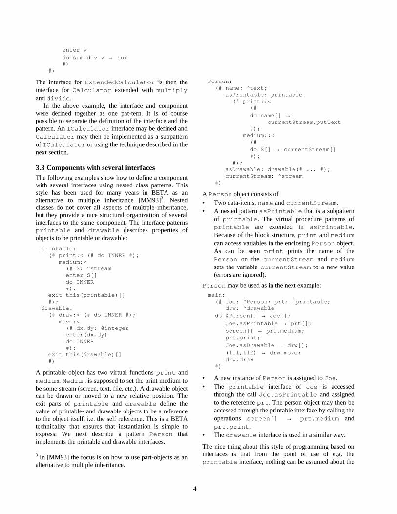
4
enter v do sum div v → sum #) #)
The interface for ExtendedCalculator is then theinterface for Calculator extended with multiplyand divide.
In the above example, the interface and componentwere defined together as one pat-tern. It is of coursepossible to separate the definition of the interface and thepattern. An ICalculator interface may be defined andCalculator may then be implemented as a subpatternof ICalculator or using the technique described in thenext section.
3.3 Components with several interfacesThe following examples show how to define a componentwith several interfaces using nested class patterns. Thisstyle has been used for many years in BETA as analternative to multiple inheritance [MM93]3. Nestedclasses do not cover all aspects of multiple inheritance,but they provide a nice structural organization of severalinterfaces to the same component. The interface patternsprintable and drawable describes properties ofobjects to be printable or drawable:
printable: (# print:< (# do INNER #); medium:< (# S: ^stream enter S[] do INNER #); exit this(printable)[] #);drawable: (# draw:< (# do INNER #); move:< (# dx,dy: @integer enter(dx,dy) do INNER #); exit this(drawable)[] #)
A printable object has two virtual functions print andmedium. Medium is supposed to set the print medium tobe some stream (screen, text, file, etc.). A drawable objectcan be drawn or moved to a new relative position. Theexit parts of printable and drawable define thevalue of printable- and drawable objects to be a referenceto the object itself, i.e. the self reference. This is a BETAtechnicality that ensures that instantiation is simple toexpress. We next describe a pattern Person thatimplements the printable and drawable interfaces. 3 In [MM93] the focus is on how to use part-objects as analternative to multiple inheritance.
Person: (# name: ^text; asPrintable: printable (# print::< (# do name[] → currentStream.putText #); medium::< (# do S[] → currentStream[] #); #); asDrawable: drawable(# ... #); currentStream: ^stream #)
A Person object consists of• Two data-items, name and currentStream.• A nested pattern asPrintable that is a subpattern
of printable. The virtual procedure patterns ofprintable are extended in asPrintable.Because of the block structure, print and mediumcan access variables in the enclosing Person object.As can be seen print prints the name of thePerson on the currentStream and mediumsets the variable currentStream to a new value(errors are ignored).
Person may be used as in the next example:
main: (# Joe: ^Person; prt: ^printable; drw: ^drawable do &Person[] → Joe[]; Joe.asPrintable → prt[]; screen[] → prt.medium; prt.print; Joe.asDrawable → drw[]; (111,112) → drw.move; drw.draw #)
• A new instance of Person is assigned to Joe.• The printable interface of Joe is accessed
through the call Joe.asPrintable and assignedto the reference prt. The person object may then beaccessed through the printable interface by calling theoperations screen[] → prt.medium andprt.print.
• The drawable interface is used in a similar way.
The nice thing about this style of programming based oninterfaces is that from the point of use of e.g. theprintable interface, nothing can be assumed about the

5
actual objects being printed. I.e. prt may refer to aprintable interface implemented by any object.
The use of nested classes to implement severalinterfaces can be used in general and is not specific toCOM. We will not go into details about the specifics ofCOM but just indicate how several interfaces andIUnknown may be implemented.
IUnknown: COM (# QueryInterface:< (# id: ^text; IF: ^IUnknown enter id[] do inner exit IF[] #); AddRef:< (# do inner #); Release:< (# do inner #) #)Person: IUnknown (# QueryInterface::< (# do (if true (* if no match then *IF[] = NONE * by default *) // ’printableId’ → id.equal then asPrintable → IF[] // ’drawableID’ → id.equal then asDrawable → IF[] if); inner #); AddRef::< (# ... #); Release::< (# ... #); asPrintable: printable(# ... #); asDrawable: drawable(# ... #); name: ^text; currentStream: ^stream; #)
To be COM compliant, at least the followingmodifications to the above example are needed:QueryInterface should return an HRESULT value,printable and drawable should inherit fromIUnknown, and QueryInterface should returnunique instances of asPrintable and asDrawable.
4. Implementation
The main change at the BETA language level is thatinterface patterns must be subpatterns of COM. Thereason for this is that the calling sequence for a virtual ina COM pattern is treated in a special way. Consider thepattern foo describing a component implementing theinterface Ifoo:
foo: Ifoo (# foo1::< (# ... do ... #);
foo2::< (# ... do ... #); foo3::< (# ... do ... #); #);
Instances of foo are generated as any other BETA object.The virtual procedure patterns foo1, foo2 and foo3are handled in a special way since their run-timeorganization and code layout must be in a form wherethey can be called from external languages. They cantherefore only be used as virtual procedure patterns andnot as general patterns. It is for instance not possible touse them as class patterns and generate instances fromthem.
The BETA garbage collector used to move objectsaround. COM objects cannot be moved, since referencesto COM objects may be given to external code. A changewas therefore necessary here. The memory managementof BETA is based on generational scavenging with atraditional mark-sweep in the old object space. Acompletely new object management scheme has beenimplemented. For the new object space, scavenging is stillused, but in the old object space, free space is collected insophisticated lists and objects are not moved. COMobjects are allocated directly in the old object space toensure that they are never moved. The new memorymanagement system has also been designed to supportpersistent objects in a more direct way than the currentpersistent object store. For a further description of thenew persistent store see [Kor99].
A BETA object has a reference to a prototype keepingrun-time information such as the virtual dispatch table forthe object. The prototype pointer used to point to the startof the prototype, but has been changed to point directly tothe dispatch table. For the Ifoo example the new run-time layout is as shown in Figure 1. S is a referencequalified by the Ifoo interface and referring an instanceof foo. The dashed lines illustrate the foo-object withthe solid lines showing the reference to the dispatch tablein the prototype for foo. In the old implementation, theprototype pointer in the foo-object pointed to the start ofthe prototype (the start of the dashed box in Figure 1).

6
data-item s off o o object
S : ^ I f o o Im plementation of foo1
Im plementation of foo2
Im plementation of foo3
Prototype for f o o with dispatchtable indicated with solid lines
Fi gure 1f o o object
It was pretty straightforward to implement support forBASICCOM although it is always a time consuming task toimplement and debug a new memory managementsystem. To add the necessary interfaces and externalfunctions to support EXTERNALCOM was also astraightforward task. The most time consuming andfrustrating task has been to support FULLCOM with all themany different parameter types. As mentioned it turnedout to be impossible to obtain a complete definition ofCOM IDL. The current implementation is thus based onan ad hoc extension of CORBA IDL that currently canhandle all known IDL interfaces defined in Windows.
A translator from IDL to BETA has been implemented,which means that BETA interface patterns are availablefor all Windows interfaces. It has been a time consumingtask to develop a suitable COM IDL and to implement thetranslator. To be able to support the many differentparameter types, a special holder pattern has beenimplemented. The holder pattern is inspired byMicrosoft J++ and can be used to represent pointers tointegers, pointers to references to COM objects, etc. Dueto space limitations no details will be given here.
Garbage collection. As mentioned above, the objectmanagement scheme for BETA has been changed toprevent COM objects to be moved around. There is,however, more to garbage collection than to preventCOM objects from being moved.
There is no direct support for garbage collection(addRef and release) in the current implementation.When a component is imported to BETA, the programmermust keep track of it and make an explicit release of itwhen it is no longer used in the BETA code.
When a BETA object is collected by the garbagecollector, it may contain references to COM objects. It iscurrently the responsibility of the programmer to makesure that a release-call is made on such COM references ifnecessary.
For COM components implemented in BETA, it is alsothe responsibility of the programmer to keep track of theobject. When the component is created and exported, theBETA program should keep a reference to it in someglobal table to prevent it from being collected by theBETA garbage collector. The component should have anexplicit reference counter to be manipulated by addRefand release. When the counter reaches zero, thepossible global reference to the component may beremoved and the compo-nent may then be collected bythe BETA garbage collector.
Most COM tools handle AddRef and Releaseautomatically, and we expect to add better support for thisin a future release.
5. Status and future work
As of today a working prototype has been implementedand COM support is expected to be part of the nextofficial release of the Mjølner System. The prototype iscurrently being used in a number of projects [Coc97,Des98, COT97] for developing COM-based applicationsand COM-based frameworks. To complete the BETACOM implemen-tation, the following parts should bedone:• As mentioned above, the support for garbage
collection should be improved.• In the current implementation, the value of
HRESULT must be checked explicitly by the client.We expect to add a higher level of exceptionhandling.
• In the current implementation dynamic load (usingDLL's) is not fully supported.
• The Mjølner System includes powerful tools such asbrowser, structure editor, CASE tool, interfacebuilder and debugger. It is planned to provide bettersupport for components based on input from e.g.[KP98, Elm98].
• It is planned to extend the COM implementation tosupport CORBA. We expect the BASICCOM layer to

7
be unchanged from a programmer point of view. Thechanges will primarily be at the EXTERNALCOM layerwhere a similar layer for CORBA probably will beintroduced.
• In [Elm98] a study of mainstream tools was made. Acomparison with environments like Oberon andEiffel needs to done.
Acknowledgements. The work described here is part ofCOT [COT97], which is an in-dustrial research projectsponsored by the Danish National Centre for IT Research.Peter Andersen, Morten Grouleff, Christian Heide Damm,Stephan Erbs Korsholm, and Len-nert Sloth have madesignificant contributions to the project. In additiondiscussions with other participants of COT have beenuseful. The idea of implementing COM sup-port forBETA was triggered by discussions with ClemensSzyperski and other members of the Oberon team. PeterAndersen, Christian Heide Damm, Henrik Røn, LennertSloth and Peter Ørbæk gave useful comments on aprevious version of this paper.
6. References
[Bro95] Kraig Brockschmidt: ,QVLGH� 2/(�� �QG� HGQ.Microsoft Press, Redmond, WA, 1995.
[Coc97] Project &RFRQXW��&ROODERUDWLRQ��&RPSRQHQWV��LQWHU�� 1HW�EDVHG� 8ELTXLWRXV� 7HOHZRUNLQJ,http://www.cit.dk/Cocunut, 1997-99.
[COT97] Project &27�� &HQWUH� IRU� 2EMHFW� 7HFKQRORJ\,http://www.cit.dk/COT, 1997-2000.
[Des98] Project DESARTE: Computer-SupportedDesign of Artefacts & Spaces in Architectureand Landscape Architecture,http://www.daimi.au.dk, 1998-2000.
[Elm98] Réne Elmstrøm, Peter Petersen, Kåre Kjelstrøm,Morten Grouleff, Peter Andersen, Henrik LykkeNielsen, Kristian Lippert, Steen D. Olsen, KimVestergaard: (YDOXDWLRQ� RI� &20� 6XSSRUW� LQ'HYHORSPHQW� (QYLURQPHQWV, Centre for ObjectTechnology, Aarhus University, TechnologicalInstitute, COT/3-4, 1998, available fromhttp://www.cit.dk/COT.
[Kor99] Stephan Korsholm: 7UDQVSDUHQW�� 6FDODEOH�(IILFLHQW��22�SHUVLVWHQFH, ECOOP'99 workshopon object-oriented databases.
[KP98] Kaare Kjelstrøm, Peter Petersen: $�&$6(�7RRO�IRU&20� 'HYHORSPHQW, The Eighth NordicWorkshop on Programming EnvironmentResearch 1998, NWPER'98. Revised version inNordic Journal of Computing, 6(1), Spring 1999.
[MM93] Ole Lehrmann Madsen, Birger Møller-Pedersen:3DUW� 2EMHFWV� DQG� WKHLU� /RFDWLRQV. In Proc.Technology of Object-Oriented Languages andSystems – TOOLS'10, (B. Magnusson, B.Meyer, J.F. Perrot, eds.), Prentice-Hall, 1993,pp. 283-297.
[Rog97] Dale Rogerson:� ,QVLGH� &20, Microsoft Press,Redmond, WA, 1997.
[Szy97] Clemens Szyperski: &RPSRQHQW� 6RIWZDUH� �%H\RQG� 2EMHFW�2ULHQWHG� 3URJUDPPLQJ, ACMPress/Addison Wesley, 1997.

3URSRVDO�IRU�7RROV�6XSSRUWLQJ�&RPSRQHQWEDVHG�3URJUDPPLQJ
Position paper for Fourth International Workshop on Component-Oriented Programming (WCOP’99)
Henrik Lykke Nielsen and René Elmstrøm
'DQLVK�,QVWLWXWH�RI�7HFKQRORJ\,QIRUPDWLRQ�7HFKQRORJ\
7HNQRORJLSDUNHQ'.������$DUKXV�&
'HQPDUN
+HQULN�/\NNH�1LHOVHQ#WHNQRORJLVN�GN5HQH�(OPVWURP#WHNQRORJLVN�GN
$EVWUDFWOur experiences with basing application architectures
on component structures have shown us that componentbased architectures result in several advantages such asgreater reuse and consistency, ease of maintenance etc.But there are also a number of problems arising whenusing binary components. We see most of theseproblems falling in one of the following categories:Culture and organisation, documentation and componentmanagement. We propose a number of tools and relatedtechniques that will help lessen the problems arisingwhen using binary components. The tools will addressissues such as auto-generating documentation, managingcomponents in different configurations and formalspecification and run-time test of functionality.
��� %DFNJURXQG
This paper is based on experiences gathered fromclient driven as well as in-house projects involving in-house developers, client employed developers anddevelopers employed at third-party consultingcompanies. Some of the work reported in this paper hasbeen performed as part of the Centre of ObjectTechnology (COT). At http://www.cit.dk/cot moreresults from the project can be found.
The applications being developed are win32 baseddatabase applications with GUI front-ends. Our primarydevelopment tool has been Visual Basic and thecomponent technology in question is ActiveX.
One project in particular has provided us withintensive practical experience in making component-based development. The application being developed is atypical small-to-medium-sized multi-user applicationfocusing on handling administrative routines as well asproviding the basis for a small data-warehouse-likesolution. The application is very similar to applicationswe have developed in the past, and even though theworkflow and the specific business-rules are new mostof the technical problems are well known and have wellknown solutions. The project is a client-based projectinvolving participants from third party consultingcompanies as well as from the client itself. Our own rolehas been twofold: As architects we have designed thestructure of the system, created standards etc, and ascomponent constructors we have created a number ofcomponents for implementing solutions and enforcingstandards. The decision to base the application structureon binary components has largely been ours and we haveprimarily used the potential reuse as the primary sales-argument, but we find it just as important that the use ofcomponents provides a consistent coding style andencapsulates solutions of technical problems. Thedivision of the involved participants into an architecture& components group and an application developmentgroup has been partly inspired by the organisationalstructure described in [1] and recommended by e.g. IvarJacobsen et al in Software Reuse [2]. An inspiration thathas been strengthened by the fact that the mostexperienced developers were placed at a geographicallocation separate from that of the client.

��� 0RWLYDWLRQ
����� 6RXUFH�FRGH�UHXVH�FRQWUD�ELQDU\FRPSRQHQWV
In our reference project we found several problems inusing binary components. Most of the problems had todo with the very essence of binary components.
When we introduced the concept of component baseddevelopment in the reference project, we insisted (ascomponent developers) to maintain the code ofcomponents developed i.e. we released only the binaryversions of the components (and not the source code) tothe application developers. This caused quite someresistance among the application developers. Theyargued that having access only to the binary version ofthe components would give them a number ofdisadvantages:
• The source code is the most precise specification ofthe code’s functionality
• If the code does not work we are able to fix thesource code version
• If the code needs changed or extended functionalitywe are able to implement the change if we haveaccess to the source code
We believe that these reasons originate from theattitude that: “We do not trust what we can not verifyourselves”.
For an application developer with a deadline the focuson development will usually be on his own project. So ifthe code he receives from others (be it source code orbinary components) has errors or lacks required optionshe will always consider programming it himself.
For the single developer focusing on his own projectthe above mentioned reasons seem very valid. Thus thechallenge is to address the issues of the developer so thathis objections to using binary components will be takeninto account but at the same time to comply with theproductivity- and quality-related demands of theorganisation.
����� 0DQDJLQJ�&RPSRQHQWV
Of the many technical/practical problems arisingwhen developing, maintaining and using ActiveXcomponents the greatest turned out to be themanagement of the various versions of components andtheir many interdependencies.
In the following we will propose a number of tools tohelp solve these problems.
��� $FWLYH;�FRPSRQHQWV�DQG�W\SH�OLEUDULHV
The ActiveX technology includes formal descriptionsof component interfaces in the form of type libraries.The tools we propose analyse both type librariesassociated with components as well as source codeversions of components. The results of such analyses areused for documentation purposes etc.
Given a type library there is a lot of usefulinformation about the structure of the component at thedeveloper’s fingertips such as:
&ODVVHV: Class name, class type, supporting interfaces,QWHUIDFHV: Interface name, members of the interface(QXPHUDWLRQV0HPEHUV: member type, member name$UJXPHQWV: Argument name, by value/by referencetransfer, argument type
For most of the component parts it is possible todefine short textual descriptions as well as Help ContextID’s linking to an optional help file for the component.
��� 3URSRVHG�7RROV
����� &RPSRQHQW�%URZVHU
By using a component browser it is possible tobrowse type libraries - and thereby to access theinformation which is automatically available.Unfortunately neither Visual Basic’s Object Browser orVisual Studio’s OLE/COM Object Viewer are very wellsuited for the average application developer’s needs.Visual Studios OLE/COM Object Viewer is a very low-level viewer displaying much of the informationtextually and as such it is a very direct presentation ofthe type-library. The tool is very useful for developerswho are familiar with ODL/IDL, but not for the generalVisual Basic developer who simply want easy-to-readand easy-to-understand information on how to use acomponent. Visual Basic’s Object Browser on the otherhand is an easy to use tool. But it presents a rathersimplified view of a type library, as some information isnot accessible in this tool. Furthermore both tools arerather non-hierarchical in their presentation of acomponent’s structure. Most non-trivial componentshave some kind of inherent hierarchy in their structure.This hierarchy is not directly presented in either of thecomponent browsers. Additionally a data type is oftendefined as Object or Variant (which both accept any typeof object) because there are multiple specific data typeswhich may be used for this value. So only a limitedamount of information on object hierarchies can begained from the static information available in typelibraries.
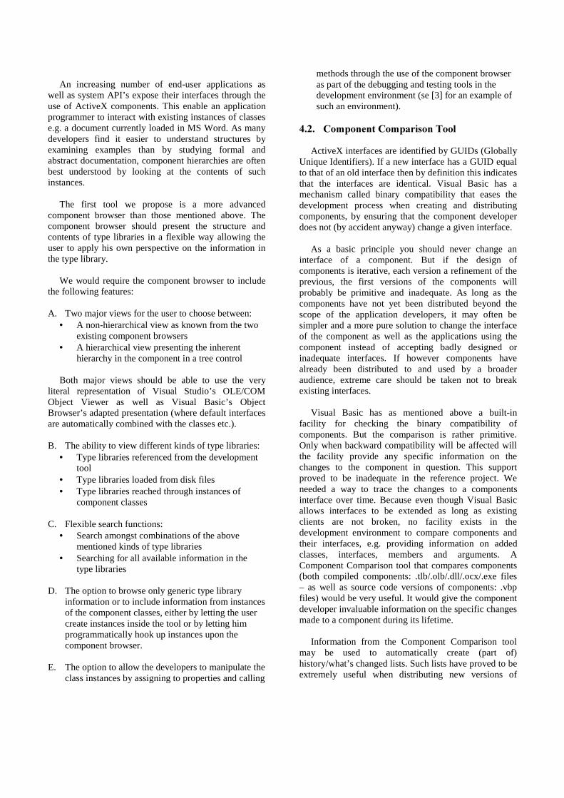
An increasing number of end-user applications aswell as system API’s expose their interfaces through theuse of ActiveX components. This enable an applicationprogrammer to interact with existing instances of classese.g. a document currently loaded in MS Word. As manydevelopers find it easier to understand structures byexamining examples than by studying formal andabstract documentation, component hierarchies are oftenbest understood by looking at the contents of suchinstances.
The first tool we propose is a more advancedcomponent browser than those mentioned above. Thecomponent browser should present the structure andcontents of type libraries in a flexible way allowing theuser to apply his own perspective on the information inthe type library.
We would require the component browser to includethe following features:
A. Two major views for the user to choose between:• A non-hierarchical view as known from the two
existing component browsers• A hierarchical view presenting the inherent
hierarchy in the component in a tree control
Both major views should be able to use the veryliteral representation of Visual Studio’s OLE/COMObject Viewer as well as Visual Basic’s ObjectBrowser’s adapted presentation (where default interfacesare automatically combined with the classes etc.).
B. The ability to view different kinds of type libraries:• Type libraries referenced from the development
tool• Type libraries loaded from disk files• Type libraries reached through instances of
component classes
C. Flexible search functions:• Search amongst combinations of the above
mentioned kinds of type libraries• Searching for all available information in the
type libraries
D. The option to browse only generic type libraryinformation or to include information from instancesof the component classes, either by letting the usercreate instances inside the tool or by letting himprogrammatically hook up instances upon thecomponent browser.
E. The option to allow the developers to manipulate theclass instances by assigning to properties and calling
methods through the use of the component browseras part of the debugging and testing tools in thedevelopment environment (se [3] for an example ofsuch an environment).
����� &RPSRQHQW�&RPSDULVRQ�7RRO
ActiveX interfaces are identified by GUIDs (GloballyUnique Identifiers). If a new interface has a GUID equalto that of an old interface then by definition this indicatesthat the interfaces are identical. Visual Basic has amechanism called binary compatibility that eases thedevelopment process when creating and distributingcomponents, by ensuring that the component developerdoes not (by accident anyway) change a given interface.
As a basic principle you should never change aninterface of a component. But if the design ofcomponents is iterative, each version a refinement of theprevious, the first versions of the components willprobably be primitive and inadequate. As long as thecomponents have not yet been distributed beyond thescope of the application developers, it may often besimpler and a more pure solution to change the interfaceof the component as well as the applications using thecomponent instead of accepting badly designed orinadequate interfaces. If however components havealready been distributed to and used by a broaderaudience, extreme care should be taken not to breakexisting interfaces.
Visual Basic has as mentioned above a built-infacility for checking the binary compatibility ofcomponents. But the comparison is rather primitive.Only when backward compatibility will be affected willthe facility provide any specific information on thechanges to the component in question. This supportproved to be inadequate in the reference project. Weneeded a way to trace the changes to a componentsinterface over time. Because even though Visual Basicallows interfaces to be extended as long as existingclients are not broken, no facility exists in thedevelopment environment to compare components andtheir interfaces, e.g. providing information on addedclasses, interfaces, members and arguments. AComponent Comparison tool that compares components(both compiled components: .tlb/.olb/.dll/.ocx/.exe files– as well as source code versions of components: .vbpfiles) would be very useful. It would give the componentdeveloper invaluable information on the specific changesmade to a component during its lifetime.
Information from the Component Comparison toolmay be used to automatically create (part of)history/what’s changed lists. Such lists have proved to beextremely useful when distributing new versions of

components to application developers. Creating the listsautomatically would ease the burden when maintainingcomponents.
����� 'RFXPHQWDWLRQ�*HQHUDWLRQ
Documentation is a neglected part of manydevelopment projects. If the application is wellstructured and adheres to a consistent coding style andstandard the omission of or the placing of low priority ondocumentation might however not be fatal. A skilledprogrammer used to the coding style and standard andwith experience in the field of the application domainwould in most cases be able to follow the flow of a well-structured program without any major effort. But if thesame programmer were to use a binary component thesituation would prove less simple. As there is no longeraccess to the source code only syntactical information onthe component’s interfaces are available (via the typelibrary). Much can be achieved by intuitive andconsistent naming strategies for the different elements ofthe component and by imbedding element-descriptions.But the source code no longer provides the applicationdeveloper with a formal specification of the component’ssemantics.
����� 3UH��DQG�SRVW�FRQGLWLRQV
As ActiveX components contain no build-in semanticdocumentation but only a syntactical description of itsinterfaces, it is in most cases necessary to provideexplicit semantic documentation of components. In thereference project we find this to be crucial in order toanswer the complaint that binary components as acontrast to source code components do not have theirown build-in semantic documentation.
As part of the documentation it would be beneficial tohave a formal specification of the components’functionality. This would result in fewermisunderstandings and questionable cases, but it wouldalso enable others than the component developersthemselves to verify the functionality of the components.
Using the principles of Design by Contract [4], a firststep in formalising the description of the componentsmight be to define pre- and post-conditions for themembers of a component.
These pre- and post-conditions should be stored insuch a way that they can be automatically included in thegenerated documentation. We would require these pre-and post-conditions to be independent of theimplementation language of a component, as theActiveX components themselves are languageindependent. And we prefer not to define the pre- andpost-conditions in the source code so that we are able tohandle components alike whether or not we have accessto the source code or only to the binary versions of the
components (e.g. if they were made by third partycompanies). Finally pre- and post-conditions might bewritten by designers as part of the specification ofcomponents – even before the components themselveswere created.
So we suggest that the pre- and post-conditions aswell as other extra component information is storedoutside the source code.
����� 5XQ�WLPH�FRPSRQHQW�ZUDSSHUV
Beside the aspect of documentation, pre- and post-conditions have the advantage of being possible to checkat run-time (depending on the way in which the pre- andpost-conditions are expressed), and invariants oninterfaces can be checked as part of pre- and post-conditions as suggested in [6]. If a component wereaccompanied by a component wrapper (and maybematching test-cases) whose purpose would be to checkwhether the pre- and-post conditions were compliedwith, the component’s users would have moreconfidence in the component. This would address one ofthe major problems with binary components contrasource code fragments.
Given a component and its pre- and post-conditions itwould be simple to generate component wrappers forchecking for and logging of violations of pre- and post-conditions. There are several possible ways to expresspre- and post-conditions. UML’s Object ConstraintLanguage (OCL) has the advantage of standardisation(see a brief introduction in [5]). Another strategy couldbe to use one of the many existing (scripting) languagessuch as VBScript, JavaScript (or JScript) etc. Suchscripting languages have the advantage of being simpleto implement because parsers and interpreters are readilyavailable.
It would be advantageous to have a general systemthat could easily create wrappers for components.Several architectures for calling such wrappers arepossible, e.g.:
A. Change all design-time references to components topoint to the wrapper component instead of the realcomponent. Could be a major task if no effectivemanagement tool is available. And would beimpossible if the clients (which could themselves becomponents) were only available in binary form.
B. Instead of creating instances directly in clients,object factories could be explicitly called from theclients to return references to either a wrapper objector the corresponding real object. This strategywould allow central configuration of whether to usewrappers or not. Besides a slight overhead in calling

the factory this would again be impossible if theclients were only available in binary form.
C. (Extensible) interception (as described in [7]) whichmakes it possible to call wrappers transparentlywithout changing clients.
D. Manipulation of registry settings so that whenclients believe that they call the real componentinstead they actually call the wrapper.
Only the architectures mentioned in C. and D. canmake the use of wrappers work transparently.
Several kinds of functionality would be interesting toimplement in wrappers, e.g.:
• Pre- and post condition checks• Performance measuring• Call statistics: Call frequency and order, logging of
arguments etc.• Run-time visualisation of member-calls• Logging of errors – possibly as part of a centralised
error-handling mechanism
����� &RPSRQHQW�PDQDJHPHQW�WRRO
Practical work has shown us that there are multipleand serious problems in the area of componentmanagement. Ensuring that different versions ofdifferent components enter into the correct combinationis basically simple, but due to human errors and presseddeadlines it often tends to fail. In the reference projectwe have often encountered situations where extensionsor bug fixes of components cover more than a singlecomponent. We therefore propose a tool that administerscomponents by handling both individual components aswell as sets of related components (componentpackages). The tool should preferably be able toautomatically set references to whole packages ofcomponents (to various versions of both binary andsource code versions of the components), compilecomponents, create dependency files for components andeventually handle registration of components andcomponent packages on application developers’machines.
��� &RQFOXVLRQ
Even though we find that the most serious problemsin committing organisations to component baseddevelopment is of a cultural and organisational nature,we also believe that progress can be found in additionaltool-support. Automated generation of thoroughdocumentation, formal and verifiable specification offunctionality and fewer practical problems arising when
managing and applying components all further theprocess of introducing component development in theorganisation. The more faith the application developershave in the components they are using the higher is theprobability of achieving success.
In the coming months we will implement the toolsproposed in this paper and subsequently apply them toselected components used in our development projects.
5HIHUHQFHV
[1] Harmon, Paul: Component Methodologies. ComponentDevelopment Strategies Vol. VIII, No. 11, CutterInformation Group, November 1998, ISSN 1059-4108.
[2] Jacobsen, Ivar; Griss, Martin; Jonsson, Patrik: SoftwareReuse. Addison-Wesley, 1997, ISBN 0-201-92476-5.
[3] Kölling, Michael: Teaching Object Orientation with theBlue Environment. The Journal of Object-OrientedProgramming Vol. 12, No. 2, SIGS Publications Inc., May1999, ISSN 1097-1408.
[4] Meyer, Bertrand: Object-Oriented Software Construction,Second Edition, Prentice Hall, 1997, ISBN 0-13-629155-4.
[5] Warmer, Jos; Kleppe, Anneke: The Constraint Languageof the UML. The Journal of Object-OrientedProgramming Vol. 12, No. 2, SIGS Publications Inc., May1999, ISSN 1097-1408.
[6] Szyperski, Clemens: Component Software: BeyondObject-Oriented Programming. Addison-Wesley, 1997,ISBN 0-201-17888-5.
[7] Brown, Keith: Building a Lightweight COM InterceptionFramework Part 1: The Universal Delegator. MicrosoftSystems Journal Vol. 14 No. 1, Miller Freeman, January1999, ISSN 0889-9932.

Three Features for Component Frameworks
James NobleMicrosoft Research Institute
Macquarie UniversitySydney, Australia
Abstract
Component-oriented programming promises to providemany of the benefits that object-oriented programminghas arguably failed to deliver: increased productivity,reliability, and flexibility via increased reuse of third-party software. Unfortunately, it is not always clearhow component-oriented programming differs from object-oriented programming, or why component-oriented pro-gramming should succeed where object-oriented program-ming has failed. We identify three technical features whichneed to be supported by component-oriented programminglanguages or frameworks — component containment; mul-tiple instances of component interfaces; and interface dis-patch — and give examples to show why these features mayhelp component-oriented programming live up to its claims.
1. Introduction
This position paper addresses two themes of interest tothe workshop: first, programming languages’ and compo-nent frameworks’ support for component-orientedprogram-ming, and second, properties which can be established bycomponent frameworks. We take the position that com-ponent oriented programming languages and componentframeworks need to support three key features — compo-nent containment; multiple instances of component inter-faces; and interface dispatch — which are not provided bymainstream object-oriented languages or frameworks. Foreach feature, we describe examples to illustrate why webelieve it is useful, and briefly evaluate the level of sup-port provided by programming languages and componentframeworks. We expect this statement will be relevant tothe workshop by delineating some architectural features ofcomponent systems, and to the wider community in provid-ing additional criteria by which component-oriented solu-tions can be evaluated.
In the remainder of this position statement, we describethese three features in more detail.
2. Component Containment
The WCOP’96 definition of component states that:
A component is a unit of compositionwith . . . explicit context dependencies only . . .
Object identity is one of the foundations of object-oriented programming, and mutable state in objects is an-other — indeed, object identity only really makes sense be-cause an object’s state variables can be changed while itsidentity remains the same [9]. Unfortunately, the interac-tions of object identity and mutable state can lead toalias-ing problemswhere references to components’ internal ob-jects are accessible from outside the components [6]. Com-ponent frameworks and languages need to provide protec-tion against aliasing problems — probably the most effec-tive mechanism is to enforce acontainment invariant[10]which ensures that a container’s internal representation maynever be exposed outside the container. Component lan-guages or frameworks which enforce a containment invari-ant are qualitatively different from object-oriented frame-works which do not enforce containment invariants.
Example 1A dialog box component is implemented as acomposition of smaller widgets. To support efficient com-position, the dialog box supports operations which returnits internal widgets, allowing aliases to the widgets fromoutside the dialog box and exposing its representation. Amalicious external client could alter the widgets and breakthe invariant of the dialog box. A component frameworkcould detect when the widgets were being passed outsidetheir containing component (and that this would break thecontainment invariant) and thus prevent the transfer.
Example 2An email client component maintains an in-ternal address book using a simple data store component.A malicious macro could extract the address book from the
1

email client, and then use it to spam all your friends on theinternet. Arguably, the address book component and theaddresses should be contained within the email client com-ponent, and the component framework or language shouldenforce a containment invariant so that they are never visi-ble outside the email client component.
Current Support No current programming languagesor component framework fully support containment invari-ants — such support as languages provide works at the levelof classes or names, rather than objects or components —typically a private component can be returned by a publicfunction, or exchanged between two components which areunrelated but have the same implementation type. Contain-ment is a topic of current research [5, 1] and we are inves-tigating the use of both static type systems [2] and dynamicchecks [8] to enforce containment invariants in componentframeworks and languages.
3. Multiple Instances of Interfaces
The WCOP’96 definition of component also states that:
A component is a unit of composition with con-tractually specified interfaces . . .
Implicit in this statement is that a component must be ableto support multiple interfaces [11]. Obviously, a compo-nent must be able to support multiple interfaces of differenttypes, in much the same way as a Java object can implementmany different Java interfaces [4]. What is not so clear fromthe definition is that it is crucial that a component is able tosupport multipleinstancesof interfaces with thesametype.
Example 3. Consider a simple component such as agraphical control component which might appear in an ap-plication’s tool bar. This component may generate manyevents which may be of interest to the component composer— obviously an action event must be generated when thebutton is pressed, but also events must be generated whenthe mouse pointer enters the button, leaves the button, oreven lingers over it (to show popup screentips or start pa-perclips dancing). Now, an object-oriented button wouldsend a different message or event in each of these circum-stances, and objects receiving the messages (or handling theevents) would have to be programmed specially to handleeach of them. But in a component-oriented approach, eachof these events should be handled in the same way — thatis, the button component needs to be able to support multi-ple instances of an interface with the same type signature,but different semantics.
Example 4Consider a larger scale database component.A database needs to provide an interface for retrieving theresults of queries, and this interface is often stateful, pro-viding operations to retrieve the nextn results and test thenumber of results remaining. Database components also
need to be able to support multiple active queries in parallel— that is, multiple instances of the query interface. This isparticularly important in conjunction with component con-tainment, because containment prevents one component di-rectly accessing the internal representation of another com-ponent — so an independent query component could notaccess the contained representation of the database. In thisand similar cases, however, the query object is playing therole of an additional interface to the database: a componentframework should support this role directly.
Current Support No current object-oriented program-ming language allows objects to provide multiple instancesof the same interface directly, although Java’s inner classesand Smalltalk’s blocks can provide some support. Multi-ple instances of interfaces are supported natively within theCOM component framework.
4. Interface Dispatch
The evolution of software module interconnections is animportant part of the evolution of programming paradigms.Early unstructured programs were connected using simplegotos, structured programs using procedure calls which canreturn to their calling context, and object-oriented programsusemethod dispatch— essentially an indirect procedurecall where the body of the method that is executed dependsupon the (class of the) object to which a message is sent.
Component-oriented programming needs still more gen-eral interconnections between components — in particular,interconnections whose semantics depend upon both inter-faces and components. The actual method body invoked ex-ecuted by a component should depend upon both the opera-tion invoked and the interface (or type of interface) throughwhich the operation is invoked.
If a procedure call is written simply as:
procedure(args)
a static call to a procedure in another module could be writ-ten:
module:procedure(args)
and an object-oriented message dispatch is a dynamic indi-rect procedure call:
object! method(object; args)
whereobject must be passed as a “self” parameter. We canrepresent classes explicitly:
object! class:method(object; args)
if methods are stored statically in classes. A component-based interface dispatch is effectively a doubly-indirect pro-cedure call:
2

component! interface!
method(object; interface; args)
or
component! interface:type!
method(object; interface; args)
if methods are stored on interface types, not interface in-stances. Both the object and the interface need to be passedto the executing method as “self”-style parameters.
Example 5Consider again the database component fromExample 2. This component supports multiple instances ofa query interface — one instance is used for each outstand-ing query. When a client component makes a request to oneof the query interfaces, the code inside the database com-ponent needs to be able to determine which instance of theinterface is called, so that the correct results are returned.
Example 6Consider a whiteboard component whichmust work with two separate clients — that is, the compo-nent is working as a two-way adaptor [3]. Each client maysend the message to the client with the same names and ar-guments, but expect a completely different implementationof the message [7]. For example, one client of the white-board may use themove(x,y) message to move an icon toan absolute position, while another client may use the samemessage to reposition an icon relative to its current posi-tion. Component-oriented programming allows the compo-nent to implement two interfaces, each containing a methodwith exactly the same signature, but which are implementeddifferently, to provide the semantics each client expects.
Current Support The COM component framework sup-ports interface dispatch. Multiple inheritance in Eiffel andC++ can be used to provide different behaviours for thesame message, but the dispatch depends on the caller’sstatic type context, rather than a dynamic interface dispatch.
5. Conclusion
Component orientation is still an evolving model of pro-gramming. We have proposed three features which weconsider should be supported by component frameworksand component-oriented programming languages. Support-ing these features would address some of the problems ofreusability and component independence which continue toaffect object-oriented languages and frameworks, and hope-fully help component-orientedprogramming to live up to itspromise.
Acknowlegements
Thanks to the anonymous reviewers for their comments.This workwassupported by Microsoft Australia Pty Ltd.
References
[1] P. S. Almeida. Baloon Types: Controlling sharing of statein data types. InECOOP Proceedings, June 1997.
[2] D. Clarke, J. Potter, and J. Noble. Ownership types for flex-ible alias protection. InOOPSLA Proceedings, 1998.
[3] E. Gamma, R. Helm, R. E. Johnson, and J. Vlissides.DesignPatterns. Addison-Wesley, 1994.
[4] J. Gosling, B. Joy, and G. Steele.The Java Language Spec-ification. Addison-Wesley, 1996.
[5] J. Hogg. Islands: Aliasing protection in object-oriented lan-guages. InOOPSLA Proceedings, Nov. 1991.
[6] J. Hogg, D. Lea, A. Wills, D. deChampeaux, and R. Holt.The Geneva convention on the treatment of object aliasing.OOPS Messenger, 3(2), Apr. 1992.
[7] U. Holzle. Integrating independently-developed compo-nents in object-oriented languages. InECOOP Proceedings,1993.
[8] J. Noble, D. Clarke, and J. Potter. Dynamic alias protectionin prototype-based languages. InOOPSLA’98 Workshop onPrototype-Based Programming, 1998.
[9] J. Noble, J. Vitek, and J. Potter. Flexible alias protection. InECOOP Proceedings, 1998.
[10] J. Potter, J. Noble, and D. Clarke. The ins and outs ofobjects. InAustralian Software Engineering Conference(ASWEC), 1998.
[11] C. Szyperski. Component Software: Beyond Object-Oriented Programming. Addison-Wesley Longman, Har-low, Essex, 1997.
3

Black-Box Program Specialization
Ulrik Pagh SchultzCompose Group, IRISA, France
Abstract
Software components offer numerous advan-tages in terms of development, but may give riseto inefficiency due to highly generic implementa-tions. Program specialization can automaticallyremove overheads due to overly generic imple-mentations, but requires inspection of the sourcecode. To retain the advantages of black-boxsoftware components, we propose black-box pro-gram specialization: specialization opportunitiesare specified by the developer and become partof the interface of a component, allowing the userto specialize the component according to specificneeds.
We characterize the problem of consolidatingprogram specialization and black-box componentre-use, outline our proposed solution, and illus-trate our approach using an example.
1 Introduction
Software components increase the re-use of ex-isting program fragments, allowing an applica-tion to be created by combining existing compo-nents. Unlike objects which may implement partfunctionalities only, a component usually encom-passes a complete functionality and functions inan autonomous fashion. In the context of this pa-per, we consider that components are first createdby the component programmer, then either com-bined with other components by the applicationprogrammer (to form complete applications), orinserted into running applications by the end user.
The more a component is generic in its func-tionality, the more places it can be used, and thegreater is the productivity boost that results fromcode-reuse. However, genericity is known to in-troduce run-time overheads. For example, param-eters that control the behavior of a component maybe repeatedly tested even though they remain fixedthroughout the lifetime of the component. Also,features that may be needed only in specific situ-
ations must be included in a component, even ifthey are never needed in most applications.
To improve performance, a software compo-nent can be manually specialized to obtain a ver-sion dedicated to a given application, but suchmanual albeit systematic modification of sourcecode is error-prone and introduces maintenanceoverheads. Automatic program specialization is atechnique for removing overheads that are due togenericity. Program specialization can automati-cally instantiate a generic component for a specificcontext, thus obtaining an efficient implementa-tion. Nevertheless, for program specialization tobe effective, it requires guidance by an applica-tion programmer familiar with the complete pro-gram being specialized, seemingly contradictingthe philosophy behind black-box re-use of soft-ware components.
As a solution, we propose to extend the descrip-tion of a component with information regardingthe opportunities for specialization that are intrin-sic to the component. The burden of identifyingthe specialization opportunities is placed on thecreator of the component, who is assumed to be fa-miliar with its source code. The existing opportu-nities for specialization are thus externalized, andpublished as part of the interface of the compo-nent. This interface not only allows the applica-tion programmer to configure the component to aspecific functionality, but also for the frameworkthat joins the components together to automati-cally complete the configuration process by adapt-ing the components to one another. This configu-ration process results in a program optimized forthe opportunities associated with each actual com-ponent.
Overview: First, Section 2 provides an intro-duction to program specialization. Then, Section3 describes the main topic of this paper: black-box program specialization. Afterwards, Section4 describes how components can be automaticallyadapted when they are installed into a framework.

Section 5 provides a concrete example. Finally,Section 6 discusses both the questions raised bythis position statement and future work.
2 Program Specialization
Program specialization is the optimization of aprogram (or a program fragment) based on infor-mation about the context in which it is used. Foran object-oriented program, specialization can beapplied to individual methods of a class. Contextinformation can include both constant values, suchas values of parameters, local fields, or fields ofother objects, and type information.
One approach to automatic program specializa-tion is partial evaluation, which performs aggres-sive inter-procedural constant propagation (of alldata types), and performs constant folding andcontrol-flow simplifications based on this informa-tion. Partial evaluation has been extensively inves-tigated for functional [3, 4], logic [6], and imper-ative [1, 2, 5] languages. This technique has beenrecently extended to Java by Schultzet al. [7].Partial evaluation is a two-stage process: first theprogram is analyzed with an abstract domain ofvalues (values are either known or unknown), andthen it is specialized with concrete values. Whileanalysis must be performed before compilation,the actual specialization to concrete values can bedone at any time. Specialized code can thus bedynamically adapted to situations that have beenabstractly analyzed before compilation.
For specialization to be effective, it must onlybe applied to the performance-critical regions ofthe program. The application programmer is oftenaware of where such regions exist in a program,perhaps with the help of profile information. Butto optimize such regions, knowledge of how theywork is still required for program specialization tobe effective. Thus, some understanding of how thesource program works is necessary for applyingprogram specialization.
To specialize a software component, it must notonly be known how it has been implemented, butalso how it will be used. This makes it difficult forthe developer to specialize the component, sincethe exact needs of the application programmer andeven the end user must be known. Specializationcan be done to cover the most common cases, butit is often impractical, if not impossible, to pre-specialize components for all possible values.
3 Black-Box Program Specialization
To exploit the full potential of program specializa-tion in the field of software components, we mustunify seemingly contradictory needs: specializa-tion must be done according to the needs of theapplication programmer and it must be done at thecomponent level without requiring the program-mer to inspect the source code of the component.The solution is to make the available specializa-tion opportunities external to the component. Wethus separate the process of declaring specializa-tion opportunities and the subsequent choice ofwhich opportunities to exploit.
Concretely, we propose to express abstract spe-cialization opportunities as part of the interface ofa component. The component developer identi-fies specialization opportunities and the applica-tion programmer chooses which opportunities toexploit. To actually perform specialization, we canuse a technique such as specialization classes [8],which allow many specialized behaviors to beadded to a component, while keeping the original,generic behavior.
Indeed, specialization classes, provide a simple,declarative framework for specifying specializa-tion opportunities and controlling specialization,and might seem appropriate for defining the spe-cialization interface of a component. However,specialization classes work at the implementationlevel and not at the component level: they declareopportunities on a class-by-class basis, specify-ing invariants over values that are private to someobject. Also, several specialization classes maybe needed to express specialization for a specificopportunity. While useful for actually perform-ing specialization, we conclude that specializationclasses are too fine-grained and implementation-specific for specifying specialization opportunitiesat the component level.
In the same way that the interface of a compo-nent must be rich enough to support those opera-tions that are required by the programmer, the setof available specialization opportunities must berich enough to enable optimization for those casesthat are needed. But while an interface that is toolimited can hinder appropriate use of a component,a limited set of specialization opportunities willonly result in reduced performance. Restrictingthe programmer to predefined opportunities has anadvantage in terms of predictability of specializa-tion: it ensures that specializing according to theseopportunities will be beneficial.
The specialization interface should not only al-
low configuration by the programmer, but also au-tomatic configuration, as described in the next sec-tion. Also, the concrete interface that one wouldwant to use will depend on what framework is be-ing used. In Section 5 we provide a concrete ex-ample that illustrates what can be needed from ainterface, but for now we will leave the definitionof the specialization interface as future work.
4 Framework-Based Specialization
Large applications are constructed from manycomponents, so manually performing completeconfiguration of each individual component wouldbe a tedious task. Furthermore, individual compo-nent configuration is only feasible during applica-tion development: we cannot require the end userof an application to configure components whenthey are dynamically installed into the applicationframework. While individual configuration of acomponent is essential at application constructiontime, we deem that it is not sufficient by itself.
Rather than requiring the application program-mer to specify how each component should bespecialized for a concrete application, specializa-tion can be done based on information about howthe components have been combined. This infor-mation can be extracted from the components bythe framework that binds them together, and usedto automatically specialize each component to itscontext.
A component normally specifies its interfaceand its dependencies on other components. Notonly can the interface of the component includeinformation regarding the specialization opportu-nities intrinsic to the component: dependencies onother components express more opportunities forspecialization. Specifically, dependencies can in-clude specialization opportunities for other com-ponents that are due to the way they will be usedby this component.
Globally, each component expresses specializa-tion opportunities that influence the specializationopportunities of other components. This can beimplemented in a straight forward fashion by al-lowing each component to configure those compo-nents that it depends upon. This allows the com-ponents of an application to automatically adaptto the way they will be used. By implementing thepropagation of specialization opportunities in theframework, propagation can be done either stati-cally at compile time when the application is cre-ated, or dynamically at run time when new com-
ponents are plugged into the application. Oncethe configuration process is complete, specializa-tion can be done for the resulting configuration op-tions.
Concretely, the components and their depen-dencies form a graph structure, and specializationopportunities are propagated through this graphstructure until a fixed point is reached. To ensuretermination and a simple way of merging configu-rations, a partial ordering over the possible config-uration options could be defined, with the emptyset of configuration options as the bottom elementand the set of all configuration options together asthe top element. (Note that some configurationoptions may be incompatible; it is the job of thecomponent programmer to decide what happensin the case of conflicts.) Once completely con-figured, each component can then be specializedaccording to the selected specialization opportu-nities. Formalization and implementation of thisapproach is future work.
5 Example: Image-Processing JavaBeans
As a simple example, consider an image pro-cessing application that loads an image, removesnoise or performs blurring, and displays the re-sult. When programmed using common object-oriented abstraction mechanisms, such applica-tions can contain many opportunities for special-ization [7]. For example, specialization can bedone for the concrete representation of image dataused while processing the image, or for the actualfilters being applied to the image.
In this example, the components will be imple-mented as Java Beans. The Java Beans frameworkalready encompasses the notion ofpropertiesthatallow configuration of specific parameters. How-ever, this interface alone is too simple for our pur-poses, since we also work with dependencies be-tween components. Thus, we choose to slightlyextend the Java Beans framework, and have a spe-cific mechanism for specialization operations.
Inspired by the BeanInfo interface for com-plex introspective operations on Beans, we pro-vide each bean with a method for obtaining itsspecialization controllerobject. This object is theinterface performing configuration and the actualspecialization operations, as well as describing de-pendencies between beans to allow automatic con-figuration. The specialization controller object canbe accessed by a BeanBox-like tool for configura-

tion during creation of an application, or by somerun-time framework for Java Beans that wouldpermit the specialization controllers to be con-nected as defined by dependencies between com-ponents.
To facilitate the construction of different imageprocessing applications, we program each specificfunctionality as a separate component. In the con-text of this example, we are interested in the fourfollowing components:
GIFSource: Reads an image from a GIF file.
Median: Removes noise in an image, using agiven mask (different kinds of noise are bestremoved with different masks).
Blur: Performs blurring of an image, using anymask size (the larger the mask, the strongerthe blurring effect.)
Display: Displays an image on the screen.
The components work on image data through ageneric interface, manipulating image data storedeither pixel by pixel or separately for each color.
The blurring algorithm can be specialized forthe size of the blurring mask, so the componentdeveloper has specified this as a specialization op-portunity. In normal use of the application, onlya small blurring effect is desired, so the applica-tion programmer can configure theBlur compo-nent to be specialized in advance for a couple ofsmall mask sizes, and to be prepared for being spe-cialized at run time for larger mask sizes. Sim-ilarly, the median component can be specializedfor a concrete mask.
There is a significant overhead associated withaccessing all image data through a generic inter-face. The components could all be specialized forthe same data representation, thus optimizing theprogram. If the application programmer specifiesthat the local machine uses packed pixels whendisplaying data on the screen, theDisplay com-ponent can specify this as a specialization oppor-tunity, thus causing all the components that it de-pends upon to be specialized for this representa-tion.
By a combination of manual configuration andautomatic propagation of specialization opportu-nities, we can thus essentially specialize the graph-ical application as was done by Schultzet al.,which was shown to result in a speedup in exe-cution time between one and a half and five times.However, by specifying specialization opportuni-ties at the component level as was done here,
the process of performing specialization has beengreatly simplified.
6 Open Questions and Future Work
This position statement outlines an overall ap-proach to applying program specialization to soft-ware components. However, many open questionsremain:
� Does component-level configuration of eachcomponent combined with automatic propa-gation of specialization opportunities answersome of the needs for specialization of thesoftware component community?
� Is a software component in fact an appro-priate unit for specifying possible specializa-tion opportunities and subsequently relyingon automatic propagation of opportunities todetermine which opportunities to exploit?
� Is it possible to unify the specialization needsthat arise when the same component in a sin-gle application is used by several differentcomponents, possibly each through a uniqueinterface?
In terms of future work, the specialization inter-face should be defined, and automatic propagationof specialization opportunities should be formallyspecified. Both should be experimentally imple-mented in a framework. To minimize the amountof configuration by the programmer, it would bepossible to allow components to have “prefer-ences” for certain configuration options. In the ex-ample of the previous section, a specific represen-tation could have been the preferred one, and thechoice made automatically in the case where theprogrammer had no preferences (or at run time).Finally, an interface to individual component con-figuration is needed before this technique can betested. We envision having a complete graphicalinterface for controlling and monitoring both ap-proaches, in the form of aspecialization wizardthat can guide the application programmer throughthe specialization process. In the specific case ofJava Beans, it would be advantageous to integratesuch an interface with an existing BeanBox tool.
Acknowledgments
This position statement is based on work beingdone in the Compose group at IRISA. In particu-lar, it is influenced by the current efforts of Phillipe

Boinot, Charles Consel, Renaud Marlet, Miguelde Miguel, Gilles Muller, and the author at ap-plying program specialization to software compo-nents. Thanks are due to Julia Lawall for proof-reading and helpful comments.
References
[1] L.O. Andersen. Program Analysis and Spe-cialization for the C Programming Language.PhD thesis, Computer Science Department,University of Copenhagen, May 1994. DIKUTechnical Report 94/19.
[2] R. Baier, R. Gluck, and R. Z¨ochling. Partialevaluation of numerical programs in Fortran.In ACM SIGPLAN Workshop on Partial Eval-uation and Semantics-Based Program Manip-ulation, pages 119–132, Orlando, FL, USA,June 1994. Technical Report 94/9, Universityof Melbourne, Australia.
[3] A. Bondorf. Self-Applicable Partial Evalua-tion. PhD thesis, DIKU, University of Copen-hagen, Denmark, 1990. Revised version:DIKU Report 90/17.
[4] C. Consel. A tour of Schism: a partial evalu-ation system for higher-order applicative lan-guages. InPartial Evaluation and Semantics-Based Program Manipulation, pages 66–77,Copenhagen, Denmark, June 1993. ACMPress.
[5] C. Consel, L. Hornof, F. No¨el, J. Noye, andE.N. Volanschi. A uniform approach forcompile-time and run-time specialization. InO. Danvy, R. Gluck, and P. Thiemann, edi-tors, Partial Evaluation, International Semi-nar, Dagstuhl Castle, number 1110 in Lec-ture Notes in Computer Science, pages 54–72,February 1996.
[6] J.W. Lloyd and J.C. Shepherdson. Partial eval-uation in logic programming.Journal of LogicProgramming, 11:217–242, 1991.
[7] U. Schultz, J. Lawall, C. Consel, andG. Muller. Towards automatic specializationof Java programs. InProceedings of the Eu-ropean Conference on Object-oriented Pro-gramming (ECOOP’99), volume 1628 ofLec-ture Notes in Computer Science, pages 367–390, Lisbon, Portugal, June 1999.
[8] E.N. Volanschi, C. Consel, G. Muller, andC. Cowan. Declarative specialization ofobject-oriented programs. InOOPSLA’97Conference Proceedings, pages 286–300, At-lanta, USA, October 1997. ACM Press.

A Component-Based Data ow Framework for Simulation and
Visualization
Alexandru Telea
Department of Mathematics and Computer Science
Eindhoven University of Technology, The Netherlands
Abstract
Reuse in the context of scienti�c simulation appli-
cations has mostly taken the form of procedural or
object-oriented libraries. End users of such systems
are however often non software experts needing very
simple, possibly interactive ways to build applications
from domain-speci�c components and to control their
parameters. Integrating independently written (existing
or new) code as components should ideally be a sim-
ple, possibly automated black-box process. We propose
a data ow-based component framework for simulation
and visualization in which large existing C++ appli-
cation libraries were easily integrated as interactively
manipulable components by using a meta-layer object-
oriented component abstraction. The path from user-
level requirements to the framework design and imple-
mentation decisions is outlined.
1 Introduction
Designing open systems for scienti�c visualization andsimulation (VisSym) has become crucial for disciplinessuch as computational uid dynamics (CFD), medicalsciences, or numerical analysis. As simulations' com-plexity has grown, the amount and variety of softwareelements involved in their design has increased consid-erably. In consequence, VisSym software architecturesstrive to evolve from problem-speci�c, monolithic ap-plications to general-purpose frameworks o�ering inter-active application monitoring and control and simplemechanisms to plug in various domain speci�c soft-ware.
Component-based frameworks seem ideal for theabove task as they decouple component manufactur-ing from component usage. The latter is reduced to asimple operation of connecting matching componentsand having the framework enforce their correct coop-
eration via some standard protocol. Most of VisSymend-users are not programming experts, so frameworksshould provide simple, interactive ways to load variouscomponents and connect them to produce the desiredapplication without having to program. The compo-nents' parameters should be easily controllable inter-actively in order to steer the running simulations, andresults should be available in real-time. Finally, thelarge amounts of existing scienti�c software librariesshould be easily integrable in such frameworks as com-ponents, without having to modify their often unavail-able source code.
However, due to several factors, designers have beenso far reluctant to adopt component-based designs.Firstly, the above constraint combination is hard tosatisfy, so virtually all existing VisSym frameworksmostly use white-box inheritance techniques, and arethus notoriously limited and di�cult to use by re-searchers that need to focus on the modelled problemand not on the often intricate software integration tech-niques. Secondly, the extra indirections introduced byloosely coupled designs were considered too expensivefor the interactive behavior of VisSym applications.
We addressed the above issues by designing vission[15], a component-based VisSym framework based onan object-oriented component model which extends theC++ class notion non-intrusively, in a black-box man-ner. Based on this component notion, we provide aneasy way to build components from existing C++ classlibraries, an interactive, programming-free manner toload, instantiate and connect them to create applica-tions, and automatically built graphics user interfaces(GUIs) for for component parameter control and visualmonitoring.
1

1.1 Requirements and User Roles
In VisSym, frameworks strive to satisfy the require-ments of three user roles, or viewpoints, in the termi-nology of by Alencar et al[1]. End-users (EU), mostlynon-programming experts, need virtual cameras, GUIs,and sometimes scripting languages. Application de-signers (AD) build the EU application by assemblingprede�ned domain-speci�c components and work bestif this assembly process is supported by a visual, in-teractive tool. This is usually done by connecting thecomponents in a directed graph called a data ow net-work. As the simulation runs, data ows from itssource through components that process it up to thevisualization components [10, 2]. The component de-veloper (CD) forms the third user category: he buildsapplication libraries by writing or often reusing exist-ing code. The CD requires that existing code shouldbe easily extensible and reusable as application com-ponents, and that the system loading the componentsshould not constrain their design. Most frameworks ad-dress the CD's requirements by supporting some formof object-oriented components. By OO component, weshall further denote an OO software entity directlyreusable in the context of a given framework. Oftenthe same person cycles through all the roles (e.g. aresearcher who develops his code as a CD, then buildsa test experiment as an AD, and steers the �nal ap-plication as an EU). The cycle is repeated, as end-user insight triggers application re-design for the AD,which may induce component changes, a task for theCD. As the same person must quickly and frequentlyswitch roles, frameworks should not only o�er freedomfor each individual role, but also an ideally automaticway to make the work of a role immediately availableto the next role.
1.2 Limitations of Current Frameworks
Matching the above requirements to the most knownVisSym frameworks, we identi�ed the following limita-tions:
1.2.1 Extensibility and Reuse Problems
While OO libraries written in e.g. C++ or Java areeasily extensible by subclassing (e.g. vtk [16] and OpenInventor [11] for C++ or Java3D for Java [7]), mostframeworks require relinking or recompilation to usenew component versions. They also often force compo-nents to inherit from a common root class (hierarchieshaving di�erent roots are not accepted) or use only sin-gle inheritance (SI) in e.g. the C++ case [11, 10, 16].
White-box frameworks based on inheritance or othercompile-time schemes that check the validity of com-ponents by checking their interface conformance arethus the most common.
1.2.2 In exible I/O Typing
By providing typed inputs and outputs for compo-nents (also called ports in the data ow terminology),VisSym frameworks assist the AD with run-time typechecking to forbid connections between incompatibletypes. However, most frameworks' run-time type sys-tems have only a few basic types (integer, oat, string,and arrays of these), and are not extensible with userde�ned types. By value and by reference data passingare also rarely both supported in the same framework.To provide run-time data conversion from one type toanother, explicit conversion modules [2],[16] or compli-cated run-time schemes to register conversion functions[11] are used, instead of more elegant schemes presentin some programming languages such as conversion op-erators or copy constructors, or of other meta-levelobject protocols that could negotiate data conversionsmore exibly.
1.2.3 Intrusive code integration
Frameworks take a limited number of run-time deci-sions so are often simpler than full- edged compilersor interpreters. The development language is oftenricher in concepts than the target framework, so CDsare forced to change their code to match the system'sstandard (e.g. give up multiple inheritance, pass byvalue, etc). Some frameworks require the componentsto be interfaced in a language di�erent from the devel-opment one (e.g. tcl used by [16, 10] to interface C++classes), thus the manual creation of wrapper classes or'glue' code [1]. Sometimes the CD must add system-speci�c code to his components to add data ow andGUI functionality [2, 5, 14], which is yet another formof white-box composition. Many researchers reportedthat otherwise well-designed OO libraries could not beintegrated in VisSym frameworks due to the need tointrusively adapt their (sometimes unavailable) sourcecode or need to build complex wrappers.
1.2.4 Di�erent Run-Time and Compile-Time
Languages
Most VisSym frameworks implement their componentsin native executable code for speed reasons, and o�erthe EUs interpreted languages to quickly set up exper-iments or issue various commands. Component devel-
2
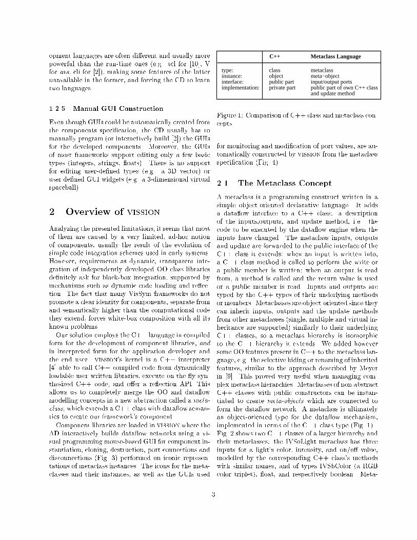
opment languages are often di�erent and usually morepowerful than the run-time ones (e.g. tcl for [10], Vfor avs, cli for [2]), making some features of the latterunavailable in the former, and forcing the CD to learntwo languages.
1.2.5 Manual GUI Construction
Even though GUIs could be automatically created fromthe components speci�cation, the CD usually has tomanually program (or interactively build [2]) the GUIsfor the developed components. Moreover, the GUIsof most frameworks support editing only a few basictypes (integers, strings, oats). There is no supportfor editing user-de�ned types (e.g. a 3D vector) oruser de�ned GUI widgets (e.g. a 3-dimensional virtualspaceball).
2 Overview of vission
Analyzing the presented limitations, it seems that mostof them are caused by a very limited, ad-hoc notionof components, usually the result of the evolution ofsimple code integration schemes used in early systems.However, requirements as dynamic, transparent inte-gration of independently developed OO class librariesde�nitely ask for black-box integration, supported bymechanisms such as dynamic code loading and re ec-tion. The fact that many VisSym frameworks do notpromote a clear identity for components, separate fromand semantically higher than the computational codethey extend, forces white-box composition with all itsknown problems.
Our solution employs the C++ language in compiledform for the development of component libraries, and
in interpreted form for the application developer andthe end user. vission's kernel is a C++ interpreter[4] able to call C++ compiled code from dynamicallyloadable user-written libraries, execute on-the- y syn-thesized C++ code, and o�er a re ection API. Thisallows us to completely merge the OO and data owmodelling concepts in a new abstraction called a meta-
class, which extends a C++ class with data ow seman-tics to create our framework's component.
Component libraries are loaded in vission where theAD interactively builds data ow networks using a vi-sual programming mouse-based GUI for component in-stantiation, cloning, destruction, port connections anddisconnections (Fig. 3) performed on iconic represen-tations of metaclass instances. The icons for the meta-classes and their instances, as well as the GUIs used
C++ Metaclass Language
type: class metaclassinstance: object meta−objectinterface: public part input/output portsimplementation: private part public part of own C++ class
and update method
Figure 1: Comparison of C++ class and metaclass con-cepts
for monitoring and modi�cation of port values, are au-tomatically constructed by vission from the metaclassspeci�cation (Fig. 4).
2.1 The Metaclass Concept
A metaclass is a programming construct written in asimple object-oriented declarative language. It addsa data ow interface to a C++ class: a descriptionof the inputs,outputs, and update method, i.e. thecode to be executed by the data ow engine when theinputs have changed. The metaclass inputs, outputsand update are forwarded to the public interface of theC++ class it extends: when an input is written into,a C++ class method is called to perform the write ora public member is written; when an output is readfrom, a method is called and the return value is usedor a public member is read. Inputs and outputs aretyped by the C++ types of their underlying methodsor members. Metaclasses are object-oriented since theycan inherit inputs, outputs and the update methodsfrom other metaclasses (single, multiple and virtual in-heritance are supported) similarly to their underlyingC++ classes, so a metaclass hierarchy is isomorphicto the C++ hierarchy it extends. We added howeversome OO features present in C++ to the metaclass lan-guage, e.g. the selective hiding or renaming of inheritedfeatures, similar to the approach described by Meyerin [9]. This proved very useful when managing com-plex metaclass hierarchies. Metaclasses of non abstractC++ classes with public constructors can be instan-tiated to create meta-objects which are connected toform the data ow network. A metaclass is ultimatelyan object-oriented type for the data ow mechanism,implemented in terms of the C++ class type (Fig. 1).Fig. 2 shows two C++ classes of a larger hierarchy andtheir metaclasses: the IVSoLight metaclass has threeinputs for a light's color, intensity, and on/o� value,modelled by the corresponding C++ class's methodswith similar names, and of types IVSbColor (a RGBcolor triplet), oat, and respectively boolean. Meta-
3

class IVSoLight { public: BOOL on; void setIntensity(float); float getIntensity(); void setColor(IVSbColor&); IVSbColor getColor();};
class IVSoDirectionalLight: public IVSoLight{ public: void setDirection(IVSbVec3f&); IVSbVec3f getDirection();};
module IVSoLight{ input: WRPort "intensity" (setIntensity,getIntensity)
editor: Slider WRport "color" (setColor,getColor) WRport "light on" (on)}
module IVSoDirectionalLight : IVSoLight{ input: WRPort "direction" (setDirection,getDirection)}
Metaclasses: C++ classes:
Figure 2: Example of C++ class hierarchy and corresponding metaclass hierarchy
class IVSoDirectionalLight extends IVSoLight with aninput for the light's direction, of type IVSbVec3f (a3-space vector). Besides the port to C++ membermapping, metaclasses specify other non-functional re-quirements such as the labels to be used in their au-tomatically constructed GUIs (Fig. 4), optional widgetpreferences (for the intensity, a slider is preferred to atypein in the above example), and documentation datathat can be accessed on-line. Appropriate widgets areautomatically created based on the ports' C++ types(3 oat typeins for IVSbColor and IVSbVec3f, a togglefor the boolean, and a slider, as the user option spec-i�ed, for the oat). The requirements and limitationslisted in Sect. 1.2 are addressed as follows:
2.1.1 Extensibility and Reuse
The CD develops his application C++ classes with norestriction imposed by vission (no common root classrequired, multiple and virtual inheritance can be used,etc) and organizes them in application libraries. Ex-tra information is next added by writing the meta-class descriptions for the C++ classes in a straight-forward fashion (the metaclass language has only afew keywords and very simple declarative constructs).Metaclasses are organized in libraries using the C++application libraries as implementation only via theirpublic interfaces, introducing a �rst level of black-boxreuse. Metaclass libraries can include other metaclasslibraries and metaclasses from one library can inheritfrom metaclasses in other libraries, similarly to Javapackages. When vission dynamically loads a meta-class library, metaclasses from directly and indirectlyincluded libraries are transparently loaded, togetherwith their corresponding C++ classes. This is a secondlevel of black-box reuse between the framework and themetaclass libraries.
2.1.2 Flexible I/O Typing
Data ow between ports is based on the full OO typingof C++: it can be passed by value, by reference, andcan be of any type (fundamental or class). For classtypes, constructors and destructors are automaticallycalled when data ows from an output to an input.Port connection type checking obey all C++ typingrules: a port of C++ type A can be connected to aport of type B if A conforms to B by trivial conversion,subclass to baseclass conversion, user-de�ned construc-tor and conversion operator [12]. This generalizes thedata ow typing policies of other systems: The Oorangesystem [10], based on Objective C, o�ers by-referencebut no by-value data passing. AVS/Express [2] limitsthe run-time data types to the ones provided by its OOV language which lacks constructors, destructors, andmultiple inheritance. Compiled toolkits as Open In-ventor [11] and vtk [16] are only statically extendable,as all types have to be known at compile time.
2.1.3 Non-intrusive code integration
All information needed to promote a C++ class toa metaclass directly usable by vission resides in themetaclass. The metaclass-C++ class pair is roughlysimilar to the handle-body idiom [3], the Adapter pat-tern [6] or the customizable adapters presented by Ku-cuk et al [8], but is much easier to do than e.g. manualAdapter coding as the parallel hierarchies are managedautomatically by the system, not the user. Separat-ing the data ow information in the metaclass allowsadding data ow semantics to existing class libraries,even when they are not available in source form. Thisseparation between the pure, framework-independentcode and the 'adaptation' layer including frameworkspeci�c elements such as non-functional requirementsis advocated by many [6],[13], as it allows code to be
4
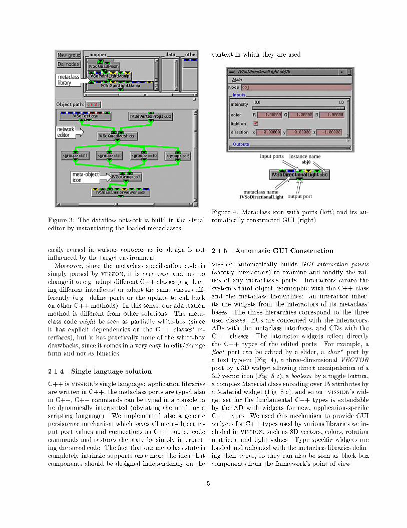
network editor
meta-objecticon
metaclasslibrary
Figure 3: The data ow network is build in the visualeditor by instantiating the loaded metaclasses
easily reused in various contexts as its design is notin uenced by the target environment.
Moreover, since the metaclass speci�cation code issimply parsed by vission, it is very easy and fast tochange it to e.g. adapt di�erent C++ classes (e.g. hav-ing di�erent interfaces) or adapt the same classes dif-ferently (e.g. de�ne ports or the update to call backon other C++ methods). In this sense, our adaptationmethod is di�erent from other solutions. The meta-class code might be seen as partially white-box (sinceit has explicit dependencies on the C++ classes' in-terfaces), but it has practically none of the white-boxdrawbacks, since it comes in a very easy to edit/changeform and not as binaries.
2.1.4 Single language solution
C++ is vission's single language: application librariesare written in C++, the metaclass ports are typed alsoin C++, C++ commands can be typed in a console tobe dynamically interpreted (obviating the need for ascripting language). We implemented also a genericpersistence mechanism which saves all meta-object in-put port values and connections as C++ source codecommands and restores the state by simply interpret-ing the saved code. The fact that our metaclass state iscompletely intrinsic supports once more the idea thatcomponents should be designed independently on the
context in which they are used.
output port
input ports
metaclass nameIVSoDirectionalLight
instance name obj0
Figure 4: Metaclass icon with ports (left) and its au-tomatically constructed GUI (right)
2.1.5 Automatic GUI Construction
vission automatically builds GUI interaction panels
(shortly interactors) to examine and modify the val-ues of any metaclass's ports. Interactors create thesystem's third object, isomorphic with the C++ classand the metaclass hierarchies: an interactor inher-its the widgets from the interactors of its metaclass'bases. The three hierarchies correspond to the threeuser classes: EUs are concerned with the interactors,ADs with the metaclass interfaces, and CDs with theC++ classes. The interactor widgets re ect directlythe C++ types of the edited ports. For example, a oat port can be edited by a slider, a char* port bya text type-in (Fig. 4), a three-dimensional VECTORport by a 3D widget allowing direct manipulation of a3D vector icon (Fig. 5 c), a boolean by a toggle button,a complex Material class encoding over 15 attributes bya Material widget (Fig. 5 c), and so on. vission's wid-get set for the fundamental C++ types is extendableby the AD with widgets for new, application-speci�cC++ types. We used this mechanism to provide GUIwidgets for C++ types used by various libraries we in-cluded in vission, such as 3D vectors, colors, rotationmatrices, and light values. Type-speci�c widgets areloaded and unloaded with the metaclass libraries de�n-ing their types, so they can also be seen as black-boxcomponents from the framework's point of view.
5

c
a b
c
d e f
Figure 5: Automatically constructed GUIs and visualization examples in the vission framework
The association of a widget to a port type is done au-tomatically at run-time by vission, which picks fromthe available widgets the one whose C++ type best
matches the type of the port to edit. The best matchrules are based on a distance metric in type space be-tween the type to edit and the type editable by a wid-get, roughly similar to C++'s type conformance rules.The GUI building process can be however customizedby supplying new GUI widgets or by specifying pre-ferred widgets (a oat type-in can be preferred to aslider for a oat port, for example) in the metaclassspeci�cation. The loose coupling between OO widgetsand OO ports via the run-time best match rule, theuser-speci�able hints and the interactive widget switch-ing correspond to the three user layers (CD,AD,EU).They form a meta-object protocol between vission andthe component to negotiate the GUI creation.
3 Architecture
vission consists of three main parts: the object man-ager, the data ow manager, and the interaction man-ager (Fig. 2) that use two subsystems: the C++ inter-preter and the library manager. All subsystems com-municate by sharing the simulation data ow graph.The key element is the C++ interpreter [4]. Opera-tions throughout vission, such as connection or dis-
Interaction ManagerC++ Interpreter
Editor Widnow
"type"
Center
NameValue
ROTOR r1
12.45-123.2 60.66
Editor Widnow
Editor Widnow
End user
Dataflow Graph
Dataflow Manager
Library Manager
Application libraries
Application developer
Figure 6: Architecture of the vission componentframework
connection of ports, data transfer between ports, up-date methods' call, GUI editing of ports, are all im-plemented as small C++ fragments dynamically sentto the interpreter. The automatic GUI constructionand the port connection type checking use the inter-preter's re ection API. The interpreter cooperates withthe library manager to dynamically load and unload
6

metaclass libraries and their underlying compiled C++classes, with the object manager to parse metaclassdeclarations and instantiate metaclasses, and with theinteraction manager to build and control the GUIs.Almost all code is executed from the compiled C++classes, leaving only a tiny amount of C++ code to beinterpreted. Performance loss as compared to a 100%compiled system was estimated to be below 2%, evenfor complex networks requiring an intensive commu-nication with the interpreter, so the extra indirectionlevel due to the loose coupling was de�nitely negligible.Loading and unloading metaclass libraries was howevermuch slower: this implies, for medium-sized librarieshaving hundreds of metaclasses with 10-20 attributeseach, the introduction in vission's type and functiontables of thousands of new names and other informa-tion. We noticed however that loading a few large li-braries is times faster than managing a �ne-grainednetwork of many small libraries referring each other, afact similar to the performance issues of compilers vsheader �les.
Figure 7 presents the relationship between the portread and write operations, the interpreted and com-piled C++ code, and the high-level tasks (data trans-fer, GUI-based inspection and modi�cation of ports).A write operation in a GUI widget triggers a write toa port of the GUI's metaclass (step W1), which sendsa C++ fragment of the form "obj1.set()" to the inter-preter (step W2), the argument of set() being the datawritten to the GUI and the target of the set() mes-sage being the metaclass's C++ object obj1. The in-terpreter executes the C++ fragment calling the set()method from the compiled application library (stepW3). A similar process occurs when reading a C++value to refresh the GUI (steps R1,R2,R3). To transferdata between two ports (step T1), a port read (stepsR1,R2,R3) followed by a port write (steps W1,W2,W3)is executed. The data ow manager uses the abovemechanism to perform automatically a network traver-sal calling node updates whenever an input changes.
4 Conclusion
vission is a general-purpose visualization and simula-tion component framework built on a black-box com-ponent foundation. It provides simple ways to speci-�cation, monitoring, steering of simulations, and com-ponent integration, by merging the powerful, yet so farindependently used OO and data ow modelling con-cepts in the metaclass component notion.
Metaclasses extend C++ classes with data ow se-
Node n1
C++ Object obj1
void set(T)
C++ Interpreter
C++ Compiled Library
Node n2
C++ Object obj2
U get()
User Interface ReadUser Interface Write Data Transfer
transfer data (T1)
portread (R1)
interprete"obj2.get()"(R2)
call compiledget() (R3)
port write (W1)
interprete"obj1.set()" (W2)
call compiled set() (W3)
Figure 7: User interface read/write operations, datatransfers between ports and the underlying C++mech-anism
mantics, GUI and documentation information in ablack-box fashion, making them easily reusable in othercontexts and also making it easy to plug-in existingC++ libraries as components. Metaclass libraries (ortheir underlying implementation C++ libraries) can beseen as application frameworks modelling some partic-ular domain, while vission is a component framework,since it a) coordinates the interaction of independentlydesigned components according to its domain-speci�c(VisSym) rules implemented using the data ow model,and b) it communicates with these components only
via the metaclass interface.
We have provided a mechanism for automatic GUIconstruction from type-speci�c, user-de�ned widgets,based on a meta-object protocol merging OO typingwith higher level information such as user preferences.vission's implementation key issue was the choice fora single (OO) language solution based on C++. vis-sion's C++ interpreter/compiler design shows thatone can combine speed and design freedom of com-piled C++ (multiple inheritance, pass by value for usertypes, etc) with the advantages of interpreted environ-ments (run-time exibility, ease of use, re ection APIs)like Java/JavaBeans also in the context of the C++.Had we chosen a JavaBeans-based implementation, itwould have been tedious and very di�cult for our tar-
7

get users to integrate several large existing C++ classlibraries which extensively use pass by value and mul-tiple inheritance.
Several applications illustrate the advantages a fullyobject-oriented computational steering architectureprovides. Component designers plugged-in existingwell-known libraries such as vtk [16] for scienti�c vi-sualization and Open Inventor [11] for rendering (420classes,over 200000 C++ lines), or other libraries forradiosity (18 classes, over 6000 C++ lines) and �niteelement analysis (25 classes, over 7500 C++ lines) invission in a short time (approximately 2 months, 5days, respectively 10 days). Integration required writ-ing a comparable number of metaclasses of an averagelength of 6 lines, and absolutely no change of the li-braries (of which, Inventor was only available as bina-ries).
Application designers and non-programmer endusers could e�ectively use visison in a matter of min-utes (Fig. 5 a,b,e,f show snapshots from scalar, vector,tensor, and medical visualizations).
The strong separation of pure application code (writ-ten by the component designer) from infrastructure asdata ow mechanisms, GUIs, persistence schemes (pro-vided by vission) makes the code to be written by theformer clear and also very concise. This is noteworthysince most large application toolkits [11, 16] dedicateup to 50% of their code to implement backbone ser-vices as the ones mentioned before. Library designersmay save 50% time if infrastructural services are au-tomatically provided. Moreover, if a single backboneis applicable, it is coded just once (in vission) andnot replicated in endless avors among the open set ofapplication libraries.
References
[1] P. Alencar, D. Cowan, C. Lucena, L. Nova,A Model for Gluing Components, Proc. of WCOP'98, Turku Centre for Computer Science, 1998.
[2] C. Upson, T. Faulhaber, D. Kamins,
D. Laidlaw, D. Schlegel, J. Vroom,
R. Gurwitz, and A. van Dam, The ApplicationVisualization System: A Computational Environ-
ment for Scienti�c Visualization., IEEE Com-puter Graphics and Applications, July 1989, 30{42.
[3] J. O. Coplien, Advanced C++ Programming
Styles and Idioms, Addison-Wesley, 1992
[4] M. Goto, The CINT C/C++ Interpreter and
Dictionary Generator, The ROOT System URLhttp://root.cern.ch/root/Cint.html
[5] J. J. van Wijk and R. van Liere, An environ-
ment for computational steering, in G. M. Niel-son, H. Mueller and H. Hagen, eds, Scienti�c Vi-
sualization: Overviews, Methodologies and Tech-
niques, Computer Society Press, 1997
[6] E. Gamma, R. Helm, R. Johnson, J. Vlis-sides, Design Patterns: Elements of Reusable
Object-Oriented Software, Addison-Wesley, 1995
[7] The Java 3D Application Programming Interface,http://java.sun.com/products/java-media/3D/
[8] B. Kucuk, M. N. Alpdemir, R. N. Zo-
bel, Customizable Adapters for Black-Box Com-
ponents, in Proceedings of WCOP '98, Turku Cen-
tre for Computer Science
[9] B. Meyer, Object-oriented software construction,Prentice Hall, 1997
[10] C. Gunn, A. Ortmann, U. Pinkall,
K. Polthier, U. Schwarz, Oorange: A Vir-
tual Laboratory for Experimental Mathematics,Sonderforschungsbereich 288, Technical Univer-sity Berlin. URL http://www-sfb288.math.tu-berlin.de/oorange/OorangeDoc.html
[11] J. Wernecke, The Inventor Mentor: Program-
ming Object-Oriented 3D Graphics with Open In-
ventor, Addison-Wesley, 1993.
[12] B. Stroustrup, The C++ Programming Man-
ual, Addison-Wesley,1993.
[13] C. Szyperski, Component Software - Beyond
Object-Oriented Programming, Addison-Wesley,1998.
[14] D. Jablonowski, J. D. Bruner, B. Bliss, andR. B. Haber, VASE: The visualization and ap-
plication steering environment, in Proceedings of
Supercomputing '93, pages 560-569, 1993
[15] A. C. Telea, J. J. van Wijk Design of an
Object-Oriented Computational Steering System,to be presented at the IEEE-Eurographics Work-shop on Scienti�c Visualization and SimulationVisSym'99, Vienna, Austria
[16] W. Schroeder, K. Martin, B. Lorensen,The Visualization Toolkit: An Object-Oriented
Approach to 3D Graphics, Prentice Hall, 1995
8

&RPSRQHQW�7UDGLQJ7KH�%DVLV�IRU�D�&RPSRQHQW�2ULHQWHG�'HYHORSPHQW�)UDPHZRUN
6RWLULRV�7HU]LV 3DGG\�1L[RQ&RPSXWHU�6FLHQFH�'HSDUWPHQW�
8QLYHUVLW\�RI�'XEOLQ��7ULQLW\�&ROOHJH��'XEOLQ����,UHODQG(PDLO��6RWLULRV�7HU]LV#FV�WFG�LH��3DGG\�1L[RQ#FV�WFG�LH
$EVWUDFW&RPSRQHQW�RULHQWHG� VRIWZDUH� VHHPV� SURPLVLQJ� LQSURYLGLQJ� WKH� G\QDPLVP� DQG� IOH[LELOLW\� QHFHVVDU\� WRUHDOLVH� WKH� 9LUWXDO� (QWHUSULVH� �9(�� PRGHO� IRU� G\QDPLFEXVLQHVV� RUJDQLVDWLRQV��$FFRUGLQJ� WR� WKH�9(�PRGHO�� DQGIURP� WKH� SHUVSHFWLYH� RI� FRPSRQHQW�RULHQWHGSURJUDPPLQJ�� D� YLUWXDO� HQWHUSULVH� V\VWHP� FRXOG� EHFRQVWUXFWHG� E\� PDUVKDOOLQJ� WKH� QHFHVVDU\� VHUYLFHVWKURXJK� FRPSRVLWLRQ� RI� DYDLODEOH� FRPSRQHQWV� VHOHFWHGIURP�D�FROOHFWLRQ�SURYLGHG�E\�WKH�SDUWLFLSDWLQJ�HQWHUSULVHV\VWHPV�WR�IRUP�WKH�QHZ�YLUWXDO�HQWHUSULVH�V\VWHP��,Q�WKLVFRQWH[W� WKH� SURFHVV� RI� VHOHFWLQJ� DQG� FRPSRVLQJ� RIFRPSRQHQWV�LV�QRW�D�WULYLDO� WDVN��7KLV�SDSHU�SURSRVHV�WKHXVH�RI�D�FRPSRQHQW�WUDGLQJ�IDFLOLW\��ZKLFK�LQWURGXFHV�WKHQRWLRQ� RI� VHPDQWLF� WUDGLQJ�� WR� VXSSRUW� WKH� FRPSRQHQWVHOHFWLRQ�DQG�FRPSRVLWLRQ�SURFHVV�
���0RWLYDWLRQ
We are currently witnessing a convergence of severalthreads of technology and business imperatives. A newmodel for business organisations, the 9LUWXDO(QWHUSULVH (VE) is emerging. The new model is basedon the idea that business organisations should be ableto marshal more resources than they have availablewithout the need for expansion. The VE model aims toprovide the responsiveness that businesses require inhighly changeable market conditions where nichemarkets emerge rapidly. Although, a number oftechnological phenomena and business trends make theVE model both feasible and appealing, theeffectiveness and efficiency of the model depends onthe development of global information infrastructures.These infrastructures should span organisationalboundaries and support flexible, dynamic and seamlesscomposition of services from a worldwide pool.It seems that the only reasonable way to achieve theflexibility and dynamism required by the VE model isthrough a new perspective on enterprise systemdevelopment. The decomposition of current enterprisesystems into services and components will provide thenecessary framework within which this newperspective can be built. This framework should be
based on component-oriented software and shouldallow the dynamic composition and configuration ofcomponents services. It should also allow on-the-flyrecomposition and reconfiguration of services. Finally,since the number of these components and serviceswill be significant, the framework should also bescalable (see [1] for a more detailed discussion).Inside this component-oriented framework thedevelopment of a new system is a process ofdynamically selecting the appropriate components andcomposing them into a new configuration. Thisprocess presents a number of challenges to traditionaldevelopment techniques. The VE model for enterprisesystems changes the basic assumption of equallytrusted and equally under control system parts thatdrives traditional system development. Under the VEmodel that is simply not the case. In fact the modelrequires semantically rich component interactions andcomposition, not supported by current syntacticallybased development frameworks like CORBA [2] andDCOM [3]. So, from the purely technical perspective,development inside this component-orientedframework seems to hinge on issues as diverse astrading through high-level semantic servicedescriptions, on-the-fly re-configuration, novelprogramming language structures, and the closeintegration of trust and trust management into thefabric of applications [4].This paper proposes the use of a component tradingfacility to support the component-orienteddevelopment framework presented above. The facilityis based on the notion of semantic trading, which is akind of trading using ontological exchange of domainknowledge inside a community of component traderswith the support of component composition facility.Having described the framework, the discussion willfocus on how the framework provides for componentlocation and management. Furthermore, it will addresshow semantic trading allows the inclusion of non-functional information in the component descriptionand thus how it provides a richer environment forcomponent composition. Discussion about the otheraspects of the framework can be found elsewhere [5]and [6].

���5HTXLUHPHQWV�IRU�D�&RPSRQHQW�7UDGLQJ)DFLOLW\
)LJXUH���/HYHO�RI�DEVWUDFWLRQ�IRU�HQWHUSULVH�V\VWHPGHFRPSRVLWLRQ
The component-orient framework for enterprisesystem development, presented above, requires thedecomposition of current enterprise systems into anumber of services and components. This systemdecomposition is done according to different levels ofabstraction (see Figure 1). At the lowest level thesystem is decomposed to a number of basiccomponents. Some of these components groupedtogether form functionally cohesive entities calledservices. At the highest level, these services arecombined together to form the whole enterprisesystem. In the development of a VES the participatingsystems could contribute either basic level componentsor services. So, the facility should support trading atboth levels.
)LJXUH���8VH�RI�&RPSRQHQW�7UDGLQJ�)DFLOLW\�IRU�9(6GHYHORSPHQW�
The component trading facility will support thedevelopment of VES in the following way (see Figure2): In the start there are a number of existing enterprisesystems. Each of these systems consists of a number ofconnected components (both basic level componentsand services from Figure 1) and a semantic trader (the
black circle inside each system). The creation of theVES (the system in the middle) will be driven by anew component trader, which is formed by composingthe existing ones. Then, the new trader is used to selectthe components that will form the VES while thecomposition will be supported by a wrapping service(explained below) associated with the trader creates thenew configuration. Some times the existing systemsmight not provide all the necessary components inwhich case the component trader will try to retrievemissing components from a worldwide pool ofavailable ones.
�����&XUUHQW�7UDGLQJ
The accepted definition of trading is: “WKH� DFWLYLW\� RIFKRRVLQJ� VHUYLFHV�� VXFK� WKDW� WKH\�PDWFK� VRPH� VHUYLFHUHTXLUHPHQWV��7KH� FKRLFH� LV� EDVHG�RQ� WKH� FRPSDULVRQRI�WKH�VSHFLILFDWLRQ�RI�D�VHUYLFH�UHTXLUHG��SURYLGHG�E\D�SURVSHFWLYH�FRQVXPHU��DQG� WKH� VHUYLFH� VSHFLILFDWLRQVXSSOLHG� E\� VHUYLFH� SURYLGHUV� RU� WKHLU� DJHQWV” [7].Trading is based on the notion of matching serviceoffers and service requests. The componentresponsible for the maintenance of the trading spaceand the matching of offers and requests is called atrader. Current traders [7], [8], [9] organise services ina service type hierarchy. Each service type defines aninterface that prescribes the operations available for theinteraction between the service provider and theservice consumer. They also allow the association of anumber of properties as attribute value pairs with eachservice type. The use of service types with associatedproperties allows the expression of quite refinedservice offers and requests in an easy way.Service providers are called exporters. An exporterexports a service offer by specifying its service typeand service properties. The service provider can alsorefine its offer by specifying a number of service offerproperties. On the other hand service consumers arecalled importers. An importer requests a service byspecifying the type of the service and constraints onthe properties of the type. The importer might also beable to specify a search scope thus limit the part of thetrading space that wants to be searched. Or it might beallowed to specify the selection criteria for theselection of offers when more than one meets thespecified type and property constraints. Or, finally, itcould probably specify the search method that is goingto be used by the trader.The combination of the trading policy of the trader, theexport policy of the exporter and the import policy ofthe importer determine the service matching process.The centre of the service type matching is the notion oftype conformance1. Type conformance is based on the“no surprise rule” on the interaction interface, whichmeans that no unexpected input or output requirements
1 If TypeA conforms to TypeB then instances of TypeA can besubstituted for instances of TypeB and the clients will not be able todetect that the interface being used is not of the exact requested type.

or operation termination conditions will emerge (see[7] for a more detailed discussion about typeconformance). Since type conformance is determinedby the interaction interface, the description ofinterfaces is crucial in trading. At the basic level thedescription of an interface is based on determining thetype of the parameters and of the return value for thesupported methods (the signature of the interface). Inmost cases this is not sufficient. For example, in the Cmath library nearly two thirds of the functions have thesame signature double → double [10]. In order toovercome the problem the name of the method isconsidered part of the signature. Also, since a numberof programming languages support exception handlingmechanisms for dealing with unusual cases, thrownexceptions are also considered part of a method’ssignature. For the specification of method signaturesand interfaces in general interface definition languages(IDLs) have been developed (e.g. CORBA/IDL [11]).So, trading is currently IDL-based. This means that thefoundation of trading is answering questions of thekind: “)LQG� PH� D� VHUYLFH� WKDW� FRQIRUPV� WR� WKHIROORZLQJ� VHUYLFH� W\SH� DQG� KDV� WKH� IROORZLQJDWWULEXWHV”.
�����&RPSRQHQW�7UDGLQJ
The foundation of current trading is not sufficient forcomponent trading because of its syntactic nature. Asemantically rich trading is necessary. In order toestablish this a concise definition of components isnecessary. In the literature the notion of components isquite overloaded. There are a number of differentdefinitions with subtle differences (see [12] for acomparison of a number of them). A clear definition isimportant in order to determine the set ofcharacteristics that are significant for the description ofcomponent and subsequently for component trading.The following definition seems to be both clear andconcise: “$� VRIWZDUH� FRPSRQHQW� LV� D� XQLW� RIFRPSRVLWLRQ� ZLWK� FRQWUDFWXDOO\� VSHFLILHG� LQWHUIDFHVDQG� H[SOLFLW� FRQWH[W� GHSHQGHQFLHV� RQO\�� $� VRIWZDUHFRPSRQHQW� FDQ� EH� GHSOR\HG� LQGHSHQGHQWO\� DQG� LVVXEMHFW�WR�FRPSRVLWLRQ�E\�WKLUG�SDUWLHV.” [12]. This hasa number of implications, which establish theinappropriateness of current trading as the basis for thecomponent trading facility. Because current trading isinsufficient to capture all the aspects of a componentas these are identified through the definition.According to the definition a software component is aunit of composition� with contractually specifiedinterfaces and explicit context dependencies only. Thisimplies first that the basis of trading should becomponent descriptions and some notion of“component conformance”2. Second, if interfacedefinitions are seen as specifications of interaction
2 The definition of component type conformance should incorporate thenotion of substitutability in a way analogous to that of typeconformance. A prerequisite for the definition is the definition ofcomponent types.
contracts between two parties, then IDL-based tradingseems to cover the contractually specified interfacerequirement. On the other hand, if a notion of contractas the one described in [13], which specifies not onlythe interaction interface between the parts, but also theobligations and benefits for each part is adopted. Then,it requires interfaces to be extended to includeassertions like pre-/post-conditions and invariants. Thissense of contract raises serious doubt on theappropriateness of current trading. It should be alsonoted that the application of this notion of contracts ina component-oriented model is not straightforward.Finally, context dependencies include the events thatthe component produces and consumes, itsrelationships with other components and its stateinformation that needs to be exposed to its clients.Making context dependencies explicit implies that thecomponent definitions should include constructs toallow their expression. There are already attemptstowards this direction (e.g. [14], [15]).The next part of the definition requires that a softwarecomponent can be deployed independently and issubject to composition by third parties. Theindependent deployment of components could beconsidered as a consequence of the previousrequirements of the definition with the addition thatcontext dependencies should not be as severe as toprevent the independent deployment of the component.The requirement for composition by third partiesthough has significant implications. A third party is aside that does not have any knowledge of both thecomponent’s internals and the internals of thecomponent’s clients [12]. This means that thecomponents involved should provide sufficientinformation about their functionality in order to becomposable. This poses a serious challenge on currenttrading techniques, since it requires semanticinformation about the components’ behaviour.“8QIRUWXQDWHO\��«EHKDYLRXU� RI�PHWKRGV� LV� FOHDU� RQO\E\� H[SODQDWLRQ� RU� GRFXPHQWDWLRQ�� DQG� WKHUHIRUHVXVFHSWLEOH�WR�PLVLQWHUSUHWDWLRQ�DQG�PLVXQGHUVWDQGLQJ�«&25%$�>,'/@�SURYLGHV�RQO\�WKH�V\QWD[«�VHPDQWLFVDUH� LPSOLFLW�DQG�XQHQIRUFHG” [15]. So, current tradingis not sufficient as the basis for component locationmechanisms, because: “$Q� LQWHUIDFH� GHILQLWLRQSURYLGHV� WUHPHQGRXV� OHYHUDJH� LQ� GHILQLQJ� D� FRQWUDFWEXW� LV� LQVXIILFLHQW� IRU� IUDPHZRUNV� WKDW� VXSSRUWVHPDQWLF� FRQFHSWV� EH\RQG� WKRVH� SURYLGHG� E\� DPHVVDJLQJ� LQIUDVWUXFWXUH” [17], as is the case forcomponent software. What is needed is “7KH�LQFOXVLRQRI� VHPDQWLFV� «>WR@� ,'/�� LQIRUPDWLRQ� DERXW� WKHPHDQLQJ�RI�D� FRPSRQHQW�� LQIRUPDWLRQ�DERXW�ZKDW� WKHFRPSRQHQW�ZLOO�DFFRPSOLVK��DQG�LQIRUPDWLRQ�DERXW�WKHPHWKRG¶V� LQSXWV� DQG� RXWSXWV� ” [16]. In other wordswhat is needed is a new kind of semantically basedtrading, “semantic trading”.“Semantic Trading” is a fundamentally different typeof trading because its foundation is answeringquestions of the type: “)LQG�PH� D� FRPSRQHQW�VHUYLFH

WKDW�GRHV� WKH�IROORZLQJ”. So, the focus shifts from theappearance (syntax) to the functionality (semantics) ofthe components. In this sense it can be considered ahigher level of trading.
���$Q�$UFKLWHFWXUH�IRU�D�&RPSRQHQW�7UDGLQJ)DFLOLW\
The component trading facility is based upon the ideaof semantic trading. Before its architecture can bedefined there are some issues concerning semantictrading that need to be clarified.In semantic trading the idea is to incorporate semanticinformation about the components’ behaviour in thetrading process. This is achieved by supporting thetrading process with a knowledge base that containsthis semantic information. Central in the constructionof the knowledge base is the definition of an ontologyof the components’ domain. The knowledge needed forthe definition of this ontology is acquired from thedomain analysis performed during the design of theenterprise system. In fact, if a design process like theone described in [18] is followed, then the concepts ofthe ontology are directly the concepts (types) identifiedduring the design and their relationships are alsodirectly mapped into the ontology. If the requireddomain knowledge is not available from the design,then it could be acquired through a process of reverseknowledge engineering (see [19] for more details).Finally, central to semantic trading is a componentdescription language. This language should allow thespecification of both appearance (interface) and thebehaviour of components and will also be the basis forthe expression of requests to the trader. There are anumber of component description languages alreadyavailable (for examples see [14] and [15]).
)LJXUH���&RPSRQHQW�7UDGLQJ�)DFLOLW\�$UFKLWHFWXUH�
The architecture of the component trading facility ispresented in Figure 3. Central to the architecture is thetrader. The trader receives service requests and repliesby providing the retrieved components. The requests
go through some pre-processing component. A numberof different pre-processing components allow thetrader to support a number of different formats forexpressing requests. This makes the trader moreflexible since it can support a number of differentlanguages for expressing requests. After the requestshave been transformed to the basic format supported,which depends on the component description languageselected for semantic trading. Then, the requests areforwarded to the “translator”. The “translator” is theheart of the semantic trading process. Its aim is totransform the requests from the component descriptionlanguage into the knowledge representation languagethat will provide semantic retrieval. The translation isdone using the terms of the ontology and the notion ofcomponent conformance. The ontology is representedby a number of relationships between its terms andkept in a relationship service. The translation leads tothe expansion or restriction of the request in afunctionally and semantically sound way. Then, the“translated” requests are used to retrieve theappropriate components from the trading space. Theinterface of the components plays a secondary role inthe retrieval phase. When the retrieval phase iscompleted the trader has to prepare the reply for therequest. The preparation of the request reply is donewith the support of a component wrapper. Thecomponent wrapper takes the retrieved componentsand a wrapping strategy. The wrapping strategydetermines how the wrapping should be performed andis supported by a scripting language (in the sensedescribed in [20]). During, the wrapping phase theretrieved components are wrapped to support therequired interface or in more complex cases acomposition might be also created. Finally, the tradingfacility returns the wrapped components to the client.As mentioned above, the use of the component tradingfacility for VES development requires the compositionof existing semantic traders. This composition involvesthe exchange of knowledge between the traders and thecreation of a common ontology. The issue ofexchanging knowledge is quite central in the multi-agent systems development and standards like KIF[21] and KQML [22] have been developed in order tosupport it.
���2SHQ�,VVXHV�DQG�'LVFXVVLRQ
From the above presentation it is clear that the use ofthe component trading facility in a componentselection and composition framework exhibits anumber of advantages:- It simplifies the application composition task sinceit allows the use of domain terminology for thedescription and retrieval of components.- It increases the reliability of the code producedthrough composition by making explicit the semanticsof the operation supported by components.

- It is a powerful composition framework, since it isnot limited by the appearance (interface) of thecomponents.- It adds value in programming, since it can supportthe domain-related constraints on the requiredcomponent.It is also clear there are a number of open issues thatneed to be covered before the framework can be fullyrealised and deployed. These issues are:- The construction of the ontology from the designdomain knowledge. In particular are specificationnotations like UML sufficient to express the necessaryinformation? How can we automate the knowledgeextraction form the specification notation and theontology construction?- The construction and use of the knowledge base.In particular how the knowledge base is used duringthe search phase and how it can drive to thespecification of the wrapping strategy?- The definition of a component descriptionlanguage. Although the analysis of the definition ofcomponents in relation to trading provides someinsight on basic principles of such a language, currentapproaches ([14] and [15]) seem to diverge. The issueof defining a component description language remainsopen.- The definition of scripting language for thewrapper. This raises the issue of compositionlanguage, which is still open.Most of these issues are of central interest tocomponent-oriented programming and are closelyrelated to its future.
���5HIHUHQFHV[1] S. Terzis, P. Nixon, V. Wade, S. Dobson and J. Fuller,"The Future of Enterprise Groupware Applications", inproceedings of the �VW� ,QWHUQDWLRQDO� &RQIHUHQFH� RQ� (QWHUSULVH,QIRUPDWLRQ�6\VWHPV��,&(,6¶���, Setubal, Portugal, March 1999.[2] OMG, “CORBA/IIOP 2.2 Specification”, July 1998.[3] Microsoft, DCOM, http://www.microsoft.com/com/.[4] P. Nixon, V. Wade, S. Dobson, J. Fuller and S. Terzis,“Designing Components for a Virtual Organisation: A CaseStudy”, in proceedings of the 2EMHFW�� &RPSRQHQWV� DQG� WKH9LUWXDO�(QWHUSULVH�:RUNVKRS�RI�WKH�,QWHUQDWLRQDO�&RQIHUHQFH�RQ2EMHFW�2ULHQWHG� 3URJUDPPLQJ� 6\VWHPV� /DQJXDJHV� DQG$SSOLFDWLRQV��2236/$¶���, Vancouver, Canada, October 1998.[5] Simon Dobson, “A First Taste of Vanilla”, technical reportTCD-CS-1998-20, Dept. of Computer Science, Trinity CollegeDublin, September 1998.[6] Paddy Nixon, Simon Dobson, Vincent Wade, John Fuller,Sotirios Terzis and Tim Walsh, “The Virtues architecture”,Dept. of Computer Science, Trinity College Dublin, 1999.[7] Jean-Pierre Deschrevel, “The ANSA Model for Tradingand Federation”, Architecture Report APM. 1005.01, Approved15 July 1993.[8] Draft Rec. X.950-1| ISO/IEC 13235-1 – ODP TradingFunction: Specification.[9] OMG, “Trading Object Service Specification”, in&25%$VHUYLFHV�� &RPPRQ� 2EMHFW� 6HUYLFHV� 6SHFLILFDWLRQ,December 1997.
[10] Moormann Zaremski and J.M. Wing, “Specificationmatching of software components”, in proceedings of the �UG
$&0� 6,*62)7� 6\PSRVLXP� RQ� WKH� )RXQGDWLRQV� RI� 6RIWZDUH(QJLQHHULQJ, October 1995.[11] J. Siegel, “CORBA fundamentals and programming”,Wiley 1996.[12] Szyperski, “Component Software: Beyond Object-OrientedProgramming”, Addison-Wesley, 1998.[13] Meyer, “Applying Design by Contract”, IEEE Computer,vol. 25, no. 10, October 1992.[14] OMG, “CORBA Components – orbos/98-12-02”, jointrevised submission, February 1999.[15] J.R. Kiniry, “CDL: A Component Description Language”,submitted to the Advanced Topics Workshop (ATW) of the �WK
86(1,;� &RQIHUHQFH� RQ� 2EMHFW�2ULHQWHG� 7HFKQRORJLHV� DQG6\VWHPV� �&2276¶���, March 1999, available athttp://www.cs.caltech.edu/~kiniry/projects/papers/kiniry/COOTS99_ATW/cdl/cdl.html[16] J.H. Gennari, A.R. Stein and M.A. Musen, “Reuse ForKnowledge-Based Systems and CORBA Components”, inproceedings of the ��WK�.QRZOHGJH�$FTXLVLWLRQ� IRU�.QRZOHGJH�%DVHG�6\VWHPV�:RUNVKRS� �.$:¶���, Banff Canada, November1996, available athttp://ksi.cpsc.ucalcary.ca/KAW/KAW96/gennari/[17] T. Digre, “Business Object Component Architecture”,IEEE Software, vol. 15, no. 5, September/October 1998.[18] J. Martin and J.J. Odell, “Object-Oriented Methods: AFoundation”, UML edition, Prentice-Hall, 1998.[19] P. Devanbu, R. Brachman, P. Selfridge and B. Ballard,“LaSSIE: A Knowledge-based Software Information System”,Communication of the ACM, vol. 34, no. 5, May 1991.[20] O. Nierstrasz, D. Tsichritzis, V. de Mey, and M.Stadelmann, “Objects + Scripts = Applications”, in proceedingsof the (VSULW������&RQIHUHQFH, Dordrecht Germany, 1991.[21] ARPA Knowledge Sharing Effort, “KnowledgeInterchange Format (KIF)”, information available at http://ksl-web.stanford.edu/knowledge-sharing/kif/[22] T. Finin, Y. Labrou, and J. Mayfield, “KQML as an agentcommunication language”, in J. Bradshaw (ed.), “6RIWZDUH$JHQWV”, MIT Press, Cambridge, (1997).