Astrophysical Parameter Determination Using Chaotic Orbital ...
Upload
uni-siegenCategory
view
0download
0
Wavelength division multiplexing of chaotic secure and fiber-optic communications
Jian-Zhong Zhang, An-Bang Wang, Juan-Fen Wang , and Yun-Cai Wang∗
Department of Physics, College of Science, Taiyuan University of Technology,
Taiyuan 030024, China
∗Corresponding author: [email protected]
Abstract: Wavelength division multiplexing (WDM) transmission of
chaotic optical communication (COC) and conventional fiber-optic
communication (CFOC) is numerically confirmed and analyzed. For an
80-km-long two-channel communication system, a 1-Gb/s secure message
in COC channel and 10-Gb/s digital signal in CFOC channel are
simultaneously achieved with 100GHz channel spacing. Our numerical
simulations demonstrate that the COC and CFOC can realize no-crosstalk
transmission of 80km when the peak power of CFOC channel is less than
8dBm. We also find that the crosstalk between COC and CFOC does not
depend on channel spacing when the channel spacing exceeds 100GHz.
Moreover, the crosstalk does not limit channel number by comparing the
synchronization performance of COC in four- and six-channel WDM
systems.
2009 Optical Society of America
OCIS codes: (140.5960) Semiconductor lasers; (060.2330) Fiber optics communications;
(060.4230) Mutiplexing.
References and links
1. L. M. Pecora and T. L. Carroll, “Synchronization in chaotic systems,” Phys. Rev. Lett. 64, 821-824
(1990).
2. T. Sugawara, M. Tachikawa, T. Tsukamoto, and T. Shimizu, “Observation of synchronization in laser
chaos,” Phys. Rev. Lett. 72, 3502-3505 (1994).
3. G. D. VanWiggeren and R. Roy, “Communication with chaotic lasers,” Science 279, 1198-1200 (1998).
4. P. Colet and R. Roy, “Digital communication with synchronized chaotic lasers,” Opt. Lett. 19, 2056-2058
(1994).
5. J. Ohtsubo, “Chaos synchronization and chaotic signal masking in semiconductor lasers with optical
feedback,” IEEE J. Quantum Electron. 38, 1141-1154 (2002).
6. V. Annovazzi-Lodi, S. Donati, and A. Sciré, “Synchronization of chaotic lasers by optical feedback for
cryptographic applications,” IEEE J. Quantum Electron. 33, 1449-1454 (1997).
7. H. F. Chen and J. M. Liu, “Open-loop chaotic synchronization of injection-locked semiconductor lasers
with gigahertz range modulation,” IEEE J. Quantum Electron. 36, 27-34 (2000).
8. V. Annovazzi-Lodi, S. Donati, and A. Sciré, “Synchronization of chaotic injected-laser systems and its
application to optical cryptography,” IEEE J. Quantum Electron. 32, 953-959 (1996).
9. A. B. Wang, Y. C. Wang, and H. C. He, “Enhancing the bandwidth of the optical chaotic signal generated
by a semiconductor laser with optical feedback,” IEEE Photon. Technol. Lett. 20, 1633-1635 (2008).
10. J. Mørk, B. Tromborg, and J. Mark,”Chaos in semiconductor lasers with optical feedback: theory and
experiment,” IEEE J. Quantum Electron. 28, 93-108 (1992).
11. S. Sivaprakasam and K. A. Shore, “Message encoding and decoding using chaotic external-cavity diode
lasers,” IEEE J. Quantum Electron. 36, 35-39 (2000).
12. V. Annovazzi-Lodi, M. Benedetti, S. Merlo, M. Norgia, and B. Provinzano, “Optical chaos masking of
video signals,” IEEE Photon. Technol. Lett. 17, 1995-1997 (2005).
13. C. R. Mirasso, P. Colet, and P. García-Fernández, “Synchronization of chaotic semiconductor lasers:
application to encoded communications,” IEEE Photon. Technol. Lett. 8, 299-301 (1996).
14. A. Sánchez-Díaz, C. R. Mirasso, P. Colet, and P. García-Fernández, “Encoded Gbit/s digital
#106686 - $15.00 USD Received 21 Jan 2009; revised 14 Mar 2009; accepted 17 Mar 2009; published 2 Apr 2009
(C) 2009 OSA 13 April 2009 / Vol. 17, No. 8 / OPTICS EXPRESS 6357

communications with synchronized chaotic semiconductor lasers,” IEEE J. Quantum Electron. 35,
292-297 (1999).
15. A. Bogris, D. Kanakidis, A. Argyris, and D. Syvridis, “Performance characterization of a closed-loop
chaotic communication system including fiber transmission in dispersion shifted fibers,” IEEE J.
Quantum Electron. 40, 1326-1336 (2004).
16. A. Argyris, D. Syvridis, L. Larger, V. Annovazzi-Lodi, P. Colet, I. Fischer, J. García-Ojalvo, C. R.
Mirasso, L. Pesquera, and K. A. Shore, “Chaos-based communications at high bit rates using commercial
fibre-optic links,” Nature 437, 343-346 (2005).
17. D. Kanakidis, A. Bogris, A. Argyris, and D. Syvridis, “Numerical investigation of fiber transmission of a
chaotic encrypted message using dispersion compensation schemes,” J. Lightwave Technol. 22,
2256-2263 (2004).
18. Y. L. Li, Y. C. Wang, and A. B. Wang, “Message filtering characteristics of semiconductor laser as
receiver in optical chaos communication,” Opt. Commun. 281, 2656-2662 (2008).
19. G. P. Agrawal, Nonlinear fiber optics, 3rd Edition (Academic Press, San Diego, 2001) Chap. 2.
20. P. Grassberger and I. Procaccia, “Characterization of strange attractors,” Phys. Rev. Lett. 50, 346-349
(1983).
21. J. Z. Zhang, Y. C. Wang, and A. B. Wang, “Improving performance of optical fibre chaotic
communication by dispersion compensation techniques,” Chin. Phys. B 17, 3264-3269 (2008).
1111. Introduction
Many researches have been devoted to achieving chaotic secure communications since the
idea of synchronization between two chaotic oscillators was proposed in early 1990s [1].
Compared with electrical chaos, optical chaos generated from lasers offers higher dimension,
broader bandwidth and thus has attracted extensive attention in recent years. Optical chaos
synchronizations have been implemented in many laser systems: gas laser [2], fiber laser [3],
solid laser [4], semiconductor laser [5-8], and so on. As the chaotic transmitter and receiver,
semiconductor lasers with optical feedback [5, 6, 9, 10] or optical injection [7-8] have been
enthusiastically studied because they are the main light sources in conventional optical
communication systems.
Up to now, Chaotic optical communication (COC) based on semiconductor lasers has
been successfully demonstrated in a back-to-back configuration [5, 7,8,11] or short fiber
transmission [12].To extend the distance of transmission, COC through long-distance optical
fiber using semiconductor lasers with optical feedback has been theoretically studied [13, 14].
The effects of fiber transmission characteristics, such as dispersion and nonlinearity, on the
performance of COC system are further investigated by a numerical simulation [15]. Although
a field COC system was successfully implemented in 120-km commercial fiber-optic channel
for 1-Gb/s transmission rate [16], COC sharing the existing fiber networks with conventional
fiber-optic communication (CFOC) to realize the wavelength division multiplexing (WDM)
transmission has not been reported so far.
In this paper, we numerically realize WDM transmission of COC and CFOC in fiber link.
In addition, we investigate the inter-channel crosstalk between COC and CFOC and the
dependence of COC and CFOC WDM system on channel spacing and channel number.
2. Theoretical model
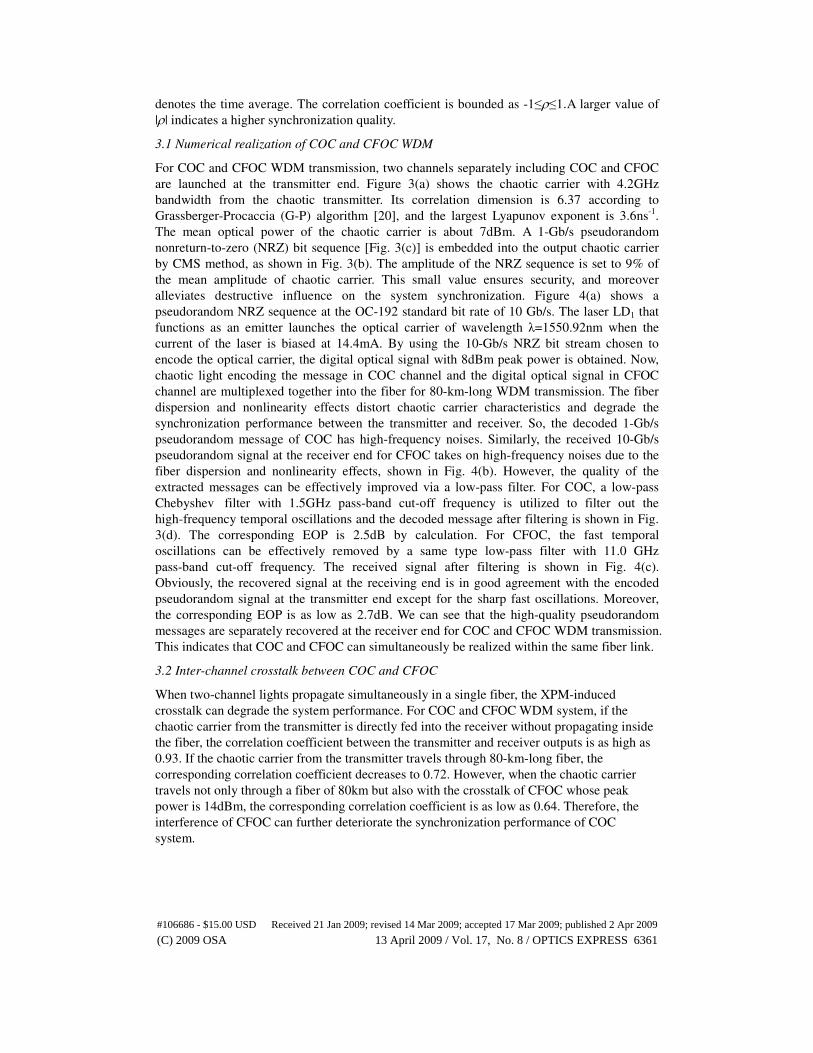
The schematic diagram of COC and CFOC WDM transmission in our study is shown in Fig. 1.
Each channel, defined by the wavelength of its carrier wave, is coupled into the same optical
fiber in its original data format. The chaos cryptography technique encrypts some important
information at a given WDM channel λC. In COC system, transmitter (LDT) and receiver
(LDR), both of which are composed of a single-mode semiconductor laser with an external
reflector, have the same configuration. Transmitter laser (LDT) emits a chaotic carrier and an
optical isolator (ISO) is used to ensure unidirectional transmission. The original message is
superposed on chaotic carrier by chaos masking (CMS). The CMS method is implemented by
#106686 - $15.00 USD Received 21 Jan 2009; revised 14 Mar 2009; accepted 17 Mar 2009; published 2 Apr 2009
(C) 2009 OSA 13 April 2009 / Vol. 17, No. 8 / OPTICS EXPRESS 6358
simply adding the message to the output chaotic carrier. The chaotic carrier encoded by
message and multiple digital optical signals from lasers LD1, LD2, … , LDN are launched
together into the fiber via a WDM multiplexer (MUX), and separated by a WDM
demultiplexer (DMUX) after long-haul transmission. An erbium-doped fiber amplifier (EDFA)
is placed at the end of the fiber to compensate the fiber loss. The demultiplexed chaotic light
is divided into two beams by a beam splitter (BS). One beam is injected into the receiver laser
to achieve chaos synchronization. The other beam, as well as the output from the receiver
laser, is separately detected by two identical photodiodes. The message can be extracted from
the subtraction of the two detected signals.
Fig. 1. Schematic diagram of COC and CFOC WDM transmission.
The dynamics of the transmitter and receiver in COC system can be described by the
following Lang-Kobayashi rate equations with optical feedback and injection terms [17]:
T,R
T,R T,R T,R T,R inj ext
P
d ( ) 1 1(1 )[ ( ) ] ( ) ( ) exp( ) ( )
d 2
E ti G t E t k E t i k E t
tα τ ωτ
τ= + − + − − + (1)
2T,R T,R
T,R T,R T,R
n
d ( ) 1( ) ( ) ( )
d
N t IN t G t E t
t qV τ= − − (2)
T,R 0
T,R 2
T,R
[ ( ) ]
( )1 ( )
,G N t N
G tE tε
−=
+ (3)
where E and N are the slowly varying complex electrical field amplitude and the carrier
density in the laser cavity. Subscripts T and R represent the transmitter and receiver,
respectively. ωτ is the round-trip phase shift induced by the external feedback, where ω is the
angular frequency of the free-running laser and τ is the external cavity round-trip time. The
field Eext is the input signal at the receiver and I is the pump current density of the
semiconductor laser.
The feedback coefficient kT,R of the semiconductor lasers with optical feedback and the
injection coefficient kinj from the transmitter to the receiver are defined as follows:
2
0 T ,R
T ,R
in 0
(1 )1 r rk
rτ
−= (4)
2
0 in j
in j
in 0
(1 )1 r rk
rτ
−= , (5)
#106686 - $15.00 USD Received 21 Jan 2009; revised 14 Mar 2009; accepted 17 Mar 2009; published 2 Apr 2009
(C) 2009 OSA 13 April 2009 / Vol. 17, No. 8 / OPTICS EXPRESS 6359

where τin is the round-trip time in the laser cavity, r0 and rT,R represent amplitude reflectivity
of the laser exit facet and the external reflector respectively, rinj represents the percentage of
the transmitter’s output electrical field amplitude injected into the receiver laser cavity. All the
involved laser parameters and their values used in our numerical model are from [18].
For COC and CFOC parallel transmission, we first consider a two-channel WDM system
(each subscript denotes the channel number). The light propagation through the fiber is
described in terms of the well-known nonlinear Schrödinger equation [19]. 2
2 2
2 2( 2 )
2 2
j j
j j k j
k j
A AiA i A A A
z T
αβ γ
≠
∂ ∂+ + = +
∂ ∂∑ . (6)
Here j, k is chosen to be 1, or 2. Aj is the slowly varying complex electrical field amplitude, z
is the propagation distance, and T is the time measured in a reference frame moving at the
group velocity. α,β2,γ are the fiber attenuation coefficient, the second-order dispersion
parameter and the nonlinear coefficient,respectively. The two terms on the right-hand side of
Eq. (6) are due to self-phase modulation (SPM) and cross-phase modulation (XPM),
respectively. The factor of 2 shows that XPM is twice as effective as SPM for the same
intensity. In our numerical simulations, we consider nonzero dispersion-shifted fiber (NZ-DSF)
with typical values of α=0.2dB/km, β2=5.1ps2/km and γ=1.5W
-1/km as transmission link. The
wavelengths of the emitted signals are set on the International Telecommunication Union
(ITU) grid with a spacing of 0.8nm (100GHz). The channel, λ=1550.12nm, is viewed as
transmission channel of chaotic light, and the channel, λ=1550.92nm, as transmission channel
of conventional digital optical signal. The optical spectra corresponding to two channels are
shown in Fig. 2. Optical spectrum of semiconductor laser is broadened owing to optical
feedback. Thus, the linewidth of chaotic optical spectrum is as much as 11.8GHz. However,
this value is still smaller than channel spacing, 100GHz.
Fig. 2. Optical spectra for COC and CFOC WDM system with 2 channels and 0.8nm channel
spacing.
3. Numerical results and discussions
We first evaluate the system performance of COC and CFOC WDM system. The quality of
the recovered message can be quantitatively evaluated by the eye opening penalty (EOP)
defined as 10log10(a/b), where a and b are the maximum eye opening measured for the
decoded message without and with transmission. Value of the EOP smaller than 3dB can be
considered fairly good. The synchronization performance of COC system can be evaluated by
introducing the correlation coefficient defined as
[ ][ ]
[ ] [ ]
T T R R
2 2
T T R R
( ) ( ) ( ) ( )
( ) ( ) ( ) ( )
P t P t P t P t
P t P t P t P t
ρ− −
=
− −
, (7)
where PT(t) and PR(t) are the outputs of the transmitter and the receiver, respectively, and ⟨ ⟩
#106686 - $15.00 USD Received 21 Jan 2009; revised 14 Mar 2009; accepted 17 Mar 2009; published 2 Apr 2009
(C) 2009 OSA 13 April 2009 / Vol. 17, No. 8 / OPTICS EXPRESS 6360
denotes the time average. The correlation coefficient is bounded as -1≤ρ≤1.A larger value of
|ρ| indicates a higher synchronization quality.
3.1 Numerical realization of COC and CFOC WDM
For COC and CFOC WDM transmission, two channels separately including COC and CFOC
are launched at the transmitter end. Figure 3(a) shows the chaotic carrier with 4.2GHz
bandwidth from the chaotic transmitter. Its correlation dimension is 6.37 according to
Grassberger-Procaccia (G-P) algorithm [20], and the largest Lyapunov exponent is 3.6ns-1
.
The mean optical power of the chaotic carrier is about 7dBm. A 1-Gb/s pseudorandom
nonreturn-to-zero (NRZ) bit sequence [Fig. 3(c)] is embedded into the output chaotic carrier
by CMS method, as shown in Fig. 3(b). The amplitude of the NRZ sequence is set to 9% of
the mean amplitude of chaotic carrier. This small value ensures security, and moreover
alleviates destructive influence on the system synchronization. Figure 4(a) shows a
pseudorandom NRZ sequence at the OC-192 standard bit rate of 10 Gb/s. The laser LD1 that
functions as an emitter launches the optical carrier of wavelength λ=1550.92nm when the
current of the laser is biased at 14.4mA. By using the 10-Gb/s NRZ bit stream chosen to
encode the optical carrier, the digital optical signal with 8dBm peak power is obtained. Now,
chaotic light encoding the message in COC channel and the digital optical signal in CFOC
channel are multiplexed together into the fiber for 80-km-long WDM transmission. The fiber
dispersion and nonlinearity effects distort chaotic carrier characteristics and degrade the
synchronization performance between the transmitter and receiver. So, the decoded 1-Gb/s
pseudorandom message of COC has high-frequency noises. Similarly, the received 10-Gb/s
pseudorandom signal at the receiver end for CFOC takes on high-frequency noises due to the
fiber dispersion and nonlinearity effects, shown in Fig. 4(b). However, the quality of the
extracted messages can be effectively improved via a low-pass filter. For COC, a low-pass
ChebyshevⅠfilter with 1.5GHz pass-band cut-off frequency is utilized to filter out the
high-frequency temporal oscillations and the decoded message after filtering is shown in Fig.
3(d). The corresponding EOP is 2.5dB by calculation. For CFOC, the fast temporal
oscillations can be effectively removed by a same type low-pass filter with 11.0 GHz
pass-band cut-off frequency. The received signal after filtering is shown in Fig. 4(c).
Obviously, the recovered signal at the receiving end is in good agreement with the encoded
pseudorandom signal at the transmitter end except for the sharp fast oscillations. Moreover,
the corresponding EOP is as low as 2.7dB. We can see that the high-quality pseudorandom
messages are separately recovered at the receiver end for COC and CFOC WDM transmission.
This indicates that COC and CFOC can simultaneously be realized within the same fiber link.
3.2 Inter-channel crosstalk between COC and CFOC
When two-channel lights propagate simultaneously in a single fiber, the XPM-induced
crosstalk can degrade the system performance. For COC and CFOC WDM system, if the
chaotic carrier from the transmitter is directly fed into the receiver without propagating inside
the fiber, the correlation coefficient between the transmitter and receiver outputs is as high as
0.93. If the chaotic carrier from the transmitter travels through 80-km-long fiber, the
corresponding correlation coefficient decreases to 0.72. However, when the chaotic carrier
travels not only through a fiber of 80km but also with the crosstalk of CFOC whose peak
power is 14dBm, the corresponding correlation coefficient is as low as 0.64. Therefore, the
interference of CFOC can further deteriorate the synchronization performance of COC
system.
#106686 - $15.00 USD Received 21 Jan 2009; revised 14 Mar 2009; accepted 17 Mar 2009; published 2 Apr 2009
(C) 2009 OSA 13 April 2009 / Vol. 17, No. 8 / OPTICS EXPRESS 6361

Fig. 3. COC numerical realization (a) chaotic carrier (b) chaotic carrier encoding the message
(c) pseudorandom NRZ bit sequence at 1Gb/s (d) decoded message after filtering.
Fig. 4. CFOC numerical realization (a) pseudorandom NRZ sequence at the OC-192 standard
bit rate of 10Gb/s (b) the received pseudorandom signal (c) after filtering.
The main reason is that the accumulation of fiber dispersion and nonlinearity effects leads to
the widening of chaotic carrier. Figures 5(a)-5(c) show the output chaotic carriers from the
transmitter and an 80-km-long fiber without and with the crosstalk of CFOC, respectively.
From Figs. 5(b) and 5(c), we can see that chaotic carriers are broadened through a length of
fiber. Moreover, when CFOC and COC simultaneously propagate inside the fiber, the
nonlinear phase shift of chaotic carrier is induced by another field of CFOC due to XPM
effect. Thus, the XPM-induced frequency chirp interacts with the fiber dispersion-induced
chirp, not only leading to the broadening of chaotic carrier but also producing the sharp
oscillations at the leading and trailing edges of irregular pulses of chaotic carrier. Therefore,
the synchronization performance of COC system is further degraded.
#106686 - $15.00 USD Received 21 Jan 2009; revised 14 Mar 2009; accepted 17 Mar 2009; published 2 Apr 2009
(C) 2009 OSA 13 April 2009 / Vol. 17, No. 8 / OPTICS EXPRESS 6362
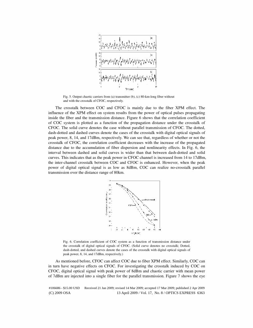
Fig. 5. Output chaotic carriers from (a) transmitter (b), (c) 80-km-long fiber without
and with the crosstalk of CFOC, respectively.
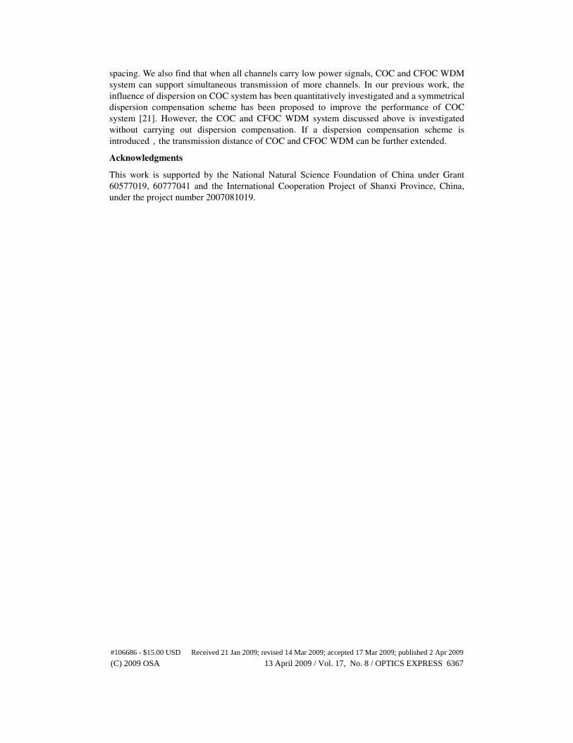
The crosstalk between COC and CFOC is mainly due to the fiber XPM effect. The
influence of the XPM effect on system results from the power of optical pulses propagating
inside the fiber and the transmission distance. Figure 6 shows that the correlation coefficient
of COC system is plotted as a function of the propagation distance under the crosstalk of
CFOC. The solid curve denotes the case without parallel transmission of CFOC. The dotted,
dash-dotted and dashed curves denote the cases of the crosstalk with digital optical signals of
peak power, 8, 14, and 17dBm, respectively. We can see that, regardless of whether or not the
crosstalk of CFOC, the correlation coefficient decreases with the increase of the propagated
distance due to the accumulation of fiber dispersion and nonlinearity effects. In Fig. 6, the
interval between dashed and solid curves is wider than that between dash-dotted and solid
curves. This indicates that as the peak power in CFOC channel is increased from 14 to 17dBm,
the inter-channel crosstalk between COC and CFOC is enhanced. However, when the peak
power of digital optical signal is as low as 8dBm, COC can realize no-crosstalk parallel
transmission over the distance range of 80km.
Fig. 6. Correlation coefficient of COC system as a function of transmission distance under
the crosstalk of digital optical signals of CFOC. (Solid curve denotes no crosstalk; Dotted,
dash-dotted, and dashed curves denote the cases of the crosstalk with digital optical signals of
peak power, 8, 14, and 17dBm, respectively.)
As mentioned before, CFOC can affect COC due to fiber XPM effect. Similarly, COC can
in turn have negative effects on CFOC. For investigating the crosstalk induced by COC on
CFOC, digital optical signal with peak power of 8dBm and chaotic carrier with mean power
of 7dBm are injected into a single fiber for the parallel transmission. Figure 7 shows the eye
#106686 - $15.00 USD Received 21 Jan 2009; revised 14 Mar 2009; accepted 17 Mar 2009; published 2 Apr 2009
(C) 2009 OSA 13 April 2009 / Vol. 17, No. 8 / OPTICS EXPRESS 6363

diagrams of the received NRZ digital signal at 10Gb/s under the crosstalk of COC when the
propagated distance is 20, 80, and 160km, respectively. As the transmission distance is
increased to 160km, the eye diagram is almost closed. Figure 8 illustrates the corresponding
EOP of CFOC versus the transmission distance. The solid curve denotes the case without the
crosstalk, and the dotted and dash-dotted curves denote the cases with the crosstalk of COC
and the other CFOC channel, respectively. We can see that when the transmission distance is
less than 80km, COC has almost no influence on CFOC. After the transmission distance
extends beyond 80km, the effect of COC on CFOC increases with the increase of the
propagated distance. Clearly, the influence of COC on CFOC is similar to that of CFOC on
COC as previously mentioned. At the same time, we also compare the effects of the crosstalk
between COC and the other CFOC channel on the given CFOC channel. For the other CFOC
channel, it has the same transmission rate and peak power as the above-mentioned CFOC
channel. Channel spacing of these two CFOC channels is still set to 100GHz. For a short
transmission length of 80km, the crosstalk of COC on CFOC is similar to the influence of the
other CFOC channel on CFOC, as shown in Fig. 8. CFOC can achieve no-crosstalk parallel
propagation with COC or the other CFOC channel. However, for the comparatively long
distance that exceeds 80km, the communication quality of CFOC under the crosstalk of COC
degrades severely compared with the crosstalk of the other CFOC channel.
Fig. 7. Eye diagrams of the received NRZ digital signal at 10Gb/s with the crosstalk of COC
for transmission distance of 20, 80, and 160km, respectively.
Fig. 8. EOP of the received 10-Gb/s NRZ sequence with peak power of 8dBm as a function
of transmission distance. (Solid curve denotes no crosstalk; Dotted and dash-dotted curves
denote the cases of the crosstalk with COC channel and the other CFOC channel, respectively.)
#106686 - $15.00 USD Received 21 Jan 2009; revised 14 Mar 2009; accepted 17 Mar 2009; published 2 Apr 2009
(C) 2009 OSA 13 April 2009 / Vol. 17, No. 8 / OPTICS EXPRESS 6364

3.3 Dependence on channel spacing and channel number
The channel separation is a very important parameter in WDM system. To investigate the
dependence of COC and CFOC WDM transmission on channel separation, we still consider
two channels with variable channel separation, that is, COC channel with 7dBm mean power
and CFOC channel with 8dBm peak power. Figure 9 and Fig. 10 show that for the 80-km-long
transmission distance the correlation coefficient of COC and EOP of CFOC are plotted as
functions of channel spacing, respectively. Obviously, the synchronization performance of
COC and the communication quality of CFOC increase with the increase of channel spacing.
When two channels are closely spaced, the nonlinear crosstalk between COC and CFOC can
be enhanced. Moreover, optical filters do not completely eliminate the power input of adjacent
channel. On the demultiplexing of these two channels, COC channel is separated by an optical
band-pass filter (BW=60GHz) and CFOC channel by another optical band-pass filter
(BW=20GHz). Both filters are ChebyshevⅠfilters. So, the crosstalk induced by XPM effect
and the filtering characteristics of optical filter can degrade the synchronization performance
of COC and the communication quality of CFOC. However, when channel spacing exceeds
100GHz, the influence of channel spacing on COC and CFOC WDM system decreases the
lowest level, and moreover, keeps unchangeable as the channel spacing increases.
Fig. 9. Correlation coefficient of COC system as a function of channel spacing for an
80-km-long two-channel WDM system.
Fig. 10. EOP of CFOC system as a function of channel spacing for an 80-km-long two-channel
WDM system.
In the previous sections, COC and CFOC WDM system with only two channels is
investigated. Now the system performance of a four- and a six-channel WDM system with
#106686 - $15.00 USD Received 21 Jan 2009; revised 14 Mar 2009; accepted 17 Mar 2009; published 2 Apr 2009
(C) 2009 OSA 13 April 2009 / Vol. 17, No. 8 / OPTICS EXPRESS 6365

100GHz channel spacing is further investigated when channel number is expanded to 4 and 6.
Of these channels, one of the two innermost of four or six channels is chosen as the COC
channel and other channels as the CFOC channels. Figure 11 shows that the correlation
coefficient of COC system is plotted as a function of transmission distance for four- and
six-channel WDM systems for the different peak power of CFOC. We can see that the
degradation of the six-channel system is no more severe than that of the four-channel system
when the peak power of each channel of CFOC is equal and as low as 8dBm. We attribute the
similarity of performance of the six- and four-channel systems to the fact that only XPM from
neighboring channels degrades the performance of a given channel for the lower peak power
so that channels that are farther removed have little or no influence. However, when the peak
power per channel for CFOC is increased to 11dBm, the performance of multichannel systems
depends somewhat on the power that is carried by each channel. From Fig. 11, it is clear that
when the transmission distance is less than 60km, the system performance of a four-channel
system is almost similar to that of a six-channel system. However, when the transmission
distance exceeds 60km, the synchronization quality of COC system for six-channel WDM
system is significantly degraded compared with four-channel WDM system. So, more
channels simultaneously travel inside a single fiber for COC and CFOC WDM system only if
all channels carry low power signals.
Fig. 11. Correlation coefficient of COC system is plotted as a function of transmission distance
for a four- and a six-channel system with100GHz channel spacing for different value of the
peak power of CFOC.
4. Conclusions
In this paper, a theoretical model of COC and CFOC WDM system is proposed, and the
parallel transmission of COC and CFOC is numerically confirmed. At the same time, the
inter-channel crosstalk of COC and CFOC is further analyzed only considering the fiber XPM
effect. The theoretical investigation indicates that for a two-channel WDM system with
channel spacing of 100GHz, when the mean power of chaotic channel is 7dBm and the peak
power of CFOC channel is less than 17dBm, the synchronization of COC system is very good
within 80km. When COC system maintains the high-quality chaos synchronization, for
achieving COC and CFOC WDM transmission, CFOC must simultaneously ensure a high
communication quality. However, as the peak power of CFOC is set to 17dBm, the
corresponding EOP of the received NRZ sequence is as high as 6.2dB at 80km. This value is
far higher than 3dB. So, we need to degrade the peak power of digital optical signal of CFOC.
The investigations suggest that CFOC with the peak power of 8dBm can realize high-quality
parallel transmission together with COC in 80km. In addition, the dependence of COC and
CFOC WDM system on channel spacing and channel number is investigated. When the
channel spacing exceeds 100GHz, the inter-channel crosstalk between COC and CFOC
decreases to the lowest level, and moreover, keeps unchangeable with the increase of channel
#106686 - $15.00 USD Received 21 Jan 2009; revised 14 Mar 2009; accepted 17 Mar 2009; published 2 Apr 2009
(C) 2009 OSA 13 April 2009 / Vol. 17, No. 8 / OPTICS EXPRESS 6366
spacing. We also find that when all channels carry low power signals, COC and CFOC WDM
system can support simultaneous transmission of more channels. In our previous work, the
influence of dispersion on COC system has been quantitatively investigated and a symmetrical
dispersion compensation scheme has been proposed to improve the performance of COC
system [21]. However, the COC and CFOC WDM system discussed above is investigated
without carrying out dispersion compensation. If a dispersion compensation scheme is
introduced,the transmission distance of COC and CFOC WDM can be further extended.
Acknowledgments
This work is supported by the National Natural Science Foundation of China under Grant
60577019, 60777041 and the International Cooperation Project of Shanxi Province, China,
under the project number 2007081019.
#106686 - $15.00 USD Received 21 Jan 2009; revised 14 Mar 2009; accepted 17 Mar 2009; published 2 Apr 2009
(C) 2009 OSA 13 April 2009 / Vol. 17, No. 8 / OPTICS EXPRESS 6367
Copyright © 2022 FDOKUMEN