HYPERSPECTRAL BIDIRECTIONAL REFLECTANCE MEASUREMENTS OF FAGUS SYLVATICA LEAVES
Upload
khangminh22Category
view
0download
0
High Power Laser Science and Engineering, (2019), Vol. 7, e5, 9 pages.© The Author(s) 2019. This is an Open Access article, distributed under the terms of the Creative Commons Attribution licence (http://creativecommons.org/licenses/by/4.0/), which permits unrestricted re-use, distribution, and reproduction in any medium, provided the original work is properly cited.doi:10.1017/hpl.2018.67
Dual-wavelength bidirectional pumped high-powerRaman fiber laser
Zehui Wang, Qirong Xiao, Yusheng Huang, Jiading Tian, Dan Li, Ping Yan, and Mali GongState Key Laboratory of Precision Measurement Technology and Instruments & Key Laboratory of Photonics Control Technology ofthe Ministry of Education, Tsinghua University, Beijing 100084, China
(Received 21 September 2018; revised 12 November 2018; accepted 21 November 2018)
AbstractIn this paper, we reported both the experimental demonstration and theoretical analysis of a Raman fiber laser basedon a master oscillator–power amplifier configuration. The Raman fiber laser adopted the dual-wavelength bidirectionalpumping configuration, utilizing 976 nm laser diodes and 1018 nm fiber lasers as the pump sources. A 60-m-long25/400 µm ytterbium-doped fiber was used to convert the power from 1070 to 1124 nm, realizing a maximum poweroutput of 3.7 kW with a 3 dB spectral width of 6.8 nm. Moreover, we developed a multi-frequency model taking intoconsideration the Raman gain spectrum and amplified spontaneous emission. The calculated spectral broadening ofboth the forward and backward laser was in good agreement with the experimental results. Finally, a 1.5 kW, 1183 nmsecond-order Raman fiber laser was further experimentally demonstrated by the addition of a 70-m-long germanium-doped passive fiber.
Keywords: fiber laser; fiber optics amplifiers and oscillators; Raman laser
1. Introduction
Lasers with wavelengths ranging from 1100 to 1300 nmare promising for applications such as remote sensing[1],spectral beam combining[2], and Tm-[3, 4] and Ho[4–7]-dopedfiber laser pumping. In general, ytterbium-doped fiber lasers(YDFLs) are considered the most promising candidates forachieving high output powers based on the master oscil-lator power amplifier (MOPA) configuration[8]. However,traditional YDFLs can only efficiently operate within theband of 1000–1100 nm. The small emission cross-sectionof ytterbium and the amplified spontaneous emission (ASE)may deter YDFLs from realizing high output powers whenthe lasing wavelength exceeds 1100 nm[9]. Nevertheless, ithas become a trend to realize lasers of a wide range ofwavelengths by taking advantage of the stimulated Ramanscattering (SRS) effect with appropriate and available pumpsources. As the fiber power coupler replaces the wavelengthdivision multiplexer (WDM), the Raman fiber laser has madesignificant progress in recent years.
In 2014, Zhang et al. proposed a 732-W integratedYb-Raman fiber amplifier with dual-wavelength seeds of1080 and 1120 nm. The length of the 20/400 µm Yb-doped
Correspondence to: Q. Xiao, Department of Precision Instrument,Tsinghua University, Beijing 100084, China.Email: [email protected]
fiber (YDF) in their amplifier was 45 m[10]. Subsequently, in2015, a 1.5 kW Raman fiber laser was realized by usingthe same experimental configuration[11]. In 2014, Zhanget al. injected a seed laser at 1120 nm into a 1080 nm Yb-doped fiber MOPA consisting of a 12 m YDF and 70 mgermanium-doped fiber (GDF) with the same parameterof 20/400 µm. As a result, a 1.28 kW 1120 nm Ramanlaser was realized[12]. In 2015, Ma et al. designed linearlypolarized output Yb-Raman cascaded oscillators consistingof a 1120 nm Raman Stokes cavity and 1080 nm laser cavity.They obtained a 1181 W, 1120 nm laser with an optical-to-optical efficiency of 74.3% using a 21-m-long 20/400-µm YDF[13]. It should be noted that all the approachesmentioned above adopt the forward-pumped configuration,in which the output laser is in the same direction as thepump laser. Both theoretical[14] and experimental results[15]
prove that the backward pumping Raman threshold shouldbe larger than that of the forward pumping. However, therelatively small gap between the first- and second-orderRaman threshold limits the power scaling of the first-orderRaman wave. Thus, backward pumping or bidirectionalpumping is an effective and competitive method to addressthe problem, which presents yet another challenge for thebackward fiber coupler.
In 2016, our group realized a bidirectional pumped Ramanfiber laser, which consisted of a single-wavelength seed and
1
Downloaded from https://www.cambridge.org/core. 09 Mar 2022 at 09:41:44, subject to the Cambridge Core terms of use.

2 Z. Wang et al.
a one-stage bidirectional pumped amplifier. A 30-m-long20/400 µm YDF was adopted in the amplifier. Under a pumppower of 5487 W, a 3889 W output power of the first-orderRaman amplification was achieved with an optical-to-opticalefficiency of 70.9%[15].
In the aforementioned examples, the adopted YDF hada relatively small core size of 20 µm. This is becausesmaller core sizes, as well as longer-gain fibers, can inducehigher Raman gains. However, the accompanying self-phase modulation and four-wave multiplexing also inducespectral broadening because of the high laser density in thesmall-core-size fiber. In some cases, high-power and narrowbandwidth lasers are required. For example, the spectrumbeam combining is an effective method to break throughthe limitation of output power in single mode fiber. Andthe basic elements of spectrum beam combining are high-power and narrow bandwidth lasers with different operatingwavelengths[2]. The spectral broadening could be suppressedby using a larger-core-size fiber. In 2018, Glick et al.reported a 1.2 kW cladding pumped Raman laser by usinga 80-m-long specialty multi-layer fiber (25/45/250 µm)[16].Chen et al. proposed a 987 W Raman laser with a largeGRIN fiber[17].
In theory, Ying et al. analyzed the Raman noise-enhancedSRS in a continuous-wave fiber amplifier with a single-frequency model[14]. Zhang et al.[10], Xiao et al.[15], Chenet al.[18] and Rini et al.[19] adopted the single-frequencymodel to calculate the output power of their Raman oscillatoror amplifier. However, in the single-frequency model, Ramangain coefficient is simplified to a number irrespective ofwavelength. Actually, conventional silica fibers have a wideRaman gain spectrum. Therefore, it is not accurate for powercalculation via this model. Besides, the spectrum evolutionalong the fiber cannot be calculated either.
In this paper, we presented both the experimental realiza-tion and theoretical analysis of a 3.7 kW, 1123 nm Ramanfiber laser system based on the dual-wavelength bidirectionalpumping configuration. A total forward pump power of4200 W and a backward pump power of 2510 W wereinjected into the amplifier of the system. The forward pump-ing used long-wavelength fiber laser sources at 1018 nmfor reducing the thermal effect caused by quantum defects.Due to the slow absorption of the 1018 nm fiber laser,976 nm laser diodes (LDs) were used as the backward pumpsources to reduce the unabsorbed pump light and provide anenhanced absorption. In the core of YDF, the 1070 nm signallaser was amplified via Yb gain and then it was converted to1123 nm laser via Raman gain. The system incorporated a60-m-long 25/400 µm YDF, realizing a 3 dB spectral widthof 6.8 nm. Further, the backward Raman laser had a powerof 65 W with a 3 dB spectral width of 5.2 nm. Moreover, wedeveloped a multi-frequency model of the Raman fiber lasertaking into consideration the Raman gain spectrum and ASE.Using this model, we can simulate the spectrum and power
evolution along the fiber. The numerical simulation resultswere in good agreement with the experimental results. Thenwe analyzed the new peak at 1095 nm and we found that itwas generated from ASE initially and was strongly amplifiedalong the fiber because of much larger gain coefficient. Thenew peak only appeared when the gain fiber length waslarger than 50 m. In addition, we spliced another GDF afterthe gain fiber to acquire a high Raman gain for realizinga second-order Raman laser. When the length of the GDFreached 70 m, a 1.5 kW, 1187 nm second-order Raman laserwas obtained.
2. Experimental setup
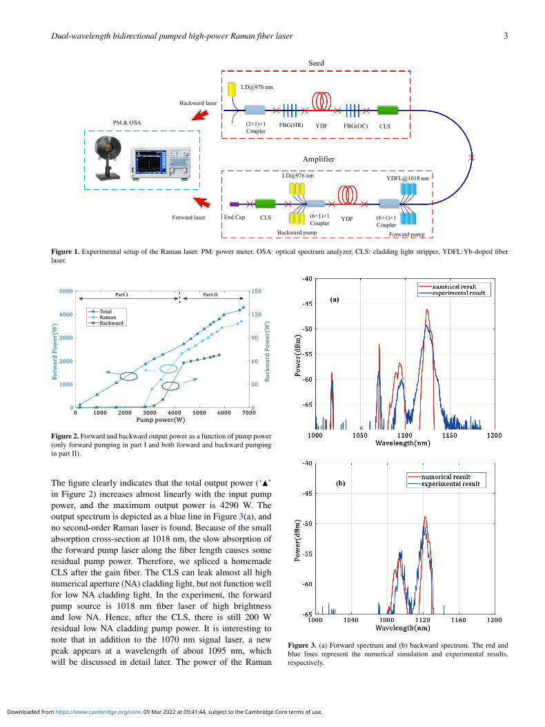
The Raman fiber laser employing the MOPA configurationconsists of a 1070 nm laser seed and an amplifier of the dual-wavelength bidirectional pumping configuration, as shown inFigure 1. The seed comprising a pair of fiber Bragg gratings(FBGs) is pumped by an LD through a (2 + 1) × 1 coupler.The maximum output power of the seed is 107.4 W andthe 3 dB linewidth is 0.9 nm. In the amplifier, a 60-m-longYb-doped double-cladding fiber (25/400 µm) is adopted asthe gain medium. To reduce the thermal effect caused byquantum defects, 1018 nm YDFLs[20, 21] are used as theforward pump source. The cladding absorption coefficientof YDF at 976 nm is 1.8 dB/m. In the experiment, the pumppowers of six 1018 nm YDFLs are coupled into the gain fiberwith a (6+ 1)× 1 coupler. The pump coupler efficiency canreach 99% with a total forward pump power of 4296 W. Toprovide an enhanced absorption and reduce the unabsorbedpump light, six 976 nm LDs provide backward pump powerthrough another (6 + 1) × 1 coupler. The pump power ofeach LD is approximately 400 W and the total backwardpump power is 2510 W. All the couplers mentioned aboveare homemade with an excellent coupling efficiency andvery small loss coefficient[22, 23]. A cladding light stripper(CLS) is spliced with the backward coupler to leak theresidual pump laser. At the end of the experimental system,a specially made end cap, whose coating is designed to anti-reflect the Raman laser, is spliced after the CLS and cooledby water. In addition to the power meter, optical spectrumanalyzers are used both before the signal input port of theseed coupler and after the end cap to monitor the real-timeforward and backward output spectra, respectively.
3. Experimental results
Figure 2 shows the output power in the amplifier varyingwith the input pump power. In part I of Figure 2, the forwardpump power increases to a maximum of 4200 W while thebackward pump power remains disabled. Then, in part II, thebackward pump power increases from zero to a maximumof 2510 W while the forward pump power reaches 4200 W.
Downloaded from https://www.cambridge.org/core. 09 Mar 2022 at 09:41:44, subject to the Cambridge Core terms of use.
Dual-wavelength bidirectional pumped high-power Raman fiber laser 3
Figure 1. Experimental setup of the Raman laser. PM: power meter, OSA: optical spectrum analyzer, CLS: cladding light stripper, YDFL:Yb-doped fiberlaser.
Figure 2. Forward and backward output power as a function of pump power(only forward pumping in part I and both forward and backward pumpingin part II).
The figure clearly indicates that the total output power (‘N’in Figure 2) increases almost linearly with the input pumppower, and the maximum output power is 4290 W. Theoutput spectrum is depicted as a blue line in Figure 3(a), andno second-order Raman laser is found. Because of the smallabsorption cross-section at 1018 nm, the slow absorption ofthe forward pump laser along the fiber length causes someresidual pump power. Therefore, we spliced a homemadeCLS after the gain fiber. The CLS can leak almost all highnumerical aperture (NA) cladding light, but not function wellfor low NA cladding light. In the experiment, the forwardpump source is 1018 nm fiber laser of high brightnessand low NA. Hence, after the CLS, there is still 200 Wresidual low NA cladding pump power. It is interesting tonote that in addition to the 1070 nm signal laser, a newpeak appears at a wavelength of about 1095 nm, whichwill be discussed in detail later. The power of the Raman
Figure 3. (a) Forward spectrum and (b) backward spectrum. The red andblue lines represent the numerical simulation and experimental results,respectively.
Downloaded from https://www.cambridge.org/core. 09 Mar 2022 at 09:41:44, subject to the Cambridge Core terms of use.

4 Z. Wang et al.
Figure 4. M2 factor of output laser.
laser (‘�’ in Figure 2) is approximately 3700 W, which wascalculated by spectral integration. The forward first-orderRaman threshold is about 3000 W. The center wavelength ofthe Raman laser is 1123.8 nm and the 3 dB width is 6.8 nm,which is much narrower than that in Ref. [15]. We ascribedthe narrow output linewidth to the adoption of the 25/400 µminstead of 20/400 µm gain fiber, thus leading to a lowerpower density in the fiber core. We also monitored thebackward output power, indicated by the green line (‘ ’) inFigure 2, and its spectrum is presented in Figure 3(b). Onlya Raman laser and new peak near the 1095 nm laser can befound in the backward spectrum. The center wavelength and3 dB spectral width of the backward Raman laser are 1121.9and 5.2 nm, respectively.
In Figure 2, the curve of the backward power versus pumppower can be divided into three sections. The first one iswhen the forward pump power is below 3000 W, in whichthe Raman threshold has not been reached and only Ramannoise less than 3 W can be detected. In the second section,the forward pump power rises above the Raman threshold,causing the backward Raman laser power to rapidly amplifyto about 65 W. The backward power is much lower thanthe forward power because the 1070 nm laser barely prop-agates in the backward direction. In the third part, whenthe forward pump power stops rising while the backwardpump power starts rising, the power of the backward Ramanlaser grows slowly. Through the backward power curveand forward Raman power curve, we can easily confirmthat the first-order Raman threshold is about 3000 W inthe experiment.
The M2 factor of the output laser was measured by aPRIMES High-Power-LaserQualityMonitor. The M2 factor
of 1070 nm seed is 1.39. When the pump power was 3020 W,the M2 factor deteriorated to 2.18, as shown in Figure 4. Wethink that it is a result of thermal effect and the mismatch ofthe core diameter in the oscillator and amplifier.
4. Numerical simulation
We want to figure out the spectral evolution in the fiberamplifier and the existing single-frequency model does notwork anymore. Thus, we build the multi-frequency modelbased on steady-state rate equations to solve the problem.The spectral broadening caused by the Raman gain, ASE,seed and pump light linewidth in the evolutions can be cal-culated via the multi-frequency model. The model includesthe following equations:
∂P±p (z, λ±p )
∂z= Γp {[σa,p(λp)+ σe,p(λp)]N2(z)
− σa,p(λp)N } P±p (z, λp)− αp P±p (z, λp),
(1)∂Ps(z, λs)
∂z= Γs {[σa,s(λs)+ σe,s(λs)]N2(z)
− σa,s(λs)N } Ps(z, λs)− αs Ps(z, λs),
−
∫r1
λ
λs
gr (λ− λs)
Aeff[P+r1(z, λ)+ P−r (z, λ)
+ 4Pspon1] Ps(z, λs) dλ, (2)
∂P±r1(z, λr1)
∂z= ±Γr1 {[σa,r1(λr1)+ σe,r1(λr1)]N2(z)
− σa,r1(λr1)N } P±r1(z, λr1)
Downloaded from https://www.cambridge.org/core. 09 Mar 2022 at 09:41:44, subject to the Cambridge Core terms of use.

Dual-wavelength bidirectional pumped high-power Raman fiber laser 5
∓αr1 P±r1(z, λr1)±
∫s
gr (λr1 − λs)
Aeff
×[P±r1(z, λr1)+ 2Pspon]Ps(z, λ) dλ
∓
∫r2
λ
λr1
gr (λ− λr1)
Aeff[P+r2(z, λ)
+ P−r (z, λ)+ 4Pspon1] P±r1(z, λr1) dλ, (3)
∂P±r2(z, λr2)
∂z= ±Γr2 {[σa,r2(λr2)+ σe,r2(λr2)]N2(z)
− σa,r2(λr2)N }P±r2(z, λr2)∓ αr2 P±r2(z, λr2)
±
∫r1
gr (λr2 − λs)
Aeff[P±r2(z, λr2)+ 2Pspon]
× [P+r1(z, λ)+ P−r1(z, λ)] dλ, (4)
∂P±ase(z, λ)∂z∂λ
= ±Γaseσe,s(λs)N2(z)hc2
λ3 ∓ αase P±ase(z, λ),
(5)
N2(z)N=
∑i=p±,p−,s,r±1 ,r
±
2 ,ase±
∫i
Pi (z, λ)σa,iΓi dλ
∑i=p±,p−,s,r±1 ,r
±
2 ,ase±
∫i
Pi (z, λ)(σa,i + σe,i )Γi dλ+hcAc
τ
.
(6)
In the above equations, the subscripts p, s, r1 and r2 repre-sent the pump laser, signal laser, first-order Raman wave andsecond-order Raman wave, respectively. The superscripts‘+’ and ‘−’ represent the forward-propagating waves andbackward-propagating waves. Γ is the filling factor, α isthe background loss coefficient, Aeff is the effective modefield area of the core, N is the population density of dopedions, N2 is the upper lasing level population density, σaand σe are functions of the wavelength representing theabsorption and emission cross-sections, respectively, h isPlanck’s constant, c is the speed of light in vacuum and τis the spontaneous lifetime of doped ions. The subscriptsunder the integral sign indicate that the integral domain is thewavelength of the corresponding wave. The adopted valuesof the parameters mentioned are listed in Table 1. The Ramangain is a function of the wavelength shift between the Ramanwave and its corresponding Raman pump wave. Figure 5depicts the Raman gain spectrum in a 25/400 µm gain fiberwith a Raman pump wavelength of about 1070 nm[24, 25].
Table 1. Parameters for the numerical calculations.Parameter Valueσa Ref. [26]σe Ref. [26]
Γs 0.8[27]
Γp 0.05 (20/400), 0.0625 (25/400)[27]
Γr1, Γr2, Γase 0.8c 2.9979× 10⁸ m/sh 6.626× 10⁻³⁴ J · sτ 0.82 ms
Figure 5. Raman gain spectrum in a 25/400 µm gain fiber.
5. Simulation results and discussion
5.1. The simulation of the 3.7 kW bidirectional Raman fiberlaser
Figure 6 illustrates the power distribution along the fibercalculated from the multi-frequency model. The 1070 nmlaser power decreased while the first-order Raman laserpower rose rapidly from a fiber length of 45 to 60 m.At the end of the gain fiber, the Raman laser power wascalculated to 3850 W and the backward Raman laser powerwas calculated to 69 W. The numerical results of the forwardand backward spectra were represented by a red line inFigures 3(a) and 3(b), respectively, which agreed with theexperiment well.
We also used the model to simulate the spectrum evolutionalong the fiber, as shown in Figure 7. We can see that the Ybfiber Raman gain spectrum possessed two peaks where theshift frequencies were 13 and 14.7 THz, as shown in Fig-ure 5[28–30]. Therefore, in the spectrum shown in Figure 7,next to the main peak of the Raman laser at 1123 nm, therewas another peak at 1129 nm. The simulated results of outputspectrum for forward and backward direction were shown asred lines in Figures 3(a) and 3(b), respectively. As can beseen clearly, the shapes of the simulated and experimentaloutput spectra were similar. The 3 dB spectral width wascalculated to 5.3 nm, which was little narrower than that ofthe experimental result (6.8 nm). We attributed it to omittingother nonlinear effects under the high-intensity light field,which will be left for future research.
5.2. The comparison of 976 nm and 1018 nm pump sources
In the experiment, we adopted dual-wavelength pump con-figuration, consisting of 1018 nm YDFLs and 976 nm LDsas the forward and backward pump sources, respectively.It should be noted that due to the small quantum defect and
Downloaded from https://www.cambridge.org/core. 09 Mar 2022 at 09:41:44, subject to the Cambridge Core terms of use.

6 Z. Wang et al.
Figure 6. (a) Calculated power distributions of the (a) pump laser, signallaser and Raman laser along the fiber in the multi-frequency model (L =60 m), and (b) backward Raman laser in the dotted box in (a).
Figure 7. Transmission and amplification of Raman laser from 40 to 60 m(SRS has not been generated from 0 to 40 m).
a flatter power distribution, the 1018 nm YDFLs pumpingsuffers from the less thermal effect than the 976 nm LDspumping. Therefore, the temperature of gain fiber in 976 nmLDs pump configuration is higher [31–33].
We analyzed the impact of different pump source ontemperature distribution via simulation under the same pumppower. The forward pump power and the backward pumppower were set to 4200 W and 2510 W, respectively. Theresult was shown in Figure 8. Two situations were analyzedto compare the difference. One of the situation has the sameparameters with our actual experiment, while in the othersituation only 976 nm LDs were used as pumping source.The simulation result showed that the highest temperature inthe gain fiber of these two configurations was 36◦ and 210◦,respectively. In consideration of thermal effect, adopting1018 nm YDFLs as pump source will have more potentialfor further power scaling.
5.3. The analysis of the new peak at 1095 nm
As mentioned above, we found that a new peak at a wave-length of about 1095 nm appeared when the total outputpower exceeded 1360 W, much smaller than the Ramanthreshold. Thus, we assumed that it was not related to theSRS. In addition, the wavelength of the new peak shiftedfrom 1089 to 1095 nm while the total output power rose from1360 to 4290 W, as shown in Figure 9.
Without the item of SRS, we integrated both sides ofEquation (2) in the region [0, L], obtaining the followingexpression of the gain coefficient G:
G(λ) = lnPs(L)Ps(0)
= Γs[σa,s(λ)+ σe,s(λ)]
∫ L
0N2(z) dz
− [σa,s(λ)N + αs]L . (7)
It is clear that the gain coefficient G was the function ofwavelength. Figure 10 illustrated the exponential of gain co-efficient when forward pumping power was 1800 W. Owingto a very long length of gain fiber and high pump power,the maximum gain coefficient was located at 1095 nm. Atthe beginning of the amplifier, the 1070 nm signal laserwas dominant. However, the 1095 nm laser, only generatedfrom ASE initially, was strongly amplified along the fiberbecause of much larger gain coefficient. Figure 11 presentedthe numerical simulation results of the power evolution alongthe fiber according to Equations (1)–(6). The gain coefficientG increased in pace with gain fiber length growth. We foundthat the new wavelength of the laser only appeared when thegain fiber length was larger than 50 m. The new peak canalso be explained by resorption in a long YDF laser[34].
6. Experiment of the second-order Raman fiber laser
To increase the Raman gain coefficient and produce asecond- or higher-order Raman laser, we spliced anotherGDF after the gain fiber, as shown in Figure 12. The coreand cladding diameters of the GDF were 25 and 400 µm,
Downloaded from https://www.cambridge.org/core. 09 Mar 2022 at 09:41:44, subject to the Cambridge Core terms of use.

Dual-wavelength bidirectional pumped high-power Raman fiber laser 7
(a) (b)
Figure 8. Temperature distribution at the input end of two situations. (a) The experiment; (b) only 976 nm LDs were used.
Figure 9. Output spectra under different powers (the length of YDF is60 m).
respectively, identical to the gain fiber. Figure 13 presentedthe output spectra when the length of the GDF was 50, 70,80 and 100 m.
Figure 13(a) indicated that the first-order Raman laserwas still dominant when the GDF length is 50 m. Asthe length of the GDF increases, the second-order Ramanlaser will replace the dominance of the first-order Ramanlaser. While the GDF was 70 m, as shown in Figure 13(b),the center wavelengths of the first-, second- and third-order stimulated Raman lasers were 1122.5, 1182.7 and1243.3 nm, respectively. In addition, the output power ofthe second-order Raman laser was about 1500 W, whichaccounts only for 45% of the total 3610 W output power. The3 dB spectral width of the 1182.7 nm second-order Ramanfiber was 14 nm. However, the power of the second-orderRaman laser was only approximately 5 dB higher than thatof the first- or third-order Raman laser. For future work, to
Figure 10. Exponential of gain coefficient versus wavelength (the length ofYDF is 60 m).
Figure 11. Generation of the new laser wavelength (the forward pumppower is 1800 W).
obtain a second-order Raman laser and suppress other-orderRaman lasers, we are preparing to optimize the length ofthe YDF and GDF, and inject a seed comprising a 1070 and1180 nm laser into the amplifier.
Downloaded from https://www.cambridge.org/core. 09 Mar 2022 at 09:41:44, subject to the Cambridge Core terms of use.

8 Z. Wang et al.
Figure 12. Experimental setup when the GDF is spliced after the YDF.
Figure 13. Output spectra and total power (P) at different lengths (LG) ofsplicing GDF: LG, P are (a) 50 m, 3900 W, (b) 70 m, 3610 W, (c) 80 m,3300 W and (d) 100 m, 2440 W, respectively.
7. Conclusions
In this paper, we presented both the experimental realizationand theoretical analysis of a 3.7 kW, 1123 nm Raman
fiber laser system. The system adopted a dual-wavelengthbidirectional pumping configuration, consisting of 1018 nmYDFLs and 976 nm LDs as the forward and backwardpump sources, respectively. The usage of long-wavelengthpump sources reduced the thermal effect caused by quantumdefects. A 60-m-long, 25/400-µm YDF was employed asthe Raman gain medium. The maximum output power was3700 W while 4200 W of forward pump power and 2510 Wof backward pump power were injected into the amplifier.The 3 dB spectral width of the 1123 nm Raman laser was6.8 nm. The backward Raman laser power was 65 W witha 3 dB spectral width of 5.2 nm. Under a pump power of3020 W, the M2 factor of the output laser was measuredto be 2.18. In addition, we proposed a multi-frequencymodel based on the steady-state rate equation. Taking thespectrum of the Raman gain and ASE into account, ourmodel can resolve the spectra and power evolutions in boththe forward and backward directions along the fiber. Thenumerical simulation results were in good agreement withthe experimental results. The appearance of a new peakat about 1095 nm was also investigated theoretically andexperimentally. Furthermore, a 1500 W, 1187 nm second-order Raman laser was obtained by splicing another 70 mGDF after the YDF. The power scaling of the second-orderRaman laser will be studied in future work.
Downloaded from https://www.cambridge.org/core. 09 Mar 2022 at 09:41:44, subject to the Cambridge Core terms of use.

Dual-wavelength bidirectional pumped high-power Raman fiber laser 9
Acknowledgements
This work was supported in part by the National Nat-ural Science Foundation of China (Nos. 61675114 and61875103) and the Tsinghua University Initiative ScientificResearch Program (No. 20151080709).
References
1. L. R. Taylor, Y. Feng, and D. B. Calia, Opt. Express 18, 8540(2010).
2. Y. Feng, L. Zhang, and H. Jiang, Proc. SPIE 9344, 93440U(2015).
3. G. Qin, S. Huang, Y. Feng, A. Shirakawa, and K. Ueda, Opt.Lett. 30, 269 (2005).
4. X. Du, H. Zhang, H. Xiao, P. Ma, X. Wang, P. Zhou, andZ. Liu, Ann. Phys.-Berlin 528, 649 (2016).
5. X. Wang, P. Zhou, Y. Miao, H. Zhang, H. Xiao, X. Wang, andZ. Liu, J. Opt. Soc. Am. B 31, 2476 (2014).
6. H. Zhang, P. Zhou, X. Wang, X. Du, H. Xiao, and X. Xu, Opt.Express 23, 17138 (2015).
7. S. D. Jackson, Nat. Photon. 6, 423 (2012).8. F. Beier, C. Hupel, S. Kuhn, S. Hein, J. Nold, F. Proske,
B. Sattler, A. Liem, C. Jauregui, J. Limpert, N. Haarlammert,T. Schreiber, R. Eberhardt, and A. Tunnermann, Opt. Express25, 14892 (2017).
9. H. Zhang, H. Xiao, P. Zhou, K. Zhang, X. Wang, and X. Xu,Appl. Phys. Express 7, 52701 (2014).
10. H. Zhang, H. Xiao, P. Zhou, X. Wang, and X. Xu, Opt. Express22, 10248 (2014).
11. H. Zhang, R. Tao, P. Zhou, X. Wang, and X. Xu, IEEE Photon.Technol. Lett. 27, 628 (2015).
12. L. Zhang, C. Liu, H. Jiang, Y. Qi, B. He, J. Zhou, X. Gu, andY. Feng, Opt. Express 22, 18483 (2014).
13. P. Ma, H. Zhang, L. Huang, X. Wang, P. Zhou, and Z. Liu,Opt. Express 23, 26499 (2015).
14. H. Ying, J. Cao, Y. Yu, M. Wang, Z. Wang, and J. Chen, Optik144, 163 (2017).
15. Q. Xiao, P. Yan, D. Li, J. Sun, X. Wang, Y. Huang, andM. Gong, Opt. Express 24, 6758 (2016).
16. Y. Glick, Y. Shamir, M. Aviel, Y. Sintov, S. Goldring,N. Shafir, and S. Pearl, Opt. Lett. 43, 4755 (2018).
17. Y. Chen, J. Leng, H. Xiao, T. Yao, and P. Zhou, in 8th EPS-QEOD Europhoton Conference (Barcelona, Spain, 2018),paper TuM1.6.
18. Y. Chen, H. Xiao, J. Xu, J. Leng, and P. Zhou, Appl. Opt. 55,3824 (2016).
19. M. Rini, I. Cristiani, and V. Degiorgio, IEEE J. QuantumElectron. 36, 1117 (2000).
20. P. Yan, X. Wang, D. Li, Y. Huang, J. Sun, Q. Xiao, andM. Gong, Opt. Lett. 42, 1193 (2017).
21. P. Yan, X. Wang, Z. Wang, Y. Huang, D. Li, Q. Xiao, andM. L. Gong, IEEE J. Sel. Top. Quantum Electron. 24, 0902506(2018).
22. Q. Xiao, P. Yan, H. Ren, X. Chen, and M. Gong, J. LightwaveTechnol. 31, 2715 (2013).
23. Q. Xiao, H. Ren, P. Yan, X. Chen, and M. Gong, Opt.Commun. 300, 220 (2013).
24. Y. Feng, Raman Fiber Lasers (Springer, New York, 2017).25. M. Chen, A. Shirakawa, X. Fan, K. Ueda, C. B. Olausson,
J. K. Lyngsø, and J. Broeng, Opt. Express 20, 21044 (2012).26. R. Paschotta, J. Nilsson, A. C. Tropper, and D. C. Hanna,
IEEE J. Quantum Electron. 33, 1049 (1997).27. A. Hardy and R. Oron, IEEE J. Quantum Electron. 33, 307
(1997).28. R. H. Stolen, C. Lee, and R. K. Jain, J. Opt. Soc. Am. B 1, 652
(1984).29. D. Hollenbeck and C. D. Cantrell, J. Opt. Soc. Am. B 19, 2886
(2002).30. Y. Glick, V. Fromzel, J. Zhang, A. Dahan, N. Tergabrielyan,
R. K. Pattnaik, and M. Dubinskii, Laser Phys. Lett. 13, 65101(2016).
31. C. Jauregui, J. Limpert, and A. Tunnermann, Nat. Photon. 7,861 (2013).
32. T. Yao, J. Ji, and J. Nilsson, J. Lightwave Technol. 32, 429(2014).
33. P. Zhou, H. Xiao, J. Leng, J. Xu, Z. Chen, H. Zhang, andZ. Liu, J. Opt. Soc. Am. B 34, A29 (2017).
34. J. Nilsson, W. A. Clarkson, R. Selvas, J. K. Sahu, P. W. Turner,S. Alam, and A. B. Grudinin, Opt. Fiber Technol. 10, 5 (2004).
Downloaded from https://www.cambridge.org/core. 09 Mar 2022 at 09:41:44, subject to the Cambridge Core terms of use.
Copyright © 2022 FDOKUMEN