
Wave energy: Nostalgic Ramblings, future hopes and ...
31
Edinburgh Research Explorer Wave Energy: Nostalgic Ramblings, Future Hopes and Heretical Suggestions Citation for published version: Salter, SH 2016, 'Wave Energy: Nostalgic Ramblings, Future Hopes and Heretical Suggestions', Journal of Ocean Engineering and Marine Energy, vol. 2, no. 4, pp. 399–428. https://doi.org/10.1007/s40722-016- 0057-3 Digital Object Identifier (DOI): 10.1007/s40722-016-0057-3 Link: Link to publication record in Edinburgh Research Explorer Document Version: Publisher's PDF, also known as Version of record Published In: Journal of Ocean Engineering and Marine Energy General rights Copyright for the publications made accessible via the Edinburgh Research Explorer is retained by the author(s) and / or other copyright owners and it is a condition of accessing these publications that users recognise and abide by the legal requirements associated with these rights. Take down policy The University of Edinburgh has made every reasonable effort to ensure that Edinburgh Research Explorer content complies with UK legislation. If you believe that the public display of this file breaches copyright please contact [email protected] providing details, and we will remove access to the work immediately and investigate your claim. Download date: 15. Mar. 2022
-
Upload
khangminh22 -
Category
Documents
-
view
7 -
download
0
Transcript of Wave energy: Nostalgic Ramblings, future hopes and ...

Edinburgh Research Explorer
Wave Energy: Nostalgic Ramblings, Future Hopes and HereticalSuggestions
Citation for published version:Salter, SH 2016, 'Wave Energy: Nostalgic Ramblings, Future Hopes and Heretical Suggestions', Journal ofOcean Engineering and Marine Energy, vol. 2, no. 4, pp. 399–428. https://doi.org/10.1007/s40722-016-0057-3
Digital Object Identifier (DOI):10.1007/s40722-016-0057-3
Link:Link to publication record in Edinburgh Research Explorer
Document Version:Publisher's PDF, also known as Version of record
Published In:Journal of Ocean Engineering and Marine Energy
General rightsCopyright for the publications made accessible via the Edinburgh Research Explorer is retained by the author(s)and / or other copyright owners and it is a condition of accessing these publications that users recognise andabide by the legal requirements associated with these rights.
Take down policyThe University of Edinburgh has made every reasonable effort to ensure that Edinburgh Research Explorercontent complies with UK legislation. If you believe that the public display of this file breaches copyright pleasecontact [email protected] providing details, and we will remove access to the work immediately andinvestigate your claim.
Download date: 15. Mar. 2022

J. Ocean Eng. Mar. EnergyDOI 10.1007/s40722-016-0057-3
REVIEW ARTICLE
Wave energy: Nostalgic Ramblings, future hopes and hereticalsuggestions
Stephen Salter1
‘...if you can bear to hear the truth you’ve spoken twisted by knaves to make a trap for fools...’
Received: 21 March 2016 / Accepted: 9 May 2016© The Author(s) 2016. This article is published with open access at Springerlink.com
Abstract This study extends and updates a chapter in thebook edited by Joao Cruz entitled Ocean Wave Energy:Current Status and Future Perspectives, Cruz (Ocean waveenergy: current status and perspectives, Springer, Berlin,2008). It outlines laboratory techniques and results from thefirst work on wave energy, which led to the Edinburgh duck.It then describes some of the work done on later devicesat Edinburgh University. Some of the results and ideas forpower conversion, component testing, and installation maybe relevant to other wave energy designs and may help futuregenerations of wave inventors to save time and avoid expen-sive mistakes.
Keywords Wave energy · Test-tank · Wavemaker · Long-spine duck · Desalination · Hurricane · Digital hydraulics
1 Wave energy at the University of Edinburgh
In the autumn of 1973, the western economies were given therare chance of a ride in a timemachine and sawwhat theworldwould be like when there was no longer cheap oil. Most peo-ple thought it looked rather uncomfortable, but a few verypowerful people made a great deal of money by exagger-ating the crisis. Others, who had previously been regardedas eccentric, increased their efforts to develop what werethen called alternative, and are now called renewable, energysources. Still others set out to destroy what they saw to be athreat. In 1973, the main fear was a shortage of fossil fuels.
B Stephen [email protected]
1 School of Engineering, University of Edinburgh,Edinburgh EH9 3JL, Scotland, UK
In 2016, the growing fear is what fossil fuels are doing to theclimate, especially to ice in the Arctic.
Waves were only one of many possible sources, and thereare many possible ways in which waves can be harnessed.There are floats, flaps, ramps, funnels, cylinders, airbags,and liquid pistons. Devices can be at the surface, the seabed, or anywhere between. They can face backwards, for-wards, sideways, or obliquely and move in heave, surge,sway, pitch, and roll. They can use oil, air, water, steam, gear-ing, or electromagnetics for generation. They make a rangeof different demands on attachments to the sea bed and con-nections of power cables. They have a range of methods tosurvive extreme conditions but perhaps not quite enough.
Their inventors, myself included, invariably claim at firstthat they are simple and, after experience with the dreadfulfriction of reality, discover that this is not totally true whenthey come to test in the correct wave spectra with a Gaussiandistribution ofwave amplitudes.An easyway to detect begin-ners is to see if they draw waves the same size on both sidesof their device.
Appeals to simplicity are widespread and have a strongappeal to non-engineers and, particularly, to politicaldecision-makers and investors. However, it is hard to findany field of technology in which what is inside the box doesnot get steadily more complicated as it gets faster, lighter,cheaper, more powerful, and more efficient. The complica-tions are all introduced for good reasons and, if the necessaryhardware is properly researched, will produce good results.Who would abandon railways for wheel barrows because ofthe smaller number of wheels? Only a simpleton.
Many inventors of wave power devices, going back toGirard pere et fils in 1799, start with heaving floats. Apartfrom a brief flirtation with oscillating water columns, so didI. But I had the advantage of a workshop in which I couldmake anymechanical or electronic instrument that I was able
123

J. Ocean Eng. Mar. Energy
to design and there was a narrow tank that I could borrow.As so often in physics and engineering, a full understandingof all the energy flows leads to a full understanding of theproblem and points to suitable solutions.
It was necessary to make something against which a floatcould do work that could be accurately measured and com-pared with the energy transfers from incoming, transmitted,and reflected waves. While the Girards proposed the use ofa ship of the line, I thought that it would initially be cheaperto begin with a length of 100 mm by 25 mm varnished balsawood, just fitting inside the 300 mm width of a small wavetank. Rotating bearings are much nicer than translating ones.However, if they are at the end of a long arm, they give a goodapproximation to a translating constraint. If you grind a 70-degree cone on the end of a length of tool steel and use it topunch the end of a light alloy or brass rod you get a beautifulsocket into which you can place a 60-degree conical-pointscrew with friction acting at a very short radius. Grease willslow, if not stop, corrosion long enough for plenty of tests.The first heaving buoy model is shown in Fig. 1a.
For the power measurement, I used two very strong barmagnets in a magnetic circuit which excited two coils woundlike an oversize galvanometer movement and linked togetherin a parallelogram using the same spike bearings pulled byelastic bands into cones in the end of a strut. The parallel-ogram could be coupled to the float with another strut andelastic band. These acted like a universal joint with very lowfriction and no backlash.
Moving the float generated a nice velocity signal in one ofthe coils. This could be amplified and fed back to the secondcoil with polarity chosen, so as to oppose the movement.Changing the gain of the amplifierwould change the dampingcoefficient. A high gain made it feel as if it was in very thickhoney. If the amplifier feedback connections are such that itdelivers an output current proportional to the input voltage,then temperature changes in the galvanometer coils do notchange the calibration.
From calculus, we know that the position of an object isthe time integral of its velocity history plus some constant.If the signal from the velocity coil is put into an operationalamplifier circuit connected as an integrator, we get an accu-rate position signal. If the parallelogram is moved backwardand forward between the jaws of a vernier gauge, the inte-grator output signal will be a square wave. The field-effecttransistor operational amplifiers of 1973 had low enough off-set currents to allow this position signal to be read on a digitalvoltmeter. The force was calibrated by making the pushroddrive the pan of a weighing machine.
Measuring the waves could be done with a light floatmade from expanded polystyrene foammounted on a swing-ing arm. A pair of microammeters, coaxial with the linkagebearings, with their needles glued to the float arms, gave avery clean velocity signal from even the smallest waves. Inte-grating float velocity gave an even cleaner wave-amplitudesignal. The float took an average measurement across thewidth of the tank and, therefore, was insensitive to cross
Fig. 1 In the beginning was a vertical heaving float
123

J. Ocean Eng. Mar. Energy
waves which are nearly always present. It could measurewaves down to 0.01 mm which we could not even see, farless than the meniscus hysteresis of resistive-wire gaugeswhich we later had to use for very steep waves.
To calculate the power, you justmultiply the instantaneousforce signal by the instantaneous velocity signal, which willgive you an offset sine wave at twice the wave frequency.You then take a long-term average with a low-pass filter.
This equipment allowed the measurement of model effi-ciency. The first result for the vertical heaving balsa woodfloat in Fig. 1a was disappointing—only 15% whateveradjustments were made to the damping coefficient. Someof the energy was reflected, but most went straight past themodel. However, the depth of the hinge was very easy toadjust. If it was pushed down, so that the movement wasalong a slope as in Fig. 1b, the performance shot up to 50%,much higher than most people would have predicted.
A vertical flap hinged below the water as in Fig. 1c couldalso be coupled to the dynamometer. This showed an effi-ciency of about 40% with 25% being transmitted on to thebeach and 25% sent back to the wave-maker. It looked asthough the horizontal motion of a wave, which almost allnew wave inventors ignore, was better than the vertical one.Despite rich vocabularies of nautical terms, we have no wordin any language for this movement of a wave.
The borrowed narrow tank had a commercial hinged-flapwave-maker with amplitude set by a crank radius and fre-quency set by a mechanical variable-speed mechanism. Oneproblemwas that therewas noway tomakemixed seas. How-ever, a more serious one was that the drive to the flap wasrigidlyfixedby the crank eccentricity, so that theflap reflectedwaves just like a rigid vertical cliff. Test tank beaches arenot perfect, and the first designs of any wave device arelikely to reflect a substantial fraction of the incoming waves.It was even worse, because the amplitude of a wave cre-ated by a hinged flap for a given angular movement dependson the square of the depth of the hinge, and this would beincreased during the crest of any reflection and reduced dur-ing the trough, together with some Doppler shifting. Even ifwe could not make irregular waves with the spectrum of ourchoice, the tank reflections would make one with a spectrumof their own. Trying to make a regular wave could lead toamplitude variations of three to one and power variations ofnine to one.
The vertical flap showed that it was wrong to allow themodel to transmit waves behind. Was it possible to make amodel with a front but no back? Figure 1d shows an attempt,code-namedKite. This showed an efficiency of 70%and verylow onward wave transmission. Figure 1e shows the modelcode-named Tadpole, which was meant to allow the circularmotion of water particles to continue but had the same result.However, waves are very good at sending energy to the nextvolume of water with almost no loss: the idea of allowing
Fig. 2 Jamie Taylor’s photograph taken in 1976 which convinced peo-ple who really knew about waves that high efficiency could be achieved
the water motion to continue in the way it would do in theabsence of a model was powerful. Could the circular backsof Fig. 1d, e be combined with a front shape which allowedthe decaying orbital motion of water particles to take placejust as it would in the open sea?
I asked a computer-mindedPh.D. student, PeterBuneman,to help while I struggled with a slide rule and drawing board.We converged on the same shape shown in Fig. 1f, code-namedDuck. Its efficiencywasmeasured at 90%,which evenwe did not believe despite many calibrations cross-checkedby Jim Leishman from the National Engineering Labora-tory, Gordon Goodwin from the Department of Energy andBrian Count from the CEGB, then the big English electric-ity monopoly. Later, photographs by Jamie Taylor in Fig. 2allowed visual proof that the calibrations were correct. It isa one-second exposure of a duck model on a fixed mountingin a narrow tank. The two wires are connections to part ofan electromagnetic dynamometer, which is absorbing power.Waves are approaching from the right. Drops of a neutrallybuoyant tracer fluid consisting of a mixture of carbon tetra-chloride (a nasty green-house vapour, now illegal) and xylenewith titanium oxide pigment have been injected to show thedecaying orbits of wave motion.
The amplitude of the incoming waves can be measuredfrom the thickness of the bright band on the right. Nodes andantinodes due to the small amount of reflection are evident.However, the thickness of the bright band to the left of themodel is largely due to the meniscus, as is confirmed by thevery small orbits of tracer fluid in this region.
As the energy in a wave is proportional to the square ofwave amplitude, we can use the photograph to do energyaccounting. If nodes and antinodes show that the reflectedwave is one-fifth of the amplitude of the input, it wouldhave one twenty-fifth, or 4%, of its energy. This means that96% has gone into the movement of the test model. Thedynamometer showed that just over 90% of the power in the
123

J. Ocean Eng. Mar. Energy
full width of the tank had been absorbed by the power takeoff,leaving 6% losses through viscous skin friction and vortexshedding. We joked that the rate of improvement might slowbecause of some impenetrable barrier around 100%.
One should be careful about such jokes. Budal and Falnes(1975) in Trondheim had found that point absorbers in widetanks or the open sea could absorb more energy than wascontained in their own geometrical width, just as the signalfrom a radio aerial does not depend on the wire diameter.The terms ‘capture width’ and ‘capture width ratio’ replacedefficiency for solo devices in wide tanks. The Falnes Budalfindings were simultaneously and independently confirmedby David Evans at Bristol and by Nick Newman and ChiangMei at MIT.
Because absorbing energy from waves was the wholeobjective and making waves was very similar to absorbingthem, it seemed an obvious step to build a wave-maker withthe same control of force and velocity as an absorbingmodel.The motors available then had too much brush friction toallow the use of current as a control, so a force-sensing straingauge was built into a drive arm. A tachogenerator measuredthe velocity. The displacer was the same shape as a duck butwith a hollow cylindrical interior to avoid the large verti-cal buoyancy force. The shape was rather expensive to makein the large numbers planned for a wide tank and later ver-sions used flaps with a textile rolling-seal gusset to maintaina ‘front with no back’. Either design allowed the generationof very accurate waves even with 100% reflecting modelsand gave repeatability and stability to one or two parts perthousand.
Force-sensing does not suffer the phase lag, 90◦ at about8Hz, of the meniscus of a wire wave gauge. It takes an aver-age measure across the entire wave-maker. It provides a stiffdrive path, so that high loop gains can be achieved. Usingforce and velocity to control energy and giving that energyto the water at the right frequency, we allow the water tochoose the shape of wave that it likes to transmit that energyeven if what are called ‘evanescent modes’ have the wrongwaveform close to the wave-maker. The chief design prob-lem is getting rid of any friction that could corrupt the forcemeasurement.Manymore absorbingwave-makers (1300 andcounting) have been sold by a spin-off company, EdinburghDesigns, run by Matthew Rea.1
The next task was to widen the band of high efficiency andmove it to longerwave periods, equivalent to having a smallerdevice. This was done by Jamie Taylor who used systematicvariations of the hub depth, ballast position and power takeoffdamping for various duck shapes.Webuilt a slidingmountingwith a clamp and adjustable stop, which allowed one person
1 Unpublished Edinburgh wave power project reports can be down-loaded from the folder /Wave energy/Old reports at http://www.homepages.ed.ac.uk/shs.
to remove and reinstall a model to the exact position usingonly one hand in three seconds. Installation is likely to beharder, slower, andmore expensive at larger scales. Themod-els had tubes running through them into which stainless steelrods of various lengths could be inserted to adjust ballast.They had Aeroflex moving-magnet torque-motors at eachend. One gave a velocity signal which could be processedby analogue operational amplifier networks built by DavidJeffrey to give an opposing torque. This could implementvariable damping, torque-limiting, positive or negative springand inertia, indeed any power takeoff algorithm we couldspecify. Glenn Keller built an accurate gyro simulator.
Analogue multipliers needed for power calculations canperform a useful jobwith large input signals. The usual trans-fer function is 0.1 (A × B). With 10 volts on both inputsgiving 10 volts output, an error of 100 millivolts is only 1%and would be tolerable. However, if A and B are only 1 volt,the product is 0.1 volts and the error is 100%. The solution isto arrange a system of pre-amplifiers and post-attenuators ona double-bank rotary switch before and after the multiplierand manually adjust gain and attenuation, so that the twoinput signals do not quite clip. Modern digital electronicsoffers a complete solution.
To measure waves, we used a pair of heaving-floats onmountings which could be clamped to each other at distancesof one quarter or three quarters of a wavelength. The paircould slide along ground stainless steel rails aligned paral-lel to the calm water surface. This rail alignment had beendone with a capacitance proximity sensor and fine adjust-ment screws with everything finally locked by a metal-filledepoxy putty. The sensor was just sensitive enough for us topretend that the rails followed the curvature of the earth ratherthan being quite straight. By sliding the pair of gauges to theposition which maximized the difference of their outputs, wecould put one gauge on a node and the other on an antinode.Half the sum gave the amplitude of the incoming wave andhalf the difference gave the amplitude of any reflection.
If we set a very high damping coefficient, themodel wouldbe locked almost stationary and would reflect nearly all theincoming energy like a cliff with an antinode at its front sur-face. If we set the damping to zero, it would move violentlybut still reflect with a node at the front. It was easy to find thebest match, because David’s electronics (Jeffrey et al. 1976)could calculate the instantaneous efficiency and Jamie wouldknow immediately if his choice of damping, hub-depth, orballast position was good or bad. He would have acceptablyaccurate measurements for a new test after about 40 seconds.This is much better than saving lots of data for subsequentprocessing.
Playing with different damping settings showed that wavedevices were like loads on transmission lines which shouldbe matched to the line impedance. A mismatch by a factor
123

J. Ocean Eng. Mar. Energy
of two either way was tolerable but more than this wouldprogressively lose much more output from reflections.
By integrating the velocity signal with a very low driftoperational amplifier, we could get a good position signal andwe could combine either polarity of this with the dampingfeedback signal to get positive or negative spring. Althoughthis needed a small investment of energy back to themodel, itwas repaid with large interest, widening the efficiency bandand moving it to longer waves. Rapid changes with rapidresults make for rapid progress. Jamie Taylor pushed theperformance band from a peak at a wavelength of four duckdiameters to fifteen diameters with creditable performanceat twenty-five.
David Jeffrey built two more electronic systems whichturned out to be immensely useful and should be copied byothers, perhaps using computer graphics.We had nearly sixtysignal sources from wave gauges and the model that couldbe sent to thirty signal destinations, such as meters, signalprocessors, and oscilloscope displays. Getting any connec-tions confused could negate an entire experiment and wastedays of work. David built a pin-board matrix with signalsources along the top and destinations along the left verti-cal. Any source could be connected to any destination by theinsertion of a pin at the corresponding intersection of rowand column. A new experiment could be planned, set up, andchecked in about a minute with first results a minute later.
The second system was a display of two oscilloscopes.One had a long-persistence phosphor, while the second hada storage tube which used electrostatic technology to retaina trace for about an hour. The conventional oscilloscopetime-basewas replaced by onewhichwas locked to thewave-maker drive frequency. Phase is of vital importance in manyareas of energy research but vital in work on waves. Thesweep time was exactly the full wave period but also the startof the trace was always at an upward zero crossing of a wave,the crest always at 25% of the screen width and the troughalways at 75%. We could also plot any variable against anyother.
When the long-persistence tube showed that the tank con-ditions were steady, the press of a buttonwouldwrite the next
trace to the storage tube. The conditions could be changedfor the next test and the next trace written. Provided we couldfinish a series within the tube storage time we could build upfamilies of curves, and take Polaroid photographs such as theones in Fig. 3.
This shows torque-to-angle diagrams for variations indamping, torque limit, and reactive loading with negativespring. The area inside the loopmeasures useful work. Thesediagrams are analogous to pressure-volume indicator dia-grams for steam engines.
Another veryuseful commercial instrumentwas a transfer-function analyzer which combined a very accurate, crystal-locked low-frequency signal generator with two digitalvoltmeters giving the in-phase and quadrature magnitudesof signals at that frequency or at harmonics of it.
The control desk allowed two people to sit in comfortwithin reach of every control knob and with eyes at wavelevel. It is shown in Fig. 4. Some people think that this pho-tograph was contrived, but this was the actual working setupused every day. Despite enormous advances in digital com-
Fig. 4 The all-analogue tank control-bench with direct-reading effi-ciency calculation, pin board, transfer-function analyzer, and wave-locked pair of oscilloscopes
Fig. 3 Families of Lissajous plots of duck torque against angle for variable damping, variable amounts of negative spring giving reactive loading,and a selection of torque limits. These are from actual oscilloscope photographs of signals from tank models
123

J. Ocean Eng. Mar. Energy
puting power since 1976 and wonderful data collection andanalysis software, I have never since worked with such afast and convenient tank control system as one using entirelyanalogue electronics. The Jeffrey circuit diagrams can bedownloaded from Jeffrey et al. (1976). I advise tank testersto copy the interface on the screens of the computers of today.
Until then, all data analyses had been performed with theHewlett Packard HP 65 hand-calculator which had a mag-netic strip reader that could store programmes with as manyas 64 steps. To work with multiple spectra, we went to thedreadful expense of £7000 to get a Tektronix 4051 computerwhich had an enormous memory of 16k, a graphics displayand even a cassette tape reader for programmes and data.This cost the annual salaries of three research associates butallowed measurements of every possible wave and modelsignal in realistic wave spectra.
If the large forces from waves are to do useful work, theremust be some reaction path to oppose them.By now,we knewenough about wave forces to realize that providing this witha rigid tower for the largest Atlantic waves in deep waterwould be very expensive and we wanted a way in whichthe structures would never be stressed to any level abovethat which would arise at their economic power limit. Wewanted something that would experience large forces andhigh relative velocities in small waves but not in large ones.If the reaction frame could move 27 m in a 30-m wave theducks would think that, yet again, they were in 3-m wavesworking at the optimum power limit.
The only solution for deep water seemed to be a spinelong enough to span many wave crests to get stability butwith joints that could flex before the bending moments couldcause any damage. We needed to know how such an elas-tic and yielding system would behave. We built the nearestapproximation to replicate a short section of a very long spinein a narrow tank. Itwas amounting called a pitch-heave-surgerig, shown in Fig. 5, which allowed the support stiffness,
Fig. 5 The hundred year wave with maximum possible steepnessachieved by selection of the phases of a mixed sea hitting a duck on alocked pitch-heave-surge rig
damping and inertia to be set to any desired value but alsoto yield at forces above a chosen value. It could also be usedto drive a model in calm water to measure the relationshipbetween force and velocity, so as to give hydrodynamic coef-ficients of damping and added mass.
The rig proved to be ideal for testing the Bristol cylin-der invented by Evans (1976), Evans et al. (1976) and Clareet al. (1982). Whereas we had worked for days to discoverthe best ballast position and power takeoff settings of a newmodel shape, he was able to calculate directly what the val-ues should be. We already had a 100-mm diameter neutrallybuoyant cylinder which we had used for force measure-ments. We set the stiffness and damping to his values andthe model achieved almost 100% efficiency immediately.The Bristol cylinder does this by combining movements inboth horizontal and vertical directions, so that a long wave,which might be expected to propagate below the cylinder,is cancelled by the wave generated by the cylinder move-ments. David Evans suggested that this would also be truefor our duck system and so it was. The long-wave perfor-mance could be greatly improved by reducing the mountingstiffness. A demonstration can be seen at 3 min 10 s into thevideo which can be downloaded from http://www.youtube.com/watch?v=_bdeNuRF-yE. Fortunately the correct stiff-ness values were lower than those that could be supplied bypost-tensioned concrete at full scale.
Jamie Taylor explored the effects of mounting stiffnessand produced a map with two regions of high efficiency sep-arated by a valley of very low efficiency at a particular heavestiffness. We called this Death Valley. The angular move-ments of the duck and its movement relative to the watersurface could be reduced to almost zero in quite large waves.This could be very convenient for gaining access in smalland medium sea states.
Computers are like bacteria. Once you have one it breedsothers at exponentially increasing rates. The Tektronix wasjoined by a Commodore Pet which could generate seas inwhich the phases of each component could be combinedwithcunning malevolence to produce extreme wave events suchas those as shown in Fig. 6. These are the result of freakwaveshitting the model placed at a series of positions relative to thenominal break point. It could also trigger flash photographsat any time with microsecond precision. Figure 7 shows asequence taken at intervals corresponding to one second atfull scale. The force records plotted as heave against surgeforces for all the test positions are shown in Fig. 8. It was asurprise to discover that there was a strong downward andseaward tendency, the most dramatic production of whitewater could occur with quite low forces, and the peak forceoccurred during the secondwave trough following the instantof wave breaking. We clocked up half a million year’s worthof hundred-year waves. Any developer who does not follow
123

J. Ocean Eng. Mar. Energy
Fig. 6 The superposition of a set of time series records of the forcesduring a freak wave on a duck on a rigid mounting. The records aretaken with the model axis at each of the vertical tick points alongthe water line shown in Fig. 5. Note the downward forces and the
larger total force at 130 s—long after the nominal break. ‘Damped’means the normal operation of the duck power takeoff which hadrather little effect in such large waves. Half the testing was done withnone
this path does not deserve insurance but will certainly needit badly.
There were always anxieties about whether results fromsmall models at around 1:100 scale could apply to full scale.We hired a 1:10 scale tank for a week at a cost ten times thatof the material to build our narrow tank. The results werewithin 2% of our narrow tank ones with efficiency slightlybetter but, while you could lift a 1:100 scale model withone hand and make it in a day, dropping a 1:10 scale modelcould easily kill somebody. The 1:10 scale tank took twentyminutes instead of forty seconds to settle. Everything was farslower and more expensive but, for shapes like those of mostwave devices, no more accurate.
The operators of wave tanks all have ingenious argumentsto show that the size of their tank is ideal. Their effort risesin proportion to their investment. The cost of building andoperating wave tanks is related to their volume. If we includethe building, the initial cost turns out to be close to the costof filling the tank with beer.
The forces waves exert on immersed bodies are compli-cated but we can gain an insight about scale from the simplestpossible experiment with objects floating in still water. Thetwo forces we could consider are the Archimedes buoyancyforce and surface tension. The simplest shape we can thinkof or make is a cube. Let us consider cubes of different sizesmade of a material with a density half that of water and withsides increasing from 1 mm.
The surface tension of fresh water at room temperature isabout 0.072 N per metre and will act over a length of fourtimes the side of a cube. It will be up or down accordingto whether the material is wet or not. If a 1-mm cube wasimmersed to a depth of half its side, Archimedes would saythat his buoyancy force was 4.89 × 10⁻⁶ N. A non-wettedcube with a side of 1 mm will have an upward surface ten-sion force of 2.88 × 10⁻⁴ Newton. This is nearly 60 timesmore than Archimedes so that 1-mm sized insects can hap-pily walk on water with dry feet. However, the cube law isvery powerful. For a 10-mm cube, the surface tension ratio
123

J. Ocean Eng. Mar. Energy
Fig. 7 Water positions during the passage of a freak wave taken at onesecond intervals full-scale
is less, (0.589 of the buoyancy force) but still an unaccept-able error for experiments. However, with a 100-mm cube,surface tension error is only 0.58 %, quite acceptable forengineering design. By the time we get to a 200-mm cube,the surface tension error is only 0.15% or one part in 670,far better than most wave gauges. The model would weigh 4kg and, therefore, could easily be handled without a crane.
I argue that models with dimensions of a few hundredmillimetres are at the sweet spot of convenience and accuracy.The only exception is models of oscillating water columns,which are affected by air pressure, but we can correct thepressure scaling error with big external tanks. Many peopleare using scales that are too big in tanks that are too expensive,which take too long to settle with models that are slow toinstall and can kill somebody if you drop them. If you aregoing to make mistakes it is best to do this in private withsmall-scale models which can be installed in seconds andrepaired in a fewminutes rather than a fewmonths. But aboveall being able to repeat exactly the conditionswhich led to themistake,whichwe should perhaps call ‘the interesting event’,allows you to understand and learn. Often all you learn froma mistake made in the ‘natural wave environment’ is that thedata collection system has gone off-line and that water is wet,cold, and bad for electronics.
A second consideration for model builders is the powertakeoff. We want to control the force on the model which
Fig. 8 Lissajous plots of the vertical heave forces plotted against surge forces. Note the low forces in upward–forward quadrant. The lower figuresare force multiplied by time for each direction. Taking power makes little effect in extreme waves
123

J. Ocean Eng. Mar. Energy
is opposing its velocity and also multiply force times veloc-ity with regard to phase to get instantaneous power. I arguethat it is a very bad mistake to try to make the model powertakeoff be anything like a microscopic version of the full-scale one. Power goes up with scale to the 3.5, so 1 MW atfull scale is only 100 mW at a scale of 1:100. Bearings forany model connection must have the lowest possible frictionwhile the full-scale bearings will be the very largest avail-able. For early lessons, we can learn a great deal from watchmakers.
The mathematically simplest force would be one propor-tional to velocity, but this turns out to be quite difficult toimplement at full scale. The constant of proportionality forthe ideal device will be a damping coefficient with the samevalue as the hydrodynamic damping of the device driven incalm water. It may well vary with frequency, and so we wantto make it easily adjustable. It will not be economic to pro-vide the correct force for the biggest but rare waves, and sowe will need an easily adjustable force limiter.
The model power takeoff should be more flexible thanthe full-scale one. The Edinburgh group built a controller,called porcupine, to test extreme absurdities of power con-version in regular waves. The period of the wave was splitinto sixteen different time slices. Either the damping forceor the damping coefficient could be separately set for eachslice.We found that it was possible to generatewith almost nodrop of efficiency (butwith a nastier energy-storage problem)with generation for only half the wave period. What mattersis the area and mean direction to the ‘centre of gravity’ of theforce-velocity diagram.
The results of the work with the pitch-heave-surge rigwere convincing enough to justify building awide tank to testlong-spine models. This had to be designed backwards from£100,000, the maximum amount of money which could beauthorised by the programme manager, Clive Grove-Palmer,without going to a superior committee which had a memberwho was certain to oppose it. We got the go signal on 1 June1977.
Meeting the cost was made possible only by the purchaseof 120 scrapped printed-motors which had been stripped outof ancient IBM disk drives. Some of the armatures had beenoverheated and had comeunglued.Opening the case to regluethem broke the magnetic path and destroyed the magnetisa-tion of the alnico disks which energised the gap. Each ofthese magnets was wrapped by one and a half turns of wireleading to terminals outside the case. We calculated that itneeded a current pulse of 7000 amps for one millisecond toreset the magnets but that a pulse of 10 ms would melt thewire. The resetting of the magnets was done by Glen Keller,but the method he used has been removed from this paperfor fear of prosecution by the Health and Safety Executive.He recovered over 100 good motors, most of which wereworking still, forty years later.
While the tank building was being put up we built thewave-makers and drive electronics with the help of studentsand school leavers, many of whom are now successful engi-neers. Filling with water was complete on 1 January 1978.The electronics for 89 wave-makers and the drive softwarewere debugged in two weeks and a rival wave power teambegan testing on 1 February 1978. We had overspent the£100,000 limit by £1800, but we had built some spare wavemakers and sold them toHerriotWatt University for the exactamount of the overspend. A second tank with 60 identicalwave-makers was built near Southampton, and soon bothwere working 24-h shifts. An even bigger one with flatter-ingly similar but very much bigger wave-makers was builtin Trondheim. It took us 18 months to get money to buildduck models to test in our wide tank, because politics hadreared its ugly head. It would be painful for me to repeatthe miserable account, but it can be found in evidence givento a House of Lords committee which can be downloadedfrom Salter (1988). Suffice it to say that, if the failure rateof marine cables for our ducks predicted by the official con-sultants was suffered by the cable from the UK mainland toOrkney, it would by now (2016) have failed 140 times buthas not failed once.
2 Jumping the gun
The traditional, and sound, engineering approach for manyprojects has been to calculate or measure from previousprojects ormodels, all the loads on a structure beforefinishingthe design and then to make a series of design modificationsin the light of cost calculations before arriving at the finaloptimised result. However, politicians and investors want toknow the bottom line before making any initial investmentand are in a position to enforce their wishes for early fig-ures for the cost of electricity. This is very much like peoplewanting to know the winning horse before placing a bet.
Work on the full-scale design was carried out long beforewe knew enough about bending moments and mooringforces. We had help from the big civil engineering companyLaing, who taught us lots about the advantages of post-tensioned concrete in sea water. The first power takeoff wasbased on getting a torque reaction from a pair of gyros spin-ning in opposite directions. If they were allowed to processfreely, they would lock a frame against which a ring-campump could do useful work. Two advantages were that thegyros could also be used as flywheels to store energy for tensof minutes and that everything was hermetically sealed in asuper-clean vacuum. The disadvantage was that the full ducktorque had to go as a radial load through high-speed gyrobearings. Robert Clerk designed some amazingly efficienthydrostatic ones with active impedances and fine clearancesdespite large deflections, but we could get only about halfthe desirable torque.
123
J. Ocean Eng. Mar. Energy
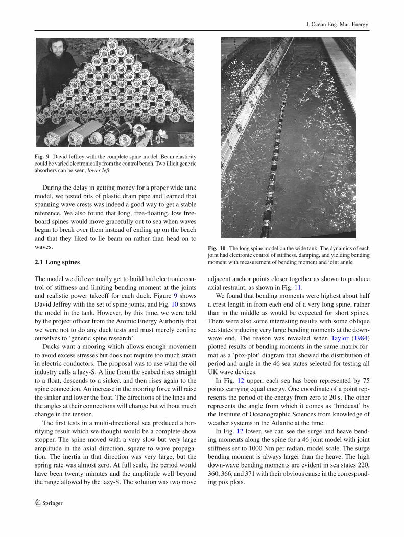
Fig. 9 David Jeffrey with the complete spine model. Beam elasticitycould be varied electronically from the control bench. Two illicit genericabsorbers can be seen, lower left
During the delay in getting money for a proper wide tankmodel, we tested bits of plastic drain pipe and learned thatspanning wave crests was indeed a good way to get a stablereference. We also found that long, free-floating, low free-board spines would move gracefully out to sea when wavesbegan to break over them instead of ending up on the beachand that they liked to lie beam-on rather than head-on towaves.
2.1 Long spines
The model we did eventually get to build had electronic con-trol of stiffness and limiting bending moment at the jointsand realistic power takeoff for each duck. Figure 9 showsDavid Jeffrey with the set of spine joints, and Fig. 10 showsthe model in the tank. However, by this time, we were toldby the project officer from the Atomic Energy Authority thatwe were not to do any duck tests and must merely confineourselves to ‘generic spine research’.
Ducks want a mooring which allows enough movementto avoid excess stresses but does not require too much strainin electric conductors. The proposal was to use what the oilindustry calls a lazy-S. A line from the seabed rises straightto a float, descends to a sinker, and then rises again to thespine connection. An increase in the mooring force will raisethe sinker and lower the float. The directions of the lines andthe angles at their connections will change but without muchchange in the tension.
The first tests in a multi-directional sea produced a hor-rifying result which we thought would be a complete showstopper. The spine moved with a very slow but very largeamplitude in the axial direction, square to wave propaga-tion. The inertia in that direction was very large, but thespring rate was almost zero. At full scale, the period wouldhave been twenty minutes and the amplitude well beyondthe range allowed by the lazy-S. The solution was two move
Fig. 10 The long spine model on the wide tank. The dynamics of eachjoint had electronic control of stiffness, damping, and yielding bendingmoment with measurement of bending moment and joint angle
adjacent anchor points closer together as shown to produceaxial restraint, as shown in Fig. 11.
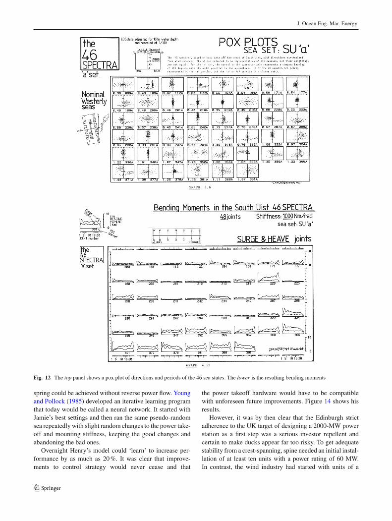
We found that bending moments were highest about halfa crest length in from each end of a very long spine, ratherthan in the middle as would be expected for short spines.There were also some interesting results with some obliquesea states inducing very large bending moments at the down-wave end. The reason was revealed when Taylor (1984)plotted results of bending moments in the same matrix for-mat as a ‘pox-plot’ diagram that showed the distribution ofperiod and angle in the 46 sea states selected for testing allUK wave devices.
In Fig. 12 upper, each sea has been represented by 75points carrying equal energy. One coordinate of a point rep-resents the period of the energy from zero to 20 s. The otherrepresents the angle from which it comes as ‘hindcast’ bythe Institute of Oceanographic Sciences from knowledge ofweather systems in the Atlantic at the time.
In Fig. 12 lower, we can see the surge and heave bend-ing moments along the spine for a 46 joint model with jointstiffness set to 1000 Nm per radian, model scale. The surgebending moment is always larger than the heave. The highdown-wave bending moments are evident in sea states 220,360, 366, and 371with their obvious cause in the correspond-ing pox plots.
123

J. Ocean Eng. Mar. Energy
Fig. 11 A plan view of the mooring modified to remove the slow axialoscillations
Chris Retzler measured spine bending moments as a func-tion of wave frequency and the angle between wave crest andspine with a wide variety of appendages. These included,extra buoyancy skins, square corners, fins, increased free-board, and vertical plates. His results shown in Fig. 13 showa V-shaped response. All the appendages increase bendingmoment relative to the bare spine. The largest increase waswith the largest increase in freeboard. The increase occurswhen the propagation velocity of the flexure wave along thespine coincides with the intersection velocity of the wavecrest which causes it. As the flexure wave is a function ofjoint stiffness, which is under our control, it is not a cause forconcern and can indeed be turned to advantage as in Pelamis.The largest credible wave at themost sensitive joint produceda deflection angle of only 4◦. The full-scale joint angle wouldallow 12◦ giving the full-scale design a factor of safety ofthree.After some brilliant design, the joints for Pelamis couldmove 40◦.
3 The mooring problem
As well as the alternating wave-by-wave forces on any wavedevice which we wanted to resist with connections to wavesof opposing phase somewhere along the spine, there is asteadiermomentum force predicted by Longuet-Higgens and
Stewart (1964). This depends on the squares of the ampli-tudes of incident plus reflected minus transmitted waves.Clearly, we should never reflect any waves and should tryto transmit all the waves above some economic limit. Trans-missionwill occur naturally whenwaves break over a device,so low freeboard, exactly unlike a harbour wall, is indicated.It might also occur from deliberate spine flexure. However,if the breaking is non-linear, it can induce frequency dou-bling. If this happens without too much energy loss, we canget an increase of wave amplitude in the transmitted wave.This should reduce or even reverse the mooring forces whichis why our plastic pipe models moved out to sea contrary tothe expectation of experienced marine engineers. This lev-elling off and reduction had been shown in the narrow tankexperiments. It greatly affects mooring design.
We built seabed anchors to measure vertical and horizon-tal forces from the lazy-S mooring. We could measure thespine position with very light threads wrapped round drumson the shafts of Portescap motors fitted with a tachogenera-tor and shaft encoder. A constant motor current would givea constant thread-tension, but we could add or subtract anadditional small current to correct the very small brush fric-tion. Today, we would use an optical Selspot system withtruly zero friction. By converging directions and phases ofa mixed seas, we could produce an extreme ‘50-year’ wavethat could sink a model trawler bow over stern. At full scalewith no appendages, this wave would increase the tension inthe lazy-S by only 2.1 kN per metre length of spine andmovethe spine by only 15 m. Measurements of the angle changesshowed that we had a factor of 400 relative to cable fatiguebending tests carried out by Pirelli (McConnell 1983).
Despite the official Atomic Energy Authority ban ontesting ducks, careless management and an unfortunatebreakdown of internal communications meant that someducks were in fact tested with proper moorings and a realisticpower takeoff. The performance was in line with what hadbeen predicted from the narrow tank models at the time thatthe long spine models had been designed, but we were notable to soften the sharp corners that give a useful increase inthe larger waves. It was a surprise that quite often a fault inone duck could not be detected in the total power generationof a group of them, because the neighbours teamed up tohelp by absorbing reflections from the casualty. The groupalso produced an efficiency of 25% based on the spine lengthwhen the waves ran directly parallel to it.
4 Parrots and monkeys
Work had continued in the narrow tank. We found that sharpcorners shed far more energy in vortex shedding than weexpected. Making a small model out of toffee and suck-ing it shows the way. We found that the benefits of negative
123
J. Ocean Eng. Mar. Energy
Fig. 12 The top panel shows a pox plot of directions and periods of the 46 sea states. The lower is the resulting bending moments
spring could be achieved without reverse power flow. Youngand Pollock (1985) developed an iterative learning programthat today would be called a neural network. It started withJamie’s best settings and then ran the same pseudo-randomsea repeatedly with slight random changes to the power take-off and mounting stiffness, keeping the good changes andabandoning the bad ones.
Overnight Henry’s model could ‘learn’ to increase per-formance by as much as 20%. It was clear that improve-ments to control strategy would never cease and that
the power takeoff hardware would have to be compatiblewith unforeseen future improvements. Figure 14 shows hisresults.
However, it was by then clear that the Edinburgh strictadherence to the UK target of designing a 2000-MW powerstation as a first step was a serious investor repellent andcertain to make ducks appear far too risky. To get adequatestability from a crest-spanning, spine needed an initial instal-lation of at least ten units with a power rating of 60 MW.In contrast, the wind industry had started with units of a
123

J. Ocean Eng. Mar. Energy
Fig. 13 Chris Retzler’s V-plots showing the effect of the coincidence of the velocities flexure and wave-crest intersection
few kilowatts, and most other countries were building wavedevices of a few hundred kilowatts. While Johannes Falneshad frequently urged very small devices in large numbersspaced well apart, I lived in a country with much less percapita sea front than Norway and wanted to use every mil-limetre to best advantage. While this might eventually bethe right way, in 1983, it was as wrong as giving Bleriot thespecifications for a Boeing Dreamliner. We wanted to buildsmaller systems of solo ducks, or even just parts of solo ducksto build confidence.
Skyner (1987)moved the pitch-heave-surge rig to thewidetank and achieved capture widths of 1.8 formost of the usefulAtlantic spectrum with a 10-m diameter unit. However, forthe first time, we were facing forces with nothing like spine-bending to limit them and the tension-leg moorings of thesolo duck showed nasty snatching if ever they went slack andthen retightened. We badly needed a small system to buildconfidence in components even if it was nothing like a duck.
The next attemptwas theMace, Fig. 1g, a vertical, invertedpendulum meant for testing ring-cam power takeoff and
123

J. Ocean Eng. Mar. Energy
Fig. 14 Henry Young’s narrow tank results for duck efficiency in the46 sea states specified for the UK programme. Circle diameter is pro-portional to output power with the effects of torque and power limitsshowing in the largest seas. The period axis has been stretched to reflectthe energy content of the Atlantic SouthUist wave climate with clippingof any sea states above 100 kW/m. Harwell reported to the UK Depart-ment of Energy that ‘efficiency of wave plant was typically 40%, adistortion fraction of 45/46 or 97.83%’
driven through tapes wound round the cam leading downto seabed attachments. It had a very wide but rather low effi-ciency band at much longer wave periods than any heavingbuoy, a vacuum energy store in its column, extraordinarysurvival features and no need for end stops.
If buoys moving vertically were too stiff and flaps movinghorizontally not stiff enough, itwas interesting to ask ifmove-ment along a slope direction would be a happy compromise.Pizer (1994) used his own numerical prediction software toshow that this indeed was so for a wide range of deviceshapes. My phobia about translations and end-stops in wavedevices was reduced by the stroke-limiting feature of theSwedish IPSbuoyPayne et al. (2006) andFalcao et al. (2011).
Chia-Po Lin built a test rig to find out how a sloped ver-sion would behave Salter and Lin (1995) and Lin (1999). Heused a half cylinder to reduce rear transmission of waves,as shown in Fig. 15. He supported it on a straight slide withwater-fed hydrostatic bearings and was easily able to adjustthe slope of the slide. He drove it in calmwater tomeasure thehydrodynamic coefficients and used these to draw theoreticalefficiency curves for a selection of slope angles as shown inthe middle graph and then confirmed them with true powergeneration.
The 45-degree prediction shows a capture width ratioabove unity for a two-to-one range of period, so wide thatwe would not really need to vary the slope to suit changes inwave spectrum. The results are in agreementwith experimen-tal ones as shown the lower graph. It is clear that movementalong a slope increases efficiency and widens the efficiencyband in both directions but especially towards longer peri-ods. It is not easy to make sloped slides at full scale andour attempts to make a free-floating sloped version of theIPS buoy have not so far been as good. However, it is clear
that water displacement in the slope direction, as shown inthe 1973 models that led to the duck, makes for good wavedevices.
Conventional hydraulic pumps could apply analogue con-trol of power flows from single sources by changing anglesof a swash plate or bent-axis machine. We wanted to use dig-ital control, and this had profound effects of the design ofhigh pressure oil pumps and motors. We tried to design forthe level of technology which would be available at the timewe expected that the energy crisis would really hit, ratherthan for things that would be obsolete by then. Many ofthe ideas, such as the use of microchips to change mechan-ical design, seemed wild at the time and were questionedby people responsible for power generation issues. All wereoutside the field of the civil end heavy electrical engineerswhowere employed to assess ourwork.Accordingly, the taskof assessing ducks was transferred from Rendel Palmer andTritton to an outside consultant Gordon Senior. He subjectedus to a sharper scrutiny than the civil engineers, who hadmissed a serious mistake we had made with the 1979 refer-ence design. He checked calculations, quotations, and datafrom tank experiments. His questions and comments were agreat help in improving the design.
The consultants had to consider many sorts of data. Therewere the heights, spectral shapes, and angular distributionsof the raw wave input. There was the hydrodynamic perfor-mance of the devices. There was the conversion efficiencyof the mechanism used for generating electricity, collect-ing it, and transmitting it ashore. There was the reliabilityof the overall system. There was the capital cost of build-ing yards and of the devices and transmission cables. Therewas the rate of interest charged for the loans. There werecharges for installing the devices and charges for mainte-nance. Finally, there was the ultimate life. Some of thesedata are well known. Some can be measured by experiment.Some have to be guessed. Some are unalterable. Some can bechanged by better understanding or more intelligent design.Many can be misinterpreted through accident, malevolence,or enthusiasm. Some remain unknown. If input data are false,no amount of subsequent processing can improve the conclu-sion. However, it has always been necessary to decide policywith imperfect assumptions. With skill and luck, some of themistakes cancel others. The history of official cost predic-tions at values of the time up to 1982 is shown in Fig. 16.On the basis of this information, the Secretary of State forEnergy, Nigel Lawson, now Lord Lawson, decided to winddown the UK wave energy programme.
5 Spectra and tuning
Many wave developers mention the word ‘tuning’. The wordis used by radio engineers to describe their way to block
123

J. Ocean Eng. Mar. Energy
0
20
40
60
80
100
120
140
0 0.5 1 1.5 2 2.5
period (sec)
Effic
ienc
y (%
)
without platewith platepredict
0
20
40
60
80
100
120
140
0 0.5 1 1.5 2 2.5
Period (sec)
Effic
ienc
y (%
)
90°60°
45° 35°
Model Load Cell
Plate
Motor and Tacho
Wave maker
G - +
Bearing Hydrostatic
Controller Velocity U Force F
Beach
Fig. 15 Chia-Po Lin’s model and results for a half cylinder moving on a fixed slope. Top model set-up. Centre efficiency from hydrodynamiccoefficients. Bottom measured efficiency at 60◦
reception of signals from unwanted transmitters. However,wave engineers want to listen to all the transmissions at thesame time. We therefore want to detune the response. Theperfect wave absorber would present the right value of resis-tance to water movement with force always in phase withvelocity. However, inertia of the structure and added iner-tia of the water around it are inevitable. They feel a forcein phase with acceleration. We should try to counter theireffects by allowing water particles to move in their naturalway with orbit diameter decaying exponentially with depth.
We then want to choose the right amount of spring, withforce in phase with change of position and, therefore, 180◦out of phase with the acceleration force, for resonance in theexpected wave spectra. The radio engineers would advise alow-Q resonance with resistive forces as large as possiblerelative to reactive ones. However, the Taylor pox-plots inFig. 12 show that about half the sea states have more thanone spectrum, so choice is not easy. I repeat, phase is the key.
Tank tests are nowoften donewith a JONSWAP spectrum.This is based on measurements of new waves developing
123

J. Ocean Eng. Mar. Energy
1970 1980 1990 2000
RPT 78
ETSU R9RPT 81
COJG-P32
5
10
203050
100
Pence / kWh
Fig. 16 Official electricity costs for spine-based ducks during the firstpart of theUKwave energy programme fromRendel Palmer andTritton,theEnergyTechnologySupportUnit and the programmemanager,CliveGrove-Palmer, whose figure was based on final development
over a short fetch and is much narrower than the other math-ematical descriptions of wave spectra. It will give an overoptimistic prediction for highly tuned, narrow bandwidthdesigns when they are come to be used in the long fetchesof big oceans. I advise either real spectra or at least pairs ofspectra with amplitudes varied to cover the scatter diagram,at least by a factor of two.
6 A thought experiment for future work
Let us imagine a wide test tank with a large number of sepa-rate, narrow, dry-backwave-makers along onewall. Oppositethe row of wave makers is a rigid wall which will act as aperfect reflector of all incoming waves. A single wave-makerat the centre of the row generates a wave group, which radi-ates out as concentric semi-circles according to the Huygensprinciple. Figure 17 shows the group about to arrive at thereflectingwall. The singlewave-makerwill have been puttingpower into the water that can be exactly measured from itsforce and velocity or torque and angular velocity. The reflec-tions from the vertical will be like waves from the mirrorimage of the source behind the reflection wall and are shownin Fig. 19.
Suppose now that the rigid reflecting wall is replaced bya second bank of dry-back wave-makers which are driven,so as to produce wave fronts that are the exact inverse of thereflections and so would cancel all the reflections at everypoint in the tank. If energy has been put in by the first singlewave-maker but is no longer anywhere in the water, it musthave been absorbed by the second bank of wave makers.We could measure the amount of energy from the force andvelocity signals from each of them (Fig. 18).
What is true of a short wave group from the original sin-gle wave-maker will also be true of a second wave-makerand indeed of all the wave-makers making a continuous seastate from a large number of separate wave fronts at variousangles and wave lengths. We could either calculate the com-mand signals to the second bank with a computer fed withinformation from the first bank or measure the forces exertedon them by the waves and set up a control loop to maintain arelationship between forces and velocities. This would allowwaves from any other objects in the tank to be absorbed aswell as ones from the wave-makers.
This form of force control is now common in a large frac-tion of the world’s test tanks and gives very much greaterstability for long wave tests and faster settling between tests.The optical analogy is not quite perfect. For waves approach-ing a wall at acute angles less than about 20◦, the Mach stemeffect splits the wave front into one part running along thewall, and a second part reflected at a steeper angle thanwouldbe predicted by classical optics. Wave absorbers can makeallowance.
The absorption idea would not work if the wave-makersproduced waves on both sides as does the widely popularheaving buoy which radiates a circular pattern of waves.While some of this radiation can cancel waves that a station-ary buoy would have reflected, they are also sending energyto where the water would have been calm. A possible way toavoid someof this losswould be to have a line of close-packedheaving buoys placed a quarter of a wavelength in front of areflecting cliff, so that the wasted energy is returned with thecorrect phase. But what is the right phase for one wave length
Fig. 17 A single wave-maker sending a group of circular wave fronts to a reflecting wall
123

J. Ocean Eng. Mar. Energy
Fig. 18 The reflecting wall has been replaced by a row of dry-backed, hinged-flap wave-makers which are driven to produce the inverse of thereflection from the rigid wall. The fronts would appear to come from a point source placed at the mirror image of the single wave-maker
and amplitude will not be correct for different ones. A crestof a wave in an irregular sea is seldom the same magnitudeas the next trough. The loss of energy from unwanted radi-ation patterns would not matter in countries with very longcoastlines or at mid ocean sites with energy coming from allround. But if we want to take full advantage of the near-shorecoast resource, we should try to use shapes and motions thatgenerate or absorb waves only on one side, at least in lowand moderate sea states.
There are several possibilities to reduce waves transmit-ted astern: air-filled bags or sliding wedges mounted on afixed back wall and the Edinburgh duck mounted on a longspine are all obvious. A particularly efficient one is the Evanscylinder mentioned earlier. This is submerged, has a circularcross section, and moves in both heave and surge. If it movedonly in heave, it would generatewaves symmetrically on bothsides. If it moved only in surge, the waves on each side wouldbe antisymmetric. It follows that if itmoved in both directionswith a 90◦ phase shift between heave and surge the radi-ated waves would combine on one side but cancel each otheron the other. The result is an astonishingly efficient waveabsorber with fewer moving parts than the long-spine ducksystem. The only snag is that a submerged, neutrally buoy-ant, circular cylinder has no hydrostatic spring. The springrate needed to cancel the inertia has to be provided by thepower takeoff. This can be done with very high efficiencywith small models but gets much harder at full scale. Recentadvances in hydraulics allow us to make high energy springsystems which lose about 5% of the energy for each transferin or out. However, the Evans cylinder needs to put in to the
spring and then take out again about five times more energythan goes into the damping system, which delivers the usefuloutput. Future reductions in losses may be possible.
7 Mind the gaps
Whatever the choice of absorber I am arguing that, contraryto proposals from many developers, we should minimisegaps between them with a positive method to control the gapdimension. To start a company and raise investments a newdeveloper must build a working prototype and the quickerthe better. The choice of power levels will often be less than1 MW far below 2 GW required by the UK Department ofEnergy. Attention is so focussed on the very first machinethat it is easy to forget that we will be wanting thousandsof them. Except, for places like Norway and the Falklands,the per capita length of high-energy sea front is quite low,only 6.15 mm for the UK. Isolated point absorbers are ableto get more energy than is contained in their own geometricalwidth. However, getting the very high capture widths, whichare mathematically possible, needs large movements whichbecome non-linear. Point absorbers do not make full use ofthe sea front. The main importance of point absorber theoryis that if close-packed devices have to be installed with mod-erate gaps for practical reasons, we do not need to worry somuch about energy loss through gaps.
Wave energy must live alongside other uses of the sea.Mariners are used to submerged rocks and sandbanks. Theygreatly prefer obstructions to carry lights, bells, and radarreflectors and to be clearly marked on charts. They will pre-
123

J. Ocean Eng. Mar. Energy
Fig. 19 An early drawing of a fast multi-bank, radial piston machine with digital poppet valve control of pumping, motoring, or idling. Laterimprovements have led to a commercial product
123

J. Ocean Eng. Mar. Energy
fer only a moderate number of generously wide, blindinglyobvious gaps on the great circle lines between ports to amuchgreater number of narrow gaps with poorly marked indica-tions.
Owners ofwave plant should not have toworry about side-to-side collisions. The crews of installation and maintenancevessels should not have to worry about being squashed in thegap. People developing isolated devices must be asked howclose they will be to one another, how far will they moveunder the worst-case wave or fault conditions, how muchgap is available for safe passage and how much energy willget through the gaps. While we will have to compete withnuclear energy, we should not attempt tomimic the collisionsof neutrons and atomic nuclei.
The cost of cables has a large initial constant and is cer-tainly not linear with rating. Large numbers of wet cablejoints are expensive and possibly unreliable. Close packingof wave devices allows dry power combination up to hun-dreds of megawatts, levels attractive to networks especiallyif each element has a moderate amount of storage as closeas possible to the wave input. We need to develop the tech-nology to provide mechanical and electrical couplings withthe right degrees of freedom which can quickly connectedor disconnected. These couplings could use something like ahighly manoeuvrable arms with and strong claws and sonarvision at the claw tips. We will need to fit such arms to main-tenance vessels, so that they can make a safe connection toremove and replace devices in the middle of a row. I hopethat ideas for arms and claws for the seabed attachments ofthe Oyster will be suitable for shapes that can offer holes inpairs of steel with shapes to guide an approaching claw.
Magnets can give contact forces a bit over half an MN persquare metre on steel surfaces. The clever bit is disconnec-tion, but this can be done by surrounding the contact areawitha flat fire hose and then pumping in water. For non-ferrousmaterials, we can make suction pads like an octopus. It ishighly desirable for the response amplitude operators of thewave plant and themaintenance vessel to be the same but oneinstallation vessel can be shared with hundreds of megawattsof wave plant, so we can afford something quite expensive,perhaps with adjustable hydrodynamics. It is also desirablefor connecting hardware to be soft, either with air bags orintelligent hydraulic arms.
A further advantage of close-packed devices is that muchof the testing can be done with single units in a narrow tank.A second thought experiment involves a single real narrowtank surrounded by a large number of imaginary narrow tanksplaced side by side. Each tank has a wave-maker driven withdifferent signals to mimic the effect of directionally spreadirregular seas. Lots of imaginary devices will be mountedon force-sensitive rigs either side of the real one. The differ-ence of heave and surge forces of adjacent rigs will give thedistributed shear forces that would be experienced by a long
spine. Beam theory tells us that the integral of a distributedshear force pattern along a beam will give the pattern of dis-tributed bending moments. If the beam had joints which hadsome means to produce that pattern of bending moments,each numerical device would think that it was part of a longarray. We need to build and test only one real wet model toget the result of many.
8 Power conversion
The change from testing in regular waves to more realisticirregular ones with a Gaussian distribution of wave ampli-tudes is an unpleasant experience for wave inventors. Thepower signal is the square of the Gaussian distribution withfrightening peaks of energy that are determined to go some-where but are totally incompatible with electrical grids. Itwas clear that storing energy for about 100 s would make theoutput much more acceptable. The only way to do this andstill retain intelligent power takeoff seemed to be with high-pressure oil hydraulics. However, the designs then on themarket were too low in power rating, too low in efficiencyespecially at part load and were bad at combining energyflows from multiple uncorrelated sources. We did a rigorousenergy analysis of every loss mechanism and ended upwith adesign using digital control of displacementwith electromag-netically controlled poppet valves on each chamber (Salterand Rampen 1993). It did for hydraulics what the thyristors,MOSFETS, and switching-mode control have done for elec-tronics. It allowed us to move away from swash plates andport-faces in an axial configuration to a radial one with eightor even more separate machines on a common shaft, somemotoring, some pumping, and some idling all under the con-trol of a microcomputer costing a few euros which couldlatch or unlatch poppet valves at the right instants. Figure 19shows an early design. Each chamber can be controlled topump or motor or idle with an option to change the operatingmode of each chamber twice a shaft rotation.
There is now a growing need for flexible control andhighpart-load efficiency in vehicle transmissions and suspen-sions, and it turned out to be possible to fund development bywork on machines for the motor industry. This developmenthas been carried out by Artemis Intelligent Power (2016).They measured the fuel consumption of a standard BMW5 series car over a set of defined drive patterns at the Mill-brook Vehicle Testing Facility. They replaced the standardtransmission with a digital hydraulic one which included an11-L gas accumulator for regenerative braking. They thenrepeated the same driving patterns. High-speed motorwayfuel consumption was the same, but the standard urban fuelconsumption was less than half. All the vehicle power man-agement was done by the transmission, and the engine couldrun at the sweet spot of the power curve, so that the carbon
123

J. Ocean Eng. Mar. Energy
release might be even better than the fuel reduction. The sys-tem should be particularly suitable for buses and deliveryvehicles which make frequent stops and starts.
There has also beenwork on ring campumps for absorbingthe very high torques at low speeds needed for wind turbines(Salter and Rea 1984) wave energy (Salter et al. 2002) andtidal stream generators (Salter 2012). Mitsubishi Vestas havereplaced conventional gearing of for their Sea Angel turbine.The first prototype has been built on land at Hunterston nearGlasgow. The rotor diameter of 167 m made it the largest inthe world for several weeks. The digital hydraulics allows thecombinationof true synchronous grid-lockedgenerationwithexact tip-speed ratio but with a much lower weight than con-ventional gears. Short grid dropouts can be tolerated becauseof short-term storage. I would like to make all the mistakes(there will be lots on such a new technology) on land beforeanything goes to sea.
A duplex ring cam outside the full spine diameter with theforce reaction through the thickness of the cam rather thanround the circumference gives an amazingly light power takeoff with lots of parallel redundancy. If a duplex cam is good,a quad one would be even better. This is proposed for a 200-MW tidal stream generator. There is a scarcity of bearingsthat size, but it would be regarded as very small for a railway.Short sections of cam lobes would be pulled together likebeads on a necklace. A likely roller force is 100 kN movingthrough a stroke of 100 mm giving 10 kJ per stroke or 40kJ for one operation of four rollers on a quad cam. Readersare invited to work out how many cam lobes can fit in thecircumference of the cam, then tomultiply this by the numberof sets of pumping modules, and then to multiply this by 40kJ to get the work done in one cam revolution. I want to buildcomplete confidence in digital hydraulics in wind and tidalstream before trying anything under water driven by waves.
8.1 And now for something completely different
While the new digital hydraulics was being developed, itseemed interesting to investigate a device that would inher-ently give the ideal torque proportional to velocity but deliveran output which in some places could be even more valu-able than energy. The result was a desalination device usingvapour compression rather than the normal reverse osmo-sis (Salter 1985; Salter et al. 2007; Cruz and Salter 2006).Figure 20 shows the arrangement. A solo duck is half filledwith water. A vertical partition reaches down just past theduck axis. The inertia of the water makes it tend to stayfixed like a pendulum. Movements of the duck will varythe volumes either side of the partition, so that they becomeenormous double-acting pumps but with no machined parts,sliding contacts or seals. The pump chambers are full ofsteam, and the movements suck and then compress it fromand then to opposite sides of a large heat transfer surface
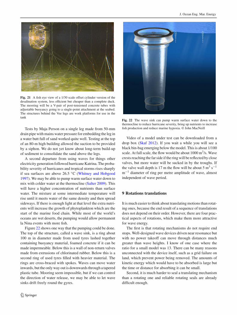
contained in the partition. The result is two or three thou-sand cubic metres of pharmaceutically pure water a day ina tropical trade wind wave climate. A cross-sectional viewshowing internal details is shown in Fig. 21. Figure 21 showsa 1/30 scale model with an offset axis of rotation under testpumping air through a blanket instead of steam.
Whales and elephants do not need fur coats or wet suits,because objects of that size and shape lose heat very slowly.With a metre of foam concrete for thermal insulation, thedesalination system will cool at only 4 ◦C per month. Amore serious problem is that vapour compression can pro-duce a water purity of 0.5 parts per million of dissolvedsolids. It will be necessary to add quantities of trace min-erals, such as iodine and selenium, if it is to be used fordrinking.
A major concern was the need to raise cold sea water toboiling point and then recover heat from the fresh water andthe double-strength brine.DesireeHelenschmidt built a smallsection of the zigzag heat exchanger design shown at the topleft corner of Fig. 20. She put it in a test tank, removed thebeach, and drove the wave-maker to produce a standing wavewith a node at the heat exchanger model. There was one sheetof aluminium between two sheets of polycarbonate with anairspace to two more sheets to give the function of doubleglazing.
The unequal resistances of the zigzag gave an effectivedistributed pumping effect which should remove much ofthe pressure-related stress. A source of heat was provided bythe copper strips of a sheet of Veroboard used for prototypeelectronic circuits. With 80 volts at 50 Hz across adjacentcopper strips, the heater drew 10 amps, putting 8 kW persquare metre into the water. The only available temperaturesensors had a resolution of 0.1 ◦C. The temperature increasewas only just detectable, so it was possible to say that, ifthis was the temperature rise, we could claim a heat transfercoefficient of 80 kW per square-metre Kelvin, way above theperformance of flat-plate heat-exchangers, because the alter-nating flows.With all the heat from internal fluid movementsin full size plant tending to raise the temperature, we have tobe careful not to overheat.
The main application will be in places with severe waterproblems which usually do not have such large waves asthe Scottish Atlantic climate. However, this is the first Edin-burgh device to have a stiff mooring, and therefore, weare extremely concerned about peak loads. One possibleapproach is to allow the hull or legs to fill with water if severeweather is expected and lower the system belowwave action.Many sites have sandy sea beds, and it may be possible touse a combination of water jetting to sink a tripod anchorinto the sand and then suction to consolidate it. This wouldmean that deployment and recovery could be done from lightinflatable work boats with water pumps and air compressorsbut no heavy lifting gear.
123

J. Ocean Eng. Mar. Energy
Fig. 20 Sections through the desalinating unit. People would not be present during operation
123
J. Ocean Eng. Mar. Energy
Fig. 21 A fish eye view of a 1/30 scale offset cylinder version of thedesalination system, less efficient but cheaper than a complete duck.The mooring will be a V-pair of post-tensioned concrete tubes withadjustable buoyancy going to a single-point attachment at the seabed.The structures behind the Vee legs are work platforms for use in thetank
Tests by Maja Person on a single leg made from 50-mmdrain pipewithmainswater pressure for embedding the leg ina water butt full of sand worked quite well. Testing at the topof an 80-m high building allowed the suction to be providedby a siphon. We do not yet know about long-term build-upof sediment to consolidate the sand above the legs.
A second departure from using waves for things otherelectricity generation followed hurricaneKatrina. The proba-bility severity of hurricanes and tropical storms rises sharplyif sea surfaces are above 26.5 ◦C (Whitney and Hobgood1997). We may be able to pump warm surface water down tomix with colder water at the thermocline (Salter 2009). Thiswill have a higher concentration of nutrients than surfacewater. The mixture at some intermediate temperature willrise until it meets water of the same density and then spreadsideways. If there is enough light at that level the extra nutri-ents will increase the growth of phytoplankton which are thestart of the marine food chain. While most of the world’soceans are wet deserts, the pumping would allow permanentla Nina events with more fish.
Figure 22 shows one way that the pumping could be done.The top of the structure, called a wave sink, is a ring about100 m in diameter made from used tyres lashed togethercontaining buoyancy material, foamed concrete if it can bemade impermeable. Below this is a wall of non-return valvesmade from extrusions of chlorinated rubber. Below this is asecond ring of used tyres filled with heavier material. Therings are cross-braced with spokes. Waves can move waterinwards, but the onlyway out is downwards through a taperedplastic tube. Mooring seem impossible, but if we can controlthe direction of water release, we may be able to let wavesinks drift freely round the gyres.
Fig. 22 The wave sink can pump warm surface water down to thethermocline to reduce hurricane severity, bring up nutrients to increasefish production and reduce marine hypoxia. © John MacNeill
Video of a model under test can be downloaded from adrop box (Skaf 2012). If you wait a while you will see ablack bin-bag emerging below themodel. This is about 1/100scale. At full scale, the flowwould be about 1000m3/s.Wavecrests reaching the far side if the ringwill be reflected by closevalves, but more water will be sucked in by the troughs. Ifthe valve wall depth is 17 m the flow will be about 5 m3 s−1
m−1 diameter of ring per metre amplitude of wave, almostindependent of wave period.
9 Rotations translations
It ismuch easier to think about translatingmotions than rotat-ing ones, because the end result of a sequence of translationsdoes not depend on their order. However, there are four prac-tical aspects of rotations, which make them more attractivefor wave energy.
The first is that rotating mechanisms do not require endstops.Well-designed wave devices driven near resonance butwith no power takeoff can move through distances muchgreater than wave heights. I know of one case where theratio for a small model was 13. There can be many reasonsunconnected with the device itself, such as a grid failure onland, which prevent power being removed. The amounts ofkinetic energy which would have to be absorbed is large butthe time or distance for absorbing it can be small.
Second, it is much harder to seal a translating mechanismthan a rotating one and reliable rotating seals are alreadydifficult enough.
123
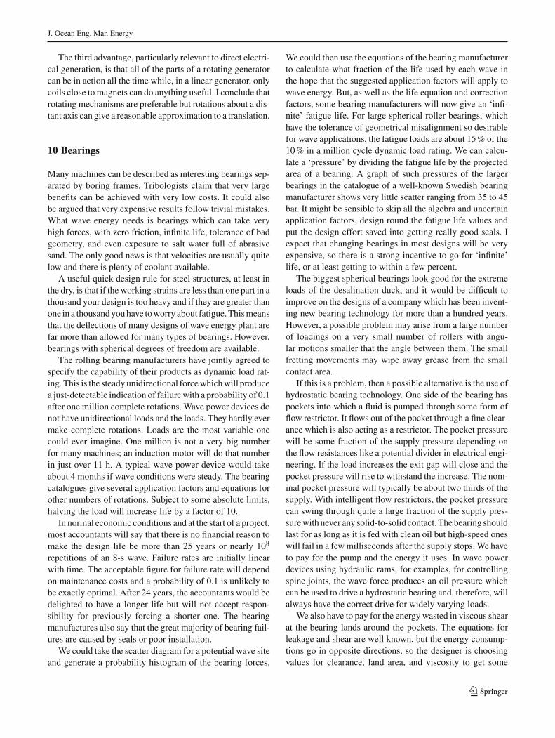
J. Ocean Eng. Mar. Energy
The third advantage, particularly relevant to direct electri-cal generation, is that all of the parts of a rotating generatorcan be in action all the time while, in a linear generator, onlycoils close to magnets can do anything useful. I conclude thatrotating mechanisms are preferable but rotations about a dis-tant axis can give a reasonable approximation to a translation.
10 Bearings
Manymachines can be described as interesting bearings sep-arated by boring frames. Tribologists claim that very largebenefits can be achieved with very low costs. It could alsobe argued that very expensive results follow trivial mistakes.What wave energy needs is bearings which can take veryhigh forces, with zero friction, infinite life, tolerance of badgeometry, and even exposure to salt water full of abrasivesand. The only good news is that velocities are usually quitelow and there is plenty of coolant available.
A useful quick design rule for steel structures, at least inthe dry, is that if the working strains are less than one part in athousand your design is too heavy and if they are greater thanone in a thousandyouhave toworry about fatigue.Thismeansthat the deflections of many designs of wave energy plant arefar more than allowed for many types of bearings. However,bearings with spherical degrees of freedom are available.
The rolling bearing manufacturers have jointly agreed tospecify the capability of their products as dynamic load rat-ing. This is the steadyunidirectional forcewhichwill producea just-detectable indication of failurewith a probability of 0.1after one million complete rotations. Wave power devices donot have unidirectional loads and the loads. They hardly evermake complete rotations. Loads are the most variable onecould ever imagine. One million is not a very big numberfor many machines; an induction motor will do that numberin just over 11 h. A typical wave power device would takeabout 4 months if wave conditions were steady. The bearingcatalogues give several application factors and equations forother numbers of rotations. Subject to some absolute limits,halving the load will increase life by a factor of 10.
In normal economic conditions and at the start of a project,most accountants will say that there is no financial reason tomake the design life be more than 25 years or nearly 108
repetitions of an 8-s wave. Failure rates are initially linearwith time. The acceptable figure for failure rate will dependon maintenance costs and a probability of 0.1 is unlikely tobe exactly optimal. After 24 years, the accountants would bedelighted to have a longer life but will not accept respon-sibility for previously forcing a shorter one. The bearingmanufactures also say that the great majority of bearing fail-ures are caused by seals or poor installation.
We could take the scatter diagram for a potential wave siteand generate a probability histogram of the bearing forces.
We could then use the equations of the bearing manufacturerto calculate what fraction of the life used by each wave inthe hope that the suggested application factors will apply towave energy. But, as well as the life equation and correctionfactors, some bearing manufacturers will now give an ‘infi-nite’ fatigue life. For large spherical roller bearings, whichhave the tolerance of geometrical misalignment so desirablefor wave applications, the fatigue loads are about 15% of the10% in a million cycle dynamic load rating. We can calcu-late a ‘pressure’ by dividing the fatigue life by the projectedarea of a bearing. A graph of such pressures of the largerbearings in the catalogue of a well-known Swedish bearingmanufacturer shows very little scatter ranging from 35 to 45bar. It might be sensible to skip all the algebra and uncertainapplication factors, design round the fatigue life values andput the design effort saved into getting really good seals. Iexpect that changing bearings in most designs will be veryexpensive, so there is a strong incentive to go for ‘infinite’life, or at least getting to within a few percent.
The biggest spherical bearings look good for the extremeloads of the desalination duck, and it would be difficult toimprove on the designs of a company which has been invent-ing new bearing technology for more than a hundred years.However, a possible problem may arise from a large numberof loadings on a very small number of rollers with angu-lar motions smaller that the angle between them. The smallfretting movements may wipe away grease from the smallcontact area.
If this is a problem, then a possible alternative is the use ofhydrostatic bearing technology. One side of the bearing haspockets into which a fluid is pumped through some form offlow restrictor. It flows out of the pocket through a fine clear-ance which is also acting as a restrictor. The pocket pressurewill be some fraction of the supply pressure depending onthe flow resistances like a potential divider in electrical engi-neering. If the load increases the exit gap will close and thepocket pressure will rise to withstand the increase. The nom-inal pocket pressure will typically be about two thirds of thesupply. With intelligent flow restrictors, the pocket pressurecan swing through quite a large fraction of the supply pres-surewith never any solid-to-solid contact. Thebearing shouldlast for as long as it is fed with clean oil but high-speed oneswill fail in a fewmilliseconds after the supply stops.We haveto pay for the pump and the energy it uses. In wave powerdevices using hydraulic rams, for examples, for controllingspine joints, the wave force produces an oil pressure whichcan be used to drive a hydrostatic bearing and, therefore, willalways have the correct drive for widely varying loads.
We also have to pay for the energy wasted in viscous shearat the bearing lands around the pockets. The equations forleakage and shear are well known, but the energy consump-tions go in opposite directions, so the designer is choosingvalues for clearance, land area, and viscosity to get some
123

J. Ocean Eng. Mar. Energy
balance between the two for the expected speeds and loads.We can use hydrostatic pads for spherical, conical, cylin-drical, and flat geometries. We now can buy pumps, hoses,and hydraulic fittings for pressures up to 400 bar, and so itlooks as though hydrostatic bearings should be even betterthan rolling ones for wave applications provided that we canretain the desired clearances. However, there are several bighowevers as follows:
• The ideal clearances are very fine, sometimes less than10 microns and can easily be smaller than the elasticdistortions of the material around the bearing.
• A single pad can tilt to make a solid contact at one corner,so groups of pads have to obey the rules of kinematiclocation.
• The viscosity of the working fluid is a function oftemperature and there can be quite large changes withuncertainty about heat transfer through parts of the bear-ing to the outside and the thermal expansionof the bearingparts.
• We have to collect the exit flow and dreadful things willhappen if any oil leaks into the sea.
• Wehave to keep the oil cleaner than the closest-ever clear-ances.
• Wemay have to parkwave plantwhen there is no pressuresupply.
While we can buy rolling bearings and expect them to workout of the box, most hydrostatic bearings still have to bespecial designs developed for each particular application. Apossible step for the velocities which are above the very slowones of high-load plain-bearing velocities is to supply plainbearings with oil taking nearly but not quite all the bearingload leaving a moderate fraction to be taken by the plainbearing surfaces.
When fully hydrostatic bearings are working, theirrequirement for high-quality lubricants is less than for hydro-dynamic and plain ones. It is the non-working condition thatmakes demands on tribology. If suitable choices for the bear-ing parts allow us to relax the requirement for lubricity, wemay be able to reduce the leakage problem by using watersoluble, edible fluids, such as glycerine-water mixtures. Themixing ratio can give a very wide range of viscosity adjust-ments.
Another possible solution to avoid the leakage problemcompletely is to use filtered sea water as a hydrostatic fluiddespite its rather low viscosity. Reverse osmosis membraneslast much better if they are fed clean water. There is a briskmarket for filters to do this. A group of filters can sequentiallyback-flush each of the group in turn with a change-over everytenminutes or so. The original filtermarket was for removing30-nm polio viruses from drinking water and so is far smallerthan any hydrostatic bearing clearance.
An interesting bearing for the duck was developed byAnderson (1987). Peak wave forces on ducks in big wavesare about 1 MN per metre width. But if this is evenly sharedover a metre width of a 12-m diameter spine the pressureis only 0.083 MPa—in expanded polystyrene country. Thebearing idea is copied from synovial lubrication which canworkwell in human hip joints for sixty years, or considerablymore if people take glucosamine sulphate.
The bearing ismade as bed of springy rubber ‘concertinas’filled with sea water. Axial length is chosen to suit the round-ness tolerance of spine and duck, perhaps 200 mm. They aremounted on a flexible carpet with holes which could allowwater to flow in to a gap of a few millimetres. The shapeof the holes makes it slightly easier to move water into theconcertina than out. The projected area of the concertinasis lower than the total area between the duck and the spineand so the wave force would produce a pressure which washigher. Successful operation depends on how long it wouldtake to empty the concertinas with flow to the far side ofthe bearing or its ends. Calculations showed that it wouldbe several minutes, far longer than the time for the forces toreverse, even very long period swell. The alternating forceswhich cause so much misery for energy quality would beturned to advantage.
The only problem is that the bearing would not work incalmwater. This could be solvedwith lines of ferritemagnetson the carpets facing others embedded like cat’s eyes in tar-mac on the spine. The cheapest ferritemagnets aremade fromblast-furnace slag and cost about the same as their weight insteel. We built a 1-m diameter, vertical-axis thrust-bearingwhich could take the weight of a student. His inertia couldkeep him spinning with apparently no reduction of speed forthree minutes.
11 Seabed operations
New technologies raise demands for new tools and waveenergy is no exception. We may need to do cosmetic surgeryon unwanted rock outcrops. Wemay want to cut cones, cabletrenches or prismatic shapes in rock and drill long holesfor Macalloy post-tensioning bar. We may want to tightennuts ormake electrical connections. Free swimming remotelyoperated vehicles are excellent for inspection but cannot doanything really muscular.
I suggest that there is a need for a seabed walking vehicle–robot–machine tool which can move to a precision of amillimetre (much better than anything that can be cone witha jack-up rig) exert large forces, withstand the highest cur-rent velocities and be easily moved. Ideas for a design weredescribed at the 2011 EWTEC conference (Salter 2011).They made extensive use of digital hydraulics. A drawingis shown in Fig. 23.
123

J. Ocean Eng. Mar. Energy
Fig. 23 Sketch views of a seabed crawler for intricate, high-force operations
The frame conforms to the ISO specification for ‘forty-foot’ sea-containers, so that it can be moved anywherequickly and cheaply. There are eight legs on quadrilaterallinkages which can be driven by two hydraulic rams in thehorizontal plane and one ram in the vertical plane. One sideof the rams is connected to a source/sink of constant pres-sure at half the system pressure. The other side is connectedto a digital machine which can deliver or remove a cham-
ber full of oil to give a millimetre of movement or presenta closed poppet valve to lock the leg. Having eight legsallows the frame to cross wide trenches and jump over largerocks. The open frame will reduce loads from waves andcurrents.
Ram diameter will set the force capability. Until otherwiseadvised a value of 430 kN is proposed based on the specifica-tion of Admiralty tugs built in large numbers. The suggested
123

J. Ocean Eng. Mar. Energy
power rating is 100 kW supplied by a cable wrapped aroundor paid out from a cable drum and laid in a trench cut as thevehicle walks out from land.
The most useful tools will be chain saws on a parallel-ogram linkage and long-hole drills but the frame will havemounting holes to allowanyother attachments. Themost use-ful instruments will be a sonar camera with 1-mm resolution,pressure transducers to tell us all the forces being exerted andmicrophones. Everything will be controlled by an operator,sitting warm and dry, in a Portakabin on land. None of thepresent developers can alone afford to fund design, but per-haps, a consortium could agree common specifications anda price which would justify building a reasonable batch ofmachines.
12 Component reliability
A painfully learned lesson has been that lengthy and veryexpensive delays (months and millions) can be cause by thefailures of very cheap components becauseofmisunderstand-ings of specification sheets or poor communications withcontractors. We may be able to reduce these by testing largenumbers of components and subassemblies at sea before theyget joined together in a complete generating system. Thiscould be done with a component test raft (Salter 2003, 2011)as shown in Fig. 24. It is in the shape of a ladder with largecircular rungs. Components would be mounted on ‘saddles’pulled against the rungs by cinches. If a cinch is loosened,the saddle can be rotated to allow inspection of parts withoutthe risk of heavy equipment being moved by waves.
Electrical power can be taken to the raft from land. Somecan be used for driving shaft seals, exercising mechanismsand testing high-voltage wet insulation. Most of the powercan be returned to land, so that conductors and connectorscan run at full current. We can accelerate test results by over-driving and do regular inspections at little cost. Such a facilitywould seem expensive for a single developer, but the entireindustry would benefit if results from a common one wereshared.
13 Marine hazards
Wave energy is often criticised because of the extreme haz-ards of themarine environment. This view is reinforced everytime we see television pictures of extreme waves breakingover promenades and parked cars and reaching beach-fronthotels. The film crews would not be able to get any imagesfrom deeper water but, if they could, they would be muchmore boring.
When people are asked to list the hazards of the sea, theobvious one is the size of the waves, but to complain of the
dangerously high waves at a good wave site is like complain-ing of the high temperatures in the flame of a thermal plant.For low freeboard devices, the stresses in large waves rise atslightly less than the first power of wave height, while theavailable power rises with the square. The analogy in ther-modynamics would be of higher temperatures giving higherCarnot efficiency. This means that the economic viabilityshould rise in higher waves. This should not be regarded as ahostile feature. Marine currents might also be regarded as ahazard but the same arguments of power rising with the cubeof velocity, while stresses rise with only the square applies.Marine current designerswould dearly love higher velocities.Afterwave height and current velocity, there is salt. But salt isfound at 28 times greater concentration on land and is thrownat high speed, mixed with abrasive gravel, at the underside ofevery vehicle in an attempt to overcome the serious hazard oficy roads. After salt, there are poisonous jellyfish, great whitesharks, drifting icebergs, none of these common in Europeanwaters. At this point, the list usually terminates. I would liketo hear from readers who can help me extend it.
The list of hostile features for land is longer and muchmore diverse. There is a wider range of temperatures withrapid changes between extremes combined with very poorheat transfer to still air. Air offers very little damping toresonating objects and the wind can induce much higherfrequencies of oscillation. There is gravity unopposed bybuoyancy with point loading rather than distributed load-ing. There are cliffs, gullies, crevasses, and steep gradients.There are rockfalls, mudslides, landslides, subsidence, col-lapsing tunnels and avalanches, volcanic explosions, lavaflow, and earthquakes, none of which are anywhere nearlyas predictable as bad weather at sea. Trees grow very tallbut all eventually have to fall. Being under the two hun-dred year, tree when it comes down can be dangerous. Whentrees are not falling, they can be catching fire and spreadingit to others. Some have thorns with poisoned spikes. Thereare snakes, tsetse flies, mosquitoes, river-borne bacteria, andscorpions. There are corrosive chemicals, asbestos, dioxins,mercury, heavy metals, NOX, SOX, carbon monoxide, anddiesel particulates. There is abrasive gravel and sand drivenat high speeds in storms. There are higher water velocitieswith rocks driven by flash floods. Tornadoes on land movesheets of corrugated iron, bricks and even camper vans atmuch higher velocities than the spray in typhoons and hurri-canes at sea. Tornadoes occur more frequently and with lesswarning. Tidal waves and rising sea levels are danger to anycoastal structure but of no concern to deepwater floating ones.Narrow gaps, traffic congestion, barbedwire, low bridges,quicksand, andmarshmake it harder tomove large structureson land, while there is almost no size limit in the deep sea.Electric cables on the seabed are safe from lightning, van-dalism, kites, and model aircraft. Properly routed marinescables are more reliable than those on land. Planning objec-
123

J. Ocean Eng. Mar. Energy
Fig. 24 The suggested design of a component testing raft. The saddles can be rotated around the rungs to allow inspection with heavy items gettingloose
123

J. Ocean Eng. Mar. Energy
tions, which are crippling onshore wind, should be fewerfor distant offshore installations. You can dive from greaterheights into water than on to earth, and buckets of water hurtless than buckets of stones. It is more comfortable to be under30 m of water than 30 m of rock. Corrosion of steel in cleansea water, which is free from acidic exhaust fumes, occurs ata rate one fifth of that in the air of a damp industrial city. Thiscan be shown by examination of the steel hulls of 19th cen-tury sailing ships abandoned in the Falklands after damagein the passage round Cape Horn and of the remains of rivetedhull wreckage (built beforeWorldWar II) on a beach on Islay.
There can be no doubt that our wave fields are thermally,gravitationally, flammably, structurally, meteorologically,chemically, zoologically, botanically, seismologically, tribo-logically, logistically, and administratively more attractivethan many places on land. It was the benign marine environ-ment that allowed life on earth to begin. The creatures thatsurvived species extinctions were those that lived in water.The reason that some made hesitant steps to life on landwas that the sea was getting too crowded. They managed tosurvive on land only by learning all about the dangers. Get-ting economical power from sea waves will be difficult andwill need the very best engineering skills. I accept that con-ditions at sea are very different from those ashore and thatevery aspect must be carefully considered. However, the dif-ficulties arise not so much from hazards at sea as from ourpractice of applying land-based technology to marine condi-tions without sufficient thought.
14 Looking forward
The challenge eventually must be to reduce costs of waveenergy by a factor of about two. We may not be able to waitfor the costs of fossil fuel generation to rise because thatrise may push our construction costs up in direct proportion.However, the initial task is to ensure that early wave powerdevices survive and produce the output predicted by theirdesigners, even if the first wave electricity is as expensive asthe first from coal or wind.
Survival depends on full understanding of the statisticsof the loads induced by waves and the strength of our parts.Every wave is a random experiment. Wemust understand theoverlap of the upper asymptotic skirt of the load histogramand the lower skirt of the part endurance histogram. Separat-ing themwith large safety factors (which are really factors ofignorance and waste) is too expensive. If possible, we musttry to clip the load skirt to the economic limit and narrow thestandard deviation of the strength histogram.
Large systems can fail because of very small components.While we can do lots in computers and indoor laborato-ries, we must test large numbers of quite basic components,such as bearings, seals, grommets, fasteners, surface coat-
ings, cables, and connectors in parallel in the chemistry andbiology of the sea to know which ones will actually work.Building entire generating devices to test cheap parts, oneby one, is a very expensive and very slow way to relearnthe painful lessons of marine engineering. We should, there-fore, have a test raft on which parts and subassemblies canbe subjected to accelerated life tests.
We must try to maximise the ratio of the swept volume ofany displacer to its own volume and the idle volume of thesupporting structure. Low freeboards allow waves to breakover a structure and so reduce, or even reverse, the moor-ing forces. The freeboard should, therefore, be chosen to suitthe economic power limit. Concave shapes, like the cornerat the foot of a breakwater or the focus of a shaped explo-sive charge, can amplify peak stresses in breaking waves, soeverything must be convex. Sharp edges, which we see ina great many designs of wave energy device, waste lots ofenergy by shedding vortices, so the convexities should havea large radius like a sucked toffee.
We must realise that it will never be possible to apply arestraining force for the largest waves and that a loss of thegrid connection, even one due to some event on land, willmean that sometimes we cannot apply any restraining forceat all. Devices, such as nicely rounded buoys, can move anorder of magnitude more than the wave amplitude and canbuild up very large amounts of kinetic energy which fewend-stops can absorb. If we cannot use rotary mechanisms,we must provide some other means for load shedding.
When we know how to make devices survive we can starttomake themmore productive. It has been a long-term dreamto design and test wave power devices in a computer withseamless links between the original drawing and the finalresults and with new ideas tried as quickly as Jamie Taylorcould change models in a narrow tank. It is still a dream, butwe may be getting closer.
I predict that this will show that we must overcome theinstinctive preference for movements in the vertical direc-tion. Just because vertical motions are obvious to eyes andcameras and because we have instruments to measure themand a vocabulary to name them, does not make vertical thebest mode. The horizontal forces and velocities can be justas useful. Movement in a slope direction or a combinationof both as in the Evans cylinder can give more than twicethe power for much less than twice the cost. It is wrong topay to resist large horizontal forces and then not get anypower from them but nearly every beginner does exactlythat.
Phase is the key to efficient transfer of energy. We mustunderstand the inertia, damping, and spring of our displac-ing mechanisms. We want a large swept volume for waves tomove into but without the spring and inertia that is the usualaccompaniment, except for EvenMehlum’s Tapchan and theover-toppers. Work that is put into accelerating masses or
123

J. Ocean Eng. Mar. Energy
deflecting springs will have to be returned. Only those forcesthat are in phase with a velocity are useful. We must max-imise damping, reduce inertia to the minimum and have onlyenough spring to resonate with the undesirable inertia at themost useful parts of the spectra.
We must find ways to choose and control, instant byinstant, the amplitude, phase and upper limit of the forcegoing to the power conversion mechanism. Asymmetry canshed about half the added inertia and slope reduces spring bya controllable amount. It is quite wrong to think about ‘tun-ing’ wave power devices. In radio terms, tuning is the waynot to get signals from unwanted transmitters. Good wavedevices would be very ‘low Q’ resonators with a high ratioof damping resistance to reactive impedance. We need tounderstand why the performance in irregular waves falls offwith increasing amplitudes at a rate larger that would be pre-dicted by non-linearity or torque and power limits of regularwave tests.
We should all use accurate common transparent costingmethods, such as those developed by Tom Thorpe, based onmaterial weight and safe working stresses. He even producedgraphs of cost prediction plotted against the rate of interest,so that people could see the effect of the 15% return requiredof wave energy investments and compare it with the 2.6%achieved by the CEGB or the negative rates being consideredin Japan and Switzerland today.
We must find ways to install and remove devices morequickly and much more cheaply than the towing methodsinherited from the offshore oil industry. This may require thedesign of special vessels with high thrust, agilemanoeuvring,instant connection, and disconnection but will not need longrange.
Some wave devices may be vulnerable to currents andmany marine current devices may be vulnerable to waves.Waves and current interact with one another in complicatedand often dangerous ways. We must build tanks and developsoftware to understand the effects of these interactions.
Every new technology makes many painful mistakes.Many boilers burst, ships sank, and planes crashed beforewe got them reliable. The mistakes only become less painfulif people learn from them. They will learn only if full detailsof every mistake are circulated throughout the industry. Thisis certainly not happening now. The requirements for rais-ing private investment require the concealment of expensivedisasters in the hope that commercial rivals will repeat themistakes. Most of the money goes to the most convincingliars.
We must find ways to get the right amount of money tofront-line engineers as and when they need it. Over-elaboraterules for tenders and contract management will not stopcrooks embezzling public money, but they certainly are toocomplicated for honest engineers to follow unless they alsohave a Ph.D. in contract law. Perhaps, we should try fast and
flexible agreements for people who have shown that theyhave earned trust with cruel and unusual punishments if theybetray it.
We must have a management structure which can reachsensible decisions in a few days not a year or more. Thepresent committee trees are designed to make the post-disaster audit trail so complicated that no individual can beidentified to take the blame when things go wrong as they sooften do when decisions take so long. The community needsto believe that political leaders and officials genuinely wantthe technology to succeed rather than appearing to want it,because they feel that this will win votes.
Acknowledgments Wave research at Edinburgh University was enor-mously helped by a succession of vacation students and school leaverswho learned engineering skills envied by local industry in an amazinglyshort time. Many reported that they learned as much as from a degreeand many are now senior industrialists. I cannot name several peopleworking for the Atomic Energy Authority who risked their jobs to sendus documents that were very clearly not intended for us. One includeda note to say that just because I was not paranoid did not prove that theywere not out to get me! The resurrection of the UK wave programmewould not have occurred but for the evidence given by Gordon Senior totheHouse of Lords. Gordon Senior died in 2007 but will be rememberedby his many friends in the wave community he saved.
Open Access This article is distributed under the terms of the CreativeCommons Attribution 4.0 International License (http://creativecommons.org/licenses/by/4.0/), which permits unrestricted use, distribution,and reproduction in any medium, provided you give appropriate creditto the original author(s) and the source, provide a link to the CreativeCommons license, and indicate if changes were made.
References
Anderson CG (1987) Optimum geometry analysis for rectangular hardmagnet pairs. IEEE Magn 23:3836–3844
Artemis Intelligent Power (2016). http://www.artemisip.com.Accessed1 June 2016
Budal K, Falnes J (1975) A resonant point-absorber of ocean wavepower. Nature 256:478–479. doi:10.1038/256478a0
Clare R, Evans DV, Shaw TL (1982) Harnessing sea wave energy by asubmerged cylinder device. J Inst Civil Eng 73:356–385. doi:10.1680/iicep
Cruz J (2008) Ocean wave energy: current status and perspectives.Springer, Berlin
Cruz J, Salter SH (2006) Numerical and experimental modelling of amodified version of the Edinburgh Duck Wave Energy Device.Proc. I. Mech E. vol 220 part M. Engineering for the MaritimeEnvironment. doi:10.1243/14750902JEME53
Evans DV (1976) A theory for wave-power absorption by oscillatingbodies. J Fluid Mech 77:1–25
Evans DV, Jeffrey DC, Salter SH, Taylor JRMT (1979) Submergedcylinder wave energy device: theory and experiment. Appl OceanRes 1:3–12
Falcão AFO, Cândido JJ, Justino PAP, Henriques JCC (2012) Hydrody-namics of the IPS buoy wave energy converter including the effectof non-uniform acceleration tube cross section. Renew energy41:105–114
Jeffrey DC, Richmond DJE, Salter SH, Taylor JRM (1976) EdinburghWave Power Project second year report
123
J. Ocean Eng. Mar. Energy
Lin (1999) Experimental studies of the hydrodynamics of a slopedwaveenergy device. PhD Thesis, Edinburgh University
Longuet-Higgens MS, Stewart RW (1964) Radiation stresses in waterwaves; a physical discussion with applications. Deep Sea Res11:529–562
Lucas J, Salter SH, Cruz J, Taylor JRM (2009) Performance optimisa-tion of a modified Duck through optimal mass distribution. In: 8thEuropean Wave and Tidal Stream Conference. Uppsala
McConnell J (1983) Comparative Fatigue Tests on 3 Core 22kV ACSubmarine Cables for Floating Wave Energy Converters. Pirelliproject, p 8526
PayneGS,Taylor JRM,Parkin P, Salter SH (2006)Numericalmodellingof the sloped IPS buoy wave energy converter. In: Proceedings ofthe Sixteenth International Offshore and Polar Engineering Con-ference, International offshore and polar engineering conferenceby ISOPE, pp 396–402
Pizer D (1994) Numerical modelling of wave energy absorbers. Edin-burgh wave project report
Salter SH (1988) Evidence to the House of Lords Select Committee onEuropean Communities. Alternative Energy Sources. 16th report.HL Paper 88:190–206
Salter SH, Rampen WHS (1993) The Wedding-cake Multi-eccentricRadial-piston hydraulic machine with direct computer control ofdisplacement. In: 10th International Conference on Fluid Power.Bruges
Salter SH, Rea M (1984) Hydraulics for wind. European Wind EnergyConference, pp 534–541
Salter SH, Lin C-P (1995) The sloped IPS Wave energy Converter. In:Second European Wave Energy Conference Lisbon, pp 337–334
Salter SH (2012) Are nearly All Tidal-stream turbine designs wrong?In: 4th International Conference on Ocean Energy. Dublin
Salter SH, Taylor JRM, Caldwell NJ (2002) Power Conversion Mecha-nisms forWave Energy. Proc Inst.Mech. Eng. PartM, Engineeringfor the Marine Environment
Salter SH (1985) Wave powered desalination, conference on energyfor rural and island communities. In: Twidell J (ed). Pergamon,Oxford, pp 235–241
Salter SH, Cruz JMBP, Lucas JAA, Pascal RCR (2007) Wave powereddesalination. International conference on integrated sustainableenergy resources, Abu Dhabi
Salter SH (2009) A 20 GW Thermal 300-metre3/sec wave-energised,surge-mode nutrient-pump for removing atmospheric carbon diox-ide, increasing fish stocks and suppressing hurricanes. In: 8thEuropean Wave and Tidal Conference. Uppsala
Salter SH (2011) Two impediments to wave energy and ideas forremoving them. In: European Wave and Tidal Energy ConferenceSouthampton
Salter SH (2003) Proposals for a component and sub-assembly testplatform to collect statistical reliability data for wave energy. In:4th European wave and Tidal Energy Conference Cork
Skaf K (2012) Drop box. http://www.dropbox.com/sh/c852tpue32fr5iy/nQDRPbSO_p. Accessed 1 June 2016
Skyner D (1987) Solo duck linaer analysis. Edinburgh Wave PowerProject Report
Taylor JRM (1984) Bending moments in long spines. Edinburgh WavePower Report
Whitney LD, Hobgood JS (1997) Relationship between sea-surfacetemperature and maximum intensities of tropical cyclones in theeastern north pacific ocean. Am Meteorol Soc J Clim 10:2921–2930
Young HE, Pollock J (1985) Variable coefficient control of a waveenergy device. Edinburgh Wave Power Project Report
123