WATER TREATMENT PLANT OPERATIONS MANUAL ...
34
\\WSLDCTVDFS1\USERS$\JDEVILLI\DOCUMENTS\STANDARDS TEMP\WST-01-WATER TREATMENT OPS MANUAL STRUCTURE, STYLE GUIDE.DOC WATER TREATMENT PLANT OPERATIONS MANUAL STRUCTURE AND STYLE GUIDE
-
Upload
khangminh22 -
Category
Documents
-
view
3 -
download
0
Transcript of WATER TREATMENT PLANT OPERATIONS MANUAL ...
\\WSLDCTVDFS1\USERS$\JDEVILLI\DOCUMENTS\STANDARDS TEMP\WST-01-WATER TREATMENT OPS MANUAL STRUCTURE, STYLE GUIDE.DOC
WATER TREATMENT PLANT
OPERATIONS MANUAL STRUCTURE AND STYLE
GUIDE


WATERCARE SERVICES LIMITED OPERATIONS MANUAL STRUCTURE AND STYLE GUIDE
VERSION 1.0 CONTROLLED DOCUMENT i JULY 2006 DESTROY UNBOUND COPIES AFTER USE
Document Control
This manual is a controlled document and is subject to document control processes.
The source document is maintained and updated as the current version by the Systems Specialist, who is the Document Controller for this document. The location of the source document is indicated in the footer.
Printed copies of this document are uncontrolled. The Version number of this document is indicated in the footer. The date of this version number is also indicated in the footer. Amendments Requests for amendments or revisions of the manual are made to the Document Controller, who has the responsibility of reviewing requests and implementing amendments or revisions to the document. Amendments are documented in relevant tables overleaf. Amendments or revisions of the manual result in a new Version number and date in the footer.

WATERCARE SERVICES LIMITED OPERATIONS MANUAL STRUCTURE AND STYLE GUIDE
VERSION 1.0 CONTROLLED DOCUMENT ii JULY 2006 DESTROY UNBOUND COPIES AFTER USE
Amendments
Version No Page No. Authorised Date

WATERCARE SERVICES LIMITED OPERATIONS MANUAL STRUCTURE AND STYLE GUIDE
VERSION 1.0 CONTROLLED DOCUMENT iii JULY 2006 DESTROY UNBOUND COPIES AFTER USE
Section Page
1 Purpose .............................................................................................................................. 1
2 Organisation and Content .............................................................................................. 2
3 Standard Content of Manuals ....................................................................................... 4 3.1 Topic 1 – Process Theory ........................................................................................... 4 3.2 Topic 2 - Standard Operating Procedures ............................................................... 7 3.2.1 SOP - Operator Input for Normal (Auto) Operation ................................. 8 3.2.2 SOP – Abnormal (Manual) Operation ....................................................... 12 3.2.3 Equipment Operating Descriptions ........................................................... 14
4 File Format and Style Guidelines ............................................................................... 15 4.1 Manual Structure ...................................................................................................... 15 4.2 Chapter Numbers, Figure Numbers, and Table Numbers ..................... 17 4.3 Word Page Format ....................................................................................... 18 4.4 Writing Style Conventions .......................................................................... 20
Appendix 1 Sample cover, flysheet and Document Control requirements

WATERCARE SERVICES LIMITED OPERATIONS MANUAL STRUCTURE AND STYLE GUIDE
VERSION 1.0 CONTROLLED DOCUMENT PAGE 1 OF 21 JULY 2006 DESTROY UNBOUND COPIES AFTER USE
1 Purpose
Operations Manuals provide information on the processes involved in water treatment at
all Water Treatment Plants managed by Watercare Services, and allow a clear
understanding of the operation requirements by process operators. All process areas
must be detailed in a coherent and structured manner in order to provide the operator
with adequate information on the objective of each particular process and how to run the
facility.
The manuals are to be constructed in hard (paper) format. This means that each manual
must be complete and stand-alone as a document. However, where generic information
is discussed or generic procedures or processes described these must be identified as
such so that these ‘structural’ elements can be used across all water treatment manuals.
This Style Guide is broken down into two areas:
Organisation and Content of the Manuals (Refer Sections 2 and 3)
Document Format (Refer Section 4)
WATERCARE SERVICES LIMITED OPERATIONS MANUAL STRUCTURE AND STYLE GUIDE
VERSION 1.0 CONTROLLED DOCUMENT PAGE 2 OF 21 JULY 2006 DESTROY UNBOUND COPIES AFTER USE
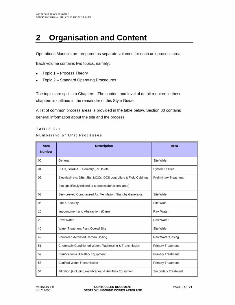
2 Organisation and Content
Operations Manuals are prepared as separate volumes for each unit process area.
Each volume contains two topics, namely;
Topic 1 – Process Theory
Topic 2 – Standard Operating Procedures
The topics are split into Chapters. The content and level of detail required in these
chapters is outlined in the remainder of this Style Guide.
A list of common process areas is provided in the table below. Section 00 contains
general information about the site and the process.
T A B L E 2 - 1
N u m b e r i n g o f U n i t P r o c e s s e s
Area
Number
Description Area
00 General Site Wide
01 PLCs, SCADA, Telemetry (RTUs etc) System Utilities
02 Electrical- e.g. DBs, JBs, MCCs, DCS controllers & Field Cabinets
(not specifically related to a process/functional area)
Preliminary Treatment
03 Services–eg Compressed Air, Ventilation, Standby Generator. Site Wide
05 Fire & Security Site Wide
10 Impoundment and Abstraction (Dam) Raw Water
20 Raw Water Raw Water
40 Water Treatment Plant Overall Site Site Wide
49 Powdered Activated Carbon Dosing Raw Water Dosing
51 Chemically Conditioned Water, Flashmixing & Transmission Primary Treatment
52 Clarification & Ancillary Equipment Primary Treatment
53 Clarified Water Transmission Primary Treatment
54 Filtration (including membranes) & Ancillary Equipment Secondary Treatment

WATERCARE SERVICES LIMITED OPERATIONS MANUAL STRUCTURE AND STYLE GUIDE
VERSION 1.0 CONTROLLED DOCUMENT PAGE 3 OF 21 JULY 2006 DESTROY UNBOUND COPIES AFTER USE
55 Filtered Water Transmission Secondary Treatment
56 GAC Contact & Ancillary Equipment Secondary Treatment
57 GAC Treated Water Transmission Secondary Treatment
58 Mixing System Utilities
59 Chlorine contact System Utilities
70 Alum/PACl plant Raw Water Dosing
71 Polyelectrolyte plant Raw Water Dosing
73 Carbon dioxide plant Filtered Water Dosing
74 Caustic plant Filtered Water Dosing
75 Hypochlorite plant Filtered Water Dosing
76 Gas chlorine plant Filtered Water Dosing
77 Lime plant Filtered Water Dosing
78 Fluoride plant Filtered Water Dosing
79 Sodium bisulphite plant Filtered Water Dosing
81 Citric acid plant Filtered Water Dosing
82 Chemical neutralisation Systems Utilities
85 Washwater recovery Sludge Treatment
86 Sludge dewatering Sludge Tretament
90 Treated Water (General)
91 Treated Water Pumping

WATERCARE SERVICES LIMITED OPERATIONS MANUAL STRUCTURE AND STYLE GUIDE
VERSION 1.0 CONTROLLED DOCUMENT PAGE 4 OF 21 JULY 2006 DESTROY UNBOUND COPIES AFTER USE
3 Standard Content of Manuals
Each Operations Manual shall contain all the contents described in this section 3. The
format in which the information is presented can be changed to suit the nature of the
process as long as all the contents described in this section are included.
3.1 Topic 1 – Process Theory
Topic 1 – Process Theory consists of Chapters described in 3.1.1 – 3.1.6
The purpose of this topic is to provide sufficient description of the operation of automated
processes so as to provide all water treatment staff and process engineers with
adequate information on the objective of each particular process and how this is
achieved in an automatic way.
Topic 1 - Process Theory consists of a lot of information that is contained in well-
prepared Functional Descriptions. Until Operations Manuals are developed for all Water
Treatment Plants, the existing Functional Descriptions shall be used to fill the place of
Topic 1 in the Operations Manuals.
3.1.1 Plant Overview:
The plant overview provides a brief description of the water treatment plant design and a
brief description of how the unit process in this manual contributes to the overall
operation of the plant.
3.1.2 Process Overview:
The Process Overview is to provide an introduction and overview of the process,
referring to the relevant P&ID (and Process Flow Diagram if relevant) and describing the
objectives of the treatment process. The narrative also describes how the unit process
relates to connected processes (reference to P&IDs is a way of doing this). The section
also describes any constraints that exist for the process.
3.1.3 Process Theory / Process Principles
Provide the theory and principles of the process unit in summary form. Provide
references to detailed sources of information that are specific to the technology being
described, and that have been used in the design of the technology.
3.1.4 Design Data
WATERCARE SERVICES LIMITED OPERATIONS MANUAL STRUCTURE AND STYLE GUIDE
VERSION 1.0 CONTROLLED DOCUMENT PAGE 5 OF 21 JULY 2006 DESTROY UNBOUND COPIES AFTER USE
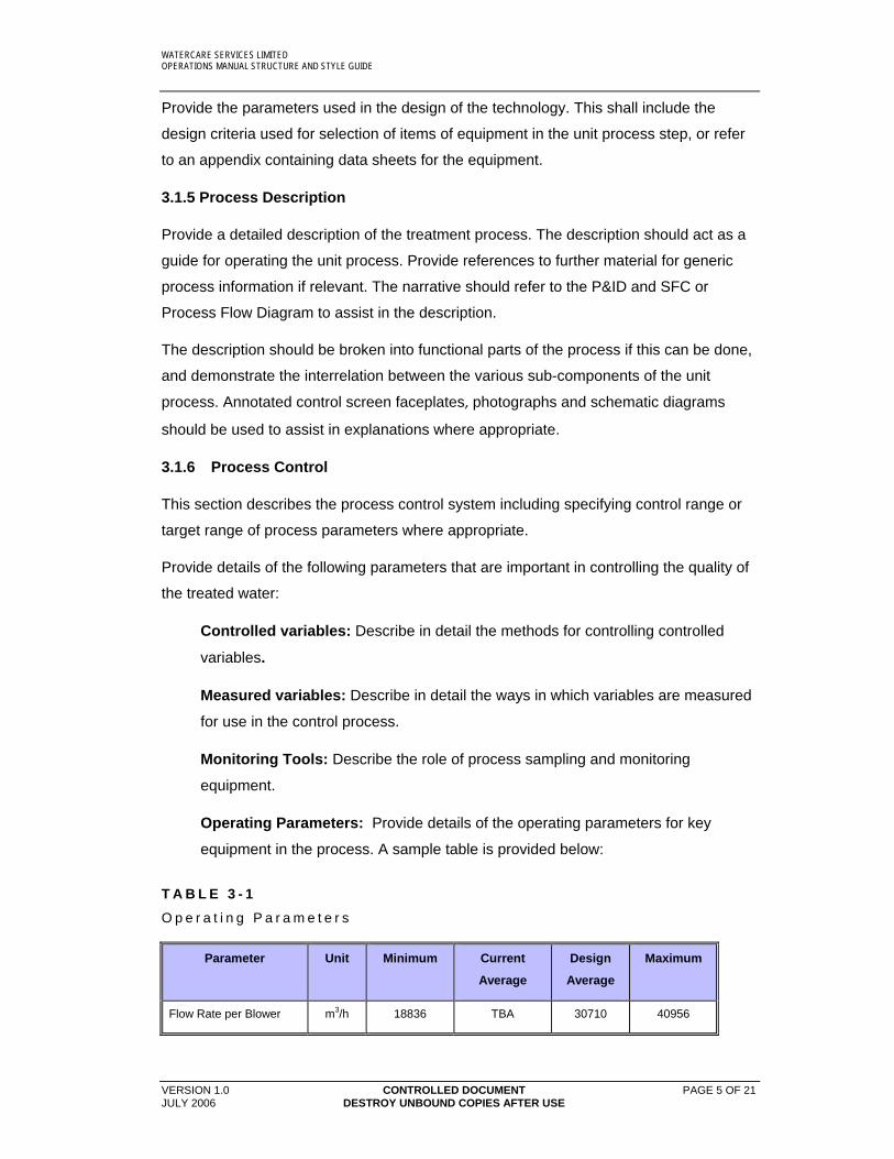
Provide the parameters used in the design of the technology. This shall include the
design criteria used for selection of items of equipment in the unit process step, or refer
to an appendix containing data sheets for the equipment.
3.1.5 Process Description
Provide a detailed description of the treatment process. The description should act as a
guide for operating the unit process. Provide references to further material for generic
process information if relevant. The narrative should refer to the P&ID and SFC or
Process Flow Diagram to assist in the description.
The description should be broken into functional parts of the process if this can be done,
and demonstrate the interrelation between the various sub-components of the unit
process. Annotated control screen faceplates, photographs and schematic diagrams
should be used to assist in explanations where appropriate.
3.1.6 Process Control
This section describes the process control system including specifying control range or
target range of process parameters where appropriate.
Provide details of the following parameters that are important in controlling the quality of
the treated water:
Controlled variables: Describe in detail the methods for controlling controlled
variables.
Measured variables: Describe in detail the ways in which variables are measured
for use in the control process.
Monitoring Tools: Describe the role of process sampling and monitoring
equipment.
Operating Parameters: Provide details of the operating parameters for key
equipment in the process. A sample table is provided below:
T A B L E 3 - 1
O p e r a t i n g P a r a m e t e r s
Parameter Unit Minimum Current
Average
Design
Average
Maximum
Flow Rate per Blower m3/h 18836 TBA 30710 40956
WATERCARE SERVICES LIMITED OPERATIONS MANUAL STRUCTURE AND STYLE GUIDE
VERSION 1.0 CONTROLLED DOCUMENT PAGE 6 OF 21 JULY 2006 DESTROY UNBOUND COPIES AFTER USE

WATERCARE SERVICES LIMITED OPERATIONS MANUAL STRUCTURE AND STYLE GUIDE
VERSION 1.0 CONTROLLED DOCUMENT PAGE 7 OF 21 JULY 2006 DESTROY UNBOUND COPIES AFTER USE
3.2 Topic 2 - Standard Operating Procedures
Topic 2 - Standard Operating Procedures comprises the following three standard
operating procedures, which must be performed to operate each unit process:
SOP - Operator input for Normal (Auto) Operation
SOP - Abnormal (Manual) Operation
Equipment Operating Descriptions
Topic 2 - Standard Operating Procedures are described in detail in Chapters 3.2.1 –
3.2.3
WATERCARE SERVICES LIMITED OPERATIONS MANUAL STRUCTURE AND STYLE GUIDE
VERSION 1.0 CONTROLLED DOCUMENT PAGE 8 OF 21 JULY 2006 DESTROY UNBOUND COPIES AFTER USE
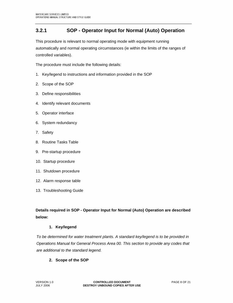
3.2.1 SOP - Operator Input for Normal (Auto) Operation
This procedure is relevant to normal operating mode with equipment running
automatically and normal operating circumstances (ie within the limits of the ranges of
controlled variables).
The procedure must include the following details:
1. Key/legend to instructions and information provided in the SOP
2. Scope of the SOP
3. Define responsibilities
4. Identify relevant documents
5. Operator interface
6. System redundancy
7. Safety
8. Routine Tasks Table
9. Pre-startup procedure
10. Startup procedure
11. Shutdown procedure
12. Alarm response table
13. Troubleshooting Guide
Details required in SOP - Operator Input for Normal (Auto) Operation are described
below:
1. Key/legend
To be determined for water treatment plants. A standard key/legend is to be provided in
Operations Manual for General Process Area 00. This section to provide any codes that
are additional to the standard legend.
2. Scope of the SOP
WATERCARE SERVICES LIMITED OPERATIONS MANUAL STRUCTURE AND STYLE GUIDE
VERSION 1.0 CONTROLLED DOCUMENT PAGE 9 OF 21 JULY 2006 DESTROY UNBOUND COPIES AFTER USE
Define the extent of this SOP by describing the unit process boundaries in Auto mode of
operation.
3. Define responsibilities
Define who is specifically responsible for implementing the SOP
4. Identify documents
Identify all documents relevant to the unit process, including P&IDs, PFDs, SFCs,
schematics and drawings.
5. Operator interface
Provide annotated graphics to describe the operator interface (HMI) with the process
unit under automatic operation. Describe options selections available to the operator for
operation of the process, based on the control equipment.
6. System redundancy
Describe redundancy of equipment within the unit process.
7. Safety
Identify any safety aspects and warnings, including descriptions of all equipment
interlocks and fail sequences for automatic shutdowns.
8. Routine Tasks Table
Provide a table of any operational tasks that are required to ensure operability of the
process unit during a normal mode of operation.
The table is to identify the equipment, define the routine task and the frequency of the
task as per the example below:
T A B L E 3 - 2
R o u t i n e O p e r a t i n g P r o c e d u r e s
Equipment Key Tasks Frequency
1 Odour Control/Safety Check and ensure that all necessary hatches, doors,
guards, and covers are closed to maintain odour
control and prevent the emission of offensive odours.
Daily
9. Pre-startup procedure

WATERCARE SERVICES LIMITED OPERATIONS MANUAL STRUCTURE AND STYLE GUIDE
VERSION 1.0 CONTROLLED DOCUMENT PAGE 10 OF 21 JULY 2006 DESTROY UNBOUND COPIES AFTER USE
List the prerequisites for starting the unit process in Auto mode, including all valve and
equipment numbers, and assuming a normal mode of operation.
10. Startup Procedure
List the steps for starting the unit process in Auto mode, assuming a normal mode of
operation.
11. Shutdown Procedure
List the steps for shutdown of the unit process from Auto mode, assuming a normal
mode of operation.
Identify the failsafe position for each field device.
12. Alarm Response table
Provide a table of the responses required to critical alarms.
The table is to identify instrument, alarm/trip, automatic action and operator action as per
the example below:
T A B L E 3 - 3
A l a r m R e s p o n s e
Instrument Alarm/Trip Automatic Action Operator Action
Blower Header
47-PIT-006 High Pressure Initiate alarm. Investigate cause. Check
pressure sensor.
Low Pressure Initiate alarm. Investigate cause. Check
pressure sensor.
13. Troubleshooting Guide
WATERCARE SERVICES LIMITED OPERATIONS MANUAL STRUCTURE AND STYLE GUIDE
VERSION 1.0 CONTROLLED DOCUMENT PAGE 11 OF 21 JULY 2006 DESTROY UNBOUND COPIES AFTER USE
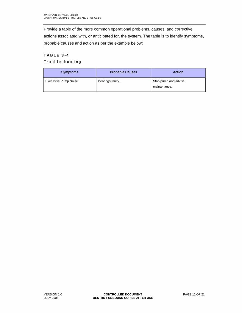
Provide a table of the more common operational problems, causes, and corrective
actions associated with, or anticipated for, the system. The table is to identify symptoms,
probable causes and action as per the example below:
T A B L E 3 - 4
T r o u b l e s h o o t i n g
Symptoms Probable Causes Action
Excessive Pump Noise Bearings faulty. Stop pump and advise
maintenance.

WATERCARE SERVICES LIMITED OPERATIONS MANUAL STRUCTURE AND STYLE GUIDE
VERSION 1.0 CONTROLLED DOCUMENT PAGE 12 OF 21 JULY 2006 DESTROY UNBOUND COPIES AFTER USE
3.2.2 SOP – Abnormal (Manual) Operation
SOPs for abnormal (manual) operation are provided for operation of the unit process, or
part of the unit process, in manual mode, or any operational modes that deviate from the
standard Auto operating mode. Examples include isolation of equipment for maintenance
or tasks that are not of a routine nature.
The procedure must include the following details:
1. Purpose and scope of the procedure
2. Define responsibilities
3. Communication requirements
4. Identify documents
5. Operator interface
6. System redundancy
7. Safety
8. Isolation procedures
9. Control System Response
10. Pre-startup and startup procedures for remote manual startup
11. Pre-startup and startup procedures for local manual startup procedures
12. Troubleshooting
Details required in SOP - Abnormal (Manual) Operation are described below:
1. Purpose and scope of the procedure
Describe the purpose of this SOP and define the extent of the SOP in situations where it
could be ambiguous.
2. Define responsibilities
Define who is specifically responsible for implementing the SOP.
3. Communication requirements

WATERCARE SERVICES LIMITED OPERATIONS MANUAL STRUCTURE AND STYLE GUIDE
VERSION 1.0 CONTROLLED DOCUMENT PAGE 13 OF 21 JULY 2006 DESTROY UNBOUND COPIES AFTER USE
Define any requirements to communicate any issues relating to undertaking the
abnormal SOP, such as informing operating staff of equipment isolations, informing the
Central Control Room of resulting restrictions in water treatment plant output.
4. Identify documents
Identify all documents relevant to the unit process, including P&IDs, PFDs, SFCs,
schematics and drawings.
5. Operator interface
Describe options selections available to the operator for operation of the process in
abnormal operating mode(s), based on the control equipment. Alternatively, provide this
information within the written procedures.
6. System redundancy
Describe redundancy of equipment within the unit process when operating in an
abnormal or manual mode.
7. Safety
Identify any safety aspects and warnings in manual or abnormal modes of operation.
Identify any specific hazards over and above those that exist in auto mode of operation.
8. Isolation Procedures
List the prerequisites and steps for isolating equipment within the unit process. Provide
details of any isolation schemes that exist for multiple devices or grouped process units.
9. Control System Response
Describe the response from control system for specific equipment when the equipment is
in the abnormal mode that is the subject of the SOP.
10. Pre-startup and startup procedures for remote manual startup
List the prerequisites and steps for starting the unit process in remote manual mode,
including all valve and equipment numbers.
11. Pre-startup and startup procedures for local manual startup
procedures
List the prerequisites and steps for starting the unit process in local manual mode,
including all valve and equipment numbers.
WATERCARE SERVICES LIMITED OPERATIONS MANUAL STRUCTURE AND STYLE GUIDE
VERSION 1.0 CONTROLLED DOCUMENT PAGE 14 OF 21 JULY 2006 DESTROY UNBOUND COPIES AFTER USE
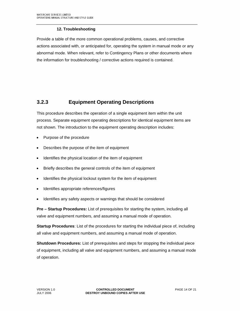
12. Troubleshooting
Provide a table of the more common operational problems, causes, and corrective
actions associated with, or anticipated for, operating the system in manual mode or any
abnormal mode. When relevant, refer to Contingency Plans or other documents where
the information for troubleshooting / corrective actions required is contained.
3.2.3 Equipment Operating Descriptions
This procedure describes the operation of a single equipment item within the unit
process. Separate equipment operating descriptions for identical equipment items are
not shown. The introduction to the equipment operating description includes:
Purpose of the procedure
Describes the purpose of the item of equipment
Identifies the physical location of the item of equipment
Briefly describes the general controls of the item of equipment
Identifies the physical lockout system for the item of equipment
Identifies appropriate references/figures
Identifies any safety aspects or warnings that should be considered
Pre – Startup Procedures: List of prerequisites for starting the system, including all
valve and equipment numbers, and assuming a manual mode of operation.
Startup Procedures: List of the procedures for starting the individual piece of, including
all valve and equipment numbers, and assuming a manual mode of operation.
Shutdown Procedures: List of prerequisites and steps for stopping the individual piece
of equipment, including all valve and equipment numbers, and assuming a manual mode
of operation.
WATERCARE SERVICES LIMITED OPERATIONS MANUAL STRUCTURE AND STYLE GUIDE
DRAFT VERSION A CONTROLLED DOCUMENT PAGE 15 OF 21 JULY 2006 DESTROY UNBOUND COPIES AFTER USE
4 File Format and Style Guidelines
Operations manuals are designed to function as hard copy manuals.
Style guidelines are used to provide consistent organisation throughout the manual.
4.1 Manual Structure
Cover and Flysheet
Operations Manuals shall have a cover page containing the name of the manual, and a
flysheet with the manual name, document control details and header and footer that are
common to all of the manual.
A sample cover and flysheet is provided in Appendix 1, annotated with requirements for
these pages.
Document Control:
The wording of document control requirements is presented in Appendix 1 of this Style
Guide.
Revisions shall be named using consecutive alpha characters and include the word
“Draft” until the document is accepted by Watercare as meeting all requirements. The
first revision supplied to Watercare after acceptance of draft versions shall be named
“Version 1”.
Table of Contents
Operations Manuals shall have a Table of Contents, with page numbers provided
for every chapter of the manual. Appendices shall be named in a list. The table of
contents headings hyperlink the page number to the relevant section, when the
number is clicked with a mouse.
Headers
Headers are used to identify the document and chapter within the manual. Headers
contain the words “Watercare Services Limited” and manual name and are left -justified.
The Unit Process and Chapter name are provided right -justified.

WATERCARE SERVICES LIMITED OPERATIONS MANUAL STYLE GUIDE
DRAFT VERSION A CONTROLLED DOCUMENT PAGE 16 OF 22 JULY 2006 DESTROY UNBOUND COPIES AFTER USE
Sample header:
WATERCARE SERVICES LIMITED FILTRATION ARDMORE WATER TREATMENT PLANT OPERATIONS MANUAL FILTER AIR SCOUR
Footers
Footers are used to identify the document page number, revision status and controlled
document status.
Revision status and date are left –justified. The date of revision is manually input. The
Microsoft Word date stamp feature is not used.
The words “CONTROLLED DOCUMENT” and “DESTROY UNBOUND COPIES AFTER
USE” are centred. The page number is right –justified.
Sample footer:
DRAFT REVISION A CONTROLLED DOCUMENT PAGE 16 OF 21
22/6/00 DESTROY UNBOUND COPIES AFTER USE
Page Numbers
Pages from the flysheet to the sheet with the Table of Contents are numbered with
Roman numerals, ie i, ii, iii, iv.
Pages after the Table of Contents are numbered consecutively to the end of the
document, but excluding appendices. Page numbers are noted as "Page X of Y".

WATERCARE SERVICES LIMITED OPERATIONS MANUAL STRUCTURE AND STYLE GUIDE
DRAFT VERSION A CONTROLLED DOCUMENT PAGE 17 OF 21 JULY 2006 DESTROY UNBOUND COPIES AFTER USE
4.2 Chapter Numbers, Figure Numbers, and Table Numbers
Chapter Numbers
The manual is broken out into discrete chapters. Chapters headings are all linked from
the Table of Contents.
Chapter headings are used as follows:
Heading 1 - Topic
Example: 1. Process Theory
Heading 2 - Section Title
Example: 1.5 Process Control
Heading 3 – Main Section Chapters
Example: 1.5.4 Controlled Variables
Heading 4 – Subsections
Example: 1.5.4.1 Free Available Chlorine
Figure Numbers
Figure numbers consist of the word “Figure” and two numbers separated by a hyphen,
for example F I G U R E 2 - 7
The number before the hyphen is the Section in which the figure appears. The second
number is a consecutive number in the section. In the example above, the figure is the
7th figure in section 2.
Table Numbers
Tables follow the same rules as figures except that the word “Table” is used in place of
the word “Figure”.
WATERCARE SERVICES LIMITED OPERATIONS MANUAL STYLE GUIDE
DRAFT VERSION A CONTROLLED DOCUMENT PAGE 18 OF 22 JULY 2006 DESTROY UNBOUND COPIES AFTER USE
4.3 Word Page Format
Text files are produced in Microsoft Word for Windows, Version 2000 or
subsequent versions.
For portrait pages the justification is set to the left. The inside margin is set at
2.17cm, outside margin 2.54cm, top margin at 2.54cm, and bottom margin at
2.54cm.
For landscape pages the inside margin is set at 2.54cm, outside margin at
2.54cm, top margin at 3.17cm, and the bottom margin at 2.54cm. The pages are
set up with mirror margins.
Body Text
All body text is Book Antiqua, 11-point font, left justified, with 8-point spacing after
the paragraph.
Drawings, Photos and Images
Standard formats are JPG for photos, GIF for diagrams and Autocad Release 13 or later DWG files for drawings.
Heading System
The heading system is designed to work onscreen and in a hard copy.
Heading 1 – Contents page header format.
Font – arial, bold, initial caps, 22pt
Paragraph spacing – space after, 30pt
Border – Bottom (single solid line, ¾; line width)
Heading 2 – Section Title.
Font – arial, bold, initial caps, 22pt
Paragraph spacing – space after, 24pt
Border – Bottom (single solid line, ½; line width)
Outline Numbered – level 2
Indent – hanging 2.54cm
WATERCARE SERVICES LIMITED OPERATIONS MANUAL STRUCTURE AND STYLE GUIDE
DRAFT VERSION A CONTROLLED DOCUMENT PAGE 19 OF 21 JULY 2006 DESTROY UNBOUND COPIES AFTER USE
Heading 3 – Main Section Chapters.
Font – arial, bold, initial caps, 14pt
Paragraph spacing – space before 4pt, after 8pt
Outline Numbered – level 3
Indent – hanging 2.54cm
Heading 4 – Subsections.
Font – arial, bold, initial caps, 12pt
Paragraph spacing – space before 4pt, after 8pt
Outline Numbered – level 4
Indent – hanging 2.54cm
Tabs – 2.86cm, 3.81cm
Heading 5 – Further subsections.
Font – arial narrow, bold, initial caps, 12pt
Paragraph spacing – space before 4pt, after 8pt
Hyperlinks
Hyperlinks are used to jump to a location within the current document from the contents
page. Each page number on the contents page is hyperlinked to its respective page in
the document. A hyperlink is represented by blue text and/or the number being
underlined (as in the case for the tables and figures) which, when the reader clicks on
the text, the document jumps to the respective page location.

WATERCARE SERVICES LIMITED OPERATIONS MANUAL STYLE GUIDE
DRAFT VERSION A CONTROLLED DOCUMENT PAGE 20 OF 22 JULY 2006 DESTROY UNBOUND COPIES AFTER USE
4.4 Writing Style Conventions
In writing, use short sentences in the active voice. Avoid use of passive voice such as “is
to be set” or future tense such as “will be available” when referring to operating
equipment.
Avoid writing that sounds like a specification due to use of words such as ‘shall’. Go from
general descriptions to specific descriptions when describing the operation of equipment.
Use transitions (such as "first" and "next") to indicate the sequence of events. Attempt to
avoid using cumbersome names of stringed modifiers, and be reader friendly.
The conventions used in preparing the operations manual are as follows:
The steps in a procedure are numbered.
Initial capitalisation is used for the names of specific buildings, processes, and
rooms. For example, "The primary sludge pumps are located in the Primary
Sludge Pump Building."
Full capitalisation is used to quote instrument and equipment settings. For
example, turning a switch is described like this: “Select the auto/man selector
switch to AUTO”.
Selecting a DCS panel button is described in square brackets like this: “Select
Screen X to [START]”
Field based instructions are in Courier New 8.5 pt Font.
DCS based instructions are in Book Antiqua Italics 8.5 pt Font.
DCS based automatic sequences are in Book Antiqua 8.5 pt Font.
Provide a name for a specific item of equipment, along with the equipment tag
number. Do not use the equipment tag number alone.
The full name of a piece of equipment is provided before using an acronym or
abbreviation. For example, "The return activated sludge (RAS) pumps are Flygt
submersible pumps. The RAS pumps can be locally controlled."
One-digit numbers are spelt out unless they are units of measurement, or
describe an item number. Numbers of more than one digit are not spelt out. For
example, “… three pumps are … " or “… 12 filters are …” The numbers are not
put in parentheses.
WATERCARE SERVICES LIMITED OPERATIONS MANUAL STRUCTURE AND STYLE GUIDE
DRAFT VERSION A CONTROLLED DOCUMENT PAGE 21 OF 21 JULY 2006 DESTROY UNBOUND COPIES AFTER USE
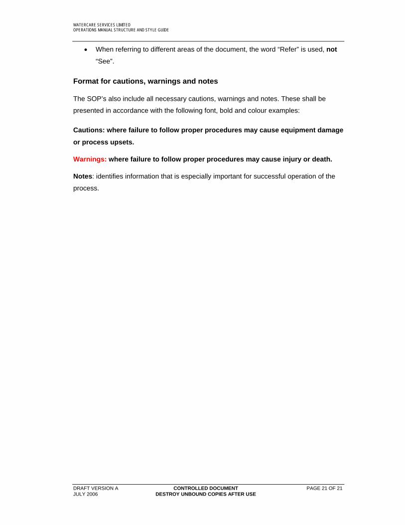
When referring to different areas of the document, the word “Refer” is used, not
“See”.
Format for cautions, warnings and notes
The SOP’s also include all necessary cautions, warnings and notes. These shall be
presented in accordance with the following font, bold and colour examples:
Cautions: where failure to follow proper procedures may cause equipment damage
or process upsets.
Warnings: where failure to follow proper procedures may cause injury or death.
Notes: identifies information that is especially important for successful operation of the
process.
WATERCARE SERVICES LIMITED OPERATIONS MANUAL STYLE GUIDE
DRAFT VERSION A CONTROLLED DOCUMENT JULY 2006 DESTROY UNBOUND COPIES AFTER USE
Appendix 1
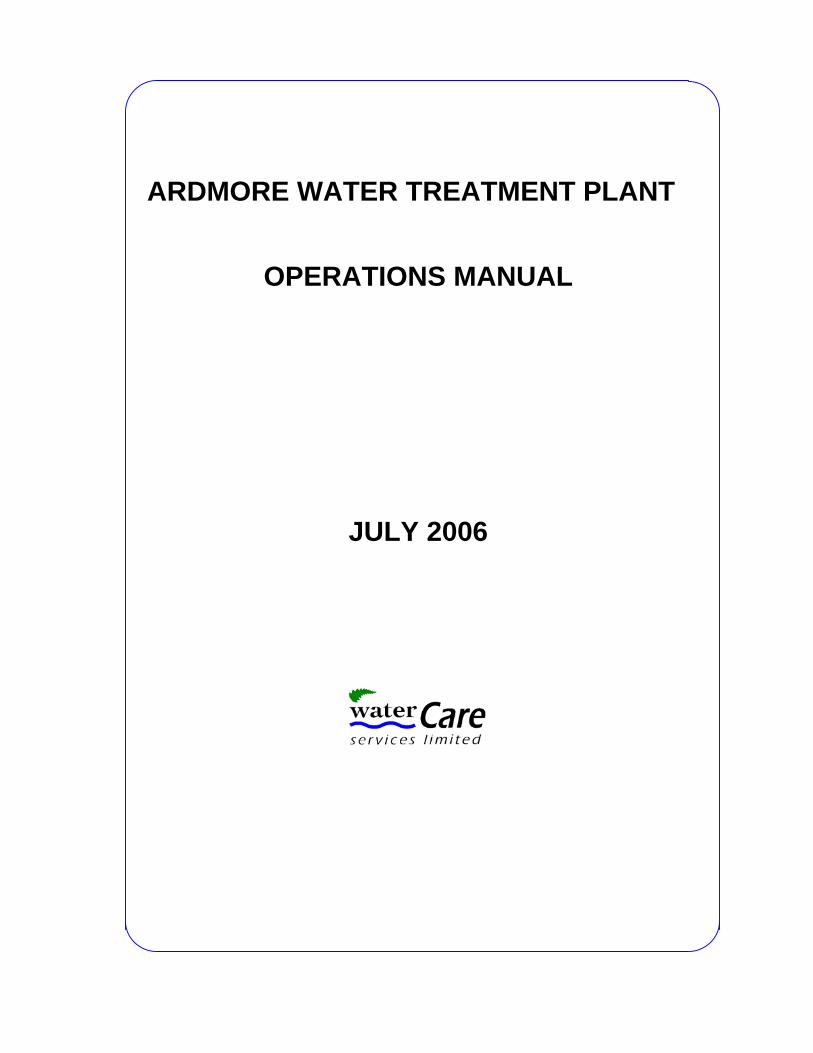
ARDMORE WATER TREATMENT PLANT
OPERATIONS MANUAL
JULY 2006


WATERCARE SERVICES LIMITED FILTRATION ARDMORE WATER TREATMENT PLANT OPERATIONS MANUAL
DRAFT VERSION A CONTROLLED DOCUMENT i JULY 2006 DESTROY UNBOUND COPIES AFTER USE
ARDMORE WATER TREATMENT PLANT
OPERATIONS MANUAL
FILTRATION
This manual is a controlled document and is subject to document control processes. The source document is maintained and updated by the Document Controller. When you print this document the copy is an uncontrolled copy.
Copy # _______________________ of __________________________________
Issued to ____________________________________________________________
Location ____________________________________________________________
Authorised by Document Controller _________________ Date ________________________________
Provide name of Water Treatment Plant
This text and table all required for document
control purposes
All Operations Manuals are to include this line
Unit Process Area or concise descriptor of the Unit Processes
covered in the manual
WATERCARE SERVICES LIMITED
and manual name required in header
Unit process and chapter name required on right of header
Revision # required in footer
WATERCARE SERVICES LIMITED FILTRATION ARDMORE WATER TREATMENT PLANT OPERATIONS MANUAL
DRAFT VERSION A CONTROLLED DOCUMENT ii JULY 2006 DESTROY UNBOUND COPIES AFTER USE
Master Distribution List
Held By Location Copy No. Total Copies

WATERCARE SERVICES LIMITED FILTRATION ARDMORE WATER TREATMENT PLANT OPERATIONS MANUAL
DRAFT VERSION A CONTROLLED DOCUMENT iii JULY 2006 DESTROY UNBOUND COPIES AFTER USE
Amendments
Section Page No. Authorised Date
WATERCARE SERVICES LIMITED FILTRATION ARDMORE WATER TREATMENT PLANT OPERATIONS MANUAL
DRAFT VERSION A CONTROLLED DOCUMENT iv JULY 2006 DESTROY UNBOUND COPIES AFTER USE
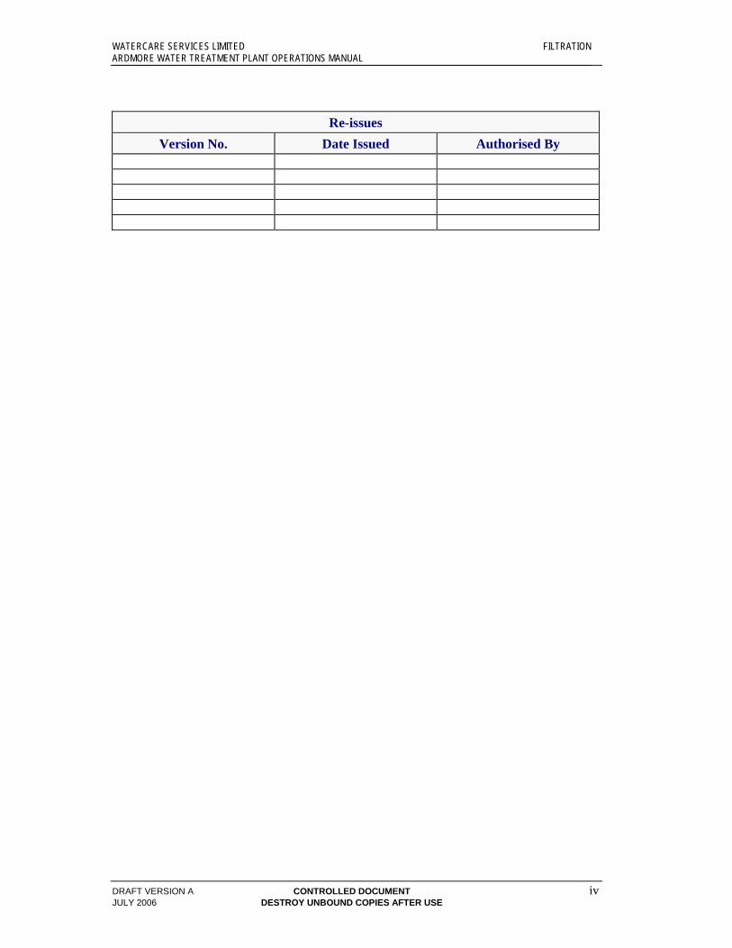
Re-issues
Version No. Date Issued Authorised By