fdny plant operations standard drawings and ... - NYC.gov
54
FDNY PLANT OPERATIONS STANDARD DRAWINGS AND STANDARD SPECIFICATIONS FOR CONSTRUCTION WORK
-
Upload
khangminh22 -
Category
Documents
-
view
5 -
download
0
Transcript of fdny plant operations standard drawings and ... - NYC.gov

FDNY PLANT OPERATIONS STANDARD DRAWINGS AND STANDARD SPECIFICATIONS FOR CONSTRUCTION WORK

PAGE OF INTENT The collection of Standard Drawings and Specifications are to be utilized by the following:
General Contractors Electrical Subs Engineering Firms Consultants Government Agencies Contractors for Private Construction Work

TABLE OF CONTENTS
PART A 1) Standard Drawing # 140; Manhole Cover & Frame2) Standard Drawing # 141; Manhole Construction, Post Setting &
Subsidiary Connections3) Standard Drawing # 144; Manhole Construction, Type ‘A’ & Type ‘B’4) Standard Drawing # 144BS; Slotted Handhole Construction5) Standard Drawing # 144CC; Galvanized Steel Step for Type 'B' F.D.
Manhole6) Standard Drawing # 144E; Drain Plate for FD Manhole and Handhole7) Standard Drawing # 144S; Slotted Manhole Construction for Type ‘A’
Manhole8) Standard Drawing # 144SB; Slotted Manhole Construction for Type ‘B’
Manhole9) Standard Drawing # 144SC; Slotted Manhole Construction for Central
Office Manhole10) Standard Drawing # 145AA; Typical Pole Installation with Chippy Metal
Terminal Box11) Standard Drawing # 146; Typical Pole Installation with NEMA 4X
Enclosure Terminal Box for Large Cable.12) Standard Drawing # 166; Fire Alarm Box Installation in Public Buildings13) Standard Drawing # 167; Fire Alarm Detail ‘M’ Adjust to Grade14) Standard Drawing # 168; Installation of Fire Alarm Pedestal Bumpers15) Standard Drawing # 169; Standard Drawing Required for Installing Fire
Alarm facilities in Fire Houses
PART B 1) Addendum for Replacement of Fire Communications System2) Specifications for Installation of Aerial Cable3) Specifications for Installation of Underground Cable4) Specifications for Installation of Underground Conduits and Posts5) Specifications for Municipal Fire Alarm Installation for ERS at Schools,
Hospitals and Institutions6) Specifications for Municipal Fire Alarm Installation for Mechanical at
Schools, Hospitals and Institutions

FIRE DEPARTMENTBUREAU OF FACILITIES MANAGEMENT
05/20/2009 N.V.
11/21/2014 N.V.

ORIENTATE THE TERMINAL BOX WITH
THE SOLDER SIDE FACING TRAFFIC
FIRE DEPARTMENT
BUREAU OF FACILITIES MANAGEMENT
07/15/2008 N.V.
02/16/2012 N.V.
11/21/2014 N.V.
DATE INT.
REVISIONS
02/23/2017 N.V.
2"
CONCRETE FOOTING
CONCRETE MIX 1:3:5
SUBBASE
WEIGHT: 50 LBS
CONCRETE FOOTING
(TYP)
4"
INSTALL WOODEN BARRIER AS PER FIRE DEPARTMENT
SPECIFICATION FOR INSTALLATION OF UNDERGROUND
CONDUITS AND POSTS, PAGE CP9 OF 12, SECTION 20,
PARAGRAPH 2.
JOSLYN J-5131 HOOK (4 TYP)
JOSLYN J-5125 RACK (4 TYP)
30"
WASHER
11/16/2018 N.V.

REVISIONS
DATE INT.
CITY OF NEW YORKFIRE DEPARTMENT
BUREAU OF FACILITIES MANAGEMENT
MANHOLE CONSTRUCTION
TYPE “A” & “B”
STANDARD DRAWING 144
05/19/2009 N.V.
11/21/2014 N.V.
4"
6"
02/24/2017 N.V.
8" G.I. DRAIN PLATE
SECTION A - A
6" 6"38"
4' - 2"
5' - 10"
4' - 10"
B B
3' - 6"
7' - 0"
8' - 4"
9' - 4"
STREET LEVEL
6" 6"
MANHOLE FRAME & COVER
3/4 “ TWISTED STEEL BARS
10 INCHES CENTER TO CENTER
STEEL BEARING PLATES
6" x 6" x 3/8"
A A
18" 18"
15 3/8" 15 3/8" 12"12"
CONCRETE 1: 2: 4
30O
5"3"
6"
6" I 12.259"
9"
30" MIN.
3' - 0"
6' - 3" MIN.
6"6" 6"
9' - 4"
7' - 0"
18"
18"
SECTION B - B
FIELD STONES
TYPE “B” MANHOLE
8" G.I. DRAIN PLATE
NOTES:1. EACH TYPE ‘A’ MANHOLE SHALL BE EQUIPPED WITH 4 UNDERGROUND CABLE
RACKS EQUAL TO JOSLYN MFG. & SUPPLY CO. RACK NO. J-5125 AND THE
REQUIRED NUMBER OF GALVANIZED STEEL HOOKS EQUAL TO JOSLYN HOOK
NO. J-5131 OR LENGTH AS SPECIFED AND JOSLYN INSULATORS NO. J-5122,
IF SPECIFIED.
2. BRICK CHIMNEY HIGHER THAN 6 COURSES OF BRICK SHALL BE EQUIPPED
WITH STANDARD GALVANIZED STEEL STEP FOR BRICK CONSTRUCTION AS
PER FIRE DEPARTMENT STANDARD DRAWING NO. 144CC AND AS DIRECTED
BY THE ENGINEER.
TYPE “A” MANHOLE
6"
6"
30"18"
NOTES: 1. A PRECAST CONCRETE CHAMBER EQUAL IN ALL RESPECTS TO TYPE F347 OF PRECAST INC. WILL BE
ACCEPTED IN LIEU OF TYPE “B”.
2. EACH TYPE ‘B’ MANHOLE SHALL BE EQUIPPED WITH A GALVANIZED IRON LADDER, HUBBARD OR
EQUAL THERETO AND EACH MANHOLE SHALL BE EQUIPPED WITH 4 UNDERGROUND CABLE RACKS
EQUAL TO HUBBARD #2124 AND THE REQUIRED NUMBER OF GALVANIZED STEEL HOOKS EQUAL TO
HUBBARD “T” HOOKS, LENGTH AS DIRECTED.
JOSLYN J-5125 RACK (4 TYP)
JOSLYN J-5131 HOOK (4 TYP)
HUBBARD #2124 RACK (4 TYP)
HUBBARD “T” HOOK (4 TYP)
8"8"
18"
TO PROVIDE FOR STREET GRADE BEING
LOWERED IN FUTURE, A TWO COURSE
BRICK COLLAR SHALL BE INSTALLED TO
BRING CASTING UP TO PRESENT
STREET GRADE
30"

F
D
NY
¾” ¾”
RAISE LETTERS INTEGRAL WITH COVER
1/8" HIGH
3 PIECE RECESSED SIDEWALK FRAME
AND COVER
CHECKERED SURFACE DIAMOND PATTERN
STYLE “C” CLEAR 1 ¾” FROM EDGE
PRY BAR SLOTS-¼” x 2" ONE ON EACH EDGE
3/8" HEX. HD. CAP SCREWS
½” VENT
VENT
VENT
VENT
A A3
0" 2
4"
36"
42"
SEE DETAIL B
SEE DETAIL C
COVER SLIP MAX. 1/8"
FRAME
COVER
COLLAR
SECTION A - A BB
1 ½”
1 ½”
2"
3/8" 5 ¾
”
1/8" MAX. 3/8" HEX. HD. SCREWS
1/8" RUBBER GASKET FASTENER WITH
APPROVED CEMENT
NOTES:
1. FRAME, COVER & COLLAR TO BE OF CAST IRON. SAME SHALL BE
HOT-DIPPED GALVANIZED.
2. ALL SCREWS & BOLTS SHALL BE OF STAINLESS STEEL.
¼” FLATHEAD SCREWS 8" C.C. SPACING
DETAIL C
DETAIL B
RIB1 ½”
3/8
"
24"
SECTION B - B
6"
GRADE
EACH HANDHOLE SHALL BE EQUIPPED WITH 4
UNDERGROUND CABLE RACKS EQUAL TO HUBBARD
#2124 AND THE REQUIRED NUMBER OF GALVANIZED
STEEL HOOKS EQUAL TO HUBBARD “T” HOOKS,
LENGTH AS DIRECTED.
8" 8" 5 ¾
”
24
"(O
R A
S S
PE
CIF
IED
)
4"
PULLING EYES SHALL BE ¾” DIA. MALLEABLE IRON
U-SHAPED, IMBEDDED AS SHOWN IN CENTER OF WALL.
OPEN END SHALL BE APPROXIMATELY 3".
6"
36"
4"
CABLE HANGERS
SEE NOTE
CONDUIT ENTRANCE TO BE POINTED
CONCRETE PLUG
CONCRETE MIX 1. 2. 4.
NUMBER & SIZE OF CONDUIT AS SPECIFIED
36"
12
"
MIN
.
PULLING EYES-SEE NOTE
3"
6"
8" DRAINPLATE
FIELD
STONES
12
"
6"
C C
16"
12"
36"
24"
24"
36"
44"
16"
SECTION C - C
CITY OF NEW YORKFIRE DEPARTMENT
BUREAU OF FACILITIES MANAGEMENT
STANDARD DWG. 144BS
SLOTTED HANDHOLE
CONSTRUCTION
REVISIONS
DATE INT.
11/21/2014 N.V.

SECTION A - A
CITY OF NEW YORK
FIRE DEPARTMENT
BUREAU OF FACILITIES MANAGEMENT
STANDARD DRAWING No. 144CC
GALVANIZED STEEL STEP
FOR TYPE “B” F.D. MANHOLE
REVISIONS
DATE INT.
06/18/2008 N.V.
01/24/2018 N.V.
11/28/2018 N.V.
MATERIAL:
GALVANIZED STEEL
SECTION B - B
A
A
C
C
B B
SECTION C - C
5/8" DIA.
1/4”
1/4”
5/8" DIA.
1 5/8"

FIRE DEPARTMENT
BUREAU OF FACILITIES MANAGEMENT

FIRE DEPARTMENT
BUREAU OF FACILITIES MANAGEMENT
NOTES
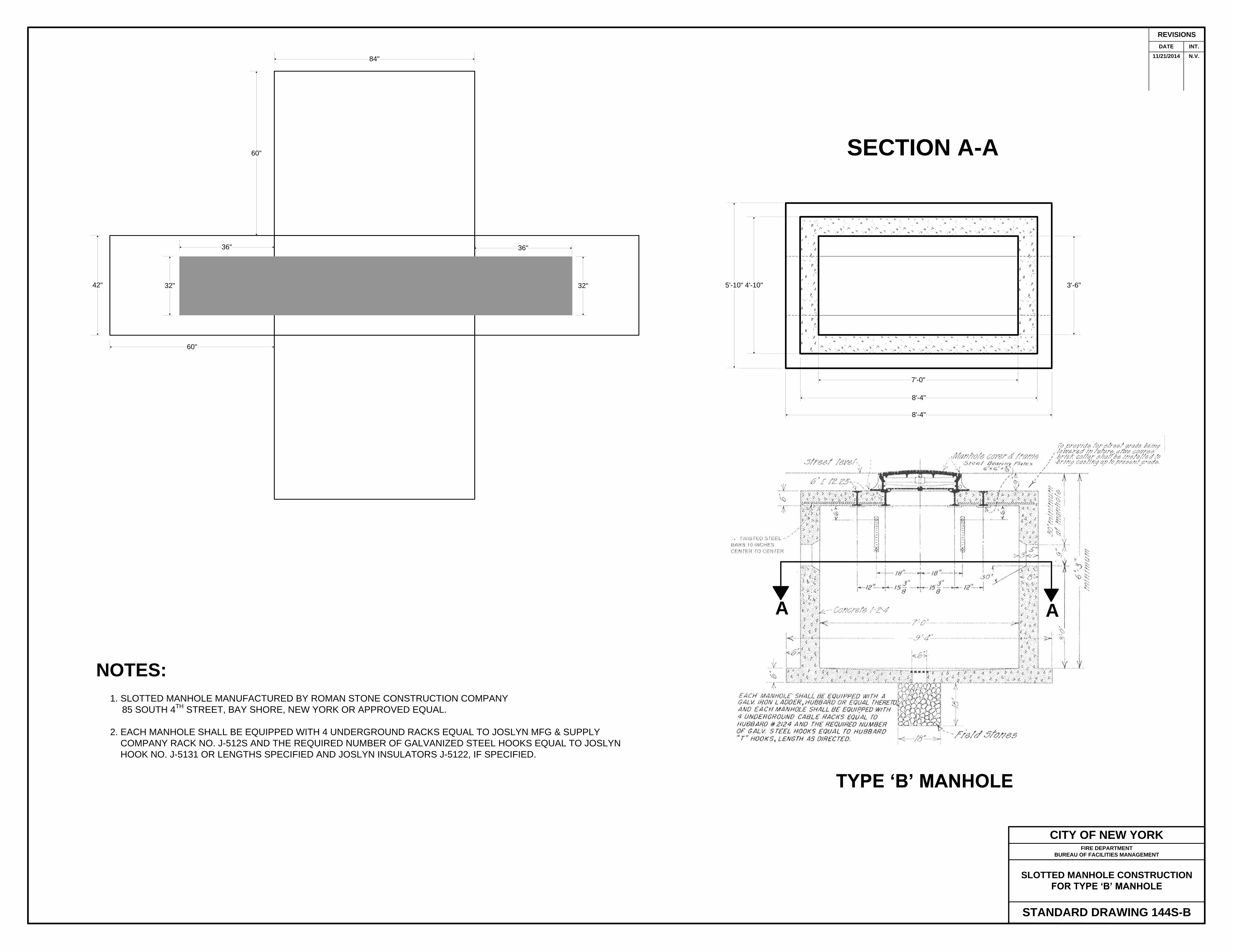
1. SLOTTED MANHOLE MANUFACTURED BY ROMAN STONE CONSTRUCTION COMPANY
85 SOUTH 4TH
STREET, BAY SHORE, NEW YORK OR APPROVED EQUAL.
2. EACH MANHOLE SHALL BE EQUIPPED WITH 4 UNDERGROUND RACKS EQUAL TO JOSLYN MFG
& SUPPLY COMPANY RACK NO. J-5125 AND THE REQUIRED NUMBER OF GALVANIZED STEEL
HOOKS EQUAL TO JOSLYN HOOK NO. J-5131 OR LENGTH AS SPECIFIED AND JOSLYN INSULATORS
NO. J-5122, IF SPECIFIED.
3. BRICK CHIMNEY HIGHER THAN 6 COURSES OF BRICK SHALL BE EQUIPPED WITH STANDARD
GALVANIZED STEEL STEP FOR BRICK CONSTRUCTION AS PER BOROUGH PRESIDENT. MANHATTAN
DRAWING 28721 AND AS DIRECTED BY THE ENGINEER.
AA
SECTION A-A
16"
5'-10" 4'-10" 3'-6"
7'-0"
8'-4"
8'-4"
A A
REVISIONS
DATE INT.
CITY OF NEW YORKFIRE DEPARTMENT
BUREAU OF FACILITIES MANAGEMENT
SLOTTED MANHOLE CONSTRUCTION
FOR TYPE ‘B’ MANHOLE
STANDARD DRAWING 144S-B
NOTES:
1. SLOTTED MANHOLE MANUFACTURED BY ROMAN STONE CONSTRUCTION COMPANY
85 SOUTH 4TH
STREET, BAY SHORE, NEW YORK OR APPROVED EQUAL.
2. EACH MANHOLE SHALL BE EQUIPPED WITH 4 UNDERGROUND RACKS EQUAL TO JOSLYN MFG & SUPPLY
COMPANY RACK NO. J-512S AND THE REQUIRED NUMBER OF GALVANIZED STEEL HOOKS EQUAL TO JOSLYN
HOOK NO. J-5131 OR LENGTHS SPECIFIED AND JOSLYN INSULATORS J-5122, IF SPECIFIED.
SECTION A-A
TYPE ‘B’ MANHOLE
36"
32"
36"
32"42"
60"
60"
84" 11/21/2014 N.V.

REVISIONS
DATE INT.
NOTES:
1. SLOTTED MANHOLE MANUFACTURED BY ROMAN STONE CONSTRUCTION COMPANY
85 SOUTH 4TH
STREET, BAY SHORE, NEW YORK OR APPROVED EQUAL.
CITY OF NEW YORKFIRE DEPARTMENT
BUREAU OF FACILITIES MANAGEMENT
SLOTTED MANHOLE CONSTRUCTION
FOR CENTRAL OFFICE MANHOLE
STANDARD DRAWING 144S-C
8'-4" 6'-0"
8'-4"
9'-4"
SECTION A-A
7'-4"
7'-0"
4'-2"
11"
11"
8'-0"
6"
MANHOLE SHALL BE EQUIPPED WITH A GALVANIZED IRON
LADDER, HUBBARD OR EQUAL THERETO, AND ALSO EQUIPPED
WITH 4 UNDERGROUND CABLE RACKS EQUAL TO HUBBARD
#2124 AND THE REQUIRED NUMBER OF GALVANIZED STEEL
HOOKS EQUAL TO HUBBARD “T” HOOKS, LENGTH AS DIRECTED.
¾ INCH TWISTED STEEL BARS
10 INCHES CENTER TO CENTER
6'-3"
4'-2"
6'-3"
4'-2"5'-0"
8'-0"
8'-0"
7'-0"
21"21"
MANHOLE FRAME & COVER
STEEL BEARING PLATES 6" x 6" x 3/8"
STREET LEVEL
6"
6"
6"
FIELD STONE18"
18"
7'-0"
9'-4"
CONCRETE 1-2-4
A A
11/21/2014 N.V.

CITY OF NEW YORKFIRE DEPARTMENT
BUREAU OF FACILITIES MANAGEMENT
TYPICAL POLE INSTALLATION WITH
CHIPPY METAL TERMINAL BOX
STANDARD DRAWING 145AA
REVISIONS
DATE INT.
01/17/1991 N.V.
10/10/1991 N.V.
10/17/1991 N.V
06/16/2008 N.V.
05/19/2009 N.V.
DRAWN 09/03/1964 P. McD.
5 F
EE
T I
N A
VE
RA
GE
SO
IL F
RO
M G
RA
DE
#10 A.W.G. GROUND WIRE CONNECTED TO GROUND
ROD THRU A TYPICAL ‘B’ COPPERWELD CLAMP WITH
SQUARE HEADSET SCREW OR EQUAL
SIDEWALK
CURB
STREET
“P.V.C. CONDUIT
PITCH TO MANHOLE
4 INCH P.V.C. COUPLING
4 INCH P.V.C. STANDARD FIRE DEPT.
90 DEGREE BEND
6 FEET BY ½ INCH SECTIONAL COPPERWELD GROUND ROD
OR RODS TO GIVE A GROUND RESISTANCE NOT MORE THAN
75 OHMS
NOT TO SCALE
RISER PIPES MUST BE INSTALLED
ON POLE OPPOSITE TRAFFIC
MARATHON #313 TERMINAL STRIP TO BE SUPPLIED
BY FIRE DEPARTMENT
DETAIL “B”
STRAP – 2 HOLE HEAVY DUTY OR ONE HOLE
CAST IRON TYPE SPACED 2 FEET APART
HALF INCH GALVANIZED CONDUIT
HALF INCH COUPLING SEALED WITH
DUCT SEAL
#10 GROUND WIRE
12"
DETAIL “A”CABLE TERMINATION
(COVER REMOVED)
NOT TO SCALE
MARATHON #313 TERMINAL STRIP TO BE
SUPPLIED BY FIRE DEPARTMENT
SIZE AND TYPE OF COUPLING TO BE
DETERMINED BY FIRE DEPARTMENT
GALVANIZED STEEL CONDUIT (SIZE TO BE
DETERMINED BY FIRE DEPARTMENT)
MOUNTING HEIGHTPOLE METAL CHIPPY BOX TO BE MOUNTED ON
POLE 16' FROM THE BOTTOM OF THE BOX TO THE
SIDEWALK GRADE
03/09/2012 N.V.
COUPLING SEALED WITH DUCT SEAL
(SIZE TO CONDUIT)
01/06/2014 N.V.
11/21/2014 N.V.
BLUE
WHITE
WHITE
WHITE
WHITE
ORANGE
GREEN
BROWN
#10 A.W.G. SOLID COPPER GREEN GROUND WIRE
TO GROUND ROD
CABLE TERMINAL TO BE EQUAL TO SHERMAN
SQ-8 OR BURNDY QA8C-8 CONNECTOR
¼’ - 20 BRASS SCREW
INSTALL #14 A.W.G. SOLID COPPER GREEN GROUND
WIRE TO TERMINAL STRIP AND FOIL OF CABLE
2 INCH GALVANIZED STEEL CONDUIT
3/4 INCH GALVANIZED STEEL CONDUIT
FASTEN PLASTIC STRAP
TO WALL OF BOX
ALL WIRES SHALL BE LONG ENOUGH TO
REACH ALL TERMINALS
4 PAIR FIRE ALARM CABLE
WIRE COVERED WITH PLASTIC TAPE
(SCOTCH No. 88T)
MARATHON #313 TERMINAL STRIP TO
BE SUPPLIED BY FIRE DEPARTMENT
06/11/2018 N.V.
CITY OF NEW YORKFIRE DEPARTMENT
BUREAU OF FACILITIES MANAGEMENT
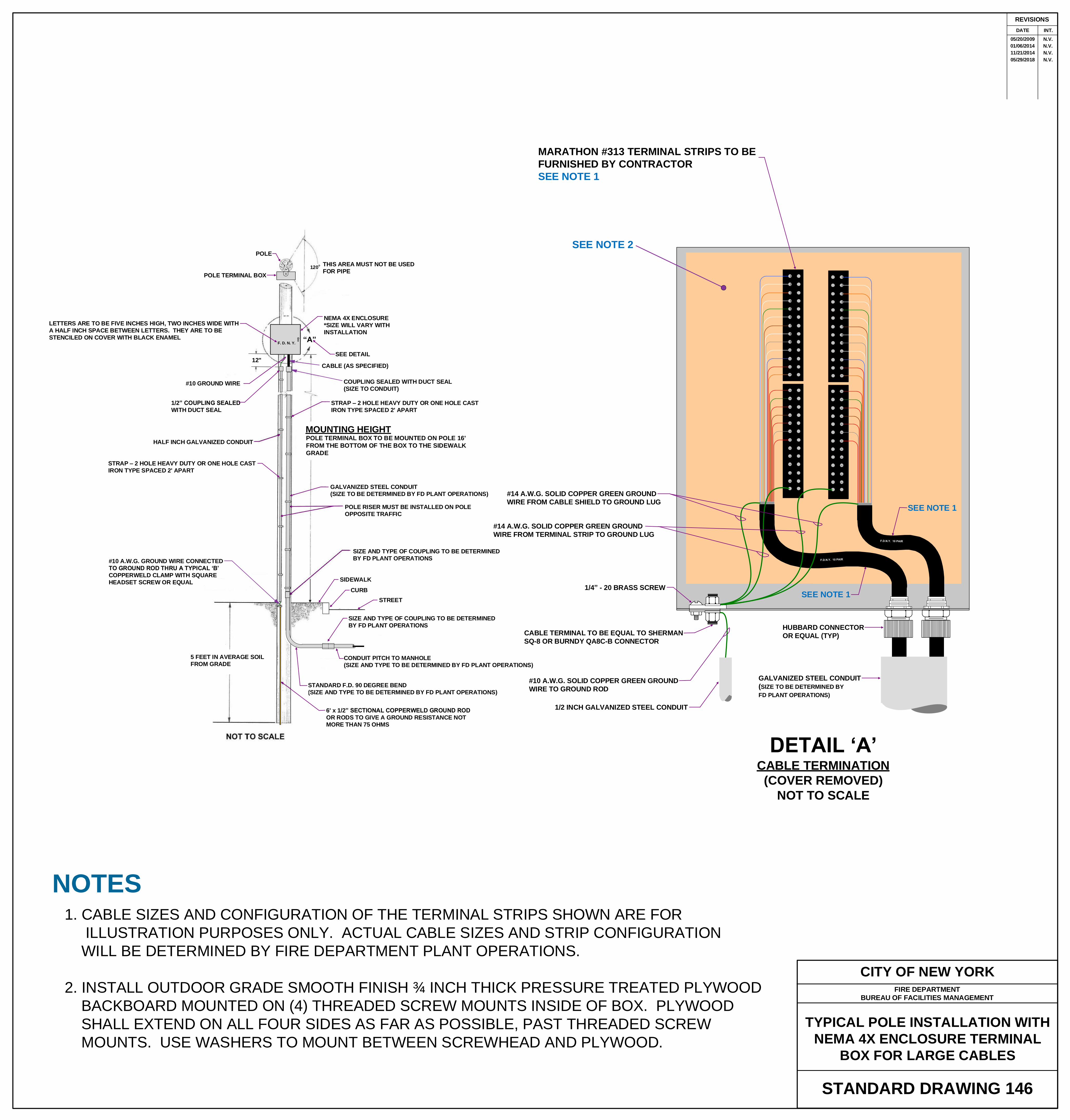
STANDARD DRAWING 146
TYPICAL POLE INSTALLATION WITH
NEMA 4X ENCLOSURE TERMINAL
BOX FOR LARGE CABLES
REVISIONS
DATE INT.
05/20/2009 N.V.
CABLE TERMINAL TO BE EQUAL TO SHERMAN
SQ-8 OR BURNDY QA8C-8 CONNECTOR
POLE
POLE TERMINAL BOX
120o THIS AREA MUST NOT BE USED
FOR PIPE
NEMA 4X ENCLOSURE
*SIZE WILL VARY WITH
INSTALLATION
LETTERS ARE TO BE FIVE INCHES HIGH, TWO INCHES WIDE WITH
A HALF INCH SPACE BETWEEN LETTERS. THEY ARE TO BE
STENCILED ON COVER WITH BLACK ENAMELF. D. N. Y.
12"
#10 GROUND WIRE
1/2” COUPLING SEALED
WITH DUCT SEAL
“A”
SEE DETAIL
CABLE (AS SPECIFIED)
COUPLING SEALED WITH DUCT SEAL
(SIZE TO CONDUIT)
STRAP – 2 HOLE HEAVY DUTY OR ONE HOLE CAST
IRON TYPE SPACED 2' APART
HALF INCH GALVANIZED CONDUIT
MOUNTING HEIGHTPOLE TERMINAL BOX TO BE MOUNTED ON POLE 16'
FROM THE BOTTOM OF THE BOX TO THE SIDEWALK
GRADE
STRAP – 2 HOLE HEAVY DUTY OR ONE HOLE CAST
IRON TYPE SPACED 2' APART
GALVANIZED STEEL CONDUIT
(SIZE TO BE DETERMINED BY FD PLANT OPERATIONS)
POLE RISER MUST BE INSTALLED ON POLE
OPPOSITE TRAFFIC
SIZE AND TYPE OF COUPLING TO BE DETERMINED
BY FD PLANT OPERATIONS
SIDEWALK
CURB
STREET
CONDUIT PITCH TO MANHOLE
(SIZE AND TYPE TO BE DETERMINED BY FD PLANT OPERATIONS)
STANDARD F.D. 90 DEGREE BEND
(SIZE AND TYPE TO BE DETERMINED BY FD PLANT OPERATIONS)
6' x 1/2” SECTIONAL COPPERWELD GROUND ROD
OR RODS TO GIVE A GROUND RESISTANCE NOT
MORE THAN 75 OHMS
5 FEET IN AVERAGE SOIL
FROM GRADE
#10 A.W.G. GROUND WIRE CONNECTED
TO GROUND ROD THRU A TYPICAL ‘B’
COPPERWELD CLAMP WITH SQUARE
HEADSET SCREW OR EQUAL
GALVANIZED STEEL CONDUIT
(SIZE TO BE DETERMINED BY
FD PLANT OPERATIONS)
#10 A.W.G. SOLID COPPER GREEN GROUND
WIRE TO GROUND ROD
CABLE TERMINAL TO BE EQUAL TO SHERMAN
SQ-8 OR BURNDY QA8C-B CONNECTOR
1/4” - 20 BRASS SCREW
1/2 INCH GALVANIZED STEEL CONDUIT
SIZE AND TYPE OF COUPLING TO BE DETERMINED
BY FD PLANT OPERATIONS
DETAIL ‘A’CABLE TERMINATION
(COVER REMOVED)
NOT TO SCALE
MARATHON #313 TERMINAL STRIPS TO BE
FURNISHED BY CONTRACTOR
SEE NOTE 1
1
2
3
4
5
6
7
8
9
10
11
12
13
14
15
16
17
18
19
20
21
22
23
24
25
1
2
3
4
5
6
7
8
9
10
11
12
13
14
15
16
17
18
19
20
21
22
23
24
25
SEE NOTE 2
HUBBARD CONNECTOR
OR EQUAL (TYP)
NOTES
1. CABLE SIZES AND CONFIGURATION OF THE TERMINAL STRIPS SHOWN ARE FOR
ILLUSTRATION PURPOSES ONLY. ACTUAL CABLE SIZES AND STRIP CONFIGURATION
WILL BE DETERMINED BY FIRE DEPARTMENT PLANT OPERATIONS.
2. INSTALL OUTDOOR GRADE SMOOTH FINISH ¾ INCH THICK PRESSURE TREATED PLYWOOD
BACKBOARD MOUNTED ON (4) THREADED SCREW MOUNTS INSIDE OF BOX. PLYWOOD
SHALL EXTEND ON ALL FOUR SIDES AS FAR AS POSSIBLE, PAST THREADED SCREW
MOUNTS. USE WASHERS TO MOUNT BETWEEN SCREWHEAD AND PLYWOOD.
01/06/2014 N.V.
11/21/2014 N.V.
05/29/2018 N.V.
#14 A.W.G. SOLID COPPER GREEN GROUND
WIRE FROM CABLE SHIELD TO GROUND LUG
#14 A.W.G. SOLID COPPER GREEN GROUND
WIRE FROM TERMINAL STRIP TO GROUND LUG
SEE NOTE 1
SEE NOTE 1

REVISIONS
DATE INT.
FDNY
COMM
GRD
RED METAL MARKER
GROUND TAG
GENERAL RECOMMENDATION FOR LOCATION, MOUNTING HEIGHT AND NICHE
FOR THE INSTALLATION OF N.Y. CITY FIRE ALARM
ERS OR MECHANICAL HOUSING
NYC FIRE ALARM BOX DETAIL
NYC FIRE DEPT. BUILDING PULL BOX DETAIL
(12" x 12" x 6")
NOTE:
1. 4 PAIR FIRE ALARM CABLE TO BE INSTALLED CONTINUOUSLY FROM JUNCTION BOX INSIDE BUILDING TO THE FIRE ALARM
POST.
2. CONTRACTOR SHALL LEAVE 5 FEET OF SLACK INSIDE EXISTING FIRE ALARM POST FOR F.D. COMMUNICATIONS
ELECTRICIANS TO TERMINATE.
3. INSTALL 1-4 INCH PVC CONDUIT (SCHEDULE 40, U.L.651) AND 1-4 INCH PVC 90 DEGREE BEND IN THE NEWLY INSTALLED
FIRE ALARM POST OR 1-4 INCH PVC CONDUIT (SCHEDULE 40, U.L.651), 1-4 INCH PVC 90 DEGREE BEND AND ONE 4 INCH TO
TWO INCH REDUCER FOR WOOD UTILITY POLE OR 1-3 INCH PVC CONDUIT (SCHEDULE 40, U.L.651) AND 1-3 INCH PVC 90
DEGREE BEND IN EXISTING FIRE ALARM POST.
4. SEE FIRE DEPARTMENT SPECIFICATIONS FOR FIRE ALARM INSTALLATION AT SCHOOLS, HOSPITALS AND INSTITUTIONS.
5. SEE FIRE DEPARTMENT SPECIFICATIONS FOR INSTALLATION OF UNDERGROUND CONDUIT AND POSTS.
6. SEE FIRE DEPARTMENT SPECIFICATIONS FOR INSTALLATION OF UNDERGROUND CABLE.
7. SEE FIRE DEPARTMENT ADDENDUM FOR REPLACEMENT OF FIRE COMMUNICATIONS SYSTEM.
8. INSTALL EXPANSION FOAM SEALANT IN CONDUIT OPENING OF THE BUILDING PULL BOX, THE SCHOOL LEG AND POST LEG
CONDUITS IN MANHOLE AND THE CONDUIT INSIDE THE FIRE ALARM POST.
9. SEE FIRE DEPARTMENT T.B. DRAWING FOR SPECIFIC DETAILS PER PROJECT.
10/17/2006 N.V.
07/16/2008 N.V.
02/06/2009 N.V.
05/19/2009 N.V.
12/15/2010 N.V.
12/21/2011 N.V.
01/23/2012 N.V.
03/16/2012 N.V.
03/19/2012 N.V.
03/26/2012 N.V.
10/25/2013 N.V.
04/09/2014 N.V.
08/11/2014 N.V.
09/10/2014 N.V.
A13 ½”
B
C
7 ½”4"
A
A
SEC A-A
(1) 3/4” GALVANIZED
LOCKNUT
(1) 3/4” GALVANIZED
BUSHING
(1) 3/4” GALVANIZED
NIPPLE
(1) 3/4” GALVANIZED
TELEPHONE ELBOW
ALSO USE GALVANIZED
LOCKNUTS AND BUSHINGS
TO INSTALL #1900 BOX
FIRE ALARM HOUSING
NICHE BACKBOARD
F.A.
HOUSING
3"
SEE NOTE 5
CUT HOLE IN FRONT OF 4" SQUARE
1900 OUTLET BOX IN BACKBOARD
ONLY
1" SOLID WOOD BACKBOARD
FOR FIRE ALARM HOUSING
1"
NOTES:1. SEE F.D. SPECIFICATION FOR FIRE ALARM INSTALLATION IN PUBLIC BUILDINGS.
2A. FIRE ALARM HOUSING SHALL BE LOCATED BEHIND SECURITY DESK UNLESS OTHERWISE NOTED.
2B. FIRE ALARM HOUSING IS TO BE PURCHASED FROM FIRE DEPARTMENT.
2C. FIRE ALARM HOUSING MAY BE SURFACE MOUNTED. SEE STD. SPECIFICATION FOR FIRE ALARMINSTALLATION AT SCHOOLS, HOSPITALS & INSTITUTIONS, SECTION 2C PAGE BE3 OF 4.
3A. BACKBOARD IS TO BE MADE OF SOLID WOOD ONLY. NO PLYWOOD WILL BE ACCEPTABLE.
3B. ONE INCH THICK BACKBOARD IS TO BE PAINTED RED AND INSTALLED FLUSH WITH WALL ANDSECURED IN AN APPROVED MANNER, INDEPENDENT OF THE FIRE ALARM HOUSING.
3C. THE MINIMUM SIZE FOR THE BACKBOARD IS TO BE NO SMALLER THAN THE SIZE OF THE FIREALARM HOUSING AND NOT TO EXCEED THE SIZE OF THE NICHE IN WALL.
4. 1900 OUTLET BOX TO BE ACCESSABLE BY REMOVING FIRE ALARM HOUSING.
5. CUT OPENING IN BACKBOARD FOR SETTING OUTLET BOX FLUSH WITH BACKBOARD.
3/4 INCH GALVANIZED CONDUIT
TO F.A. JUNCTION BOX
GALVANIZED STEEL (4"x4")
DEEP OUTLET BOX (1900)
ERS MECHANICAL
A 17" 14 1/2”
B 15" 12 1/2”
C 9 1/2" 10"
MAKE LETTERS 2" WIDE WITH HALF
INCH SPACE BETWEEN LETTERS
STENCIL ON COVER WITH
BLACK ENAMEL
FDNY
COMMDRILL CLEARANCE HOLES FOR
B-32 RH MACHINE SCREWS (4 REQ.)
3" TO 4"
1900 BOX
BEHIND WALL
11
1/2
"1
2 1
/4"
9 3/4"12 1/4" 3
/8"
11
1/4
"
9 3/4"12 1/4"
11 1/4"
3/8"
12
IN
CH
IN
SID
E D
IME
NS
ION
1/8"
12 INCH INSIDE DIMENSION
3/8"1/2"
1/8"
3. INSTALL EXPANSION FOAM SEALANT AT CONDUIT OPENING.
6 1
/4"
6" I
NS
IDE
DIM
EN
SIO
N
1" 1" SOLID WOOD
BACKBOARD
SEE NOTE 3
SEE NOTE 3
09/15/2014 N.V.
11/21/2014 N.V.
FIRE DEPARTMENT
BUREAU OF FACILITIES MANAGEMENT
Nema 4X Stainless Steel Enclosure junction box shall be installed in the Communications Room and not be obstructed by
pipes or any other objects, approximately 7 ½ feet above the finished floor and mount on 1/2 inch Kindorf on wall. If this
cannot be achieved, then the contractor must consult with the Fire Department’s Plant Operations Engineering Unit for
direction. This box SHALL NOT be installed in toilets, dressing rooms, locker rooms, cafeterias or any room where
there is a secondary lock.
11/28/2014 N.V.
6 1/2”
APPROXIMATE DIMENSIONS
A = 16 1/8"
B = 26 1/2"
C = 3"
D = 4 3/4"
E = 4"
F = 52"
G = 73 3/4"
H = 69 3/4"
L = 1"
APPROXIMATE DIMENSIONS
A = 16"
B = 24"
C = 3"
D = 4 3/4"
E = 1"
F = 52"
H = 70 1/4"
I = 71 1/4"
J = 66"
K = 5 1/4"
L = 1"
3 3/4" MAXIMUM NOT TO BE EXCEEDED UNLESS
AUTHORIZED BY FDNY ENGINEERING UNIT
26 1/2"
9 1/2"
E
6½”
3 3/4" MAXIMUM NOT TO BE EXCEEDED UNLESS
AUTHORIZED BY FDNY ENGINEERING UNIT
E
I
12/01/2014 N.V.12/05/2014 N.V.
F.D. OR TEL. CO.
MANHOLE
SEE NOTE 3
SEE NOTE 8
SEE NOTE 8
1 1/2” GALVANIZED STEEL CONDUIT &
1-4 PAIR FIRE ALARM CABLE
1 No. 10 A.W.G. GROUND WIRE (GREEN) IN 3/4” GALVANIZED
STEEL CONDUIT FROM THE GROUND BUS BAR THROUGH THE
JUNCTION BOX AND INTO THE FIRE ALARM BOX.
NEAREST F.A. POST OR
WOOD UTILITY POLE
1-4" P.V.C. CONDUIT (SCHEDULE 40)
AND 1-4 PAIR FIRE ALARM CABLE
(F.D. SPEC. NO. 12-C-9/87A)
WIDE RADIUS BEND
F.D. SERVICE ENTRANCE
PULL BOX
JUNCTION BOX
(INSTALL ON 1/2“
KINDORF)
FIRE ALARM BOX3 #14 A.W.G. WIRES (RED, BLACK, BLUE) AND
1 #10 A.W.G. GROUND WIRE (GREEN) IN 3/4“
GALVANIZED STEEL CONDUIT
NYC FIRE ALARM RISER DETAIL
12/07/2014 N.V.
NOTES: 1. BOX AND COVER TO BE FABRICATED OF STAINLESS STEEL
OR GALVANIZED STEEL.
2. FOUR (4) 8-32 ROUND HEAD MACHINE SCREWS, 3/8 INCH
LONG, STAINLESS STEEL, TO BE SUPPLIED WITH EACH BOX.
3. INSTALL EXPANSION FORM SEALANT AT CONDUIT OPENING.
GROUND BAR
METALLIC INSULATED GROUND
BUSHING METALLIC INSULATED GROUND
BUSHING3/4" GALVANIZED STEEL CONDUIT
3/4 INCH GALVANIZED STEEL CONDUIT
NEMA 4X STAINLESS STEEL
ENCLOSURE (16" x 12" x 6")
LOCK NUTS
#14 A.W.G. WIRE TO
BE SOLDERED TO
FOIL OF CABLE
4 PAIR FIRE ALARM CABLE
1 1/2“ GALVANIZED STEEL CONDUIT
BLUE
WHITE
ORANGE
WHITE
GREEN
WHITE
BROWN
WHITE
1/2" E.M.T.
CLAMP
GROUND
WIRE
4 PAIR FIRE ALARM
CABLE
BONDING BUSHING
13 WIRE TERMINAL STRIP
(MARATHON #313)
LEAVE SUFFICIENT SLACK FOR EACH WIRE
TO REACH EVERY TERMINAL
CABLE CONDUCTORS SHALL
BE PROPERLY LACED AND/OR
TAPED AND FORMED SO AS
NOT TO TOUCH THE SIDES OR
BACK OF THE ENCLOSURE
2"WRAP WITH TWO LAYERS
OF SCOTCH TAPE
#10-24 R.H.M.S.
#10-24 HEX NUT
BONDING BUSHING
TO BUILDING GROUND
BUS BAR
TO FIRE ALARM BOX
(3) #14 A.W.G. WIRE TO RUN FROM THE
JUNCTION BOX TO THE FIRE ALARM BOX.
FD COMMUNICATIONS ELECTRICIANS TO
TERMINATE IN JUNCTION BOX
STENCIL ON COVER WITH
BLACK ENAMEL
MAKE LETTERS TWO INCHES WIDE
WITH HALF INCH SPACE BETWEEN
LETTERS
INSTALL 1/2 INCH
KINDORF
NYC FIRE DEPT. JUNCTION BOX DETAIL
(NEMA 4X STAINLESS STEEL ENCLOSURE:
(16" x 12" x 6")
#10 A.W.G. WIRE TO RUN CONTINUOUSLY FROM
THE BUILDING GROUNDING BUS BAR TO THE
FIRE ALARM BOX
INSTALLATION OF FIRE ALARM CABLE
TO FIRE DEPT. JUNCTION BOX
METALLIC INSULATED GROUND
BUSHING
CITY OF NEW YORK
FIRE ALARM BOX INSTALLATION
IN PUBLIC BUILDINGS
STANDARD DWG. 166
12/17/2014 N.V.

REVISIONS
DATE INT.
05/19/2009 N.V.
CITY OF NEW YORKFIRE DEPARTMENT
BUREAU OF FALITIES MANAGEMENT
FIRE ALARM DETAIL ‘M’
ADJUST TO GRADE
STANDARD DRAWING 167DRAWN 09/29/1992 G.K.
4"
HEIGHT REQUIRED
02/10/2012 N.V.
EXTEND EXISTING CONDUIT TO
3 INCHES ABOVE NEW SIDEWALK
GRADE AND INSTALL END BELL
11/21/2014 N.V.

02/03/2012 N.V.
NOTES:
1. CONCRETE AROUND FENDERS TO BE ONE (1) FOOT SQUARE AND TWO (2) FEET DEEP.
2. USE GALVANIZED STEEL FIVE INCH DIAMETER PIPE AND PAINT THE EXPOSED PIPE
FEDERAL SAFETY YELLOW, TWO COATS. FIRE DEPARTMENT
BUREAU OF FACILITIES MANAGEMENT
11/21/2014 N.V.

FDNY
COMM
TERMINAL
CABINET
3" TO 4"
STENCIL ON COVER WITH
BLACK ENAMEL
03/28/2014 N.V.
04/11/2014 N.V.
FDNY
COMM
PULL BOX
STENCIL ON COVER WITH
BLACK ENAMEL
3" TO 4"
DRILL CLEARANCE HOLES
FOR B-32 RH MACHINE SCREWS
(4 REQ.)
40"
40"
1 1/4"1/4"
2 1/2"
40 1/2"
4"
8 1/2“
DRILL 1/4“ HOLE FOR
DRAINAGE (2 REQ)
11/17/2014 N.V.
39"
2 1/2"35 1/2“
3/4"1"
4"
16"
16
1/2
"
1/2"
40 1/2"
35 1/2“2 1/2"
39" 40 1/2"
3/4"
39"
2 1/2"
3/4"1"
4"
16"
16
1/2
"
1/2"
40 1/2"
35 1/2“2 1/2"
39" 40 1/2"
3/4"
RED METAL MARKER
GROUND TAG
FDNY
COMM
GRD
NYC FIRE DEPT. TERMINAL CABINET
(NEMA 4X STAINLESS STEEL ENCLOSURE)
*SIZE TO BE DETERMINED BY FDNY
FDNY
COMM
TERMINAL
CABINET
NYC FIRE DEPT. PULL BOX
(NEMA 4X STAINLESS STEEL ENCLOSURE)
H-36" x W-30" x D-8"
FDNY
COMM
PULL BOX
FIRE DEPARTMENT OR
TELEPHONE MANHOLE
MOUNT PULL BOX ONTO
INSTALLED KINDORF
INSTALL PULL BOX
STENCIL ON COVER WITH
BLACK ENAMEL. LETTERS
ARE TO BE 3" TO 4' HIGH
STENCIL ON COVER WITH
BLACK ENAMEL. LETTERS
ARE TO BE 3" TO 4' HIGH
REVISIONS
DATE INT.
07/15/2008 N.V.
05/20/2009 N.V.
01/28/2013 N.V.
10/30/2013 N.V.
03/28/2014 N.V.
04/11/2014 N.V.
11/17/2014 N.V.
11/19/2014 N.V.
CITY OF NEW YORKFIRE DEPARTMENT
BUREAU OF FACILITIES MANAGEMENT
STANDARD DRAWING REQUIRED FOR
INSTALLING FIRE ALARM FACILITIES
IN FIRE HOUSES
STANDARD DWG. 169
INSTALL KINDORF (TYP)
INSTALL KINDORF
FOUNDATION WALL
INSTALL 2-4 INCH GALVANIZED
STEEL CONDUITS
INSTALL TWO (2) MARATHON #313 13 WIRE TERMINAL STRIPS
(QUANTITY MAY VARY WITH SIZE AND QUANTITY OF
CABLE)
INSTALL 2-4 PAIR FIRE ALRM
CABLES
(SIZE OF CABLES MAY VARY
WITH INSTALLATION)
PULL BOX
INSTALL GROUND BAR
INSTALL BONDING BUSHING
INSTALL NEMA 4X STAINLESS STEEL ENCLOSURE
(QUANTITY MAY VARY WITH SIZE AND QUANTITY
OF CABLE)
INSTALL 3/4 INCH OUTDOOR PLYWOOD TO FIT
INSIDE TERMINAL CABINET AGAINST THE BACK
INSTALL #14 A.W.G. GROUND WIRE (GREEN)
TO BE SOLDERED TO THE FOIL OF CABLE (TYP)
INSTALL #10 A.W.G. GROUND WIRE (GREEN) IN 3/4 INCH
GALVANIZED STEEL CONDUIT TO GROUND CLAMP ON
THE STREET SIDE OF WATER MAIN VALVE
INSTALL 3/4 INCH GALVANIZED STEEL CONDUIT
TO THE WATER MAIN VALVE GROUND
INSTALL 1-4 INCH GALVANIZED
STEEL CONDUIT
INSTALL 3/4 INCH GALVANIZED STEEL CONDUIT
TO THE HOUSE WATCH
INSTALL A FLUORESCENT LED LIGHT FIXTURE OVER
THE NEMA 4X ENCLOSURE TERMINAL CABINET
11/21/2014 N.V.
12/17/2014 N.V.
INSTALL 2-4" GALVANIZED STEEL
CONDUITS & FIRE ALARM CABLE
INSTALL 1-4" GALVANIZED STEEL
CONDUIT & FIRE ALARM CABLE
MOUNT NEMA 4X ENCLOSURE TERMINAL
CABINET ONTO INSTALLED KINDORF
INSTALL NEMA 4X STAINLESS STEEL
ENCLOSURE (SIZE MAY VARY BY SIZE
& QUANTITY OF CABLE)
INSTALL No. 10 A.W.G. GREEN GROUND WIRE (SOLID) IN 3/4 INCH GALVANIZED
STEEL CONDUIT TO GROUND CLAMP ON THE STREET SIDE OF WATER MAIN VALVE
NOTES: 1. CONTRACTOR SHALL INSTALL FIRE DEPARTMENT CABLE(S) CONTINUOUSLY FROM MANHOLE TO TERMINAL CABINET.
2. CONTRACTOR SHALL TERMINATE CABLE(S) IN TERMINAL CABINET AS PER SPECIFICATION OF PLANT OPERATIONS
ENGINEERING UNIT OF FIRE DEPARTMENT.
3. CONTRACTOR IS TO WRAP THE CABLE(S) ONCE AROUND THE MANHOLE FOR SPLICING BY THE FIRE DEPARTMENT
COMMUNICATIONS ELECTRICIANS.
4. THE NUMBER OF CABLES, CONDUITS, SIZE OF PULL BOX AND NEMA 4X ENCLOSURE TERMINAL CABINET MAY VARY WITH
INSTALLATION.
5. WHEN IT IS NECESSARY TO INSTALL THE PULL BOX AND TERMINAL CABINET ONE ABOVE THE OTHER, THE TERMINAL CABINET
MUST BE ABOVE THE PULL BOX. THE MINIMUM HEIGHT FROM THE BOTTOM OF THE TERMINAL CABINET TO THE FLOOR SHALL BE
4 FEET. THE BOTTOM OF THE PULL BOX SHALL BE ONE FOOT MINIMUM OFF THE FLOOR.
11/21/2017 N.V.

FIRE DEPARTMENT, CITY OF NEW YORK Page A1 of 4 BUREAU OF FACILITIES MANAGEMENT
ADDENDUM FOR REPLACEMENT OF FIRE COMMUNICATIONS SYSTEM
1. Where the term “Contractor” is used in regard to work to be done with relation to the Fire Communications System and appurtenant Fire Alarm and Communications Structures, it means the General Contractor or a Sub-contractor who is acceptable to and has been approved by the New York City Fire Department and is qualified to perform the work involved.
2. The work to be done under this Section of the Specifications shall consist of
constructing new Fire Communications facilities to replace similar existing facilities which will be in interference with the construction of new structures to be installed under this contract.
Installation of new Fire Communications System facilities will be made at locations indicated on the Plans or as directed by the Engineer and will include removal and/or salvage of such portions of the existing system as may be required by the New York City Fire Department, Bureau of Facilities Management; connection of the new facilities to the existing adjoining portions of the Fire Communication network, furnishing and placing of sand backfill for the Fire Ducts, cutting out portions of the existing Fire Ducts without damage to the cable or cables contained therein, etc., testing of the completed work, and the protection and maintenance of the System for the duration of the guarantee period. The locations of the existing Fire Communications facilities are based on record data, the accuracy of which cannot be warranted. If the Contractor desires verification of the location of any of the existing Fire Ducts, the New York City Fire Department, Bureau of Facilities Management, will establish the locations by “Toning” in the field, within one (1) week, following receipt of the Contractor’s written request for such verification. All work to be done in regard to the Fire Communications System and associated Fire Alarm and Communications Structures, including workmanship and testing shall be performed in accordance with the latest specifications, standard practice and under the supervision of the New York City Fire Department. Standards and Specifications for the work involved in this work of replacement of the Fire Communications System, will be made available to the Contractor for reference via e-mail. The Contractor’s attention is directed to the requirement that the existing Fire Alarm Communications System shall be maintained continuously in service until the communications services are transferred to the new facilities, except as otherwise permitted by written authorization of the New York City Fire Department. The Contractor shall not schedule or commence any phase of the work of this Contract which would disrupt or interfere with the operation of existing Fire Communications System until the new System is operational to the satisfaction of the New York City Fire Department.

Page A2 of 4
All live splices, transfers and/or removals of alarm boxes or aerial cables will be made by the Fire Department Communications Electricians.
All bends not at Fire Alarm Post or Poles are to be 48 inch radius.
Temporary Fire Alarm Communications facilities may be installed, upon written
authorization by the New York City Fire Department, where the scheduling of other phases of the work of this Contract may be adversely affected, in the opinion of the Engineer, by the necessity of prior completion of the installation of the new Fire Communications facilities. Except upon written authorization for his/her installation of Temporary Fire Alarm Communication facilities, the Contractor shall not schedule or commence any phase of the work of this Contract which would disrupt or interfere with the operation of the existing Fire Communications System until the new System is operational to the satisfaction of the New York City Fire Department.
3. On completion of all Fire Communications System work, the Contractor shall apply
for and obtain a letter of acceptance from the Assistant Commissioner of the New York City Fire Department, Bureau of Facilities Management indicating that all Fire Communications System work has been completed in accordance with the Specifications.
Final payment of this Contract will be withheld until such a letter is obtained.
4. The Contractor, at his/her own expense, shall furnish and supply all necessary materials, of whatever types and in the required quantities necessary to complete this portion of the work all in accordance with requirements of the New York City Fire Department, Bureau of Facilities Management.
5. The Contractor will be held responsible and shall replace with new material, at
his/her own expense, any Fire Communications System structure or structures or portions thereof, required to remain in service or required to be altered or moved, which are damaged or lost by him/her. Appurtenances to be removed shall be carefully disassembled in accordance with the New York City Fire Department, Bureau of Facilities Management’s requirements.
6. The Contract prices bid for Replacement of Fire Communications Systems shall be
as follows:
A. The Contractor price for Fire Communications Conduit and 48 inch Radius Bends shall be a unit price per linear foot measured from centerline of manhole to centerline of manhole, or from centerline of manhole to centerline of Fire Alarm Post, as in applicable, for each run of Fire Communications Conduit and 48 inch Radius Bends installed, as shown on the Plans or required and shall include the cost of all labor, materials, including sand backfill, plant, equipment, etc.
B. The Contract price for Fire Alarm Cable shall be a unit price per linear
foot for each size of cable measured continuously through manholes for each run of Fire Alarm Cable installed, as shown on the Plans or required, and shall include the cost of splices as required, cutting existing conduit, if required, and all labor, materials, plant, equipment, etc.

Page A3 of 4
C. The Contract price for installation 4 inch Bends of 18 inch radius for Fire Alarm Posts or Poles, as shown on the New York City Fire Department’s Standards shall cover the cost of each individual 4 inch Bend of 18 inch radius in place, including labor, materials, plant and equipment required.
D. The Contract price for installation of Fire Alarm Post, including subbase,
terminal box and appurtenances, as shown on the New York City Fire Department’s Standards, shall cover the cost of each individual Fire Alarm Post in place, including all labor, materials, plant and equipment required.
E. The Contract price for installation of Fire Department Manholes, as shown
on the New York City Fire Department’s Standards shall cover the cost of each individual Fire Department Manhole in place, including all labor, materials, plant and equipment required.
F. The Contract price for installation of Pole Cable Boxes, as shown on the
New York City Fire Department’s Standards shall cover the cost of each individual Pole Cable Box in place, including all labor, materials, plant and equipment required.
The above Contract prices shall also include the cost of samples, tests insurance and permits, and letter of acceptance required or necessary to construct the new Fire Communications System to the lines shown and in conformance with the Specifications, including the excavation of all materials of whatever nature encountered [except excavation of boulders in open cut], concrete cradles and/or encasements, as required; all sheeting and bracing; bridging; decking; backfilling, cleaning up, temporary restoration of street surface; permanent restoration of street surfaces, removal or abandonment, as required, of parts of the existing Fire Communications System, provision of temporary Fire Communications Services, if required, maintenance of traffic; furnishing guarantee, if required; and furnishing and installing all other items necessary to complete this work and all work incidental thereto, all in accordance with the Plans and Specifications and as directed by the Engineer. The cost of all labor, materials, plant, etc. to support, maintain, alter, relocate or replace portions of the existing Fire Communications System including Manholes, other than those shown on the Plans or specifically ordered by the Engineer, necessary in order to complete the work under this Contract shall be included in the Contract prices for all the items for which there are Contract Prices. Fire Alarm Posts, Subbases, Terminal Boxes and Appurtenances will be SOLD to the Contractor at the New York City Fire Department’s Plant Operations’ Warehouse at 87 Union Street, Brooklyn, New York 11231-1416.

Page A4 of 4
FD Plant Operations Fees
1) Final Inspection Fee
When construction of Municipal fire alarm facilities is substantially complete, a blank Punch list form supplied by FD will be filled out by the R.E.I. or the contractor and returned to the FD Plant Ops Engineering Unit requesting a “Substantial Final Inspection”. The Substantial Final Inspection and any necessary one time follow up “Final” Inspection by the Plant Ops Engineering Unit will be at no charge. If at the “Final” Inspection, there are still outstanding Punch list items, the contractor will be charged $500 for each additional “Final Re-Inspection” until all Punch list items are completed.
2) Materials Pick-up Late Fee
FD Plant Ops has the right to charge the contractor a late fee if materials are not picked-up within 72 hours of the scheduled pick-up date. The late fee will be a 10% surcharge of the total amount of the order.
3) Damage and Repair Fee
If any damage or poor workmanship shall be noted upon final inspection it will be the responsibility of the contractor to make such applicable repairs in consequence thereof at his/her own expense. Contractors who fail to repair any damaged or incorrectly installed facilities within time limits set forth at such time as determined by FD Plant Ops Engineering will be charged a damage and repair fee.
Rev.: May 1, 2018

FIRE DEPARTMENT, CITY OF NEW YORK BUREAU OF FACILITIES MANAGEMENT Page AC1 of 6
S P E C I F I C A T I O N S FOR
INSTALLATION OF AERIAL CABLE
INTENT
1. The intent of this specification is to provide for all the labor and material necessary and required to install multi-pair polyethylene insulated polyvinyl chloride sheathed, shielded, aerial cable, seven strand galvanized steel messenger wire, and pole terminal boxes, together with all other appurtenances, all as shown on the contract drawings and as specified herein.
WORK TO BE DONE
2. The Contractor shall furnish, deliver and install aerial cables, messenger-wire and pole terminal boxes at the locations shown on the contract drawings. The schedule hereinafter contained gives the approximate quantities and sizes of cables and terminal boxes to be installed. The Contractor shall notify the Engineer of the Bureau of Facilities Management at (718) 624-4194 or (718) 624-2370, five working days prior to starting work on the contract.
CABLE
3. The size(s) of cable conductors and the type of cable(s) to be used in any location shall be specified by the Fire Department in the contract schedules or drawings. The Contractor shall determine the feet of cable per reel, the number of reels and the points and manner of delivery. Cables shall be delivered at the location for installation as required. Drawings are made available to the Contractor only as information in the possession of the City, without any warranty, expressed or implied, as to their present accuracy or sufficiency. The Contractor must make his own field check of all information obtained from these drawings, before putting it to use. The Contactor shall keep the Engineer informed a reasonable time in advance of the times and places at which he intends to do work in order that proper arrangements may be made for inspection.
INSPECTION AND SAMPLES
4. Cable will be inspected and tested at the factory by the Engineer. Samples of all other materials necessary to properly complete the work shall be submitted to the Engineer for inspection, test and approval, before commencing work.

Page AC2 of 6
INSTALLATION OF AERIAL CABLE
5. Before commencing work the contactor shall arrange with the Fire Department Engineer as to the position of cable and appurtenances on the poles. He shall also provide, at his expense, for relocation of any existing attachments on poles as may be necessary to accommodate the cable to be installed.
INSTALLATION OF SUSPENSION STRAND
6. Aerial cable shall be lashed to a seven strand galvanized steel messenger wire, equal to ASTM-A122-41 utility grade, Class A, 5/16”, 6000#, which shall be secured to each pole by means of an approved galvanized clamp, equal to A.B. Chance #7903. Through bolts, (5/8”) shall be employed to secure clamps to poles except at poles with light fixtures or power runs. Clamps at these poles shall be secured by means of a suspension screw and safety straps equal to A.B. Chance #7905, and such hardware as is required with the lashing method of suspension.
Splices in the suspension strand shall be made by means of a strand connector equal to Reliable Electric strandlink. The end of the suspension strand at dead ends and corner poles shall be permanently dead ended using one (1) 5/8” through bolt and thimbleyelet and two (2) 3 bolt guy clamps to prevent slipping when cable has been placed. “Dead Ends” on corner poles shall be separated by 6 to 8 inches in the vertical plane. Strain plates shall be provided to protect poles where guys are attached. The suspension strand shall be placed on the side of poles as directed by the Engineer, and at such a height that the cable when lashed to it, will comply with all existing rules and regulations of all interested authorities and the owner of the pole line. The suspension strand shall be installed with a tension that shall be approved by the Engineer. Cable in the span shall clear all telephone and signal wires by at least one foot and shall pass under primary and secondary power and lighting circuits with a clearance of at least four feet. Where it may be impracticable to pass under secondary circuit, the cable may be placed above such circuits with a minimum clearance of four feet. The suspension strand and cable shall be placed so as not to obstruct the climbing space on poles. They shall also be placed as low as practicable, but in no case shall the clearance above the ground be less than 18 feet. On electric light or jointly used lines the support wire shall be placed not less than 6 feet below the lowest electric light cross arm, and in no case shall a cable be placed less than 6 feet from a transformer or less than one foot from an electric light fixture. The suspension strand shall be grounded through the pole terminal ground as directed by the Engineer at each terminal pole box. A #10 AWG solid copper wire shall be used for the connection between the lashing wire clamp on the suspension strand and the ground lug in the terminal box. Wherever necessary to attach a metal bridge or structures, the support wire and cable shall be insulated from the metal structure in a manner approved by the Engineer.

Page AC3 of 6
INSTALLATION OF SUSPENSION STRAND (Continued) At the terminal poles and at corner poles and at curves in the line, the Contractor shall install such additional guys, guy stubs, anchors and cribbing as may be required to counteract the strain produced by the installation of the cable under this contract, as determined by the owner of the pole line and the Engineer. Where necessary, strain insulators shall be installed by the Contractor. Where guys are anchored in earth, they shall be protected by an approved metal guard for a distance of 10 feet above the ground. Where a cable in passing through trees is in danger of mechanical injury on account of resting on or against a branch or limb, it shall be protected throughout the exposed portion by means of properly secured approved cable guards.
LASHING
7. The aerial cable shall be lashed tightly to the suspension strand by means of 0.045 stainless steel lashing wire applied by a lashing machine equal to Type “C” or “D” cable lasher (General Machine Products Co.) At pole, splices, or at other points where it in not desired to hold the cable snugly against the strand, the cable shall be formed in a long smooth curve, supported in this position and kept free from possible contact with hardware or other points of interference that might cause abrasion. The Contractor shall furnish and install connectors, lashed cable supports, spacers and shields as may be required. The methods of securing the ends of lashing wires at fixed supports, at dead ends, at cross-overs and at splices shall be done in accordance with modern practice, and in a manner satisfactory to the Engineer. The aerial cable shall not be bent in an arc, the radius of which is less than 5 times the overall diameter of the cable. The ends of cable not immediately spliced shall be protected by a serving of rubber tape, then friction tape a distance of at least 3 inches on the jacket. The friction tape shall then be painted with E.B. paint or its equivalent, approved by the Engineer.
SPLICING OF AERIAL CABLE
8. Splices on all aerial cable shall use Plastic Housings as manufactured by the Hysol Corp., or equal in type and quality of material. The type and size of housings shall be determined by the size and number of cables to be spliced. Before splicing, the two parts of the sleeve case shall be slipped over the end of the cables to be spliced. The cable sheath shall be carefully removed so as not to injure the metal tape. The metal tape shall be unwrapped and bent aside for later wrapping around the splice. The ends of the wires to be connected shall be skinned of their insulation and bared

Page AC4 of 6
SPLICING OF AERIAL CABLE (Continued)
for a distance of four to five inches and brightened. Extreme care shall be exercised in this operation to avoid nicking the copper conductor. The conductor splices shall be “pig-tailed”. The twisted jointed of a pig-tail shall be relatively loose at the neck but very tight at the end. The length of the joint when finished shall be 1 ¼ to 1 ½ inches. One quarter inch of the end of the twisted joint shall be soldered with a soldering iron and resin tubular solder. No other flux shall be used. The conductor joint shall be folded parallel with the wire. A coating of rubber cement equal to “Okonite Rubber Cement” shall be applied thoroughly over exposed copper conductor splice and back each way on the insulation for at least one inch. There shall be only one joint per wire. The conductor joints shall then be covered with two layers of high grade approved splicing compound (plastic tape). Each of these coverings shall be put in strips about ¾ inch wide and shall be lapped for half their width. The taping shall be a quarter inch over the conductor insulation and back again to ¼ inch over conductor insulation on other side of joint, then back to center of joint. The joints of the several wires in the splice shall be staggered as much as possible. The wires in each joint shall to spliced to “position” and shall be so arranged as to conform with splicing requirements to be furnished by the Fire Department. In lieu of tape, a silica filled sleeve of proper diameter may be substituted with appropriate variations to the above procedure to insure correct installation of the silica filled sleeve. The entire mass of insulated conductors shall be loosely but firmly wrapped with one layer of friction tape. The metal shielding tapes which were unwrapped and bent back under the first phase of splicing, shall now be wrapped around the splice and soldered. A layer of approved tape shall be placed over the metal tape. The sleeve case shall then be slipped over the spliced joint, and the case cable ends shall be clamped tight over the jacket of the cables. Splices in aerial cable cables shall be made so that the center of the splice shall not be more than 2’-6” from a pole. At each splice, and at tap splices on poles, the cable shall be supported by lashed cable supports, cable spacers and shields.
TERMINATING AERIAL CABLE
9. The cable shall enter the bottom of a Wood Pole Terminal Box and be fastened along the side wall and then in a horizontal position near the top of the box with the cable end turned down. The outer sheath shall be carefully removed avoiding any damage to the conductors or metal shielding tape. The metal shielding tape, approximately two inches long, shall be folded back over the sheath, joined to a #10 AWG green ground wire with a T & B Sta-Kon two-way connector, or equal, then

Page AC5 of 6
TERMINATING AERIAL CABLE (Continued)
soldered. The metal shielding tape and ground wire shall be wrapped around the sheath as directed by the Engineer. A serving of three layers of approved tape shall be wrapped around the sheath and ground wire and the exposed conductors. This serving of tape shall start at the edge of sheath and work three inches both ways. The exposed ground wire shall then be ring taped down along the cable. The tape used shall be equal to Scotch Electrical Tape Type #88T. The cable and ground wire shall be fastened to the inside of the box with strips of sheath plastic and screws. The conductors shall be formed into terminal position and laced with lacing twine into a neat form as directed by the Engineer. In Pole Chippy Metal Terminal Boxes, cable shall enter through the bottom of the box. The outer plastic sheath shall be cut back, exposing the metal shielding tape to a point where it can be properly grounded. The individual wires shall be brought down and shall be terminated on a Marathon #313 13 Wire Terminal Strip as specified on Fire Department Standard Drawing #’s 145AA & 146. Conductors terminating on a Marathon #313 13 Wire Terminal Strip shall be secured properly to the terminal screw.
TESTING OF AERIAL CABLE
10. The Contractor shall furnish the manpower, tools and material required to aid the Engineer in the testing and inspection of the cable installation. No cable that is damaged in any way will be accepted. After the cable has been installed, it will be tested by the Engineer and shall show that every wire is continuous between ends of the runs, and has no greater ohmic resistance than called for in the specifications covering manufacture of cable, and has an insulation resistance of not less than seventy-five percent (75%) of the specification requirements. Should it be found necessary to open any cable splice or end of cable or terminal box connections for rearrangement of wires, examination, test or any other necessary purpose, same shall be done by the Contractor, and he shall be required to remake the splice, replace the sleeve, seal the cable end or re-connect the terminal box as may be necessary.
POLE TERMINAL BOXES
11. Pole terminal boxes shall be furnished and installed by the Contractor in the sizes and types and equipped with terminal blocks as specified in schedule and as shown on Contract drawings. The wooden pole box shall be given two coats of approved gray or red paint as directed. The metal galvanized (Chippy) pole box shall not be painted.

Page AC6 of 6 POLE GROUND CONNECTIONS
12. At each pole terminal box location, a #10 AWG soft drawn copper wire protected by a ½ inch galvanized steel conduit shall be extended from the ground lug attached to the box to an approved threaded sectional six (6) foot, one half inch copper weld ground rod, driven into the earth as directed. Additional grounding devices shall be installed by the Contractor and in a manner approved by the Engineer where “R” is greater than 75 ohms.
ED:nv February 23, 2015

FIRE DEPARTMENT, CITY OF NEW YORK BUREAU OF FACILITIES MANAGEMENT Page UC1 of 6
S P E C I F I C A T I O N S FOR
INSTALLATION OF UNDERGROUND CABLE
INTENT
1. The intent of this specification is to provide for all the labor and material required to install shielded, multi-pair polyethylene insulated, polyvinyl chloride sheathed underground cables, primarily for use in the fire alarm systems, together with all other appurtenances, all as shown on the contract drawings and as specified herein.
WORK TO BE DONE
2. The Contractor shall furnish, deliver and install underground cables at the locations shown on the contract drawings. The schedule, hereinafter contained, gives the approximate quantities and sizes of cables to be furnished and installed.
CABLE
3. The size(s) of cable pairs and the type of cable(s) to be used in any location shall be specified by the Fire Department in the contract specifications/documents or drawings. Drawings are made available to the Contractor only as information in the possession of the City, without any warranty, expressed or implied, as to their present accuracy, or sufficiency. The Contractor must make his/her own field check of all information obtained from these drawings before putting it to use. The Contractor shall determine the linear footage of cable per reel, the number of reels and the points and manner of delivery. Cables shall be delivered at the location for installation as required. No more cable shall be stored on the streets or highways than necessary and only when permission has been obtained from the Department of Highways. The Contractor shall keep the Engineer informed a reasonable time in advance of the times and places at which he/she intends to do work in order that proper arrangements may be made for inspection.
INSPECTION AND SAMPLES
4. Cable will be inspected and tested at the factory by the Engineer. Samples of all other materials necessary to properly complete the work shall be submitted to the Engineer for inspection, test and approval, before commencing work.

Page UC2 of 6
CARE OF MANHOLES
5. The Contractor shall comply with the rules and regulations of the owner of the manholes with regard to work performed in the manholes and shall be responsible and liable for any damage to facilities therein due to negligence of his/her employees. Contractor shall clean manholes and pump water out of same where required. The contractor shall never leave an open manhole unattended; he/she shall protect the open manhole with a guard rail and all necessary traffic cones, flags and signs as required by the Department of Highways. Upon completion of the contract, and before final acceptance, the Contractor shall file proof with the Engineer that the work was performed in a manner satisfactory to the owner of the manholes.
INSTALLATION OF UNDERGROUND CABLE
6. All necessary equipment and labor required for wiring and cleaning ducts, for the cleaning of manholes, for pumping water out of manholes and for drawing cables in ducts shall be provided by the Contractor. No equipment shall be employed, the use of which is not approved by the owner of the duct. Should the Contractor encounter a duct obstruction which he/she cannot clear, he/she shall rod the section of conduit from both manhole duct ends, ascertain extent and location of the obstruction and notify the Engineer. The owner of the duct will be notified by the Engineer to clear the duct of the obstruction. If, in the presence of the representatives of the Engineer, the Contractor and the owner, the obstruction proves to be one that could and should have been removed by the Contractor, if competent employees and proper equipment were used, the contractor shall be liable to the owner of the duct for the expense incurred in removing the obstruction. All ducts shall be tested with a proper sized mandrel, approved by the Engineer before installing cable. All cable shall be drawn into ducts in such a manner as not to injure the conductors, insulation or sheath in any way. Where directed, cables shall be lubricated before pulling into the ducts. Such lubricant shall be “Albany RBR Cable pulling lubricant or equal”. Where it is necessary to pull in a section of cable in the same duct with an existing cable, the Contractor shall rod the duct with rods approved by the Engineer and using extreme care not to damage the existing cable in the duct and then pull the new cable with a non-metallic rope and in the presence of a Fire Department representative. Sufficient slack shall be left in each manhole so that the cable can be properly spliced and racked. Cables entering subsidiary ducts shall be racked the long way around manholes unless otherwise directed by the Engineer or a representative of the company owning the manhole. Short bends in the manholes shall be avoided and care shall be exercised not to cross over any cables already in the manhole. The cable shall not cross in front of or block any vacant duct. Should the span between racks in the manholes be such that cables installed require additional support, the Contractor shall provide and install clamps or hooks where directed.

Page UC3 of 6
Cable ends shall be sealed with approved cable end caps equal to the “Hysol Cable End Caps”, to prevent the entrance of dirt and moisture into the core of the cable.
SPLICING OF UNDERGROUND CABLE
7A. All splices necessary to make all cables continuous from end to end as shown on the contract drawing, shall be made by the Contractor. There shall be only one joint per wire in the Splice Case Housing. Splices shall be made as follows:
The metallic tape beneath the cable jacket shall be carefully unwrapped and bent aside. The ends of the wires to be connected shall be skinned of their insulation and bared for a space of four to five inches and brightened. Extreme care shall be exercised in this operation to avoid nicking the copper conductor. The twisted joint of a “pig-tail” shall be relatively loose at the neck but very tight at the end. The length of the joint when finished shall be 1 ¼ to 1 ½ inches. One quarter inch of the end of the twisted joint shall be soldered with a soldering iron and resin tubular solder. No other flux shall be used. The conductor joint shall be folded parallel with the wire. A coating of fast drying sealant equal to “Scotch” Brand Scotchkote Electrical Coating shall be applied thoroughly over exposed copper conductor splice and back each way on the insulation for at least one inch.
The conductor joints shall then be covered with two layers of high
grade approved Plastic Electrical Tape equal to “Scotch” Brand All Weather Electrical Tape, Type #88T. This covering shall be put on in strips about ¾ inches wide and shall be lapped for half their width. The taping shall be started at the center of the joint, working over to a quarter inch over the conductor insulation and back again to ¼ inch over conductor insulation on other side of joint, then back to center of joint. An approved silica jell filled sleeve of approved diameter may be used in lieu of the taping of the wire splices with appropriate variations to the above procedure to insure correct insulation of the filled sleeve. The joints of the several wires in the splice shall be staggered as much as possible. The wires in each joint shall be spliced in “position” and shall be so arranged to conform to the splicing requirements to be furnished by the Fire Department.
After all of the wires are spliced, the entire bunch of wires shall be bound with two continuous layers of Plastic Electrical Tape, equal to “Scotch” Brand All Weather Electrical Tape, Type No. 88 covering splice, sheath to sheath, to hold them firmly, but not too tightly, together. The taping operation shall start and finish at the center of the splice. The finish end of the tape shall be left in a visible position. After the conductors are spliced and bound with tape, the metallic shielding tape shall be wrapped around the splice and

Page UC4 of 6
soldered, in order to maintain electrical continuity of the metallic tape. A layer of approved plastic electrical tape shall be placed over the metallic shielding tape. In no case shall the tape binding the splice shall come in contact with the inside of the cable splice housing.
A plastic communication cable splice case, pressurized type, equal
to the “Hysol Corporation”, double branch shall be placed over the splice. The cable ends of the splice case shall be clamped tightly over the cable as directed by the Engineer. Two clamps shall be used to hold the two halves of the splice casing together. The clamps shall be stainless steel. The cable ends to be clamped and the splice case body halves shall be clean and dry in order to secure a tight seal at the clamps. The installation of the cable splice shall conform to Standard Drawing 145E.
At a “Y” joint or where two cables enter at the end of the splice case,
the two cables shall be tied in an approved manner with copper leaded lashing wire of 5 turns, 8 turns, 10 turns on cable up to 1 inch, 1 to 1 ¾ inches, and over 1 ¾ inch diameter respectively. The first tie shall be made approximately 6 inches from the crotch. Where necessary, additional ties, no further apart than 18 inches shall be made, as directed by the Engineer. In lieu of lashing wire, approved type plastic tie raps may be used and installed in a manner as directed by the Engineer. Submit samples for Engineer’s approval, prior to installation of same.
7B. The plastic splice case on all underground cables installed shall be air tight. To
determine whether this requirement has been complied with, the Contractor shall gas pressure test all cable splice cases in the presence of the Engineer. The testing apparatus and procedures shall be the same in all respects as employed by the New York City Fire Department. The testing apparatus and the gas shall be furnished by the Contractor. The flash test shall be made as follows:
1. Check tightness of valve stem nut on splice case. Charge splice case
at 10-15 pounds till back pressure reads 5 pounds. Then with gas flowing, soap and inspect joints, all associated cable and where splice case is joined at the center. The gas used shall be dry, inert such as oil dried Nitrogen Gas or air pumped through an “Andrews” Silica Gel Dry Air Pump.
2. If leaks are found, corrective measures shall be taken and retest as
described above.
3. Upon completion of the gas test, a valve cap shall be placed on the valve stem and the valve stem and cap shall be covered with two layers of plastic tape.
7C. So far as practicable all splices in underground cables shall be made to occupy the
center of the side wall of the manhole, but shall come between hangers. No splice will be permitted in a duct, or between rack and duct.

Page UC5 of 6 7D. Where cable splices are left open over night, or at any time, they shall be carefully
protected and wrapped with a rubber bandage, and covered with canvas blanket 3 feet by 3 feet.
LIVE SPLICES
8. Live splices to existing cable plant will be made by the Fire Department. In all cases however, where working in close proximity to working cables and wires of the existing plant, the Contractor shall exercise extreme care to avoid interruption to live circuits.
TAGGING OF CABLE
9. Brass Tags (T.B. Drawing # 1381) stamped with cable size and the letters F.D.N.Y. shall be furnished by the Contractor and attached to every cable installed in each manhole. Tags shall be attached by means of a copper lead covered lashing wire. All wire necessary for attaching tags shall be furnished by the Contractor. Tags shall be placed at points where they will be easily seen.
SEALING DUCTS
10. After the cables are installed, all ducts to posts, poles and buildings shall be sealed in the manholes and in the posts, poles and buildings with approved expansion foam or duct seal, equal to B.S. Barnard & Co. Type X, or Thoro-Water Plug Hydraulic Cement.
CABLE ENTERING LIVE POSTS OR POLE BOXES
11. Where cable is drawn into a live fire alarm post or pole box, a sufficient length of cable to properly pothead the cable to the terminal box or pole box shall be provided. The Fire Department will pothead and terminate this cable to existing equipment.
TERMINATING OF UNDERGROUND CABLE
12. Cable entering buildings, posts or pole boxes, except live posts and cable boxes, shall be terminated by the Contractor as shown on drawing to be furnished by the Engineer. At posts, the cables shall be terminated in post terminal boxes SOLD by the City at the Fire Department Store house located at 87 Union Street, Brooklyn, N.Y. Where necessary, junction boxes in buildings and boxes on poles shall be furnished by the Contractor
12A. In junction boxes, the cable shall be fastened to the junction box with a galvanized
iron clamp. The metallic shielding tape shall be brought out and terminated as directed by the Engineer. The cable wires shall terminate on approved Marathon # 313 Terminal Strip furnished by the Contractor. A ½ inch ring of plastic jacket shall be carefully removed as directed by the Engineer, for test purposes.
12B. The terminating procedure in a post shall be done in accordance with the
Engineer’s directive and drawing.

Page UC6 of 6 12C. Cable entering pole terminal boxes shall be terminated in accordance with the
Engineer’s directive and drawing. 12D. The form between the cable and the terminals in a junction or pole terminal box
shall be taped with approved plastic tape and where necessary, secured with plastic straps; cable wire shall be laced with lacing cord in lieu of above when directed by the Engineer.
12E. The cable wires entering post terminal box shall be terminated in accordance with a
diagram furnished by the Fire Department. After soldering in place, the wires shall be centered in the rear of the box and shall be neatly straightened out so as to be removed as far as possible from the binding post of other wires. The rubber Grommets inside the Connectors can be removed in part or entirely for one ten pair cable or larger or multiple cables of any size.
TESTING OF UNDERGROUND CABLE
13. The Contractor shall furnish the manpower, the tools and material required to aid the Engineer in testing and inspection of the cable installation. No cable that is damaged in any way shall be accepted. After the cable has been installed, it will be tested by the Engineer and shall show that every wire is continuous between ends of the runs, and has no greater ohm resistance than called for in the specifications covering manufacture of cable, and has insulation resistance of not less than seventy-five percent (75%) of the specification requirements. Should it be found necessary to open any cable splice or end of cable or terminal box connections for rearrangement of wires, examination test or any other necessary purpose, the same shall be done by the Contractor and he/she shall be required to remake the splice, replace the splice case, and reconnect wires in terminal box that may be necessary. Re-made splices shall be flash tested (as per Section 7B).
Rev. April 25, 2018
FIRE DEPARTMENT, CITY OF NEW YORK BUREAU OF FACILITIES MANAGEMENT Page CP1 of 12
S P E C I F I C A T I O N S
FOR
INSTALLATION OF UNDERGROUND CONDUITS AND POSTS
INTENT 1. The intent of this specification is to provide for all the labor and material necessary and
required to install underground conduit, to construct manholes, to erect fire alarm posts, to install or remove protective bumpers, to install pole connections and install junction boxes in buildings, with all the work incidental thereto, all in accordance with Fire Department Standard Drawing No. 141; Manhole Construction, Post Setting & Subsidiary Connections and F.D. Std. Dwg. No. 168; Installation of Fire Alarm Pedestal Bumpers.
WORK TO BE DONE 2. Under this section the Contractor shall perform the required work at the locations shown
in accordance with the contract drawings. Drawings are made available to the contractor only as information in the possession of the City, without any warranty, expressed or implied, as to their present accuracy or sufficiency. The Contractor must make his own measurements at the site and make his own field check of all information obtained from these drawings before putting it to use. The locations indicated in the plans are approximately correct, but are subject to such revision as may be found necessary at the time the work is installed, in order to meet difficulties or to simplify the work, or for any other legitimate cause. The schedule hereinafter contained, gives the approximate quantities of the work to be performed under this contract. The Contractor shall notify the Engineer of the Bureau of Facilities Management Plant Operations at (718) 281-3846 or (718) 281-3933, five working days prior to starting work on the contract.
REGULATIONS OF OTHER CITY AGENCIES
3. The Contractor shall observe the law and ordinances of the City in relation to obstructing
the street, keeping open passageways and protecting same where they are exposed and would be dangerous to public travel. He shall conform to the requirements of the Department of Public Works, Bureau of Gas and Electricity, the Department of Transportation and the Department of Environmental Protection, Bureau of Water and Sewer in relations to method and quality of work and material under their jurisdiction and to all other regulations and requirements as they may apply to the work in this contract and issued by a City or State Agency.

Page CP2 of 12
BUREAU OF GAS AND ELECTRICITY REGULATIONS
4. The Contractor shall make all arrangements with the Bureau of Water and Sewer for the
necessary supply of water and shall pay all charges imposed by that Bureau for same. The Contractor shall comply with the following rules and regulations of the Department of Environmental Protection, Bureau of Water and Sewer. The Contractor shall before beginning any work give at least 72 hours written notice to the Bureau of Water Supply in the Borough where the work is to be performed. The work authorized shall be performed in such a manner as not unnecessarily to obstruct ready access to water mains or their appurtenances. These shall be protected during the work from all damage or injury, including freezing. Any damage thereto which may be due to any act or neglect of the Contractor, his agents or sub-contractors shall be immediately repaired at the expense of the Contractor to the satisfaction of the Chief Engineer of the Bureau of Water Supply. In locating sub-surface structures in the vicinity of water mains, the following rules shall be observed: A. The minimum clear distance between any other sub-surface structure and any part of
a water main shall be six inches, except that an electrical subway may in case of necessity cross a water main with less than six inches of clearance, provided it is supported by a one-half inch steel plate resting on piers eight inches thick built on each side of the water main and their base carried below the bottom of the main.
B. Except as provided in subdivision (c) hereto, no sub-surface structure shall be
located within the space required for a trench with perpendicular sides twelve inches distant from the outside of a water main (exclusive of the hub) and whose horizontal bottom shall be six inches below the bottom of such water main.
C. Where it is unavoidable that another sub-surface structure shall cross a water main,
the angle of crossing shall be not less than 22 1/2 degrees.
No alterations shall be made to a water main, hydrant, valve, blowoff, service pipe or other sub-surface structure except with the written permission and in conformity with a plan duly approved by the Bureau of Water and Sewer. If it becomes necessary to alter any sub-surface structure, other than a water service pipe, owned by other than the City of New York, the written consent of the owner shall also be obtained. No blasting shall occur within five feet of a water main or other pipe line. In backfilling, no stone shall be placed within three inches of a water main or other pipe line. Where an excavation crosses an entrance to a driveway or garage, or where it crosses a space used for the loading and unloading of vehicles, a suitable bridge shall be provided and maintained until the surface is finally restored for traffic.

Page CP3 of 12
DEPARTMENT OF TRANSPORTATION REGULATIONS
5. The Department of Transportation restoration shown on the contract drawings, are final
restoration requirements only and do not indicate the existing type of pavement that will be required to be excavated to facilitate the installation of conduits and manholes.
The Contractor shall obtain all necessary permits for opening sidewalks and pavements and will be required to pay all permit fees. The cost to pay the permit fees should be included in the contractors unit prices bid for installing manholes, conduit and fire alarm pedestals.
RESTORATION AND COLOR CODING
Final restoration of pavement shall be made by the Contractor and shall include each kind of pavement specified or required. The materials for pavement restoration shall conform in all respects to the requirements in the latest revision of the Standard Highway Specification’s copies of which are obtainable from the Department of Transportation. Color coding of restoration insignia shall conform with Appendix “M” of the “Amendment of Rules and Regulations Relating to Street Openings” issued by the Department of Transportation. In particular the Fire Department insignia shall consist or a Cherry Red Marker-3 inch triangle (solid); painted as per Federal Specification TT-P115, or approved vinyl markers. All restoration of pavement shall be performed by qualified contractors approved by the Fire Department Engineer and the Department of Transportation. The Contractor shall provide the Fire Department with copies of permits and “Cut Forms” issued by the Department of Transportation.
EXCAVATION
6. Pavements disturbed in error by the Contractor’s force shall be restored at the expense
of the Contractor. All excavations for underground conduit shall be of such depth that the top of the conduit or duct at the highest point in the run will not be less than 24 inches below the surface of the street. The width of trench shall be kept to a minimum, but shall be sufficiently wide to allow for the installation of the conduit, duct or ducts in a proper manner. The trench width for conduit systems up to four (4) inch ducts in the width line shall be limited to 24 inches maximum. No consideration will be given by the Fire Department for cuts made in excess of 24 inches. When the linear extent of restoration of trench is varied from that shown on the contract drawings by change order from the Commissioner, the amount of deletion or increase shall be based on the width of trench multiplied by the length of trench. Payment shall be made on unit price per square yard bid for the item. The bottom of the trench shall be tamped where necessary and graded to a slope of not less than 6 inches in 100 feet toward the lowest manhole or from the middle of the section toward both manholes. When rock is encountered beyond the estimated quantity as shown in the Schedule of this specification, and as specified in Section 4A of proposals, payment will be made for such excess quantity at a cost to be determined by the commissioner under Section 4 of

Page CP4 of 12 proposals in the document. No extra payment will be made for excavated materials that do not comply with the following definition of rock. Rock excavation shall be defined as ledge rock, bedrock, boulders larger than 1/2 (one-half) cubic yard in volume and all concrete and masonry structures which require drilling and are below the pavement and pavement base. When rock is disintegrated to such an extent that it can readily be loosened by a mechanical trench digger or by a manual mean of tools not requiring power, then such material shall not be regarded as rock. The amount of rock excavation shall be determined by the Engineer, after presentation of an affidavit certified by the Contractor of such rock excavation. The Contractor will not be paid for rock excavation exceeding in width or depth the actual amount of excavation necessary for the proper installation of his work. All material removed from the excavation shall be carted immediately from the premises and disposed of by the Contractor.
ROUTING
7. All trenches and other excavations shall be located as shown on the contract drawings
or as directed by the Engineer. No offset in the alignment or grade of the subsidiary will be allowed unless approved by the Engineer. In all case where obstructions are met, the judgment of the Engineer shall govern the passage of such obstacle.
STEEL CONDUIT / PIPE / BENDS
8. The steel conduit and bends shall be rigid electrical conduit, continuous welded hot-
dipped galvanized. For Streetlight and Traffic pole connections (mainly in the borough of Manhattan), HDPE (High Density Polyethylene Electrical) conduit may be used from the manhole to the curb in lieu of steel conduit. However, we prefer steel.
RIGID PVC PLASTIC CONDUIT & FITTINGS
9. Rigid PVC plastic conduit and fittings shall be Schedule 40, Heavy Wall type of high
impact strength PVC (polyvinyl chloride) and shall conform to Underwriters’ Laboratories, Inc. Standard UL-651, listed for direct burial. The outer surface of every length of straight conduit and bend shall bear the markings “Rigid PVC”; the nominal size of the conduit and the name or trademark of the manufacturer.
INSTALLATION OF CONDUIT
10. The type of conduit or duct specified shall be installed underground at locations
indicated on the contract drawings. Conduits between manholes and posts and the subsidiary shall terminate in the post in a bend. Conduits between manholes shall be steel conduit as specified in Paragraph 8 or of non-metallic material as specified in Paragraph 9, as indicated on the drawings. The steel conduit shall be in a straight line, no snaking of the run will be allowed. Where it becomes necessary to divert from a straight line, the bend shall be a large radius or sweep as directed by the Engineer. At no point shall conduits be less than 24 inches below the surface, except where they terminate in posts. In the event, that it is not possible to obtain 24 inches of cover, the

Page CP5 of 12 Contractor will be required to install a 3/8 inch steel plate, one (1) foot wide, over the conduit, before backfilling. Under electrified railroad tracks a clearance of five (5) feet between bottom of rails and top of conduit structure shall be obtained. Where steel conduits must of necessity cross in close proximity to other iron pipes or metal structure, they shall be protected by a concrete envelope or as directed by the Engineer in such manner as to permanently insulate and separate the conduit installed. Caution tape must be placed one foot above all new conduits for the entire length. Double conduits shall be installed one on top of the other with the top conduit not less than 24 inches below grade. All joints in steel conduits shall be made in the trench in a substantial manner with standard couplings screwed up tight. The joining of the plastic conduit lengths and fittings shall be of the solvent-weld type. The PVC solvent cement to be used shall be the type as recommended by the plastic conduit manufacturer. All surfaces should be wiped clean and dry. Using a natural bristle brush, apply a coat of cement to the outside of the plastic conduit end being careful to allow the cement to flow on and not brushed out. The plastic conduit and the fitting are then pressed firmly together until the conduit is butted in the fitting and the fitting is twisted slightly to distribute the cement evenly. The joints between the plastic conduit and fitting shall be watertight. When it becomes necessary to cut the plastic conduit in the field, the end shall be cut square using a handsaw and the cuttings and burrs removed from the conduit ends. Plastic conduit of standard length only shall be used. The use of special plastic accessories such as adapters, bends, sweeps, offsets, etc. shall not be used unless approved by the Engineer. Where it may be necessary to cut steel pipes, the inside edge of pipes shall be carefully reamed and cleaned in such a manner that no burrs or other obstacles shall exist which might injure cables to be drawn in. All cut surfaces shall be re-coated by brushing or spraying on zinc or approved galvanic materials. Non-metallic conduits shall be installed in a manner approved by the FDNY Authorized Representative. After the conduit is installed a proper sized mandrel for the size of the conduit shall be pulled through. A 4200 pound 1/2 inch twisted polypropylene rope shall be placed in the conduit with five (5) feet of slack in each manhole. Galvanized Steel conduits on poles shall be installed as shown on Fire Department Standard Drawing No.’s 145AA and 146. Approved type U-Cable Guards equal to Joslyn Manufacturing & Supply Company No. J-987 or FDNY approved equal; Mounting Straps No. J-996 fastened with 1/4 inch lag screws and conduit adapters equal to Fairmont Cast Iron Cap-Size 2-3 1/2 or FDNY approved equal may be substituted for the galvanized steel conduit riser and installed in a manner approved by the FDNY Authorized Representative if deemed appropriate.
INSTALLATION OF SPLIT CONDUIT
10A. When directed by an FDNY Authorized Representative, split conduits shall be placed
around all exposed cables and/or inner ducts. Split conduit shall be staggered top to bottom by one half of section length with plastic bands to be drawn hand tight around the split PVC at a maximum spacing of twenty four (24) inches, and no more than six (6) inches from each connection sleeve. All connection joints for both split and solid conduit shall be staggered by a minimum of six (6) inches.

Page CP6 of 12
PIPE PLUGS
11. The ends of all conduits in fire alarm posts, in buildings and on poles, shall be provided
with standard bushings, fittings or caps as required and shall be plugged with approved plugs.
PIPE ENTRANCE TO MANHOLES
12. Openings for the entrance of conduits in the walls of manholes shall be made where
directed by the owner of the manhole. The Contractor shall notify the Engineer not less than 48 hours in advance for information on point of entrance. Openings in the wall of the manhole shall be a neat, clean core, drilled from the inside or outside of the manhole and shall be 6 inches minimum from any interior corner. Openings shall be no larger than the outside diameter of the entering conduit plus two (2) inches. All conduits shall be brought into manholes at a right angle to the wall and terminated in the wall three inches from the inner surface. The walls shall be properly “Pointed Up” to the satisfaction of the FDNY Authorized Representative immediately after pipes are installed. The openings at the outer surface of the wall shall be filled with concrete around the conduit or conduits before backfilling the trench. The opening in the inside wall of the manhole shall be properly closed in and finished to the satisfaction of the owner of the manhole. All unused knockouts in the walls of the manhole installed shall also be properly closed in and finished by the Contractor.
CONDUIT ENTRANCE TO POSTS
13. At posts all subsidiary conduit shall terminate in 90 degree bends as shown on Fire
Department Standard Drawing No. 141 latest revision. The four (4) inch PVC bends shall meet the requirements of Paragraph 9. Where necessary, conduits shall be nippled out in posts to bring them up to proper height.
WORK IN BUILDINGS
14. Wherever necessary in buildings, the Contractor shall cut openings in floors and walls
for installation of conduits and after installation the openings around the conduits shall be restored to their original condition. The Contractor shall take all necessary precautions to avoid damage to existing painting, varnishing, woodwork, plastering, hardware and structures which adjoin the work herein specified and shall make good any damage that may be due to his operations. Nema 4X Stainless Steel Enclosure junction box as per Fire Department Standard Drawing No. 166 shall be installed in the Communications Room and not be obstructed by pipes or any other objects, approximately 7 ½ feet above the finished floor and shimmed out approximately ¼ inch away from the wall. If this cannot be achieved, then the contractor must consult with the Fire Department’s Plant Operations Engineering Unit for direction. This box SHALL NOT be installed in toilets, dressing rooms, locker rooms, cafeterias or any room where there is a secondary lock. This box shall be 16 x 12 x 6 inches. The letters “FDNY COMM” three (3) to four (4) inches in height, two (2) inches wide with half inch space between letters, shall be stenciled on the cover in black enamel. A Marathon No. 313, 13 Wire terminal strip, shall be furnished and installed in the junction box by the contractor.

Page CP7 of 12 A pull box 12 x 12 x 6 inches with screw cover shall be installed on the wall at the conduit entrance into the building, with the same stenciled letters as above, on the cover. A 1 ½ inch galvanized mild steel rigid conduit shall be installed between the pull box and the junction box. An insulating coupling shall be installed in this conduit at its entrance into the pull box.
BACKFILLING
15. No portion of an excavation shall be backfilled until the conduit work has been examined
and approved. The work of installing conduits shall be so arranged that all street openings will be completed and the roadbed replaced for the use of traffic before leaving the work at night. Should a trench be left open after work has been stopped for the day, the Engineer may order the trench backfilled by others and the cost thereof shall be deducted from the money due or to become due under this contract. Upon inspection and acceptance of the sub-surface work the trench shall be carefully backfilled with clean sand that shall be rammed and thoroughly compacted so that no future settlement shall occur. Upon the backfill shall be placed a temporary pavement of cold patch of suitable thickness, materials and quality as required by the Department of Transportation. All work must be conducted in an orderly manner, and upon completion all excess material shall be removed. The street must be in such condition that it will be entirely safe and with no material irregularities in the surface after the pavement has been temporarily replaced. Should the removal of excess material be delayed or neglected by the Contractor, the Fire Commissioner after giving six hours notice may order the material removed by others, charging the expense thereof to the Contractor. The Contractor shall keep all openings, which have been temporarily restored, in a safe condition until the permanent restoration of the pavement is made. Openings and trenches not restored to proper condition, in accordance with these regulations, may be repaired by the City at the expense of the Contractor and the cost thereof shall be deducted from the money due or to become due under this contract. Sidewalk flag stones, curb stones, gutter stones and crosswalks, which may be displaced during the progress of the work, shall be restored to their original condition, and should any of the stones be broken or injured in any way, the Contractor shall provide suitable new ones at his expense. All cement walks damaged shall be relayed to match in color the adjacent portions of the sidewalk and to the requirements of the Department of Transportation. Where posts are set in dirt walks, a four (4) foot by four (4) foot cement sidewalk with four (4) inch concrete base shall be laid around the post. This concrete work shall be continued to an existing sidewalk when so directed by the Engineer. Cement sidewalks shall have a one (1) inch top finish consisting of one (1) part of cement and one (1) part of clean sand troweled to a hard smooth finish.

Page CP8 of 12
MANHOLES
16. Manholes are of two types, viz: A and B. The details of construction of each type are
shown on Fire Dept. Standard Drawing No.’s 141, 144, 144C and 144E. Manholes shall be installed at the locations shown on the drawings and shall be the type indicated. Their distance to any connecting fire alarm post, utility pole or streetlight/traffic pole shall be no more than 50 feet unless otherwise approved by the Engineer. Maximum distance between manholes shall be 500 feet unless otherwise approved by the Engineer. The manhole chamber shall be of concrete either of a precast type or poured into shape at the site. The finished chamber shall meet the requirements of Fire Department Standard Drawing No.’s 141 and 144. A Seven (7) inch collar shall be placed on the concrete chamber. The location, size or shape of a manhole may be changed at the discretion of the Engineer to avoid sub-surface obstructions that may be encountered. To insure a wall of uniform thickness, an inner and outer form shall be used when pouring concrete. The use of the excavation as an outer form will not be permitted. The manhole casting shall not be placed on the chamber until at least 24 hours after the concrete has been poured. Care shall be exercised to have the top of the manhole head flush with the grade of the finished street surface. Each manhole shall be provided with four approved cable racks (and hooks) as shown on Fire Department Standard Drawing No.’s 141 and 144. The Contractor shall fasten the bottom of each rack to the manhole wall as directed by the Engineer. An approved eight (8) inch galvanized iron hinged cesspool drain shall be installed in the floor of the manhole as shown on Fire Department Standard Drawing No. 144E. Type B manholes shall be provided with an approved galvanized iron ladder of a size appropriate to the depth of the hole as per F.D.N.Y. Standard Drawing No. 144CC.
MANHOLE HEADS
17. Manhole heads shall be furnished by the Contractor under this contract. Each head
shall consist of a frame casting, a round top cover, an inner cover, a lock bar and a lock bar screw of monel metal. All materials shall be of the best quality, and all workmanship first class in every respect. All component parts shall conform to the materials, weights and the dimensions shown on Fire Department Standard Drawing No. 140. Similar parts shall be interchangeable.
FIRE ALARM POSTS AND TERMINAL BOXES
18. Fire alarm posts will be purchased from the Fire Department and shall consist of a steel
sub-base and pedestal, which shall be erected to conform to these specifications and Fire Department Standard Drawing No. 141. The Contractor shall install each post complete with a proper complement of bolts, panels and before final acceptance of the

Page CP9 of 12 contract will be required to replace any parts missing. The threads on all bolts shall be wrapped with nylon electrical tape. Terminal boxes of specified size shall be purchased from the Fire Department and shall be hung inside the pedestal onto the hanging bar provided.
DELIVERY OF POST PARTS
19. The sub-bases, pedestals with hardware and terminal boxes will be picked up by the
Contractor from the Fire Department Storeroom at 87 Union Street, Brooklyn, New York. These post parts shall be delivered by the Contractor at the locations shown on the contract drawing, not earlier than two (2) days before installation.
SETTING OF SUB-BASE
20. Excavations for setting of sub-bases shall be made by the Contractor in such a manner
that subsidiary conduits furnished under this item can be readily brought into the sub-base. After subsidiary conduits and bends have been set in place, the bottom of the hole shall be filled with concrete; the sub-bases shall then be suspended in the hole over the subsidiary ducts in such a manner that the top of sub-base is four (4) inches below the finished sidewalk grade, or below the proposed grade. The opening in the wall of the sub-base shall then be closed from the outside by means of wooden barriers and the entire hole around the sub-base filled with earth carefully rammed in place. The concrete filling shall be carried to the level as shown on the drawings. Care shall be exercised so that the sub-base is so set that the complete post shall stand in a vertical position.
SETTING OF BASE
21. Twenty-four hours after the sub-base has been set and after the concrete has taken
permanent set, the pedestal shall be securely bolted to the sub-base.
REMOVAL OF FIRE ALARM POST
22. The Contractor shall remove fire alarm posts and sub-bases when notified by FDNY.
This shall be completed within seven (7) business days after receiving notification. The Contractor shall provide for proper ventilation at all times when using flame devices such as blowtorches or spark generating devices to cut metal or heat any bolts associated with removal of the fire alarm pedestal due to the possibility that gas from manhole can leak into the fire alarm pedestal. The work shall include but not be limited to removing the fire alarm post (with or without empty alarm Housing) and delivering them to the Fire Department’s Storehouse as directed, cutting and tying back of cables and conduit, removing sub-bases and mounting brackets, filling in holes and restoring of street, sidewalk, walks, grass or dirt areas. Contractors shall cut back the conduit and fire alarm cable to a depth of at least six (6) inches below ground level. The post end of the conduit shall be caped using a PVC plug or other approved FDNY plug. The sub-base for each removed fire alarm pedestal post shall be removed completely. The sub-bases for the fire alarm posts have

Page CP10 of 12 outward protruding flanges, which tend to be firmly embedded in its footing. The Contractor shall excavate and break up the footing, if required.
INSTALLATION OF PROTECTIVE BUMPERS
23. Protective bumpers are intended to prevent the fire alarm posts from being hit by
vehicles. Each fire alarm post is surrounded by two (2) poles. They are constructed of five (5”) inch galvanized steel pipe filled with concrete and anchored in the ground. They will stand approximately three (3) feet above ground level. The Contractor shall install the protective bumpers in accordance with Fire Department Standard Drawing No. 168. The work shall include but not be limited to excavating the holes, filling voids with concrete, placing one (1’) foot square and two (2’) foot deep concrete around the fenders. The Contractor shall furnish and paint the exposed part of the protective bumpers. Each coat of paint be free of brush marks, streaks, sags, skipped or missed areas. The protective bumpers shall be painted as follows: 1st Coat - Primer Seal 2nd Coat - Undercoat-Safety Yellow or FDNY approved equal 3rd Coat - Safety Yellow or FDNY approved equal The protective bumpers shall be painted as per the following schedule: A. Each complete coat of paint shall be totally dry before the application of the next
coat. B. Where the required number of coats of paint fail to cover the surface to the
satisfaction of the FDNY Authorized Representative, additional coats of paint shall be applied at no additional cost to the Fire Department.
C. The Contractor shall be responsible for repainting protective bumpers that are defaced after installation but prior to final acceptance by the Fire Department.
REMOVAL OF PROTECTIVE BUMPERS
24. The Contractor shall remove protective bumpers where specified by the Fire
Department. A. The Contractor shall loosen concrete around each protective bumper pole, remove
each pole from the ground, fill each hole with compacted sand fill and restore street, sidewalk, walks, grass or dirt areas to match original.

Page CP11 of 12
RESTORATION
25. The area that is disturbed will be restored to exactly match the existing surrounding
surface. The Contractor is advised that some areas might have distinctive sidewalks. Such sidewalks can be made of marble, brick face, tinted cement or other materials.
A. Any paved surfaces, such as concrete sidewalks shall be restored to a flat surface without mounds, slopes or bulges.
B. Dirt areas disturbed shall have sod restored if needed.
C. New posts shall have their own flags with ¼” preformed joint filler and sealer.
CEMENT
26. All cement used shall be high grade Portland cement of a well established and approved
brand. It shall be dry and free from lumps, caking or water marks and shall develop hard set in not less than one (1) hour nor more than two (2) hours.
SAND 27. All sand used shall be clean, sharp, coarse and free from foreign matter.
STONE 28. Stone shall be sound, hard and durable, crushed to sizes not exceeding three quarter
(3/4”) inch in any direction.
MORTAR 29. Mortar for brick work shall consist of one (1) part of cement and three (3) parts of sand,
carefully measured and mixed with clean water to uniform color and proper consistency. Mortar that has stood more than thirty minutes after the addition of water shall not be used.
CONCRETE 30. All concrete shall be composed of cement, sand and clean gravel or fine crushed stone
of the proportions shown on Fire Department Standard Drawing No. 141. The materials for each batch of concrete shall be mixed at the site of the work, shall be based on the dry volume method and shall be measured in approved receptacles. Concrete that has been allowed to stand more than thirty minutes shall not be used. No concrete work will be permitted during freezing temperatures.
BRICK 31. Brick shall be hard, whole, sound and well burned North River or equal and shall be of
standard size. Brick shall have recessed into one of its sides or ends the name of the manufacturer or such trade name or trademark as will identify the brand of the material.

Page CP12 of 12
INSTALLATION OF 3-WAY MCD
32. Where 3-way multiple concrete duct (MDC) is indicated on the contract drawings, lay the MCD in a formation as indicated in the detail plans employing straight, mitered, curved and split units as required. All MDC shall be inspected in the field before laying to see that the bores are clean and free from mud, pebbles, and other foreign materials. Only MCD with relatively smooth bores, free from burrs, rough projections caused by blisters or salt drips etc. shall be used. When laying MCD, align all sections reasonably straight initially to avoid excessive shifting of the duct-structure after the joints have been connected. Any deviations from a true line shall be corrected. All joints shall be staggered in order to increase the rigidity of the duct-structure. On all joints, approved type sealing compound equal to Warco Extreme Pressure Compound shall be used. Mitered and/or curved MCD Units are to be used for making vertical or horizontal deflections in conduit runs. Where required, conduit couplings shall be used to change from Multiple Concrete Duct to Clay conduit, or Transite conduit by employing approved type couplings. All such couplings shall be encased in concrete. The bottom of the trench shall be tamped and made firm, ducts are to be pitched towards manholes. When laying MCD through rock, place a cushion of sand or fine earth as a base for the duct-structure. If a base for the duct-structure is not specified and excavation discloses that it may be desirable, the Fire Department Engineer will order a concrete base to be installed. As the MDC is being laid, an approved type test mandrel shall be used. The test mandrel shall be drawn through each duct of the multiple concrete duct and if the test mandrel cannot be drawn, the defect must be corrected and the test mandrel redrawn. An approved test mandrel for bore concrete shall be made of a cylindrical hardwood twelve (12”) inches long and 3 1/4 inches in diameter with a steel plate on each end, 1/2-inch thick and equipped with a pulling eye. Each section between manholes shall be proven with the mandrel and wire brushed after installation of the section of duct. All unused ducts shall be plugged at each end in the manholes with approved plugs. The 3-way multiple concrete duct in standard three (3’) foot lengths must be similar or equivalent in all respects to that manufactured by the Concrete Conduit Corporation, 130-01 Northern Boulevard, Corona, New York.
Rev. November 15, 2019

FIRE DEPARTMENT, CITY OF NEW YORK BUREAU OF FACILITIES MANAGEMENT Page BE1 of 4
S P E C I F I C A T I O N S FOR
MUNICIPAL FIRE ALARM INSTALLATION FOR ERS (for communications with Fire Department)
AT SCHOOLS, HOSPITALS AND INSTITUTIONS It is the intent of these specifications to provide for all labor and material required to install a Municipal fire alarm system at schools, hospitals, institutions, etc., for communications with a Fire Alarm Central Station of the New York City Fire Department. The school, hospital, institution, etc., is referred to as the Sponsor. The Bureau of Facilities Management, Fire Department, City of New York, will connect the completed installation to the lines of the Fire Department without cost to the Sponsor, but all other labor and material in connection with the installation shall be provided by the Sponsor. Neither new installation nor any modification of an existing installation shall be undertaken unless the Bureau of Facilities Management, Plant Operations Engineering of the NYC Fire Department has expressly granted permission and approved the plans and specifications covering the work proposed to be done. Prior to commencing work, the contractor shall apply to the Bureau of Facilities Management Plant Operations Engineer for assistance in the interpretation of details involved in the installing of fire alarm equipment described in the specifications and drawings, and in the preparation of the necessary applications for permits to be issued by the Bureau of Water Supply and the Department of Transportation in the Borough affected for the necessary work to be done in streets outside the building. The contractor shall pay all charges imposed for street opening permits and shall bear all expense involved in the restoration of street pavements disturbed in connection with the work including maintenance of temporary pavement in safe condition until permanent pavement restoration is made and all other required safety precautions including blast damage to persons or property.
1. Exterior Work: A. The exterior work between the junction box in the building and manhole or fire alarm
post or pole, consisting of the necessary conduit, cable, manholes, fire alarm post and pole connections, etc., as shown on drawings, shall conform with the Bureau of Facilities Management, F.D.N.Y. Standard Specifications and Drawings for the work. These documents may be obtained via e-mail. Specifications and Drawings are listed in Item 3.
B. The manhole casting shall be installed flush with the finished grade of the street. Where
streets have not been regulated and where the present grade is above the proposed grade, the concrete chamber of the manhole shall be built to conform to the proposed grade, having a brick chimney on which the head casting shall be set at the present grade. Steps shall be provided in the chimney if and as directed. The conduit entering the building shall be pitched away from the building, towards the manhole. The size of this conduit shall be in accordance with the drawing furnished by the Bureau of Facilities
Page BE2 of 4
Management Plant Operations Engineering for the specific installation. The mouth of the conduit, at service entrance in the building, in the manhole and in the fire alarm post shall be sealed with duct seal or expansion foam to prevent entrance of gases into the building or fire alarm post. Care shall be exercised in installing this conduit to keep it clear of contact with all foreign metallic structures, including the steel reinforcing rods in the concrete foundation. If this conduit outside of the building is steel and must of necessity cross within two (2) inches of other iron or galvanized pipes or metallic structures, it shall be protected by a concrete envelope as directed by the FDNY Authorized Representative as to permanently insulate and separate the conduit installed.
C. Installation of fire alarm facilities, on a pole when required, consisting of pole box,
conduit, pole guards, ground rod, cable and wire, shall be in accordance with Fire Department Standard Drawing No.’s 145AA and 146, Latest Revision.
The installation shall avoid the curb side of the pole and shall be positioned on the pole opposite traffic or as directed by the Fire Department Engineer. The cable on the pole shall be terminated in an approved manner to a Marathon No.313 Mounting Block, 13 Wire Terminal Block, latest Fire Department approved model. This block shall be installed in a pole terminal box, built to or in conformity with Fire Department Standard Drawings 145AA and 146, Latest Revision. A No. 10 A.W.G. solid soft drawn copper wire, protected by a ½ inch galvanized steel conduit, or approved type wood channel molding, 7/16 inch x 7/8 inch x 8 feet shall be extended from the ground lug of the lighting arresters to an approved threaded sectional 6 foot, ½ inch copperweld ground rod, driven into the earth as directed. Where this rod does not produce a ground of less than 75 ohms, additional sections shall be added and the rod driven deeper into earth until the desired 75 ohms or less ground is obtained. The No. 10 A.W.G. ground wire shall be connected to the end of the rod with an approved clamp. The steel conduits and ground wire guard shall be painted black.
D. Cable – The cable shall be four (4) Pair unless otherwise specified. The conductors shall be solid No. 16 A.W.G. The insulation and cable assembly shall be purchased from F.D.N.Y. The fire alarm cable shall be terminated in the pole terminal box (refer to FD STD DWG. No.’s 145AA and 146) and in the junction box (refer to FD STD DWG No. 166), all in accordance with Fire Department cable installation specifications. The cable conductors shall be properly laced and/or taped and formed so as not to touch the sides or back of enclosure. The contractor shall terminate the cable in the fire alarm post terminal box in “dead” fire alarm posts. Where the cable enters a “Working Fire Alarm Post” the contractor shall pull the cable up into the post (via a new conduit) leaving sufficient cable for proper terminating by Fire Department Communications Electricians. The end of this cable must be hermetically sealed to prevent the entrance of moisture into the core of the cable.
2. Interior Work: A. The cable entering the building from the street shall pass through the pull box with one
loop of slack and terminate in the junction box referred to in 2B.

Page BE3 of 4 B. Nema 4X Stainless Steel Enclosure junction box as per Fire Department Standard
Drawing No. 166 shall be installed in the Communications Room and not be obstructed by pipes or any other objects, approximately 7 ½ feet above the finished floor and shimmed out approximately ¼ inch away from the wall. If this cannot be achieved, then the contractor must consult with the Fire Department’s Plant Operations Engineering Unit for direction. This box SHALL NOT be installed in toilets, dressing rooms, locker rooms, cafeterias or any room where there is a secondary lock. This box shall be 16 x 12 x 6 inches. The letters “FDNY COMM” three (3) to four (4) inches in height, two (2) inches wide with half inch space between letters, shall be stenciled on the cover in black enamel. A Marathon No. 313, 13 Wire terminal strip, shall be furnished and installed in the junction box by the contractor.
A Pull box 12 x 12 x 6 inches with screw cover shall be installed on the wall at the conduit entrance into the building with the same stenciled letters as above, on the cover. A 1 ½ inch galvanized mild steel rigid conduit shall be installed between the Pull box and the Junction box. An insulating coupling shall be installed in this conduit at its entrance into the Pull box.
C. The fire alarm signal box consists of E.R.S. electronics module and housing. The housing shall be installed as shown on Fire Department Standard Drawing No. 166 or as directed. The F.D.N.Y. will deliver and install the E.R.S. module with break glass windows. The E.R.S. module and housing to be purchased from F.D.N.Y. The box shall be secured to a one-inch thick wooden backboard, conforming to the shape of the outer shell of housing. The backboard shall be painted red. The outlet box of the 3/4 inch conduit (refer to FD STD DWG No. 166) shall be set flush with the backboard at the back of the recess and positioned to conform to the space for the entrance of the wires to the fire alarm box procured for this installation. The backboard shall be cut out to conform to size and position of the outlet box. A 3/4 inch chase nipple and lock nut shall connect the rear of the outer fire alarm box shell to the outlet box. The outer shell shall not come in contact with the finished surface of the recess. Where the fire alarm box is surface mounted, the 3/4 inch conduit from the junction box shall be terminated in a pull box located below the fire alarm box. Solid or flexible conduit shall be installed between the pull box and a hole (7/8 inch) to be drilled in the bottom of the fire alarm box.
D. A 3/4 inch conduit shall be installed between the fire alarm box and the junction box (refer
to FD STD DWG No. 166). Another 3/4 inch conduit shall be installed from the junction box to the grounding connection. The conduit shall be rigid, galvanized, of mild steel and shall bear the manufacturer’s name or brand. It shall be equal to Sheraduct, Pittsburgh Standard, or approved equal. At the point where both 3/4 inch conduits enter the junction box, approved insulating coupling (equal to OZ Electrical Manufacturing Co.) shall be installed so that the conduits are not electrically connected to the box.
Three (3) No. 14 A.W.G. solid soft drawn wires shall be installed between the fire alarm box and the junction box and one (1) No. 10 A.W.G. solid single soft drawn wire shall be installed between the fire alarm box and the water main, utilizing the 3/4 inch conduits referred to above. The above wire shall be insulated with a 3 / 64 inch wall of “R.H.W.” rubber compound and a black moisture repelling braid. “THHN-THWN” conductors insulated with a 2 / 64 inch wall of polyvinyl chloride and a nylon outer cover will be accepted in lieu of the “R.H.W.” insulated conductors. The No. 10 A.W.G. ground wire shall be connected to an approved pipe clamp, or in the case of a public school, to the Board of Education ground bus bar, which in turn shall be attached to the main water pipe at the point of entrance to the building and ahead of the main valve.

Page BE4 of 4 An approved metal marker painted red and inscribed “FDNY COMM GRD” shall be fastened to the ground wire at the point of the ground connection. Submit marker for approval. The three (3) No. 14 A.W.G. wires and the one (1) No. 10 A.W.G. wire shall be coiled up with sufficient slack inside the alarm box housing. The No. 14 A.W.G. green ground wire shall be soldered to the shield of the cable and attached to the junction box by means of a ground bar or machine screw. The No. 10 A.W.G. green ground wire shall be attached to the building ground bus bar and run continuously to the junction box, strip off the insulation, attach to a bond bushing on all the metallic insulated ground bushings and continue to the fire alarm housing. All wire shall be continuous in length; splices are not allowed.
3. Drawings: (Latest Revision)
A. Manhole Cover and Frame (Bureau of Facilities Managements Standard Drawing No.140 with lock bar screw).
B. Manhole Construction, Post Setting, Subsidiary connections (Bureau of Facilities Management Standard Drawing No.141, 144 & 144E), Type “A” CHAMBER SHALL BE INSTALLED UNLESS OTHERWISE SPECIFIED.
C. Pole Terminal Boxes, Chippy Boxes and Appurtenances (Bureau of Facilities
Management Standard Drawing No.’s 145AA and 146), Latest Revision. D. Fire Alarm Box Installation in Public Buildings (Bureau of Facilities Management
Standard Drawing No. 166), Latest Revision. 4. Tests and Acceptances
A. The Bureau of Facilities Management Plant Operations Engineering shall be notified at (718) 281-3846 or (718) 281-3933 five working days in advance of the time of starting work so that a representative may be present.
B. The installation will be Final inspected and tested by the Bureau of Facilities Management, Plant Operations Engineering Unit to determine its compliance with these specifications before it is connected to the lines of the Fire Department.
The Contractor shall furnish the manpower, the tools and material required to aid the Fire Department Engineer in the testing and inspection of the cable installation.
C. The entire work shall be done to the complete satisfaction of the Bureau of Facilities
Management, F.D.N.Y. D. The School Construction Authority shall provide and be responsible for the day to day
Resident Engineering and Inspection Services for the Municipal fire alarm facilities installation or relocation and shall give written notice to the Bureau of Facilities Management Plant Operations Engineering, FDNY, when all work is substantially complete so that we can schedule our Final Inspection.
Rev. October 19, 2015

FIRE DEPARTMENT, CITY OF NEW YORK BUREAU OF FACILITIES MANAGEMENT Page BM1 of 4
S P E C I F I C A T I O N S FOR
MUNICIPAL FIRE ALARM INSTALLATION FOR MECHANICAL (for communications with Fire Department)
AT SCHOOLS, HOSPITALS AND INSTITUTIONS It is the intent of these specifications to provide for all labor and material required to install a Municipal fire alarm system at schools, hospitals, institutions, etc., for communications with a Fire Alarm Central Station of the New York City Fire Department. The school, hospital, institution, etc., is referred to as the Sponsor. The Bureau of Facilities Management, Fire Department, City of New York, will connect the completed installation to the lines of the Fire Department without cost to the Sponsor, but all other labor and material in connection with the installation shall be provided by the Sponsor. Neither new installation nor any modification of an existing installation shall be undertaken unless the Bureau of Facilities Management, Plant Operations Engineering of the NYC Fire Department has expressly granted permission and approved the plans and specifications covering the work proposed to be done. Prior to commencing work, the contractor shall apply to the Bureau of Facilities Management Plant Operations Engineer for assistance in the interpretation of details involved in the installing of fire alarm equipment described in the specifications and drawings, and in the preparation of the necessary applications for permits to be issued by the Bureau of Water Supply and the Department of Transportation in the Borough affected for the necessary work to be done in streets outside the building. The contractor shall pay all charges imposed for street opening permits and shall bear all expense involved in the restoration of street pavements disturbed in connection with the work including maintenance of temporary pavement in safe condition until permanent pavement restoration is made and all other required safety precautions including blast damage to persons or property.
1. Exterior Work: A. The exterior work between the junction box in the building and manhole or fire alarm
post or pole, consisting of the necessary conduit, cable, manholes, fire alarm post and pole connections, etc., as shown on drawings, shall conform with the Bureau of Facilities Management, F.D.N.Y. Standard Specifications and Drawings for the work. These documents may be obtained via e-mail. Specifications and Drawings are listed in Item 3.
B. The manhole casting shall be installed flush with the finished grade of the street. Where
streets have not been regulated and where the present grade is above the proposed grade, the concrete chamber of the manhole shall be built to conform to the proposed grade, having a brick chimney on which the head casting shall be set at the present grade. Steps shall be provided in the chimney if and as directed. The conduit entering the building shall be pitched away from the building, towards the manhole. The size of this conduit shall be in accordance with the drawing furnished by the Bureau of Facilities Management Plant Operations for the specific installation. The mouth of the conduit, at service entrance in the building, in the manhole and in the fire alarm post shall be sealed

Page BM2 of 4 with duct seal or expansion foam to prevent entrance of gases into the building or fire alarm post. Care shall be exercised in installing this conduit to keep it clear of contact with all foreign metallic structures, including the steel reinforcing rods in the concrete foundation. If this conduit outside of the building is steel and must of necessity cross within two (2) inches of other iron or galvanized pipes or metallic structures, it shall be protected by a concrete envelope as directed by the FDNY Authorized Representative as to permanently insulate and separate the conduit installed.
C. Installation of fire alarm facilities, on a pole when required, consisting of pole box,
conduit, pole guards, ground rod, cable and wire, shall be in accordance with Fire Department Standard Drawing No.’s 145AA and 146, Latest Revision.
The installation shall avoid the curb side of the pole and shall be positioned on the pole opposite traffic or as directed by the Fire Department Engineer. The cable on the pole shall be terminated in an approved manner to a Marathon No.313 Mounting Block, 13 Wire Terminal Block, latest Fire Department approved model. This block shall be installed in a pole terminal box, built to or in conformity with Fire Department Standard Drawings 145AA and 146, Latest Revision. A No. 10 A.W.G. solid soft drawn copper wire, protected by a ½ inch galvanized steel conduit, or approved type wood channel molding, 7/16 inch x 7/8 inch x 8 feet shall be extended from the ground lug of the lighting arresters to an approved threaded sectional 6 foot, ½ inch copperweld ground rod, driven into the earth as directed. Where this rod does not produce a ground of less than 75 ohms, additional sections shall be added and the rod driven deeper into earth until the desired 75 ohms or less ground is obtained. The No. 10 A.W.G. ground wire shall be connected to the end of the rod with an approved clamp. The steel conduits and ground wire guard shall be painted black.
D. Cable – The cable shall be four (4) Pair unless otherwise specified. The conductors shall be solid No. 16 A.W.G. The insulation and cable assembly shall be purchased from F.D.N.Y. The fire alarm cable shall be terminated in the pole terminal box (refer to FD STD DWG. No.’s 145AA and 146) and in the junction box (refer to FD STD DWG No. 166), all in accordance with Fire Department cable installation specifications. The cable conductors shall be properly laced and/or taped and formed so as not to touch the sides or back of enclosure. The contractor shall terminate the cable in the fire alarm post terminal box in “dead” fire alarm posts. Where the cable enters a “Working Fire Alarm Post” the contractor shall pull the cable up into the post (via a new conduit) leaving sufficient cable for proper terminating by Fire Department Communications Electricians. The end of this cable must be hermetically sealed to prevent the entrance of moisture into the core of the cable.
2. Interior Work: A. The cable entering the building from the street shall pass through the pull box with one
loop of slack and terminate in the junction box referred to in 2B. B. Nema 4X Stainless Steel Enclosure junction box as per Fire Department Standard
Drawing No. 166 shall be installed in the Communications Room and not be obstructed by pipes or any other objects, approximately 7 ½ feet above the finished floor and shimmed out approximately ¼ inch away from the wall. If this cannot be achieved, then the contractor must consult with the Fire Department’s Plant Operations Engineering Unit for direction. This box SHALL NOT be installed in toilets, dressing rooms, locker

Page BM3 of 4 rooms, cafeterias or any room where there is a secondary lock. This box shall be 16 x 12 x 6 inches. The letters “FDNY COMM” three (3) to four (4) inches in height, two (2) inches wide with half inch space between letters, shall be stenciled on the cover in black enamel. A Marathon No. 313, 13 Wire terminal strip, shall be furnished and installed in the junction box by the contractor.
A Pull box 12 x 12 x 6 inches with screw cover shall be installed on the wall at the conduit entrance into the building with the same stenciled letters as above, on the cover. A 1 ½ inch galvanized mild steel rigid conduit shall be installed between the Pull box and the Junction box. An insulating coupling shall be installed in this conduit at its entrance into the Pull box.
C. The fire alarm signal box consists of the mechanism and shells (inner and outer). The outer shell shall be picked up from the FDNY and installed as shown on Fire Department Standard Drawing No. 166 and/or as directed by FDNY. The outer shell shall have a breakglass door; glass to be provided or installed by FDNY. The mechanism shall be equipped with a code wheel (cut to transmit the coded signal assigned to the building). Both will be furnished and installed by FDNY. The box (outer shell) shall be secured to a one-inch thick wooden backboard, conforming to the shape of the box (outer shell). The backboard shall be painted red. The pull handle of the fire alarm box shall be between five feet three inches and five feet ten inches from the finished floor. The outlet box of the 3/4-inch conduit (refer to FD STD DWG No. 166) shall be set flush with the backboard at the back of the recess and positioned to conform to the space for the entrance of the wires to the fire alarm box procured for this installation. The backboard shall be cut out to conform to size and position of the outlet box. A 3/4-inch chase nipple and lock nut shall connect the rear of the outer fire alarm box shell to the outlet box. Unused conduit opening in the outer shell of the fire alarm box shall be closed with flat brass screw plugs. The outer shell shall not come in contact with the finished surface of the recess. Where the fire alarm box is surface mounted, the 3/4-inch conduit from the junction box shall be terminated in a pull box located below the fire alarm box. Solid or flexible conduit shall be installed between the pull box and existing hole in the bottom of the fire alarm box.
D. A 3/4 inch conduit shall be installed between the fire alarm box and the junction box
(refer to FD STD DWG No. 166). Another 3/4 inch conduit shall be installed from the junction box to the grounding connection. The conduit shall be rigid, galvanized, of mild steel and shall bear the manufacturer’s name or brand. It shall be equal to Sheraduct, Pittsburgh Standard, or approved equal. At the point where both 3/4 inch conduits enter the junction box, approved insulating coupling (equal to OZ Electrical Manufacturing Co.) shall be installed so that the conduits are not electrically connected to the box.
Three (3) No. 14 A.W.G. solid soft drawn wires shall be installed between the fire alarm box and the junction box and one (1) No. 10 A.W.G. solid single soft drawn wire shall be installed between the fire alarm box and the water main, utilizing the 3/4 inch conduits referred to above. The above wire shall be insulated with a 3 / 64 inch wall of “R.H.W.” rubber compound and a black moisture repelling braid. “THHN-THWN” conductors insulated with a 2 / 64 inch wall of polyvinyl chloride and a nylon outer cover will be accepted in lieu of the “R.H.W.” insulated conductors. The No. 10 A.W.G. ground wire shall be connected to an approved pipe clamp, or in the case of a public school, to the Board of Education ground bus bar, which in turn shall be attached to the main water pipe at the point of entrance to the building and ahead of the main valve.

Page BM4 of 4 An approved metal marker painted red and inscribed “FDNY COMM GRD” shall be fastened to the ground wire at the point of the ground connection. Submit marker for approval. The three (3) No. 14 A.W.G. wires and the one (1) No. 10 A.W.G. wire shall be coiled up with sufficient slack inside the alarm box housing. The No. 14 A.W.G. green ground wire shall be soldered to the shield of the cable and attached to the junction box by means of a ground bar or machine screw. The No. 10 A.W.G. green ground wire shall be attached to the building ground bus bar and run continuously to the junction box, strip off the insulation, attach to a bond bushing on all the metallic insulated ground bushings and continue to the fire alarm housing. All wire shall be continuous in length; splices are not allowed.
3. Drawings: (Latest Revision)
A. Manhole Cover and Frame (Bureau of Facilities Managements Standard Drawing No.140 with lock bar screw).
B. Manhole Construction, Post Setting, Subsidiary connections (Bureau of Facilities Management Standard Drawing No.141, 144 & 144E), Type “A” CHAMBER SHALL BE INSTALLED UNLESS OTHERWISE SPECIFIED.
C. Pole Terminal Boxes, Chippy Boxes and Appurtenances (Bureau of Facilities
Management Standard Drawing No.’s 145AA and 146), Latest Revision. D. Fire Alarm Box Installation in Public Buildings (Bureau of Facilities Management
Standard Drawing No. 166), Latest Revision. 4. Tests and Acceptances
A. The Bureau of Facilities Management shall be notified at (718) 281-3846 or (718) 281-3933 five working days in advance of the time of starting work so that a representative may be present.
B. The installation will be Final inspected and tested by the Bureau of Facilities Management, Plant Operations Engineering Unit to determine its compliance with these specifications before it is connected to the lines of the Fire Department.
The Contractor shall furnish the manpower, the tools and material required to aid the Fire Department Engineer in the testing and inspection of the cable installation.
C. The entire work shall be done to the complete satisfaction of the Bureau of Facilities
Management, F.D.N.Y. D. The School Construction Authority shall provide and be responsible for the day to day
Resident Engineering and Inspection Services for the Municipal fire alarm facilities installation or relocation and shall give written notice to the Bureau of Facilities Management Plant Operations Engineering, FDNY, when all work is substantially complete so that we can schedule our Final Inspection.
Rev. October 19, 2015