Water and Power Conservation ... a way of life
940
ANTONI O R. VlLLARAlGOSA l\lfaynr January 5, 2011 The Honorable City Council City ofLos Angeles Room 395, City Hall Los Angeles, California 900 12 Honorable Members: Commission LEE KANON ALPER T, THOMAS S. SAYLES, Vice -Pres iclenl ERIC HOLOMAN CHRISTINA E. NOONAN JONATHAN PARFREY BARBARA E. MOSCHOS, Secrelw J' Subject: Agreement No. 47997 with Kiewit Power Constructors Co. Pursuant to Charter Section 373, enclosed for approval by your Honorable Body is AUSTIN BEUTNER General Ma 11ager RAMAN RAJ C!tief Operating O ffi ce•· Resolution No. 011-172, adopted by the Board of Water and Power Commissioners (Board) on January 4, 2011, approved as to form and legality by the City Attorney, which authorizes execution of Agreement No. 47997 with Kiewit Power Constructors Co. to engineer, procure, and construct the balance of plant facilities and install the combustion turbine generator units for the Haynes Units 5 and 6 Repowering Project. As directed by the Board, transmitted to you are supporting documents. If there are any questions regarding this item, please contact Ms. Winifred Yancy, Manager- Local Government and Community Outreach, at (213) 367-0025, or Mr. Aram Benyamin, at (213) 367-4435. Sincerely, Barbara E. Moschos Board Secretary BEM:oja Enclosures: LADWP Resolution Board Letter Agreement No. 47997 (CD provided) Water and Power Conservation ... a way of life 111 North Hope Street, Lo s Angeles, Cal ifo rnia 900 12-2607 Ma iling addre.l' .l': Box 5111 1, Los Angeles 90051 -5700 Telephone: (2 13) 367-42 11 Cable addres s: DEWAPOLA r0t\ Recyclillje and made from mcycled """"· 'CJQ'
-
Upload
khangminh22 -
Category
Documents
-
view
2 -
download
0
Transcript of Water and Power Conservation ... a way of life

ANTONIO R. VlLLARAlGOSA l\lfaynr
January 5, 2011
The Honorable City Council City ofLos Angeles Room 395, City Hall Los Angeles, California 900 12
Honorable Members:
Commission LEE KANON ALPERT, P•~sidenl THOMAS S. SAYLES, Vice-Presiclenl
ERIC HOLOMAN CHRISTINA E. NOONAN JONATHAN PARFREY BARBARA E. MOSCHOS, Secrelw J'
Subject: Agreement No. 47997 with Kiewit Power Constructors Co.
Pursuant to Charter Section 373, enclosed for approval by your Honorable Body is
AUSTIN BEUTNER General Ma 11ager
RAMAN RAJ C!tiefOperating Office•·
Resolution No. 011-172, adopted by the Board of Water and Power Commissioners (Board) on January 4, 2011, approved as to form and legality by the City Attorney, which authorizes execution of Agreement No. 47997 with Kiewit Power Constructors Co. to engineer, procure, and construct the balance of plant facilities and install the combustion turbine generator units for the Haynes Units 5 and 6 Repowering Project. As directed by the Board, transmitted to you are supporting documents.
If there are any questions regarding this item, please contact Ms. Winifred Yancy, Manager- Local Government and Community Outreach, at (213) 367-0025, or Mr. Aram Benyamin, at (213) 367-4435 .
Sincerely,
Barbara E. Moschos Board Secretary
BEM:oja Enclosures: LADWP Resolution
Board Letter Agreement No. 47997 (CD provided)
Water and Power Conservation ... a way of life 111 North Hope Street, Los Angeles, Cal ifornia 900 12-2607 Ma iling addre.l'.l': Box 5111 1, Los Angeles 90051 -5700
Telephone: (2 13) 367 -42 11 Cable address: DEWAPOLA r0t\ Recyclillje and made from mcycled """"· 'CJQ'

c/enc: Mayor Antonio Villaraigosa Councilmember Jan C. Perry, Chair, Energy and the Environment Committee Mr. Gerry F. Miller, Chief Legislative Analyst Mr. Miguel A. Santana, City Administrative Officer Mr. Rafael Prieto, Legislative Analyst, CLA Mr. William R. Koenig, Chief Administrative Analyst Ms. Winifred Yancy Mr. Aram Benyamin
WHEREAS, the Settlement Agreement between South Coast Air Quality Management District (SCAQMD) and the Department of Water and Power of the City of Los Angeles (LADWP) requ ires the repowering of Haynes Generating Station (HnGs) Units 5 and 6, which were originally commissioned in 1968 and 1967; and
WHEREAS, LADWP has developed and approved the Integrated Resource Plan (IRP), which calls for multiple major power projects including the repowering of HnGS Units 5 and 6; and
WHEREAS, LADWP intends to oversee the acquisition, design, engineering, procurement, fabrication, construction, and all associated financing costs of the HnGS Units 5 and 6 Repowering Project; and
WHEREAS, the Repowering Project includes decommissioning Units 5 and 6 currently in place by removal of sections of the fuel gas pipeline that will permanently isolate the units from their fuel gas supply, and LADWP will surrender the operating permits for these units; and
WHEREAS, LADWP desires to minimize the use of once-through ocean cooling, and the retirement of Units 5 and 6 will eliminate the use of once-through ·ocean cooling associated with these Units; and
WHEREAS, Units 5 and 6 have a combined output of 600 Mega Watts (MW) and will be replaced by Six - 100 MW simple-cycle advanced gas turbines to be designated as Units 11, 12, 13, 14, 15, and 16; and
WHEREAS, the Project goals are to provide fast-start capability, improved efficiency and reliability, rap id load following, and load range flexibil ity that is needed to support both the load requirements of the system and the generation requirements of the current and future renewable resources; and
WHEREAS, under Ordinance No. 181220, approved by the Los Angeles City Council, LADWP is authorized to let design-build contracts pursuant to a competitive-sealed proposal method, permitting negotiations, for the engineering, procurement, and construction of the HnGS Units 5 and 6 Repowering Project, based on the criteria established by the Ordinance. The Ordinance also authorizes a term not to exceed four years for each contract due to the complexity of the Project, the long lead time to fabricate major components, schedule uncertainties in the permitting process, and the possible inclusion of extended warranties; and
WHEREAS, a Request for Proposal RFP 295-10 was issued on May 13,2010, for two Contract items: Item 1 to furnish and deliver Combustion Turbine Generators (CTG's); and Item 2 to Engineer, Procure, and Construct the Balance of Plant (BOP) facilities and install the CTG's for the Haynes Units 5 and 6 Repowering Project; and

I HEREBY CERTIFY that the foregoing is a full, true and correct copy of a resolution adopted by the Board of Water and Power Commissioners of the City of Los Angeles at its meeting held. JAN 0 4 Z 01 1
APPROVED AS TO FORM AND LEGAUTY CARMEN A. TRUTANICH, CITY ATIORNEY
DEC 16 Z~-t( BY __ 4~~~~~:;:-
ERIC ROSENBLATI DEPUTY CITY ATIORNEV
ib-ut~l(j._ <i,~ Secretary

LOS ANGELES DEPARTMENT OF WATER AND POWER (LADWP) BOARD APPROVAL LETTER
TO: BOARD OF WATER AND POWER COMMISSIONERS DATE: December 13, 2010
SUBJECT: \
\
ChiefO
Agreement No. 47997 between the LADWP and Kiewit Power Constructors Co. to Engineer, Procure, and Construct the
Balance of Plant Facilities and Install the Combustion Turbine Generator Units
for the Haynes Units 5 and 6 Repowering Project .
~M~----------------Senior Assistant General Manager
Power System
~ITY COUNCIL APPROVAL £QUIRED: Yes ~ No D
PURPOSE
IF YES, BY WHICH CITY CHARTER SECTION: 373
FOR COMMISSION OFFICE USE:
The attached Resolution recommends approval of Agreement No. 47997, between LADWP and Kiewit Power Constructors Co. (Kiewit) for the engineering, procurement, and construction of the Balance of Plant (BOP) facilities and the installation of the six simple cycle 1 00 megawatts (MW) Combustion Turbine Generator (CTG) units. This Agreement complements a separate agreement (Agreement No. 47994) for furnishing and delivering the six CTG· units, which was awarded to General Electric Packaged Power, Inc. (GEPPI) on December 7, 2010.
The Scope of Work of Agreement No. 47997 includes engineering, procurement, and construction of the BOP facilities, and installation of CTG units (Units 11 through 16). Work and equipment shall include the Emission Control Systems (ECS) with its auxiliaries, the Continuous Emission Monitoring System (GEMS), all necessary mechanical auxiliary systems, equipment and components, all necessary electrical equ ipment up to the interface point at the GSU high voltage bushings, BOP control and instrumentation, civil work, training programs, and comm ission ing and testing.

Board of Water and Power Commissioners Page 3 December 13, 2010
Per the California Environmental Quality Act (CEQA) process, the Final Environmental Impact Report for the Project was certified by the Board on May 4, 2010. The final permit-to-construct is expected to be issued by SCAQMD before the end of the year upon clearing the final public and U.S. Environmental Protection Agency review.
Ordinance No. 181220, approved by the Los Angeles City Council, grants the City of Los Angeles Board of Water and Power Commissioners (Board) the authority to let two contracts (see attached). The Ordinance authorizes LADWP to let design-build contracts pursuant to a competitive-sealed proposal method, permitting negotiations, for the engineering, procurement, and construction of the Haynes Generating Station Units 5 and 6 Repowering Project, based on the criteria established by the Ordinance. The Ordinance also authorizes a term not to exceed four years for each contract due to the complexity of the Project, the long lead time to fabricate major components, schedule uncertainties in the permitting process, and the possible inclusion of extended warranties
METHOD OF SELECTION
fZl Competitive D Cooperative Purchase D Sole Source
On May 13, 2010, RFP 295-10 was advertised on the City of Los Angeles' Business Assistance Virtual Network (LABAVN) website. A mandatory pre-proposal bidder's conference and site visit were held on June 8, 2010, and June 9, 2010, respectively. There were four responsive written proposals received. All four proposals were evaluated by an Evaluation Committee comprised of members of the Repowering Project team and their consu ltants, and there was input from the Financial Services Organization. The selection of the contractor was based on written proposals and oral presentations given in response to invitations for oral presentations. Proposal written evaluations were based on criteria defined in the RFP that included the following:
1. Compliance with RFP required submittals and writing requirements. 2. Qualification of Firm and Personnel. 3. Commercial Factors such as cost and schedule. 4. Techn ical Approach and Compliance.
· 5. Job Opportunities and Training Policy. 6. Local Bid Preference. 7. Good Faith Effort Outreach to MBE/WBE: Pass/Fail.
The proposals were evaluated, and Kiewit was determined to be the most qualified and experienced contractor to provide the required engineering, procurement, and construction of BOP equipment and facilities, and the installation of the CTG units.

Board of Water and Power Commissioners Page 5 December 13, 2010
• WBE Subcontracting
Description of Name Subcontracting Work
Pinnacle Petroleum Inc. Fuel/Oil Electrica l Bui lders Inc. lsophase Morrow-Meadows Electrical Work Infra-Structure Aggregates AQQreQates Total:
• OBE Subcontracting
Description of Name Subcontracting Work
Foundation Piles Concrete PilinQ CMC Rebar Rebar B.M.T Graver Storage Tanks (Furnish and
Erect) Continental Fire Fire Protection Total:
RECOMMENDATION
Dollar Amount Percentage* 1,500,000 0.68%
148,000 0.07% 7,391,000 3.33% 1,079,000 0.49%
10,118,000 4.57%
Dollar Amount Percentage* 7,668,000 3.46% 1 ,508,000 · 0.68% 1,689,000 0.76%
1 '147,000 0.52% 12,012,000 5.42%
It is recommended that your Honorable Board adopt the attached Resolution authorizing execution of Agreement No. 4 7997.
DD/LT:gg Attachments e-c/att: Austin Beutner
Raman Raj Richard M. Brown Aram Benyamin James B. McDaniel Cecilia K.T. Weldon Lorraine A. Paskett Ann M. Santilli Maria Sison-Roces Anselmo G. Collins Marvin D. Moon Dawson Dong Louis Tsai
AGREEMENT No. 47997
WITH
KIEWIT POWER CONSTRUCTORS CO.
ENGINEER, PROCURE AND CONSTRUCT THE BALANCE OF PLANT FACILITIES AND
INSTALL THE COMBUSTION TURBINE GENERATOR UNITS 11, 12, 13, 14, 15 and 16
HAYNES UNITS 5&6 REPOWERING PROJECT
.AND
DEPARTMENT OF WATER AND POWER OF THE CITY OF LOS ANGELES

TABLE OF CONTENTS
PART 1 -AGREEMENT ....................................................................................... 1
1.1 PARTIES ........................................................................................................................................ 1
1.2 INTENT .......................................................................................................................................... 1
1.3 PRIORITY OF DOCUMENTS .................................................................................................... 1
1.4 COST ............................................................................................................................................... 2
1.5 EXPIRATION OF AGREEMENT ............................................................................................... 2
PART 2- STATEMENT OF WORK ...................................................................... 3
2.1 WORK TO BE PERFORMED ..................................................................................................... 3
2.2 SCHEDULE .................................................................................................................................... 5
2.3 GUARANTEES .............................................................................................................................. 5
PART 3- GENERAL CONDITIONS ..................................................................... 6
3.1 DEFINITIONS ............................................................................................................................... 6
3.2 INTEGRATED AGREEMENT .................................................................................................. 14
3.3 WARRANTY AND ERRORS AND OMISSIONS .................................................................... 17
3.4 LANGUAGE ................................................................................................................................. 19
3.5 PERSONNEL ............................................................................................................................... 19
3.6 SUBCONTRACTORS AND AGREEMENTS .......................................................................... 20
3.7 QUALITY CONTROL AND QUALITY ASSURANCE .......................................................... 21
3.8 CONTRACTOR'S INJURY, ILLNESS AND ACCIDENT PREVENTION ......................... 23
3.9 PROFESSIONAL LICENSURE ................................................................................................ 23
3.10 REPRESENTATIVES, NOTICES, AND LEGAL SERVICES ............................................... 23
3.11 SUSPENSION AND TERMINATION ....................................................................................... 24
3.12 RIGHTSOFWAY ....................................................................................................................... 26
3.13 WORK TO BE DONE ................................................................................................................. 27
3.14 ORDINANCES AND CODES ..................................................................................................... 27

3.15 TIME IS OF THE ESSENSE AND EXTENSIONS OF TIME ................................................ 27
3.16 CHANGES AT REQUEST OF CONTRACTOR AND LADWP ............................................ 28
3.17 REQUEST FOR SUBSTITUTION OF EQUIVALENT MATERIALS OR EQUIPMENTS33
3.18 AUTHORITY OF THE PROJECT MANAGER ...................................................................... 34
3.19 PROTESTS, DISPUTES, CLAIMS ............................................................................................ 35
3.20 VENUE .......................................................................................................................................... 36
3.21 CLAIMS FOR LABOR AND MATERIALS ............................................................................. 36
3.22 LABOR LAWS ............................................................................................................................. 36
3.23 CORRESPONDENCE TO LADWP .......................................................................................... 37
3.24 LAWS AND REGULATIONS .................................................................................................... 38
3.25 PERMITS ..................................................................................................................................... 38
3.26 NOTIFICATION FOR INSPECTION OF WORK .................................................................. 38
3.27 COPYRIGHTS, PATENTS, AND ROYALTIES ...................................................................... 39
3.28 FACILITY COMPLETION ........................................................................................................ 39
3.29 TITLE TO GOODS AND EQUIPMENT .................................................................................. 48
3.30 PROPRIETARY INFORMATION AND PUBLICATION ..................................................... 48
3.31 POLICE AND SANITARY REGULATIONS ........................................................................... 49
3.32 RIGHT OF PROPERTY IN MATERIALS ............................................................................... 49
3.33 INFRINGEMENT OF INTELLECTUAL PROPERTY RIGHTS ......................................... 49
PART 4- SPECIAL CONDITIONS ..................................................................... 51
4.1 HOLIDAYS .................................................................................................................................. 51
4.2 TIME OF COMPLETION AND DELIVERY .......................................................................... 51
4.3 LIQUIDATED DAMAGE ........................................................................................................... 51
4.4 SAFETY/ENVIRONMENTAL REQUIREMENTS ................................................................. 52
4.5 RIGHT TO OPERATE UNSATISFACTORY EQUIPMENT ................................................ 57
4.6 PRINTED DOCUMENTS ........................................................................................................... 57
4.7 IDENTIFICATION OF CONTRACTOR'S EMPLOYEES .................................................... 57
ii

4.8 SECURITY REQUIREMENTS AT CONSTRUCTION SITE ............................................... 58
4.9 CONTROL OF PERSONNEL .................................................................................................... 59
4.IO PERSONNEL OTHER THAN CONTRACTORS .................................................................... 59
4.11 ALCOHOL, CONTROLLED SUBSTANCES, AND DRUG TEST ........................................ 59
4.12 LIMITATION OF LIABILITY AND WAIVER OF CONSEQUENTIAL DAMAGES ....... 60
4.13 LADWP ......................................................................................................................................... 60
4.14 THE BOP CONTRACTOR ........................................................................................................ 61
4.15 DUST, FUME, AND EMISSION CONTROL ........................................................................... 61
4.16 PLANT ACCESS ......................................................................................................................... 62
4.17 CONTRACTOR LABOR ............................................................................................................ 62
4.18 REMOVAL OF PROPERTY FROM THE SITE ..................................................................... 63
4.19 SCHEDULE AND PROGRESS REPORT ................................................................................ 63
4.20 PRE-CONSTRUCTION AND CONSTRUCTION MEETING ............................................... 65
4.21 DAILY AND WEEKLY CONSTRUCTION/EQUIPMENT REPORTS ................................ 65
4.22 FIELD PERSONNEL AND EMPLOYMENT RECORDS ...................................................... 66
4.23 QUALITY OF WORKMANSHIP .............................................................................................. 67
4.24 CONTRACTOR'S SUBMITTALS AND RFI's ........................................................................ 67
4.25 HANDLING AND PROTECTION OF MATERIAL AND WORK. ....................................... 68
4.26 REMOVAL OF DEBRIS ............................................................................................................. 69
4.27 MAINTENANCE AND PROTECTION OF WORK AND PROPERTY ............................... 69
4.28 INTERFACE POINT LOCATION, PROTECTION AND CONNECTION ......................... 70
4.29 SANITARY FACILITIES ........................................................................................................... 71
4.30 NOT USED ................................................................................................................................... 71
4.31 LADWP OWNERSHIP AND USE OF DOCUMENT .............................................................. 71
4.32 UTILITY SERVICES .................................................................................................................. 72
4.33 RECYCLED-CONTENT PRODUCTS ..................................................................................... 72
4.34 SUBSURFACE EXPLORATIONS AND PHYSICAL CONDITIONS ................................... 73
4.35 REPAIRING AND PATCHING ................................................................................................. 73
iii

4.36 DESIGN AND DESIGN MODIFICATIONS ............................................................................ 74
4.37 AS-BUILT DRAWINGS .............................................................................................................. 74
4.38 COST FOR SHIPPING DEFECTIVE ITEMS ......................................................................... 74
4.39 SPARE PARTS AND SPECIAL TOOLS .................................................................................. 75
4.40 CONTRACTOR'S RESTRICTED ACCESS AT THE SITE .................................................. 75
PART 5- TECHNICAL REQUIREMENTS ......................................................... 76
5.1 PROJECT REQUIREMENTS ................................................................................................... 76 A. Project Scope ............................................................................................................................... 76 B. General Project Requirements .................................................................................................. 84 C. Document Submittal Requirements .......................................................................................... 97 D. Quality Assurance and Data ..................................................................................................... 109 E. Quality Control ............................................................................................................................ 111 F. Governing Codes, Standards, Regulations and Other Documents .................................... 113
5.2 INTENTIONALLY OMITTED ................................................................................................. 116
5.3 INTENTIONALLY OMITTED ................................................................................................. 116
5.4 CONSTRUCTION AND OPERATING REQUIREMENTS .................................................. 116 A. Operating Requirements ........................................................................................................... 116 B. Environmental Requirements ................................................................................................... 116 C. Termination Points ..................................................................................................................... 118 D. Transmission Systems ............................................................................................................... 118 E. Compliance With EIR Traffic, Noise, Dust, Over Spray Abatement and Mitigation
Measures ..................................................................................................................................... 118 F. Plant Operational Modes ........................................................................................................... 119 G. Western Electricity Coordinating Council's Requirements ................................................... 119 H. Noise Abatement ........................................................................................................................ 120 I. Plant Operating Life and Reliability .......................................................................................... 120 J. Post Construction Startup, Testing and Checkout, and Commissioning Tests ................. 120
5.5 INTENTIONALLY OMITTED ................................................................................................. 120
5.6 COMBUSTION TURBINE-GENERATOR (CTG) ................................................................. 121 A. Information and Scope ofWork ................................................................................................ 121 B. Contractor's Responsibilities Prior to Installation .................................................................. 126 C. CTG Installation .......................................................................................................................... 128 D. Field Testing, Check-Out and Start-Up of CTG ..................................................................... 130
5.7 EMISSION CONTROL SYSTEM ............................................................................................ 131 A. Information and Emission Control System Scope of Work .................................................. 131 B. ECS Design Criteria and Guaranteed Operating Conditions ............................................... 134 C. Contractor's Responsibilities Prior to Installation .................................................................. 135 D. ECS Installation .......................................................................................................................... 137 E. Field Testing, Check-Out and Start-up of ECS ...................................................................... 139
5.8 4.16kV STANDBY EMERGENCY DIESEL GENERATORS AND ENCLOSURES .......... 140 A. Scope ........................................................................................................................................... 140
iv
B. Codes, Standards, and Regulations ........................................................................................ 141 C. Technical Requirements ............................................................................................................ 141 D. Testing ......................................................................................................................................... 154 E. Data Submission Requirements ............................................................................................... 155
5.9 MECHANICAL REQUIREMENTS ......................................................................................... l56 A. Information and Scope of Work ................................................................................................ 156 B. Water Treatment System .......................................................................................................... 157 C. Cooling Water System ............................................................................................................... 161 D. Water Storage Tanks ................................................................................................................. 165 E. Water Sampling System ............................................................................................................ 168 F. Service Water System ............................................................................................................... 169 G. Fuel Gas Delivery System ......................................................................................................... 169 H. Wastewater Collection ............................................................................................................... 174 I. Oil/Water Separator ................................................................................................................... 175 J. Sump Pumps ............................................................................................................................... 180 K. Shop Fabricated Tanks ............................................................................................................. 180 L. Pumps .......................................................................................................................................... 181 M. Compressed Air System ............................................................................................................ 184 N. Ammonia System ....................................................................................................................... 187 0. Fire Protection and Detection ................................................................................................... 189 P. Potable Water ............................................................................................................................. 195 Q. Sanitary System .......................................................................................................................... 195 R. Heating, Ventilation, and Air Conditioning .............................................................................. 196 S. Piping ........................................................................................................................................... 198 T. Valves ........................................................................................................................................... 212 U. Pipe Hangers and Supports ...................................................................................................... 217 V. lnsulation ...................................................................................................................................... 225 W. Cranes and Hoists ...................................................................................................................... 230 X. Corrosion Control and Cathodic Protection ............................................................................ 230
5.10 ELECTRICAL REQUIREMENTS ........................................................................................... 233 A. Electrical Systems and Equipment .......................................................................................... 233 B. Generation System ..................................................................................................................... 235 C. Isolated Phase Bus Duct (Generator Bus) ............................................................................. 235 D. Generator Step-Up Transformers (GSUT) .............................................................................. 240 E. Generator Breakers .................................................................................................................... 248 F. Auxiliary Transformer (AT) ........................................................................................................ 253 G. System Relaying ......................................................................................................................... 259 H. Digital Fault Recorder ................................................................................................................ 270 I. Non-Segregated Phase Bus Duct ............................................................................................ 272 J. Medium-Voltage System ........................................................................................................... 273 K. Low Voltage 480 Volt System ................................................................................................... 279 L. Uninteruptable power supply and DC System ....................................................................... 294 M. Motors ......................................................................................................................................... .312 N. Miscellaneous ............................................................................................................................ .314 0. Cable and Raceway Systems .................................................................................................. .323 P. General Wiring ........................................................................................................................... .328 Q. Testing and Checking of Electrical Equipment ..................................................................... .329 R. Power Distribution Centers ...................................................................................................... .330 S. Electrical requirements for packaged mechanical equipment ............................................. 341 T. Interfaces with Existing Facilities ............................................................................................. 366
5.11 INSTRUMENTATION AND CONTROL REQUIREMENTS .............................................. 366 A. Instrument & Control Equipment and Systems ...................................................................... 366 B. Distributed Control System (DCS) ........................................................................................... 369
v

C. Automatic Generation Control (AGC) ...................................................................................... 385 D. Plant Time Standard Requirements ........................................................................................ .386 E. Plant Critical Infrastructure Protection .................................................................................... .386 F. Preventive Maintenance Tool .................................................................................................. .386 G. Combustion Turbine Generators (CTG) Controls .................................................................. 386 H. Balance Of Plant (BOP) Controls ............................................................................................ .387 I. Condition Monitoring ................................................................................................................. .388 J. Synchronizing EquipmenL ........................................................................................................ 388 K. Electrical Distribution System Monitoring and Control .......................................................... 388 L Plant Metering And Monitoring ................................................................................................. 389 M. Requirements For Instrumentation .......................................................................................... 390 N. Instrument lnstallation ............................................................................................................... .406 0. Central Control Room ............................................................................................................... .419 P. Cabinets ...................................................................................................................................... .420 Q. Identification ............................................................................................................................... .421 R. Documentation ........................................................................................................................... .421 S. Continuous emissions monitoring (CEMS) ............................................................................ .423
5.12 CIVIL/STRUCTURAL/ARCHITECTURAL (CIS/A) REQillREMENTS .......................... .442 A CIS/A General ............................................................................................................................ .442 B. CIS/A Purpose ........................................................................................................................... .442 C. CIS/A Scope ofWork ................................................................................................................ .442 D. CIS/A Design Philosophy ......................................................................................................... .445 E. CIS/A Specific Building and Architectural Requirements .................................................... .452 F. C/S/A Materials .......................................................................................................................... .461 G. CIS/A Structural Loads ............................................................................................................. .464 H. CIS/A Civil Design ..................................................................................................................... .470 I. CIS/A Structural Steel Design ................................................................................................. .486 J. CIS/A Foundation Design ......................................................................................................... .491 K. CIS/A Geotechnical Design ..................................................................................................... .493 L NOT USED ................................................................................................................................ ..494 M. CIS/A DESIGN AND WORKMANSHIP .................................................................................. .495 N. C/S/A Welding ............................................................................................................................. 521 0. CIS/A Surface Preparation and Protective Coatings ............................................................. 523 P. CIS/A Shipping Requirements .................................................................................................. 529 Q. CIS/A Inspection and Tests ...................................................................................................... 530
5.13 ACCEPTANCE/PERFORMANCE CRITERIA AND TESTING REQUIREMENTS ........ 531 A General Testing Requirements ................................................................................................ 532 B. Plant Commissioning ................................................................................................................. 532 C Tests of Completion ................................................................................................................... 546 D Plant Performance Tests ........................................................................................................... 549
PART 6- BUSINESS POLICIES ...................................................................... 557
6.1 DEPARTMENT OF WATER AND POWER RECYCLING POLICIES ............................. 557
6.2 AFFIRMATIVE ACTION ......................................................................................................... 557
6.3 MINORITY AND WOMEN BUSINESS ENTERPRISE (MBE/WBE) OUTREACH PROGRAM .................................................................................................................................. 557
6.4 CHILD SUPPORT POLICY ...................................................................................................... 558
6.5 SERVICE CONTRACT WORKER RETENTION AND LIVING WAGE POLICY .......... 559
vi

6.6 JOB OPPORTUNITIES AND TRAINING POLICY .............................................................. 560
PART 7- INDEMNIFICATION, CHECK OR BONDS, INSURANCE REQUIREMENTS, AND RISK OF LOSS ......................................................... 561
7.1 INDEMNIFICATION ................................................................................................................. 561
7.2 BONDS ......................................................................................................................................... 561
7.3 GENERAL INSURANCE REQUIREMENTS ......................................................................... 562
7.4 SPECIFIC INSURANCE COVERAGES ................................................................................ .566
7.5 BUILDER'S RISK ...................................................................................................................... 566
7.6 RISK OF LOSS ........................................................................................................................... 567
PART 8 -INVOICES AND PAYMENTS ........................................................... 568
8.1 GENERAL PAYMENT PROVISIONS .................................................................................... 568
8.2 INVOICES ................................................................................................................................... 570
8.3 CURRENT LOS ANGELES CITY BUSINESS TAX REGISTRATION CERTIFICATE REQUIRED ................................................................................................................................. 571
8.4 TAXPAYER IDENTIFICATION NUMBER (TIN) ................................................................ 571
PART 9- PROVISIONS FOR WORK ............................................................... 572
9.1 STANDARDS AND CODES ...................................................................................................... 572
9.2 MATERIALS AND WORK ....................................................................................................... 572
9.3 SUPERVISION AND WORKERS ............................................................................................ 572
9.4 CONTRACTOR'S PRESENCE AT SITE ................................................................................ 572
9.5 COOPERATION OF CONTRACTORS .................................................................................. 573
9.6 INTERFERENCE WITH OPERATIONS OR PLANT AND TAGGING PROCEDURES573
9.7 DRAWING .................................................................................................................................. 574
9.8 AUTOMATED DRAFTING SYSTEM ..................................................................................... 574
9.9 NAMEPLATES ........................................................................................................................... 575
9.10 CLEANUP ................................................................................................................................... 575
PART 10- MONITORING OF WORK .............................................................. 576
vii

10.1 RETENTION OF RECORDS, AUDIT, AND REPORTS ....................................................... 576
10.2 RIGHT TO REVIEW SERVICES, FACILITIES, AND RECORDS .................................... 577
10.3 INSPECTION .............................................................................................................................. 578
PART 11- TITLE TO DOCUMENTATION AND WORK .................................. 579
11.1 CONFIDENTIALITY AND OWNERSHIP OF DATA ........................................................... 579
11.2 RIGHT TO DOCUMENTATION DEVELOPED BY CONTRACTOR ............................... 579
11.3 ATTORNEY FEES AND COSTS .............................................................................................. 580
11.4 LAWSANDREGULATIONS ................................................................................................... 580
PART 12- SIGNATURE AUTHORIZING AGREEMENT ................................. 581
viii

LIST OF EXHIBITS (BOP)
EXHIBIT A BOP Contractor's Rates Schedule
EXHIBIT B Contract Drawings
EXHIBIT C Contract Pricing and Option Pricing
EXHIBIT D BOP Contractor Project Schedule
EXHIBIT E Estimated Payment Schedule and Schedule of Values
EXHIBIT F Approved Subcontractors Information
EXHIBIT G Key Personnel
EXHIBIT H Labor and Material Bond, and Performance Bond Information
EXHIBIT I Storm Water Pollution Prevention Program (SWPPP)
EXHIBIT J Environmental Impact Report (EIR)
EXHIBIT K Intentionally Left Blank
EXHIBIT L Base CTG Specification Sections 5.6 and 5.7
EXHIBIT M BOP Contractor Estimate of Power and Water Usage
EXHIBIT N BOP Contractor Guarantees
EXHIBIT 0 NERC/FERC Program and CIP Reference
EXHIBIT P Permits by LADWP and Regulatory Site Requirements
EXHIBIT Q LADWP Haynes Station Site Safety Guidelines
EXHIBIT R Background Check Certification
EXHIBITS Available Soils Data
EXHIBIT T 0 & M Training Programs
EXHIBIT U Intentionally Left Blank
EXHIBIT V Intentionally Left Blank
EXHIBIT W Intentionally Left Blank
EXHIBIT X Intentionally Left Blank
EXHIBIT Y Intentionally Left Blank
EXHIBIT Z Common
ix


PART 1 -AGREEMENT
1.1 PARTIES
A. THIS AGREEMENT is made and entered into by and between the CITY OF LOS ANGELES (City), acting by and through the LOS ANGELES DEPARTMENT OF WATER AND POWER (LADWP), and Kiewit Power Constructors Co. (Contractor).
1.2 INTENT
A. The general intent of LADWP through this Agreement is that the BOP Contractor designs, purchases and constructs all balance of plant equipment for a six (6) unit, 600 MW simple cycle generating facility including the installation of the combustion turbine generators that will be supplied by others. Major work includes design, procurement, site mobilization, foundation and earthwork, construction of all equipment and structures, training, commissioning and testing. The BOP Contractor is responsible for meeting all Agreement requirements including, but not limited to, safety, security, environmental compliance, quality control, schedule, budget, and Performance Guarantees.
1.3 PRIORITY OF DOCUMENTS
A. In the event of any conflicting prov1s1ons between the documents referenced or included in this Agreement, the priority shall be as follows:
1. Agreement Change Orders based on latest date of execution
2. Agreement including all Sections, Attachments, Appendices, Exhibits, and Drawings
3. Drawings, documents, and data furnished by Contractor after the effective date of the Agreement that are approved and accepted in writing by LADWP or its Representatives.
4. Other Documents referenced and incorporated into the Agreement.
B. Each party shall notify the other immediately upon the determination of any such conflict or inconsistency.
C. Should anything necessary for a clear understanding of the Work be omitted from the Agreement Documents, or should the requirements appear to be in conflict, the BOP Contractor shall secure written instructions from LADWP before furnishing the Work affected thereby. It is understood and agreed that the Work shall be furnished according to the true and highest intent of the Agreement Documents.
1

1.4 COST
A. The Cost for this Agreement shall not exceed $247,954,690, which includes the cost of the Total Agreement Lump Sum in the amount of $229,217,000 and Option Pricing as set forth in Exhibit C. Payment to be made in accordance with Exhibits A, C and E.
B. All sales, use, excise, and other taxes shall be included in the total Agreement Cost and in the Option Pricing.
C. All duties, fees, and other costs, including all escalation costs, shall be included in the total Agreement Cost and in the Option Pricing.
D. The Total Agreement Lump Sum may be adjusted to take into account any necessary change orders/Agreement amendment or other adjustment as specifically provided under this Agreement.
1.5 EXPIRATION OF AGREEMENT
A. The Agreement period shall not exceed four (4) years from Agreement Effective Date (as defined in Section 3.2(E)).
2
PART 2- STATEMENT OF WORK
2.1 WORK TO BE PERFORMED
See Part 5 for the work to be performed. Details of the work are also provided in the reference drawings and other reference material provided as part of this Agreement. Contractor shall also perform all other work necessary to meet BOP Contractor's obligations under this Agreement, including all Exhibits and change orders.
The work to be performed shall include, but not be limited to, the following:
A. Installation of six (6) simple cycle combustion turbine-generator units (to be supplied by LADWP under separate agreement) including all auxiliary equipment. The units will be capable of burning natural gas.
B. Installation of six (6) Emission Control System (ECS) (to be supplied by LADWP under separate agreement) including all auxiliaries.
C. Engineer, procure, install and certify all Continuous Emission Monitoring System (GEMS).
D. Engineer, procure and install all necessary mechanical auxiliary systems, equipment and components including, but not limited to, the following:
1. Air cooled heat exchangers and all associated equipment, piping and control to provide cooling water for combustion turbine generator equipment and systems and fuel gas compressor lube oil systems.
2. Fuel gas conditioning and compression systems, including equipment, piping and controls as required.
3. Aqueous ammonia transfer system including ammonia transfer pumps, associated piping and control.
4. Raw water storage and transfer systems.
5. Water treatment systems for raw water and Title 22 water supplies.
6. Waste water collection and treatment systems.
7. Fire protection and detection systems.
8. Compressed air systems.
9. Building & Building systems.
10. Compressed Gases (including but not limited to C02 , N2, and GEMS calibration gases).
3

11. Emergency Stand-by Generator Systems
E. Engineer, procure and install electrical equipment: All necessary electrical equipment, up to the interface point at the GSU high voltage bushings. Electrical work shall include, but not be limited to the following:
1. MV/LV switchgear, MCCs, Power Panels, and transformers.
2. Raceway and Cable systems.
3. Battery and UPS systems.
4. Miscellaneous electrical systems.
5. BOP DCS systems.
6. BOP Controls, Instrumentation and metering equipment and panels.
7. Cathodic protection.
8. Grounding.
9. Relay Protection Systems.
10. The dead-end structure foundation at the 230 kV step-up transformers (dead-end structure will be by LADWP).
11. Power Distribution Center (PDC) buildings for electrical equipment
F. Engineer, procure and install control and instrumentation: A central control room shall be provided, in addition to all necessary BOP control and instrumentation for the plant.
G. Engineer, procure and install a new Control and DCS building which shall be new and separate from the existing Units 8, 9 & 10 Control and Administration Building.
H. Engineer, procure and install civil work: All civil, structural and architectural works associated with the above equipment shall be provided. Work shall include, but not be limited to the following:
1. Grading and drainage systems.
2. Foundations including piling and/or soil modification.
3. Building and structures (including construction offices).
4. Roads and paving.
4
5. Landscaping, fencing and noise barriers.
I. Painting and protective coatings.
J. Unload, receive, inspect, transport from the delivery point to the storage, store and preserve LADWP furnished equipment.
K. All necessary drawings, design, operating and maintenance manuals.
L. Operation and maintenance training programs.
M. Spare parts and Special Tools Recommendations.
N. Special tools and equipment.
0. Commissioning, start-up and plant performance, demonstration and guarantee testing.
P. Project Management Fund (See Exhibit C).
2.2 SCHEDULE
A. The duration of the overall project schedule shall be in accordance with the BOP Contractor's Project Schedule, which is set forth in Exhibit D. The BOP Contractor shall submit to LADWP, for approval, a Level Ill project schedule no less than 60 days after award of this Agreement and shall include all events and dates that the BOP Contractor requires LADWP to meet.
The schedule shall take into consideration normal weather conditions such as wind, rain, snow, etc. and labor productivity. The schedule shall contain an ample and sufficient amount of float time.
The schedule for this Agreement requires that the Substantial Completion Date be no later than that defined in the Project Schedule. Liquidated damage shall be based on the Substantial Completion Date as defined in this Agreement.
2.3 GUARANTEES
A. The BOP Contractor shall provide guarantees as indicated in Exhibit N.
5

1
1
1
1
1
1
1
1
1
1
1
1
1
1
1
1
1
1
1
1
1
1
1
1
1
1
1
1

PART 3- GENERAL CONDITIONS
3.1 DEFINITIONS
The following words shall have the following meanings:
Agreement: Engineer, Procure, and Construct the Balance of Plant Facilities and Install the Combustion Turbine Generators Units 11, 12, 13, 14, 15, and 16 Haynes Units 5&6 Repowering Project Agreement, including all Sections, Exhibits (other than the Schedule of Values), Appendixes, Table of Contents, Attachments, and any subsequent written modifications as negotiated. The word Agreement and Contract shall mean the same thing.
Agreement Documents: The final Agreement, as signed by both parties, including all Exhibits, Appendixes, Table of Contents, Drawings, Attachments, and any subsequent written modifications in this agreement and all documents or drawings submitted to LADWP by the BOP Contractor under the requirements of this Agreement.
Balance of Plant (BOP): Balance of Plant Work or BOP will be performed by BOP Contractor (see Contractor or BOP Contractor below)
Board: The Board of Water and Power Commissioners of the City of Los Angeles.
Calendar Day: A calendar day shall include every consecutive days in the calendar including Saturday, Sunday and Holidays. Day or days by itself shall be Calendar day or days.
Change in Law: The adoption, enactment, repeal, modification, amendment, reinterpretation by the appropriate government body possessing jurisdiction over such issue, change in application or change in interpretation of any law, regulation, rule, ruling or any other legislative, judicial, executive, or regulatory action that becomes effective after the date of execution of this contract. Change in law shall include any such change that is applicable to taxes, fees, levies, or any other charges imposed by any governmental body having jurisdiction at the work site regardless of whether such amounts are directly imposed on the Contractor or must be collected by Contractor from Owner. Notwithstanding the preceding, changes in law shall not include changes in taxes imposed on the net income of the Contractor.
6

Change Work: The term shall have the meaning as defined in Section 3.16.
Construction Permits: The Contractor Permits, the governmental approvals set forth herein and all other governmental approvals as required to be obtained and maintained by the Contractor under Law in order to perform its obligations hereunder applicable on execution of the Agreement.
Contract: Synonymous with Agreement.
Contractor or Balance of Plant (BOP) Contractor: Company and/or Partnership that has been awarded the Agreement. The BOP Contractor is generally responsible for the design procurement and construction of the facilities necessary to support the installation and commissioning of the combustion turbines.
Combustion Turbine Generator (CTG) Contractor Company and/or Partnership that has been awarded the Agreement to furnish and deliver the CTGs, equipment and services as required by the CTG Agreement.
Contractor Representative: Individual designated by Contractor to be its single point of contact with LADWP on all matters pertaining to this Agreement.
Defects: Defects would include anything which would materially and adversely affect the safe, economical, dependable and efficient operation of the Facility or the performance of the Facility under the Performance Guarantees or would materially and adversely affect the continuous operation of the Facility, during the Facility's design life. Defects will be kept on a "Punch list" and must be resolved prior to Substantial Completion. Unless otherwise specifically stated, the term "Defects" includes (without limitation) any designs, engineering, materials, equipment, tools, supplies, work or installation which, in LADWP representative's reasonable judgment; does not materially conform to the Agreement Documents or the Performance Guarantees or materially conform to the drawings and specifications or is of improper or inferior workmanship or which has been done or manufactured by the BOP Contractor or a Subcontractor/Vendor in an improper or inferior manner or does not otherwise conform to the requirements of this Agreement or does not materially conform to Utility Industry Standards.
7
Deficiencies: Unless otherwise specifically stated, the term "Deficiencies" includes (without limitation) any designs, engineering, materials, equipment, tools, supplies, work or installation which, in LADWP Representative's reasonable judgment; does not materially conform to the Agreement Documents or the Performance Guarantees or materially conform to the drawings and specifications or is of improper or inferior workmanship or which has been done or manufactured by the BOP Contractor or a Subcontractor in an improper or inferior manner or does not otherwise conform to the requirements of this Agreement or does not materially conform to Utility Industry Standards; and is not a safety concern or will not affect the function or design life of the Facility or its equipment. Deficiencies will be kept on a "Punch list" and must be resolved prior to Final Completion.
Department: "Los Angeles Department of Water and Power (LADWP)" or "Owner" as defined in Section 4.13 of this Agreement.
Directed, Required, Approved, Etc.: The word "directed", "required", "approved", "permitted", "ordered", "designated", "prescribed", "instructed", "acceptable", "accepted", "satisfactory", or similar words shall refer to actions, expressions, and prerogatives of the Project Manager or their designated representative, unless otherwise expressly stated.
Director of Supply Chain Services: The Director of Supply Chain Services, or the Assistant Directors of Supply Chain Services, of LADWP.
Facility: The term Facility will be interchangeable with Project and will mean the complete operational entity to be designed, engineered, procured, delivered, constructed, start-up, tested and put into commercial operation under this Agreement, including all equipment necessary to generate and transmit all of the outputs required to be achieved.
Facility Site: The location at which the Facility is to be constructed.
Federal Holidays Recognized federal holidays shall be New Year's Day, Martin Luther King's Birthday, Presidents' Day, Memorial Day, Independence Day, Labor Day, Columbus Day, Veterans Day, Thanksgiving Day, the day after Thanksgiving Day, and Christmas Day. If any of said holidays should fall on a Sunday, the following Monday shall also be considered a holiday; and if a holiday should fall on a Saturday, the previous Friday shall also be considered a holiday.
8

Final Completion: Completion of the Facility in accordance with and to the extent set forth in Section 3.29 (F) of this Agreement.
Final Completion Date: The date on which Final Completion occurs as specified in LADWP's acceptance of Contractor's Notice of Final Completion to the extent set forth in this Agreement.
Hazardous Waste: Any "hazardous substances" or "contaminants" as defined pursuant to the Federal Comprehensive Environmental Response, Compensation and Liability Act, 42 U.S.C. 9601 et seq., "regulated substances"_ within the meaning of Subtitle I of the federal Resource Conservation and Recovery Act, 42 U.S.C. 6901 et seq., ("RCRA"), "hazardous waste" as defined pursuant to RCRA, "hazardous substances" or "hazardous waste or toxic substance, waste or material defined generally as such in any federal, state, or local statute, law, ordinance, code, rule, order or decree.
Initial Synchronization: First synchronization of each unit with LADWP's grid for a minimum of four (4)-consecutive hours.
Initial Synchronization Date: The date on which Initial Synchronization occurs for each unit as provided herein.
Key Personnel: Discipline/area/equipment lead, engineering supervisor and above.
LADWP Representative: The single point of contact identified by LADWP to interface with the BOP Contractor.
Laws: All federal and state constitutions, statutes, laws (including environmental laws), ordinances, codes, regulations, orders, permits and approvals and any legislative or administrative actions of any agency, department, authority, or other governmental instrumentality and the requirements set forth in applicable engineering and construction codes and standards in each case applicable to Contractor, LADWP, the Work.
Major Subcontractor: A Subcontractor providing more than $1 million worth of material and/or services.
9

Mechanical Completion: Satisfaction of all of the conditions for Mechanical Completion of the Facility as described in Section 3.29 (B) of this Agreement.
Mechanical Completion Date: The date on which Mechanical Completion occurs as specified within the Notice of Mechanical Completion.
Minimum Performance Standards: Achievement of the Guaranteed Net Plant Electrical Output and the Guaranteed Net Plant Heat Rate as defined in Exhibit N.
Notice: A written communication between LADWP and the BOP Contractor required or permitted by this Agreement.
Notice of Final Completion: A written communication from LADWP to Contractor stating Contractor has satisfied all of the requirements for Final Completion set forth in this Agreement.
Notice of Initial Synchronization: A written communication from LADWP to Contractor stating Contractor has satisfied all of the requirements for Initial Synchronization notice set forth in this Agreement.
Notice of Mechanical Completion: A written communication from LADWP to Contractor stating Contractor has satisfied all of the requirements for Mechanical Completion set forth in this Agreement.
Notice of Substantial Completion: A written communication from LADWP to the BOP Contractor stating that Contractor has satisfied all of the requirements for Substantial Completion set forth in this Agreement.
Notice to Proceed: A written communication from LADWP to the BOP Contractor to begin work without any restriction but subject to the requirements of this Agreement.
Operating Personnel: Individuals employed by or acting at the request of LADWP, in connection with the operation of the Facility from time to time.
Owner: "Los Angeles Department of Water and Power (LADWP)" or "Department" as defined in Section 4.13 of this Agreement.
Owner Supplied Eguipment:
10
Shall mean any equipment specified herein to be provided by LADWP.
Parties: The BOP Contractor and LADWP.
Performance Guarantees: The guarantees of Contractor set forth in Exhibit N of this Agreement.
Performance Tests: The tests to be conducted by Contractor to demonstrate Facility performance in accordance with the procedures set forth in Exhibit N of this Agreement.
Person: Any individual, firm, corporation, trust, partnership, utility, or other public or private entity.
Preliminary Performance Test Report: The term shall have the meaning as defined in Section 3.28.0 of this Agreement.
Prevailing Wage: The BOP Contractor, its agents, and employees shall be bound by and comply with applicable provisions of the Labor Code and Federal, State, and local laws related to labor. The BOP Contractor shall strictly adhere to the provisions of the Labor Code regarding minimum wages; the 8-hour day and 40-hour week; overtime; Saturday, Sunday, and holiday work; and nondiscrimination because of race, color, national origin, sex, or religion. The BOP Contractor shall forfeit to the Agency the penalties prescribed in the Labor Code for violations. In accordance with the Labor Code, the Board has on file and will publish a schedule of wage rates and such subsistence and travel as required by such prevailing wages for the types of work to be done under this Agreement. The BOP Contractor shall not pay less than these rates.
Project: The Facility to be designed, engineered, procured, delivered, constructed, commissioned, tested and put into commercial operation in accordance with this Agreement necessary to generate and transmit all of the outputs required to be achieved under this Agreement.
Project Guarantees: The guarantees of Contractor set forth in Exhibit N of this Agreement.
11
Project Schedule: The detailed schedule set forth in Exhibit D.
Project Update Schedule: A schedule that shows actual progress compared to the Project Schedule. The Project Update Schedule will be provided by the BOP Contractor in accordance with this Agreement.
Project Manager: LADWP's designated project manager, or their designated representative.
Project Permits: LADWP Permits, the governmental approvals set forth herein and all other governmental approvals required to be obtained and maintained by LADWP under Law in order to perform its obligations hereunder applicable on execution of the Agreement.
Project Requirements: (i) Laws, (ii) this Agreement and contractual provisions (including without limitation: insurance policies) relating to the designing, engineering, procurement, construction, start-up, testing, or operation of the Project, (iii) all operating manuals required under this Agreement or the components thereof and (iv) the Project Permits.
Punch List: List of all incomplete Work items required by the Work for the Facility's systems and equipment which are to be completed by the BOP Contractor. LADWP is responsible for approving the closeout of items in the Punch List.
Reference Documents: Those bulletins, standards, rules, methods of analysis or test, codes, and specifications of other agencies, engineering societies, or industrial associations referred to in these Agreement Documents. These refer to the latest edition, including amendments, published and in effect as of the date of the proposal, unless specifically referred to by edition, volume, or date.
Representatives: A person, firm, or corporation working on the Project for LADWP.
Scheduled Final Completion Date: The date set forth in Exhibit D (the Project Schedule).
Scheduled Initial Synchronization Date: The date established for initial synchronization.
Scheduled Substantial Completion Date: The date set forth in Exhibit D of this Agreement.
12
System Checkout Packages: The term shall have the meaning defined in Section 3.28.A of this Agreement.
Subcontractor: A person, firm, or corporation, other than the BOP Contractor and employees thereof, who is under contract to the BOP Contractor and supplies equipment, material, labor or services on a portion of the Work.
Substantial Completion: Substantial Completion of the Facility in accordance with and to the extent set forth in Section 3.28.E of this Agreement.
Substantial Completion Date: The date on which substantial completion occurs as specified in the approved Notice of Substantial Completion issued pursuant to this Agreement.
Substantial Completion Date Notice: A written communication from the BOP Contractor to LADWP issued at least ten (10) business days prior to the date Contractor proposes to satisfy all of the requirements for Substantial Completion per Section 3.28.E of this Agreement.
Utility Industry Standards: Those standards of design, engineering, construction, workmanship, equipment, components, practices, methods and equipment in effect at the time of performance of the Work that are commonly used in the electric power production industry in the United States to design, construct and operate electric generating equipment such as the Facility at the time of construction of the Facility, that are operated lawfully, with safety, dependability, efficiency and economy. Such standards or are not intended to be limited to a single best practice or method to the exclusion of all others, but rather to be a spectrum of possible, but reasonable, practices and methods, having due regard for, among other things, manufacturers', vendors' and Subcontractors' requirements and warranties, applicable law, and the requirements of this Agreement.
Vendor(sl: A person, firm, or corporation other than the BOP Contractor and employees thereof, who is under contract to the BOP Contractor and supplies equipment and/or materials to Contractor and/or Subcontractor(s) in connection with the performance of the Work.
13

Venue: Venue for any dispute or litigation shall be in Los Angeles, California.
Work: Work required to be performed by Contractor under this Agreement, including (without limitation) the design, engineering, procurement, project management, demolition, construction, equipping, interconnection, startup, testing, submittal of documentation, and other services, equipment and materials required by the BOP Contractor to achieve Final Completion of the Facility in accordance with this Agreement.
Work Day: A calendar day excluding Saturday, Sunday and Federal holidays. In the event an obligation to be performed under this Agreement, falls due on a Saturday, Sunday or Federal holiday, the obligation shall be due on the next business day thereafter. Day(s) shall be Calendar day(s).
3.2 INTEGRATED AGREEMENT
A. This Agreement sets forth all of the rights and duties of the parties with respect to the subject matter hereof, and replaces any and all previous agreements or understandings, whether written or oral, relating thereto. This Agreement may be amended only as provided for in Section 3.2.8 hereof.
B. Amendment
Any change in the terms of this Agreement, including changes in the services to be performed by the BOP Contractor, extension of the term, and any increase or decrease in the amount of compensation authorized in this Agreement, agreed to by the Parties, shall be incorporated into this Agreement by a written amendment properly executed and signed by the Board of Water and Power Commissioners or General Manager, which ever is appropriate and the person(s) authorized to bind the BOP Contractor thereto.
Agreement extensions may require City Council approval pursuant to Section 373 of the Charter of the City of Los Angeles (hereinafter "City Charter").
C. Prohibition Against Assignment or Delegation (See 3.5.0)
The BOP Contractor may not, unless it has first obtained the written permission of LADWP:
14

1. Assign or otherwise alienate any of its rights hereunder, including the right to payment, or
2. Delegate, subcontract, or otherwise transfer any of its duties hereunder to a Major Subcontractor.
D. Non-Waiver of Agreement
LADWP's failure to enforce any provision of this Agreement or the waiver thereof in a particular instance shall not be construed as a general waiver of any part of such provision. The provision shall remain in full force and effect.
E. Effective Date
Unless otherwise provided, this Agreement shall take effect when all of the following events have occurred:
1. This Agreement has been signed on behalf of the BOP Contractor by the person(s) authorized to bind the BOP Contractor hereto; and
2. The Office of the Los Angeles City Attorney has indicated in writing its approval of this Agreement as to form and legality; and
3. This Agreement has been approved by the Los Angeles City Council and by the Board, officer, or employee authorized to give such approval; and
4. This Agreement has been signed on behalf of LADWP by the person designated by the Board; officer or employee authorized to enter into this Agreement.
Note: No payment shall be made prior to the effective date of the Agreement.
F. Independent Contractor
The BOP Contractor is acting hereunder as an independent Contractor and not as an agent or employee of LADWP. The BOP Contractor shall not represent or otherwise hold out itself or any of its directors, officers, partners, employees, or agents to be an agent or employee of LADWP.
15

G. Applicable Law, Interpretation, Enforcement and Severability
Each party's performance hereunder shall comply with all applicable laws of the United States of America, the State of California, Los Angeles County, and the Cities of Long Beach and Los Angeles. This Agreement shall be enforced and interpreted under the laws of the State of California.
If any part, term or provision of this Agreement shall be held void, illegal, unenforceable, or in conflict with any law of a Federal, State or Local Government having jurisdiction over this Agreement, the validity of the remaining portions or provisions shall not be affected thereby.
H. Excusable Delays
In the event that performance on the part of any party hereto shall be delayed or suspended as a result of circumstances beyond the reasonable control and without the fault and negligence of said party, none of the parties shall incur any liability to the other parties as a result of such delay or suspension. Circumstances deemed to be beyond the control of the parties hereunder shall include, but not limited to, acts of God or of the public enemy; insurrection; acts of the Federal Government or any unit of State or Local Government in either sovereign or contractual capacity; fires; floods; epidemics; quarantine restrictions; strikes; freight embargoes or delays in transportation; to the extent that they are not caused by the party's willful or negligent acts or omissions, and to the extent that they are beyond the party's reasonable control.
I. Breach
Except for excusable delays, if any party fails to perform, in whole or in part, any promise, covenant, or agreement set forth herein, or should any representation made by it be untrue, any aggrieved party may avail itself of all rights and remedies, at law or equity, in the courts of law. Said rights and remedies are cumulative of those provided for herein except that in no event shall any party recover more than once, suffer a penalty or forfeiture, or be unjustly compensated.
For Termination due to Breach see Section 3.11.B.2.
J. Permits
The BOP Contractor and its officers, agents and employees shall obtain and maintain all permits and licenses
16
necessary for the BOP Contractor's performance hereunder and shall pay any fees required therefore.
3.3 WARRANTY AND ERRORS AND OMISSIONS
A. Warranty
The BOP Contractor warrants and guarantees that it will perform all of the Work in a good and workmanlike manner and in accordance with the Agreement Documents. When complete, the BOP Contractor warrants and guarantees that the Facility, its design, its components (other than Owner Supplied Equipment) and the Work, shall be free from Defects caused by errors or omissions in design, engineering and construction, that the Facility will comply in all respects with the requirements of the Agreement, and that the Facility will comply with, and be capable of operation, in accordance with Laws and the guarantees in this Agreement.
If during performance of the Work hereunder and for a ONE-year period following Substantial Completion, LADWP promptly notifies the BOP Contractor of Defects or Deficiencies in the Work, and if LADWP provides the BOP Contractor access to the site to inspect, repair and replace such Defect or Deficiency, the BOP Contractor shall remedy any such defective Work, at no additional cost to LADWP, to correct any such errors, omissions, Defects or Deficiencies, and in the case of any construction installation defect, or contractor supplied materials, or other items, the BOP Contractor shall repair or replace the same. The BOP Contractor's obligations under Section 3.3.A, shall include removal, repair and replacement of non-conforming portions of the Work, machinery, equipment, materials, systems, software, supplies or other items, as well as uncovering, removal, re-covering and replacement of other portions of the Work, machinery, equipment, materials, systems, supplies or other items as may be necessary to gain access to the nonconforming Work, machinery, equipment, materials, systems, supplies or other items. LADWP's notice of any such Defect or Deficiency shall be delivered to the BOP Contractor as soon as practicable following LADWP's discovery thereof. If any defective machinery, equipment, materials, systems, supplies or other items are repaired or replaced during the one-year corrective period, the corrective period for such replaced equipment or materials shall be extended until the date which is ONE year after the date that the repaired or replaced component is placed in service. The duties, liabilities and obligations of the BOP Contractor under Section 3.3. shall not extend beyond twenty-four (24) months following Substantial Completion, (except in the case of an extended warranty provided by a Subcontractor or as provided elsewhere herein) and, do not extend to any repairs, adjustments, alterations, replacements or maintenance of materials as a result of the failure of LADWP to operate and maintain the
17

Facility in accordance with the operating manuals, or good practice, alteration or modification performed without the BOP Contractor's consent or which are required as a result of normal wear and tear in the operation of the Facility, other than as caused by the negligence of the BOP Contractor or failure of the BOP Contractor to comply with the Agreement. The one-year period described in Section 3.3.A applies only to the BOP Contractor's responsibility to correct defective Work, and does not establish a limitation on any other obligations of the BOP Contractor under this Agreement, including the BOP Contractor's obligations for its warranties and its duty to perform the Work in accordance with the Agreement.
If the BOP Contractor supplies any material or equipment whose manufacturer's warranty does not comply with LADWP's requirements, the BOP Contractor will supplement the manufacturer's warranty to bring it into compliance with LADWP's warranty as set forth in this Section.
After giving reasonable notice of such Defects to the BOP Contractor, the BOP Contractor shall proceed immediately to take action towards correcting such Defects. If, after two (2) Business Days, the BOP Contractor fails to take any action towards correcting said Defect or defective equipment, material or workmanship, LADWP shall have the right to correct or replace defective or non-conforming equipment, materials or workmanship and the BOP Contractor shall pay LADWP the reasonable cost and expense thereof.
It is recognized that some suppliers may provide, or LADWP may require, warranties for their equipment, materials, structural components or systems that extends for a period of time longer than the ONE year warranty period specified herein. All other requirements of this section also apply to any extended warranties. This warranty is in lieu of all other warranties, express or implied, including any warranties of merchantability or fitness for a particular purpose.
This warranty is in lieu of all other warranties, express or implied, including any warranties of merchantability or fitness for a particular purpose. THE REMEDIES SET FORTH IN THIS SECTION 3.3 ARE THE SOLE AND EXCLUSIVE REMEDIES OF OWNER FOR ALL CLAIMS BASED ON FAILURE OF OR DEFECT IN THE EQUIPMENT, MATERIAL AND/OR WORKMANSHIP PROVIDED UNDER THIS AGREEMENT.
18

If more than 25% of the total number of similar components fails within the warranty period, then at LADWP Project Manager's option, the remaining similar components shall be replaced by the BOP Contractor at no cost to LADWP.
B. Errors and Omissions
The BOP Contractor shall be responsible for correcting or remedying its errors or omissions which occur in the performance of this Agreement and which are the result of the BOP Contractor's negligence or action. The cost of correcting or remedying any error or omission shall be borne by the BOP Contractor. Revising Contractor-prepared documents at the request of LADWP to incorporate comments by the public or by agencies having jurisdiction in matters related to the Work is not considered to be a remedy of errors or omissions, but is considered an integral part of document preparation which may be called for.
3.4 LANGUAGE
A. Everything submitted by the BOP Contractor shall be written in the English language. All key personnel and all site personnel provided by Contractor and any subcontractors shall be fluent in written and spoken English.
3.5 PERSONNEL
A. The BOP Contractor agrees to provide the services and work of competent and experienced personnel with backgrounds in providing similar services and work, and who are fluent in written and spoken English.
B. Identification of Key Personnel
The BOP Contractor shall furnish LADWP the names, titles, and qualifications of its key project personnel which shall include but not limited to: the project manager, the project site manager/superintendent, QC manager, safety manager. and the engineering project manager. Contractor shall insure that its employees and its subcontractor's employees have valid licenses, permits, certificates, etc necessary to perform their duties. Contractor shall maintain records at the job site to show that its employees and its subcontractor's employees have valid licenses, permits, certificates, etc necessary to perform their duties. Key personnel to be assigned to the Project by BOP Contractor are identified in the list of Key Personnel set forth in Exhibit G.
C. Approval of Key Personnel
19

LADWP Project Manager will have the right to interview and approve key personnel. Resumes of individual key personnel may be reviewed and approved by LADWP's Project Manager before the individual can be assigned work.
D. Changes in Key Personnel
The BOP Contractor shall minimize changes to its key project personnel. LADWP shall have the right to request key project personnel changes and to review and approve key project personnel changes proposed by the BOP Contractor. LADWP's approval of key project personnel assignments and changes shall not be unreasonably withheld.
3.6 SUBCONTRACTORS AND AGREEMENTS
A. Subcontracts/Joint Participation Agreements
Subject to the approval by LADWP of those Subcontractors identified and listed in Exhibit F, and the review of all other Major Subcontractors, the BOP Contractor may enter into subcontracts and joint participation agreements with others for the performance of portions of this Agreement. The BOP Contractor shall at all times be responsible for the acts and errors or omissions of its subcontractors or joint participants and persons directly or indirectly employed by them. Nothing in this Agreement shall constitute any contractual relationship between any others and LADWP or any obligation on the part of LADWP to pay, or to be responsible for the payment of, any sums to any subcontractors, nor do the subcontracts and/or joint participation agreements create any third party beneficiaries to this Agreement.
B. Provisions Binding On Subcontractors
The relevant and applicable provisions of this Agreement shall apply to all subcontractors in the same manner as to the BOP Contractor. In particular, LADWP will not pay, even indirectly, the fees and expenses of a subcontractor which do not conform to the limitations and documentation requirements of this Agreement
C. Copies of Subcontractor Agreements
Upon written request from the Project Manager, the BOP Contractor shall supply LADWP with all redacted copies of subcontract agreements.
D. Major Specialty Consultants, Subcontractors, and Equipment Suppliers
In connection with the purchase of any items of equipment or machinery from any Subcontractor, the BOP Contractor shall purchase only such models of equipment, machinery or materials for incorporation into the Project as have attained the standard of reliability and performance required under the Agreement. The BOP Contractor shall provide to LADWP such information concerning the Subcontractors or the
20
subcontracts as LADWP may from time to time reasonably request. Except for any portion of the Work for which a Subcontractor is named in this Agreement, the BOP Contractor shall not subcontract any portion of the Work to a Major Subcontractor; or any portion of the Work involving craft labor activity at the Facility site, without first notifying LADWP in writing of its intention to do so and obtaining LADWP's written consent of the proposed subcontracting and the proposed Subcontractor.
E. Assignment of Agreement Prohibited
The BOP Contractor shall not assign or otherwise attempt to dispose of this Agreement, or of any of the moneys due or to become due there under, unless authorized by the prior written consent of the Project Manager. No right shall be asserted against LADWP, in law or equity, by reason of any assignment or disposition unless so authorized.
If the BOP Contractor, without such prior written consent, purports to assign or dispose of the Agreement or of any interest therein, LADWP, at LADWP's option, may terminate the Agreement, and LADWP will be relieved and discharged from any and all liability and obligations to the BOP Contractor, and to any assignee or transferee thereof.
F. PAYMENTS BY THE BOP CONTRACTOR
The BOP Contractor shall provide all material, labor, services, supervision, construction equipment, transportation, tools and such other items necessary to perform and complete the Work under this Agreement, and shall pay for same in a timely fashion.
The BOP Contractor shall procure and pay for, in the BOP Contractor's name as an independent contractor and not as agent for LADWP all Contractor and Subcontractor labor, materials, equipment, supplies, manufacturing and related services (whether on or off the Facility Site) for construction of and incorporation into the Project which are required for completion of the Project in accordance with the Agreement and which are not explicitly specified as LADWP furnished equipment.
The BOP Contractor shall be solely responsible for paying each Subcontractor and any other person to whom any amount is due from the BOP Contractor for services, equipment, materials or supplies in connection with the Work. Prior to any such payment, the BOP Contractor shall ensure that such equipment, materials and supplies have been received, inspected and approved and that such services have been properly performed. LADWP shall have no responsibility for settling Subcontractor claims or disputes.
3.7 QUALITY CONTROL AND QUALITY ASSURANCE
Contractor shall prepare and submit for review and approval a project specific QA/QC plan within 75 days of Notice to Proceed.
21

A. Quality Control
The BOP Contractor shall have overall responsibility for performing inspections, vendor/subcontractor surveillance, testing, monitoring and final acceptance under a documented quality control program. Upon LADWP's Project Manager's request, related quality control information and access shall be accommodated.
The BOP Contractor shall thoroughly test and inspect materials, equipment, and work in order to assure that the requirements of the specifications have been met. The BOP Contractor shall eliminate all materials, equipment, and work which are defective or which do not meet the requirements of the specifications before inspection, testing, or acceptance by LADWP's Project Manager. Materials and equipment not so inspected and tested by the BOP Contractor shall not be incorporated in the Work. The BOP Contractor shall submit materials, equipment, and/or quality control records for LADWP Project Manager's review, acceptance, or further independent inspection, only after such testing and inspection by the BOP Contractor has been performed.
The BOP Contractor shall keep LADWP's Project Manager informed of the progress of the Work and of the times and places of manufacture of materials and equipment. The BOP Contractor shall give advance notice of inspections and tests as described in Section 3.26. The BOP Contractor shall furnish LADWP's Project Manager with reasonable facilities and samples, with such information as the Project Manager may desire, and with proper authority for access to observe inspections and tests. If these specifications require specific inspections or tests to be made or observed by the Project Manager or designated agent of LADWP, the BOP Contractor shall not proceed beyond the point of any such inspection or test until the same has been made and so observed or until this requirement is waived by LADWP's Project Manager in writing with respect to such inspection or test.
The BOP Contractor is responsible for all guarantees provided by equipment suppliers, except for Owner Supplied Equipment, and shall verify that they have been met.
B. Quality Assurance
All test procedures shall be subject to review and acceptance by the Project Manager. All materials, equipment, and work shall be subject to rigorous inspection. LADWP's Project Manager reserves the right to inspect all work continuously. Inspection, testing, approval, or acceptance by LADWP's Project Manager shall not relieve the BOP Contractor of the responsibility of furnishing the best labor, materials, and equipment in accordance with these specifications or of the responsibility for later discovered flaws or defects. If any material, equipment, or portion of work does not meet the requirements of these specifications, the material, the equipment, or the portion of work, or any faulty portion, may be rejected; and Contractor shall make correction accordingly.
22

3.8 CONTRACTOR'S INJURY, ILLNESS AND ACCIDENT PREVENTION
The BOP Contractor shall do everything reasonable to protect the life, and safety of personnel and precautions shall be exercised at all times for the protection of persons and property. The safety provisions of all applicable laws and building and construction codes shall be observed. Machinery, equipment and other hazards shall be guarded in accordance with the regulations promulgated under the Occupational Safety and Health Act Public Law 91-596 (OSHA), plus state and local statutes as well as the Los Angeles Department of Water and Power Haynes Station Site Safety Guidelines in Exhibit Q.
The BOP Contractor, and all Subcontractors, shall have in place a written Injury and Illness Prevention Program (IIPP) which complies with Title 8 California Code of Regulations, Section 3202 (CAL OSHA) and the Haynes Safety Guidelines. The Injury and Illness Prevention Program shall be subject to the review and acceptance of LADWP.
3.9 PROFESSIONAL LICENSURE
Drawings (designs, specifications, and reports) and field design changes shall be signed and sealed by professional engineers and architects with appropriate legal registration in the state of California.
3.10 REPRESENTATIVES, NOTICES, AND LEGAL SERVICES
A The address given in the proposals shall be considered the legal address of the BOP Contractor and shall be changed only by written notice to LADWP. The BOP Contractor shall supply an address to which certified mail can be delivered. The delivery of any communication to the BOP Contractor's designated representative or alternate, to the BOP Contractor personally, or to such address, or the depositing in the United States mail, registered or certified with postage prepaid, addressed to the BOP Contractor at such address, shall constitute legal service thereof.
B. Authorized Representatives
The representatives of the respective Parties authorized to administer this Agreement, including, but not limited to, Charge Order Notice approval, and to whom formal notices, demands and communications shall be given are as follows:
The authorized representative of LADWP shall be, unless otherwise stated in the Agreement:
Nazih Batarseh Repowering Project Office Manager DEPARTMENT OF WATER AND POWER CITY OF LOS ANGELES 111 North Hope Street, Room 1255 Los Angeles, California 90012
23

Facsimile Number: (213) 367-5132
AND
Dawson Dong Project Manager DEPARTMENT OF WATER AND POWER CITY OF LOS ANGELES 111 North Hope Street, Room 1250 Los Angeles, California 90012 Facsimile Number: (213) 367-5004
Re: Agreement No. 47997 Engineer, Procure and Construct The Balance of Plant Facilities and Install the Combustion Turbine Generator for the Haynes Units 5&6 Repowering Project Units 11, 12, 13, 14, 15, and 16
C. All changes to the Agreement must be in writing and will require mutual written agreement and approval by both LADWP and the BOP Contractor. See Section 3.16 for additional details.
D. Any notice, demand, or request directed to the BOP Contractor shall be delivered to:
James K. (Kevin) Needham Vice President Kiewit Power Constructors Co. 9401 Renner Blvd. Lenexa, KS 66219 Facsimile Number: (913) 689-4027
E. Such correspondence shall be in writing, except as specified elsewhere in this Agreement. Service will be deemed complete upon receipt.
F. Change of Address or Representatives
Either party, by written notice, may designate different or additional person(s) or different addresses.
3.11 SUSPENSION AND TERMINATION
A. Suspension of Work
The Project Manager may at any time suspend the entire Work by written notice to the BOP Contractor, who shall thereupon discontinue all Work except as necessary to prevent damage to property or to Work already accomplished and except as ordered by the Project Manager in writing. Work shall be resumed by the BOP Contractor upon written notice from the Project Manager. The Project Manager may, at any time, by notice in
24

writing to the BOP Contractor, suspend any part or portion of the Work for such period as may be required.
Extensions of time, compensation for delays, and payment for Work performed in accordance with such written orders of the Project Manager will be made and determined in accordance with Sections 3.15 'Time is of the Essence and Extensions of Time" and 3.16, "Changes at Request of Contractor and LADWP" of this Division.
If through no fault of the BOP Contractor or any Subcontractor, the entire Work shall be suspended by written order of the Project Manager for 180 consecutive days or in the aggregate, the BOP Contractor may, by written notice to the Board, terminate the agreement. LADWP will have no claim for damages because of such termination. Such a termination shall be deemed a cancellation without cause.
B. Termination of Agreement
1. Cancellation Without Cause
This Agreement may be canceled by LADWP, without cause, on 30 calendar days' written notice or at any time by mutual agreement of the parties. Said notice, on LADWP's behalf, will be given by the Board or Assistant General Manager of Power System. Upon receipt of such notice, the BOP Contractor shall immediately stop all work under this Agreement. The BOP Contractor shall be entitled to payment for all materials and services performed to the date of cancellation and shall be compensated at the established rates for all work required to organize and deliver all material developed in the course of the work to date of termination, as well as the reasonable costs for demobilization and for the cancellation of any subcontracts, which costs will be subject to audit by LADWP. The BOP Contractor shall then deliver to LADWP, in an organized and usable form, all work done prior to the date of cancellation. Any and all cancellation costs claimed by the BOP Contractor are subject to audit by LADWP.
2. Cancellation for Cause
In the event of breach by the BOP Contractor (except for those breaches for which liquidated damages are payable) , LADWP shall provide BOP Contractor fifteen (15) days notice and an opportunity to commence to cure such breach (other than the circumstances described in (a) below, which shall not be subject to such opportunity to cure). BOP Contractor shall notify LADWP the anticipated time duration to effect the cure, which must be reasonable given the nature of the alleged breach. If BOP Contractor fails to commence to cure such breach within such
25

fifteen (15) day period, then, upon fifteen (15) calendar days' written notice to the BOP Contractor, LADWP may terminate the Agreement for default as provided herein. It shall be considered a breach by the BOP Contractor whenever it shall:
a. declare bankruptcy, become insolvent, or assign its assets for the benefit of its creditors;
b. fail to provide materials or workmanship meeting the requirements of the Specifications;
c. disregard or violate important provisions of the Agreement Documents; or,
d. fail to provide a qualified superintendent, competent workmen, or subcontractors, or materials or equipment meeting the requirements of the Agreement Documents.
In the event the Agreement is terminated in accordance with this subsection, LADWP may take possession of the Work and may complete the Work by whatever method or means LADWP may select. The reasonable cost of completing the Work shall be deducted from the balance which would have been due the BOP Contractor had the Agreement not been terminated and the Work completed in accordance with the Agreement Documents. If such cost exceeds the balance which would have been due, the BOP Contractor shall pay the excess amount to LADWP. If such cost is less then the balance which would have been due, the BOP Contractor shall not have claim to the difference except to such extent as may be necessary, in the opinion of the Contract Administrator, to reimburse the BOP Contractor or the BOP Contractor's sureties for any expense properly incurred for materials, tools, equipment, property, and labor devoted to the prosecution of the Work, of which LADWP shall have received the benefit. In computing such expenses, as it relates to equipment and property, the salvage value at completion of the Work shall be deducted from the depreciated value at the time the agreement was terminated, and the difference shall be considered as an expense.
3. Termination of the Services of any Person
If LADWP no longer desires the services of a particular person(s) supplied by the BOP Contractor, LADWP, for any reason or no reason at all, may terminate the services of a particular person upon written notice to the BOP Contractor.
3.12 RIGHTS OF WAY
A. The site or right of way for structures, to be constructed will be provided by LADWP. The BOP Contractor shall make arrangements, pay for, and
26
iUJ)

assume all responsibility for acquiring, using, and disposing of additional work areas and facilities required. The BOP Contractor shall indemnify and hold LADWP harmless from all claims for damages caused by such actions.
3.13 WORK TO BE DONE
A. The BOP Contractor shall perform all work necessary to complete the Agreement in a satisfactory manner. The BOP Contractor shall at all times schedule and employ sufficient forces, plant, materials, equipment, tools, labor, and incidentals to assure compliance with these Agreement Documents and shall progress and properly inspect the Work to assure completion within the time specified. The obligation to deliver finished work in accordance with the Agreement shall be absolute and shall not be affected by the Project Manager or their designated representative's approval of, or failure to prohibit, actions, means, or methods of the BOP Contractor prior to final acceptance of the complete Work.
3.14 ORDINANCES AND CODES
A. The BOP Contractor and the Work shall comply with all laws, ordinances, rules, regulations, permits, and codes relating to the Work, use of premises and highways, and safety of persons and property.
3.15 TIME IS OF THE ESSENCE AND EXTENSIONS OF TIME
A. Time is of the essence of the Agreement. All work shall be completed within the times and by the dates specified in the Project Schedule. Time shall not be extended except as provided in this Article and in Section 3.16.
B. If the BOP Contractor makes a timely written request in accordance with this Article, the time for performance will be extended by the Project Manager or their designated representative for a period of time equivalent to any delay of the Work which is (1) authorized in writing by the Board or the Director of Supply Chain Services acting through the Project Manager or their designated representative, or (2) to the extent caused by LADWP, or (3) due to unforeseeable causes (such as war, strikes, natural disasters, or abnormal amounts of adverse weather), and which delay is beyond the control and without the fault or negligence of the BOP Contractor and Subcontractors. The BOP Contractor shall promptly notify the Project Manager or their designated representative in writing at both the beginning and ending of any delay, of its cause, its effect on the whole work and the extension of time claimed. Failure of the BOP Contractor to provide such written notices and to show such facts shall constitute conclusive evidence that no excusable delay has occurred and that no extension of time is required.
C. The Project Manager or their designated representative will ascertain the facts and the extent of the delay and will extend the time for performance when the Project Manager or their designated representative's findings of
27

fact justify such extension. The Project Manager or their designated representative's determination shall be subject to dispute resolution.
D. If, as a result of delay caused by any of the events listed in 3.16(a) and except as indicated elsewhere herein the BOP Contractor sustains a loss which could not have been reasonably avoided, the BOP Contractor will be paid such amount as the Parties agree to be fair and reasonable compensation for such part of the BOP Contractor's actual loss as unavoidable and to the extent caused by any of the events listed in 3.16(a). LADWP Claims for any such loss shall be made and determined in accordance with the applicable Articles of this Agreement. The BOP Contractor shall provide the Project Manager or their designated representative with all records regarding the handling of forces, equipment, and plant and regarding the costs incurred.
E. The requirements of this Article shall be in addition to, and shall not be construed as waiving, claims provisions of the Los Angeles City Charter and of the Government Code of the State of California. LADWP will be responsible for extensions of time as herein provided, but will not otherwise be responsible in any manner or to any extent for compensation in addition to the Agreement price or for damages directly or indirectly suffered by the BOP Contractor because of delay except as otherwise set forth herein.
3.16 CHANGES AT REQUEST OF CONTRACTOR AND LADWP
A. Changes at the Request of the BOP Contractor
Within five (5) business days after the BOP Contractor first becomes aware of any circumstances which the BOP Contractor, through the exercise of reasonable judgment, would have reason to believe may constitute a (1) change in the Work; (2) unknown subsurface conditions or subsurface conditions at the Facility site that differ from the geotechnical information made part of the Contract; (3) a Change in Law; (4) discovery of hazardous material on the Facility site; (4) Owner caused delay; (5) breach of Owner obligations including any delay in the issuance of the Notice to Proceed; (6) acts or omissions of Owner's other contractors, including providers of the Owner Supplied Equipment; (7) delays in the delivery of, or delivery of incomplete, non-conforming or defective Owner Supplied Equipment or loss of or delay in the transportation of any other materials or equipment; or (8) an event or circumstance that entitles Contractor to request a Change Order under any other provision of this Agreement, the BOP Contractor shall issue to LADWP a Change Notice (also referred to as a Potential Change Order) at the BOP Contractor's expense. All change notices shall include preliminary documentation to the extent available sufficient to enable LADWP to determine the factors necessitating the possibility of a change in the Work; the impact, which the change will have on the Agreement price; and the impact, which the change will have on scheduling.
28

Whenever LADWP shall order any such change, other than the addition or deletion of bid units, LADWP will send to the BOP Contractor a written change order specifying the change in Work.
Changes which are legally permissible may be made to facilitate the work of the BOP Contractor. Such changes may only be made without additional cost to LADWP and without extension of time. Permission for such changes shall be requested in writing by the BOP Contractor to the Project Manager or their designated representative, whose decision will be in writing and will be final.
B. Changes at the Request of LADWP
1. General: LADWP reserves the right at any time before Final Acceptance of the entire Work to order the BOP Contractor to perform extra work, furnish extra material or equipment, or to make changes altering, adding to, or deducting from the Work, without invalidating the agreement or bonds. Changes shall not be binding upon either LADWP or the BOP Contractor unless made in writing in accordance with this Article and covered in a change order.
2. Changes shall originate with or be received by the Project Manager who will transmit to the BOP Contractor a written request for proposal, covering the requested change, setting forth the Work in detail, and including any required supplemental plans or specifications.
3. Upon receipt of such request, the BOP Contractor shall promptly and in no case later than 14 calendar days after receipt, submit a proposal in writing to the Project Manger offering to perform such extra work or change. The proposal shall be firm for a period of 90 calendar days from the date of receipt by the Project Manager. The proposal shall include a fully itemized statement of all costs and/or credits, a schedule analysis indicating all schedule activities affected by the change, an analysis of any other impacts affected by the change, and a request for any required extension of time caused by impacts to critical path activities to the extent then discernable. Failure of the BOP Contractor to include a request for extension of time in their proposal shall constitute conclusive evidence that such extra work or revisions will entail no delay and that no extension of time will be required.
4. If the BOP Contractor's proposal is accepted and authorized by the Board or by the Director of Supply Chain Services, a written Change Order will be issued by the Director of Supply Chain Services, stating that the extra work or change is authorized and granting any required adjustments of agreement price and of time of completion.
29

5. The performance of extra work or changes pursuant to Change Order shall be in accordance with the terms and conditions of this Agreement. No LADWP requested extra work shall be performed, and no change shall be made, unless pursuant to such written change order and no claim for an addition to the Agreement Price shall be valid, unless so ordered. Changes not resolved under this section shall be subject to Section 3.19 "Protests, Disputes, Claims."
6. Lump Sum Change Orders: Payment of all costs, including markups for all overheads and profit, for all lump sum Change Orders, either additive or deductive shall be in accordance with the following:
a. Prevailing Wage Labor: The costs of labor including wages of workers performing the extra work at the time the extra work is done, plus employer payments of payroll taxes, workers' compensation insurance, liability insurance, health and welfare, pension, vacation, apprenticeship funds, and other direct costs resulting from federal, state, or local laws, as well as assessments or benefits required by lawful collective bargaining agreements. Labor costs shall be in compliance with Prevailing Wage requirements. Each labor classification shall be appropriate for the task to be performed. Labor costs for equipment operators and helpers shall be reported only when such costs are not included in the invoice for equipment rental.
b. Materials: The cost of materials reported shall be the value as determined by Contractor plus sales tax, duties, freight and delivery. The Project Manager reserves the right to approve materials, or to supply materials to the BOP Contractor, if necessary, for the progress of the Work. No markup shall be applied to any material provided by the Project Manager.
c. Equipment Rental: Regardless of ownership, the rates to be used in determining equipment rental costs shall not exceed the rates published by the State of California, Department of Transportation, Division of Construction, at the time the work is performed. When machinery and equipment not so listed is required, an average rental rate, based on listed rates prevailing locally at equipment rental agencies, will be allowed. All equipment rental costs shall include the cost of fuel, oil, lubrication, supplies, srnall tools, necessary attachments, repairs and maintenance of any kind, depreciation, storage, insurance, and all incidentals, Necessary loading and transportation costs for equipment used on the extra work shall be included. All equipment shall be acceptable to the Project Manager, shall be in good working condition, and shall be suitable for
30

the purpose for which it is to be used. All equipment shall comply with any air quality standards.
The reported rental time for equipment already at the jobsite shall be the duration of its use on the extra Work, commencing at the time it is first put into actual operation on the extra Work, plus the time required to move it from its previous site and back or to a closer site. If equipment is used intermittently and, when not in use, could be returned to its rental source at less expense than holding it at the jobsite, it shall be returned, unless the BOP Contractor elects to keep it at the jobsite at no cost to LADWP.
e. Other Items & Expenditures: The Project Manager may authorize other items which may be required on the extra work. Such iterns shall include labor, services, material, and equipment which are different in nature from those required for the work and which are of a type not ordinarily available from the BOP Contractor or any of the subcontractors. Detailed invoices covering all such items shall be submitted with the request for payment. No payment will be made for the use of equipment and tools which have a replacement value of $200.00 or less. Such costs shall be included in the markups established in Subsection g below.
f. Professional Services and Supervisory Services/ Superintendents: The costs of engineering services and supervisory services/superintendents at the rates set forth in Exhibit A, and related expenses normal and incidental to the service. Each labor classification shall be appropriate for the task to be performed. The labor costs for management shall be apportioned to all of their assigned work, and only that applicable to extra work shall be paid.
g. Markups for Additive Lump Sum Change Orders:
1.) Work by Contractor: The following percentages shall be added to the net amount of the BOP Contractor's costs and shall constitute the markup for all other expenses, overheads, and profit for each Lump Sum Change Order:
Prevailing Wage Labor 20 Materials 15 Equipment Rental 15 Other Items and Expenditures 15 Professional Services and Supervisory Services 0
31
2.) Work by Subcontractor: When all or any part of the extra work is performed by a Subcontractor, of any tier, the markup established in Subsection g.1 of this Section shall be applied to the Subcontractor's actual cost of such work. A markup of ten (10) percent on the first $5,000 of the subcontracted portion of the extra work and a markup of five (5) percent on work added in excess of $5,000 of the subcontracted portion of the extra work may be added by the BOP Contractor. In the case of subcontracted work, only one markup shall be allowed, notwithstanding the actual number of intervening Subcontractors. This markup shall fully compensate the BOP Contractor for overhead and profit with respect to subcontracted work.
3.) The markup specified in Subsections g.1 and g.2 above shall be considered as including, but not limited to, the BOP Contractor's labor costs for personnel not working directly on the "extra work," including the cost of any tools, equipment, and supervisors/superintendence that they may use, other than those costs associated with supervisors/superintendence referenced under Section 3.16(f). Such costs shall not be reported as labor or equipment costs elsewhere except when they are actually used to physically construct the "extra work." The BOP Contractor shall then report labor costs for the labor classification corresponding to the type and nature of "extra work" done.
4.) Markups for Credit Lump Sum Change Orders: Markups for all other expenses, overheads, and profit on net deductive change orders shall be credited to LADWP at the rate allowed for additive lump sum Change Orders in Subsection (g) of this Section.
h. Additional Bond and Insurance Expense: To the sum of all costs accumulated under Subsections (a) through (g) of this Section, the BOP Contractor and all Subcontractors will be compensated up to 2% of cost for the additional expenses of bonds and insurance actually paid due to additive change orders as provided in Subsection (g) above. No profit or overhead shall be allowed on this compensation for bond and insurance costs. The BOP Contractor and all Subcontractors shall credit LADWP for
32

the reduced expenses of bonds and insurance due to net deductive change orders.
7. Cost-Plus Change Orders: When a lump sum price for extra work cannot be established or agreed upon because of the nature of the work, or for any other reason, the Project Manager may issue a cost-plus change order. Such Change Order shall specify the maximum limit for the payment to be made and the time extension to be allowed for such work or changes. The BOP Contractor shall perform such work and shall furnish LADWP daily invoices and itemized bills only for the actual cost of labor, engineering, materials, equipment use, transportation, supplies, and other items in accordance with paragraphs a through h of Subsection 6 immediately above. The total of such bills shall not exceed the specified maximum cost limit and time allowance of the change order. Before approving payments for cost-plus extra work, the Project Manager may request the BOP Contractor to provide copies of vendor invoices for material, equipment rental, subcontractor and other expenditures. If such invoices or other documentation are not provided, the Parties may establish the cost of the item involved at the prevailing price which was current at the time of the request. For all equipment related costs, California Department of Transportation standard equipment rates shall apply to all cost-plus change orders.
8. Excluded Costs: Costs which shall be considered as part of the markups for all other expenses, overheads, and profit as allowed for in paragraphs (f) and (h) of Subsection 3.16.B.6 above and which shall not be paid separately in the change orders under this Agreement include, but are not limited to, safety program expenses (unless specifically applicable to the change order), cleanup expenses (unless specifically applicable to the change order), home office expenses, superintendence and other field office costs, interest costs of any type; claim preparation or filing costs; legal expenses, cost of preparing or reviewing proposed Change Orders; lost revenue; lost profits; lost income or earnings; rescheduling costs; costs of idled equipment when such equipment is not at the site or has not yet been employed on the work; lost earnings or interest on unpaid retainage; claims consulting costs; costs of corporate officers or management visiting the site; any compensation due to the fluctuation of foreign currency conversion or exchange rates; or loss of other business.
3.17 REQUEST FOR SUBSTITUTION OF EQUIVALENT MATERIALS OR EQUIPMENTS
A. If any material or equipment is offered as the equivalent to that specified in the agreement or in contractor specifications that was previously approved by LADWP, the BOP Contractor shall submit to the Project Manager or their designated representative for approval or acceptance a written request for substitution. The request shall contain the name of the
33
manufacturer, brand, catalog number, catalog or relevant portions thereof, and other information sufficient to show that such material or equipment is equivalent to that specified. If requested by the Project Manager or their designated representative, the BOP Contractor shall, at no cost to LADWP, provide test reports of such equivalent material or equipment as to its quality, strength, durability, design, efficiency, finish, service, or chemical and physical characteristics. Only equivalent materials or equipment, approved in writing by the Project Manager or their designated representative, may be substituted for specified materials or equipment.
B. Substitutions for material or equipment having a Los Angeles Research Report will require that the substitute material or equipment have an active Los Angeles Research Report and that the BOP Contractor shall obtain approval from the Los Angeles City Department of Building and Safety. Evidence of the City's approval shall be furnished to the Project Manager or their designated representative prior to LADWP's approval or acceptance of the substituted material or equipment.
C. All costs incurred by LADWP arising from the BOP Contractor's requests for substituted or equivalent materials or equipment, including, but not limited to, those arising from additional engineering or adaptation of other parts of the design, shall be borne by the BOP Contractor.
3.18 AUTHORITY OF THE PROJECT MANAGER
A. The Project Manager or their designated representative will give the orders and directions as provided in the Agreement Documents and will determine, within the limitations of these Agreement Documents, the amount, quality, acceptability, and fitness of the various kinds of work and materials to be paid for.
B. Should any discrepancy appear or any misunderstanding arise as to the import of anything contained in these Agreement Documents, the matter shall be immediately referred to the Project Manager or their designated representative, who will decide the matter in accordance with the true intent and meaning.
C. If the BOP Contractor at any time fails to maintain adequate progress, or to schedule or employ sufficient and adequate work forces, plant, materials, and tools, the Project Manager or their designated representative may notify the BOP Contractor of the deficiency, and the BOP Contractor shall provide a recovery plan detailing any planned increase the progress of the work and/or modification of procedures and activities to address the issues raised by the Project Manager or their designated representative. Nothing in this section shall relieve the BOP Contractor of the obligation to comply with these Agreement Documents and to complete the work within the time specified and at the Agreement cost.
34
D. If the BOP Contractor at any time fails to comply with these Agreement Documents in any way which would lead to immediate injury to persons or property, or any violation of safety requirements, environmental requirements or applicable codes, or irreparable harm to LADWP, the Project Manager or their designated representative shall have the right to order all work or a portion of the work stopped at a time specified by the order. Such Stop Work Order shall be in writing and shall allow the BOP Contractor three (3) working days in which to comply with the demands of the order. The work to which a Stop Work Order is directed shall be corrected to the entire satisfaction of the Project Manager or their designated representative. Any such order shall not relieve the BOP Contractor of the obligation to complete the entire work within the time specified and at the Agreement cost.
E. If an operational emergency is declared by the Haynes Generating Station Manager, Assistant Manager, or shift supervisor, they, or their representative may direct the actions of the BOP Contractor until the declared emergency is cleared.
3.19 PROTESTS, DISPUTES, CLAIMS
A. If the BOP Contractor considers any demand of the Project Manager or their designated representative to be outside of the requirements of the Agreement, or considers the amount of any payment, or any record, ruling, or other act of omission by the Project Manager or their designated representative to be unreasonable, or should any dispute arise respecting the true value of any work done or omitted, the BOP Contractor shall promptly deliver to the Project Manager or their designated representative a written statement of the protest and of the amount of compensation claimed.
B. If the BOP Contractor submits a claim to the Project Manager or their designated representative for additional compensation, the Project Manager or their designated representative shall have the right, as a condition to considering the claim and as a basis for evaluation of the claim, and until the claim has been settled, to audit the BOP Contractor's cost records (but excluding any information regarding the mark-up of a previously agreed fixed price or rate, or any information which is subject to employer-employee confidentiality ,including but not limited to obligations under applicable data protection legislation) to the extent they are relevant, as determined by the Project Manager or their designated representative. This right shall include the right to examine the books, the records, the documents, and the other evidence and accounting procedures and practices, sufficient to discover and verify all direct and indirect costs of whatever nature claimed to have been incurred or anticipated to be incurred and for which the claim has been submitted. The right to audit shall include the right to inspect the BOP Contractor's plants, or such thereof, as may be or have been engaged in the performance of this Agreement. The BOP Contractor further agrees that the right to audit encompasses all subcontracts and is binding upon subcontractors. The right to examine and inspect, as herein provided for, shall be exercisable
35

through such representatives as the Project Manager or their designated representative deems desirable during the BOP Contractor's normal business hours at the office of the BOP Contractor. The BOP Contractor shall make available to the Project Manager or their designated representative for auditing all relevant accounting records and documents and other financial data and upon request shall submit true copies of requested records to the Project Manager or their designated representative.
C. On all claims, the BOP Contractor shall certify that the BOP Contractor believes the damages requested actually and accurately reflect the liability of LADWP.
D. Upon review of the protest, claim, and evidence, the Project Manager or their designated representative will promptly advise the BOP Contractor in writing of the Project Manager or their designated representative's final decision.
E. The requirements of this Article shall be in addition to, and shall not be construed as waiving, claims provisions of the Los Angeles City Charter and of the Government Code of the State of California.
3.20 VENUE
A. Venue for any dispute or litigation shall be in Los Angeles, California. The parties agree that in any action to enforce the terrns of this Agreement or to resolve a dispute or litigation, that each Party shall be responsible for its own attorney fees and costs.
3.21 CLAIMS FOR LABOR AND MATERIALS
A. The BOP Contractor shall promptly pay, when due, all amounts payable for labor and materials furnished in the performance of this Agreement so as to prevent any lien or other claim under any provision of law from arising against any City property (including reports, documents, and other tangible matter produced by the Agreement or hereunder), against the BOP Contractor's rights to payments hereunder, or against the City, and shall pay all amounts due under the Unemployment Insurance Act with respect to such labor.
3.22 LABOR LAWS
A. The BOP Contractor and the BOP Contractor's agents, employees, and Subcontractors shall comply with all applicable provisions of the labor code and all federal, state, and local laws and regulations which affect the hours of work, wages, and other compensation of employees, nondiscrimination, and other conduct of the Work.
Workers shall be paid not less than the prevailing wages pursuant to determinations of the Director of Industrial Relations as applicable in accordance with the Labor Code. Copies of determinations last received
36

by LADWP are on file with the Director of Supply Chain Services and shall be made available for inspection on request. LADWP does not represent, however, that such are in fact the applicable determinations. Penalties prescribed by the Labor Code for violations shall be forfeited to LADWP.
The BOP Contractor intends to execute a Project Labor Agreement with the State Building and Construction Trades Council of California and certain applicable local unions in order to facilitate the construction of the Project in accordance with BOP Contractor's obligations.
3.23 CORRESPONDENCE TO LADWP
A. All correspondence pertaining to performance of the Agreement shall be addressed as indicated in Section 3.1 O.B.
B. Correspondence transmitted by facsimile shall be followed by original copies, delivered by regular mail services. Correspondence sent only by facsimile will not meet submittal requirements.
C. All correspondence shall be one of the following categories: Letter, Request for Information (RFI), or Submittal. Each category of correspondence shall have its own sequential numbering system.
D. A letter is defined as a written communication about the project between the Project Manager and Contractor which is not a Submittal or RFI. Examples of situations that require letters include Request for Substitution of Materials, Response to Notice of Non-Conformance, assertion of a differing site condition, request for substitution of a listed Subcontractor, protests, disputes, claims, and the like.
E. An RFI is defined as a request transmitted from the BOP Contractor to the Project Manager seeking an interpretation or a clarification of some requirement of the agreement documents. RFI procedures are defined in Section 4.24.C Submittal is defined as information required in the Specifications to be transmitted from the BOP Contractor to the Project Manager in sufficient detail to enable the Project Manager to review the information and determine that the BOP Contractor clearly understands the requirements of the agreement documents. Submittal procedures are detailed in Section 4.24. Examples of documents that shall be transmitted as Submittals include schedules and schedule updates and revisions, safety plans, Contractor's Drawings, calculations, sketches, reports, manufacturer's catalog cuts, samples of materials, and permit applications. LADWP shall have the right to use all submittals for any future LADWP project.
37

3.24 LAWS AND REGULATIONS
A. In the execution of the Work under this Agreement, the BOP Contractor and its Subcontractors shall comply with all prevailing and applicable laws and ordinances of the United States of America, the State of California, the City of Long Beach and the City of Los Angeles. The BOP Contractor shall protect LADWP from all fines and penalties arising from violation of laws and ordinances of any kind by either the BOP Contractor or its Subcontractor in effect on the date of this Agreement.
The BOP Contractor shall give all notices and comply with all laws, ordinances, rules and regulations bearing on the conduct of the Work as drawn and specified.
3.25 PERMITS
A. The BOP Contractor shall be responsible for permits that are required to be in the BOP Contractor's name or in the name of any of his subcontractors (i.e. transportation permits). With the exception of occupied structures, no building permits are to be provided by Contractor. LADWP shall provide all required environmental permits including those associated with air and water quality and operations of the Facility as listed in Exhibit P. Constructing of the Project is on Los Angeles City property and is exempt from Local Building and Zoning ordinances under Government Code Section 53091. Delays resulting from LADWP provided permits (defined in Exhibit P) will be considered an excusable delay.
3.26 NOTIFICATION FOR INSPECTION OF WORK
A. Wherever an inspection is required at the site, before starting any work activity, a phase thereof, or work by a different craft, the BOP Contractor shall notify the Project Manager not less than two (2) business days in advance, unless otherwise specified in the Detailed Specifications.
When items are to be shop-fabricated, shop inspection shall be scheduled by contacting the Project Manager within the following time frames:
Not less than five (5) business days prior to start of work when the fabrication shop is less than 200 driving miles from the City of Los Angeles.
Not less than twenty-one (21) calendar days prior to start of work when the fabrication shop is greater than 200 driving miles from the City of Los Angeles.
Failure to give notice prior to doing work may require the removal and replacement of the Work without additional cost to LADWP if the Project Manager cannot fully inspect all parts of the Work to determine whether or not the Work complies with these specifications. The BOP Contractor
38

shall furnish the Project Manager with facilities, samples, information, and proper access authority for inspection and tests.
3.27 COPYRIGHTS, PATENTS, AND ROYALTIES
A. The BOP Contractor hereby grants an irrevocable exclusive license to LADWP for all information used during the development, design, and construction of the Project, or needed for the operation of the Project, including, without limitation, all schematics, designs, models, drawings, studies, manuals, memoranda, specifications, computer software, computer printouts, computer programs, development tools and processes, technical data and improvements, preliminary and final site plans, and permits with related attachments, that have been created by the BOP Contractor or prepared at the BOP Contractor's direction. If the BOP Contractor directed one or more of its subcontractors to prepare or create the work that is the subject of LADWP's irrevocable exclusive license, then the BOP Contractor shall notify its subcontractors of the conditions set forth in this Section and obtain all necessary releases for LADWP's license.
All royalties and license fees to cover claims or patents of any nature shall be paid by the BOP Contractor.
As the BOP Contractor's sole obligation and LADWP's sole remedy for any claim or suit involving patents or copyright, any suit or action brought against LADWP, its officers, employees or agents based on a claim that any invention, equipment, product or process, or any part thereof furnished hereunder, or the use thereof in connection with this Agreement, constitutes an infringement of any patent rights, shall be defended by the BOP Contractor consistent with the Los Angeles City Charter, particularly Article II, Sections 271, 272 and 273 thereof, if notified promptly in writing and given authority, information and assistance for the defense of same, and, the BOP Contractor shall pay all costs and damages awarded therein against LADWP.
In case any invention, equipment, product or process, or any part thereof or the use thereof is in such suit held to constitute infringement and its use is enjoined, the BOP Contractor shall, at its own expense, either procure for LADWP the right to continue using said invention, equipment, product or process, or modify it so it becomes non-infringing or replace same with non-infringing invention, equipment, product or process, or refund the purchase price and the transportation and installation costs thereof.
3.28 FACILITY COMPLETION
Contractor acknowledges that the air quality permit includes specific limits for air contaminants and how they are measured or calculated. To that end, Contractor shall develop test plans for start up and testing that minimizes air emissions and certifies the Continuous Emission Monitoring System (GEMS) as quickly as practical.
39

A. Prior to Mechanical Completion
Prior to Mechanical Completion of each unit, Contractor shall start-up and checkout each system required for the generation of electricity including (without limitation) the systems outlined in Part 5 of this Agreement. Contractor shall provide system start-up and checkout procedures, schedules and the list of system checkout packages to be submitted to LADWP on or before the earlier of (A) forty-five (45) calendar days prior to the Scheduled Initial Synchronization Date as defined in Subsection 3.28.C or (B) ten (10) calendar days prior to the actual checkout of each system. System checkout packages will include all necessary checkout and operation information including, but not limited to, that outlined in Part 5 of this Agreement.
Contractor will provide system checkout packages as they become available throughout Facility start-up.
After receipt of system checkout packages, including hard copy and work files LADWP will have five (5) business days to review and comment on the package. LADWP will submit a list of Deficiencies which may include, without limitation, (A) missing information, and (B) any discrepancies between (1) installed equipment or materials and workmanship of such equipment, and (2) materials, workmanship and/or functionality required under this Agreement, or any incomplete items required for Mechanical Completion. LADWP's comments or failure to comment on any system checkout packages shall not result in the waiver of any of Contractor's obligations under this Agreement, shall not prevent Contractor from proceeding with the Work, and shall not constitute or give rise to any liability of LADWP to Contractor or any other Person.
B. Mechanical Completion
Contractor shall provide written notice of Mechanical Completion to LADWPwhen:
1. Contractor has complied with provisions of this Agreement and the Project Requirements relating to the installation of necessary components and systems of the Facility except for completion of insulation, painting, final cleanup, final grading, Punch List items, and any other portion of the Work that in LADWP's reasonable opinion does not affect the operability, safety, or mechanical or electrical integrity of the Facility
2. Facility and each sub-system of the Facility necessary to support initial firing of the combustion turbines and Initial Synchronization in a safe and workmanlike manner is mechanically, electrically and functionally complete
3. Facility is ready to be initially operated, adjusted, tuned, commissioned and tested without damage to the Facility, and
40

without injury to any person. The written notice of Mechanical Completion to LADWP shall include Quality Assurance and NonCompliance Reports in order to determine if there are any disputes.
Within five (5) business days after receipt of Contractor's notification, LADWP shall advise Contractor in writing of any dispute with the representations set forth in Contractor notice including, without limitation:
1. Any known Defects, Deficiencies and/or discrepancies that interfere with the safe generation of electrical power
2. Any discrepancies between (1) installed equipment, or materials and workmanship of such equipment and (2) materials and workmanship as required under this Agreement of which LADWP then has knowledge that materially affects the performance, operation and maintenance of the Facility. Contractor shall then perform corrective measures to remove such Defects, Deficiencies and/or discrepancies and upon completion of such corrective measures shall again notify LADWP in writing that it has satisfied the requirements above. LADWP will have five (5) business days after each subsequent notification to advise Contractor, in writing, of any remaining Defects, Deficiencies and/or discrepancies which must be corrected by Contractor.
Promptly after verification by LADWP that Contractor has satisfied all of the requirements of Section 3.28.B, LADWP will accept the Notice of Mechanical Completion, which shall specify the Mechanical Completion Date as the date of the final notice of Contractor to LADWP. Acceptance of the Notice of Mechanical Completion by LADWP shall in no way relieve Contractor of any of its obligations under this Agreement.
Mechanical Completion, at the discretion of LADWP Project Manager, may be approved on a unit by unit basis, but Mechanical Completion for the Project will not be considered complete until LADWP accepts Mechanical Completion for all units.
No action properly taken pursuant to this Section shall affect the Scheduled Substantial Completion Date unless specifically agreed to in writing by LADWP or the BOP Contractor.
C. Initial Synchronization
Contractor shall:
1. Be responsible for correct phasing connections to LADWP's High Voltage equipment. LADWP will install and terminate the high voltage cables to the GSU high side bushings. Contractor and LADWP will jointly verify that all circuits, protection, and safety equipment are in place and operational prior to initial energization of the GSU and backfeed.
41

2. Provide a test plan including a load profile for synchronization and estimated fuel usage.
3. Achieve Initial Synchronization with LADWP for a minimum of four (4) consecutive hours. Contractor shall provide LADWP with at least five (5) business days written notice including the test plan, and forty-eight (48) hours verbal notice of the time at which Initial Synchronization with LADWP is expected to be conducted, subject to LADWP approval. Contractor shall notify LADWP in writing no more than forty-eight (48) hours after Initial Synchronization has been achieved. Upon receipt of each such notice of Initial Synchronization from Contractor including supporting documents and date, LADWP shall determine its accuracy and, subject to such determination, LADWP shall issue a "Notice of Initial Synchronization" in writing no more than fortyeight (48) hours after receiving notification.
Mechanical Completion for each unit shall be deemed to have occurred upon Initial Synchronization of that unit.
No action properly taken pursuant to this Section shall affect the Scheduled Substantial Completion Date unless specifically agreed to in writing by LADWP or the BOP Contractor.
D. Performance Tests
Contractor shall perform Performance Tests for Substantial Completion as provided in Exhibit N. All initial start-up and Performance Test procedures conducted by Contractor shall be in accordance with the specifications, this Agreement, the Project Requirements, applicable manufacturer's instructions and warranty requirements and the procedures set forth in Exhibit N.
The cost of the Performance Tests including any materials and services as set forth in Exhibit N is included in the Agreement Amount. Reasonable costs incurred by Contractor associated with failure of such tests due to LADWP's equipment (if applicable) shall be borne by LADWP.
Contractor shall be responsible for, and request through LADWP's Project Manager, start-up and Performance Testing. Contractor shall at all times before the Substantial Completion Date remain responsible for the Facility and during such period shall provide all labor required to perform functions at the Facility that are outside the scope of LADWP operation activities. LADWP will strive to provide operating personnel, as requested by the BOP Contractor, to assist Contractor within the operation of the Facility during start-up and Performance Testing; provided, however, that such assistance in no way relieves the BOP Contractor of its responsibility to achieve the level of performance for Substantial Completion. All Operating Personnel shall be working under the
42

supervision, control and instruction of LADWP's shift foreman, who will, in turn, work closely with the BOP Contractor and convey its request, which will be strictly followed.
The shift foreman or control operator may act without Contractor instruction or contrary to Contractor instruction to protect the safety or welfare of personnel and/or the integrity of equipment.
At least thirty (30) calendar days before the start of the Performance Tests, Contractor shall deliver final test procedures including expected load profiles and schedules to LADWP. LADWP shall have fifteen (15) calendar days after receipt of the test procedures for review and comment. Contractor shall give LADWP at least fifteen (15) calendar days prior written notice of the date on which the first and any subsequent Performance Tests will begin and at least five (5) calendar days prior written notice of a change in the Performance Test procedures. If additional Performance Tests are required due to Contractor's failure before the Substantial Completion Date, Contractor shall provide at least seven (7) calendar day's prior written notice of the date on which the retest will begin. However, LADWP shall allow a four hour notice period for the restart of a test. Each notice described in this Section shall contain a preliminary plan, including an expected load profile and schedule, for the conduct of the applicable Performance Tests. During the Performance Tests, LADWP shall make available fuel, in the form and amount as specified in the final test procedures, as revised from time to time in accordance with this Section. LADWP shall have the right to be present during all Performance Tests.
In addition to the foregoing, Contractor shall give all Notices, submit all data and other required submittals and otherwise take such action regarding the Performance Tests as required by Exhibit N, subject to clarifications provided within Exhibit N and other Project Requirements.
Contractor shall deliver to LADWP a preliminary written test report, including the test data sheets and calculated results for each Performance Test (the "Preliminary Performance Test Report"), within ten (10) business days after completion of each Performance Test. Notice to LADWP certifying completion of all of the Performance Tests in accordance with this Agreement shall be submitted after the Preliminary Performance Test Report is accepted by LADWP. Promptly after receipt of such Preliminary Performance Test Reports, LADWP and Contractor shall consult concerning the results of such tests, and within ten (10) business days thereafter, LADWP shall advise Contractor in writing of any Defects or Deficiencies in the Facility discovered by LADWP during the Performance Tests. Contractor shall immediately commence and promptly complete corrective measures to remove such Defects or Deficiencies to Contractor supplied scope of Work (including replacement of any defective parts at Contractor's sole cost and expense). However, if there is any dispute that the corrective Work was not required in order to correct Defects or Deficiencies in the Facility, the Work, equipment or materials procured in connection with the Work, or was not otherwise
43
required pursuant to this Agreement, then the BOP Contractor shall follow the "Protests, Disputes, and Claims" process described in Section 3.19 immediately upon discovery rather than proceed with the Work and ask for a change order. Contractor shall then provide notice to LADWP when corrective measures have been completed and shall specify in such notice the date and time on which the Facility will be ready for the Performance Tests (or any part thereof) to be rerun where said Defects or Deficiencies are of such a nature as to warrant retesting. Contractor shall promptly re-perform the Performance Tests on such date in accordance with the procedures described in Exhibit N.
Within twenty-one (21) calendar days following acceptance of the Preliminary Performance Test Report, Contractor shall provide to LADWP a written "Final Performance Test Report" and a final notice to LADWP certifying completion of the Performance Tests. Within ten (1 0) business days of receipt of such documentation from Contractor, LADWP shall either accept or object to such certifications. If LADWP objects to such certifications, then Contractor shall, to the Project Manager's satisfaction, either: Within ninety (90) calendar days re-perform the applicable Performance Tests (or any part thereof which is not acceptable to LADWP) in accordance with the procedures described in Part 5.13, if LADWP accepts such certifications, Contractor shall proceed to satisfy other conditions necessary to achieve Substantial Completion.
LADWP and Contractor acknowledge that careful planning and coordination will be required in regard to and Contractor's interconnections to existing LADWP facilities and performance testing. It will be essential that any outages and/or interruptions to existing operating facilities are kept to a minimum. Contractor agrees to use their best efforts to avoid undo interface with ongoing operations and/or maintenance of existing facilities. The BOP Contractor shall notify LADWP no less than thirty (30) calendar days prior to the start of any required outage or potential interruption to existing operations. Contractor and LADWP shall develop a mutually agreeable outage plan to provide such access and minimize impacts on LADWP's operations.
During all access times granted to Contractor, LADWP shall, consistent with manufacturers instructions, start, stop, synchronize, load, unload, run, and trip each system as required by the BOP Contractor to complete the Performance Tests and other Work required to meet the requirements of this Agreement. All fuel consumed shall be to LADWP's account. All revenue generated shall be to LADWP's account.
After Substantial Completion, LADWP shall provide reasonable access as specified above.
E. Substantial Completion
Substantial Completion of the Facility shall occur only when all of the following requirements have been satisfied:
44
1. The Facility, excluding Punch List items, is substantially complete; Contractor has further certified that the Facility has been designed, constructed and is operating in accordance with the Work Scope and this Agreement, and Contractor has performed all of its material obligations under this Agreement;
2. Contractor has achieved Mechanical Completion, Initial Synchronization, and LADWP has received the Substantial Completion Notice;
3. The Facility has demonstrated (and Contractor has certified) performance in accordance with the Agreement Requirements and all applicable Laws and all Government Approvals.
4. The Facility has met or exceeded each of the Guarantees as required of Contractor by this Agreement and Exhibit N.
5. LADWP has received, all drawings (including but not limited to red-lined drawings, system operational manuals and software upgrades and transfer of runtime licenses), reports and information to be provided to it by Contractor as required to startup, maintain and operate the Facility in a safe, efficient and effective manner and to demonstrate successful completion of the Performance Tests.
6. All special tools and spare parts purchased by Contractor have been delivered to LADWP;
7. Contractor shall have completed the Operation and Maintenance Training Program as defined in Exhibit T of this Agreement.
8. All Defects have been resolved to LADWP's satisfaction.
9. Successful completion of program/software for the Distributed Control System (DCS) to operate the entire Facility automatically including all documentation.
Contractor shall provide written notice to LADWP when Contractor has satisfied all of the conditions for Substantial Completion as described in Section 3.28.E. Contractor may provide such notice based on the Preliminary Performance Test Reports.
Upon receipt of the notice by LADWP, LADWP and Contractor shall schedule an inspection of the Facility to take place within five (5) business days of receipt of such notice to determine if Substantial Completion has occurred and shall review the outstanding and critical items of the existing Punch List as defined. LADWP shall advise Contractor within ten (10) business days in writing of any dispute with the presentations set forth in Contractor's notice. Substantial Completion shall be deemed to have
45
occurred in the event LADWP fails to so notify BOP Contractor within the ten (10) business day period, except that Owner may notify Contractor that it is still in the process of evaluating whether or not Substantial Completion has occurred. In such instance, Owner shall be entitled to an additional ten (10) business day period for further evaluation provided that Contractor shall not be charged Delay Liquidated Damages during the period of such further evaluation. Contractor shall then perform corrective measures necessary to satisfy the conditions above in order to achieve Substantial Completion and upon completion of such corrective measures shall again notify LADWP in writing that it has satisfied the requirements. LADWP will have five (5) business days after each subsequent notification to advise Contractor, in writing, of any remaining Defects and/or discrepancies of items on the original Punch List in Section 3.28.E, which must be corrected by Contractor. That Procedure will be repeated as necessary until the Facility has reached Substantial Completion. Substantial Completion shall be deemed to have occurred in the event LADWP fails to so notify BOP Contractor within the subsequent five (5) business day period.
Promptly after verification by LADWP that Contractor has satisfied all of the requirements above, LADWP will issue a Notice of Substantial Completion which shall specify the Substantial Completion Date as the date of the final notice of Contractor to LADWP issued pursuant to the Section above. Issuance of the Notice of Substantial Completion by LADWP shall in no way relieve Contractor of any of its obligations under this Agreement.
The Substantial Completion Date may occur with a small amount of Work remaining to be performed by Contractor in order to satisfy its obligation to design, engineer, construct and equip the Facility in accordance with all of the requirements of this Agreement. This Work shall be described in a Punch List to be developed by Contractor and approved by LADWP in writing. Contractor shall use reasonable efforts to minimize interference with LADWP's operation of the Facility while completing the Punch List. The initial Punch List shall be submitted to LADWP for review prior to the proposed date included in the Substantial Completion Date Notice.
No action properly taken by LADWP pursuant to this Section shall affect the Scheduled Substantial Completion Date unless specifically agreed to in writing by LADWP.
F. Final Completion
Within ten (1 0) business days after receipt by Contractor of the Notice of Substantial Completion, Contractor shall submit to LADWP a detailed list of Work to be completed in order to achieve Final Completion. LADWP shall have ten (10) business days to review and approve the list of requirements for Final Completion.
Final Completion of the Facility shall occur only when all of the following requirements have been satisfied:
46

1. The Facility has achieved Substantial Completion with all outstanding Punch List items completed;
2. All Contractor's and Subcontractors' personnel, supplies, equipment, waste materials, rubbish and temporary facilities have been removed from the Facility Site to LADWP's satisfaction and repairs have been made to LADWP and public property that was damaged or excessively worn by Contractor;
3. LADWP has received from Contractor evidence satisfactory to LADWP that all payrolls, material bills and other costs and expenses connected with, or related to, the BOP Contractor's obligations under this Agreement have been paid or otherwise satisfied (including but not limited to lien waivers and releases, from Contractor, every Subcontractor and every other Person who provided labor, material, equipment or supplies for the Work on the Facility (above $250,000 each). Lien waivers and releases shall be in the form required by the State of California;
4. Contractor has performed all other provisions of and delivered all items required by this Agreement and the City of Los Angeles (e.g., Living Wage Ordinance, child support, recycled paper and the MBEIWBE/OBE filings) in accordance with the terms hereof;
5. All Deficiencies have been resolved;
6. The above requirements shall be completed less than 120 calendar days after the Substantial Completion Date, unless extended by mutual agreement of the Parties;
7. The BOP Contractor has provided an As-Constructed schedule.
8. Contractor has paid in full any applicable liquidated damages.
Contractor shall provide written notice to LADWP when Contractor has satisfied all of the conditions for Final Completion as described above.
Within ten (1 0) business days after receipt of Contractor's notification that the Facility has satisfied the requirements of above, LADWP shall advise Contractor in writing of any dispute with the representations set forth in Contractor's notice. Contractor shall then perform corrective measures necessary to satisfy the conditions above in order to achieve Final Completion and upon completion of such corrective measures shall again notify LADWP in writing that it has satisfied the requirements above. LADWP will have five (5) business days after each subsequent notification to advise Contractor, in writing, of any remaining Deficiencies and/or discrepancies which must be corrected by Contractor.
Within three (3) business days of verification by LADWP that Contractor has satisfied all of the requirements of this Section 3.28(F), LADWP will
47

issue a Notice of Final Completion which shall specify the Final Completion Date as the date of the final notice of Contractor to LADWP issued pursuant to Section above (as the case may be). Issuance of the Notice of Final Completion by LADWP shall in no way relieve Contractor of any of its obligations under this Agreement.
3.29 TITLE TO GOODS AND EQUIPMENT
A. Title to all goods and equipment shall transfer to LADWP when all Work related to such goods or equipment has been completed by Contractor; contractor certifies in writing that such goods or equipment are complete, finished, in full compliance with the Agreement Documents, and LADWP has accepted such in writing.
3.30 PROPRIETARY INFORMATION AND PUBLICATION
A. All know-how, data, documents, designs, drawings, bills of material, specifications, and other information furnished hereunder and conspicuously marked as proprietary (herein collectively referred to as "Proprietary Information") by either party shall be received by the other party in confidence. Each party shall use its best efforts to preserve the value of such Proprietary Information and maintain its confidentiality; however, it is recognized that LADWP requires and is hereby granted the right to utilize such Proprietary Information in the ongoing conduct of its operations and that, in accordance therewith, LADWP may reveal or release such Proprietary Information to LADWP consultants and other third parties as is necessary, in its judgment, for the conduct of its operations.
This obligation of confidentiality shall not apply to any verbal communications unless they are promptly thereafter reduced to a written memorandum acknowledged by both parties. In addition, this obligation of confidentiality shall not apply to any Proprietary Information which is (1) in the public domain at the time of disclosure or thereafter becomes part of the public domain by publication or otherwise, other than by the receiving party; or (2) is in the receiving party's possession prior to the disclosure as shown by written record; or (3) after it has lawfully been obtained by the receiving party on a non-confidential basis from other sources; or (4) is required to be disclosed or otherwise made public by order of a court of competent jurisdiction.
The provisions of this Section shall continue in full force and effect until termination of this Agreement.
48

3.31 POLICE AND SANITARY REGULATIONS
A. All police, sanitary, and site regulations shall be fully and promptly carried out. An ample supply of water of appropriate quality shall be provided and maintained at all times. Suitable facilities shall be provided for the sanitary necessities of all persons employed on the Work, unless such facilities are other wise available. All persons connected with the Work shall use the sanitary conveniences provided. The committing of nuisances shall be rigorously prohibited.
3.32 RIGHT OF PROPERTY IN MATERIALS
A. Nothing in this Agreement shall be considered as vesting in the BOP Contractor any right of property in materials attached or affixed to the Work or the soil but all such materials shall, upon being so attached or affixed, be the property of LADWP. This Article shall not relieve the BOP Contractor of the obligation to protect materials and Work or the obligation to protect persons and property of others.
3.33 INFRINGEMENT OF INTELLECTUAL PROPERTY RIGHTS
A. Contractor will defend at its expense and hold harmless in any infringement claim, demand, proceeding, suit or action ("Action" hereinafter) against The Los Angeles Department of Water and Power, its officers, directors, agents. employees, or affiliates ("LADWP") for any infringement or violation. actual or alleged, direct or contributory, intentional or otherwise. of any intellectual property rights, including patents. copyrights, trade secrets, trade marks, service marks, and other proprietary information or rights (collectively "Intellectual Property rights" hereinafter), (1) on or in any design, medium. matter. plant. article, process, method, application. equipment. device, instrumentation. software, hardware. or firmware used by the BOP Contractor in the construction of the work under this Agreement; or (2) as a result of LADWP's actual or intended use under the specifications contained herein by LADWP of any Product furnished by Contractor. Product herein includes. without limitation, any hardware. software. firmware. equipment, device, instrumentation, design, medium. matter. plant. article, process. method, and application. Contractor also shall indemnify LADWP against any loss, cost, expense. liability, and damages finally awarded against LADWP or settlement as a consequence of such Action.
B. Contractor. however, shall have no liability to LADWP hereinunder with respect to any claim of infringement which is based upon the combination or utilization of the BOP Contractor's Product with machines or devices not reasonably anticipated hereunder; or based upon an unintended modification by LADWP of the Product furnished hereunder.
C. In Contractor's defense of LADWP, negotiation. compromise. and settlement of any such infringement Action. LADWP shall retain discretion in and control of the litigation. negotiation, compromise, settlement, and
49

appeals therefrom, as required by the Los Angeles City Charter, particularly Article II, Sections 271, 272 and 273 thereof.
D. In addition, if any part of the Product (a) becomes the subject of an Action, (b) is adjudicated as infringing any Intellectual Property right, or (c) has its use enjoined or license terminated; Contractor shall, with LADWP's consent, do one of the following immediately. Contractor shall at its expense either: i) procure for LADWP the right to continue using said part of the Product; ii) replace the Product with a functionally equivalent, non-infringing product; OR iii) modify the Product so it becomes non-infringing.
Exercise of any of the above-mentioned options shall not cause undue business interruption to LADWP or diminish the intended benefits and use of the Product by LADWP under the specifications herein. If Contractor proves to LADWP's satisfaction that none of option (i), (ii), and (iii) is commercially feasible, Contractor shall instead refund the full purchase price of the Product.
E. Rights and remedies available to LADWP hereinabove shall survive the expiration or other termination of this agreement. Further, the rights and remedies are cumulative of those provided for elsewhere in this Agreement and those allowed under the laws of the United States, the State of California, and the City of Los Angeles. This section shall survive the expiration or other termination of this Agreement.
50


PART 4- SPECIAL CONDITIONS
4.1 HOLIDAYS
Recognized holidays shall be New Year's Day, Martin Luther King's Birthday, Presidents' Day, Memorial Day, Independence Day, Labor Day, Columbus Day, Veterans Day, Thanksgiving Day, the day after Thanksgiving Day, and Christmas Day. If any of said holidays should fall on a Sunday, the following Monday shall also be considered a holiday; and if a holiday should fall on a Saturday, the previous Friday shall also be considered a holiday.
LADWP personnel may not be available on those days.
4.2 TIME OF COMPLETION AND DELIVERY
The Agreement will be awarded to the BOP Contractor in reliance upon its maintaining the completion, delivery, drawing, and submittal date(s) established in the Agreement Documents, and the BOP Contractor shall make provisions to effectively proceed with the Work immediately upon notification from LADWP to the BOP Contractor.
4.3 LIQUIDATED DAMAGES
If Substantial Completion is not achieved by the Scheduled Completion Date, LADWP will suffer significant damages, including additional interest and financing charges on funds received by LADWP to finance the Work, higher replacement power costs, supervision, and other operating charges which are difficult or impossible to measure. Therefore, if the BOP Contractor has not achieved Substantial Completion by the Scheduled Substantial Completion Date, Contractor shall pay liquidated damages to LADWP for Contractor's failure of performance in an amount determined below for each calendar day until the Project achieves Substantial Completion. It is expressly agreed that these liquidated damages do not constitute a penalty.
The amount of liquidated damages payable by Contractor to LADWP for each day, by which the Substantial Completion Date is delayed, and not otherwise excused under the terms of this Agreement, beyond the Scheduled Substantial Completion Date is $125,000 per day.
In no event will the sum of the BOP Contractor's liability under Section 4.3 for delay exceed in the aggregate, fifteen (15) % of the Agreement amount. This amount shall be LADWP's sole and exclusive remedy for delay.
The amount of liquidated damages payable by Contractor to LADWP for each kilowatt of auxiliary loads over the auxiliary load guarantee shall be $3,000 per kilowatt. In no event will the sum of BOP Contractor's liability exceed in the aggregate ten percent (10%) of the Agreement amount. This amount shall be LADWP's sole and exclusive remedy for Contractor's failure to meet the auxiliary load guarantee.
51
The total aggregate amount of liquidated damages that Contractor shall owe to LADWP for failure to meet any guarantee provided by Contractor relative to the Project to which liquidated damages apply shall not exceed twenty-five percent (25%) of the Agreement amount.
The emission guarantees and the far field noise guarantees are absolute and shall be met. If any unit does not meet the emission guarantees or the far field noise guarantees, the Project will not achieve Substantial Completion.
Additional details and requirements regarding Contractor's guarantees are set forth in Exhibit .l{.
4.4 SAFETY/ENVIRONMENTAL REQUIREMENTS
The BOP Contractor shall comply and require that all subcontractors comply with the safety/environmental requirements, including, but not limited to, the following:
A. The BOP Contractor shall possess and shall have available at the jobsite. at all times, for inspection by the Project Manager or their designated representative, an Injury and Illness Prevention Program (IIPP) complying with OSHA/CAL OSHA regulations and LADWP requirements. These Injury and Illness Prevention Programs shall be submitted to LADWP for review and acceptance sixty (60) days after Notice to Proceed.
B. The BOP Contractor shall implement and administer for the Project. a safety and health program including development of a safety manual for the Project establishing Contractor and Subcontractor safety guidelines and requirements. These safety requirements and procedures shall apply to the Work. and shall, at a minimum, comply with the safety rules and regulations stated in Section 4.4.
C. The BOP Contractor shall provide a full-time Safety Officer on-site at any time the BOP Contractor is performing Work on-site.
D. The BOP Contractor shall furnish and require all subcontractors to furnish all necessary safety equipment, including, but not limited to, personal protective equipment, safety devices, and safeguards.
E. LADWP reserves the right to review safety programs and practices and to make recommendations to the BOP Contractor. Any such review or recommendation by LADWP shall not increase LADWP's liability or responsibility and shall not relieve the BOP Contractor from providing a safe work environment and complying with legal requirements.
F. If LADWP determines that there is a material deviation from any regulatory agency's requirements or the IIPP that could result in injury, the BOP Contractor may be ordered to stop work. Failure by the BOP Contractor to comply with any regulatory agency's requirements or the BOP Contractor's IIPP may result in termination of this Agreement.
52
G. The BOP Contractor will be required to follow the Haynes Generating Station Safety Requirements included as Exhibit Q.
H. During performance of the Work, Contractor shall take reasonable precautions for the safety of persons and shall provide reasonable protection to prevent damage to the Facility. During construction, of the Facility and at any other time during which any Subcontractors may be on the Facility site, Contractor shall require Subcontractors working on the Facility site to comply with all safety requirements in effect at all such times. Contractor shall at all times comply with all applicable occupational safety and health laws and other applicable laws.
I. The BOP Contractor shall take all necessary precautions to prevent accidental contact with, or unsafe proximity to, any electrically hazardous installations by crane booms or other objects, and to take measures necessary to prevent damage of any nature to underground and overhead utilities, roads, substructures, structures, overhead facilities, equipment, and all other existing installations. The BOP Contractor shall use proper care and diligence in bracing and securing all parts of the Work and shall in all cases judge as to the amount of support and/or protection required.
J. The BOP Contractor shall be directly and totally responsible for its own safety program and the BOP Contractor's representatives and the Subcontractor's representatives shall follow the BOP Contractor's Project Safety Guidelines, as described in this agreement. All representatives shall attend the BOP Contractor safety policy meeting and all follow up meetings that they may be requested to attend.
The BOP Contractor shall comply with all Federal, State, and Local Governmental orders, rules, and regulations governing safety and the safe performance of its Work including, but not limited to, those contained in or issued pursuant to the Occupational Safety and Health (OSHA) Act of 1970, as amended, 29 C.F.R. 1910 and 29 C.F.R. 1926.
The BOP Contractor shall comply with all Federal, State, and Local Governmental orders, rules, and regulations governing environmental hazards caused by the BOP Contractor. Such hazards may include, but not be limited to, handling and disposal of hazardous materials, hazardous/special/solid wastes, chemical and petroleum product storage, spill prevention, and spill response. The BOP Contractor shall comply with any other directions regarding environmental hazards caused by the BOP Contractor as specified by LADWP in the Agreement Documents or otherwise designated by LADWP.
The BOP Contractor shall immediately report to LADWP any environmental hazards found at the Facility site, which were not created by the BOP Contractor. LADWP will be responsible for the costs of handling, containing, transporting and disposal of all environmental hazards found at the Facility site which were not caused by the BOP Contractor or which are not the responsibility of the BOP Contractor to
53

remove and dispose of as part of the scope of Work specified in the Agreement Documents.
The BOP Contractor shall comply with local noise ordinance limits and the Project Final EIR requirements during construction for noise emanating from "operation of any tool or equipment" and the BOP Contractor shall implement a construction noise control program acceptable to the local authorities.
K. The BOP Contractor shall provide its own temporary fire protection facilities for the equipment and materials furnished by the BOP Contractor or LADWP and for its temporary construction areas, buildings and structures. The BOP Contractor shall maintain and inspect this equipment in accordance with applicable NFPA codes.
The BOP Contractor shall provide sufficient quantity and type of fire extinguishers during the progress of the Work to extinguish fires caused by the execution of the Work specified in this Agreement. Fire extinguishing equipment shall meet the requirements of any applicable OSHA/CAL OSHA and governing codes.
L. In addition to the requirements specified herein, the BOP Contractor shall also comply with the following requirements for hazards control:
1. Store volatile wastes in covered metal containers and remove these wastes from the plant site on a routine basis.
2. Prevent accumulation of wastes, which create hazardous conditions.
3. Provide adequate ventilation during use of volatile or noxious materials during welding.
4. Conduct cleaning and disposal operations to comply with applicable ordinances and laws.
5. Do not burn or bury rubbish or waste materials on the plant site. The BOP Contractor shall dispose of all wastes in accordance with applicable Federal, State, and Local Governmental orders, rules, and regulations.
M. The BOP Contractor and Subcontractors shall also comply with the following requirements when they become applicable to the Work being performed:
1. Respirators
Contractor personnel shall wear respirators when dust or other hazards are present. The BOP Contractor shall ensure and document that personnel are clean-, medically qualified, adequately trained and fit tested before they may use respirators
54

on the Facility site. Respirators and breathing air compressors shall comply with OSHA Standard 1910.134.
2. Fall Protection
Contractor personnel shall use full body harnesses, lanyards, etc., to protect themselves when working at elevation (100% tie-off is required). The BOP Contractor shall utilize fall protection as required by and in accordance with OSHA/CAL OSHA standards.
3. Eye Protection
Contractor personnel shall use proper glasses, goggles, helmets, etc., to protect themselves against injury from dust, fine particles, welding arcs or other hazards.
4. Hard Hats
Contractor personnel shall wear head protection, complete with the BOP Contractor supplied individual employee identification number, any place in the plant and outdoors on LADWP property. The BOP Contractor and its Subcontractor's hard hats shall be any color except white.
5. Noise Protection
Contractor personnel shall wear earplugs or other adequate noise protectors when working in areas where the noise level exceeds 85 dBA.
6. Shoring
The BOP Contractor shall provide shoring for excavations in accordance with OSHA/CAL OSHA requirements and as specified in the Agreement Documents. Shoring shall protect personnel from cave-ins.
7. Barricades
The BOP Contractor shall provide barricades in accordance with OSHA/CAL OSHA and State of California requirements. Barricades shall be adequate to protect personnel from hazardous conditions including, but not limited, to overhead work, excavations, energized electrical parts, areas where paint containing lead is being abated and areas where material or equipment containing asbestos is being removed, abated, or stored.
The BOP Contractor shall also provide barriers to prevent unauthorized entry to construction and demolition areas and to
55

protect existing facilities and adjacent property from damage from construction and demolition work.
N. Material Safety Data Sheets (MSDS)
The BOP Contractor shall evaluate all substances, used in the materials or the equipment furnished, in accordance with the requirements of General Industry Safety Order 5194 of Title 8 of the California Code of Regulations and Division 5, Chapter 2.5 of the California Labor Code. The BOP Contractor shall furnish a material Safety Data Sheet (MSDS) for each Hazardous Waste and for each hazardous mixture of substances used. The MSDS's shall be furnished to LADWP prior to the date of the first delivery of the materials or the equipment. If the specifications require that the BOP Contractor furnish instruction books, the MSDS's shall also be included in such books.
Copies of MSDS's for materials to be brought on the Facility site by the BOP Contractor shall be available at the Facility site. The BOP Contractor shall provide employees with adequate training as to the hazards associated with materials used on the Facility site and protection measures as specified in 29 C.F.R. 1910.1200.
The BOP Contractor shall be solely and completely responsible for the proper delivery, storage, handling, use removal, and cleanup of any hazardous materials used by Contractor on Work directly or indirectly associated with the Project.
Safety equipment suitable to the hazards involved and conforming to the applicable OSHA/CAL OSHA standards must be furnished by the BOP Contractor.
The BOP Contractor shall utilize non-conductive; OSHA/CAL OSHA approved ladders in all areas of construction.
0. The BOP Contractor shall provide, at the Facility site, such equipment and medical facilities as are necessary to supply first aid service to anyone who may be injured in connection with the Work.
P. If the BOP Contractor is performing work in a hazardous or dangerous manner that is putting existing structures and LADWP personnel in danger, LADWP shall have the right to shut down the Work until such time as the BOP Contractor makes necessary corrections to bring its Work into compliance or when the BOP Contractor can prove to LADWP that their safety program, which governs this Work, is adequate to provide the necessary protection to existing LADWP structures and personnel. The BOP Contractor shall be entitled to no additional compensation or extension of time for performance of this Agreement in the event LADWP has to shut down the BOP Contractor's Work because of safety violations.
56

Q. The BOP Contractor shall specifically require that any and all of their lower tier Subcontractors comply with the provisions and requirements as outlined in the Agreement Documents. The BOP Contractor agrees to indemnify and hold harmless LADWP and its officers. agents, or Representatives from and against all losses and all claims, demands, suits, actions. payments. judgments arising from personal injury, death or property damage brought or recovered against LADWP. its officers, agents. or Representatives to the extent caused by the negligent act or omission of the BOP Contractor. its agents. servants. or employees in the performance of this Agreement including any and all expense. legal or otherwise, incurred by LADWP. its officers, agents or Representatives in the defense of any claim or suit, as a result of the failure of the BOP Contractor or its Subcontractors to comply with safety requirements.
R. The BOP Contractor shall promptly report in writing to LADWP all accidents and lost time involved, including those of their Subcontractors. whatsoever arising out of or in connection with the performance of the Work (whether on or adjacent to the site) which cause death, personal injury, or property damages. giving full details and statements of witnesses. One (1) copy each of Employer's First Report of Injury shall be provided to LADWP for accidents occurring to the BOP Contractor or their Subcontractors' employees.
S. If any claim is made by anyone against the BOP Contractor or any Subcontractor because of any accident, the BOP Contractor shall promptly report the facts to LADWP in writing, giving full details of the claim.
4.5 RIGHT TO OPERATE UNSATISFACTORY EQUIPMENT
A. If the operation of the equipment after Substantial Completion proves to be unsatisfactory to the Project Manager or their designated representative, LADWP shall have the right to operate such equipment until it can be taken out of service without injury to LADWP for the correction of defects, errors, or omissions, provided the period of such operation pending the correction of defects. errors, or omissions shall not exceed one year without written consent of LADWP and the BOP Contractor.
4.6 PRINTED DOCUMENTS
A. All printed documents, including drawings and instruction books. if applicable, shall be in the English language. All units of measurement shall be in the English foot-pound-second system.
4.7 IDENTIFICATION OF CONTRACTOR'S EMPLOYEES
A. The BOP Contractor shall provide identification for the BOP Contractor and subcontractors, employees. and representatives who will be required to enter upon the construction site.
57

The identification shall be worn at all times while on the site and shall be displayed whenever required. The identification shall consist of the BOP Contractor's name or logo and the employee's name prominently displayed.
4.8 SECURITY REQUIREMENTS AT CONSTRUCTION SITE
A. General
An up-to-date list of employees' names and addresses shall be kept by the BOP Contractor and shall be furnished to the Project Manager or their designated representative upon request.
The BOP Contractor's employees shall log in when entering and log out when leaving the site.
The BOP Contractor shall be responsible for providing the BOP Contractor's own security for the BOP Contractor's equipment, tools, and materials at the jobsite.
The BOP Contractor shall comply with the BOP Contractor's own security, safety and administrative procedures and all Federal, State, and Local Governmental orders, rules and regulations governing safety and security and the safe and secure performance of its Work.
The BOP Contractor shall be solely responsible for the security of the construction, material, storage, office and parking areas required to complete their scope of work.
B. Background Check
The BOP Contractor shall: (1) perform the required background checks of all designated principals, employees and/or subcontractors of the BOP Contractor; and (2) not assign principals, employees and/or subcontractors of the BOP Contractor convicted of any felony or offense of moral turpitude, or for whom other derogatory information has been found pursuant to criteria set forth in this Agreement or any attachment hereto (including, without limitation, Exhibit R and Exhibit 0), shall result in irreparable harm to LADWP and, at LADWP's option, the immediate termination for breach of contract without opportunity to cure, without liability on the part of LADWP.
Contractor agrees to submit a statement along with any invoices or billing associated with this Agreement which certifies that all work performed under this Agreement at critical facilities as designated by LADWP to Contractor was conducted by persons for whom background checks have been conducted and who do not have disqualifying background information in their histories pursuant to this section.
Contractor is advised that submission of a false claim for payment to LADWP may subject Contractor to liability under the California False
58

Claims Act (Cal. Gov't Code Sec. 12650 et seq.). In addition, any failure to comply with the background procedures as required by this section may be considered in connection with future contracting opportunities with LADWP. The following specific language in the invoices/bills is acceptable: "Contractor certifies that all work performed for which this invoice/bill is submitted which required access to critical facilities as designated by LADWP was performed by persons for whom background checks have been conducted, and for whom no disqualifying information (including felonies, offenses of moral turpitude, and other disqualifying criteria, if any, as specified in the Agreement between Contractor and LADWP) has been found."
None of the remedies available to LADWP under this section shall preclude LADWP from any other remedies available in law or equity to compensate it for damages caused by the BOP Contractor's failure to comply with this section.
C. NERC/FERC Requirements
The BOP Contractor shall adhere to all physical and cyber-related security policies, standards, requirements and procedures (collectively, "Security Requirements"), applicable to the project. All Contractor personnel, equipment, products, services, and sub-contractors involved with the work must adhere to all applicable Security Requirements throughout the duration of the agreement or any extensions or amendments thereof. Security Requirements may be imposed by LADWP policy, or by Federal, State or Local laws, regulations or industry practices, including, without limitation, requirements that may be imposed by the Federal Energy Regulatory Commission (FERC), the North American Electric Reliability Corporation (NERC), the Western Electricity Coordinating Council (WECC) and the Department of Energy (DOE).
4.9 CONTROL OF PERSONNEL
A. Subject to the provisions of Section 7.1, Indemnification, the BOP Contractor shall at all times be responsible to LADWP for all acts of and happenings to their employees and the BOP Contractor shall also be held responsible for all acts of and happenings to employees of any Subcontractors that may be doing work on this Project for the BOP Contractor.
4.10 PERSONNEL OTHER THAN CONTRACTORS
A. Authorized LADWP personnel and authorized representatives and personnel of other Contractors on the project shall be given access to the property for the purpose of performing other work required.
4.11 ALCOHOL, CONTROLLED SUBSTANCES, AND DRUG TEST
A. The BOP Contractor's personnel on the jobsite shall report for work in a manner fit to do their jobs and shall not be under the influence of or in
59
possession of any alcoholic beverage or of any controlled substance, except a controlled substance as prescribed by a physician, so long as the performance or safety of the work is not affected thereby.
B. The BOP Contractor shall be responsible for administering, throughout the term of this Agreement, an Employee Drug and Alcohol Testing and Screening Program. The BOP Contractor's program shall include, throughout the term of this Agreement, initial and random drug testing and screening. LADWP reserves the right to request the BOP Contractor to perform drug and alcohol testing and screening on a "for cause" basis for any Contractor employee. All costs associated with this Drug and Alcohol Testing and Screening Program are the responsibility of the BOP Contractor.
4.12 LIMITATION OF LIABILITY AND WAIVER OF CONSEQUENTIAL DAMAGES
Except for losses arising from indemnity obligations resulting from claims of third parties resulting directly or indirectly from BOP Contractor's intentional misconduct, the BOP Contractor shall not be liable in contract, in tort, or otherwise, for consequential, indirect, or incidental damages of any nature whatsoever. The total cumulative liability of the BOP Contractor to LADWP for claims covered by insurance shall not exceed the coverage limits available through Contractor's general or excess liability insurance policy limits as required herein. The total cumulative liability of the Contractor to LADWP for claims not covered by insurance shall not exceed the One Hundred Percent (100%) contract price.
In no event shall BOP Contractor or its Subcontractors or their respective partners, successors, or assigns be liable (in contract or in tort, including negligence, strict liability, indemnity, and warranty) to LADWP, or its affiliates, partners, successors, or assigns, for special, indirect, incidental, punitive or consequential damages resulting from such party's performance, nonperformance, or delay in performance of its obligations under this Agreement, or from its delay, termination (with or without cause), or suspension of the Work under this Agreement.
4.13 LADWP
A. Whenever reference is made to "LADWP" or "Owner" it shall mean Los Angeles Department of Water and Power, P. 0. Box 51111, Los Angeles, California 90051-0100. LADWP shall recognize no extra work that has not been authorized and ordered beforehand in writing. LADWP's Project . Manager has the right to stop the Work whenever and for so long as such stoppage may be found necessary to insure proper execution of this Agreement. LADWP's Project Manager will be the sole judge of the meaning and intent of the Agreement Documents, and whenever a dispute arises, the BOP Contractor must abide by LADWP's Project Manager decisions which will be in writing, subject to resolution of the matter per Section 3.19 or in a court of competent jurisdiction, even though Contractor shall continue with the Work.
60

4.14 THE BOP CONTRACTOR
A. The terms "Bidder" (when referring to the time period before the award of this Agreement), "Manufacturer," "Vendor," and "Contractor" as used in the Agreement Documents are one and the same and reference to any shall be as if the term "Contractor" had been used.
The BOP Contractor shall give efficient supervision to the Work, using their best skill and attention. The BOP Contractor shall assign a competent Site Manager and any necessary assistants to the Work. The Site Manager shall not be changed except with the consent of LADWP, unless the Site Manager proves to be unsatisfactory to the BOP Contractor and ceases to be in their employ. The Site Manager shall act for the BOP Contractor in their absence and all directions given to and received from such Site Manager shall be binding as if given to and received from the BOP Contractor. The BOP Contractor shall be responsible for the Work to be provided as specified in this Agreement from the date this Agreement is awarded by LADWP until the Work is accepted by LADWP.
4.15 DUST, FUME, AND EMISSION CONTROL
A. Equipment for the complete protection of all personnel and property against dust and fumes caused by work of any kind shall be installed, maintained and effectively operated by the BOP Contractor as required by law, OSHA/CAL OSHA, and the Agreement Documents.
All such equipment is to be of a type approved by the State, County, and/or Municipal regulatory body or shall be in accordance with the specifications adopted by such regulatory body, and "harmful dust or fumes" shall be as defined by the Industrial Board of the State Labor Department or other governmental body having jurisdiction.
The BOP Contractor and its Subcontractors shall implement the necessary controls and perform their scope of Work in such a manner to prevent fugitive dust from exiting the construction and work areas. The BOP Contractor shall also implement measures included in compliance with any regulations of the South Coast Air Quality Management District.
All air contaminant emitting equipment, for example, internal combustion engines greater than 50 horsepower, shall have one of the following posted on the equipment, unless exempt according to South Coast Air Quality Management District (SCAQMD) Rule 219 - "Equipment Not Requiring a Written Permit Pursuant to Regulation II":
Current SCAQMD Permit to Operate; or Current California Air Resources Board (CARB) State Registration.
61

The equipment shall be operated according to the Permit to Operate or State Registration conditions.
All Work performed by the BOP Contractor shall be in compliance with all SCAQMD, GARB, and Environmental Protection Agency rules and regulations.
The BOP Contractor shall reimburse LADWP for monetary fines against LADWP as a result of Contractor non-compliance.
The SCAQMD rules may be obtained from:
South Coat Air Quality Management District 21865 East Copley Drive Diamond Bar, California 91765-4812
Telephone: (909) 396-2000
4.16 PLANT ACCESS
A. The BOP Contractor shall provide LADWP and its representatives with unrestricted access to the site.
Plant access for the BOP Contractor shall be as shown on Exhibit Z. No additional access shall be created without written permission from LADWP.
Contractor shall provide a method, which shall be subject to the approval of LADWP, of checking the employees of Contractor and its Subcontractors in and out of the plant site. Contractor shall be responsible for the security of the Project and the Facility site at all times after mobilization of Contractor's forces at the Facility site and until termination of this Agreement. The BOP Contractor will establish a dedicated construction gate which will remain under the control of the BOP Contractor until demobilization.
4.17 CONTRACTOR LABOR
A. General
Contractor shall provide, or shall cause the Subcontractors to provide, adequate labor and personnel required in connection with the Project including without limitations:
1.
2.
Professional engineers legally qualified to perform engineering services in the applicable jurisdiction.
A Project engineer, a construction manager, and structural, mechanical, chemical, electrical, instrumentation and control, civil, cost, schedule, procurement, construction personnel and startup and training supervisors, all of whom shall have had appropriate
62

training and experience in designing, building, procuring, scheduling budgeting or testing of power plant facilities of similar technology and magnitude.
3. A Project Manager or other representative who shall be acquainted with the Project and shall have the authority to administer the Agreement on behalf of Contractor.
4. Quality control personnel, all of whom shall report directly to Contractor's home office managers and not to the Project personnel located at the Facility site.
5. A full time safety supervisor.
B. Key Personnel
Contractor will provide the services listed as key personnel in Exhibit G of this Agreement. Contractor may not remove, transfer, replace, promote or demote any key personnel during the term of this Agreement without LADWP's prior written acceptance.
C. Removal of Key Personnel
After commencement of the Work, Contractor shall request and obtain consent of LADWP, prior to replacing, transferring, promoting, or demoting any of the BOP Contractor's key personnel performing the Work (including Contractor's Project Site Manager). At LADWP's request, the BOP Contractor shall replace, at the BOP Contractor's expense, any of the BOP Contractor's personnel if it is reasonably determined by LADWP that such individual's continued presence would jeopardize the quality or timely completion of the Work. If in the opinion of LADWP, any of the BOP Contractor personnel are not qualified, LADWP has the right to reject such personnel and the BOP Contractor shall replace such rejected personnel with qualified replacements.
4.18 REMOVAL OF PROPERTY FROM THE SITE
A. No Contractor, Subcontractor or employee thereof shall either remove or attempt to remove any machinery, equipment, tools or materials of any nature from the site without providing written notification to LADWP's Designated Representative and without written approval from LADWP prior to removing said items. LADWP reserves the right to inspect all machinery, equipment, tools, and materials of any nature prior to its removal from the plant site.
4.19 SCHEDULE AND PROGRESS REPORT
A. The BOP Contractor shall prepare and maintain a Level Ill resource loaded Critical Path Method (CPM) Project Schedule showing duration and dates for completion for all activities per the requirements in this Agreement. The schedule shall be updated on a monthly basis showing
63
actual progress in relation to scheduled progress. Schedule shall indicate critical path items, and available float for noncritical path items. A hard and native copy of schedule updates shall be submitted to LADWP by the 1Oth day of each month. The BOP Contractor shall use Primavera project management software, to produce the CPM schedules. The schedules shall conform in all respects to the requirements of the Agreement Documents. The schedule shall include requirements related to the switch yard.
Contractor shall prepare a monthly progress report to accurately define the current status of the Project in the main categories of design, procurement, construction, and startup and testing. The report shall begin with an executive summary and shall include sections on the following subjects:
Summary of Progress: a synopsis of project including activities completed during the month, as well as expected progress for the following month.
Schedule overview: interim milestones planned/met, next month's target milestones, slipped dates, recovery plan.
This progress report shall provide an overview of the entire project and shall be updated to reflect actual progress monthly. This progress report shall include the following items as a minimum:
1. Equipment procurement, shipping/expediting status, when expected, actual(s), slippages, and explanations.
2. Project Schedule showing duration and dates for completion for all major activities.
3. Design activities and submittal review periods 4. Subcontractor support activities 5. Shop fabrication activities 6. Field construction (overview) 7. Discussion of any unusual weather conditions 8. Approval drawing and data submittals 9. Equipment Delivery 10. Startup and Testing 11. Meeting status, providing a summary of major meetings for the
current month and next month identifying the date and attendees. 12. Activities Behind Schedule and Recovery Plan 13. Problems and Resolutions 14. Cash Flow Estimate vs. Actual 15. Drawing list with current revisions and approval dates. 16. Safety, Health, and Accident Prevention summary. 17. Construction photos with dates and captions. 18. Report on construction quality problems. 19. Commodity (concrete, steel, large and small piping, cable, cable
tray, and terminations) curves showing planned and actual progress.
64

20. Planned/actual and earned construction progress using the BOP Contractor's field progress measurement system.
21. Contractor permit status. 22. Total number of Contractor and Subcontractor personnel onsite. 23. Inspection/Test Reports/Non-Compliance Reports. 24. Results/Findings from any regulatory agencies. 25. Project Financial Status, including the billing breakdown for the
current month, a comparison to the Program Payment Schedule and financial review of the project to date.
Three monthly progress reports (organized in a three ring binder) shall be submitted to LADWP by the 1Oth day of each month following the reporting month, in a meeting to be scheduled at a mutual location.
After mobilization to the site, the BOP Contractor shall meet with LADWP weekly at the site to review progress, safety, schedule, and issues affecting the successful completion of the Project. Meeting minutes shall be prepared by the BOP Contractor, reviewed by LADWP, and distributed in the next meeting.
The BOP Contractor shall confer on a regularly scheduled basis with their Subcontractors and LADWP. This communication shall result in formulating the detailed work schedule in accordance with the progress schedules and assist the BOP Contractor in coordinating its work with the Work of their Subcontractors, and LADWP personnel working on the Project.
The BOP Contractor shall conform their schedules to the requirements of this Agreement and LADWP's schedule in order to achieve the rapid completion of the Project as a whole and within the limits of their progress schedule submitted with their bid proposal. The BOP Contractor's schedules shall also take into consideration normal weather conditions such as wind, rain, snow, etc., and labor productivity. Any float in BOP Contractor's schedule is for the benefit of Contractor.
4.20 PRE-CONSTRUCTION AND CONSTRUCTION MEETING
A. A pre-construction meeting will be held in the John Ferraro Building, 111 North Hope Street, Los Angeles, California, at which time the BOP Contractor shall meet with the Project Manager and representatives of LADWP's Construction Management and Design Sections. The meeting will be held not sooner than seven (7) business days and not later than twenty one (21) business days after date of award of Agreement. The meeting will consist of a discussion of the specifications, the Affirmative Action Requirements, and all inquiries regarding the Agreement.
4.21 DAILY AND WEEKLY CONSTRUCTION/EQUIPMENT REPORTS
65
A. The BOP Contractor shall prepare a Daily Construction Report describing the site work done the previous work day, including the work of all of its subcontractors. The report shall describe any safety issues, any problems or potential problems, major activities planned for the next work day including any major deliveries or any other activities that may affect the generating station. Contractor should include photographs in the report. The BOP Contractor shall deliver these reports to LADWP Project Manager, Site Construction Manager, the Haynes Station Manager, the station coordinator assigned to the project and the shift foreman's office before 10 a.m., of the following workday. This report shall include top supervision by name and title, number of foremen, the number of personnel of each craft, weather conditions and any unusual conditions. Photographs can be included with the report.
A Weekly Construction Report shall be prepared by the BOP Contractor including the work of all of his Subcontractors. The Weekly Construction Report shall also include a two-week (next week and the week following) look ahead for Work to be performed. This report shall be due in LADWP's office by noon, the first work day of the following week. This report shall include a manpower summary by craft and a brief description of Work completed for the past week. The report shall also include a brief description of expected deliveries and work planned for the current week.
4.22 FIELD PERSONNEL AND EMPLOYMENT RECORDS
A. All portions of the BOP Contractor's scope of Work shall be done by personnel who are experienced and skilled in the type of Work assigned to them. All Work shall be accomplished by currently accepted methods, using Contractor supplied labor, supervision, machinery, apparatus, equipment, tools, devices, materials, and things of the kind and type necessary to do all phases of the Work in a proper and expedient manner as specified in the Agreement Documents.
All types and kinds of field Work shall be done under the direction of one competent Site Manager stationed at the Facility site whenever the Work is in progress, and fully authorized by the BOP Contractor to represent, act and negotiate for the BOP Contractor.
The Site Manager shall not be changed except with the consent of LADWP, unless Site Manager proves to be unsatisfactory to Contractor and ceases to be in their employ. LADWP reserves the right to have any employee working on-site for the BOP Contractor or its Subcontractor replaced if the employee conducts him or herself in an unprofessional manner or consistently performs substandard Work.
The Site Manager shall fully understand the Agreement and shall be fully authorized to represent and to act and negotiate for the BOP Contractor and all directions given to the Site Manager shall be as binding as if given to the BOP Contractor. Directions shall be confirmed in writing to the BOP Contractor. The BOP Contractor or their Site Manager shall give efficient supervision to all phases of the Work, using their best skill and attention.
66

4.23 QUALITY OF WORKMANSHIP
A. All Work shall follow established modern practice for the design, manufacture and construction indicated. The BOP Contractor shall maintain an adequate quality control program to assure LADWP of compliance with all items required by per Section 3.7 and the Agreement Documents.
The BOP Contractor shall at all times schedule and employ sufficient forces, plant, materials, equipment, tools, labor, and incidentals to assure compliance with these specifications and shall progress and properly inspect the Work to assure completion within the time specified. The obligation to deliver finished Work in accordance with the Agreement shall be absolute and shall not be affected by the Project Manager's approval of, or failure to prohibit, actions, means, or methods of the BOP Contractor prior to final acceptance of the complete Work.
4.24 CONTRACTOR'S SUBMITTALS AND RFI'S
Submittals, RFI's, and Letters are defined in Section 3.23.
A. Contractor's Submittals
General: Submittals shall fully demonstrate that the Work to be done and the materials to be furnished will comply with the provisions of these specifications and shall furnish a true and complete record of the Work as finally completed. Review of submittals shall not relieve the BOP Contractor of the responsibility to meet all the requirements of these specifications or of the responsibility for the correctness of the submittals furnished by the BOP Contractor. All drawings related to a class of Work should be submitted at the same time, or as directed by LADWP's Project Manager.
The BOP Contractor shall have no claim for additional costs or extension of time on account of delays due to revisions of submittals that may be necessary to comply with the Agreement, except for the actual failure of LADWP to review such submittals within the time limitations provided for under subsection (B), below. In case of later discovery of errors, omissions, or inconsistencies in the submittals, the BOP Contractor shall promptly submit revised copies for re-review.
B. Submittal Schedule
In order to prevent Work delays and to give the Project Manager sufficient time to review the drawings the BOP Contractor shall allow 7 days for LADWP review. However, the Parties may mutually agree to extend this period of time for review depending on the circumstances at issue. In rare instances, the BOP Contractor may request that LADWP complete its review in less than 7 days.
67
C. Contractor's Request for Information
The BOP Contractor shall clearly and concisely set forth the issue for which they seek clarification or interpretation and why a response is needed from the Project Manager. The BOP Contractor may make the Request for Information (RFI) by either print or electronic format; however, the BOP Contractor must develop a logical tracking and identification system for each request.
Responses from the Project Manager shall not constitute a change in any requirement of the Agreement documents unless so noted in the response to the RFI written by the Project Manager.
The Project Manager will review all Contractor correspondence transmitted as RFI's to determine whether they are RFI's within the definition stated here. If the Project Manager determines that the document is not an RFI, it will be returned to the BOP Contractor, unreviewed as to content, for re-transmittal as a Submittal or Letter.
4.25 HANDLING AND PROTECTION OF MATERIAL AND WORK
A. The BOP Contractor shall be responsible for receipt inspection of all material and equipment procured by the BOP Contractor and delivered to the Facility site for installation by the BOP Contractor. This receipt inspection shall be performed on all material and equipment furnished. A copy of the results of the receipt inspection performed by the BOP Contractor, complete with the name(s) of the personnel who performed the inspection and the date of the inspection, shall be provided to LADWP within 24 hours after the material and equipment is unloaded on-site. This receipt inspection shall, as a minimum, verify that the material and equipment received matches the bill of lading in terms of size, dimensions, type, model, and quantity; verify that the material and equipment matches the design or fabrication drawings in terms of dimensions and detail; identify any missing or extra items; denote any as received damage to the material and equipment; and denote any damage to the material and equipment that occurred during the unloading and handling. If the material and equipment is damaged during shipment or unloading, the BOP Contractor shall include photographs of the damage with the copy of the receipt inspection report submitted to LADWP. If any damage or shortage is present, the BOP Contractor shall mark accordingly on the shipper's freight bill prior to the shipper leaving the site. The BOP Contractor shall have the shipper inspect the cargo with the BOP Contractor during the receipt of material and equipment.
B. If the BOP Contractor signs a delivery receipt without a specific notation of damage or shortage, the BOP Contractor is responsible to supply, at their own expense, the damaged or shortage materials or equipment.
C. Lifting and moving materials and equipment is the BOP Contractor's responsibility. Equipment shall be lifted and moved in accordance with the equipment manufacturer's procedures and instructions.
68

D. The BOP Contractor shall be responsible for the protection, including weather protection, and proper maintenance, of all components, equipment and material where it is received by them. Equipment and material subject to moisture contamination shall be kept dry with adequate heating elements furnished by the BOP Contractor at their own cost. Stored materials shall be accessible for inspection.
E. The BOP Contractor shall therefore provide any necessary protected storage space required for its Work, material and equipment, as well as the material and equipment. The BOP Contractor shall be under an absolute obligation to protect the finished and unfinished work against damage, loss, or injury until final acceptance of the entire Agreement Work. In the event of damage, loss or injury, the BOP Contractor shall promptly replace or repair such Work or materials as determined by the Project Manager or their designated Representative at Contractor's cost.
4.26 REMOVAL OF DEBRIS
A. The BOP Contractor shall keep the Facility site free from accumulation of waste materials, rubbish and other debris resulting from the performance of the Work. The BOP Contractor shall, in compliance with applicable laws, remove, transport and dispose of any hazardous material transported onto the Facility site by or on behalf of the BOP Contractor or any Subcontractor, or created, used or handled as part of the Work at the Facility site.
4.27 MAINTENANCE AND PROTECTION OF WORK AND PROPERTY
A. Contractor shall provide, and shall require that each Subcontractor provides, proper and ample protection from damage or loss to the Project, the Facility site, materials, construction equipment and tools (whether on or off the Facility site) during its performance of the Work. In the event that the Facility or materials or tools comprising a part of the Facility or the Work are damaged or destroyed, Contractor shall, at no additional expense to LADWP rebuild, restore or replace the Facility or items so damaged or destroyed with no impact on schedule.
B. The BOP Contractor shall do all field Work, shipping, transportation and construction in a manner causing the least possible obstruction or damage to public and private highways, streets, roads and alleys; shall continuously maintain adequate protection of all of its Work from damage or loss; and shall protect all property of LADWP from any unnecessary obstructions and any injury or loss attributable to the BOP Contractor's operations. The BOP Contractor shall repair, replace and/or compensate the applicable party for any such damage, injury or loss.
C. Throughout the progress of the Work, the BOP Contractor shall provide and maintain all passageways, guard fences, flags, lights and other protective measures required by Federal, State, and local government, statutes, ordinances, procedures, rules, guidelines, regulations, codes.
69

D. The BOP Contractor shall maintain, and repair all access roads, construction areas, fabrication areas, storage areas, trailer areas, and parking lots. Cumulative damage that occurs over time within the Haynes facility due to the Project will be repaired by the BOP Contractor at the direction of the Project Manager.
E. LADWP will not be responsible for any damage caused by the BOP Contractor to the County and State roads used to access the plant site. The BOP Contractor shall be responsible for repairing any damage to the County and State roads caused by the BOP Contractor.
F. Within three (3) business days after the occurrence of any such damage, loss, or injury, the BOP Contractor shall make a full and complete report thereof in writing to the Project Manager.
G. The provisions of this Article shall not be deemed to create any right of action in favor of third parties against the BOP Contractor, any Subcontractor, the City of Los Angeles, the Board, LADWP, or any officer or any employee thereof.
4.28 INTERFACE POINT LOCATION, PROTECTION AND CONNECTION
A. Any connections to existing LADWP equipment shall be done by LADWP employees. It is the BOP Contractors responsibility to route and secure any pipe, cable, etc to the interface location and provide all materials needed for LADWP employees to make the final connection.
Interface points either existing or to be installed by others for connection of Work by the BOP Contractor shall be approximately where shown on the drawings. It shall, however, be the responsibility of the BOP Contractor to ascertain the exact position of any point where its Work connects to work which has been or will be installed by others, and to make adjustment in the length, line or grade of the Work if necessary for proper and workmanlike connection thereto. Reasonable deviations in the location of such an interface point from the position shown on the drawings or specified elsewhere in the Agreement Documents shall not be considered cause for additional payment unless excessive additional costs are incurred. It shall further be the responsibility of the BOP Contractor to provide all things such as cutting, trimming, welding, stress relieving, radiographing, bolts and gaskets as well as testing and inspection required to properly complete the terminal connection.
Where Work by Contractor provides an interface point for future connection by the BOP Contractor or by others, the interface point shall be where and as shown on the drawings, or if not specifically located on the drawings, it shall be where and as directed by LADWP. Such interface points shall be provided with covers or other protective devices required to prevent damage, and to prevent entry of dirt, water and other foreign material.
70

4.29 SANITARY FACILITIES
A. The BOP Contractor shall provide and maintain toilet facilities for their employees, Subcontractors, and LADWP. LADWP personnel shall be allowed to use any toilet facilities located on site. All facilities must meet OSHA/CAL OSHA requirements.
4.30 Not used.
4.31 LADWP OWNERSHIP AND USE OF DOCUMENT
A. Except as otherwise provided herein, sealed original drawings, specifications, final project specific calculations, and other engineering and construction documents which the BOP Contractor prepares and delivers to LADWP pursuant to this Agreement shall become the property of LADWP when the BOP Contractor has been compensated for the cost to the BOP Contractor of preparing such documents in accordance with the terms of this Agreement. Nothing contained in this paragraph shall be construed as limiting or depriving the BOP Contractor of its rights to use its basic knowledge and skill to design or carry out other projects or work for itself or others, whether or not such other projects or work are similar to the Work to be performed pursuant to this Agreement. Rights to intellectual property developed, utilized, or modified in the performance of the Work shall remain the property of the BOP Contractor.
B. Subject to LADWP's obligations of confidentiality under this Agreement, LADWP shall have the right to retain and use copies of drawings, documents, and engineering and other data furnished or to be furnished by the BOP Contractor and the information contained therein. LADWP shall not acquire any rights to any of the BOP Contractor's, its Subcontractors' or vendors' proprietary computer software that may be used in connection with the Work except as expressly provided in the Scope of Work or as may be separately agreed in writing by the Parties.
C. All documents, including drawings, reports, specifications, and computer software prepared by the BOP Contractor pursuant to this Agreement and provided to LADWP for this Project are to be used only for the Project. They are not intended or represented to be suitable for reuse by LADWP or others. Any reuse, other than in respect to the Project, without prior written verification or adaptation by the BOP Contractor for the specific purpose intended will be at LADWP's sole risk and without liability or legal exposure to the BOP Contractor. LADWP shall hold harmless the BOP Contractor and its affiliates and related entities and their respective employees, agents, officers and/or assigns, responsible for claims, losses, damages, injuries, and expenses, including attorney's fees, arising out of or resulting from the reuse of such instruments of service, without the prior written adaptation or verification by the BOP Contractor, in any manner other than in respect to the Project. Any verification or adaptation of documents will entitle the BOP Contractor to additional
71
compensation at rates to be agreed upon by LADWP and the BOP Contractor.
4.32 UTILITY SERVICES
A. Temporary Construction Power
Temporary construction power will be furnished by LADWP at the location, voltage and amperage specified in Exhibit M.
B. Temporary Construction Water
Temporary construction water will be furnished by LADWP at the location and pressure specified in Exhibit M.
4.33 RECYCLED-CONTENT PRODUCTS
A. In accordance with City of Los Angeles Ordinances 168313 and 170485, LADWP supports the use of recycled-content products of all types. Recycled-content products help conserve natural resource, including water and energy, and reduce demands upon landfills. The Ordinances target the purchase of these items as follows:
Paper (various products) Compost and co-compost Glass Lubricating oil, Anti-freeze Plastic Solvents and paint, including water-based. Tires Building insulation Concrete- and cement-containing fly ash Automobile parts Rubber Asphalt Batteries Aggregate rock Toner cartridges
The ordinances do not apply to motor vehicles, machinery, or electronic equipment, or to tin, aluminum, or copper.
B. The recommended minimum amount of recycled content for each product is specified in the U.S. Environmental Protection Agency's (EPA) Comprehensive Product Guide (CPG), which is updated annually. LADWP agreements for those products and commodities included on the CPG will be written using only recycled-content specifications. LADWP may elect to mandate recycled-content levels above those stipulated by the EPA. "Closing the Loop" does not require LADWP's awarding authorities to "disregard product performance standards or guarantees such as efficiency, operating costs, availability, and other appropriate
72
factors in determining the lowest responsive and responsible bidder." Nothing in the Ordinances relieves the BOP Contractor from providing a product that "meets all specifications and applicable performance standards."
4.34 SUBSURFACE EXPLORATIONS AND PHYSICAL CONDITIONS
A. The Project Manager is making available information in LADWP's possession of the subsoil investigations and conditions at the locations indicated on the drawings, See Exhibit S. All soil test data, analyses, interpretations, and conclusions apply only to the locations tested, and only at the date of testing. LADWP makes no representation as to the actual conditions encountered during construction of the project, which include soil moisture content, water table elevations, soil stability for trenching and shoring operations, and interpolations between test holes. Any additional subsurface explorations necessary for the construction of the project shall be performed by the BOP Contractor. However, notwithstanding any provision to the contrary, BOP Contractor shall be entitled to a change pursuant to Section 3.16(A){2) for any unknown subsurface conditions or subsurface conditions at the Facility site that differ from the geotechnical information made part of the Contract.
Prior to performing any Work, in any part of the Project, and prior to any excavation in the area of the Work, the BOP Contractor shall make a thorough field check at the Facility site and otherwise for the purposes of verifying existing conditions that may affect the Work, such as possible errors in work done by others, and dimensions and other matters relating to the interconnections of the Work with the work of others. The BOP Contractor's Work shall include a thorough investigation of the potential interferences and difficulties that it may encounter in the proper and complete execution of the Work, including the field location and identification of underground or embedded utilities within and adjacent to the limits of the construction. The BOP Contractor shall advise LADWP immediately of the discovery of any conditions, including the existence of underground or embedded utilities that may affect the timely and safe execution of the Work.
Should the BOP Contractor fail to perform any of the obligations set forth above, Contractor's later plea of ignorance of existing or foreseeable conditions which create difficulties or hindrances in the execution of the Work will not be considered as an excuse for any failure on the part of Contractor to fulfill in every detail the requirements of the Project Specification and the Drawings, nor will such a plea be acceptable as the basis of a claim for additional compensation.
4.35 REPAIRING AND PATCHING
A. When Work performed under this Agreement is to be repaired, patched, or extended, the new Work shall exactly match the previous Work in material, form and construction, unless otherwise directed by the Project Manager.
73

The BOP Contractor shall replace or repair all existing materials including paving that was disturbed during the course of this Work. New paving shall be of the same type, strength, texture, and finish and shall be equal to the material removed.
4.36 DESIGN AND DESIGN MODIFICATIONS
A. Contractor shall inform the Project Manager or its Representatives about the need to make changes to the work included in the Agreement no more than two (2) working days after the discovery. If the Project Manager or its Representatives decide to have Contractor make design modifications, the BOP Contractor shall have a professional engineer registered in the State of California to prepare a Field Change Order (FCO). FCO shall include a description about why a change is required, detailed changes including a sketch if needed and a reference of the original drawing number. The BOP Contractor shall submit the FCO to the Project Manager or its Representatives for review three (3) working days before the release of FCO. The construction work covered by the FCO shall not start until FCO is accepted by the Project manager or its Representatives.
4.37 AS-BUlL T DRAWINGS
A. As-built drawings include all forms of printed or written material that was used in the construction, or is needed for the operation and maintenance, of the project. This includes, but is not limited to, drawings, manuals, logic diagrams, system descriptions, narratives, software documentation, P&ID's, flow diagrams, heat balances, etc.
Not more than 30 calendar days after Substantial Completion of the Work, the BOP Contractor shall furnish all as-built drawings. As-Built drawings shall include all changes made during the construction and shall include all Work furnished by the BOP Contractor. All FCOs issued during the construction phase shall be incorporated and reflected in the as-built drawings submitted to Project Manager for review. If any FCO issued is not incorporated in the corresponding drawing, such drawing will not be accepted and will be returned to the BOP Contractor as a punch list item. Those drawings will be accepted later when the FCO is incorporated, asbuilt drawing is resubmitted to Project Manager and no further change is required. All as-built drawings shall be signed, sealed, and dated by licensed and registered California engineers per California Professional Engineers Act, Business and Professions Code 6700 - 6900, effective January 1, 2006.
4.38 COST FOR SHIPPING DEFECTIVE ITEMS
A. The BOP Contractor shall, at no additional cost to LADWP, be responsible for shipping any item supplied by the BOP Contractor which is determined to be defective during the performance of this Agreement until the end of the warranty period.
74

4.39 SPARE PARTS AND SPECIAL TOOLS
A. Supply of spare parts for permanent Facility operation is not included in the BOP Contractor's scope. Contractor shall be required, however, as part of the scope, to obtain recommended spare parts lists from the selected suppliers during the engineering and design effort. The lists shall include as a minimum each recommended spare part unit price, quantity, description, OEM, and OEM part number. The lists shall include all parts that are anticipated based on three years of operation and the lists shall be forwarded to LADWP for review and further procurement action.
Spare parts and consumables required to support Facility check out, startup and commissioning shall be to the BOP Contractor's account until all performance tests have been completed and accepted by LADWP. Special tools to support initial Facility startup and permanent Facility operation shall also be to the BOP Contractor's account. Special tools shall be turned over to LADWP.
4.40 CONTRACTOR'S RESTRICTED ACCESS AT THE SITE
A. The BOP Contractor's access at the site will be restricted to those areas shown in Exhibit K. All materials, equipment or personnel of the BOP Contractor, or any of his subcontractors, vendors, or suppliers shall at all times remain within the designated area, unless specifically exempted by the project manager or his designee. Contractor shall partially or totally fence off the area to insure compliance.
75

PART 5 ·TECHNICAL REQUIREMENTS
5.1 PROJECT REQUIREMENTS
A. Project Scope
1. General Scope
a. The BOP Contractor shall engineer, procure, design, build, construct, comm1ss1on and test a complete, fully operational simple cycle generating unit, capable of daily cyclic loading and continuous operation from no load to part load to full load to maximum load, capable of putting 600 MW online within ten minutes, in compliance with all regulatory agencies and operational agreements with interconnected electric systems.
b. All equipment shall be suitable for outdoor installation in a coastal environment.
2. Work by BOP Contractor
a. Generally, BOP Contractor's scope of supply shall include a simple cycle power plant complete with, but not limited to, the following:
b. Receive, offload, inspect, store, install, commission, and test six (6) Combustion Turbine Generator (CTG) units provided by CTG Contractor. The units shall be complete with all auxiliary equipment with natural gas as the fuel. The CTGs shall be provided with all necessary accessories and appurtenances. Single Annular Combustors (SAC) and evaporative inlet air cooling system shall be provided with the CTG units. See Section 5.6 set forth in Exhibit L for further information.
c. Receive, offload, inspect, store, install, commission, and test six (6) Emission Control Systems (ECS) provided by CTG Contractor. ECSs will be provided with individual stack and all necessary accessories and appurtenances. See Section 5. 7 set forth in Exhibit L for further information.
d. A demineralization system to produce product water suitable for NOx injection and evaporative cooling make up for the gas turbines. The BOP Contractor shall provide a portable or mobile demineralized treatment system to meet all operation needs for demineralized water during Plant start up and commissioning phases up to the Plant Substantial Completion. The BOP Contractor shall also design, construct and prepare necessary civil work with all utility tie-in connections to support the installation of a potential demineralized water treatment system secured separately under a water service contract by another LADWP group. See Section 5.9.B for further details
76

e. A cooling water system to remove waste heat from the plant shall be supplied. See Section 5.9.C for further details.
f. A fuel gas system, including gas compression system and fuel gas conditioning as required shall be supplied. See Section 5.9.G for further details.
g. All necessary BOP mechanical auxiliary systems, equipment and components including, but not limited to, the following shall be provided:
1) Storage tank for demineralized water 2) Feed tank for EDI system
3) Potable water and fire water (if required) storage, pumping, and distribution systems
4) Isolating and safety valves
5) Transfer and booster pumps 6) Associated piping, valves and fittings
7) Aqueous ammonia forwarding system 8) Fire protection and detection systems
9) HVAC systems 1 0) Service water system
11) Compressed service and instrument air systems with filters, dryers, and distribution piping and valves
12) Sampling system 13) Process drains, sumps, including necessary
conditioning and treatment systems, effluent collection tanks for storm water and process water complete with discharge connection to the nominated termination point
14) Standby emergency diesel generators
15) Cathodic protection
h. All necessary electrical equipment, up to and including the cable termination pad on the high voltage bushing of the 230 kV step-up transformers shall be provided. Electrical work shall include, but not be limited to, the following:
1) Main power transformers and associated equipment
2) Generator circuit breakers
3) Auxiliary transformers 4) HV/MV/LV switchgear, transformers and motor
control centers 5) Cabling, conduit, and cable tray
6) Motors 7) Control, protection, monitoring, and metering
77

8) Grounding and lightning protection 9) Lighting, communication raceway systems, and
paging system 10)AGC from LADWP ECC. 11) BOP Batteries, charger, and uninterruptible power
supply 12) BOP DC and AC distribution equipment
13) Miscellaneous equipment such as relay panels, panel boards, transformers, local control stations, etc.
14) Communications and telemetry control between the plant switchyard and the DCS
15) Two 50A, 125VDC circuits to the 230 kV relay building
16) Two 250A, 3 phase, 480VAC circuits to the 230 kV relay building
17) All interfacing relay, metering, control and communication circuits between the 230 kV relay building interfacing terminal blocks and the plant.
18) Foundations, anchorage, steel erection of the 230 kV take-off structures located at the generator stepup transformers. Design and steel for the structure is by LADWP.
i. Control and instrumentation shall include, but not be limited to, the following:
1) A central control room shall be provided, in addition to all necessary control and instrumentation for the plant
2) Continuous emissions monitoring system (GEMS)
3) DCS system, including all necessary supervisory, control and data acquisition systems
4) C&l and metering equipment
5) Control room equipment including:
a) Central supervisors control console for common services and overall supervision of the power train
b) All necessary hard-wired backup systems
c) Fire control panel interconnection
6) All plant local instrumentation
7) All alarms, sirens, radio, and telecommunication systems
j. Civil works: All civil, structural and architectural works associated with the above equipment shall be provided. Work shall include, but not be limited to, the following:
78

1) Building and structures
2) Geotechnical investigation and soil improvement methods
3) Construction staking
4) Site preparation
5) Demolition of existing underground facilities associated with fuel oil tanks, which were removed by LADWP
6) Demolition of fuel oil tank ring-wall foundations and duct banks within project boundary and disposal of material.
7) Removal of buried fuel oil pipeline within the project boundary, treated as if it contains a hazardous material for disposal by LADWP.
8) Separation and stock piling of soil suspected of contamination. Soil testing will be provided by LADWP in accordance with applicable codes and regulations. Non-contaminated soil will be managed by the BOP Contractor as required by this Agreement; contaminated soil will be managed by LADWP.
9) Temporary on-site storage of hazardous or contaminated materials, prior to off-site disposal by LADWP
1 0) Disposal of unsuitable backfill off-site
11) Excavation and backfill
12) Storm and plant drainage
13) Underground electrical cable duct runs
14) Asphalt roads and area paving
15) All piling, reinforced concrete slabs and foundations for all plant components and buildings
16) Above ground structures for all buildings
17) All grading work, piling, and foundations for sound walls, including sound walls in option numbers 14, 15, 16 and 17
18) Temporary roads within the temporary and permanent work areas
19) Gravel surfacing, except for 230 kV switchyard
20) Anchor bolts, shear bars, sole plates, and base plates
21) Temporary and permanent fencing
79

22) Repair of roads and areas on-site and off-site, damaged by the BOP Contractor or his subcontractors
23) Rough grading of Units 11 thru 16 switchyard
k. Cleaning, flushing, testing, check-out, pre-commissioning, commissioning, start-up and plant performance testing services in accordance with manufacturer's recommendations.
I. All necessary drawings, design documents, system descriptions, and operation and maintenance (O&M) manuals
m. Formal and structured operation and maintenance training services
n. Commissioning spare parts, such as gaskets and filters
o. Operations and Maintenance spare part recommendations
p. First fill of media, oils, chemicals, lubricants and other consumables
q. Special tools and equipment for testing and maintenance not supplied by the CTG Contractor.
r. Other general scope shall include, but not be limited to, the following:
1) Maintenance of site safety
2) All necessary lifting and handling equipment (including necessary hoists and lifting beams) for plant operation and maintenance
3) Thermal insulation and lagging
4) Painting and protective coatings, including finish coat
5) Complete preparation and coordination of project schedule, including engineering/design, procurement, construction, cleaning, testing, startup, commissioning and turnover
6) Progress reporting
7) Supervision and control of subcontractors
8) Supply of all labor, supervision, management, materials, and equipment onsite
9) Receipt, inspection, storage, protection, preservation, per manufactures recommendation and procedures of LADWP supplied equipment
10) Transportation, packing, protection, preservation, customs clearance, unloading handling and storage
80

of materials and equipment, per manufacturer's recommendation and procedures
11) Obtaining construction and transportation related licenses, permits, and authorizations, including those offsite
12) Complete basic/conceptual and detailed design and engineering
13) Engineering, design, and construction management
14) Conformed to construction drawings and documents
15) Procurement
16) Quality control plan
17) Implementation of the Environmental Impact Report (EIR) requirements, including prevention, mitigation and control measures for the environmental impact generated by the execution of the project as specified in the final EIR.
18) Permitting support, including supply of information, preliminary design data, commissioning, testing and operating details needed by the agencies to obtain operating permits, including all testing and verification
19) Daily site clean-up, waste disposal and other services through commercial operation of the facility
20) Dust mitigation on site
21) On-site inspections and verifications
22) Manufacture, fabrication, and factory testing and inspections
23) Construction and testing
24) Training and training coordination
25) All temporary facilities, services, and utilities for construction, including equipment and facilities
26) One trailer, equipped with separate conference room for LADWP's use during construction, located in a suitable area including facilities, services, and all utilities
27) Office space for vendors, third party testing team personnel and CTG Contractors technical support personnel
28) Removal of temporary works after main works are completed
81

s. Startup, Testing, Checkout and Commissioning
1) General Requirements
i. The BOP Contractor's scope shall include post construction cleaning, inspection, checkout, startup, testing, turnover and plant operation leading up to commercial operational turnover.
2) Startup
i. The startup of the system and each unit shall include, but not be limited to, the following activities:
1) Management and implementation of the systems and unit with completion of startup packages prior to turn over activities.
2) Efforts in the equipment and systems startup shall comply with the BOP Contractor requirements and good industry practices as established by the equipment manufacturers/suppliers.
3) Support representatives by the equipment manufacturers/suppliers, and regulatory agency personnel in coordinating scheduling, witnessing and validation activities and results, as required, on an ongoing basis.
3) Testing and Checkout
i. As plant systems become available, the BOP Contractor shall perform all required testing and equipment checkouts for all equipment, systems, instrumentation and controls to support system turnovers. Turnover package and test procedures formatting examples shall be submitted to LADWP for approval prior to their use and submittals. These examples shall be considered guidelines for assembling the minimum procedural requirements. No activities shall occur until the BOP Contractor has received LADWP's written concurrence. It is the BOP Contractor's responsibility to develop the formal program and to complete the required testing and checkouts to successfully turnover the systems, including all electrical and control equipment and cabling testing and
82

checkouts necessary to support turnover of the systems and equipment.
4) Commissioning Tests
i. Functional checkout without firing the turbine to include as a minimum the following groups of tests: a) loop checks, b) checkout of alarms, c) checkout of safety trips, and d) checkout of automatic transients from manual to automatic and automatic to manual.
3. Work by LADWP
a. Supply and transport of six (6) CTG units. The units shall be complete with all auxiliary equipment with natural gas as the fuel. The CTGs shall be provided with all necessary accessories and appurtenances. Single Annular Combustors (SAC) and evaporative inlet air cooling system shall be provided with the CTG units. See Section 5.6 set forth in Exhibit L for further information.
b. Supply and transport of six (6) ECSs. ECSs will be provided with individual stack and all necessary accessories and appurtenances. See Section 5. 7 set forth in Exhibit L for further information.
c. Supply and transport of two (2) generator clutches required for synchronous condensing. See Section 5.6 set forth in Exhibit L for further details.
d. Construction water, potable water, Title 22 reclaimed water and fire water at the interfaces identified in Exhibit Z Section 15.
e. LADWP will provide un-metered construction power. The BOP Contractor shall distribute, maintain and remove at the end of the project the construction power system for the construction site including power for construction trailers. The switchgear sources for construction power will be identified and located by LADWP. LADWP will terminate the construction power cable at the switchgear sources. The BOP Contractor shall furnish to LADWP devices or equipment as required to equip or modify source breakers as necessary for the services. LADWP will install the modifications to the source breakers. Modifications and relay settings shall be approved by LADWP. The BOP Contractor shall furnish all required raceway, cable, transformers, distribution panels, etc. as required for distribution of construction power including power for the trailers. Construction power will be limited to a maximum of 1000 kVA from 4.16 kV Station Service Switchgear D, 1000 kVA from 4.16 kV Station Service Switchgear 4B, and 250 kVA from 480V Station Service
83

Power Center G. Construction power requirements in excess of these available amounts shall be provided by the BOP Contractor. The connections are further defined on the drawings included in Exhibit Z Section 15. LADWP will additionally provide for 7MW of 4.16kV power to be used by the BOP Contractor for commissioning and startup activities. Please reference Exhibit D for schedule required for startup and commissioning power availability.
f. Land for the facility and any required easements.
g. Fuel gas for operational testing. Quantity of fuel used during testing shall be scheduled and submitted by the BOP Contractor to LADWP.
h. Fuel and consumables after Final Acceptance.
i. Transmission lines and 230 kV switchyard for interconnection with existing transmission system. This scope includes geotechnical report, foundations, anchorage, steel, equipment, raceway systems internal to the switchyard, protective relay systems, cabling, terminations, marshalling cabinets, and commissioning activities.
j. AQMD and NPDES operating permits
k. Environmental Impact Report (Exhibit J Section 9) development and preparation.
I. Labor to operate the facility after acceptance.
m. Demolition of above ground Fuel Oil Tanks.
n. Waste water disposal beyond the termination point indicated in Exhibit Z Section 15.
o. Removal of materials from existing site conditions, primarily underground, which are identified as "Hazardous Materials", and stockpiled by the BOP Contractor.
p. Design and steel for the 230 kV takeoff structure located at the generator step-up transformers.
q. First fill and usage of aqueous ammonia and any reagents and gases required for owner-furnished equipment. LADWP will provide oil fills and any applicable gases for the transformers procured and installed by the BOP Contractor.
B. General Project Requirements
1. General Criteria
a. The Facility shall be equipped with six (6) utility grade combustion turbine generators (CTG) and six (6) ECS units integral with stacks. The total nominal generation output shall be 600 MW. Pre-combustion gas cooling shall be accomplished using six (6) intercoolers and cooling
84

water circulation utilizing six (6) air cooled heat exchangers.
b. The combustion turbines shall be designed to fire natural gas and shall be equipped with Single Annular combustors. The combustion turbines shall also be equipped with inlet evaporative coolers. Other equipment to be indicated at the project ODM meeting with the CTG Contractor.
c. Drawings referenced in Exhibit Z Section 15 show the approximate location of water supply, fuel gas and other utility lines, including existing access and roadways. A plot plan that depicts a conceptual arrangement of the Facility is also included.
d. ECS system shall included a Selective Catalytic Reduction (SCR) system to reduce NOx emission and an Oxidation Catalyst system to reduce carbon monoxide (CO) and volatile organic compounds (VOCs) generated.
e. The simple cycle plant is a daily cycling plant with the CTGs shut down each night. The plant shall be designed for 6 startups and 6 shutdowns per CT per day and 186 startups and 186 shutdowns per CT per month. On an annual basis, there will be 1,476 startups and 1,476 shutdowns per CT (6 start/shutdown per day for 31 days for six months + 2 start/shutdown per day for 30 days for six months). The Plant will be capable of conducting ten minute starts.
f. The plant may also be shutdown over the weekend and restarted for weekday operation. The plant shall also be capable of base load operation.
g. Adequate redundancy shall be built into the plant design to meet the reliability and availability requirements set forth herein. In general, no single piece of equipment should cause the loss of total plant generation.
h. The Facility shall be capable of reliable operation and in compliance with the permit requirements over the design operating range of the gas turbines at 50 percent or less load up to full load. The Facility shall also be capable of "Island" operation, disconnected from the utility grid.
i. The primary source of potable water for the Facility is treated water from the City of Long Beach. LADWP will provide a pipeline carrying this water supply to the interface point.
j. Title 22 water from Long Beach Reclamation Plant will be delivered to the interface point for use as an influent for the demineralization facility.
85

k. The BOP Contractor's scope of work shall terminate at the interface points listed in Exhibit Z Section 15. LADWP will be responsible for designing and installing any pipe, supports, and piping tie-ins beyond the interface point. The BOP Contractor shall make all tie-in connections at the interface points.
2. Site Construction Requirements
a. The site construction environmental requirements shall adhere to the requirements listed in Exhibit Q.
b. Construction shall be performed in a manner as to not interfere with the operation and/or maintenance of the existing facility. Any work to be performed that requires involvement with the existing facility shall be coordinated with LADWP prior to commencing the work.
3. System and Equipment Design
a. The systems and equipment supplied by the BOP Contractor shall be new from the OEM using technology with a proven historical design, performance and reliability record suitable for the environment in which they will be located and shall be designed for a Facility life of 30 years. The new equipment provided shall be capable of starting, running reliably, efficiently, and delivering power in accordance with the specified criteria under these specified ambient conditions.
b. The plant shall generally be of outdoor design. The layout of all equipment shall be such that maintenance with mobile cranes readily available in the Los Angeles area is facilitated.
c. The Facility must be designed to accommodate ambient conditions as indicated in Exhibit Z Section 1 of this document.
d. Where a percentage of size or capacity is specified, it shall be based on the guaranteed design point for the Facility.
e. The Facility shall be designed to attain emission compliance in shortest time possible after the start-up sequence is initiated as required by the Air Permit Application Exhibit P.
f. Natural gas revenue metering will be supplied by LADWP; however, the BOP Contractor shall have provisions for connecting metering and chromatograph output signals into the Facility DCS.
4. System Design Responsibility
a. The specifications provided herein are intended to identify overall system requirements and certain specific hardware requirements that LADWP requires to ensure that the
86

Facility provided by the BOP Contractors shall operate reliably and safely during the Facility's design life, and that the Facility shall be able to be operated and maintained in a cost-effective manner. The adequacy of the overall system design to meet these requirements is the responsibility of the BOP Contractors.
b. The general system performance criteria are defined herein as are the technical characteristics of water streams to be supplied by LADWP. The BOP Contractor is responsible for ensuring that all system design criteria are met by the final Facility design.
c. The BOP Contractor shall prepare and provide an auxiliary power calculation to show that the actual auxiliary power loads do not exceed the value assumed for plant guarantees.
d. In addition to the performance criteria, conceptual Facility layout drawings, process flow diagrams, and electrical one-line diagrams, are listed in Exhibit Z Section 15 and attached hereto. These drawings have been included to convey what the final Facility design will look like and identify typical equipment to be included as part of the design, as well as the minimum level of desired redundancy. BOP Contractor is encouraged to further optimize the suggested Facility layouts; as long as the design proposed is consistent with the requirements of this Specification and due consideration is given to ensuring adequate operability and maintainability of the Facility. Stack locations may not be revised without prior approval by LADWP.
e. The BOP Contractor shall prepare project specific P&IDs integrated with the combustion turbine and ECS information included as a single set of design documents. The BOP Contractor shall not be required to reproduce CTG Contractor P&IDs or other CTG Contractor equipment documentation. The BOP Contractor shall include system descriptions for all interfaces between CTG Contractor and BOP Contractor system scope.
f. The BOP Contractors are required to adhere to all LADWP physical and cyber-related security policies, standards, requirements and procedures (collectively, "Security Requirements"), applicable to the project, including CIP requirements. All Contractor personnel, equipment, products, services, and sub-contractors involved with the work must adhere to all applicable Security Requirements throughout the duration of the agreement or any extensions or amendments thereof. Security Requirements may be imposed by LADWP policies, or by Federal, State or Local laws, regulations or industry
87

practices, including, without limitation, requirements that may be imposed by the Federal Energy Regulatory Commission (FERC), the North American Electric Reliability Corporation (NERC), the Western Electricity Coordinating Council (WECC) and the Department of Energy (DOE).
g. The BOP Contractor shall meet LADWP's Security Requirements as described in Exhibit 0.
h. All equipment is to be obtained from reputable suppliers who normally produce the type of equipment specified for use in heavy industrial applications.
i. Where specific requirements for equipment are included herein, Contractors shall ensure that these requirements are included in the BOP Contractor's specifications and complied with by the selected manufacturer. Contractor shall be responsible for proposing resolutions to any exceptions taken by suppliers to the requirements outlined herein and obtaining LADWP's concurrence with these resolutions prior to accepting the exceptions.
j. LADWP's review of these exceptions will be limited to ensuring compliance with the intent of these specifications. LADWP's concurrence or comments will be forwarded to the BOP Contractor within ten (1 0) working days of the date they are received in LADWP's offices.
k. Unless otherwise noted in specified technical sections of this document, all equipment supplied under this Agreement shall comply with the requirements of all USA recognized design and manufacturer's standards applicable to that type of equipment, including the National Electrical Code, Institute of Electrical and Electronics Engineers (IEEE), American Society of Mechanical Engineers (ASME), and American National Standards Institute (ANSI) standards, etc.
I. LADWP reserves the right to participate in scheduled vendor inspections of any equipment supplied under the terms of this Agreement. Contractor shall submit to LADWP, prior to use, a listing of planned inspections for the major equipment to be supplied, including the CTG, ECS, demineralization, cooling, fuel gas, generator step-up transformers and distributed control systems (DCS).
5. Spare Parts to Support Facility Operation
a. Supply of spare parts for permanent Facility operation is not included in the BOP Contractor's scope. Contractor shall be required, however, as part of the scope, to obtain recommended spare parts lists from the selected suppliers during the engineering and design effort. These lists shall
88

be forwarded to LADWP for review and further procurement action.
b. Spare parts and consumables required to support initial Facility startup shall be to the BOP Contractor's account.
6. Tools and Equipment for Maintenance
a. The BOP Contractor shall supply a complete set of any special tools and other equipment, as customarily furnished within a specific vendor's scope of supply to support routine inspection and maintenance.
7. Noise Levels
a. Noise levels during plant operation, measured at the property boundary of the Facility, shall be no greater than specified in Exhibit N.
b. Near-field noise levels from plant equipment shall not exceed 85 dBA, measured 3 feet in all three directions frorn each itern of the plant and 5 feet above grade.
c. Warning notices shall be provided at all entrances to rooms where the noise level exceed 75 dBA.
d. The additional noise requirements during construction shall comply with the requirements as set forth by EIR.
8. Miscellaneous Technical Requirements
a. The station shall be designed with the objective of maintaining optimal effective staffing level; i.e. it shall exhibit a high reliability, availability and level of automation necessary to minimize operator intervention. Ease of trouble shooting, preventative maintenance and equipment accessibility and removal shall also be included in the design.
b. Long-term operability and maintainability of the Facility is of primary concern to LADWP. As a result, the BOP Contractors shall take prudent measures in the design to facilitate ease of operation and maintenance and provide adequate access to all equipment. Where required to perform normal maintenance functions, facilities such as equipment removal monorails shall be provided. Wherever practical, valves and instruments shall be located such that they can be operated and easily accessed from grade or local operating platform. Where valves and instruments normally requiring operator access must be located in elevated locations, access platforms, handrails, ladders shall be provided. Minimum clearance over walkways and platforms shall be 7'-6". Minimum clearance under major interconnecting structures shall be 22 ft for truck and crane movement. Pulling, jacking, and lifting supports and devices shall be provided for removal of the CTG rotors. Adequate provisions for removal of major equipment, such
89

as, the generator rotor for maintenance and laydown must be considered in the general arrangement proposed by the BOP Contractor. The proposed layout must accommodate concurrent maintenance on the combustion turbines with separate cranes. All lifting devices shall be clearly stenciled with rated lifting capacity.
c. Platform access with stairs shall be provided to all metering and custody transfer points that are not readily accessible from grade.
d. Equipment or other items which contain PCBs, asbestos, or asbestos bearing materials are prohibited from use, as are instruments containing mercury except encapsulated switches. All hazardous and non-hazardous wastes generated during the construction process shall be collected and segregated by the BOP Contractor and stored in a secure area in properly labeled drums that identify the wastes contained. Disposal of such wastes shall be the responsibility of the BOP Contractor, using the services of properly licensed, technically capable subcontractors approved by LADWP. The BOP Contractor shall comply with all applicable local, state, and federal regulations. Any assessed fines due to the violations of local regulations shall be the responsibility of the BOP Contractor.
e. Nameplates and Labels
f. Nametags and nameplates shall be provided for all equipment and instruments supplied under this Agreement. Nameplates or tags shall be constructed of stainless steel and should be stamped, as a minimum, with the manufacturer's name, the purchase order number under which the item was purchased, and the equipment identification number and equipment designation used to identify that piece of equipment on the BOP Contractor's drawings. Nametags shall either be permanently attached to the equipment using rivets or stainless steel machine screws or shall be wired to the item using stainless steel wire.
1) Permanent instruction plates, nameplates and labels shall be provided for all items of the plant giving particulars of duty, size, serial number and full information for identification and operation. Warning labels and emergency equipment shall have red lettering in place of the black. Labels shall be of sufficient size to carry a full description of the plant item and a unique item alphanumeric identification, as shown on BOP Contractor's drawings.
90

2) In the design and layout of equipment within the Facility boundary, the BOP Contractor shall comply with all Occupational Safety and Health Administration (OSHA) and California OSHA (Cai/OSHA) permissible sound exposure level without the use of hearing protection for a twelve-hour duration per day. Where this is not practicable, the BOP Contractor shall designate these as high sound level areas by way of warning signs in exposure areas.
g. The BOP Contractor shall be responsible for providing signs, fire extinguishers, marking of high sound areas requiring hearing protection, and other items needed to meet Cai/OSHA and OSHA regulations and otherwise ensure minimal risk to personnel health and safety while at the Facility.
h. Safety Guards for Plant and Apparatus
The Plant shall be designed for safe operation and maintenance and shall ensure that plant items can be safely isolated from all hazards during maintenance. Refer to specific requirements noted in subsequent sections of this specification for more details.
9. Facilities for LADWP Personnel
a. General
1) All facilities provided for LADWP personnel shall be at suitable locations approved by LADWP. Such facilities must be in a trailer provided for this purpose with acceptable means for locking. All floor plans, utility layout, site layout, and final specifications shall be approved by LADWP prior to procurement and installation.
2) All facilities and items provided by the BOP Contractor shall be new and not used. All facilities shall conform to the applicable codes, ordinances, and regulations of the local jurisdiction and of the State of California, and shall conform to current practice. The interior shall be paneled or suitably lined to provide a facility of good appearance. Internal furnishing, floor/carpet, partitions, windows, and doors shall be further developed by governing codes and proposed by the BOP Contractor. Any broken or missing items shall be replaced by the BOP Contractor immediately at no cost to LADWP.
3) The BOP Contractor shall provide all utilities services to LADWP facilities such as water, power, sanitary (septic tank and vacuum truck services), and data line and telephone line connection. The
91

BOP Contractor shall also provide janitorial and other maintenance services/agreements for all types of consumables within the LADWP facilities provided for the duration as stated in Section 5.1.B.9.c including any time-extension amendment(s). Such services/agreements shall include the supply of the appropriate paper products and dispensers. Trash receptacles shall be provided at the BOP Contractor's temporary facilities, laydown area, and parking area and emptied daily. The trash shall be removed from the project site as often as required so as not to allow a build up of trash to occur.
4) The BOP Contractor shall provide Construction Site Field Offices in accordance with Section 5.1.B.9.b.
b. Construction Site Field Office
1) The BOP Contractor shall provide one (1) Construction Site Field Office in the BOP Contractor's Operations and Storage Yard for LADWP personnel. See Exhibit Z Section Z.15 for sample trailer layout.
2) The Construction Site Field Office for LADWP personnel shall be located in an area designated adjacent to the BOP Contractor's. The Construction Site Field Office, including all furnishings, equipment, and utilities, shall be installed by the BOP Contractor within thirty (30) Days of the Notice to Proceed (NTP) and shall be maintained by the BOP Contractor throughout the duration as stated in Section 5.1.B.9.c at no additional expense to LADWP. The BOP Contractor's Operations and Storage Yard and access thereto shall be kept neat and orderly throughout construction and all deficiencies in the maintenance of this area shall be promptly corrected by the BOP Contractor. The BOP Contractor's Operations and Storage Yard shall be restored to a condition equal to the condition prior to the start of construction and equal to the condition of areas adjacent to the Site and as approved by LADWP. Stock piling of any material shall be at the discretion of LADWP.
3) The Construction Site Field Office shall be identified with only basic signage not larger than the dimensions of 3'x 5' noting basic information such as the LADWP company name.
4) The Construction Site Field Office for LADWP personnel shall have a minimum floor space of
92

three-thousand square feet (3,000 sq. ft.), at least three (3) exterior doors, and window area of not less than five-hundred square feet (500 sq. ft.). Windows shall be provided with security bars. All doors and windows shall be provided with screens and secure locks. Provide mini-blinds for all windows. As a minimum, there shall be four (4) enclosed offices with a minimum floor area of 12'x12' each; one (1) conference room that can fit at least 20 people; one (1) Kitchen/Break Room with a refrigerator and freezer combination of not less than 24 cubic-feet in capacity, a microwave oven, and a 5-gallon bottled drinking water dispenser (hot and cold); two (2) restrooms (Men/Women) with exhaust fans, hard piped water supply (hot and cold), and a hard-piped septic or holding tank for all sanitary drainages; seven (7) cubicles with a minimum floor area of 8'x8' each, one (1) reception area, and one (1) file room. Each office and each cubicle shall at least be equipped with office desks with at least two (2) file drawers, and at least two (2) ergonomic chairs. The BOP Contractor shall propose and supply all office furniture and equipment to the rooms, offices, cubicles, and areas.
Each construction trailer shall have acoustic ceiling panels throughout. The flooring shall be neutralcolored stain-resistant commercial-styled carpet throughout, except in the bathroom where non-slip linoleum flooring shall be provided. The installation in the extended area shall include sufficient extension cord to serve the plan table and desk.
The trailer shall have at least fourteen (14) telephone handset units with at least fourteen (14) dedicated lines (unique numbers) with various port locations; one (1) dedicated facsimile machine capable telephone line; and twenty (20) high-speed internet access with various port locations. Telephone system shall include voicemail accessible from outside phone line and shall be password-protected.. High-speed internet service provider shall be compatible with LADWP Virtual Private Network system. Submit system specifications for LADWP approval. Contractor shall be responsible for all telephone and internet system charges including but not limited to hardware and software procurement and installation, connection fees, usage fees, monthly service fees, taxes, and full maintenance for the duration as stated in Section 5.1.B.9.c.
93
5) 11 0-220-Volt electric power shall be provided to include code required 11 0-volt ale duplex electric convenience outlets. At least one such outlet shall be located on each wall of the offices and at least one such outlet shall be located on each wall of the cubicles. The electrical distribution panel shall provide all required circuits but not less than two (2) circuits providing 11 0-Volt, 60-Hertz service for lighting and outlets. Heating and air conditioning loads shall be 220-volt device. If the trailermounted generator is used, it shall be low-noise rated for residential use .
6) Lighting shall be provided for offices and cubicles that achieve adequate levels of illumination.
7) Heating and air conditioning of sufficient capacity shall be provided at no expense to LADWP to adequately control the temperature at all times. HVAC system shall be dueled to every room in the trailer with adjustable registers and shall be temperature controlled by EnergyStar thermostats.
8) The BOP Contractor shall provide integral sanitary facilities within offices(s) for the sole use of office personnel. Sanitary facilities shall include a water closet and wash basin with hot and cold potable running water. Flush urinal shall be provided in the Men's Restroom in additional to the toilet. Each restroom shall be provided with all-purpose cleanser with dispensers, automatically-dispensed air fresheners, liquid soap and dispensers, toilet paper and dispenser, toilet seat covers and dispenser, paper towels and dispenser, waste baskets, industrial first aid kits with eye washers, and continuous ongoing supply of all disposable goods for the duration as stated in Section 5.1.B.9.c.
All services, including but not limited to, construction cleaning (twice a week, with vacuuming and dusting), garbage removal and disposal (twice a week), sanitary holding tank emptying, carpet cleaning/shampooing (once a month), pest and wildlife control, and bottled drinking water supply shall be provided for each construction trailer. The frequency for the sanitary holding tank emptying, pest and wildlife control, and bottled drinking water supply shall be as frequent as necessary with no lapse in service.
9) LADWP Construction Site Field Offices shall at least be equipped with the furniture, services and
94

equipment listed in the table below. All furniture, services and equipment shall be maintained by the BOP Contractor upon issuance of the Notice to Proceed (NTP) and continue through the duration as stated in Section 5.1.B.9.c at no additional expense to LADWP.
95
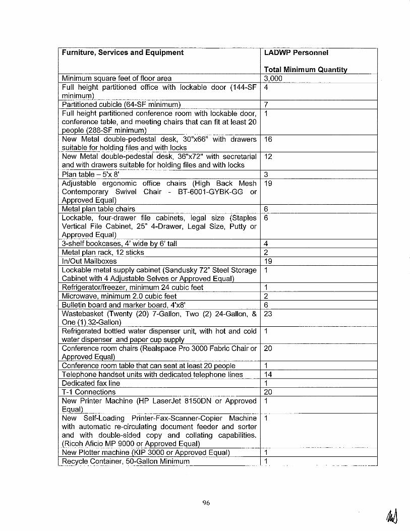
Furniture, Services and Equipment LADWP Personnel
Total Minimum Quantity Minimum square feet of floor area 3,000 Full height partitioned office with lockable door (144-SF 4 minimum) Partitioned cubicle (64-SF minimum) 7 Full height partitioned conference room with lockable door, 1 conference table, and meeting chairs that can fit at least 20 people (288-SF minimum) New Metal double-pedestal desk, 30"x66" with drawers 16 suitable for holding files and with locks New Metal double-pedestal desk, 36"x72" with secretarial 12 and with drawers suitable for holding files and with locks Plan table - 5'x 8' 3 Adjustable ergonomic office chairs (High Back Mesh 19 Contemporary Swivel Chair - BT-6001-GYBK-GG or Approved Equal) Metal plan table chairs 6 Lockable, four-drawer file cabinets, legal size (Staples 6 Vertical File Cabinet, 25" 4-Drawer, Legal Size, Putty or Approved Equal) 3-shelf bookcases, 4' wide by 6' tall 4 Metal plan rack, 12 sticks 2 In/Out Mailboxes 19 Lockable metal supply cabinet (Sandusky 72" Steel Storage 1 Cabinet with 4 Adjustable Selves or Approved Equal) Refriqerator/freezer, minimum 24 cubic feet 1 Microwave, minimum 2.0 cubic feet 2 Bulletin board and marker board, 4'x8' 6 Wastebasket (Twenty (20) ?-Gallon, Two (2) 24-Gallon, & 23 One (1) 32-Gallon) Refrigerated bottled water dispenser unit, with hot and cold 1 water dispenser and paper cup supply Conference room chairs (Realspace Pro 3000 Fabric Chair or 20 Approved Equal) Conference room table that can seat at least 20 people 1 Telephone handset units with dedicated telephone lines 14 Dedicated fax line 1 T-1 Connections 20 New Printer Machine (HP LaserJet 8150DN or Approved 1 Equal) New Self-Loading Printer-Fax-Scanner-Copier Machine 1 with automatic re-circulating document feeder and sorter and with double-sided copy and collating capabilities. (Ricoh Aficio MP 9000 or Approved Equal) New Plotter machine (KIP 3000 or Approved Equal) 1 Recycle Container, 50-Gallon Minimum 1
96

c. Removal of Facilities
1) Field offices and laboratory facilities that have been provided by the BOP Contractor at the Project Site shall be removed upon completion of the Work and as directed by LADWP. Buildings and equipment furnished by the BOP Contractor at the Project Site under the provisions of this Section are the property of the BOP Contractor.
2) Removal and cleanup of the field offices and laboratories at the Site shall be completed within five (5) days following the Final Acceptance of the Work under this Contract and as directed by LADWP. The BOP Contractor shall restore any damage to the Operations and Storage Yard and staging site in accordance with Section 5.1.B.9.b.
C. Document Submittal Requirements
1. General Document Submittal Requirements
a. The BOP Contractor shall be responsible for designing and erecting a Facility complying with the requirements of this scope document and good engineering practice with a minimum amount of input and involvement by LADWP. The BOP Contractor shall produce all engineering documentation normally required for a project of this type, including, but not limited to, design studies and analyses, design calculations, equipment specifications and detailed design drawings.
b. LADWP shall furnish to the BOP Contractor as-built drawings relating to existing facilities for interface to the Facility. The BOP Contractor shall make all verifications necessary to ensure this as-built information is correct, prior to any work.
c. All drawings shall be accompanied with a letter of transmittal showing the status of each drawing submitted to date. The BOP Contractor shall submit to the Project Manager or their designated representative for review of all Contractor design documents. These documents will be posted to the BOP Contractor's SharePoint site. Major BOP Contractor-supplied vendor drawings shall be posted to SharePoint for LADWP review. Where applicable, a disk of electronic copies of the drawings shall also be provided. Interim electronic versions shall be PDF files.
d. Language
1) All communications, notes, and nomenclature contained in the drawings, plans, reports, calculations, and other documents provided by the
97

BOP Contractor to the Owner shall use the English language.
2. Documents to be submitted for LADWP Review
a. The required engineering and design shall begin immediately after Release for Engineering, regardless of the shipping date, and shall proceed in an expeditious and orderly manner until complete. Drawings submitted in accordance with the MDL shall be suitable for use in balance of plant design. The BOP Contractor shall submit certified drawings and data as hereinafter listed to LADWP for review.
b. Drawings shall be Project specific and marked or stamped as such.
c. Dimensions and loads on drawings and data submittals shall be as follows:
1) All dimensions shall be in feet, inches, and decimal inches.
2) All loads shall be in kips and pounds (lbs.).
d. Drawings and Data
1) BOP Contractor's drawings shall apply specifically to the Contract. If general-type drawings are submitted for review which includes devices which Contractor does not intend to supply on this Agreement, the BOP Contractor shall certify on the drawings which devices are not to be supplied.
2) Identification of changes on all drawings from previous issue must be clearly shown on each drawing.
3) Where alternatives are shown alternative being furnished identifiable on that drawing.
on drawings, the shall be easily
4) Drawings and data, or portions thereof, submitted for review will be reproduced and distributed to meet the project and subsequent operational and maintenance requirements. This includes drawings and data with proprietary statements.
5) General arrangement drawings (including building layouts) consisting of a composite outline layout of all major equipment including auxiliary equipment. General arrangement drawings shall show all basic dimensions, clearances, tolerances, and required clearances for access and maintenance, including door swings, laydown and pull space. Access platforms, stairs and ladders shall also be clearly indicated on the general arrangement.
98

6) Static and dynamic design criteria to be used for the analysis and design of the foundation(s), including final loads and load orientation with details for all equipment. Loads shall be calculated in accordance with the 2007 California Building Code.
7) Building Architectural drawings.
8) Seismic analysis.
9) Foundation and embedment requirements.
1 0) Allowable recommended reaction range on each equipment connection. Reactions should be stated as the resultant force and resultant moment for each connection.
11) Loading conditions on which the above reactions are based.
12) Total allowable moments on all casings and bearings from all reactions of the connections.
13) Free expansion direction data of all connections from cold to operating temperature position.
14) P&IDs including representation of symbols and identification · for equipment items, pipe lines, valves, instrumentation and control systems consistent with the graphic symbology and rules for identification as defined in the applicable ISA standards for such work.
15) Bills of Material for all mechanical and electrical equipment.
16) Drawings showing special requirements for rigging and tooling.
17) Clearance and alignment drawings
18) Piping and valve lists.
19) Hazardous classification drawings showing all hazardous classification areas.
20) LADWP's Mechanical and Electrical Physical interface connection points.
21) Utility requirements including quality, usage, pressure, and temperature at interface points.
22) Motor and Electrical Load List, including rated loads as well as normal running load.
23) Wiring drawings, elementary diagrams, and schematics for all equipment. Drawings shall include in detail all information required to make all external connections.
99

24) Underground raceway, cable tray, and grounding requirements.
25) Settings for all supplied protective devices, protective relays, and synchronizing equipment shall be provided.
26) Thermal insulation, lagging and lagging anchorage.
27) Installation drawings for instruments furnished by the BOP Contractor's supplier for field installation by the BOP Contractor.
28) IEEE 693 Seismic compliance reports for electrical equipment.
29) One-line diagrams including key diagrams for the 4160 kV and 480 V switchgear (including relaying)
30) Electrical calculations including load flow, fault analysis, grounding, cable sizing and pulling, protective relay settings, arc flash, lighting, cathodic protection, lightning, equipment sizing, and running and starting voltage drop calculations.
31) Technical specifications for major equipment.
32) Vendor guarantees to meet emission limits specified in Air Permit Application see Exhibit P.
33) DCS input/output, configuration, and power distribution drawing
34) CRT graphic displays
35) Station heat balances
36) Station water balances
37) Detailed system startup, turnover and test procedures and plant performance test procedures
38) GEMS vendor information to support LADWP's development of the GEMS monitoring plan
39) Instrumentation and control location drawings.
40) Control System input I output list.
41) Alarm list (Included as part of control narratives).
42) Instrument list (including instrument names, models, and calibration data).
43) Control diagrams and vendor supplied-logic diagrams.
44) Details of the control system and other controls furnished (including specific, detailed instruction manuals for all control subsystems).
100
45) Instrument manufacturer, name, model number, calibration, and set point data for all instruments and control devices furnished by BOP Contractor.
46) Performance test protocol and reports.
47) QA factory and site inspection program and subsequent status report(s) and updates.
48) O&M Manuals.
49) Equipment lay-down and pull space area requirement with component weights and overall dimensions which will be required for erection, disassembly and maintenance of the equipment.
50) Motor nameplate data for all motors furnished in the form of nameplate drawing or a completed proposal data form certified to be actual nameplate data. In addition, data sheets for all medium-voltage motors including sufficient information to allow setting of protection relays (including hot and cold safe stall times, acceleration time, full load current, locked rotor current, etc.) shall be provided.
51) Flushing method, procedures, and recommendations.
52) Procedure for grouting of soleplates, subsoleplates, etc.
53) Cleaning, checking and testing procedure.
e. The BOP Contractor shall submit all design documents and equipment specifications developed by Contractor upon initial sign out and at each subsequent revision, to LADWP for information. Key vendor drawings on major equipment, including general arrangements, P&IDs, and one-lines, shall also be submitted to LADWP. These vendor drawings shall reflect the BOP Contractor's comments.
f. In addition to the above, LADWP reserves the right to request any document produced specifically for this project to be submitted for LADWP's information.
g. The intent of documents for review is to enable LADWP to be cognizant of the engineering progress and to validate the intent of the scope of the Agreement.
h. LADWP's review of the above documents will normally be limited to ensuring the BOP Contractor's design complies with the intent of the Agreement documents. In the event BOP Contractor believes LADWP's comments extend beyond the scope of the Agreement, he shall promptly notify LADWP using the Change Control Procedure
101

identified in the Agreement. The BOP Contractor shall not incorporate such changes into the design pending final resolution of the scope change request.
3. Documents to be Submitted Following Completion of Construction
a. Prior to Final Performance Acceptance, the BOP Contractor shall update drawings and other design documents marked with an asterisk in this section to reflect conformed to construction records information and shall provide copies of all design documents to LADWP as detailed below. Prior to submittal of these final documents, the BOP Contractor shall provide LADWP access to field markup drawings and other documents as required to support LADWP's operations and maintenance requirements. In addition, a complete set of all design and installation drawings, procedures, manuals, and guidelines shall be provided to LADWP's Representative at the site during construction.
b. In general, all design deliverable documents prepared by the BOP Contractor while performing engineering, design and construction on this project shall be submitted to LADWP for review and comments. In addition to the documents listed in Article 5.1.C.2.a of this Section the BOP Contractor shall submit, as a minimum, the following:
1) Equipment foundation design drawings* 2) Area paving and drainage drawings* 3) Final approved structural calculations for all buildings,
equipment supports, tanks, pipe racks, foundations, yard structures, and all structures in general
4) Structural steel plan, section, and detail drawings* 5) Building architectural drawings* 6) Electrical duct bank, cable tray, conduit layout,
grounding, and lighting drawings* 7) Electrical load lists* 8) Electrical cable and raceway lists* 9) Electrical panel schedules 1 0) Control wiring diagrams* 11) Control panel internal wiring drawings* 12) Instrument cabinet layout drawings* 13) Instrument installation details 14) Control panel layout drawings 15) Large bore piping isometric drawings* 16) Piping composite layout drawings for underground
piping and drains* 17) Valve lists* 18) Line lists* 19) Equipment lists* 20) Consolidated instrument index* 21) Engineered pipe hanger and support drawings* 22) Protective relaying logic diagrams*
102
23) Operating and maintenance manuals for all engineered equipment (initial issue is required 60 days prior to the first fire of the first CTG)
24) Maintainability and access study 25) Design studies, including CTG intake air modeling
study, fuel gas pipeline surging study, plant noise study 26) Drainage report in accordance with Los Angeles City
standard guidelines 27) Stress analysis reports 28) Dynamic analysis for rotating machines (where
applicable) 29) Dynamic foundation analysis* 30) Equipment contract specifications* 31) Three line diagrams (phasing and voltage vector)* 32) DCS Factory acceptance plan 33) Electrical system stability study* 34) Arc flash study 35) Relay setting and programs to be loaded into protective
relays and associated bills of materials and documentation sheets*
36) Instrument data sheets* 37) Control and relief valve data sheets 38) Set-point calculations for instruments (if not included in
instrument index)* 39) Equipment assembly details showing required laydown
pull space and component weights and overall dimensions which will be required for disassembly and maintenance of the equipment
40) Vendor drawings, (general arrangements, wiring diagrams and P&IDs to be as-built)*
41) Field weld procedures 42) Final grounding and cathodic protection survey reports 43) Field electrical test reports 44) Geotechnical and foundation investigation 45) Final Geotechnical Report by the BOP Contractor 46) Equipment and system startup records 4 7) Inspection certificates 48) BOP Contractor Startup Administrative Manual,
including testing and procedures
*Conformed to construction records Drawings, See Section 5.1.C.3.a
c. The BOP Contractor will include engineering studies and analysis consistent with BOP Contractor's Design for Safety Program and the applicable portions of the Electric Power Research Institute's (EPRI) Ergonomic Handbook for the Electric Power Industry (dated March 2008). BOP Contractor will jointly review the design with LADWP, and will include interviews with facility personnel. Alterations
103

to BOP Contractor's design mutually agreed by the Parties as necessary that increase the construction costs beyond the requirements of applicable codes and standards as a result of these analyses will be treated as a Change to the Agreement.
4. Drawing and Drawing Quality
a. The BOP Contractor's drawings, including but not limited to layering, graphic standards, presentation, format, appearance and all other representations, shall be per the BOP Contractor's standards. The BOP Contractor will insert LADWP's numbering system per Exhibit Z.1 0.
b. Engineering calculations that demonstrate the adequacy of the design shall be submitted (upon request).
c. The drawings shall fully demonstrate that the equipment to be furnished will comply with the provisions of these Agreement Documents and shall furnish a true and complete record of the equipment as manufactured and delivered. All underground utilities will be accurately located and recorded using GPS technology, and will be incorporated into the conformed to construction records drawings. Review of the BOP Contractor's drawings by the Project Manager or their designated representative shall not relieve the BOP Contractor of the responsibility to meet all of the requirements of these Agreement Documents or of the responsibility for the correctness of the drawings furnished by the BOP Contractor.
d. "Issued for Construction" and "Record Documents" are the two phases of design documents provided. Individual design or work packages consistent with the sequence of Work shall be as determined by the BOP Contractor. Documents shall be forwarded to LADWP throughout the project.
e. Not more than 60 calendar days after Substantial Completion of the Work, the BOP Contractor shall furnish all conformed to construction record drawings. These drawings prepared and furnished by the BOP Contractor shall include all Work furnished by the BOP Contractor.
f. All documents shall be sealed by a professional engineer registered in State of California.
g. All drawings, which are revised by the BOP Contractor, after being issued for construction, shall contain a brief description of all such revision in the revision block area of the drawings. The review and signatures of revisions shall be handled the same as for the original drawing, except that signatures shall be by initials only. Revisions shall be
104

raised numerically with Changes shall be seeped circles.
5. Automated Drawing System
each successive rev1s1on. or clearly identified with back
a. Contractor's drawings shall be prepared in MicroStation. 3-D model shall be prepared as required to support the design, fabrication and construction. Layering, graphic standards, presentation, format, appearance and all other representations shall be per the BOP Contractor's standards. All drawing files shall be complete, including as-built drawings, and the original files shall be turned over to LADWP as part of the turn over package at the end of the project. See Exhibit Z Section 10 for drawing produced by the BOP Contractor requirements.
6. System Narrative Manuals
a. The BOP Contractor shall prepare system narratives as part of this Agreement scope. These manuals shall be in addition to the Operation and Maintenance (O&M) manuals prepared by individual equipment vendors. The narratives shall provide a brief description of how each system is put into service, how it normally operates, identification of abnormal operating conditions likely to be encountered, and a description of corrective actions which should be taken. All operating instructions shall be developed and finalized prior to the initiation of operator training to facilitate the training and plant familiarization process. Each system narrative shall include as a minimum the following content.
1) Table of Contents 2) Process Description 3) Control Description 4) Permissives 5) Equipment List 6) Electrical Load List with Power Source 7) Instrument List with ranges and set points 8) 1/0 List 9) Alarms with set point values 10) P&ID's 11) On-Line Diagrams 12) Loop Diagrams
7. Instruction (Operation and Maintenance) Manuals
a. The BOP Contractor shall prepare Operation and Maintenance (O&M) manuals as part of this Agreement scope.
b. The BOP Contractor shall furnish ten (1 0) bound sets and three (3) compact discs of complete Operation and Maintenance (O&M) manuals for all equipment furnished
105
by Contractor consisting of instruction books, leaflets and drawings for maintenance, operation and erection of the equipment, and to give Owner complete information for ordering of spare parts and dismantling of equipment.
c. The manuals shall be as provided by the equipment vendors and manuals covering multiple models shall specifically indicate the model provided. The BOP Contractor shall not retype or consolidate vendor manuals.
d. The manuals shall be submitted complete. Partial shipment with material deliberately missing is unacceptable.
e. The information shall be separated into logical groups or sections with identifying tabs. Each O&M manual shall have an index listing all leaflets, in the same order as they appear in the book.
f. O&M manuals shall include:
1) Equipment ID by equipment number, project name and function
2) List of all equipment drawings 3) Final reduced drawings of general arrangements and
cross sections, warranted performance data, design data, shop test results and performance curves for all equipment
4) Parts list identified by the original manufacturer's complete part number as well as contractor's ID number
5) Complete operation, troubleshooting and maintenance instructions including programming instructions for all software provided
6) Major and minor maintenance schedules, showing maintenance intervals and inspections
7) Spare parts list 8) O&M manuals shall be edited before submittal to
exclude and/or cross out text data illustrations, curves, etc., that do not apply to the equipment or model being purchased
9) Contractor shall supply additional information or replace information, if field inspection of equipment indicates omissions or inaccuracy of the manuals
8. Requirements for Technical Document Submittals
a. All drawings provided, including vendor drawings, shall be dimensioned in English units.
b. Cable and conduit list, line list, valve list, and instrument index are to be provided using Microsoft "Access" compatible software.
106
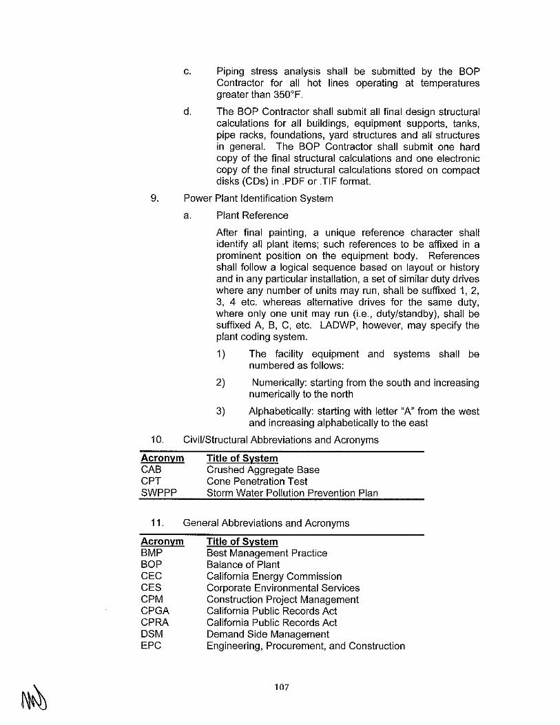
c. Piping stress analysis shall be submitted by the BOP Contractor for all hot lines operating at temperatures greater than 350°F.
d. The BOP Contractor shall submit all final design structural calculations for all buildings, equipment supports, tanks, pipe racks, foundations, yard structures and all structures in general. The BOP Contractor shall submit one hard copy of the final structural calculations and one electronic copy of the final structural calculations stored on compact disks (COs) in .PDF or .TIF format.
9. Power Plant Identification System
a. Plant Reference
After final painting, a unique reference character shall identify all plant items; such references to be affixed in a prominent position on the equipment body. References shall follow a logical sequence based on layout or history and in any particular installation, a set of similar duty drives where any number of units may run, shall be suffixed 1, 2, 3, 4 etc. whereas alternative drives for the same duty, where only one unit may run (i.e., duty/standby), shall be suffixed A, B, C, etc. LADWP, however, may specify the plant coding system.
1) The facility equipment and systems shall be numbered as follows:
2) Numerically: starting from the south and increasing numerically to the north
3) Alphabetically: starting with letter "A" from the west and increasing alphabetically to the east
10. Civil/Structural Abbreviations and Acronyms
Acronym CAB CPT SWPPP
Title of System Crushed Aggregate Base Cone Penetration Test Storm Water Pollution Prevention Plan
11. General Abbreviations and Acronyms
Acronym BMP BOP CEC CES CPM CPGA CPRA DSM EPC
Title of System Best Management Practice Balance of Plant California Energy Commission Corporate Environmental Services Construction Project Management California Public Records Act California Public Records Act Demand Side Management Engineering, Procurement, and Construction
107
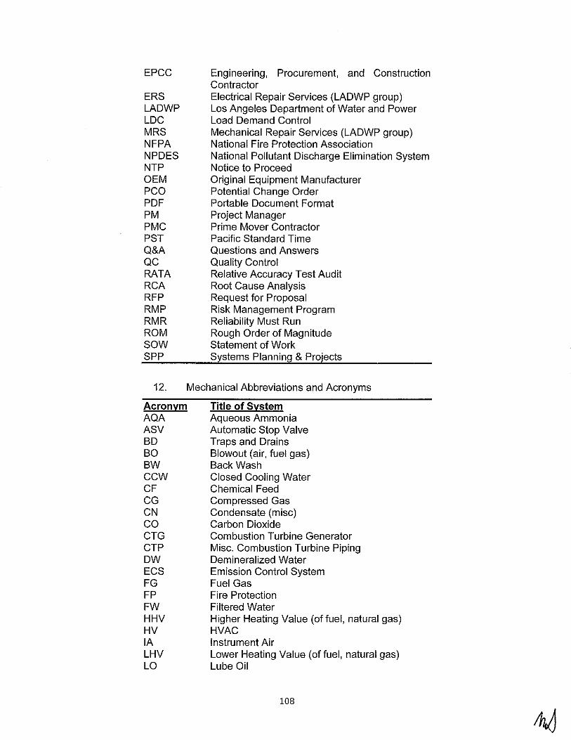
EPCC
ERS LADWP LDC MRS NFPA NPDES NTP OEM PCO PDF PM PMC PST Q&A QC RATA RCA RFP RMP RMR ROM sow SPP
12.
Acronym AQA ASV BD BO BW ccw CF CG CN co CTG CTP ow ECS FG FP FW HHV HV lA LHV LO
Engineering, Procurement, and Construction Contractor Electrical Repair Services {LADWP group) Los Angeles Department of Water and Power Load Demand Control Mechanical Repair Services (LADWP group) National Fire Protection Association National Pollutant Discharge Elimination System Notice to Proceed Original Equipment Manufacturer Potential Change Order Portable Document Format Project Manager Prime Mover Contractor Pacific Standard Time Questions and Answers Quality Control Relative Accuracy Test Audit Root Cause Analysis Request for Proposal Risk Management Program Reliability Must Run Rough Order of Magnitude Statement of Work Systems Planning & Projects
Mechanical Abbreviations and Acronyms
Title of System Aqueous Ammonia Automatic Stop Valve Traps and Drains Blowout (air, fuel gas) Back Wash Closed Cooling Water Chemical Feed Compressed Gas Condensate (mise) Carbon Dioxide Combustion Turbine Generator Misc. Combustion Turbine Piping Demineralized Water Emission Control System Fuel Gas Fire Protection Filtered Water Higher Heating Value (of fuel, natural gas) HVAC Instrument Air Lower Heating Value (of fuel, natural gas) Lube Oil
108

NT Nitrogen PD Plant Drains and Disposal PRO Permeate- Reverse Osmosis PW Potable Water (Raw Water, Service Water) RRO Reject - Reverse Osmosis SA Service Air SD Sanitary Disposal SM Sampling SO Seal Oil SW Service Water TTD Terminal Temperature Difference TW Title 22 Water WD Wastewater WD Wastewater Disposal
13. Electrical Abbreviations and Acronyms Acronyms
Acronym AGC AT BAGC BIL GEMS DCS DFR DNP 3.0 ECC ECS FERC GSUT HMI kV LCI MCC MODBUS NERC OPGW PDC PLC RTU SCAD A sus SWYD WECC
Title of System Automatic Generation Control Auxiliary Transformer Back-up Automatic Generation Control Basic Impulse Level Continuous Emission Monitoring System Distributed Control System Digital Fault Recorder Distributed Network Protocol LADWP Energy Control Center Emissions Control System Federal Energy Regulatory Commission Generator Step-up Transformer Human Machine Interface Kilovolt Load Commutated Inverter Motor Control Center Serial communications Protocol North American Electric Reliability Corporation Optical Ground Wire Power Distribution Center Programmable Logic Controller Remote Terminal Unit Supervisory Control and Data Acquisition Secondary Unit Substation Switch yard Western Electricity Coordinating Council
D. Quality Assurance and Data
1. Quality Assurance Program
109

a. Contractor shall have a QA Program in effect at all times to verify that all items and services, including subcontracted items and services, comply with the requirements of the Purchase Order and its attachments.
b. This QA program shall clearly establish the authority and responsibility of those responsible for the QA Program. Persons performing quality functions shall have sufficient and well-defined responsibility and authority to enforce quality requirements; to identify, initiate, recommend, and provide solutions to quality problems; and to verify the effectiveness of the solutions.
c. When requested, Contractor shall submit a controlled copy of his QA or Quality Systems Manual for review and acceptance by LADWP. In addition, when requested by LADWP, Contractor shall submit copies of any associated implementing procedures and/or instructions. In addition a pre-inspection meeting will be held at the BOP Contractor's facility to discuss purchase order requirements.
d. If subsequent to its acceptance, the QA Program is found to be ineffective or inadequate in providing acceptable quality control, LADWP reserves the right to require the necessary revisions.
2. Contractor's Responsibilities for Suppliers
Contractor shall identify, in purchase documents to his suppliers, all applicable quality and QA requirements imposed by the specification on Contractor and shall ensure compliance thereto. Contractor has the prime responsibility for vendor surveillance and evaluating and monitoring the implementation of the Quality Assurance Programs of his sub-suppliers. Contractor shall submit a copy of his Vendor Surveillance plans to LADWP for review prior to implementation. Upon request, Contractor shall submit to LADWP copies of the reports of the vendor surveillance activities that he performs on his suppliers.
3. Witness Points
a. Contractor shall propose a witness point inspection program during the bid period and this inspection program shall be finalized no later than ninety (90) days after award. LADWP and Contractor shall establish mutually acceptable witness points for which Contractor shall give 10 business days prior notification of upcoming witness points.
b. Witness points are defined as predetermined points during fabrication when equipment or activities may be inspected or witnessed for compliance with the Purchase Order, specification, and quality requirements.
110

c. LADWP shall have the right to access the BOP Contractors and sub-vendors facilities at any time to verify the progress and quality of the work.
4. Deviations and Non-conformances:
a. Any departure from any requirement of this specification is considered a deviation or non-conformance. Examples include physical defects in equipment, test failures, equipment out-of-tolerance, or deviations from specification, inspection or test procedures. No deviation or non-conformance from this specification shall be accepted until approved in writing by LADWP. Such approval shall not be unreasonably withheld.
5. Manufacturing Schedule
a. Contractor shall prepare and submit to LADWP, within three (3) weeks after contract award, a CPM schedule to accomplish the entire WORK. The schedule shall include a separate entry for each item of the WORK.
6. Contractor's Master Document List and Submittal Schedule
a. Within four (4) weeks after notification of award, Contractor shall provide LADWP with the finalized Master Document List (MDL). The MDL shall contain all drawings, documents, lists and official documentation relating to the WORK of this specification. The MDL shall be updated and resubmitted to LADWP for the duration of the WORK and/or until all items on the list have been issued final or as-built status.
E. Quality Control
1. General
a. The BOP Contractor shall provide the necessary Quality Control activities to ensure compliance with the Agreement Documents. The BOP Contractor's Quality Plan shall outline and define the Quality Control requirements including, without limitation, inspection and testing programs for the Work which shall cover limitation, the design and engineering, procurement, construction, installation, and inspection and construction testing aspects of the Work. The BOP Contractor shall implement its Quality Program to assure that the equipment and services furnished comply with the Specifications and all referenced and applicable Codes and Standards, and such program shall include methodology to document nonconformances and correction of non-conformances.
b. The BOP Contractor shall prepare and submit for review and approval an integrated Manufacturing, Inspection, and Testing Plan (sequence sheet or flow chart), identifying the major steps in the fabrication/testing/inspection process,
111
including those applicable nondestructive examinations and tests required to satisfy the Specifications and referenced and applicable referenced Codes and Standards that will encompass all aspects of all the Work, including provisions for adequate documentation of BOP Contractor's performance of all such inspection and testing activities. The Testing Plan shall also delineate BOP Contractor's recommendations regarding the specific materials to be inspected, as well as the nature and extent of such inspections. At a minimum, BOP Contractor shall inspect all designated materials procured by BOP Contractor and its Subcontractors that are to be incorporated into the Work, and prior to installation of same, BOP Contractor shall verify that said materials conform to the BOP Contractor Documents. As the Work progresses, LADWP may instruct the BOP Contractor to perform supplemental inspections and testing as LADWP deems necessary.
c. The Inspection and Testing Plan for the manufactured or fabricated engineered component will be reviewed by LADWP for the purpose of selecting LADWP witness points. Once the witness/inspection points are identified, a fourteen (14) day notice is required from BOP Contractor to LADWP in order that LADWP and/or representatives may witness any such tests.
d. The BOP Contractor shall impose its Quality Control requirements to all applicable lower-tier Subcontractors. The BOP Contractor is responsible to review and determine that all lower-tier Subcontractor's procedures, comply with the Specification requirements and referenced and applicable Codes and Standards.
e. The BOP Contractor and its lower-tier Subcontractors are responsible for using qualified personnel for the performance of all inspections and tests required by the Specifications and by referenced and applicable Codes and Standards.
f. LADWP and its representatives shall have the right of reasonable access to the BOP Contractor's facility or Work area, and that of any lower-tier Subcontractors, in order to evaluate the implementation and effectiveness of the Quality Program and the Work at no cost to LADWP.
g. Major deviations (non-conformances) from the requirements of the Agreement Documents shall be reported in writing to LADWP. Deviations noted as "Repair/Rework" or "Use As Is" shall require approval or concurrence by LADWP prior to proceeding further with the Work.
112

h. Within five (5) Days after BOP Contractor receives inspection and testing documentation, BOP Contractor shall furnish LADWP with documentation, showing the results of all inspections and tests.
F. Governing Codes, Standards, Regulations and Other Documents
1. General Codes and Standards
a. Design specifications and construction of the Project shall be in accordance with (1) applicable laws, regulations, codes and standards of the Federal Government and State of California, including those set forth below and, (2) applicable local (including county and city) laws, regulations, codes and ordinances, including those set forth below.
b. Publications of the following nationally recognized organizations are applicable to the engineering, design, manufacture, and testing of the equipment included in the Specifications to the extent referenced in this Specification. All references to publications are to the latest issue of each together with all latest addenda, amendments, or additions thereto as of the date of Agreement. References shall be made in accordance with the abbreviations listed below:
c. In the event that conflicts arise between the codes, standards of practice, specifications or manufacturer recommendations described herein and codes, laws, rules, decrees, regulations, standards, etc., of the locality where the equipment is to be installed, the more stringent code shall apply. The BOP Contractor shall provide a written position of any such conflict clarifications to LADWP in writing.
2. Federal Codes
CAAA
CFR
Title 29,
EPA
FERC
FAA
NERC
SCAQMD
Clean Air Act and Amendments
Comprehensive Environmental Response, Compensation and Liability Act of 1980.
Code of Federal Regulations
Code of Federal Regulations (CFR), Part 1910 Occupational Safety and Health Standards.
Environmental Protection Agency
Federal Energy Regulatory Commission
Federal Aviation Administration Regulations
North American Electric Reliability Corporation
South Coast Air Quality Management District
3. Industry Codes
AA Aluminum Association
113
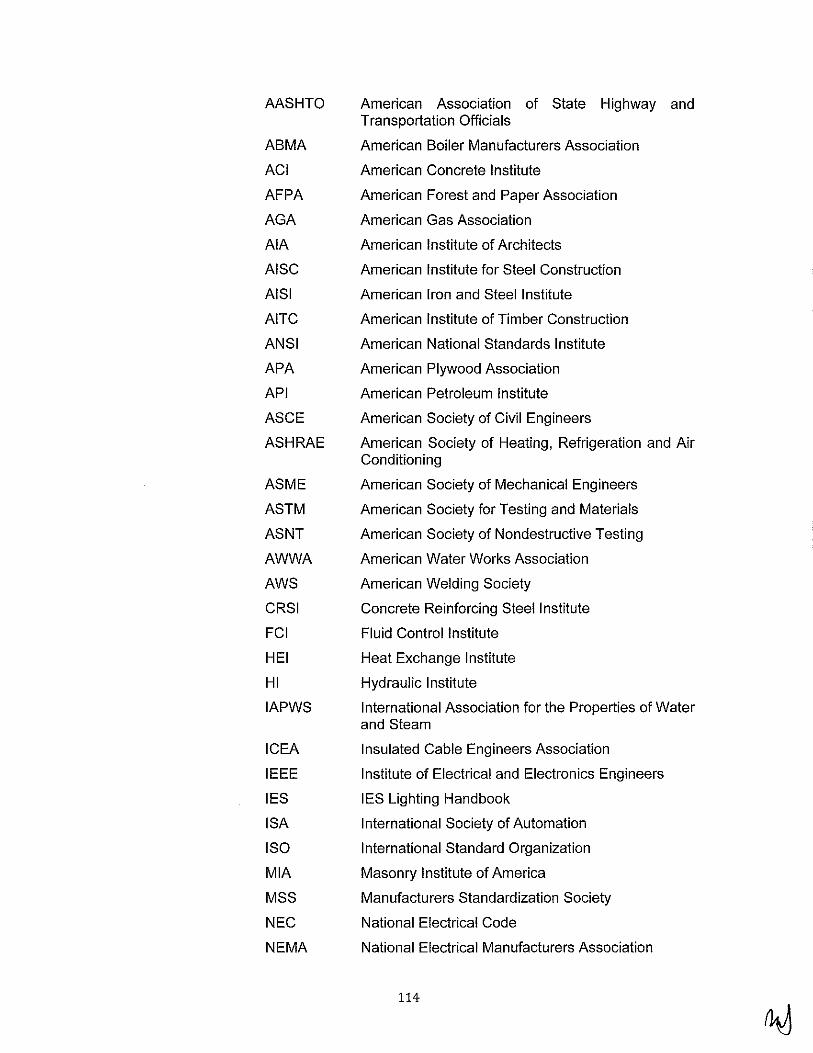
AASHTO
ABMA
ACI
AFPA
AGA
AlA
AISC
AISI
AITC
ANSI
APA
API
ASCE
ASH RAE
ASME
ASTM
ASNT
AWWA
AWS
CRSI
FCI
HEI
HI
IAPWS
ICEA
IEEE
IES
ISA
ISO
MIA
MSS
NEC
NEMA
American Association of State Highway and Transportation Officials
American Boiler Manufacturers Association
American Concrete Institute
American Forest and Paper Association
American Gas Association
American Institute of Architects
American Institute for Steel Construction
American Iron and Steel Institute
American Institute of Timber Construction
American National Standards Institute
American Plywood Association
American Petroleum Institute
American Society of Civil Engineers
American Society of Heating, Refrigeration and Air Conditioning
American Society of Mechanical Engineers
American Society for Testing and Materials
American Society of Nondestructive Testing
American Water Works Association
American Welding Society
Concrete Reinforcing Steel Institute
Fluid Control Institute
Heat Exchange Institute
Hydraulic Institute
International Association for the Properties of Water and Steam
Insulated Cable Engineers Association
Institute of Electrical and Electronics Engineers
IES Lighting Handbook
International Society of Automation
International Standard Organization
Masonry Institute of America
Manufacturers Standardization Society
National Electrical Code
National Electrical Manufacturers Association
114

4.
5.
NESC
NFPA
PCA
PCI
SDI
SEAOC
SMACNA
SSPC
SSPWC
TEMA
UFC
UL
UMC
UPC
State Codes
Gal/OSHA
CAL TRANS
CBC
CEC
CPC
CCRs
County Codes:
HM
National Electric Safety Code
National Fire Protection Association
Portland Cement Association
Precast/Prestressed Concrete Institute
Steel Deck Institute
Structural Engineers Association of California
Sheet Metal and Air Conditioner Contractors National Association
Steel Structures Painting Council
Standard Specifications for Public Works Construction
Thermal Insulation Manufacturers Association
Uniforrn Fire Code
Underwriters Laboratories
Uniform Mechanical Code
Uniform Plumbing Code
California Occupational Safety and Health Administration
State of California Department of Transportation, Standard Specifications and applicable Special Provisions and Reference Specifications, as last revised
California Building Code, 2007 Edition, (Including Title 24 - Requirements for California PE Stamp et Finite Element Analysis)
California Electrical Code
California Plumbing Code
California Code of Regulations
• Business and Professions Code Section 6704, et seq.; Section 6730 and 6736. (Requires state registration to practice as a Civil Engineer or Structural Engineer in California).
• Vehicle Code Section 35780, et. Seq. (Requires a permit for Caltrans to transport heavy loads on state roads).
Los Angeles County Department of Public Works -Hydrology Manual
115

6. City Codes:
FM Fire Marshall having Jurisdiction
City of Los Angeles Mechanical Code
City of Los Angeles Plumbing Code
City of Los Angeles Building Code
City of Los Angeles Electrical Code
7. Other Local Codes:
a. All Applicable Local Codes, Standards and Bylaws
5.2 INTENTIONALLY OMITTED
5.3 INTENTIONALLY OMITTED
5.4 CONSTRUCTION AND OPERATING REQUIREMENTS
A. Operating Requirements
1. The facility shall be designed for cycling, peaking, partial, and baseload operation. The units shall be capable of frequent startups and shutdowns as well as occasional load trips. The initial planned service for each CTG is defined as follows:
a. CTG Starts and Shutdowns I year:
1) 1476
b. Normal Operation Hours/year on Natural Gas (maximum):
1) 5256
c. Start time to reach 100 percent load and em1ss1ons compliance shall be achievable within 10 minutes.
B. Environmental Requirements
1. General
a. In addition to the environmental stipulations contained herein, the BOP Contractor shall ensure that all environmental restrictions within the guidelines stipulated by the United States Environmental Protection Agency (USEPA), South Coast Air Quality Management District (SCAQMD) and by the local authority, where applicable, are adhered to when designing, installing and commissioning the plant.
2. Gaseous and Particulate Emissions
116

a. The BOP Contractor shall meet the emission limits during the commissioning phase as specified in the Plant Air Permit to the extent within the scope of supply for the BOP Contractor. The BOP Contractor shall test the simple cycle units for emissions compliance as specified in the conditions of the Facility Permit to Construct/Temporary Permit to Operate. Unit compliance source testing shall not be performed until SCAQMD has approved source testing protocol. The SCAQMD compliance source tests must be performed by an independent testing laboratory that is approved by the AQMD Laboratory Approval Program (LAP) for the type of testing required. The expected operating loads for emissions compliance testing are when gas turbine is operating at 100, 75 and 50 percent of full rated load.
b. The measured values shall be continuously monitored and displayed in the Control Room as required by SCAQMD, USEPA and local regulations. The stack emission shall also be measured, recorded and reported as required by the SCAQMD and local regulations. Process parameters shall be measured and recorded in the continuous emission monitoring system DAHS, as specified in the SCAQMD Facility permit requirements. Sampling points and safe access for technicians and equipment adjacent to the monitoring points shall be installed as required by the SCAQMD and state and local regulations.
3. Emissions during Plant Starts and Shutdowns
a. The SCAQMD permit limits for emissions during plant startups shall be per Air Permit Application Exhibit P.
4. CEMS Certification Testing
a. The BOP Contractor shall provide a third party testing subcontractor to perform the CEMS certification testing and Relative Accuracy Test Audit (RATA) as stated in Section 5.11.S.1 0.
5. Other Emissions
a. During construction the BOP Contractor will adhere to all required construction permits for any requirements.
b. The discharge of any effluent, air emission, including site drainage during construction, will be the responsibility of the BOP Contractor who shall reach agreement with LADWP, local regulatory authorities, local water company and the local sewage company with regard to the detailed methods of disposal.
c. During the continuous operation of the Facility, waste water discharges shall meet the following:
117

1) Sanitary Waste shall be discharged to the sanitary sewer at the termination point.
2) Oil-free, clean storm water shall be discharged to the Facility clean storm water system.
3) Liquid discharges from potentially oil contaminated areas, equipment drains and evaporative cooler blow down shall be collected and routed to the low volume waste system and/or oily water separators (one per power block) and shall meet the requirements of the existing NPDES Permit (Exhibit P).
4) Reject Water and back wash water discharge from the demineralization plant shall be collected in a sump and pumped to the designated sanitation station. A fraction of unused stagnant water from the reclaimed water influent line will be diverted back to the sump.
5) CTG compressor wash waste shall be discharged to a storage tank, one per block, provided by the BOP Contractor. The contents will be pumped out in truck for transportation to off site disposal.
d. The BOP Contractor shall ensure that all waste water discharges within the current NPDES waste discharge requirements.
C. Termination Points
1. The BOP Contractor shall make the necessary tie-ins at each interface point as identified on the drawing included in Exhibit Z Section 15. The facility's design and the BOP Contractor's Scope of Work shall be based on the terminal points and boundaries of interface. The BOP Contractor shall be responsible for the design and design approvals required to accommodate the tie-ins. Tie-in point locations shall be presented to LADWP for approval prior to implementation. The BOP Contractor shall provide to LADWP a schedule proposing the tie in dates.
2. The BOP Contractor shall supply all equipment necessary to accommodate their tie-ins to those existing utilities (including capacity, quality, pressure and temperature) as listed in Exhibit Z Section 15. 3. Drawings listed in Exhibit Z Section 15 show approximate location of interface points.
D. Transmission Systems
1. The transmission system will be designed and constructed by LADWP.
E. Compliance With EIR Traffic, Noise, Dust, Over Spray Abatement and Mitigation Measures
118

1. The BOP Contractor shall comply with the requirements of the implemented Environmental Impact Report (EIR) by adhering to construction traffic mitigation measures. The personnel traffic and construction equipment transportation will impose additional burden to the surrounding residence and traffic. To this end, it is at the responsibility of the BOP Contractor to support EIR for this Project in both regional and local contexts. It is the responsibility of the BOP Contractor to address in his/her work plan the construction traffic, noises, dust, over-spray, etc abatement or mitigation during construction mobilization, erection work and demobilization periods.
2. The characterization of local existing and planned public roads, and access within a defined mileage radius shall be adhered too.
F. Plant Operational Modes
1. Operational Modes of the overall facility: The simple cycle facility shall be capable of cycling or long term operation. Individual CTGs may be idle for as little as a few hours or as longs as several weeks. In addition to variable load operations, the plant shall also be capable of base load operation. Each CTG train shall be able to operate independently or in combination with any other unit. All balance of plant systems that support normal operation of the CTGs must be capable of supporting startup, continuous operation above minimum load and shutdown for any combination of units. In addition, Units 12 and 14 having synchronous condensers shall be capable of freewheeling operation or on VAR support:
2. The Facility shall be capable of reliable operation and in compliance with the permit requirements over the design operating range of the gas turbines at 50 percent load up to full load. The Facility shall also be capable of "Island" operation, disconnected from the utility grid.
3. On loss of the 230 kV grid, the Facility shall be capable of black starting a combustion turbine from minimum gas pressure using the limited capacity of the black start diesel generators. The combustion turbine shall run in island providing power to its associated gas compressor, connect to the isolated 230 kV grid, and provide power to the auxiliaries of the remaining units.
G. Western Electricity Coordinating Council's Requirements
1. Generator frequency operation shall have relaying protection that accommodates, as a minimum, under frequency and over frequency operation for the specified time frames as per WECC Coordinated Off-Nominal Frequency Load Shedding and Restoration Plan approved on April 1, 2005.
Under Frequency Over Frequency Minimum Time Limit Limit
119

> 59.4 Hz 60Hz to < 60.6 Hz N/A (continuous operating range)
< 59.4 Hz > 60.6 Hz 3 minutes s; 58.4 Hz ~ 61.6 Hz 30 seconds < 57.8 Hz 7.5 seconds
s; 57.3 Hz 45 cycles s; 57.0 Hz > 61.7 Hz Instantaneous trip
2. The generator stator temperature relay shall be used for alarm only.
3. For additional protective relaying, interlocks and lockout relays, please refer Section 5.1 O.G.
4. All current transformers used for generator protection shall be a minimum of C400 relaying accuracy as defined by IEEE C57.13.
5. All generator protective relays shall be located on a single panel, in plain view, in the generator control cabinet, and equipped with a test switch. Please refer Section 5.1 0, article 1 O.G.6.d.1 for panel specification.
6. CTG units 12 and 14 shall be equipped with synchronous automatic engaging/disengaging, freewheel-type overrunning clutch required for VAR compensation by synchronous condensing operation.
H. Noise Abatement
1. The BOP Contractor shall describe the criteria used for noise control to meet local noise ordinance requirements and how the required far field noise limits shall be achieved during construction and operation of the Facility. See Section 5.1.B.7 for noise level requirements.
I. Plant Operating Life and Reliability
1. The BOP Contractor shall design the Facility to meet an extended life of 30 years. In addition, the BOP Contractor shall design the Facility to allow for cyclic operation, including the time required for emission compliance during CTG rapid startup, shutdown and partial-load operation and to meet the plant reliability requirements.
J. Post Construction Startup, Testing and Checkout, and Commissioning Tests
1. The BOP Contractor's scope shall consist of post construction cleaning, inspection, checkout, startup, testing, turnover and plant operation leading up to commercial operational turnover as specified in Section 5.13.
5.5 INTENTIONALLY OMITTED
120
5.6 COMBUSTION TURBINE-GENERATOR (CTG)
A. Information and Scope of Work
1. General
a. The intent of this Specification is to describe requirements for receiVIng, unloading, transportation, storage, preservation, maintenance, installation, check-out, start-up and testing of six (6) Combustion Turbine-Generators (CTGs) provided by the Prime Mover (PM) Contractor.
b. The CTGs will be used to generate electrical power and flue gas will be exhausted through an Emission Control System (ECS) also provided by the CTG Contractor.
c. Three (3) CTGs (Units 12, 14 and 16) will be provided with a standard "handing" configuration in which the intercooler is located on the left side of the unit and the ECS on the right as viewed from the generator non-driven end. Three (3) CTGs (Units 11, 13 and 15) will have an alternative "handing" configuration in which the intercooler is located on the right and the ECS on the left side as viewed from the generator non-driven end.
d. Units 12 and 14 will include the synchronous condenser mode operation with the generator clutch.
e. The CTG equipment will be designed for peaking cycle operation. For other site specific details and design conditions, refer to this Specification Exhibit Z Section 1.
f. The CTG Contractor will furnish the equipment with accessories and auxiliaries as described below and detailed in Section 5.6 of the CTG Contract provided with the RFP documents issued by LADWP.
g. All equipment shall be installed by the Engineering, Procurement, Construction Contractor (BOP Contractor) as shown on the drawings provided in Exhibit Z Section 15.
2. Scope of the CTG Contractor Furnished Equipment
1) For each CTG, the CTG Contractor will provide the following auxiliaries and features:
2) Based mounted Combustion Turbine.
3) Water cooled, 2-pole, 13.8 kV, 60 Hz generator located outside of the turbine enclosure.
4) Gas turbine weatherproof acoustic, fully ventilated enclosure with a removable roof for quick engine removal and replacement.
5) Natural gas fuel system with an electronically controlled fuel-metering valve and all necessary
121
shutoff valves, including piping and instruments between base-plate connection and the engine.
6) Generator brushless excitation system with a magnet generator along with neutral and line side cubicles.
7) The Power System Stabilizer (PSS) to control power fluctuations and improve the stability of the power system. A power system study is to be completed by the BOP Contractor. With the study complete, the CTG Manufacturer will assist the BOP Contractor in programming the PSS with the set points established in the power system study.
8) Automatic voltage regulation system.
9) Generator neutral grounding equipment.
1 0) Water injection system for NOx control consisting of an inlet strainer, pump, motor, valves, piping and controls.
11) Microprocessor-based generator protective relay module, mounted in the turbine control panel with functions necessary for protection of the generator.
12) CTG synthetic lubricating oil system for gas turbine core & intermediate pressure turbine. The lube oil system will complete with filters, shell and tube coolers, and thermostatically-controlled electric heaters.
13) CTG auxiliary skid mounted mineral lubricating oil system for generator, low pressure compressor & power turbine consists of mineral lube oil cooler, oil reservoir, filters and interconnected piping and control.
14) Factory installed fire protection system complete with optical flame detection, hydrocarbon sensing and thermal detectors, piping and nozzles in the engine compartment and C02 cylinders containing mounted on a separate module.
15) Inlet air system supplied with a high efficiency self cleaning filtration system and recirculating type evaporative cooler.
16) Intercooler system that includes water cooled heat exchanger, variable bleed valve (VBV), VBV stack with silencer, and interconnect piping and supports.
17) Gas turbine exhaust system supplied with the exhaust outlet connection flange to facilitate mounting of the exhaust system.
122
18) On/Off line cleaning and soak water wash system (one system for each CTG).
19) Electro-hydraulic start system supplied with an electric motor driven hydraulic pump assembly, filters, cooler, hydraulic motor, hydraulic hoses and controls.
20) Skid-mounted, duplex (2 x 1 00%) coalescing gas fuel filters designed and code stamped per latest ASME Section VIII Div. 1. Filters shall be designed for removal of 99.9% of particles (1 micron or larger).
21) Skid mounted duplex (2 x 100% capacity each) demineralized water filters.
22) Instrument and control system, including automatic start-up/shutdown/emergency stop sequencing.
23) Control system including all individual turbinegenerator system monitoring and operating indicators, controls, and transmitters as well as central electronic control system.
24) Internal and external lighting and electrical outlets for enclosures and equipment housings.
25) Thermal and personnel protection insulation with lagging.
26) Shop applied priming and finish painting for external surfaces of all equipment and interior surfaces of enclosures.
27) Exterior and interior access platforms and stairways for CTG, generator, inlet filter house and all enclosures, needed for normal maintenance and operation.
28) Synchronous clutch, in its own enclosure, between the gas turbine and generator for units 12 and 14 only with the required modifications to the protective relay and voltage regulator system.
29) Relaying and control panel(s), including Beckwith M-3425A relay, sync-check, automaticsynchronizing equipment, meters, switches, sync scope, etc.
30) Electrical auxiliary power distribution (480V and below) and control systems including protective devices and relays.
31) AC/DC battery and charger system. Chargers shall be sized to supply the full DC load and battery charging requirements simultaneously, so that the batteries are not discharged when AC power is
123

available. There will be two 100% rated chargers per battery system. Each charger is sized such that the charger can supply all normal DC load while simultaneously recharging the battery within eight (8) hours
32) Electric motor driven or electro-hydraulic turning gear.
33) All interconnecting piping, fittings, supports and hardware integral to or between any equipment furnished under this Specification.
34) All necessary instrument, power and control wiring, and raceways integral to and interconnecting between any equipment furnished under this Specification.
35) Leveling blocks, soleplates, baseplates, thrust blocks, anchor bolts, jacking posts, embedded plates, anchor bolt and embedded plate erection templates and shims.
36) Lifting beams, lugs and other provisions for offloading, erection, and maintenance.
37) Special tools required for installation, operation and maintenance.
38) Spare parts and consumables normally required for installation, commissioning and start-up of the CTG.
39) Shop testing including functional testing of the specified equipment.
40) Shipping and freight to job-site for all equipment.
41) Installation instruction manuals. This information will be complete and comprehensive with the necessary drawings, instructions, bills of material, and information as to the extent of field fabrication, bolting, cleaning, checking, inspection, painting, testing, etc., required to be done by the BOP Contractor.
42) CTG Contractor will provide a training program for LADWP's personnel to inspect, maintain, and operate the furnished equipment.
3. Manufacturer's Representative.
a. LADWP will retain the services of the manufacturer's representative(s) for advising on the receipt, installation and start-up of each CTG. The BOP Contractor shall cooperate with the manufacturer's representative at all times.
124
b. The BOP Contractor shall provide all necessary equipment, labor and materials to perform the check-out and start-up activities in a timely manner, such that the services of the manufacturer's representative are utilized in a cost effective manner.
c. The CTG Contractor will provide manufacturer's field services as follows:
1) Installation Engineers.
2) Start-up Engineers.
3) Supervision during field performance testing.
4) Supervision at project site during unloading, storing and field erection of all equipment.
4. BOP Contractor Furnished Equipment
a. The BOP Contractor shall furnish and install all components necessary to obtain a complete operating system as specified herein.
b. The following items shall be procured by the BOP Contractor. This is a partial list only and is included to clarify the limits of the CTG Contractor's scope of supply related to each CTG and shall not be meant to be allinclusive. It shall be the responsibility of the BOP Contractor to determine fully the extent of work to be performed under this Specification. Failure to determine beforehand the extent of work shall not be cause for extra compensation.
1) Labor, equipment and materials required for unload, receive, inspect, transport, store, preserve, maintain, install, check-out, test and start-up of each CTG from the delivery point to the BOP Contractor's storage.
2) Pipe and gaskets required for installation of the CTG, associated equipment and piping which are not included in the CTG Contractor's scope of supply.
3) Interconnecting wires and conduits between control panels provided by the CTG manufacturer and the DCS, and between control panels and equipment.
4) Power and control wiring, conduit, instrument piping and pneumatic tubing external to supplier skids.
5) Temporary scaffolding, blocking, wedges, shims and other material required for installation of equipment.
6) Equipment foundations.
125
7) All anchor bolts, nuts, washers and sleeves (except as specified otherwise) required to secure the equipment to foundations.
8) Access platforms in addition to those provided with the CTG.
9) All lubricants, lubricating oil, grease and all other materials and appurtenances as necessary and as recommended by the CTG Manufacturer for startup, check-out and operation of the CTG and associated equipment.
B. Contractor's Responsibilities Prior to Installation
1. Equipment Delivery
a. The BOP Contractor shall schedule the delivery of equipment and materials so that they arrive near the time that they will be installed and after all provisions have been made for their installation. This will minimize any problems that might arise due to improper storage of equipment and materials. The equipment will be shipped to the job site by the CTG Contractor.
b. The BOP Contractor shall be responsible for protecting and maintaining all CTG Contractor equipment upon its delivery to the job site. Upon transfer the equipment from the CTG Contractor to the BOP Contractor, the BOP Contractor shall assume full responsibility for proper storage, transportation and installation of the equipment.
c. The BOP Contractor shall have the responsibility to unload this equipment once it arrives at the job site. The BOP Contractor shall coordinate with the CTG Contractor and LADWP regarding major equipment delivery and notify LADWP 48 hours prior to delivery of equipment.
2. Unloading and Transport
a. The BOP Contractor shall provide all equipment and labor for unloading and transport of the CTG Contractor furnished equipment from the delivery trucks. The BOP Contractor shall unload the equipment and transport it to the designated storage area within 48 hours of actual delivery.
b. All transportation and unloading and loading activities shall be performed under the supervision of the Manufacturer's representative. The BOP Contractor shall be responsible for all procedures recommended by the equipment manufacturer and shall be responsible for all damage to the equipment as a result of unloading, loading and transportation activities.
3. Inventory and Inspection
126

a. The BOP Contractor shall be responsible for checking all parts and assemblies for shortages and damages. The BOP Contractor shall make a checklist of parts and materials. The BOP Contractor shall claim shortages and damages in writing within 72 hours of the date of delivery. The BOP Contractor shall carefully inventory and inspect the shipment to determine if all equipment and necessary components are present as stated and are undamaged. An early and thorough inspection will allow some time for ordering new or replacement parts in the event of missing or damaged items.
4. Storage
a. The BOP Contractor shall leave the equipment in its delivery crates, except as otherwise required to conduct the inventory, until the equipment is ready to be installed.
b. Upon completion of the installation work, the BOP Contractor shall remove the storage area improvements and shall return all storage sites to their original condition.
5. Preservation and Maintenance
a. The BOP Contractor shall perform all preservation and maintenance work on the CTG Contractor furnished equipment between the actual dates of delivery and the start-up of the equipment.
b. The BOP Contractor shall be responsible for protection of the above equipment and accessories against corrosion, dirt, moisture and any damages or losses occurring to said equipment during the above time frames.
c. All preservation and maintenance work shall be performed in accordance with the Manufacturer's recommendations.
d. All preservation and maintenance procedures are subject to the approval of the Manufacturer's Representative and shall be submitted to LADWP for review.
e. Inspection procedures and maintenance procedures shall be performed upon the first delivery of equipment and accessories. Maintenance procedures shall be performed per the Manufacturer's recommendations thereafter until the equipment has been satisfactorily placed in operation and accepted by LADWP. The BOP Contractor shall maintain and turnover full records of all maintenance, preservation and/or repair performed on any the CTG Contractor furnished equipment.
f. The BOP Contractor shall furnish all lubricants, lubricating oils, greases, rust preventatives, silica gel bags, coatings, paints and all other equipment and appurtenances necessary and recommended by the Manufacturer for maintenance during storage.
127

g. Rust preventative oils shall be renewed and rusting surfaces shall be cleaned by the BOP Contractor at any time during the storage period when deemed necessary by either the Manufacturer or LADWP.
h. The BOP Contractor shall slowly rotate the motor shaft and propellers by hand, once every two (2) weeks, to distribute bearing grease and prevent bearing corrosion.
i. The BOP Contractor shall examine all bearing grease to determine if water has contaminated the lubricants at a minimum frequency of once per month. If contaminated, the lubricants shall be flushed out and replaced with new lubricants in accordance with the Manufacturer's recommendations.
j. The BOP Contractor shall check the lubricating oil, prior to storage, according to the Manufacturer's procedure in the equipment reference documents. If the oil appears dirty, it shall be changed. Grease the units as required. Use only lubricating oil and grease recommended by the Manufacturer in the equipment reference documents.
k. Care shall be taken when storing the equipment to prevent them from rolling or falling over. Machines shall never be lifted by the motor cable.
I. Electrical controls shall be stored in a protected dry environment, free from any corrosive atmosphere.
m. The BOP Contractor shall check all terminal connection screws and bolts for tightness prior to installation.
C. CTG Installation
1. General
a. The CTG and associated equipment described herein shall be installed in strict conformance with the Manufacturer's recommendations and the special construction requirements set forth in this Section.
b. The BOP Contractor shall make all mechanical and electrical connections between equipment as required to provide a fully functional installation.
c. The Manufacturer's recommendations regarding maintenance requirements and procedures after installation and prior to start-up shall be continued by the BOP Contractor until the equipment has been satisfactorily placed in operation and accepted by LADWP.
2. Time Allowed for Installation, Check-out and Start-up.
a. The BOP Contractor shall complete the installation, checkout and start-up of the CTG Contractor furnished equipment and associated piping, valves, electrical and instrumentation work within the specified time frame.
128

b. The BOP Contractor shall notify LADWP at least five (5) working days prior to beginning any installation, checkout or start-up of the CTG Contractor furnished equipment.
3. Equipment Removal from Storage and Equipment Handling
a. The BOP Contractor shall remove all coverings and shall provide all necessary labor, equipment and materials for removing the CTG Contractor furnished equipment from storage prior to installation. All work shall be performed in accordance with the Manufacturer's recommendations. Equipment shall not be removed from storage until just prior to installation. The BOP Contractor shall demonstrate that preparations for installation of the equipment are complete prior to removing the equipment from storage.
b. The BOP Contractor shall provide an approved lifting device and all other labor, equipment and materials required to move the equipment. The BOP Contractor shall be responsible for all damage to the equipment as a result of improper loading, transportation and handling procedures at the job site.
4. Mechanicallnstallation
a. The BOP Contractor shall make all mechanical connections between the CTGs and auxiliary equipment and piping furnished by the CTG Contractor and the equipment and piping provided the BOP Contractor.
b. The BOP Contractor shall properly level and align all installed equipment. Alignment tolerances shall be in accordance with the Manufacturer's instructions. Components of rotating machinery shall be checked for run-out, parallelism and concentricity. Stainless steel shims shall be provided and installed by the BOP Contractor as required.
c. Alignment and connection of motors to equipment shall not be made until the motors have been tested for proper rotation and have been run-in and tested for vibration.
d. The BOP Contractor shall recheck alignment and complete all necessary realignment of the rotating equipment after installation of connecting piping. In the absence of other specific instructions from the Manufacturer or LADWP, 0.002 inch shall be the maximum change in alignment due to external strain, which will be allowed without requiring realignment of equipment.
e. The BOP Contractor shall check the alignment of rotating equipment after it has reached normal operating temperature and complete all necessary realignment. Checking of alignment shall not be completed until equipment has operated at its rated speed and
129

temperature for at least two (2) hours. The alignment check shall be completed at the time of initial operation of the equipment.
f. Lubrication of equipment shall be done by the BOP Contractor with the lubricants recommended by the Manufacturers. The initial fill of lubricants shall be furnished by the BOP Contractor. Points of lubrication shall be specified by equipment Manufacturers.
g. Rotating equipment, which has been shipped dismantled for assembly in the field or is not shipped with lubricants, shall have the bearings flushed clean and inspected prior to lubrication.
h. All lube oil reservoirs shall be cleaned, inspected and filled with oil.
i. The BOP Contractor shall repair any damage to the Manufacturer's equipment coating that occurs during storage or installation.
5. Electricallnstallation
a. The BOP Contractor shall install CTG Contractor furnished motor control centers, conduits, pull boxes, interconnecting wiring, grounding, connections and all other equipment devices not specifically identified as CTG Contractor furnished and as required to provide a complete and fully functional installation. All equipment, material and installation shall be as required by Section 5.1 0. CTG Contractor shall ship CTG equipment indicated above to the BOP Contractor's PCM vendor for installation and packaging.
b. The BOP Contractor shall be responsible for termination of all wires, except for those that will impact the existing process control of the facility.
c. Flexible connections shall be provided for all connections to the equipment. Cables shall be run so that they do not have any sharp bends and are not pinched. The length of these flexible cables shall be such that the equipment can be removed for maintenance. In no event, however, shall the cables interfere with the equipment during normal operation.
d. Prior to checkout and start-up of equipment, the BOP Contractor shall verify all interconnecting wiring.
e. The BOP Contractor shall be responsible for any damage to the CTG Contractor furnished electrical equipment as a result of improper storage, handling or installation.
D. Field Testing, Check-Out and Start-Up of CTG
1. General
130

a. After completion of all related construction work, the BOP Contractor shall proceed with achieving mechanical completion, initial operation, operational completion and complete start up, performance and reliability testing as specified in Section 5.13.
5.7 EMISSION CONTROL SYSTEM
A. Information and Emission Control System Scope of Work
1. General
a. The intent of this Specification is to describe requirements for rece1v1ng, unloading, transportation, storage, preservation, maintenance, installation, check-out, start-up and testing of six (6) Emission Control Systems (ECS) provided by the Combustion Turbine Generator (CTG Contractor).
b. Each ECS consists of NOx Selective Catalytic Reduction (SCR) and CO Oxidization Catalyst (CO) Systems to reduce NOx, CO and VOC emissions to atmosphere resulting from the operations of six (6) CTGs.
c. The ECS equipment will be designed for peaking cycle operation. For other site specific details and design conditions, refer to this Specification Exhibit Z Section Z1.
d. The CTG Contractor will furnish the equipment with accessories and auxiliaries as described below and detailed in Section 5. 7 of the CTG Contract provided with the RFP documents issued by LADWP.
e. All equipment shall be installed by the Engineering, Procurement, Construction Contractor (BOP Contractor) as shown on the drawings provided in Exhibit Z Section Z15.
2. Scope of the CTG Contractor Furnished Equipment
a. For each ECS, the CTG Contractor will provide the following auxiliaries and features:
1) Inlet gas transition duct from the CTG to the ECS.
2) Outlet expansion joint including bolting and gaskets.
3) Exhaust stack with stack noise silencer and perimeter acoustical panels as required to meet near-field and far-field requirements as specified in Section 5.1.B.7.
4) Ammonia vaporization skid complete with:
a. Two (2) 100% capacity each dilution air blowers including noise silencing equipment and motor starters pre-wired on skid.
131

b. One ( 1) electric heater, contactor, and thermostat with spare heater capacity.
c. On-skid aqueous ammonia supply piping system.
d. PLC-based aqueous ammonia control system mounted on ammonia vaporization skid.
e. Structural steel base and support frame.
5) Ammonia Injection Grid (AIG) completes with flow control and flow balancing valves.
6) Off skid piping between the ammonia vaporization skid and the ammonia flow balancing manifold assembly
7) Piping between the ammonia flow balancing manifold assembly and the ammonia injection grid.
8) Two (2) 100% capacity each flue gas cooling (tempering) air fans including fan noise silencing equipment.
9) Tempering fan system including interconnecting duct work, valves, dampers, instrumentation, piping and flue gas cooling air/purge control.
10) SCR and CO catalyst systems complete with catalyst elements, catalyst support frames and gas bypass seals. All catalyst modulus will be provided with lifting lugs.
11) Gas tight casing with thermal insulation.
12) All integral and interconnecting piping, fittings, supports, hardware and skid-mounted equipment furnished under Section 5. 7 of the CTG Contract provided with the RFP documents issued by LADWP.
13) All required motors including motors for motoroperated valves furnished under Section 5. 7 of the CTG Contract provided with the RFP documents issued by LADWP.
14) Starters for all motors enclosed in panel boards, quantity as specified in Section 5. 7 of the CTG Contract provided with the RFP documents issued by LADWP.
15) Shop priming of all non-galvanized items.
16) Hot-dip galvanized walkways, platforms and stairways necessary for access to instrumentation, valves and emission monitoring ports.
132

17) All necessary instrumentation for performance and acceptance testing of the furnished equipment. Portable instrumentation required for performance and emissions testing shall be included.
18) Leveling blocks, slide plates, baseplates, thrust blocks, and slotted washers (non-embedded items).
19) Structural steel supports for equipment.
20) Liner splice piece at interface of ECS inlet duct.
21) One set of all special tools.
22) Freight to the site for truck shipments and nearest rail siding for rail shipments or nearest port.
3. Manufacturer's Representative.
a. LADWP will retain the services of the manufacturer's representative( s) for advising on the receipt, installation and start-up of each ECS. The BOP Contractor shall cooperate with the manufacturer's representative at all times.
b. The BOP Contractor shall provide all necessary equipment, labor and materials to perform the check-out and start-up activities in a timely manner, such that the services of the manufacturer's representative are utilized in a cost effective manner.
c. The CTG Contractor will provide manufacturer's field services as follows:
1) Installation Engineers.
2) Start-up Engineers.
3) Supervision during field performance testing.
4) Supervision at project site during unloading, storing and field erection of all equipment.
4. BOP Contractor Furnished Equipment
a. The BOP Contractor shall furnish and install all components necessary to obtain a complete operating system as specified herein.
b. The following items shall be procured by the BOP Contractor. This is a partial list only and is included to clarify the limits of the CTG Contractor's scope of supply related to each ECS and shall not be meant to be allinclusive. It shall be the responsibility of the BOP Contractor to determine fully the extent of work to be performed under this Specification. Failure to determine beforehand the extent of work shall not be cause for extra compensation.
133
1) Aqueous ammonia forwarding pumps as specified in Section 5.9.
2) Equipment foundations.
3) GEM systems as specified in Section 5.11.
4) Labor, equipment and materials required for unload, receive, inspect, transport, store, preserve, maintain, install, check-out, test and start-up of each ECS from the delivery point to the BOP Contractor's storage.
5) Piping, gaskets and thermal insulation required for installation of the ECS, associated equipment and piping which are external to supplier skids and not included in the CTG Contractor's scope of supply.
6) Interconnecting wires and conduits between control panels provided by the ECS manufacturer and the DCS, and between control panels and equipment.
7) Power and control wiring, conduit, instrument piping and pneumatic tubing external to supplier skids.
8) Temporary scaffolding, blocking, wedges, shims and other material required for installation of equipment.
9) All anchor bolts, nuts, washers and sleeves (except as specified otherwise) required to secure the equipment to foundations.
1 0) Access platforms for the maintenance manways on the ECS. 11) All lubricants, lubricating oil, grease and all other materials and appurtenances as necessary and as recommended by the ECS Manufacturer for start-up, check-out and operation of the ECS and associated equipment.
B. ECS Design Criteria And Guaranteed Operating Conditions
1. Design Conditions
Combustion Turbine Model. .......................... CTG Contractor to Provide
Manufacturer ............................................ General Electric
Fuel(s) ......................... 0 Refinery Gas~ Natural Gas D Oil
Maximum Exhaust Gas Flow ...... CTG Contractor to Provide lbs/hr
Coincident Exhaust Gas Temperature .CTG Contractor Provide °F
Maximum Exhaust Gas Temperature .CTG Contractor Provide oF
Exhaust Gas NOx Emission @ 15% 0 2 .. Per AQMD Air Permit Application Requirements
134
Exhaust Gas CO Emission @ 15% 0 2 ... Per AQMD Air Permit Application Requirements
Exhaust Gas VOC @ 15% 0 2 ............... Per AQMD Air Permit Application Requirements
2. ECS Minimum Design Requirements
Equipment Identification ........ Selective Catalytic Reduction and Oxidation
Number of ECS Required .................................................. 6
Service .......................................................................... 12:('] Cycling
Gas Flow .................................................................... i2:('] Horizontal
Gas Side Static Pressure Drop Through SCR and CO catalyst, and stack silencer (if required) ................................... Not to Exceed 12 inch WG
Stack Height (above grade) .................. Per AQMD Air Permit Application Requirements
Stack Damper w/ operator ................................................ No
Stack Diameter. .. Per AQMD Air Permit Application Requirements
3. Other ECS Requirements
a. All devices and components shall be UL listed for ammonia service.
4. ECS Sound Levels
a. The BOP Contractor furnished equipment shall meet under any operating condition, the specified maximum Aweighted (dB, re: 0.0002 microbar) sound specified herein.
5. Code Requirements
a. The equipment provided by the BOP Contractor for ECS systems shall conform to all latest federal, state, and local codes or regulations having jurisdiction at the project site. It shall be Contractor's responsibility to investigate such statutes and determine applicable provisions regarding the equipment they propose to furnish.
C. Contractor's Responsibilities Prior to Installation
1. Equipment Delivery
a. The BOP Contractor shall schedule the delivery of equipment and materials so that they arrive near the time that they will be installed and after all provisions have been made for their installation. This will minimize any problems that might arise due to improper storage of equipment and
135

materials. The equipment will be shipped to the job site by the CTG Contractor.
b. The BOP Contractor shall be responsible for protecting and maintaining all CTG Contractor equipment upon its delivery to the job site. Upon transfer the equipment from the CTG Contractor to the BOP Contractor, the BOP Contractor shall assume full responsibility for proper storage, transportation and installation of the equipment.
c. The BOP Contractor shall have the responsibility to unload this equipment once it arrives at the job site. The BOP Contractor shall coordinate with CTG Contractor and LADWP regarding major equipment delivery and notify LADWP 48 hours prior to delivery of equipment.
2. Unloading and Transport.
a. The BOP Contractor shall provide all equipment and labor for unloading and transport of the CTG Contractor furnished equipment from the delivery trucks. The BOP Contractor shall unload the equipment and transport it to the designated storage area within 48 hours of actual delivery.
b. All transportation and unloading and loading activities shall be performed under the supervision of the CTG Contractor's representative. The BOP Contractor shall be responsible for all procedures recommended by the equipment manufacturer and shall be responsible for all damage to the equipment as a result of unloading, loading and transportation activities.
3. Inventory and Inspection
a. The BOP Contractor shall be responsible for checking all parts and assemblies for shortages and damages. The BOP Contractor shall make a checklist of parts and materials. The BOP Contractor shall claim shortages and damages in writing within 72 hours of the date of delivery. The BOP Contractor shall carefully inventory and inspect the shipment to determine if all equipment and necessary components are present as stated and are undamaged. An early and thorough inspection will allow some time for ordering new or replacement parts in the event of missing or damaged items.
4. Storage
a. The BOP Contractor shall leave the equipment in its delivery crates, except as otherwise required to conduct the inventory, until the equipment is ready to be installed.
b. Upon completion of the installation work, the BOP Contractor shall remove the storage area improvements and shall return all storage sites to their original condition.
136
5. Preservation and Maintenance
a. The BOP Contractor shall perform all preservation and maintenance work on the CTG Contractor furnished equipment between the actual dates of delivery and the start-up of the equipment.
b. The BOP Contractor shall be responsible for protection of the above equipment and accessories against corrosion, dirt, moisture and any damages or losses occurring to said equipment during the above time frames.
c. All preservation and maintenance work shall be performed in accordance with the Manufacturer's recommendations.
d. All preservation and maintenance procedures are subject to the approval of the Manufacturer's Representative and shall be submitted to LADWP for review.
e. Inspection procedures and maintenance procedures shall be performed upon the first delivery of equipment and accessories. Maintenance procedures shall be performed per the Manufacturer's recommendations thereafter until the equipment has been satisfactorily placed in operation and accepted by LADWP. The BOP Contractor shall maintain and turnover full records of all maintenance, preservation and/or repair performed on any the CTG Contractor furnished equipment.
f. The BOP Contractor shall furnish all lubricants, lubricating oils, greases, rust preventatives, silica gel bags, coatings, paints and all other equipment and appurtenances necessary and recommended by the Manufacturer for maintenance during storage.
g. Rust preventative oils shall be renewed and rusting surfaces shall be cleaned by the BOP Contractor at any time during the storage period when deemed necessary by either the Manufacturer or LADWP.
h. Care shall be taken when storing the equipment to prevent them from rolling or falling over. Machines shall never be lifted by the motor cable.
i. Electrical controls shall be stored in a protected dry environment, free from any corrosive atmosphere.
j. The BOP Contractor shall check all terminal connection screws and bolts for tightness prior to installation.
D. ECS Installation
1. General
a. The ECS and associated equipment described herein shall be installed in strict conformance with the Manufacturer's recommendations and the special construction requirements set forth in this Section.
137
b. The BOP Contractor shall make all mechanical and electrical connections between equipment as required to provide a fully functional installation.
c. The Manufacturer's recommendations regarding maintenance requirements and procedures after installation and prior to start-up shall be continued by the BOP Contractor until the equipment has been satisfactorily placed in operation and accepted by LADWP.
2. Time Allowed for Installation, Check-out and Start-up.
a. The BOP Contractor shall complete the installation, checkout and start-up of the CTG Contractor furnished equipment and associated piping, valves, electrical and instrumentation work within the specified time frame.
b. The BOP Contractor shall notify LADWP at least five (5) working days prior to beginning any installation, checkout or start-up of the CTG Contractor furnished equipment.
3. Equipment Removal from Storage and Equipment Handling
a. The BOP Contractor shall remove all coverings and shall provide all necessary labor, equipment and materials for removing the CTG Contractor furnished equipment from storage prior to installation. All work shall be performed in accordance with the Manufacturer's recommendations. Equipment shall not be removed from storage until just prior to installation. The BOP Contractor shall demonstrate that preparations for installation of the equipment are complete prior to removing the equipment from storage.
b. The BOP Contractor shall provide an approved lifting device and all other labor, equipment and materials required to move the equipment. The BOP Contractor shall be responsible for all damage to the equipment as a result of improper loading, transportation and handling procedures at the job site.
4. Mechanicallnstallation
a. The BOP Contractor shall make all mechanical connections between the CTGs, ECS and auxiliary equipment and piping furnished by the CTG Contractor and the equipment and piping provided the BOP Contractor.
b. The BOP Contractor shall properly level and align all installed equipment. Alignment tolerances shall be in accordance with the Manufacturer's instructions. Components of rotating machinery shall be checked for run-out, parallelism and concentricity. Stainless steel shims shall be provided and installed by the BOP Contractor as required.
138

c. Alignment and connection of motors to equipment shall not be made until the motors have been tested for proper rotation and have been run-in and tested for vibration.
d. The BOP Contractor shall recheck alignment and complete all necessary realignment of the rotating equipment after installation of connecting piping. In the absence of other specific instructions from the Manufacturer or LADWP, 0.002 inch shall be the maximum change in alignment due to external strain, which will be allowed without requiring realignment of equipment.
e. The BOP Contractor shall check the alignment of rotating equipment after it has reached normal operating temperature and complete all necessary realignment. Checking of alignment shall not be completed until equipment has operated at its rated speed and temperature for at least two (2) hours. The alignment check shall be completed at the time of initial operation of the equipment.
f. The BOP Contractor shall repair any damage to the Manufacturer's equipment coating that occurs during storage or installation.
5. Electricallnstallation
a. The BOP Contractor shall install CTG Contractor furnished motor control centers, conduits, pull boxes, interconnecting wiring, grounding, connections and all other equipment devices not specifically identified as CTG Contractor furnished and as required to provide a complete and fully functional installation. All equipment, material and installation shall be as required by Section 5.1 0.
b. The BOP Contractor shall be responsible for termination of all wires, except for those that will impact the existing process control of the facility.
c. Flexible connections shall be provided for all connections to the equipment. Cables shall be run so that they do not have any sharp bends and are not pinched. The length of these flexible cables shall be such that the equipment can be removed for maintenance. In no event, however, shall the cables interfere with the equipment during normal operation.
d. Prior to checkout and start-up of equipment, the BOP Contractor shall verify all interconnecting wiring.
e. The BOP Contractor shall be responsible for any damage to the CTG Contractor furnished electrical equipment as a result of improper storage, handling or installation.
E. Field Testing, Check-Out and Start-up of ECS
1. General
139

a. After completion of all related construction work, the BOP Contractor shall proceed with achieving mechanical completion, initial operation, operational completion and complete start up, performance and reliability testing as specified in Section 5.13.
5.8 4.16KV STANDBY EMERGENCY DIESEL GENERATORS AND ENCLOSURES
A. Scope
1. General
a. Description
1) This specification covers the design, performance, manufacturing, and installation requirements for the standby emergency diesel generators.
2) All of the equipment supplied with the standby emergency diesel generators shall be mounted on the same common steel base as the standby emergency diesel generators
3) The standby emergency diesel generators shall meet the general operating conditions, equipment sizing and ratings, fuel supply and storage capability, starting system, noise level and emissions as specified within.
2. Work to be Provided:
a. The work to be provided by the BOP CONTRACTOR includes, but is not limited to, the following:
1) Furnish and ship to the site two (2) complete diesel generator packages in accordance with these specifications. Each generator shall be sized to meet the requirements of this specification but shall be rated no less than 2500kW standby duty. The diesel generator sets shall be capable of being synchronized to a live grid across their generator breaker, the associated switchgear main breaker, and the two associated switchgear tie breakers.
2) Provide all field service support required to assist with installation, commissioning, and startup of each unit, including all travel and associated expenses.
3) Design and installation of the foundation. See Section 5.12 for foundation requirements.
4) Erection and installation of the standby emergency diesel generator packages, including making all external connections.
140
5) Protective relay settings
B. Codes, Standards, and Regulations
1. Requirements
a. The equipment furnished shall conform to the following:
1) Latest version of applicable codes or standards of ANSI, SAE, ASME, NFPA, IEEE, NEMA, AGMA, HEI, TEMA, API, EGSA, UL, SCAQMD, EPA, California Electrical Code, and Los Angeles Electrical Code.
2) The equipment furnished under these specifications shall meet the requirements of NEC Article 702, "Optional Standby Systems" and any other applicable articles of the NEC.
3) All materials and devices shall be in accordance with applicable requirements of the Federal Occupational Safety and Health Standards (OSHA) and California Occupational Safety and Health Standards (Gal/OSHA).
4) Any relevant air pollution control regulations and permits
b. In cases where the noted or local codes and standards include differing requirements, the more stringent shall apply.
C. Technical Requirements
1. Performance Requirements and Guarantees
a. Performance Requirements - The standby emergency diesel generator sets shall be designed to operate reliably without exceeding the specified noise levels or exceeding emissions limits.
b. The Standby Emergency Diesel Generators shall be capable of producing power in accordance with the Standby Service Duty rating, which is defined as having rated kW and kVAR output available at a 60% Load Factor for the duration of the interruption of the normal source of power.
c. Noise Levels - The near -field noise level shall not exceed 85 dBA when measured 3 ft (1 m) in the horizontal plane and at an elevation of 5 ft (1.5 m) from grade. Far-field noise level shall be per Section 5.1.
d. All performance requirements, guarantees, and normal operation shall be based on the use of No. 2 Diesel fuel as supplied in California for this application.
2. Design and Construction Features
141

a. General - The standby emergency diesel generators shall be designed and constructed in accordance with these specifications. All of the equipment shall be mounted on a common steel base and housed in an enclosure suitable for the coastal environment. The units shall be furnished with all auxiliary equipment required to locally and remotely operate the unit. Power panels and transformers shall be provided to supply power to feed the generator's auxiliary loads. All motor starters, breakers, etc. required to operate auxiliary equipment shall be supplied. All equipment shall be mounted in the confines of the common steel base. All interconnecting piping and wiring for the equipment mounted on the steel base shall be factory installed.
b. Engine- The engine shall be diesel fueled, four (4) cycle water cooled, while operating with nominal speed not exceeding 1800 RPM. The engine will use in-cylinder combustion technology as required to meet applicable Environmental Protection Agency (EPA) non-road regulations and/or the EPA NSPS (National Security Personnel System) rule for satisfactory reciprocating compression ignition engines. In addition, the engine shall comply with the State and Local Emission regulations at the time of installation and commissioning. The engine emission values shall comply with applicable emission standards per ISO 8178. The in-cylinder engine technology must not permit unfiltered exhaust gas to be introduced into the combustion cylinder.
c. Enclosure - A weatherproof walk-in enclosure shall be provided to totally enclose all of the equipment on the common steel base. Sufficient space shall be allowed in the enclosure for access required for routine maintenance with removable sections to allow for major maintenance and full access to the equipment. Lights shall be provided within the enclosure with switches at each access point. The enclosure shall also have acoustical damping as required to meet the total noise level requirements.
d. Fire Detection - Fire detection with external alarm indication shall be provided to detect a fire in the enclosure. Fire detection shall be such that it will not falsely activate during normal operation.
e. Vibration Isolators - Each engine and generator shall be mounted on vibration isolators to isolate the vibration forces between the engine and generator and the common steel base. These isolators shall be designed based on seismic restrain calculations so that equipment damage will not result due to amplification of seismic forces.
f. Starting System - A DC electric starting rnotor system including unit mounted starting motors with positive
142

engagement drive shall be furnished for each generator unit. The motor voltage shall be as recommended by the engine manufacturer.
g. Batteries - The batteries shall be floated cell lead acid construction. Batteries shall be of a design that will provide the starting capability for the engine/generator units. The battery set shall be rated for five (5) complete fifteen (15) second cranking cycles. Necessary cables and clamps for battery connection shall be provided. The batteries shall be located in the engine generator enclosure. The batteries shall be fully warranted for 5 years.
h. Battery racks-Battery racks shall be all fiber glass construction. Racks shall contain any spillage or boil-over of electrode to prevent a direct path to ground.
i. Battery Charger - One current limiting battery charger for each diesel generator shall be furnished to automatically recharge the batteries. Each shall include overload protection, voltage surge suppressor, DC voltmeter, and overcurrent protected AC input. Each charger shall be sized to fully recharge the battery within 12 hours while simultaneously providing power to the continuous DC load. Chargers shall be UL listed. Chargers shall be furnished with a charger trouble alarm, an automatic equalize timer for fast recharge, and shall alarm on loss of power.
j. Loading_- The standby emergency diesel generators shall be capable of accepting load up to their full rating with the largest load step. The voltage variations shall remain within 10% and -10% and the frequency variations shall remain within 0.25% and -0.25%.
k. Fuel Supply System - A fuel system shall be furnished to regulate fuel flow to maintain constant rated speed regardless of load variations. The fuel system shall include an engine governor, fuel metering equipment, actuator, strainer, engine-driven fuel pump, relief valve, filters, and fuel cutoff valves.
I. Fuel Tank - A fuel tank shall be supplied with each standby emergency diesel generator and within the confines of the common steel base for the standby emergency diesel generator package. The fuel tank shall be sized for a minimum of sixteen (16) hours of operation at rated load. All valves, piping, and pumps required to interconnect the fuel storage tank with the standby emergency diesel generator equipment shall be provided. The fuel storage tank shall be double-walled with leak detection provided to indicate a fuel leak. The fuel storage tank shall be equipped with a level gauge to show the fuel level inside the tank. Fuel filling operations shall not
143
disturb the accuracy of the level indication system. Level switches shall be supplied to alarm on low and high fuel levels.
m. Lubrication System - A lubrication system shall be provided for positive lubrication of the high-speed bearings and main gears, and pressure jets for secondary gears. The remaining bearings and gears may be splash lubricated. Equipment for the system shall include an engine-driven oil pump, system pressure regulator, engine block heater, full flow oil filter, heat exchanger, pressure and temperature sensing devices, and indicators. The lube oil heat exchanger shall be designed to utilize the engine coolant as the cooling medium. The heat exchanger shall be mounted on the unit base. An electric de motor-driven pre-lube oil pump shall be provided if required by the manufacturer's design for "black start" (i.e. no external power available) of the standby emergency diesel generator. Provisions shall be made to facilitate the removal of used engine oil from the unit for discharge into drums. The BOP Contractor shall furnish lube oil heater(s) and lube oil circulating pump(s) if required to keep the engine in a ready state down to the minimum specified design ambient temperature.
n. Air Filter - Dry-type filters shall be provided to clean the engine intake airflow. Indication shall be provided when the restriction of airflow through the filters becomes excessive. The air filters shall be provided with automatic swing open louvers to allow inlet air flow during engine operation.
o. Exhaust System - The exhaust system shall consist of an exhaust silencer, expansion joints, interconnecting ductwork, and necessary amount of an exhaust pipe to allow the unit to be exhausted outdoors. The silencer shall be designed to lirnit the noise to the levels specified in this specification. Exhaust piping shall come with a flapper to prevent moisture ingress.
p. Generator - The generator shall be a synchronous wyeconnected generator designed for direct connection to the engine. Generator construction shall include damper windings and shall conform to the applicable standards for synchronous generators, salient-pole type. The generator and exciter shall be provided with an open drip proof, fully guarded, screen protected enclosure. The generator shall have a rated capacity at least equal to or greater than the maximum engine overload capacity at the rated power factor load. The BOP Contractor shall guarantee satisfactory operation at maximum capacity continuously and at all other levels of reduced loading and at the maximum ambient conditions within the standby
144
emergency diesel generator enclosure. The BOP Contractor shall design and furnish any required equipment, devices, or materials to ensure that the generator provides voltage, current, and frequency within the allowable tolerances of all connected loads being supplied. A vacuum pressure impregnation (VPI) process shall be utilized on form wound stator windings. The armature and field windings shall be coated with a fungus resistant resin. The manufacturer shall provide a stator coil pitch, coil distribution, and skew to minimize the Total Harmonic Distortion (THO) to less than 5 percent.
q. Generator Insulation System - The insulation system of the armature and field windings shall be a minimum of Class F (155'C hot spot). Based on the maximum ambient conditions and a 1 O'C hot spot allowance, the temperature rises when measured by resistance shall not exceed 130'C for Class F insulation or 150'C for Class H insulation.
r. Generator Excitation_ System -The excitation system shall enable the generator to sustain 300 percent of rated full load current for 10 seconds during a fault condition. An automatic voltage regulator with 3-phase sensing shall be provided. The regulator shall have over-excitation protection. A solid-state voltage adjuster shall be provided for use with an automatic synchronizer. The voltage shall also be manually adjustable.
s. Generator Neutral Grounding Equipment - The generator shall be grounded through the neutral grounding equipment. The diesel generator shall be equipped with high resistance grounding. The neutral grounding equipment shall be provided with ground fault detection to alarm and trip on the occurrence of a ground fault.
t. Wiring - The BOP Contractor shall supply, install at the factory, and factory test all wiring and raceway required between devices mounted within or on the standby emergency diesel generator unit base. All wiring shall be neatly and carefully installed in wiring gutters, conduits, or raceway. All power supply circuits shall be provided with suitable isolation/electrical protection means consisting of either fuses or circuit breakers. All low voltage wiring shall be 600V Type SIS single-color switchboard wire with XLP gray insulation. All internal wiring shall have heatshrinkable wire markers or other Owner-approved labeling at both ends of the conductor. Minimum wire size shall be #10 AWG for CT circuits and #14 AWG for all other circuits.
u. Raceway - The BOP Contractor shall supply and install at the factory all wiring and raceway required for the cabling
145

furnished and installed by the BOP Contractor. All wiring shall be neatly and carefully installed in wiring gutters or raceway. Raceways shall not exceed 40 percent fill.
v. Unit Junction Boxes- A single junction box and set of terminal blocks shall be furnished at one location for all control and instrumentation cabling for equipment located on the standby emergency diesel generator base. A separate junction box shall be provided for all power cabling for equipment located on the standby emergency diesel generator base. Terminal blocks shall be provided for all motor power circuits, space heater circuits, monitoring and control circuits, current transformers, and potential transformers. The generator output terminals shall be housed in a separate box (see sub-section w below). In addition, a separate external customer interfaces junction box shall be provided as indicated in Section 5.8.C.2.x for all external control and instrumentation cabling interfaces.
w. Primary Cable Connections- Terminal compartments shall be large enough to provide working space of the installation of stress cones within the chamber and to contain the stress cones after installation. Supports for vertical support of primary cables shall be provided at intervals of 18 inches or less. The terminal compartment shall be capable of accepting the required size and number of conductors.
x. External Customer Interfaces -All external electrical connections, apart from the main power output connections and the 480V auxiliary power feed, shall be made at terminal blocks at one location on the unit.
y. Unit Control and Protection Panel -A unit control and protection panel shall be provided by the BOP Contractor as part of the common standby emergency diesel generator unit base. The panel shall be mounted with resilient mounts on the standby emergency diesel generator common steel base. The panel shall be completely enclosed on all sides. A hinged front panel shall be provided to allow for maintenance of the equipment. The unit control and protection panel shall be accessible from the exterior of the common steel base via a weatherproof door with weatherproof transparent sections provided as part of that door to allow visual inspection of the status of the protective relaying, trouble alarms, etc. A weatherproof emergency shutdown mushroom switch shall be provided on the exterior of the door.
z. Current Transformers (CTs)
146

1) Neutral-side CTs - Two (2) sets of 600:5 C100 current transformers shall be provided on the neutral side of the generator.
2) Terminal-side CTs - One (1) set of 600:5 C100 current transformers and one (1) set of 4000:5 C200 current transformers shall be provided on the terminal side of the generator.
aa. Voltage Transformers - Voltage transformers shall be provided in the 4160V switchgear with the required voltage signals taken to the diesel generator package for use in the control, synchronizing, and protection equipment. A three-phase voltage (open-delta connected) shall be provided for the connection from the incoming side of the diesel generator breaker and single-phase voltage shall be taken from the incoming side of the associated switchgear main breaker and the other two switchgears for use in synchronizing across the main and tie breakers.
bb. Heaters - Heaters shall be furnished as required to maintain the interior of the acoustic enclosure, the interior of the protective relaying and control panel, the generator, the engine, and any other applicable equipment above the dew point under all ambient conditions. In addition, engine heaters shall be provided to ensure that the engine is ready at all times to start and take on full load. The rated voltage of all heaters shall not be less than 1.5 times the applied voltage. The BOP Contractor shall provide all internal heater wiring and branch circuit protection. A complete heater control system shall be furnished by the BOP Contractor as an integral part of the standby emergency diesel generator unit. The heaters shall be controlled using multiple thermostats. The heater in the control and protection panel shall be controlled using a separate independent thermostat located in the protective relaying and control panel. The heaters in the acoustic enclosure and the generator and engine shall be interlocked with the standby emergency diesel generator unit such that the heaters are de-energized when the generator is operating.
cc. Catch basins and Drains - Catch basins and drains, with a single gravity-drain exit point shall be designed integral to the standby emergency diesel generator unit to allow drainage to the plant oily water waste system.
dd. Ground Bus - A continuous Y.-inch by 1-inch bare copper ground bus shall be provided for the entire length of the protection and control panel. All equipment requiring grounding shall be connected to the ground bus. A compression or clamp-type connector shall be provided at each end.
147

ee. Grounding Pads - A two-hole bronze-grounding pad attached to the generator frame shall be supplied adjacent to the main lead terminal housing. A two-hole grounding pad shall be placed on each end of the standby emergency diesel generator common steel base frame.
ff. Nameplates - Engraved stainless-steel nameplates shall be furnished and mounted on the front of each standby emergency diesel generator unit. The BOP Contractor shall provide nameplate inscriptions during detail design.
gg. The standby emergency diesel generator shall be able to start and supply all of the equipment as defined in Exhibit Z Section 12.The diesel generators shall be sized based on the following criteria:
1) Start one (1) combustion turbine (without the clutch option) at minimum gas pressure while serving all other loads identified above.
2) Maintain a ready to start status for all six (6) combustion turbine units.
3) Provide a 20% design margin.
3. Seismic Requirements
a. General - Equipment shall be designed and installed in accordance with the Seismic Design information as indicated in Section 5.12.
4. Electrical Requirements
a. Power Supplies and Distribution - The BOP Contractor shall furnish one 125VDC feed to be used to power protection and metering equipment only. The BOP Contractor shall also furnish one 480VAC, 3 phase, 3 wire auxiliary power feed to the standby emergency diesel generator package. The BOP Contractor shall furnish all transformers, distribution panelboards, cabling, etc. required to supply and distribute the electrical power needs of the equipment furnished by the BOP Contractor from this one auxiliary power source. The BOP Contractor shall furnish protective equipment in accordance with the appropriate available fault current. The standby emergency diesel generator set shall be capable of starting, loading up to full load, and operating for an unlimited amount of time without this auxiliary power feed.
b. Starters and Contactors - All starters and contactors for equipment supplied by the BOP Contractor shall be furnished by the BOP Contractor.
c. Protective Relaying- In addition to the standard protection package provided by the diesel generator manufacturer, the BOP Contractor shall furnish a Schweitzer SEL-300G Generator Protection Relay in accordance with the
148

requirements of the one-line in the 4160V switchgear for protection of each diesel generator.
d. Metering - The BOP Contractor shall furnish a 0.5% accuracy metering package with each diesel generator with four 4-20mA outputs that may be connected to the plant's DCS system. Each 4-20mA output shall be userselectable between any phase current, and phase voltage, total kW, total kVAR, frequency, and power factor.
e. Test Switches- ABB FT-1 test switches shall be applied to protective relaying and metering current and voltage inputs as well as the protection trip outputs.
5. Instrumentation and Control Requirements
a. General - Each standby emergency diesel generator shall be provided with a complete, self-contained, instrumentation and control system.
b. Governor, Synchronizing, and Load Control - The BOP Contractor shall furnish a governor and load controller capable of both automatic droop control and automatic isochronous frequency control as described in Exhibit Z Section 12. External signals as required shall be provided for use by the governor in proper selection the operating mode. In addition the BOP Contractor shall provide automatic synchronizing equipment to automatically raise and lower load and raise and lower voltage to automatically synchronize with a live bus. The synchronization system shall be able to synchronize across the generator breaker, the associated switchgear main breaker, and both of the associated switchgear tie breakers. All control and synchronization shall be capable of being performed remotely through the DCS. Following synchronization, the load controller shall ramp the standby emergency diesel generator to a programmable preset load setpoint. Equipment shall also be provided as required to provide dead-bus connection of the standby emergency diesel generator and operation in isochronous mode. The BOP Contractor shall also furnish any and all external devices required for setting, operating, and programming the governor, synchronizing equipment, and load control equipment. The BOP Contractor shall provide the engineering, software, software license, and settings for this equipment. The BOP Contractor shall provide the calculations for review by LADWP.
c. Gas Turbine Generator Synchronizing Control - After synchronizing with the bus, the diesel generator shall be capable, on command, to provide synchronizing with any single operating Combustion Turbine Generator (CTG). The CTG will be running in islanded mode, with the high voltage breakers open. Synchronizing shall be performed
149

using the main breaker for the 4160V switchgear. At any time after, the CTG controls may synchronize with the electrical grid through the high voltage breakers. The diesel generators shall be capable of running at full load, in parallel with the CTGs, while connected to the electrical grid.
d. Control System Features - The features of the control system shall include the following:
1) Generator Controls Set Mounted - The BOP Contractor shall provide a fully solid-state, microprocessor based, generator set control. The control panel shall provide all operating, monitoring and control functions for the generator set. The control panel shall provide real time digital communications to all engine and regulator controls.
2) Environmental Requirements - The generator set control shall be tested and certified to the appropriate environmental conditions
3) Enclosure - The enclosures and equipment shall be suitable for the coastal installation location with appropriate coatings as required. The enclosures and equipment shall be suitable for the seismic conditions of the installation location.
4) Control Panel Requirements - The Vendor shall furnish a suitably-rated instrument control panel for all instrumentation, controls and protective devices required for the operation and monitoring of the diesel generator set and its auxiliaries. All normal and abnormal operating conditions shall be indicated on the control panel.
5) Engine and Generator Digital Monitoring Capability - The controls shall provide digital readouts for the engine and generator. Pre-alarms sensors shall be provided on the engine to provide signals to audible and visual alarm warnings units of impending fault conditions and provide alarm on fault shutdown. Sensors shall govern low oil pressure and high water temperature functions. Pre-alarms shall include low water levels at the radiator.
6) Engine Alarms and Shutdown -- The pressure and temperature electronic sensors shall be direct continuous reading type with adjustable range and differential. Pressure sensors shall be provided for lube oil low alarms and shutdown. Temperature sensors shall be provided for jacket water temperature low alarm and high temperature
150

shutdown, and lube oil low alarm and shutdown. All alarms and shutdowns shall be accompanied by a time, date, and engine hour stamp that are stored by the control panel for first and last occurrence.
7) Generator Alarms and Shutdown - The control shall monitor and provide alarm indication and subsequent shutdown as required.
8) Voltage Regulator - The digital voltage regulator shall be capable of communicating to the generator control panel the excitation current, frequency, voltage, current, rotating diode failure, diagnostic status and operating hours.
e. Remote Communication
1) The control shall include data link communication to the facility DCS via RS-485 Mod bus.
2) Remote Monitoring Software - The control shall provide Monitoring Software with access to all date and events on generator set communication network, remote control capability for the generator set, and the ability to communicate via Mod bus RS-485.
3) Local and Remote Annunciation - A local control, mounted annunciator shall be provided with each diesel generator. The annunciator shall be mounted on the generator set control; it shall include a lamp test pushbutton, alarm horn and alarm acknowledge pushbutton; and it shall be furnished with individual light indicators for protection and diagnosis.
6. Governor Control
a. Each diesel generator shall be provided with governor control that automatically switches operational mode (e.g. droop, isochronous) as required, depending on the system configuration. Switch between governor modes shall be bumpless.
b. The equipment shall be capable of load sharing with other paralleled generators. The load sharing shall consist of both kW and kVAR.
1) Manual voltage control
2) Manual speed/load control
3) Automatic system (manually-initiated) to resynchronize to the normal system across the main breaker.
7. External Control Interface
151
a. Each diesel generator shall be provided with all control interfaces required for seamless operation through the DCS with both automatic and manual modes of operation.
b. When a start command is received, either locally or through the DCS, the standby emergency diesel generator shall start. When ready to load and there is a live bus, the standby emergency diesel generator shall automatically synchronize to the live bus and ramp up in load to the preset loading value. If there is a dead bus, the standby emergency diesel generator shall automatically close its generator circuit breaker and energize the bus.
c. When in automatic, upon loss of normal power to the associated switchgear the DCS shall clear the bus by opening the breakers of all power sources and loads, the diesel generator shall automatically start and energize the switchgear, and the DCS shall in sequence provide power to the required buses and start the required loads.
d. When a stop command is received, either locally or through the DCS, if the standby emergency diesel generator is operating in droop control paralleled with the system it shall de-load, disconnect from the bus, and go through a normal automatic shutdown. If the standby emergency diesel generator is operating in isochronous control the standby emergency diesel generator shall open its generator circuit breaker disconnecting itself from the bus and go through a normal automatic shutdown.
e. The operator shall have the capability through the DCS of automatically synchronizing the diesel generator to a live bus across the diesel generator breaker, a switchgear main breaker, or the switchgear tie breakers. Following synchronization, the diesel generator shall continue to operate at its load setpoint until a stop command is received.
f. The operator shall have the capability through the DCS of raising or lowering the load setpoint of each diesel generator and raising or lowering the voltage setpoint of the voltage regulator.
g. An external permit to start shall be provided to the diesel generator controls to prevent a start of the diesel generator in an unsafe condition (e.g. tagout, switchgear protection tripped, etc.).
h. A local/remote switch shall be provided. When in local, remote control shall be disabled with local control enabled. When in remote, local control shall be disabled with remote control enabled.
i. External indication - The following external indication shall be provided, as a minimum, in the DCS:
152

1) Ready for Remote Start - A dry contact shall be provided that is closed when the standby emergency diesel generator is ready to be started remotely. Part of this permissive shall be that the local/remote switch is in the "remote" position and that the external start permit has been met.
2) Running - Indication that the standby emergency diesel generator is running.
3) Stopped - Indication that the standby emergency diesel generator is not running.
4) Trouble - Indication of trouble with the standby emergency diesel generator or its associated equipment.
5) Protection Tripped - Indication that the diesel generator has tripped due to a protection trip.
6) Local/Remote - Indication of the status of the local/remote switch.
7) Metering - kW, kVAR, amps, voltage, and frequency.
j. Local Indication - Local indication shall be provided of any equipment alarms with a common alarm indication in the DCS for any trouble with the standby emergency diesel generator set equipment.
k. Alarms - As a minimum, the following conditions shall be alarmed:
1) Loss of normal AC power supply
2) Loss of DC power supply
3) Low battery voltage
4) Low fuel level
5) High fuel level
6) Battery charger trouble
7) Protection trouble
8) Governor trouble
9) Engine trouble alarms
1 0) Generator and exciter alarms
I. Status Indicators - As a minimum, the following status indications shall be provided locally:
1 ) Generator Circuit breaker position
2) Switchgear main circuit breaker position
3) Gensel running status
153
8.
4) Gensel ready to load status
5) Battery voltage
6) Exhaust temperature
7) Oil temperature
8) Oil pressure
9) Coolant temperature
1 0) Hours of operation
Storage and Handling
a. Prior to shipping, all orifices shall be closed or screened to prevent entry of foreign material. Exposed machined surfaces shall be protected by wood blocks, wood covers, or other means to prevent damage in transit and handling. Special handling instructions shall be conspicuously placed on all equipment requiring unusual handling or shipping care.
b. Equipment shall be prepared for shipment in a manner to facilitate orderly unpacking. The packaging shall provide suitable protection as to assure that normal shipping abuses will not cause damage to the equipment.
c. All lifting points shall be clearly marked. Threaded connections shall be inspected and irregularities corrected. Threads shall be given a rust preventative coating and shall be protected from damage.
d. Each standby emergency diesel generator package shall be provided with convenient arrangement for slinging or handling during erection and overhaul. Any item that may be stripped or lifted during maintenance with weights 100 lb and over shall be permanently marked with its weight and its center of gravity.
e. The space heaters shall be energized while the equipment is in storage.
9. Not used.
D. Testing
1. Shop Tests
a. General - The drive and generator shall be completely factory assembled and tested by the manufacturer to prove that they are assembled correctly, and capable of meeting the net generator output kVA rating. The entire unit shall be operated at full load for a minimum of 30 minutes as part of the testing program. Vibration limits and normal standard tests shall be performed on each unit. Tests results for emissions levels, noise levels, and fuel
154

consumption levels may be provided from type testing, if available. Otherwise these tests shall also be performed. All components and support systems shall be thoroughly inspected by the BOP Contractor prior to shipment. All control systems shall be tested to verify correctness of assembly and operation, applicable high potential tests, and applicable standard tests. The integrity and proper connection of all electrical circuits shall be verified.
2. Field Testing
a. General -The BOP Contractor shall furnish procedures for the recommended field commissioning tests to be performed prior to putting the equipment in-service as well as the recommended period tests to be performed.
E. Data Submission Requirements
1. Data Submission Requirements
a. The following information shall be submitted by the Contractor:
Description Mechanical and structural outline and assembly drawings for the equipment and enclosure Foundation design details including anchoring requirements, design loads, mass of moving parts, and dynamic loading data Electrical one-line diagrams Electrical three-line diagrams Electrical schematic diagrams Wiring diagrams Erection details Mechanical pipinQ and instrument diaQrams Mechanical piping certified drawings indicating all oil, water, fuel, etc., pipinQ connections to external pipinQ and equipment. Diesel fuel tank layout drawinQ EnQine performance curves Pump characteristic curves Fuel consumption curves Atmospheric temperature power correction curves Voltage magnitude and frequency curves during the starting sequence of adding the loads Generator loss curves Voltage dip and speed deviation versus time Reactive capability versus kilowatt load curves Thermal damage curve illustrating volts/hertz versus time for the generator Generator voltaQe decay curve with loss of exciter Generator "V" curves Zero power factor rated current saturation curve No-load saturation curve Synchronous impedance curve
155
Current transformer secondary excitation and ratio correction factor curves. Governor, load controller, and synchronizing equipment setting calculations Two year recommended spare parts list Startup and commissioning required spare parts list Generator design parameters, including a minimum of X"d, X'd, Xo, X2, and X/R ratio. Final "as-built" documents Draft instruction manual Final instruction manual
b. Final Documents - The BOP Contractor shall provide "asbuilt" revisions for all documents that accurately reflect the as-installed condition of the equipment.
2. Operating and Maintenance (O&M) Manual
a. O&M Manuals - The BOP Contractor shall submit number of O&M Manuals in accordance with the requirements of Section 5.1. Include final as-built wiring interconnection diagrams and recommended preventive maintenance schedules. In addition the O&M Manuals shall include the following:
1) Complete installation and assembly procedures
2) Complete service and repair manuals
3) Complete parts list with vendor part numbers part numbers and a recommended spare parts list
4) Bill of materials
5) Certified tests reports Operating procedures and instructions
6) Drawings, curves and specifications.
5.9 MECHANICAL REQUIREMENTS
A. Information and Scope of Work
1. The intent of this specification is to describe the requirements for the services and auxiliary systems provided by the BOP Contractor which support the operation of the major equipment such as the Combustion Turbine Generators (CTG - Section 5.6 of the Contract and Section 6 of the CTG Contract provided with the RFP documents issued by LADWP) and Emission Control System (ECS - Section 5. 7 of the Contract and Section 7 of the CTG Contract provided with the RFP documents issued by LADWP).
156

2. The BOP Contractor shall procure (other than CTG Contractor supplied equipment), install, commission, start-up, tested and make operable each system as defined below in this Specification.
3. General References
a. Requirements for general project information, overall scope of work, document submittal, governing codes and standards, etc. are included in Section 5.1
b. Requirements for electric motors, wiring and related accessories are included in Section 5.10
c. Requirements for instrumentation and control system components and DCS are included in Section 5.11. The BOP Contractor shall install data links to interface all field mounted equipment microprocessor based controllers and/or PLC controls to the plant DCS for monitoring, alarm reporting and supervisor control from the central control room operator.
B. Water Treatment System
1. General
a. A new water treatment system shall be provided by the LADWP for supplying treated water to all CTGs for: water injection for NOx control, make up water to the inlet air evaporative coolers, and filling water wash tanks.
b. The BOP Contractor shall provide a portable or mobile demineralized treatment system to meet all operation needs for demineralized water during Plant start up, commissioning and testing phases. The system will utilize raw water during that time up to the Plant Substantial Completion.
c. The BOP Contractor shall also design, construct and prepare necessary civil work with all utility tie-in connections to support the installation of an LADWPfurnished demineralized water treatment system. The water treatment system shall primarily process Title 22 reclaimed water supplied by Long Beach Water Department (LBWD), with the existing raw water supply available as a standby influent.
d. The interface locations and design conditions for the raw water system and the Title 22 reclaimed water system are listed in Exhibit Z Section 15 and the system flow diagram is included in Exhibit Z Section 15.
e. The water treatment systems shall be designed to handle effluent flow of 450 gpm.
f. The new installation shall be outdoors except where noted otherwise and as shown in the general arrangement. The BOP Contractor shall verify compatibility of the plant
157

arrangement with space allocation shown in the General Arrangement drawing.
2. Scope of Work
a. BOP Contractor scope of work of the permanent water treatment system shall include the following:
1) One (1) new 250,000 gal raw water storage tank with contents to be filled with potable water makeup. The tank is sized to provide a backup water source during interruption of reclaimed water supply for up to 6 hours at the maximum demineralized water flow rate.
2) Two (2) 100% of the total system capacity Title 22 water supply booster pumps.
3) One (1) 50,000 gallons reverse osmosis storage tank.
4) Two (2) 100% of the total system capacity reverse osmosis forwarding pumps.
5) Two (2) demineralized water storage tanks sized for 3 days of CTG operation with 50% of a total demineralized water system capacity providing makeup. The total capacity shall be a minimum of 1,000,000 gallons
6) Each Demineralized Water Storage Tank shall be provided with a dedicated Recirculation and Sterilization System. The system shall consist of a recirculating pump, control panel, filter and ultraviolet disinfection assemblies, flow meter(s), and associated piping, valves and instrumentation.
7) Two (2) 100% of the total system capacity demineralized water forwarding pumps
8) The BOP Contractor shall provide electrical equipment or components with UL Label.
9) All piping, tubing, valves, instrumentation and controls, and other accessories required to connect tanks and associated pumps with the demineralized water treatment system provided under a separate water service agreement.
1 0) All required pipe supports shall be supplied by the BOP Contractor. The BOP Contractor shall provide drawings indicating locations of pipe supports and loading information for use in the design of the pipe bridge.
11) All required shop testing (including providing documentation of shop testing and inspection).
158
12) All required packaging, storage, handling, and shipping of all equipment to the designation stated in Section 5.1.2 of this Specification.
13) All special tools required for operation and maintenance of equipment.
14) Document submittals shall include all required documentation as specified in Section 5.1.3.
3. Design Conditions and Performance Requirements
4.
a. The LADWP-furnished Demineralized Water System shall primarily treat Title 22 water with potable water as a standby influent. Design system influent water temperature range is 40°F to 90°F, and expected influent water pressure is 20- 60 psig.
b. The BOP Contractor shall provide the required piping and infrastructure to meet the system design for the LADWPfurnished demineralized water treatment system.
c. The water treatment system shall be sized for a total system capacity of 450 gpm. The system flow requirement has been determined based on the preliminary information provided by the CTG manufacturer. The system shall sustain a 3 day emergency water supply to CTGs with 50% of a total demineralized water system capacity providing makeup.
d. The BOP Contractor shall provide demineralized water for commissioning, startup, and testing that meets the CTG Contractor's requirements under MID-TD-0000-3 (June, 201 0) or latest version of CTG Manufacturer document made available to BOP Contractor.
e. Not Used
a.
Design and Construction Features
Tanks
1) Field erected storage tank shall be constructed in accordance with the requirements of Article "Water Storage Tanks" within this Section of these Specifications
2) Shop fabricated tank shall be constructed in accordance with the requirements of Article "Shop Fabricated Tanks" within this Section of these Specifications.
b. Pumps
1) Title 22 water supply booster pumps, RO water forwarding pumps and demineralized water forwarding pumps supplied by the BOP Contractor
159

shall meet the requirements of Article "Pumps" within this Section of these Specifications.
c. Demineralized Water Tank Recirculation and Sterilization System
1) Demineralized water tank recirculation system shall be installed to prevent microbial growth in the tank during periods of extended storage. The recirculation system shall allow to remove suspended solids that may accumulate in the tank and minimize microbial growth in the demineralized water itself.
2) The system equipment and piping shall be sized to provide filtration of the entire contents of the demineralized water storage tank at least once a week.
3) The system shall be designed to provide demineralized recirculation of stagnated water via a dedicated recirculation pump from the bottom of the tank, through direct sterilization use of ultraviolet light with further filtration of water in cartridge filter.
4) Suction line of the recirculating pump shall be connected to the demineralized storage tank as close as practicable to the bottom of the storage tank.
5) Sterilized filtered water shall be returned back to the top of the tank. The return line at the top of the tank shall have a proper orientation in order to provide sufficient water circulation and minimize short-circuiting of water flow through the demineralized water tank.
6) The ultraviolet sterilizer shall normally operate at 254 nm wavelength and shall be interlocked with the pump to provide an automatic shut off when the recirculation pump is deenergized.
7) The filtration assembly shall consist of 0.1 micron absolute cartridge-type filters and shall be equipped with a top vent valve, bottom drain valve, and differential pressure gauge.
d. Other Requirements
1) All pumps, piping, valves, drives, electrical wiring, instrumentation shall meet the requirements of Sections 5.9, 5.10 and 5.11 of these Specifications.
2) BOP Contractor shall provide equipment to recycle water sources from evaporative cooler recirculation and intercooler condensate drain tanks. This water will be returned to the service water tank.
160
C. Cooling Water System
1. General
a. The BOP Contractor shall be responsible for the complete design, engineering, procurement, installation and commissioning of induced draft air cooled heat exchangers (fin-fan coolers) to be used for heat rejection from the CTG intercoolers, mineral and synthetic lubricating oil coolers and generator cooler heat exchangers. Each cooling water system shall consist of air cooled heat exchangers, pumps, piping, valves, instrumentation, and all other items required for a complete, operating system that supports the cooling requirements of the CTG cooling water pump skid.
2. System Components
a. A single system shall be provided for all cooling needs on each CTG, including CTG intercooler, synthetic oil coolers, mineral oil coolers, synchronous condensing clutch lube oil coolers, and the CTG TEWAC generator.
b. The Air Cooled Heat Exchangers (ACHE's) shall be used to cool combustion turbines, generators, and auxiliary systems. Individual ACHE bays will be added together in a row forming a bank of ACHE units, having common inlet and outlet piping headers. A common supply header and return header will serve all 6 CTGs.
3. System Design Criteria
a. The exchanger shall be connected to a cooling loop as specified herein, that will supply cooling water to the CTG cooling water pump skids for cooling the CTG intercooler, generator and lubricating oil systems. All related pipe work, valves, accessories and fill water and chemical additive connections shall be provided.
b. The CTG intercooler/lube oil cooling system shall be provided with three (3) 50% capacity cooling water booster pumps, and two (2) 100% black-start cooling water booster pumps. The pumps shall take suction from the air cooled exchanger discharge and connect into the common header for the CTG cooling water pump skid, lube oil coolers, and TEWAC generator. Cooling water return from each CTG will be routed to the common header and then routed to the air cooled exchanger.
c. Service water from the service water distribution system shall be used for the cooling system make-up.
d. All equipment shall be designed for outdoor service, including marine environment coating protection system
161

e. Each ACHE bay shall be fitted with a thermowell on both inlet and outlet sides.
4. Design and Construction Features
a. Air cooled exchanger tubes shall be capable of handling the maximum-expected heat requirements, and shall have 10% excess tubes i.e., 10% margin on the waterside based on the maximum cooling duty. The exchangers shall be capable of handling the maximum-expected heat requirements, as specified, while using 90% of the total airflow provided by the fans; i.e., 10% margin required on the airside. Materials of construction for wetted surfaces must be compatible with chemically treated service water.
b. The air cooled heat exchangers shall be designed and fabricated to achieve an ambient air to cooling water outlet approach temperature of ?"F for rated the duty at a design ambient temperature of 91 °F.
c. Individual shop assembled bays shall be of the largest size possible commensurate with transportation and handling limitations.
d. Tube bundles shall conform to the requirements of ASME code Section VIII, Div. I. Tube bundles shall be rigid, selfcontained, and designed for handling as a complete assembly. Maximum flow velocities in the tubes will be limited to 10 ftls. Tubes shall be supported under the bottom row of tubes by a structural member. A zinc band shall be utilized for uniform distribution of loads to the side frame. The wiggle strip tube separators shall not be used. A structural hold down member shall be provided at each tube support. Tube supports shall be of sufficient number and properly spaced to provide adequate support for the tubes.
e. Tube material shall be carbon steel. Fin material shall be fully extruded marine-grade aluminum such that carbon steel tube is completely enclosed by the extruded fins. All fins must be smooth and continuous. Serrated or cut fins are not acceptable.
f. Inlet and outlet headers shall be on the same end of the ACHE bays. All headers shall be designed per ASME code Section VIII Division 1. All headers shall have plugged vents and drains in the absence of inlet-outlet nozzles at high and low locations. It shall be possible to drain all portions of the heat exchanger without breaking piping connections. A 1/16-in. corrosion allowance shall be added to the minimum wall required by ASME Section VIII for all carbon steel pressure parts, except tubes.
g. Design shall include provisions for withstanding the forces and moments as experienced during operation at the
162
design conditions as well as expansion and contraction of all parts. There shall be no flow induced vibrations.
h. Each bay shall have a minimum of two (2) fans. The clearance between the fan ring and ground level for fresh air intake should be considered for proper installation. To prevent any airflow restriction, the group of exchangers should be situated high enough to maintain an entering velocity of air equal to the velocity through each fan. Under any operating conditions, the fan tip speed shall NOT exceed 200 ft/s.
i. The BOP Contractor shall specify with proposal the minimum free area/space needed for equipment. Fan maintenance platforms are required only if the clearance to the fan I motor drives is greater than 7 feet. Fans shall be axial flow type. Fan blade material shall be suitable for a marine environment.
j. V-belt drive assemblies suspended from the structure may be used up to and including 37.3 kW (50 horsepower) motor size and shall have a minimum service factor of 1.15, based on motor horsepower. Vertical motors for V -belt assemblies shall be mounted with the shaft down to protect motor bearings and to facilitate V-belt replacement. The BOP Contractor shall quote standard V-belt drive assemblies as a base option. High Torque Drive belt shall be quoted as an option. Installation of a friction type belt drive is not acceptable. Above 37.3 kW (50 horsepower), right-angle gear drives are required with a minimum service factor of 1.5 based on motor horse-power.
k. Fan operations (number of working fans) shall be automatically controlled based on the tube side discharge water temperature. The plant DCS will control fan operation. The BOP Contractor shall provide logic diagrams and graphics for fan operation.
I. An access platform shall be provided for the entire length of a bank of ACHE units which will provide access to the inlet and outlet headers for every individual heat exchanger. The platform shall have a minimum of three access ladders from grade to platform level. Platform, ladder and handrail design shall meet all OSHA and Gal/OSHA requirements and L &Ps of this Specification.
m. All structural steel, ladders, walkways and handrails shall be shop-galvanized for corrosion protection and shall comply with the applicable requirements of Section 5.12 of these Specifications.
n. Nameplates shall be located on the side of the Air cooled exchangers so that they are visible from ground level.
163
5. Chemical Feed Requirements
a. A chemical addition tank shall be provided for the closed cooling water system to periodically add corrosion inhibiting or other chemicals to the system.
b. Appropriate facilities for the receipt, storage and use of concentrated chemicals shall be provided. The design shall include sufficient barriers, curbs and a spill containment sump to retain chemical spillage. Sump size shall be adequate to contain the maximum holding volume of the largest vessel. Chemical storage areas shall be covered.
c. All drainage in this area shall be segregated and be piped to a chemical drain sump. A permanent standing emergency shower and eyewash shall also be installed in this area within 10 sec reach.
6. Electrical and Control Requirements
a. The equipment shall include all necessary local control switches, indicating lights, alarms, primary measuring equipment, control components, and final drive devices for a complete functional system. The fans will be remotely controlled from the plant DCS per BOP Contractor furnished logic. Indications for fan trouble shall be available in the control room on the DCS.
7. Sound Levels
a. The A-weighted sound level (dB, Re: 0.0002 microbar) shall not exceed 85 dBA at any point three (3) feet from equipment and appurtenances including motor drive under any operating conditions. The BOP Contractor shall provide provisions to meet required sound attenuation limitations.
8. Seismic and Building Code Requirements
a. All seismic and building code requirements shall be in accordance with applicable Codes and Section 5.12 of this Specification.
9. Performance/Guarantees and Warranties
a. The guarantee period, warranties, corrective actions, penalties, etc., shall be as specified in the Contract, together with any supplementary requirements specified in the Contract.
b. The BOP Contractor shall guarantee the performance of the air cooled heat exchangers as follows:
164

1) Total power consumption per unit when operating at specified ambient conditions, as listed in the performance guarantees in Exhibit N.
2) Cold water temperature or approach temperature at specified ambient conditions.
D. Water Storage Tanks
1. The BOP Contractor shall engineer, design, manufacture, deliver, receive, unload, inspect, store, protect, handle, rig, erect, field adjust, apply internal and external coatings, and test the tanks complete with all necessary accessories.
2. Each water tank shall be designed, fabricated, and erected, in accordance with AWWA D100. The tanks shall be provided with all nozzles, connections, ladders, platforms and handrails, and instrumentation for process control. Handrails shall be provided to access top of tank instrumentation.
3. Tanks shall be carbon steel construction. The Demineralized Water tank shall be coated to be suitable for demineralized water service.
4. The dimensional specifications and the pressure/temperature rating of pipe nozzle flanges shall be in accordance with ASME B16.5 for Class 150 raised faced flanges. Manhole flanges shall be flat faced. Bolt holes shall straddle the flange centerlines. Connections shall terminate in a true horizontal or vertical plane. All socket weld connections shall be Class 3000 in accordance with ASME B16.11.
5. Each tank shall be self-standing, cylindrical, and vertical. Each tank bottom shall be crowned, with a slope of 1%.
6. All tank joints shall be constructed so that openings in the shell and shell reinforcements shall not intersect longitudinal or circumferential joints. Seams shall be butt welded inside and out. All exterior and interior welds shall be continuous on all seams and attachments, including all supporting members, roof plates, bottom plates, side wall plates, and nozzles. Joints in roof and bottom plates shall be lap welded type.
7. Tanks shall be provided with all internal piping as required. All internal piping shall be in accordance with ASME B31.1 and of material type ASTM A 1 06 Gr B or better for the raw water tank and ASTM A312 Gr TP304 or better for the demineralized water tank. Internal piping shall be supported to ensure rigidity during operation. Supports shall be designed to permit thermal expansion of internal piping for the design temperatures specified.
8. Nominal nozzle sizes and minimum projections, measured from the outside surface of the tank, shall be:
a. 2 inches and smaller: 6 inches
b. 2-1/2 and larger: 8inches
165

9. Nozzles shall be plate reinforced in accordance with the requirements of the design code applicable to the tank. Nozzles shall be flush and ground smooth inside unless piping is continued inside the tank.
10. Each water tank outlet shall be provided with an anti-vortex device.
11. Each water tank shall be provided with one roof manhole and one shell manhole.
12. Venting shall conform to requirements of AWWA 0100. A vent with breather/filter shall be of sufficient size to accommodate normal inlet and outlet flow. The overflow pipe shall not be considered to be a tank vent. The vent shall be so designed and constructed as to prevent the entrance of birds or animals.
13. Each storage tank shall be provided with a ground reading level gauge. The level gauge shall be located such that the tank liquid level can be accurately indicated to a height equal to the straight side height of the tank.
14. Ladders, platforms and handrails shall be of welded construction and designed in accordance with the requirements of Gal/OSHA, Part 1910.
15. Four (4) stainless steel grounding pads equally spaced around the exterior of the tank, welded to the tank shell 6 inches above the bottom. The pads shall be 2 inches wide by 3-1/2 inches long by 1/2 inch thick, drilled and tapped to full thickness for two 3/8-16 hex head cap screws. Screw hole spacing and location to that of NEMA standard two-hole terminals shall be matched. Contact surfaces shall be flat and smooth and shall be protected during handling to maintain contact surface quality.
16. Tank interior and exterior surfaces shall be prepared in accordance with the Society for Protective Coatings and coated as required per the coating manufacturer's instructions and as approved.
17. Open air sandblasting is not allowed at the project site.
18. The following painting system shall be used for the Demineralized Water Storage Tank:
a. Tanks must be tested and inspected before preparing surface and coating of tank interior.
b. Interior of tank:
1) Surface Preparation: SSPC-5 White Metal Blast Cleaning to obtain a blast profile recommended by the coating manufacturer.
2) Coating: Two to three coats, Plasite No. 7156 HiResistant Heavy Build Protective Coating, D.X.T. 8 to 10 mils.
166

c. Exterior of tank: 1) Surface Preparation: SSPC SP-6 Commercial
Blast Cleaning to obtain a blast profile recommended by the applicable prime coat manufacturer.
2) Prime Coat: Epoxy based 4-6 mils OFT
3) Finish Coat: High-Build Acrylic Polyurethane Enamel, 2-3 mils OFT.
19. The following painting system shall be used for the Raw Water Storage tank:
a. Interior of tank: 1) Surface Preparation: SSPC SP-1 0 near white
finish to obtain a blast profile recommended by the coating manufacturer.
2) Coating: Two coats, epoxy based, total 10 mils OFT.
b. Exterior of Tank: 1) Surface Preparation: SSPC SP-6 Commercial
Blast Cleaning to obtain a blast profile recommended by the applicable prime coat manufacturer.
2) Prime Coat: Epoxy based 4-6 mils OFT
3) Finish Coat: High-Build Acrylic Polyurethane Enamel, 2-3 mils OFT.
20. Material Testing & Inspection
a. Welded joints shall be tested in accordance with the requirements stated in AWWA Standard 0100 and as described herein.
b. All welded joints shall be visually inspected. The visual inspections shall assure that the requirements of AWWA 01 00 have been met.
c. The welded joints in the shell shall be radiographically inspected in accordance with the requirements of AWWA Standard 0100. Location of the required spot radiographs shall be, insofar as practical, uniformly distributed.
d. After completion of all welding of the tank bottom, a vacuum box test shall be applied to all joints, and the joints
167

shall be tested for leaks using soapsuds, linseed oil or other suitable material. Special attention shall be given to this test to assure that there are no leaks in the tank bottom. Any leaking joint shall be repaired and retested.
e. After completion of the tank, and before any external piping has been connected, the tank shall be filled with water and all submerged joints inspected. Any leaking joint shall be repaired after the water level has dropped to at least 1 foot below the point being repaired. The test shall be repeated until all joints are tight.
f. The tank roof shall be tested by applying an external vacuum box test. All seams shall be examined using soapsuds, linseed oil or other suitable material. Any leaking joint shall be repaired and retested.
g. The BOP Contractor shall be responsible for draining the tank after testing has been completed and all piping connected.
E. Water Sampling System
1. System Design Requirements
a. Individual sample stations shall be provided. Each sample station shall be designed to provide for manual collection (from each sample point).
b. As a minimum, the sample stations listed below are required for the plant (each to be located near the appropriate sample source and easily accessible by plant personnel:
Reclaimed (Title 22) Water
Raw/Potable/Service Water
PH Specific conductivity Grab
PH Specific Conductivity
Water Treatment System Reject Effluent Grab
c. All conductivity meters shall give a continuous record of conductivity on the DCS in the central control room.
d. All pH meters shall give a continuous record of pH in the analyzer house and on the DCS in the main control room.
168
e. Continuous system operation shall be required under both normal and abnormal conditions during startup and operation of the Facility. Individual sample lines shall be provided for each sample point. Sharing of sample lines between multiple sample points is not permitted. The water analysis/sampling will perform stream sampling automatically, and as such, appropriate controls shall be provided to accomplish this requirement. Samples shall be analyzed and the information shall be displayed on local instruments and sent to the main plant DCS for trending and alarm.
F. Service Water System
1. System Design Requirements
a. A service water system shall be supplied for the Facility to provide make-up water to the CT evaporator cooling system, closed cooling system, and for miscellaneous service water needs such as for hose stations.
b. The service water system shall include two (2) X 100% pumps. The pump sizing shall account for demand for evaporative cooler makeup for all six combustion turbines at worst ambient conditions, as well as other service water needs. The pumps shall take suction from the New Raw Water Storage Tank which will be filled from the existing potable/raw water supply system. This tank also provides a backup water source to the new LADWP-furnished demineralized water system.
c. The service water system shall have an interconnection with the service water system of the existing facility, such that there is capability to supply service water to the existing facility and receive service water from the existing facility.
d. The BOP Contractor shall meet the water quality requirements for evaporative cooler as specified by the CTG Manufacturer. If service water alone cannot meet these requirements, the evaporative cooler water quality requirements shall be met by mixing demineralized water with the service water in the required proportion.
G. Fuel Gas Delivery System
1. Fuel Gas Supply
a. Natural gas is delivered to the site by SoCal Gas Company at the minimum operating pressure of 200 psig. The gas quality requirements are provided in Exhibit Z Section 5.
169

The 24 inch supply pipe line currently supplies gas to the existing Units 9 and 10. Preliminary assessment indicated that the line has additional capacity to meet the requirements of the new units. An existing 18 inch stub (See Drawing SK-TP-1 in Exhibit Z) located approximately 50 ft north from the existing compressor FG-01A suction tie-in has been provided as a tie-in point to supply gas to the six (6) CTG units at a minimum pressure of 200 psig, but the Contractor may select another suitable tie-in location as necessary.
b. The main supply line shall provide gas to all six fuel gas compressor systems.
2. Fuel Gas Compressors System
a. The BOP Contractor shall be responsible for the complete design, engineering, procurement, installation and comm1ss1oning of the fuel gas conditioning and compression system. Each system shall be designed to meet the flow requirements of one CTG. A spare bareshaft compressor shall be provided for storing in the warehouse. The discharge from each compressor is headered into a common fuel gas line. Each compressor will additionally be provided with isolation valves including double block and bleed valves per code.
b. The compressors shall be of the driven engine oil-injected rotary screw type in accordance with API 619 furnished as a packaged unit mounted on a baseplate, complete with individual enclosures, interconnecting piping, valving, drain tanks, instrumentation, wiring and controls. Owner and BOP Contractor acknowledge that as of the effective date of this Agreement, there is only one supplier of the rotary screw compressor technology. BOP Contractor's agreement to the Total Agreement Lump Sum is based upon BOP Contractor reaching reasonable terms and conditions with this supplier and that such supplier honors its bid price and performance guarantee. In the event that BOP Contractor and supplier are unable to reach reasonable terms acceptable to BOP Contractor and LADWP, then BOP Contractor and LADWP may consider and pursue reciprocating compressors (as provided as an option under Exhibit C).
c. Each compressor, drive motor, and all accessories (excluding lube oil cooler) shall be assembled on a common, fabricated steel base.
d. Each fuel gas compressor system shall include the following:
170
1) Compressor drive motor with flexible coupling and coupling guard. Motor enclosure shall be WPII. The motor shall be in accordance with the requirements specified in Section 5.1 0.
2) Suction gas scrubber for water and other liquids removal, including automatic and manual drains, relief valve and instrumentation.
3) Discharge coalescing filter/separator with automatic and manual drains, drain tank and instrumentation.
4) Complete pressurized lubricating oil system.
5) Programmable logic controller (PLC) based compressor control system, including automatic capacity control. PLC shall be data linked to DCS for control room alarm annunciation, monitoring and remote start/stop control. The remote controls will operate in parallel with local controls.
6) Fabricated steel skid(s) complete with all compressor interconnecting piping, isolation valves, relief valves and compressor/driver support to minimize skid vibration.
7) Instrument control panel located on the compressor skid.
8) Gas suction and discharge isolation valves.
9) Air cooled lube oil cooler.
10) One (1) spare compressor to be stored in the warehouse.
11) Terminal blocks for Control Room Emergency Shutdown.
12) All interconnecting air and lubricating oil piping and instrument tubing between furnished components.
13) Interconnecting wiring for all furnished electrical components which are integral to the compressor skid.
14) One set of special maintenance tools for compressor maintenance and overhauling shall be provided.
171
e. Weatherproof, fully ventilated acoustic enclosures shall be provided for the fuel gas compressors as required to comply with noise requirements. Carbon dioxide (C02) fire protection and detection system shall be provided for the acoustic enclosure as required by code and local Fire Marshall.
3. Design Conditions
a. Each compressor will be used as a fuel gas booster machine. The compressors shall be suitable for operation at any gas demand rate from zero to the maximum capacity without time limit. The compressors shall provide a constant discharge gas pressure at any gas flow rate and any suction pressure. The compressor control system shall supply the required flow rate at a constant pressure.
b. The fuel gas compressor system shall be designed to allow the CTG start-up from zero to full load within 10 min.
c. An automatic recirculation system shall be provided for gas compressor. The recirculation mode will be used during startup and low load operation when the gas turbine plant has low or no fuel demand. Gas recirculation shall be to a point upstream of the inlet gas scrubber.
d. The automatic recirculation control valve shall be equipped with a block valve on each side to isolate the automatic recirculation valve for control valve maintenance during bypass operation. The automatic recirculation shall be an integral part of the gas compressor skid, and shall include all piping, valves, instrumentation, etc. required for automatic recirculation and manual bypass. The automatic recirculation shall be rated for continuous duty.
e. A bypass shall be provided on the compressor package from the suction header to allow flow to bypass the compressor when the pipeline pressure is adequate for startup and low load operation and compression is not required.
f. The fuel gas delivered to each CTG shall meet the requirements of the CTG manufacturer.
g. Each compressor shall operate throughout the full range of conditions specified in the table below:
Design volumetric flow rate 20.8 MMSCFD Design minimum suction pressure 200 psig Design maximum suction pressures 500 psig
172
Design discharge pressure 920 psig* CTG Inlet Temperature s 50"F of superheat above Requirement moisture dew point
* Discharge pressure shall be verified by the BOP Contractor based on the latest fuel gas pressure requirement by the CTG Manufacturer at the CTG base plate and pressure losses in the associated discharge piping system.
h. Fuel gas piping shall be provided with isolation flanges at each interface between above ground and below ground piping.
i. The compressor system shall be provided with a suction scrubber upstream of the compressor to eliminate 99.9% of moisture, condensate and liquid droplets larger than eight (8) microns in the fuel gas supply.
j. The discharge filter separator shall have a first stage knockout followed by a coalescing filter element in the second stage. Filter separators shall be designed to remove 99.98% of all particles, three-tenths (0.3) microns and larger when operating between zero and 110% of design operating conditions.
k. The oil content downstream of the discharge filter separator shall meet the requirements of the CTG Manufacturer. The BOP Contractor shall conduct performance tests to verify the operation of the discharge filter separator. Tests shall be performed in accordance with ANSI/CAGI 400 "Standards for Testing and Rating Coalescing Filters," or ISO 8573-2-2007, Part 2 "Test methods for aerosol oil content." The BOP Contractor shall provide to LADWP test procedures prior to testing for approval prior to the start of testing.
I. Fuel gas piping upstream of the final filter shall be carbon steel. Piping downstream of the final filter to the CTG shall be of 304L stainless steel construction.
m. The BOP Contractor shall provide fuel gas filtered to no more than 0.5 ppm by weight oil carry-over to the CTG Contractor's coalescing gas filters.
n. BOP Contractor is responsible for p1p10g, foundation, electrical, and instrumentation to the CTG Contractor provided coalescing filter. BOP Contractor is responsible for piping from coalescing filter to the CTG fuel gas tie-in point.
173
the

4. Fuel Gas System Safety Requirements
a. A suitable venting system shall be provided for the disposal of vented or emergency relief gas, preferably utilizing a common vent stack to minimize hazardous area. The system shall vent to a safe location and shall disperse the ground level concentration of gas to below the lower explosive limit.
b. The BOP Contractor shall identify and submit drawings showing hazardous classification areas. All equipment within hazardous classification areas shall be rated for such service.
H. Wastewater Collection
1. System Design Requirements
a. The surface water drainage, plant wastes including water treatment back wash wastes, and sanitary wastes from each of the three power blocks and common systems shall be discharged to the existing waste water facilities on the site. The BOP Contractor shall make the necessary tie-in at the termination points identified in Exhibit Z Section 15.
b. Surface water drainage from each power block subject to potential oil contamination shall be directed to dedicated new oil/water separator(s) prior to discharging to the existing waste water system. Discharge from the oil/water separator(s) will undergo further settlement before being discharged outside the Plant boundary. The discharge shall comply with the requirements of the NPDES, local permitting agency and LADWP requirements.
c. Site drainage subject to potential chemical contamination, from each power block shall drain to a new effluent neutralization sump and then be transferred to existing waste water system (Basins E, F, and G).
d. Water treatment system reject water shall be pre-treated before discharging to the existing sewer system. The pretreatment system shall consist of a three-compartment, gravity separation interceptor and a sampling box. The interceptor shall have a minimum capacity of 500 gallons and must be properly baffled to prevent sand, oil, grit and grease to enter the sewer system. The sampling box must be suitable for collecting grab or samplings. It shall be located in a secure area away from the traffic.
e. The flow measurement system shall be installed, calibrated and shall be capable to provide continuous recording
174

effluent flow rate. The flow measurement system shall be installed downstream of the interceptor and shall be an open channel design.
I. Oil/Water Separator
1. General
a. The plant Oil I Water Separators shall be industrial-duty, high performance units designed for long term efficient removal of both oils and solids. The requirements of this specification are the minimum for the equipment and are to be supplemented by the Seller's own requirements. Three (3) Separators (one per power block of two CTG units) are to be provided to prevent oil from small spills and wash down wastewater from being discharged. The oil/water separator shall be an underground double-wall steel design.
2. Scope of Supply
a. The BOP Contractor shall furnish, install, and test packaged, pre-engineered dual wall steel tank Cylindrical Corrugated Plate Oil Separators. Scope of supply for each package shall include, but not be limited to:
1) Prefabricated oil separator.
2) Oil and water liquid level monitoring system with floats, a high level alarm and all controls, switches and other electrical equipment for actuating the skimmed oil removal pump, including a support frame and weatherproof enclosure in which to mount the equipment.
3) One skimmed oil removal pump, suction and riser pipe and fittings on the inlet piping.
4) Leak detection system probes and controls, including supports and a weatherproof enclosure in which to mount the system. Provide data link to the DCS for all alarms and monitoring instruments. A single controller, which incorporates liquid level and leak detection modules, can be provided.
5) Cathodic Protection Mounting Lug, test lead and terminal. A dual wall steel tank with a fiberglass outer tank may be considered as an option.
6) Hold down slab.
175

7) Piping to and from the oil separator.
8) Foundation for the pump.
9) Vent piping and vapor vent.
1 0) Covers, pipe skirts, and concrete collars for tank manholes, the monitoring well, and the observation well.
11) Electrical power and control cables between the tank and the controllers.
b. The oil separator shall include the following equipment and features:
1) Double wall horizontal cylinder steel tank with flat heads, flanged inlet and outlet connections including interior risers, steel striker plates, and lifting lugs.
2) Internal flow distribution system.
3) Sludge baffle and sludge storage area.
4) Top tank couplings. Locations shall be as specified on the Design Drawings.
5) Tank manholes, manhole extension spool pieces, and manhole covers.
6) Hold down straps and anchors.
7) Lifting lugs.
8) Interior coating.
9) Corrosion protection system, including sacrificial anodes, exterior coating and dielectric bushings.
1 0) Motor operated stop valve at inlet.
11) 100% capacity motor driven vertical sump pumps
12) External monitoring well, riser and screw cap.
13) Oil and water liquid level monitoring system with pump controls and level alarms.
14) Leak detection system with detection sensors and detection monitor.
176
3. Design Criteria
a. The oil separator shall have the capability of producing required quality effluent when treating influent with properties described below.
b. The BOP Contractor shall design the separator based on the following loads for structural design of tank:
1) AASHTO HS20-44 truck load.
2) Soil weight at 130 pcf maximum dry density.
3) Hold down system shall be designed based on the groundwater elevation at the site.
4) Structural design shall conform to Section 5.12 of this Specification.
c. Influent consists of discharges from the following sources:
1) Continuous and intermittent plant equipment drains and equipment area floor drains, which may contain oil.
2) Equipment maintenance facility floor drains.
3) Lube oil spill containment area drains.
4) Influent flow- gravity
5) Effluent flow- pumped
6) Recovered oil flow - gravity into top of OWS tank, removed by vacuum truck
d. Influent condition design shall include:
1) Operational maximum temperature: 34°F to 120°F
2) Emergency maximum temperature: 180°F
3) Oil concentration <0.1% (1000 ppm), max. oil concentration 1.0% (10,000 ppm)
4) Particle size 20 and above
5) Average specific gravity of oil: 0.80 - 0.90
6) pH: 6 to 9
177
e. Design shall be to achieve the following effluent quality:
1) Oil Content: Operational Flow Conditions Not in excess of 15mg/l
4. Tank Capacity
a. The internal oil storage capacity shall not be less than 40 % of total separator volume.
b. A sludge storage capacity of a minimum of 12 inches deep at the bottom of the tank. The separator shall be designed in accordance with Stokes' Law formula derivations found in the latest edition of the American Petroleum Institute Publication 421, Monographs on Refinery Environmental Control - Management of Water Discharges, Design and Operation of Oil Water Separators. The separator will be specifically designed to separate both oils and solids efficiently from wastewater, thereby significantly extending intervals between required maintenance due to sludge and solids fouling.
c. Separator shall be double wall, underground construction, with internal coating. The separator structural reinforcement shall account for environmental loads (soil and seismic) for the project.
d. The Oil/ Water Separator shall be designed in accordance with requirements of UL-58 (Standard for safety for steel underground tanks for flammable and combustible liquids) and UL-17 46 (External Corrosion Protection Systems for Steel Underground Storage Tanks).
5. Design and Construction Features
a. Separator design shall contain a cross flow coalescer having flat plates to aid the separation process. Plate pack consists of multiple flat individually removable plates. Number of plates and plate material shall be as needed to meet performance requirements. The coalescer shall contain quiescent areas for processing solids and oils away from the pack to prevent premature fouling. Plate pack shall be fully removable as a single unit. The coalescer shall have design features to prevent wastewater flow from bypassing the coalescer. Coalescer shall have lifting hooks for ease of removal.
b. Separator shall contain an adjustable oil weir separating the oil storage compartment from the separation chamber.
178

An additional weir plate shall separate the effluent water compartment from the separation chamber.
c. Tank weldment and structural steel frames shall conform to ASTM A-36, "Standard Specification for Structural Steel", latest edition. Minimum interior plate thickness shall be Y." with an additional1/16" for corrosion allowance. The outer wall shall be made of fiberglass in accordance with UL-17 46. The fiberglass outer wall shall provide corrosion resistance to the carbon steel inner wall.
d. Materials selected for use, as frames, brackets, coalescing elements, etc., shall be corrosion resistant, not merely surface treated. Internal material shall be selected such that degradation frorn corrosion shall not reduce the capacity of the separator.
e. Access will be provided for all routine operation and maintenance functions.
f. Separator shall also include the following features:
1) A distinct inlet charnber for equalizing flow turbulence.
2) Separator shall have coalescer guides integral to the separator tank for ease of insertion of the plate pack.
3) Separator shall have a built in rack downstream of the primary coalescer location for housing the secondary mesh coalescers or similar filters.
4) Separator sediment chamber shall be designed to prevent wastewater flow from bypassing the coalescer.
5) The separator shall be designed for a 200 psf loading.
6) Two (2) access hatches. Hatch shall be sized to allow direct vertical removal of the entire plate pack system in one pick. Design shall allow hatch to be locked in the open position during maintenance/cleaning. The second hatch shall allow access to the secondary coalescer.
7) One (1) full size manway.
8) Not used.
179
J. Sump Pumps
9) Separated oil and hydrocarbons shall be skimmed or otherwise removed from the separator and stored for later removal by others. Oil storage chamber shall contain local level indication, and a level switch with an alarm contact to provide a dry contact to the Owner's control system.
1 0) The oil holding compartment shall be integral to the separator. Oil shall be removed from the compartment by means of a vacuum truck.
11) A 2 inch NPT valve connection shall be provided for removal of oil. Seller shall supply the ball valve.
1. Design Requirements
a. Duplex submersible sump pumps shall be furnished as required. The pumps shall be sized for one (1) pump to operate and the other pump to be spare. The pumps will be equipped with guide bars for removal and automatic discharge connections.
b. A local control panel complete with auto/manual control, starters, level switches, etc., shall be included. Pumps shall alternate in automatic mode at high level, and both pumps shall operate at high-high level.
K. Shop Fabricated Tanks
1. General
a. Shop Fabricated Tanks shall be designed in accordance with the applicable Codes, Standards and in accordance with state and local requirements.
b. Tanks requiring the ASME code stamp shall be designed to ASME VIII standards. Data reports for all code stamped tanks shall be provided. The tanks shall be stamped tanks with the National Board of Boiler and Pressure Vessel Inspectors.
2. Scope of Work
a. The following items shall be provided:
b. Process, vent, and drain connections for startup, operation, and maintenanc;e.
c. Materials compatible with the fluid being handled.
180

L. Pumps
d. Carbon steel tanks shall have a minimum corrosion allowance of 1/16 inch. Where practical, coated pressure vessels shall be avoided.
e. A minimum of one manhole and one air ventilation opening (e.g., hand hole) where required for maintenance or cleaning access.
f. Shop-installed insulation clips spaced not greater than 18 inches on center for vessels requiring insulation.
g. Vessel capacity consistent with design requirements of the system and not less than required to absorb the maximum anticipated system transients.
h. Relief valves in accordance with the applicable codes.
1. General
a. All pump materials shall be suitable for safe and satisfactory operation under its operating conditions. Where there is at least one installed spare pump in the system, it shall start automatically upon failure of the primary operating pump. All pumps shall be provided with a minimum flow protection system.
b. Pumps shall be capable of delivering their rated capacity at efficiency of no less than 50%, or where applicable, NEMA MG1 efficiencies shall apply.
c. All pumps shall be suitable for continuous single pump and/or parallel operation, as applicable, at the specified conditions. In the case of centrifugal pumps, this shall mean from minimum flow to pump run-out flow, without vibration, cavitation, and without undue noise under all operating conditions.
d. Base plates for horizontal pumps shall be of fabricated steel extended to receive the motor. If required, a subbase under the motor or pump shall be furnished as part of the base plate. The base plate shall extend under all parts of the pump and motor from which fluid may drip. A drip lip shall extend along the two sides to a tapped drain connection located in the middle of the pump end of the base. Steel wedges for leveling, leveling screws, support plates, found;;~tion plates, grouting, etc, shall be included.
e. Unless otherwise stated, all pumps shall be furnished with all necessary vents, drains leak-offs and gauges.
181
f. The BOP Contractor shall include any equipment required to prevent damage to any part of the drive in the event of reverse rotation of the pumps. All pumps and motors exceeding 250 hp motor rating shall have vibration switches.
g. Suction and withstanding connections.
discharge connections shall be capable of reactions from properly designed
h. Lifting eyebolts with means for attachment or pad eyes shall be provided to aid in handling heavy parts.
i. Motors shall be furnished and mounted by the driven equipment supplier on a common baseplate in accordance with the motor requirements identified in Section 5.10 of this specification.
2. Centrifugal Pumps (Horizontal & Vertical)
a. Centrifugal pump materials shall be specifically chosen to resist cavitation, erosion, corrosion, seizure or other destructive influences to which a pump may be subjected in service. If the pump impellers and the impeller shaft are of different material, any portion of the impeller shaft that could be in contact with the fluid must be covered by a sleeve of the same material as used in the impeller construction. All materials shall be in accordance with the specified code where such exists, or with other recognized industry standards.
b. All horizontal centrifugal pumps shall be complete with fully balanced impellers; common base plate, gear type flexible coupling and base mounted coupling guard, arranged for easy disconnection and re-assembly and designed to withstand all service conditions. Spacer type couplings shall be used in conjunction with end suction pumps to allow impeller removal without moving the motor. All pumps shall be direct drive.
c. All vertical centrifugal pumps shall be complete with curb plate for mounting on the pump deck, rigid type adjustable coupling and coupling guard. All pumps shall be arranged for easy disconnection and reassembly.
d. Horizontally split pumps shall have the casing split on the horizontal centerline with suction and discharge connections and pump feed cast in the lower half. Complete removal of the bearing housings and rotating
182
assembly shall be possible without requiring disassembly of any lower half connections.
e. Where end suction pumps are specified or proposed, these shall be of the back pullout design.
f. Centrifugal pumps shall have a ns1ng head/capacity characteristic from design point toward shutoff and the pump/motor combination shall be designed to be nonoverloading. Unless otherwise specified, the maximum head at shutoff shall not exceed the design point head by more than 25% (axial and mixed flow pumps will not be subject to this limitation).
g. All capacity and head calculations used for determining the rating of centrifugal pumps shall include at least a 5% margin on flow and a 5% margin on friction head, unless another margin has been specified for a specific pump application to accommodate possible system surge or makeup. All margins necessary for other system uncertainties shall be included in the pump rating calculations.
h. The Net Positive Suction Head (NPSH) required by centrifugal pumps at any capacity up to and including the run-out condition NPSH shall be less than the available head. This assumes the required NPSH is the onset of cavitation or 0 % head breakdown.
i. The rotating assembly shall not have a critical speed within 25% of the pump operating speed. The rotating part of the pump shall be balanced statically and then dynamically at a speed below the first critical speed after its rated speed.
3. Positive Displacement Pumps
a. All positive displacement pumps shall be of the horizontal screw or gear type.
b. All positive displacement pumps shall be complete with electric motor driver, common base plate, gear type flexible coupling and base mounted coupling guard, arranged for easy disconnection and reassembly and designed to withstand all service conditions. The pump/motor combination shall be non-overloading at 125% of the normal system operating pressure at the maximum pumping viscosity value. Spacer type couplings shall be used if required to allow pump disassembly without moving the motor. All pumps shall be direct drive.
183
c. Pumps of the rotary screw type shall have two or three rotors in accordance with manufacturer's standard. Where the lubricity of the medium being pumped is insufficient to prevent excessive wear of the pump internals, externally lubricated gears and bearings shall be provided.
d. The NPSH required by positive displacement pumps shall be at least 20% or 50 inches less than the NPSH available; whichever creates the greater margin.
e. Unless specified otherwise, mechanical seals shall be used exclusively. Ample space shall be provided for seal maintenance.
M. Compressed Air System
1. Scope of Supply
a. The compressed air systems comprise both the instrument air and the service air systems as specified herein.
b. The scope of supply comprises, but is not limited to, all piping, valves, fittings, hangers, traps, utility stations, controls and instrumentation, compressors, drivers, heat exchangers, moisture separators, receivers, filter/silencers, filters and dryers, miscellaneous equipment and piping specialties. Major equipment shall be as specified herein and includes, but is not limited to, the following:
1) Two (2) 100% capacity rotary screw air compressors with motors, each complete with suction air filter/silencer and after-cooler with moisture separators and a common air receiver.
2) The service air system and instrument air system will be a shared system, The instrument air system will be protected from pressure loss by employing pressure de-regulating valves on all service air connections.
3) Three instrument air receivers and one general service air receiver shall be provided. The air receiver shall be of sufficient capacity to facilitate safe shutdown in the case of emergency, with all other provisions considered.
4) Two (2) 100% capacity instrument air filters and desiccant type air dryers shall be provided for the instrument air system.
184

5) One (1) pipeline type after-cooler per compressor with cyclone type water separators shall be provided.
6) One (1) set of special maintenance tools for compressor maintenance and overhauling shall be provided.
2. Design Criteria
a. The compressed air system shall be capable of delivering all instrument and service air required throughout the plant during any operating or maintenance period with maximum consumption of any user in the facility including pressurization air for the iso phase bus ducts.
b. The duty filter/dryers supplied as part of the instrument air system shall be sufficient to condition the air required by the plant while the second train of filter/dryers is in regeneration or in standby mode.
c. System design and equipment shall conform to the requirements and recommendations of the appropriate Codes and Standards.
3. System Description
a. The compressed air system shall supply all pneumatic instruments and controls, and supply all service air users with the required airflow at the appropriate conditions under all occurring ambient conditions. Instrument air shall be dried before flowing to its users.
b. The suction air filters on each compressor suction side shall retain all dust and contaminants, which may be detrimental to the compressor. The suction air filters shall be of the single element dry type. Filter screens shall be quickly changeable or cleanable. Means to indicate when cleaning or replacement is needed shall be provided.
c. The air compressors shall be of the electrical, direct driven, rotary type. Oil lubrication of the instrument compressor parts in contact with compressed air is not acceptable. Each air compressor shall include a motor, coupling, base plate, lubrication system, air-cooling system and all appurtenances. The compressors shall be designed for a wide operating range and frequent on/off or load/unload switching. The noise level of the compressors shall not exceed 85 dBA at 3 feet from the source. The silencers
185

shall be the manufacturer's standard, specially designed to dampen the low frequency compressor intake noise.
d. The after-coolers shall be suitably mounted so as to be accessible for maintenance and inspection. Easy access for inspection and cleaning shall be provided. Fouling factors shall be as recommended by TEMA. Each cooler shall be equipped with a relief valve. Drains shall be provided.
e. The air receivers shall be designed per ASME Boiler and Pressure Vessel Code, Section VIII and shall have the appropriate ASME stamp. The air receivers shall keep an ample amount of air available during short term air consumption peaks, reduce the frequency of compressor cycling, reduce flow pulsation, allow for settling of any moisture droplets and allow for the maintenance of air supplies during compressor switch-overs, plant shut-downs and trips, whilst maintaining air pressure supplies at or above an acceptable minimum level. Each receiver shall have a pressure gauge and code stamped relief valve(s). The receiver shall be furnished with one snap-action type moisture trap. The trap shall be provided with a bypass valve. Easy access to the drain valve shall be provided. The receiver shall conform to the appropriate Codes and Standards and shall be suitable for the site ambient condition specified in this Specification.
f. Air dryers shall be provided to dry instrument air for the requirements of the pneumatic devices. The air dryers shall be of the dual tower, regenerating desiccant type each capable of meeting the requirements of the station instrument air demand and of removing moisture from the instrument air at 100 OF, 80% relative humidity and providing an outlet dew point of -40 OF. The dryers shall be packaged self-supporting units, shipped completely piped and wired. The dryer shall have a control cabinet and multi-port valves for automatic transfer of air between towers. The towers shall be fully insulated.
g. Each instrument air dryer shall be provided with a pre-filter and after-filter. The pre-filter shall protect the desiccant of the dryer from contaminants such as liquid (water), pipe scale and dirt; while the after-filter shall prevent desiccant fines of the dryer from entering the instrument air supply headers. Each filter shall be provided with a differential pressure gauge. The pre-filter shall be equipped with an automated low point drain to prevent water carry over into the dryers. The low-point drain shall be piped to a drain.
186
h. The compressed air systems shall have drains on all low points. Snap-action type traps with inlet strainers shall be provided. The minimum size shall be% inch. Drains from all low points in headers, water separators and air receivers shall empty into waste funnel connections.
i. A sufficient number of local and remote reading instruments for the purpose of reliable plant operation with detailed alarm indication shall be provided. Low discharge header pressure from each compressor shall provide an alarm. All operations shall be monitored from the central control room DCS System.
j. Each compressor shall have a dual control system allowing for modulating and on-line/off-line operation. Each compressor shall be arranged for automatic start-up in the event the running compressor cannot meet the demand as indicated by loss of system pressure. Instrumentation shall be provided to allow for local monitoring and control and data linked to the DCS for remote central control room monitoring and control at the operator workstations. Operation of instrument air dryers shall be fully automatic. Drying and regenerating cycles shall be controlled by timers and by terminating heating and purging upon reaching low water loading of desiccant. Overpressure protection and high heater element temperature cut-out shall be provided as a minimum to safeguard the equipment. The dryers shall include all instruments and controls required for local monitoring and control and data linked to the DCS for remote monitoring and control.
N. Ammonia System
1. General
a. The ammonia supplied to the six individual SCR systems (one for each CTG) shall be from the existing 29% aqueous ammonia storage facility.
2. Scope of Work
a. The BOP Contractor shall provide new ammonia forwarding pumps mounted on a common skid. The skid shall be complete with three (3) 50% capacity pumps, inter-connecting, piping, valves, controls, alarms and indication to supply the new SCR system specified in Section 5. 7 of the CTG Contract provided with the RFP documents issued by LADWP.
187
b. The BOP Contractor shall provide interconnecting piping and instrumentation between the ammonia storage tank and vaporization skid.
c. The BOP Contractor shall provide all wiring to and from skid including all components of the ductwork.
d. The BOP Contractor shall provide the Motor Control Center for ammonia forwarding pumps and for CTG Contractor-furnished ECS equipment.
e. Near the termination point of the ammonia supply piping to each ammonia flow control skid, a recirculation line shall tee off the supply line and return to the ammonia tank. The recirculation line shall minimize stagnant flow in the supply line.
f. All piping, valves and instruments for the ammonia system shall be stainless steel, type 316. Bronze, brass, copper or copper-alloy materials shall not be used in SCR components or in areas with exposure to ammonia vapors from vents or drains.
g. In order for LADWP to be in compliance with the Generating Station Risk Management Plan, the BOP Contractor shall perform the following:
1) Conduct a process hazard analysis (PHA) for any new aqueous ammonia storage or piping system using Hazard Operability and What-If/Checklist Analyses,
2) Conduct a seismic evaluation walkthrough of the system using the most current California Accidental Release Prevention Program Seismic Assessment Guidance,
3) Use personnel with relevant and appropriate expertise for the PHA and seismic evaluation walkthrough,
4) Include LADWP representatives in the PHA session(s) and seismic evaluation walkthrough,
5) Implement all accidental release preventive measure(s) identified by the PHA and the seismic evaluation walkthrough and the measures shall be verified and approved by LADWP Project Engineer prior to the startup of the system.
188

6) Provide documentation for the PHA, seismic evaluation walkthrough and implementation of the measures.
0. Fire Protection and Detection
1. Regulations and Codes
The design of the fire fighting and alarm system and the equipment contained therein shall be in accordance with the latest codes and standards published by the National Fire Protection Association (NFPA), all local, State, and Federal requirements, the requirements of the local Fire Marshal and LADWP's insurance carrier and with the requirements of this Specification.
2. Scope of Work
a. The scope of work for the fire fighting installation comprises the complete system design and all related piping and equipment within the limits defined herein. It is not the intent to specify all details of design and construction; however, the system components described herein shall be construed as the minimum requirements for the system. The system shall comply with all State and local codes and Regulations.
b. The scope of supply includes all related piping, valves and operators, hangers and supports including secondary steel, instrumentation and controls, miscellaneous equipment and piping specialties. Major equipment shall be as specified herein and shall include, but not be limited to, the following:
1) Interconnection to existing fire fighting supply header.
2) Automatically operated deluge systems for transformers.
high velocity water spray the generator step-up
3) A fire hydranUwater spray system complete with Class I hydrants and section isolating valves. Section isolating valves shall have post indicators. Hydrants shall be in accordance with local fire department standards and requirements.
4) A fire alarm system comprising the main fire alarm panel and all contacts and cabling between the main fire alarm panel, to be located in the control room and the various protection, detection, and alarm systems located throughout the plant which
189

shall include the gas turbine detection/alarm system terminal block.
5) Wet pipe fire sprinkler system for warehouse areas, maintenance shop, offices, locker rooms, and personnel access areas
6) Not used.
7) Portable fire extinguishers to be located throughout the plant and ancillary buildings. Fire extinguishers shall be conspicuously located where they are readily accessible and immediately available in the event of fire. Fire extinguishers shall be located along normal paths of travel, including exits from areas
8) For fire protection of fuel gas compressors, refer to Section 5.9.G.2.e
9) Fire protection for the emergency diesel generators, as required by code.
c. The piping up to the various water control valves shall be continuously charged with high-pressure water.
d. The number and type of nozzles used and their disposition shall be selected with regard to the water delivery requirement and the physical make-up of the risk. Particular attention shall be given to covering those parts of a risk where an obstruction might shield them from receiving water spray. In the case of oil piping the protection shall provide complete coverage of all pipe runs along the whole of their length, using approved nozzles. Additional nozzle positions shall be provided to achieve proper coverage of all joints, of areas where multiplicity of piping occurs and of the floor areas and plant, if any, immediately beneath. The whole area within transformer compounds shall be protected.
e. Generally, in the design of the plant buildings, materials shall be fire resistant and structures shall be protected against fire in accordance with the appropriate regulations and codes, including local codes and regulations. The layout of equipment shall be spaced in accordance with these codes and standards. Piping and cabling is to be segregated and protected from physical damage. Fire brigade access and escape routes and fire barriers are to be arranged to mitigate the spread of flame.
3. Automatic High Velocity Water Spray Systems
190

a. Automatic high velocity water spray systems shall be provided for the protection of the generator step-up transformers. The systems shall comply with requirements of NFPA and have local release station within sight of the covered area.
b. Lubricating oil piping which are subject to oil flow, oil spray or oil accumulation shall be protected with a manual control water spray installation.
c. Operation of a deluge system shall be displayed on the main fire alarm panel to be located in the central control room.
4. Site Fire Main
a. The plant areas shall re-use a buried fire main which ties into the existing fire water system in two locations and forms a closed loop system. Exhibit Z Section 15 provides the tie-in locations to the existing header, design conditions and flow conditions (hydrant test) at each location. The BOP Contractor shall determine based on this information whether new main and fire water tank are required to meet NFPA, local, state and federal regulations.
b. All piping valves, hydrants, hose cabinets and associated equipment needed to provide a ring main system, which shall include sufficient section isolating valves for maintenance purposes, shall be supplied. The number of hydrants shall be such that two hose streams can be directed to any single outbreak of fire. Each hydrant location shall be provided with a weatherproof cabinet of steel construction complete with break glass locks. Each cabinet shall contain the following equipment as a minimum:
1) One (1) hydrant turnkey and bar
2) One (1) Hose with quick connect outlet connections
3) Two (2) 50-foot lengths of best quality light synthetic fiber imperviously jacketed hose with light alloy quick connect couplings
4) One (1) hose quick connect nozzle.
c. The design of the fire main shall be to NFPA to give a Class I standard.
191

5. Fire Water Storage Tank- (If required):
a. One fire fighting water storage tank shall be provided if the volume of the existing fire water storage tank is not adequate to satisfy the fire protection criteria of the Facility including all applicable codes. The capacity shall be based upon a two-hour supply with the main fire pumps operating at 100 % duty. It shall be assumed that the twohour storage capacity will be replenished within an eighthour period. The tank shall be of the vertical steel plate cylindrical totally enclosed non-pressure type of all welded construction, incorporating a fixed, self supporting dome or cone roof designed in accordance with the requirements of API and NFPA. The BOP Contractor may elect to use LADWP's existing firewater storage tank if deemed feasible.
b. The tank shall be supplied by water derived from the city water supply.
c. Plate and shell thickness shall be as required by the design code specified; in addition a minimum corrosion allowance of 1/16 inch shall be provided in excess of any code requirement. In no case however shall the tank plate or shell be less than Y. inch.
d. All tank connections shall have a sufficient wall thickness and reinforcing pads to prevent distortion during welding and to accommodate piping loads.
e. The tank shall be complete in all respects and as a minimum shall be provided with the following attachments:
1) Roof and shell manholes with davit arm arrangements
2) Ball float make-up
3) Vortex inhibitors for the main and standby fire pumps
4) External access to roof and shell manholes
f. Overflows
1) Remote and local tank contents indication and vents.
6. Portable Extinguishers
192

a. The following portable equipment shall be provided throughout the plant:
1) Dry powder extinguishers for internal oil fires associated with electrical equipment. The extinguishers shall be of the type where the powder is expelled by compressed C02 gas and controlled by a pistol grip nozzle attached to the discharge hose.
2) Foam extinguishers for use against small oil fires, the extinguishers shall be pressurized with C02
gas.
3) Carbon dioxide fire extinguishes for use against fires associated with electrical equipment. The extinguishers shall be provided with a distribution horn attached to the extinguisher by a flexible hose.
4) C02 gas pressure operated water extinguishers for use against ordinary small fires. The extinguishers shall be of the type supplied with a discharge nozzle and flexible hose and with means for intermittent control.
5) Breathing apparatus and other equipment and extinguishers as necessary.
7. Fire Detection and Alarm System
a. The fire alarms system shall be complete in all respects and shall include the main and local fire alarm/control panels, the fire detection system, the alarm contacts for local and remote signaling, all cabling between the fire detectors and alarm contacts and the local and main fire alarm/control panels.
The following alarm facilities, including initiating devices shall be provided:
1) Graphic display panel on the system control panel in the control room, showing status of all fire system/equipment.
2) Local audible and visual indication of the operation of any water spray protection or C02 protection system.
3) Remote audible and visual indication of the operation of any water spray protection. FM200 or C02 protection system.
193
4) Local and remote audible and visual indication of the operation of any manual break glass alarm switch.
b. Remote audible and visual indication of pump running, pump failure to start, and any other fault condition of each fire pump.
c. The local alarm and indicator panels shall be mounted in approved locations adjacent to the areas being protected including the existing fire water supply system. The remote alarms and indicators covering all sections of the plant shall be mounted on a fire alarm panel of approved design, which shall be supplied and installed in the central control room.
d. All detection circuits shall be monitored against open/short circuits and ground faults. Should a malfunction occur in any circuit, this shall result in a trouble condition on this detection zone, while all other zones continue operating normally.
e. Smoke detection and alarm equipment shall be provided for the plant MCC, switchgear and transformer rooms, and central control room (including false floor space) and arranged to give local audible alarm and remote audible and visual indication of the presence of smoke.
f. The fire alarm system shall interface with the combustion turbine fire protection system package to provide audible and visual indication on the main fire alarm panel located in the central control room.
g. Manually operated alarm switches shall be provided for mounting at selected positions throughout the plant, and ancillary buildings. All outdoor stations shall be rated for salt air or corrosive environment.
h. All call points shall be provided with a key test facility to allow for testing of the system without dismantling or breaking the glass.
i. Fire sirens of an approved type and make shall be provided and mounted externally to plant buildings. One key shall be provided for this panel to initiate the operation of the sirens.
j. The Fire Alarm panel shall be interfaced with the existing Units 8, 9 and 10 panels. The panel interface shall be compatible with the existing Units 8, 9 and 10 panels.
194

k. The panels shall operate at 24 VDC. Batteries and battery charger shall be provided with each panel, sized to accommodate each panel's load, with a 120V AC singlephase power input.
I. All 120V AC power input, 24 V DC batteries, and battery chargers shall be electrically supervised to alarm at the central control panel.
P. Potable Water
1. System Design Requirements
a. The BOP Contractor shall be responsible for supplying and installing all piping, valves and instrumentation to bring potable water into the new Facility from an existing pipeline adjacent to the Facility site. This shall include a flow integrating meter that sends signals to the DCS in the central control room. The potable water interface location and design conditions are shown in Exhibit Z Section 15. The potable water analysis is given in Exhibit Z Section 4.
b. Potable water shall be provided to Facility Buildings to support sanitary and domestic uses and Title 22 water back up for the demineralized water system.
c. Eyewash and/or shower stations shall be provided within 10 seconds reach of chemical hazards and battery rooms. The potable water lines at each eyewash and shower shall be provided with a flow switch and alarm indication in the DCS when the system is used.
Q. Sanitary System
1. System Design Requirements
a. The BOP Contractor shall be responsible for directing all sanitary wastes to the existing waste water system adjacent to the Facility site. The BOP Contractor shall verify the capability of the existing sanitary system. A sanitary lift station with two (2) 100% sump pumps sized for the full plant operating range (if required) shall be provided. The waste water system interface location and design conditions are shown in Exhibit Z Section 15. The wastewater streams leaving the plant shall be provided with a sampling location.
b. Gravity sanitary drains which routed to the lift station shall be designed as follows:
195

1) Minimum pipe size- 4 in. 2) Minimum pipe velocity- 2 fps 3) Maximum pipe velocity -7.5 fps 4) Minimum slope
4 in. pipe- 2% 6 in. and larger pipe -1%
c. Maximum manhole spacing - 300 feet
d. Additional manholes - provide, at all turns, junction changes in pipe size and changes in pipe slope.
R. Heating, Ventilation, and Air Conditioning
1. General
a. All buildings shall be provided with electrical heating, ventilation and/or air conditioning systems (HVAC) as specified herein. The BOP Contractor shall be responsible for the complete design of the HVAC systems, which shall be in accordance with the guidelines published by the American Society of Heating and Refrigeration Engineers (ASH RAE), other relevant standards and local jurisdictions.
b. The BOP Contractor shall be responsible for the supply of all plant, equipment and materials, installation, testing and commissioning of all HVAC systems to provide fully functional and efficient systems. The following specifications provide an outline of the minimum design requirements for each of the buildings and/or areas identified.
Control Room (including any administrative 75°F, @ 50% R.H., Air Offices) Conditioned Locker Rooms, Break Room, etc 75°F, @ 50% R.H., Air
Conditioned Electrical Equipment Rooms, such as 75°F, @ 50% R.H., Air Battery Rm., DCS Rm., Cable Rm., Conditioned Washroom Areas 75°F, @ 50% R.H., Air
Conditioned Other Internal Areas 1 05°F, Ventilated Only
c. The HVAC systems shall be split system with compressor units mounted on the ground on concrete pads and the air handling units reasonably accessible for maintenance.
d. All ductwork and support hangers shall be galvanized metal. The duct system shall include fire dampers. Insulation, flexible connectors, and other products shall meet NFPA 90A. Fire dampers shall meet NFPA 90A and UL 555. No products used in the duct construction shall
196

exceed the maximum rating of 25 for flame spread and the rating of 50 for smoke developed and fuel contributed. The duct system shall include appropriate design to include a seismic restraining of mechanical equipment.
e. Explosion resistant construction and appropriate ventilation shall be used in all battery rooms where hydrogen may be developed or released.
f. The HVAG system shall be designed for the 1% ambient conditions indicated in the latest ASH RAE data for the site location.
g. Internal conditions relative to mm1mum and maximum temperature and humidity shall be maintained per ASHRAE requirements/recommendations for the external conditions given above. Systems of all areas shall be designed to ensure the comfort of the personnel and the safe and reliable, long-term operation of the equipment in the areas. The HVAG system in the electronic and computer areas shall be designed to meet the temperature and humidity requirements defined by ASHRAE, NEG, and the equipment manufacturers. LADWP shall have final approval of the design parameters. The air conditioning and ventilation loads shall be designed using the maximum heat rejection of the personnel and/or equipment occupying the area.
h. All occupied areas including control rooms and offices, office type areas, toilets, kitchens shall have a noise environment not exceeding Gal/OSHA and OSHA requirements.
i. Rooms and enclosures containing plant and equipment shall have a noise environment consistent with the plant and equipment contained in the area. In general, these areas should be limited to no greater than 85 dBA at 3 feet in all directions but in no event shall exceed Gal/OSHA and OSHA requirements.
j. Externally mounted HVAG plant and equipment shall not exceed the site restricted local noise levels.
2. System Design Requirements
a. Each area/building described above shall be airconditioned and heated and shall consist of the equipment necessary to meet the requirements of this specification. The control room shall have two 100% capacity air handling units. All other climate controlled space shall have one 100% capacity unit per dedicated area. Scope
197
S. Piping
also includes filters, ductwork, duct thermal insulation, silencers (if required), fire dampers when necessary, humidity control, automatic control for temperature and humidity. Each individual room/area or unit shall be complete with dedicated controls that can be adjusted by the room users.
b. The fresh air shall be supplied to all offices, meeting rooms, reception area and ancillary type areas such as toilets and kitchen that will generally exhaust the expended room air. Meeting rooms shall have local switch activated additional ventilation fans to supplement air exchange rate. Toilet and similar areas shall be fitted with a dueled mechanical extraction system and duplicate fans installed wherever the fans have to operate continuously.
c. Office areas and similar rooms shall be air conditioned and heated to satisfy the local, maximum heat loads under maximum ambient conditions.
d. Total fresh air will be calculated according to ASHRAE Standard 62a.
e. All louvers in external walls shall be double bank configuration, constructed of aluminum; syntha-pulvin finished to required color and fitted with rear mounted noise attenuators.
f. Electric fan unit heaters shall provide standstill heating in winter. Commercially available fan heaters are not suitable for this application. Fan heaters shall be constructed from mini air handling units with variable speed centrifugal fan units, electric heating coils and mesh guards.
g. All HVAC plant and equipment shall be new, of good quality and shall be constructed and performance certified to industry standards.
h. HVAC plant and equipment must not be selected at the limit of its performance level. HVAC Equipment shall be selected to have at least 25% capacity margin above the heat rejection or heating value calculated at the worst site ambient condition and equipment operating condition.
1. General
a. BOP Contractor shall be responsible for the erection of all large and small bore piping and any interconnecting pipe not required to be provided by the CTG Contractor.
198

b. BOP Contractor shall furnish and install all piping appurtenances including strainers, isolation valves, control valves, flow nozzles, flow orifices, restriction orifices, thermowells, venturis, expansion joints, etc. that are integral to the piping systems.
c. The BOP Contractor shall be responsible for the inspection of all shop-fabricated piping material. The BOP Contractor shall maintain qualified personnel to check shop and field fabrication of all piping systems for compliance to both material specifications and dimensional accuracy, including weld integrity.
2. Design Requirements
a. Maximum fluid velocities in steel pipe for the purpose of pipe sizing shall be in accordance with the following table.
Recommended Maximum Pipe Velocities (ft/sec) Nominal Pipe Size
Service/Fluid Under 2" 2" to 6" 18" to 16" 18" & Larger Service/Potable/Cooling 8-10 Water (ftlsec) Pump Suction (ft/sec) 3 5 7 7 Pump Discharge (ft/sec) 6 10 15 LADWP. Approval reqd. Gases (ft/min) 3,000 4,000 5,000 5,000 Note 1. Gas velocities are feet per minute and water velocities are feet per second.
Note 2. Velocities are for headers in continuous service. Velocities immediately upstream of equipment should not exceed manufacturer's recommendations.
Note 3. Piping upstream of pumps shall be at least as large as the pumps suction connection. Velocity shall not exceed 4 fps if there is a suction lift (negative pressure).
b. The design of all pipes, bends and fittings shall comply with ASME Boiler and Pressure Vessel Code, Section I, or ASME/ANSI B31.1, as applicable.
3. Piping Materials
Service Media Material Compressed Gas Air (Headers) NG - Stainless Steel Schedule 10
w/ Victaulic Pressfit Fitting System
U/G- ASTM A312, Type 304
Compressed Air Air (Instrument Tubing) ASTM A213, Type 316
199

Compressed Air Air (General Services) Galvanized Carbon Steel
Chemical Feed ASTM A312, Type 316L (Seamless, Welded joints)
Chlorination Chlorine CPVC, Sch 80 Demineralized Water Water AIG- ASTM A312, Type 316L
U/G - PE3408 HOPE Cooling Water Water A/G: ASTM A106, Grade B
U/G: Concrete lined ductile iron or HOPE up to 24", concrete lined carbon steel or ductile iron above 24"
Potable/Raw/Service Water AIG - ASTM A53 Gr B (Galv.) Water ERW or Copper Type K
U/G- PE3408 HOPE
Fire Protection Water Water U/G: HOPE rated for fire protection service, mechanical joints for underground. (Note 1) A/G: A53 Grade B, Type E or S
CTG Lube Oil Oil ASTM A312, TP 304 or Equip. (Supply Piping) Manufacturer's Recommendation
(Seamless, Welded joints) Waste Drain Piping Water HOPE for design Temp. below
140T Ductile iron above 140°F.
Water Sampling Piping Water Stainless Steel A312, Grade 316L or Tubinq Ammonia Ammonia A312 TP316 L, Double contained
IIU/G- w/LADWP approval) Natural Gas Natural Gas Upstream of Final CTG
Filter/Separator - A106 Gr. B Seamless, Welded joints, coated and wrapped under ground Downstream of Final CTG Filter/Separator - A312 TP304L Seamless ..
Note 1. HOPE f1re system p1pe shall trans1t1on to ductile 1ron pnor to penetrating floor slabs or equipment foundations to avoid exposed abovegrade HOPE fire pipe.
a. Expansion joints shall be provided where required for thermal expansion.
200
b. Approved valve connections shall be provided at suitable positions adjacent to isolating valves to give warning of leakage when carrying out on-load maintenance.
c. Thermowells and pressure gauge connections (with instrument valving) shall be provided as required.
d. Labels indicating the drain services for each respective pipe entering a drain vessel shall be attached to the pipe.
e. The dimensions and drilling of the flanges shall be to ANSI standards.
f. Compression couplings may not be used.
4. Underground Piping
a. Comply with prov1s1ons of the following codes, specifications, manuals and standards, except where more stringent requirements are shown or specified. Where provisions of these conflict, the more stringent shall apply, except as noted otherwise herein. The latest revision of the following shall be used:
1) AWWA M11 - Steel Pipe Guide for Design and Installation
2) AWWA M41- Ductile Iron Pipe and Fittings
3) AWWA C200 - Standard for Steel Water Pipe Six (6) inch and Larger
4) SSPWC 207- Pipe (Public Work Standard)
5) ANSI/AWWA C150/A21.50 - American National Standard for Thickness Design of Ductile Iron Pipe
6) Steel Sheets - ASTM A570 Grades 30, 33, 36 and Appendix XI.
7) ASCE Manuals and Reports on Engineering Practice No. 79, Steel Penstocks
b. The design and installation of the pipe shall consider measures to prevent the pipe from floating due to groundwater conditions.
5. Support Loading
a. The steel water piping and its supports shall be designed with appropriate design loads, load combinations, and
201
analyses methodologies in accordance with the ASCE Manuals and Reports on Engineering Practice No. 79, Steel Penstocks (ASCE Manual} except as modified below. Loads and load combinations are defined in Section 3.2 of the ASCE Manual. The loads shall be determined and applied in accordance in Section 3.2 of the ASCE Manual, where applicable, except as modified below. Design shall also conform to 2007 CBC requirements.
b. Construction Loads
1) Construction loads shall be determined in accordance with Section 3.2.1 of the ASCE Manual, where applicable.
c. Live Loads
1) Live loads shall be determined in accordance with Section 3.2.2 of the ASCE Manual, where applicable with the following exceptions.
2) LL3 = Vehicle loads from normal parked or moving truck and car loadings
3) EQ1 = Design Basis Earthquake, as determined by Section 5.12.G.
4) EQ2 = Not required.
d. Dead Loads
1) Dead loads shall be determined in accordance with Section 3.2.2 of the ASCE Manual, where applicable with the following exceptions:
2) DL= Not required
e. Intermittent and Pressure Loads
1) Intermittent loads, internal pressures, external pressures, shall be determined in accordance with Sections 3.2.5.1 through 3.2.5.3 of the ASCE Manual, where applicable.
f. Temperature Loads
1) Temperature loads shall be determined in accordance with Section 3.2.5.4 of the ASCE Manual, where applicable with the following exceptions:
202

2) TL 1 = Loads as defined in ASCE Manual + normal operational temperature loads.
g. Sliding/Friction Loads and Differential Settlement Loads
1) Sliding/friction loads and differential settlement shall be determined in accordance with Sections 3.2.5.5 and 3.2.5.6 of the ASCE Manual, where applicable, with the following exceptions:
2) OS 1 = loads generated by the settlement of a single-support determined by methods described in the Geotechnical Report. Vertical settlement and horizontal movement shall be considered acting simultaneously in areas subject to the seismic hazard of lateral spreading as described in the Geotechnical Report.
h. Service Conditions and Load Combinations
1) All service Load conditions and load combinations shall be determined in accordance with Section 3.3 of the ASCE Manual with the following exceptions:
2) Earthquake loads need not be included in combination with construction loads.
6. Piping Stresses and Allowable Stresses.
a. Piping stresses shall be determined in accordance with methodologies outlined in Section 3.4 of the ASCE Manual. Allowable stresses and stress intensities shall be those in Section 3.5 of the ASCE Manual with the following exceptions. A K- factor value of 1.15 shall be substituted for intermittent loading combinations that include earthquake loads.
7. Exposed and Buried Piping
a. Exposed and buried piping shall be designed in accordance with the applicable general requirements and recommendations of Sections 4 and 5 of the ASCE Manual, except the Geotechnical Report shall be used for determining soil design parameters.
8. Anchor Blocks and Piers
a. Anchor blocks and piers shall be designed in accordance with the applicable general requirements and recommendations of Section 8 of the ASCE Manual,
203

except the Geotechnical Report shall be used for determining soil design parameters.
9. Corrosion Protection
a. The BOP Contractor shall propose a corrosion protection system most appropriate for the piping based on the chemistry of transported water, environment, and soil conditions. The BOP Contractor shall utilize recognized AWWA, ANSI, ASTM, SSPWC standards, materials and methodologies in developing corrosion protection systems. The proposed corrosion protection system shall address both internal and external protection. The BOP Contractor shall submit proposed corrosion protection system to LADWP for review and approval.
10. Pipe Joints and Appurtenances
a. The BOP Contractor shall design all p1p1ng joints and appurtenances using appropriate recognized AWWA, ANSI, ASTM and SSPWC standards, materials and methodologies. The design of joints and appurtenances shall consider chemistry of transported water, environment and soil in conjunction with hydraulic and strength requirements.
11. Existing Pipeline System Rehabilitation
a. The BOP Contractor may rehabilitate portions of existing pipeline upon approval from LADWP. Any portions of existing pipelines that are rehabilitated by the BOP Contractor shall meet the minimum requirements of Section 500 of the SSPWC and the Geotechnical Report in addition to the other requirements of this specification.
12. Quality Control
a. LADWP reserves the right to inspect excavation, pipe connections, welding or any other part of the work at any time and to perform tests and prepare test reports.
b. The BOP Contractor shall engage an independent testing and inspection agency to inspect pipe connections and welded connections and to perform tests and prepare test reports.
c. Provide access for LADWP and testing agency to places where work is being conducted so that required inspection and testing can be accomplished.
204

d. Correct deficiencies in work that inspections and laboratory test reports have indicated to be not in compliance with requirements. Perform additional tests, at no expense to LADWP, as necessary to reconfirm any noncompliance of original work and to show compliance of corrected work.
13. Water, Drain, Air, Natural Gas Piping
a. All piping for compressed air and natural gas systems shall be seamless. Steel piping for all other systems may be seamless or welded.
b. Compressed air piping for general services shall be of galvanized seamless steel piping. All galvanizing of steel pipes shall, wherever possible, be carried out after attaching and machining of pipe flanges. Where galvanizing is carried out, the weight of zinc coatings, both inside and outside the pipes, shall comply with ANSI standards. Where tubes are cut and screwed after galvanizing, the galvanizing shall be repaired in an approved manner.
c. Instrument air piping for control systems shall be of austenitic steel material to ANSI standards.
d. Subject to the approval of LADWP, underground piping for low pressure and low temperature water distribution systems may be of HOPE of approved thickness. Manufacturer's temperature and pressure ratings shall be reduced by at least 10% except where LADWP gives specific approval otherwise. Plastic pipe is not permitted for aboveground piping. All polyethylene piping bends shall be made using the manufacturer's standard range of performed fittings. Fabricated bends or bends made by heating in the field will not be permitted.
e. Brass with high zinc content shall not be used in the construction of those parts of valves, strainers and other equipment that will be in contact with chlorinated water.
f. Before flowing any gas to the gas turbine, gas piping from the boundary limits to the gas turbines shall be blown clear. Orifices, control valves, and other items in the gas path that could be damaged shall be removed prior to blowing. Initial blow pressure shall be at least 150 psig. Large receivers must be used to attain sustained blows of 30 seconds or more before supply pressure drops below 80 psig. Blows shall be repeated until the exhaust is visually clear to the satisfaction of LADWP.
205

g. Before pressurizing the compressed air system, all piping and tubing shall be blown clear. Main headers shall be blown to atmosphere individually with the installed air receiver at an initial pressure of 100 psig. Pipe and tubing to individual instruments, actuators and controllers shall be blown clear by disconnecting the airline at each device.
h. Piping and testing for low-pressure services shall comply with the requirements of ASME Boiler and Pressure Vessel Code, Section I, ASME B31.1, as applicable.
14. Joints for Water, Drain and Air Services
a. Joints for water, drain and air services shall be of approved design, in which all coupling together of pipes and valves 2 1/2" and larger, shall be by means of butt welded or flanged joints, unless otherwise specified or approved by LADWP. Flanges shall be square to the pipe.
b. Steel piping 2 inch and smaller may, in approved locations, be coupled using socket type fittings or with screwed couplings. Screwed fittings shall not be used for natural gas and air service. All galvanized pipes for air service shall have flanged joints unless otherwise approved.
c. Unless otherwise approved, all polyethylene piping joints shall be made using automatic type welding machines with displayed jointing cycle times and countdown facilities. A flanged joint shall be provided at connections to valves and at such other points in the piping system as necessary to facilitate dismantling of piping and plant for maintenance purposes. Unless otherwise approved screwed joints shall not be used for polyethylene piping.
d. The diameter and drilling of the flanges shall, where applicable, be in accordance with ANSI standards to suit the respective working pressures to which they are subject.
e. Testing shall meet the requirements of the ASME Boiler and Pressure Vessel Code, Section I or ASME B31.1, as applicable.
15. Joints for Gas Services
a. Joints for this service shall be of flanged or butt-weld construction and shall be of approved design. All details of joint preparations, welding procedures, electrodes and/or welding wires that are to be used shall be submitted to LADWP. Fabrication, installation, and testing shall meet the requirements of ASME B31.1 Code.
206

16. Piping Installation
a. All pipes, before being butt welded, or in the case of pipes fitted with flanged joints before the flanges are welded and/or bolted together, shall be hung on their respective supports and lined up so that the joints are parallel. In making joints no springing of pipes into position will be allowed except where approved for the purpose of relieving strains due to expansion.
b. Piping materials, fabrication, and erection shall be in accordance with ASME B31.1 "Power Piping" except as noted otherwise herein.
c. Extra strong or schedule 80 shall be used for all piping 2 inch and smaller except for stainless steel construction where schedule 40S may be used. Socket weld construction shall be used for all piping 2 inch and smaller. Threaded connections at equipment shall be provided with unions.
d. Positive material identification is required for all alloy pipe.
e. Minimum corrosion allowances for all piping systems shall be 1/16" for carbon steel, 1/32" for alloy steel and 0" for stainless steel, per ANSI B31.1 requirements and standard industry practices for facilities with a 30-year design life. Natural gas systems shall use butt weld construction for all sizes 2.5 inches and larger. Water and water-based systems using steel pipe may be either butt weld or flange construction for sizes 2.5 inches and larger.
f. For field welds, the root pass and one fill pass shall be made with the gas tungsten arc welding (GTAW) process if using consumable inserts or open butt joints except for carbon steel piping having a design pressure less than 250 psia. SMAW or GTAW may be used for the second and remaining passes. Gas metal arc welding (GMAW) in the short arc mode shall not be used for making root passes in a shop or in the field, without approval of LADWP.
g. Temporary welded attachments shall be removed and surface inspections performed using Non-Destructive Examinations (NDE) in the affected area.
h. Stud bolts in accordance with ASTM A193 and hex nuts in accordance with ASTM A194 shall be used for all flanged joints. The grade shall be in accordance with the Code. Stainless steel flanges and bolting shall be used in stainless steel piping systems. Lap joint or slip-on carbon steel flanges shall not be used with stainless steel piping.
207

Flat face flanges with full-face gaskets shall be used when connecting to cast iron flanges.
i. Care shall be taken to protect low hydrogen electrodes from the elements after removal from their sealed container. If the electrodes are not to be used for an extended period they shall be stored in vented oven.
j. All temporary welded attachments shall be removed in such a manner as to not damage the base material
17. Pipe Supports and Expansion
a. All brackets, stays, frames, fixed or roller supports and hangers of approved design necessary for carrying and steadying the pipes, valves and fittings shall be provided. The BOP Contractor shall provide all steelwork that may be necessary for the attachment of pipe supports or anchors.
b. Pipes and fittings shall be so supported that the pipes may expand and contract freely. Supports shall be so designed that on the removal of one support the load is safely redistributed over the remainder and arranged that any pipe, valve or fitting can be withdrawn without disturbing the remainder of the piping system. All supports for pipes subject to high temperature conditions shall be of the same material as the pipe and fitted direct to the pipe itself.
c. Particular attention shall be given to the supporting of polyethylene piping and if necessary, all heavy valves and fittings shall be independently supported. The spacing of supports for polyethylene piping shall be to approval and where dictated by the operating temperature the supports shall be continuous. Polyethylene piping shall not be erected in close proximity to hot surfaces.
d. Pipe systems shall be properly anchored at approved points and all expansion and contraction shall be taken up by bends or loops except that in the case of low pressure piping systems, approved expansion joints may be used.
e. A stress analysis shall be performed on all piping operating at temperatures greater than 350°F. The completed stress analysis package, including electronic files, shall be submitted to LADWP for review prior to installation of the piping.
18. Pipe Sleeves
208
a. All pipes passing through concrete or masonry walls or floors shall have sleeves provided. Sleeves shall be sized and have clearances to allow for packing and sealant installation. Sleeves shall be 18-gauge carbon steel minimum. The annular space between the pipe and sleeve where required shall be packed with fiberglass, except where special materials are required for fire or air pressure barriers.
19. Dissimilar Metal Joints
a. In all cases (except for air systems) when a p1p1ng connection is made between steel and aluminum or copper the mating surfaces shall be electrically isolated. For 2-112 in. and larger piping, flanges shall be used and the flanged joint shall be made using an electrically non-conducting gasket and flange bolts fitted with appropriate ferrules and plastic washers under the bolt heads. The electrical isolation shall be verified after installation. Two- inch and smaller connections may be made using flanges, as stated above, or with dielectric type couplings, bushings or unions.
20. Vents, Drains and Manholes
a. High points shall be vented and low points drained for mechanical systems.
b. Drains from skid mounted equipment shall generally go directly to the floor drains without piping or effluent running across the floor.
21. Sample and Test Connections
a. Sample and test connections shall be provided for water and chemical lines as required and as specified herein. The wastewater streams leaving the plant shall be provided with sampling points to facilitate the manual extraction of representative samples.
22. Root Connections
a. Root connections on horizontal or sloping lines shall not be located below the center of the line. The following guidelines shall be observed:
1) Root connections for service on condensable vapors or wet gas shall be taken from the top or side of the pipe or from any point between the top and the side.
209

2) Root connections for service on liquids shall be taken only from the side of the pipe, with the root nipple horizontal.
3) Root connections for service on dry gases shall be taken from the top of the pipe.
23. Pipe Line List and Marking
a. During the project design phase the BOP Contractor shall prepare a piping line list showing line number, classification (including design piping Coded, schedule, flow media), size, insulation symbol, material and design and operating pressures, and temperatures.
24. Clearances
a. Good design practice shall be followed to optimize clearance between piping equipment and passageways for operation and maintenance.
b. Pipe Stress Analysis and Support
c. Piping systems shall be supported, anchored and guided so they shall not be overstressed from operating conditions or transient condition and shall not react on equipment beyond limits established or approved by the manufacturers.
25. Surface Cleaning
a. Cleaning of surfaces, which are not to be painted or coated, shall be done according to the supplier's recommended practice.
26. Inspection
a. The BOP Contractor shall be responsible for inspection of all shop fabricated piping material. The BOP Contractor shall periodically test and inspect shop-fabricated piping in accordance with the BOP Contractor's quality control program. The BOP Contractor shall maintain qualified personnel to check shop and field fabrication for both material specifications and dimensional accuracy, including weld integrity. Structural steel pipe supports require Special Inspection by an independent testing and inspection agency, provided by the BOP Contractor, in accordance with 2007 CBC Chapter 17.
27. Hydrostatic Testing
210

a. Hydrostatic testing, when required, shall be conducted prior to field painting, coating or insulating and shall be witnessed by representatives of the BOP Contractor and LADWP. Hydrostatic testing shall be performed to meet all relevant code requirements and acceptance criteria.
1) The following systems shall be hydrostatically tested:
2) Fire protection
3) Service Water 4) Cooling Water
5) Potable Water 6) Demineralized Water 7) Pressurized Plant Drains
8) Not used
b. The following systems shall be air tested:
1) Service Air 2) Instrument Air
3) Fuel gas
c. The compressed gas may constitute an enormous amount of stored energy which, in the event of a failure, releases suddenly with tremendous force. Therefore, special precautions to ensure the safety of personnel and property must be taken whenever a pneumatic pressure test is conducted.
d. For a pneumatic pressure test, a pressure relief device must be in the system and should be set at the test pressure plus either 50 psi or 10% of the test pressure, whichever is lower. The gas used for the pneumatic test, if not air, should be non-flammable and non-toxic gas. The test pressure required for this test is 110% of the design pressure. If the gas supply cannot be controlled from outside the test area then the pipe work in the test area should be protected to limit damage if an explosive failure of the piping occurs. No work should be carried out on the piping during the test.
e. The following systems shall be in-service tested:
1) Gravity Drains
2) Waste water
211

T. Valves
1. General
a. All valves shall operate smoothly and steadily in both opening and closing directions. All valves shall be free from flow induced vibration and shall comply with all noise levels when specified. The pressure and temperature ratings of all valves shall comply with the criteria outlined in ASME B16.34. Valve end to end dimensions (other than control valves) shall comply with ANSI B16.10.
b. All isolating valves shall be capable of being locked in both the open and closed positions and the BOP Contractor shall provide the necessary devices and locks.
c. The spindles of all valves for use outdoors shall have weatherproof protection covers of approved construction.
d. All valves shall be fitted with open/shut indicators that may be readily seen from the operator's level and in the case of those valves fitted with extended spindles; indicators shall be fitted both to the extended spindle and to the valve spindle.
e. Valves shall be fitted with approved limit switches where required for interlocking purposes.
f. The operating mechanism for large size valves shall be such as to ensure that a minimum of maintenance is required.
g. Eyebolts shall be provided where necessary to facilitate handling heavy valves or parts of valves.
h. Valves shall not be installed in an inverted position.
i. Swing check valves shall be limited to 6-inch nominal diameter or less. Tilting disc design shall be used for larger sizes. Butterfly style check valves (twin flappers spring-mounted on a center stem) with resilient seats may be used for water and air service provided the design pressure does not exceed 400 psig. The resilient seat material shall be suitable for the operating fluid. Where check valves are installed, examination or replacement of the internal parts shall be possible without removing the check valve from the line.
j. Butterfly valves intended for isolating purposes shall be used only for sizes 6 inches and larger and shall be limited
212

in application to water and air services. Resilient materials in the valve shall be suitable for the fluid being transported.
k. Ball valves limited in size to 2 inch nominal diameter may be used in lieu of gate and globe valves (except for throttling and control purposes) for compressed air systems. Valves above 2 inch nominal diameter shall be of the gate valve type in this system. The valves shall have provision for locking in-place if used for other than full open or closed service. Ball valves shall be of suitable construction for servicing in position without being removed from liners and shall be top or bottom but not side entry.
I. All valving for fire protection and fire safe service shall be of designs specifically for the service and shall be capable of receiving regulatory approval.
m. Cast Carbon steel, A216 Gr. WCB valves shall be limited to a maximum system design temperature of 750F. Forged equivalents may also be used in accordance with ANSI B16.34.
n. Cast iron material shall be limited to non-shock service, a system design pressure of 200 psig and a design temperature of 200'F. Cast iron valves shall not be used in natural gas service.
o. Ductile iron material shall be limited to a system design pressure of 350 psig and a design temperature of 400'F.
p. Bronze and brass materials shall be limited to a system design pressure of 350 psig and a design temperature of 200'F.
q. Valves of 2 inch nominal diameter and below shall have a rating classification of 600 psig for all services.
r. Water, Drain and Air Services
s. Valves over 2 inch nominal bore which are intended for water, water drains or air services shall have cast iron bodies; valves of 2 inch nominal bore and under shall have bodies of bronze and may be of the inside screw type. Sealing between the disc and body of butterfly type valves shall be renewable metal to rubber facings secured to the disc and body in an approved manner.
2. Valves for Natural Gas Services
All isolating valves intended for use in natural gas services shall be AGA approved manufacture and shall be full bore, 90' turn,
213

ball or plug valve type, PTFE coated (PTFE is not acceptable for heated fuel gas), with cast or forged steel bodies and butt welded or flanged ends. The valves shall be classified as fire resistant, in as much as the valves shall incorporate either a primary or secondary metal to metal seal to ensure negligible external leakage which could contribute to the risk of fire and, when closed, shall minimize through leakage when in a fire. All valves shall be fitted with an anti-static device, which shall ensure electric continuity between the ball stem and the body of the valve. No aluminum or zinc alloys or similar low melting material shall be included in their construction. Valves up to 2 inch in size may be of the non-lubricated type, valves greater than 2 inch in size shall incorporate design features that enable lubricant to be injected under pressure between the plug and body whilst the valve is in service. All valves shall incorporate sliding sealing surfaces such that further movement of the closing part is provided after gas shut-off. All valves shall provide reliable tight shut-off and be capable of easy operation after long periods in one position. Where solenoid operated valves are used in conjunction with gaspowered actuators for automatic isolation, the valves shall be generally in accordance with ANSI standards. The solenoid shall be of the normally closed, direct operated type, such that the valve is closed when the coil is de-energized.
3. Valves for Oil Services
a. All valves intended for lubricating oil services shall be of cast or forged steel construction with flanged, butt weld, screwed or socket-welded ends. Weld-on flanges will not be acceptable. All valves shall be fire safe and shall be provided with suitable features in the valve to ensure electrical continuity between the valve stem and the body of the valve. No aluminum or zinc alloys or similar low melting material shall be included in their construction. All valves shall provide reliable tight shut-off and be capable of easy operation after long periods in one position.
4. Safety and Relief Valves
a. Safety valves shall be installed on all pressure vessel where required by ASME Boiler and Pressure Vessel Code, Section I or Section VIII, as applicable, and where it is conceivable that the actual pressure could exceed the design pressure under any possible circumstance.
b. Safety valves shall be of the high capacity, flat seated, reactive type attaining full lift on pop and having a maximum blow down of 3% (or as specified by the applicable Code and Standards) of the set gauge pressure.
214

c. Safety valves shall have welded or flanged ends at the inlets and flanged outlets. They shall be of the spring loaded or torsion bar, angle valve type Relief valves shall be of the spring loaded, angle valve type. The open spring casing type shall be used for air only.
d. Encased relief valves shall be used for liquids.
e. Valves shall be equipped with lifting levers. Where required, test gags shall be furnished for hydrostatic testing of the system when higher than the valve set pressure. Valves shall be factory set for pressure.
f. Isolating valves shall not be installed on either the inlet or outlet of safety valve piping. Discharges shall be directed to a safe location outside of buildings to a minimum of 14 feet above the building roofline.
g. As an option, the BOP Contractor shall provide information associated with the addition of silencers located on the relief valve stacks for noise attenuation.
5. Pressure Reducing Valves and Control Valves
a. All pressure reducing valves shall be of an approved type and shall be perfectly stable, quiet and free from vibration in operation when pressure reducing any flow up to the maximum flow, and shall be suitable for continuous use at the operating temperature. Pressure and temperature gauges and transmitters shall be provided downstream of the reducing valve.
b. A pressure relief valve shall be provided on the downstream (outlet) side of each pressure reducing valve, where the downstream piping system is not designed for the upstream pressure, and shall be capable of exhausting to atmosphere the maximum discharge of the reducing valve without undue build-up of pressure on the low pressure side. The discharge from the relief valve shall be routed to a safe location outside of buildings, a minimum above 14 feet above the roofline of the building.
c. All control valves shall have a sufficient overload range. At full load and normal operation, the control valves shall be 85% open. Valves shall be sized for flow requirements taking into account the appropriate CV factor.
d. Cast iron bodies for control valves will not be accepted.
215

e. Isolating and bypass valves adequate for full flow shall be provided for control valves, where the facility could operate safely with the control valve being bypassed.
f. Manufacturer's shop test certificates shall be furnished for the hydro-test of control and pressure reducing valve bodies and for the leakage rates across control valve seats.
6. Vent Valves
a. Except for natural gas piping, all low and high-pressure vent valves shall be of an approved globe valve style. For natural gas service, only plug or ball valves shall be used.
7. Motor Operated Valves
a. Motor operated valves shall be complete in all respects including the motor and the necessary controls for automatically stopping the motor when the valve gate has reached the 'full open' or 'full closed' position. The control gear shall form an integral part of the valve assembly. A clutch mechanism shall be included to prevent damage in the event of jamming. The motor and control gear shall be placed in such a position relative to the valve that there is no possibility of leakage of fluid from the valve joints or glands blowing on to the motor or control equipment. Hand operation facility shall be provided and be so arranged that the hand-operated mechanism must be disengaged before the operating motor can be energized. Motor operated valves shall be provided with hand wheels having plain polished rims.
b. The operation of opening or closing the valve shall be controlled by means of three push button controls labeled respectively 'open', 'stop' and 'close'. The local control station shall include a local/remote selector switch to permit operation from a point remote from the valve. The control shall be so arranged that the motor can be stopped with the valve in any position and can then be restarted in either direction.
c. Where valves are required to be remotely controlled, a lockable changeover device shall be fitted at the valve local control position.
d. Where valves are required to be automatically controlled, they shall be provided with local controls for maintenance purposes and with a lockable changeover device fitted at the valve local control position.
216

e. Where required, limit switches with an approved number (minimum of two) of contacts shall be provided for control and interlocking purposes.
f. Ball valves shall be used for fuel gas service. Cast iron body valves may be used for wastewater only.
8. Valve Labeling
a. All valves shall be clearly labeled with a number referenced to the BOP Contractor supplied valve list and drawings. Numbering system shall be consistent throughout the plant. All valves shall have permanent tagging securely attached.
U. Pipe Hangers and Supports
1. General
a. The supports shall be designed to meet all static and operational conditions to which the piping system and connected equipment will be subjected. These conditions shall include hydrostatic test loading, thermal expansion and contraction, seismic shock loading, impact, vibration, overloading, spring failure, erection loading, pressure thrust and fluid momentum (for open discharge systems), and (for outdoor locations) wind loading. Code, seismic and safety classifications, and other necessary data are defined herein.
b. The materials and fabrication of all supports that are to be furnished by BOP Contractor shall be in strict conformance with such details and applicable codes and standards. The BOP Contractor shall provide a bill of material tabulation, indicating weight of support, correct total loading, and any/all other necessary data. When existing supports have to be modified, the BOP Contractor shall verify all design data furnished on the reference drawings and shall clearly indicate on drawings sent to LADWP for review. All modifications recommended by the BOP Contractor.
c. The BOP Contractor's supports designer shall analyze and determine the piping loads and movements that will exist at any time, including all applicable forces acting simultaneously, and shall design and detail the supports in accordance therewith. The temperature of piping to be used in the design of supports shall be considered. Consideration of piping movements shall not be made before the maximum temperature of such piping is indicated.
217

d. The type and thickness of insulation shall be considered in support design. The thickness shall be provided on support drawings and shall include the insulation jacket or covering. The weight of the insulation shall be indicated on drawings.
e. As a general guideline, the BOP Contractor shall strive for a minimum clearance of approximately 6 in., as far as practical, for all systems in both hot and cold positions between supports and any obstructions. For systems where thermal growth will occur, sufficient clearance shall be provided to prevent interference between supports and surrounding equipment during this growth.
f. The BOP Contractor shall be responsible for all piping support design, loads, movements, and details prepared by Contractor. The BOP Contractor shall submit his shop drawings to LADWP for review and/or record, for all supports designed and/or detailed (partially and/or completely) by the BOP Contractor, in accordance with this Specification.
g. LADWP will not necessarily check the BOP Contractor's design and details, nor will they notify the BOP Contractor of acceptance of BOP Contractor's drawings. Return of comments on BOP Contractor's drawings will be at LADWP's option and will be done only for any changes that they deem necessary.
h. The BOP Contractor will be responsible for design and details prepared by them.
i. The BOP Contractor shall be responsible for providing to LADWP correct and updated dimensional data of BOP Contractor's standard support components.
j. Clevises, Turnbuckles, Rods: All clevises and turnbuckles shall be forged steel and compatible with the material of rod. Turnbuckles and locknuts shall be provided, if not supplied internally, with constant support and variable spring hangers.
k. Horizontal Movement: The supporting element units shall be designed so that supporting rods are within 1/2 degree frorn the vertical in the hot position, unless otherwise noted on the drawings or herein. Pipe clarnps or beam connections shall permit the horizontal movement of pipe (when hot) to swing the hanger rod into the vertical position. The maximum vertical offset between pin-to-pin connections when cold shall be four degrees.
218

2. Saddles
a. Saddles shall be provided for any bottom-supported (trapeze) horizontal lines having an insulation thickness over 1 in. Rod attachments at clamps shall be clear of the insulation.
3. Riser Clamps
a. Surfaces bearing against pipe attachments shall be ground so that all parts of pipe attachments will be bearing against clamp surfaces.
4. Spring-Type Units
a. Unless otherwise indicated herein or on the drawings, the following shall apply:
5. Constant-Support-Type Units
a. Spring-type units shall be of the constant-support type only where the following conditions exist:
1) At locations where it is necessary to minimize the transfer of stresses from one support to another or to equipment connecting with the supported piping.
2) Where load variations exceed the limitations specified below for variable-type supporting units.
b. Constant-support-type units shall have a minimum adjustable supporting weight margin of plus or minus 10% from the calculated load, and an over travel margin of not less than 25%, and not less than 1 in.
c. The maximum and minimum allowable loads for constant support hangers throughout their travel range shall be as follows:
1) Max./Min. Hanger Load = Design Load ± 6%
d. The actual load deviation of the hanger as manufactured shall be the same absolute deviation above and below the design load of the hanger. The above equation shall be used in lieu of the MSS SP-58 definition of load deviation.
e. Support load setting test data shall be supplied with each constant support.
219

f. Constant-support units shall have an indicator showing hot and cold positions.
6. Travel Stops and Locks
a. All constant-support units shall be provided with hydrostatic test and erection locks, installed and preset in the cold position on the units before they are shipped. The locks must be removable and replaceable in a cold position and shall be provided with permanent means of attaching them to the support unit when not in use. These devices shall be painted red and have an attached large "CAUTION" tag stating that the device must be removed before putting the pipeline into service.
b. All constant support units shall be designed and constructed with the following provisions:
c. Over travel in either direction is stopped before the spring(s) would be overstressed.
d. Failure of spring(s) would not cause the unit to release the load.
e. All spring supports furnished by the BOP Contractor shall be calibrated by the BOP Contractor at his shop, after assembly.
f. Where spring-type units are to be installed out-of-doors, the units shall be designed to protect the springs and working parts from corrosion and freezing.
g. All compression coil springs shall have ends ground flat and shall be provided with suitable guides where necessary to prevent bowing when loaded.
h. Spring-support construction shall be such that the hanger rod or spring compressing rod will be maintained concentric with the spring.
i. Where spring-type supports are not required for piping, rigid (plain) supports shall be provided in sufficient quantities to support such piping properly. Rigid supports shall be of ample strength and made of steel.
j. All anchors, supports, guides, braces, etc., shall be fabricated in a neat and workmanlike manner. Bearing surfaces and bolt holes shall not be flame cut. If flame cutting is to be used on surfaces to be welded, scale and oxide shall be ground away before welding. All screw or
220

similar adjusting devices shall be provided with positive locking features.
7. Piping Attachments
a. The following attachments shall be of the same material as the piping to which they connect:
1) All clips, lugs, plates, saddles, etc., welded to piping.
2) All straps, ring hangers, clamps, etc., fastened to piping by means other than welding, where design temperature of piping is greater than 500°F.
b. All straps, ring hangers, clamps, etc., fastened to piping by means other than welding may be of carbon steel material where design temperature of piping is 500°F or less.
c. Austenitic stainless steel U-bolts may be used in the supports and shall be solution annealed after hot or cold forming.
d. All attachments welded to p1p1ng for connecting pipe supports will be provided by the piping fabricator, unless otherwise indicated.
e. Multiple runs of pipe may be supported together on trapeze hangers. Pipes shall not be supported from or attached to cable trays, HVAC ducts, conduit, or other pipes, or their associated hangers and supports. Pipe support rods shall not pass through cable trays or HVAC ducts.
f. Continuously threaded support rods are not acceptable when the rod is greater than 3/8 inch in diameter. Welding of extension pieces to support rods is prohibited for all size rods.
g. All pipe supports shall be designed so they cannot become disengaged by normal movements of the supported pipe.
8. Anchors, Guides and Restraints
a. Anchors, guides and restraints shall be designed for the imposed loading by a method of analysis acceptable to LADWP. The specific means provided shall not interfere with the intended thermal movement of the piping system. Calculations for such items designed by the BOP Contractor shall be submitted to LADWP for review and/or record.
221

b. Piping subject to shock loading, such as those generated by quick closing valves, water hammer, and relief or safety valve reaction forces shall be provided with rigid anchor, pipe guide restraint type shock absorbing devices.
c. Pipe saddles shall be made to fit the curvature of the pipe. If roller bearings are used, pipe shall be guided.
d. All braces that may be required to eliminate piping vibration shall be furnished by the BOP Contractor.
e. Insulated piping shall be provided with standard p1p1ng covering protection saddles except where special details are indicated or required.
f. Anchors, guides, and restraints shall be designed so that excessive heat will not be transferred from piping to building steel.
9. Snubbers (Hydraulic and Mechanical Shock Arrestors)
a. Hydraulic snubbers or similar devices shall be used in the system to provide dynamic restraint while allowing sufficient flexibility to accommodate thermal expansion where the pipe movement does not permit the use of rigid struts or guides.
b. Snubbers shall restrain and dampen the imposed loading generated by seismic events, rapid valve closure, water hammer, and relief or safety valve discharge without locking in a fixed condition.
c. Safety valve discharge thrust forces shall be calculated in accordance with Appendix II to ANSI/ASME B31.1. Safety valve vent stacks shall be rigidly supported against these thrust loads, but consideration shall also be given to vent stack thermal expansion during sustained safety valve blow down.
d. Each snubber assembly shall contain spherical ball bushings that permit a minimum total of 100 angular rotation of the snubber in any direction.
e. Test data shall be submitted that will demonstrate that the snubbers can resist the specified loads without undergoing excessive displacements. The test data shall include a full description of the tests conducted.
f. Hydraulic Snubbers
222

1) Hydraulic fluid shall be nonflammable.
2) The reservoir system shall be designed to permit installation of the snubbers in any orientation.
g. Mechanical Snubbers
1) Mechanical-type snubbers shall have all stainless steel working components, including internals and bearings and shall not require the use of lubricants. Housings, brackets, and struts rnay be of carbon steel.
2) Resilient frictional or dampening materials, if used, shall be suitable for the environmental requirements stated herein.
h. All working parts shall be enclosed within a protective metal housing.
i. Piping supports shall be designed and constructed so that periodic lubrication is not required or is minimized. The BOP Contractor shall identify all items that may require lubrication and advise type and frequency of lubrication that should be used. Lubrication fittings shall be visibly and permanently marked.
10. Supports for Small Bore Piping and Tubing
a. Small diameter piping and tubing (refrigeration, instrument sensing, control air, and sampling piping and tubing; capillary leads; etc.) which may be subject to sag or damage shall be laid on channels or shall have continuous supporting means such as Tube Track, Unistrut, or other suspension system. Supporting system shall be subject to review by LADWP.
b. All suspension system hardware that may be in contact with uninsulated copper pipe or tubing or other dissimilar metal piping shall be of materials or design, which will provide protection against galvanic corrosion.
c. Shop-fabricated supports shall be preassembled in the shop to the greatest extent possible. The requirement for field welds shall be minimized.
11. Welding
a. The BOP Contractor shall establish welding procedures for the Work.
223
b. Qualification of welding procedures to be used and qualification of welders and welding operators shall comply with the requirements of Section IX of the ASME Boiler and Pressure Vessel Code.
c. Welding not under the jurisdiction of ASME or ANSI Codes shall be in accordance with the applicable requirements specified herein.
12. Galvanizing
a. All ferrous metal components (including alloy) furnished that will be located outdoors, except bearing surfaces, springs, and surfaces to be field welded, shall be hot dipped galvanized. Steel members furnished as part of a hanger assembly (trapeze-type hanger) shall be galvanized. Galvanized surfaces shall not be painted.
b. Galvanizing shall conform to the applicable requirements set forth in the latest editions of ASTM Standard Specification A123, A153, and A386; and the recommended practice set forth in A384 and A385.
c. Bolts and rods shall be galvanized after threading. Nuts shall be galvanized before tapping. Members who are being punched or drilled shall be galvanized after punching or drilling.
13. Inspection and testing
a. In addition to the requirements herein before set forth, the following shall also apply:
1) Each complete constant support hanger assembly shall be shop tested under loading conditions simulating 100% design conditions.
2) Any lug attachments welded to the BOP Contractor's auxiliary steel in the shop shall be ultrasonically tested to inspect the full penetration weld. Acceptance criterion shall be AWS 01.1, Section 8.15.
b. After the equipment is put in service, the BOP Contractor will test the equipment to ascertain that it is performing properly. The BOP Contractor shall arrange to have its authorized representative present to witness and assist in the tests.
14. Rated Loading and Code Limitations
224

a. All constant-support type units shall have the manufacturer's maximum rated design load and the temporary load for hydrostatic test purposes stamped on the nameplate. These loads shall be determined by tests. The temporary load rating shall reflect the allowable stress for hydrostatic testing as specified by applicable code limitations.
b. Stops furnished on spring-type supports for hydrostatic test purposes shall be capable of supporting 2-1/2 times the normal operating load for constant-support units.
c. The BOP Contractor shall maintain a certified load capacity data sheet or a certified stress report for each ASME Section Ill, Class 1 support.
15. Nameplates
a. Each spring support and snubber unit shall have a metal nameplate attached in a conspicuous place. The following information shall be clearly stamped thereon:
1) Manufacturer's model and/or catalog number.
2) Manufacturer's serial number.
3) Size.
4) Load (in pounds), as follows: Calibrated load for snubbers. Operating load for constant supports.
5) The BOP Contractor's or Contractor's identification number.
6) Travel (in inches), where applicable.
7) "Caution" or "Danger" information.
b. Nameplates shall be protected to avoid damage during shipment, storage, and erection.
V. Insulation
1. General
a. The BOP Contractor shall furnish and install all insulation and lagging for piping, ducts, tanks and equipment to reduce system heat losses, provide personnel protection, and prevent freezing or sweating as required by the specific application.
225
b. Anti-sweat insulation shall be designed on the basis of the relative humidity of the ambient air considering the fluid temperature with the system.
2. Materials
a. All insulating materials shall be of the best quality and suitable for the purpose intended, and shall be of such durability as to be capable of giving effective service for a period of at least 30 years under normal operating conditions. All insulation for hot surfaces shall be of high thermal efficiency and shall be capable of withstanding the maximum specified work temperatures to which they will be subjected without deterioration and without loss of thermal efficiency. All insulation for cold surfaces shall be highly effective in preventing sweating and shall be capable of resisting the effects of moisture. The BOP Contractor shall not install any cracked or damaged insulation. Any Insulation that is cracked or damaged during installation shall be removed and replaced. All insulating materials, adhesives, finishes, tapes, lagging materials, insulation sealants, mastics, vapor barriers, etc., shall be received at the site in unopened cartons, and shall be kept dry and protected against the elements during storage and during all stages of application. All insulating materials shall conform to the respective requirements of the applicable ASTM specifications. All references to the ASTM specifications are to the latest issue in each case.
b. All material shall be asbestos and Refractory Ceramic Fiber (RCF) free and shall have a fire rating of 25 or less when tested by ASTM E84 method.
3. Multiple Layer Insulation
a. All block, segmental, and sectional insulation for all piping, etc., 3 inches and above in total thickness or 1/2 inch less than the thickness of the outer layer where this is not practical shall require multiple layers of insulation. Staggered joint construction shall be used for joints in both directions on all multiple layer insulation.
b. Fastening wires for pipe and equipment insulation shall be in accordance with the following:
1) Single-layer insulation and the outer layer of insulation for all double-layer applications shall be fastened with 16-gauge or heavier galvanized steel wire.
226

4. Joints
2) The inner layer of insulation for all double layer application shall be fastened with 16-gauge or heavier stainless steel wire.
3) In addition to the above requirements, any fastening wire coming in contact with surfaces over 499°F shall be 16-gauge or heavier stainless steel.
a. All insulation shall be laid with tightly butted joints, and all voids, chipped corners, or other openings in the insulation sections or blocks shall be filled with an approved insulating cement, finished smooth and neat. All forms of insulation shall present a smooth, even surface so that no joints or wire grooves will appear on the finished surface.
5. Insulation for Hot Piping
a. Insofar as possible, all piping insulation shall be applied in sectional form. When the segmental form is necessarily used, segments shall fit the curved surfaces to which they are applied. Not less than three insulation tie wires shall be applied on each 3-ft- long section of sectional pipe insulation. All fastening wire shall be at right angles to the axis of the pipe, not diagonally wound on. End tie wires shall be applied 3 inches in from the end of each insulation section. The tie wires applied to outer layers shall be tightly twisted together, bent over and pressed into the insulation so as to leave no projection visible on the finished surface. Each layer of insulation shall be fastened independently of other layers. Insulation for all of the specified piping systems shall include insulation for main lines, bypasses, cross connections, valves, valve bypasses, flanges, and fittings, unless otherwise specified. On pipelines that originate or terminate at a piece of equipment, insulation shall be finished complete to the equipment. All projecting hanger lugs and hanger clamps on piping with operating temperatures of 300oF and above and on all outdoor heat insulated piping shall be completely insulated with the same type and thickness of insulation as that specified for the pipeline in which the hanger is located.
6. Insulation for Hot Valves and fittings
a. All valves and fittings shall be covered with insulating materials of the same kind and thickness as that specified for the pipelines in which they are installed. Alternatively, valves and flanges may be encased with removable, reusable covers of the type described below. In the case
227

of reducing fittings, the largest pipe size shall determine the thickness of the insulation to be used. All valves, including safety and relief valves (except electromagnetic relief valves) installed in pipes to be insulated, shall be completely insulated to and include the valve bonnet joint in each case. Each insulated safety valve shall be provided with a metal sleeve through the insulation to provide access to those portions, which require adjusting, such as the ring pin. Electromagnetic relief valve bodies shall be insulated completely up to and including the top flange of the valve. Pilot valves and interconnecting piping between the electromagnetic relief valve and the pilot valve shall also be insulated on all outdoor installations. Insulation sections or segments used for covering valves, fittings, etc., shall be properly mitered as required and shall fit together snugly. Insulation shall be properly secured by tie wire as previously specified. Insulation for valves and fittings where the OD of the insulation is 6 inches or greater shall be reinforced with 1-inch mesh, 18-gauge galvanized wire netting and finished with a 1/2-inch thick (when dry) coating of hard finish cement. Netting shall not be visible through the cement finish. Insulation for valves and fittings made in accordance with ASTM specification C450 will not require mesh-reinforced cement over the insulation. Mineral wool insulating cement may be used to insulate valves and fittings in 2-inch and smaller piping to be insulated with 2 inches or less of insulation.
b. All removable, reusable covers for valves, flanges, etc. shall be of the following types:
1) Insulated Cans
2) Metal Mesh Encased Blankets
3) Fabric Encased Blankets
7. Personnel Protection
a. In addition to the specified insulation, personnel protection insulation shall be provided for the following:
1) Insulation for personnel protection shall be provided on surfaces above 140°F and within 3 ft horizontally or 7 ft vertically of walkways, ladders and platforms. The thickness of the insulation shall be such as required by the hot face or piping surface temperature to produce an outside lagging surface temperature of not over 140°F at the Facility design maximum ambient temperature and 3 mile per hour wind.
228
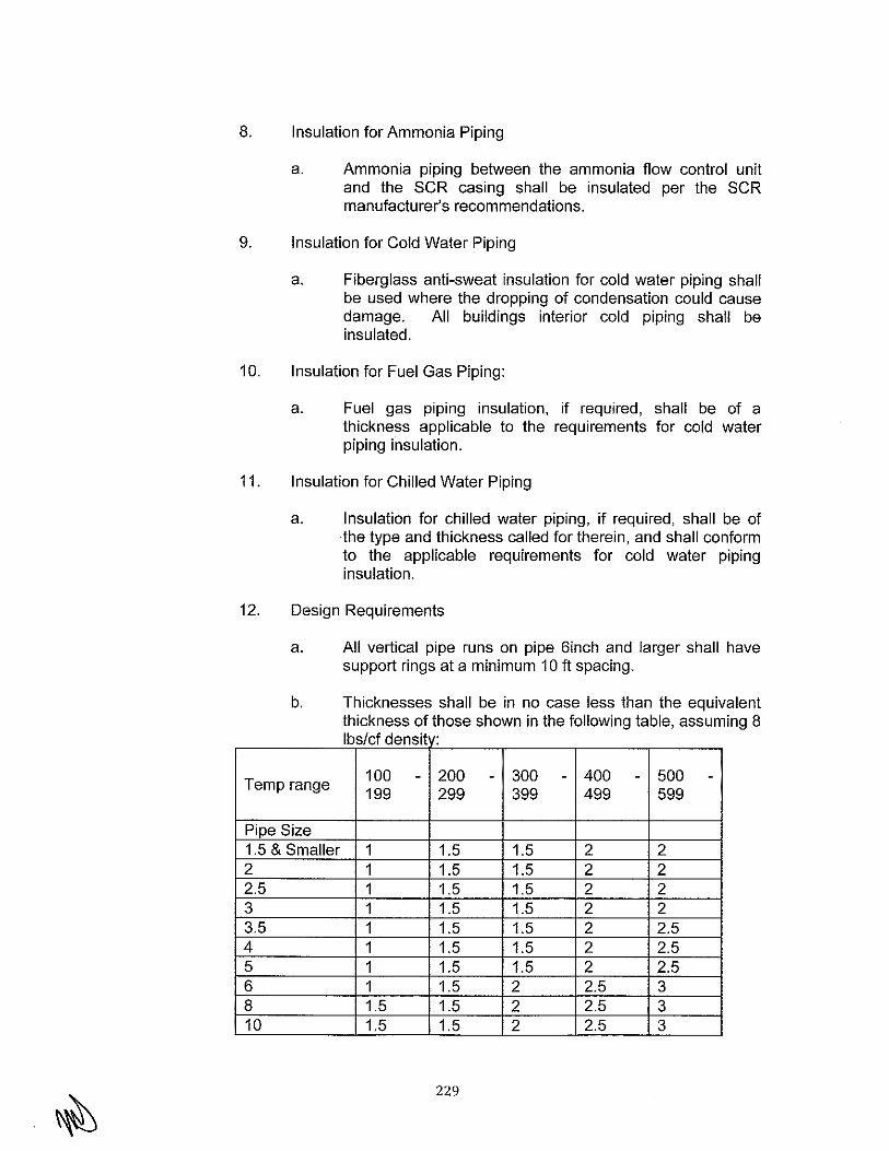
8. Insulation for Ammonia Piping
a. Ammonia piping between the ammonia flow control unit and the SCR casing shall be insulated per the SCR manufacturer's recommendations.
9. Insulation for Cold Water Piping
a. Fiberglass anti-sweat insulation for cold water piping shall be used where the dropping of condensation could cause damage. All buildings interior cold piping shall be insulated.
10. Insulation for Fuel Gas Piping:
a. Fuel gas piping insulation, if required, shall be of a thickness applicable to the requirements for cold water piping insulation.
11. Insulation for Chilled Water Piping
a. Insulation for chilled water piping, if required, shall be of the type and thickness called for therein, and shall conform to the applicable requirements for cold water piping insulation.
12. Design Requirements
a. All vertical pipe runs on pipe 6inch and larger shall have support rings at a minimum 10 ft spacing.
b. Thicknesses shall be in no case less than the equivalent thickness of those shown in the following table, assuming 8 lbs/cf densit :
- - - - -Temp range 100 200 300 400 500 199 299 399 499 599
Pipe Size 1.5 & Smaller 1 1.5 1.5 2 2 2 1 1.5 1.5 2 2 2.5 1 1.5 1.5 2 2 3 1 1.5 1.5 2 2 3.5 1 1.5 1.5 2 2.5 4 1 1.5 1.5 2 2.5 5 1 1.5 1.5 2 2.5 6 1 1.5 2 2.5 3 8 1.5 1.5 2 2.5 3 10 1.5 1.5 2 2.5 3
229

12 & larger 1.5 1.5 I 2.5
13. Lagging Material and Thickness
a. Ductwork, Breaching, Exposed Drums, Field erected tanks, and deaerator: 0.036" embossed, box ribbed aluminum, weather-proofed appropriately.
b. Piping: 0.02" embossed aluminum.
c. Valves & Fittings: 0.02" embossed aluminum.
W. Cranes and Hoists
1. General
a. As required, the BOP Contractor shall provide local hoist and trolley required to remove, access and perform routine maintenance.
b. All heavy parts of the plant supplied under the Agreement shall be provided with arrangements for lifting, slinging and handling during erection, maintenance and overhaul. All parts normally lifted during periods of maintenance and weighing one ton or over shall be appropriately marked with their weight.
c. Lifting beams (if required) shall be provided to facilitate handling of the various parts of the plant that require to be removed for cleaning and overhaul. The beams shall be supplied with trolleys for the attachment of blocks and lifting tackle and a range of suitable blocks and tackle shall be supplied. The lifting beams shall comply with the requirements of ANSI standards and shall be tested after erection. The BOP Contractor shall be responsible for the provision of the appropriate test certificates, which must be in accordance with ANSI Standards.
X. Corrosion Control and Cathodic Protection
1. Corrosion Control
a. Corrosion at the Power Plant in most cases can be mitigated. The correct application of materials with proper use of corrosion prevention measures will reduce maintenance costs and extend the life of equipment. It is imperative that all underground metallic components are electrically connected to the ground grid. Listed below are the minimum requirements for corrosion prevention of the major metallic components at the Power Plant.
230

b. The BOP Contractor shall furnish and install an impressed current cathodic protection system for all underground metallic components if required by the soil conditions.
c. An impressed current cathodic protection system has been installed for existing Units 1 through 10. The BOP Contractor shall insure that the new impressed current cathodic protection system, designed and furnished by the BOP Contractor, will not interfere with the existing systems. The BOP Contractor shall also insure that the existing cathodic protection system will not interfere with the new system.
d. The cathodic protection system shall be designed and installed in accordance to the latest issue of NACE International, ICEA, NEMA, ANSI, and any applicable local or national codes.
e. A cathodic protection survey is required at the end of the project to verify complete equipment protection.
2. Soil Resistivity
a. Prior to construction of the Power Plant, a survey of the soil resistivity should be conducted. The survey should provide resistivity profiles of the soil down to depths of 2.5', 5', and 1 0' using the Wenner four-pin method. This data is used in classifying soil corrosiveness, designing grounding grids, and determining cathodic protection needs.
3. Cooling Water Pipelines
a. The materials generally selected for circulating water pipelines are concrete lined ductile iron pipe, steel pipe or a non-metallic (HOPE) piping system depending on water temperature. Concrete lined steel pipe or ductile iron pipe needs to be electrically continuous, the exterior steel coated, and a cathodic protection system installed to protect the exterior of the pipe. Whenever cathodic protection is used, electrical potential test stations are to be installed along the pipeline route.
4. Natural Gas Piping
a. The natural gas piping shall be seamless steel pipe. The exterior underground portion of the pipeline and at least one-foot above grade shall be coated with a material suitable for underground installation. The exterior underground portion of the pipeline shall be cathodically protected. The exterior portion of the pipeline above ground shall be coated to prevent atmospheric corrosion.
231

Electrical potential test stations are to be installed along the underground pipeline route.
5. Miscellaneous Metal Piping Systems
a. The exterior underground portion of metallic p1p1ng systems and at least one-foot above grade shall be coated with a material suitable for underground installation. The interior of some of these piping systems may require an internal lining to prevent corrosion depending on the product being carried. The exterior underground portions of these pipelines shall be cathodically protected. The exterior portion of the pipeline above ground shall be coated to prevent atmospheric corrosion. Electrical potential test stations are to be installed along the underground pipeline route.
6. Metallic Above Ground Water Tanks
a. Above ground storage tanks, where the entire tank bottom is sitting on a concrete foundation, shall have the annulus between the foundation and the tank sealed to prevent the migration of any moisture to the exterior tank bottom. Above ground storage tanks constructed on a concrete ring with a soil foundation shall have the annulus between the ring wall and the tank sealed to prevent the migration of any moisture to the exterior tank bottom. The top 6 inches of the soil foundation must be sand. Rock or gravel is not permissible. The exterior bottom of the tank shall be cathodically protected and copper/copper sulfate reference cells installed to measure structure to soil potentials. The exterior of the tanks shall be coated to prevent atmospheric corrosion. The interior of the tanks shall be coated to prevent corrosion. Cathodic protection of the interior of the tanks is required. It is recommended that impressed current cathodic protection is used utilizing automatic potential rectifiers, mixed metal oxide anodes, and silver/silver chloride reference electrodes.
7. Structural Steel
a. See Section 5.12 for requirements.
8. Corrosion Protection
a. Where dissimilar metals are in contact or close proximity and corrosion may occur through electrolytic action or electroplating, suitable gaskets, cathodic protection or other means, shall afford differences in electrical potential protection.
232
b. Chromium plated parts shall not be used in any damp or corrosive atmosphere.
c. All surfaces shall be adequately protected in transit, and any damage shall be renovated immediately on off-loading and again on completion of erection.
d. After cleaning and inspection, but before the plant leaves the manufacturer's factory, the machined surfaces of steel and ironwork shall be covered with a preserving fluid of an approved type, or otherwise protected to LADWP's satisfaction.
e. All external steel screw fixings shall be hot dipped galvanized or stainless steel to comply with ANSI standards and with passivation treatment.
5.10 ELECTRICAL REQUIREMENTS
A. Electrical Systems and Equipment
1. Electrical System Design and Equipment Requirements
a. In general, the electrical systems and equipment described in this section shall, as a minimum, meet the requirements of NFPA 70 (National Electric Code), ANSI, IEEE, NEMA, NESC, California Electrical Code (CEC), and Los Angeles Electrical Code. Where the requirements of these conflict with the requirements of this document, these conflicts shall be referred to LADWP for resolution.
b. All Station electrical equipment, including bus, breakers, transformers, switchgear, motor control centers, cable, etc., shall be designed to withstand the maximum available fault current from the switchyard and/or generators, as applicable.
c. Efforts shall be made to reduce and control arc flash incident energy levels throughout the electrical system.
1) An arc flash calculation shall be performed to satisfy the requirements of IEEE 1584 and NFPA 70E. The electrical system shall be designed to limit the Incident Energy Level to a hazard/risk category of two and lower as defined by the current revision of NFPA 70E wherever possible. LADWP should be advised if the hazard/risk category for any part of the system is above category two. Arc flash labels with Incident Energy Level, Hazard/Risk Category, and Arc Flash Protection Boundary shall be provided for all electrical equipment.
233
2) Medium-voltage switchgear, medium-voltage motor control centers, and low-voltage switchgear shall be Type 2B arc-resistant in accordance with IEEE C37.20.7. Switchgear shall be capable of racking with the doors closed. SEL-751A relay with fiber optic arc flash detection and current supervision shall be included with the switchgear.
d. Under normal operating configuration (with tie breakers open) the loss or failure of a single component shall not result in the loss of more than two operating units.
e. On loss of normal power to a bus, after a short dead bus time delay the bus shall be automatically switched to the alternate source by the DCS. The DCS operator shall have the ability to disable the transfer scheme and also the ability to pre-select which alternate source to transfer to if more than one source is available. The intent of this requirement is to not rely on operator action to provide power to aid in safe shutdown of a unit.
f. Each Auxiliary Transformer (AT) shall be sized to carry the main breaker rating. Operators shall have the capability through the DCS to switch between auxiliary sources in a make-before-break scheme. When paralleling buses with having both main source breaker closed and the tie breaker closed, a paralleling alarm scheme shall be provided in the control room.
g. During all operating conditions other than during the starting of large motors, the voltage at motor terminals shall be maintained between 90% and 110% of motor rated voltage. Temporary voltage drops during motor starting shall not extend below 80% of the motor rated voltage at the terminals of the motor being started, and non-starting motors on the same bus shall not have a voltage of less than 90% of rated voltage at their motor terminals.
h. Electrical equipment shall be designed and purchased to satisfy seismic requirements of IEEE 693. See Section 5.12 of this Specification for additional requirements. Specifications shall include the general requirements (Annex Sections A and B), the high level of qualification and the specific requirements of IEEE 693 for the following equipment:
1) Circuit Breakers
2) Transformers
3) Disconnect Switches
4) Grounding Switches
5) Station Batteries and Battery Racks
234

6) Metalclad Switchgear
i. "States" type sliding link terminals shall be provided for connections of control and protection circuits such as at transformer control boxes, protective relay panels and any other terminations of cable to LADWP equipment.
j. One (1) independent 250A 480V ac power feed shall be provided to the switchyard relay room by the BOP Contractor from the plant power distribution equipment.
B. Generation System
1. General Requirements
a. The Generation System shall consist of the generators, generator buses, generator breakers, and the GSUTs. The Generation System shall be designed to meet WECC and NERC guidelines and requirements.
2. Generators
a. The generators for the combustion turbines and diesel generators will be in accordance with the combustion turbine specifications in the CTG Contract provided with the RFP documents issued by LADWP and the diesel generator specifications in Section 5.8 of this Contract.
C. Isolated Phase Bus Duct (Generator Bus)
1. Isolated Phase Bus Duct General
a. The BOP Contractor shall design, manufacture, test, deliver, and install generator bus for each generator, as described below.
b. Generator bus shall be provided between the generator and generator breaker, and the generator breaker and GSUT for each unit. A cable termination box shall be provided on the generator bus between the generator circuit breaker and the GSUT to connect each Auxiliary Transformer (AT). The cable termination box shall have separate phase enclosures and shall be designed such that the cables can be temporarily disconnected to provide an isolation point to allow continued operation of the associated generator in the event that any auxiliary transformer is required to be out of service for maintenance.
c. All generator bus shall be rated to carry the maximum generator output continuously at 95% of rated voltages. Generator bus connections shall be arranged such that bends in the generator buses shall be minimized, overall bus lengths shall be as short as practical, and transformer cooling airflow shall not be restricted.
d. Where it is not possible to terminate the isolated phase bus enclosures at the generator, a suitable segregated
235

enclosure and associated bus work shall be provided to transition from the generator terminals to the iso-phase bus duct. The Generator supplier shall furnish the line-side terminal enclosure.
2. Isolated Phase Bus Duct Equipment Specification
a. Isolated Phase Bus Duct General
1) BOP Contractor shall design, manufacture, test and deliver isolated phase bus duct and auxiliary equipment as specified herein.
2) The isolated phase bus duct will interconnect the following equipment:
1) Generators
2) Generator Circuit Breakers
3) Cable Termination Box for Auxiliary Transformers
4) Generator Step-up Transformers (GSUTs)
3) The isolated phase bus duct shall be a self-cooled design.
The equipment shall conform to, and tests shall be conducted in accordance with, the latest applicable Standards of the American National Standard Institute, Inc. (ANSI), the Institute of Electrical and Electronics Engineers, Inc. (IEEE), and the National Electrical Manufacturers Association (NEMA). See "Electrical System Design and Equipment Requirements" Section for seismic design criteria. For environmental loading, see Exhibit Z Section 1. "Site Meteorological Data" and Section 5.12. "Structural Loads".
b. Bus Ratings
1) Bus nominal operating voltage (3-phase, 60 Hz) (kV}: 13.8
2) Rated maximum voltage (kV): 15
3) Standard full wave impulse withstand voltage (kV): 110
4) Continuous current rating:
o Main bus (A) 7000
o Tap bus (A) BY BOP Contractor
5) Momentary current values which the buses are mechanically braced to withstand shall be not less than:
• Main bus BY BOP Contractor
236
• Tap bus BY BOP Contractor
6) The temperature rise, at rated current, above ambient temperature of 50'C of air surrounding the bus enclosures and cubicles, shall be in accordance with IEEE C37.23 and shall not be more than:
a. Bus conductors and their silver surfaced, welded or brazed connections and disconnect switches or links ............ 55'C
b. Generator and transformer connections ......................................................... ~'C
c. Bus enclosure and support structures ......................................................... 30'C
d. Instrument panels, control panels, doors and cubicles accessible to personnel ......................................................... 30'C
d. Cable connection (using silver-plated terminations) .................................... 35'C
c. General Requirements
1) The isolated phase bus structure shall consist of rigid electrical conductors mounted on porcelain or polymer insulators. Each phase shall be enclosed in a separate weather and dust-tight nonmagnetic metal enclosure, separated by an air space from the adjacent phases. The three phases shall be securely braced, mounted on and supported by a substantial metal structure.
2) The bus shall be suited for outdoor installation and shall include all necessary equipment connections, flanges, seals, taps, elbows, offsets, splicing materials, adapter bars, supporting structure, and any material required to make a complete coordinated bus installation. A complete set of drawings and installation instructions shall be furnished with each run of bus. Expansion joints shall be provided as required to accommodate thermal expansion of the bus.
3) All bus conductors and connections, insulators, supports, enclosures and supporting structures, when installed, shall have sufficient mechanical strength to ensure continuous, satisfactory operation under normal operating conditions and shall withstand, without incurring damage, the effect of any momentary current resulting from a three-phase, line-to-line or line-to-ground short circuit. The momentary current shall be of the rms value, including the direct current component, of the maximum cycle that corresponds to the rms
237

asymmetrical Specification.
currents specified in this
4) Equipment of the same type and rating, shipped under the same contract, shall be physically and functionally interchangeable.
d. Positive Pressure Air Provisions
1) A tap connection in each phase bus run shall be provided for connection to plant dry instrument air. The positive pressure air provisions are intended to pressurize the bus enclosure to prevent dust or moisture entering the bus enclosure.
2) One connection point for air supply and metering and one connection point for pressure monitoring shall be furnished in each phase bus enclosure. Connection points shall be 1/2 inch NPT; shipped with a plug. All air supply and metering connection points shall be at the top of enclosure.
3) A pressure regulating station, including orifices, valves, and filters shall be provided to regulate the compressed air within pressure limits of the bus enclosures. Each phase bus enclosure run shall be equipped with a pressure relief valve to prevent bus damage in case of regulator device failure, exposing the duct to high supply pressure.
4) Manual valves shall be furnished with the pressure regulator system to allow manual purging of each phase bus enclosure.
5) Vapor isolation barriers or seal-off bushings shall be furnished at each equipment termination location, where required to provide an airtight seal.
e. Conductors, Insulators, Supports, and Fittings
1) All bus conductors, when installed in their housing, shall have a cross-sectional area sufficient to carry rated current continuously with a temperature rise not to exceed the values specified. All conductor bolted connections shall be silver plated.
2) Bus insulators and supports shall be braced or designed to prevent the permanent displacement of any part due to stresses incident to short circuits. Provisions shall be made for expansion and contraction, due to load changes and changes in the ambient temperature, to prevent stress or damage to the conductors within the housing. The bus conductors shall be supported by insulator blocks or post insulators. The insulation/insulator
238

design shall exceed the BIL rating specified for the bus.
3) Flexible connections shall be provided at all equipment terminations. Expansion connections shall be provided, as required, by Manufacturer.
4) At all points where metal contact is made between copper and steel, or between other dissimilar metals, the Manufacturer shall provide protective coatings for the contact surfaces that will effectively prevent corrosion and ensure good electrical contact.
f. Bus Structure Supports
1) Rigid metal frames shall be furnished to support the three-phase sections and single-phase section of the bus structure. The frames shall be designed to be supported from below by structural members.
2) The BOP Contractor shall furnish all supporting structures, including columns, base plates, hangers and all necessary hardware required for supporting the sections of bus structure.
3) All outdoor steel structures shall be hot-dipped galvanized steel.
4) The BOP Contractor shall furnish the framework required for insertion in walls or floors to permit passage of the bus through such walls and floors, if necessary.
5) Where necessary to avoid excessive heating, the framework supporting the bus structure shall be of non-magnetic materials, or it shall be provided with low resistance shielding bands or short-circuiting rings. The BOP Contractor shall check the heating effects in any building columns, reinforcing beams, or other structural members, which are close to the bus, and if necessary, shall recommend the location of short-circuiting rings, shielding bands, or shielding plates.
6) All foundations for the bus structure supports and all openings in walls and floors, if any, will be provided by the BOP Contractor.
7) See Section 5.12 of this Specification for additional requirements related to foundations and structural supports.
g. Bus Enclosures
1) The bus enclosures shall completely surround and enclose the conductors and insulators. They shall
239

be fabricated of nonmagnetic material and they shall be designed to afford easy access to conductor joints and insulators for assembly, inspection, and maintenance.
2) Removable sections, covers and inspection doors in the enclosures shall be furnished with gaskets designed and secured in position so that movement of the bus, enclosures or supporting structures (caused by vibration, temperature changes, or short-circuit forces) will not displace or damage the gaskets. The gasket material shall ensure long life without replacement or adjustment, and shall be reusable.
3) The bus enclosures shall be electrically continuous over the entire length and shall be electrically short circuited at all ends. The enclosures shall be welded to form a continuous enclosure.
4) Flexible or expansion joints shall be furnished at enclosure terminations, and wherever required, as determined by the BOP Contractor.
5) Filter drains shall be provided at terminations to equipment, at building walls, floors, or roof and at all low points in the horizontal portions of the bus structure, to ensure the elimination of any condensation that might collect in the enclosures.
6) The connection between the bus duct enclosures and flanges at the transformer tank shall be provided with insulated gaskets to prevent circulating currents in the transformer tank top caused by induced voltages in the bus duct enclosures.
D. Generator Step-Up Transformers (GSUT)
1. GSUT General
a. Three (3) GSUTs and specified accessories including oil and gases will be provided by the BOP Contractor.
2. GSUT Equipment Specification
a. GSUT Specification General
1) The GSUT's shall be three winding transformers with a CTG connected to each of the secondary windings. The power generated from each generator will be supplied to the 230 kV switchyard via a GSUT. The GSUTs shall be sized to match their associated generators. The sizes of the transformers in the bid proposal are subject to review and approval by LADWP prior to Agreement award.
240

2)
3)
4)
5)
6)
7)
8)
9)
Angular Displacement: The transformers shall have the standard phase relationship.
A manually operated tap changer shall be provided on each transformer for operation when the transformer is not excited. The tap changer handwheel shall be between two and four feet above the transformer base. The tap changer shall have a visual indication of tap position with padlocking capabilities at any tap position. The noload tap changers shall be as manufactured by "Reinhausen" or agreed upon equal. The BOP Contractor shall verify with LADWP the nominal operating voltage for the 230 kV switchyard.
The transformers shall be designed, constructed, and tested in accordance with IEEE Standard C57.12 series and the applicable National Electrical Manufacturers Association (NEMA) standards. The vendor shall provide guaranteed maximum losses per IEEE standard C57.12 series.
See "Electrical System Design and Equipment Requirements" Section and "Lockout Relay Action" Section for IEEE seismic design criteria. For environmental and other loading, see Exhibit Z Section 1 "Site Meteorological Data" and "Structural Loads" Section. Design must comply with both 2007 California Building Code and IEEE 693.
The GSUTs shall be designed to withstand without damage, back-feeding of plant auxiliaries, with low voltage windings connected only to Auxiliary Transformers that may or may not be carrying load.
The transformer shall be capable of withstanding, without damage, the effects of continuous unbalance corresponding to a negative phase sequence current of 10%, provided rated MVA is not exceeded, and the maximum current does not exceed 105% of the rated current in any phase.
Parallel Operation: The transformers shall not be required to operate in parallel with any existing transformers except during short-time transition of power supply sources in the auxiliary system.
Noise Levels: The equivalent "A" weighted sound level measured at 5 feet elevation above grade level and 3 feet horizontally from the base of any of the equipment furnished, expressed in decibels to a reference of 0.0002 microbar, shall not exceed 85 dBA.
241

1 0) Transformers and accessories shall be painted in accordance with the Manufacturer's standards for outdoor power equipment. All finish paint shall be applied at the Manufacturer's facility. Finish paint color shall be ANSI 70 grey.
11) The transformer shall be capable of withstanding, without damage, the mechanical and thermal stresses caused by short circuits on the external system of any winding in accordance with Section 7 of IEEE Standard C57.12.00.
12) The cooling system shall consist of necessary radiators, stainless steel fans and pumps in such combination as required, complete with automatic control equipment required to maintain the specified temperature rise.
13) Two (2) 480V, three phase, power circuits shall provide power to the transformer control through an automatic transfer switch.
14) Control circuits shall be designed for operation on 120 volts, 60Hz, and alarm circuits for 125-Vdc. BOP Contractor shall supply all auxiliary power required for transformer operation.
15) Control equipment shall include the necessary fused switches or circuit breakers, fuses, fuse clips, control transformers, temperature control relays, alarm actuating devices, and associated equipment required to provide a complete control system. All auxiliary relays shall be furnished in their own individual enclosure. A complete set of spare fuses shall be furnished.
16) All voltage failure relays shall be connected to alarm on loss of monitored voltage.
17) Cooling equipment controls shall be arranged so that no single fault in the control circuitry shall cause a loss of more than one half of the cooling system capability.
18) The transformer cooling equipment controls shall be arranged so that a single remote contact shall shut down all pumps and fans, regardless of the mode of operation selected.
19) Manual control switches shall be provided in the control cabinet to allow testing and maintenance of the cooling fans and pumps. Controls shall provide for changing the sequence of cooler groups.
242

20) See "ELECTRICAL SYSTEMS AND EQUIPMENT" Section for terminal block requirements for connections to the control circuits.
b. Transformer Oil Preservation System and Accessories
1) Oil Preservation System: Equipment shall be of the conservator/liquid preservation system.
2) Expansion Head: Sufficient expansion head shall be provided to allow an ambient temperature range from -1 O'C to 40'C under all load conditions without exceeding pressure limits or operating pressure vacuum bleeder device. A pressurevacuum gauge shall be provided. Low gas pressure alarm contacts are not required.
3) Combustible Gas Device: A combustible gas device shall be provided with each GSUT. The device shall be complete with a meter calibrated in percent total combustible gas and an adjustable alarm contact shall close a preset level of total combustible gas. Contact shall be suitable for 125-Vdc service.
4) Combustible Gas On-Line Monitoring System: Morgan Schaffer Model AMS-500 Plus or approved equal. 4-20 mA signals shall be wired back to the DCS for water and hydrogen monitoring.
5) Fault Pressure Devices: A Buchholz Relay and two (2) Qualitrol Model 900-1A or agreed upon equal, shall be provided to close a contact for relay operation in case the internal pressure rises suddenly. Where applicable, isolation valves shall be installed on either side of the devices. One ( 1) of the two Qualitrol or equal devices should be located at the transformer drain. BOP Contractor shall review the application of the fault pressure device in order that the location chosen ensures proper operation. The devices shall be wired in parallel for maximum safety. An individual auxiliary seal-in relay shall be furnished for each device. The auxiliary relay shall have two (2) form-C open contacts. A reset push-button shall be provided.
6) The control cabinet shall be provided with space heaters to prevent condensation of moisture within the cabinet. Space heater capacity shall be as required to maintain temperature above the dew point. The heaters shall be spaced away and thermally insulated from devices or painted surfaces.
243
7) BOP Contractor shall provide transformation equipment within the transformer control cabinet to supply the specified space heater power and shall provide acceptable branch circuit protection.
8) Each transformer shall be provided with the following accessories:
i. Winding temperature indicator
ii. Liquid temperature indicator
iii. Magnetic level gauge
iv. Two (2) mechanical pressure relief device
v. Manufacturer shall provide dry contact outputs for alarm status to plant DCS.
c. Transformer Tank and Base
1) Transformer Tank: Tank shall be designed to withstand vacuum filling at full vacuum in the field.
2) Base: The bottom of the transformer shall have a steel skid base.
3) Groundpads shall be furnished on each transformer tank in accordance with the requirements of ANSI C57.12.10 -1977, Article 9.2.8.
4) Unless alternate acceptable provision is made to prevent corrosion of the exterior of the bottom of the tank, the transformer tank design shall be such that ventilation is provided between the concrete supporting slab and the bottom of the transformer tank. Only supporting steel beneath the transformer tank may touch the concrete slab. Design of the steel supporting the transformer tank bottom shall be such that the bottom is accessible for inspection after installation.
5) The transformers shall be provided with welded guardrail cleats and all safety rail equipment including storage cabinet per Gal/OSHA and OSHA requirements.
d. Performance Test
1) Transformer windings shall be subjected to and shall satisfactorily withstand dielectric tests in accordance with IEEE C57.12.10 and applicable standards of NEMA, at voltage levels specified.
2) A Sweep Frequency Response Analyzer test shall be performed on each transformer at the factory and at site. The test instrument and method shall be in accordance with Doble M5100 Sweep Frequency Response Analyzer.
244

3) Each transformer shall be subjected to a 12-hour over excitation test.
4) A full temperature rise test shall be performed on one unit.
e. Transformer Losses and Auxiliary Power Requirements
1) The load losses, efficiency and regulation shall be corrected to a reference temperature according to IEEE C57.12.00.
f. Transformer Ratings
1) The transformer shall be three-phase, threewinding, 60 Hz, outdoor, oil-immersed type, Class ONAN/ONAF/ONAF. The transformers shall be rated to accommodate the full MVA output of the associated generators over the full power factor range, and the frame size of the generators.
i. Transformer losses should be minimized at full load operation. The manufacturer shall provide guaranteed maximum transformer losses
2) Generator Step-up transformers - Quantity: 3
Rated Voltage (line-to-line) (kV)
Transformer Connections (Wye or Delta)
Full Load at 65°C Rise:
Self-cooled (ONAN) (MVA)
First-stage cooling (ONAF) (MVA)
Second-stage cooling (ONAF) (MVA)
Impedance shall be 8% H-X and H-Y, 16% X-Y with ±10% standard tolerance@ 93 MVA Base.
No-load tap changer:
Above rate voltage at full MVA capacity (number of taps and
High-Voltage
H-Winding
230
Wye
186
248
310
High-Voltage H-Winding
percent volts each tap) [ 2 @ 2-%%
Below rated voltage at full MVA capacity (number of taps and percent volts each tap) [ 2 @ 2-%% ]
245
Low-Voltage
X& YWindings
13.8
Delta
93
124
155
Low-Voltage X-Winding

System neutral (Isolated or type of grounding) Solidly grounded
Ungrounded
Insulation Class (kV) 230 25
Neutral Insulation Class (kV) 25
Winding Basic Impulse Insulation Level (BIL) (kV) 825 150
Bushing Ratings:
Insulation Class
g. Terminal Connections and Bushings
(kV)
1) Transformer leads shall be brought out of the transformer case by means of bushings of the outdoor type. Bushings shall be capable of withstanding the 60 Hz applied potential tests and the lightning impulse tests specified herein.
High-Voltage
H-Winding
230
Low-Voltage High-Voltage
X & Y-Winding Neutral
15 25
Basic Impulse Insulation Level (BIL) (kV) 1050 110 150
2) The color of the bushing shall be ANSI 70 light grey.
3) Bushings for the high voltage windings shall be composite type resin impregnated paper (RIP) insulated bushings. The bushing creep distances shall be based on heavy contamination as specified by IEEE C57.19.01, as required for the coastal environment.
4) Bushings for the high-voltage windings shall be cover-mounted and connected to the surge arresters.
5) The GSUT High Voltage bushings shall be supplied with terminals matching LADWP standard high voltage lugs, as defined by LADWP. The BOP Contractor shall request the information from LADWP when specifying equipment for procurement.
6) Bushings for low-voltage windings shall be top mounted, and have a flanged enclosure suitable for connection to isolated phase bus duct. Ample space and access shall be provided for the installation of the isolated phase bus duct. The box and connections shall be so arranged that the transformer may be disconnected and removed without disturbing the incoming bus connections. The chamber shall be air-filled, and all current
246

carrying parts in it shall be properly insulated, supported, and braced. The low point of flanged enclosure shall be provided with a minimum 5/8-inch diameter screened drain.
7) The neutral bushing shall be cover-mounted.
8) Oil-filled bushings shall be tested for power factor at the factory, and test values shall be included in test reports to LADWP. Space on the bushing nameplates shall be provided for stamping values of initial field power factor tests.
9) Bushings shall be IEEE Standard.
1 0) All current carrying parts of power transformer bushings shall be copper or copper alloy material and surfaces shall be plated to inhibit deterioration.
11) A suitable copper bar shall be installed between neutral bushing on top of tank and ground pad on top of tank.
12) Bushing Monitoring System: Each transformer shall be provided with a bushing monitoring system to continuously monitor the changes in the bushing insulation based on changes in bushing capacitance and bushing power factor. The system shall detect changes in the power frequency current through the bushing insulation. The system shall also provide provisions for the connection of instrumentation for periodic electrical partial discharge measurements, on-line, using portable equipment without requiring a transformer outage, or any modifications to the sensing circuit. The system shall provide remote monitoring and trending to the plant control system. All equipment and accessories required for a complete functional system shall be provided.
h. Bushing Current Transformers
1) Two (2) multi-ratio, 1 ,200 to 5 ampere relaying accuracy Class C800 current transformer on each high-voltage bushing.
2) One (1) multi-ratio, 1,200 to 5 ampere metering accuracy 0.3B1.8 current transformer shall be mounted closest to the winding on each highvoltage bushing. Metering accuracy CTs shall be lab certified.
3) One (1) multi-ratio, 1,200 to 5 ampere relaying accuracy Class C800 current transformer shall be mounted on each high-voltage neutral bushing.
247

4) Multi-ratio current transformer shall be five lead distributed winding type with all leads brought out to a shorting-type terminal block in the weatherproof cabinet.
5) Type test certificate for each transformer shall be furnished.
i. Surge Arresters
1) The following surge arresters, of a type not susceptible to failure because of external contamination, shall be furnished mounted on and grounded to the transformer tank:
E. Generator Breakers
i. One (1) 192kV MCOV, station type, for each 230-kV bushing terminal.
ii. Each arrester shall be self-supporting, designed for base mounting.
iii. All insulators used in or with each arrester shall be of the composite type, free from laminations, cavities, or other flaws affecting its mechanical and dielectric strength.
iv. Corona-free full ampacity connections shall be provided between the surge arresters and the associated bushings. (These connections shall have a flexible arrangement, so that the bushings shall not be overstressed during vacuum filling.) The MCOV connections shall be made to the arrester terminals. BOP Contractor shall furnish a %-inch-thick NEMA 4-hole horizontal tinned copper pad at each arrester terminal for bolting to LADWP's connectors.
v. All ferrous parts exposed to the weather and subject to corrosion shall be zinc coated by the hot-dipped galvanized process.
vi. Each arrester shall have a pressure relief device, which shall act positively to vent gas pressures for the prevention of explosion of the porcelain in the event of arrester failure.
vii. The color of the arresters shall be ANSI 70 grey.
1. Generator Breaker General
The generator circuit breakers shall be SF6 breakers and designed, manufactured and tested in accordance with the latest standards of ANSI/IEEE, particularly IEEE C37.013, and NEMA.
248

2. Generator Breaker Equipment Specification
a. Generator Breaker Specification General
1) The generator circuit breaker shall be designed, manufactured, and tested in accordance with the latest standards of ANSI/IEEE and NEMA. See "Electrical System Design and Equipment Requirements" Section for seismic design criteria. For environmental loading, see Exhibit Z Section 1. "Site Meteorological Data" and Section 5.12.G "Structural Loads."
2) A generator breaker shall be connected between each generator and GSUT.
3) The generator circuit breaker shall be located outdoors.
4) The generator breaker shall conform to the following Specifications.
b. Generator Breaker Rating (on a symmetrical basis)
c.
1) Nominal voltage class (kV) 13.8
2) Maximum design voltage (kV) 25
3) Current rating on a symmetrical basis:
i. Rated continuous current at 60 HZ 7000 (Arms)
ii. Rated short-circuit current (at rated 100 maximum voltage) (kA rms)
iii. Three-second short-time current 100 carrying capability (kA rms)
4) Rated interrupting time (cycles) 50
5) Rated permissible tripping delay 50 (cycles)
Operating Mechanism
1) The operating mechanism shall be Manufacturers standard.
2) If an air compressor or hydraulic pump is furnished, the power supply by BOP Contractor will be 125 Vdc.
3) A "Local" control means shall be provided which will close or trip the breaker when the permissive switch is in the local position. Closure of the
249
breaker shall only be allowed the when the associated disconnect switch is open.
4) The "Local" control shall include a "permissive" switch, which shall block remote control of the breaker when in the "Local" position.
5) Portable SF6 gas top-up/recharge equipment shall be supplied. An SF6 gas leakage detector shall be included along with all equipment necessary to safely carry out top-up/recharging operations.
6) Space heaters rated for continuous operation at 120 Vac with necessary control devices shall be furnished for circuit breaker drive and control panel, as a minimum.
7) The control, indicating and interlocking wires for the operating mechanism shall be enclosed and shall be brought together to a terminal block in the operating mechanism cabinets. Secondary wiring from bushing current transformers, which terminates within mechanism cabinet, shall be completely enclosed with water tight joints, between the transformer housing and the mechanism cabinet.
8) Operating mechanism shall be arranged to immediately trip all poles if any one pole fails to close.
9) Terminal blocks for terminating all current transformer leads, including tap leads, and for terminating control wiring are to be furnished. See "Electrical Systems and Equipment" Section for terminal block requirements for customer connections to the control circuits.
1 0) Auxiliary contacts for external indication and interlocking shall be provided as required.
d. Mechanism Housing
1) Suitable weather tight and dustproof cabinets of liberal size shall be provided for housing the operating mechanisms, relays, and terminal blocks for small wiring. Provision shall be made in the bottom of the cabinet for remote control wiring.
e. Motorized Disconnect and Ground Switches
1) Each generator circuit breaker shall have two (2) motorized grounding switches and one (1) motorized disconnect switch per pole. One grounding switch shall be installed on each side of the circuit breaker, and the disconnect switch shall be installed on the transformer side of the circuit
250
breaker. The grounding switch on the transformer side of the circuit breaker shall be installed between the disconnect switch and the transformer.
i. Grounding and disconnect switches shall be rated for both the continuous current rating and the short time rating of the installed system.
ii. Visual confirmation of the position of all three poles of the isolating and grounding switches shall be provided.
iii. Provisions shall exist such that the switches and interrupter cannot operate in an unsafe condition. This includes, but is not limited to, ground switches not being allowed to be closed when the phase conductors are energized and the disconnect switch not being allowed to be closed when the interrupter is closed. Key interlocking shall be used where possible.
f. Current Transformers
1) Bushing type current transformers (CT) shall be supplied as listed below. CT ratios shall be 8,000:5, single ratio. Each CT shall have a relaying accuracy of C400 minimum and metering accuracy of 0.3B1.8 as defined by IEEE C57.13. Metering accuracy CTs shall be lab certified.
2) The generator circuit breaker shall have a relaying accuracy CT on the generator side and a relaying accuracy CT on the GSUT side.
3) The generator circuit breaker shall have a metering accuracy CT on the generator side.
4) All secondary tap leads of the current transformers shall be brought together to short circuiting type terminal blocks for connection to BOP Contractor's cables. All wiring shall be No. 10 AWG, single conductor, stranded copper, 600 volt rated, flame and moisture resistant.
5) Type test certificate for each current transformer shall be furnished. In addition, calibration test reports shall be provided for the metering current transformer.
g. Potential Transformers (PTs)
1) Manufacturer shall furnish three (3) three-winding potential transformers (PTs) as part of the circuit breaker.
251

2) Potential transformers shall be located between the GSUT and the generator circuit breaker.
3) The primary and secondary windings of the PTs shall be fused.
4) One secondary winding shall be connected in broken-delta configuration with a ferro-resonance suppression device connected directly to the broken delta connection without fuses and a fused connection extended to the relays. The other secondary winding shall be connected wyegrounded with separate sets of fuses for the connected devices.
5) The Contractor shall provide a means for disconnecting the PTs.
6) The PTs shall be rated 14,400- 120 V.
7) Each PT shall be rated 0.3WXMY, 1.2Z.
h. Nameplates
1) A suitable connection diagram plate showing current transformer connections shall be mounted in the current transformer cabinet adjacent to the terminal blocks.
2) A suitable nameplate shall be mounted on air or gas compressors and tank giving normal and maximum pressure rating.
i. Tests
1) BOP Contractor shall perform tests on the breaker to check the quality and uniformity of the workmanship and materials used in the manufacture of the generator breaker. Fifteen (15) copies of certified data shall be submitted to LADWP for each of the following tests:
a. Operating tests to check speed and mechanical performance.
b. Tank leakage and complete air or gas systems tests.
c. Low frequency shall withstand voltage tests on completely assembled breakers or on major insulation components such as bushings, etc.
d. Low frequency shall withstand voltage tests on assembled control and secondary wiring.
2) BOP Contractor shall also submit, if requested, test data to substantially prove that the breaker design capability to meet the ratings as hereinafter specified. BOP Contractor shall describe method of making all tests on which data is submitted.
252
3) BOP Contractor shall furnish certified test data on all current transformers furnished.
F. Auxiliary Transformer (AT)
1. Auxiliary Transformer General
a. The BOP Contractor shall provide and install three (3) Auxiliary Transformers and accessories including oil and gases as specified below.
b. The ratings and capabilities of each Auxiliary Transformer and electrical distribution equipment shall be such that the loss of a single Auxiliary Transformer shall not limit the total station generation capacity. Transformer losses shall be minimized at full load operation.
2. Auxiliary Transformer Specification
a. Purpose of Auxiliary Transformer Equipment
1) Each Auxiliary Transformer shall be three-phase, three-winding, 60 Hz, outdoor, step-down, oilimmersed type, Class ONAN/ONAF/ONAF.
b. Transformer Ratings
High-Voltage
H-Winding
Low-Voltage
X-Winding
Nominal System Voltage (line-to-line) (kV) 13.8 4.36
Transformer Connections Delta)
Full Load at 65° Rise:
Self-cooled (ONAN) (MVA)
(Wye or
First-stage cooling (ONAF) (MVA)
Second-stage cooling (ONAF) (MVA)
No-load tap changer:
Above rated voltage at full MVA capacity (Number of taps and percent volts each tap)
Delta ] Wye ]
[BY BOP [BY BOP Contractor] Contractor]
[BY BOP [BY BOP Contractor] Contractor]
[BY BOP [BY BOP Contractor] Contractor]
[2@ 2-1/2%]
253

Below rated voltage at full MVA capacity (Number of taps and percent volts each tap) [2@ 2-1/2%]
System neutral (Isolated or type of grounding)
Ungrounded Grounded through resistor
Insulation Class (kV) 25 5
Neutral insulation class (kV) 5
Basic impulse insulation level (BIL) (kV) 150 75
1) Angular Displacement: The transformer shall have the standard phase relationship.
2) Impedance: The impedance at the rated connections shall be (As required) % based on (As required) MVA base with IEEE standard ±7.5% tolerance.
3) A manually-operated tap changer shall be provided for operation when the transformer is not energized. The tap changer handwheel shall be between two and four feet above the transformer base. The tap changer shall have a visual indication of tap position with padlocking capabilities at any tap position.
4) The transformer shall be designed, constructed, and tested in accordance with IEEE Standard C57.12 series and the applicable National Electrical Manufacturers Association (NEMA) standards. The vendor shall provide guaranteed maximum losses per IEEE standard C57.12 series.
5) See "Electrical System Design and Equipment Requirements" Section and "Lockout Relay Action" Section for IEEE seismic design criteria. For environmental and other loading, see Exhibit Z Section 1 "Site Meteorological Data" and "Structural Loads" Section. Design must comply with both 2007 California Building Code and IEEE 693.
6) Parallel Operation: The transformer shall not be required to operate in parallel with any existing transformer except for short-time operation when transferring power sources in the auxiliary system.
7) Reliability shall be of the utmost importance in the design of the transformer.
254

8) Noise Levels: The equivalent "A" weighted sound level measured at 5 feet elevation above grade level and 3 feet horizontally from the base of any of the equipment furnished, expressed in decibels to a reference of 0.0002 microbar, shall not exceed 85 dBA.
9) Transformers and accessories shall be painted in accordance with the Manufacturer's standards for outdoor power equipment. The paint color shall be ANSI 70 light gray. All finish paint shall be applied at the Manufacturer's facility.
c. Short Circuit Capability
1) The transformer shall be capable of withstanding, without darnage, the mechanical and thermal stresses caused by short circuits of the external system of any winding in accordance with Section 7 of IEEE Standard C57.12.00.
d. Thermal Connections and Bushings
1) Transformer leads shall be brought out of the transformer case by means of bushings of the outdoor type. Bushings shall be capable of withstanding the 60 Hz applied potential tests and the lightning impulse tests specified herein.
HighVoltage HWinding
LowVoltage XWinding
Neutral Y) Bushing
Auxiliary Transformer Bushing Ratings:
Insulation class (kV) 25 5 5
Basic lightning impulse insulation level (BIL) (kV)
150 l 75 75
2) The color of the bushings shall be ANSI 70 light gray.
3) Bushings for the high-voltage windings shall be suitable for cable connections and include a cable termination enclosure. The enclosure shall be airfilled, and all current-carrying parts in it shall be properly insulated, supported, and braced. The low point of flanged enclosure shall be provided with a rninirnurn 5/8 inch diameter screened drain.
255

)
4) Bushings for each of the low-voltage windings shall be side-mounted and entirely enclosed and shall be provided with a flat %-inch thick minimum NEMA 4-hole pad. Ample space and access shall be provided for the installation of the non-segregated bus duct. The chamber shall be air-filled, and all current-carrying parts in it shall be properly insulated, supported, and braced. A minimum 5/8-inch diameter screened drain shall be provided.
5) The neutral bushing shall be cover-mounted and connected to the 400A neutral grounding resistor.
6) All current-carrying parts of power transformer bushings shall be copper or copper alloy material and surfaces shall be plated to inhibit deterioration.
e. Bushing Current Transformers
1) Two (2) 2,000 to 5 ampere and one (1) 8,000 to 5 ampere single ratio relaying accuracy Class C800 current transformer shall be mounted on each highvoltage bushing.
2) One (1) 4,000 to 5 ampere single ratio relaying accuracy Class C800 current transformer shall be mounted on each low-voltage bushing.
3) One (1) multi-ratio, 400 to 5 ampere relaying accuracy Class C400 current transformer shall be mounted on the low-voltage neutral bushing.
4) Multi ratio current transformers shall be five lead distributed winding type with all leads brought out to a shorting-type terminal block in the weatherproof cabinet. See "Electrical Systems and Equipment" Section for terminal block requirements for customer connections to the control circuits.
5) Type test certificate for each current transformer shall be furnished.
f. Neutral Grounding Resistors
1) Each neutral grounding resistor shall be arranged with cover mounting adjacent to the associated lowvoltage neutral bushing.
2) The neutral grounding resistor shall have the following characteristics:
i. Impedance at 25'C (ohms) [6]
ii. Voltage Rating (V) [2400]
iii. Frequency (Hz) [60]
iv. Continuous current rating amps) [ 400 ]
256
(rms sym.
v.
vi.
vii.
Mechanical current rating continuous) [ 1.2 ]
(seconds)
(multiple of
[10] Rated time
Service type [outdoor]
3) The cast iron or stainless steel resistor shall be corrosion protected and shall be of the enclosed tank type. Steel mounting details shall be galvanized.
4) The resistor shall conform to IEEE 32, "Standard for Neutral Grounding Devices", except as modified herein.
5) Manufacturer shall furnish and install suitable insulated copper bar between the low-voltage neutral bushing and the associated neutral resistor and between each resistor and the ground pad on the transformer cover.
6) Rigid, self-supporting, ventilated, outdoor type, sheet steel cubicle, shall be furnished for enclosing the above neutral grounding equipment.
7) A terminal box complete with terminal block shall be provided on the side of the cubicle for terminating control cables and associated conduits. The BOP Contractor shall furnish all connections between the terminal block and cubicle equipment and all connections between the transformer and resistor.
g. Cooling System
1) The cooling system radiators, and fans required, complete equipment required temperature rise.
shall consist of necessary in such combination as with automatic control
to maintain the specific
2) BOP Contractor shall furnish all necessary power for transformer auxiliaries.
3) Control circuits shall be designed for operation on 120 volts, 60 Hz, and alarm circuits for 125 Vdc. BOP Contractor shall furnish the step-down transformer, if required.
4) Control equipment shall include the necessary circuit breaker or fused switches, fuses, fuse clips, control transformers, temperature control relays, alarm actuating devices, and associated equipment required to provide a complete control system. All auxiliary relays shall be furnished in their own
257

individual enclosure. A complete set of spare fuses shall be furnished and shipped loose.
5) All voltage failure relays shall be connected to alarm on loss of monitored voltage.
6) The transformer cooling equipment controls shall be arranged so that a single remote contact shall shut down all pumps and fans, regardless of the mode of operation selected.
7) Manual control switches shall be provided in the control cabinet to allow testing and maintenance of the cooling fans. Controls shall provide for changing the sequence of cooler groups.
8) Cooling equipment controls shall be arranged so that no single fault in the control circuitry shall cause a loss of more than one half of the cooling system capability.
h. Transformer Oil Preservation System and Accessories
1) Oil Preservation System: Equipment shall be of the sealed tank type.
2) Expansion Head: Sufficient expansion head shall be provided to allow an ambient temperature range from -10'C to 40'C under all load conditions without exceeding pressure limits or operating pressure vacuum bleeder device. A pressurevacuum gauge shall be provided. Low gas pressure alarm contacts are not required.
3) Fault Pressure Device: A device, such as Qualitrol Model 900-1A or agreed upon equal, shall be provided to close a contact for relay operation in case the internal pressure rises suddenly. Manufacturer shall review the application of the fault pressure device in order that the location chosen ensure proper operation. An individual auxiliary seal-in relay shall be furnished. The auxiliary relay shall have two normally open contacts. A reset push-button shall be provided.
4) The control cabinet shall be provided with space heaters to prevent condensation of moisture within the cabinet. Space heater capacity shall be as required to maintain temperature above the dew point. The heaters shall be spaced away and thermally insulated from devices or painted surfaces.
5) Manufacturer shall provide transformation equipment within the transformer control cabinet to
258

supply the specified space heater power and shall provide acceptable branch circuit protection.
6) Each transformer shall be provided with the following accessories:
i. Winding temperature indicator
ii. Liquid temperature indicator
iii. Magnetic level gauge
iv. One (1) mechanical pressure relief device
v. BOP Contractor shall provide dry contact outputs for alarm status to plant DCS
i. Transformer Tank and Base
1) Transformer Tank: Tank shall be designed to withstand vacuum filling at full vacuum in the field.
2) Base: The bottom of the transformer shall have a steel skid base.
3) Ground pads shall be furnished on transformer tank in accordance with requirements of IEEE C57.12.1 0, Article 5.5.
each the
4) Unless alternate acceptable provision is made to prevent corrosion of the exterior of the bottom of the tank, the transformer tank design shall be such that ventilation is provided between the concrete supporting slab and the bottom of the transformer tank. Only supporting steel beneath the transformer tank may touch the concrete slab. Design of the steel supporting the transformer tank bottom shall be such that the bottom is accessible for inspection after installation.
j. Performance Test
1) Transformer windings shall be subject to and shall satisfactorily withstand dielectric tests in accordance with IEEE C57.12.10 and applicable standards of NEMA, at voltage levels specified.
k. Transformer Losses and Auxiliary Power Requirements
1) The load losses, efficiency and regulation shall be corrected to a reference temperature according to IEEE C57.12.00. The BOP Contractor shall provide guaranteed maximum transformer losses.
G. System Relaying
1. System Protection
a. A full scheme of protection relays covering all items of primary plant and their connections shall be provided.
259
Relays shall be microprocessor based smart lEOs. This full scheme shall incorporate all interfaces between primary plant protective relaying and 230 kV switchyard protective relays.
b. Switchyard Relay Protection scheme and equipment will be furnished by LADWP. BOP Contractor is responsible to accommodate the required interface signals in their design. The interface point will be at LADWP wall terminals in the relay room.
c. Control of the switchyard breakers will be primarily from the central control room. The breakers will also be able to be operated by the system dispatcher through LADWP SCADA System.
d. The protection of the electrical system, provided by the BOP Contractor, shall include requirements in this section. These documents together define the minimum electrical system protection requirements. The BOP Contractor shall be responsible for incorporating these requirements, equipment supplier recommendations, and BOP Contractor's expertise into the final design to provide an adequately protected safe and reliable system.
e. The BOP Contractor shall generate the analysis used to determine the settings for the protective relays, the settings for all of the functions and logics and miscellaneous settings of the relays, and prepare the software downloads for loading into the protective relays.
f. The relays shall be ordered with expanded digital inputs and outputs as required to accommodate the control and acquisition requirements.
g. See "Electrical Systems and Equipment" Section for terminal block requirements for customer connections to the control circuits.
2. Generator Protective Relaying
a. See Section 5.6.D.1.a for Generator Protective Relaying
3. Generator Bus and Transformer Protective Relaying
a. Protection for the generator bus and GSUTs shall be provided by the same relaying systems used to protect the generator against phase faults and ground faults and in accordance with drawing HNGS-0-SK-624-206-001.
i. Differential (87)
ii. Neutral over voltage (59N)
4. GSUT Protective Relaying
a. The following GSUT relays and protection schemes shall be provided:
260

i. GSUT, generator breaker, and generator bus zone differential relaying
ii. Fault pressure relaying; two (2) devices with either device alarming; and two-out-of-two logic to trip
iii. Mechanical fault pressure relief device
iv. Lockout relay for GSUT, generator bus, and Auxiliary Transformer
v. Transformer differential relay
5. Auxiliary System Relaying
a. The Auxiliary Transformers and medium-voltage switchgear and MCCs shall be protected by relaying in accordance with drawing HNGS-0-SK-625-206-001.
6. Lockout Relay Actions
a. Separate lockout relays shall be associated with generator protection only, and all trips requiring the tripping of the turbine or excitation shall operate this lockout relay. These lockout relays shall trip the turbine, excitation, and generator circuit breaker. For those trips that do not require the turbine or excitation to be tripped, the protection relay may trip the generator breaker directly.
b. In addition, lockout relays shall be provided for breaker failure of the generator circuit breaker, for GSUT protection, and for Auxiliary Transformer protection.
c. All lockout relays provided must be monitored and alarmed on coil failure, with the monitoring being handled in such a manner that the reliability of the circuit is not compromised. Indicating lights shall be used to monitor the integrity of the lockout relay power. An alarm shall be provided to alert on loss of power or coil trouble.
d. Protective relaying as described above not provided by generator suppliers shall be installed in a protective relay panel provided by BOP Contractor.
1) Protective Relay Panel General
i. Protective relay panels shall be located indoors in the Control Room. The panels and all equipment mounted on them shall be suitable for an ambient temperature of up to 90°F.
ii. The BOP Contractor shall size length, height, and depth of the protective relay panels. BOP Contractor shall provide 20% spare internal mounting capacity. LADWP shall approve final panel layouts and device arrangements.
261

iii. The protective relay panels shall be arranged to accommodate all controlling and indicating devices, instruments, switches, relays, lights, alarms, etc., required.
iv. All electrical equipment shall conform to the requirements herein specified. All instruments control switches and devices, relays, indicating lights, terminal blocks, fuses, disconnecting and safety switches, circuit breakers, etc., and wiring connections, unless otherwise stated herein, shall be furnished, installed and wired by BOP Contractor. BOP Contractor shall install and wire equipment as hereinafter specified in a workmanlike and satisfactory manner.
v. See "Electrical System Design and Equipment Requirements" Section for seismic design criteria.
vi. BOP Contractor shall be responsible for providing all drawings required to furnish and wire the panels, including panel layouts, ac and de schematics, and wiring diagrams. Wiring diagrams shall also show the external cable terminations ...
2) Construction
i. General
I. The BOP Contractor shall minimize the size of the panels while including all required equipment, spare capacity, and allowing for rear access to the panel.
II. The front verticals of the panels shall be of steel plate, and welded construction, built and reinforced in such a manner that no discernible deflection or vibration will occur due to weight of instruments, interconnecting wiring, etc.
Ill. All joints between adjacent plate sections shall be butt-welded and reinforced on back if necessary.
IV. Additional support shall be provided at the rear of deep instruments to eliminate cantilever forces.
262

V. Control faces of the panels shall be constructed of one piece of steel, except as otherwise noted. Particular care shall be taken with the control panel faces to ensure that no warping or distortion results from cutting or punching operations, and that the final finish is smooth.
VI. Design, material selection, and workmanship shall be such as to result in a neat appearance outside and inside with no welds, rivets or bolt heads apparent from fronts and faces of the panels, and with all exterior surfaces true and smooth. Cutout dimensions shall be within the tolerances specified. All cutout edges shall be square and smooth.
VII. Cable entry shall be from the top or bottom.
VIII. Rear access to the panels shall be free and clear of any components. Maintenance personnel shall be able to access any component without obstruction of internally mounted components.
ii. Openings and Drillings
I. Each piece of equipment shall be so mounted and wired such that removal and replacement may be accomplished without interruption of service to adjacent equipment. All equipment mounted inside the panels shall be so located such that terminals and adjustment devices are readily accessible without use of special tools and with terminal markings clearly visible.
II. Removable shipping eyes shall be provided and additional temporary bracing shall be provided to enable movement of panels without straining or distorting the structures.
iii. Panel Access
I. Doors on the rear of the panels shall be provided for full access to the interior.
263

iv. Panel Arrangement
I. Protective relaying shall be mounted on the front of the panels, together with their related switches and indicator lights. Relays shall be grouped in a logical manner, such that all relays protecting a given piece of equipment are grouped together in the same area of the panel with the associated switches, lockouts, and indicating lights. Layouts for similar equipment should be the same.
v. Nameplates
I. Nameplates shall be installed to designate the purpose of all equipment. Nameplates shall be provided for all devices, fuse blocks, terminal blocks, etc. mounted inside the panel or on the panel.
II. Nameplates shall be white, blackcore micarta.
Ill. Nameplate schedule shall be provided on same elevation drawing as the component it describes.
vi. AC Supply/DC Supply
I. The BOP Contractor shall furnish and install the following ac and de supply components within the electrical panel:
II. BOP Contractor shall supply a 125V de power feed to each panel to supply protective relay circuits. BOP Contractor shall supply terminal block point pairs, positive and negative, for distributing power to the relays. These shall be fed from a DPDT knife switch with 20 A fuses in both legs. The switch shall be wired to incoming terminal block pairs for one 125V de feed. Distribution terminal block points shall include 10% spare point pairs. Wiring shall be #12 AWG copper insulated wire minimum.
264

Ill. If a panel has devices requ1nng 120VAC UPS power, the BOP Contractor shall supply a single 120V, 15A AC UPS power feed to the panel and provide a fused disconnect means for this circuit and connect it to the devices requiring reliable 120 V ac power.
IV. All 120 V ac lighting and receptacle circuits shall be wired and terminated in a single "handy box" to accept an incoming 120V ac, 15A, unregulated feed provided by BOP Contractor.
V. The ac and de supply components shall not obstruct or block maintenance or operator access through the panel or other components.
VI. All contactors, fuses, and similar devices shall be installed and mounted in locations easily accessible for maintenance. Fuse blocks shall be barrier type with covers.
VII. BOP Contractor shall provide ac and de schematic and wiring drawings for the distribution systems provided in the each panel. The ac and de systems shall be clearly identified within the panel.
VIII. Lighting and Plug Receptacles
IX. Heavy-duty fluorescent lighting fixtures with unbreakable plastic lenses located at top and inside of panel shall be installed for interior illumination. Each light shall be activated by a door switch such that when the door is opened the light is on and off when the door is closed. The lights shall be connected using #12 AWG insulated wire. Lighting wiring shall be enclosed in thin wall conduit, which shall terminate in a "handy box" located approximately one ( 1 ) foot above the floor.
265
X. Plug receptacles shall be 3-wire, 20 amperes and shall be located on at least 6' centers or less. These receptacles shall be connected to the unregulated 120V ac supply.
vii. Grounding
3) Testing
I. All panels shall be equipped with a 1/4- in. x 1-in., solid copper ground bus extending the entire length of each panel. Each ground bus shall be securely anchored to the panel so as to effectively ground the entire structure. A clamp-type terminal shall be provided at each end of the ground bus for taking the BOP Contractor's ground cable. Ground jumpers shall be supplied with suitable lugs for interconnection of adjacent panels. Cases of all devices shall be effectively grounded through the steel structure unless otherwise indicated. Where the device has a specific ground terminal or a definite circuit ground is required, a single wire not less than #10 AWG shall be run independently to the panel ground bus and fastened thereto with a bolted terminal lug.
i. Tests and checks shall be made by BOP Contractor, before shipment, to ensure that all electrical equipment and wiring furnished and installed by BOP Contractor is in proper operating condition and that the wiring is in exact accordance with the wiring diagrams and that all will function as intended. The wiring shall be capable of withstanding a one-minute field test at 1500 Vac or 1800 Vdc for one second. Acceptance tests, when made by BOP Contractor, will be in accordance with ANSI and IEEE Standards of latest issue.
4) Instrumentation, Switches and Meters
i. The following devices shall be furnished by the BOP Contractor.
266
ii. Breaker Control Switches: Control switches shall be GE SBM Type. These switches shall be furnished and wired per BOP Contractor's drawings.
iii. Auxiliary Relays: The auxiliary relays shall be ABB Type AR or equal, with ac or de coils (as shown on BOP Contractor's drawings).
iv. Lockout Relays: The lockout relays shall be Electroswitch Series 24 with 125V de coil and manual reset. The number of contacts required shall be determined by the BOP Contractor.
v. Meters: Four (4) Power Logic ION8600B shall be provided for each of the three (3) CTG pairs. The meters shall be provided capable of displaying, as a minimum, each phase voltage, each phase current, kW, kVAR, watt-hours, var-hours, power factor, and frequency (one or multiple quantities at any given time). The meters shall be installed as shown on the 13.8kV one line diagram, HNGS-0-SK-624-206-001. The meters shall be installed flush-mounted in a switchboard metering cabinet.
vi. Test Switches: Test switches shall be ABB Type FT-1. Test switches shall be installed in all current and potential transformer leads and tripping circuits. All test switches shall be mounted in accordance with LADWP standards and requirements.
5) General Wiring Requirements
i. Control Switch: Each control switch shall have two (2) 12-point terminal blocks.
ii. See "Electrical Systems and Equipment" Section for terminal block requirements for customer connections to the control circuits. A permanent marking strip, identified in accordance with the wiring diagrams, shall be furnished on each terminal block. At least 20 percent spare terminal points shall be furnished.
iii. All control wiring internal to panels shall be 600V, Type SIS, No. 14 AWG minimum copper conductors with Class D stranding.
267

iv. All power wiring internal to panels shall be 600V, No. 12 AWG minimum. Power cable #8 AWG and larger shall have copper conductors, with 90°C, cross-linked polyethylene (XLP), overall CPE jacket, NEC type TC, UL-Listed. The XLP insulation shall meet the physical and electrical requirements for Type I insulation as designated in ICEA S-68-5 16, Section 3.6.A and 3.6.B. Power cable internal to panels which is #10 AWG or #12 AWG shall be Type SIS with copper conductors and Class D stranding.
v. All wiring internal to panels shall be capable of passing the flame test requirements of UL 44, Section 56.
vi. Wiring shall be terminated using compression-type, ring-tongue terminals, which firmly grip the conductor. Connectors shall be Thomas & Belts Sta-Kon or LADWP approved equal. Both ends and at each terminating point of each wire shall be uniquely identified with permanent, heat shrinkable wire markers (125°C rated) (Raychem Thermofit) or other LADWP approved permanent marker using indelible printing, white sleeve with black lettering. Adhesive wire labels are not acceptable.
vii. Splicing of wiring is prohibited. No more than one wire plus one jumper shall be connected to any one terminal point.
viii. Only one ground connection shall be provided for each instrument circuit. Ground connection for shield wiring shall be at the power source.
ix. All panel assemblies shall be furnished completely wired. With the exception of control and ac power buses, all other control wiring for extension to remote equipment or for interconnection between compartments shall terminate at terminal blocks.
x. Wiring shall be neatly arranged and clamped securely to panels to prevent movement of breaking. Except as otherwise provide in standard vendor supplied packages, a maximum of 12 wires shall be in a bundle in order to facilitate tracing of wires. Wiring clamps and supports at hinge
268

transition points shall he properly sized to prevent chafing of insulation when the panel door is opened and closed. Metal clamps must have insulating inserts between the clamps and wiring. Nonmetallic clamps are preferred. Panduit or equal is acceptable.
xi. Connections between shipping sections shall be arranged to require a minimum amount of field wiring. Terminal blocks shall be provided on one side of a shipping break, and coiled wires, properly tagged, shall be provided on the other side to facilitate these connections.
xii. Wire Connector Requirements
I. The connectors shall be constructed from high-conductivity copper and shall be tin-plated.
II. Conductors shall have insulated ferrules whenever the spacing between adjacent terminations is such that they could make contact with one another.
Ill. To ensure positive electrical connection and to avoid damage to the ferrule it is mandatory that proper crimping tools be used. Only those tools approved by the connector manufacturer shall be used. Crimping tools shall be calibrated.
IV. In the case of required special instruments that are only available with plug in type connectors, the BOP Contractor shall provide mating plug complete with connected cable. The cable end opposite the plug shall terminate on terminal blocks.
V. Coaxial and triaxial cable, if required, shall be furnished with a mating plug at each end, and shall be wired directly from the transmitting to the receiving instrument.
7. Relay Data Acquisition System
a. The system shall consist of one (1) server, a minimum of four (4) data concentrators (at least one (1) unit for each
269

electrical building so that all relays are connected}, a human machine interface, a DCS Communication Interface, and a Satellite-Synchronized Clock.
b. BOP Contractor shall include with the proposal a cable block-interconnection diagram or single-diagram showing the required external cabling requirements for the system specified. BOP Contractor shall also provide the recommended cable types for each cable connection specified.
c. External power supplies for equipment shall be 125Vdc.
d. The Satellite Clock signal shall be transmitted to all relays to ensure all relays are accurately time-synchronized. All events shall be time stamped and be transmitted with the time stamp information.
e. The System shall collect, time stamp, and store relay input contacts, output contacts, functions, and metering information.
H. Digital Fault Recorder
1. Digital Fault Recorder General
a. The BOP Contractor shall provide a Digital Fault Recorder (DFR) for analysis of faults for the plant.
b. Fault analysis including waveform and events shall be provided by the DFR.
2. Digital Fault Recorder Specification
a. One (1) Digital Fault Recorder (DFR) system with decentralized acquisition units as required shall be furnished for this project.
1) The DFR shall be located indoors in the Control Room and shall be suitable for a maximum ambient temperature of 90°F.
2) The entire system shall consist of a decentralized acquisition units (at least one (1) unit for each unit and electrical building so that all required inputs are acquired), a Central Control Module, a human machine interface, a DCS Communication Interface, and a Satellite-Synchronized Clock. BOP Contractor shall include with the proposal a cable block-interconnection diagram or single-diagram showing the required external cabling requirements for the system specified. BOP Contractor shall also provide the recommended cable types for each cable connection specified.
3) External power supplies for BOP Contractor's equipment shall be 125Vdc. BOP Contractor shall
270
provide all power supplies within the equipment to any other required voltages for the equipment.
4) The Satellite Clock signal shall be transmitted to all DFR devices to ensure the system is accurately time-synchronized. All events shall be time stamped and be transmitted with the time stamp information.
5) DFR inputs shall include current transformers, potential transformers, and relay outputs throughout the electrical system. Hardwired alarms, breaker and contactor status, and lockout status shall be included.
6) External signals that shall be wired into this system for each generator include, but are not limited to the following:
i. Generator phase a to b voltage (Vab)
ii. Generator phase b to c voltage (Vbc)
iii. Generator phase c to a voltage (Vca)
iv. Generator phase to neutral voltage (Van, Vbn, Vcn)
v. Generator phase a current (Ia}
vi. Generator phase b current (I b)
vii. Generator phase c current (I c)
viii. Generator field voltage (or exciter field voltage on brushless exciters) (Vfd}
ix. Generator field current (or exciter field current on brush less exciters) (lfd)
x. Generator neutral grounding transformer current (In)
xi. Automatic voltage regulator output (Vavr)
xii. Power system stabilizer output (Vpss)
xiii. Generator air gap flux probe voltage (Vfp)
xiv. System phase a to b voltage (Vab sys)
xv. Systern phase b to c voltage (Vbc sys)
xvi. System phase c to a voltage (Vca sys)
b. Nameplates
1) Letters shall be block type and square cut.
2) Nameplates shall be white, black core rnicarta.
271

3) Nameplates shall be fastened to the equipment with rustproof screws or other agreed upon methods.
I. Non-Segregated Phase Bus Duct
1. Non-Segregated Phase Bus Duct
a. As required, the BOP Contractor shall design, manufacture, test, deliver, and erect non-segregated phase bus duct between each Auxiliary Transformer and the associated medium-voltage switchgear and between each 4160-480V transformer and the associated 480V switchgear.
b. Non-segregated phase bus shall be copper bus insulated with a thermosetting insulation. The non-segregated phase bus duct shall be a self-cooled design. The bus shall be rated to carry the maximum nameplate output of the Auxiliary Transformer + 5% continuously under the maximum temperature rises specified by ANSI C37.23.
c. Vapor barriers or fire stops must be supplied at all building wall entrances to prevent the transfer of indoor and outdoor air. It is the BOP Contractor's responsibility to maintain the fire rating of any penetrated walls or floor.
d. Bus Ratings
1) Buses shall be sized and rated for the maximum operating conditions.
2) The non-segregated bus duct shall have ratings as required in accordance with the standards.
2. Bus Connections
a. All bus conductor connections shall be completed by bolting. All bolted joints shall have silver-to-silver contact surfaces with minimum contact resistance. Provisions shall be made for bus expansion, to prevent undesirable or destructive mechanical strains in the bus supports and connections, through an ambient temperature range from 20'F to 1 05'F. Expansion joints shall be furnished where required.
3. Space Heaters
a. Outdoor bus duct sections shall be furnished with space heaters to prevent condensation of moisture within the bus duct.
b. The heaters shall be located and thermally insulated such that no painted surface or bus insulation shall be damaged or discolored. Space heater capacity shall be as required to maintain the compartment and the bus duct internal temperature above the dew point. Voltage normally applied to the space heaters will be 120 volts.
272

c. Space heater voltage rating shall be 240 volts. Space heaters shall be controlled by an adjustable thermostat, factory set at manufacturer's recommended set points.
J. Medium-Voltage System
1. Medium Voltage Requirements General
a. A medium-voltage auxiliary system shall be provided by the BOP Contractor to feed motors and other mediumvoltage loads. This medium-voltage system distributes power to the CTG's 4160V electrical auxiliaries. The system shall consist of three (3) Auxiliary Transformers and three (3) 4160 volt switchgear lineups. The switchgear buses shall be connected by normally open tie breakers
b. Control and monitoring of the aux system shall be via remote 1/0 input through the plant DCS. A data communication connection shall also be provided for monitoring.
c. BOP Contractor shall prepare and provide to LADWP load flow and system fault calculations, along with motor starting and voltage drop analysis. The analysis shall include the minimum and maximum voltage range in the switchyard with the associated unit off-line, minimum and maximum voltage of the generator with the generator online, and both minimum and maximum load (maximum load when tie breaker closed) to determine worst-case minimum and maximum voltages on bus during operation and motor starting. The system fault currents are provided in Exhibit Z Section 1.
d. All settings for all equipment shall be provided by BOP Contractor.
2. Medium Voltage System Configuration
a. The medium-voltage system shall consist of a low resistance grounded system powered through a delta-wye Auxiliary Transformer.
b. The medium-voltage system provides power to motors and secondary unit station transformers. Relay protection shall be as specified in "Auxiliary System Relay" Section of this document. Additionally, all relays shall provide metering information to the DCS through the data communication connection. All motor loads be monitored and alarmed by the DCS for potential overload conditions.
3. Medium Voltage Switchgear.
a. Medium Voltage Switchgear Specification
1) Medium Voltage Switchgear Specification General
i. The 4160-Volt Switchgear {this includes both metal-clad switchgear breakers and
273
medium-voltage NEMA E2 motor controllers) shall be designed, manufactured, and tested in accordance with the latest standards of IEEE and NEMA.
ii. See "Electrical System Design and Equipment Requirements" Section and "Lockout Relay Action" Section for IEEE seismic design criteria. For environmental and other loading, see Exhibit Z Section 1 "Site Meteorological Data" and "Structural Loads" Section.
iii. The switchgear shall consist of three (3) lineups of 4.16 kV medium-voltage circuit breakers and medium-voltage fusible starters. A common horizontal bus shall be provided for each lineup.
iv. The Switchgear assembly shall consist of individual vertical sections housing various combinations of circuit breakers, fused starters, and auxiliaries bolted together to form a rigid two-high metal-clad Switchgear assembly that is arc-resistant in accordance with Type 2B requirements of IEEE C37.20.7.
v. The switchgear shall be housed in the Power Distribution Centers as specified in section ""Electrical Requirements for Packaged Mechanical Equipment" Section. The building shall be sized to accommodate the 4160 volt switchgear.
vi. Infrared inspection ports shall be permanently installed to allow thermographic inspection of all medium voltage busbar and cable connections without removal of covers. Each port shall have a reinforced lens suitable for application with the thermography means being used and capable of withstanding the pressures produced by an arcing fault without allowing passage of hot gasses or material. Each port shall have a cover that can be put in place when the port is not in use.
vii. The circuit breakers shall be horizontal draw-out type capable of being withdrawn on extendable rails self-contained in the Switchgear housing. The breakers shall be
274

operated by a motor charged spring stored energy mechanism. The stored energy mechanism shall be front accessible and will be charged normally by a universal electric motor and in an emergency by a manual handle. The primary disconnecting contacts shall be silver-plated copper.
viii. Each circuit breaker shall contain vacuum interrupters separately mounted in a selfcontained, self-aligning glass polyester housing which can be removed as a complete unit. The vacuum interrupter pole unit shall be mounted on porcelain supports. A contact wear gap indicator for each vacuum interrupter shall be easily visible when the breaker is withdrawn on the extension rails. The current transfer from the vacuum interrupter moving stem to the breaker main conductor shall be a nonsliding design. The breaker front panel shall be removable when the breaker is withdrawn for ease of inspection and maintenance.
ix. The secondary contacts shall be silverplated and shall automatically engage in the breaker operating position. They can be manually engaged in the breaker test position.
x. Interlocks shall be provided to prevent closing of a breaker between operating and test positions, to trip breakers upon insertion or removal from housing and to discharge stored energy mechanisms upon insertion or removal from the housing. The breaker shall be secured positively in the housing between and including the operating and test positions.
xi. Each circuit breaker shall be provided with breaker-operated auxiliary switches with sufficient numbers of contacts and terminals. For switches that are breakermounted, sufficient cell-mounted bypass switches shall be provided to maintain correct interlock circuits when the breakers are removed from operation positions.
xii. Starters shall be ac magnetic, fused-type medium-voltage starters, NEMA Class E2 employing current limiting power fuses, and
275

magnetic contactors. Each medium-voltage starter shall be completely self-contained, prewired, with all components in place when delivered. Vacuum contactors will be current rated based upon motor horsepower requirements. Starters shall provide full voltage starting. Starters shall be mounted in a sheet steel, freestanding, front accessible enclosure with segregated high -and low-voltage sections. These starters shall conform to NEMA Industrial Control Standard ICS3 Class E2 controllers and applicable IEEE and ANSI published industrial control standards. The starters shall be controlled using 125V de.
xiii. Each fused starter assembly shall be provided with all components on necessary for proper operation.
xiv. BOP Contractor shall size starters as required for BOP Contractor furnished motors.
xv. Instrument Transformers: Ring-type current transformers shall be furnished. The thermal and mechanical ratings of the current transformers shall be coordinated with the circuit breakers. Their accuracy ratings shall be as required to minimize saturation to the maximum extent possible with maximum asymmetrical fault current applied.
xvi. Potential transformers quantities/ratings shall be determined by BOP Contractor. Potential transformers shall be mounted in drawout drawers contained in an enclosed auxiliary compartment. Self-contained extendable rails shall be provided for each drawer to permit easy inspection, testing, and fuse replacement.
xvii. A mechanical interlock shall be provided for potential transformers to require the secondary breaker to open before the drawer can be withdrawn.
xviii. A copper ground bus, minimum 1/4 in x 2 in, shall extend the entire length of the Switchgear.
xix. Switchgear shall be designed for top or bottom cable entry.
276
xx. BOP Contractor shall furnish all insulating materials required for field connections between BOP Contractor's power cables and the insulated Switchgear conductors.
xxi. Accessories: BOP Contractor shall furnish one set of accessories for test, inspections, maintenance and operation, including:
I. One (1) - Maintenance tool for slow closing the breaker outside the compartment, manually charging the breaker closing spring and manually opening the shutter.
II. One (1) - Levering crank for moving the breaker between the test and connected positions.
Ill. One (1)- Test jumper for electrically operating the breaker while out of its compartment.
IV. One (1) - Breaker lifting yoke used for attachment to breaker for lifting breaker on or off compartment rails.
V. One (1) - Transport dolly for moving breaker about outside its compartment.
VI. One (1) - Rail clamps for clamping breaker on extended rails for maintenance.
VII. One (1) - Set of test plugs for use with test switches.
VIII. One (1) - Test cabinet for testing electrically-operated breakers outside housing.
IX. Two (2) - Remote racking device.
X. Three (3) - Bus or load grounding breaker.
xxii. Nameplates shall be white, black core micarta, 1 x 2-1/2 in. minimum.
xxiii. Medium voltage motors shall be fed from a grouped indoor lineup of medium voltage combination motor controllers. Each combination starter shall be complete with full voltage magnetic contactor in accordance with NEMA ICS3, Class E2 or other appropriate standard, isolating switch and current limiting power fuses to interrupt
277

the short-circuit current. All components shall be front accessible, facilitating routine inspection and parts replacement. The bus bars shall be copper and insulated.
xxiv. Metering quality CTs and PTs shall be provided as determined by BOP Contractor to feed revenue quality meters located in the protective relay panel. Instrument transformers shall have an accuracy of 0.3% or better.
2) 4160-Volt Switchgear Ratings shall be a minimum of the following:
i. Circuit breakers (on a symmetrical basis):
I.
II.
Ill.
IV.
V.
Nominal voltage class kV
Rated maximum voltage Standards
Low frequency withstand Standards
Impulse withstand (BIL) Standards
Rated continuous current required
4.16
Per
Per
Per
As
VI. Rated short circuit current As required
VII. Rated interrupting time 3 cycles
VIII. Momentary rating As required
IX. Close and latch capability As required
X. Control bus voltage (nominal) 125 Vdc
XI. Circuit breaker stored energy operating mechanism voltage 125 Vdc
3) MV Switchgear Detailed Specifications
i. Switchgear lineups shall be arranged as determined by BOP Contractor.
ii. Current transformers and potential transformer ratios shall be as shown on drawing HNGS-0-SK-625-206-001.
278
4) Switchgear Enclosure
i. Each switchgear lineup is to be furnished in a NEMA 1 indoor enclosure. All switchgear lineups shall be installed in the same Power Distribution Center as specified in section "Electrical Requirements for Packaged Mechanical Equipment" Section. The lineups and building shall be shipped to the site with shipping splits as required.
5) Pre-Wired 1/0 Cabinet
i. BOP Contractor shall provide and install a freestanding or wall mounted remote 1/0 cabinet in the Switchgear Electrical Building.
ii. BOP Contractor shall wire all digital and analog, input and output signals to the 1/0 cabinet. All starters and circuit breakers shall be factory wired to the 1/0 cabinet.
K. Low Voltage 480 Volt System
1. Low Voltage 480 Volt System Requirements
a. The low-voltage auxiliary system provided by the BOP Contractor distributes power to the low-voltage station electrical auxiliaries. The main components are the SUS transformers, 480V switchgear, and motor control centers.
2. Low Voltage 480 Volt System Configuration
a. The low-voltage system consists of a 480V high-resistance grounded 3-wire system powered from SUS transformers. Each SUS transformer is fed from the medium-voltage switchgear.
3. Low Voltage 480 Volt System Operational Requirements
a. All breakers in 480V switchgear shall be electrically operated power circuit breakers. Control of all breakers shall be provided remotely through the DCS unless there is another system that needs to provide direct control of that load.
b. MCC loads shall be controlled through the DCS unless there is another system that needs to provide direct control of that load.
4. Low Voltage 480 Volt System Protection
a. Overcurrent protection for switchgear power circuit breakers shall be provided by integral trip units. The integral trip units shall also contain a display for metering values. At the MCC level, motor circuit protectors shall be used for motor circuits, and non-motor feeder breakers shall be protected by thermal magnetic circuit breakers.
279

The thermal overload relays provided with MCC combination starters shall be wired to trip.
b. The power circuit breakers in a 480V switchgear lineup shall be wired with a zone interlocking scheme that provides fast tripping for bus faults but blocks fast tripping if the fault is downstream of one of the feeder breakers. The zone interlocking scheme shall automatically interface with the main breaker or tie breaker as applicable depending on the operating configuration the equipment is in at that time.
c. Feeder power circuit breakers shall be provided with a "maintenance switch" option that is enabled by a switch in the downstream distribution equipment to reduce the arcflash hazard when personnel are working with the equipment. The option shall include a contact that is wired to energize a light next to the switch in the downstream equipment to provide positive indication that the scheme is active. Each 480V switchgear lineup shall also include a maintenance switch and light that is interfaced with the upstream 4160V relaying to provide a reduction in arc-flash hazard when personnel are working with the 480V switchgear lineup.
d. The 480V systems shall be high resistance grounded. A high resistance grounding system shall be provided. This resistor shall be housed with the furnished low voltage switchgear. The following high resistance grounding equipment shall be provided (in addition to the grounding resistor):
1) Pulsing contactor.
2) Six (6) Portable hook-on type ground current detector.
3) Ground fault and trouble alarms for local and remote annunciation.
5. 480V Secondary Unit Substation Equipment Specification
a. 480V Substation Specification General
1) The unit substations shall be designed, manufactured, and tested in accordance with the latest edition of ANSI/IEEE C37.20. 1 and related standards. Each 480 V unit substations shall consist of one (single-ended) or two (double-ended) line-ups of circuit breakers and shall be fed by 4160-480V ONAN/ONAF transformers with FR3 natural ester less-flammable insulating fluid or equal. The connection from the transformer to the low-voltage switchgear shall be via non-segregated phase bus duct using uninsulated bus bars.
280

Adequate space shall be provided for terminating cables. Cable entry will be from the bottom or the top.
2) The unit substations shall consist of low-voltage circuit breakers, buses, and accessories, mounted on metal frames, complete with all electrical connections and completely enclosed within sheetmetal housings.
3) In all cases, switchgear equipment ratings shall be in accordance with the latest ANSI/IEEE C37.16.
4) The transformers shall be designed to the applicable parts of the latest version of ANSI/IEEE C57 and the applicable National Electrical Manufacturers Association (NEMA) standards.
5) See "Electrical System Design and Equipment Requirements" Section for seismic design criteria. For environmental loading, see Exhibit Z Section 1 "Site Meteorological Data" and Section 5.12.G "Structural Loads."
6) Main current carrying parts, insulators, supports and housings shall have sufficient mechanical strength to withstand, without incurring damage, the effect of any momentary current resulting from a three-phase, line-to-line, or line-to-ground short circuit. The current shall be the rms value, including the direct current component, during the maximum cycle corresponding to the rms symmetrical and asymmetrical currents specified.
7) See Section 5.1 O.A for terminal block requirements for customer connections to the control circuits.
b. Transformer Ratings
1) The transformer shall be delta-wye connected, with the neutral of the wye connected high resistance grounded. The transformer shall be liquid-insulated type with fan cooling, FR3 natural ester or equal insulating liquid, rated for outdoor service, and with the following rating:
i. Sizing, ratings, and impedance shall be as required. Transformers shall be provided with four (4) 2-1/2% taps (2 above rated primary, 2 below rated primary), ONAN/ONAF, 60Hz, 4160 V primary, 480-V secondary, Class 155°C insulated, 75 kV HV BIL, 10-kV LV BIL.
281

ii. The core and windings shall be braced to prevent displacement or distortion during transportation.
iii. The transformer windings and all bus material shall be copper.
iv. The transformer shall be capable of withstanding, without damage, the mechanical and thermal stresses caused by external short circuits in accordance with IEEE C57 series of standards.
v. The equivalent "A" weighted sound level measured at 5 feet elevation above grade level and 3 feet horizontally from the base of any of the equipment furnished, expressed in decibels to a reference of 0.0002 microbar, shall not exceed 85 dBA.
vi. The transformer cooling fan motors shall be totally enclosed with an operating voltage not to exceed 120 Vac. The fan controls shall automatically turn on the fans whenever the transformer temperature rise requires their operation. The controls and 480-120 V transformers for the fans shall be mounted in a transformer mounted terminal box and all interconnecting control and power wiring shall be furnished.
vii. A second ground pad shall be provided and located in the same segment as the high voltage connections. The ground pad shall meet the requirements in IEEE Standard C57.12.51.
viii. Provisions shall be made for detaching the connections to connected equipment and moving the transformer in a direction perpendicular to the connections. The transformer shall be removable without disturbing the connected equipment or cables connections on either side of the transformer.
ix. The transformer shall be designed for bringing in all cables and conduits through the top or bottom.
x. Equipment enclosures, supporting frames, bases, and all non-current carrying parts shall be bonded to the transformer ground bus.
282
xi. The transformer shall be provided with either a winding temperature simulator or hot spot device and equipped with a dial type temperature indicator and adjustable contacts that close on high temperature for automatic fan control and electrically separate and ungrounded contacts for LADWP's use.
2) The following accessories shall be supplied:
i. High voltage terminal chamber integral to transformer with clamp type connectors.
ii. Low voltage non-seg bus connection to switchgear.
iii. Warning signs meeting National Electric Code (NEC), Occupational Safety and Health Administration (OSHA) and California OSHA (Gal/OSHA).
3) The transformer secondary shall be connected to the SUS switchgear bus with non-segregated bus duct through the wall of the switchgear building.
c. Switchgear Ratings and Details
1) Switchgear assemblies shall be supplied in accordance with the requirements of ANSI/IEEE Standard C37.20.1.
2) Two switchgear buses shall be connected in a double-ended arrangement with a normally open tie breaker and one switchgear bus shall be connected in a single-ended arrangement.
3) 480 volt Switchgear Rating:
i. Circuit breakers (on a symmetrical basis):
Nominal voltage class ............................................................. 480 V Rated voltage .......................................................................... 508 V Rated continuous current. ............................................... As required Rated short time short circuit current at 480 Volt ........... As required
4) Bus:
Momentary rating ............................................................ As required Continuous rating ........................................................... As required Circuit breaker control bus voltage (nominal) ..................... 125 Vdc Circuit breaker stores energy operating mechanism voltage 125 Vdc
5) UL labels shall be furnished where applicable.
6) The quantity of circuit breakers furnished shall be as required.
283
7) Cable sizes for feeder cables and nameplate engravings will be by BOP Contractor.
8) All bus work shall be insulated copper.
9) Control of all breakers and the bus tie breaker shall be provided from the DCS, unless another system requires direct control of that breaker.
1 0) When power is required to two or more identical major equipment items on each generating unit, the power to each item shall be supplied from different buses. Auxiliary equipment shall be fed from the same bus as its associated major equipment.
d. Switchgear Enclosure
1) Each switchgear lineup is to be furnished in a NEMA 1 indoor enclosure and installed in the Power Distribution Centers as specified in section "Electrical Requirements for Packaged Mechanical Equipment" Section.
2) Supporting frames with sheet metal enclosures shall be designed and fabricated to form rigid selfsupporting structures that will withstand, without damage, the installation and service conditions for the equipment is specified.
3) Each circuit breaker shall be installed in a separate compartment with a hinged door opening to the front of the housing. The door shall have concealed hinges and a latch in order to secure it and prevent vibration, and allow access to circuit breakers and associated equipment. All doors shall have provisions for padlocking.
4) The BOP Contractor shall make provision in the switchgear assemblies to prohibit the insertion of a circuit breaker into a cubicle with a rating that is different than that of the circuit breaker which was originally sized for the cubicle.
5) The BOP Contractor's cables will enter from bottom or top.
6) Ventilating openings shall be provided. The circuit breaker arrangement shall be so designed that future circuit breakers can be added at either end. Any unused openings shall be covered by removable plates. The location of structural steel members shall not prevent the extension of bus to additional units.
7) A ground bus shall be installed in each structure and bolted to each section of it. The ground bus shall be capable of carrying current of magnitude
284

and duration corresponding to the short time rating of the largest circuit breaker in the Unit Substation group. The ground bus dimensions shall in no case be less than Y," by 2" copper. Grounding devices shall be provided which effectively ground the frames of all circuit breakers and other removable devices in both the operating and test positions.
8) Channel iron bases shall be furnished for each Unit Substation group and also for any specified power transformer. Bases shall be furnished in accordance with ANSI/IEEE standard.
9) Suitable attachments shall be provided on the top of the shipping assemblies for lifting or moving the equipment to the final location. Provisions shall not necessitate disassembly of the equipment.
1 0) The circuit breaker compartments shall be designed such that the front door can be closed and padlocked while the breaker is in the test and disconnected positions.
11) Structures shall be designed for removal of the circuit breakers from the front of the housing. A shutter assembly shall be provided which will effectively prevent any accidental contact with live parts of bus or connections while the breaker is withdrawn. Replacing the breaker in the operating position in its housings shall automatically reposition the shutters for normal operation.
e. Auxiliary Contacts
1) Each breaker shall be furnished with not less than four (4) "a" and four (4) "b" spare electrically separate auxiliary contacts for remote interlocking service and one spare overcurrent trip alarm contact. These contacts shall be in addition to interlocks required for protection and control.
2) All additional auxiliary contacts and all alarm contacts shall be wired to terminal blocks for external connection.
f. Circuit Breakers
1) The circuit breakers shall be designed in accordance with ANSI/IEEE C37.13 latest edition.
2) The low-voltage switchgear circuit breaker shall be three- pole, single throw, air magnetic, electrically operated, metal-clad, draw-out type, supported on a frame and designed to be rigidly connected to the housing in the operating position. There shall be provision for easily moving the circuit breaker to a
285

test position (by means of hand-operated device at each breaker), when the main disconnecting devices are open, but with the control and operating circuits operable.
3) Electrically operated mechanisms shall be designed for remote control at the nominal voltage of 125 Vdc. Closing mechanism shall operate satisfactorily over the voltage range of 100 to 140 Vdc. Tripping mechanism shall operate satisfactorily over the voltage range of 70 to 140 Vdc.
4) Circuit breaker mechanism shall absorb any shock incident to the operation of the breaker with minimum of vibration and noise.
5) Contact devices shall be provided on breaker mechanisms and housings such that when a breaker is placed in either the operating or test position in the housing, all control circuits on the breaker shall be connected.
6) Provision shall be made for manual operation of the circuit breaker, closing and tripping, for maintenance purposes when the primary contacts are in the open position.
7) Each circuit breaker shall be equipped with the following:
i. A control relay which shall be trip free type, connected so that the closing circuit will be de-energized after the breaker is closed regardless of the position of the control switch, but the closing circuit shall not be de-energized until the circuit breaker has had ample time to complete the operation of closing. It shall be impossible to again energize the closing circuit until the breaker control switch has been moved to the neutral position.
ii. A test control switch or pushbutton, operable only when the circuit breaker is in the local test position.
iii. Auxiliary switches with all contacts, whether used or not, connected to the terminal block.
iv. An operation counter.
v. One red and one green LED indicating light located so that the position of the circuit breaker primary contacts, open or closed, is
286
\~
indicated without opening the compartment door.
vi. A truck position cell switch, which can be used to externally indicate when the breaker is in the fully connected position and provide required interlocks in the control circuit.
vii. Circuit breaker anti-pumping or tripping arrangements shall not prevent the immediate restoration of the "stored energy" after closing operation. In some cases automatic control may call for "close" at the time when manual control initiates a "trip". Circuit breaker shall then immediately reclose upon release of the trip circuit.
viii. The circuit breaker shall be provided with electrically charged, mechanically and electrically trip free, stored energy mechanism. Spring windup shall occur after the breaker closing operation. Provision shall be made for manual charging of the mechanism and for slow closing of the contacts for inspection and adjustment.
ix. The circuit breakers will be horizontal drawout type capable of being withdrawn on extendable rails self-contained in the switchgear housing. The breakers shall be operated by a motor charged spring stored energy mechanism. The stored energy mechanism shall be front accessible and will be charged normally by a universal electric motor and in an emergency by a manual handle. The primary disconnecting contacts will be silver-plated copper.
x. Each circuit breaker shall be equipped with bell alarm contact which closes when the circuit breaker is tripped by other than manual means.
xi.
xii.
Trip units shall be solid state or microprocessor type equipped with targets to provide trip indication. They shall also have an overcurrent trip switch that can be used to initiate an alarm. Sensor ratings shall be as required.
Interlocks will be provided to prevent closing of a breaker between operating and test positions, to trip breakers upon insertion or removal from housing and to discharge
287

stored energy mechanisms upon insertion or removal from the housing. The breaker will be secured positively in the housing between and including the operating and test positions.
xiii. Each circuit breaker or switchgear unit shall be provided with breaker-operated auxiliary switches with sufficient number of contacts and terminals (in addition to those required for breaker operation) required for future interlocks. If switches are breaker-mounted, sufficient cell-mounted truck position switches shall be provided and wired to maintain correct interlock circuits when the breakers are removed from operation positions.
xiv. The breakers shall be furnished with adjustable long time (L T) delay and short time (ST) delay trip units. Breakers feeding transformers or motors shall also have an instantaneous trip unit. All breakers shall be furnished and wired to from a zone interlocking scheme. All feeder breakers shall have "maintenance switch" functionality to allow a reduction in arc-flash hazard when enabled. All trip units shall have metering and display.
g. Protective Relays and Test Devices
1) Protective relays and test devices shall be semiflushed mounted. Relay shall be so arranged that they can be tested in position on the panel, and also readily withdrawn from the panel for inspection or replacement.
2) Protective relays shall be designed to pass the surge withstand capability test of ANSI/IEEE C37.90.1.
3) BOP Contractor shall furnish a sufficient quantity of SEL-751A relays with fiber-optic arc-flash detection system to detect an arc-flash in any of the compartments in the switchgear lineup. Current transformers shall be provided at each incoming point and paralleled to provide the current input into the SEL-751A relay for current supervision of the fiber-optic arc-flash detection scheme. Upon detection of an arc-flash, the scheme shall trip all upstream 4160V breakers to clear the entire 480V switchgear lineup.
288

4) BOP Contractor shall furnish a three-phase under voltage protection relay for each bus.
5) BOP Contractor shall furnish a blown fuse detection device to alarm on any blown PT fuse.
h. Instruments and Meters
1) All indicating instruments, meters and relays shall have semi-flush mounting cases. Meters shall be multi-function metering capable of displaying each phase current, each phase voltage, kW, kVAR, power factor, and frequency (one or multiple quantities at any given time).
2) Indicating meters shall be 1 percent accuracy or better.
3) Equipment on each panel shall be arranged with a maximum amount of space allowed for possible future additions.
i. Instrument Transformers
1) Instrument Transformers: Ring type current transformers shall be furnished as required. The thermal and mechanical ratings of the current transformers shall be coordinated with the circuit breakers. Their accuracy rating shall be equal or higher than IEEE standard requirements.
2) Instrument transformers shall be insulated for a test voltage corresponding to the insulation level of the switchgear.
3) Current transformers shall have 5 ampere secondary windings.
4) Secondary windings shall terminate at barrier type terminal block suitable for connection to BOP Contractor's cables. All current transformer terminal blocks shall be short circuiting type.
5) The standard location for the current transformers on the bus side and line side of the breaker units shall be front accessible to permit adding or changing current transformers without removing high-voltage insulation connections.
6) If current transformers are provided whose secondary are connected to terminal blocks, temporary jumpers shall be provided at the terminal blocks to prevent an open circuit if the switchgear is energized. These temporary jumpers shall be tagged and indicated on the wiring diagrams.
7) Each set of voltage transformers and their protective fuses shall be assembled in a separate
289

compartment, and shall be arranged so that the unit can be readily withdrawn from the operating position. In the withdrawn position, voltage transformers and fuses shall be completely disconnected from service, with all exposed parts visibly grounded.
8) The primary and secondary of voltage transformer shall be fused.
9) Voltage transformers shall have a 480-120V ratio. Minimum rating shall be 200 VA (thermal).
10) Voltage transformers shall have ANSI 0.3W, X, Y, and 1.2Z accuracy.
11) The accuracy rating of current transformers shall be as shown in ANSI/IEEE Standard C37.20.1.
12) All instrument transformers shall be grounded directly to the ground bus, not to the housing.
j. Buses and Insulators
1) The size, material, and arrangement of the bus bars, connections, conductor insulators and supports, shall be reviewed by BOP Contractor before fabrication.
2) All buses and conductors shall be copper, and when installed shall be capable of carrying the maximum load continuously with a temperature rise not exceeding the values specified.
3) All copper connections, including provisions for BOP Contractor's power connections shall be silver plated.
4) Connections for cables to outgoing services shall be extended to the rear for accessibility. The studs on the load side of all circuit breakers shall be drilled or provided with copper details so that all incoming cable lugs can be connected to the studs with the lugs vertical and perpendicular to the stud. NEMA standard drilling shall be provided for all BOP Contractor's incoming cable connections.
5) Insulators and supports shall be braced to prevent displacement due to stresses incident to short circuits.
6) The bus shall be protected against damage from expansion and contraction due to load and temperature changes when the housing is assembled in groups.
7) Rear insulating barriers shall be furnished and installed to provide complete isolation of incoming
290

cables from the vertical bus, such that load side connections can be made without danger of contacting any energized bus.
k. Cables and Terminals
1) Power and control cables, to and from locations external to the equipment will be furnished by BOP Contractor, unless otherwise specified.
2) Compression type cable lugs for terminating feeder cables entering and leaving the enclosed structures shall be furnished and installed by the BOP Contractor.
3) Supports shall be provided for all power and control cables.
I. Accessories
1) The BOP Contractor shall furnish three (3) sets of accessories for test, inspections, maintenance and operation, including:
2) Three (3) - Maintenance tool for slow closing the breaker outside the compartment, manually charging the breaker closing spring and manually opening the shutter.
3) Three (3) - Levering crank for moving the breaker between the test and connected positions.
4) Three (3)- Test jumper for electrically operating the breaker while out of its compartment.
5) Three (3) - Breaker lifting yoke used for attachment to breaker for lifting breaker on or off compartment rails.
6) One (1) -Transport dolly for moving breaker about outside its compartment.
7) Three (3) - Rail clamps for clamping breaker on extended rails for maintenance.
8) Three (3) - Set of test plugs for use with Flexitest relays and meters.
9) Three (3) - Test cabinet for testing electricallyoperated breakers outside housing.
1 0) One (1)- Remote racking device
11) Three (3) - Bus grounding breaker.
m. Nameplates
1) Nameplates of laminated phenolic material with Y. inch minimum height engraved letters shall be installed to identify the unit substations assembly,
291

transformers, each circuit breaker, all control switches, lights, meters, relays, fuses, etc. on both the front panels and interior panels of the assembly.
2) Letters shall be block type and square cut. The required wording shall be determined by BOP Contractor.
3) Nameplates shall be white, black core micarta, 1 x 2-1/2 in. minimum.
4) Nameplates shall be fastened to the equipment with rustproof screws or other agreed upon methods.
6. 480V Motor Control Center (MCC) Equipment Specification
a. MCC Specification General
1) BOP Contractor shall provide motor control centers per this specification and as required by design.
2) Sizing shall be as required. Enclosures shall be NEMA 1 indoor for enclosures within PDCs or weatherproof walk-in enclosures for the Air Cooled Heat Exchanger MCCs. Cable entry shall be from bottom or top. Control of MCCs shall be via DCS Remote 1/0 cabinets.
b. Detailed Specification
1)
2)
Enclosure: NEMA 1 or Weatherproof Walk-In
Structure depth and mounting: front mounting only
20-inch deep
3) Main Bus:
i. Continuous current: As required
ii. Momentary rating: As required
iii. Bus material: Insulated Copper
4) Vertical bus:
i. Continuous current: Manufacturer's standard
ii. Momentary rating: As required
iii. Bus material: Insulated Copper
5) Ground bus: Copper
6) Main cables shall enter from top or bottom. A minimum of 24 inches of compartment space shall be available for incoming line lugs.
292

7) Combination starters shall consist of magnetic-only circuit breakers and contactor with thermal overload.
8) Vertical and horizontal bus barriers are required.
9) Nameplates shall be white, black core micarta.
1 0) The short circuit withstands capability of the combination starters and circuit breakers shall be sized as required and in accordance with UL508.
11) Wiring shall be NEMA Class 1 B.
12) Each combination starter shall have a three-phase thermal overload relay.
13) Space Heaters:
i. Space heaters shall be furnished at the bottom of each vertical section of all outdoor motor control centers to prevent condensation of moisture within the enclosures. The heaters shall be located and thermally insulated such that no painted surface shall be damaged or discolored. Space heater location shall not interfere with the normal entrance of cables into the sections.
ii. Space heater capacity shall be as required to maintain the compartment and section internal temperature above the dew point.
14) Inspection and Testing:
BOP Contractor shall test all components to verify satisfactory performance in accordance with routine quality assurance/control programs for such accessories.
c. Motor Control Center Component Tabulation
1) The numbers of vertical sections and future positions available for future components shall be indicated in the proposal data. Future positions shall include all bus work and details required for installation of combination starters and circuit breakers. BOP Contractor shall include in his proposal the number of vertical sections included based upon expected motor loads.
d. Nameplates
1) Nameplates of laminated phenolic material with Y. inch minimum height engraved letters shall installed to identify the motor control centers assembly, transformers, each circuit breaker, all control
293
switches, lights, meters, relays, fuses, etc. on both the front panels and interior panels of the assembly.
2) Letters shall be block type and square cut. The required wording shall be determined by BOP Contractor.
3) Nameplates shall be white, black core micarta, 1 x 2-1/2 in. minimum.
4) Nameplates shall be fastened to the equipment with rustproof screws or other agreed upon methods.
L. Uninterruptable power supply and DC System
1. General Requirements
a. The BOP Contractor shall design, manufacture, test, deliver, and install a BOP Uninterruptible Power Supply (UPS) and DC system as described below:
b. The BOP UPS subsystem provides 120V AC, singlephase, 60-hertz power to essential control, instrumentation, and equipment loads that require uninterruptible AC power.
c. The essential-service DC subsystem provides a reliable source of power for the BOP UPS subsystem and critical control and power functions including the switchyard during normal and emergency Station operating conditions. The DC systems shall be operated ungrounded except through high resistance ground detectors and instruments.
d. The BOP Contractor shall furnish one (1) 250 Arnp 480 volt and two (2) 50 Amp 125 volt DC circuits for the existing 230kV Switchyard Relay Roorn.
2. Batteries
a. Batteries General
1) BOP Contractor shall design, fabricate, test, deliver and install one (1) 125Vdc battery system. The battery shall supply the DC and UPS loads.
b. Specification for 125Vdc Batteries
1) 125 Vdc Batteries Specification General
i. The batteries shall be sized based on serving the DC and UPS loads for a minimum of 4 hours.
ii. The batteries shall be sized in accordance with IEEE 485 and these specifications in order to provide a 20 year minimum life with a 10% design margin and temperature
294
2)
correction factor based on a minimum temperature of 65°F.
iii. The battery cells shall be lead-acid type with pasted plate grids of lead-calcium alloy contained in transparent plastic jars. The number of cells shall be 60 for 125-volt nominal systems. The battery shall be sized such that the battery terminal voltage does not drop below 1 05V at the end of the duty cycle period throughout the specified 20 year minimum life.
iv. The necessary number of acid resisting cell numbers shall be included; also the electrolyte level shall be marked on all sides of the cell jar.
v. The cell jar shall be equipped with spray proof type safety vents.
vi. The cells shall be shipped fully charged and with sufficient electrolyte to provide for full capacity at all ratings.
vii. The batteries shall include all inter-cell, inter-tier, inter-row inter-rack connectors racks, cell numbers, terminal lugs, and accessories specified herein. All connectors, inter-cell, inter-tier, inter-row and inter-rack bolts and terminal lugs shall be lead plated copper with 316 SS hardware. Posts shall be copper. The Manufacturer shall supply appropriate terminal lugs once a cable size has been determined by the BOP Contractor.
viii. See "Electrical System Equipment Requirements" seismic design criteria.
Battery Accessories
Design and Section for
i. One set of the following accessories shall be provided for each battery:
I. One (1) thermometer, vent-hole type.
II. One (1) hydrometer, vent-hole type.
Ill. One (1) hydrometer, portable.
IV. One (1) hand lifting strap
V. One (1) acid resistant face shield
VI. One ( 1) acid resistant apron
295

VII. One (1) acid resistant pair of gloves
VIII. One (1) container for acid
ii. One (1) hand-operated hoist.
iii. Battery racks
iv. The battery racks shall be of the heavy-duty type arranged so that the cells will stand with the plates at right angles to rack rails. The rack shall be arranged in steps so that none of the cells are directly above the others. The rack shall be of all steel construction with non-aging equalizing plastic or molded rubber covers for the battery rails and shall be painted with a minimum of two coats of acid resisting gray paint and shall be solidly connected to the station grounding system. The battery racks shall be complete with the necessary cross braces, restraining rails, cell spacers and required hardware. The BOP Contractor shall design the rack to ensure that it will withstand the seismic forces as defined by "Electrical System Design and Equipment Requirements" Section.
3) Testing
I. The batteries shall be arranged for mounting in two steps on each of two racks consisting of equal amount of cells on each rack.
II. The BOP Contractor design shall meet applicable building or local codes for the equipment design and anchorage. See Section 5.12.G "Structural Loads.
i. The batteries shall be given a full discharge factory test to prove that it will meet the specified 8-hour discharge rate.
ii. Each cell shall demonstrate 100% rated capacity in the discharge test. Cells less than 100% capacity shall not be shipped.
iii. LADWP shall be notified at least two weeks in advance to provide an opportunity for LADWP to witness the IEEE-450 Battery Testing.
iv. The BOP Contractor shall provide certified test reports covering IEEE testing of the batteries.
296

I. The batteries shall be tested in accordance with IEEE Standard 450, "IEEE Recommended Practice for Maintenance, Testing, and Replacement of Large Stationary Type Power Plant and Substation Lead Storage Batteries".
3. Battery Chargers Specification
a. Battery Chargers Specification General
1) Chargers shall be sized to supply the full DC load and battery charging requirements simultaneously, so that the batteries are not discharged when AC power is available. There should be two (2) 100% rated chargers per battery system. A disconnect switch should be located on the AC side of each charger. The chargers should be supplied by different sources of power.
2) Each battery charger shall be sized in accordance with IEEE Std. 946 to recharge a fully-discharged battery within 8 hours while simultaneously providing power to the normal continuous DC loads including the UPS inverter.
3) The chargers shall be capable of regulated and filtered voltage operation with the battery disconnected (battery eliminator type), with a maximum ripple of 100 mV rms under these conditions.
4) Each charger shall be housed in a heavy gauge sheet metal cabinet of modern design.
5) The cabinet shall be arranged for floor mounting, and shall have a NEMA 1 enclosure. Field cables will enter through the top or bottom of the cabinet. A removable gland plate shall be provided for drilling in the field.
6) Each charger shall be self-ventilated for operation in an ambient temperature not to exceed 40°C or below 0°C.
7) Each charger shall be capable of float charging the battery at 2.15-2.25 volts per cell and simultaneously supplying other loads to it full ampere capacity.
8) Each charger shall be capable of providing an equalizing charge at 2.24-2.33 volts per cell.
9) The power supply furnished by BOP Contractor to each charger shall be 480 volts, three phase, 60 Hz.
297

1 0) Each charger shall have a voltage regulation of ±0.5 percent from no load to full load with a ±1 0 percent supply voltage variation. It shall operate properly over a ±5 percent supply voltage frequency variation. It shall be provided with an automatic load limiting feature that will limit the output current to 11 0 percent of its rated load without tripping the ac or de breaker or blowing fuses. It shall also be capable of picking up a discharged battery without tripping.
11) The chargers shall be designed to prevent the battery from discharging back into the charger in case of ac power failure or other charger malfunction.
12) Each battery charger shall be equipped with the following:
i. Output de voltmeter, 1.0 percent accuracy at full scale.
ii. Output de ammeter, 1.0 percent accuracy at full scale.
iii. Float voltage setting.
iv. Equalizing voltage setting
v. Float and equalize switch.
vi. Alternating-current power failure relay, with contacts to close on loss of ac power.
vii. Direct-current low voltage alarrn relay with contacts to close on low output voltage or loss of charger output. The alarm point shall be adjustable.
viii. Input ac magnetic circuit breaker.
ix. Output de two pole magnetic circuit breaker.
x. Direct-current high voltage alarm relay with a 30 second fixed time delay. The contacts shall close on sustained high voltage and trip the ac input circuit breaker with the 125-volt shunt trip coil. The high-voltage alarm point shall be adjustable.
xi. Ground detection relay with ground locating equipment.
xii. Alternating-current power "ON" pilot light.
xiii. Equalizing charge pilot light.
xiv. 0-72 hour manual-reset equalizing charge timer.
298

xv. Each charger shall be equipped with a battery eliminator such that the charger can carry and regulate the connected de load without the battery in the circuit.
xvi. A set of two (2) battery chargers shall be capable of being connected as load sharing in parallel operation with each other.
xvii. The battery charger nameplate shall contain:
b. Control Wiring
I. Manufacturer's name.
II. Model, type, and serial number.
Ill. Alternating-current voltage and frequency.
IV. Number of phases.
V. Alternating-current ampere rating.
VI. Direct current voltage rating.
VII. Direct current ampere rating.
VIII. Ripple voltage in mV when connected to a fully charged battery.
1) All control wiring shall be #14 AWG, except where larger size conductors are needed for current carrying requirements. The conductors shall be 600 volt, gooc rated, stranded copper wiring. Flexible connections between stationary and hinged panels or doors shall be made between terminal blocks or clamps in such manner as to afford flexibility without damage to the wires.
2) All wiring for external connections shall be terminated at terminal blocks. Terminal points shall be clearly and permanently identified. One side of terminal blocks shall be reserved for future LADWP connections.
3) Maximum number of conductors connected to any one terminal on a terminal block shall be two.
c. Mounting Requirements
1) The vendor design shall meet applicable building or local codes for the equipment design and anchorage. See Section 5.12.G "Structural Loads".
2) The loads shall include dead loads, operating loads and seismic anchorage loads tabulated separately.
299
3) Foundation outline dimensions and anchorage requirements shall be provided. The outline drawings shall also include the center of gravity of the equipment in plan and elevation views.
d. Testing
1) Tests shall include those required by NEMA Standard PE-5 and other applicable ANSI and IEEE standards. These tests shall include, but not be limited to, the design and production test required by NEMA Standard PE-5.
2) The battery charger shall be capable of passing the following acceptance tests:
• Four-hour test heat ran at current limiting value. • Voltage regulation check from 0 to 100 percent
of rated output with plus or minus 10 percent ac line voltage variation.
• BOP Contractor shall provide certified test reports complete with data and test results.
4. 125V ac Distribution Panel Specification
a. 125V de Distribution Panel Specification General
1) The distribution panelboard covered by this specification will provide centralized switching and circuit protection of de power for auxiliaries, control and lighting. The de source will be supplied from the BOP Contractor's 125 V de battery and battery chargers.
2) The panelboard shall consist of one or more vertical sections bolted together to form a rigid, free standing assembly.
3) All bare bus (except the ground bus) and power connections shall be covered to prevent accidental contact by personnel. Positive and negative polarity busbars shall be segregated from each other using barriers.
4) Panelboards shall be designed so as to permit future additions of vertical sections and the interchanging of units by LADWP.
5) The incoming cables will enter the panel from the top or bottom. Removable cover plates shall be provided for drilling in the field.
6) The panelboard shall be UL-Iisted, where applicable, and conform to the latest issue of the National Electric Code (NEC) and NEMA Panelboard Standard PB 1.
300

b. Technical Requirements
1) Structure
i. Panel Assemblies shall be freestanding corrosion resistant galvanized sheet steel units designed for separate or adjacent mounting. The overall size of the panels shall be no more than 90 inches high, approximately 36 inches deep, and width as required. Panels shall be so designed as to form rigid, self-supporting units of neat appearance. A channel iron base, integral with the panels, shall be provided. The completed assembly shall have a NEMA rating.
2) Circuit breaker panelboards shall be dead-front type mounted in enclosing cabinets consisting of a sheet steel box with trim and door. The door shall be equipped with a three-point latch and lock with two (2) keys supplied for each lock. All locks shall be keyed alike.
3) The panel cabinets shall be of sufficient size to allow a clear space of at least 12 inches on either side of the panelboards for BOP Contractor's wiring.
4) The panels shall be provided with hinged doors with all circuit breakers operable from the front of the panel. Panels shall not have rear access.
5) Panelboards shall be supplied that are capable of withstanding the maximum total fault current available from the battery, battery chargers, and all other devices that can contribute fault current. Circuit breakers shall have de current interrupting ratings that meet or exceed the maximum total fault current available from all sources.
6) Molded case circuit breakers for de application, shall be de rated, bolt-in breakers, shall be GE, Cutler-Hammer or Square D, with minimum frame size of 150 amperes, 2-pole, and manually operated. All breakers shall conform to the latest revisions of applicable industry standards, and as detailed in this specification.
7) All circuit breakers of 150 and 250 ampere size shall be assembled in flush mounted convertible type panelboards.
301
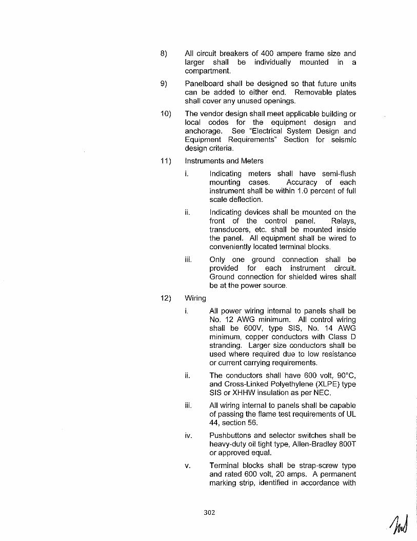
8) All circuit breakers of 400 ampere frame size and larger shall be individually mounted in a compartment.
9) Panelboard shall be designed so that future units can be added to either end. Removable plates shall cover any unused openings.
1 0) The vendor design shall meet applicable building or local codes for the equipment design and anchorage. See "Electrical System Design and Equipment Requirements" Section for seismic design criteria.
11) Instruments and Meters
i. Indicating meters shall have semi-flush mounting cases. Accuracy of each instrument shall be within 1.0 percent of full scale deflection.
ii. Indicating devices shall be mounted on the front of the control panel. Relays, transducers, etc. shall be mounted inside the panel. All equipment shall be wired to conveniently located terminal blocks.
iii. Only one ground connection shall be provided for each instrument circuit. Ground connection for shielded wires shall be at the power source.
12) Wiring
i. All power wiring internal to panels shall be No. 12 AWG minimum. All control wiring shall be 600V, type SIS, No. 14 AWG minimum, copper conductors with Class D stranding. Larger size conductors shall be used where required due to low resistance or current carrying requirements.
ii. The conductors shall have 600 volt, 90°C, and Cross-Linked Polyethylene (XLPE) type SIS or XHHW insulation as per NEC.
iii. All wiring internal to panels shall be capable of passing the flame test requirements of UL 44, section 56.
iv. Pushbuttons and selector switches shall be heavy-duty oil tight type, Allen-Bradley BOOT or approved equal.
v. Terminal blocks shall be strap-screw type and rated 600 volt, 20 amps. A permanent marking strip, identified in accordance with
302

BOP Contractor's wiring diagrams, shall be furnished on each terminal block. At least 20 percent spare terminal points (two per 12-point terminal block) shall be furnished.
vi. All spare relay contacts shall be wired out to terminal blocks.
vii. Splicing of wiring is prohibited. No more than two wires (one wire plus one jumper) shall be connected to any one terminal point.
viii. All assemblies shall be furnished completely wired. All other alarm and control wiring for extension to remote equipment or for interconnection between compartments shall terminate at terminal blocks.
13) Nameplates
i. Nameplates of white laminated phenolic material with black engraved letters shall be furnished to identify all compartments and components including but not limited to instruments, fuses, control and test devices, etc.
ii. Nameplates for cabinet identification shall have 1/2 inch high letters. Nameplates for all other components shall have 1/4 inch high letters.
iii. The nameplate on the outside of the cabinet shall read "125 VOLT DC DISTRIBUTION PANELBOARD." All other nameplate data will be determined by BOP Contractor.
14) Grounding
i. A ground bus consisting of 1/4" x 1" copper bar shall be installed in each cabinet.
ii. A ground bus shall be installed in each cabinet. The ground bus shall have a main lug and solder-less connectors, numbered to agree with the load circuits.
15) Testing
i. Tests shall be made by BOP Contractor before shipment, to ensure that all electrical equipment and wiring furnished and installed by BOP Contractor is in proper operating condition and that the wiring is in accordance with the wiring diagrams and functions as intended. The assembled
303

equipment and wiring connections shall be subjected to, and withstand, a one minute test of 1500 volts, 60 Hz, all phases to ground at the factory.
16) Equipment Rating
i. Circuit Breaker Ratings:
Design voltage ..................................................... (volts de) 250 Operating voltage ................................................. (volts de) 125 Minimum circuit breaker interrupting As rating at 125 volts dc ..................................... (DC amperes) Required
ii. Bus, Insulator and Support Ratings:
Continuous current.. ...................................... (DC amperes) As Required
Momentary current ........................................ (DC amperes) As Required
17) DC Panelboard
i. The DC Panel board shall have the following equipment mounted and wired within the specified enclosures:
ii. Service: Main Feed from 125 Volt DC Battery - One 250V 2-pole de circuit breaker with current rating that meets or exceeds maximum continuous de load current.
iii. Service: Main Feed from Battery Chargers - Two 250V 2-pole de circuit breakers with current rating that meets or exceeds maximum current from chargers.
iv. Service: Uninterruptible Power Supply (UPS) Feed- j
v. Feeder Breakers - Quantity as required of 250V 2-pole de circuit breakers with current ratings that meet or exceed the maximum load current of the given feeder.
vi. The following auxiliary devices shall be furnished for each DC panel:
I. One (1) voltmeter to measure battery voltage.
II. One (1) voltmeter to measure bus voltage.
304

Ill. One (1) de ammeter to measure discharge/charge current to/from the battery.
IV. One (1) 100 millivolt ammeter shunt with the necessary calibrated leads for use with the above ammeter.
V. Two (2) fuses and fuse block for use with voltmeter leads; fuse block shall be rated 250 volts and fuses rated 6.0 amperes.
VI. One (1) under-voltage relay, ABB/Westinghouse Type SV, or equal 125 Volts de, with contact to close on low voltage in a semi-flush mounting case.
VII. One (1) set of ground detection equipment consisting of two (2) lights with amber caps and resistors, or LEOs, and one (1) pushbutton, shall be wired and mounted in the cabinet.
5. Uninterruptible Power Supply (UPS)
a. UPS General
1) The power source for the UPS shall be the 125V de station battery.
2) UPS feeds shall be provided for the plant PBX system, LAN system, and AGCT in addition to the normal UPS loads.
b. Specifications for the Uninterruptible Power Supply
1) Uninterruptible Power Supply System (UPS) Specification General
i. One (1) UPS system is to be furnished for this project. The UPS system shall be supplied with 30% spare capacity above calculated requirements.
ii. Each power supply shall consist of an Integrated UPS System including one single-phase 120 volt, three wire 60Hz ferro-resonant inverter with a static transfer switch, de input circuit breaker, a manual maintenance bypass switch for ac circuits, ac circuit breaker, one alternate supply voltage regulating transformer, and ac distribution panel.
305

iii. Each UPS system will be fed from two independent power sources furnished by the BOP Contractor.
iv. The primary source will be a 125-volt de feed from the ungrounded station battery. This source will serve as the primary power supply to the inverter.
v. The backup source of power will be from a 480-volt power feed to the UPS alternate supply voltage regulating transformer.
vi. The BOP Contractor's station battery will serve a variety of loads in addition to the inverter and will be subject to a variety of disturbances. These disturbances will include a steady-state voltage variation from 105 to 140 volts, 100 percent voltage dips of up to one cycle due to short circuits on the de distribution system and voltage spikes up to 4000 volts for 10 microseconds on a 40 ohm impedance.
vii. The BOP Contractor's 480-volt, ac supply will serve a variety loads in addition to UPS and will be subject to various disturbances. These disturbances will include a steadystate voltage variation of ±1 0% momentary, up to 30 seconds, voltage dips of up to 20% below the steady-state voltage variation during the starting of large motors and momentary frequency variations of ± 10% during periods when main generator is disconnected from the power system.
viii. The equipment shall be compatible with the associated power supply system maximum available short-circuit current.
ix. The equipment shall be capable of carrying overloads, at an output voltage in accordance with this specification, of up to 115% of full load continuous and 500% for 16 milliseconds (to provide adequate subcycle fault current for fuse clearing on short circuits) when supplied from the inverter alone without transferring to the alternate source.
x. The output kVA rating of UPS System shall be as required. The inverter shall output single phase 120 volt, two-wire, 60 Hz, 0.8 lagging PF to 1.0 PF, at up to 40°C ambient.
306

2) Inverter
i. The inverter shall be of the ferro-resonant design.
ii. The inverter voltage regulation (transient response) shall not exceed the following limits under the range of conditions specified with loads of 0.8 lagging to 1.0 PF (there will be no leading power factor loads) and other variables as stipulated herein.
I. For steady-state loads: ±2.0 percent to 0 to 100% full rated load, 0 to 40"C ambient, and 105 to 140 volt de input.
II. For a sudden application or removal of 100% of the full rated load, the change in inverter output voltage shall not exceed the following:
• ±1 0% after 0.5 cycle
• ±2.5% after 1.0 cycle
iii. The inverter de input shall be equipped with an auto shutdown and restart circuit and with a current limiter active on powering of the system to limit the inrush to the inverter.
iv. The BOP Contractor shall size the system such that the clearing of faults on the branch circuit protected by the largest fuse shall result in a maximum average voltage deviation not exceeding ±1 0 percent after 0.5 cycle following initiation of a fault.
v. The inverter by itself (assuming alternate supply is not available) shall have the ability to clear faults on a branch circuit protected by the largest fuse on the distribution panel within a Y. cycle. The inverter shall return to rated voltage following the clearing of a fuse, as specified above.
vi. The output voltage shall be adjustable over a range of ±5% from the nominal voltage or two ±2-1/2% taps are to be supplied for fixed output-type inverters.
vii. The output waveform of the inverter shall have less than 5 percent distortion from a pure sine wave at the worst case combination of de input voltage, 105 to 140 volts, 10 to 100 percent load, and 0.8
307

lagging to 1.0 PF, excluding a fault condition.
viii. The inverter shall be equipped with a 60 Hz ±0.5 percent internal frequency control. The maximum slew rate shall not exceed 2.0 Hz per second.
ix. The inverter shall be equipped with automatic synchronizing controls. The inverter shall normally operate in synchronism with the BOP Contractor's alternate ac power supply. Synchronism shall cease when the frequency of the ac power supply changes ±1 percent or upon loss of the ac power supply. The inverter shall then operate on its internal frequency control upon return of normal frequency and voltage; the inverter output voltage shall pull back into synchronism with ac supply at the specified slew rate after a time delay of approximately 1.0 second.
x. The inverter shall be capable of continuous operation at no load.
3) Static Transfer Switch
i. The static transfer switch shall be singlepole and double-throw. The switch shall be capable of carrying the continuous, short time (overload) and short circuit specified for the UPS system.
ii. The switch shall be used for automatic transfer between the synchronized static inverter and the alternate ac supply. The switch shall be done with silicon-controlled rectifiers or other agreed-upon solid-state circuitry. The switch shall transfer from one source to another within 0.25 cycle.
iii. The switch shall have an independent and continuously adjustable range for automatic under-voltage transfer. The initial factory setting shall be such that transfer to the alternate ac source occurs at -10 percent of the nominal voltage. The nominal voltage shall be 120 Vac.
iv. The normal source of power shall be from the inverter. Upon loss of power from the inverter, the static transfer switch shall transfer to the alternate source. After the inverter source has been restored, after an
308

approximate 2.0 second time delay the static transfer switch shall transfer from the alternate source back to the inverter source. During this 2.0 second period, to assure source stability, the inverter source voltage shall remain within ±5 percent of the nominal voltage and ±0.8 percent of the nominal frequency; also, the sources rnust be synchronized at time of transfer. Means shall be provided to adjust the time delay or disable the time delay.
v. A pilot relay shall be provided for remote indication of the operational status of the static switch. The relay shall have doublepole, double-throw contacts.
vi. In the event of malfunction of the inverter frequency or synchronizing control, the static switch shall automatically transfer to the alternate source and close an alarm contact for the plant DCS. The transfer shall be completed before the inverter frequency changes by more than ±1.0 percent from 60 Hz.
vii. A static switch continuity monitor and latch circuit to prevent the static switch from returning to the inverter supply after an internal fault had developed shall be included. The continuity monitor shall monitor the normal supply (inverter) constantly. If an internal fault at the normal supply is detected by the continuity monitor, the latch circuit shall transfer and latch the static switch to the alternate supply. A rnanual reset (pushbutton or equal) shall be included to manually return the static switch to the normal (inverter) supply after an internal fault is removed. For faults external to the static switch, return shall be automatic.
4) Alternate Source Voltage Regulating Transformer
i. An alternate source voltage regulating transformer shall be furnished to provide transformation and regulation of backup power.
ii. The voltage regulating transformer shall be appropriately sized, including harmonic affect consideration, 480-120/240 volts, single phase, three wire, 60 Hz, dry type,
309

sooc rise with taps at 5 percent and 1 0 percent above and below the nominal 480 volts. Line and load regulation shall be ±2 percent with effective filtering of line noise with input voltage range of +1 0 percent to -20 percent.
5) Manual Bypass Switch
i. A make-before-break bypass switch shall be provided to isolate the inverter or the alternate source during maintenance. Provide contacts from the bypass switch for indicating the operating position.
6) Distribution Panelboard
i. Two (2) 120/240 VAC, single phase, threewire, distribution panelboard with main breaker and neutral buses shall be furnished. The rating of the main bus and interconnections shall be equal to the rated continuous full load current of the inverter without exceeding a 65°C rise. The main bus shall have a minimum interrupting rating of 10 kA.
ii. The panelboard shall have forty-two (42), single pole, thirty (30) ampere frame, fusible disconnect switch branch circuit devices. Fuses shall be sized and specified by the BOP Contractor to interrupt fault current from the inverter in Y. cycle or less. Fuse holder adapters shall be furnished as necessary to accommodate fuses.
iii. The panelboard shall be furnished with a single hinged door with lock and key, cardholders for circuit identification and trim over the entire panel. The panelboard shall be flush mounted within a freestanding enclosure that matches and is aligned on a common base with the other UPS System panels.
iv. The panelboard shall be UL-Iisted and conform to the latest issues of the National Electric Code and NEMA Panelboard Standard PB 1.
7) Alarms
i. The manufacturer shall provide an alarm contact with a 5 ampere rating at 120 volts ac for the following alarms for each UPS
310

system. The following alarms shall be provided at minimum:
UPS Static Switch Transfer UPS Low DC N/A Voltage
UPS Battery Supplying UPS Inverter Failure UPS Out of Sync Load UPS Bypass Source Failure UPS Low AC Input UPS Fan Failure
8) Control Wiring
i. All control wiring shall be #14 AWG, except where larger size conductors are needed for current carrying requirements. All wiring to circuit boards shall be #18 AWG. The conductors shall be 600 volt, 90'C rated, stranded copper wiring. Flexible connections between stationary and hinged panels or doors shall be made between terminal blocks or clamps in such manner as to afford flexibility without damage to the wires.
ii. All wiring for BOP Contractor's connections shall be terminated at terminal blocks. Terminal points shall be clearly and permanently identified. One side of terminal blocks shall be reserved for future LADWP connections.
iii. Maximum number of conductors connected to any one terminal on a terminal block shall be two.
9) Mounting Requirements
i. The vendor design shall meet applicable building or local codes for the equipment design and anchorage.
ii. The loads shall include dead loads, operating loads and seismic anchorage loads tabulated separately.
iii. Foundation outline dimensions and anchorage requirements shall be provided. The outline drawings shall also include the center of gravity of the equipment in plan and elevation views.
1 0) Testing
i. Tests shall include those required by NEMA Standard PE-1, ANSI/IEEE 944, and other applicable ANSI and IEEE standards.
311
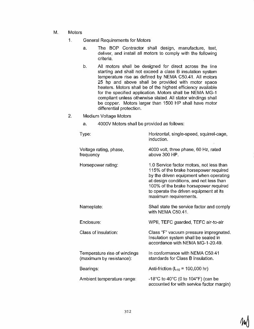
M. Motors
1. General Requirements for Motors
a. The BOP Contractor shall design, manufacture, test, deliver, and install all motors to comply with the following criteria.
b. All motors shall be designed for direct across the line starting and shall not exceed a class B insulation system temperature rise as defined by NEMA C50.41. All motors 25 hp and above shall be provided with motor space heaters. Motors shall be of the highest efficiency available for the specified application. Motors shall be NEMA MG-1 compliant unless otherwise stated. All stator windings shall be copper. Motors larger than 1500 HP shall have motor differential protection.
2. Medium Voltage Motors
a. 4000V Motors shall be provided as follows:
Type: Horizontal, single-speed, squirrel-cage, induction.
Voltage rating, phase, frequency
Horsepower rating:
Nameplate:
Enclosure:
Class of insulation:
Temperature rise of windings (maximum by resistance):
Bearings:
Ambient temperature range:
312
4000 volt, three phase, 60 Hz, rated above 300 HP.
1.0 Service factor motors, not less than 115% of the brake horsepower required by the driven equipment when operating at design conditions, and not less than 100% of the brake horsepower required to operate the driven equipment at its maximum requirements.
Shall state the service factor and comply with NEMA C50.41.
WPII, TEFC guarded, TEFC air-to-air
Class "F" vacuum pressure impregnated. Insulation system shall be sealed in accordance with NEMA MG-1-20.49.
In conformance with NEMA C50.41 standards for Class B insulation.
Anti-friction (L10 = 100,000 hr)
-18°C to 40°C (0 to 104°F) (can be accounted for with service factor margin)

Limitations on starts: In accordance with NEMA C50.41, a nameplate shall designate the maximum permissible number of starts and the required cooling period when motor is started under conditions of (a) cold rotor and (b) warm rotor (after running continuously at full load for a period of one hour).
Locked rotor (starting) torque at Not less than 80% offull-load torque. rated voltage and frequency:
Pull-up and breakdown torques: The torque of the motor shall be 15% above the load torque requirement throughout the entire speed range at 85% of motor-rated voltage with 80% pull-up torque as a minimum.
Locked rotor current: Not to exceed 650% of full load.
Base: Soleplates are required.
Sight glasses: Sight glasses shall be furnished in place of oil cups on all oil-filled bearings.
Preparation of storage: Motors shall be prepared for extended outdoor storage by protecting the motor bearings with either a protective grease covering or liquid preservative. The motors shall be tagged to show that a preservative has been used. The procedure to be followed before motors are placed in operation shall also be indicated on that tag.
Heaters: Heaters shall be included. Heaters which total more than 1200 watts in capacity shall be rated for 480 volt AC three-phase and heaters totaling less than 1200 watts in capacity shall be rated for 120 volt ac, single phase. They shall be de-rated for extended life and shall be sized to prevent condensation.
Grounding:
313
BOP Contractor shall provide two copper ground pads, one on each side of the motor with drilled and tapped holes suitable for attaching two-hole NEMA grounding lugs.

Direction of rotation:
Magnetic center:
Motor test:
Air filters for WPII:
Lifting lugs:
Sound levels:
Instrumentation:
3. Low-Voltage Motors
Motors shall have the direction of rotation marked on a nameplate for the supply voltage sequence of T1 - T2 - T3.
The magnetic center at rated load shall be marked on all motors.
Motor test shall be performed with motor terminal housing installed on motor.
Removable dry type complete with stainless steel filter screens with pressure differential switches.
Suitable lifting lugs shall be provided for hoisting motors during installation and for maintenance purposes.
Warranted maximum A-weighted sound level shall not exceed 85 dBA re: 0.0002 microbar at any point one meter from motor when tested as per IEEE Standard 85.
Provide vibration switch for anti-friction bearing.
Motors shall be provided with an ambient temperature sensing RTD to measure the cooling air going into the motor. The RTD shall be wired to the motor protection relay for protection and monitoring.
Provisions shall be provided for mounting vibration monitoring probes.
a. Refer to "Low-Voltage Motors" Section.
N. Miscellaneous
1. Communications Section
a. LADWP will furnish and install the telephone and Local Area Network (LAN) equipment. BOP Contractor shall furnish and install the remainder of the communication equipment and all of the communications system raceway as described below.
314
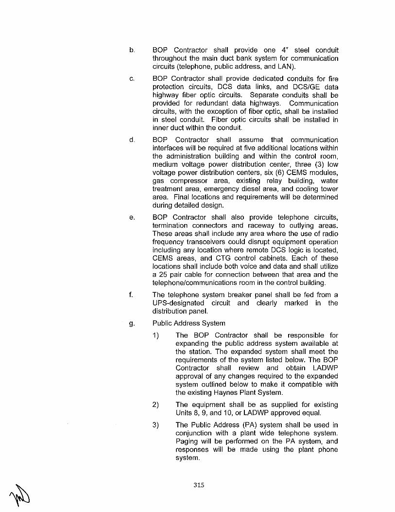
b. BOP Contractor shall provide one 4" steel conduit throughout the main duct bank system for communication circuits (telephone, public address, and LAN).
c. BOP Contractor shall provide dedicated conduits for fire protection circuits, DCS data links, and DCS/GE data highway fiber optic circuits. Separate conduits shall be provided for redundant data highways. Communication circuits, with the exception of fiber optic, shall be installed in steel conduit. Fiber optic circuits shall be installed in inner duct within the conduit.
d. BOP Contractor shall assume that communication interfaces will be required at five additional locations within the administration building and within the control room, medium voltage power distribution center, three (3) low voltage power distribution centers, six (6) CEMS modules, gas compressor area, existing relay building, water treatment area, emergency diesel area, and cooling tower area. Final locations and requirements will be determined during detailed design.
e. BOP Contractor shall also provide telephone circuits, termination connectors and raceway to outlying areas. These areas shall include any area where the use of radio frequency transceivers could disrupt equipment operation including any location where remote DCS logic is located, CEMS areas, and CTG control cabinets. Each of these locations shall include both voice and data and shall utilize a 25 pair cable for connection between that area and the telephone/communications room in the control building.
f. The telephone system breaker panel shall be fed from a UPS-designated circuit and clearly marked in the distribution panel.
g. Public Address System
1) The BOP Contractor shall be responsible for expanding the public address system available at the station. The expanded system shall meet the requirements of the system listed below. The BOP Contractor shall review and obtain LADWP approval of any changes required to the expanded system outlined below to make it compatible with the existing Haynes Plant System.
2) The equipment shall be as supplied for existing Units 8, 9, and 10, or LADWP approved equal.
3) The Public Address (PA) system shall be used in conjunction with a plant wide telephone system. Paging will be performed on the PA system, and responses will be made using the plant phone system.
315
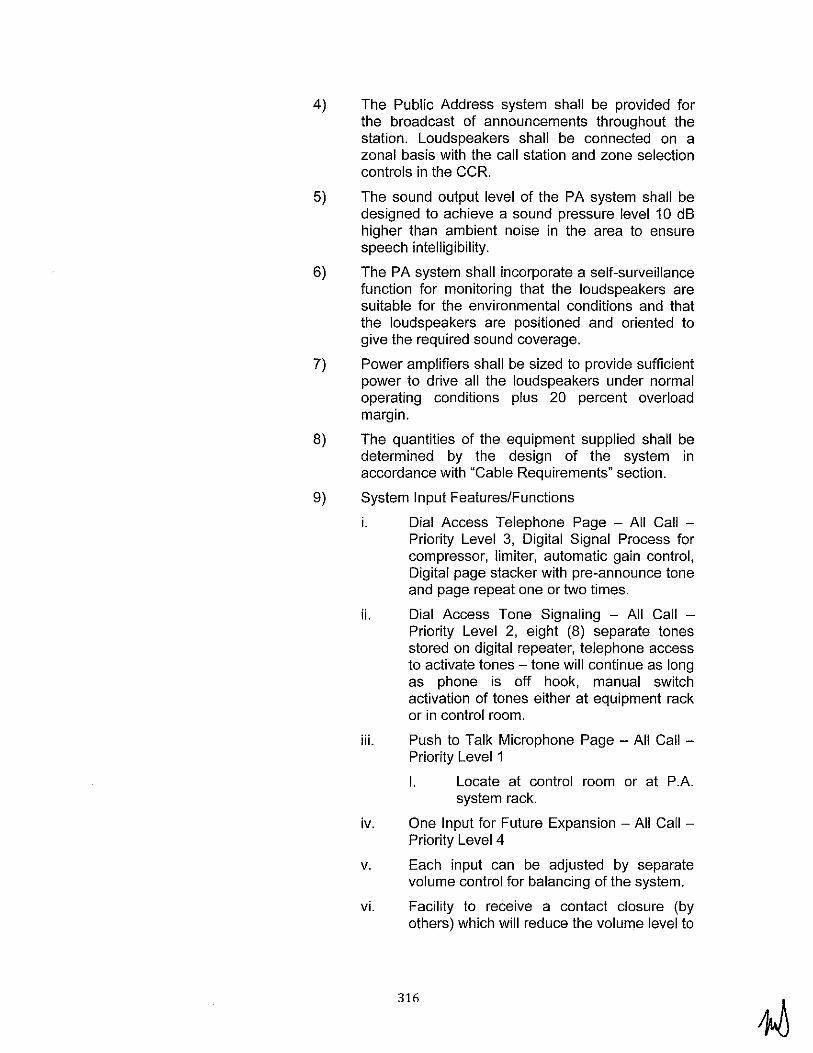
4) The Public Address system shall be provided for the broadcast of announcements throughout the station. Loudspeakers shall be connected on a zonal basis with the call station and zone selection controls in the CCR.
5) The sound output level of the PA system shall be designed to achieve a sound pressure level 10 dB higher than ambient noise in the area to ensure speech intelligibility.
6) The PA system shall incorporate a self-surveillance function for monitoring that the loudspeakers are suitable for the environmental conditions and that the loudspeakers are positioned and oriented to give the required sound coverage.
7) Power amplifiers shall be sized to provide sufficient power to drive all the loudspeakers under normal operating conditions plus 20 percent overload margin.
8) The quantities of the equipment supplied shall be determined by the design of the system in accordance with "Cable Requirements" section.
9) System Input Features/Functions
i. Dial Access Telephone Page - All Call -Priority Level 3, Digital Signal Process for compressor, limiter, automatic gain control, Digital page stacker with pre-announce tone and page repeat one or two times.
ii. Dial Access Tone Signaling - All Call -Priority Level 2, eight (8) separate tones stored on digital repeater, telephone access to activate tones -tone will continue as long as phone is off hook, manual switch activation of tones either at equipment rack or in control room.
iii. Push to Talk Microphone Page - All Call -Priority Level 1
I. Locate at control room or at P .A. system rack.
iv. One Input for Future Expansion -All Call -Priority Level 4
v. Each input can be adjusted by separate volume control for balancing of the system.
vi. Facility to receive a contact closure (by others) which will reduce the volume level to
316

a preset level on a generator by generator basis, when generators are shut down.
10) System Output Features/Functions
i. For each unit: Minimum five (5) dual channel x 300 watts (600 watts total) power amplifiers, minimum Twenty (20) panel mounted speaker volume controls for area by area adjustment, and Output monitor panel with LED ladder meter for each of the 10 output channels. Panel also contains a speaker with volume control and selector switch to audibly monitor each amplifier channel output.
11) System Loudspeakers
2. Security
i. The following loudspeakers will be provided for sound coverage to each generator:
I. Type 1 - Explosion Proof minimum 12 Atlas HLE/MLE - 30 Horns with MLE - 3T Driver Units, or LADWP approved equal.
II. Type 2 - Bi-Directional minimum 24 Atlas APT - 34T Bi-Directional Paging Horns, or LADWP approved equal.
Ill. Type 3 - Long Throw minimum 12 Atlas CJ-46 Long Throw Horns with PD-60T drivers units or LADWP approved equal.
IV. Type 4 - General Purpose Paging Horns minimum 152 Atlas APX20Tn Paging Horns.
V. Type 5 - Interior Speaker Assembly m1mmum 32 Quam System 1 Surface Mounted Interior Speakers.
a. BOP Contractor shall furnish and install a security system as described below.
b. Provisions shall be made for security requirements for gate, including signal raceway (video, intercom, card reader, etc.), power, lighting, gate operators, and concrete pedestal for card reader.
c. A station security system for Units 11 through 16 shall be provided and shall conform to the following:
317

1) Grounds, eight foot perimeter fence (proper signage), ample lighting, CCTV (approximately five (5) cameras) positioned for maximum coverage of the grounds.
d. The station security system shall be compatible with the existing plant security system.
3. Panelboards
a. Panelboards shall be UL-Iisted and conform to the latest issues of the National Electrical Code and NEMA Panelboard Standard PB 1. Panelboards shall be rated for 480/277 VAG Service or 125/250 VDC service. A minimum of 20% spare breakers shall be provided. A completed directory card and frame shall be provided on the inside of the door.
4. Grounding and Lightning Protection System
a. The BOP Contractor shall perform a grounding calculation using CDEGS software and furnish and install the grounding system in accordance with the calculation. The grounding system shall consist of bare, stranded copper cable and copper weld rod buried in the soil below the ground-floor concrete slab and spaced in a grid pattern sized as required for safe step-and-touch potentials. Each junction of the grid shall be securely bonded together by an exothermic weld. The ground grid pattern (size and number of ground rods or ground wells) shall be based on the grounding calculation. The grounding calculation shall be performed using the available fault current and ground resistivity measured at the Station site, in accordance with the Geotechnical report in Exhibit Z Section 8. A sufficient number of ground rods shall be installed and welded exothermically to the grid to assure a low-resistance earth connection. These rods shall be situated throughout the grounding system to minimize voltage gradients that occur during faults.
b. All structures, conduit, cable tray and electrical equipment shall be grounded per the NEG or applicable state and local standards, and LADWP standards.
c. The lightning protection system shall be designed, furnished, and installed in accordance with the latest applicable NFPA Standard 780, ANSI/UL Standard 96A, and any other applicable codes and standards.
d. The location, number, and depth of ground rods welded exothermically to the ground grid shall be in accordance with the grounding calculation. Buried ground conductors and the tops of driven ground rods shall be installed in accordance with the grounding calculation and at a depth
318

of at least 18 to 24 inches below final grade in earth fill. Ground test wells shall be provided.
e. The bases of every other column, as required, of all plant buildings structural steelwork shall be bonded together during construction and shall be connected using no. 4/0 AWG bare stranded copper conductor to the station main ground grid.
f. Flush surface grounding terminals (4/0 or 500 kcmil spools) shall be furnished for all equipment grounds. This grounding terminal will be flush mounting near the equipment in a location to minimize any possible damage to the exposed ground conductor. The exception to this shall be ground conductor connections to building steel.
5. Cathodic Protection System
a. Cathodic Protection General
1) Refer to 5.9 for details.
6. Lighting Systems
a. Lighting General
1) The BOP Contractor shall furnish and install the lighting system, which shall provide illumination for Station operation under normal conditions, and emergency lighting to perform manual operations during outage of the normal power source, and include all equipment specified herein.
2)
3)
4)
5)
6)
The work shall be performed in accordance with the National Electrical Code (NEC) and applicable local codes in a manner consistent with recognized good practice for power station.
Lighting fixtures shall be located and adjusted for the maximum useful light output. It is the BOP Contractor's responsibility to insure that the lighting illumination meets "Illuminating Engineering Society's" recommended (shown in the middle range) foot-candle levels. Accessibility for maintenance shall be considered.
All indoor fixtures shall be controlled at the lighting panel/switches located at the entrance areas.
Lighting panels shall be sized with a minimum of 20% future spare capacity. Lighting panels shall be provided with a variation of spare breakers and blank spaces.
BOP Contractor shall wire the circuits at the distribution panel in such a manner that they are balanced within ±15% between the phases.
319

7) For normal unit operation, the lighting system shall provide illumination in all Station areas to the levels required by ANSI/IES RP-7.
8) If any conflicts arise between this specification and the Los Angeles City Building Code, the Los Angeles City Building Code shall take precedence.
b. Lighting Transformers
1) Transformers shall be sized as required for the connected and future loads, 480/277 V threephase, 60 Hz, delta primary, self-cooled, AA type with weather shield in outdoor enclosures.
2) Lighting transformers shall be sized on the full load of the lighting panel including the future spares/spaces.
c. Receptacles
1) 480 VAG, 3 phase, 60A welding receptacles shall be located as following:
• One (1) at the turbine generator and one (1) at the exhaust stack and shall not be located in classified areas.
• Two (2) outside of the Gas Compressor Building
• Four (4) in the Maintenance Building
2) 120 VAG, single-phase convenience outlets shall be duplex, 1 SA, shall be, as a minimum, located for convenient access in all buildings and control cubicles, and shall not be located in classified areas. "GFCI" outlet ground fault interrupter type, with watertight covers is required for all outdoor convenience receptacles. Four (4) electric car recharging stations shall be provided in the parking areas near the control and maintenance buildings.
3) Equipment designated receptacle outlets shall be routed with a separate neutral, rated for the equipment connected load which shall not exceed 80% of the breaker rating.
d. Emergency Lighting
1) Emergency exit signs shall operate continuously. Exit signs shall identify all exits and shall be visible from all directions of the access route. Exit signs with an arrow indicating the direction of travel shall be used as necessary to direct personnel to the nearest appropriate exit. Exit sign placement shall
320

be such that no point in the exit route is more than 100 feet from the nearest visible exit sign.
2) The emergency lighting systems primarily consist of lights fed directly from the 125 VDC station battery. This system is supplemented by self contained battery pack units and emergency lights. The self contained battery pack units shall be 4-hour rated wet nickel cadmium units with lamps. These units are used for emergency egress routes. These units are not powered from the station battery.
7. Local Control Cabinets, Enclosures and Associated Panel Inserts
a. The cabinets and panel inserts include all control panels used generally for the local control and indication of equipment and systems.
b. All electrical enclosures which have equipment mounted therein shall have a sub-panel for mounting such equipment.
c. Local control cabinets and associated panel inserts used for mounting of devices shall be suitably reinforced structurally to limit vibration. Access doors, where applicable, shall be provided with stiffening members to prevent warping.
d. Hinged panels and access doors shall be provided with concealed hinges, latches, and interchangeable locks. All doors shall be capable of making a minimum swing of 130 degrees from the closed position. Where doors are furnished for panel sections greater than 30 inches in width, access doors shall be a double type.
e. Structures shall be welded to the maximum extent possible to ensure rigidity during assembly, handling, shipping and installation. Welds, rivets and bolt heads shall not be visible from the outside. Assembled structures shall be of NEMA Type 12 construction when used in non air conditioned environments, NEMA Type 1 gasketed for air conditioned, and NEMA Type 4 or 4X when used outdoor-as defined in NEMA Standard 250.
f. Control panels/cabinets for use in hazardous areas (as defined on LADWP's drawings) shall be designed to meet NEC Article 500 requirements for the particular area.
g. Panels shall be rigid, self-supporting structures braced rigidly with structural members. Panels shall be of sufficient strength and rigidity to permit lifting and moving without suffering any distortion.
h. Control faces of all panelboards shall be constructed of one-piece steel. Design and workmanship shall be such as to result in a neat appearance outside and insides, with
321

no welds, rivets, or bolt heads apparent from the front face of the panelboards. All exterior surfaces shall be true and smooth. All cutout edges shall be square and smooth. Uniformity shall be maintained in layout of equipment on all panel boards when and where practical.
i. All controls and operating instruments intended for panel mounting shall be installed flush or semi-flush.
j. Local control cabinets and associated panel designs shall provide for the safe, neat, and accessible installation of w1nng. Stiffener location, interior barriers, and arrangement of devices, terminal blocks and accessories shall insure clear functional layout and maximum accessibility for maintenance and inspection. No equipment, control devices or terminal blocks shall be located less than 6 inches from the bottom or sidewalls of any control cabinet.
k. Space heaters shall be provided in control panels/cabinets where condensation could cause a system malfunction and, if used, shall be so located that the temperature of the nearest metallic structure shall not exceed 50 degrees C. Space heaters shall be thermostatically controlled and wired to their own branch circuit breaker. Space heaters shall be rated for 1-phase 240 Volts, but sized for operation on 1-phase 120 Volts.
I. Control panels/cabinets shall be provided with a minimum of 10 percent spare space for future additions to the associated control systems. This space shall be allocated for each of the control logic and power distribution sections of the panel and cabinet.
m. Control panels/cabinets shall be designed for both side and bottom entry of cables. Openings shall have easily removable screwed, watertight gasketed covers. Cables entering the side shall enter at the upper portion of the side or back panels and shall use a drip-proof design to prevent entrance of moisture.
n. All combustible material used for barriers, covers and the like shall meet the flammability test criteria of UL 94 for materials classed 94 V -0.
o. Flame retardant materials, as specified herein, shall be those materials which are self extinguishing and which do not support combustion.
8. Variable Frequency Drives (VFD)
a. VFD's shall meet IEEE-519 harmonic distortion and current limits.
b. The Point of Common Coupling (PCC) should be at the input terminals of the VFD. Voltage harmonic distortion
322
and the current demand distortion caused by the drive should not exceed 3% and 5%, respectively, at the PCC.
c. VFD input power factor is .94 or greater from 50% to 100% speed.
d. VFD system efficiency shall be a minimum of 96%. VFD system efficiency includes losses in power conversion equipment, input transformers, and output transformers, power factor correction or harmonic filters, if needed.
e. VFD must protect motors against overspeed, overload and short circuit.
0. Cable and Raceway Systems
1. Cable Requirements
a. BOP Contractor shall furnish, install, and terminate all cable required for the project in this specification.
i. 25000 Volt Cable
Conductors
Insulation Material
Jacket for single or multi-conductor cables
Conductor shield
Insulation shield
Metallic insulation shield
Voltage
ii. 5000 Volt Cable
Conductors
Insulation Material
Jacket for single or multi-conductor cables
Conductor shield
323
Auxiliary transformers connection to isolated phase bus.
Copper, Class B stranded, annealed
Ethylene-propylene-rubber (EPR), 345 mils minimum 133% insulation level
Per NEG and UL listed as type MV-105 suitable for use in cable tray
Extruded semi-conducting thermosetting compound
Extruded semi-conducting thermosetting compound
Uncoated copper tape, minimum 25% overlap
25,000 volt
Copper, Class B stranded, annealed
Ethylene-propylene-rubber (EPR), 115 mils minimum 133% insulation level
Per NEG and UL listed as type MV-105 suitable for use in cable tray
Extruded semi-conducting thermosetting

compound
Insulation shield Extruded semi-conducting thermosetting compound
Metallic insulation shield Uncoated copper tape, minimum 25% overlap
Voltage 5,000 volt
iii. 600 Volt Power Cable
Conductors Copper, Class B stranded, annealed, with a tin or lead alloy coating, minimum No. 12 AWG
Insulation Material Ethylene-propylene-rubber (EPR), 90'C
Jacket for single Per NEC and UL listed as type TC conductor or multiplexed cables
Voltage 600 It
iv.600 Volt Control Cable
Conductors Copper. Class B stranded, annealed, with a tin or lead alloy coating, No. 14 AWG
Insulation Material Ethylene-propylene-rubber (EPR) or cross linked polyethylene (XLPE). 90'C
Jacket for single Per NEC and UL listed as type TC conductor or multiplexed cables
Jacket overall Heavy-duty chlorosulfonated-polyethylene (Hypalon) or chlorinated polyethylene (CPE)
Voltage 600 Volt
Wire colors for multi- NEMA Standard conductor cables
v.lnstrument Cable
Conductors Copper, stranded
Insulation material s;90'C, fire retardant XLPE, EPR
~90'C, TFW Teflon tape and Kaplan tape
324

over the Teflon
Jacket over each pair or Per NEC and UL listed as Type PL TC triad
Shield Each pair individually shielded, overall shield is 1.5 mil aluminum or copper-mylar laminate tape
Drain wire One per pair
Voltage
vi. Thermocouple Cable
Conductors
Insulation material
Jacket overall
Shield
Voltage
600 Its
Type E, chromel-constantan, or Type K, chromel-alumel18 AWG
s:;gooc, fire retardant XLPE
:2:90°C, TFW Teflon tape and Kaplan tape over the Teflon
Per NEC and UL listed as Type PL TC
Each pair individually shielded, overall shield is aluminum or copper-mylar laminate tape
600 Volts
b. All of the above cable shall conform to, and equipment tests shall be conducted in accordance with, the latest applicable standards of American National Standards Institute (ANSI), Underwriters' Laboratories (UL), the Insulated Cable Engineers Association (ICEA), the Institute of Electrical and Electronics Engineers (IEEE), and the National Electrical Manufacturer's Association (NEMA), unless otherwise stated herein.
c. All cables shall meet or exceed flame test requirements of UL 83.
d. All cable shall be "sunlight resistant" and for use in cable trays ("for CT use").
e. Cable with PVC insulation is not allowed in the control room or other normally occupied areas.
f. Instrumentation and thermocouple cable shall be twistedshielded with a minimum twist frequency of 3 inches, or 4 twists per foot.
325

g. Potential transformer and current transformer leads shall be No. 10AWG minimum.
h. All control and instrument leads for the external connections shall be brought out to terminal blocks mounted in terminal boxes, control boards, or panel in an accessible location, including all spare contacts.
i. Cable shall be identified with identification markers at both ends after cables have been permanently routed, positioned and connected.
j. BOP Contractor shall adhere to the cable manufacturer's recommendations on minimum pulling temperatures and maximum pulling tension. All cable ends shall be sealed from contamination during the pulling operation, and during storage on cable reels.
k. Splicing of cables in raceway is not an accepted practice and shall not be allowed without prior approval. BOP Contractor shall receive approval from LADWP for any cable that needs to be spliced before the cable is pulled.
I. Color Coding of Controls
1) Indicating for controls shall conform to LADWP's Standard 20.10.05 located in Exhibit Z.1 0, "Control Board and Equipment/Machine Local Control Indicating Lamp Color Codes, Generating Stations".
2. Cable Tray/Raceway System Requirements.
a. The BOP Contractor shall design, furnish, and install a cable tray system as required for a complete installation.
b. A four-tray cable segregation system shall be furnished: Medium-voltage power, low-voltage power, control, and instrumentation.
c. The cable tray systern shall be designed, fabricated, and installed in accordance with the latest edition of NEMA Standard Publication No. VE-l - Cable Tray Systems, load/span class designation NEMA Class 12C. The rnaxirnurn cable fill on cable trays shall be 40% per the National Electrical Code.
d. Flat cable tray covers shall be furnished and installed by the BOP Contractor on all instrument trays, and on power and control tray where the tray passes under grating-or open areas where falling debris may damage the cable. Covers on power trays shall be raised covers, if the covered section is over 6 feet long.
e. Cable trays shall be identified prior to the installation of any cables. Cable trays shall be identified in a distinct, permanent manner with identification numbers at reasonable intervals.
326

f. The BOP Contractor shall furnish and install all conduit required for the project. It shall be the BOP Contractor's responsibility to determine the most efficient and economical routing of all conduit runs. It shall be the BOP Contractor's responsibility to determine the proper size of all conduits in accordance with the National Electric Code (NEC).
g. Junction and pull boxes shall conform to UL Standard UL 50. Galvanized coatings for steel boxes shall conform to ASTM A 525 designation G90 for dry locations and G210 for wet and outdoor locations.
h. Conduits
1) All conduits will be sized in accordance with the number and total area of cables that they contain using the National Electric Code.
2) All outdoor exposed conduits shall be rigid galvanized steel.
3) All outdoor exposed conduits shall have low point conduit drains.
4) Use of thin-wall EMT conduit shall be limited to indoor concealed conduit in walls and ceilings typically for lighting and convenience outlets.
5) BOP Contractor shall furnish raceways for BOP Contractor located telephone, PA, and communication circuits.
6) Conduits with wall thickness suitable for use in concrete encased duct banks will be used and supported by pre-fabricated spacers. PVC conduit may be used for underground duct runs.
i. Concrete encased duct banks will be reinforced under roadways and other areas to withstand heavy equipment forces (H-20 rated) over the duct during construction and operations.
j. All duct banks have a minimum slope of 0.25 percent and arranged to drain toward manholes.
k. Manholes: Manholes will be placed at distances that facilitate cable pulling without exceeding permissible tensions and/or side wall pressures. Power conductors operating at 1000 volts and above shall be installed in separate manholes than cables operating below 1000 volts. Low-voltage power, control, and instrumentation cables shall be segregated within the manholes and hand holes.
I. Conduits and duct banks will be installed as required to complete the raceway system. Duct banks will use bends
327

with large radius sweeps to minimize pulling tensions. All conduits shall have a 48" minimum radius for turns. Conduits in ductbank shall be separated by a minimum spacing of 3". Minimum of 25% of each segregation type shall be installed in duct banks for future use.
3. Raceway Systems Embedded Work
a. Embedded Work Requirements
1) BOP Contractor shall provide all electrical conduit and fittings, built in, concealed or a part of the concrete work.
2) All conduits embedded in floors, walls, foundations, duct, etc., shall be hot-dipped galvanized rigid steel conduit, which shall conform to ANSI C80.1, "Rigid Steel Conduit-Zinc Coated." Fittings for rigid steel conduits shall be steel or malleable iron, except for insulated bushings, and such metal fittings shall be either electro-galvanized, or cadmium plated. Fittings shall comply with the latest ANSI Standard C80.4, "Fittings for Rigid Metal Conduit and Electrical Metallic Tubing." Rigid steel conduits shall be bent to the radii in accordance with the NEC or manufacturer's recommendation.
P. General Wiring
1. Wiring Requirements
a. This section is not applicable to the equipment furnished per Sections 5 through 16. This section applies to all other equipment furnished by the BOP Contractor both for internal and external connections.
b. Terminal blocks shall be strap screw and rated 600 volt, 20 amps. A permanent marking strip, identified in accordance with BOP Contractor's wiring diagrams, shall be furnished on each terminal block. At least 20% (two on 12-point terminal block) spare terminal points shall be furnished. Terminal blocks for control circuits shall be sliding link type.
c. All control wiring internal to panels shall be 600V, Type SIS, No. 14 AWG minimum, copper conductors with Class D stranding.
d. All power wiring internal to panels shall be 600V, No. 12 AWG minimum. Power cable #8 AWG and larger shall have copper conductors, with 90'C, heat, moisture, and flame-resistant ethylene-propylene-rubber (EPR) insulation and Hypalon jacket. The EPR insulation shall meet the physical and electrical requirements for Type I insulation as designated in ICEA S-68-516, Sections 3.6.1 and 3.6.2. Power cable internal to panels which is #10 AWG or #12
328

AWG shall be Type SIS with copper conductors and Class D stranding.
e. All wiring internal to panels shall be capable of passing the flame test requirements of UL 44, Section 56.
f. Wiring shall be terminated using compression-type, ringtongue terminals which firmly grip the conductor. Connectors shall be Thomas & Betts Sta-Kon on Purchaser approved equal. Both ends and at each terminating point of each wire shall be uniquely identified with permanent, heat shrinkable wire markers (125°C rated) (Raychern Thermofit) or other LADWP approved permanent marker using indelible printing, white sleeve with black lettering. Adhesive wire labels are not acceptable.
g. Splicing of wiring is prohibited. No more than one wire plus one jumper shall be connected to any one terminal point.
h. All 480V wiring shall be segregated frorn other control wiring and low voltage devices for personnel safety by means of an insulated barrier or other means.
i. Only one ground connection shall be provided for each instrument circuit. Ground connection for shield wiring shall be of the power source.
j. All switchgear assemblies shall be furnished completely wired. With the exception of control and AC power buses, all other alarm and control wiring for extension to remote equipment-or for interconnection between compartments shall terminate at terminal blocks.
k. Wiring shall be neatly arranged and clamped securely to panels to prevent movement of breaking. Except as otherwise proved in standard vendor supplied packages, a maximum of 12 wires shall be in a bundle in order to facilitate tracing of wires. Wiring clamps and supports at hinge transition points shall be properly sized to prevent chafing of insulation when the cubicle door is opened and closed. Metal clamps must have insulating inserts between the clamps and wiring. Nonmetallic clamps are preferred.
I. All signal level cables installed in underground duct shall be in iron conduits. There shall be an independent raceway system for the telephone/communications system.
Q. Testing and Checking of Electrical Equipment
1. Testing and Checking of Electrical Equipment Requirements
a. Test equipment shall be supplied by the BOP Contractor.
b. Manufacturers' instruction books shall be carefully read prior to the start of any test or energizing any equipment.
329

All tests required by the individual manufacturers' shall be done by the BOP Contractor.
c. Testing for each piece of equipment shall be conducted to insure normal and safe operation of the Station. All tests shall be in accordance with applicable ANSI, IEEE, and NEMA standards.
1) Power cables shall be high pot tested and, where applicable, polarization index tested.
2) Motors shall be high pot tested and rotation verified.
3) Transformers and other large equipment shall be tested to manufacturers' standards and to applicable NEMA, IEEE, and ANSI standards.
R. Power Distribution Centers
1. Scope
a. This specification covers the design, materials, installation and testing of the Power Distribution Centers (PDC) for housing the MV and LV switchgear, Station Battery, UPS/DC power equipment and other equipment as specified and in accordance with the specifications herein and layout drawings.
b. Provide all labor, materials, tools and equipment required for the completion of the following Work, as specified herein:
1) Design, manufacture, inspect, shop test, and furnish a complete, prepackaged PDC including all electrical distribution and other equipment and interconnecting wiring as specified herein and on the layout drawings. Coordinate CTG contractor supplied equipment to be included in PDC.
2) Install all interconnecting power, control and instrumentation wiring between individual pieces of electrical equipment and between electrical equipment and other equipment, including the UPS and DCS cabinets, within the building in accordance with these specifications and drawings.
3) Furnish all data, drawings, calculations and information in accordance with the specifications.
4) Receive, offload, and set PDCs.
5)
6)
Make required electrical bus and w1nng connections between PDC sections, if required; using either bus or wiring connectors.
Apply touch up painting as required.
2. Codes, Standards, and Regulations
330

a. General
1) All design, equipment, installation, and testing shall conform to applicable codes and standards of California Building Code, California Electrical Code, Los Angeles Codes, ANSI, ASME, ASTM, IEEE, NFPA, UBC, NETA, NEMA, and UL; and these specifications herein.
2) All materials and devices shall be in accordance with applicable requirements of the Federal 'Occupational Safety and Health Standards."
3) All design, equipment, installation, testing, materials and devices shall meet all permit requirements and all state and local codes and standards.
4) All electrical equipment shall be installed in accordance with applicable National Fire Protection Association standards including the most recent published edition of NFPA 70 (the National Electrical Code).
5) In case of conflict between the requirements of the various parts of these documents, the requirements of the different parts shall govern to the extent of such conflict in the following sequence: mandatory governmental regulations, codes and standards; Drawings; Technical Specifications; and the referenced industry codes and standards.
3. Technical Requirements
a. Design and Construction Features
1 ) Description
i. The PDC's shall be elevated approximately six feet above the ground on piers. All PDC's shall be designed for service in a non-hazardous (un-classified} location.
ii. See Section 5.12 for structural and architectural requirements for the PDC enclosures.
2) Fabrication
i. The design and fabrication of the PDC shall incorporate a watertight, dust proof sealed enclosure in accordance with the preliminary, conceptual, Equipment Layout Plan included in the referenced drawings.
ii. The enclosure shall be designed to withstand the wind loading without damage
331

and shall be designed in accordance with the environmental site conditions.
iii. The base, which forms the main support for the enclosure, shall be fabricated of structural steel, which is rigidly braced and designed to withstand transportation handling stresses. The maximum allowable floor deflection under normal live loading is L/240. The base shall be sandblasted, and shall have a mastic fire resistant undercoating to prevent corrosion. Base mounted lifting eyes and jacking provisions shall be provided.
iv. All outer walls, interior walls, and the ceiling shall be fabricated from sheet steel panels. Flooring shall be fabricated from galvanized steel plate with a non-skid finish. Each PDC enclosure and associated equipment shall be made of non-combustible material whenever possible. Colors shall be selected by LADWP from the panel Manufacturer's standard color charts.
v. The PDC enclosure shall have a sloped roof, and shall be provided with weather guards to prevent the entry of water. The roof shall not have penetrations of any kind. All openings for pipes, vents, ducts, etc. shall be made through the walls of the PDC enclosure. The roof shall be warranted against leakage for a period of not less than twenty (20) years.
vi. R-19 class or better insulation shall be provided for the outer sides of the PDC. All insulating materials shall be non-combustible and fire resistant. If metal insulated sandwich panels are provided, they shall be UL Listed or Factory Mutual Approved assuring that they will not contribute to a fire.
vii. The PDC doors shall be complete with key locks, doorstops, and automatic closures. All buildings slated for delivery to the same site shall be keyed alike. The equipment doors shall be provided with a removable transom to provide a total opening 96 inches tall. The final location of the equipment doors shall be approved by LADWP. All doors shall be equipped with
332
indoor panic bars. The door key locks shall be defeatable from the inside and shall not render the panic bars inoperable when placed in the locked position. All doors that open within the building shall be supplied with a viewing window. Each door closer shall be adjustable to insure a complete door closure and seal.
viii. Door tolerances, sealing methods, and fabrication shall be of premium quality to prevent the entrance of water and dust into the PDC enclosure. Doors shall be fabricated of corrosion resistant primed steel with a zinc coated steel frame and neoprene gaskets. All door hardware shall be 316 stainless steel. Doors shall be finish painted in accordance with the cleaning, painting, and coatings requirements in "Execution" section.
ix. A minimum head clearance of seven feet shall be maintained between the bottom of overhead bus duct, cable tray, or conduit and the PDC floor.
x. The enclosure size and equipment layout shall be spacious in order to facilitate ease of maintenance and operations, and to accommodate possible future equipment additions.
xi. Minimum electrical clearances as defined by the NESC, NEG, and other applicable codes and standards shall be maintained in the equipment layouts. In addition, manufacturer's minimum clearances shall be maintained for serviceability and equipment removal.
xii. Provide hinged doors in the wall of the PDC behind each switchgear compartment to allow access to the rear of the equipment from the outside. Each access door shall be formed from 12 gauge steel, and will be sealed with a continuous neoprene gasket. Each access door will be secured using four (4) bolts with captive nuts and will include a door prop, drip shield, and provisions for a padlock. The associated switchgear shall be installed in direct contact with the interior PDC wall. Extensions to the switchgear shall be provided, if required.
333

xiii. All equipment shall be bolted to the floor, not welded.
3) HVAC Equipment
i. Supporting calculations to determine heating and air-conditioning requirements shall be furnished. HVAC systems shall be designed to maintain a 77°F interior summer temperature and a 70°F interior winter temperature.
ii. Supply and install a minimum of two (2) sets of 100% wall-mounted HVAC units, with integral heaters to provide heating and cooling for each enclosure and/or each room in the enclosure. The heating and air conditioning equipment shall be capable of continuously maintaining an indoor PDC temperature plus or minus 3°F. Hot spots within the PDC shall not exceed plus or minus 5°F from the set point temperature. A heating /cooling thermostat shall be provided for temperature set point adjustment. HVAC wall units shall have 3-speed cooling. Heating and cooling units shall be sized assuming worst-case ambient temperature limits, solar radiation, and the heat rejection from lights and other electrical equipment within the PDC enclosure. The HVAC units shall provide outdoor air for ventilation for the PDC in accordance with building code requirements. The system shall also provide make-up air for any required exhaust systems. The loss of one HVAC unit shall not result in the building temperature exceeding the specified minimum or maximum temperature.
I. All provided HVAC equipment shall be of industrial grade and premium quality to reduce the amount of maintenance required, and the installation shall be designed to accommodate quick replacement of a failed unit with a common spare for all PDCs.
II. HVAC units shall have highefficiency rotary compressors.
Ill. All HVAC units shall be interlocked with the fire detection system to automatically shutdown the HVAC
334
units in accordance with NFPA 90A requirements.
iii. The battery room shall be provided with an exhaust fan(s) sized to maintain the room below 1% hydrogen concentration. A hydrogen detector shall be installed in the battery room. The detector shall be provided with a form "C" contact to alarm high hydrogen concentration and trouble from the detector. Fans shall be suitable for use in a Class I, Division 2 Group B classified area. There shall be a flow switch with a form "C" contact provided to indicate failure of the exhaust fans. The batteries should be provided with mats to catch spills.
iv. A thermostat for indicating "High building temperature alarm" shall be provided. One ( 1) form C contact shall be provided from the thermostat. Alarm shall be set to actuate at temperature equal to and greater than 85 degrees.
v. All outside air shall be filtered.
vi. All ductwork shall be fabricated from galvanized sheet metal in accordance with SMACNA standards.
4) C02 Fire Extinguishers
i. Portable C02 fire extinguishers sized, located, and installed in accordance with NFPA 10. As a minimum, a C02 fire extinguisher shall be located at each exterior door entrance to the PDC.
5) Fire Detection Equipment
i. The PDC shall be provided with a complete fire detection system. This shall include the following systems and components.
I. Area wide fire detection system in accordance with NFPA 72 covering all rooms and areas in the PDC.
II. A separate, dedicated raceway system shall be supplied to accommodate the addition of the fire detection system.
Ill. Supervisory control panel for the fire detection and fire alarm systems in accordance with NFPA 72.
335
IV. Manual pull stations for manual activation of fire alarm.
V. Audible and visual alarms for each room and area of the enclosure and an external visual alarm indicating activation of the fire alarm system located outside of the building near the doors.
VI. The design of all fire detection and fire alarm and supervision systems shall be in accordance with the applicable NFPA codes and standards and all local and state codes.
VII. All fire detection system equipment and components shall be UL listed and/or FM approved for fire detection service.
VIII. Building fire detection system shall be automatic, intelligent, multiplexing type using intelligent, addressable detectors and inputs. Control panel shall include all fire system actuation, and trouble alarms for the detection system, manual pull stations, and alarm devices. The control panel shall be capable of providing all alarms to the Control Room Fire Detection Control Panel. The Fire Detection Control Panel shall have its own internal backup battery system.
IX. Control panels and all internal components shall be UL listed and shall be designed for Class "B" supervision (style C for initiating circuits, style 4 for signal circuits).
X. Building smoke detectors and duct Smoke detectors shall be provided for PCM modules and shall be provided for any dueled HVAC system.
XI. Each PDC enclosure's associated equipment shall be rnade of noncombustible materials whenever possible. Material that contains asbestos shall not be used.
336

6) Not Used.
7) Auxiliary Electrical Equipment
i. Supply and install all branch circuit equipment including dry type transformers, panelboards, convenience receptacles, and lighting components with associated control devices.
ii. Indoor Lighting - Indoor fluorescent fixtures shall be installed in sufficient quantities to provide a minimum of 50-foot candles of light measured 3 feet above floor level inside the PDC enclosure. All fixtures shall have energy efficient ballast's. Three-way switches shall be installed on the interior walls near each door to operate these lights.
iii. Emergency Lighting - Supply a minimum of two (2) emergency lighting units, which are designed to turn on automatically on loss of power for each PDC enclosure. Emergency lighting units shall be UL listed and meeting applicable NFPA codes. Emergency lighting units shall be Dura-Lite model EZ-2 or equal, mounted above or near each egress door.
iv. Receptacles - At least four (4) 120 VAC shall be installed on the inside of each PDC module, one (1) 120 VAC GFCI type receptacle next to each exterior personnel door, and one (1) 120 VAC GFCI type receptacle next to each group of (4) equipment access doors. There shall be a receptacle placed at least every 20 feet along each indoor wall of the PDC. Receptacles shall be 20 amp, three-wire grounded.
v. Outdoor PDC Lighting - Outdoor type, wallpak mounted, 70-watt metal halide lighting fixtures with internal photocell shall be installed on the PDC exterior above or adjacent to each personnel access door.
8) Cable Types and Wiring Methods
i. Furnish and install all wiring between equipment in the PDC. This shall include all w1nng between PDC equipment and UPS/DC panels, power panels, transformers, etc.
337

ii. All power and control cables shall be flameretardant type.
iii. Supply all cable access openings, conduit, raceway, tray, and wireways required for the incoming power and control cables and for circuit routing within the PDC enclosure.
9) Raceway
i. Grounding of tray, conduit and all other raceways shall be provided according to the NEC and all other applicable codes.
ii. Cable trays and/or wireways shall be provided and installed below the PDC for power, control and instrumentation cables routed within the PDC. Cable trays shall be provided for cables routed internally within the building. The cable tray and conduit design shall accommodate the required bending radius of the cables. Instrumentation and 4-20 ma analog circuits shall be installed in an enclosed raceway.
iii. Ladder tray systems shall be aluminum and manufactured in accordance with NEMA VE 1. Ladder rung spacing shall not exceed 9 inches on center. Solid bottom type tray shall be galvanized steel with solid cover. All trays shall have a minimum useable depth of no less than 4 inches.
iv. Provide galvanized unistrut or other suitable supports on the ceiling for hanging tray. Supports shall be placed based on the NEMA rating of the tray.
v. All conduits shall be rigid galvanized steel conduit with the exception that internal lighting and receptacle circuits may be run in EMT conduit. The conduit design shall provide adequate room to accommodate the required bending radius of the cables.
1 0) Equipment and Building Grounding
i. One (1) NEMA 2-hole stainless steel or copper-faced steel grounding pads shall be provided at each corner of each section of the PDC enclosure base for grounding the PDC structure. The dimensional location of the ground pads shall be shown on the layout drawing.
338

ii. Connect equipment grounds to a ground bus or grounding system that is directly connected to the building grounding system. Indirect grounding of panelboard or switchgear ground bars is not acceptable.
iii. Provide a grounding strap for bonding each exterior access door. The strap shall be installed in such a manner to allow for full opening of the door.
b. Seismic Requirements
1) BOP Contractor shall meet all seismic requirements and submit calculations to meet state and local regulations.
c. Painting
1) Enclosure surface preparation, corrosion inhibitors, paint, and paint application methods shall be of the highest quality and workmanship in order to prevent corrosion and minimize the need for repainting. The primer and paint coverings shall provide superior protection against corrosion, chemical reactions, fading, chalking or peeling.
i. Battery rooms shall have an acid resistant protective floor coating. The coating shall be a high performance EPOXY NOVALACCarboline Phenoline 379 or approved equal with a broadcast slip resistant aggregate. Surface preparation shall be SSPC-SP1 0 minimum, and coating thickness (OFT) shall be 4-5 mils minimum. In a separate, nearby area of the battery room, an eye wash and shower station shall be located for rinsing eyes and skin in the event of acid contact. A monorail or other means shall be included in the design of the battery rooms to assist in removing or replacing cells.
ii. One gallon of touchup paint shall be provided for each interior and exterior color. MSDS sheets shall be submitted to LADWP prior to shipping.
d. Packaging and Shipping
1) Shipping Requirements
i. The BOP Contractor shall notify LADWP one week in advance of the estimated equipment arrival date, and shall inform LADWP of the final gross shipping weight. The BOP Contractor shall notify LADWP
339

4. Testing
a. Shop Tests
when the PDC leaves the factory, and shall provide the name and telephone number of the carrier as well as the estimated arrival time.
1) Equipment Testing
i. The BOP Contractor shall be responsible for the testing of all electrical equipment furnished with the PDC. A functional test of the PDC enclosure and all electrical equipment shall be performed by the BOP Contractor, and certified test reports shall be supplied to LADWP before shipment. Tests shall be conducted according to applicable ANSI, NETA, and NEMA standards.
ii. Complete functional tests for all building systems including, but not limited to:
I. HVAC system and controls
II. Fire detection system
Ill. Indoor and outdoor lighting and controls
IV. All circuit wiring checked per latest rev1s1on of the elementary or schematic diagrams.
V. All circuitry and devices tested for proper operation as outlined on the typical schematic control diagrams.
VI. All relays and contactors adjusted as specified in equipment's installation and operation instructions.
VII. All primary bus works and cables checked for proper torque and phasing.
VIII. Verification of Bill of Material and Nameplates.
2) Witness Testing
i. LADWP reserves the right to witness all testing described herein as well as to perform a general inspection at the plant before shipment. The BOP Contractor shall notify LADWP at least one-week in advance of completion of the PDC assembly so
340

LADWP may inspect the completed assembly.
ii. The BOP Contractor shall notify LADWP at least one-week in advance of testing so that LADWP may exercise the right to witness tests.
S. Electrical requirements for packaged mechanical equipment
1. General
a. Specification Includes
1) This Specification covers the electrical requirements for the design, manufacture, delivery, and testing of electrical equipment associated with the packaged mechanical equipment.
2) This Specification covers:
i. Design, supply, furnishing, and shop testing of electrical equipment.
ii. Documentation specified herein.
iii. Items not included in the Vendor's scope are foundations, installation and external connections to Owner's equipment.
b. References
1) Latest revision, as of the Agreement Award date, of the following apply:
i. National Fire Protection Association (NFPA) 70, "National Electrical Code"
ii. National Electrical Safety Code (NESC)
iii. Institute of Electrical & Electronics Engineers (IEEE)
I. IEEE 112, "IEEE Standard Test Procedure for Polyphase Induction Motors and Generators"
II. IEEE 519, "Recommended Practices and Requirements for Harmonic Control in Electrical Power Systems"
Ill. IEEE 841, "Severe Duty Totally Enclosed Fan-Cooled (TEFC) Squirrel Cage Induction Motors"
iv. National Electrical Manufacturers Association (NEMA):
I. AB 1, "Molded Case Circuit Breakers"
341

II. ICS 1, "General Standards for Industrial Controls and Systems"
Ill. ICS 4, "Terminal Blocks for Industrial Use"
IV. MG-1, "Motors and Generators"
V. ST 1, "Specialty Transformers"
VI. ST 20, "Dry-Type Transformers for General Applications"
v. Underwriters Laboratories (UL):
I. UL 94, "Test for Flammability of Plastic Materials for Parts in Devices and Appliances"
II. UL 489, "Circuit Breakers, Branch Circuit and Service"
Ill. UL 508, Equipment"
"Industrial Control
2) Where the above referenced codes and standards contain recommendations in addition to requirements, the recommendations shall be considered requirements and shall be followed unless stated otherwise by this technical specification.
3) In the event of any conflict between codes, or this Specification and codes, the more stringent applies.
c. Design Requirements
1) Description of Service:
i. The electrical equipment specified herein provides the power and the local control, monitoring, and protective functions for auxiliaries associated with the specified equipment.
2) Electrical Design Conditions:
i. Available alternating and direct current services and the service conditions and ratings for the equipment shall be as follows unless:
I. 480 ± 10% Volts, 3 phase, 3 wire, 60 Hz, high-resistance grounded system.
II. 208/120 ± 10% Volts, 3 phase, 4 wire and single phase, 60 Hz, for lighting, receptacles, miscellaneous loads, control, etc.
342

Ill. 240/120 ± 5% Volts, 1 phase, 3 wire from panel in MCC's for space heaters and control.
IV. Uninterruptible power system (UPS) 120 ± 2% Volts, single phase, 60Hz, for control power supply. Neutral solid grounded.
V. 125 Volts DC ungrounded, 102-140V de range for control power supply.
VI. Alternating power sources are subject to voltage dips, swings, and interruptions up to 2 seconds. The Vendor shall state in his proposal the power consumption required for the operation of the packaged system.
3) Construction Features:
i. Local Control Cabinets, Enclosures and Associated Panel Inserts:
I. The cabinets and panel inserts include all control panels used generally for the local control and indication of equipment and systems with which this Specification is associated.
II. All electrical enclosures which have equipment mounted therein shall have a sub-panel for mounting such equipment.
Ill. Local control cabinets and associated panel inserts used for mounting of devices shall be suitably reinforced structurally to limit vibration. Access doors, where applicable, shall be provided with stiffening members to prevent warping.
IV. Hinged panels and access doors shall be provided with concealed hinges, latches, and interchangeable locks. All doors shall be capable of making a minimum swing of 130 degrees from the closed position. Where doors are furnished for panel sections greater than 30 inches in
343

width, access doors shall be a double type.
V. Structures shall be welded to the maximum extent possible to ensure rigidity during assembly, handling, shipping and installation. Welds, rivets and bolt heads shall not be visible from the outside. Assembled structures shall be of NEMA Type 12 construction when used in non-air conditioned environments, NEMA Type 1 gasketed for air conditioned, and NEMA Type 4 or 4X when used outdoor, as defined in NEMA Standard 250.
VI. Control panels/cabinets for use in hazardous areas (as defined on the owner's drawings) shall be designed to meet NEC Article 500 requirements for the particular area.
VII. Panels shall be rigid, self-supporting structures braced rigidly with structural members. Panels shall be of sufficient strength and rigidity to permit lifting and moving without suffering any distortion.
VIII. Control faces of all panelboards shall be constructed of one-piece steel. Design and workmanship shall be such as to result in a neat appearance outside and insides, with no welds, rivets, or bolt heads apparent from the front face of the panelboards. All exterior surfaces shall be true and smooth. All cutout edges shall be square and smooth. Uniformity shall be maintained in layout of equipment on all panelboards when and where practical.
IX. All controls and operating instruments intended for panel mounting shall be installed flush or semi-flush.
X. Local control cabinets and associated panel designs shall provide for the safe, neat, and accessible installation of wiring.
344

Stiffener location, interior barriers, and arrangement of devices, terminal blocks and accessories shall insure clear functional layout and maximum accessibility for maintenance and inspection. No equipment, control devices or terminal blocks shall be located less than 6 inches from the bottom or sidewalls of any control cabinet.
XI. Space heaters shall be provided in control panels/cabinets where condensation could cause a system malfunction and, if used, shall be so located that the temperature of the nearest metallic structure shall not exceed 50°C. Space heaters shall be thermostatically controlled and wired to their own branch circuit breaker. Space heaters shall be rated for 1-phase 240 Volts, but sized for operation on 1-phase 120 Volts unless otherwise required by the manufacturer.
XII. Control panels/cabinets shall be provided with a minimum of 10 percent spare space for future additions to the associated control systems. This space shall be allocated for each of the control logic and power distribution sections of the panel and cabinet.
XII I. Control panels/cabinets shall be designed for both side and bottom entry of cables. Openings shall have easily removable screwed, watertight gasketed covers. Cables entering the side shall enter at the upper portion of the side or back panels and shall use a drip-proof design to prevent entrance of moisture.
XIV. All combustible material used for barriers, covers and the like shall meet the flammability test criteria of UL 94 for materials classed 94 V 0.
XV. Flame retardant materials, as specified herein, shall be those
345

materials which extinguishing and support combustion.
4) Electrical Equipment and Wiring:
are self which do not
i. The electrical equipment and accessories to be furnished shall include, but not necessarily be limited to, all incoming line and circuit protective devices, motor starters, pushbutton stations, selector switches and control stations, counters, auxiliary relays, indicating lights, etc., and the local control cabinets and associated panel inserts for the mounting thereof. Personnel protection covers over live terminals shall be provided as appropriate to protect personnel when door is open.
ii. Provisions shall be made for the proper termination of all Owner-supplied electrical services. For Vendor-furnished motors with Owner-supplied starting and protective equipment, provisions shall be made at the motor terminal boxes for connection of Owner-furnished power, control, and instrumentation cables.
iii. Low Voltage Motors:
I. All motors shall be provided in accordance with the requirements of IEEE 841.
II. Horizontal or vertical as required, single-speed, squirrel-cage induction, energy efficient, mill and chemical dry type. Cast iron frames and copper windings only.
Ill. 460 volts, three-phase, 60 Hz, for all motors rated at % hp through 300 hp, 115 volts, single-phase, 60 Hz, for all motors below % hp. Service factor of 1.15.
IV. The nameplate horsepower rating shall be equal to, or greater than, the requirements of the driven equipment when operating at design conditions and motor shall be able to handle the maximum capability of the driven equipment within their service factor rating. This relation
346

shall be provided for all operating speeds and conditions.
V. The ambient temperature range shall be -18°C to 40°C (0 to 104 oF) (can be accounted for with service factor margin).
VI. The nameplate shall state the service factor and comply with NEMA MG-1.
VII. Enclosure shall be TEFC totallyenclosed, ventilation, and cooling as applicable to the environment. General purpose and open drip proof enclosure are acceptable for indoor applications only.
VIII. Insulation shall be class F. Temperature rise of winding (maximum by resistance) shall be in conformance with NEMA C50.41 standards for Class B insulation.
IX. Motors 30 hp or greater shall be supplied with heaters. The heaters shall be rated for operation at 120V AC. Heaters rated above 1200 W shall by 480VAC, 3 phase.
iv. Motor Starters and Contactors:
I. Motor starters when supplied shall be the combination type consisting of a full voltage magnetic only (instantaneous) circuit breaker (with appropriate short circuit value), magnetic contactor and auxiliary control devices as required.
II. Starting contactors shall be the magnetic type, suitable for line voltage starting of 480 Volts, 3-phase, single speed induction motors unless specified otherwise required by the manufacturer. Overload protection shall consist of three (3) manual reset, ambient temperature compensated thermal overload relays, or solid-state overload relays. Contactors shall be minimum NEMA Size 1.
347
Ill. A 480-120 Volt control transformer shall be provided for each starter with a secondary fuse in the ungrounded line.
IV. Magnetic contactors supplied by the Vendor to control non motor loads such as heaters shall not include overload elements.
v. Relays, Meters, and Instruments:
I. Protective relays and meters furnished shall be installed on the front of the control cabinets/panels and cubicles. The relays shall be of the semi flush, draw-out design with testing devices (ex.: FT-1 test switch assemblies). Type and details shall be subject to acceptance by the Engineer or Owner.
II. All relays shall be contained in dustproof cases. All metal bases and frames of relays shall be grounded except where they must be insulated for special requirements. Where it is necessary to accommodate relays of secondary importance in the rear of panels, they shall be so arranged as to be accessible for inspection and wiring.
Ill. The contacts of all relays shall be capable of "making" the maximum current that can occur in the circuit that they control. They shall also be capable of "breaking" such currents unless prov1s1on is made for breaking the currents elsewhere in the circuits. Relays shall not be affected by mechanical shock or vibration or by external magnetic fields. The contacts shall be of a material that shall ensure repeated operation without deterioration.
IV. All protective and lockout relays shall be provided with an operation indicator.
V. All relays shall be so arranged that any dust that may have collected on the case shall not fall on to the relay
348

mechanism when the case is opened. When relays are required to operate with a time delay the delaying adjustment shall not be of the dash pot type.
vi. Circuit Protective Equipment:
I. Protection shall be provided by application of circuit breakers. Circuit breakers shall be the molded case type rated for 40°C ambient temperature.
II. Circuit breakers shall be equipped with external operating handles with "Open", "Close", and "Trip", indications. Means shall be provided to lock the handle in the "Open" position with padlock.
Ill. Circuit breakers shall be singlethrow; with ambient compensated inverse time thermal and magnetic element overload protection and tripfree mechanism.
IV. Circuit breakers shall have sufficient interrupting capacity.
V. Circuit breakers shall be in accordance with NEMA AB 1 and UL 489.
vii. Transformers:
I. Small power and conditioning transformers, for operation of its parent equipment, shall be of the dry type, encapsulated whenever practicable, and in accordance with NEMA ST 20. Ignition and all other specialty transformers shall be in accordance with NEMA ST 1.
viii. Fuses and Fuse Blocks:
I. Fuses shall be of the dual element type having one element to handle short-circuits or heavy overloads and a time-lag thermal cutout to handle light overloads.
II. Fuses shall be rated for 250 Volts minimum, with current ratings as applicable.
349

Ill. Fuse blocks shall have phenolic bases and cadmium-plated copper alloy current carrying parts.
ix. Terminal Blocks:
I. Terminal blocks provided for all circuit wiring shall be equipped with white fiber marking strips.
II. Terminal blocks shall be arranged in a series of rows approximately 6 inches on center. No devices or other material shall obstruct access to the terminal blocks for connection of terminals or for installation of Owner's cables. The Vendor's drawings shall show the arrangement of the blocks.
Ill. No terminal block shall carry more than two conductors on either side of any terminal.
IV. At least 20 percent spare terminal points shall be provided.
V. Any shielded cables terminating on terminal blocks and whose shields are shown as grounded on the wiring diagrams shall be connected to terminals on the terminal blocks, unless terminated in a special connector. The shields for internal wiring shall be grounded at one point in accordance with the Engineer's instructions.
VI. Provision shall be made for terminating incoming cables, including spare conductors, on adjacent points on the terminal blocks.
VII. Terminal blocks shall be of the molded plastic type, rated at 600 Volts, flame retardant materials, with screw type terminals and with barriers between the terminals. Control terminal blocks shall be ringlug type, 600V, 12-point Buchanan terminal blocks. Terminals shall be clearly and permanently identified. No power terminal blocks shall be used for motor leads. Motor leads
350

shall be brought to the starter terminals.
VIII. Terminal blocks for thermocouples shall be of like material to the thermocouple.
x. Miscellaneous Control Devices:
I. Voltage and current ratings of control devices shall be commensurate with the application, and shall be in accordance with NEMA ICS 1.
II. All control devices shall be heavyduty type and, when mounted on control panels, shall be of the oiltight type.
Ill. Where the quantity or the application of control devices does not lend itself to assembly on a common control board or cabinet, the devices shall be furnished in enclosures for individual mounting with the same NEMA rating as the main panel or cabinet.
IV. Automatic control devices shall control the starting and stopping of motors directly only if they are designed specifically for the purpose. They shall have a rating adequate for continuous and repeated operation; otherwise, a magnetic contactor shall be used, with the automatic control device actuating the pilot control circuit.
V. Contacts for annunciator and alarm circuits shall be rated 125 Volts DC or as required by the manufacturer and for pilot duty. Contacts utilized in single phase ac control circuits shall be capable of making, breaking, and continuously carrying 6.0 amperes inductive minimum. Contacts utilized in 125 Volts DC control circuits shall be capable of making or breaking 0.5 amperes.
VI. The insulation of control device coils shall be Class B or higher and shall completely seal the conductors to
351

prevent penetration of moisture or other contaminants for continuous operation at a minimum rated total temperature of 130°C.
VII. Pushbuttons and selector switch station shall be heavy-duty, oil tight, type, with contacts rated 10 amperes continuously. All pushbuttons and selector switches shall have appropriate marking, such as STOPSTART, STOP-AUTO-START, etc., and have nameplates identifying service equipment. Indicating lights shall be LED (Light Emission Diode). The lamp and lens shall be replaceable from the front of the panel. All pushbuttons and selector switches shall be easily accessible from the nearest platform. The indicating light color code shall be:
a. Red - Process equipment operating, flowing or increasing, breaker closed.
b. Green - Process equipment not operating, not flowing or in a decreasing state, breaker open.
c. White - Ready or automatic standby
d. Yellow- Overload, automatic trip
e. Blue indicating lights shall be avoided because of the low level of brightness obtained with this color. Lights that indicate equipment status such as motor operated valves or isolation gates shall show both red and green lights when in intermediate positions.
xi. Variable Frequency Drives
I. Input Harmonics
352
a. VFD's shall meet IEEE-519 harmonic distortion and current limits.
b. The point of common coupling (PCC) should be at the input terminals of the VFD. Voltage

harmonic distortion and the current demand distortion caused by the drive should not exceed 3% and 5%, respectively, at the PCC.
II. Input Power Factor
• VFD input power factor is .94 or greater from 50% to 1 00% speed.
Ill. System Efficiency
• VFD system efficiency shall be a minimum of 96%. VFD system efficiency includes losses in power conversion equipment, input transformers, and output transformers, power factor correction or harmonic filters, if needed.
IV. Motor Protection
• VFD must protect motors against overs peed, overload and short circuit.
xii. Nameplates:
I. Equipment and major devices, such as instruments, relays, switches, indicating lamps, etc., shall be provided with a nameplate. Nameplates shall be engraved and shall be laminated phenolic or plastic material providing white letters on a black background, unless otherwise specified on the Drawings. Size of the letters shall be Vendor's standard. All nameplates shall show, at least, device description and tag number.
II. All interior-mounted devices shall be adequately identified inside equipment by nameplates stenciled with high visibility paint or suitably inscribed with fiber tags. Identification of interior devices shall be applied to the body of the device and not to its protective cover or associated wiring.
353

Ill. All equipment showing on the front of all enclosures shall be identified by individual nameplates immediately below the device on both the front and back of the enclosure.
xiii. Lighting Equipment:
I. Each freestanding or wall mounted electrical control board or cabinet shall be provided with one 3-wire, 20A duplex, non-locking convenience outlet and at least one lighting fixture. Where the sections have an intermediate barrier, then each such subsection shall be provided with one lighting fixture. The lighting fixtures shall include incandescent lamps rated 100 watts, or fluorescent lamps rated 40 watts and shall be controlled by a light switch mounted alongside the access door. Complete wiring including terminal blocks for Owner's incoming lighting supply shall be provided by the Vendor.
xiv. Grounding:
I. Electrical equipment within the Vendor's scope of work shall be grounded by the Manufacturer in accordance with the requirements of this Specification.
II. All non-current carrying components of the electrical installation shall be adequately grounded, with provision made for single-point connection to Owner's ground system unless stated otherwise in this Specification.
Ill. Methods of grounding:
354
a. All integral horsepower motors' grounding leads shall be extended into its respective terminal box for grounding the motor. The conduit enclosing the phase conductors may be considered only as a supplementary grounding

355
connection provided the requirements of Article 250 of the NEC are met.
b. Fractional horsepower motors bonded to steel which is grounded, or having a conduit enclosing the phase conductors which meet the requirement of NEC Article 250, need no grounding cable connection. Motors not meeting these conditions shall have a visible grounding cable connection between the motor frame and the station grounding system. Motor power circuits provided by the Owner will include a ground conductor with the power wires. The motor shall have a lug to terminate the ground wire.
c. All conduit runs shall be grounded at enclosures of electrical distribution or control equipment at which they originate, and shall provide a conductive path, in compliance with NEC for grounding of enclosures of all locally mounted electrical equipment.
d. Regardless of any regulatory body, no conductor smaller than #4 AWG shall be permitted for an exposed ground circuit.
e. Grounding cable smaller than #4 AWG shall not be used except for grounding instrument cases and secondary circuits of instrument transformers where #10 AWG shall be permitted.
t. Equipment requiring grounding shall be provided with means for the attachment of a ground cable to the enclosure. The grounding means may be a tapped hole in the enclosure with a matching bolt and a compression lug. Hold down bolts shall not be
356
used for attaching grounding cables.
g. "Packaged" or "skid-mounted" equipment shall be provided with single-point connection to Owner's ground system.
h. Ground lugs and connectors will be of bronze or copper, and all hardware such as bolts, washers, and nuts shall be of Durium, Everdur, or silicon bronze.
i. Instrument grounding system:
j. Enclosures containing control equipment shall have an insulated copper bus for the termination of signal cable shield wires. Enclosures containing control equipment that also have power or motor feeders shall have a separate grounding pad with a hole for termination of the main grounding conductor.
k. All analog signals shall be run using twisted shielded pairs (TSP). Shields or signal leads shall not be grounded in the field. Rather, all wiring shall be brought back to the point of usage where each shield shall be terminated. The point of usage shall be the Owner supplied ICMS if this system is involved. Shield braids shall be taped or insulated with sleeves to prevent accidental grounds or touching of shields. All TSP cables shall have an overall jacket to prevent field grounds.
1. Shields shall have continuity maintained from the primary sensor to the termination cabinets.
m. Each control cabinet, unless deletion is authorized by Owner shall be provided with a minimum Y. X 1" copper ground

bus for its entire length. The copper ground bus shall have compression type terminal lugs suitable for #4/0 AWG bare wire at each end and located near the bottom of the cabinet. Ground bus shall be predrilled for external cable termination.
n. All rnetal parts of control cabinets shall be connected to the ground buses. Ground wires for connections between individual devices and the ground bus shall be insulated; individual ground connections shall be provided for each device, looping shall not be permitted.
o. The ground bus splice points of control cabinets shall not be coincident with the bolts that support the ground bus. Connections to the ground bus shall be such that it is not necessary to open neither the ground bus nor any other connection to the bus to remove any connection. Bolted connections to the ground bus shall be separate from the support and joint bolts.
xv. Ventilation:
I. NEMA Type 1 or 3R control panels shall be satisfactorily ventilated by using louvers or fans. Filters for 3R panels shall be provided. Breathers and drains for Type 4 and 4X panels shall be provided. This will ensure that all components, devices, subassemblies and electronic equipment will operate continuously within the temperature and accuracy limits as specified or as guaranteed. NEMA Type 12 rated cabinets shall be non-ventilated.
II. Induction type fan motors requiring an external capacitor shall not be
357

permitted unless the capacitor is integral to the motor housing.
Ill. Vent fans, blowers, or special filters shall have automatically operated self-contained thermostat control. Filters shall be easily removable for replacement and maintenance while equipment is operating.
IV. All ventilating openings on outdoor electrical equipment shall be louvered to prevent entrance of rain under weather conditions described above. All ventilating openings on outdoor electrical equipment shall be equipped with fine mesh filters and stainless steel bug screens.
V. The area above the rear access doors shall be louvered to facilitate the ventilation.
VI. Suitable means of fire/high panel temperature detection shall be provided.
xvi. Wiring:
I. Wiring shall be provided between devices and outgoing terminal blocks. All wiring accessories, including connectors, wire clamps and supports, terminal blocks, and terminal test links and their supports shall be provided.
II. Wires shall be neatly arranged and properly supported throughout control cabinets and panels, to prevent sagging and breaking. Wiring shall have a minimum bending radius suitable for wire used. Suitable wireways equivalent to one and one-half times the space required for wiring shall be provided to permit the safe and accessible installation of wiring. Wiring between the wireways and the devices may be run exposed. Exposed wiring shall be bundled and supported using non-metallic wiring cleats, bands and tie wraps. Binding points shall be kept to a maximum
358

distance of 6 inches apart; continuous binding will not be acceptable.
Ill. Control wiring or instrument leads shall not be spliced.
IV. All instruments and devices, except those noted herein, shall be wired to terminal blocks. All spare contacts on lockout relays, limit switches, instruments or similar devices shall be wired to accessible terminal blocks for the Owner's future connections. All wiring leaving a junction box or enclosure shall leave from terminal blocks and not from other devices in the enclosure.
V. Each piece of equipment shall be mounted and wired so that removal and replacement may be accomplished without interruption of service to adjacent equipment. No wire shall be routed across the face or rear of a device in a method that shall prevent the opening of covers or obstruct access to leads or terminals.
VI. All solenoid and relay coil circuits shall be designed so that any ground or short of the coil shall not prevent the solenoid or relay coil from dropping out.
VII. All enclosures of electrical or electrically operated instruments shall be separately grounded.
VIII. Terminal blocks in control cabinets and on panel inserts shall be mounted in the vertical position. All incoming leads shall be connected to one side of the blocks and internal leads are connected to the other side of the blocks.
IX. Internal wiring between groups separated for shipment shall be brought to terminal blocks appropriately identified so as to require only short jumper connections for field assembly;
359

identified jumper wires shall be furnished by the Vendor.
X. Terminal blocks shall not be mounted in compartments containing cables or buses operating at voltages above 600 Volts. Space for field wiring shall be allocated to segregate the various ac and de source wiring and terminals. Where terminals for circuits greater than the control voltages exist, those terminals shall be separated from other terminals, shielded by barriers and identified to prevent accidental contact by workers.
XI. A shorting type terminal block shall be installed at an accessible location for each set of current transformers supplied with the equipment furnished under this Specification. The shorting terminal block shall be the one nearest the current transformers. Every device requiring testing or removal shall be provided with ABB FT-1 type test switches near the devices. Separate ABB FT-1 type test switches shall be provided for potential circuits.
XII. All connections requiring disconnect plug and receptacle type devices shall be provided with factory terminated conductors on each plug and receptacle. Plugs and receptacles shall be factory wired into junction boxes containing terminal blocks for the Owner's external connections. All conductors on the disconnect portion of plugreceptacle assemblies shall be in a common jacket.
XIII. Wire size shall be commensurate with the intended duty and with due regard for mechanical requirements. Wire size shall be a minimum of #1 0 AWG for CT circuits, #12 AWG for power; #16 AWG for control, and #16 AWG shielded twisted pair for instrumentation. Power and control wire shall have a 600 Volt rating.
360
Instrumentation wire shall have a 300 Volt rating.
XIV. Power, Control and Instrumentation Wiring:
• All wiring shall be of stranded copper, synthetic flame retardant, moisture and heat resistant thermosetting insulation. Low level instrumentation wiring (millivolt or milliampere signals) shall be individually shielded twisted pairs with copper shielding and flame retardant insulation and an overall flame retardant jacket for multiconductor cable. No PVC materials allowed.
• All wiring shall be in accordance with NFPA 70, "National Electrical Code."
XV. Thermocouple wires and special shielded cables entering the control cabinet shall be run directly to the associated instruments or devices without intermediate termination within the panel.
XVI. Wire terminations shall be made with solder-less compression-type ring tongue non-insulated terminals. Wire stripping shall be accomplished with a tool that assures that the wire shall not be nicked. Terminals shall be attached to the stripped wire by means of a ratchet-type-crimping tool, which makes a full crimp, to the specified pressure before allowing the wire with the terminal to be released. No solder or "quick" type connectors shall be used with any wiring except solder type shall be acceptable for indicating light resistors.
XVII. Permanent markings shall identify each terminal (at device and terminal block) in accordance with the wiring and schematic diagrams. Each conductor shall be similarly identified at each terminating point
361
using a sleeve type smear-proof, nonconductive, embossed wire marker. Marking shall be able to withstand the same environment as the cable insulation.
XVIII. All equipment shall be completely assembled and wired at the factory, ready for installation when received at the site.
XIX. If any panel-mounted item is not available for installation to meet scheduled shipment, wiring of the item shall be completed. The wire ends shall be exactly formed to the configuration required, with terminals and identifying sleeves applied, and ready for connection.
xvii. Conduit and Fittings:
I. All wiring between electrical devices and/or instrument racks shall be run in rigid galvanized and liquid tight flex conduit with appropriate cast metal fittings as required.
II. All conduit routing on skids shall be shown on drawings. Bills of Material shall show size and type.
d. Packaging and Delivery
1) Packaging:
i. All equipment shall be packaged to ensure cleanness and freedom from damage during shipment, storage and installation.
ii. Equipment openings shall be protected against entrance of dirt, dust, moisture or other deleterious elements. Such surfaces as may be subject to corrosion or oxidation shall be protected in accordance with Vendor's standards.
2) Delivery:
i. Where groups must be separated for shipment, all materials and equipment required to facilitate re-assembly and reconnection of interconnecting bus work and wiring in the field shall be furnished.
e. Handling, Storage and Protection
362
1) Prior to delivery, the Vendor shall identify to the Owner in writing all special storage and preventive maintenance requirements to be applied after receipt of electrical equipment at the construction site.
2) The Vendor shall be responsible for protecting equipment he is to install from mechanical damage, and for maintaining such equipment in a dry condition. The latter may be accomplished by the use of space heaters where furnished with the equipment, external lamps or other heat-producing sources, or by the application of reduced voltage where practical.
2. Products
a. Acceptable Manufacturers
1) As specified in the Approved Vendor List or as approved by the Engineer.
b. Materials
1) As required by the previous sections of this specification.
c. Mixes and Processes
1) As required by the previous sections of this specification.
d. Fabrication and Assembly Requirements
1) As required by the previous sections of this specification.
e. Inspection and Test Requirements
1) In accordance with the Vendor's standard requirements.
f. Cleaning and Painting
1) Local control cabinets and associated panel inserts shall have all metal surfaces freed of sharp edges, burrs and weld splatter by grinding, sandblasting, or abrasive cloth. Preparatory to painting, all scratches, dents and other imperfections shall be filled with putty and sanded srnooth. All surfaces shall be cleaned to remove all oil, dirt, and grease. A rust-resistant primer coat shall then be applied. Two or more finish coats of paint shall be applied to exterior surfaces for a dry film thickness not less than 3.5 mils. Tops and insides of enclosures shall receive a minimum of one finish coat of paint. Bottoms and unexposed sides (sides where enclosures are butted up against each other) may
363

be primed only. Finish color of control panels/cabinets inside and outside shall be approved by the Purchaser.
2) Touch-up paint, in a quantity equivalent to onequarter pint per linear foot of exterior control cabinet or panel surface (from the same lot or batch of paint as used on the control cabinets and panels} shall be shipped with the control cabinets and panels.
g. Corrosion Protection/Coatings
1) In accordance with the Vendor's standard requirements.
3. Execution
a. Inspection and Preparation
1) Perform a visual inspection for damage upon receipt and prior to installation.
b. Installation
1) In accordance with the Vendor's standard requirements.
c. Personnel Requirements
1) Install all equipment in a neat manner using competent individuals in complete accordance with the Drawings and the vendor's instructions and recommendations.
d. Inspection and Test Requirements
1) Testing, inspection, and acceptance criteria shall adhere to applicable codes and standards as specified in the "Products" Section.
2) Shop Tests
i. Shop tests shall be performed as outlined below in order to assure the correctness and completeness of all equipment covered under this Specification. Shop tests shall verify the ability of all equipment to perform its intended functions within the applicable tolerances and performance guarantees, such that when the equipment is shipped and correctly connected to external devices, the complete system is operable as intended.
ii. All components shall be checked for correct location in accordance with the applicable drawings and that they are properly mounted, secured and labeled. All wiring
364

shall be inspected for proper insulation and that it is routed, bundled and tie-wrapped in a neat, workman-like manner and that all wiring is identified. All crimped connections shall be checked for tightness and proper insulation. Plugs and connectors shall be checked for loose pins, sections and cable clamps.
I. After complete assembly, each circuit or system shall be tested for continuity, rung out, and tested for operation under simulated service conditions.
II. High potential and insulation dielectric tests shall be performed in accordance with NEMA ICS standards. Manufacturer shall provide adequate jumpers, disconnecting means and other such precautions to protect meters, instruments and devices while testing is in progress. Vendor supplied solid state logic equipment shall not be subjected to high potential tests.
Ill. All motors shall be given routine tests in accordance with the "Motors" Section.
IV. The Vendor shall record, correct and retest all failures discovered during testing. Vendor shall restore all devices to their correct position, disconnect and remove all test provisions prior to preparation for shipment.
V. All test reports shall be certified by the Vendor indicating their accuracy and conformance with applicable codes and specification requirements. Certified test reports covering all tests performed shall be submitted.
e. Adjustment and Cleaning
1) Clean cabinet and panel interiors as required to remove dust, debris, and other materials.
365

2) Clean exposed cabinet and panel surfaces as required to restore the finish and affix Tag Numbers.
f. Corrosion Protection/Coatings
1) Following installation, touch up all scratched or marred areas of manufacturer's primed or finished paint. Use the same paint as manufacturer's original finish or prime paint with surface preparation and paint application in accordance with the manufacturer's requirements.
g. Protection
1) Boxes shall be protected against damage including weather damage during storage.
T. Interfaces with Existing Facilities
1. Interfaces with Existing Units
a. Exhibit Z Section 14 shall be referenced for divisions of responsibility.
b. Exhibit Z Section 15 shall be referenced for interconnection drawings.
5.11 INSTRUMENTATION AND CONTROL REQUIREMENTS
A. Instrument & Control Equipment and Systems
1. General Requirements
a. The BOP Contractor shall be responsible for all work required providing a fully functioning, safe, and reliable operating plant that meets all requirements of this specification as well as applicable codes and standards. This includes, but is not limited to, all engineering, optimization, documentation, supply of equipment and materials, finish painting and coatings, factory testing, shipping, erection, installation, site calibration, testing, commissioning, field services, providing operating and maintenance manuals for the instrumentation and control systems provided for the plant, and providing spare parts required for commissioning and startup.
b. A consistent control, instrumentation and data acquisition philosophy shall be applied throughout the project. All equipment shall be state-of-the-art design incorporating proven technology.
c. The instrumentation and control equipment shall:
1) Provide safe, reliable, and efficient start-up, synchronizing, loading, shut-down and emergency tripping with control and monitoring of all plant operations through the DCS.
366

2) Allow one operator to control and monitor the entire plant through the DCS.
3) Provide a high level of automatic control incorporating 'one-button' start-up (i.e. operator initiated but without further operator intervention up to synchronization), synchronization, ramp loading, and unloading with shut-down. Each system shall also be capable of operating in a fully automatic mode.
4) Allow remote start, stop, monitoring, and control of the units through LADWP's SCADA system.
5) Reduce start-up and shutdown sequence times to an optimum.
6) Provide facilities for comprehensive monitoring, storage and presentation of information concerning plant conditions and performance with systems for sequence of events, energy management, and plant data storage and retrieval.
7) Implement a system that is fully compliant with The LADWP's procedures for implementation of NERC Critical Infrastructure Protection (CIP) compliance.
8) Meet all applicable NERC and Western Electricity Coordination Council (WECC) requirements.
d. The DCS and any PLCs shall be supplied by an experienced systems vendor acceptable to LADWP and in accordance with these specifications. The proposal shall state the proposed vendors for this equipment.
e. The systern shall be designed to assure bumpless transfer from manual to automatic and vice versa with no operator balancing or upset in the individual control loops.
f. The controls shall be designed such that it shall not be possible to operate any equipment from more than one point of control simultaneously.
g. Main and redundant process transmitter inputs shall be provided for critical control loops only. Inputs shall be brought into two (2) different 1/0 modules for integrity. Critical Shut-Down Loops shall triplicate with inputs brought into three (3) different 1/0 modules for integrity. Two-out-of-three logic shall be used for these instruments.
h. Where equipment redundancy is required the 1/0 shall be segregated such that no control card or cable failure shall affect the operation of both primary and standby equipment.
367

i. Mechanical equipment on automatically start upon a equipment.
standby status shall trip of the operating
j. Fail-in-place lock-up features upon loss of air or signal shall be provided as appropriate for the application.
k. The following operational sequences for the plant shall be fully automated:
1) Start through synchronization
2) Normal shutdown
3) Emergency shutdown
4) Black-start
I. Pneumatic actuators shall generally be used for modulating services or regulating duties.
m. Electric actuators having integral starters and contactors shall generally be used for remotely-controlled isolating valves.
n. Local manual controls for motor-operated valves shall be provided for test and maintenance purposes only. Local controls for pneumatic and 4-20ma controls shall not be required unless necessary due to inaccessible location. These shall not be regarded as part of an operational control level and therefore will not form part of the control hierarchy. Selection of local or remote control shall be made locally at the equipment. The status of the control selection shall be transmitted to the control system in order to inform the operator and to inhibit the automatic control and sequence programs, where appropriate.
o. Local instrumentation and indication shall also be provided where necessary for test and commissioning purposes and where intermittent local supervision is required.
p. Suitable instrumentation shall be provided for performance metering and monitoring, for the display and logging of actual and integrated plant parameters and the processing of the data to produce calculated data such as individual unit efficiencies.
q. All signals for the plant's protection systems to ensure safe startup, operations, and shutdown in both normal and emergency situations shall be provided.
r. All software provided shall include full site licenses and proprietary licenses shall be open to LADWP for revisions.
2. Standardization and Consistency
368
a. All equipment and design approaches shall be consistent and standardized throughout the plant to the extent possible in order to simplify operation and maintenance, minimize training requirements, and reduce quantity of spare parts required.
b. The design shall not include unnecessary interfaces.
c. The design shall minimize time required for installation, testing, and commissioning.
B. Distributed Control System (DCS)
1. General Requirements
a. A fully integrated DCS shall be supplied to monitor, control, display, alarm, record, and store the process and electrical parameters associated with all plant areas.
b. Currently the DCS installed at Haynes Unit 8, 9 and 10 is an Emerson Ovation. The DCS provided shall have equivalent control system functionally, capabilities of user access and reliability of the Emerson Ovation. The DCS proposed shall be open system architecture, licensed providing Department maintenance staff access for performance of hardware maintenance, software maintenance, system changes and upgrades.
c. To ensure that a common and integrated approach across the whole plant is achieved, the DCS system design shall be coordinated through a single point of contact within the BOP Contractor's organization.
d. All necessary hardware for marshalling and terminating external cabling shall be provided. This shall include terminal blocks, barriers, isolation devices, labeling, and wiring, gland plates, and glands as required. All equipment located in hazardous areas shall be designed for that purpose.
e. All functions shall be performed via the DCS display screens. All plant operation and plant history (chart records, sequence of events etc) shall be through the DCS. All operator logs shall be entered into the DCS. These logs, alarm records and daily reports shall be made available through the DCS displays or remotely by data communication link to a remote computer system.
f. Process control processors shall be capable of autonomous operation and perform all necessary data acquisition, calculation and control functions.
g. The DCS shall be capable of providing NERC and WECC audit logs.
369

h. In addition to plant equipment, the DCS shall also be integrated with the electrical switchyard control and protection system.
i. Permissive interlocks shall be active at all times to prevent incorrect operation of the plant and to ensure safe, reliable operation. The protection and interlocks systems shall be visible during the plant start-up and shut-down sequences via the DCS displays for troubleshooting purposes.
j. Remote 1/0 and logic cabinets may be used within the Station.
k. Standardized device level interfaces shall be provided and shall be part of the DCS so that the control of the same type of device is standardized throughout the plant.
I. DCS control shall not be required for self-contained components that do not require operator control or intervention (e.g. sump pumps, vent fans, etc.)
m. The BOP Contractor shall provide and install the required primary and secondary process signal inputs (flow, specific conductivity, etc.) between the sampling system and DCS.
n. The DCS shall also perform the following applications and functions:
1) Totalize the number of starts and stops for each motor
2) Calculate the total run times for each equipment
3) Totalize flows, power, steam flow, fuel flow, water, effluent, power generated, net power generated, etc.
4) Perform the operations of lead/lag for redundant equipment
5) Perform redundant equipment starts, multiple equipment starts and operating equipment trips
o. Equipment shall be grounded in accordance with manufacturer's and code requirements.
p. The DCS equipment shall conform to, and tests shall be conducted in accordance with, the latest applicable Standards of the American National Standard Institute, Inc. (ANSI), the Institute of Electrical and Electronics Engineers, Inc. (IEEE), and the National Electrical Manufacturers Association (NEMA). The equipment shall be designed, manufactured and tested to the requirements of IEEE 693. For environmental loading, see Section 2.12 "Site Meteorological Data" and Section 7.7 "Structural Loads."
370

2. System Redundancy, Failure Protection, and Diagnostics
a. Sufficient redundancy shall be provided such that a loss of a processor, power feed, or data highway will not cause a loss of logic processing, control, or display capability. Changeover to the redundant component shall be "bumpless" and not cause any data or function to be lost or interrupted.
b. The DCS shall react in a predictable manner to system, equipment, and component failures. Control loops shall transfer to manual control and alarm upon loss of valid process data being input to that loop.
c. Comprehensive system diagnostics shall be incorporated to assist in maintenance and trouble-shooting. These shall include, but not be limited to continuous monitoring of memory, control processors, input and output modules, redundant data highway, and storage devices. The occurrence of a trouble condition shall be indicated to the operator together with details of the cause and location of the fault down to card level. DCS cards shall be 'on line replaceable' and it shall be possible to modify and download configuration changes on line, ensuring that necessary QA procedures are in place.
3. Partitioning
a. The DCS shall be divided into subsystems. The BOP Contractor proposed partitioning of the DCS shall be subject to approval by LADWP.
b. The logic hardware for each subsystem shall be independent from the other subsystems. Redundant processors shall be provided for each subsystem and its control 1/0.
4. DCS Communication Network
a. The communication network between the DCS equipment shall consist of a fully redundant multi-mode fiber-optic Ethernet data highway. No single equipment failure or loss of power supply or feed shall interrupt communications between the equipment. The communication hardware shall have automatic transfer capability to provide protection against a single data highway failure.
b. Equipment, cables, power supplies, etc. for each data highway rnust be physically and electrically separate from each other and routed in different raceway systems. All engineering functions must be able to be performed remotely via the Engineering Workstation through the data highway.
5. Power
371

a. The DCS equipment shall utilize redundant power feeds and power supplies. The primary feed shall be 120 VAG from the plant UPS and the secondary feed shall be from the plant 125 VDC distribution system or other means approved by LADWP.
b. A failure of a power feed or power supply shall be alarmed in the DCS and shall not affect system operation. Power supplies shall be capable of being replaced with the system on-line.
c. Any 110 or control power sourced from the DCS cabinets (e.g. contact wetting voltage, solenoid valve power, etc.) shall each be provided with overcurrent protection.
d. A blown fuse or tripped breaker alarm for the contact wetting power for each 1/0 card shall be provided.
6. Data Acquisition
a. A data acquisition system (DAS) shall be provided as part of the DCS including 1/0 and processing capability as required.
b. The system shall average, weighted average, and integrate pressures, temperatures, flows, calculated values, etc. as required for the performance calculations, logs, etc.
c. 1/0 shall each be individually electrically isolated from other 1/0 and from all cabinet wiring. All 1/0 cards shall be protected so that a fault in one channel will not affect any other channel.
d. The system shall be equipped to withstand lightning surge by atmospheric electrical disturbances without damage or disruption when normally installed and operating.
e. Digital 1/0
1) Digital inputs and outputs shall not require shielded cable.
2) Digital inputs shall be optically isolated between field contacts and internal logic voltages.
3) Digital outputs shall be either Triac or interposing relay type. Outputs shall be rated to handle the current applied during operation including, as examples, inrush current, continuous current, and surge withstand capability.
4) Digital 1/0 shall operate at 24VDC or 48VDC with interposing relays as required to interface with the external circuits
f. Analog 1/0
372
1) Analog inputs and outputs shall be 4-20mA de.
2) RTDs shall generally be 100 ohm platinum.
3) The input analog-to-digital and the output digital-toanalog converters shall have an absolute accuracy of 0.1 percent of full scale of the signal.
4) 1/0 cards shall support HART communication with all HART-enabled field equipment through the 4-20mA analog input and output cards.
5) System shall provide "bad" quality alarm for each analog input.
7. Sequence of Events Monitoring
a. The DCS shall have a sequence of events (SOE) monitoring capability to allow analysis of the causes of trips or plant disturbances. The SOE shall scan all operated designated digital inputs continuously with a resolution of one millisecond.
b. SOE reports shall be generated and printed using the stored data and shall be used for post event review and analysis. The report shall be presented in a clear and logical format showing at least the date and time to the nearest millisecond and the event name and status.
c. These SOE inputs shall be scanned to discriminate between inputs changes which occur a minimum of one millisecond apart and display and print them in their proper sequence. Each event shall be stored as an individual event.
d. The SOE input cards shall accept field inputs that are either normally open or normally closed.
e. The events shall be stored in the Historical Storage and Retrieval (HSR) system.
f. The SOE system shall monitor the following parameters:
1) Each turbine-generator protection relay trip and lockout trip
2) Each generator circuit breaker status (52b contacts)
3) Each generator step-up transformer protection relay trip and lockout trip
4) Each auxiliary transformer protection relay trip and lockout trip
5) Each high-voltage circuit breaker status (52b contacts)
6) Each high-voltage protection relay trip and lockout trip
373

7) Each diesel generator protection relay trip and lockout trip
8) Each 4160V main, tie, and diesel generator breaker status (52b contacts)
9) Each 4160V volt breaker feeding secondary unit substation (4160 to 480V) transformers status (52b contacts)
1 0) Each 480 volt secondary unit substation main and tie breaker status (52b contacts)
11) Each lockout relay status (normally-open contacts)
12) In the list above where only one protective relay trips a lockout then only the lockout needs to be wired as an SOE input.
8. Data Logging and Trends
a. The DCS shall incorporate long-term data logging facilities for all analog, digital, serial data and other internally generated points including the overall extension capacity specified. All signals shall either be scanned periodically or reported by exception and updated values or digital status changes shall be stored. Data shall be stored for up to 5 years on a suitable storage medium with on-line retrieval by the operator. An alarm shall be given to the operator when the storage medium approaches capacity. All data shall then be automatically archived onto a removable medium for long term record for minimum of 5 years.
b.
c. The operator shall have the ability to present real time data, recall data held in the data logger memory or from archives by specifying the time period of interest. The information requested may be presented on the operator workstations either in tabular form or as selected variables on a trend display. It shall be possible to compare on the same display, multiple trends of realtime data or historical data from the data logger or archives.
d. The data which is currently being accumulated for the log shall be protected in case of system failure. The log program shall automatically re-initiate the accumulation of data following a system fail over without loss of data.
e. Trend resolution shall be 1 second. The operator shall be provided with the capability of varying the x-axis (time) on a trend. The trends shall be capable of displaying real time and historical data simultaneously.
374

f. The ability to export trends to a Microsoft Excel spreadsheet shall be provided.
9. Historical Data Storage and Retrieval (HSR)
a. The purpose of the HSR system shall be to have available detailed information at long intervals, after events have occurred. To be properly used, it shall not be necessary to detail what is to be stored. The HSR shall have the capability to provide three (3) years of online access with user-friendly backup. All alarms and returns to normal shall be stored, as shall all logs, and all trended variables that are identified for archiving. The HSR shall be furnished with a server class computer, redundant power supplies, RAID6 disk array with hotswap disk capability, at least 1 OTB of storage space, and a Blu-Ray/DVD writer for backups and archival purposes.
b. The system shall inform the operator or station engineer when the storage media is a stated percentage full and needs to be changed, and if an invalid device has been mounted.
c. The HSR functions shall run in parallel and independently of all other software functions.
10. Operator and Engineering Workstations
a. Four (4) DCS Operator Workstations shall be provided and shall include two Energy Star rated high-resolution 22" (as a minimum) flat-screen LCD monitors, keyboard, mouse. Use of wireless connection for any workstation peripherals or devices including but not limited to monitor, keyboard and mouse are not allowed.
b. One (1) Engineering Workstation shall be provided and shall have access to all equipment and data within the DCS. It shall be provided with two Energy Star rated high-resolution 22" (as a minimum), flat-screen LCD monitors a Blu-ray DVD read/write drive. In addition to plant control capability, the EWS (under password protection) shall be able to configure control loops, adjust tuning parameters and set points, generate displays, logs and reports, provide trend analysis and calculations, and interrogate all security and diagnostic systems. The EWS shall be provided with a complete development version of the same software package used in the DCS as well as loop tuning software and Microsoft Office Professional with access to the real-time control system database and historical database.
11. Software and Application Programs
a. The latest version of the manufacture's system software shall be provided fully developed, tested and installed
375

with all updates if available within the warranty period specified in this document.
b. The Application Software and associated displays, reports, databases, etc, shall be pre-formatted when installed at Site. The creation or modification of displays, reports, databases or control strategies shall be possible with the system on-line by the LADWP's engineering personnel without affecting the plant operation. Modifications to the software shall be done in straightforward and logical steps using, wherever possible, graphic displays. It shall not be necessary to have specialist knowledge of the underlying software in order to carry out modifications.
c. All necessary software licenses shall be included and transferred to LADWP. Transfer of all licenses shall be documented to ensure LADWP is granted unrestricted use of all specified software packages.
d. Access to software and application programs at various levels shall be possible by operating or engineering personnel using passwords. This shall protect the software from unauthorized access.
e. To prevent corruption of the system, virus checking and inhibiting software shall be provided and installed throughout and must be supplied by the LADWP's current anti-virus software Vendor.
f. The software provided shall include the following major components:
1) High level process control oriented languages for control and monitoring function development.
2) High level programming languages (Visual Basic and C++) for development of specialized data manipulation applications.
3) High level graphic generation language for Workstation graphic display development.
4) High level log generation language for development of log report formats.
5) All software to provide the functions described and control, communications, and scheduling within the DCS.
6) System database for identification of all process and calculated variables and for definition of the system attributes associated with each variable.
7) Licenses for all software and that required to operate, maintain, and program the DCS shall be
376
provided and issued to LADWP and that allow unrestricted use of all specified software packages.
12. Operator Interface Software and Graphic Displays
a. Operator interface software and a complete and effective set of graphics and displays shall be provided for all control and monitoring that is performed by the DCS.
b. A graphic interface and display configuration standard shall be prepared for the project and used to prepare all displays. The BOP Contractor shall prepare this document to make the most efficient use of the system's features to most efficiently and consistently prepare the displays. The standard shall be subject to review and approval by LADWP. The graphics configuration standard shall address the following items as a minimum: Display hierarchy, menu displays, display title blocks, display numbering, operation station setup, color standards, use and design of pop-up faceplates, graphic shapes, and script usage.
c. Graphics shall include, as a minimum:
1) Overview graphic for all units
2) Overview graphic for each process
3) P&ID/process type graphics for all systems
4) Detail graphics/displays of complex equipment where it is impractical to show all process parameters for a piece of equipment on the P&ID graphic
5) Detail graphics/displays of each turbine
6) Detail graphics/displays of the power distribution system and high-voltage switchyard
d. Control displays with numerous permanently placed control faceplates can be utilized for coordination complex processes
e. Mixed displays that include control faceplates, trends, and P&IDs/process graphics to control the system/equipment in an efficient manner shall be provided
f. All software-derived and hardwired permissives and overrides shall be visible to the operator.
g. Where process measurements have been duplicated into the DCS for improved reliability, the signals shall be averaged for control purposes and quality monitoring shall be employed to automatically switch to the good signal in the event of an interruption. The operator should have, for the purposes of maintenance, an on screen
377
facility to select either signal or the average, as the measured variable for control.
h. The operator interface shall be the same for all control and monitoring functions. The location, layout, and orientation of data and objects on the operator graphics and displays must be consistent and logical such that the operator will instinctively know where on the display to find the needed information.
i. Dynamic permissive and interlock lists, including any hard-wired permissives, shall be directly accessible from control faceplates and shall be provided for each device to allow the operator to quickly determine why the device does not have an operational permissive.
j. Each sequence shall be provided with a listing of all conditions required for the sequence to start. Each sequence shall be provided with diagnostics to allow the operator to easily determine the failure of any step of the sequence. These diagnostics shall be available from the sequence faceplate through the click of a button.
k. First-out trip indication shall be provided for all devices with multiple interlocks where the cause of the trip may not be apparent to the operator.
I. Pop-up faceplates shall be developed for control of all devices both analog and digital. The pop-up faceplates shall be capable of being moved to different positions on the display. A minimum of four pop-ups at a time shall be able to be called on each display. Buttons on the faceplate shall be provided as applicable for all control functions (e.g. start, stop, auto, manual, open, close, jog, raise, lower, setpoint, bias, tagout, reset first out, etc.). All status indications for that device shall be provided as applicable (e.g. auto/manual mode, open/closed, running/stopped, position (0-1 00%), interlocked, tagged out, ready status, permissive list button, trip list button, etc.)
m. All graphics, alarms, and trending points shall be labeled according to its specific process application.
n. All remotely-controlled breakers, starters, drives, and valves shall have their positions displayed on graphics. DCS-controlled regulating valves shall have their actual position (0-100%) displayed on graphics.
o. The operator shall have the ability to tag out equipment (fans, pumps, valves, dampers, etc.) from an operator's workstation for work performed by maintenance personnel. When a piece of equipment is tagged out by the operator, the operation of that device by the control system shall be inhibited in the system logic. The
378

13. Reports
graphics displays shall indicate when a device is tagged out.
a. The DCS shall be capable of presenting pre-defined and customizable reports on the workstation displays and printing them out on the printers. The operator shall have the capability of running a report on request and setting up reports to be automatically generated both on event occurrences and on a periodic basis. Trip reports for selected conditions shall automatically be generated including SOE points. Reports shall include periodic logs, daily logs and group logs, system status/faults, alarms, sequence of events, fiscal/balance of energy and efficiency logs, etc.
b. In addition reports shall be produced to meet the requirements of the Environmental Protection Agency, NERC, and WECC.
c. Report generation shall be further defined during the engineering stage of the Agreement and shall be approved by LADWP.
14. Alarms and Alarm Management
a. The DCS shall alarm all abnormal process and operating conditions, system component failures, loss of air on critical valves, etc. to ensure safe and efficient operation of the plant. Alarms shall also be provided to meet the requirements of all applicable fire protection directives.
b. The alarm system shall display time, point tag, description, and alarm value for each point in alarm. Alarms shall be latched until acknowledged and reset. Alarm displays shall be colored to correspond to alarm priority. A minimum of five (5) alarm priority levels shall be provided. An audible alarm shall be sounded for alarms requiring operator attention. The alarm shall flash until acknowledge and change to green when alarm is no longer active. The alarms shall be displayed with the most recent at the top of the list.
c. To facilitate having one operator for all six units, there shall be a comprehensive alarm management policy to avoid alarm flooding and to ensure that non-critical alarms are grouped to cover an area of plant for display on the DCS and shall be restricted to conditions that only require to be advised for information to the operators. All critical alarms that require immediate operator action shall be individually displayed on the DCS.
d. A hierarchical alarm system shall be implemented that has several priorities of alarms and several alarm
379
groups. Clicking on an alarm on the alarm screen will change the display to the detail of the equipment that is the source of the problem.
e. Each alarm message shall be logged along with tag number, date and time, alarmed value, unit, set point, area, and status (acknowledged, non-acknowledged, or returned to normal).
f. The system shall be provided with the capability to print all points in alarm to a printer.
15. Performance
a. The maximum response times for the operator workstation under all operating conditions (i.e. transients and alarm flooding) shall be as follows.
1) The time between selection and display of a new HMI display screen with all current live data shall not exceed two (2) seconds.
2) The time between execution of a control function on an operator workstation and the command reaching the output terminations of the field processor shall not exceed one (1) second.
3) The time between the occurrence or change of signal at the field processor and the change of state/value/alarm on the HMI display shall not exceed one (1) second.
4) The maximum scan and processing time for digital signals shall be 100 milliseconds and 250 milliseconds for analog.
b. The system shall operate satisfactorily with ambient temperatures from 20°F to 120°F at a relative humidity of up to 95% non-condensing.
c. The system shall be properly protected from voltage surges. Inputs, input power, outputs, and other connections shall meet the surge withstand requirements of IEEE C37.90.1.
16. Spare Requirements
a. The DCS shall be provided with spare capacity, (in percentage of total capacity) as follows after factory acceptance test (FAT} and prior to shipment to site:
1) Control Processors: 50% of total processing capacity per module
2) Power Supplies: 25% of full capacity for the rack
3) Cabinet space for expansion: 20%
4) 1/0: 10% by wired 1/0 type
380

5) System communications: 70% (maximum design throughput 30%)
6) Module configuration space/logic gates: 20%.
17. Interfaces
a. The DCS shall be designed to interface as required with other devices and systems as required to integrate control and monitoring of those devices and systems into the DCS.
b. Data communication links shall be provided to the switchgear relays, fuel gas metering station, GEMS, CO/SCR, gas turbine control systems, gas compressors, and all PLCs. Data communication links shall be redundant wherever possible.
c. A Data communication link utilizing DNP3 protocol shall be provided to The LADWP's SCADA system. This SCADA interface shall provide remote plant monitoring, remote plant start/stop control, and Automatic Generation Control (AGC). The quantity, type, and function of signals exchanged over the interface shall meet The LADWP's interface requirements.
d. The DCS shall be seamlessly integrated with the combustion turbine generator (CTG) control systems to allow all CTG control and monitoring functions to be accessed, controlled, trended, alarmed, logged, and displayed through the DCS.
e. The DCS shall include all equipment and software for a data communications link between the DCS and a remote computer system, expandable to further sites, located externally to the plant. All information on the DCS shall be addressable, using the tag identifier from the remote location and shall include the large-scale block transfer of analog and digital parameters extracted or derived by calculation from the parameters in the DCS database. The equipment shall include the DCS communications port, both local and remote routers and cabling at the plant and a data communication link of a type and protocol to be specified by LADWP. All necessary software shall be provided including, as examples, the communications protocol, data compression, error detection and data display application software for use on the remote computer system. The remote computer system, operating system software and remote cabling will be provided by others.
18. Testing
a. Factory Acceptance Tests (FAT)
381

1) In addition to the manufacturer's production tests, the BOP Contractor shall carry out routine tests on completed equipment. LADWP reserves the right to witness such tests. All routine equipment tests shall be fully documented and include at least the following: visual inspection, performance test, control loop testing, and voltage withstand test and insulation test. Where a number of pieces of equipment are intended to operate together, the complete assembly shall be tested to demonstrate that the interconnected pieces are compatible.
2) Full test documentation shall be provided. The BOP Contractor shall provide test schedules detailing the level of testing to be carried out at the factory and on site.
3) All equipment necessary for full testing shall be provided.
4) All DCS functions, inputs and outputs and ranges of same, all information exchanges and paths, all operator interfaces and all spare hardware shall be tested.
5) The hardware testing at the factory shall cover both module testing standard manufacturers tests and 1 00-hour soak test at 50°C.
6) The system/software testing shall comply with ISO 9001 and IEEE Std. 829.
7) These tests shall cover individual module tests, systems tests and complete DCS system testing using simulated signals and all the different types of interfaces that will exist in the plant.
8) All software shall be checked against all hardware systems.
9) From the various factory equipment/components tests, evidence shall be provided to prove that the equipment meets the required Specification and are sufficiently reliable to justify delivering to site. The equipment will not be accepted as suitable for delivery until LADWP is satisfied that it complies with the Specification.
1 0) The factory acceptance tests are intended to prove that the modules and sub-systems are compatible and that the complete system hardware and software conforms to the Specification. This can be achieved by simulating the interfaces between the modules and sub-systems, which are not available to the manufacturer at the time of test.
382

11) The factory acceptance tests schedule must be approved by LADWP 3 months prior to the commencement of the tests. The tests shall run for at least 100 hours and all functions of the system shall be tested. In the event of a serious malfunction LADWP reserves the right to demand that the 1 00-hour tests be repeated. The factory system tests schedule shall also include a performance test to adequately prove the system.
12) The interchangeability of modules shall be demonstrated along with the remote communication links.
13) Logs shall be kept by the BOP Contractor of all system faults during tests.
b. Site Acceptance Tests (SAT)
19. Tools
1) The site acceptance tests shall be fully documented and include, but not be limited to, the following:
2) All outstation or PLC facilities are tested without connection to workstations in the new control room.
3) Data communications connections shall be established to all workstations and PLCs.
4) Commissioning tests including, in-situ instrument calibration check to DCS/PLC, control loops, DCS/PLC device drivers, protection and interlock logic, sequences, station master load control, alarms, etc.
5) Site tests - control and instrumentation. The BOP Contractor shall carry out all necessary calibrations of instruments, control valves and control loops. All the testing and proving of instrumentation shall be carried out per the pre-comm1ss1oning and commissioning activities specified. Calibration documentation shall be provided in all cases and be part of the "turnover package" submitted to the Owner.
6) Data communication and interfaces between DCS and proprietary control equipment shall be demonstrated.
a. One complete set of all special tools, fixtures, and appurtenances required for maintenance and operation shall be furnished with each system. The DCS supplier shall itemize the special tools that shall be furnished. If no special tools are required, the DCS supplier shall rnake a clear statement to this effect in the proposal to the BOP Contractor. Ownership of all specialized tools
383

required shall be transferred to LADWP including documentation of transfer.
20. Installation and Operating Instructions
a. One preliminary set of installation, operating, and maintenance instructions shall be available for use by LADWP during the factory simulation test.
b. Within one month after shipment of the system, ten complete bound copies of the installation, operation, and maintenance instructions for each item of equipment furnished, except for the volume containing the DCS drawings shall be transmitted to LADWP. The complete instructions shall also be provided electronically. All final instructions shall be certified by the manufacturer as applicable to the equipment furnished and shall be specifically identified, such as by serial number.
c. One additional set of instructions, certified by the manufacturer, shall be packed and sent with the equipment to the jobsite. A parts identification list shall accompany each set of instructions. This list shall include sectional and/or outline prints or illustrations identifying each numbered part and location in relation to the equipment as a whole.
d. If as-built drawings or performance curves are not available when instruction books are required, a statement to this effect shall be prominently displayed therein, and provision shall be made for their addition when available but not later than 60 days after transmittal of instruction manuals.
e. For each electrical and electronic component not manufactured by the DCS supplier, a parts list shall be provided showing the supplier's part number, manufacturer, and manufacturer's part number.
f. System logic diagrams, configuration drawings, and schematics shall be bound in a separate volume of the instruction manual, and shipped within two months of system shipment. Drawings shall be 11" x 17."
21. Performance Monitoring System
a. BOP Contractor shall provide a proven, high-level performance monitoring system (such as OSisoft PI or approved equal) to enable both on-line and off-line optimization together with enhanced monitoring facilities.
b. On-line optimization of the operation of the station shall allow the running of a plant computer model in real-time using actual operational parameters (i.e. CTG and auxiliaries). The data shall be produced and stored for later analysis, the majority of this data being generated
384

directly from the plant and equipment. Use of this facility shall not directly affect the operation or control of the station but shall be capable of providing the information back to the operator screens.
c. The user interface shall enable access to a large amount of data without overloading the viewing screen with too much detail.
d. Off-line optimization of the operation of each gas turbine and the station shall provide the facilities to carry out "What Happens If' computer runs to investigate the impact of any possible changes on the efficiency of the station. Since this will involve a greater data input than the on-line real-time scenario, BOP Contractor shall ensure that the performance monitoring system is properly sized to maintain performance and response and that the number of screens supplied shall be adequate for the duty.
e. Use of this facility shall not be used as a direct input to affect the operation or control of a gas turbine or the station, but shall provide guideline information to the operator workstation HMI display screens.
f. The computer-based optimizer shall provide, but not be limited to, the following main functions through its on-line, and off-line optimization control models, employing nonlinear optimization techniques:
1) Balancing gas consumption against requested station load to maximize station overall efficiency (on-line optimizer).
2) Recommend future equipment selections in terms of anticipated station loads and turbine efficiencies derived from past operational patterns and condition monitoring and information from the turbine generators, and their auxiliaries (predictive optimizer).
3) Provide plant managers and operators with a tool to study possible future scenarios (management optimizer), by including what effect changing operating data, and/or making modifications to the on-line control optimizer, will have on overall station efficiency, and maintenance requirements.
g. Failure of this additional computing system shall not affect the normal control of the station.
C. Automatic Generation Control (AGC)
1. Requirements
a. The DCS shall provide the capability for Set point rernote block Automatic Generation Control for LADWP dispatch.
385

The Remote Terminal Unit for interface will be provided by LADWP. The BOP Contractor shall be responsible for connection of the required process monitoring and control points to the RTU. The connections required shall be implemented as specified by LADWP standard for AGC interface provided in Exhibit Z.13.
D. Plant Time Standard Requirements
1. Requirements
a. The DCS will receive input from a GPS time receiver for use throughout the plant, with sufficient outputs of the correct type to meet the operating requirements of the station. A minimum of four (4) spare IRIG-B signals shall be provided for future use.
E. Plant Critical Infrastructure Protection
1. Requirements
a. The entire plant is assessed as a critical asset as defined by NERC CIP standards. All cyber assets to be installed shall meet LADWP department policies for critical cyber assets. Compliance process must follow department policies and be approved before system design is completed.
b. The equipment shall be supplied with hardening of new devices before arrival at site: (1) fully reformat drive (2)install OS (minimal installation)and drivers (3) Install only software required for normal/emergency operations (4) Install network supporting software such as virus protection, firewalls, back/up recovery software, (5)harden ports and services. (6) Vulnerability assessment and remediation on the device level.
F. Preventive Maintenance Tool
1. Requirements
a. The BOP Contractor shall furnish and include MAXIMO as the preventative maintenance tool to be used by LADWP.
G. Combustion Turbine Generators (CTG) Controls
1. General
a. The control systems supplied for the control of each combustion turbine generator shall be directly interfaced with the plant DCS to provide coordinated operation with all elements of the plant. Centralized control and monitoring of the combustion turbine-generator shall be provided at the CCR via the DCS with local control available for commissioning, testing and during emergency conditions.
386
H. Balance Of Plant (BOP) Controls
1. General BOP Control Requirements
a. Equipment shall be supplied to interface all BOP systems and all auxiliary plant equipment items with the DCS to enable remote monitoring and data logging. This shall also be supplemented with local controls, gauges and other devices to allow local maintenance and testing activities where required. The control and instrumentation systems for the common BOP systems shall be designed, manufactured and installed to the same standards as that provided for the main plant process systems.
b. Complete control, instrumentation and protection packages shall be provided as applicable for all systems provided under the Agreement. This shall include but not be limited to:
1) Water systems (service and demineralized)
2) Water treatment system
3) Generator cooling systems for combustion turbine
4) Compressed air systems
5) Fire protection and detection system for BOP systems and equipment
6) Gas detection system
7) Fuel gas system
8) Independent coolers (fin-fan or similar) to cool plant auxiliaries
9) New waste water systems including facilities relocation.
c. Demineralized water storage tanks shall have level monitoring and alarms reporting in the DCS.
d. Instrument and Service Compressed Air Systems shall each have their own respective control and monitoring system, but shall interface with the DCS such that control and status/alarm conditions are available to the operator in the CCR.
e. The BOP Contractors fire protection systems and the PM suppliers Fire protection and detection systems shall have reporting panels located in the CCR.
f. The fuel gas systems shall be designed by the BOP Contractor as control nodes on the DCS system. Manufacturer's standard packages will only be considered if they are capable of fully interfacing with the DCS to keep
387
the operator fully informed and in complete control through the DCS.
g. The closed loop cooling water system, chemical treatment system and waste water system shall be fully automated and instrumented. All controls and instrument signals shall interface with the DCS such that the operator shall be able to assess their condition especially under alarm conditions.
I. Condition Monitoring
1. Requirements
a. Condition monitoring and diagnostic equipment shall be provided for major plant and auxiliaries. (e.g., vibration monitoring, bearing temperature monitoring, equipment runtime monitoring, etc.)
b. BOP Contractor shall furnish a programmable, workstation-based, on-line condition monitoring system that automatically acquires, processes, and displays vibration and process data of all major rotating machinery.
c. The systern shall have the capability to collect data from continuous monitors, other process computers, and various process controllers/foreign device interfaces. The system shall be designed for standalone operation, using Microsoft Windows-based workstations, preloaded and configured, with network cards, modems and external data storage device(s).
d. The condition monitoring system shall be used to collect, store, diagnose, trend, and display all vibration, temperature, and other process data from rotating equipment in the plant.
J. Synchronizing Equipment
1. Requirements
a. Synchronizing and operational philosophies shall be in accordance with Exhibit Z Section 12.
K. Electrical Distribution System Monitoring and Control
1. Requirements
a. The controls and indications shall include, but not be limited to, the following:
1) Operation and status of circuit breakers, contactors, isolating devices, bus tie breakers and ground switches at the 230 kV switchyard, 13.8 kV generator breaker, 4.16 kV switchgear, and 480 V switchgear main, tie, and feeder breakers.
2) Alarms associated with circuit breakers, contactors, isolating devices, bus tie breakers, ground
388
switches, transformers and electrical protection equipment
3) At the 4.16 kV main breaker, voltage and current on each phase, MW, MVAR, MWh, MVARh, power factor, and frequency.
4) Bus potentials at the 4.16kV and 480V switchgear.
5) Gross MW and net MW signals for each unit for the emissions monitoring system.
L. Plant Metering And Monitoring
1. Metering Requirements
a. Metering shall be supplied to include but not be limited to the following:
1) Mass flow of fuel gas to each of the gas turbines.
2) Water used for the cooling systems.
3) Each turbine-generator, auxiliary transformer, and generator step-up transformer electrical power (active and reactive) on individual unit basis. Metering shall be revenue accuracy. Section 5.10 shall be referenced for metering requirements.
4) Full metering of the gas supply to the plant from the existing metering station to the new control room.
5) Effluent water flow meter (on-line from waste water holding tank to effluent treatment plant).
6) Control and monitoring of new wastewater systems including booster pumps, storm drain pumps, wastewater leak detection systems, total wastewater flow and ph monitoring.
7) Process parameters as required by the EPA, SCAQMD, and the Facility permit shall include as a minimum: Electrical output of the generators (net and gross); Ammonia injection rate; Water injection rate; Temperature of the inlet gas stream to SCR; Pressure drop across the SCR catalyst bed; Waterto-fuel ratio in the gas turbine; Ammonia slip (calculated) - NOx analyzer to measure the SCR inlet NOx or other method.
b. Gas Metering Interface
1) The signal type, quality and quantity will need to be discussed to establish an agreed upon interface between the DCS and off-site metering system. Exchange of information may also be discussed regarding the status of remotely operable valve (ROV), alarms etc. Typical signals required from the off-site gas metering station are:
389
i. Calorific Value (Analog)
ii. Relative Density (Analog)
iii. Meter Pressure (Analog)
iv. Meter Temperature (Analog)
v. Instantaneous Standard Volume Flow (Analog)
vi. Instantaneous Standard Energy Flow (Analog)
vii. Integrated Standard Volume Flow (Digital)
viii. Integrated Standard Energy Flow (Digital)
ix. Metering System Fault (Digital)
x. Flow Computer Configuration (an industry standard digital communication link)
xi. Non reset - totalizing flow meter (Comply with emissions rule)
2) Measurements for flow, pressure, temperature, Btu, specific gravity, and H2S measurements at the natural gas metering station shall be provided to the DCS.
2. Other Metering and Monitoring Requirements
a. In addition to metering for process control, operation and trending there shall be metering for performance monitoring and for emissions monitoring. The data shall be actual values and integrated values and shall be available for display, logging, and transmission over a communication link to an off-site computer system and as printing on a regular basis as logs for performance monitoring and Integrated Pollution Control purposes. All metering signals shall be input to the DCS. Metering accuracies shall be maximized, stated and agreed with LADWP.
b. The telemetry system, as well as the range of signals, will be determined at the detailed design stage and must be compatible with the DCS equipment. The telemetry system will be located at the off-site connection, within the secure compound. In addition to the above signals the telemetry unit will monitor the ROV and monitor pressures either side of it. By arrangement, signals obtained from the off-site connection shall be made available to the DCS/metering system.
M. Requirements For Instrumentation
1. Instrumentation General
390

a. All instrumentation, related devices, material, and equipment necessary to allow the safe, reliable and efficient operation of the plant shall be supplied.
b. In general, all equipment shall be of modern state-of-the-art design, incorporating proven technology. All equipment shall be to the approval of LADWP.
c. The instrumentation and control equipment/systems and materials and their installation shall be designed in accordance with applicable codes, industry standards, this scope document, and material selection specified in this section.
d. An identification tag showing the purchaser's identifying tag number as per the data sheets shall be attached to each field instrument. The tag shall be a minimum of 20 gage stainless steel wired to the transmitter with a minimum letter height of 0.25", 85 characters maximum or permanently stamped on the instrument with 65 characters maximum. As a minimum the tag should have the manufacturer name, model number and purchase order number. For safety, tag wired ends shall be curled.
2. BOP Control and Instrumentation Signal Levels
a. The following signal levels shall be used for instrumentation and control valve actuating; other signals to the Engineer's approval:
1) Analog: 4-20mA at 24VDC
2) Digital outputs: 24VDC or 48VDC, with interposing relays as required by the circuits
3) Digital inputs: 24VDC or 48VDC wetting voltage
4) Solenoids: 120VAC or 125VDC as required
5) Pneumatic signals: 3 to 15 psig
6) The above does not preclude the use of integrated intelligent instrument systems.
3. Field Mounted Instruments
a. Unless otherwise specified or approved by LADWP, all parameter (e.g. pressure, flow, level, temperature) for indication on local control panels or control panels remote from the point of measurement or for use in the plant DCS, CCR, or other plant auxiliary control/monitoring system shall utilize state-of-the-art electronic 2-wire transmitters which convert the measured parameter into a standard de electrical signal, as above.
391
b. Redundant instruments shall be supplied for critical control functions. A single transmitter shall be supplied for non-critical and performance monitoring.
c. All field mounted electrical equipment shall be weatherproof to NEMA Type 4X or equivalent and suitable for the local ambient weather conditions. Pneumatic instruments shall be weatherproof to NEMA Type 38 or equivalent.
d. All Rosemount smart transmitters with HART Protocol shall be provided with both the DCS and field programmable tools. Each transmitter which is used to transmit a signal to the control system shall be loop powered directly from the DCS 1/0 cards, compatible with the DCS scheme.
e. All electrical and pneumatic transmitters shall be of the indicating type or equipped with separately mounted local indicator. All transmitters shall be provided with test connections and instrument isolating valve manifolds (i.e. 3-way for single input, 5-way for differential inputs). For high-pressure systems (above 200 psi) manifold blowdown piping or plugs must be provided.
f. Transmitters shall be used to the greatest extent possible in place of process type switches.
g. Switches may be used with Department approval for pressure, temperature and level monitoring shall be of the heavy-duty type with double pole changeover contacts Double Pole-Double Throw (DPDT). Contacts shall be rated to suit their required duty. Mercury switches shall not be used. All pressure and level switches shall be provided with isolation valves.
4. Flow Instruments
a. Paddle type orifice plates shall generally be used as the primary elements in flow measurement. Orifice plates shall be of the square edge concentric type for clean fluids. Differential pressure instruments shall be close coupled to the orifice taps where practical. Orifice plate sizing, orifice plate construction, and the design of associated meter piping shall conform to the requirements of ASME.
b. The orifice plate information shall be stamped on the upstream side of the paddle handle, and the tag number shall be stamped on the downstream side.
c. Orifice plates shall be made of a material suitable for the service application.
d. The orifice beta ratio (d/D) shall be between 0.5 and 0.7 for flow control measurements.
392
e. Orifice meter accuracy shall conform to ASME MFC-3M specifications.
f. Rotameters shall be used for local indication on low flows. Process rotameters shall have metal tubes. Glass tube rotameters shall only be used for purging or auxiliary service with non-hazardous fluids.
g. Positive displacement type meters shall be used for measuring oil flow.
h. Flow meters employing alternative measurement principles may be utilized for appropriate applications subject to the approval of LADWP. For special applications, turbine meters, positive displacement meters, magnetic flow meters, venturi flow tubes, pilot tubes, Annubar tubes, Coriolis mass flowmeters, vortex meters, sonic and ultra-sonic flowmeters, etc., shall be used. Straight meter runs for all special application flow meters shall conform to industry accepted design standards and/or the meter manufacturer's requirements. Calibrated flow elements shall have an accuracy within +I- 1.0 percent or better of calibrated full scale range.
i. Where density, temperature or pressure corrections for metered performance monitoring signals are required, such measurements shall be made close to the flow meter location.
j. Flowmeters for the fuel gas flow measurements for the CT shall meet the requirements of the EPA and SCAQMD. Manufacturer's calibration certificate shall be provided that shows that the flow meter meets the accuracy requirements of the EPA and SCAQMD.
5. Level Instruments
a. Level . measuring devices may be of the direct measurement, differential pressure or electrical/electronic type as appropriate to the application. For local indication of level, direct measuring devices shall be used. Unless otherwise approved by LADWP, each measuring instrument shall be removable without the vessel or other instruments being taken out of service.
b. Level gauges shall be of the reflex type made from stainless steel bar and fitted with toughened borosilicate glass and marked with their safe working pressure and temperature, except on low temperature and pressure application when transparent types may be used. Each gauge shall be fitted with top and bottom-isolating valves with full bore drain valve at the bottom and plugged vent at the top. Condensing chambers shall be used on the top connection of all steam/water level systems and have
393
a ball check valve to automatically stop leakage in the event of glass breakage. They shall be sized to the satisfaction of LADWP and positioned safely. Flanged connections, rated as the vessel, shall be used. Gauges shall be arranged so that the visible length is in excess of the maximum operating range.
c. Generally, differential pressure type transmitters shall be used for clean liquid level measuring service. Level transmitters shall have an accuracy within +/- 0.1 percent or better of calibrated full scale range and a repeatability of 0.1 percent or better. Filled capillary system level instruments shall be used where fluids are viscous or contain solids that may plug external devices. Displacement type instruments and switches shall be mounted in external cages with flanged connections, rating same as vessel. This type of instrument shall not be used for applications involving viscous, corrosive or flashing liquids. Other types of sensing elements may be used such as paddle, capacitance, sonic, etc., may be used when floatldisplacer type switches are not suitable for the application
d. Direct measurement of level by means of internally mounted floats etc, shall only be used when the switchpoint is either well defined in advance or is adjustable in service, and the vessel can be emptied and/or depressurized for the removal of the switch without effect to the normal operation of the plant, or where choking of extended connections is likely to occur.
e. Float switches shall be glandless with magnetic coupling.
6. Pressure and Differential Pressure Instruments
a. In general, process transmitters shall be 4-20 mA DC, two wire, solid state SMART type with HART protocol. Where compatible with the process and application, all transmitters shall be Rosemount or approved equal. All process transmitters shall have an accuracy within ±0.1% of calibrated range or better, which shall include the combined effects of linearity, hysteresis, and repeatability. Pressure and differential pressure transmitters shall have adjustable zero and span and shall have zero elevation/suppression capability. All transmitters shall be furnished with local indicators with a scale of 0-100% of range. Transmitters for fluid applications that may be corrosive, highly viscous, or contain entrained solids shall be furnished with diaphragm seals and stainless steel capillary tubing (if required). All differential transmitters shall be equipped with 5 valve manifolds. All pressure transmitters shall be equipped with two valve manifolds.
394
b. Transmitters shall be used whenever possible in place of process type switches (pressure, level, flow, etc.) for all system applications.
c. Locally mounted pressure gauges shall be provided upstream and downstream of each piece of equipment that can effect process pressure i.e. pumps, filters, heat exchangers, etc.
d. Pressure gauges shall have weatherproof cases, solid front with blowout back, an accuracy within ±0.5% of calibrated full scale range (both upscale and downscale) and be furnished with bourdon tube type elements with Type 316 stainless steel wetted parts unless a more corrosion resistant material is required. Pressure gauges shall be Ashcroft Type 1279 or approved equal with 4 Yz" dials with black graduations and pointer on a white face, Yz" NPT lower bottom connection, and furnished with windows of shatterproof glass or plastic material. Pressure gauge ranges shall be selected such that the maximum operating system pressure does not exceed 75% of the full-scale range. Pressure gauges for fluid applications that may be corrosive, highly viscous, or contain entrained solids shall be furnished with diaphragm seals.
e. Differential pressure indicators shall have bellows, piston, bourdon tube or diaphragm type sensing elements with wetted movement parts of 316 stainless steel, unless a more corrosion resistant material is required. Differential pressure indicators shall be furnished with 4Yz" minimum diameter indicator dials, Yz" NPT process connections, and windows of shatterproof glass or plastic material. Accuracy shall be within ±1.0% full-scale indication (both up and down) or better with no leak-through.
f. Differential pressure instruments shall be capable of taking full line pressure on one side only without damage or loss of calibration.
g. Pressure and differential pressure switches, if used, shall be either of the bellows, piston, or bourdon tube type. The setpoint adjustment shall be internal with some means of tamper proofing provided. Pressure switches shall have a repeatability within ±1.0 percent of operating range or better.
h. Pressure instruments exposed to possible vacuum shall be protected for full vacuum.
i. Diaphragm seals shall be used for slurries, corrosive fluids, and for very viscous liquids.
395

j. Pulsation dampeners shall be used for pressure instruments that are directly connected to positive displacement pump and reciprocating compressor suction or discharge lines. Liquid-filled gages shall be used where extreme vibration of the gage is expected.
k. Siphons shall be used for pressure instruments on steam service unless a liquid filled impulse line is used.
I. Pressure connections on process lines and vessels and the root valves for most applications shall be 3/4-inch minimum and be suitable for the service.
7. Temperature Instruments
a. The method of temperature measurement to be employed shall be selected for the particular application bearing in mind requirements for accuracy and reliability.
b. The primary elements for temperature service shall consist of thermocouples or Resistance Temperature Detectors (RTD), depending upon the service applications. The temperature sensors shall have an accuracy within ±0.4% of full scale or better.
c. Thermocouple extension wire will have the same characteristics as the thermocouple and only compatible thermocouple type terminal blocks shall be used for intermediate connections.
d. Thermocouple temperature detectors shall conform to ANSI MC96.1 and shall be Dual Element type chromelconstantan (ISA Type E) or chromel-alumel type (ISA Type K) for high temperature applications. Thermocouple calibrations shall conform to the latest issue of ANSI-MC96.1 Temperature Measurement Thermocouples, with cold junction reference at 32°F. Thermocouples shall be ungrounded.
e. Resistance temperature detectors (RTD) shall be used for temperatures less than 200°F. Process control applications shall use 100 0 at ooc, three-wire platinum type RTDs. All RTD elements shall be duplex.
f. Thermocouples and RTDs elements shall be springloaded to provide good thermal contact with its associated thermowell. All connection heads shall be rated NEMA 4 as a minimum with appropriate hazardous area rating as required, made of cast iron, steel, or aluminum with screwed covers and retaining chain, and supported from the well by a nipple-union-nipple extension. Connection heads shall be furnished with insulated brass terminal blocks for extension wiring. Connection head conduit connections shall be %" NPT.
396

g. Local temperature indicators shall be provided upstream and downstream of each piece of equipment that can affect process temperature (i.e. large pumps, heat exchangers, coolers, etc.). Local temperature indicators shall be bimetal type with adjustable angle head, 5-inch dials with plastic windows, hermetically sealed stainless steel construction with 0.25" O.D. stems. Dial scales shall be white with black graduations and pointer, and shall have the normal operating range in the middle third of the dial range. The accuracy of local temperature indicators shall be ±1.0% of full scale or better. Local temperature indicators shall be mounted in thermowells as detailed below.
h. All fluid system temperature sensors shall be equipped with thermowells. Thermowells material shall be the same general type of material as the pipe or vessel
i. Thermowells shall be installed in all locations requiring temperature test points. Thermowells shall also be installed at all locations necessary to support the requirements for ASME performance testing where required.
j. Thermowells shall be suitable for the design pressure, flow and temperature of service. Each thermowell shall be provided with brass plug and chain. Thermowells shall be Alloy Engineering Co. series 260 or 260WH or approved equal.
k. Sensing elements for air, inert gas and radiant temperature measurements shall be complete with suitable protective sheath. For steam, water and hazardous applications, thermowells shall be utilized.
I. No temperature measuring system shall use mercury as its sensing medium.
8. Position Instruments
a. Position measuring devices employing magnetic, proximity, electrical (e.g. potentiometers and limit switches) or optical principles may be utilized as appropriate to the application.
b. Mounting locations shall, wherever possible, be remote from sources of heating or leakage of process, gases or liquids. Where vibration-free locations are not possible, the mounting arrangement shall incorporate flexibility in the coupling between the device and the point of measurement and the transducer mountings.
c. For position instruments in high temperature applications such as steam valves etc, the calibration of position transducers and the setting of limit switches shall be
397

unaffected by the hot/cold operating temperatures of start-up and shutdown.
9. Quality Measurement/Analyzers
a. Quality measuring instruments monitoring chemical or physical properties of process fluids and substances may be installed either directly in the process line or vessel or at a distance and connected by means of sampling systems.
b. Analytical instruments shall be selected to operate continuously, infrequently or on a continuously interrupted cycle as most suited to the measurement and the intended application.
c. If sampling systems are employed then they must be designed such that the sample cannot be contaminated and time lags between the sampling point and the analyzer are insignificant (e.g. on start up where the lines may have been stagnant and steam/water quality is a required release condition for the steam turbine).
d. Sensors shall be of ruggedized construction and shall not require frequent maintenance or recalibration. Where sensors require the use of calibration solutions or gases, then a minimum of one years supply at normal usage shall be supplied. Where sensors require replacement or removal for recalibration or rejuvenation at regular intervals, then an adequate number of spare sensors shall be supplied for one year's normal usage.
10. Control Valves and Actuators
a. General
1) Control valves in general shall be of the single seat; cage guided globe pattern type with bolted bonnets for steam and clean liquid/gas applications. Valves for liquid/gas applications containing suspended solids, and valves that are too small for cage guiding, shall be top guided. Valve, actuator and accessory assembly for severe service application, shall be designed with considerations for vibration, erosion, corrosion and cavitation.
2) Severe service valves shall be designed for such heavy duty and extreme functional demands that may occur . through the full, normal, and upset conditions.
3) Publications of the following nationally recognized organizations are applicable and in addition to those such as ASME, MSS, etc identified herein this BOP are for the design, manufacture and testing of the equipment included in the
398
ISAGuide
specification to the extent specified therein. All references to publications are to the latest issue of each together with all latest addenda, amendments, or additions thereto as of the date of Agreement. References within this specification will be made in accordance with the abbreviations listed below:
Control valves, Practical Guides for Measurement and Control
ISA-S20.50 Specification Forms for Process Measurement and
ISA-S75.01 ISA-S75.05 ISA-S75.11
Control Instruments, Primary Elements and Control Valves Flow Equations for Sizing Control Valves Control Valve Terminology Inherent Flow Characteristic and Rangeability of Control Valves
ISA-S75.17 ISA-S75.19 ISA-S75.23 FCI70-2 IEC 534
Control Valve Aerodynamic Noise Prediction Hydrostatic Testing of Control Valves Consideration for Evaluating Control Valve cavitation Control Valve Seat Leakage Industrial Process Central Valves-Part 8-Noise Considerations
b. Conflicts
1) In the event that conflicts arise between the codes, standards of practice, specifications or manufacturer recommendations described herein and codes, laws, rules, decrees, regulations, standards, etc., of the locality where the equipment is to be installed, the more stringent code shall apply. The BOP Contractor shall provide a written position of any such conflict clarifications to LADWP in writing.
c. Design and Construction
1) Valves and actuator shall function smoothly, without sticking, rubbing, scoring or vibrating.
2) Valves and associated equipment shall be designed for the maximum and minimum load conditions specified and shall operate satisfactorily under all intermediate-operating conditions. Valves shall be capable of full stroke opening or closing against the maximum differential pressure specified.
3) Valve Data Sheets in accordance with the requirements of ISA S20 shall be prepared for all control valves.
4) For valves used in liquid service, the liquid velocity through the valve inlet and outlet should not exceed
399

60 ftls. For valves used in gas and steam applications, the fluid velocity exiting the trim should result in a velocity head that is less than 70 psi.
5) Parts subject to wear, corrosion, other deterioration or requiring adjustment, inspection or repair shall be accessible and capable of convenient removal when required.
6) On/off valves for combustible fluid or gas shall have fire safe seats and seals for valves and actuator.
d. Materials
1) Steel valves shall have pressure-temperature ratings equal to or greater than those in ANSI 816.34. Cast Iron Valves shall be designed and manufactured in accordance with the requirements of MSS SP-70 and MSS SP-85. Bronze Valves shall be designed and manufactured in accordance with MSS SP-80. Valve Stems shall be stainless steel. Valve seating surfaces shall be the manufacturer's standard for the intended service and may be 13 percent chrome-stellite, or stainless steel. Seats and seating surfaces shall have a Rockwell C Hardness of 44 or greater. The seat material must retain adequate compressive properties at operating temperatures and be immune to growth or other chemical change due to temperature. The seat must also resist oxidation and corrosion to retain a smooth surface essential for tightness. Trim materials shall be selected to withstand corrosion, erosion and wear under severe service applications.
e. Sizing
1) Control valve body size shall be no more than two nominal sizes smaller than the line in which the valve is to be installed. Valve body sizes of 1 Y. inch, 2% inch, 3% inch and 5 inch shall not be used. Valve body sizes smaller than %" nominal size shall not be used. Control valves shall conform to the face-to-face or end-to-end dimensions of ANSI B 16.1 0, and tested in accordance with ANSI 816.34. All welding performed on valves shall conform to ASME IX. All welds shall be non-destructive inspected to the requirements of ASME 831.1. Steel valves 2-inch nominal size and smaller shall be furnished with socket weld ends. Steel Valves larger than 2-inch nominal size shall be furnished with butt weld ends per ASME 816.25. Flanged end and threaded end
400

valves shall not be used without permission of LADWP.
2) Control valve sizing shall consider valve application and the minimum, normal, and maximum-operating conditions specified to ensure suitable valve capacity, trim and rangeability. Control valve sizing shall be based on ISA Standard 75.01. Valves shall be designed to pass the maximum flow of 70% to 85% of valve capacity and normally be no less than 10% open at minimum required Cv conditions. BOP Contractor shall make available as part of the turnover documents and/or for prior review submittal the control valve sizing information to LADWP. The documents shall be consistent with the control valve terminology of ISA S75.05.
3) Flow Characteristic: BOP Contractor shall select the control valve flow characteristic to meet the rangeability requirements and consistence with ISA S75.11. Valve plugs and seats or cages shall be contoured for the flow control characteristics specified or to suit special applications. Characterizing cams may be used when necessary. For rangeability, and to provide stable control over the required range of operating conditions, the BOP Contractor should select the control valve flow characteristic specified in the control valve data sheets. The BOP Contractor should provide/recommend a flow characteristic that would be more suitable for the conditions specified.
f. Equipment Sound Levels
1) Control valves shall be in accordance with ISA S75.17. The warranted maximum A-weighted sound level shall not exceed 85 dBA (dB, Re: 0.0002 microbar) measured 3 feet downstream of the valve discharge plane and 3 feet away from the exterior wall of the discharge piping occurring in the operating plant under any valve operating condition, and in accordance with ANSI S1.2 and S1.13. Sound pressure level (dBA) shall be calculated as per IEC 534-8. Noise reduction effects of thermal insulation are not to be considered.
g. Actuator System
1) BOP Contractor shall be responsible for correctly sizing the actuators based on duty applications for process operating conditions for both normal and upset conditions that maybe encountered.
401

2) Actuators shall be sized to close (or open) the valve against 120 percent of the maximum shut-off differential pressure noted in the Valve Data Sheet. Actuator sizing shall take into account breakaway forces and dynamic unbalanced forces, particularly where flow tends to close the valves. A valve body greater than 2-inch that is subject to pressure drop in excess of 580 psi shall not use diaphragm type actuators. Air-to-close valves shall have actuators in which increasing air pressure moves the valve stem to the close position, and air-to-open valves will use actuators, in which increasing air pressure moves the valve stem to the open position. The total maximum inaccuracy of the valve travel position due to limitations, such as repeatability, deadband, resolution, hysteresis, etc. shall be less than 2.0%. For modulating valve stability applications, the overshoot shall be no more than 2.0% as observed during shop testing and field testing.
3) Control valve actuators shall normally be spring diaphragm type. Piston actuators may be used when stroke length or thrust requirements exceed that available from diaphragm actuators. Valve actuators shall be sized against the maximum shut off pressure, packing friction, and spring rate using 70 psig minimum instrument air supply pressure. Valve positioners equipped with air supply and output pressure gages shall be provided on all modulating valves. Manual handwheels and air filter/regulators, suitable for service at up to 150-psig-inlet pressure, shall be furnished on all control valves. All ON/OFF control valves shall be provided with valve mounted 3-way solenoid valves and two (2) limit switches one (1) at full open and one (1) at full closed positions. Solenoid valves shall be Automatic Switch Co. (ASCO) or approved equal. Stainless steel or copper tubing and compression fitting shall be used to pipe pneumatically operated accessories. All valves shall be furnished with an easily readable mechanical valve position indicator. BOP Contractor shall submit test reports with final submittal data showing performance curve of previous experience with the same specification. The documents shall be consistent with the control valve terminology of ISA S75.05.
h. Seatleakage
402

1) Seat leakage classification shall be in accordance with FCI 70-2 or MSS-SP-61.
2) Leakage problems are commonly related to insufficient seat loading. While a control valve with insufficient seat loading may pass a specified leakage test after it is manufactured, the same valve will not meet the specified leakage rate after it has been subjected to thermal distortion, flashing, or erosive service.
3) The maximum shut-off differential pressure shall always be calculated and specified for the selected control valve. For all metal-to-metal shut-off applications equal to or exceeding FCI 70-2 Class IV requirements, actuator load calculations shall be provided. Calculations are required to show the minimum load to be applied to the plug-seat arrangement for meeting the required shut-off specifications.
i. Valve Failure Position
1) Valve failure positions will be determined by the process requirements. Valve failure positions shall be subject to review and approval by LADWP.
j. Handwheel
1) Hand-wheels shall be constructed of steel or malleable iron. Steel hammer blow hand-wheels shall be provided, where required for the service conditions. The lever "push-pull" of the hand-wheel shall not exceed 50 lb. force.
2) An arrow shall be clearly displayed on the handwheel in the form of castings, stamping or plate indicating the turning direction of "openingclosing" the valve.
k. Cavitation
1) Control valves shall be evaluated in accordance with ISA S75.23, "Consideration for Evaluating Control valve Cavitation". The sizing calculation shall consider cavitation and flashing damage in liquid service throughout the pressure, flow and temperature ranges specified. Control valves subject to cavitation, choked flow and flashing shall be in accordance with ISA S75.01, the ISA Guide "Control Valves, Practical Guides for Measurement and Control", and the control valve cavitation index data for determining their severity. BOP Contractor shall provide a control valve that eliminates cavitation damage. The design of valves in
403

cavitation and flashing service shall be based on Chapter 7 of the ISA Guide. Techniques for cavitation-resistant valves, shall consider a) reducing the pressure in multiple stages, b) direct flow away from the valve body and pipe walls, c) break the flow into many small streams, and d) force the flow through multiple turns or tortuous paths.
2) The design shall provide a sufficient number of discrete pressure drop stages to maintain the trim exit velocity for cavitating and flashing service. BOP Contractor shall specify number of discreet pressure drop stages required and provide body and trim exit velocity calculations with BOP Contractor's final data submittal. The documents shall be consistent with the control valve terminology of ISA S75.05. For multi-constituent fluids, special consideration shall be given to the potential for cavitation of the minor components in the fluid.
3) Soft-seated valves shall not be used in service applications with design temperature conditions greater than 450 OF or in flashing services. Valve seats, plugs and surfaces subject to wear such as stems, guides, etc., may be either hard surfaced or suitably through hardened material. Hardened surfaces should be used with steam pressure drops exceeding 50 psi and applications with pressure drop conditions exceeding 580 psi. Sliding surfaces of like material shall have dissimilar Rockwell C hardness of at least 8 to prevent galling. The sacrificial or field replaceable surface shall have the lower Rockwell hardness.
I. Shop Inspection and Testing
1) Hydrostatic Shell Test: Each valve shall be subjected to a hydrostatic shell test and proven tight in the manufacturer's plant. Hydrostatic shell test for steel cast iron, and ductile iron valves shall be performed in accordance with the requirements set forth in ANSI B 16.37 and ISA S75.19. Hydrostatic shell test procedure for bronze valves shall be in accordance with MSS SP-80 and ISA S75.19.
2) Seat Leakage Test: Each valve shall be given a seat leakage test per ANSI B16.104 (FCI 70.2), with the following exceptions: a) Air-to-open valves shall be tested with zero psig air pressure to the diaphragm. b) Air-to-close valves shall be tested
404

with the m1mmum specified air pressure to the diaphragm or with positioner supply pressure to the diaphragm. c) The line pressure during the test shall be the maximum shutoff differential (DP) specified for the leakage requirements per ANSI B16.104 (FCI70.2).
3) All valves with shutoff/block capabilities shall be a minimum of ANSI B16.104 Class V leakage. The leakage class for valves in throttling service that do not have shutoff requirements during plant operation shall be per manufacturer's standard for application, but in no case less than leakage ANSI B16.104 Class Ill. All on/off steam and highpressure water control valves shall have ANSI B16.104 Class V leakage classification. Modulating control valves shall have Class IV leakage.
4) Pressure retaining equipment, other than valves shall be tested in accordance with manufacturer's standard practice.
5) Seat leakage and shell pressure testing procedures shall be submitted to LADWP for review with terminology per ISA S75.05.
6) Nondestructive examination requirements shall be in accordance with the requirements specified in ANSI B16.34.
m. Performance Testing
1) After the equipment is put in service, the BOP Contractor shall confirm that the equipment is performing according to specification and intended use.
11. BOP Instrumentation for Motorized Valves (I&C Requirements)
a. These shall generally be used for isolation purposes and shall consist of self-contained units, with integral starters. A lockable local/remote selection shall be available at the valve together with local open/close controls. A method to change over to handwheel operation if problems occur shall also be provided. These units shall be fitted with torque switches and limit switches at both extremes of movement. The limit switch shall function prior to the torque switch at each extreme. These signals shall be made available to the operator in the CCR.
12. BOP Instrumentation for Manual Valves (I&C Requirements)
a. Manual valves important to the process shall have their open/closed status monitored and displayed. Where the open/closed status of manual valves is monitored, dual
405

changeover (DPDT) limit switches shall be provided, one for each end of travel.
13. BOP Instrumentation for Primary Isolation and Instrument Valves (I&C Requirements)
a. All primary isolating and blow down valves shall be capable of being locked in the open or shut positions. The direction of rotation shall be clearly marked on the handwheel.
b. The primary isolating valve shall be located at the tapping point, be a globe type, and rated for the temperature and pressure of the main line.
c. Double isolation shall be provided for steam services or where required by code.
14. BOP Instrumentation for Electrical Indicating Instruments and Lamps (I&C Requirements)
a. All electrical indicating instruments shall be in accordance with the appropriate ANSI/IEEE standards and shall be approved by LADWP.
b. All indicating lamps shall be LED type with flushmounting pattern and shall permit lamp changing frorn the front. Lamp bezels shall have a non-reflecting finish.
c. Lenses shall afford good visibility up to 60 degrees frorn the axis and should not discolor or craze with heat or age. Luminous output shall be suitable for the location and ambient lighting conditions.
d. The use of alternative indicators, e.g. light-emitting diodes, will be considered for applicable equipment where filament types are unsuitable.
N. Instrument Installation
1. General Requirements for Installation Work
a. Instrumentation and control devices shall be located in areas that are freely accessible for maintenance/calibration without impinging on the access to other equipment. These locations shall be free of mechanical vibrations and greatly varying environmental conditions. Indicating instruments that are directly connected to process lines or vessels shall be clearly visible from the adjacent operating area. Components that are not line or vessel mounted shall be mounted on local instrument racks or stands and connected to the measurement source with stainless steel tubing. Instruments shall not be located in areas classified as hazardous unless they are appropriately rated to the proper NEMA classification or are intrinsically safe.
406

b. For applications where it is not appropriate to use rackmounting concept i.e., one or two devices present, then a structurally sound, floor stand or wall mounted support shall be used. Local indicating instruments shall be positioned with the face fully visible and readable to the plant operator from an upright position.
c. All the instrumentation shall be installed so that it complies with the recommendations of the manufacturer. For redundant instrument measurements, only one instrument shall be fitted to each pipe tap.
d. Taps on process lines shall be located in such a manner that the impulse lines for water services are free from entrapped air and impulse lines for air or gas services are free from liquid. Impulse lines for steam services shall be installed so that they will collect water or allow the line to be filled with water from an external source. Consistent with this, pressure-tapping points on horizontal piping runs containing liquids and condensable vapors will be on the horizontal centerline of the pipe. Pressure taping points on horizontal piping runs containing non-condensable gases will be on the top vertical centerline of the pipe. The connection of impulse lines to all process lines shall have provisions to allow for the thermal movement of the process line and also the impulse line.
e. All process line takeoffs for instrumentation applications (including pressure test points) shall have a suitable root valve conforming to the applicable piping class. For ANSI 600 LB Class steam service systems and all 900 LB Class and higher systems, double root valves shall be provided. Pigtail siphons or condensate chambers shall be used for steam applications, pressure snubbers for pulsating pressure/flow applications, and chemical diaphragm seals for corrosive/hazardous applications. Each instrument shall have its own isolation valve(s) in close proximity to the instrument. An additional valve connection shall be provided between the instrument isolation valve and the instrument for testing/in-situ calibration.
f. Pressure transmitters shall be furnished with a factory installed and seal pressure tested two-valve coplanar integral manifold. Differential pressure transmitters shall be furnished with a factory installed and seal pressure tested, five-valve coplanar integral manifold. Differential pressure instruments (POls, PDSs, etc.) shall have a three valve manifold and test connections in close proximity to each instrument. Pressure instruments (Pis, PSs, etc.) shall have a two valve manifold and test connections in close proximity to each instrument. All
407

manifolds shall conform to the requirements of ASME B31.1. All manifolds shall be rated for the conditions of service and shall be of 316 Stainless Steel construction unless a more corrosive resistant material is required by its service application. All impulse lines shall be installed with a blowdown valve(s) located at a low point of instrument tubing. Single blowdown valves shall be installed for those systems requiring only one root valve. Series connected double blowdown valves shall be provided for those systems requiring double root valves. All blowdown valves shall conform to ASME B31.1 requirements and shall be of 316 Stainless Steel construction unless a more corrosive resistant material is required by its service application. Electric pre-traced tubing shall be used for all outdoor impulse tubing.
g. Instruments shall be positioned such that covers are fully removable, vent holes are not blocked and adjusting screws, valves, w1nng connections and tubing connections are all accessible.
2. General Criteria for Balance-of-Plant (BOP) Instrumentation Installation
a. The following criterion covers The LADWP's standards for the installation of instrumentation and control systems and shall be used as a reference by the BOP Contractor. The LADWP's standard instrumentation installation details and local instrument cabinet specification will be provided to the BOP Contractor.
b. The scope of work covered by this specification includes, but is not limited to installation and support of field instruments, instrument impulse lines, pneumatic signal lines, sample lines, and local instrument cabinets.
3. BOP Instrumentation Installation - General Design
a. All instruments and equipment shall be installed in a manner which assures reasonable protection against mechanical damage, wetting, or extremes of heat or cold. Instrumentation shall be handled at all times so as to protect it from damage to the internal mechanisms. Instrumentation shall be stored in accordance with the manufacturer's recommendations until installation. Final locations and orientations must be selected for accessibility, repair, and calibration in place, easy access to the rear of the instruments (if needed), and for disconnection without resorting to cutting, burning, or welding.
b. Instrument supports shall not be mounted on or connected to handrails, stairways, machinery, or to any equipment subject to movement under load.
408

c. All pipe-mounted temperature and pressure indicators and bridle-mounted level gauges shall be mounted so as to provide direct visual readings from operating decks and accessibility for maintenance. If pipe-mounted instruments are subject to freezing, they shall be appropriately freeze protected.
d. Electronic process transmitters shall be FisherRosemount or Department-approved equal.
e. Temperature, pressure, and differential pressure transmitters, switches, and transducers shall be mounted on either stands, racks, or in local instrument cabinets as long as instruments are properly protected including environmentally protected (heat traced). Instruments which can be logically grouped shall be installed on racks or in local instrument cabinets. Instrumentation, accessories, and all other equipment shall be located and mounted such that calibration, maintenance, and removal work can be performed on any one piece of equipment without disturbing another. Adequate clearance shall be provided so that calibration, adjustments, and connections are easily accessible without need of instrument removal. All instrument covers shall be provided with adequate clearance space for removal. Equipment shall be arranged such that work can be performed easily, without need for special tools.
f. Instruments and manifold valves shall be easily accessible for calibration. All pressure and differential pressure transmitters shall be installed using Anderson Greenwood or PGI instrument manifolds. All differential transmitters shall be installed with three valve or five valve manifolds. Two valve manifolds shall be used for all static pressure transmitters.
g. Orifice flanges and flow nozzles or venturis shall be oriented such that taps are horizontal, neither above nor below the centerline of the pipe. Flow orifice plates shall be installed only after applicable piping has been flushed or blown down.
h. Each pressure connection, except for relief valves, shall have a root valve. Double block and bleed valves are required for relief valves that would require an entire plant outage to service. Each temperature connection shall have a well that will withstand the maximum system pressure and whose velocity rating to withstand vibration exceeds the maximum fluid velocity to which the well may be subjected.
i. All external electrical connections of junction boxes and cabinets shall be made to terminal blocks. The wiring and terminal blocks for different voltage classes shall be
409

physically separated in order to minimize electrical noise and hazard to personnel. Terminal blocks shall be provided with marker strips. All analog signals to controllers shall have terminal blocks with disconnects.
j. Instruments shall be mounted in a manner that prevents vibration effects. Snubbers or other suitable damping devices shall be provided for pulsating services.
k. All process transmitters that require 2-valve, 3-valve, or 5-valve instrument manifold shall be supplied by the packaged system supplier installed and hydro tested to jobsite delivery.
I. The vendor shall identify the specific instruments and lines that require freeze protection.
4. Instrument Cabinets and Local Control Panels Installation
a. Local Instrument Cabinet Installation
1) Instrument cabinets shall be secured to structural steel or to concrete. Cabinets shall be electrically grounded, ensuring separate signal grounds as may be specified by the respective DCS and instrument vendors. Bolting to bare or galvanized metal shall be used for attaching a ground strap.
2) Prior to installation, the BOP Contractor shall ensure that instrument cabinets have sufficient clearances for the required blowdown piping and headers, door swing radius, etc., and that cabinets are completely accessible for maintenance.
3) The cabinets shall be installed and anchored in place so that they are level and plumb and properly aligned in accordance with the above mounting requirements.
4) Cabinets shall not be supported by handrails. All instrument line penetrations into instrument cabinets shall be through bulkhead fittings (couplings). Bulkhead couplings shall be supplied on instrument cabinets for each instrument location. Top entry of instrument cabinets or instrument cabinet junction boxes is prohibited. Bottom entry is the preferred method for conduits.
b. Local Instrument Cabinets
1) Local instrument cabinets shall be constructed of high quality galvanized commercial 12 gauge sheet steel plate or stainless steel, flat and free of pitting. All cabinet sections shall be continuous with no weld joints. Seams between assembled sections shall be joined by welding.
410
2) Cabinet doors shall have 3-point latches. Door gaskets shall be provided. Door hinges shall be all stainless steel piano hinges.
3) The cabinets shall be provided with thermostatically controlled heaters and fully insulated for freeze protection and humidity control. The cabinets shall be designed to maintain an inside temperature of 60°F with an ambient temperature of 20°F. Fesco board (or equal) insulation shall be installed on all cabinet surfaces.
4) Each cabinet shall contain an instrument air supply bulkhead. All instrument air supply lines shall contain tubing valves for isolation purposes. Every air supply shall contain a valve outlet for maintenance uses.
c. Cabinet Painting and Coating
1) All sheet steel used in the construction of the cabinets (except stainless steel} shall be pregalvanized per ASTM-525 to a coating thickness of 9.90 ounces/sq ft, minimum. Where galvanized coating has been removed or degraded due to cutting, welding, scratches, etc., cabinet shall be protected with CRC Zinc Re-Nu No 03074 per manufacturer's recommendations. Before painting, cabinet exterior shall be washed twice with lacquer thinner. Bulkhead fittings shall not be painted.
d. Instrument and Control Wiring and Instrument Cabinet Wiring
1) Instrumentation and control wiring shall be installed in accordance with the requirements of the Electrical Systems sections of the BOP specification.
2) Both ends of each wire shall be identified with labels which are indelibly imprinted on heat shrinkable plastic tubing (Raychem Thermofit). The BOP Contractor shall heat shrink the wire markers. Wire identification shall consist of a from-to device identifier. For example, wire from TB3-2 to TB6-7 shall be identified by wire marker TB3-2/TB6-7 on each end.
e. Cleaning
1) All necessary precautions shall be taken to maintain a high standard of cleanliness during storage and assembly. All metal chips, turnings, rust, dust, weld splatter, scale, and other particles
411
shall be removed without destroying the continuity of the surface.
2) All oil and grease shall be removed from areas where they are not appropriate.
3) All systems turned over to LADWP and ready for operation shall be clean inside and outside.
4) Prior to testing of the systerns, an oil-free air blast shall be used to purge all sand and adhering scale from inner surfaces of all instrument piping. The method of cleaning shall not leave any material on the inner or outer surfaces that will affect the serviceability of the piping, valves, and instruments. Service air is not acceptable for purging lines.
f. Painting and Coating
1) Where galvanized coating has been removed or degraded due to cutting, welding, scratches, etc., BOP Contractor shall protect affected areas with CRC Zinc Re-Nu NO. 03074 per manufacturer's recommendations.
2) The BOP Contractor shall touch up all equipment finish paint coats damaged while under the control of the BOP Contractor. The BOP Contractor shall use paint of the original specification color, and finish.
g. Marking
1) The BOP Contractor shall install stamped stainless steel tags for the following:
i. All process root valves and all process blowdown valves shall be tagged with the associated instrument tag number(s). Tags shall protrude from any insulation.
ii. All instruments shall be tagged with the appropriate instrument tag number. Tags shall be secured with stainless steel wire or chain with ends crimped together.
iii. Each local instrument cabinet shall have a stainless steel tag permanently affixed to the cabinet front.
iv. Each cabinet mounted instrument shall have a tag affixed to the instrument.
5. Instrument Tubing and Piping Installation
a. Instrument Tubing
1) All tubing shall be ASTM 213 type 316 stainless steel (except in acid service), both seamless and
412
annealed. Copper tubing shall be ASTM B-75 and shall be permitted only for instrument air service inside instrument cabinets.
2) Tubing shall be installed so that sags and low spots are avoided. All tubing cuts shall be made with a roller-type tubing cutter and shall be de-burred. All tubing bends shall be made with an approved mechanical bender to avoid flattening of the bends.
3) All tubing fittings shall be compression type, Parker Hannifin CPI or Swagelok. The use of flared-type fittings shall not be accepted and is strictly prohibited. Pipe dope or Teflon tape shall not be used on the tubing-side threads of compression fittings.
4) Tubing runs requiring support shall be run in Tube Track.
b. Instrument Piping
1) Instrument piping, when required for proper protection, shall be in accordance with the following requirements.
i. For service conditions greater than 600 psig or 750°F, instrument piping material shall be schedule 160, ASTM A312 TP304 seamless stainless steel pipe with 6000# socket weld ASTM A 182 F304 fittings.
ii. For service conditions less than 600 psig and 750°F and including fuel gas, instrument piping material shall be schedule 160, ASTM A106B seamless carbon steel pipe with 3000# socket weld ASTM A105 fittings (all valves except root valves shall be 600% ASTM A105).
iii. For air and flue gas (non-corrosive) service, instrument piping material shall be schedule 40, ASTM A53B galvanized carbon steel pipe with 3000# ASTM A 105 cadmium plated, screwed fittings (all valves except root valves shall be 125# bronze).
2) Piping runs shall be installed with continuous slopes to process connection or instrument connection as required.
3) Instrument line pipe shall be bent whenever possible. Socket weld elbows are permitted when bending is not possible due to space limitations.
413
4) Each instrument sensing line shall terminate with a main line class blowdown valve mounted adjacent to or below the instrument cabinet.
5) Instrument sensing lines for draft measurements and other very low pressure and differential pressure measurements shall be 1 inch pipe. Instrument sensing lines for other pressure and differential pressure measurements shall be Y:. inch pipe. The length of the sensing lines shall be kept as short as possible to minimize instrument sensing errors.
c. Instrument Tap Installation Criteria
1) Each instrument tap shall have a main line class root valve. Instrument pressure taps in horizontal process piping should generally be mounted on the top centerline where the process is air or gas. When the process is steam or a liquid, instrument pressure taps should generally be mounted on the side centerline of the process pipe. There shall not be any instrument taps on the bottom of process lines.
2) Instrument pressure taps shall be located such that there is undisturbed flow in the area of the tap. There should not be any device or component which could cause flow disturbance for a distance of at least 10 pipe diameters upstream and downstream, but not less than one (1) foot.
3) Thermowells should generally be mounted on the top centerline of horizontal process piping. Thermowells should generally be located at least 5 pipe diameters or one foot (whichever is greater) downstream of any instrument pressure tap or flow tap. Thermowells may be located at least 10 pipe diameters or one foot (whichever is greater) upstream of any instrument pressure tap; however, this is not a preferred installation and should be avoided if possible.
d. Piping Supports
1) Hangers and supports shall be located such that sags and low spots in piping are avoided.
2) The BOP Contractor shall consider the relative motion that may exist between pieces of equipment due to thermal expansion and/or vibration. As necessary, the BOP Contractor shall provide the following:
i. Expansion loops
414

ii. The use of Parker Push-Lok 801 self-grip (flexible) hose in special cases where high vibration or differential expansion exists.
iii. Cold springing of piping to compensate for thermal expansion is unacceptable.
iv. Where extreme temperatures, differential thermal expansion and vibration exist, an armored flexible metal hose should be used.
e. Instrument Air Piping, Fittings, and Pneumatic Devices
1) All instrument air piping shall have low point drains and all vertical risers shall have collection pots and drains.
2) Instrument air secondary branch headers for the supply of instrument air to analog control equipment shall not be used to supply solenoid valve operated air cylinders.
3) An air filter pressure regulator with outlet gauge shall be supplied for each individual instrument air user. The air filter pressure regulators shall be mounted on the instrument air piping near the end user using a flexible hose connection between the regulator and the end user.
4) All instrument air piping and tubing shall be purged of extraneous material by blowing clean, dry, oilfree air through the system prior to final connection.
5) The BOP Contractor shall install all pipe threaded fittings using either Lok-Tile, pipe sealant with Teflon or Teflon tape to seal the connection. The use of lead base pipe dope is not acceptable.
6) The use of Teflon tape is acceptable with the following restrictions:
i. Teflon tape shall not be used on any instrument where such use is prohibited by the instrument manufacturer.
ii. Teflon tape shall not be used on any instruments that use plastic piping or tubing connections.
iii. Teflon tape shall not be used on any instrument that uses connections made of brittle materials (i.e., cast aluminum or pot metal).
7) No Teflon tape or Lok-Tite shall be applied to tubing-side threads of compression fittings.
415

8) All pneumatic devices with pilot air vents and/or solenoid air vents shall be protected with bug screens such as Fischer bug proof vent assembly model Y602-1.
6. Instrument Air Supply Installation
a. Clean, dry instrument air with a dew point of -40°F shall be supplied by the BOP Contractor to a single point on the packaged system. Normal instrument air pressure is 80 to 100 psig but may fall to 70 psig at which all pressure control valves and devices shall function properly.
b. Materials for the distribution of instrument air supply and pneumatic control tubing within the Sellers equipment boundary shall be adequately sized and of a suitable material for the application.
c. Each air user shall be provided with a ball type shutoff valve, a filter-regulator with an output pressure gage. The shutoff valve shall be upstream of the filter-regulator. Tubing connected to equipment subject to movement due to thermal expansion shall be installed with provision to allow sufficient movement of the equipment without damage to the air supply tubing. All service air connections shall have a pack regulator to secure air flow to the connection in the event that the instrument air header pressure drops below 70 psi.
7. Instrument Impulse Tubing Installation
a. Instrument impulse lines shall be installed in accordance with good practice, the instrument manufacturer's recommendations, and ISA Standard 77.70 "Fossil Fuel Power Plant Instrument Piping Installation - ANSI/ISA -1994."
b. Impulse tubing and fittings for process measurements and sampling shall be Yz" 0.0., ASTM A213 TP316 seamless stainless steel with Swagelok 316 SS type or approved equal compression fittings. Impulse tubing minimum wall thickness shall be determined in accordance with ASME 831.1, but in no case shall be less than 0.065-inch wall thickness. Electric pre-traced tubing shall be used for all outdoor impulse tubing.
c. Impulse and sample lines shall be routed well away from areas of extreme heat or cold. Impulse and sample lines shall be so routed for personnel protection and protected from physical damage during construction and plant operation and shall not obstruct walkways or equipment handling area space for equipment disassembly and removal. Impulse lines shall maintain a clearance of 8 ft above walkways and floor areas intended for free
416

personnel movement. Impulse line runs greater than 50 ft shall be avoided.
d. Impulse and sample lines which will be hot in service, or which may be heated temporarily during blowdown or as a result of leakage, shall be so routed and protected that its heat will not injure personnel or damage nearby equipment.
e. Condensate pots shall be included in the piping for flow and level measurements on steam service.
f. Flowmeter impulse line pairs shall be run side by side throughout as much of the run as possible. Spacing shall not be less than 2 inch but at all times wide enough to allow each line to thermally expand independently at all turns without striking adjacent piping or other equipment.
g. Testing of air and process sensing/sample lines shall be performed in accordance with ASME B31.1.
h. Steam and water process sensing and sample lines shall be cleaned of all foreign material by pressure flushing or by blowing with clean, dry, oil free air. Compressed air and gas sensing lines shall be cleaned of all foreign material by blowing with clean, dry, oil free air.
i. Impulse and sample lines shall continuously slope a minimum of % inch per foot to the instrument system, except for measurement of condenser vacuum and gas measurements where the piping shall rise.
j. The bending of impulse and sample lines shall be carried out in such a manner and using such radii that the thickness of the line wall at any point in the end is not less than the minimum allowable wall thickness. Bends shall not be made by hand.
k. Where impulse and sample lines may be subject to blocking, all changes in direction between the tapping point and the instrument isolating valve shall be made with tees fitted with screwed plugs to facilitate rodding.
I. The open ends of drain and blowdown piping shall be solidly anchored to prevent movement under operating conditions.
m. All impulse and sample line welding and weld inspections shall conform to the requirements of ASME B31.1.
n. Capillary tubing of all instruments utilizing filled systems shall be routed in angle or channel supports for protection and shall be installed with bend radius that will not kink or pinch the capillary. All excess capillary shall be coiled and secured at the instrument.
417
o. All lines shall be properly supported. Care shall be taken to permit movement of process piping without stressing impulse/sample lines.
p. Wherever vibration is expected, a coil shall be provided in the impulse/sample line tubing at the pressure source connection.
q. Tubing and instrument supports shall not be mounted on or connected to handrails, stairways, machine bases, plant process piping, or any equipment subject to vibration sway or movement under load. Tube support structures shall be supported independently of instruments or instrument supports, with no direct connection to them or contact with them.
r. All lines shall be routed and supported in a manner that allows free thermal movement and general flexibility. The following requirements shall be met:
1) Tubing shall be supported with 2D and 3D stainless steel support clamps.
2) Not more than one 3D anchor shall be used on any single straight run.
3) When two or more tubes are supported on a single hanger, each tube shall be guided so that it can move lateral independently of the others, unless the hanger is designed specifically as an anchor.
4) Tubing which may be subjected to severe vibration shall be supported at irregular intervals as needed to minimize resonance.
5) All patent channel struts (Uni-Strut or equal) and all hanger fittings and fasteners shall be zinc-coated by the hot dip galvanizing method. Cut or welded surfaces shall be repaired with a cold galvanizing compound.
6) Maximum support intervals for 1/2" stainless steel tubing external to instrument racks shall not exceed the following:
i. 4ft on horizontal or sloped runs
ii. 8 ft on vertical runs supported from top
iii. 5 ft on vertical runs supported from bottom
7) Maximum support interval for pneumatic tubing external to instrument racks shall not exceed the following:
418

Tube 0. D. 1/4" & 3/8" 1/2"
3/4"
8)
0. Central Control Room
Maximum Interval Continuous 4 ft on horizontal or sloped runs 6 ft on vertical runs supported from top 4 ft on vertical runs supported from bottom Support as NPS pipe of same normal size
Where screwed joints are used in tubing and at instruments connections, the thread form shall conform to ANSI/ASME B1.20.1. This shall also apply to such items as test plugs.
1. Central Control Room General Requirements
a. The Central Control Room (CCR) shall be provided with the following: three operator workstations, (consisting of 3 dual-screen DCS Operator Workstations for the six CTGs one engineering workstation (EWS); one Performance Monitoring System (PMS) workstation; one GEMS workstation), and other workstations as required.
b. BOP Contractor shall solicit and use The LADWP's input on the design, configuration and materials of the control furniture, shape and form of tables and other equipment in the CCR. All control console furniture shall be of the same manufacturer and model.
c. The CCR operator consoles (OpCons), control desks, and panels shall be state-of-the-art modular console furniture, which uses a coordinate rigid design of steel or steel and wood construction to provide suitable and ergonomic means for mounting the monitors and placement of workstations, keyboards, mouses, emergency trip push buttons, etc.
d. The OpCons, control desks, and other furniture shall be ergonomically arranged in a manner suitable for operation by a single operator while still making it possible for more than one operator for special operations and training purposes. Consideration shall be given to conveniently locating the telecom equipment and providing sufficient desk and writing space for the operators, e.g. when using operating manuals or updating of a logbook while monitoring the plant.
e. The OpCons shall include in their construction, facilities in the desktop and the base of the units to route cable from monitors, keyboards, telephones, etc, lockable drawer/storage space, leveling and fixing devices. There shall be one fully adjustable swivel chair for each workstation plus one additional chair. Before CCR
419
P. Cabinets
construction release, the BOP Contractor shall get the LADWP's approval for the detailed configuration and design.
f. Two (2) quiet, high-capacity color laser printers along with stands shall be provided. Each printer shall be capable of printing both on 8.5x11" and 11 x17" format paper without changing paper or trays. Any workstation in the control room shall have the capability of printing on the printers.
g. An emergency trip panel with hardwired, redundant, mushroom-style emergency trip pushbuttons for the entire block, each CTG, and one for closing the emergency fuel gas shutoff shall be provided and mounted in the modular console sections.
1. Requirements
a. Doors shall be provided and arranged to lay flat back when open and not restrict access to the apparatus contained within the cabinet. The doors shall be of the lift-off type, secured with integral handles provided with locks and duplicate keys to an approved system, and shall be flush fitting and sealed with a gasket of rubber or other approved material to prevent the ingress of dust. Cabinets and doors shall be structurally stiff and braced to withstand twisting without distortion.
b. Cabinets housing equipment that must be secured for NERC Critical Infrastructure Protection (CIP) compliance shall meet LADWP's standards for access.
c. Cable entry into cabinets shall be through the top or bottom except when exposed to the environment in which case cable entry shall be from the bottom. Cable supports shall be provided in each cabinet. Cables shall not block access to any cabinet equipment for equipment inspection, maintenance, or removal and replacement.
d. A high temperature alarm for each DCS cabinet shall be provided and alarmed in the DCS.
e. Each 1/0 point including all spares shall be wired to terminal block. Terminal blocks shall be PHOENIX CONTACT or Department approved equal, screw clamp terminal blocks with sliding disconnect functions product order number 0305080 UGSK/S. Terminal shall be UL 600 Volt, AWG 26-8 wire gauge capable, 1 level of terminals. No more than one wire shall be connected to one terminal, except where jumper wires are necessary.
420

f. Forced ventilation shall not be used without the approval of LADWP. Where forced ventilation is approved, fans shall be duplicated to provide 100 per cent standby capacity and shall initiate remote alarms in the event of failure. Air filters shall be provided and shall be renewable and arranged for ease of replacement.
g. No more than one wire shall be connected to one terminal block point except where jumper wires are necessary, in which case 2 wires may be connected for internal wiring.
h. Wire markers on both ends of each wire that is longer than 12 inches shall be provided with indelible and legible designations in accordance with the DCS supplier's wiring diagrams. The markers shall be Raychem or approved equal.
i. The lowest mounting point, plug-in group or terminal block shall be not less than 12 inches above floor level.
j. Cabinets shall be complete with all necessary tag blocks, terminal blocks, ground bars with grounding connection, etc. These items shall be located in an approved, easily accessible, position and so arranged that the terminals face the access direction for convenience during maintenance. Terminals shall be provided for connecting the cable shields.
k. Humidistat-controlled space heaters shall be provided as required in each cabinet.
Q. Identification
1. Identification Requirements
a. Each piece of equipment shall be durably and legibly labeled as required by LADWP, indicating the purpose, plant identification number and where necessary any operating position functions.
b. The material of all labels and the dimensions, legend and method of printing shall be to approval. Surfaces of labels for cubicles and control equipment shall have a matt or satin finish to avoid dazzle. Colors shall be permanent and free from fading. Danger labels shall have red lettering on a white background.
c. Labels shall be provided on front access doors of all cubicles. Labels shall also be provided inside cubicles to assist the identification of apparatus and terminals.
d. All actuated valves shall be provided with labels, which shall include the valve and actuator reference number.
R. Documentation
1. General
421
a. In addition to the general requirements for operating and maintenance and commissioning instructions detailed elsewhere in this BOP Specification, the BOP Contractor shall provide the following specific requirements for the DCS and other computer-based systems. In particular the operating and control philosophy shall be issued for discussion and subsequent approval within three months of the start of the Agreement.
2. Operator Assistance Documentation
a. The following operator assistance documentation shall be provided:
1) Operation and control philosophy
2) Menu guide to DCS facilities
3) Description of all sequences in a structured step-by-step format
4) Printed error message guide
5) Alarm message guide
6) Brief description of any hardware back-up features
7) Process parameter values under normal operating regimes
8) Hardware trouble-shooting guide
9) Instructions for changeover from DCS control to local and vice-versa
1 0) Detailed commissioning instructions for the C&l equipment
3. Software Documentation
a. Documentation of the supplied software shall be provided including, as a minimum:
1) Plant configuration and database listing
2) Plant operating system listing
3) User-configurable software listing
4) System error messages listing
5) Trouble-shooting guidelines
6) On and off-line diagnostic software
7) Communications network management software
4. Hardware Documentation
a. Documentation of the hardware shall be provided including, as a minimum:
1) Hardware list and system diagrams
422

2) Start-up instructions for all hardware
3) Listing of system error messages
4) Description of links or interface hardware between vendor control packages and the DCS
5) 1/0 card listing identifying location and function.
5. Plant Equipment Diagrams
a. The plant equipment diagrams shall be provided including, as a minimum:
1) Control and monitoring loop diagrams for each section of plant
2) Plant piping and instrument diagrams (PIDs)
3) Diagrams identifying hazardous areas
6. Conform to Construction Documentation
a. The BOP Contractor shall keep a master set of the BOP Contractor's and vendor's wiring drawings; CTG control system configuration, cabinet arrangement, and power distribution drawings; instrument index; instrument and control valve data sheets; and P&IDs marked with all asbuilt changes.
b. All as-built changes shall be incorporated into the final drawings, documents, etc. which are to be submitted to LADWP upon completion of the project as conformed to construction drawings and documentation.
S. Continuous emissions monitoring (GEMS)
1. GEMS General Specifications and Criteria
a. The BOP Contractor shall provide certified continuousduty Continuous Emissions Monitoring Systems (GEMS) for each unit that shall meet the requirements of the South Coast Air Quality Management District (SCAQMD), the Environmental Protection Agency (EPA), any other authority, and any permits.
b. For each unit, the GEMS hardware shall be housed in a shelter with temperature alarms and air conditioning for temperature control.
c. The GEMS hardware shall be the same manufacturer's model, where applicable, that currently exists at the Haynes Generating Station. The GEMS DAHS software shall be compatible and integrated with the existing software and communication equipment that currently exists at the Haynes Generating Station. The proposed GEMS must be approved by LADWP for consistency of operation and maintenance with the existing GEMS.
423
d. A common data collection system shall be provided for all units 11-16.
e. The CEMS shall be complete in all respects including analyzers, sample extraction equipment, flue gas flow equipment, data acquisition system, controller (if required), printer, display, keyboard, software, controls, data communication equipment, electronic data recorder, interface terminal box, other system specific accessories, etc. A minimum of two additional analyzer spaces with spare 1/0 terminations shall be provided for future installation(s). Analyzers and probe system shall be KVB, STI, or Thermo-Environmental.
f. The BOP Contractor shall be responsible for coordination of information exchange between LADWP and the CEMS vendor. The CEMS Vendor shall prepare the EPA Monitoring Plan and the SCQAMD Quality Assurance Plan for submittal by LADWP to the EPA and the SCAQMD.
g. The CEMS for each unit shall be installed, certified and operational in compliance with the monitoring, recording and reporting requirements of:
1) SCAQMD RECLAIM program under SCAQMD Rule 2012;
2) EPA Acid Rain Program under 40 CFR Part 75;
3) SCAQMD Non-RECLAIM CEMS under SCAQMD Rule 218 and 218.1; and
4) Haynes Generating Station Facility Permit to Construct.
5) SCAQMD CEMS Certification Approval
h. The CEMS shall be certified under the certification testing requirements of SCAQMD Rule 2012, EPA 40 CFR Part 75 and SCAQMD Rule 218 and 218.1.
i. The CEMS shall consist of three major subsystems; sampling interface, analyzers, and data acquisition system. The CEMS DAHS software shall be able to perform missing data procedures separately for the RECLAIM and Acid Rain Programs. The CEMS shall measure and record the parameters specified in the SCAQMD RECLAIM program, EPA Acid Rain Program, and SCAQMD Non-RECLAIM CEMS that include, but not limited to, stack NOx concentration, 0 2 concentration, fuel flow rate to determine stack flow, 802 emissions by measuring heat input with a gas flow meter and using a default emission rate, C02 emissions by a mass balance estimation, heat input, and CO concentration.
424
j. The CEMS shall measure and record the parameters in the Haynes Generating Station Facility Permit to Operate. This includes, but not limited to, fuel use, water injection rate, ammonia injection rate, temperature of the inlet flue gas stream to SCR, temperature of the inlet flue gas stream to CO catalyst, pressure drop across the SCR catalyst bed, NH3 slip concentration by formula calculation with the NOx concentration of the inlet flue gas stream to SCR, electrical output of the generator (net and gross), and temperature of the sample gas at exit of the CEMS sample conditioning system.
k. The CEMS shall measure monthly emissions of CO, VOC, PM10 and SOx by using monthly fuel use data and provide alarm when monthly limit is close to being exceeded
I. The CEMS shall provide an alarm when monthly fuel usage limit is close to being exceeded
m. The CEMS sample conditioning system shall achieve moisture and particulate removal without altering the concentration of the monitored gaseous contaminants. The monitored gaseous constituents exiting the sample conditioning system shall be maintained at a dew point of 3rF and this temperature shall be continuously recorded. An alarm shall be sent to the main control room when temperature exceeds 40°F.
n. An electronic data recorder to record NOx, 0 2 , and stack gas volumetric flow rate per SCAQMD Rule 2012, Appendix A, Chapter 2.A.1.g shall be provided. The electronic data recorder may be a Yokogawa model which has been previously approved by SCAQMD.
o. The CEMS shall comply with SCAQMD Rule 2012 requiring NOx emissions to be reported daily, monthly, and quarterly to SCAQMD. The reports must be submitted electronically from an automated system. The CEMS shall be integrated with the existing RTU to telecommunicate the data to the SCAQMD per Rule 2012, Chapter 7. NOx emissions data must be recorded for each gas turbine separately and as a combined total and transmitted daily each gas turbine separately.
p. The CEMS shall follow RECLAIM Missing Data Procedures to determine substituted data whenever a valid hour of NOx emission data in lb/hr has not been obtained or recorder for reporting to SCAQMD.
q. The CEMS shall include a computer-based data acquisition and handling system (DAHS) for recording and performing calculations with the data under
425

SCAQMD Rule 2012. All records of monitoring data shall be kept for a period of five years.
r. The GEMS shall be certified under SCAQMD rules for specified fuels by completing all required certification tests including fuel flowmeters (Section 11.15.13).
s. Certification of CO monitoring system including documents and test reports for submittal to agencies shall be provided as required by SCAQMD Rule 218 and 218.1
t. The BOP Contractor shall provide documents, drawings and test reports for submittal to agencies which includes but not limited to the Quality Assurance Plan.
u. The GEMS shall continuously measure and record variables for gas turbine per EPA 40 CFR, Part 75 including, as a minimum:
i. S02 emissions in pounds per hour.
ii. NOx emissions in pounds per mmBtu by using a NOx monitor and dilutent gas 0 2 monitor
iii. Opacity in percent (as applicable)
iv. C02 in pounds per hour
v. Heat input in mmBtu/hr
vi. Compliance with EPA 40CFR requirements including Part 75 requ1nng quarterly electronic data reports (EDR) of the emissions. The EDRs must be in conformance with EPA software requirements and must be submitted electronically to EPA.
vii. Follow EPA 40 CFR, Part 75, Subpart D -Missing Data Substitution Procedures whenever a valid, quality-assured hour of NOx emission rate data in lb/mmBtu has not been obtained or recorded for reporting to EPA.
viii. Certification of the GEMS under EPA 40 CFR, Part 75 for specified fuels by completing all required certification tests including fuel flowmeters.
ix. Manufacturer certification for the gas turbine fuel flowmeters as required under EPA 40 CFR, Part 75.
x. Provide documents, drawings and written and electronic test reports for submittal to
426
agencies including but not limited to the monitoring plan and test results.
v. Personnel shall have the ability to view and access the DAHS from the Central Control Room and Instrument Shop.
w. Software shall be provided that provides remote sites the capability to view data on unit's DAHS.
x. Two sets of EPA protocol gases (+/- 1% accurate) for daily calibration and one set of EPA protocol gases (+/-1% accurate) for linearity checks shall be provided. Regulator valves for each of the protocol gases shall also be provided. Daily calibration and linearity checks shall be performed automatically (hands-free).
y. Spare parts including certified fuel flowmeters for combustion turbine and other flowmeters. The fuel flowmeter shall be orifice type unless accuracy issues preclude using this type of flowmeter.
z. The BOP Contractor shall provide training on hardware and software for GEMS.
aa. The BOP Contractor shall perform factory acceptance testing on GEMS equipment and provide the opportunity for LADWP to witness the testing.
bb. The GEMS certification testing shall be completed immediately after steady-state control is achieved. This will limit the amount of time an emission factor is used to calculate the unit's emissions. GEMS must be certified within 90 days after first fire of the gas turbine.
2. Emissions Monitoring
a. Each Unit's GEMS shall consist of one (1) set of continuous emissions monitors which shall monitor CTG flue gas constituents. Continuous emissions monitors shall be required for the following flue gas constituents:
1) Nitrogen oxides (NOx)
2) Oxygen (02 } or carbon dioxide (C02} (02 analyzer shall be Servomex)
3) Carbon monoxide (CO)
b. The continuous emissions monitors shall be capable of multi-range operation, if necessary for compliance with 40 CFR Part 75, Appendix A; SCAQMD Rule 2012; and SCAQMD Rule 218 and 218.1.
c. The continuous emissions monitors must meet the following EPA and SCAQMD installation, performance, and testing requirements:
427

Monitor Installation Performance and Performance Specifications Equipment Testing Procedures
Specifications NOx 40 CFR Part 75, 40 CFR Part 75, 40 CFR Part 75,
Appendix A, Appendix A, Appendix A, Section 1 and Sections 2 and 3 and Section 6 and SCAQMD Rule 2012 SCAQMD Rule 2012 SCAQMD Rule
2012 02, C02 40 CFR Part 75, 40 CFR Part 75, 40 CFR Part 75,
Appendix A, Appendix A, Appendix A, Section 1 and Sections 2 and 3 and Section 6 and SCAQMD Rule 2012 SCAQMD Rule 2012 SCAQMD Rule
2012 co 40 CFR 60 and 40 CFR 60 and 40 CFR 60 and
SCAQMD Rule 218 SCAQMD Rule 218 SCAQMD Rule 218 and 218.1 and 218.1 and218.1
3. Sampling Hardware
1) The monitors must also be designed to comply with the Quality Assurance Procedures of 40 CFR Part 75, Appendix B and SCAQMD Rules 2012, 218, and 218.1. In addition, the monitors must be designed to comply with all applicable EPA installation, performance, testing, and quality assurance procedures and requirements set forth in 40 CFR Part 60, Subparts A, Db, and GG, and Appendices B and F, and SCAQMD Rules 2012, 218, and 218.1, as well as all applicable requirements of state and federal air quality permits.
4. Sample Transport System
a. The sample transport systems shall be supplied, one per Unit, complete with all necessary blowers, pumps, heaters, tubing and fittings, hangers and supports, insulation, nozzles, etc. If required by the equipment manufacturer, automatic probe cleaning shall be furnished. Automatic probe cleaning shall be such that the sequential analyzing cycles are not interrupted. Indication of blow back cycle shall be provided. Sample line heating shall be provided, as well as all required temperature control equipment. Heat tracing shall be the self limiting type and shall be an integral part of the sample line, as shipped.
b. Sample probes shall have a sufficient length to meet EPA requirements and SCAQMD Rules 2012, 218, and 218.1 and to obtain a representative sample. Heated probes and the necessary provisions to prevent failure due to moisture or other flue gas constituent shall be
428

supplied. Each sample line shall be fabricated from FEP Teflon or the LADWP's approved equal. All necessary tubing and hardware required for a complete installation shall be provided. Sample lines shall be capable of splicing should additional sample line be required. Each sample line shall contain one (1) spare sample tube and one (1) spare calibration tube. Each sample line shall be suitably protected from the weather and damage from the operating environment.
c. The sample line shall be designed such that its orientation does not affect its performance i.e., either end can be at the probe. Sample lines longer than 200 ft will have a minimum of 3/8" inside sample tube diameter.
d. Provisions shall be made for the introduction of audit gas at the probe to allow for independent verification of the accuracy of the entire measurement system. The BOP Contractor shall require the GEMS manufacturer to include provisions to reduce the usage of calibration gas. Sample transport systems shall have sufficient instrumentation to detect and annunciate sample loss, sample line blockage, sample line leaks, sample system component failure (i.e., pump, valve, etc.), power loss, loss of instrument air, or loss of sample conditioning functions. Each Unit's sample system shall be fully and automatically operable in the event of a failure of the DAS.
5. Stack Gas Monitoring Equipment
a. Stack gas monitoring equipment shall be furnished which meet or exceed the range requirements dictated by the emission gases being monitored for each Unit. Multirange analyzers shall be provided as necessary such that em1ss1on measurements fall within required boundaries and future changes to emission rates will not necessitate replacement of analyzers. Analyzers shall switch ranges automatically. For multi-range analyzers, all output channels shall be wired to the data acquisition system.
b. In addition to the requirements of this Specification, analyzers responding to 0 2 and/or C02, and NOx shall comply with the requirements set forth by the EPA in 40 CFR Part 75, Appendices A and B and SCAQMD Rules 2012,218 and 218.1.
c. Monitoring equipment shall consist of a complete system guaranteed to function as a unit. The systems shall make measurements using an extractive sampling technique. The systems shall contain, as a minimum, a probe in the stack, a filter to remove particulate, a heat-traced sample line, appropriate gas conditioning/monitoring equipment
429

(to sense gas concentrations), and a method of dynamically calibrating the system. The dynamic calibration will use calibration gases which are injected into the system at an appropriate location which includes as much of the probe as practicable. Calibration gases will follow the same path within the system as incoming stack gas. Provisions shall be made to remove particulate from the filter (if necessary) and probe by an automatic blow back system without requiring a person to climb to the probe location. The source of air (if required) for blow back and system operations shall be provided for in the BOP Contractor's design. The probe and all other surfaces which come into contact with the gas or calibration gas stream shall be of Teflon, glass, or heavy wall 316 stainless steel or other appropriate material.
d. The system shall be designed to operate for a minimum of 30 days without routine maintenance, with the exception of zero and span checks. The system shall also be designed to function with a minimum of seven (7) days without manual adjustment of analyzer zero and span. All equipment, including that required to span and zero the monitoring system, shall be provided. Techniques approved by the EPA shall be used. Probe material must be designed and proven to withstand the quality of stack gas produced by the CTG Units. All required flange adapters needed to mate the probe to the stack flange shall be provided. The system shall provide two linear isolated 4 to 20 milliamp DC outputs for each measurement. The outputs shall represent zero to full scale readings for the monitored gas. Alternate measurement ranges shall not affect the converted output.
e. For each measured parameter, the system shall provide one (1) set of DPDT contact outputs rated for not less than 0.5 amperes at 125 VDC for remote alarming in the station's main control room. Remote alarming contacts shall be provided for:
1) System failure/trouble
i. Low instrument air pressure
ii. High and high-high emission (per measured parameter)
f. Forced air ventilation equipment shall be provided for the cabinets if natural ventilation is insufficient.
g. The BOP Contractor shall furnish all interconnecting cables and gas sample lines (umbilical) between the probe and monitoring devices. All interconnecting cables
430
shall be the manufacturer's standard equipment. Sample gas umbilical shall contain the necessary gas lines including spare sample lines and shall be electrically heated.
6. GEMS Programmable Logic Controller
a. The GEMS PLC system shall be provided by ESC of Knoxville, Tennessee or Department approved vendor. The PLC will serve to orchestrate sampling, sample line purging, calibrations, etc., as well as storage of newly measured data, and alarming faulty conditions. The PLC shall be capable of storing a minimum 7-10 days of minute emissions data. If daily calibration error correction and bias adjustments are not computed and stored in the PLC, i.e., such computations are done in the DAS PC, then provision shall be made to transmit and store such data in the PLC and be redundant or backed up as technologically feasible immediately upon completion of such calculations. If such computations are done in the PLC the data shall be transmitted to the DAS PC and stored on the hard drive and redundant or backed up as technologically feasible, i.e., CD or DVD. The primary data storage device shall be the local DAS. Data shall be written to the backup device on a daily basis. The DAS located in the station's main control room shall be used for alarming and display of system parameters.
7. GEMS Data Acquisition System
a. The DAS shall be provided by ESC of Knoxville, Tennessee or Department approved equal. The DAS which fully complies with all applicable requirements of 40 CFR Part 75 and SCAQMD Rules 2012, 218 and 218.1 shall be furnished and shall be located in the station's main control room. A common shared system will be supplied. The DAS shall be integrated for data reporting purposes with the existing DAS and communication equipment that is currently used at the Haynes Generating Station. The system shall collect, store, calculate, edit, display, and print out data, and other information as set forth in the requirements that follow:
b. GEMS DAS Hardware
1) The GEMS shall consist of the following:
i. Computer-GEMS PC shall be Intel processor Windows based, and shall latest available state-of-the-art technology. The monitors shall provide enough resolution to
431
read 8-pt type and shall be a minimum size of 21-inch flat panel monitor.
ii. Input condition hardware to receive 4-20 mA DC current signals and dry contact closures from em1ss1ons monitoring analyzers. Inputs must be isolated.
iii. Data and program storage with a minimum capacity to store 24 months of archived data. System should write over old data when storage capacity is full.
iv. Report printer- Tally Genicom, or approved equal.
v. Data Link to plant DCS network for data exchange shall be Ethernet, by fiber optic or cable.
vi. A separate electronic data recorder shall be a Yokogawa paperless strip chart recorder with 30 channels, Model DX230-3-2/AR2/F1 or Department approved equivalent.
vii. All interconnecting cables.
viii. Non-volatile electronic rnemory disk emulator to store a minimum of 60 days data.
ix. Field input terminal blocks (GE model CR151 B2 or equal).
x. Computer, HMI, printer and other equipment shall be mounted on a 60 inch width workstation/desk with an accompanying printer stand.
xi. Alarm contacts -violation and/or failures.
xii. Separate circuit breakers for printer, computer, monitor, external hard disk, and 1/0 rack and to include one convenience outlet.
xiii. A single copper bus bar insulated from ground to be used for shield grounding. The bar shall be connected to a single point on the station ground grid by way of a dedicated, insulated conductor.
xiv. Full duplex Ethernet connectivity/capability for station LAN connection.
c. GEMS DAS Software
1) The GEMS DAHS software shall be compatible and integrated with the existing software and
432

communication equipment that is currently used at the Haynes Generating Station and the system program shall provide the following features:
2) Multi-task operation such that data can be collected in background mode allowing report generating or data editing in foreground mode.
3) Printer failure shall not cause the program to stop. All printer output is to be stored so that when the printer is ready, the system will print in sequence all reports generated during the time the printer was unavailable.
4) Auto-restart. Should a system failure occur, it will automatically restart itself when the failure is cleared. This feature eliminates the need for any manual reloading of the system program.
5) Editing of all data on reports such that the revised data shall be included in any requested report, unless otherwise specified.
6) Internal clock/calendar with automatic leap year and operator-controllable daylight savings time adjustments.
7) Keylock feature to limit access to program parameters using multi-level passwords.
i. One level for operators to call up reports
ii. One level for engineers to edit report
iii. One level for technicians for diagnostics, etc.
8) The system shall have the ability to download data in ASCII format and Microsof(TM Excel spreadsheet format.
9) Capability of expanding if other emission monitoring points or types are added.
1 0) The program backup shall be supplied on a CDR OM for reloading should the system fail.
11) BOP Contractor shall supply the software with standard REASONS CODES
12) GEMS workstation to provide
i. Real-time view of all measured and calculated parameters
ii. Combustion turbine, and monitor status
iii. Visual alarm indication of potential emission standard violations, excessive monitor calibration drift, or monitoring system failure
433

iv. Graphics, alarms, & trending. All graphics, alarms, and trending points shall be labeled according to its specific process application. Transmitter Nos. shall not be used to label these points. Data shall be transferred to the non-volatile memory or C Hard Drive hourly and then transferred to the D hard drive daily.
13) Remote interrogation software and hardware required for transmittal of air quality reporting data.
14) Users Manual based on LADWP specific software
15) Calculations, record keeping, reporting, bias adjustment, automatic data substitution procedures, and other requirements set forth in 40 CFR Part 75 and SCAQMD Rules 2012, 218 and 218.1.
d. Reporting and Record Keeping Requirements
1) The data acquisition system shall reduce all gaseous pollutant and dilutent concentrations, and all data needed to calculate substitute data separately pursuant to EPA 40 CFR Part 75 and SCAQMD Rules 2012, 218 and 218.1 to hourly averages starting on the hour. A minimum of four equally spaced data points are required to produce a valid hourly average, except during periods when calibration, quality assurance, or maintenance activities pursuant to 40 CFR Part 75.21 and Appendix B and SCAQMD Rules 2012, 218 and 218.1 are being performed. During these periods, a minimum of two data points, spaced at least 15 minutes apart, are required to produce a valid hourly average. For the NOx monitor and the dilutent gas monitor, the average hourly emission data is valid only if the hourly average emission data is valid for both the pollutant monitor and the dilutent gas monitor.
2) The data acquisition system shall automatically compute and cause to have printed all information required pursuant to 40 CFR Part 60 Subparts A, Db, and GG, and Appendices A and F; 40 CFR Part 75 Subparts A, B, D, and G, as applicable; all applicable California DEQ requirements and SCAQMD Rules 2012, 218 and 218.1.
e. Quality Assurance and Quality Control Data
1) The data acquisition system shall be required to record and maintain data pertaining to daily and periodic monitor calibrations and checks and all other monitoring data quality assurance and quality
434

control procedures. The records generated and maintained shall be sufficient to satisfy all applicable quality assurance and quality control provisions of 40 CFR Part 75 and 40 CFR Part 60 and SCAQMD Rules 2012,218 and 218.1.
2) Data shall be recorded on a daily basis for each gaseous pollutant, dilutent, and flow monitor, as applicable.
3) Periodic testing and certification procedures are required to assure monitoring data quality in meeting the requirements of 40 CFR Part 75, 40 CFR Part 60, and SCAQMD Rules 2012, 218 and 218.1. These testing and certification procedures include, but are not necessarily limited to, 7 -day calibration error tests, quarterly flow monitor leak checks, and initial and subsequent relative accuracy tests, test audits, and cylinder gas audits. The data to be recorded on a periodic basis for each gaseous pollutant, dilutent, and flow monitor, as applicable, shall meet all applicable requirements of 40 CFR Part 75 and 40 CFR Part 60 and SCAQMD Rules 2012,218 and 218.1.
8. GEMS Enclosure
a. All apparatus except the gas cylinders shall be enclosed in heavy-duty weatherproof GEMS enclosure(s), NEMA 4 or equivalent, mounted on reinforced concrete foundation(s). The GEMS enclosure(s) shall be walk-in type wherein maintenance can be performed comfortably, with the door closed, by at least two (2) technicians, along with all necessary tools and test equipment. There shall be adequate access to maintain GEMs equipment as required. An enclosure with a minimum size of 8'x10' shall be provided with exterior equipment access on two sides only. BOP Contractor shall furnish redundant heating, ventilation, and air conditioning equipment as required for personnel comfort and equipment protection and should maintain the interior between 68°F and 76°F. The GEMS enclosure(s) shall be insulated to minimize heat transfer. Temperature and CO alarms shall be provided to notify LADWP of abnormal conditions. The backup air conditioning unit shall start automatically when the operating air conditioning unit fails and provide an alarm to the control room. The door to the GEMS enclosure shall have a window to allow plant personnel to be able to visually read the CO alarm display. Gas cylinders shall be enclosed in a rigid frame suitable for floor mounting, convenient for cylinder change out and shall be mounted exterior to the GEMS enclosure. Each
435
cylinder of span and zero gas and linearity gas shall be supplied with an appropriate two stage regulator and shall be connected to the analyzer(s) using 316 stainless steel tubing or approved equal. The regulatory valves shall be able to perform a calibration error test and linearity test automatically. Calibration and linearity tests shall be performed "hands-free". BOP Contractor shall provide a six (6) month supply of National Institute of Standards and Technology (N)/EPA Protocol 1, certified gases in rechargeable cylinders.
b. BOP Contractor shall provide sufficient 120 VAG fluorescent lighting and utility receptacles to allow normal testing, trouble shooting and maintenance. The environmental design requirements for the electronic equipment shall be identified on the mechanical plan. Ductwork shall be included as necessary to distribute the air uniformly within the GEMS enclosure to avoid hot spots. The manufacturer model number and equipment design capacity shall be clearly noted on the mechanical plan for all HVAC equipment. The instrumentation and controls for both temperature and humidity control shall be detailed on the mechanical plans. All HVAC equipment shall be suitable for use in industrial or heavy commercial environments and shall have a three-phase voltage rating. The BOP Contractor shall provide a copy of the HVAC calculations for review and acceptance.
c. For loads applied to the enclosure, see Section 5.12.
d. The enclosure shall be provided with a galvanized structural steel skid with sufficient number of anchor bolt/tie down locations for the required design loads.
e. The enclosure or steel skid shall be provided with sufficient lifting eyes/lugs for lifting and setting on a foundation.
9. GEMS Warranty
1) BOP Contractor shall warrant that operation of the Continuous Emissions Monitoring System shall satisfy the performance, hardware, software, and reporting requirements specified above with an uptime service record of 95% or greater for no less than one (1) year after successful completion of system certification testing. The costs of all corrective measures, including re-testing, shall be borne by the BOP Contractor until such time as tests demonstrate that the specified requirements have been met.
10. GEMS Source Testing Company
436

a. The source testing company for GEMS certification testing and unit compliance source testing must meet the following qualifications:
b. Approved by the SCAQMD under the Laboratory Approval Program and state-certification by the California Air Resource Board (GARB) as an emissions testing BOP Contractor to perform the required testing.
c. "Statement of No Conflict of Interest as an Independent Contractor" that certifies compliance wit the California Code of Regulations, Title 17, Section 91200-91220 and SCAQMD Rule 304.
d. Successfully performed and completed GEMS certification testing and unit compliance source testing at a recently constructed combustion turbine facility located within the SCAQMD area.
e. LADWP requires that the same source testing company perform both the GEMS certification testing and unit compliance source testing.
11. GEMS Initial Certification Source Tests
a. The GEMS requires certification under both EPA 40 CFR Part 75 and SCAQMD RECLAIM Regulation 2012 and Non-RECLAIM rules and regulations 218 and 218.1. The EPA and SCAQMD have their own certification test requirements although tests common to both agencies may be combined. The SCAQMD certification tests must be performed by an independent testing laboratory that is approved by the SCAQMD Laboratory Approval Program (LAP) for the type of testing required.
b. GEMS Certification Tests Required by EPA 40 CFR Part 75
1) NOx/02 System monitors
i. NOx/02 7 -day calibration error test - 40 CFR 75, Appendix A, 6.3
ii. NOx/02 Linearity check Appendix A, 6.2
40 CFR 75,
iii. NOx/02 Cycle time test - 40 CFR 75, Appendix A, 6.4
iv. Relative accuracy test audit - 40 CFR 75, Appendix A, 6.5
v. Bias test- 40 CFR 75, Appendix A, 6.5
vi. Use test methods in 40 CFR, Part 60, Appendix A, Method 7E for NOx, Method 3A for 0 2, Method 2 for flow rate and Method 4 for moisture.
437

2) Fuel Flow Meters
i. Accuracy test - 40 CFR Part 75, Appendix D, 2.1.5
ii. Fuel flow meter must meet accuracy of +/-2.0 percent of the upper range value either by design or as calibrated and as measured by the manufacturer, by an independent laboratory, or by LADWP.
3) Automated Data Acquisition and Handling System (DAHS)
i. DAHS verification test - 40 CFR Part 75, Appendix A, 4
ii. Verification of proper computation and application of hourly averages, missing data substitution procedures and the bias adjustment factors.
4) The GEMS certification testing should begin as soon as the generating unit is stable under normal emission-controlled operating conditions. EPA requires the GEMS certification tests to be conducted within 90 days after commercial operation of the generating unit.
5) Certification test notification and initial monitoring plan shall be submitted to EPA greater than 45 days prior to start of GEMS certification testing. The initial monitoring plan shall be provided to DWP for submittal to EPA.
6) Certification application including test results and monitoring plan shall be submitted to EPA within 45 days after completion of GEMS certification testing. The GEMS certification application including test results and monitoring plan shall be provided to DWP for submittal to EPA.
7) EPA will issue a notice of approval or disapproval within 120 days after receipt of completed certification application.
c. GEMS Certification Test Required by SCAQMD Reclaim Rule 2012 and SCAQMD Non-Reclaim Rule 218 and 218.1
1) Absence of stack gas cyclonic flow and stratification test SCAQMD Rule 2012, Appendix A, Chapter 2.B.21
i. Use test methods SCAQMD Source Test Manual, Chapter X and IV
2) GEMS pollutant concentration monitors
438
i. NOx/02/CO 7-day calibration error test -SCAQMD Source Test Manual, Method 100.1
ii. NOx/02/CO Zero and span calibration drifts - SCAQMD Rule 2012, Appendix A, Chapter 2.B.9
iii. GEMS response time test - SCAQMD Source Test Manual, Method 100.1
iv. Relative accuracy test audit - SCAQMD Rule 2012, Appendix A, Chapter 2.B.11 and 2.B.12
v. System bias test before and after each reference method test - SCAQMD Rule 2012, Appendix A, Attachment B
vi. Interference test where ammonia is present for NOx monitor - SCAQMD Source Test Manual, Method 100.1
vii. N02 converter efficiency test for NOx monitor - EPA Method 20 or by using an NBS traceable gas mixture of N02 in air
viii. CO linearity check- SCAQMD Rule 218.1
ix. Use test methods in SCAQMD Source Test Manual, Chapter V, Method 7.1 and 100.1. Use test method in SCAQMD Source Test Manual, Chapter IV, Method 1 and 2.1 for flow rate and Method 4.1 for moisture.
3) Fuel Flow Meter - Orifice inspection - SCAQMD Rule 2012, Appendix A, Chapter 2.0.2
4) An emission factor is used to calculate the reported NOx emissions until the GEMS certification testing is completed.
5) The GEMS certification testing should begin as soon as the generating unit is stable under normal emission-controlled operating conditions. SCAQMD requires the NOx/02 GEMS certification tests to be conducted within 365 days of initial startup of the generating unit. However, the SCAQMD requires the CO GEMS certification test to be conducted within 90 days of initial startup of the generating unit.
6) GEMS must be operating for 168 hours before conducting GEMS certification tests.
7) GEMS Certification application and GEMS Facility Plan should be submitted to SCAQMD for initial approval before purchase and installation of GEMS
439
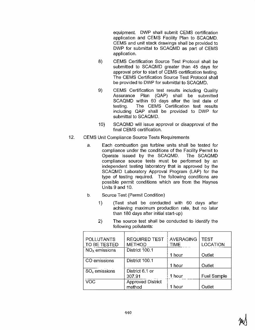
equipment. DWP shall submit CEMS certification application and CEMS Facility Plan to SCAQMD. CEMS and unit stack drawings shall be provided to DWP for submittal to SCAQMD as part of CEMS application.
8) CEMS Certification Source Test Protocol shall be submitted to SCAQMD greater than 45 days for approval prior to start of CEMS certification testing. The CEMS Certification Source Test Protocol shall be provided to DWP for submittal to SCAQMD.
9) CEMS Certification test results including Quality Assurance Plan (QAP) shall be submitted SCAQMD within 60 days after the last date of testing. The CEMS Certification test results including QAP shall be provided to DWP for submittal to SCAQMD.
10) SCAQMD will issue approval or disapproval of the final CEMS certification.
12. CEMS Unit Compliance Source Tests Requirements
a. Each combustion gas turbine units shall be tested for compliance under the conditions of the Facility Permit to Operate issued by the SCAQMD. The SCAQMD compliance source tests must be performed by an independent testing laboratory that is approved by the SCAQMD Laboratory Approval Program (LAP) for the type of testing required. The following conditions are possible permit conditions which are from the Haynes Units 9 and 10.
b. Source Test (Permit Condition)
1) (Test shall be conducted with 60 days after achieving maximum production rate, but no later than 180 days after initial start-up)
2) The source test shall be conducted to identify the following pollutants:
POLLUTANTS REQUIRED TEST AVERAGING TEST TO BE TESTED METHOD TIME LOCATION NOx emissions District 100.1
1 hour Outlet CO emissions District 100.1
1 hour Outlet SOx emissions District 6.1 or
307.91 1 hour Fuel Sample voc Approved District
method 1 hour Outlet
440

PM emissions District method 5.2 4 hours Outlet
NH3 emissions District method 207.1 and 5.3 or 1 hour Outlet EPA method 17
3) The test shall be conducted to determine the oxygen levels in the exhaust.
4) The test shall measure the fuel flow rate (CFH), the flue gas flow rate, and the turbine generating output (MW).
5) PM test run duration shall be for four (4) hours for each of the operating loads and obtain a sample of not less than 5 mg.
6) Operating loads of:
7) Condition 1: Combustion turbine only at 100% of full rated load
8) Condition 2: Combustion turbine only at 75% of full rated load
9) Condition 3: Combustion turbine only at 50% of full rated load
1 0) The test shall be conducted for all pollutants at the Conditions 1 and 2. The test shall be conducted for NOx, CO, VOC and NH3 at Conditions 3 and 4.
11) Source Test Protocol
12) The test shall be conducted in accordance with a District approved source test protocol. The source test protocol shall be provided to DWP for submittal to AQMD no later than 45 days before the proposed test date and shall be approved by SCQAMD before test commences. Test protocol shall include the proposed operating conditions of the turbine during the test, the identity of the testing lab, a statement from the testing lab certifying that it meets the criteria of R304, and a description of all sampling and analytical procedures.
c. Source Test Report (Permit Condition)
1) Source test report shall be in accordance with the following specifications:
2) Emission data in terms of concentration in ppmv, corrected to 15 percent oxygen, dry basis
3) Exhaust flow rate in terms of DSCFM and DACFM
4) Moisture concentration in terms of percent corrected to 15 percent oxygen, dry basis
441
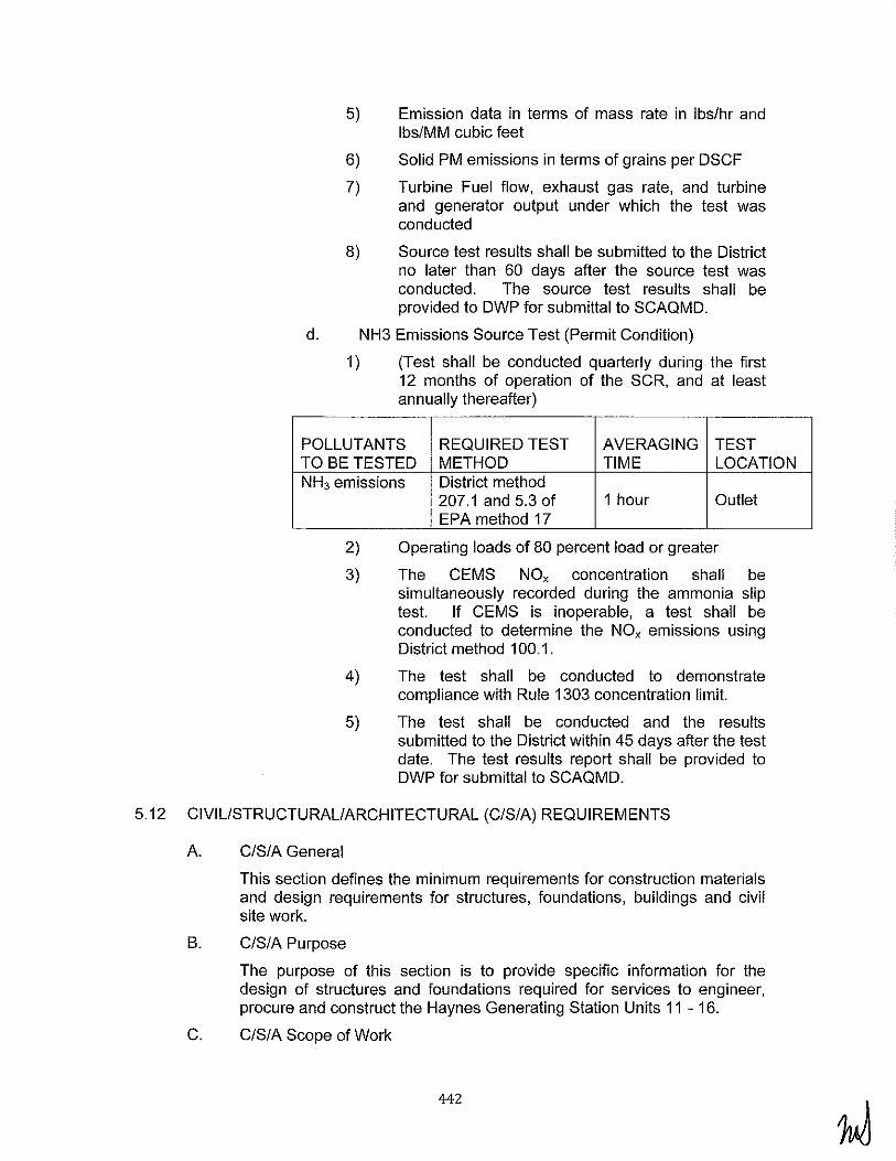
5) Emission data in terms of mass rate in lbs/hr and lbs/MM cubic feet
6) Solid PM emissions in terms of grains per DSCF
7) Turbine Fuel flow, exhaust gas rate, and turbine and generator output under which the test was conducted
8) Source test results shall be submitted to the District no later than 60 days after the source test was conducted. The source test results shall be provided to DWP for submittal to SCAQMD.
d. NH3 Emissions Source Test (Permit Condition)
1) (Test shall be conducted quarterly during the first 12 months of operation of the SCR, and at least annually thereafter)
POLLUTANTS REQUIRED TEST AVERAGING TEST TO BE TESTED METHOD TIME LOCATION NH3 emissions District method
207.1 and 5.3 of 1 hour Outlet EPA method 17
2) Operating loads of 80 percent load or greater
3) The GEMS NOx concentration shall be simultaneously recorded during the ammonia slip test. If GEMS is inoperable, a test shall be conducted to determine the NOx emissions using District method 1 00.1.
4) The test shall be conducted to demonstrate compliance with Rule 1303 concentration limit.
5) The test shall be conducted and the results submitted to the District within 45 days after the test date. The test results report shall be provided to DWP for submittal to SCAQMD.
5.12 CIVIL/STRUCTURAL/ARCHITECTURAL (CIS/A) REQUIREMENTS
A. CIS/A General
This section defines the minimum requirements for construction materials and design requirements for structures, foundations, buildings and civil site work.
B. CIS/A Purpose
The purpose of this section is to provide specific information for the design of structures and foundations required for services to engineer, procure and construct the Haynes Generating Station Units 11 - 16.
C. CIS/A Scope of Work
442
1. This section is applicable to the civil, structural, architectural, and geotechnical engineering, design, and construction required for the Haynes Generating Station Units 11 - 16. It details the technical requirements for engineering, designing, furnishing, shop detailing, fabricating, delivering to the jobsite and constructing the foundations, buildings, structures and site related work for the Project.
2. The complete scope of work is defined in Section 5.1, herein and is briefly summarized below.
3. The relocation and/or demolition of certain existing systems, equipment, utilities, buildings, or structures required to make room for the new simple cycle facility will be performed by the BOP Contractor as defined herein, in addition to all required procurement of equipment and materials. The BOP Contractor rnay also need to remove any chain link fencing, paved areas, and/or contaminated soil (if any) and buried trash from the intended site as required.
4. The BOP Contractor shall furnish all labor, supervision, materials, equipment, tools, engineering and design services to design, furnish, fabricate, deliver to the jobsite, unload, haul, store and construct all foundations, buildings, and structures, including all sitework, for the Project.
5. The BOP Contractor shall provide all Special Inspection and testing services required for construction the project, in accordance with 2007 CBC, by an independent testing agency that is approved by LADWP. The BOP Contractor shall also provide Structural Observation Reports by a registered Professional Engineer as required by 2007 CBC. These requirements apply to all equipment, buildings, components, accessories, or other items installed by the BOP Contractor, whether supplied by the BOP Contractor or others.
6. All civil, structural, architectural, and geotechnical work for the Project shall be performed under the direction of a Professional Engineer registered to execute work in the State of California. The Professional Engineer shall perform engineering work only in those fields in which the engineer is fully competent and proficient. The Professional Engineer shall have current knowledge of, and experience in, civil and structural engineering practice in Southern California, including seismic design. All design calculations, drawings, reports, specifications, and other construction documents shall be approved and stamped by the Professional Engineer and submitted to LADWP.
7. In general, the scope of work is, but not necessarily limited to, the following:
a. Engineering, designing and constructing the power block areas and ancillary equipment foundations including, but not necessarily limited to:
443
i. CT Generators
ii. CT Air Intakes with Evaporative Coolers
iii. CT Air Intercoolers and Intercooler VB Stacks and Pump Skids
iv. Auxiliary Skids
v. Fuel Conditioning and Coalescer Filter skids
vi. Selective Catalytic Reduction units
vii. Stacks
viii. GEMS Shelters
ix. Oily Water Separators
x. Waste Oil Tanks
xi. Demineralization Plant Equipment
xii. Water Storage Tanks
xiii. Air Cooled Heat Exchangers
xiv. Waste Water Collection Sumps
b. Engineering, designing and constructing general equipment foundations including, but not necessarily limited to:
i. Main Step-Up Transformers
ii. Auxiliary Transformers
iii. Motor Control Centers
iv. Packaged Distribution Centers (PDC's)
v. Electrical Duct Banks
c. Engineering, designing and constructing buildings, yard structures, tanks, sumps, and associated structures and foundations including, but not necessarily limited to:
i. Buildings
ii. Dead-end Structures and Foundations at GSU Transformers (except steel dead-end structures shall be designed and supplied by LADWP for installation by BOP Contractor)
iii. Pump and/or Skid Foundations
iv. Access Platforms
v. Pipe Racks
vi. Bus Supports
vii. Miscellaneous Supports, e.g. for Piping or Electrical
viii. Grade Slabs
444

ix. Roads
x. Stormwater Pump Station, Detention Tank and Outfall
xi. Sanitary Sewer System
xii. Fencing (including project site and switchyard)
d. Engineering, designing, and constructing of new underground piping systems. The underground piping shall be routed as required to maintain existing road crossings and access for maintenance.
e. Site development which includes, but not necessarily limited to: clearing, rough and finish grading, site and storm water drainage, area paving, fences and gates, sewers, oil containment, and sedimentation and erosion control during construction. Rough grading for the Units 11 - 16 switchyard is to be included with the BOP Contractor's scope of work. Rough grading elevations in a switchyard shall be in accordance with the drawings provided in Exhibit Z Section 15.
D. CiS/A Design Philosophy
1. General
The overall philosophy for the civil-structural construction activities is to the BOP Contractor engineer and design structures, foundations and structural components that will be consistent with the scope of work included herein.
2. Structural Steel
a. Structural steel for access platforms, utility racks and individual supports, high-voltage electrical equipment, conductor supports, and other structures shall be procured, shop detailed, fabricated, prime painted or galvanized, and delivered to the site and erected by the BOP Contractor. Touch up will be performed on site as required.
3. Foundations
a. Reinforced concrete foundations for equipment, buildings and other structures shall be by the BOP Contractor, including, but not necessarily limited to, material procurement, fabrication, delivery, and erection of formwork, reinforcing steel, embedded items, and concrete.
b. All buildings and various yard structures shall have reinforced concrete foundations with top of concrete elevation set at 6" minimum above final grade elevation. Foundations shall be designed in accordance with the project Geotechnical Report ("C/S/A GEOTECHNICAL DESIGN" Section). All exterior and interior wall footings and grade beams shall extend, at a minimum, to the minimum depth required by the Report. Vertical loads from
445

the superstructure shall be carried directly down to the foundations through walls and/or pier elements. Lateral loads from the superstructure shall be carried directly into the earth through walls and foundation elements and resisted by the soil as detailed in the Report. Foundations shall be designed and sized to meet the specific site soil conditions and m1n1m1ze potential for differential settlement. For ease of construction, foundation dimensions shall be standardized to the maximum extent possible.
4. Ground Floor Slabs
Ground floor slabs shall consist of minimum 6 inch thick reinforced concrete slab on grade and shall be designed integral with a perimeter haunch section. Concrete pads or paved areas shall be designed and provided for equipment maintenance. Slab design will accommodate pipe trenches and continuous trench floor drains as the mechanical systems dictate.
5. Architectural
The architectural features and accessibility requirements for this project shall be designed in accordance with the California Building Code and local building codes.
6. Civil
The site work shall include, but not be limited to all necessary excavation, dewatering, and backfill; rough and finish site grading; site subsurface drainage (if required); site storm drainage and/or ties into the existing drainage system (as required); storm water lift station and piping; a stormwater detention tank and outfall facility; connection to the existing sanitary sewer system and verification of capacity, sedimentation and erosion control during construction, permanent parking areas; permanent asphalt paved roads; patching of existing paved roads and other paved areas; permanent and temporary chain link fencing; oil containment; and any other work necessary for a complete and finished installation. All grading and site preparation shall be done in accordance with the project Geotechnical Report ("C/S/A GEOTECHNICAL DESIGN" Section).
7. Design Codes, Standards, Laws and Ordinances
As a minimum, all structures and site improvements shall be designed and constructed in accordance with the requirements or recommendations contained in the following codes, specifications, and standards, except where more stringent requirements are shown or specified. In addition, all aspects of this Project shall comply with applicable laws and regulations of the federal government, the State of California, and local city and town codes and ordinances. Where provisions of these conflict, the more stringent shall apply, unless otherwise approved by LADWP.
446

When an edition date is not indicated, the latest edition and addenda in effect as of the date of the Agreement shall apply.
a. Federal
1) Title 29, Code of Federal Regulations (CFR), Part 1910, Occupational Safety and Health Standards.
2) Title 40, CFR Part 112 et seq., US Environmental Protection Agency (EPA), Spill Prevention Control and Countermeasure (SPCC) Rule.
b. State
1) Business and Professions Code Section 6704, et seq.; Section 6730 and 6736 requires state registration to practice as a Civil Engineer, Structural Engineer, or Architect in California.
2) State of California Department of Transportation (Caltrans), Standard Specifications and applicable Special Provisions and Reference Specifications, as last revised.
3) California Occupational Safety and Health Administration (Gal/OSHA).
4) California Building Code (CBC), 2007.
5) Standard Specification for Public Works Construction (SSPWC), "Greenbook", 2009.
6) County
7) Los Angeles County Department of Public Works - Hydrology Manual.
8) SUSMP - Standard Urban Storm Water Mitigation Plan
c. City
1) Fire Marshall of Authority having jurisdiction.
d. Industry Codes and Standards
1) The following general design requirements and procedures shall be followed in development of project specifications regarding the use of Codes and Industry Standards.
i. Specifications for materials shall generally follow the standard specifications of the American Society for Testing Materials (ASTM) and the American National Standards Institute (ANSI).
ii. Field and laboratory testing procedures for materials shall follow standard ASTM
447

specifications and shall comply with 2007 CBC requirements.
iii. Design and placement of structural concrete shall follow the recommended practices, the latest version of the American Concrete Institute (ACI), the 2007 CBC, the Concrete Reinforcing Steel Institute (CRSI), and the Precast/Prestressed Concrete Institute (PCI).
iv. Design, fabrication, and erection of structural steel shall follow the recommended practices and the latest version of the American Institute of Steel Construction Code (AISC) and the 2007 CBC.
v. Steel components for metal wall panels and roof decking shall conform to the American Iron and Steel Institute (AISI) Specification for the Design of Light Gage Cold-Formed Structural Members. Cold Formed Steel-Design Manual.
vi. Welding procedures and qualifications for welders shall follow the recommended practices and codes of the American Welding Society (AWS).
vii. Preparation of metal surfaces for coating systems shall follow the specifications and standard practices of the Society for Protective Coatings (SSPC), National Association for Corrosion Engineers (NACE), and the specific instructions of the coatings manufacturer.
viii. Fabrication and erection of grating shall follow applicable standards of the National Association of Architectural Metals Manufacturers (NAAMM).
ix. Design and erection of masonry materials shall follow the recommended practices and codes of the latest revision of the ACI Building Code Requirements for Masonry Structures and the 2007 CBC.
x. Plumbing shall conform to the California Plumbing Code (CPC).
xi. Design of roof coverings shall conform to the requirements of the National Fire Protection Association (NFPA), Factory Mutual (FM) and be approved by the Los Angeles Department of Building and Safety, and have a valid research report number.
448

xii. Design of roadways and storm drain systems shall conform to APWA, American Public Works Association, or other local codes if applicable.
xiii. Design, testing, construction and installation for specialty items, proprietary items, patented items shall follow International Council of Building Officials (ICBO) report recommendations, and manufacturer recommendations, where applicable.
2) The following Codes and Industry Standards shall be used:
California Code of Regulations, Title 24, including California Building Code (CBC), California Pluming Code (CPC), California Electrical Code (CEC), California Fire Code (CFC), California Mechanical Code (CMC), and other applicable codes.
Recommended Seismic Design Criteria for New Steel Moment- Frame Buildings FEMA 350, June 2000.
Structural Engineers Association of California, "Recommended Lateral Force Requirements and Commentary," Blue Book.
American Institute of Steel Construction (AISC).
Steel Construction Manual, 13th Edition.
Specification for Structural Steel Buildings.
Code of Standard Practice for Steel Buildings and Bridges.
Seismic Design Manual.
RCSC Specification for Structural Joints Using ASTM A325 or A490 Bolts.
American Iron and Steel Institute (AISI) "Specification for the Design of Cold-Formed Steel Structural Members"
AWS D1.1-100 American Welding Society (AWS) "Structural Welding Code-Steel Fifteenth Edition"
American Concrete Institute (ACI)
301 "Specifications for Structural Concrete"
302.1 R "Guide for Concrete Floor and Slab Construction"
318/318R "Building Code Requirements for Structural Concrete"
449
350R "Environmental Engineering Concrete Structures"
530 "Building Code Requirements for Concrete Masonry Structures and Commentary"
Precast/Prestressed Concrete Institute, PCI Design Handbook Precast and Prestressed Concrete
American Society of Civil Engineers (ASCE)
ASCE 7, Minimum Design Loads for Buildings and Other Structures
ASCE Manuals and Reports on Engineering Practice No. 79, Steel Penstocks
ANSI/ASME STS-1-2000-Steel Stacks.
American Society for Testing and Materials (ASTM). The following codes and standards shall be included as a minimum:
A36 "Standard Specification for Structural Steel"
A53 "Standard Specification for Pipe, Steel Black and Hot-Dipped, Zinc Coated, Welded and Seamless"
A82 "Standard Specification for Welded Steel Wire Fabric, Plain, for Concrete Reinforcement"
A153 "Specification for Zinc Coating (Hot-Dip) on Iron and Steel Hardware"
A 182 "Standard Specification for Steel Wire, Plain, for Concrete Reinforcement"
A276 "Standard Specification for Stainless Steel Bars and Shapes"
A307 "Standard Specification for Carbon Steel Bolts and Studs, 60,000 PSI Tensile Strength"
A416 "Standard Specification for Steel Strand, Uncoated Seven-Wire for Pre-stressed Concrete"
A500 "Standard Specification for Cold-forced Welded and Seamless Carbon Steel Structural Tubing in rounds and Shapes"
A572 "Standard Specification for High-Strength Low-Alloy Columbium-Vanadium Structural Steel"
A615 "Standard Specification Deformed and Plain Billet Steel Bars for Concrete Reinforcement"
A695 "Standard Specification for Steel Bars, Carbon, Hot-Wrought, Special Quality, for Fluid Power Applications"
450
A706 "Standard Specification for Low-Alloy Steel Deformed and Plain Bars for Concrete Reinforcement"
A992 "Standard Specification for Steel for Structural Shapes for Use in Building Framing."
A1011 "Standard Specification for Steel, Sheet and Strip, Hot Rolled Carbon, Structural, High Strength Low-Alloy and High Strength Low-Alloy with improved Formability"
B695 "Standard Specification for Coatings of Zinc Mechanically Deposited on Iron and Steel."
C618 "Standard Specification for Coal Fly Ash and Raw or Calcined Natural Pozzolan for Use in Concrete"
F1554 "Standard Specification for Anchor Bolts, Steel, 36, 55 and 1 05-ksi Yield Strength"
American Association of State Highway and Transportation Officials (AASHTO) (GDHS-3-com), "A Policy on Geometric Design of Highways and Streets"
Asphalt. Asphalt Institute Pacific Coast Division. Asphalt Institute Handbook (MS-4)
National Fire Protection Association Standards (NFPA)
Standard Specifications for Public Works Construction (SSPWC)- Section 207, "Pipe"
California Geological Survey - Special Publication 117 A, "Guidelines for Evaluating and Mitigating Seismic Hazards in California"
3) The following Codes and Industry Standards shall be used for the design and construction of the Stormwater Detention Tank:
AWWA D-100, Welded Carbon Steel Tanks for Water Storage.
AWWA D-103, Factory-Coated Bolted Steel Tanks for Water Storage.
API-650, American Petroleum Institute Welded Steel Storage Tanks.
e. Geotechnical Engineering
Project Geotechnical Requirements - the BOP Contractor shall use the Geotechnical Information provided in Exhibit Z Section 8 for information only. The BOP Contractor shall perform all additional geotechnical studies and
451

investigations necessary to design and construct the project. A new Geotechnical Report shall be prepared and submitted to LADWP for review and approval in accordance with "C/S/A GEOTECHNICAL DESIGN" Section.
E. CIS/A Specific Building and Architectural Requirements
1. General
a. The architectural features and accessibility requirements for this project shall be designed in accordance with the California Building Code and local building codes as required.
b. All buildings shall have fire detection and protection.
c. The preparation of the manufacturer's drawings, calculations and specifications shall be under the direction of a Registered Professional Engineer in the State of California. All documents submitted for construction shall bear the stamp of the Registered Professional Engineer.
d. The final size determination of the buildings and enclosures shall be based on BOP Contractor's layout of all equipment and equipment foundations that may be housed within the building. This layout shall also account for code-required egress and adequate clearance requirements for the removal and/or normal maintenance of all equipment contained within the buildings.
e. Protective Coatings - The exposed exterior metal structures and components of pre-engineered buildings shall be primed and topcoat painted, galvanized, or fabricated of corrosion resistant material. Painting systems shall be selected in accordance with recognized guides to achieve a life of at least 25 years to first maintenance repainting in a residential environment with no industrial fumes or fallout. Exposed interior metal structures and components shall be prime painted, galvanized, or fabricated of corrosion resistant material. Members subject to aggressive compounds shall have appropriate chemical resistant coatings applied. Exposed concrete surfaces, exterior and interior, shall be uncoated except that areas subject to aggressive compounds shall have appropriate chemical resistant coatings or liners applied.
f. ADA requirements - The design and construction of the Control Building including but not limited to toilet facilities, doors, slopes, ramps, and parking shall comply with the accessibility requirements of the California Code of Regulations.
2. Buildings
452

The BOP Contractor is responsible to furnish all labor, materials, and equipment to perform and coordinate the necessary operations for the design, permitting, fabrication, delivery, erection, construction, commissioning, and certification of all buildings for the Project, including but not limited to all primary and secondary structural framing, bolt assemblies, roofing, siding, doors and hardware, windows and hardware, batt insulation, interior finishes, fixtures, flashing, closures, sealants, vapor barriers, downspouts, gutters, HVAC, fire protection and detection, plumbing, power, lighting, grounding, lightning protection, communications, signage, foundation, furnishings, accessories, and any other iterns or appurtenances required for a complete code-compliant installation. Buildings shall be in accordance with applicable federal, state and local requirements and shall be approved by LADWP.
Buildings shall consist of a metal building system designed, fabricated, and supplied by a metal building Manufacturer approved by LADWP, generally conforming to this Specification. Primary framing shall be manufacturer's standard modular rigid frame construction with tapered or uniform depth rafters rigidly connected at ends to pinned base uniform depth columns. Purl ins and girts shall be cold-formed "C" or "Z" sections conforming to "Specifications for Design of Cold-Formed Steel Structural Members" of American Iron and Steel Institute {AISI). All other members shall be hot rolled shapes conforming to "Specification for Design, Fabrication and Erection of Structural Steel for Buildings" of American Institute of Steel Construction {AISC).
In general, materials and installation of architectural systems or components shall be as follows:
a. Exterior Walls. These shall be metal wall panel systems of the factory assembled or field erected type with exposed fasteners. Wall panels shall be minimum 24 gauge, unless greater thickness is required by design. Wall panels shall have configurations for overlapping sheets or interlocking ribs for securing adjacent sheets. Exterior wall panels shall be fastened to framework using concealed fasteners where possible.
b. Installed walls shall be watertight and shall provide a "U" factor in accordance with the California Code of Regulations, Title 24 and the ASHRAE Handbook. Sound attenuation shall be provided for sound absorption on walls enclosing equipment as required. Thermal resistance of wall insulation shall be not less than R-19. R-values shall be determined at a mean temperature of 75 degrees in accordance with ASTM C518.
c. Interior Walls. Where durability is required, interior walls may be constructed of concrete block masonry, structurally designed and reinforced as required. In offices, shops,
453
etc., metal studs with 5/8" gypsum board shall usually be used to form interior partitions. Insulation for sound control shall be used where required by design. Interior finishes shall be compatible with the intended operational use of each building area. Interior finishes for the control room areas shall be aesthetically pleasing to the workers and the potential large number of visitors to the facility.
d. Fire Exits. Fire exits shall be provided as required by code. Exit signs and emergency lighting shall be provided. Fire doors shall bear an Underwriters Laboratory (UL) certification level for class of opening and rating for door, frame, and hardware. Doors shall conform to hollow metal door requirements and have fillers adequate to meet the fire rating.
e. Exterior Roll-up Doors. Large access exterior doors shall be rolling steel type with weather seals and windlocks. Components shall be formed from galvanized steel, factory assembled, and factory painted. Doors shall be motoroperated with manual override operation feature.
f. Metal Roof Deck and Insulation System. Units shall be fabricated of minimum 20 gauge sheet steel unless otherwise required by design. Roof panels shall be a minimum 2-3/4-inch standing seam with concealed clips. Design provisions shall be made for thermal expansion and contraction consistent with the type of system to be used. Deck shall not deflect more than 1/240 of span under live load and the deck shall not deflect more under temporary construction load. Thermal resistance of roof insulation shall be not less than R-30.
g. Wall and roof panels shall be zinc-coated steel with a factory applied polyvinylidene fluoride finish (70% minimum KYNAR) on the exterior side. The finish shall be a minimum of 1 mil thickness consisting of a baked fluoropolymer enamel topcoat factory applied over an appropriate prime coat.
h. Color Schemes. Color schemes shall be selected by LADWP from the manufacturer's standard colors.
i. Signage. Signs and graphic designs for identification and directions shall be incorporated into the interior finishes of each area. Signs shall be placed for safety, ease of operation and direction. The sign system shall provide simple and direct indications using both graphics and text as required. All signage shall comply with ADA requirements.
j. Steel
454

i. Hot rolled, fabricated components shall conform to ASTM A36, ASTM A572 Grade 50 or ASTM A992, prime painted or hot dip galvanized.
ii. Cold-formed components shall conform to ASTM A570, Grade E, 42,000 psi minimum yield for material thickness equal to or less than 0.23 inch, or to ASTM A375, 50,000 pounds per square inch (psi) minimum yield for high tensile strength purlin or girt sections with material thicknesses equal to or less than 0.23 inch.
iii. Roof covering and wall covering shall conform to ASTM A446, Grade A, galvanized 33,000 psi minimum yield.
iv. All cold-formed components shall be manufactured by precision roll or break forming.
k. Control Building:
The BOP Contractor shall provide a new Control Building to accommodate the necessary controls, DCS and Human Machine Interface hardware, and a full operating crew to meet plant operating requirements. In addition to ADA requirements, design of the Control Building shall comply with applicable requirements of North American Electric Reliability Corporation (NERC) and Critical Infrastructure Protection (CIP).
See Drawing Number HNGS-0-SK-171-201-003 (in Exhibit Z Section 15) for conceptual layout of the Control Building. The Control Building footprint is approximately 4,000 square feet or as otherwise required by design.
The Control Building shall include the following features at a minimum:
i. Control Room
ii. DCS Room, with ingress/egress separate from the Control Room
iii. Shift Supervisor's Office
iv. Kitchen, with eating area
v. Simulator Room
vi. Bathrooms, with lockers and showers
vii. Utility Room, for storage of supplies, inspection appurtenances, safety equipment, PPE, etc.
viii. UPS/Battery/Telecom Facilities, with ingress/egress separate from the Control Room
I. Maintenance Facilities
455

The BOP Contractor shall provide new Maintenance Facilities, consisting of Maintenance Offices and a Maintenance Shop with an outside Covered Storage area.
The Maintenance Shop and Covered Storage shall be designed to service and re-condition the super cores and combustion components as well as store capital spares, and shall include truck ingress/egress to facilitate rigging, heavy equipment, and parts. The Covered Storage Area shall be an open-sided covered shelter complying with "Open-Sided Covered Shelters" Section below and shall be located adjacent to the shop. The approximate footprints for the shop and storage areas are 125' x 40' and 125' x 20', respectively, and shall include the following features at a minimum:
i. Four roll-up doors, for access to deliver and pick up parts
ii. Bridge crane (minimum 15-ton capacity) in Maintenance Shop, to rig supercores, compressors, combustion cans, or other heavy combustion turbine parts
iii. 5-ton capacity overhead crane in Covered Storage area
iv. Two pedestal grinders
v. Feed blast cabinets
vi. Small lathe
vii. Air and water connections
viii. Accommodate storage of capital spares (e.g. Unit 9 and 10 spare HRSG tube bundles, approximately 87' long x 15' wide)
Maintenance Offices shall be approximately 80' x 40' and shall include the following features at a minimum:
i. Five Supervisor's Offices
ii. Five Planning and Scheduling Offices
iii. Bathrooms, with lockers and showers
iv. Electrical Shop
v. Machine Shop
vi. Weld Shop
m. Instrument Shop
A new Instrument Shop (approximate footprint 1 00' x 40') is required to address the need for quick access to the Control Building. The Instrument Shop shall include the following features at a minimum:
456

i. Supervisor's Office
ii. Training Office
iii. Clean Work Area
iv. Dirty Work Area
v. Break/Lunchroom Area
vi. Bathrooms, with lockers
n. Architectural Finishes
Architectural finishes in the buildings shall conform to the following table as applicable:
ROOM NAME FLOOR WALL CEILING
Control Room ace gbp sat
Corridors vet gbp sat
Offices vet gbp sat
Mechanical Equipment Rooms me gbp/mwlp ex
Janitor Closet me gbp sat
Storage Rooms vet gbp sat
Shops me gbp/cmup/mwlp ex
Electricai/DCS Room me gbp sat
Toilet Rooms eft cwl/gbp sat
UPS/Battery Room me* gbp/cmup/mwlp sat
Floor Finishes:
Me
Vet
Cfl
Ace
*
Sealed, cast-in-place concrete
Vinyl composition tile
Unglazed ceramic tile
Access floor panel system with anti-static HPL!vinyltiles, 18" clear space
Specialty coatings will be applied in areas subject to acid or chemical spills
457

Wall Finishes:
Gbp
Mwlp
Cmup
Cwt
Ceiling Finishes:
Sat
Ex
0.
Painted gypsum board on metal studs
Metal wall liner panel at pre-engineered building exterior Walls
Filled, painted concrete masonry
Unglazed ceramic tile over masonry or gypsum board, Wainscot to 4' -0" above finished floor.
Suspended acoustical tile
Exposed to structure
Mechanical
1) HVAC
The HVAC system for the buildings shall be designed to comply with applicable code requirements, Section 5.9. R, and as further specified herein. The BOP Contractor shall prepare all system design engineering calculations and drawings to be used in the sizing and selection of all HVAC equipment and components and submit to LADWP for approval. Cooling load shall include all heat gain sources including all internal electrical and mechanical sources, building solar heat gains, and ventilation loads. For the purpose of sizing heating equipment, no credit shall be taken from any internal sources. Design shall include safety margin of 15% for both cooling and heating.
Contractor shall develop and submit for approval all necessary compliance forms or energy budgets to local authority having jurisdiction. A copy of the approved compliance forms shall be submitted to LADWP.
Seismic bracing shall be specified and installed in accordance with applicable building code requirements.
All rooms shall have at least one inlet and one outlet. Coordinate exact locations of ceiling inlets and outlets with reflected ceiling plans. Inlets and
458
outlets shall be located and sized to prevent drafts or direct impingement of air on people.
Sound levels shall not exceed RC-35 in offices and control room and RC-40 in other areas.
Balancing dampers shall be provided where necessary to facilitate ease of testing and balancing of the systems. Locate dampers in accessible location. Dampers installed above gypsum board ceilings shall be provided with ceiling access doors.
The HVAC system will include both heating and cooling of the filtered inlet air. Air filters will be housed in a manner that facilitates removal. The filter frames will pass the air being handled through the filter without leakage.
Provisions shall be made to interlock and stop the HVAC system operation upon actuation or detection of fire or smoke by the building fire protection system.
2) Fire Protection and Detection
The BOP Contractor shall furnish all labor, materials, tools, and equipment to design and install the fire protection and detection system for the buildings, including seismic bracing and supports as described herein, ready for service to the entire satisfaction of LADWP and governing authorities. The work must be in accordance with Section 5.9.0 and all local or state requirements that apply. Fire protection and detection design for the buildings shall be coordinated with the fire protection and detection design for the plant.
Provide fire department connections as required by the local Fire Marshall.
Use only UL and FM approved equipment.
The proposed fire protection and detection for the buildings, including all drawings, calculations, and related system details, will be reviewed and approved by the local Fire Marshall and LADWP as required prior to installation.
3) Plumbing
Design and specify all plumbing fixtures, hot and cold-water piping, waste and vent piping and drains, valves, etc., required for the buildings in accordance with California Building Code and local requirements. As a minimum, provide hot and cold water and sewer demands, isometrics, and hot
459
water heater sizing calculations to LADWP for approval.
Plumbing fixtures shall be manufactured by American Standard, Kohler, Eljer, or equal and shall be suitable for industrial use.
Provide electric water heater units with glass lined steel tanks. Units shall be floor mounted in accordance with code requirements and shall be UL listed and labeled. Tanks shall be wrapped with "Heat Saver" or equal R-7 water heater blanket. Heaters shall be listed in the State Energy Commission Directory of Certified Water Heaters.
p. Electrical
1) Power Supply
Provide all equipment, panels, receptacles, raceways, wiring, and accessories as necessary for routing and installation of a complete electrical power system for the building including all equipment and accessories in accordance with code requirements and Section 5.10.N of this Specification.
Convenience outlets will be provided throughout the buildings as required by code. Provide a minimum of one receptacle on each wall of all normally occupied spaces. Provide minimum of one floor receptacle in the Control Room, or as otherwise required to supply power to Control Room equipment. Provide one GFCI-type outdoor convenience receptacle adjacent to each exterior doorway, at a minimum.
One disconnect switch shall be provided that will disconnect all power sources to the building and installed in a location and manner that is acceptable to LADWP.
Submit electrical plans to LADWP for approval indicating proposed locations of indoor and outdoor receptacles, panel board( s ), raceways, and other electrical equipment and features.
2) Lighting
Lighting shall comply with code requirements and Section 5.1 O.N.6. At a minimum, lighting shall be provided for each room of all buildings and at all exterior entrances.
The Control Room ceiling will be provided with recessed, non-glare, florescent lighting fixtures and switched adjustable lighting levels.
460

Provide emergency lighting with integral battery packs along all paths of travel for egress and as otherwise required.
Submit lighting plan to Owner for approval indicating proposed types and locations of interior and exterior lights and raceways including emergency lighting and illuminated signage.
3) Grounding and Lightning Protection
Design in accordance with code requirements and Section 5.10.N.4.
4) Telephone I Fax I LAN Systems
Provide raceway and/or conduit and all accessories as necessary for routing and connection of phones, fax machines, and computers throughout the buildings in accordance with Section 5.10.N.1. Wiring for this system will be provided by LADWP.
Provide at least one wall-mounted receptacle in each office. Requirements for receptacles in the Control Room and other occupied spaces shall be coordinated with LADWP. Each receptacle shall include connections for telephone/fax and LAN.
Submit plan to LADWP for approval indicating proposed locations of receptacles and raceways for telephone, fax, and LAN throughout the building.
3. Open-Sided Covered Shelters
Where indicated on the General Arrangement or where otherwise required, covered shelters shall be open-sided and constructed of galvanized structural steel and sloped exposed fastener metal roof deck, with gutters and downspouts. Shelters shall conform to the applicable requirements listed above for Pre-Engineered Buildings.
4. Construction Noise Requirements
Near field noise levels at the plant site will meet US and California Occupational Safety and Health Administration (OSHA and Gal/OSHA) requirements. Noise abatement controls will be specified to meet applicable industry guidelines. The BOP Contractor shall implement best available noise abatement measures for normal and significant noise-producing construction activities. See the Environmental Impact Report for additional requirements.
F. C/S/A Materials
All material for the items listed below shall be new and shall be certified to be in accordance with the applicable specification of the serial designation listed below. Evidence of certification shall
461

be on file in the BOP Contractor's office and furnished to LADWP upon request.
Certified copies of material test reports shall be available in the BOP Contractor's file, showing chemical and mechanical properties and the results of each test required by the material specification, for all steel materials furnished under this specification, unless otherwise noted herein.
Certificates of Conformance in lieu of material test reports may be accepted as documentation of the above requirements, only upon the written approval of LADWP.
Structural Steel
Shapes and miscellaneous plates
Structural Steel Connections
High Strength Bolts
Nuts
Hardened Washers
Direct Tension Indicators
Standard Bolts
Nuts
Hardened Washers
Structural Steel Welding Filler
Expansion Bearing Plates
Concrete
All materials
Cement
462
ASTM A36, ASTM A500 Grade A992 and A572 Grade 50. galvanized ASTM A123, unless noted
B, ASTM Hot-dip
otherwise
ASTM A325, Type 1, Zinc Coated, ASTM A153 Class C
ASTM A563, Grade DH Heavy Hex, Zinc Coated, ASTM A 153 Class C
ASTM F436, Zinc-Coated, ASTM A153 Class C
ASTM F959
ASTM A307, Zinc-Coated, ASTM A153 Class C
ASTM A563, Grade A Heavy Hex, Zinc Coated, ASTM A153 Class C
ASTM F436, Zinc-Coated, ASTM A153 Class C
AWS 01.1, E70XX
As required
ACI301
ASTM C150, Type 11/V low alkali, f'c = 4000 psi at 28 days

Fly Ash
Aggregate
Water
Admixtures
Masonry
Concrete Masonry Units (CMU)
Masonry Mortar
Masonry Grout
Reinforcing Steel:
Reinforcing bars
Prestressing Tendons
Welded wire fabric
Anchor Bolts:
Standard:
Bolts
Nuts
Washers
High Strength:
Bolts
Nuts
463
ASTM C618, Class F
ASTM C33
ASTM C94
Water-reducer, if applicable, per ASTM C494, Type A
ASTM C90 Hollow load-bearing, lightweight, f'm = 1 ,500 psi
ASTM C270, Type S; minimum compressive strength of 1,800 psi at 28 days
ASTM C476; minimum compressive strength of 2,000 psi at 28 days
ASTM A615, Grade 60
ASTM A416, Standard Specification for Steel Strand, Uncoated Seven-Wire for Prestressed Concrete
ASTM A185
F1554, Grade 36 or 55, Zinc-Coated, ASTM A153
ASTM A563 Grade A Heavy Hex, ZincCoated, ASTM Al53 Class C
ASTM F436, or ASTM A36 plate washer, Zinc-Coated, ASTM A153 Class C
F1554, Grade 105, Zinc-Coated, ASTM A153
ASTM A563 Grade DH Heavy Hex, ZincCoated, ASTM Al53 Class C

Washers
Drilled-in Anchors
G. CIS/A Structural Loads
1. General
ASTM F436, or ASTM A36 plate washer, Zinc-Coated, ASTM A 153 Class C
Hilti-Kwik Bolt TZ, designed and installed in accordance with ICC ESR-1917
For the purpose of determining design loads, the Haynes Generation Station shall be considered as an essential facility, defined as Occupancy Category IV in accordance with 2007 CBC Section 1604.5. Design loads to be applied to the structure and/or foundations consist of the following:
Dead load (refer to CIS/A STRUCTURAL LOADS Section herein).
Live load (refer to CIS/A STRUCTURAL LOADS Section herein).
Snow load (refer to CIS/A STRUCTURAL LOADS Section herein).
Wind loads (refer to C/S/A STRUCTURAL LOADS Section herein).
Earthquake load (refer to CIS/A STRUCTURAL LOADS Section herein).
Erection loads shall be temporary loads imposed on structures and/or foundations during the erection of structures and installation of equipment.
Operating load shall be dead load plus weight of any fluid or solid present during operating conditions and/or permanently stored materials.
Maintenance loads shall be temporary loads resulting from repairs or dismantling of equipment.
Vehicle load shall be that load caused by vehicles (forklifts, cranes, trucks; special trucks for heavy hauling, locomotives) during construction and plant operation.
Impact loads shall be those loads caused by impact, i.e. crane loads, moving vehicles, water hammer, etc.
Vibration loads shall be loads caused by vibrating equipment such as pumps, fans, compressors, turbine-generators or loads such as vortex shedding on stacks, substation short circuit, aeolian vibration, etc.
Test load shall be dead load plus weight of any fluid or solid necessary to test equipment or piping.
Ice load shall be ice accumulation on transmission wires and support structures, switchyard structures, etc.
464

Thermal loads shall be loads caused by temperature changes.
Torsional loads shall be loads creating torsion or loads not passing through the shear center of a structure.
Settlement load shall be the load due to differential settlements of equipment and structure foundations.
Detailed descriptions of design loads being applied to the structure and/or foundations consist of the following:
2. Dead Load
Dead load shall be considered as the weight of all permanent construction, including framing, walls, floors, platforms, roofs, partitions, stairways, handrails, insulation, lagging, and the operating weight of all fixed equipment and piping. Actual operating loads shall be used whenever they exceed the live load allowance for the area occupied by the equipment.
3. Live Load
a. General
Live load includes any movable load or other load that can vary with intensity or occurrence, such as crane loads and uniform floor or roof live loads.
The minimum design live loads to be used are shown below in Table 12.7A, Minimum Uniform Live Loads, and as further defined in ASCE 7. In addition to these loads, other live loads, including erection loads, rotor emergency loads, generator emergency loads, equipment thermal loads, crane loads, and horizontal skidding loads should be considered where appropriate.
TABLE 12.7A Minimum Uniform Live Loads
Location Live Load Remarks
Noted
Ground Floor Slab 125 psf
Outdoor Grade Slab 250 psf Note a
Grating access platforms for servicing 125 psf Note c equipment
Stairs 100 psf Note b
Walkways 60 psf Note c
Roof Live Load 20 psf
Driveways, slabs or pavement subject to HS20-44 AASHTO
465

I trucks or fire equipment I Loading
b. Notes Applying to Design Live Loads:
A truck may operate over most accessible areas. The ground floor slabs and grade slabs including truck aisles and entrances shall be designed to carry an HS20-44 truck load plus impact. This load will not be combined with any other live load and should not reduce the strength required by other design parameters.
Members will be designed to support safely the uniformly distributed live load or a concentrated load of 300 lb. on an area of 4 sq. in. at the center of the tread.
In addition to uniformly distributed live loads, a concentrated load of 1,000 pounds shall be applied concurrently to the supporting beams to maximize stresses in the members, but the reactions from the concentrated loads shall not be carried to the columns.
Equipment loads shall be used when they exceed minimum live load. Equipment and minimum uniform live loads will not be applied simultaneously.
When considering equipment laydown areas, loads shall be cribbed and spread over an area in order not to exceed the posted live load.
c. Point Load
All main framing beams shall be designed to withstand a 5 kip point collateral construction load plus normal dead loads plus normal operating loads. The 5 kip load shall be placed on the individual beams to maximize the bending, shear, and axial stresses in combination with the normal dead loads and operating loads. The 5 kip point load shall be applied individually to members and shall not be additive to adjoining members.
All columns shall be designed to withstand a 25 kip axial collateral construction load plus normal dead loads plus normal operating loads. The 25 kip point load shall be placed on the individual columns to maximize the axial stresses in combination with the normal dead loads and operating loads. The 25 kip point load shall be applied to each individual column.
d. Live Load Reduction
No reduction of live load is allowed for roofs and storage areas. Likewise, no reduction of live load shall be made in the design of slabs and joists.
e. Live Load Posting and Drawing Notation
466
Live load posting will be achieved in the field by permanent signage which states the maximum live load that shall apply to these areas. To satisfy state and other requirements, the live load used for design shall be shown on each concrete, steel, and roof plans. If a special live load applies to a partial area, the limits of the special loading shall be shown on the drawings and the building posted accordingly.
4. Snow Load
Snow load is not applicable for this Work.
5. Wind Load
a. General
Basic wind speed used in the design of buildings, mechanical equipment, support structures, electrical equipment, and other major structural components, shall be 85 miles per hour (3-second gust). Design wind pressures shall be determined in accordance with Section 1609 of the 2007 CBC.
b. Exposure Category
Exposure Category D shall be used for determining wind loads, as defined by 2007 CBC Section 1609.4.3.
c. Special Wind Effects
The BOP Contractor shall investigate and include any wind effects in the analysis that may be applicable for the site based on Sections 6.5.4.1 or 6.5.4.2 of ASCE 7.
6. Earthquake Load
a. General
Every building, structure, equipment, and facility, as a minimum requirement, shall be designed and constructed to resist seismic forces determined in accordance with the California Building Code, unless otherwise specified herein. In addition, Architectural, Mechanical, and Electrical components shall be designed and constructed to resist seismic forces determined in accordance with the California Building Code, unless otherwise specified herein.
b. Seismic Design Criteria
Seismic design coefficients shall be determined in accordance with the California Building Code and ASCE 7, based on a site-specific Geotechnical Report ("C/S/A GEOTECHNICAL DESIGN" Section).
Without ground improvements prior to detailed design, the site soil shall be classified as Site Class F due to the reported presence of potentially liquefiable soils. In such
467

case, a site-response analysis is required in accordance with ASCE 7 Section 21.1.
If ground improvements are completed prior to detailed design, the site soil may be reclassified if postimprovement soil testing justifies lower site classification in accordance with the California Building Code and ASCE 7. Post-improvement soil testing shall only be carried out by a geotechnical consultant that is approved by LADWP. Final site soil classification and seismic design criteria used for design is subject to review and approval by LADWP.
c. Equipment Anchorage
All analyses and design of anchorage material and components provided by equipment manufacturers shall be reviewed by the BOP Contractor to verify that the anchorage shall withstand seismically induced stresses in combination with other normal operational loads and the requirements of these specifications.
d. Seismic Qualification for Electrical Equipment
All electrical equipment supplied by the BOP Contractor shall meet the requirements of this section. The BOP Contractor shall meet the seismic qualification requirements for electrical equipment by meeting the requirements of the following sections.
1) Qualification Requirements
All electrical equipment supplied by the BOP Contractor shall be qualified in accordance with the requirements of IEEE Standard 693. All equipment shall meet the requirements of the high qualification level. Frequency modifying devices shall not be allowed. Individual equipment or classes of equipment shall be qualified in accordance with the specific requirements of the appropriate Annexes of IEEE Standard 693 and to the general requirements of Annex A of IEEE Standard 693 except as modified herein.
All equipment shall be qualified in its in-service configuration. All equipment supplied with supports shall be qualified by including the support structure in its in-service configuration in accordance with Annex A.1.1 of IEEE Standard 693. Additionally, all equipment supplied with supports shall consider site response characteristics and soil-structure interaction recommendations of IEEE Standard 693.
A damping value of 2 percent of critical damping shall be used to qualify supplied equipment, unless
468

a higher value can be justified by one of the methods identified in IEEE Standard 693.
A California-licensed Civil or Structural Engineer who meets the requirements for the specialist defined in IEEE Standard 693 shall sign all seismic reports and calculations furnished under this paragraph.
2) Alternative Qualification Requirements
Test reports or analysis reports for equipment previously qualified under the requirements of IEEE Standard 693 may be submitted to LADWP by the BOP Contractor for the consideration of qualification. Such reports shall meet the minimum combined requirements of IEEE Standard 693 and shall be signed by a seismic specialist. LADWP will review any such reports and may approve the report; or may require the BOP Contractor to revise the report according to LADWP's instructions and resubmit the revised report for LADWP's approval; or may reject the report in its entirety. Should LADWP reject any test report submitted by the BOP Contractor; the BOP Contractor shall qualify the equipment in accordance with all the requirements of "C/S/A STRUCTURAL LOADS" Section herein at no extra cost to LADWP.
3) Test Report or Analysis Report
The test reports or analyses shall be prepared in accordance with IEEE 693.
The reports shall be submitted to LADWP for review and approval not later than 60 calendar days after date of award of contract, if the report is by analysis, or 21 calendar days after date of award of the Agreement if testing or analysis will be complete prior to the award date. LADWP will return a disposition of the report within 14 calendar days after date of receipt.
4) Porcelain Components
The material for grouting 180 kV or greater porcelain bushing or insulators into the metal end fittings shall be non-shrink Portland cement or epoxy. No other material shall be used without prior written approval from LADWP.
5) Deflections
Maximum allowable deflection of bushings or insulators shall be as follows measured at the top of the bushing or insulator from the base of the
469

bushing or insulator, neglecting deflection and rotation of the base support structure, if any:
3.5 inches for less than 138 kV
6.5 inches for 138 kV to 230 kV
8.0 inches when greater than 230 kV
6) Testing
The following equipment that has not been previously tested and approved in accordance with the requirements of IEEE Standard 693 shall be shake table tested for both sine beat and timehistory testing in accordance with Annex A of IEEE Standard 693.
Dead Tank Circuit Breakers;:, 169 kV
Live Tank Circuit Breakers;:, 121 kV
Bushings and Surge Arresters ;:, 169 kV
Disconnect Grounding Switches ;:, 200 kV
Circuit Switches ;:, 200kV
7. Temporary Load
Provision shall be made for temporary loads arising from the installation of the heavy machinery and equipment.
8. Equipment Load
Static and dynamic equipment loads shall be as specified on the Manufacturer's drawings.
H. CIS/A Civil Design
1. Description of Work
This work shall include, but not be limited to the following:
a. Soil Erosion and Sediment Control
b. Dewatering
c. Excavation and Backfill
d. Grading and Drainage
e. Paving and Curbing
1. Fences and Gates
g. Oil Containment
2. Reference Documents
All civil design and construction shall be in accordance with the applicable codes, specifications and standards listed in "Design Codes, Standards, Laws and Ordinances" Section, except where more stringent requirements are shown or
470
specified. In addition, all work shall be in accordance with the project Geotechnical Report ("C/S/A GEOTECHNICAL DESIGN" Section). Any deviations from these requirements shall be submitted to LADWP for approval.
3. Excavation and Backfill
a. Quality Assurance
The BOP Contractor shall employ an independent testing agency, approved by LADWP, to perform tests and inspections and to submit Special Inspection reports to LADWP in accordance with 2007 CBC Chapter 17, this Specification, and the recommendations of the project Geotechnical Report ("C/S/A GEOTECHNICAL DESIGN" Section). The BOP Contractor shall notify LADWP 48 hours prior to each required testing/inspection.
During the course of the work, the soils testing personnel shall perform tests to identify materials and to determine characteristics, moisture content, and density of compacted fill. These tests will be used to verify that the fill conforms to the requirements of this Specification and the Geotechnical Report.
b. Project Conditions
Do not interrupt utilities serving facilities occupied by LADWP or others unless permitted in writing by LADWP and then only after arranging to provide temporary utility services according to requirements indicated.
If the BOP Contractor uncovers any unmarked or unknown plant facility during excavation, he shall report findings to LADWP, and receive instructions from them before proceeding further.
c. Clearing and Grubbing
Areas to be graded shall be cleared of all vegetation. All stumps and roots larger than 2 inches shall be removed.
d. Stripping
All topsoil and other organic materials shall be stripped from the areas to be graded prior to starting earthwork.
e. Soil Materials
Soil materials that are used for backfill shall be as specified in the project Geotechnical Report. If a ground improvement program is implemented, spoils developed may be used for fill if approved by the geotechnical engineer and LADWP.
f. Excavation
Excavations shall meet the requirements of the project Geotechnical Report. Excavate to the required elevations
471

and dimensions within a tolerance of plus or minus 0.1 ft. Extend excavations a sufficient distance from structures for placing and removing concrete formwork, for installing services and other construction, and for inspections. The bottom of the excavation shall be graded uniformly and free from bumps and hollows, and the sides of the excavation properly sloped. Excavate by hand to final grade just before placing concrete reinforcement. Trim bottoms to required lines and grades to leave solid base to receive other work. All slopes shall be properly maintained during the work.
Excavations shall be braced or supported in accordance with Gal/OSHA requirements, such that the ground alongside the excavations will not settle or slide.
g. Subgrade Preparation
After the grading of the excavation and prior to the concrete work, the density shall be tested. The natural subgrade material shall be properly compacted in accordance with the project Geotechnical Report.
h. Testing, Storage, and Disposal
The BOP Contractor is responsible, at the BOP Contractor's expense, for providing an independent agency for testing of excavated materials to determine if materials are suitable for re-use as structural fill and for offsite disposal of any uncontaminated material that is not suitable for re-use as structural fill. LADWP is responsible for any HAZMAT testing that may be required and for disposal of any contaminated materials.
If test results indicate that uncontaminated materials are suitable for use as structural fill in accordance with the project Geotechnical Report, the BOP Contractor shall stockpile different soil types separately without intermixing. Place, grade, and shape stockpiles to drain surface water. Cover to prevent windblown dust and provide and maintain appropriate erosion control measures. Stockpile soil materials away from the edge of excavations.
If any materials are suspected by the BOP Contractor to be contaminated with HAZMAT, by odor or visual inspection or for any other reason, then the BOP Contractor shall separate and place all suspect materials in a temporary onsite disposal area as directed by LADWP, to be tested by LADWP at a later time. The BOP Contractor is responsible for providing and maintaining appropriate erosion control measures for the temporary onsite disposal area and for taking appropriate measures to prevent pollutants from entering the storm drainage system.
472
Materials determined to be uncontaminated and unsuitable for structural fill or other project use shall be disposed of offsite by the BOP Contractor. Materials determined to be contaminated shall be stored at the designated disposal area onsite, to be disposed of by LADWP at a later time.
All work shall fully comply with local, state, and federal regulations.
i. Backfill Placement
After placing mats, spread footings and other foundations, the BOP Contractor shall place backfill to fill all voids and to bring the excavated area to grade. Likewise, the backfill material itself shall be clean, without rubbish or debris, and free of frost and/or frozen material.
Place and compact backfill in excavations promptly, but not before completing the following:
i. Construction below finish grade.
ii. Surveying locations of underground utilities for record documents.
iii. Inspecting and testing of subgrade.
iv. Inspecting and testing of underground utilities.
v. Removing concrete formwork.
vi. Removing trash and debris.
vii. Removing temporary shoring and bracing.
Plow, scarify, bench, or break up sloped surfaces steeper than 1 vertical to 3 horizontal such that the backfill material will bond with existing material.
Backfill shall not be placed upon a porous, wet, spongy, or frozen surface, nor shall frozen material be incorporated in the fill.
Materials placed by dumping in piles or windrows shall be spread uniformly before being compacted.
Adjacent to structures, fill shall be placed in a manner which will prevent damage to the structures and will allow the structures to assume the loads from the fill gradually and uniformly.
Backfilling against concrete shall not be done until concrete has attained sufficient strength that backfilling will not cause damage.
Height of fill adjacent to a structure shall be increased at approximately the same rate on all sides of the structure simultaneously.
473

Each layer of fill shall extend the entire length and width of the area being filled when practicable.
Backfill shall be done in accordance with the project Geotechnical Report.
j. Moisture Control
Uniformly moisten or aerate subgrade and each subsequent fill or backfill layer before compaction to within 2 percent of optimum moisture content.
Remove and replace, or scarify and air-dry, otherwise satisfactory soil material that exceeds optimum moisture content by 2 percent and is too wet to compact to specified dry unit weight.
k. Compaction of Backfills and Fills
Place materials in layers in loose lifts not exceeding the values shown below.
Material
Structural Fill
Maximum Loose Lift (Inches)
8
Hand Compacted Structural Fills 4
Place backfill and fill materials evenly on all sides of structures to required elevations, and uniformly along the full length of each structure. Compaction of all backfill and fill shall be done in accordance with the requirements of the project Geotechnical Report.
I. Grading
Uniformly grade areas to a smooth surface, free from irregular surface changes. Comply with compaction requirements and grade to cross sections, lines, and elevations as required. All grading and site preparations shall be done in accordance with the requirements of the project Geotechnical Report and conceptual drawings provided in Exhibit Z Section 15.
Provide a smooth transition between adjacent existing grades and new grades. Cut out soft spots, fill low spots, and trim high spots to comply with required surface tolerances.
Slope grades to direct water away from buildings and to prevent pending.
m. Field Quality Control
The compaction of in-place soils will be tested by the sand cone method, ASTM D 1556; or nuclear methods, ASTM D 2922.
474
Tests will be performed at sufficient locations and frequencies to ensure that the compaction requirements are being met.
When subgrades, fills, or backfills have not achieved the degree of compaction specified, the BOP Contractor shall scarify and moisten or aerate, or remove and replace soil to depth required; recompact; and retest until specified compaction is obtained.
n. Clean-Up
At the conclusion of all fill and backfill operations, the BOP Contractor shall clear away from the job site as well as from private and public roads, ditches and surrounding areas, all rubbish and construction materials and all subcontractors tools, equipment and other property, before the work is finally accepted.
The BOP Contractor shall remove from the facility and dispose of properly all unsuitable soil material and unused spoil material excavated from the site.
4. Trenching
a. Trench Excavation
1) Comply with the requirements of the Geotechnical Report, the applicable requirements of this Specification, and the requirements of SSPWC except as modified herein. Bituminous or concrete pavement, gutters, curbs, sidewalks, or driveways removed in connection with construction shall be removed in accordance with Subsection 300-1.3 of the SSPWC and shall be disposed of by the BOP Contractor. Pavement over proposed excavations shall be sawcut 3 inches wider than the excavation.
2) Excavations shall be braced in accordance with Cai/OSHA requirements and Subsection 306-1.1 of the SSPWC. Excavations shall be braced or supported such that the ground alongside the excavations will not settle or slide. The BOP Contractor shall provide all shoring as required.
3) Soft or unsuitable materials encountered in the bottom of excavations shall be removed and replaced with compacted %-inch crushed rock. Two layers of geosynthetic material shall be used for stability and separation. The top of the rock refill shall be left with a slightly rough surface to promote adhesion with the sand bedding to be placed above it.
b. Trench Backfill
475
1) Furnish, place, and compact bedding and backfill for the installation of pipelines and appurtenances and restore surfaced improvements to their original condition upon completion of the work except as required.
2) Backfill shall be in accordance with the Geotechnical Report and Subsection 306-1.3 of the SSPWC, except as modified by the requirements of this Specification. Soil used as backfill material shall be in accordance with the requirements of the Geotechnical Report. All bedding and backfill shall extend horizontally in all directions to undisturbed ground. Backfilling shall follow immediately behind the laying of pipe as practicable. No more than 500 feet of trench shall be left unfilled without prior approval from LADWP. Consolidated backfill shall be free-draining material with the maximum size of rocks and unbroken masses of earthy material no larger than 3 inches. Backfill shall be consolidated by rolling, vibration, jetting, or additional means as may be necessary to achieve compaction in accordance with the Geotechnical Report. Consolidated backfill shall be placed in lifts not to exceed 8 inches, except the maximum lift thickness for jetting shall not exceed 5 feet. Care shall be taken not to disturb the bedding placed within the lower zones. Backfill shall not be placed until the subgrade has been inspected and approved. Care shall be taken during backfilling of excavations close to existing improvements. Water shall not be added in such quantities such that flotation, settlement, or lateral movement might occur.
3) Soil cement backfill shall be placed as determined by the BOP Contractor. Soil cement backfill shall meet the requirements of SSPWC 301-3.1. Soil cement shall be placed around pipe, fittings, and structures in a manner to prevent floatation of these items.
4) Cement slurry backfill shall be placed as determined by the BOP Contractor. Cement slurry backfill shall be washed concrete sand with cement added at the rate of % sack of cement per cubic yard of sand with sufficient water to facilitate placement. Cement slurry shall be placed around pipe, fittings, and structures in a manner to prevent floatation of these items
c. Trench Bedding
476

1) Bedding material and placement shall be in accordance with Subsection 306-1.2.1 of the SSPWC, except as modified by the requirements of this specification. Prior to the installation of each pipe section, a minimum 6-inch thick layer of bedding material shall be placed in the full excavated width of the trench bottom.
2) Densified bedding shall be sand meeting the following gradation requirements:
Sieve Size Percent passing by weight
Min Max
3/4" 100 --
No.4 85 100
No.8 70 100
No. 16 45 90
No. 30 20 70
No. 50 5 40
No. 100 -- 20
No. 200 -- 10
3) Placement and compaction of bedding sand shall meet the same requirements as backfill.
4) Soil cement bedding shall meet the requirements of SSPWC 301-3.1. Soil cement shall be placed around pipe, fittings, and structures in a manner to prevent floatation of these items.
5) Cement slurry bedding shall be washed concrete sand with cement added at the rate of % sack of cement per cubic yard of sand with sufficient water to facilitate placement. Cement slurry shall be placed around pipe, fittings, and structures in a manner to prevent floatation of these items.
5. Dewatering
a. Performance Requirements
Design, provide, test, operate, monitor, and maintain a dewatering system of sufficient scope, size, and capacity to control ground-water flow into excavations and permit construction to proceed on dry, stable subgrades.
477

Maintain dewatering operations to ensure erosion is controlled, stability of excavations and constructed slopes is maintained, and flooding of excavation and damage to foundation work, utilities, yard piping and/or other work improvements are prevented.
Prevent surface water from entering the work area by maintaining grading, dikes, ditches, berms or other means. Furthermore, prevent surface water and subsurface or ground water from ponding on prepared subgrades, and from flooding site and surrounding area.
Accomplish dewatering without damaging structures and improvements adjacent to excavation.
If the dewatering requirements and the flooding requirements are not satisfied due to failure or inadequacy of the system, then loosening of the foundation soils, instability of the walls or damage to the structure may occur. The supply of all labor and materials, and the performance of all work necessary to carry out additional work for repair of the foundation or structure resulting from such inadequacy or failure shall be undertaken by the BOP Contractor to the approval of LADWP, at no additional cost to LADWP.
Handle and treat the effluent generated by the dewatering process prior to discharge in a manner which meets the requirements of local and State regulations.
Provide, take measurements, and maintain observation wells and/or piezometers to monitor groundwater levels.
The BOP Contractor shall obtain permits from the Los Angeles County Department of Health Services for the installation and destruction of all monitoring, observation and dewatering wells. The BOP Contractor shall also obtain all pertinent permits from any other Agency with jurisdictional control over a particular activity involved in the dewatering.
The BOP Contractor shall prepare a detailed pump test plan and dewatering construction plan, and shall submit it to LADWP for review and approval one month before the dewatering activity.
b. Project Conditions
Do not interrupt utilities serving facilities occupied by LADWP or others unless permitted in writing by LADWP and then only after arranging to provide temporary utility services according to requirements indicated.
During the installation and operation of the dewatering system, the BOP Contractor shall monitor the operation to ensure that excessive amounts of sand or fines are not
478

removed which could result in voids or undermining the subsurface conditions below concrete structures.
The BOP Contractor shall establish and perform a movement and settlement survey. The BOP Contractor shall employ a Land Surveyor registered in the State of California (or Civil Engineer licensed in California to perforrn surveying) to establish the exact elevations at fixed points that act as benchmarks. Clearly identify benchmarks and record existing elevations. During dewatering, resurvey benchmarks weekly, maintaining an accurate log of surveyed elevations for comparison with original elevations. Promptly notify LADWP if changes in elevations occur or if cracks, sags, or other damage is evident in adjacent construction or existing improvements.
c. Dewatering System
Install dewatering system utilizing wells, well points, or similar rnethods complete with pump equipment, standby power and pumps, filter material gradation, valves, vacuum gauges, appurtenances, water disposal, and surface-water controls.
Continuously operate system until foundation work, utilities, yard piping and/or other improvement work is completed and fill materials have been placed, or until dewatering is no longer required.
Provide an adequate system to lower and control ground water, to permit excavation, construction of foundation work, utilities, yard piping and/or other improvement work is completed, and placement of fill materials on dry subgrades. Install sufficient dewatering equipment to drain water-bearing strata above and below bottom of foundations, drains, sewers, and other excavations.
Dispose of water removed from excavations in a manner which meets State and local regulations. Provide sumps, sedimentation tanks, and other flow-control devices as needed to fulfill these requirements.
Remove dewatering system from project site on completion of dewatering. Remove piezometers and other monitoring equipment. Before abandonment, observation wells, dewatering wells, and test wells shall be filled with a bentonite cement slurry and capped with a 5-foot deep concrete plug. All other requirements for well destruction shall be per Section 23 of the Department of Water Resources' Bulletin 74-81 "Water Well Standards: State of California", and Section 19 of Bulletin 74-90, "California Well Standards, Supplement".
Promptly repair damages to adjacent structures, facilities and/or improvements caused by dewatering operations.
479

6. Sedimentation and Erosion Control
a. Quality Control
Erosion and sediment control measures shall be in accordance with the applicable State and local regulations, codes and standards. The BOP Contractor shall submit Erosion and Sedimentation Control Plans and Best Management Plan (BMP) to LADWP for review and approval prior to any civil related construction activities.
b. Control of Water
The BOP Contractor shall provide, operate, and maintain all ditches, basins, site grading, and pumping facilities to divert, collect, and remove all water from the work area.
All water shall be removed from the immediate site and discharged at approved locations. The BOP Contractor shall comply with all Storm Water Federal, State, and local laws, regulations, and ordinances. The BOP Contractor shall comply with and implement the Storm Water Pollution Prevention Plan, which will be amended and provided by LADWP.
The BOP Contractor shall be responsible for all costs incurred for compliance with the provisions of any National Pollutant Discharge Elimination System (NPDES) for groundwater dewatering, hydrostatic test dewatering, and storm water discharge associated construction and land disturbance permits obtained by LADWP. Provisions of the NPDES permit will include but is not limited to, monitoring, treatment (when necessary), and compliance resolution. The BOP Contractor shall notify LADWP when wastewater is generated. The BOP Contractor shall conduct all permits required sampling and analysis and submit the reports to LADWP for review and approval. LADWP's Wastewater Compliance Group (WQCG) may elect to conduct all permit required sampling and analysis. LADWP will be responsible for reporting to the State Water Resources Control Board. No wastewater shall be discharged by the BOP Contractor prior to LADWP's approval. See Exhibit P for permit information.
c. General
The BOP Contractor shall, in addition to specific erosion and sediment control work outlined in this specification, minimize soil erosion in areas affected by his activities. Such action shall include the following:
i. Conducting construction operations to minimize duration of exposure of bare earth surfaces.
ii. Controlling rainfall runoff
480

iii. Effective maintenance of erosion and sediment control facilities during the construction period
iv. Preventing siltation of water bodies.
Temporary cut and embankment slopes shall be maintained at the designed slope. Surface runoff shall be diverted at the slope shoulder where necessary to prevent erosion damage.
Spoil and stockpiles shall not be placed in locations where blockage of natural drainage ways can occur.
Excavation dewatering shall be accomplished so as to prevent siltation of land or water bodies.
Spillage or tracking soil or other construction materials on roads used for access to the site shall be avoided.
Proper precautions shall be taken to avoid tracking mud from the construction site onto public roadways. Stabilized construction entrances shall be provided at both access roads. Public roadways within 500 feet of the site entrance shall be scraped at the end of each workday and swept once per week minimum.
7. Protection of Structures
The existing structures and utilities which are adjacent to and within the limits of the excavation shall be protected against damage. The BOP Contractor shall be fully responsible to LADWP in the event of removal or damage of any existing objects which are intended by LADWP to remain in place. In the event the BOP Contractor uncovers any unmarked or unknown plant facility during excavation, the BOP Contractor shall report his findings to LADWP, and shall receive instructions from LADWP before proceeding further.
Protect structures, utilities, sidewalks, pavements, other facilities and/or improvements from damage caused by settlement, lateral movement, undermining, washout, and other hazards created by earthwork operations.
Compact fill adjacent to structures to a density equivalent to that of the surrounding fill by hand-tamping or handpower tampers.
Do not operate heavy equipment within 2 ft of any structure.
Do not operate heavy vibratory compactors within 5 ft of any structure.
Do not permit passage of heavy compaction equipment over completed facilities within the following periods: (1) over cast-in-place concrete conduits prior to 14 days after placement of the concrete; (2) over cradled precast
481
conduits prior to seven days after placement of the concrete cradle; or (3) over any type of conduit until the backfill has been placed above the top surface of the structure to a height equal to one-half the clear span width of the structure or pipe, or 2 ft, whichever is greater.
8. Grading and Drainage
a. General
The working areas of the site shall be well drained during and after construction. No low lying areas shall be left where water accumulation could occur. The site drainage plan and discharge from the site shall conform to federal, state, and local laws and regulations.
Drainage shall be designed to discharge the noncontaminated storm water to the existing station drainage system. Structural pad elevations and site grades shall be established to allow for proper drainage away from foundations and structures, and to prevent ponding anywhere in the project area.
Earthwork associated with grading and drainage, including materials and installation, will be in accordance with the project Geotechnical Report requirements. Grading and drainage design by the BOP Contractor shall comply with the conceptual drawings provided in Exhibit Z Section 15.
Grading and earthwork performed by the BOP Contractor at Haynes Generating Station for storage areas and laydown yards outside of the construction site shall be to the same requirements as on the site itself.
Final grading shall consist of establishing finished grades and placing surface materials (soil, aggregate, asphalt, etc.) to the design grades to facilitate site access and drainage. The minimum slope for asphaltic concrete surfaces shall be 1.0%. The minimum slope for Portland cement concrete surfaces shall be 0.5%. Permanent erosion and sedimentation control measures will be included in this design, as required, to facilitate the overall site drainage plan.
The project site shall be left properly leveled and cleaned with no construction debris or dirt piles. All areas disturbed during construction shall be graded to a smooth surface and covered with appropriate material. Existing improvements damaged during construction shall be restored or replaced.
Paving will be sloped up to all concrete pads where access is required.
b. Erosion Control
482

Proper erosion control measure including the use of silt fences, sand bags and seeding shall be employed during construction to control erosion of embankments, temporary material stockpile(s), and to limit sediment runoff. Hay bales shall not be used.
c. Storm Water Drainage System
Swales and ditches at +5% grade shall be lined with concrete to control concentrated flow velocities and minimize erosion and siltation concerns. The surface area of unpaved areas within the project site shall have a 4-inch thick compacted crushed stone surface to facilitate drainage, prevent ponding and provide a driving surface during wet conditions.
Site drainage for the Units 11 - 16 area shall consist of a storm drainage collection system designed to meet the current storm water regulations. Discharge of the first %inch of storm water shall be directed to the retarding/treatment system and the balance of the water, up to the regulated 50-year 24-hour storm event. From there, the storm water will be detained and released in accordance with the requirements of Los Angeles County SUSMP.
As a minimum, the storm drainage collection system shall be by surface drainage, v-gutters, and catch basins at every 24,750 square feet of work area connected by 18-inch diameter minimum lateral pipe sized to handle the 25-year design storm event as detailed in the Los Angeles County Hydrology Manual. Discharge shall be to a pump station which pumps all storm water to the stormwater detention tank where a skimmer will skim off the surface water and deliver it to an oil/water separator. Flow in excess of the 50 year 24 hour storm event will be allowed to overflow and discharge to the Orange County Flood Control Channel. Clean water from the oil/water separator will be allowed to discharge to the Orange County Flood Control Channel. A monitoring maintenance hole shall be constructed to allow sampling of the clean water prior to discharge per NPDES requirements. Oil from the oil/water separator shall be collected in a tank which can be pumped out and hauled away by trucks.
d. Maintenance Holes and Catch Basins
Maintenance holes and catch basins shall be provided as required by final design. Existing catch basins within the project area shall be modified or replaced as necessary to accommodate the new finished grade.
e. Floor Drains and Sumps
483
A system of floor drains and sumps shall be incorporated into the overall design of the power plant buildings and structures. The system shall consist of collection troughs, sumps, piping, fittings and valves necessary for gravity drainage of wastewater to various collection points. From these points, the wastewater will flow by gravity and/or be pumped to the oil/water separator sump and then on to the sewer tie-in location point. Direct process drains may bypass the oil/water separator. Combustion turbine water wash, waste oil drains, and any drains from the natural gas system shall be collected in underground tanks to be disposed off the site by trucks.
9. Parking, Paving and Curbing
a. Parking
The parking areas shall be paved with asphaltic concrete. All parking stalls shall be laid out in a 90 degree pattern whenever possible.
The parking stall criteria are as follows:
Parking Stall Criteria:
Standard stall: 9 ft x 20 ft
Handicapped stall: 13 ft x 20 ft
Aisle width: 24 ft
b. Paving and Curbing
All site roads and parking areas shall be paved with asphaltic concrete. Any remaining unimproved areas within the power block area bounded by the perimeter roads shall also be paved with asphaltic concrete.
The minimum pavement cross-section shall be 4 inches of asphaltic concrete on 8 inches of crushed aggregate base or on 9 inches of crushed miscellaneous base, on a compacted subgrade. The asphalt mix design shall be C2 AR8000. All paving, curbing and sidewalks shall be in accordance with the Standard Specifications for Public Works Construction.
Roads shall be designed for a vehicle that has a wheel base of 60ft, a height clearance of 13ft. 6 in., and a width of 8ft 6 in. Minimum intersection radius and minimum curb return radius are 25 feet. Design speed is 20 miles per hour. Minimum road width is 20 feet.
Sidewalks will be reinforced concrete, minimum 4" thick. Sidewalks will have a maximum cross slope of 2 percent.
The parking lot and access roads will be provided with the appropriate signs in accordance with Gal/OSHA and OSHA guidelines and striping.
484

10. Fences and Gates
Where indicated on the General Arrangement drawing or where otherwise specified or required, the BOP Contractor shall install an eight (8) foot high chain link security fence with three strands of barbed wire. Fences will be equipped with gates (sizes and locations as required). Fence and gate material will be galvanized steel.
Chain link fence fabric shall be fabricated from 9 gauge wire, 2 inch mesh, Class 1 zinc coated per ASTM A392. Provide 45 degree, one piece, three wire extension arms for barb wire. Barbed wire shall conform to ASTM A121, Class 1, consisting of two strands of 12-1/2 gauge wire, twisted with 4-point, 14-gauge barbs spaced at 5 inch maximum on center.
Fence shall have a top rail and bottom tension wire. Top rails shall be 1.63" O.D. pipe minimum. Wire shall be No. 7 gauge zinc coated coil spring wire.
Line posts shall be as a minimum 2.5" O.D. Schedule 40 galvanized steel pipe. End and corner posts shall be a minimum 3" O.D. Schedule 40 galvanized steel pipe. Terminal posts shall be braced.
Swing gates shall be internally braced against sagging and furnished with hinges, latches, stops, keepers, etc.
All posts shall be set in concrete footings having a diameter at least 3 times the post diameter and a minimum depth of 3 feet below grade.
11. Spill Containment Requirements
a. General
Spill containment shall be provided for any oil storage, chemical feed, and Hazmat storage areas. As a minimum requirement, containment structures for spills shall be designed in accordance with the federal requirements of 40 CFR 110 and 112, IEEE 980, and these specifications. The BOP Contractor shall provide containment for all equipment containing 100 gallons or more of oil.
Concrete surfaces within containment pits shall be coated with a LADWP-approved, VOC-compliant epoxy coating system such as Carboline Phenoline 309.
b. Oil Containment System Requirements
Containment structures for equipment containing oil shall consist of reinforced concrete mat foundations and walls. Oil containment systems may include multiple pieces of equipment that contain oil. Unless otherwise approved by LADWP, the volume of the containment pit shall be sized to contain at least 100% of the largest oil volume of any
485

single piece of equipment located within the containment system, plus the larger of either the volume of water delivered from the fire protection system in 10 minutes or from the 25-year, 24-hour storm event.
Containment pit walls shall generally be located a minimum of 5 feet horizontal distance from the nearest oilcontaining equipment components, or minimum of 10 feet horizontal distance from the nearest oil-containing components of the main step-up transformers, in order to capture potential arcing streams. Containment pits having walls higher than 12 inches shall include galvanized steel framing and grating covering the entire containment pit for personnel access to equipment. Main step-up transformer pits will also be topped with a 12 inch thick gravel bed on top of the steel grating. Reinforced concrete firewalls shall be provided between oil-filled transformers and adjacent structures and equipment as required by NFPA 850.
Each containment pit shall include a concrete sump, minimum 4 feet square, with removable grating section(s) to allow for inspection and testing of contained liquids. The top of grating elevation over the sump shall be equal to or slightly higher than the top of gravel elevation over the containment pit. The sump will include a normally closed, manually operated outlet valve with a valve handle located so that it can be safely operated during a transformer fire. The valve shall connect to a drain line routed to the storm water system to allow drainage of rain or fire water after inspection and testing by plant operators. If found to contain oil, the containment pit will be manually drained from the concrete sump by a portable pump, pump truck, or other means.
12. Survey Control
The BOP Contractor shall perform all survey work required for the design and construction of the project.
All horizontal survey control shall be established to the Haynes Generating Station coordinate system. Vertical control shall be set to Haynes Generating Station vertical bench monuments. These shall be used for design drawings and construction.
I. CIS/A Structural Steel Design
1. General
This section covers the design of structural steel for buildings, utility racks, platforms, and other structures.
Structural steel shall be designed by the allowable strength design method in accordance with the AISC Specification.
486
Design of all structural framing, elements, and connections shall further comply with the California Building Code.
The following subsections provide specific criteria for analysis and design of structural steel. Included are general design considerations, materials and structural loads for each structure.
2. Structural Loads
Design loads and load allowances to be applied to the structures are given in Section 5.12.G, herein.
3. Load Combinations and Allowable Stress
a. General
Loads shall be combined in accordance with the requirements of the California Building Code. In addition, the seismic design shall combine seismic loads with dead, live, and operating loads. The design shall provide adequate strength and stiffness to allow the footings, structures, equipment and supports to perform their intended function after a seismic event whose measured free field response spectra falls within any part of the performance level response spectra.
Allowable stresses shall be based on the California Building Code and the AISC Specification. Cold-formed steel components shall conform to the American Iron and Steel Institute specifications for structural members. Ceramic, porcelain, or glass components shall be designed to allowable stresses based on one-half of the rated ultimate mechanical strength as determined by the manufacturer in accordance with applicable ANSI standards. Fiberglass, plastic, or silicon rubber components shall have allowable stresses that fall within the maximum long term stress loading that allows for elastic behavior of the component within normal operation temperature ranges.
All buildings, mechanical equipment, support structures, and other major structural components shall be designed in accordance with site-specific project Geotechnical Report requirements and recommendations.
At a minimum, the loads shall be considered to act in the following combinations, whichever produces the most unfavorable effect in the building, foundation, or structural member being considered.
b. Combining Nominal Loads using Allowable Stress Design
1) Effects of one or more loads not acting shall be investigated. The most unfavorable effect may occur when one or more of the contributing loads are not acting.
487

2) Live load shall not be combined with other loads in such a manner as to reduce the affected member stresses.
c. Load Reduction:
When structural effects due to two or more loads in combination with dead load, but excluding earthquake load, the combined effects shall comply with both of the following requirements:
1) The combined effects due to the two or more loads multiplied by 0. 75 plus effects due to dead loads shall not be less than the effects from the load combination of the dead load plus the load producing the largest effects.
2) The allowable stress shall not be increased to account for these combinations.
4. Acceptance Criteria
a. General
This subsection includes allowable deflections and other applicable acceptance criteria for steel structures and structural elements.
b. Deflections
The maximum lateral deflection of a structure at height, H, above the base shall not exceed 0.005 x H.
The maximum lateral deflection of dead-end structures carrying high-voltage conductors at height, H, above the base shall not exceed 0.010 x H.
c. Factors of Stability
The overturning moment due to the wind, earthquake and/or other loads shall not exceed 66 2/3 percent of the stabilizing moment of the building or other structure due to dead load only unless the building or other structure is anchored so as to resist the excess overturning moment without exceeding the allowable stresses for the material used.
During construction (empty building enclosed with siding) the above ratio shall be increased to 90 percent. Also, anchor bolts, tension reinforcement in piles or other tension steel may be stressed to the elastic limit.
5. Platforms, Stairs, and Ladders
a. General
Long-term safety, reliability, operability, and maintainability of the facility are of major concern to LADWP. As a result, the BOP Contractor shall take prudent measures in the
488
design to facilitate ease of operation and maintenance and provide adequate access to all equipment, valves, instruments, meters, and other components requiring regular operator access.
The BOP Contractor shall provide permanent platforms and fixed ladders at locations indicated on General Arrangements, mechanical outline drawings, and as otherwise required by LADWP or this Specification. Stairs or ladders will be provided between platforms or walkways of varying elevations. Minimum clearance over walkways and platforms shall be 7'-6". Wherever practical, valves and instruments shall be located such that they can be operated and easily accessed from grade.
Where equipment, valves, and instruments normally requiring operator access are located in elevated locations, permanent access platforms, handrails, and/or fixed ladders shall be provided. Stairs and platforms shall be provided, where practical, at locations where regular access is required for plant operations or maintenance (more frequently than once per week). Permanent vertical ladders shall be provided where access is less frequent (less than once per week).
b. Design
All platforms, handrail, toe plate, ladders, cages, gates, etc., shall be in accordance with applicable codes and regulations including 2007 CBC and Gal/OSHA. Where practical, ladders shall be designed and installed so that the rungs of the ladder are perpendicular to the edge of the upper platform being accessed, to allow side-step ladder access rather than step-through access.
A minimum uniform load of 50 psf shall be used to account for support of piping and cable trays, where occurs. Where the actual piping and cable tray loads exceed 50 psf, the actual loads shall be used.
Handrails and guards for stairs, platforms, or other uses shall be designed to withstand a minimum load of 50 pounds per linear foot (plf) or 200 pounds applied in any direction at any point on the top of the rail, or as otherwise required to comply with applicable codes and regulations. Where handrails and guards are designed employing allowable stress design method, the allowable stress for the members and their attachments are permitted to be increased by one-third.
Safety cages and/or other devices will be provided for fixed ladders as required by applicable codes and regulations. At a minimum, ladders that may expose a person to a fall of greater than twenty (20) feet will have a cage. Landing
489

platforms shall be installed at minimum 30 feet intervals, except that, where no safety cages and/or devices are provided, landing platform shall be provided for at least every 20 feet of height. Alternatively, safety devices such as Saf-T-Ciimb (or equal) may be provided.
Gates will be installed as fall protection to protect all ladder openings. The gates will fall into two categories: a single bar gate and a gate that is equal to a guardrail (i.e. top rail, mid rail and equal strength).
A single bar gate may be used as follows:
1) For offset platforms between fixed ladders used only for passing through (not a work area).
2) Caged ladders to a pass through area.
A guardrail equivalent gate is required as follows:
1) A work platform that is accessed by a fixed ladder without a cage must be guarded by a guardrail or gate equivalent to a guardrail system so that a person cannot walk directly into the opening.
2) A work platform that is accessed by a floor opening ladder must be protected on all sides except that a gate equivalent guardrail system may be used.
3) An open sided work platform that is accessed by a caged fixed ladder on the side of the platform, where the ladder's cage is at least as high as the guardrail system protecting the work platform, must have a guardrail equivalent gate.
Ladder rungs will be of a non-slip design.
c. Steel Floor Grating
Platform design shall employ the use of open grating in lieu of checkered plate unless required for containment purposes. Shop cuts shall be provided to make the grating fit around structural members, equipment, piping, or other known floor penetrations. The BOP Contractor shall provide all necessary interfacing between preparation of floor grating shop details and the structural steel shop details.
All floor openings cut for piping or equipment shall include toe plates where the opening is more than 8 in. in diameter or least dimension, or more than 50 in2 in area. Grating abutting ductwork or siding shall include toe plates without regard to opening size. Toe plates shall project 4 in. above the top of the grating to form a curb and be at least the same thickness as the bearing bars to which they are welded.
490
Open ends of grating, including at floor openings where toe plate is not required, shall be banded with bars at least as thick as the bearing bars. Additional support members for larger openings will be provided as required.
The direction of bearing bars shall be consistent within the floor framing system, and they shall be aligned with the adjoining section. At the joints, the end of one section shall be banded to prevent other sections from telescoping.
J. CiS/A Foundation Design
1. General
This specification covers the design of all reinforced concrete foundations, ground floor slab, and yard structures.
Reinforced concrete structures, grade and/or ground floor slabs shall be designed by the ultimate strength method in accordance with ACI 318. Design of concrete foundations shall include loads as specified in Section 5.12.G herein. Minimum foundation embedment depth and other foundation design criteria shall be in accordance with the project Geotechnical Report ("C/S/A GEOTECHNICAL DESIGN" Section).
Foundations constructed by the BOP Contractor for temporary structures for construction support, such as warehouses and crane pads, shall be removed entirely before the project is completed. The foundations may only remain if LADWP elects to keep them and so states in writing, and if the foundations are designed, inspected, and constructed to the same standards as permanent foundations on the project.
The following subsections provide specific criteria for analysis and design of foundations. Included are general design considerations, materials, and structural loads for each structure.
a. Miscellaneous Foundations
The miscellaneous foundations consist of individual pipe supports, individual pump pads, etc.
b. Rotating Equipment Foundations
Foundations for rotating equipment shall be designed in accordance with the specific requirements of the equipment manufacturer. In the absence of such specific requirements, these foundations shall be designed in accordance with this section.
For soil supported foundations, the ratio of machine concrete foundation mass to equipment mass shall be at least 2:1. The ratio of machine concrete foundation mass to equipment mass of rotating parts shall be at least 20:1.
491

The thickness of concrete foundation shall be at least onefifth of the least concrete plan dimension and at least onetenth of the greatest concrete plan dimension.
The minimum width of the turbine-generator foundation shall be at least 1.5 times the vertical distance from top of foundation to centerline of turbine generator.
Equipment foundations shall extend a minimum of 18 inches all around beyond the edge of the equipment.
The center of gravity of the combined equipment and foundation shall be below the top of concrete. Adjust the length and width of the foundation so that the centers of gravity of the machine and foundation coincide.
2. Structural Loads
Design loads and load allowances to be applied to the structures are given in Section 5.12.G, herein.
3. Load Combinations
Reinforced concrete design shall address the applicable load combinations required by the California Building Code and ACI 318.
For uplift load combinations, only the portion of the dead load permanently present to counteract the uplift condition shall be considered. Consequently, laydown load, contingency load, and other such loads of temporary nature shall not be considered in this equation.
4. Acceptance Criteria
a. General
This section establishes allowable stresses and other applicable acceptance criteria for the design of foundations.
Foundations shall conform to the requirements of ACI 318 and the provisions of the project Geotechnical Report ("CiS/A GEOTECHNICAL DESIGN" Section).
b. Factors of Stability
The overturning mornent due to the wind load or earthquake load shall not exceed 2/3 of the stabilizing moment of the building or other structure due to dead load only unless the building or other structure is anchored so as to resist the excess overturning moment without exceeding the allowable stresses for the material used.
During construction (empty building enclosed with siding) the above ratio shall be increased to 90 percent. Also, anchor bolts, tension reinforcement in piles or other tension steel may be stressed to the elastic limit. The
492

weight of earth superimposed over footings may be used to calculate the dead load resisting moment.
The factors of safety shall be as follows:
i. Sliding shall be 1.5
ii. Uplift shall be 1.5
iii. Buoyancy (normal groundwater) shall be 1.5
iv. Buoyancy (flood groundwater) shall be 1.1
K. CIS/A Geotechnical Design
The BOP Contractor shall engage, at its own cost, a geotechnical consultant that is approved by LADWP, to conduct a site-specific geotechnical investigation and prepare a Geotechnical Report that shall govern for the design and construction of the project. The Geotechnical Report shall include all necessary site-specific soil descriptions and properties in the vicinity of the project work and shall include all 2007 CBC requirements, in particular those of Chapter 18 relating to geotechnical investigations. In addition to CBC and ASCE 7, the project shall also conform to California Geological Survey Special Publication 117 A, "Guidelines for Evaluating and Mitigating Seismic Hazards in California," as applicable.
The BOP Contractor shall submit a proposed boring location plan and geotechnical scope of work for LADWP approval prior to mobilizing for the geotechnical investigation. Geotechnical design parameters shall be reviewed and approved by LADWP prior to detailed design. The final Geotechnical Report shall be signed and sealed by a registered Professional Engineer in California and shall include the following soil and foundation information at a minimum:
i. Unit weight in pcf
ii. Moisture content in %
iii. Atterberg limits
iv. Cohesion in psf
v. Angle of internal friction in degrees
vi. Allowable bearing capacity in ksf
vii. Minimum foundation embedment depth
viii. Static and dynamic settlement, total and differential
ix. Lateral bearing capacity in psf and earth pressure coefficients Ko, Ka, and Kp
x. Modulus of subgrade reaction
xi. Coefficient of friction for concrete on the underlying soil
xii. Groundwater depths
xiii. Seismic setting and design parameters, per CBC and ASCE 7
493

xiv. Corrosion potential
xv. Soil profile type for seismic criteria for structural design
xvi. Liquefaction potential
xvii. Recommendations for ground improvements (e.g. cement deep soil mixing) to mitigate liquefaction potential
xviii. Requirements and capacities for deep foundations (piles, drilled piers)
xix. Requirements and capacities for shallow soil-supported foundations
xx. Dynamic soil design parameters for the design of foundations for vibrating equipment
xxi. Soil resistivity using Wenner 4-electrode method
xxii. Requirements for site preparation and grading
xxiii. Backfill requirements including compaction
xxiv. Recommendations for asphalt and concrete pavement sections
xxv. Recommendations for concrete slabs-on-grade and flatwork
xxvi. Soil classification for Gal/OSHA and OSHA trenching and soil design
xxvii. Requirements for soil testing and inspection during construction
xxviii. As-drilled boring location plan
xxix. Boring logs
xxx. Laboratory test results
Prior geotechnical information (see Exhibit Z Section 8) indicates that the project is underlain by potentially liquefiable soils. Settlement due to heavy loading and/or liquefaction shall be considered during detailed design. The BOP Contractor will utilize auger cast displacement piles as the design choice for the deep foundation design. The BOP Contractor will perform a geotechnical investigation to confirm soil design conditions.
At minimum, auger cast displacement piles, or another approved deep foundation system shall be provided under the Gas Turbines and Generators, Inlet Air Ducts, SCR's and Stacks, VBV Stacks, Lube Oil Skids, GSU Transformers, PDC's, Air Cooled Heat Exchangers, Control Building (if required), and other heavily loaded or settlement sensitive structures. In general, foundation design for all structures shall be based on 1" maximum total settlement or W' maximum differential settlement, unless more stringent settlement criteria are specified by equipment manufacturers.
L. NOT USED
494
M. CiS/A DESIGN AND WORKMANSHIP
1. Structural Steel- Fabrication
The AISC Specification and Code are hereby incorporated into this specification and shall apply except as otherwise specified herein or in related documents, or approved in writing by LADWP.
The steel fabricator shall demonstrate AISC Certification, Category STD (Standard for Steel Building Structures) and shall comply with the provisions of 2007 CBC Section 1704.2.2.
Steel furnished under this specification shall conform to ASTM A6 requirements with regard to defects that are observed during fabrication or preparation for painting.
a. Design of Connections
All connections not fully detailed on the construction drawings shall be developed in accordance with the AISC Specification and AISC Manual except as otherwise indicated herein.
Maximum column uplift shall be calculated using 75 percent of the dead load plus wind or earthquake.
Impact loads shall be included with Live Load.
Shop connections shall be either welded or high strength bolted. Field connections shall be high strength bolted unless otherwise specified.
Unfinished bolts may be used for field connections of purl ins and girts only. The threads of unfinished bolts shall be burred to prevent possible loosening of nuts, or selflocking nuts shall be used.
In general, bolted connections shall be slip critical connections. Slip critical connections shall be checked for bearing capacity in case the connection should slip into bearing.
Connections with specific end reactions, moments or horizontal forces indicated on the drawings shall be designed for the indicated loads.
Connections without specific end reactions shall be standard connections designed for the reactions obtained from the "Table of Allowable Uniform Loads": AISC Manual, Part 2, but shall have not less than the number of bolts in the outstanding legs as indicated below.
Standard bolted connections shall include the maximum number of rows of 7/8 in. diameter ASTM A325-X, Type 1 fasteners that can be placed within the beam depth.
The accuracy of fabrication shall be such that, for any group of holes in a connection, not less than 2/3 of the number of holes in the group shall admit the bolt at right
495

angles to the plane of the connection when assembled; otherwise, the unfair member will be rejected.
When 2/3 or more of the number of holes in the assembly admits the bolt at right angles, the remaining holes shall be corrected as follows:
i. Holes unfair by over 1/8 inch but not over 3/16 inch shall be reamed to admit the next larger size bolt. The reamer shall not exceed the nominal diameter of the bolt by more than 1/16 inch.
;;, Holes unfair by more than 3/16 inch shall be welded, ground smooth, and drilled to admit the bolt.
Oversized or slotted holes for members including, but not limited to, baseplates shall be designed in accordance with the AISC Steel Construction Manual, considering all loads imposed on the connection. As a minimum, a hardened washer of appropriate size and thickness shall be provided at the outer ply.
Abutting joints shall be cut and finished true and straight. Joints designed for contact bearing shall have the surfaces faced to have even bearing when bolted and aligned.
Connection angles shall be 3/8 inch thick, minimum.
Where connections are to be field welded, holes for erection bolts shall be placed in the end connections and the members to which they are to be attached and erection bolts shall be furnished.
When beams are coped, all re-entrant corners will be shaped, notch-free, to a radius of approximately% in.
b. High-Strength Bolts
1) General
The use of high-strength bolts shall conform to the RCSC Specification, unless otherwise noted herein. Bolts shall be heavy structural hexagonal. Nuts shall be heavy hexagonal. A minimum of one washer per bolt shall be placed under the part turned in tightening A325 bolts. Bolts, nuts, and washers shall be galvanized in accordance with ASTM A 153 or ASTM B454.
All galvanized nuts shall be provided with a lubricant which shall be clean and dry to the touch in accordance with supplemental requirements of ASTMA563.
Welding of or to high-strength bolts is prohibited.
All high-strength bolts shall have the standard identification markings described in ASTM A325.
496

2) Bolting Procedure
Installation of high-strength bolts shall conform to the RCSC Specification. Steel, prior to bolting, shall be inspected to see that the surfaces are in close contact and that the areas are free from burrs.
Bolts used in temporary "bolt to ship" connections shall be square-headed machine bolts.
High-strength bolts for shop connections shall be tightened in accordance with procedures described in the RCSC Specification.
3) Inspection of High-Strength Bolts
The testing and inspection of high-strength bolt assemblies shall conform to the provisions of the RCSC Specification, 2007 CBC Chapter 17, and this Specification.
c. Plate and Angle Curbs
All plate and angle curbs shall have neat close joints and shall be butted at corners. The maximum clearance at joints shall be 1/8 in. Curb plates shall be erected within the following tolerances: 1/4 in. sweep per 10 ft length and 1/4 in. from plumb.
d. Structural Steel Stair Stringers
Structural steel stairs shall be constructed of rolled sections of the size and weight indicated on the construction drawings. The ends of the stringers shall be fabricated to provide a tight joint between all exposed abutting surfaces and in no case shall the clearance be greater than 1/8 in. Uneven and ragged cuts shall be cause for rejection.
When stringers project above the floor and do not butt against plate curbs, the ends shall be closed with a plate neatly welded and the welds ground smooth.
e. Handrail
Handrail and posts shown on the construction drawings shall be new steel pipe. Rails and posts shall be spaced at a maximum of 6 feet on centers.
Pipe rails shall be made with complete penetration groove welded connections, without fittings. Bends shall be smooth without miters, kinks, or collapsed wall sections, and all welds shall be ground where necessary to provide a smooth handrail surface. Welds shall not have rough surfaces even where all weld reinforcement is not
497
removed. All shop cuts made to facilitate bending shall be seal welded closed and ground smooth.
All exterior handrails and accessories shall be galvanized in accordance with ASTM A123.
f. Ladders
All exterior ladders, cages, and accessories shall be galvanized in accordance with ASTM A123.
g. Safety Gates
All exterior steel safety gates and attachments shall be galvanized in accordance with ASTM A123 or primed and finish painted.
h. Grating and Stair Treads
1) General
All grating is generally 1 1/4 in. deep, serrated. Stair treads, and landings are 1 in. deep unless otherwise noted on the drawings.
All grating and stair treads shall be galvanized after assembly in accordance with ASTM A123.
2) Floor Grating
Floor grating shall be welded construction, rectilinear in pattern, with minimum 3/16 in. thick longitudinal bearing bars at 1 3/16 in. on centers and cross members minimum 3/16 in. thick with minimum cross-sectional area of 1/16 sq in., 4 in. on centers.
Grating shall be galvanized and furnished in reasonable size pieces, avoiding patchwork, and with due regard for neat overall appearance.
Sections shall be fabricated so that longitudinal and cross bars in adjacent sections shall be in line when erected end to end.
Manufacturing standards and tolerances of the NAAMM Manual will be considered satisfactory with the following supplementary requirement for galvanized grating only:
Where banding, carrier plates, or toe plates are required, all surfaces normally in contact shall be fully seal welded. Non-welded intersections of bands or toe plates with bearing or cross bars shall have a gap allowance of 1/8 in. to ensure complete galvanizing coverage.
No. 14 gage saddle type clips shall be provided, minimum four per grating panel. Provide two additional clips for each beam that supports the panel, where a grating panel spans over one or more intermediate beams. Clips shall
498

be galvanized and have 5/16 in. diameter by 1/2 in. slotted hole.
3) Stair Treads
Stair treads shall be the same construction as the floor grating. Standard treads shall not be less than 9 3/4 in. wide. The BOP Contractor shall provide special sized treads where they may occur, or otherwise be necessary due to interfaces, notably at the top tread of certain runs. Treads shall not have kick plates.
4) Visible Safety Grip
1 1/4 in. abrasive nosing shall be fastened to all stair treads and to grating at floors or landings at the top of all stair runs.
i. Checkered Floor Plate
Checkered floor plate shall be smooth-cut or finished to provide smooth straight edges. Floor plates shall be bolted to the supporting steel and shall be removable. Holes in the supporting steel shall be drilled in the field after erection, using the shop-drilled countersunk holes in the checkered plate as a template to ensure proper fit. Holes in the supporting steel may be tapped or nuts may be welded under the beam flanges to receive the flathead bolts. An alternate, mechanical, securing system may be used as approved by LADWP. Checked floor plate shall be stiffened wherever required for the span and loading.
2. Structural Steel - Erection
a. General
This Section includes erection of structural steel work, as shown on construction drawings including schedules, notes, and details showing size and location of members, connections, and steel required.
The fabrication and erection tolerances shall conform to those specified in the AISC Steel Construction Manual.
Comply with prov1s1ons of the following codes, specifications, and standards, except where more stringent requirements are shown or specified. Where provisions conflict, the more stringent shall apply, unless otherwise approved by LADWP. The latest revision of the following shall be used:
1) American Institute of Steel Construction (AISC) "Code of Standard Practice for Steel Buildings and Bridges."
2) AISC "Specification for Structural Steel Buildings."
3) AISC "Seismic Provisions for Structural Steel Buildings."
499

4) "Specification for Structural Joints using ASTM A 325 or A 490 Bolts" approved by the Research Council on Structural Connections (RCSC).
5) American Welding Society (AWS) D1.1 "Structural Welding Code-Steel."
6) ASTM A 6 "General Requirements for Delivery of Rolled Steel Plates, Shapes, Sheet Piling and Bars for Structural Use."
7) NAAMM Manual - Metal Bar Grating Manual
8) Standard Specification for Public Works Construction (SSPWC) Section 304
Qualifications for Welding Work: procedures and welding operators AWS "Qualification" requirements.
Qualify welding in accordance with
1) Provide certification that welders to be employed in work have satisfactorily passed AWS qualification tests.
2) If recertification of welders is required, retesting shall be the BOP Contractor's responsibility.
Submit test reports for tests performed by the BOP Contractor.
Submit Weld Procedures and Welder Qualification Statements.
b. Delivery, Storage, and Handling
Unload and store materials to permit easy access for inspection and identification. Keep steel members off ground by using pallets, platforms, or other supports. Protect steel members and packaged materials from erosion and deterioration. If bolts and nuts become dry or rusty, clean and relubricate before use.
Do not store materials on structure in a manner that might cause distortion or damage to members or supporting structures. Repair or replace damaged materials or structures as d i reeled.
c. Materials
Materials shall conform to the requirements specified in "CIS/A Materials" Section herein and shall conform to the additional requirements indicated below.
1) Shim Materials thickness shall be 0.25 inch or greater, ASTM A36. Less than 0.25 inch thick, ASTM A167 Type 304 or Type 304L.
2) Electrodes for Field Welding: Comply with AWS Code.
500
3) Cement Grout: Portland cement (ASTM C150, Type I or Type Ill) and clean, uniformly graded, natural sand (ASTM C404, Size No. 2).
4) Nonmetallic Shrinkage-Resistant Grout: Premixed, nonmetallic, noncorrosive, nonstaining product containing selected silica sands, Portland cement, shrinkage compensating agents, plasticizing and water-reducing agents, complying with CE-CRD-C 621.
d. Erection
Surveys: Check elevations of concrete bearing surfaces, and locations of anchor bolts and similar devices, before erection work proceeds, for conformance to the design drawings. Do not proceed with erection until corrections have been made or until compensating adjustments to structural steel work have been agreed upon with LADWP.
Temporary Shoring and Bracing: Provide temporary shoring and bracing members with connections of sufficient strength to bear imposed loads. Remove temporary members and connections when permanent members are in place and final connections are made. Provide temporary guy lines to achieve proper alignment of structures as erection proceeds.
Provide temporary planking and working platforms as necessary to effectively complete work.
Protection of Existing Structures: The existing structures and utilitie.s which are adjacent to and within the limits of the BOP Contractor's work shall be protected against damage. The BOP Contractor shall be fully responsible to LADWP in the event of removal or damage of any existing objects which are intended by LADWP to remain in place.
Setting Bases and Bearing Plates: Clean concrete and masonry bearing surfaces of bond-reducing materials and roughen to improve bond to surfaces. Clean bottom surface of base and bearing plates.
1) Set base plates and bearing plates for structural members on plate or sheet shims using wedges or other adjusting devices as necessary.
2) Tighten anchor bolts after supported members have been positioned and plumbed. Do not remove wedges or shims, but if protruding, cut off flush with edge of base or bearing plate prior to packing with grout.
3) Pack grout solidly between bearing surfaces and bases or plates to ensure that no voids remain. Finish exposed surfaces, protect installed materials, and allow curing.
501
4) For proprietary grout materials, comply with manufacturer's instructions.
Field Assembly: Set structural frames accurately to lines and elevations indicated. Align and adjust various members forming part of complete frame or structure before permanently fastening. Clean bearing surfaces and other surfaces that will be in permanent contact before assembly. Perform necessary adjustments to compensate for discrepancies in elevations and alignment.
Level and plumb individual members of structure within specified AISC tolerances.
Establish required leveling and plumbing measurements on mean operating temperature of structure. Make allowances for difference between temperature at time of erection and mean temperature at which structure will be when completed and in service.
Splice members only where indicated on drawings.
Erection Bolts: On exposed welded construction, remove erection bolts.
1) Comply with AISC Specifications and Code of Standard Practice for bearing, adequacy of temporary connections, alignment, and removal of paint on surfaces adjacent to field welds. As a minimum, when all the columns, beams, bracing, and struts within a given erection sequence have been set in place, the joints shall be made secure by the insertion of a number of erection bolts equal to at least 30 percent of the total number of bolts in the connection. A minimum of two bolts shall be installed in every connection. The structure shall be plumbed and the connection holes faired up with enough driftpins to maintain dimensions and plumbness.
2) Do not enlarge unfair holes in members by burning or by using drift pins. Ream holes that must be enlarged to admit bolts.
Welded Connections:
i. Comply with AWS D1.1 for qualification of welders, weld procedure qualifications, and all welding. See "C/S/A DESIGN AND WORKMANSHIP" Section for additional requirements.
Bolted Connections:
1) Use galvanized ASTM A325 High Strength bolts unless specified otherwise.
502

2) Unfinished threaded fasteners are only allowed for field bolted connections of purlins and girts.
3) Do not use burning torches to create holes or to cut rnernbers unless specifically authorized by LADWP.
4) Bolt field connections unless otherwise shown on the drawings.
5) Use bolts sufficiently long to extend beyond but not less than flush with the face of the nut when tightened. Do not use bolts excessively long such that the nut binds on the unthreaded bolt shank.
6) Install and tighten bolts in accordance with the "Specification for Structural Joints Using ASTM A325 or A490 Bolts" as approved by the Research Council on Structural Connections. Prior to bolting, steel shall be inspected to see that the surfaces are in close contact and that the areas are free frorn burrs.
7) High-strength bolts shall never be driven into the holes. If bolts do not enter easily, holes shall be made fair by the use of drift pins without distorting the rnetal or by moderate reaming.
8) All bolts in any connection shall be installed with all nuts on the same side, unless interferences will not permit.
9) It may be necessary to provide a lubricant such as beeswax or WD-40, as manufactured for WD-40 Company, San Diego CA, to the bolts to assure adequate rotational capacity during tightening to provide the minimum clamping force in the connection.
Crane Rails: Crane runway rails shall be straight, parallel, level, and at the same elevation.
1) Rail separation at joints shall not exceed 1/32 in.
2) Rail clips and pads shall be installed in accordance with manufacturer's specifications.
Gas Cutting: Do not use gas cutting torches in field for correcting fabrication errors in primary structural framing. Cutting will be permitted only on secondary members that are not under stress and only with prior approval from LADWP. Finish gas-cut sections equal to a sheared appearance when permitted.
Straightening and Cleaning: All material shall be straight, clean, and free from rust and mill scale. If straightening is necessary, such material shall be straightened or flattened as may be necessary by some process which will not injure
503

the material. All material with sharp kinks or bends will be rejected.
Field Assembly and Erection: Field bolting shall be done to ensure safety and proper alignment during erection. If the erection bolting is not sufficient, the BOP Contractor shall add the field bolts to the connection.
Installation of Metal Bar Gratings:
1) Install gratings to comply with recommendations of NAAMM grating standard that apply to grating types and bar sizes indicated, including installation clearances and standard anchoring details.
2) Secure removable units to supporting members with type and size of clips and fasteners indicated, or if not indicated as recommended by grating manufacturer for type of installation shown.
3) Secure nonremovable units to supporting members by welding where both materials are the same; otherwise, fasten by bolting as indicated above.
e. Quality Control
LADWP reserves the right to inspect high-strength bolted connections and welded connections or any other part of the work at any time and to perform tests and prepare test reports.
The BOP Contractor shall engage, at its own expense, an independent testing and inspection agency to perform Special Inspections in accordance with 2007 CBC Chapter 17 and this Specification.
Provide access for LADWP and Special Inspection agency to places where structural steel work is being erected so that required inspection and testing can be accomplished.
Correct deficiencies in structural steel work that are deemed non-compliant by LADWP or Special Inspectors. Perform additional tests, at no expense to LADWP, as necessary to reconfirm any noncompliance of original work and to show compliance of corrected work.
Field-Bolted Connections: Test and inspect in accordance with AISC and RCSC Specifications. For Direct Tension Indicators, comply with requirements of ASTM F959.
Field Welding: Inspect and test during erection of structural steel as follows:
1) Qualify welders and conduct visual inspections as required. Record types and locations of defects found in work. Record work required and performed to correct deficiencies.
504

2) Perform visual inspection of all welds. Inspection and quality of welds shall conform to the requirements of Sections 6 and 8 of AWS D1.1.
3) Welds found deficient shall be repaired in accordance with AWS D1.1.
4) The weld inspection shall be by an AWS Certified Inspector, or Assistant Welding Inspector under the supervision of the AWS Certified Inspector, employed by an independent testing and inspection agency. Special Inspection requirements shall be specified on the design drawings.
3. Steel Floor Form Deck and Roof Deck
a. Deck General
All steel floor form deck (noncomposite) and steel roof deck (noncomposite), and accessories shall be galvanized steel and conform to ASTM A653, Structural Grade 33 and ASTM A924. Galvanizing shall conform to ASTM A924 with a minimum coating class of G60 as defined in ASTM A653.
Galvanizing repair, where galvanized surfaces are damaged, shall prepare surfaces and repair with high zinc dust content paint with dry film containing not less than 94 percent zinc dust by weight and complying with SSPCPaint-20.
Flexible closure strips shall be the manufacturer's standard vulcanized, closed-cell, synthetic rubber as approved by LADWP.
Side joints shall be overlapped or interlocking seam.
b. Steel Floor Form Deck (noncomposite)
Units shall be fabricated from Steel conforming to Section A3 of the AISI Specifications for the Design of ColdFormed Steel Structural Members.
Units shall be fabricated of not less than 0.034 in. min. (20 gage) sheet steel.
Units shall be designed to withstand live and dead loads in accordance with details shown on the drawings, including weight of deck. Stress shall not exceed 0.60 times the yield strength, or 36 ksi under the combined loads of wet concrete, deck, and the specified construction live loads in conformance with the SDI specifications.
Forms shall not deflect more than 1/180 of span or% in., which ever is smaller, based on the load of wet concrete (as determined by the design slab thickness) and the steel deck, uniformly loaded on all spans.
505

Cell closures shall be provided to close the span ends of all cell runs at columns, walls, etc, and those which occur where cells change direction. Flashing shall also be provided over gaps where these floor units change direction.
c. Steel Roof Deck (noncomposite)
Units shall be fabricated from Steel conforming to Section A3 of the AISI Specifications for the Design of ColdFormed Steel Structural Members.
Units shall be fabricated of not less than 0.034 in. min. (20 gage) sheet steel unless shown otherwise on the drawings.
Units shall be designed to withstand live and dead loads in accordance with details shown on the drawings, including weight of deck, without producing stresses in excess of 20,000 psi in conformance with the SDI specifications.
Deck shall not deflect more than 1/240 of span under live load or the temporary construction load.
d. Deck Fasteners
The fastener system for connecting the roof, form and/or floor deck to all supporting steel, unless specified on the drawings, shall be designed by the manufacturer and shown on the erection drawings. All framing connections shall be made by fusion welds spaced at not more than 12 in. on center for panels up to 3 in. deep and not more than 8 in. on center for panels 3 in. or deeper and closer if recommended by the manufacturer of the panels being erected.
The manufacturer shall design the fastening weld for roof deck to withstand the uplift or suction pressures indicated and to provide lateral stability to the top flange of the supporting structural members. The dead load of the roof construction may be deducted from the above uplift pressure.
For welded installation, welds shall be proportioned so that the unit shear stress at the throat of the fillet or plug welds shall not exceed the values as specified by the AISI Specification.
e. Deck Fabrication
1) Deck Fabrication General
Form deck units in lengths to span three or more supports, with flush, telescoped, or nested 2 in. laps at ends centered over supports and interlocking or nested side laps, of metal thickness, depth, and width indicated. Provide accessory materials for steel deck that comply with
506

requirements indicated and recommendations of the steel deck manufacturer.
2) Metal Cover Plates
Fabricate metal cover plates for end-abutting floor deck units of not less than same thickness as decking. Form to match contour of deck units and approximately 6 in. wide.
3) Metal Closure Strips (Pour Stops)
Fabricate metal closure strips, for openings between decking and other construction, of not less than 0.045 in. min. (18 gage) sheet steel, galvanized. Form to provide tight-fitting closures at open ends of cells or flutes and sides of decking.
4) Deck Openings
Unframed openings and all skew cutting shall be cut and reinforced, if necessary, in the field. Where framed openings are shown on the drawings, the deck panels shall be fabricated to fit the openings, except that any notching of panels required at the side of openings shall be done in the field. Openings wider than 24 in. will be framed by the BOP Contractor.
Openings cut in floor form, one rib wide to 24 in. (61 em) wide, shall be reinforced with 2 in. by 2 in. by 1/4 in. angles welded to the underside of deck and running at right angles to the ribs, or as otherwise required to support design loads. Angles shall project either side of opening the same number of ribs as cut.
f. Deck Welding
All field welding, shop welding, weld procedures and weld qualification shall be in accordance with AWS Dl.3.
The surfaces to be welded shall be clean and free from rust, dirt, and heavy coats of paint. The presence of mill scale and/or a prime coat of paint or galvanizing are permitted on support steel.
Puddle welds shall penetrate all layers of deck and have good fusion to deck and structural steel members. Welds shall be free of sharp edges and burrs.
Continuous visual inspection shall be made to ensure that welds are of the correct size, free from cracks, with proper fusion and penetration of the support steel. The acceptance criteria for field weld inspection shall be in accordance with AWS D1.1.
Welding shall not be performed on materials that are at a temperature below 32°F (0°C), unless preheated to the temperature called for in AWS Dl.1.
507
Comply with applicable provisions of AWS D1.1 "Structural Welding Code-Steel" and AWS D1.3 "Structural Welding Code-Sheet Steel." Certify that each welder has satisfactorily passed AWS qualification tests for welding processes involved and, if pertinent, has undergone recertification. Use qualified welding processes and welding operations in accordance with AWS Dl.3.
Welded decking in place is subject to inspection and testing. The BOP Contractor shall remove work found to be defective and replace it with new acceptable work.
g. Deck Erection Requirements
1) Deck Erection General
Install deck units and accessories in accordance with SDI Publication No. 28, manufacturer's recommendations, shop drawings, and as specified herein. The BOP Contractor's procedures shall comply with 29 CFR 1910.
Place deck units on supporting steel framework and adjust to final position with ends accurately aligned and bearing on supporting members before being permanently fastened. Do not stretch or contract side lap interlocks.
Align deck units for entire length of run of cells and with close alignment between cells at ends of abutting units.
Place deck units flat and square, secured to adjacent framing without warp or deflection. When storing decking bundles on structural steel, locate them to prevent overloading of structural members.
Do not use floor deck units for storage or working platforms until permanently secured.
2) Fastening Deck Units
Fasten floor deck units to steel supporting members by nominal 5/8 in. puddle welds or elongated welds of equal strength, spaced not more than 12 in. o.c. with a minimum of two welds per unit at each support.
Tack weld or use self-tapping No. 8 or larger machine screws at 4 ft o.c. for fastening end closures.
Fasten roof and floor deck units to steel supporting members by not less than 5/8 in. diameter puddle welds or elongated welds of equal strength, spaced in a 36/5 fastening pattern with at least one side lap
508

connection between support members unless shown otherwise on the drawings.
The BOP Contractor shall take great care in welding side lap connections to ensure that no "blow thrus" occur. If a "blow thru" does occur, method of repair shall be approved by LADWP.
Comply with AWS requirements and procedures for manual shielded metal arc welding, appearance and quality of welds, and methods used in correcting welding work.
Use welding washers where recommended by deck manufacturer and in accordance with the requirements of the SDI.
Mechanically fasten side laps of adjacent deck units between supports, at intervals not exceeding 36 in. o.c., using self-tapping No. 8 or larger machine screws or 5/8 in. diameter puddle welds or 1 in. long arc seam or fillet welds.
3) Deck Cutting and Fitting
Cut and neatly fit deck units and accessories around other work projecting through or adjacent to the decking, as shown on the drawings.
4) Deck Joint Covers
Provide metal joint covers at abutting ends and changes in direction of floor deck units, except where taped joints are required.
5) Deck Closure Strips
Provide metal closure strips at open uncovered ends and edges of roof decking and in voids between decking and other construction. Weld into position to provide a complete decking installation.
6) Flexible Closure Strips
Install flexible closure strips over partitions, walls, and where indicated. Install with adhesive according to manufacturer's instructions to ensure complete closure.
7) Deck End Bearing
Install deck ends over supporting framing with a minimum end bearing of 1-1/2 in. with end joints lapped 2 in. minimum.
4. Reinforced Concrete
a. General
509

Comply with prov1s1ons of the following codes, specifications, and standards, except where more stringent requirements are shown or specified. Where provisions of these conflict, the more stringent shall apply unless otherwise approved by LADWP. The latest revision of the following shall be used:
;, ACI 117- Specification for Tolerances Concrete Construction and Materials
;, ACI 301 - Specification for Structural Concrete for Buildings
;;, ACI 315- Details and Detailing of Concrete Reinforcement
iii. ACI 318 - Building Code Requirements for Reinforced Concrete
iv. SSPWC - Standard Specifications for Public Works Construction Section 303 Concrete and Masonry Construction
The BOP Contractor shall engage, at its own expense, an independent testing and inspection agency to perform concrete testing and Special Inspections in accordance with 2007 CBC Chapter 17 and this Specification.
Materials and installed work may require testing and retesting at any time during progress of work. Retesting of rejected materials for installed work shall be done at LADWP's direction and at no expense to LADWP.
b. Materials
Materials shall conform to the requirements specified in "C/S/A MATERIALS" Section herein and shall conform to the additional requirements indicated below:
Steel Wire: ASTM A82, plain, cold-drawn steel.
Wire Ties: 16 Gauge (min.) black, annealed wire
Supports for Reinforcement: Bolsters, chairs, spacers, and other devices for spacing, supporting, and fastening reinforcing bars and welded wire fabric in place. Use wire bar-type supports complying with CRSI specifications.
Use one brand of cement from a single source throughout Project unless otherwise approved by LADWP.
Normal-Weight Aggregates: ASTM C33 and as herein specified. Provide aggregates from a single source. Conform to requirements of Innocuous Aggregates in accordance with ASTM C289.
Admixtures, General: Provide concrete admixtures that contain not more than 0.1 percent chloride ions.
510
Air-Entraining Admixture: ASTM C260, certified by manufacturer to be compatible with other required admixtures when tested in accordance with ASTM C233.
Liquid Membrane-Forming Curing Compound: Liquid-type membrane-forming curing compound complying with ASTM C309, Type I. Moisture loss not more than 0.11 psf when applied at 200 sq ft/gal. Material shall have a maximum volatile organic compound (VOC) rating of 350 mg per liter.
Bonding Agent: Polyvinyl acetate or acrylic base.
Joint Filler: ASTM D 1751 or ASTM D 1752 Type II. Provide 1/2" minimum isolation joints between adjoining concrete structures.
Joint Sealant: Elastomeric sealants complying with ASTM C920, produced and installed to establish and to maintain watertight and airtight continuous seals without causing staining or deterioration of joint substrates or other as approved by LADWP. Obtain joint sealant from the same manufacturer as joint filler material.
Joint Sealant Backing: Provide sealant backings of material and type that are nonstaining; are compatible with joint substrates, sealants, primers and other joint fillers; and are approved for applications indicated by sealant manufacturer based on field experience and laboratory testing.
Bond-Breaker Tape: Polyethylene tape or other plastic tape as recommended by sealant manufacturer for preventing sealant from adhering to rigid, inflexible joint filler materials or joint surfaces at back of joint where such adhesion would result in sealant failure. Provide selfadhesive tape where applicable.
c. Proportioning and Designing Mixes
Prepare a mix design for each type and strength of concrete by either laboratory trial batch or field experience methods as specified in ACI 301. For the trial batch method, use an independent testing agency acceptable to LADWP for preparing and reporting proposed mix designs. The testing agency shall not be the same as used for field quality control testing.
Use fly ash in all concrete mixes up to a maximum of 25 percent of cement content by weight.
Submit mix designs and associated test reports including 7- and 28-day compressive strength data to LADWP at least 30 days prior to start of work. Do not begin concrete production until proposed mix designs have been reviewed
511

and written confirmation has been received stating that no exception has been taken by LADWP.
Design mixes to provide normal weight concrete, with slumps and water-cement ratios as indicated below, with a minimum 28 day compressive strength fc' of 4000 psi utilizing No. 67 (3/4 in. max.) coarse aggregate unless noted otherwise below.
Provide concrete for following conditions by limiting the maximum water-cement (W/C) ratios of the concrete to be used for specific exposure conditions as identified by LADWP as follows:
L Standard foundations, mats, and footings: Maximum W/C 0.45.
ii. Watertight structures: Maximum W/C 0.40, minimum 6% air entrainment.
iii. Miscellaneous slabs and pads: Maximum W/C 0.50; minimum fc' of 2500 psi.
iv. Lean fill and ductbanks: Maximum W/C 0.80; minimum fc' of 2000 psi.
Proportion mixes to result in concrete slump of not more than 6 inches at point of placement.
Adjustment to Concrete Mixes: Mix design adjustments may be requested by the BOP Contractor when characteristics of materials, job conditions, weather, test results, or other circumstances warrant, and as accepted by LADWP. Laboratory test data for revised mix design and strength results must be submitted to and accepted by LADWP before using in work. However, no water shall be added to the concrete after discharge from the truck has begun.
d. Admixtures
Use water-reducing admixture in concrete, as required, for placement and workability and only when approved by LADWP.
Use non-chloride accelerating admixture in concrete slabs placed at ambient temperatures below 50°F and only when approved by LADWP.
Use air-entraining admixture in concrete exposed to hydraulic pressure unless otherwise indicated. Add airentraining admixture at manufacturer's prescribed rate to result in concrete at point of placement having total air content with a tolerance of plus or minus 1-1/2 percent.
Use admixtures for water reduction and set accelerating or retarding in strict compliance with manufacturer's directions.
512

The addition of calcium chloride mixes is prohibited.
e. Concrete Mixing
Ready-Mixed Concrete: Comply with requirements of ASTM C g4, and as specified.
When air temperature is between 85oF and gooF, reduce the time to complete discharge of concrete from go minutes to 75 minutes, and when air temperature is above gooF, reduce the time to 60 minutes.
f. Joint Material and Forms Placement
1) General
Coordinate the installation of joint materials and other related materials with placement of forms and reinforcing steel.
2) Forms
General: Design, erect, support, brace, and maintain formwork to support vertical, lateral, static, and dynamic loads that might be applied until concrete structure can support such loads. Construct formwork so concrete members and structures are of correct size, shape, alignment, elevation, and position. Maintain formwork construction tolerances and surface irregularities complying with the ACI 347 limit applicable to Class A tolerances for concrete surfaces.
Construct forms to sizes, shapes, lines, and dimensions shown and to obtain accurate alignment, location, grades, level, and plumb work in finished structures. Provide for openings, offsets, keyways, recesses, moldings, chamfers, blocking, screens, bulkheads, anchorages and inserts, and other features required in the work. Use selected materials to obtain required finishes. Solidly butt joints and provide backup at joints to prevent cement paste from leaking.
Fabricate forms for easy removal without hammering or prying against concrete surfaces. Provide crush plates or wrecking plates where stripping may damage cast concrete surfaces. Provide top forms for inclined surfaces where slope is too steep to place concrete with bottom forms only.
Provide temporary openings for clean-outs and inspections where interior area of formwork is inaccessible before and during concrete placement. Securely brace temporary openings and set tightly to forms to prevent losing concrete mortar. Locate temporary openings in forms at inconspicuous locations.
513

Chamfer exposed corners and edges as indicated, using wood, metal, PVC, or rubber chamfer strips fabricated to produce uniform smooth lines and tight edge joints.
Provisions for Other Trades: Provide openings in concrete formwork to accommodate work of other trades. Determine size and location of openings, recesses, and chases from trades providing such items. Accurately place and securely support items built into forms.
Cleaning and Tightening: Thoroughly clean forms and adjacent surfaces to receive concrete. Remove chips, wood, sawdust, dirt, or other debris just before placing concrete. Retighten forms and bracing before placing concrete, as required, to prevent mortar leaks and maintain proper alignment.
g. Fabricating and Placing Reinforcement
Fabricate reinforcement in accordance with ACI 315 to the exact lengths, sizes, and configurations shown on the approved placing drawings.
Comply with Concrete Reinforcing Steel Institute's recommended practice for "Placing Reinforcing Bars," for details and methods of reinforcement placement and supports and as specified.
Clean reinforcement of loose rust and mill scale, earth, and other materials that may compromise bond with concrete.
Accurately position, support, and secure reinforcement against displacement. Locate and support reinforcing by solid precast concrete blocks, runners, bolsters, spacers, and hangers, as approved by LADWP. Comply with the placing tolerances of ACI 318. Reinforcing steel and accessories shall be installed or placed as specified and as shown on the approved shop drawings. Placement details of reinforcement and accessories not specified or shown on the drawings shall be in accordance with ACI 315 and ACI318.
Place reinforcement to maintain minimum coverages as indicated for concrete protection. Arrange, space, and securely tie bars and bar supports to hold reinforcement in position during concrete placement operations. Set wire ties so ends are directed into concrete, not toward exposed concrete surfaces. Reinforcing steel shall not be bent or straightened in the field. Bars with bends or kinks not indicated on the approved shop drawings shall not be used. Welding of bars will be permitted only where shown on the drawings. Welding shall be in accordance with AWS 01.4 or as directed.
Install corner or trim bars at all re-entrant corners.
514
Install welded wire fabric in lengths as long as practicable. Lap adjoining pieces at least one full mesh and lace splices with wire. Offset laps of adjoining widths to prevent continuous laps in either direction.
h. Joints
Construction Joints: Locate and install construction joints not otherwise indicated so they do not impair strength or appearance of the structure.
Place construction joints perpendicular to main reinforcement. Continue reinforcement across construction joints except as indicated otherwise.
Use bonding agent on existing concrete surfaces that will be joined with fresh concrete. Apply the bonding agent within the time frame for concrete placement as specified by the manufacturer.
i. Installing Embedded Items
General:
Set and build into formwork anchorage devices and other embedded items required for other work that is attached to or supported by cast-in-place concrete. Use setting drawings, diagrams, instructions, and directions provided by suppliers of items to be attached.
Include chamfers on all exposed concrete edges.
The BOP Contractor, in cooperation with other trades, shall properly locate and secure in position before concrete is placed all embedded conduit and piping, anchors, inserts, hangers, dowels, sleeves, blocking grounds and other fastening devices required for attachment of other work.
i. Ample opportunity and full cooperation shall be given the various trades to install their required embedded items.
ii. Failure of the BOP Contractor to obtain the information and cooperate shall require him to do all cutting, removal, and patching of concrete that may thereby become necessary.
Sleeves, whether shown on the structural drawings or solely on mechanical or electrical drawings, shall be furnished and set prior to the placement of concrete. The location of all openings shall be verified by the BOP Contractor prior to the placement of concrete. Where it becomes necessary to provide openings in concrete where sleeves have inadvertently been omitted, cutting of holes shall be performed with a rotary concrete diamond drill or masonry bits in such a manner as not to spa II the surfaces
515

of the concrete. Drills shall be equipped with drill stops (electrical shut-offs) to avoid damaging reinforcement.
Forms for Slabs: Set edge forms, bulkheads, and intermediate screen strips for slabs to achieve required elevations and contours in finished surfaces.
j. Concrete Placement
Inspection: the BOP Contractor shall engage an independent service for the inspection of concrete placement. Before placing concrete, inspect and complete metal form deck installation, reinforcing steel, and items to be embedded or cast in. Notify other trades to permit installation of their work. A Concrete Placement Card shall be supplied by the BOP Contractor for all placements.
Remove all debris and standing water from the placement location.
General: Comply with ACI 304, "Guide for Measuring, Mixing, Transporting, and Placing Concrete," and as specified.
Deposit concrete continuously or in layers of such thickness that no new concrete will be placed on concrete that has hardened sufficiently to cause seams or planes of weakness. If a section cannot be placed continuously, provide construction joints as specified. Deposit concrete to avoid segregation at its final location. Do not drop concrete freely for more than 5 feet. Use "elephant trunks" where drops are greater than 5 feet. Do not place concrete during rain.
Placing Concrete Slabs: Deposit and consolidate concrete slabs in a continuous operation, within limits of construction joints, until completing placement of a panel or section.
;, Consolidate concrete during placement operations so that concrete is thoroughly worked around reinforcement, other embedded items and into corners.
ii. Bring slab surfaces to correct level with a straightedge and strike off. Use bull floats or darbies to smooth surface free of humps or hollows. Do not disturb slab surfaces prior to beginning finishing operations.
iii. Maintain reinforcing in proper position on chairs during concrete placement.
Cold-Weather Placement: Satisfy recommendations specified in ACI 306R "Cold Weather Concreting." Use of accelerating admixtures in cold weather is not allowed unless approved by LADWP.
516
When air temperature has fallen to or is expected to fall below 40°F, uniformly heat water and aggregates before mixing to obtain a concrete mixture temperature of not less than 50oF and not more than 80°F at point of placement.
i. All methods and materials used for concreting in cold weather shall be subject to the prior approval of LADWP. Cold weather shall be as defined in ACI 306. Chill factor shall be taken into consideration in determining proper protection of the concreting operations.
ii. Do not use calcium chloride, salt, or other materials containing antifreeze agents or chemical accelerators unless otherwise accepted in mix designs.
Hot-Weather Placement: Satisfy recommendations specified in ACI 305R "Hot Weather Concreting" when air temperature has risen to or is expected to rise above 7rF. Use of retarding admixtures in hot weather is not allowed unless approved by LADWP.
i. Cool ingredients before mixing to maintain concrete temperature at time of placement to below 90°F. Mixing water may be chilled or chopped ice may be used to control temperature, provided water equivalent of ice is calculated to total amount of mixing water.
ii. Cover reinforcing steel with water-soaked burlap if it becomes too hot, so that steel temperature will not exceed the ambient air temperature immediately before embedding in concrete.
iii. Fog spray forms, reinforcing steel, and subgrade just before placing concrete. Keep subgrade moisture uniform without puddles or dry areas.
k. Finishing Concrete
1) Formed Surfaces
Smooth-Formed Finish: Provide a smooth-formed finish on formed concrete surfaces exposed to view or to be covered with a coating material applied directly to concrete, or a covering material applied directly to concrete, such as waterproofing, dampproofing, veneer plaster, painting, or another similar system. Repair and patch defective areas with fins and other projections completely removed and smoothed.
Related Unformed Surfaces: At tops of walls, horizontal offsets, and similar unformed surfaces occurring adjacent to formed surfaces, strike-off smooth and finish with a texture matching adjacent formed surfaces. Continue final surface treatment of formed surfaces uniformly across adjacent unformed surfaces, unless otherwise indicated.
517

2) Monolithic Slab Finish
Trowel Finish: Apply trowel finish to monolithic slab surfaces to be exposed-to-view, and slab surfaces to be covered with resilient flooring, carpet, ceramic or quarry tile, paint, or other thin film finish coating system. Consolidate concrete surface by final hand-troweling operation, free of trowel marks, uniform in texture and appearance, and with surface leveled to tolerances Class B for slabs on metal decks. Grind smooth surface defects which would telegraph through applied floor covering system.
3) Miscellaneous Concrete Items
Filling In: Fill in holes and openings left in concrete structures for passage of work by other trades, unless otherwise shown or directed, after work of other trades is in place. Mix, place, and cure concrete as specified to blend with in-place construction. Provide other miscellaneous concrete filling shown or required to complete work.
Curbs: Provide monolithic finish to curbs by stripping forms while concrete is still green and by steel-troweling surfaces to a hard, dense finish with corners, intersections, and terminations slightly rounded.
Equipment Bases and Foundations: Provide machine and equipment bases and foundations as shown on drawings. Set anchor bolts for machines and equipment to template at correct elevations, complying with diagrams or templates of manufacturer's furnishing machines and equipment.
4) Concrete Curing and Protection
Curing of concrete shall be in accordance with ACI 318 and the following requirements. Protect freshly placed concrete from premature drying and excessive cold or hot temperatures. In cold weather, maintain in-place concrete temperature above 50°F for not less than 7 days. In hot, dry, and windy weather protect concrete from rapid moisture loss before and during finishing operations with an evaporation-control material. Apply according to manufacturer's instructions after screeding and bull floating, but before power floating and troweling.
Start initial curing as soon as free water has disappeared from concrete surface after placing and finishing. Keep continuously moist for not less than 7 days. Continue curing of concrete for the full 28-day cure period or until lab tests indicated that the concrete has obtained its specified minimum compressive strength.
518

Apply curing compound in accordance with manufacturer's recommendations on exterior slabs, walks, and curbs as follows:
i. Apply curing compound to concrete slabs as soon as final finishing operations are complete (within 2 hours and after surface water sheen has disappeared). Apply uniformly in continuous operation by power spray or roller according to manufacturer's directions. Recoat areas subjected to heavy rainfall within 3 hours after initial application. Maintain continuity of coating and repair damage during curing period.
ii. Use membrane curing compounds that will not affect surfaces to be covered with finish materials applied directly to concrete.
Cure formed concrete surfaces, including underside of beams, supported slabs, and other similar surfaces, by moist curing with forms in place for the full curing period or until forms are removed. If forms are removed, continue curing by methods specified above, as applicable.
Cure unformed surfaces, including slabs, floor topping, and other flat surfaces, by applying the appropriate curing method. Do not use curing compound for interior slabs unless otherwise directed.
I. Concrete Surface Repairs
Patching Defective Areas: Repair and patch all defective areas with cement mortar immediately after removing forms in accordance with ACI 301 Chapter 9.
Repairing Formed Surfaces: Remove and replace concrete having defective surfaces if defects cannot be repaired to satisfaction of LADWP. Surface defects include texture irregularities, cracks, spalls, air bubbles, honeycomb, rock pockets, fins and other projections on the surface, and stains and other discolorations that cannot be removed by cleaning. Flush out form tie holes and fill with dry-pack mortar.
Repairing Unformed Surfaces: Test unformed surfaces, such as monolithic slabs, for smoothness and verify surface tolerances specified for each surface and finish. Correct low and high areas as specified. Test unformed surfaces sloped to drain for trueness of slope and smoothness by using a template having the required slope.
m. Quality Control Testing During Construction
The BOP Contractor will employ a testing agency to perform tests and inspections and to submit Special Inspection reports to LADWP in accordance with 2007 CBC Chapter 17 and this Specification.
519

The BOP Contractor shall facilitate the work and cooperate with LADWP at all times. The BOP Contractor shall furnish ample notification of construction schedules and shall be responsible to ensure that LADWP is present as required.
i. Sampling and testing for quality control during concrete placement may include the following, as directed by LADWP.
ii. Sampling Fresh Concrete: ASTM C172, except modified for slump to comply with ASTM C94.
iii. Slump: ASTM C143; one test at point of discharge for the first batch each day and whenever compressive strength test cylinders are made of each type of concrete; additional tests when concrete consistency seems to have changed.
iv. Air Content: ASTM C173 or C231; one for the first batch each day and whenever compressive strength test cylinders are made of each type of air-entrained concrete.
v. Concrete Temperature: ASTM C1064; one test hourly when air temperature is 40"F and below or when 77"F and above, and one test with each set of compressivestrength specimens.
vi. Compression Test Specimen: ASTM C31; one set of four standard cylinders for each compressive-strength test, unless otherwise directed. Mold and store cylinders for field-cured test specimens.
vii. Compressive-Strength Tests: ASTM C39; one set for each day's pour exceeding 5 cu. yd., minimum one set for each 100 cu. yd. of each concrete class placed in any one day; one specimen tested at 7 days, two specimens tested at 28 days, and one specimen retained in reserve for later testing if required.
viii. Evaluation and acceptance of concrete shall be based upon tests of laboratory cured and/or field cured specimens in full accordance with the requirements of ACI318.
ix. When frequency of testing will provide fewer than five strength tests for a given class of concrete, conduct testing from at least five randomly selected batches or from each batch if fewer than five are used with a minimum total of 3 required.
x. When total quantity of a given class of concrete is less than 50 cu yd, LADWP may waive strength testing if adequate evidence of satisfactory strength is provided.
Test results will be reported in writing to LADWP, readymix producer, and Resident Engineer within 48 hours after
520

N. CIS/A Welding
tests. Reports of compressive strength tests shall contain the Project identification name and number, date of concrete placement, name of concrete testing service, concrete type and class, location of concrete batch in structure, design compressive strength at 28 days, concrete mix proportions and materials, compressive breaking strength, and type of break for both 7 -day tests and 28-day tests.
Additional Tests: The testing agency will make additional tests of in-place concrete when test results indicate specified concrete strengths and other characteristics have not been attained in the structure, as directed by LAOWP. Testing agency may conduct tests to determine adequacy of concrete by cored cylinders complying with ASTM C42, or by other methods as directed. The BOP Contractor shall pay for such tests including coring. In addition, the BOP Contractor shall remove and replace all concrete that does not meet the specified requirements at his own expense. Impact hammer, sonoscope, or other nondestructive device may be permitted but shall not be used as the sole basis for acceptance or rejection.
1. General
All welding, welding procedures and qualifications, and welder qualifications shall be in accordance with AWS 01.1 and the additional requirements herein. Welding procedures shall be submitted for approval prior to the start of production welding and shall be maintained in the BOP Contractor's file. For prequalified joints, the welding procedures shall comply with the requirements of Appendix E of AWS 01 .1. Welded joints which are not in accordance with AWS 01 .1 require preparation and LAOWP's approval of a procedure and qualification test report.
All welding shall be in strict accordance with these procedures and shall be made by a qualified welder.
Tack welds which do not become an integral part of a weld shall be removed, the surface ground smooth, and the area visually inspected in accordance with AWS 01.1.
Only low hydrogen type covered electrodes shall be used as weld filler metal if shielded metal arc welding (SMAW) is the welding process selected for production welding of carbon steel.
Materials used for run-off tabs, temporary attachments, and backing bars shall be of the same nominal chemical composition and metallurgical structure as the base metal. All run-off tabs, temporary attachments, and backing bars, where possible, shall be removed, the area ground smooth and visually inspected in accordance with AWS 01.1.
521

Surfaces to be welded and surfaces up to 2 in. from the edge of the weld shall be clean and free from oil, rust, scale, paint, galvanizing, slag, grease, and other foreign material which is detrimental to welding. Removal of weld-through primer, e.g., "Carbo-Weld 11 ," is not required. Tightly adhering oxides need not be removed. Cleaning methods may include, but not be limited to, the use of solvents, wire brushes, and power wheels.
2. Weld Filler Metals
All weld filler metals shall meet the requirements of the applicable AWS Filler Metal Specification. A Certificate of Compliance shall be available in the BOP Contractor's file for each heat, lot or batch of filler metal.
3. Weld Filler Metal Control
In addition to the requirements of AWS 01.1, all welding materials shall be stored in a controlled access, clean, dry area that is weathertight and is maintained at a temperature between 40°F and 140°F. The material shall not be in contact with the floor and shall be stored on wooden pallets or cribbing. The materials shall be identifiable at all times during storage, handling, and issuance.
Weld filler materials which are damaged shall be discarded. All covered electrodes/wire which are oil or water soaked, dirty, or have the flux separated from the wire shall be discarded.
Low-hydrogen steel covered electrodes shall be stored in accordance with AWS 01.1. Initial issuance of electrodes may either be directly from sealed containers or storage areas. Returned electrodes shall be stored in and reissued from storage ovens. Electrodes issued from the storage oven shall be on approximately a first-in first-out basis.
Welders shall not be issued more than one type of electrode at any time and shall not have more than one type of electrode in their pouches or portable rod heaters.
Each welding material shall be segregated into groups. The group size for covered electrodes shall be based on type, lot, and electrode diameter. The group size for bare and flux-covered wire shall be based on type, heat, and wire diameter.
4. Inspection, Tests, and Repair of Welds
All welds shall be visually inspected. Inspection and quality of welds shall conform to the requirements of Sections 6 and 8 of AWS 01.1.
All welds found deficient shall be repaired in accordance with AWS 01.1.
The weld inspection shall be by an AWS Certified Inspector, or Assistant Welding Inspector under the supervision of the AWS Certified Inspector, employed by an independent testing and
522

inspection agency. Special Inspection requirements shall be specified on the design drawings.
0. CIS/A Surface Preparation and Protective Coatings
1. General
All steel material furnished under this Specification, except machined surfaces or as otherwise specified herein, shall be cleaned, primed and top coated and/or galvanized as required herein.
A Standard Painting System is incorporated herein, which includes surface preparation, prime, intermediate (if required) and top coating material, required application procedure, and corrective procedure.
Any conflict between this Specification and the requirements or instructions of the SSPC, or the coating manufacturers, shall be brought to LADWP's attention in writing.
The BOP Contractor shall submit the coating manufacturer's standard color charts, chips or samples for selection of final finish colors by LADWP.
Open air sandblasting is not allowed at the project site.
2. Application
Coatings shall be applied in accordance with the requirements of Section 3.5 of SSPC PAl, supplemented by requirements of the coating manufacturer and application requirements of this specification.
Where abrasive blast cleaning is required, abrasives shall be used that develop a substrate profile of at least 1.0 mil. A fine, sharp anchor pattern shall be achieved on the cleaned steel surface.
Prevent fallout from cleaning operations from being deposited on adjacent surfaces which are ready for painting and freshly painted surfaces. Where deleterious material may be deposited as a result of normal construction activities, a prepared surface shall either be protected or coated immediately.
Areas where blast product has become embedded in the paint film shall be repaired by removing these particles and touching up the area.
All coating material containers shall be examined upon delivery. Any evidence of leaks, broken seals, freezing or other damage which may have resulted in any loss of the constituents by volatilization or otherwise shall be cause for rejection. Coating material containers shall be labeled to show the name of the manufacturer, the product trade name or designation, color and the expiration date. Containers shall have their labels intact and completely legible.
523

Mixing shall conform to the requirements of Section 3.4 of SSPC PA 1 except as otherwise required below. Paint, which has skinned, gelled, separated or otherwise deteriorated during storage to the extent that normal thinning will not restore the paint to its intended viscosity, uniformity, and consistency, shall not be used. All paint shall be strained after mixing.
Only those types and brands of thinner recommended by the coating manufacturer shall be used for thinning. The amount of thinning shall be limited to the amount necessary to facilitate application. Surfaces which have been prepared, as required, and are ready for painting shall be painted as soon as practical.
Coatings shall be applied to dry, frost free surfaces and within the ambient condition parameters established in Sections 3.5.1.2 through 3.5.1.4 of SSPC PA 1, except as otherwise required or permitted herein. Application at temperatures in excess of 1 OOoF shall not be permitted if the resultant film is found to be prone toward bubbling, cratering, or pin holing.
Application equipment shall be kept clean and free of contaminants or residues which could detract from the appearance or integrity of the deposited film.
Low speed pot agitators shall be used to keep zinc in suspension when applying primers containing zinc dust. Zinc primers shall be properly cured and free from dry spray and mud cracking. Where present, these shall be removed and the coating repaired.
All surfaces to be painted shall be protected from the weather continuously throughout the cleaning, painting, and curing periods.
Spot touch up priming shall be accomplished before rust has formed on the cleaned surface. The prepared spot or area shall be cleaned with a cleaning solvent and allowed to dry completely before applying topcoat materials. Touch up materials for spot priming shall be brushed applied.
Surfaces which have been prepared and touched up as required and are ready for painting shall be painted as soon as practicable after the spot priming or touch up coating material has thoroughly dried, so as to minimize the chance of recontaminating the prepared surface.
The minimum drying time before handling the coated material shall be in accordance with the manufacturer's recommendations. Subsequent finish coats, if required, shall be applied only after the previously applied coat has been allowed to dry for the necessary dry-to-recoat interval.
All coats shall have smooth, streamline surfaces relatively free of dryspray, overspray, orange peel, and other significant surface defects. Such imperfections, if visible at a distance of 5 ft. or more, shall be repaired.
524
Appropriate precautions shall be taken to prevent coatings being applied in one area from dripping or drifting onto previously coated surfaces or damaging previously coated surfaces. Suitable protective coverings shall be used when applying materials. Paint spots and fogging from sprays shall be removed from affected surfaces.
Where more than one topcoat is applied, the underlying coat(s) shall be tinted a different shade than the required final coat color to facilitate proper coverage and to allow for clear differentiation between coats. Only the specific tinting agents recommended by the coating manufacturer shall be used. Specifically, with urethane coatings, only solvent base universal tints shall be used.
When topcoating inorganic zinc primer, first apply a seal/mist coat at a sufficiently rapid rate to seal the surface without obtaining any significant film build, then proceed with application of the coating to the specified film thickness.
Sufficient material quantity and craftsmanship shall be employed so that the entire surface is visually covered without skips, shadow-through or thin spots and relatively free of craters.
The condition of contact surfaces of slip critical connections shall conform to the requirements of the RCSC Specification for the type of coating used. Contact surfaces of bearing type connections, shall receive one shop coat of paint.
Shop welded contact surfaces, such as the faying surfaces between connection angles and beam webs, shall be painted with an acceptable product before assembly or completely seal welded prior to painting to prevent rust formation. Inaccessible surfaces, the perimeters of which are continuously seal welded, need not be primed. An acceptable product for shop welded contact surfaces is Carbo-Weld 11 as manufactured by the Carboline Company, St. Louis, Missouri or equal.
Inorganic zinc coatings shall be allowed to cure overnight before the contact surfaces of individual parts are assembled together.
Milled surfaces shall be coated with a rust-preventative material similar. Coating shall be applied after the BOP Contractor's inspection and prior to being placed outdoors.
3. Film Thickness
Prior to shipment, all coated surfaces shall have a dry film thickness (OFT) within the limits stated in the Painting System herein. The BOP Contractor shall control the work and perform routine checks of OFT.
Where the primer is found to have a OFT other than that specified, the OFT shall be adjusted in accordance with methods described in the Standard Painting System. The applied coating shall be visually free from skips, thin spots or other surface defects (an infrequent or minor run or sag shall not constitute grounds for
525

rejection of coating work.) If present, these defects shall be corrected.
4. Standard Painting System
a. General
With the exception of galvanized surfaces, the following painting requirements shall apply for all structural and miscellaneous carbon steel shapes and plates, and all surfaces of insulated ductwork that will be exposed after lagging is complete, such as the metal parts of expansion joints, support frames and brackets, hangers and posts.
This painting system involves zinc-rich paint, gray in color, with material requirements meeting SSPC PS12, surface preparation meeting SSPC SP6 without appendix.
b. Painting Schedule
The painting schedule shown in Table 7.14A summarizes the coating work anticipated for any non-galvanized structural steel work for the Project. Also indicated are the standard painting system and finish colors to be used.
TABLE 7.14A
Painting Schedule
Items and Exposure Surface Standard Finish Color Remarks Condition Painting
System
1. Structural Steel (including handrail, ladder and cages)
a.
b.
c.
New Exterior Shop Prime IZ SPS-F1 By LADWP Field Touchup
New Interior Shop Prime IZ SPS-F2 ByLADWP Field Touchup
Existing Exterior NA NA NA
Notes:
1. Standard painting systems for items which are not specifically listed below shall be assigned as stated above, and approved on a case by case basis by LADWP.
2. In general, unless specifically noted on the schedule below, the following items need not be painted:
i. Galvanized steel
ii. Miscellaneous steel embedments completely embedded in concrete.
526
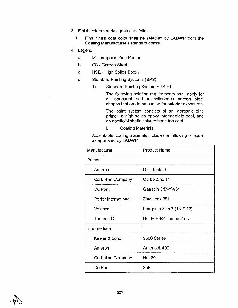
3. Finish colors are designated as follows:
i. Final finish coat color shall be selected by LADWP from the Coating Manufacturer's standard colors.
4. Legend:
a. IZ - Inorganic Zinc Primer
b. CS - Carbon Steel
c. HSE- High Solids Epoxy
d. Standard Painting Systems (SPS)
1) Standard Painting System SPS-F1
The following painting requirements shall apply for all structural and miscellaneous carbon steel shapes that are to be coated for exterior exposures.
The paint system consists of an inorganic zinc primer, a high solids epoxy intermediate coat, and an acrylic/aliphatic polyurethane top coat.
i. Coating Materials
Acceptable coating materials include the following or equal as approved by LADWP:
Manufacturer Product Name
Primer
Ameron Dimetcote 9
Carboline Company Carbo Zinc 11
DuPont Ganacin 347-Y-931
Porter International Zinc Lock 351
Valspar Inorganic Zinc 7 (13-F-12)
Tnemec Co. No. 90E-92 Theme-Zinc
Intermediate
Keeler & Long 9600 Series
Ameron Amerlock 400
Carboline Company No. 801
DuPont 25P
527
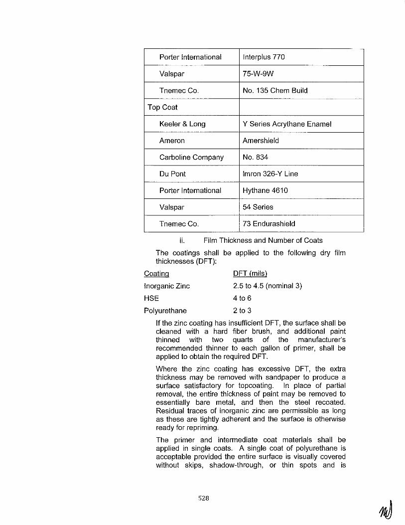
Porter International lnterplus 770
Valspar 75-W-9W
Tnemec Co. No. 135 Chem Build
Top Coat
Keeler & Long Y Series Acrythane Enamel
Ameron Amershield
Carboline Company No. 834
Ou Pont lmron 326-Y Line
Porter International Hythane 4610
Valspar 54 Series
Tnemec Co. 73 Endurashield
ii. Film Thickness and Number of Coats
The coatings shall be applied to the following dry film thicknesses (OFT):
Coating
Inorganic Zinc
HSE
Polyurethane
OFT (mils)
2.5 to 4.5 (nominal 3)
4 to 6
2 to 3
If the zinc coating has insufficient OFT, the surface shall be cleaned with a hard fiber brush, and additional paint thinned with two quarts of the manufacturer's recommended thinner to each gallon of primer, shall be applied to obtain the required OFT.
Where the zinc coating has excessive OFT, the extra thickness may be removed with sandpaper to produce a surface satisfactory for topcoating. In place of partial removal, the entire thickness of paint may be removed to essentially bare metal, and then the steel recoated. Residual traces of inorganic zinc are permissible as long as these are tightly adherent and the surface is otherwise ready for repriming.
The primer and intermediate coat materials shall be applied in single coats. A single coat of polyurethane is acceptable provided the entire surface is visually covered without skips, shadow-through, or thin spots and is
528

relatively free of craters. Additional coats of polyurethane shall be applied if required by LADWP.
2) Standard Painting System SPS-F2
5. Galvanizing
The following painting requirements shall apply for all structural and miscellaneous carbon steel shapes that are to be coated for interior exposures.
The paint system consists of an inorganic zinc primer and a high solids epoxy mastic top coat.
i. Coating Materials
Acceptable coating materials are those listed as the primer and intermediate coats listed in SPS- F1.
ii. Film Thickness and Number of Coats
The film thickness and number of coats shall be as specified for the primer and intermediate coats in SPS - Fl.
After fabrication and before assembly, all shop fabricated, exterior structural steel, grating and stair treads, handrails, ladders and cages, and all related fasteners shall be degreased, cleaned of rust and scale, prefluxed, and hot-dipped galvanized. The zinc (hot galvanized) coatings applied to the fabricated products shall be in accordance with ASTM A123 and all of the incorporated specifications and recommended practices of the ASTM referenced therein, except as otherwise required or permitted herein. Additionally, hot-dip galvanizing and fabrication of items for hot-dip galvanizing should conform to the standards and -guidelines set forth in AHDGAIZI Manual.
Precautions shall be taken to avoid distortion or warpage of members during galvanizing. The procedure suggested in ASTM A384 and on pages 26 and 27 of AHDGAIZI Manual shall be observed. Material failing to meet the required criteria for straightness and length shall be subject to rejection.
P. CIS/A Shipping Requirements
1. Structural Steel
For all items, packaging shall be adequate to prevent contamination, mechanical damage or deterioration during the field storage period which could be several months. Structural steel members shall be identified by erection marks. Bolts, nuts, and washers shall be shipped in closed containers.
2. Grating and Stair Treads
All material shall be banded together in reasonably sized bundles. Bundles shall be laid flat in cars, separated by wooden dunnage for ease of handling and to minimize wear, and blocked within the
529
cars to prevent shifting in transit. All bundles shall include material from the same level or area within the structure. All loose and small platforms shall be banded together without mixing additional pieces with them.
Each piece of grating shall be identified with its own mark number, painted or stamped on a metal tag to permit easy installation. All tags shall be COLOR CODED for each floor level for which the material is required.
All special or odd size stair treads in small lots may be bundled together.
Floor grating shall be shop detailed, fabricated, and delivered to the job in a sequence that will permit it to be erected in conjunction with the structural steel framing on which it is supported. Within the limits of each sequence, grating for lower elevation shall be delivered first, and grating for higher elevations delivered last.
3. Steel Floor Forms and Roof Deck
Steel roof deck and floor forms shall be bundled and tagged in accordance with the roof (or floor) area in which they are to be located. In addition, the gage of the metal deck (and forms) required in each area shall be clearly marked on each bundle.
Q. CIS/A Inspection and Tests
1. General
The BOP Contractor shall identify, in purchase documents to his suppliers, all applicable quality requirements imposed by local and state requirements and LADWP's specifications and shall ensure compliance thereto. Construction documents developed by the BOP Contractor shall include a Statement of Special Inspections, clearly listing requirements and frequencies for special inspections and testing, in accordance with 2007 CBC Chapter 17. The BOP Contractor shall provide for Special Inspection and testing services by an independent testing agency that is approved by LADWP.
LADWP has the right to establish notification points for which the BOP Contractor shall give prior notification. In addition, LADWP may establish temporary notification points to ensure resolution of temporary quality problems. Notification points require receipt of notification at least five working days in advance of the scheduled time of performance.
LADWP may or may not witness the event. In any event, the BOP Contractor shall proceed with his work unless specifically directed otherwise by LADWP. In addition, LADWP reserves the right to inspect the work at any time, and the BOP Contractor and BOP Contractor's Suppliers/Subcontractors shall make their facilities available as required.
530

LADWP reserves the right to stop any work that is found to not conform to the Agreement or Code requirements.
2. Tests
The tests for welding and film thickness required by this specification are to be performed and paid for by the BOP Contractor.
In addition, the BOP Contractor shall perform and require its subcontractors and vendors to perform sufficient testing and inspections to ensure that the products supplied satisfy specifications. Records of any and all tests and inspections shall be maintained in BOP Contractor's files, available to LADWP on request.
a. Shop Welding
The BOP Contractor shall be responsible for the inspection and verification of all shop welding to the requirements of Sections 6, 8, and 9 of AWS 01.1 and 2007 CBC Chapter 17.
A visual inspection is the minimum inspection required.
The weld inspection shall be by an AWS Certified Inspector, or Assistant Welding Inspector under the supervision of the AWS Certified Inspector, employed by an independent testing and inspection agency.
b. Film Thickness Test
For film thickness measurement, the requirements and recommended practices of SSPC-PA2 shall be followed. Testing shall be performed for all of the work processed during any painting shift for one full day per painting work week for all steel.
Readings should be taken on smooth regular surfaces, not at corners, pockets, edges, bolt heads, fillets, etc. Representative "sample areas" should be established on the surface prior to making film thickness reading.
The size of the sample area shall be as follows:
Surface Sample Area
Large plate surfaces Every 200-300 sq ft
Structural steel beams, Every 15-20 linear ft
Columns, bracing, etc. on every 1Oth member
Three or more spot readings shall be taken in any sample area being inspected. This includes items with a total surface area less than one sample area.
5.13 ACCEPTANCE/PERFORMANCE CRITERIA AND TESTING REQUIREMENTS
531

A. General Testing Requirements
1. General Scope
a. The Engineering, Procurement, Construction Contractor (BOP Contractor) shall be responsible for functional testing, comm1ss1oning, performance testing, demonstration testing and reliability testing of the complete plant. The reliability test shall be carried out after completion of the overall plant simple cycle combustion turbine Performance Test. The Combustion Turbine Generator Contractor (CTG Contractor) will provide assistance to the BOP Contractor for performance testing specific to their equipment.
b. Other than those materials and services specifically called out in the CTG Contractors scope of supply, the BOP Contractor shall be responsible for providing all the necessary permanent and temporary equipment, materials, consumables (excluding fuel) and services to meet his commitments with regard to this phase of the work.
c. To the maximum extent possible, the instrumentation used during the test shall be the same as the permanently installed plant instrumentation. The plant instrumentation shall be suitable for use in the performance tests. The installed instrumentation shall have accuracy levels to meet the requirements of the relevant performance Codes/Standards and to achieve consistency with the measurement tolerances identified therein. Additional test instrumentation may be used to reduce performance test uncertainty.
B. Plant Commissioning
1. General
a. The BOP Contractor shall commission all equipment and systems associated with the new installation except high voltage switchyard. The BOP Contractor shall work with the CTG Contractor technical field advisors to commission Combustion Turbine Generators (CTG) and Emission Control Systems (ECS).
b. The BOP Contractor shall be responsible for performing mechanical and functional testing to confirm compliance with design basis and operating criteria. During this period the BOP Contractor shall undertake all installation checks, preliminary mechanical and electrical checks, pressure testing, flushing and cleaning of equipment and pipework, and other activities necessary to prove the integrity of all connections, safety systems and verification that all plant systems are functionally complete.
532

c. Where plant components form part of a system, each component comprising that system shall be similarly inspected and tested prior to placing the system into service. Static tests to demonstrate interactive operation of components within the system shall also be completed prior to charging or energizing the system for the first time.
d. LADWP personnel shall be given the opportunity to witness all such testing and inspection.
e. All checks, inspections, test activities and results shall be logged by the BOP Contractor on suitable forms and shall be available for review by LADWP at all times during the course of the work. Copies of this documentation shall be provided to LADWP on completion of the work.
2. Scope of Services
a. The BOP Contractor shall provide the following commissioning services as part of the required scope of commissioning and these items shall be part of a comprehensive construction and commissioning package:
1) Pre-Commissioning and Commissioning Activities
ii. Scope subsystem turnover packages P&ID's
iii. Place system boundary tags in the field
iv. Prepare system turnover packages
v. Develop and maintain commissioning schedule
vi. Provide supervision of craft support for commissioning
vii. Administer a lockout tag-out procedure, and transition to LADWP
viii. Prepare and maintain master system punch list
ix. Maintain red line as-builts for turnover packages
x. Prepare required data sheets and test records
xi. Provide complete O&M manuals for each equipment item provided
xii. Provide operator training of purchased equipment
xiii. Issue commissioning as-built drawings
xiv. Prepare plant energization procedures
xv. Prepare and submit procedures for performance, noise, stack emissions, demonstration and reliability tests
xvi. Perform site specific training
533

2) Commissioning Mechanical Systems
i. Perform equipment alignment
ii. Design, supply, install and remove temporary piping gas blows
iii. Furnish, install and rernove temporary piping and equipment for oil flushes
iv. Flush piping and equipment
v. Clean tanks and equipment prior to commissioning
vi. First fill lubricants and chemicals, other than those required for the water treatment system, which shall be provided by LADWP.
vii. Verify pump strainers and filters are installed
viii. Couple rotating equipment
ix. Perform vibration checks
x. Perform oil flushes
xi. Remove piping hanger stops and set in "cold" positions
xii. Furnish and install start up strainers, remove after commissioning
xiii. Operate permanent plant equipment coordinate with LADWP
xiv. Furnish start up spares
xv. Tag all equipment and valves
3) Commissioning Electrical Systems
i. Provide temporary power for motor/equipment space heaters
ii. Continuity checks of all cables
iii. Megger all power cables 120 V and higher
iv. Dress out and fill transformers
v. Test transformers
vi. Perform high voltage insulation tests
vii. Provide protective relay settings
viii. Back-feed plant develop integrated Plant protective relay and metering coordination study to develop relay settings
ix. Test high voltage breakers
534

x. Test current transformers and potential transformers
xi. Megger motors 25HP and larger per site quality control measures
xii. Check motor rotation
xiii. Motor run-in and vibration checkout
xiv. Final Relay Setting/Calibrate
4) Instrumentation Systems Commissioning
i. Verify per instrument data sheet
ii. Provide calibration set points
iii. Final instrument calibration
iv. Tag instruments with instrument identification numbers
v. Tag instrument calibration
vi. Tag electrical panels, check breakers, etc.
vii. Witness SCS factory acceptance test
viii. Loop checkout of devices
ix. Final in-place stroking of valves
x. Fine tune SCS including control loops, graphics, etc.
xi. GEMS functional testing and GEMS certification
xii. GEMS source testing
b. Individual systems shall be completed on a sub-system Turnover Package basis in a sequence that shall permit systematic checkout and trail operation of each such component before it is incorporated in the initial operation.
3. Commissioning Safety
a. In addition to those safety processes and procedures implemented for construction, BOP Contractor shall set up, execute, and maintain, a site-specific lock-out/tag-out process and procedure, which shall refer to, a safe means to secure all types of stored energy (electrical, mechanical, etc.) The BOP Contractor shall submit the same procedure to LADWP for review and comment prior to implementation. The LO/TO procedure shall be demonstrated through the site safety orientation. Any personnel dealing with any LO/TO implementation must first be trained to the specific procedure. The ECP Contractor shall maintain documentation of LO/TO procedure training for the duration of the project and records shall be available for audit by LADWP at any time.
535

4. Commissioning Project Procedures Manuals
a. A Project specific Commissioning Procedures Manual shall be developed by the BOP Contractor to cover all work to turn over a fully commissioned plant. This manual shall be submitted for review and comment to LADWP for approval. The procedures shall be complete in all detail and shall be specifically designed for each component, equipment, and system.
b. Such manual shall include, but not be limited to, the items set forth below:
1) An alphabetical listing of all plant systems, providing the names, general system description, and a brief description of mechanical and electrical boundaries.
2) The sequence for commissioning each commissioning subsystem.
3) A description of the BOP Contractor's inspection, testing, and preparation check out activities including sequential and step-by-step test procedures and write up.
4) A general description of contractual performance, functional, and acceptance tests which are applicable to plant equipment and systems.
5) A description of the environmental compliance tests which are required. These descriptions shall be grouped for each environmental consideration
6) Check lists, forms, test formats, and data sheets.
7) A commissioning schedule providing task durations, forecasted turnover dates, and identification of critical path.
8) Lock-out/tag-out procedures.
9) Acceptance criteria for system cleanliness.
5. Commissioning Personnel
a. The BOP Contractor shall provide all labor including, but not limited to, supervision, administration, and management.
b. Personnel provided by the BOP Contractor shall include, but not limited to, the following classifications:
1) Commissioning Manager to provide overall coordination of the commissioning program from the completion of construction through system turnover to LADWP.
536

2) Technical Supervisors experienced in areas of electrical engineering and metering, instrumentation and control systems, and power plant mechanical and fluid process systems.
3) Electrical and instrument technicians experienced in working with electrical schematic and wiring diagrams, electrical one-line and three-line diagrams in accordance with calibration and checkout assignment.
4) A group of sufficient numbers of craftsmen.
5) Technical field advisors and manufacturer's service representatives of various systems and equipment packages provided by PM and BOP Contractors.
c. LADWP reserves the right to approve the candidates for Commissioning Manager and Technical Supervisors.
d. LADWP will make available LADWP's operation personnel during commissioning and acceptance testing for purposes of operating plant equipment and systems during commissioning and testing up to Commercial Operation. BOP Contractor shall provide direction to LADWP's operation personnel and in the job training during commissioning and acceptance testing.
6. Equipment
a. The BOP Contractor shall supply all the test and calibration equipment, materials, and services necessary to perform the system calibration, checkout, flushing, acceptance and initial operation complete and in accordance with Contract.
b. The test equipment shall be periodically certified. Test equipment found out of tolerance during certification shall be replaced or repaired. Calibrations performed with the equipment found out of tolerance shall be re-calibrated.
c. The BOP Contractor shall be responsible for procurement of certain special test equipment. The special test equipment maybe required to calibrate or adjust certain devices or systems, and may not be required for the full duration of the project schedule. The BOP Contractor shall provide or arrange provisions for all required special test equipment in a timely manner to complete the work with accordance with the project schedule.
7. Commissioning Sequence and Coordination
a. The overall Commissioning sequence and logic shall be developed by the BOP Contractor so that sub-system Turnover Packages are completed and presented to LADWP for review and comment in proper sequence to support an orderly commissioning.
537
b. The BOP Contractor shall maintain a system turnover checklist to track the status of the systems.
c. Commissioning activities shall be coordinated with LADWP staff. LADWP will have the right to witness any and all commissioning activities.
d. The BOP Contractor shall energize and operate the equipment for the first time.
e. The BOP Contractor shall coordinate the efforts with the applicable equipment representatives in commissioning of the equipment. The BOP Contractor shall record data required to analyze the initial system performance.
f. The BOP Contractor's personnel shall perform calibration of permanent instrumentation. Errors found during or after system commissioning shall be corrected. The sub-system Turnover Package exception items shall be completed and verified by the BOP Contractor. The BOP Contractor shall formally notify LADWP of exception item completion.
8. Turnover Packages
a. The BOP Contractor shall prepare system Turnover Packages. The commissioning sequence shall commence with scheduling and issuing package definitions for information and shall continue with completion of construction and testing work for each package, electrical testing and calibration, initial operation, and subsequent debugging of any operational problems by the BOP Contractor. Each Turnover Package shall be reviewed and accepted by LADWP.
b. The subsequent Turnover Package shall include the piping and instrument diagrams, one-lines diagrams, loop diagrams, and electrical schematic diagrams marked to define the limits of the subsystem. Applicable data and test forms and manufacturer's service reports shall be prepared by the BOP Contractor and included in the package. Manufacturer's drawings shall be included as required to support the testing and functional checkout of the subsystem.
c. Each system/subsystem Turnover Package shall contain but not limited to the following:
1 ) Package index
2) Commissioning release form
3) System open item list- punchlist.
4) System boundary with scoped P&ID's and electrical one-line diagrams
5) Red lined drawings
538

6) System descriptions with valve line-ups, alarm and trip settings, start-up/shut-down procedures
7) System test index
8) I&C instrumentation index and calibration reports
9) Instrument loop check reports
1 0) Initial motor rotation/run-in reports
11) Initial pump operation reports
12) Initial fan operation reports
13) System flush reports
14) System hydro test reports
15) Final tank /vessel inspection reports
16) Final hot alignment reports
17) Electrical test reports
18) Megger test reports
19) Not used
20) Continuity test reports
21) Temporary condition I modification reports
22) Die system reports
23) RFI's/ECN's
24) Others as required
d. All supporting documentation shall be provided by the BOP Contractor and shall be inserted into its' appropriate section of the system Turnover Package. The documentation shall include but not limited to the following:
1) Hydrotest forms
2) Calibration sheets
3) Manufacturer's service reports
4) Alignment data sheets
5) Lubrication data
6) Others as required
e. The final subsystem Turnover Packages shall be submitted to LADWP only when it includes the completed and signed sign-off sheet, and the completed test sheets, exception sheets, manufacturer's service reports, pressure test forms, alignment data, and other applicable information.
9. Turnover Package Documentation
a. Calibration and Test Forms
539
1) The BOP Contractor shall complete calibration and test forms for each device calibrated or tested. The format of the forms shall be acceptable to LADWP.
2) In addition, protective relay forms shall include an accurate curve of relay operation, so drawn that it may be read at various points in the relay operating range.
3) All reports, calibration sheets, corrected drawings, and other data shall be maintained by the BOP Contractor, with updates to current status at least weekly. The documents shall be maintained at the BOP Contractor's filed office until the specified turnover to LADWP. The documents shall be made available for inspection and review.
4) The manufacturer's service representatives shall submit a service report to the BOP Contractor stating whether or not the equipment is ready for operation. Electrical and control testing required by the manufacturer shall be coordinated between the BOP Contractor and the manufacturer's service representative and the results shall be attached to the Service Report. The Service Report shall be placed in the Turnover Package prior to final submittal to LADWP.
10. As Constructed Marked-up Drawings
a. The BOP Contractor shall keep one set of the marked-up with all field corrections performed throughout the construction, testing, and commissioning phases. The marked up copy shall be retained onsite until the drafted "as constructed" drawings become available. The drawing list shall include but not limited to the drawings listed in Section 5.1.C.3.b.
11. General Commissioning Procedures
a. Procedural requirements shall include, but are not limited to, the following:
1) Inspection - the BOP Contractor shall inspect the installed systems and equipment prior to the starting calibration and checkout, and shall correct all deficiencies that could prevent proper checkout of such equipment and systems as noted herein.
2) Manufacturer's Procedures - drawings, installation and operating instructions from manufacturers of instrumentation and other equipment appropriate to the work describe in this specification shall be submitted to LADWP for review. The BOP
540
Contractor shall follow the manufacturer's instructions in the performance of his work.
3) Discrepancy Procedure - the BOP Contractor shall endeavor to promptly discover major discrepancies in the equipment, materials, and installation and notify LADWP of such discrepancy, and initiate corrective procedures, without delay. When the BOP Contractor discovers equipment and materials with incorrect rating, damaged equipment, or equipment which is not specified or is otherwise unsatisfactory, arrangements shall be made for replacement of the equipment and materials.
4) Calibration In-Place - devices and equipment shall be adjusted and calibrated with the equipment normally installed in-place.
5) Calibration Range - Analog devices shall be calibrated to be accurate within the manufacturer's specified tolerance. Digital or switch contact devices shall be set to accurate or change state at the required process condition and shall be checked for accuracy and hysteresis (dead band) at this condition. Both accuracy and hysteresis for both analog and digital devices shall be certified to within the manufacturer's stated tolerances.
6) Loop Checks - For pressure and differential pressure instruments, the BOP Contractor shall perform final loop checks by applying pressure to the instrument and performing a five point check though the control system. For RTD's, wiring shall be disconnected at the RTD and a temperature compensated signal shall be introduced to perform a five point check through the control system. Other devices, such as positive displacement meters and vortex shedding or target meters, shall be operationally checked and verified by conventional test instruments measuring differential.
7) Calibration Sticker - the BOP Contractor shall furnish and affix a self-adhesive label to each device calibrated or adjusted. The label shall indicate the date and the name of the person performing the calibration or adjustment, and shall include the set point or range which the device is calibrated.
8) Test Instrument Certification - the BOP Contractor shall provide and maintain an onsite facility to perform periodic calibration and certification of test instruments and equipment. Certification methods
541
shall follow recommendations of the test instrument manufacturers. The BOP Contractor's personnel performing certification shall be specially trained in the methods required.
9) Personnel Protection Control - The BOP Contractor shall establish a control system to protect personnel while working around energized systems and equipment. This system shall be used as the permanent plant equipment and systems are completes and capable of energization. The system shall consist of placing appropriate tags on all equipment and system components to indicate its status and requiring mandatory clearances from designated personnel to operate, energize, or remove from service the equipment or systems.
12. Device Commissioning Procedure
a. The BOP Contractor shall include in his comm1ss1oning manual written calibration and adjustment procedures to be utilized for performing work on the various device categories. The BOP Contractor shall submit his written calibration and adjustment procedures to the Owner 30 days prior to starting device calibration work.
13. System Commissioning Procedure
a. The BOP Contractor shall perform all calibration, adjustment, and check out operations on all systems, which are required to ready the systems for service.
b. In the event LADWP/BOP Contractor believe the integrity of the system has been compromised, the BOP Contractor shall recalibrate or readjust systems when necessary or as directed by LADWP. LADWP will initiate such requests when systems are damaged or are suspected of being out of adjustment after the BOP Contractor has completed initial work on the systems. The BOP Contractor shall prepare and submit revised Calibration and Adjustment Report for devices, which have been recalibrated. The recalibration or readjustment shall be performed by the BOP Contractor at his own expense.
c. The BOP Contractor shall provide written calibration and adjustment procedures to be utilized for performing the work on the various systems categories, including but not limited to, the following:
1) Plant Auxiliary Equipment Logic Systems
i. The systems covered by this article are generally eletromechanical consisting of local sensors and switch devices; local motor starters and breakers; panel mounted
542

lights, manual switches, and meters; alarm outputs; cabinet mounted relays and timers; and the cables interconnecting the various items. The BOP Contractor shall check out and verify operation of each logic system, using logic diagrams and electrical schematic diagrams prepared by the BOP Contractor or his sub BOP Contractor/equipment suppliers. All inputs and outputs shall be verified for proper functions. All timers shall be set and verified. Each final drive device shall be directly operated by its own logic system in all cases where it is particle. All indicating lights and alarms shall be verified in operation. All interlock and alarm modes shall be verified.
2) Special Instrumentation Systems
i. The systems covered by this article are generally consisting of local drive controllers, drives, valves, and signal converters; panel mounted display and control subpanels; cabinet mounted logic modules; and the cables interconnecting the various items. The BOP Contractor shall perform the calibration and checkout operations, and shall be responsible for direct supervision of his personnel engaged in the work.
ii. Each final drive device shall be verified for correct operation and shall be directly functioned by its own logic system. All system outputs to recorders, indicators, indicating lights, and similar display devices shall be verified to work accurately.
iii. System logic equipment shall be calibrated and verified as appropriate for the specific system and as directed by the respective manufacturer's representatives.
iv. System peripheral devices such as printers, control sub-panels, and key board shall be adjusted and checked out as appropriate for the specific system and as directed by the manufacturer's representative.
v. All interfaces between systems shall be verified. Interfaces shall include but not necessarily be limited to status contacts, commands contacts, and exchange of
543

information via dedicated wiring and by data link.
3) Equipment "Package" Control Systems
i. This category of systems shall be defined as complete self-contained instrumentation and control systems provided with the plant equipment, and requiring little interface with other systems for correct operation. The BOP Contractor shall calibrate, adjust, and check out these "package" systems in accordance with the manufacturer's recommendation. The "package" systems include, but are not necessarily limited to, those listed below:
i. Gas Compressors
ii. Air dryers
iii. Air Compressors
4) Instrumentation and Control Devices and Systems Provided with Major Equipment
i. This category shall be defined as instrumentation and control equipment provided with plant equipment, but which is not self-contained and which requires extensive interface with other systems for correct operation. The BOP Contractor shall calibrate, adjust, and check out these systems in accordance with the manufacturers' recommendations. The BOP Contractor shall provide the services of one or more manufacturer's representatives to give direction concerning the work. In addition, the BOP Contractor shall verify correct operation of the interfaces with other systems. The interfaces may be contact status, contact command, or analog inputs or outputs. The interfaces shall be defined by manufacturers' and/or BOP Contractor's Logic Diagrams, Electrical Schematic Diagrams, or other documents. The systems provided with major equipment include, but are not necessarily limited to, those listed below:
i. Stand-alone control systems, PLC's, etc.
ii. Annunciator System.
544

iii. Vibration Monitoring System
d. The BOP Contractor shall submit his written calibration and adjustment procedures for these systems to the Owner 30 days prior to starting system calibration work.
14. Trial Operation of Equipment
a. Trial Operation of equipment and sub-loop systems shall extend over a period of time as required to reveal any equipment weaknesses in bearings, cooling systems, heat exchangers, and other components, or any performance deficiencies which may later handicap the operation of main systems and the complete plant.
b. All rotating equipment shall be checked by the BOP Contractor for overheating, noise, vibration, and any other condition which would tend to shorted the life of the machinery. All equipment shall operate such that a level of vibration displacement is not more than required by the equipment manufacturer.
c. Cooling water systems shall be adjusted by the BOP Contractor to provide proper flow of coolant to each item of equipment.
d. The BOP Contractor shall adjust control system set points, gains, and resent rates, field device set points, timing relays, and all other devices and systems necessary to provide correct operation.
e. All motor driven equipment shall have amperage readings taken during trail operation.
15. Post-Commissioning Checkout
a. Main System Checkout
1) Main systems shall be checked, operated, and tested by the BOP Contractor in the presence of LADWP personnel after each individual piece of equipment and its accessories have been operated and declared ready for on-line operation. The BOP Contractor's Test and Commissioning Manager shall be present during the main systems checkout.
2) All functional and operational testing of protective interlocking, automatic controls, instrumentation, alarm systems, and all other field testing of the main systems shall be completed before the systems are started.
b. On-Line Operational Checks
1) During on-line operation of the integrated systems, all equipment shall be checked by the BOP Contractor for overheating, noise, vibration, and any other checks recommended or required by the
545

manufacturer of the specific piece of equipment. Representatives of the BOP Contractor shall be present during the on-line operational checks.
2) BOP Contactor shall be responsible for the following:
a) All piping systems shall be visually checked for leaks, plugged pressure gauges, interference, excessive vibration, and other abnormal conditions.
b) Pump suction strainers shall be checked periodically for clogging. Temporary strainers shall be removed from the piping after initial operation, when strainer loading no longer occurs and replace with the spacers.
c) Any realignment, recalibration, and adjustments necessary to make system acceptable for online operation.
d) Conducting plant thermal imaging to identify any locations where insulation is not properly installed or equipment is running hotter than normal.
e) Conduct testing of the Power system Stabilizers (PSS), Automatic Voltage Regulators (AVR's) and Western Energy Coordinating Council (WECC) interface equipment to ensure that all applicable requirements are met. The CTG Contractor shall assist and provide direction to the BOP Contractor in performing these tests for CTG provided equipment.
3) Once the component or system is charged, energized or otherwise made live, the BOP Contractor shall conduct further tests to demonstrate that the system and its constituent components function collectively as designed/specified, that individual components operate at varying loads under steady state conditions within their stated operating parameters, and that the components and system respond correctly to transient conditions.
C Tests of Completion
1. General
a. The object of these tests is to demonstrate the fitness for purpose of the Facility prior to commercial operation and take-over by LADWP. The scope of tests shall include but not be limited to the following:
i. Demonstration Tests
546
ii. Electrical Systems Compliance Tests
iii. Startup Stack Emission Compliance
iv. Reliability Test
2. Demonstration Tests
a. Tests shall be conducted to demonstrate the Facility is designed to safely and efficiently operate in accordance with the technical requirements of the Agreement under certain operational events, as defined below. The BOP Contractor shall develop and provide test procedures to LADWP for review and comments prior to the test execution. Tests may be completed during startup and commissioning or concurrently with the performance testing.
b. Successful completion of the following Demonstration Tests shall be required to meet Substantial Completion. The test shall be conducted by the BOP Contractor to demonstrate that the Facility can perform the following:
c. Start Up Time Test - each unit shall be tested to demonstrate that start-up times for cold, warm, and hot startups meet the equipment manufacturer guarantees. The startup and shut-down to start-up times will be measured as the duration, in minutes from BOP Contractor's receipt of the start-up order until the unit is operating at full load. The Emission Control System (ECS) casing and stack shall be pre-purged in accordance with NFPA and GE Aero guidelines. The test shall be considered successful if the unit is automatically synchronized to the grid and ramped up to 100% load in less than 10 minutes.
d. Minimum Load Test - each unit will be tested to demonstrate the ability of the unit to maintain stead-state operation at the minimum load specified by the equipment manufacturer while maintaining all emission rates within the guaranteed emission limits. The test will be considered successful if no component or system operating limits (trip points) or regulatory limits are exceeded.
e. Load Rejection Test - each unit, or combinations thereof, shall be tested to demonstrate the shutdown of the unit after a trip with loss of all power to the Project when operating at or above minimum load. The test shall demonstrate that the shutdown systems operate correctly and that all DC systems start-up and operate correctly with sufficient emergency power.
f. Total Plant Start-up Test - the BOP Contractor shall conduct a test to start all units and bring them to full load on the grid such that the entire facility is operating at full
547

load. The test shall be judged successful when the plant has reached the maximum available load and successfully supplied that level of power to the network for a period of 2 hours without interruption.
g. Stand-by Emergency Generator Start-up Test - the BOP Contractor shall demonstrate the capability of the emergency generator and associated electrical systems and controls to start and provide emergency backup power upon loss of AC power as required in Exhibit Z.12.
h. All test reports and test results required shall be provided to LADWP for final approval.
i. Clutch System Tests - The objective of this test is to demonstrate correct equipment functioning for the following system operations:
1) The clutch will automatically engage to drive the generator the moment the gas turbine starts to rotate.
2) The clutch will automatically disengage the moment the gas turbine is shut down and its speed drops below that of the generator.
3) The gas turbine can be started and the clutch will be automatically engaged to drive the generator the moment the accelerating gas turbine tries to overtake the generator, when the generator is rotating in a synchronous condensing mode and power generation is required.
3. Electrical Systems Compliance Tests
a. All testing required to ensure compliance with WECC and NERC requirements, including model validation testing, shall be performed by the BOP Contractor.
b. All tests shall be in accordance with WECC and NERC requirements.
c. Test may include, but not be limited to: excitation response tests, excitation limiter response tests, reactive capability tests, power system stabilizer testing and tuning, and combustion turbine governor response tests.
d. Signals, hardware, software, personnel etc. required to perform the tests shall be provided by the BOP Contractor. All signals required for a given test shall be available at a common location and shall have acceptable resolution (including frequency of samples). Any required signal injections shall also be provided.
e. A preliminary excitation and power system stabilizer setting study shall be performed and submitted at least 60 days
548
prior (or longer if required by WECC or NERC) to performance of power system stabilizer testing and tuning.
f. All reports and test results required shall be provided.
4. Stack Startup Emission Compliance Tests
a. Tests shall be performed on each CTG unit to determine the time required between start-up and reaching emissions compliance at the stack.
b. The tests shall include warm up of the SCR catalyst systems and introduction of ammonia.
c. The CTG I ECS shall have a minimum of 12 hours of shut down time prior to conducting the test.
d. The test will be completed upon achieving compliance with all stack emissions given in the permit.
e. The Startup Stack Emissions Compliance Tests shall be deemed successful if the time to achieve compliance is less than the Startup Stack Emissions Compliance Guarantees.
f. The Startup Stack Emissions Compliance Tests may be run concurrent with the Ten Minute Start Tests.
D Plant Performance Tests
1. General
a. The BOP Contractor shall conduct Performance Tests to demonstrate that the plant complies with the performance guarantees. These tests shall only be performed after successful completion of all Tests on Completion specified above with the exception of the Reliability Test which may be performed concurrently at the risk of the BOP Contractor. The BOP Contractor will take lead responsibility of Performance Tests with the CTG Contractor in supporting role.
b. The precise nature of the tests together with detailed testing procedures and programs, accuracy of measurement, test instrumentation, correction curves etc. shall be provided by the BOP Contractor at least three months prior to the commencement of the tests. The BOP Contractor shall coordinate with the CTG Contractor, Equipment Manufacturers and LADWP to ensure a comprehensive performance testing procedure is in place at an early stage in the Contract.
c. The full performance guarantee test will be conducted for the entire Plant at base load for compliance with the Agreement guarantees.
549

d. A full load Performance Test shall demonstrate to LADWP that the Plant meets guaranteed net electrical output net heat rate and auxiliary loads contractual requirements.
2. Performance Test Design Conditions
a. The following design conditions shall form the basis of the performance guarantees set forth in the table below.
Fuel Type
Ambient Dry Bulb Temperature
Relative Humidity
Site Elevation
Combustion Turbine Load
OEM generator Power Factor
CTG Inlet Air
CTG Inlet Loss
CTG Exhaust Loss
CTG NOx Control
Fuel Gas Temp (Max.) at CTG
Fuel Gas Pressure at Interface
Plant and Combustion Turbine Degradation
Natural Gas (Refer to Z.5 for fuel properties)
65 deg F
60%
10 ft above mean sea level
Base Load
0.90
Evaporative Cooler Off
5" w.c.
12" w.c.
Water
As required by CTG Manufacturer
Minimum 200 psig Maximum 500 psig
New and Clean
b. During the contractual guarantee performance test the plant mode of operation shall be:
• Each combustion turbine operating at full load
• Variations exceeding steady state conditions shall invalidate the test run and shall be repeated.
• Emissions shall be maintained within guaranteed criterion throughout the performance tests.
• Every effort shall be made to run the test under the reference operating conditions, or as close to the reference conditions as possible, in order to reduce the application of corrections to the test results.
3. Performance Test Requirements
550

a. The BOP Contractor shall provide all instrumentation, parts and labor for the test, including purchase of any instrumentation and hire of any labor required to conduct the test.
b. During all plant performance tests, the Facility shall be operated in a normal mode which is representative of a long term operating configuration with all equipment operating as designed and within specification and alarm limits consistent with the Plant design requirements. No normally operating systems should be taken out of service including bypassing or suppressing of alarms unless specifically allowed in the test procedure.
4. Performance Testing Procedure
a. A Performance Test Procedure document shall be prepared by the BOP Contractor for approval by LADWP and shall be submitted to LADWP in its final form not less than three months prior to the scheduled Test date.
b. The performance testing procedure will be discussed and mutually agreed between the BOP Contractor and LADWP at an early stage in the Agreement schedule. The Performance Test Procedure shall include all calculations showing the use of all correction curves and factors for each parameter. LADWP shall witness the Performance Tests and the evaluated test results submitted to LADWP for approval.
5. Instruments and Measurement Uncertainty
a. Just prior to the Performance Test every test instrument required for the measurement of test data shall be checked and recalibrated if necessary.
b. All instruments used in the Performance Test shall be of the standard, quality and measurement accuracy suitable for performance testing as specified in the Performance Test Code, or as mutually agreed.
c. Instruments for primary measurements shall be calibrated by independent nationally or internationally approved calibration authorities.
d. Calibration certificates shall be provided for the temporary test instruments at the tirne of test. The costs involved in preparation of calibration certificates shall be to the BOP Contractor's account. Precision test instrumentation will generally be utilized per the relevant ASME PTC. Allowances will be made for measurement uncertainty in performance calculation. Measurement uncertainty will be based on the accuracy of the individual instruments used in conducting the performance test. An analysis of the measurement uncertainty will be performed by the BOP
551
Contractor, in accordance with ASME PTC 19.1 and 22 as part of the detailed performance test procedure and will be submitted to LADWP for review and approval.
e. Output guarantees will be satisfied if the corrected test output surrounded by the measurement uncertainty interval encompasses the guaranteed plant output or falls above it. Heat rate guarantee will be satisfied if the corrected test heat rate surrounded by the measurement uncertainty interval encompasses the guaranteed plant heat rate or falls below it. The Auxiliary Power guarantee will be satisfied if the corrected auxiliary power value surrounded by the measurement uncertainty interval as defined in Exhibit N encompasses the guaranteed auxiliary power value or falls below it.
6. Fuel Analysis
a. Samples of the fuel used during the tests shall be taken just prior to, during and on completion of the Performance Tests. The BOP Contractor shall supply the necessary apparatus for taking and containing the fuel samples. Three separate samples shall be taken for each sample period. An independent authority shall analyze one of each set of three samples and the costs of these analyses shall be borne by the BOP Contractor. One sample of each set of three shall be properly labeled and handed over to LADWP. An independent party, in case of dispute of the results, shall maintain one set.
b. The characteristics to be determined by the independent authority shall include:
i. Density at standard reference conditions (mass per unit volume);
ii. Mole percentage of relevant fuel constituents.
c. Fuel heating value shall be calculated in accordance with ASTM 03588. The BOP Contractor shall provide fuel flow measurement equipment. All gas fuel flow rate calculations, either manual or flow computer shall be performed in accordance with gas properties other than heating value determined from AGA 8.
7. Correction to Guarantee Basis Conditions
a. The measured results recorded during the Performance Test shall be corrected, as applicable, to those which would have been achieved had the test been carried out at the guarantee basis conditions by using mutually agreed correction curves and/or formulae.
b. These correction curves and/or formulae will include, but may not necessarily be limited to:
i. Correction for ambient temperature
552
ii. Correction for humidity iii. Correction for intercooler cooling water intake temperature
iv. Correction for barometric pressure
v. Correction for natural fuel calorific value vi. Correction for power factor.
8. Unit Net Power Output and Net Heat Rate Test
a. A full load Performance Test shall demonstrate to LADWP that each Combustion Turbine Generator meets its guaranteed net electrical output and net heat rate contractual requirements. Net output is defined as the gross output of the CTG generator less electrical loads of the auxiliary equipment supplied by the CTG Contractor for that CTG.
b. The CTGs will be tested for output, fuel input and heat rate in accordance with the latest revision of ASME Power Test Code 22 and by using equipment manufacturer's correction curves and procedures. The test shall be of at least two hours duration. Measurement accuracy shall be better than 0.5%.
c. For this test, the following data shall be measured:
1) CTG Gross Power Output at the Generator Terminal for each CTG and corrected using the corrected CTG output
2) Fuel flow at each CTG and total fuel consumption at the metering station for comparison
3) Natural gas composition at the metering station (by sampling)
4) Auxiliary loads associated with the CTG measured at the CTG Manufacturer's MCC
5) Results of these tests shall be fully documented along with the results of the the Unit Power Output and Heat Rate tests.
9. Auxiliary Load Test
a. The two-hour time weighted average auxiliary load shall not exceed the BOP Contractor Guaranteed Auxiliary Load.
b. Six CTGs firing natural gas, all normally operating auxiliaries, and loads listed below, shall be in operation during the test, which shall be of at least two hours duration. Uncertainty shall be calculated and used in the analysis as per section 5 above .
c. In addition to all normally operating loads the auxiliary transformers will supply the following loads during the test:
553

1) One (1) Air compressor at full load
2) Air conditioning and lights on in all buildings, no outdoor lighting
3) All HMis, PCs, monitoring and control equipment on
4) LADWP-furnished water treatment plant shall be excluded from the BOP Contractor's auxiliary power guarantee.
5) Pumps as required to meet full production capacity
6) Air cooled heat exchangers at the guarantee conditions indicated in Exhibit N
7) Fuel gas compressor at guarantee conditions indicated in Exhibit N.
8) GEMS and SCR systems in operation
d. During the test the plant shall be configured to allow these loads to run. If a load cannot be run, its rated power capacity shall be added to the auxiliary load.
e. During performance testing, the BOP Contractor shall collect the following data:
1) Total Facility power output measured on the high side of each step-up transformer (Pouttotal)
2) CTG Gross Power Output at the Generator Terminal for each CTG and corrected using the corrected CTG output (PoutCTG)
3) Parasitic loads associated with the CTG Contractor Furnished Equipment (PoutCTG)
4) The auxiliary loads associated with the balance of Plant provided by the BOP Contractor will be determined as follows:
PauxBOP = L P outCTG 11 -16- LPauxCTG 11-16 - LPouttota11-3
f. Additionally the gas pressure at the fuel gas interface point shall be measured and recorded, and the Guaranteed Gas Compressor Pressure Correction Curve will be used to correct the Auxiliary Load for gas compressor suction pressure.
g. The Guaranteed Auxiliary Load Temperature Correction Curve will be used to correct the measured and recorded Auxiliary Load for ambient temperature.
h. All data points logged during Agreement testing shall also be recorded during these additional tests, however no additional fuel gas samples are required. In addition the following data points are required:
554

10. Air Emissions Tests
a. Emission source testing shall be performed at the following conditions, as a minimum:
b. Gas turbine operating at full rated (100%) load -test for NOx, CO, VOC, PM and NH3
c. Gas turbine operating at 75% of full rated load - test for NOx, CO, VOC, PM and NH3
d. Gas turbine operating at 50% of full rated load - test for NOx, CO, VOC, PM and NH3
e. The emissions compliance test shall be conducted by an SCAQMD approved firm, experienced with such testing, in accordance with 40 CFR 60. The duration of the emissions test shall be as required by 40 CFR 60 or 4 hours as a minimum. Normal plant start up and operating procedures should be used in operating the unit during the tests. All plant systems will be in automatic control. Testing shall be performed at all loads required by the operating permit
f. Sampling shall be conducted in accordance with EPA Reference Method 201 A and 202 or Method 5 modified to include back-half condensables, for the concentration of PM10; Reference Method 8 or Reference Methods 6 or 6c for sulfur dioxide (802 ); Reference Method 10 for the concentration of CO; Reference Method 25A, modified to exclude methane and ethane, for the concentration of VOC (to measure total carbon as propane); Reference Method 20 for the concentrations of NOx and 0 2 ; or by other equivalent methods approved by LADWP. For SCR ammonia slip: Phenol-Nitroprusside Method, the Indophenol Method, or EPA Conditional Test Method (CTM) 27.
g. During the Emissions test, the Facility shall be operated in a normal mode which is representative of a long term operating configuration with all equipment operating as designed and within specification and alarm limits consistent with good power generation industry practice. No normally operating systems should be taken out of service including bypassing or suppressing of alarms unless specifically allowed in the test procedure.
11. Near and Far Field Noise Tests
a. After plant construction, the BOP Contractor shall undertake the following witnessed noise tests on the plant and equipment to prove compliance with the specified noise requirements:
1) Near field 2) Far field (at site boundary)
555

b. Each measurement of continuous plant noise shall be made over 5 minute long sample periods. Background noise shall be tested without any of the new facility equipment in operation.
c. The measuring equipment and test method shall be in accordance with ASME PTC 36 Measurement of Industrial Sound I or equivalent.
d. The equipment shall be calibrated before use.
e. Noise tests shall only be carried out when weather conditions are dry with either zero or light winds in the normally prevailing direction. Wind speed during the test should not exceed 5 mph.
f. Noise measurements shall be made with the Facility operating at base load conditions in its normal plant configuration.
g. The results of the tests shall be fully reported together with operating conditions of the equipment, meteorological conditions, all noise measurements and test locations and details of the instrumentation used for the test. Any corrections made to the measured noise levels to take account of background noise or noise from other sources shall be identified.
h. For work area noise acceptance tests, equivalent continuous levels shall be obtained at a minimum distance of 1 m from the surface of equipment at normal operating conditions, acoustic enclosures, or room boundaries.
12. Reliability Test
a. The reliability of the plant, complete with all ancillary plant, equipment and services required for the full, safe and efficient operation, shall be proved by starting fully automatically and by running under normal commercial operation for a period of 24 consecutive hours.
b. The Plant shall be in its normal operating configuration that is representative of a long-term operating configuration with normal auxiliaries in service in automatic mode. No normally operating systems will be taken out of service including the bypassing or suppressing of alarms or trips. The BOP Contractor shall follow prudent, safe and reliable operating practices. Equipment shall be operated as designed and within specification and alarm limits consistent with good power generation industry practice. The configuration of the plant shall be reviewed and verified by LADWP.
556


PART 6 - BUSINESS POLICIES
6.1 DEPARTMENT OF WATER AND POWER RECYCLING POLICIES
A. The Department of Water and Power supports the use of recycledcontent products of all types. Recycled-content products help conserve natural resources, including water and energy, and reduce demands upon landfills.
The successful Contractor shall submit all written documents on paper with a minimum of 30 percent post consumer recycled content. Existing company/corporate/letterhead/stationery that accompanies these documents are exempt from this requirement. Documents of two or more pages in length shall be duplex-copied (double-sided pages). Neon or fluorescent paper shall not be used in any written documents submitted to LADWP.
6.2 AFFIRMATIVE ACTION
A. During the performance of any contract, the BOP Contractor shall not discriminate in its employment practices against any employee or applicant for employment because of race, religion, national origin, ancestry, sex, age or physical handicap. All subcontracts awarded under any such contract shall contain a like nondiscrimination provision. The applicable provisions of Executive Order No. 11246 of September 24, 1965; Part 60-7 41 of 41 CFR pertaining to handicapped workers, including 60-741.4 Affirmative Action Clause; and Sections 10.8 to 10.13 of the Los Angeles Administrative Code pertaining to nondiscrimination in employment in the performance of City contracts are incorporated herein by reference and made a part hereof as if they were fully set forth herein.
Each of the above documents, if approved, shall be effective for twelve (12) months following the date of approval for the Affirmative Action practices. An Affirmative Action plan shall be in effect and on file with LADWP for the duration of the agreement period.
6.3 MINORITY AND WOMEN BUSINESS ENTERPRISE (MBE/WBE) OUTREACH PROGRAM
A. It is the policy of LADWP to provide Minority Business Enterprises (MBEs), Women Business Enterprises (WBEs) and all Other Business Enterprises (OBEs) an equal opportunity to participate in the performance of all LADWP contracts. The BOP Contractor shall assist LADWP in implementing this policy and shall use its best effort to attain MBE and WBE participation of 15 percent and 7 percent, respectively, and to ensure that all available business enterprises, including MBEs, WBEs, and OBEs, have an equal opportunity to compete for and participate in the work of this Agreement.
B. MBE/WBE Defined
557

"Minority Business Enterprise" (MBE) or "Women's Business Enterprise" (WBE), as used herein means a business enterprise that meets both of the following criteria:
1. A business that is at least 51 percent owned by one or more minority person(s) or women or, in the case of any business whose stock is publicly held, at least 51 percent of the stock is owned by one or more minority person(s) or women.
2. A business whose management and daily business operations are controlled by one or more minority person(s) or women.
C. Program Documentation
The BOP Contractor shall submit monthly reports to the Project Manager or their designated representatives demonstrating compliance with LADWP's Outreach Program, and make related records available to LADWP upon request. The reports shall be submitted on LADWP forms which can be obtained from the Project Manager or their designated representative, and show the following:
1. The name of each participating subcontractor;
2. Description of work each subcontractor has contracted to perform;
3. The percentage of completion for the work under each subcontract;
4. The compensation contracted to be paid to each subcontractor (attach copy of subcontractor's invoice);
5. The cumulative compensation earned by each subcontractor; and
6. The cumulative compensation paid to each subcontractor.
D. Subcontractors which are anticipated to be utiltized on the Project are indentified in Exhibit F, Approved Subcontractor Information. Exhibit F contains a list of Subcontractors, and also contains a description of the service, task responsibilities, and anticipated participation (percentage of overall cost of services) of each Subcontractor identified in Exhibit F.
6.4 CHILD SUPPORT POLICY
A. In accordance with the City of Los Angeles Ordinance No. 172401, LADWP requires all contractors and subcontractors performing work for LADWP to comply with all reporting requirements and wage earning assignments relative to court order child support.
B. The BOP Contractor and any Subcontractor(s) must fully comply with all applicable State and Federal employment reporting requirements for the BOP Contractor's and any Subcontractor(s)' employees. The BOP
558

Contractor and any Subcontractor(s) must fully comply with all lawfully served Wage and Earnings Assignment Orders and Notices of Assignment in accordance with the California Family Code. The BOP Contractor and any Subcontractor(s) must certify that the principal owner(s) thereof (any person who owns an interest of 10 percent or more) are in compliance with any Wage and Earnings Assignment Orders or Notices of Assignment applicable to them personally. The BOP Contractor and any Subcontractor(s) must certify that such compliance will be maintained throughout the term of the Agreement.
C. Failure of the BOP Contractor and/or any Subcontractor(s) to fully comply with all applicable reporting requirements or to implement lawfully served Wage and Earnings Assignments or Notices of Assignment or failure of the principal owner(s) to comply with any Wage and Earnings Assignments or Notices of Assignment applicable to them personally shall constitute a default under the Agreement. Failure of the BOP Contractor and/or any Subcontractor(s) or principal owner(s) thereof to cure the default within 90 days of notice of such default by the City shall subject the Agreement to termination.
6.5 SERVICE CONTRACT WORKER RETENTION AND LIVING WAGE POLICY
A. This Agreement is subject to the Service Contractor Worker Retention Ordinance (SCWRO), Section 10.36 et seq., and the Living Wage Ordinance (LWO), Section 10.37 et seq., of the Los Angeles Administrative Code. The Ordinances require that, unless specific exemptions apply, employers who are awarded service contracts that involve expenditures in excess of $25,000, and have a duration of at least three months; and any persons who receive City financial assistance of one million dollars or more in any 12-month period, shall comply with the following provisions of the ordinances:
1. Retention of a 90-day transition period, the employees who were employed for the preceding 12 months or more by the terminated Contractor or subcontractor, if any, as provided for in the SCWRO.
2. Payment of minimum initial wage rate to employees as defined in the LWO, Employee Information Form OCC/LW-6 and /or Subcontractor's Declaration of Compliance Form OCC/LW-5.
B. Termination Provisions: Service Contract Worker Retention and Living Wage Policy
1. Under provisions of Section 10.36 and Section 10.37 of the Los Angeles Administrative Code, the Department of Water and Power, shall have the authority, under appropriate circumstances, to terminate this Agreement and otherwise pursue legal remedies that may be available, if the Department of Water and Power determines that the subject Contractor or financial assistance recipient violated the provisions of the referenced Code Section.
559

C. Invoice Provisions
All invoices to SCWRO and LWO Contracts shall contain the following statement:
"The BOP Contractor fully complies with Section 10.36 et. Seq. And Section 10.37 et. Seq., SCWRO and LWO, respectively, of the Los Angeles Administrative Code."
Contractor agrees to submit a statement along with any invoices or billing associated with this Agreement which certifies that all work performed under this Agreement at critical facilities as designated by LADWP to Contractor was conducted by persons for whom background checks have been conducted and who do not have disqualifying background information in their histories pursuant to this Agreement.
6.6 JOB OPPORTUNITIES AND TRAINING POLICY
A. BOP Contractor shall comply with the requirements of LADWP Job Opportunities and Training Policy. The BOP Contractor shall devote three percent (3%) of the total direct labor costs to job development and training activities, with approximately half of that outlay funding job opportunities for unemployed and underserved workers. The BOP Contractor shall develop a job opportunities and training program plan that includes organized and formal activities designed to facilitate and aid in the training and hiring of job seekers, laid-off workers, youth, incumbent workers, new entrants to the workforce, veterans, and persons with disabilities in professional/engineering, skilled craft, para-professional, clerical, and administrative functions. The BOP Contractor shall report on the job opportunities and training program plan implementation and expenditures with submittal of all invoices for payment. More frequent reports may be required at the request of LADWP.
560
PART 7 -INDEMNIFICATION, CHECK OR BONDS, AND INSURANCE REQUIREMENTS, AND RISK OF LOSS
7.1 INDEMNIFICATION
The BOP Contractor undertakes and agrees to indemnify and hold harmless the City of Los Angeles, the Department of Water and Power, the Board of Water and Power Commissioners of the City of Los Angeles, and all of their officers and employees, and, at the option of LADWP, defend LADWP, and any and all of their Boards, officers, agents, representatives, employees, assigns and successors in interest from and against any and all suits and causes of action, claims, charges, damages, demands, judgments, civil fines and penalties, or losses of any kind or nature whatsoever, for death, bodily injury or personal injury to any person, including Contractor's employees and agents, or damage or destruction to any property of either party hereto, or third persons in any manner arising by reason of the negligent acts, errors, omissions or willful misconduct incident to the performance of this Agreement on the part of the BOP Contractor, or the BOP Contractor's officers, agents, employees, or subcontractors of any tier except for the active negligence or willful misconduct of LADWP, its Board, officers, agents, representatives or employees.
7.2 BONDS
A. General
1. A certificate of deposit or an unconditional irrevocable letter of credit issued by a responsible bank, in a format acceptable to LADWP, will be accepted as a substitute to the requirements specified in Section 7.2.B of this Article. Wherever in these Agreement Documents reference is made to the check or the bonds required by Section 7.2.B of this Article, it shall be deemed to include such substitutes.
2. No substitution will be accepted in lieu of the labor and material payment bond, specified in Subsection 7.2.C of this Section, in accordance with Section 3248 of the Labor Code.
B. Performance Bond
1. The successful bidder shall furnish and maintain a satisfactory performance bond. The bond shall be executed by a responsible corporate surety, authorized to issue such bonds in the State of California and in other states where work is to be performed, and shall be secured through an authorized agent with an office in California. The bond shall be in an amount of not less than the Total Agreement Price of the Work Authorized and released by LADWP, including any Amendments that modify the Agreement amount, and shall be accompanied by a current copy of the surety company's license issued by the Department of Insurance of the State of California.
561

2. The performance bond shall be furnished by the successful bidder within 30 calendar days after the date of award/Notice to Proceed.
3. In lieu of a Performance Bond, the BOP Contractor may propose alternate security, in the form of an irrevocable Letter of Credit or a Corporate Guarantee, which LADWP shall accept or reject in its sole discretion as substitute security.
C. Labor and Material Payment Bond
1. The BOP Contractor shall furnish and maintain a satisfactory labor and material payment bond. The bond shall be executed by a responsible corporate surety, authorized to issue such bonds in the State of California and in other states where work is to be performed, and shall be secured through an authorized agent with an office in California. The bond shall be in an amount of not less than the Total Agreement Price of the Work Authorized and released by LADWP, including any Amendments that modify the Agreement amount, and shall be accompanied by a current copy of the surety company's license issued by the Department of Insurance of the State of California.
7.3 GENERAL INSURANCE REQUIREMENTS
A. Prior to the start of work, but not later than 30 days after the date of award of Agreement, the BOP Contractor shall furnish LADWP evidence of coverage from insurers acceptable to LADWP and in a form acceptable to the Risk Management Section and the Office of the City Attorney. Such insurance shall be maintained by the BOP Contractor at the BOP Contractor's sole cost and expense throughout the term of the agreement. Said evidence of insurance must be on file with the Risk Management Section in order to receive payment under any agreement for services rendered, and in order to commence work under this Agreement.
For further information regarding these requirements, please contact:
Los Angeles Department of Water & Power Risk Management Section Phone: (213) 367-4674 Fax: (213) 367-0214 Web Address: http://www.ladwp.com/ladwp/cms/ladwp005363.jsp
B. Please reference the Agreement when writing to Risk Management Section.
C. Such insurance shall not limit or qualify the liabilities and obligations of the BOP Contractor assumed under the Agreement. LADWP shall not by
562

reason of its inclusion under these policies incur liability to the insurance carrier for payment of premium for these policies.
D. Any insurance carried by LADWP which may be applicable shall be deemed to be excess insurance and the BOP Contractor's insurance is primary for all purposes despite any conflicting provision in the BOP Contractor's policies to the contrary.
E. Said evidence of insurance shall contain a provision that the policy cannot be canceled or reduced in coverage or amount without first giving 20 calendar days' notice thereof (1 0 days for non-payment of premium) by registered mail to The Office of the City Attorney, Water and Power Division, Post Office Box 61111, Room 340, Los Angeles, California 90051-0100.
F. Should any portion of the required insurance be on a "Claims Made" policy, the BOP Contractor shall, at the policy expiration date following completion of work, provide evidence that the "Claims Made" policy has been renewed or replaced with the same limits, terms and conditions of the expiring policy, or that an extended discovery period has been purchased on the expiring policy at least for the Agreement under which the work was performed.
G. Failure to maintain and provide acceptable evidence of the required insurance for the required period of coverage shall constitute a breach of agreement, upon which LADWP may immediately terminate or suspend the agreement.
H. Contractor shall be responsible for all subcontractors' compliance with the insurance requirements.
I. Not used.
J. LADWP may elect to procure any or all of the insurance required herein at its sole discretion. Contractor shall be responsible for satisfying the applicable deductible whether it is procured by LADWP or not.
K. Liability Insurance Coverage General
Evidence of liability coverage shall be on LADWP's additional insured endorsement form or on an endorsement to the policy acceptable to the Risk Management Section and provide for the following:
1. Additional Insured
Include LADWP and its officers, agents, employees, and Representatives as additional insured with the Named Insured for the activities and operations under the Agreement.
563
2. Severability-of-Interest
A Severability-of-Interest or Cross-Liability Clause or Separation of Insured Clause such as: "The policy to which this endorsement is attached shall apply separately to each insured against whom a claim is made or suit is brought, except with respect to the limits of the company's liability".
A description of the coverage included under the policy.
3. Liability Insurance
a. Commercial General Liability Insurance
The BOP Contractor shall provide Commercial General Liability insurance with Contractual Liability, Broad Form Property Damage, Premises and Operations, Independent Contractors, Products and Completed Operations and Personal Injury coverage included. Such insurance shall provide coverage for total limits actually arranged by the BOP Contractor, but not less than $25 million combined single limit per occurrence/aggregate. Limits shall apply on a per project basis.
Should the policy have an aggregate limit, such limits should not be less than double the Combined Single Limit and be specific for this Agreement. Umbrella or Excess Liability coverage may be used to supplement primary coverage to meet the required limits.
b. Commercial Automobile Liability Insurance
The BOP Contractor shall provide Commercial Automobile Liability insurance which shall include coverage for liability arising out of the use of owned, non-owned, and hire vehicles for performance of the Work as required to be licensed under the California or any other applicable state vehicle code. The Commercial Automobile Liability insurance shall have not less than $1 ,000,000 combined single limit per occurrence and shall apply to all operations of the BOP Contractor.
The Commercial Automobile Liability policy shall name the City of Los Angeles, the Board of Water and Power Commissioners of the City of Los Angeles, the Los Angeles Department of Water and Power, and their officers, agents, employees, and Representatives while acting within the scope of their employment, as additional insured with the BOP Contractor, and shall insure against liability for death, bodily injury, or property damage resulting from the performance of this Agreement.
564

c. Umbrella or Excess Liability
The BOP Contractor may use a project specific Umbrella or Excess Liability coverage to meet the coverage limits specified in the Agreement. Evidence of Excess Liability shall be in the form of LADWP's Excess Liability -Additional Insured Endorsement form or equivalent. The BOP Contractor shall require the carrier for Excess Liability to properly schedule and to identify the underlying policies as provided for on the Additional Insured Endorsement, form including, as appropriate, Commercial General Liability, Commercial Automobile Liability, Employer's Liability or other applicable insurance coverage.
d. Worker's Compensation Insurance
The BOP Contractor shall provide Workers' Compensation insurance covering all of the BOP Contractor's employees in accordance with the laws of any state in which the work is to be performed and including Employer's Liability insurance. The limit for Employer's Liability coverage shall be not less than $1 million each accident and shall be a separate policy if not included with Workers' Compensation coverage. Evidence of such insurance shall be in the form of a special endorsement of insurance and shall include a waiver of Subrogation against LADWP, its officers, agents and employees. Workers' Compensation/Employer's Liability exposure may be self-insured provided that LADWP is furnished with a copy of the certificate issued by the state authorizing the BOP Contractor to self-insure. Contractor shall notify the Risk Management Section by return receipt delivery within three (3) business days of the state withdrawing authority to self-insure.
e. Professional Liability Insurance
The BOP Contractor shall provide or cause to be provided Professional Liability insurance covering liability arising from errors and omissions made directly or indirectly during the execution of this Agreement and shall provide coverage for the total limits actually arranged by the BOP Contractor, but not less than $5 million combined single limit and in the annual aggregate. Such policy shall be maintained for not less than three (3) years after the date of Final Completion of the Work performed under this Agreement. Evidence of such insurance shall be in the form of a special endorsement of insurance.
565

L. Other Coverage
Contractor will obtain and maintain an all risk property insurance policy in the form of a Contractor's Equipment or Tool Floater for the full cost of replacement at the site of any loss upon their own equipment or tools. Contractor shall bear all deductibles and co-insurance penalties, if any.
M. Notused
N. Not Used
7.4 SPECIFIC INSURANCE COVERAGES
A. Not used.
7.5 BUILDER'S RISK
A. Builder's Risk insurance shall be provided by LADWP and be of the "all risk" type, shall be written in completed value form, and shall protect the BOP Contractor, the City of Los Angeles, the Board of Water and Power Commissioners of the City of Los Angeles, and the Los Angeles Department of Water and Power against risks of damage to buildings, structures, materials, and equipment. The amount of such insurance shall be not less than the insurable value of the Work at completion. The Builder's Risk insurance shall provide for losses to be payable to the BOP Contractor and to the aforementioned additional insured, as their interest may appear. The Builder's Risk insurance policy shall not expire until LADWP has accepted the facility as defined in Section 3.28.F, "Final Completion."
The policy shall contain a provision that, in the event of payment for any loss under the coverage provided, the insurance company shall have no rights of recovery against the BOP Contractor and the aforementioned additional insured. The Builder's Risk policy shall insure against all risks of direct physical loss or of damage to property from any external cause including flood and earthquake.
BOP Contractor shall be responsible for the payment of any deductibles pertaining to losses or claims to the extent the loss or claim is caused by BOP Contractor's negligent acts, errors or omissions or willful misconduct, as applicable.
566

7.6 RISK OF LOSS
Except as otherwise provided for under Sections 7.1 and 7.5, LADWP shall bear risk of loss with respect to the Work.
567

j j
j
j
j
j
j
j
j
j
j
j
j j
j
j j j
j
j
j
j
j
j
j

PART 8 -INVOICES AND PAYMENTS
8.1 GENERAL PAYMENT PROVISIONS
A. In consideration of the scope and schedule, and upon satisfactory performance of the Services, Equipment, or Work required herein, LADWP agrees to pay and the BOP Contractor agrees to accept in full satisfaction thereof the cost of Services Equipment or Work rendered payable in accordance with the pricing sheets as actually performed or provided by Contractor, appropriately documented by Contractor, and verified by LADWP.
B. Any progress payment or other payment to the BOP Contractor or any use of the Facility by LADWP shall not constitute an acceptance of any of the Work or shall relieve the BOP Contractor of any of its obligations or liabilities with respect thereto. Undisputed invoices received by LADWP shall be paid no later than thirty (30) calendar days after receipt by LADWP.
C. Progress Payment
On or before the fifth day of each calendar month, the BOP Contractor will, estimate the quantity and the value of the work performed on-site and in-place. The estimate will be based on the BOP Contractor's Schedule of Values, which is provided for informational purposes only and is not a part of the Agreement (even though attached hereto as Exhibit E). Rather, the Schedule of Values is intended only for reference purposes relative to the issuance of Contractor's invoices. The Schedule of Values is not intended to serve as the basis for pricing scope additions or deletions, but instead is provided for Owner's convenience as a view of Contractor's internal segregation of its total lump sum price which Owner is obligated to pay in full pursuant to the terms of the Agreement. For purposes of clarification, final payment shall be the difference between the aggregate monthly progress payments and the amount remaining under the lump sum.
The BOP Contractor shall certify such estimates and shall include on each certified estimate the BOP Contractor's City of Los Angeles Business Tax Registration Certificate account number or, if exempt, the Vendor Registration Number. The BOP Contractor shall, as a condition precedent for receiving the monthly progress payment, subrnit to the Project Manager that month's Suppliers Diversity Prograrn records on LADWP forms, verifying compliance with LADWP's Suppliers Diversity Program, as specified in Section 6.3 and Exhibit F. LADWP will, within thirty (30) calendar days of receipt of such certified estimates and Suppliers Diversity Program records, make payment to the BOP Contractor in accordance with such estimate, subject to LADWP verification, except that 10 percent thereof will be retained until final acceptance of the entire Agreement Work, unless the Project Manager accepts deposited securities as a substitute for such retention. In lieu of
568

retainage, Contractor may supply LADWP with an Irrevocable Letter of Credit in form and amount reasonably satisfactory to LADWP.
Within thirty (30) calendar days after Final Acceptance of the entire Work, the retained percentage or deposited securities less all sums which may be lawfully deducted or retained pursuant to the agreement or law will be transmitted to the BOP Contractor. Acceptance of such payment by the BOP Contractor or by anyone claiming through the BOP Contractor shall constitute a complete release of all claims of the BOP Contractor against the City of Los Angeles, the Board, LADWP, and all officers, agents, and employees thereof, except for amounts so deducted or retained, or for any written claims previously submitted by the BOP Contractor. Neither payments by LADWP nor acceptance approval, or acts of the Project Manager shall waive LADWP claims.
If there is any dispute about any amount invoiced by the BOP Contractor, the amount not in dispute shall be promptly paid as described above. LADWP will provide a notice to the BOP Contractor within ten (1 0) business days after receipt of the BOP Contractor's invoice concerning any invoiced amounts disputed by LADWP.
For any extra Work ordered in writing by LADWP payment will be remitted under the sarne provisions as it is remitted for other Work under this Agreement, provided that a different progress payrnent schedule may be set up by rnutual agreement.
The BOP Contractor may submit its invoice for the final payment of ten percent (10%) of the Agreement price to LADWP upon Final Completion.
D. Payment Withheld
LADWP may withhold payment of the whole or part of any sum due to or claimed by the BOP Contractor to such extent as may be necessary to protect LADWP from loss on account of:
1. Defective work not remedied or guarantees not met by the BOP Contractor.
2. Claims filed or reasonable evidence indicating probable filing of claims.
3. Damage to LADWP, another Contractor, Subcontractor, or third party.
4. Failure of the BOP Contractor to complete any part of the Work.
When the above grounds are removed, payment without interest shall be remitted for amounts withheld because of them.
569

E. In the event LADWP fails to properly pay any undisputed invoice within the time set forth herein, BOP Contractor may, upon ten (1 0) days prior written notice to LADWP, suspend the Work until such payment has been made. BOP Contractor shall be entitled to an equitable adjustment in both the schedule and the Agreement price in such event. If LADWP's failure to properly pay any undisputed invoice continues for sixty (60) days after receipt of notice from BOP Contractor, BOP Contractor may terminate this Agreement and such termination shall be treated as a termination for LADWP's convenience, in which case BOP Contractor shall be compensated as set forth in Section 3.11 (B)(1 ).
8.2 INVOICES
A All invoices shall be sent to:
Department of Water and Power City of Los Angeles Power System Engineering Division, IRP Project Office John Ferraro Building 111 North Hope Street, Room 1250 Los Angeles, California 90012-2607 Attention: Mr. Dawson Dong, Project Manager
The detailed invoice shall relate to items included in the Agreement and include the agreement number, the vendor code number, the City of Los Angeles Business Tax Registration Certificate Number, and the identification of material, equipment and/or services covered by the invoices. Each item included in the invoice shall have an adequate description about the work or services performed and have backup information such as copies of Field Change Orders for design changes performed by the BOP Contractor's engineers or consultants.
The following information shall be included in each invoice submitted by the BOP Contractor to LADWP:
1. An accompanying document identifying the BOP Contractor labor amounts paid for both the current invoice and total invoiced to date. The BOP Contractor shall explain the amounts expended on implementation of the job opportunities and training program developed pursuant to Section 6.6 of this Agreement, the actual programs implemented, and the location and date the activities occurred.
2. An accompanying LADWP Subcontractor Tracking Form, identifying the amounts paid to each authorized subcontractor for both the current invoice and total invoiced to date. The BOP Contractor shall explain any deviations from the anticipated subcontractor percentages identified in Exhibit F, List of Subcontractors, attached hereto and made a part hereof, and recommendations for recovering any shortfalls in subcontractor utilization.
570

3. A statement along with the invoice which certifies that all work performed under this Agreement at critical facilities as designated by LADWP to Contractor was conducted by persons for whom background checks have been conducted and who do not have disqualifying background information in their histories pursuant to this section.
B. CONTRACTOR'S PURCHASE ORDER
The BOP Contractor shall promptly provide to the Project Manager or their designated representative three (3) copies of those purchase orders requested by the Project Manager or their designated representative. These copies of purchase orders shall be complete, showing material properties, quantities, items, conditions of delivery, and manufacturer's name. They will be used for assisting the Project Manager or their designated representative, and prices need not be shown.
8.3 CURRENT LOS ANGELES CITY BUSINESS TAX REGISTRATION CERTIFICATE REQUIRED
A. The BOP Contractor represents that it has obtained and presently holds the Business Tax Registration Certificate(s) required by the City's Business Tax Ordinance (Article 1, Chapter 2, Sections 21.00 and following, of the Los Angeles Municipal Code). For the term covered by this Agreement, the BOP Contractor shall maintain, or obtain as necessary, all such Certificates required of it under said Ordinance and shall not allow any such Certificate to be revoked or suspended.
The BOP Contractor represents that its authorized Business Tax Ordinance Certificate Number is 000064 7133-0001-1
8.4 TAXPAYER IDENTIFICATION NUMBER (TIN)
A. Contractor declares that its authorized TIN is 47-0647804. No payment will be made under this Agreement without a valid TIN number.
571

PART 9 • PROVISIONS FOR WORK
9.1 STANDARDS AND CODES
A. The equipment and structures furnished under these Agreement Documents shall be designed, constructed, and tested to meet all of the applicable requirements of the ASTM, ASME, AWS, EPA, EEl, FM, HEI, IEEE, ISA, National Electrical Code, National Electric Safety Code, OSHNCAL OSHA, Uniform Building Code, Uniform Plumbing Code, and the City of Long Beach and Los Angeles City and County requirements, and other Codes and Standards applicable to the Services, Equipment, and Work as generally shown in the Agreement.
Wherever standards, codes, regulations or specifications are referred to in the Agreement Documents, either by title or by number, the latest revision of such standard, code, regulation or specifications, in effect on the proposal due date shall apply.
9.2 MATERIALS AND WORK
A. All materials and work shall comply with these Agreement Documents. All materials and equipment furnished shall be new and unused, but this requirement shall not preclude the use of recycled materials in the manufacturing processes. All work shall be done by qualified workers in a thorough and workmanlike manner. Materials or quality of work not definitely specified, but incidental to and necessary for the work, shall conform to the best commercial practice for the type of work in question.
Equipment or materials furnished by the BOP Contractor which are not in accordance with the Agreement Documents shall be removed and replaced at the BOP Contractor's expense. If the progress of the Work is such that removal is impractical, LADWP shall have the right to deduct the amount of money it considers equivalent to the difference in value received. Such decision by LADWP shall be equitable.
9.3 SUPERVISION AND WORKERS
A. The BOP Contractor, or an experienced superintendent authorized to act for the BOP Contractor, shall be continually in charge of the Work. The BOP Contractor shall have a qualified and experienced supervisor in charge of each branch of the work. Only competent workers shall be employed. No worker, supervisor, or superintendent shall be continued on the work who, in the judgment of the Project Manager or their designated representative, is negligent, incompetent, who acts with willful misconduct, or who fails or refuses to perform work properly and acceptably.
9.4 CONTRACTOR'S PRESENCE AT SITE
A. Before commencing work, the BOP Contractor shall designate, in writing, a representative who shall have complete authority to act for the BOP
572
Contractor. An alternate rnay also be designated. The representative or the alternate shall be present at the site whenever work is in progress or when weather conditions or other circumstances require measures to protect materials, work, persons, or property. Information given by the Project Manager or their designated representative to the BOP Contractor's superintendent, representative, or alternate shall be as binding as though given to the BOP Contractor in person.
9.5 COOPERATION OF CONTRACTORS
A. The BOP Contractor shall cooperate with LADWP and other Contractors by avoiding interference with the work and storage of materials of others engaged in the work and by performing the BOP Contractor's work in the proper sequence in relation to that of LADWP and other Contractors and as directed by the Project Manager or their designated representative.
9.6 INTERFERENCE WITH OPERATIONS OR PLANT AND TAGGING PROCEDURES
A. LADWP is engaged in the business of generating, transmitting and distributing electric power and energy. Neither the BOP Contractor nor any of their Subcontractors nor any employee of either of them shall enter any part of LADWP's premises other than the area designated in Exhibit Z, or touch, move, manipulate or tamper with any of LADWP wires, pipes, valves, electrical breakers, controls, fixtures, machines, appliances or equipment without express written permission from LADWP. The BOP Contractor/Subcontractor employees who violate this rule will not be allowed to enter the plant.
The BOP Contractor shall maintain and follow OSHA/CAL OSHA established lockouUtagout procedures. The BOP Contractor shall supply padlocks and other necessary supplies to comply with all OSHA/CAL OSHA lockouUtagout procedures. All lockout and tagging operations shall be coordinated with LADWP. LADWP will lockouUtagout plant systems and equipment applicable during various phases of construction, testing, startup and operations. The BOP Contractor shall at no time tamper, manipulate, or remove any tags/ locking devices placed by LADWP. The BOP Contractor shall at no time operate or test any equipment or systems unless in the presence of LADWP and all tags/ locking devices have been removed. Failure to comply with the requirements will be grounds for dismissal. The BOP Contractor is not authorized to operate LADWP's equipment. All operation of LADWP's equipment shall be performed by LADWP. LADWP shall take care, custody and control of the Facility at Substantial Completion and prior to this date the Facility shall be under the care, custody and control of the BOP Contractor. During site activities, Contractor may direct through LADWP's assigned operations manager, LADWP Operating Personnel to perform certain equipment or unit operations necessary to perform the Work. Under such circumstances, Contractor shall retain full and sole responsibility for the results of such directions, intended or not.
573
The BOP Contractor shall ensure that LADWP has use of all the access roads located on the plant site. The BOP Contractor shall notify LADWP of any temporary closure of an access road.
9.7 DRAWING
A. The drawings, including drawings furnished by the BOP Contractor and reviewed and returned with no exceptions noted by the Project Manager, shall determine the general character and details of the Work. Such review of drawings by the Project Manager shall not relieve the BOP Contractor of the obligation to deliver finished Work in strict accordance with the Agreement. Parts of the Work not detailed shall be constructed in accordance with best standard practice. Dimensions shown shall be followed in every case in preference to scale. Detail drawings shall take precedence over drawings to smaller scale. The BOP Contractor shall acknowledge receipt of reviewed and returned drawings and shall be responsible for all errors made due to the use of superseded drawings.
B. Drawings shall be positive and right reading. They shall not be folded and shall be sufficiently legible to make 35 mm microfilm negatives which can be read clearly when enlarged 14.5 times. Drawings shall incorporate LADWP's title block, legends and numbering system. Contractor shall add LADWP drawing numbers to all drawings prepared by the BOP Contractor. When requested by the Agreement, or the Project Manager or their designated representative, drawings shall be made on LADWP-furnished sheets. Final drawings shall be furnished either on mylar sheets or on vellum sheets, in either case accompanied by electronic data suitable for LADWP's automated drafting system. Drawings shall fully demonstrate the work to be done and the materials required. Dimensions, diagrams, descriptions, cross sections, and details shall demonstrate adequacy of design. Engineering calculations which demonstrate the adequacy of the design shall be submitted (upon request).
9.8 AUTOMATED DRAFTING SYSTEM
Contractor shall submit all drawings in digital form in addition to hard copies required by the agreement. The digitalized vector drawing format and media type shall be as follows:
A. Drawing Format:
1. Microstation Version 8.5 or higher
2. Applicable sections in Z1 0 of Exhibit Z
B. Media Type: Media type shall be one of the following:
1. High capacity compact disc (CD). The CD shall be compatible with a CD drive on a standard personal computer with the Windows
574

Operating System. CDs shall be sent to the Project Manager by overnight mails such as UPS or Fed Ex.
2. The drawings may be emailed as compressed files to the Project Manager in addition to the media type abovementioned in Section 9.8.8.1.
9.9 NAMEPLATES
A. The nameplates shall be in accordance with the applicable ANSI or NEMA Standards and shall contain LADWP's agreement number, Item number, total lifting weight, and applicable rating and/or performance data.
9.10 CLEANUP
A. Throughout all phases of construction, including suspension of work, and until final acceptance of the work, the BOP Contractor shall keep the work site clean and free from rubbish and debris on a continuous basis. Materials and equipment shall be removed from the site as soon as they are no longer necessary; and upon completion of the work and before final inspection, the entire work site shall be cleared of equipment, unused materials, and rubbish so as to present a clean and neat appearance satisfactory to the Project Manager or their designated representative.
575

PART 10 ·MONITORING OF WORK
10.1 RETENTION OF RECORDS, AUDIT, AND REPORTS
A. Contractor shall maintain, and shall cause Contractor's subcontractors and suppliers as applicable to maintain all records pertaining to the management of this Agreement and, related subcontracts, and performance of services pursuant to this Agreement, in their original form, including but not limited to, reports, documents, deliverables, employee time sheets, accounting procedures and practices, records of financial transactions, and other evidence, regardless of form (e.g., machine readable media such as disk, tape, etc.) or type (e.g., databases, applications software, database management software, utilities, etc.), sufficient to properly reflect all costs claimed to have been incurred and services performed pursuant to this Agreement. If the BOP Contractor, the BOP Contractor's subcontractors and/or suppliers are required to submit cost or pricing data in connection with this Agreement, the BOP Contractor must maintain all records and documents necessary to permit adequate evaluation of the cost or pricing data submitted, along with the computations and projections used. All records shall be retained, and shall be subject to examination and audit by LADWP personnel or by LADWP's agents (herein after "Authorized Auditors"), for a period of not less than four (4) years following final payment made by LADWP hereunder or the expiration date of this Agreement, whichever is later.
The BOP Contractor shall make said records or to the extent accepted by the Authorized Auditors, photographs, micro-photographs, etc. or other authentic reproductions thereof, available to the Authorized Auditors at the BOP Contractor's offices at all reasonable times and without charge. The Authorized Auditors will have the right to reproduce, photocopy, download, transcribe, and the like any such records. Any information provided by the BOP Contractor on machine-readable media shall be provided in a format accessible and readable by the Authorized Auditors. The BOP Contractor shall not, however, be required to furnish the Authorized Auditors with commonly available software.
Contractor, and the BOP Contractor's subcontractors and suppliers, as applicable to the services provided under this Agreement, shall be subject at any time with fourteen (14) calendar days prior written notice to audits or examinations by Authorized Auditors, relating to all billings and to verify compliance with all Agreement requirements relative to practices, methods, procedures, performance, compensation, and documentation.
Examinations and audits will be performed using generally accepted auditing practices and principles and applicable City, State and Federal government audit standards. For Contractors that utilize or are subject to FAR, Part 30 and 31, et seq. accounting procedures, or a portion thereof, examinations and audits will utilize such information.
576

To the extent that the Authorized Auditor's examination or audit reveals inaccurate, incomplete or non-current records, or records are unavailable, the records shall be considered defective.
Consistent with standard auditing procedures, the BOP Contractor will be provided fifteen (15) calendar days to review the Authorized Auditor's examination results or audit and respond to LADWP prior to the examination's or audit's finalization and public release.
If the Authorized Auditor's examination or audit indicates the BOP Contractor has been overpaid under a previous payment application, the identified overpayment amount shall be paid by the BOP Contractor to LADWP within fifteen (15) calendar days of notice to the BOP Contractor of the identified overpayment.
The BOP Contractor shall contractually require all subcontractors performing services under this Agreement to comply with the provisions of this section by inserting this provision in each subcontractor contract and by contractually requiring each subcontractor to insert this provision in any of its subcontractor contracts related to services under this Agreement. In addition, Contractor and subcontractors shall also include the following language in each subcontractor contract:
"The Los Angeles Department of Water and Power is a third party beneficiary of the foregoing audit provision. The benefits of the audit provision shall inure solely for the benefit of the Los Angeles Department of Water and Power. The designation of the Los Angeles Department of Water and Power as a third party beneficiary of the audit provision shall not confer any rights or privileges on the BOP Contractor, subcontractor or any other person/entity."
The provisions of this section shall survive expiration or termination of this Agreement.
10.2 RIGHT TO REVIEW SERVICES, FACILITIES, AND RECORDS
A. LADWP reserves the right to review any portion of the services, equipment, and work performed by the BOP Contractor under this Agreement, and the BOP Contractor agrees to cooperate to the fullest extent possible. Contractor shall furnish to LADWP such reports, statistical data, and other information pertaining to the BOP Contractor's services as shall be reasonably required by LADWP to carry out its rights and responsibilities under its agreements with its bondholders or noteholders and any other agreement relating to the development of the project(s) and in connection with the issuance of its official statements and other prospectuses with respect to the offering, sale, and issuance of its bond and other obligations.
B. The right of LADWP to review or approve drawings, Agreement Documents, procedures, instructions, reports, test results, calculations,
577

schedules, or other data that are developed by the BOP Contractor shall not relieve the BOP Contractor of any obligation set forth herein.
10.3 INSPECTION
A. LADWP reserves the right to perform such examination, inspection and tests of equipment, material and workmanship as it may desire to assure itself that the Work meets all specified requirements. The BOP Contractor shall furnish all information requested by LADWP concerning the nature or source of any materials or equipment.
B. The BOP Contractor shall give LADWP sufficient advance notice of its readiness for inspection or test to permit LADWP scheduling of all necessary personnel. If due to reasons within the control of the BOP Contractor the Work is not ready for inspection when scheduled, the BOP Contractor may be charged for any additional costs to LADWP, which results there from.
C. Authorized inspectors for LADWP shall have authority to reject Contractor-furnished materials and workmanship, which are defective or not in accordance with the Agreement Documents, and, to require their correction or replacement. If the BOP Contractor fails to proceed at once with the replacement of such rejected material or the correction of such defective workmanship, LADWP may, by Agreement or otherwise, replace such material and correct such workmanship and charge the direct cost thereof to the BOP Contractor.
D. Authorized representatives of LADWP shall be allowed access to Contractor or Subcontractor facilities for the purpose of auditing the services being rendered and the quality related program of the BOP Contractor. LADWP shall have the right to such information as is necessary to demonstrate that engineering, procurement and production are proceeding in accordance with established schedules. LADWP shall also have the right to inspect the material, equipment, and the BOP Contractor's or Subcontractor's production and inspection procedures, to confirm that the requirements of this Agreement are being complied with. Reasonable notice of any such audit shall be provided to the BOP Contractor prior to the audit. Such notice shall be in writing and shall include such information as the scope and schedule of the audit and, if known, the name of the participants.
E. Nothing contained in this Section 10.3 shall in any way void, restrict or limit the right of LADWP to later conduct such performance tests as it may desire, or its rights under any warranty or guarantee.
578


PART 11- TITLE TO DOCUMENTATION AND WORK
11.1 CONFIDENTIALITY AND OWNERSHIP OF DATA
A. All information contained in drawings, specifications, technical reports, and data provided by LADWP to the BOP Contractor shall be held in confidence by the BOP Contractor and used only to provide services or work to LADWP. The BOP Contractor shall not disclose said information without the Project Manager or their designated representative's written consent.
B. Ownership of Data
Except for title and ownership of the intellectual property contained on copyrighted drawings, reports, documents, plans, specifications, and estimates, upon completion of all Work under this Agreement, ownership and title to all reports, documents, plans, specifications, and estimates produced as part of this Agreement will automatically be vested in LADWP and no further agreement will be necessary to transfer ownership to such Documents. Copies made for the BOP Contractor's records shall not be furnished to others without the written authorization from LADWP. Contractor grants a non-exclusive perpetual license to LADWP to use and copy those drawings, reports, and documents copyrighted solely by the BOP Contractor in the course of LADWP's normal business for maintenance and operation.
11.2 RIGHT TO DOCUMENTATION DEVELOPED BY CONTRACTOR
A. Except for title and ownership of the intellectual property contained on any copyrighted documentation including all drawings, reports, documents, field notes, specifications, and data that are specifically and individually copyrighted, all documentation, including all reports, drawings, documents, field notes, specifications, and data developed by the BOP Contractor and its subcontractors shall become the property of LADWP when LADWP is invoiced and makes payment for said documentation. Said documentation may be used, revised, and distributed by LADWP in any manner. Contractor shall not be responsible for any revisions to the documentation generated by LADWP, unless such revisions have been reviewed and approved by the BOP Contractor.
B. Indemnify for Reuse or Revision
LADWP agrees to hold harmless and indemnify the BOP Contractor against all damages, claims, and losses, including defense costs, arising out of revision to or reuse of the plans and Agreement Documents produced under this Agreement, unless such reuse is approved in writing by Contractor.
C. Nondisclosure
579
The BOP Contractor shall not disclose to others any information developed by Contractor under this Agreement without prior written approval by the Project Manager
11.3 ATTORNEY FEES AND COSTS
A. The Parties agree that in any action to enforce the terms of this Agreement that each Party shall be responsible for its own attorney fees and costs.
11.4 LAWS AND REGULATIONS
A. In the execution of the Work under this Agreement, the BOP Contractor and its Subcontractors shall comply with all prevailing and applicable laws and ordinances of the United States of America, the State of California, the City of Long Beach and the City of Los Angeles. The BOP Contractor shall protect LADWP from all fines and penalties (except consequential damages as specified in Section 4.12) arising from violation of laws and ordinances of any kind by either the BOP Contractor or its Subcontractor in effect on the date of this Agreement.
The BOP Contractor shall give all notices and cornply with all laws, ordinances, rules and regulations bearing on the conduct of the Work as drawn and specified.
EXHIBITS A to Z are also parts of the Agreement.
580

PART 12- SIGNATURE AUTHORIZING AGREEMENT
Each party was represented by counsel in the negotiations and execution of this Agreement.
IN WITNESS WHEREOF, the parties hereto have caused this Agreement to be executed by their authorized representatives on the day and year written below.
KIEWIT POWER CONSTRUCTORS CO.
Dated: __ .....=D:::::......:::.e=e...._e..:....:m:.....!..>:::b=e-'-r___,.b~J ....... a=o:::...\:...::D:::.__ _____ _
DEPARTMENT OF WATER AND POWER OF THE CITY OF LOS ANGELES
BY BOARD OF WATER AND POWER
COMMISSIONERS OF THE CITY OF LOS ANGELES
By: _________________ _ General Manager
and: ------------------------Secretary
Dated: __________________ _
581

LIST OF EXHIBITS (BOP)
EXHIBIT A BOP Contractor's Rates Schedule
EXHIBIT B Contract Drawings
EXHIBIT C Contract Pricing and Option Pricing
EXHIBIT D BOP Contractor Project Schedule
EXHIBIT E Estimated Payment Schedule and Schedule of Values
EXHIBIT F Approved Subcontractors Information
EXHIBIT G Key Personnel
EXHIBIT H Labor and Material Bond, and Performance Bond Information
EXHIBIT I Storm Water Pollution Prevention Program (SWPPP)
EXHIBIT J Environmental Impact Report (EIR)
EXHIBIT K Intentionally Left Blank
EXHIBIT L Base CTG Specification Sections 5.6 and 5.7
EXHIBIT M BOP Contractor Estimate of Power and Water Usage
EXHIBIT N BOP Contractor Guarantees
EXHIBIT 0 NERC/FERC Program and CIP Reference
EXHIBIT P Permits by LADWP and Regulatory Site Requirements
EXHIBIT Q LADWP Haynes Station Site Safety Guidelines
EXHIBIT R Background Check Certification
EXHIBITS Available Soils Data
EXHIBITT 0 & M Training Programs
EXHIBIT U Intentionally Left Blank
EXHIBITV Intentionally Left Blank
EXHIBITW Intentionally Left Blank
EXHIBIT X Intentionally Left Blank
EXHIBITY Intentionally Left Blank
EXHIBIT Z Common
ix

EXHIBIT A
BOP Contractor's Rates Schedule

EXHIBIT A. BOP CONTRACTOR'S RATES SCHEDULE
Key Personnel and Rates
tmmi§~ ~ Job Title Hourly Rate
1 Project Director $ 206.40
2 Project Manager $ 202.80
3 Construction Manager $ 186.00
4 Quality Manager $ 146.40
5 Safety Manager $ 102.00
6 Start Up Manager $ 186.00
7 Project Controls Manager $ 169.20
8 Senior Business Manager $ 115.20
9 Business ManaQer $ 96.00
10 General Superintendent $ 158.40
11 Superintendent $ 141.60
12 Lead Field Engineer $ 120.00
13 Field Engineer $ 102.00
14 Start Up Lead $ 141.60
15 Start Up Field Engineer $ 102.00
16 Project Controls Engineer $ 102.00
17 Asst Business Manager $ 96.00
18 Purchasing Manager $ 123.60
19 Clerk/Receptionist $ 62.40
20 Interns $ 96.00
21 Procurement Manager $ 186.00
22 Procurement Engineer $ 102.00
23 Warehouse ManaQer $ 96.00
24 Quality Inspector $ 141.60
Escalation will be between 0% to 3% per year based upon Bureau of Labor Statistics, Nonfarm Wage and Salary Employment, Total Nonfarm, 12-month% change for the region Los Angeles-Long Beach-Santa Ana, CA (http://www.bls.gov/eag/eaq.ca losanqeles msa.htm). The escalation will be applied to the rates above annually on April 1 of each year beginning on April 1, 2011.

(
!Fill li!i@~ @lr®JJU3.3~~
Job Title Hourly Rate
1 Project Manager $ 178.00
2 Engineering Manager $ 149.00
3 Civil Engineers $ 89.00
4 Civil Designers $ 81.00
5 Structural Engineers $ 132.00
6 Structural Designers $ 95.00
7 Mechanical Engineers $ 143.00
8 Mechanical Designers $ 116.00
9 Electrical Engineers $ 149.00
10 Electrical Designers $ 105.00
11 I & C Engineers $ 135.00
12 I & C Designers $ 105.00
13 Procurement Specialists $ 151 .00
14 Admin/Project Controls/Support $ 62.00 - 89.00
Escalation will be between 0% to 3% per year based upon Bureau of Labor Statistics, Nonfarm Wage and Salary Employment, Total Nonfarm, 12-month% change for the region Los Angeles-Long Beach-Santa Ana, CA (http://www.bls.gov/eag/eag.ca losangeles msa.htm). The escalation will be applied to the rates above annually on April1 of each year beginning on April 1, 2011.

EXHIBITB
Contract Drawings

EXHIBIT B. CONTRACT DRAWINGS
CLARIFICATION OF PURPOSE AND INTENT OF CONTRACT DRAWINGS
LADWP and BOP Contractor understand and agree that the design documents and drawings in the attached exhibit represent BOP Contractor's initial basis for the development of the design for the Facility. It is further understood that these documents may change as the design for the Facility is further developed by BOP Contractor. The attached documents are provided for clarity as to the basis for the future anticipated design at the time of execution of the Agreement. However, BOP Contractor shall retain the right to revise, edit, add to and/or delete portions of these documents as it may see fit in the performance of its obligations under the Agreement. In so doing, it remains BOP Contractor's obligation to meet the requirements of the Agreement with respect to design standards and performance guarantees.

LOS ANGELES DEPARTMENT OF WATER AND POWER HAYNES GENERATING STATION UNITS 11-16
!
POl 0-017 -PP-001 F Plot Plan
POl0-017 -SP-001 c Site Plan
POl0-017 -GA-001 D General Arrangement - 5KV Module & ACHE Electrical Enclosure
POI0-017 -GA-002 c General Arrangement - Control/Instrument and Maintenance Buildings
POI0-017 -GA-004 B General Arrangement - Power Control Module
PO 10-017 -GA-005 B General Arrangement - Power Control Module
PO 10-017 -E0-00 1 F Overall One Line Diagram
PO 10-0 17 -PS-000 D P&ID KPE Drawing Index
POJ0-017 -PS-010 c Legend
POI0-017 -PS-011 c Legend
POl0-017 -PS-260 D Circulating Water ( CW)
POl0-017 -PS-261 D Circulating Water (CW)
PO 10-017 -PS-262 D Circulating Water (CW)
P010-017 -PS-331 c Combustion Turbine Piping- Unit 11 (CTP)
POI0-017 -PS-332 D Combustion Turbine Piping- Unit 12 (CTP)
P010-017 -PS-333 D Combustion Turbine Piping- Unit 13 (CTP)
P010-017 -PS-334 D Combustion Turbine Piping- Unit 14 (CTP)
P010-017 -PS-335 D Combustion Turbine Piping- Unit15 (CTP)
P010-017 -PS-336 D Combustion Turbine Piping- Unit 16 (CTP)
POl0-017 -PS-375 D Demineralized Water Treatment Ultrafiltration (DWT)
P010-017 -PS-376 D Demineralized Water Treatment Reverse Osmosis (DWT)
P010-017 -PS-377 D Demineralized Water Treatment Reverse Osmosis (DWT)
P010-017 -PS-380 D Demineralized Water Treatment Reverse Osmosis (DWT)
POI0-017 -PS-390 D Service Water- Storage and Forwarding (SW)
. POl0-017 -PS-391 c Service Water (SW)
P010-017 -PS-400 D Potable Water (PW)
PO 10-017 -PS-40 1 D Potable Water (PW)
PO 10-017 -PS-402 D Potable Water (PW)
P010-017 -PS-410 D Demineralized Water- Storage and Forwarding (DWS)
P010-017 -PS-411 D Demineralized Water (DWS)
P0!0-017 -PS-412 D Demineralized Water (DWS)
P010-017 -PS-471 D Fire Protection (FP)
P0!0-017 -PS-530 D ACHE Chemical Feed (ACF)
P0!0-017 -PS-540 D Water Treatment Chemical Feed (WCF)
LADWP-Haynes 11-16 I of2 ·~
12/6/2010

LOS ANGELES DEPARTMENT OF WATER AND POWER HAYNES GENERATING STATION UNITS 11-16
POI0-017 -PS-560 c Instrument Air (!A)
POI0-017 -PS-561 c Instrument Air Unit II (IA)
POI0-017 -PS-562 c Instrument Air Unit 12 (lA)
P010-017 -PS-563 c Instrument Air Unit 13 (lA)
POI0-017 -PS-564 c Instrument Air Unit 14 (!A)
POI0-017 -PS-56S c Instrument Air Unit IS (!A)
POI0-017 -PS-566 c Instrument Air Unit 16 (IA)
POI0-017 -PS-567 D Instrument Air BOP (lA)
PO I 0-017 -PS-640 D Fnel Oil (FOL)
POI0-017 -PS-650 D Fuel Gas- Compressor A (FG)
P010-017 -PS-651 D Fuel Gas - Compressor B (FG)
PO 10-017 -PS-652 D Fuel Gas- Compressor C (FG)
POI0-017 -PS-653 D Fuel Gas - Compressor D (FG)
POI0-017 -PS-654 D Fuel Gas- Scrubber Unit No II & 12 (FG)
POI0-017 -PS-6S5 D Fuel Gas- Scrubber Unit No 13 & 14 (FG)
POI0-017 -PS-656 D Fuel Gas- Scrubber Unit No IS & 16 (FG)
POI0-017 -PS-657 D Fuel Gas - Compressor E (FG)
P010-017 -PS-658 D Fuel Gas - Compressor F (FG)
POI0-017 -PS-780 D Aqueous Ammonia (AQA)
POI0-017 -PS-781 D Aqueous Ammonia (AQA)
POI0-017 -PS-931 c Combustion Turbine Drains Unit II (CTD)
PO 10-017 -PS-932 c Combustion Turbine Drains Unit 12 (CTD)
P010-017 -PS-933 c Combustion Turbine Drains Unit 13 (CTD)
POl 0-017 -PS-934 c Combustion Turbine Drains Unit 14 (CTD)
POI0-017 -PS-935 c Combustion Turbine Drains Unit 15 (CTD)
POI0-017 -PS-936 c Combustion Turbine Drains Unit 16 (CTD)
POI0-017 -PS-960 D Wastewater Drain (WD)
POI0-017 -PS-961 D Wastewater Drain (WD)
POI0-017 -PS-962 c Wastewater Drain (WD)
PO I 0-017 -PS-970 D Plant Drains (PD)
POI0-017 -PS-971 D Plant Drains (PD)
POI0-017 -PS-972 D Plant Drains (PD)
LADWP-Haynes 11-16 2 of2 121612010 ~

' •
: ' I
. -.. I
'
i -
I
-~ F 5 [ir=:CJ ~ i
~ !=-==---·· -:::. =====!=' ====================: i -
1-~-
]
~~ •. . ... ········ ...... ··•················ .... ····•····.
CJI -' r--r·-,; . . . . . i cn1
~~--~----
.
._)
E :i \] ~J ~~I' sse~
CCJC
. \ \
I' . '
---~·--~--------·--
---------- ------ ~----~----
'" 0 "" SCALE IN rEET
SCALE' 1" • 60'-0"
ADMINISTRAT!O~ BUILOHIG WATER TREATIIHIT BUILDING INSTRUI.ENT SHOP MAINTENANCE SHDP AND OFFICES SW!TCHYARO CONTROL MOOI.JLE IBY OTilERSl AIH--eGOlEO HEAHXCHANGf:R CIRCULATING WATER PUli'S BLACKSTART CIRCULATING WATER PUI/f'S OIL/WATER SEPARATOil DIESEL GENERATOO OE!.HNERALIZED WATER PUIJI'S OE!.1!NERALIZEO WATER STOHAGE TANK CIRCULATING WATER EXPANSION TANK RAW \!lATER STORAGE TANK RAW WATER TR.IIlSFER PUMPS FIHEIIATER LOOP EOU!Pt.IENT fiREWALL DEADEND STRUCTURE !BY OTHERS! PARKING JlllEA CURB CONTAIN!.ENT ROAOWAY, 20' WIDTH ROADWAY, 14' \i'IDTII SITE fENCE STORM WATER OETENTIOJ.I TANK PLAIIT SW!TCIIYARD {BY OTHERS I STORM WATER DRAINAGE SUW COWIUSTIO!l TURBINE CDII.BUSTIO!l TURBIN£ GENERA TOR TURBINE ROTOR REIJllVAL AREA GENERATOR RE~OVAL A!lEA AIR !Nl£T FILTER FUEL GAS FILTER/SEPARATOR PAD I.IIJUNTEO TRANSFOOMER 13.BKV GHIERATOR BREAKER ISO-PIIASE BUS DUCT CTG STEP--tJP TRANSfORMER FUEL GAS COII.PRESSORS AIR COI&'RESSORS
1 lf£1 AIR RECEIVER AIR DRYERS FUEL GAS COf,f'RESSOR OIL COOlERS CTG AUXILIARY SKID ltlTERCOOLER CTG EXHAUST DUCT
1 STACK
' ' ' '
LOS ANGELES DEPARTMENT OF WATER AND POWER
HAYNES GENERATING STATION UNITS 11-16
il,lKiewit Xiowil Po~or 9401Roooor Bo"iovord Looo<o, Xon,oo 66219
~------L _______ ~
' '
LEAIJ EMG
EHG MGR
PROJ MGR
PLOT PLAN BASE BID
POlO 017-PP-001

TP-0068
N-~ <OO
SCAlE IN I'EET SCALE: 1" • 200'-0''
TERMINAl POINT NO ~
1P-{){l1 AQUEOUS AI.O.IONIA PRESSURE RELIEf DISCHARGE HEADER
TP-oo£ AOIJEOUS i\MI.IONIA PU!IP SUCTION HEADER
TP-003 T tTLE 22 l/A TER SUPPLY
TP-{l()4 RO R£JECT RETURN TO WASTE WATER TREATIEHT PLANT
TP-005A/B FIRE WATER PDWER BLOCK 11 I 12
TP-ilOGAIB FIRE WATER P!l\1/ER BLOCK 13 I 14
TP-ilOTAIB fiRE WATER POWER BLOCK 15 I 16
TP-il60 NATURAl GAS COWRESSOR SUCTION HEADER
TP-il70 RAWIINOOSTAIAL WATER St!PPLY TO EXISTING US£RS FROM !lEW WATER lMIK
TP-il71 l'f.lfABLE WATER SUPPLY TO NEW RAW IIA1ER TANK
TP-il90 CONSTRUCTION WATER. FIRE Pfl01ECT!ON SYSTEM NEAR HYDRANT NO 40
TP-100 TIE-IN FOR CONSTRUCTION POWER AT 41£0Y SS2
TP-101 TIE-IN FOR CONSTRUCTION POWER AT EXISTING ELECTRICAL POWER CENTER 'G'
TP-102 TIE-IN FOR CONSTllUCTION POWER AT EXISTING 4160V SWGR UNIT 48
TP-104 INTERFACE WITH COI.!MON SWITCHYAflO RELAY RDOM Mill EOUIP!I£11T CURRWTLY USEO FOO UNITS a. St. 10
TP-105 INTERfACE Wrrn UNITS 6, 9 t. 10 CONTROL BUilOHIG FOR FIRE PROTECTION, TELECOI.!IIJJN!CATION$, T1, MID PA SYSTEII
TP-115 INTERfACE Ttl 230KV SWITCHYMO AT GSU A- 11 I 12
TP-116 INTERFACE TO 230KV S\HTCHYAflO AT GSU a -13 I H
TP-117 INTERFACE TO 230KV SWmHYAflD AT GSU C- 15 I 16
TP-m HIOUSTRIAL WASTE WATER LINE
TP-120 SANITARY SE\n:R
PRELIMINARY NOT FOR CONSTRUCTION
CONFIDENTIAL """' """""" "'" <OOC]OE.ll.C IN NAl<l"· '"'" ""'"" 00 !JoiAUlH<>IU"O ""'"""""' "' '"" ........ "'"'"""' "''"" '"" ., '"""""'""", ... ""'"""'"-In "'""""'"''" '"" '""""' '"' ""'"""'"'"""''-In· ...... "''''"""""""" 0< RmeJ<tfT5H>it."l>»T!wrE .... >.ecEPTA"OE<>'TllESETI"R"SI>JIDl>IEITilM<<FJ.J«UNO<nlllNO COOF"IO">TI"-ln: '"""...,. .-.: ><<Y "'"" UEetJml 111 DBTA!IIlNO lli!S !>~OR-All"" CR0>4 A T"lRIIP..,.,.ICT>J<OECIPl<m!<NOT]N.ORE<>•"fTW!TNI""(IllCIGA1"UlN<>' COOI'JOmTl"-!H lN<N lll£ OltAO!"" SNALL "' ll£1""''" fO '"" OH!OINAl',R·
lS$\lt~ frn trnm•tr
"· WAG~lER ,_ HANNI "· s~ORT 11-19-10
muE~fOR810rROPO>II.
"· ~AGN<R ,_ HANNI "· SHORT oa-o3-IO
f"llELI~lN/Jlf ,_ WAGNER ,_ !IANNI "· SHORT OG-10-10
PRAWN av C>!OCK!:O BY
LOS ANGELES DEPARTMENT OF WATER AND POWER
HAYNES GENERATING STATION UNITS 11-16
til Kiewit
SITE PLAN
~~\lJ~IiffciPESI~~ HANN 1 DRAW!NG NUMSER
lEAD ENG C, WAGNER
ENG !.<GR D. SHOOT POl0-017-SP-001 PROJ !.<GR J. OEORlCKSON

60'--Q" IINS!DE DI~NSIONI
'iWs' PANEl 125VDC 125VOC
PANEL PANEL
DCS DCS CAIIINE1 CABINH 1;1
__________ ':~-5:·-~--------------------------------~~-----gg ___ ~ ~ I I I I I """ """ ~
l-- IICC-5KV-<
t:-1 - SliGR-5KY-B SWGR-5KV-l:
IICC-5KV-8
I I I \ I/
SKV MOQ!U E
... \! BD\ARG\P010 017 GA-OO!.dgn 11/22/2010 10: 13: 11 AM scott .hanni
20'--Q"
I INSIDE DIUENSIONI
(l ~ (l r-
i'l~ r--~ '§
' , r-- i ~ r-- !;i ~ ' ~
' " r-- I • ''"' '"~[ : PANEL
F
!§ ! §'"''[ r--~
j PANEL A
r-- i ij "~,[ 1- !;i ' ~ 125VDC r-- 1 PANEl
F ::: ~ 1-• r--~ -
~: r-- !;i .o
1-r;;~
1- ~§ ~ •• r--
i i~ 1-r--
iij r--r-- "" 8 r-- CABIN£T
r-- • ~: ~ "" CABINET
1- I ~~ r-- ' F I g ...
'§ ' i~ 1- ' I
r-- ~ ~ ' ' r---z I ·-' ·-r-• i I I ~'I LN~
~CHE ElECTRICAl E~CL.QSUBE
' ' . SCALE IN F ( E T
SCALE: ~" • 1'·0"
• ' • • ""
-PRELIMINARY -NOT FOR CONSTRUCTION
CONFIDENTIAL
C. HICKS S.HANN! (},SHORT 11-19-10
I~UEOI!lli!OPIIO'OSI.l
C. HICKS S.l!loi!NI O.SHORT 08-03-10
Plll:li~IHART
C.H]CKS S.HIJ!Nl O.SHORT OG-14-\0
PllfliVIIIART
C. HICKS C.ORAPER D. SHORT 06-04-10
"'"'"'H ev OIIAWH UY e><:c•fo av OATE
LOS ANGELES DEPARTMENT OF WATER AND POWER
HAYNES GENERATING STATION UNITS 11-16
GKiewit
LE.W EN~
ENG I.IGR
ROJ MGR
GENERAL ARRANGEMENT 5KV MODULE & ACHE ELECTRICAL
ENCLOSURE
C.DIIAPER
D. SHORT
~.OE:ORI~KSON
DRAWiNG NU~SER
P010-017-GA-001

SUPERVISOR'S OtFIC£
, 0.
- ~. - ~
58' 10"
INSTRUI-{NI SHOP OIRTY
!.EN'S LOCHR ROOWTO llH /SHOWER
•IJI1X AREA
IIISIRUMENT SH!Y' ClEAN
WQRI( AREA
ioECHANICAL ROO~/HVAC
UlllliTY ROOM & STORAGE
SHifT SUPERVISOR'S
O'FICE
~HHJ 1\Hl -D Q
CONTROl RO~ = Q
El El ", ,ss "' ' /
TRAINING OFfiCE
SU.ULAHJR
""""
R£CEPTIIDI
XITCHEN •/EATING AHtA
• \ 1 BD\ARG\P010-017-GA-002.dgn 12/6/2010 10:42:31 AM scott .hanni
20'-{l"
"""oeP OVERHEA~ CRANE
CO~ERED OPEN S 10£0
? 1.1.\INIENANCE STORAGE - AREA
40' -<).
! L
IS TON BRIDGE CRANE
I
I
·~ [f I
h I I
I ~AINIENANCE SHOP AREA
I
I
kL
~ ~ w
I
I
I
I
I
~
""'rc~ 11,"'~~1~ '"~ SC!IEOUliNG
OtFIC£ I CfFICE
1.1.\CRI~ i "'""'~ SHOP
i"~i~~l OFFICE
"WtlOH!G PI.ANNING
'"~ 4 SOtEOUliNG OFF ICC . l:Hitt
1;"""'1~~ "'"1~~ A SCHEDULJNG OFF!CE CfFICE
c PLA~H!NG SUPER~ I SOil'S
4 SCHEO\JL lNG CfFICE OfFICE
LJ \j L_ -
!
I
.~ 1--
~ I ~ I"F
I
I
I
I
~ !-
~ l F I
I
I i
l.{tHANICA~ ROOUIHVAC,
I
bl SUPERVISOR'S
CfF!CE
~
SUPERVISOfl'S O't IC£
7 SUPERVISOR'S
CfF ICE
N-->--<=
S c A l E f" E E T
SCALE: V8" • 1'-0"
PRELIMINARY NOT FOR CONSTRUCTION
CONFIDENTIAL
-~ X* IS5UEDfOJILll'"<CT
C.><IC~S S.HANNI ~.s~o~r 11-19-10 "soco rm a1~ 'J!U'05"-
C. HICKS S.HANNI ~- s~o~r 08-0l-00
""'""'"'"" C.HICKS C.O~M'ER Q.SHQRT 06-11-10
"""""' "' OA!~
LOS ANGELES DEPARTMENT OF WATER AND POWER
HAYNES GENERATING STATION UNl'fS 11-16
ill Kiewit
GENERAL ARRANGEMENT CONTROL/INSTRUMENT AND MAINTENANCE
BUILDINGS
ENGINEER/VESlG~ ORIGINATOR C.HICKS
I.E:A[l E:NC C. DllAPER
ENG MCR o. SH0!1f POJ0-017-GA -002 PROJ ~(;R J,OEORICK5QN

" ?~ ;,• -~
g
12SVOC BOP PNL
• ?~ ~:
g
125VOC u~
54'.-{l' I INSIDE OIIIENSIONl
40'-7' 13'-5'
GTG tiCC
SCR/BOP I«:C
""'" I I I I LJOQ;J EOUIPJ.[IH I I I I !Ill' NOVOC
JIITER-l:OOlEII lATER OCS SYSTEM
CHARGERS 1'\M' SKID lo!CC
24VDC
0 CNTL 125VDC BATTERY
·~ SYSTEM
240VllC ld-200 TURBINE 45XVA '" """ FIRE Tl!Ril[NE "~ COIHR£l ""' "'- '"' OEIECTJ
'"' PANEL '"' CTG 11. 13, & 16 POWER CONTROL MODULE
25'-.('
SCR/601' IICC "" ocs
52'-(l"
I lfiSIDE DIIENS!ONl
125VDC BATTERY SYSTHI
26'-8"
240VOC BATTERY SYSTEll
I I I I I I I I I I r-+-rY-r+-+---+-rrlo
GTC IICC
FIC-200
"~
0 PH IETER FIRE 24VOC
Pill. PNL DETfCTIOO CNTL Pill PNL
CTG 12 POWER CONTROL MOQULE
... \! BD ARG\P010-017-GA-004.dgn 11 22/2010 10: 13: 35 AM scott.hanni
~ • ~ ~
N -~•~$>-~==<
SCAL( IH FEET
SCALE: '11'' • 1'-0"
PRELIMINARY NOT FOR CONSTRUCTION
CONFIDENTIAL '"'" .... ,..,, .. , """"'"'"""'- '" .. ,... .. ''" ~'"'"' ... .....,""'"" "''"'""""' Dfl!O:DI .. OIHC5C<IIOf""'OH<O<OHOILLO,AYI«..TIOII(FtH15C ... IDEHTIIo.t.<H R<OUI"'OEl<l 0Nt1 .... .I<OT , ... ,.li..lllO TO '-"OIL!f,, ...... OF '"'' .._,..,,U OY om>I<HT$H4LOOOI<fi!Uf<"'<O"PUHI:<OFtl<HJ:IDIII<AI<ITHE"OKI(F•H•I><OE ... TIHO Cll..-llli:HTIALilY AOI!rtiENT 00: .. , ..... E><£(;.>Tt0 I~ OOWHIOO T•IS II<I' ... I<Aflo• .... A '"IRO ~ ..... I' ••< ••<IPI<.T IS..,, 1• '""'"""' WIT>I I>£ a!LIOATHW I>" OOO!<IOE•TI"-ITTI"IItooT"' .. AWIHil5SIW.L.,.OETllli ... DTOTHE ... I01"'T"'"
1
C.HtCKS
OCS"'H SY
S. HANNI
IIIIAWN SY
D. SHORT
08-()~-\0
LOS ANGELES DEPARTMENT OF WATER AND POWER
HAYNES GENERATING STATION UNITS 11-16
.Kiewit
&lfd.~fr~£s~~ lEM PIG '· £NG LIGR o. PROJ loiGR '·
GENERAL ARRANGEMENT POWER CONTROL MODULE
HA"""I
HIC~S
SHORT P0!0·017·GA·004 DEDRICKSOH
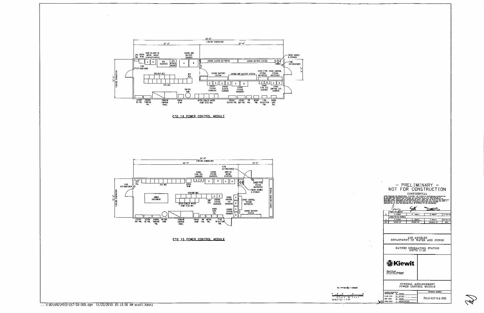
• . ~ ·-;.o -~
~
5B'-o'
25'-8' 1 INSIDE O!loENSIOOl
l2'-.4'
NOVDC ClUTCH BATTERIES 240V!X: BATTERY SYSTEiol
SCR/BOP UCC
I I I I I I I I I I
""' ocs H--rY-r+-+---+-,---o
12 40VIl GE PNL TOOBINE
PM.
OTO IICC
TURBINE COOTROL
PANEL
GTG UCC
.... EQUJPt.ENT
0 12SVDC 12SVOC 240VDC FM-200
BOP PNL GE PNL TURBINE TAt«
'"'
Fl.l-200
0 INTER-COCUR lATER
PUll' SKID UCC
CTG 14 POWER CONTROl MDQ!!! E
54'-o" 1!tiSIDE D!t.ENS!OIIl
~0'-T'
SCR~OP IICC
f--rl-1-+-1 +1---r-.1 --'---[jjJ£] I I I I 811' ~~~~~~
INTER-cooLER lATER DCS CHARGERS PUll' SKID I<¥:C
24VDC CttTL PM.
PR f,ETER FIR£ Pl4. Pill. DETECTI
PM.
CTG 15 POWER CONTROl MOQU! E
240VDC 125VOC PR W:TER fiRE CLUTC!I Pill. 811' PNL Pill. PHL DETECTION
13'-5'
24VllC IXWTIIOL SYSTEII
BATTERIES
125YDC BATTERY SYSTEII
'"'
SCAlE 1N fEET
SCALE: If~" · 1'·0"
PRELIMINARY NOT FOR CONSTRUCTION
CONFIDENTIAL
LOS ANGELES DEPARTMENT OF WATER AND POWER
HAYNES GENERATING STATION UNITS 11-16
Kl..,ll Po~•• 9401 Re'"'•' Poul••••d l•noxa, ~""""" 55219
GENERAL ARRANGEMENT POWER CONTROL MODULE
P0!0-017-GA-005
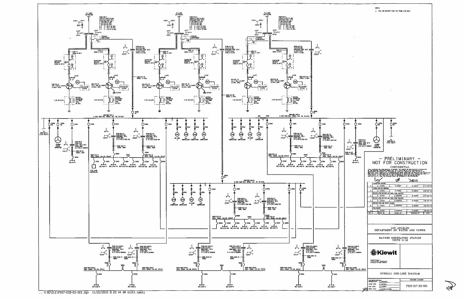
-" SIIGil-51:H
!THISSHHTI
TO t!Jlll' SIIICHYIKI
1 ](flfl~l Zl!l\V/Il e~V/U It!¥
Jl I!Hll (lllliltiHAf/IJIIJ' 65'~
CIH :fi' ~ mrmmo:r Hilzl! H·l Z•8119liiVI
-,. H-r l•6lo9lWI'A X Y l ~ 161 I ~liiVI
ciXll ciYll
i>oiXII~~:!!:,bR;:ITll biXl'l ·:~~---~-.:..:___ l£l!YIHI.I.
~~- lciJII'OIITIIEIII
~'lr ....... "~~~~8::-1 ISS.IINieO.!SPT - -H.nv, GOIIZ [XCITITI!JI 1
-~![~ J
,-- ~ 1 I£UTRAL ' f<ll ERIXKIIHG 7.9llV>I2JVI l)l n.JIIll6
-~M~c.
I o-j1• 1
'tr-~
,....- - 1 1£UIIlll • []I moo1111NG l.57KY:127Y I o.llllWS 1 ~~5~
-~ &IlSEe.
S\IGR/UX-5KV-1 4.16lV SIG!I BtiS, 40001, liJ• Jl, 50 lAIC
TO LAlli!' SIITCHYIKI
2lOKV/1J,!lV/B,BU
1 ••<w->
CIHll:t.liiH11 :r~:~~f ~rc X~l/124/ISS!til
81H21 ~-~l/l~~~~~~ ~~J WI ,- H-Y Z•ne~liiVI
l-Y Z ~ 1611 9liiVI oiXll ciTJI
i>ollll,:; ~ ~. i>oiYil bUll ';··· -~Yl~ TEili/IHI.I.
1-- lcDif'I.IHIIEHT -o-!1•1
',---~
L_,I'Sil-13 __ 11-0ooa • ~we I -®1
GEI.9!ll(ll ,;@-> _j_ ' BR£1lER 65001e4WtiM l®!
~ ];:-"= J
,....- - 1 HEtilAI.I. ' []IGROOIIIIHG J,9Jlv:mv
1 n.JIIliiS
142'>1 -~605£t.
,....- - 1 1£UTIII.I. ' []I Cll~DING 1.97 lVIl21V I D.l OOIIS 1 (251
- ~ &051:C.
r-~-I.IAT-112 WOIJA, (, ltilV ,....- - 1 NEUTilll
... •
• f<IIGROUialiNG 7.91 lV•I!lV I l)l o.J 00115
- ~ :~s~Ec.
ll-1-F
SI'OOIII:C-5!!Y-II (,\6KY S\IGR BUS, 4000~. JIJ, JV, SD IIIIC
lflfl.-j;SU-l ZlOH/1l.B~Yf1l.BlY IJIIJi/IJIAf/(llAfG">'C H 150/HIIl\0 11'11 X 9l/12(/\5S It'll y 9!/12~/155 It'll H-X Z•!119llti1 H-Y l • 810 9l WI x-r Z•l6119lii'IA
1 - ----,I!'U!Rit
I []1 CllllMUHG
l-97 ~V1127V I (],]IIIIlS 1 4251
_, 60SEC,
SIG!IIII:C-5KY-C 4.1~V SIG!I DtiSo 40001, ]IJ, Jl, SO me
·~·
·~· •
t Xflfl-IH
a6a .. - ~":~'~ we -~ -:" ~\60V-I8DV
b --{c Z"5,)5ll lllOIXVI
~~ms:
I. rUSE 1141 fll[Mt;R SllE> lRE f!Wol SIZE CJli.Y,
2500U DIESEl
!li'I£R~l(ll •lf.a:»i~•
NSBil-'11-112 2001l.1.410V
r-----'
•
-PRELIMINARYNOT FOR CONSTRUCTION
LOS ANGELES DEPARTMENT OF WATER AND POWER
------------1- HAYNES GENERATING STATION UNITS 11-16
.agn 11/22/2010 Be 25:44 AM scott.nann1
c I lflll-sus-.\tiiEu •"• F~v~5·c ~
c \60'1-480'1 • S. 151 1 2SOOlVA ,, . IISBD-I.OIE-Il -
mu- > ·~· 'ooora > "I ~ "I . SIG!I-480'1-.I.OIE:l ~~ SI00--.4a0'/-I.OIE:~ !"e•c-"'""'"-c'"•o·•e•·c'e"e'o"J"-rj-----------""'----.-------JL'~'""c''"'"~·"''•"·':'·""'''""'
J"' J~ ll:t-ICIIE< 10:-I.Ch'E-o
' B61 c)'
.,~. :AtHE-16-
GlKiewit ~;owll Pow.-g~m Ro......- !lo""'v"'d ~onoxo, Konoo• ~6219
l~~ > lOOOI 'oon > S1!.11-taliV-IIliES HC I ~~ ; 11
s1!.11--.4tDV-atiiE6 '------------''----------------l ,••e•c·"-~"·•e•c·'e'"''"''rj""-4------------""'---,--------~~· ... ~'"'"":='"'=·~··=•·c"=o"'' r
l~· l~· ICC-I.CHE-£ ll:t-ID1E-f
OVERALL ONE-LINE DIAGRAM
C. HICKS
POl0-017-E0-001
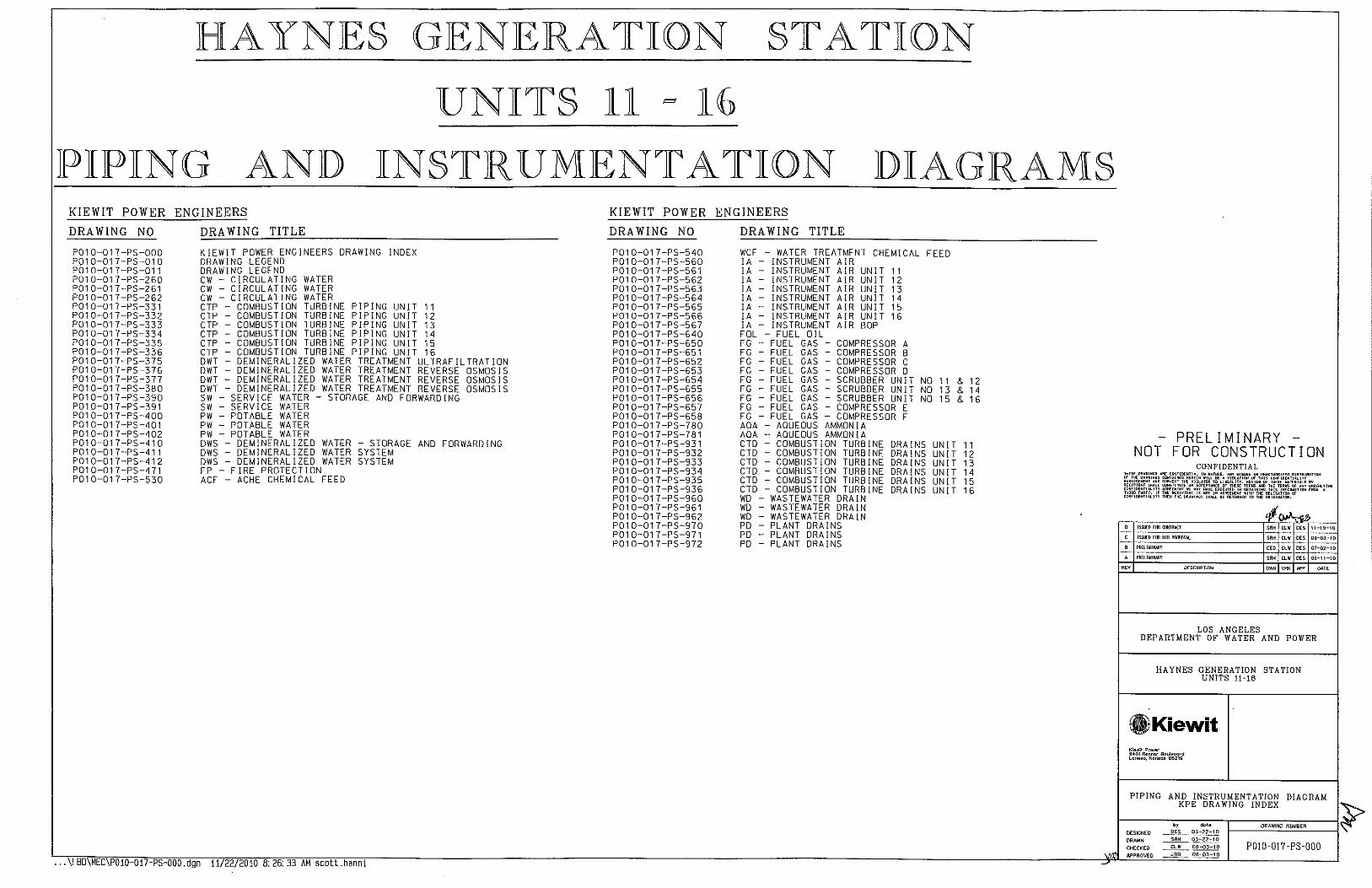
HAYNE§ GENERATION STATION
UNIT§ 11 = 16
IPIIPING ANJD INSTR UMJENT A TION JDIAGRAM§ KIEWIT POWER ENGINEERS
DRAWING NO
P01 0-017-PS-000 P010-017-PS-010 P01 0-017-PS-011 P01 0-017-PS-260 P01 0-017-PS-261 P01 0-017-PS-262 P01 0-017-PS-331 P01 0-017 -PS-332 P01 0-017-PS-333 P01 0-017 -PS-334 P01 0-017-PS-335 P01 0-017-PS-336 P01 0-017-PS-375 P010-017-PS-376 P01 0-017-PS-377 P01 0-017-PS-380 P010-017-PS-390 P01 0-017-PS-391 P010-017-PS-400 P010-017-PS-401 P010-017-PS-402 P010-017-PS-410 P01 0-017-PS-411 P010-017-PS-412 P010-017-PS-471 P010-017-PS-530
DRAWING TITLE
KIEWIT POWER ENGINEERS DRAWING INDEX DRAWING LEGEND DRAWING LEGEND CW- CIRCULATING WATER CW -CIRCULATING WATER CW - CIRCULATING WATER CTP -COMBUSTION TURBINE PIPING UNIT 11 CTP - COMBUSTION TURBINE PIPING UNIT 12 CTP - COMBUSTION TURBINE PIPING UNIT 13 CTP - COMBUSTION TURBINE PIPING UNIT 14 CTP COMBUSTION TURBINE PIPING UNIT 15 CTP COMBUSTION TURBINE PIPING UNIT 16 DWT- DEMINERALIZED WATER TREATMENT ULTRAFILTRATION DWT OEM! NERAL I ZED WATER TREATMENT REVERSE OSMOSIS DWT- DEMINERALIZED WATER TREATMENT REVERSE OSMOSIS DWT- DEMINERALIZED WATER TREATMENT REVERSE OSMOSIS SW - SERVICE WATER - STORAGE AND FORWARDING SW - SERVICE WATER PW - POTABLE WATER PW - POTABLE WATER PW - POTABLE WATER DWS- DEMINERALIZED WATER- STORAGE AND FORWARDING DWS - DEMINERALIZED WATER SYSTEM OWS- DEMINERALIZED WATER SYSTEM FP- FIRE PROTECTION ACF - ACHE CHEMICAL FEED
... \! BD\MEC\POl0-017-PS-OOO.dgn 11/22/2010 8:26:33 AM scott.hanni
KIEWIT POWER ENGINEERS
DRAWING NO
P010-017-PS-540 P01 0-017-PS-560 P01 0-017-PS-561 P01 0-017-PS-562 P010-017-PS-563 P010-017-PS-564 P01 0-017-PS-565 P010-017-PS-566 P01 0-017-PS-567 P010-017-PS-640 P01 0-017-PS-650 P01 0-017-PS-651 P01 0-017-PS-652 P01 0-017-PS-653 P01 0-017-PS-654 P01 0-017-PS-655 P01 0-017-PS-656 P01 0-017-PS-657 P01 0-017-PS-658 P010-017-PS-780 P01 0-017-PS-781 P01 0-017-PS-931 P01 0-017-PS-932 P01 0-017-PS-933 P01 0-017-PS-934 P01 0-017-PS-935 P01 0-017-PS-936 P01 0-017-PS-960 P01 0-017-PS-961 P01 0-017-PS-962 P01 0-017-PS-970 P01 0-017-PS-971 P01 0-017-PS-972
DRAWING TITLE
WCF - WATER TREATMENT CHEMICAL FEED lA - INSTRUMENT AIR lA- INSTRUMENT AIR UNIT 11 lA - INSTRUMENT AIR UNIT 12 lA - INSTRUMENT AIR UNIT 13 !A - INSTRUMENT AIR UNIT 14 lA - INSTRUMENT AIR UNIT 15 lA - INSTRUMENT AIR UNIT 16 lA - INSTRUMENT AIR BOP FOL - FUEL OIL FG - FUEL GAS - COMPRESSOR A FG - FUEL GAS - COMPRESSOR B FG - FUEL GAS - COMPRESSOR C FG - FUEL GAS - COMPRESSOR D FG- FUEL GAS- SCRUBBER UNIT NO 11 & 12 FG - FUEL GAS - SCRUBBER UNIT NO 13 & 14 FG - FUEL GAS - SCRUBBER UNIT NO 15 & 16 FG - FUEL GAS - COMPRESSOR E FG - FUEL GAS - COMPRESSOR F ADA - AQUEOUS AMMONIA ADA - AQUEOUS AMMONIA CTD - COMBUSTION TURBINE CTD - COMBUSTION TURBINE CTD - COMBUSTION TURBINE CTD - COMBUSTION TURBINE CTD - COMBUSTION TURBINE CTD - COMBUSTION TURBINE WD - WASTEWATER DRAIN WD - WASTEWATER DRAIN WD WASTEWATER DRAIN PO - PLANT DRAINS PO - PLANT DRAINS PO - PLANT DRAINS
DRAINS DRAINS DRAINS DRAINS DRAINS DRAINS
UNIT 11 UNIT 12 UNIT 13 UN IT 14 UNIT 15 UNIT 16
PRELIMINARY -NOT FOR CONSTRUCTION
CONFIDENTIAL
0 !>SUED Filii CllHIIACT
C ISSUED FOR 818 PROPOSAl
B l'll£LI~INARY CEO CLW DES 01-0~-10
PllHIMINARf SRH CUI OES 06-11-10
"" OESCRIPTlON OWN CHK M'P DATE
LOS ANGELES DEPARTMENT OF WATER AND POWER
HAYNES GENERAT!ON STATION UNITS 11-16
®ilKiewit KiowR F'owoc 9401 Rennec B<>u!evotd Lenexa, Konsos 66219
PIPING AND INSTRUMENTATION DIAGRAM KPE DRAWING INDEX "):::>
~------~.~,---,~.,~.--r---~,~~=,=,-'"="'~"~---~ DESIGNED ~~ DRAWN ~ 03-22-10
CHECKED ~ 08-03-10 POI0-017-PS-000 N'PROVED __:!l!!!___ 08-03-10

~
SKID LIMITS
PIPING FURNISHED BY OTHERS
PROCESS PIPING
EXISTING PIPING AND COMPONENTS
HEAT TRACED PIPING AND INSTRUMENTATION
TERMINAL CONNECTION POINT LIMITS OF LIMITS OF UPSTREAM DOWNSTREAM PIPE CLASS-----<>4- PIPE CLASS OR LINE I OR LINE NUMBER NUMBER
PIPING DESIGNATION
POWERBLOCK/UN IT ,.------LINE SIZE
SYSTEM CODE LINE NUMBER EXTRA CHARACTER (WHERE APPLICABLE l NOTES INSTRUMENT ROOT LINE PIPE CODE
c, c £ INSULATION THICKNESS
1A-6"-BFW1001A-AAA-2"A & TYPE
INSULATION TYPE A- HIGH TEMP l>500"Fl CONTINUOUS B- MEDIUM TEMP [<500'Fl CONTINUOUS C- HIGH TEMP 1>500'Fl INTERMITTENT,
FOR PERSONNEL PROTECTION D- MEDIUM TEMP (<500'Fl INTERMITTENT,
FOR PERSONNEL PROTECTION AND HEAT TRACING
VALVE NUMBER DESIGNATION POWER BLOCK / UNIT MANUAL VALVE PID NUMBER VALVE NUMBER SUFFIX - F-FURNJSHEO BY OTHERS
PS032-PS301-03 FLOW DIAGRAM SHEET CROSS REFERENCE
I I UNIQUE IDENTIFIER ~~0 SHEET NUMBER '-----FROM SHEET NUMBER
------t><l- GATE VALVE
0 ------l><l- VALVE LOCKED OPEN
• --t><J- VALVE LOCKED CLOSED
-{.»::]----- GLOBE VALVE
---l'e.l---- BUTTERFLY VALVE
-t:S:J---- BALL VALVE
-----[>l<j.- PLUG VALVE
----17"}--- DIAPHRAGM VALVE
---c:f::l- KNIFE GATE VALVE
NEEDLE VALVE
CHECK VALVE
STOP CHECK VALVE
ANGLE VALVE
HAND VALVE
PRESSURE RELIEF VALVE
AUTOMATIC RECIRCULATION !ARC) VALVE
UNDERGROUND VALVE WITH VALVE BOX
THREE WAY VALVE
FOUR WAY VALVE
·· .\!bd\mec\PD10 017-PS 010.dgn 11/22/2010 8:26:34 AM scott.hanni
101 11-"il
-]
---{
D
II
Ill
~
0
IHI
y
TRAP
FILTER
INJECTION ELEI.IENT
Y-TYPE STRAINER
DUPLEX BASKET STRAINER
SIMPLEX BASKET STRAINER
T-TYP( STRAINER
STARTUP STRAINER
SCREEN STRAINER
EXPANSION JOINT
FLEK!BLE HOSE
THREADED CAP
OU[CK DISCONNECT
WELDED CAP
FLANGE
UNION
DIELECTRIC UN lON
DIELECTRIC FLANGE
VENT
WALL PENETRATION
ROOF, FLOOR OR GROUND PENETRATION
EJECTOR
MIXING TEE
ISOK)N(T!C SAMPLER
AIR FILTER REGULATOR
BACKFLOW PREVENTER
REMOVABLE SPOOL
[OU!PI.IENT DRAIN
FLOOR DRAIN
ORA! N FUNNEL
CLEAN OUT
FREEZE PROOF HOSE VALVE
AIR RELEASE VALVE
PIPING SPECIALTY lDENTIFICATlONS UU XXX YYYZZ
UU -POWER BLOCK / UNIT XXX- PIPING SPECIALTY IDENTIFICATION YYY - P <1. !0 NUMBER Zl '"' EOU 1 PMENT NUMBER
'"' "' ace '" ceo
'"' "' "' ''" EO!>
'" '" "' '"' '" '" ''" "' "' "'' '" '" ''" "' "' '" "' m
'" "' m
"" "' '" m
[}:J
ol-ii
®
"
AIR RELEASE VALVE COMBINATION AIR RELEASE/VACUUM BREAKER VALVE BACKFL0\'1 PREVENTER BASKET STRAINER CLEAN OUT CONNECTION POINT DAMPER DRAIN FUNNEL DESUPERHEATER EOU[PMENT ORAlN EYE \'/ASH EYE WASH w/ SHOWER EXPANS!DN JOINT FIRE HOSE STATION FLAME ARRESTOR FLOOR DRAIN FLEXIBLE HOSE FILTER FIRE DEPARTI.IENT CONNECTiON F 1 R( HYDRANT INDICATING VALVE ISOK!NETIC SAMPLER INJECTION ELEMENT MIXING TEE ~~~~~R~~~~E TEST CONNECTION
SCREEN STRAINER START -UP STRAINER TERMINAL POINT TRAP T-TYPE STRAINER UTILITY STATION VACUUM BREAKER WASTE CONE Y-TYPE STRAINER
POST INOICATING VALVE
DRY PIPE VALVE
DELUGE VALVE
FREEZE PROOf YARD HYDRANT
FIRE HYDRANT
FIRE HYDRANT WITH HOSE HOUSE
HaS( RACK
HOSE REEL
FIRE HOSE HEADER
ELECTRIC HO!lN
FIRE DEPARTMENT CONNECTION
INSPECTORS TEST STATION
WASTE CaNE
SMOKE DETECTOR
THERI.IAL DETECTOR
W/>,TER MOTOR GONG
SPRINKLER HEAD
VACUUM BREAKER
DRIVER M = MOTOFI A = AIR D = DIESEL
0
Of----~)
D
CENTRIFUGAL PUMP
ROTARY PUMP
POSITIVE DISPLACEMENT OR METERING PUMP
VACUUM PUMP
SUMP PUMP
CAN PUMP
WET PIT PUMP
AIR BLOWER
COOLER
U-TUBE HEAT EXCHANGER
STRAIGHT TUBE HEAT EXCHANGER
PLATE HEAT EXCHANGER
COOL lNG TOWER CELL
DOUBLE FLO\'/ TURBINE
SINGLE FLOW TURBINE
SAFETY SHOWER
EYE WASH
FLAME ARRESTOR
RESIN TRAP
SILENCER
REDUCER
1<1
0
FLOW NOZZLE
TURBINE METER
ORIFICE PLATE
VENTURI METER
AVERAGING PilOT TUBE
VARIABLE AREA FLOW METER
MAGNETIC FLOWMETER
VORTEX FLOWMETER
VARIABLE HIGH PRESSURE REDUCING VALVE
PRESSURE REDUCING REGULA TOR EXTERNAL PRESSURE TAP
BACK -PRESSURE REGULATOR SELF-CONTAINED
PRESSURE REDUCING REGULATOR SELF-CONTAINED
ELECTRO-HYDRAULIC OPERATED VALVE
MOTOR oPER. VALVE
SOLENO!O OPER. VALVE
ALARM VALVE
CONTROL VALVE W/ HAND OPERATO!l
OESUPERHEATER
OESUPERHEATER & CONTROL VALVE COMBINATION
MIXER
CYLINDER, SINGLE ACTING OR WITH PaS!TION(R
CYLINDER· DOUBLE ACT!NG
NOT PRELIMINARY -
FOR CONSTRUCTION CONFIDENTIAL
tiltS[ O~A.II«lS .RE CIIHI'ID1:NTIAl. IW IIAT I>' THE DRA.IHGS CII!<TAINED HEREIN .II.L PIS'IRIIIUTIDII R1:0UIR1:"'1<T.., SUOJECT THE VIIIUlllA 1 TI•I.ITY RECIPI<NT SHALL Cl!HST11U1E ""AC TERULS OY COIIFID[I<TIAl.lrYAGREEIIEIIT"" Cl' ... YIJ!<0£RI.TIIIO tmRP PAIITY. If THE RECIP([Nl 1101 IN A<illHIIENT Wl :::""" fR ... A COOI'!DEIIT!.lliTY THEN THE OnA• SHAll. OE ll£1~11tD TD TilE DIIIGI""l""
C ISSU~D FOO COI!RACT
B ISSUED FOO 610 PRI.ti'OS.It
A PR£li~II!MY
'" DESCRIPTION
SRH ClW DES 11-1~-10
SRH CLW DES DH-03-10
SRH CLW DES 06-11-10
OWN CHI< API' DATE
LOS ANGELES DEPARTMENT OF WATER AND POWER
HAYNES GENERATION STATION UNITS 11-16
GlKiewit Kio,.i\ Power 9401 Rennor Boulovord L@Mxo, ~ansa• 66219
PIPING AND INSTRUMENTATION DIAGRAM DRAWING LEGEND
1----c"o'cwc"='='="="c"o':_ __ -l 'S> P010-017-PS-010 ~
DESIGNED
by dote DES 03-22-10
DRAWN SRH 03-22-10
CHEC~EO CLW 08-03-10
APPROVED JRD 00-03-10

INSTRUMENT IDENTIFICATION LETTERS m ANSI/ISA- S5.1 -LATEST EDITION FOR DETAILED EXPLANATIONS
FIRST-LETTER SUCCEED lNG-LETTERS INSTRUMENT SYMBOLS INSTRUMENT DESIGNATION MEASURED OR READOUT OR INSTRUMENT fiELD hiDUNTEO INITIATING MOOIF!ER OUTPUT MODIFIER PASSIVE FUNCTION FUNCTION
0 E = E-f: TYPE T/C
9 VARIABLE
K = K-K TYPE T/C LOCAL ] NSTRUMENT ' ANALYSIS ALARM RTO = RT0-100fl.PLATINUM RTO
IF I =FURNISHED BY VENDOR ' '
BURNER, lEJ =EXISTING COMBUSTION FO =FAIL OPEN '" ~POWER BLOCK I UNIT FC =FAIL CLOSE WWW = IDENTIFICATION LETTERS ' CONTROL
YYY = P&IO NUMBER OJ FFERENT I AL C) ZZZ = LOOP NUMBER 0
1/P ~ELECTRO PNEUMATIC
' VOL TAG[ SENSOR (PRIMARY S/V = SOLENOID AClUAlED ELEMENT\
------------- ELECTRIC SIGNAL
' FLOW RATIO !FRACTION!
' GLASS
8 VIEWING DEVICE INACCESSIBLE OR BEHIND-THE-PANEL
CAPILLARY TUBE " HAND HIGH DEVICES OR FUNCTIONS
' CURRENl INDICATE !ELECTRICAL 1
8 li Xi !1: if !I /1; PNEUMAliC BINARY LINE
' POWER SCAN LOCAL PANEL DEVICE-
TIME. l~~G~ATE OF OPERA lOR ACCESSIBLE
' TIME SCHEDULE CONTROL STATION
// If /l If If v PNEUMAl/C LINE I ' LEVEL L IGHl
'"' ' MOMENTARY MIDDLE,
INlERMEO!AlE
8 OCS ACCESSIBLE L L L L L L HYDRAULIC INSTRUMENT SIGNAL
' XX =BLANK -MAIN DCS CONTROL SYSTEM ST - SlM TURBINE CONTROL SYSTEM
0 ORIFICE, CT -COMBUSTION lURBINE
' ' RESTRICTION CONTROL SYSlEM
' ' ' ELECTRICAL BINARY LINE
' PRESSURE, POINlcfT~~Tl XX WT - WATER TREAlMENl VACUUM
0 QUANTITY INlEGRATE, - PREL IMINARY -TOTALIZE
@ SONIC LINE
RAOIAT!DN RECORD NOT FOR CONSTRUCTION COMP FUNC " XXof'UNCTIDN DESCRIPTION NUI.IBER
' SPEED, SAFETY SWITCH CONFIDENTIAL FREQUENCY -o-o-o-o-o-o- SOFTWARE OR DATA LINK
' ' ' TEMPERA lURE TRANSMIT ' ' "
~ PLC ACCESSIBLE " MULTI VARIABLE MULTIFUNCTION ldLILTIFUNCTION MULTIFUNCTION ~J:li"'-!lNG MECHAN)CAL LINK
' XX = BloiS - BURNER MANAGEMENT SYSTEM
' VIBRAliON. VALVE. DAMPER. VALVE ' ' WT - WATER TREATMENT MECHANICAL LOUVER ANALYSIS
qy.~~ XX INSTRUMENT L !NE
' WE I GHT, FORCE WELL
' UNCLASSIFIED X AXIS UNCLASSIFIED UNCLASSIFIED UNCLASSIFIED ' ISSUED FOR COOJRACT '"" '" "' 11-1"1-10
0 INTERLOCK LOGIC
' EVENT, STATE Y AXIS RELAY, COMPUTE. ' ISSU£0 FOR BID PRl'i'OSAL '"" "' "' OB-03-10 XX =LOGIC NUI.!BER OR PRESENCE CONVERT
DRIVER, ACTUATOR, • PR£LIM!NARY '"" "' "' 06-11-10 z POSIT!ON, Z AXIS UNCLASSIFIED FINA 0ESCR1PT10N "" '"' ~' DATE DIMENSION CONTROL ELEMENT '"
LOS ANGELES DEPARTMENT OF WATER AND POWER
HAYNES GENERATION STATION UNITS 11-16
.Kiewit Kiewil Powec "1401 Renner Bouievord lenexa, Kan•<>• 66:!19
~ PIPING AND INSTRUMENTATION DIAGRAM DRAWING LEGEND
,, dole DRAWING Nt.IMSER DESIGNED '" 03-Z:!-10
DRAWN ~03-22-10
P0!0-017-PS-011 CHECKED ~ OB-03-tO
-~· APPROVED oeo OB-03-ID
~ ... \! bd\mec\P010 017 PS 011.dgn 11/22/2010 8. 26.34 AM scott.hanni
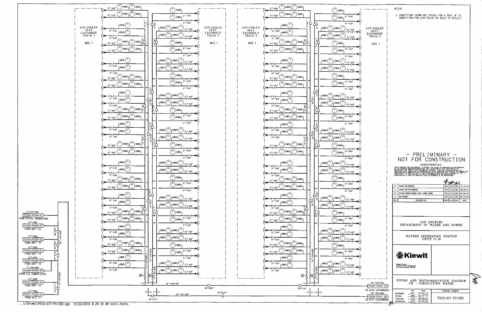
3~-CW-EMD
PS640-PS260-01
FROM DIESEL GENERATORS 14"-EMD
PS336-PS260-01
FROM UNIT 16
14"-EMD
PS335 PS26D-01
FROM UNIT 15
14"-EMO
PS334-PS260-01
FROM UNIT 14 14"-B.tO
PS333-PS260-01
FROM UN IT 13 ~ 3"-CW-EMD
PS560-PS260-01
FROM A I R COMPRESSORS
14 "-£MD
PSJ32-PS260-01
FROM UNIT 12
14" EMO
PSJJ 1 -P$260-01
FROM UNIT 11
r--
p 0 >
~ w ' • u ' . ~ N
?' ~ . X
~
0 > ~ • u '
~ .
X .
I
AIR-COOLED HEAT
EXCHANGER TRAIN 1
NOTE 1
, ________ j
... \!bd\mec\P010 017 PS 260.dgn 11/22/2010 8:26:34 AM scott.hanni
16 "-CW-EMO
1B"X14"
AIR-COOLED HEAT
EXCHANGER TRAIN 2
NOTE 1
36"X30"
JO"X16"
AIR-COOLED HEAT
EXCHANGER TRAIN 3
NOTE 1
________ j
"""'" I I ""I"" ""I"''
AIR-COOLED HEAT
EXCHANGER TRAIN 4
NOTE 1
TO HEAT EXCHANGERS
PS260-PS261-02
TO HEAT EXCHANGERS
NOTES:
1. CONNECTIONS SHOWN ARE TYPICAL FOR A TOTAL OF 32 CONNECTIONS FOR EACH TRAIN (16 INLET Hi OUTLETl.
-PRELIMINARY -NOT FOR CONSTRUCTION
CONFIDENTIAL llil' AAE CDNnOUllAL IH lilT..,£. ANY WISUSE DR UNAUTHORIZED Dl5m!HUTIIIN OF CDNTAI,.._Il Ul'RtiH Will o• A V!OUTHI<I OF THIS C"""llll'NIIA!.l<T
AHO SUBJECT lHE Ylll\.ATOR TO lUBilll"r. Rl'VIEW OF Tli .. E ... TER!ACS Of All CDNSHlUIE AH ACC;PTmo£ OF liiESE fER,.,; AIID Tilt; TOCR"' OF .,., ui<!J;RLYING JTY Ao•<r•EftT liE YAY li.V< EMECOTl'll IIi !II!UININC lli!S )NH,.WATI<>< F""" A
IF THE RECIP!EIH 15 liO! IN AOREOIIf.NI WJIH lilt; DBLIGAT!ON OF llY THEN Tot ORA•IIics SH.,_L OE ""''"'"'" TO TH£ MIOINAfOR.
0 ISSUED FDR C!IITR~CI
C ISSUEO FDR BID POO'OSI.I.
6 REVISffi BRANCH IIEAIIER SIZES, AllOCiliNSTRS
A PRELIWINARY
OESCRJPTION
SRH CLW DES 11-19-10
SRH CLW DES 08-03-10
C£0 CLW DES 07-02-10
SRH CLW DES OG-14-10
OWN CHK N>P DATE
LOS ANGELES DEPARTMENT OF WATER AND POWER
HAYNES GENERATION STATION UNITS 11-16
.Kiewit Kiewit Power 9401 Rern1er Boulevard Lenexa, Konsos 66219
PIPING AND INSTRUMENTATION DIAGRAM CW -CIRCULATING WATER
dele ORAWING NUMBER
DESIGNED DES 03-22-10
P0!0-017-PS-260 DRAWN ~~ CHECKED ~ 06-03-10
APPROVED JRD 08-03-10

16 "-CW-Et.tD
PS260-PS261-01
FROM HEAT EXCHANGERS 30"-CW-Et.ID
PS260-PS261-02
FROM HEAT EXCHANGERS
1 bd\mec\P010-017-PS-261.dgn 11/22 2010 8:26:34 AM scott.hanni
---------,
AIR-COOLED HEAT
EXCHANGER TRAIN 5
NOTE 1
I li~::;:"~;:____l.:::,:::__J_---,
li~:;;:"-"~-L="--_J'--1 .
________ J
' 0
0
0
" 0
~
36"X30"
,-------~ I
r---:_~-L,.,.<_,;;;>-+ijl
~--:_~_..L,.--<_,;;;>-+Ijl AIR-COOLED HEAT
EXCHANGER TRAIN 6
0
'
~-.:::,::L-'='--~'·~~~1 6"-AAF 1
J...l---~:..l-~-"<,~11
6"-AAF 1
'~II 6"-AAF 1
'~II
6"-AAF 1
'~II 6"~~il
1-l--o;;::.L-....::o::...'::,".~~il ~-~L-'~'::,·.~~~1
NOTE 1
I _______ _
1111 1111 36"-CW-EMD
PS261-PS262-01
TO CIRC WATER PUMPS
NOTES:
1. CONNECTIONS SHOWN A.R[ TYPICAL FOR A TOTAL OF 48 CONNECTIONS fOR EACH TRAIN !24 INLET, 24 OUTLETl.
PRELIMINARY NOT FOR CONSTRUCTION
CONFIDENTIAL m•;E DRAWINGS All£ C"""I!IEHTIAL IH HATW,, ANY ~1«1<£ (Ill ~HAU'I>IMI (;f' TH£ DRAW)HGS CIII<Tlli<E!I IIEREltl lrlll 9£ A V!OI.ATIOH (;f' lll">UIR<""HT AKD SII!I.JE<T THI: VIO<.ATOO TO L!A91UTf, R<VI< lll:CIPIEHT SHM.l COMSTrlUTE AH ACCEPTAHOE OF THESE TERI<S """"IDEHTIALJTY ~EO.IEI<T .. U>Y """" E'ECUT"ED IN QIIUIH THIRD PARTY, IF TI<E FIEtiPIEHT IS HOT !H ACREOEOIIENT "ITll T <OOFIDEHT!A!.ITY THEil THE IIIIAWIIIOS SHA!.L SE IIETUfiHED TO
'"
ISSUED FOO BIU Plllf'IISAL
ISSUED FOO 810 PR!f'IISAL
Rf.VIS£0 BRAIICH lltAO[R SIZ[S, AOD£0 IHSIRS
PRELl~ I NARY
DESCRIPTION
OES 11-19-\0
Sll~ CLW OES OB-Q3-Hl
CEO CLW OES 07-02-\0
Sll~ CLW OES 06-14-\0
OWN CHK AI'P DATE
LOS ANGELES DEPARTMENT OF WATER AND POWER
HAYNES GENERATION STATION UNITS 11-16
tl,lKiewit Kiewit Power 940111eMer Boulevard Lene><o, Kcnscs 86219
PIPING AND INSTRUMENTATION DIAGRAM "">< CW CIRCULATING WATER ~
b.y dole OIIAWING NUMBER
OESK>NED ........Qf.L_~ OIIAWN ~ 03-22-10
CH£CKEO ........9JL._ 08-03-10 PD!0-017-PS-261 APPROVED ~ oe-OJ-10

"
2"-ABA
1-{-ACF-GJB
PS530-PS262-01
CORROSION I Nl-11 8 I TOR
SYSTEM BALANCE PRESSURE
36"-CW-EMD
P$261-P$262-01
FROM AIR-COOLED HEAT EXCHANGERS
VENT
CIRC WATER EXPANSION
TANK 18,500 GAL
2"-ABA
PT
~ -
36"-CW001-AAF
36"-AAF
Pi SYSTEM LEVEL CONTROL
2"-SWXXX-ABA
PSS67-PS262-01
COMPRESSED A I R
... ! bd\mec P010-017-PS-262.dgn 11/22/2010 8:26:34 AM scott.hanni
~ ., ., ' ~ ~ 0
"' u
' , ~
N
AR-26001
w ~I 0 ~ N >
V260020-501
I
1-{-ACF-GJB
PS530-PS262--Q2
CORROSION l NH l B I TOR
0 ~ ~ ~ ! ( v)
TE
26005A-F '-..___./
36 "-CW001-AAF
CIRCULATING WATER PUMPS
3X507.
~ ., ., ' ~ ~ 0
"' u
' , ~
N POI
I L_
AR-26001
w ~I 0 ~ N >
V260020-501
36"-AAF
14150 GPM@ 125 TOH
PS391-PS262-01
SYSTEM FILL
~ "X2"
36"-EMO
PDT
PS530-PS262-03
CORROSION INHIBITOR
BLACKSTART CIRCULATING WATER
PUMPS 2X1DO%
4650 GPM @ 125 FT
1111 1111
PS530-PS262-04
CORROSION INHIBITOR
AR-26002
~ ., ., ' "' u ' ,
~ ':.f 0 0
"' N « > "' .,
' w ~
~ u ,' ~
14"-EMO
NOTES:
1. NOT USED
2. TRIP CIRC WATER PUMPS.
3 "-EMD
PS262-PS640-01
TO UNIT 16
14"-EMO
P$262-P$336-01
TO UNIT 16
14"-EMD
PS262-PS335-01
TO UNIT 15
14"-EMD
PS262-PS33~-01
TO UNIT 14
14"-EMD
PS262-PS333-01
TO UNIT 13
3"-EMD
PS262-PS560-01
TO UNIT 13
1~"-EMO
P$262-P$332-01
TO UNIT 12
1~"-EMO
PS262-PS331 -01
TO UNIT 11
PRELIMINARY NOT FOR CONSTRUCTION
CONFIDENTIAL
lSSII£D fOO tOOTRACT
lSSII£D FOO Sin PR!lP!IS.ll
JIEYJS£{) LU£ sms. PIM' CJ'W, lAIII; SJZ£
PR£llY!IWlY
"' [!(SCRIPTION
SRI! CLW DES 08-03-10
CEO CLW OES 07-02-10
SRI! CLW DES 06-11-10
OWN CHK N'P OAT(
LOS ANGELES DEPARTMENT OF WATER AND POWER
HAYNES GENERATION STATION UNITS 11-16
8lKiewit l(i~wll Power 9401 Renner Boulevard Lene.o, Kcnsas 56219
PIPING AND INSTRUMENTATION DIAGRAM CW CIRCULATING WATER
by dale DRAWING NUMBER DESIGNED ~ 03-22-10 ORAWN ~~ CHECKED ____Eh!__ OS-Q3-1 0 POJ0-017-PS-262 APPROVED ______,!_f!Q__ DB-03-10

,---------1
1"-li\111-FKO I AQUEOUS AMMONIA
IPS561-PS331-04)>----------I!I DELIV~~~ SKID INSTRUMENT AIR I
PS331-PS780-01
AMMONIA RECJRC
2"-!A110-CBA
P$561-P$331-02
~--{iNERArOR-#11;0:1!--''-='==-i ' '
4"-CTP-ABA
100<: 100<,~ 4"-CTP-ABA I 30eli-...::...=="'----l 4"-CTP-ABA
4"-CTP-ABA 10~ 10~---249A Joel
3001
4 "-CTP-ABA
10~---4 "-CTP-ABA
10~---4 "-CTP-ABA
10~---4 "-CTP-ABA
29AI
2981
29C ·r--'-'""""'"'-1 I 10~---290 ·c---'-'"'--""-----1
13wl I 1 24BA 81A -1-------r,:--·
2 U2";:rN:JTE1 <:: ~ 14'X6"
r--Ia--,,,--, H':oi----3-" .... -FG\14-CEB-1 1/2"0 • r (PS654-PS331-011
""
FROM FUEL GAS FILTER/SEPARATOR
C] a ">:4 8
a"x4"
r
--Ej
"" 18"
3" CTP111 ABA 1 1/2"0
. [oR:IN[~ ~3,.._ CTP156-ABA
271 c
! INTERCOOLER #11
2710 0
I 8'X3" ~ I~ VENT
a
~ p ~ I - . N m
' ' • ' • - ~ ' I m
~ . • • 0
m ~ ;;: • ' " ~ •
0 ' N I '
'
[J u I '
;6-;----- -1
CONOENSA Tl ON I TANK #11
2688
26BA
J3 PRESSURIZATION AIR LM$100
MAIN UNIT #11
-------------------~ I ' ~ ' ~
~ y > ;;: Nn 2766
,...-----------1
I CARBON DIOXIDE
BOTTLE RACK #11 '"1--~'--'"~4~"----~ 161 A
I '---------_I
'" 2"
INTERCOOLER #11 INTERCONNECTING
PIPING SKID
V330,, II I
18"-CTP1D8-ABA-1 1/2"Dy L _______ :u..!A}----9, ~
8 x6 V330017 :z 112"-crP1o7-AaA-1 1/2"o a:;: I
1 'Sd/2" 3/4"-CTP155-ABA ~
1 "-CTP107-ABA-1 1/2"0
2718
y ~ ~ y
I " ' :., i
I "r-I
I 3/4"-CTP143-ABA I J DRAIN '
2728
I ill~-----
V330105F
1 1 = = T T
1 "-!A106-FKO
P$561 -P$331 -01
INSTRUMENT A! R FOR CONDENSATE
DRA!N VALVE
r~---~-~------
1 243 244 269
COOLING WATER PUMP SKID
#11
239 240
I- ~J~33oo~_l---- _j
<::::) EJ-33003 c::)
3/4"-CTP149-AB [
¥330007 u . J i ~e _ --rr:-_ 14"-CW102-EMO
~r-.---.~es~3~3~,-~,7s~2~,,~-~o~'/ ~36
2"
' --1"- -12 ,:'~'J 1 1 /2"
1/2" N N
VENT 2"
2" \_ ________ )
8~-CTP-ABA
;-----~~~e~·-~c~TP=-~AB~A---, L
I I {5 ti u•~
23,,--- __ _[] __________ _':-CTP:OH~AJ_·~,·~~1 ·~m~"
~ 0 1A 26A 25A 247 23 22
i ~ CT AUXILIARY SKID ! •'T> #11 °
~ ~ I u
olEo~·:-~~f~~i~~~::§fo~,:~~~~~~'>l,o_v_,~:r::::..~· .....• , , : '''"~· jT .. %:· - - -r .. ·.:~~·~~·::~- -/ ~ :--< ' F I L TERHOUSE #11
1 "-IA104-FKO
P$561-P$331-03
WATER WASH INSTRUMENT AIR
2"-0W102-CBA-1 "0
P$411-P$331-03
OEM! N WATER SUPPLY TO WATER WASH
¥330 18 NOTE 4
3/4"-CTP114-CBA-1 "0
"" < y N
3/4 "-CTP147 -ABA [
¥330005 3/4 "-CTP148-ABA [
¥330006
14"X1o":: ' TO ACHE
PS262-PS331-01
FROM ACHE
L-----------~~;_ ~ 10"x8"
,----i'-1 1Q"-pp @A
,_ ___ 1 o<"Jxa_"7
___ _,__ ,~~~,1 l =t~: -l'!:'".:-:::c~re::-"''"~'c.J 8"-CTP-EMO
11/22/2010 B: 26:35 AM scott.hanni
NOTES:
1. CONNECT !ON LOCATED UNDERNEATH PIPING TO VBV STACK.
2. FLEX HOSE IS ONLY PIPING BETWEEN GE CUSTOMER CONNECTIONS.
3. NOT USED.
4. REMOVABLE PIPE SPOOL FOR START-UP ACTIVITIES.
5. PIPE TO BE WRAPPED AND CATHOO! CALLY PROTECTED WITH ANODES.
PRELIMINARY NOT FOR CONSTRUCTION
CONFIDENTIAL
ISSU£0 FOO ct!IJRACJ
A£1101'[1) HEAT TRACING. lO COCUR BOOSTER PUll'S. R£VIS£ S COOlJHG WA1£11llh'E SIZES, ADDED BELEll OOI.Df CEO CLW DES D7-D2-1D
A PA£llMUWlY SRH CLW DES 06-14-10
'" DESCRIPTION OWN C41K APP DATE
LOS ANGELES DEPARTMENT OF WATER AND POWER
HAYNES GENERAT!ON STAT!ON UNITS 11-16
®ilKiewit Kiewit Power 9401 Re~ner Bculevcrd Lenexa. Konscs 56219
PIPING AND INSTRUMENTATION DIAGRAM CTP - COMBUSTION TURBINE PIPING
UNIT 11
by dole ORAWWG NUMBER DESIGNED ___!l!.L__ ~ DRAWN ~ 03-22-10 CHECKED ~ 08-03-10 P0!0-017-PS-331 APPROVED -!!.!!!L_ ~

8 "-CTP-ABA
J 6--~
t ~------,
~2~'~'-ti~AI~I~O~-C~B~At>-----------------------------------1' l;ss62-PSJJ2-02) I! I J3 PRESSURIZATION I
AIR
I ;----------1
I CARBON DIOXIDE I
BOTTLE RACK # 1 2 16111
f' --1'-'1 ~"~"------i 161 A
I , __________ I
LM$100 MAIN UNIT
#12
: I I f.--
18"
Jo1 I =T 1.3ff-CTP111-ABA-1 1/2ff0
! DRAIN[----: -3/4"-CTP156-ABA
i--;43A -244A-
1
271:').;
3"-4 ~
0 ;6;------l
, 271 c t, ._. VENT ~ icONDENSATIONI
! I NTERCDDLER #12! ~ o ; [J-'1260
1 ANK "12 ~~ 1
1 I ~ ~ ~ I , ~ - ~ ~ I I 1 ~ ~ ~ ~ ll. 26BA I I
-------lNT~R~O~LE~ #1;----: !I ~ ~ ~ ~ ~ ~n:mo ~~ II INTERCONNECTING I .. , ~ ~
PIPING SKID , J 2728
t -
1 "-IA106-FKD
--<_ PS562--PS332-01]
INSTRUMENT AIR FOR CONDENSATE
DRAIN VALVE
COOLING WATER PUMP SKID
"' 2
I 27181 ~ II ' I ' I I 3/4"-CTP143-ABA I I '239 240
! -_I -F"'-='F-~;::::=;-l r--=~-;- ~7~ I V330016 J DRAIN I' I' l =-F'"- -,,:,300-, ...,----- _j ~- , 'B"-CTP10B-ABA-1 1/2"0 ___l__ ··· uu ---..1..._
1 1 1 I 1" L 271 AJ---c] '"11 272~---- ___! c:::> EJ-33003 c:::>
1" ! T T ! f-1;2::;P:7~ABA-~~2ff0 B'XG" ~]~I _I Et'' ---a--r"J/4~-CTP149-Ailr-! 2" i ~~578 246A 257AI i 1'X112" 3/4"-CTP155-ABA§i _ V330002
I 2570 257C~ 1" ZIH - ZSH ~ 246~ 2560 256C i
11"~~ ]2568 NOT~5~256AJ'~~~_j j V330105F 1"-CTP107-ABA-1 112"0 El :8 ro
li I ' I" VBV ' ~. " u ! STACK #12 ! o--- PY ~~ I I
1 4 u-CW1 02-EIAD
..----fPS332-PS260-01)
TO ACHE
',_ ________ }
8"-CTP-ABA
I 8"--tTP-ABA
VENT 2" 7~~7 7 I ~~ Q'l. ~16'X14" ~ B'XI 3/4 "-CTP147-ABA E
V330005 3/4 "-CTP1 46-ABA
---- --- __ _[] __________ _::-CTP:~A~Ad_n6" _ __}-:--,lB~" 1 236A 1 A 26A 25A 247 22 ro
I 23 f CT AUXILIARY SKID I 0~
' #12 I I ~
10"-CW ... -ABA _ --n-:-~~--t-----<~~,~~~-~tr ~ 1- PS262-PS332-01
V3 ooo124"X10"; FROM ACHE
( ""R VJ30006
< m < ' ~
:-;~~i~~~~~~~~;~\:~3;~::~~-~~i;>;O-y--.~ ~3:310(£0~3~- - --- ~ - ],.-~tr :J"cP:;;. -,, - ~"~"~ OOCO,. mrn- - >~ ~ ~ : ' ' 1 V<"-CTPJOJ-ceA o ~z MINIMUM FLOW LINE ,/ '1
1 "-IAl04-FKD V330~1B NOTE 4 ! F I L TEAHOUSE #12 C"------------'
PS562-PS332-0J r~,~,~·~ .. -~,~,~,,t,~·~-cs,-' __ ' ._.,...,!~r·~!!..--'jl. !I I ~- ~ INSTRUMENT AIR 1 1/2n-IA103-FKD ~------------------------------------- ~o:_--,------1 ) ED-33410 41 IB -
2n-DW102-CBA 1 "op;;;2
;~:;:2
;~~ - -NOT_£_
4
f:,-, .-2
-, --- -' 10ux8" = I rPS411-PS332-03 "' , L ______ __
DEI.HN WATER SUPPLY TO WATER WASH .--------.....[ 'P"-GTP-ABA
~ ~ t; '
0
ll"-CW El-10
NOTES:
1. CONNECTION LOCATED UNDERNEATH PIPING TO VBV STACK.
2. FLEX HOSE IS ONLY PIPING BETWEEN GE CUSTOMER CONNECT! ONS.
3. NOT USED.
4. REMOVABLE PIPE SPOOL FOR START-UP ACTIVITIES.
5. PIPE TO BE WRAPPED AND CATHODICALLY PROTECTED WITH ANODES.
-PRELIMINARY -NOT FOR CONSTRUCTION
CONFIDENTIAL TH£>£ DRAWl$< AAE CON>IDEHTIM_ IIi HAT<"<£, .,.., ""THE DRA.It!VS C""UIN!;D HEREIN WILL !1£ A"'"'REDUIRE>ENl .... SU8.1ECITHE>UIUTOOTDll RtCIPI<Hf SH"'-L CDtiSTHUTE ""AC<[PlAilcE COt<>lOEHT!"'-111 AORE£1<(!/T lot 11>\Y HAVE THI•D Pli!TY. If THE RECIPIENT IS tiOf IN AomE..,Hf C<•<'TDEHTIAI.ITY THEH THE O"AWINOS SHALL B£ A£TLilNED T
0 ISSUED FOil CIJIIRACT
C ISSUED FOO BID PROPOSAl
R£W/[O HEAT TRACUIG, lD COOlER BOOSTER PUif'S, REVISE B COO. lNG WAI£R Llll: SIZES, ADDED BH!JW GRillE
A PREliKUWIV
'" OtSCRIPTION
DISmiBUliON
;.:; "' 1NY ""OEOI.YIMG OF Hll< FO'"' A
SRH CLW DES 11-19-10
SRH CUI DES OB-03-10
CEO CL'fi DES Ol-02-10
SRH CL'fl DES 06-1~-10
OWN CHK N'P DATE
LOS ANGELES DEPARTMENT OF WATER AND POWER
HAYNES GENERATION STATION UNITS 11-16
.Kiewit Kiowi\ Pow~t 9401 Renn~t Boulov<>rd L@nexo, K<>n•os 66219
UNIT 12 r';'·,~"-~O~W~1~03~-~C~BA~-~I>"~O:-------------;:; T 10"x8" I ~ 1 --t-; t PS377-PS332 03) "3[8]3""~0-,-----------------------------------~ l-------(J--r--------'----.,,~-i_f------1'-l + ---i ~~~--~J~O~"-~C~1~P~-E~'~O~
RO PERMEATE SUPPLY TO • vu EVAP COOLER
PIPING AND INSTRUMENTATION DIAGRAM ~ CTP - COMBUSTION TURBINE PIPING
~, ~~~~--~=--l-------------------------------------------...!•:"·~C~1~P~A~B~A---++ I •__:-~B~'~'-c~~1P~-~E~Mn!J b~ <lale DRAWING Nlli.!BER DESIGNED ~~
- DRAWN _2!l!!_____ 03-2~-10 CHECKEIJ ____f.b.!__ ~ P0!0-017- PS-332
... \! bd\meC\?010 017-PS 332,dgn 11/22/2010 8:26:35 AM scott.hanni APPROVED JRO OB-03-1 0
.J•
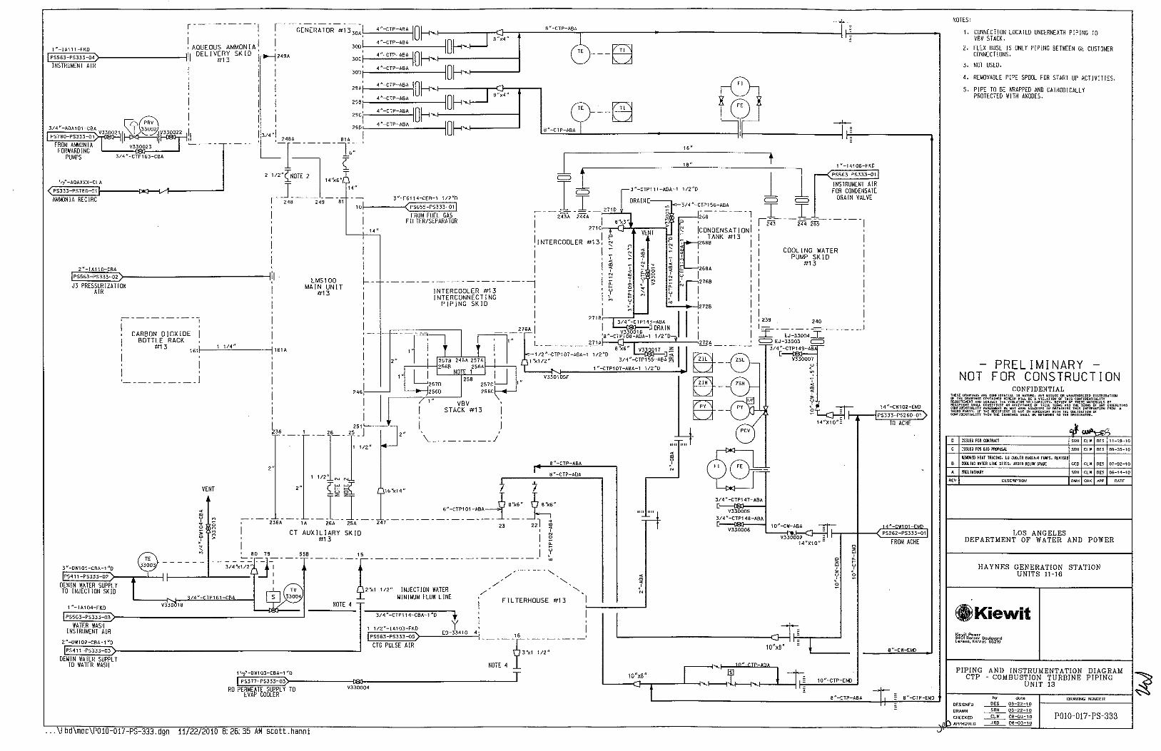
3/4"-AOA101 CBrA V33002 , 1(9a1~,,,,! :1 PS7BO-PS333-01 ~~ 1 FROM AMMONIA V330023 ~---
FORWARDING PUMPS 3/4 "-CTP1 63-CBA
1,2"-AOAXXX-CLA
PS333-PS7B0-01
AMMONIA RECIRC
2"-IA110 CBA
EIP~ss~6~3-P~"~'~,;-o~2?>:---------------ll!l J3 PRES~~~IZATION I
2"-DW102-CBA-1 "0
PS411-PS333 03
DEMIN WATER SUPPLY TO WATER WASH
I ;------------1 I
CARBON DIOXIDE BOTTLE RACK
#13 , ___ 1~1~/4~"----~ 161i : 161 A
I
I
I I , __________ ]
LMS100 MAIN UNIT
#13
... \! bd\mec\P010 017-PS-333.dgn 11/22/2010 B. 26.35 AM scott.hann1
14"
I
I f.---
1
I
8 "-CTP-ABA
6--~ ~
1..!!.::::'"-c~"-"~Y, ''_-_-~_,1
-------i~Y-
< m < ' ;,
J/4 "-CTP147-ABA c
VJJOOOS 3/4 "-CTP148-ABA c
V330006
~--- ....... ] 10" pp-AAA
10"x8" ~ L---c}-r---'-__,....._1-------;~1----(-.....]
t ~------, -
1 "-IA106-FKO
r--( PS563-PS333-01!
INSTRUMENT AIR FOR CONDENSATE
DRAIN VALVE
COOLING WATER PUMP SKID
#13
10"-CW.:A~A =- ~~-t---<jj~"~--C~W"T~OT-~CM~O - P5262-PS333-01 V3 0002 :
14"X10"- FROMACHE ~
~ y 0
NOTES:
1. CONNECTION LOCATED UNDERNEATH PIPING TO VBV STACK.
2. FLEX HOSE IS ONLY PIPING BETWEEN GE CUSTOMER CONNECTIONS.
3. NOT USED.
4. REMOVABLE PIPE SPOOL FOR START-UP ACTIVITIES.
5. PIPE TO BE WRAPPED AND CATHODICALLY PROTECTED W!TH ANODES.
-PRELIMINARY -NOT FOR CONSTRUCTION
CONFIDENTIAL THESE lli<AWIHG< ARE CONFIDEHTUl ]H HAT"'£, ... Wi>USE ""YHAUTHOOIZED DISlRIBUTION I>' THE lllllWIHGS ComAJO.O:D HEOEIH Will. OE A VIOlAliO>I 01' THIS COHFIDENTIJ.l!TY REOUI!U'IEHT AND SUOJECT THE VIOI.ATOfl TO liABICJTY. REVIEW 01' fHES£ IU,lERI"-S BT F!£CII>I£HT SHAll CD>I511TUTE"" ACCEPiAiiCE OF T"ES< TERUS AHD THE TERIIS llf AHY UHDIRlYIHG COHF!!I£HTIALJTY AGRHIII:NI,.,; lb\Y HAVE U<CIITED IN MfAIHIHG THIS l>l!'l!Rib\T)DN FRDN A THI!II> PAATY. IF THE RECIPIENT JS ~OT Ill AoREE ... HT WI Ill THE DIIUGUIOH OF WIIFI!I£HT .. lllV THEN THE DRA•IHGS SH ... C OE RET ... HED TO THE DI'IIOIIU.T<JII.
[I ISSUED FOR OlllRAtl
C ISSUED FOO SID PR£J>OSAI.
R£110'/m H~AI IRACIII{;. tO COOlER BOI!Sllil PIN'S, REYIS£D B COO.IHG WA1£R Lll£ SIZES, AOD~D HELDW Gl!.IM
A PRHIW!IWIY
'" DESCRIPTION
SRH CLW DES 11-19-ID
SRH CLW DES DB-03-1D
CEll CLW DES (ll-D2-1D
SRH CLW DES l)ij-1~-10
OWN CHK 1\PP DATE
LOS ANGELES DEPARTMENT OF WATER AND POWER
HAYNES GENERATION STATION UNITS 11-16
GlKiewit Kiewit Pow&r 9401 RenMr Boulevard le~exa, Kor>•os 66219
PIPING AND INSTRUMENTATION DIAGRAM CTP - COMBUSTION TURBINE PIPING ~
__.._ '- J------,-----,-~U-N_I~T-13-------~ L---------------------__!8~"-~C~T~e-~A~S~A--+t I '-'~·~·~·-c~~Te~-~E~MD~ by do\a DRAWING NUMBER
DESIGNED ~ 03-22-10
- DRAWN ~~ !,.. CHECKED L) APPROVED
__fk_1!___ OB-03-10 JRD OB-03-10
POJ0-017- PS-333

,---------
! AQUEOUS AMMON I A 1 "-JA111-FKD
r::~~ftf;E>----------1111 DELIVERY SKID I~S564-PS334-04) ·, #14
INSTRUMENT AIR I
3/4"-AOI\101-CBA V330021 C9A 330022 1,1 PS780-PSJ34-01 ~~~
FROM AMMONIA VJ30023 FORWARDING
PUMPS
1.-{-AOAXXX-CLA
PS334-PS7B0-01
AMMONIA RECIRC
3/4 "-CTP163-CBA
4 "-CTP-ABA
I Of-<,: I Of-<,~ 4 "-CTP-ABA
4 "-CTP-ABA
4"-CTP-ABA I Of-<,
I Of-<, 249A Joe)
JoDI
4 "-CTP-ABA I Of-<, 4"-CTP-ABA I Of-<, 4 "-CTP-ABA I Of-<, 4"-CTP-ABA
2SA!
zsaj
I Of-<, "'ci-:...::~~'-1 290,_~~~~~--------4
,;, ·I I 1 248A 81A -r------r,::--·
>~2 "~N::JTE2 <:: l 14'X6"
r _j_~-----14
" 3"-FG114-CEB-1 1/2"0
248 249 81 '0 1------...:..~~~~~~~~ '~ (PS655-PS334-01j
I FROM FUEL GAS FILTER/SEPARATOR
C] 8 "x4"
l 8 "x4"
8 "-CTP-1\BA
6--eg
--eg
=1 Tr 3"-CTP111-ABA-1 1/2"0
......... -~--=--=-~2710 243A 24411
8').:3" I 1 211 c•~r-0-'l.-,.,,.---i
I INTERCOOLER #14! ~
3/4 "-CTP156-ABA
N
'
;6;---~-- -1
icoNDENSAT 1 ON I
~
1"~!A106-FKD
PS564-PS334-01
INSTRUMENT AIR FOR CONDENSATE
DRAIN VALVE
~~2'~'-~'~A~,,~O~-~CO~A~~----------------------------------
, I ' ~ ~
r2ee~ANK #14 ~ i ~ gu268A • 1
COOLING WATER PUMP SKID
#14
~PS564-PS334-02) 1!1 J3 PRESSURIZATION
AIR
LMS100 MAIN UNIT
#14
~ t> I I · ~ ~ ~n~2768
1 !
I y ~ · · I ""' '! "'~_,.--\212a I ·
-------------------, INTERCOOLER #14 , INTERCONNECTING I
PIPING SKID
CARBON DIOXIDE BOTTLE RACK
#14
,,1 " II ' I I
3/4"-CTP143-ABA I I 239 240 '
-~2_76A I V330016 CIORAIN I I--;,-J~3300~...I.~-~-_j ,-=~," L 27111~108-ABA-1 1/2"0-w 1272~~-~-~ ~EJ-33003 ~
-~------ 8"xG" I V330017 ~I 3/4"-CTP149-AB 1/2"-CTP107-ABA-1 112"0 ~]...:: ~ C:-~<J'.--"~
[').:l/2" 3/4"-CTP155-ABAg; ZIL _ V330002
1 "-CTP107-ABA-1 1/2"0 "'
'"'f----''-''~1'~'-' ------1161 A '" I '---------_I V330105F
, --I-"--I252
~'J 1 1/2"
1/2" ~ ~
8"-CTP-ABA 2"
13"-cTP-ABA
~~,., eTD ~- ~ 16').:14"
~ " _____ I_I __________ _::-cre: 0,_.~,~-'~'"-~lo'>:· 6 0 236A lA 26A 25A 247
23 22 Ill
~ f i: .-. CT AUX ILl ARY SKI 0 ~
2" I VENT
J' > #14 e:
0.~;~~-i;;f~~;!;~~s:~~a~;~;~~;~~'>, ,----.-.:::C::._,-f-----_-__ -__ :....t_·_-__ ,_~_;_~_;=--_12_~.~'jT --,v-
558
- - - - - - I" 2 ~'~ 12 ~ -, NJEC-TioN -WATER - - - - - -: ~-:-_:_ ~ ~ - : , ' '
TO INJECTION SKID / 33004 MINIMUM FLOW LINE • F 1 L TERHOUSE #14
l"-!Al04-FKD V330 18 .__,~,"~ NOTE 4
riPS~5~'~A~~~S~3~3·~-;0~3>----------------------------------===~~::::J WATER WASH
INSTRUMENT AIR
2"-DW102-CBA-1 "0
PS411-PS334-03
DEM!N WATER SUPPLY TO WATER WASH
... \!bd\mec\P010-0l7-PS-334.dgn 11/22/2010 8:26:35 AM scott.hanni
3/4 "-CTP114-CBA-1 "D
"" . !? N
~-6-
3/4 "-CTP147-ABA C'----::!81-___.::...J
V33D005 3/4 "-CTP14B-ABA c:--~SJ----1
V330006
L------------~~~ ~ 10"xB"
14 "-CW1 02-EMD
PS334-PS260-01
TO ACHE
8"-CW-EMD
- 8"-CTP-EMD
NOTES:
1. CONNECT! ON LOCATED UNDERNEATH PIPING TO VBV STACK.
'· FLEX HOSE IS ONLY PIPING BETWEEN GE CUSTOMER CONNECTIONS.
J, NOT USED.
4. REMOVABLE PIPE SPOOL FOR START-UP ACTIVITIES.
s. PIPE TO BE WRAPPED AND CATHODICALLY PROTECTED WlTH ANODES.
PRELIMINARY NOT FOR CONSTRUCTION
CONFIDENTIAL
ISSUEO FOil CllllAA~T
ISSUED Hill 61D PR!l'OSA!.
REIIIII'W HEAT TRACING, LO t!KLER 800Sl81 PUll'S, Rtv!S£0 B COOUilG WA1ER LIM: SllES, .liiD<D 6El01 ®AilE CEO CUI DES 07-02-10
A PR[LI~INARY SRH CLII DES OG-1~-10
'" OESCR<f'TION OWN CHK M'P DATE
LOS ANGELES DEPARTMENT OF WATER AND POWER
HAYNES GENERATION STATION UNITS 11-16
fi)Kiewit Kiewit Powe< 9401 Renner Boulevc<d lenexa, Konsas 66219
PIPING AND INSTRUMENTATION DIAGRAM CTP - COMBUSTION TURBINE PIPING
UNIT 14
by dale DRAWING NUMBER O(SIGNEO ~ 03-22-10
P0!0-017-PS-334 DRAWN ~~ CHECKED ~ 06-03-10 APPROVED _.-!__!!Q._ OB-03-10

i---------: i--GENERATDR~l5 30;1'-, ...::...'"=-m=-""-4' 10~~~: IOL~~ ,8, .. l 1"-lA111-FKD , AQUEOUS AMMONIA 3osl~-='~"~-c~;~e--A~B~A'-----1 I
~~P~S~S~GS~-tes~3~3fs-~0~4)>----------ll!l DELIV;~~ SKID i+---1249A 30ci 4"-CTP-ABA 10~ INSTRUMENT AlR ! i i 300 ',_
1 _<;:."_-c;;.;'c..'.:.-A;::B::,A ___ __,IO~,>-----_J
B "-CTP-ABA
6--Ej [ [ :::,_: _,:.:_::~.;::c.;::_:,.::::;:::.._I0_~_~_"10~,~ B"x4"
i ! :::! ::::;::::: IO~~ IOL~,_ ____ _J 13""1 1 I , 24BA B1A
t 1+--------.
''2"-AOAXXX-CLA I ( PS335 PS7B0-01
AMMONIA RECIRC
, .. _ '"" ~ J3
3/4 "-CTP163-€BA
)
,----------1 I
-1-------r,::-· ::.,N~ ~
~·-~ ~ _I14'X6" r- ]_------
1
~~I ___ _:3~"--~"2'~'~<-~C~E~B~-'~'~1~2'rt'O 1
248 249 81 10~ (PS656-PS335-011 I FROM FUEL GAS
I F lLTER/SEPARATOR
Jsl I =T J[3"-cTP111-ABA-1 112"o
DRAJ N [----: 1--3/4 "-CTP1 56-ABA - 2710 ~~ -------1 ,----- 243A - 244A- ;:--: 268
I I ''""~ o , 27 1c !'. .._, vENT ~ lcoNDENSA TI oN I I I 6 ' TANK #15 INTERCOOLER #15, ~ p ~c2688 , I ~ P ~ ::
I ~ ~~· • ' ~ ~ ~ : I
14"
LMS100 MAIN UNIT
#15
~-
1
:;'; ~:'· ,, I I <( t :::: ~ n: 26BA
___________________ _, i ~ ~ ~ ~ Ynl2768
i~+~~gg~~~~T~~~ 1 ~ ~ ~ ~ > ~ N ! PIPING SKID ! 1 "' 2728
t
1 1 = = T T
-
1"-lA106-FKO r---( PS565-PS335-Q1
JNSTRUMENT AlR FOR CONDENSATE
DRAIN VALVE
·~---~-~------
! 243 244 269
COOLING WATER PUMP SKID
#15
I I :., , 2718
1 13/4"-CTP143-ABA Ill 239 240 - --2_7~ I V330016 J DRAIN I I~--, ,:J30n-. .,----- _j
I
CARBON DIOXIDE BOTTLE RACK
#15 ,e----'~'~~·~"--------4 1611
: 161A t t 1 18"-CTP108-A8A-1 1/2"0]' I -L " v~---1._
1" i I, l" L _______ :u..!.A~G" I V330017 :z 1_1 272~----- ~~~J·~~~~~~9-A~ o ~1/2"-CTP107-A8A-1 1/2"0 ~]:;;: E! -a- C
I ,_--------_I
I 2" i 12578 246A257AI I 1"x112" 3/4"-CTP155-A8Agj Z!L - ZSL V330007
2568 rr 25GAI I 1 "-cTP107-ABA-1 112"0 ~
1 2570 NOT25! 257Cu 11" V330105F ~ - (z;;\ ~ 246!- 2560 256C ~ -~ ...:
li I ,----7,! -';,-. .. _ __JVBV ~ --~' " ~! . --rr:- H"-CWW2-E"
STACK #15 ! ~ e S~f-..----IPS335-PS260-01) I 251 I ! 8 14"X10";; TO ACHE
1 1/2" f.--J -~---l----1"--j''-J I""\_ ________ ) ... ~ PCV
8"-CTP-ABA ~ ¢c:n=l 2" I N Fl FE I ~
1 1/2" N 8"-CTP-ABA
2" ~g ~ 16">:14" 7 I VENT
~' " __ _[]___ -------~:-m::·~·d_n,·~~l'~'" ~ Q ----236..\--lA 26A 25A 247 23 22 ~
~ ~ I CT AUXILIARY SKID I ! ? > I #15 I 0
I ~
.... R
< ~ I N
~-;~,~;-~~~;:t~~~~~;;~~~~::~;~~~;>;o-,--.1~ @3:;o['o~3~- - - ,. ~. ,~::'t!.' j~ ;· - -·l~" -.:~:;·~~~.- -/'~"'~~":: , 1"-IA104-FKO V330~1B ~p NOTE 4 I c-------'
3/4 "-CTP147-A8A [
V330005 3/4 "-CTP1 ~B-ABA
' V330006 10"-CW.:.ASA _ "1"'1. r--f--d~"-~cw"~'"'~-~'""tr -);:::;-C}--71 t- PS262-PS335-01 V3 ooo124"X10" § FROM ACHE
~ ~ ~ y 0
P$565 PS335-03 3/4 "-CTP114-CBA-1 "0 yt I ! WATER WASH 1 1/2"-!A103--FKD ' I
INSTRUMENT AlR i~$;:tg~!5---''~o~-i33~'~'~o~< 1
2"-DW102-CBA-1 "D !P;;;s;~:;:s;~:) - NOT_E_4 f" 3:,-,/-2-" --- -' I L------~~; _____;
10"x8" = ! PS411-PS335-03 " DEMIN WATER SUPPLY
TO WATER WASH ~---~c[ -=~'llO~"~-C~lllF~-~ABWA~-,
L_ __ B"-CW-E~O
NOTES:
1. CONNECTION LOCATED UNDERNEATH PIPING TO VBV STACK.
2. FLEX HOSE IS ONLY PIPING BETWEEN GE CUSTOMER CONNECTIONS.
3. NOT USED.
4. REMOVABLE PlPE SPOOL FOR START-LIP ACTJVJTIES.
5. PIPE TO BE WRAPPED AND CATHODICALLY PROTECTED WITH ANODES.
- PRELIMINARY -NOT FOR CONSTRUCTION
CONFIDENTIAL TO<!:<£ D~~WIHG< MtE: COOr!""Nlii.L IN HAT ... E. ANY III'U<E:"" UJ<U)THO!I) I>' TH. ORAW!HG; CONUI""D HEA[IN •lc< a• A
Ol<r:~OUTIDH
A.O!IIAEIENT A!ID SUa•E~t >H[ YIIJUt'"' TOll I<(OIPIEHI S>II.LC COOST!TUt£ AN A<:O:EPUHO£ COHFIOENTJI.L!TY AGRE«<ENT 0[ I<AY KloYE THIAV PAATY. If T>OE RECIPIENT 15 HOT IN <:Ot<FIOEHTIA1.!TY THEH THE DAA•It<OS SHALl.
0 ISSUED FOO CIIHRAtT
C ISSUED Filii BW PRI1'0S.ll
TH Til< 001.1GU!ON OF TO Tlll1 OIIIDIHATM.
;~ ... X'""
SRH CUI DES 11-U-\0
SRH CLW DES 08-03-10
R£110\1£0 liEU TRACiNG. LO COCUR BOOSITR PIN'S, REVIS[
B COOI..IIIG WUER t!!l£ Sl2tS, I.OOED BEl!IV GRADE
A PRfUWINAIIY
'" OESC~PTIO>I
CEO CUI DES 01-02-10
SRH CUI DES 06-14-1D
OWN CH~ AI'P DATE
LOS ANGELES DEPARTMENT OF WATER AND POWER
HAYNES GENERATION STATION UNITS 11-16
®)Kiewit Kiewa Pc,..er 9401 RoMer BDl.ll.,vord lono•c, KCII'ISC$ 662\9
CTP - COMBUSTION TURBINE PIPING PIPING AND INSTRUMENTATION DIAGRAM ~
__,_ ~~ f------.,.--~U_N_ITT-15---------J"' l---------------------...!•:·-~c~;~e~-A~B~A--++ I '-'~e~·~·-~c;~e~-~E~'D!!J by dote DRAWING NUMBER
t;'o~·-~o~'~'~o3~-~'!''~'>·~o~-----------:; ll I PS377-PS335 03) t:e:ll------------------' RO PERMEATE SUPPLY TO V330004
EVAP COOLER
10"xB" r ~ I -r L---C)-,----L__,,t---1-l.._J----;,[ + --1 ~1-'-~-~'~0~":-c~;;e~-E~":::....J
DESIGNED ___Qg__ ~ - DRAWN ~ D3-22-10
1,. CHECKED ~ 0!1-03-10
\( 14U APPROVED JRD 0!1-03-1 D
PO!D-017-PS-335
,_.\! bd\mec\P010 017 PS 335.dgn 11/22/2010 8:26:36 AM scott_hanni

,---------B#~CTP~ABA
C5--E9 I 1"~JA111~FKD ! AQUEOUS AMMONIA
~~P~S~SG~G~-e~s~D~G~-o~<>)----------'j!j DEL IV;~~ SKID INSTRUMENT AIR I
314"-AoA101-CB~, 1 (l?~l¥330022 :,I PS7BO~PS336-01 ~~ ' I
t ~-------. -FROM AMMON I A V330023 I ~-- -
FORWARDING ,.
PUMPS 3/4"-CTP163~CBA
Js1 t 1'2" -AQAXXX-CLA
· ( PS33E.-PS780-01 AMMONIA REC!RC I =T !.3"-CTP111-ABA-1 112"0
! DRAJN[----:j--3/4"-CTP156-A8A
:---;43A -244A-2710 g ;6;------l
I I s'XJ"~ "' o ' , 211c Z, VENT ~ ~ icoNOENSATIONI
1 1 = =
1"-!A106-FKO r---( PS566-PS3J6-01j
INSTRUMENT AlR FOR CONDENSATE
DRAIN VALVE
T T 1243--244-;t------
COOL lNG WATER PUMP SK 10
#16
[~2~'-~f4~>i>;o~-C~B~4t>--------------------4 ' iPS566-PS336 02) 1!1 J3 PRESSURIZATION I LMS100
MAIN UNIT #16
:INTERCOOLER #16! ~ ~ ! ~ r i'"1ANK #
16
I 1- I·..,. 00 0:: 26SA
I·~~~~ !:J I ~-- -------m~~~gg~h~irf~i----~ i ~ ; ~ ~ ~ ~n"" AIR
PIPING SKID • "' 'T "' _ j~
I ! 27181 I 3/4~-~43-ABA 1112728 239 240
l- _I -F-::-=-e-:::::::;::::::;-l r--=~-;- ~76A I I V330016 J DRAIN ' I~------=------ _j 1- =..:..:.., '8"-CTP108-ABA-1 1/2"DJ I __.l_ EJ-330o4_I_
.------------1 I
CARBON DIOXIDE BOTTLE RACK
#16 ,,,~---~''~1''-'---------11611>. ! 1" I 1 1 i
1" L ______ J!.!A~6" I V330017 z '-'
272~----- ~~~J"-=-~~~~~9-AF I ' T T ' fE-1/2"-CTP107-ABA-1 112"0 ~]:;( EJ --a- E
! __________ i
VENT
' 2" I E578 246A 257AI I 1'X112" 3/4"-CTP155-ABAf;§ ZIL - ZSL V330007
I 't·' -'-~~--1 '1:-~ r2s6a NOTE ,256A~,~WJI I v330105F 1"-cTP107-ABA-1 1/2~o ~ -{:2- ~ 1
l_____;2570 250
257C;_j " ZIH _ ZSH ~ 246~ 2560 256C 1
li I ( 1" VBV ' ~ --~y II J e. -~ 14"-CW102-EMO
! J 14"X10"!: TO ACHE ! sTAcK #16 1 ~
6 ~ ~ r ....----irs336-PS260 01)
1 1/2" ~ G.:r f.-'--- :---I''--12s2~'J I j,-· \._ ________ ./ ""U ecv
2" 8"-CTNB4 ! Q' (,;\ L1 =:~ 1 1/2" I 8"-CTP-ABA ~
2' ;r~D 1 J,-1 ~~ :::t_ 16'X14"
---- --- __ I_ --- _______ _::-.::,-·~·~-8%'-~18'>6' ' 236A 1A 26A 25A -247 23 22 ~
I CT AUXILIARY SKID ' .!. #16 ! ~
.... R J/4 "-CTP14 7-ABA E
V33000S 3/4 "-CTP14B-ABA E
V330006 10"-CW.:ABA _ ~~r~~-<!~"-~c-~••u•~o~--"'~'"0 -~ r PS262-PS336-01
V3 ooo124"X10"E o FROM ACHE > (r;\ ~ I l'i'
,J;if~;~~~~;:t~~~l~~:~~~~::~~~~~~)~O•y--ll.: 'Y13:3TI~0~3-· ... • :.·,.,. ::jf j~ ~'" - - -r.~.:~::·~~·::~- -//~ ~ ~ ~ < ' V33ciai· --r::Y NOTE 4 I FILTERHOUSE #161 c ------
~ y 0
1 "-IA104-FKO PS566-PS336-03
WATER WASH INSTRUMENT AIR
PS411 -PS336-03 DEM l N WATER SUPPLY
TO WATER WASH
~ I I 't ~1~/~2~-~-~14~1~0~3~-~FK~0>----'"~-::3~3~<1' £'~'1 " I l'~;;';~t:~';~:) -NOT~~ f~,--;;2:----- -'
3/4 "-CTP114-CBA-1 "0
ti''~>"~-~ow~1~0~3~-~"~'~-~'?':o::--------;;; T I PS377-PS336-03) CSJ~------------------~ RO PERMEATE SUPPLY TO V330004
EVAP COOLER
... \!bd\mec\P010 017 PS-336.dgn 11/22/2010 8:26:36 AM scott.hanni
L__l ----~'--.--' ___j
10"x8" - 1 L__ __ 8"-CW-EMD
8 "-CTP-ABA 8"-CTP-EMO
J>
NOTES:
1. CONNECTION LOCATED UNDERNEATH PIPING TO VBV STACK.
z. FLEX HOSE IS ONLY PIPING BETWEEN GE CUSTOMER CONNECTIONS.
3. NOT USED.
4. REMOVABLE PIPE SPOOL FOR START~UP ACTIVITIES,
5. PIPE TO BE WRAPPED AND CATHODICALLY PROTECTED WITH ANODES.
-PRELIMINARY -NOT FOR CONSTRUCTION
CONFIDENTIAL
0 lSIU£D fOO CllllRACl SRH CLW OES 11-19-10 C lSSU£D fOO S!D PROP~SAL SRH CLW DES 08-03-10
JtEIIIl'/£0 H[Af IRACIHG, LO m:UR BOOSTIR !'Oil'S, REVISED S COO. lNG WAT£RLINE SllES• ADO!:D &LOll GRI.O£ CEO CLW OES 01-02-10 A PlltliK!ItiRY SRH CLW DES 06-14-10
'" OE5CRIPnON OWN CHK N'P OATE
LOS ANGELES DEPARTMENT OF WATER AND POWER
HAYNES GENERATION STATION UNITS 11-16
iJ)Kiewit Ki~wit Power 94D! Renner Boule~ord Lene•o, Kcnsos 65219
PIPING AND INSTRUMENTATION DIAGRAM CTP - COMBUSTION TURBINE PIPING
UNIT 16
by <:!ole DRAWING NlJMSER
DESIGNED DES 03-22-10
P0!0-017-PS-336 DRAWN ~ 03-22-10 CHECKED ~~ APPROVED JRO 08-D3-1D
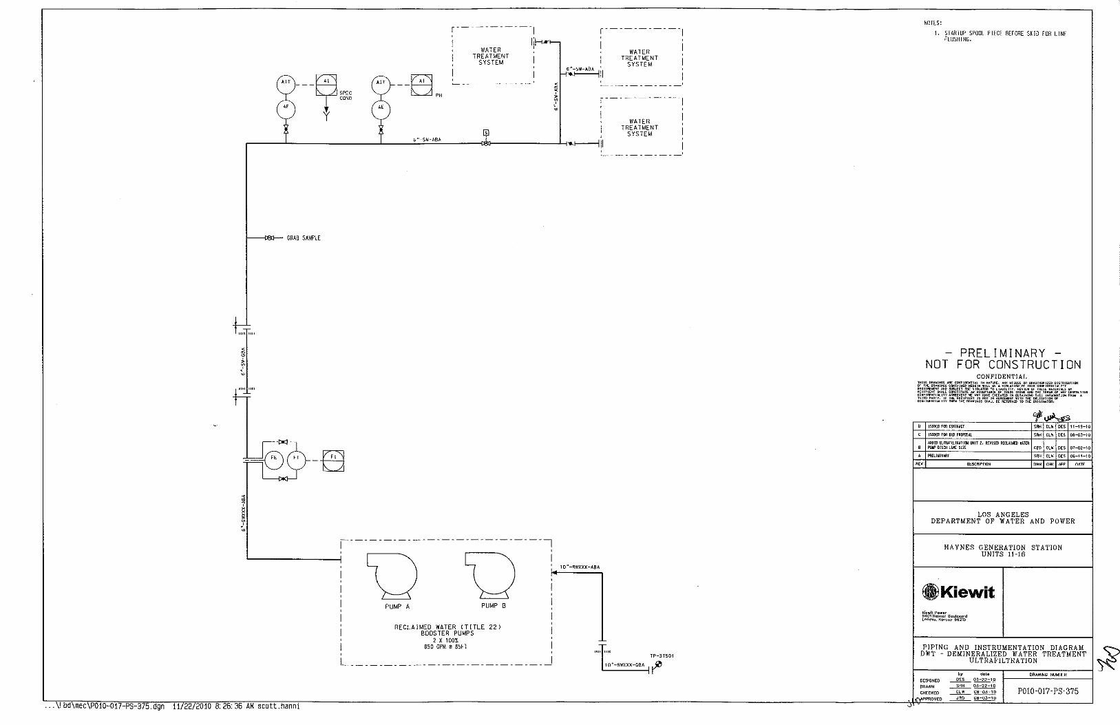
--R,,,, TCOND y
--~ D'"
r-----------1
i lii-<•1-WATER
TREATMENT SYSTEM
' -----------
"'
~-----------1
! WATER I I TREATMENT I
6"-sw-ABA ' SYSTEM -<'--~II
r-----------1
i i ' WATER , I TREATMENT I
SYSTEM ,-------L--______________ _L ______ :_' ";;;.-S;_:W;;;.-A"'B::_A ---------i_T_:0J---------------1-;-o.f-----111
GRAB SAMPLE
f""
I -~
I -8
... \! bd\mec\P010-017-PS-375.dgn 11/22/2010 8:26:36 AM scott.hanni
I
RECLAIMED WATER CTITLE BOOSTER PUMPS
2 X 100'/. 850 GPM @ 85FT
22)
L ___________________________ ~
-----------
TP-37501
1 0"-RWXXX-GBA 1 ~
'
'
' ' ' A
NOTES:
1. STARTUP SPOOL PIECE BEFORE SKID FOR LINE FLUSHING.
-PRELIMINARY -NOT FOR CONSTRUCTION
CONFIDENTIAL
.,~ JSSII£0 FOO COOlfUCT '"" "' '" 11-19-10
JSWI:D fOO: BlD PRlt'OSIJ.. '"" "' '" 06-03-HI
ADDED ULTR.lFillfUTIOO OOJT 2, REVISED REClAUED IATI:R Pt.U' DISCH lUI£ S!Z£ "' '" '" 07-02-HI
PREliWIHAI\Y "" '" '" 06-11-10
'" DESCRIPTIO~ ''' '"" ~· DATE
LOS ANGELES DEPARTMENT OF WATER AND POWER
HAYNES GENERATION STATION UNITS 11-16
®)Kiewit Kiewit Power 9401 Renn.r Boulevard L~ne~o. K<msas 66219
PIPING AND INSTRUMENTATION DIAGRAM I~ DWT - DEMINERALIZED WATER TREATMENT
~------~--U_L_T~R~A_F_I~L_T_R_A_TI_O~N~---------" .. by date DRAWING NU~8ER
DESIGNED ~ 03-22-10 DRAWN ~ 03-22-10
CHECKED ~~ IJ\APPROVED JRO 00-03-10
P0!0-017-PS-375
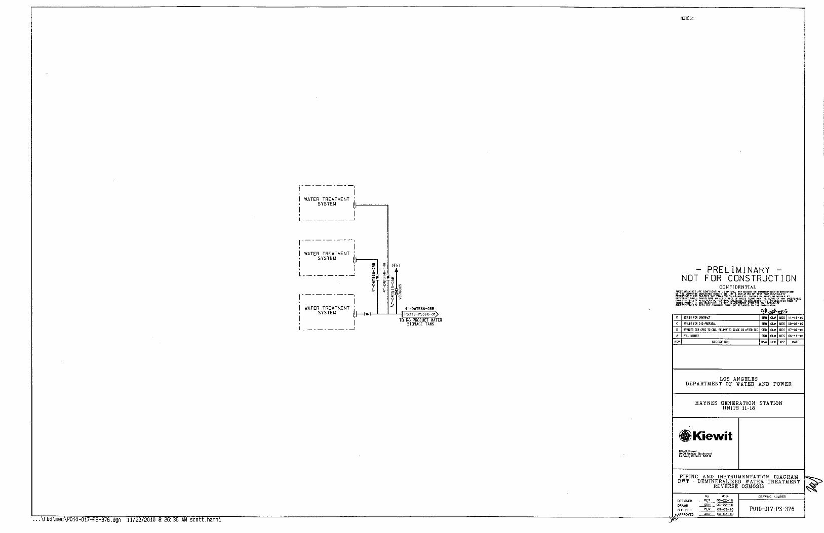
1----------, , I I WATER TREATMENT 'I , SYSTEM If----, I ,
I L _________ __,
1----------, , I I WATER TREATMENT I' ' SYSTEM I~ I , gs , I tt L ' " ---------- ~;
• ~
VENT
"~ ~ ~ )g . ~----------
.,. ~ ~ ? ~ ~ ...
! WATER TREATMENT •1 . _L_l_j~i'~"-~o~"~5~"~"~'!? ' SYSTEM I ~ ..... t- PS376-PS360-01 I ' TD RO PRODUCT WATER I STORAGE TANK L _________ __,
NOTES:
PRELIMINARY NOT FOR CONSTRUCTION
CONFIDENTIAL
LOS ANGELES DEPARTMENT OF WATER AND POWER
HAYNES GENERATION STATION UNITS 11-I6
GlKiewit Kiewit Pow~r 9401 Renn•r Boulevord lene•o. Kon•os 6621!1
PIPING AND INSTRUMENTATION DIAGRAM DWT - DEMINERALIZED WATER TREATMENT
REVERSE OSMOSIS
DESIGNED ~ 03-22-10 DRAWN ____2!lli._ 03-22-10
CHECKEO _..£b!!...._~ P0!0-017-PS-376

[~,~·-~o~w~-o~sf'~>---~~~~ I~ I l PS411-PS377-01) , ~
[~,~·~-~,W~D~BA~~---~ PS3!11 P$377-01) . ~ I '~~1~1
RO PERMEATE STORAGE TANK
10.000 GAL
II_,_,
~ !;; ~ ~
... \! bd\mec\P010-017-PS-377.dgn 11/22/2010 8:26:36 AM scott.hanni
r----------------------------------,
PI
PI
I I
2~X1 1 .-{
f-D rn rn y " • 0
2"X1 1'{ ' . f-D
2"X1''2"
3,4"-DWT-CBB f-D
b~
2"Xt 1.-2" - f-D -
2"Xt 1'2" - f-D
2"X1 1'2"
f-D
11-t-DWT -CBB
I PS377 PS336-01)
TO UNIT 16
11.-{-DWT -CBS
I PS377-PS335 ot) TO UNIT 15
1 ''{-DWT -eBB
I PS377-PS334-01)
TO UNIT 14
11,{-0WT-CBB
I PS377-PS333-0t)
TO UNIT 13
11'2" DWT-CBB
I PS377-PS332-0t)
TO UNIT 12
ti;{-OWT-CBB
I PS377-PS331-0t)
TO UNIT 11
PRELIMINARY NOT FOR CONSTRUCTION
CONFIDENTIAL
l5SU£U FOO C!JITRI.CT SRH CLW PES 11-19-10
ISSUto FOR BID PJilll'llSJ.l SRH C~W DES OB-03-1 0
B fi£V1Sffi CBA & GOO SPEC TO l:llB CEO CLW OES 07-02-10
A PllHJ~INARY SRH CLW PES 06-1\-10
DESCRIPTION OWN CHK N>P DATE
LOS ANGELES DEPARTMENT OF WATER AND POWER
HAYNES GENERATION STATION UNITS 11-16
fi)Kiewit ~;ewlt Power 9401 Rennec Boulevord Lene•<>, Kcnsns 66219
PIPING AND INSTRUMENTATION DIAGRAM DWT - DEMINERALIZED WATER TREATMENT
REVERSE OSMOSIS
by d<>te DRAWING NUMBER DESIGNED ~ 03-22-10 DRAWN ~ 03-22-10
CHECKED ____f.b!!_ ~ POJ0-017- PS-377 APPROVED ~ oa-03-10
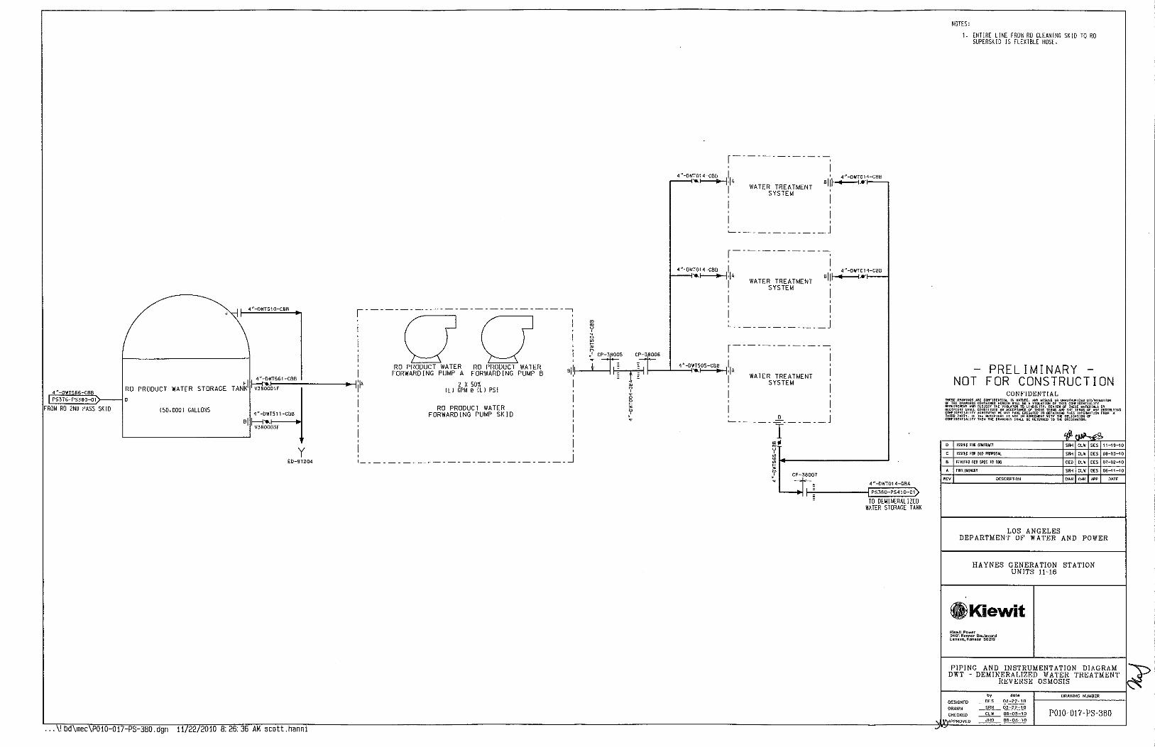
4 "-DWT51 0-CBB ,---------------------------;
!00! RO PRODUCT WATER RD PRODUCT WATER I
FORWARDING PUMP A FORWARDING PUMP B 6
4 "-DWT566-CBB PS376-PS380-01
FROM RO 2ND PASS SK lD
I T ANkl ~£wo!::
0;:;;:.c•_-c;;a::••-l:-----....-j(
4 "-OWT511-CBB
Bl ~~03F L__ _____ __J
RO PRODUCT WATER STORAGE
!SD.DDOl GALLONS
2 X 50"!. !Ll GPM@ Ill PSI
RO PRODUCT WATER FORWARDING PUMP SKID
y E0-97204
I ~---------------------------J
... \! bd\mec P010-017-PS-3BO.dgn 11 22/2010 8:26:36 AM scott.hanni
~ y 0 ~
r-------------; , I
4"-DWT014-CBB I I 4"-DWT014-CB8
---~·lA WATER TREATMENT 8~~~~
I SYSTEM
I :_ ____________ j
r-------------; , I
4"-DWT014-CBB I I 4 "-OWT014-CBB
--->------+-~ 'I A 'Iii--+---<• I WATER TREATMENT
SYSTEM
I ! :_ ____________ j
~ r------------~ ~ CP~-3 0~'5 CP-38006 1 ! I 4"-owrs
1os-cse
111 ~I _:,--,+11---'--'---"i"O- ' A I I WATER TREATMENT
~ SYSTEM
I g ' > I I ... ~----- 8 ______ j
I ~· ~ ~~------------' > J' CP-38007
4 "-DWT014-GBA
I PSJ80-PS41 0-01)
TO DEMINERALIZED Wi\TER STORAGE TANK
NOTES:
1. ENTIRE LINE FROM RO CLEANING SKID TO RO SUPERSK!D IS FLEXIBLE HOSE.
PRELIMINARY NOT FOR CONSTRUCTION
CONFIDENTIAL
g, ISSIIEU fOO CO!Tlti.CI
ISSIIEU fiJI 5!0 PRDPOSlt.
6 R!:VIS[(l GilD Sl'!:C TO COO
A PREUYIHAIIY
OESCRIPnON
·~ ·~ "" ·~ "'"
"' "' 11-19-10
"' "' 08-03-10
"' "' 07-02-10
"' "' 06-11-10
'"' we DATE
LOS ANGELES DEPARTMENT OF WATER AND POWER
HAYNES GENERATION STATION UNITS 1!-16
®ilKiewit Kiewa Po""' 940\ R"""~' Bculevord lon .. c, KMSOS 66219
PIPING AND INSTRUMENTATION DIAGRAM DWT -DEMINERALIZED WATER TREATMENT
REVERSE OSMOSIS
by dole DRAWING NUMBER DESIGNED ~ 03-22-10 DRAWN __2!lli._ OJ-22-1D
CHECKED ~ OB-03-1 D P0!0-017-PS-380 APPROVED _____-!!!Q___ DB-03-10
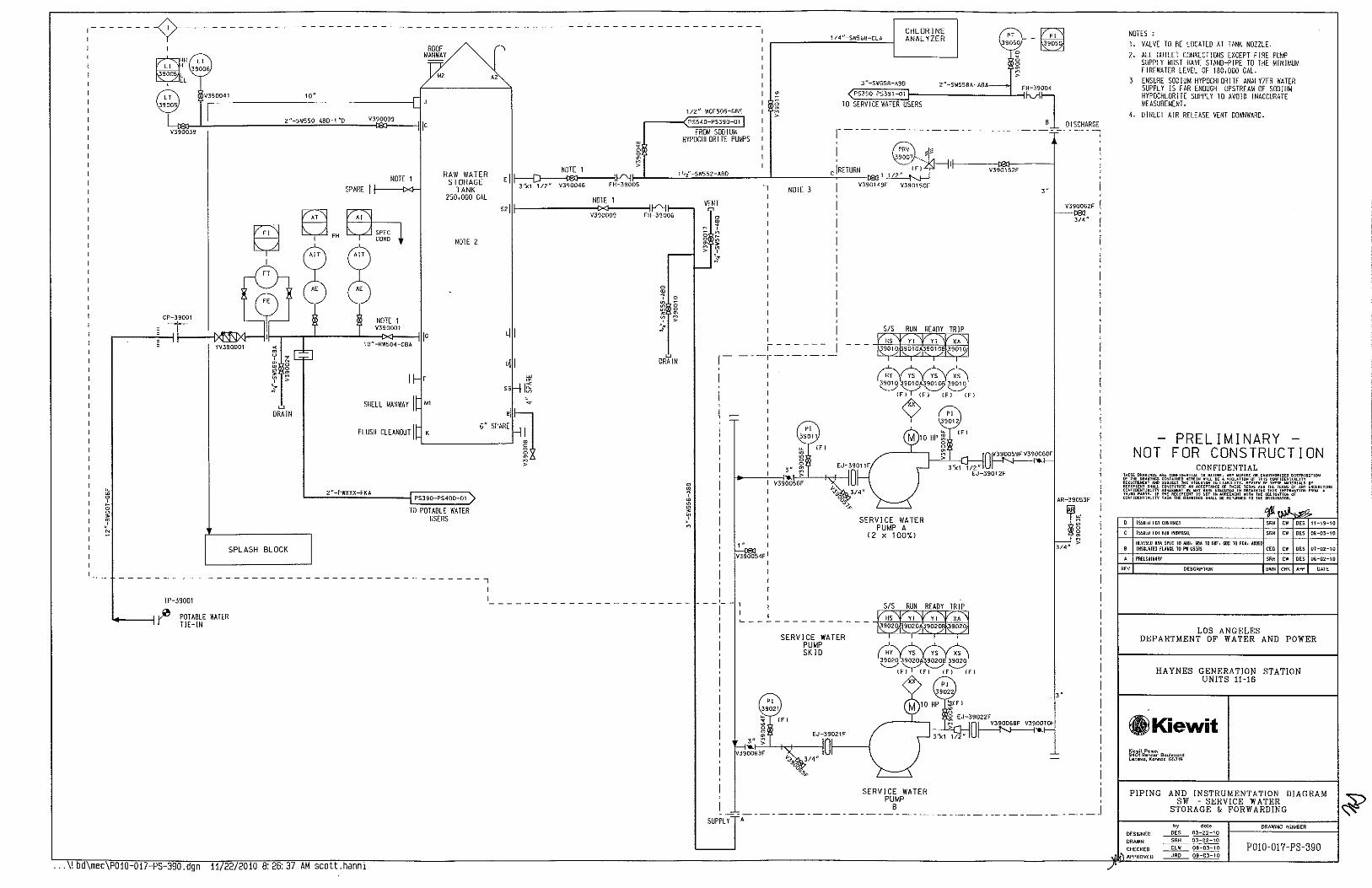
:------- -<Y--------
CP-39001
w DRAIN
NOTE 1
SPARE I f----9<1~
NOTE 1 V390001
RAW WATER STORAGE
TANK 250.000 GAL
NOTE 2
6"
NOTE 1 "1111---------::1?::":::---;:;
V390009
Ljj
oil ~ ~
" I~ ~
sj~ SPARE I FLUSH CLEANOUT I K
L__ ___ ____,
2~-PWXXX-FKA
SPLASH BLOCK
PS390-PS400-01
TO POT ABLE WATER USERS
-----------------------------------------~
TP-39001
POT ABLE WATER TlE-!N
... \! bd\mec\POI0-017-PS-390.dgn II 22/2010 8:26:37 AM scott.hanni
>
w DRAIN
1/2 ~-WCF505-GB£
PS540-PS390-01
FROM SODIUM HYPOCHLORITE PUMPS
I - _,_
I
1"
V390054F
SUPPLY A
I
PI 39011
"'
1/~"-SW$68-CLA CHLORINE ANALYZER " 3'.1050
)7;01 -~
<~~3~"-~S~W~S~SD~-~A~8~DJ,:::--~'~"--:S:WS:S:D:A~-~A:8A====:J--~FH-39004 TO SERVICE WATER USERS
PS390-PS391-01 h._ri1 B DISCHARGE
~-------------------------------------------~
i i
M
SERVICE WATER PUMP A
12 X 100"/.)
PI 39012
'"
V390152F
3" V390062F
AR-J9053F
SERVICE WATER PUMP SKID
SERVICE WATER PUMP
B
NOTES : 1. VALVE TO BE LOCATED AT TANK NOZZLE. 2. ALL OUTLET CONNECTIONS EXCEPT FIRE PUMP
SUPPLY MUST HAVE STAND-PIPE TO THE MINIMUM FIREWATER LEVEL OF 180,000 GAL. ENSURE SODIUM HYPOCHLORITE ANAL YlER WATER SUPPLY IS FAR ENOUGH UPSTREAM OF SODIUM HYPOCHLOR lTE SUPPLY TO AVOID INACCURATE MEASUREMENT.
4. DIRECT AIR RELEASE VENT DOWNWARD.
PRELIMINARY NOT FOR CONSTRUCTION
CONFIDENTIAL
~ JSSUEOFDRC!IHRAI;I '"' " "' 11-19-10
ISSUED FOO BID PRDI'OSIJ. "' " "' os-o3-1o
R£V1S£D IJI~ SPEC TO IJIO, reA TO CBf, GilD TO FKA· IJIDJ: lNSUUTED FLA1ffi[ TO PW USERS '" " "' 07-02-10
PREUWINARY "" " "' 06-1}2-10
"" DESCRIPTION "'" '~ ~' OATE
LOS ANGELES DEPARTMENT OF WATER AND POWER
HAYNES GENERATION STATION UNITS 11-16
Kiewit Power 9401 Renner 8oulevord Lenexc, Kcnsos 6621!1
PIPING AND INSTRUMENTATION DIAGRAM SW -SERVICE WATER
STORAGE & FORWARDING
by <!ole
DESIGNED ~ 03-22-10
DRAWN
CHECKED
DRAWING NUMBER
P0!0-017-PS-390

[~'~"-~s~•~s~ss~-~A~BAE>----------;; -T-: 3 "~swo£l-GBA I PS390-PS391-01) ~ r-~'--,------':...:~;::;.::::;r--------------------------, FROM SERVICE v
391002 ~ WATER PUMPS
2 "-SWXXX-GBA
2"-SW037-GBA
2"-SW039-GBA
2"-SW-GBA
PS391-PS377-01
TO EVAP COOLER SUPPLY
DEMIN WATER TANK UT-391XX
RAW WATER TANK UT-39107
AMMONIA STORAGE UT-39111
SOUTH SIDE OF '-'-'-'C:::0:::..-1 ~----------{~AIR COOLED HEAT EXCHANGERS
2"-SW040-GBA UN IT 16 NORTH
OF CW PUMP SKID UT-39112
UN IT 16 NORTH OF CTG
UT-3911£
L..;;.'".,:-:;:s::"~'::;'-::':::':.'-j '~~~~~~~---·TUNJT 16 WEST OF SCR r r t6: ur-3s117
2"-SW064-GBA
2"-SW077-GBA
UNIT 15 WEST OF SCR UT~39123
UN IT 15 SOUTH OF CTG
UT-39125
2"-SW077-GBA UNIT 15 SOUTH 1-=--::.~:!.:.::~.-j ~-----------1)1... OF CW PUMP SK 10
UT-39125
2"-SW077-GBA UNIT 14 NORTH OF f-:;..,:=c:.c::--1 ~-----------1)1... CW PUMP SKID
UT-39125
2"-SW077-GBA
~~2~"=-s~·~o~77~-~'~'!'_; c~~~~~~~~~~~tr
f-~2~"--5~·~0~7~7-~G~B~A- f-----~~~---ti
3"-SW-GBA
UN IT 14 NORTH OF CTG
UT-39125
UNIT 14 WEST OF SCR
UT-39125
UNIT 13 WEST OF SCR
UT-39125
... \!bd\mec\POlO-Ol7-PS-391.dgn 11/22/2010 8:26:37 AM scott.hanni
< . 0
' " • 0 • f "
2"-SWXXX-GBA 2"-SWXXX-GBA
2"-SW045-GBA
2"-SW-GBA
2 "-SW045-GBA
2"-SW046-GBA
2"-SW046-GBA
2"-SW046-GBA
2"-SWOS2-GBA
2"-SW049-GBA
2"-SWOSO-GBA
2"-SW051-GBA
2"-SW053-GBA
2"-SWOS4-GBA
2"-SW05£-GBA 1 "-ABA
~ 2'X1"
2"-SW057-GBA 1 "-ABA
~ 2'X1"
2"-SW059-GBA
2"-SW0£0-GBA
2"-SW0£1-GBA
2"-SW0£1-GBA
2"-SW0£1-GBA
2"-SW0£1-GBA
2"-SW0£1-GBA
2"~SW061-GBA
2"-SW0£1-GBA
2"-SW0£1-GBA
I PS391--PS262-01>
CW SYSTEM FILL
UN IT 16 NORTH OF AUX SK !0
UT-39106
UNIT 16 SOUTH OF AUX SK !D
UT-3910£
FUEL GAS COMPRESSORS NORTH
UT-39106
ti. FUEL GAS COMPRESSORS SOUTH
UT-39102
UN IT 15 NORTH OF AUX SKID UT-39102
UNIT 15 SOUTH OF AUX SK JD
UT-39101
ti UN IT 14 NORTH OF AUX SKID
UT-39130
ti UN IT 14 SOUTH OF AUX SK 10
UT-39121
ti UN IT 13 NORTH OF AUX SK 10
UT-39103
ti UNIT 13 SOUTH OF AUX SKID
UT-39104
ti UN IT 12 NORTH OF AUX SKID
UT-39106
ti UN IT 12 SOUTH OF AUX SKID
UT-39109
NORTHEAST CORNER OF WT BUILDING
SOUTHWEST CORNER OF WT BUILDING
ti UNJT 11 NORTH OF AUX SKID
UT-39116
ti UN IT 11 SOUTH OF AUX SK 10
UT-39119
ti UN IT 11 SOUTH OF CW PUMP SK 10
UT-39120
ti UNIT 11 SOUTH OF CTG
UT-39120
ti UNTI 11 WEST OF SCR
UT-39120
ti UNIT 12 WEST OF SCR
UT-39120
ti UNIT 12 NORTH OF CTG
UT-39120
ti UNIT 12 NORTH OF CW PUMP SKID
UT-39120
ti UN IT 13 SOUTH OF CW PUMP SK lD
UT-39120
ti UN IT 13 SOUTH OF CTG UT~39120
NOTES:
PRELIMINARY NOT FOR CONSTRUCTION
CONFIDENTIAL
fSSUEO FOO BID PI!!JPIISI.l
A l'll[lJ~fWARl
OESCRIPTIO>I
SRH CUI DES OB-D3-10
SRH ClW DES 06-02-10
OWN CHK APP OAT£
LOS ANGELES DEPARTMENT OF WATER AND POWER
HAYNES GENERATION STATION UNITS 1H6
.Kiewit Kiewit Powor 9401 ReMor Boulevard L~~exo, K<>nsoo 66219
PIPING AND INSTRUMENTATION DIAGRAM SW -SERVICE WATER
by dole DRAWlNC NUMBER
DESIGNED DRAWN ____§_fi!j__ 03-22-10 CHECKED __Eh!__ Oa-03-10 P010-017-PS-391
PROVED ~ OB-03-10
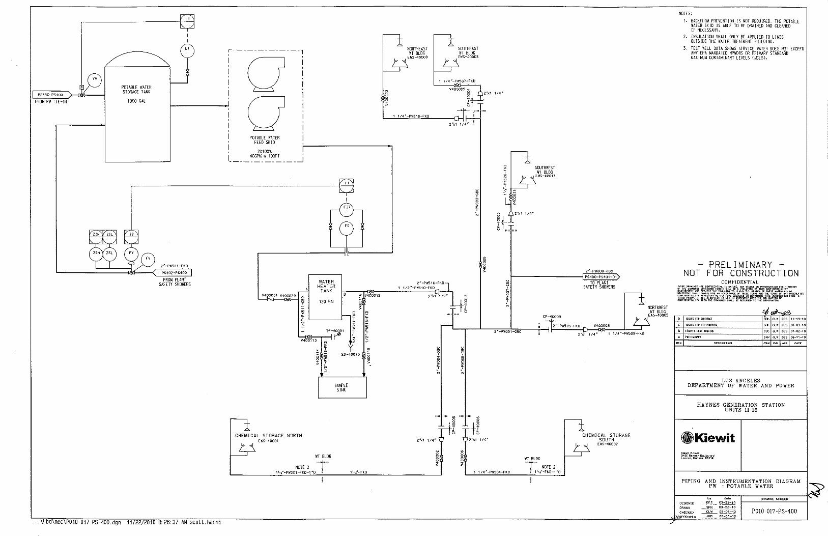
PS390-PS400
FROM PW TIE-IN
POT ABLE WATER STORAGE TANK
1000 GAL
u
2"-PW521-FKO
PS402-PS400
FROM PLANT SAFETY SHOWERS
... \! bd\mec P010-017-PS-400.dgn 11/22/2010 B: 26:37 AM scott.hanni
POTABLE WATER FEED SKID
, 2X100'1. I 40GPM @ 1OOFT I _____________ _j
¥400031 V400029
WATER HEATER
TANK
120 GAL
'-::c~\1:-:,-;rT-IP-~1 ¥400113 ~
~
B
y E0-40010
• ~ N
'
NORTH
SAMPLE SINK
¥400012
N 0
g >
,I
NORTHEAST WT BLDG
EWS-40009
SOUTHEAST \'IT BLDG
EWS-40003 I
1 1/4"-PW507-FKD
1 1/4"-PWSl!l--fKO
2"-PWS\0-FKO 1 112"-PWS\0-fKO
u
! g • :t N
2'l<1 1/4"
u
~ g • :t N
SOUTHWEST WT BLDG
1 EWS-40013
~-----------~Q2~"~-~P~W0~0~6~-G~6~C~ PS400-PS401-01 u
9 SAF~~/~~~~ERS b ~ :t N
2"-PWOOl-GBC
2'X1 1/4''
1 1/4 "-PW504-FKD
CP-40009
2"-PW509-FKD
WT BLDG
J NOTE 2 ~ 11.-{-FKD-1 "0
V40000B
1 1/4 "-PW509-FKO
NORTHWEST WT BLDG
EWS-40005 I
NOTES:
1. BACKFLOW PREVENTION IS NOT REQUIRED. THE POTABLE WATER SKID IS ABLE TO BE ORA !NED AND CLEANED IF NECESSARY.
2. INSULATION SHALL ONLY BE APPLIED TO LINES OUTSIDE THE WATER TREATMENT BUILDING.
3. TEST WELL DATA SHOWS SERVICE WATER DOES NOT EXCEED ANY EPA MANDATED NPWDRS OR PRIMARY STANDARD MAXIMUM CONTAMINANT LEVELS <MCLSl.
PRELIMINARY NOT FOR CONSTRUCTION
CONFIDENTIAL
ISSliED HlR C[IHRlCT
1ssrn:o roo B!O PRCPom S R£1/llVID !lEU TRACING
A PREUWINMII
"" DESCRIPTION
CtD CLW [I(S 01-02-10
SRH CLW [I(S 06-11-10
OWN CHl< 1\PP DATE
LOS ANGELES DEPARTMENT OF WATER AND POWER
HAYNES GENERATION STATION UNITS 11-16
.Kiewit Kiewit Pc .. er 9401 Re...,.,er 8o<Jievcrd Lonoxc, Konscs 66219
PIPING AND INSTRUMENTATION DIAGRAM
t-:::::--~~'~:~W~~-~,"~:~:~T~A~B=L=E==W~:~~~,:~,~:~,,~,~,,~,======~~ DESIGNED ~ D3-22-1 0
DRAWN ~~ CHECKED ~ Oa-D3-1D P0!0-017-PS-400
PROVED ~ 09-03-10

2"-PWOOB-GBC
PS400-PS401-01
FROM HOT WATER HEATER
2"-GBD
( PS401-PS<l02-01
TO PLANT SAFETY SHOWERS
c
' e t ~· -
~"
-H ... ~
~ ~
"" ~-t-FKD
u • ~ c 0 • ~ ' N
u • ~ ~ ~ ~
T3105
- 1
2"x1 1/4" =
TP~~~06 -
2'S<3/4" -
UNIT 11 PCM
1/4n I
UNIT
± 11 AMMONIA
VAPORIZATION SKID SAFETY SHOWER
EWS-40111
314, y
UNIT 11 AMMONIA VAPORIZATION SKID
EYEWASH STAT! ON EWS-40112
=-~0
2"x1 114"
u
~ 0 • ~ TP-~10B N
2''><314"
~ ~ 0 • ~ ~
2"-PW009-GBC
TP-~15
- 1 1/4, I
161
AMMONIA n1 1/4" -
UNIT VAPORIZATION SKID
SAFETY SHOWER EWS-40121
u • y u TP-~~16 ,!_
0 - 314"
• L '2'X314" ~ ~ UNIT 16 AMMONIA ~ VAPORIZATION SKID
2"-PW018-GBC EYEWASH STATION EWS-40122
... \! bd\mec P010-017-PS-401.dgn 11/22/2010 8:26:37 AM scott.hanni
--
--
u • u .:, ~ ~ ~
1 1/4 ~ I ± UNIT 12 AMMONIA
VAPORIZATION SKID SAFETY SHOWER
EWS-40113
I I
314,
UNIT 12 AMMONIA VAPORIZATION SK 1D
EYEWASH STATION EWS-40114
TP-~113
:~ '" 1/4" UNIT 15 AMMONIA
VAPOR I ZA T! ON SK to SAFETY SHOWER
EWS-40119
:-,114 - 314"
y AMMONIA t 2'X 314" = UNIT 15
VAPORIZATION SKID 2"-PW020-GBC EYEWASH STATION
EWS-40120
_.r- TP-i\ 09 - 1 1/4" I ± ,~. 1/4" -
TP-~1.10 -
~14" ; 2"-PW01J-GBC
211 - 1
! 2'X1 1/4" -
0 • • ' ~ TP~~12
-L r'X314" -2"-PW015-GBC
UNIT 13 A VAPORIZATI
MMONIA ON SK 1D HOWER , SAFETY 5
EWS-40
I I
3/4"
UNIT 13 A VAPORIZATI
EYEWASH 5
MMONIA ON SKID TAT ION 16 EWS-401
1/4"1
141
AM UNIT VAPORIZATIO
MONIA N SKID OWER SAFETY 5H
EWS-40117
314" y
UNIT 14 AM VAPORIZATIO
MONIA N SKID AT ION EYEWASH ST
EWS-4011 B
NOTES:
PRELIMINARY NOT FOR CONSTRUCTION
CONFIDENTIAL
ISSUED FOO CIJilRACT
ISSUEO FOR BIO POOI'OSAL
REIIO\ItO HEU TRACING
PRELI~INART
DESC~IPT10N
SRH CLW [IES 11-1 9-1[1
SRH CLW [IES 08-[IJ-10
em CLW [IES [17-[12-1[1
SRH CLW [IES [16-11-1[1
OWN CHK N'P O.O.TE
LOS ANGELES DEPARTMENT OF WATER AND POWER
HAYNES GENERATION STATION UNITS 11-16
til Kiewit Kiewit Power 94[11 Renner B<>ulevord Le....,~o, Kansas 66219
PIPING AND INSTRUMENTATION DIAGRAM PW - POT ABLE WATER
by date DRAWING NUMBER OEStGNto ~ [13-22-10
OR.O.WN ~ [13-22-10
CHECK[[) ~ 08-[IJ-1[1 P0!0-017-PS-401 PROVED _l!.!.Q___ 08-[IJ-1 [I
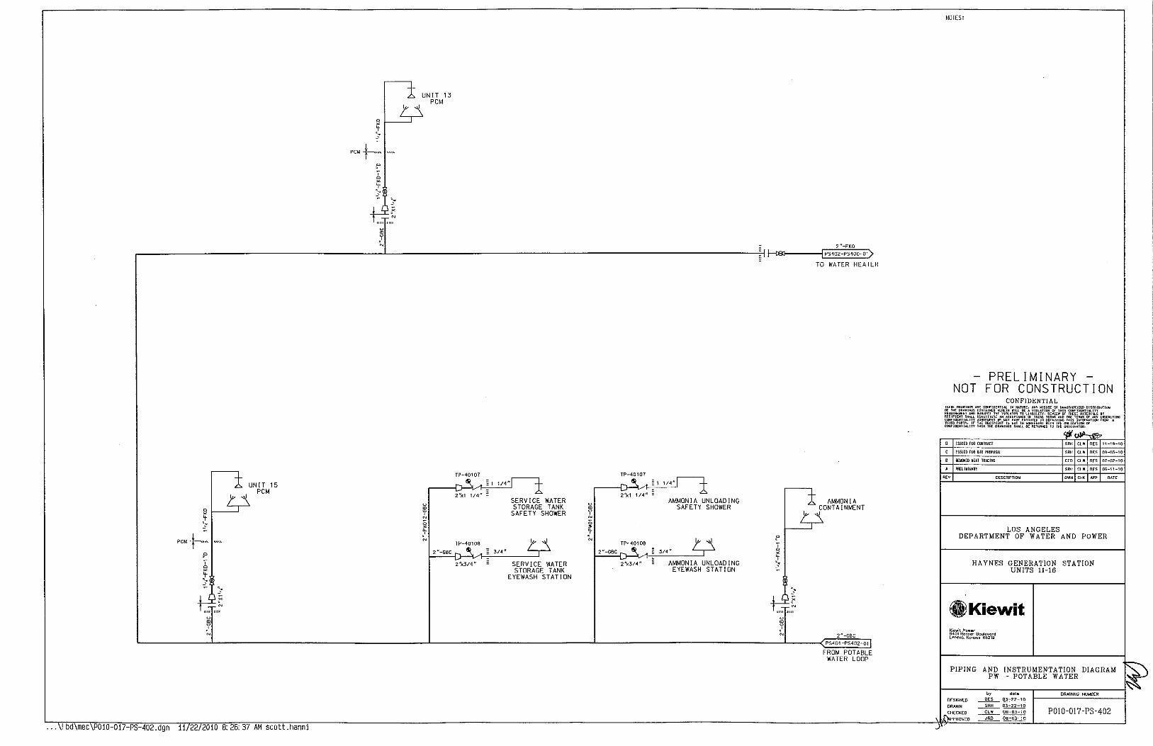
PCM +---"'
u . J
X
N
UNIT 13 PCM
"---------~~,~-~--~'~'~'~~ r------------------------------------------------------------1------------------------------------------------------------------------------------------~:1~- )PS402-PS400~1)
X
N
UNIT 15 PCM
11 22/2010 8:26:37 AM scott.hanni
u • u ~ 0
~ ;,
TP-40107
2'Xl 1/4"
TP-40106
2"-GBC
2'X314"
~ 1 1/4"
SERVICE WATER STORAGE TANK
SAFETY SHOWER ~ u ~ 0 • ~ ;,
- 3/4"
SERVICE WATER STORAGE TANK
EYEWASH STATION
TP-40107
~ 1 1/4"
2'S.:1 1/4" AMMONIA UNLOADING
SAFETY SHOWER
TP-40108
2"-GBC 3/4"
2'X3t4" AMMONIA UNLOADING EYEWASH STATION
u
J N
TO WATER HEATER
AMMONIA CONTAINMENT I
2"-GBC
PS401-PS402-D1
FROM POTABLE WATER LOOP
J
NOTES:
PRELIMINARY NOT FOR CONSTRUCTION
CONFIDENTIAL OI"Aial!TI'"' 1";)1~ ••
~:::;~~·l:ll"'
'"" "' "" 11-19-10
ISSUED FOR BID PI«<''SAl '"" '" "" oa-m-10
l!£110V£D HW TRACING "" "' "" 07-()2-10
PR£lt~IWARY '"" "' "" 06-11-10
'" OESC~IPTION "'" '"" ~ DATE
LOS ANGELES DEPARTMENT OF WATER AND POWER
HAYNES GENERATION STATION UNITS 11-16
i8Kiewit Kjewit Po,.er 9401 Rennor 8m>1evord l•nexo, Kcnsos 66219
PIPING AND INSTRUMENTATION DIAGRAM PW - POTABLE WATER
by dcte DRAWING NUMBER
DESIGNED ~~
P0!0-017-PS-402 DRAWN ~ D3-22-1 0
CHECKED .........£!:..! ~ PROVED ~ 08-03-10

4"-DWT014-GBA
PS380-PS410-01
FROM MIXED BED UNITS
u 41005
NOTE 2
30" MANWAY- "
"'
VENT n
~~';"-~o~w;s~,,~-B'~"~"~------------~'~H-41oo,'------------------_, ( PS410-PS411-011 lf-1'-lf- (]]-------------. 6)(4" l TO CTG DEM!N USERS
DISCHARGE ,. 6
-----------~----------------------------·
41010
"' RETURN' V-410117
NOTE 1 2"-DW501-CBB-1 "D DEMINERALIZED WATER STORAGE
TANK
iPcP~yo
V410115 FH-41005 3"-DWS09-cBA I V410173F 2" _,~,~-~------------------l HI ~~;:::....L-~.,----,----------------_:_.::......::::::::...::,:r~J,~.-. ''~if--'-~,~-_:_~,.~,r:,~,l;;72F V41 01 71 F 1--t>.,_.;.-_ __;__ __ -ill'
V410100 ~0· g
> VENT 1:1~
Ll 41006
' - . 0 • • > 9
CP-41010 ~v
w DRAIN
____ j
I
NOTE 1
VENT n~
Ll ~ X
~ 9
CP-410XX ~...-
· 500,000 GAL
st [ 2 1/2" SPARE
NOTE 1
g ~ . 9 > ~ ..
FH-41001
'I +---=:J:-:--,----IV'-If---+> V410106
a!
6"-DWSOS-CBB
w
~----- ---------: DRAIN
L------!Clb51J I , I L ____________ _
STERILL!ZAT!ON RECIRC SKID
NOTE 2 FH-410XX
2"-DWXXX-CBB-1 "0 DEMINERALIZED WATER STORAGE
TANK 500,000 GAL
"' f--+--<xl---;V'-Iif---JL-..-----' NOTE 1
30" MANWAY l M1
S1 I 2 1/2" SPARE
4 "-DWTXXX-CBB NOTE 1
f.--.r--l.-----IMI---!><1----l!o
w DRAIN
FH-41 OXX NOTE 1 6 "-DWXXX-CBB 2" SPARE
I 'II f---__:_-l:><J--,----IV'-IIf---~
6"-DWXXX-CBB
1--------------:
L-------..:!Clb51J I
I L ____________ _
STERILL!ZAT!ON RECIRC SKID
. . y
E • 5' N
FH-41 OXX
DRAIN
_____________ _j
I
6'
PI 41011
'" ~
M 40 HP
;; 3/4"
~ ~----"-~--~·~~~'~''}'~-~~ 4" ~
3/4" 314"
V410165F V410167F
V410166F V410168F
"'!':r:s"' 6" 6M '"'" 6"
3/4" V410153F 410151
F 3/4" v
• 0 314"
'" V410154F
DEMINERALIZED WATER PUMP SK 10
P-DW-001A
DEMINERALIZED WATER PUMP
PI 41012
PI 41021
A 12 X 100%l
~~5 GPM @ 250 FT
S/S RUN READY TR! P
IPl
~,HOS2x~~x~~J:1xt2J
~ 41 020 41 020A410208 41020
~F~F~F~FJ
'V "' . . M 40 HP
;; 3/4"
> ~--Lif-__'~'~"~'('l-' ·:._,~ h--~·,·1-~-~
" . ;; 3/4"
~
P-DW-001 B DEMINERALIZED WATER PI
PUMP 4102
B (Fl
V410161F V410163F
314" 314"
V410160F V410162F
V41016!1F 314"
3/4" AR-41012F I
V410174F
3/4"
V410170F
'"
L--------------------·---·---------------------------·J A SUPPLY
... !bd\mec\P010-0!7-PS-410.dgn 11/22/2010 8:26:38 AM scott.hanni
NOTES:
1. VALVE TO BE LOCATED AT TANK NOZZLE.
2. OVERFLOW AND FLAPPER VALVE PROVIDED WITH TANK.
PRELIMINARY NOT FOR CONSTRUCTION
CONFIDENTIAL
ISSI.I£0 fOO CIJIIAAtT '"' "' 11-19-10
lSS!I£0 fOO SID PRIPOSAL '"' "' "' 08-Q3-10
' R£110\tD H£AT IRIC!HG, REVISED SPEC Ca4 TO CIIB '" "' "' 07-02-10
' PREliYlNI.RY '"' '" "' 06-02-10
"" OESCRif'TION ''" "" ~· OATE
LOS ANGELES DEPARTMENT OF WATER AND POWER
HAYNES GENERATION STATION UNITS 11-16
GlKiewit Ki~wa f'ow~r 940111enner 8culevord lene.c, Konsas 65219
PIPING AND INSTRUMENTATION DIAGRAM DWS - DEMINERALIZED WATER SYSTEM
STORAGE & FORWARDING
by dote DRAWING NU~8EII
DESIGNED ~ 03-22-10 DRAWN ~ 03-22-10 CHECKED __fh!(__ 08-03-10 P0!0-017-PS-410
PROVED ~ 08-03-10

4 "-DWS516-CBA
PS410-PS411-01
FROM DEM!N WATER PUMPS
VENT n
f'
~ 0 ~ > .
~ c ' ~ ..
PT 41101
;;
> . m u ' ~ . ~ 0
' ;.
DRAIN
CP-41101
3 "-DW-GBA
r--i PS41\-PS377-01
EVAP COOLER SUPPLY
6"-DWS021-GBA
... \! bd\mec\P010-017-PS-411.dgn 11/22 2010 8:26:38 AM scott.hanni
CP-41102
3"-DWS012--GBA _
CP-41103 DRAIN
V411 001
3 "-DWS 101 -CBA-1 "D
PS411-PS336-02
TO UNJT 16 DEMJN WATER INJECTION PUMP
~ 3~2" ~;-------------------------------~2~"~-o~W;'~'~0~2~-C~B~A~-~1"D f-----------------''c"c-o~w~'"'"'"'c-""~''-''----11-DI-· ----------,cc<<e:JI:::------------<C83 I Ps4 , 1-PS336 -o3) V411002 V411027 TO UNIT 16 WATER
WASH SYSTEM
CP-41104
-...j.. 3"-DWS201-CBA-1 "0
----~o_:o_~J,I_~~~~----------------~~~ ,-- PS411-PS335-02
g: V411003 TO UNIT 15 DEMIN WATER INJECTION PUMP l,i'-OWS205-C8A-1 "0
~~' L.~~~~~"-~C-P~S 3'X21-~_,'_'_'_' ______ _,~ ~;,~------------------------------~2i";·~O~W,~2~0~2~·~CB~A~-~'~"O v•a- 3"-DWSO\S-GBA -i ~ 1.'041-------------c-<1.'04 jPS411-PS335 01)
~ V411004 V411024 TO UNIT 15 WATER
,1 WASH SYSTEM
_c41o6
~ I ~----:=:~:-----~~~~---------------------------------------------:~3~"-D~Wf'f3~0~,-~C~B~A~-~'":>.0 r-----------~,_~,f- PS411-PS334-02
~ V411005 TO UNIT 14 OEM!N WATER 0 INJECTION PUMP
CP-41107 DRAIN
~ ~~2" 2"-DWS302-CBA-1 "D
.CL.!_"~"!)!"~"'~7~C~A~ -----~~~------~~:;;~------------------~~~~~ wr -u :>u , ~~: 1.'04 jPS411-PS334 01) 0 V411006 V411025 ~ TO UNIT 14 WATER J WASH SYSTEM
"
6"-DWS-GBA
PS411 -PS412-0\}
TO OEMIN USERS
NOTES:
1. GASKETS AND BOLTING FOR CBA/GBA FLANGED CONNECTIONS SHALL BE PER SPEC GBA.
PRELIMINARY NOT FOR CONSTRUCTION
CONFIDENTIAL
ISSUED FOR Cllltll~CT
ISSUED FOR B!D l'llllPDSIJ.
R£110\ltD HEU m~CIHG CEO CLW DES D7-02-10
PRELIYINI.Ilf SRH CLW DES OG-02-10
DESCRIPTION OWN CHK >PI' OATE
LOS ANGELES DEPARTMENT OF WATER AND POWER
HAYNES GENERATION STATION UNITS 1!-16
il,lKiewit Kiowi\ Po .. or 94DI Renn•r Boulevord leMXO, K""SOS 56219
by dota
DESIGNED ~ 03-22-10 DRAWN ~ 03-22-10 CHECKED ~~ APPROVED ~ OS-03-10
DRAWING NUMBER
P0!0-017-PS-411

NOTES:
1. GASKETS AND BOLTING FOR CBA/GBA FLANGED CONNECTIONS SHALL BE PER SPEC GBA.
,-t- 3"-0WS2'01-CBA-1 "0
PS41 2'-PS333-02)
3,4"-!WS205-CBA-1 ~ N vqttoo3
TO UNIT 13 DEMIN WATER 0 INJECTION PUMP
" >
6"-0WS-GBA < DRAIN 6 "-DWS021 -GBA 0
~~2" 0 2"-DWS202-CBA-1 "D PS411-PS412-01 .:. 3"-DWS015-GBA I PS412-PS333-01) FROM OEMIN 0 tel tel WATER PUMPS ~ V411004 V411024
TO UNIT 13 WATER ? WASH SYSTEM ;.,
.
~ 0 ,-t-' 3 "-DWS301-CBA-1 "0 N 0
PS412 PS332 02 ~
3,{-0!5305-CBA-1~ • V411005 0
N TO UNIT 12 OEM!N WATER ' PREL IMINARY ;., 0 INJECTION PUMP - -~ NOT FOR CONSTRUCTION
DRAIN CONFIDENTIAL <
~" .RE COHI'JDENIIAl. II< I<AT ... E. ""'U]Sl,_E OR lii<AUl-JZEU UJS!RJSUTIDOI 0 2"-DWS302-CBA-1 "0 0 CDIIUIN!:U "E0£1~ .ILL BE A VIOlATJDOI OF THIS CIIOIFJDENHAl.!U
' 3 "-DWS017-GBA . 1Ps4t2-PS332 ot)
SUOJEOT THE Vl!llUM TO ll"'-lliTY. R .. I[W OF THESE ""TERIAl.< BY w tel tel COO<TiiUTE A!< ACCEPTANCE Of THESE IER .. Alii! TH£ ttR ... Of OJIY UHllERLYING ., AoRE[IIEtll ... ~OY H.VE EMEWTED IN DIIUit<II<O Till< JM"M~ATJOO '""" • 0 V411006 V411025 1"£ RECIPIENT I<""' IN Ml0£EI<ENI Willi IK£ OI!LIG.TIOOI (II"
~ . TO UNIT 12 WATER ' ,., THE" lH£ D!U.WU«,_ SHIJ.J. 5< RHUfiHED TD THE MIOINATOII.
0 WASH SYSTEM
~~.£ ' n
" ISSII£D fOO ClllTR.I.CT ''" "' "" 11-19-10
" ISSIIED fOO BlO PRll'DSI.L "' "' "" 08-03-10
• REIID'/EliiiEAT JR~CIHG "'" "'' "" 07-02-10
' PRtliWlHIJIY '"' '" "" 06-02-10
'" O~SCRIPTION "'' "" we OAT£
,-t- 3"-0WS401-CBA-1 "0
3f{-D~WS405-CBA-1 c V411007 PS412-PS331-01)
LOS ANGELES ~ TO UNIT 11 DEM!N WATER DEPARTMENT OF WATER AND POWER g INJECTION PUMP
l6'X3"
~
>
• ~DRAIN HAYNES GENERATION STATION ffi 2"-DWS402-C8A-1 "0 UNITS 11-16 ' 3"-0WS018-G8A . I PS41 2-PS331-02 > N
3'X2" tsO tel
0 V411 00!1 V411026 ~
. TO UNIT 11 WATER ? WASH SYSTEM ~
iJ)Kiewit Kiewil Pcwer 9401 Renner BC\Jiev<lrd Lenexc, Kansas 66219
PIPING AND INSTRUMENTATION DIAGRAM •
~ DWS . DEMINERALIZED WATER SYSTEM
" d<lle DRAWII>IG NUMBER r" DESIGNED "" 03-22-\0
DRAWN ~03-22-10
P0!0-017- PS-412 liD ~HECKEO ~ 08-03-10
APPROVED "'" 08-03-10
... \! bd \ mec \ POlO 01 -7 PS 412.dgn 11/22/ 2010 8: 26: 38 AM scott.hanni -'

~~ < <
~ ~ >
" ~ " 0
< ¥471008 <
~ ~ a ~ . 6"-FP017-GAA
0 ~
6"-FP028-EMB ------
IAUX SKI 0 FIREWATER. ' VALVE ENCLOSURE I I ____ #1_§_ ____ ,
;;
" . >
0
~
>
6"-FP017-GAA
6"-FP028-£MB ------
AUX SKID FIREWATER! ' VALVE ENCLOSURE I I_-- _':'12- ---,
8"-FP013-GAA
8"-FP014-EMB
" r 0
TP-471 XX
~ f----',':"l-"-"------''"'c"-o>"'"'~'.!.' -:'e:'~''--,
6"-FP017-GAA
AUX SKID FIREWATER VALVE ENCLOSURE L ____ _~t1_4__ ___ _
¥471006 < <
~ ;; • ~
~ .
0 . >
0
~
" >
AUX SKID FIREWATER VALVE ENCLOSURE ,
I _____ #'~------~
~--.~~~--1 CONTROL & WATER
TREATMENT BUILDINGS
HYD-47108
~
6"-FP032-GAA
.... --;;,--, , . ' ' .
0 . ~
AUX SKID FIREWATER I I VALVE ENCLOSURE I I ____ _ mL _____ ~
8"-FP013-GAA
8"-FP014-EMB
,---------------, MAIN FIRE PANEL
CONTROL ROOM
~ ~ TROUBLE
~ ~
FlRE
AUX SKID FIREWATER VALVE ENCLOSURE
I_---- _#_1_1_---- ~
1 0"-FPOOS-GAA
;;
>
V471004
6"-FP009-GAI\
0 HY0-47103
--------! 0 ~YD-47102
,-- ~~ i XFMR ~'j::T§ -r--r---r--r--+~' ~ • GSU I ,r§! =>!=I=>!= 1-~~
TP-471XX
L--'-'r"'~'-""""" ~ ~'-r~f----1=>1=-• ..-~ =>!=-,---• ..--;!, :'-'d x:~u~ L _ _: ~ ~ ""' I cP-47120 'f ~ 't' N NORTH TRANSFORMER
• .. I ~ .-. DELUGE ENCLOSURE I ~ ~ ~ j ~ 1'( 0. I
~ L~-~----------~
~----; - I CENTRAL TRANSFORMER ' I XFMR tt' ' I DELUGE ENCLOSURE I •GSU;!I\Ijj; ' L ' ~--~- ... -r-~, I
_.........,CP-47126! y !l_c:-471_2~------------------'
q ~ ~ -l, CP-47120 SOUTH TRANSFORMER ~ ~o ~ ~ DELUGE ENCLOSURE ~ ~ ~
I "' I ' J, ~
L----------~-~J ~ ~ . ~ . 0 0 0 . . . " " " •' _, _, <D ';, -
••• \ 1 bd\mec\P010-017-PS-471.dgn 11/22/2010 8:26:38 AM scott.hanni
PRELIMINARY NOT FOR CONSTRUCTION
'"
CONFIDENTIAL
ISSUEO FOO COOTRlCT
ISSUEO FOR Bin PROI'OSIJ.
DHH£6 TID SUPPliES TO Xfl,fl AU~
PRHl~INARY
DESCRIPTION
"" "' "" "' "" "' "" "' "" '"'
DISm!BUTIOII
'"'-'" ....... ~~ ~~~""!'>10
"' 11-19-10
"' 08-03-10
"' OT-02-1'0
"' 06-02-10
~' DATE
LOS ANGELES DEPARTMENT OF WATER AND POWER
HAYNES GENERATION STATION UNITS 11-16
®)lKiewit Klewlt Power 9401 Renner Boulevard Lenexo, Kon~o• 66219
PIPING AND INSTRUMENTATION DIAGRAM
DESIGNED
DRAWN
CHECKED
APPROVED
FP FIRE PROTECTION
by dote
____QfL_~ ~03-22-10
DRAWING NUMBER
POJ0-017- PS-4 71

~------------------------------------------,
CIRCULATING WATER CORROSION INHIBITOR
PUMP SKID
HY -----r - - - - - 53101
•---'->~"'''-""-'"'"-''e.'c:'::-'"'"J _____ I :4l I C
if ?,.r ·- ···-·-·---1- ' 1/3 HP -~ YS Yl ---- y---- 3101A ----- 3101A RUN
> ' I CIRCULATING WATER I ' I CORROSION I NH I B !TOR PUMP
Fill ~ CIRCULATING WATER [ 112n-TcFSOG-GBJ ' 10 GPH@ 75FT CORROSION INHIBITOR TOTE !U A
1000 GALLONS I NOTE 1
~-------------------J
CIRCULATING WATER 'CORROSION INHIBITOR PUMP [ 10GPH@75FT
t - --- - ~--- -- -e~~j REMOTE
I ~ ~ :-----~------~STROKE
~--- ---@- ----- ti::~ ALARM
I
1----- 53121
A " v---- 3121A
:------22} _____ _ :-----~------
CIRCULATING WATER CORROSION INHIBITOR PUMPS CONTROL PANEL
B
! I L------------------------------------------
... \! bd mec P010-017-PS-530.dgn 11/22 2010 8:26:38 AM scott.hanni
1/2 "-ACF507-GBJ
PS530-PS262-Q1
1/2 "-ACF507-GBJ
PS530-PS262-02
1/2 "-ACF507-GBJ
PS530-PS262-03
112 n-ACF507-GBJ
PSS30-PS262-04
J
NOTES:
1. OWNER PROVIDED TOTE WITHIN CONTAINMENT BASIN.
PRELIMINARY NOT FOR CONSTRUCTION
CONFIDENTIAL
0 ISSUEO FOO CIJIIRACT "" "' "' 11-19-10
c ISSUEO F£11 BID PROPOSAL "" "' '" 08-03-10
' REIIll\I!D •Alt P£1.{lJ!AliOOS "' "' '" 07-02-10
' PREliWIHARY "" "' "' 06-11-10
"'" OESCR1f>TION ,.. ~ ~· PATE
LOS ANGELES DEPARTMENT OF WATER AND POWER
HAYNES GENERATION STATION UNITS 11-16
0Kiewit K;ewil Power 9401 Renner Bouievor<j lene><c. K<>r>$0$ 66219
PIPING AND INSTRUMENTATION DIAGRAM
DESIGNED
DRAWN
CHECK EO
APPROVED
ACF ACHE CHEMICAL FEED
by <lcte DRAWING NUMBER
____Qf£_~ SRH 03-22-10
c;::w- 08-03-10 POI0-017-PS-530 JRD OB-03-1 0
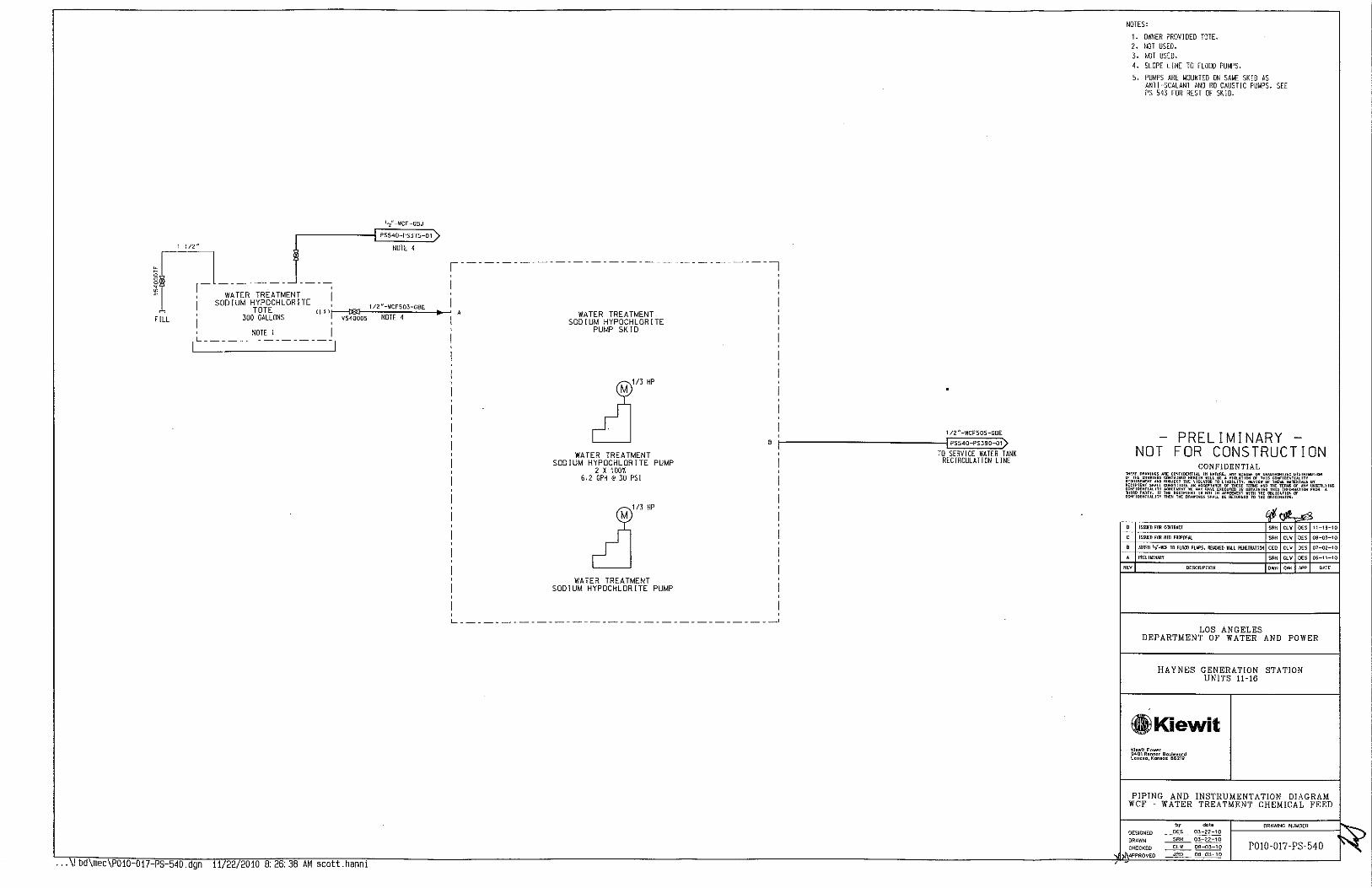
1,2"-WCF-GBJ
PS540-PS375 01
1 112" NOTE 4
,-----------------------------------!
I if7~ ---;,~ TER- TR~AT~ENT--- i I SODIUM HYPOCHLORITE ' 112"-WCF503-GBE , TOTE <U l~r-'--"':N~O~T~E~4;:::...;;.:;:_-to•~ FILL I 300 GALLONS V540005
A WATER TREATMENT SODIUM HYPOCHLORITE
PUMP SKID NOTE! I L---------------
... \! bd\mec P010-017-PS-540.dgn 11/22/2010 8:26:38 AM scott.hanni
'
cd]'"" WATER TREATMENT
SODIUM HYPOCHLORITE PUMP 2 X 100'/.
6.2 GPH@ 30 PSI
WATER TREATMENT SODIUM HYPOCHLORITE PUMP
1/2 "-WCF505-GBE
B ~~.--------------------------:j1Qe~S~5~40~-;P~S3~9~0~01) TO SERVICE WATER TANK
J RECIRCULATION LINE
L------------------------------------1
NOTES:
1. OWNER PROVIDED TOTE. 2. NOT USED. 3. NOT USED. 4. SLOPE LINE TO FLOOD PUMPS.
5. PUMPS ARE MOUNTED ON SAME SKID AS ANTI-SCALANT AND RO CAUSTIC PUMPS. SEE PS-543 FOR REST OF SKID.
PRELl M I NARY NOT FOR CONSTRUCTION
CONFIDENTIAL
ISSUED FOR C!JHRACI SRH CLW DES !1-19-10
SRH CLW DES OS-03-10
B AOOI:D 1•{-leF TO ILOOO PUll'S, REilii'W WAll P[IIURAI!OO CEO CLW DES 07-02-10
A PRrliK!HAIIY SAH CLW OES 06-11-10
OESCRIPnON OWN CHK N'P OAT[
LOS ANGELES DEPARTMENT OF WATER AND POWER
HAYNES GENERATION STATION UNITS 11-16
(j)Kiewit Ki~wit Pow~r 9401 R~nner 9oo.oleVQrd LenexQ, Konsos 66219
PIPING AND INSTRUMENTATION DIAGRAM WCF - WATER TREATMENT CHEMICAL FEED
by dote
DESIGNED ~ 03-22-10
DRAWN ~ 03-22-10
CHECKED ~ 08-03-10 P0!0-017-PS-540 APPROVED ~ OS-03-10

SYSTEM
~ ¥
I
RUN
0 ¥
I
~ ¥
I
A 1 R COMPRESSOR A 1 1--_;':..".;.-:.:":;:'::."~-r":::':.._.,
1285 SCFM
y ED-97025
112"-IAGOl-CLA
~ I
~ I
y ED-97024
1285 SCFt.!
y ED-97023
112"-!A610-CLA
w <
' N
'
< w <
~ <
' ~
6'X4"
0 w >
V561132 6'X4"
;;
... \! bd\mec P010-017-PS-560.dgn 11 22/2010 B: 26:39 AM scott.hanni
~ <
~ <
'
"' 56103
"
<
~ ,' N
'
SET @
150 PSIG
< • < ~
~ w 0
' >
~
TEMPORARY COMPRESSOR CONNECTION
____ , ______
WET AIR RECEIVER
2400 GAL
NOTE 2
2"-!A553-ABA
PI rcvo5f.,~1H0c,o,T-\sslo1
IFI
V561107
3/4 "-1 A537-ABA
,-----------~
W;J ~ TBL
,-----<~• 8
6'):4 ~ I I , :___- ~----- -"'7"-- J
' 2
~ ~ f ~ . ~ 0
' ]" ' N N
~ '
'----ID-+--,' 8
TR-56104F 6'X4"
y ED-97022
I (F l
~ ~
TBL
, I L-=------~--_;
" D2 < < • • < <
~ ~ ~ ~
' ' ~
N
'
6'X4"
6"x4"
~ ~
' :.,
V561108 8'X6"
< w u ' N
0
~
I w
PSV 56107
" SET @
150 PSIG
DRY AIR RECEIVER
4800 GAL
NOTE 2
2"-!ASS~-ABA
r-cvc56:!,~,q0c9c,,--{s:, 1os
IFI
w 0 >
0 8'\(6"
V56111 0 EJ-56101
J/4 "-1 A536-ABA
TR-5610BF
~ ¥
I
PT 56160
CP-56101
NOTES:
1. NOT USED. 2. VENT TO SAFE LOCATION. 3. AIR DRYER HAS INLET AND OUTLET ISOLATION
VALUES ON SK 10
- 6"-JA025-GBH
I ~ I PS560-PS567-o1)
= TO INSTRUMENT AIR USERS
.)
PRELIMINARY NOT FOR CONSTRUCTION
CONFIDENTIAL
ISSU!:D fOil COOffiACT
JSS\J£0 fOO BID PRDPOSAL
PREliN!NAliY SRH CI.-W DES 06-02-10
R£V OESCRIPT!ON OWN CHK APP llAT£
LOS ANGELES DEPARTMENT OF WATER AND POWER
HAYNES GENERATION STATION UNITS 11-16
il,lKiewit !liewil Power 9401 Rermer Bo~levord Lenello, Konsos 66219
PIPING AND INSTRUMENTATION DIAGRAM !A -INSTRUMENT AIR
by dole DRAWING NUidBER DESIGNED ____Q§____ 03-22-10
P0!0-017-PS-560 DRAWN ~ 03-22-10
CHEC!IEO ~ 06-03-10
PROVED __::1.!!Q____ 06--Q3-1 0

2"-IA-GBH
PSSO 7-PSSGl-01
FROM COMPRESSED AIR LOOP
2"-IA-CBA
( PS561-PS331-02
TO UNIT 11 J3 BEARING
3"-IA-GBH
PS567-PS561-02
FROM COMPRESSED AIR LOOP
... \! bd\mec\P010-017 PS 561.dgn
SET @
100 PSIG
CBA CLA
2"-!A-GBH ~I T '"t -IA-CLA ~~--~;.~
;: 2"x1-t CBA CLA
2"-IA-GBH T '-{ -IA-CLA t...::.._:::..=~-~
-
NORTH OF AUX SKID
TO CTG FUEL GAS
VALVES
TO GEMS
1 "-IA-FKD
((;:es~S~G~I~-~e~53~3~1~0~3}---£>31J-------;:r:--1! I~ 2"-IA-GBH
TOAUXSKID 2':;;" II~ WATER WASH
SET @
100 PSIG
SOUTH OF ~-~2 _"-.:.IA:..·.:."::."'J AUX SKID z"x3,/ _
TO CONTROL 1, 2, -lA-CLA VALVE AND +-"--':...:.::... _ _,
REGULATORS
2"-IA GBH
SOUTH OF CW PUMP SKID
2"-[A-GBH ~ 1 ''-:[) "-::-----!BJI---E~I~"~-~IA~-~F~K0~0 =I r PS561 PS331-01)
- 2"x1" TOCWPUMP SK lD
1'1
T}-~-~sr---~-T·r-------~r----~--~---~~'~"-~'~'-~'~''~-'1 'e-~-, ' -
11/22/2010 B. 26.39 AM scott.hann1
SET @
100 PS!G
rc2c"c·ci~A:-CeB~"'---=-l~ I J,,.,"-!A-FKDCC? ,.~ WEST OF SCR
- 2"x~'/
2"-IA-06" § o o " r-_L,-I,C,},-,LL::!.!::!~'-.~~ I I 2"x1" I
TO AMMON I A CONTROL PANEL
1"-!A-FKO
PS561-PS331-04)
TO AMMONIA DILUTION SKID
CBA CLA
'---~2-"-:I~A~-~G~BH~----~ T I;{-IA-tLA r -~ TO ISOPHASE
BUS DUCT -
L __ _o2_"-:o.:IA::-~'e'o"---,O.-
-
SET @
55 PSIG
TO BLEED HEAT CONTROL
VALVE
SOUTH SIDE OF CTG
-PRELIMINARY -NOT FOR CONSTRUCTION
CONFIDENTIAL TH;,£ OI .. WINGS ARE C!""' Ill. IN NAt I>' THE OR •• INOS COOTAI ""O!JIAE""WT AND SUBJ<C f<ECIPIEHT .HAll COtl'ST[ CDHFIOEkTIALIYY ACREEIIEHT K ~·· THif<fl PAATY. IF THE RECIPIENT r• WNFIII£HTIM.IT1 THEN"'£ DRAOIHOS
C ISSU~D FOO «r!TRM:T
8 JSSU~D FOO 8JD PROPDSAL
A PllHl~lii.I.RY
'" DESCRIPTION
III .. IITHORIZ£0 DISTRIBUT[OO THIS CDNI'!D£HTlAL!1Y
a' '""'" ... , .... l. "' TilE TERIIS OF ANY UHDEI'Il. YIOO
"" '"" '""""""''"""""". Ill THE ll!lliGAT[IIN Of TO THE M!G!HAt(lR,
SRH CUI DES 11-19-10
SRH CUI OES DB-03-10
SRH CUI DES 06-02-10
OWN CHK N'P O<'.TE
LOS ANGELES DEPARTMENT OF WATER AND POWER
HAYNES GENERATION STATION UNITS 11-16
.Kiewit Kiewa P~wer 9401 R~Mcr Boulovord l<!noxo, Xon•os 66219
PIPING AND INSTRUMENTATION DIAGRAM' R !A • INSTRUMENT AIR
UNIT 11
by dole DRAWING NUMBER
O(SIGNEO ~ D3-22-10
DRAWN
'
. k ClfECKED I~ \APPROVED
~~ .........9:.!._ oe-o3-1o
JRO 06-03-10 P010-017-PS-561

2"-!A-GBH
PS567--PS562 01
FROM COMPRESSED AIR LOOP
2"-IA-CBA
<, PS562-PS332-02
TO UNIT 12 J3 BEARING
,._''"''"
2"x1"
... \! bd\mec\P010 017 PS 562.dgn 11/22/2010 8.26.39 AM scott.hann1
SET @
100 PSIG
PS562-PS332-01)
TO CW PUMP SKID
TO CONTROL VALVE AND
REGULATORS
TO 2"x1 1'2" F IL TERHOUSE
PULSE AIR
(PS562-PS332-03 TO AUX SKID 2"x1" WATER WASH
SET @
100 PS!G
SOUTH OF AUX SKID
2"x3-~"
SET @
55 PSIG
TO BLEED HEAT CONTROL
VALVE 2"x''2"
SCR SEAL 1, 2"-!A-CLA A I R DAMPER -+---"'--":..::::::_,
SET @
100 PS!G
, .. _,_""'' ~ ~
1. 2"x3'4"
NORTH SIDE OF CTG
CBA CLA
g ~{-!A-CLA .-~--~,.~
2"x1'2"
TO CTG FUEL GAS
VALVES
~ 2"-!A-GBH
~ 2"-!A-GBH
- 2"-!A-GBH
-
2"-!A-GBH --
2"-!A CBA
,. "'
' ' '
1 "-IA-FKO
" 2"x1"
CBA CLA
TO CEMS
WEST OF SCR
TO AMMONIA CONTROL PANEL
PS562-PS332-D4
TO AMMONIA DILUTION SKID
TO T ''2"-IA-CLA
~ ISOPHASE
2"x1'2" BUS DUCT
-PRELIMINARY -NOT FOR CONSTRUCTION
CONFIDENTIAL fHESE DRAWINGS • ANY WISUS< OR lii .. UTHORIWI DISmiH"TION
4 VIOL4T!<m Of" TIHS C""'!O£!<TI4\.lTY I481CITT. f!OVI(W OF THESE IU.T[AIA\.S 8l
OF THE DRAWINGS A~OUIAE...:Nt 4ND SIIBJEC RECIPIENT SHAU <:aNSll COI<FID£Nfi41.JTY A<>JI£! THIRD PARfY. IF THE R£ COII!'ID .. ITIAciTY litEM HIE
THESE TEA"" 4ffll THE T£!1"" or ANI UND£R\.YUfO IIT£0 IN (lBUINENO THIS INFORlHT]flll FRElll 4
NDI IN J.GREEOIENJ •I Til THE OOLIOATIDH !IF SHAll 8E RETURNED TQ IN[ ""IC)IOU(>"l.
<-~-~ ' ISSUED Ftll C!JIT!!~Cl "" "' "' 11-1S~10
' ISSUED Ftll BID Pl«lf'IISI.I. "' "' "' 08-03~10
• PR£LIYI~ARf "' "' "' 06-02-10
'" OESCRlPTIO~ ,., '"' ~· DATE
LOS ANGELES DEPARTMENT OF WATER AND POWER
HAYNES GENERATION STATION UNITS 11~16
.Kiewit K;~.,i\ Pow~r 9401 Ro~n~r Boule•ord leMKO, K<msos 66219
PIPING AND INSTRUMENTATION DIAGRAM !A - INSTRUMENT AIR
UNIT 12
r------e'c'c'•c"c'cc"c""='=''c_ ____ _,~ POI0-017-PS-562
by date
DESIGNED _QfL 03-22-10 DRAWN .........2B!!._ 03-22-10
I.J'I. C~~CKED ____9:_\L_ ~ \'IX. 'jAPPROVED JRD OB-o3-10

2"-!A-GBH
PS567-PS563-0\
FROM COMPRESSED AIR LOOP
SET @
100 PSIG
j-2_"_-_,_-_c_B_H ___ ~o-j: I ~I 2"xl,{
CBA CLA
- T 1•{ -IA-CLA
1--D-------te>-- 2"x1'{
CBA CLA
- T 112" -IA-CLA
~ - 2"x11{
NORTH OF AUX SK lD
TO CTG FUEL GAS
VALVES
TO C[MS
Y ~~~fps@JG 1'•2''-IA-FKD
<~~=;;g~~-j_ __ .:c,~o,__--{:l;<)------:;(~f::-111 ~ 2"-IA-GBH (PS563-PS333 OS I I :
TO FILTERHOUSE 2"x1 1•{
TO CONTROL VALVE AND
REGULATORS
PULSE AIR
-1 II~ 2"-IA-GBH <~~~~"~-~~·~-~'~'~'~}---ooo---------~~J:-1 <_PS563-P5333-03 1 1 :
TOAUXSK!O 2"x1"
SCR SEAL AIR DAMPER
WATER WASH
SET @
100 PSIG
SOUTH OF :;: 2"-IA-GBH
AUX SKID 11:;: 2"x31{ -
<~~2~"~-~~,!-c~a~·~-------{~~~l:(~}-----~~--_l-{I}_l----~~-----~Jt'~------------~~------JL----_j----~~~2~"-~l~'-~'~''~--~ '",'; <_PS563-PS333-02 L...W
TO UNIT 13 J3 BEARING
3"-IA-GBH
... \! bd\mec\P010 017 PS 563.dgn 11!22/2010 B: 26:39 AM scott.hanni
2"-IHBH '
'
SET @
100 PSIG
SOUTH OF CW PUMP SKID
1 "-IA-FKO
PS563-PS333-01
TO CW PUMP SK lD
WEST OF SCR
TO AMMON I A CONTROL
I PANEL
2"-IHBH ', '' t--j~-tal--~1 "-~IH~<D ~ PS563-PS333-04)
2"x1" TO AMMONIA DILUTION
SET @
55 PSIG
SK !D
TO ISOPHASE BUS DUCT
TO BLEED HEAT CONTROL
VALVE
"'
-PRELIMINARY -NOT FOR CONSTRUCTION
CONFIDENTIAL 1>1tSE DR•WI!<GS .RE CONFIDENTIAl IH I<U,..t. AMY WISUS< GR I>' TMt DR.~INOS CDNTAIN£D HOREIH Will BE A VIOUIIDN I>' REiliiiR .. £NT •Ill> SUBJEcT THE Vlllt.UGR TO liABiliTY. REVIE RECIPIENT SH,ll CDNST!TUTE AH AcoEPTm<E DF THESE TERM> toHFIDEHri.U.lf"r •GR>:EIIE>Il lfE WAY H.V< EXECUT£0 II< <H>TAIH TiilRD PM<Tr. IF THE RECIPIENT IS NOT IN AORE£11EN1 WITH I CDNFIDEI<TIOI.ITY THEH THE ~RAWIHGS !;\lOI.l 8E RETIIAAI'D TOT
cj.~3 ' ISSUfD fOO J:(IIJRACT "" "' "' 11-19-10
' ISSU£0 fOO BID PRIPUSA!. "" "' "' 06-0)-10
• PREliYHIARY '"" "' "" 06-0Z-10
"" otSCRIPTION ,., ~· - OAT£
LOS ANGELES DEPARTMENT OF WATER AND POWER
HAYNES GENERATION STATION UNITS 11-16
ill Kiewit Kle .. it Power 9401 Renner Bou\ovord Lenexc, Konsoo 66219
PIPING AND INSTRUMENTATION DIAGRAM lA - INSTRUMENT AIR
UNIT 13
"' dale DRAWING NUMBER DESIGN£0 '" 03-22-10
DRAWN ~03-22-10
P0!0-017-PS-563 [,rt CHECKED ~08--{13-10
APPROVED '"' OO--D3-10
~

- -IPS567-PS564-01
FROM COMPRESSED AIR LOOP
SET @
100 PSJG
2"-IA-GBH~ NORTH OF AUX SKID - 2"x3'{
SET @
100 PS!G
2"-!A-GBH ~ NORTH OF
- 2"x3•4" CW PUMP SK JD
2"-lA-GBH ,.. 1 "-!A-FKD - PS564-PS334-01 ) - 2 "x1" TO CW
PUMP SKID
2"-JA-CBA
"y SET@ 100 PSJG
(PSSG<-Pm<-" ·~ 11•2"-!A-FKD
TO 2 "x1''2" F! L TERHOUSE
PULSE AIR
1" !A-FKD ( P$564-P$334-03
TO AUX SKID 2"x1"
WATER WASH
SET @
too PS!G
SOUTH OF AUX SK 10
TO BLEED HEAT CONTROL
VALVE
SCR SEAL 1,2"-!A-CLA AIR DAMPER
TO CONTROL ,,2"-IA-CLA
VALVE AND -4----'-"'-=C:.., REGULATORS
2 "K3;4"
SET @
55 PS!G
- 2"-!A-GBH
-
- 2"-JA-GBH
-
- 2"-!A-GBH
-
- 2"-JA-GBH I ~
PS564-PS334-02 T]--'----tE»-----<ok>---------ts:l----_jL_ __ _jL_ ______ -tE,_....:._.:;;_;::::--j f-:----, <~~~~~~-----{:J>kc}----!SJ--_1---{ 2"-!A-CBA
TO UNIT 14 -J3 BEARING
NORTH SIDE OF CTG
TO CTG FUEL GAS
VALVES
2"-IA-GBH -
-
1 "-IA-FKD
2"x1"
TD CEMS
WEST OF SCR
TO AMMONIA CONTROL PANEL
PS5Ei4-PS334-D4
TO AMMONIA DILUTION SKill CBA CLA
~_.~~~------~~~ TD !SDPHASE BUS DUCT
... \! bd\mec\P010-017-PS-564.dgn 11/22 2010 8:26:40 AM scott.hanni .J
PRELIMINARY NOT FOR CONSTRUCTION
CONFIDENTIAL
ISSUED roo t!JIIHACT
ISSU£D roo Bin PHDPOS.l!.
A PH£LIMIHARY SRH CL\11 DES 06-{)2-10
'" DESCRIPTIO!< OWN CHK Al'P OA.TE
LOS ANGELES DEPARTMENT OF WATER AND POWER
HAYNES GENERATION STATION UNITS 1!-16
.Kiewit Kfowit Power S401 Renner Boul~vord Lenexa, Konsoo B6219
PIPING AND INSTRUMENTATION DIAGRAM !A INSTRUMENT AIR
UNIT 14
~-----'~'='="="'~'"="=''~'c_ ____ "~ P0!0-017-PS-564
by dole
DESIGNED .........Q!.L~ DRAWN ~ 03-ZZ-10
CHECKED ~ OB-03-10
APPROVED ---=:!!.!.Q___~
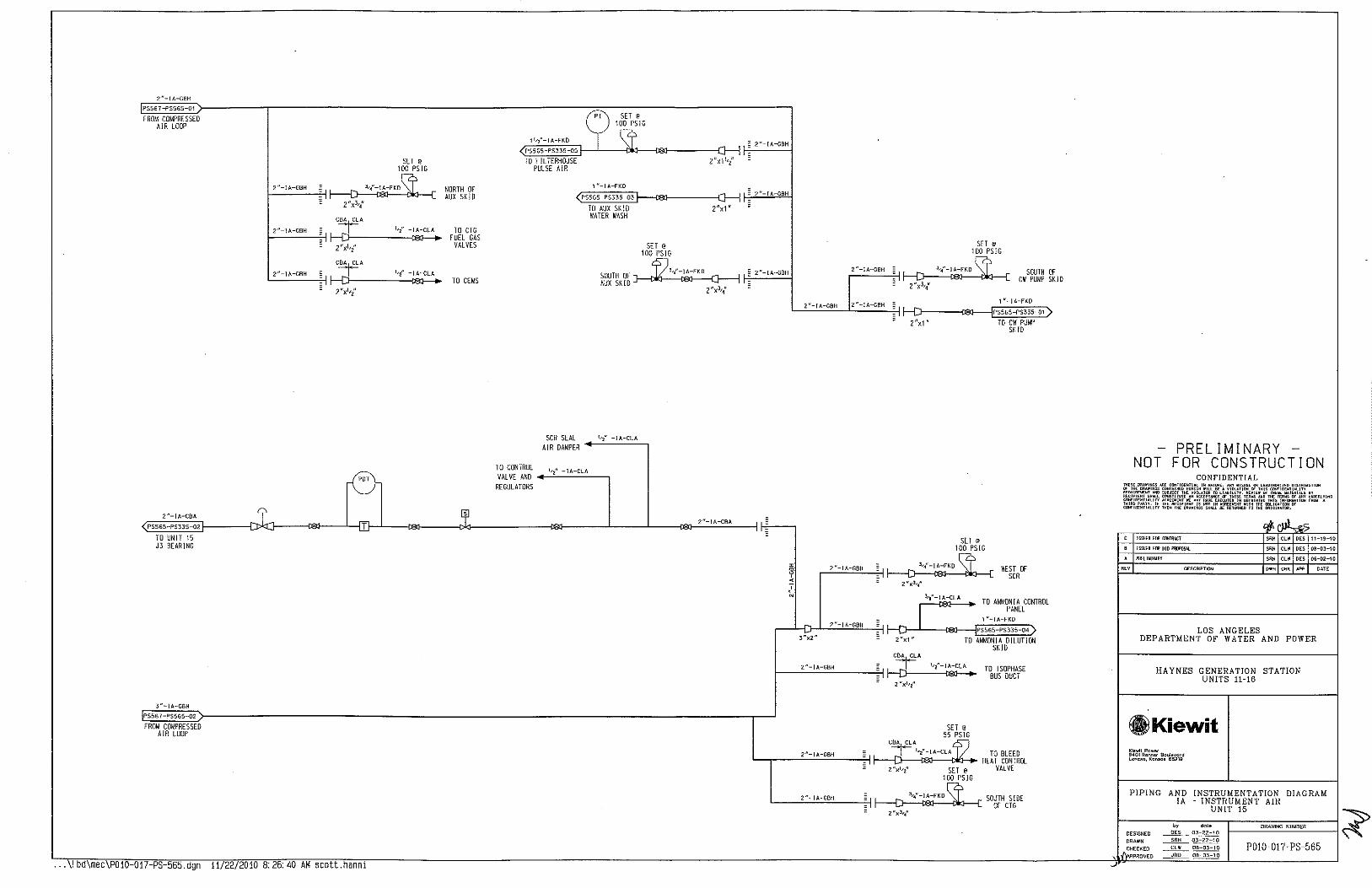
2n-IA-GBH
PSS67-PS56S-01
FROM COMPRESSED AIR LOOP
2"-!A-CBA
<;_PSS65-PS335-02
TO UNIT 15 J3 BEARING
3n-IA-GBH
jPS567-PS565-02
FROM COMPRESSED AIR LOOP
. -.11 bd\mec\P010 017 PS 565.dgn 11/22/2010 8:26:40 AM scott.hanni
SET @
100 PSIG
NORTH OF AUX SKID
TO CTG FUEL GAS
VALVES
TO CEMS
11f2n-!A-FK0
(PS56S-PS335-05
TO F I L TEAHOUSE PULSE AIR
n SET'
~l~IG I. ~ 2n-IA-GBH
z"x1 1rz" ' ' ~
1n-IA-FKO
<~PS~S~6~S~P~S~3~3S~0~3}---t8CI-----:;:r,-1' ~ TO AUX SK!O Z"x1"
1
~ 2"-IA-GBH
TO CONTROL VALVE AND
REGULATORS
SCR SEAL AIR DAMPER
WATER WASH
SET @
100 PSIG
SOUTH OF 0~,{-JA-FKO -
AUXSKID~ 2"x3r4" -
2n-IA-CBA
2n-JA-GBH _
r"'c"c-.c"o-o'"'""---~ "
2n-IA-GBH
c_ __ c2c"c-o'!'c-o,s~Hc_ __ ~--
2"x1"
I 2"x1"
SET @
100 PSIG
SOUTH OF CW PUMP SKID
1 n-IA-FKO
PSS65-PS335-01)
TO CW PUMP SKID
SET @
100 PSIG
WEST OF SCA
TO AMMON I A CONTROL PANEL
1 n-IA-FKD
PSS65-PS335-04)
TO AMMONIA DILUTION SKID
SET @
55 PSIG
TO ISOPHASE BUS DUCT
TO BLEED HEAT CONTROL
VALVE
SOUTH SIDE OF CTG
-PRELIMINARY -NOT FOR CONSTRUCTION
CONFIDENTIAL
C !SSUEH fOO C£1llRI.CT
B ISSUED Hill 8!0 PRDI'OSIJ.
l'llHIWJJ<AIIY
'" DESCRIPTION
SRH CLW DES 11-19-10
SRH CLW DES DB-03-10
SRH CLW DES 06-02-10
OWN CllK pPp DATE
LOS ANGELES DEPARTMENT OF WATER AND POWER
HAYNES GENERATION STATION UNITS 11-16
GlKiewit Kiewit Pcwer 9401 Renner a""'"""'d Lenexo, Kcnsos 66219
PIPING AND INSTRUMENTATION DIAGRAM lA - INSTRUMENT AIR
l":,:,,:.:,:,~,-~~;~i,~~,,~-~·;~~:~~~0N~I~T==1=5==~o~'~'w~'~''~'~""'~'~'======~ ~ DRAWN ~ 03-22-10
.~!~~~~0 ~~~ ~:~~=~~ POI0-017-PS-565

2"-IA-GBH
PS567-PS566-01
FROM COMPRESSED AIR LOOP
2"-IA-CBA
<._PS566-PS336-02
TO UNIT 16 J3 BEARING
3"-IA-GBH
PS567-PS566-02
FROM COMPRESSED AIR LOOP
f-----''-"_-,_1 'o-"'"''-"~~-i -
2"x~,{
... \! bd\mec\POIO 017-PS 566.dgn 11/22/2010 8: 26: 40 AM scott.hanni
SET @
100 PS!G
NORTH OF AUX SK !0
SET @
100 PSIG
1 "-]A-FKO
NORTH OF CW PUMP SKID
PS566 PS336-01)
TO CW PUMP SK 10
A SET@
1
~100 PSIG
<PSSGC-Pm,-OS .(J: TO
F IL TERHOUSE PULSE AIR
1 I~ 2"-IA-GBH .. f-','-'-"-'--"9
<~~~~~~------------~~~·~~~·~~~'~'-:~:--1 ,_-"'-=--"' c" -c'"'"-"'"'""1 <P.S566-PS336-03 _, 1 I;_ TO AUX SKID 2"x1" WATER WASH
SOUTH OF AUX SKID
SET @
100 PSIG
SET @
55 PSIG
~~ :~--''c""-o'o'=-'~'""~ 2"X~'4" I I =
CBA CLA
'-----~-"'c"=-·1'>-;G•B•"--~~-jj cJ 1~"-J~LA ~ TO BLEED
HEAT CONTROL VALVE ~ J-;-------':·_·-c1c'c-="="'----'
~ 1
2"x 1'2"
TO CEMS
2"-IA-GBH~
SCR SEAL 1- 2"-JA-cLA
AIR DAMPER
TO CONTROL 1,2"-IA-CLA
VALVE ANO +---"'-"'--":.::., REGULATORS
NORTH SIDE OF CTG
CBA CLA
~{-IA-CLA .----'-----=-!-~
TO CTG FUEL GAS
VALVES -
-
2"-IA-CBA
I w ? <
'
3:;2"
2"x3;{
SET @
100 PSIG
WEST OF SCR
TO AMMONIA CONTROL PANEL
2"-IA-GBH~ J f-~;f .-,:,-:j__..:.'~"'-~1~,<-~FK~O~--§~~~~~) PS566-PS336-04)
- 2"x1" TO AMMONIA
CBA CLA
f---'2-"-~1~·~-G~B~"C-------~-~ DILUTION SKID
TO ISOPHAS£ BUS DUCT -
"
-PRELIMINARY -NOT FOR CONSTRUCTION
CONFIDENTIAL lfl05 .Rl' C<IH'IOEHtiAI. OR u••UTHfl!IJZ[D DJ<TRia<JTJ(lN
ODNT>I!<ED "'""" r,,1;"1: ~~~o~~~~~!;':~ a• SUIIJEOl TH< VIlli. CllnSlllUl£ AN AC '"~~g ~::is'i~~~,t:::; r.faSFil.XINo
In •"'"""""' IE.,., If THE; R£CI"Itm IS THE Ofll.IGAliDN OF COHr ITY 1HE:N T"E DRAWINOS D TO THE OI!IGifl .. QR.
'1- loi> "
' !SSU£0 fOR Clliili~CT Sru< "' '" 11-19-10
' ISSUED fOO 810 I'IUlPOSI.I. '"" "' "' 05-03-10
• PREli~IHIJ'Il '"" '" "' 06-!12-10
'" OESC~IPTION ''' '"" ~' OAT£
LOS ANGELES DEPARTMENT OF WATER AND POWER
HAYNES GENERATION STATION UNITS 11-16
GlKiewit Kiewit Powec 9401 Rennor Bou\ovocd Lon~•o. Konsos 86219
PIPING AND INSTRUMENTATION DIAGRAM !A - INSTRUMENT AIR
UNIT !6
" da\e DRAWING NU~8ER DESIGNED '" 03-22-10
DRAWN ~03-22-10
P0!0-017-PS-566 ,1()~HECKED -...9:!!...._ 06-03-10
APPRO \lEO "' 06-03-10
~

6" !A-GBH jPS560~PS567 -01
fR OM AIR COMPRESSORS
SET 10 100 PSIG
~ WT BLDG
2x3-~"
SET @
100 PSJG
~ WT BLDG
3;{-IA-FKD
2x''4"
C!RCWATER ~ EXPANSION TANK....,~
SET \00 p
0 SIG
DIESEL ?J '·-"-' '-"~" ''l-IA-FKD
GENERATORS~ 2x''~"
'4"-IA-FKO DIESEL 3
GENERATORS ------a----1 2x''4"
2x3'l
- 2"-!A GBH
-
- 2"-!A-GBH
-- 2" !A-GBH
-
2"-!A-GBH --
2"-!A-GBH
- 2"-IA-GBH
- 2"-!A-GBH
2"-!A-GBH
" • 12"-JA-GBH m ~ ~ < <
' ' N N
2"-IA-GBH
---{PSSfi7-PS566-01)
TO UNIT 16 EAST
" m 0
' <
' ;,
I 3" JA-GBH
r---iPSS67-PS566-02)
TO UNIT 16 WEST
... \! bd\mec\P010-017-PS-567.dgn 11/22/2010 8:26:40 AM scott.hanni
-
-
--
J
--
SET @
100~ SOUTH J,{ -I A-FKD - 2"-tA-GBH
FG COMPRESSORS 3
, -2x '4
l.-4"-!A-FKO - 2"-IA-GBH FG VALVES --------o---1
2XJ-'{ -[
A-GBH I 3,~"-!A-FKO '~"-FG COMPRESSOR 3~ zxl,/ -
J,~"-JA-FKO
FG COMPRESSOR 2~ - 2"-!A-GBH
2x3'4" -3,4"-!A-FKO 2"-IA-GBH
FG COMPRESSOR 1 --------o---1 -
~s0
IG 2x3'4" -
NORTH FG COMPRESSORS
2x3'4" ~ ~
3,4"-tA-FKO ' ~ FG VALVES N
2x3'4"
3.-/-!A-FKO ~ FG COMPRESSOR 4
2x3'i
J.
2"-IA-GBH zu-IA-GBH
'----j PS56 7 -PSS 65-{)1 L....--..iPS567-PS564-01)
TO UNIT 15 EAST TO UNIT 14 EAST
3"-IA-GBH 3"-IA-GBH
r-----!PS567-PS565-02} r---iPS567-PS564-02)
TO UNIT 15 WEST TO UNIT 14 WEST
l 6"-IA-GBH
.I J_ 6"-IA-GBH
2"-IA-GBH 2"-IA-GBH 2"-!A-GBH L....-...-jPS56 7 -PSSGJ-01/ l....__...jps567-PS562-01) l--..fPS567-PS561-01)
TO UNIT 13 EAST TO UNIT 12 EAST TO UNIT 11 EAST
3"-IA-GBH 3"-IA-GBH 3" IA-GBH r--JPS567 PS563-02) ..----IPS567-PS562 oi'> r---iPS567-PS56\-02)
TO UNIT 13 WEST TO UNIT 12 WEST TOUNIT11W£ST
T
PRELIMINARY NOT FOR CONSTRUCTION
CONFIDENTIAL
ISSUED roo tooiRACT
ISSUED roo 810 PRIPOSll
OCLHED SUPPLY 10 AIIIUIIA STOllAGI:• FIR£ l'lM' IIOOS£, RtVJS£0 SUI'IU TO ClRC IAiffi [XP JMj~
Pll£LIN!NARY
0E5CR1PT!ON
CEO CL'II DES Dl-0:2-10
SR~ CUI DES 06-02-10
OWN CHK M'P OAT£
LOS ANGELES DEPARTMENT OF WATER AND POWER
HAYNES GENERATION STATION UNITS 11-16
fi)Kiewit K;ewll Power 9~01 Rennoc 13oul&vocd Lenexo, Kcnso• 66219
PIPING AND lA
INSTRUMENTATION DIAGRAM INSTRUMENT AIR
BOP
by dele DRAWING NUMBER OES1GNEO ~ 03-22-10
DRAWN ~~ CHECKED _____fh!!____ 06-DJ-1 0 P0!0-017-PS-567
PROVED ~~

4" FLAME ARRESTOR
VENT
" 2"-CW-ABA
3 "-CW-EMD - PS262-PS640-01 ,-- --~----------
I 3"x2" - FROM ACHE
E3 ~
' I I 2"-CW ABA
3 "-CW-ABA
9 _L"'"'"! -fr , .. ,,,, .. "' ' ''{ FDL ABA ''2"-FOL-ABA COLUMN I PS640 PS260-01
' VENT .L. , .. ,, .. TO ACHE
FOAM ~ FOAM I I CHAMBER
I I CHAMBER I -- ---1
T .
T '
I PUMP 01A I FILL 2"-FOL-ABA I BACKUP I CONNECTION " _(/ ~
I I 1 "-CW-ABA ' DIESEL '
0 ' GENERATOR I
DIESEL FUEL I
~ I ' '
NO 2 I 01 I . STORAGE TANK I m 15.000 GAL I . L _______ l '
~ ), 0 I I ~ ;., // '
I I PUMP 01 B I
CJ ' I I
2"-FOL-ABA : BACKUP DIESEL 1 "-FOL-ABA GENERATOR I DRAIN PUMPS
~ ' 2 X 100"/. ' 2" LEAK
I 173.3 GPH @ 10 PSJG I ' MONITORING
~ L----------------J
' " ~ ~~ ,----------------1 - PRELIMINARY -
I
~ I
NOT FOR CONSTRUCTION ; CAC
2"-CW-ABA CONFIDENTIAL
COLUMN I I __ _L ___ I
lH"E oo••II<Oi AA£ C""'IDENTIIJ. IN ~~~~£ ,:" ~~~:;::~~~~~ ~!~~~ou<l<>< a T><t: OR••tuo• CONTU""D RERE)H w
VENT Rt:gUI!!f;...-NT M!1l SUBJECT 1HE VIOL• lTV. RrYIEW fY THES£ II<TERIA!.S BY
' RECIPI£HT SNIJ.l catlSTITUTE"" ACC ERIIS""" lHE TtROIS D1' ""' UNDtRlVINO
I OON'IOI:HT! ... In Mru:E~ENT !IE'""' U!!<II<O YH" IHrOOIIHIDii TR"" A THiru> PMITY. If THE fli<CIPIEHT IS HOT IH "" l1IE """'o•H"" a OON'IOI:I<T! ... IfY HIEH THE DRAWINGS SHALl. OE
ro'"" ;~~"·':f "S ' PUMP 02A I
• ' I I " ISSUED FOO CIJHRACT "" "' "" 11-19-10
m I BACKUP ' lSSI.I:ED FOO BID I'Rli'D:SI.l "" "' "" 08-D3-10
• 1 "-CW-ABA ~ ' DIESEL 2"-CW-ABA
~ I.OOED OOOBI.[ IAll TO TAH~. FOA~ CHAlllER, lHK
'
~ I '
GENERATOR ' lllllllDRJMG, EloERG V£Hl, flAioE Alffi[SJ(f( "" "' "' 07-D2-10
' I 02 I • PI!HIWHWIY - ' '"" "' "' 06-11-\0
I ' ' '" DESC!itf'TIO~ ow• '"' ~· DATE
L _______ l I
I PUMP 02B ' ' I I ' BACKUP DIESEL LOS ANGELES
! GENERATOR PUMPS I DEPARTMENT OF WATER AND POWER
2 X 100"/. I 173.3 GPH @ 10 PSIG I ' ' HAYNES GENERATION STATION L-------~--------J UNITS 11-16
O!L CONTAINMENT
.Kiewit Kiewit Pcwer 9401 Renn~r 8oulevard lenexa, Konsos 662l9
PIPING AND INSTRUMENTATION DIAGRAM
~ FOL - FUEL O!L
,, dole DRAWJ~C NUMBER DESIGNED ~D3-22-10
DRAWN ~03-22-10
\ ~:!~~~~0 "' 08-03-10 P0!0-017-PS-640 "'' OB-03-10
••• \ 1 bd\mec\P010 017 PS 640.dgn 11/22/2010 B: 26:40 AM scott.hanni

'r
: "' TP-65001 ~TIE-IN
FUEL GAS
18"x10"
j NOTE 1 c NOTE 3
"' \10
NOTE 1
VENT
IFI
SUCTION ACCUMULATOR
A
m 0
t .
V651100
SHUTDOWN TROUBLE READY RUNN lNG
V Yl "'\f' Yl "'\!( Yl "'\J( Yl \j ~51~512}Mi5123#512yj
SUCTION SCRUBBER
A
V651101
10"-FG504-AEA
3/4"-FGSB2-AEA
ORA1NC'--<B:i':.._-,l V651020
6"-FG511-A[A-1 1/2"0
~ OMPRESSOR DISCHARGE FILTER/
SEPARATOR A
I ' I ' I '
I! B
u ' I
I ' I '
.:"i D 1 :2 ~ >
" . ' N
~ I
TE 65105
8"-FG-ADA ~----~~~~--~----l·
V651010
,J. FUEL GAS
COMPRESSOR A
~ I
16'k14 N
14 'S<12"
8"-FG-AOA
PSGSO-PS651 -01,)
TO COMP B
8"-FG-ADA
PS650-PS652-01_)
TO COMP C DRAIN
Bu-FG-AOA V651013F
PS650-PS653-01)
TO COMP D
0
FUEL GAS COMPRESSOR SKID
A
' I ' I 10"-FG003-AEA
I ' I ' I ' I
I 1 "-lA573-FKD
l-------E~'~'~'-~F~G~-~AO~A~~~~~~~i>------------------,i'l I 5567-PSGS0-01 H 11
0
SK-FG-001 A PS650-PS657-01 NSTRUM£NT AIR
TO COMP E I_~-----------------:;=---------------------------------------------------------- _j 12'S<s~
... \!bd\mec\POlO 017-PS 650.dgn
8 "--FG-ADA
PS650-PS658-01
TO COMP F
11/22/2010 8: 26: 40 AM scott.hanni
G 4 "-FG-AEAl 2"-fG515-AEA-1 1/Z"D--;o 4"-fG-AEA-11,{0 ft1 :
2" PUMP OUT CONNECTION- il 2"-FG516-AEA-1 1/2"0 NOTEVlENT CP~102 ... :,',
L[e~s~£~5~' -~P~S~65~o~-~'~' >-----~ }~_.J'-j FROM COMPRESSOR B
OUTLET CP-65110
y ED-97001 A
I t T ,-i,---c,[-"--,}-------<t------4-----16~~~7
GAS COMPRESSOR
LEAK~CTION
Fl DRAINS TANK A
- ~
~ ~
3 f-----t----{6~~~8 - -I- -
"'
1 O"xa"
4 "-FG007-AEA l Cc~-6510'2,
<'~'-~C~G~52~3~-~A~E~A~-,~~~"~"O>---------~ LPS652-PS650-01 lf...;~--'--1 FROM COMPRESSOR C
OUTLET c~P 6511•0,
' "r-~F~os~2~2~-EA~E A~-~'~''~'t''>---------~ f-s "-F G522 -AEA [esm-Ps65o-<>1 If-=-~ --1 FROM COMPRESSOR 0
OUTLET 4"-AEA ~- G"X4" B"XG"
~~~~~~1''-~---~£~"-AE~A------~~ ::;5657-PSGSO r-:-"
FROM COMPRESSOR E OUTLET
4 "-AEA --i--
I:::~PS~£~5~8~-P~S~£~50~>::------l ~ ir+-FRQM COMPRESSOR F
OUTLET
NOTE 2 1 O"-FG003-AEA
< PS650-PS655-01
TO CT UNITS 11. 12. 13. 14
NOTE 2 6"-FG004 AEA
( PS650-PS656--Q1
TO CT UNlTS 15 & 16
~
" . ' . u
1-
NOTES:
" ' ' '
1. VENT TO SAFE LOCATION AND PROVIDE BIRD SCREEN.
2. UNDERGROUND STEEL PIPING TO BE COATED AND WRAPPED.
3. INSTALL TEE ONTO DISCHARGE OF PSV TO PREVENT DAMAGE TO VENT PIPING.
NOT PRELIMINARY -
FOR CONSTRUCTION CONFIDENTIAL
<#<JP..,q; ISSUED FOO COOTAACT '"' "' "'' 11~19-10
ISSUED fEIR 8!0 PROPOS.ll. "' "' "'' 08-03 10
A!J!IED HEIIG STOP VAl VII«;, Pl!llG[; REVISED ClliiPR£SSEIR BYP~SS Sl2£ "" "' '" Ol-02-10
Pf!Eli~HWIY '"' "' "" 06-02-10
'" DESCRIPTION "'' "' ~· O"'TE
LOS ANGELES DEPARTMENT OF WATER AND POWER
HAYNES GENERATION STATION UNITS 11-16
ill Kiewit Kiewit Powec 9401 Renno.- Boulevard lenexo, Kon~o• 66219
PIPING AND INSTRUMENTATION DIAGRAM ~ FG - FUEL GAS
t--:::::---~·~•:--:C:0~00~~~P:-R-ErS=S=O=R=~:~o~AW~<~>e~w~""~E~o===:f' DESIGNED DES 03-22-10 DRAWN ~ 03-22-10
CHECKED ~ OB-03-10
'\_ bo~PROVED JRO 08.-{}3-1 0
P0!0-017- PS-650

NOTE 1 VENT
SUCTION ACCUMULATOR
B
l~'~"~-~CG~S~0~3-~A~O~A~------~~~~----------~ PS6SO-PS651-01 A
In IA573-FKO
PS567-PS651-01
INSTRUMENT AIR
V651010
DRAIN
V651013F
... \! bd\mec P010-017-PS-651.dgn 11 22/2010 8:26:41 AM scott.hanni
< 0
1 0
~ 0
I .
"
.-------------
SUCTION SCRUBBER
B
FUEL GAS COMPRESSOR SKI 0
B
DRAIN [~3~1~<~"-c:::tio~stB2~-~A~EA, V651020
6"-FG511-AEA-1 1/2"0
I RECYCLE-GAS-: coo
8LER !
I 6n-FG520-AEA-1 1/2"0 - M1
j.-::31~·~·--~"85~8~' ~-A:E;:_A ~ VENT V651021
FUEL GAS COMPRESSOR
8
'> VENT
~ NOTE 1
OMPRESSOR DISCHARGE
FILTER/ SEPARATOR
8
I! s
u
_o -------------------~-------------------------------------------------------------~
2"-FG515-AEA-1 1/2"0
2u PUMP OUT CONNECTION--
y ED-97001 A
G
r----2~"~-~c~os~·~,~-~"~'~-~, -'~'~2~"''-----+: VENT
' 2 ' GAS COMPRESSOR
DRAINS TANK B
NOTE 1
F1
f-----+---{6;~~6
'"
< 0 ~ ' ~ . . > ~ 0 • ~ ' 0 N
• >
w ~
' TE
65105
4 n-FG51 6-AEA-1 1,{0
PSG 51 -PS650-01)
TO FUEL GAS HEADER
NOTES:
1. VENT TO SAFE LOCATION AND PROVIDE BIRD SCREEN. 2. UNDERGROUND STEEL PIPING TO BE COATED
AND WRAPPED.
3. INSTALL TEE ONTO DISCHARGE OF PSV TO PREVENT DAMAGE TO VENT PIPING.
PRELIMINARY NOT FOR CONSTRUCTION
CONFIDENTIAL
8 R[VJS£B PIP£ COO£
A PR[lfW!NARt
"' DESCRIPTION
CEO CLW DES 07-02-10
SRH CLW DES OG-02-\0
OWN CHK U>P DATE
LOS ANGELES DEPARTMENT OF WATER AND POWER
HAYNES GENERATION STATION UNITS 1!-!6
GlKiewit Ki~wit Power 9401 Rennor Bo~levcrd lena•c, Konso~ 56219
PIPING AND INSTRUMENTATION DIAGRAM FG - FUEL GAS
DESIGNED
DRAWN
CHECKED
APPROVED
COMPRESSOR B
by dole DRAWING NU~BER
PO!D-017-PS-651

NOTE 2 NOTE 1
<
NOTE 1
VENT
<
~ N 0
~ ~ >
ORA lN n
< " < ' . " 0 .
~ 0
~ >
' "
6"-FG532-AEA-1 1/2"0' N2
3/4 "-FG586-AEA f-'----:WJ,-:--J VENT
V652010
0
VENT
:: ~OlE ' ~
~L_---CC3~~~C---. ~; r 2"-FG583-AEA
0
~ 0 ~ .. ~ m
~-------
1
---------~---------------------------=-------------------~-------~
210 0
~ c ~ ..
~
~ ~
SUCTION
~s~--~-~,G~5~0~7-~A~O~A~>-~~io7------~ACCUMULATOR A PS650-PS652-01 A C V652001
1 "-!A572 FKO
I PSS67-PS652-<l1)
INSTRUMENT AIR
DRAIN
V652003F
"I, I I
SUCTION SCRUBBER
c
FUEL GAS COMPRESSOR
SKID C
0
FUEL GAS COMPRESSOR
c
OMPRESSO DISCHARGE
FILTER/ SEPARATOR
c
----------------------=----------------------------------
y ED-91001B
-- .\!bd\mec P010-017-PS-652.dgn 11 22/2010 8:26:41 AM scott.hanni
!? N
'
G
2" PUMP OUT CONNECTION
GAS COMPRESSOR DRAINS TANK
c
2"-FG552-AEA-1 1/2"0 VENT
NOTE 1
I -t k;::A , I ~L ____ ,
I I
,:, B II,
!j I'
7E 65205
4 "-FGSZ3-AEA-1 1,.2"D
PS652-PS650-1)
TO FUEL GAS HEADER
NOTES:
1. VENT TO SAFE LOCATION AND PROVIDE BIRO SCREEN.
2. INSTALL TEE ONTO DISCHARGE OF PSV TO PREVENT DAMAGE TO VENT PIPING.
PRELIMINARY NOT FOR CONSTRUCTION
CONFIDENTIAL
ISSUED roo CIIHRACT
ISSUED roo BW P~OS.I,l SRH CLW OES 08~03-10
REVJS£l! SUPPlY & ACCUIO.ATI:fl PIP£ Sl'£C FRill AH TO l.ll CEO CLW DES 07-02-10
A PREli~INARY SRH CLW DES 06-02-10
"' DESCRIPTION OWN CHK /<PP OATE
LOS ANGELES DEPARTMENT OF WATER AND POWER
HAYNES GENERATION STATION UNITS 11-16
GlKiewit Kiewi\ Power 9401 Renner Bculevcrd Lenuo. K<m5os 66219
PIPING AND INSTRUMENTATION DIAGRAM FG - FUEL GAS COMPRESSOR C
by dole DRAWING NUMI!ER DESIGNED ~~ DRAWN ~ 03-22-10
CHECKED ~ 06-Q3-10 P0!0-017-PS-652 1 APPROVED ~ ~

NOTE 1 VENT
SHUTDOWN TROUBLE READY RUNN lNG Vn'Vn'Vn'Vn'i ~5J2-*532;#532*532YJ
YS YS YS YS 65321 65323 65325 65327
DRAIN rl~
0 ~ ~ ~ - ~ >
6"-FG525-AEA-1 112'0
V£53011 f---,:..::Oiit.c.,-,,.--:J VENT 3/4"-FG5!11-AEA
----------1 •
1
RECYCLE GAS , CODDLER I
p N
'
6"-FG541-AEA-1 1/2"0 ~ V£53008
f--31
-4
.:-,_:0,90,'1'
0.:.0
_-"::-'A J VENT
" VENT p NOTE 1 ~
' ~ ~!.----------~ ~ .
D C E NOTE 2 NOTE 1 r------------ ---------=----------------------~-------------~---1
m
"'
8"--FGSOS-AOA
< 0
N
~ 0
~ 0
~ >
'" ~v
/' SUCTION
ACCUMULATOR D <
1 " . 0
~
~~~'~'~'~'~D~e~'~'~'~3~-~D,~--~~~:----------iA I a<f---L----1 FROM FUEL GAS V6SJ001
REGULATOR
1 "-!A570-FKD
I ?SS£7-PS£53-{)1
INSTRUMENT AIR
DRAIN
V65J003F
D
••• \ 1 bd\mec\P010 017-PS-653.dgn 11/22/2010 8:26:41 AM scott.hanni
' I ' I I I ' I
'I
SUCTION SCRUBBER
D
FUEL GAS COMPRESSOR
SKID D
FUEL GAS COMPRESSOR
D
/
COMPRESSOR DISCHARGE
FILTER/ SEPARATOR
D
I I
I ,i, a
'!' I
I D '
--]_;N:---------·-----------~~~j~;~·-· ~-~--------------------·----~
2"-FG553-AEA-1 112"0 ! VENT ~
NOTE 1 ~
ED-J001 c LEAK I T { DETECTION 1 2 1
-®--t-
GAS COMPRESSOR 4 DRAINS TANK
' D
~ - @-t-L___3 ---'
~ I I
I
NOTES:
1. VENT TO SAFE LOCATION AND PROVIDE BIRD SCREEN.
2. INSTALL TEE ONTO DISCHARGE OF PSV TO PREVENT DAMAGE TO VENT PIPING.
-PRELIMINARY -NOT FOR CONSTRUCTION
'"'
" ' • • '"
CONFIDENTIAL
~(~ ISSUED Hilt Clli!RACT "" "' "" 11-19-10
ISSUED Hill 6!n Pllil'DSA!. "" "' "" oe-o3-10
R£VIS[lJ PIP£ COO!: "" "' "" 01-02-10
PRHI~IIWlY '"" "' "" 06-02-10
DESCRIPTIO~ "'" '"" ~· OATE
LOS ANGELES DEPARTMENT OF WATER AND POWER
HAYNES GENERATION STATION UNITS 1!-16
.Kiewit
~ ff~~~~:~~j~~~~:~J~~,l~I"~::":~~~~~I~N:S:T~R~~U:M~E~N~~T~A~T:l~O:N:~D~l:A:G~R~~A~M~:~ FG - FUEL GAS COMPRESSOR D by date DRAWING NUMBER
DESIGNED ~ 03-22-10
DRAWN
,.CHECKEO ,J liPPROVEO
P0!0-017- PS-653

&"-FG-AEA
PS655-PS654-D1
FROM COMPRESSORS
NOTE 1
w 5 z
1 "-FG1 D3-AEA-1 1 12"
¥£
CP-654D1
4"-FGlDD-AEA-1 1/2"D V654D2D ~~~~~--~~~~~~~~~
G'X4"
1"-FG110-AEA-1 1/2"
3 LC 654D2
E (Fl
FUEL GAS FILTER/SEPARATOR
#11
(3 LG 65403
E (F)
w
4"-FG101-AEA-1 1/2"0
1 "-FG2D3-AEA-1 1/2"D
A CP-65402 -lf e.---r::>----il~-....:·~·~-:'~"~'~'~-~':;.":-~·~·-"'-'':..:'~">'>:0>2~8---c}---i
6"x4" 6'X4"
~
" " ~ ~ DU
1"-fG21D-AEA-1 1/2"~ w
A
¥654026
3 LC 65416
E IF>
FUEL GAS FILTER/SEPARATOR
#12
3 LG 65417
E IF>
~ N
~ OL
IF>
LAHH 6541D
1/2"0
1------,c:c"" ~ 65410 -~
IF> 1-------,~LS:;---L ~ N
65410 - 0 ~
NOTE 2
2"-FG106-CEB-1 112"0
~---{j~!I:F~I~'~E~S~<~0~07~~·~·C-FCG~>c>~<=-C~E"B~-C>_c>;C2~·~·oc_r---~~~--~:J----ci~~c---------j_--~'~O~Sj<o~>~3~F~3~"~-~FG~>~>~<~-~C~E8~-~·tj'~'2:>"0 8 6"x4" PSfi54-PS331-01
4 'X3 " v- S42!1F
"' 65418
IF
LSL 6541
IF>
4"-FG102-CE8-1 112"0
NOTE 2
LAHH 65419
1 /2"0
LSL ~ f-------"''-='='_:;19 - ~
"' 8
"'
~ -~
TO CT UNIT 11
NOTE 2
2"-FG2DG-CEB-1 112"0
V654064F 3"-FG214-CEB-1 1/2"0
PS654-PS332-01 4'X3"
TO CT UNIT 12
1"-FG211-AEA-1 1/2"0
4"-FG2D1-AEA-1 1/2"0 4"-FG202-CEB-1 1/2"0
¥654031
••• \ 1 bd\mec P010-017-PS-654.dgn 11/22/2010 B: 26:41 AM scott.hanni
NOTES:
1. UNDERGROUND STEEL PJPJNG TO BE COATED AND WRAPPED PER KPE STANDARDS.
2. VENT TO SAFE LOCATION AND PROVIDE BlRD SCREEN.
PRELIMINARY NOT FOR CONSTRUCTION
CONFIDENTIAL
""
ISS!I[D fOil Cllll1lltCT
ISS!I[D fOil SID PROPOSAL
REVI$£D R£DUf:fl! LOCATIOO TO ABOI'[ GRMl£
PREliW!NIJIY
DESCRIPTION
SRH CL\11 OES 08-03-10
CW CLW OES 07-02-10
SRH CLII OES Oli-Q2-10
OWN CHK APP OATE
LOS ANGELES DEPARTMENT OF WATER AND POWER
HAYNES GENERATION STATION UNITS 11-16
GlKiewit Kiewit Pow~c 9401 R~nn~c Boulevocd Lenexo, Konsos 66219
PIPING AND INSTRUMENTATION DIAGRAM ~ FG - FUEL GAS
SCRUBBER UNIT NO 11 & 12
by dole DRAWING NtJM!lER
DESIGNED ~~ DRAWN ~ 03-22-10
CHECKED ~ OB-03-10 P0!0-017-PS-654 APPROVED ~~

1 0"-FG-AEA
PSG50-PS655-01
FROM COMPRESSORS
8"x6"
PS655-PSGS4-01
TO CT UNITS 11 & 12
1 "-FG303-AEA-1 1/2 "0
(3 LC 6550 c (FI
m 65501
"
NOTE 2
SET AT 1050 PSIG
F========--r::LSHH 65510
"'
1 /2"0
LAHH 65510
LSH ~ f-------'''5~5:>;0 - -~
G"-FG-AEA -cP-6511s-o_'_C>--¥--i,if-~'-"--c~cr'~':'_-:":'~-~'_.:."~'~"4D:S:f--{]--~-j FUEL GAS
FILTER/SEPARATOR #13
f------'~'~:;~;::7'"- -~ LSHH
65512 G"x4"
1o'Xs"
10'X6"
V655026 6 "x4"
4"-FG301-AEA-1 1/2"0
(3 LC 65503 c IFI
p N
" ' N
~ I ~ DLi'J
1 w ~
c
I
'" LSH ~
f-----~6~5~5_/12 - -~
LSC 6551
"'
4"-FG302-CEB-1 1/2"0
V655027
1 "-FG403-AEA-1 1/2"0
' ~ " 1 ~ 0 ~ ~ou >
(3 LC 65516 c (F)
FUEL GAS FILTER/SEPARATOR
#14
(3 LC 65517 c tFl
w -
c
'
m 65518
NOTE 2
1 "-FG405-AEA-1 1/2"0
SET AT 1050 PS!G
F=======e_-y;;LSHH 65519
'" LSH ~
f------'',5_5/19 - -~ '" f---~L5L ~
65519 -~
6'X4" 4"-FG414-CEB-1 1/2"0
'" LSH ~
65515 -~ 1-------''C;;{Fl
LSL 6551 ~ -~
V655035
4"-FG401-AEA-1 1/2"0 4"-FG402-CEB-1 1/2"0
V655053
... \! bd\mec P010-0!7-PS-555.dgn 11/22/2010 8:25:41 AM scott.hanni
2 "-FGJOG-CEB-1 1/2 "0
2"-FG406-CEB-1 1/2"0
4 'X3"
NOTE 2
2"-FG315-CEB-1 1/2"0
NOTE 2
2"-FG415-CEB-1 1/2"0
V655037F 3"-FG414-CEB-1 1/2"0
PS655-PS334-01
TO CT UNIT 14
NOTE:
1. UNDERGROUND STEEL PIPING TO BE COATED AND WRAPPED PER KPE STANDARDS.
2. VENT TO SAFE LOCATION AND PROVIDE BJRO SCREEN.
PRELIMINARY NOT FOR CONSTRUCTION
CONFIDENTIAL
ISSUED FOR CilllRAn
ISSUED FDR 810 PRtiPOSAl
REVISED R[!IIK[R UICUJON TO ABOVE Gllldl[ C£0 CLW DES 01-o2-1 0
PRHI~INAIIY SRH CLW 0£S 06-02-10
DESCRIPTION OWN CHK 1\PP OAT(
LOS ANGELES DEPARTMENT OF WATER AND POWER
HAYNES GENERATION STAT ION UNITS 11-16
GlKiewit ~;o.,.it Pow~r 9401 Renno< 8ou!ovord L~na~o. X<>1sos 65219
PIPING AND INSTRUMENTATION DIAGRAM FG - FUEL GAS
SCRUBBER UNIT NO 13 & 14
by dote DRAWtNG NU~BER DESIGNED ~~ DRAWN ~ 03-22-10 CHECKED ____fh!'L__ ~ P0!0-017-PS-655
PRO \lEO ~ 08-0J-1 0

6u-FG-AEA
PSGSO-PS656-01
FROM COMPRESSORS
(3 LG 65502 c IF)
FUEL GAS ¥ <"-F050o->C.->'•{OL------'-i
"----D>--'-11
FILTER/SEPARATOR CP-65601 #15
A G"x4" V655026 6'l<4u (3 LG
65503 c IF)
4 u-FG501 -AEA-1 1 ~zuD
8
m 65501
NOTE 2
<F
SET AT 1050 PSJG
LSHH
f-----'';.:5.:.":.;:' "'
LAHH 65510
L5" ~'" 65510-- 65510 1-----'SC-'
1-------'':::;~:~~/<F' --~ LSHH 65512
L5" 6551
L5L 6551
(F)
"'
.~ -~
V655D27
1 "-FG603-AEA-11,2"D
P5V 65516
NOTE 2
( " )J(f''C,.,"'""'~·
t=r==~===~====~~=~r~·~-~-~FG605-AEA-11
•2"D SET AT 1050 PS!G (3 """ """
FT
CP-65502
6"x4" V655052 6 ,)< 4 "
65519 65519
LG (F l 65516
C {Fl LSH ~
1------"'~5~5_;19- -~ "'
FUEL GAS FILTER/SEPARATOR
#16
(3 LG 65517 c (Fl
f--~LSC -~ 65519 ~
LSH ~ 6551S -~
e---------'--',,,
LSL 6551
V655009
4 "-FG601-AEA-1I,{O 4 ~-FG602-CE8-11,{D
V655053
... ! bd\mec\P010-017-PS-656.dgn 11/22/2010 8:26:42 AM scott.hanni
N
~ >
4 'l<3"
NOTE 2
2 "-FG606-CEB-11,/0
V655011 F 3 u -FG514-CE8-1 1•2"D
PS656-PS335-01
TO CT UNIT 15
2 u-FG615-CEB-1 1,{D
NOTE:
1. UNDERGROUND STEEL PJP!NG TO BE COATED AND WRAPPED PER KPE STANDARDS.
2. VENT TO SAFE LOCATION At-10 PROVIDE BIRD SCREEN.
PRELIMINARY NOT FOR CONSTRUCTION
CONFIDENTIAL
JSSUEO FDR COOIRACI
ISStml rDR BID POO"OSA!.
RH!Stn REOIJtER lOCAIIOO TO AB~'IE GR4DE
PRH!WIHARY
DESCRIPTION
CEO CL'II DES 07-02-10
SRH CL'II DES 06-02-10
OWN CHK M'P DATE
LOS ANGELES DEPARTMENT OF WATER AND POWER
HAYNES GENERATION STAT !ON UNITS 11-16
®iKiewit Kiewit Power 9401 Rennor Boulevard Lenexa, Kansas 66219
PIPING AND INSTRUMENTATION DIAGRAM ~ FG - FUEL GAS
I~===--S-C:.R~U-B~B;E~R~U-Nll=T==N=0~15~&~16~~==~ by <lata DRAWING NUMBER DESIGNED ~ 03-22-10
DRAWN _2!!!:!___ 03-22-1D
CHECKED ____9:!L_ ~ P0!0-017-PS-656 PROVED ~ Da-03-10
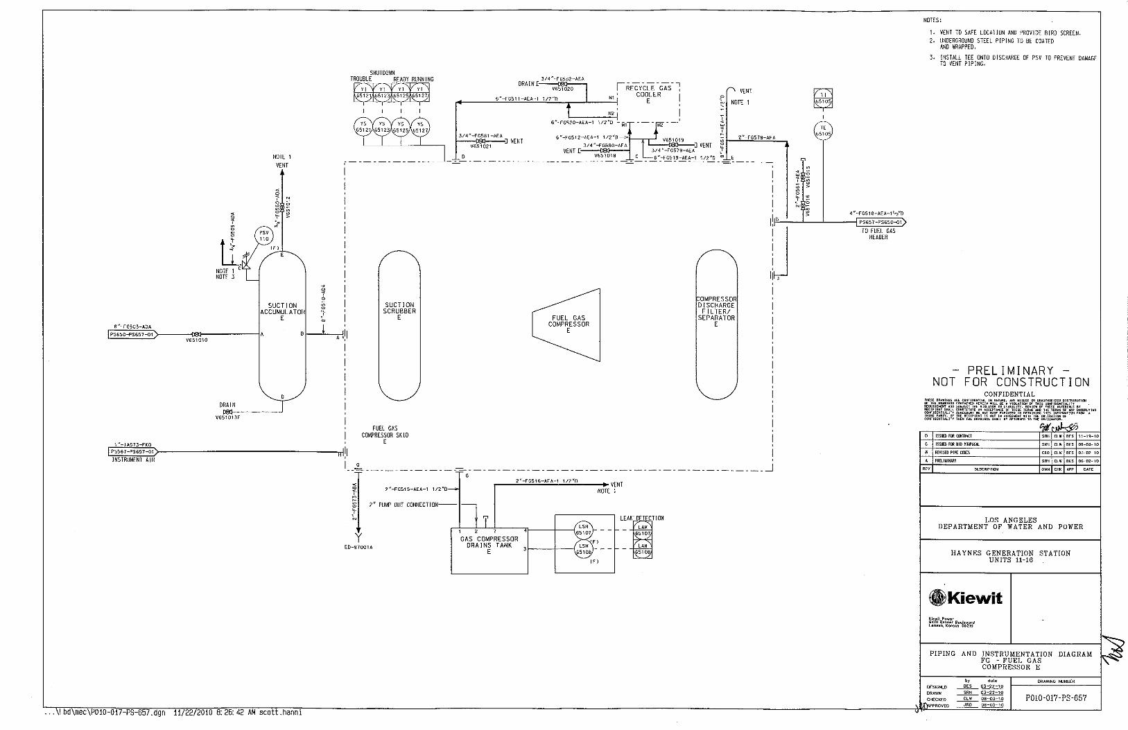
8 "--fG503-A0A
PS650-PS657-01
1 "-IA57J-FKD PS567-PS657-01
INSTRUMENT AIR
V651010
DRAIN
V651 013F
NOTE 1
VENT
SUCTION ACCUMULATOR
E
... \!bd\mec\PD10-017-PS-657.dgn 11/22/2010 8:26:42 AM scott.hanni
A
H
,-------------
SUCTION SCRUBBER
E
FUEL GAS COI>'f'RESSOR SK 10
E
3/4"-FG582-AEA
DRAIN [:--,,<,5:€,»02:-:,-., ! RECYCLE-GAS-;
~------~,·~·-c~o~S.~T~-A~E~A-~'~'~''~"0~~--L---~'~' CO~LER I
3/4"-FG581-AEA 1---reJ----:o VENT
V651021
6"--FG520-AEA-1 1/2"0 - M!
FUEL GAS COMPRESSOR
E
r, VENT
~ NOTE 1
OMPRESSOR DISCHARGE F! L TER/
SEPARATOR E
_o -------------~-----------------------------------------~ 0
2"-FG515-AEA-1 112"0 r---''-·-,ccocse'!':-'~'"'::-;:'-"""''-"~o~--+ VENT
NOTE 1
2" PUMP OUT CONNECTION--
y " E0-97001A f------i-----{6~;~
ICI
[2l ¥
I
" 65105
NOTES:
1. VENT TO SAFE LOCATION AND PROVIDE BIRD SCREEN. 2. UNDERGROUND STEEL PIPING TO BE COATED
AND WRAPPED.
3. INSTALL TEE ONTO DISCHARGE OF PSV TO PREVENT DAMAGE TO VENT PIPING.
PRELIMINARY NOT FOR CONSTRUCTION
CONFIDENTIAL
lSSUEll rill CIJHR~CI
lSSUEll roo 8!0 PliOI'OSi.L
R£V!S£D PIPE COOCS
PREL!WlNAIIY
DESCRIPTION
CEO CLW DES 07-02-10
SRH ClW DES 06-02-10
OWN CHK I>PP OATE
LOS ANGELES DEPARTMENT OF WATER AND POWER
HAYNES GENERATION STATION UNITS 11-16
GlKiewit Kiewit Power 9401 Rennor Boulevard Lensxo, ~CU\so• 66219
PIPING AND INSTRUMENTATION DIAGRAM FG - FUEL GAS COMPRESSOR E
by date DRAWING NUMBER DESJGNED ~ 03-22-10
DRAWN ___1!!1:!____ 03-22-10
CHECKED ~~ PD!0-017-PS-657 PROVED ~ oa-03-10

NOTE 1 VENT
SUCTION ACCUMULATOR
F
6"-FGS03-AOA
r,P~S~6~s£o-~P:S~6~5!8~-0~1~------~~~~-------------1A 1..: V651010
1 "-!A573-FKO
PS567-PS658-01
INSTRUMENT AIR
DRAIN
V651013F
••• \ 1 bd\mec\P010-017-PS-658.dgn 11/22/2010 8:26:42 AM scott.hanni
,------------
SUCTION SCRUBBER
F
FUEL GAS COMPRESSOR SKI 0
F
3/4 "-FG5B2-AEA
DRAIN E.--",t,E,"o,-=o-.., I REcYCLE -GAS-;
,+----'-'-=" -F::'c:'.cc".::-'"'"-'-:..c'...c'c;."L"-'.0 ---,.-__1.--::.:.j"' ' CD~L ER I N2 I
6"-FG520-AEA-1 112"0 -M1
c '> VENT
N
'
' <
NOTE 1
3/4 "-FGSB 1-AEA f---<e:f---" VENT
V651021
! 6 "-FG512-AEA-1 1/2 "0 -l-l'1::...::'~'&S1~0~l"''-~ l __ "2c"o-cF0~5"7~8::-!AE"A!:_&
314 "-Fcsao-AEA 1 J VENT ~ r VENT [ 3/4"-FG579-AEA j
0 V65l0lS C 6"-FG519-AEA-1 112"0 "" E ..;::_-------------------------=-------------=-----~
FUEL GAS COMPRESSOR
F
OMPRESSOR DISCHARGE
FILTER/ SEPARATOR
F
u
I __ o --------- ----~- ---------------------------------------- _j
2"-FG515-AEA-1 1/2"0
2" PUMP OUT CONNECTION--
y E0-97001A
,-----''-'" -:'c0e5c16,-:'e'!'c-!1 -'"1"'c"eo ______ _.. VENT NOTE 1
E)
'1-----t---{6;~~8 IE)
~ ¥
I
7E 65105
4 "-FG518-AEA-1 1.-{D
PS658-PS650-01
TO FUEL GAS HEADER
NOTES:
1. VENT TO SAFE LOCATION AND PROVIDE BIRD SCREEN. 2. UNDERGROUND STEEL PIPING TO BE COATED
AND WRAPPED.
3. INSTALL TEE ONTO DISCHARGE OF PSV TO PREVENT DAMAGE TO VENT PIPING.
PRELIMINARY NOT FOR CONSTRUCTION
CONFIDENTIAL TH£$£ 0RA1riNG$ <II£ C""fiDE!lTill IN HAT .... £, 10' tH£ ·~·WINGS CQHUINED H£10(1N REOUIR<I'EHT AND SUaJ£Cl THE VIOl II£CIPIENT SHAll CDIISTITUTE AN AOC Clli<FIDEHTIAllTY AORE£..,.Nl WE~ .. THIRD ...... IF THE RECIPIENT 15 <<>"'ID£NTIAUTY THEN THE DIIA•I>«>s SIOill O<
ISSUED H11 C!IITRAt!
!SSU£D FOO BID PRDPnSll.
II£VISED SUPPLY & AtCU~UHJt PIPE. SPEC
PI!£Ll~U!.IRY
REV OESCRIPHON
CEO CLW DES (ll-OZ-\0
SRH CLW DES Oii-02-10
OWN CHK M'P Qj!.TE
LOS ANGELES DEPARTMENT OF WATER AND POWER
HAYNES GENERATION STATION UNITS 11-16
eKiewit Kiewa Power 940! Rennor Boulevard Lene•<>, Ken•<>• 55219
PIPING AND INSTRUMENTATION DIAGRAM FG - FUEL GAS COMPRESSOR F
by dote DRAWING NUI.I8ER
DESIGNED ~~ DRAWN ~ 03-22-10
CHECKED ~ 08-03-10 P0!0-017- PS-658 APPROVED ~~

3/4 N -AOA1 01 -CLB
PS7BO-PS331-01
TO UNIT 11
3/4 "-AOA201-CLB
PS7BO-PS332-01
TO UNIT 12
3/4 N -AOA301 -CLB
PS780-PS333-01
TO UNIT 13
3/4 "-AOA401-CLB
PS7BO-PS334-01
TO UNIT 14
3/4 N -AOA401-CLS
PS780-PS335-{)1
TO UNIT 15
3/4 "-AOA401-CLB
PS780-PS336-01
TO UNIT 16
CP-78002
~2 "-AOA001 -CLB
2'X314"
CP-78003
2"-AOA002-CLB
2'X3/4"
CP-78004
2"-AOA003-CLB
CP-78005
- 2 "-AOA004-CLB
2'X3/4" < . u
' 0 ~ 0
CP-78005 1 ;.
2"-AOA004-CLB
2'X:314"
CP-78005
2"-AOA004-CLB
2'X314"
... \! bd\mec\P010-017-PS-780.dgn 11/22/2010 8:26:42 AM scott.hanni
. u ' <
0 < ' " " ~
0 ' ~ • ~
" " . .
V780009
r---------------------------1
. ~ d y ~ ~ 0
1 < '
" " ' ~
;; ~ '
~ :: z • 5 ~
~ ~ ~ 0 0
E E •
AMMONIA STORAGE TANK NOTE 4
2"
2" V780003F
L,-,n,•,•,-,-,~ 1~;o, (F)
. " u ~ 0 < ' " " ~
1111
'i ::> 0
' ~ ~ ~ ::
z z • ~ ~
~
~ ~ ~ 0
~ E ~ •
NOTE 3
~ ~ y y < < 0 0
J J " " ' '
0 ' ~ ~ z • ~ ~ ~ ~ ~
AMMONIA TANK AND PUMP1 CONTAINMENT SUMP <120"1. CAPACITY)
0 ~ '
~ z ~ ~
~ ~ 0
• E •
~ ¥ ,----;--,
1@-@ ~ ki~J ! I L-------~
PS7B1-PS780-02
FROM AMMON I A FORWARDING PUMP SKID
PS781 PS780-01
FROM AMMONIA FORWARDING PUMP SKID
P57SO-PS78 1-01
TO AMMONIA FORWARDING PUMP SKID
NOTES:
1. CONTAINMENT FOR TRUCK IS FOR MINOR MISCELLANEOUS SPILLS DURING UNLOADING (NOT FOR FULL CATASTROPHIC LOSSl.
z. VENT TO SAFE LOCATION
3. AMMONIA CONTAINMENT SUMP TO BE EMPTIED BY 0\'/NER-PROVJDED SUBMERSIBLE PUMP
4. 29"/. AMMONIA TANK AND CONTAINMENT ARE EXISTING.
PRELIMINARY NOT FOR CONSTRUCTION
CONFIDENTIAL mm•u"""
'!:<i ~~OERl.VJNG ION'""" A
ISSUED filii CllllR.I.CT 11-19-10
JSS~ED Filii B!O PROI'DSAl '"' "' '" 08-03-10
REVISEO CBA· ClA SPEC TO CLS, DELETED RELIEf VAlVES. LINES. IJJa.OI.DIKG "' "' '" 07-02-10
P!!EliWIUARY '"' "' '" 06-02-10
'" OESCiliPf!ON ,,, '~ ~· DATE
LOS ANGELES DEPARTMENT OF WATER AND POWER
HAYNES GENERATION STATION UNITS 11-16
GlKiewit Kiewll Power 9401 Renner Boulevord lene•o. K<>41sos 66219
PIPING AND INSTRUMENTATION DIAGRAM AQA AQUEOUS AMMONIA
ORA.WlNG NUMBER DES!GI'IED ~ 03-22-10
DRA.WI'l ~ 03-22-10
CHECKED ~~ P0!0-017-PS-780 PROVED ____:!.!!Q__ OB-03-10

PS781-PS780 02
TO UNITS 11-16
PS781-PS7B0-01
PRESSURE REL l EF TO AMMON!A TANK
PS780-PS781-01
FROM AMMONIA TANKS
,-~-~-,
, I I
RUN p;:sj-- _:_------ - J-- AHi!-------------0---- ~ RNNG ~--!------- -~--~' 1
READY ~ - _!- - ----- - ~ - -~ TRIP~--! _______ -~---05
I
RUN --1-------
1"
I V78001 1F
I
Pi 78008
" . ~ >
"' 1"
' " -l-- 8010A
-~--~ -~--@
I
u -----------t I ,
Yl I 1 YS RNNG 78020A - -~- - - - - - - - - I B020A
READY~ --i---------1 '?;;( ~ I I ~8~~0~ TRIP ~,';,~ __ I __ ------- t ~
-----
AMMONIA SUPPLY PUMP SKID
3/4"
1"
V780200F "- V780203F
~ ~ >
1"
V7B0210F
J/4"
V780211F
3/4"
V780016F
V780014F
Pi
"'
314"
AQUEOUS AMMONIA FORWARDING PUMP
3 X 50'!.
"
V780206F 1/2"
78TOI27oJ-~~IFI
PSL V780216F
78025 3/4"
PI 7601
V780219F
3/4"
V780214F
3/4'X112"
AQUEOUS AMMONIA FORWARDING PUMP
f/'1
'"
V7B0197F
'"
SET @
100 PSI
1/2"
3/4"
Pi V780196F
76022 1 /2" If)
3/4"
V7B021SF
" N
N 0
>
-----------------------------------------------------------------------------------------... \! bd mec\P010-017-PS-781.dgn 11/22/2010 8:26:42 AM scott.hanni
NOTES:
PRELIMINARY NOT FOR CONSTRUCTION
CONFIDENTIAL
lSSUEO fOil roiiRACT
ISSUED fOil BID PRDPOW.
P11tllM!HARY CEO CLW PES 07-02-10
P11tllMI11ARY SRH CLW PES 05-1)2-10
'" DESCRIPTION OWN CHK APP
LOS ANGELES DEPARTMENT OF WATER AND POWER
HAYNES GENERATION STATION UNITS 11-16
®J)Kiewit Klewil Pow8r 9401 Renner Boul&vord Lenexa, K<>l\sos 66219
DATE
PIPING AND INSTRUMENTATION DIAGRAM AQA AQUEOUS AMMONIA
by dot~ ORAWINC NUMBER DESIGNED ~ 03-22-10
P010-017- PS-781 DRAWN ~~ CHECKED ~ Oa-03-10
APPROVED
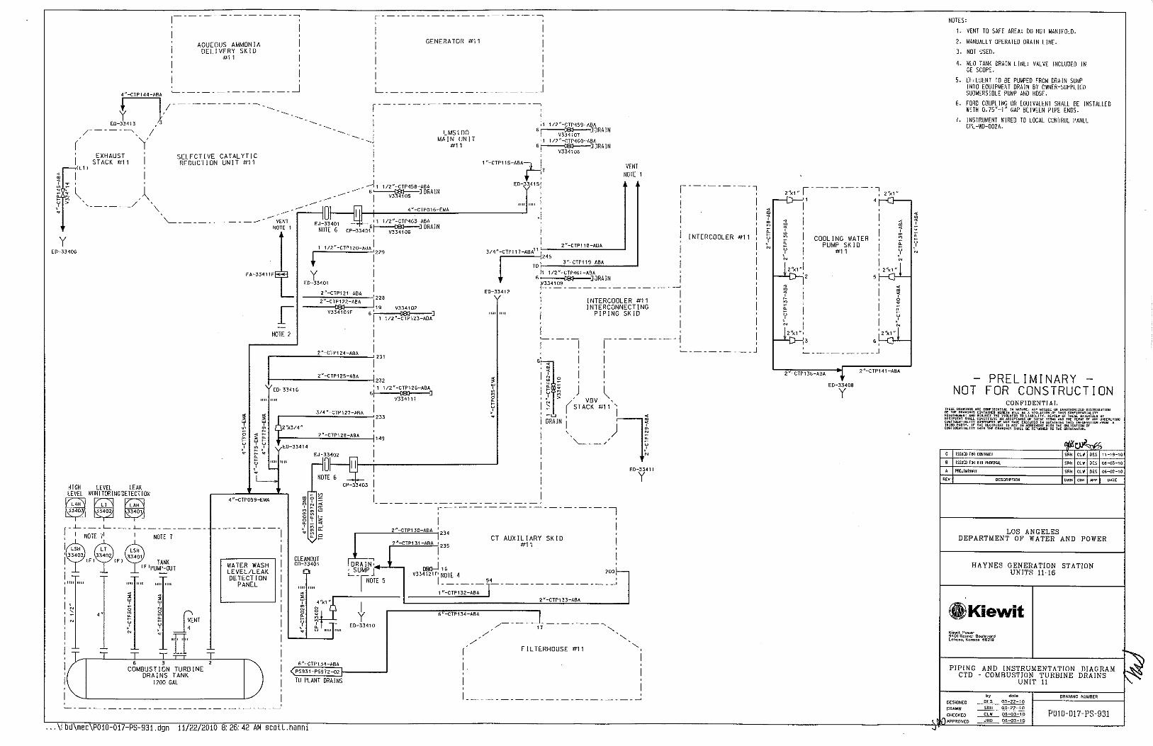
I
AQUEOUS AMMONIA DELIVERY SKID
#11
~"-CTP144-ABA ~--------------- _j
GENERATOR #11
L _____________________ J
r·--------------------; ED-Ll/------------- ~- ~ -~-~ I
F----~ .. \/ -~-~-~-~
EXHAUST STACK #11
SELECTIVE CATALYTIC REDUCTION UNIT #11
I
LMS100 MAIN UNIT
#11
I ,1 1/2"-CTP459-ABA
'r------C8l----J ORA IN I V334107 '1 112"-CTP460-ABA 6~JDRAIN
1 V334108
VENT NOTE 1
~ ~ 1 1/2"-CTP458-ABA
----- 6~JDRAIN
\ "-CTP115-ABA~ 7 ED-33415! ,---------,
i i
y ED-33406
------ ! V3 4105
\.., ---------- 10 ! " 4"-CTP016-EMA
\..._- ~- ~- ~-~ - - __. VENT EJ~~3401 ' 1 112 -CTP463-ABA NOTE 1 NOTE 6 6!----IRI--J DRAIN
CP-33401 ~ v334i"o6 '
FA-33411F~~
2N-CTP121-ABA --.;;,-;,:;,;,;,;-.:;::;=---c· 228 2 "-CTP122-ABA I
------~,,~~~,,-,----,~~] I 1 1/2"-CTP123-ABA
"" '"' l ' -1
2N-CTP118-ABA I
"'J7P\\7-AeA'' 1~4~/2"-:::~:~~:~·" ! -------]DRAIN I ~~109-------~-------~
E0-33412 , ! ] INTERCOOLER #11 ,
INTERCONNECTING I PIPING SKID "" ""
INTERCOOLER #11 ! I
I ' '
----------j I I , , NOTE 2
' ......_ _________ j
I I
:i ~
i ~ ~ 'f ! 'f
) VBV \,
(STACK #11 I ""
', ~
-w I DRAIN
!--------~2~"~C~7~P~"~"t-~A~eA!..._--I 1 4S ED-33414
"' ~ ~ ~ ~ ""
I )1! '-._ __ / ~
~54~---r-! ------' ND~I 6---r.: !
HIGH LEVEL LEAK LEVEL MONITORINGOETECTION
~~~ r--'---- L- ---'------ -----
i$:" NOT?E :
1
7 L:H NOTE 1
' 33403 33402 33401 ! [fl [fJ TANK • ( F 1PUMP-OUT I T -•"" "" I ~
~ !"' 0 ' ' 4" ~ ri
4"-CTP059-EMA
WATER WASH LEVEL/LEAK DETECT! ON
PANEL
! "' 'i' _j~ENT
! ~~=-,_~T--NT~-~·T_,ITTIJl"' __ ~T--~ I v 6 3 2
COMBUSTION TURBINE
I' DRAINS TANK
1200 GAL
I
CLEANOUT C0-33401
~
"" "'' ~ ~
4'X1"
~ '! "
~ U:• T
""I""
6"-CTP\34-ABA
<"._PS!!31 ...PS972-02
TO PLANT DRAINS
... \! bd\mec\POI0-017 PS-931.dgn 11/22/2010 8:26:42 AM scott.hanni
I cP"t3! ' ' I ______________________ !
:-----------------------~
I 2" CTP13D-ABA ' 234
I CT AUXILIARY SKID 2"-CTP131-ABA ;Z35 #11
DRAIN,.· ~...., ~ ! :_S~MP J V334121F' ~~TE 4 200r--
rOTE S [1~'-CTP-1~:6~ y---------------- ~ 2" CTP133-ABA
+ ED-33410
6"-CTP\34-ABA /"""--- ___ J------- -, ~ 17 ........
~/ ~ ........ / '
F l L TERHOUSE #11 '-, I
I I __ ---------------------___;
2 "-CTP138-ABA 2"-CTP141-ABA
ED-33408
y
NOTES:
1. VENT TO SAFE AREA; DO NOT MANIFOLD.
2. MANUALLY OPERATED DRAIN L!NE.
3. NOT USED.
4. MLO TANK DRAIN LINE; VALVE INCLUDED IN GE SCOPE.
5. EFFLUENT TO BE PUMPED FROM DRAIN SUMP INTO EQUIPMENT DRAIN BY OWNER-SUPPLIED SUBMERSIBLE PUMP AND HOSE.
G. FORD COUPLING OR EQUIVALENT SHALL BE INSTALLED W!TH 0.75"-1" GAP BETWEEN PIPE ENDS.
7. INSTRUMENT WIRED TO LOCAL CONTROL PANEL CPL -WD-002A.
-PRELIMINARY -NOT FOR CONSTRUCTION
CONFIDENTIAL li<ESE IF T"[
AIIECIJNr!DENTIAL THM.TUA£. -~ CONTAINED NLR[IH WILL S£ A 5UBJ£CT li<E VUUTOR TO l
OR II'IAUTHORIZEI> DISTHIBUTIOil TillS COHFIO<:<TIALltY
SHAll CONST!TIITE AN ACCEn.,.cE .. llTf AOREE .... Nl"" WAY HAW E .. TY. IT THE RECIPI£NT IS NOT IN IALITV THEN THE DRAWINGS stiALl
C ISSUEO FOR CIJHRACT
B ISStiEU FOR BID PRIJ'OSil
A PR£liWIHAIIY
"'" OESCRIPHON
lEW 01' THESE OUlER!AlS Sf ANll THE lER"' 01" <NV \IRilERI.YING
AINIHG nus IHFDRUATll>< fRIIU A IH THE OBl!CUIOO OF TO THE ORIGI""TOI<.
SRH CLW DES 11-19-1D
SRH CLW DES DB-03-10
SRH CUI DES 06-02-10
OWN CHI< M>P OATE
LOS ANGELES DEPARTMENT OF WATER AND POWER
HAYNES GENERATION STAT ION UNITS 11-16
GlKiewit ~iewlt Powec 9401 Ren~er Boulovard Lenuo, Konsos 66219
PIPING AND INSTRUMENTATION DIAGRAM CTD - COMBUSTION TURBINE DRAINS
UNIT 11
DESIGNED ~ 03-22-10
DRAWN
].,.. CHEC~EO \ 11\JAPPROVEO
P010-017-PS-931

~----------------~
, I I
AQUEOUS AMMONIA DELIVERY SKID
#12
I ~---------------~
f-CTeo<HBl/ ----------- --~-~-~-ED-33413 -.._
/--------.., ;' ----( y I ( L 1)
~ I
EXHAUST STACK #12
SELECTIVE CATALYTIC REDUCTION UNIT #12
,---------------------~
GENERATOR #1 2
L _____________________ J
,---------------------;
-------J LMS100 MAIN UNIT
#12
I 11 1/2"-CTP459-ABA 6~JDRAIN
I V334107 '1 1/2 "-CTP4GO-ABA
6 r---<><1---J ORA IN ~ V3341os ·
VENT NOTE 1
! ~ ~ \ .-\
- --l1 1/2"-CTP456-ABA - G~JDRAIN
,---------, ':! > ', _____ __/ .
y ED-33406
"· "~ \__--------------VENT
NOTE 1
NOTE 2
+ y
I V334105
4 "-CTP01 6-EMA
I 1 112"-CTP463-ABA G~JDRAIN
CP-33401 ~ V3J4fo6 .
1/2 "-CTP120-ABA ! 229
I
ED-33401
2"-CTP121-ABA ----::;,..;:;;,-;:::,..;:;::--.,
1 2 28 2"-CTP122-ABA I
----vcJ~J~o>-,-,---,~~J I 1 112"-CTP123-A6A
"" I .I
2"-CTP118-ABA
JI<10Te"HBA" 1
r-:-·-:,-,-.. -_:.:C:~O~:.!:C~.!.~C~9c8~"A~B:A ____ _, ~JDRAIN ~~109_~-~-----------~
ED-33412
INTERCOOLER #12 INTERCONNECTING
PIPING SKID
I ' I
----------1
INTERCOOLER #12
I , ' ~---------J 2"-CTP124-ABA
HIGH LEVEL LEAK LEVEL MONITOR!NGOETECT!ON
~ ~':'~ [;;~] r- .L---L--- J._---- -----
i$:" NOTE~:', I NOTE 7
I 33403 33402 I <Fl (F) TANK I ( F }PUMP-OUT
I I""""
N
' , .. < < > ~
> ~
~ N
~ ~ y u ' N
6 J COMBUSTION TURBINE
DRAINS TANK 1200 GAL
< < > >
! ~ 0 < ~ > ~ ~ y
~ y
1; ' ~
4"-CTPOSS-EMA
WATER WASH LEVEL/LEAK DETECTION
PANEL
i"' 2"-CTP125-ABA 232
ED-33416 I 1 1/2"-CTP126-ABA 6f----teJ--l
I V334111
3/4 "-CTP127-ABA I 2JJ
2'X314" I 2"-cTP12B-ABA
'" ED-33414
CP-33403
6 ~ <
< ~ > * i ~ .
y ~
~ ~ u
' ~ -w
DRAIN
I I '
) VBV ~ • (STACK#12~ ""
I )1! ' N ' -"----~/ ~
:-----------------------~
I ;---------'CC"-jCJo"'l'"'0~-1AOB<A~
1
234 CT AUXILIARY SKID
#12
CLEANOUT C0-33401
6"-CTP134-A6A
PS932-PSS72-02
TO PLANT DRAINS
+ ED-33410
2"-cTP131-ABA 1235 I
csrJ" V334121 Fl NOTE 4 200
1,:'-CTP-132-;B-; r----------------
2"-CTP133-ABA
6"-CTP134-ABA
_.r----- ---------, ~ 17 ..........
/
F I L TEAHOUSE #12 ",
I I _____________ ------ ____ ___;
11/22 2010 8:26:43 AM scott.hanni
COOLING WATER PUMP SKID
#12
~
~ ~ y
I N
I 2''x1 u f 5
2" CTP138-A8A 2"-CTP\41-ABA
ED-33408
y
i ' ;
NOTES:
1. VENT TO SAFE AREA: 00 NOT MANIFOLD.
2. MANUALLY OPERATED ORAl N LINE.
3. NOT USED.
4. MLO TANK DRAIN LINE: VALVE INCLUDED IN GE SCOPE.
5. EFFLUENT TO BE PUMPED FROM DRAIN SUMP INTO EQUIPMENT DRAIN BY OWNER-SUPPLIED SUBMERSIBLE PUMP AND HOSE.
6. FORO COUPLING OR EQUIVALENT SHALL BE INSTALLED WITH O. 75"-1" GAP BETWEEN PIPE ENOS.
7. INSTRUMENT WIRED TO LOCAL CONTROL PANEL CPL -WO-o02A.
PRELIMINARY NOT FOR CONSTRUCTION
CONFIDENTIAL
ISSUED Hili crt!liUCT
lSS!JED fOil B!O PROPOSM.
Plltli~IIWlY SRH CLW OtS 06-02-10
O~SCRIPTION OWN CHX M'P DATE
LOS ANGELES DEPARTMENT OF WATER AND POWER
HAYNES GENERATION STATION UNITS 11-16
.Kiewit Kiewit Powoc 9401 Renn~r Boulevacd Lenexa, Kon~o~ 55219
PIPING AND INSTRUMENTATION DIAGRAM CTD - COMBUSTION TURBINE DRAINS
UNIT !2
by dote DESIGNED ---.!!!2._ 03-22-10
OR AWN CHECKED
APPROVED ~ 08-03-10
DRAWING NUMBER
P0!0-017- PS-932

' EXHAUST I STACK #13
r.ll1l
~ I
AQUEOUS AMMONIA DELIVERY SKID
#13
SELECTIVE CATALYTIC REDUCTION UNIT #13
GENERATOR #1 3
L~-~-~-~-~-~-~-~-~-~-~J ~---------------------;
LMS100 MAIN UNIT
#13
I o1 1/2"-CTP~59-ABA
6 r-CS:l----J DRAIN I V3341o7 . 1 1 1/2"-CTP460-ABA
6 t--1><>---J DRAIN ~ V334i'oa ·
VENT NOTE 1
~~
1 "~CTP115-ABAt-+
EO- 34151 - _.-i 1 1/2°-CTP458-A8A I I --- 6'-----181--J DRAIN ,
"" .. , _____ _//',,, -- ------.:0- ! V334105 '"' '"' I y > . ' .-- .-- II llf--1----....!'c"-c"'-1T!P~0"16~~;!E~MeA __________ ~ ' '\....__ ____________ VENT EJ~~3qol ""~}11 1/2"-CTP463-A8A ·!
y ED-33406
HIGH LEVEL LEAK LEVEL MONITORINGDETECTION
~~~ r ~-'- ~- ~ L, _ ~ L, -- _ ~ _ ~ _ ~
~$~H NOT?[ :~ L~H NOTE 7 I 33403 33402 33401 I (f) !Fl ·TANK • ! F 1PUMP-OUT I ~, -ollll ""
<"
NOTE 1 NOTE 6 CP-334016~] DRAIN I
FA-33411F8~
NOTE 2
~
rc1C-'
1 c"c'_' ~"'"'c'c"c0c-"'~'::C' I '229
+ I y
ED-33401
2"-CTP121-ABA 2"-CTP122-ABA
1228
----,c,~:ffro-,-,---6.J~J I 1 112"-CTP123-ABA
I 2"-CTP116-ABA
701 3"-CTP119-ABA
31< JTP11 T-ABA11 I '" I, 1/2"-CTP461-ABA 6~JDRAJN
~~109---------------~ ED-3j412 I I
[ INTERCOOLER #13 1 1 INTERCONNECTING
' -u
I
I '
PIPING SKID
I -~-~-~-~-~j I ,
) VBV \,
(STACK #13' I ! :;
~ ~ L 2'X314"
~ u
I )1! ' N ' -'-----"' ~
I DRAIN
2" CTP126-ABA
. ' "'
ED-33414 :;: . ~ ~""
4 "-CTP059-EMA
f--~-~-~-~-
WATER WASH LEVEL/LEAK DETECT! ON
PANEL
~QL___fif--i-! ------' NO;,I 6 ~ !
CLEANOUT C0-33401
,~,1 I
L-~-~-~-~-~-~-~-~-~-~-j ~-~-~-~-~-~-~-~-~-~-~--~
I 2"-CTP130-ABA I 234 I 2"-CTP131-ABA ~235 CT AUXIk1~RY SKID !
~~~.L_. ~ ! ~S~MP J V334121F1 ~~TE 4 200~
rOTE 5 11 :~,~,~:,;,- y- ~ _ ~ _____ ~ _ ~- ~ _ ~ __; 2"-cTP133 ABA
+ ED-33~1 0
6"-CTP134-ABA _.----- ~- ~ _J -~- ~- ~- ~. , 17 ..........
,/ ~ ..........
ED-33411 y
I '/ F I L TERHOUSE #1 3 ~ ........._
6 "-CTP134-ABA \PS933-PS971-02
TO PLANT DRAINS
I
I I~-~-~-~-~-~-~-~-~-~-~-~__;
•.. \! bd\mec\P010 017-PS 933.dgn 11/22/2010 B: 26:43 AM scott.hanni
21""-'X,, r-- ------- 1 2'X1,
~ r---IJ---1! 1 4 ! ._,
~ I I ~ ~ i y I COOLING WATER
N ~ I PUM:1 ~KID ! ~ INTERCOOLER #13
),.,,,! !n,·l • ~ I' s, w ' ~
~ ! I ~ g: I I ~ ~ i I ~ r2''x1 "· i 2'l<J,"T
3 6 :_ _________ j
2"-CTP138-ABA 2"-CTP141-ABA
ED-33408 y
NOTES:
1. VENT TO SAFE AREA: DO NOT MANIFOLD.
2. MANUALLY OPERATED DRAIN LINE.
3. NOT USED.
4. MLO TANK DRAIN LINE: VALVE INCLUDED IN GE SCOPE.
5. EFFLUENT TO BE PUMPED FROM DRAIN SUMP INTO EQUIPMENT DRAIN BY OWNER-SUPPLIED SUBMERS ISLE PUMP AND HOSE.
6. FORD COUPLJNG OR EQUIVALENT SHALL BE INSTALLED WITH 0.75"-1° GAP BETWEEN PIPE ENDS.
7. INSTRUMENT WIRED TO LOCAL CONTROL PANEL CPL -WD-002A.
NOT PRELIMINARY -
FOR CONSTRUCTION CONFIDENTIAL
C JSS!IED rm Clll!RM:I SRH CLW DES 1\-19-10
B ISSU£Dr(li6(D~I1SI.I. SRH Clifl DES 08-03-10
A PREUWIN!!II SRH Cl'll DES OS-02-10
DESCRlPTION OWN CHK I>PP DATE
LOS ANGELES DEPARTMENT OF WATER AND POWER
HAYNES GENERATION STATION UNITS !1~I6
ill Kiewit Kiewit Po,.er 9401 R~nnor Bo~levord Lan~•o, Kon•o• 66219
PIPING AND INSTRUMENTATION DIAGRAM ~ CTD ~ COMBUSTION TURBINE DRAINS
UNIT I3
r------c,:,--c,".~,.c--r----:,:,,~.=.,=,~,,:,o,o,,:----1 DESIGNED ~ 03-22-10
DRAWN ~ 03-22-10
CHECK£0 __fh_l!___ ~ \1 [ij);;.PROV£0 JRO OB-03-10
POJ0~017 ~ps~933
" y

I I (L1 )
EXHAUST STACK #14
~----------------~
I AQUEOUS AMMON I A
DELIVERY SKID #14
SELECTIVE CATALYTIC REDUCTION UNIT #14
~---------------------~
GENERATOR #14
L _____________________ J
r---------------------;
----_J LMS1 DO MAIN UNIT
#14
I '1 1/2"-CTP459-A6A
Gc-<e:l--]DRAIN I V3341o7 · '1 1/2"-CTP460-ABA
6 >---~><>---J DRAIN ~ V33".1i'oe ·
VENT NOTE 1
' \ _\ - ~ 1 112"-CTP45B-ABA
-- 6~]0RAIN ,---------,
', _____ _/
' ' -~ '\.__ ___ ---------_.-VENT
NOTE 1
y ED-33406
FA-33411F
NOTE 2
I V3341 05
"" "" I ~~-4--------!4~"-~ClT~eO~l~G=-E~M~Ac_ ________________ .J '
.I
~ y
'1 1/2"-CTP463-ABA G~JDRAIN
CP-33401 ~ v3341oo ·
112 "-CTP12D-ABA I '229 I
ED-33401
2"-CTP121-ABA 2"-CTP122-ABA '
1228
------tsJf--...C::;;_....J 19 V33~ 1 02 VJ34101F 6~] I 1 1/2"-CTP123-ABA
2"-CTP118-ABA
245 iO' 3"-CTP119-ABA '"I'" 17-m" I
I, 112"-CTP461-ABA 6~JORA!N ~~109 _______________ ~
ED-33412 I INTERCOOLER #14 INTERCONNECTING I
PIPING SKID
----------j
INTERCOOLER #14
2"-CTP124-ABA I , ' .__ _________ J
HIGH LEVEL LEAK LEVEL MONITOR!NGDETECTION
~ ks';'oA ~:~ r- ..1..---- L_--- L------ ----
~0p~H NOT~[ :IT L~H NOTE 7
' 33403 33402 33401 I lFl (F) TANK • 1 F 1PUMP-OUT
N
' 4"
~ ~ ~
i ~ y ;.. ~
6 ' COMBUSTION TURBINE
DRAINS TANK 1200 GAL
~ ~
! ~ ~ < ' > •
w" y oo ~· ~ '. :;: . " y ~
4 "-CTP059-EMA
WATER WASH LEVEL/LEAK DETECTION
PANEL
!"' ~ <
2"-CTP125-ABA ' < ~ 232 >
ED-33416 '1 1/2"-CTP126-ABA ~ t; . 6~] ~
~ ' > , V334111 ~
3/4 "-CTP127-ABA y
233 ~ •u
I DRAIN 2'X3/4"
2"-CTP12B-ABA "'
E0-33414
I I '
) VBV \, (STACK #14 ' , I ~
I )1! ' N ' -"-_ __ /' ~
CP-33403
:-----------------------~
I r-------....1.2 ·~· -~CITe~l~3~o~-,~B~A"-1' 234
CT AUXILIARY SKID #14
CLEANOUT CD-33~01
6"-CTP134-ABA PS934-PS971-02
TO PLANT DRAINS
+ ED-33410
2"-CTP131-ABA ' 235 I
~" V334121F' NOTE 4 200
~~~'~P-132-:8-:- y----------------2"-CTP133-ABA
6"-CTP134-ABA
~---- ---------, ~ 17 .........
/
FILTERHOUSE #14
I I_--------------------- _ __;
... \! bd\mec P010-017-PS-934.dgn 11 22/2010 8:26:43 AM scott.hannl
_,... ' 4 ~
~
I ' I < I . . m < ' <
' I ' ~ I . COOLING WATER . ' PUMP SKID I ~ " 0 I #14 0
' '
r2')(1"i I N
' 2 'X1,! '2
~ ! 5
<
I • ~ I <
' ~ ~ I I ~ y ' 0
' ' ;.. I I ;.. !2'X1 "' i 2~1 ·J ~ ' 6,
:__ _________ j
2 "-CTP13B-ABA 2"-CTP141-ABA
ED-33~08
y
NOTES:
1. VENT TO SAFE AREA; DO NOT MAN !FOLD.
2. MANUALLY OPERATED DRAIN LINE.
3. NOT USED.
4. MLO TANK DRAIN LINE; VALVE INCLUDED IN GE SCOPE.
5. EFFLUENT TO BE PUMPED FROM DRAIN SUMP INTO EOUJPMENT DRAIN BY OWNER-SUPPLIED SUBMERSIBLE PUMP AND HOSE.
G. FORO COUPLING OR EQUIVALENT SHALL BE INSTALLED WITH 0. 75"-1" GAP BETWEEN PIPE ENDS.
7. INSTRUMENT WIRED TO LOCAL CONTROL PANEL CPL-WD-OOZA.
PRELIMINARY NOT FOR CONSTRUCTION
CONFIDENTIAL
<lu:r~ !SSU£D fOO COOJRJJ:T '"' "' "" 11-19-10
!SSU£D fOil BID PROPDSll '"' "' "" 05--{)3-10
PR£L!W!l!ARY '"' "' "" 06--{)2-10
'" DESCRIPTION "'" '" ~' OATE
LOS ANGELES DEPARTMENT OF WATER AND POWER
HAYNES GENERATION STATION UNITS 1!-16
.Kiewit Ki~wil Power 9401 Renner Boulevo<d lene•o, Konsos 66219
PIPING AND INSTRUMENTATION DIAGRAM CTD - COMBUSTION TURBINE DRAINS
UNIT 14
by dote DRAWING NUMBER
DESIGNED ~~ DRAWN ~ 03-22-10
CHECKED ~ D8-D3-10 P0!0-017-PS-934 APPROVED ---!!.B..Q.._~

AQUEOUS AMMONIA DELIVERY SKID
#15
GENERA TOR #15
I ~---------------~ f-"""-'1;----------------- -- r--------------------- i
ED-33413 -- I t1 1/2"-CTP459-ABA
L _____________________ J
( ~/---------,1,/' ------~,I LMS100 6~]0RAIN ~ MAIN UNIT •1 112"-CTP460-ABA
#15 6~JDRAIN I ' V334108 ' EXHAUST I STACK #15
r.(L1l
~ I
SELECTIVE CATALYTIC REDUCTION UNIT #15 '"-em »-"'~7 VENT
NOTE 1 ED-33415j
~ ~ ( - ~ 1 1/2"-CTP45B-A8A I --- 6'---{:8:J--] DRAIN
'"" ------ I V334105
~---------,
y >
y ED-33406
,_---- __/ ·" _ ~- ~ 1ro ' -~ '\_----------_.----VENT EJ~~3401
I 4 "-CTP016-EMA
LU '1 1/2"-CTP463-ABA
NOTE 1 NOTE 6 rc~.6~JORAJN CP-33401 ~ v3J4i"o6 .
NOTE 2
E0-33416
+ i229
y I ED-33401 '
I 2"-CTP121-ABA -----::,,-;:;,;,,c:;:;---:· 228
-_ _.:':...":...-''"lTP122-ABA I
vJfftb-,c,-----,~~J I 1 1/2"-CTP123-ABA
2ff-CTP124-ABA
2'X3/4"
J;---------"'c"~-"''"'"'"'~'~-!''~'~--1''' ED-33~14
I
'"' 1111 I '
.I
2"-CTP118-ABA I
"'ITPT 1 He.' 1 1:·: ;,•-::~~:,~:~"' ! --JORA!N I ~~~---------------~
ED-33412 I I I l NTERCOOLER #15 ' , INTERCONNECTING
-~ DRAIN
PIPING SKID
I ----------1 I ,
I
I '
) VBV \,
(STACK #15~
' N ' -"---"' l ~0"'
i )1! llf--1-' _______ ..J
! ED-33411
NOTE 6 y HIGH LEVEL LEAK CP-33403 I LEVEL MONITORINGDETECTJON
~
'"' ""
N
'
T 6 3
COMBUSTION TURBINE DRAINS TANK
1200 GAL
T
4 "-CTP059-[MA
WATER WASH LEVEL/LEAK DETECTION
PANEL
CLEANOUT CD-33401
~
6"-CTP134-ABA
(PS935-PS970-02
TO PLANT DRAINS
... \! bd\mec\POl0-017 PS 935.dgn 11/22/2010 B: 26:43 AM scott.hanni
I _____________________ _ :-----------------------~
I 2" CTP130-ABA 1
234 I CT AUXILIARY SKID
2"-CTP131-ABA ' 235 #15
DRA I N;.o• ,__x---, J ! I SUM~..-!.. V334121F• ~~TE 4 200r-
~-rOTE 5 \1
:-cr;,,_;,-; y-- ______________ __; 2"-CTP133 ABA
+ ED-33410
6 "-CTP1 34-ASA
~-~-~'c--------, ~ 17 .......
~/ ,......_
I _/ FILTERHOUSE#15 ,......_
' I
I I_----------------~---- _ __;
INTERCOOLER #15
2'X1" ,---------, 2'X1"
,--{}-cr 'I ~ • I ,
~ ! I ! ~y -"·· I I ~ COOLING WATER 1
. ~
N PUMP SKID I y I #15 . e y
N I N
I 2'X1 "I 5 : I
. . ~
I ~
I ~ i ''"."l
'· ~---------J
2"-CTP\38-ABA * ED-3;408
y
2"-CTP141-ABA
NOTES:
1. VENT TO SAFE AREA; DO NOT MANIFOLD.
2. MANUALLY OPERATED DRAIN L!NE.
3. NOT USED.
4. MLO TANK DRAIN L!NE; VALVE INCLUDED IN GE SCOPE.
5. EFFLUENT TO BE PUMPED FROM DRAIN SUMP INTO EQUIPMENT DRAIN BY OWNER-SUPPLIED SUBMERSIBLE PUMP AND HOSE.
6. FORO COUPLING OR EQUIVALENT SHALL BE INSTALLED WITH 0.75"-1" GAP BETWEEN PIPE ENOS.
7. INSTRUMENT WIRED TO LOCAL CONTROL PANEL CPL -W0-002A.
-PRELIMINARY -NOT FOR CONSTRUCTION
CONFIDENTIAL
C lSSUEO FOR CIJHR~CT
B lSSUED FDR BID PIUIPOSll.
A PRELIW)HARY
'" DESCRIPTION
UH.UTIIOOIZEO OISllUBUTI!IH THJS C"""JDE•ITl"-lTY
D1' THE•£ ""IE~!AI.• DV •Ho THE TERliS !If IJ<Y UHDERI-11HG
fAIHIHG THJ< INt!JR""t]'"' 'Mil ~ IH IH£ c•UGUIOH Of TO THE OFUGIUUDR.
SRH CLW DES 11-19-10
SRH CLW DES 08-03-10
SRH CLW DES 0£-02-10
OWN CHK >f'P DAlE
LOS ANGELES DEPARTMENT OF WATER AND POWER
HAYNES GENERATION STATION UNITS IH6
.Kiewit Kjewil Power 9401 Ren"er Boulev~cd L~""""· K~n•cs 66219
PIPING AND INSTRUMENTATION DIAGRAM I? CTD - COMBUSTION TURBINE DRAINS
UNIT 15
t-----------~,:,-----,:":,.c---r-----~,~.~,.c,c,,~.c,,o,c,~,------~ DESIGNED ~~ DRAWN ~ 03-22-10
CHECKED ~ OB-03-1 0 POI0-017-PS-935 1\
1WJ>PROVED JRO 08-03-10
J

~-~-~-~-~-~-~-~-~~
I AQUEOUS AMMONIA
DELIVERY SKID #16
I ~~-~-~-~-~-~-~-~~
[l<"-CTP><<~.SA/~-~-~-~-~-~-~-
y ' ~---~-ED-33413, ~---~--...
/~---~~. I
( y I IL 1 l
EXHAUST STACK #16
I I
SELECTIVE CATALYTIC REDUCTION UNIT #16
r---------------------~
GENERATOR #16
L~-~-~-~-~-~-~-~-~-~-~J r~-~-~-~-~-~-~-~-~-~-~;
---~---~_J LMS100 MAIN UNIT
#16
I I, 1/2 "-CTP459-ABA 6~JDRAIN
I V334107 1 1 1/2"-CTP460-ABA 6~JDRAIN
~ V334io8 ·
VENT NOTE 1
' '
\ .~ - ~ 1 1/2"-CTP458-ABA
- _.- 6~]0RA!N ,~-~-~-~-~-,
', _____ __/ '\ ' -r-"---- _____ ----- ...-r VENT
NOTE 1
y ED-33406
NOTE 2
- - I V3 4105
+ y
4"-CTP016-EMA
11 1/2"-CTP463-ABA 6,____,____ J DRAIN
CP-33401 ~ v3341oG ·
112 "-CTP120-ABA! 229 I
ED-33401
2"-CTP121-ABA --~~~~~~__,1 228 2 "-CTP 1 22-ABA I __ .::..._~,~~t,::,--6~~]
I 1 112"-CTP\23-ABA
"" I .I
2"-CTP118-ABA 314
JTP1\ T-ABA111_'_"_--'3-"-~c~T~P~n~,~~~.S~A:.._ ___ ~ 1 1/2"-CTP461-ABA ~JORAJN
~~~---------------~ E0-33412
INTERCOOLER #16 INTERCONNECTING
PIPING SKID
I
-~-~-~-~-~1 I ,
INTERCOOLER #16
2"-CTP124-A6A ' ~---------
HIGH LEVEL LEAK LEVEL MONITOR!NGOETECTION
~ [,';'oA [;;~] r ~ -'-~- ~ L ~- ~ L ~ _ ~ _ ~ _ ~ _ ~
~~:, NOT
7E :~ ,:, NOTE 7
I 33403 33402 3J4Q\ I (F) {F) TANK 1 F l PUMP--DUT
"" "" <
~ > w ' ~
N
~ ~ ' <" u
4"-CTP059-EMA
WATER WASH LEVEL/LEAK DETECTION
PANEL
2"-CTP\25-ABA
E0-33416
3/4 "-CTP127-ABA
2'X314" 2"-CTP128-ABA
ED-33414
CP-33403
CLEANDUT C0-33401
+
1 ["' 6 • • • < ~ ~ 232 >
I ' I, 1/2"-CTP\26-ABA ! .
6~] " n
~ y ~
1 V334\1\ >
If N
'
"' . -w
I DRAIN
"'
J VBV ~. (STACK #16' I I ~
I )1! ', ~ "-----/ l
I I
L-~-~-~-~-~-~-~-~-~-~-j :-----------------------~
I CT AUXILIARY SKID
#16
~16 • V334121FI NOTE 4 200
~1~-CTP~32-:B: r----------------- __: 2"-CTP\33-ABA
6"-CTP\34-ABA
' u ' ED-33410
N .
6 3 COMBUSTION TURBINE
DRAINS TANK 1200 GAL
~----------------------------
6"-CTP\34-ABA PS936-PS970-02
TO PLANT DRAINS
... \!bd\mec P010-017-PS-936.dgn 11/22/2010 8:26:43 AM scott.hanni
/ FILTERHOUSE #16
I I~-~-~-~-~-~-~-~-~-~-~-~___;
1 4
I : ' I ' < I < • •
~ ' I <
I COOLING WATER ~ ' . ' PUMP SKID ~ " I u I #16 ' '
J,~,.i I N
' 2'X1"! cJ-: '2 5 ~ < ! -: <
~ I • I < ' ' ~ . I I ~ " y ' u
' '
l''" .. ! I :.
G ! 2 '~"1 ~,.: 3
: ~~-~-~-~-~J
2 "-CTP138-ABA + 2"-CTP141-ABA
ED-33408 y
'
'
NOTES:
1. VENT TO SAFE AREA: DO NOT MANIFOLD.
2. MANUALLY OPERATED DRAIN LlNE.
3. NOT USED.
4. MLO TANK DRAIN L!NE; VALVE INCLUDED JN GE SCOPE.
5. EFFLUENT TO BE PUMPED FROM DRAIN SUMP INTO EQUIPMENT DRAIN BY OWNER-SUPPLIED SUBMERSIBLE PUMP AND HOSE.
6. FORO COUPLING OR EQUIVALENT SHALL BE INSTALLED WITH Q, 75"-1" GAP BETWEEN PIPE ENOS.
7. INSTRUMENT WIRED TO LOCAL CONTROL PANEL CPL -WD-002A.
PRELIMINARY NOT FOR CONSTRUCTION
CONFIDENTIAL
ISSUED FOR CO/TRACT
ISSUED FOR 8!0 PRDP!IS.ll
A I'RH(~!!!ARY SRH CLW DES Oli-D2-1D
'" DESCRIPTION OWN CHK M'P OAT~
LOS ANGELES DEPARTMENT OF WATER AND POWER
HAYNES GENERATION STATION UNITS Il-16
filKiewit Ki<wil Pcwer 9401 Renner Bculevcrd LeM><c, Kansos 66219
PIPING AND INSTRUMENTATION DIAGRAM CTD ~ COMBUSTION TURBINE DRAINS
UNIT I6
by dele
DESIGNED ~~ DRAWN
CHECKED
DRAWING NUMBER
P0!0~0!7~PS~936

8~-PD-DNEl
PS972-PS960-01
FROM UNITS 11 & 12
SUMP PUMP
"" '"' ~ ' VENT g ~ ·'
LAHH 96001
OIL 1 PNL -WD-001
~ ~
I
~ I
OIL/WATER SEPARATOR
2000 GAL
~ ~ RNNGR--~
15 HP
SUMP PUMP A
0..~ RNNG !~o£:;t1 - -~
EQUIPMENT DRAINS
SUMP PUMP PANEL
15 HP
SUMP PUMP 8
~ "'±"
,----!!"!:";O-WO!!!;:·';JB!!!'~-,------i Jf;~-_Jl.!<OC;"·:!WO<O·:!E"M!'-6 ---'~'-111-----,
PI
STORM WATER SUMP PUMPS
6"-WD-ABB
PI
SUMP PUMP
2 X 50% 1000 GPM @ 50 FT
... \! bd\mec P010-017-PS-960.dgn 11/22 2010 8:26:43 AM scott.hanni
CP-96003
;6~":·W:D~D~0~3-~E~M~B---r-~-l 6"-W0501-ABA --T-; - !--....!.---''-'-"""--""'--{ r---,-,,:::<96.!0~ ~
-J.-J.-----19~~~4 - -@ - k~~~A
VENT
!F! WATER
MANWAY
STORM WATER DETENTION TANK
250.000 GAL
-a Ll
~ 1 ~
TIE-IN TO NEW STORM WATER
SYSTEM
_._3/4"-WD522-ABA
V960007
GRAB SAMPLE
~ TIE-IN TO
FLOOD CONTROL CHANNEL
6"-WD·EMB fil=
PS961-PS960-01
UNITS 13 & 14 OWS DISCHARGE
PS962-PS960-01
UNITS 15 & 16 OWS DISCHARGE
NOTES:
1. MINIMUM STRAIGHT RUN IS 5 DIAMETERS UPSTREAM AND 2 DIAMETERS DOWNSTREAM OF FE-96D02.
2. 2" OIL PUMP-OUT CONNECTION WITH CAMLOCK FITTING PROVIDED BY VENDOR
3. DRAIN PIPING SHOULD BE SLOPED AT 1/8" PER FOOT TOWARDS OIL/WATER SEPARATOR
T!E-IN TO EXISTING INDUSTRIAL
WASTE LINE TP-960001
6"-WD-ABA ! ~
PRELIMINARY NOT FOR CONSTRUCTION
CONFIDENTIAL
ISSUED FOR CORJRACI
ISSUED FOO BID PROPIISI.l. "" '" '" oa-o3-1o
I.OO!:D Slm~ WAT£11 SUIIJ'S, !l!:IENT!OR IAAI WITH LE\'Il JHSIS, fi!:VJSED OWS !Hl!:l SPtC TO E\6 '" "' '" 07-02-10
' PRHI~JIWlf '"" "' "' 06-02-10
'" OESCRIPTION '"" '"' ~' DATE
LOS ANGELES DEPARTMENT OF WATER AND POWER
HAYNES GENERATION STATION UNITS 11-16
.Kiewit Kiewit Pewee 9401 Renner Bo~levord Lene•o, Kcnsos 56219
PIPING AND INSTRUMENTATION DIAGRAM WD WASTEWATER DRAIN
date DRAWING NUMBER DESIGNED ~ 03-22-10
DRAWN ___2!!!:!__ 03-22-10
CHECK£0 ~ 06-03-10 P0!0-017- PS-960 APPROVED ~ Oa-{)3-10

8"-PD-DNB
PS971-f'S961-01
FROM UNITS 13 & 14
'
"" "" 0 < f 8 ~ ' ~
SLOPE
NOTE 3
6 I y
OIL/WATER SEPARATOR
2000 GAL
~ Yo1L
~ --§ -WD-001
Y,Fl 1 (f) I
VENT
MANWAY
I
15 HP
SUMP PUMP A
A HO~ v-D 1 PNL -W0-001
I
I
I
EOU I PMENT DRAINS
SUMP PUMP PANEL
15 HP
SUMP PUMP B
1 HOA
~ 1
PNL -WD-001
I
RNNGtj---() ~ A\ RNNG~--u
... \! bd\mec\P010-017-PS-961.dgn 11/22/2010 8:26:44 AM scott.hanni
++----{ LS" -€0-8 (FI WATER
qP-WO-EMB
PS961-PS960-01
'
NOTES:
1. MINIMUM STRAIGHT RUN IS 5 DIAMETERS UPSTREAM AND 2 DIAMETERS DOWNSTREAM OF FE.
2. 2" OIL PUMP-OUT CONNECTION WITH CAMLOCK FITTING PROV IDEO BY VENDOR
3. DRAIN PIPING SHOULD BE SLOPED AT 1/B" PER FOOT TOWARDS OIL/WATER SEPARATOR
PRELIMINARY NOT FOR CONSTRUCTION
CONFIDENTIAL
'It/: !SSI.{D Fill WNIRACT "" "' "" 11-1'3-10
ISSU::D Fill BID PROP!lSll "" "' "" OS-03-10
REVISED Wll.H LlH( SIZ£, ABA PIP£ COO£ TO £111 "" "' "" 07-02-10
PII£LlWIN/dlY "" "' "" 06-02-10
'" DESCRIPTION "" '"' ~' OATE
LOS ANGELES DEPARTMENT OF WATER AND POWER
HAYNES GENERATION STATION UNITS 11-16
til Kiewit K;~,.u Power 940\ Renner Bculevord len"""· Konoos 66219
PIPING AND INSTRUMENTATION DIAGRAM ~
t-::::---W;,D;-~W~A~S~T~ElW=A=T=E=R~D~R~A~IN~~====~~ by dole DRAWING NUI.!BER
DESIGNED ~~ DRAWN ~ 03-22-10
CHt:CKEO ~ 08-03-10 P010-017-PS-961 PROVEO ~~

NOTES:
1. MINIMUM STRAIGHT RUN !S 5 DIAMETERS UPSTREAM AND 2 DIAMETERS DOWNSTREAM OF FE.
'· 2" OIL PUMP-OUT CONNECTION WJTH CAMLOCK F ITT I NG PROV I OED BY VENDOR
3. DRAIN PIPING SHOULD BE SLOPED AT 1/8" PER FOOT TOWARDS 0 I L/WATER SEPARATOR
6 OIL
~ ~- -E:;-W0-001
EQUIPMENT DRAINS
I IF l 1 (F) SUMP PUMP y I PANEL LSH LSHH
" IFI IF I
w w w • T . • 0
6 0
' ' s X s 0 ~ !f "" "" • ' ' 0
'[~: VE~NWAY 4 "-WD-EMB <
VENT 1 MANWA y 6"-WD-EMB < v PS962-PS960-0T) 6" WD-DNB 8 I PS960-PS962-01 -n ~
6~4" 0 II MANWAY
T • ' N I'
8"-PD-DNB ·r4TI--.
PS970-PS972-01
FROM UNITS 15 & 16 SLOPE 15 HP 15 HP
NOTE 3 -- -- - M <;'---- M I
OIL/WATER I I SEPARATOR
I I
PRELIMINARY I
-~--a - -I 2000 GAL I L>H NOT FOR CONSTRUCTION I
I I
I I IFI WATER CONFIDENTIAL I JH[5£ ~OAWING~ AilE CONI'!OENTIAl It< t<oTUR£ ...... U!SUSE OR U!I.UTHO.!IED O!STR!BUT!CH
I OF \HE D"AW!NGS tDNTA!N[O li[O[!N Will DE A V!OUT!OH OF THIS CDNT!0£HT]Al!TY
( ) I ( ) REWIREI.EHT ..., SUfiJ:E:tT "THE VIOUTCIII TO CIA51llTY. REVIEW .,.. THES£ ltUEIIIAI.S BY
I R<CIPTENT SHAll CONSTITUTE AN ACCEPT>HCE !II' TI<ES[ ..... '""THE T£R ... OF"'" UI<OERlr!NO COOl'IOEHTIA1.!1Y AORE£1.EHT If[ IH.Y HAllE EXOCOTED IN OfiUIHII$ THIS IM'CIII"'TI<»< fROit •
I I THIRO PAATY. If THE "EC!PIEHT IS OOT IH -'>IIEE ... HT WITH THE OfllJGATIIll< OF
COIII'iOENTIAl.!lY TH[H TH£ DRAWINGS .I!All BE RETU.H[fl TO TH£ Ofi]GiNoT<lli.
I SUMP PUMP I SUMP PUMP I A I B 4-VI'&.
I ' ISSLUI FM Cll'ITR~CI "" "' "' 11-19-10 I
~ I HOA R£VIS!:O OJllET UI!E SIZE, 1.11~ SPEC TO [1(1; AOOED liHE
~ ' TDIIli.ET "' '" '" 07-02-10 s • PREll~INMIY '"" '" '" 06-02-10
1 PNL -WD-001 '" O~SCRIPT!ON '"" ~ ~e OATE
I 1 PNL -WD-001
I I
I I
I I
I I
I I
RNNG t:j-- -cJ ~--C) LOS ANGELES
DEPARTMENT OF WATER AND POWER RNNG
HAYNES GENERATION STATION UNITS 11-16
tl,lKiewit Kiowil Pcwer 9401 Re~ner Boulevord LeMxc, Konscs 66219
PIPING AND INSTRUMENTATION DIAGRAM WD - WASTEWATER DRAIN
,, dale DRAWING NUMBER
DESIGNED ~03-22-10
DRAWN ~03-22-10
POl0-017- PS-962 o~HECKEO ~ OB-03-10
'I APPROVED "" 08-0J-10
... \! bd\mec\PO!O 017 PS 96 .d n 11 22 2010 8:26:44 AM scott.hanni ./ 2 g I I
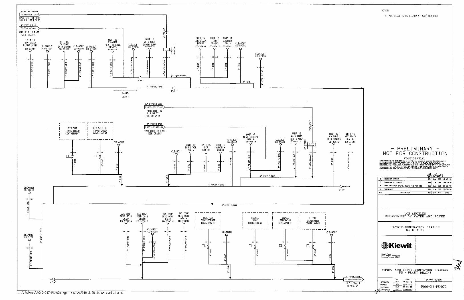

IT 14 UN cw
SK 10 ED-
PUMP DRAIN
33408
" '"' . z
~ g 0
~ .
CLEANOUT C0-9~001
'"' "" . ~
" 0 g • ' .
UNIT 14 VBV STACK
CLEANOUT FLOOR DRAIN C0-:7004 ED-33411
"" lilt "" '"' . . z z 9 ~ -0 ;; 0
~ ~ . ,.
6" CTP134-ABA
PS936-PS971-02
FROM UNIT 14 AIR INLET
FILTER SKID
4 P0093-DNB
PS93G-PS971-01
FROM UNIT 14 EAST SIDE DRAINS
CLEANOUT co-~101o
CLEANOUT C0-97009
"" "" . z 9
'"' "" g • . ' z
~ .
~ ' ~
CLEANOUT C0-9~014
1111 "" . z 0
~ 0 0
~ .
CLEANOUT C0-~021
1111 '"' . z
~ 0
~ w
... \! bd\mec\P010-017-PS-971.dgn 11/22/2010 8:26:44 AM scott.hanni
" ;; ~;
UNIT 14 > EXHAUST UNIT 14
WEST TURBINE MAIN UNIT DRAINS DRAIN SUMP
ED-33401 ED-33410
~! "" "" "" "" "" ""
• ~ . z z 0 0
~ " ~ g g g ~ • • ' ' . . ;,
6"-P0018-0NB
6''x4 N
4"-P0012 ONB
6''x4" SLOPE
NOTE 1
,---------; ,---------;
I I i I CTG SUS CTG STEP-UP TRANSFORMER ' TRANSFORMER ''
I CONTAINMENT ! I CONTAINMENT I :___ ___ .---...1 :___ ___ ,---...1
CLEtNDUT
1111 1111 1111 '"' "" '"' []_ o_
• • ~ z
' 9 . v ~ 9 ' . .
z . ~
z 0
' ;; ~ 0
~ ;,
'" "
UNIT 14 UNIT 14 UNIT 14 SCR STACK SCR AMMONIA
CLEANOUT DRAIN DRAINS DRAIN C0-9701G ED-33410 ED-3]410 E0-334i0
'~
"" '"* 1111 1111 "" "" "" ""
I . ~ ~ ~ z 9 0 0 0
' ' ' . ~ . v
CLEANDUT C0-97016
' 4 "-ONB
"" "" • z
~ g • ' ~ 6"-P0012-DNB
" N 0
~; >
UNIT 13 UNIT 13 MAIN UNIT WEST TURBINE
!~-DRAIN SUMP DRAIN CLEANOUT E0-3351 0 ED-33515 C0-97017
"" "" "" 1111 "" "" "" "" • • • z z . z z 0
~ ~ 0
~ ~ g 0 0 0 0 0
• • 0 ~ ' ' ~ ~ ;, ~ . 6"-P0057-0NB
6"-P0057-0NB
UNIT 13 UNIT 13 UNIT 13 SCR STACK SCR AMMONIA
CLEANDUT DRAIN DRAINS DRAIN
;>
"" 1111 "" 1111
'~I"" "" 1111 . . • • z z z z
0 0 0 9 ' ' ' . . v ~
6"-CTP234-ABA
PS935-PS971-021
FROM UNIT 13 AIR INLET
FILTER SKID 4 "-P0094-DNB
PS935-PS971-011
FROM UNIT 13 EAS SIDE DRAINS
UNIT 13 UNIT 13 VBV STACK C\1' PUMP
DRAINS SKID DRAINS CLEANOUT ED-33515 ED-33515 co-;7017
'"' '"' "" "" "" '"' . z
~ ~ ' .
X
w 4"-0NB
4"-0NB
,---------; ' I I UAT TRANSFORMERS ' CONTAINMENT '
CLEANOUT I I
"" ""
. z 9 .
:___ __ ~ .----...1
"" "" o_
. z 9 .
8 N -PD01 2-DNB PS971-PS961 -01)
10 OIL/WATER SEPARATOR
NOTES:
1. All L!NES TO BE SLOPED AT 1/8" PER FOOT
'"
PRELIMINARY NOT FOR CONSTRUCTION
CONFIDENTIAL
!SSUrD FOR C!JHRin
!SSU~D Fill! BID PRWO:S.ll
Wllf.D Xl'lll C!IIIAINI£Nl DRAINS
I'R!:LIYIHARY
DESCRIPTION
CW CL\11 DES 01-02-10
SRH CLW 0£5 06-02-10
OWN CHK JIPf' DATE
LOS ANGELES DEPARTMENT OF WATER AND POWER
HAYNES GENERATION STATION UNITS II-16
.Kiewit Kiowl\ Powoc ~401 Renner Bo.,lov~rd Lenexo, Konsos 66219
PIPING AND INSTRUMENTATION DIAGRAM ~ PD - PLANT DRAINS
~----:-------:-~=:------~ by dote DRAWING NUMBER DESIGNED __Qf_L_ 03-22-10
DRAWN
POI0-017- PS-971 CHECKED APPROVED __.,ll!Q_.___ OB-03-10
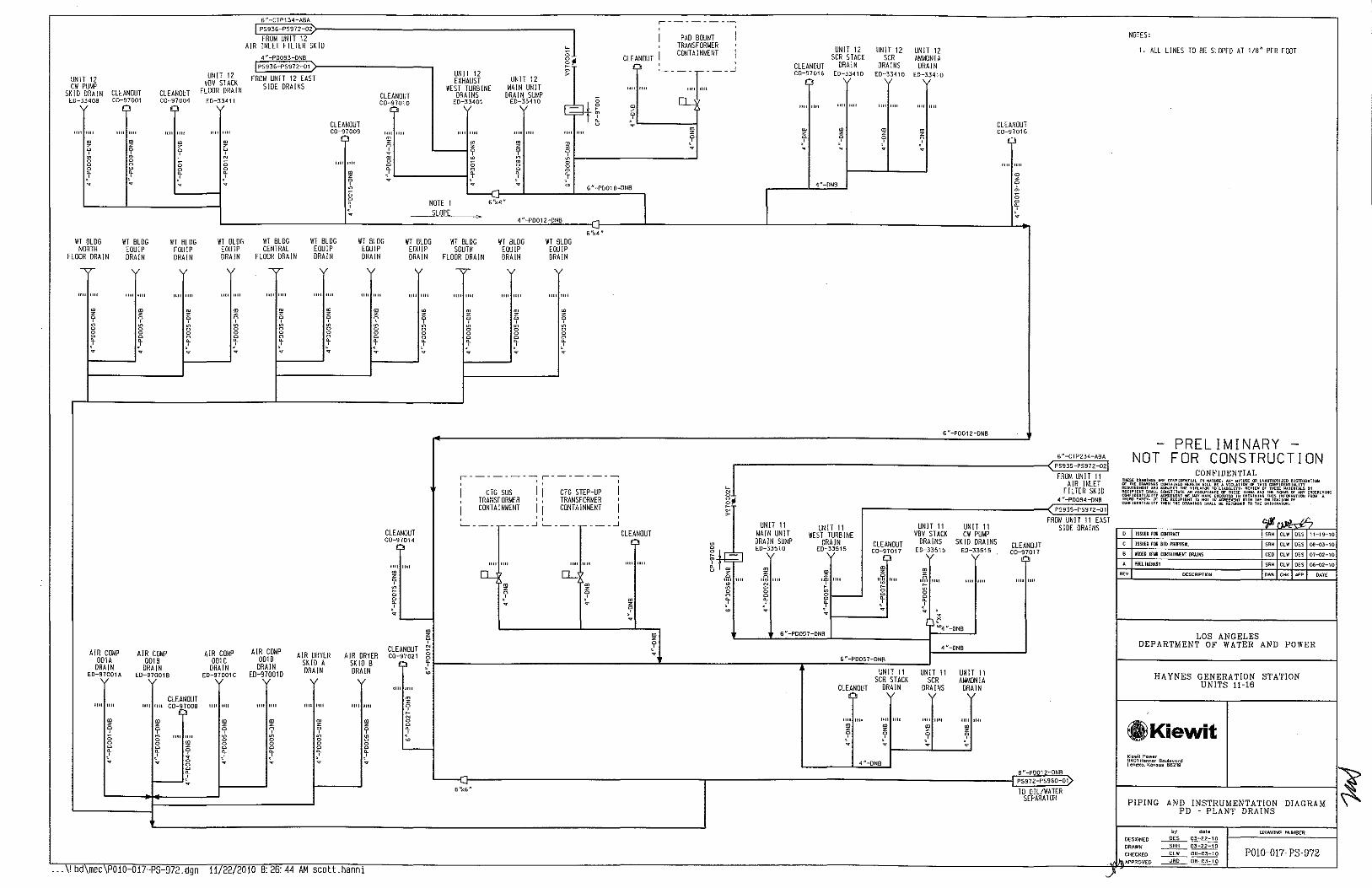

EXHIBIT C
Contract Pricing and Option Pricing
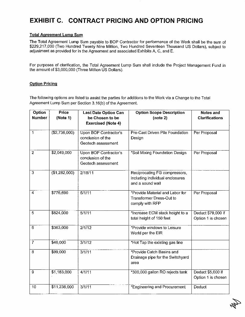
EXHIBIT C. CONTRACT PRICING AND OPTION PRICING
Total Agreement Lump Sum
The Total Agreement Lump Sum payable to BOP Contractor for performance of the Work shall be the sum of $229,217,000 (Two Hundred Twenty Nine Million, Two Hundred Seventeen Thousand US Dollars), subject to adjustment as provided for in the Agreement and associated Exhibits A, C, and E.
For purposes of clarification, the Total Agreement Lump Sum shall include the Project Management Fund in the amount of $3,000,000 (Three Million US Dollars).
Option Pricing
The following options are listed to assist the parties for additions to the Work via a Change to the Total Agreement Lump Sum per Section 3.16(b) of the Agreement.
Option Price Last Date Option Can Option Scope Description Notes and Number (Note 1) be Chosen to be (note 2) Clarifications
Exercised (Note 4)
1 ($2,736,000) Upon BOP Contractor's Pre-Cast Driven Pile Foundation Per Proposal conclusion of the Design Geotech assessment
2 $2,049,000 Upon BOP Contractor's *Soil Mixing Foundation Design Per Proposal conclusion of the Geotech assessment
3 ($1 ,282,000) 2/18/11 Reciprocating FG compressors, including individual enclosures and a sound wall
4 $776,690 5/1/11 *Provide Material and Labor for Per Proposal Transformer Dress-Out to comply with RFP
5 $824,000 5/1/11 *Increase ECM stack height to a Deduct $79,000 if total height of 150 feet Option 1 is chosen
6 $363,000 2/1/12 *Provide windows to Leisure World per the EIR
7 $46,000 3/1/12 *Hot Tap the existing gas line
8 $99,000 3/1/11 *Provide Catch Basins and Drainage pipe for the Switch yard area
9 $1,183,000 4/1/11 *300,000 gallon RO rejects tank Deduct $5,000 if Option 1 is chosen
10 $11,236,000 3/1/11 *Engineering and Procurement Deduct

for the total Switchyard, and $1,118,000 if Construction of only grading Option 1 is chosen work, piles, and foundations for the Switchyard (Note 3)
11 $13,771,000 3/1/11 Engineer, Procure, and Deduct Construct Switchyard (Note 3) $1,118,000 if
Option 1 is chosen
12 $302,000 30 days after the Fuel *Fuel Gas Line Accumulator Gas Study Tank
13 ($119,000) 4/1/11 Changes to Control Room & Buildings
14 $715,000 2 weeks after Contractor *Sound Wall at ACHE to Meet requests mitigation based 65dB at Boundary with GE on the noise study Guarantees
15 $143,000 2 weeks after Contractor *Sound Mitigation at CTG requests mitigation based Cooling Water Skid to Meet on the noise study 65dB at Boundary with GE
Guarantees
16 $143,000 2 weeks after Contractor *Sound Mitigation at CTG requests mitigation based Auxiliary Skid to Meet 65dB at on the noise study Boundary with GE Guarantees
17 $358,000 2 weeks after Contractor *Sound Mitigation at CTG requests mitigation based Enclosure vent exhaust and on the noise study supply fans to Meet 65dB at
Boundary with GE Guarantees
18 $500,000 90 after recommended *Additional Maintenance Spare spare parts list is Parts submitted
TOTAL AGGREGATE POTENTIAL OPTION COST ADJUSTMENT
(Note: Items with* add to the total.)
$18,737,690
References to Notes from the table above:
1. The value shown for this option can be exercised prior to the "Date of Expiration of the Option" after this time the price is not valid.
2. The parties agree that a more defined scope will be jointly developed if the option is exercised and will be part of the Change Order.
3. The prices given for Option Numbers 10 and 11 are based upon Contractor's standards specifications, design, and methods. Deviations or changes from this basis may require pricing modification.
4. Schedule and cost impacts will affect the project if the option is chosen to be exercised after the date shown.
The following pages are provided for purposes of further description relative to the option pricing referenced in the table above:

Option 1: Pre-Cast Driven Piles
This option is to provide 16 inch and 20 inch pre-cast driven piles in lieu of the Auger Pressure Grouted
Displacement (APGD) piles. This option includes all the engineering, design, and geotechnical work
needed to ensure the pre-cast driven piles will support the loads on the foundations. Also, included in
this option BOP Contractor will meet the requirements stated in the Final Environment Impact Report,
dated April 2010, specifically N3-1 and N3-2. N3-3 will be addressed in another option.
This price for this option is based off the geotechnical information provided to the BOP Contractor in the
RFP and subsequent addendums. This price excludes any changes due to subsurface conditions that are
found to differ from the information provided to the BOP Contractor.
The project schedule as shown in Exhibit D will not change due to this option.
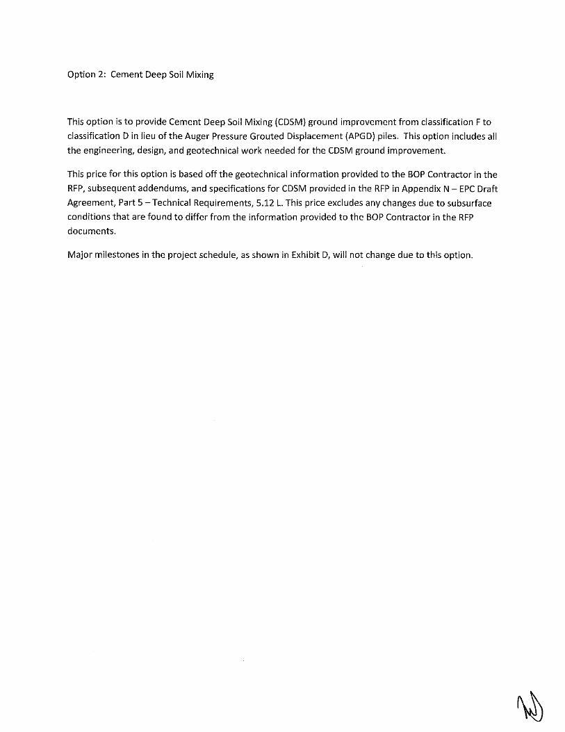
Option 2: Cement Deep Soil Mixing
This option is to provide Cement Deep Soil Mixing (CDSM) ground improvement from classification F to
classification Din lieu of the Auger Pressure Grouted Displacement (APGD) piles. This option includes all
the engineering, design, and geotechnical work needed for the CDSM ground improvement.
This price for this option is based off the geotechnical information provided to the BOP Contractor in the
RFP, subsequent addendums, and specifications for CDSM provided in the RFP in Appendix N- EPC Draft
Agreement, Part 5- Technical Requirements, 5.12 L. This price excludes any changes due to subsurface
conditions that are found to differ from the information provided to the BOP Contractor in the RFP
documents.
Major milestones in the project schedule, as shown in Exhibit D, will not change due to this option.

Option 3: Reciprocating Fuel Gas Compressors
This option is to provide six {6) 16.7% reciprocating fuel gas compressors in lieu of oil-flooded rotary
screw compressors, and no spare bare-shaft compressor will be provided. The reciprocating
compressors will be engineered and designed per API 618, and will include a pulsation study and any
necessary modifications required by the study to ensure that the fuel gas supply to each CTG meets the
short-term pressure pulsations requirement as specified by the CTG Contractor.
Included in this option is to provide individual sound enclosures for the six proposed rotary fuel gas
compressors, as well as a sound wall around the six proposed fuel gas compressors and the two existing
fuel gas compressors, as necessary to meet the site noise limits. The sound wall will be set far enough
away from the gas compressors so that a crane can fit in between the gas compressors and the wall to
perform major maintenance on the gas compressors. The enclosures include lighting, ventilation, gas
detection, and a C02 fire protection system. The enclosure walls allow for routine maintenance to be
performed, but major overhaul procedures could require some removal of some enclosure panels. The
sound wall consists of steel support columns, located at 14-foot spacing, with acoustic wall panels
between the columns. A drawing of the sound wall has been included to show the proposed location of
the wall. The sound wall will extend to the existing gas compressors, and access to the existing gas
compressors will be re-routed from the east to the west.
A redline of the contract document for the fuel gas compressor section (5.9.G) is attached to indicate
the changes required to make the section applicable to reciprocating fuel gas compressors.
The project schedule as shown in Exhibit D will not change due to this option.
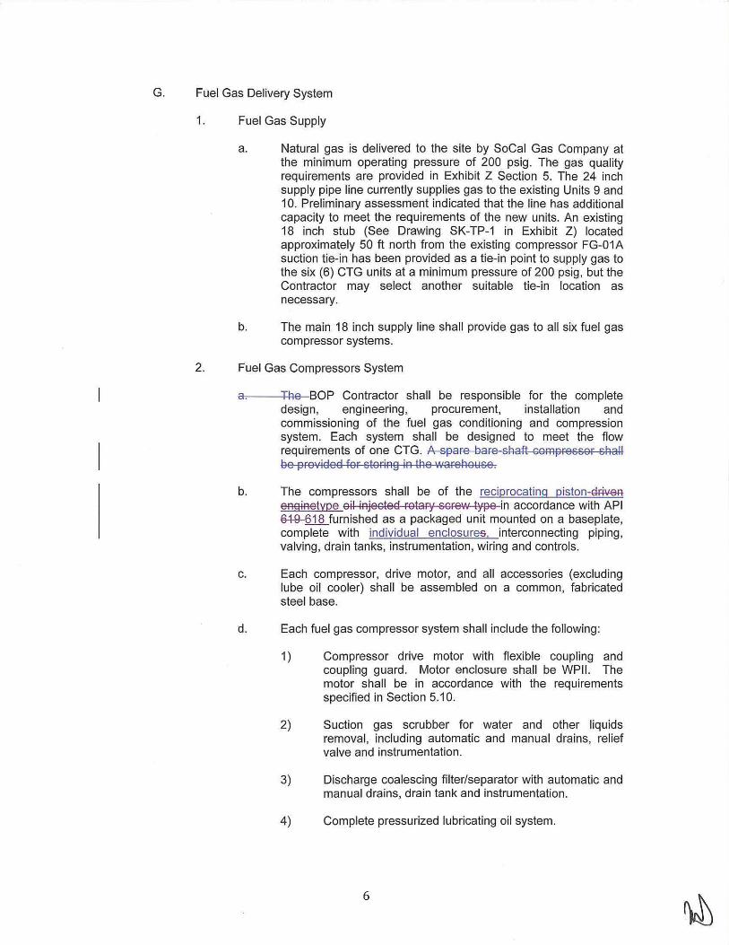
G. Fuel Gas Delivery System
1. Fuel Gas Supply
a. Natural gas is delivered to the site by SoCal Gas Company at the minimum operating pressure of 200 psig. The gas quality requirements are provided in Exh ibit Z Section 5. The 24 inch supply pipe line currently supplies gas to the existing Units 9 and 10. Preliminary assessment indicated that the line has additional capacity to meet the requirements of the new units. An existing 18 inch stub (See Drawing SK-TP-1 in Exhibit Z) located approximately 50 ft north from the existing compressor FG-01A suction tie-in has been provided as a tie-in point to supply gas to the six (6) CTG units at a minimum pressure of 200 psig, but the Contractor may select another suitable tie-in location as necessary.
b. The main 18 inch supply line shall provide gas to all six fuel gas compressor systems.
2. Fuel Gas Compressors System
a. The BOP Contractor shall be responsible for the complete design, engineering, procurement, installation and commissioning of the fuel gas conditioning and compression system. Each system shall be designed to meet the flow requirements of one CTG. A spare bare shaft compressor shall be provided for storing in the 'Narehouse.
b. The compressors shall be of the reciprocating piston-Gfi.ve.R eooffietype oil injected rotary screw type in accordance with API e4-9-618 furnished as a packaged unit mounted on a baseplate, complete with individual enclosures. interconnecting piping, valving, drain tanks, instrumentation, wiring and controls.
c. Each compressor, drive motor, and all accessories (excluding lube oil cooler) shall be assembled on a common, fabricated steel base.
d. Each fuel gas compressor system shall include the following :
1) Compressor drive motor with flexible coupling and coupling guard. Motor enclosure shall be WPII. The motor shall be in accordance with the requirements specified in Section 5.1 0.
2) Suction gas scrubber for water and other liquids removal, including automatic and manual drains, relief valve and instrumentation.
3) Discharge coalescing filter/separator with automatic and manual drains, drain tank and instrumentation.
4) Complete pressurized lubricating oil system.
6

5) Programmable logic controller (PLC) based compressor control system, including automatic capacity control. PLC shall be data linked to DCS for control room alarm annunciation, monitoring and remote start/stop control. The remote controls will operate in parallel with local controls.
6) Fabricated steel skid(s) complete with all compressor interconnecting piping, isolation valves, relief valves and compressor/driver support to minimize skid vibration.
7) Instrument control panel located on the compressor skid.
8} Gas suction and discharge isolation valves.
9} Air cooled lube oil cooler.
1 0} One (1) spare compressor to be stored in the warehouse.
11) Terminal blocks for Control Room Emergency Shutdown.
12) All interconnecting air and lubricating oil piping and instrument tubing between furnished components.
13) Interconnecting wiring for all furnished electrical components which are integral to the compressor skid.
14) One set of special maintenance tools for compressor maintenance and overhauling shall be provided.
e. Weatherproof, fully ventilated acoustic enclosures shall be provided for the fuel gas compressors as required to comply with noise requirements. Carbon dioxide (C02) fire protection and detection system shall be provided for the acoustic enclosure as required by code and local Fire Marshall.
3. Design Conditions
a. Each compressor will be used as a fuel gas booster machine. The compressors shall be suitable for operation at any gas demand rate from zero to the maximum capacity without time limit. The compressors shall provide a constant discharge gas pressure at any gas flow rate and any suction pressure. The compressor control system shall supply the required flow rate at a constant pressure.
b. The fuel gas compressor system shall be designed to allow the CTG start-up from zero to full load within 10 min.
c. An automatic recirculation system shall be provided for gas compressor. The recirculation mode will be used during startup and low load operation when the gas turbine plant has low or no

fuel demand. Gas recirculation shall be to a point upstream of the inlet gas scrubber.
d. The automatic recirculation control valve shall be equipped with a block valve on each side to isolate the automatic recirculation valve for control valve maintenance during bypass operation. The automatic recirculation shall be an integral part of the gas compressor skid, and shall include all piping, valves, instrumentation, etc. required for automatic recirculation and manual bypass. The automatic recirculation shall be rated for continuous duty.
e. A bypass shall be provided on the compressor package from the suction header to allow flow to bypass the compressor when the pipeline pressure is adequate for startup and low load operation and compression is not required.
f. The fuel gas delivered to each CTG shall meet the requirements of the CTG manufacturer.
g. Each compressor shall operate throughout the full range of conditions specified in the table below:
Design volumetric flow rate 20.8 MMSCFD Design minimum suction pressure 200 psig Design maximum suction pressures 500 psig Design discharge pressure 920 psig* CTG Inlet Temperature Requirement s 50"F of superheat above the moisture
dew point
* Discharge pressure shall be verified by the BOP Contractor based on the latest fuel gas pressure requirement by the CTG Manufacturer at the CTG base plate and pressure losses in the associated discharge piping system.
h. Fuel gas piping shall be provided with isolation flanges at each interface between above ground and below ground piping.
i. The compressor system shall be provided with a suction scrubber upstream of the compressor to eliminate 99.9% of moisture, condensate and liquid droplets larger than eight (8) microns in the fuel gas supply.
j. The discharge filter separator shall have a first stage knockout followed by a coalescing filter element in the second stage. Filter separators shall be designed to remove 99.98% of all particles, three-tenths (0.3) microns and larger when operating between zero and 110% of design operating conditions.
k. The oil content downstream of the discharge filter separator shall meet the requirements of the CTG Manufacturer. The BOP Contractor shall conduct performance tests to verify the operation of the discharge filter separator. Tests shall be performed in accordance withANSI/CAGI 400 "Standards for Testing and Rating Coalescing Filters." The BOP Contractor

shall provide to LADWP test procedures prior to testing for approval prior to the start of testing.
I. Fuel gas piping upstream of the final filter shall be carbon steel. Piping downstream of the final filter to the CTG shall be of 304L stainless steel construction.
4. Fuel Gas System Safety Requirements
a. A suitable venting system shall be provided for the disposal of vented or emergency relief gas, preferably utilizing a common vent stack to minimize hazardous area. The system shall vent to a safe location and shall disperse the ground level concentration of gas to below the lower explosive limit.
b. The BOP Contractor shall identify and submit drawings showing hazardous classification areas. All equipment within hazardous classification areas shall be rated for such service.
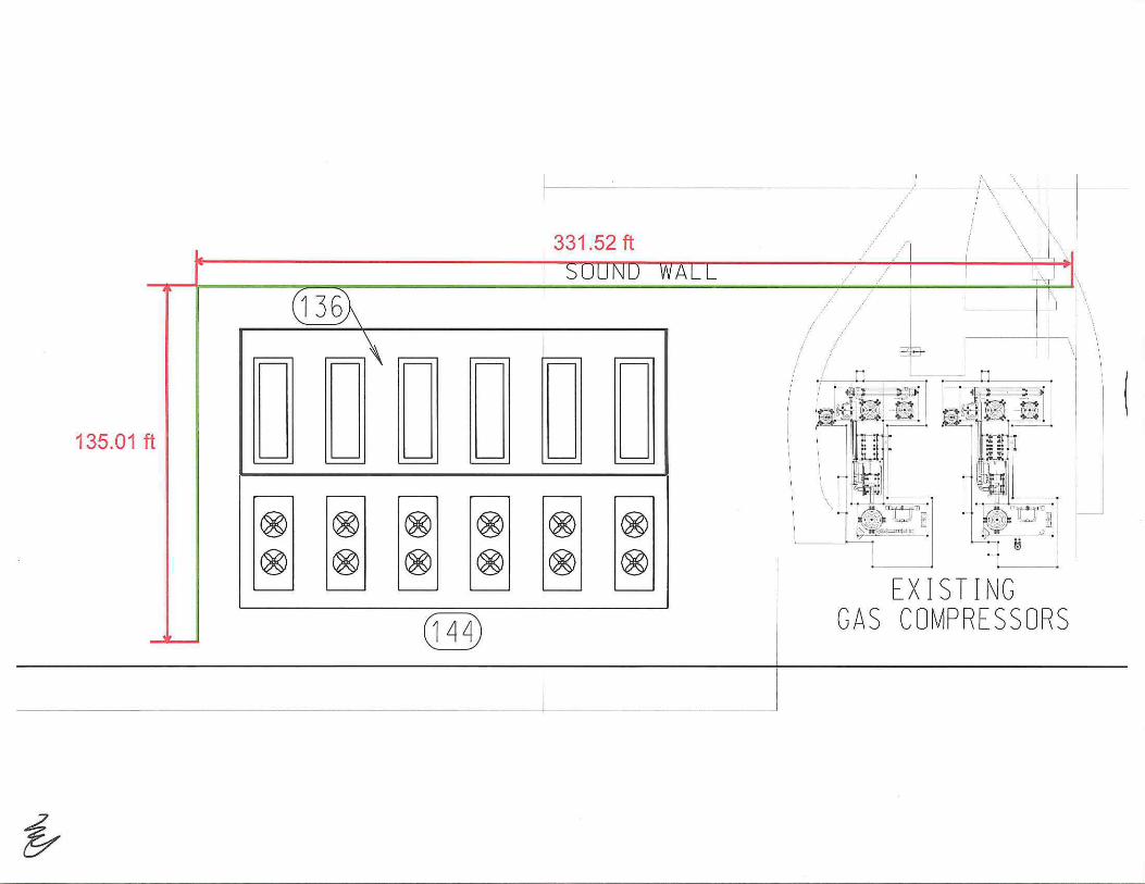
135.01 ft
~
I ~~-.1. 1 '~ .. _) - - ~ \\ \ I
/ \\\\, \\· ... \
I ·... • I
331 .52 ft ! r 1 "I I
.\'
// /
' / I
! !
.:=llg..
~-- '1\ \ \
1,-' . ltti~: . '"""' ' ·- . [ _' -i le ' ~ ,., Jo 4~~. --::c· _ ,
~~~~.:-~~·. ' •• -1-~ - - S'f~~~~~--~1 ': l ~u. . =~ Bl \ ; UI J z~!
fW, ' ·- - 1~\."..!, ~ ® ® ® ® ® \: 1\U l i:Jr; -~ilL_ c .
!i I
+ I CfEl EXISTING I GAS COMPRESSORS
~
_I

Option 4: Provide Material and Labor for Transformer Dress-Out Pricing to Comply with RFP
This option is to provide full dress-out for the generator step-up and unit auxiliary transformers as
required by the RFP. Dress-out activities include full installation of all transformer accessories that are
not pre-installed in the factory, as well as filling of oil and any applicable gasses, which are provided by
BOP Contractor's transformer supplier.
The project schedule as shown in Exhibit D will not change due to this option.

Option 5: Increase Emissions Control Module Stack Height to a Total Height of 150 Feet
This option is to increase the Emissions Control Module (ECM) Stack from a total height of 90 feet to a
total height of 150 feet, for Units 11 through16. Included in this option is the additional piles and
increase in the foundation needed to support the taller stack, and the installation of the Owner supplied
ECM stack material. Also included in this option is the necessary FAA lighting, electrical, and
instrumentation work, for the increased stack height.
Excluded from this option is the purchase of the ECM stack and the stack material and/or platforming
required to increase the ECM stack height.
The project schedule as shown in Exhibit D will not change due to this option.

Option 6: Provide Windows for Leisure World
This option is to provide sound-attenuating replacement windows, to meet the requirements of the
Final Environmental Impact Report (EIR) section N3-3, in the following buildings at Leisure World where
the existing windows in these buildings also face the project:
Mutual8: Building 190 Building 199 Building 201 Building 202 Building 203 Building 204 Building 205
Mutual9: Building 209 Building 210 Building 211 Building 214
The price for this option is based off previous window replacement work done in 2002 at Leisure World, and is not based off an actual accurate count of the amount or types of windows that need to be replace in the above mentioned buildings, due to the BOP Contractor not being able to physically access these buildings.
The price includes:
• Window measurement walkthroughs and assessments on all units requiring window replacements
• Coordination and scheduling of construction activities with tenants/homeowner coordinators • Placement of window order with DBE window supplier
• Procurement of required building permits and local licenses
• Receive, Inventory, and Store all required materials until ready for installation at residents • Installation of sound rated windows at required locations determined to be treated
• Removal and reinstallation of existing window treatments
• Furniture moving where required
• Modify/Cut back carpet or flooring to accommodate new windows (at all stacked window locations)
• Removal and disposal of all construction debris to off-site containers
• Cleaning of windows and surrounding areas
• Perform final inspections and obtain final sign off of completed work
• Provide 1 year workmanship and materials warranty for installation of new windows
• All work performed under this project will be in conformance with the City of Los Angeles Residential Soundproofing Program guidelines and specifications in respect to; insurances, bonds, materials, installation standards, and other requirements.

The price excludes:
• Correction of existing code deficient items associated with new window installations
The project schedule as shown in Exhibit D will not change due to this option.

Option 7: Fuel Gas Hot-Tap Into Existing Gas Line
This option is to provide a hot-tap into the 24" fuel gas main directly upstream of the 18" stub originally
provided for expansion. The hot-tap will produce an 18" valve connection. A purge is not required due
to the hot-tap process, and the BOP Contractor will provide temporary filtering of the fuel gas line as
necessary during the startup process to ensure the line is adequately clean.
The following drawings have been attached to illustrate the location of the fuel gas hot-tap on the
existing 2411 main:
• 2002-057-PS-650
• 2002-057-YP-820
The project schedule as shown in Exhibit D will not change due to this option.

Hot Tapping on Carbon Steel Lines
Specifications and Procedures
The hot tapping procedure is a means of permanently adding an outlet to an existing system without disruption of service. The O.D. of the existing line and the operating pressure shall be submitted. Prior to the welding of the assembly, the pipe coating is removed and the pipe is cleaned. The weld fitting is set and leveled on the existing pipe where proper fit is then checked. Both sides of the fitting should be tacked so the fitting will not be pulled to one side and will stay uniformly straight. A minimum of three passes is required to fill the bevel, not including the root pass. (Only the outside of the fitting is to be welded). Once welding is complete the fitting shall be allowed to cool for approximately 15 minutes. The appropriately rated valve for the existing line pressure is then installed. Prior to installation of hot tapping equipment, the whole assembly is pressure tested with air and is sprayed with a solution of soapy water to check for leaks. Once it is determined to be a qualified weld, the hot tapping equipment is then installed and another pressure test is performed to verify our equipment is air tight. When tapping natural gas lines, a nitrogen purge shall be installed with valves (in the off position) on the entering and exiting sides of the head. During tapping, the pilot drill penetrates the line and its contents enter the head and will remain there throughout the tap. When the hot tap is completed the "cookie" or cut portion of the pipe, which is normally retained by the pilot drill wires, is lifted out and the valve is closed. When tapping natural gas lines the nitrogen purge is turned on and both valves on the head are opened and the purging of the head is begun. After no natural gas is detected from the exiting purge hose, the purge will be halted and hot tapping equipment will be removed. The valve is now ready to be used for the branch connection.
Fire Safety and Emergency Shut Down
Prior to starting the hot tap, locate and make accessible shut off valves serving the pipe being tapped. All fire safety equipment, welding permits and fire watch personnel shall be in place prior to starting the hot tap work.
Hot Tapping
Hot tapping or pressure tapping is the method of making a connection to existing piping or vessels without interruption to the system. Hot tapping is also the first procedure in line stopping, where the hole saw is used to make an opening in the pipe, so a line stopping head can be inserted.
Hot tapping services include tapping 1/ 2" to 54" on natural gas, water, sewage, steam petroleum products, and chemicals.
A. Saddle or weld nozzle installed, valve installed, assembly pressure tested and tapping machine attached.
B. Valve opened, hot tap completed, coupon or cut portion retained by latches on pilot drill. Pressure is contained within tapping machine.
C. Cutter retracted and valve closed. Fluid is drained and tapping machine removed. The tapped valve is now ready for the contractors tie-in.

0 0
I
OWNER FUEL GAS TIE-IN POINT "B" 220 PSIC MINIMUM
520 PS I G MAX. PRESSURE
TP-65001
: NEW GAS LINE I BY SOCAL GAS
NOTE 6
~ ~ ~~ I I I I I I I
~ - , - - - - r - - - -r - - - T--0
SOCALGAs! @ ® @ @ I f.ETERING I 0 1 2 3 STAl!ON
l __ __ __ _ - ------ ____ _ I
12/10/2004 03:42:24 PM
INDICATION 98850 EMERGENCY ~s
STOP
1 ~s CONTROL ROOM 1 cs 1 EMERGENCY A TRIP ~ _ _ ...J CONSOLE
EMERGENCY STOP VALVE
CP- 6501
14" - FG015- ADC
14 " - FGZOO- ADC
PSGSO-PSG51-02
TO FG COMPRESSOR B
NOTE 8 14~6• G"-FG015- ADC
14" - FG100-ADC
PS650- PS651- 01
TO FG COMPRESSOR A
Fuel gas hot tap tie-in
~- - --- - -- -- - -- --------~-I I
T 3
F I
:z: !::!
B
o-u ..... o-.... Q
1111 1111
FA- 65002
NOTE 2
<
I 1
T 2
F)
PUMP OUT CONNECTION
"' "' 0
"' u. , o
"' ES
A -
xz • 24"
MANWAY 0
z ~ !::! __, o- c < c:>
~ E4 --'"-C)Vl
~.Ill 1111 lU I If II 1111 IIU
FUEL GAS DMPRESSOR DRAINS TK-FG-01
350 GALLONS
~ -~-
CPL-FG- 0 1
3" NPT
ffsT El E2 E3
TANK
G"--fG018 - ADC
PS650- PS653- 01
TO HRSCS
2"
C0-£5001
"' 9 ... ;;; "' ... , o ... 4" - FG2 1J-DNB
PS6S 1 -PSGSO-QZ
FUEL GAS COMPRESSOR ORA INS
NOTES: 1. UNDERGROUND STEEL PIPING TO BE COATED AND WRAPPED PER
SPECIFICATION 15600. 2. ROUTE TO SAFE LOCATION A MINIMUM OF 12 FEET
ABOVE GRADE. 3. EXI STING DIELECTRIC FLANGE KIT BY O't/NER. 4. 18" CAP FOR FUTURE EXPANSION. 5. NOT USED. 6. SEE SOUTHERN CAL GAS P&JO 31054-20001 -D-PID
BIBB SHOP 0\IG 020-PD-OOOHll 7. ROUTE TO SAFE LOCATION. POTENTIAL CLASS 1. OIV 1 SOURCE
OF NATURAL GAS. HAZARDOUS AREA CREATED IS A SFT CLASS 1, DI V 1. GROUP D SHPERI CAL RADIUS. WITH THE AREA BETWEEN SFT AND 15FT SPHERICAL RADIUS CLASSIFIED AS CLASS 1, DI Y 2, GROUP 0.
8. SCH 160 PIPE TO BE COUNTERBOREO TO SCH 40 AT INTERFACE. 9. SCH 160 PIPE TO BE COUNTERBORED TO SCH XS AT INTERFACE.
5
• 3
2
I
0
REV
~s CONFORKO TO COHSTRUCIII»< R£ta<OS IHCt.UOIHC ECH'S A RFI'S THI\OUCH 12- 14--GC. SIU< LAD SI!G t'l- 14- 04
CIUHCED lAC - ER TO CPl. -rc~n . ... DCL GCS OB- 01-03
A00£0 FG003o 004, 211• C0-650Qt, F.t-£5002· EOUIP COOf A, U , ES, FG004 , GRI.£lE PENH R.\rtoo. HOT£ , , lOVED f C022 · R£VISEO Nl)J[ 2 AND S .. 'R DCL GGS 03-21- 03
ISSl(O FCR COHSTJWCTUM - IDD£0 UloiE FCOfS, f'C018, f'GIOO. AND FC700 ANR SOil GG S 02- 17-Dl
R£LUSE rtl! RWTIKG A.'lll 51() GGS 01 - 10..0)
ISSUED f ll! COHSTRUCTII»< - ... ~ERGfillii<D OlfL Y J RB 51() ADS ll-D2-D2
CESCRF ilON DWH CHK - DATE
INDUSTRIAL CO. A Kiewi't Company
LOS ANGELES DEPARTMENT OF WATER AND POWER
HAYNES GENERATING STATION UNITS 3 8c 4 REPOWERING PROJECT
8.5!1 Lcncuco Drive lcncxo, Kansas EG214
PIP I NG AND INSTRUMENTATION DIAGRAM FG - FUEL GAS
by dote DRAWING NUMBER
OESICNED ~~ OAAWN ~~ CHECKED ......!.!.!!!._ ~ 2002-057-PS-650 APPROVED ~ 12- 02- 0Z
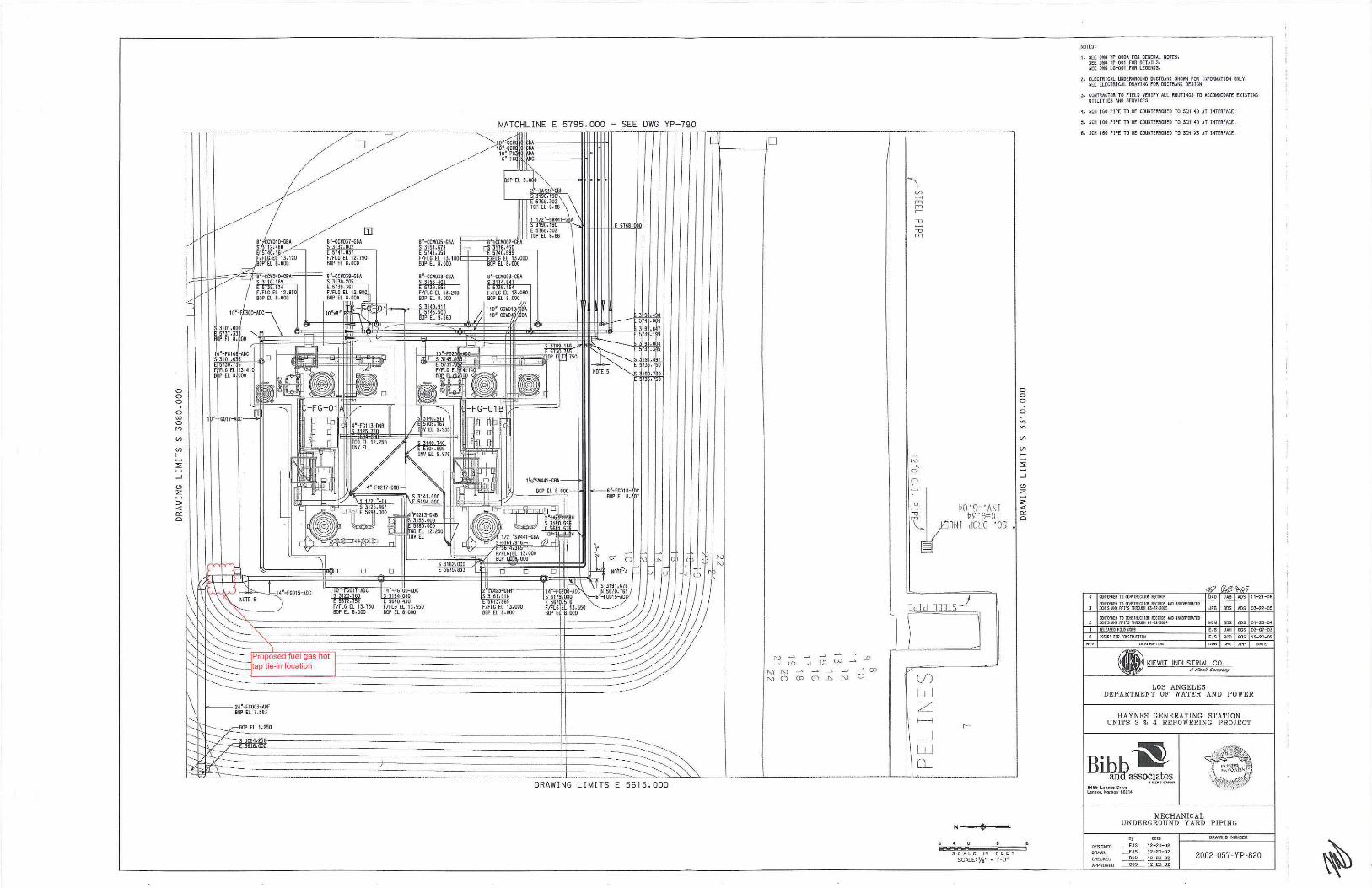
0 0 0
0 (()
0 I')
(/)
(/) f-
:::;;
_J
C)
z
"' <{
cr: a
0
MATCHLINE E 5795.000 - SEE DWG YP-790
_, .. Ba' EL 8.00)-
Ba' EL e.:p7
I< 1: 1~ l <t:>
DRAWING LIMITS E 5615 . 000
f-----~/0
~;,s;~u;;:; ::::: <.O NN --' ---"---" .._.),.~CP NOCXlO>J>,NO
h t/)
- 1 fT1 fT1 .-
0 0 0
0 I') I')
(/)
(/) f-
:::;;
_J
C)
;~' t>O'S==' ANJ ; ;:g v£ · S=::Jl gs \_ lN r dOHO ·os ,
§I
3d I d l331S _)
V)
w z __j
w Q_
S C A L E IN f E E T
SCAJ.£o Y•" • 1'-0"
..
NOTES:
1. SEE OWG YP-oooA FM GENERAl NOTES. SEE OVG YP-j)01 FM DETAILS. SEE ore l G-j)Q1 FOR lEGENDS.
2. ELECTRICAl UNOERGROONO OUCTBANK SHOWN FOO IM'M"'TION ONlY. SEE ElECTRICAl ORAIING FM OUCTBANK DESIGN.
J , CONTRACTOR TO FIElD VERIFY All ROOTING$ TO ACCOIO.OOATE EXISTING UTiliTIES AND SERVICES.
~. SCH 160 PIPE TO BE COUNTERBIIREO TO SCH ~0 AT INTERFACE.
5. SCH 100 PIPE TO BE COUNTERBIIREO TO SCH ~0 AT INTERFACE.
G. SCH 160 PIPE TO BE COUNTERBMEO TO SCH XS AT INTERFACE.
-4 «<f"IJII(O TO WISTR!JCTJ(tj IIEIDIDS 11 - 21--01;
Ctlf"IJIIolD TOta'ISTRUCTIOO fi1CUID5 00 ll:ttRF'aUTED 3 ECN'S .IJI) Rfi'S 1MR(LQI 03..,2-2005 JR8 BOS ADS OJ-22-o5
ctH'orutD 10 Cl1tSTR!XTICII RHtliiOS oUiO l t.CMPOUTtO 2 ECN'S 00 Rfi'S THRWGH 01-U- ZO!H '-IGM 80S ADS 01-23-{)4
PllW£0fULO P059 EJS JA.H GGS OJ--<()7-QJ
EJS RCD GGS 12--20- 02
DESCRf'TION
~.·. • KIEWIT INDUSTRIAL CO. '87 A /r'i#l,il Compony
LOS ANGELES DEPARTMENT OF WATER AND POWER
HAYNES GENERATING STATION UNITS 3 S. 4 REPOWERING PROJECT
8455 lenua Otlve l enuo,Korti<J:t 66214
MECHANICAL UNDERGROUND YARD P IPING
by DRAWING MJMBER
DESIGNED ~~ DRAWN ~ 12-20-oz
CHECKED ~ 12- 20--o2 2002-057-YP-820 .APPROVED ~ 12-20-02

Option 8: Provide Catch Basins and Drainage Pipe for the Switchyard Area
This option is to provide 2 catch basins on the west side of the Switchyard Area and the necessary
drainage pipe to connect the catch basins to the base scope BOP storm drain system. This option
includes all excavation and backfill work necessary to install the catch basins and drainage piping.
This option is based off LADWP's Switchyard Area grading drawing in Exhibit Z, section Z7. Any changes
in the Switchyard Area grading that would increase the number of catch basins or drainage piping is
excluded.
The project schedule as shown in Exhibit D will not change due to this option.
Option 9: 300,000 Gallon RO Reject Tank
This option is to provide a 300,000 gallon reverse osmosis (RO) reject storage tank in order to provide
holding capacity while the reject flow is directed to the RO reject tie-in point on the north end of the site
as described in the BOP Contractor's base proposal. This option includes the required foundation work,
including piling, and includes the field erection of the tank.
The following P&ID has been included to illustrate the changes to the RO reject system when this option
is selected:
• P010-017-PS-3760PT2
The project schedule as shown in Exhibit D will not change due to this option.
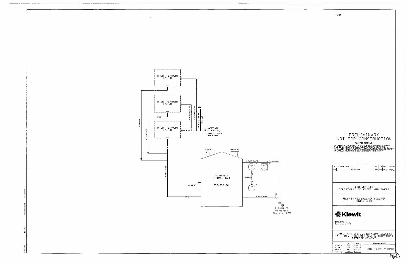
WATER TREATMENT SYSTEM I r----,
,.-----<=1-----y------
m
< ' • ?
' WATER TREATMENT i SYSTEM
1:~ l m ' u
------~------J ~, ll'l VENT ' m ~,<II e m • u a ' l m o r----<•J ~
------------·---·-·-·-------~ .. ~ ~
WATER TREATMENT j ~j__j_"_"j_~'~'~-~"~';'~'~'~-c~'~'~ SYSTEM Ji~-._, PS376-PS380-01
! TO RO PRODUCT WATER ' _____ T _____ j
m
< ' • ?
"
MANWAYit
STORAGE TANK
RO REJECT STORAGE TANK
300,000 GAL
OVERFLOW 6"-DWT-ABB
C) .... E'B
"'
,_______;;__='-----!~ ~ I 6"-0WT-ABB 1,-
~ TIE-IN TO RO REJECT
WASTE STREAM
NOTES:
-PRELIMINARY -NOT FOR CONSTRUCTION
CONFIDENTIAL
A ISSUEO FOO COillRM:I SRI! Cl\< DES tt 19 10
REV DESCRIPTION DWH CHS< WI' DATE
LOS ANGELES DEPARTMENT OF WATER AND POWER
HAYNES GENERATION STATION UNITS 11-16
8!Kiewit Kiewit Power ~~01 Re""~' Boulevard Lene<o, Konsos 55219
PIPING AND INSTRUMENTATION DIAGRAM DWT DEMINERALIZED WATER TREATMENT
REVERSE OSMOSIS
by dote 0RAW1NG NUMBER DESIGNED ----'!f.L_ 03-22-10
DRAWN ___2!l!!_ 03-22-10
1':,~:. CHECKED ~ DB-03-10 "~ APPROVED JRO 08-03-10
~-----------------------------------------------------------------~~====~----~~~~
P0!0-017-PS-3760PT2

Option 10: Engineering and Procurement for the total Switchyard, and Construction of only grading work,
piles, and foundations for the Switch yard
This option is to provide design engineering and procurement services for the switchyard scope of the
project as follows; and to provide construction services for the grading work, foundation work, and
piling:
• Ten {10) 230kV, 900kV BIL, 3000A, SOkA SF6 breakers
• One (1) 125VDC battery with two (2) 125VDC battery chargers
• One (1) complete lot of switchyard relay panels, communication panels, and RTU panels • Eleven (11) 230kV, 900kV BIL, 3000A manual disconnect switches
• Nine {9) 230kV, 900kV BIL, 3000A manual disconnect switches with grounding switch
• Twelve {12) 230kV, 900kV BIL single phase surge arresters
• Twenty-One (21) 230kV, 900kV BIL CCVT's • One (1) control enclosure
• One (1) lot of rigid 4" aluminum bus with dampening cable
• One (1) lot of 2- 1590 kcmil "Lapwing" conductor strain bus and jumpers per phase
• One (1) lot of lighting protection and static line
• One (1) lot of equipment support structures and insulators • One (1) lot of deadend poles and H-frames, including GSU dead end structures
• All grading, foundation, and piling work to support the above mentioned equipment
Material and services not included in the scope of this option are:
• Switchyard perimeter fencing
• Ground grid with associated stingers and ground rods
• Raceway, including PVC conduit and Trenwa trench • Control and power cable
• Labor for installation, testing and commissioning
The following assumptions were used to develop the scope and pricing for this option:
• The BOP Contractor has assumed H-frames in lieu of A-frames.
• The BOP Contractor has followed the one line drawing HNGS-0-SK-601-206-001 Rev D and plot plan arrangement P010-017-PP-001 for design basis and material takeoffs.
• The BOP Contractor has assumed four (4) 3-phase sets of surge arresters. There will be a 3-phase set of surge arresters for each of the two (2) underground lines and the two (2) outgoing overhead lines. GSU XFMR's will be supplied with surge arresters adjacent to the HV bushings.
• No revenue metering units have been included.
• The BOP Contractor has assumed that the BOP Contractor's scope of supply for engineering and procurement stops at the 230kV termination structures on the end of the main buses. Underground transmission cable materials and installation is not in the BOP Contractor's scope.
• The BOP Contractor has assumed the use ofTrenwa trench throughout the switchyard with PVC conduit feeders to different pieces of equipment.

• The BOP Contractor has assumed a 20 x 20 ground grid for the switchyard with a 6" layer of crushed rock on the surface.
• The BOP Contractor has assumed a control enclosure of size 60' x 15' for the new switchyard as indicated on plot plan POl0-017-PP-001 contained in Exhibit B- Contract Drawings.
• The BOP Contractor has assumed lighting fixtures on all switch stands and H-frames. No additional light posts have been provided.
• The BOP Contractor has assumed piles for the foundations at the switchyard. There will be one (1) pile for each small support and switch legs, and a cluster of four (4) piles for each H-frame or dead end pole. Pile lengths will be determined after the geotechnical report is completed. The breakers will be placed on mats.
• Since LADWP standards were not provided in advance of this estimate, the cost provided for this option is based on drawings HNGS-0-SK-601-206-001 Rev D and POl0-017-PP-001 and typical industry practice. If material changes are required because of LADWP standards, the BOP Contractor would request appropriate adjustments.
Please see the attached P6 Level 2 schedule, labeled Haynes Leve/2 Option 11- E/P/C SWITCHYARD.

A1000
A1010
A1210 If---==-~~""'"':''·
Kiewit Substantial Completion
Final Completion
Site General 386 18-Jan-11 16-Jul-1 2
A1220 T Detailed Engineering Design 325f 18~an~11 J 02-May-12
A2920 JIFC P&IDs - - I 40J15-Jul-11 I 09-Sep-11
A2930 i IFC UG ~ipe I Electrical _ -=- 34 J29-JUI=11 ~ -15-seP-11 A2940 IFC One-Lines I o J 15-Dec-11
A2950 IFCThree-Lines --- ~-- 01 -- 07-Feb-12
A2960 IFC Instrument Details l ~ 04 17-Feb-12 116-Jul-12
A3090 l iFC Mechanical Supports --~---------L~ 0120-Mar-12 Switchyard I Transformers 98 26-Aug-11 13-Jan-1 2
A2970 ,~c SkV Foundation oj 26-Aug-11 I A2980 IFC SkV System --0 1 0-0ct-11 ,. -A2990 l i Fe Race-w-ay_s___ ---- --0113-Jan-12
-----------------~--=-----"'-Admin I Warehouse 105 05-Aug-11 03-Jan-1 2
A3000 'JTFc Admin I Warehouse Foundations 0 I 05-Aug-11 I A3210 [ IFC DCS Interconnect -- ~ -- 01 03-Jan-12 ----
Water Treatment 0 21 -Jul-1 1 21-Jul-11
A301 0 JIFC Foundations FE Tanks 0 T 21-Jul-11
Heat Exhanger 0 08-Ju l-11 08-Jul-11
A3100 ~CHeat Exchanger Pile Caps --~~~~~--~-...J...--308~-J~u=l-1=1=~-==== Gas Compressors I Ammonia I Diesel o 02-Sep-1 1 02-Sep-11
A3020 I~? Gas Compressor I Ammonia Foundations _o J 02-Sep-11
CTG #14 0 08-Aug-11 08-Aug-11
A3030 IFC CTG 141 SCR 1 Foundations
CTG #13 A3040 IFC CTG 131 SCR 2 Foundations
CTG #16
A3050 JIFC CTG 16 I SCR 3 Foundations
CTG #15 A3060 T IFC CTG 15 I SCR 4 Foundations
CTG #12 A3070 JIFC CTG 12 I SCR 5 Foundations
CTG #11 A3080 IFC CTG 11 I SCR 6 Foundations
Procurement I CTG Package Equipment
--==~-' _____ r
A1730
A1270
A1630
A1670
A1290
I Procure GSU I Aux XFMR Material
[ Procure Air Cooled Heat Exchanger
J Procure BOP Equipment
I Procure Generator Circuit Breakers
Procure Pre-Engineered Buildings ~SUB)
- Actual Work c::::::::J Critical Remaining Work ~•--•o Summary
C==:J Remaining Work + +Milestone
0 [ 08-Aug-11 I 0 08-Aug-1 1 08-Aug-11
o T 08-Aug-1 Tj 0 08-Aug-11 08-Aug-11
0 J 08-Aug-11 J
0 08-Aug-11 08-Aug-1 1
0 l 08-Aug-11 I 0 08-Aug-11 08-Aug-11
o j 08-Aug-11 1
0 08-Aug-11 08-Aug-11
08-Aug-11
375 14-Jan-11 12-Jul-12
203 18-Jan-11 03-Nov-11
240 18-Jan-11 30-Dec-1 1
277 21-Jan-11 29-Feb-12
240 01-Feb-11 17-Jan-12
17-0ct-11
I I I I
+ !'Joliqe To Froc~ed I I I I
' ' '
I I I I I I I I I I I I J I I -- ---- , ----,-- - -- I" ---- .. ----,- ---,--- - --- --.-- ---.-----,-- - --.- --- r- - - -- - -- - - - -- --- - -.--- - -f s=juf--1-2.-~-~9i-~~~~i-~9 -- -I I I I I
..-----~~~~~~-... --...--... ----... ----... -------., ~ 6-Ju)-12, pite Genei;al
' ' ' D~taile~ Eng!neeri~g D~sign ~
.__,_--.-': I IF,C P&IDs :
. t::=:=J iFC UG Pi~e I EiectriG:al . . I I I I I I I I I I I I I I I I I t I I I I
-- ---- : ----:·---- : ---- ---- : ---- ·- - - - ~- - -- y --- ·:-- -- · :- ---- :- - . -(Fc·a~~=cr~~~- :----:-----:·----.--- --.---- ·:· ----:- ---j· -- -:--- -I t I I I I I I I 1 1 1
~ ~ ~ : ~· 1~c Three-L1nes ~ : : : ; ; ; . , . . !Fe l~strun:,ent Details
: : : • :IFC r¥1ech~nica( SupPorts ; 1 1 1 I I I I 1 I 1
, : . : . : . : : : : 1:3-Jar-12, ;switqhyar~ /Tr~nsformer~ ' ' ' -- ----:----:----- f- ---;- ---:-- --: --- --;-- ·· :· iFc-~sk"v -~ou~-~~~i~~----- ] - - -- f----] ----r----:-- --·:-----:---------- ---- ;---- ;-- --;- ---' ' ' ' ' ' ' ' '
; + I~C SkY Sy~tem ; ; ;
~ + lfC R~cew~ys . , , . o3:Jan~12, Apmin Y Wareho~se
I I I I I I I I
. . : , ~ IF~ Adl;nin I )Nar~hous~ Fo~ndat(ons ; , , , , ---·:----: -- -- :---- :---- -:-----:-----:--- --:---- ·:-- ---.-~-FE[icsinier~an~~~i ·:--- -·:---- -:-----
I I I I I I I
; • ; 21-J~I-11 ,;wat$r Tr~atmert
: + :IFc F.oundation:s FE :Tanks I I I I I I I
:• O$-JuH 1, H~at E~hanger ; I I I I I I I
, , , : ;+ IP;C He~t ExphanQer P~le Caps : , , , , , . I I t t ---; ---- ;----- i---- i-- --' I I I I I I I
' ' '
-- ---- ·--- -.- -- --,--- -,- -- -·---- ·---- -.----!- o2ts~i>~~ 1-.-~~~ c?mi>~+sso~s- i i\~-mo~i-~ 1 -~~~~~i~---- -.----t IFQ Ga~ Con)pres$or I ~mm\Jnia ~ounqation:s
~· o$-Au~-11 , ~TG ~14 ~ :+ u=:c c"T;G 14;1 scfl1 Fpund~tion~ I I I I I I
' ' ' ' ' ' ' ' ' ' ' ' ' ' ' ' ' ' ' ' ' ' ' ' , , , , , , :• 0~-AUQ-11, ~TG ~13 : , , , , , . . ' ' ' ' ' ----:----:·-- --,----:----:----·----:+-iFcci:G1-3fs-cf:f 2 F"~~~da'tians:--- -:- --- ·:- ---·:·----:----- ---- . ----.-- --;---- ;----1 I I '
' ' ' I I I I ' ' I I I ' I I ' ' ' ' ' :• 0~-Aug-11, QTG #16 ; ; ' ; ' ' '
' ' ' -- -- --;-- --,----- ; ---
:. IF:c cT.G 1e:1 seA 3 FbundatianS · · I I I I o I
:• o$-Aug-11, CTG #15 ; I I I I I I
, :+ IF;G C"f:G 15;1 SC~ 4 Fpund*tion~ . , , , : : : --- -:---- --- --~~- o~~i\~~=11: -~;:c3-~12--f·- - -;---T -- - ~ ---- ·:- ---- -- -f ---~--- __ : ____ -:-- --[ ----:+ IF:C CT;G 12;1 SCf! 5 Fpund$tion$
~· o$-Au~-11, ~TG ~11 ~ ; ~ :+ IF:c cT:G 11 ;1 scfl6 Fpund~tion~
' ' ' ' ' ' ' ' ' ' ' ' ' ' ' ' ' ' ' ' . ' ' ' ' ' ' ' ' ' ' ' ' .
: , , , : : : , , : : , , , , , , : 0~-AUQ-12,proc~rem~nt -- -- , --- - ·----- L ---- L ---- · -- --,-- -- J --- - -·---- -·- - -- -·-- - - -·----- , ---- '----,-- -- , ---- J ------- -- -·--- -6=rG-~-~~k~~~- E~uip~~~~ -: --- -
> I I 0 I I I
Pr~cur~ GS~ I Au~ XFtjA R M~teri~l
e=========~~~~ Pr~cure ~Air Cpole~ Hea! Exc~ang~r ~~~~~~~~~~~ Prqcure ;BoP;Equi~men~
-:- ----:- --- -;-- -- -( --- +--- -;----' ' ' '
Page 1 of 5
, : ~ Fi~al Cqmpl~tion ; , , - - --.,-- - - .,-----.----- ----..- - --- ,.---- ,. - ---., --- -.,----
-----.----- ---- .- ----. .
' ' ' -- - -;- - -- -----,-- - --,- - - - -~- - - - -
I I I I
' ' ' ' ' ' ' ' ' ' . ' ' ' ' ' ' ' ' ' . ' '
.
----,----;----
' '
' ' ' - - -- ; ----; -- --;
' ' ' ' ' ' ' ' '
' ' ' I I I I I I - - ,- - -- -,- -- - - .- --- - - -- - r - - - - 1 -- - - 1 - - - -
'
. ' ' ' ' ' ' ' ----.- --- - -- --,---- -.-----.----- ---- --- " " 1"-- "1" - ---
' . ' ' ' ' ' ' ' ' ' ' ' ' ' ' ' ' ' ' ' ' ' ' '
' ' ' --- --- --,--- --,-----.- ----' ' ' ' ' '
--- - -- -- --- - -- -- -:--. --:-4---:----. ' ' ' ' ' ' ' ' . ' ' . ' ' ' ' ' ' ' ' . ' .
' ' ' -----,-----,-----,-- - --
@ Primavera Systems,

Haynes Level 2 Option 10 - E/P Switch yard
Activity ID Activity Name Original Start Duration
Finish
A 1300 Procure Balance of Electrical Equipment 229 22-Feb-11 120-Jan-12
A 1280 Procure UPS and DCS Systems 187 15-Ap~-11 13-Jan-12
A1680 Oil Water Separators Delivered _]__ I 05-Aug-11
A 1640 Air Cooled Heat Exchanger - Start Delive~y --=--=---=- I ~ 15-Sep-11 I A 1870 j CTG #13 Re~dy T-; Shjp 1 114128-0ct-11 113-Apr-12
A 1860 -=I CTG li14 Ready To Shlp- --- - 111'1 02-N~: 11 1 13-Apr-1~ A1370 15kV Delivered I 0 I I 03-Nov-11
A 1890 CTG #11 Ready To Ship ! 140 23-~~-~ 114-Jun-:12-
A 1480 I 480V MCC Delivered_ 0 I 01-Dec-11
A 1590 Switchgear Delivered _ I__ 0 - --oS:Dec-11
A1880 CTG #12 Ready To Ship _1_~2_1 , 22-Dec-11 14-Jun-12
A 1650 Air Cooled Heat Exchanger- Finish Delivery _j 0 I 130-Dec-11
A 1600 l lso-Phase Duct Delivered I 0 I 17-Jan-12
-~ 0 Non-Seg Bus Delivered I 0 j 118-Jan-12
A 191 0 I CTG #15 Ready To Ship 135131-Jan-12 09-Aug-12
A1740 SCR#14Delivered _ _ o j 101-Feb-12
A 1690 Fuel Gas Compressors Delivered ~ 09-Feb-12
A1710 GEMS Delivered ~-~ -~ 13-Feb-12 A 1720 - -I c;mplete Steel Delivery 0 I 28-Feb-12
A1900 - --~ CTG #16 Re;.dyT"a"Stiip 11] 29-Feb-12 [ 0-9-Aug-12
A1700 I BOP Equipment Delivery Complet;" oj 129-Feb-12
A 1750 I SCR #13 Delivered - - 0 j I 02-Mar-12
KIEWIT POWER CONSTRUCTORS 1 0-Dec-1 0 13:2
:Proc)Jre Balance of I:Oiectrical ~quipment
c:;=::;:=:;:::=:;~:::;:. =::;:. =::;==:;::==::;:::~ ~rocu:re U~S an~ DC~ Sy~tem~ !
~ Oi! Waf:er Sepera~ors qelive~ed i , , : ' I I I I I ---- .-- __ :__ : • N:_?~~~~-~~~~~~l~~?~~~~~[--_~-~~~ ~~~i~~-1- --- .:. --- -·---- -~---
C?TG f!13 R~ady;To S~ip --- - 4-- - - .. -- - - - -- - ---- --- - --- --·---- -·- --- ---- - - --~ - --... ---- ~ ----.. -----
: , , , , ~TG ~14 R~ady!To S~ip ~ 5k~ De~iverep ; ; : ; I I I f
I 0 I I I
, , • 48QV M¢;C D:eliver,ed , , , , , , , , --- -·----- ----- -----.---- . ---~- --- -·-- -- T--- -~ -- - -~ -S~i-tch'd,~~r -~eiiv~red- r-- --- --- ·:-- ---·- --- -~-- ----- -- r---- ~ --- - .- --- ---- -- -- ~ ---: : : erG #12 Ready:To ship : :
I I I I I I I I I I I 1 1 I
: ; ~ Air pool~d H~at E~changer - finis~ Deli;very ; ; :
: : : • iso-Phase iouct :oeliV.ered : : 1 1 I I I I I I 1 1
I I I I I : : • : • Non-~eg $us D~liveied : I , I I ; I ' o o o I -- · ···--- · ·-- ·- ·----·---- · -- -- ---- --·-- ---·---- -·- --- -·-----:---- ~----:----:---- ~---- ~ ---- -·-----·- -- -~;:ci#~s R'~~dy t"a"s~ip -- ---- -- -- ~---- -- - - -·-- - - -·--- - - .... - - - - ~ - - - - ~ - - - - ~ - - -
+ SCR #1;4 Delivered I I I I I I I 1
; + ~uel Qas C~mpr~ssor~ Deljvere~
: + CEMS Delivered I I I I I
. • Cor,nplet~ Ste~l Delivery; , I I I I
-- - -·-- -- _,...--- _,_ - - -- ,_ - ---.---- .. ---- ~ - --- .... -- . .. . --- -·- --- -·- - -- -1----- ~ ----~ --- _ .. - --- ~ ---- - - - - -·· - - - • I • - - - - ... - - - - ~ - - - - .. - - - - ~ -- - - ... - - ---
' ' ' ' ' ' . , , , , , , ~TG#~6R~adyToS~ip ' ' ' ' ' . ' . ~ so;P Eq~ipm~nt D~livery Co~plet~ ' ' • SQR #1 !3 Del)vere~ : :
' • scR #12 DeliVered I
I I I I I A 1760 I SCR #12 Delivered o I 130-Mar-12
A1800 CTG ~14Delivered I _ o j j 13-Apr-12 _ __________ , _____ _
A1810 CTG #13 Delivered 01 j 13-Apr-12
A1770 SCR #11 Delivered I -_ 0 . j 01-May-12
- - - - ~ - - - - ~ - -- - .. - - - - • I • - - - - · - - - -
'
; + CTG #14 D~livei,ed , . . , - --- ~--- - ~- --- .. --- - ~- --- ... - --- ... ---- - 1-----1- -- -- ... ---- .. -.-- .. --- - ~---- .. ----
+ C?TG ~13 D~live~ed ;
+ SQR #1 i Delivered
.. ---- ~ ----~ -. ' ' ' ' .
A 1780 SCR #16 Delivered 1 ~ I _1 31-May-12
A 1820 I CTG #12 Delivered 0 j 14-Jun-12
A1830 CTG #11 Delivered I - 01 [ 14-Jun-12 ______ _
A 1790 I SCR #15 Delivered 0 j 29-Jun-12
' . . I I I I I + SCft #1 ~ Deli~ereq : + CTG #12 Delivei.ed I I I I I
, , , , , , ; + ¢TG #11 Qelivei,ed , , : - - - - ... - - - - .. - - -- ~ - - -- • - -- - • - - - - .. - • - - - · - - - - •I• - - - - .... - - - - ... - - - - .. - - - - • - - - - .. - - - - • - -- - .. - - - - .. - - - - • I • - - - • I • - -- •I- ---- .. ---- .. - - - - • - - - - .. - -- -
: I : : : : I : : : : : ~ sc~ #1 ~ Deliyere~ ; : , : : : : : : : : : . c:TG #j 6 oeliver9d I I I I I I I I I I I I I I
; ; ; ; : : ; ; ; : • C:TG #~5 D$1iver~d
-- -.... ---- .. -- -- .. ---- .. ---- .. ---- -I I I I I I I I
I I I I
I I I I
I I I I
I I I I
I I I I I I I I
' ' ' ' ' '
A 1840 I c TG#16 Delivered I _o 1 _ ~-Aug-12 A 1850 _I CTG #1 ~ Delivered 0 09-Aug-12
Construction 561 14-Jan-11 18-Mar-13 ... ~~· -~-i--!-·-~-i-~-~-~· --!-·-~-~· -•· -•·-~· --!-·-~--!-' --'!'--!-' -~· --!·-~--!---!--. ~ 8-M~r-13; Co~struc~ion . . '
Milestones
A1 030 TRough Grading Start
A1 050 I Construction Mobilize
A3270 Switchyard Grading Complete
A1 060 I Owner Water Availabe
A1 080 I Switchyard Complete (BY OTHERS)
~4~ 113.8kV Permanent Backfeed Available ____ _
A 111 0 BOP Complete
A 11 00 I Demin Trailers Available
A 1120 Owner Gas Available
A 1360 I CTG 14 Mechancial Completion
A 1380 I CTG 13 Mechanc~ Completion
A 1490 r CTG 12 Mechancial Completion
A2430 -I CTG 11 Mechancial Completion
- Actual Work c:::=::J Critical Remaining Work 0 c:==:J Remaining Work + + Milestone
442 01 -Apr-1 1 14-Dec-1 2
0 I 01-Apr-11
o l 01-Apr-11
0 I 126-Apr-11
oj 02-Aug-11
0 l 29-Mar-12 ~ -
~{ 0 [ 25-Jun-12
I ~ I of
L_o j
16-Apr-12
30-May-12
01-Jun-12
r 11-0ct-12
j 18-0ct-12
1
13-Nov-12
21-Nov-12
I I I I I
I I I I I I I I , , , , , . , , , , , i 4-DS:c-12i M ile$tone:s ; : : . , , .
-- --·--- -+--R~u9h-~-radi~9- st~-rt - - -.--- - -.-- -- ·• • • - - 1 - - - - r - - - - 1 • • • - '"I- -· • .., -- - • -,-- - - -,- • - • • r • • • • r • • - - r • - - - 1 - · - - 1 • • • .., • • - - 1 - - - - .., - - - - .., -- - - -~- - - - - , - - • - • r- • • • • r • • • • r • • • • 1 • • • - 1 - - - - -
• CO,nstruption ;Mobi(ize : I I I I I I
~ Switch yard Gr~ding; Corrjplete;
+Owner V.Vater.Avaiiabe o I I I
o I I I I , , ~ Swi~chy~rd Cqmpl~te (BY OT~ER$) , , , , . . , . , . , ,
---- ' ---- , . • - -- --- -~ - .. - ·r-- .. ----:----:----:-. -·risk\t-F>e)rm~r,-~nisi~i<~~~d- A"Jaii~bie- -- :---- · -- - · : --- - : ·-- -:· --- ·:-- -- ·:-- ·- ·: · ·--: - · ·------:-- .. , -----1 I I I I I I I I I I I I I I
; ; ; • BOP Co[nplet~ ; : : : ; ' ' I I I I I I I I I I I I 0
; : ; ~ Defnin T;raile(:s Av~ilabl$ ; I ;
; : ; ; .; owner Gas Availabte ; ; I I I I I I I I I I
' ' : , ; • : , I , :• QTG 1~ Mef:han¢ial Qompl~tion ; , : I , • ,
- - - • 1' - • - ~ , - - - - - · - - - - -.- - - • --- ·:----- ----[-- --:-- --: -. -- :---- ~ ----T-- --:---- ·:·- ---,-.-~TG ~-3 -M~-~h~~~~~~ ~~m~ieti~~----r-- ·:--· --:----· [----:-- --[---- :-----: ; ; + CTG 12 M~charicial Completion; : ; ; ; I I I 1 I I I I I I I I I
: : • : crq 11 f'v1ech~nc ial ; comp1eti~n : : : :
Page 2 of 5 TASK filter: All Activities
@ Primavera Systems, Inc.
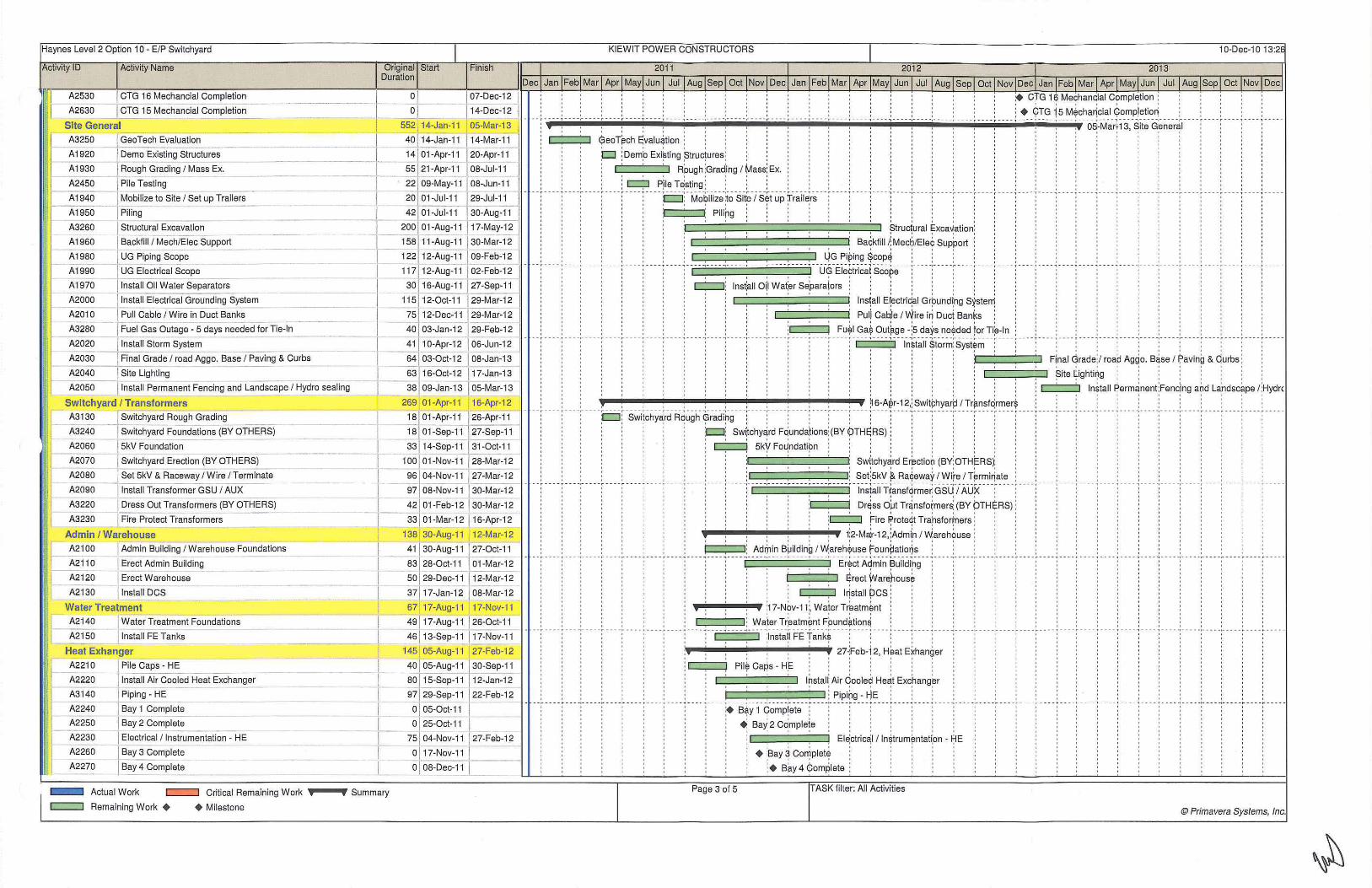
Haynes Level 2 Option 10 - E/P Switchyard KIEWIT POWER CONSTRUCTORS
Activity ID Activity Name Finish
A2530 I CTG 16 Mechancial Completion
' ' I I I 0 I I ' ' '
A2630 J CTG 15 Mechancial Com.;..p~le=tio~n _ __ _ __ l ~0 107-Dec-12 _ ~ 14-Dec-12
-~-- --- -r--- - -- --.- • • - T • • • • f • --- ,. • • - - , - • • • • o• • • • •o• • • • • . --- "'!·--- .,. --- .,. - - - - r ----
Site General
A3250 __[ GeoTech Evaluatio~ Demo Existing Structures
Rough Grading I Mass Ex.
552 14-Jan-11 05-Mar-13
40" 14-Jan-11 114-Mar-11
14Jo1-Apr-11 120-Apr-11
I 55 j 21-Apr-11 08-Jul-11
A1920
A1930
A2450
A1940
A1950
A3260
IPiie Testing -
Mobilize to Site I Set up Trailers
I Piling
---r 22lo8-M~y-11 1 o8-Jun-11 -I 20 01-Jul-11 t 29-Jul-11 - - - - - --
[ 42 01-Jul-11 30-Aug=-11"
_, __ 2oo l 01-Aug-11 117-May-12
A1960
A1980
A1990
A1970 -
A2000
Structural Excavation __ _
I Backfill / Mech/Eiec Suppo_rt_
UG Piping Scope
I UG Electrical Scope
Install Oil Water Separators
l~t~liEiectrical G_r_ou_n_ding Sy_st_em_
Pull Cable I Wire in Duct Banks
158, 11-Aug-11 130-Mar-12
~- 122 12-Aug-11 I 09-Feb-12
I 117 12-Aug-~ 02-Feb:!. 2
I 30 16-Aug-11 127-Sep-11
115 12-0ct-11 29-Mar-12
40 03-Jan-12 29-Feb-12
A2010
A3280
A2020
A2030
A2040
--j Fuel Gas ~utage- 5 days needed for Tie-In _
j lnstall Storm System __ _ __
Final Grade I road Aggo. Base I Paving & Curbs ----
I ~ 12-Dec-11 29-Mar-~2 ~
[ 41 .10-Apr-12 I 06-Jun--=-1"2 -~ - - -
[ 64f o3-0ct-1210aTan-13
I 63J16-0ct-12 117-Jan-13 J I 38 1 09-Jan-13 J 05-Mar-13
Site Lighting
A,-2-05- 0---l lnstall Permanent Fencing and Landscape I Hydro sealing
Switch yard I T ransformers 269 01-Apr-1 1 16-Apr-12
A3130 Switchyard Rough Grading I 18 01-Apr-~1 26-Apr-11
__ _ I 18 01-Sep-1~ 27-sep-11
A2060 5kV Foundation I 33 14-Sep-11 31-0ct-11
A3240 Switchyard Foundations (BY OTHERS)
A2070 I Switchyard Erecti~ (BY OTHERS) 100 01-Nov-11 128-Mar-12
A2080 I Set 5kV & Raceway / Wire /Te~e I 9s 04--~v-11-·J 27-Mar-12 A2090 j Install Transformer GSU I AUX 97 08-Nov-11 30-Mar-12
A3220 Dress Out Transformers (BY OTHERS) I 42 1 01-Feb-12 30-Mar-12
A3230 Fire ProtectTransformers I 33 01-Mar-12 16-Apr-12 ------------~-
Admin I Warehouse 138 30-Aug-11 12-Mar-12
A2100 l Admin Building I Warehouse Foundations I 41 ~0-Aug -11 27-0ct-11
A211 0 Erect Admin Building J - 83 28-0c~ 01-Mar-12 I--A2- 1-20 -E-re-ct-Warehouse -- [ - SO 29-Dec-11 12-Mar-12
A2130 J Install Des I 37 17 -Jan-12 08-Mar-12
WaterTreatment 67 17-Aug-11 17-Nov-11
A214~ I Water Treatment Foundations j 4s[ 17-Aug-11 126-0ct-11
A2150 Install FE Tanks I 46J13-Sep-11 117-Nov-11
Heat Exhanger 145 05-Aug-11 27 -Feb-12
A221 0 Pile Caps - HE
A2220
A3140
A2240
A2250
A2230
A2260
A2270
Install Air Cooled Heat Exchanger
Piping- HE
Bay 1 Complete
I Bay 2 Complete
I Electrical / Instrumentation - HE
J Bay 3 Complete
J Bay 4 Complete
- Actual Work c::==::J Critical Remaining Work 0
c=::::J Remaining Work + +Milestone
I
I-I-I I I
0 Summary
40 05-Aug-11 30-Sep-11
80 15-Sep-11 12-Jan-12 - -
97 29-Sep-11 22-Feb-12
o lo5-0ct-11 I o j 25-0ct-11 I
75 J 04-Nov-11 J27 -Feb-12
o j 17-Nov-11 J
0 J 08-Dec~.!_ l __
- -- ----
o ' I I I I I I I 1
$eoT~ch E;valu~tion ; o o I I
p ;Demp Exi~ting ~truc)ures ;
Rpugh ~Gra~ing I ~ass! Ex.
c:::::;:J Pjle T~sting ; . : : , ' ' ' I I I I I I t I --- -~----p~ - Mci~iii~~-~~ ·si-~"i s-~t-uii fl_.rail~rii-- [ --- · :·- - - 1'--. - - - -~---- -, -- - - -..- - - --..-- - -- r - --- ,--- - 1 • --- , - -- - 1- ---
: ) : Pili[lg ; ' ; ; ; ; ; o o I 0 I I o I 1
, ~truc1ural ~xca~ation ;
I I I I I I
Backfill /; Mecb/Eiec Support ;
: , , , , , ~G Pi~ing ~cop~ : ~ ! ~ , , , , - •, • -- •, • • • • •o• • • • •o· • • • •o• • • • •,. • • • • t" • • • • T • • • • T • • • • • -- ·-: -- --: ----:-----.---- -·- ---....... ,--- -,---- ·--uE Eiei:!ri~a.rs~~~ie - · ·:· - - - ·:- -- - -:- -- ·- : -··· : ··-- :- - --:--- -: - - --
! ! ~ C:J~ lnst~ll 0~ Wa~er Se~aralors : : i : : ! ! ! ! ! :
' ' ! ' ' lnsiall El:ectri~al Gr~und(ng S~ste~ ! ! !
: Puli Cab:le I Wire iri Duci Banks ; :
, , ! . , , , Fu~l Ga$ Out~ge -!s da~s ne~ded for Ti~-ln ; ; - - - -,---- , ---- -.---- ..., -----.----- .- ---- .- ---- y---- y-----
1 I I I I I I
I I I I
I 0 I I
• • · -:· • • • -~ • • • • • • •• ; ·-·· ; • • • • ~- • • • • :• • • • •: • • • • -~- - - • · :· • • • -~ •• •• ; · - - - ~ - - --~- - •• ,. • • •-, • -- - -,---- -, - - • • ·:• • • •-,.- • • • - r •• ... • • - T • • • •., • • • •
: : : , : : : : : , : . : ln~tall ~torm: Syst~m
i : : i : ' : ! : i ::c::::::::::::::::~ F(nal Grade;/ roa~ Aggo. B~se I Paving & Qurbs ' ' ' ~ite ~ighti~g
0 I I 0 I I 1
o o I I 1
' ' ' ' ' ' ' ' ' ' ' '
I I I I I I
, , , , , , , , , , , ~ 6-A~r-12,: Swit~hyarp I Tr~nsfqrmer$ , --- ·:o ·swi!~hy~rci R"~u9t;~;~d~9-- -~ - -- -~ ----~ · ---:- ·- -f ---- · ---- ~ ---- ~ ·-- -~- - --,- -- ···· · · · ··--- ··---- · · · .. --·- ·-·--
: ; t::::::J; Swi:tchy~rd Fqunda\ions;(BY ¢>THE;Rs) ; ; I I I I I I 1
; c;:::::::::! sky Fo~ndatipn
: : :c:::::::::::· ~· ==· ::::':::::::J , : Set;skV $<. Ra¢eway I Wire I T~rmi~ate
---- :---- : - --- ~---- : ·- --- - --- -.-----,- -- - · ---- , -- -- · · ~~~!ail-rta~516rme~ C3s·cuP.ux··- -· · -·-: --- -I I I I I I I I I I
; : ; Dr~ss O~t Tr~nsfo~mers; (BY OTH~RS) : I I I I I 0 I I I
: : ;c:::::;::J fire ~roteqt Trarsfor~ers :
' ' : : : : 1:2-M~r-12, :Admi~ I ~areh?use ! Adrj1in B~ilding I Warehquse f=ounpatior)s ; , ; , , ·---·-·-· ·-· ·r-····----·----··----_,----·--- -·- -E~~~~ i\~mi~- ~uiid~9 · ·r-· · ·:·---··· ·- ··---· · -· ·-·---: ----
; greet Warehouse ; I I I I o
. . , !~stall pes ; ;
,..!-..-.-~r j17·N?v-11; Wa~er Tr~atm~nt ! , ; Waier Tr~atm~nt Fpund~tion~ ; , , ,
--- ---- -- --.. -----. -----.---- -1-- ---·-----o--- -- ~ ----·-- - -- .- - ---~---- · --- -.. ---- .. -----·----- .- ----·---- - ----: ; ;1 nsta~l FE Tank~ ; : ; '
27~Feb-i 2, H~at E~han~er I I I I I
I I I 1
' ' ' Pil$ Caps- HF
l~stal( Air qoole~ He~t Exc~ang~r
-. -~--=-~--.=-_:::: __ :::::_,_:::: __ :::: __ :::,_:::: __ :::: __ :::, _::::J_-_j_ ~-i~!~~-~ ~~--- : ---- j_-- -j.--- .:. -- -.:. --- _;_---. ;+ B* y 1 qomp!ete ;
+; BaY; 2 C~mple!e
+ ~Bay~ Co~plet~ ; + B~y 4 ¢ omplete ;
Page 3 of 5 TASK filter: All Activities
ln~tall ~erm~nent!Fenc)ng a~d L~ndsc~pe <Hydrc I I I I I I I 0 I I I I I I I I I I I I I I I I I I I
- • • ·., • • • ·., • • • • -. - • • • -. · • • • · o· • ·- ·r ·- - .,. · -- · r-- • • r • • • • •
' ' ' ' ' ' ' ' ' ' ' ' ' ' ' ' ' ' ' ' I I I I
I I I I
I I I I
---- .. --. -·-. -. -·- ----.--- - - "" ---. "" - -- --I I o I I I . ' '
@Primavera Systems, Inc.

Haynes Level 2 Option 10- E/P Switchyard
Activity ID Activity Name Finish
~l A2280 I Bay 5 Complete .1 A2290 - ! Bay 6 Com:....pl-et_e __
~=====
__ 0129-Dec-11 ~ 0 12-Jan-12
---... Gas Compressors I Ammonia I Diesel 181 16-Sep-11 29-May-12
A2300 ] Diesel Generator Foundations
I Set Diesel Generators I
A2330 Gas Co~ressor I A~monia Pump Foundat1~ns
A2320 J Set Diesel Pumps I Tanks _ I A2370 1 Set Ammonia Forwarding Pumps J
A2400 I Erect Fuel Gas Compr; _ssor Pre-E_ngr Buildin~ - ___ _
1 0 j 1 6-Sep-11 129-Sep-11
- 19 130-Sep-11 (27-0ct-11
27 j 30-Sep-11 J 08-Nov-11
_3'i'7 -Oct-11 128-Nov-11 ~ 23-Dec-11 31-Jan-12
8~ 03-Jan-12 03-May-12
39_117 -Jan-12 1. 12-Mar-12
30 j 1 0-Feb-12 23-Mar-12
A2380 Ammonia Piping f A2340 I Set Gas Compressor Equipment ------ ~
A2390 fA~monia Ele~tircal / lnstrumentation - I A2350 I Gas Compressor Piping
A2360 Gas Compressor Electircal / lnstrumentation _j--A241 0 I Fuel Gas Regulator Station __
A2420 J Insulation (SUB) - FG
CTG #1 4 (Clutched)
A2490 j Concrete - CTG 14 ~ower Block Are~ I A2520 r Erect SCR Casings/ Weld Out I -A251 0 T Erect/Install CTG Equipment t A2470 [ Erect/Install Accessory Equipment __ - .
- 1 A2460 Jlnstall BOP Mech Equipment/ FP System
A2480 - ! Install Piping (include vendor) =± A2500 AG Electrical/Instrumentation
A2440 - -~ Mech lnsuL (SUB) ~--~-----~- -
CTG #13 A2590
A2620
A2610
A2570
A2560
A2580
A2600
I Concrete - CTG 13 Power Block Area
I Erect SCR Casings/ Weld Out -
I E~tiettlnstall CTG Equipment
I Erect/Install Accessory Equipment
Install BOP Mech Equipment/ FP System
I Install Piping (include vendor) -
AG Electrical / Instrumentation --- --
A2540 Mech lnsuL (SUB)
CTG #12 (Clutched)
A2690 l Concrete - CTG 12 Power Block Area
A311 0 Erect SCR Casings/ Weld Out
A271 0 I Erect/Install CTG Equipment
A2670 Erect/Install Accessory Equipment
A2660 I Install BOP Mech Equipment/ FP System _
A2680 Install Piping (include vendor)
A2700 I AG Electrical/Instrumentation -
-I 4 -f
~-j I I I I
-- I __ I A2640 I Mech l_ns_u_L...:..(s_u_B..:.) ______ ==--=~--d---
CTG #11 A1550
A2720
A1570
Concrete - CTG 11 Power Block Area
I Erect SCR Casings/ Weld Out
! Erect/Install CTG Equipment
- Actual Work c=::=:J Critical Remaining Work •o--•o Summary
c::::J Remaining Work + +Milestone
51] 21-Feb-12 1 01 :May-12
60 122-Feb-12 15-May-12
59 [07 -Mar-12 129-May-12
11 J16-Mar-12 30-Mar-12
30 j1?-APr="12 J29-May-1-2
303 06-Sep-1 1 06-Nov-12
67 J 06-Sep-11 13-Dec-11
7 4 1"'ii2-Feb-12 16-May-12
80 16-Apr-12 07-Aug-12
80_1_ 30-Apr-12 21-Aug-12
7211 0-May-12 21-Aug-12
86 21-May-12 20-Sep-12
82 15-Jun-12 11-0ct-12
42 ] 07 -Sep-12 06-Nov-12
290 05-0ct-11 16-Nov-12
67j' 05-0ct-11 113-Jan-12
7~ 05-Mar-12 111-Jun-12
80 J16-Apr-12 I 07-Aug-12
77130-Apr-12 116-Aug-12
65 J14-May-12 J14-Aug-12
86 24-May-12 25-Sep-12
18-0ct-12
16-Nov-12
292 02-Nov-1 1 18-Dec-12
67[~2-Nov-11 110-Feb-12
7o j o2-Apr-12 J1o-Jul-12
78 , 15-Jun-12 ro4-0ct-12
70 , 29-Jun-12 I 09-0ct-12
73 09-Jul-12 119-0ct-12 !
75116-Jul-12 -J30-0ct-12
78 24-Jul=-12 ] 13-Nov-12
42 J17-0ct-12 18-Dec-12
271 02-Dec-1 1 19-Dec-1 2
67 J ~2-Dec-11 109-Mar-12
721 02-May-12 13-Aug-12
7 4 15-Jun-12 28-Sep-12
Dec
KIEWIT POWER CONSTRUCTORS
; + ~ay 6;complete
... -!-~.-...... -~.--!-. _lllj __ _.._-i-_, 29-May-l2, Gas ccimpr~ssors I Ammonia 1 Diesel : I I I I I I 0 I j ! I : I I I
d Die:sel ~ener~tor Fpund;ation~ 0 I I I I j I
c::::J : Set: Diesel Geheratbrs : , . --- --:-- ---:-----:- ----:---- - ~- --- ~---- ~- ---7--- -.~ ---- -:-----:- -- --:-- ---:--- - -;.---- r- -- -{--- -r- --- ~ -- -- { ---- -:-- -- ----:-- -- -:-----:----- r---- r -- --1----7-----
: c=:J Gas Compressor:/ Ammoma Pump Fo.undations : : : : : : : : : : · · : . . . ----,- --- -;.--- r-- . -
I I I I I I I I I I I I I I I I 0 I
; ; Set;Dies~l Pu[nps 1: Tan~s ; ; ; . : ; ; ; · ;
; · C:::::::i Set Ammoni~ ForWardi~g Putnps ; · ; · : I ! I I 1 I I 0 I I I
c:::::=:::::::. =j. Er~ct F~el G~s Cqmpre:ssor Pre-E;ngr ~uildi~g Ammdnia Riping : , · ·
-r -- --:.- --- r--- -1- --- 1---- -:-----:-----:- --- - ~ --- -t-- --}----r ---- 1---- r--- -1 --- -1--- --:---- -:- --- -:- -- --r .. --r---- ~---- r---- -: c:::=::::J :Set Gas Gompressar Eq1..1ipment : : : : : : : : : : : : : ! 0 I > I 1 1 1 : : I : : : : : : :
ArJimoni~ Ele:ctirc~l / ln~trum~ntati(m ; : : · · : · · · :
' . ' - ---,-----,- ----;·-' . .
. . . - ------- -;--- -;----
c===::J ~as ~ompresso:r Pipibg j , , . . . ,
c::::=::::::::.=j. Ga~ Co~pre~sor E!Jectirpal / l~stru~ent~tion j , , . . . q Fu~l Ga~ Re~ulator Station ; , , ; . . . . . . . . : . .
---- --- --:-----:---- ·:---- ·:- --- ·:----: -- -·: ---- :-- C:::::::::::J --,;;s-ul~ti~n -(stJs) ~ -fG- -·:---- ·: --- -:- -- -:----:-- --:----:-- --·:· --- -:--- --:--- --:-- ---:--- --:-- -·:-- ---! ' ' ' : : : : : : : : ' ' ' o~-No~·12, QTG#14(i:;lutc~ed) ! ! ! . ! ! !
· Conc+te - jCTG j14 P9wer ~Joe~ Are~ . ; ' ;
; l=rect;scR; Casi~gs/ '?Veld jout , j j
. . . , . , , . . . . . Etect/l~stall ;cTG ;Equipmen1 , . . : . . . . . ; --- -- · ---'"--- -.-- - --.- - --- .--- - - , -- --.- - --- ,---- , -- -- · ---- , -----.---- ·:-Er~Cfti~siaii -Acc~-;;o;yEqui,;rr;~;,i- : ---- : ---- ·:- -- - : ---- ·:----- - - -- ·:---- : ---- ~ -----
c::;::::::;= =;=::J i lnst~ll sop Me~h E~uiprn:ent/ fP S~stem! : : ; :
j lnst~ll Pipjng (i~clud~ ve~dor) j
c~:::::::=:::==::J AG El~ctric~ l / ln~tru~enta\ion
, , , . : . , , . , : , . . M~ch l~sul. (SU~) ' ' ' ---- -- -- ---- -- -'" --- -,-----,-----,--- -'--- -, ---- , --- -;- ---,- ---,- --- ~-- --·;---- -,----.----- j 6-Nov~12~ -CTG-#1 ~ ---- -- - ~- - - - - ,-- - - ·r - - - - r- - -
¢onc~ete - ;cTG ;13 Ppwer F3Joc~ Are~ I ' ' I I I
~reel ?CR ~asi~gs/ IJI:Ield <?ut .
C:=~=~~ Erect/l~stall :erG ;Equipmenl I I I I I I
: , . . . . : , . . . Frec~lnst~ll Acqessory Eq~ipm~nt , , o I o f ' ---,- --- T--- -.-----, ----,- ---.-----,---- ·---- ·---- ,---- ,--- --~nsi~ifsoP;-M~c~-Eq~ipn,-~n!/W sy~tem- ~-- -- --· -,-- . --,- - - --,- - - - -r --- - ,- - -- --
c=:;:::=;=:::::::J : lnst~ll Piping Onclucle vendor): : 0 I I I I I I
;AG t::Jectri~al / lrstrurnent~tion ;
.-'---'--' ...,, Mech lnsu!. (S~B) j j
. •.-•.-•.- ... - •. - ... --..--..-IIIIi.-~.-.... -•. -•. -•. -. ;1a-D~c-1~,CT<?#14 (Ciu!cheq) . ' . . -- - - ~ --- - -, - ----,-----,---- - r- . - oon~r~t~--- CTG~-2Pd~~;BI~C-k:Area:··-- -,- --- -:- --.- ----'--- -.---- -,- --- T- -.-, -- .. , ---. ~-- - - --- -,- - -- -.-- - - -.--
: ~rect $cR 6asirigs/ Weld but ; I I 0 I I
Er;ect/l~stall ~TG Fquipmen1 .
t=~=~=::j ~rect/l~stal \ Acc~sso~ Eq~ipme~t , : , , . . . , , . :Install sop Me~h Ecjuipm:enl/ ~p S~stem; . . , . ,
---,-- -- ·:-- -- , -- ---.-- ---:--- ·:-- ---.----:-- - -:- ---: ----'-- -- , ---- -.- --- -.-- in~!~1i -Pipir;9 (i-~~IJd~ -~~~;;a"~ ----:- --- :- --- :- - - -·:----·:----·:----;---- --
: ! : : AG Eiectri~altlbstru~ent~tion ! : . I I I I I I I
' ;Mec~ lns~l. (SliJB) ; ·
P.--~llllljl-~---!-~--•-!--!--~~ .. ;19-D.ec-12, CTG #11
Qoncr~te - QTG 11 Pqwer !;!lock ;Area; , . , . . . , --. ~- - - ·- --- · - --- ·-- -- . ---- ~re~t-~cR"jc~~~~9~/ ifi~1;i~ui _ j_ -- - -~ -- - -~ - - --:- - -- : -- -- ~ - - - - ·:---- "!" ----:-----:----- -
Er~ct/ln~tall GTG e;quipment: · · ; :
Page 4 of 5 TASK filter: All Activities
© Primavera Systems, Inc.

Haynes Level 2 Option 10 - E/P Switchyard
Activity ID Activity Name
II A1530 ErecVInstall Accessory Equipment
A1520 Install BOP Mech EquipmenV FP System
A1540 Install Piping (include vendor) -
J AGB ectrical l lnstrumentation A1560
A1500 I Mech lnsul. (SUB) --CTG #16
A1440 I Concrete - CTG 16 Power Block Area
A1470 Erect SCR Casings/ Weld Out - -A1460 ErecVInstall CTG Equipment
A1420 Erect/Install Accessory Equipment - --
A1410 Install BOP Mech Equipment/ FP System
A1430 Install Piping (include vendor)
A1450 AG Electrical / Instrumentation
A1390 Mech lnsul. (SUB)
CTG #15
[ Concr~e - CTG 15 Power ~ck Area
A1340 1 Erect SCR Casings/ Weld Out --- - --
A1330 ErecVInstall CTG Equipment
A1310 J ErecVInstall Accessory Equipment ·----- -----
A1260 Install BOP Mech EquipmenV FP System
A1250 Install Piping (include vendor)
A1230 AG Electrical / Instrumentation
Original Start Duration
Finish
I ______.!!__ 29-Jun-12 111-0ct-12
I 73 11-Jul-12 23-0ct-12
_ I_ 77 16-Jul-12 [ 01-Nov-12_
I 75 06-Aug-12 ] 21-Nov-12
--·-,.---J~.-- 4s 17-0ct-12 119-:Dec-12 281 04-Jan-12 04-Feb-13
67 l_o4-Jan-12 09-Apr-12
70] 01-Jun-12 1 0-Sep-12
7'0'f10-A~g-12 20-Nov~ 67]~ug-12 26-Nov-12
65[ 24-Aug-12 29-Nov-12
65 27-Aug-12 j 30-Nov-12'
60 11-Sep-1 2 . 07 -Dec-12)
43 03-Dec-12 [ 04-Feb-13 I 261 02-Feb-12 05-Feb-13
I 67T02-Feb-12 07-May-12
I - 70 I 02-Jul-12 1 0-0ct-12
F= 65 , 10-Aug-12 13-Nov-12
62 17-Aug-12 15-Nov-12
- 60 127-Aug-12 j 21-Nov-12
I 65129-Aug-12- 0 4-Dec-12
~0 [ 18-Sep-12 14-Dec-12
A1320 Mech lnsul. (SUB) ·---~~~~---lr-- 44 [ 03-Dec-12 05-Feb-13 Start Up A2730
A2750
A2770
A2830
A2780
A2790
A2800
A2810
A2820
A2840
A2850
A2860
A1150
A2910
A2870
A1160
A2880
A1170
A2890 ---A1180
A2900 -
A1190
A1200
r aotstort Up ST I Comm 13.8kV Perm Backfeed Power
ST I Comm Heat Exchanger Bay 1
ST I Comm Ammonia
I ST I Comm Heat Exchanger Bay 2
I ST I co;nm Heat Exchanger Bay 3
I ST I Comm Heat Exchanger Bay 4 l ST I Comm Heat Exchanger Bay 5
ST I Comm Heat Exchanger Bay 6
I ST I Comm Fuel Gas
ST I Comm CTG #14
I ST I Comm CTG #13
CTG #14 First Fire
I Plant Tuning
ST I Comm CTG #12 j CTG #13 Fl"t Fl" ST I Comm CTG #11
CTG #12 First Fire
I ST I Comm CTG #16
I CTG #11 First Fire
I ST I Comm CTG #15
r CTG #16 First Fire
I CTG #15 First Fire
t _J _-=i-~ ~
I
I I I j
- Actual Work c::::=:J Critical Remaining Work 'tiO--IWO Summary
c::::=:J Remaining Work + + Milestone
270 01 -Mar-12 18-Mar-13
262 f 01-Mar~ 18-Mar-13
25 20-Mar-12 23-Apr-12
20 I ~-Apr-12 [ 16-May-12
29 02-May-12 112-Jun-12
13117-May-12 [ 05~un-12 13 06-Jun-12 22-Jun-12
12[ 25-Jun-12 11-Jul-12
1 ::J 12-Jul-12 27-Jul-12
11 30-Jul-12 J 13-Aug-12
35 14-Aug-12 1 02-0ct-12
25 03-0ct-12 [ 07-Nov-12
21 119-0ct-12 [ 19-Nov-12
ol To7-Nov-1 2
86 1 08-Nov-12 118-Mar-13
221 09-Nov-12 113-Dec-12
ol [ 19-Nov-12
20 j 21-Nov-12 [ 20-Dec-12
Ql 113-Dec-12
19J14-Dec-12 11-~ Ql 20-Dec-12
Tsl~Dec-12 J1 8-Jan-13
o] [ 11-Jan-13
o j - [ 18-Jan-13
KIEWIT POWER CONSTRUCTORS
---- ----,-----,-----
- --- ----,-- --- ,-----
----,----
' ' ' ----,-----,- - --- ,-----' ' ' . ' '
' ' ' -.-- -- -,- -- - -~- - - - -
' ' '
' ' ' ----,-----~-----,-----
' ' '
c:::::;::=::::::;:=:::;::J : lnst~ll BqP M~ch E~uiprryenV fP Systerrj
, Install Piping ~inciJde v~ndor.) : ---- ---- -- -- -- -- --- - ~---- -~ ---- -~---- -·- -- --l--- -l-- -- ~A-G-~i9Ctr(~~~ ~~~~trJ~~~~clti~-rt --- -:---- --- - L- - -- t_-- -l---- - - ---
• I I I I I I I
; ' ; ;Mec~ lns~l. (S~B) ;
, : , ' , , , , : o4-Feb~13, 6TG #16 I I 0 I I I I
C1>ncr$te - QTG i 6 PoY-ter ~lock ~rea ; ,
' ' ' : ' ' ' ' Erect SCR Casi~gs/ Weld Out , , ~ -- 1 --- - ~ - - - -1 ----1----1-- -- -· ----:---- -·-- --_, ____ , __ _ -!ErecVIns1~i~-c1:G- E:-~~Ji"pm~~nl- . ---- ~- - ---- --:-----:--- --:-- -- -:- -- -- ~
I I 0 I
I t I I 1 I I I I I I
: : : ; : ErepV1ns1all A~ces~ory ~quiprJlent ;
! ! ! ! lns~all B~P ~ech ~quip~ent': FP ~yste~ ' ' ' ' ' '
lns)all Piping ~incl~de v$ndor)
, : : AG Elebtriccil t lnStrumentatibn , . , . -- --1-- --r---- :----1-- --1-----.-----:-- ---:-- --c- --:---- -;-- --:----: i- -M~~h -~&s-ui: (sus)- ----:-----:-----:--- -r ----:---- -- ------ - ----:-----:-----:---
' ' ' I I I I I I I I I I I I I I
, : : , : : , : : 0~-Feb~ 13, <?TG ff15 : : :
cOncre~e - dTG 1:5 PoWer s:lock Area : : : : : : : : : I I I I I I I I I I I
qrect $CR ~asinfJs/ \~Veld <;Jut : : :
c~~=~ ErecVlnstali CTG EqJipmeht -- ---:---- -:---- -·-----:-----·---- -tr~~v~n-stall ;.:~J855~}y-Eq~i~;rn~-nt-- -:---- ·:---------:-----:-----:----
' ' ' ---- :- ----+--- ----.---- -
I I I I I I I t
; lnst~ll BOF M~ch EguipnjenV fP SY,stem;
ln~tall ~ipin~ (incl~de ~endof) f!:.G El~ctriqal I l~strurjlent*ion ;
I I I I I + I
. :c:=:---=:J Mech lnsul. (SUB~ -----:-----:-----:-----:-----:----
' I I I I I I I I I
~ --- -·- -- - ----- _, _-- _,_ - -- -·---- ~ - -- - -·---- -·---- -·-- -- -' --- -' --- -'--- -' - -- - ~1-a:M:~~-1{ si~~ up·:-- ---:-----:----I I I I 1 I I I I I
I I I I
I + I I
' ' ' plan~ Start; Up ; : :
I I I I I I I I I
' ' ' ' ' ' ' ' ' C::::::l : ST ;:comm 13:8kV Perm:Backfeed Power
I I I I I I I I I ' ' ' ' ' ' ' ' ' ' ' '
0 pT I ¢omri;l He* Exc[lang~r Bay 1 ;
:~ ST I Comm: Amnlonia: : : : ---- ~ ----1--q· -sf ic~~~ ~~~i -~~~h~n9~~~8~~+ -- -1 --- -r-- --1----( --;--- -1----r-- ------- ----- -----
: : ; D : ST t; Comfn He~t Exphan~er B~y 3 ; : : : : :
! · ~ ~T I ~omm !Hea~ Exc~ang~r BaY; 4 ! : o ; ST ( Con}m H~at E~cha~ger aay 5:
I I I I I I I I
' ' ' , p ~T I ~om~ Hea\ Exc~ang~r Bay 6 , , : : , ---- :---- :---- ·:- -~- -sT:-i c~m~ F.tiei G~s~ - :--~ --: --- -----:--- -: -- -- -:----·:·----- - --- - - - i- - - -.---- - i----
' ' ' -----. ---- , -- ---~- - --
I I I I I ' ' ' - - ; - - - - -~- --- -~- ---- ,----- , -- -- ,---- ---- ; - ---;----; -' ' ' ' ' ' ' ' ' ' ' ' ' ' '
' ' ' --- r---- ;- ---,- ---I I I I I I I --- - -;-- - - , - -- - -,---- -,- ----,-- - -- r -- - -,----
Page 5 of 5 TASK filter: All Activities
1 I I I I I I
;c:::::;::J s;r I C~mm pG;#14 :
C:::::J :sr 1 comm CTG #1 ~ I I I I I I
: + c :m #~ 4 Fir,st Fi~e
. , , , , ;Plan. Tunirg , ·:-·cs-·sr-i o~~m- e-rG #1-2:----:-----I I I I I
+ ;cm;#13 first fire :
¢:::1 ! ST I ~om~ c~ #1 ~ : + ¢;TG #12 ~irst Fire : I I I I I
: c;:J ~T I qom~ CT~ #16 ; -- --c--• :-crG: #1·1-:i=irst- f:i~e - : ---- · ----t I I t I
r,::::::J ;sr I;Gomi;n CT~ #1 $ : + ¢m ~16 F!rst Fjre
+ ;em: #15 First Fire
@Primavera Systems, Inc.

Option 11: Engineering, Procurement and Construction for the Switchyard
This option is to provide design engineering, procurement, and construction for the switchyard scope of
the project as follows:
• Ten (10) 230kV, 900kV BIL, 3000A, 50kA SF6 breakers
• One (1) 125VDC battery with two (2) 125VDC battery chargers
• One (1) complete lot of switchyard relay panels, communication panels, and RTU panels • Eleven (11) 230kV, 900kV BIL, 3000A manual disconnect switches
• Nine (9) 230kV, 900kV BIL, 3000A manual disconnect switches with grounding switch
• Twelve (12) 230kV, 900kV BIL single phase surge arresters
• Twenty-One (21) 230kV, 900kV BIL CCVT's
• One (1) control enclosure
• One (1) lot of rigid 4" aluminum bus with dampening cable
• One (1) lot of 2- 1590 kcmil "Lapwing" conductor strain bus and jumpers per phase
• One (1) lot of lighting protection and static line
• One (1) lot of equipment support structures and insulators • One (1) lot of deadend poles and H-frames, including GSU dead end structures
• One (1) lot of concrete foundations
• One (1) lot of switchyard perimeter fencing
• One (1) lot of ground grid with associated stingers and ground rods
• One (1) lot of raceway including PVC conduit and Trenwa trench
• One (1) lot of control and power cable
• All foundation and piling work to support the above mentioned equipment
• Labor for installation of all materials
• Labor for testing and commissioning
The following assumptions were used to develop the scope and pricing for this option:
• The BOP Contractor has assumed H-frames in lieu of A-frames.
• The BOP Contractor has followed the one line drawing HNGS-0-SK-601-206-001 Rev D and plot plan arrangement POl0-017-PP-001 for design basis and material takeoffs.
• The BOP Contractor has assumed four (4) 3-phase sets of surge arresters. There will be a 3-phase set of surge arresters for each of the two (2) underground lines and the two (2) outgoing overhead lines. GSU XFMR's will be supplied with surge arresters adjacent to the HV bushings.
• No revenue metering units have been included.
• The BOP Contractor has assumed that the BOP Contractor's scope of supply stops at the 230kV termination structures on the end of the main buses. Underground transmission cable materials and installation is not in the BOP Contractor's scope.
• The BOP Contractor has assumed the use ofTrenwa trench throughout the switchyard with PVC conduit feeders to different pieces of equipment.
• The BOP Contractor has assumed a 20 x 20 ground grid for the switchyard with a 6" layer of crushed rock on the surface.
• The BOP Contractor has assumed a control enclosure of size 60' x 15' for the new switchyard as indicated on plot plan P010-017-PP-001 contained in Exhibit B- Contract Drawings.

• The BOP Contractor has assumed lighting fixtures on all switch stands and H-frames. No additional light posts have been provided.
• The BOP Contractor has assumed piles for the foundations at the switchyard. There will be one (1) pile for each small support and switch legs, and a cluster of four (4) piles for each H-frame or dead end pole. Pile lengths will be determined after the geotechnical report is completed. The breakers will be placed on mats.
• Since LAOWP standards were not provided in advance of this estimate, the cost provided for this option is based on drawings HNGS-0-SK-601-206-001 Rev D and POl0-017-PP-001 and typical industry practice. If material changes are required because of LADWP standards, the BOP Contractor would request appropriate adjustments.
Please see the attached P6 Level 2 schedule, labeled Haynes Leve/2 Option 12- E/P/C SWITCHYARD.
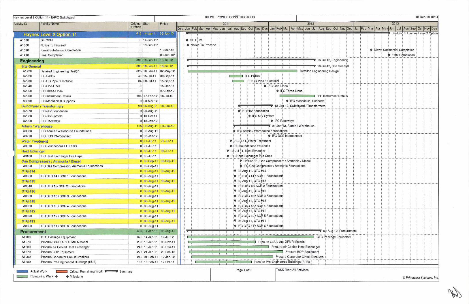
A1000
A1010
A1210
-Site General A 1220 1 Detailed Engineering Design
A2920 I IFC P&iDs- · -
A2930 t IFC UG Pipe I Electrical
A2940 IFC One-Lines
A2950 IFC Three-Lines
A2960 IFC Instrument Details
386 18-Jan-11 16-Jul-12
f 3251 1~~an-=_1_1 j 0_2-May~ 2 I 40.j 15-Jul-11 I 09-Sep-11
34 ~ 2~-Jul-11 115-Sep-11
0 J15-Dec-11
_- o l -- 107-Feb-12
A3090 IFC Mechanical Supports
104117-Feb-12 116-Jul-12
----~-----' c:J.20-Mar-12 --Switchyard I Transformers 98 26-Aug-11 13-Jan-12
A2970 IFC 5kV Foundation I __ 0 26-Aug-11
A2980 IFC 5kV System
A2990 IFC Raceways f. _ 0 10-0c~ _
0 13-Jan-12 I ----~--=-------------------
Admin I Warehouse A3000 fiFe Admin I Warehouse Foundations
A321 o fiFe DCS Interconnect
Water Treatment
A3010 f 1FC Foundations FE Tanks
Heat Exhanger
A3100 I IFC Heat Exchanger Pile Caps
Gas Compressors I Ammonia I Diesel A3020 [ IFC Gas Compressor I Ammonia Foundations
CTG #14 A3030 I IFC CTG 14 1 SCR 1 Foundation_s _
CTG #13
A3040 I IFC CTG 131 SCR 2 Foundations
CTG #16
A3050 IFC CTG 16 1 SCR 3 Foundations
CTG #15
A3060 f IFC CTG 15 1 SCR 4 Foundation~ CTG #12
A3070 T IFC CTG 12 1 SCR 5 Foundations
CTG #11 A3080 IFC CTG 11 I SCR 6 Foundations
Procurement A1730
A1270
A1630
A1670
A1290
A1620
CTG Package Equipment
I Procure GSU I Aux XFMR Material
l Procure Air Cooled Heat Exchanger
T Procure BOP Equipment
I Procure Generator Circuit Breakers
Procure Pre-Engineered Buildings (SUB)
- Actual Work c:::::=:J Critical Remaining Work ••--•; Summary
c::::J Remaining Work + + Milestone
1 05 05-Aug-1 1 03-Jan-1 2
0 T 05-Aug-11 1_ __ _ 0 l 03-J~ j-=----=_ 0 21-Jul-11 21-Jul-11
oi 21-Jul-11 r 0 08-Jul-11 08-Jul-11
o j o8-Jul-11 j __ 0 02-Sep-11 02-Sep-11
o] 02-Sep-11 T 0 08-Aug-11 08-Aug-11
~ 08-Aug-11 j 0 08-Aug-11 08-Aug-1 1
0 08-Aug-11 1 0 08-Aug-11 08-Aug-11
0 08-Aug-11
0 08-Aug-11 08-Aug-11
~ 08-Aug-11 I 0 08-Aug-11 08-Aug-1 1
0 [ 08-Aug-11
08-Aug-11
08-Aug-11
12-Jul-12
203 118-Jan-11 I 03-Nov-11
240 118-Jan-11 130-Dec-1 1
~77 1 21-J~~-11 129-Feb-12
240 1 01-Feb-11 117-Jan-12
167 18-Feb-11 117 -Oct-1 1
• GEOPM ' ' ' + !'Joti~e To f>roc~ed
I I I I I
' ' ' ' ' ' + l<iew(t Sub~tantjal C~mple!ion
' ' ' ' ' ' ~ Firjal Cqmple~ion ;
• • • • • • T • • • . ,.. • • • • r • • • • r • -- • T • • • • T • • • • -- ---~- ----.---- -~-- -- -
' ' ' ~ 6-Ju)-12, !3ite Gene~al
' ' ' D~taile~ Eng!neeri~g D~sign ~
I I I I I I
I I I I I I
I I I I I I I~C P&,IDs ;
I I I I I I I t I I I I
: : , : : : r;::::::::::;:: 'Fe ~G PiP,e I E~ectri9a1 : : : : : : : : : : : : ' ' I I I I ----:·-- ·:- ----:----:----:----:-- --:--- --:·----:-- ·- ·:·-- --:--+ -lfc·a~8~Ur18~- : - ---:- -· · ·:·-- · ·:·----:·----:·----:-- -- :----:---·:-·- - ---- :-- ·- ----,-----,-----
' ' ' '
---- , - - --; ----;----; -- - -' I I I
I I I I
: : : : : : : : : I I I I I : : : : : I :
: : : : : . : : : :• I~C Three-qnes ; : : : : : : I I I I
I I I I
I I I I
I I I I
: ' : : : : : : ' IFC l~strument DetailS : I I I I
I I I I
I I I I
I I I I I 0 I I I I I I I I I I I
~ ~ ~ ~ ~ ~ , , + ;IFC ¥ech~nica\ Supports ~ ~ I I I I
I I I I
' ' ' ' ' ' : , . : : : : . , : , . 1:s-Jar-12, ;switqhyar~ I Tr~nstormer~ . . . , : ' ' ' ' ' '
I I I I I I ---·1·-- ·r ----f- -- -f----;--- -;----r-··:- iFc-~skv-~~uri~atia~ ---.;--- - f--- .;--. -r ---r ·--:·---·:- --- ·:---- .:----;--- -:-- --:---- ----:- -- - - -- • • - -- -~-- • --~-- • - - ,- -- •- >- -- • i----I- - -- I -- - -I I I I I I I
I I I I I I
I I I I I
' ; ; ; ' ' ; + I~C 5k~ Sy~tem ; ; ; ; : I I I I I I I I I
: : : ; + I!'"C R~cew~ys ; '
, , , , 03~Jan~12, A~min Y Warehol\se I I I I I I I
~ IF~ Ado/Jin I yvar~'hous~ Fou:ndat(ons ; , , , , , , ----~---- ---- : ·.-- ·:· --- ·:---- ·:---- ·:-- . ..• . 1"FcY o·csl~i~i~~~o"Ei~t- : ·--- ·:· --- ·:·- -- -- . - ' .-- -' ----'---- · -- · ·
' . I I I I I I
: • :21-Jwl-11 :water Treatment I I I I I I I I
: + :IFC F-oundation~ FE :rank~ I I I I I I I
:• 0$-Jul-~ 1 1 H~at E~hanger : I I I I I I I
;+ I~C He~t Ex~han$er P(le C~ps , , , , , , , , -' ---:.---r -f o2i8ep~~ 1·. -~-~~ c?~pr+ssor~-I A+-~a~i~ I -~i-~~ei:·- .--.- ----.-- -t IF<f: Ga~ Corrjpres$or I ;;-.mm~nia ~ounqation;s
!• O~-Au~-11, ~TG ~14 : , ,
:• IFP Ci:G 14 :1 sc(=! 1 FiJUnd~tion~ I I I I I I 0
' ' ' -·--·-;·---; ----
I I I I I
I I I I I
I I 0 I I
I I I I I
I I I I I
' ' ' ' ' ' ' ' '
' ' ' I I I I I I I I -- -:- --- ---- -- --·:----·:- --- ·:---- -: ---- :----:--- -:-----I I I I I I
I o t o I I I 0 I I
I I I I I
I I I I I I I I I I
I I I I I
I I t I
I I 0 I
' ' ' ' '
- ---~--- --~- ---
:• 08-Aug-11, CTG #13 : : , , , , , , , , ---- ~--- - -:---- -:-- ---:---- -:----- r--- -1- - --; - -- -1---- -:-- -- -:---- -:---. -:---- -:- -- -- r-- -- ~ ---- ' ' I I I I ------ --- ----;·- -· ---- ; ----;----"i·---;-- -- -
0 ' '
' ' ' ' ' '
;+ 1Fp C~G 13{ SC~ 2 F~unda1ions: ; ; · · : ' ' ' ' ' ' ' ' '
:• O~-Aug-11 , ~TG #16 ; ;
:. IFc dG 16:1 sci=! 3 Foundations ' ' '
I I 1 I I I I
:• O$-Aug-11, CTG #15 ; ' I I 1 I I I I
I I I I - - --- - - - -~ - - -- - ~----- i-- - - i - - -
I I I I
I I I I
I I I I
---- ~ -- ---.-- - - - -- - j" --- - 1- --- 'l- -- - - - - -~ -- -- - ---'
, , : : , ;+ I~C CT;G 15:1 SCfl4 F~und~tion* -- ----]- -- - ~- - - - ·r ---- ' ----;·---:··- - ~~ -o~~Au~~11 ;-?1G-#1i£T -- :·· ·:· -., I I I I
I I I I
I I I I : : : : :• IFP CT;G 12:/ sc~ 5 Fpund~tion$ I
' ' ' ' ' ' ' ' ' ' ' ' : ~ ~ ~ ~· 0~-Au~-11 I ~TG ~11 ~ : : ' ' ' ' ' '
' ' : : : : :• IF~ cT:G 11 :1 sc~ 6 FPund~tion~ I I I I ' ' ' '
' ' ' ' ' ' , , , , , , : , , , : : , , , ; ; : : 0~-AUQ-12, Froc~rem~nt , · · ____ ,_ -- -·-· -- ·; ___ _,_ ___ , ___ _ , ___ · ,_ -·--·-· ---·- · ---:-· · · ·:· ---- ~----:----: ·--- :----~---- ~ - --- -·--- ·4:rc3· ~~~k~~e; E~uipn{e~i ·1·--- -- · ·'-· · · - - - - -,- - - - - -- - - -:- - - - - ~ - - -- ~ . - - - f - - - -+----
I I I I I I
I I I 1 I 0 I I
Pr~cur~ GSL! I A~x XFrylR M~teri~l : ; ; ' ' ' ' '
c=~=~~=~=~~=~=~~=~=:J Pr~cure ~Air Cpole~ Heal Exc~ang~r ~ : ' '
Proc~re G~nerator circuit :Breakers : , : - ' - --·-- - - -'-- - . L- - -- '---- '· - -- , ___ - -·- • · · -·- · ·- -~roc~-r~- F>-~~--E~bi~e~~~d ~uiidiri95-{$usi -~ - · · · -~ ---- -~- · · · - ~- · · - - ~-- -- - - -----:-----:-----:----
' ' ' ' ' '
---- :- - - - - f- - -- ! __ _ _
Page 1 of 5 ASK filter: All Activities
© Primavera Systems,

Haynes Level 2 Option 11 - E/P/C Switchyard
ActiVIty ID Ac!lv1ty Name Ongmal ::;tart Duration
I KIEWIT POWER CONSTRUCTORS I 10-Dec-10 10:51
l-In ISh 1 2011 1 2012 J 2o13 1
DecT JanTFebT MarT Apr MayTJunT Jul TAug lsep I Oct I Nov I Dec I Jan I Feb I Mar I Apr I May I Jun I Jul I Aug I Sep I Oct I Nov [Dec I Jan I Feb I Mar I Apr I MayiJun I Jul IAug-jSepT Oct I Nov I Dec I ~--------~~--------------------------------------~----+-------~----~
I 229122-Feb-11 20.-Jan-12 ; Pro~ure ~alan~e of plect~ical ~quip~ent ; j P'""" B•l~ooe ol Elecl,;ool Eq,lpmeo_t ___
'--
. L..o
A1300
A1280 Procure UPS and DCS Systems -··- --
A1680 Oil Water Seperators Delivered
A1640 - ]_Air Cooled Heat Exchanger - Start Delive2'
A1870 I CTG #13 Ready To Ship
A1860 I CTG #14 Ready To Ship
A1370 15kV Delivered - -
A1890 I CTG #11 R eady To Ship
A1480 j4 8oV MCC Delivered -
A1590 Switchgear Delivered -----
A1880 CTG #12 Ready To Ship
A 1650 Air Cooled Heat Exchanger - Finish Delivery
A 1600 l lso-Phase Duct Delivered
A 1610 I Non-Seg Bus Delivered
A19W - ] cTG#15 ReadyToShip
A1740 l SCR #14 Delivered
A 1690 ~ Fuel Gas Compressors Delivered
A1710 l GEMS Delivered
A1720 IGomplete Steel Delivery -
A1900 f cTG #16 Ready To Ship
A 1700 BOP Equipment Delivery Complete
A1750
A1760
SCR #13 Delivered
SCR #12 Delivered
A 1800 I CTG #14 Delivered
A1810 ~G #13 Delivered
A 1770 J SCR #11 Delivered
A 1780 I SCR #16 Delivered
A 1820 I CTG #12 Delivered
A 1830 I CTG #11 Delivered
A 1790 --~ SCR #15 Delivered
A 1840 I CTG #16 Delivered
A 1850 J CTG #15 Delivered
Construction Milestones
A1030 I Rough Grading Start ----A1050 Construction Mobilize
A3270 -1 Switchyard Grading Complete
A1060 Owner Water Avail abe
A1080 I Switchyard Complete
A1140 13.8kV Permanent Backfeed Available - - . -
A111 0 J BOP Complete
A1100 I Demin Trailers Available __
A1120 I Owner Gas Available
A1360 CTG 14 Mechancial Completion
A1380 I CTG 13 Mechancial Completion
A1490 I CTG 12 Mechancial Completion
A2430 CTG 11 Mechancial Completion
I - Actual Work c==:J Critical Remaining Work
1====:1 Remaining Work • • Milestone '
--. =-- 187 , 15~- 1_~-Jan-12 f?roCLjre ups a~d Dqs Sy$tem~ : :
_I_ o ____ 05-Aug-11 ~· 0~1 Wa~er S~pera!ors ~elivered ~ . .
I o J15-Sep-11 I : • Air Cooled: Heat Excriang~r - Start D~livery , : : : : . , . . . , I -114, 28-0ct-11 . 113-Apr-12 - -·- -- - -·-- - "---. -·---- -·- -- -- · --- -· --- - ---- : --- -; - -- - " - --- " - --- -·- -- - -- - - - -·- - - - -~ -- - -~TG-~1-3 ~eadY, T~ ~hip . -: - -.--: -.-- T--- -:- -- --·- ---:- ---- ~ - - - - ~ ----~ -- -. : --- - ~ - - --r --- ~ ----·:----T-----I 111 J02-Nov-1 1J 13-Apr-12 ~ . . . . ~TG ~14~eadY; To~hip ~ ~ ~ : ~ ~ ~ I - 0 ---- I o3~ ~ ~ 5~V D~liver~d ~ ' ~ ~ ~ ~ ' ~ ~ : ~ ~
140 23-Nov-11 J14-Jun-12 ~ , , , , , ~TG ~11 P;~eadY, To ~hip · ~ ~ ~ o 01-Dec-11 , . . . . : . • 48PV MCC Qelivered . . , , : : : , . : : . . . : : -o - o5-De"'Z-11 --:----- : --- "---- -·- - - - -·- - -- ----- -~---- -- - -·- - - -· --- - "----:.+-s~ . .- itch; ear -o.- eiiv~.·-r~x :.- - --:----:---- ·- -- -· ---- " - - - - ·---- -:-----:- -- - -·--- -:-- - -------:--- -~-- -- · - --- ~ - ---~ -- -- "--- -~----:-- - - - -
I I ~ : I : : : I • :
~ 22-Dec-11 14-Jun-12 . , . , , , pTG~12~eadY;To~hip : · ~ _9 1 130-Dec-11 • Air; Cooled H~at E~charjger -: Fini~h De(ivery ; · ·
0 I 17-Jan-12 ~ • ~lso-P;has~ Ducf; Deli+ered:
o j 118-Jan-12 : , . : : . . : , . . : • :Non~Seg f3us Qelivered : , , . 13513 1-Jan-12 o9-Aug-12 - -r - --~ - - - ~---- T ---T -- -- ~ ----~ - ---r- ---;---- ;--- · 1 ·---~- --- -:-----:---- ·:--- --:-----~----~--- -· - ·-- · ----Gi-8-~is-~~ady~~ s~ip -- ·-----·-----
o l 101-Feb-12 ~ ' ~ · ~ : : ~ : ~ SCR#14De)iver~d ... o J 09-Feb-12 : : : : • fuel Gas Qompr;esso(s Delivere~ ~~ J13-Feb-12 : : : ~ • ~EM~ Del!vere~ , , , , , , , , , . .
o l J28-Feb-12 : : • complete steel Deliver1 : : : : : : : : : : : : : : : :
l''-Feb-12 1 :::~:::: . T c " ··· " ·····"· ···" ···· " · · ·· · ···· · · - -- . • -"····· •• 't£~i~;~~::i"''~~:t,~.~·~~·•;r;S~;p( T r : T T ' ' t
' ' ' ' ' __ __ ,L __ __ .. ____ .. ____ .J ____ .J __ _ _ _ _
0 I 130-Mar-12 t sqR #1 ~ Del1vere~ o l 113-Apr-12 . , , . . . , . . . . . : • bTG#14Delivared . .
~~ II ~~:~:~~122 - ·:- - - --: - - -: -- -- "( - __ 1 ___ --:----·:-----:- --- ;- --- ~ ---_1 ___ _ 1_ -- --:-----:----r -- --:- .• tr~!~:~1e~=~~::r~l- - - ~-- --
0 I 31-May-12 ~ • ' : ~ ~ sdR #1~6 Delivered
0 114-Jun-12 : • PIG ~12 ~eliv~red o 114-Jun-12 . . . . . . , . . . , : • CTG :tl11 Delivered . . . , . . . , .
- I 1 I 1 1 l 1 I J I I I I I I L I I I I I I I I • •• ·:•. • • · :· • • • •:· • • • • :- . • • • i • .. . ~ .... ~ .... ~ ... • • 0 129-Jun-12 -------- ----~ - --- -~---- -.---------- : ---T--T--- :--.- -~ - - - - -.- - - - -: - · ---:-----~---- -~-----.--sqF!"#i~ DeiFe~e~--.-r ---~ ---- -~----r --. ' : : : : : 0 I 09-Aug-12 ; ; ; ; ; ; ; ; • <pTG ~16 qelive~ed ; ; ; ; ; ;
0 __j 09-Aug-12 ~ ' ~ ~ ~ ~ ~ : • CTG th 5 Qeliveied ~ · : . . : ~ . . : 561 14~an-11 18-Ma~13 ~~~~~~~~~~~~~~~~~~~~~•. ~•.~~.~~. ~-.~~. ~•. ~~~~~.~~~~. ~•.~•.~: 18-~a~1~Co~stru¢tion ;
' ' ' I I I I I 0 I I I I I I I
-- -- ~--- - ~-- -- -:-- ---:-- -- -;- -- - -:--- --:-----:---- -~ -- -- ~ - -- - ~ -- --~ - ---~ - - -- --1 I I I I I I I I I I
I I I I I I I
I I I I
t I 0 I I I I I I I I I I I I I
: : : : : : : : : : : ., :14-Dec-12, Milestones : : : 442 01 -Apr-11 14-Dec-12 I I I I I I I I I ' ' '
- - - - ·'- - - - J - - - - J _ - - - - ' - - - - - ' - - • • -I. - -- - '- - - - - l- - -- - J - -- - J - - -- .J - - - - J - - - - - ' - - - - .J - -- - - ' - - - - - ' - - - - -'- - - - -'- - -- - L - - --0 I I I I I I 1 t 1 I t I I I I I I
t I I I I I I I I I I I I I I I I I 0 I I I I I t t I I I I I I I I I
I I I I I I I I I I I I I I I I
0 I I I I I I I I I I I I I I
I I I I I I I I I I I I I I
I I I I I I I 0 I I I I I
t I I I I I I I I I
I I t 1 1 I I I I I
I I I 1 1 I I I I I
I t t 1 1 I I I I I
I I 0 I 1 I I
I I I I I
I I : :
. . • sWitchyard cOmplete : . . . . · -- -- -:-- --1-----·-· ·-~-{3.-a~v-F>~r~~~-e~i~cici<tJed- ~Vci iia~i~ - · .. ----:---- ---- ·· ----:---- -:- ----:----
I I I I I I I
; : ~ sqp cqmpl~te , , :
: : :+ oemin :rraile:rs AVailable + I I I I
; : ~ O~ner Qas A)tailaQie
: : : : : : : : • CTG 14 Mechancial Comp etio~ : : ----r- --1·---r ---;---- ·:---- -:-----:-----: ----;--·~ c-r~-1-3-~~-ch~ncial: co~pieti~n-- --:-- ---:- ----
: : ; ; : : : : • ~TG ;12 M~charcial pompletiop I I I t I
I I I I I
I I I 0 I
I o f o1-Apr-11
I 0 01-Apr-11 I --
1- 0 126-Apr-11 0 02-Aug-11
I 0 29-Mar-12 1
I 0 16-Apr-12
I o l 130-May-12
I o l__ 01-~un-~ I 0 1 25-Jun-12 1~ I o 111 -Oct -1 2
I 0 --~ 18-0ct-12 ·
I 0 113-Nov-12
i 0 j 21-Nov-12
· ----· --F!~"u"9h -~~a.ci(n~i s~~-ri -- t----t- -- ·1· ---!---- •••• L •••• .J •• • • i ..... . --·---------' ' ' ' ' ' ' ' ' ' ' ' ' '
I I I t I I
~ c9nstr~ction; Mob!lize ;
~ ~ Sw!tchyard G~adin$ Co~plet~ ; ; ; ~ O~ner ~atef Ava~labe I I I I I I I I
I I I I I I I I
I I I I I I I I
- - - - ~ - - - - ~-- - - -:- - - - -:- - - - -:- - - - - ~ - - - - ~ - - - -! - - - - ~ - - - -I I I I I I I I I
I I I I I I I
I I I I I I
I I I I I
I I I I I
I I I I I
I I I I I
I I I I
' ' ' ' ' ' ' ' ' ' ' '
-- - - ~ - - - - ~ - - - - ~ - - - - - ---:-- ---:-- --
0 1 1 o o I I I
- - ~ --- - -:--- - - - - -~ - - - - ~- -- - -:- - - - -: -- -- -~ -- -- ~ - - --} -- -- +- - - - ~ - ---1 I I I I I I I I I I I I I I I I I I I I I I I I I I I I I I I I I I
I I I I I I I I I I
I I I I I
I I I I 1
---- ~ . --- ~.---;..--- ;- ---- .. ' ' ' ' ' ' ' ' ' ' ' ' ' ' ' ' ' ' ' ' ' ' ' ' ' ' ' ' ' ' ' ' ' ' ' '
0 Summary Page 2 of 5 TASK filter: All Activities
@Primavera Systems, Inc.

Haynes Level 2 Option 11 - E/P/C Switchyard I KIEWIT POWER CONSTRUCTORS I 1 0-Dec-1 0 10:51
IAct1v1ty ID Act1v1ty Name Ongmall ~tart t-1msn I 1 2011 I 2012 1 2013 I
Duration I pec1 JanTFebf MarT Apr MayTJun T Jul TAug [Sep I Oct [Nov[ Dec[ Jan [Feb[ Mar I Apr [May[ Jun I Jul [Aug I Sep [Oct [Nov I Dec I Jan [Feb[ Mar I Apr I May[Jun I Jul [Aug [Sep I Oct [Nov I Dec[ ~----------L--------------------------------------~----~~----~------~ T A2530 I CTG ~6Mechancia1Completio_n___ l oj __ 07_-D_ec-12 1 :+ qTG1~Mephan~iaiC;ompl~tion ;
A2630 CTG 15 Mechancial Completion I - o"J 14-Dec-12 - ' ' : ' ' ' ' : ' ' ' ' : ' ' ' ' ' ' ' ! • PTG ~ 5 M~cha~cial PomP,Ietio~ Site General ~-~~=,_,...-~~----l--==5-5~2 14-Jan-11 05-Mar-1 3 - -~- -~- -- ___ , ____ - ~-- - - -~- -- - -~ -- --~- - - - ~ --- -,- - -- , ----, ----, ----.,.- - --r - - --.- - - - -r-- -- '--- - - ----,---- · - - --, ---- -·---- - ----.-- - - . ,. -- - . , ----.- - -o-~--Ma~13-, -~~~~- ~~~~-r~-~ -- . r---r ----:-----:------A3250 f GeoTech Evaluation 40J14-Jan-11 I 14-Mar-11 L-,.-~: --11 ~eo~ech ~valu~tion i : · ; ; ; : :
A1920 i DemoExistingStructures 14101 -Apr-11 120-Apr-11 ;o ; DerrjoEx\sting;StruqtureS: , ' : : : ·
A 1930 I Rough Grading I Mass Ex. _ 55 21-Apr-1 1 J 08-Jul-11 , , ~ough! Gra~ing I ~as~ Ex. ! ' ' '
A2450 I Pile Testing - i 2 09-May-1 1 J 08-Jun-1 1 , , c:::::;::J ~ile T~sting; : : : : , , , , , , , , , , , , , , , , , A1940 1 Mobilize to Site I Set up Trailers 20 01-Jul-1 1 29-Jul-1 1 --·---- ----- - --- :----·:-----:---- ~ ---- , - M~~ili~~]io-Si~e-i S~t up-!Trail~-rs-- ·:- -- --:----T --T---1-- -T--- ~ ----r---~--- --:- - . --:--- --~----:- ---r --r ---r-m[-- -- i-- -- r--· ~ - - ---.-mTm--A1950 Piling 42 01-Jul-1 1 30-Aug-11 :1 . ! Pil!ng : ! ! : : : : : ! : ! ! ! '
2Do1 01 -Aug-11 17-May-12 c~=~~=~=~~;:::::::;::=:;::~.~ ;struqtural1=xcayatio~ : : : A3260
A1960
Structural Excavation
Backfill I Mech/Eiec Support
A1980 UG Piping Scope :m: ::~::::: I ~::::::~ nm ncm m nn n t m( n' m , _ [ _=_ .=. _= __ =_=: _=_=_ -=~=-_=_=_ -=. _= __ =_=_:_=_= __ =_:=-_=_ u=_ ~=: _G=_ E:j~I~;~;£tt Strt ' . . . . . ' . . . . .. ..•.... ·' ... .. .. ...... ~ ... .. . . . .
30 J16-Aug-11 127-Sep-11 ! : ! c:::=J lns\aiiO)IWa\erS~par~tors i . . ! , 1: ~ A1990 I UG Electrical Scope
A 1970 Install Oil Water Separators I
-- I A2000 ! Install Electrical Grounding System
A201 0 I P ull Cable I Wire in Duct Bank s -
A3280 I Fuel Gas Outage - 5 days needed for Tie-In
A2020 Install Storm System
A2030 I Final Grade /road Aggo .. Base I Paving & Cur_b_s ------
A2040 Site Lighting A2050 I Install P-e-rm_a_n_e-nt_F_e_n-cing and Landscape I Hydro sealing
--1
l Switchyard I Transform ers
~ 30 T Switchyard Rough Grading
~3240 I Switchyard Foundations
A2060 5kV Foundation
A2070 J Switchyard Erection
A2080 l Set 5kV & Raceway I Wire I Terminate
A2090 j lnstall Transformer GSU I AUX
II A3220 ~~ess Out Transformers (BY OTHERS)
A3230 Fire Protect Transformers
Admin I Wareh ouse
I
A2~ r Admin Building I Warehouse Foundations
A211 0 I Erect Admin Building
A2120 ErectVVarehouse
A21 30 I Install DCS ----
l.f
Wat er Treatment
A2140 l Water Treatment Foundations I A2150 Install FE Tanks ----~-~----~-----"--,_!_~~
Heat Exhanger
A2210 ~ Pile Caps- HE I A2220 Install Air Coo~d ~eat Exchanger j
A3140 Piping- HE I A2240 I Bay 1 Co~ple~~ _
A2250 I Bay 2 Complete j A2230 Electrical I Instrumentation - HE I A2260 I Bay 3 Complete I A2270 I Bay 4 Complete I
Actual Work c:::=::J Critical Remaining Work ••--•; Summary
c:::=::J Remaining Work + +Milestone
115 1 12~ 1 29-Ma;i2 ; ; ln~tall EJectri¢al GfOUn~ing Syste~ 7sj 12-Dec-1 1 29-Mar-12 , Pu!l Ca~le I ~ire i~ Du~t Ba~ks i
40] 03-Jan-12 29-Feb-1 2 , , , , . Fu~l Ga,s outage ~ 5 daYs ne~ded:for Tie-In , , . . , , , , , , . 41 11 0-Apr-12 06-Jun-12 -T--- -:--- -- ---:---- --- - ~ - - - -· -- --:. --- --- --. -.... --- -·- ---r ---r---·--- ---- -l~stall-~t~-r~ -Sys~~m- ----- ... ----:---- -·---- T---r--·:· --- - ~- -- - ~ --- -r- -- -~ - --- ~ - - - - ~- -- -1 ---- -
~ 03-0ct-12 I 08-Jan-=1"3 · : ~inal ~rad~ I ro~d Ag~o. B~se t iPavi~g & ~urb~ : 16-0ct-12 I 17-Jan-13 ;site pghti)1g : · · ·
09-Jan-13 I 05-Mar-13 !~stall perm~nenj Fen~ing ~nd L~ndsqape 1 Hydrc =- 1
I I I 1 I I I I I I I
269 01-Apr-11 1 6-Apr-12 , , , , , , , , , , , , , :1 6-Apr-12; Switchya~d I Tr,ansfQrme~s : : : : : : : :
~: I ~~ ~~~~-1111 I :~~~~~~111 1 --·- --- ----- -----:;---(sw:tchy~-rd- R~ugh- ~radlng~~:~~~~~~- ~~-~~~~~i~~~- --- -!---- ·:·----: n --r n- · : ---- :- -- ·:· - -- ~ ---- :· u- - --- - · ---- - --- - · --- --· - --- ----------- . ---d----.----------------
33 114-Sep-1 1 J 31 -Oct-11 ; c::::=:;J SkY Fo~ndation : : : '
1 00 I 01-Nov-11 128-Mar-12 ' ' ' ' ' ' S~itchy~rd E~ectid,n . .
:~ 1 ~:~~:~~~ ~ I ~~~~:~~~: · -:- -- --~ --- ----_; ___ - ~ ---- ·---_:_--· -~-- --t ----: · -- -i ----·-- --------·- --- - ----·- - f~~i!~~~:s~t~;~ ~:Jr-i ~J~~~-ir-~~~- ~ -- --s 01 -Feb-12 130-Mar-1 2_ . . Dr~ss ~ut Tr~nsf~rmer~ (BY iOTH~RS)i
33 J 01-Mar-12 16-Apr-12 : c:::::::::J ;Fire prole~! Tr~nsfoi;mers: : :
138 30-Aug-11 12-Mar-12 ... ~-.... -•.--i:-.... :-•:-. i2-M*r-12,~ Adm:in t v¥areh:ouse i ! : ~-~J 30-Aug-11 127-0ct-11 . Admin Building 1 Warehouse :Foundations : . , : , 83 j 28-oct-1 1 1 o1-Mar-1 2 - · - -- - -" - -- ---- -·- - - - -·- -- - -" --- · ---- · - - - - ' · ·- -,- - -- ~ ---- -·-- · - '- - -Er~cl /\~mir;isuiidJn9 - -: - -- - ~ --- - ~ --- - ~ -- -- ~- - · ·
50 129-Dec-11 J 1 2-Mar-12 Erect War~house : : : · :
37j 17-Jan-1 2 I 08-Mar-1 2 , , , , !?stall :Dcs: : : :
67 17-Aug-11 17-Nov-11 ... - ... -.-r ;17-N:ov-11 , W*erT~eatm:ent : · · ·
~l 17-Aug"T11 26-0ct-11 ~ 13-Sep-11 1 17-Nov-11 145 05-Aug-11 27-Feb-12
40 I 05-Aug-1 1 130-Sep-1 1
80 115-Sep-11 112-Jan-1 ~ 97 29-Sep-11 j 22-Feb-12
a 1 os-oct-11 1 -0 [ 25-0ct-11 j
751 04-Nov-11 J27 -Feb-1 2
0 1 17-Nov-11- l
0 08-Dec-1 1 I
--:- -- --;-- --' '
--,--- - -,--- - ---- -.-- ---,--- --.-- -' ' ' ' ' '
Water Treatment P.oundations : . . . . . . -r --_, ___ _ ·-- -- i 1-n~~-~~~ FE-+an-~~- - - -:--- --:-- -- -:- ---·r----:- -- --r ----r-·1 ----r---
I I I I I 0 I I I I I
: : : , 27~Feb-~ 2, ~eat ~xhan~er : ' : '
Pil;e Caps- ~E , ,
(nstal) Air Cf:oolep He$1 Exqhanger I I I I
. , , , : Pip~ng -ltfE : : . , -.- - ·:• -say1 -co~-p~~~e- -:-- --: -- -- ·:- - - --:-----.----- .- · ·- -.--- --,- - -. -
: • Ba~ 2 C~mpl~te i ' ' I I I I I
Electrical I Instrumentation - HE ' ' '
+ Bay S Cor],plet~ + !:laY 4 pomplete :
Page 3 of 5 TASK filter: All Activities
I I I 0 I
--- -' ---- -' - - -- - '--- - - '---- . L - -- - L- --- L ---- .J ---- .l ------t I I I I t t 0 0
I I I I I I I
I I I I I 0 I
' '
I I I I I I
--- - ...! • •• - -'-.- - - '---- - ' --- - .L -- -- l- --- L - - - -
I I t I I I I I I ---- -, ---- - ----,-- - --,---- -,---- -;- ---;---- i - - - - i ------
I : I : : :
' ' ' '
@Primavera Systems, Inc.

Haynes Level 2 Option 11 - E/P/C Switchyard 1 KIEWIT POWER CONSTRUCTORS 1 10-Dec-10 10:51
Ongmal[ Start II t-1n1sn I 1 2011 I 2012 1 2013 I Duration I DecT Jan[ Feb[ MarT Apr MayTJun T Ju!lAug [sep I Oct [Nov[ Dec I Jan Feb[ Mar I Apr [May[ Jun I Jul [Aug I Sep [Oct[ Nov [Dec I Jan [Feb[ Mar I Apr I May[Jun I Jul [Aug [Sep I Oct [Nov I Dec[
~----------~--------------------------------------+-----~~----+-----~ A2280 I Bay 5 Complete 0 129-Dec-11 ~~ + Bay 5 Complete : :
1 A2290 JBay6Complete --- 0 -~ : , , : : + ~aysj cornpletej : : : : : ! : : :
::; Gas Compressors I Ammonia I Diesel 181 16-Sep-11 29-May-12 , "' : : : : : : 7 29jMay~12, ~as C~mpr~ssor~ I A~mo~ia I qiesel! '
1 ~ A2300 ___ [Diesel Generator Foundations _ - _ .[ _ 1 0 116-Sep-11 [ 2~-Sep-11_ _ : : d Di~sel ~ener~tor ~oundation:s ,
~ ~ ~ - A2310 j setDieseiGenerators __ J 19J30-Sep-11 [ 27-0ct-11 : ' : : :c::::J: Se~ DieseiGe'nerators : : : : : : : , . .
l11 :~::~ ,, ~~s ~::;;~::: /AT:::s~i-~Um_P Foundations I = :~ 1' ~~~~:~-1\1 1~:~~:~-~~ --,-----,--- -----:-----:---- -~ -- --r --- -~ ---- ;---- ~~--ia-~~t~!:t~~oJ~:~~:~t~P-utp F~und-iti~ns1-- -- -: - - --~-- ---:-----:---- - ~ --- -:-- ---~ · · - ·:·. · - ·: .... r · ---:----1--- -;-- ---:-----:--- ---
~~: A2370 ~et Ammonia Forwarding Pumps _ _ I 25 23-Dec-11 i 31-Jan-12 , , : : C::::::=J S~t Am~oni~ Fo~ardi~g P~mps ! , , ; , ; ' : : : ,
.ii 1--- A2400 l Erect Fuel Gas Compressor Pre-Engr Building I - B61 03-Jan-12 I 03~ 12 : : : E~ect F~el G;as Compr~ssor: Pre-~ngr ~uildi~g '
A2380 JAmmoniaPiping - J - 39 J17-Jan-12 [12-Mar-12 , , , , :::: , , , , , -'?-mmqniaf?iping;,,;,;; ; , , , , , , ,
-l :~::~ I !::::i~;:~;i;::~=:een~~tion -- ,, ;~ I ~~~~::~ ~ ~ ~~~~~:~-~ .. , .... · r. .. . .. , . . ....... T--- .. .. ' .... '.... .. .. , .. .. ~ .. -. -;· .... , .. i ·,·;· ... ,!. sei ~a!%~:~;-~~~~t~~~;~::~:~~~~:~:;~-~- -:· ... T.. . .. ·r . . .. , . . .. T . .. '. .. . . ... , ... . , . ... , •.. - ., .•. . -
A- 2-3-50- I Gas Compressor Piping 60 122-Feb-12 [ 15-May-12 : : : ~as 9om~ress~r Piping ! , , ' : ' '
~:::: I ~:,:::~=~~f~i:.::_~-/ -ln-st-ru-~-e-n-ta-tio~n~~ I 59 13"~:;_:;: l :::~:~~~ . : ... : .... ... ; ... i ... : .. . ; .... : .. .. • .... ; .... j u' u - -!- ;u~ F~ ~t:!~:1~;tll"'" t'T"ota"'"i ( -~ m(" ·; .... :- j j . CTG #14 (Clutched) ~ 303 06-Sep-11 06-No, -12 . : . i • : : : : . : : : : : : 0~-Not-12. i::TG ~14 (CI,tQhed) : i i i : A2490 T Concrete - CTG 14 Power Block Area _ J 67 J.o6-Sep~11 13-Dec-11 : ~onc~ete -;erG; 14 Ppwer ;Bioc~ Are~ ,
A2520 I Erect SCR casiriQS/Weld Out --=- I 74[ 02-Feb-12 16-May-12 ' ' ' ! Erec~ SCR Cas!ngs/ ~eld~ Out ! . ' : ' : :
-~-:_:~~ ~~:~~:~::::: ~::~~~~;qe~~ment _ I I ~~~~:~~~~ I ~~~;~~~~: -···-········ ..... : ..... : ..... : ..... : ..... ~---- ~ .... : ···-~· -·· j· ·--1 · ----\----1-----:-··- .,. ·-- ~ ----; .... , ... ~r~~~t~~a~~~~~~~:~~~Juip~e~i -j-·--T---·f-- ··f··--:- ·- -~ ·-- ·:····i·--·r-· · · · A2460 Install BOP Mech Equipment/ FP System J 7211 O-May-12 J21-Aug-12 : ; ' ; lnst~ll BQP M~ch E~uipri,lent/ ;FP Systeri,l ; '
A2480 ! Install Piping (include vendor) __ l ~[ 21-May-12 J 20-Sep-12 : : ! lnst*ll Pi~ing (~nclu~e ve~dor) ! ' '
A2500 I AG Electrical / Instrumentation 82] 15-Jun-12 J11-0ct-12 : AG Electrical / Instrumentation '
A2440 JMechlnsui.(SUB) --~--~------- ' 42 J07-Sep-12 106-Nov-12 , , , , : , , , ! , , : , : , ~echinsul. :(sU$) , , , , ; : :
ActiVIty ID I Act1v1ty Name
erG #13 290 os-oct-11 16-Nov-12 · ··· - · ·- · · · -- · ··· · - -···· · - ··· -- · ., . · · -· • · · · ~ ~- - - ~ · ·· • ·- · · •· · · · -;---- ~-- · · ·;·- · · - ~ ·---~- - - · ~ --- - ~ - · · -; -- -- · ---- • --- - ·j16-~~v~1~·:crp.it1¥ · ·-T · ·· T ·-· -:-· · ··--·: ···-·-· ··' · ···;-· --· · A2590 Tconcrete-CTG13PowerBiockArea ,
1
67 , 05-0ct-1_DI 1 3-Jan-~ bonC,rete-: cTG; 13Power!Bioc~Are~ , , ; · ; : ; : :
A2620 I Erect SCR Casings/ Weld Out 70 05-Mar-12 11-Jun-12 ' : !i=rect ;scR ;casi~gs/ \!Veld put : : ' ;
A2610 Erect/Install CTG Equipment __ r- 80 j 16-Apr-12 l 07-Aug-12 ~rectllbstal~ CT~ Equ~pme~t : :
A2~~ JErectllnstaiiAccessoryEquipment 77J30-Apr-12J16-Aug-12 , , , , , , , ; EreciJinst~IIAc~essQryEquipnient, ! A2560 [ Install BOP Mech Equipment/ FP System I 65 , 14-May-12 r 14-A~g-12 - + .. .• . - .•. -.-:- ... · :·· - -·:- -- -- -- - ----.--- .•... • · - · .. : · --··---- - · · • . -··· • . , .. . .. , . .. ··;· · -. · ;- ---;----j~~~~(I-BO~-Me4h-Eq~ipm·~~iiF;P-Sy~te.mT .. ·-:--·· ·:· ·· --· · · -- [ ... . : ·· ·· :-- · · :-- · -- ·
A2580 Jlnstall Piping (i;;dUde vendor) I 86 r 24-May-12 ,25-Sep-12 ' lns!all Piping ~inclu~e v~ndorj : :
A2600 I AG Electrical / Instrumentation jl 82 J22-Jun-12J18-0ct-12 ' : ; AG ~lectrjcal/ Jnstrl)menjation; ;
A2540 _l Mech lns_ul_. ,;,(S=U_B,;,)'"='-~ ---~--------.t- 42 118-Sep-12 116-Nov-12 • : : ! Mec~ lns~l. (S~B) : : . . !
II
CTG #12 (Clutched) 292 02-Nov-11 18-Dec-1 2 , , , , ; : ,..- , , , , , , , , , , , , , ; 18-Qec-1~,CT~#1~(CI~tche~) , : , , ,
~:~~: l ::::~~~t:l~~;:~::;i.~,~lok "" • 1 ~:1 ~EE:~~ j :::~~~~ ........... ' . n , •• • i" u m . :. n • • •••• r .. .. -. m .... . . .•... c~~,.~; -PTGii 2 PfW~i:.~:.~~L~EbbiL.:, · .. ' . u : ••• - ••• : u • • : •• • • • •••• • • n. i ..... .
A2670 I Erect/Install Accessory Equipment I --7- 0 29-Jun-12 ] 09-0ct=-1"2 , $rectt!nsta(1 Acc~ssof;y Eq~ipm~nt ,
~:::~ __ 1 :~::::: ~~~:(~~:l~d:u~e:::~ FP_sy_s_tem I·· *:~:::: ~ I :~~=:: ~ _. _ _ . . . _ . ·: _ , . i j j _ , : : ; ; '"~~~~~~~~t~~~:tJ:~:~p Si:'t•~ C _ • _ . _ . . :. _ .• _ . . __ .
A2700 I AG Electrical / Instrumentation __ _ _
1
1 78 J 24-Jul-12 1 1 -~-Nov-12 : , , AG ~lectri~al / l:nstru~ent~tion A2640 j Mech lnsul. (SUB) -~~----- 42 J17-0ct-12 18-Dec-12 : : : : Mec~ lns~l. (S~B) :
CTG #11 271 02-Dec-1 1 19-Dec-12 , : : : : : : ; 19-qec-1~,CT;G#1;1
A1550 Tconcrete-CTG11PowerBiockArea I 67Jo2-Dec-11 T09-Mar-12 , : 6oncrete-CTG ;11PowerBiock Area ,;;;;; :, ! , -~-~-:~~ I ~~:~:~~~t:l~~~~g:~;pe:e~tut - I ~: I ~:~~u:-11: : ::~~~:~~: I -J .. --- ' ---- ---- --- -- --' --- --· ----- • --- r. -- -:--- -;-- -- -- -· .... --- L ·t·· ··-- ---'--- --'----_, __ ---~re-~t[s~i~~~~:!~:~~dl~~:J~~J - -- t·-r·. -~-- ·--:-. ···r --· ·r --·· r ·--T· ...
- Actual Work c::::::J Critical Remaining Work 0 0 Summary Page 4 of 5 TASK filter: All Activities
c==:::J Remaining Work + +Milestone © Primavera Systems, Inc.

Haynes Level 2 Option 11 - E/P/C Switchyard I_
KIEWIT POWER CONSTRUCTORS I 10-Dec-10 10:51
I Acl1V1ly 10 t-1msn 1 2011 I 2012 1 2013 I
pec1 Jan I Feb I Mar I Apr May I Jun I Jul !Aug ISep I Oct I Nov I Dec I Jan I Feb I Mar I Apr I May I Jun I Jul I Aug I Sep I Oct I Nov IDee I Jan jFeb I Mar I Apr I May I Jun I Jul I Aug ISep I Oct I Nov I Dec I ~~·----------~--------------------------------------~----~~----~----~
ActiVIty Name Ong1nal :start Duration
I:· A1530 j ErecUinstall Accessory Equipment __ ~ 29-Jun-12~1-0ct-12 grecUtnstall Accessory Equipment
A 1520 j lnstall BOP Mech EquipmenU FP System ~[ 11-Jul-12 23-0ct-12 , [ lnst~ll BQP M$ch ~quip~enU[FP Syste~ i A1540 l lnstaiiPiping (includevendo~~ 77 1 16-Jui-~ 01-Nov-12 : : : : ! : : : ' ' ' ' lnStaiiRiping : (inciUdev~ndoh ; : : ! : ; ;
I;[ A156o AG Electrical/ Instrumentation 75 [ o6-Aug-12 j 21-Nov-12 -"( -- _, --- -:---- "( -- -:-----:---- -:--- --~ - --- '- - -- ~ ---- --- ( - - -:-----:- ----:-- ---:----- t--- ·t---- ~ ---- ! --- -'---- -·- ·- · ·'· -- --:-AG -~iec!r.icai /[.,n~ir~men~ati~~ - ···t --- · ~ · · · · ~ · · · ~ · · · ·:· · · · ·· · · · · ·
I'
: A1500 I Mechlnsui.(SUB) 43 11?·0ct-12J1s-Dec-12 ' [ [ [ [ · ' [ [ [ [ [ · [Mec~ lns~I.(S~B) [ [ [
CTG #16 281 04-Jan-12 04-Feb-13 : : : : ' ' ' : · . . . . 0~-Feb-13, CTG #16 : :
A 1440 I Concrete - CTG 16 Power Bl<:_ck Area J 67 fo4-'Jan-12 T09-Apr-12 ] [ [ [ cloncr~te - ~TG ~ 6 P~wer $lock[ Area; ' . '
A1470 ErectSCRCasings/ WeldOut I 70To1-=-Jun-12 110-Sep-12 : : : . . . ~rectSCRCasi~gs/ WeldOut ~~::~ '--~-:~_:~::: ~:::s:~~;;u~~ment _ l ~~f~~~~~: :~~~:~~~: --:-----r· -- r----·---- ____ i __ ___ : ____ -:- --- --....... . ·-· --.--.-.- --.------.--. --- - ~ .. -.! --- ·j· ---,--- --·---- -·---- ·[·E~~:~~~~:~;~t!e~~~i~i:~~~~~~~: .. . -! .. -- :· -- ·:· --- -:- -· -- --.---
A1410 I install BOP Mech EquipmenU FP System [ 65 -24- --A-ug- -12 29-No-v--1-2- : ; : ln~all B~P ~ech ~qui~ment( FP ~yste~ A1430 Install Piping (include vendor) I 65 27-Aug-12 , 30-Nov-12 ln~tall P;iping; (incl~de v~ndo~) ; :
~~::~ I ~~c~~~~:~~-a:~~n;)trumentation -- I :~ I ~~~~:~~~: I ~:~~=~~:: ___ .: ..... :. ----:---- -: _____ ; ..... :. ___ -~--.. i---- i----;---- __ --.---- __ ··:· ·-··:· . . ··!·---· ~ -- -·i-·. _ j· ___ ·:··· _ ·[· __ · }--~~-EI~-jtri_~~-~~t~~8;~~aJr- - ~ -- --f-- __ i __ .. i· ___ ·[·· .. ·:··---_ I I 0 I I I I I I I : : I : :
CTG #15 261 02-Feb-12 05-Feb-13 !"' , , , , , , , , Op-Feq-13 , ~TG~15 ; : : :
A1350 Concrete-CTG15PowerBiockArea r, 67 02-Feb-12 107-May-12 Concrete-6TG15Power~lock~rea [ : : :
A1340 I Erect SCR Casings/ Weld Out 70 02-Jul-12 1 0-0ct-12 ~reel $CR ;casi~gs/ Weld put
~~ ~~~ -~t:~~:~::::: ~::~:~:;:u~~-m-e-nt ~- :: ~~~~~-~-~~-: -~-:~-~-:;~: · -:- · · · -:-- --;- · · -:-----.- - - --·---- -:--- · -~ ····; .... ; . . .. ;. . ·· - -- · ·.- -- --,----- ----:-- · -- ~ - ·--:- - --- ; · - .,. _,_ · · .; .... ; .. · --~:~t~~~:~i~:~e~:~:-~~-~~pm:e-nt- -:----- t --·· j -- --j··---:-- -- j·-----A1260
A1250
A1230
A1320
-,n-stall BOP Mech Equipmen_U_F_P_S- ystem ~ 60 27-Aug-12 21-Nov-12 ~::::;=::;::J [ lnst~ll BQP M~ch E~uip~enU [FP S~ste~ [ [ [ [
Install Piping (include vendor) 651 29-Aug-12 04-Dec-12 !~stall ~ipin~ (inc!ude yend~r) [ [ [ [ [ [
I AG Electrical I Instrumentation i 60 18-Sep-12 14-Dec-12 c=::::::::J '.p.G E)ectri~al I l~stru~ent~tion : i : : i : l Mech lnsul. (SUB) 44 03-Dec-12 05-Feb-13 . , , . . . . , , . : , , , . , . . . , ~ech ~nsuL ; (sU~) , : . . ; :
270 01-Mar-12 18-Mar-13 -- - - · · ··-- · --~--- --.- · · · ·:·· · · -:---- -r -- · ·: · · --'- -- · ,---- -- ·-:-- --~- - -- ·:-· --- :·· -- -~----~-- - -~ ---- : ---- ~ -- - -~-- ---:· - -- ~---·· :-- --~ ---~-:-1·a:r~.1"clr--1-3.-StirtUp: - -- -:· ---: ----:--·-:-- -- --Start Up A2730 1 Plant Start Up
A2750 1 ST I Comm 13.8kV Perm Backfeed Power
A2770 ST I Comm Heat Exchanger Bay 1
--~--------------------------~
A2830 I ST I Comm Ammonia
~2_7_8_o __ l ST I Comm Heat Exchanger Ba~ A2790 ST I Comm Heat Exchanger Bay 3
A2800 ST I Comm Heat Exchanger Bay 4 --
A281 0 ST I Comm Heat Exchanger Bay 5
A2820 I ST I Comm Heat Exchanger Bay 6
A2840 j s T 1 Comm Fuel Gas --
A2850 ST I Comm CTG #14
A2860 ST I Comm CTG #13
262 01-Mar-12 1 18-Mar-13 : ! : : ' ' ' · · ' ' ' ' · ' ' i Pian~ Sta~Up [ . . [ [ [
25 ~-Mar-12 123-Apr-12 .
20 19-Apr-12 j 16-May-12
29 02-May-12 112-Jun-12 -- I I I I . ' ' 13 17-May-12 05-Jun-12 - -,- - - - -,-- -- ,. --- -~---- .,. --- - • • -,- - • - ·r • •- • r • - --
' . ' ---- -.---- ., --- - -,---- , ----- --- -,----- r ---- r ---- r -- -- T--- -' ' ' ' ' '
¢=I [ ST { Co~m 1 ~.8kV :Per~ Bac~feed [ Pow~r 0 :sT I Com in He~t Excihanger Bciy 1 :
I I I I I I I
: , , : ~ ~T I <fomrrj Amrj1oni~ , , , . : : , , : , , , , -----.----,---·····---.·- ·o -·sr-i coninii-i6ai'Exchari9et"say:2· ---.- -- ·:-- · · ·:· ·- · -.--- · -:- - -- ·:·- -- -, ---- : -- --:---- : ---- : ·- --- -
[ D! ST { Co~m H~at E~chan~er ~ay 3 [ ~ , [ : ; :
p ;:>T I qomrrj Hea~ Exc~ang~r Bay 4
[ d ST:/ Co~m ~eat E~cha~ger ~ay ~ . . : , , ;o pT I Qom~ He~t Ex~hang~r B~y 6 ,
' ' ' .. -~-- --r ---:-... ·:--.-·:---·:-- i- , ----~I- -st"i c~mm fuei~as· ~-- .. ·[- -. - ·- - T ·- - - r- - • ·-. - - • ·-.- • ·- - •
: : : c::::::J ~T 1 c~mm:cT~ #14 : I I I I I I
c;::::::J ; ST t;com)n C"fG #1:S ~~ A 1150 CTG #14 First Fire
II :~-A2_9_1_0_ 1 Plant Tuning
13 j 06-Jun-12 j 22-Jun-12
12 25-.Jun-=-1"2 , 11-J~ 12 12-Jul-12 27-Jul-12
11 30-Jul-12 113-Aug-12
35 14-Aug-12 J 02-0ct-12
25 03-0ct-12 107-Nov-12
2_i] !_?-Oct-1 2 19-Nov-12
01 I 07-Nov-12
861 08-Nov-12 18-Mar-13
22 09-Nov-12 [ 13-Dec-12
: + CTG #14 Fi:rst Fire
' ' A2870 ST I Comm CTG #12
- -· ---- -·- -- - .. -- - - , . --- , . --- -·-----0 I I I I I
0 I I I I I
••• - o- ---- r•• • • r • -- - • - - -· I t I I
- --_,._ - -- -.. --- - ~ -- -- .. ----. --I I I I
' ' '
0 I 119-Nov-12
20 [ 21-Nov-12 120-Dec-12
0 J l 13-Dec-12
19 j 14-Dec-12 j 11-Jan-13
A 1160 CTG #13 First Fire
A2880 ST I Comm CTG #11
A 1170 CTG #12 First Fire
A2890 ST I Comm CTG #16
' ' ' ' ' ' '
' ' ' ' ' '
I I I I
: + CTG #12 First ~ire :
. : : , . . : . , . [ 6 $r I 6om~ CT~ #16: , . . .
0 I 120-Dec-12 19121-Dec-12 18-Jan-13
o j 1 11-Jan-1~ o j 18-Jan-13
A 1180 I CTG #11 First Fire
A2900 1ST I Comm CTG #15
A 1190 I cTG #16 First Fire
A 1200 CTG #15 First Fire
----1---- .. ·-- - -o-----o-- - --·- - - --l-- - -- .. ---- + -- -- .. - ---·- - -- ---- ... . --- .. ---- _.,_- -- ·1--- --·--- -... --- ... ---- .. ---- + ---- . ---- .. - --- .. ---- _, -- -- .. -- -- _, _- -- ... -- - - _, _--- -·---- -·----- •. --- .. ---- . ---- . -- - ---
; ; : ; ; .; CTCf #11; First: Fire : : : : : I ; ;
: : : t:::J : ST f Com:m cT:G #1S : : ! : I I I I I I I I : : : :
+ ~TG ~16 ~irst ~ire :
- Actual Work c::::::=:::J Critical Remaining Work 0 0 Summary Page 5 of 5 TASK filter: All Activities
c=:::::J Remaining Work + + Milestone @Primavera Systems, Inc.

Option 12: Fuel Gas line Accumulator Tank
This option is to provide an accumulator tank on the suction side of the fuel gas compressors in order to
reduce the pressure drop impact on the fuel gas main when the compressors are started.
The following P&ID has been provided to illustrate the changes to the fuel gas system when this
accumulator tank is added:
• P010-017-PS-6500PT
The project schedule as shown in Exhibit D will not change due to this option.

~
V651100
SHUTDOWN TROUBLE READY RUNNING
v Y! \V Y! \V Y! \V Yl 'l ~51~51~51~51~
V651101
10"-FG504-AEA
OR A I N [-3CI_4C"C-'\F G~5\i8:'2~-c"o':, V651020 I
6"-FG511-AEA-1 1/2"0
i ; N2 i
RECYCLE GAS COOLER
A
6"-FG$20-AEA-1 1/2"0 ;_MT
o ("; VENT
N
'
' <
NOTE 1
< '
r?G:J?:{~ yyyy 3/4"-FG581-AEA J VENT 6 '-FG5t2-AEA-1 112 •a_,. v651019 ;;:; 2 -FG578-AEA " 65105
: Q\ TP-65001 ....i.:::"-' TIE -IN
NOTE 1 VENT
;--------------- _l_ ~ ~ _"""' ------------- ~E~T [ 31< ::,',:':e-"'~-'-~~~~~,';~;~:;:_ ~:~o _{-E-------
! ! ! ! ! ! !
FUEL GAS
KNOCKOUT DRUM
FUEL GAS
18''xt6 ,,
18 "x1 0"
. !
uJ NOTE 1 c NOTE 3
'" '" '"
N
0 . >
SUCTION ACCUMULATOR
A
< 0 < ' 0
' ' ' ' ' ' ' ' ' ; ! ' ! ' ' ' ' ' '
~ i '
8"-FG-ADA ~----~~~~--~~--~·
~ !
B f--"-';-1' ~ ' ,, B ''-FG-ADA
PS650 PS651-01
TO COMP B
8"-FG-ADA
PS650-PS652 01)
V051010
SUCTION SCRUBBER
A
16''x14" J TO COMP C DRAIN
8 "-FG-ADA V651 013F
PS650 PS653-01) FUEL GAS TO COMP D COMPRESSOR SK lO
14 ''xl2" J 1 "-JA573-FKD A
~------~~e~"~-;F~G~·~O~'~§ri~~~~~~------------------crl P$567 -P$650-01 f{ I :,I SK -FG-001 A PS&50 P$&57 - 01 NSTRUMENT AlR - I
~ FUEL GAS
COMPRESSOR A
~
OMPRESSOR DISCHARGE
FILTER/ SEPARATOR
A
12''x8" J TOCOMPE ! o
' -~c---------------~c---------------------------------------------------------B "-FG-ADA
P$650 P$658-01) <.: 2'-FG516-AEA-1 1/2"0 VENT CP-65102
8
" 0
~ . ru ~ C~3
~" ;G518-AEA-1 1,tD rGt--+-
10"-FG003-AEA
G 4'-FG-AE'l
1 2'-FG515-AEA-1 1/2"0------o> NOTE 1 4"-FG-AEA-1''2'0 -'--#L= ~ PS651 P$650-0\ 1-7'---'---j ~ 2" PUMP OUT CONNECTlON-l T FROM COMPRESSOR 8 ~
TO COMP F
1--
1--
. 0 < ' 0
'
N LEAK~TlON OUTLET CP-65110
J1o"x8"
LSH lfLAH" 4"-FG007-AE'l
1 2 1 4
65107 ---- !:>510( c_P --t-65102'-Y GAS COMPRESSOR Fl 4"-FG$23-AEA-1 1'2"0
ED 9700\A ORAlNS TANK f-------1-----{ LSH LAH 1'-;---'--j - A 3 65108 --- ------~~510;! PS652 P5650 01 I:
4 "-AEA
PS657 P5650
FROM COMPRESSOR E OUTLET
1 r 1 ~ FROM COMPRESSOR C OUTLET
4 "-FG522 -AEA-1 1,/'D
PS653-PS650 01
FROM COMPRESSOR 0 OUTLET
~- 6"X4" 8"X6" ffjl~~-c}o-----"-''_:'-o;"co'---------<::1---'
4 "-AEA ---rt.l [l~e~s~6~58~-~'~'~'s~o~=>---------~lr4----
NOTE 2 10"-FG003-AEA
( PS650-PS655-01
FROM COMPRESSOR F OUTLET
TO CT UNJTS 111 12' 13. 14
NOTE 2 6"-FG004-AEA < PS650-PS656-01
TO CT UNJTS
X X
" . ' ~
NOTES:
1, VENT TO SAFE LOCATION AND PROVIDE BIRO SCREEN. 2. UNDERGROUND STEEL PIPING TO BE COATED
AND WRAPPED.
3. INSTALL TEE ONTO DISCHARGE OF PSV TO PREVENT DAMAGE TO VENT PIPING.
NOT PRELIMINARY
FOR CONSTRUCTION CONFIDENTIAL
A ISSUEO fOR COIIIRJ.Cl SRH Cll!l DES 11-1~-10
DESCRIPTION OWN I CHK APP DAlE
LOS ANGELES DEPARTMENT OF WATER AND POWER
HAYNES GENERATION STATION UNITS 11-16
8Kiewit K;~,.,;l Pcwet 9401 Rennet Boulovord Lono,o, Konsos 66219
PIPING AND INSTRUMENT AT ION FG FUEL GAS COMPRESSOR A
DIAGRAM
by dote DRAWING NUMBER
DESIGNED
OR AWN
CHECKED
~03-22-10
_2_~ 03-22-10 ~ 08-03-10 POl0-017- PS-6500PT
~ "--------------------------------------------------------------------------------------------------------------------------------------------------------------------------------'cs~&ccl6:_ ____________________________________ . ____________________ _c_:"c'c'"''"'"'--~="'='==c='"=-='='-='='--c_ ______________________ ~
~

Option 13: Changes to Control Room & Buildings
This option is to provide a control room attached to the existing control room for Haynes Units 8, 9, &
10, in lieu of a standalone control room. This option also included combining the Instrument Shop with
the Warehouse, Maintenance Shop, and Office, into an "L shaped" building.
The following drawings have been provided to illustrate the changes to the fuel gas system when this
accumulator tank is added:
• POl0-017-PP-001 • P010-017-GA-002
The project schedule as shown in Exhibit D will not change due to this option.

E 6000 -
----
C::>
LEGEND
@]) ADMINISTRATION BUILOING @QV CDNmOL BUILDING @@ WATER TREATI£NT BUILDING @j) INSTRUf.ENT SH(}P
0 .. · .. ·· .· .· • .····
0 ,~,
(./)!
s ::1695.000 E 580~.667
@ MAINTENANCE SHOP AND OfFICES @ SW!TCHYARO CONff!{]L 1.1.10Ul£ IBY OTHERS I @j) AIR-COOLED HEAT EXCHANGER @]) CIRCUlATlNG WATER PUMPS @ OIL/WATER SEPARATOR @fll DIESEL G£NERATOR @ OEMINERAU1£0 WATER PU~PS @E) OEMINERAl!lED WATER STORAGE TANK @] CIRCliLATING WATER EXPANSION TANK @]) RAW WATER STORAGE TANK
-------
/
PROI-'F.RW LINE I . _-:_======:-:::=====--------::-====J·-.-1
SAN G?.BRiEL RiVER C!-.N ll'RLihif-:
-+--------------- ----- --
RESERVED FOR OlL DRJLLJNG c
f-
-E:
.....
7( 1---
<@) J u
----- ------------'--------
@ RAW WATER TRANSFER PUWS @ FIREWATER LOOP @1} EOUIPIJENT FIREWALL @Th) DEAlJENll STRUCTURE !flY OTHERS I @@) PAAKING AREA (@} CURS CONTAINM:NT @?) ROADWAY, 20' II lOTH (Q@ ROAOWAY, \4' WIDTH @@ SITE FENCE (§@ STilR!.I WATER DETENTION TANK @ PLANT SWITCHYARO 18Y OTHERS I @@ STORM WATER ORA!NAGE SUIJf' @ COMBUSTION TURBINE @I) COIIIBUSTION TURBINE lif.NEAAlOO @?.) TURBINE ROTOR REMOVAL AREA (i@ GENERATOR REMOVAL AREA @ AIR INLET F ll TEA {iTI) FUEL GAS F!L TER/SEPARATOO {'fEl PAD MOUNTED TRANSFORMER @I) ll.SKV GEN£RATOO BREAKER @ID I SO-PHASE BUS DUCT @ CTC STEP--IJI' TRANSFORr.IER (ill) FUEL GAS COWRESSOOS WITH ACCOUST!CAL ENCLOSURE QTil AIR COWRESSOO BUILDING Q}j) WET AIR RECEII/EA Q}1) FUEL CAS COM"RESSOR OIL COOLERS {f1ID CTG AUXILIARY SKID {)]ID INTERCOOLER @ CTG EXHAUST DUCT Q:W STACK @ AI.MJNIA VAPORIZATION SKlO (]g) COIHINUOUS E~ISS!ONS MONITORING SYSTEMS EQUIPMENT ICEMSI @§) AI.MJN!A FORWARDING PUWS (ill) SCR RE~OVAL AREA QTI) SCR ELECTRICAL MODULE GliD AIR COOLED HEhf EXCHANGER ELECTRICAL MODULE (ill} SCR @ COOLING WATER PlM' SKIO @}) DIESEL STORAGE TANK @ 5KV ~OOLJLE (]]1) UAT XHRS (ill) ere sus Xfr-115 @§) AIR COOLED HEAT EXCHANGER SUS XF~RS {1JID DRY AIR RECEII'ER @]) RO PERM':ATE STORAGE TANK @I) EVAP COOLER FIJRWAROING PUJ.I' SKID Q@ RO PROOUCT WATER STIJRAGE TANK (f@ CIRCLJLATING WATER CIJRAOSION INHI81TOR SKID
-PRELIMINARY -NOT FOR CONSTRUCTION
LOS ANGELES DF:PARTMF:NT OF' WATER AND POWER =-===-===- -------- -- __ ----------1
-- ------------- -- ---- HAYNES GuERI~'~AJl_~~ STATION
--------
-------------- ---
til Kiewit !Cewa Powe' 9401 Ro"""' Boolevo<d Leoe•o.Kooso> 66210
PLOT PLAN OPTION

INSTR\JI£NT SIIOP DIRTY
IORK AREA
IH~lR\IllfNT SH(ll CL£1111 -"''
BREAK/ LUI-(HROOI4 AR£A
5 liD! BRlllG£ (llAilE
1/AlNTEIIM-!CE
"" "''
.o
.0 0
N s$ =
' SC~tE IN fE~l
SCALE: !fa" - 1'-0"
•
PRELIMINARY NOT FOR CONSTRUCTION
CONFIDENTIAL
LOS ANGELES DEPARTMENT OF WATER AND POWER
HAYNES GENERATING STATION UNITS 11 ~16
ill Kiewit
lE.All ENO
ENG I.«>R
PRClJ !.IGR
POl0-017-GA-002

Option 14: Sound Wall at ACHE to meet 65dBA at Boundary with GE Guarantees
This option is to install a 400' long x 30' tall sound wall on the east side of the Air-Cooled Heat
Exchanger. This option does not include the piling and foundations for the sound wall. The attached
sketch shows the wall dimensions and location.
The project schedule as shown in Exhibit D will not change due to this option.

J ....
..._, .. _
~ liNn ~
·· .. ~-.,
.....
.. -·· "·-·
/
/ /
/
i
'-· I
LLI Ld D~ j----(/ )
<(

Option 15: Sound Mitigation at CTG Cooling Water Skid to Meet 65dBA at Boundary with GE Guarantees
This option is to design and install noise mitigation on the CTG Cooling Water Pump Skid adjacent to the
intercooler at each unit to meet the 65dBA noise limit at the site boundary. The mitigation included
here is pending review and approval by GE.
The project schedule as shown in Exhibit D will not change due to this option.

Option 16: Sound Mitigation at CTG Auxiliary Skid to Meet 65dBA at Boundary with GE Guarantees
This option is to design and install noise mitigation on the CTG Auxiliary Skid at each unit to meet the
6SdBA noise limit at the site boundary. The mitigation included here is pending review and approval by
GE.
The project schedule as shown in Exhibit D will not change due to this option.

Option 17: Sound Mitigation at CTG Enclosure Vent Exhaust and Supply Fans to Meet 65dBA at
Boundary with GE Guarantees
This option is to design and install noise mitigation on the ventilation exhaust and supply fans to the GE
CTG enclosure at each unit to meet the 65dBA noise limit at the site boundary. The mitigation included
here is pending review and approval by GE.
The project schedule as shown in Exhibit D will not change due to this option.

Option 18: Additional Maintenance Spare Parts
This option is an allowance for additional maintenance spare parts.
The project schedule as shown in Exhibit D will not change due to this option.

EXHIBITD
BOP Contractor Project Schedule

Site General A 1220 T Detailed Engineering Design __ _
A2920 j iFC P&IDs ~~~~----~~
A2930 [ IFC UG Pipe I Electrical
A2940 JIFC One-LiMs-
A2960 IFC Instrument Details
A2950
A3090
IFC Three-Lines
IFC Mechanical Supports
Admin I Warehouse
A3000 ] IFC Admin I Warehouse Foundation_s __ _
A321 0 IFC DCS Interconnect
Water Treatment A301 0 IFC WT Foundations I FE Tanks
- F-
I r
01 -Jul-1 1 01-Jul-11
--------~~---- ~=-~..0_1_-J_ul-22_] 0 01-Jul-11 01-Jul-11
0 foT-Jul-11 -=========-----d==~--!
0 01-Jul-11 01-Jul-11
==~==- o j o1-J_u~l-1_1~~=-~ 0 0 1-Jul-11 o 1-Jul-11
A3070 [ IFC CTG 12 I SCR 5 Foundations ___ _,_,L=~ 0 I 01-Jul-11 '---CTG #11 0 01-Jul-11 01 -Jul-11
A3080 [ IFCCTG 11 I SCR 6 Foundations I o] 01-Jul-11 Procurement ~-----..o==---====""""'--.1........-4~2o· 12
CTG Package Equipment
Generator Circuit Breakers
- Actual Work
c:::::::=J Remaining Work + Critical Remaining Work
+Milestone
Summary
• GE OPM ' ' ' + ('Joti~e To ,Proc~ed
' ' ' ' ' ' ' ' ' ' ' ' ' ' ' ' ' ' ' ' ' ' ' ' p I I I
- - ---- ·--· -·----- .. --- - .. ---- -----· --- -,-- -- -.--- --.- -o2~tvi~;,~ i 2-.-6~9-i~~eri~;f --f + I I I ,_,__.._..__ ... _.._llll!lll_,_ ... _llll!llll_.--._111111_111!11111111111!1-lllll!ll-~ 02;May~12, ~ite G~ner~l
D~taile~ Englneer(ng D~sign ; I I I I t
I I I I 0
I I I o t IF;C P&)Ds
I I I I I I ' ' ' ' ' ' '
0 I I I I I t I 1 I I I I c;:::=:::;::J lfC U~ PiP,e I El~ctri~al ,
- - ; - --- ,--- - i - --- , ---- . - -- -,---- -,- - -- -,--- - , - -- - , --- - , -- - - , - ---1 I I t I I I
I I I I I 0
- - --- i - - - - ,-- - - - ;- -- - - ;-I I I I
I I I I
--, -- -- , - - - -;- --- -;- -- --. - -li=c-Cin-~:Li~-e~ I I I I ' ' ' . ' '
IFQ lnst[ume[lt De)ails ; I I I I
I 0 I I
I t I I ' ' ' ' ' ' ' ' ' '
0 I I I
' ' ' ' :. IFC Th~ee-Lines ; ' ' I I I 0 I I
' ' • IF(:; M~chan(cal S~ppo~s : ; ' ' ' ' ' ' ' .
- - - --- , --- ·, . ' ' ' -- ,-- ~ -- t ----;
' ' ' ' ' '
, : : : : , , 02~Feb~12, S~itchyard ~ Tra~sfor~ers , , ---- ,--. ·:IFC-5kV -FOU~daiio~- ; -- - · :- - - -: - · · - ; -- · - : -- --:· --- :·-- --:- - - - - -- - -, -- - t ··
• ; - ---
o I I 1 I I I
~ IFc ;skV $ystef11 ; ; ; + IF~ Ra~ewaxs . . .
.. -.-•.---• . .., ~O-J~m-12:. Adri)in I Ware~ous~ I I I I I I I I 0
' ' ' ! ' IF9 Ad~in I '{Vare~ous~ Fou)ldati?ns ; , , , , , ,---·-.- ----.- --
' ' ' ' ' '
-- ·:---- ·:---- ·:-- -·: --- ·:-----:--. -:1Fc -6cs-friterc~ririec_t _ - - ·:---- ·:- -- --:· -- - -:-- --: 1 I I I I I I I I
,- 01 ~Aug-;11, IJYater ;T"rea(ment;
+ IFC WT!Foundatiohs 1 RE Tahks ' I I I I I
T 30~Jun-1:1, H~at E~hanger ; I I I I I I
, . . . , ' IF(i Hea' Excrang~r Pil~ CaP,s , . , ' ' ' ' ' I I I I I ---T--·:-- --T---:----;----;-·-·:----·:--:y·: 2·1-.-s~p--1T·c,-~~ -co~i;re~-;~~; { f..m~~ni-~i 6i~;~el 1 -- -- r ·- - -,---- ,- - - - , I I I I I
I I I I I
I I I I I
; ; : ; : : +;I FC ~as Cfompfesso:r I Afilmon:ia Fo~nda~ions : I I I I
' ' ' ' I I 0 I
' . . t 01 ~Jul-1 ~,c-f:G#1~ ' ' ' ' ' ' ' ' ' ' ' '
• IFG CTG 14 /: scR: 1 Fo:unda\ions : ' ' ' I I I 0 I
' ' ' , : : , : r o1 :Ju i-1~.CT;G #1~ . , . ' ' ' ' ' -- ----,----.-----,----.- ----.----. -~-FcrcrC3- i 3iscF!2-~:~-uridaifari~ -: -, - -- - , - --·-.- -- - -, - - --- ~ ·-
1 0 I I I
,- 01 ~Ju l -1 ;1,c-T;G #1p
+ IFC CTG 16 i SCR3 Fo~ndations ; I I I I I
'01 ;Ju l -1~.c-t:G#1~ I I I I I I
' ' : , , ' IFq CT<f 15 f: SCR; 4 Fo~ndations ; , , : ' ' ' 0 I I I ' 0 - -- - .- ---- ; ----;-- - -Y -Oi~j~i--1-~ .- Ci'G#{f- - ·:· -. -r - - -; -- --.-- - -- : · -- - : ---.- -- --,---- -,-- -· ~- - - -- , - · --r-·· r · · ··;· · --o -- --
I I I I I 0 I I I
' IFG CT~ 12 /; scR: 5 Fo:unda\ions :
t 01 ~Jul-1~ . cT;G#1~ .
• IFG CTG 11 1: SCR; 6 Fo:undajions ;
' ' ' ' ' ' ' ' ' ' ' ' ' ' ' ' ' ' ' ' ' ' ' ' ' ' ' ' ' ' ' ' ' ' ' ' ' ' '
,..-!-~-.... -•: -~:-..j.: --~-.-•. _._ ... _ ..... -•. -•.'-..j.--!--'-..;.-.;..-'--r 29-~ug-)2, P~ocur$meni
r-::=+=-=·::- ~=- -=-=-~~ -=-=·::::~ =--=--~!=--=· :::-!=- =- -=- -=~ -=- -=- =-: -=- ·::::::··-=-=- :::- ~-=-=· =- :=--=· =--:::·-=·=--~·=- =- =-~=- -=· :::- !=--=--~~-=- =·:::' ·=-=- =-·-= ·:::-·=--=--j·'-- -- -·-----'· -- -·-. -- '-- -_, __ L . CTO Packag~ Equipme~t I I I I I I I
Pr~cur~ GSL/ I Au~ XFfiAR M.ateri~l
t::==~=::========~~=====:==: =~: :::::J ~ Pro~ure ~OP ~quip~ent~ c::;::=:;::::::::;==;::=::;::=;::::::::::;::=::;:::=;::::::=:;:=:~ ; Proqu re ~ ater!Trea~men! Equjpme~t
c::::::::::=~=========:J : Procure Air Cdoled Heat Exchknge~ - -·-- - -!- - - - -!. ___ .!, _ - - ! ·--- ~ - - - --·-----~ -----~- - --·- - -- - '- -- - - !--- - ~ --- ~ - --- ~-- - - 1 - - ---· - ----· - -- - - ·-- - - - '- - - - '- - - - - !- - -1
· · · P~ocu r~ Gerieratqr CirGuit Breakers
Page 1 of 6 ASK filter: All Activities
10- 1010:1
~ Ki~wit S~bsta~tial ~om~letio? : : : : ~ Fin?l
• • • • •r• • • • • t• • • • I • • • • I • • • ~ • • ~
I I I I -,- ---; -- --;- --- -i ----i- - --I I I I
I I I I
I I I I
I I I I
I I I I . ' ' ' ' ' '
' ' ' - --- -.-- -- -,--- --,- - -- -,-- - --• I I I
I I I I
' ' ' ' ' ' ' ' ' ' ' ' ' ' ' ' ' ' ' ' ' ' ' ' ' ' ' ' ' ' ' ' ' ' ' ' ' ' ' ' ' I I I I I ---- -,- ----,-- - -- ,- -- - - r - - ·-;
' ' ' -.---- -,--- --; -' ' ' ' ' ' ' ' ' ' ' ' ' ' ' ' ' ' ' ' '
I I I I
1 t I I I I I - '. ~. ~ -,-- . - -,--- --f- -.- f---.'- -- - ' ----I I I I I
I I I I I
1 I I I I
I I I ! I
I I I I I
' ' I I I I I I
I I I I . ' . ' I I I I
I I I 1
0 I I I
I I I I
I I o > I I I I
I I I I
I I I I I
-- ~ -- - - - .-- - --.- - --;---- ; --- -
' I I I I
I I I > I
' ' ' ' I I I I
' ' ' ' '
--- -: -- ---:-----; -- --;- - -+- -- -
' '
----:- ----:---- -; ---- ~ - - -- ;
© Primavera Systems,

Haynes Level 2 Schedule w/ November 15th Backfeed I KIEWIT POWER CONSTRUCTORS I 1 0-Dec-1 0 1 0:1 1
Activity ID Activity Name Original Start Finish 1 2011 1 2012 1 2o13
I Duration
Dec [ Jan [Feb[ Mar I Apr [ May[Jun I Jul [Aug [Sep I Oct [Novl Dec I Jan Feb I Mar I Apr I May[ Jun I Jul [Aug ISep l Oct I Nov i Dec l Jan I Feb I Mar I Apr [May[Jun I Jul [Aug [Sep I Oct[Nov[ Dec
A1620
I A1300 i I A1280 1-----------l
A1680
A1640
A1870
A1860
Procure Pre-Engineered Buildings (SUB)
Procure Balance of Electrical Equipment
Procure UPS and DCS Systems
Oil Water Seperators Delivered
- -----
---------Air Cooled Heat Exchanger- Start Delivery
CTG #13 Ready To Ship
06-Apr -11 08-Dec-11
08-Apr-11 16-Mar-12
- 1 ___ 1_8_7 1 09-Jun~11 09-Mar-12
- -+- - - 0 I 02-Aug-11 0 02-Sep-11
I CTG #14 Ready To Ship
j CTG #1 1 Ready To Ship __ ---,
-- I 114128-0ct-11 113-Apr-12
111 02-Nov-11 13-Apr-12 ------- -- -A1890 140 23-Nov-11 14-Jun-12
1-A1650 I 0 23-Nov-11 ----Air Cooled Heat Exchanger - Finish Delivery ----
I ~---A1880 I A1370
121 122-Dec-11 14-Jun-12
---------4'~ ol=== ol J CTG #12 Ready To Ship __ _
5kV Delivered -------+1_4a_o_v MCC Delivere_d __ _
30-Dec-11
A1480
A1590 1---
A1910
A1740
A1690
A1900
A1750
A1600
A1610
A1700
A1760
A1710
A1800
A1810
A1720
A1770
A1780
A1820
A1830
Switchgear Delivered
CTG #15 Ready To Ship
SCR #14 Delivered ---
Fuel Gas Compressors Delivered
CTG #16 Ready To Ship
SCR #13 Delivered
lso-Phase Duct Delivered ------
Non-Seg Bus Delivered
BOP Equipment Delivery Complete
SCR #1 2 Delivered
CEMS Delivered
CTG #14 Delivered
CTG #13 Delivered
I Complete Steel Delivery
[ SCR #11 Delivered
SCR #16 Delivered
CTG #12 Delivered
CTG #1 1 Delivered l !t--,-------1
A1790
A1840
A1850
SCR #15 Delivered
CTG #16 Delivered
CTG #15 Delivered
Construction
27-Jan-12
0 30-Jan-12
135 31 -Jan-12 09-Aug-12 ----
0 01-Feb-12 -
0 1 09-Feb-12
115129-Feb-12 09-Aug-12
0 02-Mar-12 - -
0 07-Mar-12
0 15-Mar-12
0 20-Mar-12 1---cl --
30-Mar-12 ---1--
0 06-Apr-12 -
0 13-Apr-12
--~[ 13-Apr-12
16-Apr-12
~ 01-May-12
31-May-12
--_ol -14-Jun-12
-0 14-Jun-12
0 29-Jun-12
0 09-Aug-12
0 09-Aug-12
615 14-Jan-11 31 -May-13
Milestones 469 01-Apr-11 25-Jan-13
I""""-A1050 r Construction Mobilize (For Si~e General Work) _-'~ - 0 T I 01 -Apr-11
A 1030 Rough Grading Start _____ _ _ _ _ __ _ 0 I 04-Apr-11 I A3120 I Switchyard Grading Complete I Owner Turnover 0 I - 22-Apr-11
A 1060 Owner Water Avail abe 0 05-Aug-11 ------ l--_:;_--1-----1
0 A1110 BOP Complete 28-Jun-12
A1360 CTG 14 Mechancial Completion 0 05-Sep-12
A 11 oo Demin Water Trailers Available -!, - A:-1_3_8_0---If-C-T-G 13 Mechancial Comple- t-io_n __ _
t: r-- A 1120 Owner Ga"~ Available 1! 1-----' i A1490 CTG 12 Mechancial Completion 02-Nov-12
0 13-Sep-12 ---- -------t-----1
0 27-Sep-12
0 12-0ct-12 ---1----
0
1!1 __ A_1_0_8o__ Switchyard Complete (OWNER)
13.8kV Permanent Backfeed Available by Others A1140 l __ ---o
0
15-Nov-12 __ 1 ___ _
15-Nov-12
- ActuaiWork IIIBll!!!l:l Critical Remaining Work .... -...-; Summary
c:=:=::::J Remaining Work + +Milestone
· P~ocur~ Pre:·Engi;neer~d Bu/lding;s (S~B) ~ ·
c:::::::;==:;=~=~=::;:::=:;==;:=:::;:=::::;::=:::;==;::~ procyre B~lanc$ of E;lectri\;al Equiprrjent
0 I I < I I I Procur~ UP~ and DC~ Sys\ems :
' ' ' • Oil; Wat~r Seperatprs D~liver~d , , , , , :
·-- --·--- --.- --·- · -··· ·-- ·-· -~ --- '- Ai~coc;l~ci H"~~t -E~~h~-~9~~ --~s~~;( o~li~~~- : -- - · -:- --- T- ---:-----~- - - ··-·-· ·----;-' ' ' CTG ~13 R;eady:To S~ip : :
~TG #14 R~ady;To S[lip :
, , , , , , , C?TG ~11 ~eady:To s:hip
. . , . . . , +:Air Goole9 He~t Exqhang:er- ~inish :Deli~ery : . . . . . · ---- · --- -· --- - · --- -"- -- --·-----·- - ---,_ __ _ ·-- -- -- ---- - - -- - >- -- - - ·- - .. .. ....... .. . .. _, ___ _ __. ____ _ , _____ , __ _ ._ ____ , __ _ ·---- .o ---- · -- -- ... ·-- - ..0 ' : : : , . , . <yTG ~12 ~eady;To Ship
+ 5kV Delivered I I I I
~ 48QV MGC D$1 iver~d
------- -·--- --·- ----·--' I I I
I I t I 1
, , , , • :+ lsp-Phase D:uct D~live~ed , . . , , ---·· ____ , ____ ., ' ' ' '
- · -- -- - -- - --·-- · · ·- ----!·----:- -- - - ~ - - -- · - --- ~ ·· · ~-~~~~~-9~u; D~-li:V~r~d-- -:----- ~ - -- -~ - -- - · ---- · ----1----·- ---·- -: + :BOP !Equipme~t Delivery ~om~lete : !
• SCfl #1 ? Deli)terecj · : ·
:. GEMS Delivered : I I I I I
. . : • GTG #14 D:eliveied . . . ' . . . . ' . . . . ' . - - - -·-- - - - .. - - - - .. - - - - ~ - - - - . - - - - .. -- -- -·-- - - ---. .. ----. - -- .. ---- ----- .., . --- -·- --·----- .. - ---o- --- - .--- - . --- .. . ----. --- -... . --- .. -- ---·---- _,_-- --·-------- --,... ----.---- . -----
' '
-- - -,----- .- ----,.- -- , -- --. ---- .. ' '
: + <fTG lf13 D:elive(ed :
' S~R #1 ) Del !vere~
I ' t o • • I''' " (" • • • - I •' •' .,
+ SCR #16 Del(vered I t I I
+ QTG #12 qeliveted + -Ci-8#1-1 o~li-~~r~d - ·:--- -:. · -
• 0 I I I I
• SCR #1 $ Deliyere~ I I I I I
: + C,TG #~ 6 D~liver~d
: + aTG #~ 5 Delivered
I I I I ' . -, -----.- -- -;·- -- ··-- • • • ., •• • • • ~ • - • • r- • • • • ~ • • • • T • • • • -
. '
I I I I I I I I I I I I I I I
I I I I 1 I I 1 I I I I I I I
: : : ; 31 ~May-:13 , Cpnstr~ctio~ -- • · ,- • · • · ;-- -- r - - -- r -----;- --- ; · - - - -,- · - • -, - • -- - ,- - - - · ,· • · • · ;-- • · ; --- - ,- ·--- r - --- -, ---'. - -- -.-----.---- -.- ·- -- .- - -· - .- - - ·- · · ·- · · --- - : -2s:J~~~1 I3:Mi t~;i~~~~-- ·:-- -- ·:- . -- · :·-- .. ,.
~ Cqnstru~tion :Mobi!ize (F;or S(te G~nera( War~)
~ R9ugh ~radi:ng s(art : . . , .
: + : Swit~hyar~ Gr~ding bomplete J. Owrier TJrnov~r o I I I I I
' . . ~ O~ner yvater Ava!labe: , . . : . . , . , , . . -, ---- -·,- ----.- --- -.-----,---- ,.--- .- ---- ' -- --,---- ,-- --+: 6o~-C:()~j:;1~i~- ----- - , -- - : - -- - ~- - -- , ---- ,--- -- - - -,- -- - -,- - - - - ,- - -' ' ' ' ' ' . ' .
I 0 I I I I I I I
: : ~ CTG 14 Mecranc\al Cqmpl~tion ;
: + Demirl Wat:er Trailers:Avaiiable : I I I I I I
+. CT$ 13 ~ech~nci~l Corjlpleti~m I I I ' t I
: + qwne~ Gas;Avail~ble : : ,
. . .
I I I I ---- ,- -- -- ,----- r ·-- - ., -----
·- ,--- · · ~ -c~G- i 2~ M~~h~~~i~l-C:c;rr;pl~ti.on ~ -- ·, • - ,- - -- -; - -- - i-- - - ; - -. · , ···· ·,••• • •,• • • • •,• • • • I •
I I I I . ' ' . ' '
--,--- - r --- - , ---- , - --- -,- - ---
: + $witc~yard ;corrjplete; (oWNERj ' ' ' . . '
! + ~ 3.8kY Pe~man~nt B~ckfe~d A~ailab!e by ¢the~s
Page 2 of 6 TASK filter: All Activities
© Primavera Systems, Inc.

Haynes Level 2 Schedule w/ November 15th Backfeed I KIEWIT POWER CONSTRUCTORS I 10-Dec-1 0 10:1 1
Activity ID Activity Name Original Start Finish 1 2011 1 2012 1 2o13 Duration
V A2430 CTG 11 Mechancial Completion
Dec I Jan I Febl Marl Apr l MayLJun l Jul I Aug I Sepl Oct I Nov I Dec I Jan Feb I Mar I Apr I May! Jun l Jul I Aug I Sep I Oct I Nov I Dec I Jan I Feb I Mar I Apr [ Mayl Jun l Jul J Aug [ Sep [Oct [Nov I Dec
O! 28-Nov-12 ------ ------------------d ~ j 03-Jan-13
25-Jan-13
11.! A2530 CTG 16 Mechancial Completion
ltl A2630 CTG 15 Mechancial Completion
549 14-Jan-11 28-Feb-1 3 llf Site General 111 r- A3330 I Geotech Evaluation 40 14-Jan-11 14-Mar-11
-- -12 04-Apr-11 19-Apr-11 IIJ A 1920 r Demo Existing Structures
~~ ! A 1930 I Rough Grading~ Mass Ex. 60 20-Apr-11 14-Jul-11 ----- -
,. A2450 Pile Testing i' l ------ - + ---2_2 11-May-11 110-Jun-11 1 A 1940 Mobilize to Site I Set up Trailers 20 28-Jun-11 26-Jul-11
--1----+ 42 05-Jul-11 31-Aug-11
- - 1----1 --- -A1950 Piling
I,: ;! I ' I A1960 Backfill / Mech/Eiec Support 199 12-Aug-11 30-May-12
II '' A1980 UG Piping Scope !: A 1990 UG Electrical Sco_p_e __ _
'---'--------- --- -----122 15-Aug-11 1 0-Feb-12
117 15-Aug-11 03-Feb-12 I A_1_9_7_0--t-ln-s-ta_II_O_i_I _W_a_te_r_S_e_p_a-ra-to_r_s_
I'· ----;;;2ooo
---- ---30 17 -Aug-11 28-Sep-11
---
I
I· - _
:
Install Electrical Grounding System 17 4 12-Sep-11 22-May-12
Pull Cable I Wire in Duct Banks 75 13-Dec-11 30-Mar-12 A2010
A3320
A2020
A2030
A2040
- , --- --r--- -Fuel Gas Outage- 5 days needed for Tie_-l_n _______ ~ ___ 4_0+! _03_-_J_an-12 29-Feb-12
Install Storm System 41 1 08-Mar-12 03-May-12
_! Final Grade I road Aggo. Base I Paving & Curbs - -- --- 64 28-Sep-12 03-Jan-13
Site Lighting 63 29-0ct-12 31-Jan-13
38 04-Jan-13 28-Feb-13 ~-----~ -~
A2050 Install Permanent Fencing and Landscape I Hydro sealing
Switchyard I Transformers 419 04-Apr-11 14-Nov-12 -----15 T 04-Apr-11 22-Apr-11
-+----:--A3130 Switchyard Rough Grading
--1---3_1-10119-Aug-11 14-Nov-12 30 25-0ct-11 08-Dec-11
A2070 Switchyard Foundations I Erection (BY OTHERS)
A2060 5kV Foundation ----+----
99 03-Jan-12 22-May-12 ; 1
A2080 Set 5kV & Raceway I Wire I Terminate
I I A2090 Install Transformer GSU 1 AUX ____ _ 102 06-Jan-12 31-May-12
; A3220 I Dress Out Transformers (BY OTHERS) 42 03-Apr-12 31-May-12
A3230 I Fire Protect Transformers ----_-_ -_ -__ -__ --------====---.11 ~-~3~3.1~01-May-12 [ 15-Jun-12 Admin 1 Warehouse 136 01 -Nov-11 1 0-May-12
100 Admin Building I Warehouse Foundations '[ 41 J 01-Nov-11 03-~ 110 Erect Admin Building i 83 1 04-Jan-12 01-May-12
120 Erect Warehouse 50 02-Mar-12 1 0-May-12
130 Install DCS 37 12-Mar-12 01-May-12 - --==----- -~-=--=-=="
Water Treatment 68 27-Sep-11 30-Dec-11
r- A2140 rFE Tank Found~ions 30 127-Sep-11 108-Nov-11
A2150 Install FE Tanks ~ 24-0ct-11 30-Dec-~ _
Heat Exhanger 148 05-Aug-11 01-Mar-12
- A221o Pii; caps-HE __ 3'o5-Aug-11 04-0ct-11
A2220 Install Air Cooled Heat Exchanger ___ 89 1 02-Sep-11 13-Jan-12
A2240 Bay 1 Complete 0 123-Sep-11
A3140 Piping / Instrumentation- HE 97 28-Sep-11 21-Feb-12
A2250 Bay 2 Complete
, A2230 Electrical- HE
li' - A2260 Bay 3 Complete
A2270 Bay 4 Complete ---,-------1-'
A2280 Bay 5 Complete
- Actual Work c::::=:::J Remaining Work +
-----
-± Critical Remaining Work -.---. Summary
+Milestone
0 13-0ct-11
81 01-Nov-11
0 04-Nov-11
0 [ 28-Nov-11
0 [ 16-Dec-11
01-Mar-12
- - : : - - - - · : - ; · · · + CTG 11 ~ec~anci~l Co~pleti;on ~ · · ·
• C\G 1 ~ Mecranc!al Cqmple)ion ; ' ' I I I I I I 1 I I o I I I I I I , . - - -,-----r---- .- ---- , --- -, ··• .,. _ _ _ • • •••••••••• ••• •• • • &MM O r • ••• - --, ---- ,- ----,-- - -' - ---,----- r -- · ·-· · · ·- ·• ; c;:~- i 5-~e~t¥~~i-~!-c'a'0-pt~ti-?~ -- - ' -- --' - --
,..lllillll_._..,_._llllllli._lllllil_lllillll_lllllllilllllil-llllilll-llllllli_._..,._.._ __ ..,._..,_._..,_._ .... ._ .. _lllillll_lllillll,.._,.. T: 28-:Feb-j 3, Si~e G~nera\
<peot~ch Eyaluation
I t 0 I I I
;o ;Dem? Exi~ting ~truc~ures ; , ,
' , , l;{oug~ Graping ( Mas~ Ex.; I I I I 0 I I I I I ' I I I 0 I ----.-----,---- t::::l · ~ii~ T~siin-9; - - - ·:·- -- ;· - - -·;---- -,-- - - ' - , - • • • - ,- - • • • 1• • • • a r • - - - r- - - - - o - - • • , a • - • -, - • -- T • - • • ., • - • • ., • -- • --,- • - • -~ - • • • - , - • • • • r - • • - r- - • • - 1 - • • •
I + I I
I I I I
(::::=1 ; Moqilize jo Sit~ I SEit up trailers
Pili:ng ' '
I I I 0 Ba~kfill /; Mec~/Eie~ Support
+ I I I I . ' ' ' ' . c:::;,::::::;:::::::;::::=:;:::::::;::=::;:::J L/G Piping 9cop~ I I I I I I 0
--- -· - -- - ·-- - -,- --- -- -- · :· - ~ ~- -- : · · u·~-Ei~?i;ic~\8~~~~ -, • •- • •1 • • • • •1 • "• - • 1• • • - • r - • • - I"" • " " - T • " • • T • • • -
c:::::=::J: lns(all O(l Wa(er Se'parators ' ' '
c:::;:=~=:::;=::;:::=:;:::::::;==;==.~ ~ lnst~ll El~ctric~l Gro~ndin:g Sy~tem ; Puli Cab)e I Wire in Duci Ban~s
I + + I I I
' '
' ' ' . , Fu$1 Ga$ Out~ge - :5 days ne$ded for Ti~-ln , , , , , , ,
· --· --, -----.-- ---.--' ' ' . . '
·---- · ---- ·--- -'-- i~~i~ti -~ion~;;syst~m---'---- ' ---- · --- - ·- -- - ~ · - - · : - · · ~ - -- - ~ -- - --:---- ·:--- - ·:--- . ~ - -- : - --- • · -
• I FiDal Gfade I, roaq Agg9. Ba$e I P:avinQ & Cl)rbs ; I I I I
t;::=;::::=;==1. Sit~ Lig~ting ; I 0 I 0 I I I
, . , lns!all P~rmanent ~enci~g an~ La~dscape I ~ydro
-~ ___ - :- -- - - ~ - ---; ___ . ; ___ _ : ____ ~ - ___ ; __ __ -:- ____ ; ____ -:-----~ __ __ ; __ __14:N_~~--~~; ~":'!tp~~~~~ !-~~~~~!~~~~~~ ____ ; ____ - ~ ___ - ~ -- - _; ____ ; __ 0 I I I I -.-----:ci s~it?hya~d R~99h ~~~di~9-- t t I I I I I t I 1 t 1 I I t I I I I I t
I 0 I I f f 1 j I 0 I I
. ' c=~~~-~. ~-~~~~~~~ $witchyard ; Fou~datic~ns I ~recti\'m (B:V OT}-iER$)
c;:::=:::;J 5~V Fo:und~tion , . ,
·c:::::::· ==·=~=~:::J ; Set ~kV ~ Rac~way~ Wir~ I T~rmin~te
' ' ' , , c:=.;:::::::;=:::;.= ::::;:. ==1 Install T~ansfqrmer; GSU, I AU:X ; , , , , , , . , , ,
·- --, - --- -~ ---- -~- ---.---- -·-- --' -- : -'-- --~---- ~ - -o~~~~- o~i rr~risio~mer~ (8'1 o-Ti-i$Rs) ~ -- -- .---- ,. --- ,. -- --.-----.-- -- -.----- ' -- -., -- -- ·----'----~ fire Rroteqt Tra~sfonpers
.... ....-!--!---!:-~:--!-: --!·..- 1 9-Ma~-12, ~Adm(n I w:areh~use A~min ~uildi~g I ~are~ous~ Fou~dati~ns
, , , , , , , . Er~ct Aqmin t;luildipg -----~---- ·:·- ---r - ---.-- - · - :· - - . , •• - .-- - - -, -· - - , - ·· sr~~t- W~-r~-h~~s~- --
• I I I I
: : : c:::::::::::j lns)all D~S I I I t j I I
.. - ... -~·~~. 30-pec-~ 1, IJ\(ater ;rreat[nent ; t::::=:::j FE Tank Foimdaiions :
' ' ' c===::;.=::J. lns(all Ff: Ta~ks , , , ,
--- - -- -- ---- :1- .--.-~--------- -~,- -- ---~-·-----ii- ii''. -- -"!-'lllll_lo_ -~~~-~- -... -... --·~ --Ol ~M~;.y2: H~~i E~h~~~~r -, - -- -
c::::::=:::::). Pil~ Caps - HE ' ' '
I I 0 I !~stall, Air Coole9 He* Exchanger
+ : Bay !1 Co~plet~ t;::=;::. =:;:. =~. =:::;_::::J ; Pipi~g / l~stru~enta!ion -;HE
-·;-+-~~y 2;c~~ri~~~ ;
El~ctric~l - H~ I I I I
~ B~y 3 ~ompl~te
~ Ba~ 4 C~mpl~te • t;lay 5;corrjplete;
Page 3 of 6 TASK filter; All Activities
' ' ' ' ' ' --- . - - -- , •-aa , ·- - - -.---- ,-- , ---- ·-- -- . ---- -
I I I I , . --,---- , -----. - - - --~ - -- --•.. - -
t I I I I , -- ---,- ----,-- ---,- - - --.-' ' ' . ' ' ' ' '
© Primavera Systems, Inc.
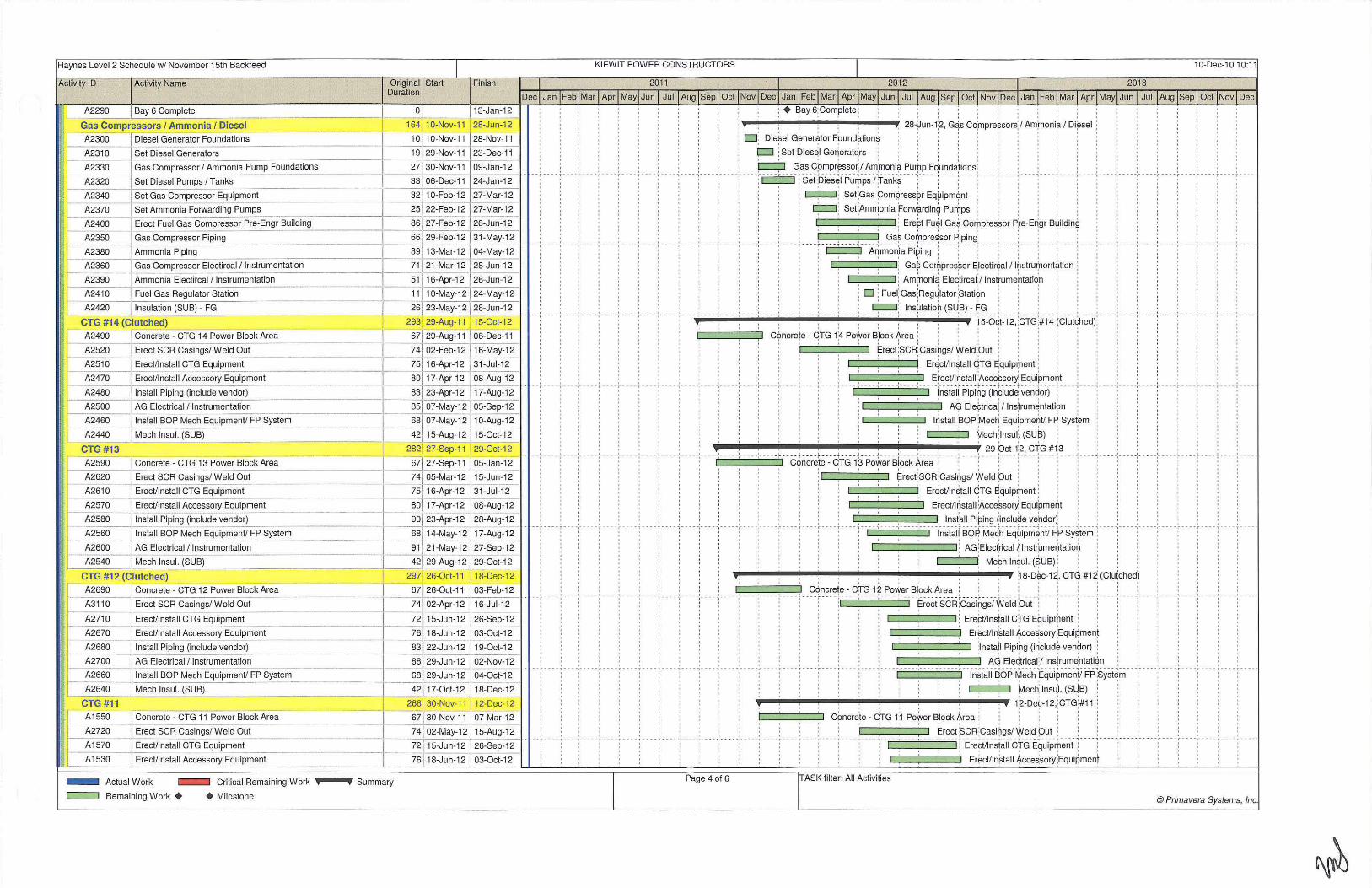
Haynes Level 2 Schedule w/ November 15th Backfeed I KIEWIT POWER CONSTRUCTORS I 10-Dec-10 10:11
Activity ID Activity Name Finish 1 2011 1 2012 1 2o13 Original Start Duration
Dec l Jan IFebl Mar I Apr I Mayi Jun I Jul I Aug ISep l Oct I Nov I Dec I Jan Feb I Mar I Apr IMayl Jun I Jul [Aug [sep [ Oct [ Nov [Dec [ Jan [Feb [ Mar [ Apr [May[Jun [ Jui[Aug [Sep[ Oct [Nov [ Dec
13-Jan-12 o[ ~1 0-Nov-11 28-Jun-12
j Bay 6 Complete A2290
Gas Compressors I Ammonia I Diesel
A2300=-+Diesel Generator Foundations ---------- ·~ -
1 0 1 0-Nov-11 28-Nov-11 ·---
A231 0 Set Diesel Generators 19 29-Nov-11 23-Dec-11 ~-- -----~-~-------1
A2330 Gas Compressor I Ammonia Pump Foundations 27 30-Nov-11 09-Jan-12
A2m I Set Diesel Pumps/Tanks --- 33 06-Dec-11 24-Jan-12
A2340 I Set Gas Compressor Equipment 32 11 0-Feb-12 ~-12 A2370 I Set Ammonia Forwarding P~ -----------~-- 25 22-Feb-12 27-Mar-12
A2400 Erect Fuel Gas Compressor Pre-Engr BUIIdin--=g'--------1---8_6-1-2_7_-F_e_b_-_124
_26_-_J_un_-_1_2_1
f----p,2350 Gas Compressor Piping 66 29-Feb-12 31-May-12
A2380 Ammonia Piping 39 13-Mar-1 2 04-May-12
L A2360 Gas Compressor Eleclircal / lnstrumentation ! ~2390 Ammonia Electircal / lnstrumentation----------1---
71 21-Mar-12 28-Jun-12
IH II !r
E A241 0 Fuel Gas Regulator Station ----l----~-
A2420 Insulation (SUB) - FG
CTG #14 (Clutched) A2490 ........._ Concrete - CTG 14 Power Block Area
f- A2520 Erect SCR Casings/ Weld Out
I- A2510 Erect/Install CTG Equipment
A2470 Erect/Install Accessory Equipment ~----~---- ---------~--
A2480 Install Piping (include vendor) ~----~-
A2500 AG Electrical / Instrumentation ~-----1---
51 16-Apr-12 26-Jun-12
11 10-May-12 24-May-12
26 23-May-12 28-Jun-12
293 29-Aug-11 15-0ct-12
67129-Aug-11 I 06-Dec-11
74 1 03-Fe~12 16-May-12
75 [ 16-Apr-12 31-Jul-12
80 17-Apr-12 08-Aug-12
83 23-Apr-12 17-Aug-12
lnstall BOP Mech Equipment/ FP System ~~~~--1 ----------+-
Mech lnsul. (SUB) 1..----,..----'--
II! A2460
14 A2440 I
85 07-May-12 05-Sep-12
68 07-May-1 2 10-Aug-12
42 Q 5-Aug-12 15-0ct-12
I CTG #13
A2590
A2620
A2610
A2570
f-A2580
A2560
A2600
282 27 -Sep-11 29-0ct-12
Concrete - CTG 13 Power Block Area _________ ! 67f 27 -Sep-11 1 05-Jan-12
Erect SCR Casings/ Weld Out 74 ! 05-Mar-12 15-Jun-12
~-t/1-n-st_a_II _CTG Equipme~t -----11- ~ 16-Apr-12 ~ul-12 Erectlln~all Accesso~ E_q_u_ipment _ _ 80 [ 17-Apr-12 08-Aug-12
Install Piping (include vendor) 90 23-Apr-12 28-Aug-12 ------- ------ -
Install BOP Mech Equipment/ FP System 68 14-May-12 17-Aug-12
AG Electrical! Instrumentation 91 21-May-12 27-Sep-12
j1
1, r~r=~-A=-2=5~4-=-o~-:,~+-M-ech lnsul. (SUB) ---- -=-====L=:~_-_-4_,§~29:Aug- 1 2 29-oct-12
CTG #12 (Clutched) 297 26-0ct-11 18-Dec-1 2
A3110 ErectSCR Casings/ WeldOut 74102-Apr-12 16-Jul-12 ----- ------I-----
A2690 ~oncrete - CTG 12 Power Block Area I 67 26-0ct:;-;--- 03-Feb-12
r - A2670 Erect/Install Accessory Equipment 18-Jun-12 03-0ct-12 A2710 Erect/Install CTG Equipment :~ 15-Jun-12 26-Sep-12
,, I-· A2680 _ J lns~ing (include vend~ __ _ ______ l ~-12 19-0ct-12
'i ~:::: ]:~~~:·,;;,~~:~:::';:.:::~:1°FP Sy_st_e_m_______ ~--- ~::~~~: ~ ~ ~~:~::-11: A2640 - IMech lnsul. (SUB) 17-0ct-12 18-Dec-12
,rb-..-"""""=- ~ CTG #1 1 268 30-Nov-11 12-Dec-12
:' ) r- A155_0_-+_c_o_ncrete-CTG 11 Power BiockArea ~ 67 130-Nov-11 07-Mar-12
A2720 Erect SCR Casings/ Weld Out 74 [ 02-May-12 15-Aug-12
~70 ==~=E=re=ct/l nstall C-TG Equipme-nt____ - _ _ 72] 15-Jun-12 26-S;p-12 .
A 1530 Erect/Install Accessory Equipment 76 18-Jun-12 03-0ct-12 ---- Actuai Work
c=::::::J Remaining Work +
Critical Remaining Work
+Milestone
Summary
· · ; · · · ~ · ~ + ~ay 6~ Complete ~ · · ~ . , , · , : · · · · · ·
' ' ' -,----- ,--·- · ; ' ' ' ' ' ' ' ' ' ' ' '
' ' ' - ; ---,- -- --;- - -- ;- ---' ' '
I I I I -· · ·; ·--- ,-- - - - ;- -- -;·- -• I I I
I I I 0 - - , - --- ,--- - - r · · - - r ----
I I I I - - - - , ---- ~----- ;- --- ; · · --
' ' --.-- ---..-----..--- --
, , , , , , 28-~un- 1;2, G~s Coinpre~sors: I Am:moni~ I Di~sel ;
o : Die$el G~nerator Fbund~tions I I I I I
!=J :Set Oies~l Gerieratqrs
' ' ' l::=::::j Gas Cbmpr~ssor:/ Am:moni~ Purhp Fdundalions: , · · I I I I I I I t I I 1 t I t I o I 0 I I t I I I I
--- -~ - ----, - - ---~ --- -- --,---- -, ----,- ---; -.---, ---- , ---- , - · --,- -- --,-- -- -,-----,---- , -- -- , ---- 1 ---, -- --·o··--; --·--.-- -- -,--- - -,- ----,-----.-- ---; -··· r··· ·r-· ·· : ~ : Set p1esel Pu~ps I ;Tank~ ; : : : : : ' ' '
' ' '
: ' : c:::;:::J; Set ;Gas pomP,ress(>r Eq~ipm$nl ;
' ¢::J! Set !Am~onia :Forw~rdin9 Pu0ps : , , ,
· ; Erei:t Fu~l Ga~ CoriJpres~or Pie-Erigr B~ilding ' ' '
I I I 0 , , , , , Ga~ Cor)lpre~sor J=;iping; , , , , , , ,
' ' ' -----.-. . . -,-- -- -~ - - -- -.-- ·: ·- ·-r·-- -'--- --.-- A~r~;;~i-~Pi~i~g- r···:-·· ·; ----:--·-; --- ---: --·-·:··--:··---.-----.- -,- -- -; - .- -i- --- i -- -
' ' '
c;:=:::;::=:;:::::J: Ga$ Co~pres~or E,lectir¢al / l(lstru(nent*tion :
c.==. :::::1 ! Am~oni~ Ele~tircal !t lnst'rume~latidn ; D: Fue(Gas:Regl]lator ;s tati<?n
. . . . : ¢::::1: lns~latio~ (su:B) - f;G , . . , : , , . , . . . : -.---· -.-----.- ·---,--·' ---,---,. · · --.--- · -.-· · · -.-----, · · · ·f 5:o~t~12·. ;crG;#14 (C"Iui~t,~-ci( ·- · -.-- ---:- - · - -.--- - · : ·- · ·:· - - · -: · -- - :
Cc?ncrete - QTG 1:4 Po~er s:lock ~rea : , ; : : : : '
: · · · · ~rect !scR! Casibgs/ Weld ;o ut ! !
. Er~ctlln~tall QTG E;quip(nent ; I ! I I I I I
, , , , , Erect/lt;lstall ;Acce~sorY, Equipme~t : : , : · ·----.--- -··--- -.--- · -.-· · · !;.;;,~;~r Pipi~9-(i~cll1d~ ~~~~~~)- ; -- - ·r---··-- --.-----.--
c:::::;::=:;:::=:;~:::;J. A<fl Ele(:trica~ / lns)rum~ntat i (>n
!~stall ~OP !Mec~ Equ!pme0t/ FP; Sys~em Mech:lnsu(. (SU~) ' :
' ' '
I I I I
I I I I I --,--- -- ; - -- - r- -- - ,--- - ., ----
, ; , : : ; , : : : , 29-~cq2, G~G #1,3 I I I I I I I -----.-----.- ----.-- .. . --- .,. -c~~~~~t~---orG:1-s f-l~we~ si~~-kAr~a ·:- · - ., - ·· :·---- ;- · -- :- - - - :- · · - •.. -- - , -- - --~ - --- - , - ----.- ---- ~--- - -;--··;
I I I I
' ' ' 0 I I I I I I ' ' '
~rect ;scR ;casi~gs/ 'i'Jeld put : . ' ' ' ' Er~ct/ln~tall C:TG ~quipr;nent ;
C::==::=:::==::J Erect!lrjstall :Acce~sor}( Equipmer)t t I I I t I t
, : : , , , , , . . , , : lnst.all Piping (inclu~e vef!dor) , , , . : , , . , -----.-----.-----.- ----.---- ·:-· --;--- ·:-- --.--- -,----'--- --.-----.---- -!;.;;,~-~ !" so~M~~hEq~ipm~~ii f:~ sy~i~m 1"--- -;- ----.--- --.- -- --,----,---- '---- '- -- .. c:;::=:;:::=:;::::=:;=:::J' AG ;Etect[ical ( l nstr~merjtatio~ ' '
.__ _ ____,· Meth ln~ul. (SUB)! , , , ..,.._.,.. .. _.__._._llllllil __ ...,._ ....... ___ ._._. .. ~ 8-D~c-1~, CTG #1~ (Ciu(ched)
, , , , , Cc)ncre1e - c ;m 1? Po.,Yer Blpck ~rea , , , , , , : : , : , , , · · - - --.-- -- -.---- -.-----, - :· ; - - -.- - -- . ---- -. - ----~~~~i :sc·Firc~~-i~9:;t"~eicip~• r·--···-·r--·r ····:··- -·-- ·--:··--T·-·r·---.---- ,-- ---
: : Ere~t/lnsfall C!rG Equiprf,ent : : : : ; : I I I I I I
Er~ct/ln~tall ~cce~sory ;EquiP,men'
!lnsta!l Pipi~g (i~clud~ ven~or) :
, , , , : , . . , , , Aq Eleqtrical/ lns(rum~ntat iqn , , , , ' --. -' -- -., --- -. ---- ·---- ·--- --.-----.-----.--- --,--i~~i~,i~o-r -~~~h~qui~m~nV i=r sy~i~m - - -.- -- --.-- -- -' ---Mec~ lnsu). (Sl)B) : ' ' '
: : . , : : : , 1 ;2-De~-12.;cTG:#1 1 : cOncreie - dTG 1:1 PoWer B)ock Area : I I '
I I I I I I
' ' ' ~reel :ScR ;casi~gs/ '!Veld put :
~=-· · ==:1'· ·--,-- --· -- -··· · .,---···· ., .... , ..... , .... '-:- : Ere~t/lns!all c :m E~uip~enl :
"I"----,--- .- -- -- .- - - -.. -4
Er~ct/ln~tall /.lcce~sory ;Equipment
Page 4 of 6 TASK filter: All Activities
@Primavera Systems, Inc.

Haynes Level 2 Schedule wl November 15th Backfeed I KI EWIT POWER CONSTRUCTORS I 10-Dec-10 10:11
Original Start Finish 1 2011 1 2012 1 2o13 Duration
Dec I Jan I Feb! Mar I Apr I May! Jun I Jul I Aug l Sep I Oct I Nov I Dec I Jan Feb I Mar I Apr I May! Jun l Jul [Aug I Sep I Oct 1 Nov 1 Dec 1 Jan [Feb I Mar I Apr I May[ Jun [ Jul I Aug I Sep [ Oct [Nov I Dec
i l_
90 22-Jun-12 30-0ct-12
68 16-Jul-12 19-0ct-12
88 23-Jul-12 28-Nov-12
43 10-0ct-12 12-Dec-12
290 04-Jan-12 15-Feb-13 -
04-Jan-12 T 09-Apr-12 67
74 01-Jun-1 2 14-Sep-12 -72 10-Aug-12 26-Nov-12
76 13-Aug-12 03-Dec-12 -1---~
~:~~~~~ ~: ~:~~:~~ ~: 31 -Aug-1 2 03-Jan-13
14-Dec-12 15-Feb-13 ~_ ___ _;....,_,;_ ______ ~------- 275 02-Feb-12 25-Feb-13
A3250
A2820
A2840
A2880
A3260
Permanent Backfeed Available (13.8kV)
ST I Comm Heat Exchanger Bay 6
ST I Comm Fuel Gas
Start-up Turnover CTG #1 1
Start-up Ready For First Fire CTG #14
________ -=-~ 02-Feb-:j"2 07-May-12
~~ 02-Jul-12 16-0ct-12 --- --72 1 0-Aug-12 26-Nov-12
----------!-----!--- -----76 13-Aug-12 03-Dec-12 ---90 17-Aug-12 28-Dec-12
----1 -;----88 17-Sep-12 25-Jan-13
1---1 l----6_5_] 17-Sep-12 20-Dec-12
43 21-Dec-12 25-Feb-13 -t---r--~-
248 15-Jun-12 31 -May-13
---~] 15-Jun-12 ~May-13 j~1 18-Jun-12 31-Jul-12
-
0 31-Jul-12
14 15-Aug-12 04-Sep-12
~_lo4-Sep- 12 1 15-0ct- 12 13 05-Sep-12 21 -Sep-12
40 06-Sep-12 01-Nov-12
13 24-Sep-12 11 -0ct-1 2 '----·
39 28-Sep-12 27-Nov-12
30 05-0ct-12 19-Nov-12
12 12-0ct-12 29-0ct-12
12 ---30-0ct-12 15-Nov-12
38 05-Nov-12 02-Jan-1 3
·a 15-Nov-121 '- 11 16-Nov-12 04-Dec-12
----- -27 20-Nov-12 31-Dec-12
---39 29-Nov-12 25-Jan-13
- -------- 10 02-Jan-13 15-Jan-13
-r------A2890 Start-up Turnover CTG #16
A 1150 CTG #14 First Fire .,--------
A2910 PlantTuning --------
A3270 Start-up Ready For First Fire CTG #13
A2900 Start-up Turnover CTG #15
A 1160 I CTG #13 First Fire
- Actual Work c::=:::J Remaining Work +
Critical Remaining Work
+Milestone
38 04-Jan-13 28-Feb-13 t---
o 15-Jan-13
95 16-Jan-13 31-May-13 ---i
9 16-Jan-13 29-Jan-13 --36 28-Jan-13 19-Mar-13
0 29-Jan-13 -
Summary
; . . . ~ . ~ · · · · : · · · Install Pi:ping (inclu;de v~ndor) · · · · ·
;1 nsta~ l BOI;' Me~h Equipm~ntl F;P Sy~tem ;
I I I I
. -- -;- .- - . :--. --; . --- ~ - .. -~ -- -- -:--- -:- ----:-----:-- --- ~ ----¢======:::J AG: Electricalt lnst~umentatioh :
·:··-- -:-- ·-y ----:--- --; c::;:::::::;:J-- ~e~-h 1~s!;l !isu~-l--- r--- T - : -' . . . . . . . '
I I + I I
--:- --- -~ - ---:-- --- :- --- -; ----+---- + -- - . : - - -- -:- - - - -:- - - - -:- - - - -:- - - -I I I I I I I I ! 0 I
I I I I I 0 I
' . . . .
t t I I t I I I I
- -; -. --~ --- -:-- ---~ ---- } . -- !- - - -; - --- -: - --- -:-- - - -:- --- -:---' ' . I I I I I I . . . I I I I
' . ' I I I I
' . ' t t I ' . . . ' . . . ' . . . '
' ' ' . ' . •• !. ••• • ! . . .. • ..... L • • •• L •• • • ! .... ! . ... J •• • •• ' -- -- - ' - -- -- '- ----'--- - ·
I I I I I o I I I I o I
I I I I I I I I I I
I I I I I
I I t I I
I I I I
' ' ' ' ' ' ' ' . ' ' ' ' ' ' ' ' ' . '
- - ; - -- - + - - - -:- - - - - ; - - -- :- - - - -+ ~ -- . + - - - - ~- - - - -: - - - - -:- -- - -:- - - - -:-- -- -I I I t I I I t I I
I I I I I I
I I I I I I
I I I I I
I I I I
. . ' . . ; -- + - :- ~ + •• f - • -- ! - - --:-- -- -: · I I I I
I t I < . . .
' .
,_111111!1-.-111111!1-.,._. __ _.: _ _.,_~:-•: -1-. _..,: _....,....,,. ~5-F~b-13~ crq #16:
c:oncrete - 6TG 16 Power Block Area : I I I I I
~reel ~CR ;casi~gs/ '«eld :out
I I I I
- - - - ~ - - -- :- - - - -+ - - - - -: I I I I
I I I I
. : Erettllnstall C~rG Equipment ; : : . : . . ---!-- ---·----- ~ ·- ·-:-- -- -~ - · i:r~c-vl~~tail ~cce~sai-Y:Eciui~-m€;~\- - · --:-- - -- ~-- - - ~ -- --1----:--
. ' ' I I I I I I I I I 0 I
' ' ' ~nstal~ Pipirg ( i~clud~ ven~or) : : ;
ln~tal l ~OP ~ech: Equi:pme~tl FP; Syst~m ' ·
~==;:::::::::::;:==;J ACf Ele¢trica~ I l ns~rum~ntat i$n
. . . , , , Mech: lnsui. (SU,B) ;
.......... ~- ' • · ·--· · · ' •••••• J ... -----~J -----....... -------· .................... , ... ;.· ... II.' ·•·•· .• , ... ...... i.i" llil' .--.. '·--···-l - - - - .J - - - - J- - - - · '- - - ' ••
. . . :- - -- -:---- -:- --·· i ·-- - ; --- --
Y . . , 25-feb-1:3, CT;G #1;5 • I I 0 I
I I I 0 I
I t I I
C~mcre:te - q TG 1:S Po~er B,lock ~rea ; .
: · · · ~rect :scR; casibgs/ ~eld ;out : .
c::;:::~=::;=::::J ; Ere~tllnsjall c:m Ef:luiprtJent ;
. - ! . - -- ~ - - -- T. . '
Er~ctlln~tall Accessory :Equipment 1·--- '-----:---- T- --~- :-::·::--=:::' ·::·::· :;:=:~=-j- :- ~~st;~~~ ·rip i~9 F~clu~~e -v~iiC!orf- - --:---- -~---- : ---- : - - -- ~ - ---
: : c:::;=::;::=::;::=:;:. ::::J ; AG :Eiect[ical f: lnstr~me~tatio~ ,
----; ---- ~---- +- ---{ I I I t . . .
' ' . ' ' . ' .
. .
:lnsta!l BO~ Me?h E9uipm~ntl ~p Sy~tem : .__,__.,---__. ; Me¢h ln~ul. (S:UB) ; ·
, , , , . , , 31 ~May-j3, siart Up _ _ ,_-- - ·- --- :- - - - ~ --- - ~ - --- ~ ---- ~- -- .J. -- .! . - . • .J -·- - +- _ , _ - - - - ·-- - + -'-- - -- -'- ~ -
c:::=::::::~~::::=~~=::=:~=:::=~=:::==l Pl~nt st?rt uP. : I I I I I t I o I
c::;::==1 St~rt-up ;remp Po~er Energi~at io~ .
~ St~rt-up :Tem~ Po~er E~ergi~ed (~MW): ; Q S\ I C~mm f!leat ii=xch~nger; Bay ~
: . :~ ST 1 Comni Amrr10nia . - - ~ + ~ • - - - ~ --- • ~ - - • .J - • • • J •• -- 1 • •• • • 1 •••• - ' · .- •• L ••• • L •• -. ! .. .. l .•• • .J •• • • ! .... J- •• - J •• • • •• - •• ----:----- :-- --. .
' ' : : : ' ; D ; ST ( Comi,n He~t Ex\;hanger B?y 2 : ; . ' I I o I I I j
, St~rt-up: Turn~JVer pG #14 ;
D ST 1 Comm :Heat:Exctianger Ba~ 3 I I t I I
.,_----, _ __. ; Start-up Jurn9ver QTG #13
' ' -.:----- ;----:-- ---;-- --:- ----;----;.--- :-----:·.-. -: . -- ·:-----:---- - ---- ; --- -:- --- ; • - - - ~ - - -- ~ - -- - - :. -- - -: - +
:c=:::J iPerrrianen:t Badkfeed Ene:rgization . , . - - 1·-- -- '-----'-- - - - - l -- - - ! • • •• 2 • • . . l .... .J •••• J ••••• • ••• • • 1 • • ••• 1 _ _ ___ ._ _ _ _ _ ._ _ __ _ ! _ _ __ ! ____ _ : : o : ST I Cornm H~at E'xcha~ger ('lay 4: : : ' ' : ' I I I I I I I i I ' .
I I o I I I o . . . . 1 I > I I I l I I . ' . ' p F I qomrrj He~t Exc~ang~r Bay 5 ;
St~rt-u~ Tur~over ;erG ;#12 ! + f;'erm?nen( Bac~feed ;Avai (able (13.8~V)
;- - • -- ~ - -- - : - -- - - ~-- -- '- - - +- ; - - - -
' ' ' . ' '
--- . ~ +-- . -:- - -- -:-- . . -:· +-- -:- - - -+ I I I I
' . . . d ST I coi-nm li-leat Exch~nger: Bay 6 ' . ' ' -· ·:· ·-·1 · -- -!--- - - ~ -- - -!- ---~ - '- --- i-sr1i c~~~ F='~ei ~~~-- ·!---- -:---· -:-----t · · · _, __ -·;·---,_ ·--
. ' ' ' . . 1 I I I I I I o I I
~=;.=JI : Star:t-up Turn~ver ~TG ~11
;o ~tart-~p R~ady For F!rst F!re C1G #1;4
, St~rt-up ;Turn\Jver PG #16 :
. + CTG U14 Rirst Rire : • • '. - . · - L •• • - ~- • • • • !. • • • •
I I I I . ' -----:-----:- -.. ·:-.- :- · - --:- -- .-
' ' ' ' '
:--.-: -- -- ~ - . -~... ; --- :-.. --:- . ri~~i ·-r~:~~~g ! -- --' - -'-----:- -- --:-- -.-:---. ' . ' ' ' 1 I I I I 1 1 I
q St~rt-up ;Reaqy For; First; Fire pG ~13 ~ Start~up T~rnov~r cT;G #15
~ CT~ #1 ~ Firs~ Fire; : :
Page 5 of 6 TASK fi lter: All Activities
@Primavera Systems, Inc.

Haynes Level 2 Schedule w/ November 15th Backfeed
Activity ID Activity Name
r- A3280 Start-up Ready For First Fire CTG #12
I -A1170 CTG #12 First Fire
i A3290 Start-up Ready For First Fire CTG #11
i A1180 CTG #11 First Fire I ' -
I A3300 Start-up Ready For First Fire CTG #16 I A1190 CTG #16 First Fire j c-
A3310 Start-up Ready For First Fire CTG #15
l - A1200 [ CTG #15 First Fire -
- Actual Work
c::::===J Remaining Work +
Critical Remaining Work
+Milestone
I Original Start Finish
Duration
10 30-Jan-13 12-Feb-13 - - -0 12-Feb-13
9 13-Feb-13 26-Feb-1 3 - -0 26-Feb-1 3 --
10 27-Feb-13 12-Mar-13
0 1 12-Mar-13 - l----1 0-f--1-3-,-M-a-~-13 26-Mar-13
-_ ~-- -~ oj - J26-Mar-13
Summary
KIEWIT POWER CONSTRUCTORS I 10-Dec-10 10:11
1 2011 1 2012 1 2o1 3
Dec! Jan !Feb! Mar I Apr I May!Jun I Jul I Aug[Sepl Oct !Nov ! Dec ! Jan Feb ! Mar I Apr !May! Jun[ Jul l Aug [Sep [ ocq Nov!Dec l Jan [Feb! Marl Apr l May[Jun l Jul [Aug [Sep l Oct [Nov[ Dec
· _ - ~- -- : : ___ · · : : ~ -- - - ·----- ~ ---- ---- ~ - --- : . _i _ : · : : tJ -~~a~~~p_ R~ad_Y_~~r-~!r_st_~!~-e_~~E'~~~-- -- ; ____ ; ___ _ : : : : : o ; + QTG 412 First F(re ; ; ' ; ; ;
1 1 o : o o o: Sta~-up ~eady For! First !Fire ¢ TG ~11 :
o ; : : ! o • CT~ #11; Firs~ Fire ! . ; ,
o : o ; : p ~tart-~p Re~dy f:or Fir;st Fir~ CT~ #16 0 0
' ' ' 0 ' ' ___ .~. ___ _ , ___ __ ..._ __ __ .._ _ __ _ _ ___ _. ___ __ , _____ , __ ___ _
. . - - - *-- ~ - - * - 1- --- ... -- -t I I I I I I I
' 0 0
' ' ' D ; Sta~t-up f;leady For first fire GTG ~15
' ' ' '
Page 6 of 6 TASK filter: All Activities
© Primavera Systems, Inc.

EXHIBITE
Estimated Payment Schedule and Schedule of Values

DATE
NTP
January-2011
February-2011
March-2011
April-2011
May-2011
June-2011
July-2011
August-201 I
HAYNES UNITS 5&6 RE-POWERING PROJECT LADWP
CASH FLOW BOP CONTRACTOR
ITEM CONTRACT VALUE
Mobilization of Engineering & Procurement at Engineering Office $ 9,168,680
Issue Project Controls Manual
Issue Specification for Bids- Step-Up Transformer $ 1,449,748 Issue Specification for Bids -Auxiliary Transformer
Issue Specification for Bids - Air Cooled Heat Exchanger
Issue Preliminary Aux. Load List $ 2,282,784 Issue One-Lines- Owner review
Begin Procuring Generator Circuit Breakers
Begin Procuring ACHE $ 12,969,168 Issue Specification for Bids - Shop Tanks
Award ACHE
Issue Specification for Bids - Shop Tanks $ 15,300,065 Issue Specification for Bids- 480 V Unit Substation
Start Pile testing
Issue Specification for Bids -Fuel Gas Filter Separator $ 8,504,722
Issue Specification for Bids - Isolated Phase Bus Duct
Rough Grading I Mass Ex.
Begin Mobilize to Site
Issue Specification for Bids- Black Start Generators $ 22,690,207 Issue Specification for Bids - DCS
IFC P&IDs
IFC UG Pipe I Elect
Oil Water Separator Equipment Delv. $ 8,997,695 Finish Set up Trailers
IFC CTG I SCR Area FNDs
Install Oil Water Separator
5kV FNDIFC
Owner Water Available $ 7,784,767 Install Pile Caps
Piling
Start ACHE Deliveries
September-2011 Admin/Warehouse FND IFC $ 9,371,252 Issue Preliminary Equipment List
IFC One-Lines
October-2011 5kV IFC $ 7,673,937 Install FE Tanks

HAYNES UNITS 5&6 RE-POWERING PROJECT LADWP
CASH FLOW BOP CONTRACTOR
DATE ITEM CONTRACT VALUE
5kYFND
ACHE Deliveries Complete
November-201 1 FE Tanks $ 9,654,267 Set Diesel Generators
CTG #14RTS
JFC Three-Lines
Admin Building FND I Warehouse
December-2011 Set Diesel Pumps I Tanks $ 5,297,205
Concrete- CTG # 14 Power Block Area
Set Diesel Generators
UG Electrical Scope
Heat Exchanger Electrical
January-2012 Heat Exchanger Piping $ 10,620,432 IFC DCS Disconnects
Concrete - CTG #13 Power Block Area
Gas Compressor Equipment Set
Pull Cable I Wire in Duct Banks
February-2012 IFC Raceways $ 4,419,110
SCR #14 Delivered
Concrete - CTG # 12 Power Block Area
Ammonia Pumps Set
SCR 13 Delv.
March-2012 Pull Cable I Wire in Duct Banks Finish $ 5,271,627 SCR #12 Delv.
Concrete - CTG # 11 Power Block Area
CTG 14 Delv.
Install Electrical Grounding System
April-2012 Pipe I lustrum. Water Treatment $ 7,786,251 CTG 13 Delv.
Concrete - CTG #16 Power Block Area
SCR 16 Delv.
Load Catalyst CTG 14
May-2012 Fire Protect Transformers $ 5,709,300
Erect SCR Casings I Weld Out
Elect- Equip/Raceway/Wire/Heat Trace WT

HAYNES UNITS 5&6 RE-POWERING PROJECT LADWP
CASH FLOW BOP CONTRACTOR
DATE ITEM CONTRACT VALUE
Plant Start-up Onsite
CTG 12Delv.
June-2012 Erect/Install CTG Equipment # 14 $ 18,733,799 Erect/Install Accessory Equipment# 14
CTG ll Delv.
SCR Unit 15 Delivered
BOP Mechanical Completion
July-2012 Erect!rnstall CTG Equipment #14 $ 5,148,856
Install BOP #14 Mech Equipment/ FP System
Erect/Install Ancillary Equipment# 13
Temp Power 7 MW Energized
Load Catalyst CTG 16
August-2012 Start ACHE Start-up $ 9,325,553 Install Piping/ Instrum. (including vendor) #14
AG Electrical Scope Unit #14 Power Block
Mechanically Complete Unit #14
Demin Water Trailers Availabe for use
September-2012 CTG 13 Mech Complete $ 10,421,264
AG Electtical Scope Unit #13 Power Block
Install Piping/ Instrum. (including vendor)# 12
Amonia Start-up Complete
Erect/Install Accessory Equipment # 16
October-2012 AG Electrical Scope Unit # II Power Block $ 5,548,141 Install BOP #16 Mech Equipment/ FP System
Erect Install CTG Equipment # 15
Energize Backfeed
Finish ACHE Start-up
November-2012 Fuel Gas Start Up/ Comm. $ 9,989,557 Tum-over CTG 13
Turn-over CTG 12
Site Lighting
December-2012 Final Grade/ Road Aggro. Base/ Paving & Curbs $ 1,365,527
Install Pern1anent Fencing I Landscaping
Start-up Unit 14
January-2013 Start-up Unit 13
$ 5,525,746 First Fire Unit 14
First Fire Unit 13
Plant Start-Up Unit II
February-20 13 First Fire Unit 12 $ 2,274,458 First Fire Unit 11

DATE
March-2013
April-2013
May-2013
June-2013
July-2013
HAYNES UNITS 5&6 RE-POWERING PROJECT LADWP
CASH FLOW BOP CONTRACTOR
ITEM CONTRACT VALUE
Plant Start-Up Unit 15
First Fire Unit 16 $ 3,062,787 First Fire Unit 15
Plant Tuning/ CEM RAT/ Demo Test $ 599,827
Site Demobilization
Plant Tuning/ CEMRAT/ Demo Test
Site Demobilization $ 2,270,268 Substantial Completion
Site Demobilization $ -Final Completion
SUBTOTAL $ 226,217,000
LADWP Project Management Fund $ 3,000,000
Total Aggregate Sum $ 229,217,000

HAYNES UNITS 5&6 RE-POWERING PROJECT LADWP
SCHEDULE OF VALUES
Kiewit Power Constructors Co.
This is a schedule of values for a lump sum project. Schedule of values is for the purpose of monthly progress payments, not for pricing scope additions or deletions.
'·····-"OF ENGINEERING & PROCUREMENT AT ENGINEERING OFFICE $ 9.168.680
~~ IT >HEAT GEA Rainey
= ~ $112,836 Issue $3,223,884 TSSiiiiShoo PO . $5,373.14'
.-shoO <1,61~1* Delivery to Jobsite $1, 174,•
~ - Kobe leo Issue ' Order or Notice $77,668
= $761 1.149 ~ = ;,82:
'Shop I, 1G ;,73 DeiWeiV >Jo6site .24: '.69:
~ Total
= $11 1,402 Issue Cerlffied $21 , 16G 7isuesii0iii"i5 for f SlaifS!iOD: $51 .319 ==site $1( ,935
~ Total
$21 ,454 rrssue $4. ,251
= = $91 :502 IDelive,y To Jobsite $11 ,969
~ Iii rrssue , to Proceea $G ~ $C llssue Shop PO for $G DeiiveFv To Jobsite $G
~ Total $0
Atlas Copco
= ~ $48,611 llssue Cerlified llSSue Shoo PO for
=~ $97,231
~ Total
I Issue ' Order or Notice to Proceea $34,341 llssue Cerlifiec $68,69C ~ $137,38[ !Delivery To Jobsite $34,341
~ -IISSue Order or Notice to Proceed $30,23 ~ $60,46l llssue Shop PO for $120,924 IDelive,y To Jobsite $30,23
~ Total
= ~ $• '191 llssue Cerlified Drawin.as $3: ',591 ~i510i $81 •,591
$61 ,197 Total

HAYNES UNITS 5&6 RE-POWERING PROJECT LADWP
SCHEDULE OF VALUES
Kiewit Power Constmctors Co.
This is a schedule of values for a lump sum project Schedule of values is for the purpose of monthly progress payments, not for pricing scope additions or deletions.

HAYNES UNITS 5&6 RE-POWERING PROJECT LADWP
SCHEDULE OF VALUES
Kiewit Power Constructors Co.
This is a schedule of values for a lump sum project. Schedule of values is for the purpose of monthly progress payments, not for pricing scope additions or deletions.
DeiiViiiV I
~ ~
Total
llssuePumhas~ $36, 799 !Issue Cerl;t;ed Drawin.as $: 599 ~ starl shoe ' $36: ·.993 = $21 1,439 !Deliver; $: 599
- rotal $58: .428
Cemtek ,c >to Proceec $40.37: ~ $237,448 !Issue Shop PO for ' $633,194
1 Shoo $158.298 ~ $79,149
- Total $1,170,820
Eme.,on 'Order 'roceea $36,37:
!Issue Cerlified Drawinqs 218.23: ~ ' ~727445
I Shop 72,744 lbeliver; To Jobsite $43.64
~ Total
~ $4.31: !Issue Cerlified D1 $ '153
?PC $37,17 ~ $7.435
Total $60,078
rwJ!I!!!!! !Issue F ~Proceea $6, 13t !Issue Cerlified Drawinas 18,404
JPC >49.078 !Deliva~ 12,2
- Total $85,88:
!Issue Pumhase Order or Notice to Proceea $84,80( ~- f5( •.80( !Issue ShoiiPQ7
'Shor !161 1,60( $1( .761
~ Total
I li"SSUe ~ $1 1,232 !Issue Cerlified Drawinqs ~ -~ !.634 = 1,463
I $8: 1,078
~ • liiit•• I7Ssue ~ $81.708 ~ $490,24 'Issue Shop PO $1,634,15
eshcii: $98,049
-- Total
I I I

HAYNES UNITS 5&6 RE-POWERING PROJECT LADWP
SCHEDULE OF VALUES
Kiewit Power Constructors Co_
This is a schedule of values for a lump sum project. Schedule of values is for the purpose of monthly progress payments, not for pricing scope additions or deletions.
~ [issue Projec/ !issue Civil
; Manual
= ·~
=
[issue · '>fur Was [issue 1 · ' fo> Gas = ·~ ilssue · '>fur Jssue Us/ = . LoiiiJTiS[ !Issue u;;e[]SI Jssue 'fo> = ~ Jssue ~ !Issue ' fo> I V = ~ lissue '>fDi lissue ' fo> Bids - Black Slarl IJSSue ~ lissue ~ lissue 'fo>
Phase Bus Duel Bus Duel
IJSSue ~ lissue ~ lissue 7 fo> Bids - Wale> IJSSue~ ~ lissue Heal Balance &'W'iiier Mass Balance IJSSue lissue Thmeo;;eg:: lissue 7 fo> IJSSue ~ lissue AifiniBI lissue CTG
Svslem
~ (iSSue s fo>Bids 'issue GSU liiSSUe" lissue lissueACHE IJSSue lissue
~ 7 fo> Bids - GEMS
dBuiiiiiiiii Test
· 7Pumos
fSeVeiii SeNice)
~66~019 ____ +-------------~ $266,019
$212.a15 $66,50t
$425,63(
~~::
;;~~---4---------------4 $266.019 $212,81t
$93.10; $93,107
$49.879
~~:: $49, 179 $19.951
$194,194
$133,009
$133,009

HAYNES UNITS 5&6 RE-POWERING PROJECT LADWP
SCHEDULE OF VALUES
Kiewit Power Constructors Co.
This is a schedule of values for a lump sum project. Schedule of values is for the purpose of monthly progress payments, not for pricing scope additions or deletions.

HAYNES UNITS 5&6 RE-POWERING PROJECT LADWP
SCHEDULE OF VALUES
Kiewit Power Constructors Co.
This is a schedule of values for a lump sum project. Schedule of values is for the purpose of monthly progress payments, not for pricing scope additions or deletions.
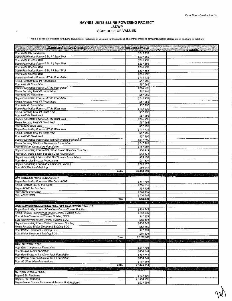
HAYNES UNITS 5&6 RE-POWERING PROJECT LADWP
SCHEDULE OF VALUES
Kiewit Power Constructors Co.
This is a schedule of values for a lump sum project. Schedule of values is for the purpose of monthly progress payments, not for priclng scope additions or deletions.
IBeo/n, ·~ $231,863 rPOiffGSU #1 = ·~ IPourGSU#2 = · 1 Forms GSU #3 Blast Wall IPoW'GSU1i3 IBeoin iUATif
!Finish Form/no UAT #1 $5i ,966 fi50ij([J,iffif $5i .966 !Begin ·~
Finish Form/no UA T #2 $51 ,966 IPoUrVAf $51 ,966 = ·~ Finish Form/no UA T #3 $57,966 IPoUrVAf $57,966 = ·~ Finish Form/no UA T #1 Blast Wall $57,966 fi50iiFTJAT#1 Blast Wall $57,966 = ·~ Finish Form/no UA T #2 $57,966 1PoUrVATi12 Blast Wail $57,966 = ·~ <115,932 Finish Form/no UA T #3 Blast Wall $57,966 fi50iffUAr#3 Blast Wall $57,966 = ·~ :547,780 Finish Form/no Blackout $ 17,38•
17,38• = ·~ t86,94G IPour ISO Phase & Nor Se' Bus Duct ' t43,4 = 'orms t69,558
= ~ 17,391 IBeoin Forms $173,897 IPOui 5KV Electrical Build/no $86,945
~ 1'0laT .so;
IBeoin ·~capsACHE $341 ,79t !Finish Form/no ACHE Pile Caps = $9<
'· J( oPileCaDS $171 l,4
!Strip ACHE SOG
-uw:~~T TOtal -$434,740
!Finish Form/no >I Build/no SOG $104,338 . iiSOG $17,388
!StriP iiSOG $10,434 IBeqin Fonns ~aWater '' 8UiiiJiiiiiSOG $52,168 ~ $17,388 IS/rip Water Buildin.o SOG $10,434
~ Total $1
IPOuiG8S $347,79t Tank $434,744
IPoUrllBw- · e Water $434,74<
~ $434,744 IPour All r Mise
Total $1
~. IBeOinGSIT .,,H~ IBeoin CTG $1,304, ll3e<Jin Power Control Module , ' MDa Piafform'

HAYNES UNITS 5&6 RE-POWERING PROJECT LADWP
SCHEDULE OF VALUES
Kiewit Power Constructors Co.
This is a schedule of values for a lump sum project. Schedule of values is for the purpose of monthly progress payments, not for pricing scope additions or deletions.
IMObWze !Begin
~egm
Finish, Begin.
· 1 out
' & Sheh Core & Sheh
HVAC
~173,898
(,590 1347,795
· r Finishe' I Jntenor 1-inishe' I Punch Lisl ;~~r----r------------~
~------------ThW~----------· ~egm of SCR's 1-inish r'aincmg or oCXs Begin Painting of Plant Pipe
' Painting of Plant Pipe /OUCh Up
Begin Firer
1,846
$347,796
',796
$1,271,148
Total $3,31 r,7481
~~m~ .......................... .. !Begin Bringing temp Power to Site
~ . t Bank Conduit 11ns1a11mg r <;onawl
'Begin Installing r • tray TG #11 ,Begin Pulling Cable CTG #to
~egin s <; "'"" Begin lnstaltlng Begin Pulling Cable CTG #12 ~eG So/GH?<
Begin Installing 1
Begin Pulling Cable CTG #13 ~eG >UGH?o
Begin lnstaltlng 1
Begin Pulling Cable CTG #14
~e, '"'""" BeG 1 lnstaltlng Begin Pulling Cable CTG #15
~eG '"'""'" BeG 1 tnstaltlng Begin Putling Cable CTG #16
~eG '"'""'o
>#13
>#14
>#15
>#16
Finish lnstatling /ray GIG #1 Finish Pulling Cable 1 ·G #11
rmisn '" 1"., Finish lnslatling /ray c 1 G #12 Finish Pulling Cable TG #12
rmisn ' u" ., < Finish lnstatling /ray c 1 G #13 Finish Pulling Cable C TG #13 rmisn ' CTG #13 hnish Installing 1 ray C 1 G #14 Finish Pultlng Cable CTG #14
Finish Tr 1 ; CTG "" hnisn Installing 1 ray CTG #15 Finish Pultlng Cable C TG #15
Finish Tr ; <;J G "' o 1-inish Installing Jtay CTG #16 Finish Pulling Cable C TG #16
1-inisn 1 ; <; 1 G "" Begin lnstaltlng 1
Begin Putling ~egin JAres Finir 1 lnstaltlng Conduit.
p/3,895 >894,74: 125,645
$1, 16,422 :8g4,74: ~325,645
$1,216,422 ~894,74:
~325,645
$1, (,422 ;894,74; P25,645
$', (,422 ;894,74; P25,645
$>, (,422 ;894,741
$> (,422
P13,78: 002
$113,78: /,002
$113,78: /,002
$228,134 $113,78:
/,002 $228,134
13,78: /,OO:
$1,738,975 $52,169
$ ',795 ;17,39G

HAYNES UNITS 5&6 RE-POWERING PROJECT LADWP
SCHEDULE OF VALUES
Kiewit Power Constructors Co.
This is a schedule of values for a lump sum project. Schedule of values is for the purpose of monthly progress payments, not for pricing scope additions or deletions.
RniSh
~ Beain Pull/no 'ACHE I Water 1Area
BeGin iWire AC 'Tan~ !Hnish rmv ~Water TankFarmArea !Finish Puliina Wire ACHE I Water RniSh i Wire ACHE I Waliii ~ !Bealn Puliina Wire Fuel Gas Area Beam Was Area
~·= Finish Pulling Wire Fuel Gas Area Finish Fuel Gas Area ~ Beair 1 GSU Finish. GSU ~ Be.r 1 Salting UA Beain UA RnTiiii: ~ Be.alr Beair ' Phase Duct ~
!Be<~ ~
i/#12 Clutch rtifJTCiutch
~ !Set Un/1#12 rsetUiiififf3Suoer Care ~ !Setun/1#15 rsetUniflf/6 rsetTJnii#iT !Setunil #12 rsetUniflf/3 ~ ISetunit #15 riiiifUnillfj 6 ~ !Finish Unit #1 I Intake ll3ealn Unit •12 ~ !Be.ain Unit #13 ri'infsh Unit #13 Intake ~ !Finish Unit #14 Intake !Bealn unit"" ~ iBe.ain Unit #16
TG#11 'Gifi2
'5fGii13 TG#14
House
House
House !Finish Unit #16 Intake ISeTO'FG!fi~
!Set CTG y Base Ski<
!SeT= ViliiSiiSffi (SeiCTG iSet ~TG Base Skid ~ !Finish Super Care Finish Super Core
'Tank Farm Area UTank
"olaf
$81.949 $1,73 :975
>34< 795 $869.488 $1: 1,898 $1: 1,898
$1,~~~~----+-------------~ $5:',169
iWo:;~~ $130,42: $130.423
$1,695,501
$1,478,129 $52,169 $34.78(
$304,321
$869,488
$137,67C $137.67( $137,67 $137,67( $13767( $137,67
$3 1,561 $3' 1,568
$3' ,561 $3 ,568
$3' ,561 $3' ,568
-$31 .568 z: ,561 $3 ,568 $31 .568 $371 '77
$21•.982 $371 77
$21'.98l $371
$21',98: $371
$21•,98l $37t 77
$21'.98l $371
$28,98: $28,9821 $28,9821 $28,9821 $28,98l $28,98l $28,98: $57,961 $57,967
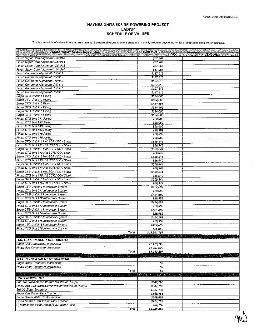
HAYNES UNITS 5&6 RE-POWERING PROJECT LADWP
SCHEDULE OF VALUES
Kiewit Power Constroctors Co_
This is a schedule of values for a lump sum project. Schedule of values is for the purpose of monthly progress payments, not for pricing scope additions or deletions.
Finish. Tliiififi4 $57,96; Rn/ShSuoer Unil#15 $57,96; ~ TJiiifffi6 $57.96: Finish' Vriii#i1 P27,813 FmiSh Unit #12 $127,81: FmiSh TJiiiflff3 $127.81: Finish Tliiififi4 $127,813 Finish Unit #15 $127,81: FmiSh TJiiifffi6 $127.81: aeg;;;c~ 'Dinii $634,60(
BeaifiC'FGUnif#13 P'oina $634.606
Bei iciTi-unit#16 P'oina $634.606
FmiSh ?fTJnii#IT 'Dinii $2. '· 982 Finish TG Unit I $28,98: FiiiiSfi: "(; Unit $21.98: = ~ ;;;;;;a $2. ,982 Finish TG Unit I $21,982 FiiiiSfi: "(;Unit $21.98: Beijii1 ~ $550,844 FiniSh TG Unit #11 f CO. Slack $86,949 Bee CfG Unit #12 Hot SCR I CO istaeii $550.844
=~= $86,949 IBe' 'CT Wnil#13 Hot SCRICOI Slack $550,844 FmiSh "(;Unit ~RICO !Stack $86.949 =~ $550,844 !Finish TG Unil#14 Slack $86,949
1Bei,~mi~rc~tt~G~~m;itit#~15~Hott~S;~(CR<I~C~CJ~II~Sf8<*~-------------------------+----~$55~~~: WniSh ~ $86,," IBeain CTG Unit #16 Hot SCR I CO I Stack iF!nish TG Unil#16 Hot SCRICOI SlaCk ~ Finish TG Unit #11 J3eair CTG Unit #12 vstem FiniSh TGTJiiitiFf2 Be.ain CTG Unit #13 Fiiiish TG Unit #1: = G'fi.ITJiJtifi4 ;vs;em Finish CTG Unit #14
IBeain CTG Unit #15 ;ystem !FiniSh TGfJiiiiiff5
IBe.ain CTG Unit #16 r System !Finish TG Unit #16
IGASC~. IBeain Gas !Finish Gas
Total
$8t .949 $424,599 $28,98<
$28,98,
$28.98: $424,59S $28,98<
$28,98<
$28.98:
$2, 173,72(
~----------~------~~--------~ $( $(
~ ................. row~---~$' .. ~ ........ .. = IFinal A/ian Circ = .~
' Water Pumps
'olaf
$347,79t $347,79t $347.79t
$121.728 $34,780

HAYNES UNITS 5&6 RE-POWERING PROJECT LADWP
SCHEDULE OF VALUES
Kiewit Power Constructors Co.
This is a schedule of values for a lump sum project. Schedule of values is for the purpose of monthly progress payments, not for pricing scope additions or deletions.
Beain 1 Cim. Water: U/G
~ AliTBit Cim. Water UIG BeQii1 -~ Beiiii)Jnstalling Circ
Circ. Water AIG
' Waste Drain Piping U/G 8eiiiii1'uefGai Piaina U/G ~
Begin Plant Drain Pipe UIG ., Pipe UIG
Beiiii1 if5iiiiiWV7G ' Fire . Piping U/C
BeiiiiiDBmin p;afno U/G ~ 'All 1Hvdro's
Total
$86.949
$8,695
U47,795 104,339
~347,795
~;:: $69,559
$217,37< $43,4; $86,949
~-------~------~----~ ~ 'Finish Demin Storage &
Begin ACH1 Chemical Feed Pipina fRniSii7iCFiE mDiiiii IBeginRaw !Finish •r Pipinr ~ Finish 'iping
!Begin Fuel Gas Piping ~
$ $86,949 >36t, 185 $5;, 169
$34i,795 $61,559
$92,166
$434,744
~~BBBBBBBBBBBBBBBBBBmiwil~' .. aji~~.4i9''··~7~ .................. ~ IBeain U/G Small Bare Service Air IBeiiiii" 7JlGSma7!Biii'e ~>Air !Begin Instal/ina U/G t Air
IBeain Pioe suaaarl ~ IBe.ain Shot n Pipe
'Shoo
IBe.ain 'TG ' Supply &Install li'inish ' Supplv & lnstaiT
Total
Total
~273,01
173,898 $86,949 $69.559 $43,474
$/7 .. 896 $12 726
$~~~~~.----~------------~
$86,949
~ $34,78G Finis/ 'items Supply & install $652, 116
~--------------fu~~~--~32~------~ IFTr1iSh !Begin
CfGifj.
QCTG#/1: CTG #12·
TGiH2. 1 CTG #13:
Test& 'Test & Checkaur
Test&
Test & Checkour $ ,231,48G

HAYNES UNITS 5&6 RE-POWERING PROJECT LADWP
SCHEDULE OF VALUES
Kiewit Power Constructo!S Co.
This is a schedule of values for a lump sum project. Schedule of values is for the purpose of monthly progress payments, not for pricing scope additions or deletions.

EXHIBITF
Approved Subcontractors Information
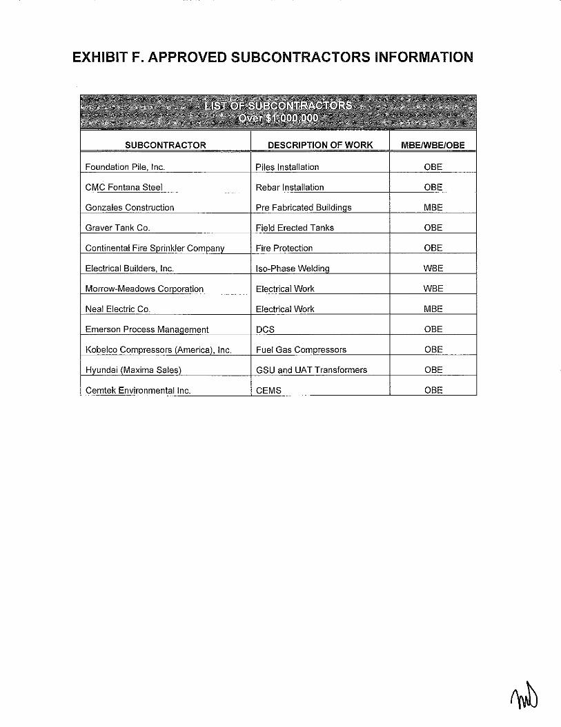
EXHIBIT F. APPROVED SUBCONTRACTORS INFORMATION
Foundation I Inc. Piles Installation OBE
I i
Pre
Graver Tank Co. Field Erected Tanks OBE
Fire OBE
, Inc. !so-Phase
Morrow-Meadows Electrical Work WBE
Emerson Process DCS
Kobelco Gas OBE
GS
Cemtek Environmental Inc. CEMS OBE

EXHIBITF
List of Subcontractors and Suppliers
The following subcontractors and suppliers are authorized to work on the Project:
Name Special Expertise of Anticipated Location Firm Type Anticipated Firm Task/Service (MBE/WBE/OBE) Compensation*
Responsibilities Pinnacle Petroleum Distribution of refined Fuel/Oil Southern California WBE 0.68% Inc. petroleum products &
lubricants Electrical Builders Electrical services Isophase Minnesota WBE 0.07% Inc.
Morrow-Meadows Electrical services Electrical Work Southern California WBE 3.33% Infra-Structure Aggregates supplier Aggregates Southern California WBE 0.49% Aggregates Advantage Demolition and Demolition Southern California MBE 0.09% Demolition and grading Grading Inc. Western Paving Asphalt paving and Paving Southern California MBE 0.39% Contractors site development Built-Rite Fence Fence, gates and Fencing Southern California MBE 0.02% Co. railing supplier Paramonnt Metal & Metalwork and Steel Southern California MBE 0.20% Supply Co. structural steel Gonzales Pre-engineered Pre-Engineered Southern California MBE 2.00% Construction buildings. critical-path Buildings
network infrastructure Seville Program and Testing Southern California MBE 0.18% Construction construction Services management One Source Electrical supplies, Electrical Materials Southern California MBE 1.72%
industrial automation,
ir

and utility products Neal Electric Electrical services Electrical Southern California MBE 5.41% Ncent Transport Transportation Trucking Southern California MBE 0.02% Inc. services Berkel & Company APGD Piling APGD Piling Kansas OBE 3.46% Contractors Inc. CMCRebar Rebar Rebar Texas OBE 0.68% B.M. T. Graver Shop, field erected Storage Tanks New Mexico OBE 0.76%
tanks (Furnish & Erect) Continental Fire Fire protection Fire Protection Nebraska OBE 0.52%
systems Total: 20.02%
* Subcontractors and suppliers participation is estimated and may be modified to reflect actual services requested.
LADWP- [Consultant Name] Exhibit F - List of subcontractors and suppliers
b
EXHIBIT G
Key Personnel
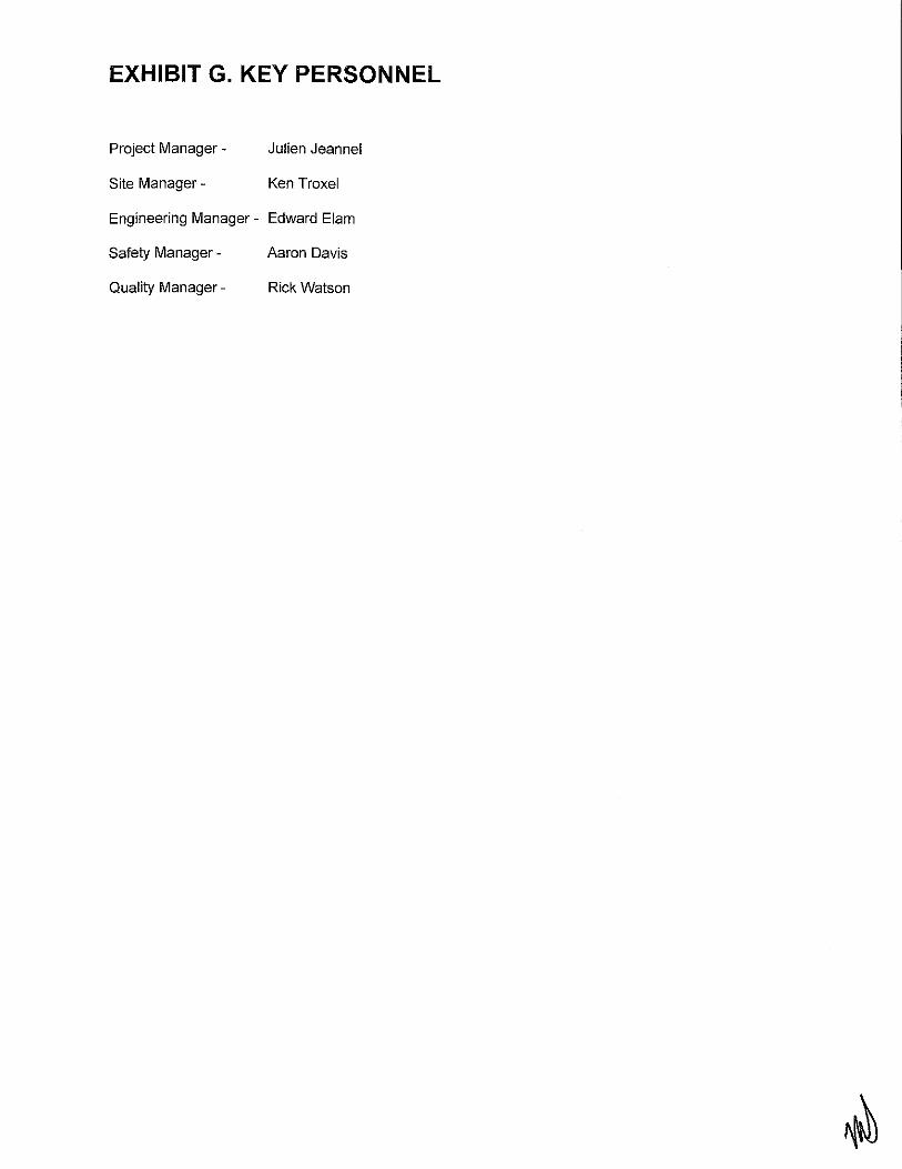
EXHIBIT G. KEY PERSONNEL
Project Manager -
Site Manager -
Julien Jeanne!
Ken Troxel
Engineering Manager- Edward Elam
Safety Manager - Aaron Davis
Quality Manager- Rick Watson
EXHIBITH
Labor and Material Bond, and Performance Bond Information

LABOR AND MATERIAL PAYMENT BOND
We, the undersigned principal and surety, acknowledge ourselves jointly and severally bound to the Department of Water and Power of The City of Los Angeles in the suru of Dollars ($ . The condition of said obligation is such, that if said principal or his subcontractors, under the attached Contract No. -------= between said Department and said principal, shall fail to pay any of the persons named in Section 3181 of the Civil Code of the State of California, or amounts due under the Unemployment Insurance Code with respect to work or labor performed by any such person, or amounts required to be deducted, withheld, and paid over to the Franchise Tax Board from the wages of employees of the principal and his/her subcontractors pursuant to Section 18806 of the Revenue and Taxation Code, with respect to such work and labor, and surety will pay for the same, and also, in case suit is brought upon this bond, a reasonable attorney's fee, to be fixed by the court. This bond shall inure to the benefit of any and all persons named in said Section 3181 so as to give a right of action to such persons or their assigns in any suit brought upon this bond. Notwithstanding the number of claims made or the nuruber of claimants, the aggregate liability of the principal and surety under this Bond shall not exceed the sum set forth above.
Dated~-------' 20_
(SEALJ (PRINCIPAL) ___ _
By ______________ ~=---PREs
and -----------------""''isEY".cyv_--
(SEAL) (SURETY) By _________________ _
State of California } County of Los Angeles } ss
On this day of , 20 __ , before me, a Notary Public in and for said County and State, personally appeared.C""C--------,-
-=--=----=---=---=--:----:----=c---::-c--:-----:-----' each known to me to be the duly authorized Attorney in Fact of the above named surety, and acknowledged to me that he/she subscribed the name of said surety thereto and his/her own name as Attorney in Fact
IN WITNESS WHEREOF, I have hereunto set my hand and affixed my official seal in said County the day of the year in this certificate first above written.
Notary Public in and for said County and State
The foregoing contract and bond approved as to form ______________ _
CARMEN A. TRUTANICH, City Attorney
By __ ~~~~~~----=--AssJsTANT CITY ATTORNEY
The foregoing bond approved by the Department of Water and Power.
ANSELMO G. COLLINS ACTING DIRECTOR OF SUPPLY CHAIN SERVICES#
·~

CONTRACTOR'S PERFORMANCE BOND
We, the undersigned principal and surety, acknowledge ourselves jointly and severally bound to the Department of Water and Power of The City of Los Angeles in the sum of Dollars ($ . If the Principal faithfully performs the attached Contract No. __ or pays to the said Department any costs or damages the Department suffers because of the Principal's failure to so perform, then this bond is void; otherwise to remain in full force and effect. No right of action shall accrue under this bond to or for the use of any person other than the Department.
Dated ___ ,, 20_
(SEALl (PRINCIPAL) __ _ By ____________________ ~
PRES.
and --------------------------~smcEC'Y
(sEALl (SURETY) ____ __ By ___________________ _
State of California } ss County of Los Angeles }
On this day of , 20 , before me, a Notary Public in and for said County and State, personally appeared::---::--:----:---::----:--:-------:--:::--:--:-o----:---------=----' each known to me to be the duly authorized Attorney in Fact of the above named surety, and acknowledged to me that he/she subscribed the name of said surety thereto and his/her own name as Attorney in Fact.
The surety hereby stipulates and agrees that no change, extension of time, alteration or addition to the terms of the Agreement or to the work to be performed thereunder or the specifications accompanying the same shall in any way affect its obligation on this bond, and said surety does hereby waive notice of any such change, extension of time, alteration or addition to the terms of the Agreement or to the work or to the specifications.
IN WITNESS WHEREOF, I have hereunto set my hand.and affixed my official seal in said County the day of the year in this certificate first above written.
Notary Public in and for said County and State
The foregoing contract and bond approved as to form ________________________ __
CARMEN A. TRUTANICH, City Attorney
By~~~~~~~----AssJsT ANT CITY ATTORNEY
The foregoing bond approved by the Department of Water and Power.
ANSELMO G. COLLINS ACTING DIRECTOR OF SUPPLY CHAIN SERVICES

EXHIBIT I
Storm Water Pollution Prevention Program (SWPPP)

EXHIBIT I. STORM WATER POLLUTION PREVENTION PLAN
This Exhibit I references the following document provided in the RFP 295-10- Haynes Units 5 & 6 Repowering 051310, Appendix M, Exhibit 1:
Los Angeles Department of Water and Power (LADWP) Local Storm Water Pollution Prevention Plan. July 10 2002. 99pp.

EXHIBIT J
Environmental Impact Report (EIR)

EXHIBIT J. ENVIRONMENTAL IMPACT REPORT
This Exhibit J references the following documents provided in the RFP 295-10- Haynes Units 5 & 6 Repowering 051310, Appendix M, Exhibit J:
Los Angeles Department of Water and Power (LADWP), Haynes Generating Station Units 5 & 6 Repowering Project Draft Environmental Impact Report (EIR) (SCH#2005061111) & Appendix A:
Notice of Preparation, Initial Study, and Comment Letters, January 2010. 325pp.
AND
Los Angeles Department of Water and Power (LADWP), Haynes Generating Station Units 5 & 6 Repowering Project Final Environmental Impact Report (EIR) (SCH#2005061111 ), April 2010.
69pp.

EXHIBITK
Intentionally Left Blank

EXHIBITL
Base CTG Specification Sections 5.6 and 5.7

&. Plaflt OperBtifl~ Life aAd Reliability
1. The GTG GoAtraeter shs ll deseribe ifl proposal deeumeAts the desi~fl eriteria that will be speeifieally used to meet afl exteAded Faeility life of 30 years. lA additiefl , the GTG GoAtraetor shall diseuss ·9·9·hat desi~fls will be employed te allow for eyelie operatiefl , i Aelud i fl~ the time re~u i red for emissiofl eemplisAee durifl~ GTG rapid startup, shutde'o"o'fl afld psrtial load operatiofl afld to meet the pia At reliability re~u iremeAts . I fl addressifl~ the rel+ability afld life exteflsiefl issues, the GTG Gentraetor sh-aH pre'tlide diseussiefl efl hew Major E~uipmeAt speeifieatieAs aAd proper material seleetiofl 'Vvi ll be utilized to ael=lie'tfe tl=lese ~oals .
5:5 INTENTIONALLY OMITTED
5:6 GOMBUSTIO~~ TURBINE GENERATOR (GTG)
A. Information and Scope of Work
1. General
a. The intent of this Specification is to describe design, fabrication, testing and delivery requirements for the Combustion Turbine-Generator (CTG) equipment. As part of the Agreement, the Contractor shall provide six (6) CTGs for the Haynes new Generating Station. The CTGs will be referred to as Units 11 - 16. The Contractor referred to in this section is the Prime Mover (PM) Contractor or his designated sub-contractor(s).
b. Each CTG will be used to generate electrical power and flue gas will be exhausted through an Emission Control System (ECS) to an exhaust stack.
c. The CTG Contractor shall provide three (3) CTGs (Units 12, 14 and 16) with a standard "handing" configuration in which the intercooler is located on the left side of the unit and the ECS on the right as viewed from the generator non-driven end. Three (3) CTGs (Units 11 , 13 and 15) shall have an alternative "handing" configuration in which the intercooler is located on the right and the ECS on the left side as viewed from the generator non-driven end.
d. Units 12 and 14 will include the synchronous condenser mode operation with the generator clutch.
e. The CTG equipment shall be designed for peaking cycle operation. For other site specific details and design conditions, refer to this Specification Exhibit Z Section 1.
78

f. The LADWP is relying upon the CTG Contractor's skill, judgment, and ability to furnish equipment suitable and fit for such purposes.
g. The generator shall have a higher inertia constant and shall be classified as "heavy."
2. Scope of Work
a. The CTG Contractor shall be responsible for designing, furnishing, fabricating, assembling, shop cleaning, shop testing, delivering and field testing of six (6) Combustion Turbine Generators (CTG). The combustion turbine will be fueled by natural gas. Water injection shall be used for controlling NOx emission below the permit limit through the complete operating range when operating on natural gas. The output of each unit shall be nominally 100 MW at the specified site conditions.
b. The work shall include all necessary equipment and appurtenances for the safe, efficient, and convenient operation of the CTG within the scope of this Specification whether or not such items are specifically referred to in this Specification. For each CTG, the CTG Contractor shall provide auxiliaries and features including, but not limited, to the following:
1) Based mounted Combustion Turbine consisting of a Low-pressure Compressor (LPG); an aeroderivative core consisting of a high-pressure compressor, combustor and high pressure turbine; a two stage Intermediate Pressure Turbine (IPT) which drives the LPG; and a 5-stage free power turbine (PT), with the output shaft located behind of the PT.
2) Water cooled, 2-pole, 13.8 kV, 60 Hz generator located outside of the turbine enclosure.
3) Gas turbine weatherproof acoustic enclosure with a removable roof for quick engine removal and replacement. The enclosure shall be fully ventilated.
4) Natural gas fuel system with an electronically controlled fuel-metering valve and all necessary shutoff valves, piping and instruments between base-plate connection and the engine are included.
79
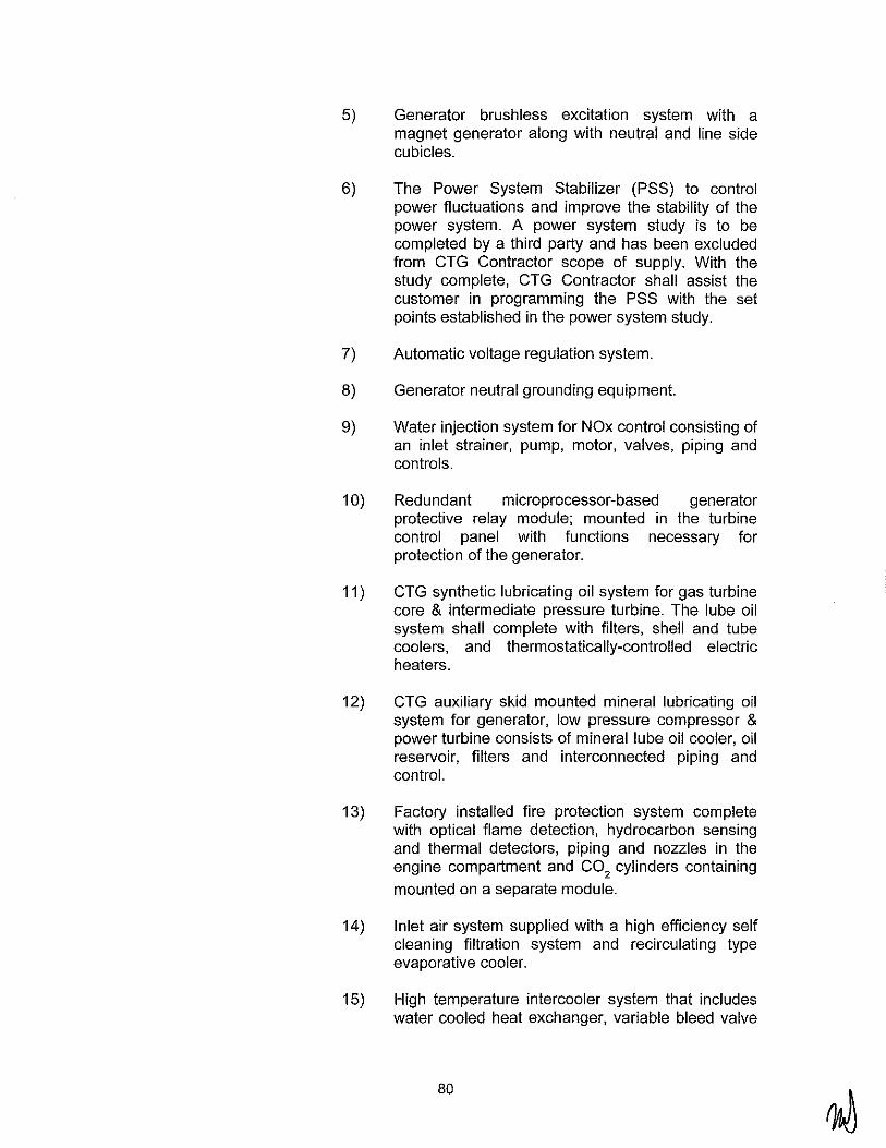
5) Generator brushless excitation system with a magnet generator along with neutral and line side cubicles.
6) The Power System Stabilizer (PSS) to control power fluctuations and improve the stability of the power system. A power system study is to be completed by a third party and has been excluded from CTG Contractor scope of supply. With the study complete, CTG Contractor shall assist the customer in programming the PSS with the set points established in the power system study.
7) Automatic voltage regulation system.
8) Generator neutral grounding equipment.
9) Water injection system for NOx control consisting of an inlet strainer, pump, motor, valves, piping and controls.
1 0) Redundant microprocessor-based generator protective relay module; mounted in the turbine control panel with functions necessary for protection of the generator.
11) CTG synthetic lubricating oil system for gas turbine core & intermediate pressure turbine. The lube oil system shall complete with filters, shell and tube coolers, and thermostatically-controlled electric heaters.
12) CTG auxiliary skid mounted mineral lubricating oil system for generator, low pressure compressor & power turbine consists of mineral lube oil cooler, oil reservoir, filters and interconnected piping and control.
13) Factory installed fire protection system complete with optical flame detection, hydrocarbon sensing and thermal detectors, piping and nozzles in the engine compartment and C0
2 cylinders containing
mounted on a separate module.
14) Inlet air system supplied with a high efficiency self cleaning filtration system and recirculating type evaporative cooler.
15) High temperature intercooler system that includes water cooled heat exchanger, variable bleed valve
80

(VBV), VBV stack with silencer, and interconnect piping and supports.
16) Gas turbine exhaust system supplied with the exhaust outlet connection flange to facilitate mounting of the exhaust system.
17) On/Off line cleaning and soak water wash system (one system for each CTG).
18) Electro-hydraulic start system supplied with an electric motor driven hydraulic pump assembly, filters, cooler, hydraulic motor, hydraulic hoses and controls.
19) Skid-mounted, duplex (2 x 100%) coalescing gas fuel filters designed and code stamped per latest ASME Section VIII Div. 1 Code requirements. Filters shall be designed for removal of 99.9% of particles (1 micron or larger).
20) Skid mounted duplex (2 x 100% capacity each) demineralized water filters.
21) CTG motor control center and intercooler water pump skid motor control center.
22) 240V DC motor starters.
23) Instrument and control system, including automatic start-up/shutdown/emergency stop sequencing.
24) Control system including all individual turbinegenerator system monitoring and operating indicators, controls, and transmitters as well as central electronic control system.
25) Internal and external lighting and electrical outlets for enclosures and equipment housings.
26) Thermal and personnel protection insulation with lagging.
27) Shop applied priming and finish painting for external surfaces of all equipment and interior surfaces of enclosures.
28) Access platforms, stairways, and ladders for inlet filter house and vent fans, needed for normal maintenance and operation.
81
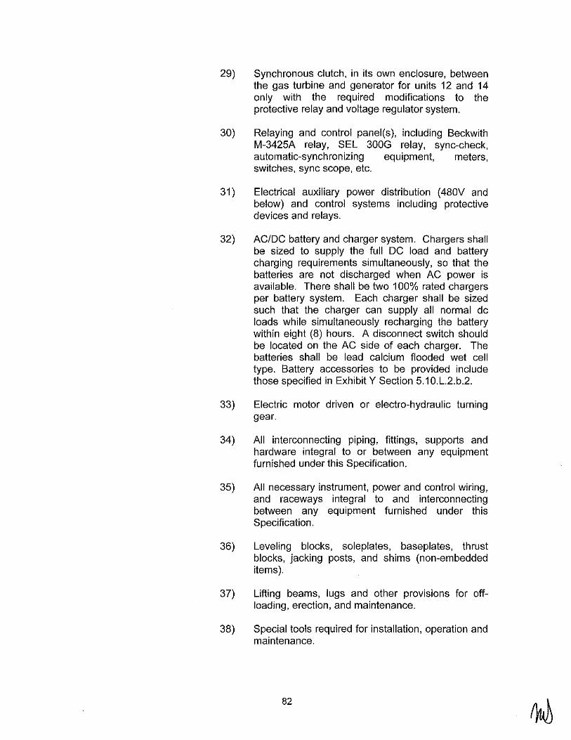
29) Synchronous clutch, in its own enclosure, between the gas turbine and generator for units 12 and 14 only with the required modifications to the protective relay and voltage regulator system.
30) Relaying and control panel(s), including Beckwith M-3425A relay, SEL 300G relay, sync-check, automatic-synchronizing equipment, meters, switches, sync scope, etc.
31) Electrical auxiliary power distribution (480V and below) and control systems including protective devices and relays.
32) AC/DC battery and charger system. Chargers shall be sized to supply the full DC load and battery charging requirements simultaneously, so that the batteries are not discharged when AC power is available. There shall be two 100% rated chargers per battery system. Each charger shall be sized such that the charger can supply all normal de loads while simultaneously recharging the battery within eight (8) hours. A disconnect switch should be located on the AC side of each charger. The batteries shall be lead calcium flooded wet cell type. Battery accessories to be provided include those specified in Exhibit Y Section 5.1 O.L.2.b.2.
33) Electric motor driven or electro-hydraulic turning gear.
34) All interconnecting piping, fittings, supports and hardware integral to or between any equipment furnished under this Specification.
35) All necessary instrument, power and control wiring, and raceways integral to and interconnecting between any equipment furnished under this Specification.
36) Leveling blocks, soleplates, baseplates, thrust blocks, jacking posts, and shims (non-embedded items).
37) Lifting beams, lugs and other prov1s1ons for offloading, erection, and maintenance.
38) Special tools required for installation, operation and maintenance.
82

39) Spare parts and consumables normally required for installation, commissioning and startup of the CTG.
40) Shop testing including functional testing of equipment specified.
41) Shipping and freight to job-site for all equipment.
42) CTG Contractor shall provide documentation and data to the LADWP, including but not limited to the following:
• QAJQC Program • Schedules • Installation instruction manuals. This
information shall be complete and comprehensive with the necessary drawings, instructions, bills of material, and information as to the extent of field fabrication, bolting, cleaning, checking, inspection, painting, testing, etc., required to be done by the BOP Contractor.
• Operation and maintenance manuals
43) CTG Contractor shall provide field technical services as follows:
• Startup • CTG performance testing • Unloading, storing and field erection of all
equipment
44) CTG Contractor shall provide a training program for LADWP's personnel to inspect, maintain, and operate the furnished equipment.
3. Work not Included in Scope
a. The following work will be provided by the BOP Contractor:
1)
2)
3)
Receiving, unloading, storing, and field erection of equipment and accessories
Foundations, anchor bolts, embedments, and anchor bolt templates
Grouting materials and the placing thereof
83
4) Exterior and interior access platforms, stairways, and ladders (except for inlet filter house and vent fans).
5) Permanent electric wiring to connect equipment terminal boxes to the plant electrical equipment supplied by the BOP Contractor
6) Interconnecting piping between fuel gas coalescing skid and main CTG skid
7) Fuels for operation
8) Solvents and cleaning materials
9) Operating personnel for startup and testing, except in the case where the Agreement stipulates that this function shall be preformed by the Seller with support from the Buyer
1 0) Special Inspection and Structural Observation during construction, as required by 2007 California Building Code.
4. General Operating Requirements
a. The CTG shall be designed for cyclic, peak, part, black start, islanded and base load services. The unit shall be capable of frequent startups and shutdowns as well as occasional trips from load and shall be designed suitable in all respects for potential cycling service operation. Although the turbine is capable of frequent cycling the initial planned service is defined as follows:
1) CTG Starts and Shutdowns I year: 14 76
2) Normal Operation Hours/year on Natural Gas (maximum): 5256
b. Each CTG unit shall have a design life of 30 years operation without distress due to cycling loads.
c. If the CTG is disconnected from the grid, the combustion turbine shall automatically reduce load via a speed/load governor. The CTG will then be safely shut down manually or resynchronized with the grid without causing damage to the CTG. The 13.8kV generator breaker shall enable resynchronization of the plant after main line voltage is restored.
84

d. Each CTG shall be capable of starting and running in islanded mode at 250 psig gas pressure.
e. All CTG units shall be capable of running in isochronous load-sharing mode and each CTG shall be capable of being switched to droop mode by remote operations.
f. Each CTG shall be capable of the operating philosophies described in Exhibit Z Section 12.
g. The CTG turning gear system shall have the ability to jog the rotor to allow maintenance and borescope inspections. The CTG Contractor shall specify all means, including options, for indexing rotor for such events.
h. Near-field noise level shall not exceed 85 dBA when measured 3 ft (1 m) in the horizontal plane and at an elevation of 5 ft (1.5 m) from grade.
5. Code Requirements
a. The CTG Contractor shall conform to 2007 California Building Code, and all federal, state, and local codes or regulations having jurisdiction at the project site. It shall be CTG Contractor's responsibility to investigate such statutes and determine applicable provisions regarding the equipment they propose to furnish.
b. The equipment shall meet all applicable NERC, WECC, and LADWP requirements.
6. Welding
All welds on pressure vessels and piping shall be in accordance with the requirements of the latest version of ASME B&PV Code, Section VIII and ANSI B31.1.
7. Cleaning and Painting
a. Cleanliness and Surface Preparation
1) All manufacturing waste, such as metal chips and filings, welding rods and stubs, waste, rags, debris and other contaminants shall be removed from the interior of each component. All loose mill scale, rust, oil, grease, chalk, crayon, paint marks and other deleterious material shall be removed from interior and exterior surfaces. At time of shipment, product shall be dry and clean inside and outside.
85

2) The CTG Contractor shall prepare, prime and paint the CTG to provide the required protection during shipment and installation of the equipment.
3) Metal surfaces to be shop painted must be clean and free of rust, grease, dust, scale, and other foreign matter. Surfaces must be prepared in accordance with paint manufacturer's specifications for the selected primers. Application of a zinc-rich prime coat over blast clean surfaces shall normally be made within eight hours after completion of blast cleaning. This time restriction may be modified to more or less than eight hours, depending on the temperature and humidity control exercised; the main criteria shall be that no rust bloom forms prior to application of the prime coat. If any rust bloom forms, the surface shall be re-blasted before application of the prime coat.
b. Structural and miscellaneous steel including platforms, grating, stair treads, handrail, toe plates, and ladders shall be hot-dipped galvanized after shop fabrication.
c. Painting Systems
1) The CTG Contractor shall prime and finish paint all equipment including for the exterior of enclosures, inlet and exhaust duct and the inlet filter housing. The CTG Contractor shall prime and finish paint all internals of enclosures. Field finish paint shall be from same manufacturer as Contractor's shop applied prime coats.
2) Prime, intermediate and finish paint shall be applied by the CTG Contractor at the shop. LADWP shall have the option of selecting finish paint colors. Finish paint colors will blend in with the surrounding environment. Chrome, silver and highly reflective colors are not acceptable. The prime coat shall be a shop-applied coat in accordance with CTG Contractor's standards. The intermediate coat shall be a high build, epoxy intermediate coat. The finish coat shall be a polyamide epoxy top coat. The prime, intermediate and finish coat shall be from the same manufacturer.
3) The compressor inlet bell mouth shall be provided a protective coating. CTG Contractor's standard coating shall be applied in the shop.
86
4) All exposed steel which may be subjected to temperature of 200°F and higher shall be primed with one coat of inorganic zinc primer to a dry film thickness of 2-4 mils and painted with one coat of silicon acrylic paint to a dry film thickness of 1.5 to 2mils.
8. Tagging, Packaging and Shipping
a. Equipment Marking.
1) All required Cai/OSHA, OSHA, and NFPA signs, including labels as to warning, danger, caution, etc., shall be applied at the factory. All signs shall be in English language and shall conform to applicable requirements.
2) A corrosion-resistant stainless steel or engraved phenolic nameplate with clearly legible writing shall be permanently attached to each assembled piece of equipment at an easily visible place. It shall provide all necessary information pertaining to the equipment, but as a minimum the following must be included: Manufacturer's name, type of equipment, serial number, shop order number, year of manufacturer, part identification number, and weight. Any special maintenance instructions shall also be shown at this or other suitable location.
b. Preparation for Shipment
1) The equipment shall be prepared for shipment after shop tests have been completed. Lifting points shall be clearly marked and all openings shall be tightly and effectively closed. Flanges shall be protected by metal covers, screwed openings closed with steel plugs. All combustion turbine openings, including inlet and exhaust openings, are to have suitable shipping covers.
2) Before the equipment is shipped, the original shipping stops, bolts, ties, etc., shall be reinstalled in all devices.
3) Electrical and control panels shall be protected against corrosion, weather and mechanical damage during transit. Temporary structural bracing shall be installed as required to allow for normal field handling, skidding and hoisting.
87

4) In addition to the foregoing the CTG Contractor shall provide internal and external protection from the effects of corrosion for all parts not otherwise coated or painted. Where closure is incomplete, plastic material adequately supported, protected and sealed shall be used to fabricate an effective barrier.
5) Equipment that is leak tested in the shop by the CTG Contractor shall be completely drained and blown dry by air prior to shipment when practical. When such drainage requires the removal of plugs, drain valves, or other parts, the CTG Contractor shall reinsert or reassemble these parts prior to shipment.
6) Equipment supplied with space heaters shall have heater leads accessible without uncrating, and no flammable material shall be located near the heaters such that energizing of heaters, without uncrating, will not pose a fire threat.
c. Delivery and Storage
1) The CTG Contractor shall furnish all instructions for proper care and handling after delivery including outdoor storage procedures and preventive maintenance procedures before the equipment is shipped to the jobsite.
9. Shop Testing
a. General
1) The CTG Contractor or CTG Contractor's subcontractors at their shops prior to shipment shall test the CTG and auxiliary equipment furnished under this specification. Factory test and inspections shall demonstrate the quality, accuracy, workmanship, balance, clearances and similar characteristics. The CTG Contractor shall furnish certified reports showing the results of all such tests to LADWP for information. The content and format of these test reports will be mutually agreed to by the CTG Contractor and LADWP during project execution.
2) The combustion turbine, generator, exciter, and the auxiliary and accessory equipment shall be factory assembled as required to establish critical fits and clearances, alignment, weld connection, mating
88
surfaces and bolt hole alignment, to minimize field adjustments and fitting.
3) The CTG Contractor shall provide an option price to conduct a full speed no load string test of the rotating equipment and supporting systems, including turbine, generator, intercooler, inlet filter and controls.
4) All combustion turbine-generator equipment including auxiliaries and accessories, but excluding field installed piping, which utilizes a working fluid, control fluid, lubricating fluid or cooling fluid shall be inspected or leak tested as system, parts of systems, or elements in accordance with CTG Contractor's accepted standard practices to ensure their proper operation without leakage, or with such leakage as necessary for lubrication purposes. Such tests shall comply with applicable code requirements.
b. Combustion Turbine
1) Factory tests on the turbine shall include 100% rotor inspection by radiograph, ultrasonic methods or other equivalent tests to verify the integrity of the material being used in the assembled turbine rotor. Rotors can be tested for mechanical integrity in spin pits, heater boxes, or vacuum chambers.
2) After assembly in the factory, a thorough and complete checkout and test of the entire fuel gas flame safety unit shall be required. All limit devices shall be set and tested, all circuitry shall be checked thoroughly, and complete programming checks, including testing of the flame detectors, shall be accomplished. A complete checkout form covering all aspects of burner operation shall be completed and submitted to LADWP.
c. Generator
1) Standard ANSI tests (IEEE C50.13 Para. 9) shall be made on the generator as a minimum requirement.
2) The excitation system shall be tested in accordance with IEEE 421.1 and 421.2.
d. Control System
89

1) All circuit boards, power supplies and 1/0 modules shall be subject to "burn-in" at an appropriate normal temperature for a period of tirne sufficient to reduce premature failures of the components. Burn-in shall be accomplished prior to assembly of the components into the control system. The CTG Contractor shall provide type testing reports of all components at elevated temperature, RFI, surge, etc.
2) Prior to shipment of the control system hardware from the CTG Contractor's facility, the entire DCS system shall be "staged" for operational hardware testing and demonstration. This testing shall include proper operation of all input/output (1/0), redundant control processors, redundant power supplies, operator console(s), communication highways, printer(s), and interfaces (foreign datalinks).
3) Prior to shipment of the control system software from the CTG Contractor's facility, the entire control systern software package shall be fully tested on similar hardware as supplied for this project to determine that all logic (including all automatic control functions), graphics, alarming, etc. operate properly. All interlocks and critical parameters must be hardwired into the control system to verify proper logic implementation. The hardware and software testing shall be done together if schedule permits.
4) LADWP shall witness and participate in the control systern hardware and software testing. A minimum of 2 weeks prior notice shall be given of the CTG Contractor's intent to conduct these activities.
e. Electric Motor Testing
1) Each motor shall be given routine tests in accordance with NEMA MG1 or manufacturer's standard test if NEMA test requirements are satisfied. Rotation, megger and higher potential tests, as minimum shall be included.
10. Performance Guarantees and Performance Testing
a. The requirements for performance guarantees are provided in Exhibit N.
90

b. The CTG Contractor shall guarantee that the combustion turbine generator will satisfy the performance criteria when the test data, correlated to the guarantee conditions specified in the Technical Proposal meet or exceed all the guaranteed performance requirements.
1) Guarantees shall be met in everyday operation under all specified operating conditions.
2) All guarantees shall be at continuous (base) load of each combustion turbine generator unless otherwise specified.
c. Performance tests will be conducted with the CTG in a new and clean condition to verify CTG guarantees. A new and clean condition shall be defined to be within two hundred fifty fired hours (250) of operation.
1) All hours of fired operation accumulated during the Commissioning Test and any time lost to a result of Commissioning Test failures are excluded from this requirement.
d. The CTG Contractor shall provide any correction curves or correction factors, etc. necessary for correlation to the guarantee conditions specified. Corrections will be made in the calculations to take into account conditions that do not correspond to the Agreement documents guarantee conditions.
e. Performance testing will be accomplished in accordance with latest version at the time of Agreement signing of ASME PTC - 22. Acceptance tests for the combustion turbine-generator will be performed in the field by the BOP Contractor, with the guidance from the CTG Contractor designated representative in accordance with a mutually agreed upon written procedure.
1) All guarantees listed below shall be met simultaneously:
f. Net Power Output
1) The continuous (base) load net electrical capability of each combustion turbine generator shall be guaranteed to be not less than that stated in the Technical Proposal for operation on natural gas.
2) Gross power output shall be measured at the generator terminals. The CTG parasitic load shall be determined by measuring the power
91
consumption at the motor control centers supplying power to the CTG equipment. The CTG Net Power Output shall be determined from the generator Gross Power Output minus the summation of the parasitic loads.
g. Net Heat Rate
1) The continuous (base) load Net Heat Rate (LHV basis) shall be guaranteed to be not more than that stated in the Technical Proposal for operation on natural gas.
2) Fuel flow shall be measured during the performance test. Grab samples of the fuel shall be taken during the test to obtain the fuels heating value. The fuel heating value and fuel flow shall be used to calculate the CTG fuel consumption. The fuel consumption shall be divided by the Net Power Output calculated above to determine the Net Heat Rate.
h. Ten Minute Start Demonstration
1) The CTG Contractor shall demonstrate that the CTG is capable of achieving full load in 10 minutes as measured from the time of start initialization while meeting NFPA code requirements for purging the SCR duct, casing and stack.
i. Water Injection Rate
1) The actual water injection rate for NOx control shall be guaranteed to be within ±1 0 percent of the injection rate stated in the Technical Proposal for operation on the natural gas. Water flow shall be measured during the performance test.
j. Reliability Test
1) The Reliability Test shall demonstrate that each combustion turbine generator operates safely, reliably, and without undue maintenance or operator attention. The reliability test may be run concurrently or consecutively with other performance tests at the sole discretion of LADWP. Should the reliability test be interrupted due to problems not attributable to CTG Contractor provided equipment, credit shall be given for the period of time already completed when the reliability test is resumed; provided that no work is
92
done on the CTG equipment unless requested by LADWP and approved by the CTG Contractor.
k. Air Emission Testing
1) All exhaust emissions rates shall be guaranteed not to exceed the specified emissions rates at all loads between 50 percent of the continuous (base) load capability to the full continuous (base) load capability of each unit for the natural gas operation over the full range of specified ambient conditions.
2) Emission testing shall be performed by BOP Contractor as necessary to fulfill all applicable federal, state, and local environmental requirements, including any limitations and requirements set forth in the air quality permit application.
I. Noise Testing
1) Each combustion turbine unit shall not exceed the acoustical performance requirements specified in Exhibit Y Section 5.1.8. 7 as measured in accordance with the latest applicable codes and standards. The acoustical performance shall be based upon the equipment furnished under this Agreement operating at any loads under normal operating conditions over the entire specified range of ambient conditions.
2) Near field noise testing shall be done for the CTG and auxiliaries in accordance with ASME PTC 36 Measurement of Industrial Sound.
m. Compliance Testing
1) All compliance testing required by WECC shall be done in accordance with WECC requirements.
B. Combustion Turbine and Auxiliaries
1. General Design Criteria
a. The Combustion Turbine-Generator (CTG) design and construction shall be GE- LMS100 machines. The CTG Contractor shall indicate in their proposal where the Specification varies from or exceeds their standard design.
b. The CTG shall be designed to provide the adequate protection and safety for personnel and equipment during
93

startup, operation and shutdown. The CTG Contractor shall consider catastrophic failures of the rotating equipment in the design of the CTG to mitigate these effects.
c. The automatic speed governor shall prevent the unit from reaching the electronic over-speed trip point in the event of a full load to no load situation.
d. The CTG shall be provided with redundant over-speed trip protection systems. Equipment design shall allow testing of over-speed protective devices.
e. For field balancing requirements, the methods to balance and degree of disassembly required to do so shall be described in the proposal. The CTG Contractor shall describe provisions of CTG units to be field balanced.
f. The equipment shall include rotor turning device, with automatic starting feature, to prevent thermal bowing of the rotor after shutdown and to allow immediate restart of turbine without excessive vibration. The preferred device would be an electric motor-driven or electro-hydraulic turning gear. A rotor brake or other provision shall be provided if unacceptable wind-milling is anticipated during shutdown.
g. All rotating equipment shall be capable of withstanding the normal fatiguing stresses from aerodynamically and mechanically induced excitation forces at all operating loads.
h. The CTG shall safely withstand transient speeds up to and including the turbine trip speed setting for brief periods at operating temperature. The equipment shall be capable of subsequent normal operation without need for inspection.
i. The CTG Contractor shall provide hydraulic coupling bolts, with all necessary tools and a hydraulic pump, for the turbine generator load coupling.
j. Casings, supports and expansion joints shall prevent injurious distortion caused by temperature, load or piping stresses. Supports shall maintain proper alignment of connected equipment
k. Jack screws, lifting lugs, eyebolts and/or the equivalent on casings and ductwork shall be provided to facilitate alignment during disassembly and re-assembly.
94

I. All pressure parts shall be suitable for operation at the most severe condition of coincident pressure and temperature expected. Casing joints shall be designed to minimize leakage.
m. All journal shaft bearings shall be provided with vibration monitors. Active thrust bearings shall be monitored using proximitors. At least two removable or three nonremovable thermocouples per bearing shall be provided for control systern monitoring and alarrn. It shall be possible to change wiring from failed thermocouples to non-failed thermocouples without thermocouple or bearing removal.
n. Couplings and guards shall be designed to take necessary movements of various casings and shafting of rotating equipment. The CTG Contractor shall specify alignment for all components connected with these couplings.
o. Couplings and spacers shall be dynamically balanced independent of the rotating assemblies to a tolerance suitable for the maximum continuous speed. The coupling halves, spacers and bolting shall be match rnarked or numbered.
p. Couplings and guards shall be removable without removal of rotors of interconnected equipment and shall not prevent access to adjacent bearings and seals.
q. Sub-soleplates, if used, shall be factory drilled and tapped for leveling screws to level and support the equipment.
r. The CTG shall be capable of achieving full load in 10 minutes measured from time of start initialization. To accommodate 10 minute starts the SCR casing, duct and stack will be pre-purged in accordance with NFPA and GE Aero Energy guidelines. The CTG Contractor shall design and supply a system that supports pre-purging of the SCR casing duct and stack, including double block and bleed valve systems in the fuel gas system, that rneets NFPA requirements. Demonstration tests of 10 minute start will be required as part of acceptance testing.
2. Combustion Turbine Design
a. General
1) Both compressor and turbine design shall provide easy accessibility to all parts. Openings shall be included in casings and ductwork to allow visual inspection of critical areas without disassembly of the compressor, combustion section and turbine
95

sections. Access shall be by removable covers and/or holes designed for use of borescopes and/or eddy current probes.
2) The CTG Contractor shall carefully consider and take into account all movements and differential movements due to temperature gradients in all components and structural members during start-up, operation, and shutdown. The CTG Contractor is fully responsible for all design considerations necessary to prevent buckling, distortion, and misalignment or fatigue failure of components. The CTG Contractor shall indicate on his drawings all such movements at interfaces with supports.
3) All compressor and turbine casings shall be designed for ease of inspection and maintenance and shall include suitable provisions for lifting access and alignment.
4) The CTG Contractor shall provide Borescope inspection ports for internal inspections of critical components in the hot gas path of the turbine and combustion systems and all stages of the compressor.
5) Turbine bearings shall be designed to allow examination and repair without removing major components, i.e., inlet duct, and silencer.
b. Compressor and Turbine Blading
1) The blading and discs of the Combustion Turbine shall be designed to be free from resonant vibrations and shall withstand thermal transients without distortion or creep.
2) Rotating blades shall be individually removable for replacement. Vane segments shall also be removable.
3) Stationary and rotating blades shall be coated as necessary to minimize erosion and corrosion degradation. Stages to be coated and coatings to be used shall be identified in the proposal.
c. Compressors
1) The HP and LP compressors shall be multistage axial-type and shall be directly coupled to their
96

applicable turbine section. Modulating inlet air guide vanes shall be provided.
2) Variable inlet vanes shall be provided for modulating airflow to enhance starting, to prevent compressor surge and stall, and to maintain high exhaust temperature during part load operation. The design shall provide control at low ambient temperature conditions to limit high mass air flow into the compressor.
3) Provision shall be made for bleeding off air from the compressor when necessary to prevent compressor surge or stall. Bleed air shall be discharged independently.
4) Compressor design shall be suitable for washing, using detergents. The detergent requirements shall be in accordance with the GE Specification MIDTD-000-5 for Liquid Detergent for Compressor Cleaning for GE Aircraft Derivative Gas Turbine.
5) Bell-mouth shall be coated with CTG Contractor's standard coating. The bell-mouth shall be calibrated for flow calculations and have connections to allow a manometer to be connected for flow measurement.
d. Combustion Systems
1) Singular Annular Combustors (SAC) shall be provided, with control of NOx emissions through water injection.
2) The combustion system shall be designed to max1m1ze combustion efficiency, combustion stability and equipment life while using natural gas.
3) Combustion turbines with multi-burner design shall have provisions to ensure accurate fuel distribution to all fuel nozzles. These provisions shall minimize blade path temperature differences and unnecessary pulsing of turbine blades.
4) Combustion liners or baskets and transition pieces shall be individually removable. Combustion liners or baskets and transitions while installed shall be accessible without removal to perform the manufacturer's combustion inspection criteria. All combustion liners or baskets shall be interconnected with cross-flame tubes.
97

5) A mtmmum of three redundant ultra-violet flame detectors shall be used to verify ignition and proper combustor operation.
6) Multiple igniters shall be provided for starting the units and shall be removable after the unit is operating.
e. Gas Turbine
1) Turbine blading shall be designed to mtmmtze loads due to tangential, axial and torsional modes of vibration under all anticipated operating conditions.
2) Turbine blades and nozzles shall be coated as necessary to prevent degradation from erosion, corrosion, or deposits. Components to be coated and coatings to be used shall be identified in the proposal.
3. Intercooler System
a. A high temperature air- to-water intercooler of the shell and tube multi-pass type shall be provided for each CTG. It shall be connected through a system of piping and expansion bellows, from the low pressure compressor volute to the intercooler and upon return to the high pressure compressor inlet volute.
b. The intercooler system shall also consist of the following components:
1. Variable bleed valve 2. Variable bleed valve stack and silencer 3. Stainless steel interconnecting dueling 4. Pressure balanced expansion joints 5. Cooling water pump skid (sized for intercooler and lube
oil coolers)
4. Inlet Air System
a. General
1) The inlet air system shall consist of a three-stage pulse-type inlet air filter, inlet silencer, evaporative cooler, ductwork, expansion joints, instrumentation, controls, lighting, support steel, platforms, ladders and access stairs.
98

2) The base of the lowest air inlet of the filter enclosure shall be elevated a minimum of 8 ft above grade and shall be accessible by CTG Contractor's stairway.
3) A jib crane with provisions for a suitably sized portable electric wire hoist shall be provided. Jib crane will be utilized to lift filter elements from grade up to the inlet filter house access platform.
4) The filter system shall include the following:
b. Filters
a. A louver or weather-hood to minimize the entry of rain into inlet filter. The horizontal component of the airflow velocity through the weather-hood shall not exceed 600 ft/min.
b. A metal inlet screen of one-inch mesh shall be located immediately ahead of the inlet filter openings to prevent debris and birds from entering inlet. Inlets shall have drainage holes to prevent standing water during outages.
c. Where seasonal flying insect infestation is severe, suitable screens will be required.
d. Stairways, ladders, and platforms (for access and maintenance) meeting Gal/OSHA and OSHA requirements.
e. Interior lighting and convenience outlets. t. Differential pressure gauge with an alarm
contact output located outside of filter house enclosure and on a control panel.
9. A system shall be provided to indicate possible inlet icing conditions.
h. Enclosure shall be sufficiently rigid to avoid vibration problems. Fasteners shall be suitably locked to prevent loosening especially those on the inlet that could be ingested by compressor.
1) The air inlet filter shall be a high efficiency pulse type cartridge system without moving parts. Suitable stairs and platforms shall be provided for access and for changing of the filters.
2) The high efficiency filters shall be designed for 99.9% efficiency for removing particles 5 microns and larger and 99% efficient in removing particles 2 microns and larger. The face velocity, (horizontal component of the airflow in cross section of inlet ductwork), through the filter media shall not exceed 500ft/min.
99

3) Non-water absorptive filler elements shall be provided.
c. Recirculating Evaporative Cooler
1) Evaporative cooler shall include all water dispersion media, moisture separator, casing, drain piping, feed piping, valves, pumps, catch basin, instrumentation and controls for a fully functional system.
2) Evaporative cooler structure shall be constructed of galvanized carbon steel. Water basin and downstream ductwork shall be stainless steel or stainless steel lined.
3) The evaporative cooler shall be sized for 85% efficient design at the Summer Design conditions specified in this Specification Exhibit Z Section 1.G.
4) Air velocity through the evaporative media shall not exceed 600 feet/min.
5) A moisture separator, (or drift eliminator), shall be provided after the evaporative media. The drift eliminator shall remove a minimum of 90% of all droplets 50 microns or larger in diameter.
6) An automatic dump and make-up system shall be provided to monitor and maintain evaporative cooler water quality in accordance with manufacturer's requirements.
7) Evaporative cooler shall have fully redundant recirculation pumps, either 2-100% or 3-50%. Pumps shall be made of a corrosion resistant material such as stainless steel.
d. Inlet Silencing
1) Silencers shall be designed to meet the noise requirements defined herein.
2) The CTG Contractor's proposal shall include full details of silencer construction including material description and acoustical insulation.
3) Construction of silencers shall prevent the entry of baffle packing material into the gas stream and
100

shall prevent damage to them resulting from acoustical or mechanical resonance.
e. Inlet Ductwork
1) Ductwork shall be carbon steel, with two (2) coats of protective coating applied to all exterior and interior surfaces.
2) The inlet dueling system shall be arranged for the least number of changes in direction.
3) If required, turning vanes shall be provided at changes in direction to assure uniform flow distribution at the compressor inlet. Vanes shall be designed to avoid resonance and shall be attached to the duct by a continuous weld.
4) Duct supports shall be designed to remove all loads from the gas turbine flanges. The ducts shall be supported to allow lateral as well as axial growth due to temperature changes. The dueling and support shall be designed to remain stationary when sections near the gas turbine are removed for unit maintenance. Ducts shall be sufficiently rigid to avoid vibration.
5) Access shall be provided to allow final cleaning and inspection of the entire duct systems before operation.
6) The inlet ductwork shall include facilities or provisions for the manufacturer's recommended offline I on-line compressor cleaning method.
5. Exhaust System
a. The gas turbine package shall be furnished with a complete exhaust system including the exhaust diffuser plenum, supports and thermal insulation.
b. The exhaust plenum shall direct the exhaust gases into the CTG Contractor supplied ECS unit with the stack.
c. The turbine exhaust system shall consist of an exhaust plenum terminating with a flange. The flange will mate up with the flange of an expansion joint that will connect the exhaust plenum to the SCR inlet. All exhaust plenum growth due to thermal expansion shall be accommodated in the expansion joint such that allowable loading on the gas turbine exhaust flange is not exceeded.
101

d. The exhaust plenum shall be designed to prevent separation of joints, loosening of turning vanes and braces and fracture of bolts due to thermal forces, operating forces and vibration.
e. The exhaust system shall be designed for the rnaximurn expected temperature plus the CTG Contractor's normal design margin. The exhaust duct shall be provided with liners of stainless steel material. Exhaust system outside skin temperature shall not exceed 140°F for personnel protection during any operating condition at summer design ambient conditions with still air (0 mph wind speed).
f. Hot end bearing tunnel temperature shall remain below 200°F when operating at base load with summer design conditions.
6. Natural Gas System
a. The natural gas system shall be designed to operate on a range of natural gas compositions. Natural gas conditions and analysis is provided in this Specification Exhibit Z Section 5.
b. The CTG Contractor shall provide the following natural gas system components, but not limited to:
1. Fuel metering valve 2. Pilot starter metering valve 3. Fuel flow meter 4. Final inlet strainer 5. Stop (shutoff) valve s. Control valve( s) 7. Pressure transmitters, temperature elements, and local
gauges s. Block and bleed valves 9. Blow-off valve 10. Fuel gas nozzles 11. Interconnecting piping 12. Ring manifold to burners 13. Coalescing gas fuel filters- skid rnounted
c. Stop valves shall be provided on the natural gas piping in the turbine compartment for fire protection isolation. Interlocks shall be provided to alarm and trip the combustion turbine on actuation of these stop valves. Stop valves shall close on loss of power.
d. Two means for stopping fuel flow shall be provided in the turbine compartment. They shall respond to norrnal or
102

emergency shutdown control signals. A fast acting stop/shutoff valve shall be provided as one means.
e. A fuel control station for regulation and control of the supply of natural gas to the unit shall be provided. The pressure regulating station shall include pressure regulating valves, pressure relief valves, normal and emergency gas shutoff valves, manual shutoff valves, and necessary controls for pressure regulation.
f. A calibrated flow element for measurement of fuel gas flow shall be included in the CTG Contractor scope of supply. This flow meter shall be used for EPA emissions reporting calculations and CTG control, if required. The flow meter must meet the requirements of 40 CFR 60 and 40 CFR 75, and allow separate connections for the CTG control system and the GEM system. Flow meters shall be pressure and temperature compensated. The meter shall include a calibrated flow section and a remote transmitter.
g. A skid mounted duplex (2 x 100%) coalescing gas filters shall be provided. The filters shall be designed per ASME Section VIII Div. 1 Code and shall be code stamped. The filter shall be designed for removal of 99.9% of particles of 1 micron and larger. The skis shall be provided with all required piping valves and instrumentation. The filter shall remove oil carry-over from gas compressors from 0.5 ppm as guaranteed by the compressor manufacturer to the level required by the CTG vendor. The CTG Contractor shall confirm the oil carry-over guarantee value from gas compressors with the compressor manufacturer.
h. The CTG Contractor supplied interconnecting fuel gas piping shall be stainless steel.
7. Water Injection
1) The function of the water injection system is to provide dilution water for NOx control. The water injection system shall not cause a flameout or cause premature combustor distress. The water injection system will consist of on base piping, control valves, instrumentation and water injection skid.
2) The gas turbine shall be supplied with a water injection manifold, water injection nozzles, and controls for injecting water. Water flow rate metering devices shall be provided.
103

3) The water injection equipment shall be skidmounted and be provided with easy accessibility to all equipment. Equipment shall include two (2) 100% capacity pumps with variable frequency drives; inlet and outlet isolation valves; low pressure duplex filter; high pressure simplex filter; recirculation valve; stop valve; flow meter; check valves, piping, and instrumentation and controls. The use of a right angle gear box for the pump is unacceptable. Water injection skid shall have lighting; heater and controlling thermostat; interconnecting wiring, conduit, and junction box for skid-mounted equipment. Duplex filter shall be provided upstream of the water injection pumps. Duplex filter shall have nominal ten (10) micron rating. Local gauges shall measure pressure at the system inlet, pump discharge, and filter discharge.
4) All piping and accessories associated with the water injection system shall be of type 304 or 316 stainless steel construction. Stainless steel braided aircraft quality flexible hoses shall be provided at the burner connections.
5) A single-point connection shall be provided, at the edge of the skid, for the injection water inlet, injection water recirculation, and the injection water outlet. If drains are required for the skid or for the equipment contained within the skid, they shall be routed to a single-point drain connection located at the edge of the skid.
6) The water injection controls shall automatically regulate water flow rate to meet the emissions criteria for all ambient conditions and for the full plant load range. The control system shall provide operator interfaces for monitoring and recording of the water-to-fuel ratio and fuel flow. The control system shall alarm (annunciate) on low water pressure and high-pressure drop across the filters. Water flow shall be stopped automatically and immediately upon loss of flame. Water quality monitoring devices, if required, shall be furnished by the CTG Contractor.
7) The CTG Contractor shall specify the water quantity, quality, and pressure required at the inlet connection of the water injection skid in their proposal.
8. Synthetic Lube Oil System
104

a. A Synthetic Lube Oil system (SLO) shall be provided for the gas turbine core bearings, accessory drive gears and shaft splines.
b. The turbine external SLO system shall consist of the following major components:
1. SLO reservoir 2. Supply filter 3. Scavenge filter 4. Duplex shell and tube heat exchanger 5. Air/Oil separator
c. The turbine internal SLO system shall consist of the following major components:
• Turbine bearings and accessory gearbox • Supply pump
d. Five-elernent scavenge pump
e. The SLO reservoir shall be sized in accordance with the industry standards to provide a normal operating volume of at least 10 times the flow per minute to it users. The SLO reservoir shall be constructed of 304 stainless steel. The SLO reservoir shall be equipped with a low level alarm switch, a level gauge, a filler connection and a positive ventilation demister system. An electric heater with thermostatic control shall be provided.
f. All bearing sumps shall be vented to an air/oil separator. The air/oil separator shall be of the mechanical type and mounted on top of the turbine enclosure. The recovered oil shall be returned to the SLO reservoir, and the air removed shall be vented to atmosphere.
g. Turbine Scavenge Lube Oil System
1) A turbine scavenge lube oil system shall be provided to remove oil from the turbine bearing sumps.
2) A five-element scavenge pump shall be provided and located on and driven by the turbine accessory gearbox. A check valve shall be provided on the pump discharge to prevent siphoning of oil into the engine during shutdown.
3) A dual element, platinum RTD shall be provided to measure temperature on each scavenge line with
105

readout, alarm, and shutdown at the unit control panel.
4) Magnetic chip detectors shall be provided in each scavenge line to monitor bearing health.
h. Synthetic Lube Oil Filters
1) Duplex, multi-element filters with a continuous flow transfer valve shall be provided. The two 100% capacity nominal six micron filters with a manually controlled continuous flow transfer valve shall be furnished to filter contaminants out of the synthetic oil. Both filters shall be easily accessible for maintenance. High-pressure drop across the filter in use shall alarm on the unit's control system and be visually indicated at the filter.
i. One (1) supply duplex filter shall be provided downstream of the lube oil supply discharge.
ii. One (1) scavenge duplex filter shall be provided upstream of the lube oil heat exchangers.
i. Synthetic Lube Oil Coolers
i. 100% capacity duplex, shell and tube, water -cooled synthetic oil coolers shall be provided.
ii. The heat exchanger (HX) shall be designed to TEMA standards and shall be a Class "C", Type "AEA or AFA".
iii. The synthetic oil coolers shall be sized for not less than 1 00 percent of the actual heat duty at the maximum rated capability of the CTG unit at the specified water flow rate and with a maximum cooling water temperature. Heat exchanger design fouling resistance shall be per Section 1 0 of the TEMA standards with 5 percent of the tubes.
iv. Coolers shall be provided with inlet and outlet temperature indication, pressure test connections, prov1s1on for flow measurement, vent & drain connections,
106

and pressure relief between the isolation valves.
v. A thermostatic bypass valve shall be provided to prevent overcooling of the lube oil during cold ambient conditions.
9. Mineral Lube Oil System
a. A Mineral Lube Oil system (MLO) shall be provided for the LPC turning clutch, LPC, power turbine, generator bearing lubrication, turbine hydraulic system, and jacking oil pump system.
b. The MLO system shall include the following
1. MLO reservoir 2. AC pumps (primary and standby) 3. DC pump 4. Duplex shell and tube heat exchanger 5. Duplex filter 6. Air/Oil separator(s)
c. Mineral Lube Oil Reservoir
1) The MLO reservoir shall be sized in accordance with the industry standards to provide a normal operating volume of at least 10 times the flow per minute to the bearings and other services. The system shall be designed to provide adequate dwell time to separate entrained air and water and to permit safe coast down of the unit on loss of AC power.
2) The MLO reservoir shall be 304 stainless steel. Accessories shall include a manhole and connections with block valves for oil makeup and for contaminated oil drains. The oil fill connection shall contain a filter to prevent solid particle contamination into the reservoir. Connections on the reservoir shall be provided to allow connection of an oil centrifuge or by-pass filter system. A sample connection shall be provided for obtaining grab samples for laboratory testing. Reservoir shall have a visual oil level indicator, high- and low-level switches and top-mounted relief and access doors. High- and low-levels shall be annunciated in unit's control system. All reservoir instrumentation shall be accessible without opening access doors.
107

3) Electrical immersion heaters with thermostatic control shall be provided. Heater shall be capable of maintaining the optimal oil temperature at m1mmum specified winter design ambient temperature conditions. The heaters shall be placed below the low oil level. Heaters shall be placed in wells to allow heater removal without draining the reservoir. Heaters will be automatically de-energized upon low oil level in the reservoir.
d. Mineral Lube Oil Piping
1) MLO supply piping, valves, and fittings from the reservoir to the bearings shall be type 304 stainless steel. Drain piping from the bearings to the reservoir shall be carbon steel.
2) The use of screwed, flanged or other non-welded joints in the oil systems shall be permitted only where components must be removed for maintenance. This requirement does not apply to tubing.
3) All piping shall be guarded in high temperature areas. All mechanical connections shall include spray guards.
4) To help in the identification, of which bearing may be the cause of elevated levels of contamination in the oil reservoir, each bearing drain line shall include a manual sample line to allow grab samples to be taken with the unit on line.
e. Mineral Lube Oil Pumps
1) Two full-capacity AC motor driven pumps shall be supplied with one partial capacity DC motor driven pump.
2) The standby AC pump shall start automatically upon initial loss of normal lube oil pressure. The DC auxiliary pump shall start automatically upon loss of normal lube oil pressure after AC driven auxiliary or redundant pump fails to bring lube oil pressure back to normal. The redundant AC or the DC pump shall be capable of being started at anytime to verify readiness.
3) Each pump shall have a suction strainer to protect the pump.
108
4) A pressure control valve shall be furnished to provide constant pressurization of the system during transients such as start of lube oil pump and to damp pump pulsation.
5) If a jacking or lift oil pump is required for the bearing design, two 100% pumps shall be provided. The pumps shall be furnished with suitable interlocks to prevent rolling of the turbine without acceptable pressure. In addition, if the lift oil pump is required for turning gear operation, it shall be a DC motor driven.
6) All control equipment necessary for operation of DC equipment on loss of AC power shall be provided.
f. Mineral Lube Oil Coolers
1) 100% capacity duplex. shell and tube, water-cooled mineral lube oil coolers shall be provided.
2) The Heat Exchanger (HX) shall be designed to TEMA standards and shall be a Class "C", Type "AEAorAFA".
3) The mineral lube oil coolers shall be sized for not less than 100 percent of the actual heat duty at the maximum rated capability of the CTG unit at the specified water flow rate and with a maximum cooling water temperature. Heat exchanger design fouling resistance shall be per Section 10 of the TEMA standards with 5 percent of the tubes.
4) Coolers shall be provided with inlet and outlet temperature indication, pressure test connections. provision for flow measurement, vent & drain connections. and pressure relief between the isolation valves.
g. Mineral Lube Oil Filters
1) A duplex, multi-element filter with a continuous flow transfer valve shall be provided. The two 100% capacity nominal five micron filters with a manually controlled continuous flow transfer valve shall be furnished to filter contaminants out of the mineral lube oil. Both filters shall be easily accessible for maintenance. High-pressure drop across the filter in use shall alarm on the unit's control system and be visually indicated at the filter.
109

2) A coalescing type filter for removal of water shall be provided. This function can be incorporated in the duplex filter.
10. Water Wash System
a. The CTG units shall be provided with an on-line and off line compressor water washing system. The system shall be skid mounted and consist of the following:
1. Detergent tank. 2. One (100%) booster pump with AC driven motor. 3. Valves, piping, nozzles, and piping specialties. 4. Instrumentation and Controls. 5. Water injection manifold piping and effluent drains on
the combustion turbine. 6. Enclosure with interior and exterior lighting, power
receptacles, heating and ventilation. 7. All other piping and accessories shall be provided,
including demineralized water piping between the water wash skid and the on-base turbine spray manifold.
b. The system design shall not allow water or detergents to enter lube oil systems. All driven equipment shall be electrically operated.
c. Detergent tank shall be stainless steel. Piping, valves, etc., shall be stainless steel. All hardware shall be made of corrosion resistant materials.
d. Minimum water pressure, maximum water flow rate, and approximate total water consumed for a wash cycle shall be provided in the proposal.
11. Auxiliary Skid
a. The auxiliary skid shall include the following:
1. Main and standby mineral lube oil pumps and dual filtration system
2. Structural steel base assembly with integral mineral lube oil storage tank
3. Duplex shell and tube synthetic and mineral lube oil heat exchangers
4. Water wash system with reservoir 5. Electro-hydraulic start system 6. Cooling water pump skid 7. Noise Enclosure
110

b. The auxiliary skid shall be designed to minimize field assembly and installation. The skid layout shall provide for convenient maintenance and operating access to the various components on the skid.
c. The on-skid piping shall be assembled so that a minimum number of inter-connections are required to assemble the units. Items such as drains, instrument air supply lines and vents shall be routed to skid edge.
d. Valves, flow meters, strainers and other in-line equipment shall be installed in such a manner that they are accessible and can be easily maintained, replaced or repaired and without placing a strain on the piping. Breakout flanges shall be provided between equipment and valves to allow ease of removal. All lines shall be piped to the skid edge. All equipment and piping shall be insulated where energy conservation is required; personnel protection and/ or temperature maintenance is required. Skids shall be of the heavy steel frame type with sled ends complete with non-slip steel grating overall operating areas.
12. Fire Protection and Detection System
a. The CTG Contractor shall provide a fire protection and detection system for the combustion turbine, generator, equipment compartments/enclosures, bearing tunnels, and for lube, oil systems. The fire detection system and other components of the fire protection system shall be designed and laid out in a manner that permits inspection and maintenance without causing any interference with the combustion turbine operation.
b. The fire protection and detection system shall comply with the requirements and recommendations of the National Fire Protection Association (NFPA) 12 and NFPA 850 and any additional requirements of the local Fire Marshall.
c. Fire Protection System
1) Each CTG shall be provided a carbon dioxide (C02) multi-zone fire protection system that meets the requirements and recommendations of NFPA 12. Initiation of the system shall trip the turbinegenerator, provide an alarm on the fire protection panel annunciator, shut-off fuel valves, turn-off ventilation fans and close ventilation openings. Also, the annunciator will identify which individual detector is in alarm. Nozzles shall direct the C02
agent to the compartments at concentrations sufficient for extinguishing flarnes. This
111

concentration is maintained by gradual addition of C02 for an extended period.
2) The C02 system shall provide an initial concentration of 34 percent in the turbine enclosure and the mechanical enclosures, containing fuel gas, and/or lube oil equipment, within 30 seconds of the system actuation. The C02 concentration in the control or electrical enclosure shall not exceed 50 percent. Each compartment shall be designed to ensure a concentration of at least 34 percent for 20 minutes after discharge.
3) The storage system shall consist of C02 cylinders.
d. Fire Detection System
1) The fire detection system shall include gas, optical flame, and thermal detectors as follows:
2) Two (2) gas detectors shall be located in the turbine compartment near the ceiling. One (1) gas detector shall be located in the lower half of the enclosure near the engine. A warning alarm shall be initiated if a detector senses gas in the area (at 15% lower explosive limit). A fast stop with lockout shutdown shall be initiated if two out of three detectors sense a combustible gas ratio of 25%.
3) Three (3) gas detectors shall be located on the enclosure exhaust, downstream of the exhaust fans. A warning alarm shall be initiated if one detector senses gas in the area (at 5% lower explosive limit). A fast stop with lockout shutdown shall be initiated if any of the three detectors sense a combustible gas ratio of 10%.
4) Six (6) optical flame detectors shall be mounted in the turbine enclosure. A flame indication from any of the detectors shall be communicated to the control system.
5) Seven (7) thermal detectors shall be mounted in the gas turbine compartment. Fixed temperature sensing fire detectors shall monitor absolute temperature and rate of temperature rise. The temperatures shall be indicated at the main control room fire protection panel. Upon reaching temperature set-points, the control system shall automatically and immediately initiate a unit shutdown and dispense the low pressure carbon
112

dioxide (C02 ) automatic zoned fire protection system.
e. Fire Protection/Detection System Controls
1) The fire detection controls shall normally be powered by 24 VDC with a battery backup system.
2) Each sensor shall be monitored by the unit control system and compared to alarm and shutdown setpoints. An alarm or shutdown indication shall be sent to the plant control system. A shutdown signal to the main control system will automatically initiate an emergency shutdown of the unit.
3) Each sensor shall be connected in a closed loop circuitry to verify readiness. Fault conditions such as a defective sensor or wiring will be indicated on the unit control system and shall not initiate a unit trip or initiate a C02 release.
13. Starting System
a. Each CTG unit shall be provided with an electro-hydraulic starting system capable of starting and loading the unit to the design load rating with system AC auxiliary power available. Starting and loading times shall be submitted by the CTG Contractor with their proposal. This information shall also be delineated in the operational instructions.
b. Complete CTG electrical starting system including low speed AC or DC motor driven turning gear assembly, electro-hydraulic starter, required control and isolation equipment, and all controls and indication interfaces.
c. All starting equipment shall be capable of continuous operation to allow rapid cool down of the machine for maintenance following shutdown. It shall be interlocked with the lubrication system to provide bearing lubrication for turbine rotation during standby, pre-start and cool-down periods or for any period with normal bearing lubrication.
d. The starting system shall be capable of accelerating the combustion turbine to a level where the starting system may be secured, allowing the combustion turbine to accelerate normally without undue thermal stress. If a start is terminated any time prior to the normal securing of the starting system, the combustion turbine must be capable of attempting a restart within 10 minutes after securing. If there is a time limitation on the number of successive starts due to a duty cycle constraint on the equipment, the
113

control circuit shall go into an alarm condition, once the limitation has been reached.
e. The CTG starting system shall be rated for continuous duty at or near the cranking speed for rapid cool down and offline water washing. In the cool down mode, the system must be capable of continuous operation for at least 3 hours.
14. Synchronous Condensing for VAR Compensation
a. A synchronous self-shifting, automatic engaging/disengaging, freewheel-type overrunning clutch which transmits torque through the full surface contact of gear coupling teeth shall be included in the rotor assembly of CTG Units 12 and 14.
b. Appropriate and required modifications shall be made to the Protective Relay System and the Voltage Regulator for the aforementioned units for when they are in synchronous condensing mode.
c. The clutch assembly shall include following instrumentation and control:
1) Pinion engaged switch to indicate when the pinion is partially engaged to initiate the turning gear control sequencing.
2) Pinion disengaged switches to indicate that the pinion teeth are disengaged, providing an interlock that the clutch is fully disengaged.
3) A four port double acting, solenoid operated, spring return, control valve required for hydraulic actuation of the pinion clutch towards engagement with the stationary shafting, shall be mounted adjacent to the pinion.
4) A manual override valve shall be fitted so that the pinion can be driven into mesh for emergency operation or manual barring.
d. Remote indication of the above signals, integrated with the plant DCS system, shall be available at the control room in accordance with requirements of Exhibit Y Section 5.11.
15. Enclosures
a. For outdoor installations, the combustion turbine-generator package shall be enclosed by several connected sections
114

of weather-tight protective housing structurally attached to the compartment base. These enclosures shall provide thermal insulation, acoustical attenuation, and fire protection media containment.
b. Maintenance hoists and jigs inside the enclosures shall be provided as required to allow normal maintenance to be performed without removing the enclosure. Roof hatches may be provided above large pieces of equipment for exterior crane access. Roof hatches shall be stenciled to denote the equipment for which the hatches provide access to.
c. Enclosures with sound panels are required for the turbine, auxiliary, and electrical/controls packages regardless of noise conditions.
d. Internal lighting and power receptacles for operation and maintenance shall be provided. Lighting shall meet Gal/OSHA and OSHA requirements for maintenance functions. External lighting at door entrances shall be provided.
e. All equipment shall be mounted on steel bases. Each base shall be sufficiently rigid to allow lifting and installation of the skids with the major equipment in place. Bases shall be sufficiently rigid to maintain alignment of components during operation. Lifting lugs shall be provided on each base structure. Foundation mounting holes and jacking screws shall be provided on each base.
f. All on-base piping and package interconnect and wiring shall be provided.
g. All interface connections shall be brought out to common connection points at the perimeter of each base.
h. The gas turbine and the majority of the auxiliary equipment shall be housed in fully enclosed, sound attenuated enclosures. These enclosures shall have, as a minimum, the following features:
1) Steel inner and outer surfaces are to be provided. Perforated inner shell sound insulation containment to be 409 stainless steel. Gas turbine enclosure to be painted carbon steel.
2) Separate compartments are to be provided for the inlet plenum and the gas turbine. The compartments are to be divided by bulkheads.
115

16. HVAC
3) Walls are to be supported sufficiently to withstand the internal pressure developed by the C02 fire extinguishing system.
4) Fire retardant R13 or better insulation is to be used.
5) A minimum of two access doors and removable panels are to be installed on all enclosures to provide easy access for inspection and maintenance of equipment. All equipment shall be located within reach from finish grade elevation or shall be provided with stair access and platforms to facilitate normal operation and maintenance activities.
6) Stainless steel hinges and chrome plated latches are to be used on all doors.
7) Interior lighting shall be provided in each compartment. Electrical package shall have enclosed fluorescent lighting. Fixtures designed so as not to cause interference with electronic equipment. All other compartments shall have enclosed incandescent lighting fixtures. Lighting levels shall be per ANSI C2 & IES Standards.
a. Heaters
1) The CTG Contractor shall provide heaters to maintain start-up temperatures and humidity protection during shutdown and standby periods. All compartments and enclosures require heating.
2) The heating systems shall be designed to maintain system design basis temperatures and humidity protection down to the winter design temperature. Systems will also be sized to prevent enclosure temperatures from falling below the freezing point for the site Record Low temperature. All heaters shall be thermostatically controlled.
b. Ventilation
1) The CTG Contractor shall provide redundant exhaust fans to create a negative pressure within the turbine compartment. The redundant fan shall automatically start to maintain the compartment temperature at or below 120"F. Redundant full capacity exhaust fans shall be provided for each
116
compartment or enclosure. The standby fan shall automatically start in the event the primary fan fails. Fan failure will be alarmed at the main control room. All ventilation air is to be filtered to the same quality levels as the turbine combustion air.
2) Multiple exhaust fan(s) for all enclosures shall be provided. Failure of a single fan shall not cause the internal temperature to rise above equipment design temperature, cause equipment de-rating or restrict or shut down CTG operation. Fan failure will be alarmed in the control system.
3) Ventilation of enclosures shall be in accordance with NFPA recommendations and requirements.
c. Air Conditioning
C. Mechanical
1) Primary and backup air conditioning units for the control compartment shall be provided which will maintain the interior environment suitable for sustained and stable operation of electrical and control equipment at the site extreme temperature. Failure of an air conditioning unit will automatically start the redundant unit, and alarm the main control room. Control logic shall be designed to allow either air conditioning unit to be the primary unit.
1. General
a. The CTG Contractor shall comply with all requirements of this Section, unless directed otherwise in the technical section of the specifications and unless it is not applicable to the scope of supply, namely the manufacture of a standard gas turbine generator set.
The following requirements apply to the CTG Contractorfurnished skid-mounted systems, packaged modular designs and/or CTG Contractor-engineered systems.
1) Mechanical Design Criteria
i.
ii.
Pump design margins shall be as indicated in the Technical Specifications.
Pumps shall be suitable for operation at the design point as well as the normal operating range.
117

2. Pumps
iii. Heat conservation insulation on all piping and equipment operating above 200°F for which heat loss is not desirable shall be provided. Insulation thickness shall be determined based on limiting the surface temperature to 140°F at a 2 mph wind speed and 80°F ambient temperature. In no case shall the surface temperature of any insulated lines be allowed to exceed 140°F throughout the operating range of the plant.
iv. Provide personnel protection insulation on all surfaces operating above 140°F or the Gal/OSHA and OSHA limit, whichever is lower, which are accessible from grade, ladders, or elevated platforms. Personnel protection insulation shall limit the surface temperature to a maximum of 140°F at any ambient condition or as required by Gal/OSHA and OSHA (whichever is more restrictive). Personnel protection insulation shall extend to a level of 7 feet (minimum) above grade or platforms and 3 feet (minimum) beyond any handrail.
v. Skid-mounted equipment shall be arranged to optimize maintenance work by providing adequate space around equipment and control panels. All glass gauges, local instrumentation and controllers for operation and maintenance shall be installed and oriented as practical. Provide adequate work platforms and locate manual operators, etc. within reach of plant operators.
2) Operability and Safety
i. Equipment, valves, instrumentation, motor controls and testing devices shall be designed for ease of operation and easy access, i.e. without the need for portable ladders. The design shall comply with Gal/OSHA and OSHA requirements.
a. Pumps shall be furnished by the CTG Contractor in accordance with the pump requirements identified in Exhibit Y Section 5.9.12.
118

3. Piping, Valves, Piping Hangers and Supports
a. Piping furnished by CTG Contractor shall comply with the piping requirements identified in Exhibit Y Section 5.9.S.
b. Valves furnished by CTG Contractor shall comply with the valve requirements identified in Exhibit Y Section 5.9.T.
c. Hangers and supports furnished by CTG Contractor shall comply with the requirements identified in Exhibit Y Section 5.9.U.
4. Equipment and Piping Insulation
a. Equipment and Piping Insulation furnished by CTG Contractor shall be in accordance with insulation requirements identified in Exhibit Y Section 5.9. V.
D. Generator and Appurtenances
1. General
1) The generator and its appurtenances shall conform in all respects to the American National Standards Institute Standards for synchronous machine (ANSI C50.1 0) and to ANSI Standard for cylindrical rotor synchronous generators (ANSI C50.14), with their latest revisions and additions, and to the following additional Specifications.
2) The generator shall be of the cylindrical rotor type, totally enclosed water to air cooled (TEWAC). The generator shall be designed to develop the capacities specified under the operating conditions described.
b. Generator Rating
1)
2)
3)
4)
The rating of the generator shall be such that when operating at the rated power factor and the cooling method. The generator shall be capable of carrying continuously the maximum output as provided in the heat balance diagram of the driving turbine. The generator shall have the following additional characteristics:
Cooling method- TEWAC
Power factor- (0.85)
Voltage - 13.8kV
119
5) Number of phases - 3
6) Frequency- 60 Hz
7) Speed - 3600 r/min
8) Short circuit ratio- Not less than 0.50
9) Negative sequence capability (l,fT - Per IEEE C50.13
1 0) 3-phase short circuit capability - Not less than 10 seconds
11) Excitation system speed of response - 0.50 second maximum
12) Nominal excitation voltage optimum
13) Stator winding connection - Star
14) Number of leads brought out- 6
15) Field winding conductors - Copper
Manufacturer's
16) The generator windings and end-turns shall be braced for peaking duty requiring frequent startups and shutdowns (See Section 5.4.A for approximate number of startup and shutdown cycles per year). The combustion turbine-generator will operate in parallel with other electrical generating equipment connected to the transmission system.
c. Electrical Characteristics
1) Generator shall have a normal continuous rating as specified.
2) The wave form of the generated voltage measured from line to line on open circuit at rated voltage and speed shall have a deviation factor of not more than 10% from a pure sine wave. Generator shall have a balanced T.I.F. of not more than 40, and residual T.I.F. of not more than 30.
3) Generator shall be capable of operating continuously at maximum rated MVA output at any power factor between the rated power factor lagging and unity and at any voltage between five
120

percent below and five percent above rated volts, but not necessarily within guaranteed temperature limits. The generator shall be capable of operating at the maximum rating of the selected frame size, over the range of rated power factor.
4) Generator shall be of the cylindrical revolving field type.
5) The exciter shall have sufficient capacity to operate within its current rating with the generator operating at its maximum capability.
6) The generator shall be completely enclosed and arranged for cooling by air to water. Pressure and temperature devices shall determine the availability of the cooling system.
7) The brushless exciters shall be completely enclosed and air-cooled with ventilating systems as required.
8) Design of generator shall be such that stator and/or rotor may be removed and replaced with a minimum of difficulty.
9) Insulating materials used shall be of the best quality available, and be properly applied to give a high factor of safety. The insulation shall be Class F; however the machine shall be designed for a Class B maximum temperature rise.
1 0) Bearings shall be suitably insulated where necessary to prevent the flow of shaft current.
d. Stator
1) Generator stator core shall be built up of steel stampings of high permeability and low hysteresis loss, and the windings shall be securely embedded in slots or tunnels in the core. The design shall be such that the temperature of all parts of the windings and the core is kept as uniform as possible throughout so as to avoid excessive heating and expansion at any point. The arrangements for spacing, keying and clamping the stampings shall be such as to ensure that neither they nor the stampings break or overheat, either through vibration or other causes.
121

2) Stator core and winding including end rings shall be completely factory assembled. Design shall not require field welding within the stator frame. The generator is to be shipped completely assembled with rotor installed.
3) Generator stator winding shall be insulated with an approved type of insulation designed and selected with a view to permanence and flexibility under all expected conditions, and such that the whole may form a compact and solid construction free from all internal air spaces.
4) Generator stator winding, including end turns, coil connections, and main phase leads shall be designed so that there will be the minimum of deterioration of insulation due to corona.
5) Generator shall be braced to withstand the fault current that will result from any type of short circuit at the terminals, provided the duration of the short circuit is not sufficient to cause injurious heating. The generator neutral will be grounded through a resistor of such value as to limit the phase-toground fault current in the winding to not more than the instantaneous current under three-phase fault conditions.
6) Approved precautions shall be taken to avoid injurious local over-heating when short circuits occur.
7) All joints in stator and rotor windings shall be made and insulated in a suitable manner, and arranged to have ample mechanical strength for withstanding the stresses which may be imposed at the moment of short circuit.
8) General arrangement and design of the generator terminals shall be such as to facilitate connections to the outgoing phase and neutral leads or cables.
9) Phase and neutral terminals shall be marked consecutively in the order of their phase sequences.
1 0) Suitable supports shall be provided around the generator terminals for the connection of isolated phase bus duct enclosures.
122

11) Suitable provision shall be made to collect any oil leakage from shaft sealing device so that any such leakage will be prevented from coming into contact with the generator windings, terminals or leads.
12) Generator stator housing shall be designed so that any moisture collecting within same will drain to the lowest point of the machine where facilities for its removal shall be provided.
13) Partial discharge arc sensors shall be furnished in the generator stator.
e. Rotor
1) Castings shall not be used for any part of the rotor, unless approved by LADWP.
2) Generator rotor winding shall be insulated with mica or other suitable material specially chosen to ensure against deterioration by temperature, vibration, or other causes due to constant running under all working conditions.
3) Generator rotor winding shall be designed and arranged so that movement between portions of the same coil, and between the coils and the core, due to centrifugal forces is reduced to a minimum. The design shall be so covered, protected, and supported as to ensure against excessive wear of the insulating material.
4) All cross connections between field coils shall be of ample cross section, carefully insulated, rigidly supported and fastened so as to prevent undue vibration, wear and breakage.
5) Generator rotor shall have two retaining rings, made of 18 Mn - 18 Cr forged material.
6) Coupling between turbine spindle and generator rotor and all other couplings shall be completely enclosed and covered by guards to give protection to operators.
7) Permanently mounted generator flux probes or manufacturer's standard device shall be provided on all associated devices to detect any turn-to-turn shorts in the rotor.
f. Excitation System
123

1) A brush less excitation system is required.
2) The exciter shall be of the fast-response type. The response ratio shall be 0.5 or greater at generator rated load conditions.
3) The exciter shall have the ability to satisfactorily operate in parallel with other exciters having similar characteristics.
4) The entire exciter shall be totally enclosed in removable sheet steel housing with inspection windows, and shall be arranged with an integral heat exchanger to maintain a proper ambient temperature. Appropriate enclosure light and receptacles shall be provided. Light switches shall be mounted on outside of housing.
5) A fused field flashing circuit shall be provided.
6) The generator field temperature shall be monitored and displayed.
g. Voltage Regulating Equipment
1) A continuously acting solid state, redundant channel, automatic voltage regulator shall be provided complete with required relays, contractors, switches, and auxiliary devices. The regulator shall contain an adjustable reactive-current compensation feature to provide adjustment of the reactive load when the generator is operated in parallel with similar units. The circuitry shall be designed to permit a smooth transfer from automatic to manual regulation and vice versa, by means of a transfer switch and a field tracking circuit.
2) The regulator shall contain a m1mmum excitation limiter circuit, which shall be set to coordinate with the generator reactive capability curve characteristics.
3) A generator terminal voltage protection scheme, with a volts-per-hertz regulator and a volts-perhertz protection system shall be provided for use during normal operation plus startup and shutdown of the turbine-generator to prevent over excitation of the generator and all transformers connected to the generator terminals. Backup protection shall be
124
provided during manual control and voltage regulator control while the turbine-generator is in service to protect the close coupled transformers during periods of sudden load shedding. The system shall be provided with an alarm and shall initiate exciter field rheostat runback unless the disturbance is transient in nature. The exciter field rheostat shall be driven to a preset position where limit switches trip the voltage regulator and prevent the field breaker from being tripped. If the preset field rheostat limit switch is not actuated within a predetermined time setting, the field breaker shall trip if the unit is off line or the lockout relay shall be tripped if the unit is on line.
h. Cooling System
1) The generator shall be totally enclosed to water air cooled (TEWAC).
i. Surge and Potential Transformers Cabinet
1) A surge and potential transformer cabinet shall be furnished. The cabinet shall house surge capacitors, surge arresters, potential transformers, disconnect links, copper bus, and all other materials and accessories in a NEMA 4 enclosure.
2) Two (2) sets of three (3) potential transformers are required. One set shall be dedicated to metering, synchronizing, and voltage regulating functions. The second set shall be dedicated to protection functions. All voltage transformers shall have 0.3% accuracy. A voltage balance relay shall be provided to detect and inhibit trips in the case of PT fuse failure. Potential transformer secondary circuits shall be three phase, three wire, 120 volts AC with "B" phase grounded. Two (2) auxiliary potential transformers shall be provided to isolate the line and the machine PT's from the synchronizing circuits.
j. Surge Protection
1) Lightning arresters and surge capacitors shall be furnished by the CTG Contractor. Lightning arresters shall be station type. Surge capacitors shall not contain PCBs.
k. Generator Neutral Grounding
125

1) A suitable means of grounding the generator shall be provided. This equipment shall provide a high resistance generator grounding system which will limit the generator neutral current to between 5 A and 10 A.
2) A distribution-type transformer with a one-minute rated resistor in the secondary circuit is preferred. The grounding system shall be designed for the use of a voltage relay filtered for 180 Hz harmonics to provide 100% generator ground fault protection.
I. Metering and Relaying
1) All meters shall be of the switchboard 250-degree scale type and have an accuracy of 1% or better. When a meter requires a current input, 0.3% accuracy metering class current transformers shall be used.
2) As a minimum, the following meters shall be provided:
• Generator Frequency • Generator Voltage, phase-to-phase (3 phases
with a voltmeter switch) • Generator Current (3 phases with an ammeter
switch) • Generator Field Voltage • Generator Field Current • Generator Gross Watts • Generator Gross VARS • Generator Gross Watt-hours (with a pulse
output suitable for tale-metering)
3) Transducers shall also be provided for the above quantities (except watt-hours) to facilitate remote metering. Transducers shall have an accuracy of 0.25% or better and shall have an output range of 4-20 mA. Meters are not required if the equivalent information is not available.
4) LADWP's SCADA AGC will generate 4-20 mA control outputs to the CTG control system.
5) The CTG Contractor shall provide a primary and backup generator protection package. The primary relay package shall consist of a Beckwith M-3425A relay with an expanded 1/0 module, 100% stator ground protection, and oscillograph analysis
126

software. The CTG Contractor shall provide and install a Schweitzer SEL-300G relay, model SEL-0300G303325XX4XXX, used as a backup to the primary relay package. The backup relay shall include all functions of the primary relay and shall not impact the CTG Contractor's warranty. Other relay functions shall include:
a. Generator Differential b. Generator Time Over-current with Voltage
Restraint c. Generator Reverse Power d. Generator Loss-of-Excitation e. Generator No-Load Over-excitation (for off-line
protection) t. Generator Negative Phase Sequence (with
external meter) 9. Generator Under-frequency and Over-
frequency h. Generator Under-voltage and Overvoltage i. Generator Stator Temperature j. Generator Stator Ground (provide 100%
coverage) k. Generator Field Ground
6) Generator frequency operation should have relaying protection that accommodates, as a minimum, under frequency and over frequency operation for the specified time frames as per WECC Coordinated Off-Nominal Frequency Load Shedding and Restoration Plan revised April 1, 2005.
Under Frequency Over Frequency Limit Minimum Time Limit
> 59.4 Hz
:0: 59.4 Hz :0: 58.4 Hz :0: 57.8 Hz :0: 57.3 Hz :0:57.0 Hz
60Hz to < 60.6 Hz N/A (continuous operating range)
2 60.6Hz 3 minutes
2 61.6 Hz 30 seconds 7.5 seconds 45 cycles
> 61.7 Hz Instantaneous trip
7) The generator stator temperature relay shall be used for alarm only.
m. Current transformers used for generator protection shall be C400 minimum relaying accuracy.
127
n. As a m1mmum, two (2) generator and one (1) breaker failure lockout relays shall be furnished, each with a minimum 14 NO and 14 NC contacts. All other generator protective relays shall be located on a single panel, in plain view, in the generator control cabinet, and equipped with a test switch. Please refer to Exhibit Y Section 5.10.14.7 for panel specification.
o. The turbine-generator shall have appropriate synch check relay and auto synchronizer to allow automatic synchronizing with the utility power grid.
2. Motors
a. Direct Current Motors: All de motors shall be designed to operate on 240 volts.
b. Auxiliary Alternating Current Motors: Each auxiliary ac motor, except those required by NEC to be explosionproof, shall comply with the Exhibit Y Section 5.1 0.13. Explosion-proof motors shall be manufacturer's standard design.
3. Motor Control Center(s)
a. The CTG Contractor shall provide 480V MCCs for the CTG and Intercooler System. The MCCs shall be supplied separately in order to be mounted in a PCM. They will provide both power and control for all the 480-V loads associated with the CTG and Intercooler System. If digital communication is used for the starter circuit, it shall be compatible with the DCS. Please refer to Exhibit Y Section 5.10.11 for additional MCC requirements.
b. The CTG Contractor shall provide 240V DC Motor Starters for all 240V DC motors.
4. Grounding
a. The CTG Contractor shall provide suitable copper ground grid connection pads on skid for connection of 500 MCM copper stranded ground grid connections: Two diagonally opposite ground pads shall be furnished on the generator. Facilities for grounding all equipment shall be provided by the CTG Contractor. All equipment shall be grounded by copper conductor permanently bonded to skid and bolted to equipment.
b. Gas pipes shall not be connected to the grounding network.
128

c. A copper ground bus extending the full length of panels shall be provided. The ground bus shall be bolted to the panel structure and effectively ground the entire structure. The ground bus shall be grounded to the skid or the ground grid at both ends.
d. Each circuit requiring grounding shall be individually and directly connected to the copper ground bus, and fastened with a drilled and tapped connection. Each ground point shall be readily accessible for removal, testing, and replacement.
e. The cases of all instruments, relays, and switching devices shall be grounded through the steel structure.
5. Panels
a. Panels shall be completely piped and wired, requiring only connection to the external piping and wiring circuits. When more than one wiring point is required on a unit for control or instrumentation, wiring to each switch or instrument shall be provided from terminal boxes with terminal points mounted on the unit (or its base).
6. Terminal Blocks and Wiring
a. Please refer to Exhibit Y Section 5.10.P.1 for terminal blocks and wiring requirements.
7. Miscellaneous Requirements
a. The CTG Contractor shall provide all electrical distribution equipment required for all voltage levels required by the CTG auxiliaries.
b. All auxiliary switches, control switches and alarm switches shall be heavy-duty type suitable for 125 VDC operation with contact separation of at least 0.07 in. and inductive rating of at least 0.5 ampere at 250 VDC. If it is impossible in certain applications to obtain switches in accordance with these requirements, lighter duty switches may be substituted provided an agreement of contact separation, inductive rating and switch type are obtained from LADWP in writing for each application.
c. All solenoid valves shall be suitable for continuous operation and shall have coils with Class "H" insulation. Solenoids shall have NEMA 4 enclosures.
d. All limit switches shall be of heavy-duty construction with NEMA 4 type enclosures as manufactured by National
129

Acme Company. They shall have a minimum of two double breaks; double make contacts, each pole being electrically independent and ungrounded. The contacts shall have a minimum continuous rating of 10 amperes at 120 VAC and an interrupting rating of 1/2 ampere inductive at 250 VDC.
e. All junction boxes on the turbine-generator or mounted on equipment furnished separate from the turbine-generator shall have hinged doors and shall be a NEMA 4 type enclosure rninimum. The CTG Contractor is to provide junction boxes suitable for environment as required by NEC.
f. The unit shall have prov1s1on for interfacing with plant distributed control system (DCS).
g. The unit shall have both manual and automatic synchronizations. Switches and meters are to be provided for local control on the CTG Contractor's control panel and contact input to the CTG Contractor's system for remote synchronization.
h. The unit shall include MW and MVAR/PF controllers. Unit is to be controlled locally or remotely. Remote control of unit MW set-point will be through a signal from the DCS or SCADAAGC.
i. It is possible that transient voltage of approximately 2.5 kV (10 microsecond rise time, 20 microsecond decay time, 1.5 joules of energy) may be generated or induced into power supply circuits and interconnecting cables. Power source conditioning is the responsibility of the CTG Contractor.
j. Radio Frequency Interference
1) The system shall be designed to operate in a power plant environment and shall exhibit immunity to stray magnetic and electric fields.
2) The system shall be immune to radio frequency interference generated by 5 watt FM transceivers operating in the 50 to 900 MHz range and tested in accordance with SAMA PMC 33.1-1978. Consideration shall also be given to frequency range of commercial and private transmitters in the direct vicinity of the plant (i.e., 1 to 2 miles radius).
3) Operation of such radio equipment within 5 feet of combustion turbine equipment or cables, with cabinet doors closed, should not affect combustion
130

E. Electrical
1. General
turbine operation (as determined by a 1 percent change in analog output and no digital output changes). The CTG Contractor's documentation shall identify any special grounding or cable length limitations as may be required.
a. Exhibit Y Section 5.10 shall be referenced for electrical requirements for packaged mechanical equipment.
F. Instrumentation and Control
1. Control System - General
a. The CTG Contractor shall provide each CTG with a complete and functional control system located adjacent to the CTG to operate all the equipment from a local HMI. Control from a remote central control room shall also be possible via a data link to the Distributed Control System (DCS). The operator workstation graphic (HMI) will communicate with the local CTG control system via data link for each CTG. A high speed DATA-LINK shall connect the DCS with each local CTG control system.
b. The CTG Contractor's control system shall utilize state of the art microprocessor-based hardware, featuring split architecture in which the redundant processing/logic functions performed by cabinet-mounted system hardware is separate from the operator interface equipment. The operator interface equipment shall be connected to the system hardware cabinets by redundant prefabricated plug cables or data communication cables.
c. The CTG control system will be used as a source of control, data acquisition, performance calculations and monitoring, alarming, historical storage and retrieval, sequence of events recording (SOE), logging and operator information. As such reliability, availability, and maintainability of this system is imperative. As a minimum, no single point failure shall cause CTG control system malfunction. All processors, power supplies, communication interfaces, data highways should be redundant with automatic failover.
d. The CTG Contractor's equipment and circuit design shall utilize industry-accepted design practices and quality components in a way that will ensure high reliability and minimize maintenance requirements. Ease of
131

maintenance and failure isolation shall be a primary consideration in the equipment design. The design shall utilize modular, plug-in-type assemblies and subassemblies.
e. A data base shall be developed from all 1/0 points and shall consist of, but not be limited to, 1/0 I.D. - English description, set point, alarming priorities, etc., for the system provided for controlling the CTG - per unit. The CTG Contractor shall provide the system database files in Excel or Access format.
f. Reliability is a requirement of the highest order. The process and local indication instrumentation furnished and the control system shall be of the highest quality and performance. The system shall be designed to minimize unwarranted shutdowns from faults in the control system (nuisance trips). All key operating parameters of the combustion turbine and generator shall be monitored. Sufficient sensors and channels shall be provided such that a single component failure neither causes nor inhibits a trip. To minimize nuisance trips, the system shall employ such techniques as redundancy for critical items such as sensors; modular power supplies (n+2) arrangements or 100% redundant power supplies; two out of three voting (fault tolerant design) for shutdown actions; pre-alarm warning before shutdown; time delay before shutdown; self-checking circuitry with diagnostic test points, etc. it should be possible to change out failed equipment with the system on-line with no interruption of service.
g. The DCS shall access the CTG control system via a completely compatible and redundant communication interface, which allows complete two-way communication of analog and digital information between the two systems. The communication interface hardware and software shall be included in the CTG control system scope of supply. The CTG Contractor shall furnish complete information to LADWP (software and hardware details) on the communications interface. The CTG Contractor shall provide all required hardware and software necessary to perform routine maintenance and configuration changes on the control system during both on-line and off-line modes of operation. This shall include any special tools. A special tool is defined as equipment or software not commonly found in a power plant. The CTG Contractor shall provide a CD ROM and two hard copies of the control system configuration as-shipped drawings within one week of shipment of the system.
132

h. The historical storage and retrieval system within the CTG control system shall include a minimum storage of critical parameters for a minimum of 30 days.
i. All hardware, firmware or software, or any system consisting of one or more thereof, including without limitation, any and all enhancements, upgrades, customizations, modifications, maintenance and the like, and any and all deliverables of the CTG Contractor under the resulting purchase order or Agreement (hereinafter collectively referred to as "CTG Contractors Deliverables") will operate fault-free, individually and in combination, such that neither the performance nor the functionality of CTG Contractor's Deliverables, including any system into which the CTG Contractor's Deliverables may ultimately be made a part, will be affected by the receiving, exporting, comparing, sequencing, calculating, or processing of date data.
2. Control System - Functional Requirements
a. The functional requirements, description of operation and control requirements included herein are not intended to limit the operation, functions, and safeguard to those either mentioned or implied. The CTG Contractor shall make any additional suggestions or recommendations that will improve the proposed operational procedures or method of control. All the system engineering and hardware needed to constitute a fully integrated, complete and operable startup; shutdown and on-line control and monitoring system shall be supplied by the CTG Contractor whether or not specifically detailed.
b. The advantages of a distributed digital system shall be utilized to perform advanced control strategies, algorithms, and functions efficiently. The input/output processing subsystems shall calculate, generate nonlinear functions such as square roots and thermocouple conversions, provide nonlinear characterizations for flow relationships to valve position, as well as perform complex logic in a digital manner. All calculations shall be accomplished within the CTG control system. The system response time for output to be generated in response to an input status change shall be within the duration required to attain the CTG performance requirements.
c. The CTG control system shall be designed for complete automatic startup, synchronizing, loading, load sharing, protective shutdown, and manually initiated shutdown. The control system shall also be designed for complete manual startup, synchronizing, and loading. In the startup
133

mode, it shall be capable of allowing the operator to initiate each step in the starting sequence.
d. In the case of a sudden loss of load while the CTG is operating with maximum power output, the speed governing system will be capable of controlling the speed at a value that is less than the setting of the emergency over speed governor.
e. The CTG shall be equipped with an exhaust temperature controller to limit power output (fuel input) commensurate with maximum allowable exhaust temperature and shall effectively override all other devices asking for increased power output.
f. The starting control system shall provide automatic purge after a trip to exhaust all natural gas. Purge shall displace three times volume of entire exhaust system before allowing starting sequence to begin.
g. The CTG control system shall interface with the DCS to provide the capability for Set point remote block Automatic Generation Control for LADWP dispatch. The Remote Terminal Unit for interface will be provided by LADWP. The BOP Contractor shall be responsible for connection of the required process monitoring and control points to the RTU. The connections required shall be implemented as specified by LADWP standard for AGC interface.
h. The control system shall include protection functions independent of the control and monitoring functions. Provision shall also be included for hard-wired over-speed protection independent of control system with on-line testing of the protection system, such as over speed protection, while the CTG is on line.
i. Control system must be fault tolerant including double and triple redundant sensor instrumentation for measurement of the critical parameters. The CTG Contractor shall include in his proposal a list of measurements for which double and triple redundant instruments will be furnished. The control system shall employ the median select logic or the voting logic for selecting the signal used for control.
j. An automatic CTG trip shall occur if at least three out of four flame detectors indicate a lack of flame. Warning shall be given when any detector indicates lack of a flame. Flame detectors shall be continuously self checking and annunciate if they malfunction. Flame detectors shall be removable with the CTG operating. Automatic CTG trip may also occur based on exhaust temperature differential.
134

k. All sensors and inputs to the DCS via MOD BUS datalink shall be provided to perform continuous performance monitoring of the combustion turbine generator.
I. Control system shall be triple redundant, with triple redundant critical inputs/outputs, independent power supplies, power-off to trip magnetic relays and optical isolators. The triple redundancy shall extend to the gas turbine's final control drive servos.
m. The gas turbine control shall use multiple independent computers, containing identical hardware and software, for all calculations which are necessary to keep the gas turbine running after it has reached complete sequence and all calculations needed for a normal shutdown. The control system reliability, including sensors and actuators, shall exceed 99.9 percent.
3. CTG Control System - System Diagnostics and Security
a. The CTG control system shall include extensive selfchecking to detect malfunction of the input/output equipment, the communications subsystems (i.e., data highway, etc.), memory parity errors, lost or spurious interrupts, program hang-ups and other checks that indicate erroneous operation. When such checks show a problem from which the system can recover without intervention by plant personnel, or interruption to the control system, a system error shall be alarmed, a message shall be displayed on the control room operator workstation identifying the exact cause of the error and operation shall resume.
b. Power failure shall always be considered a recoverable system error. The system shall be capable of retaining or automatically restoring all required programs and critical data following a momentary power loss in order to gain control capability without the need for operator action. The CTG Contractor's proposal shall indicate the maximum duration of power loss after which the system would recover automatically. On permanent loss of power, an orderly shutdown shall be performed by the system, storing all volatile information and registers in nonvolatile memory. On restoration of power, the system shall safely resume operation and print a message. The system clock shall have a battery backup; therefore, time will not have to be reset. Also, an alarm shall be activated when the clock is not running. Subsequent to power restoration, the system shall scan all input/output signals and update all control logics and operator displays accordingly.
135
c. On loss of control power to the processing units, the controlled equipment shall failsafe. The CTG Contractor shall determine and specify the failsafe conditions and the status of the operating (controlled) equipment during transition from and to the failsafe status. The failsafe criteria shall be subject to LADWP's review and acceptance.
d. A complete set of any special tools to install, test, and troubleshoot all electrical and control systems shall be furnished.
4. Control System- Human-Machine Interface
a. The CTG control system human-machine interfaces (HMis) shall be comprised of an operator workstation graphic display-based operator console and printer located in the CTG Contractor's local-mounted enclosure and the DCS operator workstation graphic display and printer located in remote central control room for all CTGs. Control Room operator workstation HMI shall be connected directly to the CTG control systems via CTG Contractor's supplied data highway (datalink). During the engineering stage, the CTG Contractor shall provided recommended graphics to be displayed in the DCS to the BOP Contractor.
b. The CTG Contractor's equipment shall also include provisions for interfacing through hardwired and/or redundant data highway to facilitate controlling and monitoring the CTGs from the central control room using a distributed micro-processor-based control system (DCS) furnished by others. During the engineering stage, the CTG Contractor shall provide a list of signal interface with the DCS. In addition a hardwired emergency trip pushbutton shall be provided in the central control room to trip CTGs manually via operator initiation.
c. The CTG Contractor's schedule shall include the duration required for engineering and testing the interface with the DCS system. The CTG Contractor shall include in his proposal the names of DCS manufacturers with whom such interface has been designed and implemented.
d. Each unit's local operator console shall have a fullfunction, 19-inch minimum color display with keyboard and the associated electronics. Through the display/keyboard interface, the system shall provide all the necessary information and capabilities to enable the operator to conveniently and effectively control and monitor the CTG
136

operation. The display, keyboard and their electronics shall be provided for the local operator consoles.
e. Each local operator console shall be furnished with one state-of-the-art, industrial-type, heavy-duty, black and white printer. Printer shall print alarms, logs, etc. The CTG Contractor shall provide the printer complete with floor stand, paper storage and feed mechanisms, terminal boxes for power and signal cables, maintenance access, etc.
5. Control System - System Configuration and Partitioning
a. The control system shall be an integrated system, essentially comprised of functionally distributed microprocessors for control and monitoring, 1/0 processing, data communication, human machine interface, and system peripherals. Each functional processor shall be a configurable module programmed to execute specific dedicated tasks. Each functional processor shall be backed up by a 100% redundant processor, and shall utilize a dedicated set of hardware to implement its tasks. The 100% redundancy criteria shall also apply to the internal power supply and data distribution system.
b. The input/output processing subsystem shall scan the field analog, digital and pulse inputs, and process the information in a manner that can be utilized by the control and monitoring subsystem. The input/output interface cards shall be functionally and physically partitioned such that redundant input/output signals are processed in independent separate interface cards. All inputs and outputs shall be available on the data communication system to each processor and its backup without the use of additional hardwiring (single-point 1/0 termination). The input/output processing system shall be designed so that no single failure except individual 1/0 point card failure will not cause loss of continuous and sequential control functions. The input/output subsystem components shall be mounted in cabinets in the CTG Contractor's localmounted enclosure.
c. Data Communication Subsystem
1) The data communication subsystem shall link the control and monitoring subsystem, input/output processing subsystem, and system peripherals through redundant high-speed data communication link systems so as to provide reliable and efficient communication between the CTG control system components. Failure of any component which
137

interfaces with the data communication subsystem shall not cause the failure of the data communication subsystem or any other system or component. The transfer between main and backup data communication subsystems shall be bumpless. Alarm signals (messages) shall be initiated when transferring from main to backup and vice versa. Alarm messages shall be sent on failure of any part of the system.
2) Each functional processor and its backup shall be programmed to execute the assigned tasks with no communication overhead. Security of communication shall be assured by use of a proven highway protocol and system-wide diagnostics that are designed to detect faults and initiate recovery actions transparent to the operator.
d. 1/0 shall be partitioned so that redundant field instruments/equipment shall be partitioned and assigned to different 1/0 cards.
e. System Redundancy: The system shall include redundant equipment for each real time operational subsystem up to (excluding) the 1/0 card's level. Transfer to the backup shall be automatic and bumpless, and shall not create any disturbance to the system. Provisions shall be made in the cabinets to allow manual transfer to the backup control system and vice versa. Controller redundancy shall be provided in a one-to-one fashion; no more than one microprocessor shall be backed up by the redundant processor. A processor failure shall be alarmed on the operator's console.
6. Control System- Programming/Configuring (Software)
a. The CTG Contractor shall furnish a complete configured system, debugged, tested, and operational. The CTG Contractor shall perform all work required for programming/configuring the control system, using his standard software and all special configurations required to implement and meet all the functional requirements of this Specification. The CTG Contractor's Project schedule shall establish the duration required for programming/configuring activities. The CTG Contractor shall ensure that the schedule is maintained so that all software is configured, debugged, and tested prior to shipment, and those as-built functional diagrams, descriptions, and configuration and logic diagrams are shipped with the system.
138
7. Vibration Monitoring System
a. The CTG Contractor shall furnish a Bently Nevada 3500 monitoring system, or approved equal, complete with a computer (hardware and software) and printer for vibration monitoring analysis, to provide continuous measurement and monitoring of various turbine-generator supervisory parameters.
b. General Requirements
1) All equipment furnished with the monitoring system shall be designed for operation in the electrical environment of a power plant. This environment includes, but is not necessarily limited to, highfrequency noise, high voltage surges caused by electro-mechanical equipment, voltage dips, energy coupled between conductors by capacitance and mutual inductance, and imperfect grounds on both ac and de systems.
2) Hand held radio transmitters will be used by operations and maintenance personnel in areas near the supplied equipment. Field strength levels should be considered to be Class 2 as defined by SAMA Standard PMC 33.1-1978 and will be in the 50-900 MHz band. The use of Class 2 radio transmitting and receiving equipment shall not cause degradation of system performance.
3) The CTG Contractor shall provide a system which is protected from voltage surges normally experienced in a power plant.
4) The CTG Contractor shall provide devices that have input to output isolation and shall state any shielding, separation of circuits, surge suppression or other measures which may be required in the facility equipment and wiring to meet these provisions.
5) The CTG Contractor shall provide a bill of material for the monitoring system which includes all necessary probes, extension cable, signal conditioning equipment, housings, junction boxes and/or monitors, switches, and alarm lights. In addition, the CTG Contractor shall provide all other equipment necessary for an operating system within the scope of this specification and the intent of API 670 and shall accept for credit any items not required for the subject system.
139

c. Parameters Monitored
1) As a minimum, the following parameters shall be monitored as outlined below. The intent is to provide alarm and trip monitoring, diagnostic and predictive maintenance information for the combustion turbine-generator.
a. Turbine Inlet End Vibration X Relative b. Turbine Inlet End Vibration Y Relative c. Turbine Inlet End Vibration X Seismic d. Turbine Inlet End Vibration Y Seismic e. Turbine Exhaust End Vibration X Relative t. Turbine Exhaust End Vibration Y Relative 9. Turbine Exhaust End Vibration X Seismic h. Turbine Exhaust End Vibration Y Seismic ;_ Generator Turbine End Vibration X Relative j. Generator Turbine End Vibration Y Relative k. Generator Collector End Vibration X Relative 1. Generator Collector End Vibration Y Relative m. Collector Bearing X Vibration Relative n. Collector Bearing Y Vibration Relative o. Speed Indication p. Zero Speed for turning gear failure alarm q. Angular displacement (phase angle) between
vibration high spots and a fixed reference on the rotor.
r. Relative axial position of the rotor thrust collar with respect to the thrust bearing.
2) The CTG Supervisory system values and alarms will communicate with the CTG control system via serial communication links. Trips will be hardwired between the CTG supervisory system and CTG control system.
d. Probes and Housings
1) The primary elements shall be proximity probes (displacement) and/or seismic (velocity) pickups. Key phasor(s) shall be provided as required.
2) Proximity probes and/or seismic pickups shall be mounted inside the bearing covers external of and adjacent to bearing caps or machine cases using a mounting assembly adapted to the machine. Dual plane probes should be offset from the plane of the existing single plane probe. All vibration pickups shall be replaceable without disassembly of the bearings.
140

3) All probe housings shall be watertight, NEMA 4.
e. Signal Conditioners and Housings
1) Field-mounted signal conditioners shall be provided as necessary to amplify the proximity probe signal for transmission up to 1000 ft. to the monitoring panel. The signal conditioners shall be mounted in a watertight, NEMA 4 enclosure in the vicinity of the probe, but clear of the turbine bearing cover, etc.
f. Extension Cable (Probe to Signal Conditioner)
1) The CTG Contractor shall provide the cabling from probes to the signal conditioner. The cable shall be designed for the same environmental conditions as the probe. The CTG Contractor shall also provide the necessary connector/protector kits.
2) The cable shall be suitably shielded and have prov1s1ons for grounding to ensure an undiminished, noise-free signal.
g. Monitor Racks and Cabinet
1) One (1) freestanding cabinet shall be provided for panel mounting monitor racks.
2) Monitor rack shall be panel-mounting type of CTG Contractor's standard 1 0-monitor rack designs.
3) Each rack shall be independently powered and shall have provisions for self-diagnosis.
h. Monitor Modules
1) Each monitor module shall provide continuous online monitoring for the specific channels being monitored. Failure of a monitor or host processor shall not affect other monitoring modules from performing basic monitoring and machine protection functions, nor shall it activate false alarm conditions on its associated relays. Further, dual monitor (those that monitor 2 or more pickups or probes) shall not activate a false trip when only one probe/pickup has failed.
2) Alarm and trip contact output shall be grouped for similar type monitors within each rack.
141
3) Short-circuit protection shall be supplied to ensure that field wiring faults to a transducer will not affect any other transducer in the system.
4) Monitor modules shall be supplied with LCD displays for each parameter monitored and status indicator (lights) for alarms, trips, and probe signal quality. Probe gap measurement (for proximity probe input) shall be available for display on all channels. Monitors for seismic or velocity pickups shall indicate mils displacement peak-to-peak.
5) Each channel of monitoring shall furnish power as required to its associate field devices and shall provide an analog output of 4 to 20 MADC for each parameter monitored.
6) Each vibration monitor module shall be permanently identified with the service and monitor mark number on the front of each module.
i. Power Supply
1) Power supplies (n+2) arrangement or 100% redundant shall be furnished to the load requirement specified by the CTG Contractor. The power supplies, housed in the rack connected to an external power source, shall furnish all direct current voltages needed by the rack. Rack relays contained in the power supply area shall be electromechanical.
8. Indication and Alarms
a. The CTG Contractor shall furnish automatic sensors/devices to alarm and protect the unit from at least, and not limited to, the following malfunctions:
(Note: Generally, critical alarms would require some form of operator intervention, operator action or automatic run-back/trip function. As such, these critical alarms shall be given high priority designation on graphic displays, audible and visual annunciation, and navigation links to diagnostics/operator guides, etc.)
142
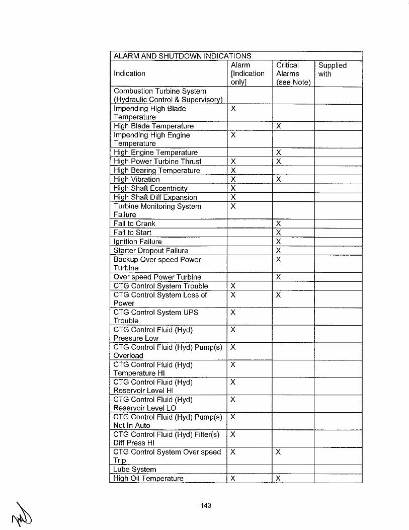
ALARM AND SHUTDOWN INDICATIONS Alarm Critical Supplied
Indication [Indication Alarms with onlv] (see Note)
Combustion Turbine System IHvdraulic Control & Supervisorvl Impending High Blade X Temperature Hiqh Blade Temperature X Impending High Engine X Temperature Hiah Engine Temoerature X High Power Turbine Thrust X X Hiqh Bearinq Temperature X Hiah Vibration X X Hiah Shaft Eccentricitv X Hiah Shaft Diff Expansion X Turbine Monitoring System X Failure Fail to Crank X Fail to Start X lanition Failure X Starter Dropout Failure X Backup Over speed Power X Turbine Over speed Power Turbine X CTG Control Svstem Trouble X CTG Control System Loss of X X Power CTG Control System UPS X Trouble CTG Control Fluid (Hyd} X Pressure Low CTG Control Fluid (Hyd} Pump(s) X Overload CTG Control Fluid (Hyd) X Temperature HI CTG Control Fluid (Hyd} X Reservoir Level HI CTG Control Fluid (Hyd) X Reservoir Level LO CTG Control Fluid (Hyd) Pump(s) X Not In Auto CTG Control Fluid (Hyd} Filter(s) X Diff Press HI CTG Control System Over speed X X Trio Lube Svstem HTc:ih Oil Temperature X X
143
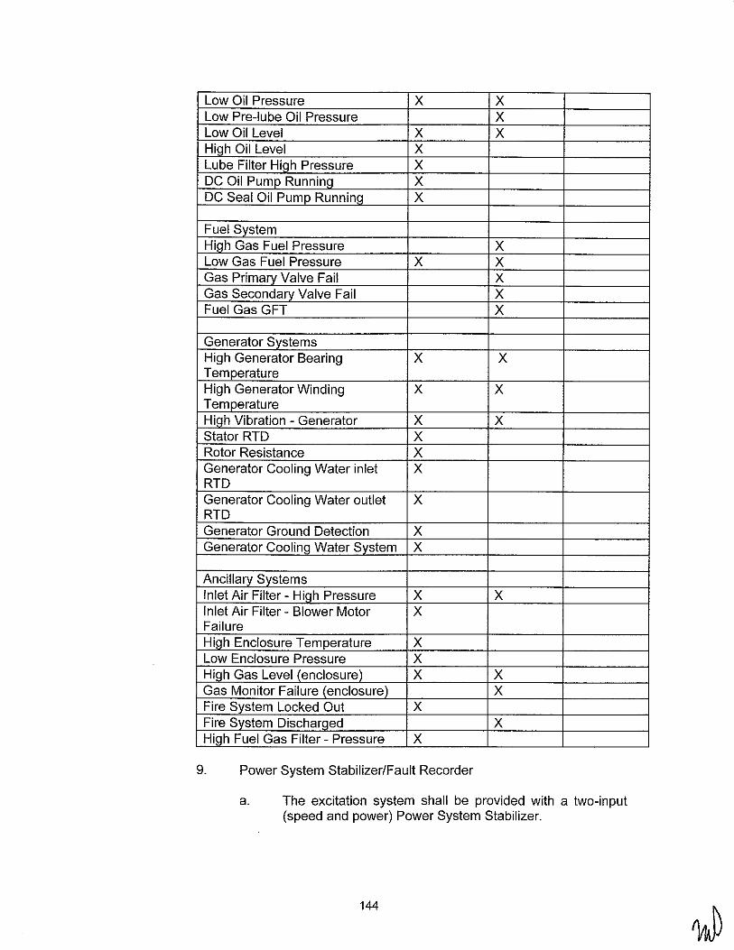
Low Oil Pressure X X Low Pre-lube Oil Pressure X Low Oil Level X X Hlah Oil Level X Lube Filter HiQh Pressure X DC Oil Pump Running X DC Seal Oil Pump Runnina X
Fuel System Hiah Gas Fuel Pressure X Low Gas Fuel Pressure X X Gas Primary Valve Fail X Gas Secondary Valve Fail X Fuel Gas GFT X
Generator Systems High Generator Bearing X X Temperature High Generator Winding X X Temperature Hiah Vibration- Generator X X Stator RTD X Rotor Resistance X Generator Cooling Water inlet X RTD Generator Cooling Water outlet X RTD Generator Ground Detection X Generator CoolinQ Water System X
Ancillary Systems Inlet Air Filter- HiQh Pressure X X Inlet Air Filter- Blower Motor X Failure High Enclosure Temperature X Low Enclosure Pressure X Hiah Gas Level (enclosure) X X Gas Monitor Failure (enclosure) X Fire System Locked Out X Fire Svstem Discharaed X High Fuel Gas Filter- Pressure X
9. Power System Stabilizer/Fault Recorder
a. The excitation system shall be provided with a two-input (speed and power) Power System Stabilizer.
144

b. The CTG Contractor shall include preliminary set-points for the Power System Stabilizer for review as well as final tuning including all personnel and equipment required.
c. Exhibit Y Section 5.10.H shall be referenced for instruments and outputs that are required for the Digital Fault Recorder.
10. Performance Monitoring Instrumentation
a. Permanent plant instrumentation shall be supplied for both CTG proper and BOP areas to allow detailed performance monitoring of each CTG by others. The CTG performance monitoring instrumentation shall include as a minimum: gross power, power factor, inlet filter dry bulb temperature, compressor inlet dry bulb temperature, barometric pressure (included in balance of plant (BOP) supply), relative humidity (included in BOP supply), and all available engine monitoring points including Hp and LP rotor speeds, HP compressor discharge pressure, intercooler inlet and outlet temperatures, exhaust temperature, fuel flow, fuel heating value and so forth.
11. Field-Mounted Equipment
a. The CTG Contractor shall provide all local pressure, temperature, flow and level instrumentation required to properly monitor the equipment in accordance with good engineering practice and safe operation.
b. The CTG Contractor shall furnish all necessary pressure reducing valves, solenoid valves, relief valves, other special valves, alarms, sampling tubing, strainers, filters, power supplies, pressure, temperature, level, and flow switches, meters, gauges, RTDs, thermocouples, etc., and other instruments as required for proper installation, interlocking and operation of his equipment. Equipment shall conform to applicable ANSI Standards for pressure and temperatures encountered. All process transmitters shall be Fisher-Rosemount type (Model 3051) or equal.
c. The CTG Contractor shall provide temperature test wells on the inlet and outlet of all heat exchangers.
d. Dual element temperature probes shall be furnished as a minimum. The CTG Contractor shall also supply multielements other than dual element, as required by CTG Contractor's design. Thermocouples shall be either ISA type E (chromel-constantan) or type K (chromel-alumel) ungrounded tip. RTD (resistance temperature detectors) shall be three-wire 1 00-ohm platinum. The exhaust
145

temperature and turbine wheel space thermocouples may be single element design. Exhaust plenum shall have eighteen (18) thermocouples uniformly spaced; with each one (each wheel space has two separate single element thermocouples) individually monitored and automatically rejected from temperature calculations should it fail. Wheel space thermocouples shall be replaceable without disassembling the combustion turbine-generator. Bearing metal temperature thermocouples shall be provided.
12. Instrument And Control Tubing and Valves
a. The CTG Contractor shall furnish individual instrument shutoff/isolation (root) valves at process connection.
b. All process tubing shall be seamless, Type 316 stainless steel. Pressure elements such as bourdon tubes, capsule diaphragms, etc., shall be made of Type 316 stainless steel.
c. Instrument primary connection lines shall use welded fittings up to the instrument valve connection to prevent vibration induced loosening.
d. All pressure, differential pressure, flow, and level instruments shall be installed to permit maintenance calibration in-place without removal of the instrument or disconnection of the process tubing. Manifold valves shall be provided with calibration tees for each process transmitter. Differential pressure instruments shall be furnished with five-valve manifolds and calibration connection.
G. Structural
1. General
a. CTG Contractor shall comply with the applicable requirements of Exhibit Y Sections 5.12.F, 5.12.G, 5.12.1, 5.12.L, and 5.12.M.
b. The design and fabrication of all structural, load-bearing elements of equipment furnished under this specification shall conform to all applicable requirements of the State of California and Federal safety regulations. Any and all deviations from these criteria are subject to approval by LADWP. In cases where conflicts between the cited codes and standards exist, the requirements of the more conservative code shall be met. When the codes do not use consistent design methodologies and it is not clear which code governs, both (all) codes shall be checked
146
individually to ensure compliance with each code. Loads and allowable values obtained from different codes shall not be mixed.
2. Structural Design Requirements
a. The CTG Contractor shall calculate and provide all loads for design of the foundation (by others), including at a minimum dead, live, seismic, wind, transient, and miscellaneous loads. Dead load shall include all selfweight of the CTG Contractor supplied equipment, including the machine, oil tanks, oil, piping, etc.
b. Miscellaneous Loads
1. Normal generator torque 2. Normal turbine torque 3. Differential pressure 4. Generator short circuit 5. Machine thermal expansion 6. Turbine accident/trip 7. Insulation 8. Impact 9. Dismantling, removal, and maintenance
c. Load factors and combinations used in the CTG Contractor's steel design shall be as specified in Exhibit Y Section 5.12.1. Other load factors and combinations, including miscellaneous loads, shall be as deemed appropriate by the CTG Contractor, subject to review by LADWP.
3. Structural Deliverables
a.
b.
c.
The preparation of the CTG Contractor's drawings, calculations, specifications and other construction documents shall be under the direction of a Registered Professional Engineer in the State of California. All documents submitted for construction shall bear the stamp of the Registered Professional Engineer and shall be submitted to LADWP for review and approval.
The CTG Contractor's compliance with the structural design requirements of this specification shall be documented in the form of a design report, calculations, test reports and/or drawings, as appropriate. Such documentation shall include a complete description of the analysis methods/techniques used in the structural design.
The CTG Contractor shall furnish to LADWP all final engineering and interface data required to design the
147

foundations for all equipment furnished under this specification. Final data shall be provided in a final design report or on final drawings. The CTG Contractor's foundation requirement documents shall clearly define seismic and generator short-circuit loads and shall include the following data at a minirnurn:
1. Loads to be transferred to equipment foundations, including load locations defined relative to equipment centerlines.
2. Anchorage details requiring anchors or embedments in the foundations.
3. Foundation stiffness requirements and any relative (e.g., vertical) displacement limits between machine support points.
4. Operating temperatures at bases of turbine and generator skids.
5. Foundation plate levelness requirements. 6. Minimum anchor bolt strength, diameter, and projection
above top of concrete. 7. Clearance and limitation requirements that dictate
foundation pier sizes.
H. Quality Assurance and Specific Submittal Requirements
1. General
a. Quality assurance requirements are included in Exhibit Y Section 5.1.D.
b. General document submittal requirements are included in Exhibit Y Section 5.1.C.
c. Additional and specific submittals for the CTG are listed below.
2. Performance Curves
a. For operating conditions that are different from either ISO conditions or site rating conditions, the CTG Contractor shall supply LADWP certified performance curves and correction factors to cover the intended range of site conditions. This information should cover the expected range of variation including but not limited to the following: shaft speed, power output, compressor inlet temperature, atmospheric pressure, inlet and exhaust pressure losses, cooling water temperature and effect of variations in fuel properties. Performance parameters indicated should be power, fuel flow, water flow rate, and heat rate (designate higher or lower heating value). The following type of performance curves shall be provided:
148

b.
1) Curves showing correction to heat rate vs. exhaust pressure in increments of .5" H20 from zero to maximum CTG backpressure at specified loads.
i. Performance (power output, heat rate, fuel flow, water flow) with evaporative inlet cooling system in operation.
ii. Curves showing performance degradation over time based on recommended maintenance practices.
iii. V-Curve - showing generator kVA output against field current through the entire power factor range.
iv. Capability Curve showing reactive capability versus load and shall show the full and accurate capability of the generator.
v. Decrement curves for three-phase, line-toline, and line-to-line to ground, short circuits, including effect of voltage regulator.
vi. Regulation curve with excitation and speed constant.
vii. No load and full load saturation curves for the exciters.
viii. Exciter load versus exciter voltage curves showing drooping characteristic.
ix. Saturation Curve - showing data on the excitation and voltage regulation system characteristics showing generator stator, field and exciter per unit amperes vs. time. Specify which IEEE excitation system model type and constants are representative of the CTG Contractor's equipment.
x. Emission Performance curves, including near-field noise data.
xi. Power, heat rate, exhaust flow and exhaust temperature versus ambient temperature, inlet losses, exhaust losses, humidity, and load range.
Test Reports
149

1) Before major components like gas turbine and generator rotors are assembled, the CTG Contractor shall make the following information available for review by LADWP:
i. Results of chemical and physical testing of major components like turbine and generator rotors, such as ultrasonic, magnetic, borescope, etc.
ii. Results of heat stability tests on rotors.
I. Field Services, Training, Tools, and Spare Parts
1. Field Services
a. The CTG Contractor shall provide services of competent personnel to provide technical advice, assistance and guidance in the unloading and erection of the equipment furnished under this specification; this includes all necessary field services for equipment furnished by CTG Contractor's suppliers in each case. The technical personnel will not leave the installation operation until Substantial Completion or release of technical personnel is given by LADWP, such approval not to be unreasonably withheld.
b. The CTG Contractor shall provide services of competent startup engineers to instruct, advise, and train LADWP's personnel in correct startup, commiSSioning, safe operation, maintenance procedures, testing, and placing of the equipment in successful service. The startup engineer(s) shall commence at the project site one week before the scheduled start of startup activities and will not leave the startup operation until Substantial Completion by the BOP Contractor or release of startup personnel is given by LADWP, such approval not to be unreasonably withheld.
c. The CTG Contractor shall provide necessary technical services as required to resolve preliminary operating problems as they develop until satisfactory operation is achieved and LADWP accepts the unit. All technical services required to correct design or manufacturing errors will be at the CTG Contractor's expense.
d. Field personnel shall be provided as necessary for compliance testing and for tuning of the power system stabilizer.
150

e. Field personnel will be capable, qualified, and able to perform the duties required to the satisfaction of LADWP and will be vested with authority to make decisions binding on the CTG Contractor.
f. The CTG Contractor's proposal shall contain the proposed technical and startup personnel schedule at the project site. The schedule shall list the area of expertise, proposed start date, proposed completion date, and proposed hours per week for all proposed personnel.
2. Training
a. General
1) The CTG Contractor shall conduct a full and comprehensive training program for LADWP's suitably qualified personnel to enable them to fully and efficiently operate the combustion turbine generator. The courses will include material on inspection, maintenance, troubleshooting, and operation of all equipment furnished with the specification. Outlines of the proposed training courses and a description of the material covered shall be included in Contractor's proposal. See Exhibit T for detailed training requirements.
b. Basic Training
1) The Basic training shall be performed using either a specially prepared textbook and/or the operating and maintenance manuals provided by the CTG Contractor. Each student will receive an individual copy of the printed course material. The course should be specific for the combustion turbine furnished for this specification. The training program shall include hands on experience with the LADWP's equipment.
2) The training course shall be appropriate for all levels of operations and maintenance staff, e.g. Engineer, Technician, Supervisor, etc. Instruction shall be in the English language. A single common course shall be provided for 15 people. Classes shall be held on consecutive days, eight hours a day, with no classes on holidays or weekends. The course should be a minimum of 10 days.
3) LADWP will provide a suitable classroom for training at the site. LADWP will provide the CTG
151

Contractor at least four weeks advance notice of desired training dates.
c. Advanced Training
1) The CTG Contractor shall quote as an option the use of the CTG Contractor's proprietary CTG training simulator. Training shall consist of programming, troubleshooting, and familiarization with the control system for this CTG. The CTG Contractor shall include training for four students. The LADWP will assume all costs associated with the LADWP employees' travel and living costs.
3. Special Tools
a. The CTG Contractor shall provide a complete set of special equipment and tools, required for installation, operation, maintenance, adjustment and complete dismantling and assembling of the equipment. Tools shall be new and of first-class quality. Tools shall be shipped to the project in a suitable, separate container clearly marked with the name of the equipment for which they are intended.
b. The following minimum special tools shall be provided:
• Lifting Beam and Slings • Alignment tools • Fuel nozzle maintenance kits
c. Specially designed and fabricated rigging appurtenances, such as spreader bars, lifting beams, lifting devices, etc. Shall comply with ASME B30.20 "Below-the-Hook lifting devices".
4. Spare Parts
a. Startup Spare Parts
1) Startup spare parts shall include a complete set of spare parts and consumables, normally required for installation, commissioning, testing and start-up of the CTG. The recommended start-up spare parts list may be unit priced or lump sum priced, but will be included in the firm price for the CTG price.
b. Startup spare parts list shall:
1) Be submitted to LADWP with the Proposal.
152
2) Be inclusive for and applicable to all equipment components, auxiliaries, accessories, materials, and lubricants being furnished under the Agreement.
3) Include for each recommended spare part, unit price (if not lump sum priced), quantity, description, part number references, etc., to completely identify the itern and the equipment component for which it is recommended.
4) Be based upon furnishing and delivering the parts at the delivery point of the combustion turbine. The CTG Contractor will indicate the point of shipment, the amount included for freight charges, and the lead-time required for delivery the spare parts.
5) Include a listing of all lubricants and consumables required to startup and operate the CTG.
c. Maintenance Spare Parts
1) The CTG Contractor shall submit a recommended major maintenance spare parts quotation. Major Maintenance is defined as a Combined Inspection, Hot Gas Path Inspection and Major Inspection. The parts that LADWP should carry in stock prior to a major planned overhaul will be identified. The Recommended Major Maintenance Spare Parts Quotation shall be unit priced. Contractor shall state in the Proposal the design life of each component in the turbine section in baseload fired hours or normal starts or an equivalent operating hour. The data should also identify the number of possible repair angles, if applicable, before complete replacement is required. The formula for this equivalent operating hour shall be defined.
2) The CTG Contractor shall provide with their proposal CTG Contractor's maintenance documents used for calculating maintenance intervals and spare part replacement.
3) The CTG Contractor may at their option propose a maintenance service agreement covering up to the first major overhaul. This option does not relieve the Contractor from providing Major Maintenance Spare Parts Quotation above.
5. 7 SELECTIVE CATALYTIC REDUCTION (SCR) SYSTEM
A. Information and SCR Scope of Work
153

1. General
a. The intent of this Section is to describe design, fabrication, testing and delivery requirements for an Emission Control System (ECS) which consists of NOx Selective Catalytic Reduction (SCR) and CO Oxidization Catalyst (CO) Systems to reduce NOx, CO and VOC emissions to atmosphere resulting from the operations of six (6) LMS100 CTG(s).
b. The Prime Mover (PM) Contractor shall provide as part of their scope of supply six (6) ECS units each coupled with one LMS100 CTG, complete with all accessories and appurtenances as specified hereinafter.
c. It is the CTG Contractor's responsibility to furnish equipment in full compliance with the Contract Documents and fit for their intended purposes.
d. The CTG Contractor shall conform to 2007 California Building Code, and all federal, state, and local codes or regulations having jurisdiction at the project site. It shall be CTG Contractor's responsibility to investigate such statutes and determine applicable provisions regarding the equipment they propose to furnish.
e. The preparation of the CTG Contractor's drawings, calculations, specifications and other construction documents shall be under the direction of a Registered Professional Engineer in the State of California. All documents submitted for construction shall bear the stamp of the Registered Professional Engineer and shall be submitted to LADWP for review and approval.
2. Scope of Work
a. The CTG Contractor shall be responsible for designing, furnishing, fabricating, assembling, shop cleaning, shop testing and delivering of six (6) Emission Control Systems, complete with all accessories and appurtenances as hereinafter specified. Each ECS shall include but is not necessary limited to the following items:
1) Inlet gas transition duct from the CTG to the ECS. All CTG exhaust plenum growth due to thermal expansion shall be accommodated. The interface to the ECS will be flanged.
2) Combustion turbine exhaust expansion joint including bolting and gaskets.
154

3) Exhaust stack with stack noise silencer and perimeter acoustical panels as required to meet near-field and far-field requirements as specified in Exhibit Y Section 5.1.8.7. Exhaust stack shall be provided with FAA lighting as required.
4) Ammonia vaporization skid complete with:
a. Two (2) 100% capacity each dilution air blowers including noise silencing equipment.
b. One ( 1) electric heater, contactor, and thermostat with spare heater capacity.
c. On-skid aqueous ammonia supply piping system.
d. PLC-based aqueous ammonia control system mounted on ammonia vaporization skid.
e. Structural steel base and support frame.
5) Ammonia injection grid (AIG) completes with flow control and flow balancing valves.
6) Off skid piping between the ammonia vaporization skid and the ammonia flow balancing manifold assembly.
7) Piping between the ammonia flow balancing manifold assembly and the ammonia injection grid.
8) Two (2) 100% capacity each flue gas cooling (tempering) air fans including fan noise silencing equipment.
9) Tempering fan system including interconnecting duct work, valves, dampers, instrumentation, piping and flue gas cooling air/purge control.
1 0) SCR and CO catalyst systems shall be complete with catalyst elements, catalyst support frames and gas bypass seals. All catalyst modules shall be complete with lifting lugs.
11) The system shall be designed for the NOx and CO removal efficiencies needed to achieve the Contractual em1ss1on limits throughout the guaranteed life of their respective catalyst.
12) Gas tight casing with thermal insulation.
155

13) All integral and interconnecting piping, fittings, supports and hardware and skid-mounted equipment furnished under this Section.
14) All required motors including motors for motoroperated valves.
15) Shop priming of all non-galvanized items.
16) Hot-dip galvanized walkways, platforms and stairways necessary for access to instrumentation, valves and emission monitoring ports.
17) All necessary instrumentation for performance and acceptance testing of the furnished equipment. Portable instrumentation required for performance and emissions testing shall be included.
18) Leveling blocks, slide plates, baseplates, thrust blocks, and slotted washers (non-embedded items).
20) Shop testing including functional testing of equipment specified.
21) Flow or computer model testing to assure equal flow distribution over the CO and SCR catalysts.
22) Freight to the site for truck shipments and nearest rail siding for rail shipments or nearest port.
23) Structural steel supports for equipment.
24) Liner splice piece at interface of ECS inlet duct.
b. CTG Contractor shall provide SCR documentation and data to the LADWP, including but not limited to, the following:
1) Monthly status report.
2) CTG Contractor's and SCR Supplier's QNQC Program.
3) All drawings, including as-built drawings. These drawings shall include, but not be limited to, the following:
a. Piping and Instrument Diagrams.
156

b. General arrangement drawings of plan, rear, side and front elevations of each ECS and major equipment.
c. Detail drawings of major components and sub-assemblies.
d. Welding procedures. e. Erection drawings and procedures. 1. Commissioning procedures. 9. Control interlock logic drawings. h. Electrical control schematic and wiring
diagrams for all major equipment. i. Insulation anchors, liners, and insulation details
for the ECS. j. Structural steel arrangement and detail
drawings including platforms, ladders, stairs, and handrail.
k. Ductwork arrangement including insulation and supports.
1. Expansion joints. m. Access doors n. Enclosure drawings. o. Arrangement drawings for the NOx and CO
sections showing the catalyst module arrangement and structural support.
p. Detail drawings of the skid mounted aqueous ammonia evaporation system including controls, electrical wiring, equipment, piping and power requirements and AIG grid.
q. Safety Valve Drawings.
4) Schedules.
5) Installation instructions drawings and or manuals.
6) Operation and maintenance manuals.
c. CTG Contractor shall provide spare parts as follows:
1) Installation, start-up and commissioning spares.
2) An option for recommended operational spares for two (2) years of operation.
d. Work by Others:
1) Receiving, unloading, storing, and field erection of equipment and accessories.
2) Aqueous ammonia storage tank.
3) Aqueous ammonia forwarding pumps.
157
4) Foundations, anchor bolts, and embedments.
5) Grouting materials and the placement thereof.
6) Power and control wiring, conduit, instrument piping and pneumatic tubing external to supplier skids.
7) Piping and thermal insulation external to supplier skids.
8) GEM systems.
9) Special Inspection and Structural Observation during construction, as required by 2007 California Building Code.
3. ECS Quality Assurance Program
a. CTG Contractor's QA Program shall be in effect at all times to verify that all items and services, including subcontracted items and services, comply with the requirements of the Contract.
4. ECS Witness and Hold Points
a. The LADWP shall have the right to establish witness and hold points for which the CTG Contractor and or its suppliers shall give ten (10) business days prior notification. In addition, the LADWP may establish witness points to ensure resolution of quality problems.
5. ECS Performance Curves and Data
a. As a minimum the following performance correction curves shall be provided:
1) Guaranteed and predicted emission performance curves.
b. Other Data
1) Gas flows, velocity, temperatures, and pressures for the following sections:
a. Inlet to the flow distribution system. b. Inlet to the CO catalyst. c. Inlet to the Ammonia Injection Grid (AI G). d. Inlet to the SCR catalyst.
158

2) Predicted and guaranteed NOx, CO, VOC, PM and N H3, concentrations and/or mass flow rates versus load at the inlet and outlet of the ECS.
3) Ammonia consumption versus load.
c. For operating conditions that are different from site rated conditions, the CTG Contractor shall supply the LADWP certified IBM/PC compatible software or performance curves and correction factors to cover the intended range of Site conditions and combustion turbine load conditions, including but not limited to combustion turbine exhaust energy output and temperature, atmospheric pressure, and the effects of variations in fuel properties.
B. ECS Design Criteria and Guaranteed Operating Conditions:
1. Design Conditions
Combustion Turbine Model ............................... CTG Vendor to Provide
Manufacturer ................................................ CTG Vendor to Provide
Fuel(s) ..................................... D Refinery Gas [8] Natural Gas D Oil
Maximum Exhaust Gas Flow ..................... CTG Vendor to Provide lbs/hr
Coincident Exhaust Gas Temperature ........... CTG Vendor to Provide oF
Maximum Exhaust Gas Temperature ............ CTG Vendor to Provide oF
Exhaust Gas NOx Emission @ 15% 0 2 ............. CTG Vendor to Provide
Exhaust Gas CO Emission@ 15% 0 2 ............... CTG Vendor to Provide
Exhaust Gas VOC @ 15% 0 2 .......................... CTG Vendor to Provide
2. ECS Minimum Design Requirements
Equipment Identification ........ Selective Catalytic Reduction and Oxidation
Number of ECS Required .............................................................. 6
Service........................................................................ [8] Cycling Gas Flow .................................................................... [8] Horizontal
Gas Side Static Pressure Drop Through SCR and CO catalyst, and stack silencer (if required) Not to Exceed 12 inch WG
Stack Height (above grade) .................. Per AQMD Air Permit Application Requirements
159
Stack Damper w/ operator ........................................................... No
Stack Diameter. ................................ Per AQMD Air Permit Application Requirements
3. Other ECS Requirements
a. Emission guarantees shall be in accordance with Exhibit N.
b. Space and mounting fixtures shall be provided in the SCR frame for the addition of 50% more volume of catalyst to be added. The associated equipment shall also be sized to handle an additional layer of catalyst, if needed.
c. All devices and components shall be UL listed for ammonia service.
4. ECS Sound Levels
a. CTG Contractor and its suppliers shall provide ductwork lagging, and stack silencer(s) as required, to attenuate the combustion turbine exhaust and/or the CTG Contractor furnished equipment, under any operating condition, to meet the specified maximum A-weighted (dB, re: 0.0002 microbar) sound specified herein. If the CTG Contractor and its suppliers cannot comply, the maximum expected noise level should be stated in their respective proposals. If a stack silencer is not required, the CTG Contractor shall retain 0.5 inches water gage pressure margin for an addition of a future stack silencer.
5. Code Requirements
a. The ECS system shall conform to all latest federal, state, and local codes or regulations having jurisdiction at the project site. It shall be CTG Contractor and its suppliers responsibility to investigate such statutes and determine applicable provisions regarding the equipment they propose to furnish.
C. ECS Design Requirements
1. General
a. All equipment shall be designed for an outdoor, dusty, marine environment.
b. All equipment shall be designed for continuous 24 hours per day operation as well as frequent starts and shutdowns. Additionally, all equipment shall be designed
160

for the thermal stresses associated with combustion turbine generator load changes and maximum ramping rates.
c. All equipment shall be engineered and designed to withstand a rapid cold combustion turbine startup from zero to full load in ten (10) minutes to ensure the equipment is not damaged due to the high thermal stress conditions associated with rapid CT/CTG cold startup. It is not necessary for the stack emissions to be controlled to permit levels under this rapid 10 minute startup case.
d. The use of asbestos, lead, PCBs, or instruments containing mercury except encapsulated switches, in any portion of the equipment furnished, is not acceptable.
e. Insulation and freeze protection shall be by the CTG Contractor. The CTG Contractor and/or its suppliers shall identify insulation type and thickness and piping requiring freeze protection on the P&ID's.
f. The outer casing of the ECS duct shall be carbon steel. Insulation shall be installed internally and covered with a stainless steel lining. Support columns shall be shopwelded to the outer casing.
2. Supports and Expansion
a. All parts of the ECS shall be supported and properly braced and stayed, where required, to prevent misalignment, sagging, and vibration. All parts including ECS and setting structures, ductwork, etc. shall be arranged to properly provide for expansion movements and to minimize stresses. The CTG Contractor and its supplier's design shall account for all braces and external stiffeners to be continuously seal welded.
b. All equipment, components, appurtenances and anchorage shall be designed to resist seismic and wind load requirements in accordance with the latest Codes.
3. Equipment Accessibility
a. The CTG Contractor and/or its suppliers shall provide hinged or davit arm access and inspection doors to allow access to both sides of all parts of the ECS, ammonia injection grid, ductwork, flues, and other equipment. Doors shall be designed for tightness and easy operation. Where necessary, doors shall be provided with latches to hold doors open for inspection, access, or cleaning. Doors shall be provided with linings for thermal insulation, where
161

necessary. Doors shall be designed to anchor and hold the linings in place. Doors shall be insulated with a gasketed seal to the casing.
b. Where required to perform normal maintenance functions at a frequency less than every 3 years, facilities such as equipment removal monorails shall be provided. All lifting devices shall be clearly stenciled with rated lifting capacity.
4. Ductwork and Insulation
a. Ductwork and breaching included with the equipment shall be complete with all accessories, such as expansion joints, access doors, supports including base plates with shear bars as required, internal insulation where required, etc. Internal insulation shall include stainless steel liner as noted in this Specification.
b. Duct design shall be such that the velocity of gas or air will not be excessive. Maximum gas velocity shall not exceed 6,000 fpm downstream of the CT inlet duct transition. Abrupt turns shall be avoided, but where required, guide vanes and/or other flow control devices shall be provided. Internal design pressure of the ducts shall be not less than 20" water gauge and no visible distortion of the ducts under this pressure will be permitted.
c. The ECS's limits shall include all components from the connection between the exhaust duct from the down stream side of the combustion turbine generator expansion joint to the flange connection to the exhaust stack. The inlet transition ductwork shall not exceed a 45 angle of inclination for single slope designs, or for the initial slope on compound angle designs.
d. The stainless steel covering system shall consist of mineral wool insulation and an interior stainless steel liner. Insulation shall be retained to prevent packing. The liner shall be retained in such a manner as to prevent detrimental movement perpendicular to the duct and to allow axial thermal expansion and contraction. Provisions at overlaps shall be provided to prevent the liner from buckling or being lifted by gas flow velocities in the duct. Details for this system shall be included in the CTG Contractor's proposal.
e. Ducts shall be of gas tight welded construction, properly stiffened and reinforced to prevent buckling and vibration Ducts shall be shop-fabricated panels in sections as large as shipping limits will permit. Access doors shall be
162

provided to permit entry into the ductwork. Doors shall be lined with insulation and shall be pressure tight
5. ECS Outlet Stack
a. The exhaust stack shall be a self-supporting carbon steel stack, with emission testing ports, platforms, caged ladder, insulation for heat retention and personnel protection, access door, drain connections and a stack silencer, if required.
b. Steel stacks shall be designed in accordance with the requirements provided in the following documents: 1) AISC -"Steel Construction Manual" 2) ANSI/ASME STS-1-2000- "Steel Stacks" 3) ASME- Boiler and Pressure Vessel Code- Section
Ill"
c. Stack design temperature shall encompass all expected normal operating and upset conditions. Stack shall be made of ASTM A36 carbon steel with a corrosion allowance of 1/16 inch incorporated in the stack design. A minimum plate thickness of Y. inch shall be used. The CTG Contractor shall provide an option price to include an ASTM A588 (Cor Ten)
d. Stack shall include a 2 foot by 2 foot access door at the base of the stack above the false bottom and a 24 inch by 24 inch access door below the false bottom. Drain piping for the stack shall include a water seal external to the stack and all piping shall be 2 inch Schedule 80 stainless steel minimum.
e. The stack shall be insulated and lined with 409 stainless steel liner. The insulation shall be of such thickness and material to ensure that the outer casing temperature does not exceed 140°F ambient temperature.
f. Stack design shall include a lifting arm to facilitate lifting of CEMS test probes and cable up to the CEMS platform elevation.
g. Stack shall include proper openings for sampling flue gas per the United States EPA and SCAQMD specifications. A four-foot wide 360 degree platform shall be located four (4) feet below the EPA test port level. A caged ladder shall be used to access the platform from the top of the SCR. Two 11 0 V electrical convenience outlets shall be provided at the EPA platform level and six outlets at the base of the stack. Handrails shall not interfere with the test ports.
163

h. The ECS stack shall be equipped with a stack beacon lighting system in accordance with FAA Advisory Circular 7017 460-1 G "Obstruction Marking and Lighting" or any other FAA requirements that apply. The system shall be identical to and shall be coordinated with the lighting of the existing Haynes Units 9 and 10 ECS stacks.
6. Casing, Insulation and Liner
a. ECS inlet and outlet duct shall consist of exterior gas tight carbon steel casing, internal insulation and a stainless steel floating liner.
b. All duct and casing shall be designed to provide suitable drainage. Horizontal surfaces shall be sloped or provided with a means to remove rainwater other than evaporation to assure runoff of rainwater. Stiffeners shall be designed in such a manner as not to impede rainwater runoff.
c. Exterior casing shall be welded steel plate to provide a gas tight construction. Casing shall be welded with full penetration welds properly stiffened and reinforced to prevent buckling and detrimental vibration, designed to withstand a pressure equal to maximum turbine exhaust static pressure
d. The inlet duct to CO catalyst shall be provided with twelve (12) exhaust sample ports (six on each side). Twelve (12) exhaust sample ports (six on each side) shall be installed upstream and downstream of SCR catalyst. Test ports shall be four (4) inch minimum diameter and adequate for performance testing according to ASME PTC 4.4 and for emission testing per EPA Reference Method 40 CFR 60 and applicable SCAQMD tests. Two (2) four (4) inch CEM sample ports shall be provided upstream of CO catalyst for measurement of CTG exhaust NOx and CO emissions. The sample ports shall have stair or ladder access with a suitable maintenance platform.
e. The CTG Contractor shall shop install internal insulation of mineral wool. Insulation thickness shall be designed to meet Gal/OSHA and OSHA requirements for personnel protection, but in no instance should external casing temperature exceed 140°F.
f. Internal gas path liner shall be stainless steel in accordance with the table below.
164

Max. Gas Temperature °F Material Below 600-1200 TP 409 SS 1200-1400 TP 304 SS 1401-1600 TP 309 SS
g. Transition ductwork internal gas path liner shall be a 12 gauge (3mm) minimum thickness for floor, sides and roof. ECS liner shall be 12 gauge (3mm) minimum thickness for floor panels and minimum of 16 gauge (1.5mm) thickness for sidewalls and roof. Liner shall be connected by 3/8-inch-minimum-diameter studs to the exterior casing and insulation with a welded nut or retention clip to the stud, which will allow free expansion of the liners. Stud spacing for internal gas temperatures over 700'F shall not exceed 12 inches (or manufacturer's standard); 18-inch spacing (or manufacturer's standard) may be used in the cooler zones. The stud material shall be equal to or greater than the liner material and shall be connected to the duct or ECS casing by welding. Stainless steel washers on both sides of the liner will be placed under the nut or retention clip to seal the gap between the liner and the stud.
D. Selective Catalytic Reduction (SCR) System
1. General
a. The Selective Catalytic Reduction (SCR) system shall be designed, fabricated and installed to control concentrations of NOx generated by Units 11 thru 16. The CTG Contractor shall be responsible for design and equipment supply for the SCR reactor and catalyst in full accordance with all applicable regulations and requirements. Operating and maintenance procedures established for this equipment shall also be developed in full accordance with all applicable regulations and requirements.
b. Emission guarantees shall be in compliance with Exhibit N and Exhibit P. The design of the SCR system shall be guaranteed to provide the emission reductions without requiring rejuvenation, maintenance, addition, or replacement for five (5) calendar years after initial operation or up to 25,000 hours of operation which ever comes first.
c. Aqueous ammonia with a concentration of 29 percent by weight will be supplied by LADWP and used in the SCR system. The aqueous ammonia specification is included in Exhibit Z.17.
165
d. The SCR catalytic element sampling coupons for each layer shall be readily accessible without disturbing other equipment and by use of common tools. Identify the catalyst vendor's particulars for used element disposal. This shall include identification of hazardous waste, composition, concentration, need for special handling or storage, personnel precautions, need for special tools or prov1s1ons, means of transportation, and disposal destination. The SCR catalyst used element disposal shall be in accordance with all applicable regulations. MSDS shall be provided for SCR catalyst.
e. The outer casing shall have provisions for test ports and connections before and after the SCR system to determine the performance of the catalyst.
f. The CTG Contractor and/or its SCR supplier shall provide detailed operating and maintenance instruction for the equipment as required by Exhibit T. This shall include but not be limited to:
1) Performance monitoring
2) Diagnostic and repair procedures
3) Provisions for controlling NOX while maintaining or servicing SCR equipment.
4) Operating restrictions (temperatures, gas composition, etc.)
5) Performance data - mole ratio vs. cleanup, NH3: NOX molar ration and effect of injection on emissions (CO, C02 , VOC, PM etc.) as required by Exhibit T.
6) Preventive requirements
and scheduled maintenance
7) Recommended maintenance practices.
8) Detailed procedures for installation, checkout, startup, operation, shutdown and testing of the SCR system including but not limited to:
9) Catalyst washing procedure
1 0) Catalyst inspection procedure
11) Catalyst replacement criteria
166

12) Catalyst replacement procedure
13) Catalyst storage requirements
14) System troubleshooting procedures
g. The CTG Contractor and/or its SCR supplier shall provide a SCR manufacturer's service or maintenance programs as well as their scopes, limitations, and costs.
h. The CTG Contractor and/or its SCR supplier shall provide in detail, the guarantees and warranties, as well as restrictions and limitations, on equipment performance and life. (Including the SCR manufacturer's predicted catalyst life at 100% plant capacity factor)
2. SCR Arrangement
a. Access shall be provided between SCR and CO catalysts for removal of catalyst coupons and to allow cleaning of the catalyst during periodic maintenance intervals. The internal structure of the SCR casing shall allow complete access to the catalyst front face without removal of internal structures.
b. Provisions shall be included in the design to allow a mobile crane to be used for replacement of SCR and CO catalysts. The mobile crane will be used for loading and unloading catalysts on/from trucks and shall have no interference with other equipment.
3. Ammonia Injection Grid
a. The injection grid shall be designed and arranged to ensure uniform mixing of the ammonia and the exhaust gas stream. The location of the ammonia injection grid and the SCR catalyst modules shall be as recommended by the CTG Contractor and/or its catalyst manufacturer based on the results of the model study.
b. The ammonia injection grid shall be designed for safe and effective operation to achieve the guaranteed NOx and ammonia slip emission rates over the full load range when firing natural gas based on the requirements described in this specification. The design of the ammonia injection grid shall be in full compliance with all applicable regulations and code requirements. Operating and maintenance procedures for this equipment shall be developed in accordance with all applicable regulations and code requirements.
167

c. The injection grid shall be designed with multiple injection branches. The number of injection zones shall be adequate to meet the performance requirements and NOx and NH3 distribution defined in the specification. The ammonia injection system shall be designed with independently adjustable ammonia injection zones. Each ammonia injection zone (branch) shall be adjustable from the exterior of the duct.
d. The injection grid shall include flow control valves on branch headers located off the main distribution header on each leg of the SCR duct.
e. Ammonia injection grid shall be designed to provide ammonia from manifolds along the length of the SCR without interference with the flue gas duct or cause congestion. The manifolds shall be designed to allow for flow balancing and NOx reduction optimization during comm1ss1oning. Each injection zone shall include measuring devices and/or test ports, flow orifices, injection nozzles, and independent flow rate adjusting valves necessary to allow maximum tuning flexibility. Valve connections for a Magnehelic type differential pressure measurement instrument shall be provided on each branch of the injection grid. Valve connections shall be located for ease of access Magnehelic type differential pressure measurement instruments shall be provided with the ammonia injection grid.
f. The injection grid shall be properly supported to prevent thermal distortion and damage due to vibration induced by the flue gas flow. The injection grid shall be designed for maximum thermal expansion including consideration for maximum thermal expansion without cooling provided by the flow of ammonia and dilution gas.
g. All injection grid piping connections inside the flue gas ductwork shall be socket-weld or butt-weld type. Nozzles shall be designed to be free from plugging.
4. Ammonia Vaporization/Dilution Skid
a. Skid mounted aqueous ammonia vaporizing and dilution equipment shall be provided with the SCR system. Exhaust gas or heated air shall be used as the dilution and vaporization medium. Air shall be introduced by a centrifugal blower. The aqueous ammonia feed shall be filtered, measured, and injected into a vaporizer unit. The ammonia shall contact the hot air in a co-current evaporator.
168

b. The resultant air and ammonia mixture shall typically contain between 2 and 5 percent ammonia by volume for all load conditions and in no case shall contain greater than 7 percent ammonia by volume.
c. The vaporization system shall include two (2) 100% each dilution air blowers, liquid ammonia mass flow meter, flow control valve, electric heater, mixing chamber, piping, instruments, and all other required accessories.
d. Blowers shall be provided with suitable noise inlet silencers and sound insulation as necessary to meet the noise requirements stated herein.
e. Dual filters shall be provided in the ammonia lines. The filters shall be 100% capacity each and shall be arranged in a parallel configuration to allow isolation and maintenance of one filter while other is in operation. The filters shall be provided with instrumentation to monitor the pressure drop across each set of the filters. Each filter shall have provisions to connect fresh water flush and drain.
f. The electric heater shall be provided with at least 20% of spare capacity heater elements such that the single failure of a heater element will not prevent the electric heater system from achieving full required heating capacity.
g. The ammonia vaporization unit shall be pre-piped, prewired, and suitable for outdoor installation in the marine environment.
5. CTG Exhaust Cooling Air Fans
a. Two (2) x 100% capacity each CTG exhaust cooling air fans shall be provided to ensure the flue gas temperature is within the optimum operating conditions of the SCR catalyst and to provide purge air in accordance with NFPA and GE guidelines.
b. Both fans shall be located on the same side of the SCR main exhaust ductwork.
c. The fans shall be provided with inlet noise silencers and sound insulation as necessary to meet the near-field and far-field noise requirements stated herein.
d. The fan discharge shall be provided with a suitable expansion joint and designed to allow insertion of a blanking plate for maintenance and a check valve, isolation damper, or other suitable means to prevent back flow of
169
flue gas through the fan housing, when a fan is not in operation.
e. The cooling air system shall be designed to minimize the stratification of cooling air and CTG exhaust.
6. SCR Reactor and Catalyst
a. The design and procurement services supplied by the CTG Contractor and or its Suppliers shall provide for a complete, functional, and safe SCR reactor and catalyst system including, but not necessarily limited to, the following:
1) Reactor (catalyst housing). 2) Test ports. 3) Reactor access. 4) Reactor access doors. 5) Catalyst modules. 6) Catalyst support frames including additional frames
for a future addition of 50% more catalyst volume. 7) Catalyst test elements/coupons. 8) Catalyst seals. 9) Catalyst removal/replacement system (including
hoist). 1 0) Gas distribution devices (as required). 11) Model study.
b. Any ductwork, expansion joints, structural steel, painting, insulation, and lagging procurement requirements that are necessary for installation of a complete SCR system and not mentioned herein shall be included.
c. The reactor shall be equipped with test ports at the inlet and outlet of the reactor. The test ports shall be arranged to allow testing of at least a 6 by 6 matrix of points. Test port diameters shall not be less than 4 inch inside diameter.
d. Exterior access for the reactor (ladder, stairs, and platforms) shall be provided to the reactors as required for maintenance.
e. The maximum included transition angle of ducts shall not exceed 45 degrees unless specifically approved by LADWP.
f. Each catalyst layer and flue gas distribution layer (if applicable) shall have exterior access provisions to allow complete and convenient internal inspections.
170
g. The catalyst composition shall be appropriate to meet the performance requirements as specified and for the intended range of operation.
h. Appropriate seals shall be provided with the catalyst to prevent any flue gas bypass around the catalyst modules.
i. In order to monitor catalyst life and performance, a minimum of 10 test coupons shall be provided and installed in the catalyst beds as recommended by the catalyst manufacturer. An additional one catalyst coupon shall also be furnished in a sealed container to be used as a control sample for future reference for performance and composition analysis. Each catalyst coupon shall be labeled with a serial number. All catalyst coupons shall be from the same lot as the installed catalyst. These samples will be tested to evaluate catalyst activity and physical properties as the catalyst ages.
j. Catalyst shall be shipped in weatherproof packaging of the catalyst modules.
k. Specimens of the catalyst to be used shall be tested, prior to fabrication, to determine specific surface area, activity, and 802 to 803 conversion rates.
I. Any Special tools or necessary equipment to lift or transport the catalyst modules from delivery vehicle to the final reactor positions and to remove the modules and load on a truck for disposal shall be included.
m. Provide all gas distribution devices or turning vanes that are recommended as a result of the model study. The gas velocity distribution at the reactor outlet shall be controlled to meet the guaranteed requirement specified below.
7. Control Requirements
a. The normal operator interface to control the system is the Facility DCS work stations in the Control Room. Logic shall be available for both manual and automatic control of all major SCR systems.
b. Control signals shall be provided to protect equipment and personnel from system upsets including high catalyst section differential pressure and loss of instrument air pressure, dilution gas flow, and exhaust gas flow. Instrumentation shall be provided to alarm ammonia dilution gas fan failure and institute an instrument air purge of the ammonia lines upon failure of both ammonia dilution
171

gas fans. Additional instrumentation shall be provided to alarm the following conditions as a minimum:
1) High ammonia flow (leak). 2) Low dilution gas flow. 3) High catalyst temperatures. 4) Low instrument air pressure. 5) High ammonia/NOx operating ratio. 6) High or low dilution gas temperature. 7) Pressure drop across the catalyst per the SCAQMD
permit.
c. All alarms will be transmitted to the DCS for annunciation in the control room.
d. Ammonia slip, inlet NOx, or air flow measurements are required for proper control, with appropriate instrumentation. Inlet NOx signal is used to determine SCR inlet NOx.
e. All primary control and instrumentation required by the ammonia injection control system shall be included in the scope. Primary instruments shall be provided for monitoring, alarming, and verification of performance in order to assure reliability of the SCR system and associated equipment. Scope of equipment to be furnished shall include, but not be limited to, the following:
1) Microprocessor based PLC for SCR process controls
2) Datalink interfaces for each of the SCR process controllers to the DCS
3) 110 interface cards for PLC control system 4) Control valves. 5) Transmitters: level, pressure, and flow. 6) Signal converters. 7) Flow measurement devices. 8) Limit switches. 9) Pressure switches. 10) Temperature switches. 11) Level switches. 12) Pressure gauges. 13) Thermometers. 14) Temperature detectors. 15) Thermowells 16) Test wells. 17) Vibration transducer mountings. 18) Flow indicators. 19) Flow switches. 20) Valve positioners. 21) Diaphragm seals
172

22) Solenoid valve 23) Ammonia detectors
f. Local instrumentation shall be furnished where required for maintenance and periodic inspection. As a minimum, provide local instrumentation and test taps at all locations where a pressure or temperature process tap has been made.
g. Instrumentation shall be suitable for the environment and shall be corrosion-resistant. All devices shall have a NEMA 4X rating. All instrument devices shall be designed for easy access and maintainability.
h. Instrument Accuracy
1) All instruments shall be constructed to perform normally and meet all guarantees when subjected to vibration and the range of ambient temperatures.
2) Pressure transmitters shall transmit a signal that is linear with respect to the measured pressure within plus or minus 1/2 of 1 percent of the measured range span.
3) Level transmitters (if required) shall transmit a signal which is linear with respect to the measured level within plus or minus 1 percent of the metered level range span based on a specific gravity of 1.00.
4) Resistance temperature detector elements shall have a resistance characteristic that is linear with respect to temperature within plus or minus 1/2 of 1 percent of the top range value.
8. SCR Operating Requirements
9.
a. The SCR system shall be suitable for up to 6 cycles per day for the full guarantee period, thermal cycling between the maximum system operating temperature and the minimum outdoor temperature without injurious effect on the structure, catalyst, or other system components. The design shall include, but not be limited to, the following operating parameters:
1) Starting of flue gas source into a cold system. 2) Starting of flue gas source into warm or a hot
system.
SCR Materials
173

a. Copper or copper alloys shall not be used for any components in the SCR system.
b. The SCR catalyst shall be the regular packed parallel flow type and shall be designed to minimize pressure loss. The catalyst shall be a homogeneous extruded material or the catalyst shall be supported on a metallic, fiberglass or ceramic monolithic base material. The bonding procedure used and the design of the catalysts cells shall be such that de-lamination of the catalyst from the support material or permanent deformation of the support material shall not occur due to stresses induced by the design seismic, pressure, wind, and thermal conditions or combinations thereof.
c. Piping and equipment in contact with liquid and vaporized ammonia shall be constructed of stainless steel.
10. SCR Construction
a. Catalyst cells shall be shop assembled into arrays for installation into the SCR catalyst housing. Arrays shall be the maximum practical size to facilitate and minimize field maintenance. Final dimensions shall meet shipping and handling limitations and shall facilitate handling, installation, and removal of catalyst by operating/maintenance personnel.
b. The SCR system casing shall be designed and constructed for all required internal supports for catalyst loading, wind loading, thermal stress, and earthquake loading.
c. The catalyst design shall allow for thermal expansion and contraction of the catalyst modules without subjecting the catalyst, internal support members, or SCR catalyst reactor to excessive stress levels or shifting while heating up, operating, or cooling down.
d. All required handling tools, platforms, stairs, ladders, and support steel shall be provided to support installation, maintenance and removal of catalyst. Structural and miscellaneous steel shall be in accordance with this specification.
e. The SCR catalyst shall be designed to prevent any detrimental effects resulting from high flue gas turbulence.
11. SCR Performance Guarantee Requirements
174
a. The following system performance parameters shall be guaranteed over the full load range and meet the Emission guarantees detailed in Exhibit N.
1) Nitrogen oxide (NOx) emissions. 2) Ammonia slip. 3) SCR reactor outlet gas velocity distribution. 4) SCR reactor outlet NOx and NH3 distribution. 5) Catalyst life. 6) Suitability for continuous dispatched operation
(Operational Performance Guarantee).
b. All guarantees are to be achieved simultaneously. Design values for fuel quality and associated operating parameters, and any other required parameters will be as defined elsewhere in this specification.
c. Ammonia Slip Emissions. The SCR system shall be guaranteed to limit ammonia slip emissions for operation at any point between the minimum and maximum operation capabilities of the CTG.
d. Ammonia Usage Rate. The consumption of ammonia shall be guaranteed not to exceed the rates stated in the Proposal for operation at the maximum capabilities of the gas turbine generator.
e. Power Consumption. The total auxiliary power consumption shall be guaranteed not to exceed the consumption stated in the Proposal for operation at the maximum capabilities of the gas turbine generator.
f. Catalyst Life. The life of the initial charge of catalyst shall be guaranteed for 5 calendar years after initial operation, up to 25,000 hours of SCR system operation. Compliance with this guarantee requirement shall be demonstrated while simultaneously meeting the other guaranteed parameters. Provisions for 50% additional supplemental catalyst volume shall be included in the design of the SCR reactor for future use if needed.
g. Suitability for Continuous Dispatched Operation (Operational Performance Guarantee). The SCR system shall be guaranteed to operate safely and reliability, without undue maintenance or operator attention, while meeting all emission and performance guarantees required by this specification on a continuous basis throughout the entire operating load range without degrading overall unit availability. The SCR system shall be guaranteed not to limit the unit load (i.e., there will be no impact on overall unit availability as a result of the SCR system).
175

h. NOx Reduction System Performance Curves. Curves as follows shall be submitted. Inlet NOx values should range from maximum value seen at combustion turbine exhaust (in ppmvd, corrected to 15% oxygen). Performance indicated shall be guaranteed:
1) Flange-to-flange pressure loss through the NOx reduction system including the limits of all ductwork and accessories versus inlet flue gas flow rate in pounds per hour for the quantity of catalyst originally furnished. Curve shall take into consideration the effects of particulate accumulation and other potential deposits on the catalyst.
2) Flange-to-flange pressure loss through the NOx reduction system including the limits of all furnished ductwork and accessories versus inlet flue gas flow rate in pounds per hour for the quantity of catalyst originally furnished plus 50% additional volume of catalyst. Curve shall take into consideration the effects of particulate accumulation and other potential deposits on the catalyst.
3) Maximum NOx reduction capability at 5 ppmvd ammonia slip versus time, indicating rate of catalyst deactivation and recommended point of addition of catalyst material and catalyst replacement.
4) NOx at SCR outlet as a function of inlet NOx at maximum NOx loading in the flue gas.
12. SCR System Model Test
a. A three-dimensional model of the SCR reactor of not less than 1/12 scale shall be constructed and tested by an independent contractor. The general requirements for the model study shall be as described below. The specific objectives of the SCR model study are as follows:
1) Determine the optimum arrangement of the SCR reactor, associated ductwork, and the shape and location of gas distribution devices necessary to obtain uniform gas flow conditions through the load range and to minimize pressure losses.
2) Establish the locations for gas test ports for performance testing of the SCR system.
176

3) Demonstrate that the velocity profiles at the inlet to the ammonia injection grid, the inlet to the catalyst layer, and the SCR system test ports meet the requirements of this specification and the operational requirements of the SCR design.
4) Gas flow distribution, ammonia distribution and pressure drop tests shall be completed for 40, 50, 75, and 100 percent of the full load design flow conditions.
b. SCR Reactor Inlet Gas Velocity Distribution. The velocity of the flue gas in 90% of the cross-section at the face of the catalyst shall not vary more than ±1 0% from the arithmetic mean value. For the remaining 10% of the cross-section, the velocity of the flue gas shall not vary more than ±15% from the arithmetic mean value. The model shall verify that the total pressure drop is within the CTG operating requirements.
c. SCR reactor inlet NH3/NOx ratio in 100% of the crosssection of the SCR upstream of the SCR shall not vary by more than +1 0% from the arithmetic mean value at the test conditions.
d. The model shall be tested in the turbulent flow regime with an airflow rate equivalent to the gas flow rates of the fullscale installation. The model shall also take into account changes in pressure drop equivalent to the pressure drop of the full-scale installation.
e. The model construction and test procedure shall be submitted for approval by the LADWP.
f. The LADWP shall have the right to witness the model flow tests.
g. A final report describing the modeling scale parameters, the model construction, and the test procedures, summarizing the model tests. A copy of the videotape shall be made available at the conclusion of the model tests.
h. The responsibility shall include the determining all gas flow vaning, straightening, or distribution devices required by the SCR system. The required devices shall be based on the model tests described herein. The required devices shall be included in the model test report.
i. The model shall be retained until the final performance test has demonstrated that the SCR system has met the performance guarantees.
177

j. The maximum deviation from the flow weighted mean of the ammonia concentration downstream of the catalyst shall not vary more than +50%/-50%.
k. Under all operating conditions, variation in temperature across the duct cross-sectional area at the catalyst face inlet shall not vary by more than +/- 20"F from the arithmetic average temperature.
I. All major design changes or modifications shall be modeled.
m. Perform system pressure drop tests at the specified design flow conditions. Flow model shall be used to optimize the pressure drop in the total system, including ammonia injection grid and reactor.
n. All tests shall be conducted, including tests that are not specifically listed herein, that are normally performed or required for proper operation of the SCR system or to achieve the test flow model study objectives.
o. Flow Model Study Report - shall include the following items as a minimum in the flow model test report:
1) Methodology, procedures and conclusions of the flow model test stating how the objectives were achieved in the model and how these same results can be achieved in the full-scale design. Provide an analysis to show that the model data correlates well with actual SCR systems in commercial operation.
2) Development of flow model parameters including an explanation of the theory used to correlate the modeling conditions (temperature, pressure, etc.) to the expected conditions in the full size system.
3) Effect of various arrangements of flow correction devices on gas distribution and pressure loss.
4) Recommendations on the location and configuration of the flow correction devices and ammonia injection grid.
5) Recommendation on the size, number and orientation of the ammonia injection grid including number of headers and nozzles.
p. The test flow model shall be stored for a minimum of one year after the initial gas flow through the full size system.
178

Notification should be sent to the CTG Contractor to take possession of the flow model prior to disposal by the modeling contractor.
q. Provide a video with narration describing the physical scale model and summarizing the major results and recommendations.
E. Oxidation catalyst system (CO)
1. General
a. Each CTG Exhaust shall be furnished with an Oxidation Catalyst system to reduce carbon monoxide (CO) and Volatile Organic Compounds (VOC) generated by the gas turbine units 11 thru 16.
b. Emission guarantees as specified in Exhibit N shall be met for all combustion turbine exhaust conditions and all site ambient conditions. The design of the CO system shall be guaranteed to provide the emission reductions without requiring rejuvenation, maintenance, addition, or replacement for 5 calendar years after initial operation or up to 25,000 hours of operation.
c. The detailed operating and maintenance instructions for the catalyst equipment shall be provided. This shall include but not limited to the following:
1) 2) 3)
Performance monitoring Diagnostic and repair procedures Preventive and scheduled requirements
maintenance
4) Recommended maintenance practices. 5) Detailed procedures for installation, checkout, start
up, operation, shutdown and testing of the CO system including but not limited to:
6) Catalyst washing procedure
d. Catalyst inspection procedure
e. Catalyst replacement criteria
f. Catalyst replacement procedure
g. Catalyst storage requirements
1) System troubleshooting procedures
h. The CO/VOC catalyst supplier shall specify, in accordance with all applicable regulations, the particulars for used
179
element disposal/recycling. This shall include identification of hazardous waste, composition, concentration, need for special handling or storage, personnel precautions, need for special tools or provisions, means of transportation, and disposal destination.
2. Operational Requirements
a. The CO oxidation system components shall be designed to withstand the design exhaust temperature ±50°F at catalyst inlet.
b. In order to monitor catalyst life and performance, test coupons shall be provided and installed in the catalyst beds as recommended by the catalyst supplier. Each catalyst test element shall be labeled with a serial number. All catalyst test elements shall be from the same lot as the installed catalyst. These samples will be tested to evaluate catalyst activity and physical properties as the catalyst ages. Catalytic test elements shall be readily accessible without disturbing other equipment and by use of common tools.
3. Oxidation System Construction
a. The CO oxidation system shall be incorporated as an integral part of the ECS design and system. The CO oxidation system shall be of the modular design to allow access, installation, and removal of individual catalyst modules with the least amount of labor and dismantling of adjoining equipment. The catalyst module shall be designed and equipped for easy operation and maintenance
b. An upstream flow distribution plate shall be provided if necessary to achieve an even flow distribution into the catalyst.
c. The oxidation catalyst shall be located upstream of the ammonia injection grid of the SCR system.
d. The catalyst casing shall include all required internal supports for catalyst loading, thermal stress, wind, and seismic loading.
e. Removable access covers of sufficient size shall be incorporated into the casing above the oxidation catalyst section to allow installation and removal of the oxidation catalyst modules. Access doors shall also be provided along the casing sidewalls for maintenance and inspection.
180

Sufficient clear space shall be provided upstream of the oxidation catalyst bank for accessibility.
f. The catalyst module support frame shall be designed to reduce thermal stress by allowing for thermal expansion between the catalyst modules, support frame, and casing.
g. The outer casing shall have provisions for test connections before and after the CO/VOC system to determine the performance of the catalyst.
h. The internal structure of the ECS casing shall allow complete access to both side of the catalyst reactor without removal of internal structures.
4. CO System Model Test
a. A three-dimensional model of the CO reactor of not less than 1/12 scale shall be constructed and tested by an independent contractor. The general requirements for the model study shall be as described below. The specific objectives of the CO model study are as follows:
1) Determine the optimum arrangement of the CO reactor, associated ductwork, and the shape and location of gas distribution devices necessary to obtain uniform gas flow conditions through the load range and to minimize pressure losses.
2) Establish the locations for gas test ports for performance testing of the CO system.
3) Gas flow distribution test shall be completed for 40, 50, 75, and 100 percent of the full load design flow conditions.
b. CO Reactor Inlet Gas Velocity Distribution. The velocity of the flue gas in 90% of the cross-section at the face of the catalyst shall not vary more than ±1 0% from the arithmetic mean value. For the remaining 10% of the cross-section, the velocity of the flue gas shall not vary more than ±15% from the arithmetic mean value.
c. The model construction and test procedure shall be submitted for approval by the LADWP.
d. The LADWP shall have the right to witness the model flow tests.
e. A final report describing the modeling scale parameters, the model construction, and the test procedures,
181

summarizing the model tests. A copy of the videotape shall be made available at the conclusion of the model tests.
f. All major design changes or modifications shall be modeled.
F. Mechanical
1. General
a. The CTG Contractor shall comply with all requirements of this Section, unless directed otherwise in the technical section of the specifications and unless it is not applicable to the scope of supply, namely the manufacture of a standard gas turbine generator set.
b. The following requirements apply to the CTG Contractorfurnished skid-mounted systems, packaged modular designs and/or CTG Contractor-engineered systems.
1) Mechanical Design Criteria
a. Pump design margins shall be as indicated in the Technical Specifications.
b. Pumps shall be suitable for operation at the design point as well as the normal operating range.
c. Heat conservation insulation on all piping and equipment operating above 200 °F for which heat loss is not desirable shall be provided. Insulation thickness shall be determined based on limiting the surface temperature to 140 °F at a 2 mph wind speed and 80°F ambient temperature. In no case shall the surface temperature of any insulated lines be allowed to exceed 140 °F throughout the operating range of the plant.
d. Provide personnel protection insulation on all surfaces operating above 140 °F or the Gal/OSHA or OSHA limit, whichever is lower, which are accessible from grade, ladders, or elevated platforms. Personnel protection insulation shall limit the surface temperature to a maximum of 140 °F at any ambient condition or as required by Gal/OSHA or OSHA (whichever is more restrictive). Personnel protection insulation shall extend to a level of 7 feet (minimum) above grade or platforms and 3 feet (minimum) beyond any handrail.
e. Skid-mounted equipment shall be arranged to optimize maintenance work by providing
182

adequate space around equipment and control panels. All glass gauges, local instrumentation and controllers for operation and maintenance shall be installed and oriented as practical. Provide adequate work platforms and locate manual operators, etc. within reach of plant operators.
2) Operability and Safety
2. Pumps
• Equipment, valves, instrumentation, motor controls and testing devices shall be designed for ease of operation and easy access, i.e. without the need for portable ladders. The design shall comply with Cai/OSHA and OSHA requirements.
a. Pumps shall be furnished by the CTG Contractor in accordance with the pump requirements identified in Exhibit Y Section 5.9.L.
3. Piping, Valves, Piping Hangers and Supports
a. Piping furnished by CTG Contractor shall comply with the piping requirements identified in Exhibit Y Section 5.9.S.
b. Valves furnished by CTG Contractor shall comply with the valve requirements identified in Exhibit Y Section 5.9.T.
c. Hangers and supports furnished by CTG Contractor shall comply with the requirements identified in Exhibit Y Section 5.9.U.
4. Equipment and Piping Insulation
a. Equipment and Piping Insulation furnished by CTG Contractor shall be in accordance with insulation requirements identified in Exhibit Y Section 5.9.V.
G. Structural
1. General
a. CTG Contractor shall comply with the applicable requirements of Exhibit Y Sections 5.12.F, 5.12.G, 5.12.1, 5.12.L, and 5.12.M.
b. The design and fabrication of all structural, load-bearing elements of equipment furnished under this specification
183

shall conform to all applicable requirements of the State of California and Federal safety regulations. Any and all deviations from these criteria are subject to approval by LADWP. In cases where conflicts between the cited codes and standards exist, the requirements of the more conservative code shall be met. When the codes do not use consistent design methodologies and it is not clear which code governs, both (all) codes shall be checked individually to ensure compliance with each code. Loads and allowable values obtained from different codes shall not be mixed.
c. The CTG Contractor shall calculate and provide all loads for design of the foundation (by others), including at a minimum dead, live, seismic, wind, transient, and miscellaneous loads.
d. Load factors and combinations used in the CTG Contractor's steel design shall be as specified in Exhibit Y Section 5.12.1. Other load factors and combinations, including miscellaneous loads, shall be as deemed appropriate by the CTG Contractor, subject to review by LADWP.
2. Support Steel
a. A steel structure shall be supplied to support the ECS and its components and to provide means for the removal and replacement of the SCR and the CO catalyst modules. All support steel base plates shall extend to the same bottom of base-plate elevation. All base plates and connection plates for supporting of structure and components shall be included and shop welded to structural steel prior to shipment. All other required installation hardware, such as anti-friction plates and shims, shall be supplied.
b. Each primary beam near ECS terminal points shall be designed for an additional concentrated pipe load of 5 kips (minimum).
c. Surface preparation and coating application shall be in accordance with the supplier's printed instructions.
3. Platforms and Stairs
a. CTG Contractor and/or its suppliers shall furnish a system of hot-dip galvanized platforms, ladders and stairway for access to the ECS, stack outlet test ports, stack dampers and all valves and instrumentation.
184

b. All grating shall be open and skid proof and shall comply with Cai/OSHA and OSHA requirements.
4. Platform Locations
As a minimum, a stairway shall be provided to each of the following platform elevations:
a. Stack sampling and monitoring ports (360°).
b. Casing and duct access doors and manholes greater than 3 feet above grade to bottom of door.
H. Electric system
1. Electric System Requirements
a. Electrical requirements for packaged mechanical equipment, electric motors, wiring and related accessories are included in Exhibit Y Section 5.1 0.
I. Control system
1. Control System Requirements
a. Requirements for control valves and control system components are included in Exhibit Y Section 5.11.
b. The ECS shall be provided with the complete control system including but not limited to control of the ammonia flow and vaporization control systems and flue gas cooling air I purge air fan control systems. The control logic diagrams and complete logic descriptions shall be provided.
2. Control Panels
a. CTG Contractor and/or its suppliers shall furnish rigid selfsupporting sheet steel NEMA 4X panels containing all equipment and devices. The controls shall integrate with the DCS for control room operator workstation interface.
J. Tagging
1. Tagging Requirements
a. Nametags and nameplates shall be provided for all equipment and instruments supplied under this Contract in accordance with the following guidelines. Nameplates or tags shall be constructed of stainless steel and should be stamped, as a minimurn, with the supplier's name, the
185

Purchase Order number under which the item was purchased, and the LADWP's equipment identification number used to identify that piece of equipment on CTG Contractor's drawings. Nametags shall either be permanently attached to the equipment using rivets or stainless steel machine screws or shall be wired to the item using stainless steel wire.
K. ECS Cleaning and Painting
1. Cleaning and Painting Requirements
a. Before shipment, all parts of the ECS shall be thoroughly cleaned of all mill scale, rust, grease and other foreign matter and all external non-machined ferrous metal surfaces will be given one shop coat of zinc primer paint.
b. All exposed machined ferrous metal surfaces shall be coated with a suitable anti-rust compound before shipment.
L. Performance Testing
1. General
a. The ECS will be tested by the BOP Contractor after completion of installation to demonstrate its ability to operate under the specified conditions and to meet the specified warranties (emissions performance and noise). Performance testing shall be conducted as specified in Exhibit Y Section 5.13.
186


EXHIBITM
BOP Contractor Estimate of Power and Water Usage

EXHIBIT M. CONTRACTOR ESTIMATE OF POWER AND WATER
Kiewit estimates that for the duration of the project, the monthly construction water usage will be 700,000 gallons and the monthly construction power usage from the available LADWP temporary power feeds will be 63,000 kWh. Please see the attached power consumption chart.

Power Demand Haynes 5 & 6
Load
Haynes 5 & 6
Wa rehouse/ Ma i ntena nee
Pre and Post Weld Heat Treatme
Spider Boxes (General Electric Use)
Building Temporary Lighting
Area/Parking lot Lighting
"C Ql "C Ql
800
700
600
sao
~400
~
300
200
100
0
.............................................................................................................................................................................................................................................................................................................................................................................................................................. 108 108 108 108 108 108 108 108 108 108 108 108 108 108 108 108 108 108 108 108 108 ........................................................................................................................................................................................................................................................................................................................................................ ....................................................................
14 14 14 14 14 14 14 14 14 14 14 14 14 14 14 14 14 14 14 14 14 50
432 432 432 432 432 432 432 432 ........................................................................................................................................................................................................................................................................................................................................................................................................................... 9.6 9.6 9.6 9.6 9.6 9.6 9.6 70 70 70 70 70 70 70 70 70 70 70 70 ...........................................................................................................................................................................................................................................................................................................................................................................................................................
8 8 8 8 8 8 8 8 8 8 ............................................................................................................................................................................................................................................................................................................................................... ............................................................................ 8 8 8 8 8 8 8 8 8 8 8 8 8 8 8 8 8 8 8 8 .................................................................................................................................................................................................................................................................................................................................................... .... ...................................................................
41 41 41 41 41 41 41 41
kW Demand - kw ...
Total kilowatt hours -1,266,555
Peak kilowatts- 690 ,...
/" ~ 640
I
\ I
\ I
I \ 0
1 2 3 4 5 6 7 8 9 10 11 12 13 14 15 MMith 17 18 19 20 21 22 23 24 25 26 27 28 29 30 31

EXHIBITN
BOP Contractor Guarantees
I .
l" .
(· ..

0
~
ro~~ HAYNES UNITS 5 & 6 REPOWERING PROJECT ODKiewit
EXHIBIT N. BOP CONTRACTOR GUARANTEES
FAR FIELD NOISE
The BOP Contractor guarantees that the far field noise at the eastern Project boundary shall not exceed a combined noise level of 65 dBA from all sources emanating from the Project and also including background noise contribution from Units 8, 9, and 10 at baseload, subject to and conditional upon correction for assumed GE furnished equipment as described herein . The existing ambient noise levels in the following table serve as the basis for and qualify the BOP Contractor's far-field noise guarantee:
Location Existing Nighttime Operational
Sound Level (Leq, dBA)
1 47
2 52
3 58
4 58
The location numbers in the table above reference the locations on the following diagram:
Exhibit N - Performance Guarantees Page 1 of 9 · 20 December 2010

lEW 1 ~-:.. 1 "'"'...-- HAYNES UNITS 5 & 6 REPOWERING PROJECT PK~ Kiewit
The BOP contractor does not guarantee any sound pressure levels at specific frequencies. Equipment shall be operating from 50% to 100% load during measurements. Testing methodology shall be based on the latest version of ANSI/ASME PTC 36. All far-field guarantees must be met prior to Substantial Completion, with schedule relief and cost impacts afforded to BOP Contractor through a Change Order in the event of failure to achieve this guarantee due to overages in noise emissions above assumed values in GE furnished equipment.
BOP Contractors' far field guarantee is based and conditional upon GE furnished mitigation measures being employed as per the following table:
Octaye Band Center Frequency, Hz -------------------------------------------------------:
Item '31.5 63 125 250 · 500 1000 2000 4000 8000 ---------------------~-~------· ------------~------------------------VBV Silencer Diffuser Pipe Lagging Transmission Loss, dB
5 9 9 15 15 3
The BOP Contractor shall meet the required far field noise levels based on the following data and predicted A-weighted noise levels provided by GE and dated November 29, 2010:
Exhibit N - Performance Guarantees Page 2 of 9 20 December 2010

HAYNES UNITS 5 & 6 REPOWERING PROJECT (PDKiewit
GE ENERGY AERO
GE Energy, Aero: Stand Adams LMS1 00-PA, 60-Hz LADINP • Non.Ciutch Version 16415 Jacintoport Blvd.
Houston, TX 77015
CUSTOMER PROJECT DESCRIPTION
PROJECT NUMBER
DATE 29 NOV 2010-- Updated for 400-ft FF Dis!. F-4 :
SPL LEVELS, Position F-4.
Coordinates:
Turbine illet End (Front}
East North Height
(ft.} (ft.} (ft.}
X y_ z 426 148 5
ANG LE: 20 .747
De sc. Noise Model, ONE (1) LMS100-PA 60-Hz Package . Data includes BRUSH 330 TEWAC Generator with ENCLOSURE.
GAS TURBINE: 1.) 2.) 3.)
NOTE: Turt>tne & Air tnet End Far-Field. Summary Description:
4.)~=t~~ 5.) IIUT'Tni<•U!I'!J'I:I:& !11Rm<r:'I!I"Sl>e 6
.1 t~~~~~~;:.,T 7.)
8.) 9.)
10.) 11.) 12.) 13.)
F-4 :
14.) 463.5
Turbine nlel End (Front}
15.) Power Shaft Coupling Guard Surfaces 467.4 48 39 43 39 32 26
16.) t-:;~-t,P,:o:-;w;,;e;:_r Shaft Coupling Guard Openings 467.4
~~:: ~~~,~~·~~g ox AL~L -60-Hz 1"""?~:6tJU~~ 41 ~(§9(65) 19.) ne t Cl 0 U c_g__j4 0.1 l_S 20.) nerator, tc s ~
21 .) Generator Air Inlet- 60-Hz 476.9 22.) GeneratorTEWAC BONNET Surfaces (Lined}60 Hz 480.3 36 39 35 30 27 23.) Generator Cooling Air Exhaust- 60-Hz 480.5 24.) Generator Enclosure- Vent Inlet & Exhaust 483.4 55 44 42 35 22 17 25.) 26.) 27.) 28.) 29.) 30.) 31 .) 32.) 33.) 34.) 35.) 36.) 37.) 38.) 39.) 40.) 41 .) 42.) 43.) 44.) 45.) 46.) 47.) 48.) 49.) 50.) 51.) 52.) 53.) 54.)
ANCILLARIES:
Intercooler Booster Discharge- Flashing (encl.) lntercoo~r Booster Discharge Transition Intercooler Booster Discharge -1st Exp. Joint lntercoo~r /VBV "T" - Pipe Surface- 60" dia - UPDATED Intercooler /VBV "T's" -1 of 2 x 36" Sect'n before Valve Intercooler /VBV "T's"- 2 of 2 x 36" Sect'n before Valve VBV Silencer- Diffuser Pipe 1 (Sync-Idle- Steady State) VBV Silencer- Diffuser Pipe 2 (Sync-Idle- Steady State) VBV Base & Diffuser EJ (closer) 1 of 2 x 36" VBV Base & Diffuser EJ (closer)2 of 2 x 36" VBV Silencer- Stack Base (Sync-Idle- Steady State) VBV Silencer- Stack Exit (Sync-Idle- Steady State) Intercooler Booster Olsch- 2nd Exp. Joint Intercooler Booster Dlsch- Short Transition INTERCOOLER- Air-Water, Shell & Tube Intercooler HPC Return Pipe -1st Section Intercooler HPC Return - 3rd Exp. Joint Intercooler HPC Return Pipe- 2nd Section Intercooler HPC ln~t Transition Intercooler HPC ln~t- Flashing & Gaps (encl.) J3 Bearing Vent Fan- Filter Face & Fan Cooler(18" x 18") J3 Bearing Vent Fan motors & Filter Housing Combustion Exhaust Expansion Joint Combustion Exhaust Transition #1
Combustion Exhaust SCRICOR Catalyst Section Combustion Exhaust Stack Shell #1 (Lower) Combustion Exhaust Stack Shell #2 (Upper) Combustion Exhaust Stack Exit
M""l '"" 'I'""''""""" '<"'•m••• """ 55.) - Auxiliary Starter-Motor & Pump 56.) - Auxmary Starter- Fan w/ Oil Cooler 57.) X Water Injection Boost Motor& Pump 58.) - Water Forwarding Motor& Pump Skid (Loc?) 59.) - Liquid Fuel Boost Motor & Pump 60.) - Liquid Fuel Forwarding Motor& Pump Skid (Loc?) 61 .) - (This line item currently not used.) 62.) - Aux. Enclosure Ventilation Discharge
426.8 424.7 422.5 419.5 413.2 412.0 412.1 410.8 411.7 410.4
45 51 46 45 45 38 39
38 43 38 35 35 37 37
42 44 38 30 30 37 37
41 43 35 24 24 40 40
405.5 ··~50··~ 407.8 417.8 51
39 40 37 37 38 38 38 32
416.2 48 410.5 49 423.3 51 426.2 51 427.7 50 430.6 44 432.2 454.6 456 .4 459.6 462.0 466.8 470.9 475.8 482.7 483.8 490.1
394.3 399.6 397.8 397.8 401 .7 397.8 397.8 451 .0
36 35 59 51 51 50 50 46 48
52
40 41 43 42 42 36
39 40 42 42 42 35
45 39 29 37 40 27 36 30 41 41 42 43 42 42 41 40
43 40 21
41 •• 3~7••9 64
28 21 29
35 21 21
24 40 37 37 37 37 36 29
40 40 13 22 39 40 39 35 31 39
34
29 34 26
18 30 27 27 24 24 24 16
10 30 31 30 26 16 30
32
21
20
26
18
23 27 22
30 30
14 13
8
26 27 25 21
11
20
14
12 16
7
25 25
29 27
19 21 18 17
12 12
17 16
11 ·--11 31
26 18 12
50
50
56
55
49 53 48 46 46 47 47
50 51 52 52 52 45
49 46 59 51 53 52 52 49 49
52
34.5
34.1
40.4
30.4
39.4 42.9 34.7 21.4 21 .4 42.4 42.5
35.9 36.0 36.1 36.0 35.6 28.5
43.2 41.9 22.0 24.1 39.6 40.9 40.0 35.8 31.4
35.5
Rank:
10
Exhibit N - Performance Guarantees Page 3 of 9 20 December 2010

~
1~-:.. 1 vv...- HAYNES UNITS 5 & 6 REPOWERING PROJECT
397.8 22 32 27 18 30 16 13 64.) - Mineral Lube Oil DC Motor& Pump (Standby) 397.8 63.) §Mineral Lube OiiAC Motor& Pump {1 of2op)
65.) X Mineral lube Oil Sump Evac System (MLO SES) 397.5 40 46 39 35 27 20 10 66.) X Turbine lube Oil AC Motor & Pump System (2 op) 397.8 36 19 19 24 31 30 21 17 67.) - Turbine Lube Oil DC Moto r & Pump (Standby)
Intercooler Cooling Systems: 68.) ~Water Pump Skid -I.C. Loop Water Pump A (1 of 2 op)+ L 69.) - Water Pump Skid -I.C. Loop Water Pump 8 (1 of 2 op) + L. 70.) x Water Pump Skid- Upper Piping- Flow Noise 71.) - Intercooler Fin-Fan Cooler Bank -Water-Ai r
Lube Oil Cooling Fin-Fan Systems: 72.) c=]Fin.fan Lube Oil Cooler(Turbine Supercore) 73.) c=]Fin-Fan Lube Oil Cooler (Gen & Booster Lube Oil)
BOPE~i ment: 74.) X SCR System- Tempering Air Fan (estimated) 75.) X SCR System- Dilution Air Fan (estimated) NYB 76.) - GSU Transformer 77.) - Aux Transformer #1 -Auxiliary Equipment 480V 78.) - Fuel Gas Filter I Coarescer I Metering Skid 79.) - Fuel Gas Compressor(s) w/ motor 80.) - Fuel Gas Fin-Fan Cooler(s)
397.8
437.8 437.8 441 .9 561 .1
451.0 451 .0
475.0 479.9 452.7 447.1 359.4 396.5 397.3
49
35
31
54 52 48 « 38 33
47 43 46 43 42 33
50 45 38 30 26 16 32 30 27 25 20 15
63 125 250 500 1K 2K 1 Unit: Sound Pressure Levels (SPL's), dB re 20 Micropascals SUM TOTAL SPL's due to SOURCES ONLY
A-wt O.B's:
SUM TOTAL SPL's including BACKGROUND A-wt O.B's:
Poi li:er kjentifier T!Yeshold: c==::IID dB. Note : Pointer appears, for level within threshold value of overall level.
86 47
86 47
80 67 54 51
80 67 54 51
58 55 49 48 49 52 49 49
58 56 51 49 49 53 51 50
22
16
4K
45 46
47 48
P~ Kiewit
8K
. 34 33
40 39
35
49 38
58
52
52 35
Lin.
87
87
27.6
39.7 32.8
34.5 26.1
dBA
59.3
60.0
The basis and condition of BOP Contractor's far field guarantee is the preceding predicted values for the GE equipment.
Should GE's predicted values be exceeded, and the overall testing indicates the 65 dBA far-field requirement is exceeded, the BOP Contractor will perform a component noise study· of the plant and will work with LADWP to determine the most efficient method to apply the noise-related Contract Options, then, LADWP will exercise the following Contract Options as necessary to reduce the far-field noise level to the appropriate level :
• Contract Option 14 to install a 400' long by 30' high noise barrier to the east of the Air-Cooled Heat Exchanger
• Contract Option 15 to install an enclosure on the GE Cooling Water Pump Skid at each unit, • Contract Option 16 to install a sound barrier around the GE Auxiliary Skid at each unit, • Contract Option 17 to install silencing on the GE turbine enclosure vent exhaust fan and vent fan
motor at each unit,
If LADWP exercises the relevant options above (14, 15, 16, and 17) AND all GE guaranteed equipment base noise values equal or fall below the following sound data values then the BOP Contractor guarantees that the far-field noise requirement of 65 dBA at the site boundary will be met, provided GE meets the following conditions:
• Each inlet filterhouse meets a far-field noise level of 50 dBA at 400 feet as listed in the predicted noise levels provided by GE on November 29, 2010,
• Exhaust system noise is mitigated to meet the following specification per unit:
Exhibit N - Performance Guarantees Page 4 of 9 20 December 2010

IEJII 1~-~1 .......... HAYNES UNITS 5 & 6 REPOWERING PROJECT GKiewit -- --- - -- ~---~----- --- - --- - ,...
Octave Band Center Frequency, Hz •
' '
Item ~31.5 , 63 125 250 · 500 1000 2000 4000 8000 dBA '\• .
-I ___ -- --- ·----------- -----~-- -----------
Exhaust System Noise Specification, Sound Pressure Level at 350' , dB 76 66 61 54 49 40 38 41 · 31 52
• The following guaranteed far-field noise data per unit as provided by GE on November 30' 2010:
Exhibit N - Performance Guarantees Page 5 of 9 · 20 December 2010

~
rc~~ HAYNES UNITS 5 & 6 REPOWERING PROJECT P~ Kiewit
FAR FIELD NOISE: 63.5 DB {A) AVERAGE MEASURED IN FRONT OF UNIT {F-41 AT A VERTICAL DISTANCE OF 1 .5 METERS {5-FT I ABOVE GRADE AT A HORIZONTAL DISTANCE OF 122 METERS {400FT I FROM THE EXTERIOR PLANE OF THE EQUIPMENT AS TESTED IN A FREE-FIELD CONDITION OVER A HARD-REFLECTIVE, LEVEL GROUND PLANE, OPERATING FROM 50% TO 100% LOAD
NOT VALID WIT HOUT SIGNATURE
BASIS OF GUARANTEE:
ENGINE : FUEL :
FUEL SPEC: FUEL TEMP :
GENERATOR . GENERATOR OUTPUT
POWER FACTOR AMBIENT TEMP :
AMBIENT RH : INLET CONDITIONING
ALTITUDE: INLET FILTER LOSS:
EXHAUST LOSS:
NOX CONTROL : INJECTION RATE : INJECTION TEMP:
INTERCOO LER :
ENGINE CONDITION : FIELD TEST METHODS
NEAR FIELD NOISE: FAR RELD NOISE:
GUARANTEE PR OJECT: LADWP HAYNES-6XLMS1DD
LOCATI ON: CA USA
GE ENERGY
NEAR FIELD NOISE:
Johnny Metcalf Performance Engineer Date : 11130110
TH IS GUARANTEE COINCIDES WITH THE PREVlOUS GUARANTEE ISSUED ON 11 /.30/201 0
405924-1 00-CGER-44325125-1 D
BASE LOAD, GAS FUEL NOZZLIE SYSTEM NO BLEED OR EXTRACTED POWER
85 DB{A) ARIT HMETIC AVERAGE SOUND PRESSURE LEVE L {dB REF 20 MICROPASCALS, RMS I OF LOCATIONS AROUND THE PACKAGE {VERTICAL DISTAI\JCE OF 5FT. {1 5MI ABOVE PACKAGE BASE AT A HORIZONTAL DISTANCE OF 3FT. {1 Ml FROM THE EXTERIOR PLANE OF EQUIPMENT AS TESTED IN A FREE-FIELD CONDITION OVER A HARD REFLECTING GROUND PLANE, OPERATING AT BASE LOAD I
VALID UNTIL 0212&'11
{1) GE LMS1 DOPA DRY FIN FAN COO LING GAS TU RBINE 22737Btur1b I {52BB7 kJikg I H HV, GAS FUEL {#900-271 71 MID-TD-0000-1 September 2009 SITE FUEL TEMPE RATURE OF1 30'F{544'CI
BDAX 9B-33DERH 13.8kV, 60Hz ~0.9
65 O'F I {1 B3'C I 60.0% EVAP TO 57 9'F I {14.4'C ) AT 92 .8% RH 1 0 Oft I {3 Om I s4.50 in H20 I {1 14.3 mmH201 s 12 .00 in H20 I {304.8 mmH201
WATIER 253281b!hr l {11489kglhrl±20 % FLOW 1oo ·FI{378 ·c1 COO LING WATER SUPPLY TEMP s B5' FI 100% WATER
NEW AND CLEAN s 200 SITE RRED HOURS FOR POWER & HEAT RATE
GE ACOUSTIC TESTING PROCEDURE AND ASME PTC-35-2004 Al\JSI B133.8- 1977, "GasTurbinelnstallation Sound Emissions
BASIS OF GUARANTEE IS NOT FOR DESIGN, REFER TO PROJECT DRAWINGS FOR DESIGN REQUIREMENTS.
Sl VALUES ARE FOR RE FEREN CE PURPOSES ONLY.
4 05924 -1 00 -CGER-44326 128-1 0
THlS GUARJ\NTEESUPERSEDES At#
PREVIOUS GLI'\RANTE ES PRESENTED
Exh ibit N- Performance Guarantees Page 6 of 9
Page2of13
20 December 2010

IEJII 1~-~1 ._.... HAYNES UNITS 5 & 6 REPOWERING PROJECT (PjKiewit
Should GE not meet the conditions listed above, it is the responsibility of LADWP to incorporate additional measures to meet the 65dBA requirement, and in addition to the remedies described above, the BOP Contractor shall be relieved of any Substantial Completion Liquidated Damages.
AUXILIARY POWER
The BOP Contactor guarantees that the Base Load Auxiliary Load shall be equal to or less than 25,274 kW (the "Base Load Auxiliary Load Guarantee"). For purposes of this guarantee, the "Base Load Auxiliary Load" shall mean the total electrical load required by the Balance of Plant (BOP) equipment, which is to be supplied by the BOP Contractor as its base scope of Work. For the avoidance of doubt, the Base Load Auxiliary Load Guarantee expressly excludes all equipment to be provided by LADWP, the CTG Contractor, and any other contractors or suppliers which LADWP may choose to retain or contract with separately ("Excluded Equipment"). The following notes fully define the guarantee conditions and assumptions made:
• Gas Pressure/Temperature/Flow - Gas compressor power consumption is based upon the performance design point fuel gas specific gravity of 0.58, minimum inlet pressure of 200 psig, inlet temperature of 60 Deg. F, and maximum flow of 48,000 lb/hr. This is measured at the fuel gas tie-in point.
• Equipment auxiliary loads are based on the following conditions: o Ambient Dry Bulb Temperature- 65°F o Barometric Pressure- 14.69 psia o Relative Humidity - 60% o Power Factor- 0.9 o Evaporative Cooler - On o Fuel Gas Temperature (at CTG Boundary) - 50°F superheat per CTG requirements o Fuel Gas Analysis (Volumetric%)
• Methane - 96.172% • Ethane - 1.480% • Propane - 0.250% • 1-Butane - 0.040% • N-Butane - 0.065% • 1-Pentane - 0.018% • N-Pentane - 0.015% • C6 Plus- 0.029% • Carbon Dioxide - 1.375% • Nitrogen - 0.557%
o Fuel Gas Higher Heating Value (H HV) - 1014 BTU/SCF o NOx Control - Water
• Auxiliary power for the air-cooled heat exchanger is based on operation at the ambient design temperature of 65°F and delivering 85°F cooling water to the GE Cooling Water Pump Skid suction as required by GE.
Exhibit N - Performance Guarantees Page 7 of 9 20 December 2010

IE1II 1~-~1 vv.. HAYNES UNITS 5 & 6 REPOWERING PROJECT PK5 Kiewit
• Auxiliary power is based on GE requirements for cooling water flow, J3 bearing seal air demand, and all other flows specifically stated in the GE P&IDs received on June 22, 2010, excluding the fuel gas flow described herein.
The Base Load Auxiliary Load Guarantee shall be verified during plant performance testing by means of direct measurement at the BOP Contractor furnished electrical equipment and less any measured loads from Excluded Equipment. However, notwithstanding any provision to the contrary, in the event that the Overall Plant Performance (defined as both net plant output and net plant heat rate) meet or exceed the guarantees provided by the CTG Contractor, then BOP Contractor shall be conclusively deemed to have met and satisfied the Base Load Auxiliary Load Guarantee.
Should the Overall Plant Performance fall below the relevant guarantees provided by the CTG Contractor, but the Facility net plant output has achieved 95% of the guaranteed net plant output value, then BOP Contractor shall be deemed to have met the minimum required Base Load Auxiliary Load Guarantee ("Minimum Auxiliary Load Guarantee") which shall satisfy the requirement of Section 3.28(E)(4) of the Agreement. Following achievement of the Mini~um Auxiliary Load Guarantee, the BOP Contractor shall be allowed to either (i) cure, correct and retest to satisfy the full requirements of the Base Load Auxiliary Load Guarantee, or (ii) elect to pay the incremental liquidated damages associated with such shortfall as set forth and described in Section 4.3 of the Agreement, which shall be limited to quantum that the measured and corrected auxiliary load exceeds the Base Load Auxiliary Load Guarantee.
REMOTE OPERATION
The BOP Contractor shall demonstrate the ability for each CTG to be remotely started from LADWP's Energy Control Center (EEC) and operated under automatic generator control. The Facility shall be operated by the normal compliment of operators and maintenance personnel and equipment lined-up in standby mode.
BLACKSTART/EMERGENCY GENERA TOR CAPABILITY
The BOP Contractor shall demonstrate the ability of the standby emergency generators to start any one CTG on minimum gas pressure and bring that unit to full load. Once one unit is operating, the balance of the Facility will be capable of energization to full Facility output.
The BOP Contractor guarantees emissions shall be in compliance and certified by the SCAQMD.
Contractor shall demonstrate that each emergency generator is capable of starting, synchronizing and delivering its full rated output.
CONTINUOUS EMISSIONS MONITORING (CEMS) CERTIFICATION
The BOP Contractor shall conduct CEMS certification testing and provide test protocol for approval by LADWP and SCAQMD. The BOP Contractor shall coordinate and conduct this testing with support from the CTG Contractor. The CTG Contractor shall retain all responsibility for emissions values and guarantees.
Exhibit N - Performance Guarantees Page 8 of 9 20 December 2010

(
IE!III IJ:)~I HAYNES UNITS 5 & 6 REPOWERING PROJECT eKiewit
SIX UNIT SIMULTANEOUS START
The BOP Contractor guarantees that the BOP Contractor's design shall support and allow for simultaneous starting of all six CTGs under normally operating conditions, and achieving full load within 10 minutes from the time the "Start" signal is initiated.
Exhibit N - Performance Guarantees Page 9 of 9 20 December 2010
EXHIBIT 0
NERC/FERC Program and CIP Reference

EXHIBIT 0. NERC/FERC PROGRAM AND CIP REFERENCE
INTRODUCTION
This Exhibit outlines the scope of work to incorporate the North American Electric Reliability Corporation -Critical Infrastructure Protection (NERC-CIP) requirements, especially the Distributed Control System (DCS) approach.
Kiewit and LADWP scope of supply and basis for responsibility is as outlined in the Exhibit.
The NERC-CIP approach consists of the following major systems:
• CIP-002- Critical Cyber Asset Identification
• CIP-003- Security Management Controls
• CIP-004- Cyber Security Personnel and Training
• CIP-005- Cyber Security Electronic Security Perimeter
• CIP-006- Cyber Security Physical Security of Critical Cyber Assets
• CIP-007- Cyber Security Systems Security Management
• CIP-008- Cyber Security Incident Reporting and Response Planning
• CIP-009- Cyber Security Recovery Plans for Critical Cyber Assets
SYSTEM PURPOSE
The purpose of the NERC-CIP system is to ensure the reliability of the bulk power systems in North America. The system, as a minimum, will provide compliance with CIP standards 002 through 009 as interpreted by Kiewit.
SYSTEM OVERVIEW
General Description
The NERC-CIP requirements are composed of physical and cyber security, as well as a series of reporting procedures, policies, and documentation to verify compliance with these requirements. NERCCIP requirements do not take effect at the facility until the plant achieves final completion and becomes a critical generating facility on the grid. At this point, LADWP will be responsible for ensuring all compliance is maintained and documented in accordance with all NERC-CIP requirements. The system described herein will cover the requirements for CIP-002 through CIP-009.
System Functions
The system that is outlined below will include physical security requirements of NERC-CIP including site security cameras, card readers and lockable cabinets. In addition to these physical security requirements, the cyber security requirements will be incorporated into the DCS. The DCS will contain all cyber protection necessary by the NERC-CIP documents as interpreted by Kiewit.

MAJOR COMPONENTS AND SUBSYSTEMS
CIP-002 - Critical Cyber Asset Identification
Standard CIP-002 requires the identification and documentation of the Critical Cyber Assets associated with supporting the reliable operation of the Bulk Electric System. Per the RFP, all assets shall be classified as critical. Kiewit complies with this requirement and classifies all Cyber Assets for the Haynes 5 & 6 repowering project as critical.
CIP-003 - Security Management Controls
Security Management Controls will be implemented by LADWP, with Kiewit's assistance as requested. This should include but is not limited to the following:
a. Develop a cyber security policy that represents management's commitment and ability to secure its critical cyber assets.
b. Leadership - Assign and identify a single senior manager.
c. Exceptions- Identify and document where the entity cannot conform to its cyber security policy.
d. Information Protection - Develop and implement a program to identify, classify, and protect information.
e. Access Control - Develop and implement a program for managing access to critical assets. Kiewit will provide infrastructure for access control.
CIP-004 - Cyber Security Personnel and Training
Cyber Security Personnel and Training will be implemented by LADWP, with Kiewit's assistance as requested. LADWP will have to implement the Standard CIP-004 as needed. This should include but is not limited to the following:
a. LADWP shall establish, implement, and maintain a security awareness program to ensure personnel with authorized cyber access or authorized unescorted physical access to critical assets receive on-going reinforcement in sound security practices.
b. LADWP shall establish, document, implement, and maintain an annual cyber security training program.
c. LADWP shall have a documented Personnel Risk Assessment. d. LADWP shall maintain lists of personnel with authorized cyber access or authorized unescorted
physical access to critical assets.
CIP-005 - Cyber Security Electronic Security Perimeter
Standard CIP-005 concerns defining the cyber security electronic security perimeter, and is interpreted by Kiewit as the buildings that contain routable protocols that are not in physical key access cabinets.
The electronic security perimeter shall ensure that every critical cyber asset resides within an electronic security perimeter. Kiewit will provide necessary cyber security protection at all critical cyber assets.

Firewalls will be configured with the "least-privilege" concept (only opening ports that need to be open for operation).
Electronic access control shall be implemented with documentation for control of electronic access at all electronic access points on the electronic security perimeter. There will be logging of events on the firewalls and use of an Intrusion Detection System (IDS) at all points on the perimeter.
NERC-CIP requires LADWP to implement and document an electronic or manual process for continuously monitoring and logging access at access points. The provided Honeywell DCS has strong logical access controls in the system and documentation on how to accurately monitor them.
NERC-CIP requires LADWP to perform a cyber vulnerability assessment of all electronic access points to the electronic security perimeter on a minimum yearly basis. In addition, LADWP shall review, update, and maintain all documentation to support compliance with the requirements of CIP-005.
CIP-006 - Cyber Security Physical Security of Critical Cyber Assets
Kiewit defines the physical security perimeter as any equipment that contains routable protocols. LADWP is responsible for creating and maintaining the physical security plan, with assistance by Kiewit as required.
Physical access control shall be documented and implemented for continuously monitoring physical access at all access points to the Physical Security Perimeter. Kiewit will provide all electronic access points with key cards for access the Power Distribution Center (PDC), all Power Control Modules (PCMs), Air-Cooled Heat Exchanger (ACHE) electrical module, Water Treatment electrical room, Water Treatment mechanical building, DCS room, and Control Room. In addition, the Diesel Generators, Gas Compressors, Air Compressors, and GEMS enclosures will feature restricted key locks to secure their respective PLCs. All other equipment that contains a routable protocol will also have the access point in a restricted key lock cabinet.
Unauthorized access attempts to any secured access point shall be reviewed immediately and handled in accordance with the procedures specified in requirement CIP-008. Kiewit will provide cameras at all doors entering or exiting rooms that contain critical cyber assets where the cyber asset is not physically contained in a lockable cabinet. The locations that are monitored by site security cameras include the PDC, all PCM's, ACHE electrical module, Water Treatment electrical room, Water Treatment mechanical building, DCS room, and Control Room.
The Access log retention system shall retain physical access logs for at least ninety calendar days. Key card access will be tied into the plant security system to record access to any electronic access point via key card history. It will be LADWP's responsibility to keep logs for the control of the restricted key locks.
LADWP shall implement a maintenance and testing program to ensure that all physical security systems described herein function properly to remain compliant with the NERC-CIP requirements.
In order to ensure compliance with the physical security of cyber assets, Honeywell is prepared to assist with its Security Assessment Services. In addition, Honeywell can also assist in addressing the physical security of the site
CIP-007 - Cyber Security Systems Security Management
LADWP shall ensure that new cyber assets and significant changes to existing cyber assets within the electronic security perimeter do not adversely affect existing cyber security controls. LADWP will be responsible for performing all tasks not associated with the actual construction of the system.

LADWP shall establish, implement, and document a process to ensure that only those ports and services required for normal and emergency operations are enabled. Kiewit will ensure that at project completion that only the ports and services that are required for normal and emergency plant operation are enabled. LADWP is responsible for maintaining and developing the process to ensure this standard is followed after project completion.
Kiewit will use anti-virus software and other malicious software prevention tools in the provided DCS to detect, prevent, deter, and mitigate the introduction, exposure, and propagation of malicious software on all cyber assets. It will be LADWP's responsibility to maintain this software after project completion.
LADWP shall establish, implement, and document technical and procedural controls that enforce access authentication of, and accountability for, all user activity. In addition, LADWP shall ensure that all cyber assets within the perimeter implement automated tools or organizational process controls to monitor system events that are related to cyber security, to the extent which is technically feasible.
LADWP shall establish and implement formal methods, processes, and procedures for disposal or redeployment of cyber assets within the perimeter as identified and documented in CIP-005.
Honeywell offers products, on-site and remote services to support customers with patches, upgrades, anti-virus, security fixes, and associated areas. CIP-007 states power companies must test changes including updates and that the test environment used should represent the production environment. Access to a test environment is one component of Honeywell's Open Systems Performance Management program. Additionally, Honeywell offers services and documentation addressing security monitoring and alerting. Honeywell's high security password best practices exceed the basic requirements of NERC.
CIP-008 - Cyber Security Incident Reporting and Response Planning
Cyber security incident reporting and response planning will be implemented by LADWP, with assistance by Kiewit as required. This should include but is not limited to the following:
a. Cyber Security Incident Response Plan - LADWP shall develop and maintain a plan in response to cyber security incidents.
b. Cyber Security Incident Documentation - LADWP shall keep relevant documentation related to cyber security incidents that are reportable.
CIP-009, Cyber Security Recovery Plans for Critical Cyber Assets
Cyber security recovery plans for critical cyber assets will be implemented by LADWP, with assistance by Kiewit as required. This should include but is not limited to the following:
a. Recovery Plans - LADWP shall create and annually review recovery plans for critical cyber assets.
b. Exercises- Recovery plans shall be exercised at minimum on an annual basis.
c. Change Control - Recovery plans shall be updated to reflect any changes or lessons learned as a result of an exercise or an actual incident.
d. Backup and Restore- The recovery plan shall include processes and procedures for the backup and storage of information required to successfully restore assets.
e. Testing Backup Media- Information essential to recovery that is stored on backup media shall be tested at minimum on an annual basis.

.EXHIBITP
Permits by LADWP and Regulatory Site Requirements

EXHIBIT P. PERMITS BY LADWP AND REGULATORY SITE REQUIREMENTS
This Exhibit Preferences this table and documents provided in the RFP 295-10- Haynes Units 5 & 6 Repowering 051310, Appendix M, Exhibit P:

EXHIBIT P
PERMITS BY LADWP AND REGULATORY SITE REQUIREMENTS
PERMIT NAME/ DESCRIPTION ' PERMIT/DOCUMENT Number ISSUING AGENCY i EXPIRATION '
1 Application for Permit to Construct and Operate Later SCAQMD ' 2 CEQA Process--EIR SCH#2005061111 EPA CEQA Process1
Local Building and Zoning ordinances under iN/A LADWP is exempt' 3 Government Code Section 53091
4 Not Used I
~ NPDES - Stormwater Discharge Associated with '
General NPDES No. CAS000002 State Water Resources Control Construction and Land Disturbance Activities
Board
'""'"I 6 NPDES -Tank Farm NPDES No. CA0057649
State Water Resources Control !
7 :swPPP (Under General Construction Permit) Existing Plan Dated Jul 10, 2002
iBoard I
8 1 Construction (groundwater) Dewatering 1CAG994004 I 6/5/2013
·Hydrostatic-Test CAG674001 State Water Resources Control
9 Board 6/14/2014
' SWPPP (Stormwater) Plan State Water Resources Control
10 Board '
Standard Urban Storm Water Mitigation Plan 1 LA County Department of Public 11 (SUSMP) I Works
12 ·Haynes Fire Permit 1 City of Long Beach
13 Haynes Fire Permit 2 City of Long Beach Certified Unified Program Agency (CUPA) Permit
14 Hazardous Material Certified Unified Program Agency '
Notes 1 See Environmental Impact Report (EIR) Exhibit J 2 LADWP shall act for the City of Los Angeles Department of Building and Safety and thus no City permits are required.
~

EXHIBIT Q
LADWP Haynes Station Site Safety Guidelines

LADWP HAYNES STATION SITE SAFETY GUIDELINES
Non-DWP/Contractor Safety Policy
INTRODUCTION
Good communication is a necessary element of maintaining safety. Communication among Non-DWP/Contractor (Contractor and/or Subcontractor) groups must identify safety hazards and prevention practices that each brings to the worksite. Therefore, the Los Angeles Department of Water and Power - Generation Business Unit (GBU) has implemented the following Non-DWP/Contractor safety program for our facilities/worksites so that on-the-job injuries are minimized and work practices may be standardized.
PURPOSE
This written Non-DWP/Contractor safety policy establishes guidelines to be followed for contractors working at our company. These established rules:
•!• Provide a safe working environment.
•!• Govern facility relationships with outside contractors.
•!• Ensure that contractor employees and our employees are trained to protect themselves from all potential and existing hazards.
The effectiveness of this program depends upon the active support and involvement of all employees. It implements a program to ensure that all contractor work practices are performed safely to minimize the possibility of injury or harm to the contractors' employees or our own employees. It also serves as an additional tool in safeguarding the health and safety of employees.
The contractor safety policy establishes uniform requirements designed to ensure that contractor safety orientation, coordination, and safety administration practices are communicated to and understood by employees.
This document is provided to ensure all Corporate, Business Unit, and Facility safety plans; policies and procedures are communicated to all participating contractors. It also provides an avenue for contractors to communicate their safety plans, policies and procedures to the company. This program's goal is to prevent personal injuries and illnesses.

ADMINISTRATIVE DUTIES
The Generation Business Unit Safety and Training Manager is responsible for developing and maintaining the program. All employees will review a copy of the plan. The master copy of the program is located in the Generation Business Unit Safety and Training Office, with copies located in each facility Control Room, and all facility Supervisor's Offices as listed on the master distribution list. Each GBU employee is also issued a reference copy during training. In addition, each facility Safety and Training Coordinator is responsible for maintaining any records related to the contractor safety program.
If after reading this program, you find that improvements can be made, please contact the GBU Safety and Training Manager, facility Safety and Training Coordinator, or your Supervisor. We encourage all suggestions because we are committed to the success of our contractor safety program. Clear understanding, safe behavior, and involvement from every level of our Business Unit, is an important factor.
GENERAL RESPONSIBILITIES
DWP-GBU Responsibilities
The assigned Contract Administrator, the Facility Safety and Training Section, and the Facility Management and personnel, have specific safety responsibilities when contractors are hired to come onto the worksite, onto the grounds, or into the buildings or facilities to perform work. These groups will:
1. Take steps to protect contract workers who perform work on or near a potentially hazardous piece of equipment or work process.
2. Obtain and evaluate information regarding the contract employer's safety performance and programs.
3. Inform the contractor of known potential fire, explosion, or toxic release hazards related to the contractor's work and the work process.
4. Explain the applicable provisions of the Plant's Emergency Action Plan to the contractor, and require that the contractor disperse that information to all workers who will work at this site.
5. Develop and implement safe work practice procedures to control contract employee entry into hazardous work areas.
6. Periodically evaluate the contract employer's fulfillment of his or her responsibilities under this policy.
7. Hire and use only contractors who meet Contractor Selection Criteria as listed in the next section of this policy.
8. Require and review the Contractor's Injury and Illness Prevention Plan.

Contractor Responsibilities
Contract employees must perform their work safely. Considering that contractors often perform very specialized and potentially hazardous tasks, such as confined space entry activities and non-routine repair activities, their work must be controlled. Contractor responsibilities when performing work activities in GBU facilities include the following listed steps. The contract employer will:
I. Assure that its employees are trained in the work practices necessary to safely perform his or her job.
2. Instruct its employees in the potential fire, explosion, or toxic release hazards related to his or her job and the work process.
3. Assure that all contract employees know the applicable provisions of the Plant's Emergency Action Plan.
4. Document contract employee training.
5. Inform contract employees of facility safety rules and enforce those rules, particularly those implemented to control the hazards of the contractor process during operations.
6. Require that all subcontractors abide by the same rules to which this section binds the contractor.
7. Abide by the facility smoking mles.
8. Maintain a contract employee injury and illness log and submit the log and any injury/accident report to the facility Safety and Training Office for review.

GUIDELINES FOR INFORMATION EXCHANGE
GBU and Facilitv Guidelines (or In(ormation Exchange
Before contract work begins, each facility shall:
1. Designate a representative to coordinate and communicate all safety and health issues and communicate with the contractor. The designated representative will have a copy of the work document/specification/work package, be thoroughly familiar with its contents, and with the safety and health aspects of the work, or know whom to call to obtain this information. The designated representative is responsible for ensuring that all facility responsibilities listed below are carried out.
2. Provide a copy of the facility's written safety policies and procedures to the contractor.
3. Inform the contractor of any emergency signals and procedures that may be put into operation in areas where the contractor's employees are working. The contractor should be given the telephone numbers of the nearest hospital, ambulance service, and fire department.
4. Conduct an inspection of the proposed worksite area before the prestart-up meeting so any known information about on-site hazards, particularly nonobvious hazards, are documented and thoroughly communicated to the contractor.
5. Work directly with the contractor's designated representative, with whom all contacts should be made.
6. Conduct a pre-start up meeting (walk through) with the contractor's personnel and any supervisor from each of the areas of the plant involved in the contractor's work as needed.
7. Review all contract requirements related to safety and health with the contractor's designated representative, including, but not limited to, rules and procedures, personal protective equipment (PPE), and special work permits or specialized work procedures. Advise the contractor that the facility safety and health policies must be followed. A copy of the facility's safety plans must be furnished to the contractor.
8. Inform contractor's designated representative and personnel of the required response to employee alarms and furnish the contractor with a demonstration or explanation of the alarms.
9. Communicate thoroughly with the contractor's designated representative any safety and health hazards (particularly non-obvious hazards and hazard communication issues) known to be associated with the work, including those in areas adjacent to the worksite. Tell them it is the contractor's responsibility to

convey this information to its employees.
10. Review preparation ofworksite before contractor begins initial work.
II. Identify connect-points for all services, such as steam, gas, water, electricity, etc. Define any limitations of use of such services.
12. Ensure that all affected employees at each facility receive training on all hazards that a contractor's work process may expose them to.
During the contract work, this Facility must:
1. Limit, as necessary, the entry of Department employees into any contractor work areas.
2. Monitor the contractor's compliance with the contract throughout the duration of the work. When checking contractor work during the project, note any negligent or unlawful act or condition in violation of safety standards or requirements using the Safety Infraction Form. Any items noted should be brought immediately to the attention of the contractor's designated representative in writing, with a copy of the notice being sent to the Plant's Safety and Training Office concurrently. However, if an unsafe act or a condition is noted that creates an imminent danger of serious injury, immediate steps shall be taken with the contractor's employees to stop the unsafe act or condition. Do not allow work that is in violation of a regulation to continue.
3. Document all safety discussions or meetings, including place, time, and names of contractor employees in attendance.
4. Do not allow loaning of tools and equipment to outside contractors and their subcontractors. The contractor is required to provide the necessary tools and equipment, unless prior agreement with the facility Superintendent has been made.
5. Contact the nearest medical facilities, when available, in emergency situations where severity of the injury dictates immediate attention.
6. Obtain a copy of each OSHA recordable injury report from the contractor and/or subcontractor. Investigate and report to the facility manager all personal injuries to contractor and/or subcontractor employees.
7. Investigate and report any property losses. Maintain a contractor accident report file.
After conclusion of the contract work, the Contract Administrator, the Designated Coordinator and the Safety and Training Coordinator will complete a post-project assessment of the contractor's safety performance for the facility manager to be used for future reference.

Contractor Guidelines {Or In{Ormation Exchange
Before the contract work begins, the contractor must:
1. Designate a representative to coordinate all safety and health 1ssues and communicate with this company's designated representative.
2. Upon request, the contractor shall furnish the facility representative with the following information:
•!• Employee injury records such as Experience Modification Rate (EMR or MOD) for workers' compensation for the past three years and the contractor's past safety record in performing jobs of a similar nature.
•!• OSHA log, which includes the injury and illness rates (number of lost-time accident cases, number of recordable cases, number of restricted workday cases, number of fatalities) for the past three years.
•!• Incidence rates for lost-time accidents and recordables for the past three years.
•!• The Contractor's written safety program and training system.
•!• Permits, licenses, certifications, or skilled trades people necessary to be capable of performing the work in question.
•!• A current certificate of insurance for workers' compensation and general liability.
•!• Copies of any citations for violations occurring within the last three years.
3. Having all bidders on jobs describe in detail in writing any safety programs in place at the contractor, infractions, accidents, and workers' compensation claims within the last three years. This information will provide the company DWP with a solid background on that contractor's safety performance and adherence to safety rules and regulations.
4. Provide documentation of any necessary safety training, as described in the Training Requirements section of this policy, to this company's designated representative.
5. Provide information to the designated representative on the safety and health hazards that may arise during the course of the contractor's work at this company and the means necessary to avoid danger from those hazards, including Hazard Communication and all other potential hazards.
6. Obtain from this company any safety rules and regulations in effect at the site or potential hazards present that may affect the contractor's work.
7. Be certain to be informed of any emergency signals and procedures that may be put into operation in areas where the contractor's employees are working. The
contractor should be certain to have the telephone numbers of the nearest hospital, ambulance service, and fire department.
8. Advise and train its employees on hazards associated with the work to be performed, including any Hazard Communication or other hazard information provided the contractor by the facility's designated representative.
9. Keep the designated representative of the facility fully informed of any work, which may affect the safety of this company's employees or property. This includes complying with the state and federal right-to-know legislation and providing the designated representative appropriate material safety data sheets (MSDSs) or other required information about chemicals the contractor will bring onto the site.
10. Know who to call and what to do in emergencies, including where first aid and medical services are located and train employees on this.
During the contract work, the contractor will:
1. Have a designated site safety coordinator present and attentive to the work being carried out at all times by the contractors and/or subcontractors working at the facility site.
2. Ensure that all subcontractors are abiding by the terms of this plan.
3. Perform its work while the plant is operating, if necessary, and establish necessary safe practices to permit work under operating conditions without endangering the facility's employees and property. This includes, but is not limited to barricading, sign-posting, and fire watches.
4. Make sure that any equipment, chemicals, or procedures used by the contractor to perform contracted work meet all OSHA, DOT, SCAQMD and EPA requirements.
5. Be held responsible and accountable for any losses or damages suffered by this facility and/or its employees as a result of contractor negligence.
6. Provide its employees with medical care and first-aid treatment. Plant first-aid facilities may be used only in case of emergencies.
7. Use only the plant or building entrance designated, and follow the facility access control practice. The contractor also will ensure that each contractor employee is issued and wears some form of easily seen identification.
8. Provide supervisors and employees who are competent and adequately trained, including training in all health and safety aspects of the work involved in the contract.
9. Provide all tools and equipment for the work, including personal protective
equipment (PPE), and ensure the equipment is in proper working order and employees are instructed in its proper use.
10. Maintain good housekeeping in the workplace.
II. Follow specific instructions supplied by this company should emergency alarms be activated.
12. Notify the designated representative immediately of any OSHA recordable injury or illness to contractor employees or subcontractor employees occurring while on the site of this facility. Provide a copy of each accident report to the designated representative.
13. Receive and use a copy of the facility's written safety policies and procedures.
TRAINING REQUIREMENTS
Facility Requirements:
The facility Safety and Training Section will make sure that affected facility employees receive training on all hazards that they may be exposed to by a contractor.
In addition, it is the contractor's responsibility to convey to its employees any safety information provided by the Department or Facility to the contractor.
Contractor Requirements
The contractor must:
I. Train all workers on all safety and health hazards and provisions applicable to the type of work being done, and provide documentation of such training to this facility's designated representative.
2. Train employees where to obtain first aid and medical services.
RECORD KEEPING REQUIREMENTS
Facilitv Requirements
The designated facility representative will:
1. Have a copy of the contract on file and be thoroughly familiar with its contents, and with the safety and health aspects of the work.
2. Keep records of all training done with company workers regarding hazards to be caused by the facility.
3. Keep copies on file of all forms or statements related to the contract that are

required by the company to be filled out before or during contract work.
4. Keep a file of all OSHA recordable injuries and illnesses for the project, as well as copies of accident reports on all accidents that occur in the course of the project.
5. Keep a log regarding safety inspection findings and mitigation measures.
6. Keep records of all documentation of any sort received from the contractor, including records of training completed, MSDSs, accident reports, etc.
7. Keep records of all documentation of any sort given to the contractor, including a list of hazards to train their employees, MSDSs, etc.
Document all discussions, letters, memos, or other communications made to the contractor regarding safety issues, including place, time, and the names of contractor personnel involved.
Contractor Requirements
The contractor will:
1. Keep records of all training done with contract workers and all documentation provided to the contracting facility regarding such training.
2. Keep copies on file of all forms or statements related to the contract that are required by the Department or facility to be filled out before or during contract work.
3. Have on file the telephone numbers of the nearest hospital, ambulance service, and fire department.
4. Have copies on-site of all material safety data sheets (MSDSs) or other required information about chemicals relevant to the work on-site.
5. Keep an OSHA recordable injury and illness log for the project, as well as copies of accident reports on all accidents that occur in the course of the project.

SPECIFIC GBU AND FACILITY RULES AND POLICIES
DWP includes specific "Boiler-Plate" clauses into all Job Spec/Contracts when hiring contractors. The clauses listed under "General Conditions" or "Special Conditions" include, but are not limited to, the following:
•!• Protection of Persons and Property: The Contractor shall take all reasonable precautions to protect persons and property of others from damage, loss, and injury until final acceptance of the entire contract work. Such precautions shall include sufficient guards, lights, barricades, and enclosures at and about the site.
•!• Indemnification: The Contractor undertakes and agrees to indemnify and hold harmless the City of Los Angeles, the Department of Water and Power, the Board of Water and Power Commissioners of the City of Los Angeles, and all their officers and employees,
•!• And, at the option of the Department, to defend the Department and any and all of their Boards, officers, agents, representatives, employees, assigns, and successors in interest from and against all suits and causes of action, claims, charges, damages, demands, judgments, civil fines and penalties, or losses of any kind or nature whatsoever, for death, bodily injury, or personal injury to any person, including the Contractor's employees and agents, or damage or destruction to any property, including loss of use, of either party hereto, or third persons in any manner arising by reason of the negligent acts, errors, omissions, or willful misconduct incident to the performance of this contract on the part of the Contractor or the Contractor's officers, agents, employees, or subcontractors, except for the active negligence or willful misconduct of the Department, it's Board, officers, agents, representatives, or employees.
•!• Alcohol and Controlled Substances: Contractor personnel on the jobsite shall report for work in a manner fit to do their jobs and shall not be under the influence of or in possession of any alcoholic beverages or of any controlled substance, except a controlled substance as prescribed by a physician, so long as the perfonnance or safety of the work is not affected thereby.
•!• Ordinances or Codes: The contractor and the work shall comply with all laws, ordinances, rules, regulations, permits, and codes relating to the work, use of premises and highways, and safety of persons and property.
•!• Safety: The Contractor shall comply and require that all subcontractors comply with the requirements specified in the previous bullet, including, but not limited to, the following:
o The contractor shall possess and shall have available at the jobsite, at all times, for inspection by the Contract Administrator, or the Safety and Training Manager or Coordinator, an Injury and Illness Prevention Program (IlPP) complying with CaVOSHA regulations.
o The contractor shall furnish and require all subcontractors to furnish all necessary safety equipment, including, but not limited to, personal protective equipment, safety devices, and safeguards.
o The Department reserves the right to review safety programs and practices and to make recommendations to the contractor. Any such review or recommendation by the Department shall not increase the Department's liability or responsibility and shall not relieve the Contractor from providing a safe work environment and complying with legal requirements.
o If the Department determines that there is a material deviation from any regulatory agency's requirements or the IIPP that could result in serious injury, the Contractor may be ordered to stop work. Failure by the Contractor to comply with any regulatory agency's requirements or the Contractor's IIPP may result in termination of the contract.
•!• Pre-construction Meeting: A pre-construction meeting will be held, at the facility, at which time the Contractor shall meet with the Contract Administrator and representatives of the Department's Operating Sections. The meeting will be held within 14 calendar days prior to the start of work. The meeting will consist of a discussion of the specifications and all inquiries regarding the contract. The facility Superintendent may waive the 14-calendar day rule for emergency or spot-type work activities, but a pre-job meeting must be conducted in any case to discuss the job and hazards.
•!• Identification of Contractor's Employees: All personnel required to enter the jobsite shall wear hard hats, plainly marked with the company's identification and the employee's name.
In addition to the "boiler-plate" clauses above, the contractor must also abide by the following GBU and facility specific requirements:
•!• Prior to beginning the work process, all contract persom1el must attend a facility orientation. Facility safety and training personnel will conduct and document the orientation and include fire alarms, evacuation plans, and all other known hazards.
•!• All work authorizations (OK To~, CLEARANCE, etc.) for contractor work shall be obtained and held by a desiguated DWP employee. This designated employee will show the contractor personnel the limits of the work authorization before permitting any work to commence.
•!• The DWP Power System has an effective Lockout/Blockout system as outlined in Operating Orders 2, 3 & 5, and is in accordance with State and Federal law (see footnote on last page). Contract personnel shall abide by the DWP Lockout/Blockout system, and shall not be allowed to place any additional tags or locks on DWP equipment. Safety Locks may be requested by the contractor, in which case, the facility personnel at the request of the contractor shall place a

designated safety lock. The key will be given to the contract representative during the time that work is in progress under the issued work authority. The key will be returned to the facility representative at the end of each workday and reissued as needed for subsequent workdays.
•:• Contract personnel are required to wear appropriate clothing for the job they are performing. Short pants are prohibited. Clothing made of cotton or other natural fibers is highly recommended. Personal injury due to fires or other sources of burns can be greatly reduced if cotton or wool clothing is utilized.
•:• All personnel shall wear appropriate eye protection for the work being performed. Cal-OSHA requires additional protection for certain jobs. In addition, many facilities require the use of safety glasses to walk through the station, whether performing a work process or not (this requirement will be covered in the orientation). Eye protection is generally not required when a person is in transit for the purpose of reporting to work or leaving the facility from work, unless the employee must walk through and "active" work area.
•:• All personnel shall wear OSHA approved non-metallic hard hats except when in offices, shops, warehouses, or while in vehicles.
•:• Contractor shall furnish its employees with appropriate respiratory protection, as required by the job process, and shall ensure that the employees have been medically evaluated, trained in the proper donning and use of the respirator, and fit tested for that particular respirator. At no time shall any supplied air respirator be connected to the station, instrument, or any other air source at any GBU facility.
•:• Smoking is prohibited in all areas of the indoor facilities. Therefore, smoking is only allowed in designated areas outside the facilities.
•:• All appropriate safety equipment, including eyewash stations, showers, and first aid kits shall be supplied by the contractor. The facility will inform the contractor of the nearest available medical services.
•:• All fires, serious injuries, or other emergency condition shall be reported immediately by dialing the facility's emergency number _______ _ This number rings an emergency phone in the Control Room. Be sure to give your name, company, location, and the type of emergency to the operator. Do not attempt to extinguish a fire before reporting it. The facility Control Operator will dispatch additional personnel to assess the fire and will call the appropriate emergency services as needed. Contractor supervisors will maintain a means for accounting for their personnel in the event that an evacuation is warranted.
•:• Prior to bringing any hazardous materials into the facility, the contractor must supply the facility representative with the applicable Material Safety Data Sheets (MSDS) for review. All hazardous materials shall be in properly labeled and approved containers. Any spill of hazardous material must be cleaned up immediately for proper disposal and reported to the facility representative.

Quantities of hazardous materials brought into the station are limited to only the amount necessary to perform the task.
•:• Any hazardous waste that is generated shall be placed into approved containers provided by the facility. The container must be properly labeled and dated when hazardous waste is frrst placed in it. Liquid or solid waste shall never be placed into a trash receptacle. All questions about hazardous materials and waste should be directed to the facility Enviromnental Coordinator, or local management.
•:• Safety barriers shall be used to prevent personnel from entering hazardous areas. Sawhorses and flagged or printed stringers are the most commonly used barriers. All barriers are to be labeled with tags identifying who placed them and a description of the hazard. Barriers shall only be left in place while the hazard actually exists. For example, a barrier placed to protect personnel from sparks falling from an overhead welding operation should be removed when the welding is not in progress (i.e. overnight).
•:• Any hot work (i.e. welding, torch cutting, air arcing, etc) requires a fire watch with extinguishers, to monitor all areas where an accidental fire could be started. Combustible materials shall be removed, if possible, to prevent ignition by welding or cutting activities.
•:• Insulating materials and gasket materials may contain asbestos. Before removing any insulation, contact the facility representative. He will contact the appropriate personnel to verify the existence or absence of asbestos in that area.
•:• The speed limit on all GBU facilities is 15 MPH. Seat belts shall also be worn while driving on DWP property. All contractor vehicles shall be parked in designated parking lots.
•:• Deliveries for contractor work activities shall be clearly defined and marked to avoid confusion with plant deliveries. Notification of pending deliveries shall be made to the facility representative who will make the proper notifications to security and/or warehouse personnel.
•:• The DWP reserves the right to conduct on-site searches of lockers, vehicles, and individuals, as necessary, to ensure personnel safety and safeguard personal property. Failure of individuals to cooperate with facility management, when searches are deemed necessary, may result in punitive measures directed toward the individual and/or the contract company represented.
•:• No tools or materials will be issued from the facility warehouse/tool room without prior authorization from the facility superintendent.
•:• Contract persom1el shall keep their work areas free from debris, fire and tripping hazards, and shall leave the work area clean at the completion of the job.
•:• All contract personnel are required to adhere to the DWP and City of Los Angeles policies, and State and Federal laws, regarding sexual harassment and discrimination. Facility management will take necessary action to ensure all

persons working at or visiting the facility will have an environment free from discrimination and sexual harassment.
•:• Many GBU facilities are known as "Title V" facilities, under the Southern California Air Quality Management District. Contract personnel will be expected to follow the guidelines (given during orientation) titled, "Requirements for Portable Air Contaminant-Emitting Equipment", when such equipment is brought onto any of our Title V facilities.
This safety program has been developed with the best interests and safety of all the personnel who work in our Generation Business Unit Facilities, whether they are employed by the DWP or by Contract Organizations. Our goal is to return our equipment to service as quickly as possible in order to continue to provide reliable service to our customers. We will not, however, sacrifice the safety of employees working at our facilities, or the integrity of the equipment, to achieve this goal. Working together, we can maintain our reliability and a safety work environment.

Lockout/Blockout Footnote: The DWP Lockout/Blockout system (Operating Orders 2, 3, & 5) was developed in accordance with State and Federal Law. This system used by the DWP Power System may not be identical as those systems used by private industries, but is adequate under the law as follows:
Subchapter 7. General Industry Safety Orders Group 2. Safe Practices and Personal Protection Article 7. Miscellaneous Sqfe Practices Section 3314
(b) Prime movers, equipment, or power driven machines equipped with lockable controls or readily adaptable to lockable controls shall be locked out or positively sealed in the "ojj" position during repair work and setting-up operations. Machines, equipment, or prime movers not equipped with lockable controls or readily adaptable to lockable controls shall be considered in compliance with Section 3314 when positive means are taken, such as de-energizing or disconnecting the equipment fi'om its source of power, or other action which will prevent the equipment, prime mover or machine fi'om inadvertent movement. In all cases, accident prevention signs and/or tags shall be placed on the controls of the equipment, machines and prime movers during repair work.
NOTE: For the purpose of Section 3314, "locked out" means the use of devices, positive methods and procedures, which will result in the effective isolation or securing of prime movers, machinery and equipment fi'om mechanical, hydraulic, pneumatic, chemical, electrical, thermal or other energy sources.
(f) An energy control procedure shall be developed and utilized by the employer when employees are engaged in the cleaning, repairing, servicing or adjusting of prime movers, machinery and equipment. The procedure shall clearly and specifically outline the scope, purpose, authorization, rules, and techniques to be utilized for the control of hazardous energy, and the means to enforce compliance, including but not limited to, the following:
Standard Number: 1910.147 Standard Title: The control of hazardous energy (lockoutltagout). Subpart Number: J Subpart Title: General Environmental Controls
(a)(1)(ii)(B) Installations under the exclusive control of electric utilities for the purpose of power generation, transmission and distribution, including related equipment for communication or metering; and
(a)(1)(ii)(C) Exposure to electrical hazards from work on, near, or with conductors or equipment in electric utilization installations, which is covered by Subpart S of this part;
STANDARD NUMBER : 1910.302 STANDARD TITLE : Electric utilization systems. SUBPART NUMBER : S SUBPART TITLE : Electrical- Design Safety Standards for Electrical Systems
Sections 1910.302 through 1910.308 contain design safety standards for electric utilization systems.
(2) Not covered. The provisions of 1910.302 through 1910.308 of this subpart do not cover:
(iv) Installations of communication equipment under the exclusive control of communication utilities, located outdoors or in building spaces used exclusively for such installations.
(v) Installations under the exclusive control of electric utilities for the purpose of communication or metering; or for the generation, control, transformation, transmission, and distribution of electric energy located in buildings used exclusively by utilities for such purposes or located outdoors on property owned or leased by the utility or on public highways, streets, roads, etc., or outdoors by established rights on private property.

Acknowledgment and Review o(This Safetv Program
Contract Company: Date:
• I I we have received and reviewed a copy of the "Non-DWPIContractor Safety Policy" document. The specific hazards in our proposed work location have been identified and explained.
• I I we will indoctrinate the personnel under my I our Supervision as to the Facility's Safety requirements PRIOR to the start of any work. A copy of the tailgate safety meeting will be forwarded to the Facility Representative or ___________ within one working day of the meeting.
Contractor Supervisors:
Printed Name Signature
Printed Name Signature
Printed Name Signature
Printed Name Signature
Facility Representatives:
Printed Name Signature
Printed Name Signature
Printed Name Signature
Printed Name Signature

EXHIBITR
Background Check Certification
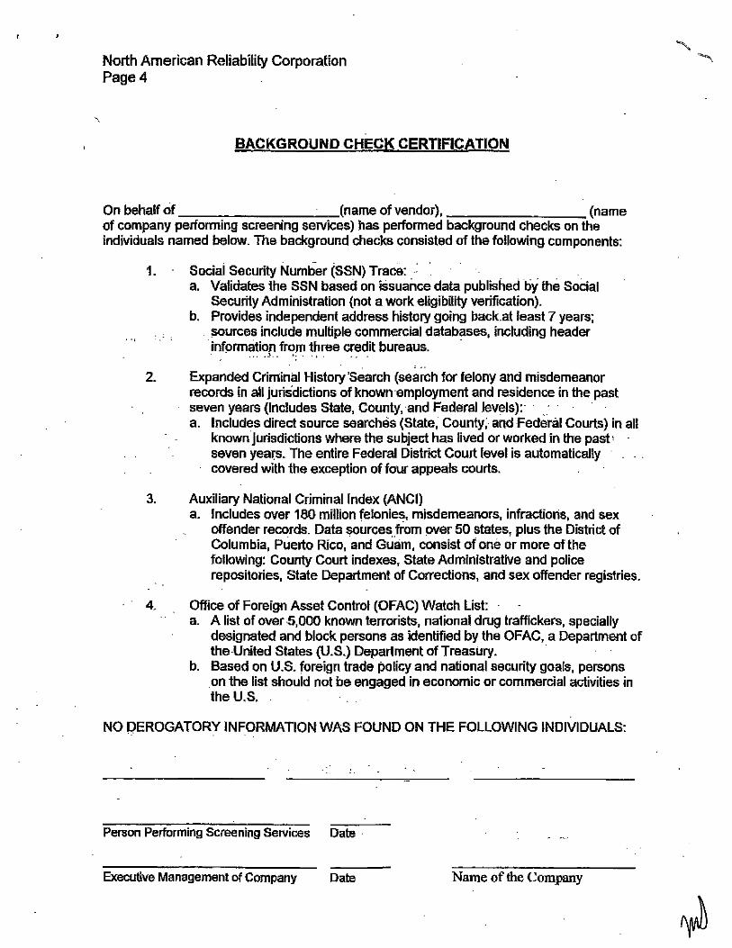
North American Reliability Corporation Page4
BACKGROUND CHECK CERTIFICATION
On behalf of (name of vendor), (name of company performing screening seNices) has performed background checks on the individuals named below. The background checks consisted of the following components:
1. Social Security Number (SSN) Trace: .. a. Validates the SSN based on issuance data published by the Social
Security Administration {not a work eligibility verification). b. Provides independent address history going back.at least 7 years;
~;;ources include multiple commercial databases, including header · informe~ti()rir<!/11 t~ree credit bureaus. ·
2. Expanded Criminal History 'Search (search for felony and misdemeanor records in all jurisdictions of known ·employment and residence in the past seven years (includes State, County, and Federal levels): . a. Includes direct source searches (State, County; and Federal Courts) in all
known jurisdictions where the subject has lived or worked in the past' seven year.~. The entire Federal District Court level is automatically covered with the exception of four appeals courts.
3. Auxiliary National Criminal Index (ANCI) a. Includes over 180 million felonies, misdemeanors, infractions, and sex
offender records. Data sourcesfrom over 50 states, plus the District of Columbia, Puerto Rico, and Guam, consist of one or more of the following: County Court indexes, State Administrative and police repositories, State Department of Corrections, and sex offender registries.
4. Office of Foreign Asset Control (OFAC) Watch List: a. A list of over 5,000 known terrorists, national drug traffickers, specially
designated and block persons as identified by the OFAC, a Department of the -United States (U.S.) Department of Treasury. ·
b. Based on U.S. foreign trade policy and national security goals, persons . on the list should not be engaged in economic or commercial activities in the U.S.
NO DEROGATORY INFORMATION WAS FOUND ON THE FOLLOWING INDIVIDUALS:
Person Performing Screening Services Date ·
Executive Management of Company Date Name of the Company

EXHIBITS
Available Soils Data

EXHIBITS. AVAILABLE SOILS DATA
The following documents constitute the soils reports referenced in Section 3.16 A. (2) of the Agreement.
Also, this ExhibitS references the following documents provided in the RFP 295-10- Haynes Units 5 & 6 Repowering 051310, Appendix M, Exhibit Z:
City of Los Angeles Department of Water and Power
Power System Planning and Projects Business Unit Geology and Soils
HAYNES GENERATING STATION UNITS 5 & 6 REPOWERING PROJECT
GEOTECHNICAL REPORT August2004 Prepared by:
James R. Magula, Civil Engineering Associate and
Jeffrie L. T. Owen, Engineering Geologist 44 Pages
Also, this ExhibitS references the following documents provided in the RFP 295-10- Haynes Units 5 & 6 Repowering 051310, Appendix M, ExhibitS:
City of Los Angeles Department of Water and Power
Power System Planning and Projects Business Unit Geology and Soils
HAYNES GENERATING STATION PROPOSED SWITCHYARD for
SIMPLE CYCLE PROJECT GEOTECHNICAL REPORT
MARCH 2010 Prepared by:
Laura L. Hays, Civil Engineering Associate and
James S. Chestnut, Engineering Geologist Associate 267 pages
AND
City of Los Angeles Department of Water and Power
Engineering Services Division HAYNES GENERATING STATION
COMBINED SIMPLE CYCLE PROJECT PRELIMINARY SOIL INFORMATION
(FOR BID PURPOSES ONLY) FEBRUARY 2010
Prepared by: Laura L. Hays, Civil Engineering Associate
and James S. Chestnut, Engineering Geologist Associate
1188 pages

City of Los Angeles
Department of Water and Power
Engineering Services Division
HAYNES GENERATING STATION
COMBINED SIMPLE CYCLE PROJECT
PRELIMINARY SOIL INFORMATION
(FOR BID PURPOSES ONLY)
FEBRUARY 2010
Prepared by:
Laura L. Hays, Civil Engineering Associate
and
James S. Chestnut, Engineering Geologist Associate
City of Los Angeles
Department of Water and Power
Power System Planning and Projects Business Unit
Geology and Soils
HAYNES GENERATING STATION
PROPOSED SWITCHYARD for SIMPLE CYCLE PROJECT
GEOTECHNICAL REPORT
MARCH 2010
Prepared by:
Laura L. Hays, Civil Engineering Associate
and
James S. Chestnut, Engineering Geologist Associate
City of Los Angeles
Department of Water and Power
Power System Planning and Projects Business Unit
Geology and Soils
HAYNES GENERATING STATION
UNITS 5 & 6 REPOWERING PROJECT
GEOTECHNICAL REPORT
August 2004
Prepared by:
James R. Magula, Civil Engineering Associate
and
Jeffrie L. T. Owen, Engineering Geologist
EXHIBIT T
0 & M Training Programs

EXHIBIT T. 0 & M TRAINING PROGRAMS
Kiewit's' has included a comprehensive plant Operating and Training program which will be structured around the following general curriculum, but will be modified to suit LADWPs' specific needs and subject to LADWPs' final approval:
Overview of Training
1. Engineering Classroom Training (detailed below)
a. Theoretical
b. Plant specific systems and equipment
c. Engineering documentation and tagging
d. Startup/shutdown/operation by system
e. Startup/shutdown/operation for the entire plant
f. HAZID
2. Vendor Classroom/Hands-on
a. Major equipment vendors
3. Startup Training- "On the Job"- Startup
a. System Walkdowns
b. Board Training
Engineering Classroom Training Monitoring and Materials
1. Skill Testing and Monitoring
a. Open book quizzes will be given at the conclusion of the Mechanical, Electrical, I&C, and startup portions of the classroom training and the results will be recorded by student and provided to LADWP.
2. Training Materials
a. A detailed PowerPoint presentation will be used to guide the class in the topics listed below. This will be bound and used as a classroom training aid in addition to a presentation.
• Overview of Power Plant Theory
• Overview of the Haynes 5 & 6 Facility
• Mechanical Theory Training
• Mechanical Engineering Documentation Training
• Electrical Theory Training
• Electrical Engineering Documentation Training
• I&C Theory Training
• I&C Engineering Documentation Training
• HAZID
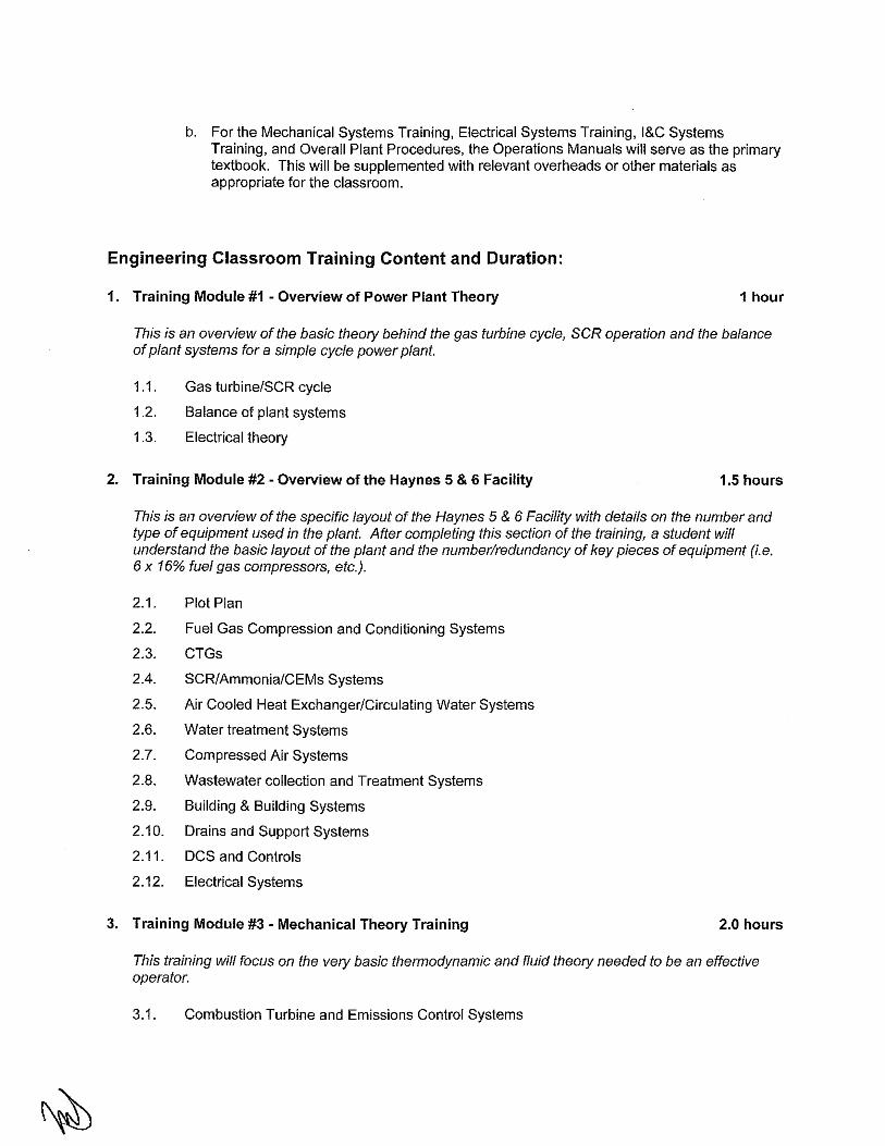
b. For the Mechanical Systems Training, Electrical Systems Training, I&C Systems Training, and Overall Plant Procedures, the Operations Manuals will serve as the primary textbook. This will be supplemented with relevant overheads or other materials as appropriate for the classroom.
Engineering Classroom Training Content and Duration:
1. Training Module #1 -Overview of Power Plant Theory 1 hour
This is an overview of the basic theory behind the gas turbine cycle, SCR operation and the balance of plant systems for a simple cycle power plant.
1.1. Gas turbineiSCR cycle
1.2. Balance of plant systems
1.3. Electrical theory
2. Training Module #2 -Overview of the Haynes 5 & 6 Facility 1.5 hours
This is an overview of the specific layout of the Haynes 5 & 6 Facility with details on the number and type of equipment used in the plant. After completing this section of the training, a student will understand the basic layout of the plant and the number/redundancy of key pieces of equipment (i.e. 6 x 16% fuel gas compressors, etc.).
2.1. Plot Plan
2.2. Fuel Gas Compression and Conditioning Systems
2.3. CTGs
2.4. SCR/Ammonia/CEMs Systems
2.5. Air Cooled Heat Exchanger/Circulating Water Systems
2.6. Water treatment Systems
2.7. Compressed Air Systems
2.8. Wastewater collection and Treatment Systems
2.9. Building & Building Systems
2.1 0. Drains and Support Systems
2.11. DCS and Controls
2.12. Electrical Systems
3. Training Module #3 - Mechanical Theory Training 2.0 hours
This training will focus on the very basic thermodynamic and fluid theory needed to be an effective operator.
3.1. Combustion Turbine and Emissions Control Systems
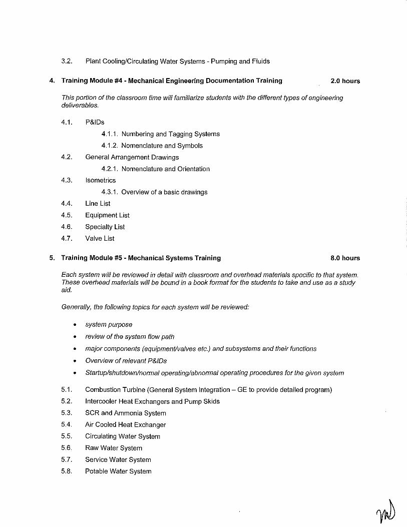
3.2. Plant Cooling/Circulating Water Systems- Pumping and Fluids
4. Training Module #4- Mechanical Engineering Documentation Training 2.0 hours
This portion of the classroom time will familiarize students with the different types of engineering de/iverables.
4.1. P&IDs
4.1.1. Numbering and Tagging Systems
4.1.2. Nomenclature and Symbols
4.2. General Arrangement Drawings
4.2.1. Nomenclature and Orientation
4.3. Isometrics
4.3.1. Overview of a basic drawings
4.4. Line List
4.5. Equipment List
4.6. Specialty List
4.7. Valve List
5. Training Module #5- Mechanical Systems Training 8.0 hours
Each system will be reviewed in detail with classroom and overhead materials specific to that system. These overhead materials will be bound in a book format for the students to take and use as a study aid.
Generally, the following topics for each system will be reviewed:
• • • • •
5.1.
5.2.
5.3.
5.4.
5.5.
5.6.
5.7.
5.8.
system purpose
review of the system flow path
major components (equipment/valves etc.) and subsystems and their functions
Overview of relevant P&!Ds
Startup/shutdown/normal operating/abnormal operating procedures for the given system
Combustion Turbine (General System Integration- GE to provide detailed program)
Intercooler Heat Exchangers and Pump Skids
SCR and Ammonia System
Air Cooled Heat Exchanger
Circulating Water System
Raw Water System
Service Water System
Potable Water System

6.
5.9. Demineralized Water System
5.10. Fire Protection Systems
5.11. Sampling System
5.12. Chemical Feed Systems
5.13. Service and Instrument Air System
5.14. Fuel Gas System
5.15. Ammonia Unloading and Storage
5.16. Waste Water Disposal System
5.17. Continuous Emissions Monitoring System
5.18. Plant Drains
5.19. Water Treatment System
Training Module #6 -Electrical Theory Training 1.0 hour
This training will focus on the vety basics of electrical theoty needed to be an effective control room operator.
6.1. Current, voltage, resistance
6.2. Plant Voltage Levels
6.3. Key equipment: Transformers, Breakers, Contactors
7. Training Module #7- Electrical Engineering Documentation Training 2.0 hours
This portion of the classroom time will familiarize students with the different types of engineering deliverables.
7.1. One Line Diagrams
7.1.1. Numbering and Tagging Systems
7.1.2. Nomenclature and Symbols
7.2. Three Line Diagrams
7.2.1. Nomenclature and Symbols
7.3. Schematics
7.3.1. Nomenclature and Symbols
7.4. Interconnects
7.4.1. Nomenclature and Symbols
7.5. Duct Bank, Conduit, and Tray Drawings
7.6. Cable and Raceway Lists
8. Training Module #8 -Electrical Systems Training 8.0 hours
Each system will be reviewed in detail with classroom and overhead materials specific to that system. These overhead materials will be bound in a book format for the students to take and use as a study aid.

Generally, the following topics for each system will be reviewed:
• system purpose
• review of the electrical flow path
• major components (equipment) and subsystems and their functions
• Overview of relevant One Lines
• Startup/shutdown/normal operating/abnormal operating procedures for the given system
8.1. General Electric Combustion Turbine Generator
8.2. Combustion Turbine Generator Protective Relaying and Metering
8.3. Combustion Turbine 13.8 KV SF6 Generator Breaker
8.4. Combustion Turbine Generator Isolated- Phase Bus Duct
8.5. Combustion Turbine Generator Step Up Transformer
8.6. Relay I Metering Panels
8.7. Unit Auxiliary Station Service Transformers
8.8. 4160 V System
8.9. 480 V, 120/208 V System
8.10. 120 V AC Plant UPS
8.11. 125 V DC Station Battery
8.12. Outdoor Lighting
8.13. SWYD Interface
8.14. Site Security
9. Training Module #9 - I&C Theory Training 1.0 hour
This training will focus on the vety basics of I&C theory and background needed to be an effect control room operator.
9.1. Basic Control Philosophy and Nomenclature
9.2. PID Loops, Tuning, Response
9.3. Critical control loops in the power plant system
9.4. Instrument basics
10. Training Module #10 -I&C Engineering Documentation Training 2.0 hours
This portion of the classroom time will familiarize students with the different types of engineering deliverables.
1 0.1. Control Narratives
1 0.2. Instrument Index
1 0.3. Logic Diagrams

1 0.4. DCS Termination Drawings
1 0.5. Loop Sheets
1 0.6. Instrument Location Plans
10.7. Communications Drawing
1 0.8. Configuration Drawing
11. Training Module #11 • I&C Systems Training 4.0 hours
The DCS system will be reviewed in detail with classroom and overhead materials specific to that system. These overhead materials will be bound in a book format for the students to take and use as a study aid.
Generally, the following topics for each system will be reviewed:
• System purpose
• Major components (equipment) and subsystems and their functions
• Overview of relevant drawings.
• DCS interface with plant PLCs and Mark VIe systems will be reviewed in detail.
11. 1 . Distributed Control System
12. Training Module #12 ·Overall Plant Procedures 8.0 hours
12.1. Startup
12.2. Shutdown
12.3. Normal Operating Scenarios
12.4. Abnormal Operating Scenarios
13. Training Module #13- HAZID 4.0 hours
The HAZID section will focus on the identification of potentially hazardous systems and substances (including stored energy), their location in the plant, and engineered systems to contain, monitor, or alert plant personnel of an event.
13.1. Chemicals and Corrosives
13.2. Thermal Energy
13.3. Electrical Energy
13.4. Flammables
13.5. Explosives and Compressed Gas
13.6. Buildings and Life Safety
13.7. Fire Suppression Systems

EXHIBITU
Intentionally Left Blank

EXHIBITV
Intentionally Left Blank

EXHIBITW
Intentionally Left Blank

EXHIBIT X
Intentionally Left Blank

EXHIBITY
Intentionally Left Blank

EXHIBIT Z
Common Files

EXHIBIT Z. COMMON
This Exhibit Z references the documents provided in the RFP 295-10- Haynes Units 5 & 6 Repowering 051310, Appendix M, Exhibit Z:
Z1 Existing Conditions
Z2 Title 22 Water Quality
Z3 Not Used
Z4 Potable Water Qualitv
Z5 Natural Gas Analysis
Z6 LADWP Site Drawinas L -573 & E-5830-1
LADWP Switchyard Grading Drawings SKETCJ-CA02 & SE-Z7 CAXXX
zs Geotechnical Report
ze Please See Exhibit J
Z10 LADWP Standards
Z11 Noise Studies
Z12 SvnchronizinQ
Z13 Interface with ECC
Z14 Division of Responsibility IDOR)
Z15 Owner's DrawinQs
Z16 Not Used
Z17 Aqueous Ammonia Specification

1 1 u
- -:.::::,.-_
11 \ ,. -·~ .: ... e:~ ....
•
GABRIEL
' ' -.. ~ ~I
"' ' I ' ' I 1 I
I
'
i !
N.E.f
l
T. 5 S.
SEC . 2
---- -~--~--- ------·;---·- -;r.r.TC.!J"'f•
I
S.E.:f SEC. 2
CO/IN T Y
SOUTH. CAL . [ OlSON CO PA RCEl ~
~ _ _ _L _ ____________ _ _ ____ ~ _______ _ r _________ --+---··----~-----------------------
~ CA LIFO R NI A EOISON
! ~ SOUTHER N CO MPANY A L AMITO S
' I 4, PAR C(L I A $ . 16 I 9 1
I N. E. ~ SE C. 2 S. E.tSEC. 2
~-~ RANCHO f LOS
PAT 1 / 4 60•462 O.M. 7 0 0/138-141
-- __)_ ______ , ____ ._ - -----' - '~---
(} !S TRIC T R/ W RIVER
I 1-----.....__
STEAM STATION SITE
~LI J 1 . . j -.... , .... ,,.,
ALAMITO S
"
1 <; •• -~ -
... :::: - - -?~ •. ~ -~ ..... .'-" ... .• \
_,r,u:; _s;-~ ... <1 ., · --~
TOWEr« 2 ~~ TO HAY~l f. S ";TEAM PL AU T RA CK ~l" t,J.III /.I,U -; I' 1(, llt\~ l l l "i ~ f• ( ',f f. I Al•l~li -II ;WIIf.~}
SE C. 12

,.,.,_,
"' ;·~ \.'.1
i' I
·' j: "C'-' <tOO
( IJ,
'!
., i
SO. CAL. i:!b/::..{'/J Cll.
I ! ............. ., ..
':;:~• ~~. ""'t;,f{""" c~
;I '"I ~~ .~]
~I
s··] ' I
PLAN/"
'8
J 1
M/NIMIJM ;;-:~';;k" N PiP.=
'I ·:[ '""'"·"·•"'·"
·- --~-"'~'·"""""""'~"'=~~ i . · " I • , . .,. """"" """' ""'"
~~E:z;:iji~:=~~:~_E~~~··r~~,~~=::t'"=·
"ri

J
H
G
F
D
c
8
A
II II II
I
"I ~
. 5400
s. 293.3.50 E. 5354 . .30 8.00 F.G.
J
~I
SWITCHYARD ROUGH GRADING LIMITS
7.90 T.G.
~-5 . .3108.~ E. 5.354 . .30 -............. 10.00 F.G.
PROPOSED CONCRETE CURB AND GUTTER SEE DETAIL HEREON
DRAWING DATE:
~I
s. 3282.50 E. 5.354 • .30 9.00 F.G.
~I
20 10 0 20 s . .3.356.50 E. 5354 • .30 9.80 F.G. SCALE: 1" = 20'
LEGEND, s.
'· F.G,
'· T.G.
-10.50-
-120)-
SOUTH
EAST
FINISHED GRADE RADIUS
TOP OF GRATE
PROPOSED CONTOUR
EXISTING CONTOUR
PROPOSED CURB AND GUTTER BY LAOWP CATCH BASIN BY EPC CONTRACTOR
PROPOSED CONCRETE CURB AND GUTTER
SWITCHYARD ROUGH GRADING PLAN HAYNES GENERATING STATION
THIS DRAWING
6801 WESTMINSTER AVENUE, LONG BEACH
POWER SYSTEM
DEPARTMENT OF WATER AND POWER CITY OF LOS ANGELES SKETCH-CA02

"I " "
£_54(J()
J
H £_ 5350
G
F
E. 5250
£.5100
D
£.5150
c
£_ 5100
B
A
E. 5050
E. 5349.63 BACK OF CURB
10.43 ~
!1.34 ~
~I ~I "I ~I :I ~I
I I I I I
PROPOSED CONCRETE CURB AND GUTTER SEE DETAIL HEREON
s. 3100.93 £, 5185.69 11.50 F.G.
"I ~
s •
"
"·"---------
---z
LEGEND' S. SOUTH
E. EAST
F.G. F.L. R. T.G.
FINISHED GRADE FLOW LINE RADIUS
-10.50-
TOP OF GRATE
PROPOSED SUBGRAOE CONTOUR
PROPOSED SUBGRAOE SPOT ELEVATION
PROPOSED CURB ANO GUTTER SEE SE -CAXXX FOR DEl AILS
S • 1.139:!. PROPOSED CURB ANO GUTTER FLOW LINE SLOPE
--x-- PROPOSED CHAIN LINK FENCE SEE SE-CAXXX FOR DETAIL
CATCH BASIN BY CONTRACTOR
NOTES, ALL CONTOUR LINES ARE SUBGRAOE.
ALL CATCH BASINS TO BE INSTALLED BY CONTRACTOR
INTERIOR SPOT ELEVATIONS ARE SUBGRAOE. UNLESS OTHERWISE SPECIFIED.
SEE SE -CAXXX FOR GENERAL NOTES AND SECTIONS. DATUM= NAVD 88 COORDINATES: STATtON COORDINATES
SWITCHYARD GRADING PLAN HAYNES GENERATING STATION 6801 WESTMINSTER AVENUE, LONG
POWER SYSTEM
DEPARTMENT OF WATER AND POWER CITY OF LOS ANGELES
BEACH
SE-CAXXX