
Warner Bros. and the History of Hollywood in the Video Game ...
Upload
khangminh22Category
view
0download
0
Wrap spring
Clutches & Brakes
Federbandkupplungen
und Bremsen
WARNER ELECTRICWARNER ELECTRIC

Wrap Spring Clutches and Brakes
Introduction
The wrap Spring Clutches and Brakes offered by WARNERELECTRIC are designed and developped using state of the arttechnology. Conceptual analysis is performed using 3-D solids-based engineering software.
Our Quality Management System has been aligned to meetthe requirements of ISO-9001. This international recognitionof the quality system is of extreme importance in our pursuit oftotal customer satisfaction.
GB
www.warnerelectric-eu.com - Fax +33 (0)2 41 21 24 70
Einführung
Die von WARNER ELECTRIC vertriebenenFederbandkupplungen und -Bremsenwerden mit der neuesten Technologie, wiez. B. 3D-Software entwickelt.
Kundenzufriedenheit ist unser oberstesZiel. Daher ist die Zertifikation nachISO 9001 nicht nur ein Schlagwort, son-dern stellt durchgängig ein Qualitäts-sicherungssystem dar, das bei derEntwicklung beginnt und sich fortsetzt beider Fertigung bis hin zum Vertrieb und zumService.
D
Special Designs
Even with a wide range of catalog modifications,WARNER ELECTRIC recognizes that standard prod-ucts may not meet your requirements. Our engineerswill work with you in developing a special adaptation:use of special materials, special hubs, shafts, shaftextensions, bore size, manufacture special matingparts... or an entirely new design.
GB
Spezialanfertigungen
Wir hoffen natürlich, dass Sie in diesem umfangrei-chen Standardprogramm die Lösung für Ihren Anwen-dungsfall gefunden haben. Sollte dies nicht der Fall sein,fragen Sie uns ! Die Ingenieure von WARNER ELEC-TRIC entwickeln maßgeschneiderte Lösungen ent-sprechend Kundenwunsch und Anwendungsfall:Besondere Werkstoffe, spezielle Naben oder Wellenmit Ihrem Wunschdurchmesser, usw. !
D

3
Federbandkupplungen und Bremsen
www.warnerelectric-eu.com - Fax +33 (0)2 41 21 24 70
Contents Inhalt
Selection by motion type 4-7 Modellwahl nach Bewegungsart
Performance Features 8-9 Leistungsmerkmale
Basic Principles of Wrap Spring Clutches 10-11 Das Prinzip der Federbandkupplung
Applications 12-13 Anwendungen
PSI Series 14-17 Baureihe PSI
Standard CB Series 18-26 Baureihe Standard CB
Super CB Series 27-32 Baureihe Super CB
All CB Series: options 33-34 Alle Baureihen CB: Extras
All CB Series: Mounting Requirements 35 Alle Baureihen CB: Montagehinweise
SAC Series 36-40 Baureihe SAC
SP Series 41-42 Baureihe SP
BIMAC Series 43-44 Baureihe BIMAC
DL Series 45-47 Baureihe DL
MAC Series 48-52 Baureihe MAC
BBC Series 53-54 Baureihe BBC
BDNB Series 55-56 Baureihe BDNB
BDSC Series 57-58 Baureihe BDSC
CTS Series 59-60 Baureihe CTS
ACCM Series 61-62 Baureihe ACCM
ACCE Series 63-64 Baureihe ACCE
Heavy Duty Actuator 65 Verstärkte Klinde
Selection and Calculations 66-68 Auswahl und Berechnungen
Terms 69 Begriffe
Application Data Sheet 70 Anwendungs-Datenblatt
4
Selection by motion type / Modellwahl nach Bewegungsart
www.warnerelectric-eu.com - Fax +33 (0)2 41 21 24 70
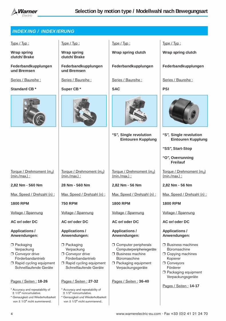
INDEXING / INDEXIERUNG
Type / Typ :
Wrap springclutch/Brake
Federbandkupplungenund Bremsen
Series / Baureihe :
Standard CB *
Torque / Drehmoment (md)(min./max.) :
2,82 Nm - 560 Nm
Max. Speed / Drehzahl (n) :
1800 RPM
Voltage / Spannung
AC or/oder DC
Applications /Anwendungen:
❒ PackagingVerpackung
❒ Conveyor driveFörderbandantrieb
❒ Rapid cycling equipmentSchnelllaufende Geräte
Pages / Seiten : 18-26
* Accuracy and repeatability of± 1/2° noncumulative.
* Genauigkeit und Wiederholbarkeitvon ± 1/2° nicht summierend.
Type / Typ :
Wrap springclutch/Brake
Federbandkupplungenund Bremsen
Series / Baureihe :
Super CB *
Torque / Drehmoment (md)(min./max.) :
28 Nm - 560 Nm
Max. Speed / Drehzahl (n) :
750 RPM
Voltage / Spannung
AC or/oder DC
Applications /Anwendungen:
❒ PackagingVerpackung
❒ Conveyor driveFörderbandantrieb
❒ Rapid cycling equipmentSchnelllaufende Geräte
Pages / Seiten : 27-32
* Accuracy and repeatability of± 1/2° noncumulative.
* Genauigkeit und Wiederholbarkeitvon ± 1/2° nicht summierend..
Type / Typ :
Wrap spring clutch
Federbandkupplungen
Series / Baureihe :
SAC
“S”, Single revolutionEintouren Kupplung
Torque / Drehmoment (md)(min./max.) :
2,82 Nm - 56 Nm
Max. Speed / Drehzahl (n) :
1800 RPM
Voltage / Spannung
AC or/oder DC
Applications /Anwendungen:
❒ Computer peripheralsComputerperipheriegeräte
❒ Business machineBüromaschine
❒ Packaging equipmentVerpackungsgeräte
Pages / Seiten : 36-40
Type / Typ :
Wrap spring clutch
Federbandkupplungen
Series / Baureihe :
PSI
“S”, Single revolutionEintouren Kupplung
“SS”, Start-Stop
“O”, OverrunningFreilauf
Torque / Drehmoment (md)(min./max.) :
2,82 Nm - 56 Nm
Max. Speed / Drehzahl (n) :
1800 RPM
Voltage / Spannung
AC or/oder DC
Applications /Anwendungen:
❒ Business machinesBüromaschine
❒ Copying machinesKopierer
❒ ConveyorsFörderer
❒ Packaging equipmentVerpackungsgeräte
Pages / Seiten : 14-17
5
Selection by motion type / Modellwahl nach Bewegungsart
www.warnerelectric-eu.com - Fax +33 (0)2 41 21 24 70
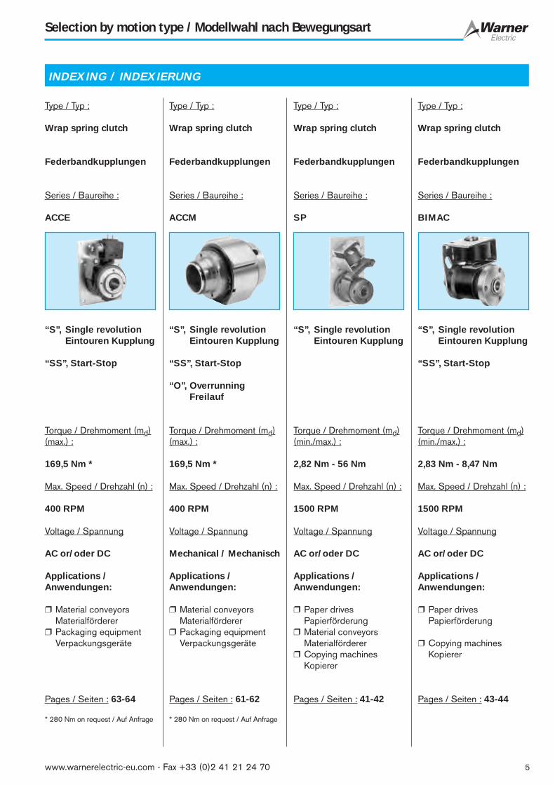
INDEXING / INDEXIERUNG
Type / Typ :
Wrap spring clutch
Federbandkupplungen
Series / Baureihe :
ACCE
“S”, Single revolutionEintouren Kupplung
“SS”, Start-Stop
Torque / Drehmoment (md)(max.) :
169,5 Nm *
Max. Speed / Drehzahl (n) :
400 RPM
Voltage / Spannung
AC or/oder DC
Applications /Anwendungen:
❒ Material conveyorsMaterialförderer
❒ Packaging equipmentVerpackungsgeräte
Pages / Seiten : 63-64
* 280 Nm on request / Auf Anfrage
Type / Typ :
Wrap spring clutch
Federbandkupplungen
Series / Baureihe :
ACCM
“S”, Single revolutionEintouren Kupplung
“SS”, Start-Stop
“O”, OverrunningFreilauf
Torque / Drehmoment (md)(max.) :
169,5 Nm *
Max. Speed / Drehzahl (n) :
400 RPM
Voltage / Spannung
Mechanical / Mechanisch
Applications /Anwendungen:
❒ Material conveyorsMaterialförderer
❒ Packaging equipmentVerpackungsgeräte
Pages / Seiten : 61-62
* 280 Nm on request / Auf Anfrage
Type / Typ :
Wrap spring clutch
Federbandkupplungen
Series / Baureihe :
SP
“S”, Single revolutionEintouren Kupplung
Torque / Drehmoment (md)(min./max.) :
2,82 Nm - 56 Nm
Max. Speed / Drehzahl (n) :
1500 RPM
Voltage / Spannung
AC or/oder DC
Applications /Anwendungen:
❒ Paper drivesPapierförderung
❒ Material conveyorsMaterialförderer
❒ Copying machinesKopierer
Pages / Seiten : 41-42
Type / Typ :
Wrap spring clutch
Federbandkupplungen
Series / Baureihe :
BIMAC
“S”, Single revolutionEintouren Kupplung
“SS”, Start-Stop
Torque / Drehmoment (md)(min./max.) :
2,83 Nm - 8,47 Nm
Max. Speed / Drehzahl (n) :
1500 RPM
Voltage / Spannung
AC or/oder DC
Applications /Anwendungen:
❒ Paper drivesPapierförderung
❒ Copying machinesKopierer
Pages / Seiten : 43-44

6
Selection by motion type / Modellwahl nach Bewegungsart
www.warnerelectric-eu.com - Fax +33 (0)2 41 21 24 70
STARTING / STARTEN
Type / Typ :
Wrap spring clutch
Federbandkupplungen
Series / Baureihe :
DL
“S”, Single revolutionEintouren Kupplung
Torque / Drehmoment (md)(min./max.) :
2,82 Nm - 3,4 Nm
Max. Speed / Drehzahl (n) :
1200 RPM
Voltage / Spannung
DC
Applications /Anwendungen:
❒ Forms handling equipmentFormenbearbeitungsgeräte
❒ Film processing machinesFilmentwicklungsgeräte
❒ PrintersDrucker
Pages / Seiten : 45-47
Type / Typ :
Wrap spring clutch
Federbandkupplungen
Series / Baureihe :
MAC-45
“S”, Single revolutionEintouren Kupplung
Torque / Drehmoment (md)(max.) :
16 Nm
Max. Speed / Drehzahl (n) :
1000 RPM
Voltage / Spannung
DC
Applications /Anwendungen:
❒ Forms handling equipmentFormenbearbeitungsgeräte
❒ Film processing machinesFilmentwicklungsgeräte
❒ PrintersDrucker
Pages / Seiten : 48-52
Type / Typ :
Wrap spring clutch
Federbandkupplungen
Series / Baureihe :
BBC-29
“S”, Single revolutionEintouren Kupplung
Torque / Drehmoment (md)(max.) :
2,82 Nm
Max. Speed / Drehzahl (n) :
1800 RPM
Voltage / Spannung
DC
Applications /Anwendungen:
❒ Forms handling equipmentFormenbearbeitungsgeräte
❒ Automatic bank tellersBankautomaten
❒ Feed rollers for paper, film…Zuführwalzen für Papier, Folien usw.
Pages / Seiten : 53-54
Type / Typ :
Wrap spring clutch
Federbandkupplungen
Series / Baureihe :
BDNB
Torque / Drehmoment (md)(max.) :
28 Nm
Max. Speed / Drehzahl (n) :
200 RPM
Voltage / Spannung
Mechanical / Mechanisch
Applications /Anwendungen:
❒ Tank turret drivesPanzer-Revolverkopfantriebe
❒ Boat or aircraft trim tabsTrimmbleche für Boote oder Flugzeuge
❒ ManliftPersonenhebanlagen
Pages / Seiten : 55-56
HOLDING / HALTERUNG

7
Selection by motion type / Modellwahl nach Bewegungsart
www.warnerelectric-eu.com - Fax +33 (0)2 41 21 24 70
SLIPPING / GLEITEN
Type / Typ :
Wrap spring clutch
Federbandkupplungen
Series / Baureihe :
BDCS
Torque / Drehmoment (md)(max.) :
0,14 Nm
Max. Speed at max. torqueMax.Drehzahl bei max.Drehmoment (n) :
200 RPM
Voltage / Spannung
Mechanical / Mechanisch
Applications /Anwendungen:
❒ Conveyor drive systems for poly film bag manufacturing
❒ Förderbandantriebe für die Plastiktüten-Herstellung
❒ Ribbon windingBandaufwicklung
❒ Paper feedPapierbeförderung
Pages / Seiten : 57-58
Type / Typ :
Wrap spring clutch
Federbandkupplungen
Series / Baureihe :
CTS
Torque / Drehmoment (md)(min./max.) :
1,58 Nm - 3,16 Nm
Max. Speed at max. torqueMax.Drehzahl bei max.Drehmoment (n) :
150 RPM
Voltage / Spannung
Mechanical / Mechanisch
Applications /Anwendungen:
❒ Cable winding equipmentKabelaufwicklungen
❒ Gear boxesGetriebe
❒ Servo systemsServosysteme
Pages / Seiten : 59-60
Powdered Metal Technology
The powdered metal technology has been used forclutches and brakes for over 20 years. This materialmade of porous metal with oil impregnated doesnot require lubrication under normal operatingconditions. Through extensive research we can offeroptions for different oil grades.
GB
Sintermetall -Technologie
Die Sintermetalltechnik wird schon seit mehr als 20Jahren für Kupplungen und Bremsen verwendet.Das Material aus in Öl getränktem porösem Metallmuss bei normalen Einsatzbedingungen nichtgeschmiert werden.
D

8
Performance Features
❒ Accurate Positionioning
❒ High Torque to
Size Ratio
❒ No Slip
❒ Simple Control
❒ Easy to install
❒ Maintenance free
❒ Long Life
❒ Low cost
High Torque to Size Ratio
Wrap Spring Clutch/Brakes offer dramatic advantages intorque to size ratios as compared to other torque transmittingdevises. The torque capacity of a wrap spring clutch is deter-mined by the cross sectional strength of the spring. A torquerating of 560 Nm results from a clutch with a diameter of125 mm only.
GB D
Höchstes Drehmoment beikleinster Abmessung
Federbandkupplungen übertragen ein sehr hohes Drehmomentim Vergleich zur Größe und verglichen mit anderen Kupplungen.Das übertragbare Drehmoment wird bestimmt vom Querschnittder Feder. Ein Drehmoment von 560 Nm kann von einerKupplung mit einem Durchmesser von nur 125 mmübertragen werden.
Ø [mm]125
100
64
38
3225
5602805628143
GB D
Torque / Drehmoment [Nm]
❒ Genaues Positionieren
❒ Hohes Drehmoment bei
kleinster Abmessung
❒ Kein Durchrutschen
❒ Einfache Steuerung
❒ Problemloser Einbau
❒ Wartungsfrei
❒ Lange Lebensdauer
❒ Kostengünstig
www.warnerelectric-eu.com - Fax +33 (0)2 41 21 24 70
9
Leistungsmerkmale
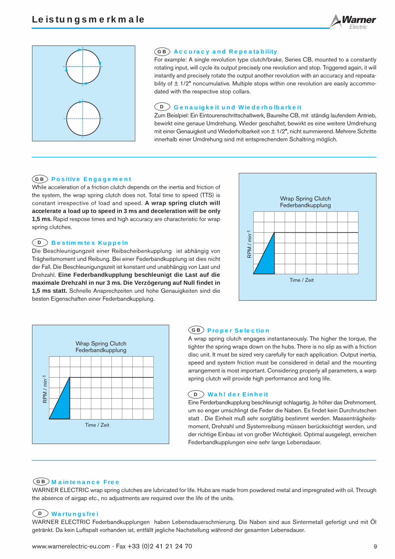
Accuracy and RepeatabilityFor example: A single revolution type clutch/brake, Series CB, mounted to a constantlyrotating input, will cycle its output precisely one revolution and stop. Triggered again, it willinstantly and precisely rotate the output another revolution with an accuracy and repeata-bility of ± 1/2° noncumulative. Multiple stops within one revolution are easily accommo-dated with the respective stop collars.
Genauigkeit und WiederholbarkeitZum Beislpiel: Ein Eintourenschrittschaltwerk, Baureihe CB, mit ständig laufendem Antrieb,bewirkt eine genaue Umdrehung. Wieder geschaltet, bewirkt es eine weitere Umdrehungmit einer Genauigkeit und Wiederholbarkeit von ± 1/2°, nicht summierend. Mehrere Schritteinnerhalb einer Umdrehung sind mit entsprechendem Schaltring möglich.
GB
D
Positive EngagementWhile acceleration of a friction clutch depends on the inertia and friction ofthe system, the wrap spring clutch does not. Total time to speed (TTS) isconstant irrespective of load and speed. A wrap spring clutch willaccelerate a load up to speed in 3 ms and deceleration will be only1,5 ms. Rapid respose times and high accuracy are characteristic for wrapspring clutches.
Bestimmtes KuppelnDie Beschleunigungzeit einer Reibscheibenkupplung ist abhängig vonTrägheitsmoment und Reibung. Bei einer Federbandkupplung ist dies nichtder Fall. Die Beschleunigungszeit ist konstant und unabhängig von Last undDrehzahl. Eine Federbandkupplung beschleunigt die Last auf diemaximale Drehzahl in nur 3 ms. Die Verzögerung auf Null findet in1,5 ms statt. Schnelle Ansprechzeiten und hohe Genauigkeiten sind diebesten Eigenschaften einer Federbandkupplung.
Proper SelectionA wrap spring clutch engages instantaneously. The higher the torque, thetighter the spring wraps down on the hubs. There is no slip as with a frictiondisc unit. It must be sized very carefully for each application. Output inertia,speed and system friction must be considered in detail and the mountingarrangement is most important. Considering properly all parameters, a warpspring clutch will provide high performance and long life.
Wahl der EinheitEine Ferderbandkupplung beschleunigt schlagartig. Je höher das Drehmoment,um so enger umschlingt die Feder die Naben. Es findet kein Durchrutschenstatt . Die Einheit muß sehr sorgfältig bestimmt werden. Massenträgheits-moment, Drehzahl und Systemreibung müssen berücksichtigt werden, undder richtige Einbau ist von großer Wichtigkeit. Optimal ausgelegt, erreichenFederbandkupplungen eine sehr lange Lebensdauer.
Maintenance FreeWARNER ELECTRIC wrap spring clutches are lubricated for life. Hubs are made from powdered metal and impregnated with oil. Throughthe absence of airgap etc., no adjustments are required over the life of the units.
WartungsfreiWARNER ELECTRIC Federbandkupplungen haben Lebensdauerschmierung. Die Naben sind aus Sintermetall gefertigt und mit Ölgetränkt. Da kein Luftspalt vorhanden ist, entfällt jegliche Nachstellung während der gesamten Lebensdauer.
GB
D
GB
D
GB
D
RP
M /
min
-1
Wrap Spring ClutchFederbandkupplung
Time / Zeit
RP
M /
min
-1
Wrap Spring ClutchFederbandkupplung
Time / Zeit
www.warnerelectric-eu.com - Fax +33 (0)2 41 21 24 70

10
The Principle of Wrap Spring Clutches
The basic wrap spring clutch consists of onlythree parts; an input hub, an output hub and a springwhose I.D. is slightly smaller than the O.D. of thehubs. With the spring mounted across the two hubs,rotation in the direction of the arrows wraps downthe spring onto the hubs, transmitting torque from theinput to the output hub.
Der Grundaufbau der Federbandkupplungbesteht aus nur drei Teilen: Antriebsnabe,Abtriebsnabe und Feder, deren Innendurchmessergeringfügig kleiner ist als der Nabendurchmesser. DieFeder umschlingt die beiden Naben und überträgt dasDrehmoment von der Antriebsnabe auf dieAbtriebsnabe.
Freewheeling clutch Model OIn its basic form, the wrap spring clutch is an overrunning clutch.Depending on the application, it can be used for freewheeling orbackstopping
Freilauf Modell OIn der Grundform ist die Federbandkupplung ein Freilauf. Je nachAnwendung kann sie auch als Überholkupplung oder alsRücklaufsperre verwendet werden.
Model SSUses the principle of the Model O plus a control tang to obtain aclutching function. When the tang is held, preventing it from grip-ping the input hub, the output hub is disconnected from the drive.The output can continue rotating in the normal drive direction(overrun).
Modell SSWie Modell O, jedoch wird dieses zur Schaltkupplung, wenn derFederanfang an der Antriebsseite als Schaltfinger abgewinkeltwird. Wird dieser Finger festgehalten, so öffnet sich die Feder aufder Antriebsseite und der Abtrieb läuf in Antriebsrichtung aus.
Model SUses the principle of the Model SS plus an additional tang at theopposite end of the spring. This tang at the output end providesan angular reference to the input tang and a braking function. Thisbraking torque capacity is approximately 20 % of the clutch torque.
Modell SWie Modell SS, jedoch ist zusätzlich das Federende auf derAbtriebsseite ebenfalls zu einem Schaltfinger abgewinkelt. DieserFinger übernimmt eine Bremsfunktion. Das Bremsmoment beträgt20 % des Kupplungsmomentes.
GB
D
GB
D
Control tangSchaltfinger
InputAntrieb
Output hubAbtriebsnabe
Wrap springFederband
OutputAbtrieb
Input hubAntriebsnabe
InputAntrieb
OutputAbtrieb
Control tangSchaltfinger
InputAntrieb
OutputAbtrieb
GB
D
GB
D
www.warnerelectric-eu.com - Fax +33 (0)2 41 21 24 70

Clutch/Brake Combination (CB)
The clutch/brake combination utilizes an input-, output- and brake hubas well as a clutch- and brake spring, each with its own controltangs, connected to a single control collar and the output hub.
Releasing the control collar, the brake spring opens, the clutchspring winds down transmitting torque from the input- to theoutput hub.
Stopping the control collar causes the brake spring tang to lock. Thebrake spring winds down fixing the output hub to the stationarybrake hub. At the same time, the clutch spring opens, causing theinput hub to idle. Positioning accuracy is ± 1/2°, noncumulative.
Kupplungs-Bremskombination (CB)
Die Kupplungs-Bremskombiation setzt sich zusammen aus Antriebs-,Abtriebs- und Bremsnabe sowie je einer Kupplungs- und Bremsfeder,jede mit eigenen Schaltfingern, verbunden mit dem Schaltring undder Abtriebsnabe.
Wird der Schaltring freigegeben, öffnet sich die Bremsfeder, dieKupplungsfeder schließt und überträgt ein Drehmoment auf dieAbtriebsnabe.
Wird der Schaltring angehalten, schließt die Bremsfeder und verbindetdie Abtriebsnabe mit der stationären Bremsnabe. Gleichzeitig öffnetsich die Kupplungsfeder und die Antriebsnabe läuft frei. DieHaltegenauigkeit beträgt ± 1/2° und ist nicht summierend.
11
Das Prinzip der Federbandkupplung
GB D
Controlling Wrap Spring Clutches
PSI Series PSI series clutches are controlled by externalmeans, most often supplied by the customer. Thisis achieved mechanically, electrically, pneumati-cally, etc.
CB Series CB’s are controlled by an integral actuation system.However as a clutch/brake, for fast cycling, veryshort response may be required. To achieve thespecified performance, modifications may benecessary such as overexitation, strongersolenoids and stronger return springs. WarnerElectric should be consulted.
SAC Series Solenoid actuated wrap spring clutches.Conveniently packaged clutch is pre-engineeredand pre-assembled for easy installation. Singlestop per revolution standard, multiple stops avail-able.
Das Schaltprinzip der Ferderbandkupplung
Baureihe PSI Die Baureihe PSI wird hauptsächlich von außengeschaltet und zwar in den meisten Fällen me-chanisch, elektrisch oder pneumatisch.
Baureihe CB Die Baureihe CB ist ein Kupplungs-Brems-Schaltwerk, das für schnelles Schalten bei kurzenAnsprechzeiten verwendet wird. Modifikationenmit stärkerem Hubmagnet, stärkerer Rückstellfedersowie Übererregung sind möglich.
Baureihe SAC Die Baureihe SAC ist eine Federbandkupplung,die über einen Hubmagneten betätigt wird. DieseKupplung ist werksseitig vormontiert und dahereinfach einzubauen.
GB D
Output shaftAbtriebswelle
Output hubAbtriebsnabe
Output shaftAbtriebswelle
Stationary brake hub Stationäre Bremsnabe
Brake control tangSchaltfinger, Bremse
Clutch control tangSchaltfinger, Kupplung
Input hubAntriebsnabe
Brake springBremsfeder
Clutch springKupplungsfeder
www.warnerelectric-eu.com - Fax +33 (0)2 41 21 24 70

Applications
Feed and Cut-Off
This is a typical example showing the application of a number ofWarner products on one machine. In the manufacture of polyethyl-ene bags, sheets for heat shrink packaging, etc., the material iscoming off a roll, treated and cut off.
GB Vorschub und Schneiden
Diese Anwendung ist ein typisches Beispiel, wo verschiedene Warner-Produkte auf derselben Maschine zum Einsatz kommen. Hier läuftPolyethylenefolie von einer Rolle und wird zu Taschen, Schrumpfmaterialfür Verpackungen, etc. verarbeitet und geschnitten.
D
Velocity of material: 30 m/min.
1. A tension control sytem is installed to maintain tension on the film.
2. The MAC-45 is defined as follows: 2 Steel shafts Ø 20 mm x 450 mm2 Rubber rollers Ø 50 mm x 400 mm2 Gears Ø 53 mm x 12 mmTotal inertia, one of each 0,0006 kgm2
Speed at Ø 50 mm and 30 m/min.191 rpm
Calculation: 0.0006 x 1919,55 x 0.003
= 4,0 Nm x 2 = 8.0 Nm
Added friction torque + 4,0 NmTotal clutch torque 12,0 Nm
3. For the rotary cut-off knife we use a CB Series clutch/brake with one stop for a single revolution, as follows:2 Steel shafts Ø 20 mm x 450 mm2 Aluminum drums / Knife Ø 80 mm x 400 mm2 Gears Ø 83 mm x 15 mmTotal inertia, one of each 0.005 kgm2
Speed at 80 mm and 30 m/min. 119,4 rpm
Calculation: 0,005 x 119,49,55 x 0,0015
= 41,7 Nm x 2 = 83,4 Nm
Deduct system friction – 6,0 NmTotal brake torque (MB) 77,4 Nm
Selection: CB-7 (add torque resulting from clutchinertia to verify. Check min. inertia required, see page 68).
For selection and calculations, please see pages 66-68
Materialgeschwindigkeit: 30 m/min.
1. Eine Bahnspannungseinheit ist eingebaut, damit das Materialgespannt bleibt.
2. Die MAC-45 wird wie folgt festgelegt: 2 Stahlwellen Ø 20 mm x 450 mm2 Gummirollen Ø 50 mm x 400 mm2 Zahnräder Ø 53 mm x 12 mmMassenträgheitsmoment, je 1 Stk. 0,0006 kgm2
Drehzahl bei Ø 50 mm und 30 m/min. 191 min-1
Berechnung: 0.0006 x 1919,55 x 0.003
= 4,0 Nm x 2 = 8.0 Nm
Zusätzliches Reibmoment + 4,0 NmGesamtes Kupplungsdrehmoment 12,0 Nm
3. Für die Messerwalze wird ein CB-Schrittschaltwerk mit einem Anschlag für eine Umdrehung eingesetzt:2 Stahlwellen Ø 20 mm x 450 mm2 Aluminiumwalzen / Messer Ø 80 mm x 400 mm2 Zahnräder Ø 83 mm x 15 mmMassenträgheitsmoment, je 1 Stk. 0.005 kgm2
Drehzahl bei 80 mm und 30 m/min. 119,4 min-1
Berechnung 0,005 x 119,49,55 x 0,0015
= 41,7 Nm x 2 = 83,4 Nm
Abzüglich Systemreibung – 6,0 NmGesamtes Bremsmoment (MB) 77,4 Nm
Gewählte Einheit: CB-7 (Drehmoment, resultierendaus Trägheitsmoment der Kupplung, berücksichtigen. Minimalbenötigtes Trägheitsmoment kontrollieren, siehe Seite 68).Auswahl und Berechnungen siehe Seite 66-68
1. TCS2. MAC-45
3. CB-7Prime moverHauptantrieb
Photo electric systemSensor
Cutt off bladeMesserwalze
12 www.warnerelectric-eu.com - Fax +33 (0)2 41 21 24 70

Applications
13www.warnerelectric-eu.com - Fax +33 (0)2 41 21 24 70
Punching, Riveting, Stapling
Crank type, single revolution applications are numerous. Generally,one stop is used and, if possible, the stopping point is selected justpast top dead center to take advantage of the mass. One only pulseto the solenoid initiates a complete cycle.Depending on the opera-tion, accuracy and brake torque, a CB-Series can be used.
Stanzen, Nieten, Heften
Kurbeltriebanwendungen sind sehr vielfältig, ein typisches Einsatz-gebiet für die Eintouren-Schrittschaltwerke von WARNER.Normalerweise wird mit einem Anschlag gearbeitet und, wennmöglich, der Schaltpunkt immer kurz nach dem oberen Totpunktgewählt. Ein einfacher Stromimpuls auf den Hubmagneten genügt,um einen Zyklus auszulösen. Je nach Anforderung, Genauigkeit undBremsmoment kann die Baureihe CB eingesetzt werden.
GB
D
Accurate Indexing and Positioning
Indexing and positioning are outstanding features of the CB Series.An accuracy and repeatability of ± 1/2°, noncumulative, can beachieved with a simple pulse to the solenoid. This application utilizesa worm wheel drive with a ratio of 16 : 1. A one-revolution CBclutch/ brake advances the index plate by one station.Connecting a feed screw with a star wheel, as used for filling oper-ations in the pharma industry, allows for stopping and starting of thefeed screw without loosing synchronization with the star wheel.
Genaues Positionieren
Sehr genaues Positionieren ist eine Stärke der Baureihe CB. EineGenauigkeit und Wiederholbarkeit von ± 1/2°, nicht summierend, wirderreicht. Bei nebenstehendem Beispiel treibt ein CB-Eintouren-Schrittschaltwerk ein Schneckengetriebe an (Übersetzung 16 : 1)und positioniert die Drehscheibe nach genau einer Umdrehung.An Abfüllmaschinen, wie eingesetzt in der Pharmaindustrie, sorgt einCB-Schrittschaltwerk für die Synchronisation der Zuführspindel mitdem Sternrad.
Backstopping and Overrunning
As shown on this inclining conveyor, simple PSI Series units can beused very effectively as backstops and overrunning clutches. Fixedto the machine frame, using a control tang, they can be used as astopping brake. Permanentely lubricated powder metal hubs ensuremaintenace free operation and long life.
Rücklaufsperre und Freilauf
Die Baureihe PSI kann als Rücklaufsperre oder Freilauf eingesetztwerden. Wird die Nabe am Maschinenrahmen befestigt und dieFeder mit einem Schaltfinger (Modell S oder SS) versehen, kann dieEinheit auch als Bremse oder schaltbarer Mitnehmer eingesetzt wer-den. Sintermetallnaben, getränkt mit Öl, gewährleisten eine langeLebensdauer ohne Wartung.
GB
D
GB
D

PSI Series
The PSI series is the basic wrap spring clutch. Input rotationcan be applied either through the free hub (1) ot the shaft assem-bly (2).
Like all wrap spring products, no adjustments or maintenance isrequired, only installation onto the desired shaft and to provide a meansof mechanically stopping the control collar (5) is required.
The control tang (4) is fixed into the control collar (5) and therebythe spring is either allowed to couple or to release the input from theoutput.
The PSI series is supplied in 3 configurations designated models “O”,“SS” and “S” to give the functions required to suit the specific appli-cation.
Model “O”, Overrunning - Uses include: one-way clutch,anti-backup or anti-over run devices. It consists of items 1, 2 and 3plus a cover over the spring.
Torque will be transmitted in only one direction while a minimumdrag torque will result when rotated in the opposite sense.
Model “SS”, Start-Stop - Provides torque transmission tothe load upon demand and decouples the load when the control col-lar (5) is restrained.
The load can still be moved, if required, in the normal forward direc-tion.
As with most wrap spring products the load cannot be moved in theopposite direction.The model “SS” consists of items 1, 2, 3, 4 and 5.
Model “S”, Single revolution - For stopping as well asstarting the load thus allowing for single revolution applicationswhere positional requirements exist.
Stopping position accuracies of ±4°, noncumulative, can be expected.The braking capacity is limited to 20 % of the clutch rated torque.
The model “S” consists of items 1 through 8.
GB Die Baureihe PSI ist die Grundausführung derFederbandeinheiten. Der Antrieb erfolgt entweder durch die freie Nabe(1) oder die Baugruppe Welle (2).
Wie bei allen Federbandeinheiten ist keine Einstellung oder Wartungerforderlich. Die Einheit wird auf die gewünschte Welle montiertund ein mechanischer Anschlag für den Schaltring (5) vorgesehen.
Der Schaltfinger (4) liegt im Schaltring (5). Durch Betätigen desSchaltfingers kann der Antrieb mit dem Abtrieb verbunden oder vondiesem getrennt werden..
Die Baureihe PSI wird als Modell “O”, ”SS” und “S” geliefert, um diegewünschte Funktion für die Anwendung zu erreichen.
Modell “O” Freilauf - verwendet als Freilaufkupplung,Rücklaufsperre oder Vorlaufsperre, bestehend aus den Teilen 1, 2und 3 sowie einer Abdeckung über der Feder.
Das Drehmoment wird nur in einer Richtung übertragen. Ein kleinesRestdrehmoment ist vorhanden, wenn in Gegenrichtung (Freilauf)gedreht wird.
Modell “SS” Start-Stop - überträgt ein Drehmoment undtrennt den Antrieb vom Abtrieb, wenn der Schaltring (5) gehalten wird.
Der Abtrieb läuft in der Antriebsdrehrichtung aus.
Bei den meisten Federbandeinheiten darf jedoch die Last nicht inGegenrichtung gedreht werden.Das Modell “SS” besteht aus den Teilen 1, 2, 3, 4 und 5.
Modell “S” Eintouren Kluppung - Zum Kuppeln undBremsen einer Last, um eine Umdrehung oder Teile einer Umdrehungauszuführen.
Die Haltegenauigkeit beträgt ±4°, nicht summierend. Die Brems-wirkung ist auf 20 % des Kupplungsnennmomentes begrenzt.
Das Modell “S” besteht aus den Teilen 1 bis 8.
D
14 www.warnerelectric-eu.com - Fax +33 (0)2 41 21 24 70

Baureihe PSI
15www.warnerelectric-eu.com - Fax +33 (0)2 41 21 24 70
Control tangSchaltfinger
InputAntrieb
OutputAbtrieb
InputAntrieb
OutputAbtrieb
Control tangSchaltfinger
InputAntrieb
OutputAbtrieb
Output tangAbtriebsfederende
Model “O” Model “SS” Model “S”Modell “O” Modell “SS” Modell “S”
Overrunning Start/Stop (Random Positioning) Single RevolutionFreilauf Ein/Aus (Zufallsposition) Eine bzw. Teil-Umdrehung
1Free HubFreie Nabe
2Shaft assemblyBaugruppe Welle
3SpringFeder
4Control tangSchaltfinger
5Control collarSchaltring
6Output tangAbtriebsfederende
7Overtravel pinÜberlaufstift
8Overtravel stop collarHaltering
Important Designations
HI Hub Input (Free Hub)
SI Shaft Input
CW Clockwise Rotation
CCW Counter-clockwise Rotation
OTS Overtravel Stop
Wichtige Bezeichnungen
HI Nabenantrieb (Freie Nabe)
SI Wellenantrieb
CW Rechtsdrehung
CCW Linksdrehung
OTS Überlaufanschlag
GB D
15 3
2
4 78 6
Model / Modell “S”, OTS
Typical Applications
❒ Business machines❒ Copying machines❒ Conveyors❒ Packaging equipment
Typische Anwendungen
❒ Büromaschines❒ Kopierer❒ Förderer❒ Verpackungsgeräte
GB D

PSI Series
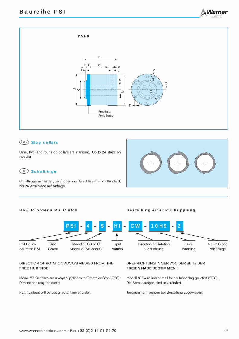
Terms: see page 69 * Only Model “S” ** Keyway BS 4235, DIN 6885 ***Consult Warner ElectricBegriffe: siehe Seite 69 Nur Modell “S” Paßfeder Warner Electric anfragen
DEH F GK
LJ
MAB C B
Free hubFreie Nabe
N
DE
HF G
KL
J M
A
B C B
Free hubFreie Nabe
P
O
N
PSI-2, PSI-4, PSI-5 PSI-6
16 www.warnerelectric-eu.com - Fax +33 (0)2 41 21 24 70
0 0 0 0 0
SizePSI-2 PSI-4 PSI-5 PSI-6 PSI-8***
Größe
MdRated torque
[Nm] 2,82 13,5 28 56 280Nenndrehmoment
MrDrag torque, clutch
[Nm] 2,3 • 10-2 4,5 • 10-2 5,6 • 10-2 6,8 • 10-2 14,7 • 10-2
Schleppmoment, Kupplung
nmaxMax. speed
[min-1] 1800 1200 750 500 300Max. Drehzahl
Jc HIInertia
[kgm2] 2,4 • 10-8 6,9 • 10-6 2,07 • 10-5 2,19 • 10-4 3,573Massenträgheitsmoment
FrMax. radial load
[N] 30 60 140 280 640Max. Radial Belastung
mWeight
[kg] 0,06 0,1 0,3 1,2 3,7Masse
øA [mm] 6H9 10H9 12H9 20H9** 35H9**øB [mm] 23,9 31,8 39,6 63,5 101,6øC [mm] 22,26+0,03 28,61+0,03 38,15+0,03 39,6+0,07 60,25+0,05
D [mm] 31,8 35,05 47,6 79,4 108Emin [mm] 7,1 5,8 10 15,2 –
F [mm]4,4* 4,8*2,4 2,2 4,0 20,0 11,0
Gmin [mm] 12 17 19 30 56H [mm] 8,4 8,9 8,6 6,4 8,6J [mm] 6,4 6,4 6,4 3,1 4,8
K [mm]4,1* 2,9* 4,8* 6,35* 15,75*4,1 4,1 5,6 6,35 15,75
L [mm] 2 x M3 x 120°1 x M4 1 x M5 1 x M5
2 x M10, 90°1 x ø4 1 x ø5 1 x ø5
Mrad [mm] 1,8 1,6 2,9 6,3 3,2N [mm] 14,6 18,3 24,4 38,1 50,8øO [mm] – – – 52,4 85,7P [mm] – – – 3 x M6 6 x M8Q** [mm] – – – 6-JS9 10-JS9
Baureihe PSI
17www.warnerelectric-eu.com - Fax +33 (0)2 41 21 24 70
Stop collars
One-, two- and four stop collars are standard. Up to 24 stops onrequest.
GB
Schaltringe
Schaltringe mit einem, zwei oder vier Anschlägen sind Standard,bis 24 Anschläge auf Anfrage.
D
How to order a PSI Clutch Bestellung einer PSI Kupplung
PSI 10H9– 4 – S – HI – CW – – 2
PSI-Series Size Model S, SS or O Input Direction of Rotation Bore No. of StopsBaureihe PSI Größe Modell S, SS oder O Antrieb Drehrichtung Bohrung Anschläge
DIRECTION OF ROTATION ALWAYS VIEWED FROM THEFREE HUB SIDE !
Model “S” Clutches are always supplied with Overtravel Stop (OTS).Dimensions stay the same.
Part numbers will be assigned at time of order.
DREHRICHTUNG IMMER VON DER SEITE DERFREIEN NABE BESTIMMEN !
Modell “S” wird immer mit Überlaufanschlag geliefert (OTS).Die Abmessungen sind unverändert.
Teilenummern werden bei Bestellung zugewiesen.
D
H F GKLJ M
A
B C
B
Free hubFreie Nabe
P
O
N
Q
PSI-8

Standard CB Series Clutch/Brakes
The Cycling Clutch “par excellence”
WARNER CB Series Clutch/Brake units are outstanding in their ownrespect. They start and stop loads, driven by a continously rotatingpower source, at amazing speeds at an accuracy of ± 1/2°,noncumulative. Cycle rates of up to 20 per second are possible.Nominal acceleration to full speed is only 3 ms, decceleration is but1,5 ms, independent of the load. Simple of design, they are easy toinstall. Mounted on the output shaft, with a restraint against rotation,the input is always through the free hub. Only a short electrical pulse(DC or AC) to the solenoid is required to trigger a cycle.
Available in 7 sizes
❒ Seven models cover torque capacities from 3 Nm to560 Nm and speeds up to 1800 RPM
❒ During the brake cycle, the load is locked in position by the brakespring and an additional anti-back spring
❒ The addition of an anti-overrun spring prevents the output fromoverrunning the input, as may be the case in a crank typeapplication
❒ Adjustable control collars allow for easy setting of output stopposition
❒ 1, 2 and 4 stop collars are standard. Multiple stop collars, up to24 stops, are optional
❒ Maintenance free, lubricated for life, hubs are inpregnated withoil. Never needs adjustments
Das Schrittschaltwerk “par excellence”
Die WARNER Schrittschaltwerke der Baureihe CB sind Weltklasse.Mit einem kontinuierlich laufenden Antrieb beschleunigen und brem-sen sie eine Last mit erstaunlicher Geschwindigkeit und einerGenauigkeit von ± 1/2°, nicht summierend. Schalthäufigkeiten bis20 pro Sekunde sind möglich. Die Beschleunigungszeit beträgt nur3 ms, die Bremszeit nur 1,5 ms, unabhängig von der Last. Einfachin der Konstruktion, sind die Einheiten sehr einfach zu montieren. Aufder Abtriebswelle montiert, gegen Verdrehung gesichert, geht derAntrieb immer über die freie Nabe (4). Ein kurzer Stromimpuls genügt(Gleich- oder Wechselstrom), um eine Schaltung auszulösen.
Erhältlich in 7 Größen
❒ Sieben Modelle mit Drehmomenten von 3 Nm bis 560 Nm undDrehzahlen bis 1800 min-1
❒ In gebremstem Zustand wird die Last von der Bremsfeder und einerzusätzlichen Rücklaufsperre in Position gehalten
❒ Eine Vorlaufsperre verhindert, daß der Abtrieb den Antrieb über-holt, wie zum Beispiel bei einem Kurbeltrieb
❒ Ein einstellbarer Schaltring erlaubt das genaue Einstellen desHaltepunktes
❒ Standardmäßig mit 1 Anschlag bzw. 2 und 4 Anschlägen liefer-bar, auf Anfrage bis 24 Anschläge
❒ Die Einheiten sind wartungsfrei. Die Sintermetallnaben sind mitÖl getränkt. Ein Nachstellen ist nicht erforderlich
GB D
1SolenoidHubmagnet
24 VDC Std.
2ActuatorSperrklinke
3Control collarSchaltring
4Input Hub (Free Hub)Antriebsnabe (Freie Nabe)
5Mounting plate Montageplatte
18 www.warnerelectric-eu.com - Fax +33 (0)2 41 21 24 70
1
2
3
4
5
Typical Applications
❒ Packaging❒ Conveyor drive❒ Rapid cycling equipment
Typische Anwendungen
❒ Verpackung❒ Förderbandantrieb❒ Schnelllaufende Geräte
GB D

Baureihe Standard CB Schrittschaltwerke
19www.warnerelectric-eu.com - Fax +33 (0)2 41 21 24 70
Brake hubBremsnabe
Clutch springKupplungsfeder
Retaining ringSicherungsring
Control tang(Brake)Schaltfinger(Bremse)
Output hubAbtriebsnabe Anti-backup spring
Rücklaufsperre
Output shaftAbtriebswelle
Anti-overrun springVorlaufsperre
Control tang(Clutch)Schaltfinger(Kupplung)
Input hubAntriebsnabe
Control collarSchaltring
Mounting plateMontageplatte
Brake springBremsfeder
Component partsGB
EinzelteileD
1Retaining ringSicherungsring
2Input hubAntriebsnabe
3Control collarSchaltring
4Clutch springKupplungsfeder
5Anti-overrun springVorlaufsperre
6Output shaftAbtriebswelle
7Anti-back springRücklaufsperre
8Brake springBremsfeder
9Brake hubBremsnabe
10Mounting plateMontageplatte
11ActuatorSperrklinke
12ScrewSchrauben
13CoilSpule
14ScrewSchrauben
16ShimScheibe
17SpacerZwischenstück
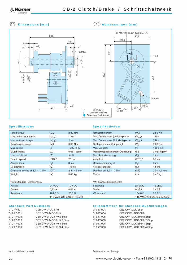
CB-2 Clutch/Brake / Schrittschaltwerk
Standard Part Numbers Teilenummern für Standard-Ausführungen
Specifications Spezifikationen
312-17-001 CB2-CW-24DC-6H9312-27-001 CB2-CCW-24DC-6H9312-17-002 CB2-CW-24DC-6H9-2 Stop312-27-002 CB2-CCW-24DC-6H9-2 Stop312-17-003 CB2-CW-24DC-6H9-4 Stop312-27-003 CB2-CCW-24DC-6H9-4 Stop
Inch models on request
312-17-004 CB2-CW-12DC-6H9312-27-004 CB2-CCW-12DC-6H9312-17-005 CB2-CW-12DC-6H9-2 Stop312-27-005 CB2-CCW-12DC-6H9-2 Stop312-17-006 CB2-CW-12DC-6H9-4 Stop312-27-006 CB2-CCW-12DC-6H9-4 Stop
Zolleinheiten auf Anfrage
25,4
50,8
25,4
86,
0
TypeModell
C-6
5 x 9,5
12,0
49,
5
2018,0
3 x M4, 120, on/auf 23,8 B.C./T.K.63,5
5,3
2,3
10,4
4,1
5,1Max.
30,
2
43,02,3
9,53
+0
–0,0
3
1,5
+0,
07–0
,01
1,5
+0,
07–0
,01
6H9
15,9
Fr
Dimensions [mm]GB Abmessungen [mm]D
Rated torque (Md) 2,82 Nm Nenndrehmoment (Md) 2,82 Nm
Max. anti-overrun torque (Maor) 1 Nm Max. Drehmoment (Vorlaufsperre) (Maor) 1 Nm
Max. anti-back torque (Matb) 2 Nm Max. Drehmoment (Rücklaufsperre) (Matb) 2 Nm
Drag torque, clutch (Mr) 0,03 Nm Schleppmoment (Kupplung) (Mr) 0,03 Nm
Max. speed (n) 1800 RPM Max. Drehzahl (n) 1800 min-1
Clutch inertia (Jc) 0,061 kgcm2 Massenträgheitsmoment (Kupplung) (Jc) 0,061 kgcm2
Max. radial load (Fr) 34 N Max. Radialbelastung (Fr) 34 N
Time to speed (TTS) * 20 ms Anlaufzeit (TTS) * 20 ms
Acceleration (ta) 3 ms Beschleunigungszeit (ta) 3 ms
Decelaration (td) 1,5 ms Verzögerungszeit (td) 1,5 ms
Overtravel setting at 1,2 - 1,7 Nm (OT) 2,3 - 4,9 mm Überlauf bei 1,2 - 1,7 Nm (OT) 2,3 - 4,9 mm
Weight (m) 0,46 kg Masse (m) 0,46 kg
*with Standard Components *Mit Standardkomponenten
Voltage 24 VDC 12 VDC Spannung 24 VDC 12 VDC
Current 0,23 A 0,46 A Strom 0,23 A 0,46 A
Resistance 104,0 Ω 26,0 Ω Widerstand 104,0 Ω 26,0 Ω115 VAC, 230 VAC on request 115 VAC, 230 VAC auf Anfrage
CCW/LinksDirection as shown
Angezeigte Drehrichtung
20 www.warnerelectric-eu.com - Fax +33 (0)2 41 21 24 70

CB-4 Clutch/Brake / Schrittschaltwerk
21www.warnerelectric-eu.com - Fax +33 (0)2 41 21 24 70
Standard Part Numbers Teilenummern für Standard-Ausführungen
Specifications Spezifikationen
314-17-001 CB4-CW-24DC-10H9314-27-001 CB4-CCW-24DC-10H9314-17-002 CB4-CW-24DC-10H9-2 Stop314-27-002 CB4-CCW-24DC-10H9-2 Stop314-17-003 CB4-CW-24DC-10H9-4 Stop314-27-003 CB4-CCW-24DC-10H9-4 Stop
Inch models on request
314-17-004 CB4-CW-12DC-10H9314-27-004 CB4-CCW-12DC-10H9314-17-005 CB4-CW-12DC-10H9-2 Stop314-27-005 CB4-CCW-12DC-10H9-2 Stop314-17-006 CB4-CW-12DC-10H9-4 Stop314-27-006 CB4-CCW-12DC-10H9-4 Stop
Zolleinheiten auf Anfrage
20,56,6 x 12,7
Type C-8Modell
60,5
30,2
49,5
3,8
8,4
85,8
2,321,1
0,9 (Max.)3,6
M4 x 5,0
16,4
25,4
65,0
104,
0
30
10H
9
31,7
5+
0–0
,05
3,0
+0,
08
–0,0
3
12,7
31,8
3 x M4, 120, on/auf 23,8 B.C./T.K.
3,0
+0,
08
–0,0
3
Fr
Dimensions [mm]GB Abmessungen [mm]D
CW/RechtsDirection as shown
Angezeigte Drehrichtung
Rated torque (Md) 13,5 Nm Nenndrehmoment (Md) 13,5 Nm
Max. anti-overrun torque (Maor) 2,82 Nm Max. Drehmoment (Vorlaufsperre) (Maor) 2,82 Nm
Max. anti-back torque (Matb) 9 Nm Max. Drehmoment (Rücklaufsperre) (Matb) 9 Nm
Drag torque, clutch (Mr) 0,08 Nm Schleppmoment (Kupplung) (Mr) 0,08 Nm
Max. speed (n) 1200 RPM Max. Drehzahl (n) 1200 min-1
Clutch inertia (Jc) 0,187 kgcm2 Massenträgheitsmoment (Kupplung) (Jc) 0,187 kgcm2
Max. radial load (Fr) 62 N Max. Radialbelastung (Fr) 62 N
Time to speed (TTS) * 24 ms Anlaufzeit (TTS) * 24 ms
Acceleration (ta) 3 ms Beschleunigungszeit (ta) 3 ms
Decelaration (td) 1,5 ms Verzögerungszeit (td) 1,5 ms
Overtravel setting at 2,3 - 4,5 Nm (OT) 4,8 - 6,3 mm Überlauf bei 2,3 - 4,5 Nm (OT) 4,8 - 6,3 mm
Weight (m) 0,91 kg Masse (m) 0,91 kg
*with Standard Components *Mit Standardkomponenten
Voltage 24 VDC 12 VDC Spannung 24 VDC 12 VDC
Current 0,325 A 0,732 A Strom 0,325 A 0,732 A
Resistance 74,0 Ω 16,4 Ω Widerstand 74,0 Ω 16,4 Ω115 VAC, 230 VAC on request 115 VAC, 230 VAC auf Anfrage

CB-5 Clutch/Brake / Schrittschaltwerk
Standard Part Numbers Teilenummern für Standard-Ausführungen
Specifications Spezifikationen
315-17-001 CB5-CW-24DC-12H9315-27-001 CB5-CCW-24DC-12H9315-17-002 CB5-CW-24DC-12H9-2 Stop315-27-002 CB5-CCW-24DC-12H9-2 Stop315-17-003 CB5-CW-24DC-12H9-4 Stop315-27-003 CB5-CCW-24DC-12H9-4 Stop
Inch models on request
315-17-004 CB5-CW-12DC-12H9315-27-004 CB5-CCW-12DC-12H9315-17-005 CB5-CW-12DC-12H9-2 Stop315-27-005 CB5-CCW-12DC-12H9-2 Stop315-17-006 CB5-CW-12DC-12H9-4 Stop315-27-006 CB5-CCW-12DC-12H9-4 Stop
Zolleinheiten auf Anfrage
6,6 x 12,7
33,266,6
2023,1
115,
8
63,5
33,2
TypeModell
C-8
3 x M5, 120, on/auf 31,76 B.C./T.K.111,1
11,7
6,4
27,7
2,34,8
55,4
22,4
1,1 Max.
3,0+0,08–0,03
39,
69
+0
–0,0
4
15,9
12H
9
39,
6
3,0+0,08–0,03
Fr
Dimensions [mm]GB Abmessungen [mm]D
Rated torque (Md) 28 Nm Nenndrehmoment (Md) 28 Nm
Max. anti-overrun torque (Maor) 5 Nm Max. Drehmoment (Vorlaufsperre) (Maor) 5 Nm
Max. anti-back torque (Matb) 18 Nm Max. Drehmoment (Rücklaufsperre) (Matb) 18 Nm
Drag torque, clutch (Mr) 0,11 Nm Schleppmoment (Kupplung) (Mr) 0,11 Nm
Max. speed (n) 750 RPM Max. Drehzahl (n) 750 min-1
Clutch inertia (Jc) 0,6 kgcm2 Massenträgheitsmoment (Kupplung) (Jc) 0,6 kgcm2
Max. radial load (Fr) 142 N Max. Radialbelastung (Fr) 142 N
Time to speed (TTS) * 27 ms Anlaufzeit (TTS) * 27 ms
Acceleration (ta) 3 ms Beschleunigungszeit (ta) 3 ms
Decelaration (td) 1,5 ms Verzögerungszeit (td) 1,5 ms
Overtravel setting at 4,5 - 6,8 Nm (OT) 3,8 - 6,3 mm Überlauf bei 4,5 - 6,8 Nm (OT) 3,8 - 6,3 mm
Weight (m) 1,4 kg Masse (m) 1,4 kg
*with Standard Components *Mit Standardkomponenten
Voltage 24 VDC 12 VDC Spannung 24 VDC 12 VDC
Current 0,325 A 0,732 A Strom 0,325 A 0,732 A
Resistance 74,0 Ω 16,4 Ω Widerstand 74,0 Ω 16,4 Ω115 VAC, 230 VAC on request 115 VAC, 230 VAC auf Anfrage
CCW/LinksDirection as shown
Angezeigte Drehrichtung
22 www.warnerelectric-eu.com - Fax +33 (0)2 41 21 24 70

CB-6 Clutch/Brake / Schrittschaltwerk
23www.warnerelectric-eu.com - Fax +33 (0)2 41 21 24 70
Standard Part Numbers Teilenummern für Standard-Ausführungen
Specifications Spezifikationen
316-17-001 CB6-CW-24DC-20H9316-17-002 CB6-CW-24DC-25H9316-27-001 CB6-CCW-24DC-20H9316-27-002 CB6-CCW-24DC-25H9-316-17-003 CB6-CW-24DC-20H9-2 Stop316-17-004 CB6-CW-24DC-25H9-2 Stop316-27-003 CB6-CCW-24DC-20H9-2 Stop316-27-004 CB6-CCW-24DC-25H9-2 Stop316-17-005 CB6-CW-24DC-20H9-4 Stop316-17-006 CB6-CW-24DC-25H9-4 Stop316-27-005 CB6-CCW-24DC-20H9-4 Stop316-27-006 CB6-CCW-24DC-25H9-4 StopInch models on request
316-17-007 CB6-CW-12DC-20H9316-17-008 CB6-CW-12DC-25H9316-27-007 CB6-CCW-12DC-20H9316-27-008 CB6-CCW-12DC-25H9316-17-009 CB6-CW-12DC-20H9-2 Stop316-17-010 CB6-CW-12DC-25H9-2 Stop316-27-009 CB6-CCW-12DC-20H9-2 Stop316-27-010 CB6-CCW-12DC-25H9-2 Stop316-17-011 CB6-CW-12DC-20H9-4 Stop316-17-012 CB6-CW-12DC-25H9-4 Stop316-27-011 CB6-CCW-12DC-20H9-4 Stop316-27-012 CB6-CCW-12DC-25H9-4 StopZolleinheiten auf Anfrage
+
+ +
146,
0
35,054,0
108,0
9,8 x 20,3
54,
0
74,2
20
Without keywayOhne Passfedernut
DIN6885
Keyway toPaßfedernut nach
109,5
3,2
5,6
9,1
4,85,6
31,7
5
39,
67+
0–0
,07
3 x M5, 120, on/auf 52,37 B.C./T.K.
76,2
63,5
13,40,25
20H9
25H9, ø4,75Hole both endsBohrung beide Enden
56,6
2 x M5 (20H9)
Fr
Bot
h en
dsB
eide
End
en
Dimensions [mm]GB Abmessungen [mm]D
Rated torque (Md) 56 Nm Nenndrehmoment (Md) 56 Nm
Max. anti-overrun torque (Maor) 34 Nm Max. Drehmoment (Vorlaufsperre) (Maor) 34 Nm
Max. anti-back torque (Matb) 34 Nm Max. Drehmoment (Rücklaufsperre) (Matb) 34 Nm
Drag torque, clutch (Mr) 0,3 Nm Schleppmoment (Kupplung) (Mr) 0,3 Nm
Max. speed (n) 500 RPM Max. Drehzahl (n) 500 min-1
Clutch inertia (Jc) 5,1 kgcm2 Massenträgheitsmoment (Kupplung) (Jc) 5,1 kgcm2
Max. radial load (Fr) 280 N Max. Radialbelastung (Fr) 280 N
Time to speed (TTS) * 45 ms Anlaufzeit (TTS) * 45 ms
Acceleration (ta) 3 ms Beschleunigungszeit (ta) 3 ms
Decelaration (td) 1,5 ms Verzögerungszeit (td) 1,5 ms
Overtravel setting at 8,2 - 16 Nm (OT) 4,8 - 9,6 mm Überlauf bei 8,2 - 16 Nm (OT) 4,8 - 9,6 mm
Weight (m) 3,2 kg Masse (m) 3,2 kg
*with Standard Components *Mit Standardkomponenten
Voltage 24 VDC 12 VDC Spannung 24 VDC 12 VDC
Current 0,586 A 1,15 A Strom 0,586 A 1,15 A
Resistance 41,0 Ω 10,4 Ω Widerstand 41,0 Ω 10,4 Ω115 VAC, 230 VAC on request 115 VAC, 230 VAC auf Anfrage
CW/RechtsDirection as shown
Angezeigte Drehrichtung

CB-7 Clutch/Brake / Schrittschaltwerk
Standard Part Numbers Teilenummern für Standard-Ausführungen
Specifications Spezifikationen
317-17-002 CB7-CW-24DC-30H9317-17-003 CB7-CW-24DC-35H9317-27-002 CB7-CCW-24DC-30H9317-27-003 CB7-CCW-24DC-35H9317-17-005 CB7-CW-24DC-30H9-2 Stop317-17-006 CB7-CW-24DC-35H9-2 Stop317-27-005 CB7-CCW-24DC-30H9-2 Stop317-27-006 CB7-CCW-24DC-35H9-2 Stop317-17-008 CB7-CW-24DC-30H9-4 Stop317-17-009 CB7-CW-24DC-35H9-4 Stop317-27-008 CB7-CCW-24DC-30H9-4 Stop317-27-009 CB7-CCW-24DC-35H9-4 StopInch models on request
317-17-011 CB7-CW-12DC-30H9317-17-012 CB7-CW-12DC-35H9317-27-011 CB7-CCW-12DC-30H9317-27-012 CB7-CCW-12DC-35H9317-17-014 CB7-CW-12DC-30H9-2 Stop317-17-015 CB7-CW-12DC-35H9-2 Stop317-27-014 CB7-CCW-12DC-30H9-2 Stop317-27-015 CB7-CCW-12DC-35H9-2 Stop317-17-017 CB7-CW-12DC-30H9-4 Stop317-17-018 CB7-CW-12DC-35H9-4 Stop317-27-017 CB7-CCW-12DC-30H9-4 Stop317-27-018 CB7-CCW-12DC-35H9-4 StopZolleinheiten auf Anfrage
Fr
M5Both endsBeide Enden
60,
25+
0–0
,10
101,
6
6 x M8, 60 on/auf 85,7 B.C./T.K.
Bot
h en
dsB
eide
End
en
124,5
22,6
9,6
6,4Both endsBeide Enden 7,12
58,6
10,2
6,4
49,
2
127,0
178,
030
45,7
63,5
63,5
79,230H9
35H9
9,8 x 20,3
DIN6885
Keyway toPaßfedernut nach
DIN6885
Keyway toPaßfedernut nach
Dimensions [mm]GB Abmessungen [mm]D
Rated torque (Md) 170 Nm Nenndrehmoment (Md) 170 Nm
Max. anti-overrun torque (Maor) 68 Nm Max. Drehmoment (Vorlaufsperre) (Maor) 68 Nm
Max. anti-back torque (Matb) 68 Nm Max. Drehmoment (Rücklaufsperre) (Matb) 68 Nm
Drag torque, clutch (Mr) 0,8 Nm Schleppmoment (Kupplung) (Mr) 0,8 Nm
Max. speed (n) 400 RPM Max. Drehzahl (n) 400 min-1
Clutch inertia (Jc) 20,0 kgcm2 Massenträgheitsmoment (Kupplung) (Jc) 20,0 kgcm2
Max. radial load (Fr) 1350 N Max. Radialbelastung (Fr) 1350 N
Time to speed (TTS) * 50 ms Anlaufzeit (TTS) * 50 ms
Acceleration (ta) 3 ms Beschleunigungszeit (ta) 3 ms
Decelaration (td) 1,5 ms Verzögerungszeit (td) 1,5 ms
Overtravel setting at 28 - 54 Nm (OT) 9,6 - 12,7 mm Überlauf bei 28 - 54 Nm (OT) 9,6 - 12,7 mm
Weight (m) 5,5 kg Masse (m) 5,5 kg
*with Standard Components *Mit Standardkomponenten
Voltage 24 VDC 12 VDC Spannung 24 VDC 12 VDC
Current 0,586 A 1,15 A Strom 0,586 A 1,15 A
Resistance 41,0 Ω 10,4 Ω Widerstand 41,0 Ω 10,4 Ω115 VAC, 230 VAC on request 115 VAC, 230 VAC auf Anfrage
CW/RechtsDirection as shown
Angezeigte Drehrichtung
24 www.warnerelectric-eu.com - Fax +33 (0)2 41 21 24 70

CB-8 Clutch/Brake / Schrittschaltwerk
25www.warnerelectric-eu.com - Fax +33 (0)2 41 21 24 70
Standard Part Numbers Teilenummern für Standard-Ausführungen
Specifications Spezifikationen
318-17-001 CB8-CW-24DC-35H9318-17-002 CB8-CW-24DC-40H9318-27-001 CB8-CCW-24DC-35H9318-27-002 CB8-CCW-24DC-40H9-318-17-003 CB8-CW-24DC-35H9-2 Stop318-17-004 CB8-CW-24DC-40H9-2 Stop318-27-003 CB8-CCW-24DC-35H9-2 Stop318-27-004 CB8-CCW-24DC-40H9-2 Stop318-17-005 CB8-CW-24DC-35H9-4 Stop318-17-006 CB8-CW-24DC-40H9-4 Stop318-27-005 CB8-CCW-24DC-35H9-4 Stop318-27-006 CB8-CCW-24DC-40H9-4 StopInch models on request
318-17-007 CB8-CW-12DC-35H9318-17-008 CB8-CW-12DC-40H9318-27-007 CB8-CCW-12DC-35H9318-27-008 CB8-CCW-12DC-40H9-318-17-009 CB8-CW-12DC-35H9-2 Stop318-17-010 CB8-CW-12DC-40H9-2 Stop318-27-009 CB8-CCW-12DC-35H9-2 Stop318-27-010 CB8-CCW-12DC-40H9-2 Stop318-17-011 CB8-CW-12DC-35H9-4 Stop318-17-012 CB8-CW-12DC-40H9-4 Stop318-27-011 CB8-CCW-12DC-35H9-4 Stop318-27-012 CB8-CCW-12DC-40H9-4 StopZolleinheiten auf Anfrage
101,
6
+ +
155,6
10,26,44,8
49,
2
M6Both EndsBeide Enden
+
++
+
++
9,8 x 20,3
178,
0
127,0
63,5
63,5
79,2
45,7
6 x M8, 60, on/auf 85,7 B.C./T.K.
60,
3+
0–0
,05
17,710,8
0,25
6,4Both EndsBeide Enden
58,6
35H9
40H9
30
Fr
Bot
h en
dsB
eide
End
en
Without keywayOhne Passfedernut
DIN6885
Keyway toPaßfedernut nach
Dimensions [mm]GB Abmessungen [mm]D
Rated torque (Md) 280 Nm Nenndrehmoment (Md) 280 Nm
Max. anti-overrun torque (Maor) 68 Nm Max. Drehmoment (Vorlaufsperre) (Maor) 68 Nm
Max. anti-back torque (Matb) 68 Nm Max. Drehmoment (Rücklaufsperre) (Matb) 68 Nm
Drag torque, clutch (Mr) 1 Nm Schleppmoment (Kupplung) (Mr) 1 Nm
Max. speed (n) 300 RPM Max. Drehzahl (n) 300 min-1
Clutch inertia (Jc) 38,0 kgcm2 Massenträgheitsmoment (Kupplung) (Jc) 38,0 kgcm2
Max. radial load (Fr) 1335 N Max. Radialbelastung (Fr) 1335 N
Time to speed (TTS) * 50 ms Anlaufzeit (TTS) * 50 ms
Acceleration (ta) 3 ms Beschleunigungszeit (ta) 3 ms
Decelaration (td) 1,5 ms Verzögerungszeit (td) 1,5 ms
Overtravel setting at 28 - 54 Nm (OT) 9,6 - 12,7 mm Überlauf bei 28 - 54 Nm (OT) 9,6 - 12,7 mm
Weight (m) 6,85 kg Masse (m) 6,85 kg
*with Standard Components *Mit Standardkomponenten
Voltage 24 VDC 12 VDC Spannung 24 VDC 12 VDC
Current 0,586 A 1,15 A Strom 0,586 A 1,15 A
Resistance 41,0 Ω 10,4 Ω Widerstand 41,0 Ω 10,4 Ω115 VAC, 230 VAC on request 115 VAC, 230 VAC auf Anfrage
CW/RechtsDirection as shown
Angezeigte Drehrichtung

CB-10 Clutch/Brake / Schrittschaltwerk
26 www.warnerelectric-eu.com - Fax +33 (0)2 41 21 24 70
Standard Part Numbers Teilenummern für Standard-Ausführungen
Specifications Spezifikationen
310-17-001 CB10-CW-24DC-40H9310-17-002 CB10-CW-24DC-45H9310-27-001 CB10-CCW-24DC-40H9310-27-002 CB10-CCW-24DC-45H9310-17-003 CB10-CW-24DC-40H9-2 Stop310-17-004 CB10-CW-24DC-45H9-2 Stop310-27-003 CB10-CCW-24DC-40H9-2 Stop310-27-004 CB10-CCW-24DC-45H9-2 Stop310-17-005 CB10-CW-24DC-40H9-4 Stop310-17-006 CB10-CW-24DC-45H9-4 Stop310-27-005 CB10-CCW-24DC-40H9-4 Stop310-27-006 CB10-CCW-24DC-45H9-4 StopInch models on request
310-17-007 CB10-CW-12DC-40H9310-17-008 CB10-CW-12DC-45H9310-27-007 CB10-CCW-12DC-40H9310-27-008 CB10-CCW-12DC-45H9310-17-009 CB10-CW-12DC-40H9-2 Stop310-17-010 CB10-CW-12DC-45H9-2 Stop310-27-009 CB10-CCW-12DC-40H9-2 Stop310-27-010 CB10-CCW-12DC-45H9-2 Stop310-17-011 CB10-CW-12DC-40H9-4 Stop310-17-012 CB10-CW-12DC-45H9-4 Stop310-27-011 CB10-CCW-12DC-40H9-4 Stop310-27-012 CB10-CCW-12DC-45H9-4 StopZolleinheiten auf Anfrage
125,
0
197,3
20,2
6,4
17,05,8
60,
3
66,06,4
40H9
45H9
+
+
++
+
++
50,8
76,2
6 x M8, 60, on/auf 86,8 B.C./T.K.
226,
0
108,
0
76,2
152,4
16,0 x 31,8
M6Both EndsBeide Enden
74,6
+0
–0,0
8
Bot
h en
dsB
eide
End
en
Fr
25
DIN6885
Keyway toPaßfedernut nach
DIN6885
Keyway toPaßfedernut nach
Rated torque (Md) 560 Nm Nenndrehmoment (Md) 560 Nm
Max. anti-overrun torque (Maor) 135 Nm Max. Drehmoment (Vorlaufsperre) (Maor) 135 Nm
Max. anti-back torque (Matb) 135 Nm Max. Drehmoment (Rücklaufsperre) (Matb) 135 Nm
Drag torque, clutch (Mr) 2 Nm Schleppmoment (Kupplung) (Mr) 2 Nm
Max. speed (n) 200 RPM Max. Drehzahl (n) 200 min-1
Clutch inertia (Jc) 118,0 kgcm2 Massenträgheitsmoment (Kupplung) (Jc) 118,0 kgcm2
Max. radial load (Fr) 2225 N Max. Radialbelastung (Fr) 2225 N
Time to speed (TTS) * 70 ms Anlaufzeit (TTS) * 70 ms
Acceleration (ta) 3 ms Beschleunigungszeit (ta) 3 ms
Decelaration (td) 1,5 ms Verzögerungszeit (td) 1,5 ms
Overtravel setting at 55 - 80 Nm (OT) 15,7 - 19,0 mm Überlauf bei 55 - 80 Nm (OT) 15,7 - 19,0 mm
Weight (m) 12,3 kg Masse (m) 12,3 kg
*with Standard Components *Mit Standardkomponenten
Voltage 24 VDC 12 VDC Spannung 24 VDC 12 VDC
Current 0,94 A 1,86 A Strom 0,94 A 1,86 A
Resistance 25,4 Ω 6,43 Ω Widerstand 25,4 Ω 6,43 Ω115 VAC, 230 VAC on request 115 VAC, 230 VAC auf Anfrage
CCW/LinksDirection as shown
Angezeigte Drehrichtung
Dimensions [mm]GB Abmessungen [mm]D

Super CB Series Clutch/Brakes / Baureihe Super CB Schrittschaltwerke
27www.warnerelectric-eu.com - Fax +33 (0)2 41 21 24 70
Higher Performance, longer Life andimproved Economy under adverse Conditions
Super CB Series clutch/brakes are of the same size and capacityas the standard CB Series. They incorporate the same basicfeatures like:
❒ Fastest acceleration/deceleration❒ Stopping accuracy of ± 1/2°, noncumulative❒ High torque to size ratio❒ Anti-back and anti-overrun feature❒ Choice of stop collars, up to 24 stops❒ Lubricated for life, never need adjustment
However, a number of vast improvements in critical areas make it verysuitable in applications running near the limits of speed- and torquecapacities.
A life expectancy of 3-5 times longer than a standard CB, makes theSUPER CB most economical for 24 hour/ 6 days a weekapplications. The units are available in sizes 5, 6, 7, 8 and 10.
Höhere Leistungen, längere Lebensdauerund verbesserte Wirtschaftlichkeit untererschwerten Bedingungen
Die Schrittschaltwerke der Baureihe CB Super haben die gleicheGröße and Kapazität wie die der Baureihe CB. HervorragendeEigenschaften sind:
❒ Schnellste Beschleunigungs- und Bremszeiten❒ Haltegenauigkeit ± 1/2°, nicht summierend❒ Höchstes Drehmoment bei kleinster Abmessung❒ Vorlauf- und Rücklaufsperre eingebaut❒ Wahl von Schaltringen mit bis zu 24 Anschlägen❒ Lebensdauerschmierung und kein Nachstellen erforderlich
Durch eine Anzahl von Verstärkungen an den besonders bean-spruchten Stellen sind diese Einheiten sehr geeignet fürAnwendungen, welche an der oberen Grenze der Drehzahl- undDrehmomentkapazitäten liegen.Mit einer 3-5 mal längeren Lebensdauer im Vergleich zu einerStandard-CB, ist die SUPER CB eine ideale Lösung für Anwedungen,die 24 Stunden und 6 Tage in der Woche im Einsatz sind.Die Einheiten sind in den Größen 5, 6, 7, 8 und 10 erhältlich.
GB D
1
2
3
4
5
6
1Heavy Duty ActuatorVerstärkte Klinke
2Steel Wear Rings on CrossoversStahleinsätze an Nabenübergängen
3Needle BearingNadellager
4Hardened and ground ShaftGehärtete und geschliffene Welle
5Hardened Thrust Washer, both endsGehärtete Druckscheibe, beide Enden
6Steel Tip InsertAnschlag mit Stahleinsatz

Super CB-5 Clutch/Brakes / Schrittschaltwerke
Standard Part Numbers Teilenummern für Standard-Ausführungen
Specifications Spezifikationen
335-17-001 Super CB5-CW-24DC-12H9335-27-001 Super CB5-CCW-24DC-12H9335-17-002 Super CB5-CW-24DC-12H9-2 Stop335-27-002 Super CB5-CCW-24DC-12H9-2 Stop335-17-003 Super CB5-CW-24DC-12H9-4 Stop335-27-003 Super CB5-CCW-24DC-412H9-4 Stop
Inch models on request
335-17-010 Super CB5-CW-12DC-12H9335-27-010 Super CB5-CCW-12DC-12H9335-17-011 Super CB5-CW-12DC-12H9-2 Stop335-27-011 Super CB5-CCW-12DC-12H9-2 Stop335-17-012 Super CB5-CW-12DC-12H9-4 Stop335-27-012 Super CB5-CCW-12DC-12H9-4 Stop
Zolleinheiten auf Anfrage
3 x M5, 120, on/auf 31,75 B.C./T.K.
39,
69
+0
–0,0
4
3,0
+0,
08
–0,0
3
3,0
+0,
08
–0,0
3
55,4
15,9
12H
9
6,4
11,7
111,1
27,7
2,3 4,8
1,1
39,
6
33,2
66,6
115,
8
63,5
33,8
20
23,1
6,6 x 12,7
Fr
Dimensions [mm]GB Abmessungen [mm]D
Rated torque (Md) 28 Nm Nenndrehmoment (Md) 28 Nm
Max. anti-overrun torque (Maor) 5 Nm Max. Drehmoment (Vorlaufsperre) (Maor) 5 Nm
Max. anti-back torque (Matb) 18 Nm Max. Drehmoment (Rücklaufsperre) (Matb) 18 Nm
Drag torque, clutch (Mr) 0,11 Nm Schleppmoment (Kupplung) (Mr) 0,11 Nm
Max. speed (n) 750 RPM Max. Drehzahl (n) 750 min-1
Clutch inertia (Jc) 0,6 kgcm2 Massenträgheitsmoment (Kupplung) (Jc) 0,6 kgcm2
Max. radial load (Fr) 142 N Max. Radialbelastung (Fr) 142 N
Time to speed (TTS) * 27 ms Anlaufzeit (TTS) * 27 ms
Acceleration (ta) 3 ms Beschleunigungszeit (ta) 3 ms
Decelaration (td) 1,5 ms Verzögerungszeit (td) 1,5 ms
Overtravel setting at 4,5 - 6,8 Nm (OT) 3,8 - 6,3 mm Überlauf bei 4,5 - 6,8 Nm (OT) 3,8 - 6,3 mm
Weight (m) 1,4 kg Masse (m) 1,4 kg
*with Standard Components *Mit Standardkomponenten
Voltage 24 VDC 12 VDC Spannung 24 VDC 12 VDC
Current 0,325 A 0,732 A Strom 0,325 A 0,732 A
Resistance 74 Ω 16,4 Ω Widerstand 74 Ω 16,4 Ω115 VAC, 230 VAC on request 115 VAC, 230 VAC auf Anfrage
CW/RechtsDirection as shown
Angezeigte Drehrichtung
28 www.warnerelectric-eu.com - Fax +33 (0)2 41 21 24 70
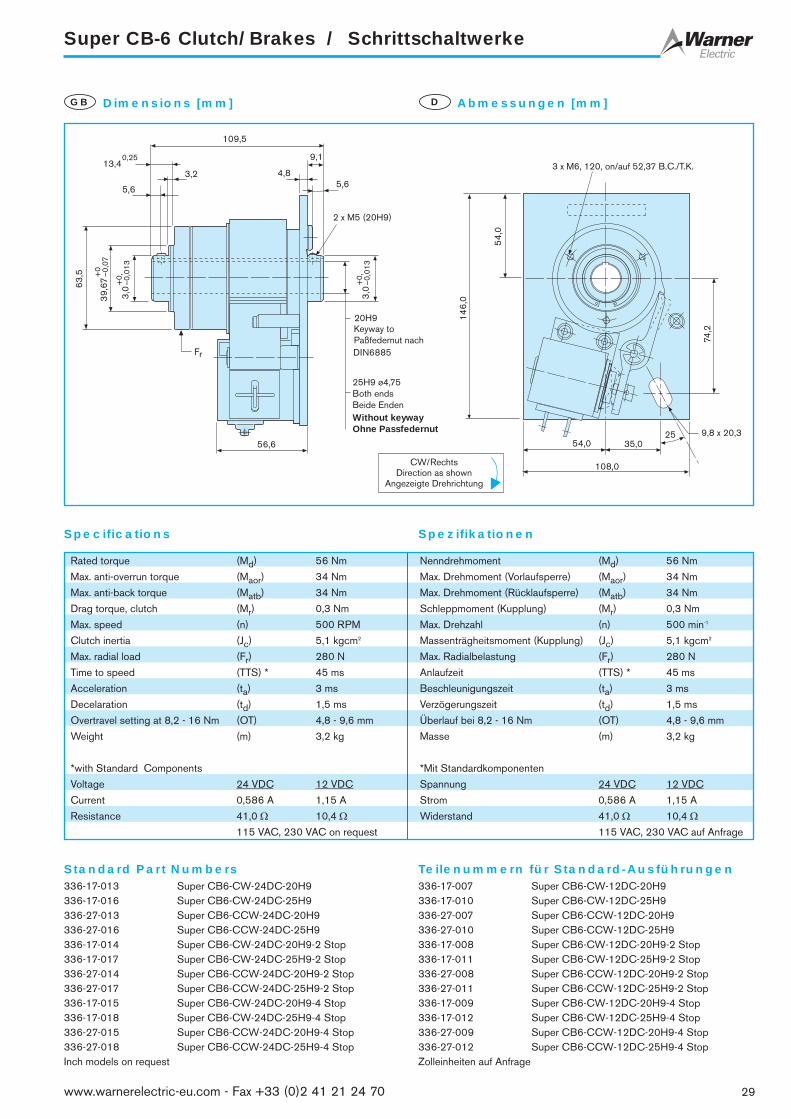
Super CB-6 Clutch/Brakes / Schrittschaltwerke
29www.warnerelectric-eu.com - Fax +33 (0)2 41 21 24 70
Standard Part Numbers Teilenummern für Standard-Ausführungen
Specifications Spezifikationen
336-17-013 Super CB6-CW-24DC-20H9336-17-016 Super CB6-CW-24DC-25H9336-27-013 Super CB6-CCW-24DC-20H9336-27-016 Super CB6-CCW-24DC-25H9336-17-014 Super CB6-CW-24DC-20H9-2 Stop336-17-017 Super CB6-CW-24DC-25H9-2 Stop336-27-014 Super CB6-CCW-24DC-20H9-2 Stop336-27-017 Super CB6-CCW-24DC-25H9-2 Stop336-17-015 Super CB6-CW-24DC-20H9-4 Stop336-17-018 Super CB6-CW-24DC-25H9-4 Stop336-27-015 Super CB6-CCW-24DC-20H9-4 Stop336-27-018 Super CB6-CCW-24DC-25H9-4 StopInch models on request
336-17-007 Super CB6-CW-12DC-20H9336-17-010 Super CB6-CW-12DC-25H9336-27-007 Super CB6-CCW-12DC-20H9336-27-010 Super CB6-CCW-12DC-25H9336-17-008 Super CB6-CW-12DC-20H9-2 Stop336-17-011 Super CB6-CW-12DC-25H9-2 Stop336-27-008 Super CB6-CCW-12DC-20H9-2 Stop336-27-011 Super CB6-CCW-12DC-25H9-2 Stop336-17-009 Super CB6-CW-12DC-20H9-4 Stop336-17-012 Super CB6-CW-12DC-25H9-4 Stop336-27-009 Super CB6-CCW-12DC-20H9-4 Stop336-27-012 Super CB6-CCW-12DC-25H9-4 StopZolleinheiten auf Anfrage
109,5
3 x M6, 120, on/auf 52,37 B.C./T.K.
39,
67+
0–0
,07
3,0
+0,
–0,0
13
3,0
+0,
–0,0
13
13,40,25
3,2
5,6
63,5
9,1
4,85,6
2 x M5 (20H9)
20H9
25H9 ø4,75Both endsBeide Enden
56,6
54,
0
146,
0
74,2
54,0 35,025
108,0
9,8 x 20,3
Fr
Without keywayOhne Passfedernut
DIN6885
Keyway toPaßfedernut nach
Dimensions [mm]GB Abmessungen [mm]D
Rated torque (Md) 56 Nm Nenndrehmoment (Md) 56 Nm
Max. anti-overrun torque (Maor) 34 Nm Max. Drehmoment (Vorlaufsperre) (Maor) 34 Nm
Max. anti-back torque (Matb) 34 Nm Max. Drehmoment (Rücklaufsperre) (Matb) 34 Nm
Drag torque, clutch (Mr) 0,3 Nm Schleppmoment (Kupplung) (Mr) 0,3 Nm
Max. speed (n) 500 RPM Max. Drehzahl (n) 500 min-1
Clutch inertia (Jc) 5,1 kgcm2 Massenträgheitsmoment (Kupplung) (Jc) 5,1 kgcm2
Max. radial load (Fr) 280 N Max. Radialbelastung (Fr) 280 N
Time to speed (TTS) * 45 ms Anlaufzeit (TTS) * 45 ms
Acceleration (ta) 3 ms Beschleunigungszeit (ta) 3 ms
Decelaration (td) 1,5 ms Verzögerungszeit (td) 1,5 ms
Overtravel setting at 8,2 - 16 Nm (OT) 4,8 - 9,6 mm Überlauf bei 8,2 - 16 Nm (OT) 4,8 - 9,6 mm
Weight (m) 3,2 kg Masse (m) 3,2 kg
*with Standard Components *Mit Standardkomponenten
Voltage 24 VDC 12 VDC Spannung 24 VDC 12 VDC
Current 0,586 A 1,15 A Strom 0,586 A 1,15 A
Resistance 41,0 Ω 10,4 Ω Widerstand 41,0 Ω 10,4 Ω115 VAC, 230 VAC on request 115 VAC, 230 VAC auf Anfrage
CW/RechtsDirection as shown
Angezeigte Drehrichtung

Super CB-7 Clutch/Brakes / Schrittschaltwerke
Standard Part Numbers Teilenummern für Standard-Ausführungen
Specifications Spezifikationen
337-17-001 Super CB7-CW-24DC-30H9337-17-005 Super CB7-CW-24DC-35H9337-27-001 Super CB7-CCW-24DC-30H9337-27-005 Super CB7-CCW-24DC-35H9337-17-008 Super CB7-CW-24DC-30H9-2 Stop337-17-009 Super CB7-CW-24DC-35H9-2 Stop337-27-008 Super CB7-CCW-24DC-30H9-2 Stop337-27-009 Super CB7-CCW-24DC-35H9-2 Stop337-17-011 Super CB7-CW-2424DC-30H9-4 Stop337-17-012 Super CB7-CW-24DC-35H9-4 Stop337-27-011 Super CB7-CCW-24DC-30H9-4 Stop337-27-012 Super CB7-CCW-24DC-35H9-4 StopInch models on request
337-17-014 Super CB7-CW-12DC-30H9337-17-015 Super CB7-CW-12DC-35H9337-27-014 Super CB7-CCW-12DC-30H9337-27-015 Super CB7-CCW-12DC-35H9337-17-017 Super CB7-CW-12DC-30H9-2 Stop337-17-018 Super CB7-CW-12DC-35H9-2 Stop337-27-017 Super CB7-CCW-12DC-30H9-2 Stop337-27-018 Super CB7-CCW-12DC-35H9-2 Stop337-17-020 Super CB7-CW-12DC-30H9-4 Stop337-17-021 Super CB7-CW-12DC-35H9-4 Stop337-27-020 Super CB7-CCW-12DC-30H9-4 Stop337-27-021 Super CB7-CCW-12DC-35H9-4 StopZolleinheiten auf Anfrage
FrM5This end onlyNur dieses Ende
60,
25+
0–0
,10
101,
6
6 x M8, 60 on/auf 85,7 B.C./T.K.
Bot
h en
dsB
eide
End
en
124,5
22,6
9,6
6,4
7,12
58,6
10,2
6,4
49,
2
127,0
178,
030
45,7
63,5
63,5
79,2
30H9
35H9
DIN6885
Keyway toPaßfedernut nach
DIN6885
Keyway toPaßfedernut nach
Dimensions [mm]GB Abmessungen [mm]D
Rated torque (Md) 170 Nm Nenndrehmoment (Md) 170 Nm
Max. anti-overrun torque (Maor) 65 Nm Max. Drehmoment (Vorlaufsperre) (Maor) 65 Nm
Max. anti-back torque (Matb) 68 Nm Max. Drehmoment (Rücklaufsperre) (Matb) 68 Nm
Drag torque, clutch (Mr) 0,8 Nm Schleppmoment (Kupplung) (Mr) 0,8 Nm
Max. speed (n) 400 RPM Max. Drehzahl (n) 400 min-1
Clutch inertia (Jc) 20,0 kgcm2 Massenträgheitsmoment (Kupplung) (Jc) 20,0 kgcm2
Max. radial load (Fr) 1350 N Max. Radialbelastung (Fr) 1350 N
Time to speed (TTS) * 50 ms Anlaufzeit (TTS) * 50 ms
Acceleration (ta) 3 ms Beschleunigungszeit (ta) 3 ms
Decelaration (td) 1,5 ms Verzögerungszeit (td) 1,5 ms
Overtravel setting at 28-54 Nm (OT) 9,6 - 12,7 mm Überlauf bei 28-54 Nm (OT) 9,6 - 12,7 mm
Weight (m) 5,5 kg Masse (m) 5,5 kg
*with Standard Components *Mit Standardkomponenten
Voltage 24 VDC 12 VDC Spannung 24 VDC 12 VDC
Current 0,586 A 1,15 A Strom 0,586 A 1,15 A
Resistance 41,0 Ω 10,4 Ω Widerstand 41,0 Ω 10,4 Ω115 VAC, 230 VAC on request 115 VAC, 230 VAC auf Anfrage
CW/RechtsDirection as shown
Angezeigte Drehrichtung
30 www.warnerelectric-eu.com - Fax +33 (0)2 41 21 24 70

Super CB-8 Clutch/Brakes / Schrittschaltwerke
31www.warnerelectric-eu.com - Fax +33 (0)2 41 21 24 70
Standard Part Numbers Teilenummern für Standard-Ausführungen
Specifications Spezifikationen
338-17-013 Super CB8-CW-24DC-35H9338-17-016 Super CB8-CW-24DC-40H9338-27-013 Super CB8-CCW-24DC-35H9338-27-016 Super CB8-CCW-24DC-40H9338-17-014 Super CB8-CW-24DC-35H9-2 Stop338-17-017 Super CB8-CW-24DC-40H9-2 Stop338-27-014 Super CB8-CCW-24DC-35H9-2 Stop338-27-017 Super CB8-CCW-24DC-40H9-2 Stop338-17-015 Super CB8-CW-24DC-35H9-4 Stop338-17-018 Super CB8-CW-24DC-40H9-4 Stop338-27-015 Super CB8-CCW-24DC-35H9-4 Stop338-27-018 Super CB8-CCW-24DC-40H9-4 StopInch models on request
338-17-007 Super CB8-CW-12DC-35H9338-17-010 Super CB8-CW-12DC-40H9338-27-007 Super CB8-CCW-12DC-35H9338-27-010 Super CB8-CCW-12DC-40H9338-17-008 Super CB8-CW-12DC-35H9-2 Stop338-17-011 Super CB8-CW-12DC-40H9-2 Stop338-27-008 Super CB8-CCW-12DC-35H9-2 Stop338-27-011 Super CB8-CCW-12DC-40H9-2 Stop338-17-009 Super CB8-CW-12DC-35H9-4 Stop338-17-012 Super CB8-CW-12DC-40H9-4 Stop338-27-009 Super CB8-CCW-12DC-35H9-4 Stop338-27-012 Super CB8-CCW-12DC-40H9-4 StopZolleinheiten auf Anfrage
+
+
+
+ +
+
+ +
+
6 x M8, 60, on/auf 85,7 B.C./T.K.
60,
3+
0,–0
,05
6,4Both endsBeide Enden
101,
6
58,6
50,
0
35H9
40H9
M6Both endsBeide Enden
6,44,8
17,7
155,6
10,2
63,5
178,
0
79,2
45,7
63,5
127,0
9,8 x 20,3
30
Fr
DIN6885
Keyway toPaßfedernut nach
Without keywayOhne Passfedernut
Dimensions [mm]GB Abmessungen [mm]D
Rated torque (Md) 280 Nm Nenndrehmoment (Md) 280 Nm
Max. anti-overrun torque (Maor) 68 Nm Max. Drehmoment (Vorlaufsperre) (Maor) 68 Nm
Max. anti-back torque (Matb) 68 Nm Max. Drehmoment (Rücklaufsperre) (Matb) 68 Nm
Drag torque, clutch (Mr) 1 Nm Schleppmoment (Kupplung) (Mr) 1 Nm
Max. speed (n) 300 RPM Max. Drehzahl (n) 300 min-1
Clutch inertia (Jc) 38,0 kgcm2 Massenträgheitsmoment (Kupplung) (Jc) 38,0 kgcm2
Max. radial load (Fr) 1350 N Max. Radialbelastung (Fr) 1350 N
Time to speed (TTS) * 50 ms Anlaufzeit (TTS) * 50 ms
Acceleration (ta) 3 ms Beschleunigungszeit (ta) 3 ms
Decelaration (td) 1,5 ms Verzögerungszeit (td) 1,5 ms
Overtravel setting at 28 - 54 Nm (OT) 9,6 - 12,7 mm Überlauf bei 28 - 54 Nm (OT) 9,6 - 12,7 mm
Weight (m) 6,85 kg Masse (m) 6,85 kg
*with Standard Components *Mit Standardkomponenten
Voltage 24 VDC 12 VDC Spannung 24 VDC 12 VDC
Current 0,94 A 1,86 A Strom 0,94 A 1,86 A
Resistance 25,4 Ω 6,43 Ω Widerstand 25,4 Ω 6,43 Ω115 VAC, 230 VAC on request 115 VAC, 230 VAC auf Anfrage
CW/RechtsDirection as shown
Angezeigte Drehrichtung

Super CB-10 Clutch/Brakes / Schrittschaltwerke
Standard Part Numbers Teilenummern für Standard-Ausführungen
Specifications Spezifikationen
330-17-001 Super CB10-CW-24DC-40H9330-17-002 Super CB10-CW-24DC-45H9330-27-001 Super CB10-CCW-24DC-40H9330-27-002 Super CB10-CCW-24DC-45H9330-17-003 Super CB10-CW-24DC-40H9-2 Stop330-17-004 Super CB10-CW-24DC-45H9-2 Stop330-27-003 Super CB10-CCW-24DC-40H9-2 Stop330-27-004 Super CB10-CCW-24DC-45H9-2 Stop330-17-005 Super CB10-CW-24DC-40H9-4 Stop330-17-006 Super CB10-CW-24DC-45H9-4 Stop330-27-005 Super CB10-CCW-24DC-40H9-4 Stop330-27-006 Super CB10-CCW-24DC-45H9-4 StopInch models on request
Super CB10-CW-12DC-40H9Super CB10-CW-12DC-45H9
Part number Super CB10-CCW-12DC-40H9to be assigned Super CB10-CCW-12DC-45H9at time of order Super CB10-CW-12DC-40H9-2 Stop
Super CB10-CW-12DC-45H9-2 StopTeilenummern Super CB10-CCW-12DC-40H9-2 Stopwerden bei Super CB10-CCW-12DC-45H9-2 StopBestellung Super CB10-CW-12DC-40H9-4 Stopzugewiesen Super CB10-CW-12DC-45H9-4 Stop
Super CB10-CCW-12DC-40H9-4 StopSuper CB10-CCW-12DC-45H9-4 Stop
Zolleinheiten auf Anfrage
40H9
25
45H9
197,3
19,5
5,8
M6
133,
4
74,6
60,
0
66,0
6,4
19,4
57,2 +
226,
0
108,
0
6 x M8, 60, on/auf 86,8 B.C./T.K.
50,8
76,2152,4
16,0 x 31,8
76,2
Fr
DIN6885
Keyway toPaßfedernut nach
DIN6885
Keyway toPaßfedernut nach
Dimensions [mm]GB Abmessungen [mm]D
Rated torque (Md) 560 Nm Nenndrehmoment (Md) 560 Nm
Max. anti-overrun torque (Maor) 135 Nm Max. Drehmoment (Vorlaufsperre) (Maor) 135 Nm
Max. anti-back torque (Matb) 135 Nm Max. Drehmoment (Rücklaufsperre) (Matb) 135 Nm
Drag torque, clutch (Mr) 2 Nm Schleppmoment (Kupplung) (Mr) 2 Nm
Max. speed (n) 200 RPM Max. Drehzahl (n) 200 min-1
Clutch inertia (Jc) 118,0 kgcm2 Massenträgheitsmoment (Kupplung) (Jc) 118,0 kgcm2
Max. radial load (Fr) 2250 N Max. Radialbelastung (Fr) 2250 N
Time to speed (TTS) * 70 ms Anlaufzeit (TTS) * 70 ms
Acceleration (ta) 3 ms Beschleunigungszeit (ta) 3 ms
Decelaration (td) 1,5 ms Verzögerungszeit (td) 1,5 ms
Overtravel setting at 55 - 80 Nm (OT) 15,7 - 19,0 mm Überlauf bei 55 - 80 Nm (OT) 15,7 - 19,0 mm
Weight (m) 12,3 kg Masse (m) 12,3 kg
*with Standard Components *Mit Standardkomponenten
Voltage 24 VDC 12 VDC Spannung 24 VDC 12 VDC
Current 0,94 A 1,86 A Strom 0,94 A 1,86 A
Resistance 25,4 Ω 6,43 Ω Widerstand 25,4 Ω 6,43 Ω115 VAC, 230 VAC on request 115 VAC, 230 VAC auf Anfrage
CCW/LinksDirection as shown
Angezeigte Drehrichtung
32 www.warnerelectric-eu.com - Fax +33 (0)2 41 21 24 70

Standard CB and Super CB Series
33www.warnerelectric-eu.com - Fax +33 (0)2 41 21 24 70
Adjustable Stop CollarsGB Einstellbarer SchaltringD
Pneumatic Actuation
Pneumatic actuation is available onCB-4, CB-5, CB-6, CB-7, CB-8 andCB-10 as well as the respective SuperCB Models.
Advantages are:❒ No electrical sparks❒ Not subject to power line
voltage fluctuations❒ Longer life of
control members
Air pressure required: 4,5 - 16,5 bar
Retrofit kits available
Pneumatische Schaltung
Anstelle des Hubmagneten ist aucheine pneumatische Schaltung verfüg-bar für CB-4, CB-5, CB-6, CB-7,CB-8 und CB-10 sowie für die ent-sprechenden Modelle der BaureiheSuper CB. Die Vorteile sind:❒ Keine elektrischen Funken❒ Keine Beeinflussung durch
Stromschwankungen❒ Längere Lebensdauer des
Schaltelements
Druckluftbedarf: 4,5 - 16,5 bar
Nachrüstsatz lieferbar
1-stop, 2-stop and 4-stop collars are standard.
Multiple stops, up to 24 stops, blanks as well as any custom con-figuration are available on request.
CB models offer unique splined stop collars for radial adjustmentsin very fine increments. This feature allows the user to set, on themachine, the final output stop position, which will be held to ± 1/2°noncumulative.
Increments are as follows:CB-2 = 2,8° CB-4 = 2,4° CB-5 = 1,8°CB-6 = 1,8° CB-7/8 = 1,6° CB-10 = 1,5°
Schaltringe mit einem Anschlag bzw. mit zwei und vier Anschlägensind Standard.Schaltringe mit bis zu 24 Anschlägen, Rohlinge sowie kundenbe-zogene Teile auf Anfrage.
Die Schaltringe sind mit einer Feinverzahnung versehen, welche esermöglicht, an der Maschine die Halteposition des Abtriebes genaueinzustellen, und zwar auf ± 1/2°, nicht summierend.
Einstellwinkel:CB-2 = 2,8° CB-4 = 2,4° CB-5 = 1,8°CB-6 = 1,8° CB-7/8 = 1,6° CB-10 = 1,5°
Standard CB-5, -6, -7, -8Super CB-5, -6, -7, -8
Other ModelsAndere Modelle
GB D
1
2
3
4
5
6
1
2
3
4
1 Retaining ring 4 Stop collar2 Drive sleeve 5 Coupling sleve3 Actuator 6 Brake sleeve
1 Sicherungsring 4 Schaltring2 Schalttrommel 5 Verbindungsring3 Sperrklinke 6 Bremsring

Baureihen Standard CB und Super CB
Dust Covers andEnclosure
Dust Cover
Dust covers are designed to fit stan-dard as well as super models.
❒ Keeping out contaminants andmoisture assures a longer live
❒ Flexible, soft plastic construction isvery durable and resists grease, oil,etc.
❒ Simple installation and removal
❒ Low cost
GB Staubabdeckungenund Gehäuse
Staubabdeckung
Staubabdeckungen können bei allenStandard- und Supermodellen einge-setzt werden.
❒ Weniger Verunreinigung undFeuchtigkeit garantieren einelängere Lebensdauer
❒ Die weiche Kunststoffausführungist sehr widerstandsfähig gegenFett, Öl, usw.
❒ Einfache Montage und Demontage
❒ Kostengünstig
D
Aluminum Enclosure
❒ Fits all CB-6 and Super CB-6 ❒ Sturdy cast aluminum construction❒ Offers NEMA 3 & 12 protection
(IP 54)❒ Quieter clutch operation❒ USDA* powder coat paint finish
Part numbersCB-6 = 101-6-0095Super CB-6 = 101-6-0096
GB Aluminium-Gehäuse
❒ Paßt auf alle CB-6 und Super CB-6❒ Widerstandsfähige
Aluminiumgußkonstruktion❒ Schutzart IP 54❒ Geräuschreduzierend❒ Anstrich genehmigt vom USDA*
TeilnummernCB-6 = 101-6-0095Super CB-6 = 101-6-0096
D
How to order a CB Clutch/Brake Bestellung eines CB Schrittschaltwerkes
CB 20H9– 6 – –CW – – 2
CB-Series Size Direction of Rotation Voltage Bore size No. of StopsBaureihe CB Größe Drehrichtung Spannung Bohrung Anschläge
DIRECTION OF ROTATION ALWAYS VIEWED FROM INPUTHUB SIDE
For standard part numbers, please see model specification in thiscatalogue.
DREHRICHTUNG IMMER VON DER SEITE DER EINGANGS-NABE BESTIMMEN !
Die Teilenummern der Standard-Ausführungen sind den Modell-spezifikationen in diesem Katalog zu entnehmen.
Part numbers CB-2 CB-4 CB-5 CB-6/Super CB-8/Super CB-10/SuperTeilnummern 287-2-0007 287-4-0002 287-5-0007 287-6-0007 287-8-0003 287-0-0002
24VDC
*U.S. Department of Agriculture
34 www.warnerelectric-eu.com - Fax +33 (0)2 41 21 24 70

Standard CB and Super CB Series
35www.warnerelectric-eu.com - Fax +33 (0)2 41 21 24 70
Mounting requirements
WARNER ELECTRIC Wrap Spring Clutches are self-containedunits ready for installation. They are designed for parallel shaft appli-cations, where they are fully supported by the output shaft they aremounted on. Connecting the parallel shaft to the input hub can beaccomplished by use of belts, chains, gears, etc.
For good performance and long life the clutch must be free of inter-nal stresses and the following must be observed:
❒ The clutch must “float”. The mounting plate must be freeand only restrained from rotating
❒ The shaft should be supported as not to induce a bend-ing moment into the clutch
❒ The drive pulley should not be bolted on to the free hubin an overhanging manner
❒ Whenever possible, it should be mounted on the shafton it’s own bearings and connected to the free hub bymeans of drive pins attached to the free hub using thetapped holes (Fig.1)
Vertical installation
When ever possible, the units should be installed horizontally. If notpossible, the following should be observed: - Free hub on top. - Ifthe free hub must be on the bottom, a hardened thrust washer mustbe added between the retaining ring and the hub to prevent wear.
GB Montagehinweise
WARNER ELECTRIC Federbandkupplungen sind vormontiert undfür den sofortigen Einbau geeignet. Sie werden auf der Abtriebswellegelagert. Der Antrieb über die freie Nabe erfolgt mit Zahnriemen, Kette,Zahnrad, usw.
Für optimale Leistung und lange Lebensdauer muß die Kupplung ohneZwang montiert werden; folgende Hinweise sind zu beachten:
❒ Die Kupplung muß “schwimmend” gelagert sein, d.h., dieMontageplatte muß frei sein und gegen Verdrehunggesichert werden
❒ Die Welle sollte so gelagert sein, daß kein Biegemomentauf die Kupplung wirkt
❒ Antriebsscheiben sollten nicht in einer überhängendenWeise an die freie Nabe montiert werden
❒ Wenn immer möglich, sollte die Antriebsscheibe separatauf der Welle gelagert sein und über Stifte, welche in diefreie Nabe eingeschraubt sind, verbunden werden (Fig.1)
Vertikaler Einbau
Wenn möglich, sollte der Einbau horizontal erfolgen. Wenn nichtmöglich, sollte die freie Nabe oben sein. Muß sie unten angeordnetwerden, sollte zwischen Nabe und Sicherungsring eine gehärteteDruckscheibe vorgesehen werden, um Abrieb an der Nabe zuvermeiden.
D
Fr
Bearing mounted pulley with pin drive to free hubAntriebsscheibe auf Welle gelagert und über Stifte (frei) mitder Nabe verbunden
FIG. /BILD 1
PinsStifte

SAC Series / Baureihe SAC
Solenoid actuated wrap springclutch
The SAC series features four models of pre-assembled, solenoid actu-ated, wrap spring clutch packages. SAC units operate from a sin-gle AC or DC pulse to accurately start loads at speeds up to 1800rpm, depending on size. Adjustable stop control collars provide easyand accurate output stop position settings. A typical SAC series clutchwill bring the load up to speed within 3 milliseconds.
Available in 4 sizes
❒ Torque range from 3 Nm to 56 Nm❒ 1, 2 and 4 stops standard. Other stops available, up to
24 maximum❒ Hub input (Shaft input available, consult factory)❒ Maintenance-free, self-lubricating hubs are 18% oil by volume❒ Sintered metal hub offers easy machining for custom drive
attachments
Elektromagnetisch betätigteFederbandkupplung
Die Baureihe SAC umfasst vier Modelle. Diese sind werkssetig vor-montiert und werden über einen Hubmagnet betätigt. Ein kurzerImpuls auf den Gleich- oder Wechselstrommagnet genügt, und dieKupplung beschleunigt innerhalb 3 Millisekunden – je nach Größe– auf 1800 min-1. Die genaue Einstellung der gewünschtenHalteposition kann mühelos mittels eines speziellen Schaltringesvorgenommen werden.
Erhältlich in 4 Größen
❒ Vier Modelle mit Drehmomenten von 3 Nm bis 56 Nm❒ Standardmäßig mit 1 Anschlag bzw. 2 und 4 Anschlägen liefer-
bar, auf Anfrage bis 24 Anschläge❒ Standardmäßig Antrieb über die Nabe, auf Anfrage auch Antrieb
über die Welle möglich❒ Die Einheiten sind wartungsfrei. Die Sintermetallnaben sind mit
Öl getränkt. Ein Nachstellen ist nicht erforderlich❒ Einfache Montage kundeneigener Adapter an der Antriebsnabe
GB D
12
34
1SolenoidHubmagnet
24 VDC Std.
2ActuatorSperrklinke
3Input Hub (Free Hub)Antriebsnabe (Freie Nabe)
4Mounting plate Montageplatte
How to order a SAC Clutch/Brake Bestellung eines SAC Schrittschaltwerkes
SAC 20H9– 4 – –CW – – 2
CB-Series Size Direction of Rotation Voltage Bore size No. of StopsBaureihe CB Größe Drehrichtung Spannung Bohrung Anschläge
DIRECTION OF ROTATION ALWAYS VIEWED FROM INPUTHUB SIDE
For standard part numbers, please see model specification in thiscatalogue.
DREHRICHTUNG IMMER VON DER SEITE DER EINGANGS-NABE BESTIMMEN !
Die Teilenummern der Standard-Ausführungen sind den Modell-spezifikationen in diesem Katalog zu entnehmen.
24VDC
36 www.warnerelectric-eu.com - Fax +33 (0)2 41 21 24 70

SAC-2 Series / Baureihe SAC-2
37www.warnerelectric-eu.com - Fax +33 (0)2 41 21 24 70
Standard Part Numbers Teilenummern für Standard-Ausführungen
Specifications Spezifikationen
782-10-002 SAC-2,CW,24DC,6.0H9B,1ST782-10-003 SAC-2,CW,24DC,6.0H9B,2ST782-10-004 SAC-2,CW,24DC,6.0H9B,4ST782-10-005 SAC-2,CW,12DC,6.0H9B,1ST782-10-006 SAC-2,CW,12DC,6.0H9B,2ST782-10-007 SAC-2,CW,12DC,6.0H9B,4ST
Inch models on request
782-20-002 SAC-2,CCW,24DC,6.0H9B,1ST782-20-003 SAC-2,CCW,24DC,6.0H9B,2ST782-20-004 SAC-2,CCW,24DC,6.0H9B,4ST782-20-005 SAC-2,CCW,12DC,6.0H9B,1ST782-20-006 SAC-2,CCW,12DC,6.0H9B,2ST782-20-007 SAC-2,CCW,12DC,6.0H9B,4ST
Zolleinheiten auf Anfrage
+ +
+
+ +
+ +120(3x)
45Nom.
43,18 max.
30,
17
9,53
6 H
918,0320
86,
11
49,
5325
,4
50,8
5,10 x 9,53
4 x ø5on / auf53,98
3 x M4on / auf23,83B.C. / T.K.
63,50
10,29
3,30min.
15,7
5 m
ax.
1,5This hole mustbe pinned tomating shaft1,5Hier mit derWelleverstiften !
2 x 1,5One-sideonly2 x 1,5Nur eineBohrungverstiften !
2,29
2,295,46
Dimensions [mm]GB Abmessungen [mm]D
CW/RechtsDirection as shown
Angezeigte Drehrichtung
Rated torque (Md) 2,82 Nm Nenndrehmoment (Md) 2,82 Nm
Max. speed (n) 1800 RPM Max. Drehzahl (n) 1800 min-1
Clutch inertia (Jc) 0,0606 kgcm2 Massenträgheitsmoment (Kupplung) (Jc) 0,0606 kgcm2
Max. radial load (Fr) 34 N Max. Radialbelastung (Fr) 34 N
Time to speed (TTS) * 20 ms Anlaufzeit (TTS) * 20 ms
Weight (kg) 0,450 kg Masse (m) 0,450 kg
*with Standard Components *Mit Standardkomponenten
Voltage 24 VDC 12 VDC Spannung 24 VDC 12 VDC
Current 0,230 A 0.460 A Strom 0,230 A 0.460 A
Resistance 104 Ω 26 Ω Widerstand 104 Ω 26 Ω115 VAC, 230 VAC on request 115 VAC, 230 VAC auf Anfrage

SAC-4 Series / Baureihe SAC-4
Standard Part Numbers Teilenummern für Standard-Ausführungen
Specifications Spezifikationen
784-10-001 SAC4,CW,24DC,10.0H9B,1 ST784-10-002 SAC4,CW,24DC,10.0H9B,2ST784-10-003 SAC4,CW,24DC,10. OH9B,4ST784-10-004 SAC4,CW,12DC,10.0H9B,1ST784-10-005 SAC4,CW,12DC,10.0H9B,2ST784-10-006 SAC4,CW,12DC,10.0H9B,4ST
Inch models on request
784-20-001 SAC-4,CCW,24DC,10.0H9B,1ST784-20-002 SAC-4,CCW,24DC,10.0H9B,2ST784-20-003 SAC-4, CCW,24DC,10.0H9B,4ST784-20-004 SAC4,CCW,12DC,10.0H9B,1ST784-20-005 SAC-4,CCW,12DC,10.0H9B,2ST784-20-006 SAC-4,CCW,12DC,10.0H9B,4ST
Zolleinheiten auf Anfrage
+ +
+
+ +
+ +120(3x)
45Nom.
49,28 max.
31,7
2
12,7
10 H
9
20,517,5
104,
14
65,0
225
,4
50,45
6,60 x 12,70
4 x ø4,75on / auf53,98
3 x M4on / auf23,83B.C. / T.K.
85,85
21,08
12,95min.
19,0
5 m
ax.
2,29
3,818,38
3This hole mustbe pinned tomating shaft3Hier mit derWelleverstiften !
2 x 3One-sideonly2 x 3Nur eineBohrungverstiften !
Dimensions [mm]GB Abmessungen [mm]D
Rated torque (Md) 14 Nm Nenndrehmoment (Md) 14 Nm
Max. speed (n) 1200 RPM Max. Drehzahl (n) 1200 min-1
Clutch inertia (Jc) 0,186 kgcm2 Massenträgheitsmoment (Kupplung) (Jc) 0,186 kgcm2
Max. radial load (Fr) 14 N Max. Radialbelastung (Fr) 14 N
Time to speed (TTS) * 24 ms Anlaufzeit (TTS) * 24 ms
Weight (m) 0,900 kg Masse (m) 0,900 kg
*with Standard Components *Mit Standardkomponenten
Voltage 24 VDC 12 VDC Spannung 24 VDC 12 VDC
Current 0,325 A 0,732 A Strom 0,325 A 0,732 A
Resistance 74 Ω 16,4 Ω Widerstand 74 Ω 16,4 Ω115 VAC, 230 VAC on request 115 VAC, 230 VAC auf Anfrage
CW/RechtsDirection as shown
Angezeigte Drehrichtung
38 www.warnerelectric-eu.com - Fax +33 (0)2 41 21 24 70

SAC-5 Series / Baureihe SAC-5
39www.warnerelectric-eu.com - Fax +33 (0)2 41 21 24 70
Standard Part Numbers Teilenummern für Standard-Ausführungen
Specifications Spezifikationen
785-10-001 SAC-5,CW,24DC,12.0H9B,1ST785-10-002 SAC-5,CW,24DC,12.0H9B,2ST785-10-003 SAC-5,CW,24DC,12.0H9B,4ST785-10-004 SAC-5,CW,12DC,12.0H9B,1ST785-10-005 SAC-5,CW,12DC,12.0H9B,2ST785-10-006 SAC-5,CW,12DC,12.0H9B,4ST
Inch models on request
785-20-001 SAC-5,CCW,24DC,12.0H9B,1ST785-20-002 SAC-5,CCW,24DC,12.0H9B,2ST785-20-003 SAC-5,CCW,24DC,12.0H9B,4ST785-20-004 SAC-5,CCW,12DC,12.0H9B,1ST785-20-005 SAC-5,CCW,12DC,12.0H9B,2ST785-20-006 SAC-5,CCW,12DC,12.0H9B,4ST
Zolleinheiten auf Anfrage
+ +
+
+ +
+ +120(3x)
45Nom.
50,80 max.
39,
67
15,8
7
12 H
923,1120
115,
82
63,5
033
,27
66,55
6,60 x 12,70
4 x ø4,75on / auf79,38
3 x M5on / auf31,75B.C. / T.K.
111
27,69
18,54min.
25,4
0 m
ax.
2,29
6,3511,94
2,97This hole mustbe pinned tomating shaft2,97Hier mit derWelleverstiften !
2 x 2,97One-sideonly2 x 2,97Nur eineBohrungverstiften !
Dimensions [mm]GB Abmessungen [mm]D
Rated torque (Md) 28 Nm Nenndrehmoment (Md) 28 Nm
Max. speed (n) 750 RPM Max. Drehzahl (n) 750 min-1
Clutch inertia (Jc) 0,571 kgcm2 Massenträgheitsmoment (Kupplung) (Jc) 0,571 kgcm2
Max. radial load (Fr) 142 N Max. Radialbelastung (Fr) 142 N
Time to speed (TTS) * 27 ms Anlaufzeit (TTS) * 27 ms
Weight (m) 1,400 kg Masse (m) 1,400 kg
*with Standard Components *Mit Standardkomponenten
Voltage 24 VDC 12 VDC Spannung 24 VDC 12 VDC
Current 0,325 A 0,732 A Strom 0,325 A 0,732 A
Resistance 74 Ω 16,4 Ω Widerstand 74 Ω 16,4 Ω115 VAC, 230 VAC on request 115 VAC, 230 VAC auf Anfrage
CW/RechtsDirection as shown
Angezeigte Drehrichtung

SAC-6 Series / Baureihe SAC-6
Standard Part Numbers Teilenummern für Standard-Ausführungen
Specifications Spezifikationen
786-10-001 SAC-6,CW,24DC,20. OH9B,1ST786-10-002 SAC-6,CW,24DC,20.0H9B,2ST786-10-003 SAC-6,CW,24DC,20.0H9B,4ST786-10-004 SAC-6, CW,24DC,25.0H9B,1ST786-10-005 SAC-6,CW,24DC,25.0H9B,2ST786-10-006 SAC-6,CW,24DC,25.0H9B,4ST786-10-007 SAC-6,CW,12DC,20.0H9B,1ST786-10-008 SAC-6,CW,12DC,20.0H9B,2ST786-10-009 SAC-6,CW,12DC,20.0H9B,4ST786-10-010 SAC-6,CW,12DC,25.0H9B,1ST786-10-011 SAC-6,CW,12DC,25.0H9B,2ST786-10-012 SAC-6,CW,12DC,25.0H9B,4STInch models on request
786-20-001 SAC-6,CCW,24DC,20.0H9B,1ST786-20-002 SAC-6,CCW,24DC,20.0H9B,2ST786-20-003 SAC-6,CCW,24DC,20.0H9B,4ST786-20-004 SAC-6,CCW,24DC,25.0H9B,1ST786-20-005 SAC-6,CCW,24DC,25.0H9B,2ST786-20-006 SAC-6,CCW,24DC,25.0H9B,4ST786-20-007 SAC-6,CCW,12DC,20.0H9B,1ST786-20-008 SAC-6,CCW,12DC,20.0H9B,2ST786-20-009 SAC-6,CCW,12DC,20.0H9B,4ST786-20-010 SAC-6,CCW,12DC,25.0H9B,1ST786-20-011 SAC-6,CCW,12DC,25.0H9B,2ST786-20-012 SAC-6,CCW,12DC,25.0H9B,4STZolleinheiten auf Anfrage
45
25
120(3x)
107,95
4 x ø7on / auf127 B.C. / T.K.
3 x M6on / auf52,38 B.C. / T.K.
146,
05
53,8
574
,17
53,85
9,80 x 20,32
35ø6
3,5
0
109,53
9,40
2 x
ø31,
75
2 x M5
4,83
57,15 max.
3,23
7,88 max.
13,41
5,59
2 x M5
ø39,
64
Thread engagement / Gewindelänge
Dimensions [mm]GB Abmessungen [mm]D
Rated torque (Md) 56 Nm Nenndrehmoment (Md) 56 Nm
Max. speed (n) 500 RPM Max. Drehzahl (n) 500 min-1
Clutch inertia (Jc) 5,027 kgcm2 Massenträgheitsmoment (Kupplung) (Jc) 5,027 kgcm2
Max. radial load (Fr) 280 N Max. Radialbelastung (Fr) 280 N
Time to speed (TTS) * 45 ms Anlaufzeit (TTS) * 45 ms
Weight (m) 3,100 kg Masse (m) 3,100 kg
*with Standard Components *Mit Standardkomponenten
Voltage 24 VDC 12 VDC Spannung 24 VDC 12 VDC
Current 0,586 A 1,15 A Strom 0,586 A 1,15 A
Resistance 41,0 Ω 10,4 Ω Widerstand 41,0 Ω 10,4 Ω115 VAC, 230 VAC on request 115 VAC, 230 VAC auf Anfrage
CW/RechtsDirection as shown
Angezeigte Drehrichtung
40 www.warnerelectric-eu.com - Fax +33 (0)2 41 21 24 70

SP Series / Baureihe SP
41www.warnerelectric-eu.com - Fax +33 (0)2 41 21 24 70
The basic design of SP series clutches comprises a PSIunit assembled to a mounting plate with a solenoid actuator and anovertravel stop. It represents an autonomous clutch system to be con-trolled with a simple voltage pulse. Standard solenoids are 24 VDCand 12 VDC, 230 VAC solenoids are available on request.
SP-Series, single- or part revolution clutch/ brake units,employ a model “S” wrap spring. Model “SS” springs (nobraking feature) are optional. This design offers a very eco-nomical clutch with a braking capacity of 20 % of the torque ratingand a positioning accuarcy of ±4°. The units are shaft mounted andthey are available with hub- (HI) or shaft input (SI), clockwise (CW)or counter-clockwise (CCW), rotation always viewed from thefree hub side.
Outstanding features are:❒ High torque to size ratio❒ Rapid acceleration in 3 ms to max. speed❒ Simple to install and simple electrical control❒ Maintenace free and very cost effective
GB
Die Baureihe SP ist eine sehr kostengünstigeAntriebslösung. Sie ist ein vormontiertes Schaltwerk undbesitzt die gleichen Funktionen wie das Modell “S” derBaureihe PSI. (Modell “SS” Federn, keine Bremswirkung,sind auf Anfrage erhältlich).Dieses ist jedoch auf einer Platte befestigt und zusätzlich mit einerelektrisch betätigten Schaltklinke versehen.Die Ansteuerung der SP-Einheiten ist sehr einfach: Es genügt einkurzer Stromimpuls auf den Magneten, um die Sperrklinke anzuhebenund dadurch den Bewegungsvorgang einzuleiten.Die Standardhubmagnete arbeiten mit 24 V Gleichspannung, jedochsind auch Magnete für 12 V Gleichspannung bzw. 230 V Wechsel-spannung auf Anfrage erhältlich.Die Haltegenauigkeit beträgt ±4°. Die Bremswirkung ist auf 20 %des Kupplungsmomentes begrenzt.Die Einheiten sind erhältlich fürden Antrieb über die Nabe (HI) oder über die Welle (SI) sowie fürdie Drehrichtung rechts (CW) und links (CCW). Die Drehrichtungist dabei immer von der Seite der freien Nabe her zubestimmen.
Herausragende Merkmale sind:❒ Größtes Drehmoment bei kleinster Abmessung❒ Beschleunigt auf maximale Drehzahl in nur 3 ms❒ Einfache Montage und elektrische Steuerung❒ Wartungsfrei und äußerst kostengünstig
D
1Control collarSchaltring
2Clutch springKupplungsfeder
3Free hubFreie Nabe
4Control tangSchaltfinger
5Retaining ringSicherungsring
6Over travel StopÜberlaufanschlag
7Acuator assemblySperrklinkengruppe
8SolenoidHubmagnet
9BearingLager
10Output shaftAbtriebswelle
11Mounting plateMontageplatte
12O.T. stop ringAnschlagring
Control tangSchaltfinger
InputAntrieb
OutputAbtrieb
Output tang connected with outputFederende mit Abtrieb verbunden
123
4
5
6
7
8
9
10
11
12

SP Series / Baureihe SP
42 www.warnerelectric-eu.com - Fax +33 (0)2 41 21 24 70
Size Größe SP-2 SP-4 SP-5 SP-6
Torque Drehmoment [Nm] 2,82 13,5 28 56
Idle torque Leerlaufmoment [Nm] 2,3 • 10-2 4,5 • 10-2 5,6 • 10-2 6,8 • 10-2
Inertia Massenträgheitsmoment [kgcm2] HI 0,02 0,05 0,20 2,0
Weight Masse [kg] 0,25 0,4 0,6 2,4
Max. radial load Radialbelastung [N] 30 60 140 280
Max. speed Drehzahl [min-1] 1800 1200 750 500
Max. time to speed Anlaufzeit [ms] 20 24 27 45
Technical DataGB Technische DatenD
Dimensions (mm) Abmessungen (mm)
00
-0,030
0-0,03
0
How to order an SP Clutch Bestellung einer SP-Kupplung
SP 24VDC– 4 – S – HI – CW – – 2
SP-Series Size Model S or SS Input Direction of Rotation Voltage Bore No. of Stops Over Travel StopBaureihe SP Größe Modell S oder SS Antrieb Drehrichtung Spannung Bohrung Anschläge Überlaufanschlag
DIRECTION OF ROTATION ALWAYS VIEWED FROM THEFREE HUB SIDE !
DREHRICHTUNG IMMER VON DER SEITE DERFREIEN NABE BESTIMMEN !
Note : SP and CB Series use the same mounting plates and solenoids. Fordetail information, please see CB specifications except for the size 2.
Bemerkung : Die Montageplatten und Hubmagnete der Baureihen SP undCB sind identisch, ausser Grösse 2.
A
U
A
C
L DG
HJ
E
S
B T
F
M
O
P
N
R
Detail X
BearingLagerring
Free hubFreie Nabe
ConnectorSteckzunge1 x 6,35 mm
Detail X(Size 6)(Größe 6)
SP-6 20H9Keyway toPaßfeder nach
DIN 6885For stop collars see PSI SeriesFür Schaltringe siehe Baureihe PSI
Q
LikeCB SeriesWieBaureihe CB
10H9 – – OTS
-0,03
Size
GrößeøA øB C D E øF G H J K L M N O P øQ R Smax øT U
SP-2 6H9 30,18-0,03 40,4 7,6 3,2 1,5+0,07 2,3 5,8 5 12 2 86 50,8 25,4 25,4 23,8 3 x M4 43 16 –
SP-4 10H9 31,75-0,03 50,8 10,9 4,1 3+0,09 2,3 6,4 8,6 17 2 104 60,5 25,4 30,2 23,8 3 x M4 49,5 17,1 –
SP-5 12H9 39,69-0,04 60,3 8,6 3,8 3+0,09 2,3 5,5 8,6 24 2,3 115,8 66,6 33,3 33,3 31,75 3 x M5 55,4 21,2 –
SP-620H9
63,5 85,7 10,7 5,5M5
+0,08 4,8 9,8 19,7 20 7,4 146 108 54 54 52,4 3 x M6 56,6 39,6+0,08 6-JS9
25H9 5

43www.warnerelectric-eu.com - Fax +33 (0)2 41 21 24 70
BIMAC Series / Baureihe BIMAC
Low Cost Solenoid Actuated Clutchesfor AC or DC Operation
Designed initially for the computer peripheral equipment and busi-ness machine market, the BIMAC Series of solenoid actuatedclutches is ideal for a wide range of indexing and rapid cycling appli-cations.
The BIMAC Series are available in start-stop and single revolutionconfigurations. Single revolution models are rated for 10% brakingload (20% with overtravel stop/anti-back option).
In operation, when the coil is energized the actuator pulls away fromthe control collar, allowing the drive spring to wrap down onto theinput and output hubs for positive torque transmission. When the coilis de-energized, the actuator engages the control collar whichunwraps the spring and disconnects the hubs.
Outstanding features are:
❒ Low cost ❒ Trouble-free design for long life ❒ Complete package for immediate installation ❒ High torque ❒ Speeds up to 1500 RPM
Typical Applications
❒ Paper drives ❒ Material conveyor ❒ Copying machines ❒ Ribbon drives ❒ Collating machines
GB Günstige elektromagnetisch betätigteKupplungen für AC oder DC-Vorgänge
Ursprünglich wurde die BIMAC Baureihe elektromagnetisch betätigterKupplungen für Computerperipheriegeräte- und Büromaschinenmarktentwickelt. Sie eignet sich jedoch ideal für eine breite Palette anIndexierungs- und Schnelldurchlaufanwendungen.
Die BIMAC Baureihe ist als Start-Stop und Eintouren-Kupplunglieferbar. Eintouren-Modelle sind für eine Bremslast von 10 % (20% mit Überlaufanschlag/Rücklaufsperren) eingestellt.
Im Betrieb zieht die Schaltklinke bei energieführender Spule vomSchaltring weg, womit die Antriebsfeder auf die Antriebsnabe undAbtriebswelle rollt und das Drehmoment übertragen wird. Bei unter-brochener Energiezufuhr zur Spule rastet die Schaltklinke amSchaltring ein, der die Feder aushakt und Nabe und Welle trennt.
Herausragende Merkmale sind:
❒ Geringe Kosten❒ Störungsfreies Konzept für eine lange Lebensdauer❒ Kompletter Bausatz für eine sofortige Installation❒ Hohes Drehmoment❒ Drehzahlen bis zu 1500 min-1
Typische Anwendungen
❒ Papierbeförderung❒ Materialförderer❒ Kopierer❒ Bandantriebe❒ Mischmaschinen
D
11
Mounting plateMontageplatte
2CoilSpule
3Input hub Antriebsnabe
4Stop collarSchaltring
5Output shaftAbtriebswelle
2
34
5

44 www.warnerelectric-eu.com - Fax +33 (0)2 41 21 24 70
BIMAC Series / Baureihe BIMAC
TNote 1Bemerkung 1
Note 2Bemerkung 2
U
F
A
CD
B
E
SR Q
G
K
J
IH
L M
N
O P
Specifications Spezifikationen
Dimensions [mm]GB Abmessungen [mm]D
Dimensions (mm) Abmessungen (mm)
-0,030
Notes 1 - #6-32 tap. 3 holes, on .938 B.C. Notes 2 - ø hole 1,574 mm
Bemerkungen 1- #6-32 tap. 3 Bohrungen, auf .938 B.C. / T.K. Bemerkungen 2- ø Bohrung 1,574 mm
SizeA B C D E F G H I J K L M N O P Q R S T U
Größe
BIMAC 1 36,83 31,75 15,74 7,62 3,53 4,82 14,27/14,24 41,14 7,87 5,08 2,28 13,97 11,17 2,28 6,36/6,38 9,52/9,49 12,7 14,22 6,35 30,17/30,14 26,92
BIMAC 2 42,92 31,75 15,74 7,62 3,53 4,82 18,87/18,84 43,68 10,41 6,85 3,17 17,27 10,92 2,54 9,55/9,60 14,27/14,24 12,7 14,22 6,35 31,75 26,92
Voltage Current Resistance
Spannung Strom Widerstand
115 VAC 60 Hz 0,15 A 785 Ω
24 VDC 0,25 A 96 Ω
12 VDC 0,40 A 30 Ω
90 VDC 0,05 A 1800 Ω
SizeBIMAC 1 BIMAC 2
Grösse
Rated torque(Md) 2,82 Nm 8,47 Nm
Nenndrehmoment
Clutch inertia(Jc) 0,00000342 kgm2 0,0000125 kgm2
Massenträgheitsmoment (Kupplung)
Max. radial load(Fr) 53,4 N 75,6 N
Max. Radialbelastung
Max. speed(n) 1500 min-1 1000 min-1
Max. Drehzahl
Time to speed(TTS) 20 ms 20 ms
Anlaufzeit
Weight(m) 0,142 kg 0,198 kg
Masse

45www.warnerelectric-eu.com - Fax +33 (0)2 41 21 24 70
DL Series / Baureihe DL
Magnetically Actuated Wrap SpringClutches
The DuraLIFE series clutch (DL-33) is an electromechanical wrapspring clutch which combines high torque, reliability and rapid accel-eration into one small package at a very competitive cost.
Wrap spring technology allows for very fast response to bring loadsup to speeds in less than 3 milliseconds (after spring wrap-down anddepending on rpm). The DL-33 exceeds industry life requirementswith little cycle-to-cycle variation.
The DL-33 is a drop-in alternative for high cost clutches used inoffice automation applications such as printers and copiers. Thelong life and reliable performance makes the DL-33 an ideal clutchfor many packaging and automotive applications.
Outstanding features are:
❒ Available in two configurations: headed coil or flying leads ❒ Wrap spring technology ❒ High torque, small package ❒ Rapid acceleration ❒ Consistent performance ❒ Low wattage required
Typical Applications
❒ OFFICE AUTOMATION: copiers, printers, paper feed systems,collators, sorters, mailing equipment, ticket and receipt dispensers
❒ PACKAGING: labeller, dispensing machines, conveyors
❒ AUTOMOTIVE: cruise control, power lift gate, trunk power doorcloser
GB Magnetisch betätigteFederbandkupplungen
Die Kupplung der Baureihe DuraLIFE (DL-33) ist eine elektro-mechanische Federbandkupplung, die ein hohes Drehmoment,Zuverlässigkeit und schnelle Beschleunigung in einem kleinen Bausatzverbindet und dies zu einem sehr wettbewerbsfähigen Preis.
Die Federbandtechnik ermöglicht bei der Beschleunigung von Lastenin weniger als 3 Millisekunden (nach Absenken des Federbandsund je nach Drehzahl) eine hohe Reaktivität. Die Baureihe DL-33 über-steigt mit einer geringen Taktabweichung gängige Industrie-anforderungen.
DL-33 ist eine günstige Alternative für teure Kupplungen inBüroautomatikanwendungen, wie Drucker und Kopierer. Die lan-glebige und zuverlässige Leistung von DL-33 macht sie zur idealenKupplung für zahlreiche Anwendungen in der Verpackungs- undAutomobilindustrie.
Herausragende Merkmale sind:
❒ In zwei Ausführungen lieferbar: gerichtete Spule oder Kabel❒ Federbandtechnik❒ Hohes Drehmoment, kleiner Bausatz❒ Schnelle Beschleunigung❒ Durchgängige Leistung❒ Energiesparend
Typische Anwendungen
❒ BÜROAUTOMATIK: Kopierer, Drucker, Papierfördersysteme,Mischer, Sortiermaschinen, Versandausrüstung, Karten- undQuittungsausgabe
❒ VERPACKUNG: Etikettierung, Ausgabemaschinen, Förderer
❒ AUTOMOBIL: Streckenkontrolle, Kraftheberschaltung,Kofferraumverschlusssysteme
D
1ConnectorStecher
2Free hubFreie Nabe
3Insulated lead wiresIsolierte Anschlusslitzen
1
2
3

46 www.warnerelectric-eu.com - Fax +33 (0)2 41 21 24 70
DL Series / Baureihe DL
HI-CW/SI-CCW
HI-CCW/SI-CW
Ø30,10
3 x 120°
3 x 5,34
R 7,85 max.
R 18,80
50°70°
14,2
3
12,703,31
3,94 min.
0,30
Ø23
,50
Ø “B”See Chart
24,06
3,33
Ø11
,10
26,80
23,50
19,05
2,62w/R Full
Dimensions [mm]GB Abmessungen [mm]D
DL-30
Specifications Spezifikationen
How to order an DL Clutch Bestellung einer DL-Kupplung
DL 24VDC– 30 – HI – CW – – 6
DL-Series Size Input Direction of Voltage Connection Bore Drive type30 = 30 mm Rotation 12 = 12 VDC MC = molded 6 mm P = pin33 = 33 mm 24 = 24 VDC connector 8 mm D = “D” Bore
90 = 90 VDC FL = flying leads
Baureihe DL Größe Antrieb Drehrichtung Spannung Anschlüss Bohrung Antrieb30 = 30 mm 12 = 12 VDC MC = Stecker 6 mm P = Stift33 = 33 mm 24 = 24 VDC FL = Kabel 8 mm D = “D” Bohrung
90 = 90 VDC
MC – – P
Voltage Current Resistance
Spannung Strom Widerstand
24 VDC 0,11 A 227 Ω
12 VDC 0,243 A 49 Ω
90 VDCOn request
Auf Anfrage
Size Grösse DL30
Rated torque Nenndrehmoment (Md) 2,82 Nm
Inertia Massenträgheitsmoment (Jc) 0,0000046811kgm2
Max. speed Max. Drehzahl (n) 1200 RPM
Operating temperature Umgebungstemperatur °C 0-60
Cycle life Lebensdauer - 15 x 106
Weight Masse (m) 0,100 kg
Bore Bohrung 6 mm 6,01/6,09
8 mm 8,01/8,103

47www.warnerelectric-eu.com - Fax +33 (0)2 41 21 24 70
DL Series / Baureihe DL
Dimensions [mm]GB Abmessungen [mm]D
1.
MAM0,01
3 x 120
MAM0,13
HI-CW/SI-CCW
HI-CCW/SI-CW
–0,08
–0,25
–0,25
–0,25
–0,038
–0,25
–0,25
+
3,81
-1,2
7
–0,33
–0,25
7,87
27,9
4
3 x 5,33
33,3226,67
18,72
4 min.
“B”
19,18
26,80
6,91
2,44
0,33
24
12,99
2 x 2,62 Rad. Full
Flying leads24 AWG300 mm
DL-33
Notes :
1. Input and rotation (viewed this end):HUB INPUT-CW/SHAFT INPUT-CCW orHUB INPUT-CCW/SHAFT INPUT-CW
Bemerkungen :
1. Drehrichtung:EINGANGSNABE-CW/SHAFT INPUT-CCW oderEINGANGSNABE-CCW/WELLE EINGANGSNABE-CW
Specifications Spezifikationen
Voltage Current Resistance
Spannung Strom Widerstand
24 VDC 0,12 A 185 Ω
12 VDC 0,26 A 45 Ω
90 VDC 0,03 A 2670 Ω
Size Grösse DL33
Rated torque Nenndrehmoment (Md) 3,4 Nm
Inertia Massenträgheitsmoment (Jc) 0,0000046811 kgm2
Max. speed Max. Drehzahl (n) 1200 RPM
Operating temperature Umgebungstemperatur °C 0-60
Cycle life Lebensdauer - 1 x 10⁶
Weight Masse (m) 0,100 kg
Bore Bohrung 6 mm 6,01/6,09
8 mm 8,01/8,09

48 www.warnerelectric-eu.com - Fax +33 (0)2 41 21 24 70
MAC-45 Series / Baureihe MAC-45
1 Free HubStructural Distaloy, permanently lubricated free hub with stan-dard lug drive
2 Housing BearingPolyetherimide bearing withstands higher loads (withoutsaponification) then powder metal bearings
3 ShaftNon-corroding, stainless steel shaft
4 SpringHigh torsion, step wound spring for positive engagement andconsistent time to speed
5 CoilContinuous duty encapsulated coil
6 Insulated lead wiresConnector available to suit any wire harness
1 Freie NabeGesintertes Material, dauergeschmiertFreie Nabe mit Mitnehmernuten
2 LagerungLager aus Polyätherimid erlaubt höhere Belastung als einSintermetallager (keine Verseifung)
3 WelleRostfreier Stahl
4 FederHohe Verdrehfestigkeit, stufengewickelt für rutschfreiesEinschalten und konstante Einschaltzeit
5 SpuleVöllig gekapselt und für Dauerbetrieb geeignet
6 Isolierte AnschlußlitzenAuf Wunsch mit handelsüblichem Stecker lieferbar
GB D
Registration RollersRegistrierwalzen
Exit Roll AssembliesAuswurfrollen
Pinch and Idler Roll AssembliesFreilaufwalzen
1
6
54
3
2
ElectromagneticWrap Spring Clutches
ElektromagnetischeFederbandkupplungen
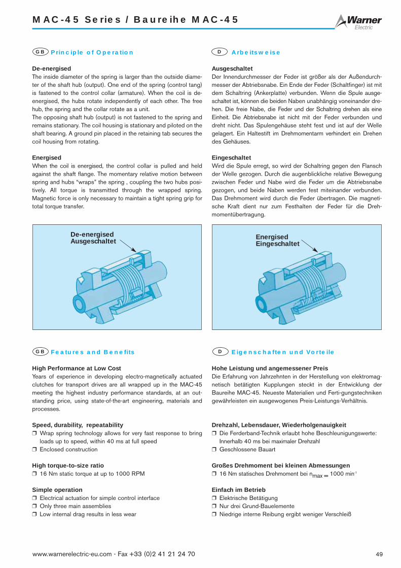
49www.warnerelectric-eu.com - Fax +33 (0)2 41 21 24 70
MAC-45 Series / Baureihe MAC-45
Principle of Operation
De-energisedThe inside diameter of the spring is larger than the outside diame-ter of the shaft hub (output). One end of the spring (control tang)is fastened to the control collar (armature). When the coil is de-energised, the hubs rotate independently of each other. The freehub, the spring and the collar rotate as a unit. The opposing shaft hub (output) is not fastened to the spring andremains stationary. The coil housing is stationary and piloted on theshaft bearing. A ground pin placed in the retaining tab secures thecoil housing from rotating.
EnergisedWhen the coil is energised, the control collar is pulled and heldagainst the shaft flange. The momentary relative motion betweenspring and hubs “wraps” the spring , coupling the two hubs posi-tively. All torque is transmitted through the wrapped spring.Magnetic force is only necessary to maintain a tight spring grip fortotal torque transfer.
GB Arbeitsweise
AusgeschaltetDer Innendurchmesser der Feder ist größer als der Außendurch-messer der Abtriebsnabe. Ein Ende der Feder (Schaltfinger) ist mitdem Schaltring (Ankerplatte) verbunden. Wenn die Spule ausge-schaltet ist, können die beiden Naben unabhängig voneinander dre-hen. Die freie Nabe, die Feder und der Schaltring drehen als eineEinheit. Die Abtriebsnabe ist nicht mit der Feder verbunden unddreht nicht. Das Spulengehäuse steht fest und ist auf der Wellegelagert. Ein Haltestift im Drehmomentarm verhindert ein Drehendes Gehäuses.
EingeschaltetWird die Spule erregt, so wird der Schaltring gegen den Flanschder Welle gezogen. Durch die augenblickliche relative Bewegungzwischen Feder und Nabe wird die Feder um die Abtriebsnabegezogen, und beide Naben werden fest miteinander verbunden.Das Drehmoment wird durch die Feder übertragen. Die magneti-sche Kraft dient nur zum Festhalten der Feder für die Dreh-momentübertragung.
D
Features and Benefits
High Performance at Low CostYears of experience in developing electro-magnetically actuatedclutches for transport drives are all wrapped up in the MAC-45meeting the highest industry performance standards, at an out-standing price, using state-of-the-art engineering, materials andprocesses.
Speed, durability, repeatability❒ Wrap spring technology allows for very fast response to bring
loads up to speed, within 40 ms at full speed ❒ Enclosed construction
High torque-to-size ratio❒ 16 Nm static torque at up to 1000 RPM
Simple operation❒ Electrical actuation for simple control interface❒ Only three main assemblies❒ Low internal drag results in less wear
GB Eigenschaften und Vorteile
Hohe Leistung und angemessener PreisDie Erfahrung von Jahrzehnten in der Herstellung von elektromag-netisch betätigten Kupplungen steckt in der Entwicklung derBaureihe MAC-45. Neueste Materialien und Ferti-gungstechnikengewährleisten ein ausgewogenes Preis-Leistungs-Verhältnis.
Drehzahl, Lebensdauer, Wiederholgenauigkeit❒ Die Ferderband-Technik erlaubt hohe Beschleunigungswerte:
Innerhalb 40 ms bei maximaler Drehzahl❒ Geschlossene Bauart
Großes Drehmoment bei kleinen Abmessungen❒ 16 Nm statisches Drehmoment bei nmax = 1000 min-1
Einfach im Betrieb❒ Elektrische Betätigung❒ Nur drei Grund-Bauelemente❒ Niedrige interne Reibung ergibt weniger Verschleiß
D
De-energisedAusgeschaltet
EnergisedEingeschaltet

50 www.warnerelectric-eu.com - Fax +33 (0)2 41 21 24 70
MAC-45 Series / Baureihe MAC-45
PerformanceGB LeistungD
Specifications / Technische Daten
Options
❒ 12 and 90 VDC❒ Connector termination of your choise on request❒ Integrated connector on request ❒ CW / CCW rotation❒ Hub or shaft input
Optionen
❒ 12 und 90 VDC❒ Montierter Stecker auf Anfrage❒ Integrierter Stecker auf Anfrage❒ Drehrichtung links/rechts❒ Antrieb über Nabe oder Welle
GB D
1
100
200
300
400
500
600 70
0
800
900
1000
1100
10
100
Speed/ Drehzahl (RPM)
Iner
tia /
Mas
sent
rägh
eits
mom
ent (
kgcm
)2
MAC-45
Static Statisches (Md) 16 Nm
Torque DrehmomentRadial load Radiallast (Fr) 130 NMax speed Max. Drehzahl (n) 1000 min-1Response time Ansprechzeitat full speed bei max. Drehzahl
(TTS) 40 ms
Voltage Spannung VDC 24Resistance Widerstand ±10% 93 ΩCurrent Strom A 0,26Lead length Litzenlänge mm 300Stripped end Abisoliert mm 5,0 – 8,0
Bore Bohrung mm 10H912H9

51www.warnerelectric-eu.com - Fax +33 (0)2 41 21 24 70
MAC-45 Series / Baureihe MAC-45
Dimensions [mm]GB Abmessungen [mm]D
Ø0,28 M MA
B
E
G
F
JL
O
H
C
Ø0 ,3 9 M MA
3 x 120
T
A
M
Q
P
R
NK
D
S
Installation ExampleGB EinbaubeispielD
Torque armDrehmomentarm
Input hub with lugs for adaptorAntriebsnabe mit Nuten für Adapter
Output shaftAbtriebswelle
CoilSpule
AdaptorAdapter
MAC-45
MAC-45
[mm] [mm]A 50° – 70° L 40,89 – 41,41B 40,38 – 41,23 M 18,54 – 19,56C 22,73 – 22,99 N 4,80 – 5,11D 45,59 – 46,11 O 44,19 – 44,71E 6.35 max. P R = 15,50 max.F 32,41 – 32,92 Q ø = 37,97 – 38,23G 0,0 – 0,82 R R = 27,94 – 28,96H 3,30 – 3,46 S 10H9J 3,09 – 3,61 12H9K 22,12 – 22,48 T 7,54 – 7,70
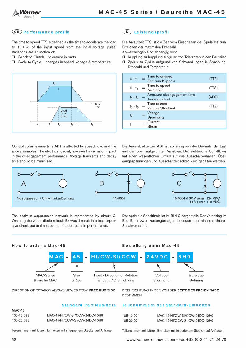
52 www.warnerelectric-eu.com - Fax +33 (0)2 41 21 24 70
MAC-45 Series / Baureihe MAC-45
Performance profile
The time to speed TTS is defined as the time to accelerate the loadto 100 % of the input speed from the initial voltage pulse.Variations are a function of:❒ Clutch to Clutch – tolerance in parts❒ Cycle to Cycle – changes in speed, voltage & temperature
Control collar release time ADT is affected by speed, load and theabove variables. The electrical circuit, however has a major impactin the disengagement performance. Voltage transients and decaytime should be minimised.
The optimim suppression network is represented by circuit C.Omitting the zener diode (circuit B) would result in a less expen-sive circuit but at the expense of a decrease in performance.
GB Leistungsprofil
Die Anlaufzeit TTS ist die Zeit vom Einschalten der Spule bis zumErreichen der maximalen Drehzahl.Abweichungen sind abhängig von:❒ Kupplung zu Kupplung aufgrund von Toleranzen in den Bauteilen❒ Zyklus zu Zyklus aufgrund von Schwankungen in Spannung,
Drehzahl und Temperatur
Die Ankerabfallzeitzeit ADT ist abhängig von der Drehzahl, der Lastund den oben aufgeführten Variablen. Der elektrische Schaltkreishat einen wesentlichen Einfluß auf das Ausschaltverhalten. Über-gangsspannungen und Ausschaltzeit sollten klein gehalten werden.
Der optimale Schaltkreis ist im Bild C dargestellt. Der Vorschlag imBild B ist zwar kostengünstiger, bedeutet aber ein schlechteresSchaltverhalten.
D
0 - t1 =Time to engage
(TTE)Zeit zum Kuppeln
0 - t2 =Time to speed
(TTS)Anlaufzeit
t3 - t4 =Armature disengagement time
(ADT)Ankerabfallzeit
t3 - t5 =Time to zero
(TTZ)Zeit bis Stillstand
U =VoltageSpannung
I =CurrentStrom
t1 t2 t3 t4 t5
TimeZeit
0
U
I
LoadLast[rpm]
+
–
+
–
+
–
A CB
Standard Part Numbers Teilenummern der Standard-EinheitenMAC-45
105-10-023 MAC-45-HI/CW-SI/CCW-24DC-10H9
105-20-038 MAC-45-HI/CCW-SI/CW-24DC-10H9
Teilenummern mit Litzen. Einheiten mit integriertem Stecker auf Anfrage.
How to order a Mac-45 Bestellung einer Mac-45
MAC 6H9– 45 – –HI/CW-SI/CCW –
MAC-Series Size Input / Direction of Rotation Voltage Bore sizeBaureihe MAC Größe Eingang / Drehrichtung Spannung Bohrung
DIRECTION OF ROTATION ALWAYS VIEWED FROM FREE HUB SIDE DREHRICHTUNG IMMER VON DER SEITE DER FREIEN NABE
BESTIMMEN
24VDC
No suppression / Ohne Funkenlöschung 1N4004 1N4004 & 30 V zener (24 VDC)15 V zener (12 VDC)
105-10-024 MAC-45-HI/CW-SI/CCW-24DC-12H9
105-20-024 MAC-45-HI/CCW-SI/CW-24DC-12H9
Teilenummern mit Litzen. Einheiten mit integriertem Stecker auf Anfrage.

53www.warnerelectric-eu.com - Fax +33 (0)2 41 21 24 70
BBC Series / Baureihe BBC
Spring Actuated Ball Bearing Clutch
The model BBC-29 clutch combines the ease of direct electro-magnetic actuation with the quick response and high torque offeredby wrap spring technology. This improved clutch design features aball bearing drive and a new magnetic circuit to enhance itsperformance and effi ciency and greatly increase its life.
Bearing life effectively determines clutch life. Clutch performance hasbeen significantly improved by replacing the sleeve bearing, commonlyused in this type of clutch, with a shielded, pre lubricated ball bear-ing. Life expectancy may now exceed 50 million cycles.
Outstanding features are:
❒ Electromagnetic actuation❒ High torque in a small package❒ Corrosion protected❒ Ball bearing mounted coil housing❒ Bearing shielded against contamination and lubricant loss❒ Redesigned, high efficiency magnetic circuit❒ Drag free, engaged or disengaged❒ High speed operation—up to 1800 RPM❒ Housing assembly can be used as shaft bearing support❒ Uni-directional input❒ Freewheeling output when disengaged❒ Simple installation—no adjustments required❒ Custom configurations
Typical Applications
❒ Forms handling equipment❒ Paper feed drives❒ Copiers❒ Photographic processing equipment❒ Printers❒ Collating machines❒ Automatic bank tellers❒ Check processing machines❒ Feed rollers for paper, film, etc.
GB Federkupplung mit Kugellager
Die Kupplung BBC-29 vereint dank der Federbandtechnik müheloseelektromagnetische Betätigung mit Reaktivität und einem hohenDrehmoment. Dieses fortschrittliche Kupplungskonzept umfassteinen Kugellagerantrieb und einen neuen Magnetkreis zur Optimierungvon Leistungsfähigkeit, Effizienz und Lebensdauer.
Die Lebensdauer der Kupplung hängt von der Lebensdauer desKugellagers ab. Die Leistungsfähigkeit der Kupplung wurde bedeu-tend erhöht, indem das für diesen Kupplungstyp übliche Gleitlagerdurch ein geschütztes, vorgeschmiertes Kugellager ersetzt wurde.Die Lebensdauer beträgt nun mehr als 50 Million Arbeitstakte.
Herausragende Merkmale sind:
❒ Elektromagnetische Betätigung❒ Hohes Drehmoment in kleinem Bausatz❒ Korrosionsabweisend❒ Kugelgelagertes Spulengehäuse❒ Vor Verschmutzung und gegen Schmiermittelverlust geschütz-
tes Lager❒ Neu überarbeiteter Hochleistungsmagnetkreis❒ Ein- und ausgekuppelt zugfrei❒ Hochleistungskupplung — bis zu 1800 min-1
❒ Gehäuse kann als Achslagerstütze benutzt werden❒ Einrichtungsantrieb❒ Freilaufabtrieb, wenn ausgekuppelt❒ Einfache Installation — keine Einstellung erforderlich❒ Kundenspezifische Konfigurationen
Typische Anwendungen
❒ Formenbearbeitung❒ Papierbeförderung❒ Kopierer❒ Fotoentwicklung❒ Drucker❒ Mischmaschinen❒ Bankautomaten❒ Prüfgeräte❒ Zuführwalzen für Papier, Folie usw.
D
1Flying leadsAnschlusslitzen
2Free hubFreie Nabe
3Ball bearingKugellager
4SpringFeder
5CoilSpule
1
2
5
3
4

54 www.warnerelectric-eu.com - Fax +33 (0)2 41 21 24 70
BBC Series / Baureihe BBC
Dimensions [mm]GB Abmessungen [mm]D
23,72/24,08
2,51
/2,6
2 ø 22
,209
/22,
231ø 9,
24/9
,76
3,55/4,58
2,79/3,81
26,74/27,26
4,45 max.
0,05/0,56
18,5
4/19
,56
3 x R 7,11/7,37
3 x 5,28/5,39
3,12/3,3144°
34°
ø 29,47 max.ø 23,39/23,60
3 X 120°
HI-CCW/SI-CW
HI-CW/SI-CCWBBC-29
Specifications / Technische Daten
BBC-29
Static Statisches (Md) 2,82 Nm
Torque DrehmomentRadial load Radiallast (Fr) 34 NMax speed Max. Drehzahl (n) 1800 min-1Response time Ansprechzeit
(TTS) 40 msat full speed bei max. DrehzahlShaft sizes Shaft sizes mm 6Input Eingang Hub or shaftConfiguration Konfiguration Nabe oder WelleBearing Kugellager Shielded
GeschütztWeight Masse (m) 0,45
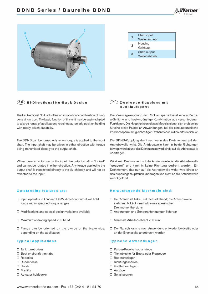
55www.warnerelectric-eu.com - Fax +33 (0)2 41 21 24 70
BDNB Series / Baureihe BDNB
Bi-Directional No-Back Design
The Bi-Directional No-Back offers an extraordinary combination of func-tions at low cost. The basic function of this unit may be easily adaptedto a large range of applications requiring automatic position holdingwith rotary driven capability.
The BDNB can be turned only when torque is applied to the inputshaft. The input shaft may be driven in either direction with torquebeing transmitted directly to the output shaft.
When there is no torque on the input, the output shaft is “locked”and cannot be rotated in either direction. Any torque applied to theoutput shaft is transmitted directly to the clutch body, and will not bereflected to the input.
Outstanding features are:
❒ Input operates in CW and CCW direction; output will holdloads within specified torque ranges
❒ Modifications and special design variations available
❒ Maximum operating speed 200 RPM
❒ Flange can be oriented on the bi-side or the brake side,depending on the application
Typical Applications
❒ Tank turret drives❒ Boat or aircraft trim tabs❒ Robotics❒ Rudderlocks❒ Hoists❒ Manlifts❒ Actuator holdbacks
GB Zweiwege-Kupplung mitRücklaufsperre
Die Zweiwegekupplung mit Rücklaufsperre bietet eine außerge-wöhnliche und kostengünstige Kombination aus verschiedenenFunktionen. Die Hauptfunktion dieses Modells eignet sich problemlosfür eine breite Palette an Anwendungen, bei der eine automatischePositionssperre mit gleichzeitiger Drehantriebsfunktion erforderlich ist.
Die BDNB-Kupplung dreht nur, wenn das Drehmoment auf denAntriebswelle wirkt. Die Antriebswelle kann in beide Richtungenbewegt werden und das Drehmoment wird direkt auf die Abtriebswelleübertragen.
Wirkt kein Drehmoment auf die Antriebswelle, ist die Abtriebswelle“gesperrt” und kann in keine Richtung gedreht werden. EinDrehmoment, das nun auf die Abtriebswelle wirkt, wird direkt andas Kupplungshauptstück übertragen und nicht an die Antriebswellezurückgeführt.
Herausragende Merkmale sind:
❒ Der Antrieb ist links- und rechtsdrehend; die Abtriebswellesteht fest R Lädt innerhalb eines spezifischenDrehmomentbereichs
❒ Änderungen und Sonderanfertigungen lieferbar
❒ Maximale Arbeitsdrehzahl 200 min-1
❒ Der Flansch kann je nach Anwendung entweder beidseitig oderan der Bremsseite angebracht werden
Typische Anwendungen
❒ Panzer-Revolverkopfantriebe ❒ Trimmbleche für Boote oder Flugzeuge❒ Roboteranlagen❒ Richtungssperren❒ Krafthebeanlagen❒ Aufzüge❒ Schaltsperren
D
1
23
1Shaft inputWellenantrieb
2HousingGehäuse
3Shaft outputWellenabtrieb

56 www.warnerelectric-eu.com - Fax +33 (0)2 41 21 24 70
BDNB Series / Baureihe BDNB
Dimensions [mm]GB Abmessungen [mm]D
Ø 63,24/63,76
Ø44,32/44,58
Ø12,70/12,76
max. 3,05
30°max.
Ø19
,02/
19,0
8
OUTPUT
Ø4,77/4,88
6,22/6,48
65,58/65,74
97,96/98,48
3,04/3,31
10,66/11,16
INPUT
Ø10,89/12,04 Ø4,77/4,88
Ø12
,59/
12,6
5
Ø53,85
4 x Ø5,30/5,69
4 x 90°
BDNB
Specifications / Technische Daten
Flange option :- Mounted on bi-side (shown above)- Mounted on brake side (shown at left)
Flanschoption :- Beidseitig montiert (siehe oben)- An Bremsseite montiert (siehenebenstehend)
Size Grösse BDNB
Torque rating Nenndrehmoment (Md) 28 Nm
Clutch holding torque, both directions Kupplung hält Drehmoment in beide Richtungen (Md) 28 Nm
Output to housing lost motion Abtrieb an Gehäuse Bewegungsverlust - 6°*
Input to output lost motion Antrieb zu Abtrieb Bewegungsverlust - 25°
Maximum additional input torque Maxim. zusätzliches Antriebsdrehmoment - 1,129 Nm**
Weight Masse (m) 0,900 kg
Notes :
* Angular movement is determined with 2,82 Nm of torque applied tooutput
** Or less than 1,15 times the output shaft load, whichever is greater
Bemerkungen :
* Winkelbewegung beträgt 2,82 Nm des auf den Abtrieb wirkenden Drehmoments
** Oder weniger als das 1,15-Fache der Last der Abtriebswelle, fallshöher

57www.warnerelectric-eu.com - Fax +33 (0)2 41 21 24 70
BDSC Series / Baureihe BDSC
Bi-Directional Slip Clutch
The BDSC clutch is a customer driven, special unit designed for highvolume usage. It consists of just four components: one snap ring, twohubs and one spring. Like the CTS series, these clutches are designedto slip when ever a preset torque limit is exceeded. Torque ratings rangefrom 0,014 Nm to 0,225 Nm.
By attaching various pulleys, sprockets and other input devices,BDSC clutches are easily adapted for a wide variety of applica-tions.
Outstanding features are:
❒ Low cost design❒ Custom configurations❒ Torque ratings from 0,014 Nm to 0,225 Nm❒ 200 RPM maximum speed❒ Suitable for 100% duty cycle❒ Torque can be varied with direction of rotation❒ Low cost
Typical Applications
❒ Turntable drives❒ Machine doors❒ Conveyor drive systems for poly film bag manufacturing❒ Gear boxes❒ Servo systems❒ Tension devices❒ Ribbon winding❒ Paper feed
GB Zweiwege-Reibungskupplung
Die BDSC-Kupplung ist eine kundenorientierte Spezialkupplung fürintensive Einsätze. Sie besteht aus nur vier Komponenten: einFederring, zwei Naben und eine Feder. Genauso wie bei der CTS-Serie besteht das Konzept dieser Kupplung ebenfalls darin, beiÜberschreiten eines voreingestellten Drehmoments eine Reibungauszulösen. Der Drehmomentbereich reicht von 0,014 bis 0,225 Nm.
Durch Hinzufügen verschiedenster Scheiben, Zahnräder und ande-rer Antriebselemente können die BDSC-Kupplungen mühelos auf eineVielfalt an Anwendungen zugeschnitten werden.
Herausragende Merkmale sind:
❒ Kostengünstiges Konzept❒ Kundenspezifische Konfigurationen❒ Drehmomentbereich von 0,014 Nm bis 0,225 Nm❒ Höchstgeschwindigkeit 200 rpm❒ Geeignet für 100 % Auslastungsgrad❒ Drehmoment kann mit der Drehrichtung eingestellt werden❒ Kostengünstig
Typische Anwendungen
❒ Drehscheibenantriebe❒ Maschinentüren❒ Förderantriebe in der Plastiktütenindustrie❒ Getriebe❒ Servosysteme❒ Spannvorrichtungen❒ Bandaufwicklung❒ Papierzufuhr
D
1
1Input, pulleyAntrieb, Scheibe
2Shaft outputWellenabtrieb
2

58 www.warnerelectric-eu.com - Fax +33 (0)2 41 21 24 70
BDSC Series / Baureihe BDSC
Dimensions [mm]GB Abmessungen [mm]D
9,98/10,11
R 2,
92/3
,43
2,10/2,62
Ø20,57/20,83
25,14/25,401,52/1,78
0,88/1,15
Ø9,
49/9
,54
2,15/2,42
Ø17
,42/
1,46
Ø6,362/6,414
#6-32 Hex Skt Set Screw6,35 Nom Lg
Ø9,52-9,58
Ø38,04/38,16 8,38/8,89
Ø15
,74/
16,0
1)
Ø32
,7/3
3,79
2 x #10-32UNF-2B85°-95°
4,83
29,46/30,48
19,07/19,69
max. 0,77
BDSC - 2
BDSC - 4
BDSC
Torque rating: 0,014 - 1,017 Nm
- Torques held within ± 10 %
- Can provide different torques in different directions
- 0,17 Nm CW, 0,035 Nm CCW
Bore sizes
- English : .25 - .625 inch (6,35 - 15,88 mm)
- Metric .2362 - .629 inch (6 - 16 mm)
Weight: 0,453 kg
Specifications Spezifikationen
BDSC
Nenndrehmoment 0,014 - 1,017 Nm
- Drehmoment innerhalb ± 10 % gehalten
- Drehmomente können richtungsunabhängig eingestellt werden
- 0,17 Nm CW, 0,035 Nm CCW
Bohrung
- Zoll : .25 - .625 inch (6,35 - 15,88 mm)
- Metrisch .2362 - .629 inch (6 - 16 mm)
Masse: 0,453 kg

59www.warnerelectric-eu.com - Fax +33 (0)2 41 21 24 70
CTS Series / Baureihe CTS
Constant Torque Slip Clutch
The unique feature of the CTS series is that the clutch is designedto slip whenever a preset torque limit is exceeded. CTS clutches canalso be used to apply drag in a system for tensioning require ments.
While standard wrap spring units are designed to drive and/or brake,the CTS clutch is an inexpensive solution when a slip function isneeded.
Outstanding features are:
❒ Suitable for 100 % duty cycle
❒ 7 watts maximum power dissipation
❒ 150 RPM maximum speed
❒ Torque ratings from 0,22 Nm to 3,16 Nm
Typical Applications
❒ Cable winding equipment❒ Torque wrenches❒ Data handling devices❒ Dispensing equipment❒ Gear boxes❒ Web tensioning❒ Servo systems
GB Reibungskupplung mit konstantemDrehmoment
Die CTS-Serie ist eigens so konzipiert, dass die Kupplung bei Über-schreiten eines voreingestellten Drehmoments reibt. CTS-Kupplungeneignen sich demnach auch für Zuganwendungen beiSpannvorgängen.
Gängige Federbandreibungskupplungen lösen Bewegung ausund/oder hemmen sie, während die CTS-Kupplung eine günstigeLösung für Reibkupplungsanforderungen darstellt.
Herausragende Merkmale sind:
❒ Geeignet für 100 % Auslastungsgrad
❒ Maxim. 7 Watt Energieaufwand
❒ Höchstgeschwindigkeit 50 min-1
❒ Drehmomentbereich von 0,22 Nm bis 3,16 Nm
Typische Anwendungen
❒ Kabelaufwicklungen❒ Drehmomentschlüssel❒ Datenverarbeitende Geräte❒ Ausgabegeräte❒ Getriebe❒ Bandspannung❒ Servosysteme
D

60 www.warnerelectric-eu.com - Fax +33 (0)2 41 21 24 70
CTS Series / Baureihe CTS
Dimensions [mm]GB Abmessungen [mm]D
Ø34,29 Ø31,757,95
/8,0
0BORE
6,36/6,41
4,82
8-32 SOCSET SCREW
6,351,57
Ø17
,42/
17,4
4
#8-32 UNC-2B3 holes Eq. SP. onØ25,4 B.C.
B
A
CTS-25
Specifications / Technische Daten
CTS-50
.
10-32 SOCSET SCREW
#10-32 UNC-2B3 holes Eq. SP. onØ31,75 B.C.
B
AØ45,97
5,58 7,62
12,7
1/12
,76
Ø19
,05
Ø39,64/39,68
Size Grosse CTS-25Torque Drehmoment Nm 1,582Shaft size Welle Abmessungen mm 6,35 and 7,938
Size Grosse CTS-50Torque Drehmoment Nm 3,164Shaft size Welle Abmessungen mm 12,7
CTS-25 - Clutch / Kupplung
Torque / Drehmoment (Nm) A (mm) B (mm)0,22 24,3 21,460,45 24,3 21,460,67 24,3 21,460,90 27,68 24,941,13 27,68 24,941,356 31,16 28,571,58 31,16 28,57
CTS-50 - Clutch / Kupplung
Torque / Drehmoment (Nm) A (mm) B (mm)0,45 31,57 28,570,90 31,57 28,571,356 31,57 28,571,80 37,31 34,342,26 37,31 34,342,71 43,05 40,083,16 43,05 40,08

61www.warnerelectric-eu.com - Fax +33 (0)2 41 21 24 70
ACCM Series / Baureihe ACCM
Mechanically ActuatedAccumulating Conveyor Clutches
Heavy-duty operationThe ACCM accumulating conveyor clutch offers extraordinary per-formance and durability.
Designed specifically for industrial equipment applications, ACCMclutches are suitable for indexing, rapid cycling and positivedisplacement clutching drives.
OperationWith the stop collar released and the input hub rotating in a speci-fied direction, the lay of helical spring around the input and outputhubs is such that the spring grips both hubs, connecting them in apositive-displacement drive.If the stop collar is engaged, the spring tang connected to it isforced back, and the spring opens. This allows the input hub to con-tinue rotating without transmitting torque to the output hub.
Available in three design styles :Standard: Model SS–Start-StopOptional: Model S–Single Revolution
Model O–Overrunning
Outstanding features are:
❒ Low cost❒ Trouble-free design for long life❒ Complete package for immediate installation❒ High torque, 169,5 Nm at speeds to 400 RPM❒ 280 Nm available, consult factory.
Typical Applications
❒ Material conveyors❒ Packaging equipment
GB Mechanisch betätigteStaubandkupplung
Schwere BelastungDie ACCM-Staubandkupplung bietet eine außergewöhnlicheLeistungsfähigkeit und Beständigkeit.
Sie wurde speziell für Industrieanwendungen entwickelt und eignetsich für Indexierung, schnelllaufende Geräte und Verdrängungs-systeme.
BetriebBei gelöstem Schaltring gelöst und bestimmter Drehrichtung derAntriebsnabe verläuft die schneckenförmige Feder um dieAntriebsnabe und Abtriebswelle so, dass die Feder sowohl Nabe alsauch Welle greift und sie miteinander verbindet, um einemVerdrängungsantrieb zu bilden. Bei eingehaktem Schaltring wirddie daran befestigte Federlasche zurückgedrängt und die Federwird geöffnet. Dadurch kann die Antriebsnabe weiterdrehen, ohnedas Drehmoment an die Abtriebswelle zu übertragen.
In drei Ausführungen lieferbar :Standard: Modell SS–Start-StopOptional: Modell S–Eintouren
Modell O–Freilauf
Herausragende Merkmale sind:
❒ Kostengünstig❒ Störungsfreies Konzept für eine lange Lebensdauer❒ Kompletter Bausatz für sofortige Installation❒ Hohes Drehmoment, 169,5 Nm bei Geschwindigkeiten bis zu
400 min-1
❒ 280 Nm lieferbar, wenden Sie sich an uns.
Typische Anwendungen
❒ Materialförderer❒ Verpackungsanlagen
D
1
14 stops collars4 Anschlägen
2InputAntrieb
3OutputAbtrieb
23

62 www.warnerelectric-eu.com - Fax +33 (0)2 41 21 24 70
ACCM Series / Baureihe ACCM
Dimensions [mm]GB Abmessungen [mm]D
5,72
47,5
7/47
,63
64,01 11,13
D
63,5
0
80,26
4 x
4,83
95,25
42,1612,95
20,32
E19,05 max. threadengagement
B
C
ABore
Bohrung
ACCM
Specifications / Technische Daten
How to order a ACCE Clutch Bestellung einer ACCE Kupplung
ACCM 1”– 7 – S – HI – CW – – 4
ACCM-Series Size Model S, SS or O Input Direction of Rotation Bore No. of StopsBaureihe ACCM Größe Modell S, SS oder O Antrieb Drehrichtung Bohrung Anschläge
Bore and Keyway data / Bohrung und Passefeder Daten
ACCMStandard Static Standard Statisches
(Md) 170 NmTorque DrehmomentHeavy duty Static Hoche Statisches
(Md) 280 NmTorque DrehmomentInertia Trägheitsmoment (Jc) 0,000585 kgm2
Max speed Max. Drehzahl (n) 400 RPMResponse time Ansprechzeit
ms 60at full speed bei max. DrehzahlWeight Masse (m) 1,8 kg
Bore A Keyway Width B Keyway Depth C Set Screws D Mounting Holes E
Bohrung A Passfeder Breit B Passfeder Tiefe C Schrauben D Einbau Bohrungen E
1.0005-1.0025 .251-.253 1.114-1.124 #1/4-20 x .5 4x #10-32 UNF(25.412-25.464) (6.37-6.43) (28.29-28.55) Hex Skt. Set Screw / Schrauben on / auf 2.125 BC
1.2505-1.2525 .3135-.3155 1.389-1.399 #1/4-20 x .5 4x #10-32 UNF(31.762-31.814) (7.962-8.014) (35.28-35.54) Hex Skt. Set Screw / Schrauben on / auf 2.125 BC
1.3755-1.3775 2x .376-.382 4x #10-32 UNF(34.937-34.989) — — Hole / Bohrung @ 180° on / auf 2.125 BC
1.4380-1.4400 (STD) 2x .376-.382 4x #10-32 UNF(36.525-36.576) — — Hole / Bohrung @ 180° on / auf 2.125 BC

63www.warnerelectric-eu.com - Fax +33 (0)2 41 21 24 70
ACCE Series / Baureihe ACCE
Solenoid ActuatedAccumulating Conveyor Clutches
The ACCE accumulating conveyor clutch offers extraordinary per-formance and durability. Designed expressly for industrial use, ACCEunits are suitable for indexing and rapid cycling in heavy-duty machin-ing such as packaging equipment and conveyors.
OperationWith the stop collar released and the input hub rotating in a speci-fied direction, the lay of helical spring around the input and outputhubs is such that the spring grips both hubs, connecting them in apositive-displacement drive.
If the stop collar is engaged, the spring tang connected to it isforced back, and the spring opens. This allows the input hub to con-tinue rotating without transmitting torque to the output hub.The solenoid actuator provides for the electrical control of engage-ment through the stop collar (power ON-clutch driving; power OFF-clutch disengaged).
The heavy-duty actuator is offered as a simple laminated AC sole-noid actuated mechanical device to operate in conjunction withPSI–6, –8 and ACCE clutches. Mounted in the proper proximity tothe clutches, it will control single, multiple or partial revolutions. It isdesigned as a no power, no revolution device. The actuator isruggedly constructed for maximum strength and long life.
Outstanding features are:❒ Low cost❒ Trouble-free design for long life❒ Complete package for immediate installation❒ High torque, 169,5 Nm at speeds to 400 RPM❒ 280 Nm available, consult factory
Typical Applications
❒ Material conveyors❒ Packaging equipment
GB Elektromagnetisch betätigteStaubandkupplung
Die ACCM-Staubandkupplung bietet eine außergewöhnlicheLeistungsfähigkeit und Beständigkeit. Sie wurde speziell fürIndustrieanwendungen entwickelt und eignet sich für Indexierung,schnelllaufende Geräte und Schwerlasteinsätze, wie Verpackungs-anlagen und Fördereinrichtungen.
BetriebBei gelöstem Schaltring und bestimmter Drehrichtung derAntriebsnabe verläuft die schneckenförmige Feder um dieAntriebsnabe und Abtriebswelle so, dass die Feder sowohl Nabe alsauch Welle greift und diese miteinander verbindet, um einenVerdrängungsantrieb zu bilden.
Bei eingehaktem Schaltring wird die daran befestigte Federlaschezurückgedrängt und die Feder wird geöffnet. Dadurch kann dieAntriebsnabe weiterdrehen, ohne das Drehmoment an dieAbtriebswelle zu übertragen. Die elektromagnetische Betätigungzur elektrischen Steuerung des Einkuppelvorgangs verfolgt durch denSchaltring (EIN - einkuppeln; AUS - auskuppeln).
Das hochbelastbare Stellglied besteht aus einer einfach beschich-teten, elektromagnetisch betätigten mechanischen Vorrichtung, diein Verbindung mit PSI–6, –8 und ACCE-Kupplungen betrieben wird.Das Stellglied wird in angemessenem Abstand zu den Kupplungenmontiert und steuert auf diese Weise einfache, mehrfache oder teil-weise Umdrehungen. Es wurde als strom- und drehungsfreieVorrichtung konzipiert und ist äußerst robust für eine maximaleBelastung und eine lange Lebensdauer
Herausragende Merkmale sind:❒ Kostengünstig❒ Störungsfreies Konzept für eine lange Lebensdauer❒ Kompletter Bausatz für sofortige Installation❒ Hohes Drehmoment, 169,5 Nm bei Drehzahlen bis zu 400 min-1
❒ 280 Nm lieferbar. Wenden Sie sich an uns.
Typische Anwendungen
❒ Materialförderer❒ Verpackungsanlagen
D
1Input hubAntriebsnabe
2Output shaftAbtriebswelle
3CoilSpule
4ActuatorSperrklinke
5Control collarSchaltring
1
2
3
4
5

64 www.warnerelectric-eu.com - Fax +33 (0)2 41 21 24 70
ACCE Series / Baureihe ACCE
Dimensions [mm]GB Abmessungen [mm]D
+
53,98
+
++
107,95
53,8
5
19,05 max. threadengagement
45° 4,78
115,09
57,15 max.
63,5
0
63,5
0
20,14
74,6
3
64,01
5,72
146,
05
4,93
13,59
47,5
7/47
,63
D
4 x Ø7,21Eql Sp onØ127 BC
E
B
C
ABore
Bohrung
ACCE
Specifications / Technische Daten
How to order a ACCM Clutch Bestellung einer ACCM Kupplung
ACCE 1”– 7 – S – HI – CW – – 4
ACCE-Series Size Model S, SS Input Direction of Rotation Bore No. of Stops VoltageBaureihe ACCE Größe Modell S, SS Antrieb Drehrichtung Bohrung Anschläge Spannung
Voltage Current Resistance
Spannung Strom Widerstand
115VAC, 60 Hz 0,334 A 57,5 Ω
24 VDC 0.586 A 41,0 Ω
12 VDC 1,15 A 10,4 Ω
90 VDC 0,151 598 Ω
– 24V
Bore and Keyway data / Bohrung und Passefeder Daten
Bore A Keyway Width B Keyway Depth C Set Screws D Mounting Holes E
Bohrung A Passfeder Breit B Passfeder Tiefe C Schrauben D Einbau Bohrungen E
1.0005-1.0025 .251-.253 1.114-1.124 #1/4-20 x .5 4x #10-32 UNF(25.412-25.464) (6.37-6.43) (28.29-28.55) Hex Skt. Set Screw / Schrauben on / auf 2.125 BC
1.2505-1.2525 .3135-.3155 1.389-1.399 #1/4-20 x .5 4x #10-32 UNF(31.762-31.814) (7.962-8.014) (35.28-35.54) Hex Skt. Set Screw / Schrauben on / auf 2.125 BC
1.3755-1.3775 2x .376-.382 4x #10-32 UNF(34.937-34.989) — — Hole / Bohrung @ 180° on / auf 2.125 BC
1.4380-1.4400 (STD) 2x .376-.382 4x #10-32 UNF(36.525-36.576) — — Hole / Bohrung @ 180° on / auf 2.125 BC
ACCEStandard Static Standard Statisches
(Md) 169,5 NmTorque DrehmomentHeavy duty Static Hoche Statisches
(Md) 280 NmTorque DrehmomentInertia Trägheitsmoment (Jc) 0,000585 kgm2
Max speed Max. Drehzahl (n) 400 RPMResponse time Ansprechzeit
ms 60at full speed bei max. DrehzahlWeight Masse (m) 5,4 kg

65www.warnerelectric-eu.com - Fax +33 (0)2 41 21 24 70
Heavy duty actuator / Verstärkte Klinfe
Heavy Duty Actuator
For use with PSI-6, PSI-8 and ACCM Series clutches
The Heavy Duty Actuator is offered as a simple laminated AC sole-noid actuated mechanical device to operate in con junc tion with thePSI-6 and PSI-8 clutches. Mounted in the proper proximity to theclutches, it will control single, multiple, or partial revolution. It isdesigned as a no power, no revolution device. Ruggedly constructedfrom steel and nylon for maximum strength and long life.
OperationWhen voltage is applied to the coil, the stop block is pulled back fromthe clutch stop collar allowing the clutch to engage. It is not necessaryto hold power on the coil for the entire revolution. A pulse to the coilwill allow the clutch to start, the return spring pressure on the col-lar will not disengage the clutch and the stop block will be in positionto dis engage the clutch after one revo lution. No “On” timing is nec-essary.
GB Verstärkte Klinfe
Die verstärkte Klinfe in Verbindung mit Kupplungen derBaureihen PSI-6, PSI-8 und ACCMDie Verstärkte Klinfe wird als einfach beschichtete, elektromagnetischgesteuerte mechanische Vorrichtung, das in Verbindung mit denKupplungen PSI-6 und PSI-8 betrieben wird angeboten. Die Klinfewird in angemessenem Abstand zu den Kupplungen montiert undsteuert auf diese Weise einfache, mehrfache oder teilweiseUmdrehungen. Es wurde als strom- und drehungsfreie Vorrichtungkonzipiert und ist äußerst robust für eine maximale Belastung und einelange Lebensdauer.
BetriebBei spannungsführender Spule wird der Anschlagblock vomKupplungsschaltring weggezogen, wodurch die Kupplung einrastet.Die Spannungszufuhr zur Spule muss nicht während der gesamtenUmdrehung erfolgen. Ein einziger Impuls reicht aus, um die Kupplungin Gang zu setzen. Die Kupplung wird durch den Druck derRückzugfeder auf den Schaltring nicht ausgekuppelt und derAnschlagblock bleibt so lange in Position, bis eine Umdrehungerfolgt ist und kuppelt dann erst aus. Eine Einschaltzeitsteuerung istnicht erforderlich.
D
EnergizedAusgeschaltet
De-EnergizedEingeschaltet
PSI-6
PSI-8
6,35 Stroke2x Male tab terminal for6,35 push on connector
47,7
5
59,6
9
22,35
24,38101,6
50,8
65,2
76,2
57,1559,18Ref.
12,7
4x Slots 6,35 Wide
5,58
Dimensions / Abmessungen [mm]Specifications / Technische Daten
Input120 AC, 60 Hz
EingangDC resistance
14,5 ohmsDC WiderstandLoad current
2,9 AStromHolding current
0,1 AHaltespannungTerminals 1/4” spade lug connectionsAnschlüsse 1/4” Gabelkabelschuhe

66 www.warnerelectric-eu.com - Fax +33 (0)2 41 21 24 70
Selection by calculation
Accellerations and decelerations are extremely short and caremust be taken to select the right size.
Main considerations are:Inertia output (Jo) kgm2
Inertia clutch (Jc) kgm2
Linear inertia (Jn) kgm2
Speed (n) min-1
Friction torque* (MF) NmLoad torque ** (ML) NmTotal torque (MCL) NmAcceleration time (ta) sec. (0,003)Deceleration time (td) sec. (0,0015) Time to determine min. required inertia (tm) = table
* Friction torque is the most unknown factor. It is the torquerequired to overcome static friction in the output by slowly rotat-ing it by means of a torque wrench or a moment arm connectedto a spring scale. At the design stage it may have to be estimat-ed or calculated.
GB Auswahl nach Berechnung
Die Beschleunigung und Verzögerung bei einer Schlingfeder-bandkupplungung ist sehr kurz. Daher muß die Größenbestim-mung einer solchen Einheit mit größter Sorgfalt mittels einerBerechnung vorgenommen werden.
Berechnungskriterien:Massenträgheitsmoment (Abtrieb) (Jo) kgm2
Massenträgheitsmoment (Kupplung) (Jc) kgm2
Lineares Massenträgheitsmoment (Jn) kgm2
Drehzahl (n) min-1
Reibmoment * (MF) NmLastmoment** (ML) NmGesamtdrehmoment (MCL) NmBeschleunigungszeit (ta) sec. (0,003) Verzögerungszeit (td) sec. (0,0015)Zeit zur Bestimmung des minimal (tm) = Tabellebenötigten Massenträgheitsmomentes
* Das Reibmoment ist die große Unbekannte. Es handelt sich umdas benötigte Drehmoment, um die statische Reibung imAbtrieb zu überwinden. Das Reibmoment kann mit Hilfe einesDrehmomentschlüssels oder eines Drehmomentarms mitFederwaage bestimmt werden. Bei der Konstruktion muß eineSchätzung oder Berechnung stattfinden.
D
Inertia calculations / Berechnung des Massenträgheitsmomentes
k = 1 Steel, cast ironStahl, Gußeisen
k = 1,1 BrassMessing
k = 0,34 Aluminium
k = 0,24 Plastic, rubberKunststoff, Gummi
J = Jc + Jo +(J1 · n1) + (J2 · n2)
[kgm2]n2
2 2
J = k · 7,65 · 10-13 [D4 - d4] · L [kgm2] J = m [D2 + d2] [kgm2]8
Jn = 91 · m · v2 [kgm2]
n2
INERTIATRÄGHEITSMOMENT
REDUCTION OF INERTIAREDUZIERTES MASSENTRÄGHEITSMOMENT
D [mm]
L [mm]
d [mm]
Clutch-brakeKupplung-Bremse
n
Jc Jo [kgm2]
J1
J2
n1
n2
kg
D [m]
d [m]
m [kg]
v [m/s]
m [kg]
n [min-1] d
n2 [min-1] J2 [kgm2]
n1 [min-1] J1 [kgm2]
n [min-1] Jc + Jo [kgm2]
v [m/s]
Selection and Calculations / Auswahl und Berechnungen

67www.warnerelectric-eu.com - Fax +33 (0)2 41 21 24 70
Selection and Calculations / Auswahl und Berechnungen
Torque calculations
This calculation determines the required torque capacity of theclutch or clutch/brake and it has a decisive influence on the per-formance and life of the unit. The most crucial elements in this cal-culation are accelleration- and deceleration times. Past experiencedictates the values.They are for clutch torque = 0.003 sec. and forbrake torque (CB series only) = 0.0015 sec.
Experience has also shown that on most CB applicationsthe brake torque is the major factor.
Clutch Torque (PSI Series)
(Jo + Jc) • n= Inertial torque (output) (MJ)
9.55 • 0.003+ Friction torque (output) (MF)+ Load torque (ML)
= Total clutch torque (MCL)
Brake Torque (CB and Super CB Series)
(Jo + Jc) • n= Inertial torque (output) (MJ)
9.55 • 0.0015– Friction torque (output) (MF)– Load torque** (ML)
= Total brake torque (MB)
** Deduct only if load is present at point of disengagement.
GB Drehmomentberechnungen
Diese Berechnung bestimmt das benötigte Drehmoment derKupplung oder Kupplungs-Bremskombination. Es beeinflußt weitge-hend die Leistung und Lebensdauer der Einheit. Die kritischenElemente dieser Berechnung sind die Beschleunigungs- undVerzögerungszeit. Sie betragen für die Beschleunigung = 0.003 sec.und für die Verzögerung (nur bei CB-Einheiten) = 0.0015 sec.
Die Erfahrung hat gezeigt, daß bei den meisten CB-Anwen-dungen das Bremsmoment ausschlaggebend ist.
Kupplungsmoment (Baureihen PSI)
(Jo + Jc) • n= Drehmonment (Abtrieb) (MJ)
9.55 • 0.003+ Reibmoment (Abtrieb) (MF)+ Lastmoment (ML)
= Gesamt-Kupplungsmoment (MCL)
Bremsmoment (Baureihen CB und Super CB)
(Jo + Jc) • n= Drehmonment (Abtrieb) (MJ)
9.55 • 0.0015– Reibmoment (Abtrieb) (MF)– Lastmoment** (ML)
= Gesamt-Bremsmoment (MB)
**Nur abziehen wenn die Last im Zeitpunkt des Abschaltenswirksam ist.
D
Quick torque reference Schnelle Drehmomentbestimmung
BrakeBremsen
ClutchKupplung
2000
1000
500
200
100
50
20
10
300200100
502010
521
25002000
1000
500
200
100
50
20
10
5.0
2.0
1.0
0.5
0.25
Spe
ed /
Dre
hzah
l [m
in-1
]
Torq
ue /
Dre
hmom
ent [
Nm
]
Iner
tia /
Mas
sent
rägh
eits
mom
ent [
kgcm
2 ]
2000
1000
500
200
100
50
20
10
300200100
502010
521
25002000
1000
500
200
100
50
20
10
5.0
2.0
1.0
0.5
0.25
Spe
ed /
Dre
hzah
l [m
in-1
]
Torq
ue /
Dre
hmom
ent [
Nm
]
Iner
tia /
Mas
sent
rägh
eits
mom
ent [
kgcm
2 ]

68 www.warnerelectric-eu.com - Fax +33 (0)2 41 21 24 70
Minimum Inertia for CB’s
To properly operate the clutch, a minimum inertia and/or speed isrequired to fully open the clutch spring and fully close the brakespring. This is crucial for accuracy, repeateability, performance anduseful life of the unit.
Main considerations are:
MC = Torque required to fully activate the clutchMF = Friction torquen = rpmJc = Inertia (clutch)Jmin = Min. Inertia requiredJo = Inertia (output)tm = Time factor (see table)
If Jmin is positive, a minimum of the same value has to be added tothe output inertia - or the speed has to be increased - or the fric-tion torque has to be reduced
GB Min. Massenträgheitsmoment für CB’s
Um die volle Funktionsfähigkeit zu gewährleisten, müssen minima-le Massenträgheitsmomente und/oder Drehzahlen eingehaltenwerden, um die Kupplungsfeder voll zu öffnen und die Bremsfedervoll zu schließen. Dies ist von größter Wichtigkeit, um Genauigkeit,Leistung und Lebensdauer zu erreichen.
Hauptmerkmale sind:
MC = Benötigtes Drehmoment um die Einheit richtig zu schaltenMF = Reibmomentn = min-1
Jc = Massenträgheitsmoment (Kupplung)Jmin = Minimal benötigtes MassenträgheitsmomentJo = Massenträgheitsmoment (Abtrieb)tm = Zeitfaktor (Tabelle)
Wenn Jmin positiv ist, muß dem Massenträgheitsmoment amAbtrieb mindestens der gleiche Wert hinzugefügt oder die Drehzahlerhöht oder das Reibmoment reduziert werden.
D
Jmin =9.55 • (MC + MF) • tm – (Jc + Jo)n Jmin =
9.55 • (MC + MF) • tm – (Jc + Jo)n
Size tm Mmax nmax MC JcGröße [s] [Nm] [min-1] [Nm] [kgm2]
CB2 0,003 2,82 1500 0,2 6,21 • 10-6
CB4 0,004 13,5 1200 0,5 1,908 • 10-5
CB5 0,004 28 750 0,8 5,85 • 10-5
CB6 0,005 56 500 1 5,154 • 10-4
Size tm Mmax nmax MC JcGröße [s] [Nm] [min-1] [Nm] [kgm2]
CB7 0,005 170 300 2,0 2,10 • 10-3
CB8 0,005 280 300 2,3 3,852 • 10-3
CB10 0,006 560 200 5,8 0,0144
Selection and Calculations / Auswahl und Berechnungen
Cycle rates for CB’s
Stop collars with up to 24 stops are available.To determine cycle rates, speed, number of stops and the actua-tor reaction time must be considered. For general applications it isrecommended to use TTS + tar as minimum cycle time.
Shorter cycle times are possible. Please consult WARNER.
TTS = Time to speed TTS + tar = mstar = Actuator return time n = rpmNst = No. of stops
(No. of stops: Do not exceed 24 and if fractional, use lower wholenumber.
Schalthäufigkeit für CB’s
Schaltringe mit bis zu 24 Anschlägen sind erhältlich.Um die Schalthäufigkeit zu bestimmen, müssen Drehzahl, Anzahlder Anschläge und die Reaktionszeit der Schaltklinke berücksich-tigt werden. Für übliche Anwendungen sollte TTS + tar alsMindest- Schaltzeit verwendet werden. Kürzere Schaltzeiten sind möglich. Bitte WARNER anfragen.
TTS = Anlaufzeit TTS + tar = mstar = Rückfallzeit, Klinke n = min-1
Nst = Anzahl Anschläge
(Anzahl Anschläge: 24 nicht überschreiten und bei Dezimalergeb-nis auf ganze Zahl abrunden.
GB D
nmax =60’000
[min-1](TTS + tar) x Nst
Nst =60’000
(TTS + tar) x n
Size TTS tar [ms]
Größe [ms] a) b) c)
CB2 20 8 12 40
CB4 24 15 20 50
CB5 27 15 20 50
CB6 45 22 32 120
Size TTS tar [ms]
Größe [ms] a) b) c)
CB7 50 22 32 120
CB8 54 22 32 120
CB10 70 27 63 145
a) No suppressionb) Diode-Zener Diodec) Diode
All values with standard components
a) keine Funkenlöschungb) Diode-Zener Diodec) Diode
Alle Werte mitStandardbauteilen

69www.warnerelectric-eu.com - Fax +33 (0)2 41 21 24 70
Terms / Begriffe
GB D
AB Anti-backup RücklaufsperreAC Alternating current WechselstromADT Armature disengagement time AnkerabfallzeitALS Actuator limit stop SperrklinkenanschlagAOR Anti-overrun VorlaufsperreCCW Anti-clockwise rotation LinksdrehendCW Clockwise rotation RechtsdrehendDC Direct current GleichstromFr Max.radial load Maximale radiale BelastungHI Hub input Antrieb über freie NabeI Current (A) Strom (A)IN Input AntriebJ Inertia MassenträgheitsmomentJc Inertia, clutch parts Massenträgheitsmoment (Kupplung)Jmin Min. required inertia Min. erforderliches MassenträgheitsmomentJn Linear inertia Lineares MassenträgheitsmomentJo Inertia output Massenträgheitsmoment (Abtrieb)k Material factor (inertia calculation) Materialfaktor (Berechnung von Massenträgheitsmoment)m Mass MasseMaor Torque, anti-overrun (Nm) Drehmoment, Vorlaufsperre (Nm)Matb Torque, anti-back (Nm) Drehmoment, Rücklaufsperre (Nm)MB Brake torque (Nm) Bremsmoment (Nm)MCL Total clutch torque (Nm) Gesamt-Kupplungsmoment (Nm)MC Min. torque to fully activate clutch (Nm) Mindest-Drehmoment, um Kupplung richtig zu schalten (Nm)Md Rated torque (Nm) Nenndrehmoment (Nm)MF Friction torque of load (Nm) Lastreibmoment (Nm)min-1 rpm DrehzahlMJ Inertial torque (Nm) Drehmoment von der Trägheitsmasse (Nm)ML Load torque (Nm) Lastdrehmoment (Nm)Mr Drag torque, clutch (Nm) Schleppmoment, Kupplung (Nm)ms Millisecond Millisekunden Speed (rpm) Drehzahl (min-1)Nm Torque DrehmomentNst No. of stops Anzahl der Anschlägenmax Max. speed Maximale DrehzahlOT Overtravel ÜberlaufOTS Over travel stop ÜberlaufanschlagR Resistance (Ω) Widerstand (Ω)sec Second SekundeSI Shaft input Antrieb über Wellet Time Zeitta Time of acceleration (ms) Beschleunigungszeit (ms)tar Actuator return time Rückfallzeit der Klinketd Deceleration (ms) Verzögerungszeit (ms)tm Time to calculate min. ineria (ms) Zeit zur Berechnung des minimalen Massenträgheitsmomentes (ms)tms Time between stops (ms) Zeit von Anschlag zu Anschlag (ms)TTE Time to engage armature (ms) Anzugszeit der Ankerplatte (ms)TTS Time to speed (ms) Anlaufzeit (ms)TTZ Time to zero (ms) Zeit bis zum Stillstand (ms)U Voltage Spannungv Velocity (ms) Geschwindigkeit (ms)

70 www.warnerelectric-eu.com - Fax +33 (0)2 41 21 24 70
Company / Firma:
City / Ort: Country / Land:
Tel: Fax:
Responsible / Verantwortlich
Application / Anwendung:
Application Data Sheet / Anwendungs-Datenblatt
Function / Funktion: Clutch❒
Clutch/Brake❒
Brake❒
Kupplung Kupp./Bremse Bremse
Actuation / Betätigung: Mechanical / Mechanisch ❒
Electrical / Elektrisch ❒ Voltage / Spannung
Pneumatic / Pneumatisch ❒ Pressure / Druck bar
T.B.A. / Vorschlag Warner Electric ❒
Motion / Drehung: Single revolution / Eine Umdrehung ❒
Fract. revolution / Teilumdrehung ❒ Angle / Winkel
No. of stops / Anzahl Anschläge
Direction of rotation / Drehrichtung CW ❒ Rechts CCW ❒ Links
Anti-overrun / Vorlaufsperre ❒ T.B.A. / Vorschlag Warner Electric
Anti-back / Rücklaufsperre ❒ T.B.A. / Vorschlag Warner Electric
Positioning Accuracy: Closer than ± 4° ?
Positioniergenauigkeit: Genauer als ± 4° ? Yes / Ja ❒ No / Nein ❒
Random position / Zufallsposition
Technical data: Speed / Drehzahl (n) min-1
Technische Daten: Load inertia / Last-Trägheitsmoment (Jo) kgcm2
Friction torque / Reibmoment (MF) Nm
Clutch torque / Gesamt-Drehmoment (MCL) Nm
Brake torque / Bremsmoment (MB) Nm
Gear ratio / Über/Untersetzung
Cycle rate / Schalthäufigkeit min.
TTS ms TTZ ms
Life expectancy / Lebensdauererwartung hrs / Std.
Shaft dia. / Wellendurchmesser mm
Mounting / Montage Horizontal ❒ Vertical ❒
Commercial data: Potential / Potential Pcs / Stück over / über Years / Jahre
Komerzielle Daten: Prototypes / Prototypen Pcs / Stück When / Wann
Pre-Series / Vorserie Pcs / Stück When / Wann
Series / Serie Pcs / Stück times P.A. / Jahr
First delivery / Erste Lieferung
Target price / Preisvorstellung
Copyright © 2022 FDOKUMEN