Vol. 9 - World Bank Documents and Reports
90
E228 Vol. 9 - Revised GUJARAT STATE HIGHWAYS PROJECT: PHASE IIB ENVIRONMENTAL DESIGN AND MITIGATION MEASURES ,- SPACER 2 017: i GUARD RAIL BEAM A~~~~I ECTIONPOST EARTH GRVLO BEL GURPI BEA 150/75, 1900 LONG IL GAE `0 GUTTER _ - ~~~~~ ~~G.L.- R.C.C. 7-SHAPD CAN71TIWRTYPF Re U~~~~~~ LU -e CAnn 1 O > wn en Rn]. 0 11cxan f9H911TAN 'H REINJFORCED CONCRETE roUN ,A, FKA PE,C CED TRQ ELEE .~~~~~~ ~ ~ / ,- - Project Coordinating Consultancy Services,-_ A World Bank Project FinalaReport-Volort E - V ol.E C O P YE Prepared for The Government of Gujarat Lea International Ltd. Roads and Buildings Department in association with March 2002 Lea Associates South Asia Pvt. Ltd. Public Disclosure Authorized Public Disclosure Authorized Public Disclosure Authorized Public Disclosure Authorized Public Disclosure Authorized Public Disclosure Authorized Public Disclosure Authorized Public Disclosure Authorized
-
Upload
khangminh22 -
Category
Documents
-
view
2 -
download
0
Transcript of Vol. 9 - World Bank Documents and Reports
E228Vol. 9 - Revised
GUJARAT STATE HIGHWAYS PROJECT: PHASE IIB
ENVIRONMENTAL DESIGN AND
MITIGATION MEASURES
,- SPACER
2 01 7: iGUARD RAIL BEAM A~~~~I ECTION POST EARTH GRVLO BELGURPI BEA 150/75, 1900 LONG IL GAE
`0
GUTTER _ - ~~~~ ~ ~~G.L.-
R.C.C. 7-SHAPD CAN71TIWRTYPF Re
U~~~~~~ LU -e
CAnn 1 O > wn en Rn].0
11cxan f9H911TAN 'H
REINJFORCED CONCRETE roUN ,A, FKA PE,C CED TRQ ELEE
.~~~~~~ ~ ~ / ,- -
Project Coordinating Consultancy Services,-_
A World Bank Project
FinalaReport-Volort E - V ol.E C O P YEPrepared for
The Government of Gujarat Lea International Ltd.
Roads and Buildings Department in association withMarch 2002 Lea Associates South Asia Pvt. Ltd.
Pub
lic D
iscl
osur
e A
utho
rized
Pub
lic D
iscl
osur
e A
utho
rized
Pub
lic D
iscl
osur
e A
utho
rized
Pub
lic D
iscl
osur
e A
utho
rized
Pub
lic D
iscl
osur
e A
utho
rized
Pub
lic D
iscl
osur
e A
utho
rized
Pub
lic D
iscl
osur
e A
utho
rized
Pub
lic D
iscl
osur
e A
utho
rized


TABLE OF CONTENTS
1. OVER-VIEW OF GUJARAT STATE HIGHWAYS PROJECT .............................. 1-1
1.1 OBJECTIVES OF THE PROJECT ............................................................... 1-1
1.2 PHASES OF THE PROJECT ............................. ,.,. 1-2
1.3 OVER-VIEW OF GSHP: PHASE IIB ............................................................ 1-3
2. GENERAL ENVIRONMENTAL IMPACTS: ANALYSIS AND MITIGATION ............... 2-1
2.1 SOIL ............................................................... . 2-1
2.1.1 Loss of Productive Soil . . . .............................................................. 2-1
2.1.2 Erosion . . .............................................................. 2-2
2.1.3 Alternatives . . .............................................................. 2-3
2.1.3.1 Revegetation .2-32.1.3.2 Stone pitching .2-42.1.3.3 Brick pitching ................ , 2-4
2.1.3.4 Concrete Block Pitching .2-42.1.3.5 Gabion Structures .2-4
2.1.4 Applicability of Alternatives . . . ....................... 2-4
2.1.5 Corridor Speciflc Solution . . . ....................... 2-5
2.1.5.1 Corridor 02: Viramgam - Halvad .2-52.1.5.2 Corridor 10: Vadodara - Jambusar ......................... ; 2-5
2.1.5.3 Corridor 12: Bharuch - Dahej .2-52.1.5.4 Corridor 13: Olpad-Ichchhapor .2-52.1.5.5 Corridor 15: Magdalla - Sachin .2-62.1.5.6 Corridor 2'1: Dholka - Bagodara .2-62.1.5.7 Corridor 22: Wataman - Pipli .2-62.1.5.8 Corridor 26: Jetpur - Junagadh .2-62.1.5.9 Corridor 27: Rajkot - Morvi...............I ......... 2-6
2.1.5.10 Corridor 28: Rajkot - Vadinar .2-72.1.6 ScourProtection forNatural WaterCourses . . ..................................................... 2-7
2.1.6.1 Options ....................................................... 2-7
2.1.6.2 Preferred Alternative ....................................................... 2-8
2.1.7 Pollution ........ .................................................. 2-8
2.2 AIR POLLUTION ....................................................... . 2-8
2.2.1 Vehicular Pollution . ........................................................ . 2-8
2.2.1.1 Ambient Air Monitoring at Sites along Phase IIB Corridors ......................... 2-10
2.2.1.2 Mitigation Measures ............... ........................................ 2-12
2.2.2 Pollution Due to Point Sources During Construction .......... 2................................ 2-13
2.2.2.1. Hot Mix Plant ........................................ ; 2-13
2.2.2.2 Stone Crusher ........................................ 2-14
2.3 DRAINAGE .......................................... 2-15
2.3.1 Corridor 02: Viramgam-Halvad . . . ....................... 2-15
2.3.2 Corridor 22: Wataman-Pipli . . . .2.............................. -17
2.4 FLORA .................. .2-182.4.1 Corridor 10: Vadodara - Jambusar . . . ...................... 2-19
2.4.2 Corridor 26 . . . .2......... ; -19
2.4.3 Proposed Tree Plantation along Phase IIB Corridors ......................................... 2-20
2.5 FAUNA ....... .. ................................................ 2-21
-D=
3. HOT SPOT MITIGATION PRESCRIPTIONS .. ....................................... 1-1
3.1 WELLS ......................................... .. 1-13.1,1 Background .. ....................................... 1-13.1.2 Issues and Options .......................................... 1-13.1.3 Solution ......................................... . 3-2
3.2 POND AT SOLDI .......................................... 3-53.2.1 Background .......................................... 3-53.2.2 Issue .......................................... . 3-53.2.3 Options ......................................... . 3-S3.2.4 Comparison .......................................... 3-63.2.5 Solution .......................................... . 3-7
3.3 DRAINAGE AT PADRA .......................................... 3-73.3.1 Background .......................................... 3-73.3.2 Issue .......................................... . 3-83.3.3 Solution ......................................... . 3-8
3.4 NoiSE ........................................... 3-93.4.1 Background .. ........................................ 3-93.4.2 Issue ......................................... . 3-93.4.3 Options ........................................... 3-103.4.4 Solution ......................................... . 3-10
3.5 RECHARGING AT BHENSALI POND ........ .................. 3-113.5.1 Background .. ....................................... 3-113.5.2 Issue ......................................... . 3-113.5.3 Solution ........................................... 3-11
3.6 COMMUNITY POND AT ASNABAD . . .............................. 3-123.6.1 Background .. ....................................... 3-123.6.2 Issue ......................................... . 3-133.6.3 Options ............. 3-133.6.4 Comparison ............. 3-143.6.5 Solution .............. 3-14
3.7 RAG PICKERS AREA . . ........... 3-163.7.1 Background ............. 3-163.7.2 Issue ............. 3-163.7.3 Solution ............. 3-16
3.8 BRIDGE ON KANKRA CREEK . . ............ 3-173.8.1 Background ............. 3-173.8.2 Issue .. ....... I. : 3-18
Parameters ....................... .. 3-183.8.3 Chemistry of Corrosion ....................... 3-18
3.8.3.1 Alkalinity ....................... 3-183.8.3.2 Chlorides ........................ 3-193.8.3.3 Other Contributors ........................ 3-19
3.8.4 Options ......................... 3-193.8.4.1 Concrete Mix ........................ 3-203.8.4.2 Coatings ............... 3-20
3.8.5 Solution ................ 3-21
ii
FIGURES:
Figure: 1.1 Typical cross - section - GSHP ......................................... 1-2
Figure: 2.1 Gabion Structure ......................................... 2-4
Figure: 2.2 Oil & Grease Spillage ......................................... 2-8
Figure: 2.3 Air Pollution Sampling Station ......................................... 2-9
Figure: 2.4 Crusher ......................................... 2-14
Figure: 2.5 Thick Growth of Prosopis along the Highway ......................................... 2-19
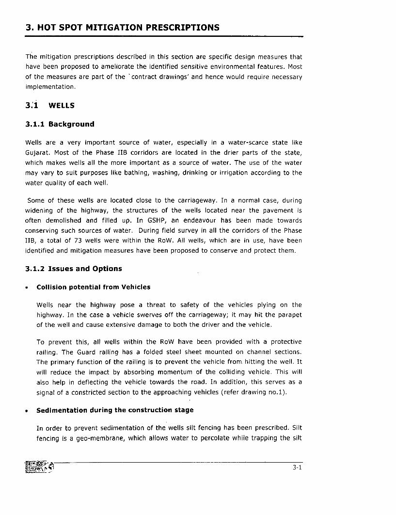
Figure: 3.1 A well located close to the carriage way .......................................... 3-2
Figure: 3.2 A well located close to the State Highway .......................................... 3-4
Figure: 3.3 A view of the pond at Asnabad ......................................... 3-13
Figure: 34 A view of the Area ..................... 3-16
Figure: 3.5 A view of Rag-Pickers Area ............................. 3-17
Figure: 3.6 Corrosion of piers ........................... 3-18
iii

TABLES:
Table: 1.1 Phase-wise Implementation Programme ................................................. 1-2
Table: 2.1 Land Acquisition Required in Phase IIB Corridors .................................................. 2-1
Table: 2.2 Increased Run-off along Corridors ................................................. 2-2
Table: 2.3 National Ambient Air Quality Standards' 2-9
Table: 2.4 Ambient Air Quality at Village Soldi - Corridor 02 .................................................. '.2-10
Table: 2.5 Ambient Air Quality at Village Sangma - Corridor 10 ................................................. 2-11
Table: 2.6 Ambient Air Quality at Bhensli on Corridor 12 ................................................. 2-11
Table: 2.7 Ambient Air Quality at Village Vadal on Corridor 26 ................................................. 2-11
Table: 2.8 Ambient Air Quality at Village Vasai on Corridor 28 ................................................. 2-12
Table: 2.9 Results of Ambient Air Monitoring Near a Hot Mix Plant ............................................ 2-13
Table: 2.10 Pollution due to a Stone Crusher near Morvi ......................................... 2-14
Table: 2.11 Details of Improvement / Addition of Culverts along Corridor 02 ............................ 2-15
Table: 2.12 Details of Improvement / Addition of Culverts along Corridor 22 ............................ 2-17
Table: 2.13 Trees to be saved along Corridor 10 ......................................................... 2-19
Table: 2.14 Proposed Tree Plantation along Phase IIB Corridor ................................................ 2-20
Table: 3.1 Mitigation Measures - Wells ......................................................... 3-3
Table: 3.2 List of Wells to be provided with Mitigation Measures ............................................... 3-4
Table: 3.3 Locations of Noise Barrier ......................................................... 3-11
Table: 3.4 Water Sampling results of the Khadi River ......................................................... 3-18
iv
1. OVER-VIEW OF GUJARAT STATE HIGHWAYS PROJECT
The state of Gujarat is located on the western coast of India, north of the State ofMaharashtra. It borders Pakistan to the north-west. The State straddles the Tropic ofCancer along the Arabian Sea and has an area of 195,904km2 .
The State has a road network of about 70,000 km, of which 2,000 km constitute theprimary network (namely, the National Highways, controlled by the GoI), and 20,000km constitute the secondary network (namely, the State Highways, controlled by theR&BD, GoG). The remaining roads are controlled by the local self-governments(namely, the Panchayats and Municipalities). Most of the State Highways are eithertwo-lane or intermediate-lane carriageways on 10m road formation.
Due to rapidly increasing traffic, industrial growth, and increasing. levels of mobility,the existing State Highways are experiencing varying levels of stress, which in turnimpedes the industrial and economic development of Gujarat. To relieve that stress,the GoG has undertaken the Gujarat State Highways Project (GSHP) with loanassistance from the World Bank (WB) to upgrade selected Highway corridors in orderto facilitate smoother and quicker movement of goods and people.
The Gujarat "Project Co-ordinating Consultancy" (PCC) was undertaken by N D LeaInternational Ltd., Canada (NDLI) in association with Lea Associates South Asia Pvt.Ltd., India (LASA).
A "Strategic Options Study" (SOS), undertaken by LASA in 1995, evaluated 3000km ofState Highways and selected 1500km for detailed feasibility study. The objectives ofthe PCC, during the feasibility study, were to conduct a detailed feasibility study, which
applied economic and environmental principles to formulate establish a roadinvestment program for a sub-set of these roads to be funded by the World Bank loan.
1.1 OBJECTIVES OF THE PROJIECT
The GSHP aims to improve a portion of the road transport network in the state withinthe constraints imposed by the available funding. More specifically, the objectives arethe following:
* to provide more efficient transportation of passengers and goods in the state;
* to provide better accessibility and reduce traffic distress on the arterial highways
passing through the state;
* to ensure a minimum longevity of the roads for a period of 15 years, therebyreducing the cost of maintenance, travel time and vehicle operation and;

Chapter I
RIGHT OF WAY: TYPICALLY 30M
Clear Carria e Wa Clear
i Shouldl I~ Choulder l
/ 3 Sm _ 3.5m
~~ / 2 .5 m _ _2_5m 2 Srm
! < 70m _ < 7 Om l
CORRIDOR OF IMPACT
Figure 1.1: Typical Cross-section - GSHP
to improve accessibility to the major ports, existing and proposed industrial
estates, and foreseeable mega-industrial complexes for efficient transport of goods.
The GSHP generally involves widening and strengthening of the project corrid,ors along
the existing alignment and within the existing RoW (subject to minor modifications in
order to improve road geometry and for road safety).
1.2 PHASES OF THE PROJECT
The project is to be implemented in three phases, designated respectively as Phase I,
IIA, and IIB. Phase I involves widening and strengthening of 246.3 km of StateHighways, whereas Phase IIA consists of 249.2 km of State Highways for widening (the
65 km Mahesana- Palanpur corridor is common to both Phases I and IIA: existing two-
lane carriage-way to be strengthened in Phase I and a two-lane new carriage-way to
be added in Phase IIA.). The remaining 393.14 km roads are a part of the Phase IIB
(Refer Table 1.1) of the Project.
Table 1.1: Phase-wise Implementation Programme
Contract CorridorLeghOPhase Corridor Name Length of
Package No. Corridor (km)
01 Sarkhej - Viramgam 47.7
II 03 Mahesana - Palanpur 65.0Phase I III 06 (part) Godhra - Halol 38.0
IV 28 (part) Rajkot - Link to Vanthali 60.0
V 17 Kadodara - Bajipura 35.6
Sub-total 246.3Mahesana-Palanpur
VI 03 (new two lanes to be 65.0added)
Phase 05 Shamlaji - Lunavada 85.5ViIIIA 06 (part) Lunavada - Godhra, 36.0
VIII 08 Ladvel - Dakor 18.009 Dakor - Godhra 47.7
Sub-total 252.2
1-2 -'

Gujarat State HIghways Project: Phase IIB - Vol. 1/ E
Contract Corridor . Length ofPhase Corridor Name
Package No. Corridor (km)
IX 10 Vadodara - Jambusar 45.4
12 Bharuch - Dahej 47.7
X 26 Jetpur - Junagarh 24.24
27 Rajkot - Morvi 68.2PHASE Xi 28 (part) Falla - Jamnagar 65.1
IIB XII 02 Viramgam - Halvad 71.5
XIII 21 Bagodara - Dholka 22.7
22 Wataman - Pipli 24.0
XIV 13 Olpad - Ichchhapor 11.0
15 Magdalla - Sachin 13.25
Sub-total 393.14.
ALL TOTAL 891.64
Source - SEA Report, NDLI/LASA, 1997
1.3 OVER-VIEW OF GSHP: PHASE IIB
Phase IIB includes 10 corridors located in Southern Gujarat and the Western peninsulaof Saurashtra, totalling to 393.14 km of State Highways that would be upgraded in thisPhase. Most of these Highways woul(i handle traffic at design speeds of 100km/h
instead of the present 65km/h. However, even with such a strengthening most of theup-gradation would occur within the RoW already acquired by R&BD.
The Environmental Study for Phase IIB of GSHP (Refer Volume IIA, ESR,NDLI/LASA, 1999) has encompassed all the components of the bio-physical andsocial environment that are relevant in the context of this Project. This study' covereddetailed assessment of elements of natural and human environment covering generalas well as site-specific situations for all corridors.
Also, composite sampling for air quality (3 days continuously) and ambient noise levels(24 hours) at selected locations along critical corridors was carried out. Trees, ponds,wells and all other water sources within the RoW were enumerated as a part ofEnvironmental Survey. Water quality was tested at wells and ponds most frequentlyused by the neighbouring communities. This would provide a base line data to comparethe effect of the Project over a period - before, during and after the implementation is
over.
As a part of study with respect to social environment, detailed socio-economic surveyswere carried out along all corridors. Data on income source/s, literacy, property andassets, perception about the project, household structure and composition etc. wascollected among other things. These details have been covered appropriately in variousChapters of the Environmental Stiudy Report (specially in Chapter 4: Existing
> U,1-3
Chap/er I
Baseline Status, Chapter 5: Assessment of Potential Impacts and Chapter 8:Resettlement Action Plan) prepared for this Phase.
All cultural properties within RoW and in the indirect zone of influence of the Projectwere also surveyed, listed and enhancement prescriptions were prepared for the same.All the details including enhancement plans in this regard have been highlighted in aseparate report (Refer Volume 2F: Cultural Properties) to provide a better and a
complete information base to the ones interested in this particular aspect.
In addition to this, in Phase IIB, the objective has been to concretize the operationplans, detailing out the methods and tools for implementation of EMAP and RAP. Thedetails of operationalisation of the institutions and their working proceduresrecommended for the implementation of environmental and R&R components havebeen worked out.
As the working procedures recommended now will form basis of any action to be takenby the EMU and all other agencies in all phases of the project, a separate stand-alonereport, Volume II B: Institutional Arrangements and Legal Setting for GSHPhas been prepared.
However, no project planning, design or implementation can be completed withoutproviding a platform for public opinion and their effective involvement in any Project.The acceptance or success of the Project depends to a large extent on how the role ofthe community has been perceived in the initial stages of the Project.
In order to obtain factual information about local level issues and true aspirations ofthe people, it is extremely essential to provide the community complete knowledgeabout the Project. This would essentially formalize the process of sharing informationso that the decisions made by the people are correct and are made in the light ofcomplete knowledge about the Project.
In order to accomplish this, exhaustive Public Participation Programme was organizedto address location specific issues more precisely so that they could be meaningfully
incorporated into road design.
In order to put together the various details of this exhaustive program a separatestand-alone report has been prepared - Volume UIC: Public ParticipationProgramme. This particular report provides complete details on the PublicParticipation Programme organized in Phase IIB - from its inception, approach andmethodology to location wise issues raised, solutions provided, evaluation and
recommendations.
A detailed Survey on Wild Asses - an endangered species inhabiting the Little Rann ofKachchh along Corridor 02 (Viramgam-Halvad), which lies south of the Wild Ass
Sanctuary, has been conducted under this Phase.
1-4 I D
Gujarat State HIGhways Project, Phase JIB - Vol 1I E
The primary objective has been to identify Wild Ass Crossing locations so thatadequate measures could be drawn up to prevent any probability of collision ofvehicles with the Wild Ass during the operational phase of the Project.
More than this, pilot projects have been developed under GSHP to protect this
endangered animal by developing fodder cum water points so as to avoid the probablecrossings altogether. This would help in providing not only mitigation measures butalso in creating better micro-environmental conditions in the area. Volume 2D: WildAss Crossing on Corridor 02: Viramgam-Halvad covers all details in this regard.
The report also discusses various reasons responsible for Wild Ass migration into areasacross the Highway. Major impact/s of the proposed widening and strengtheningactivity on Wild Ass crossings has also been identified and discussed. Various possiblemitigation measures with respect to the above-mentioned issue/s have been analyzedand discussed at length.
Among others, considerable emphasis was laid on developing effective environmentaldesigns and mitigation measures for site-specific problems, for which a separate reporthas been prepared. This Volume 2E: Environmental Design and Mitigationmeasures, covers all information and drawings in this regard.
To establish a baseline, from which the Environmental Management Unit (ReferVolume 2B: Institutional Arrangements and Legal Setting for GSHP for specificresponsibilities of the EMU) could draw information for comparison during theconstruction and operation phases of the Project, an extensive sampling programmewas drawn.
Samples from selected water sources were analysed for pollutants that could be tracedback to road run-off. In addition, composite sampling was carried out for air quality (3-days' continuously) and ambient noise levels (24-hours) at selected locations alongcritical corridors. The results and their implications are discussed in this report.
This document is structured to.discuss impacts at different levels. Some impacts willoccur along all corridors irrespective of their geographical location, length, climaticconditions, present and anticipated traffic characteristics etc while others may be onlysite specific. Of course, the degree of impact varies with a change in these variables.Soil and ambient air are the components, which are likely to be impacted along eachcorridor.
Some other components of the bio-physical environment will be impacted along somespecific corridor sections only. The impacts on the drainage and flooding will besignificant only along corridors where there is a problem of over-topping at present.Also with regard to flora and fauna, concern will be limited to only those corridor/swhere any rare or endangered species have been recorded or are likely to beencountered due to the closeness of their habitat.
m ull~~~~~~~~~~~~~~~~~~~~~ 1~~~~~~-5

Chapter I
Impact on water sources and impact due to noise pollution on sensitive receptors (suchas school students or hospital patients) is another aspect, which has been given dueattention in the report. These impacts are essentially local in nature and mitigationmay include receptor protection as preferred option rather than control at the source.
Major negative impacts of the proposed widening and strengthening activity on eachcomponent of the environment has been identified and discussed. Various possiblemitigation measures have been analysed and finally a preferred solution has beensuggested.
1-6
2. GENERAL ENVIRONMENTAL. IMPACTS: ANALYSIS ANDMITIGATION
2.1 SOIL
The road-widening project will affect the surrounding natural environment in more than one way.Such changes include both beneficial and adverse impacts on the elements of physicalenvironment. In this study, macro-level impacts have been identified based on secondary(literature and maps) information available at regional scale. The purpose has been to formulategeneral guidelines and mitigation measures for the various road links. Micro level hot spotmatrices have been designed to enhance and minimize the negative impacts of the project onnatural environment.
In this section, environmental impacts of general nature have been analyzed and mitigationmeasures have been proposed for the same.
2.1.1 Loss of Productive Soil
Topsoil is produced after action of forces of nature-wind, water, and heat over millions of years.
Loss of topsoil, either under pavement or for other ancillary areas is a permanent impact. Theeffect is especially severe if fertile land has to be acquired. This context becomes more serious incase of Gujarat, which has relatively less fertile land than other states. For this project, very littleland acquisition will be required, as the proposed widening would be carried out within the existingRoW in most cases.
Table 2.1: Land Acquisition Required in Phase IIB Corridors
Area Required forS. No. Corridor Length (km) realgent (ha
realignme.nt (ha)
nf Viramnam - Halvad 71 'n -vR7S
10 Vadodara - Jambusar 45.40 4.513
12 Bharuch - Dahei 47.70 1.994
13 Olpad - Ichchhapor 11.00 2.965
15 Magdalla - Sachin 13.30 1.904
21 Bagodara - Dholka 22.70 0.924
22 Wataman - Pipli 24.00 4.095
26 Jetpur - Junagadh 24.24 0.319
27 Raikot - Morvi 68.20 3.217
28 Falla - Jamnagar 65.10 5.907
Total 393.09 28.713
Chap ot 2
Some land may have to be acquired permanently to improve road geometry in order to ensuresafer and quicker movement of people and materials. Some land may also have to be temporarilyacquired for detours during the construction phase. Where land acquisition is unavoidable,mitigation measures have been chalked out. The total land to be acquired in various corridors ofPhase IIB has been given in Table No. 2.1.
The topsoil from land to be acquired permanently will be removed and stocked in piles for futureuse. This could be used as a cover on embankment slopes to be re-vegetated or for reclaimingthe present barren areas. In case the land has to be acquired for detours only, the topsoil will bestored in stockpiles and returned to its original position upon completion of construction. The earthrequired for fill areas would be preferably dug from barren areas to conserve fertile lands. Ifagricultural land is used, topsoil will be used in the manner described above.
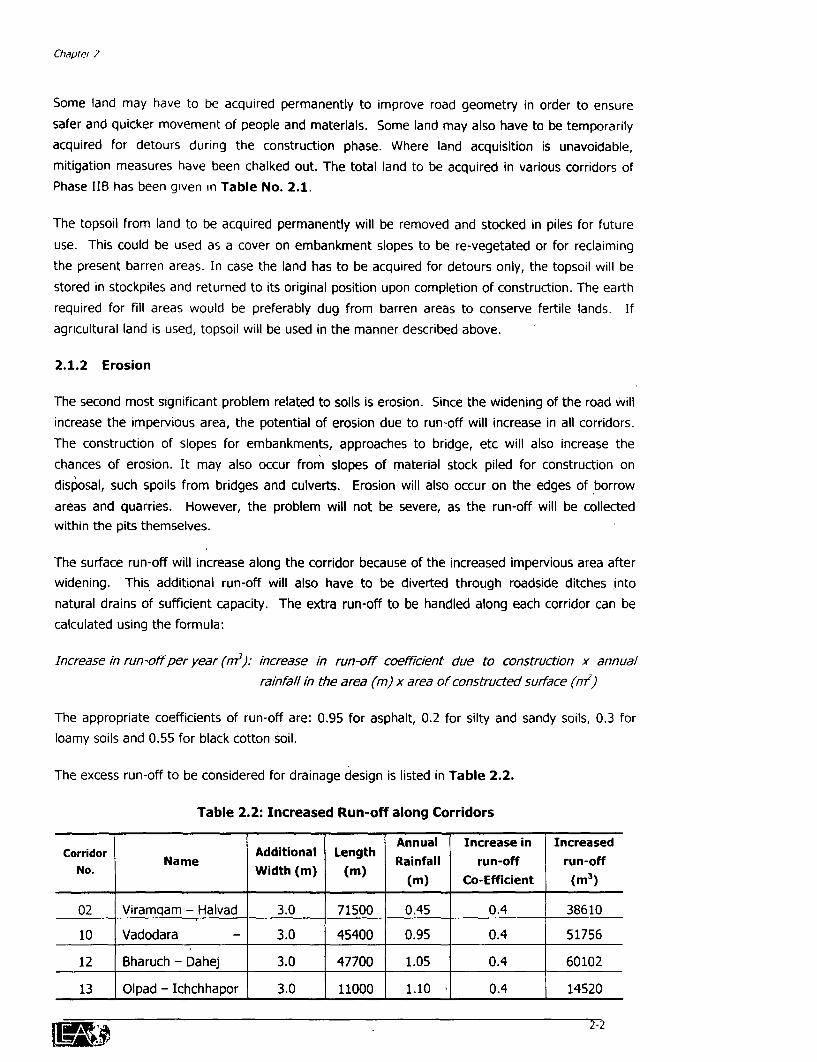
2.1.2 Erosion
The second most significant problem related to soils is erosion. Since the widening of the road willincrease the impervious area, the potential of erosion due to run-off will increase in all corridors.The construction of slopes for embankments, approaches to bridge, etc will also increase thechances of erosion. It may also occur from slopes of material stock piled for construction ondislposal, such spoils from bridges and culverts. Erosion will also occur on the edges of borrowareas and quarries. However, the problem will not be severe, as the run-off will be collectedwithin the pits themselves.
The surface run-off will increase along the corridor because of the increased impervious area afterwidening. This additional run-off will also have to be diverted through roadside ditches intonatural drains of sufficient capacity. The extra run-off to be handled along each corridor can becalculated using the formula:
Increase in run-off per year (m3): increase in run-off coefflcient due to construction x annualrainfall in the area (m) x area of constructed surface (in2
)
The appropriate coefficients of run-off are: 0.95 for asphalt, 0.2 for silty and sandy soils, 0.3 forloamy soils and 0.55 for black cotton soil.
The excess run-off to be considered for drainage design is listed in Table 2.2.
Table 2.2: Increased Run-off along Corridors
Annual Increase in IncreasedCorridor Name Additional Length
No. Name Width (m) (m) Rainfall run-off run-offNo. Width (in) (in) (m) Co-Efficient (m3 )
02 Viramqam - Halvad 3.0 71500 0.45 0.4 38610
10 Vadodara - 3.0 45400 0.95 0.4 51756
12 Bharuch - Dahej 3.0 47700 1.05 0.4 60102
13 Olpad - Ichchhapor 3.0 11000 1.10 0.4 14520
2-2

Gujarat State Highways Project: Phase fIB - Vol. 1 E
Annual Increase in IncreasedCorridor Name Additional Length Rainfall run-off run-off
No. Width (m) (m) (m) Co-Efficient (m3 )
15 Sachin - Magdalla 3.0 13250 1.10 0.4 17490
21 Bagodra - Dholka 3.0 22700 0.60 0.4 16344
22 Wataman - Pipli 3.0 24000 0.60 0.4 17280
26 Jetpur - Junagadh 3.0 24240 0.70 0.6 30542
27 Rajkot - Morvi 3.0 68200 0.50 0.6 61380
28 Falla - Khambalia 3.0 65100 0.45 0.75 65914
Erosion will effect the structural stability of slopes and damage the road itself in the longer run. In
addition, the eroded material will be carried with run-off and get deposited in ditches or water
bodies reducing their carrying capacity. This may altogether alter the local drainage pattern.
Erosion may also result in loss of fill material or topsoil, which has to be replaced at its original
place from stockpiles, on completion of construction.
There are a number of methods available to protect slopes from erosion. Salient features of each
option have been discussed along with their suitability and limitations in the following paragraphs.
Following this, a comparison has been made before suggesting corridor specific measures.
2.1.3 Alternatives
2.1.3.1 Revecetation
Shrubs are useful stabilising slopes. Shrubs with a tap root system will reduce erosion and help
other flora to grow by creating a suitable micro-habitat. The species, which are locally available in
Gujarat and are suitable for this purpose, include:
-1. Corodiya Dycotoma (Gunda)
2. Holarahina Antidicentrica (Indrajav)
3. Carisa Consteta (Kurmand)
4. Alehigam Salvipholium (Alol)
5. Casiya Ourusuleta (Awad)
6. Bauheriya Resemosa (Ashitra)
7. Agava Americana (Ketki)
Shrubs should be planted on the slope with help of a P.V.C. tube measuring 20 cm in length and 3
cm in diameter. The tube should be perforated to allow absorption of water and nutrients for the
plant. The tube will enhance the plant root to go deeper into the soil and would finally help in
developing a fine root system. This will help in stabilizing the slope. After sufficient growth the
tube will automatically rupture due to the pressure from the root system. This system will hold the
soil together and ensure the stability of the slope. An additional enhancement will be the
aIT'd 2-3

Chapter 2
development of a new ecosystem. This mneasure is best suited for corridors having soil cover thatcan hold suffident moisture for a longer duration after the rain.
2.1.3.2 Stone pitching
Where corridors are located in add areas, and adequate stones are found in the vicinity, stonepitching would be provided in case of the normal slopes. This will prevent the erosion and will holdmoisture and sediments, which in tum will fadlitate the growth of grass and small shrubs.
2.1.3.3 Brick pitching
In areas where bricks are cheaper, they could be used in place of stones (Refer figure 2.4).Bricks can absorb more moisture and retain it for longer time. The recommended brick size is 230mm x 110 mm x 70 mm. The arrangement of bricks shown above ensures stability of the slopeand provides suffident space for vegetation to grow.
2.1.3.4 Concrete Block Pitchina
In other areas punctured cement concrete blocks can be used for a similar purpose.
2.1.3.5 Gabion Structres
Gabion structures are also a viable option for use onslopes particularly if a water source is available at thebase of the slope. These structures are made up of wire ;mesh baskets and boulders. The utility of this structurelies in void ratio of its boulders and strength of themesh to keep them in place. This structure alsoprovides an opportunity for soil to get infiltrate and fillup the voids. The voids in the structure retain water forlonger time thus assists in growth of vegetation. Thisstructure will be used along edges of ponds, lakes orwater bodies where slope protection is required. Fig 2.1: Gabion Structure
2.1A Applicability of Alternatives
Each alternative discussed above has its own advantages and limitations. Though each may betechnically feasible, the discussion below highlights suitability of each option in different soils anddimatic condrtions.
Revegetation would be suitable in areas where soil is productive, dayey and sufficient rainfallo.zurs or water is available. The second option, stone pitching, would be suitable where stones orrocks are available easily and at cheaper rates. Since no binding material is to be used betweenstone blocks, steeper slopes cannot be provided with stone pitching. Use of bridcs would beadvisable where the soil is dry and where bridcs are available easily. Bricks absorb more moistureand thus would be help in vegetation growth. Goncrete block pitching, will be used where there isa danger of soil erosion due to flooding or from strong currents flowing during monsoon. TheMD 2-4
Gu/aiai State Highways Project. Phase I/B - Vol. 1/ E
strength of the arrangement would be an advantage in such a case. The cement concrete slabswill hold the soil from getting washed away. Gabions will be used to protect edge of water bodies,ponds and natural drains irrespective of. their position. This option provides the best slopeprotection at the edge of water body because it has a potential to accumulate the soil & holdmoisture, which allows vegetation to grow quite fast. However, since it is the most costlyarrangement among discussed here, its use will be limited to special conditions such as steepembankments.
2.1.5 Corridor Specific Solution
2.1.5 1 Corridor 02: Viramgam - Halvad
The average rainfall in the region through which the corridor passes is about 45-55 cms. The soiltype varies from alluvial to sandy. In a large section soils are saline in nature. The potential for soilerosion increases towards. Halvad as a result of low rainfall and lack of vegetative cover. The riversand streams drain into, the Rann of Kutchchh. As the corridor is dry the first option is not feasible.Stones are available in plenty near Halvad. Thus, stone pitching would be the obvious choice forslope protection in case of normal embankments. The embankment will be protected by usinggabions in sections where flooding is a threat.
2.1.5.2 Corridor 10: Vadodara - Jambusar
Land in this corridor is highly productive. Hence, intensive agriculture is practiced in this area. Thecorridor lies within the Dhadhar river basin. The corridor has the largest number of ponds (6)adjacent to the RoW. The terrain is by and large plain. As the soil in this corridor is highlyproductive and water availability is not a problem, provision of vegetation cover would be mostsuitable wherever slope protection is required. Gabion arrangement will be provided in such allplaces where embankment is adjacent to a pond or borrow area. As bricks are not easily availablein this corridor, in case of high embankment concrete blocks may have to be used for slopeprotection.
2.1.5.3 Corridor 12: Bharuch - Dahel
In this corridor average rainfall varies from 75-100cm annually, with a measure part of it occurringduring 30-45 days. Soil type is deep black cotton and has a high salt content. Salinity of soil andwater increases as one moves towards Dahej. This is the only corridor where 5 brick kilns existwithin 100m from the edge of the C.W. As bricks are easily available, nominal slopes would beprotected through brick pitching. At the edges of ponds and other water bodies gabions would beprovided.
2.1 5.4 Corridor 13: Olpad-Ichchhapor
The soil type in this corridor has been classified as deep black cotton soil. Climate is humid withthe area receiving an average rainfall of 1000 to 1300mm within 45 to 55 days every year. Thecorridor is located in the Tapi River basin, which is one of the largest and most importantperennial river of south Gujarat. As conditions are most favourable for vegetation, plantation of
m -s
Chaptet 2
shrubs where every required would prove to be the best. In case of high embankments, brick
pitching is recommended as brick kilns are located closeto this corridor.
2.1.5.5 Corridor 15: Magdalla - Sachin
The corridor also traverses an area of deep black cotton soil, with a very high salinity level. Itreceives an average rainfall of 130 cm to 200 cm within 45 to 55 days every year. A lot ofvegetation can be marked along this corridor. Availability of water is not a problem and thusvegetation cover will be suitable for normal slope protection along this corridor. In this case stone
pitching will also accelarate the vegetation growth at a lesser cost. At the edges of pond and waterbody slope would be protected by providing gabions.
2.1.5 6 Corridor 21: Dholka - Baqodara
The soil type along this corridor is generally deep black cotton. Over toping has been frequentlynoted at section of the road near Bagodara junction during monsoon. The farmers use the roadditches for storing water to irrigate their fields. As the ground water is available, vegetation will be
grown as in the case of normal slope protection. In case of at high embankments stone pitchingwill be used for slope protection. In areas where flooding is a problem, concrete blocks arerecommended to prevent the soil from getting washed away.
2.1.5.7 Corridor 22: Wataman - Pipli
In this corridor the type of soil is saline black cotton. The average annual rainfall varies from 65 to70 cm. The corridor is prone to problems of overtopping and erosion. The soil is excessively salineand salt encrustation is seen on large barren patches of land along the corridor. No shrubs can beexpected to thrive in such a harsh environment and therefore growth of vegetation will not besuitable. For slope protection, stone pitching will be used. For preventing the soil from gettingeroded in the flood prone areas, gabion arrangement may have to be provided especially whereerosion is expected to be major problem.
2 1.5 8 Corridor 26: Jetpur - Junagadh
This corridor is located in the basin of two important rivers of Saurashtra: Bhadar and Uben. The
ditches along the highway are used for storage of water for irrigation in the summer period. Thiscorridor has some good amount of vegetation growth compared to others, which suggests thatconditions are conducive for growth of good vegetal cover. Thus wherever normal (1 in 2) slopesare to be protected from erosion, revegetation is recommended. In case of high embankments
stone pitching will be used, as stone is easily available in the vicinity of the corridor.
2.1.5 9 Corridor 27: Raikot- Morvi
The terrain along this corridor is undulating. At a few locations the adjoining land is rocky. Theregion receives on an average 55-60cm of rainfall annually. The numbers of rainy days are limitedto 20-30 in a year. Aridity increases as one moves from Rajkot towards Morvi. The adjoining landis classified as having alluvial sandy soils. Stone is available here in plenty. The corridor is
2-6
Gujarat State Hlghways Project. Phase IIB - Vol. II E
comparatively dry and thus vegetation cover will not be a feasible solution. Easy availability ofstone makes stone pitching, most suitable for this corridor. In edges of ponds gabions will beprovided.
2.1.5.10 Corridor 28: Raikot- Vadinar
The soil type in this corridor is sandy to sandy loam and does not have a top layer. The corridorfaces a problem of over topping and flash floods during monsoon. The average annual rainfallvaries 45 to 50cm. As the corridor is dry and stone is available easily, stone pitching will beprovided for in case of normal slope protection. At places where overtopping and flash floods is aproblem concrete blocks will be used and cement concrete slabs will prevent the soil from getting
washed away. Gabions will be provided at the edges of ponds, water bodies and borrow areasadjacent to the highway.
2.1.6 Scour Protection for Natural Water Courses
Ditches collect the surface run-off from the road and carry it to nearest natural drainage. Astandard highway design includes ditches on both sides. Generally runoff collected in ditchesenters natural drain with considerable velocity, as there is a fall between the end of a ditch andthe river/stream which is at the lowest elevation in the area.
Run-off will carry all the particulate matter from the road to the natural drain or sink and thus
possess potential threat of adding TS, TSS and turbidity to it. The greater velocity may contributescouring of edges or base of the drain or sink and which may further increase the turbidity.Therefore, an arrangement, which can diffuse the force of water and provide sufficient space forsediments to settle down, is required. This can be achieved by providing some kind of anobstruction in the path of water flow.
2.1.6.1 Options
a) Rock Check Dams
A series of rock check dams 15m apart at the end of the ditches as they meet the naturaldrain of the area can be provided. The void ratio in rock structure will allow water to pass
through while allow the solids to settle down. The problem with this structure is that it can notbe used in case of steeper slopes or greater velocity of water.
b) Brick Cascades
Another solution can be a cascade made by using bricks. Alternatively, simple series of checkdams constructed in bricks could also be provided. The advantages of brick structure over rockcheck dam is its ability to -handle any kind of velocity and sediment load. Rock check damsallow water to pass with negligible reduction in velocity. Since settling time is less, there iscomparatively little reduction in the sediment load. The brick structure on the other hand,
allows complete dissipation of energy in the pond created on the next level and thus facilitates
settling.
2-7
Chapter 2
2.1.6.2 Preferred Altemative
The preferred solution is to provide three equally spaced walls on the steep slope reaching thenatural drain or sink. Each hump will be a two brick thick wall of 1.5m height with a 0.300m highcoping on it. It will be stancring on a base platform with masonry of lm width and 0.150mthickness. After over topping the coping, water will fall 1.8m on the P.C.C floor and will pondthere upto a height of 0.3m. Most of the momentum will be lost at this stage and sedimentationwill occur. Each such basin will help in settling the particulates. This will reduce the sediment loadon the receiving stream and also protect the bed, where the cascade discharges from scour.
2.1.7 Pollution
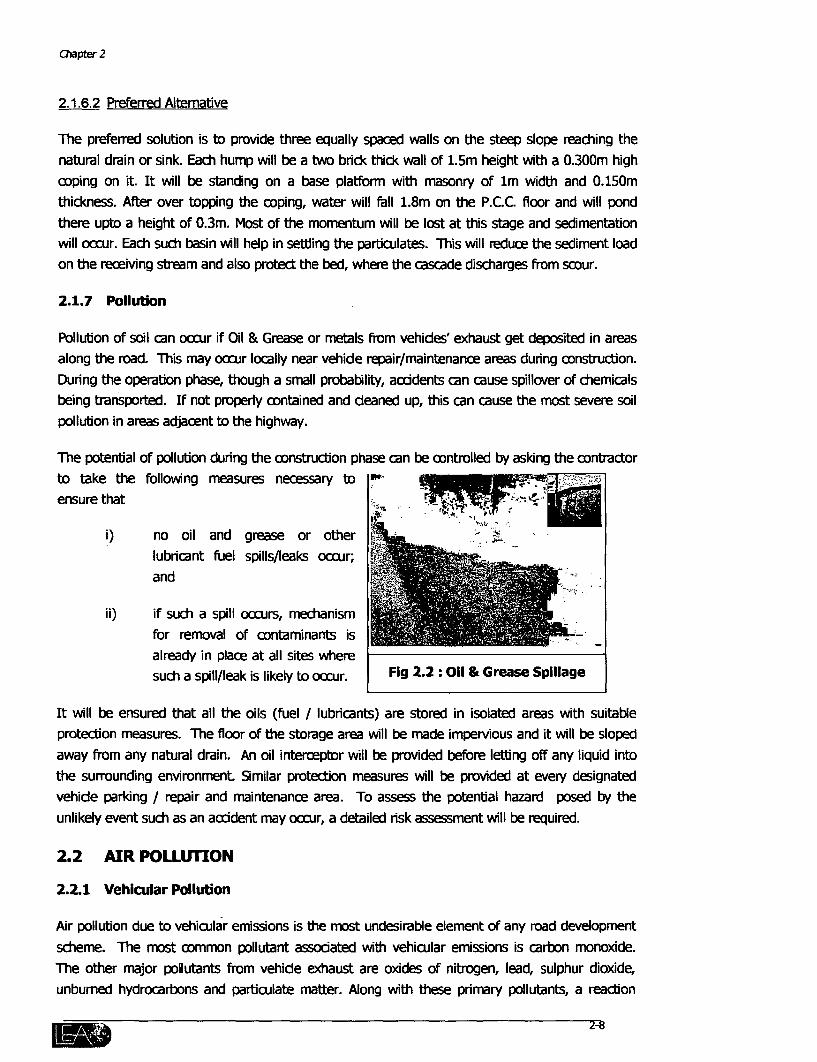
Pollution of soil can oocr if Oil & Grease or metals from vehides' exhaust get deposited in areasalong the road. This may occur locally near vehide repair/maintenance areas during construction.During the operation phase, though a small probability, acddents can cause spillover of chemicalsbeing transported. If not properly contained and deaned up, this can cause the most severe soilpollution in areas adjacent to the highway.
The potential of pollution during the construction phase can be controlled by asking the contractorto take the following measures necessary toensure that
i) no oil and grease or other '5_lubricant fuel spills/leaks occur;and
ii) if such a spill occurs, mechanism
for removal of contaminants isalready in place at all sites wheresuch a spill/leak is likely to occur. Fig 2.2: Oil & Grease Spillage
It will be ensured that all the oils (fuel / lubricants) are stored in isolated areas with suitableprotection measures. The floor of the storage area will be made impervious and it will be sloped
away from any natural drain. An oil interceptor will be provided before letting off any liquid intothe surrounding environment. Similar protection measures will be provided at every designatedvehide parking / repair and maintenance area. To assess the potential hazard posed by theunlikely event such as an accident may occur, a detailed risk assessment will be required.
2.2 AIR POLLUTION
2.2.1 Vehicular Pollution
Air pollution due to vehicular emissions is the most undesirable element of any road developmentscheme. The most common pollutant assodated with vehicular emissions is carbon monoxide.The other major pollutants from vehide exhaust are oxides of nitrogen, lead, sulphur dioxide,unburned hydrocarbons and particulate matter. Along with these primary pollutants, a reaction
2-8

Gujarat State Highways Project: Phase ZIB - Vol. I E
between them will generate unstable photochemical oxidants such as Ozone and Peroxy AcylNitrates (PANs).
The amount of each pollutant emitted will very from ;corridor to corridor but air quality will be impacted inone way or the other along all corridors dependingupon the type and quality of fuel used, the technologyused in the engine, condition of the vehide, its age, .;
road geometry, condition of he pavement, etc.Normally it has been noted that higher the emission of -,.carbon monoxide, lower will be emission of oxides ofnitrogen. The CPCB has specified nation wide standardspertaining to concentrations of various pollutantsdepending on land-use. These are being menboned in Station
Table No. 2.3.
The ambient air quality monitoring carried out as part of the Gujarat State Highway Projectinduded villages along five corridors and two other sites - one near a hot mix plant and anothernear a crusher. The equipment used was a continuous high volume sampler and the parametersfor which the samples were analyzed induded CO, Pb, SO2, NO, HC, SPM and RPM. The selectionof the sampling sites was based on the following criteria:
* Traffic growth projections;
* Traffic to be the main, preferably the only contributor to air pollution;
* Uninterrupted power supply to run the sampler and
* Site to serve as a benchmark for future repetitive sampling.
Table 2.3: National Ambient Air Quality Standards'
Time Concentration in Ambient Air (Ig /m 3 )
Pollutant .S a Rsd"a,RPOIlLIt8Ilt Wigte Aerge sensitive Residential, Rural IcitiIAeWeighted Average Area** and Ares Industaial Area
Suspended Particulate Annual Average * 70 140 360Matter (SPM) 24 hours** 50 200 500
Respirable Particulate Annual Average * 50 60 120Matter (RPM) .. __ _ _ _
'V' denoes annual arithmetic mean of rrdnrmimfn 104 measurmnts In a year tiken twie a week, 24 hourly at unfrm lntrval. **
denots 24 hourly / 8 hourly values which should be met 98% oF the time In a year (on 2% of the time, It may be eceeded for lessOman two crnaitive days). ***r denotes sertive areas which may indude.
* one ln around the periphery of health nesors so norified by GP In ansuon with Departn of Public Health;* one Icn around the periphery of Bosphere Resrves, Sanctuaries and National Parks, so notified by MoEF;* one lkn arod the periphery of an ardiaeological nonumernt derlared tD be of natlonal importane or otherwise so notified by ASI in
consultaton with GPCB; areas where aops sensiive tD air pollution are grown, so notified by GPCB In conultation with Departmnnt ofAgriculture, and,
* one km around the periphery of trnisn and/or pilgrimage sKts due to thir refigiout, hlsibdc, sorc or other attacn, so notified byDepartment of Toulvsm of the concrned State in Consulttion with GF
n Z~~~~~~~-9
Chapter 2
Time Concentration in Ambient Air (pg /m 3 )
Pollutant Sensitive Residential, Rural Industrial AreaWeighted Average Areatia AranethrAra
Area ** and Other Areas
Suiphur Dioxide (SO2) Annual Average * 15 60 80
24 hours ** 30 80 120
Annual Aeae* 15 60 80Oxides of Nitrogen (NO2) Average
24 hours ** 30 80 120
Hydrocarbons (HC) Not established Not Not established Not established
8 hours ** 1,000 2,000 5,000Carbon Monoxide (CO)-
1 hours ** 2,000 4,000 10,000
Lead (Pb) Annual Average * 0.5 0.75 124 hours ** 0.75 1.0 1.5
Source: Gol, CPCB, 1997.
2.2 1.1 Ambient Air Monitoring at Sites along Phase IIB Corridors
The results are reported as 24 hour averages for all pollutants. Continuous monitoring for all
parameters was carried out except for CO and HC for which samples were drawn into rubber
bladders after every 8-hours.
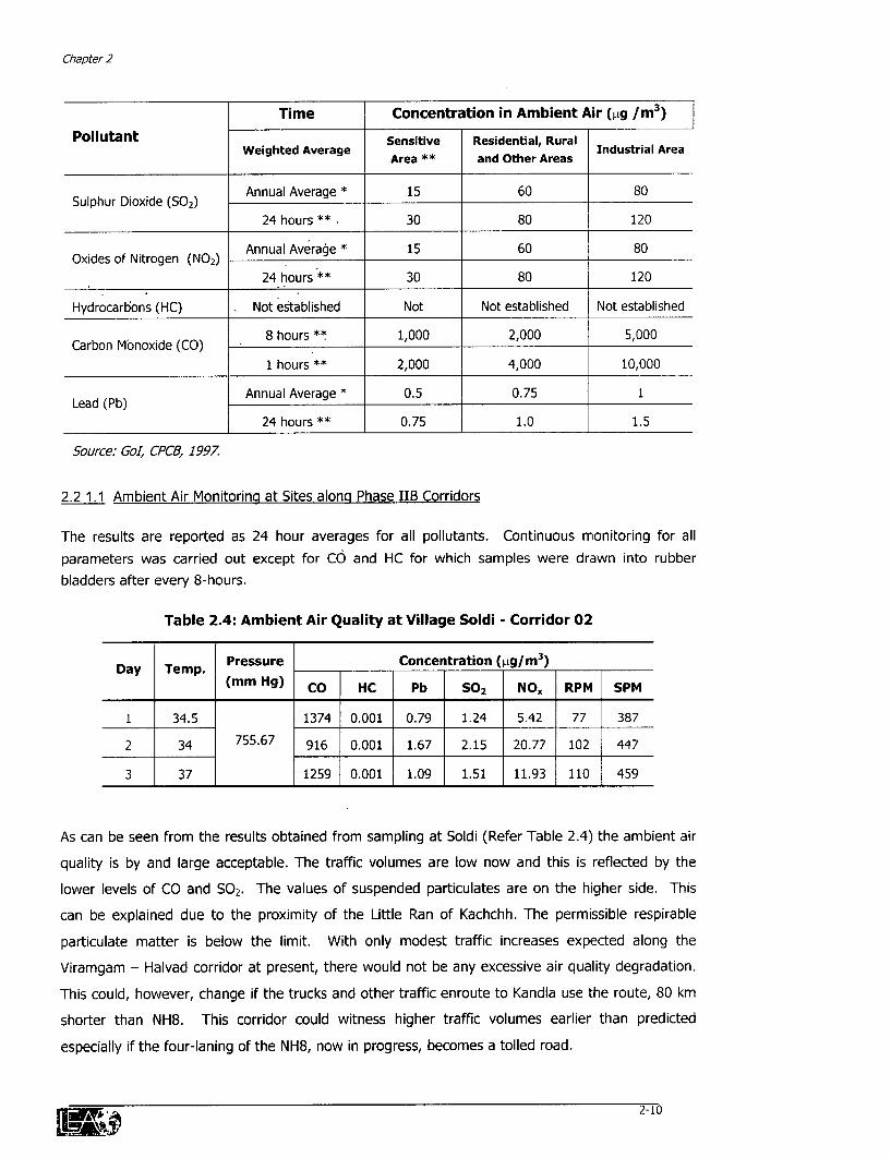
Table 2.4: Ambient Air Quality at Village Soldi - Corridor 02
Day Temp. Pressure Concentration (pig/m 3)(mm Hg) CO HC Pb SO2 NO. RPM SPM
1 34.5 1374 0.001 0.79 1.24 5.42 77 387
2 34 755.67 916 0.001 1.67 2.15 20.77 102 447
3 37 1259 0.001 1.09 1.51 11.93 110 459
As can be seen from the results obtained from sampling at Soldi (Refer Table 2.4) the ambient air
quality is by and large acceptable. The traffic volumes are low now and this is reflected by the
lower levels of CO and S02. The values of suspended particulates are on the higher side. This
can be explained due to the proximity of the Little Ran of Kachchh. The permissible respirable
particulate matter is below the limit. With only modest traffic increases expected along the
Viramgam - Halvad corridor at present, there would not be any excessive air quality degradation.
This could, however, change if the trucks and other traffic enroute to Kandla use the route, 80 km
shorter than NH8. This corridor could witness higher traffic volumes earlier than predicted
especially if the four-laning of the NH8, now in progress, becomes a tolled road.
As^z. 2-10
Gu4t State HIaS Froja: Phae BB - Vol. H E
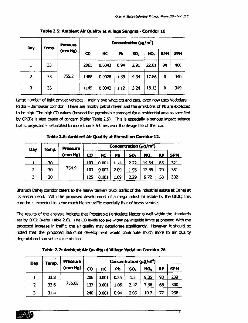
Table 2.5: Ambient Air Quality at Villge Sangnm - Conrldor 10
Prsure l=Wticln (pg4/M3)Day Terrp. Cnebto pl 3
(nunm Hg) l l Pb SO. NO, RPM I SPM
1 33 2061 0.0043 0.94 2.91 22.01 94 460
2 33 755.2 1488 0.0028 1.39 4.34 17.86 0 340
3 33 1145 0.0042 1.12 3.24 18.13 0 349
Large number of light private vehides - mainly two wheelers and cars, even row uses Vadodara -
Padra - Jambusar corridor. These are mosty petrl driven and the emissions of Pb are expected
to be high. The high CO values (beyond the permissible standard for a residential area as specifiedby CPCB) is also cause of oncern (Refer Table 2.5). This is especially a serious impact science
traffic projected is estimated to more than 5.5 times over the design lfe of the road.
Table 2.6: Ambient Air Quality at Bhensli on Conidor 12.
Day Temp. Prssure Conatation (Og/m 3)(mm Hg) CO HC Pb S02 N--_ RP SPM
1 _30 1 .n n.0n1 1.14 2.22 14.34 8R 321
2 30 754.9 103 0.002 2.09 1.93 12.35 79 351
3 30 1 1 125 0.001 1.09 2.29 9.72 58 302
Bharuch Dahej corridor caters to the heavy tanker/ truck traffic of the industrial estate at Dahej atits eastem end. With the proposed development of a mega industrial estate by the GIDC, this
corridor is expected to serve much higher traffic especially that of heavy vehides.
The results of the analysis indicate that Respirable Particulate Matter is well within the standardsset by CPCB (Refer Table 2.6). The CO levels too are within permissible limits at present With theproposed increase in traffic, the air quality may deteriorate significantly. However, it should be
noted that the proposed industrial development would contribute much more to air qualitydegradation than vehicular emission.
Table 2.7: Ambient Air Qualitlf at Village Vadal on Comidor 26
Day Temp. Pressure Concentration /nL t(mm Hg) Co 11C Pb So2 No. RP SPM
1 33.8 206 0.001 0.55 1.5 9.35 93 239
2 33.6 755.65 137 0.001 1.06 2.47 7.36 66 300
3 31.4 240 0.001 0.94 2.05 10.7 77 236
2-11
Chapt 2
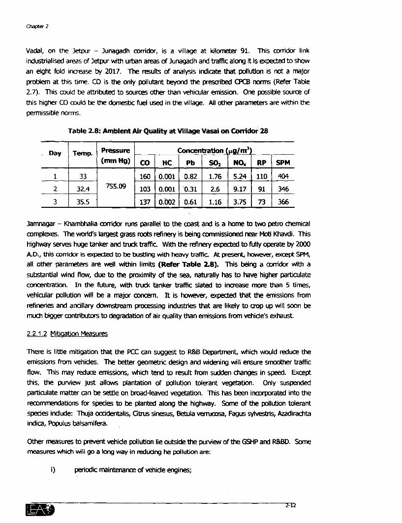
Vadal, on the Jetpur - Junagadh corridor, is a village at kilometer 91. This corridor linkindustrialised areas of Jetpur wth urban areas of Junagadh and traffic along it is expected to show
an eight fold increase by 2017. The results of analysis indicate that pollution is not a majorproblem at this timne. CO is the only pollutant beyond the prescribed OCCB norms (Refer Table2.7). This could be attributed to sources other than vehicular emission. One possible source of
this higher CO could be the domestic fuel used in the village. All other parameters are within thepermissible nomrs.
Table 2.8: Ambient Air Quality at Village Vasai on Conridor 28
Day Temp. Pressure Concentration 4/rm3
(mm Hg) CO HC Pb SO2 NO. RP SPM
1 33 160 0.001 0.82 1.76 5.24 110 404
2 32.4 55.09 103 0.001 0.31 2.6 9.17 91 346
3 35.5 137 0.002 0.61 1.16 3.75 73 366
Jamnagar - Khambhalia corridor runs parallel to the acast and is a home to two petro chemicalcomplexes. The world's largest grass roots refinery is being commissioned near Moti Khavdi. Thishighway serves huge tanker and truck traffic. Wth the refinery expected to fully operate by 2000A.D., this corridor is expected to be busting with heavy traffic. At present, however, except SPM,all other parameters are well within limits (Refer Table 2.8). This being a corridor with a
substantial wind flow, due to the proximity of the sea, naturally has to have higher particulateconcentration. In the future, with truck tanker traffic slated to increase more than 5 times,vehicular pollution will be a major concem. It is however, expected that the emissions from
refineries and ancillary downstream processing industries that are likely to crop up will soon bemuch bigger contributors to degradation of air quality than emissions from vehide's exhaust.
2.2.1.2 Miffgation Measures
There is litthe mitigaffon that the PCC can suggest to R&B Department, which would reduce theemissions from vehides. The better geometric design and widening will ensure smoother traffic
flow. This may reduce emissions, whidc tend to result from sudden changes in speed. Exceptthis, the purview just allows plantation of pollution tolerant vegetation. Only suspendedparticulate matter can be settle on broad-leaved vegetation. This has been incorporated into therecommendations for spedes to be planted along the highway. Some of the pollution tolerantspedes indude: ThuJa occdentalis, Citrus sinesus, Betula verrucosa, Fagus sylvestiis, Azadirachtaindica, Populus balsamifera.
Other measures to prevent vehide pollution lie outside the purview of the GSHP and R&BD. Somemeasures which will go a long way in reducing he pollution are:
i) periodic maintenance of vehide engines;
Gujarat State Highways Project: Phase IIB - Vol. I E
ii) rigorous implementation of the Pollution Under Control Programme and otherrelevant schemes;
iii) imposition of stricter emission norms of vehicles from the production line itself;Eg: Euro-II.
iv) Increase availability of unleaded petrol and desulphurised diesel.
Thus, abatement of air pollution from vehicle exhaust requires inputs from many other institutionsalong with R&BD. It should also be noted that the interventions from these other agencies will bemuch more effective than road design changes or any tree plantations suggested by the PCC.This fact underlines the importance of inter-departmental co-operation to resolve problemscreated by vehicular pollution.
2.2.2 Pollution Due to Point Sources During Construction.
Ambient air quality degradation during the construction phase may occur from two point sourcesin addition to dust and vehicular exhaust. These are Hot Mix Plants and Stone Crushers.
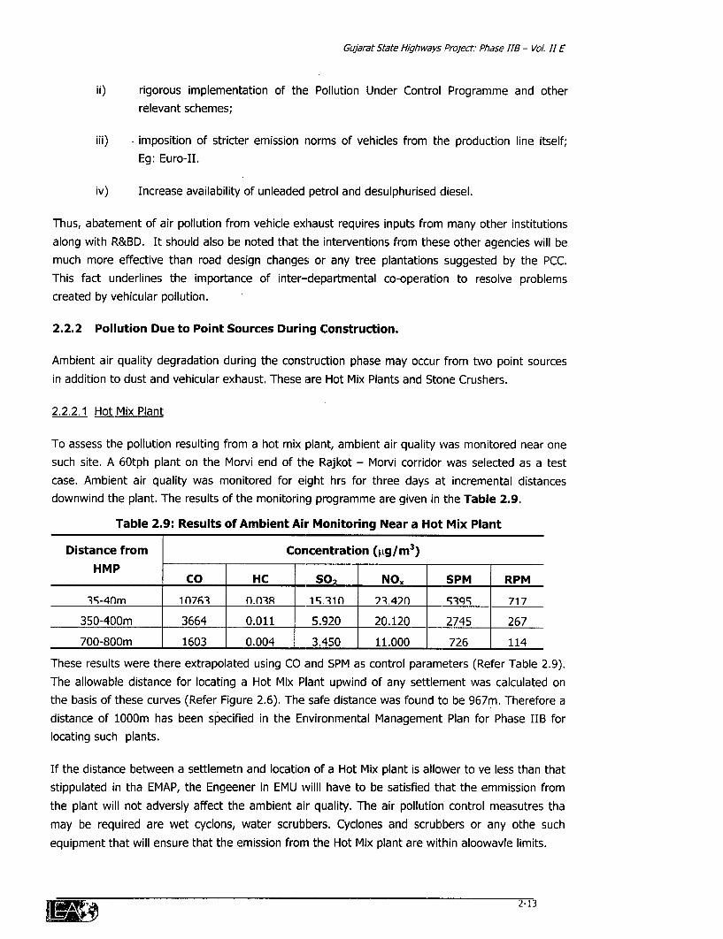
2.2.2.1 Hot Mix Plant
To assess the pollution resulting from a hot mix plant, ambient air quality was monitored near onesuch site. A 60tph plant on the Morvi end of the Rajkot - Morvi corridor was selected as a testcase. Ambient air quality was monitored for eight hrs for three days at incremental distancesdownwind the plant. The results of the monitoring programme are given in the Table 2.9.
Table 2.9: Results of Ambient Air Monitoring Near a Hot Mix Plant
Distance from Concentration (S.g/M 3)HMPHMP_________ CO HC S02 NO. SPM RPM
3';-4nm 1 n7f3 n- nR 1. 31n 2.42n ___ ____ 717
350-400m 3664 0.011 5.920 20.120 2745 267
700-800m 1603 0.004 3.450 11.000 726 114
These results were there extrapolated using CO and SPM as control parameters (Refer Table 2.9).The allowable distance for locating a Hot Mix Plant upwind of any settlement was calculated onthe basis of these curves (Refer Figure 2.6). The safe distance was found to be 967m. Therefore adistance of 1000m has been specified in the Environmental Management Plan for Phase IIB forlocating such plants.
If the distance between a settlemetn and location of a Hot Mix plant is allower to ve less than thatstippulated in tha EMAP, the Engeener in EMU willi have to be satisfied that the emmission fromthe plant will not adversly affect the ambient air quality. The air pollution control measutres thamay be required are wet cyclons, water scrubbers. Cyclones and scrubbers or any othe suchequipment that will ensure that the emission fronm the Hot Mix plant are within aloowavle limits.
3I,M.1, 2-13
aCapter 2
2.2.2.2 Stone Crusher
Ambient air quality was also monitored near a stone crusher also. The aim was to assess thepollution arising out of crushing operations. The monitoring was carried out at 40m from thecrushing unit as specified in the CPCB standards. The parameters of concern were particulatematter, which is the fine dust produced during aushing and sorting from the vibrating screen. The
results have been mentioned in Table 2.10.
Table 2.10: Pollution due to a Stone Crusher near Morvi
Particulars Observed CPCB*
Distance of HVS from Crusher 40m 40m maximum
Suspended Particulate Matter 4385t±g/Nm3 600|1g/m3
Respirable Particulate Matter 9861±g/Nm3 I _
*As per Ervironment (Protection) Rules, 1986; inserted on 18/4/87.
The observed values are a more than the standards prescribed by the CPCB (Refer Table 2.10).The SPM values are 7 times more while RPM values are nearly 10 times more than the standards
prescribed for industrial areas. In addition to being a health hazard for the workers on the plant, itmay be a safety hazard if located near a highway. Along the Rajkot - Morvi corridor, a number ofcrushers are located beyond the toll bridge over river Machchhu towards Morvi. A grey haze is
seen across the pavement on many occasions reducing visibility as one approaches theintersection with NH8 from the bridge. This is a serious safety concem for safety of vehides plying
on this corridor.
A number of steps have been suggested by the Environment (PrDtection) Rules, 1986 for
suppression of particulate matter from stone crushingunits. These are: ,-.-
(a) Dust ontainment cum suppression system for the S
equipment.
(b) Construction of wind breaking walls.
(c) Construction of metalled roads within premises.
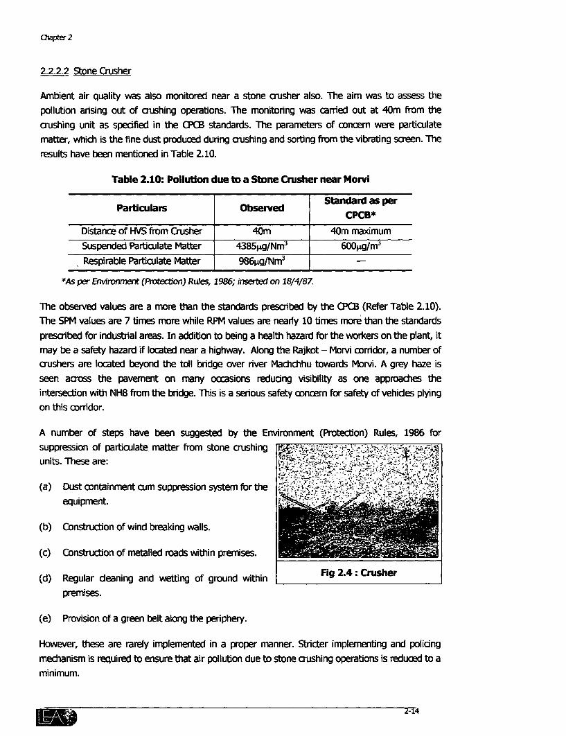
(d) Regular deaning and wetting of ground within Fig 2.4: Crusherpremises.
(e) Provision of a green belt along the periphery.
However, these are rarely implemented in a proper manner. Stricter implementing and policingmechanism is required to ensure that air pollution due to stone crushing operations is reduced to aminimum.
2-14
Gyar Sate Hgw PrOjeCt ase fiB - Vol.11 E
2.3 DRAINAGE
Roads if not designed properly present obstution to natural drainage patterns and can causeponding on one side. Good engineering pradice will normally take care of equalizing drainage ofwater pressure on eiher side of the section by providing culverts/bridges. Local drainagecharacteristics are expeded to improve due to improvement of the road itself. Culverts andbridges are being rehabilitated as part of the GSHF along with widening and. srengthening of thehighways. The two most commonly used types of culverts are I) Box Culvert and II) Pipe culverts.
A culvert can be a box culvert or a pipe culvert. Box culvert is able to carry more water than a pipe
culvert, but its provision is costier. A pipe culvert is always designed for its fulIl capadty where asin a bOx culvert a minimuM free board of 600mm has to be maintained. In pipe culverts, materialis used more economically. However, pipe culvert can take more surcharge (the filling materialsover the culvert up to pavement) than a box culvert. Normally box culverts are preferred over pipeculverts.
Two corridors in Phase IIIB are of particular concern from the point of view of drainage problems.
i) Corridor 02: Viramgam - Halvad and
ii) Corridor 22: Wataman - Pipli.
2.3.1 Corridod 02: Vhamgfam-Halvad
The problem of over topping is frequently noted in may section of corridor 02 (Vrarngam -Halwad)
during heavy rains. This is because all the storm water drains into the Rann of Kachchh in thisregion. One such aitical secion can be noted near Kharagodha village, which lies to the north of
the corridor beyond Malvan intersection at km 92. All the run off moves along the highway formore than 10 km and crosses to the north in the low-lying sections. The desbtucon in the wakeof this flooding is enormous. The chainages at which complete washout of the pavement havebeen recorded are 59.0 to 59.2, 59.8 to 60.0 and a 66.4 to 66.6. Locals have also reportedsignificant overtopping within km 73.8 to 74.5. In addition the pavement remains submerged atHansalpur Chokadi on km 60 cutting of access for people between Viramgam.
The road level is being raised by nearly 2m along the corridor to reduce the chances of over
topping. All culverts and bridges are being rehabilitated and deaned to ensure smooth passage ofwater through them. New culverts will be constructed or existing ones will be improved (ReferTable No. 2.11).
Table 2.11: Details of Imp oement/Addition of Culverts along Conidor 02
New Culverts Chainage RehabiliHation Type of Treamen
5Exsting small slze single pipe culvert Is being changed tD higher size58.900 (E) Rehabilitation multiple pipe aiveit.
59.760 (E) Rehabilitation Existing smnall size single pipe culvert is being changed to higher sizemultiple pipe alvert
59.837 (E) Rehabilitation Existing multiple pipe culvert is being changed to box culvert fromZ-1
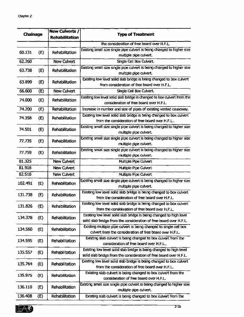
Chapter 2
Chainage New Culverts Type of TreatmentRehabilitaion
the consideration of free board over H.F.L
60.131 (E) Rehabilitation Existing small size single pipe culvert is being changed to higher sizemultiple pipe culvert
62.260 New Culvert Single Cell Box Culvert
63.738 (E) Rehabilitation Existing small size single pipe culvert is being changed to higher sizemultiple pipe culvert
63.899 (E) Rehabilitation Existing low level'solid slab bridge is being changed to box culvertfrom consideration of free board over H.F.L
66.600 (E) New Culvert Single Cell Box CulvertExisting low level solid slab bridge is changed to box culvert from the
74.000 (E) Rehabilitation consideration of free board over H.F.L
74.200 (E) Rehabilitation Increase in number and size of pipes of existing vented causeway.
74.358 (E) Rehabilitation Existing low level solid slab bridge is being changed to box culvertfrom the consideration of free board over H.F.L.
74.501 (E) Rehabilitation Existing small size single pipe culvert is being changed to higher sizemultiple pipe culvert
77.735 (E) Rehabilitation Existing small size single pipe culvert is being changed to higher sizemultiple pipe culvert
77.759 (E) Rehabilitation Existing small size single pipe culvert is being changed to higher sizemultiple pipe culvert.
81.325 New Culvert Multiple Pipe Culvert
81.918 New Culvert Multiple Pipe Culvert
82.510 New Culvert Multiple Pipe CulvertExisting small size single pipe culvert is being changed to higher size
102.491 (E) Rehabilitation multiple pipe culvert
131.738 (E) Rehabilitation Existing low level solid slab bridge is being changed to box culvertfrom the consideration of free board over H.F.L
131.826 (E) Rehabilitation Existing low level solid slab bridge is being changed tD box culvertfrom the considerabon of free board over H.F.L
134.378 (E) Rehabilitation Existing low level solid slab bridge is being changed to high levelsolid slab bridge from the consideration of free board over H.F.L.
134560 (E) Rehabilitation Existing multiple pipe culvert is being changed to single cell boxculvert from the consideration of free board over H.F.L
134.595 (E) Rehabilitation Existing slab culvert is being changed to box culvert from theconsideration of free board over H.F.L.
135.557 (E) Rehabilitation Existing low level solid slab bridge is being changed to high levelsolid slab bridge from the consideration of free board over H.F.L
135.764 (E) Rehabilitation Existing low level solid slab bridge is being changed to box culvertfrom the consideration of free board over H.F.L
135.975 (E) Rehabilitation Existing slab culvert is being changed to box culvert from theconsideration of free board over H.F.L
136.110 (E) Rehabilitation Existing small size single pipe culvert is being changed to higher size1. E Rai Ion multiple pipe culvert
136.408 (E) Rehabilitation Existng slab culvert is being changed to box culvert from the
-~ ~ ~~~~~~~~~~~~~~~~~~~~~~21
GCat State Hfpways Proeat: PBe IB - Vol. E
Chalnage New Culverts Type of TreatnentRehabilitaton
conskdratlon of free board over H.F.L
145.824 Rehabilitation Existing low level solid slab bridge is being changed tD high levesolid slab bridge from the consideration of free board over H.F.L
146.10 Reh l E)xisting low Ievel solid slab bridge is being changed to high levelsolid slab bridge from the consideration of free board over H.F.L
149.016 PRobilitatio-n' Existing low leve solid slab bridge is being changed to high level149.016 Rehabilitation solid slab bridge from the considerabion of free board over H.F.L
Note: (E) = Existirg
In addition, culvert openings will be deared to ensure that flow of water through them isunhindered. The invert levels of somne culverts will be raised to fadlitate drainage aavoss the roadsection.
2.3.2 Corridor 22: Wataman-Pipli
Wataman - Pipli oxridor acsses iver Bhogavo at. km 87. The natral slope in the region and theinland affe of Gulf of lKhabnat tgehe aeate a uique drainage problem in the area. The soil of theBhogavo rier bad and ts surounding khvlying area is sodic Salt encnsti is also visible on thesurfacx. The drainage dcaradritsics of the soil are vey poor. The land is fiat and very leIs fnfeentof water toyards the sea has been seerL The high tide rushes on to the land and submeijes the iverbed and blwying areas adjacent to the coridor fa- some time. A signboard ereced by the R&BD justbefore a low-lev causey across a dip even wams tavellers not to ply vehides in the strebd duringover - topping.
To ensure proper drainage across the highway into the sea, a series of culverts have beenproposed. Five culverts are being rehabilitated by either provision of extra height for box culvertsor through provision of multiple pipes in case of single pipe culverts along the corridor. The detailsregarding this have been given in Table No. 2.12.
Table 2.12: Details of Improvenent/Addition of Culverts along Corridor 22
Chainage Nehabilin Type of TreatmentRehabilitation
70.604 (E) Rehabilitation Box culvert of greater height from the consideration of free board overH.F.L
69.637 New Culvert Mutiple Pipe Culvert
69.845 New Cuvert Multiple Pipe Culvert
71.788 New Cuvert ctually existing single pipe culvert is being changed to multiple pipe culvertat a distance of approximate 12m.
72.290 (E) Rehabilitation E)dsting snall size single pipe cuvert is being changed to higher sizeI_________ muttiple pipe culvert
73.305 (E) Rehabilitation Edsting small size single pipe cutvert Is beirg dianged to higher sizemultple pipe alvert

CJIapter 2
aalqnage New Cu S / Type of TreatmentRehabilItation
74.1 New Culvert Multiple Pipe Culvert
74.200 (E) Rehabilitation Edsting small size single pipe aJlvert is'being dcanged intD higher sizemultiple pipe acuvert
76.681 (E) Rehabilitation Box culvert of greater height from the considerabon free board over H.F.L.
77.225 New Culvert Provision of Muldple Pipe Culvert
77.7 New Culvert Provision of Mdutiple Pipe Culvert
78.9 New Culvert Provision of Multiple Pipe Culvert
84.1 New Culvert Provision of Multiple Pipe Culvert
84.675 New Culvert Provision of Multple Pipe Culvert
85.425 New Culvert Provision of Multpie Pipe Culvert
90.425 New Culvert Provision of Multiple Pipe Culvert
90.625 New Cuvert Provision of Mutiple Pipe Clvert
91.7 New Culert Provision of Multple Pipe Cutlt
92.425 New Culvert Provision of Mutple Pipe Cuvert
Note: (E) Existing
2.4 FLORA
The remnoval of trees for widening of highways may be one of the most serious and far-reachingimpacts on the biophysical environment. In addition to the loss of shade, increased potential forerosion and in some cases loss of local primary producers may result in from cutting downroadside vegetation. It must, however, be emphasized that remnoval of some trees is essentialfrom safety point of view.
Wherever possible, green tunnels have been saved2. In addition, trees have been saved tominimize heat load onto the pavement. Trees on the west and south have been retained if it isimperative to remove trees from one side. Exceptions to this have been made only if the trees onthe opposite side are considered more valuable. However, on most corridors "Prosopis juliflora" is
the most dominant among prevailing species. Since the state government has embarked on aprosopis removal programme, removal of this species along the sides of the highway may actually
be welcomed. Removal of trees may cause a significant impact in especially two corridorsVadodara - ambusar and Jetpur - Junagadh.
2A green ztud is a situabon where cmopi of bis growing on either side of the pavnenvt touh each other above thehighway for at last 200m. of road a-tirg a continuousy shaded am.
1M 2-1B
GuJarat State Highways Proect: ehase IB - Vol. H E
2.4.1 Corridor 10: Vadodara - Jambusar
Vadodara - Jambusar is the greenest of all the oorridors in Phase IIB. Three long green tunnelshave been identified in this corridor between km 17 to 18.2, 18.8 to 19.6 ancl 27.5 to 32-5. Thesestrtches allow shade on the pavement at all times of the day and provide comfort to pedestiansand slow moving traffic
, , 9_ ,_._. The removal of trees will spedally decrease the comfortlevels of these two user groups. nother impaCt Couldbe loss of habitat for some -birds and smaller animal~s,which rmay be inhabiting in these g)adside- plantations.The trees along the corridor are well grown with neem(Azardiradha irfdica) and.copper pod.(Peltophorum spp.)being .the most dominant spedes in the green tunnels.Depending on the condition of the trees and their value
ghick iGrowthway P o as islands of comfort, saving them has been mnade a.along the Hihwy pnority in the design phase itself.
The recommended scenario about saving tree in this orridor has been given in Table 2.13.
Table 2.13-: Tree to be Saved along Conidor 10.
u hinage Side to be saved
From To
8.700 9.000 West
11.700 12.100 Both
17;000 17.600 East
18.800 19.000 West
19.100 19.200 West
19.300 19.600 Both
22.000 23.000 Either
27.500 32.500 West
2.4.2 Comdor 26
The Jetpur - Junagadh corridor ,has large stretches of green- tunnels along the last 3 km dose tothe lunagadh end (km 94 to 97). It consists mainly of Banyan (icus begalensis) -treesinterspersed with neem trees. Here too, as far as possible, trees on the west side of the highwaywill be retained to minimise the heat load on the pavement.-
-Plantation of trees is -a major component of mitigation measures under -the GSHP to reduce theimpact of tree felling due to the proposed wideningi and strengthening of selected comrridors.
Chapter 2
The project will bear the cost of the compensatory afforestation, to be carried out by theDepartment of Forests, which envisages plantation of two saplings for each tree that would be
felled. However, this plantation will occur on land reserved for the compensatory afforestationprogramme. This land may or may not be along or in vicinity of the corridor. The GSHP, on its
own, envisages plantation of saplings within the RoW to roll the tree cutting during pre-construction as a mitigation measure.
2.4.3 Proposed Tree Plantation along Phase IIB Corridors
Table 2.14 shows the list of species, which have been recommended for each corridor. While
selecting the species, due consideration was given to species found in the corridor at present, therainfall and climate of the region, the soil type and survival rate of the plant species.
Table 2.14: Proposed Tree Plantation along Phase IIB Corridors
S. Link Tree SpeciesNo.
021 Viramgam - Malvan Acacia arabica, Casia siamea, Samanea saman
022 Malvan - Dhangadhara Salvidora oleoides, Salvidora persica, Acacia nilotica
023 Dhangadhara - Halvad Salvidora oleoides, acacia Tortilis, Acacia arabica
101 Vadodara - Padra Azardichita indica, Tamarindus indica, Delonix regia,Mangifera indica
102 Padra - Jambusar Azadirachta indica, Tamarindus indica, Delonix regia,
Dalbergia latifolia
121 Bharuch - Dahej Salvidora persica, Acacia arabica, Acacia nilotica
133 Olpad - Ichchhapor Albezia lebbeck, Dalbergia latifolia, Tamarindus indica,
Peltophorum
151 Magdalla - Sachin Albezia lebbeck, Dalbergia latifolia, Casia siamea
211 Dholka - Bagodara Salvidora oleoides, Salvidora persica, Acacia arabica
221 Wataman - Pipli Salvidora oleoides, Salvidora persica, Acacia tortilis
261 Jetpur- Junagadh Azadirachta indica, Tamarindus indica, Peltophorum, Delonix
regia, Mangifera indica
271 Rajkot - Link to Neknam Delonix regia, Albezia lebbeck, Dalbergia sisoo
272 Link to Neknam - Morvi Samania saman, Acacia arabica Casia siamea
283 Falla - Link to Vanthili Dalbergia latifolia, Acacia nilotica, Casia siamea, Peltophorum
284 Link to Vanthili - Dalbergia latifolia, Acacia nilotica, Casia siamea
Jamnagar
285 Jamnagar - Khambalia Albezia lebbeck, Salvidora persica, Samanea saman
Iwo ~I 2-20
Gujarat State Highways Project: Phase IIB - Vol. I E
The number of saplings will be decided on the basis of area available for plantation beyond theend of the ditch. The mix of species would be worked out on the basis of area required for eachsapling and clear distance between two successive trees.
2.5 FAUNA
The corridors in Phase IIB mainly traverse through agricultural or barren areas. The onlycommonly recorded instances are of the blue bull (locally known as 'Nilgai'), fox and rabbits.
The only corridor where there is substantial concern regarding fauna is Viramgam - Dhrangadhra(Corridor 02). This corridor runs parallel to the southern fringe of the Wild Ass Sanctuary, which isthe last refuge in the world for the Indian Wild Ass. The Wild Ass is known to cross the corridor insearch of food and water in the fields and village ponds south of the corridor. An extensive surveyrevealed that the crossings occurred over a length of 25km between km 75 and km 104 within thecorridor (Refer Report on Wild Ass on Viramgam - Dhrangadhra Road VolIID fordetails).
A pronged strategy has been formulated to avoid collision of the Wild Ass and vehicles. Four newunderpasses are being created to allow the Wild Ass to cross the road without having to beexposed to traffic. In addition, an arrangement of reflectors is being made on the shoulder of thewidened section to discourage the Wild Ass from approaching the highway. Local cactus will alsobe planted beyond the roadside ditch to act as a barrier to the movement of the Wild Ass on tothe corridor. Apart from this a public information campaign is also envisaged using appropriate
signboards along the highway.
Except this, there is a little concern associated with fauna along any other corridor. The onlynotable area is the marshland on either side of Sachin-Magdalla (Corridor 151). Some birds mayhave established colonies and these will have to be protected from ponding during construction.
Overall, the concerns with regard to flora and fauna are only moderate to insignificant andappropriate mitigation measures have been provided wherever needed.
' 2-21

3. HOT SPOT MITIGATION PRESCRIPTIONS
The mitigation prescriptions described in this section are specific: design measures thathave been proposed to ameliorate the identified sensitive environmental features. Mostof the measures are part of the 'contract drawings' and hence would require necessaryimplementation.
3.1 WELLS
3.1.1 Background
Wells are a very important source of water, especially in a water-scarce state likeGujarat. Most of the Phase IIB corridors are located in the drier parts of the state,which makes wells all the more important as a source of water. The use of the watermay vary to suit purposes like bathing, washing, drinking or irrigation according to thewater quality of each well.
Some of these wells are located close to the carriageway. In a normal case, duringwidening of the highway, the structures of the wells located near the pavement isoften demolished and filled up. In GSHP, an endeavour has been made towards
conserving such sources of water. During field survey in all the corridors of the PhaseIIB, a total of 73 wells were within the RoW. All wells, which are in use, have beenidentified and mitigation measures have been proposed to conserve and protect them.
3.1.2 Issues and Options
* Collision potential from Vehicles
Wells near the highway pose a threat to safety of the vehicles plying on thehighway. In the case a vehicle swerves off the carriageway; it may hit the parapetof the well and cause extensive damag e to both the driver and the vehicle.
To prevent this, all wells within the RoW have been provided with a protective
railing. The Guard railing has a folded steel sheet mountecl on channel sections.The primary function of the railing is to prevent the vehicle from. hitting the well. Itwill reduce the impact by absorbing momentum of the colliding vehicle. This willalso help in deflecting the vehicle towards the road. In addition, this serves as a
signal of a constricted section to the approaching vehicles (refer drawing no.1).
* Sedimentation during the construction stage
In order to prevent sedimentation of the wells silt fencing has been prescribed. Silt
fencing is a geo-membrane, which allows water to percolate while trapping the silt
3-1

Chapter 3
in its meshes. This however would not be necessary for wells with a parapet wallaround them. The silt-fencing frame would be made of angle section (25mm X25mmX 3mm). The frame would be 0.625m. in width and 0.75m. in height. Thebottom would be 0.15m and would act as a foundation. The panel would beinserted in such a way that it is at least 0.2m below the ground. All joints would bebut welded. Filter material would be a geo-textile membrane, which would be supported f4
by a wire mesh. This mesh would be tied to N4-the angle by a binding wire through the -holes in it. -- -
* Dust accumulation during construction
A well may accumulate dust generated bythe construction activity (Refer Figure3.1). The mouth of every well would be Figure 3.1 A well located lose tothe caniage waycovered with suitable cloth that is strongenough to withstand the everyday handling stresses, while the construction activityis in progress within a radius of 100m.
* Accumulation of surface runoff during operation stage
A well may also accumulate surface runoff in the operation stage. A parapet wall
would be constructed in the case of all wells, which do not have such a structurearound them. This would prevent surface run-off from entering the well.Additionally, the area around the well would be paved to prevent dust generation.
3.1.3 Solutbon
However, every well will not require the same degree of treatment. Mitigationmeasures have been proposed for the wells, depending on their distance from thecarriage-way. The following text covers the aforesaid details -
i) Wells out side the RoW.
The ditches would flow along the edge of the embankment and hence there will
be no impact on the well. Hence, no mitigation is required. However, the mouthof the well will have to be suitably covered.
ii) Well shaft touching the ditch.
While fetching water, some amount of spillage is unavoidable. This spillage tendsto create muddy and slippery surface thereby leading to unhygienic conditionsaround the well.
3-2
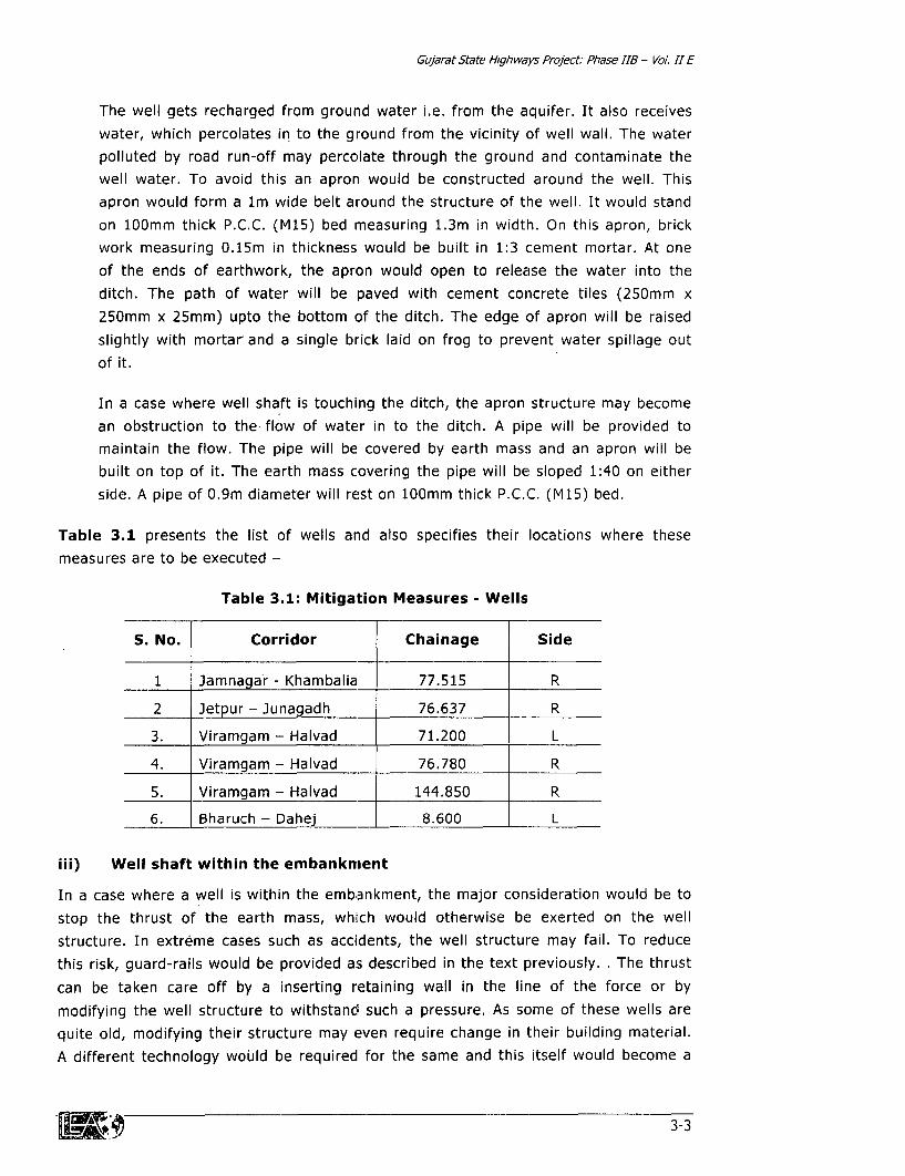
Gujarat State Hlghways Project: Phase IIB - Vol. I E
The well gets recharged from ground water i.e. from the aquifer. It also receives
water, which percolates in to the ground from the vicinity of well wall. The water
polluted by road run-off may percolate through the ground and contaminate the
well water. To avoid this an apron would be constructed around the well. Thisapron would form a lm wide belt around the structure of the well. It would stand
on 100mm thick P.C.C. (M15) bed mneasuring 1.3m in width. On this apron, brickwork measuring 0.15m in thickness would be built in 1:3 cement mortar. At one
of the ends of earthwork, the apron would open to release the water into the
ditch. The path of water will be paved with cement concrete tiles (250mm x
250mm x 25mm) upto the bottom of the ditch. The edge of apron will be raised
slightly with mortar and a single brick laid on frog to prevent water spillage out
of it.
In a case where well shaft is touching the ditch, the apron structure may become
an obstruction to the flow of water in to the ditch. A pipe will be provided tomaintain the flow. The pipe will be covered by earth mass and an apron will bebuilt on top of it. The earth mass covering the pipe will be sloped 1:40 on either
side. A pipe of 0.9m diameter will rest on 100mm thick P.C.C. (M15) bed.
Table 3.1 presents the list of wells and also specifies their locations where thesemeasures are to be executed -
Table 3.1: Mitigation Measures - Wells
S. No. Corridor Chainage Side
1 Jamnagar - Khambalia 77.515 R
2 Jetpur - Junagadh 76.637 R
3. Viramgam - Halvad 71.200 L
4. Viramgam - Halvad 76.780 R
5. Viramgam - Halvad 144.850 R
6. Bharuch - Dahej 8.600 L
iii) Well shaft within the embankment
In a case where a well is within the embankment, the major consideration would be to
stop the thrust of the earth mass, which would otherwise be exerted on the well
structure. In extreme cases such as accidents, the well structure may fail. To reduce
this risk, guard-rails would be provided as described in the text previously. . The thrust
can be taken care off by a inserting retaining wall in the line of the force or by
modifying the well structure to withstand such a pressure. As some of these wells are
quite old, modifying their structure may even require change in their building material.
A different technology would be required for the same and this itself would become a
IWO 3-3
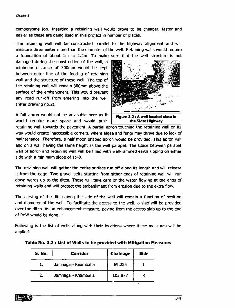
aCapter 3
cumbersome job. Inserting a retaining wall would prove to be cheaper, faster andeasier as these are being used in this project in number of places.
The retaining wall will be constructed parallel to the highway alignment and willmeasure three meter more than the diameter of the well. Retaining walls would requirea foundation of about lm to 1.2m. To make sure that the well structure is notdamaged during the construction of the wall, aminimum distance of 300mm would be keptbetween outer line of the footing of retainingwall and the structure of these well. The top of Xthe retaining wall will remain 300mm above thesurface of the embankment. This would preventany road run-off from entering into the well(refer drawing no.2).
A full apron would not be advisable here as it Figure 3.2: A well located dose towould require more space and would push the State HighwaYretaining wall towards the pavement. A partial apron touching the retaining wall on itsway would create inaccessible corners, where algae and fungi may thrive due to lack ofmaintenance. Therefore, a half moon shaped apron would be provided. This apron willend on a wall having the same height as the well parapet. The space between parapetwall of apron and retaining wall will be filled with well-rammed earth sloping on eitherside with a minimum slope of 1:40.
The retaining wall will gather the entire surface run off along its length and will releaseit from the edge. Two gravel belts starting from either ends of retaining wall will rundown wards up to the ditch. These will take care of the water flowing at the ends ofretaining walls and will protect the embankment from erosion due to the extra flow.
The curving of the ditch along the side of the well will remain a function of positionand diameter of the well. To facilitate the access to the well, a slab will be providedover the ditch. As an enhancement measure, paving from the access slab up to the endof RoW would be done.
Following is the list of wells along with their locations where these measures will beapplied.
Table No. 3.2: List of Wells to be provided with Mitigation Measures
S. No. Corridor Chainage Side
1. Jamnagar- Khambalia 69.225 L
2. Jamnagar- Khambalia 103.977 R
Gujarat State HighwaYs Project: Phase JIB - Vol. 11 E
S. No. Corridor Chainage Side
3. Jamnagar- Khambalia 104.025 R
4. Rajkot - Morvi 2.580 R
5. Viramgam - Halvad 71.225 R
3.2 POND AT SOLDI
3.2.1 Background
A pond is situated in Soldi village on the Dhrangdhara - Halvad link (023) of corridor
02 at kilometer 131 on the southern side. The pond stores rainwater as well serves as
a sink for the storm water drainage from the village. An open well is also located
nearby. The pond charges the well through an underground channel. An underground
hydraulic continuity from this well is recharging a bore-well in a field across the road
as well.
3.2.2 Issue
The pond acts as a water source for recharging the bore well. The water from this bore
well is utilised for irrigating the fields. The pond may get partly filled in by the
encroachment of the road and siltation from construction activities. The charging route
from the pond may also be cut-off during the widening of the highway. In either case,
the loss of such a source of irrigation water will be a significant impact, especially in a
water scarce area.
3.2.3 Options
i) Realignment
Encroaching into the pond area can be avoided by altering the alignment of thehighway. The highway is passing through residential area and hence, shifting of the
road alignment would involve demolition of the residential structures and consequent
displacement of a large number of residents.
ii) Slope steeping
The general emba.nkment slope is 1:2. As an option, this slope can be made steeper to
avoid encroachment of the pond area. This would, however, require slope protection
measures. Periodic maintenance would be required to ensure that there is no
encroachment into the water body.
3-5
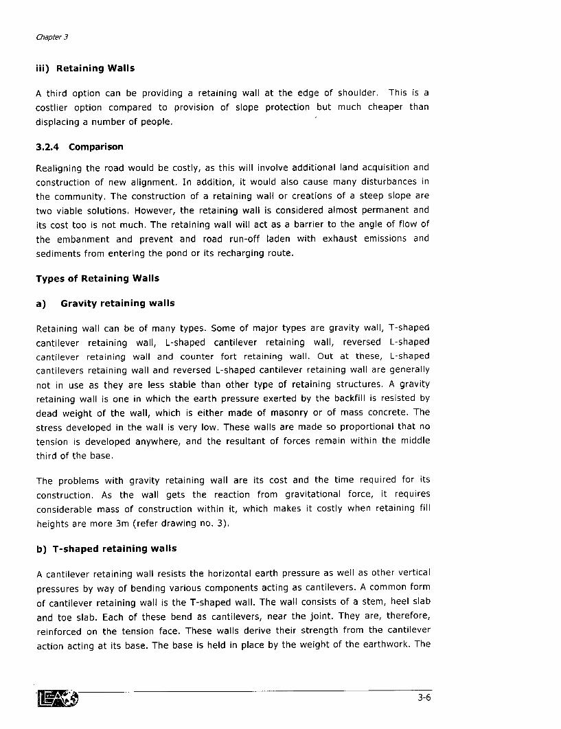
Chapter 3
iii) Retaining Walls
A third option can be providing a retaining wall at the edge of shoulder. This is a
costlier option compared to provision of slope protection but much cheaper than
displacing a number of people.
3.2.4 Comparison
Realigning the road would be costly, as this will involve additional land acquisition and
construction of new alignment. In addition, it would also cause many disturbances in
the community. The construction of a retaining wall or creations of a steep slope are
two viable solutions. However, the retaining wall is considered almost permanent and
its cost too is not much. The retaining wall will act as a barrier to the angle of flow of
the embanment and prevent and road run-off laden with exhaust emissions and
sediments from entering the pond or its recharging route.
Types of Retaining Walls
a) Gravity retaining walls
Retaining wall can be of many types. Some of major types are gravity wall, T-shaped
cantilever retaining wall, L-shaped cantilever retaining wall, reversed L-shaped
cantilever retaining wall and counter fort retaining wall. Out at these, L-shaped
cantilevers retaining wall and reversed L-shaped cantilever retaining wall are generally
not in use as they are less stable than other type of retaining structures. A gravity
retaining wall is one in which the earth pressure exerted by the backfill is resisted by
dead weight of the wall, which is either made of masonry or of mass concrete. The
stress developed in the wall is very low. These walls are made so proportional that no
tension is developed anywhere, and the resultant of forces remain within the middle
third of the base.
The problems with gravity retaining wall are its cost and the time required for its
construction. As the wall gets the reaction from gravitational force, it requires
considerable mass of construction within it, which makes it costly when retaining fill
heights are more 3m (refer drawing no. 3).
b) T-shaped retaining walls
A cantilever retaining wall resists the horizontal earth pressure as well as other vertical
pressures by way of bending various components acting as cantilevers. A common form
of cantilever retaining wall is the T-shaped wall. The wall consists of a stem, heel slab
and toe slab. Each of these bend as cantilevers, near the joint. They are, therefore,
reinforced on the tension face. These walls derive their strength from the cantilever
action acting at its base. The base is held in place by the weight of the earthwork. The
.£d 3-6

Gujarat State HIghways Pro/ect Phase 118 - Vol. 11 E
cantilever action is supported by toe slab, which adds to its stability. These walls are
less costly and quick to construct in cases where fill heights are between 3m to 6.5m.
c) Counter fort retaining walls
A counter fort retaining wall consists of a stem and a base slab. Providing counter fortsat suitable intervals strengthens the vertical stem and the heel slab. Because ofprovision of counter forts, the vertical stem as well as the heel slab acts as a
continuous slab, in contrast to the cantilevers in a cantilever retaining wall. The toeslab however, acts -as a cantilever bending upwards. This type of retaining wall is used
when backfill of greater height are to be retained. A buttressed wall is a modificationof the counter fort retaining wall in which the counter forts, called the buttresses, are
provided to the other side of the backfill. However, the buttresses reduce the clearancein front of the wall, and therefore these walls are not commonly used. These walls areused when the height to be retained is more than 6.5m.
3.2.5 Solution
e requirement retaining height in highway structures is normally between 3m and6.5m. So a T-shaped cantilever retaining wall would be used to retain the earthwork.
The retaining wall provided here is would have a total height of 4.0m. It will be cast inM25 grade concrete. The toe slab would be 0.2m wide and the heel slab would be0.7m wide. The thickness of foundation slab would be 0.4m
The vertical reinforcement in stem wall would be 12mm diameter at 225mm center tocenter whereas the horizontal reinforcement will be of 12mm diameter at 250mmcenter to center. The face reinforcement in stem would be 16mm diameter at 225mmcenter to center. The main reinforcement in foundation slab will be 16mm diameter at150mm center to center where as the distribution reinforcement will be 12mmdiameter at 250mm center to center(refer drawing no.4).
3.3 DRAINAGE AT PADRA
3.3.1 Background
Padra town situated on Vadodara - Padra - Jambusar corridor (101-102) at km 15. Theterrain of is undulating and a cause of concern therefore is a system of three inter-
connected ponds. The first pond (from Vadodara side) receives its recharge from asurface drain on the other side of road at 15.600km. This pond is connected to thesecond pond through a proper channel measuring about 70m in length and 3-4m inwidth. In the past, there was only one pond in the place second and the third pond.This larger pond had a bridge across it. With time, land was reclaimed by filling the
pond partially on the sides of the bridge Today, a small opening measuring roughly5m in width is the only channel left between the two parts of this pond.
-¢- 3-7

Ch7ap1ter 3
The old structures around the second and third pond show that they were designed as
structures along a water body. Two roads joining each other at right angles mark the
boundary of the second pond. The free ends of the roads are connected by an earthen
berm, which runs parallel to the highway giving pond shape of a quarter circle. At the
junction of the two roads a pumping station pumps water out of a bore well and the
excess of water is released into the pond. Thus, this pond receives water throughout
the year.
3.3.2 Issue
i) Blocked Drainage
The only outlet drain available for this pond system is through the second pond.
Remains of a properly constructed brick outlet can be seen. This outlet ends into a
stagnant pool on the side of culvert at 15.860km. At the other side of culvert acrescent shaped water body, runs parallel to the highway, containing lush green
coloured water, indicating the amount of eutrophication taking place in it. The other
end of the crescent touches an old brick weir, which might have acted as a check dam
in the past. The other side of the brick weir has a small depression, wvhich is connected
to the other side of the road through the culvert at 16.050km. A ditch starts from the
culvert at 16.050km and ends in a smaller pond out side the settlement, which is againconnected to the biggest pond in the area at chainage 16.300. This pond seems to bethe sink of that region as the ditches from the road beyond Padra also end at this
pond. In monsoon, the whole highway section is flooded due to such in effectivedrainage.
ii) Haphazard Garbage Dumping
The town has flourishing shops on the side of the highway, which generate a lot of
garbage. As the village side of the highway is lined entirely with shops, invariably, thegarbage generated by their activities is dumped on the other side of the road. Here,
the crescent pool and the old brick weir are located. The dumped garbage has
completely blocked the flow of water and created unhygienic conditions for theresidents of the town. All the three ponds also collect the garbage generated by the
household residing along the pond. The water in the ponds has been stagnant for
years and acts as an ideal breeding ground for vectors spreading all kinds of diseases.
3.3.3 Solution
Two things need to be done simultaneously for an effective and long-lasting solution of
the waterlogging problem at Padra. The ponds will have to be properly drained and the
community will have to be educated and made to realise that garbage dumping is
aggravating flooding and water logging in their town during monsoon.
IIU9 3-8

Gujarat State Highways Project. Phase JIB - Vol. II E
As a solution in the first case, a connecting drainage ditch will be provided. The drainwould be provided on the opposite side of the settlement, north of the corridor. It willstart from 15.400km, will cross the highway on 16.160km and will end at 16.300km. Inorder to maintain a self-cleaning flow 0.5% slope is required. The section of ditch willbe lm wide with a notch at the bottom to cater to dry weather flow during the dryperiod. The full section would provide for drainage during monsoon season. After km15.860 the ditch will be widened to 2m. The wider section is required to handle theadditional flow generated by the improvement of the culvert at 15.860km. Thisimprovement will allow the pond to drain efficiently into the drain.
A metal grill will provided on the top of the ditch to avoid accumulation of garbage init. To prevent the community from dumping the garbage in ditch, garbage bins willhave to be provided at appropriate locations.
The datum level of the final sink would be at 93.3m where as the datum level at startof the ditch would be 95.1m. Thus, a slope of 0.2 per cent would be available for thewater to flow in the final sink.
3.4 NOISE
3.4.1 Background
Noise, generated on highways is a function of pavement conditions, vehiclemaintenance, speed of the vehicle, traffic composition and traffic congestion. Assuminghighway elements (geometry, pavement condition) and traffic mix remain constant,increase in traffic volume at the rate of 25 percent, 60 percent and 100 percent wouldproduce increase in average noise level by 1 dB, 2 dB and 3 dB respectively. Averagenoise levels increase from 1 to 2 dB for each 10 kmph increase in average trafficspeed. Typically, increase in average traffic noise levels would elicit the followingperception of changes in human being.
3 dB increase- just perceptible (approx. 20 percent)
5 dB increase- clearly perceptible (approx. 40 percent)
10 dB increase- twice as loud (perceived as doubling of loudness)
3.4.2 Issue
The concern with increase in noise levels is that it will cause discomfort by reducingeffective oral communication, reduction of hearing and sleep deprivation. Of specificimportance is the disturbance caused to the students in schools located along ahighway and patients in hospitals close to the roads.
3-9
Chapter 3
3.4.3 Options
i) Provision of Noise Barrier walls
The best way to eliminate by noise pollution is to prevent the noise from reaching thetarget group. A wall generally 3 to 5 M in height and made of concrete filled materialscan act as a noise barrier. Noise walls typically provide net reduction of 5 to 10 dB intraffic noise for residences. While this means that sound energy exposures are reducedby three to ten times. Subjectively, such reductions correspond to perceived decreasesin the loudness or noisiness of traffic by about 30 percent to 50 percent. Noise barrierstend to reduce other generally negative effects resulting from proximity of a highwaysuch as litter, dust and dirt, spray and shield the view of the traffic as well. This has adirest positive effect on the environment. However, it can not be assumed that theelimination of view to the high way and possibly in settlement along the road thescenery beyond will be considered desirable by all affected residents.
Also, in the negative side, noise walls can create shading problems and presentphysical barrier to high way maintenance crews and to movement within aneighbourhood.
ii) Vegetation as noise barrier
Green belts are sometimes recommended as noise barriers. However, to be effective,the minimum width required is to the order of 50m. It also requires a mixture of treespecies along with shorter plants interspersed throughout the plantation. Theadvantage is that plantation is aesthetically pleasant and may to a limited degree helpreduce the effects of air pollution as well. But, the width and foliage requirementsmake plantation barriers, if not unviable, at least practically impossible with the RoWrestrictions.
3.4.4 Solution
It is recommended that barrier walls be provided at sensitive locations keeping in mindall the above mentioned aspects e.g. a School at village Bhensali (Bharuch-Dahej) anda School on Wataman-Pipli corridor.
The material for the noise wall will be Foam Concrete. This concrete is 1.5 timeslighter than water. This will reduce impact on colliding vehicles in case of accidents. Itsporous nature will help in absorbing sound energy. The structure will include precastpiers or post and interlocked panels. The 'I' section pier or post would hold the panelsin the notch. This will assist in easy installation. The top of the panel and pier will befixed with cast in situ concrete. The height of the wall should be at least 2.0 M. aboveground. The locations of proposed noise barriers are given bellow (refer drawing no.5).
3-10
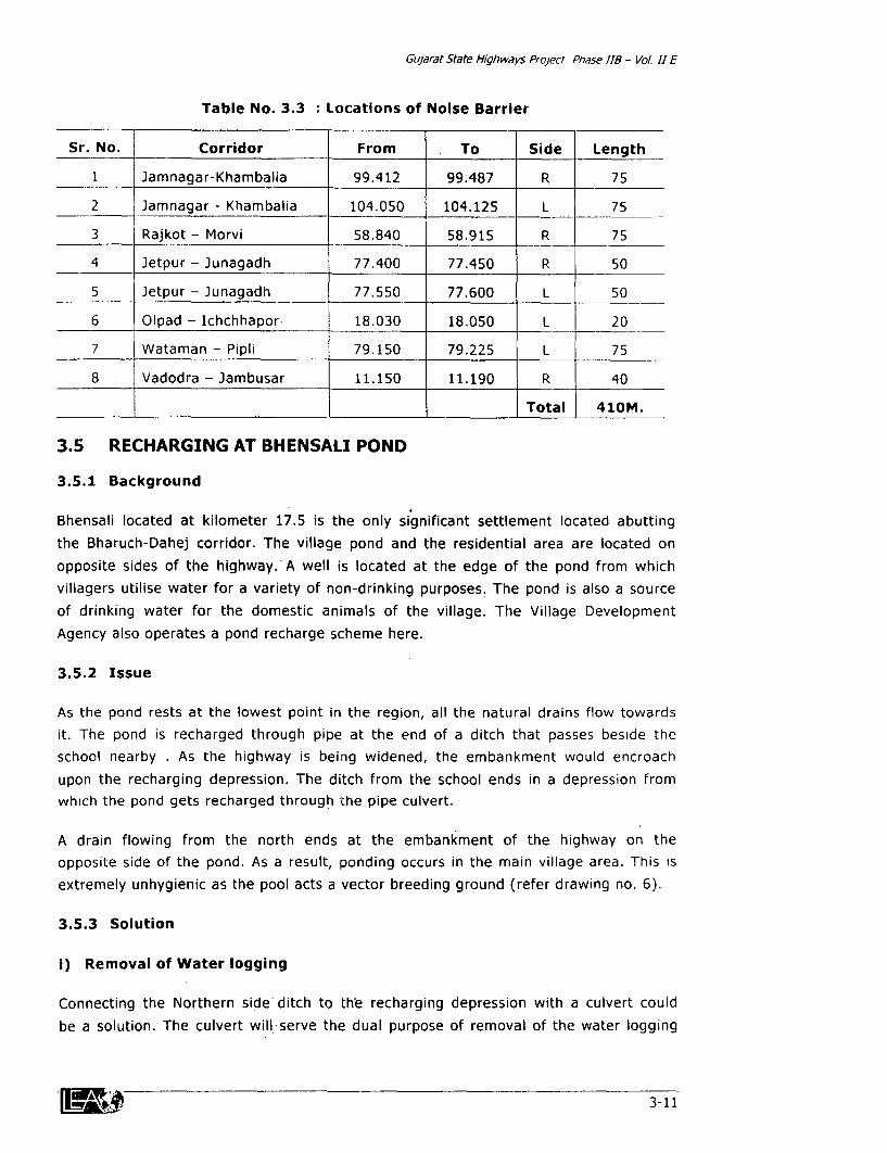
Gujarat State Highways Project Phase 118 - Vol. 1 E
Table No. 3.3 Locations of Noise Barrier
Sr. No. Corridor From To Side Length
1 Jamnagar-Khambalia 99.412 99.487 R 75
2 Jamnagar - Khambalia 104.050 104.125 L 75
3 Rajkot - Morvi 58.840 58.915 R 75
4 Jetpur - Junagadh 77.400 77.450 R 50
5 Jetpur - Junagadh 77.550 77.600 L 50
6 Olpad - Ichchhapor- 18.030 18.050 L 20
7 Wataman - Pipli 79.150 79.225 L 75
8 Vadodra - Jambusar 11.150 11.190 R 40
_ _ Total 410M.
3.5 RECHARGING AT BHENSALI POND
3.5.1 Background
Bhensali located at kilometer 17.5 is the only significant settlement located abuttingthe Bharuch-Dahej corridor. The village pond and the residential area are located onopposite sides of the highway. A well is located at the edge of the pond from whichvillagers utilise water for a variety of non-drinking purposes. The pond is also a sourceof drinking water for the domestic animals of the village. The Village DevelopmentAgency also operates a pond recharge scheme here.
3.5.2 Issue
As the pond rests at the lowest point in the region, all the natural drains flow towardsit. The pond is recharged through pipe at the end of a ditch that passes beside theschool nearby . As the highway is being widened, the embankment would encroach
upon the recharging depression. The ditch from the school ends in a depression fromwhich the pond gets recharged through the pipe culvert.
A drain flowing from the north ends at the embankment of the highway on theopposite side of the pond. As a result, ponding occurs in the main village area. This isextremely unhygienic as the pool acts a vector breeding ground (refer drawing no. 6).
3.5.3 Solution
i) Removal of Water logging
Connecting the Northern side ditch to the recharging depression with a culvert couldbe a solution. The culvert will serve the dual purpose of removal of the water logging
3-11

OCiaptel 3
pool as well as make more water available to recharge the pond. A culvert would be
provided to connect the two ditches, as no connection between exists presently.
li) Stilling Chamber with Manhole
To ensure that the recharge area is protected, a chamber will be provided with a
manhole to provide access to periodically maintain the scheme and ensure smooth flow
of water into the pond. This chamber will house the end of the school side ditch, the
end carrying water from village side ditch and the pipes recharging the pond. The
water would flow into the pond only on reaching the invert level of the outlet pipes.
The invert levels of the two incoming flows would be higher than pipes recharging the
pond (level difference nearly 0.6m) so that no back-flow takes place during storms.
The settling chamber will help in settling heavy particles.
The chamber will be a box of 2.5m. X 1.5m. X 2.0m. constructed in M15 concrete. The
long side of the box will include the pipes. The shorter wall will have an opening,
which will receive flow from school side ditch through a filtering mesh. The mesh of
10mm size will be mounted on a frame measuring 0.6m. X 0.625m made out of angles
25mm x 25mm x 3mm each. The pipe from the new culvert will enter the chamber at
an angle of 70° to the wall. Other end of the pipe culvert will be covered with the same
type of angle frame with mesh on it as for the drain from the side of the school. Thisfilter will help in keeping the garbage out of the chamber.
The chamber will have an opening from the top measuring 1.2m. X 0.6m covered with
a lid. The wall opposite to the entry of the ditch from school will have iron rungs at
every 0.3m to provide an access to the bottom. Each rung will have a section of 45mm
x 45mm and would be 0.45m in width.
Such an assembly will require timely and proper maintenance. In this particular village,maintenance will not be a problem. In the Public Participation Programme, the Village
sarpanch and others had underlined the importance of the pond for the community.
Also, the person responsible for the maintenance of the recharge schemes in nearby
villages is a resident of Bhensali village.
3.6 COMMUNITY POND AT ASNABAD
3.6.1 Background
A pond is located at km. 18.7 on the Olpad-Ichchhapor corridor, north of village
Asnabad. Its area is 14910m As the pond is fed from the north by the tail end of a
canal from the Ukai dam, the water level is almost constant through out the year. A
natural drain from the pond is connected with the nearest river at chainage 18.85. The
pond is an important community property and its water is used for a variety of non-
drinking purposes..
-ga p 3-12
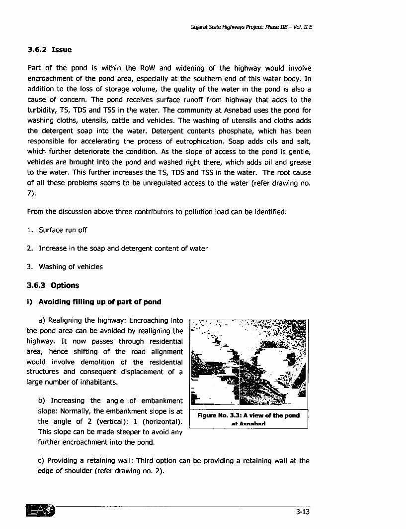
Gujarat State Highways Project: Pase B - Vol. I E
3.6.2 Issue
Part of the pond is within the RoW and widening of the highway would involveencroachment of the pond area, especially at the southern end of this water body. Inaddition to the loss of storage volume, the quality of the water in the pond is also acause of concern. The pond receives surface runoff from highway that adds to theturbidity, TS, TDS and TSS in the water. The community at Asnabad uses the pond forwashing cloths, utensils, cattle and vehicles. The washing of utensils and cloths addsthe detergent soap into the water. Detergent contents phosphate, which has beenresponsible for accelerating the process of eutrophication. Soap adds oils and salt,which further deteriorate the condition. As the slope of access to the pond is gentle,vehicles are brought into the pond and washed right there, which adds oil and greaseto the water. This further increases the TS, TDS and TSS in the water. The root causeof all these problems seems to be unregulated access to the water (refer drawing no.7).
From the discussion above three contributors to pollution load can be identified:
1. Surface run off
2. Increase in the soap and detergent content of water
3. Washing of vehicles
3.6.3 Options
i) Avoiding filling up of part of pond
a) Realigning the highway: Encroaching into -;the pond area can be avoided by realigning the i
highway. It now passes through residential 4- J1iIarea, hence shifting of the road alignment w .would involve demolition of the residential A Istructures and consequent displacement of alarge number of inhabitants.
b) Increasing the angle .of embankmentslope: Normally, the embankment slope is at Figure No. 3.3: A view of tihe pond
the angle of 2 (vertical): 1 (horizontal). at Acnahai
This slope can be made steeper to avoid anyfurther encroachment into the pond.
c) Providing a retaining wall: Third option can be providing a retaining wall at theedge of shoulder (refer drawing no. 2).
-IEJ.uI9 3-13

Chapter 3
3.6.4 Comparison
Since the highway passes through a residential area, any realignment will involve
displacing many people and possibly acquisition of some property. Moreover, there
would be serious repercussions from such a decision at the community level. In either
case, the costs of such realignment would be prohibitive. Increasing the angle of
slope as well as provision of a retaining wall are both viable solutions. However, since
the retaining wall is a permanent structure and slope protection would require regular
maintenance, provision is being made for a retaining wall.
ii) Preventing degradation of Water Quality
a) Surface run off
The standard highway design includes provision of ditches to divert run-off into nearby
natural drains.
b) Increase in the soap and detergent content of water
Restricting access to the pond could be a solution in this regard. This can be achieved
by construction of a wall around the pond. However, this would cause much hardship
to the community, as the pond is an important source of water for them.
Alternatively, arrangement can be made to stop the used water from flowing back in
the pond. This can be achieved by providing a separate drain to collect the sullageand divert it to a flowing water channel. A barrier should also be provided to separate
the water in the pond from the used water.
c) Washing of Vehicles
Ideally, no vehicle should be allowed near the pond to prevent that water used for
washing it to enter into the pond. This can be achieved by creating a sudden level
difference between the pond and the CW. If this is done, vehicles won't be able toreach the washing area and the direct contact could be eliminated. The gutter provided
for sullage will take care of any used water in case the vehicles are still washed outside.the washing area.
3.6.5 Solution
The barrier required to solve the problem of eutrophication could be a retaining wall,
which would retain the' earth on the highway side and provide sufficient depth for
water accumulation on the pond side. Therefore, a retaining wall would be used as a
barrier. Following the slope of the ground, a gutter will accompany the wall closely
near the washing area. The barrier and gutter arrangement may also help solve the
3-14
Gujarat State Highways Project. Phase IIB - Vol. I E
vehicle-washing problem too. A step will be provided at the access of the pond toprevent vehicles from entering the washing area.
i) Retaining wall with Gutter
The retaining wall will be 1.8m in height and will protrude 0.4m above the groundlevel. The top of the wall will be provided with inclined coping, to avoid its usage as awashing stone or a sitting platform. A 110mm thick brick masonry will encase a gutter300mm x 300mm in size touching the retaining wall. The gutter will be filled withgravel of size not less than 15mm. It will be covered with cement tiles (measuring250mm5250mm525mm). The tiles will act as a platform for people to stand on and thegap of 25mm on each side will allow water to flow into the gutter. The gravel will stopall the rubbish from entering into the gutter. The whole assembly of brick gutter willbe supported on PCC (M15) slab of 100mm thickness and protruding 150 mm beyondthe edge of gutter.
ii) Washing Area & Reverse Filter
Washing at will be provided with cement tiles supported on PCC (M15) with 100mmthickness forming a slope of 1:40 towards the gutter. Tiles will be laid upto a distanceof 4m from the wall.
To provide cleaner water to the community, a shallow well with reverse filter will beconstructed. The well will be 1.6 m deep from ground level with a parapet of O.9mgiving a depth of 2.5m in total. At the point of fetching water, the parapet is reducedto 0.6m to facilitate the movement of container. The reverse filter is an arrangementof two layers of aggregate. The layer near to the well will be of dry rubble withboulders not less that 100mm in any dirnension. Second layer of gravel with size notless than 10mm will be held in position by two geo-membranes.
The external layer will do the job of screening and the internal layer will protect it fromfalling into the well. The filtered water will enter the well through weep holes providedin wall which are 75mm in diameter and 0.5 m. centre to centre in a staggered fashion.
To facilitate the user, a suitably built washing platform will be provided. The washingplatform will be made up of brick masonry with 1:3 cement mortar on the face andwould be given a finishing with cement slurry.
Trees will be planted on the edge of the pond. Existing trees will be provided with"chabutara" all around them. Such sitting platforms would be provided to enable thecommunity to enjoy the pond side.
llbAb ... N"7 3-15

Chapter 3
3.7 RAG PICKERS AREA
3.7.1 Background
At the Sachin end of Magdalla-Sachin corridor, there is large industrial estate. Textileprocessing is the largest sector with a few chemical manufacturers and allied industrieshere in. There is a huge consumption of dye and dye-intermediates for dyeing and
2 ,- -:printing on cloth. Packaging for the dyes and:';.7.;:-- - -: _->chemicals is usually in drums whereas plastic
t (PP or PE) bags are used for packing the greigh~ -;--as well as finished cloth. A recycling operation
~ .~- has developed, to make use of the largequantities of waste material generated, in thelow-lying areas near the estate itself. Theproblem is the location of the operation of suchactivities. The storage, separation and resale of
Figure 3.4: A view of the Area the bags is carried out on edge of the highwayas the road provides easy connectivity to bring
in the waste products from the industry and to transport the sorted material for sale.In the list, 15-20 different establishments have sprung up between kilometers 13 and15 on both sides of the corridor. The material is stored without any cover or protectionon land.
3.7.2 Issue
A natural stream flowing into the sea passes through this area. All the waste bags anddrums are washed in its water before being resold. Due to inadequate drainage thepolluted water does not flow away and ponds up along the sides of the highway.During monsoon, the problem becomes complex as the water percolates through thestored waste packaging but cannot flow back. The standing water penetrates throughthe embankment and may damage the structure of the highway.
3.7.3 Solution
Effective solutions are required in order to mitigate such a serious problem. Firstly, theflow of water needs to be maintained unhindered and secondly, seepage of thepolluted water into the road section needs to be prevented. A lined ditch with asmooth bottom and sufficient slopes would be an ideal solution in such a case.
i) Lined ditch
The standard highway design includes ditches on both the sides of the highway. Anormal ditch is a trench dug in earth. The slope along the sides is maintained to twohorizontals to one vertical and the earth is rammed well to ensure stability. The base
3-16

Guarat State Highways Projea.: Pthse IB - Vol. 1 E
of the ditch has to be reliably uniform to allow smooth flow of water. The minimum
slope required to achieve self-cleansing velocity is 0.5 percent whereas the longitudinalgradient of ground on the site is 0.18 percent. Lining of the ditches would ensure that
the highway section is isolated from the contaminated water and would retain the
polluted water within the section of the ditch.
Pollution Tolerant vegetation
Some species of plants can survive in highly
polluted environments and can even absorb
some pollutants such as heavy metals from
water. A species of the grass of the Thypas -
genus family, which grows in Egypt, is known to
be the most tolerant to pollution. Thypas
Latafoliya, of the same genus, is considiered to
be the second most efficient grass in absorbing
polluted water is seen growing profusely nearby.
Rammed earth surface is generally undulating Figure 3.5: A view of Rag-Pickers
and can allow these bushes to grow in the small AIWJ
undulations. However, excessive growth of Thypas Latafoliya will be an obstruction to
the flow and will cause ponding. To avoid such an over growth, a cement concrete
base will be provided.
ii) Brick Lining on side slopes
In this particular section the RoW is narrow. Thus, one of the slopes i.e. either slope of
embankment or slope at the edge of ditch has to be made steep. The steeper slope
needs certain protection measures. In this case, the edge of the steep ditch has been
provided with protection of brick lining. The brick lining would also prevent the entry
of the polluted water into the highway base courses (refer drawing no. 8).
iii) Chain Link Fencing
On windy days, plastic bags being light may fly from the storage area and clog the
ditch obstructing the flow of water. Fencing will be provided along the length of thehighway for the entire stretch in which the storage areas are located to prevent the
bags from entering the ditches.
3.8 BRIDGE ON KANKRA CREEK,
3.8.1 Background
The Kankra creek carries sewage from Surat City as well as treated and untreated
effluent from textile industries located within Surat. Magdalla-Sachin corridor passes
over this creek, locally called Khadi (bridgle no. 19/3). The existing bridge, constructed
3-17
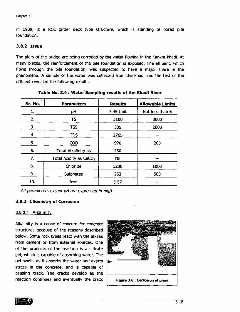
Chapter 3
in 1989, is a RCC girder deck type structure, which is standing of bored pilefoundation.
3.8.2 Issue
The piers of the bridge are being corroded by the water flowing in the Kankra khadi. Atmany places, the reinforcement of the pile foundation is exposed. The effluent, whichflows through the pile foundation, was suspected to have a major share in thephenomena. A sample of the water was collected from the khadi and the test of theeffluent revealed the following results.
Table No. 3.4: Water Sampling results of the Khadi River
Sr. No. Parameters Results Allowable Limits
1. pH 7.45 Unit Not less than 6
2. TS 3100 3000
3. TSS 335 2000
4. TDS 2765 _
5. COD 970 200
6. Total Alkalinity as 250
7. Total Acidity as CaCO 3 Nil _
8. Chloride 1200 1000
9. Sulphates 263 500
10. Iron 5.57
All parameters except pH are expressed in mg/l.
3.8.3 Chemistry of Corrosion
3.8.3.1 Alkalinity
Alkalinity is a cause of concern for concretestructures because of the reasons describedbelow. Some rock types react with the alkalisfrom cement or from external sources. Oneof the products of the reaction is a silicategel, which is capable of absorbing water. Thegel swells as it absorbs the water and exerts ,- *.stress in the concrete, and is capable ofcausing crack. The cracks develop as thereaction continues and eventually the crack Figure 3.6: Corrosion of piers
3-18
Gujarat State Hlghways Project Phase IIB - Vol. I E
patterns join up to form a map pattern.
In order for such a reaction to take place, it is necessary that alkali, water and a(reactive) aggregate are all present. Mitigating action involves limiting any one ofthese factors e.g. by limiting the total alkali content of the rnix or by using a non-reactive aggregate. There can also be advantages in using some alternativecementitious materials such as ground granulated blast furnace slag or pulverised fuelash as they tend to supply less alkali to the mix than portland cement.
3.8.3.2 Chlorides
The presence of chlorides, either in the original mix or in the concrete can allow theestablishment and movement of chloride ions in the pore water within the concretematrix. In such circumstances electrical cells can be formed with different sections ofreinforcement providing anodic and cathodic sites. The electro-chemical process drivenby the cell leads to local corrosion of reinforcement, which can also lead to cracking orspalling of the surrounding concrete.
A rare, but potentially more dangerous form of chloride induced corrosion can resultwhen strong electrical forces develop without sufficient oxygen and corrode productsto oxides. The resulting anaerobic corrosion products do not expand and do not usuallycause immediate damage to the surrounding concrete. In such cases the reinforcementcan be reduced in cross-section due to pitting and in a very extreme case could betotally corroded altogether.
3.8.3.3 Other Contributors
The effluent also contains sewage from Surat City, which explains the high COD. Thesewage also carries fecal microbes. These hydrolyze organic matter into organic acids,which may corrode the concrete.
Salts in solution can find their way into the concrete by a number of differentprocesses: direct absorption, permeation, diffusion or capillary suction. The chlorideprofile changes with time as salt penetrates from the exterior. Eventually, thethreshold value is reached at the surface of the reinforcement and corrosioncommences if sufficient moisture and oxygen are present.
3.8.4 Options'
The deterioration of the bridge piers is openly visible. Though the road is notimpacting the quality of water in any way except may be increasing the sediment loadduring construction, it was considered prudent to examine ways to protect the bridge.
3-19
C/Oavte/ 3
3 8 4 1 Concrete Mix
The first option was to change the ingredients of concrete. The quality of concrete inthe cover zone plays a crucial role in protecting the reinforcement against corrosionand also in defending the concrete against other forms of attack. The choice of cementtype is critical, as in the most severe exposure situations, the traditional and readilyavailable straight portland cement may not be the most appropriate. Although thereare moderate to high concentrations of sulphates in seawater, they do not appear tolead to rapid sulphate attack. This is possible since the presence of chlorides in theseawater, also the products formed by the reaction of sulphates with the hydrates incement, are modified by the presence of chlorides. The products expand less andhence disrupt the concrete comparatively less. On the other hand, sulphate resistingcement, because of its low C3A (TRICALCIUM ALLUMINATE,BCO, AL203) content islikely to bind chlorides less, which penetrate concrete from the marine environmentand hence concrete made form sulphate resisting cement may give less protection toembedded reinforcement. The water from Kankra khadi has quite high chloridecontents.
A number of alternative cements now available and these also can produce concrete,which are able to provide better protection to the reinforcement against chlorideingress. Microsilica has been in use on a fairly general basis for almost ten years.Cement containing blast furnace slag could also be considered. This slag has to bespecially imported which would entail tremendous extra cost.
3.8 4 2 Coatings
At present exposure conditions are so extreme that the protection afforded to thereinforcement by the cover concrete alone is not sufficient: in such circumstances itmay not be physically possible to provide the desired cover. In such cases analternative may be to use a coating either on the surface of the concrete or the surfaceof the reinforcement.
The other options were cladding the surface with stainless steel 316, with acid proofbricks or with epoxy paint on the foundation structure.
a) SS 316
The stainless steel 316 provides excellent resistance against sulfates and otherchemicals. But it fails to protect the structure from the attack of chlorides.
b) Acid Proof brick lining:
The acid proof bricks provide resistance against all type of acids. The pH and the totalalkalinity of the sample shows that acidity is not the main problem in this situation.
3-20

Gujarat State Highways Project. Phase IIB - Vol. II E
Moreover, the brick lining has to be inspected and to be periodically maintained toensure its integrity. This would be very difficult as water flows continuously throughthe khadi through out the year. Thus, putting acid proof bricks will not prove to be aviable solution.
c) Epoxy Paints
Epoxy paints are classified as organic, thermosetting two pack type coatings. Thesepaints provide excellent protection against sulphates, chlorides, organic acids and saltintrusion. In the coating ranking, the epoxy resin coatings provide the best protectionagainst chlorides, carbonization and rains. They are also the best in alkalinity toleranceand require least number of re-coats.
3.8.5 Solution
Pile and pile cap will be painted with epoxy resin paint to prevent the corrosion effectdue to highly contaminated wastewater. In addition to this, other precautionarymeasures will also be taken to ensure the integrity of the bridge sub-structure and thepiers. The concrete grade for pile and pile cap will be M35. A clear cover of 75mm willbe provided for the piles and pipe caps, which is more than that specified by the IRCcodes. A 8mm thick steel liner-will be provided for each pile upto a depth of 6m fromthe bottom of cap. During construction, joints will not be allowed for foundationbecause they will increase the chances of water intrusion in to the structure.
3-21


ENVIRONMENTAL MITIGATION COST

CONTRACT NO.: GSHP - 9
Corridor: Vadodra - Padra - Jambusar & EBharuch - Dahej
Silt Fencing
No. ] Item Unit Quantity Rate Amount
1 Angle Section 25mm x 25mm x 3mm T 0 022 22143 487 15
2 Geotextile M2 78 60 4680
3 20mm Mesh M2 78 102 7956
4 1 Welding M 60 200 12000
Total j 25123.15
Stone Pitching
No. Item Unit Quantity Rate Amount
1 Digging M3 2154.38 30.9 66570 34
2 Stone Pitching M2 4308 76 104 448111.04
> Total 514681.38
Brick Paving
No. Item Unit Quantity Rate Amount
1 | Digging M3 1077.19 30 9 33285 17
2 Plain Cement Concrete M-15 Grade M3 269.29 1615 434903 35
3 Brick Paving M2 2154.38 71 152960 98
Total 621149.5
Pre-Cast Concrete Block
No. Item Unit Quantity Rate Amount
1 Pre-Cast Cement Concrete Block M2 1077 19 250 269297 5
Total 269297.5
Proposed Manhole
No. Item Unit Quantity Rate Amount
1 Digging M3 20 9 30 9 645 81
2 Plastering with,1 4 Mortar M2 33 64 41.2 1385 96
3 Reinforced Cement Concrete M-15 Grade M3 7.82 2158 16875 56
4 Reinforcement of 10mm 4 T 0.00728 18500 134 76
5 Reinforcement of 6mm Dia. T 0.0007 17730 13 22
6 Reinforcement of 12mm ' T 0.0056 18500 104.1
7 Reinforcement of 8mm Dia T 0.003 17730 54 11
8 R.C.C. Pipes, 2.5M. Length, 0.9M. Dia No. 3 3500 10500
No. Item Unit Quantity Rate Amount
9 M S Plate T 0.0108 22143 239 14
10 M S Flat 30mm x 3mm T 0 00005 22143 1.19
11 M S Rods,12mm Dia. T 0 00076 22143 16 89
12 Angle Section 25mm x 25mm x 3mm T 0 00057 22143 12 62
13 t Geotextile M 0 39 60 23 4
14I 20mm Mesh M 0 39 102 39 78
15 i Welding M 0 4 200 80
Total 30126.54
Enhancement
No. Item Unit Quantity Rate Amount
1 Digging M3 297.67 30 9 9198
2 Plain Cement Concrete M-1 5 Grade M3 48 8 1615 78812
3 Brick Masonry M3 319.8 1086 347302 8
4 Plastering with 1:4 Mortar M2 693.3 41.2 28563.962
5 Stone Paving M2 808 04 104 84036.16
Total 547912.92
Noise Barrier 40m
No. Item Unit Quantity Rate Amount
1 Digging M3 15.79 30 9 487 91
2 Plain Cement Concrete M-15 Grade M3 4.53 1615 7315 95
3 Autoclaved Cellular Concrete Block Masonry M3 37.2 2721 101221 22
125mm x 240mm x 600mm
4 Plastering with 1:4 Mortar M2 273.54 41.2 11269.84Total 120294.92
Well Protection Type I
No. Item Unit Quantity Rate Amount
1 Digging M3 5 22 30 9 161 29
2 Plain Cement Concrete M-15 Grade M3 3 57 1615 5765 55
3 Brick Masonry M3 10 69 1086 11609 34
4 Plastering with 1:4 Mortar M2 23.4 41 2 964 08
5 Cement tiles 250mm x 250mm x 20mm M2 5 62 31
6 M S. Pipes, 2.5M. Length, 0.9M Dia No 3 3500 10500
7 Earth Filling M3 14.18 305 4324 9
Total 33356.16
Total Cost = Rs. 2161942.07
2
CONTRACT NO.: GSHP- 10
Corridor: Jetpur - Junagadh & Rajkot - Morvi
Silt Fencing
No. Item Unit Quantity Rate Amount
1 Angle Section 25mm x 25mm x 3mm T .022 22143 487 15
2 Geotextile M 78 60 4680
3 20mm Mesh M2 78 102 7956
4 Welding M 60 200 12000
Total 25123.15
Stone Pitching
No. Item Unit Quantity Rate Amount
1 Digging M3 3909.96 30.9 120817 76
2 Stone Pitching M2 7819.92 104 813271 68
Total 934089.44
Brick Paving
No. Item Unit Quantity Rate Amount
1 Digging M3 1954.98 30.9 60408 8
2 Plain Cement Concrete M-15 Grade M3 488.74 1615 789315 1
3 Brick Paving M2 3909.96 71 277607 16
Total 1127331.06
Pre-Cast Concrete Block
No. Item Unit Quantity Rate Amount
1 Pre-Cast Cement Concrete Block M2 3909 96 250 977490
Total 977490
Noise Barrier 100m
No. Item Unit Quantity Rate Amount
1 Digging M3 39.51 30 9 1220 85
2 Plain Cement Concrete M-15 Grade M3 11.32 1615 18281.8
3 Autoclaved Cellular Concrete Block Masonry M3 93.01 2712 252243.12125mm x 240mm x 600mm
4 Plastering with 1:4 Mortar M2 24.09 41 2 992 508
Total 272738.278
3

Well Protection Type I
No. Item Unit Quantity Rate Amount
1 Digging M3 5 22 30.9 161 29
2 Plain Cement Concrete M-15 Grade M 3 57 1615 5765 55
3 Brick Masonry M3 10 69 1086 11609 34
4 Plastering with 1.4 Mortar 23 4 41 2 964 08
5 Cement tiles 250mm x 250mm x 20mm M2 .5 62 31
6 M S Pipes, 2 5M Length, 0 9M Dia No. 3 3500 10500
7 Earth Filling M3 14.18 24 34012
Total 29371.38
Well Protection Type 2
No. Item Unit Quantity Rate Amount
1 Digging M3 12.54 30 9 387.48
2 Plain Cement Concrete M-15 Grade M3 1.43 1615 2309 54
3 Brick Masonry M3 5.51 1086 5983.86
4 Plastering with 1:4 Mortar M2 10.5 41 2 432.6
5 Reinforced Cement Concrete M-15 Grade M3 0.5 2297 11.48 5
6 Reinforcement of 1Omm T 0.00068 18500 11 61
7 Stone Paving M2 18.75 104 1950
8 Gravel Filling M 4 215 860
9 Earth Filling M3 168 24 40 32
10 Retaining Wall M 7 29205 204435
Total 216422.39
Total Cost = Rs. 3582565. 69
4

CONTRACT NO.: GSHP - 1 1
Corridor: Falla - Khambalia
Silt Fencing
No. Item Unit Quantity Rate Amount
1 Angle Section 25mm x 25mm x 3mm T 022 22143 487 15
2 Geotextile M2 78 60 4680
3 20mm Mesh j 78 102 7956
4 Welding M 60 200 12000
Total 25123.15
Stone Pitching
No. Item Unit Quantity Rate Amount
1 Digging M3 1694 24 30 9 52352 01
2 Stone Pitching M. 3388.48 104 352401.92
Total 404753.93
Brick Paving
No. Item Unit Quantity Rate Amount
:1 Digging M3 847.12 30 9 26176
2 Plain Cement Concrete M-15 Grade M3 423.56 1615 684049 4
3 Brick Paving M2 1694 24 71 120291 04
Total 830516.44
Pre-Cast Concrete Block
No. |Item Unit Quantity Rate 1 Amount
1 Pre-Cast Cement Concrete Block [ M2 1694.24 ] 250 423560
Total 423560
Noise Barrier 225mNo. Item Unit Quantity Rate Amount
1 Digging M3 88 91 30 9 2747.31
2 Plain Cement Concrete M-15 Grade M3 25.48 1615 41150.2
3 Autoclaved Cellular Concrete Block Masonry M3 209.27 2712 567540.24125mm *-240mm x 600mm
4 Plastering with 1.4 Mortar M2 1538.67 41.2 63393.2
Total 674830.95
5
Well Protection Type 1
No. Item Unit Quantity Rate Amount
1 Digging M3 5.22 30-9 161.29
2 Plain Cement Concrete M-15 'Grade M3 3 57 1615 5765 55
3lBrick Masonry M 10 69 1086 11609.34
4 Plastering with 1:4 Mortar M' 23 4 41.2 964.08
5 Cement tiles 250mm x 250mm x 20mm M 5 62 31
6 M S. Pipes, 2 5M. Length. 0 9M Dia No 3 3500 10500
7 E Earth Filling M3 14 18 24 340 12
Total 29371.38
Well Protection Type 2
No. Item Unit Quantity Rate Amount
1 Digging .M3 37 62 30 9 1162 45
2 Plain Cement Concrete M-15 Grade M3 4.29 1615 6928.35
3 Brick Masonry M3 16.53 1086 17951.58
4 Plastering with 1:4 Mortar M2 31.5 41 2 1297 8
5 Reinforced Cement Concrete M-15 Grade M3 1.5 2297 3445 5
6 Reinforcement of 1Omm d T 0.00188 18570 34.85
7 Stone Paving M2 56.25 104 5850
8 Gravel Filling M3 12 215 2580
9 Earth Filling M3 5.04 24 120.96
10 Retaining Wall M 21 29205 613305
Total 652676.49
Total Cost = Rs. 3040832.34
6
CONTRACT NO.: GSHP -12
Corridor: Viramgam - Halvad
Silt Fencing
No. Item Unit Quantity Rate Amount
1 Angle Section 25mm x 25mm x 3mm T .022 22143 487 15
2 Geotextile M2 78 60 468023 20mm Mesh M 78 102 7956
4 Welding M 60 200 12000
Total 25123.15
Stone Pitching
No. Item Unit Quantity Rate Amount
1 Digging M3 4698.78 30.9 145192.3
2 Stone Pitching M2 9397.56 104 977346 24
Total 1122538.54
Brick Paving
No. Item Unit Quantity Rate Amount
1 Digging M3 2349.39 30.9 72596 15
2 Plain Cement Concrete M-15 Grade M3 1174.69 1615 1897124 35_ 23 Brick Paving M2 4698.78 71 333613.38
Total 2303333.88
Pre-Cast Concrete BlockNo. Item Unit Quantity Rate Amount
1 Pre-Cast Cement Concrete Block M2 4698 78 250 1174695
Total 1174695
Well Protection Type 1
No. Item Unit Quantity Rate Amount
1 Digging M3 15.67 30.9 484.2
2 Plain Cement Concrete M-15 Grade M3 10.71 1615 17296 65
3 Brick Masonry M3 32.07 1086 34828 04
4 Plastering with 1:4 Mortar M2 70.2 41.2 2892 24
5 Cement tiles 250mm x 250mm x 20mm M2 1.5 62 93
6 M S. Pipes, 2.5M. Length, 0.9M. Dia No 9 3500 31500
7 Earth Filling M3 42.54 24 1020 96
Total 88115.09
-7

Well Protection Type 2
No. Item Unit Quantity Rate Amount -
1 Digging M 37 62 30 9 1162.45
2 Plain Cement Concrete M-15 Grade M3 4 29 1615 6928 35
3 Brick Masonry M3 16 53 1086 17951 58 !4 Plastering with 1 4 Mortar M2 31 5 41 2 1297 2
5 Reinforced Cement Concrete M-15 Grade M 1 5 2297 3445 5
6 Reinforcement of 1 Omm q M 0 00018 1 18570 . 34 98_____ ~~ ~~ ~~__ _ ....7 Stone Paving M2 56 25 104 5850
8 Gravel Filling M3 12 215 2580
9 Earth Filling M3 5 04 24 120 96
10 Retaining Wall M 21 29205 613305
Total 652676.02
Total Cost = Rs. 5366481.68
CONTRACT NO.: GSHP -13
Corridor: Bagodara - Dholka & Wataman - Pipli
Silt Fencing
No. Item Unit Quantity Rate Amount
1 j Angle Section 25mm x 25mm x 3mm T .022 22143 487 15
2 I Geotextile M2 78 60 4680
3 20mm Mesh M2 78 102 7956
4 Welding M 60 200 12000
Total 25123.15
Stone Pitching
No. Item Unit Quantity Rate Amount
1 Digging M3 5364.27 30 9 165755 94
2 Stone Pitching M2 10728.54 104 1115768 16
Total 1281524.1
Brick Paving
No. Item Unit Quantity Rate Amount
1 Digging M3 2682.13 30 9 82877.81
2 Plain Cement Concrete M-15 Grade M3 670.53 1615 1082905.952~~
3 Brick Paving M2 5364.27 71 380863 17
Total 1546646.93
Pre-Cast Concrete Block
No. Item Unit Quantity _Rate Amount
1 |_Pre-Cast Cement Concrete Block M3 536427 250 13410675
Total 1341067.5
Noise Barrier 75m
No. | Item Unit Quantity Rate Amount
1 Digging M3 29.63 30.9 915 56
2 Plain Cement Concrete M-1 5 Grade M3 8.49 1615 13711 35
3 Autoclaved Cellular Concrete Block Masonry M3 69.75 2712 189162125mm x 240mm x 600mm
4 Plastering with 1:4 Mortar M2 512.89 41.2 21131.06
Total 224919.97
Total Cost = Rs. 4419281.65
9

CONTRACT NO.: GSHP- 14
Corridor Olpad - Ichchhapor & Magdalla - Sachin
Silt Fencing
No. 1 Item Unit Quantity Rate| Amount
1 | Angle Section 25mm x 25mm x 3mm T 022 22143 487 15
2 ! Geotextile M2 78 60 4680
31 20mm Mesh M2 78 102 7956
4 Welding M 60 200 12000
Total 25123.15
Stone Pitching
No. Item Unit Quantity Rate Amount
1 Digging M3 7532.02 30 9 232739 41
2 Stone Pitching M2 15064.04 104 1566660 16
Total 1799399.57
Brick Paving
No. Item Unit Quantity Rate Amount
1 Digging M3 3766 01 30 9 116369 7
2 Plain Cement Concrete M-15 Grade M3 941 5 1615 1520522 5
3 Brick Paving M2 7532.02 71 | 534773 42
Total 2171665.62
Pre-Cast Concrete Block
No. |Item 1 Unit Quantity Rate Amount
1 [ Pre-Cast Cement Concrete Block ] M3 7532 02 250 1883005
Total 1883005
Asnabad Pond
No. Item Unit Quantity Rate Amount
1 Digging M3 304.75 30.9 9416 77
2 Plain Cement Concrete M-15 Grade M3 72 32 1615 116651 45
3 Brick Masonry in 1:3 Mortar M3 10.36 1086 11250 96
4 Plastering with 1 4 Mortar M2 330.48 41 2 13615 77
5 Reinforced Cement Concrete M-15 Grade M3 10 46 2297 24026 62
6 Reinforcement of 10mm 4 T 0.037 18500 690 55
7 Cement tiles 250mm x 250mm x 20mm m2 364.56 62 22602 72
8 Gravel Filling, Size not less than 25mm ai 8.2 215 1763
10
No. Item Unit Quantity Rate Amount
9 Dry Rubble Masonry, Size not less than 125mm M 10 39 65 675 35
10 Sand Filling, Sieve size not less than 12mm M3 3 16 215 679 4
11 Geotextile M' 30 6 60 1836
12 20mm Mesh M2 30 6 102 3121 2
13 Asbestos Cement Pipe. 75mm dia, M 12.5 17 5 218 75
14 Mortar 1:3 M3 1914 950 18183
15 Retaining Wall M 82,34 29205 5 2404780 87
Total 2629512.41
Chain Link Fencing
No. Item Unit Quantity Rate Amount l
1 Digging M3 86 24 30 9 2664 81
2 Plain Cement Concrete M-15 Grade M3 81 34 1615 131364 9
3 Brick Masonry M3 39.2 1086 42571.2
4 Plastering with 1:4 Mortar M2 739.9 41 2 30483 88
5 Angle Section 50mm x 50mm x 4mm T 0.784 .18500 14504
6 Chain Link Fencing M2 1470 96 141120
7 Cement Tiles M2 60 62 3720
8 Mortar M3 4 5 950 4275
Total 370703.79
Noise Barrier 20m
No. Item Unit Quantity Rate Amount
1 Digging M3 7 9 30.9 244 11
2 Plain Cement Concrete M-15 Grade M3 2.26 1615 3649 9
3 Autoclaved Cellular Concrete Block Masonry M3 18.6 2712 50443 2125mm x 240mm x 600mm
4 Plastering with 1:4 Mortar M2 136 77 41 2 5634 92
Total 59972.13
Total Cost = Rs.8928381.67
Total Cost (Phase IIB) = Rs. 27499485.00

WILD ASS
CONTRACT NO.: GSHP -12
Corridor: Viramgam - Halvad
Sign Post Along High Way
No. Item Unit Quantity Rate Amount
1 Digging M3 7 6 30 9 234 84
2 Plain Cement Concrete M-15 Grade M3 7.6 1615 12274
3 M.S Plate, 1.2mm thick T 0.0314 18500 580 9
4 M.S. Pipe 25mm Dia M 194.5 78 15171
5 M.S Pipe 45mm Dia. M 8 8 135 1188
6 M.S. Flat, 35mm x 3mm T 0.004 18500 75 75
7 Base Plate, 20mm thick T 0 097 18500 1803 75
8 Welding M 40 200 8000
Total 39328.24
Sign Post on Dhabas Along the High Way
No. Item Unit Quantity Rate Amount
1 Digging M3 4.84 30 9 149.55
2 Plain Cement Concrete M-1 5 Grade M3 4.84 1615 7816 6
3 M.S Plate, 2mm thick T 0.036 18500 667 48
4 M.S Pipe 25mm Dia. M 69 72 78 5438 16
5 Angle Section 50mm x 50mm x 6mm T 0 02 18500 381 84
6 Cleat Angle 25mm x 25mm x 3mm T 0 00012 18500 2 22
7 Base Plate, 12mm thick T 0 044 18500 819 18
8 Welding M 33 24 200 6648
Total 21923.03
12
ENVIRONMENTAL MITIGATION DRAWINGS

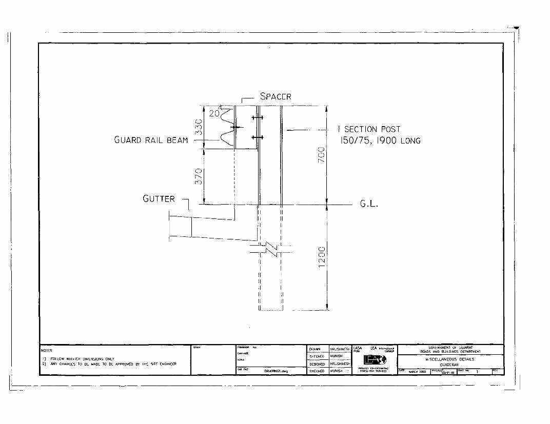
1I SPACER
20ISECTION POST
GUARD RAIL BEAM 150/75, 1900 LONG
0 ~ ~~~~
GUTTER 1 - . G. L.
~~~~~~~~I . I
11 011 1.
iiAlE iiQR D L A l
1) FOLLOW WRITTEN DIMENSIONS ONLY CHECKED MUNISH MISCELLANEOUS DETAILS2) ANY CHANGES TO BE MADE TO BE APPROVED BY THE SITE ENGINEER DESIGNED HRUSHIKESH S y GUIDERAIL
SAC INC DRAWINGCl.d.9 CHECKED MUNISH coNsAuScA SMCI I S ME -12 |ctsp I

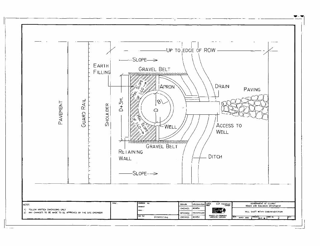
UP TO EDGE OF ROW__
k SLOPE->
GRAVEL BELTFILLING
IZ) ~~~~~~~~PAVING
z
uJ
SLOPE->
NOTES .sc. DRAWN MRUSHIKESH LASA LEA t-t-. GOVERNMENT OF CUJARAT-c I.m~~~~~~~~~~10 CAJ) ROADS AND BUILDINGS DEPARTMENT
1) FOLLOW WRITTEN DIMENSIONS ONLY CHECKED. MUNHAf WITHIN EMBAKENT,PLAN
2) ANY CHANGES TO BE MADE TO BE APPROVED BY THE SITE ENGINEER DESIGNED RUSHIKESELL S
DPAWNG2 d.9 CHECKED UUNISH CoNSLlN V ADAZC 0002 HAECSKP ,, IDG 2"


STORM WATER FROMOPEN LAND VILLAGE
NURSERY RECHARGING ROUTE FORMPOND TO WELL
CARRIAGE WAY BORE WELL -
CARR-IAGE WAY BORE WELLRECHARING ROUTE FROM WELL TO
BORE WELL
RETAINING WALL 65 M. LONG, 11M. FROM PROPOSED CENTRE LINE
TOWARDS AGRICULTURAL LAND
NOTES SCALE CORRWR All DRAWN HRUSHIKESH LASA LEA n GOVERNMENT OF GUJARATC"NAGE ~~~~~~~~~ ~~~~~ INDIA CANAD5A ROADS AND BUILDINGS DEPARTMENT
1) FOLLOW WIRITTEN DIMENSIONS ONLY SCN-E CHECKEO MUNISHl2) ANY CHANGES TO BE MADE TO BE APPROVEO BY THE SITE ENGINEER DESIGNED HRUSHIKESH lM 4 RETAINING WALL AT SOLOI
PROECT CO-ORdwM.AC,oCAD FIE DRIAWINC3 d.g CHECKED MLUNISH CORS.Mn.G SEORKES DAE ARCH 2002 1"'04 C 000 I O 3


R.C.C. T-SHAPED CANTILEVERTYPE RETAINING WALL(TYPICAL SECTION)
2 5
REINFORCED CONCRETE FOUNDATION
A
Ln S4 -_ _ _ _ _ _ _
NOTES ~~~~~~~~~~~~~~~~~s~comoRWO DRAWN' HRUSHIKIIESH LASA LEA n,o GOVERNMENT OF GOJARATNOTES
'"D"~~~~~~~~~~~~~~~~~~~~~~~~~~~~~~~~~~~~S CANAC)A ROADS AND B UILDINGS DEPARTMENT1) FOLLOW WRIITrEN DIMENSIONS ONLY DCUCESIKED HUSHIESH2) ANY CHANGES TO BE MADE TO BE APPROVED BY THE SITE ENGINEERDEINDHUHKS
M PRNNGWL
DRATONGO d.9 CHECKED M,UNISH mw!.lw5007 AE 2 00 GSP -I0El._,_D' t J
! . 1 '1 0~~~~~~~~~~~~~~~~~~~~~~~~~~~~~~~~~~~~~~~~~~~C*S.1GSOOCS 2T LC 20 PR2CT OSN fE.

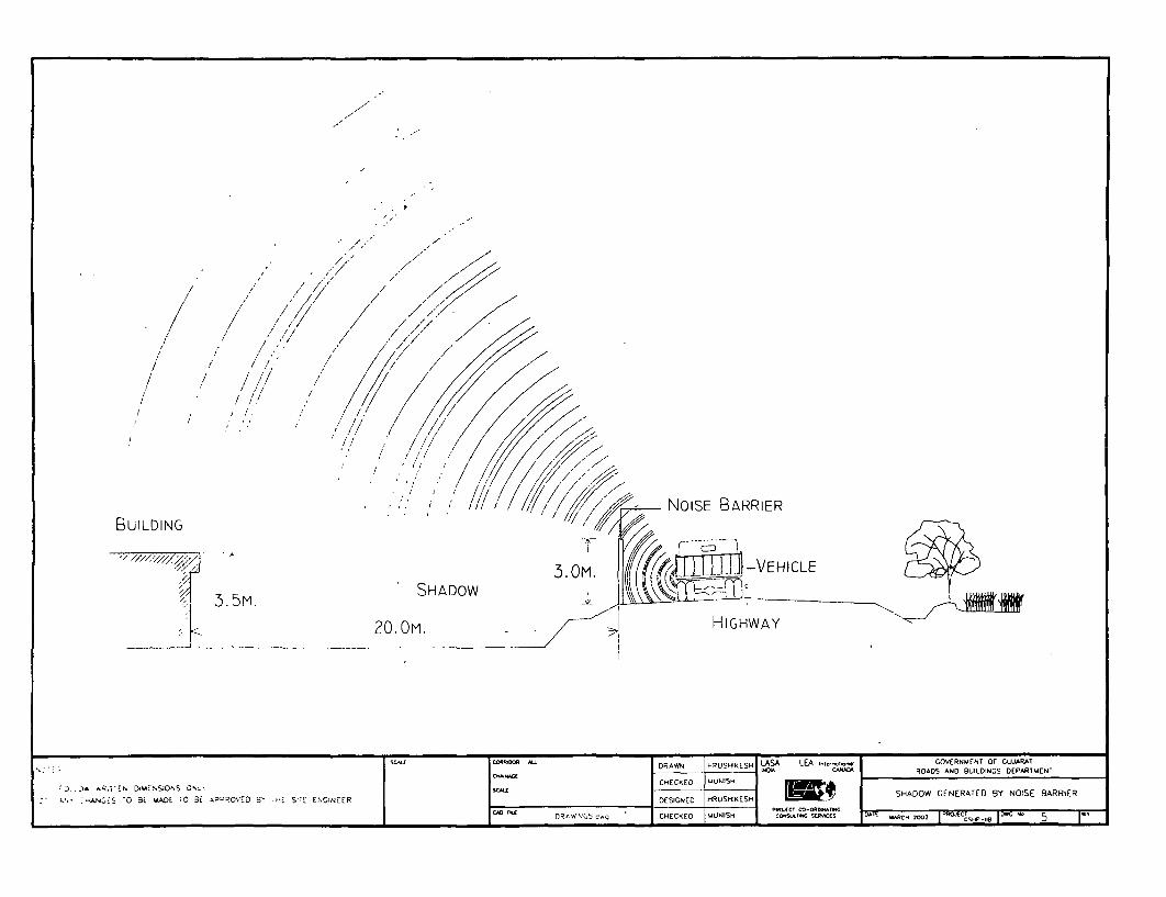
/ X ; -/NOISE BARRIER
3.5M. ~~SHADOW V,1\V17,>
t ~~~~~~~~~20.0OM. LXHIGHWAY
Co40DD ^ DRAWN HRUSHIKESH LASA LEA GnecwwXOVERNliENT OF GUJARAT
C--C1 CHECKED 9UNISH .
:):^ RiT,DWE,S9ONS OuLI scAUE SHADOW 'SENERATED BY NOISE EiARRIER
To BSSi E 9ADE TO 3E APPR2OVED B3' THiE St
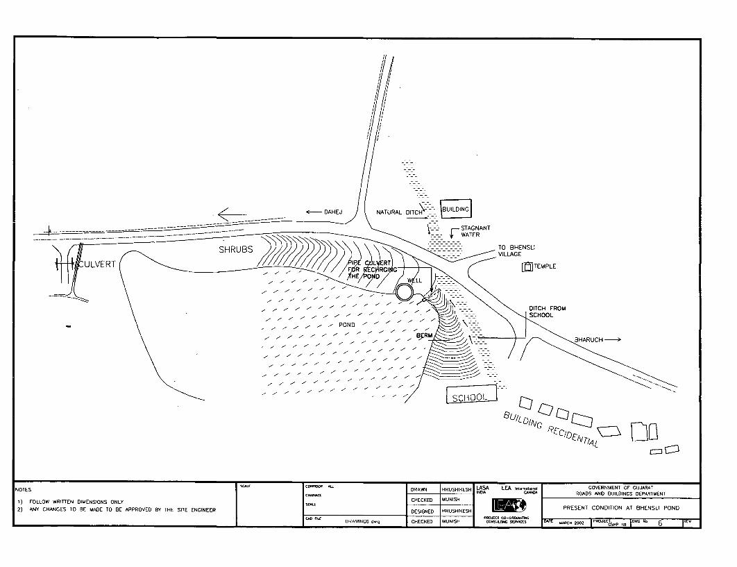
< E~~~~~~~~~- DAH EJ NATURALADITCH
I~~~~~~~~~~~~~~~~~~~~~~~~~~~~~~~~ < --- --- --- - ---A-- -
VUILAGE
NOTE~~~~~~~~~ ~~~~~~~SCAECRIO DRAWN~ HRUSHIKESH LASA LEA Ir,tIrncOI,onu GOVERNMENT OF GUJARAT
1 ) FOLLOW WRITTEN DIMENSIONS ONLY SC^LE CHECKED MUNISH 1
POND ~ ~ ~ ~ ~ ~ ~ ~ ~ ~ ~ ~~~RSN CNIINA BESIPN
2) ANY CHANGES TO BE MADE TO BE APPROVED BY THE SITE ENGINEER DESIGNED HRUSHIKESH I!tY PRESENT CONDITION AT BHENSLIDPOND
CADCAD DRAWINGE dwg CHECKED MUNISH COPsRO CERs DATE MARCH 2002 1PROJCCT. II I 6 R

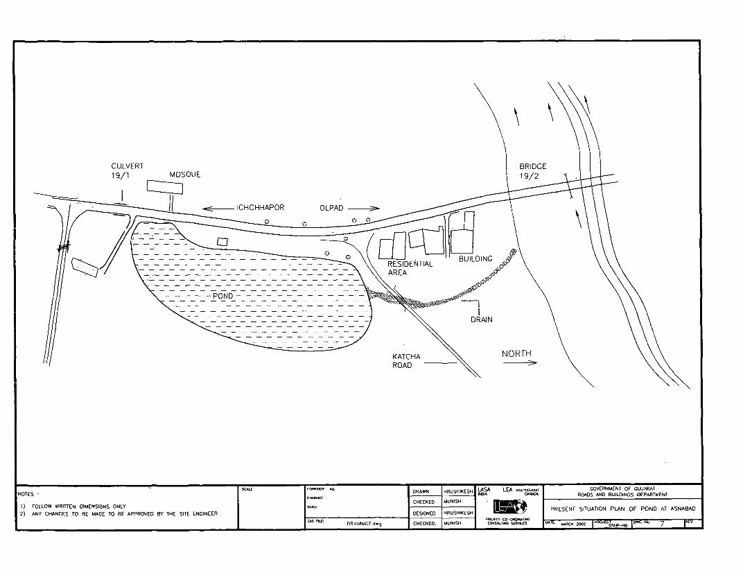
I 111 S / = = ENT ALCBUILDINGBRI\\E
1~~~~~~~~~~~~~~M S U 191\ 2
ICHCHHAPOR OLPAROA
-l - - - - - - -- - - =- - - - - - -- - -RO S AN BUILDING D A TM N
1 ) FOLLOW WRITTEN DIMENSIONS ONLY |_____CHEKED______*____PREENT_STUATON_PAN_OFPONDAT _ANABA
2) ANY CHANGES TO BE MAODE TO BE APPROVED BY THE SITE ENGINEER I_DESIGNED HRUSHIKESHPRSN SIUTO PLN O PND AANAA
| ^DiL: DRAWING7 dwg [CHECKED: [SNISH PC O- RDT CH 2002 | PROECT j(ONC N1 7 1NEV
.~~~~~~~~~~ - - - I E T A


|_~~~~~~~~~~~~~~~~~~~5 PAVIeutrNG
WELL RETAINIGDRAIN
0 _- - - - - =_ DN
'4/--…--=_-NOTES ~~~~~~~~WELDRAWN -RSHESLAALAInotoGOENETOGJRT
NOTESOSCALE DtE DR HA IA ROADS AND BUILDINGS DEPARTUENT-) FOLLOW WRITTEN DIMENSIONS ONLY - CHECKED MUNISH- - _- -
2) ANY CHANGES rol BE MADE TO 8E APPROVED B{Y THE SITE ENGINEER DESIGNED HRUSHIKESH IgsPLAN OF PROPOSEDIPOVMN. ~~~~~~~~~~~ ~ ~ ~~~~~~~~~~~~~DRAW NC8 cog CHECKED MUNISH POt CO-OSC ON lt SER'T0E 000RC 2002 |PROJEC 200-II No 8 IREV

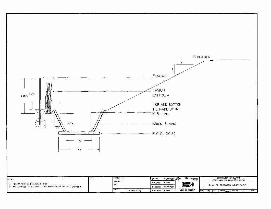
SHOULDER
- FENCING /
1HYPAS1 15.2 LATIFOLIA
TOP AND BOTTOMTIE MADE UP INM15 CONC.
.1m. CBRICK LINING
P. C.C. (M15)
1M.
NOTES DC^LE CORatIOOR ^E nRAWYN HRUSHIK£SH ,LCASOA LEA Intei.-pnol GOVERNMENT OF GUJARAT
NOTESIE DRAWN DRUSIKE CLAAA ROADS AND BUILDINGS DEPARTMENT
7) FOLLOW WRITTEN DIMENSIONS ONLY CHECKEDPLAN OF PROPOSED IMPROVEMENT
2) ANY CHANGES TO BE MADE TO BE APPROVED BY THE SITE ENGINEER DESIGNED HRUSHIKESH
CA0JED D MR C0-NAThNGDRAJVNG9 d.9 CHECKED- MUNISH COTOJnITR sER-.s DATE' MARC. 2002 I RJC AT N 9 ~

MOMA -CORM 0", MVCR-N. GmcmAAQM mcm - = w