VOGEL&NOOT - KE KELIT
274
HEAT EMISSION SYSTEMS. TECHNICAL DATA 2014 heatingthrough innovation. VOGEL & NOOT
-
Upload
khangminh22 -
Category
Documents
-
view
0 -
download
0
Transcript of VOGEL&NOOT - KE KELIT

HEAT EMISSION SYSTEMS.TECHNICAL DATA 2014
heatingthroughinnovation.
VO
GE
L&N
OO
T
Ret t ig Aus tr ia GmbH
Vog
el und N
oo
t Straße 4, 8661 St. B
arbara i.M
zt., Austria
T: +
4
3 3858 601-0, F: -1298, [email protected], www.vogelundnoot.comVOGEL&NOOT
heatingthroughinnovation.
TEC
HN
IK
2014
VOGEL&NOOT

02
heatingthroughinnovation.
363

03
ULOW-E2 low-temperature radiators 08
Profile radiators T6-Centrally connected radiators 19Multi-functional valve radiators 27Compact radiators 33HYGIENE T6 radiators 40HYGIENE Compact radiators 40Replacement radiators 46
Plan radiatorsT6-PLAN Centrallyconnected radiators 50HYGIENE T6-PLAN Centrally connected radiators 59
Vertical radiatorsVERTICAL- Centrally connected radiators 65PLAN-VERTICAL- Centrally connected radiators 68
1. Panel radiators
LASERLINEStandard Column radiators 124
LASERLINECentrally connected valveColumn radiators 134
LASERLINEArchitecture Column radiators 144
3. Column radiators
VONARIS VONARIS solitary fi nished radiators 154
VONARIS-M Centrally connected radiator 171
KONTEC convectors and heating panels 190
INTRATHERM Trench convectors 221
4. Convectors & Trench convectors
2. Towel warmers & Design radiators
CONTENTTechnology 2014
VONARIS
VONARIS-M
KONTEC
INTRATHERM
ULOW-E2
Profi le panelradiators
Plan panelradiators
Vertical radiators
Towel warmers
Design radiators
2
Standard Column radiators
Centrallyconnected Column radiators
Architecture Column radiators
3
4
Towel warmersDION 80DION-VM 81DELLA electric-only operation 82
Design radiators BAWA-VM SPA 87FATALA-VM SPA 88FATALA-VM SPA left hand design 89
SEWA 90NERO 91OHIO VSM 92LOWA VM 93KASAI 94FATALA 95FATALA left hand design 96FATALA electric-only operation 97FATALA left hand design electric-only operation 98
FATALA Replacement/left hand design 99/100ARUN-T 101BAWA 102BAWA VM 103BAWA-T VM 104BAWA electric-only operation 105BAWA Replacement 106BAWA-T Replacement 107VELINO 108
CAVALLY 109CAVALLY-VM 110FULDA 111FULDA-VM 112FULDA electric-only operation 113SEINE-V 114
1
5. Radiator Mounting Brackets 5
Installation instructions 267

04 ECO - highest energy effi ciency
FULL-RANGE SUPPLIER.
Effi cient, comfortable and aesthetic heat distribution
VOGEL & NOOT is the full-range supplier in innovative radiator and underfl oor heating
systems for any temperature range – especially for low temperature operation with renewable
energy sources.
Panel, bathroom and design radiators, convectors
Multifunctional panel radiators with the T6 technology, comfortable bathroom and individually
confi gured design radiators as well as shapely convectors from VOGEL & NOOT , have a broad
fl ow temperature range and an ideal range of applications to match.
E2-technology
The intelligent E2 technology provides quick control convenience even at low temperatures and
always with the highest level of effi ciency – also in combination with underfl oor heating systems.The sign of highest energy effi ciency
The ECO seal of quality on all radiators
from VOGEL & NOOT stands for compa-
tibility with all (renewable) energy sources
and thus for economically as well as ecolo-
gically effi cient heat distribution.

05
Contribution to the climate by improving the ecological balance
As a leader in progressive thinking on “green” heat distribution using renewable ener-
gies, VOGEL&NOOT demonstrates a high level of responsibility about the effi cient use
of our planet and its resources, for example with a strict ECO training course, the focus on
low temperature heat distribution and the compatibility with renewable energies as well
as a permanent production optimisation and product development. VOGEL&NOOT
has been a member of Klimabündnis Österreich since 2011.
Innovation as the driving force for climate protection
VOGEL&NOOT conducts intensive research & development and maintains a strong
innovation network with internal and external energy and trend experts, universities and
renowned research institutions.
Renewable energies, the future of heat distribution
Compatibility is an essential quality for heat distribution systems using renewable, low
temperature energy sources such as heat pumps, solar technology, etc. VOGEL&NOOT
radiators with the ECO quality seal ensure low CO2 emissions and thermal comfort for all
system temperatures in modern insulated buildings up to a fl ow temperature below 40°C.
ENVIRONMENT AND CLIMATE PROTECTION.
VOGEL&NOOT is a member of Klimabündnis Österreich. This network is active in 18
European countries and has set itself the objective of effectively reducing environmen-
tally harmful emissions and protecting our planet’s resources.
Effi cient heat distribution for the planet
VOGEL&NOOT has set itself the
objective of providing the world with
resource-conserving heat distributi-
on solutions, because climate pro-
tection will only work when the heat
generated is released effi ciently into
rooms.

06 Certifi ed Quality
QUALITY AS A SIGN OF
MAXIMUM SAFETY
Quality as a sign of maximum safety
The radiators manufactured by VOGEL&NOOT meet numerous internationally recognised
quality standards and the manufacturing processes at all of the production sites have been ISO
certifi ed. Furthermore, the quality and performance data of VOGEL&NOOT panel radiators
are constantly reviewed and confi rmed by accredited European institutions. VOGEL&NOOT
panel radiators have also been awarded the seal of approval of the German Committee for
Terms and Conditions of Sale (RAL), which documents the special quality of the product compa-
red with many other radiator manufacturers.
Bests with RAL Quality Seal
For architects, designers and builders, the RAL seal of approval for VOGEL&NOOT radiators
symbolises the high quality of the product in the areas of processing and handling. These quali-
ty assessments, which are controlled by independent institutions, vouch for the enduring safety
and long life of service of the product.
Highest customer confi dence
Our customers know that with each product, they can expect excellent properties in terms of
the material, surface condition and durability. VOGEL&NOOT radiators thus exceed many
requirements and outperform numerous standards (such as, for instance, the European Stan-
dard EN 442 or the CE marking). A perfected manufacturing process guarantees the best per-
formances with precise welding, reliable leak-testing and glossy surface treatment - safety com-
bined with a fantastic visual appearance!

07Panel radiatorsContents
BASICS
General technical information 71Plan radiated heat-refl ector 72Monclac-bracket 74Mounting template 3/4“ external thread 76Transfer table 78
Introduction 08Technical data 17Temperature pairings and weight 18
ULOW-E2 LOW-TEMPERATURE RADIATOR
Technical data 68Temperature pairings and weight 70
PLAN-VERTICAL- CENTRALLY CONNECTED RADIATOR
Technical data 65Temperature pairings and weight 67
VERTICAL- CENTRALLY CONNECTED RADIATOR
T6-PLAN CENTRALLYCONNECTED RADIATOR
Technical data 50Connection modes 58Temperature pairings and weight 55
HYGIENE T6-PLAN CENTRALLY CONNECTED RADIATOR
Technical data 59Connection modes 58Temperature pairings and weight 61
PLA
N R
AD
IAT
OR
SU
LOW
-E2
HYGIENE COMPACTRADIATOR
Technical data 40Connection modes 35Temperature pairings and weight 42
HYGIENE T6-CENTRALLY CONNECTED RADIATOR
Technical data 40Connection modes 22Temperature pairings and weight 42
COMPACT RADIATOR
MULTI-FUNCTIONALVALVE RADIATOR
Technical data 33Connection modes 35Temperature pairings and weight 36
Technical data 27Connection modes 30Temperature pairings and weight 36
Technical data 19Connection modes 22Temperature pairings and weight 36
T6-CENTRALLY CONNECTED RADIATOR
REPLACEMENTPANEL RADIATOR
Technical data 46Connection modes 48Temperature pairings and weight 49
PR
OF
ILE
RA
DIA
TO
RS
VE
RT
ICA
L R
AD
IAT
OR
S
Tender offer documents are available to download at www.vogelundnoot.com/download
1

08 ULOW-E2 LOW-TEMPERATURE RADIATORIntroduction
Technology
An unmatched conceptThe ULOW-E2 low-temperature radiator, with its E2 technology is the realisation of a unique product concept, that offers effi cient, economic and aesthetic heat emission.
T
ATwoee
ULOW-E2 LOW-TEMPERATURE RADIATOR

09
We reserve the right to amend typing errors and make technical changes. Valid from 1 February 2014.
ULOW-E2 LOW-TEMPERATURE RADIATORIntroduction
Powerful and intelligentOn the one hand, the ULOW-E2 gives a high proportion of radiant heat thanks to its water-fi lled panels, whilst on the other, it provides optimised, on-demand convection. Intelligent control, switches between static and dynamic operation and ensures quick heat emission and short reaction times, with high effi ciency and a maximum of thermal comfort at supply temperatures of 40° C and less.
Beauty and economy in oneAn avant-garde design meets all the demands of a modern interior and stylishly enhances any living space. Because of the small additional invest-ment costs needed for the ULOW-E2’s higher effi ciency, it quickly pays for itself. Manual temperature control in each room makes for maximum comfort in every one of them.
1
ULOW-E2

10
We reserve the right to amend typing errors and make technical changes. Valid from 1 February 2014.
ULOW-E2 LOW-TEMPERATURE RADIATORThe advantages
High savings potential Choosing it in preference to other products currently available on the market can give you huge energy savings, because of the signi-fi cantly lower ambient operational temperatures. With the ULOW-E2, operating the entire heating system is much more energy-ef-fi cient.
State-of-the-art design The ULOW-E2’s extremely elegant plane optics and its futuristically reduced artistic style appeal to persons with a sophisticated aware-ness of their furnishings, whilst the rounded soft-line edges exude stylish harmony. VOGEL&NOOT are trend-setting trail blazers with their completely new round-aperture optics – another prominent feature is the classy looking, intuitive touchpad control panel.
Intelligent control What makes the ULOW-E2 so special is that it is fi tted with fans that enhance natural convection, combined with an intelligent control system that can switch between static and dynamic operation eit-her fully automatically, or according to the user’s operating requi-rements. The fans serve as a supplement and are only switched on when needed, as this equipment provides high basic performance even in static operation.
Low-temperature compatibleThe ULOW-E2 low-temperature radiator gives problem-free use at supply temperatures of 40° C and less, with all modern, conventio-nal energy sources (oil or gas burning heating systems, &c), as well as all renewable energy sources (heat pumps, solar heating, &c).
Tried and tested central-connection technology In today’s fl exible building industry pre-piping has become indis-pensible. In this respect central-connection technology contributes signifi cantly to reductions both in installation time and costs and in susceptibility to faults. It also ensures maximum freedom in plan-ning and installation.
Heat emission in next to no time and a short reaction time Because of its high proportion of radiant heat and its on-demand fan-optimised convection, the ULOW-E2 ensures fast heat emission and short reaction times. In winter any night-time drop in tempera-ture or heat loss from ventilating room can be compensated for, no problem, in next to no time.
The advantages of the ULOW-E2low-temperature radiator at a glance.

11
We reserve the right to amend typing errors and make technical changes. Valid from 1 February 2014.
ULOW-E2 LOW-TEMPERATURE RADIATORThe advantages
System compatibility Operating in combinations in new buildings, the ULOW-E2 is perfectly compatible with other low-temperature heat emission systems, such as under-fl oor heating, under-fl oor convectors, wall heating, &c. As the ambient operational temperatures are mu-tually consistent, it is possible to install both on a single heating circuit.
A higher proportion of radiant heat In contrast to simple convectors the ULOW-E2 gives a much hig-her proportion of radiant heat, thanks to its water-fi lled panels to front and rear.
Ideal for renovations and new buildingsAfter thermal renovation and the fi tting of a modern heating source, the conditions for installing the ULOW-E2 are ideal. We recommend using ULOW-E2 low-temperature radiators on their own in renovations, but in combination with other heat emission systems in new buildings.
Versatile electrical connectionTo connect the ULOW-E2 to the power supply, there is a choice of two options – a plug connection or a direct cable connection. The power cable length is fully adjustable.
Living in comfort all year roundIn winter the ULOW-E2 works as an effi cient low-temperature radiator, with high-level control quality, to give perfect heating comfort. And then the summer breeze-effect ensures that on hot days the atmosphere in your living area is pleasantly cool thanks to gentle movement of the air.
Extremely easy installationThe ULOW-E2 is delivered as a ready to connect product, and can be installed just like any standard radiator - it’s easy, effi cient, fl exible and inexpensive. Particularly with renovations this is very important.
Technology
ULOW-E2

12
We reserve the right to amend typing errors and make technical changes. Valid from 1 February 2014.
ULOW-E2 LOW-TEMPERATURE RADIATORAreas of application
Renovations: monovalent operation Provided thermal renovation ensures a good standard of insulation, or a modern heating source has been fi tted, the conditions for installing the ULOW-E2 are ideal. Operation with all ener-gy sources (oil, gas, fi rewood, pellets, district heating or a heat pump) at a supply temperature of 40 °C and less is perfectly possible.
In new buildings: combined operation In modern style new buildings good standards of thermal insulation already apply and modern reduced-temperature heating systems (oil- or gas-fi red) are installed, or renewable low-tempera-ture energy sources are used (fi rewood, pellets, and/or district heating or heat pumps). The ULOW-E2 with supply temperature as low as 40 °C and less is compatible with these heat sources.
For sure, the ULOW-E2 can in principle also be used for monovalent operation in new buildings. However, combined operation with other low-temperature heat-emission systems, such as under-fl oor heating, under-fl oor convectors, wall heating, &c is particularly recom-mended. Combined operation is recom-mended for spaces that require fast room heating and short reaction times (bedroom, fi tness room, work space, etc.).
RENOVATION, A NEW BUILDINGOR SIMPLY GREATER THERMAL COMFORT.

13
We reserve the right to amend typing errors and make technical changes. Valid from 1 February 2014.
ULOW-E2 LOW-TEMPERATURE RADIATORComparison with commercially available fan convectors
The ULOW-E2 as compared with commercially available fan convectors:
• Fan convectors generally provide either no radiant warmth or only very little. TheULOW-E2 combines convection and radiant heat, thanks to its water-charged pa-nels.
• In static operation the ULOW-E2 is superior to commercially available fan convec-tors on account of its high level of basic performance. This is because aluminiumheat exchangers without fan support are less effi cient.
• With most fan convectors, the fans are switched on whenever the heater is in ser-vice. The ULOW-E2 has an intelligent control mechanism, which switches automati-cally between static and dynamic operation. It only starts the fans when it is turnedfull-on, or when additional output is required.
• Fan convectors are strictly limited in their designer- and architectural pretensions, be-cause of their clumsy construction. With its distinctive ‘round-hole-look’, the ULOW –E2sets new standards in radiator design. Its slim profi le and elegant plane surfaces are the perfect complement to any modern living environment.
• Maintenance and cleaning of fan convectors is usually an unpleasant, time-con-suming chore. The ULOW-E2, by contrast, can be cleaned just like a standard fl atradiator. The rows of fans just pull out to the side, with no tools required.
• With its high performance specifi cations, the ULOW-E2 offers top of the range pri-ce-for-quality value.
• Fan convectors are made up of very many individual parts, some of which are com-plex and can only be fi tted on-site. By comparison, the ULOW-E2 is delivered as aready-to-plug-in product.
• Fan convectors do not have central connections. With the ULOW-E2 these comeas standard across the range, guaranteeing maximum fl exibility for planning andinstallation.
• Installation of fan convectors is expensive and time consuming. The ULOW-E2 canfor the most part be installed with no tools needed.
ULOW-E2: slim profi le and modern design
FAN CONVECTORS:Clumsy appearance and broad bulky structure
ULOW-E2: radiant heat and convection
FAN CONVECTORS:little radiant heat
THE UNIQUE ULOW-E2 CONCEPT. ULOW-E2

14
We reserve the right to amend typing errors and make technical changes. Valid from 1 February 2014.
ULOW-E2 LOW-TEMPERATURE RADIATORFunctional and control elements
4
5 3
2 1
9 6
10 7 811 Thermostat head
Temperature scale THERMOSTAT
main switch ON/OFF
Heating icon, RED
Cooling icon, BLUE
UP button
DOWN button
Temperature icon
Boost button
Heating/Cooling button
Fans
1
2
3
4
5
6
7
8
9
10
11
TOUCHPAD-CONTROL PANEL
Functional and control elements

15
We reserve the right to amend typing errors and make technical changes. Valid from 1 February 2014.
ULOW-E2 LOW-TEMPERATURE RADIATORFunctional and control elements
Settings instructions
The thermostat head (1) is always the radiator’s MAIN CONTROL FUNCTION, with the temperature scale (2) show-ing the setting selected. The ULOW-E2 is equipped with a clearly arranged TOUCHPAD CONTROL PANEL, with which the settings for the radiator’s IN-DIVIDUAL FUNCTIONS can be entered.
The main switch ON/OFF (3) switches the electronics on or off. When the hea-
ting icon’s (4) red light shows, the heating mode is on. The factory setting for desi-red room temperature on fi rst operation is 22° C. With the UP button (6) or the DOWN button (7) you can reset the tem-perature in 1° C increments, between 18 and 26° C. The new setting is displayed by the LED temperature icon (8).The Boost button (9) activates ‘Boost Mode’, in which the power to the fans (11) is increased to its maximum value.The maximum duration of ‘Boost Mode’is preset by the factory at 120 mins. As
soon as the selected room temperature is reached, the system automatically switches to ‘Comfort Mode’.With the Heating/Cooling button (10) you can switch from heating operation to cooling operation, and the cooling icon (5) lights up in blue.For “Dry Comfort Cooling” operationsome adaptations in the boiler house will be needed, particularly to ensure thattemperatures do not fall below the dew-point. In addition the thermostat headneeds to be fully opened anti-clockwise,and with extremely high room tempera-tures it may also occasionally be neces-sary to remove the thermostat head.
Pressing the Heating/Cooling button (10) again activates the “Air CirculationMode” and the blue cooling icon (5)starts to blink. In this case the fans (11)operate independently of the tempera-ture sensors. The factory-setting of 12volts can be reduced to 8 or 5 volts, andvice versa, by pressing the UP (6) andDOWN (7) buttons. If you press the Hea-ting/Cooling button (10) once more, youreturn to the heating mode.For more detailed information see theoperating instructions, enclosed withevery ULOW-E2 low-temperature radia-tor delivery.
Functional and control elements
Temperature settings
18 °C1st LED dimly lights
18,5 °C1st LED stronglights
19 °C1st and 2nd LED
dimlylights
19,5 °C1st and 2nd LED
stronglights
20 °C2nd LED dimlylights
20,5 °C2nd LED stronglights
21 °C2nd and 3rd LED
dimlylights
21,5 °C2nd and 3rd LED
stronglights
22 °C3rd LED dimlylights
22,5 °C3rd LED stronglights
23 °C3rd and 4th LED
dimlylights
23,5 °C3rd and 4th LED
stronglights
24 °C4th LED dimlylights
24,5 °C4th LED stronglights
25 °C4th and 5th LED
dimlylights
25,5 °C4th and 5th LED
stronglights
26 °C5th LED dimlylights
ULOW-E2

16
We reserve the right to amend typing errors and make technical changes. Valid from 1 February 2014.
ULOW-E2 LOW-TEMPERATURE RADIATORService access, electrical connection und secure wall mounting
Tool-free service access What is so special about service access for the ULOW-E2 is that not a single tool is required for removing and replacing the component parts. All functional units and electrical components are freely accessible and can be fi tted by means of plug con-nections and clamp joints. This saves money and time for maintenance and cleaning. A ULOW-E2 is cleaned just the same way as a standard fl at radiator. The fans sit on gliding cradles and can easily be slid out or in from the side of the radiator.
Versatile electrical connection Connecting the ULOW-E2 to the power supply, can be done in a variety of ways and can fi t in with every structural and ar-chitectural condition. The position of the cable is fully adjustable within an overall length of 1.20 m.
The sliding cradles for the fans are made of extremely fl exible and resistant plastic. They can be bent to an angle of 90°. This is particularly useful for narrow niches and narrow side clearance with walls. Should the fan need to be replaced, press down the sliding cradle by hand and remove it from the plug connection/clamp-joint.
Example:Standard plug connection.
Example:Alternative direct cable connection, with or without on/off switch.
Service access, electrical connection und secure wall mounting
Secure wall installationFor wall-mounting the ULOW-E2, use only mounting brackets or wall-moun-ting systems with integrated connection locking.

17
We reserve the right to amend typing errors and make technical changes. Valid from 1 February 2014.
Material: cold-rolled sheet steel confor-ming to EN 442-1, 1 mm thick zinc-plated front panel.
Connecting dimensions: central di-stance between supply and return 50 mm.
Casing: consists of a perforated metal top-cover and two closed removable side panels.
Coating: 1. Primer coating conforming to DIN 55900 part 1, stoved at 190° C;2. Especially robust electrostatic powder coating conforming to DIN 55900 part 2, in RAL 9016, stoved at 210° C.
Standard design: powder coating in RAL 9016 (Traffi c White).
Packaging: 1. Cardboard packaging; 2. Edge protection; 3. Shrink wrapped.The device can be installed in packaging.
Connection modes: all models are fac-tory-fi tted with mounting brackets and can optionally be connected as valve radiators with central connection or as compact radiators. With single-pipe sys-tems, a one-pipe manifold is absolutely essential. The side panels and top-cover are allowed for in the performance spe-cifi cations.
Noise levels: comfort operation: bet-ween 20 and 25 dB; boost operation: 34 dB.These values apply at a distance of 2m, in conformity with VDI 2081. (Overall dimensions: 600 x 1000 mm).
Scope of delivery: thermostat valve with factory-adjusted kv confi gurations inclu-ding mounting cap; drain plug, dummy plug and special vent plug, all factory sealed; as well as completely pre-instal-led fan sets with microprocessor and
thermistor control unit; an integrated low-voltage transformer with ready to plug in mains cable; and a visually attrac-tive operating panel (in the top cover), all included in the purchase price.
Not designed for use with free-stan-ding console-feet!
ULOW-E2 LOW-TEMPERATURE RADIATORTechnical specifi cation
Connections:4 x G ½ internal thread and 2 x G ¾ external thread, underside centre.
Maximum positive operating pressure: Standard design: 10 bar
Maximum operating temperature: 60 °C
Safety class: IP14Supply voltage: 230 V
max
.
10 barmax.
ULOW-E2

18
We reserve the right to amend typing errors and make technical changes. Valid from 1 February 2014.
ULOW-E2 LOW-TEMPERATURE RADIATORHeat outputs
Heat outputs - ULOW-E2, model 22 PTM
Mode of operation Static operation Comfort operation Boost operation
Overall height (mm) 500 600 900 500 600 900 500 600 900
Radiator exponent n (for 45/35/20, 40/35/20 und 35/30/20)
Overall length (mm)
40045/35/2040/35/2035/30/20
60045/35/2040/35/2035/30/20
80045/35/2040/35/2035/30/20
100045/35/2040/35/2035/30/20
120045/35/2040/35/2035/30/20
140045/35/2040/35/2035/30/20
160045/35/2040/35/2035/30/20
180045/35/2040/35/2035/30/20
200045/35/2040/35/2035/30/20
163
245
327
409
490
572
654
735
817
184
276
368
460
552
644
736
828
920
233
349
466
582
698
815
931
1048
1164
252
379
505
631
757
883
1010
1136
1262
272
409
545
681
817
953
1090
1226
1362
324
486
648
810
972
1134
1296
1458
1620
294
440
587
734
881
1028
1174
1321
1468
317
475
634
792
950
1109
1267
1426
1584
375
562
750
937
1124
1312
1499
1687
1874
1,305 1,317 1,339 1,139 1,129 1,164 1,112 1,112 1,106
140
210
280
349
419
489
559
629
699
157
236
314
393
472
550
629
707
786
198
298
397
496
595
694
794
893
992
220
331
441
551
661
771
882
992
1102
238
357
476
595
714
833
952
1071
1190
282
423
564
705
846
987
1128
1269
1410
257
385
514
642
770
899
1027
1156
1284
277
416
554
693
832
970
1109
1247
1386
328
492
656
820
984
1148
1312
1476
1640
89
134
179
224
268
313
358
402
447
100
150
200
250
300
350
400
450
500
126
188
251
314
377
440
502
565
628
149
224
298
373
448
522
597
671
746
162
242
323
404
485
566
646
727
808
189
284
378
473
568
662
757
851
946
176
263
351
439
527
615
702
790
878
189
284
378
473
568
662
757
851
946
225
337
450
562
674
787
899
1012
1124
ULOW-E2 weight
Overall height (mm) 500 600 900
Overall length (mm) Model 22 PTM 22 PTM 22 PTM
400 kg
600 kg
800 kg
1000 kg
1200 kg
1400 kg
1600 kg
1800 kg
2000 kg
15,70
22,43
29,18
36,11
42,85
49,69
56,53
63,46
70,20
17,59
25,20
32,82
40,62
48,24
55,94
63,65
71,45
79,07
25,19
36,57
47,95
59,51
70,90
82,37
93,84
105,41
116,79
107 7
Ove
rall
le
ng
th
Overall height

19
We reserve the right to amend typing errors and make technical changes. Valid from 1 February 2014.
T6-CENTRALLY CONNECTED RADIATORTechnical data
T6-CENTRALLY CONNECTED RADIATOR.
13 bar
max
.
10 barmax.
Technology
1
Heat emissionThe specifi cation was verifi ed in accor-dance with DIN EN 442 at The Techni-cal University, Stuttgart (Registration at WSP-Cert Product Certifi cation Centre, Stuttgart), under the numbers: Type 11 VM 0445 Type 21 VM-S 0447 Type 22 VM 0448 Type 33VM 0449
and in accordance with OENORM (Aus-trian standard) EN 442 at the Technolo-gical Commercial Museum, Vienna.
Material T6-CENTRALLY CONNECTED RADI-ATORS are made of cold-rolled sheet
steel, and in accordance with EN 442-1, with a stylish and robust fl uting with ribs at 40 mm intervals.
Equipment Each T6-CENTRAL CONNECTION RA-DIATOR is equipped with an integrated T-valve set, and suitable for double-pi-pe and single-pipe systems with a sin-gle-pipe manifold; it comes with a fi t-ted valve top with a pre-set kv-value, a protective cap and welded suspension brackets on the back. The drain plug and the pivoting special vent plug, as well as the dummy plug are fi tted with seals. All types of radiator are equip-ped with a detachable top cover and two closed side panels.
Paint coating1. Undercoating in accordance with DIN 55900 part 1, stoved at 190° C.
2. Finish in accordance with DIN 55900 part 2, in standard colour 9016 (on request available in many standard colours and sanitary-ware colours at an extra charge), applied electro- statically in a modern powder coa- ting facility. This especially resistant coating is stoved at an object temperature of 210° C.
Packaging1. Cardboard packaging2. Edge protection3. Shrink foil
Connections4 x internal thread G 1/2 and2 x external thread G 3/4bottom centre
Test positive pressure13 bar
Max. positive operating pressure 10 bar
Max. operating temperature 110 °C
ULOW-E2
Profi le panelradiators

20
We reserve the right to amend typing errors and make technical changes. Valid from 1 February 2014.
T6-CENTRALLY CONNECTED RADIATOROverview of models
Guarantee statements are available to download at www.vogelundnoot.com/download
Overview of models
Type 11 VM 21 VM-S 22 VM 33 VM
ein
lag
ig m
it e
ine
m K
on
vek
tio
nsb
lech
27
23
23
61
32
zwe
ila
gig
mit
ein
em
Ko
nve
kti
on
sble
ch
47
39
80 7
zwe
ila
gig
mit
zw
ei
Ko
nve
kti
on
sble
che
n
59
39
105 7
dre
ila
gig
mit
dre
i K
on
ve
kti
on
sble
che
n59
39
166 7
Type 11 VM 21 VM-S 22 VM 33 VMHeight
[mm]
300 400 500 600 900 300 400 500 600 900 300 400 500 600 900 300 400 500 600 900
Length
[mm]
up to 2400
up to 2600
up to 2000
up to 2400
up to 3000
up to 2000
up to 3000
up to 2000
up to 3000
up to 2200
up to 1800
Steps all overall length starting with 400 mm available in steps of 200 mm, additionally 520, 720, 920, 1120 and 1320 mm
sing
le-la
yer
with
a c
onv
ectio
n sh
eet
do
uble
-laye
r w
ith a
co
nvec
tion
shee
t
do
uble
-laye
r w
ith t
wo
co
nvec
tion
shee
ts
thre
e-la
yers
with
thr
ee c
onv
ectio
n sh
eets

21
We reserve the right to amend typing errors and make technical changes. Valid from 1 February 2014.
T6-CENTRALLY CONNECTED RADIATOR Description and delivery equipment
Description and delivery equipment
The T6-CENTRALLY CONNECTED RA-DIATOR, with its welded-in set of T-shaped valves, sets new standards in the fi eld of centre-connection techno-logy. Besides its elegant appearance, the T6-CENTRALLY CONNECTED RA-DIATOR grabs the attention because of its unique patented features. It is suitable for all purposes and easy for the heating engineer to install. It also has many other striking advantages, as listed below:
T6-CENTRALLY CONNECTED COMPLETE RADIATORS - wall bracket fastenings make this a fl exible solution
VARIABLE CONNECTIONS - the built-in valve and its thermostat head can be switched from the right to the left-hand side – with no need to turn the radiator and without crossing over the supply and return.
VARIABLE TYPES - with all multi-layered radiators the distance between the connection and the wall is standardised (this also applies to all single-layered radiators, if a special angle fi sh-plate is used).
VARIABLE SIZES - you are free to choose the overall radi-ator length and height at any time, and even subsequently change your mind.
PERFECT PRE-ASSEMBLY - fi tting pre-installation piping and system testing are possible even without having the radiators there.
Consequently T6-CENTRALLY CON-NECTED RADIATOR truly serves to solve your problems. To round off all the advantages mentioned before, the versatility of the T6-CENTRALLY CON-NECTED RADIATOR regarding style and colouring offers a wide scope for design. By using the removable, unique and colourful decor-clips you can give individuality, also subsequently.
The T6-CENTRALLY CONNECTED RA-DIATOR is - with its welded in set of T-shaped valves - suitable for double-pipe installations as well as single-pipe installations, using a single-pipe mani-fold.
Additionally to the central connection from the bottom, the sophisticated de-sign makes possible other connections used at compact radiators, such as the single-sided and two-sided connec-tion. Radiators are delivered ready for double-pipe installation and with a factory-adjusted kv-setting, appro-priate to the radiator output.
For district heating installations with a big difference between water supp-ly and return temperature, a valve unit that allows a precise and stepless ad-justment is available on request.
By using universal supply and return connections, commercially available pipes (external thread 3⁄4“) made of copper, steel, plastic or alloy, can be connected; the corresponding acces-sories and the commercially obtainable shut-off valve have to be used.
The following thermostat heads can be directly fi tted at the radiator: „RA 2000“ and „RAW“ by Danfoss, „VK“ by Heimeier, „D“ by Herz, „thera DA“ by MNG, as well as „UNI XD“ by Oven-trop. The radiator will be delivered with a protective cap.
The operation parameters are specifi ed with a positive operating pressure of 10 bar and an operating temperature of 110° C. With single-pipe installations, a cycle’s maximum radiator power of about 10 kW at ΔT=T1-T2=20 K (at T1 = 90° C) has to be taken into account.
Thus the T6-CENTRALLY CONNECTED RADIATOR has to be regarded as re-volutionary for the new generation of centrally-connected radiators. With this type of radiator - with its ideal func-tioning of the whole radiator-valve unit, its superb heating output, compared with the motivation to install thermo-stat heads, saving heating energy be-comes evident.
Our valve radiators’ connections (exter-nal thread G 3⁄4“) comply in construc-tion and tolerance with the specifi ca-tions, in accordance with DIN V 3838. If conically sealed drain cocks are used (single-pipe and double-pipe operati-on), where an adjustment of tolerance of distance to the centre is not possi-ble, we must repudiate liability for any damage connected to this.
Therefore we recommend to use only fl at sealed drain cocks, or drain cocks where an adjustment of tolerance of the distance to the centre is possible.
T6-CENTRALLY CONNECTED RADIATOR

22
We reserve the right to amend typing errors and make technical changes. Valid from 1 February 2014.
T6 AND T6-HYGIENE CENTRALLY CONNECTED RADIATORDouble-pipe operation - Adjustment tips for built-in valve
X
B
G 3/4 A.G.
50
A
DanfossRA 2000
54
32
9102
78
56
34210
Druckverlust [mbar]
Hei
zkö
rper
dur
chflu
ss [l
/h]
103
9876
5
4
3
2
9876
5
4
3
2
10
102
Voreinstellu
ng N - k
v=0,75
7 - kv=
0,63
6 - kv=
0,52
5 - kv=
0,41
4 - kv=
0,31
3 - kv=
0,26
2 - kv=
0,21
1 - kv=
0,13
Setting instructions:VOGEL&NOOT valve radiators are factory-fi tted for double-pipe installa-tions. Each individual radiator is fi tted with a pre-adjusted valve insert, appro-priate to the radiator output. The pre-set kv-value is also marked in colour on the front surface.
Please note:Should customised adjustments be required, the pre-set kv-values can be altered as needed. Swapping the right-hand side built-in valve to the left-hand side is no pro-blem at all at any time.Radiator are delivered with protective caps. After removing the protective cap (pos. A) the following thermostat heads can be fi tted directly to the built-in valve (pos. B): “RA 2000”, “RAW” by Danfoss, “VK” by Heimeier, “D” by Herz, “thera DA” by MNG and “UNI XD” by Oventrop.
N1
23
45
67
Einstellring
Markierung
Detail „X“
ring gauge
marking
rad
iato
r fl o
w r
ate
[l/h]
Pressure drop [mbar]
default settin
g
Chart 1Pressure drop [mbar] – double-pipe operation with a proportional deviation of 2K.
Of course it is also possible to change the pre-adjusted valve setting when the equipment is operating at pressure.
kv-value chart
Pre-setting 1,1 3,9 5,2 6,5 N
kv-value up to 0,13 0,30 0,42 0,56 0,72
Colour of the adjustment ring w
hite
bla
ck
gre
en
blu
e
red

23
We reserve the right to amend typing errors and make technical changes. Valid from 1 February 2014.
T6-CENTRALLY CONNECTED RADIATORValve pre-adjustment
Hydraul ic cal ibration
Factory pre-adjustment Advantages of the valve inserts in VOGEL&NOOT valve radiators
VOGEL&NOOT valve radiators are al-ready factory-fi tted with pre-set and adjustable valve inserts, appropriate to the heat output. The valve inserts fi tted as standard allow for 8 main kv-value settings and 7 intermediate settings. The factory-adjusted kv-value settings include 5 of 15 possible settings, and are calculated for standard heating systems with a pressure difference of 100 mbar.
Continuously opening and infi ni-tely variable control apron
• Finer adjustment• Reliable operation• More easily cleaned valve inserts
Colour-coded valves
• Set kv-value immediately visible
The advantages of factory-adjusted valve settings
• Optimal hydraulic calibration for buildings with operational areas up to 1,000m2• Better energy evaluation of buildings (DIN EN 18599)• Credits for the Energy Passport• Saves time and costs for heating planners, installers and plumbers• Up to 6% energy saving, after hydrau- lic calibration • Up to 20% less energy needed for circulation pump
The hydraulic calibration of the heat emission system has two essential ef-fects: saving on energy costs and CO2 reduction. It ensures that all radiators receive the required fl ow rate of he-ating water. This is the only way that optimal heat output performance be achieved, guaranteeing thermal com-fort, with economical and ecologically responsible operation.
Any radiator requires a specifi c fl ow rate of heating water, according to its position in the distribution system. The circulation pump serves to distri-
bute heat in all rooms equally and in accordance with the required ambient temperature. Yet, in most systems the warm heating water fl ows back along the line of least resistance, which is usually through the radiator located next to the circulation pump.
This means that the radiators furthest from the circulation pump are ina-dequately supplied with heating water, whereas the nearest are oversupplied! Very often the reason why rooms are inadequately heated or overheated is attributed to either an under-size pump
or heating sources that are too weak. However, larger pumps, high supp-ly temperatures and heating controls make the negative effects worse: lack of comfort and high energy costs, as well as higher CO2 emissions and more noise.
The only effective remedy for this is hydraulic calibration, with the appro-priate kv-value, pre-adjusted by the factory. This makes the resistance of all the radiators in the distribution system similar, and they get an optimal rate of heating water fl ow.
T6-CENTRALLY CONNECTED RADIATOR

24
We reserve the right to amend typing errors and make technical changes. Valid from 1 February 2014.
T6-CENTRALLY CONNECTED RADIATORValve pre-adjustment
• Up to 6% energy saving• CO2 reduction• Increased comfort• Complies with Energy-Effi ciency regulations
A system without hydraulic calibration
A system with hydraulic calibration
The advantages of hydraul ic cal ibration

25
We reserve the right to amend typing errors and make technical changes. Valid from 1 February 2014.
T6 AND T6-HYGIENE CENTRALLY CONNECTED RADIATORSingle-pipe operation - Factory-adjusted built-in valve
Single-pipe operation - Factory-adjusted bui lt- in valve
B
G 3/4 A.G.
50
A
DanfossRA 2000
12
2
Druckverlust [mbar]
1 34
56 8 10
7 92
3 5 7 94 6 8 102 2
33/4
31/4
21/2
21/4
2Sp
ind
elve
rdre
hung
enE
inro
hrve
rtei
ler
He
izkö
rpe
ran
teil
30%
35%
40%
45%
50%
Kre
isw
asse
rdur
chfl
uss
100
l/h
15
0 l
/h
25
0 l
/h
20
0 l
/h
30
0 l
/h
35
0 l
/h4
00
l/h
50
0 l
/h
60
0 l
/h
pressure drop [mbar]
rad
iato
r p
rop
ort
ion
Flo
w r
ate
dur
ing
one
cyc
le
spin
dle
defl
ect
ion
one
-pip
e m
anifo
ld
One pipe manifold
water supply elementreturn elementunion nut cover forthrottle screw
ball valveexternal thread 3/4‘’
In single-pipe operation, setting the built-in valve on N.
The radiator will be delivered with a protective cap. After removing the protective cap (item A) the following thermostat heads can be installed di-rectly onto the built-in valve (item B): „RA 2000“ and „RAW“ by Danfoss, „VK“ by Heimeier, „theraDA“ by MNG, as well as „UNI XD“ by Oven-trop.
Caution: During the installation take care that the return element has been instal-led at the water return, and the supply element at the water supply.
Changing the built-in valve from the right- to the left-hand side can easily be done at any time.
1
2
Chart 2 pressure drop [mbar] - single-pipe operation with a proportional deviation of 2K.
Default setting: radiator proportion 30%: 3,75 revolutions *
radiator proportion 35%: 3,25 revolutions *
radiator proportion 40%: 2,50 revolutions *
radiator proportion 45%: 2,25 revolutions *
radiator proportion 50%: 2,00 revolutions *
*... when starting, turn the bypass spindle of the one-pipe manifold to the right as far as it will go.
Of course it is also possible to change the pre-adjusted valve setting when the equipment is operating at pressure.
Please take into account the maximum power per cycle (regarding single-pipe installations) of about 10 kW ΔT = T1-T2 = 20 K (at T1 = 90 °C).
Panel radiators

26
We reserve the right to amend typing errors and make technical changes. Valid from 1 February 2014.
T6-CENTRALLY CONNECTED RADIATORZinc-plated version /Connection modes - double-pipe system
With zinc-plated radiators attention should be paid to special ordering and delivery instructions:
• All models of the series COMPACT RADIATORS and T6 CEN- TRAL CONNECTION RADIATORS are available• Production is available only by special request.• Radiators that have already been ma- nufactured and delivered cannot be re- turned. • The delivery period for this radiator is 4 - 6 weeks. • The production is carried out for an ad- ditional charge to the currently re- commended retail price. • Our general warranty conditions apply.
N
2. Zinc-plated version
3. Primer coat
1. Untreated radiator
4. Powder coating
In areas of use that require higher cor-rosion protection, in rooms with ag-gressive surroundings and/or humid at-mosphere (such as in indoor-swimming pools, saunas, public toilets, &c) we recommend using a zinc-plated version of our COMPACT RADIATORS and T6 CENTRAL CONNECTION RADIATORS. These radiators are galvanised, before
the primer coat and powder coating is applied. Prior to ordering radiators for these areas of use you should get informati-on about the planned location for in-stalling the radiator and in accordance to this, defi ne its limits of use.
Zinc-plated version - COMPACT RADIATORS and T6 CENTRAL CONNECTION RADIATORS
Connection modes - double-pipe system
B: Connection both sidesA:Single-sided connection
C: Connection on top Warning: Lower performance
Caution: When using the T6-CENTRALLY CON-NECTED RADIATOR as a compact radiator, the 3/4“ screwing caps made of plastic have to be replaced by nickel-plated brass caps (accesso-ry). Available under the item number: AZ0PL000C0002000. Additionally the plastic part of the special vent plug has to be removed.

27
We reserve the right to amend typing errors and make technical changes. Valid from 1 February 2014.
MULTI-FUNCTIONAL VALVE RADIATORTechnical data
Heat emissionThe specifi cation was verifi ed in accor-dance with DIN EN 442 at The Techni-cal University, Stuttgart (Registration at WSP-Cert Product Certifi cation Centre, Stuttgart), under the numbers:
Type 11 KV 0445 Type 21 KV-S 0447 Type 22 KV 0448 Type 33 KV 0449
and in accordance with OENORM (Aus-trian standard) EN 442 at the Technologi-cal Commercial Museum, Vienna.
Material MULTI-FUNCTIONAL VALVE RADIA-TORS are made of cold-rolled sheet
steel, in accordance with EN 442-1, with a stylish and robust fl uting, with ribs at 40 mm intervals.
Equipment Each MULTI-FUNCTIONAL VALVE RADIA-TOR is equipped with an integrated valve set, and suitable for double-pipe and sin-gle-pipe systems with a single-pipe mani-fold; it comes with a fi tted valve top with a pre-set kv-value, a protective cap and welded suspension brackets on the back, (brackets only when defi ned as such); type 11 only available with brackets. The drain plug and the pivotable vent plug, as well as the dummy plug are fi tted with seals. All radiators are equipped with a detachable top cover and two closed side panels.
Paint coating1. Undercoating in accordance with DIN 55900 part 1, stoved at 190° C.2. Finish in accordance with DIN 55900 part 2, in standard colour 9016 (on request available in many standard colours and sanitary-ware colours at an extra charge), applied electro- statically in a modern powder coa- ting facility. This especially resistant coating is stoved at an object temperature of 210° C.
Packaging1. Cardboard packaging2. Edge protection3. Shrink foil
MULTI-FUNCTIONAL VALVE RADIATOR.
Connections4 x internal thread G 1/22 x G 3/4“
Test positive pressure13 bar
Max. positive operating pressure 10 bar
Max. operating temperature 110 °C
13 bar
max
.
10 barmax.
Panel radiators

28
We reserve the right to amend typing errors and make technical changes. Valid from 1 February 2014.
MULTI-FUNCTIONAL VALVE RADIATOROverview of models
Overview of models
Type 11 KV 21 KV-S 22 KV 33 KV
Type 11 KV 21 KV-S 22 KV 33 KV
Height
[mm]
300 400 500 600 900 300 400 500 600 900 300 400 500 600 900 300 400 500 600 900
Length
[mm]
up to2400
up to2600
up to2000
up to2400
up to3000
up to2000
up to3000
up to2000
up to3000
up to2200
up to2000
Steps any overall length starting with 400 mm available in steps of 200 mm, additionally 520, 720, 920, 1120 and 1320 mm
23
61
27
32
80
47
7
sing
le-la
yer
with
a c
onv
ectio
n sh
eet
do
uble
-laye
r w
ith a
co
nvec
tion
shee
t
105
59
7 166
59107
7
do
uble
-laye
r w
ith t
wo
co
nvec
tion
shee
ts
thre
e-la
yers
with
thr
ee c
onv
ectio
n sh
eets

29
We reserve the right to amend typing errors and make technical changes. Valid from 1 February 2014.
MULTI-FUNCTIONAL VALVE RADIATORDescription and delivery equipment
Description and delivery equipment
The MULTIFUNCTIONAL VALVE RADIATOR with its welded valve unit has been designed in a most trend-setting way: it can meet all require-ments regarding connections.
This radiator will convince you not only because of its simple and fast installation but also because of its versatility and elegant appearance, as the valve unit is covered up by the heating panel.
What’s more, through the optimal function of the whole radiator-valve unit, through the maximum heat out-put and, last but not least, through the motivation to install thermostat heads, saving heating energy beco-mes evident.
The MULTIFUNCTIONAL VALVE RA-DIATOR with its welded valve unit is suitable for double-pipe as well as for single-pipe installations, using a one-pipe manifold. Additionally to the con-nection possibility at the bottom, the sophisticated design also offers con-nection possibilities, known from com-pact radiators, such as single-sided or two-sided connections. The radiator is delivered ready for double-pipe installation, with a factory-adjusted kv-setting, appropriate to the radia-tor output.
For district heating installations with a big difference between water supply and return temperature, a steplessly adjustable valve element is available on request. By using universal supply and return connections with external thread 3/4“, commercially available pipes made of copper, precision steel or plastic, can
be connected, using the correspondi-ng accessories and the commercially obtainable shut-off valve. The decor-clips (standard make in stan-dard colour 9016) offer many possibi-lities for design. They are available in many standard and sanitary-ware co-lours, as well as with metallic surfaces, i.e. gilded.
The following thermostat heads can be installed directly onto the radiator: „RA 2000“ and „RAW“ by Danfoss, „VK“ by
Heimeier, „theraDA“ by MNG, as well as „UNI XD“ by Oventrop. At delivery the radiator is equipped with a protec-tive cap.
The operation parameters are specifi ed as follows: positive operating pressure 10 bar, operating temperature 110° C. With single-pipe installations a maxi-mum heat output of about 10 kW atΔT=T1-T2=20 K (at T1 = 90 °C) per ring has to be taken into accout.
MULTI-FUNCTIONAL VALVE RADIATOR

30
We reserve the right to amend typing errors and make technical changes. Valid from 1 February 2014.
MULTI-FUNCTIONAL VALVE RADIATORConnection modes - double-pipe system
D:Single-sided connection
Connection modes - double-pipe system
Attention: If the multifunctional valve radiator is used as compact radiator, the crew caps made of plastic have to be re-placed by nickel-plated brass caps (ac-cessory). Order number: AZ0PL000C0002000
B:Connectionboth sides
A:Single-sided connection
C:Connectionon top
(Warning: Lower performance)

31
We reserve the right to amend typing errors and make technical changes. Valid from 1 February 2014.
MULTI-FUNCTIONAL VALVE RADIATORAdjustment tips for built-in valve
X
B
A
N
G 3/4
DanfossRA 2000
50 30
Adjustment t ips for bui lt- in valve
presiune
external thread G 3/4
default settin
g
pressure drop [mbar]
rad
iato
r fl o
w r
ate
[l/h]
N1
23
45
67
Einstellring
Markierung
Detail „X“
ring gauge
marking
Chart 1Pressure drop [mbar] – double-pipe operation with a proportional deviation of 2K.
Setting instructions:VOGEL&NOOT valve radiators are factory-fi tted for double-pipe installa-tions. Each individual radiator is fi tted with a pre-adjusted valve insert, appro-priate to the radiator output. The pre-set kv-value is also marked in colour on the front surface.
Please note:Should customised adjustments be re-quired, the pre-set kv-values can be al-tered as needed.
Radiator are delivered with protective caps. After removing the protective cap (pos. A) the following thermostat heads can be fi tted directly to the built-in valve (pos. B): “RA 2000”, “RAW” by Danfoss, “VK” by Heimeier, “D” by Herz, “thera DA” by MNG and “UNI XD” by Oventrop.
Of course it is also possible to change the pre-adjusted valve setting when the equipment is operating at pressure.
kv-value chart
Pre-setting 1,1 3,9 5,2 6,5 N
kv-value up to 0,13 0,30 0,42 0,56 0,72
Colour of the adjustment ring w
hite
bla
ck
gre
en
blu
e
red
MULTI-FUNCTIONAL VALVE RADIATOR

32
We reserve the right to amend typing errors and make technical changes. Valid from 1 February 2014.
MULTI-FUNCTIONAL VALVE RADIATOR Single-pipe operation - factory-adjusted built-in valve
Single-pipe operation - factory-adjusted bui lt- in valve
In single-pipe operation, setting the built-in valve on N.
The radiator will be delivered with a protective cap. After removing the protective cap (item A) the following thermostat heads can be installed di-rectly onto the built-in valve (item B): „RA 2000“ and „RAW“ by Danfoss, „VK“ by Heimeier, „theraDA“ by MNG, as well as „UNI XD“ by Oven-trop.
Caution: During the installation take care that the return element has been instal-led at the water return, and the supply element at the water supply.
Changing the built-in valve from the right- to the left-hand side can easily be done at any time.
Default setting:
radiator proportion 30%: 3,50 revolutions *
radiator proportion 35%: 3,00 revolutions *
radiator proportion 40%: 2,50 revolutions *
radiator proportion 45%: 2,00 revolutions *
radiator proportion 50%: 1,75 revolutions *
*... when starting, turn the bypass spindle of the one-pipe manifold to the right as far as it will go..
Of course it is also possible to change the pre-adjusted valve setting when the equipment is operating at pressure.
Please take into account the maximum power per cycle (regarding single-pipe installations) of about 10 kW ΔT = T1-T2 = 20 K (at T1 = 90 °C).
50 30
B
A
N
G 3/4
DanfossRA 2000
2Druckverlust [mbar]
1 34
56 8 10
7 92
3 5 7 94 6 8 102 2
31/2
3
21/2
2
13/4
Sp
ind
elv
erd
reh
un
ge
nV
N E
inro
hrv
ert
eil
er
He
izkö
rpe
ran
teil
30%
35%
40%
45%
50%
Kre
isw
ass
erd
urc
hfl
uss
10
0 l
/h
15
0 l
/h
25
0 l
/h
20
0 l
/h
30
0 l
/h3
50
l/h
40
0 l
/h4
50
l/h
50
0 l
/h
60
0 l
/h
One pipe manifold
water supply element return element
union nut
cover forthrottle screw
ball valveexternal thread 3/4‘’
12
external thread G 3/4
1
2
pressure drop [mbar]
rad
iato
r p
rop
ort
ion
Flo
w r
ate
dur
ing
one
cyc
le
spin
dle
defl
ect
ion
one
-pip
e m
anifo
ld
Chart 2 pressure drop [mbar] - single-pipe operation with a proportional deviation of 2K.

33
We reserve the right to amend typing errors and make technical changes. Valid from 1 February 2014.
COMPACT RADIATORTechnical data
13 bar
max
.
10 barmax.
Max. positive operating pressure 10 bar
Max. operating temperature110 °CMax.
Heat emissionThe specifi cation was verifi ed in accor-dance with DIN EN 442 at The Techni-cal University, Stuttgart (Registration at WSP-Cert Product Certifi cation Centre, Stuttgart), under the numbers:
Type 10 0443 Type 11 K 0445 Type 21 K-S 0447 Type 22 K 0448 Type 33 K 0449
and in accordance with OENORM (Aus-trian standard) EN 442 at the Technolo-gical Commercial Museum, Vienna.
MaterialCOMPACT RADIATORS are made of
cold-rolled sheet steel, and in accor-dance with EN 442-1, with a stylish and robust fl uting, with ribs at 40 mm inter-vals.
Equipment Each COMPACT RADIATOR is equip-ped with wall brackets that are welded onto the back. The radiator types 11 K, 21 K-S, 22 K and 33 K are equipped with a detachable top cover and two closed side panels.
Paint coating1. Undercoating in accordance with DIN 55900 part 1, stoved at 190° C.2. Finish in accordance with DIN 55900 part 2, in standard colour 9016
(on request available in many standard colours and sanitary-ware colours at an extra charge), applied electro-statically in a modern powder coating facility. This especially resistant coating is stoved at an object temperature of 210° C.
Packaging1. Cardboard packaging2. Edge protection3. Shrink foil
COMPACT RADIATOR
Connections4 x internal thread G 1/2
Test positive pressure13 bar
Panel radiators

34
We reserve the right to amend typing errors and make technical changes. Valid from 1 February 2014.
Type 10 11 K 21 K-S 22 K 33 K
46
11
27
27
32
ein
lag
ig m
it e
ine
m K
on
ve
kti
on
sble
ch
61
2332
zwe
ila
gig
mit
ein
em
Ko
nve
kti
on
sble
ch
80
47
7
zwe
ila
gig
mit
zw
ei
Ko
nve
kti
on
sble
che
n
105
59
7
dre
ila
gig
mit
dre
i K
on
ve
kti
on
sble
che
n
166
59
7
Type 10 11 K 21 K-S 22 K 33 K
Height
[mm]
300 400 500 600 900 300 400 500 600 900 300 400 500 600 900 300 400 500 600 900 300 400 500 600 900
Length
[mm]
upto
1200
up to 2400
up to 2600
up to
1400
up to
2400
up to
2600
up to
2000
up to
2400
up to
3000
up to
2000
up to
3000
up to
2000
up to
3000
up to
2200
up to
2000
Steps all overall length starting with 400 mm available in steps of 200 mm, additionally 520, 720, 920, 1120 and 1320 mm
sing
le-la
yer
with
a c
onv
ectio
n sh
eet
do
uble
-laye
r w
ith a
co
nvec
tion
shee
t
do
uble
-laye
r w
ith t
wo
co
nvec
tion
shee
ts
thre
e-la
yers
with
thr
ee c
onv
ectio
n sh
eets
sing
le-la
yer
Guarantee statements are available to download at www.vogelundnoot.com/download
COMPACT RADIATOROverview of models
OVERVIEW OF MODELS

35
We reserve the right to amend typing errors and make technical changes. Valid from 1 February 2014.
COMPACT RADIATOR / HYGIENE COMPACT RADIATOR Connection modes - double-pipe and single-pipe system
Connection modes - s ingle-pipe system
B: Connection both sides
A: Single-sided connection
C: Connection on top Warning: Lower performance
Connection modes - double-pipe system
COMPACT RADIATORS can easily be converted for a single-pipe connec-tion, provided that four-way valves with a by-pass pipe are used.
COMPACT RADIATOR

36
We reserve the right to amend typing errors and make technical changes. Valid from 1 February 2014.
T6-RADIATOR / MULTI-FUNCTIONAL RADIATOR / COMPACT RADIATOROutputs - temperature group 90/70/20° C
90/70/20° C Side panels and top cover of COMPACT-, T6- and MULTI-FUNCTIONAL VALVE RADIATORS are taken into consideration in the heat outputs
Radiator power data in watts, in accordance with DIN EN 442 supply temperature 90 - return temperature 70 - room temperature 20° C
Height [mm]
300 400 500 600 900
Length [mm]
Type 10 11 K11 KV11 VM
21 K-S21 KV-S21 VM-S
22 K22 KV22 VM
33 K33 KV33 VM
10 11 K11 KV11 VM
21 K-S21 KV-S21 VM-S
22 K22 KV22 VM
33 K33 KV33 VM
10 11 K11 KV11 VM
21 K-S21 KV-S21 VM-S
22 K22 KV22 VM
33 K33 KV33 VM
10 11 K11 KV11 VM
21 K-S21 KV-S21 VM-S
22 K22 KV22 VM
33 K33 KV33 VM
10 11 K11 KV11 VM
21 K-S21 KV-S21 VM-S
22 K22 KV22 VM
33 K33 KV33 VMPower
400 Watt
520 Watt
600 Watt
720 Watt
800 Watt
920 Watt
1000 Watt
1120 Watt
1200 Watt
1320 Watt
1400 Watt
1600 Watt
1800 Watt
2000 Watt
2200 Watt
2400 Watt
2600 Watt
2800 Watt
3000 Watt
Radiatorexponent n
Type programme COMPACT Radiator T6-Central ly connected radiator and MULTI-FUNCTIONAL VALVE Radiator
The avai labi l i ty of any type of radiator, as wel l as range of s izes, i s in accordance with the product ion programme, as stated in the pr ice l i s t .
176
228
263
316
351
404
439
492
527
288
374
432
518
576
662
720
806
864
950
1008
1152
1296
1440
1584
1728
427
555
640
769
854
982
1067
1195
1281
1409
1494
1708
1921
2135
2348
2562
558
725
837
1005
1116
1284
1395
1563
1674
1842
1953
2232
2511
2790
3069
3348
3627
3907
4186
796
1035
1194
1433
1592
1830
1990
2228
2388
2626
2786
3183
3581
3979
4377
4775
5173
5571
5969
224
292
337
404
449
516
561
628
673
362
470
543
651
723
832
904
1013
1085
1194
1266
1447
1628
1809
1989
2170
534
694
801
961
1068
1229
1335
1496
1602
1763
1870
2137
2404
2671
2938
3205
695
903
1042
1250
1389
1598
1737
1945
2084
2292
2431
2778
3126
3473
3820
4168
4515
4862
5210
992
1289
1488
1785
1984
2281
2479
2777
2975
3273
3471
3967
4463
4959
5455
271
353
407
488
543
624
678
760
814
895
950
1085
1221
1357
1492
1628
430
559
645
774
859
988
1074
1203
1289
1418
1504
1719
1934
2149
2363
2578
2793
625
812
937
1124
1249
1437
1562
1749
1874
2061
2186
2499
2811
3123
3435
3748
4060
4372
4685
787
1023
1181
1417
1574
1810
1968
2204
2361
2598
2755
3149
3542
3936
4329
4723
5116
5510
5904
1140
1482
1710
2052
2280
2622
2850
3192
3420
3762
3990
4560
5130
5700
6271
317
412
475
570
634
729
792
887
951
1046
1109
1268
1426
1585
1743
1901
2060
478
621
717
860
955
1099
1194
1338
1433
1577
1672
1911
2150
2389
2628
2866
3105
689
896
1034
1241
1379
1585
1723
1930
2068
2275
2412
2757
3102
3446
3791
4136
4480
4825
5169
875
1138
1313
1576
1751
2013
2188
2451
2626
2889
3064
3501
3939
4377
4814
5252
5690
6127
6565
1251
1626
1877
2252
2502
2878
3128
3503
3753
4129
4379
5004
5630
6255
6881
446
579
668
802
891
1025
1114
1247
1337
1470
1559
659
856
988
1186
1318
1515
1647
1845
1977
2174
2306
2635
2965
3294
949
1233
1423
1707
1897
2182
2371
2656
2846
3130
3320
3794
4269
4743
1173
1524
1759
2111
2345
2697
2931
3283
3518
3869
4104
4690
5276
5863
1649
2144
2474
2969
3299
3793
4123
4618
4948
5443
5772
6597
7422
8246
1,274 1,330 1,327 1,329 1,331 1,283 1,342 1,334 1,353 1,357 1,292 1,330 1,323 1,334 1,351 1,301 1,319 1,310 1,343 1,333 1,305 1,332 1,321 1,340 1,354
360 ° views available at www.vogelundnoot.com
vailable at3360 ° views vailable at

37
We reserve the right to amend typing errors and make technical changes. Valid from 1 February 2014.
T6-RADIATOR / MULTI-FUNCTIONAL RADIATOR / COMPACT RADIATOROutputs - temperature group 75/65/20° C and 70/55/20° C
70/55/20° C Side panels and top cover of COMPACT-, T6- and MULTI-FUNCTIONAL VALVE RADIATORS are taken into consideration in the heat outputs
Radiator power data in watts, in accordance with DIN EN 442 supply temperature 70 - return temperature 55 - room temperature 20° C
Height [mm]
300 400 500 600 900
Length [mm]
Type 10 11 K11 KV11 VM
21 K-S21 KV-S21 VM-S
22 K22 KV22 VM
33 K33 KV33 VM
10 11 K11 KV11 VM
21 K-S21 KV-S21 VM-S
22 K22 KV22 VM
33 K33 KV33 VM
10 11 K11 KV11 VM
21 K-S21 KV-S21 VM-S
22 K22 KV22 VM
33 K33 KV33 VM
10 11 K11 KV11 VM
21 K-S21 KV-S21 VM-S
22 K22 KV22 VM
33 K33 KV33 VM
10 11 K11 KV11 VM
21 K-S21 KV-S21 VM-S
22 K22 KV22 VM
33 K33 KV33 VMPower
400 Watt
520 Watt
600 Watt
720 Watt
800 Watt
920 Watt
1000 Watt
1120 Watt
1200 Watt
1320 Watt
1400 Watt
1600 Watt
1800 Watt
2000 Watt
2200 Watt
2400 Watt
2600 Watt
2800 Watt
3000 Watt
Radiatorexponent n
Type programme COMPACT Radiator T6-Central ly connected radiator and MULTI-FUNCTIONAL VALVE Radiator
The avai labi l i ty of any type of radiator, as wel l as range of s izes, i s in accordance with the product ion programme, as stated in the pr ice l i s t .
75/65/20° C Side panels and top cover of COMPACT-, T6- and MULTI-FUNCTIONAL VALVE RADIATORS are taken into consideration in the heat outputs
Radiator power data in watts, in accordance with DIN EN 442 supply temperature 75 - return temperature 65 - room temperature 20° C
Height [mm]
300 400 500 600 900
Length [mm]
Type 10 11 K11 KV11 VM
21 K-S21 KV-S21 VM-S
22 K22 KV22 VM
33 K33 KV33 VM
10 11 K11 KV11 VM
21 K-S21 KV-S21 VM-S
22 K22 KV22 VM
33 K33 KV33 VM
10 11 K11 KV11 VM
21 K-S21 KV-S21 VM-S
22 K22 KV22 VM
33 K33 KV33 VM
10 11 K11 KV11 VM
21 K-S21 KV-S21 VM-S
22 K22 KV22 VM
33 K33 KV33 VM
10 11 K11 KV11 VM
21 K-S21 KV-S21 VM-S
22 K22 KV22 VM
33 K33 KV33 VMPower
400 Watt
520 Watt
600 Watt
720 Watt
800 Watt
920 Watt
1000 Watt
1120 Watt
1200 Watt
1320 Watt
1400 Watt
1600 Watt
1800 Watt
2000 Watt
2200 Watt
2400 Watt
2600 Watt
2800 Watt
3000 Watt
Radiatorexponent n
Type programme COMPACT Radiator T6-Central ly connected radiator and MULTI-FUNCTIONAL VALVE Radiator
The avai labi l i ty of any type of radiator, as wel l as range of s izes, i s in accordance with the product ion programme, as stated in the pr ice l i s t .
113
147
170
204
226
260
283
317
340
182
237
273
328
364
419
455
510
546
601
637
728
819
910
1001
1092
270
351
405
486
540
621
675
756
811
892
946
1081
1216
1351
1486
1621
353
459
529
635
706
812
882
988
1059
1165
1235
1412
1588
1765
1941
2118
2294
2470
2647
503
654
754
905
1006
1157
1257
1408
1509
1660
1760
2012
2263
2515
2766
3018
3269
3521
3772
139
181
209
251
278
320
348
390
418
226
294
339
407
452
520
565
633
678
746
791
904
1017
1130
1243
1356
335
436
503
603
670
771
838
939
1006
1106
1173
1341
1508
1676
1844
2011
438
569
657
788
876
1007
1095
1226
1314
1445
1533
1752
1971
2190
2409
2628
2847
3066
3285
624
812
937
1124
1249
1436
1561
1748
1873
2061
2185
2498
2810
3122
3434
3746
4059
4371
4683
144
187
216
260
288
332
360
404
433
228
296
342
410
455
524
569
638
683
751
797
911
1025
1139
1252
1366
337
438
506
607
674
775
843
944
1011
1113
1180
1349
1517
1686
1854
2023
436
566
654
784
871
1002
1089
1220
1307
1438
1525
1743
1961
2178
2396
2614
2832
3050
3268
621
807
932
1118
1242
1429
1553
1739
1863
2050
2174
2485
2795
3106
3416
178
231
266
320
355
408
444
497
533
283
368
425
510
566
651
708
793
850
935
991
1133
1274
1416
1558
1699
419
544
628
754
838
963
1047
1173
1256
1382
1466
1675
1885
2094
2303
2513
543
706
814
977
1086
1248
1357
1520
1628
1791
1900
2171
2443
2714
2985
3257
3528
3800
4071
774
1007
1162
1394
1549
1781
1936
2168
2323
2556
2710
3098
3485
3872
4259
174
226
261
313
348
400
434
487
521
574
608
695
782
869
956
1043
272
353
407
489
543
625
679
761
815
896
951
1087
1222
1358
1494
1630
1766
396
515
594
713
792
911
990
1108
1188
1306
1386
1584
1781
1979
2177
2375
2573
2771
2969
497
646
745
894
994
1143
1242
1391
1491
1640
1739
1988
2236
2485
2733
2981
3230
3478
3727
716
930
1073
1288
1431
1646
1789
2003
2147
2361
2504
2862
3220
3578
3935
214
279
322
386
429
493
536
600
643
708
750
858
965
1072
1179
1286
337
438
506
607
674
776
843
944
1012
1113
1180
1349
1517
1686
1855
2023
2192
491
638
736
883
982
1129
1227
1374
1472
1620
1718
1963
2209
2454
2699
2945
3190
3436
3681
617
802
926
1111
1234
1420
1543
1728
1852
2037
2160
2469
2777
3086
3395
3703
4012
4320
4629
891
1159
1337
1604
1782
2050
2228
2495
2674
2941
3119
3565
4010
4456
4902
202
263
304
364
405
465
506
567
607
668
708
809
911
1012
1113
1214
1315
303
394
455
546
606
697
758
849
909
1000
1061
1212
1364
1516
1667
1819
1970
439
570
658
790
877
1009
1097
1228
1316
1448
1535
1755
1974
2193
2413
2632
2852
3071
3290
551
716
826
991
1102
1267
1377
1542
1652
1818
1928
2203
2479
2754
3030
3305
3580
3856
4131
790
1027
1185
1422
1580
1817
1975
2212
2370
2607
2765
3160
3555
3951
4346
250
325
375
450
500
575
625
700
750
825
875
1000
1125
1250
1375
1500
1625
376
488
563
676
751
864
939
1052
1127
1239
1315
1502
1690
1878
2066
2254
2441
543
706
814
977
1086
1248
1357
1520
1628
1791
1900
2171
2443
2714
2985
3257
3528
3800
4071
685
891
1028
1233
1370
1576
1713
1919
2056
2261
2398
2741
3083
3426
3769
4111
4454
4796
5139
981
1276
1472
1766
1962
2257
2453
2747
2944
3238
3434
3925
4415
4906
5397
284
369
426
511
568
653
710
795
852
938
994
416
541
624
749
832
957
1041
1165
1249
1374
1457
1665
1873
2081
602
782
902
1083
1203
1384
1504
1684
1805
1985
2106
2406
2707
3008
739
960
1108
1330
1477
1699
1847
2068
2216
2438
2585
2955
3324
3693
1034
1344
1551
1861
2068
2378
2585
2895
3102
3412
3618
4135
4652
5169
351
457
527
632
702
808
878
983
1054
1159
1229
517
672
775
930
1034
1189
1292
1447
1550
1705
1809
2067
2326
2584
746
969
1118
1342
1491
1715
1864
2088
2237
2460
2610
2982
3355
3728
918
1194
1378
1653
1837
2112
2296
2572
2755
3031
3214
3674
4133
4592
1288
1675
1933
2319
2577
2963
3221
3608
3865
4252
4509
5154
5798
6442
1,274 1,330 1,327 1,329 1,331
1,274 1,330 1,327 1,329 1,331
1,283 1,342 1,334 1,353 1,357
1,283 1,342 1,334 1,353 1,357
1,292 1,330 1,323 1,334 1,351
1,292 1,330 1,323 1,334 1,351
1,301 1,319 1,310 1,343 1,333
1,301 1,319 1,310 1,343 1,333
1,305 1,332 1,321 1,340 1,354
1,305 1,332 1,321 1,340 1,354
Panel radiators

38
We reserve the right to amend typing errors and make technical changes. Valid from 1 February 2014.
T6-RADIATOR / MULTI-FUNCTIONAL RADIATOR / COMPACT RADIATOROutputs - temperature group 55/45/20° C and 45/40/20° C
55/45/20° C Side panels and top cover of COMPACT-, T6- and MULTI-FUNCTIONAL VALVE RADIATORS are taken into consideration in the heat outputs
Radiator power data in watts, in accordance with DIN EN 442 supply temperature 55 - return temperature 45 - room temperature 20° C
Height [mm]
300 400 500 600 900
Length [mm]
Type 10 11 K11 KV11 VM
21 K-S21 KV-S21 VM-S
22 K22 KV22 VM
33 K33 KV33 VM
10 11 K11 KV11 VM
21 K-S21 KV-S21 VM-S
22 K22 KV22 VM
33 K33 KV33 VM
10 11 K11 KV11 VM
21 K-S21 KV-S21 VM-S
22 K22 KV22 VM
33 K33 KV33 VM
10 11 K11 KV11 VM
21 K-S21 KV-S21 VM-S
22 K22 KV22 VM
33 K33 KV33 VM
10 11 K11 KV11 VM
21 K-S21 KV-S21 VM-S
22 K22 KV22 VM
33 K33 KV33 VMPower
400 Watt
520 Watt
600 Watt
720 Watt
800 Watt
920 Watt
1000 Watt
1120 Watt
1200 Watt
1320 Watt
1400 Watt
1600 Watt
1800 Watt
2000 Watt
2200 Watt
2400 Watt
2600 Watt
2800 Watt
3000 Watt
Radiatorexponent n
Type programme COMPACT Radiator T6-Central ly connected radiator and MULTI-FUNCTIONAL VALVE Radiator
The avai labi l i ty of any type of radiator, as wel l as range of s izes, i s in accordance with the product ion programme, as stated in the pr ice l i s t .
45/40/20° C Side panels and top cover of COMPACT-, T6- and MULTI-FUNCTIONAL VALVE RADIATORS are taken into consideration in the heat outputs
Radiator power data in watts, in accordance with DIN EN 442 supply temperature 45 - return temperature 40 - room temperature 20° C
Height [mm]
300 400 500 600 900
Length [mm]
Type 10 11 K11 KV11 VM
21 K-S21 KV-S21 VM-S
22 K22 KV22 VM
33 K33 KV33 VM
10 11 K11 KV11 VM
21 K-S21 KV-S21 VM-S
22 K22 KV22 VM
33 K33 KV33 VM
10 11 K11 KV11 VM
21 K-S21 KV-S21 VM-S
22 K22 KV22 VM
33 K33 KV33 VM
10 11 K11 KV11 VM
21 K-S21 KV-S21 VM-S
22 K22 KV22 VM
33 K33 KV33 VM
10 11 K11 KV11 VM
21 K-S21 KV-S21 VM-S
22 K22 KV22 VM
33 K33 KV33 VMPower
400 Watt
520 Watt
600 Watt
720 Watt
800 Watt
920 Watt
1000 Watt
1120 Watt
1200 Watt
1320 Watt
1400 Watt
1600 Watt
1800 Watt
2000 Watt
2200 Watt
2400 Watt
2600 Watt
2800 Watt
3000 Watt
Radiatorexponent n
Type programme COMPACT Radiator T6-Central ly connected radiator and MULTI-FUNCTIONAL VALVE Radiator
The avai labi l i ty of any type of radiator, as wel l as range of s izes, i s in accordance with the product ion programme, as stated in the pr ice l i s t .
73
95
109
131
146
167
182
204
218
115
149
172
206
229
264
286
321
344
378
401
458
516
573
630
687
170
221
255
306
340
391
425
477
511
562
596
681
766
851
936
1021
222
289
333
400
444
511
555
622
667
733
778
889
1000
1111
1222
1333
1444
1555
1666
316
411
475
570
633
728
791
886
949
1044
1107
1266
1424
1582
1740
1898
2057
2215
2373
50
66
76
91
101
116
126
141
151
78
102
117
141
156
180
195
219
234
258
274
313
352
391
430
469
116
151
174
209
232
267
290
325
349
383
407
465
523
581
639
697
152
197
227
273
303
349
379
424
455
500
531
606
682
758
834
910
985
1061
1137
216
280
324
388
432
496
539
604
647
712
755
863
971
1079
1187
1295
1402
1510
1618
92
120
138
166
184
212
231
258
277
143
185
214
257
285
328
357
400
428
471
499
571
642
713
785
856
212
275
318
381
424
487
530
593
635
699
741
847
953
1059
1165
1271
272
354
408
490
544
626
680
762
816
898
952
1088
1224
1360
1496
1632
1768
1904
2040
387
503
581
697
774
890
968
1084
1161
1278
1355
1549
1742
1936
2129
64
83
96
115
128
147
159
179
191
97
126
145
175
194
223
242
272
291
320
339
388
436
485
533
582
144
188
216
260
289
332
361
404
433
476
505
577
649
722
794
866
184
240
276
332
369
424
461
516
553
608
645
737
829
922
1014
1106
1198
1290
1382
262
341
393
472
524
603
655
734
786
865
917
1048
1179
1310
1441
111
144
166
199
222
255
277
310
332
366
388
443
499
554
610
665
171
222
256
308
342
393
427
479
513
564
598
684
769
855
940
1026
1111
250
325
375
450
500
574
624
699
749
824
874
999
1124
1249
1374
1499
1623
1748
1873
312
406
468
562
624
718
781
874
937
1030
1093
1249
1405
1561
1717
1873
2030
2186
2342
447
581
670
805
894
1028
1117
1252
1341
1475
1564
1788
2011
2235
2458
76
99
115
138
153
176
191
214
229
252
267
306
344
382
420
459
117
152
175
210
233
268
291
326
350
385
408
466
525
583
641
700
758
171
222
256
307
341
393
427
478
512
563
598
683
768
854
939
1024
1110
1195
1280
213
277
319
383
425
489
532
596
638
702
745
851
957
1064
1170
1276
1383
1489
1595
303
394
455
545
606
697
758
849
909
1000
1061
1212
1364
1515
1667
129
167
193
232
257
296
322
360
386
425
450
515
579
643
708
772
836
191
249
287
345
383
440
479
536
574
632
670
766
861
957
1053
1149
1244
278
361
417
500
556
639
695
778
834
917
973
1112
1251
1390
1529
1668
1807
1946
2085
345
449
518
621
690
794
863
966
1035
1139
1208
1380
1553
1725
1898
2070
2243
2415
2588
497
646
745
894
993
1142
1242
1391
1490
1639
1738
1987
2235
2483
2732
88
115
133
159
177
204
221
248
265
292
310
354
398
442
487
531
575
131
170
196
236
262
301
327
367
393
432
458
524
589
655
720
786
851
191
248
286
343
381
439
477
534
572
629
667
763
858
953
1049
1144
1239
1335
1430
234
305
352
422
469
539
586
656
703
774
821
938
1055
1172
1289
1407
1524
1641
1758
339
440
508
609
677
779
846
948
1016
1117
1185
1354
1523
1693
1862
180
234
271
325
361
415
451
505
541
595
631
262
340
393
471
523
602
654
733
785
864
916
1047
1178
1309
380
494
570
684
760
873
949
1063
1139
1253
1329
1519
1709
1899
463
602
695
834
926
1065
1158
1297
1390
1529
1621
1853
2085
2316
645
839
968
1161
1290
1484
1613
1806
1935
2129
2258
2580
2903
3225
124
161
186
223
248
285
310
347
372
409
434
178
232
268
321
357
410
446
500
535
589
625
714
803
892
260
338
390
467
519
597
649
727
779
857
909
1039
1169
1299
315
410
473
567
630
725
788
882
945
1040
1103
1260
1418
1575
437
568
655
786
874
1005
1092
1223
1311
1442
1529
1748
1966
2184
1,274 1,330 1,327 1,329 1,331
1,274 1,330 1,327 1,329 1,331
1,283 1,342 1,334 1,353 1,357
1,283 1,342 1,334 1,353 1,357
1,292 1,330 1,323 1,334 1,351
1,292 1,330 1,323 1,334 1,351
1,301 1,319 1,310 1,343 1,333
1,301 1,319 1,310 1,343 1,333
1,305 1,332 1,321 1,340 1,354
1,305 1,332 1,321 1,340 1,354

39
We reserve the right to amend typing errors and make technical changes. Valid from 1 February 2014.
T6-RADIATOR / MULTI-FUNCTIONAL RADIATOR / COMPACT RADIATORWeights
COMPACT Weight in kg of COMPACT RADIATORS
Height [mm]
300 400 500 600 900
Length [mm]
Type 10 11 K 21 K-S 22 K 33 K 10 11 K 21 K-S 22 K 33 K 10 11 K 21 K-S 22 K 33 K 10 11 K 21 K-S 22 K 33 K 10 11 K 21 K-S 22 K 33 K
weight
400 kg
520 kg
600 kg
720 kg
800 kg
920 kg
1000 kg
1120 kg
1200 kg
1320 kg
1400 kg
1600 kg
1800 kg
2000 kg
2200 kg
2400 kg
2600 kg
2800 kg
3000 kg
Type programme COMPACT RADIATOR
The avai labi l i ty of any type of radiator, as wel l as range of s izes, i s in accordance with the product ion programme, as stated in the pr ice l i s t .
3,29
4,00
4,47
5,18
5,66
6,37
6,84
7,55
8,02
4,91
6,05
6,81
7,94
8,70
9,83
10,59
11,72
12,48
13,86
14,62
16,51
18,40
20,30
22,19
24,58
6,99
8,78
9,96
11,75
12,93
14,78
15,97
17,75
18,94
20,72
21,98
24,95
28,09
31,06
34,03
37,00
8,18
10,33
11,76
13,90
15,33
17,56
18,99
21,13
22,56
24,70
26,21
29,79
33,55
37,12
40,69
44,26
47,83
51,41
54,98
12,17
15,38
17,52
20,72
22,86
26,20
28,34
31,54
33,68
36,89
39,16
44,50
50,08
55,43
60,77
66,11
71,45
76,80
82,14
4,01
4,93
5,55
6,47
7,09
8,02
8,63
9,56
10,18
6,31
7,84
8,87
10,40
11,42
12,96
13,98
15,51
16,53
18,37
19,39
21,95
24,51
27,06
29,62
32,78
9,01
11,41
13,01
15,40
17,00
19,47
21,07
23,47
25,07
27,47
29,13
33,13
37,30
41,30
45,29
49,29
10,73
13,67
15,63
18,58
20,54
23,57
25,53
28,47
30,43
33,38
35,42
40,33
45,43
50,33
55,24
60,14
65,05
69,95
74,86
15,97
20,37
23,31
27,71
30,65
35,19
38,13
42,53
45,47
49,87
52,94
60,29
67,87
75,21
82,55
4,73
5,88
6,64
7,78
8,54
9,68
10,45
11,59
12,35
13,67
14,43
16,60
18,60
20,51
22,41
24,31
7,12
8,87
10,03
11,79
12,95
14,70
15,87
17,62
18,79
20,85
22,01
24,93
27,85
30,77
33,68
37,21
40,13
10,55
13,38
15,28
18,11
20,00
22,90
24,79
27,63
29,52
32,36
34,31
39,04
43,94
48,67
53,39
58,12
62,85
67,57
72,30
12,31
15,69
17,94
21,32
23,57
27,04
29,29
32,67
34,93
38,31
40,65
46,28
52,11
57,74
63,37
69,01
74,64
80,28
85,91
18,31
23,37
26,74
31,80
35,17
40,36
43,74
48,79
52,17
57,22
60,73
69,16
77,84
86,27
94,70
5,42
6,77
7,67
9,02
9,91
11,26
12,16
13,51
14,41
15,94
16,83
19,35
21,69
23,93
26,18
28,43
30,68
7,86
9,82
11,12
13,08
14,39
16,34
17,65
19,60
20,91
23,17
24,47
27,73
30,99
34,26
37,52
41,39
44,65
12,01
15,26
17,42
20,67
22,84
26,15
28,32
31,57
33,74
36,98
39,22
44,63
50,22
55,63
61,05
66,47
71,88
77,30
82,71
13,80
17,60
20,13
23,92
26,45
30,33
32,86
36,65
39,18
42,97
45,59
51,91
58,43
64,75
71,07
77,39
83,71
90,04
96,36
20,53
26,20
29,99
35,66
39,45
45,26
49,05
54,72
58,51
64,18
68,11
77,57
87,27
96,73
106,19
7,71
9,74
11,09
13,12
14,48
16,51
17,86
19,89
21,25
23,46
24,81
11,14
14,07
16,02
18,95
20,91
23,83
25,79
28,72
30,67
33,90
35,86
40,74
45,62
50,50
17,59
22,48
25,74
30,63
33,89
38,84
42,10
46,99
50,25
55,14
58,47
66,62
74,94
83,09
20,23
25,96
29,77
35,50
39,31
45,12
48,94
54,66
58,48
64,20
68,10
77,64
87,37
96,91
30,12
38,69
44,40
52,96
58,67
67,37
73,09
81,65
87,36
95,93
101,77
116,05
130,57
144,84
T6 / MULTI-FUNCTIONAL Weight in kg of T6-CENTRALLY connected and MULTI-FUNCTIONAL VALVE RADIATORS
Height [mm]
300 400 500 600 900
Length [mm]
Type 11 KV11 VM
21KV-S21VM-S
22 KV22 VM
33 KV33 VM
11 KV11 VM
21KV-S21VM-S
22 KV22 VM
33 KV33 VM
11 KV11 VM
21KV-S21VM-S
22 KV22 VM
33 KV33 VM
11 KV11 VM
21KV-S21VM-S
22 KV22 VM
33 KV33 VM
11 KV11 VM
21KV-S21VM-S
22 KV22 VM
33 KV33 VM
weight
400 kg
520 kg
600 kg
720 kg
800 kg
920 kg
1000 kg
1120 kg
1200 kg
1320 kg
1400 kg
1600 kg
1800 kg
2000 kg
2200 kg
2400 kg
2600 kg
2800 kg
3000 kg
Type programme T6-CENTRALLY CONNECTED RADIATOR and MULTI-FUNCTIONAL VALVE RADIATOR
The avai labi l i ty of any type of radiator, as wel l as range of s izes, i s in accordance with the product ion programme, as stated in the pr ice l i s t .
5,67
6,80
7,56
8,69
9,45
10,58
11,34
12,48
13,23
14,62
15,37
17,26
19,16
21,05
22,94
25,33
7,75
9,53
10,72
12,50
13,69
15,54
16,72
18,51
19,69
21,48
22,73
25,70
28,84
31,81
34,78
37,75
8,94
11,08
12,51
14,65
16,08
18,31
19,74
21,88
23,31
25,45
26,97
30,54
34,30
37,87
41,44
45,02
48,59
52,16
55,73
12,93
16,13
18,27
21,48
23,61
26,95
29,09
32,30
34,44
37,64
39,91
45,26
50,84
56,18
61,52
66,87
72,21
77,55
82,89
7,08
8,62
9,64
11,17
12,20
13,73
14,75
16,28
17,31
19,14
20,17
22,72
25,28
27,84
30,39
33,56
9,78
12,18
13,78
16,18
17,78
20,24
21,84
24,24
25,84
28,24
29,90
33,90
38,07
42,07
46,07
50,06
11,50
14,44
16,41
19,35
21,31
24,34
26,30
29,24
31,21
34,15
36,20
41,10
46,20
51,10
56,01
60,91
65,82
70,72
75,63
16,74
21,14
24,08
28,48
31,42
35,96
38,90
43,30
46,24
50,64
53,72
61,06
68,64
75,98
83,32
7,91
9,66
10,83
12,58
13,75
15,50
16,66
18,42
19,58
21,64
22,81
25,72
28,64
31,56
34,48
38,01
40,93
11,34
14,18
16,07
18,90
20,79
23,70
25,59
28,42
30,32
33,15
35,11
39,83
44,73
49,46
54,19
58,91
63,64
68,37
73,09
13,10
16,48
18,73
22,11
24,37
27,83
30,09
33,47
35,72
39,10
41,44
47,07
52,90
58,53
64,17
69,80
75,43
81,07
86,70
19,10
24,16
27,53
32,59
35,96
41,16
44,53
49,59
52,96
58,02
61,53
69,96
78,63
87,06
95,49
8,69
10,64
11,95
13,90
15,21
17,16
18,47
20,43
21,73
23,99
25,30
28,56
31,82
35,08
38,34
42,21
45,47
12,83
16,08
18,25
21,49
23,66
26,98
29,14
32,39
34,56
37,81
40,04
45,46
51,04
56,46
61,87
67,29
72,70
78,12
83,54
14,63
18,42
20,95
24,74
27,27
31,15
33,68
37,47
40,00
43,80
46,41
52,74
59,25
65,57
71,89
78,22
84,54
90,86
97,18
21,35
27,03
30,81
36,49
40,27
46,08
49,87
55,54
59,33
65,01
68,93
78,39
88,09
97,55
107,01
12,03
14,96
16,92
19,85
21,80
24,73
26,68
29,61
31,56
34,80
36,75
41,63
46,51
51,40
18,48
23,37
26,63
31,52
34,78
39,74
43,00
47,89
51,15
56,03
59,36
67,51
75,83
83,98
21,13
26,85
30,67
36,39
40,20
46,01
49,83
55,55
59,37
65,09
68,99
78,53
88,26
97,80
31,01
39,58
45,29
53,86
59,57
68,27
73,98
82,55
88,26
96,82
102,67
116,94
131,46
Panel radiators

40
We reserve the right to amend typing errors and make technical changes. Valid from 1 February 2014.
HYGIENE RADIATOR
HYGIENE RADIATORTechnical data
HYGIENECOMPACT RADIATORConnections: 4 x G 1/2“ I. G.
T6-HYGIENE CENTRALLY CONNECTED RADIATORConnections: 4 x G 1/2“ I. G. and 2 x G 3/4“ A. G.lower edge, in the centre
The proof of suitability for the installa-tion of HYGIENE COMPACT RADIA-TORS and T6 HYGIENE CENTRALLY CONNECTED RADIATORS in rooms with particular hygienic requirements is highlighted by the hygiene certifi cate issued by Ernst Moritz Arndt University of Greifswald.
The HYGIENE RADIATORS have been specially designed for use in hospitals and for installation in rooms subject to particular hygiene requirements.
Advantages:• No collection of dust and dirt on covers or sides• Large inner separation distance without small-scale structures• Easy to clean• Rounded corners and edges, fi nished to a high level
In order to offer the necessary alternatives for installation as well as complying with the hygiene requirements and guidelines, the hygiene radiators are available in T6 and compact designs.

41
We reserve the right to amend typing errors and make technical changes. Valid from 1 February 2014.
HYGIENE COMPACT RADIATOR / T6-HYGIENE CENTRALLY CONNECTED RADIATOR Overview of models
Twin-pipe operation, single-pipe operation, types of connection
N.B.: Please refer to the appropriate sections concerning the T6 CENTRAL-LY CONNECTED RADIATOR on pages 22 - 26 for technical information on the connection settings.
Guarantee statements are available to download at www.vogelundnoot.com/download
Overview of models
Type 10 10 VM 20 20 VM 30 30 VM
46
11
27
27
32 11
11
46
32
80
47
7
s ingle- layer double- layer tr iple- layer
166
59
7
Type 10 / 10 VM 20 / 20 VM 30 / 30 VMHeight
[mm]
300 400 500 600 900 300 400 500 600 900 300 400 500 600 900
Length
[mm]
up to 1200
up to 2400
up to 2600
up to1400
up to 2400
up to 3000
up to 2000
up to 3000
up to 2200
up to 1800
Gradation All overall lengths from 400 m in gradations of 200 mm; also 520, 720, 920, 1120 and 1320 mm
39
166
59
7
39
80
47
7Panel radiators

42
We reserve the right to amend typing errors and make technical changes. Valid from 1 February 2014.
HYGIENE COMPACT RADIATOR / T6-HYGIENE CENTRALLY CONNECTED RADIATOR Outputs - temperature group 90/70/20° C
90/70/20° C Output data in watts in accordance with DIN EN 442 and/or ÖNORM EN 442 Feed temperature 90 - return temperature 70 - room temperature 20 °C
Height [mm]
300 400 500 600 900
Length[mm]
Type 1010 VM
2020 VM
3030 VM
1010 VM
2020 VM
3030 VM
1010 VM
2020 VM
3030 VM
1010 VM
2020 VM
3030 VM
1010 VM
2020 VM
3030 VM
Output
400 Watt
520 Watt
600 Watt
720 Watt
800 Watt
920 Watt
1000 Watt
1120 Watt
1200 Watt
1320 Watt
1400 Watt
1600 Watt
1800 Watt
2000 Watt
2200 Watt
2400 Watt
2600 Watt
2800 Watt
3000 Watt
Radiator exponent n
Model range HYGIENE COMPACT RADIATORS and T6-HYGIENE CENTRE-CONNECTION RADIATORS
The avai labi l i ty of any type of radiator, as wel l as range of s izes, i s in accordance with the product ion programme, as stated in the pr ice l i s t .
176
228
263
316
351
404
439
492
527
298
387
447
536
596
685
745
834
894
983
1043
1192
1341
1489
1638
1787
432
561
647
777
863
993
1079
1208
1295
1424
1510
1726
1942
2158
2373
2589
2805
3021
3237
224
292
337
404
449
516
561
628
673
376
489
565
678
753
866
941
1054
1129
1242
1318
1506
1694
1882
2071
2259
541
703
811
973
1082
1244
1352
1514
1622
1785
1893
2163
2434
2704
2974
271
353
407
488
543
624
678
760
814
895
950
1085
1221
1357
1492
1628
452
587
677
813
903
1039
1129
1265
1355
1490
1581
1807
2032
2258
2484
2710
2936
3162
3387
645
839
968
1162
1291
1485
1614
1807
1936
2130
2259
2582
2905
3227
3550
317
412
475
570
634
729
792
887
951
1046
1109
1268
1426
1585
1743
1901
2060
524
681
786
943
1048
1205
1310
1467
1572
1729
1834
2096
2358
2620
2881
3143
3405
3667
3929
747
971
1121
1345
1494
1718
1868
2092
2241
2466
2615
2989
3362
3736
4109
446
579
668
802
891
1025
1114
1247
1337
1470
1559
729
948
1094
1313
1459
1677
1823
2042
2188
2407
2553
2917
3282
3647
1047
1361
1570
1884
2093
2407
2617
2931
3140
3454
3663
4187
4710
5233
1,274 1,278 1,288 1,283 1,282 1,288 1,292 1,287 1,288 1,301 1,291 1,288 1,305 1,294 1,317
360 ° views available at www.vogelundnoot.com

43
We reserve the right to amend typing errors and make technical changes. Valid from 1 February 2014.
HYGIENE COMPACT RADIATOR / T6-HYGIENE CENTRALLY CONNECTED RADIATOR Outputs - temperature group 75/65/20° C and 70/55/20° C
75/65/20° C Output data in watts in accordance with DIN EN 442 and/or ÖNORM EN 442 Feed temperature 75 - return temperature 65 - room temperature 20 °C
Height [mm]
300 400 500 600 900
Length[mm]
Type 1010 VM
2020 VM
3030 VM
1010 VM
2020 VM
3030 VM
1010 VM
2020 VM
3030 VM
1010 VM
2020 VM
3030 VM
1010 VM
2020 VM
3030 VM
Output
400 Watt
520 Watt
600 Watt
720 Watt
800 Watt
920 Watt
1000 Watt
1120 Watt
1200 Watt
1320 Watt
1400 Watt
1600 Watt
1800 Watt
2000 Watt
2200 Watt
2400 Watt
2600 Watt
2800 Watt
3000 Watt
Radiator exponent n
Model range HYGIENE COMPACT RADIATORS and T6-HYGIENE CENTRE-CONNECTION RADIATORS
The avai labi l i ty of any type of radiator, as wel l as range of s izes, i s in accordance with the product ion programme, as stated in the pr ice l i s t .
70/55/20° C Output data in watts in accordance with DIN EN 442 and/or ÖNORM EN 442 Feed temperature 70 - return temperature 55 - room temperature 20 °C
Height [mm]
300 400 500 600 900
Length[mm]
Type 1010 VM
2020 VM
3030 VM
1010 VM
2020 VM
3030 VM
1010 VM
2020 VM
3030 VM
1010 VM
2020 VM
3030 VM
1010 VM
2020 VM
3030 VM
Output
400 Watt
520 Watt
600 Watt
720 Watt
800 Watt
920 Watt
1000 Watt
1120 Watt
1200 Watt
1320 Watt
1400 Watt
1600 Watt
1800 Watt
2000 Watt
2200 Watt
2400 Watt
2600 Watt
2800 Watt
3000 Watt
Radiator exponent n
Model range HYGIENE COMPACT RADIATORS and T6-HYGIENE CENTRE-CONNECTION RADIATORS
The avai labi l i ty of any type of radiator, as wel l as range of s izes, i s in accordance with the product ion programme, as stated in the pr ice l i s t .
139
181
209
251
278
320
348
390
418
236
307
354
425
472
543
590
661
708
779
826
944
1062
1180
1298
1416
341
444
512
614
682
785
853
955
1024
1126
1194
1365
1535
1706
1877
2047
2218
2388
2559
113
147
170
204
226
260
283
317
339
192
249
288
345
384
441
479
537
575
633
671
767
863
959
1055
1151
277
360
415
498
553
637
692
775
830
913
969
1107
1245
1384
1522
1660
1799
1937
2076
178
231
266
320
355
408
444
497
533
298
387
447
536
596
685
745
834
894
983
1043
1192
1341
1490
1639
1788
428
556
641
770
855
983
1069
1197
1283
1411
1497
1710
1924
2138
2352
144
187
216
260
288
332
360
404
433
242
315
363
436
484
556
605
677
726
798
847
968
1089
1210
1331
1452
347
451
520
624
694
798
867
971
1041
1145
1214
1387
1561
1734
1908
214
279
322
386
429
493
536
600
643
708
750
858
965
1072
1179
1286
357
464
536
643
714
822
893
1000
1072
1179
1250
1429
1607
1786
1965
2143
2322
2500
2679
510
664
766
919
1021
1174
1276
1429
1531
1684
1786
2042
2297
2552
2807
174
226
261
313
348
400
434
487
521
574
608
695
782
869
956
1043
290
377
435
522
580
667
724
811
869
956
1014
1159
1304
1449
1594
1739
1884
2029
2173
414
538
621
745
828
952
1035
1159
1242
1366
1449
1656
1863
2070
2277
250
325
375
450
500
575
625
700
750
825
875
1000
1125
1250
1375
1500
1625
414
538
621
745
828
952
1035
1159
1242
1366
1449
1656
1863
2070
2277
2484
2691
2898
3105
591
768
886
1063
1182
1359
1477
1654
1772
1950
2068
2363
2659
2954
3249
202
263
304
364
405
465
506
567
607
668
708
809
911
1012
1113
1214
1315
336
436
503
604
671
772
839
940
1007
1108
1175
1342
1510
1678
1846
2014
2182
2349
2517
479
623
719
863
958
1102
1198
1342
1438
1581
1677
1917
2157
2396
2636
351
457
527
632
702
808
878
983
1054
1159
1229
576
749
864
1037
1152
1325
1440
1613
1728
1901
2016
2304
2592
2880
823
1070
1235
1482
1646
1893
2058
2305
2470
2717
2881
3293
3704
4116
284
369
426
511
568
653
710
795
852
938
994
467
607
700
840
933
1073
1167
1307
1400
1540
1634
1867
2100
2334
665
864
997
1196
1329
1529
1661
1861
1994
2193
2326
2658
2991
3323
1,274 1,278 1,288
1,274 1,278 1,288
1,283 1,282 1,288
1,283 1,282 1,288
1,292 1,287 1,288
1,292 1,287 1,288
1,301 1,291 1,288
1,301 1,291 1,288
1,305 1,294 1,317
1,305 1,294 1,317
Panel radiators

44
We reserve the right to amend typing errors and make technical changes. Valid from 1 February 2014.
55/45/20° C Output data in watts in accordance with DIN EN 442 and/or ÖNORM EN 442 Feed temperature 55 - return temperature 45 - room temperature 20 °C
Height [mm]
300 400 500 600 900
Length[mm]
Type 1010 VM
2020 VM
3030 VM
1010 VM
2020 VM
3030 VM
1010 VM
2020 VM
3030 VM
1010 VM
2020 VM
3030 VM
1010 VM
2020 VM
3030 VM
Output
400 Watt
520 Watt
600 Watt
720 Watt
800 Watt
920 Watt
1000 Watt
1120 Watt
1200 Watt
1320 Watt
1400 Watt
1600 Watt
1800 Watt
2000 Watt
2200 Watt
2400 Watt
2600 Watt
2800 Watt
3000 Watt
Radiator exponent n
Model range HYGIENE COMPACT RADIATORS and T6-HYGIENE CENTRE-CONNECTION RADIATORS
The avai labi l i ty of any type of radiator, as wel l as range of s izes, i s in accordance with the product ion programme, as stated in the pr ice l i s t .
45/40/20° C Output data in watts in accordance with DIN EN 442 and/or ÖNORM EN 442 Feed temperature 45 - return temperature 40 - room temperature 20 °C
Height [mm]
300 400 500 600 900
Length[mm]
Type 1010 VM
2020 VM
3030 VM
1010 VM
2020 VM
3030 VM
1010 VM
2020 VM
3030 VM
1010 VM
2020 VM
3030 VM
1010 VM
2020 VM
3030 VM
Output
400 Watt
520 Watt
600 Watt
720 Watt
800 Watt
920 Watt
1000 Watt
1120 Watt
1200 Watt
1320 Watt
1400 Watt
1600 Watt
1800 Watt
2000 Watt
2200 Watt
2400 Watt
2600 Watt
2800 Watt
3000 Watt
Radiator exponent n
Model range HYGIENE COMPACT RADIATORS and T6-HYGIENE CENTRE-CONNECTION RADIATORS
The avai labi l i ty of any type of radiator, as wel l as range of s izes, i s in accordance with the product ion programme, as stated in the pr ice l i s t .
73
94
109
131
145
167
182
203
218
123
160
184
221
246
283
307
344
369
406
430
492
553
614
676
737
177
230
265
318
353
406
442
495
530
583
618
707
795
883
972
1060
1148
1237
1325
50
65
75
91
101
116
126
141
151
85
111
128
153
170
196
213
238
255
281
298
340
383
425
468
511
122
159
183
220
244
281
305
342
366
402
427
488
549
610
671
732
793
854
915
92
120
138
166
184
212
231
258
277
155
201
232
279
310
356
387
433
464
511
542
619
697
774
851
929
221
288
332
399
443
509
554
620
664
731
775
886
997
1107
1218
64
83
96
115
128
147
159
179
191
107
139
161
193
214
246
268
300
321
353
375
428
482
535
589
642
153
199
229
275
306
352
382
428
459
504
535
612
688
764
841
111
144
166
199
222
255
277
310
332
366
388
443
499
554
610
665
185
241
278
333
370
426
463
518
555
611
648
740
833
926
1018
1111
1203
1296
1388
264
344
397
476
529
608
661
740
793
872
925
1057
1190
1322
1454
76
99
115
138
153
176
191
214
229
252
267
306
344
382
420
459
128
166
192
230
256
294
320
358
384
422
447
511
575
639
703
767
831
895
959
183
237
274
329
365
420
456
511
548
602
639
730
821
913
1004
129
167
193
232
257
296
322
360
386
425
450
515
579
643
708
772
836
214
278
321
385
428
492
535
599
642
706
749
856
963
1070
1177
1284
1391
1498
1605
306
398
459
551
612
704
765
857
918
1010
1071
1224
1377
1530
1683
88
115
133
159
177
204
221
248
265
292
310
354
398
442
487
531
575
148
192
221
266
295
340
369
413
443
487
517
590
664
738
812
886
960
1033
1107
211
275
317
380
423
486
528
592
634
697
740
845
951
1056
1162
180
234
271
325
361
415
451
505
541
595
631
297
387
446
535
595
684
743
833
892
981
1041
1189
1338
1487
420
546
630
756
840
966
1050
1176
1260
1386
1470
1680
1890
2100
124
161
186
223
248
285
310
347
372
409
434
205
266
307
369
410
471
512
574
615
676
717
820
922
1025
288
374
431
518
575
661
719
805
863
949
1007
1150
1294
1438
1,274 1,278 1,288
1,274 1,278 1,288
1,283 1,282 1,288
1,283 1,282 1,288
1,292 1,287 1,288
1,292 1,287 1,288
1,301 1,291 1,288
1,301 1,291 1,288
1,305 1,294 1,317
1,305 1,294 1,317
HYGIENE COMPACT RADIATORS / T6-HYGIENE CENTRALLY CONNECTED RADIATOR Outputs - temperature group 55/45/20° C and 45/40/20° C

45
We reserve the right to amend typing errors and make technical changes. Valid from 1 February 2014.
HYGIENE COMPACT Weights in kg for HYGIENE compact radiators
Height [mm]
300 400 500 600 900
Length[mm]
Type 10 20 30 10 20 30 10 20 30 10 20 30 10 20 30
Weight
400 kg
520 kg
600 kg
720 kg
800 kg
920 kg
1000 kg
1120 kg
1200 kg
1320 kg
1400 kg
1600 kg
1800 kg
2000 kg
2200 kg
2400 kg
2600 kg
2800 kg
3000 kg
Model range HYGIENE COMPACT RADIATORS
The avai labi l i ty of any type of radiator, as wel l as range of s izes, i s in accordance with the product ion programme, as stated in the pr ice l i s t .
3,29
4,00
4,48
5,19
5,66
6,37
6,84
7,55
8,02
5,55
6,94
7,87
9,26
10,18
11,64
12,56
13,96
14,89
16,28
17,27
19,59
22,08
24,40
26,71
29,04
8,41
10,48
11,87
13,94
15,32
17,53
18,91
20,99
22,37
24,45
25,97
29,43
33,12
36,58
40,04
43,50
46,95
50,41
53,87
4,01
4,94
5,55
6,48
7,09
8,02
8,64
9,56
10,18
6,99
8,82
10,03
11,86
13,07
14,96
16,18
18,00
19,22
21,05
22,33
25,37
28,58
31,63
34,66
37,70
10,57
13,30
15,11
17,84
19,66
22,52
24,33
27,05
28,87
31,59
33,55
38,08
42,87
47,40
51,95
4,73
5,87
6,64
7,78
8,54
9,68
10,44
11,59
12,35
13,67
14,44
16,60
18,60
20,50
22,41
24,32
8,45
10,71
12,23
14,48
15,99
18,32
19,82
22,09
23,60
25,86
27,43
31,21
35,14
38,92
42,68
46,45
50,22
53,99
57,77
12,75
16,14
18,38
21,77
24,01
27,53
29,78
33,16
35,41
38,79
41,18
46,81
52,67
58,30
63,93
5,42
6,77
7,67
9,01
9,91
11,26
12,17
13,51
14,41
15,94
16,84
19,35
21,69
23,93
26,18
28,43
30,67
9,83
12,51
14,29
16,96
18,75
21,49
23,27
25,95
27,73
30,40
32,26
36,71
41,34
45,80
50,25
54,72
59,18
63,64
68,10
14,82
18,81
21,48
25,47
28,13
32,26
34,93
38,93
41,59
45,59
48,39
55,05
61,95
68,60
75,26
7,70
9,74
11,09
13,12
14,48
16,51
17,86
19,90
21,25
23,46
24,81
14,34
18,36
21,05
25,07
27,76
31,86
34,53
38,56
41,24
45,27
48,03
54,73
61,61
68,32
21,56
27,57
31,58
37,60
41,61
47,76
51,77
57,79
61,80
67,81
71,96
81,99
92,25
102,28
T6-HYGIENE Weight in kg for T6-HYGIENE centre-connection radiators
Height [mm]
300 400 500 600 900
Length[mm]
Type 10 VM 20 VM 30 VM 10 VM 20 VM 30 VM 10 VM 20 VM 30 VM 10 VM 20 VM 30 VM 10 VM 20 VM 30 VM
Weight
400 kg
520 kg
600 kg
720 kg
800 kg
920 kg
1000 kg
1120 kg
1200 kg
1320 kg
1400 kg
1600 kg
1800 kg
2000 kg
2200 kg
2400 kg
2600 kg
2800 kg
3000 kg
Typenprogramm T6-HYGIENE centre-connect ion radiators
The avai labi l i ty of any type of radiator, as wel l as range of s izes, i s in accordance with the product ion programme, as stated in the pr ice l i s t .
4,05
4,76
5,23
5,94
6,41
7,12
7,59
8,30
8,78
6,30
7,69
8,62
10,01
10,94
12,39
13,32
14,72
15,64
17,03
18,02
20,34
22,83
25,15
27,47
29,79
9,16
11,23
12,62
14,69
16,07
18,29
19,67
21,75
23,12
25,20
26,72
30,18
33,88
37,33
40,79
44,25
47,70
51,16
54,62
4,78
5,71
6,33
7,25
7,87
8,79
9,41
10,33
10,95
7,76
9,59
10,80
12,63
13,85
15,73
16,96
18,78
19,99
21,82
23,10
26,14
29,36
32,40
35,43
38,48
11,35
14,07
15,88
18,61
20,43
23,29
25,10
27,83
29,65
32,36
34,32
38,85
43,64
48,17
52,72
5,53
6,67
7,43
8,57
9,33
10,47
11,23
12,39
13,15
14,46
15,23
17,40
19,39
21,30
23,20
25,11
9,24
11,51
13,02
15,27
16,79
19,11
20,62
22,88
24,39
26,66
28,22
32,00
35,93
39,71
43,48
47,24
51,02
54,78
58,56
13,54
16,93
19,17
22,56
24,80
28,32
30,58
33,95
36,20
39,58
41,97
47,60
53,47
59,09
64,72
6,25
7,59
8,49
9,84
10,74
12,08
12,99
14,34
15,23
16,76
17,66
20,18
22,51
24,76
27,00
29,25
31,50
10,66
13,33
15,12
17,79
19,57
22,31
24,10
26,77
28,55
31,23
33,08
37,54
42,16
46,62
51,08
55,55
60,00
64,46
68,92
15,64
19,64
22,30
26,29
28,95
33,09
35,75
39,75
42,41
46,41
49,21
55,87
62,77
69,42
76,09
8,60
10,63
11,99
14,01
15,38
17,40
18,75
20,79
22,14
24,35
25,70
15,24
19,26
21,95
25,97
28,65
32,75
35,43
39,46
42,13
46,16
48,92
55,63
62,50
69,21
22,45
28,46
32,48
38,49
42,50
48,65
52,67
58,68
62,69
68,71
72,86
82,88
93,15
103,17
HYGIENE COMPACT RADIATORS / T6-HYGIENE CENTRALLY CONNECTED RADIATOR Weights
Panel radiators

46
We reserve the right to amend typing errors and make technical changes. Valid from 1 February 2014.
REPLACEMENT PANEL RADIATORTechnical data
REPLACEMENT PANEL RADIATOR.
13 bar
max
.
10 barmax.
Max. positive operating pressure 10 bar
Max. operating temperature 110 °C
Connections4 x internal thread G 1/2
Test positive pressure13 bar
Heat emissionThe specifi cation was verifi ed in accor-dance with DIN EN 442 at The Techni-cal University, Stuttgart (Registration at WSP-Cert Product Certifi cation Centre, Stuttgart), under the numbers:
Type 21 K-S 0447 Type 22 K 0448 Type 33 K 0449
and in accordance with OENORM (Aus-trian standard) EN 442 at the Technolo-gical Commercial Museum, Vienna.
MaterialREPLACEMENT PANEL RADIATORS are made of cold-rolled sheet steel, in accordance with EN 442-1, with a sty-lish and robust fl uting with ribs at 40 mm intervals.
Equipment Each REPLACEMENT PANEL RADIA-TORS is equipped with wall brackets that are welded onto the back. The ra-diator types 21 K-S, 22 K and 33 K are equipped with a detachable top cover and two closed side panels. With every REPLACEMENT PANEL RADIATOR you get a fi t-up aid, made of cardboard.
Paint coating1. Undercoating in accordance with DIN 55900 part 1, stoved at 190° C.2. Finish in accordance with DIN 55900 part 2, in standard colour 9016 (on request available in many standard colours and sanitary-ware colours at an extra charge), applied electro- statically in a modern powder coa- ting facility. This especially resistant coating is stoved at an object temperature of 210° C.
Packaging1. Cardboard packaging2. Edge protection3. Shrink foil

47
We reserve the right to amend typing errors and make technical changes. Valid from 1 February 2014.
Guarantee statements are available to download at www.vogelundnoot.com/download
REPLACEMENT PANEL RADIATOROverview of models
Type 21 K-S 22 K 33 K
Type 21 K-S 22 K 33 KHeight[mm]
554 954 554 954 554 954
Length[mm]
400 bis 3000 400 bis 3000 400 bis 3000 400 bis 3000 400 bis 3000 400 bis 3000
Bossspacing [mm]
500 900 500 900 500 900
Steps any overall length starting with 400 and 600 mm available in steps of 200 mm
Overview of models
105
27
59
27
7
50
0
105
27
59
27
7
90
0
80
27
47
27
7
50
0
166
27
120
27
7
50
0
80
27
47
27
7
90
0
166
27
120
27
7
90
0
REPLACEMENT PANEL RADIATOR

48
We reserve the right to amend typing errors and make technical changes. Valid from 1 February 2014.
REPLACEMENT PANEL RADIATORConnection modes - Double-pipe system / Replacement adapter
Boss spacing 200, 300, 500, 600 and 900
Boss spacing 1000
Connection modes - Double-pipe system
Replacement adapter - Examples of using Replacement adapters
300
300
A,B
X
A
500
500
A,B
X
A
900
900
A,B
A
X
900
1000
B
A,B
Y
A
B
B: connection single-sided, on the left A: connection single-sided, on the right
C: connection both-sides, on the right D: connection both-sides, on the left
Non-standard distances are not at all a problem!
The Replacement adapter has been developed for non-standard boss spacing. Any distance problems are solved very easily by the use of this adapter.
Note: The Replacement adapter comes with a fi t-up aid, made of cardboard.
Replacement adapter to replace radiators with a boss spa-cing of 1000 mm.
Measure Y: from 145 up to 158 mm continuously adjustable.
Artikel Nr.: AZ0MM100A0001000
By trimming the pipe by a maximum of 85 mm, the measure Y can be reduced (from 60 up to 73 mm).
Replacement adapterto replace radiators with a boss spa-cing of 200, 300, 500, 600 or 900 mm.
Measure X: From 45 mm up to 58 mm continuously adjustable.
Artikel Nr.: AZ0MM090A0001000

49
We reserve the right to amend typing errors and make technical changes. Valid from 1 February 2014.
REPLACEMENT PANEL RADIATOROutputs - temperature groups and weights
Weight in kg
Height [mm]
554 954
Length [mm]
Type 21 K-S
22 K 33 K 21 K-S
22 K 33 K
Weight
400 kg
520 kg
600 kg
720 kg
800 kg
920 kg
1000 kg
1120 kg
1200 kg
1320 kg
1400 kg
1600 kg
1800 kg
2000 kg
2200 kg
2400 kg
2600 kg
2800 kg
3000 kg
Type programme REPLACEMENT RADIATOR
The availability of any type of radiator, as well as range of sizes, is in accordance with the production
programme, as stated in the price list.
11,38
14,46
16,51
19,58
21,63
24,77
26,82
29,89
31,94
35,01
37,13
42,25
47,54
52,67
57,79
62,91
68,04
73,16
78,28
13,16
16,78
19,19
22,81
25,22
28,92
31,34
34,95
37,36
40,98
43,48
49,51
55,73
61,76
67,79
73,82
79,85
85,88
91,91
19,57
24,98
28,59
34,01
37,61
43,16
46,77
52,18
55,79
61,21
64,95
73,98
83,24
92,26
101,28
110,30
119,33
128,35
137,37
18,27
23,36
26,75
31,84
35,23
40,38
43,77
48,86
52,25
57,33
60,79
69,27
77,91
86,39
94,87
103,35
111,82
120,30
128,78
20,91
26,83
30,78
36,70
40,65
46,65
50,60
56,52
60,47
66,39
70,42
80,29
90,34
100,21
110,08
119,94
129,81
139,68
149,55
31,17
40,02
45,92
54,78
60,68
69,67
75,57
84,43
90,33
99,18
105,22
119,98
134,98
149,73
164,49
179,25
194,01
208,76
223,52
Side panels and top cover of REPLACEMENT PANEL RADIATORS are taken into consideration in the heat outputs
Radiator power data in watts, in accordance with DIN EN 442
Temperature pairings 90/70/20° C* 75/65/20° C* 70/55/20° C* 55/45/20° C* 45/40/20° C*
Height [mm]
554 954 554 954 554 954 554 954 554 954
Length [mm]
Type 21 K-S
22 K 33 K 21 K-S
22 K 33 K 21 K-S
22 K 33 K 21 K-S
22 K 33 K 21 K-S
22 K 33 K 21 K-S
22 K 33 K 21 K-S
22 K 33 K 21 K-S
22 K 33 K 21 K-S
22 K 33 K 21 K-S
22 K 33 K
Power
400 Watt
520 Watt
600 Watt
720 Watt
800 Watt
920 Watt
1000 Watt
1120 Watt
1200 Watt
1320 Watt
1400 Watt
1600 Watt
1800 Watt
2000 Watt
2200 Watt
2400 Watt
2600 Watt
2800 Watt
3000 Watt
Radiator-exponent n
Type programme REPLACEMENT RADIATORS * SUPPLY TEMPERATURE/RETURN TEMPERATURE/ROOM TEMPERATURE
The avai labi l i ty of any type of radiator, as wel l as range of s izes, i s in accordance with the product ion programme, as stated in the pr ice l i s t .
518
673
777
932
1036
1191
1295
1450
1554
1709
1813
2072
2331
2590
2849
3108
3367
3626
3885
650
846
976
1171
1301
1496
1626
1821
1951
2146
2276
2602
2927
3252
3577
3902
4228
4553
4878
911
1184
1366
1639
1822
2095
2277
2550
2732
3006
3188
3643
4099
4554
5009
5465
5920
6376
6831
781
1015
1171
1405
1562
1796
1952
2186
2342
2577
2733
3123
3514
3904
4294
4685
5075
5466
5856
945
1228
1417
1701
1890
2173
2362
2645
2834
3118
3307
3779
4252
4724
5196
5669
6141
6614
7086
1321
1717
1981
2377
2642
3038
3302
3698
3962
4359
4623
5283
5944
6604
7264
7925
8585
9246
9906
659
856
988
1186
1317
1515
1647
1844
1976
2174
2306
2635
2964
3294
3623
3952
4282
4611
4940
830
1079
1245
1494
1660
1909
2075
2324
2489
2738
2904
3319
3734
4149
4564
4979
5394
5809
6224
1161
1509
1741
2090
2322
2670
2902
3251
3483
3831
4063
4644
5224
5805
6385
6966
7546
8127
8707
996
1295
1494
1793
1992
2291
2490
2789
2988
3287
3486
3984
4482
4980
5478
5976
6474
6972
7470
1207
1570
1811
2173
2415
2777
3018
3381
3622
3984
4226
4829
5433
6037
6641
7244
7848
8452
9055
1683
2188
2525
3030
3366
3871
4208
4713
5050
5555
5891
6733
7575
8416
9258
10099
10941
11783
12624
418
544
627
753
836
962
1045
1171
1254
1380
1463
1672
1881
2091
2300
2509
2718
2927
3136
523
680
785
942
1047
1204
1309
1466
1570
1727
1832
2094
2355
2617
2879
3141
3402
3664
3926
734
954
1100
1321
1467
1687
1834
2054
2201
2421
2568
2935
3301
3668
4035
4402
4769
5135
5502
628
817
943
1131
1257
1446
1571
1760
1885
2074
2200
2514
2828
3142
3457
3771
4085
4399
4714
759
987
1139
1367
1519
1746
1898
2126
2278
2506
2658
3037
3417
3796
4176
4556
4935
5315
5695
1064
1383
1596
1915
2128
2447
2660
2979
3129
3511
3724
4256
4788
5320
5852
6384
6916
7448
7980
264
343
396
476
528
608
660
740
793
872
925
1057
1189
1321
1453
1585
1717
1849
1981
329
427
493
592
657
756
822
920
986
1085
1150
1315
1479
1643
1808
1972
2136
2300
2465
461
600
692
831
923
1061
1154
1292
1384
1523
1615
1846
2077
2307
2538
2769
3000
3230
3461
395
513
592
711
789
908
987
1105
1184
1303
1382
1579
1776
1974
2171
2368
2566
2763
2961
475
618
713
856
951
1093
1188
1331
1426
1568
1663
1901
2139
2376
2614
2852
3089
3327
3565
670
870
1004
1205
1339
1540
1674
1875
2009
2209
2343
2678
3013
3348
3682
4017
4352
4687
5022
181
235
271
325
362
416
452
506
542
597
633
723
814
904
994
1085
1175
1266
1356
224
291
336
403
448
515
559
627
671
738
783
895
1007
1119
1231
1343
1454
1566
1678
315
409
472
566
629
724
787
881
944
1038
1101
1259
1416
1573
1731
1888
2045
2203
2360
269
349
403
484
538
618
672
753
806
887
941
1075
1210
1344
1479
1613
1747
1882
2016
323
420
484
581
646
742
807
904
968
1065
1130
1291
1453
1614
1775
1937
2098
2259
2421
457
594
685
822
913
1050
1142
1279
1370
1507
1598
1827
2055
2283
2512
2740
2968
3197
3425
1,318 1,336 1,331 1,335 1,345 1,330 1,318 1,336 1,331 1,335 1,345 1,330 1,318 1,336 1,331 1,335 1,345 1,330 1,318 1,336 1,331 1,335 1,345 1,330 1,318 1,336 1,331 1,335 1,345 1,330
360 ° views available at www.vogelundnoot.com
REPLACEMENT PANEL RADIATOR

50
We reserve the right to amend typing errors and make technical changes. Valid from 1 February 2014.
T6-PLAN CENTRALLY CONNECTED RADIATORTechnical data
T6-PLAN CENTRALLY CONNECTED RADIATOR.
Technology13 bar
max
.
10 barmax.
Heat emissionThe specifi cation was verifi ed in ac-cordance with DIN EN 442 at The Technical University, Stuttgart (Regis-tration at WSP-Cert Product Certifi -cation Centre, Stuttgart), under the numbers: Type 11 PM 0680 Type 21 PM-S 0682 Type 22 PM 0683 Type 33 PM 0684
and in accordance with OENORM (Aus-trian standard) EN 442 at the Technolo-gical Commercial Museum, Vienna.
MaterialT6-PLAN CENTRALLY CONNECTED RADIATORS are made of cold-rolled
sheet steel, in accordance with EN 442-1, and a galvanised front panel (1mm thick).
Equipment Each T6-PLAN CENTRAL CONNEC-TION RADIATOR is equipped with an integrated T-valve set, and suitable for double-pipe and single-pipe systems with a single-pipe manifold; it comes with a fi tted valve top with a pre-set kv-value, a protective cap and welded suspension brackets on the back. The drain plug and the pivoting special vent plug, as well as the dummy plug are fi tted with seals. All types of radia-tor are equipped with a detachable top cover and two closed side panels.
Paint coating1. Undercoating in accordance with DIN 55900 part 1, stoved at 190° C.
2. Finish in accordance with DIN 55900 part 2, in standard colour 9016 (on request available in many standard colours and sanitary-ware colours at an extra charge), applied electro- statically in a modern powder coa- ting facility. This especially resistant coating is stoved at an object temperature of 210° C.
Packaging1. Cardboard packaging2. Edge protection3. Shrink foil
Connections4 x internal thread G 1/2 and 2 x external thread G 3/4 bottom centre
Test positive pressure13 bar
Max. positive operating pressure 10 bar
Max. operating temperature 110 °C

51
We reserve the right to amend typing errors and make technical changes. Valid from 1 February 2014.
Guarantee statements are available to download at www.vogelundnoot.com/download
T6-PLAN CENTRALLY CONNECTED RADIATOR Overview of models
Overview of models
Type 11 PM 21 PM-S 22 PM 33 PM
ein
lag
ig m
it e
ine
m K
on
vek
tio
nsb
lech
27
23
23
63
34
zwe
ila
gig
mit
ein
em
Ko
nve
kti
on
sble
ch
47
39
82 7
zwe
ila
gig
mit
zw
ei
Ko
nve
kti
on
sble
che
n
59
39
107 7
dre
ila
gig
mit
dre
i K
on
ve
kti
on
sble
che
n
59
39
168 7
Type 11 PM 21 PM-S 22 PM 33 PMHeight
[mm]
300 400 500 600 900 300 400 500 600 900 300 400 500 600 900 300 400 500 600 900
Length
[mm]
bis 2400
bis 2600
bis 2000
bis 2400
bis 3000
bis 2000
bis 3000
bis 2000
bis 3000
bis 2200
bis 1800
Steps all overall length starting with 400 mm available in steps of 200 mm, additionally 520, 720, 920, 1120 and 1320 mm
1
sing
le-la
yer
with
a c
onv
ectio
n sh
eet
do
uble
-laye
r w
ith a
co
nvec
tion
shee
t
do
uble
-laye
r w
ith t
wo
co
nvec
tion
shee
ts
thre
e-la
yers
with
thr
ee c
onv
ectio
n sh
eets
ULOW-E2
Profi le panelradiators
Plan panelradiators

52
We reserve the right to amend typing errors and make technical changes. Valid from 1 February 2014.
T6-PLAN CENTRALLY CONNECTED RADIATORDescription and delivery equipment / Connection modes - Double-pipe system
Description and delivery equipment
The T6-PLAN Centrally connected radi-ator, with its welded-in set of T-shaped valves, sets new standards in the fi eld of centre-connection technology. Be-side its elegant appearance, the T6-PLAN Centrally connected radiator at-tracts attention because of its unique patented features, its all-purpose sui-tability and easy installation for the heating-installer, leaving aside a multi-tude of other striking advantages.Consequently the T6-PLAN Centrally connected radiator truly serves to sol-ve your problems.
To round off all the advantages men-tioned above, the versatility of the T6-PLAN Centrally connected radiator regarding style and colouring offers a wide scope for design.
The T6-PLAN Centrally connected ra-diator radiator is - with its welded in set of T-shaped valves - suitable for double-pipe installations as well as sin-gle-pipe installations, using a one-pipe manifold.
Additionally to the central connection from the bottom, the sophisticated design makes possible other connec-tions known from compact radiators, such as the single-sided and two-sided connection. The radiator is delivered ready for double-pipe installation, with a factory-adjusted kv-setting, appropriate to the radiator output.
For district heating installations with a big difference between water supp-ly and return temperature, a valve unit with a stepless - and therefore precise
- adjustment is available on request.
By using universal supply and return connections, commercially available pipes (external thread 3/4“) made of copper, steel, plastic or alloy, can be connected; the corresponding acces-sories and the commercially obtainable shut-off valve have to be used.
The following thermostat heads can be directly fi tted at the radiator: „RA 2000“ and „RAW“ by Danfoss, „VK“ by Heimeier, „D“ by Herz, „thera DA“ by MNG, as well as „UNI XD“ by Oven-trop. The radiator will be delivered with a protective cap.
The operation parameters are speci-fi ed with a positive operating pressure of 10 bar and an operating tempera-ture of 110° C. With single-pipe instal-lations, a cycle´s maximum radiator po-wer of about 10 kW at DT=T1-T2=20 K (at T1 = 90 °C) has to be taken into ac-count.
Consequently the T6-PLAN Centrally connected radiator is revolutionary in the fi eld of the new generation of cen-trally-connected radiator technology.
Thus the T6-PLAN Centrally connected radiator has to be regarded as ground-breaking for the new generation of centrally-connected radiators. With this type of radiator - with its ideal func-tioning of the whole radiator-valve unit, its superb heating output, combined with the motivation to install thermo-stat heads, saving heating energy be-comes evident.
Our valve radiators´ connections (ex-ternal thread G 3⁄4) comply in construc-tion and tolerance with the specifi ca-tions, in accordance with DIN V 3838. If conically sealed drain cocks are used (single-pipe and double-pipe operati-on), where an adjustment of tolerance of distance to the centre is not possi-ble, we must repudiate liability for any damage connected to this.
Therefore we recommend to use only fl at sealed drain cocks, or drain cocks where an adjustment of tolerance of the distance to the centre is possible.

53
We reserve the right to amend typing errors and make technical changes. Valid from 1 February 2014.
T6 PLAN AND T6 PLAN-HYGIENE CENTRALLY CONNECTED RADIATORDouble-pipe operation - Adjustment tips for built-in valve
Double-pipe operation - Adjustment t ips for bui lt- in valve
X
B
G 3/4 A.G.
A
DanfossRA 2000
50
54
32
9102
78
56
34210
Druckverlust [mbar]
Hei
zkö
rper
dur
chflu
ss [
l/h
]
103
9876
5
4
3
2
9876
5
4
3
2
10
102
Voreinstellu
ng N - k
v=0,72
7 - kv=
0,61
6 - kv=
0,51
5 - kv=
0,40
4 - kv=
0,31
3 - kv=
0,26
2 - kv=
0,21
1 - kv=
0,13
Setting instructions:VOGEL&NOOT valve radiators are factory-fi tted for double-pipe installa-tions. Each individual radiator is fi tted with a pre-adjusted valve insert, appro-priate to the radiator output. The pre-set kv-value is also marked in colour on the front surface.
Please note:Should customised adjustments be required, the pre-set kv-values can be altered as needed. Swapping the right-hand side built-in valve to the left-hand side is no pro-blem at all at any time.Radiator are delivered with protective caps. After removing the protective cap (pos. A) the following thermostat heads can be fi tted directly to the built-in valve (pos. B): “RA 2000”, “RAW” by Danfoss, “VK” by Heimeier, “D” by Herz, “thera DA” by MNG and “UNI XD” by Oventrop.
N1
23
45
67
Einstellring
Markierung
Detail „X“
ring gauge
marking
rad
iato
r fl o
w r
ate
[l/h]
default settin
g
Of course it is also possible to change the pre-adjusted valve setting when the equipment is operating at pressure.
kv-value chart
Pre-setting 1,1 3,9 5,2 6,5 N
kv-value up to 0,13 0,30 0,42 0,56 0,72
Colour of the adjustment ring w
eiß
schw
arz
grü
n
bla
u
rot
pressure drop [mbar]Chart 1Pressure drop [mbar] – double-pipe operation with a proportional deviation of 2K.
T6 PLAN

54
We reserve the right to amend typing errors and make technical changes. Valid from 1 February 2014.
T6 PLAN AND T6-PLAN HYGIENE CENTRALLY CONNECTED RADIATORSingle-pipe operation - Factory-adjusted built-in valve
Single-pipe operation - Factory-adjusted bui lt- in valve
B
G 3/4 A.G.
50
ADanfossRA 2000
2
Druckverlust [mbar]
1 34
56 8 10
7 92
3 5 7 94 6 8 102 2
33/4
31/4
21/2
21/4
2
Spin
del
verd
rehu
ngen
Ein
rohr
vert
eile
r
He
izkö
rpe
ran
teil
30%
35%
40%
45%
50%
Kre
isw
asse
rdur
chfl
uss
100
l/h
15
0 l
/h
25
0 l
/h
20
0 l
/h
30
0 l
/h
35
0 l
/h4
00
l/h
50
0 l
/h
60
0 l
/h
One pipe manifold
water supply elementreturn elementunion nut cover forthrottle screw
ball valveexternal thread 3/4‘’
12
In single-pipe operation, setting the built-in valve on N.
The radiator will be delivered with a protective cap. After removing the protective cap (item A) the following thermostat heads can be installed di-rectly onto the built-in valve (item B): „RA 2000“ and „RAW“ by Danfoss, „VK“ by Heimeier, „theraDA“ by MNG, as well as „UNI XD“ by Oven-trop.
Caution: During the installation take care that the return element has been instal-led at the water return, and the supply element at the water supply.
Changing the built-in valve from the right- to the left-hand side can easily be done at any time.
1
2
pressure drop [mbar]
rad
iato
r p
rop
ort
ion
spin
dle
defl
ect
ion
one
-pip
e m
anifo
ld
Chart 2 pressure drop [mbar] - single-pipe operation with a proportional deviation of 2K.
Flo
w r
ate
dur
ing
one
cyc
le
Default setting: radiator proportion 30%: 3,75 revolutions *
radiator proportion 35%: 3,25 revolutions *
radiator proportion 40%: 2,50 revolutions *
radiator proportion 45%: 2,25 revolutions *
radiator proportion 50%: 2,00 revolutions *
*... when starting, turn the bypass spindle of the one-pipe manifold to the right as far as it will go.
Of course it is also possible to change the pre-adjusted valve setting when the equipment is operating at pressure.
Please take into account the maximum power per cycle (regarding single-pipe installations) of about 10 kW ΔT = T1-T2 = 20 K (at T1 = 90 °C).

55
We reserve the right to amend typing errors and make technical changes. Valid from 1 February 2014.
T6-PLAN CENTRALLY CONNECTED RADIATOROutputs - temperature group 90/70/20° C
90/70/20° C Side panels and top cover of T6-PLAN Centrally connected radiators are taken into consideration in the heat outputs
Radiator power data in watts, in accordance with DIN EN 442 supply temperature 90 - return temperature 70 - room temperature 20° C
Height [mm]
300 400 500 600 900
Length [mm]
Type 11 PM 21PM-S 22 PM 33 PM 11 PM 21PM-S 22 PM 33 PM 11 PM 21PM-S 22 PM 33 PM 11 PM 21PM-S 22 PM 33 PM 11 PM 21PM-S 22 PM 33 PM
Power
400 Watt
520 Watt
600 Watt
720 Watt
800 Watt
920 Watt
1000 Watt
1120 Watt
1200 Watt
1320 Watt
1400 Watt
1600 Watt
1800 Watt
2000 Watt
2200 Watt
2400 Watt
2600 Watt
2800 Watt
3000 Watt
Radiatorexponent n
Type programme T6-PLAN CENTRALLY CONNECTED RADIATOR
The avai labi l i ty of any type of radiator, as wel l as range of s izes, i s in accordance with the product ion programme, as stated in the pr ice l i s t .
270
352
406
487
541
622
676
757
811
892
946
1082
1217
1352
1487
1622
399
518
598
718
798
917
997
1117
1196
1316
1396
1595
1795
1994
2193
2393
544
707
815
978
1087
1250
1359
1522
1631
1794
1903
2174
2446
2718
2990
3262
3533
3805
4077
796
1035
1194
1433
1592
1831
1990
2229
2388
2627
2786
3184
3582
3980
4378
4776
5174
5572
5970
336
437
504
605
672
773
840
941
1008
1109
1176
1344
1512
1680
1848
2016
503
654
755
906
1006
1157
1258
1409
1510
1661
1761
2013
2264
2516
2768
3019
681
885
1021
1225
1362
1566
1702
1906
2042
2247
2383
2723
3064
3404
3744
4085
4425
4766
5106
994
1293
1492
1790
1989
2287
2486
2784
2983
3282
3480
3978
4475
4972
5469
398
518
598
717
797
916
996
1116
1195
1315
1394
1594
1793
1992
2191
2390
2590
595
773
892
1071
1190
1368
1487
1665
1784
1963
2082
2379
2677
2974
3271
3569
3866
4164
4461
774
1006
1160
1392
1547
1779
1934
2166
2321
2553
2708
3094
3481
3868
4255
4642
5028
5415
5802
1091
1419
1637
1964
2182
2510
2728
3055
3274
3601
3819
4365
4910
5456
6002
428
556
642
770
856
984
1070
1198
1284
1412
1498
1712
1926
2140
2354
2568
2782
660
858
990
1188
1320
1518
1650
1848
1980
2178
2310
2640
2970
3300
3630
3960
4290
4620
4950
852
1108
1278
1534
1704
1960
2130
2386
2556
2812
2982
3408
3834
4260
4686
5112
5538
5964
6390
1233
1603
1850
2220
2466
2836
3083
3453
3700
4070
4316
4933
5549
6166
6783
611
794
916
1099
1222
1405
1527
1710
1832
2016
2138
2443
2749
3054
901
1172
1352
1622
1802
2073
2253
2523
2704
2974
3154
3605
4055
4506
1150
1495
1725
2070
2300
2645
2875
3220
3450
3795
4025
4600
5175
5750
1612
2096
2418
2902
3224
3708
4030
4514
4836
5320
5642
6448
7254
1,311 1,328 1,308 1,314 1,321 1,327 1,328 1,342 1,313 1,299 1,322 1,327 1,303 1,302 1,337 1,333 1,328 1,326 1,349 1,336
360 ° views available at www.vogelundnoot.com
T6 PLAN

56
We reserve the right to amend typing errors and make technical changes. Valid from 1 February 2014.
T6-PLAN CENTRALLY CONNECTED RADIATOROutputs - temperature groups 75/65/20° C and 70/55/20° C
70/55/20° C Side panels and top cover of T6-PLAN Centrally connected radiators are taken into consideration in the heat outputs
Radiator power data in watts, in accordance with DIN EN 442 supply temperature 70 - return temperature 55 - room temperature 20° C
Height [mm]
300 400 500 600 900
Length [mm]
Type 11 PM 21PM-S 22 PM 33 PM 11 PM 21PM-S 22 PM 33 PM 11 PM 21PM-S 22 PM 33 PM 11 PM 21PM-S 22 PM 33 PM 11 PM 21PM-S 22 PM 33 PM
Power
400 Watt
520 Watt
600 Watt
720 Watt
800 Watt
920 Watt
1000 Watt
1120 Watt
1200 Watt
1320 Watt
1400 Watt
1600 Watt
1800 Watt
2000 Watt
2200 Watt
2400 Watt
2600 Watt
2800 Watt
3000 Watt
Radiatorexponent n
Type programme T6-PLAN CENTRALLY CONNECTED RADIATOR
The avai labi l i ty of any type of radiator, as wel l as range of s izes, i s in accordance with the product ion programme, as stated in the pr ice l i s t .
172
224
258
310
344
396
430
482
516
568
602
688
774
860
946
1032
252
328
379
454
505
581
631
707
757
833
883
1010
1136
1262
1388
1514
346
450
520
624
693
797
866
970
1039
1143
1212
1386
1559
1732
1905
2078
2252
2425
2598
506
658
759
911
1012
1164
1265
1417
1518
1670
1771
2024
2277
2530
2783
3036
3289
3542
3795
213
277
319
383
426
489
532
596
638
702
745
851
958
1064
1170
1277
318
414
478
573
637
732
796
892
955
1051
1114
1274
1433
1592
1751
1910
431
560
646
775
862
991
1077
1206
1292
1422
1508
1723
1939
2154
2369
2585
2800
3016
3231
626
814
939
1127
1252
1440
1565
1753
1878
2066
2191
2504
2817
3130
3443
253
329
380
456
506
582
633
709
760
836
886
1013
1139
1266
1393
1519
1646
380
494
570
684
760
874
950
1064
1140
1254
1330
1520
1710
1900
2090
2280
2470
2660
2850
490
638
736
883
981
1128
1226
1373
1471
1618
1716
1962
2207
2452
2697
2942
3188
3433
3678
690
898
1036
1243
1381
1588
1726
1933
2071
2278
2416
2762
3107
3452
3797
273
355
410
492
546
628
683
765
820
902
956
1093
1229
1366
1503
1639
1776
421
548
632
758
842
969
1053
1179
1264
1390
1474
1685
1895
2106
2317
2527
2738
2948
3159
537
698
806
967
1074
1236
1343
1504
1612
1773
1880
2149
2417
2686
2955
3223
3492
3760
4029
779
1012
1168
1402
1558
1791
1947
2181
2336
2570
2726
3115
3505
3894
4283
386
502
580
696
773
889
966
1082
1159
1275
1352
1546
1739
1932
570
742
856
1027
1141
1312
1426
1597
1711
1882
1996
2282
2567
2852
722
939
1084
1300
1445
1662
1806
2023
2167
2384
2528
2890
3251
3612
1017
1322
1525
1830
2034
2339
2542
2847
3050
3355
3559
4067
4576
1,311 1,328 1,308 1,314 1,321 1,327 1,328 1,342 1,313 1,299 1,322 1,327 1,303 1,302 1,337 1,333 1,328 1,326 1,349 1,336
75/65/20° C Side panels and top cover of T6-PLAN Centrally connected radiators are taken into consideration in the heat outputs
Radiator power data in watts, in accordance with DIN EN 442 supply temperature 75 - return temperature 65 - room temperature 20° C
Height [mm]
300 400 500 600 900
Length [mm]
Type 11 PM 21PM-S 22 PM 33 PM 11 PM 21PM-S 22 PM 33 PM 11 PM 21PM-S 22 PM 33 PM 11 PM 21PM-S 22 PM 33 PM 11 PM 21PM-S 22 PM 33 PM
Power
400 Watt
520 Watt
600 Watt
720 Watt
800 Watt
920 Watt
1000 Watt
1120 Watt
1200 Watt
1320 Watt
1400 Watt
1600 Watt
1800 Watt
2000 Watt
2200 Watt
2400 Watt
2600 Watt
2800 Watt
3000 Watt
Radiatorexponent n
Type programme T6-PLAN CENTRALLY CONNECTED RADIATOR
The avai labi l i ty of any type of radiator, as wel l as range of s izes, i s in accordance with the product ion programme, as stated in the pr ice l i s t .
213
277
319
383
426
489
532
596
638
702
745
851
958
1064
1170
1277
313
407
470
564
626
720
783
877
940
1034
1096
1253
1409
1566
1723
1879
428
557
643
771
857
985
1071
1200
1285
1414
1499
1714
1928
2142
2356
2570
2785
2999
3213
626
814
940
1128
1253
1441
1566
1754
1879
2067
2192
2506
2819
3132
3445
3758
4072
4385
4698
264
343
396
475
528
607
660
739
792
871
924
1056
1188
1320
1452
1584
395
514
593
711
790
909
988
1107
1186
1304
1383
1581
1778
1976
2174
2371
534
695
802
962
1069
1229
1336
1496
1603
1764
1870
2138
2405
2672
2939
3206
3474
3741
4008
778
1012
1168
1401
1557
1790
1946
2180
2335
2569
2724
3114
3503
3892
4281
314
408
470
564
627
721
784
878
941
1035
1098
1254
1411
1568
1725
1882
2038
469
610
704
845
938
1079
1173
1314
1408
1548
1642
1877
2111
2346
2581
2815
3050
3284
3519
608
790
912
1094
1216
1398
1520
1702
1824
2006
2128
2432
2736
3040
3344
3648
3952
4256
4560
857
1114
1285
1542
1714
1971
2142
2399
2570
2827
2999
3427
3856
4284
4712
338
439
506
608
675
776
844
945
1013
1114
1182
1350
1519
1688
1857
2026
2194
520
677
781
937
1041
1197
1301
1457
1561
1717
1821
2082
2342
2602
2862
3122
3383
3643
3903
668
868
1001
1202
1335
1535
1669
1869
2003
2203
2337
2670
3004
3338
3672
4006
4339
4673
5007
967
1257
1451
1741
1934
2225
2418
2708
2902
3192
3385
3869
4352
4836
5320
480
623
719
863
959
1103
1199
1343
1439
1583
1679
1918
2158
2398
708
920
1061
1274
1415
1627
1769
1981
2123
2335
2477
2830
3184
3538
899
1169
1349
1619
1798
2068
2248
2518
2698
2967
3147
3597
4046
4496
1264
1643
1895
2274
2527
2906
3159
3538
3791
4170
4423
5054
5686
1,311 1,328 1,308 1,314 1,321 1,327 1,328 1,342 1,313 1,299 1,322 1,327 1,303 1,302 1,337 1,333 1,328 1,326 1,349 1,336

57
We reserve the right to amend typing errors and make technical changes. Valid from 1 February 2014.
T6-PLAN CENTRALLY CONNECTED RADIATOROutputs - temperature groups 55/45/20° C and 45/40/20° C
45/40/20° C Side panels and top cover of T6-PLAN Centrally connected radiators are taken into consideration in the heat outputs
Radiator power data in watts, in accordance with DIN EN 442 supply temperature 45 - return temperature 40 - room temperature 20° C
Height [mm]
300 400 500 600 900
Length [mm]
Type 11 PM 21PM-S 22 PM 33 PM 11 PM 21PM-S 22 PM 33 PM 11 PM 21PM-S 22 PM 33 PM 11 PM 21PM-S 22 PM 33 PM 11 PM 21PM-S 22 PM 33 PM
Power
400 Watt
520 Watt
600 Watt
720 Watt
800 Watt
920 Watt
1000 Watt
1120 Watt
1200 Watt
1320 Watt
1400 Watt
1600 Watt
1800 Watt
2000 Watt
2200 Watt
2400 Watt
2600 Watt
2800 Watt
3000 Watt
Radiatorexponent n
Type programme T6-PLAN CENTRALLY CONNECTED RADIATOR
The avai labi l i ty of any type of radiator, as wel l as range of s izes, i s in accordance with the product ion programme, as stated in the pr ice l i s t .
75
97
112
135
150
172
187
209
224
247
262
299
337
374
411
449
108
141
163
195
217
249
271
304
325
358
379
434
488
542
596
650
151
196
226
271
302
347
377
422
452
498
528
603
679
754
829
905
980
1056
1131
220
285
329
395
439
505
549
615
659
725
769
878
988
1098
1208
1318
1427
1537
1647
92
120
138
166
184
212
230
258
276
304
322
368
414
460
506
552
137
178
206
247
274
316
343
384
412
453
480
549
617
686
755
823
185
241
278
333
370
426
463
519
556
611
648
741
833
926
1019
1111
1204
1296
1389
266
346
400
480
533
613
666
746
799
879
932
1066
1199
1332
1465
110
143
165
198
220
253
275
308
330
363
385
440
495
550
605
660
715
166
216
250
300
333
383
416
466
499
549
582
666
749
832
915
998
1082
1165
1248
212
275
317
381
423
487
529
592
635
698
741
846
952
1058
1164
1270
1375
1481
1587
297
386
445
534
594
683
742
831
890
979
1039
1187
1336
1484
1632
119
155
179
215
238
274
298
334
358
393
417
477
536
596
656
715
775
184
239
276
331
368
423
460
515
552
607
644
736
828
920
1012
1104
1196
1288
1380
230
298
344
413
459
528
574
643
689
758
804
918
1033
1148
1263
1378
1492
1607
1722
334
434
500
600
667
767
834
934
1001
1101
1168
1334
1501
1668
1835
166
216
249
299
332
382
415
465
498
548
581
664
747
830
246
319
368
442
491
565
614
688
737
810
860
982
1105
1228
306
398
460
552
613
705
766
858
919
1011
1072
1226
1379
1532
435
565
652
783
870
1000
1087
1217
1304
1435
1522
1739
1957
1,311 1,328 1,308 1,314 1,321 1,327 1,328 1,342 1,313 1,299 1,322 1,327 1,303 1,302 1,337 1,333 1,328 1,326 1,349 1,336
55/45/20° C Side panels and top cover of T6-PLAN Centrally connected radiators are taken into consideration in the heat outputs
Radiator power data in watts, in accordance with DIN EN 442 supply temperature 55 - return temperature 45 - room temperature 20° C
Height [mm]
300 400 500 600 900
Length [mm]
Type 11 PM 21PM-S 22 PM 33 PM 11 PM 21PM-S 22 PM 33 PM 11 PM 21PM-S 22 PM 33 PM 11 PM 21PM-S 22 PM 33 PM 11 PM 21PM-S 22 PM 33 PM
Power
400 Watt
520 Watt
600 Watt
720 Watt
800 Watt
920 Watt
1000 Watt
1120 Watt
1200 Watt
1320 Watt
1400 Watt
1600 Watt
1800 Watt
2000 Watt
2200 Watt
2400 Watt
2600 Watt
2800 Watt
3000 Watt
Radiatorexponent n
Type programme T6-PLAN CENTRALLY CONNECTED RADIATOR
The avai labi l i ty of any type of radiator, as wel l as range of s izes, i s in accordance with the product ion programme, as stated in the pr ice l i s t .
109
141
163
196
218
250
272
305
326
359
381
435
490
544
598
653
159
206
238
286
318
365
397
445
476
524
556
635
715
794
873
953
220
285
329
395
439
505
549
615
659
725
769
878
988
1098
1208
1318
1427
1537
1647
320
417
481
577
641
737
801
897
961
1057
1121
1282
1442
1602
1762
1922
2083
2243
2403
134
175
202
242
269
309
336
376
403
444
470
538
605
672
739
806
201
261
301
361
402
462
502
562
602
663
703
803
904
1004
1104
1205
271
353
407
488
542
624
678
759
814
895
949
1085
1220
1356
1492
1627
1763
1898
2034
392
510
588
706
784
902
980
1098
1176
1294
1372
1568
1764
1960
2156
160
209
241
289
321
369
401
449
481
529
561
642
722
802
882
962
1043
242
314
362
435
483
556
604
676
725
797
846
966
1087
1208
1329
1450
1570
1691
1812
310
402
464
557
619
712
774
867
929
1022
1084
1238
1393
1548
1703
1858
2012
2167
2322
435
565
652
783
870
1000
1087
1217
1304
1435
1522
1739
1957
2174
2391
174
226
260
312
347
399
434
486
521
573
608
694
781
868
955
1042
1128
268
348
401
482
535
615
669
749
803
883
937
1070
1204
1338
1472
1606
1739
1873
2007
337
438
506
607
674
776
843
944
1012
1113
1180
1349
1517
1686
1855
2023
2192
2360
2529
490
636
734
881
979
1126
1224
1371
1469
1616
1714
1958
2203
2448
2693
244
317
365
438
487
560
609
682
731
804
853
974
1096
1218
359
467
539
647
718
826
898
1006
1078
1185
1257
1437
1616
1796
452
587
677
813
903
1039
1129
1264
1355
1490
1581
1806
2032
2258
638
830
958
1149
1277
1468
1596
1788
1915
2107
2234
2554
2873
1,311 1,328 1,308 1,314 1,321 1,327 1,328 1,342 1,313 1,299 1,322 1,327 1,303 1,302 1,337 1,333 1,328 1,326 1,349 1,336
T6 PLAN

58
We reserve the right to amend typing errors and make technical changes. Valid from 1 February 2014.
T6-PLAN CENTRALLY CONNECTED RADIATORWeights / Connection modes - Double-pipe system
T6-PLAN Weight in kg of T6-PLAN CENTRALLY CONNECTED RADIATORs
Height [mm]
300 400 500 600 900
Length[mm]
Type 11 PM 21PM-S 22 PM 33 PM 11 PM 21PM-S 22 PM 33 PM 11 PM 21PM-S 22 PM 33 PM 11 PM 21PM-S 22 PM 33 PM 11 PM 21PM-S 22 PM 33 PM
Weight
400 kg
520 kg
600 kg
720 kg
800 kg
920 kg
1000 kg
1120 kg
1200 kg
1320 kg
1400 kg
1600 kg
1800 kg
2000 kg
2200 kg
2400 kg
2600 kg
2800 kg
3000 kg
Type programme T6-PLAN CENTRALLY CONNECTED RADIATOR
The avai labi l i ty of any type of radiator, as wel l as range of s izes, i s in accordance with the product ion programme, as stated in the pr ice l i s t .
6,81
8,28
9,27
10,75
11,73
13,20
14,19
15,66
16,65
18,37
19,36
21,82
24,28
26,74
29,20
32,16
8,89
11,01
12,43
14,55
15,97
18,16
19,57
21,69
23,11
25,23
26,71
30,25
33,96
37,50
41,04
44,58
10,08
12,56
14,22
16,71
18,36
20,93
22,59
25,07
26,73
29,21
30,95
35,09
39,42
43,56
47,70
51,84
55,98
60,12
64,26
14,07
17,62
19,98
23,53
25,89
29,57
31,94
35,49
37,85
41,40
43,90
49,81
55,96
61,87
67,78
73,69
79,60
85,51
91,42
8,59
10,58
11,90
13,88
15,21
17,19
18,51
20,50
21,82
24,11
25,43
28,74
32,05
35,35
38,66
42,58
11,29
14,14
16,04
18,89
20,79
23,70
25,60
28,45
30,35
33,20
35,17
39,92
44,84
49,59
54,34
59,09
13,01
16,40
18,67
22,06
24,32
27,80
30,06
33,46
35,72
39,11
41,46
47,12
52,97
58,62
64,28
69,93
75,59
81,25
86,90
18,25
23,10
26,34
31,20
34,43
39,42
42,66
47,52
50,75
55,61
58,98
67,08
75,41
83,50
91,59
9,79
12,10
13,64
15,95
17,49
19,80
21,34
23,66
25,20
27,81
29,35
33,20
37,06
40,91
44,76
49,22
53,08
13,22
16,61
18,88
22,28
24,54
28,00
30,27
33,66
35,93
39,32
41,65
47,32
53,15
58,81
64,47
70,13
75,79
81,45
87,11
14,98
18,92
21,54
25,49
28,11
32,14
34,77
38,71
41,33
45,27
47,99
54,56
61,32
67,88
74,45
81,02
87,59
94,16
100,72
20,98
26,60
30,34
35,96
39,71
45,46
49,21
54,83
58,57
64,19
68,07
77,44
87,04
96,41
105,77
10,93
13,56
15,31
17,93
19,69
22,31
24,06
26,69
28,44
31,37
33,12
37,50
41,88
46,26
50,64
55,62
60,00
15,07
18,99
21,61
25,53
28,14
32,12
34,74
38,66
41,27
45,19
47,87
54,40
61,10
67,64
74,17
80,70
87,24
93,77
100,30
16,87
21,33
24,31
28,77
31,75
36,30
39,28
43,74
46,72
51,18
54,24
61,68
69,31
76,75
84,19
91,63
99,07
106,51
113,95
23,59
29,94
34,17
40,52
44,75
51,23
55,47
61,81
66,04
72,39
76,76
87,34
98,15
108,73
119,31
15,38
19,31
21,93
25,86
28,48
32,40
35,03
38,95
41,57
45,81
48,43
54,97
61,52
68,07
21,83
27,72
31,64
37,53
41,46
47,41
51,34
57,23
61,16
67,04
71,04
80,85
90,84
100,65
24,47
31,20
35,68
42,40
46,88
53,69
58,17
64,90
69,38
76,10
80,67
91,87
103,27
114,47
34,36
43,93
50,30
59,87
66,24
75,94
82,32
91,89
98,27
107,83
114,34
130,29
146,47
Connection modes - Double-pipe system
Caution: When using the T6-PLAN CENTRALLY CONNECTED RADIA-TOR as a compact radiator, the 3/4“ screwing caps made of plastic have to be replaced by nickel-plated brass caps (accessory). Available under the item number: AZ0PL000C0002000. Ad-ditionally the plastic part of the spe-cial vent plug has to be removed.
A: Single-sided connection B: Connection both sides
C: Connection on top Warning: Lower performance

59
We reserve the right to amend typing errors and make technical changes. Valid from 1 February 2014.
T6-PLAN HYGIENE CENTRALLY CONNECTED RADIATORTechnical data
Materials T6 PLANE HYGIENE CENTRAL CON-NECTION RADIATORSare made of cold-rolled sheet steel, in acc. with EN 442-1and equipped with a zinc-plated front panel 1mm thick.
Equipment Each T6 PLANE HYGIENE CENTRAL CONNECTION RADIATORis equipped with a built-in T-shaped valve set suitable for two-pipe systems and sin-gle-pipe systems using a one-pipe mani-fold; equipped with a fi tted valve bonnet with kv pre-setting including protection cap, and suspension brackets welded onto the back, including drain plug and pivotable special vent plug as well as a dummy plug, all of them sealed.
Painting1. Primer coat, in acc. with DIN 55900,
part 1, stoved at 190°C.
2. Electrostatic fi nish, in acc. with DIN55900, part 2, in RAL 9016 (on requestand against a surcharge available inmany RAL and Sanitary Ware colours)in a state-of-the-art powder coatingplant. The especial y robust coating isstoved at an object temperature of210 °C.
Packaging1. Cardboard2. Edge protection3. Shrink foil
T6-PLAN HYGIENE CENTRALLY CONNECTED RADIATOR.
Technology
13 bar
max
.
10 barmax.
Connections4 x internal thread G 1/2 and 2 x external thread G 3/4 bottom centre
Test positive pressure13 bar
Max. positive operating pressure 10 bar
Max. operating temperature 110 °C
T6 PLANHYGIENE

60
We reserve the right to amend typing errors and make technical changes. Valid from 1 February 2014.
T6-PLAN HYGIENE CENTRALLY CONNECTED RADIATOROverview
Overview of models
Type 10 PM 20 PM 30 PM
11
11
48
34
39
82
47
7
39
168
59
7
s ingle- layer double- layer tr iple- layer
Type 10 PM 20 PM 30 PMHeight
[mm]
300 400 500 600 900 300 400 500 600 900 300 400 500 600 900
Length
[mm]
bis 1200
bis 2400
bis 2600
bis1400
bis 2400
bis 3000
bis 2000
bis 3000
bis 2200
bis 1800
Steps any overall length starting with 400 mm available in steps of 200 mm; additional 520, 720, 920, 1120 and 1320 mm
Two-pipe system, One-pipe system, connection types
Attention: for technical information about the connection settings, please see the relevant chapters in PLANE T6 CENTRAL CONNECTION RADIATOR (pages 53 – 54).
Guarantee statements are available to download at www.vogelundnoot.com/download

61
We reserve the right to amend typing errors and make technical changes. Valid from 1 February 2014.
T6-PLAN HYGIENE CENTRALLY CONNECTED RADIATOROutputs - temperature group 90/70/20° C
90/70/20° C Output data in watts Feed temperature 90 - return temperature 70 - room temperature 20 °C
Height [mm]
300 400 500 600 900
Length[mm]
Type 10 PM 20 PM 30 PM 10 PM 20 PM 30 PM 10 PM 20 PM 30 PM 10 PM 20 PM 30 PM 10 PM 20 PM 30 PM
Power
400 Watt
520 Watt
600 Watt
720 Watt
800 Watt
920 Watt
1000 Watt
1120 Watt
1200 Watt
1320 Watt
1400 Watt
1600 Watt
1800 Watt
2000 Watt
2200 Watt
2400 Watt
2600 Watt
2800 Watt
3000 Watt
Radiator exponent n
Type programme T6-PLAN HYGIENE CENTRALLY CONNECTED RADIATOR
The avai labi l i ty of any type of radiator, as wel l as range of s izes, i s in accordance with the product ion programme, as stated in the pr ice l i s t .
156
203
234
281
313
359
391
438
469
516
547
625
703
781
859
938
1016
1094
1172
282
367
423
507
564
648
705
789
846
930
987
1128
1269
1410
1551
1692
1833
1974
2115
420
546
630
756
840
966
1050
1176
1260
1386
1470
1680
1890
2100
2310
2520
2730
2940
3150
199
259
299
359
398
458
498
558
598
657
697
797
897
996
1096
1195
1295
1395
1494
352
458
528
634
704
810
880
986
1056
1162
1232
1408
1584
1760
1936
2112
2288
2464
2640
519
674
778
933
1037
1193
1296
1452
1556
1711
1815
2074
2334
2593
2852
3111
3371
3630
3889
239
311
359
430
478
550
598
669
717
789
837
956
1076
1195
1315
1434
1554
1673
1793
419
545
629
754
838
964
1048
1173
1257
1383
1467
1676
1886
2095
2305
2514
2724
2933
3143
612
796
918
1102
1225
1408
1531
1714
1837
2021
2143
2449
2755
3062
3368
3674
3980
4286
4592
276
358
413
496
551
634
689
772
827
910
965
1103
1240
1378
1516
1654
1792
1929
2067
483
627
724
869
965
1110
1206
1351
1448
1592
1689
1930
2171
2413
2654
2895
3136
3378
3619
703
914
1055
1266
1406
1617
1758
1969
2109
2320
2461
2813
3164
3516
3867
4219
4570
4922
5274
375
488
563
676
751
864
939
1051
1126
1239
1314
1502
1690
1877
2065
2253
2441
2628
2816
664
863
996
1195
1328
1527
1659
1859
1991
2190
2323
2655
2987
3319
3651
3983
4314
4646
4978
967
1257
1451
1741
1934
2225
2418
2708
2902
3192
3385
3869
4352
4836
5320
5803
6287
6770
7254
1,2685 1,2715 1,2628 1,2579 1,2709 1,2672 1,2473 1,2702 1,2716 1,2367 1,2696 1,2760 1,2603 1,2759 1,2964
360 ° views available at www.vogelundnoot.com
T6 PLANHYGIENE

62
We reserve the right to amend typing errors and make technical changes. Valid from 1 February 2014.
T6-PLAN HYGIENE CENTRALLY CONNECTED RADIATOROutputs - temperature groups 75/65/20° C and 70/55/20° C
75/65/20° C Output data in watts Feed temperature 75 - return temperature 65 - room temperature 20 °C
Height [mm]
300 400 500 600 900
Length[mm]
Type 10 PM 20 PM 30 PM 10 PM 20 PM 30 PM 10 PM 20 PM 30 PM 10 PM 20 PM 30 PM 10 PM 20 PM 30 PM
Power
400 Watt
520 Watt
600 Watt
720 Watt
800 Watt
920 Watt
1000 Watt
1120 Watt
1200 Watt
1320 Watt
1400 Watt
1600 Watt
1800 Watt
2000 Watt
2200 Watt
2400 Watt
2600 Watt
2800 Watt
3000 Watt
Radiator exponent n
Type programme T6-PLAN HYGIENE CENTRALLY CONNECTED RADIATOR
The avai labi l i ty of any type of radiator, as wel l as range of s izes, i s in accordance with the product ion programme, as stated in the pr ice l i s t .
70/55/20° C Output data in watts Feed temperature 70 - return temperature 55 - room temperature 20 °C
Height [mm]
300 400 500 600 900
Length[mm]
Type 10 PM 20 PM 30 PM 10 PM 20 PM 30 PM 10 PM 20 PM 30 PM 10 PM 20 PM 30 PM 10 PM 20 PM 30 PM
Power
400 Watt
520 Watt
600 Watt
720 Watt
800 Watt
920 Watt
1000 Watt
1120 Watt
1200 Watt
1320 Watt
1400 Watt
1600 Watt
1800 Watt
2000 Watt
2200 Watt
2400 Watt
2600 Watt
2800 Watt
3000 Watt
Radiator exponent n
Type programme T6-PLAN HYGIENE CENTRALLY CONNECTED RADIATOR
The avai labi l i ty of any type of radiator, as wel l as range of s izes, i s in accordance with the product ion programme, as stated in the pr ice l i s t .
124
161
186
223
248
285
310
347
372
409
434
496
558
620
682
744
806
868
930
224
291
335
402
447
514
559
626
671
738
783
894
1006
1118
1230
1342
1453
1565
1677
334
434
500
600
667
767
834
934
1001
1101
1168
1334
1501
1668
1835
2002
2168
2335
2502
101
131
151
182
202
232
252
283
303
333
353
404
454
504
555
605
656
706
757
182
236
273
327
364
418
455
509
546
600
636
727
818
909
1000
1091
1182
1273
1364
272
353
408
489
543
625
679
761
815
897
951
1087
1223
1359
1494
1630
1766
1902
2038
158
206
238
285
317
364
396
444
475
523
554
634
713
792
871
950
1030
1109
1188
279
363
419
503
558
642
698
782
838
921
977
1117
1256
1396
1536
1675
1815
1954
2094
412
535
617
741
823
947
1029
1152
1235
1358
1441
1646
1852
2058
2264
2470
2675
2881
3087
129
168
194
232
258
297
323
362
387
426
452
516
581
646
710
775
839
904
968
227
295
341
409
454
522
568
636
681
749
795
908
1022
1135
1249
1363
1476
1590
1703
335
435
502
603
670
770
837
938
1005
1105
1172
1340
1507
1675
1842
2010
2177
2345
2512
190
248
286
343
381
438
476
533
571
628
666
762
857
952
1047
1142
1238
1333
1428
332
432
499
598
665
765
831
931
997
1097
1163
1330
1496
1662
1828
1994
2161
2327
2493
486
631
728
874
971
1117
1214
1360
1457
1602
1700
1942
2185
2428
2671
2914
3156
3399
3642
155
202
233
280
311
358
389
435
466
513
544
622
700
777
855
933
1011
1088
1166
270
352
406
487
541
622
676
757
811
892
946
1082
1217
1352
1487
1622
1758
1893
2028
395
513
592
711
790
908
987
1106
1185
1303
1382
1580
1777
1975
2172
2370
2567
2765
2962
220
286
330
396
440
506
550
616
660
726
770
880
990
1100
1210
1320
1430
1540
1650
383
498
574
689
766
880
957
1072
1148
1263
1340
1531
1723
1914
2105
2297
2488
2680
2871
557
724
836
1003
1114
1282
1393
1560
1672
1839
1950
2229
2507
2786
3065
3343
3622
3900
4179
180
234
270
324
360
414
450
504
540
594
630
720
810
900
990
1080
1170
1260
1350
311
405
467
561
623
716
779
872
934
1028
1090
1246
1401
1557
1713
1869
2024
2180
2336
453
589
679
815
906
1042
1132
1268
1359
1494
1585
1811
2038
2264
2491
2717
2943
3170
3396
298
388
448
537
597
686
746
836
895
985
1044
1194
1343
1492
1641
1790
1940
2089
2238
526
684
789
947
1052
1210
1315
1473
1578
1736
1841
2104
2367
2630
2893
3156
3419
3682
3945
764
993
1145
1374
1527
1756
1909
2138
2291
2520
2673
3054
3436
3818
4200
4582
4963
5345
5727
243
316
365
438
486
559
608
681
729
802
851
973
1094
1216
1337
1459
1580
1702
1824
427
556
641
769
855
983
1069
1197
1282
1411
1496
1710
1924
2137
2351
2565
2779
2992
3206
619
804
928
1113
1237
1423
1546
1732
1856
2041
2165
2474
2783
3093
3402
3711
4020
4330
4639
1,2685 1,2715 1,2628 1,2579 1,2709 1,2672 1,2473 1,2702 1,2716 1,2367 1,2696 1,2760 1,2603 1,2759 1,2964
1,2685 1,2715 1,2628 1,2579 1,2709 1,2672 1,2473 1,2702 1,2716 1,2367 1,2696 1,2760 1,2603 1,2759 1,2964

63
We reserve the right to amend typing errors and make technical changes. Valid from 1 February 2014.
T6-PLAN HYGIENE CENTRALLY CONNECTED RADIATOROutputs - temperature groups 55/45/20° C and 45/40/20° C
55/45/20° C Output data in watts Feed temperature 55 - return temperature 45 - room temperature 20 °C
Height [mm]
300 400 500 600 900
Length[mm]
Type 10 PM 20 PM 30 PM 10 PM 20 PM 30 PM 10 PM 20 PM 30 PM 10 PM 20 PM 30 PM 10 PM 20 PM 30 PM
Power
400 Watt
520 Watt
600 Watt
720 Watt
800 Watt
920 Watt
1000 Watt
1120 Watt
1200 Watt
1320 Watt
1400 Watt
1600 Watt
1800 Watt
2000 Watt
2200 Watt
2400 Watt
2600 Watt
2800 Watt
3000 Watt
Radiator exponent n
Type programme T6-PLAN HYGIENE CENTRALLY CONNECTED RADIATOR
The avai labi l i ty of any type of radiator, as wel l as range of s izes, i s in accordance with the product ion programme, as stated in the pr ice l i s t .
45/40/20° C Output data in watts Feed temperature 45 - return temperature 40 - room temperature 20 °C
Height [mm]
300 400 500 600 900
Length[mm]
Type 10 PM 20 PM 30 PM 10 PM 20 PM 30 PM 10 PM 20 PM 30 PM 10 PM 20 PM 30 PM 10 PM 20 PM 30 PM
Power
400 Watt
520 Watt
600 Watt
720 Watt
800 Watt
920 Watt
1000 Watt
1120 Watt
1200 Watt
1320 Watt
1400 Watt
1600 Watt
1800 Watt
2000 Watt
2200 Watt
2400 Watt
2600 Watt
2800 Watt
3000 Watt
Radiator exponent n
Type programme T6-PLAN HYGIENE CENTRALLY CONNECTED RADIATOR
The avai labi l i ty of any type of radiator, as wel l as range of s izes, i s in accordance with the product ion programme, as stated in the pr ice l i s t .
65
84
97
117
130
149
162
182
195
214
227
259
292
324
357
389
422
454
486
117
152
175
210
234
269
292
327
350
385
409
467
526
584
642
701
759
818
876
175
228
263
315
350
403
438
490
525
578
613
700
788
875
963
1050
1138
1225
1313
45
59
68
81
90
104
113
126
135
149
158
180
203
225
248
270
293
315
338
81
105
122
146
162
186
203
227
243
267
284
324
365
405
446
486
527
567
608
122
158
183
219
243
280
304
341
365
402
426
487
548
609
669
730
791
852
913
83
108
125
150
167
192
208
233
250
275
292
333
375
417
458
500
542
583
625
146
190
219
263
292
336
365
408
438
481
511
583
656
729
802
875
948
1021
1094
215
280
323
388
431
496
539
603
646
711
754
862
970
1077
1185
1293
1400
1508
1616
58
75
87
104
116
133
145
162
174
191
203
232
261
290
319
348
377
406
435
101
132
152
182
202
233
253
283
304
334
354
405
455
506
557
607
658
708
759
150
195
224
269
299
344
374
419
449
494
524
599
673
748
823
898
973
1047
1122
101
131
151
181
201
232
252
282
302
332
352
403
453
503
554
604
654
705
755
174
226
261
313
347
400
434
486
521
573
608
695
782
869
956
1042
1129
1216
1303
254
330
380
457
507
583
634
710
761
837
888
1014
1141
1268
1395
1522
1649
1775
1902
70
91
105
127
141
162
176
197
211
232
246
281
316
352
387
422
457
492
527
121
157
181
217
241
277
301
338
362
398
422
482
542
603
663
723
784
844
904
176
229
264
317
352
405
440
493
528
581
616
704
792
880
968
1055
1143
1231
1319
117
152
175
211
234
269
292
328
351
386
409
468
526
585
643
702
760
819
877
200
260
300
360
400
460
500
560
600
660
700
801
901
1001
1101
1201
1301
1401
1501
290
377
436
523
581
668
726
813
871
958
1016
1161
1307
1452
1597
1742
1887
2032
2178
82
107
123
148
164
188
205
229
246
270
287
328
369
410
451
492
533
574
615
139
181
208
250
278
319
347
389
417
458
486
556
625
694
764
833
903
972
1042
201
261
302
362
402
463
503
563
603
664
704
805
905
1006
1106
1207
1307
1408
1509
157
204
235
282
313
361
392
439
470
517
549
627
705
784
862
940
1019
1097
1176
274
356
411
493
548
630
685
768
822
905
959
1096
1234
1371
1508
1645
1782
1919
2056
394
512
591
709
788
906
984
1103
1181
1299
1378
1575
1772
1969
2166
2363
2560
2757
2953
109
142
164
196
218
251
273
305
327
360
382
436
491
545
600
654
709
764
818
190
247
285
342
380
437
475
532
570
627
665
760
855
949
1044
1139
1234
1329
1424
271
353
407
488
542
624
678
759
814
895
949
1085
1220
1356
1492
1627
1763
1898
2034
1,2685 1,2715 1,2628 1,2579 1,2709 1,2672 1,2473 1,2702 1,2716 1,2367 1,2696 1,2760 1,2603 1,2759 1,2964
1,2685 1,2715 1,2628 1,2579 1,2709 1,2672 1,2473 1,2702 1,2716 1,2367 1,2696 1,2760 1,2603 1,2759 1,2964
T6 PLANHYGIENE

64
We reserve the right to amend typing errors and make technical changes. Valid from 1 February 2014.
T6-PLAN HYGIENE CENTRALLY CONNECTED RADIATORWeights
T6-PLAN HYGIENE Weights in kg for T6-PLAN HYGIENE central ly connected radiator
Height [mm]
300 400 500 600 900
Length[mm]
Type 10 PM 20 PM 30 PM 10 PM 20 PM 30 PM 10 PM 20 PM 30 PM 10 PM 20 PM 30 PM 10 PM 20 PM 30 PM
Weight
400 kg
520 kg
600 kg
720 kg
800 kg
920 kg
1000 kg
1120 kg
1200 kg
1320 kg
1400 kg
1600 kg
1800 kg
2000 kg
2200 kg
2400 kg
2600 kg
2800 kg
3000 kg
Type programme T6-PLAN HYGIENE CENTRALLY CONNECTED RADIATOR
The avai labi l i ty of any type of radiator, as wel l as range of s izes, i s in accordance with the product ion programme, as stated in the pr ice l i s t .
5,19
6,24
6,93
7,99
8,69
9,74
10,43
11,48
12,19
7,44
9,17
10,32
12,06
13,22
15,01
16,17
17,90
19,05
20,79
22,01
24,90
27,95
30,83
33,73
36,61
10,30
12,71
14,32
16,75
18,36
20,91
22,52
24,93
26,54
28,96
30,71
34,73
39,00
43,01
47,05
51,07
55,10
59,13
63,15
6,28
7,67
8,59
9,96
10,88
12,25
13,17
14,54
15,46
9,27
11,55
13,07
15,33
16,86
19,20
20,72
23,00
24,51
26,78
28,37
32,15
36,13
39,91
43,70
47,50
12,85
16,03
18,15
21,32
23,44
26,75
28,86
32,04
34,16
37,32
39,58
44,87
50,41
55,69
60,98
7,41
9,10
10,24
11,95
13,08
14,78
15,92
17,63
18,76
20,64
21,78
24,88
27,80
30,66
33,49
36,33
11,12
13,94
15,83
18,65
20,53
23,41
25,30
28,12
30,00
32,83
34,77
39,48
44,34
49,06
53,76
58,47
63,17
67,87
72,58
15,42
19,36
21,98
25,93
28,55
32,62
35,26
39,19
41,81
45,75
48,52
55,08
61,88
68,44
75,00
8,49
10,50
11,85
13,87
15,22
17,23
18,58
20,60
21,94
24,14
25,49
29,13
32,57
35,94
39,30
42,66
46,03
12,90
16,24
18,47
21,82
24,05
27,46
29,69
33,03
35,26
38,62
40,91
46,49
52,23
57,80
63,38
68,96
74,53
80,10
85,69
17,88
22,55
25,65
30,32
33,43
38,24
41,35
46,01
49,13
53,79
57,04
64,82
72,83
80,60
88,39
11,95
14,97
17,00
20,02
22,05
25,08
27,10
30,13
32,15
35,36
37,38
18,59
23,60
26,96
31,98
35,33
40,43
43,78
48,80
52,14
57,17
60,59
68,96
77,51
85,89
25,80
32,80
37,49
44,50
49,17
56,33
61,01
68,02
72,70
79,72
84,53
96,21
108,16
119,85

65
We reserve the right to amend typing errors and make technical changes. Valid from 1 February 2014.
VERTICAL CENTRALLY CONNECTED RADIATORTechnical data
Heat emissionThe specifi cation was verifi ed in accor-dance with DIN EN 442 at The Techni-cal University, Stuttgart (Registration at WSP-Cert Product Certifi cation Centre, Stuttgart), under the numbers:
Type 10 0358 Type 20 0359 Type 21 0324 Type 22 0325
VERTICAL CENTRALLY CONNECTED RADIATOR.
8 bar
6 barmax.
max
.
1
MaterialVERTICAL RADIATORS are manufac-tured from cold-rolled sheet steel in line with EN 442-1 and have an elegant, stable profi le with 40 mm beading.
Confi gurationEach VERTICAL RADIATOR is equip-ped with suspension brackets welded onto the rear side. The 20 K radiator model is also supplied with two side grills.
Coating1. Primer in accordance with DIN 55900 part 1, fi red at 190º C.2. The top coat, in accordance with DIN 55900 part 2, in RAL 9016 (available in many RAL and sanitary colours on request, for a supplement), is applied electrostatically in a modern powder coating plant. The resistant coating, which is particularly important, is fi red with the radiator at a tempera- ture of 210º C.
Packaging1. Cardboard containers2. Edge protection3. Shrink wrap
Connections4 x G 1/2 I.G
Test positive pressure13 bar
Max. positive operating pressure 10 bar
Max. operating temperature 110 °C
ULOW-E2
Profi le panelradiators
Plan panelradiators
Vertical radiators

We reserve the right to amend typing errors and make technical changes. Valid from 1 February 2014.
VERTICAL CENTRALLY CONNECTED RADIATOROverview of models / illustration showing location for welding of suspended straps
Type 10 20 21 22
Height [mm]
1500 1800 1950 2100 1800 1950 2100 1800 1950 2100 1800 1950 2100 2300
Length [mm]
-450600
-
-450600750
300450600750
300450600750
300450600
-
300450600750
---
750
Hub spacing[mm]
Length - 56 mm
Overview of models
Type 10 20 21 22
Location of suspended straps
[mm]
300 450 600 750
75 100 175 250
25 95 170 245
X
Y
X
Y
350
B1
B2
Type 10 20, 21, 22
B1 170 150
B2 270 250
Guarantee statements are available to download at www.vogelundnoot.com/download
66
80
43
65
50
50108
27
67
50
81
108
27
67
50
81
133
27
67
106
50

67
We reserve the right to amend typing errors and make technical changes. Valid from 1 February 2014.
VERTICAL CENTRALLY CONNECTED RADIATOROutputs / weights / water volume
Weight in kg and water content in l itre, for theCENTRAL-CONNECTION VERTICAL RADIATOR
Height [mm]
1500 1800 1950 2100 2300
Length[mm]
Type10 10 20 21 22 10 20 21 22 10 20 21 22 22
Weight
300 kg
450 kg
600 kg
750 kg
Length[mm]
Type10 10 20 21 22 10 20 21 22 10 20 21 22 22
Water volume
300 l
450 l
600 l
750 l
Type programme VERTICAL CENTRALLY CONNECTED RADIATOR
The avai labi l i ty of any type of radiator, as wel l as range of s izes, i s in accordance with the product ion programme, as stated in the pr ice l i s t .
-
14,1
18,8
-
-
16,86
22,48
28,1
21,4
32,1
42,8
53,5
24,92
37,38
49,84
62,3
28,16
42,24
56,32
-
-
17,4
23,2
29
23,12
34,68
46,24
57,8
27,4
41,1
54,8
68,5
30,7
46,05
61,4
76,75
-
18,06
24,08
30,1
24,52
36,78
49,04
61,3
29,08
43,62
58,16
72,7
33,24
49,86
66,48
83,1
-
-
-
88,7
Radiator power data in watts, in accordance with DIN EN 442
Temperature pairings 75/65/20° C* 55/45/20° C*
Height [mm]
1500 1800 1950 2100 2300 1500 1800 1950 2100 2300
Length[mm]
Type 10 10 20 21 22 10 20 21 22 10 20 21 22 22 10 10 20 21 22 10 20 21 22 10 20 21 22 22
Power
300 Watt
450 Watt
600 Watt
750 Watt
Radiator exponent n
Type programme VERTICAL CENTRALLY CONNECTED RADIATOR * Feed temperature / return temperature / room temperature
The availability of any type of radiator, as well as range of sizes, is in accordance with the production programme, as stated in the price list.
-
650
867
-
-
765
1020
1275
819
1229
1638
2048
963
1445
1926
2408
1132
1698
2264
-
-
819
1092
1365
877
1315
1753
2192
1020
1530
2040
2550
1192
1788
2384
2980
-
876
1168
1460
935
1403
1870
2338
1081
1621
2162
2702
1252
1877
2503
3129
-
-
-
3329
-
335
447
-
-
389
518
648
420
629
839
1049
486
729
972
1215
566
849
1132
-
-
413
551
689
448
672
896
1120
514
771
1028
1285
594
892
1189
1486
-
439
585
732
477
716
954
1193
546
819
1092
1365
623
934
1245
1556
-
-
-
1656
1,2976 1,3246 1,3094 1,3384 1,3566 1,3381 1,3135 1,3422 1,3619 1,3516 1,3176 1,3371 1,3672 1,3671 1,2976 1,3246 1,3094 1,3384 1,3566 1,3381 1,3135 1,3422 1,3619 1,3516 1,3176 1,3371 1,3672 1,3671
-
4,42
5,90
-
-
4,56
6,08
7,60
6,48
9,72
12,96
16,20
6,48
9,72
12,96
16,20
6,48
9,72
12,96
-
-
4,98
6,64
8,30
6,94
10,41
13,88
17,35
6,94
10,41
13,88
17,35
6,94
10,41
13,88
17,35
-
5,4
7,2
9,00
7,40
11,10
14,80
18,50
7,40
11,10
14,80
18,50
7,40
11,10
14,80
18,50
-
-
-
20,00360 ° views available at www.vogelundnoot.com
VERTICAL CENTRALLY CONNECTED RADIATOR

68
We reserve the right to amend typing errors and make technical changes. Valid from 1 February 2014.
PLAN VERTICAL CENTRALLY CONNECTED RADIATORTechnical data
Heat emissionThe specifi cation was verifi ed in accor-dance with DIN EN 442 at The Techni-cal University, Stuttgart (Registration at WSP-Cert Product Certifi cation Centre, Stuttgart), under the numbers:
Type 21 0323 Type 22 0900
PLAN VERTICAL CENTRALLY CONNECTED RADIATOR.
Connections: 2 x G 1/2 internal thread, at the bottomcentre, centric distance: 50 mm and 4 x G ½ internal thread,at the side, downward and up-ward. Test positive pressure: 8 bar
Max. positive operating pressure: 6 bar
Max. operating temperature: 110 °C
8 bar
6 barmax.
max
.
MaterialPLAN VERTICAL RADIATORS are ma-nufactured from cold-rolled sheet steel in line with EN 442-1 and have an ele-gant, stable profi le with 40 mm bea-ding.
Confi gurationEach PLAN VERTICAL RADIATOR is equipped with suspension brackets welded onto the rear side. The 20 K ra-diator model is also supplied with two side grills.
Coating1. Primer in accordance with DIN 55900 part 1, fi red at 190º C.2. The top coat, in accordance with DIN 55900 part 2, in RAL 9016 (available in many RAL and sanitary colours on request, for a supplement), is applied electrostatically in a modern powder coating plant. The resistant coating, which is particularly important, is fi red with the radiator at a tempera- ture of 210º C.
Packaging1. Cardboard containers2. Edge protection3. Shrink wrap

69
We reserve the right to amend typing errors and make technical changes. Valid from 1 February 2014.
PLAN VERTICAL CENTRALLY CONNECTED RADIATOROverview of models / illustration showing location for welding of suspended straps
Type 21 22
X
Y
X
Y
350
150 25
0
[mm]
300 450 600 750
75 100 175 250
25 95 170 245
Overview of models Location of suspended straps
Type 21 22
Height [mm]
1800 1950 2100 1800 1950 2100
Length [mm]
300450600750
300450600
-
300450600750
Hub spacing[mm]
Length - 56 mm
Guarantee statements are available to download at www.vogelundnoot.com/download
84
111
27
67
50136
27
67
109
50
PLAN VERTICAL CENTRALLY CONNECTED RADIATOR

70
We reserve the right to amend typing errors and make technical changes. Valid from 1 February 2014.
PLAN VERTICAL CENTRALLY CONNECTED RADIATOROutputs / weights / water volume
Weight in kg and water content in l itre, for thePLAN VERTICAL CENTRALLY CONNECTED RADIATOR
Height [mm]
1800 1950 2100
Length[mm]
Type21 22 21 22 21 22
Weight
300 kg
450 kg
600 kg
750 kg
Length[mm]
Type21 22 21 22 21 22
Water volume
300 l
450 l
600 l
750 l
Type programme PLAN VERTICAL CENTRALLY CONNECTED RADIATOR
The avai labi l i ty of any type of radiator, as wel l as range of s izes, i s in accordance with the product ion programme, as stated in the pr ice l i s t .
30,08
45,12
60,16
75,2
33,48
50,22
66,96
-
32,8
49,2
65,6
82
37,12
55,68
74,24
92,8
35,12
52,68
70,24
87,8
39,28
58,92
78,56
98,2
Radiator power data in watts, in accordance with DIN EN 442
Temperature pairings 75/65/20° C* 55/45/20° C*
Height [mm]
1800 1950 2100 1800 1950 2100
Length[mm]
Type 21 22 21 22 21 22 21 22 21 22 21 22
Power
300 Watt
450 Watt
600 Watt
750 Watt
Radiator exponent n
Type programme PLAN VERTICAL CENTRALLY CONNECTED RADIATOR * Feed temperature / return temperature / room temperature
The availability of any type of radiator, as well as range of sizes, is in accordance with the production programme, as stated in the price list.
886
1329
1772
2216
1046
1569
2092
-
936
1404
1873
2341
1103
1654
2205
2756
978
1467
1957
2446
1161
1742
2323
2903
452
678
903
1129
528
792
1056
-
476
714
953
1191
532
798
1065
1331
495
743
990
1238
587
881
1175
1468
1,3192 1,3387 1,3231 1,4255 1,3327 1,3343 1,3192 1,3387 1,3231 1,4255 1,3327 1,3343
6,48
9,72
12,96
16,2
6,48
9,72
12,96
-
6,94
10,41
13,88
17,35
6,94
10,41
13,88
17,35
7,4
11,1
14,8
18,5
7,4
11,1
14,8
18,5360 ° views available at www.vogelundnoot.com

71
We reserve the right to amend typing errors and make technical changes. Valid from 1 February 2014.
Assembly details for fl at radiator
11
0
XX
Y
70
40
40
T
CT
correct
Flat radiators are tr iple-packed
Overall height [mm] 300 400 500 554 600 900 954
Radiator type
10, 10 VM,10 PM, 11 K, 11 KV, 11 VM, 11 PM
20, 20 K, 20 VM, 20 PM
21 K-S, 21 KV-S, 21 VM-S, 21 PM-S
22 K, 22 KV, 22 VM, 22 PM
30, 30 PM 6,0 7,6 9,4 - 10,8 15,6
33 K, 33 KV, 33 VM, 33 PM
Water volume in l itre/m of f lat radiator
2,0
3,9
3,9
3,9
6,0
2,6
5,0
5,0
5,0
7,6
3,3
6,1
6,1
6,1
9,4
-
-
6,7
6,7
10,2
3,7
7,1
7,1
7,1
10,8
5,1
10,2
10,2
10,2
15,6
-
-
11,3
11,3
-
16,5
Radiator typeMeasure
X [mm]
10, 10 VM, 10 PM 100
11 K, 11 KV, 11 VM, 11 PM 93
20, 20 VM, 20 PM 100
21 K-S, 21 KV-S, 21 VM-S, 21 PM-S 100
22 K, 22 KV, 22 VM, 22 PM 100
30, 30 VM, 30 PM, 33 K, 33 KV, 33 VM, 33 PM
100
Image of how the brackets are welded on f lat radiator*
Instal lation under your window and in your alcove
GENERAL TECHNICAL INFORMATION
The packaging is done such that it does not need to be removed during the installation and the connection. The packaging will not be removed un-til the fl at´s occupation. That will keep the product pristine, right through to the hand over.
Installation of wrapped radiators, and run of a test heating up to t1 40°C possible.
1. Cardboard packaging
2. Edge protection
3. Shrink foil
air accu-mulation
wrong Optimum performance can only be guaranteed, if the air circulation is not restricted. This means that above and below the radiator there must be enough clearance. The clearance above the radi-ator is usually calculated according to the formula: radiator width + 10 %.
Clearance top CT = W x 1,1
In case this value cannot be maintained, because of constructional constraints, performance will be lower.
* VERTICAL RADIATORS excluded
Measure Y = Overall length
2
for all radiators from an overall length of 1800 mm onwards.
Panel radiators

72
We reserve the right to amend typing errors and make technical changes. Valid from 1 February 2014.
Dimensions and indications
Instal lation detai ls for inlying consoles, for f lat radiators with brackets
Depth of plane radiation shield: 13 mm
clear width: 5 mm between cover grid and plane radiation shield.Minimum clearance of 100 mm between window surface and plane radiation shield.
The minimum clearance between win-dow surface and plane radiation shield (100mm) complies with the recommen-dations of leading window surface ma-nufacturers.
100
13
5
Radiator with mounted plane radiation shield
Installing the radiator (with brackets) in front of windows increases heat loss, due to the radiation across the glass surface. Thanks to the plane ra-diation shield it is possible to minimi-se heat loss.
The new plane radiation shield• represents a successful solution also in terms of appearance because of the radiation shield’s consistent cover and short distance to the radiator;
AZ-bracket
Detail A
suspension brackets
1
3
2
4
• it is also a perfect match with the plane heating surfaces;• due to convection between radiator and plane radiation shield it feeds back into the room the majority of thermal heat, which would otherwise be lost;• installation is dead easy, without the need of any additional special tools.
PLAN RADIATED HEAT-REFLECTOR
Image 1: Radiator with inlying stand consoles, in front of a transparent out-side surface.
Image 2: Install the Z-bracket (included in the delivery equipment) on the four suspension brackets.
Note: If the length of the radiator is 2000, 2400 or 2800 mm, the Z-brackets must be installed as much as possible in the middle.
Image 3: Align PLAN RADIATED HEAT-REFLECTOR according to the radiator length; put it into position right over the Z-brackets and push it down.
Image 4: Radiator with installed PLAN RADIATED HEAT-REFLECTOR.
Note: Due to production reasons there are drill holes at the fl at that must face the ground during the installation.

73
We reserve the right to amend typing errors and make technical changes. Valid from 1 February 2014.
Plan radiated heat-refl ector
Instal lation detai ls for outlying stand consoles, for radiators with brackets
A
B
C
D
B
C
D
For installing the outlying stand con-soles only use - independently from the type of heating surface - moun-ting brackets with the order number AZ0MS000F0001000 for fixation, in-cluding the necessary accessories for installing the PLAN RADIATED-HEAT REFLECTOR (image B, detail A).
Symbol representations on radiators on 400 mm and more in length
Symbol representations on all radiator heights
Image B: Install U-shaped clamp (available as accessory) on the stand console, using the brackets.
Note: From a radiator length of 1800 mm onwards, also the fi xing devices on top have to be installed centrally on the stand console brackets.
Radiator with out-lying stand con-sole, in front of a transparent out-side surface.
Image D: Radiator with installed PLAN RADIA-TED HEAT REFLECTOR.
Image C: Put the PLAN RADIATED HEAT-REFLEC-TOR into the fi xing devices on top, ali-gning it up according to the radiator length. (Attention: The drill holes at the fl at must face the ground). Make sure that the PLAN RADIATED HEAT-REFLEC-TOR is aligned in the height according to the top edge of the radiator. Then install the PLAN RADIATED HEAT-REFLECTOR above the suspension brackets using the fi xing devices at the bottom.
Panel radiators
detail A

74
We reserve the right to amend typing errors and make technical changes. Valid from 1 February 2014.
Radiator installation Monclac console
The Monclac console consists of: 2 Mon-clac consoles (zinc-plated), with sound insulation inserts and integrated lifting and shift protection, screws and dowels, installation instructions in PE shrink foil. Wall clearance: between fi nished wall surface and radiator bracket: 27mm.
The MONCLAC CONSOLE (suitable for all heating surfaces with welded-on brackets, except Replacement and ver-tical radiators) allows an easy, rapid and robust installation of the radiator still in the packaging. It can generally be used for radiator models with the respective overall height.
The fact that the Monclac console is equipped with an integrated lifting and shift protection represents a cutting-edge advantage in terms of safety.
Radiator modelsHeight[mm]
Value Y [mm]
Value Z [mm] *
10, 10 VM, 10 PM 300 - 900 38 -
11 K, 11 KV, 11 VM, 11 PM 300 - 900 50 50 **
20, 20 K, 20 VM, 20 PM 300 - 900 74 66
21 K-S, 21 KV-S, 21 VM-S, 21 PM-S 300 - 900 74 66
22 K, 22 KV, 22 VM, 22 PM 300 - 900 86 66
30, 30 VM, 33 K, 33 KV, 33 VM, 33 PM, 30PM
300 - 900 86 66
Connection to wall c learances
.. . the f lexible Monclac console
* This only applies to the T6 CENTRAL CONNECTION RADIATOR** when using a special angle bracket, a consistent clearance of 66mm between connection and wall is
also possible for the 11VM model.
1
2
Y
Z
Height [mm]
Value V [mm]
Value W [mm]
Value X [mm]
wall rail for Height 300 - 900
300 - 135
165
400
139
235
500 335
600 435
900 735
The Monclac bracket is consistent with TÜV-Rheinland’s requirements (in terms of force loads).
Dril l ing dimensions for panel radiators
HeizkörperOberkante
HeizkörperUnterkante
VW
X
Radiator’s top edge
Radiator’s bottom edge

75
We reserve the right to amend typing errors and make technical changes. Valid from 1 February 2014.
Radiator installation
FASTENING SET SPECIAL ANGLE-FISHPLATE
ANGLE BRACKET WITH SHIFT PROTEC-TION FASTENING SET
DRILLED CONSOLE SET WITH LIFTING PROTECTIONFASTENING SET FOR ALL-PURPOSE ANGLE-FISHPLATE
FASTENING SET FOR ALL-PURPOSE ANGLE-FISHPLATE
Length: 160mm, consisting of:2 drilled consoles, 2 distance holders and 2 lifting protections
Suitable for surface mounting, each consisting of:two angle brackets, noise insulation insertswith integrated lifting protection,hexagonal wood screws and dowels.Wall clearance: between the fi nished wall surface and radiator’s bracket: 27mm
For surface mounting, consisting of: 2 angle-fi shplates with sound-absorbing fi lter 2 spacers2 hexagon head wood screws and 2 dowels.
Specially designed for pinpoint pre-assembly, in conjunction with pro-fi les (item no: AZ0FT200R0H01000, AZ0FT060R1V01000, AZ0FT090R1V01000).
With 11 VM and 11 PM models, wall clea-rance can be adjusted for multi-layered T6 radiators, in cases where pre-assem-bly on the assembly bracket was multi-layered at the position.
Wall clearance: Between fi nished wall and T6 radiator mounting link = 27 mm to 43 mm
For fi nished as well as unfi nished wall surfaces, consisting of:2 adjustable angle-fi shplates with sound-absorbing fi lter2 hexagon head wood screws with dowels and 2 spacers.
Wall clearance:Between fi nished wall and radiator mounting link = 11, 20, 30, 46, 56 and 66 mm
Panel radiators

76
We reserve the right to amend typing errors and make technical changes. Valid from 1 February 2014.
Mounting template, 3/4“external thread
T6 MOUNTING ON FINISHED WALL SURFACES
T6 MOUNTING ON FINISHED WALL SURFACESBy using the 3/4“external thread moun-ting template it is possible to install all the heating pipes without the radiator,and the whole pipe system can be pressure-tested as well. The radiators will be delivered only af-ter completion of the building work.
It makes possible very precise pre-mounting of the Monclacconsole / drilled console / special an-gle bracketwhen using a moulding set.
Fitting of the horizontal mounting rail for positioning the fi rstMonclac consoles / drilled consoles /special angle brackets fastening. Side-inverted fi ttingof the horizontal mounting rail for positioning the second Monclac consoles /drilled consoles / special angle bra-ckets fastening
The 3/4“external thread mounting template consists of a mounting bracket set and a moulding set.The 3/4“external thread mounting template consists of:
1 mounting bracket incl. connection bracket
2 dowels 2 screws 2 washers
2 caps - 1/2“internal thread 2 1/2“- 3/4“adapters
When using the fl ush elbow together with the 3/4“external thread mounting template the system can be fl ushed and tested without the radiators.
Attaching the vertical mounting rail.With radiators, with an overall length of 1800 mm and more, central mounting drill hole is marked. With the special angle bracket AZ0BU00012002000 the vertical mounting rails AZ0FT060R1V01000 are to be used for overall heights of 300 - 600mm, as well as AZ0FT090R1V01000 for overall height of 900mm. The window in the connection bracket serves to check if the correct overall depth has been selected.

77
We reserve the right to amend typing errors and make technical changes. Valid from 1 February 2014.
Mounting template, 3/4“external thread
T6 INSTALLATION ON AN UNFINISHED WALL SURFACES
Apart from the advantages of a comple-te installation. Of the heating pipes wi-thout the radiators, and the possibility to pressure-test the piping system, the 3/4“external thread mounting template has been designed for mounting on un-fi nished wall surfaces, especially for un-plastered brick walls. The compact de-sign and unique fastening system using a special drilled console ensure that also the wall behind the mounting bracket can be plastered.
After the plastering attach the horizon-tal mounting rail for positioning the fi rst Monclac consoles / drilled consoles / special angle brackets fastening. Side-inverted fi tting of the horizontal moun-ting rail for positioning the second Monclac consoles / drilled consoles / special angle brackets.
The 3/4“external thread mounting template for mounting on unfi -nished wall surfaces consists of a mounting bracket for mounting on unfi nished wall surfaces and a moulding set. The 3/4“exter-nal thread mounting template for mounting on unfi nished wall sur-faces consists of:
1 mounting bracket Incl. connection bracket1 special drilled console2 caps - G 1/2“ DIN ISO 228
2 1/2“- 3/4“adapters DIN ISO 2282 1/2“- 3/4“ Adapter
By using the adapter plate you can also enjoy all advantages of the moulding set. Attaching the adapter plate to the moun-ting bracket for the mounting on unfi -nished wall surfaces only requires a few simple hand movements. For fl ushing and testing the system without radiators, you can of course use the fl ush elbow in connection with the 3/4“external thread mounting template for the mounting on unfi nished wall surfaces.
Attaching the vertical mounting rail. With radiators, with an overall length of 1800 mm and more, the central mounting drill hole is marked. With the special angle bracket AZ0BU00012002000 the vertical mounting rails AZ0FT060R1V01000 are to be used for overall heights of 300 - 600mm, as well as AZ0FT090R1V01000 for overall height of 900mm. The window in the connection bracket serves to check if the correct overall depth has been se-lected.
It makes possible very precise pre-mounting of the Monclac console / drilled console / special angle bracketwhen using a moulding set.
Panel radiators

78
We reserve the right to amend typing errors and make technical changes. Valid from 1 February 2014.
Transfer Table - Simplif ied procedure for the domain of standard and low-temperature (ST/LT)
supplytempe-ratur
°C
returntempe-ratur
°C
room temperature °C
12 15 18 20 22 24 26
90 8070
0,610,67
0,640,72
0,680,76
0,710,80
0,740,83
0,770,87
0,810,91
80 706050
0,740,830,96
0,790,891,04
0,840,961,13
0,881,011,20
0,931,071,28
0,971,131,37
1,031,201,47
75 656055
0,820,880,94
0,880,941,01
0,951,021,10
1,001,081,17
1,051,141,24
1,121,211,32
1,181,291,42
70 65605550
0,870,930,991,07
0,941,001,081,17
1,011,081,171,28
1,071,151,251,37
1,131,221,331,47
1,191,301,421,58
1,271,391,531,71
65 60555045
0,981,051,141,24
1,071,151,251,37
1,161,261,371,52
1,231,341,471,64
1,311,431,591,78
1,401,541,711,94
1,501,661,862,13
60 55504540
1,131,221,331,47
1,231,341,471,64
1,361,481,651,86
1,451,601,782,03
1,561,731,942,24
1,681,872,132,50
1,822,052,362,80
55 50454035
1,311,431,591,78
1,451,601,782,03
1,621,802,032,36
1,751,962,242,64
1,902,152,482,99
2,072,372,783,43
2,282,643,154,02
50 45403530
1,561,731,942,24
1,751,962,242,64
1,982,252,633,20
2,172,502,963,70
2,402,793,384,39
2,673,153,925,39
3,003,614,646,99
45 4035
1,902,15
2,172,50
2,532,96
2,833,37
3,193,89
3,664,58
4,255,52
Φ S = Φ HL,i x f = 1000 Watt x 2,50 = 2500 Watt
A radiator has to be installed that emits 2500 W under the standard- design (75/65/20).
Exact method for the performance calculation
6575
The conversion factors in the table state to which extent the heat emission has to be altered under other opera-ting conditions, compared to the fol-lowing standard-design data:
supply temperature t1 75 °Creturn temperature t2 65 °Croom temperature tr 20 °C
Because an average exponent of 1.3 has been used for both the calculation of the heat outputs and the specifi ca-tion of the conversion factor, a slight performance variation from the calcu-lated value is possible.
The standard heat emission ΦS of a ra-diator covering the required heat ΦHL,i
at the chosen operating conditions, is calculated according to the formula:
ΦS = standard heat emission, in accordance with EN 442
ΦHL,i = required heat, in accordance with EN 12831
f = conversion factor from the table
Example: The required heat of a room is 1000 W, in accordance with EN 12831.Design data: t1 50 °C
t2 40 °Ctr 20 °C
Factor f according to the table = 2,50
Φ S = ΦHL,i x f
Using the formula Φ = ΦS
any performance differing from the standard can be calculated.
Φ = Radiator power [W]
ΦS = Standard radiator power inaccordance with EN 442 [W]
ΔT = Arithmetic radiator excess temperature [K]
ΔTS = Arithmetic radiator excess temperature 50 K, at a standard state of 75 °C / 65 °C / 20 °C
n = Radiator exponent
Please note: if the condition
c = < 0,7
is met, the excess temperatures will be specifi ed logarithmically.
ΔTarithmetic = - tr
ΔT logarithmic =
ΔTΔTS
n
t 2 - t r
t 1 - t r
t 1 + t 2
2
t 1 - t 2
ln t 1 - t r
t 2 - t r
Use our radiator power calculator on www.vogelundnoot.com

79
We reserve the right to amend typing errors and make technical changes. Valid from 1 February 2014.
Towel warmers & Design radiatorsIntroduction
TOWEL WARMERS AND DESIGN RADIATORS
1
ULOW-E2
Profi le panelradiators
Plan panelradiators
Vertical radiators
General
plate system
Stapler system
Special
systems
22
Trend-setters with stylish features
With cutting-edge towel warmers and design radiators, VOGEL & NOOT is the obvious choice for high quality, individual heating
system design: the combination of the very latest concepts with innovative heat emission technology means that products from
VOGEL & NOOT provide high-calibre solutions to satisfy even the most discerning aesthetic requirements. Intuitive operation and
practical functions have always been a feature of the all-encompassing design you have come to expect from VOGEL & NOOT . A hint
of luxury adds an exciting touch in your home, while concentrated heat emission from functional radiators in the bathroom form an
essential component that provides a multitude of bene�ts. Why not let yourself be inspired?

80
We reserve the right to amend typing errors and make technical changes. Valid from 1 February 2014.
Accessories 84
Towel warmersContents
Basics
DION Towel Warmer
DION RAL 9016 / Chrome 81
DION-VM Towel Warmer
DION-VM RAL 9016 /Chrome 82
DELLA Electric Towel Warmer
DELLA Electric RAL 9016 / Chrome 83
DION in RAL 9016
DION-VM in RAL 9016
DELLA Electric in RAL 9016
DION in Chrome
DION-VM in Chrome
DELLA Electric in Chrome
Tender o�er documents are available to download at www.vogelundnoot.com/download
1
ULOW-E2
Profi le panelradiators
Plan panelradiators
Vertical radiators
Special systems
2
Towelwarmers
2

We reserve the right to amend typing errors and make technical changes. Valid from 1 February 2014.
DION Towel Warmer RAL 9016 and ChromeTechnical information
Accessories: PTC electric heating elementAll DION towel warmers fi tted with an electric he-ating element can also be used when the regular heating system is switched off. It is essential to take into account the power ratings assigned to the electric heating elements.
Free accessories• A pivotable vent plug, G 1/2, nickel-plated brass, self-sealing• A dummy plug, G 1/2 nickel-plated brass• A wall mounting set• A fi tting aid• An instruction sheet
Connections 4 x internal thread G 1/2 andConnection optionsIn line with drawing
Test overpressure13 bar
Max. operating overpressure10 bar
Maximum operating temperature110 °C
13 bar
10 barmax.
max
.
Special connector (chrome-plated) is to be used when using the DION towel warmer in electric heating mode!
min
.150 m
m1
47
mm
- 2
94
mm
64 - 76mm
Ø 30 mm
Ø 2
2 m
m
Overall depth (incl. wall clearance) 97 - 109 mm
Boss spacing overall length - 40 mm
Dimensions [mm]
52
51
26
11
13
12
6
10
58
4
15
75
84
17
64
52
51
26
84
94
58
4
11
34
10
58
41
05
52
58
4
71
4
500, 600, *
750, 900 Nominal height
(Overall height) [mm]
Overall length [mm]
Nominal power (1) Watts
Rad
iato
rex
po
nent
n
E-h
eat
elem
ent
Out
put
(2) W
atts
Wei
ght
kg
Wat
er c
ont
ent
l
75
/65
/20
°C
70
/55
/20
°C
70
/55
/24
°C
55
/45
/20
°C
55
/45
/24
°C
700
(714)
500600750900
374437529617
304353428500
265306372435
196223272319
161183223262
1,2701,3141,3021,291
300300300300
2,8 3,2 3,9 4,6
6,87,89,2
10,6
1100
(1134)
500600750900
568663802937
458536649760
397464564661
289339412485
236277338398
1,3221,3141,3021,291
300300600600
4,55,36,47,5
10,411,813,916,0
1800
(1764)
500600750900
886103512521462
712833
10091180
616721874
1022
447523635745
364427519609
1,3411,3361,3281,321
600600900900
7,58,59,9
11,3
15,818,221,725,2
(1) Tested in accordance with ÖNORM EN 442 (2) at 60° C
Nominal height
(Overall height) [mm]
Overall length [mm]
Nominal power (1) Watts
Rad
iato
rex
po
nent
n
E-h
eat
elem
ent
Out
put
(2) W
atts
Wei
ght
kg
Wat
er c
ont
ent
l
75
/65
/20
°C
70
/55
/20
°C
70
/55
/24
°C
55
/45
/20
°C
55
/45
/24
°C
1100
(1134)
500600
388
452
315
368
274
321
202
237
166
1951,279 1,264
300300
4,55,3
10,411,8
1800
(1764)
500600
603
701
489
570
425
497
311
366
255
3021,295 1,271
300600
7,58,5
15,818,2
(1) Tested in accordance with ÖNORM EN 442 (2) at 60° C
DION RAL 9016
DION chrome
* in chrome fi nish: overalllength 500 and 600 mm
4018
2 3
Heat i ng e lement
Des ign r ad i a to r
81

We reserve the right to amend typing errors and make technical changes. Valid from 1 February 2014.
DION-VM Towel Warmer RAL 9016 and ChromeTechnical information
Accessories: PTC electric heating elementAll DION-VM towel warmers fi tted with an electric heating element can also be used when the regu-lar heating system is switched off. It is essential to take into account the power ratings assigned to the electric heating elements.
Free accessories• A pivotable vent plug, G 1/2, nickel-plated
brass, self-sealing• Three dummy plugs in the design with valves• A wall mounting set• A fi tting aid• An instruction sheet
Connections 2 x external thread G 3/4 (valve connec-tion set) and 4 x internal thread 1/2Connection optionsIn line with drawing
Test overpressure13 bar
Max. operating overpressure10 bar
Maximum operating temperature110 °C
13 bar
10 barmax.
max
.
14
7m
m-
29
4 m
mm
in.
150 m
m
64 - 76 mm
38 - 50 mm
97 - 109mm
Ø 30 mm
Ø 2
2 m
m
50 mm
Overall depth (incl. wall clearance) 97 - 109 mm
Boss spacing overall length - 40 mm
Dimensions [mm]
52
51
26
11
13
12
6
10
58
4
15
75
84
17
64
52
51
26
84
94
58
4
11
34
10
58
41
05
52
58
4
71
4500, 600, *
750, 900 Nominal height
(Overall height) [mm]
Overall length [mm]
Nominal power (1) Watts
Rad
iato
rex
po
nent
n
E-h
eat
elem
ent
Out
put
(2) W
atts
Wei
ght
kg
Wat
er c
ont
ent
l
75
/65
/20
°C
70
/55
/20
°C
70
/55
/24
°C
55
/45
/20
°C
55
/45
/24
°C
700
(714)
500600750900
374437529617
304353428500
265306372435
196223272319
161183223262
1,2701,3141,3021,291
300300300300
2,8 3,2 3,9 4,6
6,87,89,2
10,6
1100
(1134)
500600750900
568663802937
458536649760
397464564661
289339412485
236277338398
1,3221,3141,3021,291
300300600600
4,55,36,47,5
10,411,813,916,0
1800
(1764)
500600750900
886103512521462
712833
10091180
616721874
1022
447523635745
364427519609
1,3411,3361,3281,321
600600900900
7,58,59,9
11,3
15,818,221,725,2
(1) Tested in accordance with ÖNORM EN 442 (2) at 60° C
Nominal height
(Overall height) [mm]
Overall length [mm]
Nominal power (1) Watts
Rad
iato
rex
po
nent
n
E-h
eat
elem
ent
Out
put
(2) W
atts
Wei
ght
kg
Wat
er c
ont
ent
l
75
/65
/20
°C
70
/55
/20
°C
70
/55
/24
°C
55
/45
/20
°C
55
/45
/24
°C
1100
(1134)
500600
388
452
315
368
274
321
202
237
166
1951,279 1,264
300300
4,55,3
10,411,8
1800
(1764)
500600
603
701
489
570
425
497
311
366
255
3021,295 1,271
300600
7,58,5
15,818,2
(1) Tested in accordance with ÖNORM EN 442 (2) at 60° C
DION-VM RAL 9016
DION-VM chrome
* in chrome fi nish: overalllength 500 and 600 mm
DION
DION-VM
82

We reserve the right to amend typing errors and make technical changes. Valid from 1 February 2014.
126
mm
Ø 2
2 m
m
Ø 30 mm
- 2
54
mm
64 - 76mm m
in.
150 m
m
Description With their built-in electric heating, the electric radiators of the DELLA Elektro family provide an elegant addition to any bathroom.
Self-regulation effect - The temperature-depen-dent PTC heating element controls the tempera-ture of the heat-transfer liquid independently by modifying its electrical resistance. This cannot be adjusted manually.
Free accessories:• A wall mounting set matching the radiator
colour• A fi tting aid• An instruction sheet
10
71
16
8
14
93
12
6
17
66
48
31
68
12
6
86
31
26
11
36
14
7
52
51
68
12
61
47
500, 600
Dimensions [mm]
Overall depth (incl. wall clearance) 97 - 109 mm
Boss spacing overall length - 40 mm
DELLA Elektro Towel Warmer RAL 9016 and ChromeTechnical information
DELLA electric RAL 9016
Nominal height(Overall height)
[mm]
Overall length
[mm]
Nominal power Watts
at 60°C
Nominal voltage [V]
Protection mode Weight
kg
1100
(1136)
500
600
400
400
AC 230
AC 230
IP 24
IP 24
13,3
15,3
1800
(1766)
500
600
600
600
AC 230
AC 230
IP 24
IP 24
21,0
24,0
DELLA electric chrome
Nominal height(Overall height)
[mm]
Overall length
[mm]
Nominal power Watts
at 60°C
Nominal voltage [V]
Protection mode Weight
kg
1100
(1136)
500
600
300
400
AC 230
AC 230
IP 24
IP 24
13,3
15,3
1800
(1766)
500
600
400
600
AC 230
AC 230
IP 24
IP 24
21,0
24,0
tested
83

We reserve the right to amend typing errors and make technical changes. Valid from 1 February 2014.
All DION and DION-VM towel warmers fi tted with an electric heating element can also be used when the regular heating system is switched off. It is essential to take into account the power ratings assigned to the electric heating elements.
PTC electric heating elements
Electric heating elementEH 300 *
EHS 300 **EH 600 *
EHS 600 **EH 900 *
EHS 900 **
Nominal voltageNominal input EHDepth of immersion EHDiameter D EHCable length EH
AC 230 Volt300 Watts at 60 °C
245 mm11 mm
1500 mm
AC 230 Volt600 Watts at 60°C
450 mm11 mm
1500 mm
AC 230 Volt900 Watts at 60 °C
620 mm11 mm
1500 mm
Item no.with safety plug *
AZ1EH030A0001000 AZ1EH062A0001000 AZ1EH092A0001000
with safety plug and switch **
AZ1EH030B0001000 AZ1EH062B0001000 AZ1EH092B0001000
Designs:* with safety plug** with safety plug and switch
Protection modeIP 64IP 40
VD E
Accessories
Towel warmerAccessories
Digital room thermostat with infrared transfer incl. PTC electric heating ele-ment, for the purpose of regulating the temperature of the towel warmer. The infrared transmitter features an easy-to-understand LCD display that shows the room temperature, target temperature, operating mode and BOOST symbol at the same time.
The BOOST function allows you to acti-vate operation for a continuous period of time (without thermostat function) from 5 minutes up to 5 hours. Three pre-defi ned modifi able programmes enable you to select one or two BOOST cycles per day.
The infrared control set is especially suitable for installation at a subsequent date, as a safety plug can be exchanged for a receiver at a later date.
Infrared control set
EH 300 Set EH 600 Set EH 900 Set
PTC-electric heating element Nominal voltageNominal input EHDepth of immersion EHDiameter D EHCable length EH
AC 230 Volt300 Watts at 60 °C
245 mm11 mm
1500 mm
AC 230 Volt600 Watts at 60°C
450 mm11 mm
1500 mm
AC 230 Volt900 Watts at 60 °C
620 mm11 mm
1500 mmDigital room thermostat transmitter
Setting range for room temperatures Between + 5 °C and + 30 °C
Setting range for BOOST cycle duration Between 5 minutes and 5 hours
Display area for room temperatures from + 0 °C to + 40 °C
Static deviation < 0,3 K
Power supply 2 alkaline cells, LR03 model
RangeApprox. 10 metres (all directions)
Approx. 15 metres (in an unobstructed straight line)
Interval of Infrared transmissions Every 10 minutes
Operational temperature Between –10 °C and +50 °C
Storage temperature Between –20 °C and +60 °C
Air humidity Maxium of 90 %, at +25 °C
Protection mode IP 31
Dimensions 120 x 80 x 35 mm (height x length x depth)
Digital room thermostat receiver
Supply voltage 230 VAC +/- 10%
Mains frequency 50 Hz
Input power < 5 VA
Output 1 N/O contact (not potential free)
Switching capacity Ohm resistive load: max. 10A/2000W
Operational temperature Between –10 °C and +40 °C
Storage temperature Between –20 °C and +60 °C
Air humidity Maxium of 90 %, at +20 °C
Protection mode IP 24
Dimensions 117 x 81 x 30 mm (height x length x depth)
Digital room thermostat, transmitter and receiver AND electrical heating element
Item no. AZ1CT030I0001000 AZ1CT060I0001000 AZ1CT090I0001000
Digital room thermostat, transmitter and receiver WITHOUT electrical heating element
Item no. AZ1CT000I0001000
Digital room thermostat
De
pth
of
imm
ers
ion
D
84

We reserve the right to amend typing errors and make technical changes. Valid from 1 February 2014.
Towel warmersAccessories
Accessoires
Clothes rail
AccessoirOverall length
[mm]Item no.
DION / DION-VMOverall length
[mm]
DELLA ElektroOverall length
[mm]
500 600 750 900 500 600
CLOTHES RAIL chromee-plated (incl. two fastening kits)
Bath towel rail
492 AZ1CR049C200100SCHRO • • • • • •
596 AZ1CR060C200100SCHRO • • • •
804 AZ1CR080C200100SCHRO •
BATH TOWEL RAIL chromee-plated (incl. two fastening kits)
Glass shelf
500 AZ1BT050C200100SCHRO • • • • • •
600 AZ1BT065C200100SCHRO • • • •
GLASS SHELF (incl. two fastening kits)
Hand towel ring
300 AZ1GS030C200100SCHRO • • • • • •
500 AZ1GS050C200100SCHRO • • • • • •
650 AZ1GS065C200100SCHRO • •
HAND TOWEL RING chromee-plated (incl. fastening kit)
Hand towel rail
AZ1HT000C200100SCHRO • • • • • •
HAND TOWEL RAIL chromee-plated (incl. fastening kit)
AZ1TR000C200100SCHRO • • • • • •
Guarantee statements are available to download at www.vogelundnoot.com/download
85

86
SEIN
E-V
Basics
Design radiatorContents
FULD
A
CAVA
LLY
OH
IO V
SM
NER
O
SEW
A LOW
A V
M
BAW
A-V
M S
PA
FATA
LA-V
M S
PA
Conversion table 115Connection modes 116Accessories 117General information 118
Country house & Classics
VELINO 108CAVALLY 109CAVALLY-VM 110FULDA 111FULDA-VM 112FULDA electric-only operation 113SEINE-V 114
Universal & Modern
KASAI 94FATALA 95FATALA left hand design 96
noitarepo ylno-cirtcele ALATAFFATALA left hand design and electric-only 98FATALA Replacement 99FATALA Mod. left hand design 100ARUN-T 101BAWA 102BAWA VM 103BAWA-T VM 104BAWA electric-only operation 105BAWA Replacement 106BAWA-T Replacement 107
Architecture & Design
SEWA 90 NERO 91 OHIO VSM 92 LOWA VM 93
Trend & Style
BAWA-VM SPA 87 FATALA-VM SPA 88FATALA-VM SPA left hand design 89
KASA
I
FATA
LA
ARU
N-T
BAW
A
VELI
NO
Tender o�er documents are available to download at www.vogelundnoot.com/download
1
ULOW-E2
Profi le panelradiators
Plan panelradiators
Vertical radiators
Generalinformation
Stapler system
Special systems
Towel warmers
Design radiators
2
97

We reserve the right to amend typing errors and make technical changes. Valid from 1 February 2014.
BAWA-VM SPA Design radiatorTechnical data
Ba
uh
öh
e -
32
4 m
m1
62
mm
min
.1
50
mm
38 - 50 mm
64 - 76 mm
Ø 30 mm
Ø 2
2 m
m
50 mm4
5 m
m
Depth (incl. wall projection)for an overall length of 508 .... 102 - 114 mm for an overall length of 608 .... 102 - 114 mm for an overall length of 758 .... 102 - 114 mm
Overall length - 50 mm
Dimensions [mm] BAWA-VM SPA
14
44
74
6
61
81
28
17
64
90
6
77
81
28
13
38
12
8
14
66
10
18
12
8
11
46
12
04
508, 608, 758
90
6
77
81
28
Connection example without electric heating element
Connection examples with electric heating element
13 bar
10 barmax.
max
.
Connections2 x external thread G 3/4 (for valve con-nection set) 2 x internal thread G 1/2 and1 x internal thread G 1/4 (for vent plugs)Connection optionsIn line with drawing
Test overpressure13 bar
Maximum positive operating pvressure10 bar
Maximum operating temperature110 °C
Accessory: PTC electric heating element All BAWA-VM SPA radiators fi tted with an electric heating element can also be used when the regu-lar heating system is switched off. It is essential to take into account the power ratings assigned to the electric heating elements.
Standard basic confi guration, as supplied• A pivotable vent plug, G 1/4, and two dummy
plugs, G 1/2, nickel-plated brass self-sealing, factory-sealed
• A valve connection set in an angled two-pipedesign
• A covering rosette matching the radiatorcolour
• A wall mounting set matching the radiatorcolour
• A fi tting aid• An instruction sheet
Nominal height(Overall height)
[mm]
Overall length [mm] H
eat
ou
tpu
t (1
)
in W
atts
7
5/6
5/2
0 °
C
Rad
iato
rex
po
nent
n
E-h
eat
elem
ent
Out
put
(2) W
att
Wei
ght
kg
Wat
er c
ont
ent
l
1200
(1204)
508608758
629738898
1,20101,20121,2014
300300600
14,6416,3418,89
5,406,307,65
1500
(1444)
508608758
7478761066
1,22701,22461,2209
300600600
17,2519,2822,32
6,587,599,10
1800
(1764)
508608758
88510381263
1,26051,25461,2458
600600600
20,6323,0826,76
8,109,2510,98
(1) Tested in accordance with ÖNORM EN 442 (2) at 60° C
ove
rall
he
igh
tle
ast
87

We reserve the right to amend typing errors and make technical changes. Valid from 1 February 2014.
162 m
mm
in.
150 m
mB
auh
öh
e -
32
4 m
m
64 - 76 mm
122
mm
12
00
mm
(b
ei
Bau
hö
he
14
44
)1
52
0 m
m (
be
i B
auh
öh
e 1
76
4)
Ø 30 mm
50 mm
45
mm
Ø 2
2 m
m
Dimensions [mm] FATALA-VM SPA
14
44
12
04
505, 605,755
17
64
13 bar
10 barmax.
max
.
Nominal height(Overall height)
[mm]
Overall length [mm] H
eat
ou
tpu
t (1
)
in W
atts
7
5/6
5/2
0 °
C
Rad
iato
rex
po
nent
n
E-h
eat
elem
ent
Out
put
(2) W
att
Wei
ght
kg
Wat
er c
ont
ent
l
1200
(1204)
505605755
583704887
1,23051,20851,1754
300300600
15,6717,6120,52
5,556,638,25
1500
(1444)
505605755
6998441064
1,24381,20721,1523
300600600
18,2719,8122,12
6,457,198,30
1800
(1764)
505605755
85510321300
1,24361,22131,1878
600600600
22,1224,9629,22
8,309,9812,50
(1) Tested in accordance with ÖNORM EN 442 (2) at 60° C
Connections2 x external thread G 3/4 (for valve con-nection set) 2 x internal thread G 1/2 and1 x internal thread G 1/4 (for vent plugs)Connection optionsIn line with drawing
Test overpressure13 bar
Maximum positive operating pvressure10 bar
Maximum operating temperature110 °C
Accessory: PTC electric heating element All FATALA-VM SPA radiators fi tted with an electric heating element can also be used when the regu-lar heating system is switched off. It is essential to take into account the power ratings assigned to the electric heating elements.
Standard basic confi guration, as supplied• A pivotable vent plug, G 1/4, and two dummy
plugs, G 1/2, nickel-plated brass self-sealing,factory-sealed
• A valve connection set in an angled two-pipedesign
• A covering rosette matching the radiator colour• A wall mounting set matching the radiator
colour• A fi tting aid• An instruction sheet
Depth (incl. wall projection)for an overall length of 505 .... 102 - 114 mm for an overall length of 605 .... 102 - 114 mmfor an overall length of 755 .... 102 - 114 mm
Overall length - 95 mm
FATALA-VM SPA Design radiatorTechnical data
Connection example without electric heating element
Connection examples with electric heating element
12
00
mm
(w
ith
ove
rall
he
igh
t 1
44
4)
15
20
mm
(w
ith
ove
rall
he
igh
t 1
76
4)
ove
rall
he
igh
t 3
24
mm
BAWA-VM SPA
FATALA-VM SPA
leas
t
88

We reserve the right to amend typing errors and make technical changes. Valid from 1 February 2014.
Ø 30 mm
50 mm4
5 m
m
Ø 2
2 m
m
162 m
m
min
.150 m
m
Bau
hö
he
- 3
24
mm
64 - 76 mm
122
mm
12
00
mm
(b
ei
Bau
hö
he
14
44
)1
52
0 m
m (
be
i B
auh
öh
e 1
76
4)
Depth (incl. wall projection)for an overall length of 505 .... 102 - 114 mm for an overall length of 605 .... 102 - 114 mmfor an overall length of 755 .... 102 - 114 mm
Overall length - 95 mm
FATALA-VM SPA Design radiator, left hand designTechnical data
Dimensions [mm] FATALA-VM SPA Design radiator, left hand design
14
44
12
04
17
64
505, 605,755
Nominal height(Overall height)
[mm]
Overall length [mm] H
eat
ou
tpu
t (1
)
in W
atts
7
5/6
5/2
0 °
C
Rad
iato
rex
po
nent
n
E-h
eat
elem
ent
Out
put
(2) W
att
Wei
ght
kg
Wat
er c
ont
ent
l
1200
(1204)
505605755
583704887
1,23051,20851,1754
300300600
15,6717,6120,52
5,556,638,25
1500
(1444)
505605755
6998441064
1,24381,20721,1523
300600600
18,2719,8122,12
6,457,198,30
1800
(1764)
505605755
85510321300
1,24361,22131,1878
600600600
22,1224,9629,22
8,309,9812,50
(1) Tested in accordance with ÖNORM EN 442 (2) at 60° C
Accessory: PTC electric heating element All FATALA-VM SPA, left hand design radiators fi t-ted with an electric heating element can also be used when the regular heating system is switched off. It is essential to take into account the power ratings assigned to the electric heating elements.
Standard basic confi guration• A pivotable vent plug, G 1/4, and two dummy
plugs, G 1/2, nickel-plated brass self-sealing,factory-sealed
• A valve connection set in an angled two-pipedesign
• A covering rosette matching the radiator colour• A wall mounting set matching the radiator
colour• A fi tting aid• An instruction sheet
Connection example without electric heating element
Connection example withelectric heating element
12
00
mm
(w
ith
ove
rall
he
igh
t 1
44
4)
15
20
mm
(w
ith
ove
rall
he
igh
t 1
76
4)
ove
rall
he
igh
t 3
24
mm
13 bar
10 barmax.
max
.
Connections2 x external thread G 3/4 (for valve con-nection set) 2 x internal thread G 1/2 and1 x internal thread G 1/4 (for vent plugs)Connection optionsIn line with drawing
Test overpressure13 bar
Maximum positive operating pvressure10 bar
Maximum operating temperature110 °C
leas
t
89

We reserve the right to amend typing errors and make technical changes. Valid from 1 February 2014.
Standard basic confi guration• 1 towel rail• An integrated valve connection set
incl. thermostat head• A pivotable vent plug, G ¼, and• A dummy plug, G 3/8, nickel-plated brass,
self-sealing, factory-sealed• A wall mounting set with spacers• 2 mounting brackets, alternatively: 2 extensions• Instruction sheet
Accessory: PTC electric heating elementAll SEWA design radiators fi tted with an electric heating element can also be used when the regu-lar heating system is switched off. It is essential to take into account the power ratings assigned to the electric heating elements.
Connections 2 x G 3/4 External thread (Valve connection set)Connection modessee diagram
Maximum permissibleoperating pressure5 bar
Maximum operating temperature110 °C
FATALA-VM SPAleft hand design
SEWA
SEWA Design radiatorTechnical data
14
71
11
45
16
85
80
11
45
80
16
51
65
Abmessungen SEWA
Nominal height(Overall height)
[mm]
Overall length [mm]
Heat output (1) in Watts
Rad
iato
rex
po
nent
n
E-h
eat
elem
ent
Out
put
(2) W
att
Wei
ght
kg
Wat
er c
ont
ent
l
75
/65
/20
°C
70
/55
/20
°C
55
/45
/20
°C
1500
(1471)600 779 637 414 1,239 600 40,0 5,6
1700
(1685)
600
700
914
1045
749857
490560
1,221
1,220
600
600
46,052,8
6,57,5
(1) Tested in accordance with ÖNORM EN 442 (2) at 60° C
5 barmax.
max
.
min
.150 m
m
48 mm
67 mm
54 m
m
M A D E I N A U S T R I A
14
71
11
45
16
85
80
11
45
80
16
51
65
600
600, 700
Dimensions [mm] SEWA
5 barmax.
max
.
50 mm
X
Overall depth (incl. wall clearance) for an overall length of 600 .... 90 mm for an overall length of 700 .... 90 mm
for an overall length of 600 .... 564 mm for an overall length of 700 .... 664 mm
M A D E I N A U S T R I A
Connection example without electric heating element
Connection example withelectric heating element
leas
t
90

We reserve the right to amend typing errors and make technical changes. Valid from 1 February 2014.
14
19
10
19
18
19
12
89
03
12
81
38
3
12
89
03
530
530, 630
530, 630
Dimensions [mm] NERO
Nominal height(Overall height)
[mm]
Overall length [mm]
Heat output (1) in Watts
Rad
iato
rex
po
nent
n
E-h
eat
elem
ent
Out
put
(2) W
att
Wei
ght
kg
Wat
er c
ont
ent
l
75
/65
/20
°C
70
/55
/20
°C
55
/45
/20
°C
1000
(1019)530 451 361 225 1,366 300 17,6 4,1
1400
(1419)
530630
614721
503590
327384
1,2321,218
300600
22,125,0
5,56,6
1800
(1819)
530630
794968
649792
422515
1,4071,246
600600
27,030,0
7,28,3
(1) Tested in accordance with ÖNORM EN 442 (2) at 60° C
64 - 76mm m
in.
15
0 m
m Ø 2
2 m
m
Ø 30 mm
50 mm
Overall depth (incl. wall clearance) for an overall length of 530 .... 106 - 118 mm for an overall length of 630 .... 106 - 118 mm
Overall length - 170 mm
M A D E I N A U S T R I A
Standard basic confi guration• An integrated valve connection set
incl. thermostat head• A pivotable vent plug, G ¼, nickel-plated,
self-sealing, factory-sealed• A wall mounting set matching the radiator
colour• 2 mounting brackets, alternatively: 2 extensions• Fitting aid• Instruction sheet
Accessory: PTC electric heating elementAll NERO design radiators fi tted with an electric heating element can also be used when the regu-lar heating system is switched off. It is essential to take into account the power ratings assigned to the electric heating elements.
Connections 2 x G 1/2 Internal thread 1 x G 1/4 Internal thread (for vent plug)2 x G 3/4 External thread (mounting brackets or extensions)Connection modes see diagram
Test overpressure13 bar
Maximum positive operating pressure10 bar
Maximum operating temperature110 °C
13 bar
10 barmax.
max
.
NERO Design radiatorTechnical data
Connection example without electric heating element
Connection example withelectric heating element
leas
t
91

We reserve the right to amend typing errors and make technical changes. Valid from 1 February 2014.
OHIO VSM Design radiatorTechnical data
NERO
OHIO VSM
Nominal height(Overall height) [mm]
Over-all
length [mm]
Heat output (1) in Watts
Rad
iato
rex
po
nent
n
Wei
ght
kg
Wat
er c
ont
ent
l
75
/65
/20
°C
70
/55
/20
°C
70
/55
/24
°C
55
/45
/20
°C
55
/45
/24
°C
[mm] [mm]
VSM
10
VSM
21
VSM
10
VSM
21
VSM
10
VSM
21
VSM
10
VSM
21
VSM
10
VSM
21
VSM
10
VSM
21
VSM
10
VSM
21
VSM
10
VSM
21
1600(1600)
358
502
646
862
622
872
1123
1498
1140
1598
2057
2745
495
695
895
1193
907
1272
1637
2185
426
597
769
1025
779
1092
1406
1877
304
427
549
733
556
780
1004
1340
246
345
444
592
449
630
811
1082
1,399
1,399
1,399
1,399
1,404
1,404
1,404
1,404
15,9
22,3
28,7
38,3
37,4
52,4
67,4
90,0
4,1
5,7
7,3
9,8
8,1
11,4
14,7
19,6
1800(1800)
358
502
646
862
708
993
1278
1706
1285
1801
2318
3093
564
791
1018
1359
1024
1435
1847
2465
484
679
875
1167
880
1234
1588
2119
346
486
625
834
630
882
1136
1515
280
392
505
674
509
713
918
1225
1,401
1,401
1,401
1,401
1,397
1,397
1,397
1,397
17,8
24,9
32,0
42,8
41,0
57,4
73,9
98,6
4,5
6,3
8,1
10,8
8,7
12,2
15,7
21,0
2000 (2000)
358
502
646
862
799
1120
1442
1924
1436
2014
2592
3458
637
894
1150
1535
1147
1609
2071
2763
548
769
990
1320
988
1386
1783
2379
393
551
709
946
709
995
1280
1708
318
446
574
766
575
806
1038
1384
1,390
1,390
1,390
1,390
1,381
1,381
1,381
1,381
19,6
27,5
35,4
47,2
44,5
62,5
80,4
107,3
5,0
7,0
9,0
11,9
9,9
13,9
17,9
23,9
(1) Tested in accordance with ÖNORM EN 442
OHIO VSM
Z
VV
CLICK
Armaturen-Abdeckrosette
27 mm
50 mm
27 mm
Baulänge/2
VS
M 2
1
VS
M 1
0
VSM 10
VSM 21 47
mm
93
mm
26
,5m
m6
8m
m
beheizt
Dekorpaneelunbeheizt
Y
Z
Y
Connection fi ttingTwo-pipe operation – angled design
Standard basic confi guration • A drain plug, G ½, and• A pivotable vent plug, G ½, nickel-plated brass, self-sealing, factory-sealed• A valve connection set with angled two-pipe
design• Covering rosette in matching radiator colour• Instruction sheet
5 barmax.
Connections2 x G 3/4 External thread (bottom centre)Connection modes see diagram
Maximum operating temperature110 °C
Maximum positive operating pressureStandard design: 5 bar
Maximum positive operating pressureHigh-pressure design (supplement of 10 %): 8 bar
max
.
8 barmax.
Dimensions [mm]
20
00
Heizkörper-Grundfarbe
Dekorpaneel-Farbe lt. Farbpalette
18
00
16
00
358, 502, 646, 862
Angled connection fi tting
Mounting ModelDimen-sion
* VSM 10 *
WA 11 VSM 21 63 mm
Note:VSM models are only available with welded-on brackets.
• For the installation of the VSM 21 model use theWA 11 wall fastening set.
• *For the installation of the VSM 10 model withthe angled connection fi tting Z, please use theappropriate drill consoles or angled fasteningset in order to obtain the necessary wall clearance.
Basic radiator colour
Colour of decor panel
heated
decor panelunheated
overall length/2
Covering rosettefor fi tting
92

We reserve the right to amend typing errors and make technical changes. Valid from 1 February 2014.
LOWA VM Design radiatorTechnical data
Nominal height(Overall height)
[mm]
Overall length [mm]
Heat output (1) in Watts
Rad
iato
rex
po
nent
n
E-h
eat
elem
ent
Out
put
(2) W
att
Wei
ght
kg
Wat
er c
ont
ent
l
75
/65
/20
°C
70
/55
/20
°C
70
/55
/24
°C
55
/45
/20
°C
55
/45
/24
°C
800
(790)
500600700800
416487557626
341400457515
299350401452
223262300338
185217250282
1,2231,2171,2111,205
300300300300
12,614,516,418,3
3,03,54,04,5
1250
(1222)
500600700800
608713815915
498585670753
435512587661
324382439496
268317365413
1,2331,2211,2101,198
300300600600
18,821,624,427,2
4,55,25,96,6
1500
(1510)
500600700800
727852974
1094
595696795892
520609694778
387452514575
321374425475
1,2341,2421,2501,258
600600600600
23,527,130,734,3
5,76,67,58,4
(1) Tested in accordance with ÖNORM EN 442 (2) at 60° C
LOWA VM
36 - 48 mm
min
.1
50
mm
10
7m
mB
au
hö
he
-2
14
mm
50 mm5
0 m
m
Overall depth (incl. wall clearance) for an overall length of 500 .... 75 - 87 mm for an overall length of 600 .... 75 - 87 mmfor an overall length of 700 .... 75 - 87 mmfor an overall length of 800 .... 75 - 87 mm
Overall length - 40 mm
Dimensions [mm]
64
6 72
0
93
4
10
08 1
22
274
74
21
47
90
86
4
11
50
12
24
15
107
47
42
86
50
2 57
6
79
0
74
500, 600700, 800
Standard basic confi guration• A pivotable vent plug, G 1/4, and• A dummy plug, G 3/8, nickel-plated brass,
self-sealing, factory-sealed• Valve connection set in an angled two-pipe
design• Covering rosette in matching radiator colour• A wall mounting set matching the radiator
colour• Fitting aid• Instruction sheet
Connections 2 x G 3/4 External thread (Valve connection set) 1 x G 3/8 Internal thread and1 x G 1/4 Internal thread (for vent plug)Connection modessee diagram
Maximum positive operating pressure5 bar
Maximum operating temperature110 °C
5 barmax.
max
.
Accessory: PTC electric heating element G 3/8All Design radiators with fl at tubes which are fi tted with an electric heating element can also be used when the regular heating system is switched off. It is essential to take into account the power ratings assigned to the electric heating elements.
Connection example without electric heating element
Connection example withelectric heating element
ove
rall
he
igh
t 2
14
mm
leas
t
93

We reserve the right to amend typing errors and make technical changes. Valid from 1 February 2014.
KASAI Design radiatorTechnical data
LOWA VM
KASAI
KASAI
10
38
08
02
40
54
17
42
90
3
13
83 1
62
3
42
3
10
32
40
54
80
80
15
02
90
3
13
83
42
3
10
32
40
54
80
90
3
11
43
42
3
12
62
10
32
40
90
3 10
22
42
3
80
54
600
600, 750
600, 750, 900
750, 900
Dimensions [mm]
Accessory: PTC electric heating elementKASAI design radiators equipped with an electric heating element can also be used at times when the regular heating system is switched off. It is ab-solutely necessary to take account of the power-ratings assigned to the electric heating elements.
Standard basic confi guration • A pivotable vent plug, G 1/4, and two dummy
plugs, G 1/2, nickel-plated brass, self-sealing• A wall mounting set matching the radiator
colour• Fitting aid• Instruction sheet
Connections 4 x G 1/2 Internal thread and 1 x G 1/4 Internal thread (for vent plug)Connection modes see diagram
Test overpressure13 bar
Maximum positive operating pressure10 bar
Maximum operating temperature110 °C
13 bar
10 barmax.
max
.
Nominal height(Overall height)
[mm]
Overall length [mm]
Heat output (1) in Watts
Rad
iato
rex
po
nent
n
E-h
eat
elem
ent
Out
put
(2) W
att
Wei
ght
kg
Wat
er c
ont
ent
l
75
/65
/20
°C
70
/55
/20
°C
70
/55
/24
°C
55
/45
/20
°C
55
/45
/24
°C
1000
(1022)600 499 407 355 262 217 1,259 300 10,6 4,4
1300
(1262)
600750
613739
500606
437530
323395
267328
1,2531,225
300600
13,315,7
5,35,7
1500
(1502)
600750900
724870
1030
591711843
516622738
383462549
317383455
1,2471,2381,232
600600600
16,018,721,6
6,16,77,6
1800
(1742)
750900
10081194
822976
718854
532634
440525
1,2521,239
600600
21,724,9
7,79,2
(1) Tested in accordance with ÖNORM EN 442 (2) at 60° C
34
mm
80
mm
80
mm
min
.1
50
mm
14
3
mm
80
mm
64 - 76mm
99 mm
50 mm
Ø 2
2 m
m
Ø 30 mm
X
Y
Overall depth (incl. wall clearance) for an overall length of 600 .... 97 - 109 mmfor an overall length of 750 .... 97 - 109 mmfor an overall length of 900 .... 97 - 109 mm
Mounting nozzleWith overall heights of 1000 and 1500 mm, the 2 mounting nozzles on top are rotated 90°!
for an overall length of 600 .... 75 mmfor an overall length of 750 .... 100 mmfor an overall length of 900 .... 125 mm
for an overall length of 600 .... 400 mmfor an overall length of 750 .... 500 mmfor an overall length of 900 .... 600 mm
Connection example without electric heating element
Connection example withelectric heating element
leas
t
94

We reserve the right to amend typing errors and make technical changes. Valid from 1 February 2014.
FATALA Design radiatorTechnical data
157 m
mm
in.
150 m
mB
auh
öh
e -
31
6 m
m
64 - 76mm
117
mm
15
20
mm
(n
ur
be
i B
auh
öh
e 1
75
6)
Ø 2
2 m
m
Ø 30 mm
50 mm
Overall depth (incl. wall clearance) for an overall length of 500 .... 97 - 109 mm for an overall length of 600 .... 97 - 109 mmfor an overall length of 750 .... 97 - 109 mm
Overall length - 90 mm
Dimensions [mm]
11
96
79
61
75
6
500, 600, 750
Accessory: PTC electric heating elementAll FATALA design radiators fi tted with an electric heating element can also be used when the regu-lar heating system is switched off. It is essential to take into account the power ratings assigned to the electric heating elements.
Standard basic confi guration • A pivotable vent plug, G 1/4, nickel-plated,
self-sealing• A wall mounting set matching the radiator
colour• Fitting aid• Instruction sheet
A special adapter (chrome-plated) should be used for the electric heating insert with the FATALA Design radiator!
Heat ing e lement
Design radiator
40
8032,85019
Connections 2 x G 1/2 Internal thread (bottom left) and 1 x G 1/4 Internal thread (for vent plug)Connection modes see diagram
Test overpressure13 bar
Maximum positive operating pressure10 bar
Maximum operating temperature110 °C
13 bar
10 barmax.
max
.
Nominal height(Overall height)
[mm]
Overall length [mm]
Heat output (1) in Watts
Rad
iato
rex
po
nent
n
E-h
eat
elem
ent
Out
put
(2) W
att
Wei
ght
kg
Wat
er c
ont
ent
l
75
/65
/20
°C
70
/55
/20
°C
70
/55
/24
°C
55
/45
/20
°C
55
/45
/24
°C
800
(796)
500600750
446530653
368437538
323384473
243289356
203241297
1,1891,1891,189
300300300
8,810,011,9
3,84,35,0
1200
(1196)
500600750
650773955
535636786
469558690
352418517
293348430
1,2021,2021,202
300600600
12,914,817,6
5,96,78,0
1800
(1756)
500600750
89710811357
733883
1109
641772969
476573720
394475596
1,2411,2411,241
600600900
19,221,825,7
8,09,5
11,7
(1) Tested in accordance with ÖNORM EN 442 (2) at 60° C
FATALA
Connection example without electric heating element
Connection example withelectric heating element
ove
rall
he
igh
t 3
16
mm
15
20
mm
(o
nly
wit
h o
vera
ll h
eig
ht
of
17
56
leas
t
95

We reserve the right to amend typing errors and make technical changes. Valid from 1 February 2014.
FATALA Design radiator left hand designTechnical data
FATALA
FATALAleft hand design
Overall depth (incl. wall clearance) for an overall length of 500 .... 97 - 109 mm for an overall length of 600 .... 97 - 109 mmfor an overall length of 750 .... 97 - 109 mm
Overall length - 90 mm
157 m
mm
in.
150 m
mB
auh
öh
e -
31
6 m
m
64 - 76mm
117
mm
15
20
mm
(n
ur
be
i B
auh
öh
e 1
75
6)
Ø 2
2 m
m
Ø 30 mm
50 mm
Dimensions [mm]
Accessory: PTC electric heating elementAll FATALA left hand design radiators fi tted with an electric heating element can also be used when the regular heating system is switched off. It is essential to take into account the power ratings assigned to the electric heating elements.
Standard basic confi guration • A pivotable vent plug, G 1/4, nickel-plated, self-sealing• A wall mounting set matching the radiator
colour• Fitting aid• Instruction sheet
A special adapter (chrome-plated) should be used for the electric heating insert with the FATALA Design radiator!
Connections 2 x G 1/2 Internal thread (bottom left) and 1 x G 1/4 Internal thread (for vent plug)Connection modes see diagram
Test overpressure13 bar
Maximum positive operating pressure10 bar
Maximum operating temperature110 °C
13 bar
10 barmax.
max
.
11
96
17
56
79
6
500, 600, 750
Heat ing e lement
Design radiator
40
8032,85019
Nominal height(Overall height)
[mm]
Overall length [mm]
Heat output (1) in Watts
Rad
iato
rex
po
nent
n
E-h
eat
elem
ent
Out
put
(2) W
att
Wei
ght
kg
Wat
er c
ont
ent
l
75
/65
/20
°C
70
/55
/20
°C
70
/55
/24
°C
55
/45
/20
°C
55
/45
/24
°C
800
(796)
500600750
446530653
368437538
323384473
243289356
203241297
1,1891,1891,189
300300300
8,810,011,9
3,84,35,0
1200
(1196)
500600750
650773955
535636786
469558690
352418517
293348430
1,2021,2021,202
300600600
12,914,817,6
5,96,78,0
1800
(1756)
500600750
89710811357
733883
1109
641772969
476573720
394475596
1,2411,2411,241
600600900
19,221,825,7
8,09,5
11,7
(1) Tested in accordance with ÖNORM EN 442 (2) at 60° C
FATALA left hand design
Connection example without electric heating element
Connection example withelectric heating element
ove
rall
he
igh
t 3
16
mm
15
20
mm
(o
nly
wit
h o
vera
ll h
eig
ht
of
17
56
leas
t
96

We reserve the right to amend typing errors and make technical changes. Valid from 1 February 2014.
Nominal height(Overall height)
[mm]
Overall length [mm]
No
min
al p
ow
er
(2) W
att
No
min
al v
olt
age
[V
]
Pro
tect
ion
mo
de
Wei
ght
kg
800
(796)500 300 AC 230 IP 24 12,6
1200
(1196)
500
600
400
600
AC 230
AC 230
IP 24
IP 24
18,7
21,4
1800
(1756)600 900 AC 230 IP 24 31,1
(2) at 60° C
FATALA Design radiator - electric only operationTechnical data
FATALA electric only operation
157 m
mB
auh
öh
e -
31
6 m
m
64 - 76mm
117
mm
15
20
mm
(n
ur
be
i B
auh
öh
e 1
75
6)
Ø 2
2 m
m
Ø 30 mm
50 mm
min
.150 m
m
Overall depth (incl. wall clearance) for an overall length of 500 .... 97 - 109 mm for an overall length of 600 .... 97 - 109 mm
Overall length - 90 mm
Dimensions [mm]
79
6
17
56
11
96
500
500, 600
600
DescriptionWith their built-in electric heating, the electric ra-diators of the FATALA-E family are elegant Design and bathroom radiators.
Self-regulation effect – the temperature-depen-dent PTC heating element automatically controls the temperature of the heat-transfer liquid by mo-difying its electrical resistance.
Standard basic confi guration:• A wall mounting set matching the radiator
colour• Fitting aid• Instruction sheet
ove
rall
he
igh
t 3
16
mm
15
20
mm
(o
nly
wit
h o
vera
ll h
eig
ht
of
17
56
tested
leas
t
97

We reserve the right to amend typing errors and make technical changes. Valid from 1 February 2014.
tested
FATALA Design radiator left hand design - electric only operationTechnical data
FATALA electric only operation
FATALA left hand design, electric only operation
Overall depth (incl. wall clearance) for an overall length of 500 .... 97 - 109 mm for an overall length of 600 .... 97 - 109 mm
Overall length - 90 mm
min
.150 m
m
Dimensions [mm]
DescriptionWith their built-in electric heating, the electric ra-diators of the FATALA-E, left-hand design family are elegant Design and bathroom radiators.
Self-regulation effect – the temperature-depen-dent PTC heating element automatically controls the temperature of the heat-transfer liquid by modifying its electrical resistance.
Standard basic confi guration:• A wall mounting set matching the radiator
colour• Fitting aid• Instruction sheet
79
61
75
61
19
6
500
500, 600
600
Nominal height(Overall height)
[mm]
Overall length [mm]
No
min
al p
ow
er
(2) W
att
No
min
al v
olt
age
[V
]
Pro
tect
ion
mo
de
Wei
ght
kg
800
(796)500 300 AC 230 IP 24 12,6
1200
(1196)
500
600
400
600
AC 230
AC 230
IP 24
IP 24
18,7
21,4
1800
(1756)600 900 AC 230 IP 24 31,1
(2) at 60° C
FATALA left hand design - electric only operation
ove
rall
he
igh
t 3
16
mm
15
20
mm
(o
nly
wit
h o
vera
ll h
eig
ht
of
17
56
leas
t
98

We reserve the right to amend typing errors and make technical changes. Valid from 1 February 2014.
FATALA Replacement radiatorsTechnical data
Connection modes [mm]
44
mm
min
.1
50
mm
Ø 2
2 m
m
Ø 30 mm
15
7 m
m-
31
6 m
m
11
7 m
m1
52
0 m
m (
nu
r b
ei
Ba
uh
öh
e 1
75
6)
Y
x
Standard basic confi guration:• Pivotable vent plug, nickel plated brass G 1/4,
self-sealing, and 2 dummy plugs G 1/2• A wall mounting set matching the radiator
colour• Fitting aid• Instruction sheet
Overall length -90 mm
Connection dimensionswithout distance holders... 64 - 76with 1 distance holder set... 76 - 88with 2 distance holder sets... 88 - 100with 3 distance holder sets... 100 - 112
Overall depth (incl. wall clearance) without distance holders... 97 - 109with 1 distance holder set... 109 - 121with 2 distance holder sets... 121 - 133with 3 distance holder sets... 133 - 145
Boss spacing 500, 900, 1000, 446, 546, 846, 946, 560 and 960 mmOther centre distances upon request.
x
Nominal height(Overall height)
[mm]
Overall length [mm]
Heat output (1) in Watts
Rad
iato
rex
po
nent
n
E-h
eat
elem
ent
Out
put
(2) W
att
Wei
ght
kg
Wat
er c
ont
ent
l
75
/65
/20
°C
70
/55
/20
°C
70
/55
/24
°C
55
/45
/20
°C
55
/45
/24
°C
1200
(1196)
500600
650773
535636
469558
352418
293348
1,2021,202
300600
12,914,8
5,96,7
1800
(1756)
500600
8971081
733883
641772
476573
394475
1,2411,241
600600
19,221,8
8,09,5
(1) Tested in accordance with ÖNORM EN 442 (2) at 60° C
FATALA Replacement radiators
Connection on the left-hand side NAL
NAL0500, NAL0446NAL0900, NAL0546NAL1000, NAL0846
NAL0946
NAL0560NAL0960
Connection examples using an electronic heating element
NA
L--
--N
AL
----
11
96
500, 600
17
56
15
20
mm
(o
nly
wit
h o
vera
ll h
eig
ht
of
17
56
leas
t
99

We reserve the right to amend typing errors and make technical changes. Valid from 1 February 2014.
FATALA Replacement radiators left hand designTechnical data
FATALA Replacement
FATALA Replacement left hand design
min
.1
50
mm
Ø 2
2 m
m
Ø 30 mm
15
7 m
mB
auh
öh
e -
31
6 m
m
11
7 m
m1
52
0 m
m (
nu
r b
ei
Bau
hö
he
17
56
)
44
mm
Y
x
Standard basic confi guration:• Pivotable vent plug, nickel plated brass G 1/4,
self-sealing, and 2 dummy plugs G 1/2• A wall mounting set matching the radiator
colour• Fitting aid• Instruction sheet
Overall length -90 mm
Connection dimensionswithout distance holders... 64 - 76with 1 distance holder set... 76 - 88with 2 distance holder sets... 88 - 100with 3 distance holder sets... 100 - 112
Overall depth (incl. wall clearance) without distance holders... 97 - 109with 1 distance holder set... 109 - 121with 2 distance holder sets... 121 - 133with 3 distance holder sets... 133 - 145
Boss spacing 500, 900, 1000, 446, 546, 846, 946, 560 and 960 mmOther centre distances upon request.
x
Nominal height(Overall height)
[mm]
Overall length [mm]
Heat output (1) in Watts
Rad
iato
rex
po
nent
n
E-h
eat
elem
ent
Out
put
(2) W
att
Wei
ght
kg
Wat
er c
ont
ent
l
75
/65
/20
°C
70
/55
/20
°C
70
/55
/24
°C
55
/45
/20
°C
55
/45
/24
°C
1200
(1196)
500600
650773
535636
469558
352418
293348
1,2021,202
300600
12,914,8
5,96,7
1800
(1756)
500600
8971081
733883
641772
476573
394475
1,2411,241
600600
19,221,8
8,09,5
(1) Tested in accordance with ÖNORM EN 442 (2) at 60° C
FATALA Replacement radiators left hand design
Connection examples using an electronic heating element
Connection modes [mm]
NA
R--
--
11
96
NA
R--
--
17
56
500, 600
Connection on the right-hand side NAR
NAR0500, NAR0446NAR0900, NAR0546NAR1000, NAR0846
NAR0946
NAR0560NAR0960
ove
rall
he
igh
t 3
16
mm
15
20
mm
(o
nly
wit
h o
vera
ll h
eig
ht
of
17
56
leas
t
100

We reserve the right to amend typing errors and make technical changes. Valid from 1 February 2014.
ARUN-T Design radiatorTechnical data
Dimensions [mm]
11
94
90
1
77
31
28
17
54
90
1
77
31
28
13
33
12
8
14
61
21
54
98
1
85
31
28
16
53
12
8
17
81
500, 600,750, 900
Standard basic confi guration • A pivotable vent plug, G 1/2,
and two dummy plugs, G 1/2, nickel-platedbrass, self-sealing
• A wall and fl oor fastening set matching theradiator colour
• Fitting aid• Instruction sheet
Connection example
Connections 5 x G 1/2 Internal thread and 1 x G 1/2 Internal thread blind sleeve for fl oor fastening Connection modes see diagram
Test overpressure13 bar
Maximum positive operating pressure10 bar
Maximum operating temperature110 °C
13 bar
10 barmax.
max
.
14
8-1
53
mm
15
7 m
m9
60
mm
(n
ur
be
i
Bau
hö
he
21
54
)
Ba
uh
öh
e -
31
4 m
m
44 - 56 mm Baubreite = 68 mm
Ø 30 mm
Ø 2
2 m
m
50 mm
Overall depth (incl. wall clearance) for an overall length of 500 .... 544 - 556 mm for an overall length of 600 .... 644 - 656 mmfor an overall length of 750 .... 794 - 806 mmfor an overall length of 900 .... 944 - 956 mm
Overall length - 40 mm
Nominal height(Overall height)
[mm]
Overall length [mm]
Heat output (1) in Watts
Rad
iato
rex
po
nent
n
Wei
ght
kg
Wat
er c
ont
ent
l
75
/65
/20
°C
70
/55
/20
°C
70
/55
/24
°C
55
/45
/20
°C
55
/45
/24
°C
1200
(1194)
500600750900
885106113261590
721866
10861307
628756950
1146
464560708858
382463587714
1,2651,2511,2291,208
20,824,229,434,4
9,411,214,016,6
1800
(1754)
500600750900
1222146618312196
994119514981804
865104313111583
638771975
1184
525637808985
1,2741,2581,2331,209
28,834,942,149,5
14,216,620,023,4
2200
(2154)
500600750900
1445172421452560
1164138917282062
1008120214961786
733874
10871298
598714888
1060
1,3301,3301,3301,330
37,143,352,561,6
17,320,425,129,5
(1) Tested in accordance with ÖNORM EN 442
ARUN-T
ove
rall
he
igh
t 3
14
mm
ove
rall
heig
ht o
f 2154
96
0 m
m (
on
ly w
ith
width
101

We reserve the right to amend typing errors and make technical changes. Valid from 1 February 2014.
BAWA Design radiatorTechnical data
ARUN-T
BAWA
Ø 30 mm
Ø 2
2 m
m
64 - 76mm m
in.
150 m
m1
57
mm
Ba
uh
öh
e -
31
6 m
m
Overall depth (incl. wall clearance) for an overall length of 500 .... 97 - 109 mm for an overall length of 600 .... 97 - 109 mmfor an overall length of 750 .... 97 - 109 mmfor an overall length of 900 .... 97 - 109 mm
Boss spacing Overall length - 40 mm
Dimensions [mm]
11
96
90
1
77
31
28
79
6
58
1
45
31
28
17
56
90
1
77
31
28
13
33
12
8
14
61
500, 600, 750, 900
Connections 2 x G 1/2 Internal thread and 1 x G 1/4 Internal thread (for vent plug)Connection modes see diagram
Test overpressure13 bar
Maximum positive operating pressure10 bar
Maximum operating temperature110 °C
13 bar
10 barmax.
max
.
Accessory: PTC electric heating elementAll BAWA design radiators fi tted with an electric heating element can also be used when the regu-lar heating system is switched off. It is essential to take into account the power ratings assigned to the electric heating elements.
Standard basic confi guration • A pivotable vent plug, G 1/4, nickel-plated brass, self-sealing• A wall mounting set matching the radiator
colour• Fitting aid• Instruction sheet
A special adapter (chrome-plated) should be used for the electric heating insert with the BAWA Design radiator!
Nominal height(Overall height)
[mm]
Overall length [mm]
Heat output (1) in Watts
Rad
iato
rex
po
nent
n
E-h
eat
elem
ent
Out
put
(2) W
att
Wei
ght
kg
Wat
er c
ont
ent
l
75
/65
/20
°C
70
/55
/20
°C
70
/55
/24
°C
55
/45
/20
°C
55
/45
/24
°C
800
(796)
500600750900
420493600704
340401491580
299353432510
225265324383
187221271320
1,18881,18971,19111,1924
300300300300
7,78,8
10,512,1
3,64,14,95,7
1200
(1196)
500600750900
629738898
1053
531617740859
466541649753
348404485563
290336403468
1,20101,20121,20141,2017
300600600600
11,813,516,118,6
5,46,37,79,0
1800
(1756)
500600750900
885103812631482
717846
10361222
626739905
1068
464548671791
384453555654
1,26051,25461,24581,2370
600600900900
16,919,423,026,7
8,19,3
11,012,7
(1) Tested in accordance with ÖNORM EN 442 (2) at 60° C
BAWA
Connection example without electric heating element
Connection example withelectric heating element
4018
2 3
Heat i ng e lement
Des ign r ad i a to r
ove
rall
he
igh
t 3
16
mm
leas
t
102

We reserve the right to amend typing errors and make technical changes. Valid from 1 February 2014.
BAWA-VM Design radiatorTechnical data
Nominal height(Overall height)
[mm]
Overall length [mm]
Heat output (1) in Watts
Rad
iato
rex
po
nent
n
E-h
eat
elem
ent
Out
put
(2) W
att
Wei
ght
kg
Wat
er c
ont
ent
l
75
/65
/20
°C
70
/55
/20
°C
70
/55
/24
°C
55
/45
/20
°C
55
/45
/24
°C
800
(796)
500600750900
420493600704
340401491580
299353432510
225265324383
187221271320
1,18881,18971,19111,1924
300300300300
7,78,8
10,512,1
3,64,14,95,7
1200
(1196)
500600750900
629738898
1053
531617740859
466541649753
348404485563
290336403468
1,20101,20121,20141,2017
300600600600
11,813,516,118,6
5,46,37,79,0
1800
(1756)
500600750900
885103812631482
717846
10361222
626739905
1068
464548671791
384453555654
1,26051,25461,24581,2370
600600900900
16,919,423,026,7
8,19,3
11,012,7
(1) Tested in accordance with ÖNORM EN 442 (2) at 60° C
BAWA-VMDimensions [mm]
11
96
90
1
77
31
28
79
6
58
1
45
31
28
17
56
90
1
77
31
28
13
33
12
8
14
61
500, 600, 750, 900
Connections 2 x G 3/4 External thread (valve connection set),2 x G 1/2 Internal thread and 1 x G 1/4 Internal thread (for vent plug)Connection modessee diagram
Test overpressure13 bar
Maximum positive operating pressure10 bar
Maximum operating temperature110 °C
13 bar
10 barmax.
max
.
Standard basic confi guration • A pivotable vent plug, G 1/4, and two
dummy plugs, G 1/2, nickel-plated brass self- sealing, factory-sealed• Valve connection set in an angled
two-pipe design• Covering rosette in matching radiator colour• A wall mounting set matching the radiator
colour• Fitting aid• Instruction sheet
Accessory: PTC electric heating elementAll BAWA-VM design radiators fi tted with an elec-tric heating element can also be used when the re-gular heating system is switched off. It is essential to take into account the power ratings assigned to the electric heating elements.
Ba
uh
öh
e -
31
6 m
m1
57
mm
min
.1
50
mm
38 - 50 mm
64 - 76 mm
Ø 30 mm
Ø 2
2 m
m
50 mm5
0 m
m
Overall depth (incl. wall clearance) for an overall length of 500 .... 97 - 109 mm for an overall length of 600 .... 97 - 109 mmfor an overall length of 750 .... 97 - 109 mmfor an overall length of 900 .... 97 - 109 mm
Overall length - 40 mm
Connection example without electric heating element
Connection example withelectric heating element
ove
rall
he
igh
t 3
16
mm
leas
t
103

We reserve the right to amend typing errors and make technical changes. Valid from 1 February 2014.
BAWA-T VM Design radiatorTechnical data
BAWA-VM
BAWA-T VM
min
.1
50
mm
15
7m
mB
au
hö
he
- 3
14
mm
54 - 66 mm
80 - 92 mm
Ø 30 mm
Ø 2
2 m
m
50 mm
50
mm
Overall depth (incl. wall clearance) for an overall length of 500 .... 113 - 125 mm for an overall length of 600 .... 113 - 125 mmfor an overall length of 750 .... 113 - 125 mmfor an overall length of 900 .... 113 - 125 mm
Overall length - 40 mm
Dimensions [mm]
11
94
90
1
77
31
28
17
54
90
1
77
31
28
13
33
12
8
14
61
500, 600, 750, 900
Connections 2 x G 3/4 External thread (valve connection set) and 4 x G 1/2 Internal threadConnection modes see diagram
Test overpressure13 bar
Maximum positive operating pressure10 bar
Maximum operating temperature110 °C
13 bar
10 barmax.
max
.
Standard basic confi guration • A pivotable vent plug, G 1/2, and three dum- my plugs, G 1/2, nickel-plated brass self-sealing, factory-sealed• Valve connection set in an angled
two-pipe design• Covering rosette in matching radiator colour• A wall mounting set matching the radiator
colour• Fitting aid• Instruction sheet
Accessory: PTC electric heating elementAll BAWA-T VM radiators fi tted with an electric he-ating element can also be used at times when the regular heating system is switched off.
It is absolutely necessary to take account of the power-ratings assigned to the electric heating elements.
Nominal height(Overall height)
[mm]
Overall length [mm]
Heat output (1) in Watts
Rad
iato
rex
po
nent
n
E-h
eat
elem
ent
Out
put
(2) W
att
Wei
ght
kg
Wat
er c
ont
ent
l
75
/65
/20
°C
70
/55
/20
°C
70
/55
/24
°C
55
/45
/20
°C
55
/45
/24
°C
1200
(1196)
500600750900
885106113261590
721866
10861307
628756950
1146
464560708858
382463587714
1,2651,2511,2291,208
600600600900
21,625,030,135,2
9,210,913,315,8
1800
(1756)
500600750900
1222146618312196
994119514981804
865104313111583
638771975
1184
525637808985
1,2741,2581,2331,209
600900900900
30,835,743,150,5
13,115,619,323,0
(1) Tested in accordance with ÖNORM EN 442 (2) at 60° C
BAWA-T VM
Connection example without electric heating element
Connection example withelectric heating element
ove
rall
he
igh
t 3
14
mm
leas
t
104

We reserve the right to amend typing errors and make technical changes. Valid from 1 February 2014.
BAWA Design radiator - electric only operationTechnical data
Dimensions [mm]
79
6
58
1
45
31
28
11
96
90
1
77
31
28
17
56
90
1
77
31
28
13
33
12
8
14
61
500
500, 600
600
DescriptionWith their built-in electric heating, the electric ra-diators of the BAWA-E family are elegant Design and bathroom radiators.
Self-regulation effect – the temperature-depen-dent PTC heating element automatically controls the temperature of the heat-transfer liquid by modifying its electrical resistance.
Standard basic confi guration:• A wall mounting set matching the radiator
colour• Fitting aid• Instruction sheet
min
.150 m
m
Overall depth (incl. wall clearance) for an overall length of 500 .... 97 - 109 mm for an overall length of 600 .... 97 - 109 mm
Overall length - 40 mm
Nominal height(Overall height)
[mm]
Overall length [mm] N
om
inal
po
wer
(2
) W
att
No
min
al v
olt
age
[V
]
Pro
tect
ion
mo
de
Wei
ght
kg
800
(796)500 300 AC 230 IP 24 11,3
1200
(1196)
500600
400600
AC 230AC 230
IP 24IP 24
17,119,7
1800
(1756)600 900 AC 230 IP 24 28,5
(2) at 60° C
BAWA electric only operation
ove
rall
he
igh
t 3
16
mm
tested
leas
t
105

We reserve the right to amend typing errors and make technical changes. Valid from 1 February 2014.
BAWA Replacement radiatorsTechnical data
BAWA electric only operation
BAWAreplacement
Connection modes [mm]
NA
L--
--
NA
R--
-- 90
1
77
31
28
11
96
NA
L--
--
NA
R--
--
13
33
12
8
17
56
14
61
90
1
77
31
28
500, 600
Connection on the left-hand side NAL
NAL0500, NAL0446NAL0900, NAL0546NAL1000, NAL0846
NAL0946NAL0560NAL0960
Connection on the right-hand side NAR
NAR0500, NAR0446NAR0900, NAR0546NAR1000, NAR0846
NAR0946NAR0560NAR0960
Connection examples using an electronic heating element
Ø 2
2 m
m
Ø 30 mmm
in.
150 m
m
15
7m
m-
31
6 m
m
44
mm
Y
x
Standard basic confi guration:• A pivotable vent plug, G 1/4, nickel-plated
brass, self-sealing and 2 dummy plugs, G 1/2• A wall mounting set matching the radiator
colour• Fitting aid• Instruction sheet
Overall length -90 mm
Connection dimensionswithout distance holders... 64 - 76with 1 distance holder set... 76 - 88with 2 distance holder sets... 88 - 100with 3 distance holder sets... 100 - 112
Overall depth (incl. wall clearance) without distance holders... 97 - 109with 1 distance holder set... 109 - 121with 2 distance holder sets... 121 - 133with 3 distance holder sets... 133 - 145
Boss spacing 500, 900, 1000, 446, 546, 846, 946, 560 and 960 mmOther centre distances upon request.
x
Nominal height(Overall height)
[mm]
Overall length [mm]
Heat output (1) in Watts
Rad
iato
rex
po
nent
n
E-h
eat
elem
ent
Out
put
(2) W
att
Wei
ght
kg
Wat
er c
ont
ent
l
75
/65
/20
°C
70
/55
/20
°C
70
/55
/24
°C
55
/45
/20
°C
55
/45
/24
°C
1200
(1196)
500600
629738
531617
466541
348404
290336
1,20101,2012
300600
11,813,5
5,46,3
1800
(1756)
500600
8851038
717846
626739
464548
384453
1,26051,2546
600600
16,919,4
8,19,3
(1) (1) Tested in accordance with ÖNORM EN 442 (2) at 60 °C
BAWA Replacement radiators
leas
t
106

We reserve the right to amend typing errors and make technical changes. Valid from 1 February 2014.
Connection modes [mm]
Connection example PTC-heat element
BAWA-T Replacement radiatorsTechnical data
Nominal height(Overall height)
[mm]
Overall length [mm]
Heat output (1) in Watts
Rad
iato
rex
po
nent
n
E-h
eat
elem
ent
Out
put
(2) W
att
Wei
ght
kg
Wat
er c
ont
ent
l
75
/65
/20
°C
70
/55
/20
°C
70
/55
/24
°C
55
/45
/20
°C
55
/45
/24
°C
1200
(1196)
500600
8851061
721866
628756
464560
382463
1,2651,251
600600
21,625,0
9,210,9
1800
(1756)
500600
12221466
9941195
8651043
638771
525637
1,2741,258
600900
30,835,7
13,115,6
(1) (1) Tested in accordance with ÖNORM EN 442 (2) at 60 °C
BAWA Replacement radiators
NA
L--
--
NA
R--
-- 90
1
77
31
28
11
96
NA
L--
--
NA
R--
--
13
33
12
8
17
56
14
61
90
1
77
31
28
500, 600
Connection on the left-hand side NAL NAL0500, NAL0446NAL0900, NAL0546NAL1000, NAL0846
NAL0946
NAL0560NAL0960
Connection on the right-hand side NARNAR0500, NAR0446NAR0900, NAR0546NAR1000, NAR0846
NAR0946
NAR0560NAR0960
Standard basic confi guration:• Pivotable vent plug, nickel plated brass G 1/2,
self-sealing, and 2 dummy plugs G 1/2• A wall mounting set matching the radiator
colour• Fitting aid• Instruction sheet
Ø 2
2 m
m
Ø 30 mm
min
.150 m
m
15
7m
m-
31
6 m
m
44
mm
Y
x
Overall length -40 mm
Connection dimensions without distance holders... 80 - 92with 1 distance holder set... 92 - 104with 2 distance holder sets... 104 - 116with 3 distance holder sets... 116 - 128
Overall depth (incl. wall clearance) without distance holders... 113 - 125with 1 distance holder set... 125 - 137with 2 distance holder sets... 137 - 149with 3 distance holder sets... 149 - 161
Boss spacing 500, 900, 1000, 446, 546, 846, 946, 560 and 960 mmOther centre distances upon request.
x
leas
t
107

We reserve the right to amend typing errors and make technical changes. Valid from 1 February 2014.
VELINO Design radiatorTechnical data
BAWA-T replacement
VELINO
min
.150 m
m
Ba
uh
öh
e -
70
mm
39
mm92 - 104
mm
Ø 3
0 m
m
Ø 25 mm
Overall depth (incl. wall clearance) bei Overall height 1600 .... 169 - 181 mmbei Overall height 1800 .... 177 - 189 mm
for an overall length of 510 .... 312 mmfor an overall length of 822 .... 624 mmfor an overall length of 1030 .... 832 mmfor an overall length of 1238 .... 1040 mm
Dimensions [mm]
16
00
mm
18
00
mm
510, 822, 1030
510, 822, 1030, 1238
Standard basic confi guration• A pivotable vent plug, G 1/4, and two dummy
plugs, G 1/4, as well as a dummy plug, G 1/2,nickel-plated brass, self-sealing
• A wall mounting set matching the radiatorcolour
• Fitting aid• Instruction sheet
Connections 3 x G 1/2 Internal thread and 3 x G 1/4 Internal thread (for vent and drain plugs)Connection modessee diagram
Test overpressure13 bar
Maximum positive operating pressure10 bar
Maximum operating temperature110 °C
13 bar
10 barmax.
max
.
Accessory: PTC electric heating elementAll VELINO design radiators fi tted with an electric heating element can also be used when the regu-lar heating system is switched off. It is essential to take into account the power ratings assigned to the electric heating elements.
Nominal height(Overall height)
[mm]
Overall length [mm]
Heat output (1) in Watts
Rad
iato
rex
po
nent
n
E-h
eat
elem
ent
Out
put
(2) W
att
Wei
ght
kg
Wat
er c
ont
ent
l
75
/65
/20
°C
70
/55
/20
°C
70
/55
/24
°C
55
/45
/20
°C
55
/45
/24
°C
1600
(1600)
5108221030
85013591699
69111051382
602963
1204
444709887
365584731
1,2731,2731,273
615615615
13,521,627,0
6,510,413,0
1800
(1800)
51082210301238
948151618952274
771123215411849
671107413421610
494791988
1186
407651814977
1,2741,2741,2741,274
615615615615
15,024,030,035,8
7,712,315,418,5
(1) Tested in accordance with ÖNORM EN 442 (2) at 60° C C
VELINO
Connection example without electric heating element
Connection example withelectric heating element
ove
rall
he
igh
t 7
0 m
m
leas
t
108

We reserve the right to amend typing errors and make technical changes. Valid from 1 February 2014.
CAVALLY Design radiatorTechnical data
Dimensions [mm]
11
96
90
1
77
31
28
79
6
58
1
45
31
28
17
56
90
1
77
31
28
13
33
12
8
14
61
498, 596,742, 887
Accessory: PTC electric heat elementAll CAVALLY design radiators fi tted with an electric heating element can also be used when the regu-lar heating system is switched off. It is essential to take into account the power ratings assigned to the electric heating elements.
Standard basic confi guration• A pivotable vent plug, G 1/4,
nickel-plated brass, self-sealing• Wall fastening set matching the radiator colour• Fitting aid• Instruction sheet
Connections 2 x G 1/2 Internal thread and 1 x G 1/4 Internal thread (for vent plug)Connection modessee diagram
Test overpressure13 bar
Maximum positive operating pressure10 bar
Maximum operating temperature110 °C
13 bar
10 barmax.
max
.
A special adapter (chrome-plated) should be used for the electric heating insert with the CAVALLY Design radiator!
4018
2 3
Heat i ng e lement
Des ign r ad i a to r
min
.150 m
m1
57
mm
Ba
uh
öh
e -
31
6 m
m
64 - 76mm
Ø 30 mm
Ø 2
2 m
m
Overall depth (incl. wall clearance) for an overall length of 498 ....119 - 131 mmfor an overall length of 596 ....128 - 140 mmfor an overall length of 742 ....146 - 158 mmfor an overall length of 887 ....164 - 176 mm
Boss spacing for an overall length of 498 .... 451 mmfor an overall length of 596 .... 548 mmfor an overall length of 742 .... 691 mmfor an overall length of 887 .... 835 mm
Nominal height(Overall height)
[mm]
Overall length [mm]
Heat output (1) in Watts
Rad
iato
rex
po
nent
n
E-h
eat
elem
ent
Out
put
(2) W
atts
Wei
ght
kg
Wat
er c
ont
ent
l
75
/65
/20
°C
70
/55
/20
°C
70
/55
/24
°C
55
/45
/20
°C
55
/45
/24
°C
800
(796)
498596742887
440528659790
364437545654
321385481577
242291363436
203243304366
1,1691,1671,1651,162
300300300600
7,78,8
10,512,1
3,64,14,95,7
1200
(1196)
498596742887
649778972
1165
533641805969
467563710857
350423537653
291353450550
1,2111,1911,1621,133
300600600600
11,813,516,118,6
5,46,37,79,0
1800
(1756)
498596742887
920110313781651
754908
11411375
661798
10061218
493598762930
409499638783
1,2211,1971,1611,124
600600900900
16,919,423,026,7
8,19,3
11,012,7
(1) Tested in accordance with ÖNORM EN 442 (2) at 60° C
CAVALLY
Connection example without electric heating element
Connection example withelectric heating element
ove
rall
he
igh
t 3
16
mm
leas
t
109

We reserve the right to amend typing errors and make technical changes. Valid from 1 February 2014.
CAVALLY-VM Design radiatorTechnical data
CAVALLY
CAVALLY-VM
min
.150 m
m1
57
mm
Ba
uh
öh
e -
31
6 m
m
38 - 50 mm
64 - 76 mm
Ø 30 mm
Ø 2
2 m
m
50 mm
50
mm
Overall depth (incl. wall clearance) for an overall length of 498 .... 119 - 131 mmfor an overall length of 596 .... 128 - 140 mmfor an overall length of 742 .... 146 - 158 mmfor an overall length of 887 .... 164 - 176 mm
for an overall length of 498 .... 451 mmfor an overall length of 596 .... 548 mmfor an overall length of 742 .... 691 mmfor an overall length of 887 .... 835 mm
Dimensions [mm]
11
96
90
1
77
31
28
79
6
58
1
45
31
28
17
56
90
1
77
31
28
13
33
12
8
14
61
498, 596,742, 887
Standard basic confi guration • A pivotable vent plug, G 1/4, and two dummy
plugs, G 1/2, nickel-plated brass, self-sealing, factory-sealed
• A valve connection set with angled two-pipedesign
• Covering rosette in matching radiator colour• Wall fastening set matching the radiator colour• Fitting aid• Instruction sheet
Connections 2 x G 3/4 External thread (valve connection set),2 x G 1/2 Internal thread and 1 x G 1/4 Internal thread (for vent plug)Connection modes see diagram
Test overpressure13 bar
Maximum positive operating pressure10 bar
Maximum operating temperature110 °C
13 bar
10 barmax.
max
.
Accessory: PTC electric heat elementAll CAVALLY-VM design radiators fi tted with an electric heating element can also be used when the regular heating system is switched off. It is essential to take into account the power ratings assigned to the electric heating elements.
Nominal height(Overall height)
[mm]
Overall length [mm]
Heat output (1) in Watts
Rad
iato
rex
po
nent
n
E-h
eat
elem
ent
Out
put
(2) W
att
Wei
ght
kg
Wat
er c
ont
ent
l
75
/65
/20
°C
70
/55
/20
°C
70
/55
/24
°C
55
/45
/20
°C
55
/45
/24
°C
800
(796)
498596742887
440528659790
364437545654
321385481577
242291363436
203243304366
1,1691,1671,1651,162
300300300600
7,78,8
10,512,1
3,64,14,95,7
1200
(1196)
498596742887
649778972
1165
533641805969
467563710857
350423537653
291353450550
1,2111,1911,1621,133
300600600600
11,813,516,118,6
5,46,37,79,0
1800
(1756)
498596742887
920110313781651
754908
11411375
661798
10061218
493598762930
409499638783
1,2211,1971,1611,124
600600900900
16,919,423,026,7
8,19,3
11,012,7
(1) Tested in accordance with ÖNORM EN 442 (2) at 60° C
CAVALLY-VM
Connection example without electric heating element
Connection example withelectric heating element
ove
rall
he
igh
t 3
16
mm
leas
t
110

We reserve the right to amend typing errors and make technical changes. Valid from 1 February 2014.
FULDA Design radiatorTechnical data
Accessory: PTC electric heating elementAll FULDA design radiators fi tted with an electric heating element can also be used when the regu-lar heating system is switched off. It is essential to take into account the power ratings assigned to the electric heating elements.
Standard basic confi guration • A pivotable vent plug, G 1/4, nickel-plated brass, self-sealing• Wall fastening set matching the radiator colour• Fitting aid• Instruction sheet
A special adapter (chrome-plated) should be used for the electric heating insert with the FULDA De-sign radiator!
4018
2 3
Heat i ng e lement
Des ign r ad i a to r
Connections 2 x G 1/2 Internal thread and 1 x G 1/4 Internal thread (for vent plug)Connection modessee diagram
Test overpressure13 bar
Maximum positive operating pressure10 bar
Maximum operating temperature110 °C
13 bar
10 barmax.
max
.
D imensions [mm]
12
20
90
3
77
71
26
75
8
44
1
31
51
26
17
66
94
5
81
91
26
13
23
12
6
14
49
44
1
31
51
26
44
1
31
51
26
500, 600750, 900
64 - 76mm m
in.
15
0 m
mB
au
hö
he
-1
70
mm
84
Ø 30 mm
Ø 2
2 m
m
ca. 75 mm
Overall depth (incl. wall clearance) for an overall length of 500 .... 146 - 158 mm for an overall length of 600 .... 155 - 167 mmfor an overall length of 750 .... 171 - 183 mmfor an overall length of 900 .... 180 - 192 mm
Boss spacing for an overall length of 500 .... 400 mm for an overall length of 600 .... 495 mmfor an overall length of 750 .... 645 mm for an overall length of 900 .... 795 mm
Nominal height(Overall height) [mm]
Overall length [mm]
Heat output (1) in Watts
Rad
iato
rex
po
nent
n
E-heat ele-ment
Output (2)
Watt
Wei
ght
kg
Wat
er c
ont
ent
l
75
/65
/20
°C
70
/55
/20
°C
70
/55
/24
°C
55
/45
/20
°C
55
/45
/24
°C
Co
lour
pai
nt
chro
me-
plat
ed /
go
ld p
late
d
800
(758)
500600750900
405474574671
343401486568
307359435508
240281340398
205240291340
1,024 1,024 1,0241,024
300300300300
-300300300
7,28,29,7
11,2
3,23,74,55,3
1200
(1220)
500600750900
620724877
1025
509594719841
446520630737
333389471550
276323391457
1,2191,2191,2191,219
300600600600
300300300600
11,112,715,017,4
5,26,07,18,3
1800
(1766)
500600750900
870102112411456
712835
10151191
623731888
1042
463543660775
384450547642
1,2351,2351,2351,235
600600900900
300600600900
15,918,221,725,2
7,48,5
10,111,7
(1) Tested in accordance with ÖNORM EN 442 (2) at 60° C
FULDA
Connection example without electric heating element
Connection example withelectric heating element
ove
rall
he
igh
t 1
70
mm
leas
t
111

We reserve the right to amend typing errors and make technical changes. Valid from 1 February 2014.
FULDA-VM Design radiatorTechnical data
FULDA
FULDA-VM
50 mm
Ø 30 mm
Ø 2
2 m
m
ca. 75 mm
50
mm
min
.150 m
mB
H -
21
2 m
m126
38 - 50 mm
64 - 76 mm
Overall depth (incl. wall clearance) for an overall length of 500 .... 146 - 158 mm for an overall length of 600 .... 155 - 167 mmfor an overall length of 750 .... 171 - 183 mm
for an overall length of 500 .... 400 mm for an overall length of 600 .... 495 mmfor an overall length of 750 .... 645 mm
12
20
90
3
77
71
26
17
66
94
5
81
91
26
13
23
12
6
14
49
44
1
31
51
26
44
1
31
51
26
500, 600,750
Standard basic confi guration • A pivotable vent plug, G 1/4, and two dummy
plugs, G 1/2, nickel-plated brass, self-sealing, factory-sealed
• A valve connection set with angled two-pipedesign
• Covering rosette in matching radiator colour• Wall fastening set matching the radiator colour• Fitting aid• Instruction sheet
Connections 2 x G 3/4 External thread (Valve connection set) 2 x G 1/2 Internal thread and1 x G 1/4 Internal thread (for vent plug)Connection modessee diagram
Test overpressure13 bar
Maximum positive operating pressure10 bar
Maximum operating temperature110 °C
13 bar
10 barmax.
max
.
D imensions [mm]
Accessory: PTC electric heating elementAll FULDA-VM design radiators fi tted with an elec-tric heating element can also be used when the re-gular heating system is switched off. It is essential to take into account the power ratings assigned to the electric heating elements.
Nominal height(Overall height) [mm]
Overall length [mm]
Heat output (1) in Watts
Rad
iato
rex
po
nent
n
E-heat ele-ment
Output (2)
Watt
Wei
ght
kg
Wat
er c
ont
ent
l
75
/65
/20
°C
70
/55
/20
°C
70
/55
/24
°C
55
/45
/20
°C
55
/45
/24
°C
Co
lour
pai
nt
chro
me-
plat
ed /
go
ld p
late
d
1200
(1220)
500600750
620724877
509594719
446520630
333389471
276323391
1,2191,2191,219
300600600
300300300
11,112,715,0
5,26,07,1
1800
(1766)
500600750
87010211241
712835
1015
623731888
463543660
384450547
1,2351,2351,235
600600900
300600600
15,918,221,7
7,48,5
10,1
(1) Tested in accordance with ÖNORM EN 442 (2) at 60° C
FULDA-VM
Connection example without electric heating element
Connection example withelectric heating element
ove
rall
he
igh
t 2
12
mm
leas
t
112

We reserve the right to amend typing errors and make technical changes. Valid from 1 February 2014.
FULDA Design radiator - electric only operationTechnical data
Description: With their built-in electric heating, the electric ra-diators of the FULDA-E family are elegant Design and bathroom radiators.
Self-regulation effect – the temperature-depen-dent PTC heating element automatically controls the temperature of the heat-transfer liquid by modifying its electrical resistance.
Standard basic confi guration:• A wall mounting set matching
the radiator colour• Fitting aid• Instruction sheet
BH
-1
70
mm
84
64 - 76mm
Ø 30 mm
Ø 2
2 m
m
ca. 75 mm
min
.150 m
m
Overall depth (incl. wall clearance) for an overall length of 500 .... 146 - 158 mm for an overall length of 600 .... 155 - 167 mm
for an overall length of 500 .... 400 mm for an overall length of 600 .... 495 mm
12
20
90
3
77
71
26
44
1
31
51
26
17
66
94
5
81
91
26
13
23
12
6
14
49
44
1
31
51
26
500, 600
600
Dimensions [mm]
Nominal height(Overall height) [mm]
Overall length [mm]
No
min
al p
ow
er (2
) W
atts
No
min
al p
ow
er (2
) Wat
ts(c
hro
me-
pla
ted
/g
old
pla
ted
)
No
min
al v
olt
age
[V]
Pro
tect
ion
mo
de
Wei
ght
kg
1200
(1196)
500600
400 600
300400
AC 230 AC 230
IP 24 IP 24
16,3 18,6
1800
(1766)600 900 600 AC 230 IP 24 26,6
(2) at 60° C
FULDA electric only operation
ove
rall
he
igh
t 1
70
mm
tested
leas
t
113

We reserve the right to amend typing errors and make technical changes. Valid from 1 February 2014.
SEINE-V Design radiatorTechnical data
FULDA electric only operation
SEINE-V
Ba
uh
öh
e -
90
mm
min
.1
50
mm
63 - 71mm
X Y
Ø 3
0 m
m
50mm
ZZ
Overall depth (incl. wall clearance) for an overall length of 572 .... 225 - 237 mm for an overall length of 636 .... 251 - 263 mm
Pipe diameter for an overall length of 572 .... 25 mmfor an overall length of 636 .... 28 mm
Measurement X for an overall length of 572 .... 41,5 mmfor an overall length of 636 .... 44 mm
Measurement Y for an overall length of 572 .... 164 mmfor an overall length of 636 .... 184 mm
Measurement Z for an overall length of 572 .... 98,5 mmfor an overall length of 636 .... 111 mm
Dimensions [mm] 3
66
64
878
6
10
32
11
521
43
4
18
00
32
5
57
668
3
91
7
10
241
27
5
16
00
30
5
54
064
0
86
096
011
95
15
00
26
545
253
971
179
898
512
50
572
572
636
636
Accessory: PTC electric heating elementAll SEINE-V design radiators equipped with an elec-tric heating element can also be used at times when the regular heating system is switched off. It is abso-lutely necessary to take account of the power-ratings assigned to the electric heating elements.
Standard basic confi guration • A pivotable vent plug, G 1/4, and a dummy plug,
G 1/4, as well as a dummy plug, G 1/2, nickel- plated brass, self-sealing, factory-sealed• A wall mounting set matching
the radiator colour• Fitting aid• Instruction sheet• Valve including construction cover
Connections 4 x G 1/2 Internal thread and 2 x G 1/4 Internal thread (for vent anddrain plugs)Connection modessee diagram
Test overpressure13 bar
Maximum positive operating pressure10 bar
Maximum operating temperature110 °C
13 bar
10 barmax.
max
.
Nominal height(Overall height) [mm]
Overall length [mm]
Heat output (1) in Watts
Rad
iato
rex
po
nent
n
E-heat ele-ment
Output (2)
Watt
Wei
ght
kg
Wat
er c
ont
ent
l
75
/65
/20
°C
70
/55
/20
°C
70
/55
/24
°C
55
/45
/20
°C
55
/45
/24
°C
Co
lour
pai
nt
chro
me-
plat
ed /
go
ld p
late
d
1200
(1250)572 486 396 345 254 210 1,267 300 - 8,0 4,2
1500
(1500)572 550 447 390 287 237 1,270 300 300 9,0 4,7
1600
(1600)636 675 550 480 355 293 1,260 300 300 10,8 6,6
1800
(1800)636 735 598 521 385 317 1,267 300 300 11,8 7,2
(1) Tested in accordance with ÖNORM EN 442 (2) at 60° C
SEINE-V
Connection example without electric heating element
Connection example withelectric heating element
ove
rall
he
igh
t 9
0 m
mle
ast
114

We reserve the right to amend typing errors and make technical changes. Valid from 1 February 2014.
Conversion tableDesign radiator
Simplif ied procedures for standard and low-temperature (ST/LT)
The conversion factors in the table show the extent to which heat output varies under other operating condi-tions than those specifi ed in the follow-ing standard-design data:
Supply temperature t1 75 °CReturn temperature t2 65 °CRoom temperature tr 20 °C
Because an average exponent of 1.3 has been used both for the calculation of performance data and for specifying the conversion factor, a slight variation in performance from the calculated va-lues is possible.
The standard heating power ΦS of a ra-diator to give the required heat output ΦHL,iwith the chosen operating condi-tions, is calculated according to the formula:
ΦS = standard heating power, in accordance with EN 442
ΦHL,i = required heat output, in accordance with EN 12831
f = conversion factorfrom the table
Example:The required heat output for a room, from a 600 Watts base in accordance with EN 12831:
Variable data: t1 65 °Ct2 55 °Ctr 22 °C
Factor f according to the table = 1,43
Φ S = ΦHL,i x f
Exact method for the performance calculation for standard and low-temperature (ST/LT)
Using the formula Φ = ΦS any performance differing from the standard can be calculated.
Φ = Heating power [W]ΦS = Standard heating power in accordance with EN 442 [W]ΔT = Arithmetic radiator excess temperature [K]ΔTS = Arithmetic radiator excess temperature 50 K, from a standard base of 75°C / 65°C / 20°Cn = Radiator exponent
Please note: if the condition c = < 0,7 is met, the excess temperatures will be specifi ed logarithmically.
ΔTarithmetic = - tr ΔTlogarithmic =
ΔTΔTS
n
t 2 - t r
t 1 - t r
t 1 + t 2
2
t 1 - t 2
ln t 1 - t r
t 2 - t r
supplytempe-rature
°C
returntempe-rature
°C
room air temperature °C
12 15 18 20 22 24 26
90 8070
0,610,67
0,640,72
0,680,76
0,710,80
0,740,83
0,770,87
0,810,91
80 706050
0,740,830,96
0,790,891,04
0,840,961,13
0,881,011,20
0,931,071,28
0,971,131,37
1,031,201,47
75 656055
0,820,880,94
0,880,941,01
0,951,021,10
1,001,081,17
1,051,141,24
1,121,211,32
1,181,291,42
70 65605550
0,870,930,991,07
0,941,001,081,17
1,011,081,171,28
1,071,151,251,37
1,131,221,331,47
1,191,301,421,58
1,271,391,531,71
65 60555045
0,981,051,141,24
1,071,151,251,37
1,161,261,371,52
1,231,341,471,64
1,311,431,591,78
1,401,541,711,94
1,501,661,862,13
60 55504540
1,131,221,331,47
1,231,341,471,64
1,361,481,651,86
1,451,601,782,03
1,561,731,942,24
1,681,872,132,50
1,822,052,362,80
55 50454035
1,311,431,591,78
1,451,601,782,03
1,621,802,032,36
1,751,962,242,64
1,902,152,482,99
2,072,372,783,43
2,282,643,154,02
50 45403530
1,561,731,942,24
1,751,962,242,64
1,982,252,633,20
2,172,502,963,70
2,402,793,384,39
2,673,153,925,39
3,003,614,646,99
45 4035
1,902,15
2,172,50
2,532,96
2,833,37
3,193,89
3,664,58
4,255,52
Φ S = Φ HL,i x f = 600 Watts x 1,43 = 858 Watts
A radiator has to be installed that emits 858 Watts under normal (75/65/20) conditions.
To use our radiator performance calculator,
go to www.vogelundnoot.com
115

We reserve the right to amend typing errors and make technical changes. Valid from 1 February 2014.
X50 mm
Single pipe operation for SEINE-V
Set value at a proportional deviation of 2K (guideline value):
radiator proportion 30 % - 3,50 rotations = RECOMMENDED SETTINGradiator proportion 35 % ..... 3,00 rotationsradiator proportion 40 % ..... 2,50 rotationsradiator proportion 45 % ..... 2,00 rotationsradiator proportion 50 % ..... 1,75 rotations
Note: When installing the single-pipe manifold take care that the return insert 3 is fi tted into the return, and the supply insert 2 into the supply. Before setting the radiator proportion remove the covering cap 6 from the single-pipe manifold; the bypass shaft located below it needs to be turned to the right as far as it will go.
The following thermostat heads can be directly fi t-ted: „RA 2000“, or „RAW“ from Danfoss, „VK“ from Heimeier, „D“ from Herz, „thera DA“ from MNG, and „UNI XD“ from Oventrop.
It is not necessary to preset the valve because it has been factory-adjusted to presetting N.
1 transitionconnector
2 supply insert
3 return insert
4 cap nut
5 sphericalshut-off valve
6 cover cap forthrottle screw
7 external threadG 3/4“
X50 mm
Two pipe operation
Guideline values for presetting – basis: Supply temperature 70 °C Return temperature 55 °C Room temperature 20 °C
Guide values for the Kv-value setting, at a proportional deviation of 2K for FULDA-VM, LOWA-VM, CAVALLY-VM, BAWA-VM, BAWA-T VM and OHIO VSM (Fig. 1): KV = 0,12 up to 450 W presetting 4 KV = 0,19 up to 700 W presetting 5 KV = 0,27 bis 1000 W presetting 6 KV = 0,33 up to 1200 W presetting 7 KV = 0,48 over 1200 W presetting N
Guide values for the Kv-value setting, at a proportional deviation of 2K for SEINE-V (Fig. 2):KV = 0,13 up to 500 W presetting 1 KV = 0,21 over 500 W presetting 2
Setting instructions• Remove the protective cap and the sensor element.• Lift the adjusting ring and turn it anticlockwise, as far as to the presetting required – the set value (1, 2, ...7, N) must be positioned in line with the marker.• Presetting is possible in steps of 0.5 between 1 and 7. The „N“setting, cancels all presetting.
Note: Settings in the hatched areas are to be avoided.It is easy to set the precise value required without using any special tools.The following thermostat heads can be directly fi tted: „RA 2000“, or „RAW“ from Danfoss, „VK“ from Heimeier, „D“ from Herz, „thera DA“ from MNG, and „UNI XD“ from Oventrop.
X
50 mmN
12
34
56
7 Adjusting ring
Marker
Detail ”X“
Single pipe operation
with FULDA-VM, LOWA-VM, CAVALLY-VM, BAWA-VM, BAWA-T VM and OHIO VSM
Accessories: connection set for single-pipe ope-ration
Set value at a proportional deviation of 2K (guideline value): radiator proportion 40% is the fi xed setting
The following thermostat heads can be directly fi t-ted: „RA 2000“, or „RAW“ from Danfoss, „VK“ from Heimeier, „D“ from Herz, „thera DA“ from MNG, and „UNI XD“ from Oventrop.
It is not necessary to preset the valve.
X
50 mm
Fig. 1 Fig. 2
Connection modesTwo pipe operation / single pipe operation
Designradiators
116

We reserve the right to amend typing errors and make technical changes. Valid from 1 February 2014.
Accessoires
AccessoirOverall length [mm]
Item no.
BAWAOverall length
[mm]
ARUN-TOverall length
[mm]
FULDAOverall length
[mm]
500 600 750 900 500 600 750 900 500 600 750 900
CLOTHES RAIL chrome-plated (incl. two fastening kits)
492 AZ1CR049C100100SCHRO • • • • • • • •
492 AZ1CR049C300100SCHRO
596 AZ1CR060C100100SCHRO • • • • • •
596 AZ1CR060C300100SCHRO
804 AZ1CR080C100100SCHRO • •
804 AZ1CR080C300100SCHRO
1012 AZ1CR101C300100SCHRO
BATH TOWEL RAIL chrome-plated (incl. two fastening kits)
500 AZ1BT050C100100SCHRO • • • • • • • •
650 AZ1BT065C100100SCHRO • • • •
GLASS SHELF (incl. two fastening kits)
300AZ1G-
S030C100100SCHRO • • • • • • • •
500AZ1G-
S050C100100SCHRO • • • • • • • •
650AZ1G-
S065C100100SCHRO • • • •
HAND TOWEL RING chrome-plated (incl. fastening kit)
AZ1HT000C100100SCHRO • • • • • • • •
AZ1HT000C200100SCHRO • • • •
HAND TOWEL RAIL chrome-plated, RAL or Sanitary Ware colours, see colour chart (incl. fastening kit)
A AZ1TR000C100100SCHRO • • • • • • • •
A AZ1TR000C200100SCHRO • • • •
A AZ1TR000C300100SCHRO
1B AZ1TR000C400100SCHRO
2B AZ1TR000C400100R
3B AZ1TR000C400100S
BATHROBE HOOK chrome-plated (incl. fastening kit)
AZ1BH000C000100SCHRO
HAND TOWEL RAIL „SEWA“, RAL or Sanitary Ware colours, see colour chart (incl. fastening kit)
A AZ1TR060C0001000
B AZ1TR060C000100R
C AZ1TR060C000100S
A AZ1TR070C0001000
B AZ1TR070C000100R
C AZ1TR070C000100S
AccessoiresDesign radiator
Clothes rail
Bath towel rail
Glass shelf
Hand towel ring
Bathrobe hook
Hand towel rail
Surfaces:
A Available only in chrome-plate
Surfaces:
1B Chrome-plated2B RAL colour 3B Sanitary ware colour
Hand towel rail „SEWA“
Surfaces:
A: Traffi c white B: RAL colour C: Sanitary ware colour
117

We reserve the right to amend typing errors and make technical changes. Valid from 1 February 2014.
AccessoiresDesign radiator
Design radiator families BAWA, CAVALLY, FULDA, FATALA, KASAIand ARUN-T
Design radiator family VELINO
Inst
alla
tion
off-s
ettin
gap
prox
. 320
mm
Inst
alla
tion
off-s
ettin
gap
prox
. 320
mm
1 Fastening kit Ø 32 or use with Design radiators of the BAWA, CA- VALLY, FATALA, KASAI and ARUN-T product
families; consisting of:2 clips (half shells)1 fl at-headed screw, with ahexagonal socket, DIN 7991 M6 x 351 hexagon socket screw key, SW 4 or
1 Fastening kit Ø 40 for use with Design radiators of the FULDA product family; consisting of:2 clips (half shells)1 fl at-headed screw, with ahexagon socket, DIN 7991 M6 x 401 hexagonal socket screw key, SW 4
2 Hand towel rail and3 Hand towel ring
for use with Design radiators of the BAWA, CAVALLY, FULDA, FATALA, KASAI and ARUN-T
product families;
4 Glass shelf (not for use with the CAVALLY) as well as5 Clothes rail and6 Bath towel rail
for use with Design radiators of the BAWA, CAVALLY, FATALA, KASAI and ARUN-T product
families.
1 Clip set consisting of:2 clips (half shells)1 fl at-headed screw, with ahexagonal socket, DIN 7991 M6 x 401 hexagonal socket screw key, SW 4
2 Clothes rail
3 Bathrobe hook
4 Hand towel rail
CAVALLYOverall length
[mm]
KASAIOverall length
[mm]
VELINOOverall length
[mm]
FATALAOverall length
[mm]
OHIO VSMOverall length
[mm]
SEWAOverall length[mm]
498 596 742 887 600 750 900 510 822 1030 1238 500 600 750 358 502 646 862 600 700
• • • • • •
• • • •
• • • • •
• • •
• •
• • •
• •
• • • • • •
• • •
• • • • • •
• • • • • •
• • •
• • • • • • • • • •
• • • • • • • • • •
• • • •
• • • •
• • • •
• • • •
• • • •
•
•
•
•
•
•
Accessories
118

We reserve the right to amend typing errors and make technical changes. Valid from 1 February 2014.
AccessoriesDigital room thermostat
Digital room thermostat
Digital room thermostat with infrared transmission, (incl. PTC-electric heating element)for room temperature control using the Design radiators. The infrared transmitter has a clear LCD display, simultaneously showing the room tem-perature, target temperature, opera-tionmode and the BOOST symbol.
Using the BOOST function you can activate continuous operation (without thermostatic control) for between 5 mi-nutes and 5 hours.
1 or 2 BOOST cycles may be set for each day, using 3 preset and adjustable programmes.
The infrared control unit is especially suitable for subsequent installation, because it simply involves plugging the receiver into a safety socket.
The infrared control set is available for all Design radiator models (exceptions: VELINO, SEWA, LOWA-VM and OHIO VSM!).
Infrared control set
EH 300 Set EH 600 Set EH 900 Set
PTC-electric heating element
Nominal voltageNominal input EHDepth of immersion EHDiameter D EHCable length EH
AC 230 Volt300 Watts at 60 °C
245 mm11 mm
1500 mm
AC 230 Volt600 Watts at 60° CC
450 mm11 mm
1500 mm
AC 230 Volt900 Watts at 60 °C
620 mm11 mm
1500 mm
Digital room thermostat transmitter
Setting range for room temperatures
Between + 5 °C and + 30 °C
Setting range for BOOST cycle duration
Between 5 minutes and 5 hours
Display area for room temperatures
from + 0 °C to + 40 °C
Static deviation < 0,3 K
Power supply 2 alkaline cells, LR03 model
RangeApprox. 10 metres (all directions)
Approx. 15 metres (in an unobstructed straight line)
Interval of Infrared transmissions
Every 10 minutes
Operational temperature Between –10 °C and +50 °C
Storage temperature Between –20 °C and +60 °C
Air humidity Maxium of 90 %, at +25 °C
Protection mode IP 31
Dimensions 120 x 80 x 35 mm (height x length x depth)
Digital room thermostat receiver
Supply voltage 230 VAC +/- 10%
Mains frequency 50 Hz
Input power < 5 VA
Output 1 N/O contact (not potential free)
Switching capacity Ohm resistive load: max. 10A/2000W
Operational temperature Between –10 °C and +40 °C
Storage temperature Between –20 °C and +60 °C
Air humidity Maxium of 90 %, at +20 °C
Protection mode IP 24
Dimensions 117 x 81 x 30 mm (height x length x depth)
Digital room thermostat, transmitter and receiver AND electrical heating element
Item no. AZ1CT030I0001000 AZ1CT060I0001000 AZ1CT090I0001000
Digital room thermostat, transmitter and receiver WITHOUT electrical heating element
Item no. AZ1CT000I0001000
119

We reserve the right to amend typing errors and make technical changes. Valid from 1 February 2014.
AccessoriesElectrical heating elements
Design radiators fi tted with an electric heating element can also be used at times when the regular heating system is switched off (exceptions: the LOWA-VM, SEWA, OHIO VSM and VELINO models).
Self-adjusting effect – the temperature-dependent PTC-heating element automa-tically controls the water temperature in the radiator by adjusting its electrical resistance.
After the installation of the PTC-electrical heating element proceed as follows:Fill the heating system with water and vent it. Before start-up, the radiator must be completely fi lled and vented. Always ensure that the water inside can expand so as to reach the expansion receptacle. For operation with the electrical heating in-sert we recommend closing the radiator‘s thermostat valve, to prevent heat being diverted into the rest of the distribution system.
Which electrical heating element to use:Appropriate electrical heating elements and their insertion, positioning and faste-ning modes are specifi ed in the tables given in the technical brochures, as well as in the installation sheets for the respective Design radiator families. It is absolutely essential to adhere to these instructions.
De
pth
of
imm
ers
ion
D Electrical heating element
EH 300 *EHS 300 **
EH 600 *EHS 600 **
EH 900 *EHS 900 **
Nominal voltageNominal input EHDepth of immersion EHDiameter D EHCable length EH
AC 230 Volt300 Watts at 60 °C
245 mm11 mm
1500 mm
AC 230 Volt600 Watts at 60° CC
450 mm11 mm
1500 mm
AC 230 Volt900 Watts at 60 °C
620 mm11 mm
1500 mm
Item no.with safety plug *
AZ1EH030A0001000 AZ1EH062A0001000 AZ1EH092A0001000
with safety plug and switch **
AZ1EH030B0001000 AZ1EH062B0001000 AZ1EH092B0001000
Ausführungen:* with safety plug** with safety plug and switch
protection modeIP 64IP 40
VD E
AC 230 V supply(return)
thread G 1/2O-ringSW 22
PTC-electrical heating element, for use with all models, with the exception of: LOWA-VM, SEWA, OHIO VSM and VELINO
D
De
pth
of
imm
ers
ion
Appropriate electrical heating elements and their insertion, positioning and fastening modes are specifi ed in in the tables in the technical brochures and the installation sheets for the VELINO Design radiator family. It is absolutely essential to adhere to these instructions.
Electrical heating element
EHR 615 *EHRS 615 **
Nominal voltageNominal input EHDepth of immersion EHDiameter D EHCable length EH
AC 230 Volt615 Watts610 mm12,5 mm1500 mm
Item no.with safety plug *
AZ1EH062A1001000
with safety plug and switch **
AZ1EH062B1001000
Design:* with safety plug** with safety plug and switch
protection modeIP 54IP 40
The VELINO electrical heating element
Accessories
VD E
120

We reserve the right to amend typing errors and make technical changes. Valid from 1 February 2014.
AccessoriesElectrical heating elements
D
G 3/8
De
pth
of
imm
ers
ion
Electrical heating elementE 300 *
ES 300 **E 600 *
ES 600 **
Nominal voltageNominal input EHDepth of immersion EHDiameter D EHCable length EH
AC 230 Volt300 Watts515 mm12,5 mm1500 mm
AC 230 Volt600 Watts750 mm12,5 mm1500 mm
Item no.with safety plug *
AZ1EH030A2001000 AZ1EH060A2001000
with safety plug and switch **
AZ1EH030B2001000 AZ1EH060B2001000
Design:* with safety plug** with safety plug and switch
protection modeIP 54IP 40
VD E
Special adapter (chrome-plated) A special adapter needs to be used for Design radiators without a 1/2“ socket for the electrical heating ele-ment, as shown in the adjacent dia-gram. (Applies to the following mo-dels: BAWA, CAVALLY, FULDA, andFATALA/standard design.)
The LOWA-VM and SEWA electrical heating element, G 3/8
Special adapter
With the FATALA and FATALA left, the Design valve set for the electric heater in connection with the transition piece for the G 1/2“ electric heating element is to be used open!
Design valve set
121

We reserve the right to amend typing errors and make technical changes. Valid from 1 February 2014.
Designradiators
Product description and scope of del ivery
VOGEL&NOOT Design radiators are top quality brand-name products, suitable for use in all areas because of the wide range of models and designs on offer. Depending on the models in question, the following basic designs are available.
Standard connection designDelivered with dummy and vent plugs, as well as a wall mounting set matching the radiator colour
Central valve connection designDelivered ready to install, with factory-sealed dummy and vent plugs, as well as a wall mounting set matching the radiator colour (exception: the OHIO model will be delivered with mounting brackets). For the SEINE-V a built-in valve set. For the BAWA-VM, BAWA-T-VM, LOWA-VM, FULDA-VM, CAVALLY-VM and the OHIO VSM models a valve connection set and a cove-ring rosette in matching radiator colour are included as well. For the NERO and SEWA models an integrated connection set with a thermostat head comes included.
Room partition designThe ARUN-T model is used as a room partition. With the ARUN-T model a room can be divided in a highly distinctive way, making it a very attractive design element for any living area. Delivered with dummy and vent plugs as well as a wall and fl oor mounting set matching the radiator colour.
Purely electrical operation designThe electrical radiators of the BAWA-E, FULDA-E and FATALA-E family are designed to give purely electrical heating, without being connected to the central heating system. Self-adjusting effect – the temperature-dependent PTC heating element automatically controls the temperature of the heat-transfer liquid by modifying its electrical resistance. Delivered with wall mountings matching the radiator colour.
Operating conditionsFor all models a maximum operating temperature of 110° C applies.
Mounting setEach Design radiator is equipped with wall mounting on the rear side, suitable for both horizontal and vertical radiator align-ment. (Exception: OHIO models are delivered with mounting brackets.)
Paint coatingsAn eco-friendly double coat of top-quality covering, in accordance with DIN 55900; anodic dip painting with electro dip paint, using water-soluble paint; electro-statically powder coated, with processed surfaces electrolytically coated. For the SEINE and FULDA models with chrome-plated or gold-plated surfaces, the reduced output is about 25%.
PackagingSupport protection, protection of the visible surfaces, two layers of corrugated cardboard, and PE foil.
Strong brands of the highest quality Besides its high level of expertise in design and its enthusiasm for innovation VOGEL&NOOT offers its customers strong brands that meet the highest quality standards. All the production sites’ processes are certifi ed in accordance with ISO. The quality and performance specifi cations of the Design radiators are constantly being verifi ed by recognised European institutions.
The standards that the quality certifi cates require us to maintain are there to give you security, the best heating performance and premium product quality. For the VOGEL&NOOT warranty conditions, please see the installation sheet, which is enclo-sed with each Design radiator.
Quality certif icates
Guarantee statements are available to download at www.vogelundnoot.com/download
Design Radiators General Information 122

123
LASERLINE ArchitectureHeated bar tablesTechnical specifi cation 144 Models and outputs 145
LASERLINEStandard
LASERLINETwin
LASERLINE ArchitectureHeated benches
LASERLINECentrally connected valve
Technical specifi cation 124Models and outputs 128Installation notes 131Radiator exponents 133
Technical specifi cation 141Models and outputs 142
Technical specifi cation 147Models and outputs 148
Technical specifi cation 134Models and outputs 138
Fixing points 150BASICS
LASERLINE Column radiatorsContents
Tender o�er documents are available to download at www.vogelundnoot.com/download
1
ULOW-E2
Profi le panelradiators
Plan panelradiators
Vertical radiators
Generalinformation
Preformed plate system
Stapler system
Special systems
2
Towel warmers
Design radiators
2
3

We reserve the right to amend typing errors and make technical changes. Valid from 1 February 2014.
LASERLINE STANDARDTechnical specifi cation
LASERLINE STANDARD
Design Column radiators made from pre-cision-engineered steel pipes and fully laser-welded head pieces connected to completed radiators or blocks.Pipes and head pieces fl attened on the external sides to increase the heat out-put. No protruding welding burrs either inside or outside. The boss spacing is the overall height minus 65 mm. Con-nections for the supply, return, vent plug and drain are located on the front. The surfaces have been pre-treated and sub-ject to electrophoretic immersion coa-ting and cured powder coating.PackagingEnvironmentally friendly transport pa-ckaging with side protection (enclosing
cardboard packaging), and shrink-wrap-ped.SafetyConstruction in line with work safety requirements in accordance with the guidelines of the statutory accident in-surer (GUV). Tested and registered in accordance with European standard EN 442 Reg. No. 6R0900. Complies with the old BAGUV guidelines. Awarded a hygi-ene certifi cate.Technical dataBoss size: 1”, element length: 50 mmAttention!The manufacturer’s length tolerance is 0 to + 1%. Please take this into account du-ring pre-assembly!
Note:In the case of LaserLine Column radia-tors that are composed of blocks and are to be connected by means of nipples, the overall length increases by 30 mm (15 mm for each of the screw plugs!)Fixing and scope of deliveryDelivery without fi xings and connection materials (see Accessories)CoatingIn accordance with DIN 55 900, with electrophoretic immersion coating and cured powder coating in RAL 9016 Traffi c White, other RAL colours and bathroom suite colours are available upon request.
max
.
10 barmax.
Overall heights 155 - 3000 mmAny height between 300 and 3000 mm is available to the nearest milli-metre at the customer’s request.
Overall length 200 - 2500 mmScope of delivery in a single block by model up to a max. overall length of 2100 mm is possible, otherwise supplied in block parts including plugs, nipples and gaskets.
Overall depth 2-column: 63 mm3-column: 101 mm4-column: 139 mm5-column: 177 mm6-column: 215 mm
Connections4 x 1/2” internal thread (front) also suitable for the boss spacings of older DIN-compliant steel or cast iron radiatorsFurther possible connections: 3/8”, 3/4” and 1”
Max. operating pressure10 Heated bar tables
Max. operating temperature 110 °C
• Laser-welded – no visible weldingseams
• Highest-precision manufacturing• Highly conducive to cleanliness
and hygienic
Guarantee statements are available to download at www.vogelundnoot.com/download
124

We reserve the right to amend typing errors and make technical changes. Valid from 1 February 2014.
139,5 / 149,5
min
. 6
5
63,5 / 73,5
min
. 9
0
82,5 /92,5 101,5 / 111,5 120,5 / 130,5
63
2-Säuler
101
3-Säuler
139
4-Säuler
177
5-Säuler
215
6-Säuler
25
50
Standard heights [mm]
Boss spacing [mm]
155 90
300 235
350 285
365 300
400 335
415 350
450 385
500 435
550 485
565 500
600 535
665 600
750 685
900 835
965 900
1000 935
1065 1000
1100 1035
1200 1135
1500 1435
1800 1735
2000 1935
2200 2135
2500 2435
2800 2735
3000 2935
Boss spacing:Overall height – 65 mm
Note: The entire Laserline series is ma-nufactured without clip brackets as standard. The delivery does not in-clude fi xings, or vent plugs or dum-my plugs.
2-column 3-column 4-column 5-column 6-column
ModelOverall height [mm]
Max. elements per block
Nipples supplied by
manufac-turer max. elements
2-column
155 - 800 42 60
801 - 1000 42 48
1001 - 2400 19 -
2401 - 3000 16 -
3-column
155 - 800 42 60
801 - 1000 42 48
1001 - 2400 19 -
2401 - 3000 16 -
4-column
155 - 800 42 60
801 - 1000 32 48
1001 - 1850 19 -
1851 - 2000 18 19
2001 - 2200 16 19
2201 - 2500 14 16
2501 - 2800 12 16
2801 - 3000 11 16
5-column
155 - 665 42 60
666 - 750 37 53
751 - 800 32 48
801 - 1000 26 40
1001 - 1400 19 -
1401 - 1500 18 19
1501 - 1600 17 19
1601 - 1800 16 19
1801 - 2000 14 19
ModelOverall height [mm]
Max. elements per block
Nipples supplied by
manufac-turer max. elements
5-column
2001 - 2200 12 18
2201 - 2500 11 16
2501 - 2800 10 14
2801 - 3000 9 13
6-column
155 - 500 42 60
501 - 600 35 52
601 - 665 32 48
666 - 750 28 42
751 - 800 26 42
801 - 900 24 36
901 - 1000 22 33
1001 - 1200 19 -
1201 - 1400 16 19
1401 - 1500 15 19
1501 - 1600 14 19
1601 - 1800 13 19
1801 - 1900 12 18
1901 - 2000 11 17
2001 - 2100 11 16
2101 - 2300 10 15
2301 - 2500 9 14
2501 - 2600 9 13
2601 - 2800 8 12
2801 - 3000 8 11
LASERLINE STANDARDModels overview, dimensions and block lengths
Models overview
1
ULOW-E2
Profi le panelradiators
Plan panelradiators
Vertical radiators
Generalinformation
Preformed plate system
Stapler system
Special systems
2
Towel warmers
Design radiators
2
Standard Column radiators
3
125

We reserve the right to amend typing errors and make technical changes. Valid from 1 February 2014.
LASERLINE STANDARDConnection types
B: Connection on both sides
A: Single-sided connection
C: Connection on top
Connection types – double pipe system
Connection type – single pipe system
126

We reserve the right to amend typing errors and make technical changes. Valid from 1 February 2014.
LASERLINE STANDARDHeat output conversion
The standard heat outputIn accordance with DIN EN 442, this re-lates to t1 = 75 °C, t2 = 65 °C, tr = 20 °CExcess temperature ΔT = 50 K.In order to determine other ΔT, a con-version factor is used as shown above.
ExampleVOGEL&NOOT Laserline tube radiator, model 6050, 10 elements
Standard heat output at ΔT = 50 K: 103.76 Watts/element x 10 elements = 1037.6 Watts.Supply of 70 °C, return of 55 °C, room temperature 18 °C gives ΔT = 45 K (see table on the left).
Conversion factor Uf = 0.871 (see table above).Actual heat output: 1037.6 x 0.871 = 903.75 Watts
Supply tempera-
turet1 °C
Room air tempera-
turetr °C
Return temperature t2 °C
70 65 60 55 50 45 40
ΔT
90
1518202224
6562605856
6259575553
5956545250
5653514947
5350484643
5046444240
4643403836
85
1518202224
6360585654
6057555351
5754525048
5451494745
5148464441
4844424038
4441393634
80
1518202224
6057555351
5855535149
5552504846
5249474543
4946444239
4642403836
4239373532
75
1518202224
5855535149
5552504846
5350484644
5047454341
4744424037
4441383634
4037353330
70
1518202224
-----
5350484644
5047454341
4845434038
4542403735
4239363432
3835333129
65
1518202224
-----
-----
4845434139
4542403836
4339373533
4036343230
3633312927
60
1518202224
-----
-----
-----
4340383634
4037353331
3734323028
3431292725
55
1518202224
-----
-----
-----
-----
3835333129
3532302826
3229272523
50
1518202224
-----
-----
-----
-----
-----
3330282624
3027252321
Excess temperatures ΔT Conversion factor Uf
The table values have been calculated by arithmetic or logarithms and have been rounded up or down in line with practical considerations. It is therefore usually not necessary to make calculations yourself.
Conversion factor Uf to determine the heat output for ΔT other than 50 K
ΔT K Uf ΔT K Uf
65 1,408 43 0,821
64 1,380 42 0,796
63 1,352 41 0,771
62 1,324 40 0,747
61 1,296 39 0,723
60 1,268 38 0,699
59 1,241 37 0,675
58 1,213 36 0,651
57 1,186 35 0,627
56 1,159 34 0,604
55 1,132 33 0,581
54 1,105 32 0,558
53 1,079 31 0,535
52 1,052 30 0,513
51 1,026 29 0,491
50 1,000 28 0,469
49 0,974 27 0,447
48 0,948 26 0,426
47 0,922 25 0,404
46 0,897 24 0,383
45 0,871 23 0,363
44 0,846 22 0,342
43 0,821 21 0,322
44 0,796
LASERLINESTANDARD
127

We reserve the right to amend typing errors and make technical changes. Valid from 1 February 2014.
LASERLINE STANDARDOutput tables
Standard heat output (Watts) at 75/65/20 °C in accordance with EN 442, DIN registration number 6R0900
Attention: the 155 mm-height radiator cannot be mounted using the radiator
mounts!63mm
2-columns
101mm
3-columns
139mm
4-columns
177mm
5-columns
215mm
6-columns
Increments All lengths from 200 to 2500 mm in increments of 50 mm, the element width is 50 mm.
Overall height
155 mm
Model
Output/element in Watts
Boss spacing 90 mm
Water capacity/element in litres Weight when empty/element in kg
Overall height
300 mm
Model
Output/element in Watts
Boss spacing 235 mm
Water capacity/element in litres Weight when empty/element in kg
Overall height
350 mm
Model
Output/element in Watts
Boss spacing 285 mm
Water capacity/element in litres Weight when empty/element in kg
Overall height
365 mm
Model
Output/element in Watts
Boss spacing 300 mm
Water capacity/element in litres Weight when empty/element in kg
Overall height
400 mm
Model
Output/element in Watts
Boss spacing 335 mm
Water capacity/element in litres Weight when empty/element in kg
Overall height
415 mm
Model
Output/element in Watts
Boss spacing 350 mm
Water capacity/element in litres Weight when empty/element in kg
Overall height
450 mm
Model
Output/element in Watts
Boss spacing 385 mm
Water capacity/element in litres Weight when empty/element in kg
Overall height
500 mm
Model
Output/element in Watts
Boss spacing 435 mm
Water capacity/element in litres Weight when empty/element in kg
Overall height
550 mm
Model
Output/element in Watts
Boss spacing 485 mm
Water capacity/element in litres Weight when empty/element in kg
2016 3016 4016 5016 6016
12,66 17,51 22,83 28,71 34,80
0,27 0,39 0,51 0,63 0,75
0,30 0,45 0,61 0,76 0,93
2030 3030 4030 5030 6030
25,24 35,40 45,56 55,98 66,39
0,40 0,57 0,75 0,93 1,11
0,52 0,78 1,05 1,30 1,57
2035 3035 4035 5035 6035
28,96 40,50 52,04 63,99 75,93
0,44 0,64 0,84 1,03 1,23
0,60 0,89 1,20 1,49 1,86
3037 4037 5037 6037
42,01 53,96 66,36 78,76
0,66 0,86 1,06 1,27
0,91 1,22 1,54 1,86
2040 3040 4040 5040 6040
32,63 45,52 58,40 71,87 85,33
0,49 0,70 0,92 1,14 1,35
0,68 1,00 1,35 1,67 2,02
3042 4042 6042
47,01 60,29 88,12
0,72 0,95 1,39
1,03 1,37 2,08
2045 3045 4045 5045 6045
36,26 50,47 64,68 79,64 94,60
0,53 0,76 1,01 1,24 1,48
0,75 1,12 1,49 1,86 2,24
2050 3050 4050 5050 6050
39,87 55,38 70,88 87,32 103,76
0,57 0,83 1,09 1,34 1,60
0,83 1,23 1,64 2,04 2,46
2055 3055 4055 5055 6055
43,46 60,25 77,03 94,93 112,83
0,62 0,89 1,17 1,45 1,73
0,91 1,34 1,79 2,23 2,68
128

We reserve the right to amend typing errors and make technical changes. Valid from 1 February 2014.
LASERLINE STANDARDOutput tables
Standard heat output (Watts) at 75/65/20 °C in accordance with EN 442, DIN registration number 6R0900
63mm
2-columns
101mm
3-columns
139mm
4-columns
177mm
5-columns
215mm
6-columns
Increments All lengths from 200 to 2500 mm in increments of 50 mm, the element width is 50 mm.
Overall height
565 mm
Model
Output/element in Watts
Boss spacing 500 mm
Water capacity/element in litres Weight when empty/element in kg
Overall height
600 mm
Model
Output/element in Watts
Boss spacing 535 mm
Water capacity/element in litres Weight when empty/element in kg
Overall height
665 mm
Model
Output/element in Watts
Boss spacing 600 mm
Water capacity/element in litres Weight when empty/element in kg
Overall height
750 mm
Model
Output/element in Watts
Boss spacing 685 mm
Water capacity/element in litres Weight when empty/element in kg
Overall height
900 mm
Model
Output/element in Watts
Boss spacing 835 mm
Water capacity/element in litres Weight when empty/element in kg
Overall height
965 mm
Model
Output/element in Watts
Boss spacing 900 mm
Water capacity/element in litres Weight when empty/element in kg
Overall height
1000 mm
Model
Output/element in Watts
Boss spacing 935 mm
Water capacity/element in litres Weight when empty/element in kg
Overall height
1065 mm
Model
Output/element in Watts
Boss spacing 1000 mm
Water capacity/element in litres Weight when empty/element in kg
Overall height
1100 mm
Model
Output/element in Watts
Boss spacing 1035 mm
Water capacity/element in litres Weight when empty/element in kg
2057 3057 4057 5057 6057
44,53 61,70 78,86 97,20 115,54
0,63 0,91 1,20 1,48 1,76
0,93 1,38 1,84 2,29 2,75
2060 3060 4060 5060 6060
47,02 65,07 83,12 102,48 121,83
0,66 0,96 1,26 1,55 1,85
0,98 1,46 1,94 2,42 2,91
2067 3067 4067 5067 6067
51,64 71,31 90,97 112,20 133,42
0,72 1,04 1,37 1,69 2,01
1,08 1,60 2,14 2,66 3,20
2075 3075 4075 5075 6075
57,65 79,40 101,15 124,80 148,45
0,80 1,15 1,51 1,86 2,22
1,21 1,79 2,39 2,97 3,58
2090 3090 4090 5090 6090
68,22 93,57 118,92 146,79 174,65
0,93 1,34 1,76 2,17 2,59
1,44 2,13 2,84 3,53 4,24
2097 3097 4097 6097
72,80 99,69 126,57 185,91
0,99 1,42 1,87 2,75
1,54 2,28 3,04 4,53
2100 3100 4100 5100 6100
75,26 102,97 130,67 161,31 191,95
1,02 1,47 1,93 2,38 2,84
1,59 2,36 3,14 3,91 4,69
2107 3107 4107 5107 6107
72,71 109,07 138,29 170,72 203,15
1,04 1,55 2,04 2,52 3,00
1,76 2,46 3,24 4,15 4,98
2110 3110 4110 5110 6110
82,30 112,34 142,38 175,77 209,16
1,11 1,60 2,10 2,59 3,10
1,75 2,59 3,44 4,28 5,14
LASERLINESTANDARD
129

We reserve the right to amend typing errors and make technical changes. Valid from 1 February 2014.
63mm
2-columns
101mm
3-columns
139mm
4-columns
177mm
5-columns
215mm
6-columns
Increments All lengths from 200 to 1250 mm in increments of 50 mm, the element width is 50 mm.
Overall height
2200 mm
Model
Output/element in Watts
Boss spacing 2135 mm
Water capacity/element in litres Weight when empty/element in kg
Overall height
2500 mm
Model
Output/element in Watts
Boss spacing 2435 mm
Water capacity/element in litres Weight when empty/element in kg
Overall height
2800 mm
Model
Output/element in Watts
Boss spacing 2735 mm
Water capacity/element in litres Weight when empty/element in kg
Overall height
3000 mm
Model
Output/element in Watts
Boss spacing 2935 mm
Water capacity/element in litres Weight when empty/element in kg
63mm
2-columns
101mm
3-columns
139mm
4-columns
177mm
5-columns
215mm
6-columns
Increments All lengths from 200 to 2500 mm in increments of 50 mm, the element width is 50 mm.
Overall height
1200 mm
Model
Output/element in Watts
Boss spacing 1135 mm
Water capacity/element in litres Weight when empty/element in kg
Overall height
1500 mm
Model
Output/element in Watts
Boss spacing 1435 mm
Water capacity/element in litres Weight when empty/element in kg
Overall height
1800 mm
Model
Output/element in Watts
Boss spacing 1735 mm
Water capacity/element in litres Weight when empty/element in kg
Overall height
2000 mm
Model
Output/element in Watts
Boss spacing 1935 mm
Water capacity/element in litres Weight when empty/element in kg
LASERLINE STANDARDOutput tables
2120 3120 4120 5120 6120
89,35 121,70 154,04 190,17 226,29
1,19 1,73 2,27 2,80 3,33
1,90 2,81 3,74 4,65 5,58
2150 3150 4150 5150 6150
110,64 149,80 188,95 233,18 277,41
1,46 2,11 2,77 3,42 4,08
2,36 3,49 4,64 5,77 6,92
Standard heat output (Watts) at 75/65/20 °C in accordance with EN 442, DIN registration number 6R0900
2180 3180 4180 5180 6180
132,23 178,08 223,92 276,14 328,35
1,72 2,49 3,27 4,04 4,82
2,82 4,17 5,53 6,88 8,25
2200 3200 4200 5200 6200
146,83 197,10 247,36 304,85 362,34
1,90 2,75 3,61 4,46 5,31
3,12 4,62 6,13 7,63 9,15
2220 3220 4220 5220 6220
2250 3250 4250 5250 6250
161,63 216,28 270,93 333,68 396,42
184,23 245,44 306,30 377,21 447,78
2,08 3,01 3,94 4,87 5,81
2,34 3,39 4,45 5,50 6,55
3,43 5,07 6,73 8,38 10,04
3,89 5,75 7,63 9,49 11,37
2280 3280 4280 5280 6280
2300 3300 4300 5300 6300
207,36 275,09 342,82 421,18 499,53
223,10 295,18 367,25 450,78 534,30
2,61 3,78 4,95 6,12 7,29
2,79 4,03 5,29 6,53 7,79
4,34 6,43 8,53 10,61 12,71
4,65 6,88 9,12 11,35 13,60
Standard heat output (Watts) at 75/65/20 °C in accordance with EN 442, DIN registration number 6R0900
130

We reserve the right to amend typing errors and make technical changes. Valid from 1 February 2014.
LASERLINE STANDARDTube radiator nipples
Carefully remove any colour residue and dirt from the ports. Only use ori-ginal VOGEL&NOOT LaserLine nipp-les and gaskets. Turn both nipples (approx. one pitch of a screw thread) into the ports of a block; ensure the corresponding nipple is used for the left-handed/right-han-ded thread. The left thread is marked! (The thread surround is knurled).Push one gasket onto each nipple.
A B
C D E
F G H
I J
Lay both block parts on an even sur-face.
Fit the second block onto the nipples.
Using the 400 mm-long ratchet with a weight force (on the handle) of 22.5 kg, this will bring about a fastening torque of 90 Nm.
Use the plastic key in order to prevent damage to the plugs.
Use the nipple turning key to tighten both nipples alternately. The torque should be 90 +/- 10 Nm. Nipples only tightened on one side will cause leaks!
Remember that the screw plugs with plug gaskets will also add 15 mm to the length of the radiator.
Attention!The manufacturer’s length tolerance is 0 to +1%. Please take this into account in the pre-assembly!
Note:In the case of VOGEL&NOOT LaserLine Column radiators that are composed of blocks and are to be con-nected by means of nipples, the overall length increases by 30 mm (15 mm for each of the screw plugs!).
Guide the nipple turning key through a port of the last block that was fi xed up to the nipple. The square drive of the nipple turning key is provided for the purpose of using the ratchet.
Remember that the dummy plug will add 15 mm to the length of the radi-ator.
Tube radiator ready for connection.
Nipple turning keys are available in lengths of 0.75 m, 1 m, 1.50 m and 2.20 m. Ratchet with 400 mm lever arm.
LASERLINESTANDARD
131

We reserve the right to amend typing errors and make technical changes. Valid from 1 February 2014.
LASERLINE STANDARDDelivery and installation notes
In order to facilitate the dispatch and transport of VOGEL&NOOT Laserlinesteel Column radiators to and around
the construction site, VOGEL&NOOT Laserline radiators in larger lengths are supplied in individual element blocks
according to model and overall height.
VOGEL&NOOT Laserline steel Co-lumn radiators supplied in block parts are fi xed together on the construc-tion site and connected to one ano-ther by nipples. Only the original VOGEL&NOOT gaskets supplied with the items are to be used to seal off the nipple ports and the screw plugs at the construction site. Thread paste or simi-lar sealant is not permitted.
The bosses of the individual element blocks and the nipples feature a 1” right-handed thread and a 1” left-han-ded thread. Two studs are arranged opposite one another on the inside of the nipple, against which the fl anges of the nipple turning key will catch during assembly.In order to ensure the sound sealing of the nipple ports and screw plugs, it is necessary to adhere to the following instructions carefully:
• Lay the block parts horizontally on aneven, level surface. In order to protectthe coating from damage, cardboardor similar material should be laid un-derneath.• Carefully remove any colour residueand dirt from the sites to be sealed andthe surfaces of the bosses.• Only use original VOGEL&NOOT La-serline nipples and VOGEL&NOOT 1.5mm gaskets (EPDM, white). Thread pa-ste or similar sealant is not permitted.• Turn both nipples approximately onepitch of a screw thread into the ports/bosses of a block, ensuring the corre-sponding one is used for the right-han-ded/left-handed thread (the surroundsof the left threads are knurled).• Place a gasket onto each nipplealong the central axis so that it is radi-ally aligned.• Fit the next block part onto the nipp-le.
• Guide the nipple turning key througha port of the block that was fi tted lastup to the nipple. The square drive ofthe nipple turning key is providedfor the purpose of using the ratchet.The depth of insertion can already bemeasured beforehand and marked onthe nipple turning key. Only fault-freenipple tools may be used.• Use the nipple turning key and theratchet to tighten both nipples alterna-tely and tighten the block parts equallytogether in this way. Unequal degreesof tightening will result in leaks.The torque should be 90 +/- 10 Nm 1).The nipples and screw plugs must ne-ver be tightened with excessive force!Nipples only tightened on one side willcause leaks!
The VOGEL&NOOT Laserline steel ra-diators are sealed after the nipples to the end elements by screw plugs and connected, for the purpose of the sup-ply and return connection, by means of the pipelines. Screw plugs with right-handed and left-handed threads and gaskets are supplied with the radiator blocks.
Attention:The screw plug length (approx. 15 mm per plug) is to be added to the radiator length.
• Only the original VOGEL&NOOTscrew plugs and VOGEL&NOOT 2.6mm gaskets (EPDM, white) suppliedwith the radiator blocks are to be used.Thread paste or similar sealant is notpermitted.• Mating surfaces and threads areto be checked to ensure they appearundamaged and clean.• Fit the gaskets onto the screw plugs.• Screw on the plugs by hand, ensuringthe correct one is used for the right-handed and left-handed threads. Be-fore fi tting the plug collar, the gasketmust once more be aligned radially, sothat the entire profi le seals effectively
and the gasket does not become miss-hapen.• Screw plugs should only be tighten-ed using a suitable tool (ring spanneror open-jawed spanner). The torqueshould be 90 +/- 10 Nm 1). The use of apipe wrench or similar is not permitted.• The 1” pipe thread of the elementblocks is not suitable for direct fi ttingonto pipes; in order to ensure propersealing, the screw plugs (with a 1” ad-apter if necessary– see Accessories)and the supplied gaskets must alwaysbe used.
VOGEL&NOOT Laserl ine steel radiators of larger overal l lengths must be l i f ted upright and posi-t ioned onto the wal l brackets by at least two people. In order to prevent bowing of the radiators, suitable auxi l iary f i t t ings (Hea-ted bar tabless, shelves, tubing etc. ) should be used i f necessary. The required number of brackets ( load-bearing points) must be ta-ken into considerat ion.
When changing element blocks, the original VOGEL&NOOT nipples, screw plugs and gaskets must be used. The aforementioned directions must be followed.
The fastening torque should be 90 Nm. If using the 400 mm ratchet and weight force (on the handle) of 22.5 kg, this will bring about a fastening torque of 90 Nm.
Block lengths
Nipple instructions
Instal lation of the screw plugs
Mounting a long radiator Exchange of element blocks 1) Example
132

We reserve the right to amend typing errors and make technical changes. Valid from 1 February 2014.
LASERLINE STANDARDRadiator exponents “n”
2-column (per radiator element)
ModelOverall height [mm]
Radiator exponent n
2016 155 1,21
2030 300 1,22
2035 350 1,23
- - -
2040 400 1,23
- - -
2045 450 1,23
2050 500 1,24
2055 550 1,24
2057 565 1,24
2060 600 1,24
2067 665 1,25
2075 750 1,25
2090 900 1,26
2097 965 1,27
2100 1000 1,27
- - -
2110 1100 1,28
2120 1200 1,28
2150 1500 1,30
2180 1800 1,32
2200 2000 1,33
2220 2200 1,34
2250 2500 1,34
2280 2800 1,34
2300 3000 1,30
5-column (per radiator element)
ModelOverall height [mm]
Radiator exponent n
5016 155 1,24
5030 300 1,24
5035 350 1,25
5037 365 1,25
5040 400 1,26
- - -
5045 450 1,26
5050 500 1,27
5055 550 1,28
5057 565 1,28
5060 600 1,28
5067 665 1,29
5075 750 1,30
5090 900 1,31
- - -
5100 1000 1,32
5107 1065 1,33
5110 1100 1,33
5120 1200 1,34
5150 1500 1,35
5180 1800 1,35
5200 2000 1,35
5220 2200 1,34
5250 2500 1,33
5280 2800 1,31
5300 3000 1,30
3-column (per radiator element)
ModelOverall height [mm]
Radiator exponent n
3016 155 1,22
3030 300 1,23
3035 350 1,23
3037 365 1,23
3040 400 1,24
3042 415 1,24
3045 450 1,24
3050 500 1,25
3055 550 1,26
3057 565 1,26
3060 600 1,26
3067 665 1,27
3075 750 1,28
3090 900 1,29
3097 965 1,29
3100 1000 1,30
3107 1065 1,30
3110 1100 1,30
3120 1200 1,31
3150 1500 1,33
3180 1800 1,34
3200 2000 1,34
3220 2200 1,34
3250 2500 1,34
3280 2800 1,33
3300 3000 1,32
6-column (per radiator element)
ModelOverall height [mm]
Radiator exponent n
6016 155 1,24
6030 300 1,25
6035 350 1,26
6037 365 1,26
6040 400 1,26
6042 415 1,27
6045 450 1,27
6050 500 1,28
6055 550 1,28
6057 565 1,28
6060 600 1,29
6067 665 1,29
6075 750 1,30
6090 900 1,31
6097 965 1,32
6100 1000 1,32
6107 1065 1,32
6110 1100 1,33
6120 1200 1,33
6150 1500 1,34
6180 1800 1,35
6200 2000 1,34
6220 2200 1,34
6250 2500 1,32
6280 2800 1,30
6300 3000 1,28
4-column (per radiator element)
ModelOverall height [mm]
Radiator exponent n
4016 155 1,22
4030 300 1,23
4035 350 1,24
4037 365 1,24
4040 400 1,25
4042 415 1,25
4045 450 1,26
4050 500 1,26
4055 550 1,27
4057 565 1,27
4060 600 1,28
4067 665 1,29
4075 750 1,30
4090 900 1,31
4097 965 1,32
4100 1000 1,32
4107 1065 1,33
4110 1100 1,33
4120 1200 1,34
4150 1500 1,35
4180 1800 1,35
4200 2000 1,35
4220 2200 1,35
4250 2500 1,34
4280 2800 1,30
4300 3000 1,32
LASERLINESTANDARD
133

We reserve the right to amend typing errors and make technical changes. Valid from 1 February 2014.
LASERLINE CENTRALLY CONNECTED VALVE Technical specifi cation
Design Column radiators made from precision-engineered steel pipes and fully laser-welded head pieces con-nected to completed radiators. Only an even number of elements is possiblePipes and head pieces fl attened on the exterior to increase the heat output. No protruding welding burrs either inside or outside. With built-in presettable control valve.PackagingEnvironmentally friendly transport pa-ckaging with side protection (enclosing cardboard packaging), and shrink-wrap-ped.SafetyConstruction in line with work safety
requirements in accordance with the guidelines of the statutory accident in-surer (GUV). Tested and registered in accordance with European standard EN 442 Reg. No. 6R0900. Complies with the old BAGUV guidelines. Awarded a hygi-ene certifi cate.Technical dataBoss size: 1”, element length: 50 mmAttention!The manufacturer’s length tolerance is 0 to + 1%. Please take this into account du-ring pre-assembly!Note:The Laserline centrally connected valve radiator consists of one block (according to supply range) and cannot be joined by
nipples.Fixing See Accessories (not included in scope of delivery)Scope of deliveryIncludes thermostatic valve suitable for thermostatic heads with port thread M 30 x 1.5 mm; air vent and 2 x drain plugs G 1/2”.CoatingIn accordance with DIN 55900, with electrophoretic immersion coating and cured powder coating in RAL 9016 Traffi c White, other RAL colours and bathroom suite colours are available upon request.
max
.
10 barmax.
• Laser-welded – no visible weldingseams
• Highest-precision manufacturing• Highly conducive to cleanliness• Central connection technology
Overall heights 155 - 3000 mmAny height between 300 and 3000 mm is available to the nearest millimetre at the customer’s request.
Overall lengths 200 - max. 1500 mm
Overall depth 2-column: 63 mm3-column: 101 mm4-column: 139 mm5-column: 177 mm6-column: 215 mm
Connections4 x 1/2” internal thread front right and left, 2 x 1/2” internal thread at the bottom centrall,distance of 50 mm with integrated
thermostatic valve at the top
Max. operating pressure10 Heated bar tables
Max. operating temperature 110 °C
LASERLINE CENTRALLY CONNECTED VALVE
Guarantee statements are available to download at www.vogelundnoot.com/download
134

We reserve the right to amend typing errors and make technical changes. Valid from 1 February 2014.
LASERLINE CENTRALLY CONNECTED VALVE Models overview, radiator dimensions
139,5 / 149,5
min
. 6
5
63,5 / 73,5
min
. 9
0
82,5 /92,5 101,5 / 111,5 120,5 / 130,5
63
2-Säuler
101
3-Säuler
139
4-Säuler
177
5-Säuler
215
6-Säuler
25
50
20
Overall height – 65 mmNote:The entire Laserline centrally con-nected valve series is manufactured without clip brackets. The delivery does not include fi xings, but does include the necessary plugs and thermostatic valve!
Model Overall height [mm]
Max. no. of ele-ments per block
2-column
155 - 1000 30
1001 - 2400 18
2401 - 3000 16
3-column
155 - 1000 30
1001 - 2400 18
2401 - 3000 16
4-column
155 - 1000 30
1001 - 2000 18
2001 - 2200 16
2201 - 2500 14
2501 - 2800 12
2801 - 3000 10
5-column
155 - 800 30
801 - 1000 26
1001 - 1500 18
1501 - 1800 16
1801 - 2000 14
2001 - 2200 12
2201 - 2800 10
2801 - 3000 8
6-column
155 - 665 30
666 - 750 28
751 - 800 26
801 - 900 24
901 - 1000 22
1001 - 1200 18
1201 - 1400 16
1401 - 1600 14
1601 - 1900 12
1901 - 2300 10
2301 - 3000 8
Central connection of valve is only possible with an even number of elements! No specially-produced lengths are possible (maximum number of elements!)
Connection
Attention: The supply must always be connected on the side with the valve.
Models overview Max. number of elements per block
2-column 3-column 4-column 5-column 6-column
1
ULOW-E2
Profi le panelradiators
Plan panelradiators
Vertical radiators
Generalinformation
Preformed plate system
Stapler system
Special systems
2
Towel warmers
Design radiators
2
Standard Column radiators
CentrallyconnectedColumn radiators
3
135

We reserve the right to amend typing errors and make technical changes. Valid from 1 February 2014.
LASERLINE CENTRALLY CONNECTED VALVEDouble pipe operation
The desired setting values can be set easily and accurately without the need for special tools (see diagram below).The radiator is supplied with the pro-tective cap already fi tted. After remo-ving the protective cap (item 1) the thermostatic heads (item A not in the scope of delivery) with M 30 x 1.5 mm port threads of the brands Heimei-er, Honeywell-MNG and Oventrop, or special thermostatic heads “RAW-K” made by Danfoss and the Herz “H”
thermostatic head can be fi tted directly onto the built in valve (item B) .
Setting notes:• Remove the protective cap or ther-mostatic head• Turn the ring gauge anti-clockwiseto the desired setting – the desiredsetting value (1 6) must be positionedabove the marking• The pre-set value can be selected inincrements of 1 and 6
• The valve is set to the pre-set value 6by the manufacturer
32
4
1/2" I.G.
1 BA
Einstellring
Markierung
45
61
23
Einzelheit
50 mm
ca.
60
mm
Eckform
Durchgangsform
20
mm
Attention: the supply must always be connected on the side with the valve
Detail
Ring gauge
Marking
Duct form
Corner form
Double pipe operation
136

We reserve the right to amend typing errors and make technical changes. Valid from 1 February 2014.
LASERLINE CENTRALLY CONNECTED VALVEHydraulic setting notes
Voreinstellung 1 2 3 4 5 6
Dru
ckve
rlu
st Δ
p [
mb
ar] 2
102
987
6
5
4
3
2
10
10 2 3 4 5 6 7 8 102 2 3 4 5
2
104
987
6
5
4
3
2
103
Dru
ckve
rlu
st Δ
p [
Pas
cal]
Durchfluss V [l/h]100 mbar = 10 000 Pascal
P-Abweichung 1K
Dru
ckve
rlu
st Δ
p [
mb
ar] 2
102
987
6
5
4
3
2
10
10 2 3 4 5 6 7 8 102 2 3 4 5
2
104
987
6
5
4
3
2
103
Dru
ckve
rlu
st Δ
p [
Pas
cal]
Durchfluss V [l/h]
2K 3K
100 mbar = 10 000 Pascal
Flow rate at preset value 6
VE* 1 2 3 4 5 6
kv 0,047 0,126 0,269 0,417 0,6 0,7
* VE = preset value
The presettable control valve is built in by the manufacturer and is delivered with the thermostatic valve.Port thread M 30 x 1.5 mm.
The available models and heat outputs are in line with the tables on the next pages. The thermostatic valve is loca-ted in the upper boss of the radiator on the front left.
Flow rate at 2 K P-deviation
pre
ssu
re l
oss
pre
ssu
re l
oss
preset value
fl ow rate
pre
ssu
re l
oss
pre
ssu
re l
oss
fl ow rate
P-deviation
LASERLINE-VM
137

We reserve the right to amend typing errors and make technical changes. Valid from 1 February 2014.
LASERLINE CENTRALLY CONNECTED VALVEOutput tables
Standard heat output (Watts) at 75/65/20 °C in accordance with EN 442, DIN registration number 6R0900
Attention: the height 155 mm cannot
be mounted using the radiator mounts! 63
mm
2-columns
101mm
3-columns
139mm
4-columns
177mm
5-columns
215mm
6-columns
Increments All lengths from 200 to 1500 mm in increments of 100 mm, the element width is 50 mm.
Overall height
155 mm
Model
Output/element in Watts
Boss spacing 90 mm
Water capacity/element in litres Weight when empty/element in kg
Overall height
300 mm
Model
Output/element in Watts
Boss spacing 235 mm
Water capacity/element in litres Weight when empty/element in kg
Overall height
350 mm
Model
Output/element in Watts
Boss spacing 285 mm
Water capacity/element in litres Weight when empty/element in kg
Overall height
365 mm
Model
Output/element in Watts
Boss spacing 300 mm
Water capacity/element in litres Weight when empty/element in kg
Overall height
400 mm
Model
Output/element in Watts
Boss spacing 335 mm
Water capacity/element in litres Weight when empty/element in kg
Overall height
450 mm
Model
Output/element in Watts
Boss spacing 385 mm
Water capacity/element in litres Weight when empty/element in kg
Overall height
500 mm
Model
Output/element in Watts
Boss spacing 435 mm
Water capacity/element in litres Weight when empty/element in kg
Overall height
550 mm
Model
Output/element in Watts
Boss spacing 485 mm
Water capacity/element in litres Weight when empty/element in kg
Overall height
600 mm
Model
Output/element in Watts
Boss spacing 535 mm
Water capacity/element in litres Weight when empty/element in kg
2016 3016 4016 5016 6016
12,66 17,51 22,83 28,71 34,80
0,27 0,39 0,51 0,63 0,75
0,30 0,45 0,61 0,76 0,93
2030 3030 4030 5030 6030
25,24 35,40 45,56 55,98 66,39
0,40 0,57 0,75 0,93 1,11
0,52 0,78 1,05 1,30 1,57
2035 3035 4035 5035 6035
28,96 40,50 52,04 63,99 75,93
0,44 0,64 0,84 1,03 1,23
0,60 0,89 1,20 1,49 1,86
3037 4037 5037 6037
42,01 53,96 66,36 78,76
0,66 0,86 1,06 1,27
0,91 1,22 1,54 1,86
2040 3040 4040 5040 6040
32,63 45,52 58,40 71,87 85,33
0,49 0,70 0,92 1,14 1,35
0,68 1,00 1,35 1,67 2,02
2045 3045 4045 5045 6045
36,26 50,47 64,68 79,64 94,60
0,53 0,76 1,01 1,24 1,48
0,75 1,12 1,49 1,86 2,24
2050 3050 4050 5050 6050
39,87 55,38 70,88 87,32 103,76
0,57 0,83 1,09 1,34 1,60
0,83 1,23 1,64 2,04 2,46
2055 3055 4055 5055 6055
43,46 60,25 77,03 94,93 112,83
0,62 0,89 1,17 1,45 1,73
0,91 1,34 1,79 2,23 2,68
2060 3060 4060 5060 6060
47,02 65,07 83,12 102,48 121,83
0,66 0,96 1,26 1,55 1,85
0,98 1,46 1,94 2,42 2,91
138

We reserve the right to amend typing errors and make technical changes. Valid from 1 February 2014.
LASERLINE CENTRALLY CONNECTED VALVEOutput tables
Standard heat output (Watts) at 75/65/20 °C in accordance with EN 442, DIN registration number 6R0900
63mm
2-columns
101mm
3-columns
139mm
4-columns
177mm
5-columns
215mm
6-columns
Increments All lengths from 200 to 1500 mm in increments of 100 mm, the element width is 50 mm.
Overall height
665 mm
Model
Output/element in Watts
Boss spacing 600 mm
Water capacity/element in litres Weight when empty/element in kg
Overall height
750 mm
Model
Output/element in Watts
Boss spacing 685 mm
Water capacity/element in litres Weight when empty/element in kg
Overall height
900 mm
Model
Output/element in Watts
Boss spacing 835 mm
Water capacity/element in litres Weight when empty/element in kg
Overall height
1000 mm
Model
Output/element in Watts
Boss spacing 935 mm
Water capacity/element in litres Weight when empty/element in kg
2067 3067 4067 5067 6067
51,64 71,31 90,97 112,20 133,42
0,72 1,04 1,37 1,69 2,01
1,08 1,60 2,14 2,66 3,20
2075 3075 4075 5075 6075
57,65 79,40 101,15 124,80 148,45
0,80 1,15 1,51 1,86 2,22
1,21 1,79 2,39 2,97 3,58
2090 3090 4090 5090 6090
68,22 93,57 118,92 146,79 174,65
0,93 1,34 1,76 2,17 2,59
1,44 2,13 2,84 3,53 4,24
2100 3100 4100 5100 6100
75,26 102,97 130,67 161,31 191,95
1,02 1,47 1,93 2,38 2,84
1,59 2,36 3,14 3,91 4,69
Standard heat output (Watts) at 75/65/20 °C in accordance with EN 442, DIN registration number 6R0900
63mm
2-columns
101mm
3-columns
139mm
4-columns
177mm
5-columns
215mm
6-columns
Increments All lengths from 200 to 1000 mm in increments of 100 mm, the element width is 50 mm.
Overall height
1065 mm
Model
Output/element in Watts
Boss spacing 1000 mm
Water capacity/element in litres Weight when empty/element in kg
Overall height
1100 mm
Model
Output/element in Watts
Boss spacing 1035 mm
Water capacity/element in litres Weight when empty/element in kg
Overall height
1200 mm
Model
Output/element in Watts
Boss spacing 1135 mm
Water capacity/element in litres Weight when empty/element in kg
3107 4107 5107 6107
109,07 138,29 170,72 203,15
1,55 2,04 2,52 3,00
2,46 3,24 4,15 4,98
2110 3110 4110 5110 6110
82,30 112,34 142,38 175,77 209,16
1,11 1,60 2,10 2,59 3,10
1,75 2,59 3,44 4,28 5,14
2120 3120 4120 5120 6120
89,35 121,70 154,04 190,17 226,29
1,19 1,73 2,27 2,80 3,33
1,90 2,81 3,74 4,65 5,58
LASERLINE-VM
139

We reserve the right to amend typing errors and make technical changes. Valid from 1 February 2014.
LASERLINE CENTRALLY CONNECTED VALVEOutput tables
Standard heat output (Watts) at 75/65/20 °C in accordance with EN 442, DIN registration number 6R0900
63mm
2-columns
101mm
3-columns
139mm
4-columns
177mm
5-columns
215mm
6-columns
Increments All lengths from 200 to 1000 mm in increments of 100 mm, the element width is 50 mm.
Overall height
1500 mm
Model
Output/element in Watts
Boss spacing 1435 mm
Water capacity/element in litres
Weight when empty/element in kg
Overall height
1800 mm
Model
Output/element in Watts
Boss spacing 1735 mm
Water capacity/element in litres
Weight when empty/element in kg
Overall height
2000 mm
Model
Output/element in Watts
Boss spacing 1935 mm
Water capacity/element in litres
Weight when empty/element in kg
Overall height
2200 mm
Model
Output/element in Watts
Boss spacing 2135 mm
Water capacity/element in litres
Weight when empty/element in kg
Overall height
2500 mm
Model
Output/element in Watts
Boss spacing 2435 mm
Water capacity/element in litres
Weight when empty/element in kg
Overall height
2800 mm
Model
Output/element in Watts
Boss spacing 2735 mm
Water capacity/element in litres
Weight when empty/element in kg
Overall height
3000 mm
Model
Output/element in Watts
Boss spacing 2935 mm
Water capacity/element in litres
Weight when empty/element in kg
2150 3150 4150 5150 6150
110,64 149,80 188,95 233,18 277,41
1,46 2,11 2,77 3,42 4,08
2,36 3,49 4,64 5,77 6,92
2180 3180 4180 5180 6180
132,23 178,08 223,92 276,14 328,35
1,72 2,49 3,27 4,04 4,82
2,82 4,17 5,53 6,88 8,25
2200 3200 4200 5200 6200
146,83 197,10 247,36 304,85 362,34
1,90 2,75 3,61 4,46 5,31
3,12 4,62 6,13 7,63 9,15
2220 3220 4220 5220 6220
161,63 216,28 270,93 333,68 396,42
2,08 3,01 3,94 4,87 5,81
3,43 5,07 6,73 8,38 10,04
2250 3250 4250 5250 6250
184,23 245,44 306,30 377,21 447,78
2,34 3,39 4,45 5,50 6,55
3,89 5,75 7,63 9,49 11,37
2280 3280 4280 5280 6280
207,36 275,09 342,82 421,18 499,53
2,61 3,78 4,95 6,12 7,29
4,34 6,43 8,53 10,61 12,71
2300 3300 4300 5300 6300
223,10 295,18 367,25 450,78 534,30
2,79 4,03 5,29 6,53 7,79
4,65 6,88 9,12 11,35 13,60
140

We reserve the right to amend typing errors and make technical changes. Valid from 1 February 2014.
LASERLINE TWINTechnical specifi cation
LASERLINE TWIN
• Laser-welded – no visible welding seams• Highest-precision manufacturing• Highly conducive to cleanliness• With fi xings and towel rail
Design Column radiators are fully laser-welded. Pipes and head pieces are fl at-tened on the exterior to increase the heat output.
FixingClip brackets welded on at the back
Scope of deliveryDelivery complete with mounting bra-ckets, wall brackets, fi xing screws and anchor bolts; includes height-adjusta-ble towel rail in matching radiator co-lour with chrome-plated holders.
CoatingIn accordance with DIN 55 900, with electrophoretic immersion coating and cured powder coating in RAL 9016 Traffi c White, other RAL colours and bathroom suite colours are available upon request.
SafetyConstruction in line with work safety requirements in accordance with the guidelines of the statutory accident in-surer (GUV).
PackagingEnvironmentally friendly transport pa-ckaging with side protection (enclo-sing cardboard packaging), and shrink-wrapped.
ConnectionsThe VOGEL&NOOT Laserline Twin tube radiator is centrally connected via 2 G 1/2” ports on the bottom. The supply port on the radiator is always located on the left, while the return port is on the right. The distance between the ports is 50 mm. If requested, an additional 1/2” port can be added in production to the last element for the purpose of connec-ting an electric heating element, which is available in the accessories range. This enables the Laserline Twin to also be used when the heating system is switched off.
Attention! The manufacturer’s length tolerance is 0 to + 1%. Please take this into account during pre-assembly!
max
.
10 barmax.
Overall heights 1000, 1200, 1500 and 1800 mm
Overall length 500 mm (10 elements)600 mm (12 elements)
Overall depth 2-column: 63 mm
Connections 2x 1/2” internal thread at the bottom in the centre, spacing of 50 mm, Air vent on the top right at the side G 1/2”Possible connections1 x 1/2” internal thread bottom right for electric heating elements
Max. operating pressure10 Heated bar tables
Max. operating temperature110 °C
Guarantee statements are available to download at www.vogelundnoot.com/download
LASERLINETWIN
141

We reserve the right to amend typing errors and make technical changes. Valid from 1 February 2014.
LASERLINE TWINOverview of models, outputs and special designs
Overall height [mm] 1000 1200 1500 1800
63mm
2-columns
63mm
2-columns
63mm
2-columns
63mm
2-columns
Model 2100 2120 2150 2180
ElementsOveralllength [mm]
10 500
Watt 75/65/20° *
Water capacity in litres
Weight when empty in kg
Radiator exponent n
12 600
Watt 75/65/20° *
Water capacity in litres
Weight when empty in kg
Radiator exponent n
753
10,20
15,90
1,27
904
12,20
19,10
1,27
893
11,90
19,00
1,28
1072
14,30
22,80
1,28
1106
14,60
23,60
1,30
1328
17,50
28,30
1,30
1322
17,20
28,20
1,32
1587
20,60
33,80
1,32
* Standard heat output in accordance with EN 442 in Watts, DIN registration number 6R0900
142

We reserve the right to amend typing errors and make technical changes. Valid from 1 February 2014.
LASERLINE TWINTechnical data
50
20
4
50
63
42 - 58
Klemmschraube zurRegulierung desWandabstandes
Halterung fürHandtuchstange
46
Wandkonsole
Handtuchstange
Anschlussarmaturnicht im Lieferumfang
12
01
51
20
15
Muffe 1/2” fürElektro-Patrone
X
25
Overall length - 100 mm
The accessories (valve closure fi tting and cover cap) can be found in the price list.
Technical data
Auf Bestellung
wall bracket
locking screw to set the wall clearance
mount for towel rail
towel rail
socket 1/2“ for electric heating elementavailable upon request
Connection fi ttings not inclu-ded in the scope of delivery
LASERLINETWIN
143

We reserve the right to amend typing errors and make technical changes. Valid from 1 February 2014.
LASERLINE Architecture Heated bar tablesTechnical specifi cation
LASERLINE Architecture Heated bar tables
• Laser-welded – no visible welding seams• Highest-precision manufacturing• Highly conducive to cleanliness• Unique design options
Design Column radiators in Heated bar tables counter-style, fully laser-welded. Pipes and head pieces are fl attened on the exterior to increase the heat out-put, boss spacing 1”. Element length is 50 mm, with design set.
FixingDesign set for easy, durable installation and to conceal the ports, with option for the overlay to be affi xed at the time of installation.
Scope of deliveryDelivery complete with bracket, design set, with thermostatic head (Oventrop Uni LH) without overlay.
CoatingIn accordance with DIN 55 900, with electrophoretic immersion coating and cured powder coating in RAL 9016 Traffi c White, other RAL colours and bathroom suite colours are available upon request.
SafetyConstruction in line with work safety requirements in accordance with the guidelines of the statutory accident in-surer (GUV).
PackagingEnvironmentally friendly transport pa-ckaging with side protection (enclo-sing cardboard packaging), and shrink-wrapped.
Attention!The manufacturer’s length tolerance is 0 to + 1%. Please take this into account during pre-assembly!
max
.
10 barmax.
Overall heights 940 (750) mm or 1090 (900) mm (radiator heights shown in brackets)
Overall length 720 (700) mm, 920 (900) mm oder 1120 (1100) mm (radiator lengths shown in brackets)
Overall depth Version with 4 columns 224 mmVersion with 5 columns 262 mm
Connections Supply 1/2” internal thread bottom left, return 1/2” in-ternal thread bottom right;With built-in presettable thermo-static valve, thermostatic head port thread M 30 x 1.5 mm top left, vent plug top right G 1/2”
Max. Operating pressure10 Heated bar tables
Max. Operating tempe-rature110 °C
Guarantee statements are available to download at www.vogelundnoot.com/download
144

We reserve the right to amend typing errors and make technical changes. Valid from 1 February 2014.
LASERLINE CENTRALLY CONNECTED VALVE Models overview, radiator dimensions
139,5 / 149,5
min
. 6
5
63,5 / 73,5
min
. 9
0
82,5 /92,5 101,5 / 111,5 120,5 / 130,5
63
2-Säuler
101
3-Säuler
139
4-Säuler
177
5-Säuler
215
6-Säuler
25
50
20
Overall height – 65 mmNote:The entire Laserline centrally con-nected valve series is manufactured without clip brackets. The delivery does not include fi xings, but does include the necessary plugs and thermostatic valve!
Model Overall height [mm]
Max. no. of ele-ments per block
2-column
155 - 1000 30
1001 - 2400 18
2401 - 3000 16
3-column
155 - 1000 30
1001 - 2400 18
2401 - 3000 16
4-column
155 - 1000 30
1001 - 2000 18
2001 - 2200 16
2201 - 2500 14
2501 - 2800 12
2801 - 3000 10
5-column
155 - 800 30
801 - 1000 26
1001 - 1500 18
1501 - 1800 16
1801 - 2000 14
2001 - 2200 12
2201 - 2800 10
2801 - 3000 8
6-column
155 - 665 30
666 - 750 28
751 - 800 26
801 - 900 24
901 - 1000 22
1001 - 1200 18
1201 - 1400 16
1401 - 1600 14
1601 - 1900 12
1901 - 2300 10
2301 - 3000 8
Central connection of valve is only possible with an even number of elements! No specially-produced lengths are possible (maximum number of elements!)
Connection
Attention: The supply must always be connected on the side with the valve.
Models overview Max. number of elements per block
2-column 3-column 4-column 5-column 6-column
1
ULOW-E2
Profi le panelradiators
Plan panelradiators
Vertical radiators
Generalinformation
Preformed plate system
Stapler system
Special systems
2
Towel warmers
Design radiators
2
Standard Column radiators
Centrallyconnected Column radiators
Architecture Column radiators
3
145

We reserve the right to amend typing errors and make technical changes. Valid from 1 February 2014.
LASERLINE Architecture Heated bar tablesTechnical data
Konsolenabstand =Gliederanzahl x 50 mm - 80 mm
Anschlussabstand =Gliederanzahl x 50 mm - 50 mm
bauseitige Auflage
55
mm
13
5m
m
100mm
Thermostat
ca. 85 mm
X
Y
720 / 920 / 1120 mm
Overall radiator height + 190 mm
Overall radiator depth + 85 mm
Technical data
overlay fi tted at the time of installation
bracket spacing = number of elements x 50 mm - 80 mm
port spacing = number of elements x 50 mm - 50 mm
146

We reserve the right to amend typing errors and make technical changes. Valid from 1 February 2014.
LASERLINE Architecture HEATED BENCHESTechnical specifi cation
LASERLINE Architecture HEATED BENCHES
max
.
10 barmax.
Overall heights 422 mm (4 Elements), 472 mm (5 Elements), 522 mm (6 Elements), 572 mm (7 Elements)
Overall length 1850 to 3150 mm
Overall depth 370 mm
• Laser-welded – no visible welding seams• Highest-precision manufacturing• Highly conducive to cleanliness• Unique design options
Design Column radiators in Heated benches style, fully laser-welded. Pipes and head pieces are fl attened on the exterior to increase the heat output, boss spacing 1”.Element length is 50 mm, with 4 to 7 stacked elements.
FixingDesign set for easy, durable installation and to conceal the ports, with option for the overlay to be affi xed at the time
of installation.Scope of deliveryDelivery complete with bracket and de-sign set, with thermostatic head (Oven-trop Uni LH) without overlay.
CoatingIn accordance with DIN 55 900, with electrophoretic immersion coating and cured powder coating in RAL 9016 Traffi c White, other RAL colours and bathroom suite colours are available upon request.
SafetyConstruction in line with work safety requi-rements in accordance with the guidelines
of the statutory accident insurer (GUV).PackagingEnvironmentally friendly transport pa-ckaging with side protection (enclo-sing cardboard packaging), and shrink-wrapped.
Attention!The manufacturer’s length tolerance is 0 to + 1%. Please take this into account during pre-assembly!
Connections Supply 1/2” internal thread bottom left, return 1/2” in-ternal thread bottom right;With built-in presettable thermostatic valve, thermo-static head port thread M 30 x 1.5 mm bottom left, vent plug top right G 1/2”
Max. Operating pressure10 Heated bar tables
Max. Operating tempe-rature110 °C
Guarantee statements are available to download at www.vogelundnoot.com/download
LASERLINEHeated benches
147

We reserve the right to amend typing errors and make technical changes. Valid from 1 February 2014.
LASERLINE Architecture HEATED BENCHESOverview of models, outputs and overlay
Overall length of Heated benches structure [mm] 1850 2150 2350 2850 3150Radiator length [mm] 1500 1800 2000 2500 2800
Overall depth of Heated benches structure [mm]
370
Radiator depth
6-columns
21
5 m
m
Model 6150 6180 6200 6250 6280
ElementsOverall height [mm]
4422
(200)*
Watt 75/65/20° **
Water capacity in litres
Weight when empty in kg
Radiator exponent n
5472
(250)*
Watt 75/65/20° **
Water capacity in litres
Weight when empty in kg
Radiator exponent n
6522
(300)*
Watt 75/65/20° **
Water capacity in litres
Weight when empty in kg
Radiator exponent n
7572
(350)*
Watt 75/65/20° **
Water capacity in litres
Weight when empty in kg
Radiator exponent n
* Overall radiator height** Standard heat output in accordance with EN 442 in Watts DIN registration number 6R0900
1411
16,4
37,5
1,32
1742
20,4
45,2
1,28
1934
24,5
52,9
1,29
2204
28,6
60,6
1,29
1696
19,3
42,8
1,31
2097
24,1
51,9
1,28
2337
29,0
60,9
1,28
2670
33,8
70,0
1,29
1886
21,3
46,4
1,31
2334
26,6
56,4
1,28
2606
31,9
66,3
1,28
2982
37,2
76,3
1,30
2362
26,2
55,3
1,30
2929
32,8
67,5
1,29
3285
39,3
79,6
1,28
3770
45,9
91,8
1,31
2648
29,2
64,2
1,29
3287
36,5
78,6
1,29
3695
43,8
93
1,28
4247
51,1
107,4
1,32
Heated benches overlay
Item no. AZ13DZ8361500000 AZ13DZ8361800000 AZ13DZ8362000000 AZ13DZ8362500000 A Z13DZ8362800000
Weight in kg ~23 ~26 ~29 ~34 ~38
Heated benches overlay (beech plywood)
• Made from bonded beechwood (plywood) approx. 35 mm thick• Rounded on all sides, in two parts, in four parts for lengths exceeding 2850 m• Surface of the beech veneered with colour-less Desmophen/Desmodur coating, semi- gloss, twice-coated, splash-proof• Prepared for easy mounting onto the Architecture mounting bracket, required fi xing
materials are supplied
Technical data
148

We reserve the right to amend typing errors and make technical changes. Valid from 1 February 2014.
LASERLINE Architecture HEATED BENCHESTechnical data
77
mm
100mm
35
mm
Thermostat
Ko
nso
len
bau
hö
he
=G
lie
de
ran
zah
lx
50
mm
+1
87
mm
370 mm
300 mm
13
5m
m
A
24
mm
13
5 m
m
30
mm
(ca
.5
0)
mm
70 mm
74 mm
100 mm
Thermostat
Ventil DIN 15
OberkanteFußboden
unteres RadiatorgliedDetail „A“
X
Y
Overall radiator length + 350 mm
Bracket length:Overall radiator length + 35 mm
Boss spacing:Overall radiator length - 65 mm
Attention: A third bracket must be used in the middle for radiators exceeding 2000 mm in length!
Technical data
bottom-most radiator element
DIN 15 valve
upper edge of fl oor surface
Bra
cke
t h
eig
ht
=
nu
mb
er
of
ele
me
nts
x
50
mm
+ 1
87
mm
LASERLINEHeated benches
149

We reserve the right to amend typing errors and make technical changes. Valid from 1 February 2014.
LASERLINEFixing points
12
01
5 m
m1
20
mm
15
50 mm
12
01
5 m
m1
20
mm
15
100 mm
Anordnung derHaltelaschen von außenbei 4 - 6 Glieder
Anordnung derHaltelaschen von außenab 7 Glieder bis 20 Glieder
Overall length:n x 50 mm
Fixing The standard delivery of Laserline Column radiators does not include any fi xings. These are to be selected depending on use from the range of accessories and are to be ordered separately. However, connection sets with angle brackets and connection sets with drilled brackets are available as standard fi xtures. These sets each include the appropriate number of brackets, radiator mounts, the necessa-ry screws and anchor bolt (suitability to be checked by the customer!) and an instruction sheet*. When installing, it is recommended that the upper radiator brackets are mounted immediately be-low the upper boss.
In addition, the accessories range inclu-des drilled tension brackets, fl oor bra-ckets and wall brackets in various designs and sizes for fi xing in conjunction with ra-diator mounts. A special adjustable wall bracket makes it possible to set a very wide range of wall clearances.The Laserline tube radiator is also availa-ble in a special design with welded-on clip brackets.It is essential to note in each case the number of fi xing points that are required (see next pages). A fi xing point is under-stood to be any load-bearing fi xture (spa-cing brackets and clamping holders are not fi xing points). A fi xing point above (recom-mended position directly underneath the boss) and a fi xing point underneath (Fig. 1) in each case form a vertical fi xture axis.
Angled bracket set
ModelOverall depth
wall clearance WA connection clearance AA
2-column 63 31 / 41 63,5 / 73,5
3-column 101 31 / 41 82,5 / 92,5
4-column 139 31 / 41 101,5 / 111,5
5-column 177 31 / 41 120,5 / 130,5
6-column 215 31 / 41 139,5 / 149,5
The load-bearing capacity and stability of the walls must be checked as to whether they can support the intended load in each case. Clip brackets are not supplied with the standard design of the Laserline tube radiator.Both fl oor brackets and circular fl oor brackets are available for free-standing installation of the Laserline Column ra-diators. The fl oor brackets also offer the option to fi t a height-adjustable window Heated benches support. Both brackets can be used for radiator lengths of up to 1000 mm. A SINGLE fl oor bracket/circular fl oor bracket is recommended per fi xture axis. In the case of extraordinary loads, it is recommended that the wall bracket for use in public areas should be used (e.g. in schools).
*Attention: the radiator with the overall height of 155 mm can only be mounted with circular fl oor brackets or with wall brackets WK 155.
Fig. 1 Fixing and connection dimensions for connection set with angled bracket. The 4-part set includes 4 x the items shown below right, while the 6-part set includes 6 x these items.
Accessories
Arrangement of mounting clip bra-ckets from outside for 4-6 elements
Arrangement of mounting clip bra-ckets from outside for 7-20 elements
leas
tle
ast
150

We reserve the right to amend typing errors and make technical changes. Valid from 1 February 2014.
LASERLINEFixing points
Fig. 2 Determining the necessary fi xing points for the 2-, 3- and 4-Column radiators. A fi xing point above (recommended position directly under-neath the boss) and a fi xing point at the bottom in each case (Fig. 1) form a vertical fi xture axis.
Accessories
radiatorweight
totalweight
Points
Points
Points
Points
Points
Points Points Points Points
Ove
rall
heig
ht
Overall height
Number of elements
2-column:Maximum block lengths and required fi xing points
Overall height [mm]
Max. elements per block
up to 1000 40
up to 3000 19
Points
Points
Points
Points
Points Points Points Points
Ove
rall
heig
ht
Overall height
Number of elements
Points
radiatorweight
totalweight
4-column:Maximum block lengths and required fi xing points
Overall height [mm]
Max. elements per block
up to 750 40
up to 1000 30
up to 1500 19
up to 2200 14
up to 3000 10
Points
Points
Points
Points
Points
Points Points Points PointsO
vera
ll he
ight
Overall height
Number of elements
radiatorweight
totalweight
3-column:Maximum block lengths and required fi xing points
Overall height [mm]
Max. elements per block
up to 1000 40
up to 2200 19
up to 3000 14
LASERLINE
151

We reserve the right to amend typing errors and make technical changes. Valid from 1 February 2014.
LASERLINEFixing points
Points
Points
Points
Points Points Points Points
Ove
rall
heig
ht
Overall height
Number of elements
Points Points Points
Points
radiatorweight
totalweight
Points
Points
Points
Points
Punti
Points Points Points Points
Ove
rall
heig
ht
Overall height
Number of elements
Points Points Points
radiatorweight
totalweight
Abb. 3 Determining the necessary fi xing points for the 5- and 6-Column radiators. A fi xing point above (recommended position directly under-neath the boss) and a fi xing point at the bottom in each case (Fig. 1) form a vertical fi xture axis.
Note: A SINGLE fl oor bracket/circular fl oor bracket is recommended per fi xture axis.The radiator with the overall height of 155 mm can only be mounted with circular fl oor brackets or with wall brackets WK 155.
5-column:Maximum block lengths and required fi xing points
Overall height [mm]
Max. elements per block
up to 600 40
up to 665 35
up to 750 30
up to 1000 25
up to 1200 19
up to 1500 15
up to 2500 10
up to 3000 8
6-column:Maximum block lengths and required fi xing points
Overall height [mm]
Max. elements per block
up to 500 40
up to 600 35
up to 665 30
up to 750 25
up to 1000 20
up to 1200 15
up to 1500 13
up to 2000 10
up to 2500 8
up to 3000 7
Accessories
152

We reserve the right to amend typing errors and make technical changes. Valid from 1 February 2014.
Convectors & heating panelsContent
BasicsCalculation table 211Installation dimensions 212Guide for Fastening systems 216
Product description 190Model overview / KK connection dimensions 191WVO design 192Model overview / KH connection dimensions 193Model overview / KS connection dimensions 194Connection modes 195Heat refl ector 198Fastening systems 199Heating outputs 205Replacement radiators 209
Product description 171Model overview / VHV-M connection dimensions/ WVO design 172Model overview / VSV-M connection dimensions 173Two-pipe operation 174Single-pipe operation 177Fastening systems 179Heating outputs 186
Product description 154Model overview /VHV connection dimensions 155WVO design 156Model overview / VSV connection dimensions 157Connection modes 158Heat refl ector 159Fastening systems 160Heating outputs 168
FMK F1T F1P
INTRATHERM Trench convectors from page 221
KONTEC convectors and heating panels
VONARIS-M Centrally connected radiator
VONARIS solitary fi nished radiator
VON
ARI
S VH
VVO
NA
RIS
VHV-
MKO
NTE
C KH
KON
TEC
KK
VON
ARI
S VS
VVO
NA
RIS
VSV-
MKO
NTE
C KS
Tender o�er documents are available to download at www.vogelundnoot.com/download
11
ULOW-E2
Profi le panelradiators
Plan panelradiators
Towel warmers
Design radiators
2
Standard Column radiators
Centrallyconnected Column radiators
Architecture Column radiators
3
4
Vertical radiators
153

We reserve the right to amend typing errors and make technical changes. Valid from 1 February 2014.
VONARIS SOLITARY FINISHED RADIATORS.
VONARISProduct description
VONARIS: the solitary fi nished radiator in a fully welded horizontal design, with 1 to 4 layers of steel rectangular water-fl ow pipes arranged one-behind-the-other, each layer consisting of from 2 to 11 pipes arranged one-above-the-other.
Vertical design: with 1 or 2 layers of steel rectangular water-fl ow pipes, ar-ranged one-behind-the-other, each la-yer consisting of from 3 to 12 steel pi-pes, arranged side-by-side.A 2 mm space between the heating pi-pes guarantees additional resistance to corrosion. VONARIS solitary fi nished ra-diators are equipped with a built-in val-ve set, suitable for either double-pipe or single-pipe operation, using a one-pipe manifold, with a factory-fi tted valve (already installed) and protective cap.
VONARIS solitary fi nished radiators will normally be delivered with side panels. The horizontal design is also equipped with a top cover. VONARIS solitary fi -nished radiators, are not delivered with brackets as standard (exception: VHV 11, overall height 358 to 790 mm, does include brackets). For the vertical de-
sign, brackets are included. The VONA-RIS solitary fi nished radiator comes with a drain plug and a pivoting vent plug (with the vertical design, a dummy plug too), all of them factory-sealed. VONARIS solitary fi nished radiators are Design radiators that are just waiting to be connected.
Standard design: rectangular steel pi-pes, 70 x 11 x 1.5 mmHigh-pressure design: rectangular steel pipes, 70 x 11 x 2.0 mm
WVO design: models 22, 34 and 47 (in the horizontal design and up to an overall height of 286 mm) are also availa-ble with a rear-welded heat refl ector (no water-fl ow). The VHV 20 model (at overall heights of 358 to 574 mm), and the VHV 22 model (overall heights 358 to 646 mm) may have a heat refl ector fi tted subsequently.
Dimensions:Horizontal design: overall lengths bet-ween 500 mm and 1400 mm are available (at increments of 100 mm), and between 1600 and 4000 mm (at
increments of 200 mm).Horizontal design: the available overall heights are 142, 214, 286, 358, 430, 502, 574, 646, and 790 mm.Vertical design: overall lengths between 214 and 862 mm are available (at increments of 72 mm)Vertical design: overall heights of 1600, 1800, and 2000 mm are available.
Coatings:1. Undercoat: electrophoretic, usingwater-soluble paints, conforming to DIN55900 part 1, stoved at 165° C;2. Finish: electrostatic powder coating,conforming to DIN 55900 part 2, in astate-of-the-art facility. (On request, andat a supplementary charge, a range ofRAL and sanitary ware colours can beoffered.) This particularly robust coa-ting is stoved at an object temperatureof 180° C.
Packaging:1. Cardboard packaging2. Edge protection3. Shrink foil
max
.
5 barmax.
8 barmax.
Guarantee statements are available to download at www.vogelundnoot.com/download
Connections:horizontal design:2 x external thread G 3/4“, bottom right (by special order, bottom left). vertical design:2 x external thread G 3/4“, bottom right (by special order, bottom left).
Maximum positive operating pressureStandard design: 5 bar
Maximum positive operating pressure: High-pressure design 8 bar
Maximum operating temperature: 110 °C
154

We reserve the right to amend typing errors and make technical changes. Valid from 1 February 2014.
Schematic diagram
257
VH
V 4
6232
VH
V 3
5175
VH
V 3
4
150
VH
V 2
3
93
VH
V 2
2
93V
HV
20
68
VH
V 1
1
Bauhöhen
358
502
574
790 500 - 2400
500 - 2400
500 - 2400
500 - 2400
500 - 2400
500 - 2400
500 - 2400
500 - 2400
500 - 2400
286
214
142
430
646
VHV 20 47
26VHV 11
VHV 22 47
10
4VHV 23
VHV 34 47*
VHV 35
10
4
VHV 46
12
9
2550
5
Baulängen
Bauhöhen
358
502
574
790 500 - 2400
500 - 2400
500 - 2400
500 - 2400
500 - 2400
500 - 2400
500 - 2400
500 - 2400
500 - 2400
286
214
142
430
646
2550
5
Baulängen
VONARISModel overview/connection dimensions
Horizontal design, VHV models
* Please note: If the VHV 34 model is turned and used as a left-hand design, the distance between the VONARIS rear panel and the connection point is 129 mm.
Model VHV 11 VHV 20 VHV 22 VHV 23 VHV 34 VHV 35 VHV 46
Overall height
[mm]
214 286 358 430 142 214 286 358 430 142 214 286 358 430 142 214 142 214 142 214 142 214
502 574 646 790 502 574 646 790 502 574 646 790 286 286 286 286
Overall length
[mm]
500 - 2400 mm (for special overall lengths see output tables)
Increments 100 mm (for overal l lengths of 1400 mm and above: 200 mm)
Overall lengthsOverall heights
1
VONARIS
ULOW-E2
Profi le panelradiators
Plan panelradiators
Vertical radiators
Generalinformation
Preformed plate system
Stapler system
Special
2
Towel warmers
Design radiators
2
Standard Column radiators
Centrallyconnected Column radiators
Architecture Column radiators
3
4
155

We reserve the right to amend typing errors and make technical changes. Valid from 1 February 2014.
VONARISWVO design
Schematic diagram
The VHV-S models
VH
V-S
22
163
VH
V-S
34
245
VH
V-S
47
327
286
214
142
Bauhöhen
500 - 2400
500 - 2400
500 - 2400
VHV-S 34
11
7
VHV-S 22
11
7
VHV-S 47
19
9
2550
5
Baulängen
Model overview / connection dimensions: horizontal design, VHV-S models
With their factory-welded heat refl ec-tor (no water-fl ow), the WVO designs return a major part of the otherwise lost heat to the room. They do so by
means of convection between radia-tor and heat refl ector.
Model VHV-S 22 VHV-S 34 VHV-S 47
Overall height
[mm]
142 214 286 142 214 286 142 214 286
Overall length
[mm]
500 - 2400 mm (for special overall lengths see output tables)
Increments 100 mm (for overal l lengths of 1400 mm and above: 200 mm)
Overall lengthOverall height
156

We reserve the right to amend typing errors and make technical changes. Valid from 1 February 2014.
VONARISmodel overview / connection dimensions
Schematic diagram
68
VS
V 1
1
93
VS
V 2
0
93
VS
V 2
1
VS
V 1
0
68
16
00
, 1
80
0,
20
00
214 - 862
VSV 20 47
5550
VSV 10 26 VSV 11 26
VSV 21 47
Vertical design, VSV models
Model VSV 10 VSV 11 VSV 20 VSV 21
Overall height
[mm]
1600 1800 2000 1600 1800 2000 1600 1800 2000 1600 1800 2000
Overall length
[mm]
214 – 862 mm
Increments 72 mm
VONARIS
157

We reserve the right to amend typing errors and make technical changes. Valid from 1 February 2014.
VONARISdouble-pipe operation
Horizontal and vertical designs
It is easy to set the precise values required without using any special tools (see drawings).
N1
23
45
67
Einstellring
Markierung
Detail „X“
The radiator will be delivered with a fi t-ted protective cap. After removing the protective cap (item A), the following thermostat heads can be installed di-rectly onto the built-in valve (item B): „RA 2000“, or „RAW“ from Danfoss, „VK“ from Heimeier, „D“ from Herz, „thera DA“ from MNG, and „UNI XD“ from Oventrop.
Adjustment tips:
• Remove protective cap and sensor
• Lift the adjusting ring and turn it anti-clockwise, to the setting required –
the set value (1, 2, ...7, N) needs to be directly in line with the marker.
• Presetting is possible in steps of 0.5between 1 and 7. The „N“setting, can-cels all presetting.
Note: Settings in the hatched areas must be avoided.
54
32
9102
78
56
34210
Druckverlust [mbar]
He
izkö
rpe
rdu
rch
flu
ss [
l/h
]
103
9876
5
4
3
2
9876
5
4
3
2
10
102
Voreinstellu
ng N - k
v=0,75
7 - kv=
0,63
6 - kv=
0,52
5 - kv=
0,41
4 - kv=
0,31
3 - kv=
0,26
2 - kv=
0,21
1 - kv=
0,13
Guideline values for default settings
Basis:Supply temperature 70 °C
Return temperature 55 °C
Room temperature 20 °C
Default setting 1 kv = 0.13For radiators up to about 500 W
Default setting 2 kv = 0.21For radiators up to about 800 W
Default setting 3 kv = 0.26For radiators up to about 1000 W
Default setting 4 kv = 0.31For radiators up to about 1200 W
Default setting 5 kv = 0.41For radiators up to about 1600 W
Default setting 6 kv = 0.52For radiators up to about. 2000 W
Default setting 7 kv = 0.63For radiators up to about 2400 W
Default setting N kv = 0.75For radiators of more than 2400 W
Chart 1:
Pressure drop [mbar] – double-pipe operation at 2K proportional offset.
It is of course possible to ad-just the valve default setting, whilst there is pressure in the heating system.
50 25
G 3/4" A. G.
X
B
A
N
G 3/4" A. G.
X
B
A
N
50 55
Schematic diagram
external thread G 3/4“
external thread G 3/4“
Rad
iato
r th
roug
h-fl o
w
Pressure drop
Default settin
g
adjusting ring
marker
158

We reserve the right to amend typing errors and make technical changes. Valid from 1 February 2014.
VONARISsingle-pipe operation
Schematic diagram
Horizontal and vertical designs
A valve default setting is not necessary as the valve will be delivered factory-adjusted (default setting N).
21
The radiator will be delivered with a fi tted protective cap. After removing the protective cap (item A), the following thermostat heads can be installed direct-ly onto the built-in valve (item B): „RA 2000“, or „RAW“ from Danfoss, „VK“ from Heimeier, „D“ from Herz, „thera DA“ from MNG, and „UNI XD“ from Oventrop.
Please note!
Horizontal design:During the installation of the single-pipe manifold ensure that the return insert 2 is installed in the water return, and the supply insert 1 in the water supply.
Vertical design:Prior to the installation of the one-pipe manifold it is essential to swap over the supply insert and the return insert so that the supply insert 1 is installed in the water supply, and the return insert 2 in the water return.
2
Druckverlust [mbar]
1 34
56 8 10
7 92
3 5 7 94 6 8 102 2
31/2
3
21/2
2
13/4
Sp
ind
elv
erd
reh
un
ge
nV
N E
inro
hrv
ert
eil
er
He
izkö
rpe
ran
teil
30%
35%
40%
45%
50%
Kre
isw
asse
rdu
rch
flu
ss 1
00
l/h
15
0 l
/h
25
0 l
/h
20
0 l
/h
30
0 l
/h3
50
l/h
40
0 l
/h4
50
l/h
50
0 l
/h
60
0 l
/h
Default setting when using a single-pipe manifold:
radiator proportion 30% --- 3.50 revolu-tions *
radiator proportion 35% --- 3.00 revolu-tions *
radiator proportion 40% --- 2.50 revolu-tions *
radiator proportion 45% --- 2.00 revolu-tions *
radiator proportion 50% --- 1.75 revolu-tions *
*… before starting, turn the bypass spindle of the single-pipe manifold to the right as far as it will go.
Chart 2:
Pressure drop [mbar] – single-pipe operation with a proportional deviation of 2K.It is of course possible to change the ra-diator proportion, whilst there is pressure in the heating system.
Please take account of the maximum power per cycle (for single-pipe installa-tions) of about 10 kW:
ΔT = T1-T2 = 20 K (at T1 = 90 °C).
50 25
G 3/4" A. G.
B
A
N
12
G 3/4" A. G. B
A
N
50 55
rad
iato
r p
rop
ort
ion
pressure drop
spin
dle
revo
lutio
nssi
ngle
-pip
e m
anifo
ld
wat
er fl
ow ra
te d
urin
g o
ne c
ycle
Single-pipe manifoldsupply insertreturn insert
union nut
cover for throttle screwball valveexternal threadG 3/4‘’
Single-pipe manifoldsupply insertreturn insert
union nut
cover for throttle screw
ball valve
external thread G 3/4‘’
VONARIS
159

We reserve the right to amend typing errors and make technical changes. Valid from 1 February 2014.
VONARISHeat Refl ector
Schematic diagram
VHV 20 and VHV 22 models, in horizontal design
100
11
25
The new heat refl ector
• is available for the VHV 20 model(OH 358 - 573 mm) and the VHV 22model (OH 358 – 646 mm), in horizontaldesign
• returns a major part of theotherwise lost heat to theroom, by means of convec-
tion between the VONARIS solitary fi nished radiator and the heat
refl ector.
Design:Electrophoretically coated and fi nish in RAL 9016 (on request and at an extra charge, available in a range of RAL and Sanitary Ware colours); delivered with 8 push-in brackets, 8 stabilising brackets, 4 Z-brackets, an installation sheet, and pa-ckaging
Note:When ordering a horizontal design with heat refl ector, it is essential to use the SK 22(VHV 20) or SK 23 (VHV 22) stand consoles.
VONARIS solitary fi nished radiators with a fi tted heat refl ector (see dia-gram right)
Depth: 11 mm heat refl ector
Internal depth: 25 mm between heating pipe and heat refl ector
Minimum clearance*: 100 mm between window surface and heat refl ector
160

We reserve the right to amend typing errors and make technical changes. Valid from 1 February 2014.
VONARIS Wall mounting WA 11welded bracket positions
Wall mounting WA 11 for models VHV 11 and VHV 23
Model Wall mounting WA 11 for VHV 11 or VHV 23
Overallheight
from214 mm
to286 mm
VHV 11 for Wall mounting WA 11
Overallheight
from214 mm
to286 mm
VHV 11 for Wall mounting WA 11
Overallheight
from214 mm
to286 mm
Schematic diagram
Attention! With the horizontal design only the models VHV-M 10/11 (OH 358 - 790 mm) are by default supplied with brackets. If the models VHV-M 20 (OH 358 - 790 mm), VHV-M 22 (OH 214 - 790) and VHV-M 34 (142 – 286 mm) are wall-mounted using wall mounting WA 11, you are required to order these models as a special version, equipped with brackets.
500 - 2000
160 160
85
120
160 1601/2 1/2
2200 - 4000
85
120
130
220
500 - 2000
160 160
130
220
160 160
2200 - 4000
1/2 1/2
130
420
500 - 2000
160 160
40
130
420
160 160
2200 - 400040
1/2 1/2
60
14
60
14
Note: special order
VHV 23 VHV 11
VONARIS
161

We reserve the right to amend typing errors and make technical changes. Valid from 1 February 2014.
VONARIS Wall mounting WA 11drilling measurements and wall clearance
Wall mounting WA 11 for models VHV 11 and VHV 23
Wall mounting WA 11 is suitable for the horizontal versions of the following models: VHV-M 11 (OH 214 - 790 mm) and VHV 23 (OH 214 und 286 mm) equipped with brackets. It ensures easy, rapid and robust mounting of the VONARIS central-connection radiators still in the packaging.
Wall mounting WA 11 for BH 214 – 790 mm
Connection – wall c learance
Horizontal design modelOveral l
height [mm]Measurement
W [mm]
VHV 11 214 - 790 45
VHV 23 214 - 286 123,5
Schematic diagram
Dril l ing dimensions for wall mounting
Ab einer Overal l length von 2200 mm 3 Konsolen
Overall radiatorheight [mm]
Value X [mm]
Value Y [mm]
Value Z [mm]
Wall mounting WA 11 for BH 214 – 790 mm
214 104 162 52
286 176 234 52
358 203 261 97
430 275 333 97
502 347 405 97
574 419 477 97
646 491 549 97
790 635 693 97
Schematic diagram
HeizkörperOberkante
HeizkörperUnterkante
XY
Z
W
radiator top edge
radiator lower edge
162

We reserve the right to amend typing errors and make technical changes. Valid from 1 February 2014.
VONARIS VONOFIXpositions of the insertion (push-in) brackets
VONOFIX rapid-instal lation console for the VHV models
VHV 20 and 22 models: OH 214 – 790 mm, VHV 34 model: OH 214 and 286 mm
OH 214: for the VONOFIX 1 OH 574 and 646: for the VONOFIX 4
OH 286 and 358: for the VONOFIX 2
OH 430 and 502: for the VONOFIX 3 OH 790: for the VONOFIX 5
Schematic diagram
21
5
BH
28
6
21
5
7070 *
BH
35
8
14
3
7070 *
BH
21
4
50
3
BH
57
4
50
3
7070 *
BH
64
6
35
9
BH
43
0
BL 2200 - 4000
1/2 Baulänge
35
9
7070 *
BH
50
2
1/2 Baulänge
64
7
7070 *
BL 500 - 2000
40
BH
79
0
Important: the installation of VHV models with insertion (push-in) brackets is only feasible when using the VONOFIX rapid-installation console!
*If you are using a right-angled valve block to connect your VHV models, please leave clearance of 110 mm, instead of70 mm, from the radiator’s outside edge for the installation of VONOFIX.
Note: for an overall length of 2200 mm and greater an additional piece of foot console must be used!
VONARIS
Length Length
163

We reserve the right to amend typing errors and make technical changes. Valid from 1 February 2014.
VONARIS VONOFIXdrilling measurements and wall clearance
VONOFIX rapid-instal lation console for the VHV models
The VONARIS solitary fi nished radiator can be installed easily, quickly and securely. This is made possible by the VONOFIX rapid-installation console for the horizontal designs of the VHV 20, VHV 22 (OH 214 – 790 mm) and VHV 34 (OH 214 and 286 mm) models.
Wall rai ls for OH 214 – 790 mm
Dri l l ing measurements for the VONOFIX 1 - 5
Overall radiatorheight [mm]
Value X [mm]
Value Y [mm]
Value Z [mm]
214 – 125 89
286 100 197 89
358 100 197 161
430 100 341 161
502 100 341 161
574 100 485 89
646 100 485 89
790 100 629 161
Schematic diagram
X
Heizkörper Oberkante
HeizkörperUnterkante
YZ
Connection – wall c learance
Horizontal design model
Overal l height [mm]
MeasurementW [mm]
VHV 20 358 – 790 91
VHV 22 214 – 790 91
VHV 34 214 – 286 91*
*Note: if the VHV 34 is turned round and used as a left-handdesign model, the measurement W is 172 mm .
W
Schematic diagram
The VONOFIX rapid-installation console consists of:
2 wall consoles (zinc-plated), with sound-proofi ng fi lters, screws and dowels2 stabilising brackets2 insertion (push-in) brackets(For an overall length of 2200 mm and greater, 1 additional piece of foot console)
radiator top edge
radiator lower edge
164

We reserve the right to amend typing errors and make technical changes. Valid from 1 February 2014.
VONARISwelded brackets positions
VSV modelsOverall length
[mm]
214 286 358 430 - 862
Schematic diagram
214
16
00
, 1
80
0,
20
00
13
09
0
40
286
16
00
, 1
80
0,
20
00
13
0
7171
90
40
358
16
00
, 1
80
0,
20
00
13
09
0
7171
40
BL 430 - 862
16
00
, 1
80
0,
20
00
13
0
107107
90
40
60
48
60
14
60
14
60
14
VSV 10 VSV 11 VSV 20 VSV 21
Wall c learance measurements: WA 10 and WA 11 wall mounting brackets for the VSV models
Connection – wall c learance
Wall mounting brackets model
Vert ical design model
Measurement W [mm]
WA 10 VSV 10/11* 35
WA 10 VSV 20/21 79,5
WA 11 VSV 10/11* 45
WA 11 VSV 20/21 89,5
*Note : i f you are instal l ing the VSV 10 or VSV 11 models with a r ight-angled-designconnect ion, please use the appropriate dr i l l ing consoles or angle-f ishplate moun-
t ing brackets, to achieve the required wal l c learance.
Schematic diagram
W
VONARIS
165

We reserve the right to amend typing errors and make technical changes. Valid from 1 February 2014.
VONARIS installation consoles
Wall consoles WK 10 – 12: posit ioning for VHV models (up to an overal l height of 286 mm)
Note: when using more than 2 wal l consoles the addit ional wal l consolesmust be placed at regular intervals a long the l ine X.
WK 10 wall console
VHV 11 VHV 20 VHV 22
WK 11 wall console WK 12 wall console
VHV 23 VHV 34 VHV 35 VHV 46
Schematic diagram
68
501
15
2511
5
93
2511
5
93
50
15
0
19
7
25
17
5
19
7
50
23
2
27
9 25
25
7
27
9
Stand consoles SK 22 and SK 23: positioning for VHV models (for an overall height of 358 mm and greater)
Note : for an overal l length of 2200 mm and greater, a 3rd stand console must be used!
Schematic diagram
165 165constant
1/2 overall length 1/2 overall length
constant
150 150X
constantconstant
166

We reserve the right to amend typing errors and make technical changes. Valid from 1 February 2014.
VONARIS installation consoles
Stand consoles SK 10 – 19: positioning for the VHV/VHV-S models (up to an overall height of 286 mm)
Note: for an overal l length of 2200 mm and greater, a 3rd stand console must be used!
SK 10 / SK 11
VHV 11
SK 12 / SK 13
VHV 20
SK 12 / SK 13 SK 14 / SK 15
VHV 22 VHV 23 VHV-S 22 VHV 34
SK 14 / SK 15 SK 16 / SK 17 SK 18 / SK 19
VHV 35 VHV-S 34 VHV 46 VHV-S 47
Schematic diagram
X
88,5
93
46
88,5
X
10
3
15
0
16
6,5
X1
637
7
16
6,5
X1
758
9
16
6,5
X2
3214
6
16
6,5
X2
4515
9
24
5
X2
571
32
32
7
X3
27
16
1
X
88,5
93
46
X
65
68
33
Window sill support FBT 20: positioning for the VHV/VHV-S models (up to an overall height of 286 mm)
Window si l l support for subsequent instal lat ion with the VHV/VHV-S 22–47 models of the VONA-RIS sol i tary f in ished radiator (up to an overal l height of 286 mm )
Note: for an overal l length of 2200 mm and greater, a 3rd stand console must be used!
Schematic diagram
150 150constant
1/2 overall length 1/2 overall length
constant
150 150
con-stant
1/2 overall length 1/2 overall length
con-stant
VONARIS
167

We reserve the right to amend typing errors and make technical changes. Valid from 1 February 2014.
VONARISheating outputs
Heating output in compliance with DIN EN 442, and ÖNORM EN 442, at 75/65/20° C
Side panels and top cover are included in the heat output specifi cations
Overall height[mm]
142 214 286 358 430 502 574 646 790
Increments all overall lengths from 500 to 1400 mm in increments of 100 mm, all overall lengths from 1600 to 4000 mm in increments of 200 mm
Model VHV 11* VHV 11* VHV 11* VHV 11* VHV 11* VHV 11* VHV 11* VHV 11*
Overall depth [mm]
68 68 68 68 68 68 68 68
Watts / m 75/65/20 464 577 667 760 845 921 989 1105
Watts / m 70/55/20 374 464 540 615 683 743 797 889
Watts / m 55/45/20 236 291 344 391 433 470 503 558
Water content l / m 1,67 2,22 2,78 3,33 3,87 4,44 4,99 6,12
Weight kg / m 11,14 14,51 16,71 19,85 22,99 26,15 29,29 33,55
Radiator exponent n 1,32 1,34 1,30 1,30 1,31 1,32 1,32 1,34
Model VHV 20 VHV 20 VHV 20 VHV 20 VHV 20 VHV 20 VHV 20 VHV 20 VHV 20
Overall depth [mm]
93 93 93 93 93 93 93 93 93
Watts / m 75/65/20 304 440 561 654 757 859 960 1063 1271
Watts / m 70/55/20 249 359 458 533 617 699 781 863 1032
Watts / m 55/45/20 161 232 296 344 398 449 502 553 661
Water content l / m 2,18 3,34 4,44 5,55 6,66 7,77 8,88 9,99 12,22
Weight kg / m 9,26 13,27 17,28 21,29 25,30 29,31 33,31 37,32 45,33
Radiator exponent n 1,24 1,25 1,25 1,26 1,26 1,27 1,27 1,28 1,28
Model VHV 22 VHV 22 VHV 22 VHV 22 VHV 22 VHV 22 VHV 22 VHV 22 VHV 22
Overall depth [mm]
93 93 93 93 93 93 93 93 93
Watts / m 75/65/20 641 838 1032 1197 1343 1474 1592 1699 1886
Watts / m 70/55/20 519 674 825 963 1079 1182 1274 1357 1500
Watts / m 55/45/20 330 423 510 605 675 736 790 838 919
Water content l / m 2,18 3,34 4,44 5,55 6,66 7,77 8,88 9,99 12,22
Weight kg / m 13,97 20,59 27,23 30,89 36,93 42,96 49,01 55,05 63,06
Radiator exponent n 1,30 1,34 1,38 1,34 1,35 1,36 1,37 1,38 1,41
* For aesthetic reasons these models should not be fi tted in front of a window.
168

We reserve the right to amend typing errors and make technical changes. Valid from 1 February 2014.
VONARISheating outputs
Overall height [mm]
142 214 286
Increments all overall lengths from 500 to 1400 mm in incre-ments of 100 mm, all overall lengths from 1600 to 4000 mm in increments of 200 mm
Model VHV-S 22 VHV-S 22 VHV-S 22
Overall depth [mm]
163 163 163
Watts / m 75/65/20 641 838 1032
Watts / m 70/55/20 519 674 825
Watts / m 55/45/20 330 423 510
Water content l / m 2,18 3,34 4,44
Weight kg / m 19,43 28,34 37,24
Radiator exponent n 1,30 1,34 1,38
Model VHV 23* VHV 23* VHV 23*
Overall depth [mm]
150 150 150
Watts / m 75/65/20 797 1035 1261
Watts / m 70/55/20 645 832 1008
Watts / m 55/45/20 410 522 623
Water content l / m 2,18 3,34 4,44
Weight kg / m 17,02 24,84 32,66
Radiator exponent n 1,30 1,34 1,38
Model VHV 34 VHV 34 VHV 34
Overall depth [mm]
175 175 175
Watts / m 75/65/20 1050 1394 1723
Watts / m 70/55/20 856 1123 1377
Watts / m 55/45/20 552 707 851
Water content l / m 3,33 4,99 6,66
Weight kg / m 23,93 35,18 46,42
Radiator exponent n 1,26 1,33 1,38
Model VHV-S 34 VHV-S 34 VHV-S 34
Overall depth [mm]
245 245 245
Watts / m 75/65/20 1050 1394 1723
Watts / m 70/55/20 856 1123 1377
Watts / m 55/45/20 552 707 851
Water content l / m 3,33 4,99 6,66
Weight kg / m 29,39 42,92 56,44
Radiator exponent n 1,26 1,33 1,38
* For aesthetic reasons these models should not be fi tted in front of a window.
Overall height [mm]
142 214 286
Increments all overall lengths from 500 to 1400 mm in incre-ments of 100 mm, all overall lengths from 1600 to 4000 mm in increments of 200 mm
Model VHV 35* VHV 35* VHV 35*
Overall depth [mm]
232 232 232
Watts / m 75/65/20 1197 1651 1971
Watts / m 70/55/20 971 1326 1570
Watts / m 55/45/20 619 828 964
Water content l / m 3,33 4,99 6,66
Weight kg / m 26,98 39,42 51,86
Radiator exponent n 1,29 1,35 1,40
Model VHV 46 VHV 46 VHV 46
Overall depth [mm]
257 257 257
Watts / m 75/65/20 1454 2072 2447
Watts / m 70/55/20 1179 1664 1949
Watts / m 55/45/20 752 1040 1197
Water content l / m 4,53 6,79 9,06
Weight kg / m 33,89 49,76 65,62
Radiator exponent n 1,29 1,35 1,40
Model VHV-S 47 VHV-S 47 VHV-S 47
Overall depth [mm]
327 327 327
Watts / m 75/65/20 1522 2302 2667
Watts / m 70/55/20 1240 1846 2128
Watts / m 55/45/20 800 1149 1311
Water content l / m 4,53 6,79 9,06
Weight kg / m 41,27 60,50 79,74
Radiator exponent n 1,26 1,36 1,39
* For aesthetic reasons these models should not be fi tted in front of a window.
Heating output in compliance with DIN EN 442, and ÖNORM EN 442, at 75/65/20° C
Side panels and top cover are included in the heat output specifi cations
VONARIS
169

We reserve the right to amend typing errors and make technical changes. Valid from 1 February 2014.
VONARISheating outputs
Overall height [mm]
1600 1800 2000
Overall length [mm]
214, 286, 358, 430, 502, 574, 646, 718, 790, 862
Model VSV 10 VSV 10 VSV 10
Overall depth 68 mm 68 mm 68 mm
Watts / m 75/65/20 1738 1979 2232
Watts / m 70/55/20 1384 1577 1781
Watts / m 55/45/20 850 968 1097
Water content l / m 11,37 12,47 13,85
Weight kg / m 44,45 49,60 54,75
Radiator exponent n 1,40 1,40 1,39
Model VSV 11 VSV 11 VSV 11
Overall depth 68 mm 68 mm 68 mm
Watts / m 75/65/20 1979 2209 2450
Watts / m 70/55/20 1584 1768 1964
Watts / m 55/45/20 983 1097 1223
Water content l / m 11,37 12,47 13,85
Weight kg / m 63,39 68,53 73,69
Radiator exponent n 1,37 1,37 1,36
Overall height [mm]
1600 1800 2000
Overall length [mm]
214, 286, 358, 430, 502, 574, 646, 718, 790, 862
Model VSV 20 VSV 20 VSV 20
Overall depth 93 mm 93 mm 93 mm
Watts / m 75/65/20 2932 3301 3672
Watts / m 70/55/20 2332 2629 2929
Watts / m 55/45/20 1427 1615 1805
Water content l / m 22,74 24,34 27,71
Weight kg / m 85,44 95,46 105,48
Radiator exponent n 1,41 1,40 1,39
Model VSV 21 VSV 21 VSV 21
Overall depth 68 mm 68 mm 68 mm
Watts / m 75/65/20 3184 3588 4012
Watts / m 70/55/20 2536 2857 3206
Watts / m 55/45/20 1557 1755 1983
Water content l / m 22,74 24,34 27,71
Weight kg / m 104,37 114,39 124,42
Radiator exponent n 1,40 1,40 1,38
Heating output in compliance with DIN EN 442, and ÖNORM EN 442, at 75/65/20° C
Side panels and top cover are included in the heat output specifi cations
170

We reserve the right to amend typing errors and make technical changes. Valid from 1 February 2014.
VONARIS-MProduct description
VONARIS-M CENTRAL-CONNECTION RADIATOR
VONARIS: the central-connection radi-ator in a fully welded horizontal design, with from 1 to 4 layers of steel rectan-gular water-fl ow pipes, arranged one-behind-the-other, each layer consisting of from 2 to 11 pipes arranged one-above-the-other. Vertical design with 1 or 2 layers of steel rectangular water-fl ow pipes, arranged one-behind-the-other, each layer consisting of from 3 to 12 steel pipes, arranged side-by-side.
A 2 mm space between the heating pi-pes guarantees additional resistance to corrosion. VONARIS central-connection radiators are equipped with a built-in valve set, suitable for either double-pipe or single-pipe operation, using a one-pipe manifold, with a factory-fi tted valve (already installed) and protective cap.
Vertical central-connection radiators are delivered with a connection set, including a factory-fi tted valve, a pro-tective cap and a cover. Depending on the customer‘s preferences they will also be ready for double-pipe or
single-pipe operation and for angled or through-fl ow connection. VONARIS central-connection radiators are usual-ly delivered with side panels. The ho-rizontal design also comes equipped with a top cover. With the VONARIS central-connection radiators, brackets are not included as a matter of course (exception: VHV-M 11, where brackets are included). The VONARIS central-connection ra-diator comes with a drain plug and a pivoting vent plug (with the vertical design, also two dummy plugs), all of them factory-sealed. VONARIS cen-tral-connection radiators are Design radiators that are ready to connect. Standard design: rectangular steel pipes, 70 x 11 x 1.5 mmHigh-pressure design: rectangular steel pipes, 70 x 11 x 2.0 mm
Dimensions:Horizontal design: overall lengths between 500 mm and 1400 mm are available (at increments of 100 mm), and between 1600 mm and 2400 mm
(at increments of 200 mm)Horizontal design: the available overall heights are 142, 214, 286, 358, 430, 502, 574, 646 and 790 mmVertical design: overall lengths between 214 mm and 862 mm are available (at increments of 72 mm)Vertical design: overall heights of 1600, 1800 and 2000 mm are available.
Coatings:1. Undercoat: electrophoretic, usingwater-soluble paints, conforming toDIN 55900 part 1, stoved at 165° C;2. Finish: electrostatic powder coa-ting, conforming to DIN 55900 part2, in a state-of-the-art facility. (On re-quest, and at a supplementary charge,a range of RAL and sanitary ware co-lours can be offered.) This particularlyrobust coating is stoved at an objecttemperature of 180° C.
Packaging: 1. Cardboard packaging2. Edge protection3. Shrink foil
max
.
5 barmax.
8 barmax.
Guarantee statements are available to download at www.vogelundnoot.com/download
Connections:Horizontal design: 2 x external thread G 3/4“, bottom centre
Vertical design: 2 x external thread G 3/4“, bottom centre
Maximum positive operating pressureStandard design: 5 bar
Maximum positive operating pressure: High-pressure design: 8 bar
Maximum operating temperature: 110° C
1
VONARIS
VONARIS-M
ULOW-E2
Profi le panelradiators
Plan panelradiators
Vertical radiators
Towel warmers
Design radiators
2
Standard Column radiators
Centrallyconnected Column radiators
Architecture Column radiators
3
4
171

We reserve the right to amend typing errors and make technical changes. Valid from 1 February 2014.
VONARIS-Mmodel overview / connection dimensions
Horizontal design, VHV-M models
* Note: if the VHV-M 34 model is turned around so that the valve is located to the left, the distance between the VONARIS rear panel and theconnection point is 129 mm.
Model VHV-M 10 VHV-M 11 VHV-M 20 VHV-M 22 VHV-M S 22 VHV-M 34 VHV-M 46 VHV-M S 46Overall height
[mm]
358 430 502 358 430 502 358 430 502 214 286 358 214 286 142 214 142 214 142 214
574 646 718 574 646 718 574 646 718 430 502 574 286 286 286
790 790 790 646 718 790
Overall length
[mm]
500 - 2400 mm
Increments 100 mm (for an overal l length of 1400 mm and greater: 200 mm)
Horizontal design, VHV-M S models
Schematische Darstellung
257
12
9
VHV-M 46
6826
VHV-M 11
93
47
VHV-M 20
93
47
VHV-M 22
175
47
*VHV-M 34
68
26
VHV-M 10
Bauhöhen
358
502
574
790 500 - 2400
500 - 2400
500 - 2400
500 - 2400
500 - 2400
500 - 2400
500 - 2400
500 - 2400
500 - 2400
500 - 2400
286
214
142
430
646
718
Baulänge/2
Baulängen
163
11
7
VHV-M S 22
327
VHV-M S 46
19
9
The WVO version with factory-welded, not water-bearing radiation shield through convection between radiator and radiation shield back the majority of the otherwise lost heat in the room.
Schematic diagram
Heights Lenghts
Lenght/2
172

We reserve the right to amend typing errors and make technical changes. Valid from 1 February 2014.
VONARIS-M model overview / connection dimensions
Angled design connect ion set Connect ion set in through-f low design
Fastening set Model Measurement Y [mm] Fastening set Model Measurement Z [mm]
* VSV-M 10 * WA 10 VSV-M 10/11 35
WA 10 VSV-M 20/21 53 WA 10 VSV-M 20/21 79,5
* VSV-M 11 * WA 11 VSV-M 10/11 45
WA 11 VSV-M 20/21 63 WA 11 VSV-M 20/21 89,5
Schematic diagram
Model overview / connection dimensions: vertical design, VSV-M models
Model VSV-M 10 VSV-M 11 VSV-M 20 VSV-M 21Overall height
[mm]
600 800 1000 800 1000 1200 600 800 1000 800 1000 1200
1200 1400 1600 1400 1600 1800 1200 1400 1600 1400 1600 1800
1800 2000 2200 2000 2200 1800 2000 2200 2000 2200
2400 2600 2400 2600
Overall length
[mm]
214 - 862 mm
Increments 72 mm
* Note: when installing the VSV-M 10 and VSV-M 11 models with an angled connection set (ZE, EE), please use the appropri-ate drill consoles and angled fi shplates to ensure that the required distance from the wall is maintained.
VSV-M 10
VSV-M 20
VSV-M 11
VSV-M 21
VS
V-M
11
VS
V-M
20
VS
V-M
21
VS
V-M
10
ZCLICK
Covering cap for fitting
47
93
26
68
47
93
26
68
50
50
Overall length/2
Y
ZE / EE
27
ZE / EEZD / ED
Z
ZD / ED
Connection setZE Double-pipe operation
angled designZD Double-pipe operation
through-flow designEE Single-pipe operation
angled designED Single-pipe operation
through-flow design
Y 27
VONARIS-M
173

We reserve the right to amend typing errors and make technical changes. Valid from 1 February 2014.
VONARIS-MDouble-pipe operation
The radiator will be delivered with a fi tted protective cap. After removing the protective cap (item A), the following thermostat heads can be installed directly onto the built-in valve (item B): „RA 2000“, or „RAW“ from Danfoss, „VK“ from Heimeier, „D“ from Herz, „thera DA“ from MNG, and „UNI XD“ from Oventrop.
Adjustment tips:
• Remove protective cap and sensor
• Lift the adjusting ring and turn it anti-clockwise, to the setting required – the set value (1, 2, ...7, N) needs to bedirectly in line with the marker.
• Presetting is possible in steps of 0.5 between 1 and 7. The „N“setting, cancels all presetting.
Horizontal and vertical designs
Schematic diagram
50
G 3/4" A. G.
X
B
N
Baulänge/2
It is easy to set the precise values required without using any special tools (see drawings).
CLICKArmaturen-Abdeckkappe
N
50
X
B
A
Note:Settings in the hatchedarea must be avoided.
N1
23
45
67
adjusting ring
marker
Detail „X“
Covering cap for fi tting
Overall length/2
174

We reserve the right to amend typing errors and make technical changes. Valid from 1 February 2014.
VONARIS-MDouble-pipe operation
54
32
9102
78
56
34210
Druckverlust [mbar]
He
izkö
rpe
rdu
rch
flu
ss [
l/h
]
103
9876
5
4
3
2
9876
5
4
3
2
10
102
Voreinstellu
ng N - k
v=0,75
7 - kv=
0,63
6 - kv=
0,52
5 - kv=
0,41
4 - kv=
0,31
3 - kv=
0,26
2 - kv=
0,21
1 - kv=
0,13
Horizontal design
Guideline values for default settings
Basis:Supply temperature 70 °C
Return temperature 55 °C
Room temperature 20 °C
Default setting 1 kv = 0.13For radiators up to about 500 W
Default setting 2 kv = 0.21For radiators up to about 800 W
Default setting 3 kv = 0.26For radiators up to about 1000 W
Default setting 4 kv = 0.31For radiators up to about 1200 W
Default setting 5 kv = 0.41For radiators up to about 1600 W
Default setting 6 kv = 0.52For radiators up to about 2000 W
Default setting 7 kv = 0.63For radiators up to about 2400 W
Default setting N kv = 0.75For radiators of more than 2400 W
Chart A:
Pressure drop [mbar] – double-pipe operation at 2K proportional offset.
It is of course possible to adjust the valve default setting, whilst there is pressure in the heating system.
Chart A
Rad
iato
r th
rou
gh
-fl o
w
Pressure drop
Default settin
gs
VONARIS-M
175

We reserve the right to amend typing errors and make technical changes. Valid from 1 February 2014.
VONARIS-MDouble-pipe operation
10
Druckverlust [mbar]
He
izkö
rpe
rdu
rch
flu
ss [
l/h
]
1000
100
10
1
Voreinstellung N - kv=0,48
7 - kv=0,33
6 - kv=0,27
5 - kv=0,19
4 - kv=0,12
100 1000
Vertical design
Guideline values for default settings
Basis:Supply temperature 70 °C
Return temperature 55 °C
Room temperature 20 °C
Default setting 4 kv = 0.12For radiators up to about 450 W
Default setting 5 kv = 0.19For radiators up to about 700 W
Default setting 6 kv = 0.27fFor radiators up to about 1000 W
Default setting 7 kv = 0.33For radiators up to about 1200 W
Default setting N kv = 0.48For radiators of more than 1200 W
Chart B:
Pressure drop [mbar] – double-pipe operation at 2K proportional offset.
It is of course possible to adjust the valve default setting, whilst there is pressure in the heating system.
Chart B
Rad
iato
r th
rou
gh
-fl o
w
Pressure drop
Default settin
gs
176
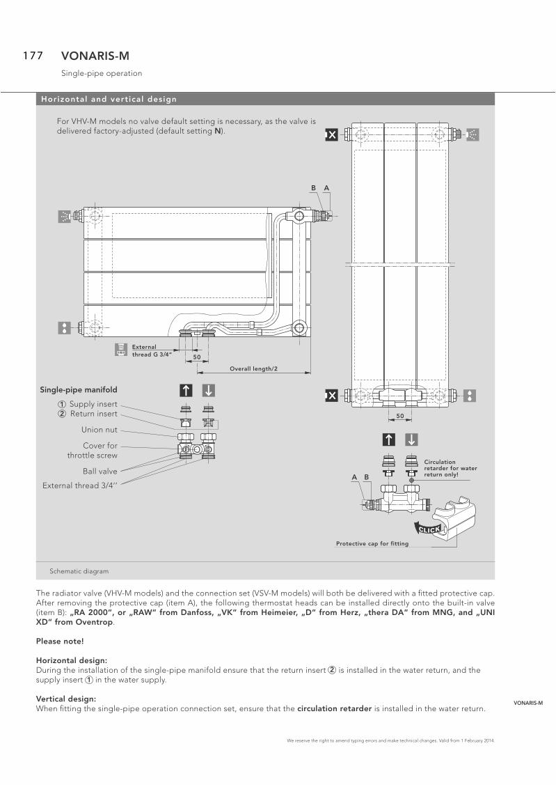
We reserve the right to amend typing errors and make technical changes. Valid from 1 February 2014.
VONARIS-MSingle-pipe operation
Schematic diagram
50
N
CLICK
Armaturen-Abdeckkappe
Zirkulations-bremse nurim Rücklauf!A B
Horizontal and vertical design
For VHV-M models no valve default setting is necessary, as the valve is delivered factory-adjusted (default setting N).
The radiator valve (VHV-M models) and the connection set (VSV-M models) will both be delivered with a fi tted protective cap. After removing the protective cap (item A), the following thermostat heads can be installed directly onto the built-in valve (item B): „RA 2000“, or „RAW“ from Danfoss, „VK“ from Heimeier, „D“ from Herz, „thera DA“ from MNG, and „UNI XD“ from Oventrop.
Please note!
Horizontal design: During the installation of the single-pipe manifold ensure that the return insert 2 is installed in the water return, and the supply insert 1 in the water supply.
Vertical design: When fi tting the single-pipe operation connection set, ensure that the circulation retarder is installed in the water return.
50
G 3/4" A. G.
N
Baulänge/2
B A
12
Single-pipe manifold
Supply insertReturn insert
Union nut
Cover forthrottle screw
Ball valve
External thread 3/4‘’
External thread G 3/4“
Overall length/2
Circulation retarder for water return only!
Protective cap for fitting
VONARIS-M
177

We reserve the right to amend typing errors and make technical changes. Valid from 1 February 2014.
VONARIS-MSingle-pipe operation
Horizontal design
2
Druckverlust [mbar]
1 34
56 8 10
7 92
3 5 7 94 6 8 102 2
31/2
3
21/2
2
13/4
Sp
ind
elv
erd
reh
un
ge
nV
N E
inro
hrv
ert
eil
er
He
izkö
rpe
ran
teil
30%
35%
40%
45%
50%
Kre
isw
asse
rdu
rch
flu
ss 1
00
l/h
15
0 l
/h
25
0 l
/h
20
0 l
/h
30
0 l
/h3
50
l/h
40
0 l
/h4
50
l/h
50
0 l
/h
60
0 l
/h
Default setting when using a single-pipe manifold:
radiator proportion 30 % --- 3.50 revolutions*
radiator proportion 35 % --- 3 revolutions*
radiator proportion 40 % --- 2.50 revolutions*
radiator proportion 45 % --- 2 revolutions*
radiator proportion 50 % --- 1.75 revolutions*
*… before starting, turn the bypass spindle of the single-pipe manifold to the right as far as it will go.
Diagram:
Pressure drop [mbar] – single-pipe operation with a proportional deviation of 2K.
It is of course possible to change the radiator proportion, whilst there is pressure in the heating system.
Please take account of the maximum power per cycle (for single-pipe installations) of about 10 kW:ΔT = T1-T2 = 20 K (at T1 = 90 °C).
Vertical design
The connection set radiator proportion comes preset at 40 %.
Please take account of the maximum power per cycle (for single-pipe installations) of about 10 kW:ΔT = T1-T2 = 20 K (at T1 = 90 °C).
Pressure drop
Rad
iato
r p
rop
ortio
n
Spin
dle
revo
lutio
nsV
N-s
ing
le-p
ipe
man
ifold
Wat
er fl
ow ra
te d
urin
g on
e cy
cle
178

We reserve the right to amend typing errors and make technical changes. Valid from 1 February 2014.
VONARIS-M Wall mounting WA 11welded bracket postions
Wall mounting WA 11 for models VHV-M 10, VHV-M 11, VHV-M 20, VHV-M 22 and VHV-M 34
Model VHV-M 10 / 11 for wal l mounting WA 11
Overallheight
358 mm
VHV-M 22 or rather VHV-M 34 for wal l mounting WA 11
Overallheight
214 mmand
286 mm
VHV-M 10 / 11, VHV-M 20/22 for wal l mounting WA 11
Overallheight
430 mmto
574 mmVHV-M 10/11,
358 mmto
502 mmVHV-M20/22
VHV-M 10 / 11, VHV-M 20/22 for wal l mounting WA 11
Overallheight
646 mmto
790 mmVHV-M 10/11,
574 mmto
790 mmVHV-M 20/22
Schematic diagram
Attention! With the horizontal design only the models VHV-M 10/11 (OH 358 - 790 mm) are by default supplied with brackets. If the models VHV-M 20 (OH 358 - 790 mm), VHV-M 22 (OH 214 - 790) and VHV-M 34 (142 – 286 mm) are wall-mounted using wall mounting WA 11, you are required to order these models as a special version, equipped with brackets.
130
120
500 - 2000
160 160
130
120
160 160
2200 - 2400
1/2 1/2
500 - 2000
160 160
85
120
160 1601/2 1/2
2200 - 2400
85
120
130
220
500 - 2000
160 160
130
220
160 160
2200 - 2400
1/2 1/2
60
14
60
14
130
420
500 - 2000
160 160
40
130
420
160 160
2200 - 240040
1/2 1/2
VHV-M 22 VHV-M 11
VONARIS-M
179

We reserve the right to amend typing errors and make technical changes. Valid from 1 February 2014.
VONARIS-M Wall mounting WA 11drilling measurements and wall-clearance
Wall mounting WA 11 for models VHV-M 10, VHV-M 11, VHV-M 20, VHV-M 22 und VHV-M 34
Wall mounting WA 11 is suitable for the horizontal versions of the following models: VHV-M 10 (OH 358 - 790 mm), VHV-M 11(OH 358 - 790 mm), VHV-M 20 (BH 358 - 790 mm), VHV-M 22 (OH 214 - 790 mm) and VHV-M 34 (OH 214 and 286 mm) equipped with brackets. It ensures easy, rapid and robust mounting of the VONARIS central-connection radiators still in the packaging.
Wall mounting WA 11 for OH 214 - 790
Dri l l ing measurements for the Wandaufhängung WA 11
From an overal l length of 2200 mm: 3 consoles
ModelVHV-MOverall height [mm]
Value X [mm]
Value Y [mm]
Value Z [mm]
Wall mounting WA 11
VHV-M 22, 34 214 104 162 52
VHV-M 22, 34 286 176 234 52
VHV-M 10, 11 358 203 261 97
VHV-M 20, 22 358 203 261 97
VHV-M 10, 11, 20, 22 430 275 333 97
VHV-M 10, 11, 20, 22 502 347 405 97
VHV-M 10, 11 574 419 477 97
VHV-M 20, 22 574 419 477 97
VHV-M 10, 11, 20, 22 646 491 549 97
VHV-M 10, 11, 20, 22 718 563 621 97
VHV-M 10, 11, 20, 22 790 635 693 97
Schematic diagram
Connection – wall c learance
Horizontal design modelOveral l
height [mm]Value W [mm]
VHV-M 10 358 - 790 45
VHV-M 11 358 - 790 45
VHV-M 20 358 - 790 89
VHV-M 22 214 - 790 89
VHV-M 34 214 / 286 89
Schematic diagram
HeizkörperOberkante
HeizkörperUnterkante
XY
Z
W
Radiator topedge
Radiator lower edge
180

We reserve the right to amend typing errors and make technical changes. Valid from 1 February 2014.
VONARIS-M VONOFIXbracket positioning for insertion (push-in) brackets
VONOFIX rapid-instal lation console for the VHV-M models
VHV-M 10 models: OH 358 - 790 mm, VHV-M 20 models: OH 358 - 790 mm,VHV-M 22 models: OH 214 - 790 mm and VHV-M 34 models: OH 214 and 286 mm
OH 214: for VONOFIX 1 OH 574 and 646: for VONOFIX 4
OH 286 and 358: for VONOFIX 2
OH 430 and 502: for VONOFIX 3 OH 718 and OH 790: for VONOFIX 5
Schematic diagram
215
Hei
ght
286
215
7070
Hei
ght
358
143
7070H
eigh
t 21
4
503
Hei
ght
574
503
7070
Hei
ght
646
359
Hei
ght
430
Length 2200 and 2400
1/2 Length + 100 mm
359
7070
Hei
ght
502
647
7070
Length 500 - 2000
40
Hei
ght
790
Important: the installation of VHV-M models with insertion (push-in) brackets is only feasible when using the VONOFIX rapid-installation console!
Note! for an overall length of 2200 mm and greater an additional piece of foot con-sole must be used!
50
3
7070
Hei
ght
64
6
VONARIS-M
181

We reserve the right to amend typing errors and make technical changes. Valid from 1 February 2014.
VONARIS-M VONOFIXdrilling measurements and wall clearance
VONOFIX rapid-instal lation console for the VHV-M models
The VONARIS central connection radiator can be installed easily, quickly and securely. This is made possible by the VONO-FIX rapid-installation console for the horizontal designs of the VHV-M 20 (OH 358 - 790 mm), VHV-M 22 (OH 214 - 790 mm) and the VHV-M 34 (OH 214 and 286 mm) models.
Wall rai ls for OH 214 – 790 mm
Dri l l ing measurements for the VONOFIX 1 - 5
Overall radiatorheight [mm]
Value X [mm] Value Y [mm] Value Z [mm]
214 – 125 89
286 100 197 89
358 100 197 161
430 100 341 89
502 100 341 161
574 100 485 89
646 100 485 161
718 100 629 89
790 100 629 161
Schematic diagram
X
Heizkörper Oberkante
HeizkörperUnterkante
YZ
Connection – wall c learance
Horizontal design modelOveral l
height [mm]Value W [mm]
VHV-M 20 358 – 790 91
VHV-M 22 214 – 790 91
VHV-M 34 214 – 286 91*
* Note: i f the VHV-M 34 is turned round and used as a left-handdesign model, the measurement W is 172 mm.
Schematic diagram
W
The VONOFIX rapid-installation console consists of:
2 wall consoles (zinc-plated), with sound-proofi ng fi lters, screws and dowels 2 stabilising brackets2 insertion (push-in) brackets(For an overall length of 2200 mm and greater, 1 additional piece of foot console)
Radiator top edge
Radiator lower edge
182

We reserve the right to amend typing errors and make technical changes. Valid from 1 February 2014.
VONARIS-Mwelded brackets positions
VSV-M models
Overal length
[mm]
214 286 358 430 - 862
Schematic diagram
60
48
60
14
VSV-M 2060
14
VSV-M 2160
14
VSV-M 10 VSV-M 11 VSV-M 20 VSV-M 21
Wall c learance measurements: WA 10 and WA 11 wall mounting brackets for the VSV-M models
Connect ion – wal l c learance
Wall mounting brackets model Vertical design model Value W [mm]
WA 10 VSV-M 10/11* 35
WA 10 VSV-M 20/21 79,5
WA 11 VSV-M 10/11* 45
WA 11 VSV-M 20/21 89,5
*Note! i f you are us ing WA 10 or WA 11 wal l mounting brackets for the insta l la-t ion of the VSV-M 10 or VSV-M 11 model with a r ight-angled-design connect ion, please fol low the instruct ions in the diagram on page 173.
Schematic diagram
W
BL 430 - 862
16
00
, 1
80
0,
20
00
13
0
107107
90
40
16
00
, 1
80
0,
20
00
13
09
0
214
40
286
7171
16
00
, 1
80
0,
20
00
13
09
0
40
358
7171
16
00
, 1
80
0,
20
00
13
09
0
40
VONARIS-M
Length
183

We reserve the right to amend typing errors and make technical changes. Valid from 1 February 2014.
VONARIS-Mstand consoles
FBT 20 window si l l support: posit ioning for the VHV-M models (up to an overal l height of 286 mm)
Window si l l support for subsequent instal lat ion with the VHV-M 22 – 46 models of the VONARIS-M central connect ion radiator (up to an overal l height of 286 mm)
Note: for an overal l length of more than 2200 mm , a 3rd window si l l support must be used!
Schematic diagram
150 150
fix fix
Baulänge1/2 Baulänge1/2
SK 12 – 17 stand consoles: posit ioning with the VHV-M models (up to an overal l height of 286 mm)
Note: for an overall length of 2200 mm and greater, a 3rd stand console must be used!
SK 12 / SK 13VHV-M 22
SK 14 / SK 15VHV-M 34
SK 16 / SK 17VHV-M 46
Schematic diagram
150 150
fix fix
Baulänge + 100 mm1/2
X
88,5
93
46
16
6,5 8
9
X1
75
24
5 13
2
X2
57
1/2 overall length + 100 mm
constant constant
1/2 overall length 1/2 overall length
constant constant
184

We reserve the right to amend typing errors and make technical changes. Valid from 1 February 2014.
VONARIS-MWall mounting
Wall mounting posit ions VONARIS-M
Attention: i f more than 2 wal l consoles are used, any addit ional wal l consoles are to be used at regu-lar distances f rom each other along a length of X.
150 150X
fix fix
WK 10-MVHV-M 22
WK 11-MVHV-M 34
WK 12VHV-M 46
Schematic diagram
2511
5
93
25
19
7
17
5
25
27
9
25
7
constant constant
VONARIS-M
185

We reserve the right to amend typing errors and make technical changes. Valid from 1 February 2014.
VONARIS-Mheating outputs
Heating output in compliance with DIN EN 442, and ÖNORM EN 442, at 75/65/20° C
Side panels and top cover are included in the heat output specifi cations
Overall height [mm]
214 286 358 430 502 574 646 718 790
Increments As regards all overall lengths between 500 and 1400 mm, use increments of 100 mm, and overall lengths between 1600 and 2400 mm, use increments of 200 mm.
Model VHV-M 10* VHV-M 10* VHV-M 10* VHV-M 10* VHV-M 10* VHV-M 10* VHV-M 10*
Overall depth [mm]
68 68 68 68 68 68 68
Watts / m 75/65/20 394 458 523 588 655 720 795
Watts / m 70/55/20 322 374 427 480 534 590 647
Watts / m 55/45/20 209 243 276 311 344 380 416
Water content l / m 2,76 3,33 3,87 4,44 4,99 5,55 6,12
Weight kg / m 11,91 14,04 16,17 18,29 20,43 22,60 24,68
Radiator exponent n 1,24 1,24 1,25 1,25 1,26 1,26 1,27
Model VHV-M 11* VHV-M 11* VHV-M 11* VHV-M 11* VHV-M 11* VHV-M 11* VHV-M 11*
Overall depth [mm]
68 68 68 68 68 68 68
Watts / m 75/65/20 625 718 804 886 965 1043 1105
Watts / m 70/55/20 505 583 652 717 781 844 889
Watts / m 55/45/20 320 372 415 456 497 537 558
Water content l / m 2,78 3,33 3,87 4,44 4,99 5,55 6,12
Weight kg / m 16,71 19,85 22,99 26,15 29,29 31,42 33,55
Radiator exponent n 1,31 1,29 1,29 1,30 1,30 1,30 1,34
Model VHV-M 20 VHV-M 20 VHV-M 20 VHV-M 20 VHV-M 20 VHV-M 20 VHV-M 20
Overall depth [mm]
93 93 93 93 93 93 93
Watts / m 75/65/20 654 757 859 960 1063 1166 1271
Watts / m 70/55/20 533 617 699 781 864 947 1032
Watts / m 55/45/20 344 397 450 501 554 607 660
Water content l / m 5,55 6,66 7,77 8,88 9,99 11,10 12,22
Weight kg / m 21,29 25,30 29,31 33,31 37,32 41,32 45,33
Radiator exponent n 1,26 1,26 1,27 1,27 1,28 1,28 1,28
Model VHV-M 22 VHV-M 22 VHV-M 22 VHV-M 22 VHV-M 22 VHV-M 22 VHV-M 22 VHV-M 22 VHV-M 22
Overall depth [mm]
93 93 93 93 93 93 93 93 93
Watts / m 75/65/20 769 938 1100 1268 1405 1534 1654 1767 1886
Watts / m 70/55/20 621 756 885 1021 1130 1232 1326 1414 1500
Watts / m 55/45/20 393 477 555 642 708 769 825 877 919
Water content l / m 3,34 4,44 5,55 6,66 7,77 8,88 9,99 11,11 12,22
Weight kg / m 20,59 27,23 30,89 36,93 42,96 49,01 55,05 59,05 63,06
Radiator exponent n 1,31 1,32 1,34 1,33 1,34 1,35 1,36 1,37 1,41
* For aesthetic reasons these models should not be fi tted in front of a window.
186

We reserve the right to amend typing errors and make technical changes. Valid from 1 February 2014.
VONARIS-Mheating outputs
Overall height [mm]
214 286
IncrementsAs regards all overall lengths between 500 and 1400 mm, use increments of 100 mm, and overall lengths between 1600 and
2400 mm, use increments of 200 mm.
Model VHV-M S 22 VHV-M S 22
Overall depth [mm]
163 163
Watts / m 75/65/20 769 938
Watts / m 70/55/20 621 756
Watts / m 55/45/20 393 477
Water content l / m 3,34 4,44
Weight kg / m 28,34 37,24
Radiator exponent n 1,31 1,32
* For aesthetic reasons these models should not be fi tted in front of a window.
Overall height [mm]
142 214 286
IncrementsAs regards all overall lengths between 500 and 1400 mm, use increments of 100 mm, and overall lengths between 1600 and
2400 mm, use increments of 200 mm.
Model VHV-M 34 VHV-M 34 VHV-M 34
Overall depth [mm]
175 175 175
Watts / m 75/65/20 953 1357 1616
Watts / m 70/55/20 773 1094 1296
Watts / m 55/45/20 493 690 808
Water content l / m 3,33 4,99 6,66
Weight kg / m 23,93 35,18 46,42
Radiator exponent n 1,29 1,32 1,36
Model VHV-M 46 VHV-M 46 VHV-M 46
Overall depth [mm]
257 257 257
Watts / m 75/65/20 1433 1895 2357
Watts / m 70/55/20 1160 1525 1885
Watts / m 55/45/20 738 957 1168
Water content l / m 4,53 6,79 9,06
Weight kg / m 33,89 49,76 65,62
Radiator exponent n 1,30 1,34 1,37
Model VHV-M S 46 VHV-M S 46 VHV-M S 46
Overall depth [mm]
327 327 327
Watts / m 75/65/20 1433 1895 2357
Watts / m 70/55/20 1160 1525 1885
Watts / m 55/45/20 738 957 1168
Water content l / m 4,53 6,79 9,06
Weight kg / m 39,35 57,50 75,64
Radiator exponent n 1,30 1,34 1,37
* For aesthetic reasons these models should not be fi tted in front of a window.
Heating output in compliance with DIN EN 442, and ÖNORM EN 442, at 75/65/20° C
Side panels and top cover are included in the heat output specifi cations
VONARIS-M
187

We reserve the right to amend typing errors and make technical changes. Valid from 1 February 2014.
VONARIS-Mheating outputs
Overal height [mm]
600 800 1000 1200 1400 1600 1800 2000 2200 2400 2600
Overall lengh [mm]
214, 286, 358, 430, 502, 574, 646, 718, 790, 862
Model VSV-M 10 VSV-M 10 VSV-M 10 VSV-M 10 VSV-M 10 VSV-M 10 VSV-M 10 VSV-M 10 VSV-M 10 VSV-M 10 VSV-M 10
Overall depth[mm]
68 68 68 68 68 68 68 68 68 68 68
Watts/m 75/65/20 657 861 1069 1284 1506 1738 1979 2232 2495 2771 3060
Watts/m 70/55/20 533 694 857 1023 1200 1384 1577 1781 1994 2219 2455
Watts/m 55/45/20 340 438 534 629 737 850 968 1097 1234 1378 1530
Water content l / m
5,17 6,41 7,65 8,89 10,13 11,37 12,47 13,85 15,24 16,48 17,72
Weight kg / m 18,70 23,85 29,-- 34,15 39,30 44,45 49,60 54,75 59,70 64,85 70,--
Radiator exponent n
1,29 1,32 1,36 1,40 1,40 1,40 1,40 1,39 1,38 1,37 1,36
Model VSV-M 11 VSV-M 11 VSV-M 11 VSV-M 11 VSV-M 11 VSV-M 11 VSV-M 11 VSV-M 11
Overall depth[mm]
68 68 68 68 68 68 68 68
Watts/m 75/65/20 1123 1331 1541 1757 1979 2209 2450 2701
Watts/m 70/55/20 897 1065 1234 1407 1584 1768 1964 2172
Watts/m 55/45/20 554 660 768 874 983 1097 1223 1361
Water content l / m
6,41 7,65 8,89 10,13 11,37 12,47 13,85 15,24
Weight kg / m 42,79 47,94 53,09 58,24 63,39 68,53 73,69 78,84
Radiator exponent n
1,38 1,37 1,36 1,37 1,37 1,37 1,36 1,34
Heating output in compliance with DIN EN 442, and ÖNORM EN 442, at 75/65/20° C
Side panels and top cover are included in the heat output specifi cations
188

We reserve the right to amend typing errors and make technical changes. Valid from 1 February 2014.
VONARIS-Mheating outputs
Overallheight [mm]
600 800 1000 1200 1400 1600 1800 2000 2200 2400 2600
Overall lengh [mm]
214, 286, 358, 430, 502, 574, 646, 718, 790, 862
Model VSV-M 20 VSV-M 20 VSV-M 20 VSV-M 20 VSV-M 20 VSV-M 20 VSV-M 20 VSV-M 20 VSV-M 20 VSV-M 20 VSV-M 20
Overall depth[mm]
93 93 93 93 93 93 93 93 93 93 93
Watts/m 75/65/20 1118 1479 1840 2202 2566 2932 3301 3672 4046 4423 4803
Watts/m 70/55/20 899 1185 1468 1750 2041 2332 2629 2929 3232 3539 3849
Watts/m 55/45/20 564 737 905 1070 1249 1427 1615 1805 1997 2194 2395
Water content l / m
10,34 12,82 15,30 17,78 20,26 22,74 24,34 27,71 30,48 32,96 35,44
Weight kg / m 35,34 45,36 55,38 65,40 75,42 85,44 95,46 105,48 115,50 125,52 135,54
Radiator exponent n
1,34 1,36 1,36 1,41 1,41 1,41 1,40 1,39 1,38 1,37 1,36
Model VSV-M 21 VSV-M 21 VSV-M 21 VSV-M 21 VSV-M 21 VSV-M 21 VSV-M 21 VSV-M 21
Overall depth[mm]
93 93 93 93 93 93 93 93
Watts/m 75/65/20 1704 2059 2421 2795 3184 3588 4012 4455
Watts/m 70/55/20 1355 1636 1922 2222 2536 2857 3206 3569
Watts/m 55/45/20 829 999 1173 1359 1557 1755 1983 2219
Water content l / m
12,82 15,30 17,78 20,26 22,74 24,34 27,71 30,48
Weight kg / m 64,29 74,31 84,33 94,35 104,37 114,39 124,42 134,64
Radiator exponent n
1,41 1,42 1,42 1,41 1,40 1,40 1,38 1,36
Heating output in compliance with DIN EN 442, and ÖNORM EN 442, at 75/65/20° C
Side panels and top cover are included in the heat output specifi cations
VONARIS-M
189

We reserve the right to amend typing errors and make technical changes. Valid from 1 February 2014.
KONTECproduct description
CONVECTORS & HEATING PANELS
KONTEC convectors and horizontal heating panels are radiators in fully welded designs, with either 1 to 5 la-yers of steel rectangular water-fl ow pipes arranged one-behind-the-other (for convectors), or 1 or 2 such layers (for horizontal heating panels). In each layer, the convectors have between one and four pipes arranged one-abo-ve-the-other; the horizontal heating panels have from 5 to 11 pipes.KONTEC vertical heating panels con-sist of 1 or 2 layers of steel rectangular water-fl ow pipes, arranged one-be-hind-the-other, with 2 to 12 steel pipes, arranged side-by-side.
A 2 mm space between the heating pi-pes guarantees additional resistance to corrosion. KONTEC convectors and horizontal heating panels come with side panels and top covers; KONTEC vertical heating panels come with side panels. KONTEC heating panels are delivered with welded mounting bra-ckets.
All KONTEC convectors and heating
panels are also delivered with factory-sealed drain plugs and pivotable vent plugs. (Exception: bottom-opposite-end connection models come with a dummy plug instead of the drain plug.) Standard design: rectangular steel pipes, 70 x 11 x 1.5 mm
High-pressure design: rectangular steel pipes, 70 x 11 x 2.0 mm
WVO-design: KONTEC convectors are also available with a welded heat refl ector (no water-fl ow).
Convector dimensions:Overall lengths: between 500 mm and 1400 mm (at increments of 100 mm), and between 1600 mm and 4000 mm (at increments of 200 mm)Overall heights: 70 mm, 142 mm, 214 mm and 286 mm
Horizontal heating panel dimensi-ons:Overall lengths: between 500 mm and 1400 mm (at increments of 100 mm), and between 1600 mm and 4000 mm
(at increments of 200 mm)Overall heights: 358 mm, 430 mm, 502 mm, 574 mm, 646 mm and 790 mm
Vertical heating panel dimensions:Overall lengths: between 142 mm and 862 mm (at increments of 72 mm)Overall heights: between 1600 mm and 2200 mm (at increments of 200 mm)
Coatings:1. Undercoat: electrophoretic, usingwater-soluble paints, conforming toDIN 55900 part 1, stoved at 165° C;2. Finish: electrostatic powder coating,conforming to DIN 55900 part 2,in a state-of-the-art facility. (On reque-st, and at a supplementary charge, arange of RAL and sanitary ware colourscan be offered.) This particularlyrobust coating is stoved at an objecttemperature of 180° C.
Packaging: 1. Cardboard packaging2. Edge protection3. Shrink foil
max
.
5 barmax.
8 barmax.
Guarantee statements are available to download at www.vogelundnoot.com/download
Connections:2 x internal thread G 1/2“, welded-in for supply and return. Vent and drain plugs (or dummy plug) are factory sealed and are fi tted according to the customer’s specifi cations.
Maximum positive operating pressureStandard design: 5 bar
Maximum positive operating pressure: High-pressure design 8 bar
Maximum operating temperature: 110 °C
190

We reserve the right to amend typing errors and make technical changes. Valid from 1 February 2014.
KONTECmodel overview / connection dimensions
Schematic diagram
Horizontal design, KK models
Model KK 11 KK 20 KK 22 KK 23 KK 34 KK 35 KK 46 KK 58Overall height
[mm]
- - - 142 70 142 70 142 70 142 70 142 70 142 70 142
214 286 214 286 214 286 214 286 214 286 214 286 214 286 214 286
Overall lenght
[mm]
500 – 2400 mm (for special overall lengths see output charts), model 58 up to 2200 mm
Increments 100 mm (for an overal l length of 1400 mm and greater: 200 mm)
20
20
OH
28
6
Side connections:
20
20
OH
21
4
20
20
OH
14
219
OH
70
**
Note: with an OH of 70 mm, vertical connection from below is not available!* Models with an overall height of 142, 214 or 286 mm can also be deli-vered with supply and return connections vertically from below (as specialdesigns and with a supplementary charge).
** Only available with top-bottom, opposite-ends, side-connection.
KK 46
25
712
9
KK 34
17
5
47
KK 58
12
9
33
9
KK 23
15
0
10
4
KK 35
23
210
4
KK 11 26
68
KK 22 47
93
KK 20 47
93
Overall height [mm] 70** 142 214 286
Boss spacing NA [mm] 32 102 174 246
Boss spacing NAS* [mm] Overall length - 50 mmx
View from below
Overall heights
142
214
286
70**
500 - 2400
500 - 2400
500 - 2400
500 - 2400
25 25
Overall lengths
x
*Connection vertically from below
20
5
OH
28
6
20
OH
21
4
5
20
5
OH
14
2
1
VONARIS
VONARIS-M
KONTEC
ULOW-E2
Profi le panelradiators
Plan panelradiators
Vertical radiators
Towel warmers
Design radiators
2
Standard Column radiators
Centrallyconnected Column radiators
Architecture Column radiators
3
4
191

We reserve the right to amend typing errors and make technical changes. Valid from 1 February 2014.
KONTECWVO design
Schematic diagram
The KK-S models
With their factory-welded heat refl ector (no water-fl ow), the WVO designs return a major part of the otherwise lost heat to the room. They do so by means of convection between radiator and heat refl ector.
Model KK-S 22 KK-S 34 KK-S 47Overall height
[mm]
70 142 214 286 70 142 214 286 70 142 214 286
Overall length
[mm]
500 – 2400 mm (for special overall lengths see output charts)
Increments 100 mm (for an overal l length of 1400 mm and greater: 200 mm)
Overall height [mm] 70** 142 214 286
Boss spacing NA [mm] 32 102 174 246
Boss spacing NAS* [mm] Overall length - 50 mm
Model overview / connection dimensions: KK-S models, horizontal design
Note: with an OH of 70 mm, vertical connection from below is not available!
* Models with an overall height of 142, 214 or 286 mm can also be delivered with supply and return connections verticallyfrom below (as special designs and with a supplementarycharge).
** Only available with top-bottom, opposite-ends, side-connection.
x
x19
OH
70*
*
1919
,5
OH
70*
*
*Connection verticallyfrom below:
View from below
Overall heights
142
214
286
70**
500 - 2400
500 - 2400
500 - 2400
500 - 2400
Side connections:
20
20
OH
28
6
20
20
OH
21
4
20
20
OH
14
2
20
5
OH
28
6
25 25
20
OH
21
4
5
OH
14
2
20
5KK-S 22
16
3
11
7
KK-S 34
24
511
7
KK-S 47
32
719
9
Overall lengths
192

We reserve the right to amend typing errors and make technical changes. Valid from 1 February 2014.
KONTECmodel overview / connection dimensions
Schematic diagram
KH models horizontal design
Model KH 10 KH 11 KH 20 KH 22Overall height
[mm]
358 430 502 358 430 502 358 430 502 358 430 502
574 646 790 574 646 790 574 646 790 574 646 790
Overall length
[mm]
500 – 2400 mm (for special overall lengths see output charts)
Increments 100 mm (for an overal l length of 1400 mm and greater: 200 mm)
Overall height [mm] 358 430 502 574 646 790
Boss spacing NA [mm] 318 390 462 534 606 750
20
20
79
0
KH 10 26
68
KH 11 26
68
KH 22 47
93
20
20
43
0
20
20
50
2
20
20
35
8
20
20
57
4
20
20
64
6
KH 20 47
93
Bauhöhen
500 - 2400
500 - 2400
500 - 2400
500 - 2400
500 - 2400
500 - 2400358
430
502
574
646
790
BaulängenOverall heights Overall lengths
KONTEC
193

We reserve the right to amend typing errors and make technical changes. Valid from 1 February 2014.
KONTECmodel overview / connection dimensions
Schematic diagram
KS models vertical design
Model KS 10 KS 11 KS 20 KS 21Overall height
[mm]
1600 1800 1600 1800 1600 1800 1600 1800
2000 2200 2000 2200 2000 2200 2000 2200
Overall length
[mm]
142 - 862 mm
Increments 72 mm
Overall height [mm] 1600 1800 2000 2200
Boss spacing NA [mm] 1550 1750 1950 2150
KS 10
KS 20
KS 11
KS 2147
93
26
68
47
93
26
68
KS
10
68 68
KS
11
93
KS
20
93
KS
21
16
00
, 1
80
0,
20
00
, 2
20
0
142 - 862
55 55
55 55
194

We reserve the right to amend typing errors and make technical changes. Valid from 1 February 2014.
Double-pipe system
Single-sided connection, right Single-sided connection, left
Top-bottom, opposite-end, side-connection, right-side supply
Top-bottom, opposite-end,side-connection, left-side supply
Bottom-only, opposite-end, side-connection, right-side supply
Note: reduced heat output
Bottom-only, opposite-end, side-connection, left-side supply
Note: reduced heat output
Vertical connection from below, bottom-only, opposite-end, right-side supply
Note: reduced heat output
Vertical connection from below, bottom-only, opposite-end, left-side supply
Note: reduced heat output
Single-pipe system
KONTEC convectors can easily be converted for use with a single-pipe system. In this case, however, 4-way valves with a by-pass pipe need to be used.
Recommendation: For reasons of appearance the VONARIS valve design is the preferred option for this connection mode.
Schematic diagram
KONTECconnection modes for KONTEC convectors
KK and KK-S models
Note: when ordering your KONTEC convector (see price list “Description of the Ordering Process“) the 4 connections must be accurately specifi ed and assigned. This is for technical production reasons. No subsequent changes to the connections on your KONTEC convector are possible! KONTEC
195

We reserve the right to amend typing errors and make technical changes. Valid from 1 February 2014.
Double-pipe system
Single-sided connection, right Single-sided connection, left
Top-bottom, opposite-end, side-connection, right-side supply
Top-bottom, opposite-end,side-connection, left-side supply
Bottom-only, opposite-end, side-connection, right-side supply
Note: reduced heat output
Bottom-only, opposite-end, side-connection, left-side supply
Note: reduced heat output
Single-pipe system
KONTEC convectors can easily be converted for use with a single-pipe system. In this case, however, 4-way valves with a by-pass pipe need to be used.
Recommendation: For reasons of appearance the VONARIS valve design is the preferred option for this connection mode.
Schematic diagram
KONTECconnection modes for heating panels
Typen KH
Note: when or dering your KONTEC KH model heating panels, (see price list “Description of the Ordering Process”) the 4 connections must be accurately specifi ed and assigned. This is for technical production reasons. No subsequent changes to the connections on your KONTEC KH model heating panels are possible!
196

We reserve the right to amend typing errors and make technical changes. Valid from 1 February 2014.
Double-pipe system
Note: with KONTEC KS model heating panels, single-pipe connection is not possible!
Single-sided con-nection, right
Single-sided connection, left
Top-bottom, opposite-end,
side-connection, right-side supply
Top-bottom, opposite-end,
side-connection, left-side supply
Bottom-only, opposite-end,
side-connection, right-side supply
Bottom-only, opposite-end,
side-connection, right-side supply
Schematic diagram
KONTECconnection modes for heating panels
Typen KS
Note: when ordering your KONTEC KS model heating panel (see price list “Description of the Ordering Process“) the 4 connections must be accurately specifi ed and assigned. This is for technical production reasons. No subsequent changes to the connections on your KONTEC KS model heating panel are possible!
KONTEC
197

We reserve the right to amend typing errors and make technical changes. Valid from 1 February 2014.
KONTECheat refl ector
Schematic diagram
KH 20 and KH 22 models, horizontal designs
100
11
25
The new heat refl ector
• is available for the KH 20 (OH 358 –574 mm) and the KH 22 (OH 358 - 646mm) models in horizontal design
• returns a major part of the other-wise lost heat to the room, by meansof convection between the KONTECheating panel and the heat refl ector.
Design:Electrophoretic coating and fi nish in RAL 9016 (on request and at an extra charge, in a range of RAL and Sanitary Ware colours); delivered with 8 push-in brackets, 8 stabilising brackets, 4 Z-brackets, an installation sheet, andpackaging
Note: when ordering one of the ho-rizontal designs with a heat refl ector, it is also essential to use either an SK 22 (KH 20) or an SK 23 (KH 22) stand console.
KONTEC heating panel with fi tted heat refl ector (see image to the right)
Width: 11 mm heat refl ector
Internal depth:25 mm between hea-ting pipe and heat refl ector
Minimum clearance*: 100 mm between window surface and heat refl ector
* The minimum clearance between window surface and heat refl ector (100 mm) complies withthe recommendations of leading window surface manufacturers.
198

We reserve the right to amend typing errors and make technical changes. Valid from 1 February 2014.
KONTEC Wall mounting WA 11 welded bracket position
Wall mounting WA 11 for al l KK (Convectors) models
Type Wall mounting WA 11 for KK 11 to KK 34
Overallheight
214 mm
Wall mounting WA 11 for KK 11 to KK 34
Overallheight
286 mm
Schematic diagram
Attention! Convectors are by default supplied without brackets. If wall mounting WA 11 is used, you are required to order the convector as a special version, equipped with brackets. Convectors with an OH of 70 or 142 mm cannot be supplied with mounting brackets.
500 - 2000
160 160
85
120
160 1601/2 1/2
2200 - 4000
85
120
130
120
500 - 2000
160 160
40
130
120
160 160
2200 - 4000
1/2 1/2
40
60
14
60
14 14
60
14
60KK 11 KK 20 / 22
KK 23 KK 34
KONTEC
199

We reserve the right to amend typing errors and make technical changes. Valid from 1 February 2014.
KONTEC Wall mounting WA 11welded bracket positions
Wall mounting WA 11 for al l KH (heating wall models horizontal design) models
Type Wall mounting WA 11 for KH 10 to KH 24
Overallheight
from358 mm
to502 mm
Wall mounting WA 11 for KH 10 to KH 24
Overallheight
from574 mm
to790 mm
Schematic diagram
130
220
500 - 2000
160 160
130
220
160 160
2200 - 4000
1/2 1/2
130
420
500 - 2000
160 160
40
130
420
160 160
2200 - 400040
1/2 1/2
60
48
60
14
14
60
14
60KH 10 KH 11
KH 20 KH 22
200

We reserve the right to amend typing errors and make technical changes. Valid from 1 February 2014.
KONTEC Wall mounting WA 11Drilling and wall clearance dimensions
Wall mounting WA 11 for types KK (convectors) and KH (Vertical heating panels)
Wall mounting WA 11 is suitable for convector models KK (OH 214 and 286 mm, with brackets) and heating wall models KH (OH 358 - 790 mm). It ensures easy, rapid and robust mounting of KONTEC convectors or KONTEC heating panels still in the packaging.
Wall mounting WA 11 for OH 214 - 790
Wall mounting WA 11 dri l l ing dimensions
From an overal l length of 2200 mm: 3 consoles
Overall height [mm]Value X
[mm]Value Y
[mm]Value Z
[mm]Wall mounting WA 11
for OH 214 – 790 mm
214 104 162 52
286 131 189 97
358 203 261 97
430 275 333 97
502 347 405 97
574 419 477 97
646 491 549 97
790 635 693 97
Schematic diagram
Connection – wall c learance
Convector and heating panelmodels
Overal l height [mm]
MeasurementW [mm]
KK 11 214, 286 45
KK 20, KK 22, KK 34 214, 286 89
KK 23 214, 286 123,5
KH 10, KH 11 358 - 790 45
KH 20, KH 22 358 - 790 89
Schematic diagram
W
HeizkörperOberkante
HeizkörperUnterkante
XY
Z
KONTEC
Radiator top edge
Radiator lower edge
201

We reserve the right to amend typing errors and make technical changes. Valid from 1 February 2014.
KONTECpositions of the insertion (push-in) brackets
Overall length
[mm]
142 214 286 358 430 - 862
Schematic diagram
KS models
60
48
KS 10 KS 11 KS 20 KS 21
Wall c learance: WA 10 and WA 11 wall mounting brackets for the KS models
Connection – wall c learance
Wall mounting type vert ical design Measure W [mm]
WA 10 KS 10/11* 35
WA 10 KS 20/21 79,5
WA 11 KS 10/11* 45
WA 11 KS 20/21 89,5
*Note: i f you are instal l ing the KS 10 and KS 11 models with a r ight-angleddesignconnect ion, please use the appropriate dr i l l ing consoles or angle-f ishplatemounting brackets, to achieve the required wal l c learance.
Schematic diagram
W
60
14
KS 20 60
14
KS 21 60
14
142
16
00
, 1
80
0,
20
00
, 2
20
0130
90
40
214
16
00
, 1
80
0,
20
00
, 2
20
0130
90
40
286
16
00
, 1
80
0,
20
00
, 2
20
0130
7171
90
40
358
16
00
, 1
80
0,
20
00
, 2
20
0130
90
7171
40
Length 430 - 862
16
00
, 1
80
0,
20
00
, 2
20
01
30
107107
90
40
202

We reserve the right to amend typing errors and make technical changes. Valid from 1 February 2014.
KONTECinstallation consoles
Wall consoles WK 10 – 13: posit ioning for KK models (convectors)
Note: when using more than 2 wal l consoles the addit ional wal l consoles must be placed at regular intervals a long the l ine X.
WK 10 wall console WK 11 wall console
KK 11 KK 20 KK 22 KK 23
WK 11 wall console WK 12 wall console WK 13 wall console
KK 34 KK 35 KK 46 KK 58
Schematic diagram
150 150X
fix fix
68
501
15
2511
5
93
2511
5
93
25
17
5
19
7
50
23
2
27
9 25
25
7
27
9 25
33
9
36
1
Stand consoles SK 22 and SK 23: positioning for KH models (horizontal design heating panels)
Note: for an overal l length of 2200 mm and greater, a 3rd stand console must be used!
Schematic diagram
50
15
0
19
7
165 165
fix fix
Baulänge1/2 Baulänge1/21/2 overall length1/2 overall length
KONTEC
203

We reserve the right to amend typing errors and make technical changes. Valid from 1 February 2014.
KONTECinstallation consoles
Stand consoles SK 10 - 19: positioning for KK / KK-S models
Window si l l support FBT 20: posit ioning for KK / KK-S models
Window si l l support for subsequent instal lat ion with the KK / KK-S 22 – 58 models of KONTEC convectors
Note: for an overal l length of more than 2200 mm , a 3rd window si l l support must be used!
Schematic diagram
Note: for an overal l length of 2200 mm and greater, a 3rd stand console must be used!
SK 10 / SK 11
KK 11
SK 12 / SK 13
KK 20
SK 12 / SK 13 SK 14 / SK 15
KK 22 KK 23 KK-S 22 KK 34 KK 35
SK 14 / SK 15 SK 16 / SK 17 SK 18 / SK 19
KK-S 34 KK 46 KK-S 47 KK 58
Measurement X:chosen distance between the wall or window surface and the back of the convector.
Schematic diagram
X
65
68
33
X
88
,5
93
46
X
88,5
93
46
88,5
X
10
3
15
0
16
6,5
X1
637
7
16
6,5
X1
7589
16
6,5
X2
3214
6
16
6,5
X2
4515
9
24
5
X2
571
32
32
7
X3
271
61
32
7
X3
391
73
150 150
fix fix
Baulänge1/2 Baulänge1/2
constant constant
1/2 overall length1/2 overall length
150 150
fix fix
Baulänge1/2 Baulänge1/21/2 overall length1/2 overall length
constant constant
204

We reserve the right to amend typing errors and make technical changes. Valid from 1 February 2014.
KONTECheating outputs
Overall height [mm]
70 142 214 286
IncrementsAs regards all overall lengths between 500 and 1400 mm, use increments of 100 mm, and overall lengths between 1600 and
2400 mm, use increments of 200 mm.
Model KK 11* KK 11*
Overall depth [mm]
68 68
Watts / m 75/65/20 464 577
Watts / m 70/55/20 374 464
Watts / m 55/45/20 236 291
Water content l / m 1,67 2,22
Weight kg / m 11,14 14,51
Radiator exponent n 1,32 1,34
Model KK 20 KK 20 KK 20
Overall depth [mm]
93 93 93
Watts / m 75/65/20 304 440 561
Watts / m 70/55/20 249 359 458
Watts / m 55/45/20 161 232 296
Water content l / m 2,18 3,34 4,44
Weight kg / m 9,26 13,27 17,28
Radiator exponent n 1,24 1,25 1,25
Model KK 22 KK 22 KK 22 KK 22
Overall depth [mm]
93 93 93 93
Watts / m 75/65/20 424 641 838 1032
Watts / m 70/55/20 345 519 674 825
Watts / m 55/45/20 222 330 423 510
Water content l / m 1,10 2,18 3,34 4,44
Weight kg / m 7,34 13,97 20,59 27,23
Radiator exponent n 1,27 1,30 1,34 1,38
Model KK-S 22 KK-S 22 KK-S 22 KK-S 22
Overall depth [mm]
163 163 163 163
Watts / m 75/65/20 424 641 838 1032
Watts / m 70/55/20 345 519 674 825
Watts / m 55/45/20 222 330 423 510
Water content l / m 1,10 2,18 3,34 4,44
Weight kg / m 10,53 19,43 28,34 37,24
Radiator exponent n 1,27 1,30 1,34 1,38
* For aesthetic reasons these models should not be fi tted in front of a window.
Overall height [mm]
70 142 214 286
IncrementsAs regards all overall lengths between 500 and 1400 mm, use increments of 100 mm, and overall lengths between 1600 and
2400 mm, use increments of 200 mm.
Model KK 23* KK 23* KK 23* KK 23*
Overall depth [mm]
150 150 150 150
Watts / m 75/65/20 524 797 1035 1261
Watts / m 70/55/20 427 645 832 1008
Watts / m 55/45/20 275 410 522 623
Water content l / m 1,10 2,18 3,34 4,44
Weight kg / m 9,20 17,02 24,84 32,66
Radiator exponent n 1,26 1,30 1,34 1,38
Model KK 34 KK 34 KK 34 KK 34
Overall depth [mm]
175 175 175 175
Watts / m 75/65/20 661 1050 1394 1723
Watts / m 70/55/20 545 856 1123 1377
Watts / m 55/45/20 360 552 707 851
Water content l / m 1,68 3,33 4,99 6,66
Weight kg / m 12,68 23,93 35,18 46,42
Radiator exponent n 1,19 1,26 1,33 1,38
Model KK-S 34 KK-S 34 KK-S 34 KK-S 34
Overall depth [mm]
245 245 245 245
Watts / m 75/65/20 661 1050 1394 1723
Watts / m 70/55/20 545 856 1123 1377
Watts / m 55/45/20 360 552 707 851
Water content l / m 1,68 3,33 4,99 6,66
Weight kg / m 15,87 29,39 42,92 56,44
Radiator exponent n 1,19 1,26 1,33 1,38
* For aesthetic reasons these models should not be fi tted in front of a window.
Heating output in compliance with DIN EN 442, and ÖNORM EN 442, at 75/65/20° C
Side panels and top cover are included in the heat output specifi cations
KONTEC
205

We reserve the right to amend typing errors and make technical changes. Valid from 1 February 2014.
KONTECheating outputs
Overall height [mm] 70 142 214 286
IncrementsAs regards all overall lengths between 500 and 1400 mm, use increments of 100 mm, and overall lengths between 1600 and 2400
mm, use increments of 200 mm.
Model KK 35* KK 35* KK 35* KK 35*
Overall depth [mm] 232 232 232 232
Watts / m 75/65/20 809 1197 1651 1971
Watts / m 70/55/20 661 971 1326 1570
Watts / m 55/45/20 429 619 828 964
Water content l / m 1,69 3,33 4,99 6,66
Weight kg / m 14,54 26,98 39,42 51,86
Radiator exponent n 1,24 1,29 1,35 1,40
Model KK 46 KK 46 KK 46 KK 46
Overall depth [mm] 257 257 257 257
Watts / m 75/65/20 950 1454 2072 2447
Watts / m 70/55/20 778 1117 1661 1949
Watts / m 55/45/20 507 748 1034 1197
Water content l / m 2,26 4,53 6,79 9,06
Weight kg / m 18,02 33,89 49,76 65,62
Radiator exponent n 1,23 1,30 1,36 1,40
Model KK-S 47 KK-S 47 KK-S 47 KK-S 47
Overall depth [mm] 327 327 327 327
Watts / m 75/65/20 986 1522 2302 2667
Watts / m 70/55/20 817 1240 1846 2128
Watts / m 55/45/20 545 800 1149 1311
Water content l / m 2,26 4,53 6,79 9,06
Weight kg / m 22,04 41,27 60,50 79,74
Radiator exponent n 1,16 1,26 1,36 1,39
Model KK 58 KK 58 KK 58 KK 58
Overall depth [mm]
339 339 339 339
Watts / m 75/65/20 1023 1659 2592 3022
Watts / m 70/55/20 849 1354 2081 2411
Watts / m 55/45/20 569 876 1301 1486
Water content l / m 2,83 5,68 8,52 11,36
Weight kg / m 23,36 43,85 64,34 85,82
Radiator exponent n 1,15 1,25 1,35 1,39
* For aesthetic reasons these models should not be fi tted in front of a window.
Heating output in compliance with DIN EN 442, and ÖNORM EN 442, at 75/65/20° C
Side panels and top cover are included in the heat output specifi cations
206

We reserve the right to amend typing errors and make technical changes. Valid from 1 February 2014.
KONTECheating outputs
Heating output in compliance with DIN EN 442, and ÖNORM EN 442, at 75/65/20° C
Side panels and top cover are included in the heat output specifi cations
Overall height [mm] 358 430 502 574 646 790
IncrementsAs regards all overall lengths between 500 and 1400 mm, use increments of 100 mm, and overall lengths between 1600 and 2400
mm, use increments of 200 mm.
Model KH 10 KH 10 KH 10 KH 10 KH 10 KH 10
Overall depth [mm] 68 68 68 68 68 68
Watts / m 75/65/20 394 458 523 588 655 795
Watts / m 70/55/20 322 374 427 480 534 647
Watts / m 55/45/20 209 243 276 311 344 416
Water content l / m 2,76 3,33 3,87 4,44 4,99 6,12
Weight kg / m 11,91 14,04 16,17 18,29 20,43 24,68
Radiator exponent n 1,24 1,24 1,25 1,25 1,26 1,27
Model KH 11* KH 11* KH 11* KH 11* KH 11* KH 11*
Overall depth [mm] 68 68 68 68 68 68
Watts / m 75/65/20 667 760 845 921 989 1105
Watts / m 70/55/20 540 615 683 743 797 889
Watts / m 55/45/20 344 391 433 470 503 558
Water content l / m 2,78 3,33 3,87 4,44 4,99 6,12
Weight kg / m 16,71 19,85 22,99 26,15 29,29 33,55
Radiator exponent n 1,30 1,30 1,31 1,32 1,32 1,34
Model KH 20 KH 20 KH 20 KH 20 KH 20 KH 20
Overall depth [mm] 93 93 93 93 93 93
Watts / m 75/65/20 654 757 859 960 1063 1271
Watts / m 70/55/20 533 617 699 781 863 1032
Watts / m 55/45/20 344 398 449 502 553 661
Water content l / m 5,55 6,66 7,77 8,88 9,99 12,22
Weight kg / m 21,29 25,30 29,31 33,31 37,32 45,33
Radiator exponent n 1,26 1,26 1,27 1,27 1,28 1,28
Model KH 22 KH 22 KH 22 KH 22 KH 22 KH 22
Overall depth [mm] 93 93 93 93 93 93
Watts / m 75/65/20 1197 1343 1474 1592 1699 1886
Watts / m 70/55/20 963 1079 1182 1274 1357 1500
Watts / m 55/45/20 605 675 736 790 838 919
Water content l / m 5,55 6,66 7,77 8,88 9,99 12,22
Weight kg / m 30,89 36,93 42,96 49,01 55,05 63,06
Radiator exponent n 1,34 1,35 1,36 1,37 1,38 1,41
* For aesthetic reasons these models should not be fi tted in front of a window. KONTEC
207

We reserve the right to amend typing errors and make technical changes. Valid from 1 February 2014.
KONTECheating outputs
Overall height [mm]
1600 1800 2000 2200
Overall length [mm]
142, 214, 286, 358, 430, 502, 574, 646, 718, 790, 862
Type KS 10 KS 10 KS 10 KS 10
Overall depth 68 68 68 68
Watts / m 75/65/20 1738 1979 2232 2495
Watts / m 70/55/20 1384 1577 1781 1994
Watts / m 55/45/20 850 968 1097 1233
Water content l / m 11,37 12,47 13,85 15,24
Weight kg / m 44,45 49,60 54,75 59,70
Radiator exponent n 1,40 1,40 1,39 1,38
Type KS 11 KS 11 KS 11 KS 11
Overall depth 68 68 68 68
Watts / m 75/65/20 1979 2209 2450 2701
Watts / m 70/55/20 1584 1768 1964 2173
Watts / m 55/45/20 983 1097 1223 1362
Water content l / m 11,37 12,47 13,85 15,24
Weight kg / m 63,39 68,53 73,69 78,83
Radiator exponent n 1,37 1,37 1,36 1,34
* For aesthetic reasons these models should not be fi tted in front of a window.
Overall height [mm]
1600 1800 2000 2200
Overall length [mm]
142, 214, 286, 358, 430, 502, 574, 646, 718, 790, 862
Type KS 20 KS 20 KS 20 KS 20
Overall depth 93 93 93 93
Watts / m 75/65/20 2932 3301 3672 4046
Watts / m 70/55/20 2332 2629 2929 3233
Watts / m 55/45/20 1427 1615 1805 1999
Water content l / m 22,74 24,34 27,71 30,48
Weight kg / m 85,44 95,46 105,48 115,50
Radiator exponent n 1,41 1,40 1,39 1,38
Type KS 21 KS 21 KS 21 KS 21
Overall depth 93 93 93 93
Watts / m 75/65/20 3184 3588 4012 4455
Watts / m 70/55/20 2536 2857 3206 3572
Watts / m 55/45/20 1557 1755 1983 2224
Water content l / m 22,74 24,34 27,71 30,48
Weight kg / m 104,37 114,39 124,42 134,44
Radiator exponent n 1,40 1,40 1,38 1,36
* For aesthetic reasons these models should not be fi tted in front of a window.
Heating output in compliance with DIN EN 442, and ÖNORM EN 442, at 75/65/20° C
Side panels and top cover are included in the heat output specifi cations
208

We reserve the right to amend typing errors and make technical changes. Valid from 1 February 2014.
KONTEC Replacement radiatorproduct description
Convectors & heating panels are ra-diators in a completely welded design, with 2 or 3 water-bearing rectangu-lar steel pipes arranged behind each other and 4 or 8 on top of each other. Between the heating pipes there is a gap of 2 mm in order to ensure high resistance to corrosion. Each convec-tor or heating wall is equipped with side panels and a top cover. They are also supplied with a drain plug and a pivotable vent plug, all of the factory sealed.
Painting:1. Primer coat with electro-dip coatingusing water-soluble paint, in acc. withDIN 55900, part 1, stoved at 165 °C.2. Electrostatic fi nish in acc. with DIN55900, part 2, in RAL 9016 (on reque-st in many RAL and Sanitary Ware co-lours), in a state-of-the-art powdercoating plant.The especially robustcoating is stoved at an object tempe-rature of 180 °C.
Standard design:Rectangular steel pipes: 70 x 11 x 1.5 mmHigh-pressure version:Rectangular steel pipes: 70 x 11 x 2 mmPlease note: surcharge of 10%
Packaging:1. Cardboard2. Edge protection3. Shrink foil
Connections:2 x 1/2“internal thread, welded on, for fl ow and return, venting and drainage, according to the customer’s specifi cations.
Maximum positive operating pressure:Standard design: 5 barMaximum positive operating pressure:High-pressure design: 8 bar
Maximum operating temperature:110 °C
5 barmax.
8 barmax.
max
.
REPLACEMENTUSING CONVECTORS & HEATING PANELS
Guarantee statements are available to download at www.vogelundnoot.com/download
Convectors & Heating panels
209

We reserve the right to amend typing errors and make technical changes. Valid from 1 February 2014.
KONTEC Replacement radiatorheating outputs
Heating output in compliance with DIN EN 442, and ÖNORM EN 442, at 75/65/20° C
Side panels and top cover are included in the heat output specifications
Overall height [mm]
286 574
Boss spacing NA [mm]
200 500
Model KK 34 KH 22
Overall length [mm]
heating outputs[Watts]
Water content [Liter]
Weight[Kg]
heating outputs[Watts]
Water content [Liter]
Weight[Kg]
500
600
700
800
900
1000
1100
1200
1300
1400
1600
1800
2000
2200
2400
Radiator exponent n
862
1034
1206
1378
1551
1723
1895
2068
2240
2412
2757
3101
3446
3791
4135
796
955
1114
1274
1433
1592
1751
1910
2070
2229
2547
2866
3184
3502
3821
1,38 1,37
3,33
4,00
4,66
5,33
5,99
6,66
7,33
7,99
8,66
9,32
10,66
11,99
13,32
14,65
15,98
23,21
27,85
32,49
37,14
41,78
46,42
51,06
55,70
60,35
64,99
74,27
83,56
92,84
102,12
111,41
4,44
5,33
6,22
7,10
7,99
8,88
9,77
10,66
11,54
12,43
14,21
15,98
17,76
19,54
21,31
24,51
29,41
34,31
39,21
44,11
49,01
53,91
58,81
63,71
68,61
78,42
88,22
98,02
107,82
117,62
20
Sideviewconnection front
20
Sideviewconnection rear
Type KK 34
connection rear
17
5
47
connection front
17
5
12
8
20Type KH 22
93
47
Overalldepth 175 mm
Overalldepth 93 mm
210

We reserve the right to amend typing errors and make technical changes. Valid from 1 February 2014.
VONARIS VONARIS-M KONTECcalculation table
Simplif ied procedure for the domain of standard and low-temperature (ST/LT)
The conversion factors in the table state to which extent the heat emission has to be altered under other opera-ting conditions, compared to the fol-lowing standard-design data:
supply temperature t1 75 °Creturn temperature t2 65 °Croom temperature tr 20 °C
Because an average exponent of 1.3 has been used for both the calculation of the performance data and the spe-cifi cation of the conversion factor, a slight performance variation from the calculated value is possible.
The standard heat emission ΦS of a ra-diator covering the required heat ΦHL,i at the chosen operating conditions, is calculated according to the formula:
ΦS = standard heat emission, in accordance with EN 442
ΦHL,i = required heat, in accordance with EN 12831
f = conversion factor from the table
Example:The required heat of a room is 1000 W,in accordance with EN 12831.
Design data: t1 50 °Ct2 40 °Ctr 20 °C
Factor f according to the table = 2.50
Φ S = ΦHL,i x f
Exact method for the performance calculation for the domain of standard and low-temperature (ST/LT)
Supplytempe-rature
°C
Returntempe-rature
°C
Room temperature °C
12 15 18 20 22 24 26
90 8070
0,610,67
0,640,72
0,680,76
0,710,80
0,740,83
0,770,87
0,810,91
80 706050
0,740,830,96
0,790,891,04
0,840,961,13
0,881,011,20
0,931,071,28
0,971,131,37
1,031,201,47
75 656055
0,820,880,94
0,880,941,01
0,951,021,10
1,001,081,17
1,051,141,24
1,121,211,32
1,181,291,42
70 65605550
0,870,930,991,07
0,941,001,081,17
1,011,081,171,28
1,071,151,251,37
1,131,221,331,47
1,191,301,421,58
1,271,391,531,71
65 60555045
0,981,051,141,24
1,071,151,251,37
1,161,261,371,52
1,231,341,471,64
1,311,431,591,78
1,401,541,711,94
1,501,661,862,13
60 55504540
1,131,221,331,47
1,231,341,471,64
1,361,481,651,86
1,451,601,782,03
1,561,731,942,24
1,681,872,132,50
1,822,052,362,80
55 50454035
1,311,431,591,78
1,451,601,782,03
1,621,802,032,36
1,751,962,242,64
1,902,152,482,99
2,072,372,783,43
2,282,643,154,02
50 45403530
1,561,731,942,24
1,751,962,242,64
1,982,252,633,20
2,172,502,963,70
2,402,793,384,39
2,673,153,925,39
3,003,614,646,99
45 4035
1,902,15
2,172,50
2,532,96
2,833,37
3,193,89
3,664,58
4,255,52
Φ S = Φ HL,i x f = 1000 Watts x 2,50 = 2500 Watts
A radiator has to be installed that emits 2500 W under the standard design (75/65/20).
75 65
Using the formula Φ = ΦS any performance differing from the standard can be calculated.
Φ = Radiator power [W]ΦS = Standard radiator power in accordance with EN 442 [W]ΔT = Arithmetic radiator excess temperature [K]ΔTS = Arithmetic radiator excess temperature 50 K, at a standard state of 75 °C / 65 °C / 20 °Cn = Radiator exponent
Please note: if the condition c = < 0.7 is met, the excess temperatures will be specifi ed logarithmically.
ΔTarithmetic = - tr ΔTlogarithmic =
Use our radiator performance calculator under www.vogelundnoot.com Technical information subject to change.
ΔTΔTS
n
t 2 - t r
t 1 - t r
t 1 + t 2
2
t 1 - t 2
ln t 1 - t r
t 2 - t r
Convectors & Heating panels
211

We reserve the right to amend typing errors and make technical changes. Valid from 1 February 2014.
VONARIS VONARIS-M KONTECinstallation dimensions
Horizontal design of VONARIS, VONARIS-M and KONTEC
Radiator placement
Placementbelow a window parapet
X + Y = GC Placementunder a bench
Thermal insulation
Placementbehind a glass surface
X + Y = GC Placementbelow a shop window
B = GC
Schematic diagram
X
Y
BA15
X + Y = BA Wärmedämmung
BA
BA 2
X
YB
A
15
X + Y = BA
B
BA
15
B = BA
5
Recommended minimum clearance for convectors
VONARIS VONARIS-M KONTEC
GC [mm] Model OH[mm] Model OH
[mm] Model OH[mm]
GC = ground clearance in mm
The minimum ground clearance recommended hereapply for all images on the pages 212 and 213!
60 VHV 11 214, 286 VHV-M 11 214, 286 KK 11 214, 286
60 VHV 20 142 VHV-M 20 142 KK 20 142
60 VHV 22 142 VHV-M 22 142 KK 22 70, 142
70 VHV 23 142 VHV-M 23 142 KK 23 70, 142
80 VHV 20 214, 286 VHV-M 20 214, 286 KK 20 214, 286
80 VHV 22 214, 286 VHV-M 22 214, 286 KK 22 214, 286
90 VHV 23 214, 286 VHV-M 23 214, 286 KK 23 214, 286
100 VHV 34 142 VHV-M 34 142 KK 34 70, 142
110 VHV 34 214, 286 VHV-M 34 214, 286 KK 34 214, 286
120 VHV 35 142 VHV-M 35 142 KK 35 70, 142
130 VHV 35 214, 286 VHV-M 35 214, 286 KK 35 214, 286
130 VHV 46 142 VHV-M 46 142 KK 46 70, 142
130 - - - - KK 58 70
140 - - - - KK 46 214, 286
140 - - - - KK 58 142
150 - - - - KK 58 214, 286
GC
GC
GC
GC
GC
212

We reserve the right to amend typing errors and make technical changes. Valid from 1 February 2014.
VONARIS VONARIS-M KONTECinstallation dimensions
Horizontal design of VONARIS, VONARIS-M and KONTEC
Radiator placement
Placementbehind ascreen
Placementbehind adesk
Schematische Darstellung
BA
5
15
hB
A
Bild 1
15
Bild 2
BA
h
5
BA Isolation
Note: Screens and desks should be movable so that the radiators and conduits can be cleaned.
Percentage increase of the radiator’s heat emission due to the chimney effect, as Illustrated with the placement in picture 1 and picture 2.
h [mm]
Percentage increase of the heat emission
OH 70 mm OH 142 mm OH 214 mm OH 286 mm
150 14 - - -
200 20 8 - -
250 26 12 2 -
300 30 15 6 -
350 33 19 9 3
400 36 22 12 6
450 39 25 15 9
500 41 28 17 11
600 46 32 21 14
700 50 35 24 18
800 - 38 27 21
GC GC Insulation
Image 2Image 1
GC
GC
Convectors & Heating panels
213

We reserve the right to amend typing errors and make technical changes. Valid from 1 February 2014.
VONARIS VONARIS-M KONTECinstallation dimensions
Horizontal design of VONARIS, VONARIS-M and KONTEC
Placement of the radiators in regard to f loor conduits
Schematic diagram
Abdeckg itter
55
C
C C
B
B = Bautiefe Heizkörper + 10 mmC BIV
Abdeckg itter
15
5
C
C
B
B = Bautiefe Heizkörper + 20 mmC BIV
The screening between the radiator surfaces and conduit walls must be made of heat-insulating materials (e. g.: timber, pla-stics etc.).
Take care that the lower edge of the screening corresponds to the lower edge of the radiator. The top edge of the screening should be fi tted as near to the fl oor conduit cover as possible.
The cover grids of the fl oor conduit should be designed in a way that the open cross-sectional area amounts to at least 60 %.
We recommend to use cover grids that can easily be taken off in order to facilitate the cleaning of the fl oor conduit.
The heat emission of radiators installed in fl oor conduits (subsurface heating) is reduced at about 20 %, compared with the values given in the heat output index.
B = Overall radiator depth + 10 mmC ≥ B
B = Overall radiator depth + 20 mmC ≥ B
214

We reserve the right to amend typing errors and make technical changes. Valid from 1 February 2014.
VONARIS Guide for fastening systems
Guide table for the selection and number of required fastening systems for VONARIS sol itary f inished radiators
Guide for the selection and number of required stand consolesfor types VHV and VHV-S (WVO design), up to an overall height of 286 mm
Stand consoles for the horizontal design, up to OH 286 mm
Radiator model VHV 11 VHV 20 VHV 22 VHV-S 22 VHV 23
Overall lenght [mm]
up to 2000
from 2200
up to 2000
from 2200
up to 2000
from 2200
up to 2000
from 2200
up to 2000
from 2200
SK 10 for fi nished fl oors 2 3
SK 11 for unfi nished fl oors 2 3
SK 12 for fi nished fl oors 2 3 2 3 2 3
SK 13 for unfi nished fl oors 2 3 2 3 2 3
SK 14 for fi nished fl oors 2 3
SK 15 for unfi nished fl oors 2 3
Radiator model VHV 34 VHV-S 34 VHV 35 VHV 46 VHV-S 47
Overall lenght [mm]
up to 2000
from 2200
up to 2000
from 2200
up to 2000
from 2200
up to2000
from 2200
up to 2000
from 2200
SK 14 for fi nished fl oors 2 3 2 3 2 3
SK 15 for unfi nished fl oors 2 3 2 3 2 3
SK 16 for fi nished fl oors 2 3
SK 17 for unfi nished fl oors 2 3
SK 18 for fi nished fl oors 2 3
SK 19 for unfi nished fl oors 2 3
Guide for the selection and number of required stand consolesfor types VHV 11, VHV 20 and VHV 22
Stand consoles suitable for the horizontal design with or without a heat refl ector,for types VHV 11, VHV 20 and VHV 22, with an overall height of 358, 430, 502, 574 and 646 mm
Radiator model VHV 11 VHV 20 VHV 22
Overall lenght [mm]
up to 2000 from 2200 up to 2000 from 2200 up to 2000 from 2200
SK 22 2
SK 22 3
SK 23 2 2
SK 23 3 3
Convectors & Heating panels
215

We reserve the right to amend typing errors and make technical changes. Valid from 1 February 2014.
VONARISGuide for fastening systems
Guide table for the selection and number of required fastening systems for VONARIS sol itary f inished radiators
Guide for the selection and number of required wall consolesfor types VHV, up to an overall height of 286 mm
Wall consoles for the horizontal design, up to OH 286 mm
Radiator model VHV 34 VHV 35 VHV 35 VHV 35
Wall console model WK 11-M WK 12 WK 12 WK 12
Overall length [mm]
between 500and 2000
between 2200 and 4000
between 500 and 2000
between 2200 and 4000
between 500 and 1800
between 2000 and 2600
between 2800 and 3600
between 3800 and 4000
Overall height
[mm]
142 2 3 2 3
214 2 3 2 3
286 2 3 2 3 4 5
Radiator model VHV 11 VHV 20 VHV 22 VHV 23
Wall console model WK 10 WK 10 - M WK 10 - M WK 11-M
Overall length [mm]
between 500 and 2000
between 2200 and 4000
between 500 and 2000
between 2200 and 4000
between 500 and 2000
between 2200 and 4000
between 500 and 2000
between 2200 and 4000
Overall height
[mm]
142 2 3 2 3 2 3
214 2 3 2 3 2 3 2 3
286 2 3 2 3 2 3 2 3
Radiator model VHV 46 VHV 46 VHV 46 VHV 46
Wall console model WK 12 WK 12 WK 12 WK 12
Overall length [mm]
between 500 and 2000
between 2200 and 3000
between 500 and 1800
between 2000 and 2800
3000between 500
and 1400between 1600
and 2200between 2400
and 2800
Overall height
[mm]
142 2 3
214 2 3 4
286 5 2 3 4
Guide table for the selection and number of required fastening systems for VONARIS sol itary f inished radiators
Guide for the selection and number of required VONOFIX rapid installation consolesfor types VHV 20, VHV 22 and VHV 34
VONOFIX rapid installation consoles for overall heights of 214, 286, 358, 430, 502, 574, 646 and 790 mm
Radiator model VHV 20 VHV 22 VHV 34
Overall length [mm] up to 2000 from 2200with foot console
up to 2000 from 2200with foot console
up to 2000 from 2200with foot console
Overallheight
[mm]
VONOFIX 1 (set for 214) 1 1 1 1 1 1
VONOFIX 2 (set for 286) 1 1 1 1 1 1
VONOFIX 2 (set for 358) 1 1 1 1
VONOFIX 3 (set for 430) 1 1 1 1
VONOFIX 3 (set for 502) 1 1 1 1
VONOFIX 4 (set for 574) 1 1 1 1
VONOFIX 4 (set for 646) 1 1 1 1
VONOFIX 5 (set for 790) 1 1 1 1
216

We reserve the right to amend typing errors and make technical changes. Valid from 1 February 2014.
VONARIS & VONARIS-MGuide for fastening systems
Radiator model VHV-M 22 VHV-M 34 VHV-M 46
Wall console model WK 10 - M WK 11 - M WK 12
Overall length [mm]
between 500 and 2000
between 2200 and 2400
between 500 and 2000
between 2000 and 2400
between 500 and 2000
between 2200 and 2400
Overall height
[mm]
142 2 3
214 2 3 4
286 5 2
Guide table for the selection and number of required fastening systems for VONARIS sol itary f inished radiators
Radiator model VSV 10 VSV 11 VSV 20 VSV 21
Overall length [mm] 214 ab 286 214 ab 286 214 ab 286 214 ab 286
WA 10, set 1 1 1 1
WA 11, set of 2 1 1 1 1
Guide for the selection and number of required VONOFIX rapid installation consolesfor types VSV 10, VSV 11, VSV 20 and VSV 21
Wall mounting brackets for the vertical design
Guide table for the selection and number of required fastening systems for VONARIS central connection radiators
Guide for the selection and number of required stand consolesfor types VHV-M up to an overall height of 286 mm.
Stand consoles for the horizontal design, up to OH 286 mm
Radiator model VHV-M 22 VHV-M S 22 VHV-M 34 VHV-M 46 VHV-M S 46
Overall length [mm]
up to 2000
from2200
up to 2000
from 2200
up to 2000
from 2200
up to 2000
from 2200
up to 2000
from 2200
SK 12 for fi nished fl oors 2 3
SK 13 for unfi nished fl oors 2 3
SK 14 for fi nished fl oors 2 3 2 3
SK 15 for unfi nished fl oors 2 3 2 3
SK 16 for fi nished fl oors 2 3
SK 17 for unfi nished fl oors 2 3
SK 18 for fi nished fl oors 2 3
SK 19 for unfi nished fl oors 2 3
Guide table for the selection and number of required fastening systems for VONARIS central connection radiators
Guide for the selection and number of required wall fastening bracketsfor types VSV-M 10, VSV-M 11, VSV-M 20 and VSV-M 21
Wall fastening brackets for the vertical design
Convectors & Heating panels
217

We reserve the right to amend typing errors and make technical changes. Valid from 1 February 2014.
VONARIS-M & KONTECGuide for fastening systems
Guide table for the selection and number of required fastening systems for VONARIS central connection radiators
Guide for the selection and number of required VONOFIX rapid installation consolesfor types VHV-M 20, VHV-M 22 and VHV-M 34
VONOFIX rapid installation consoles for overall heights of 214, 286, 358, 430, 502, 574, 646 and 790 mm
Radiator model VHV-M 20 VHV-M 22 VHV-M 34
Overall length [mm] up to 2000 from 2200with foot console
up to 2000 from 2200with foot console
up to 2000 from 2200with foot console
Overallheight
[mm]
VONOFIX 1 (set for 214) 1 1 1 1
VONOFIX 2 (set for 286) 1 1 1 1
VONOFIX 2 (set for 358) 1 1 1 1
VONOFIX 3 (set for 430) 1 1 1 1
VONOFIX 3 (set for 502) 1 1 1 1
VONOFIX 4 (set for 574) 1 1 1 1
VONOFIX 4 (set for 646) 1 1 1 1
VONOFIX 5 (set for 718) 1 1 1 1
VONOFIX 5 (set for 790) 1 1 1 1
Radiator model VSV-M 10* VSV-M 11* VSV-M 20 VSV-M 21
Overall length [mm] 214 ab 286 214 ab 286 214 ab 286 214 ab 286
WA 10, set 1 1 1 1
WA 11, set of 2 1 1 1 1
Guide for the selection and number of required wall fastening bracketsfor types VSV-M 10, VSV-M 11, VSV-M 20 and VSV-M 21
Wall fastening brackets for the vertical design
*Note: when installing the VSV-M 10 and VSV-M 11 models with an angled connection set (ZE, EE), please use the appropriate drill consoles and angled fi shplates to ensure that the required distance from the wall is maintained.
Guide table for the selection and number of required fastening systems for KONTEC convectors
Guide for the selection and number of required stand consolesfor KONTEC convectors, types KK and KK-S (WVO design)
Stand consoles for convectors without brackets
Radiator model KK 11 KK 20 KK 22 KK-S 22
Overall length [mm]
up to 2000 from 2200 up to 2000 from 2200 up to 2000 from 2200 up to 2000 from 2200
SK 10 for fi nisched fl oors 2 3
SK 11 for unfi nished fl oors 2 3
SK 12 for fi nisched fl oors 2 3 2 3
SK 13 for unfi nished fl oors 2 3 2 3
SK 14 for fi nisched fl oors 2 3
SK 15 for unfi nished fl oors 2 3
218

We reserve the right to amend typing errors and make technical changes. Valid from 1 February 2014.
KONTECGuide for fastening systems
Guide table for the selection and number of required fastening systems for KONTEC convectors
Guide for the selection and number of required stand consolesfor KONTEC convectors, types KK and KK-S (WVO design)
Stand consoles for convectors without brackets
Radiator model KK 23 KK 34 KK-S 34 KK 35
Overall length [mm] up to 2000 from 2200 up to 2000 from 2200 up to 2000 from 2200 up to 2000 from 2200
SK 12 for fi nished fl oors 2 3
SK 13 for unfi nished fl oors 2 3
SK 14 for fi nished fl oors 2 3 2 3 2 3
SK 15 for unfi nished fl oors 2 3 2 3 2 3
Radiator model KK 46 KK-S 47 KK 58
Overall length [mm] up to 2000 from 2200 up to 2000 from 2200 up to 2000 from 2200
SK 16 for fi nished fl oors 2 3
SK 17 for unfi nished fl oors 2 3
SK 18 for fi nished fl oors 2 3 2 3
SK 19 for unfi nished fl oors 2 3 2 3
Guide for the selection and number of required wall consolesfor KONTEC convectors, type KK
Wall consoles for convectors without brackets
Guide table for the selection and number of required fastening systems for KONTEC convectors
Radiator model KK 11 KK 20 KK 22 KK 23 KK 34
Wall console model WK 10 WK 10 - M WK 10 - M WK 11-M WK 11-M
Overall length [mm]
between 500 and
2000
between 2200 and
4000
between 500 and
2000
between 2200 and
4000
between 500 and
2000
between 2200 and
4000
between 500 and
2000
between 2200 and
4000
between 500 and
2000
between 2200 and
4000
Overall height
[mm]
70 2 3 2 3 2 3 2 3
142 2 3 2 3 2 3 2 3
214 2 3 2 3 2 3 2 3 2 3
286 2 3 2 3 2 3 2 3 2 3
Radiator model KK 35 KK 35 KK 35 KK 46 KK 46
Wall console model WK 12 WK 12 WK 12 WK 12 WK 12
Overall length [mm]
between 500 and
2000
between 2200 and
4000
between 500 and
1800
between 2000 and
2600
between 2800 and
3600
between 3800 and
4000
between 500 and
2000
between 2200 and
3000
between 500 and
1900
between 2000 and
2800
Overall height
[mm]
70 2 3 2 3
142 2 3 2 3
214 2 3 2 3
286 2 3 4 5
Convectors & Heating panels
219

We reserve the right to amend typing errors and make technical changes. Valid from 1 February 2014.
KONTECGuide for fastening systems
Guide table for the selection and number of required fastening systems for KONTEC convectors
Guide table for the selection and number of required fastening systems for KONTEC convectors
Guide for the selection and number of required fastening systems for KONTEC heating panels
Stand consoles, suitable for horizontal heating panels with or without heat refl ector,for types KH 11, KH 20 and KH 22
Radiator model KH 11 KH 20 KH 22
Overall length [mm]
up to 2000 from 2200 up to 2000 from 2200 up to 2000 from 2200
SK 22 2
SK 22 3
SK 23 2 2
SK 23 3 3
Radiator model KS 10 KS 11 KS 20 KS 21
Overall length [mm] up to 214 from 286 up to 214 from 286 up to 214 from 286 up to 214 from 286
WA 10, set 1 1 1 1
WA 11, set of 2 1 1 1 1
Guide for the selection and number of required wall fastening bracketsfor vertical KONTEC heating panels, type KS
Wall fastening brackets for vertical heating panels
Guide for the selection and number of required wall consolesfor KONTEC convectors, type KK
Wall consoles for convectors without brackets
Radiator model KK 46 KK 46 KK 58 KK 58 KK 58
Wall console model WK 12 WK 12 WK 13 WK 13 WK 13
Overall length [mm]
3000between 500 and
1400
between 1500 and
2200
between 2400 and
2800
between 500 and
20002200
between 500 and
1700
between 1800 and
2200
between 500 and
1100
between 1200 and
1700
Overall height
[mm]
70 2 3
142 2 3
214 4 2 3
286 5 2 3 4 6
Radiator model KK 58 KK 58 KK 58
Wall console model WK 13 WK 13 WK 13
Overall length [mm]
between 1800 and 2200
between 500 and 800
between 900 and 1300
between 1400 and 1700
between 1800 and 2000
Overall height
[mm]
70
142
214 4
286 2 3 4 5
220

INTRATHERM Trench convectors Introduction
Heating function
Natural convection
Forced convection
Connection to the two-pipe distribution
Key
Benefi ts• 3 basic types FMK, F1T and F1P• Standard design with or without a fan, for two-pipe system• An unlimited number of non-standard designs (non-standard lengths)• Trench design without frame; trench design with a U-frame, which obscures the convector trench from view; trench design
with an L-frame or Z-frame, which covers the gap between the trench and the fl oor• Removable, accessible roll-up grille or rigid linear grille made from anodised aluminium, stainless steel, beech or oak. The
wood grilles are treated with oil as standard. The aluminium grille is available in various shades: natural, black, or light ordark bronze
• Black-coated components such as the trench, cover and convection plates ensure that they integrate harmoniously with thelook of the room
• The cover plate, which protects the trench during transport and installation, is included in the delivery• A universal option for installation in living areas, hotels, administrative buildings, shopping centres, airport concourses,
motor showrooms, conservatories or swimming pools, to name but a few• VOGEL&NOOT provides its customers with reputable brands that offer the highest standards of quality. The production
processes at all of our production sites are ISO-certifi ed. The quality and performance specifi cations of our underfl oorconvectors are tested by recognised European institutes. The requirements that these quality hallmarks require us toachieve are there to ensure that the products we supply offer are safe, provide the best heatingperformance and are of the highest quality
• Easy installation and uninstallation of the heat exchangers and fans• Safe, low voltage of fan power units (12V)• Increased performance, extended
service life, minimal noise level,reduced electricity consumptionand therefore reduced operatingcosts thanks to the new EC motors
VOGEL&NOOT
1
VONARIS
VONARIS-M
KONTEC
INTRATHERM
ULOW-E2
Profi le panelradiators
Plan panelradiators
Vertical radiators
Towel warmers
Design radiators
2
Standard Column radiators
Centrallyconnected Column radiators
Architecture Column radiators
3
4
221

INTRATHERM Trench convectorsContents
Individual heat exchanger – the simplest solution 238
FMK 225
Trench convector with natural convection(without a fan), noiseless operation.The convection plates increase heatoutput and increase safety when cleaning the convectors. This model is intended for heating.
In view of various individual requirements expressed by our customers, we have expanded our product range to include individual heat exchangers that are installed in the Intratherm Trench convectors as standard. The individually installed heat exchangers are suitable for use in reconstructions of cellars, loft spaces or attics, as well as for installation in window sills or for installation in channels or gutters. Brackets for the installation of heat exchangers in fl oors or in the wall are also supplied as accessories with the heat exchangers.
F1T 229
Trench convector with forced convection(12 V EC cross-fl ow fan). This variantprovides the solution where the FMK isno longer suffi cient. This model is alsointended for heating.
F1P 234
Trench convector with even more powerful forced convection (12 V EC tangential fan), which guarantees even faster delivery of heat. This variant is available for situations requiring a level of performance that exceeds that of the F1T.
222

INTRATHERM Trench convectorsContents
Grilles 242
Control, illustrated by circuit diagrams 246
Installation of the Trench convector (instruction sheet) 261
The cover grilles are practically the only visible part of the fl oor convectors and for this reason a great deal of attention is paid to the material and the fi nish of the grilles. Apart from this design aspect, the cover grille also performs technical functions – namely accessibility and distribution. The cover grille ensures even load-bearing, which is spread over the edges of the trench onto the base, while at the same time the shape of the bars determines the air fl ow.
The heat output of the convector can be controlled either by hot water or by air (only in the design with a fan). Quantitative control of the hot water takes place via the thermostatic valve lift (thermostatic head controlled by remote control setting or adjusting drive of the room thermostat).Control by means of air (F1T and F1P) is e�ected by the fan revolution speed. The speed of revolutions can be controlled manually or automatically using a room thermostat.
The optimum functioning of the convector depends, of course, on its installation. In order to ensure problem-free operation, it is essential that the system is set correctly and fi xed properly to the base. The convectors can be embedded fully in concrete or fi xed mechanically in the raised fl oor.
Conversion Table 258Pressure loss diagram 259
Tender o�er documents are available to download at www.vogelundnoot.at/ download
INTRATHERM
223

We reserve the right to amend typing errors and make technical changes. Valid from 1 February 2014.
INTRATHERM
Fens
ter
Fenster
The Trench convectors from VOGEL&NOOToffer the optimum system-based solution for areas in which the conventional radiator is undesirable for aesthetic reasons or due to space constraints. The Trench convectors are intended for use in hidden installations that are integrated into the fl oor. In many settings, such conservatories, ent-rances and offi ce or administrative buil-dings, more stringent requirements are set with regard to appearance. Thanks to the effi cient, low-noise fans, the con-vectors are able to provide high perfor-mance at minimum depths (at least 90 mm) and are therefore ideally suitablefor inclusion in renovation works andnew-build projects alike. Removable,walkable grilles in a variety of shapes,materials and shades provide a coverfor an effi cient copper/aluminium heatexchanger (with or without a fan) loca-ted in the convector trench.
With a variety of heights, lengths, depths and a number of power variants, the Intratherm series offers the most effective solution, whatever the layout. The fully rust-proof copper-aluminium heat exchanger responds rapidly to the different temperature requirements in the room. The Trench convector coun-teracts the uncomfortable infl ux of cold air next to glazed walls, therefore effec-tively preventing the intrusion of cold air into the room and promoting air circula-tion even in large rooms.
Introduction
The positioning of the heat exchanger on the window side is a common variant that ensures even circulation of air within the entire room.
The positioning of the heat exchanger of the convector towards the centre of the room ensures the function of a ‘heat barrier’ so that cold air close to the window is screened off.
Win
do
wW
ind
ow
224

We reserve the right to amend typing errors and make technical changes. Valid from 1 February 2014.
INTRATHERM FMKProduct description
Imagine a simple, economical and entirely low-noise variant with minimal operating costs. The FMK convectors contain no fan and are intended for heating, based on the principle of free convection by natural air circulation. The heat output of the convector is controlled by a thermostatic valve, which in turn is operated by an adjusting drive (possibly in the form of thermostatic heads that can be set remotely).
• 3 standard heights (90, 110 and 140 mm)• 5 standard widths (180, 260, 290, 340 and 420 mm)• Lengths: from 800 mm
Technical specification:• Heat output, measured in
accordance with EN 442• Test overpressure 13 bar• Max. operating
overpressure 10 bar• Maximum operating
temperature 110 °C
INTRATHERM FMK.Fan-less convectors that provide natural convection
Guarantee statements are available to download at www.vogelundnoot.com/download
INTRATHERMFMK
225

We reserve the right to amend typing errors and make technical changes. Valid from 1 February 2014.
INTRATHERM FMKProduct description/construction
Intratherm FMK – Fan-less convectors that provide natural convection
1
2
3
4
5
6
7
8
9
FMK 260 x 1250 x 90 mm with an aluminium roll-up grille and U-frame
FMK 260 x 1250 x 140 mm with an aluminium linear grille and Z-frame
Key1 Roll-up grille or linear grille2 Frame (O, U, L, Z)3 Convection plate4 Fins of heat exchanger5 Cover plate
6 Convector trench7 Air vent8 Adjustable anchor brackets9 Perforations
Due to the nature of their construction, linear grilles are only suitable for the heights 110 mm and 140 mm.
Intratherm FMK standard delivery includes:• A convector trench that is galvanized on both sides and is coated in RAL 9005 Black
paint.• A trench with universally insertable heat exchanger supports, which enable the
convector to be connected from the right and the left• Front and side components of the trench with perforations for the water connection
and feeding the cable, enabling the heat exchanger to be connected from the right and the left
• Fully corrosion-proof copper/aluminium heat exchanger with minimal watercontent, with air vent, coated in RAL 9005 Black
• A pair of convective plates to increase heat output and safety during maintenance• Cover plate for the water connection• All trench components coated in RAL 9005 Black as standard• Wooden cover plate, which protects the convector trench and the heat exchanger
during transport and installation• Accessories supplied as standard: setting screws M8 x 30 for setting the position of
the trench, fl oor screed anchors for the fi xing of the trench into concrete, rubberbushings for the perforations, fl exible stainless steel connecting hoses with seal,anchor brackets for setting the trench height
• Impact-noise insulation between the grille and the trench
Extras:• Trench made from brushed stainless steel plate• Accessories: thermostatic valve, lockshield valve, thermostatic head with remote
controller, adjusting drive, room thermostat• Insulation of the trench fl oor, three-sided insulation of the trench• Coatings for the trench, heat exchanger and other components in a different
RAL colour
Construction of the Intratherm FMK Trench convector
226

We reserve the right to amend typing errors and make technical changes. Valid from 1 February 2014.
INTRATHERM FMKOutputs
• Convector lengths are available accurate to within 1 cm• Lengths over 5 m available upon request
Width (mm) 180 260 290 340 420
Height (mm) 90 110 140 90 110 140 90 110 140 90 110 140 90 110 140
Length (mm) Heat output [W] at 75/65/20 °C
750
900
1000
1100
1200
1250
1300
1400
1500
1700
1750
1900
2000
2100
2250
2300
2500
2700
2750
2900
3000
3100
3250
3300
3500
3700
3750
3900
4000
4100
4250
4300
4500
4700
4750
4900
5000
Intratherm FMK galvanized – outputs
116
150
173
196
219
230
242
264
287
333
344
378
401
134
173
199
225
251
264
278
304
330
382
395
435
461
147
190
219
248
277
291
305
334
363
421
435
478
507
152
196
226
256
285
300
315
345
374
434
449
493
523
179
231
266
301
336
354
371
406
441
512
529
582
617
220
285
328
371
414
436
458
501
544
630
652
717
760
156
201
232
263
293
308
324
354
385
446
461
507
537
199
257
296
335
374
393
413
452
491
569
588
647
685
242
313
361
408
456
480
503
551
598
693
717
788
836
201
260
299
338
378
397
417
456
496
574
594
653
692
237
306
353
399
446
469
492
539
585
678
701
771
817
306
397
457
517
577
607
637
697
757
877
907
997
1058
253
327
376
426
476
500
525
575
624
723
748
822
872
290
376
432
489
546
575
603
660
717
831
859
945
1002
360
466
537
607
678
713
749
819
890
1031
1066
1172
1243
424
458
470
515
561
572
606
629
652
686
698
743
789
487
526
539
592
644
657
697
723
749
788
801
854
906
536
579
594
651
709
723
767
795
824
867
882
939
997
553
597
612
672
731
746
790
820
850
894
909
969
1028
652
704
722
792
862
879
932
967
1002
1055
1072
1142
1212
803
868
889
976
1062
1084
1148
1192
1235
1300
1321
1407
1494
568
614
629
690
751
766
812
843
873
919
934
995
1056
724
783
802
880
958
978
1036
1075
1114
1172
1192
1270
1348
883
955
978
1073
1168
1192
1263
1311
1358
1429
1453
1548
1643
732
791
810
889
968
987
1046
1086
1125
1184
1204
1282
1361
864
933
957
1049
1142
1166
1235
1282
1328
1398
1421
1514
1607
1118
1208
1238
1358
1478
1508
1598
1658
1719
1809
1839
1959
2079
921
996
1020
1120
1219
1243
1318
1367
1417
1491
1516
1615
1714
1058
1144
1172
1286
1400
1428
1514
1571
1628
1713
1741
1855
1969
1313
1419
1455
1596
1737
1772
1878
1949
2020
2125
2161
2302
2443
812
834
857
880
926
926
971
1017
1040
1062
1085
932
958
985
1011
1063
1063
1115
1168
1194
1220
1246
1026
1055
1083
1112
1170
1170
1228
1285
1314
1343
1372
1058
1088
1117
1147
1207
1207
1266
1325
1355
1385
1415
1247
1282
1317
1352
1422
1422
1493
1563
1598
1633
1668
1537
1580
1623
1666
1753
1753
1839
1926
1969
2012
2055
1087
1117
1148
1178
1239
1239
1300
1361
1392
1423
1453
1387
1425
1464
1503
1581
1581
1659
1737
1776
1815
1854
1691
1738
1786
1833
1928
1928
2023
2118
2166
2213
2261
1400
1440
1479
1519
1597
1597
1676
1755
1794
1833
1873
1653
1700
1746
1792
1885
1885
1978
2071
2118
2164
2210
2139
2199
2259
2319
2440
2440
2560
2680
2740
2800
2860
1764
1813
1863
1912
2011
2011
2110
2209
2259
2308
2358
2026
2083
2140
2197
2310
2310
2424
2538
2595
2652
2709
2514
2584
2655
2726
2867
2867
3008
3149
3220
3291
3361
INTRATHERMFMK
227

We reserve the right to amend typing errors and make technical changes. Valid from 1 February 2014.
INTRATHERM FMKOutputs for stainless steel and wooden grilles/weights and water capacity/dimensions/item numbers
Grille Free cross-section (%)
Correction factor (-)
Aluminium 0,71 1,00
Wood 0,58 0,95
Stainless steel 0,58 0,95
Intrather m FMK – outputs for sta in less steel and wooden gr i l le
The maximum length of the convector is unlimited. Convectors over 3500 mm in len-gth can be cr eated by fi tting together multiple modules and feature at least two heat exchangers.For heat output, measured in accordance with EN 442; coe�cients for converting heat output – see page 258.
All heat outputs shown relate to the aluminium version. In the case of stainless steel and wooden grilles, the heat output value needs to be multiplied by a correction fac-tor (see adjacent table).
Intratherm FMK – Weight and water capacity
Width (mm) 180 260 290 340 420
Height (mm) 90 110 140 90 110 140 90 110 140 90 110 140 90 110 140
Weight (kg/m) 5,9 6,1 7,8 6,4 6,7 8,4 6,9 7,1 8,8 8,0 8,3 10,8 9,9 10,2 14,1
Water capacity (l/m) 0,3 0,3 0,7 0,3 0,3 0,7 0,3 0,3 0,7 0,4 0,4 1,0 0,7 0,7 1,4
Intratherm FMK – Dimensions
Wid
th
Length
Wid
th
Length
The convector connection can be selected at the installation site itself by turning the heat exchanger.
For details regarding control and the recommended circuit diagrams, see page 246.
For a choice of accessories, see price list.
Correction factor for conversion of heat outputFor a table with correction factors for converting the heat output, see page 258.
Pressure lossesFor diagrams of pressure losses of the heat exchanger for convectors, see page 259.
Connection from the left Connection from the right
least
least
228

We reserve the right to amend typing errors and make technical changes. Valid from 1 February 2014.
Benefi ts of the new technical solution• Effective use of the space inside the trench• Optimised length of fan relative to the heat exchanger• Increase in heat output• Reduction of the price of the convector, in relation to heat output• Considerable reduction in electrical power used by the convector• Considerable reduction in operating costs• Reduction of the noise level
INTRATHERM F1TProduct description
This new generation of Intratherm F1T Trench convectors succeeds the original series of FMT convectors with fans. It offers a cost-effective variant with increased heat output, reduced noise level and minimal operating costs. The length of the fan has been chosen in such a way that the largest possible area of the heat exchanger is supplied with air. The heat output of the convector can be controlled either by hot water or by the air from the fan. All fans are fitted with energy-saving 12 V EC motors.
• 2 standard heights (90 and 140 mm)
• 3 standard widths (260, 290 and 340 mm)
• Lengths from 800 mm
Technical specification:• Heat output, measured in
accordance with EN 442• Test overpressure 13 bar• Max. operating
overpressure 10 bar• Maximum operating
pressure 110 °C
INTRATHERM F1T.Effi cient basic version with 12 V cross-fl ow fan (EC motor) for heating
Guarantee statements are available to download at www.vogelundnoot.com/download
INTRATHERMF1T
229

We reserve the right to amend typing errors and make technical changes. Valid from 1 February 2014.
INTRATHERM F1TProduct description/construction
Intratherm F1T standard delivery includes:• A trench consisting of a plate galvanized on both sides and coated in
RAL 9005 Black• Front and side components of the trench with perforations for the water
connection and feeding the cable, which enable the heat exchanger and fan to beconnected from the right and the left
• Fully corrosion-proof copper/aluminium heat exchanger with minimal watercontent, with air vent, coated in RAL 9005 Black
• Cross-fl ow fan with 12 V EC motor• EC fan drive with minimal electrical consumption• Cover plate for the water connection• All trench components coated in RAL 9005 Black as standard• Wooden cover plate, which protects the trench, the heat exchanger and the fan
during transport and installation• Accessories supplied as standard: setting screws M8 x 30 for setting the position of
the trench, fl oor screed anchors for the fi xing of the trench into the concrete, rubber bushings for the perforations, fl exible stainless steel connecting hoses with seal,anchor brackets for setting the trench height
• Impact-noise insulation between the grille and the trench
Extras:• Trench made from brushed stainless steel plate• Accessories: thermostatic valve, lockshield valve, thermostatic head with remote
controller, adjusting drive, room thermostat with speed setting switch• Insulation of the trench fl oor, three-sided insulation of the trench• Coatings for the trench, heat exchanger and other components in a
different RAL colour
Intratherm F1T – efficient basic variant with 12V cross-flow fan (EC motor) for heating
Construction of the Intratherm F1T Trench convector
1
2
3
4
5
6
7
8
9
F1T 260 x 1250 x 90 mm with an aluminium roll-up grille and Z-frame
F1T 260 x 1250 x 140 mm with an aluminium linear grille and L-frame
Key1 Roll-up grille or linear grille2 Frame (O, U, L, Z)3 Fan4 Cover plate5 Fins of heat exchanger
6 Convector trench7 Air vent8 Adjustable anchor brackets9 Perforations
Due to the nature of their construction, linear grilles are only suitable for the 140 mm height.
230

We reserve the right to amend typing errors and make technical changes. Valid from 1 February 2014.
INTRATHERM F1TOutputs
• Convector lengths are available accurate to within 1 cm• Lengths over 5 m available upon request
Width (mm) 260 290 340
Height (mm) 90 140 90 140 90 140
Revolution speed 1 2 3 1 2 3 1 2 3 1 2 3 1 2 3 1 2 3
Length (mm) Heat output [W] at 75/65/20 °C
800
Galvanized*
900
1000
1100
1200
1250
1300
1400
1500
1600
1700
1750
1800
1900
2000
2100
2200
2250
2300
2400
2500
2600
2700
2750
2800
2900
3000
3100
3200
3250
3300
3400
3500
3600
3700
3750
3800
3900
4000
4100
4200
4250
4300
4400
4500
4600
4700
4750
4800
4900
5000
Intratherm F1T – Outputs
468
552
636
719
845
845
887
929
1054
1054
1221
1221
1305
1305
1472
1556
1640
1640
617
727
837
947
1112
1112
1167
1223
1388
1388
1608
1608
1718
1718
1938
2049
2159
2159
781
920
1060
1199
1408
1408
1478
1548
1757
1757
2035
2035
2175
2175
2454
2593
2733
2733
685
808
930
1052
1236
1236
1297
1358
1542
1542
1787
1787
1909
1909
2154
2276
2399
2399
902
1063
1225
1386
1627
1627
1708
1789
2030
2030
2352
2352
2514
2514
2836
2997
3158
3158
1142
1346
1550
1754
2060
2060
2162
2264
2570
2570
2978
2978
3182
3182
3590
3794
3998
3998
610
718
827
936
1045
1045
1154
1208
1372
1372
1589
1589
1698
1698
1916
2025
2134
2134
803
946
1089
1233
1376
1376
1519
1591
1806
1806
2093
2093
2236
2236
2522
2666
2809
2809
1016
1197
1379
1560
1742
1742
1923
2014
2286
2286
2649
2649
2830
2830
3193
3374
3556
3556
898
1058
1218
1379
1619
1619
1699
1779
2020
2020
2340
2340
2501
2501
2821
2982
3142
3142
1182
1393
1604
1815
2131
2131
2237
2343
2659
2659
3082
3082
3293
3293
3715
3926
4137
4137
1496
1763
2030
2298
2698
2698
2832
2966
3366
3366
3901
3901
4168
4168
4702
4969
5236
5236
714
841
969
1096
1288
1288
1351
1415
1606
1606
1861
1861
1988
1988
2243
2371
2498
2498
940
1108
1275
1443
1695
1695
1779
1863
2114
2114
2450
2450
2618
2618
2954
3121
3289
3289
1190
1402
1614
1827
2146
2146
2252
2358
2677
2677
3101
3101
3314
3314
3739
3951
4164
4164
1016
1197
1379
1560
1832
1832
1923
2014
2286
2286
2649
2649
2830
2830
3193
3374
3556
3556
1338
1576
1815
2054
2413
2413
2532
2651
3010
3010
3487
3487
3726
3726
4204
4443
4682
4682
1693
1996
2298
2600
3054
3054
3205
3356
3810
3810
4414
4414
4717
4717
5321
5624
5926
5926
1640
1723
1890
1974
2058
2058
2058
2141
2309
2309
2392
2476
2476
2643
2643
2811
2811
2811
2159
2269
2489
2599
2709
2709
2709
2820
3040
3040
3150
3260
3260
3480
3480
3701
3701
3701
2733
2872
3151
3290
3430
3430
3430
3569
3848
3848
3987
4127
4127
4406
4406
4684
4684
4684
2399
2521
2766
2888
3010
3010
3010
3133
3378
3378
3500
3622
3622
3867
3867
4112
4112
4112
3158
3319
3642
3803
3964
3964
3964
4125
4447
4447
4608
4769
4769
5092
5092
5414
5414
5414
3998
4202
4610
4813
5017
5017
5017
5221
5629
5629
5833
6037
6037
6445
6445
6853
6853
6853
2134
2242
2460
2569
2678
2678
2678
2787
3004
3004
3113
3222
3222
3440
3440
3657
3657
3657
2809
2952
3239
3382
3526
3526
3526
3669
3956
3956
4099
4242
4242
4529
4529
4816
4816
4816
3556
3737
4100
4282
4463
4463
4463
4644
5007
5007
5189
5370
5370
5733
5733
6096
6096
6096
3142
3302
3623
3783
3943
3943
3943
4104
4424
4424
4585
4745
4745
5066
5066
5386
5386
5386
4137
4348
4770
4981
5192
5192
5192
5403
5825
5825
6036
6247
6247
6670
6670
7092
7092
7092
5236
5504
6038
6305
6572
6572
6572
6840
7374
7374
7641
7908
7908
8443
8443
8977
8977
8977
2498
2626
2880
3008
3135
3135
3135
3263
3518
3518
3645
3773
3773
4028
4028
4283
4283
4283
3289
3457
3793
3960
4128
4128
4128
4296
4632
4632
4800
4967
4967
5303
5303
5639
5639
5639
4164
4376
4801
5013
5226
5226
5226
5438
5863
5863
6075
6288
6288
6713
6713
7138
7138
7138
3556
3737
4100
4281
4463
4463
4463
4644
5007
5007
5188
5370
5370
5733
5733
6096
6096
6096
4682
4921
5398
5637
5876
5876
5876
6115
6593
6593
6831
7070
7070
7548
7548
8026
8026
8026
5926
6229
6833
7136
7438
7438
7438
7740
8345
8345
8647
8950
8950
9554
9554
10159
10159
10159
2811
2811
2944
3028
3112
3112
3112
3279
3279
3279
3363
3530
3530
3614
3781
3701
3701
3877
3987
4097
4097
4097
4317
4317
4317
4428
4648
4648
4758
4978
4684
4684
4907
5047
5186
5186
5186
5465
5465
5465
5605
5883
5883
6023
6302
4112
4112
4308
4430
4552
4552
4552
4797
4797
4797
4920
5164
5164
5287
5531
5414
5414
5672
5833
5994
5994
5994
6316
6316
6316
6477
6800
6800
6961
7283
6853
6853
7179
7383
7587
7587
7587
7995
7995
7995
8199
8607
8607
8811
9219
3657
3657
3832
3940
4049
4049
4049
4267
4267
4267
4376
4594
4594
4702
4920
4816
4816
5045
5188
5332
5332
5332
5618
5618
5618
5762
6048
6048
6192
6478
6096
6096
6386
6567
6749
6749
6749
7112
7112
7112
7293
7656
7656
7837
8200
5386
5386
5643
5803
5963
5963
5963
6284
6284
6284
6444
6765
6765
6925
7246
7092
7092
7429
7640
7852
7852
7852
8274
8274
8274
8485
8907
8907
9118
9540
8977
8977
9404
9671
9939
9939
9939
10473
10473
10473
10740
11275
11275
11542
12076
4283
4283
4486
4614
4741
4741
4741
4996
4996
4996
5124
5379
5379
5506
5761
5639
5639
5907
6075
6243
6243
6243
6578
6578
6578
6746
7082
7082
7250
7585
7138
7138
7477
7690
7902
7902
7902
8327
8327
8327
8540
8964
8964
9177
9602
6096
6096
6386
6567
6749
6749
6749
7111
7111
7111
7293
7656
7656
7837
8200
8026
8026
8408
8647
8886
8886
8886
9363
9363
9363
9602
10080
10080
10319
10797
10159
10159
10643
10945
11248
11248
11248
11852
11852
11852
12155
12759
12759
13062
13667
* Floor trench coated in RAL 9005 Black (epoxy polyester coating), made from galvanized steel on both sides
INTRATHERMF1T
231

We reserve the right to amend typing errors and make technical changes. Valid from 1 February 2014.
INTRATHERM F1TOutputs for versions with stainless steel and wooden grilles/weights and water capacity/dimensions
Intrather m F1T – Outputs
The maximum length of the convector is unlimited. Convectors over 3500 mm in len-gth can be cr eated by fi tting together multiple modules and feature at least two heat exchangers.
Heat output, measured in accordance with EN 442; coeffi cients for converting heat output – see page 258.
All heat outputs shown relate to the aluminium version. In the case of stainless steel and wooden grilles, the heat output value needs to be multiplied by a correction factor (see adjacent table).
Convector length (mm) 800 - 1900 2000 - 3500 3600 - 3900 4000 - 7000
Number of fans 1 2 3 4
Electric output (VA) 10 20 30 40
Intratherm F1T – electric output Intratherm F1T – Weight and water capacity
Width (mm) 260 290 340
Height (mm) 90 140 90 140 90 140
Weight (kg/m) 7,8 9,7 8,7 11,2 10,1 13,9
Water capacity (l/m) 0,3 0,7 0,4 1,0 0,7 1,4
Wid
th
Length
Wid
th
Length
Intratherm F1T – Dimensions
Connection from the left Connection from the right
GrilleFree cross-section (%)
Correction factor (-)
Aluminium 0,71 1,00
Wood 0,58 0,95
Stainless steel 0,58 0,95
The convector connection can be selected at the installation site itself by turning the heat exchanger.
least
least
232

We reserve the right to amend typing errors and make technical changes. Valid from 1 February 2014.
INTRATHERM F1TSound level/item numbers
Convector length (mm)800
- 9001000
- 14001500
- 19002000
- 22502300
- 27002750
- 35003550
- 39003950
- 47004750
- 49004950
- 51505200
- 53505400
- 7000
Number of impellers
( - ) 1 2 3 4 5 6 7 8 9 10 11 12
Revolution speed 3
dB(A) 27,1 28,2 29 29,7 30,3 30,9 31,3 31,8 32,2 32,5 32,8 33,1
Revolution speed 2
dB(A) 25,5 26,6 27,4 28,1 28,7 29,3 29,7 30,2 30,5 30,9 31,2 31,5
Revolution speed 1
dB(A) 17 18,1 18,9 19,6 20,2 20,8 21,2 21,7 22 22,4 22,7 23
Intrather m F1T – sound level L pA
Sound level L pA in dB(A) at a distance of 1 m from the convector
The convector connection can be selected at the installation site itself by turning the heat exchanger.
For details regarding control and the recommended circuit diagrams, see page 246.
For a choice of accessories, see price list.
Correction factor for conversion of heat outputFor a table with correction factors for converting the heat output, see page 258.
Pressure lossesFor diagrams of pressure losses of the heat exchanger for convectors, see page 259.
INTRATHERMF1T
233

We reserve the right to amend typing errors and make technical changes. Valid from 1 February 2014.
INTRATHERM F1P.An even more effi cient variant with 12V tangential fan (EC motor) for heating
INTRATHERM F1PProduct description
The Intratherm F1P Trench convectors succeed the original series of FPT convectors with fans. They offer a cost-effective variant with increased heat output, reduced noise level and minimal operating costs. The length of the fan has been chosen in such a way that the largest possible area of the heat exchanger is supplied with air. The heat output of the convector can be controlled either by hot water or by the air from the fan. All fans are fitted with energy-saving 12 V EC motors.
• Standard height 90 mm
• 2 standard widths (180, 260 mm)
• Lengths from 800 mm
Technical specification:• Heat output, measured in
accordance with EN 442• Test overpressure 13 bar• Max. operating overpressure
10 bar• Maximum operating pressure
110 °C
Benefi ts of the new technical solution• Effective use of the space inside the trench• Optimised length of fan relative to the heat exchanger• Increase in heat output• Reduction of the price of the convector, in relation to heat output (see F1T)• Considerable reduction in electrical power used by the convector• Considerable reduction in operating costs• Reduction of the noise level
Guarantee statements are available to download at www.vogelundnoot.com/download
234

We reserve the right to amend typing errors and make technical changes. Valid from 1 February 2014.
INTRATHERM F1PProduct description/construction
Intratherm F1P standard delivery includes:• A trench made of steel, galvanized on both sides and coated in RAL 9005 Black• Front and side components of the trench with perforations for the water connection
and feeding the cable, enabling the heat exchanger and fan to be connected fromthe right and the left
• Fully corrosion-proof copper/aluminium heat exchanger with minimal watercontent, with air vent, coated in RAL 9005 Black
• Tangential fan with 12 V EC motor• EC fan drive with minimal electrical consumption• Cover plate for the water connection• All trench components coated in RAL 9005 Black as standard• Wooden cover plate, which protects the trench, the heat exchanger and the fan
during transport and installation• Accessories supplied as standard: setting screws M8 x 30 for setting the position of
the trench, fl oor screed anchor for fi xing the trench into the concrete, rubberbushings for the perforations, fl exible stainless steel connecting hoses with seal,anchor brackets for setting the trench height
• Impact-noise insulation between the grille and the trench
Extras:• Trench made from brushed stainless steel sheeting• Accessories: thermostatic valve, lockshield valve, thermostatic head with remote
controller, adjusting drive, room thermostat with speed setting switch• Insulation of the trench fl oor, three-sided insulation of the trench• Coatings for the trench, heat exchanger and other components in a different
RAL colour
Intratherm F1P – even more efficient variant with 12V tangential fan (EC motor) for heating
Construction of the Intratherm F1P Trench convector
1
2
3
4
5
6
7
8
9
F1P 180 x 1250 x 90 mm with an aluminium roll-up grille with L-frame
F1P 260 x 1250 x 140 mm with an aluminium linear grille and Z-frame
Key1 Roll-up grille2 Frame (O, U, L, Z)3 Fan4 Cover plate5 Fins of the heat exchanger
6 Convector trench7 Air vent8 Adjustable anchor brackets9 Perforations
Due to the nature of the construction, the 90 mm height only allows for the use of roll-up grilles.
INTRATHERMF1P
235

We reserve the right to amend typing errors and make technical changes. Valid from 1 February 2014.
INTRATHERM F1POutputs
Intratherm F1P – Outputs
Width (mm) 180 260
Height (mm) 90 90
Revolution speed
1 2 3 1 2 3
Length (mm) Heat output [W] at 75/65/20 °C
800
Galvanized*
900
1000
1100
1200
1250
1300
1400
1500
1600
1700
1750
1800
1900
2000
2100
2200
2250
2300
2400
2500
2600
2700
2750
2800
2900
Width (mm) 180 260
Height (mm) 90 90
Revolution speed
1 2 3 1 2 3
Length (mm) Heat output [W] at 75/65/20 °C
3000
Galvanized*
3100
3200
3250
3300
3400
3500
3600
3700
3750
3800
3900
4000
4100
4200
4250
4300
4400
4500
4600
4700
4750
4800
4900
5000
• Convector lengths are available accurate to within 1 cm• Lengths over 5 m available upon request
395
395
625
625
625
855
855
855
1084
1084
1084
1314
1314
1314
1544
1544
1544
1774
1774
1774
2003
2003
2003
2233
2233
2233
520
520
823
823
823
1125
1125
1125
1428
1428
1428
1730
1730
1730
2033
2033
2033
2335
2335
2335
2638
2638
2638
2940
2940
2940
659
659
1041
1041
1041
1424
1424
1424
1807
1807
1807
2190
2190
2190
2573
2573
2573
2956
2956
2956
3339
3339
3339
3722
3722
3722
579
579
915
915
915
1252
1252
1252
1588
1588
1588
1925
1925
1925
2261
2261
2261
2598
2598
2598
2934
2934
2934
3271
3271
3271
762
762
1205
1205
1205
1648
1648
1648
2091
2091
2091
2534
2534
2534
2977
2977
2977
3420
3420
3420
3863
3863
3863
4306
4306
4306
965
965
1525
1525
1525
2086
2086
2086
2647
2647
2647
3208
3208
3208
3769
3769
3769
4329
4329
4329
4890
4890
4890
5451
5451
5451
2463
2463
2463
2693
2693
2693
2693
2693
2858
2858
2858
2858
3088
3088
3088
3317
3317
3317
3547
3547
3547
3777
3777
3777
4007
3243
3243
3243
3545
3545
3545
3545
3545
3763
3763
3763
3763
4066
4066
4066
4368
4368
4368
4671
4671
4671
4973
4973
4973
5275
4105
4105
4105
4488
4488
4488
4488
4488
4763
4763
4763
4763
5146
5146
5146
5529
5529
5529
5912
5912
5912
6295
6295
6295
6678
3607
3607
3607
3944
3944
3944
3944
3944
4186
4186
4186
4186
4522
4522
4522
4859
4859
4859
5195
5195
5195
5532
5532
5532
5868
4749
4749
4749
5192
5192
5192
5192
5192
5511
5511
5511
5511
5954
5954
5954
6397
6397
6397
6840
6840
6840
7284
7284
7284
7727
6012
6012
6012
6573
6573
6573
6573
6573
6976
6976
6976
6976
7537
7537
7537
8098
8098
8098
8659
8659
8659
9220
9220
9220
9780
Intrather m F1P - Outputs
The maximum length of the convector is unlimited. Convectors over 3500 mm in length can be created by fi tting together multiple modules and feature at least two heat exchangers.
Heat output, measured in accordance with EN 442; coeffi cients for converting heat output – see page 258.
All heat outputs shown relate to the aluminium version. In the case of stainless steel and wooden grilles, the heat output value needs to be multiplied by a correction factor (see adjacent table).
GrilleFree cross-section (%)
Correction factor (-)
Aluminium 0,71 1,00
Wood 0,58 0,95
Stainless steel 0,58 0,95
* Floor trench coated in RAL 9005 Black (epoxy polyester coating), made from steel, galvanized on both sides.
236

We reserve the right to amend typing errors and make technical changes. Valid from 1 February 2014.
INTRATHERM F1POutputs/electrical power/weights and water capacity/dimensions/sound level/item numbers
Convector length (mm) 800 - 1900 2000 - 3500 3600 - 3900 4000 - 7000
Number of fans 1 2 3 4
Electrical power 10 20 30 40
Intratherm F1P – electrical power Intratherm F1P – Weight and water capacity
Width (mm) 180 260
Height (mm) 90 90
Weight kg/m) 7,2 9,0
Water capacity (l/m) 0,4 0,7
Intratherm F1P – Dimensions
min.110
min.110Length Lc Length Lc
L=Lc-320
260
260
L=Lc-320
Connection from the left Connection from the right
The convector connection can be selected at the installation site itself by turning the heat exchanger.
Convector length (mm)800
- 9001000
- 14001500
- 19002000
- 22502300
- 27002750
- 35003550
- 39003950
- 47004750
- 49004950
- 51505200
- 53505400
- 7000
Number of impellers ( - ) 1 2 3 4 5 6 7 8 9 10 11 12
Revolution speed 3 dB(A) 27,1 28,2 29 29,7 30,3 30,9 31,3 31,8 32,2 32,5 32,8 33,1
Revolution speed 2 dB(A) 25,5 26,6 27,4 28,1 28,7 29,3 29,7 30,2 30,5 30,9 31,2 31,5
Revolution speed 1 dB(A) 17 18,1 18,9 19,6 20,2 20,8 21,2 21,7 22 22,4 22,7 23
Intrather m F1T – sound level L pA
Sound level L pA in dB(A) at a distance of 1 m from the convector
The convector connection can be selected at the installation site itself by turning the heat exchanger.
For details regarding control and recommended circuit diagrams, see page 246.
For a choice of accessories, see price list.
Correction factor for conversion of heat outputFor a table with correction factors for converting the heat output, see page 258.
Pressure lossesFor diagrams of pressure losses of the heat exchanger for convectors, see page 259.
INTRATHERMF1P
least
least
237

We reserve the right to amend typing errors and make technical changes. Valid from 1 February 2014.
INTRATHERM Individual heat exchangersProduct description
Heat exchangers
In view of a variety of individual require-ments expressed by our customers, we have expanded our product range to include individual heat exchangers that are installed in the Intratherm Trench convectors as standard. The individually installed heat exchangers are suitable for use in reconstructions of cellars, loft spaces or attics, as well as for installation in window sills or for installation in chan-nels or gutters. Consoles for the installa-tion of heat exchangers in floors or in the wall are also supplied as accessories with the heat exchangers.
Models and designs of
heat exchangers
The standard range of heat exchangers comprises 125 combinations of dimen-sions, which equates to 5 models of heat exchanger in 25 lengths ranging from 675 mm to 3375 mm. The LVF 09 and 19 and LVR 10, 15 and 20 heat exchangers are the basic models. The heat exchang-ers in the LVF series, with an overall height of 50 mm and a width of 100 or 200 mm are suitable for use wherever it is necessary to minimise the height of the construction. The LVR series of heat exchangers, with a uniform height of 100 mm and available in widths of 100, 150 and 200 mm, are suitable for use in cases where higher heat output is required. All heat exchangers come with copper pipes and aluminium plate-fins. They can be supplied with a coating in RAL 9005 Black upon request. Every heat exchanger features an air vent and two connections with a G 1/2” female screw thread.
Technical specification:• Heat output, measured in
accordance with EN 442• Test overpressure 13 bar• Max. operating overpressure
10 bar• Maximum operating temperature
110 °C• Installation of the heat
exchanger to an enclosed hotwater system
INDIVIDUAL HEAT EXCHANGERS.
238

We reserve the right to amend typing errors and make technical changes. Valid from 1 February 2014.
INTRATHERM Individual heat exchangersOutputs
Length of heat exchanger L1 (mm)
Finned length of heat exchanger (mm)
LVF-09 LVF-19 LVR-10 LVR-15 LVR-20
50 x 100 mm 50 x 200 mm 100 x 100 mm 100 x 150 mm 100 x 200 mm
Heat output [W] at 75/65/20 °C
675 560 327 732 505 739 963
775 660 368 824 569 831 1083
875 760 408 915 632 923 1203
975 860 449 1007 695 1016 1324
1075 960 490 1098 758 1108 1444
1175 1060 531 1190 821 1200 1564
1275 1160 572 1281 884 1293 1685
1375 1260 613 1373 948 1385 1805
1475 1360 653 1464 1011 1477 1925
1575 1460 694 1556 1074 1570 2046
1675 1560 735 1647 1137 1662 2166
1775 1660 776 1739 1200 1754 2286
1875 1760 817 1830 1263 1847 2407
1975 1860 858 1922 1327 1939 2527
2075 1960 898 2013 1390 2031 2647
2175 2060 939 2105 1453 2124 2768
2275 2160 980 2196 1516 2216 2888
2375 2260 1021 2288 1579 2308 3008
2475 2360 1062 2379 1642 2401 3129
2575 2460 1103 2471 1706 2493 3249
2775 2660 1184 2654 1832 2678 3490
2875 2760 1225 2745 1895 2770 3610
2975 2860 1266 2837 1958 2862 3730
3175 3060 1348 3020 2085 3047 3971
3375 3260 1429 3203 2211 3232 4212
Outputs
The height of the casing of LVF-09 and LVF-19 measures 90 mm and the height of the casing of LVR-10, LVR-15 and LVR-20 measures 140 mm. The underside of the heat exchanger sits 100 mm above the floor. The outputs shown relate to 100% free cross-section.
INTRATHERMIndividual heat exchangers
239

We reserve the right to amend typing errors and make technical changes. Valid from 1 February 2014.
INTRATHERM Individual heat exchangersWeight and water capacity/dimensions/item numbers
Weight and water capacity
Heat exchanger type LVF-09 LVF-19 LVR-10 LVR-15 LVR-20
Weight (kg/m) 1,4 2,6 2,4 3,5 4,6
Water capacity (l/m) 0,3 0,7 0,7 1,0 1,4
Heat exchanger dimensions
The convector connection can be selected at the installation site itself by turning the heat exchanger.
For details regarding control and recommended circuit diagrams, see page 246.
For a choice of accessories, see price list.
Correction factor for conversion of heat outputFor a table with correction factors for converting the heat output, see page 258.
Pressure lossesFor diagrams of pressure losses of the heat exchanger for convectors, see page 259.
240

We reserve the right to amend typing errors and make technical changes. Valid from 1 February 2014.
INTRATHERM Individual heat exchangersInstallation
Instal lation of heat exchangers
LVF-09 and LVF-19 LVR-10, LVR-15 and LVR-20
Installation of the individual
heat exchangers
• The surrounding material must beable to withstand the localtemperature
• The heat exchangers must be installedonto brackets on the floor or on thewall by the installer
• In order to ensure problem-freeventilation, the heat exchanger mustbe installed in a horizontal position
• In order to guarantee maximum heatoutput, the free flow of air into and outof the heat exchanger must beensured; obstructions to the inlet andoutlet reduce heat output
Note
The heat output of heat exchangers built into floor channels is reduced by around 30% compared against the values shown in the output table for a 60% free cross-section of the cover grille.
Finned lengths >1760 mm (3 fasteners)
Wall bracket
Floor bracket
INTRATHERMIndividual heat exchangers
241

We reserve the right to amend typing errors and make technical changes. Valid from 1 February 2014.
INTRATHERM Cover grillesProduct description
The cover grilles are practically the only visible part of the Trench convectors and for this reason a great deal of attention is paid to the material and the finish of the grilles. Apart from this design aspect, the cover grille also performs technical functions. It ensures even load-bearing, which is spread over the edges of the trench onto the base, while at the same time the shape of the bars determines the air flow. The air flow of the cover grille is characterised by the parameter of the free cross-section of the grille. The cover grilles are supplied separately or together with the convectors. The product range is not restricted to stan-dard dimensions but also provides for special solutions according to customer requirements.
Technical designs
VOGEL&NOOT offers two basic technical variants – roll-up grille or linear grille. In the case of the roll-up grille, the bars and a series of spacer rings are all fixed onto a spring, which enables the grille to roll out. The linear grille can-not be used with trenches greater than 90 mm in height for reasons relating to construction.
Materials
The cover grilles are manufactured from aluminium, stainless steel or wooden bars. All grilles come in the standard height of 20 mm. The grilles made from anodised aluminium are available in the colours natural, dark bronze, light bronze or black as standard. The grilles with wooden bars are available in beech and oak. Both designs can be supplied as un-treated, polished or varnished. Dimen-sional stability cannot be guaranteed for untreated wooden grilles, as they may expand depending on moisture levels.
COVER GRILLES FOR FLOOR CONVECTORS.
242

We reserve the right to amend typing errors and make technical changes. Valid from 1 February 2014.
INTRATHERM Cover grillesOverview
Aluminium roll-up grilleColoured fi nish (anodised):- natural- light bronze- dark bronze- blackFree cross-section: 71%PMO, PMU, PML, PMZ
Aluminium linear grilleColoured fi nish (anodised):- natural- light bronze- dark bronze- blackFree cross-section: 71%Not suitable for use with convectorsof 90 mm in height.PMO, PMU, PML, PMZ
Wooden roll-up grilleGrille with oak or beech bars.The grille is treated with a protective agent – colourless oil – as standard.Free cross-section: 58%PMO, PMU, PML, PMZ
Stainless steel roll-up grille(polished or glass bead-blasted)Material: 1.4301Free cross-section: 58%PMO, PMU, PML, PMZ
Stainless steel linear grille (polished or glass bead-blasted)Material: 1.4301Free cross section: 58%Not suitable for use with convectors of 90 mm in height.PMO, PMU, PML, PMZ
Overview of cover gri l les Roll-up grille dimensions
Aluminium roll-up grille and linear grille
Wooden grille (roll-up grille only)
Stainless steel roll-up and linear grille
Bar dimensions and bar spacings are the same for roll-up and linear grilles.
For the overview of colours, see the price list.
INTRATHERM Cover grilles
243

We reserve the right to amend typing errors and make technical changes. Valid from 1 February 2014.
INTRATHERM Cover grillesFrame designs
Anodised aluminium frames
The frames are used to cover the intersection between the convector trench and the completed fl oor. U frames and L-frames are available in the same colours as the aluminium grilles. Z-frames are only available as natural aluminium.
Frameless design
U-frame design
L-frame design
Z-frame design
The Z-frame, L-frame and U-frame must all be ordered together with the grille. It is not possible to place a subsequent order for the frame for a grille that has already been deliver-ed. If using the Z-frame, the trench is to be laid 3-5 mm below the level of the completed fl oor (see diagram).The Z-frame is delivered as a whole unit that is ready to install. We recommen-
ded that the frame is affi xed to the fl oor with silicone sealant.
The L-frame consists of individual pro-fi les that are prepared for mounting on the completed fl oor. The L frame is af-fi xed on the inside with double-sided adhesive tape.
In the event that the fl oor trench is damaged or deformed as a result of improper installation, the manufac-turer shall not accept any responsibi-lity in relation to the installation of the frame.!
244

We reserve the right to amend typing errors and make technical changes. Valid from 1 February 2014.
INTRATHERM Cover grillesMaterial overview/weights
Gril le materials
• Natural beech
• Varnished beech
• Natural oak
• Varnished oak
• Natural aluminium
• Black aluminium
• Dark bronzealuminium
• Light bronzealuminium
• Stainless steel
For the colour overview, see the price list
Supports for the linear grilles
To prevent warping of the linear grille, the accompanying load-bearing spacers must be used as supports. The load--bearing spacers are laid approximately30 cm apart. For reasons relating toconstruction, rigid grilles cannot be usedwith convectors greater than 90 mm inheight (FMK, F1T, F1P).
PMO PMU PML PMZ
Aluminium Stainless steel
Aluminium Stainless steel
Aluminium Stainless steel
Aluminium Stainless steel
Gril le – Weight
Width (mm) 180 240 260 290 340 420
Type of grille PMO PMU PML PMZ PMO PMU PML PMZ PMO PMU PML PMZ PMO PMU PML PMZ PMO PMU PML PMZ PMO PMU PML PMZ
Wei
ght
(kg
/m)
Aluminium 2,0 2,2 2,3 3,1 2,6 2,8 2,9 3,7 2,8 3,0 3,1 3,9 3,1 3,3 3,4 4,2 3,6 3,8 3,9 4,7 4,3 4,6 4,7 5,6
Beech, oak
1,4 1,6 1,7 2,5 1,8 2,0 2,1 3,0 1,9 2,2 2,3 3,1 2,1 2,4 2,5 3,3 2,4 2,7 2,8 3,7 3,0 3,3 3,4 4,2
Stainless steel
3,6 3,8 3,9 4,6 4,7 4,9 5,0 5,7 5,1 5,3 5,4 6,0 5,7 5,9 6,0 6,6 6,6 6,8 6,9 7,5 8,0 8,3 8,4 9,0
INTRATHERM Cover grilles
245

We reserve the right to amend typing errors and make technical changes. Valid from 1 February 2014.
INTRATHERM Trench convectorsControl
Control l ing the heat output of the Intratherm convector
Note:1) Installation and start-up is to becarried out by an authorised specialistcompany2) During the installation, it must beensured that the convector is in avoltage-free stateThe heat output of the convector can
be controlled either by means of hot water or by air (only in the version with a fan). The quantity of hot water is ad-justed by the thermostatic valve lift (thermostatic head with remote control setting or adjusting drive controlled by the room thermostat).
Control by means of air (F1T, F1P) is ef-fected by the revolution speed. The re-volution speed can be controlled either manually or automatically via a room thermostat.
Type of heat output control – a list of accessories to choose from
Item no. Description
1. Heat output control by hot water (FMK)
1.1 AZAPTH01 Thermostatic head with remote control
1.2 AZAPPT01 Room thermostat
1.3 AZAPTP01, AZAPTP02 Thermal adjusting drive (01 – opened currentless, 02 – closed currentless)
2. Heat output control by air (F1T, F1P)
2.1 AZAPSP01 Manual fan speed switch
2.2 AZAPPT02 Room thermostat with manual speed switch
2.3 AZAPER05 Room thermostat with automatic speed switch
2.4 AZAPER06 Room thermostat with automatic speed switch and 7-day programmable function
PAT revolution speed control ler for F1T and F1P
The control of heat output using fans is always effected by PAT transformers (3-step speed control). The size of the PAT transformers (02, 04, 06 or 08) depends on the number of motors. The number of motors per PAT transformer and the output can be found in the table below.The PAT transformers are available as surface or fl ush-mounted versions and as a version for fi tting in the convector
trench.
AZAPATxxM controllerAZAPATxxM transformers can be orde-red as either surface or fl ush-mounted versions, but not as a version for fi tting in the convector trench. AZAPATxxM transformers can also be switched on/off in parallel. This offers the option to control multiple convectors simultane-
ously using a single speed switch. A sin-gle speed switch can control up to 200 AZAPATxxM transformers.
A PAT-controller must always be orde-red with a convector for the purpose of controlling the fan revolution speed.
The model of controller (transformers) depends on the total number of con-nected fans and the type of controller
(on the surface, fl ush-mounted or in the trench).
Version ModelElectric out-
put (VA)
Max. number of connectable motors
Cable recommended for connecting the convector
Thermostat
F1T (EC) F1P (EC) F1T (EC), F1P (EC) mechanical electronic
Surface-mounted
AZAPAT02M01 90 8 8 CYKY-O 2x1,5
AZAPSP01AZAPTP02
AZAPER05AZAPER06
AZAPAT04M01 160 15 15 CYKY-O 2x1,5
AZAPAT06M01 300 24 24 CYKY-O 2x2,5
AZAPAT08M01 300 30 31 CYKY-O 2x2,5
Unterputz
AZAPAT02M02 90 8 8 CYKY-O 2x1,5
AZAPAT04M02 160 15 15 CYKY-O 2x1,5
AZAPAT06M02 300 24 24 CYKY-O 2x2,5
246

We reserve the right to amend typing errors and make technical changes. Valid from 1 February 2014.
INTRATHERM Trench convectorsControl
PAT speed control ler for F1T and F1P
AZAPATxxT controllerAZAPATxxT transformers are available as a surface- or fl ush-mounted version. The number of motors per PAT transformer and the output can be found in the table below.
Note:The AZAPATxxT speed controllers cannot be operated with the AZAPER05 and AZAPER06 thermostats. The AZAPATxxT speed controllers cannot be switched on/off in parallel.
The AZAPATxxT041 controller• Transformer in the convector trench• Protection mode IP 68• Only in combination with the mechanical thermostats (AZAPSP01, AZAPPT02)• A control module must be used with other thermostats (AZAPER05 and AZAPER06)
The AZAPATxxT041 controller is suitable for installation directly in the convector trench.The number of connectable motors is the same as in the case of the AZAPATxxT01 and AZAPATxxT02 controllers (see table above). A control component must always be used for operating the electric thermostats (AZAPER05 and AZAPER06).
Dimensions of the AZAPATxxT041 controllerControl components
Version ModelElectric
output (VA)
Max. number of connectable motors
Cable recommended for connecting the convector
Thermostat
F1T (EC) F1P (EC)F1T (EC), F1P (EC) F1T (EC), F1P (EC)
mechanical electronic
Surface-mounted
AZAPAT02T01 90 8 8 CYKY-O 2x1,5
PSP-01, PTP-02
not possible
AZAPAT04T01 160 15 15 CYKY-O 2x1,5 not possible
AZAPAT06T01 300 24 24 CYKY-O 2x2,5 not possible
AZAPAT08T01 300 30 30 CYKY-O 2x2,5 not possible
Flush-mounted
AZAPAT02T02 90 8 8 CYKY-O 2x1,5 not possible
AZAPAT04T02 160 15 15 CYKY-O 2x1,5 not possible
AZAPAT06T02 300 24 24 CYKY-O 2x2,5 not possible
in the convector trench
AZAPAT02T041 90 8 8
CYKY-J 5x1,5 (1 Leiter für die Erdung der Wanne)
not possible
AZAPAT04T041 160 15 15 not possible
AZAPAT06T041 300 24 24 not possible
VersionNumber of controlled
AZAPATxxT041 controllersDimensions
(mm)
Surface-mounted
AZAPATRM0101 1 165x120x63
AZAPATRM0201 2 230x185x90
AZAPATRM0301 3 325x255x120
AZAPATRMU4101 4
230x185x120AZAPATRMU5101 5
AZAPATRMU6101 6
Flushmounted
AZAPATRM0102 1 170x170x71
AZAPATRM0202 2 230x230x84
In the convector trench
AZAPATRM0104 1 165x120x63
CylindricalOutput
Max. power
Width Height
VA A mm mm
AZAPAT02T041 90 7,5 Ø105 53
AZAPAT04T041 160 13,3 Ø125 53
AZAPAT06T041 300 24 Ø132 63
INTRATHERM
247

We reserve the right to amend typing errors and make technical changes. Valid from 1 February 2014.
INTRATHERM Trench convectorsControl
Intratherm – electrical c ircuits
Cable lines to the fl oor convectors F1T and F1PThe length of the cable between the convector and the speed controller (PAT) should not exceed 10 m. If this length is exceeded, a cable with a cross-section greater than the recom-mended one must be used, so that the potential drop in the cable does not ex-ceed 1 V (recommended potential drop 0.5 V).
PAT transformers in the surface-moun-ted version are connected to the fused line (D6A) using a two core cable 2 x 1.5 mm2. PAT transformers in the fl ush-mounted version are connected to the fused line using a three core cable 3 x 1.5 mm2 (e.g. CYKY 3A x 1.5). To pro-tect the switching circuit, a safety fuse is contained inside the controller.
A cable measuring 5 x 0.75 mm2 is used to connect the PAT transformer with the speed controller or the speed control-ler with the room thermostat.
Dimensions of the PAT speed control ler
Surface-mounted version Flush-mounted version
ModelLength BL
(mm)Width BB
(mm)Height BH
(mm)Weight (kg)
PAT-02-T, PAT-02-M-01 230 185 90 2,2
PAT-04-T, PAT-04-M-01 230 185 90 2,9
PAT-06-T, PAT-06-M-01 230 185 90 4,2
PAT-08-T, PAT-08-M-01 325 255 120 4,8
ModelLength BL
(mm)Width BB
(mm)Height BH
(mm)Weight (kg)
PAT-02-T, PAT-02-M-02 170 170 71 1,7
PAT-04-T, PAT-04-M-02 230 230 84 2,7
PAT-06-T, PAT-06-M-02 230 230 84 4,0
PAT-08-T, PAT-08-M-02 not possible
Zum Konvektor(12 V/50 Hz)
mind. 2×2,5 mm2
Erdungsklemme(nur in der
Unterputzausführung!) 2×2,5 mm2
Steuerungsplatte
Gesicherte Zuleitung1×230 V/ 50 Hz
(mind. 2 × 1,5 mm2 Aufputzausführung) (mind. 3 × 1,5 mm2 Unterputzausführung)
min
d. 4
×0,
75 m
m(2
30 V
/ 5
0 H
z)Zu
m D
rehz
ahlu
msc
halt
er
2
Zum Konvektor(12 V/50 Hz)
mind. 2×2,5 mm2
Erdungsklemme(nur in der
Unterputzausführung!) 2×2,5 mm2
Gesicherte Zuleitung1×230 V/ 50 Hz
(mind. 2 × 1,5 mm2 Aufputzausführung) (mind. 3 × 1,5 mm2 Unterputzausführung)
min
d. 4
×0,
75 m
m(2
30 V
/ 5
0 H
z)Zu
m D
rehz
ahlu
msc
halt
er
2
Internal diagram of the PAT speed control ler
PAT-xx-M PAT-xx-T
To the convector (12 V/50 Hz)
at least 2 x 2.5 mm2
To the convector (12 V/50 Hz)
at least 2 x 2.5 mm2
Earth terminal (only in the fl ush-mounted version)
2 x 2.5 mm2
Earth terminal (only in the fl ush-mounted version)
2 x 2.5 mm2
At
leas
t 4
x 0.
15 m
m2
(230
V/5
0 H
z) T
o t
he s
pee
d
switc
h
At
leas
t 4
x 0.
15 m
m2
(230
V/5
0 H
z) T
o t
he s
pee
d
switc
h
Fused line 1 x 230 V/50 Hz (at least 2 x 1.5 mm2 surface-mounted version) (at least 3 x 1.5 mm2 fl ush-mounted version)
Fused line 1 x 230 V/50 Hz (at least 2 x 1.5 mm2 surface-mounted version)
(at least 3 x 1.5 mm2 fl ush-mounted version)
Control plate
248

We reserve the right to amend typing errors and make technical changes. Valid from 1 February 2014.
INTRATHERM Trench convectorsControl
Intratherm – recommended circuit diagrams
Intr
athe
rm
Intr
athe
rm
Intr
athe
rm
Brau
n
Blau Br
aun
Blau Brau
n
Blau
Block diagram no. 1 – Intratherm FMK, controlled with adjusting drive – PTP-01 (currentless open)
Block diagram no. 2 – Intratherm FMK, controlled with adjusting drive – PTP-02 (currentless closed)
Intr
athe
rm
Intr
athe
rm
Intr
athe
rm
Brau
n
Blau Br
aun
Blau Br
aun
Blau
Note: 1) Always use a residual current device when using an adjusting drive.2) A maximum of 24 adjusting drives can be connected to a single thermostat.
Mains
Bro
wn
Bro
wn
Bro
wn
Blu
e
Blu
e
Blu
e
Mains
Bro
wn
Bro
wn
Bro
wn
Blu
e
Blu
e
Blu
e
INTRATHERM
249

We reserve the right to amend typing errors and make technical changes. Valid from 1 February 2014.
INTRATHERM Trench convectorsControl
Intratherm – recommended circuit diagrams
Block diagram no. 3 – Intratherm F1T with the PPT-02 thermostat and the PAT-xx-M external transformer
Thermostat
Intr
athe
rm
Intr
athe
rm
Intr
athe
rm
Brau
n
Blau
Schw
arz
Wei
ß
Brau
n
Blau
Schw
arz
Wei
ß
Brau
n
Blau
Schw
arz
Wei
ß
Mains
MM
Note:1) Always use a residual current device when using an adjusting drive2) Observe the maximum number of connected fans per PAT controller3) The circuit diagrams apply in the case of the fl ush-mounted version; in the case of the surface-mounted version, the PAT
controllers are only connected with a two core cable.
PTP-02 adjusting drive (currentless closed)
Bro
wn
Bro
wn
Bro
wn
Bla
ck
Bla
ck
Bla
ck
Blu
e
Blu
e
Blu
e
Whi
te
Whi
te
Whi
te
250

We reserve the right to amend typing errors and make technical changes. Valid from 1 February 2014.
INTRATHERM Trench convectorsControl
PTP-02 adjusting drive (currentless closed)
Thermostat
Intrathe
rm
Intrathe
rm
Intrathe
rm
Brau
n
Blau
Schw
arz
Weiß
Brau
n
Blau
Schw
arz
Weiß
Brau
n
Blau
Schw
arz
Weiß
Intratherm – recommended circuit diagrams
Block diagram no. 4 – Intratherm F1T with the PER-05 or PER-06 thermostat and the PAT-xx-M external transformer
PTP-02 adjus
Block diagram no. 5 – Intratherm F1T, F1P – detailed diagram of the terminal block of the EC motors
WhiteRedBlavkBlueYellow
Mains
MM
PER-05, PER-06
Bro
wn
Bro
wn
Bro
wn
Bla
ck
Bla
ck
Bla
ck
Blu
e
Blu
e
Blu
e
Whi
te
Whi
te
Whi
te
INTRATHERM
251

We reserve the right to amend typing errors and make technical changes. Valid from 1 February 2014.
INTRATHERM Trench convectorsControl
Intratherm – recommended circuit diagrams
Block diagram no. 6 – Intratherm F1T, F1P with PPT-02 thermostat and the PAT-xx-M external transformers (parallel operation of the transformers)
Intr
athe
rm F
1T, F
1P
Thermostat
Intr
athe
rm F
1T, F
1P
Intr
athe
rm F
1T, F
1P
Intr
athe
rm F
1T, F
1P
Intr
athe
rm F
1T, F
1P
Intr
athe
rm F
1T, F
1P
Brau
n
Blau
Schw
arz
Wei
ß
Brau
n
Blau
Schw
arz
Wei
ß
Brau
n
Blau
Schw
arz
Wei
ß
Brau
n
Blau
Schw
arz
Wei
ß
Brau
n
Blau
Schw
arz
Wei
ß
Brau
n
Blau
Schw
arz
Wei
ß
Block diagram no.7 – Intratherm F1T, F1P with PER-05 or PER-06 thermostats and the PAT-xx-M external transformers(parallel operation of the transformers)
Intrathe
rm F
1T, F
1P
Intrathe
rm F
1T, F
1P
Intrathe
rm F
1T, F
1P
Intrathe
rm F
1T, F
1P
Intrathe
rm F
1T, F
1P
Intrathe
rm F
1T, F
1P
Thermostat
Brau
n
Schw
arz
Weiß
Brau
n
Schw
arz
Weiß
Brau
n
Schw
arz
Weiß
Brau
n
Schw
arz
Weiß
Brau
n
Schw
arz
Weiß
Brau
n
Schw
arz
Weiß
Blau
Blau
Blau
Blau
Blau
Blau
Mains
Mains
PER-05, PER-06
Adjusting drive PTP-02 (currentless closed)
Adjusting drive PTP-02 (currentless closed)
Bro
wn
Bro
wn
Bro
wn
Bro
wn
Bro
wn
Bro
wn
Bro
wn
Bro
wn
Bro
wn
Bro
wn
Bro
wn
Bro
wn
Bla
ckB
lack
Bla
ck
Bla
ck
Bla
ck
Bla
ck
Bla
ck
Bla
ck
Bla
ck
Bla
ck
Bla
ck
Bla
ck
Blu
eB
lue
Blu
e
Blu
e
Blu
e
Blu
e
Blu
e
Blu
e
Blu
e
Blu
e
Blu
e
Blu
e
Whi
teW
hite
Whi
te
Whi
te
Whi
te
Whi
te
Whi
te
Whi
te
Whi
te
Whi
te
Whi
te
Whi
te
252

We reserve the right to amend typing errors and make technical changes. Valid from 1 February 2014.
INTRATHERM Trench convectorsControl
Intratherm – recommended circuit diagrams
Block diagram no. 8 – Intratherm F1T, F1P with the PPT-02 thermostat and the PAT-xx-T-04 controller, installed in the trench
Block diagram no. 9 – Intratherm F1T, F1P with the PPT-02 thermostat, the PAT-RM control module and the PAT-xx-T-04 controller, installed in the trench
Thermostat
Intr
athe
rm F
1T, F
1P
Intr
athe
rm F
1T, F
1P
Intr
athe
rm F
1T, F
1P
Brau
n
Blau
Schw
arz
Wei
ß
Brau
n
Blau
Schw
arz
Wei
ß
Brau
n
Blau
Schw
arz
Wei
ß
Intr
athe
rm F
1T, F
1P
Intr
athe
rm F
1T, F
1P
Intr
athe
rm F
1T, F
1P
Intr
athe
rm F
1T, F
1P
Thermostat
Brau
n
Blau
Schw
arz
Wei
ß
Brau
n
Blau
Schw
arz
Wei
ß
Brau
n
Blau
Schw
arz
Wei
ß
Brau
n
Blau
Schw
arz
Wei
ß
Mains
Mains
Adjusting drive PTP-02 (currentless closed)
Adjusting drive PTP-02 (currentless closed)
Bro
wn
Bro
wn
Bro
wn
Bro
wn
Bro
wn
Bro
wn
Bro
wn
Bla
ckB
lack
Bla
ck
Bla
ck
Bla
ck
Bla
ck
Bla
ck
Blu
eB
lue
Blu
e
Blu
e
Blu
e
Blu
e
Blu
e
Whi
teW
hite
Whi
te
Whi
te
Whi
te
Whi
te
Whi
te
INTRATHERM
253

We reserve the right to amend typing errors and make technical changes. Valid from 1 February 2014.
INTRATHERM Trench convectorsControl
Intratherm – recommended circuit diagrams
Block diagram no. 10 – Intratherm F1T, F1P with the PER-05 or PER-06 thermostat, the PAT-RM control module and the PAT-xx-T-04 controller, installed in the trench
Note: 1) Observe the maximum number of connected fans per PAT controller2) The PAT-xx-T controllers cannot be connected in parallel3) The PAT-xx-T controllers cannot be operated using the PER-05 and PER-06 thermostats
Block diagram no. 11 – Intratherm F1T, F1P with an assembly allowing for limited use of a PTL-01 fan
Intr
athe
rm F
1T, F
1P
Schw
arz
Wei
ß
Netz
Fan cut-out when the hot water temperature falls below 35 °C. Installation directly at the heat exchanger.
Intrathe
rm F
1T, F
1P
Intrathe
rm F
1T, F
1P
Intrathe
rm F
1T, F
1P
Intrathe
rm F
1T, F
1P
Thermostat
Brau
n
Blau
Schw
arz
Weiß
Brau
n
Blau
Schw
arz
Weiß
Brau
n
Blau
Schw
arz
Weiß
Brau
n
Blau
Schw
arz
Weiß
PER-05, PER-06
Adjusting drive PTP-02 (currentless closed)Adjusting dri
Mains
Bro
wn
Bro
wn
Bro
wn
Bro
wn
Bla
ck
Bla
ck
Bla
ck
Bla
ck
Bla
ck
Blu
e
Blu
e
Blu
e
Blu
e
Whi
te
Whi
te
Whi
te
Whi
te
Whi
te
254

We reserve the right to amend typing errors and make technical changes. Valid from 1 February 2014.
INTRATHERM Trench convectorsControl
Block diagram no. 12
Speed controller: RAU-04-M-04 (max. 40 Watts)• Installation in the convector trench• Electric power max. 40 Watts (4 motors)• Parallel switching is possible• Operation by means of thermostat of the user’s choice
Y12
NETZ1x230V, 50 Hz3x1,5mm² beliebiges THERMOSTAT
max. 3x1,5 mm² max. 7x1,0 mm²
Y11Q3Q2Q1NL
3210
Y12Y11Q3Q2Q1L N
LNPE
RAU - 04 - M - 0440 W
(max. 4 Gebläse)RAU - Anschlussbox
12VAnschlussbox
A B C
Intr
athe
rm F
1T, F
1P
Geb
läse
12V
DC
, max
. 10
W
Stellantrieb PTP-021 x 230 V, 50 Hz, 2,5 W
max. 250 mA(Stromlos geschlossen)
Intr
athe
rm F
1T, F
1P
Geb
läse
12V
DC
, max
. 10
W
12VAnschlussbox
A B C
2x1,
0 m
m²
„MASTER“ „SLAVE“
Intratherm – recommended circuit diagrams
These colour indications may vary. Orientation according to the cable diagrams during installation.Q1...yellowQ2...orangeQ3...brownL...blackPE...green/yellowN...blueLS...red/not necessary
Mains
THERMOSTAT of the user’s choice
RAU connection box
Fan
Fan
12 V connection box
12 V connection box
(max. 4 fans)
Adjusting drive PTP-021 x 230 V, 50 Hz, 2,5 W
max. 250 mA(currentless closed)
INTRATHERM
255

We reserve the right to amend typing errors and make technical changes. Valid from 1 February 2014.
INTRATHERM Trench convectorsControl
Mai
ns1x
230V
, 50
Hz
3x1,
5mm
²TH
ER
MO
STA
T o
f the
use
r’s c
hoic
e
max
. 3x1
,5 m
m²
N PEL
3 2 1 0
max
. 6x1
,0 m
m²
Y12
Y11
Q3
Q2
Q1 N L Intratherm F1T, F1P
Intratherm F1T, F1P
Intratherm F1T, F1P
Intratherm F1T, F1P
adju
stin
g d
rive
PTP-
021
x 23
0 V,
50
Hz,
2,5
Wm
ax. 2
50 m
A(c
urre
ntle
ss c
lose
d)
adju
stin
g d
rive
PTP-
021
x 23
0 V,
50
Hz,
2,5
Wm
ax. 2
50 m
A(c
urre
ntle
ss c
lose
d)
„MA
STE
R“
„SLA
VE
“„M
AST
ER
“„S
LAV
E“
RA
U -
04
- M
- 0
440
W(m
ax. 4
fans
)
Y12
Y11
Q3Q2
Q1L
N
RA
U -
Co
nnec
tion
bo
x
L N PE
max
. 6x1
,0 m
m²
For
F4C
7 x
1 m
m2
For
F4C
7 x
1 m
m2
RA
U -
04
- M
- 0
440
W(m
ax. 4
fans
)
Y12
Y11
Q3Q2
Q1L
N
RA
U -
Co
nnec
tion
bo
x
12 V
co
nnec
tion
bo
x
AB
C
12 V
co
nnec
tion
bo
x
AB
C
12 V
co
nnec
tion
bo
x12
V
conn
ectio
n b
ox
2x1,0 mm²
2x1,0 mm²
AB
CA
BC
Fan12V DC, max. 10 W
Fan12V DC, max. 10 W
Fan12V DC, max. 10 W
Fan12V DC, max. 10 W
Intratherm – recommended circuit diagrams
Block diagram no. 13
Parallel operation of the speed controller: RAU-04-M-04 • Installation in the convector trench• For more than 4 motors• Parallel switching is possible• Operation by means of thermostat of the user’s choice
256

We reserve the right to amend typing errors and make technical changes. Valid from 1 February 2014.
INTRATHERM Trench convectorsControl
Intratherm – recommended circuit diagrams
Block diagram no. 14 – Intratherm F1T, F1P – Moisture-proof versionTh
erm
ostat
Intratherm F1T, F1P
Intratherm F1T, F1P
Intratherm F1T, F1P
Intratherm F1T, F1P
Intratherm F1T, F1P
Intratherm F1T, F1P
Braun
Blau
Schwarz
Weiß
Braun
Blau
Schwarz
Weiß
Braun
Blau
Schwarz
Weiß
Braun
Blau
Schwarz
Weiß
Braun
Blau
Schwarz
Weiß
Braun
Blau
Schwarz
Weiß
Out
sid
e o
f the
w
et a
rea
auß
erha
lb d
es
Feuc
htb
erei
ches
PER
-05,
PE
R-0
6
Black
Black
Black
Black
Black
Black
White
White
White
White
White
White
Brown
Brown
Brown
Brown
Brown
Brown
Blue
Blue
Blue
Blue
Blue
Blue
INTRATHERM
257

We reserve the right to amend typing errors and make technical changes. Valid from 1 February 2014.
INTRATHERM Trench convectorsConversion table
Coeffi cient K1 for converting the heat output
Supply tempera-ture (°C)
Air tem-perature
(°C)
FMK convector – without fan; exponent n = 1.4
35 40 45 50 55 60 65 70 75 80 85 Return temperature (°C)
9015 15
4520 20
24 24
8515 15
5020 20
24 24
8015 15
5520 20
24 24
7515 15
6020 20
24 24
7015 15
6520 20
24 24
6515 15
7020 20
24 24
6015 15
7520 20
24 24
5515 15
8020 20
24 24
5015 15
8520 20
24 24
4515 15
9020 20
24 24
Return temperature (°C) 85 80 75 70 65 60 55 50 45 40 35 Air tem-perature
(°C)
Supply tempera-ture (°C)F1T and F1P convector with fan; exponent n = 1.1
0,78 0,88 0,98 1,08 1,17 1,26 1,35 1,43 1,52 1,61 1,69 0,52 0,46
0,63 0,73 0,83 0,93 1,02 1,11 1,19 1,28 1,36 1,45 1,53 0,42 0,36
0,51 0,62 0,72 0,81 0,90 0,99 1,08 1,36 1,24 1,32 1,4 0,33 0,28
0,73 0,83 0,93 1,02 1,11 1,19 1,28 1,36 1,45 1,53 0,62 0,57 0,51
0,59 0,69 0,78 0,82 0,96 1,05 1,13 1,21 1,29 1,37 0,52 0,46 0,40
0,47 0,58 0,67 0,76 0,85 0,93 1,01 1,09 1,17 1,25 0,44 0,38 0,32
0,69 0,78 0,87 0,96 1,05 1,13 1,21 1,29 1,37 0,73 0,67 0,61 0,55
0,55 0,64 0,73 0,82 0,90 0,99 1,07 1,14 1,22 0,62 0,57 0,51 0,44
0,44 0,54 0,63 0,71 0,79 0,87 0,95 1,03 1,10 0,54 0,48 0,42 0,35
0,64 0,73 0,82 0,90 0,99 1,07 1,14 1,22 0,84 0,78 0,72 0,66 0,59
0,51 0,60 0,69 0,77 0,85 0,92 1,00 1,07 0,73 0,67 0,61 0,55 0,48
0,40 0,50 0,58 0,66 0,74 0,82 0,89 0,96 0,64 0,59 0,53 0,46 0,39
0,60 0,69 0,77 0,85 0,92 1,00 1,07 0,95 0,89 0,83 0,77 0,70 0,63
0,47 0,58 0,64 0,71 0,79 0,86 0,93 0,84 0,78 0,72 0,66 0,59 0,52
0,37 0,46 0,54 0,61 0,68 0,76 0,83 0,75 0,69 0,63 0,57 0,50 0,42
0,56 0,64 0,71 0,79 0,86 0,93 1,06 1,00 0,94 0,88 0,81 0,74 0,67
0,43 0,51 0,59 0,66 0,73 0,80 0,95 0,89 0,83 0,77 0,70 0,63 0,55
0,33 0,41 0,49 0,56 0,63 0,70 0,86 0,80 0,74 0,68 0,61 0,54 0,46
0,51 0,59 0,66 0,73 0,80 1,17 1,11 1,05 0,99 0,92 0,86 0,78 0,71
0,39 0,47 0,54 0,60 0,67 1,06 1,00 0,94 0,88 0,81 0,74 0,67 0,59
0,30 0,37 0,44 0,51 0,57 0,97 0,91 0,85 0,79 0,72 0,65 0,58 0,49
0,47 0,54 0,60 0,67 1,28 1,22 1,16 1,10 1,04 0,97 0,90 0,83 0,75
0,35 0,42 0,49 0,55 1,17 1,11 1,05 0,99 0,92 0,86 0,78 0,71 0,62
0,27 0,33 0,40 0,46 1,08 1,02 0,96 0,90 0,83 0,77 0,89 0,61 0,52
0,42 0,49 0,55 1,40 1,34 1,28 1,21 1,15 1,08 1,01 0,94 0,87 0,78
0,31 0,37 0,43 1,28 1,22 1,16 1,10 1,04 0,97 0,90 0,83 0,75 0,66
0,23 0,29 0,35 1,19 1,13 1,07 1,01 0,95 0,88 0,81 0,73 0,65 0,56
0,37 0,43 1,51 1,45 1,39 1,33 1,26 1,20 1,13 1,06 0,98 0,91 0,82
0,27 0,33 1,40 1,34 1,28 1,21 1,15 1,08 1,01 0,94 0,87 0,78 0,69
0,19 0,25 1,30 1,25 1,19 1,12 1,06 0,99 0,92 0,85 0,77 0,68 0,59
Factor K1 for converting the heat output
Example:FMK-26-100-11, heat output for 75/65/20 °C: QN = 266 W, fl ow temperature: 50 °C,return temperature: 45 °C, air temperature: 24 °C, correction factor K1 = 0.35Corrected heat output for 50/45/24 °C: QS x K1 = 266 W x 0.35 = 93 W
258

We reserve the right to amend typing errors and make technical changes. Valid from 1 February 2014.
INTRATHERM Trench convectorsPressure loss diagrams
Intratherm pressure losses
F1T-29-LLL-14
pre
ssur
e lo
ss (P
a)
pre
ssur
e lo
ss (P
a)
pre
ssur
e lo
ss (P
a)
pre
ssur
e lo
ss (P
a)
Mass fl ow rate (kg/h) Mass fl ow rate (kg/h)
Mass fl ow rate (kg/h)Mass fl ow rate (kg/h)
LLL = Total length of convector in cm
INTRATHERM
259

We reserve the right to amend typing errors and make technical changes. Valid from 1 February 2014.
INTRATHERM Trench convectorsPressure loss diagrams
F1P-18F1P-26
F1P-18-LLL-09
F1T-34-LLL-14 F1P-26-LLL-11
Intratherm pressure lossesp
ress
ure
loss
(Pa)
pre
ssur
e lo
ss (P
a)
mass fl ow rate (kg/h) mass fl ow rate (kg/h)
260

We reserve the right to amend typing errors and make technical changes. Valid from 1 February 2014.
INTRATHERM Trench convectorsInstallation
Instal lation of the trench convectors
Recommended installation of the convector with embedding of the trench in concrete
1) Prepare the convector for installation by placing the anchors with the screws in the drill holes provided and pushing out theopenings for the pipework and cable feed. The rubber bushings are then fi tted.
2) Place the trench onto the unfi nished fl oor and position it using the adjustable screws (M8 x 30) or the anchor brackets in such away that the top of the convector lies at the level of the fl oor including the screed (horizontal alignment of the trench). Attention:if using the Z-frame, the trench must be laid 3-5 mm below the level of the fi nished fl oor!
3) Use insulation (upon request) for the purpose of noise reduction and heat insulation
4) Connect the heat exchanger to the pipelines and carry out electrical installation.
5) For the moisture-proof version, connect the drainage facility in the trench fl oor to the drain.
6) Carry out another pressure test and test the functioning of the fans
7) Check the correct fi t of the trench again
8) The wooden cover plate is refi tted in the trench
9) Then embed the trench in concrete: the entire area underneath and around the convector trench up to approximately 1/3 of theheight of the trench is fi lled evenly with light concrete; there must be no air bubbles remaining underneath the convector trench,as these are the cause of sound reverberation; the fl oor of the trench must lie on top of a concrete base layer. The remaininguncovered area is to be fi lled evenly with screed.
10) Only remove the wooden cover plate once all works have been completed
11) Fit the grille on top of the convector
width B
B - 38
B - 6
wooden cover plate
completed fl oor including fl oor covering
heig
ht H
width B - 4 (mm)
width B + 17 (mm)
anchor
INTRATHERM
261

We reserve the right to amend typing errors and make technical changes. Valid from 1 February 2014.
INTRATHERM Trench convectorsInstallation
Instal lation of the trench convector
Recommended installation of the convector in the cavity fl oor using footfall impact-resistant height adjustment
1) The position of the drill hole (anchor bolt) is marked on the base
2) The footfall impact-resistant height adjustment is fi tted onto the convector trench
3) The openings for the pipework and cable feed are pushed out and the rubber bushings are then fi tted
4) Place the trench onto the unfi nished fl oor and position it using the footfall impact-resistant height adjustment in such a way thatthe top of the convector lies at the level of the fl oor including the screed (horizontal alignment of the trench).
Attention: If using the Z-frame, the trench is to be laid 3-5 mm below the level of the fi nished fl oor!
5) Use insulation (upon request) for the purpose of noise reduction and heat insulation
6) Connect the heat exchanger to the pipelines and carry out electrical installation.
7) For the moisture-proof version, connect the drainage facility in the trench fl oor to the drain.
8) Carry out a pressure test and test the functioning of the fans
9) Check the correct fi t of the trench again
10) The wooden cover plate is refi tted in the trench
11) Only remove the wooden cover plate once all works have been completed
12) Fit the grille on top of the convector
HöhenverstellungHeight adjustment
262

We reserve the right to amend typing errors and make technical changes. Valid from 1 February 2014.
INTRATHERM Trench convectorsInstallation
Insta l lat ion of the t rench convector
Recommended installation of the moisture-proof version
The installation of convectors in a moisture-proof version proceeds according to the previously-listed points (see pages 261 and 262)
1)The convector trench, the trench components and the grille are manufactured from corrosion-proof material
2) All joints on the trench are sealed with bathroom silicone sealant.
3) The fl oor of the convector trench is equipped with a drainage facility (see drawing below)
4) The waste water pipe must be fi tted at an ensured gradient.
5) It is recommended that the installer should fi t the water drain with an odour trap
6) The thermostat and the transformer must be fi tted outside of the wet area
7) The electrical components must be connected via a residual current device
Definit ion of operating conditions
The operating conditions of Intratherm convectors have been defi ned as follows:
• Max. operating overpressure (10 bar)
• Maximum water operating temperature 110 °C
• Installation of the fl oor convectors in the enclosed hot water system
• Safe voltage of fan drives installed in the standard way is 12 V
• Defi ned non-corrosive and non-saline composition of swimming pool water
Maintenance and cleaning
• Remove dirt from the convector trench (vacuum clean, wipe down) periodically (before and after the heating season as a minimum)
• Clean the heat exchanger with a soft brush
• Remove dust on the fl oor of the housing with a vacuum cleaner
• Remove any other dirt using a damp cloth
• Check the waste water drain on the fl oor of the trench in the moisture-proof version
• Check the functioning of the individual fan drives while not in use for extended periods (prior to the heating season)
Recommended measures in the event of reduced output
Check:
• The installation of the heat exchanger (horizontal position)
• The supply temperature in the heat exchanger
• The ventilation of the heat exchanger
• The circulation of hot water in the system (function of the system pump)
• The settings of the thermostatic valve, the thermostatic head, the lockshield valve
• The functioning of the fans
INTRATHERM
263

We reserve the right to amend typing errors and make technical changes. Valid from 1 February 2014.
INTRATHERM Trench convectorsInstallation
FMK
FMK
FMK FMK
F1T F1T
F1T
F1T
F1T F1T F1T
F1P
F1P
structure height 90, 110, 140 mm structure height 90 mm
structure height 90 mm
structure height 90 mm
structure height 90 mm
structure height 90, 140 mm
structure height 90,140 mm
structure height 90, 140 mm
structure height 90, 110, 140 mm
structure height 90, 110, 140 mm
structure height 90, 110, 140 mm
structure height 140 mm
structure height 140 mm
structure width 180 mm structure width 180 mm
structure width 260 mm structure width 260 mm structure width 260 mm
structure width 260 mmstructure width 260 mm
structure width 290 mm structure width 290 mmstructure width 290 mm
structure width 290 mm
structure width 290 mm
Recommended connection examples
264

We reserve the right to amend typing errors and make technical changes. Valid from 1 February 2014.
INTRATHERM Trench convectorsInstallation
FMK
F1T
F1T
F1T
F1T
FMK FMK
FMK
FMK FMK FMK
FMKFMK
structure width340 mmstructure height 90,110 mm
structure width340 mmstructure height 90,110 mm
structure width340 mmstructure height 140 mm
structure width340 mmstructure height 140 mm
structure width340 mmstructure height 140 mm
structure width420 mmstructure height 90, 110mm
structure width420 mmstructure height 140 mm
structure width420 mmstructure height 140 mm
structure width420 mmstructure height 90, 110mm
structure width420 mmstructure height 90, 110mm
structure width340 mmstructure height 140 mm
structure width340 mmstructure height 90 mm
structure width340 mmstructure height 90 mm
Recommended connection examples
INTRATHERM
265

We reserve the right to amend typing errors and make technical changes. Valid from 1 February 2014.
heatingthroughinnovation.

34
Wall material Limestone / Beton Poroton
Height 300-400 500-750 300-400 500-750
Classifi cation
Length AWK1-2
AWK 3
AWK 1-2-3
AWK 1-2
AWK 3
AWK 1-2
AWK 3
400 2 2 2 2 2 2 2
500 2 2 2 2 2 2 2
600 2 2 2 2 2 2 2
700 2 2 2 2 2 2 2
800 2 2 2 2 2 2 2
900 2 2 2 2 2 2 2
1000 2 2 2 2 2 2 2
1200 2 2 2 2 3 2 2
1400 2 3 2 3 3 2 3
1600 2 3 2 3 3 3 3
1800 3 3 3 3 3 3 3
2000 3 3 3 3 4 3 4
2200 3 4 3 4 4 3 4
2400 3 4 3 4 4 4 4
2600 3 4 3 4 5 4 5
2800 3 4 3 4 5 4 5
3000 3 4 3 4 5 4 5
Minimum amont of brackets for AWK 1-3 to reach VDI 6036 in different wall materials
PrivateApplicationAWK 1-2likeOwn homesCondominiumsRented � atsStaff dining roomsEtc.
Applications in public housesAWK 3likeRailway stationsHotelsYouth hostelsRestaurants HospitalsShopping centresSchoolsEtc.
Panel radiator type: 20 - 21 - 22 - 30 - 33Radiator heights: 300 - 750 mm
Radiator producer: V&N Cosmo
Assembly instruction MCA-F 41for mounting radiators without lugs
Extract from the VDI 6036 of the different� elds of application (AWK):To simplify the understandings of the different applications, there is a distinction between instal-lation in private and public houses.
Important:The standard VDI 6036 recommends minimum demands of radiator brackets in different environments. To make these recommendations simple to understand for the user,there is a guideline in the withstanding tables. This is to give you thereliability and security in the planning and installation of the radiators.
Consider the wall material before the installation!
The minimum amount of brackets in the tables, is given under the circumstancesThat they are used in wall material – lime stone or concrete – together with the screws and plugs that are delivered together with the brackets.For other wall materials, like plaster, poroton or Ytong there has to be other types of screws and plugs and eventually more brackets per radiator.
From a general point of view, there has to be used the correct type of screws and plugs for the specifi c wall material in question. This can only be determined by the installer at the worksite.
More information regarding VDI 6036 guidelines, please contact Ke Kelit NZ.
Wall distanceThe distance from the wall to the backside of the radiator is 34 mm.
The measurement to the middle of the tube connection is given by the radiator producer.
Radiator Mounting Brackets267

B1
B2
Hei
ght
1
Sec
urity
agai
nst
side
war
d m
ovem
ents
Drilling information:
● Plug 10 x 60● Wood screw 8 x 80mm● Drilling 10 mm Ø● Depth of hole 80mm● Clean the hole
Remark:Don´t use hammer drills in
lime stone material.
Messurements in mm
2a 2b
Mounting with the lower screw Mounting with the upper screw
Mounting of the accessory (SFS) for preventing sideward sliding, according VDI 6036 AWK 1-3.
The mounting of the SFS is made with the upper or the lower bracket screw.
We recommend to use the right bracket for mounting the SFS
Correct position of the SFS for prevention of sideward sliding
Height B1 B2
300 200 76
400 300 76
500 400 76
550 450 76
600 500 76
900 800 76
950 850 76
Radiator Mounting Brackets
51164402 SIGARTH RADIATOR BRACKET SET, UP TO 1600mm x 400mm (2 Brackets)51164412 SIGARTH RADIATOR BRACKET SET, UP TO 2200mm x 400mm (3 Brackets)51164405 SIGARTH RADIATOR BRACKET SET, UP TO 1600mm x 600mm (2 Brackets)51164415 SIGARTH RADIATOR BRACKET SET, UP TO 2200mm x 600mm (3 Brackets)51164407 SIGARTH RADIATOR BRACKET SET, UP TO 1600mm x 900mm (2 Brackets)
268

4
3a 3b
3mm
Activation of the anti-lift-off device
NoteAfter the mounting, the upper part has to be secured by an Allen key 3 mm. This will make the radiator secured from lift-off.
Depending of the bracket upper part, the assembly can be made under or over the top grill.
Radiator Mounting Brackets269

We reserve the right to amend typing errors and make technical changes. Valid from 1 February 2014.
Notes 270

We reserve the right to amend typing errors and make technical changes. Valid from 1 February 2014.
Notes271

02
heating through innovation.

02

VOGEL&NOOT
HEAT EMISSION SYSTEMS.TECHNICAL DATA 2014
heatingthroughinnovation.
VO
GE
L&N
OO
T
heatingthroughinnovation.
TEC
HN
IK
2014
VOGEL&NOOT