Visio-Titan 12 ACTIVE Manual FINAL REV 6-11-07.vsd
19
PROFESSIONAL ACTIVE SPEAKER SYSTEM
-
Upload
khangminh22 -
Category
Documents
-
view
5 -
download
0
Transcript of Visio-Titan 12 ACTIVE Manual FINAL REV 6-11-07.vsd

PROFESSIONAL ACTIVE SPEAKER SYSTEM

TABLE OF CONTENTSPage
1………………………………………………
2………………………………………………
3………………………………………………
4………………………………………………
5……………………………………………...
6……………………………………………...
7……………………………………………...
8……………………………………………...
9……………………………………………...
10………………………………………….…..
11……………………………………….……..
12……………………………………….……..
13……………………………………………...
14……………………………………….……..
15……………………………………….……..
16……………………………………….……..
Unpacking - Warnings and Safety
Introduction
Warranty
Feature Set
Description
Description (continued)Optional AccessoriesEnclosure Features
Front Panel Features
Rear Panel Layout
Rear Panel Features
Operating Instructions
Connection diagram #1
Connection diagram #2
Block Diagram
Specifications
Specifications (continued)
Dimensions

WARNING AND SAFETY INSTRUCTIONS
1. READ INSTRUCTIONS carefully before operating this product.2. RETAIN these instructions for future reference.3. COMPLY WITH WARNINGS – All warnings and instructions for this product should be adhered to.4. SETUP PROCEDURES – In order to avoid speaker damage, it is advisable to establish and follow a pattern for powering on and off any sound system. Make sure that all input and output level controls are at their minimum settings on all components of the system. With all system parts connected, power on source equipment (playback units, instruments, mixers, signal processors, etc.), BEFORE powering on the active speakers. Power on the active speakers LAST. Wait until all system components have stabilized, then bring up volume controls to operating level. Similarly, when shutting a system down, always turn down the active speaker input controls and then turn off the active speakers BEFORE shutting down other system components. 5. CABLES – Be sure to use proper shielded signal cables for all line level and microphone level connections to and from the active speakers. 6. RIGGING – SUSPENDING – MOUNTING The rigging, suspension or mounting of this speaker system can expose members of the public to serious health risks and even death. UNDER NO CIRCUMSTANCES ATTEMPT TO RIG, SUSPEND OR OTHERWISE MOUNT THIS SYSTEM UNLESS YOU ARE FULLY QUALIFIED AND CERTIFIED TO DO SO BY RELEVANT LOCAL, STATE AND NATIONAL AUTHORITIES. ALL RELEVANT SAFETY REGULATIONS MUST BE FOLLOWED. IF YOU ARE NOT PROPERLY QUALIFIED OR DO NOT KNOW OF PERTINENT REGULATIONS, CONSULT QUALIFIED PERSONNEL FOR ADVICE AND ASSISTANCE.7. CAUTION – These professional loudspeaker systems are capable of generating very high sound pressure levels. Use care with placement and operation to avoid exposure to excessive sound levels that could cause permanent hearing damage.8. SERVICING – The user should not attempt to service this product. Please contact your local Wharfedale Pro Service Center.
UNPACKINGAll Wharfedale Pro products are fully checked before leaving the factory. After unpacking, inspect the contents for any physical damage. Retain the shipping carton and internal packing material. Check as soon as possible that the unit is functioning properly. In the event of any shipping damage, please contact your dealer and the shipper immediately to make a claim.
1

INTRODUCTION:
TITAN™ 12 ACTIVE 2-WAY POWERED LOUDSPEAKER
Congratulations! You’ve made the smart move of choosing the new Wharfedale Pro Titan™ 12 ACTIVE, a lightweight and powerful active two-way loudspeaker designed to produce high quality audio in any performance application.
A preeminent force in audio, with a long and distinguished history of innovation, Wharfedale Loudspeakers was founded in 1932 by Gilbert Briggs, who built his first loudspeakers in a small village in the county of Yorkshire, England. This quiet market town was located in the valley of the river “Wharfe” – an area known to this day as “Wharfedale”.
A visionary in the field of loudspeaker technology, Briggs developed the first two-way loudspeaker – essentially the prototype of the modern loudspeaker. Today, as part of International Audio Group, Wharfedale continues to grow as an international standard for professional loudspeakers.
In keeping with Gilbert Brigg’s original vision, all of our transducer components are engineered, tooled, and manufactured in our 1,500,000 square foot facility. In fact Wharfedale is one of only a handful of manufacturers who still build all of their own transducers.
All of which helps to explain how the new Titan™ 12 ACTIVE combines the newest technologies, materials and design topology to ensure absolute accuracy, high output and the smooth, wide dispersion of the critical mid and high frequency ranges.
Because of its functional cabinet design, the Titan™ 12 ACTIVE is versatile and easily mounted in a variety of configurations. At home indoors or outdoors, on stage, in studios, in clubs, at rehearsals, in theaters and houses of worship, the Titan™ 12 ACTIVE will provide the high standards of audio reproduction that you require.
2

WHARFEDALE PRO LIMITED WARRANTY
Wharfedale Pro Titan™ 12 ACTIVE loudspeakers systems are warranted to be clear of manufacturing or material defects for a period of one year from the original date of purchase. In the event of malfunction, contact your authorized Wharfedale Pro dealer or distributor for information.
*Be aware that warranty details may differ from country to country. Contact your dealer or distributor for information. These terms do not infringe your statutory rights.
3
Wharfedale Pro website: www.wharfedalepro.com
Wharfedale Pro is a member of the International Audio Group (IAG)
IAG reserves the right to alter or improve specifications without notice.
All rights reserved ©2007

-2-way, active bi-amplified speaker system-State-of-the-art, high efficiency switch mode power supply with a class D low frequency power amplifier and a class A/B high frequency amplifier-Low frequency power (Class D) 250W RMS, 500W PEAK
-High frequency power (Class A/B) 50W RMS, 100W PEAK
-Active signal limiting system with LED indicator on rear panel
-Power ‘ON’ LED indicators inside of the high frequency horn throat and on the back panel
-Built in 2 channel mixer with microphone and line level inputs
-Balanced XLR line output for for connections to subwoofers or daisy-chaining units together
-Switchable Bass Response Optimizer (BRO™) circuit
-Lightweight enclosure with rubberized transport handles for easy portability
-High density mineral loaded injection moulded polypropylene enclosure
-Ten M8 threaded insert rigging points
-Low distortion, high power handling, water resistant 12 inch woofer
-Professional high frequency compression driver with 2" titanium diaphragm
-Standard 35mm integral speaker stand socket and bottom mounted bracket inserts
-XLR and TRS line inputs via convenient ‘combo’ jacks
-Two band master EQ controls
-Full Protection system: DC, overload, short circuit, thermal, On / Off mute and LF / HF Limiters
Titan™ 12 Active Feature Set
4
Titan™ 12 ACTIVE DESCRIPTION
TRANSDUCERS
The Titan™ 12 ACTIVE features a custom designed, heavy-duty 12” low frequency driver precisely matched to a high frequency 2” Titanium compression driver with integral bi-amplification. Both drivers are designed for maximum output, wide dispersion and precise audio signal reproduction.
AMPLIFIER
The Titan™ 12 ACTIVE features a state-of-the-art Class D low frequency amplifier design. Class D amplifiers are known for their extended efficiency, low heat dissipation and light weight compared to other amplifier classifications. Class D technology allows for unparalleled audio quality in a lightweight, powered speaker system. High frequency power is provided by a high quality, low distortion and highly efficient Class A/B amplifier.
MIXER and CONTROLS
The Titan™ 12 ACTIVE provides basic mixing functions with a variety of input options.Two inputs with separate level controls and a common equalization section allow for overall balance and tonal characteristic control. Easy interfacing to external mixers and processors provide for easy expansion to larger, more sophisticated systems.
ELLIPTICAL WAVE GUIDE™
Our unique EWG™ design is the result of intensive computer modeling of natural acoustic wave propagation. To provide more acoustically transparent high-frequency pattern control, hard edges, corners, and parallel surfaces were eliminated from the design while still enabling 90 x 60 degree high frequency coverage. The smoother, more “organic” shape of the EWG™ design reduces high frequency distortion and diffraction eliminating acoustic artifacts found in other horn design technologies. The result is smoother frequency response, greater driver efficiency, and improved vocal and instrument reproduction.
PRACTICAL FEATURES
Designed for flexibility and ease of use, the Titan™ 12 ACTIVE also features a unique BASS RESPONSE OPTIMIZER, or “BRO™ circuit” that works like the “loudness” controls on vintage stereo systems. With the “BRO”™ circuit engaged, low frequency response increases as the overall volume is decreased providing for outstanding low frequency response at lower volume levels.
5

A top stacking feature is provided for multi-loudspeaker applications and the Titan™ 12 ACTIVE also can be used on its side as a stage monitor. The speaker stand receptacle features a locking screw to ensure stability and rubber-padded carry handles make the job of transporting the enclosure easier than ever.
Cord wrap and cable anchor features are also moulded into the enclosure. Ten M8 threaded rigging points are provided for a variety of safe flying configurations with four of these inserts available, bottom-mounted, in an OmniMount® 60.0 bracket footprint.
OPTIONAL ACCESSORIESWALL MOUNT BRACKET – Enables surface mounting of the Titan™ 12 ACTIVE for fixed installations with pan and tilt positioning.TITAN™ TOUR BAG – Ballistic nylon zippered carry bag protects your Titan™ 12 ACTIVE and features a storage pocket for cables.
ENCLOSURE FEATURES
-Proprietary 90° x 60° Elliptical Wave Guide™ horn design
-Custom 12” Low Frequency driver and Titanium High Frequency compression driver
provide exceptional clarity, high power handling capability and maximum efficiency
-Protective metal grille
-Rugged Polypropylene injection moulded cabinets with rubberized over-molded
handles and multiple M8 rigging points including wall mount bracket inserts
-Trapezoidal shape allows for vertical arrays as well as horizontal stage monitor
applications
-Integral tripod stand adapter
-Power on indicator in horn throat and on rear panel
6
Titan™ 12 ACTIVE DESCRIPTION (cont.)

1. High frequency driver and power on indicator The high frequency driver is a custom designed 2" titanium compression driver. A circular blue power ‘ON’ indicator is embedded in the throat of the horn. (There is an additional power ‘ON’ LED indicator on the rear panel).
2. Elliptical Wave Guide™ The EWG™ design is designed to provide acoustically transparent high frequency pattern control. This EWG™ waveguide (horn) enables a 90 x 60 degree high frequency coverage.
3. Ports There are two ports on front of the Titan™ 12 ACTIVE that are reflex tuned to provide enhanced low frequency response from the enclosure.
4. Low frequency driver The low frequency driver is a custom designed, high quality 12" loudspeaker.
5. Pole mount socket and bracket attachment The bottom of the Titan™ 12 ACTIVE provides a convenient built in pole mount socket for easy mounting on a standard 35mm diameter speaker stand pole. Four threaded inserts for a wall mount bracket are also provided on the bottom of the enclosure.
Titan™ 12 ACTIVE - Front Panel Features
7
1
PORT
ELLIPTICAL WAVE GUIDE™
LOW FREQUENCY DRIVER
HIGH FREQUENCY DRIVER AND POWER ON INDICATOR
4
3
2
5
3 PORT
POLE MOUNT SOCKET AND WALL BRACKET
INSERTS

(BALANCED) (BALANCED)
LOOP MIX
POWER connector
“BRO™” circuit switch
POWER ON / OFF switch
Heat Sink
XLROUTPUT
connector
XLR /¼” combo jacks for INPUT
A & B
RCA INPUT L & R(Left and Right)
VOLUME controls A & B
HI / LOW EQ(equalization)
controls
MIC / LINE switch
POWER ON LED indicator and LIMIT LED
indicator
OUTPUT source LOOP / MIX
switch
1
23
5
7
9
11
12
10
8
6
4
Titan™ 12 ACTIVE REAR PANEL LAYOUT
INPUT OUTPUTA
OFF ON
MAX -10dB +10dB
-10dB +10dB
HIGH
LOW
GAIN
MAX
l l
0
0
CD/TAPE
8

1. Heat Sink: The heat sink allows for dissipation of heat build up from the amplifier via air cooling at the rear of the enclosure.
2. HI and LOW EQ (equalization) controls: These knobs control the equalization of the overall output signal providing +/- 10dB in each frequency range.
3. POWER ‘ON’ indicator LED and LIMIT indicator LED: The bracketed LED to the left of the POWER switch illuminates when the power switch is in the ‘ON’ position. The LIMIT LED illuminates when the signal limiter is actively limiting the level of the signal to prevent distortion and overload.
4. VOLUME controls for INPUT A and INPUT B: These knobs control the volume of each input channel.
5. POWER ON / OFF switch: This switch turns the power on and off.
6. RCA L / R (Left and Right) input jacks: These jacks provide for the input of a stereo signal (left and right). The signal is actively combined or “summed” providing a mono signal to the amplifier.
7. “BRO™ ” Bass Response Optimizer circuit switch: The BRO™ circuit, when engaged, allows for enhanced low frequency response at lower volume levels.
8. GAIN selection switch: This switch selects the proper gain structure for INPUT A. If a microphone is connected to INPUT A, use the HIGH selection (up). If the signal source is anything other than a microphone (playback device, keyboard or mixer output, for instance) use the LOW selection (down).
9. Output source “LOOP / MIX” switch: In the “LOOP” mode, this switch routes the signal of INPUT B to the line level XLR OUTPUT jack, bypassing the EQ section and volume control. When in the MIX mode, this switch routes the combined (or “mixed”) signals of both INPUT A and INPUT B to the line level XLR OUTPUT jack.
10. XLR / ¼” COMBO input jacks for INPUT A and INPUT B: These convenient jacks provide for either XLR or ¼” balanced input connections to INPUT A and INPUT B.
11. POWER cord jack: This is a jack for a standard IEC, three prong, grounded AC electrical connection cord. Be sure that you are plugging into the correct source voltage that matches what is indicated just below the power cord jack.
12. XLR line level OUTPUT jack: This jack provides a balanced line level output of INPUT A and INPUT B signals (in MIX mode) or INPUT B signal only (in LOOP mode) for connection to additional Titan 12 ACTIVEs, powered subwoofers or amplifiers.
Titan™ 12 ACTIVE Rear Panel Features
9
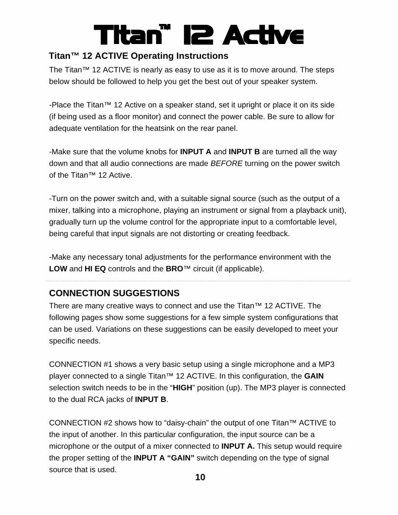
Titan™ 12 ACTIVE Operating InstructionsThe Titan™ 12 ACTIVE is nearly as easy to use as it is to move around. The steps below should be followed to help you get the best out of your speaker system.
-Place the Titan™ 12 Active on a speaker stand, set it upright or place it on its side (if being used as a floor monitor) and connect the power cable. Be sure to allow for adequate ventilation for the heatsink on the rear panel.
-Make sure that the volume knobs for INPUT A and INPUT B are turned all the way down and that all audio connections are made BEFORE turning on the power switch of the Titan™ 12 Active.
-Turn on the power switch and, with a suitable signal source (such as the output of a mixer, talking into a microphone, playing an instrument or signal from a playback unit), gradually turn up the volume control for the appropriate input to a comfortable level, being careful that input signals are not distorting or creating feedback.
-Make any necessary tonal adjustments for the performance environment with the LOW and HI EQ controls and the BRO™ circuit (if applicable).
CONNECTION SUGGESTIONSThere are many creative ways to connect and use the Titan™ 12 ACTIVE. The following pages show some suggestions for a few simple system configurations that can be used. Variations on these suggestions can be easily developed to meet your specific needs.
CONNECTION #1 shows a very basic setup using a single microphone and a MP3 player connected to a single Titan™ 12 ACTIVE. In this configuration, the GAINselection switch needs to be in the “HIGH” position (up). The MP3 player is connected to the dual RCA jacks of INPUT B.
CONNECTION #2 shows how to “daisy-chain” the output of one Titan™ ACTIVE to the input of another. In this particular configuration, the input source can be a microphone or the output of a mixer connected to INPUT A. This setup would require the proper setting of the INPUT A “GAIN” switch depending on the type of signal source that is used.
10

HI
-12dB +12dB
0
LOW
CD/TAPE
INPUT
L
R
OUTPUTINPUT
AC INPUT
OPTIMIZER
--
0
LIMIT OFF
ON
POWER
-12dB +12dB
0
EQ
MIXLOOP
AC220-240V~60Hz 400W
FUSE T4AL 250V
B(BALANCED)
INPUTA(BALANCED)
BASS RESPONSE
VOLUME∞ +6 +6
0
VOLUME∞
INPUT
AC220-240V~50Hz
AC Power Cord
Microphone Connect to power outlet
Basic microphone / playback hookup
MP3 Player
11
CONNECTION DIAGRAM #1
ONOFF
+10dB-10dB
+10dB-10dB
HIGH
LOW
GAIN
MAXMAX
Place switch down in “MIX”
position

HI
-12dB +12dB
0
LOW
CD/TAPE
INPUT
L
R
OUTPUTINPUT
AC INPUT
OPTIMIZER
--
0
LIMIT OFF
ON
POWER
-12dB +12dB
0
EQ
MIXLOOP
AC220-240V~60Hz 400W
FUSE T4AL 250V
B(BALANCED)
INPUTA(BALANCED)
BASS RESPONSE
VOLUME∞ +6 +6
0
VOLUME∞
OUTPUT
AC220-240V~50Hz
Connecting two Titan 12 ACTIVE speakers together
Input 1 from a microphone or the output of a mixer
(Be aware of MIC/LINE switch setting!)
12
CONNECTION DIAGRAM #2
INPUT
INPUT
ONOFF
ONOFF
+10dB
+10dB-10dB
-10dB
+10dB-10dB
HI 0
LOW
CD/TAPE
INPUT
L
R
OUTPUTINPUT
AC INPUT
OPTIMIZER
--
0
LIMIT OFF
ON
POWER
-12dB +12dB
0
EQ
MIXLOOP
AC220-240V~60Hz 400W
FUSE T4AL 250V
B(BALANCED)
INPUTA(BALANCED)
BASS RESPONSE
VOLUME∞
0
VOLUME∞
AC220-240V~50Hz
HIGH
LOW
GAIN-10dB +10dB
INPUT
HIGH
LOW
MAXMAX
MAXMAX
Place switch down in “MIX”
position
Place switch down in “MIX”
position

MU
TE
LIM
IT
DET
ECTI
ON
EQ
HI P
ASS
CO
MPR
ESSO
R
AU
DIO
POW
ER S
WIT
CH
TWEE
TER
THR
ESH
OLD
LOW
PA
SS
THR
ESH
OLD
THR
ESH
OLD
CO
MPR
ESS
BA
SS R
ESPO
NSE
O
PTIM
IZER
LOW
CU
T 30
Hz
CLA
SS D
EQEQ
LOW
GA
IN
HI G
AIN
LEVE
L
LEVE
L
INPU
T A
INPU
T B
LOO
P / M
IX
CD
/ TA
PE
LIN
E O
UTP
UT
DC
SEN
SE
CU
RR
ENT
SEN
SE
THER
MA
L SE
NSE
LF A
MP
BR
O
ON
/ O
FF
PRO
TEC
T
HI
LOW
HF
AM
P
DC
PR
OTE
CT
POW
ER L
ED
T R T R
FUSE
SW
AC
-IN
+/-1
5V+/
-35V
+/-7
0V
1
2 3 2 31
2 31
WO
OFE
R
LED
-DIS
PLA
Y
BLU
E
X6
LIM
IT L
ED
_ +
+ _ + _
BLO
CK
DIA
GR
AM
13

SPECIFICATIONS
Model Name Titan™ 12 ACTIVESystem Type Active 12” 2-way Bi-Amplified systemFrequency Response (+/-3dB) 55-20kHz
Low Frequency TransducerSize (mm / inches) 305mm / 12” Coil Size (mm / inches) 64.26mm / 2.5” Impedance 4 Ω
High Frequency TransducerType Compression Driver Coil Size (mm / inches) 51mm / 2” Exit Size (mm / inches) 25mm / 1” Diaphragm Material Titanium Impedance 8 Ω High Frequency Coverage (H x V) 90° x 60°
AmplifiersLow-Frequency Power Amplifier (Class D) Rated 250W RMS, 500W PeakHigh- Frequency Power Amplifier (Class A/B) Rated 50W RMS, 100W Peak
Electronic Crossover: 24dB per octave Linkwitz-RileyCrossover Frequency 2.3kHz
ControlsEqualization: High (±10dB) 10kHz Shelving Low (±10dB) 100Hz ShelvingBass Response Optimizer ("BRO”™) circuit +5dB at 60Hz Subsonic Filter 30Hz, Second-order filter
Amplifier ProtectionPower On Protection Power switch on / off mute Thermal Protection Amplifier shutdown, auto reset Low Line Voltage Shut Down 60% Nominal line voltageDriver Protection Independent LF and HF limitersDC Protection Yes Short Protection YesClip Limiter: Turns on approx 250W outputLimiter Indicator Red LED
InputsInput A – type Switchable balanced mic or line level inputInput Sensitivity Mic: -36dBu (-38.2dBv or 12.28mVrms) Line: +4dBu (1.78dBv or 1.228Vrms)Maximum Input Level +22dBuInput Connector XLR / ¼” Combo jackInput Impedance Balanced: 20kΩ - Unbalanced: 10kΩMaximum Input Level +22dBu
14

Input B – type Line level inputInput Sensitivity XLR / ¼” Combo jack: 1.78dBv or 1.228Vrms RCA: 0dBu (-2.2dBv or 0.775Vrms)Maximum Input Level +22dBu
Input Connectors Combo jack: 1/4" - XLR / Summed dual RCA jacks
Line Output Line Output Connector Switchable LOOP / MIX Balanced Male XLR ConnectorImpedance Balanced: 1k ohm – Unbalanced: 500 ohmSensitivity +4dBu (1.78dBv or 1.228Vrms)
AC Power detailsPower Supply High Efficiency Switching Mode Power SupplyAC Power Options AC100~120V / 220~240V, 50 / 60HzPower On Indicator LED
Rigging / Bracket / Mounting Options 10 M8 threaded inserts including 4 M8 threaded inserts on bottom in OmniMount 60.0-type footprint Pole-mount receptacle with lock screw 2 carry handles (one on each side) Optional wall-mount bracketEnclosureEnclosure Material Injection Moulded PolypropyleneColour Grey or whiteDimensions (mm / inches): H 556mm / 21.88”W (Front / Back) 384mm / 15.11” - 180mm / 7.1”D 312mm / 12.28”WeightNet Weight (kg / lbs) 12.8kg / 28.16lbsGross Weight (kg / lbs) 14.8kg / 32.56lbs
Details, features and specification are subject to change without notice
SPECIFICATIONS (cont.)
15

12.2
8"31
2mm
21.8
8"55
6mm
DIM
ENSI
ON
S
AAIN
PUT
OU
TPU
T
BR
O
_--
15.1
1"38
4mm
12.2
8"31
2mm
7.1"
180m
m
O
)
MIX
O
OO
PTIM
IZER
(BA
LAN
CED
)(B
ALA
NCED
)
16

Wharfedale International LTD.IAG HOUSE
Sovereign Court, Ermine Business Park,Huntingdon, Cambs,PE29 6XU, England
www.wharfedalepro.com
IAG Professional reserves the right to alter or improve specifications without notice.
All rights reserved © 2007 Wharfedale ProWharfedale Pro is a member of the International Audio Group