2015 Nissan Titan | Owner's Manual - Fifth Wheel Street
457
® 2015 TITAN OWNER’S MANUAL For your safety, read carefully and keep in this vehicle.
-
Upload
khangminh22 -
Category
Documents
-
view
1 -
download
0
Transcript of 2015 Nissan Titan | Owner's Manual - Fifth Wheel Street

®
2015 TITANOWNER’S MANUAL
For your safety, read carefully and keep in this vehicle.
2015 N
ISS
AN
TIT
AN
A6
0-D
A60-D
Printing : May 2015 (21)
Publication No.: OM1E 0A60U0
Printed in U.S.A.
OM15EA 0A60U1
Owner’s Manual Supplement
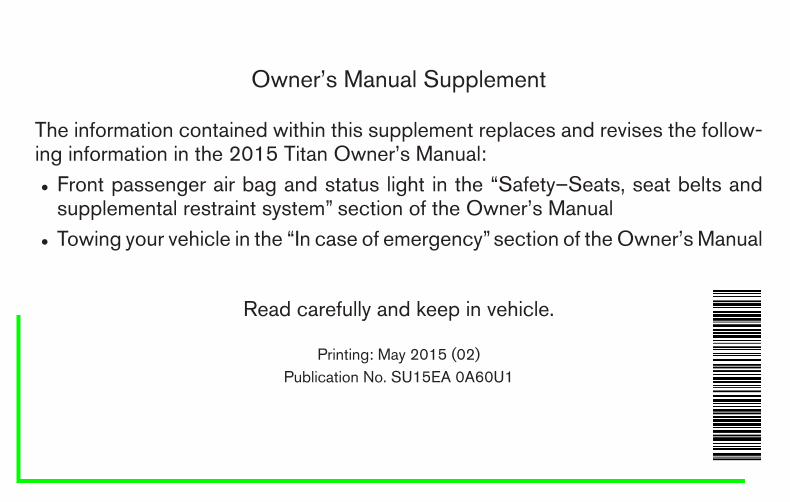
The information contained within this supplement replaces and revises the follow-ing information in the 2015 Titan Owner’s Manual:
● Front passenger air bag and status light in the “Safety–Seats, seat belts andsupplemental restraint system” section of the Owner’s Manual
● Towing your vehicle in the “In case of emergency”section of the Owner’s Manual
Read carefully and keep in vehicle.
Printing: May 2015 (02)Publication No. SU15EA 0A60U1
schulzh
Text Box

Front passenger air bag and status light
WARNING
The front passenger air bag is designed toautomatically turn OFF under some condi-tions. Read this section carefully to learnhow it operates. Proper use of the seat,seat belt and child restraints is necessaryfor most effective protection. Failure tofollow all instructions in this manual con-cerning the use of seats, seat belts andchild restraints can increase the risk orseverity of injury in an accident.
Status light
The right front passenger air bag statuslight is located under the climate controls.After the ignition switch is placed in the �ON�position, the front passenger air bag status lighton the instrument panel illuminates for about7 seconds and then turns off or operates de-pending on the front passenger seat occupiedstatus. The light operates as follows:
● Unoccupied passenger’s seat: Thelight is OFF and the front passenger air bagis OFF and will not inflate in a crash.
● Passenger’s seat occupied by a small adult,child or child restraint as outlined in thissection: The illuminates to indicatethat the front passenger air bag is OFF andwill not inflate in a crash.
● Occupied passenger seat and the passen-ger meets the conditions outlined in thissection: The light is OFF to indicatethat the front passenger air bag is opera-tional.
Front passenger air bag
The right front passenger air bag is designed toautomatically turn OFF when the vehicle is oper-ated under some conditions as described belowin accordance with U.S. regulations. If the frontpassenger air bag is OFF it will not inflate in a
crash. The driver air bag and other air bags in yourvehicle are not part of this system.
The purpose of the regulation is to help reducethe risk of injury or death from an inflating air bagto certain front passenger seat occupants, suchas children, by requiring the air bag to be auto-matically turned OFF. Certain sensors are used tomeet the requirements.
One sensor used is the occupant classificationsensor (weight sensor). It is in the bottom of theright front passenger seat cushion and is de-signed to detect an occupant and objects on theright front seat by weight. It works together withseat belt sensors described in this section. Forexample, if a child is in the right front passengerseat, the Advanced Air Bag System is designedto turn the passenger air bag OFF in accordancewith the regulations. Also, if a child restraint of thetype specified in the regulations is on the seat, itsweight and the child’s weight can be detectedand cause the air bag to turn OFF. Occupantclassification sensor operation can vary depend-ing on the right front passenger seat belt sensors.
The front passenger seat belt sensors are de-signed to detect if the seat belt is buckled and theamount of tension on the seat belt, such as whenit is in the Automatic Locking Retractor (ALR)mode (child restraint mode). Based on theweight on the seat detected by the occupant
LRS0865
schulzh
Text Box

classification sensor and the belt tension de-tected on the seat belt, the Advanced Air BagSystem determines whether the front passengerair bag should be automatically turned OFF, asrequired by the regulations.
Front passenger seat adult occupants who areproperly seated and using the seat belt as out-lined in this manual should not cause the passen-ger air bag to be automatically turned OFF. Forsmall adults it may be turned OFF; however, if theoccupant takes his/her weight off the seat cush-ion (for example, by not sitting upright, by sittingon an edge of the seat, or by otherwise being outof position), this could cause the sensor to turnthe air bag OFF. In addition, if the occupantimproperly uses the seat belt in the ALR mode(child restraint mode), this could cause the airbag to be turned OFF. Always be sure to beseated and wearing the seat belt properly for themost effective protection by the seat belt andsupplemental air bag.
NISSAN recommends that pre-teens and chil-dren be properly restrained in a rear seat.NISSAN also recommends that appropriate childrestraints and booster seats be properly installedin a rear seat. If this is not possible, the occupantclassification sensor and seat belt sensors aredesigned to operate as described above to turnthe front passenger air bag OFF for specifiedchild restraints as required by the regulations.
Failing to properly secure child restraints and touse the ALR mode (child restraint mode) mayallow the restraint to tip or move in a collision orsudden stop. This can also result in the passen-ger air bag inflating in a crash instead of beingOFF. For additional information, refer to “Childrestraints” in this section for proper use and in-stallation.
If the right front passenger seat is not occupiedthe passenger air bag is designed not to inflate ina crash. However, heavy objects placed on theseat could result in air bag inflation, because ofthe object’s weight detected by the occupantclassification sensor. Other conditions could alsoresult in air bag inflation, such as if a child isstanding on the seat, or if two children are on theseat, contrary to the instructions in this manual.Always be sure that you and all vehicle occupantsare seated and restrained properly.
Using the passenger air bag status light, you canmonitor when the front passenger air bag is au-tomatically turned OFF with the seat occupied.The light will not illuminate when the right frontpassenger seat is unoccupied.
If an adult occupant is in the seat but the passen-ger air bag status light is illuminated (indicatingthat the air bag is OFF), it could be that theperson is a small adult, or is not sitting on the seatproperly or not using the seat belt properly.
If a child restraint must be used in the front seat,the passenger air bag status light may or may notbe illuminated, depending on the size of the childand the type of child restraint being used. If the airbag status light is not illuminated (indicating thatthe air bag might inflate in a crash), it could bethat the child restraint or seat belt is not beingused properly. Make sure that the child restraint isinstalled properly, the seat belt is used properlyand the occupant is positioned properly. If the airbag status light is not illuminated, reposition theoccupant or child restraint in a rear seat.
If the passenger air bag status light will not illu-minate even though you believe that the childrestraint, the seat belts and the occupant areproperly positioned, the system may be sensingan unoccupied seat (in which case the air bag isOFF). Your NISSAN dealer can check that thesystem is OFF by using a special tool. However,until you have confirmed with your dealer thatyour air bag is working properly, reposition theoccupant or child restraint in a rear seat.
The air bag system and passenger air bag statuslight will take a few seconds to register a changein the passenger seat status. For example, if alarge adult who is sitting in the front passengerseat exits the vehicle, the passenger air bagstatus light will go from OFF to ON for a fewseconds and then to OFF. This is normal systemoperation and does not indicate a malfunction.
schulzh
Text Box

If a malfunction occurs in the front passenger airbag system, the supplemental air bag warninglight , located in the meter and gauges areaon the driver’s side of the instrument panel, willblink. Have the system checked by a NISSANdealer.Other supplemental front-impact air bagprecautions
WARNING
● Do not place any objects on the steeringwheel pad or on the instrument panel.Also, do not place any objects betweenany occupant and the steering wheel orinstrument panel. Such objects may be-come dangerous projectiles and causeinjury if the front air bags inflate.
● Immediately after inflation, severalfront air bag system components will behot. Do not touch them; you may se-verely burn yourself.
● No unauthorized changes should bemade to any components or wiring ofthe supplemental air bag system. This isto prevent accidental inflation of thesupplemental air bag or damage to thesupplemental air bag system.
● Do not make unauthorized changes toyour vehicle’s electrical system, sus-pension system or front end structure.This could affect proper operation ofthe front air bag system.
● If your vehicle has front recovery hooksas original factory equipment do notremove or modify them. If it was notequipped with front recovery hooks donot install them. Either action could af-fect proper operation of the front airbagsystem resulting in injury or death.
● Tampering with the front air bag systemmay result in serious personal injury.Tampering includes changes to thesteering wheel and the instrumentpanel assembly by placing materialover the steering wheel pad and abovethe instrument panel or by installingadditional trim material around the airbag system.
● Modifying or tampering with the frontpassenger seat may result in seriouspersonal injury. For example, do notchange the front seats by placing mate-rial on the seat cushion or by installingadditional trim material, such as seatcovers, on the seat that are not specifi-cally designed to assure proper air bagoperation. Additionally, do not stow anyobjects under the front passenger seator the seat cushion and seatback. Suchobjects may interfere with the properoperation of the occupant classificationsensor (pressure sensor).
● No unauthorized changes should bemade to any components or wiring ofthe seat belt system. This may affect thefront air bag system. Tampering withthe seat belt system may result in seri-ous personal injury.
schulzh
Text Box

● Work on and around the front air bagsystem should be done by a NISSANdealer. Installation of electrical equip-ment should also be done by a NISSANdealer. The Supplemental RestraintSystem (SRS) wiring should not bemodified or disconnected. Unauthor-ized electrical test equipment and prob-ing devices should not be used on theair bag system.
● A cracked windshield should be re-placed immediately by a qualified repairfacility. A cracked windshield could af-fect the function of the supplemental airbag system.
*The SRS wiring harness connectors areyellow and orange for easy identification.
When selling your vehicle, we request that youinform the buyer about the front air bag systemand guide the buyer to the appropriate sectionsin this Owner’s Manual.
When towing your vehicle, all jurisdictional andlocal regulations for towing must be followed.Incorrect towing equipment could damage yourvehicle. Towing instructions are available from aNISSAN dealer. Local service operators are gen-erally familiar with the applicable laws and proce-dures for towing. To assure proper towing and toprevent accidental damage to your vehicle,NISSAN recommends having a service operatortow your vehicle. It is advisable to have the ser-vice operator carefully read the following precau-tions:
WARNING
● Never ride in a vehicle that is beingtowed.
● Never get under your vehicle after it hasbeen lifted by a tow truck.
● If your vehicle has front recovery hooksas original factory equipment do notremove or modify them. If it was notequipped with front recovery hooks donot install them. Either action could af-fect proper operation of the front airbagsystem resulting in injury or death.
CAUTION
● When towing, make sure that the trans-mission, axles, steering system andpowertrain are in working condition. Ifany of these conditions apply, dollies ora flatbed tow truck must be used.
● Always attach safety chains beforetowing.
For additional information about towing your ve-hicle behind a recreational vehicle (RV), refer to“Flat towing” in the “Technical and ConsumerInformation” section of this manual.
TOWING YOUR VEHICLE
schulzh
Text Box

Welcome to the growing family of new NISSANowners. This vehicle is delivered to you withconfidence. It was produced using the latesttechniques and strict quality control.
This manual was prepared to help you under-stand the operation and maintenance of yourvehicle so that you may enjoy many miles (kilome-ters) of driving pleasure. Please read through thismanual before operating your vehicle.
A separate Warranty Information Bookletexplains details about the warranties cov-ering your vehicle. The “NISSAN Serviceand Maintenance Guide” explains detailsabout maintaining and servicing your ve-hicle. Additionally, a separate CustomerCare/Lemon Law Booklet (U.S. only) willexplain how to resolve any concerns youmay have with your vehicle, and clarify yourrights under your state’s lemon law.
Your NISSAN dealership knows your vehiclebest. When you require any service or have anyquestions, they will be glad to assist you with theextensive resources available to them.
In addition to factory-installed options, your ve-hicle may also be equipped with additional ac-cessories installed by NISSAN or by yourNISSAN dealer prior to delivery. It is importantthat you familiarize yourself with all disclosures,warnings, cautions and instructions concerning
proper use of such accessories prior to operatingthe vehicle and/or accessory. See a NISSANdealer for details concerning the particular ac-cessories with which your vehicle is equipped.
Before driving your vehicle, please read thisOwner’s Manual carefully. This will ensure famil-iarity with controls and maintenance require-ments assisting you in the safe operation of yourvehicle.
WARNING
IMPORTANT SAFETY INFORMATION RE-MINDERS FOR SAFETY!
Follow these important driving rules tohelp ensure a safe and comfortable tripfor you and your passengers!
● NEVER drive under the influence of al-cohol or drugs.
● ALWAYS observe posted speed limitsand never drive too fast for conditions.
● ALWAYS give your full attention to drivingand avoid using vehicle features or takingother actions that could distract you.
● ALWAYS use your seat belts and appro-priate child restraint systems. Pre-teenchildren should be seated in the rear seat.
● ALWAYS provide information about theproper use of vehicle safety features toall occupants of the vehicle.
● ALWAYS review this Owner’s Manualfor important safety information.
FOREWORD READ FIRST—THEN DRIVE SAFELY

For descriptions specified for 4-wheel drivemodels, a mark is placed at the begin-ning of the applicable sections/items.
As with other vehicles with features foroff-road use, failure to operate 4-wheeldrive models correctly may result in loss ofcontrol or a collision. For additional infor-mation, refer to “Driving safety precau-tions” in the “Starting and driving” sectionof this manual.
ON-PAVEMENT AND OFF-ROAD DRIV-ING
This vehicle will handle and maneuverdifferently from an ordinary passengercar because it has a higher center ofgravity for off-road use. As with othervehicles with features of this type, fail-ure to operate this vehicle correctly mayresult in loss of control or an accident.
For additional information, refer to “On-pavement and off-road drivingprecautions,” “Avoiding collision androllover” and “Driving safety precau-tions” in the “Starting and driving” sec-tion of this manual.
MODIFICATION OF YOUR VEHICLE
This vehicle should not be modified.Modification could affect itsperformance, safety or durability and mayeven violate governmental regulations. Inaddition, damage or performance prob-lems resulting from modifications maynot be covered under NISSAN warranties.
This manual includes information for all featuresand equipment available on this model. Featuresand equipment in your vehicle may vary depend-ing on model, trim level, options selected, order,date of production, region or availability. There-fore, you may find information about features orequipment that are not included or installed onyour vehicle.
All information, specifications and illustrations inthis manual are those in effect at the time ofprinting. NISSAN reserves the right to changespecifications, performance, design or compo-nent suppliers without notice and without obliga-tion. From time to time, NISSAN may update orrevise this manual to provide Owners with themost accurate information currently available.Please carefully read and retain with this manualall revision updates sent to you by NISSAN toensure you have access to accurate and up-to-date information regarding your vehicle. Currentversions of vehicle Owner’s Manuals and anyupdates can also be found in the Owner sectionof the NISSAN website athttps://owners.nissanusa.com/nowners/navigation/manualsGuide. If you have ques-tions concerning any information in your Owner’sManual, contact NISSAN Consumer Affairs. Seethe NISSAN CUSTOMER CARE PROGRAMpage in this Owner’s Manual for contact informa-tion.
WHEN READING THE MANUAL

IMPORTANT INFORMATION ABOUTTHIS MANUALYou will see various symbols in this manual. Theyare used in the following ways:
WARNING
This is used to indicate the presence of ahazard that could cause death or seriouspersonal injury. To avoid or reduce therisk, the procedures must be followedprecisely.
CAUTION
This is used to indicate the presence of ahazard that could cause minor or moder-ate personal injury or damage to your ve-hicle. To avoid or reduce the risk, the pro-cedures must be followed carefully.
If you see this symbol, it means “Do not do this”or “Do not let this happen.”
If you see a symbol similar to these in an illustra-tion, it means the arrow points to the front of thevehicle.
Arrows in an illustration that are similar to theseindicate movement or action.
Arrows in an illustration that are similar to thesecall attention to an item in the illustration.
CALIFORNIA PROPOSITION 65WARNING
WARNING
Engine exhaust, some of its constituents,and certain vehicle components contain oremit chemicals known to the State of Cali-fornia to cause cancer and birth defects orother reproductive harm. In addition, cer-tain fluids contained in vehicles and cer-tain products of component wear containor emit chemicals known to the State ofCalifornia to cause cancer and birth de-fects or other reproductive harm.
CALIFORNIA PERCHLORATEADVISORY
Some vehicle parts, such as lithium batter-ies, may contain perchlorate material. Thefollowing advisory is provided: “PerchlorateMaterial – special handling may apply, Seewww.dtsc.ca.gov/hazardouswaste/perchlorate/”.
APD1005

BLUETOOTH® is atrademark owned byBluetooth SIG, Inc.and licensed toVisteon and Bosch.
SiriusXM® servicesrequire a subscriptionafter trial period andare sold separately oras a package. Thesatellite service isavailable only in the48 contiguous USAand DC. SiriusXMsatellite service isalso available inCanada; seewww.siriusxm.ca. © 2014 NISSAN NORTH AMERICA, INC.
All rights reserved. No part of this Owner’sManual may be reproduced or stored in a retrievalsystem, or transmitted in any form, or by anymeans, electronic, mechanical, photocopying,recording or otherwise, without the prior writtenpermission of Nissan North America, Inc.

NISSAN CARES . . .
Both NISSAN and your NISSAN dealer are dedicated to serving all your automotive needs. Your satisfaction with your vehicle and your NISSAN dealer areour primary concerns. Your NISSAN dealer is always available to assist you with all your automobile sales and service needs.
However, if there is something that your NISSANdealer cannot assist you with or you would like toprovide NISSAN directly with comments orquestions, please contact the NISSAN Con-sumer Affairs Department using our toll-freenumber:
For U.S. customers1-800-NISSAN-1(1-800-647-7261)
For Canadian customers1-800-387-0122
The Consumer Affairs Department will ask for thefollowing information:
– Your name, address, and telephone number
– Vehicle identification number (attached to thetop of the instrument panel on the driver’sside)
– Date of purchase
– Current odometer reading
– Your NISSAN dealer’s name
– Your comments or questions
OR
You can write to NISSAN with the information at:
For U.S. customersNissan North America, Inc.Consumer Affairs DepartmentP.O. Box 685003Franklin, TN 37068-5003or via e-mail at:[email protected]
For Canadian customersNissan Canada Inc.5290 Orbitor DriveMississauga, Ontario L4W 4Z5or via e-mail at:[email protected]
If you prefer, visit us at:www.nissanusa.com (for U.S. customers) orwww.nissan.ca (for Canadian customers)
We appreciate your interest in NISSAN and thank you for buying a quality NISSAN vehicle.
NISSAN CUSTOMER CARE PROGRAM


Table ofContents
Illustrated table of contents
Safety—Seats, seat belts and supplemental restraint system
Instruments and controls
Pre-driving checks and adjustments
Monitor, climate, audio, phone and voice recognition systems
Starting and driving
In case of emergency
Appearance and care
Maintenance and do-it-yourself
Technical and consumer information
Index
0
1
2
3
4
5
6
7
8
9
10


0 Illustrated table of contents
Air bags, seat belts and child restraints . . . . . . . . . . . . . . 0-2Exterior front . . . . . . . . . . . . . . . . . . . . . . . . . . . . . . . . . . . . . . 0-3Exterior rear. . . . . . . . . . . . . . . . . . . . . . . . . . . . . . . . . . . . . . . 0-4Passenger compartment . . . . . . . . . . . . . . . . . . . . . . . . . . . 0-5
Instrument panel. . . . . . . . . . . . . . . . . . . . . . . . . . . . . . . . . . . 0-6Engine compartment check locations . . . . . . . . . . . . . . . . 0-8Warning/indicator lights . . . . . . . . . . . . . . . . . . . . . . . . . . . . 0-9

1. Rear seat belts (P. 1-14)2. Roof-mounted curtain side-impact and
rollover supplemental air bag (P. 1-50)3. Front seat belts (P. 1-14)4. Front-seat Active Head Restraints5. Supplemental front-impact air bags
(P. 1-50)6. Seats (P. 1-2)7. Occupant classification sensor
(weight sensor) (P. 1-59)8. Seat belt with pretensioner (P. 1-50)9. Front seat-mounted side-impact
supplemental air bag (P. 1-50)10. LATCH (Lower Anchors and Tethers for
CHildren) (P. 1-25)11. Top tether strap anchor point (P. 1-25)See the page number indicated in paren-theses for operating details.
LII2021
AIR BAGS, SEAT BELTS AND CHILDRESTRAINTS
0-2 Illustrated table of contents

1. Engine hood (P. 3-11)2. Windshield wiper and washer switch
(P. 2-30)3. Windshield-washer fluid (P. 8-14)4. Power windows (P. 2-54)5. Door locks, key fob, keys (P. 3-3, 3-2)6. Mirrors (P. 3-16)7. Tire pressure (P. 8-34)8. Flat tire (P. 6-2)9. Tire chains (P. 8-34)
10. Replacing bulbs (P. 8-28)11. Headlight and turn signal switch
(P. 2-32)12. Fog light switch (if so equipped)
(P. 2-32)13. Recovery hooks (if so equipped)
(P. 6-14)See the page number indicated in paren-theses for operating details.
LII2228
EXTERIOR FRONT
Illustrated table of contents 0-3

1. Rear sliding window (if so equipped)(P. 2-54)
2. Vehicle loading (P. 9-15)3. Tailgate (P. 3-21)4. Trailer hitch/towing (if so equipped)
(P. 9-25)5. Replacing bulbs (P. 8-28)6. Lockable bedside storage compartment
(if so equipped) (P. 2-54)7. Fuel-filler cap, fuel recommendation
(P. 3-11, P. 9-46)8. Fuel-filler door (P. 3-11)9. Child safety rear door lock
(if so equipped) (P. 3-3)See the page number indicated in paren-theses for operating details.
LII2229
EXTERIOR REAR
0-4 Illustrated table of contents

1. DVD entertainment system(if so equipped) (P. 4-69)
2. Power moonroof (if so equipped)(P. 2-58)
3. Map lights (if so equipped) (P. 2-61)4. Sun visors (P. 3-15)5. HomeLink® Universal Transceiver
(if so equipped) (P. 2-61)6. Glove box (P. 2-46)7. Cup holders (P. 2-46)8. Front seats (P. 1-2)9. Folding rear bench seat (P. 1-2)See the page number indicated in paren-theses for operating details.
LII0029
PASSENGER COMPARTMENT
Illustrated table of contents 0-5

1. Vents (P. 4-15)2. Headlight/fog light (if so equipped)/turn
signal switch (P. 2-32)3. Steering wheel switch for audio control
(if so equipped)/Bluetooth® Hands-Free Phone System (if so equipped)(P. 4-27)
4. Instrument brightness control (P. 2-36)5. Driver supplemental air bag/horn
(P. 1-50, P. 2-37)6. Meters, gauges and warning/indicator
lights (P. 2-3, 2-12)7. Cruise control main/set switches
(if so equipped) (P. 5-20)8. Shift lever (column) (if so equipped)
(P. 5-14)9. Windshield wiper/washer switch
(P. 2-30)10. Navigation system* (if so equipped)
(P. 4-4)11. Climate controls (P. 4-15, P. 4-24)12. Front passenger supplemental air bag
(P. 1-50)13. Glove box (P. 2-48)14. Storage tray (P. 2-46)15. Front passenger air bag status light
(P. 1-59)LIC2437
INSTRUMENT PANEL
0-6 Illustrated table of contents
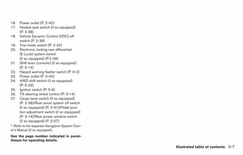
16. Power outlet (P. 2-42)17. Heated seat switch (if so equipped)
(P. 2-38)18. Vehicle Dynamic Control (VDC) off
switch (P. 2-39)19. Tow mode switch (P. 2-42)20. Electronic locking rear differential
(E-Lock) system switch(if so equipped) (P.2-39)
21. Shift lever (console) (if so equipped)(P. 5-14)
22. Hazard warning flasher switch (P. 6-2)23. Power outlet (P. 2-42)24. 4WD shift switch (if so equipped)
(P. 5-29)25. Ignition switch (P. 5-9)26. Tilt steering wheel control (P. 3-14)27. Cargo lamp switch (if so equipped)
(P. 2-38)/Rear sonar system off switch(if so equipped) (P. 2-41)/Pedal posi-tion adjustment switch (if so equipped)(P. 3-14)/Rear power window switch(if so equipped) (P. 2-57)
*: Refer to the separate Navigation System Own-er’s Manual (if so equipped).
See the page number indicated in paren-theses for operating details.
Illustrated table of contents 0-7

1. Battery (P. 8-15)2. Fuse/fusible link box (P. 8-23)3. Engine oil filler cap (P. 8-9)4. Brake fluid reservoir (P. 8-14)5. Windshield-washer fluid reservoir
(P. 8-14)6. Air cleaner (P. 8-19)7. Drive belt location (P. 8-18)8. Radiator cap (P. 8-7)9. Power steering fluid reservoir (P. 8-13)10. Engine oil dipstick (P. 8-9)11. Engine coolant reservoir (P. 8-7)
NOTE:
Engine cover removed for clarity.
See the page number indicated in paren-theses for operating details.
LDI2482
ENGINE COMPARTMENT CHECKLOCATIONS
0-8 Illustrated table of contents

Warninglight
Name Page
or
Anti-lock BrakingSystem (ABS) warn-ing light
2-13
Automatic transmis-sion check warninglight
2-13
Automatic transmis-sion park warninglight (model)
2-13
or
Brake warning light 2-13
Charge warninglight
2-14
Warninglight
Name Page
Engine oil pressurelow/engine coolanttemperature highwarning light (if soequipped)
2-14
4WD warning light( model)
2-15
Low fuel warninglight
2-15
Low tire pressurewarning light
2-15
Low windshield-washer fluid warninglight
2-17
Master warning light 2-17
Seat belt warninglight and chime
2-17
Warninglight
Name Page
Supplemental airbag warning light
2-17
Indicatorlight
Name Page
Electronic lockingrear differential (E-Lock) system onindicator light (if soequipped)
2-18
Front fog light indi-cator light (if soequipped)
2-18
Front passenger airbag status light
2-18
High beam indicatorlight (Blue)
2-18
WARNING/INDICATOR LIGHTS
Illustrated table of contents 0-9
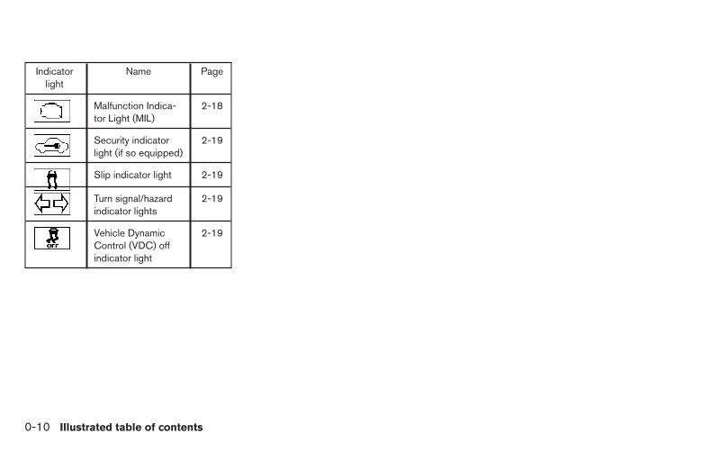
Indicatorlight
Name Page
Malfunction Indica-tor Light (MIL)
2-18
Security indicatorlight (if so equipped)
2-19
Slip indicator light 2-19
Turn signal/hazardindicator lights
2-19
Vehicle DynamicControl (VDC) offindicator light
2-19
0-10 Illustrated table of contents

MEMO
Illustrated table of contents 0-11

1 Safety—Seats, seat belts andsupplemental restraint system
Seats . . . . . . . . . . . . . . . . . . . . . . . . . . . . . . . . . . . . . . . . . . . . 1-2Front manual bench seat adjustment(if so equipped) . . . . . . . . . . . . . . . . . . . . . . . . . . . . . . . . 1-3Front power seat adjustment(if so equipped) . . . . . . . . . . . . . . . . . . . . . . . . . . . . . . . . 1-4Armrests (if so equipped). . . . . . . . . . . . . . . . . . . . . . . . 1-5Flexible seating. . . . . . . . . . . . . . . . . . . . . . . . . . . . . . . . . 1-6
Head restraints/Headrests. . . . . . . . . . . . . . . . . . . . . . . . . . 1-9Adjustable head restraint/headrestcomponents . . . . . . . . . . . . . . . . . . . . . . . . . . . . . . . . . . 1-10Non-adjustable head restraint/headrestcomponents . . . . . . . . . . . . . . . . . . . . . . . . . . . . . . . . . . 1-10Remove . . . . . . . . . . . . . . . . . . . . . . . . . . . . . . . . . . . . . . 1-11Install . . . . . . . . . . . . . . . . . . . . . . . . . . . . . . . . . . . . . . . . 1-11Adjust . . . . . . . . . . . . . . . . . . . . . . . . . . . . . . . . . . . . . . . . 1-12Front-seat active head restraints . . . . . . . . . . . . . . . . 1-13
Seat belts . . . . . . . . . . . . . . . . . . . . . . . . . . . . . . . . . . . . . . . 1-14
Precautions on seat belt usage. . . . . . . . . . . . . . . . . . 1-14Seat belt warning light . . . . . . . . . . . . . . . . . . . . . . . . . 1-17Pregnant women . . . . . . . . . . . . . . . . . . . . . . . . . . . . . . 1-17Injured persons. . . . . . . . . . . . . . . . . . . . . . . . . . . . . . . . 1-17Three-point type seat belt with retractor(if so equipped) . . . . . . . . . . . . . . . . . . . . . . . . . . . . . . . 1-17Two-point type seat belt without retractor(if so equipped) . . . . . . . . . . . . . . . . . . . . . . . . . . . . . . . 1-21Seat belt extenders . . . . . . . . . . . . . . . . . . . . . . . . . . . . 1-23Seat belt maintenance . . . . . . . . . . . . . . . . . . . . . . . . . 1-23
Child safety . . . . . . . . . . . . . . . . . . . . . . . . . . . . . . . . . . . . . . 1-24Infants. . . . . . . . . . . . . . . . . . . . . . . . . . . . . . . . . . . . . . . . 1-24Small children . . . . . . . . . . . . . . . . . . . . . . . . . . . . . . . . . 1-25Larger children . . . . . . . . . . . . . . . . . . . . . . . . . . . . . . . . 1-25
Child restraints . . . . . . . . . . . . . . . . . . . . . . . . . . . . . . . . . . . 1-25Precautions on child restraints . . . . . . . . . . . . . . . . . . 1-25
LATCH (Lower Anchors and Tethers forCHildren) System . . . . . . . . . . . . . . . . . . . . . . . . . . . . . 1-27Rear-facing child restraint installation usingLATCH . . . . . . . . . . . . . . . . . . . . . . . . . . . . . . . . . . . . . . . 1-30Rear-facing child restraint installation usingthe seat belts . . . . . . . . . . . . . . . . . . . . . . . . . . . . . . . . . 1-32Forward-facing child restraint installationusing LATCH. . . . . . . . . . . . . . . . . . . . . . . . . . . . . . . . . . 1-35Forward-facing child restraint installationusing the seat belts — front passenger andrear bench seat . . . . . . . . . . . . . . . . . . . . . . . . . . . . . . . 1-39
Forward-facing child restraint installationusing the seat belts — front bench centerposition . . . . . . . . . . . . . . . . . . . . . . . . . . . . . . . . . . . . . . 1-43Booster seats . . . . . . . . . . . . . . . . . . . . . . . . . . . . . . . . . 1-46
Supplemental restraint system (SRS) . . . . . . . . . . . . . . . 1-50Precautions on SRS . . . . . . . . . . . . . . . . . . . . . . . . . . . 1-50Supplemental air bag warning labels . . . . . . . . . . . . . 1-65Supplemental air bag warning light . . . . . . . . . . . . . . 1-65

WARNING
● Do not ride in a moving vehicle whenthe seatback is reclined. This can bedangerous. The shoulder belt will notbe against your body. In an accident,you could be thrown into it and receiveneck or other serious injuries. Youcould also slide under the lap belt andreceive serious internal injuries.
● For the most effective protection whenthe vehicle is in motion, the seat shouldbe upright. Always sit well back in theseat with both feet on the floor andadjust the seat properly. For additionalinformation, refer to “Precautions onseat belt usage” in this section.
● After adjustment, gently rock in the seatto make sure it is securely locked.
● Do not leave children unattended insidethe vehicle. They could unknowingly ac-tivate switches or controls. Unattendedchildren could become involved in seri-ous accidents.
● Do not adjust the driver’s seat whiledriving so full attention may be given tovehicle operation. The seat may movesuddenly and could cause loss of con-trol of the vehicle.
● The seatback should not be reclinedany more than needed for comfort. Seatbelts are most effective when the pas-senger sits well back and straight up inthe seat. If the seatback is reclined, therisk of sliding under the lap belt andbeing injured is increased.
CAUTION
When adjusting the seat positions, besure not to contact any moving parts toavoid possible injuries and/or damage.
ARS1152
SEATS
1-2 Safety—Seats, seat belts and supplemental restraint system

FRONT MANUAL BENCH SEATADJUSTMENT (if so equipped)
Forward and backwardPull the lever up and hold it while you slide theseat forward or backward to the desired position.Release the lever to lock the seat in position.
RecliningTo recline the seatback, pull the lever up and leanback. To bring the seatback forward, pull the leverup and lean your body forward. Release the leverto lock the seatback in position.
The reclining feature allows adjustment of theseatback for occupants of different sizes foradded comfort and to help obtain proper seatbelt fit. For additional information, refer to “Pre-cautions on seat belt usage” in this section. Also,the seatback can be reclined to allow occupantsto rest when the vehicle is stopped and the shiftlever is in P (Park).
LRS2575 LRS0427
Safety—Seats, seat belts and supplemental restraint system 1-3

FRONT POWER SEAT ADJUSTMENT(if so equipped)
Operating tips
● The power seat motor has an auto-resetoverload protection circuit. If the motorstops during operation, wait 30 secondsthen reactivate the switch.
● Do not operate the power seat switch for along period of time when the engine is off.This will discharge the battery.
For additional information, refer to “Automaticdrive positioner” in the “Pre-driving checks and
adjustments” section of this manual for automaticdrive positioner operation.
Forward and backward
Moving the switch forward or backward will slidethe seat forward or backward to the desiredposition.
Reclining
Move the recline switch backward until the de-sired angle is obtained. To bring the seatbackforward again, move the switch forward andmove your body forward. The seatback will moveforward.
The reclining feature allows adjustment of theseatback for occupants of different sizes foradded comfort and to help obtain proper seatbelt fit. For additional information, refer to “Pre-cautions on seat belt usage” in this section. Also,the seatback can be reclined to allow occupantsto rest when the vehicle is stopped and the shiftlever is in P (Park).
LRS0633
1-4 Safety—Seats, seat belts and supplemental restraint system

Seat lifter (driver’s seat)Push the front or rear end of the switch up ordown to adjust the angle and height of the seatcushion.
Lumbar support (driver’s seat)The lumbar support feature provides adjustablelower back support to the driver. Push the switchforward or backward to adjust the seatback lum-bar area.
ARMRESTS (if so equipped)To use the center armrest on the bench seats,pull on the tab in the center of the seat and fold itdown to the resting position.
WRS0164 LRS2637Front bench seat
LRS0425
Safety—Seats, seat belts and supplemental restraint system 1-5

FLEXIBLE SEATING
WARNING
● Never allow anyone to ride in the cargoarea or on the rear seats when they arein the fold-down position. In a collision,people riding in these areas withoutproper restraints are more likely to beseriously injured or killed.
● Do not allow people to ride in any areaof your vehicle that is not equipped withseats and seat belts. Be sure everyonein your vehicle is in a seat and using aseat belt properly.
● Do not allow more than one person touse the same seat belt.
● Do not fold down the rear seats whenoccupants are in the rear seat area orany luggage is on the rear seats.
– Make sure that the seat path is clearbefore moving the seat.
– Be careful not to allow hands or feetto get caught or pinched in the seat.
● Head restraints/headrests should beadjusted properly as they may providesignificant protection against injury inan accident. Always replace and adjustthem properly if they have been re-moved for any reason.
● If the head restraints/headrests are re-moved for any reason, they should besecurely stored to prevent them fromcausing injury to passengers or damageto the vehicle in case of sudden brakingor an accident.
● When returning the seatbacks to theupright position, be certain they arecompletely secured in the latched posi-tion. If they are not completely secured,passengers may be injured in an acci-dent or sudden stop.
● Properly secure all cargo to help pre-vent it from sliding or shifting. Do notplace cargo higher than the seatbacks.In a sudden stop or collision, unsecuredcargo could cause personal injury.
Rear bench seatLRS2576
1-6 Safety—Seats, seat belts and supplemental restraint system

Folding the rear bench seat upTo fold the rear bench seat up for storage capac-ity behind the front seats or to remove the jackingtools from the storage area:
1. Lift up on the lever, located on the side of theseat, while lifting the front of the seat cush-ion up.
2. Fold the bottom of the seat cushion towardthe back of the vehicle until it locks in place.
3. Repeat this process to raise and secure theseat cushion on the other side of the vehiclefor maximum storage capacity.
To return the rear bench seat to a seating posi-tion, reverse the process. Make sure to prop-erly push the seat cushion down into place.
LRS2577 LRS2578 LRS2579
Safety—Seats, seat belts and supplemental restraint system 1-7
WARNING
● When the vehicle is being used to carrycargo, properly secure all cargo to helpprevent it from sliding or shifting. Donot place cargo higher than the seat-backs. In a sudden stop or collision,unsecured cargo could cause personalinjury.
● Do not allow people to ride in any areaof your vehicle that is not equipped withseats and seat belts. Be sure everyonein your vehicle is in a seat and using aseat belt properly. Never ride in the rearseat unless the seat bottom cushionsare in place and latched.
● When returning the seatbacks to theupright position, be certain they arecompletely secured in the latched posi-tion. If they are not completely secured,passengers may be injured in an acci-dent or sudden stop.
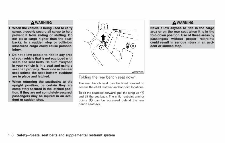
Folding the rear bench seat down
The rear bench seat can be tilted forward toaccess the child restraint anchor point locations.
To tilt the seatback forward, pull the strap up �1and tilt the seatback. The child restraint anchorpoints �2 can be accessed behind the rearbench seatback.
WARNING
Never allow anyone to ride in the cargoarea or on the rear seat when it is in thefold-down position. Use of these areas bypassengers without proper restraintscould result in serious injury in an acci-dent or sudden stop.
WRS0920
1-8 Safety—Seats, seat belts and supplemental restraint system

WARNING
Head restraints/headrests supplementthe other vehicle safety systems. They mayprovide additional protection against in-jury in certain rear end collisions. Adjust-able head restraints/headrests must beadjusted properly, as specified in this sec-tion. Check the adjustment after someoneelse uses the seat. Do not attach anythingto the head restraint/headrest stalks orremove the head restraint/headrest. Donot use the seat if the headrestraint/headrest has been removed. Ifthe head restraint/headrest was removed,reinstall and properly adjust the headrestraint/headrest before an occupantuses the seating position. Failure to fol-low these instructions can reduce the ef-fectiveness of the headrestraints/headrests. This may increasethe risk of serious injury or death in acollision.
The illustration shows the seating positionsequipped with head restraints/headrests.
� Indicates the seating position is equipped witha head restraint.
� Indicates the seating position is equipped witha headrest.
+ Indicates the seating position is not equippedwith a head restraint or headrest (if applicable).
● Your vehicle is equipped with a headrestraint/headrest that may be integrated,adjustable or non-adjustable.
Folding front seatLRS2020
Front bucket seatLRS2633
HEAD RESTRAINTS/HEADRESTS
Safety—Seats, seat belts and supplemental restraint system 1-9

● Adjustable head restraints/headrests havemultiple notches along the stalk(s) to lockthem in a desired adjustment position.
● The non-adjustable headrestraints/headrests have a single lockingnotch to secure them to the seat frame.
● Proper Adjustment:
– For the adjustable type, align the headrestraint/headrest so the center of yourear is approximately level with the centerof the head restraint/headrest.
– If your ear position is still higher than therecommended alignment, place the headrestraint/headrest at the highest position.
● If the head restraint/headrest has been re-moved, ensure that it is reinstalled andlocked in place before riding in that desig-nated seating position.
ADJUSTABLE HEAD RESTRAINT/HEADREST COMPONENTS
1. Removable head restraint/headrest
2. Multiple notches
3. Lock knob
4. Stalks
NON-ADJUSTABLE HEADRESTRAINT/HEADRESTCOMPONENTS
1. Removable head restraint/headrest
2. Single notch
3. Lock knob
4. Stalks
LRS2300 LRS2299
1-10 Safety—Seats, seat belts and supplemental restraint system

REMOVE
Use the following procedure to remove the headrestraint/headrest:
1. Pull the head restraint/headrest up to thehighest position.
2. Push and hold the lock knob.
3. Remove the head restraint/headrest fromthe seat.
4. Store the head restraint/headrest properly ina secure place so it is not loose in thevehicle.
5. Reinstall and properly adjust the headrestraint/headrest before an occupant usesthe seating position.
INSTALL1. Align the head restraint/headrest stalks with
the holes in the seat. Make sure that thehead restraint/headrest is facing the correctdirection. The stalk with the notch (notches)�1 must be installed in the hole with the lockknob �2 .
2. Push and hold the lock knob and push thehead restraint/headrest down.
3. Properly adjust the head restraint/headrestbefore an occupant uses the seating posi-tion.
LRS2302 LRS2303
Safety—Seats, seat belts and supplemental restraint system 1-11

ADJUSTFor adjustable head restraint/headrest
Adjust the head restraint/headrest so the centeris level with the center of your ears. If your earposition is still higher than the recommendedalignment, place the head restraint/headrest atthe highest position.
For non-adjustable head restraint/headrest
Make sure the head restraint/headrest is posi-tioned so the lock knob is engaged in the notchbefore riding in that designated seating position.
RaiseTo raise the head restraint/headrest, pull it up.
Make sure the head restraint/headrest is posi-tioned so the lock knob is engaged in the notchbefore riding in that designated seating position.
WRS0134 LRS2351 LRS2305
1-12 Safety—Seats, seat belts and supplemental restraint system

LowerTo lower, push and hold the lock knob and pushthe head restraint/headrest down.
Make sure the head restraint/headrest is posi-tioned so the lock knob is engaged in the notchbefore riding in that designated seating position.
FRONT-SEAT ACTIVE HEADRESTRAINTS
WARNING
● Always adjust the head restraints prop-erly as specified in this section. Failureto do so can reduce the effectiveness ofthe active head restraint.
● Active head restraints are designed tosupplement other safety systems. Al-ways wear seat belts. No system canprevent all injuries in any accident.
● Do not attach anything to the head re-straint stalks. Doing so could impairactive head restraint function.
The active head restraint moves forward utilizingthe force that the seatback receives from theoccupant in a rear-end collision. The movementof the head restraint helps support the occu-pant’s head by reducing its backward movementand helping absorb some of the forces that maylead to whiplash-type injuries.
Active head restraints are effective for collisionsat low to medium speeds in which it is said thatwhiplash injury occurs most.
Active head restraints operate only in certainrear-end collisions. After the collision, the headrestraints return to their original positions.
Properly adjust the active head restraints as de-scribed in this section.
LRS2306 SPA1025
Safety—Seats, seat belts and supplemental restraint system 1-13

PRECAUTIONS ON SEAT BELTUSAGEIf you are wearing your seat belt properly ad-justed and you are sitting upright and well back inyour seat with both feet on the floor, your chancesof being injured or killed in a collision and/or theseverity of injury may be greatly reduced.NISSAN strongly encourages you and all of yourpassengers to buckle up every time you drive,even if your seating position includes a supple-mental air bag.
Most U.S. states and Canadian provinces orterritories specify that seat belts be worn atall times when a vehicle is being driven.
SSS0136
SEAT BELTS
1-14 Safety—Seats, seat belts and supplemental restraint system

WARNING
● Every person who drives or rides in thisvehicle should use a seat belt at alltimes. Children should be properly re-strained in the rear seat and, if appro-priate, in a child restraint.
WARNING
● The seat belt should be properly ad-justed to a snug fit. Failure to do so mayreduce the effectiveness of the entirerestraint system and increase thechance or severity of injury in an acci-dent. Serious injury or death can occur ifthe seat belt is not worn properly.
SSS0134 SSS0016
Safety—Seats, seat belts and supplemental restraint system 1-15

WARNING
● Always route the shoulder belt overyour shoulder and across your chest.Never put the belt behind your back,under your arm or across your neck. Thebelt should be away from your face andneck, but not falling off your shoulder.
● Position the lap belt as low and snug aspossible AROUND THE HIPS, NOT THEWAIST. A lap belt worn too high couldincrease the risk of internal injuries inan accident.
● Be sure the seat belt tongue is securelyfastened to the proper buckle.
● Do not wear the seat belt inside out ortwisted. Doing so may reduce itseffectiveness.
● Do not allow more than one person touse the same seat belt.
● Never carry more people in the vehiclethan there are seat belts.
● If the seat belt warning light glows con-tinuously while the ignition is turnedON with all doors closed and all seatbelts fastened, it may indicate a mal-function in the system. Have the systemchecked by a NISSAN dealer.
● No changes should be made to the seatbelt system. For example, do not modifythe seat belt, add material, or installdevices that may change the seat beltrouting or tension. Doing so may affectthe operation of the seat belt system.Modifying or tampering with the seatbelt system may result in serious per-sonal injury.
● Once a seat belt pretensioner has acti-vated, it cannot be reused and must bereplaced together with the retractor.See your NISSAN dealer.
● Removal and installation of preten-sioner system components should bedone by a NISSAN dealer.
● All seat belt assemblies, including re-tractors and attaching hardware, shouldbe inspected after any collision by aNISSAN dealer. NISSAN recommendsthat all seat belt assemblies in use dur-ing a collision be replaced unless thecollision was minor and the belts showno damage and continue to operateproperly. Seat belt assemblies not inuse during a collision should also beinspected and replaced if either dam-age or improper operation is noted.
● All child restraints and attaching hard-ware should be inspected after any col-lision. Always follow the restraintmanufacturer’s inspection instructionsand replacement recommendations.The child restraints should be replacedif they are damaged.
SSS0014
1-16 Safety—Seats, seat belts and supplemental restraint system

SEAT BELT WARNING LIGHT
Both the driver’s and passenger’s front seats areequipped with a seat belt warning light. Thewarning light, located on the instrument panel,will show the status of the driver and passengerseat belt.
NOTE:
The front passenger seat belt warning lightwill not light up if the seat is not occupied.
For additional information, refer to“Warning/indicator lights and audible reminders”in the “Instruments and controls” section of thismanual.
PREGNANT WOMEN
NISSAN recommends that pregnant women useseat belts. The seat belt should be worn snug andalways position the lap belt as low as possiblearound the hips, not the waist. Place the shoulderbelt over your shoulder and across your chest.Never run the lap/shoulder belt over your ab-dominal area. Contact your doctor for specificrecommendations.
INJURED PERSONS
NISSAN recommends that injured persons useseat belts. Check with your doctor for specificrecommendations.
THREE-POINT TYPE SEAT BELTWITH RETRACTOR (if so equipped)
WARNING
● Every person who drives or rides in thisvehicle should use a seat belt at alltimes.
● Do not ride in a moving vehicle whenthe seatback is reclined. This can bedangerous. The shoulder belt will notbe against your body. In an accident,you could be thrown into it and receiveneck or other serious injuries. Youcould also slide under the lap belt andreceive serious internal injuries.
● For the most effective protection whenthe vehicle is in motion, the seat shouldbe upright. Always sit well back in theseat with both feet on the floor andadjust the seat belt properly.
● Do not allow children to play with theseat belts. Most seating positions areequipped with Automatic Locking Re-tractor (ALR) mode seat belts. If the seatbelt becomes wrapped around a child’sneck with the ALR mode activated, thechild can be seriously injured or killed ifthe seat belt retracts and becomestight. This can occur even if the vehicleis parked. Unbuckle the seat belt torelease the child. If the seat belt cannotbe unbuckled or is already unbuckled,release the child by cutting the seat beltwith a suitable tool (such as a knife orscissors) to release the seat belt.
LRS0786
Safety—Seats, seat belts and supplemental restraint system 1-17

Fastening the seat belts1. Adjust the seat. For additional information,
refer to “Seats” in this section.
�2 Slowly pull the seat belt out of the retractorand insert the tongue into the buckle untilyou hear and feel the latch engage.
● The retractor is designed to lock dur-ing a sudden stop or on impact. Aslow pulling motion permits the seatbelt to move, and allows you somefreedom of movement in the seat.
● If the seat belt cannot be pulled fromits fully retracted position, firmly pullthe belt and release it. Thensmoothly pull the belt out of the re-tractor.
�3 Position the lap belt portion low and snugon the hips as shown.
�4 Pull the shoulder belt portion toward theretractor to take up extra slack. Be sure theshoulder belt is routed over your shoulderand across your chest.
The front passenger seat and the rear seatingpositions three-point seat belts have two modesof operation:
● Emergency Locking Retractor (ELR)
● Automatic Locking Retractor (ALR)
Power front seat shownLRS0607 WRS0137 WRS0138
1-18 Safety—Seats, seat belts and supplemental restraint system

The ELR mode allows the seat belt to extend andretract to allow the driver and passengers somefreedom of movement in the seat. The ELR locksthe seat belt when the vehicle slows down rapidlyor during certain impacts.
The ALR mode (child restraint mode) locks theseat belt for child restraint installation.
When the ALR mode is activated, the seat beltcannot be extended again until the seat belttongue is detached from the buckle and fullyretracted. The seat belt returns to the ELR modeafter the seat belt fully retracts. For additionalinformation, refer to “Child restraints” in this sec-tion.
The ALR mode should be used only forchild restraint installation. During normalseat belt use by a passenger, the ALR modeshould not be activated. If it is activated itmay cause uncomfortable seat belt ten-sion. It can also change the operation ofthe front passenger air bag. For additionalinformation, refer to “Front passenger airbag and status light” in this section.
WARNING
When fastening the seat belts, be certainthat the seatbacks are completely securedin the latched position. If they are notcompletely secured, passengers may beinjured in an accident or sudden stop.
Unfastening the seat belts
�1 To unfasten the seat belt, press the button onthe buckle. The seat belt automatically re-tracts.
Checking seat belt operationSeat belt retractors are designed to lock seat beltmovement by two separate methods:
● When the seat belt is pulled quickly from theretractor
● When the vehicle slows down rapidly
WRS0139
Safety—Seats, seat belts and supplemental restraint system 1-19

To increase your confidence in the seat belts,check the operation as follows:
● Grasp the shoulder belt and pull forwardquickly. The retractor should lock and re-strict further belt movement.
If the retractor does not lock during this check orif you have any questions about seat belt opera-tion, see a NISSAN dealer.
Shoulder belt height adjustment (frontoutboard seats)
The shoulder belt anchor height should be ad-justed to the position best for you. For additionalinformation, refer to “Precautions on seat beltusage” in this section. To adjust, pull out �1 theadjustment button and move the shoulder beltanchor �2 to the desired position, so the beltpasses over the center of the shoulder. The beltshould be away from your face and neck, but notfalling off your shoulder. Release the adjustmentbutton to lock the shoulder belt anchor into posi-tion.
WARNING
● After adjustment, release the adjust-ment button and try to move the shoul-der belt anchor up and down to makesure it is securely fixed in position.
● The shoulder belt anchor height shouldbe adjusted to the position best for you.Failure to do so may reduce the effec-tiveness of the entire restraint systemand increase the chance or severity ofinjury in an accident.
Front seatsLRS0242
1-20 Safety—Seats, seat belts and supplemental restraint system

TWO-POINT TYPE SEAT BELTWITHOUT RETRACTOR (if soequipped)
Selecting the correct set of seat beltsThe center seat belt buckle and tongue are iden-tified by the CENTER mark �1 . The center seatbelt tongue can only be fastened into the centerseat belt buckle.
Fastening the seat belts
�1 Insert the tongue into the buckle until youhear and feel the latch engage.
LRS0642 SPA1347A LRS0643
Safety—Seats, seat belts and supplemental restraint system 1-21

�2 Tighten the belt by pulling the free end of thebelt away from the tongue.
�3 Position the lap belt low and snug on thehips as illustrated.
�4 Loosen the belt by holding the tongue at aright angle to the belt, then pull on the belt.
LRS0644 LRS0645 LRS0646
1-22 Safety—Seats, seat belts and supplemental restraint system
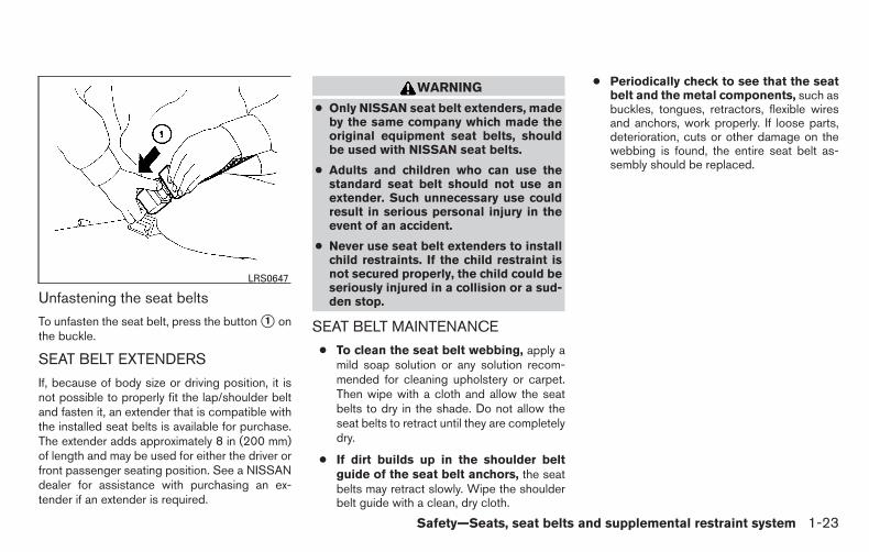
Unfastening the seat belts
To unfasten the seat belt, press the button �1 onthe buckle.
SEAT BELT EXTENDERS
If, because of body size or driving position, it isnot possible to properly fit the lap/shoulder beltand fasten it, an extender that is compatible withthe installed seat belts is available for purchase.The extender adds approximately 8 in (200 mm)of length and may be used for either the driver orfront passenger seating position. See a NISSANdealer for assistance with purchasing an ex-tender if an extender is required.
WARNING
● Only NISSAN seat belt extenders, madeby the same company which made theoriginal equipment seat belts, shouldbe used with NISSAN seat belts.
● Adults and children who can use thestandard seat belt should not use anextender. Such unnecessary use couldresult in serious personal injury in theevent of an accident.
● Never use seat belt extenders to installchild restraints. If the child restraint isnot secured properly, the child could beseriously injured in a collision or a sud-den stop.
SEAT BELT MAINTENANCE
● To clean the seat belt webbing, apply amild soap solution or any solution recom-mended for cleaning upholstery or carpet.Then wipe with a cloth and allow the seatbelts to dry in the shade. Do not allow theseat belts to retract until they are completelydry.
● If dirt builds up in the shoulder beltguide of the seat belt anchors, the seatbelts may retract slowly. Wipe the shoulderbelt guide with a clean, dry cloth.
● Periodically check to see that the seatbelt and the metal components, such asbuckles, tongues, retractors, flexible wiresand anchors, work properly. If loose parts,deterioration, cuts or other damage on thewebbing is found, the entire seat belt as-sembly should be replaced.
LRS0647
Safety—Seats, seat belts and supplemental restraint system 1-23

WARNING
Do not allow children to play with the seatbelts. Most seating positions areequipped with Automatic Locking Retrac-tor (ALR) mode seat belts. If the seat beltbecomes wrapped around a child’s neckwith the ALR mode activated, the child canbe seriously injured or killed if the seatbelt retracts and becomes tight. This canoccur even if the vehicle is parked. Un-buckle the seat belt to release the child. Ifthe seat belt cannot be unbuckled or isalready unbuckled, release the child bycutting the seat belt with a suitable tool(such as a knife or scissors) to release theseat belt.
Children need adults to help protect them.They need to be properly restrained.
In addition to the general information in thismanual, child safety information is available frommany other sources, including doctors, teachers,government traffic safety offices, and communityorganizations. Every child is different, so be sureto learn the best way to transport your child.
There are three basic types of child restraintsystems:
● Rear-facing child restraints
● Forward-facing child restraints
● Booster seats
The proper restraint depends on the child’s size.Generally, infants up to about 1 year and lessthan 20 lbs (9 kg) should be placed in rear-facingchild restraints. Forward-facing child restraintsare available for children who outgrow rear-facing child restraints and are at least 1 year old.Booster seats are used to help position a vehiclelap/shoulder belt on a child who can no longeruse a forward-facing child restraint.
WARNING
Infants and children need special protec-tion. The vehicle’s seat belts may not fitthem properly. The shoulder belt maycome too close to the face or neck. The lapbelt may not fit over their small hip bones.In an accident, an improperly fitting seatbelt could cause serious or fatal injury.Always use appropriate child restraints.
All U.S. states and Canadian provinces or territo-ries require the use of approved child restraintsfor infants and small children. For additional infor-mation, refer to “Child restraints” in this section.
A child restraint may be secured in the vehicle byusing either the LATCH (Lower Anchors andTethers for CHildren) system or with the vehicle
seat belt. For additional information, refer to“Child restraints” in this section.
NISSAN recommends that all pre-teensand children be restrained in the rear seat.Studies show that children are safer whenproperly restrained in the rear seat than inthe front seat.
This is especially important because yourvehicle has a supplemental restraint sys-tem (air bag system) for the front passen-ger. For additional information, refer to“Supplemental restraint system (SRS)” inthis section.
INFANTSInfants up to at least 1 year old should be placedin a rear-facing child restraint. NISSAN recom-mends that infants be placed in child restraintsthat comply with Federal Motor Vehicle SafetyStandards or Canadian Motor Vehicle SafetyStandards. You should choose a child restraintthat fits your vehicle and always follow the manu-facturer’s instructions for installation and use.
CHILD SAFETY
1-24 Safety—Seats, seat belts and supplemental restraint system

SMALL CHILDREN
Children that are over 1 year old and weigh atleast 20 lbs (9 kg) should remain in a rear-facingchild restraint as long as possible up to the heightor weight limit of the child restraint. Children whooutgrow the height or weight limit of the rear-facing child restraint and are at least 1 year oldshould be secured in a forward-facing child re-straint with a harness. Refer to the manufactur-er’s instructions for minimum and maximumweight and height recommendations. NISSANrecommends that small children be placed inchild restraints that comply with Federal MotorVehicle Safety Standards or Canadian Motor Ve-hicle Safety Standards. You should choose achild restraint that fits your vehicle and alwaysfollow the manufacturer’s instructions for instal-lation and use.
LARGER CHILDRENChildren should remain in a forward-facing childrestraint with a harness until they reach the maxi-mum height or weight limit allowed by the childrestraint manufacturer.
Once a child outgrows the height or weight limitof the harness-equipped forward-facing child re-straint, NISSAN recommends that the child beplaced in a commercially available booster seat toobtain proper seat belt fit. For a seat belt to fit
properly, the booster seat should raise the childso that the shoulder belt is properly positionedacross the chest and the top, middle portion ofthe shoulder. The shoulder belt should not crossthe neck or face and should not fall off the shoul-der. The lap belt should lie snugly across thelower hips or upper thighs, not the abdomen. Abooster seat can only be used in seating posi-tions that have a three-point type seat belt. Thebooster seat should fit the vehicle seat and havea label certifying that it complies with FederalMotor Vehicle Safety Standards or Canadian Mo-tor Vehicle Safety Standards. Once the child hasgrown so the shoulder belt is no longer on or nearthe face and neck and the lap belt can be posi-tioned properly across the lower hips or upperthighs, use the seat belt without the booster seat.
WARNING
Never let a child stand or kneel on any seatand do not allow a child in the cargo area.The child could be seriously injured orkilled in a sudden stop or collision.
PRECAUTIONS ON CHILDRESTRAINTS
ARS1098
CHILD RESTRAINTS
Safety—Seats, seat belts and supplemental restraint system 1-25
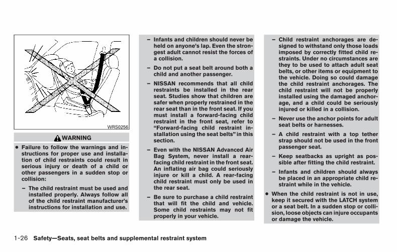
WARNING
● Failure to follow the warnings and in-structions for proper use and installa-tion of child restraints could result inserious injury or death of a child orother passengers in a sudden stop orcollision:
– The child restraint must be used andinstalled properly. Always follow allof the child restraint manufacturer’sinstructions for installation and use.
– Infants and children should never beheld on anyone’s lap. Even the stron-gest adult cannot resist the forces ofa collision.
– Do not put a seat belt around both achild and another passenger.
– NISSAN recommends that all childrestraints be installed in the rearseat. Studies show that children aresafer when properly restrained in therear seat than in the front seat. If youmust install a forward-facing childrestraint in the front seat, refer to“Forward-facing child restraint in-stallation using the seat belts” in thissection.
– Even with the NISSAN Advanced AirBag System, never install a rear-facing child restraint in the front seat.An inflating air bag could seriouslyinjure or kill a child. A rear-facingchild restraint must only be used inthe rear seat.
– Be sure to purchase a child restraintthat will fit the child and vehicle.Some child restraints may not fitproperly in your vehicle.
– Child restraint anchorages are de-signed to withstand only those loadsimposed by correctly fitted child re-straints. Under no circumstances arethey to be used to attach adult seatbelts, or other items or equipment tothe vehicle. Doing so could damagethe child restraint anchorages. Thechild restraint will not be properlyinstalled using the damaged anchor-age, and a child could be seriouslyinjured or killed in a collision.
– Never use the anchor points for adultseat belts or harnesses.
– A child restraint with a top tetherstrap should not be used in the frontpassenger seat.
– Keep seatbacks as upright as pos-sible after fitting the child restraint.
– Infants and children should alwaysbe placed in an appropriate child re-straint while in the vehicle.
● When the child restraint is not in use,keep it secured with the LATCH systemor a seat belt. In a sudden stop or colli-sion, loose objects can injure occupantsor damage the vehicle.
WRS0256
1-26 Safety—Seats, seat belts and supplemental restraint system

CAUTION
A child restraint in a closed vehicle canbecome very hot. Check the seating sur-face and buckles before placing a child inthe child restraint.
This vehicle is equipped with a universal childrestraint anchor system, referred to as the LATCH(Lower Anchors and Tethers for CHildren) sys-tem. Some child restraints include rigid orwebbing-mounted attachments that can be con-nected to these anchors. For additional informa-tion, refer to “LATCH (Lower Anchors and Teth-ers for CHildren) system” in this section.
If you do not have a LATCH compatible childrestraint, the vehicle seat belts can be used.
Several manufacturers offer child restraints forinfants and children of various sizes. When se-lecting any child restraint, keep the followingpoints in mind:
● Choose only a restraint with a label certifyingthat it complies with Federal Motor VehicleSafety Standard 213 or Canadian MotorVehicle Safety Standard 213.
● Check the child restraint in your vehicle to besure it is compatible with the vehicle’s seatand seat belt system.
● If the child restraint is compatible with yourvehicle, place your child in the child restraintand check the various adjustments to besure the child restraint is compatible withyour child. Choose a child restraint that isdesigned for your child’s height and weight.Always follow all recommended procedures.
● If the combined weight of the child and childrestraint is less than 65 lbs (29.5 kg), youmay use either the LATCH anchors or theseat belt to install the child restraint (not bothat the same time).
● If the combined weight of the child and childrestraint is greater than 65 lbs (29.5 kg), usethe vehicle’s seat belt (not the lower an-chors) to install the child restraint.
● Be sure to follow the child restraint manufac-turer’s instructions for installation.
All U.S. states and Canadian provinces orterritories require that infants and smallchildren be restrained in an approved childrestraint at all times while the vehicle isbeing operated. Canadian law requires thetop tether strap on forward-facing child re-straints be secured to the designated an-chor point on the vehicle.
LATCH (Lower Anchors and Tethersfor CHildren) SYSTEM
Your vehicle is equipped with special anchorpoints that are used with the LATCH systemcompatible child restraints. This system may alsobe referred to as the ISOFIX or ISOFIX compat-ible system. With this system, you do not have touse a vehicle seat belt to secure the child re-straint unless the combined weight of the childand child restraint exceeds 65 lbs (29.5 kg). If thecombined weight of the child and child restraint isgreater than 65 lbs (29.5 kg) use the vehiclesseat belt (not the lower anchors) to install the
LATCH system lower anchor locationsLRS0429
Safety—Seats, seat belts and supplemental restraint system 1-27

child restraint. Be sure to follow the child restraintmanufacturer’s instructions for installation.
The LATCH anchor points are provided to installchild restraints in the rear outboard seating posi-tions only. Do not attempt to install a child re-straint in the center position using the LATCHanchors.
LATCH lower anchor
WARNING
Failure to follow the warnings and instruc-tions for proper use and installation ofchild restraints could result in serious in-jury or death of a child or other passen-gers in a sudden stop or collision:
– Attach LATCH system compatiblechild restraints only at the locationsshown in the illustration.
– Do not secure a child restraint in thecenter rear seating position using theLATCH lower anchors. The child re-straint will not be secured properly.
– Inspect the lower anchors by insert-ing your fingers into the lower anchorarea. Feel to make sure there are noobstructions over the anchors suchas seat belt webbing or seat cushionmaterial. The child restraint will notbe secured properly if the lower an-chors are obstructed.
– Child restraint anchorages are de-signed to withstand only those loadsimposed by correctly fitted child re-straints. Under no circumstances arethey to be used to attach adult seatbelts, or other items or equipment tothe vehicle. Doing so could damagethe child restraint anchorages. Thechild restraint will not be properlyinstalled using the damaged anchor-age, and a child could be seriouslyinjured or killed in a collision.
LATCH lower anchor locationThe LATCH lower anchors are located at the rearof the seat cushion near the seatback. A label isattached to the seatback to help you locate theLATCH lower anchors.
LATCH lower anchor locationLRS0748
1-28 Safety—Seats, seat belts and supplemental restraint system

Installing child restraint LATCH loweranchor attachments
LATCH compatible child restraints include tworigid or webbing-mounted attachments that canbe connected to two anchors located at certainseating positions in your vehicle. With this sys-tem, you do not have to use a vehicle seat belt tosecure the child restraint. Check your child re-straint for a label stating that it is compatible withLATCH. This information may also be in the in-structions provided by the child restraint manu-facturer.
When installing a child restraint, carefully readand follow the instructions in this manual andthose supplied with the child restraint.
LATCH lower anchor point locationsLRS0395
LATCH webbing-mounted attachmentLRS0661
LATCH rigid-mounted attachmentLRS0662
Safety—Seats, seat belts and supplemental restraint system 1-29

Top tether anchor point locations
Anchor points are located under the rear windowbehind the rear bench seat.
REAR-FACING CHILD RESTRAINTINSTALLATION USING LATCHFor additional information, refer to all Warningsand Cautions in the “Child Safety” and “ChildRestraints” sections of this manual before install-ing a child restraint.
NISSAN does not recommend the use of thelower anchors if the combined weight of the childand the child restraint exceeds 65 lbs (29.5 kg). Ifthe combined weight of the child and the child
restraint is greater than 65 lbs (29.5 kg), use thevehicle’s seat belt (not the lower anchors) toinstall the child restraint. Be sure to follow thechild restraint manufacturer’s instructions for in-stallation.
Follow these steps to install a rear-facing childrestraint in the rear bench seats using the LATCHsystem:
1. Position the child restraint on the seat. Al-ways follow the child restraint manufactur-er’s instructions.
2. Secure the child restraint anchor attach-ments to the LATCH lower anchors. Checkto make sure the LATCH attachment is prop-erly attached to the lower anchors.
LRS0393Rear-facing webbing-mounted – step 2
WRS0801
1-30 Safety—Seats, seat belts and supplemental restraint system

3. For child restraints that are equipped withwebbing-mounted attachments, remove anyadditional slack from the anchor attach-ments. Press downward and rearward firmlyin the center of the child restraint with yourhand to compress the vehicle seat cushionand seatback while tightening the webbingof the anchor attachments.
4. After attaching the child restraint, test it be-fore you place the child in it. Push it from sideto side while holding the child restraint nearthe LATCH attachment path. The child re-straint should not move more than 1 inch(25 mm), from side to side. Try to tug itforward and check to see if the LATCH at-tachment holds the restraint in place. If therestraint is not secure, tighten the LATCHattachment as necessary, or put the restraintin another seat and test it again. You mayneed to try a different child restraint or tryinstalling by using the vehicle seat belt (ifapplicable). Not all child restraints fit in alltypes of vehicles.
Rear-facing rigid-mounted – step 2WRS0802
Rear-facing – step 3LRS0673
Rear-facing – step 4LRS0674
Safety—Seats, seat belts and supplemental restraint system 1-31

5. Check to make sure the child restraint isproperly secured prior to each use. If thechild restraint is loose, repeat steps 2through 4.
REAR-FACING CHILD RESTRAINTINSTALLATION USING THE SEATBELTS
WARNING
The three-point seat belt with AutomaticLocking Retractor (ALR) must be usedwhen installing a child restraint. Failure touse the ALR mode will result in the childrestraint not being properly secured. Therestraint could tip over or be loose andcause injury to a child in a sudden stop orcollision. Also, it can change the operationof the front passenger air bag. For addi-tional information, refer to “Supplementalair bag warning light” in this section.
WRS0256
1-32 Safety—Seats, seat belts and supplemental restraint system

For additional information, refer to all Warningsand Cautions in the “Child safety” and “Childrestraints” sections of this manual before install-ing a child restraint.
NISSAN does not recommend the use of thelower anchors if the combined weight of the childand the child restraint exceeds 65 lbs (29.5 kg). Ifthe combined weight of the child and the childrestraint is greater than 65 lbs (29.5 kg), use thevehicle’s seat belt (not the lower anchors) toinstall the child restraint. Be sure to follow thechild restraint manufacturer’s instructions for in-stallation.
Follow these steps to install a rear-facing childrestraint using the vehicle seat belts in the rearseats:
1. Child restraints for infants must beused in the rear-facing direction andtherefore must not be used in the frontseat. Position the child restraint on the seat.Always follow the restraint manufacturer’sinstructions.
2. Route the seat belt tongue through the childrestraint and insert it into the buckle until youhear and feel the latch engage. Be sure tofollow the child restraint manufacturer’s in-structions for belt routing.
Rear-facing – step 1WRS0256
Rear-facing – step 2WRS0761
Safety—Seats, seat belts and supplemental restraint system 1-33
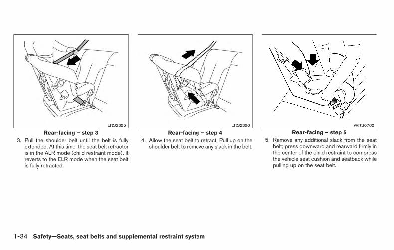
3. Pull the shoulder belt until the belt is fullyextended. At this time, the seat belt retractoris in the ALR mode (child restraint mode). Itreverts to the ELR mode when the seat beltis fully retracted.
4. Allow the seat belt to retract. Pull up on theshoulder belt to remove any slack in the belt.
5. Remove any additional slack from the seatbelt; press downward and rearward firmly inthe center of the child restraint to compressthe vehicle seat cushion and seatback whilepulling up on the seat belt.
Rear-facing – step 3LRS2395
Rear-facing – step 4LRS2396
Rear-facing – step 5WRS0762
1-34 Safety—Seats, seat belts and supplemental restraint system

6. After attaching the child restraint, test it be-fore you place the child in it. Push it from sideto side while holding the child restraint nearthe seat belt path. The child restraint shouldnot move more than 1 inch (25 mm), fromside to side. Try to tug it forward and checkto see if the belt holds the restraint in place.If the restraint is not secure, tighten the seatbelt as necessary, or put the restraint inanother seat and test it again. You may needto try a different child restraint. Not all childrestraints fit in all types of vehicles.
7. Check to make sure that the child restraint isproperly secured prior to each use. If theseat belt is not locked, repeat steps 1through 6.
After the child restraint is removed and the seatbelt fully retracted, the ALR mode (child restraintmode) is canceled.
FORWARD-FACING CHILDRESTRAINT INSTALLATION USINGLATCHFor additional information, refer to all Warningsand Cautions in the “Child Safety” and “ChildRestraints” sections of this manual before install-ing a child restraint.
NISSAN does not recommend the use of thelower anchors if the combined weight of the childand the child restraint exceeds 65 lbs (29.5 kg).If the combined weight of the child and the childrestraint is greater than 65 lbs (29.5 kg), use thevehicle’s seat belt (not the lower anchors) toinstall the child restraint. Be sure to follow thechild restraint manufacturer’s instructions for in-stallation.
Follow these steps to install a forward-facingchild restraint in the rear bench seats using theLATCH system:
1. Position the child restraint on the seat. Al-ways follow the child restraint manufactur-er’s instructions.
Rear-facing – step 6LRS2397
Safety—Seats, seat belts and supplemental restraint system 1-35

2. Secure the child restraint anchor attach-ments to the LATCH lower anchors. Checkto make sure the LATCH attachment is prop-erly attached to the lower anchors.
If the child restraint is equipped with a toptether strap, route the top tether strap andsecure the tether strap to the tether anchorpoint. For additional information, refer to “In-stalling top tether strap” in this section. Donot install child restraints that require the useof a top tether strap in seating positions thatdo not have a top tether anchor.
3. The back of the child restraint should besecured against the vehicle seatback.
If necessary, adjust or remove the headrestraint/headrest to obtain the correct childrestraint fit. If the head restraint/headrest isremoved, store it in a secure place. Be sureto reinstall the head restraint/headrestwhen the child restraint is removed. Foradditional information, refer to “Headrestraints/headrests” in this section for headrestraint/headrest adjustment information.
If the seating position does not have anadjustable head restraint/headrest and it isinterfering with the proper child restraint fit,try another seating position or a differentchild restraint.
Forward-facing webbing-mounted – step 2LRS2398
Forward-facing rigid-mounted – step 2LRS2399
1-36 Safety—Seats, seat belts and supplemental restraint system

4. For child restraints that are equipped withwebbing-mounted attachments, remove anyadditional slack from the anchor attach-ments. Press downward and rearward firmlyin the center of the child restraint with yourknee to compress the vehicle seat cushionand seatback while tightening the webbingof the anchor attachments.
5. Tighten the tether strap according to themanufacturer’s instructions to remove anyslack.
6. After attaching the child restraint, test it be-fore you place the child in it. Push it from sideto side while holding the child restraint nearthe LATCH attachment path. The child re-straint should not move more than 1 inch(25 mm), from side to side. Try to tug itforward and check to see if the LATCH at-tachment holds the restraint in place. If therestraint is not secure, tighten the LATCHattachment as necessary, or put the restraintin another seat and test it again. You mayneed to try a different child restraint. Not allchild restraints fit in all types of vehicles.
7. Check to make sure the child restraint isproperly secured prior to each use. If thechild restraint is loose, repeat steps 3through 6.
Forward-facing – step 4LRS0671
Forward-facing – step 6WRS0697
Safety—Seats, seat belts and supplemental restraint system 1-37

1. Anchor point strap
2. Anchor points
Installing top tether strapThe child restraint top tether strap must be usedwhen installing the child restraint with the LATCHlower anchor attachments.
First, secure the child restraint with the LATCHlower anchors (rear bench outboarding seatingpositions only).
1. Seatback
2. Top tether strap
3. Tether anchor point
Rear bench seat
OUTBOARD SEATING POSITIONS
1. Remove the head restraint/headrest andstore it in a secure place. Be sure to reinstallthe head restraint/headrest when the childrestraint is removed. For additional informa-tion, refer to “Head restraints/headrests” in
this section for head restraint/headrest ad-justment, removal and installation informa-tion.
2. Position the top tether strap over the seat-back.
3. Secure the tether strap to the tether anchorpoint on the wall behind the seatback behindthe child restraint.
4. Return the seatback to the locked position.
5. Tighten the tether strap according to themanufacturer’s instructions to remove anyslack.
If you have any questions when installing atop tether strap, consult your NISSANdealer for details.
Rear bench seatLRS0392
Rear bench seatWRS0423
1-38 Safety—Seats, seat belts and supplemental restraint system
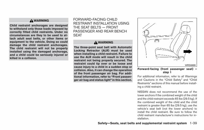
WARNING
Child restraint anchorages are designedto withstand only those loads imposed bycorrectly fitted child restraints. Under nocircumstances are they to be used to at-tach adult seat belts, or other items orequipment to the vehicle. Doing so coulddamage the child restraint anchorages.The child restraint will not be properlyinstalled using the damaged anchorage,and a child could be seriously injured orkilled in a collision.
FORWARD-FACING CHILDRESTRAINT INSTALLATION USINGTHE SEAT BELTS — FRONTPASSENGER AND REAR BENCHSEAT
WARNING
The three-point seat belt with AutomaticLocking Retractor (ALR) must be usedwhen installing a child restraint. Failure touse the ALR mode will result in the childrestraint not being properly secured. Therestraint could tip over or be loose andcause injury to a child in a sudden stop orcollision. Also, it can change the operationof the front passenger air bag. For addi-tional information, refer to “Front passen-ger air bag and status light” in this section.
For additional information, refer to all Warningsand Cautions in the “Child Safety” and “ChildRestraints” sections of this manual before install-ing a child restraint.
NISSAN does not recommend the use of thelower anchors if the combined weight of the childand the child restraint exceeds 65 lbs (29.5 kg). Ifthe combined weight of the child and the childrestraint is greater than 65 lbs (29.5 kg), use thevehicle’s seat belt (not the lower anchors) toinstall the child restraint. Be sure to follow thechild restraint manufacturer’s instructions for in-stallation.
Forward-facing (front passenger seat) –step 1
WRS0699
Safety—Seats, seat belts and supplemental restraint system 1-39

Follow these steps to install a forward-facingchild restraint using the vehicle seat belt in therear seats or in the front passenger seat:
1. If you must install a child restraint inthe front seat, it should be placed in aforward-facing direction only. Movethe seat to the rearmost position. Childrestraints for infants must be used inthe rear-facing direction and thereforemust not be used in the front seat.
2. Position the child restraint on the seat. Al-ways follow the child restraint manufactur-er’s instructions.
The back of the child restraint should besecured against the vehicle seatback.
If necessary, adjust or remove the headrestraint/headrest to obtain the correct childrestraint fit. If the head restraint/headrest isremoved, store it in a secure place. Be sureto reinstall the head restraint/headrestwhen the child restraint is removed. Foradditional information, refer to “Headrestraints/headrests” in this section for headrestraint/headrest adjustment, removal andinstallation information.
If the seating position does not have anadjustable head restraint/headrest and it isinterfering with the proper child restraint fit,try another seating position or a differentchild restraint.
3. Route the seat belt tongue through the childrestraint and insert it into the buckle until youhear and feel the latch engage. Be sure tofollow the child restraint manufacturer’s in-structions for belt routing.
If the child restraint is equipped with a toptether strap, route the top tether strap andsecure the tether strap to the tether anchorpoint (rear seat installation only). For addi-tional information, refer to “Installing toptether strap” in this section. Do not installchild restraints that require the use of a toptether strap in seating positions that do nothave a top tether anchor.
Forward-facing – step 3WRS0680
1-40 Safety—Seats, seat belts and supplemental restraint system

4. Pull the shoulder belt until the belt is fullyextended. At this time, the seat belt retractoris in the ALR mode (child restraint mode). Itreverts to ELR mode when the seat belt isfully retracted.
5. Allow the seat belt to retract. Pull up on theshoulder belt to remove any slack in the belt.
6. Remove any additional slack from the seatbelt; press downward and rearward firmly inthe center of the child restraint with yourknee to compress the vehicle seat cushionand seatback while pulling up on the seatbelt.
7. Tighten the tether strap according to themanufacturer’s instructions to remove anyslack.
Forward-facing – step 4LRS0667
Forward-facing – step 5LRS0668
Forward-facing – step 6WRS0681
Safety—Seats, seat belts and supplemental restraint system 1-41

8. After attaching the child restraint, test it be-fore you place the child in it. Push it from sideto side while holding the child restraint nearthe seat belt path. The child restraint shouldnot move more than 1 inch (25 mm), fromside to side. Try to tug it forward and checkto see if the seat belt holds the restraint inplace. If the restraint is not secure, tightenthe seat belt as necessary, or put the re-straint in another seat and test it again. Youmay need to try a different child restraint. Notall child restraints fit in all types of vehicles.
9. Check to make sure the child restraint isproperly secured prior to each use. If theseat belt is not locked, repeat steps 3through 8.
10. If the child restraint is installed in the frontpassenger seat, place the ignition switch inthe ON position. The front passenger air bagstatus light should illuminate. If thislight is not illuminated refer to �Front passen-ger air bag and status light� in this section.Move the child restraint to anotherseating position. Have the systemchecked by a NISSAN dealer.
After the child restraint is removed and the seatbelt is fully retracted, the ALR mode (child re-straint mode) is canceled.
Forward-facing – step 8WRS0698
Forward-facing – step 10LRS0865
1-42 Safety—Seats, seat belts and supplemental restraint system

FORWARD-FACING CHILDRESTRAINT INSTALLATION USINGTHE SEAT BELTS — FRONT BENCHCENTER POSITION
WARNING
● Never install a rear-facing child re-straint in the front passenger seat.Front air bags inflate with great force. Arear-facing child restraint could bestruck by the front air bag in a crash andcould seriously injure or kill your child.
● NISSAN recommends that child re-straints be installed in the rear seat.However, if you must install a forwardfacing child restraint in the front centerbench seat, follow these instructionscarefully.
● A child restraint with a top tether strapshould not be used in the front passen-ger seat.
For additional information, refer to all Warningsand Cautions in the “Child Safety” and “ChildRestraints” sections of this manual before install-ing a child restraint.
NISSAN does not recommend the use of thelower anchors if the combined weight of the childand the child restraint exceeds 65 lbs (29.5 kg). Ifthe combined weight of the child and the childrestraint is greater than 65 lbs (29.5 kg), use thevehicle’s seat belt (not the lower anchors) toinstall the child restraint. Be sure to follow thechild restraint manufacturer’s instructions for in-stallation.
WRS0256
Foward-Facing — step 1WRS0914
Safety—Seats, seat belts and supplemental restraint system 1-43

Follow these steps to install a child restraint in thefront center bench seat:
1. If you must install a child restraint inthe front seat, it should be placed in aforward-facing direction only. Movethe seat to the rearmost position. Childrestraints for infants must be used inthe rear-facing direction and thereforemust not be used in the front seat.
2. Position the child restraint on the seat. Al-ways follow the child restraint manufactur-er’s instructions.
The back of the child restraint should besecured against the vehicle seat back. Ifnecessary, adjust or remove the head re-straint to obtain the correct child restraint fit.For additional information, refer to “Headrestraints/Headrests” in this section. If thehead restraint is removed, store it in a secureplace. Be sure to install the head restraintwhen the child restraint is removed. If theseating position does not have an adjustablehead restraint and it is interfering with theproper child restraint fit, try another seatingposition or a different child restraint.
3. Route the seat belt tongue through the childrestraint and insert it into the buckle until youhear and feel the latch engage.
Be sure to follow the child restraint manu-facturer’s instructions for seat belt routing.
4. Remove any additional slack from the seatbelt. Press downward and rearward firmly inthe center of the child restraint with yourknee to compress the vehicle seat cushionand seatback while pulling up on the seatbelt.
Forward-Facing — step 3WRS0915
Forward-Facing — step 4WRS0916
1-44 Safety—Seats, seat belts and supplemental restraint system

5. After attaching the child restraint, test it be-fore you place the child in it. Push it from sideto side while holding the child restraint nearthe seat belt path. The child restraint shouldnot move more than 1 inch (25 mm), fromside to side. Try to tug it forward and checkto see if the seat belt holds the restraint inplace. If the restraint is not secure, tightenthe seat belt as necessary, or put the re-straint in another seat and test it again. Youmay need to try a different child restraint. Notall child restraints fit in all types of vehicles.
6. Check to make sure the child restraint isproperly secured prior to each use. If theseat belt is not locked, repeat steps 3through 5.
1. Anchor point strap
2. Anchor points
Installing top tether strapThe child restraint top tether strap must be usedwhen installing the child restraint with seat belts.
First, secure the child restraint with the seat belt.
Forward-Facing — step 5WRS0917 LRS0392
Safety—Seats, seat belts and supplemental restraint system 1-45

1. Seatback
2. Top tether strap
3. Tether anchor point
Rear bench seat
OUTBOARD SEATING POSITIONS
1. Remove the head restraint/headrest and storeit in a secure place. Be sure to reinstall thehead restraint/headrest when the child re-straint is removed. For additional information,refer to “Head restraints/headrests” in thissection for head restraint/headrest adjust-ment, removal and installation information.
2. Position the top tether strap over the seat-back.
3. Secure the tether strap to the tether anchorpoint on the wall behind the seatback behindthe child restraint.
4. Return the seatback to the locked position.
5. Tighten the tether strap according to themanufacturer’s instructions to remove anyslack.
If you have any questions when installing atop tether strap, consult your NISSANdealer for details.
WARNING
Child restraint anchorages are designedto withstand only those loads imposed bycorrectly fitted child restraints. Under nocircumstances are they to be used to at-tach adult seat belts, or other items orequipment to the vehicle. Doing so coulddamage the child restraint anchorages.The child restraint will not be properlyinstalled using the damaged anchorage,and a child could be seriously injured orkilled in a collision.
BOOSTER SEATSPrecautions on booster seats
WARNING
If a booster seat and seat belt are not usedproperly, the risk of a child being injured ina sudden stop or collision greatlyincreases:
– Make sure the shoulder portion ofthe belt is away from the child’s faceand neck and the lap portion of thebelt does not cross the stomach.
– Make sure the shoulder belt is notbehind the child or under the child’sarm.
– A booster seat must only be installedin a seating position that has alap/shoulder belt.
Rear bench seatWRS0423
1-46 Safety—Seats, seat belts and supplemental restraint system

A. Low back booster seat
B. High back booster seat
Booster seats of various sizes are offered byseveral manufacturers. When selecting anybooster seat, keep the following points in mind:
● Choose only a booster seat with a labelcertifying that it complies with Federal MotorVehicle Safety Standard 213 or CanadianMotor Vehicle Safety Standard 213.
● Check the booster seat in your vehicle to besure it is compatible with the vehicle’s seatand seat belt system.
LRS2479 LRS0453 LRS0464
Safety—Seats, seat belts and supplemental restraint system 1-47

● Make sure the child’s head will be properlysupported by the booster seat or vehicleseat. The seatback must be at or above thecenter of the child’s ears. For example, if alow back booster seat is chosen, the vehicleseatback must be at or above the center ofthe child’s ears. If the seatback is lower thanthe center of the child’s ears, a high backbooster seat should be used.
● If the booster seat is compatible with yourvehicle, place the child in the booster seatand check the various adjustments to besure the booster seat is compatible with thechild. Always follow all recommended pro-cedures.
All U.S. states and Canadian provinces orterritories require that infants and smallchildren be restrained in an approved childrestraint at all times while the vehicle isbeing operated.
The instructions in this section apply to boosterseat installation in the rear seats or the frontpassenger seat.
Booster seat installation on frontpassenger seat and rear bench seat
CAUTION
Do not use the lap/shoulder belt in theAutomatic Locking Retractor mode whenusing a booster seat with the seat belts.
For additional information, refer to all Warningsand Cautions in the “Child Safety”, “Child Re-straints” and “Booster Seats” sections of thismanual before installing a child restraint.
Follow these steps to install a booster seat in therear seat or in the front passenger seat:
1. If you must install a booster seat in thefront seat, move the seat to the rear-most position.
2. Position the booster seat on the seat. Onlyplace it in a front-facing direction. Alwaysfollow the booster seat manufacturer’s in-structions.
WRS0699
1-48 Safety—Seats, seat belts and supplemental restraint system

3. The booster seat should be positioned onthe vehicle seat so that it is stable.
If necessary, adjust or remove the headrestraint/headrest to obtain the correctbooster seat fit. If the headrestraint/headrest is removed, store it in asecure place. Be sure to reinstall thehead restraint/headrest when thebooster seat is removed. For additionalinformation, refer to “Headrestraints/headrests” in this section for headrestraint/headrest adjustment, removal andinstallation information.
If the seating position does not have anadjustable head restraint/headrest and it isinterfering with the proper booster seat fit,try another seating position or a differentbooster seat.
4. Position the lap portion of the seat belt lowand snug on the child’s hips. Be sure tofollow the booster seat manufacturer’s in-structions for adjusting the seat belt routing.
5. Pull the shoulder belt portion of the seat belttoward the retractor to take up extra slack.Be sure the shoulder belt is positionedacross the top, middle portion of the child’sshoulder. Be sure to follow the booster seatmanufacturer’s instructions for adjusting theseat belt routing.
6. Follow the warnings, cautions and instruc-tions for properly fastening a seat beltshown in “Three-point type seat belt withretractor” in this section.
7. If the booster seat is installed in the frontpassenger seat, place the ignition switch inthe ON position. The front passenger air bagstatus light may or may not illuminate,depending on the size of the child and thetype of booster seat being used. For addi-tional information, refer to “Front passengerair bag and status light” in this section.
Front passenger positionLRS0454 LRS0865
Safety—Seats, seat belts and supplemental restraint system 1-49

PRECAUTIONS ON SRSThis SRS section contains important informationconcerning the following systems:
● Driver and passenger supplemental front-impact air bag (NISSAN Advanced Air BagSystem)
● Front seat-mounted side-impact supple-mental air bag
● Roof-mounted curtain side-impact and roll-over supplemental air bag
● Seat belt with pretensioner
Supplemental front-impact air bag system
The NISSAN Advanced Air Bag System can helpcushion the impact force to the head and chest ofthe driver and right front passenger in certainfrontal collisions.
Front seat-mounted side-impact supple-mental air bag system
This system can help cushion the impact force tothe chest area of the driver and right front pas-senger in certain side impact collisions. The sideair bag is designed to inflate on the side wherethe vehicle is impacted.
Roof-mounted curtain side-impact androllover supplemental air bag system
This system can help cushion the impact force tothe head of occupants in front and rear outboardseating positions in certain side impact or rollovercollisions. In a side impact, the curtain and roll-over air bags are designed to inflate on the sidewhere the vehicle is impacted. In a rollover, bothcurtain and rollover air bags are designed toinflate and remain inflated for a short time.
The SRS is designed to supplement the crashprotection provided by the seat belts and is not asubstitute for them. Seat belts should always becorrectly worn and the occupant seated a suit-able distance away from the steering wheel, in-strument panel and door finishers. For additionalinformation, refer to “Seat belts” in this section forinstructions and precautions on seat belt usage.
The supplemental air bags operate onlywhen the ignition switch is in the ON orSTART position.
After turning the ignition key to the ONposition, the supplemental air bag warninglight illuminates. The supplemental air bagwarning light will turn off after about 7 sec-onds if the system is operational.
SUPPLEMENTAL RESTRAINTSYSTEM (SRS)
1-50 Safety—Seats, seat belts and supplemental restraint system

WARNING
● The front air bags ordinarily will notinflate in the event of a side impact, rearimpact, rollover, or lower severity fron-tal collision. Always wear your seatbelts to help reduce the risk or severityof injury in various kinds of accidents.
● The front passenger air bag will notinflate if the passenger air bag statuslight is lit or if the front passenger seatis unoccupied. For additional informa-tion, refer to “Front passenger air bagand status light” in this section.
● The seat belts and the front air bags aremost effective when you are sitting wellback and upright in the seat. The frontair bags inflate with great force. Evenwith the NISSAN Advanced Air Bag Sys-tem, if you are unrestrained, leaningforward, sitting sideways or out of posi-tion in any way, you are at greater risk ofinjury or death in a crash. You may alsoreceive serious or fatal injuries from thefront air bag if you are up against itwhen it inflates. Always sit back againstthe seatback and as far away as practi-cal from the steering wheel or instru-ment panel. Always use the seat belts.
● The driver and front passenger seat beltbuckles are equipped with sensors thatdetect if the seat belts are fastened. TheAdvanced Air Bag System monitors theseverity of a collision and seat belt us-age then inflates the air bags asneeded. Failure to properly wear seatbelts can increase the risk or severity ofinjury in an accident.
● The front passenger seat is equippedwith an occupant classification sensor(pressure sensor) that turns the frontpassenger air bag OFF under some con-ditions. This sensor is only used in thisseat. Failure to be properly seated andwearing the seat belt can increase therisk or severity of injury in an accident.For additional information, refer to“Front Passenger air bag and statuslight” in this section.
● Keep hands on the outside of the steer-ing wheel. Placing them inside thesteering wheel rim could increase therisk that they are injured when the frontair bag inflates.
WRS0031
Safety—Seats, seat belts and supplemental restraint system 1-51

WARNING
● Never let children ride unrestrained orextend their hands or face out of thewindow. Do not attempt to hold them inyour lap or arms. Some examples ofdangerous riding positions are shownin the illustrations.
ARS1133 ARS1041
1-52 Safety—Seats, seat belts and supplemental restraint system

WARNING
● Children may be severely injured orkilled when the front air bags, side airbags or curtain and rollover air bagsinflate if they are not properly re-strained. Pre-teens and children shouldbe properly restrained in the rear seat, ifpossible.
ARS1042 ARS1043 ARS1044
Safety—Seats, seat belts and supplemental restraint system 1-53

WARNING
● Even with the NISSAN Advanced AirBag System, never install a rear-facingchild restraint in the front seat. An in-flating front air bag could seriously in-jure or kill your child. For additionalinformation, refer to “Child restraints”in this section for details.
WARNING
Front seat-mounted side-impact supple-mental air bags and roof-mounted curtainside-impact and rollover supplemental airbags:
● The side air bags and curtain and roll-over air bags ordinarily will not inflate inthe event of a frontal impact, rear im-pact, or lower severity side collision.Always wear your seat belts to helpreduce the risk or severity of injury invarious kinds of accidents.
ARS1045 WRS0256Do not lean against doors or windows.
WRS0431
1-54 Safety—Seats, seat belts and supplemental restraint system

WARNING
● The seat belts, the side air bags andcurtain and rollover air bags are mosteffective when you are sitting well backand upright in the seat. The side air bagand curtain and rollover air bag inflatewith great force. Do not allow anyone toplace their hand, leg or face near theside air bag on the side of the seatbackof the front seat or near the side roofrails. Do not allow anyone sitting in thefront seats or rear outboard seats toextend their hand out of the window orlean against the door. Some examplesof dangerous riding positions areshown in the previous illustrations.
Do not lean against doors or windows.LRS0396
Do not lean against doors or windows.SSS0162
Safety—Seats, seat belts and supplemental restraint system 1-55

WARNING
● When sitting in the rear seat, do nothold onto the seatback of the front seat.If the side air bag inflates, you may beseriously injured. Be especially carefulwith children, who should always beproperly restrained. Some examples ofdangerous riding positions are shownin the illustrations.
● Do not use seat covers on the frontseatbacks. They may interfere with sideair bag inflation.
LRS0421 SSS0159
1-56 Safety—Seats, seat belts and supplemental restraint system

NISSAN Advanced Air Bag System(front seats)
1. Roof-mounted curtain side-impact and roll-over supplemental air bags inflators
2. Roof-mounted curtain side-impact and roll-over supplemental air bag
3. Air bag Control Unit (ACU)
4. Supplemental front-impact air bag modules
5. Crash zone sensor
6. Occupant classification system control unit
7. Occupant classification sensor (weight sen-sor)
8. Seat belt buckle switches
9. Seat belt with pretensioner
10. Satellite sensors
11. Front seat-mounted side-impact supple-mental air bag modules
This vehicle is equipped with the NISSAN Ad-vanced Air Bag System for the driver and rightfront passenger seats. This system is designed tomeet certification requirements under U.S. regu-lations. It is also permitted in Canada. However,
LRS2093
Safety—Seats, seat belts and supplemental restraint system 1-57
all of the information, cautions and warn-ings in this manual still apply and must befollowed.
The driver supplemental front-impact air bag islocated in the center of the steering wheel. Thepassenger supplemental front-impact air bag ismounted in the dashboard above the glove box.The supplemental front air bags are designed toinflate in higher severity frontal collisions, al-though they may inflate if the forces in anothertype of collision are similar to those of a higherseverity frontal impact. They may not inflate incertain frontal collisions. Vehicle damage (or lackof it) is not always an indication of proper front airbag system operation.
The NISSAN Advanced Air Bag System has dualstage inflators. It also monitors information fromthe crash zone sensor, the Air Bag Control Unit(ACU), seat belt buckle sensors, occupant clas-sification sensor (weight sensor) and right frontpassenger seat belt tension sensor. Inflator op-eration is based on the severity of a collision andseat belt usage for the driver. For the right frontpassenger, it additionally monitors the weight ofan occupant or object on the seat and seat belttension. Based on information from the sensors,only one front air bag may inflate in a crash,depending on the crash severity and whether thefront occupants are belted or unbelted. Addition-ally, the right front passenger air bag may be
automatically turned OFF under some conditions,depending on the weight detected on the pas-senger seat and how the seat belt is used. If thefront passenger air bag is OFF, the passenger airbag status light will be illuminated (if the seat isunoccupied, the light will not be illuminated, butthe air bag will be off). For additional information,refer to “Front passenger air bag and status light”in this section. One front air bag inflating does notindicate improper performance of the system.
If you have any questions about your air bagsystem, please contact NISSAN or your NISSANdealer. If you are considering modification of yourvehicle due to a disability, you may also contactNISSAN. Contact information is contained in thebeginning of this Owner’s Manual.
When a front air bag inflates, a fairly loud noisemay be heard, followed by the release of smoke.This smoke is not harmful and does not indicate afire. Care should be taken to not inhale it, as it maycause irritation and choking. Those with a historyof a breathing condition should get fresh airpromptly.
Front air bags, along with the use of seat belts,help to cushion the impact force on the face andchest of the driver and right front passenger. Theycan help save lives and reduce serious injuries.However, an inflating front air bag may cause
facial abrasions or other injuries. Front air bagsdo not provide restraint to the lower body.
Even with NISSAN advanced air bags, seat beltsshould be correctly worn and the driver and pas-senger seated upright as far as practical awayfrom the steering wheel or instrument panel. Thefront air bags inflate quickly in order to helpprotect the front occupants. Because of this, theforce of the front air bag inflating can increase therisk of injury if the occupant is too close to, or isagainst, the front air bag module during inflation.
The front air bags deflate quickly after a collision.
The front air bags operate only when theignition switch is in the ON or START posi-tion.
After turning the ignition key to the ONposition, the supplemental air bag warninglight illuminates. The supplemental air bagwarning light will turn off after about 7 sec-onds if the system is operational.
1-58 Safety—Seats, seat belts and supplemental restraint system
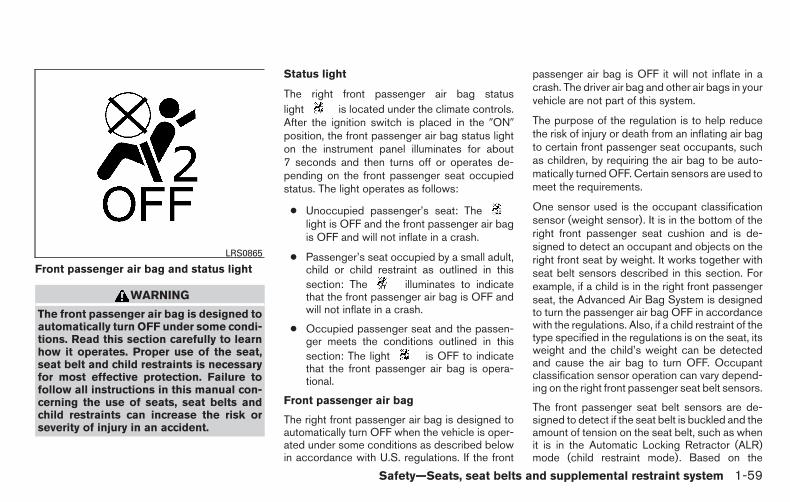
Front passenger air bag and status light
WARNING
The front passenger air bag is designed toautomatically turn OFF under some condi-tions. Read this section carefully to learnhow it operates. Proper use of the seat,seat belt and child restraints is necessaryfor most effective protection. Failure tofollow all instructions in this manual con-cerning the use of seats, seat belts andchild restraints can increase the risk orseverity of injury in an accident.
Status light
The right front passenger air bag statuslight is located under the climate controls.After the ignition switch is placed in the �ON�position, the front passenger air bag status lighton the instrument panel illuminates for about7 seconds and then turns off or operates de-pending on the front passenger seat occupiedstatus. The light operates as follows:
● Unoccupied passenger’s seat: Thelight is OFF and the front passenger air bagis OFF and will not inflate in a crash.
● Passenger’s seat occupied by a small adult,child or child restraint as outlined in thissection: The illuminates to indicatethat the front passenger air bag is OFF andwill not inflate in a crash.
● Occupied passenger seat and the passen-ger meets the conditions outlined in thissection: The light is OFF to indicatethat the front passenger air bag is opera-tional.
Front passenger air bag
The right front passenger air bag is designed toautomatically turn OFF when the vehicle is oper-ated under some conditions as described belowin accordance with U.S. regulations. If the front
passenger air bag is OFF it will not inflate in acrash. The driver air bag and other air bags in yourvehicle are not part of this system.
The purpose of the regulation is to help reducethe risk of injury or death from an inflating air bagto certain front passenger seat occupants, suchas children, by requiring the air bag to be auto-matically turned OFF. Certain sensors are used tomeet the requirements.
One sensor used is the occupant classificationsensor (weight sensor). It is in the bottom of theright front passenger seat cushion and is de-signed to detect an occupant and objects on theright front seat by weight. It works together withseat belt sensors described in this section. Forexample, if a child is in the right front passengerseat, the Advanced Air Bag System is designedto turn the passenger air bag OFF in accordancewith the regulations. Also, if a child restraint of thetype specified in the regulations is on the seat, itsweight and the child’s weight can be detectedand cause the air bag to turn OFF. Occupantclassification sensor operation can vary depend-ing on the right front passenger seat belt sensors.
The front passenger seat belt sensors are de-signed to detect if the seat belt is buckled and theamount of tension on the seat belt, such as whenit is in the Automatic Locking Retractor (ALR)mode (child restraint mode). Based on the
LRS0865
Safety—Seats, seat belts and supplemental restraint system 1-59
schulzh
Text Box
schulzh
Typewritten Text
** Click HERE to see "Owner's Manual Supplement" beginning on page 2. **

weight on the seat detected by the occupantclassification sensor and the belt tension de-tected on the seat belt, the Advanced Air BagSystem determines whether the front passengerair bag should be automatically turned OFF, asrequired by the regulations.
Front passenger seat adult occupants who areproperly seated and using the seat belt as out-lined in this manual should not cause the passen-ger air bag to be automatically turned OFF. Forsmall adults it may be turned OFF; however, if theoccupant takes his/her weight off the seat cush-ion (for example, by not sitting upright, by sittingon an edge of the seat, or by otherwise being outof position), this could cause the sensor to turnthe air bag OFF. In addition, if the occupantimproperly uses the seat belt in the ALR mode(child restraint mode), this could cause the airbag to be turned OFF. Always be sure to beseated and wearing the seat belt properly for themost effective protection by the seat belt andsupplemental air bag.
NISSAN recommends that pre-teens and chil-dren be properly restrained in a rear seat.NISSAN also recommends that appropriate childrestraints and booster seats be properly installedin a rear seat. If this is not possible, the occupantclassification sensor and seat belt sensors aredesigned to operate as described above to turnthe front passenger air bag OFF for specified
child restraints as required by the regulations.Failing to properly secure child restraints and touse the ALR mode (child restraint mode) mayallow the restraint to tip or move in a collision orsudden stop. This can also result in the passen-ger air bag inflating in a crash instead of beingOFF. For additional information, refer to “Childrestraints” in this section for proper use and in-stallation.
If the right front passenger seat is not occupiedthe passenger air bag is designed not to inflate ina crash. However, heavy objects placed on theseat could result in air bag inflation, because ofthe object’s weight detected by the occupantclassification sensor. Other conditions could alsoresult in air bag inflation, such as if a child isstanding on the seat, or if two children are on theseat, contrary to the instructions in this manual.Always be sure that you and all vehicle occupantsare seated and restrained properly.
Using the passenger air bag status light, you canmonitor when the front passenger air bag is au-tomatically turned OFF with the seat occupied.The light will not illuminate when the right frontpassenger seat is unoccupied.
If an adult occupant is in the seat but the passen-ger air bag status light is illuminated (indicatingthat the air bag is OFF), it could be that the
person is a small adult, or is not sitting on the seatproperly or not using the seat belt properly.
If a child restraint must be used in the front seat,the passenger air bag status light may or may notbe illuminated, depending on the size of the childand the type of child restraint being used. If the airbag status light is not illuminated (indicating thatthe air bag might inflate in a crash), it could bethat the child restraint or seat belt is not beingused properly. Make sure that the child restraint isinstalled properly, the seat belt is used properlyand the occupant is positioned properly. If the airbag status light is not illuminated, reposition theoccupant or child restraint in a rear seat.
If the passenger air bag status light will not illu-minate even though you believe that the childrestraint, the seat belts and the occupant areproperly positioned, the system may be sensingan unoccupied seat (in which case the air bag isOFF). Your NISSAN dealer can check that thesystem is OFF by using a special tool. However,until you have confirmed with your dealer thatyour air bag is working properly, reposition theoccupant or child restraint in a rear seat.
The air bag system and passenger air bag statuslight will take a few seconds to register a changein the passenger seat status. For example, if alarge adult who is sitting in the front passengerseat exits the vehicle, the passenger air bag
1-60 Safety—Seats, seat belts and supplemental restraint system
schulzh
Text Box
schulzh
Typewritten Text
** Click HERE to see "Owner's Manual Supplement" beginning on page 2. **

status light will go from OFF to ON for a fewseconds and then to OFF. This is normal systemoperation and does not indicate a malfunction.
If a malfunction occurs in the front passenger airbag system, the supplemental air bag warninglight , located in the meter and gauges areaon the driver’s side of the instrument panel, willblink. Have the system checked by a NISSANdealer.
Other supplemental front-impact air bagprecautions
WARNING
● Do not place any objects on the steeringwheel pad or on the instrument panel.Also, do not place any objects betweenany occupant and the steering wheel orinstrument panel. Such objects may be-come dangerous projectiles and causeinjury if the front air bags inflate.
● Immediately after inflation, severalfront air bag system components will behot. Do not touch them; you may se-verely burn yourself.
● No unauthorized changes should bemade to any components or wiring ofthe supplemental air bag system. This isto prevent accidental inflation of thesupplemental air bag or damage to thesupplemental air bag system.
● Do not make unauthorized changes toyour vehicle’s electrical system, sus-pension system or front end structure.This could affect proper operation ofthe front air bag system.
● Tampering with the front air bag systemmay result in serious personal injury.Tampering includes changes to thesteering wheel and the instrumentpanel assembly by placing materialover the steering wheel pad and abovethe instrument panel or by installingadditional trim material around the airbag system.
● Modifying or tampering with the frontpassenger seat may result in seriouspersonal injury. For example, do notchange the front seats by placing mate-rial on the seat cushion or by installingadditional trim material, such as seatcovers, on the seat that are not specifi-cally designed to assure proper air bagoperation. Additionally, do not stow anyobjects under the front passenger seator the seat cushion and seatback. Suchobjects may interfere with the properoperation of the occupant classificationsensor (pressure sensor).
● No unauthorized changes should bemade to any components or wiring ofthe seat belt system. This may affect thefront air bag system. Tampering withthe seat belt system may result in seri-ous personal injury.
Safety—Seats, seat belts and supplemental restraint system 1-61
schulzh
Text Box
schulzh
Typewritten Text
** Click HERE to see "Owner's Manual Supplement" beginning on page 2. **

● Work on and around the front air bagsystem should be done by a NISSANdealer. Installation of electrical equip-ment should also be done by a NISSANdealer. The Supplemental RestraintSystem (SRS) wiring should not bemodified or disconnected. Unauthor-ized electrical test equipment and prob-ing devices should not be used on theair bag system.
● A cracked windshield should be re-placed immediately by a qualified repairfacility. A cracked windshield could af-fect the function of the supplemental airbag system.
*The SRS wiring harness connectors areyellow and orange for easy identification.
When selling your vehicle, we request that youinform the buyer about the front air bag systemand guide the buyer to the appropriate sectionsin this Owner’s Manual.
Front seat-mounted side-impactsupplemental air bag and roof-mounted curtain side-impact androllover supplemental air bag systems
The side air bags are located in the outside of theseatback of the front seats. The curtain air bagsare located in the side roof rails. All of theinformation, cautions and warnings in thismanual must be followed. The side air bagsand curtain air bags are designed to inflate inhigher severity side collisions, although they mayinflate if the forces in another type of collision aresimilar to those of a higher severity impact. They
are designed to inflate on the side where thevehicle is impacted. They may not inflate in cer-tain side collisions.
Curtain air bags are also designed to inflate incertain types of rollover collisions or near roll-overs. As a result, certain vehicle movements (forexample, during severe off-roading) may causethe curtain air bags to inflate.
Vehicle damage (or lack of it) is not always anindication of proper side air bag and curtain airbag operation.
When the side air bags and curtain air bagsinflate, a fairly loud noise may be heard, followedby release of smoke. This smoke is not harmfuland does not indicate a fire. Care should be takennot to inhale it, as it may cause irritation andchoking. Those with a history of a breathing con-dition should get fresh air promptly.
Side air bags, along with the use of seat belts,help to cushion the impact force on the chest ofthe front occupants. Curtain air bags help tocushion the impact force to the head of occu-pants in the front and rear outboard seating po-sitions. They can help save lives and reduceserious injuries. However, an inflating side air bagor curtain air bag may cause abrasions or otherinjuries. Side air bags and curtain air bags do notprovide restraint to the lower body.
LRS2094
1-62 Safety—Seats, seat belts and supplemental restraint system

The seat belts should be correctly worn and thedriver and passenger seated upright as far aspractical away from the side air bag. Rear seatpassengers should be seated as far away aspractical from the door finishers and side roofrails. The side air bags and curtain air bags inflatequickly in order to help protect the occupants.Because of this, the force of the side air bag andcurtain air bag inflating can increase the risk ofinjury if the occupant is too close to, or is against,these air bag modules during inflation. The sideair bag will deflate quickly after the collision isover.
The curtain air bags will remain inflated for a shorttime.
The side air bags and curtain air bags op-erate only when the ignition switch is in theON or START position.
After placing the ignition switch in the ONposition, the supplemental air bag warninglight illuminates. The supplemental air bagwarning light will turn off after about 7 sec-onds if the system is operational.
WARNING
● Do not place any objects near the seat-back of the front seats. Also, do notplace any objects (an umbrella, bag,etc.) between the front door finisherand the front seat. Such objects maybecome dangerous projectiles andcause injury if a side air bag inflates.
● Right after inflation, several side air bagand curtain air bag system componentswill be hot. Do not touch them; you mayseverely burn yourself.
● No unauthorized changes should bemade to any components or wiring ofthe side air bag and curtain air bagsystems. This is to prevent damage to oraccidental inflation of the side air bagand curtain air bag systems.
● Do not make unauthorized changes toyour vehicle’s electrical system, sus-pension system or side panel. Thiscould affect proper operation of the cur-tain air bag systems.
● Tampering with the side air bag systemmay result in serious personal injury.For example, do not change the frontseats by placing material near the seat-backs or by installing additional trimmaterial, such as seat covers, aroundthe side air bag.
● Work around and on the side air bagand curtain air bag systems should bedone by a NISSAN dealer. Installationof electrical equipment should also bedone by a NISSAN dealer. The SRS wir-ing harnesses* should not be modifiedor disconnected. Unauthorized electri-cal test equipment and probing devicesshould not be used on the side air bagor curtain air bag systems.
* The SRS wiring harness or connectors areyellow or orange for easy identification.
When selling your vehicle, we request that youinform the buyer about the side air bag andcurtain air bag systems and guide the buyer tothe appropriate sections in this Owner’s Manual.
Safety—Seats, seat belts and supplemental restraint system 1-63

Seat belts with pretensioners (frontoutboard seats)
WARNING
● The pretensioners cannot be reused af-ter activation. They must be replacedtogether with the retractor and buckleas a unit.
● If the vehicle becomes involved in acollision but a pretensioner is not acti-vated, be sure to have the pretensionersystem checked and, if necessary, re-placed by your NISSAN dealer.
● No unauthorized changes should bemade to any components or wiring ofthe pretensioner system. This is to pre-vent damage to or accidental activationof the pretensioners. Tampering withthe pretensioner system may result inserious personal injury.
● Work around and on the pretensionersystem should be done by a NISSANdealer. Installation of electrical equip-ment should also be done by a NISSANdealer. Unauthorized electrical testequipment and probing devices shouldnot be used on the pretensioner system.
● If you need to dispose of a pretensioneror scrap the vehicle, contact a NISSANdealer. Incorrect disposal procedurescould cause personal injury.
The pretensioner system may activate with thesupplemental air bag system in certain types ofcollisions. Working with the seat belt retractor,the pretensioner helps tighten the seat belt whenthe vehicle becomes involved in certain types ofcollisions, helping to restrain front seat occu-pants.
The pretensioner is encased with the seat beltretractor. These seat belts are used the same wayas conventional seat belts.
When a pretensioner activates, smoke is re-leased and a loud noise may be heard. Thissmoke is not harmful and does not indicate a fire.Care should be taken not to inhale it, as it maycause irritation and choking. Those with a historyof a breathing condition should get fresh airpromptly.
After pretensioner activation, load limiters allowthe seat belt to release webbing (if necessary) toreduce forces against the chest.
The supplemental air bag warning light isused to indicate malfunctions in the pretensionersystem. For additional information, refer to�Supplemental air bag warning light” in this sec-tion. If the operation of the supplemental air bagwarning light indicates there is a malfunction,have the system checked by a NISSAN dealer.
When selling your vehicle, we request that youinform the buyer about the pretensioner systemand guide the buyer to the appropriate sectionsin this Owner’s Manual.
1-64 Safety—Seats, seat belts and supplemental restraint system

1. SRS Air bag warning labels
The warning labels are located on the sur-face of the sun visor.
SUPPLEMENTAL AIR BAGWARNING LABELSWarning labels about the supplemental front-impact air bag system are placed in the vehicle asshown in the illustration.
SUPPLEMENTAL AIR BAGWARNING LIGHTThe supplemental air bag warning light,displaying in the instrument panel, moni-tors the circuits for the air bag systems, preten-sioners and all related wiring.
When the ignition key is in the ON or STARTposition, the supplemental air bag warning lightilluminates for about 7 seconds and then turnsoff. This means the system is operational.
If any of the following conditions occur, the frontair bag, side air bag, curtain air bag and preten-sioner systems need servicing:
● The supplemental air bag warning light re-mains on after approximately 7 seconds.
● The supplemental air bag warning lightflashes intermittently.
● The supplemental air bag warning light doesnot come on at all.
Under these conditions, the front air bag, side airbag and curtain air bag or pretensioner systemsmay not operate properly. They must be checkedand repaired. Take your vehicle to the nearestNISSAN dealer.
WARNING
If the supplemental air bag warning lightis on, it could mean that the front air bag,side air bag, curtain and rollover air bagand/or pretensioner systems will not op-erate in an accident. To help avoid injury toyourself or others, have your vehiclechecked by a NISSAN dealer as soon aspossible.
WRS0885 LRS0100
Safety—Seats, seat belts and supplemental restraint system 1-65

Repair and replacement procedure
The front air bags, side air bags, curtain supple-mental air bags and pretensioners are designedto inflate on a one-time-only basis. As a reminder,unless it is damaged, the supplemental air bagwarning light remains illuminated after inflationhas occurred. Repair and replacement of thesesupplemental air bag systems should be doneonly by a NISSAN dealer.
When maintenance work is required on the ve-hicle, the front air bags, side air bags, curtain airbags, pretensioners and related parts should bepointed out to the person performing the mainte-nance. The ignition key should always be in theLOCK position when working under the hood orinside the vehicle.
WARNING
● Once a front air bag, side air bag orcurtain air bag has inflated, the air bagmodule will not function again andmust be replaced. Additionally, the acti-vated pretensioners must also be re-placed. The air bag module and preten-sioners should be replaced by aNISSAN dealer. The air bag module andpretensioner cannot be repaired.
● The front air bag, side air bag, curtainair bag systems and the pretensionersystem should be inspected by aNISSAN dealer if there is any damage tothe front end or side portion of thevehicle.
● If you need to dispose of a supplemen-tal air bag or pretensioners or scrap thevehicle, contact a NISSAN dealer. Cor-rect supplemental air bag and preten-sioner system disposal procedures areset forth in the appropriate NISSANService Manual. Incorrect disposal pro-cedures could cause personal injury.
1-66 Safety—Seats, seat belts and supplemental restraint system

MEMO
Safety—Seats, seat belts and supplemental restraint system 1-67

2 Instruments and controls
Instrument panel. . . . . . . . . . . . . . . . . . . . . . . . . . . . . . . . . . . 2-2Meters and gauges . . . . . . . . . . . . . . . . . . . . . . . . . . . . . . . . 2-3
Speedometer and odometer . . . . . . . . . . . . . . . . . . . . . 2-4Tachometer . . . . . . . . . . . . . . . . . . . . . . . . . . . . . . . . . . . . 2-5Engine coolant temperature gauge . . . . . . . . . . . . . . . 2-5Fuel gauge . . . . . . . . . . . . . . . . . . . . . . . . . . . . . . . . . . . . 2-6Engine oil pressure gauge (if so equipped) . . . . . . . . 2-7Voltmeter (if so equipped) . . . . . . . . . . . . . . . . . . . . . . . 2-7Automatic transmission fluid temperaturegauge (if so equipped) . . . . . . . . . . . . . . . . . . . . . . . . . . 2-8
Compass display (if so equipped) . . . . . . . . . . . . . . . . . . . 2-8Compass display . . . . . . . . . . . . . . . . . . . . . . . . . . . . . . . 2-9
Warning/indicator lights and audible reminders . . . . . . 2-12Checking bulbs . . . . . . . . . . . . . . . . . . . . . . . . . . . . . . . 2-12Warning lights . . . . . . . . . . . . . . . . . . . . . . . . . . . . . . . . 2-13Indicator lights . . . . . . . . . . . . . . . . . . . . . . . . . . . . . . . . 2-18Audible reminders . . . . . . . . . . . . . . . . . . . . . . . . . . . . . 2-20
Vehicle Information Display (if so equipped) . . . . . . . . . 2-20How to use the Vehicle Information Display . . . . . . . 2-21
Security systems (if so equipped) . . . . . . . . . . . . . . . . . . 2-27Vehicle security system (if so equipped) . . . . . . . . . . 2-27NISSAN vehicle immobilizer system(if so equipped) . . . . . . . . . . . . . . . . . . . . . . . . . . . . . . . 2-28
Windshield wiper and washer switch . . . . . . . . . . . . . . . 2-30Switch operation . . . . . . . . . . . . . . . . . . . . . . . . . . . . . . 2-30
Rear window and outside mirror (if so equipped)defroster switch . . . . . . . . . . . . . . . . . . . . . . . . . . . . . . . . . . 2-31Headlight and turn signal switch. . . . . . . . . . . . . . . . . . . . 2-32
Headlight control switch. . . . . . . . . . . . . . . . . . . . . . . . 2-33Daytime running light system (Canada only) . . . . . . 2-35Instrument brightness control . . . . . . . . . . . . . . . . . . . 2-36Turn signal switch . . . . . . . . . . . . . . . . . . . . . . . . . . . . . 2-36Fog light switch (if so equipped) . . . . . . . . . . . . . . . . 2-37
Horn . . . . . . . . . . . . . . . . . . . . . . . . . . . . . . . . . . . . . . . . . . . . 2-37Cargo lamp switch (if so equipped). . . . . . . . . . . . . . . . . 2-38Heated seats (if so equipped). . . . . . . . . . . . . . . . . . . . . . 2-38Vehicle Dynamic Control (VDC) off switch. . . . . . . . . . . 2-39Electronic locking rear differential (E-Lock) systemswitch (if so equipped) . . . . . . . . . . . . . . . . . . . . . . . . . . . . 2-39Power inverter switch (if so equipped) . . . . . . . . . . . . . . 2-40Rear sonar system off switch (if so equipped). . . . . . . . 2-41Tow mode switch. . . . . . . . . . . . . . . . . . . . . . . . . . . . . . . . . 2-42Power outlets . . . . . . . . . . . . . . . . . . . . . . . . . . . . . . . . . . . . 2-42
12v Outlets . . . . . . . . . . . . . . . . . . . . . . . . . . . . . . . . . . . 2-42120v outlet (if so equipped) . . . . . . . . . . . . . . . . . . . . 2-44
Storage . . . . . . . . . . . . . . . . . . . . . . . . . . . . . . . . . . . . . . . . . 2-46

Instrument panel storage trays . . . . . . . . . . . . . . . . . . 2-46Console box (if so equipped) . . . . . . . . . . . . . . . . . . . 2-47Center armrest storage (if so equipped) . . . . . . . . . . 2-48Glove box . . . . . . . . . . . . . . . . . . . . . . . . . . . . . . . . . . . . 2-48Sunglasses holder (if so equipped) . . . . . . . . . . . . . . 2-49Map pockets . . . . . . . . . . . . . . . . . . . . . . . . . . . . . . . . . . 2-49Seatback pocket (if so equipped) . . . . . . . . . . . . . . . 2-50Overhead console (if so equipped) . . . . . . . . . . . . . . 2-50Cup holders . . . . . . . . . . . . . . . . . . . . . . . . . . . . . . . . . . 2-51Grocery hooks (if so equipped) . . . . . . . . . . . . . . . . . 2-53Lockable bedside storage compartment(if so equipped) . . . . . . . . . . . . . . . . . . . . . . . . . . . . . . . 2-54
Windows . . . . . . . . . . . . . . . . . . . . . . . . . . . . . . . . . . . . . . . . 2-54Power windows . . . . . . . . . . . . . . . . . . . . . . . . . . . . . . . 2-54Rear sliding window (if so equipped) . . . . . . . . . . . . 2-57Rear power window switch (if so equipped) . . . . . . 2-57
Moonroof (if so equipped) . . . . . . . . . . . . . . . . . . . . . . . . . 2-58Power moonroof. . . . . . . . . . . . . . . . . . . . . . . . . . . . . . . 2-58
Interior light . . . . . . . . . . . . . . . . . . . . . . . . . . . . . . . . . . . . . . 2-59Console light (if so equipped) . . . . . . . . . . . . . . . . . . . 2-60
Personal lights (if so equipped) . . . . . . . . . . . . . . . . . . . . 2-61Map lights (if so equipped) . . . . . . . . . . . . . . . . . . . . . . . . 2-61HomeLink® universal transceiver (if so equipped) . . . .2-61
Programming HomeLink® . . . . . . . . . . . . . . . . . . . . . . 2-62Programming HomeLink® for Canadiancustomers and gate openers. . . . . . . . . . . . . . . . . . . . 2-63Operating the HomeLink® universaltransceiver. . . . . . . . . . . . . . . . . . . . . . . . . . . . . . . . . . . . 2-64Programming trouble-diagnosis . . . . . . . . . . . . . . . . . 2-64Clearing the programmed information . . . . . . . . . . . . 2-64Reprogramming a single HomeLink® button. . . . . . 2-65If your vehicle is stolen . . . . . . . . . . . . . . . . . . . . . . . . . 2-65
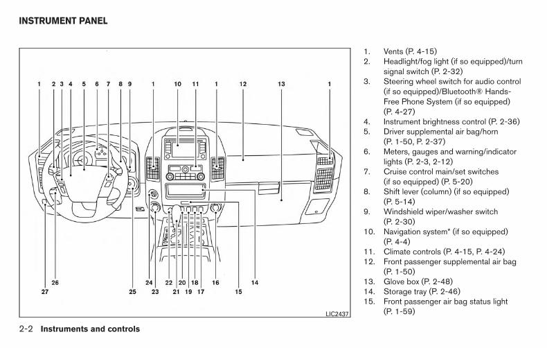
1. Vents (P. 4-15)2. Headlight/fog light (if so equipped)/turn
signal switch (P. 2-32)3. Steering wheel switch for audio control
(if so equipped)/Bluetooth® Hands-Free Phone System (if so equipped)(P. 4-27)
4. Instrument brightness control (P. 2-36)5. Driver supplemental air bag/horn
(P. 1-50, P. 2-37)6. Meters, gauges and warning/indicator
lights (P. 2-3, 2-12)7. Cruise control main/set switches
(if so equipped) (P. 5-20)8. Shift lever (column) (if so equipped)
(P. 5-14)9. Windshield wiper/washer switch
(P. 2-30)10. Navigation system* (if so equipped)
(P. 4-4)11. Climate controls (P. 4-15, P. 4-24)12. Front passenger supplemental air bag
(P. 1-50)13. Glove box (P. 2-48)14. Storage tray (P. 2-46)15. Front passenger air bag status light
(P. 1-59)LIC2437
INSTRUMENT PANEL
2-2 Instruments and controls

16. Power outlet (P. 2-42)17. Heated seat switch (if so equipped)
(P. 2-38)18. Vehicle Dynamic Control (VDC) off
switch (P. 2-39)19. Tow mode switch (P. 2-42)20. Electronic locking rear differential (E-
Lock) system switch (if so equipped)(P.2-39)
21. Shift lever (console) (if so equipped)(P. 5-14)
22. Hazard warning flasher switch (P. 6-2)23. Power outlet (P. 2-42)24. 4WD shift switch (if so equipped)
(P. 5-29)25. Ignition switch (P. 5-9)26. Tilt steering wheel control (P. 3-14)27. Cargo lamp switch (if so equipped)
(P. 2-38)/Rear sonar system off switch(if so equipped) (P. 2-41)/Pedal posi-tion adjustment switch (if so equipped)(P. 3-14)/Rear power window switch(if so equipped) (P. 2-57)
*: Refer to the separate Navigation System Own-er’s Manual (if so equipped).
See the page number indicated in paren-theses for operating details.
1. Warning/indicator lights2. Tachometer3. Engine coolant temperature gauge4. Voltmeter (if so equipped)5. Fuel gauge6. Speedometer
7. Automatic transmission fluid tempera-ture gauge (if so equipped)
8. Odometer/Twin trip odometer/VehicleInformation Display
9. Engine oil pressure gauge (if soequipped)
WIC1243
METERS AND GAUGES
Instruments and controls 2-3

SPEEDOMETER AND ODOMETER
1. Speedometer
2. Odometer/twin trip display
3. Change/reset button
Speedometer
The speedometer indicates vehicle speed.
Odometer/Twin trip odometer
The odometer/twin trip odometer is displayedwhen the ignition switch is placed in the ONposition.
The odometer records the total distance the ve-hicle is driven.
The twin trip odometer records the distance ofindividual trips.
Changing the display:
Pushing the change/reset button changes thedisplay as follows:
Trip → Trip → Odometer only
Elapsed time, driving distance and averagespeed information is also available for vehicleswith a navigation system. For additional informa-tion, refer to “Control panel buttons-color screenwith navigation system” in the “Monitor, climate,audio, phone and voice recognition systems”section of this manual.
WIC1244 WIC1245
2-4 Instruments and controls

Resetting the trip odometer:
Pushing the change/reset button for more than1 second resets the currently displayed tripodometer to zero.
TACHOMETERThe tachometer indicates engine speed in revo-lutions per minute (RPM). Do not rev the engineinto the red zone �1 .
CAUTION
When engine speed approaches the redzone, shift to a higher gear or reduce en-gine speed. Operating the engine in thered zone may cause serious enginedamage.
ENGINE COOLANT TEMPERATUREGAUGE
The gauge indicates the engine coolant tempera-ture. The engine coolant temperature is within thenormal range �1 when the gauge needle pointswithin the zone shown in the illustration.
The engine coolant temperature varies with theoutside air temperature and driving conditions.
WIC1246 LIC1135
Instruments and controls 2-5

CAUTION
If the gauge indicates coolant tempera-ture near the hot (H) end of the normalrange, reduce vehicle speed to decreasetemperature. If the gauge is over the nor-mal range, stop the vehicle as soon assafely possible. If the engine is over-heated, continued operation of the vehiclemay seriously damage the engine. For ad-ditional information, refer to “If your ve-hicle overheats” in the “In case of emer-gency” section of this manual forimmediate action required.
FUEL GAUGE
The gauge indicates the approximate fuel levelin the tank.
The gauge may move slightly during braking,turning, acceleration, or going up or down hills.
The gauge needle returns to E (Empty) after theignition key is turned to OFF.
The low fuel warning light comes on when theamount of fuel in the tank is getting low.
Refill the fuel tank before the gauge regis-ters E (Empty).
The indicates that the fuel-filler door islocated on the driver’s side of the vehicle.
CAUTION
● If the vehicle runs out of fuel, theMalfunction Indicator Light (MIL) maycome on. Refuel as soon as possible.After a few driving trips, the lightshould turn off. If the light remains onafter a few driving trips, have the vehicleinspected by a NISSAN dealer.
● For additional information, refer to“Malfunction Indicator Light (MIL)” inthis section.LIC1199
2-6 Instruments and controls

ENGINE OIL PRESSURE GAUGE (ifso equipped)The gauge indicates the engine lubrication sys-tem oil pressure while the engine is running. Theneedle should be in the middle of the gauge whenthe engine is running.
CAUTION
● This gauge is not designed to indicatelow engine oil level. Use the dipstick tocheck the oil level. (For additional infor-mation, refer to “Engine oil” in the“Maintenance and do-it-yourself” sec-tion of this manual.)
● If the gauge needle does not move withthe proper amount of engine oil, havethe vehicle checked by a NISSANdealer. Continued vehicle operation insuch a condition could cause seriousdamage to the engine.
VOLTMETER (if so equipped)When the ignition switch is placed in the ONposition, the voltmeter indicates the battery volt-age. When the engine is running, it indicates thegenerator voltage.
While cranking the engine, the volts drop belowthe normal range. If the needle is not in the normalrange (11 - 15 volts) �1 while the engine isrunning, it may indicate that the charging systemis not functioning properly. Have the systemchecked by a NISSAN dealer.
LIC1198 LIC1136
Instruments and controls 2-7

AUTOMATIC TRANSMISSION FLUIDTEMPERATURE GAUGE (if soequipped)
This gauge indicates the temperature of the au-tomatic transmission fluid. The automatic trans-mission fluid temperature is in the normal range�1 when the gauge needle points within the zoneshown in the illustration.
CAUTION
● This gauge is not designed to indicatelow automatic transmission fluid level.Use the dipstick to check the fluid level.(For additional information, refer to “5-speed automatic transmission fluid” inthe “Maintenance and do-it-yourself”section of this manual.)
● If the gauge indicates automatic trans-mission fluid temperature over the nor-mal range, stop the vehicle as soon assafely possible. Have the vehiclechecked by a NISSAN dealer. Continuedoperation of the vehicle may seriouslydamage the transmission.
This unit measures terrestrial magnetism and in-dicates the heading direction of the vehicle.
With the ignition switch in the ON position, press
the or button as described in thecharts below to activate various features of theautomatic anti-glare rearview mirror.Type A (if so equipped)
Push and hold
thebutton for about:
Feature:(Push button again for about 1 sec-ond to change settings)
1 second Compass display toggles on/off
8 secondsAutomatic anti-glare/indicator lighttoggles on/off
11 secondsCompass zone can be changed tocorrect false compass readings
13 seconds Compass enters calibration mode
Type B (if so equipped)
Push and hold
thebutton for about:
Feature:(Push button again for about 1 sec-ond to change settings)
1 second Compass display toggles on/off
8 secondsCompass zone can be changed tocorrect false compass readings
10 seconds Compass enters calibration mode
For additional information about the automaticanti-glare feature, refer to “Automatic anti-glarerearview mirror” in the “Pre-driving checks andadjustments” section of this manual.
WIC1247
COMPASS DISPLAY (if so equipped)
2-8 Instruments and controls
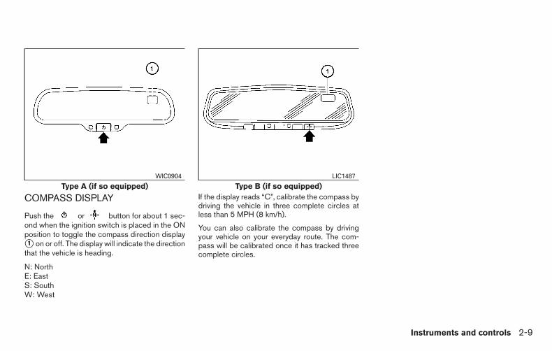
COMPASS DISPLAY
Push the or button for about 1 sec-ond when the ignition switch is placed in the ONposition to toggle the compass direction display�1 on or off. The display will indicate the directionthat the vehicle is heading.
N: NorthE: EastS: SouthW: West
If the display reads “C”, calibrate the compass bydriving the vehicle in three complete circles atless than 5 MPH (8 km/h).
You can also calibrate the compass by drivingyour vehicle on your everyday route. The com-pass will be calibrated once it has tracked threecomplete circles.
Type A (if so equipped)WIC0904
Type B (if so equipped)LIC1487
Instruments and controls 2-9

Zone variation change procedure
The difference between magnetic north and geo-graphical north is known as variance. In someareas, this difference can sometimes be greatenough to cause false compass readings. Followthese instructions to set the variance for yourparticular location if this happens:
1. Press and hold the button for about11 seconds or the button for about8 seconds. The current zone number willappear in the display. Release the button.
2. Find your current location on the zone map.Refer to the illustration.
3. Press the or the button repeat-edly to toggle through the zone numbersuntil the desired number appears in the dis-play. Once you have selected a zone num-ber, the display will show a compass direc-tion within a few seconds.
NOTE:
Use zone number 5 for Hawaii.
Inaccurate compass direction
The compass display is equipped with automaticcorrection function. If the correct direction is notshown, follow this procedure.WIC0355
2-10 Instruments and controls

1. With the display turned on, press and holdthe for about 10 seconds. The “C”icon in the compass display will illuminate.
2. Calibrate the compass by driving the vehiclein three complete circles at a maximumspeed of 5 MPH (8 km/h).
3. After completing the circles, the displayshould return to normal.
CAUTION
● Do not install a ski rack, antenna, etc.,which are attached to the vehicle bymeans of a magnet. They affect the op-eration of the compass.
● When cleaning the mirror, use a papertowel or similar material dampenedwith glass cleaner. Do not spray glasscleaner directly on the mirror as it maycause the liquid cleaner to enter themirror housing.
Instruments and controls 2-11

or Anti-lock Braking System (ABS)warning light
Low tire pressure warning light High beam indicator light (Blue)
Automatic transmission check warning light Low windshield-washer fluid warning light Malfunction Indicator Light (MIL)
Automatic transmission park warning light( model)
Master warning light Security indicator light (if so equipped)
or Brake warning light Seat belt warning light and chime Slip indicator light
Charge warning light Supplemental air bag warning light Turn signal/hazard indicator lights
Engine oil pressure low/engine coolant tem-perature high warning light (if so equipped)
Electronic locking rear differential (E-Lock)system on indicator light (if so equipped)
Vehicle Dynamic Control (VDC) off indicatorlight
4WD warning light ( model) Front fog light indicator light (if so equipped)
Low fuel warning light Front passenger air bag status light
CHECKING BULBSWith all doors closed, apply the parking brakeand place the ignition switch in the ON positionwithout starting the engine. The following lightswill come on:
, or , , , ,
The following lights come on briefly and then gooff:
or , , , ,
If any light fails to come on, it may indicatea burned-out bulb or an open circuit in theelectrical system. Have the system repairedpromptly.
WARNING/INDICATOR LIGHTS ANDAUDIBLE REMINDERS
2-12 Instruments and controls

WARNING LIGHTS
For additional information on warnings and indi-cators, refer to “Vehicle information display” inthis section.
or Anti-lock BrakingSystem (ABS)warning light
When the ignition switch is placed in the ONposition, the ABS warning light illuminates andthen turns off. This indicates the ABS is opera-tional.
If the ABS warning light illuminates while theengine is running or while driving, it may indicatethe ABS is not functioning properly. Have thesystem checked by a NISSAN dealer.
If an ABS malfunction occurs, the anti-lock func-tion is turned off. The brake system then operatesnormally, but without anti-lock assistance. Foradditional information, refer to “Brake system” inthe “Starting and driving” section of this manual.
Automatic Transmission checkwarning light
When the ignition switch is placed in the ONposition, the light comes on for about 2 seconds.If the light comes on at any other time, it may
indicate the automatic transmission system is notfunctioning properly. Have the system checkedby a NISSAN dealer.
Automatic transmission parkwarning light ( model)
WARNING
● If the ATP light is ON, this indicates thatthe automatic transmission P (Park) po-sition will not function and the transfercase is in neutral.
● When parking, always make sure thatthe 4WD shift indicator light illuminatesand the parking brake is set. Failure toengage the transfer position in 2WD, 4Hor 4LO could result in the vehicle mov-ing unexpectedly, resulting in seriouspersonal injury or property damage.
● Shift the 4WD switch into the 2WD, 4Hor 4LO position again to turn off the ATPwarning light when the shift lever to theP position and the ATP warning light isON. (Before shifting the 4WD switchinto the 4LO position, move the shiftlever to the N position once, shift theshift lever into P again and make surethe ATP warning light is OFF.)
This light indicates that the automatic transmis-sion parking function is not engaged. If the trans-fer control is not secured in any drive positionwhile the shift lever is in the P (Park) position, thetransmission will disengage and the drive wheelswill not lock.
or Brake warning light
This light functions for both the parking brake andthe foot brake systems.
Parking brake indicator
When the ignition switch is placed in the ONposition, the light comes on when the parkingbrake is applied.
Low brake fluid warning light
When the ignition switch is placed in the ONposition, the light warns of a low brake fluid level.If the light comes on while the engine is runningwith the parking brake not applied, stop the ve-hicle and perform the following:
1. Check the brake fluid level. Add brake fluidas necessary. For additional information, re-fer to the “Maintenance and do-it-yourself”section of this manual.
2. If the brake fluid level is correct, have thewarning system checked by a NISSANdealer.
Instruments and controls 2-13

WARNING
● Your brake system may not be workingproperly if the warning light is on. Driv-ing could be dangerous. If you judge itto be safe, drive carefully to the nearestservice station for repairs. Otherwise,have your vehicle towed because driv-ing it could be dangerous.
● Pressing the brake pedal with the en-gine stopped and/or a low brake fluidlevel may increase your stopping dis-tance and braking will require greaterpedal effort and pedal travel.
● If the brake fluid level is below theMINIMUM or MIN mark on the brakefluid reservoir, do not drive until thebrake system has been checked at aNISSAN dealer.
Anti-lock Braking System (ABS) warningindicator
When the parking brake is released and thebrake fluid level is sufficient, if both the brakewarning light and the ABS warning light illumi-nates, it may indicate the ABS is not functioningproperly. Have the brake system checked, and ifnecessary, repaired by a NISSAN dealerpromptly. Avoid high-speed driving and abrupt
braking. For additional information, refer to “Anti-lock Braking System (ABS) warning light” in thissection.
Charge warning light
If this light comes on while the engine is running,it may indicate the charging system is not func-tioning properly. Turn the engine off and checkthe generator belt. If the belt is loose, broken,missing, or if the light remains on, see a NISSANdealer immediately.
CAUTION
● Do not ground electrical accessories di-rectly to the battery terminal. Doing sowill bypass the variable control systemand the vehicle battery may not chargecompletely. For additional information,refer to “Variable voltage control sys-tem” in the “Maintenance and do-it-yourself” section of this manual.
● Do not continue driving if the generatorbelt is loose, broken or missing
Engine oil pressure low/Engine coolant temperaturehigh warning light (if soequipped)
This light warns of low engine oil pressure or highengine coolant temperature.
If the light flickers or comes on during normaldriving, pull off the road in a safe area, stop theengine and allow it to cool. If the light remains onafter checking the oil and coolant, stop the en-gine immediately and call a NISSAN dealer orother authorized repair shop.
This light is not designed to indicate a lowoil or low coolant level. Check the oil level withthe dipstick and check the coolant level on thereservoir. For additional information, refer to “Ifyour vehicle overheats” in the “In case of emer-gency” section and “Engine oil” and “Checkingengine coolant level” in the “Maintenance anddo-it-yourself” section of this manual.
2-14 Instruments and controls

CAUTION
● Running the engine with the engine oilpressure warning light on could causeserious damage to the engine almostimmediately. Such damage is not cov-ered by warranty. Turn off the engine assoon as it is safe to do so.
● If the gauge indicates engine coolanttemperature over the normal range,stop the vehicle as soon as safely pos-sible. If the engine is overheated, con-tinued operation of the vehicle may se-riously damage the engine. Foradditional information, refer to “If yourvehicle overheats” in the “In case ofemergency” section for immediate ac-tion required.
4WD warning light (model)
The 4WD warning light comes on when the keyswitch is turned to ON. It turns off soon after theengine is started.
If the engine or vehicle is not functioning properly,the warning light will either remain illuminated orblink. For additional information, refer to “4WDwarning light” in the “Starting and driving”sectionof this manual.
CAUTION
● If the warning light comes on or blinksduring operation, have your vehiclechecked by a NISSAN dealer as soon aspossible.
● Do not drive on dry hard surface roadsin the 4H or 4LO position. If the 4WDwarning light turns on when you aredriving on dry hard surface roads:
– in the 4H position, shift the 4WD shiftswitch to 2WD.
– in the 4LO position, stop the vehicle,move the shift lever to the N positionwith the brake pedal depressed, andshift the 4WD shift switch to 2WD.
● If the warning light is still on after theabove operation, have your vehiclechecked by a NISSAN dealer as soon aspossible.
Low fuel warning light
This light comes on when the fuel level in the fueltank is getting low. Refuel as soon as it is conve-nient, preferably before the fuel gauge reaches E(Empty). There will be a small reserve of fuelin the tank when the fuel gauge needlereaches E (Empty).
Low tire pressure warning light
Your vehicle is equipped with a TPMS that moni-tors the tire pressure of all tires except the spare.
The low tire pressure warning light warns of lowtire pressure or indicates that the TPMS is notfunctioning properly.
After the ignition switch is placed in the ONposition, this light illuminates for about 1 secondand turns off.
Low tire pressure warning:
If the vehicle is being driven with low tirepressure, the warning light will illuminate.A CHECK TIRE PRESSURE warning alsoappears in the vehicle information dis-play.If you select the tire pressure informa-tion in the display (if so equipped), the LOWPRESSURE warning message will be dis-played. The tire pressure for each tire willalso be displayed.
When the low tire pressure warning lightilluminates, you should stop and adjust thetire pressure of all four tires to the recom-mended COLD tire pressure shown on theTire and Loading Information label locatedin the driver’s door opening. The low tirepressure warning light does not automati-cally turn off when the tire pressure is ad-
Instruments and controls 2-15

justed. After the tire is inflated to the rec-ommended pressure, the vehicle must bedriven at speeds above 16 MPH (25 km/h)to activate the TPMS and turn off the lowtire pressure warning light. Use a tire pres-sure gauge to check the tire pressure.
The CHECK TIRE PRESSURE warning appearseach time the ignition switch is placed in the ONposition as long as the low tire pressure warninglight remains illuminated.
For additional information, refer to “Vehicle infor-mation display” in the “Instruments and controls”section and “Tire Pressure Monitoring System(TPMS)” in the “Starting and driving” section andin the “In case of emergency” section of thismanual.
TPMS malfunction:
If the TPMS is not functioning properly, the lowtire pressure warning light will flash for approxi-mately 1 minute when the ignition switch isplaced in the ON position. The light will remain onafter the 1 minute. Have the system checked by aNISSAN dealer. The CHECK TIRE PRESSUREwarning does not appear if the low tire pressurewarning light illuminates to indicate a TPMS mal-function.
For additional information, refer to “Tire PressureMonitoring System (TPMS)” in the “Starting anddriving” section and “Tire pressure” in the “Main-tenance and do-it-yourself” section in thismanual.
WARNING
● Radio waves could adversely affectelectrical medical equipment. Thosewho use a pacemaker should contactthe electric medical equipment manu-facturer for the possible influences be-fore use.
● If the light does not illuminate with theignition switch in the ON position, havethe vehicle checked by a NISSAN dealeras soon as possible.
● If the light illuminates while driving,avoid sudden steering maneuvers orabrupt braking, reduce vehicle speed,pull off the road to a safe location andstop the vehicle as soon as possible.Driving with under-inflated tires maypermanently damage the tires and in-crease the likelihood of tire failure. Se-rious vehicle damage could occur andmay lead to an accident and could result
in serious personal injury. Check thetire pressure for all four tires. Adjust thetire pressure to the recommendedCOLD tire pressure shown on the Tireand Loading Information label locatedin the driver’s door opening to turn thelow tire pressure warning light OFF. Ifthe light still comes on while drivingafter adjusting the tire pressure, a tiremay be flat. If you have a flat tire, re-place it with a spare tire as soon aspossible.
● When a spare tire is mounted or a wheelis replaced, tire pressure will not beindicated, the TPMS will not functionand the low tire pressure warning lightwill flash for approximately 1 minute.The light will remain on after 1 minute.Contact your NISSAN dealer as soon aspossible for tire replacement and/orsystem resetting.
● Replacing tires with those not originallyspecified by NISSAN could affect theproper operation of the TPMS.
2-16 Instruments and controls

CAUTION
● The TPMS is not a substitute for theregular tire pressure check. Be sure tocheck the tire pressure regularly.
● If the vehicle is being driven at speedsof less than 16 MPH (25 km/h), theTPMS may not operate correctly.
● Be sure to install the specified size oftires to the 4 wheels correctly.
Low windshield-washer fluidwarning light
This light comes on when the windshield-washerfluid is at a low level. Add windshield-washer fluidas necessary. For additional information, refer to“Windshield-washer fluid” in the “Maintenanceand do-it-yourself” section of this manual.
Master warning light
This light comes on when various vehicle infor-mation display warnings appear.
● No key warning
● Low fuel warning
● Low windshield-washer fluid warning
● Parking brake release warning
● Door open warning
● Loose fuel cap warning
● Check tire pressure warning
Seat belt warning light andchime
The light and chime remind you to fasten yourseat belts. The light illuminates whenever theignition switch is placed in the ON or STARTposition and remains illuminated until the driver’sseat belt is fastened. At the same time, the chimesounds for about 6 seconds unless the driver’sseat belt is securely fastened.
The seat belt warning light may also illuminate ifthe front passenger’s seat belt is not fastenedwhen the front passenger’s seat is occupied . For7 seconds after the ignition switch is placed inthe ON position, the system does not activate thewarning light for the front passenger.
For additional information, refer to “Seat belts” inthe “Safety—Seats, seat belts and supplementalrestraint system” section of this manual for pre-cautions on seat belt usage.
Supplemental air bag warninglight
When the ignition switch is placed in the ON orSTART position, the supplemental air bag warn-ing light illuminates for about 7 seconds and thenturns off. This means the system is operational.
If any of the following conditions occur, the frontair bag, side air bag, curtain air bag, and preten-sioner systems need servicing and your vehiclemust be taken to a NISSAN dealer:
● The supplemental air bag warning light re-mains on after approximately 7 seconds.
● The supplemental air bag warning lightflashes intermittently.
● The supplemental air bag warning light doesnot come on at all.
Unless checked and repaired, the supplementalrestraint system (air bag system) and/or the seatbelts with pretensioner system may not functionproperly. For additional information, refer to“Supplemental restraint system (SRS)” in the“Safety—Seats, seat belts and supplemental re-straint system” section of this manual.
Instruments and controls 2-17

WARNING
If the supplemental air bag warning lightis on, it could mean that the front air bag,side air bag, curtain air bag and/or preten-sioner systems will not operate in an acci-dent. To help avoid injury to yourself orothers, have your vehicle checked by aNISSAN dealer as soon as possible.
INDICATOR LIGHTS
For additional information on warnings and indi-cators, refer to “Vehicle information display” inthis section.
Electronic locking reardifferential (E-Lock) system onindicator light (if so equipped)
This light comes on when the electronic lockingrear differential (E-Lock) system clutch is fullyengaged.
The indicator light flashes when the system is firstturned on. When the system fully engages, thelight remains on. If the switch is on and theindicator light continues to flash, the system isnot engaged.
For additional information, refer to “Electroniclocking rear differential (E-Lock) system switch”
in this section and “Electronic locking rear differ-ential (E-Lock) system” in the “Starting and driv-ing” section of this manual.
Front fog light indicator light (ifso equipped)
The front fog light indicator light illuminates whenthe front fog lights are ON. For additional infor-mation, refer to “Fog light switch” in this section.
Front passenger air bag statuslight
The front passenger air bag status light will be litand the passenger front air bag will be OFFdepending on how the front passenger seat isbeing used.
For front passenger air bag status light operation,refer to “Front passenger air bag and status light”in the “Safety — Seats, seat belts and supple-mental restraint system” section of this manual.
High beam indicator light(blue)
This blue light comes on when the headlight highbeams are on and goes out when the low beamsare selected.
The high beam indicator light also comes onwhen the passing signal is activated.
Malfunction Indicator Light(MIL)
If this indicator light comes on steady or blinkswhile the engine is running, it may indicate apotential emission control malfunction.
The MIL may also come on steady if the fuel-fillercap is loose or missing, or if the vehicle runs outof fuel. Check to make sure the fuel-filler cap isinstalled and closed tightly, and that the vehiclehas at least 3 gal (11.4 L) of fuel in the fuel tank.
After a few driving trips, the light shouldturn off if no other potential emission controlsystem malfunction exists.
If this indicator light comes on steady for 20 sec-onds and then blinks for 10 seconds when theengine is not running, it indicates that the vehicleis not ready for an emission control systeminspection/maintenance test. For additional infor-mation, refer to “Readiness forinspection/maintenance (I/M) test” in the “Tech-nical and consumer information” section of thismanual.
2-18 Instruments and controls

Operation
The MIL will come on in one of two ways:
● MIL on steady — An emission control systemmalfunction has been detected. Check thefuel-filler cap if the LOOSE FUEL CAPwarning appears in the vehicle informationdisplay. If the fuel-filler cap is loose or miss-ing, tighten or install the cap and continue todrive the vehicle. The light should turnoff after a few driving trips. If the lightdoes not turn off after a few driving trips,have the vehicle inspected by a NISSANdealer. You do not need to have your vehicletowed to the dealer.
● MIL blinking — An engine misfire has beendetected which may damage the emissioncontrol system. To reduce or avoid emissioncontrol system damage:
– do not drive at speeds above 45 MPH(72 km/h).
– avoid hard acceleration or deceleration.
– avoid steep uphill grades.
– if possible, reduce the amount of cargobeing hauled or towed.
The MIL may stop blinking and come on steady.Have the vehicle inspected by a NISSAN dealer.You do not need to have your vehicle towed to thedealer.
CAUTION
Continued vehicle operation without hav-ing the emission control system checkedand repaired as necessary could lead topoor driveability, reduced fuel economy,and possible damage to the emission con-trol system.
Security indicator light (if soequipped)
This light blinks whenever the ignition switch is inthe LOCK, OFF or ACC position. This functionindicates the security system equipped on thevehicle is operational.
For additional information, refer to “Security sys-tems” in this section.
Slip indicator light
This indicator will blink when the Vehicle DynamicControl (VDC) system or the Traction ControlSystem (TCS) is operating, thus alerting that thevehicle is nearing its traction limits. The roadsurface may be slippery.
Turn signal/hazard indicatorlights
The appropriate light flashes when the turn signalswitch is activated.
Both lights flash when the hazard switch is turnedon.
Vehicle Dynamic Control(VDC) off indicator light
This indicator light comes on when the VDC offswitch is pushed to OFF, the transfer case is inthe 4LO position ( model), or when theVDC system is not functioning properly. Thisindicates the VDC system is not operating.
Push the VDC off switch again or restart theengine and the system will operate normally. Foradditional information, refer to “Vehicle DynamicControl (VDC) system” in the “Starting and driv-ing” section of this manual.
The VDC light also comes on when you place theignition switch in the ON position. The light willturn off after about 2 seconds if the system isoperational. If the light stays on or comes onalong with the indicator light while you aredriving, have the VDC system checked by aNISSAN dealer.
Instruments and controls 2-19
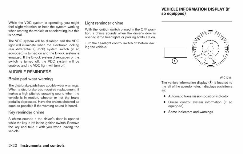
While the VDC system is operating, you mightfeel slight vibration or hear the system workingwhen starting the vehicle or accelerating, but thisis normal.
The VDC system will be disabled and the VDClight will illuminate when the electronic lockingrear differential (E-lock) system switch (if soequipped) is turned on and the E-lock system isengaged. If the E-lock system disengages or theswitch is turned off, the VDC system will beenabled and the VDC light will turn off.
AUDIBLE REMINDERS
Brake pad wear warning
The disc brake pads have audible wear warnings.When a disc brake pad requires replacement, itmakes a high pitched scraping sound when thevehicle is in motion, whether or not the brakepedal is depressed. Have the brakes checked assoon as possible if the warning sound is heard.
Key reminder chime
A chime sounds if the driver’s door is openedwhile the key is left in the ignition switch. Removethe key and take it with you when leaving thevehicle.
Light reminder chimeWith the ignition switch placed in the OFF posi-tion, a chime sounds when the driver’s door isopened if the headlights or parking lights are on.
Turn the headlight control switch off before leav-ing the vehicle.
The vehicle information display �1 is located tothe left of the speedometer. It displays such itemsas:
● Automatic transmission position indicator
● Cruise control system information (if soequipped)
● Some indicators and warnings
WIC1248
VEHICLE INFORMATION DISPLAY (ifso equipped)
2-20 Instruments and controls

HOW TO USE THE VEHICLEINFORMATION DISPLAY
Press the vehicle information display INFO but-ton �1 located on the instrument panel to togglethrough the following modes:
● Fuel economy (if so equipped)
● Driving averages
● Current trip information
● Range
● Outside temperature (if so equipped)
● Settings
● Alerts
Rotate the INFO button �2 to highlight the de-sired menu option within the selected mode.Press the INFO button �1 to enter the high-lighted menu.
The icons at the bottom of the display screenshow the options available:
ENTER — Press the INFO button to selecta highlighted option.
NEXT — Rotate the INFO button to high-light an option.
Fuel economy mode (if so equipped)
The fuel economy mode can be selected to dis-play the instant fuel economy.
WIC1249 LIC1093
Instruments and controls 2-21

Average driving information mode
The average driving information mode can beselected to display the average miles per gallonand miles per hour since the last reset.
Current trip information mode
The current trip information mode can be se-lected to show the time and distance driven sincethe last reset.
Range mode
The range mode can be selected to give you anestimation of the distance that can be drivenbefore refueling. The range is constantly calcu-lated based on the amount of fuel in the fuel tankand the actual fuel consumption.
LIC1097 WIC1266 LIC2598
2-22 Instruments and controls

Exterior temperature mode (if soequipped)
The exterior temperature mode can be selectedto provide you with the temperature outside ofyour vehicle.
Settings mode
The settings mode allows you to set reminders orpreferences for alerts, maintenance intervals, lan-guage, and units.
In the settings mode screen, rotate the INFObutton to move to:
● Alert
● Maintenance
● Display
and press the INFO button to select the menu.
Alert mode
The alert mode allows you to set alerts notifyingyou of time to rest or icy conditions.
The time to rest alert is a timer that can be set toremind the driver when the selected amount oftime has passed.
The icy alert notifies you that icy driving condi-tions may exist.
LIC1096 LIC2594 LIC2595
Instruments and controls 2-23

Maintenance mode
The maintenance mode allows you to set alertsfor the reminding of maintenance intervals for thefollowing:
● engine oil
● oil filter
● tires
● other
Set a desired interval by rotating the INFO buttonto highlight the maintenance field, then press theINFO button to select. The reset mode will openup and allow you to enter the desired distance.
Display mode
Rotate the INFO button to highlight the desiredmode, then press the INFO button to select.
Language: English or French
Unit: US — mile, °F, MPGMetric — km, °C, L/100 km
The settings are automatically saved when youexit the menu by pressing the BACK button orany other mode button.
Warning mode
The warning mode can be selected to view anywarnings that may be present. Once the screen isselected you have the option of skipping thewarning or viewing it in detail.
Warnings can be present for issues such as anopen door or low fuel. For additional informationabout potential warnings, refer to “Vehicle infor-mation display warnings and indicators” in thissection.
WIC1164 WIC1165 LIC1098
2-24 Instruments and controls
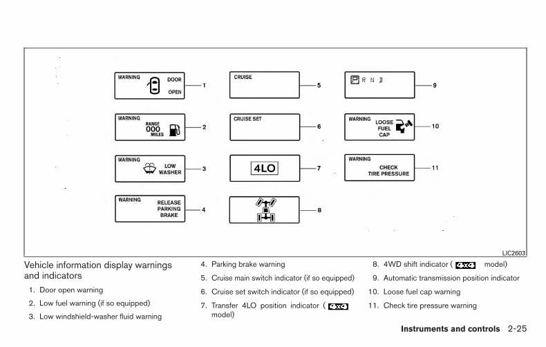
Vehicle information display warningsand indicators
1. Door open warning
2. Low fuel warning (if so equipped)
3. Low windshield-washer fluid warning
4. Parking brake warning
5. Cruise main switch indicator (if so equipped)
6. Cruise set switch indicator (if so equipped)
7. Transfer 4LO position indicator (model)
8. 4WD shift indicator ( model)
9. Automatic transmission position indicator
10. Loose fuel cap warning
11. Check tire pressure warning
LIC2603
Instruments and controls 2-25

Door open warning
This warning illuminates when a door has beenopened and the engine is running.
Low fuel warning
This warning illuminates when the fuel level in thefuel tank is getting low. Refuel as soon as it isconvenient, preferably before the fuel gaugereaches E (Empty). There will be a small re-serve of fuel in the tank when the fuelgauge needle reaches E (Empty).
Low windshield-washer fluid warning
This warning illuminates when the windshield-washer fluid is at a low level. Add windshield-washer fluid as necessary. For additional informa-tion, refer to “Windshield-washer fluid” in the“Maintenance and do-it-yourself” section of thismanual.
Parking brake warning
This warning illuminates when the parking brakeis set and the vehicle is driven.
Cruise main switch indicator (if soequipped)
This indicator illuminates when the cruise controlmain switch is pushed. The indicator turns offwhen the main switch is pushed again. When the
cruise main switch indicator illuminates, thecruise control system is operational.
Cruise set switch indicator (if soequipped)
This indicator illuminates while the vehicle speedis controlled by the cruise control system. If theindicator blinks while the engine is running, it mayindicate the cruise control system is not function-ing properly. Have the system checked by aNISSAN dealer.
Transfer 4LO position indicator (model)
This indicator illuminates when the 4WD shiftswitch is set in the 4LO position with the ignitionswitch placed in the ON position.
If the 4WD shift switch is set in the 4LO positionand the indicator blinks, stop the vehicle, driveslowly forward and the indicator will turn on.
When you shift between 4H and 4LO, stop thevehicle, move the shift lever to the N (Neutral)position, then depress and turn the 4WD shiftswitch to 4LO or 4H.
The transfer case may be damaged if you shift theswitch while driving.
You cannot move the transfer 4WD shift switchbetween 4H and 4LO unless you have first
stopped the vehicle and moved the shift lever toN (Neutral). Make sure the transfer 4LO positionindicator illuminates when you shift the 4WD shiftswitch to 4LO.
The indicator may blink while shifting fromone drive mode to the other.
4WD shift indicator ( model)
While the engine is running, the 4WD shift indi-cator will illuminate the position selected by the4WD shift switch.
The 4WD shift indicator may blink whileshifting from one drive mode to the other.
Automatic transmission position indicator
When the ignition switch is placed in the ONposition, this indicator shows the shift lever posi-tion. For additional information, refer to “Drivingthe vehicle” in the “Starting and driving” sectionof this manual.
Loose fuel cap warning
This warning appears when the fuel-filler cap isnot tightened correctly after the vehicle is refu-eled. For additional information, refer to “Fuel-filler cap” in the “Pre-driving checks and adjust-ments” section of this manual.
2-26 Instruments and controls

Check tire pressure warning
This warning appears when the low tire pressurewarning light in the meter illuminates and low tirepressure is detected. If this warning appears,stop the vehicle and adjust the tire pressure tothe recommended COLD tire pressure shown onthe Tire and Loading Information label. For addi-tional information, refer to “Low tire pressurewarning light” in this section and “Tire PressureMonitoring System (TPMS)” in the “Starting anddriving” section of this manual.
Your vehicle may have two types of security sys-tems:
● Vehicle security system (if so equipped)
● NISSAN Vehicle Immobilizer System (if soequipped)
VEHICLE SECURITY SYSTEM (if soequipped)
The vehicle security system provides visual andaudible alarm signals if someone opens the doorswhen the system is armed. It is not, however, amotion detection type system that activates whena vehicle is moved or when a vibration occurs.
The system helps detect vehicle theft but cannotprevent it, nor can it prevent the theft of interior orexterior vehicle components in all situations. Al-ways secure your vehicle even if parking for abrief period. Never leave your keys in the ignition,and always lock the vehicle when unattended. Beaware of your surroundings, and park in secure,well-lit areas whenever possible.
Many devices offering additional protection, suchas component locks, identification markers, andtracking systems, are available at auto supplystores and specialty shops. Your NISSAN dealermay also offer such equipment. Check with yourinsurance company to see if you may be eligiblefor discounts for various theft protection features.
How to arm the vehicle securitysystem
1. Close all windows. (The system can bearmed even if the windows are open.)
2. Remove the key from the ignition switch.
3. Close all doors. Lock all doors. The doorscan be locked with the key, power door lockswitch (if the door is opened, locked andthen closed), or with the key fob.
LIC0644
SECURITY SYSTEMS (if so equipped)
Instruments and controls 2-27

Key fob operation:
● Push the button on the key fob.All doors lock. The hazard lights flashtwice and the horn beeps once to indicateall doors are locked.
● When the button is pushed withall doors locked, the hazard lights flashtwice and the horn beeps once as a re-minder that the doors are already locked.
The horn may or may not beep. For addi-tional information, refer to “Silencing thehorn beep feature” (vehicles without naviga-tion system) in the “Pre-driving checks andadjustments” section of this manual.
4. Confirm that the indicator light comeson. The light stays on for about30 seconds. The vehicle security system isnow pre-armed. After about 30 seconds thevehicle security system automatically shiftsinto the armed phase. The light beginsto flash once every 3 seconds. If, during the30-second pre-arm time period, the door isunlocked by the key or the key fob, or theignition switch is placed to ACC or ON, thesystem will not arm.
● If the key is turned slowly when lockingthe door, the system may not arm. Fur-thermore, if the key is turned beyondthe vertical position toward the unlockposition to remove the key, the systemmay be disarmed when the key is re-moved. If the indicator light fails toglow for a period of time, unlock thedoor once and lock it again.
● Even when the driver and/or passengersare in the vehicle, the system will armwith all doors closed and locked with theignition switch in the OFF position.
● The lockable bedside storage compart-ment (if so equipped) is not protectedby the vehicle security system.
Vehicle security system activation
The vehicle security system will give the followingalarm:
● The headlights blink and the horn soundsintermittently.
● The alarm automatically turns off after a pe-riod of time. However, the alarm reactivates ifthe vehicle is tampered with again. The alarmcan be shut off by unlocking the driver’s doorwith the key or by pressing the buttonon the key fob.
The alarm is activated by:
● Opening a door without using the key or keyfob (even if the door is unlocked by using theinside lock knob or the power door lockswitch).
How to stop an activated alarm
The alarm stops only by unlocking the driver’sdoor with the key or by pressing the buttonon the key fob.
NISSAN VEHICLE IMMOBILIZERSYSTEM (if so equipped)
The NISSAN Vehicle Immobilizer System will notallow the engine to start without the use of aregistered key.
If the engine fails to start using a registered key(for example, when interference is caused byanother registered key, an automated toll roaddevice or automatic payment device on the keyring), restart the engine using the following pro-cedures:
1. Leave the ignition switch in the ON positionfor approximately 5 seconds.
2. Turn the ignition switch to the OFF or LOCKposition, and wait approximately 10 sec-onds.
2-28 Instruments and controls

3. Repeat steps 1 and 2.
4. Restart the engine while holding the device(which may have caused the interference)separate from the registered key.
If the no start condition re-occurs, NISSAN rec-ommends placing the registered key on a sepa-rate key ring to avoid interference from otherdevices.
FCC Notice:
For USA:
This device complies with part 15 of theFCC Rules. Operation is subject to the fol-lowing two conditions; (1) This device maynot cause harmful interference, and (2) thisdevice must accept any interference re-ceived, including interference that maycause undesired operation of the device.
NOTE:
Changes or modifications not expressly ap-proved by the party responsible for compli-ance could void the user’s authority to op-erate the equipment.
For Canada:
This device complies with Industry Canadalicence-exempt RSS standard(s). Opera-tion is subject to the following two condi-tions: (1) this device may not cause inter-ference, and (2) this device must accept anyinterference, including interference thatmay cause undesired operation of the de-vice.
Security indicator light
The security indicator light blinks whenever theignition switch is placed in the LOCK, OFF or ACCposition. This function indicates the NISSAN Ve-hicle Immobilizer System is operational.
If the NISSAN Vehicle Immobilizer System is mal-functioning, the light will remain on while theignition switch is placed in the ON position.
If the light still remains on and/or the en-gine will not start, see a NISSAN dealer forNISSAN Vehicle Immobilizer System ser-vice as soon as possible. Please bring allregistered keys that you have when visitingyour NISSAN dealer for service.
LIC0474
Instruments and controls 2-29

SWITCH OPERATION
The windshield wiper and washer operates whenthe ignition switch is in the ON position.
Push the lever down to operate the wiper at thefollowing speed:
�1 Intermittent (INT) — intermittent operationcan be adjusted by turning the knob toward�A (Slower) or �B (Faster). Also, the inter-mittent operation speed varies in accor-dance with the vehicle speed. (For example,when the vehicle speed is high, the intermit-tent operation speed will be faster.)
�2 Low (LO) — continuous low speed operation
�3 High (HI) — continuous high speed opera-tion
Push the lever up �4 to have one sweep opera-tion (MIST) of the wiper.
Pull the lever toward you �5 to operate thewasher. The wiper will also operate several times.
WARNING
In freezing temperatures the washer solu-tion may freeze on the windshield andobscure your vision which may lead to anaccident. Warm the windshield with thedefroster before you wash the windshield.
CAUTION
● Do not operate the washer continuouslyfor more than 30 seconds.
● Do not operate the washer of the reser-voir is empty.
● Do not fill the windshield-washer reser-voir with washer fluid concentrates atfull strength. Some methyl alcoholbased washer fluid concentrates maypermanently stain the grille if spilledwhile filling the windshield-washerfluid reservoir.
Type A (if so equipped)LIC0965
Type B (if so equipped)LIC2858
WINDSHIELD WIPER AND WASHERSWITCH
2-30 Instruments and controls

● Pre-mix washer fluid concentrates withwater to the manufacturer’s recom-mended levels before pouring the fluidinto the windshield-washer fluid reser-voir. Do not use the windshield-washerreservoir to mix the washer fluid con-centrate and water.
To defrost the rear window glass and outsidemirrors (if so equipped), start the engine andpush the rear window defroster switch on. Therear window defroster indicator light on theswitch comes on. Push the switch again to turnthe defroster off.
The rear window defroster automatically turns offafter approximately 15 minutes.
Type A (if so equipped)LIC0488
Type B (if so equipped)LIC1173
REAR WINDOW AND OUTSIDEMIRROR (if so equipped)DEFROSTER SWITCH
Instruments and controls 2-31

NOTE:
If the rear power window (if so equipped) islowered while the defroster switch is on,the rear window defroster will automati-cally shut off. The heated outside mirrors (ifso equipped) will remain on. The rear win-dow defroster will automatically turn onwhen the rear power window is fully closedif the switch is on.
CAUTION
When cleaning the inner side of the rearwindow, be careful not to scratch or dam-age the rear window defroster.
Type C (if so equipped)LIC1158
Type A (if so equipped)SIC2745
HEADLIGHT AND TURN SIGNALSWITCH
2-32 Instruments and controls

HEADLIGHT CONTROL SWITCH
Lighting
�1 When turning the switch to the posi-tion, the front parking, tail, license plate andinstrument panel lights come on.
�2 When turning the switch to the posi-tion, the headlights come on and all the otherlights remain on.
CAUTION
Use the headlights with the engine run-ning to avoid discharging the vehiclebattery.
Type B (if so equipped)WIC1250
Type C (if so equipped)SIC3019
Instruments and controls 2-33

Autolight system (if so equipped)The autolight system allows the headlights to beset so they turn on and off automatically. Theautolight system can:
● Turn on the headlights, front parking, tail,license plate and instrument panel lights au-tomatically when it is dark.
● Turn off all the lights when it is light.
● Keep all the lights on for a period of time afteryou place the ignition switch in the OFFposition and all doors are closed.
To turn on the autolight system:
1. Turn the headlight switch to the AUTO posi-tion �1 .
2. Place the ignition switch in the ON position.
3. The autolight system automatically turns theheadlights on and off.
Initially, if the ignition switch is placed in the OFFposition and a door is opened and left open, theheadlights remain ON for a period of time. Ifanother door is opened while the headlights areon, then the timer is reset.
To turn the autolight system off, turn the switch to
the OFF, , or position.Be sure you do not put anything on top ofthe autolight sensor �1 located on the topside of the instrument panel. The autolightsensor controls the autolight; if it is cov-ered, the autolight sensor reacts as if it isdark out and the headlights will illuminate.If this occurs while parked with the engineoff and the ignition switch placed in the ONposition, your vehicle’s battery could be-come discharged.
WIC1251 LIC0836
2-34 Instruments and controls

Headlight beam select
�1 To select the high beam function, push thelever forward. The high beam lights come onand the light illuminates.
�2 Pull the lever back to select the low beam.
�3 Pulling and releasing the lever flashes theheadlight high beams on and off.
Battery saver systemIf the ignition switch is placed in the OFF positionwhile the headlight switch is in theor position, the headlights will turn off aftera period of time.
After the headlights automatically turn off with the
headlight switch in the or position,the headlights will illuminate again if the headlightswitch is moved to the OFF position and then
turned to the or position.
CAUTION
Even though the battery saver feature au-tomatically turns off the headlights after aperiod of time, you should turn the head-light switch to the OFF position when theengine is not running to avoid dischargingthe vehicle battery.
DAYTIME RUNNING LIGHT SYSTEM(Canada only)The daytime running lights automatically illumi-nate when the engine is started with the parkingbrake released. The daytime running lights oper-ate with the headlight switch in the OFF positionor in the position. Turn the headlight switchto the position for full illumination whendriving at night.
If the parking brake is applied before the engine isstarted, the daytime running lights do not illumi-nate. The daytime running lights illuminate whenthe parking brake is released. The daytime run-ning lights will remain on until the ignition switchis placed in the OFF position.
WARNING
When the daytime running light system isactive, tail lights on your vehicle are noton. It is necessary at dusk to turn on yourheadlights. Failure to do so could causean accident injuring yourself and others.
WIC1252
Instruments and controls 2-35

INSTRUMENT BRIGHTNESSCONTROLThe instrument brightness control operates whenthe headlight control switch is in
the , or AUTO position (with auto-lights activated).
Turn the control to adjust the brightness of instru-ment panel lights when driving at night.
TURN SIGNAL SWITCH
Turn signal
�1 Move the lever up or down to signal theturning direction. When the turn is com-pleted, the turn signal cancels automatically.
Lane change signal
�2 Move the lever up or down until the turnsignal begins to flash, but the lever does notlatch, to signal a lane change. Hold the leveruntil the lane change is completed.Move the lever up or down until the turnsignal begins to flash, but the lever does notlatch, and release the lever. The turn signalwill automatically flash three times.
Choose the appropriate method to signal a lanechange based on road and traffic conditions.
WIC1506 WIC1253
2-36 Instruments and controls
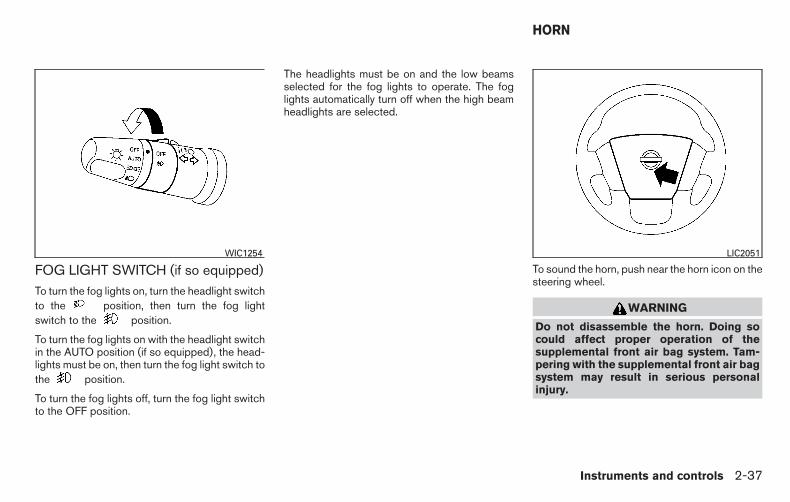
FOG LIGHT SWITCH (if so equipped)To turn the fog lights on, turn the headlight switchto the position, then turn the fog lightswitch to the position.
To turn the fog lights on with the headlight switchin the AUTO position (if so equipped), the head-lights must be on, then turn the fog light switch tothe position.
To turn the fog lights off, turn the fog light switchto the OFF position.
The headlights must be on and the low beamsselected for the fog lights to operate. The foglights automatically turn off when the high beamheadlights are selected.
To sound the horn, push near the horn icon on thesteering wheel.
WARNING
Do not disassemble the horn. Doing socould affect proper operation of thesupplemental front air bag system. Tam-pering with the supplemental front air bagsystem may result in serious personalinjury.
WIC1254 LIC2051
HORN
Instruments and controls 2-37

To turn on the cargo lamp, push the switch downto the ON position. The tailgate lights (if soequipped) will also illuminate when the cargolamp switch is in the ON position.
CAUTION
Be sure to turn the light switch to the OFFposition when you leave the vehicle forextended periods of time, otherwise thebattery will go dead.
1. Start the engine.
2. Push the LO or HI position of the switch, asdesired, depending on the temperature. Theindicator light in the switch will illuminate.
The heater is controlled by a thermostat,automatically turning the heater on and off.The indicator light will remain on as long asthe switch is on.
3. When the seat is warmed or before youleave the vehicle, be sure to turn the switchoff.
WARNING
Do not use or allow occupants to use theseat heater if you or the occupants cannotmonitor elevated seat temperatures orhave an inability to feel pain in body partsthat contact the seat. Use of the seatheater by such people could result in seri-ous injury.
CAUTION
● Do not use the seat heater for extendedperiods or when no one is using theseat.
● Do not put anything on the seat whichinsulates heat, such as a blanket, cush-ion, seat cover, etc. Otherwise, the seatmay become overheated.
● Do not place anything hard or heavy onthe seat or pierce it with a pin or similarobject. This may result in damage to theheater.
● Any liquid spilled on the heated seatshould be removed immediately with adry cloth.
● When cleaning the seat, never usegasoline, benzine, thinner, or any simi-lar materials.
LIC0616 WIC1441
CARGO LAMP SWITCH (if soequipped)
HEATED SEATS (if so equipped)
2-38 Instruments and controls

● If any malfunctions are found or theheated seat does not operate, turn theswitch off and have the system checkedby your NISSAN dealer.
● The battery could run down if the seatheater is operated while the engine isnot running.
The vehicle should be driven with the VDC sys-tem on for most driving conditions.
If the vehicle is stuck in mud or snow, the VDCsystem reduces the engine output to reducewheel spin. The engine speed will be reducedeven if the accelerator is depressed to the floor. Ifmaximum engine power is needed to free a stuckvehicle, turn the VDC system off.To turn off the VDC system, push the VDC OFFswitch. The indicator will come on.Push the VDC OFF switch again or restart theengine to turn on the system. For additional infor-mation, refer to “Vehicle Dynamic Control (VDC)system” in the “Starting and driving” section ofthis manual.
The Electronic Locking Rear Differential (E-Lock)system can help provide added traction if thevehicle is stuck or becoming stuck.
To activate the E-Lock system:
● the 4WD switch must be in the 4LO position(4-wheel drive vehicles),
● the vehicle must be stopped or moving at4 MPH (7 km/h) or less, and
● the E-Lock system switch must be turnedON.
LIC1548 LIC0729
VEHICLE DYNAMIC CONTROL (VDC)OFF SWITCH
ELECTRONIC LOCKING REARDIFFERENTIAL (E-Lock) SYSTEMSWITCH (if so equipped)
Instruments and controls 2-39

When the E-Lock switch is turned ON, the indi-cator light will flash until the system engages.However, if all operation conditions listed aboveare not met or the system becomes disengaged,the indicator light will continue to flash.
The Anti-Lock Brake (ABS) system is disabledand the ABS light illuminates when the E-Locksystem is ON. Also, the Vehicle Dynamic Control(VDC) system is disabled and the VDC lightilluminates when the E-Lock system is ON.
For additional information, refer to “Electroniclocking rear differential (E-Lock) system” in the“Starting and driving” section of this manual forfurther explanation and system limitations.
WARNING
● Never leave the E-Lock system ON whendriving on paved or hard-surfacedroads. Turning the vehicle may result inthe rear wheels slipping and result in anaccident and personal injury. After us-ing the E-Lock system to free the ve-hicle, turn the system OFF.
● Use the E-Lock system only when free-ing a stuck vehicle. Try the 4LO positionbefore using the E-Lock system. Neveruse the E-Lock system on a slipperyroad surface such as snow or ice sur-face. Using the E-Lock system whendriving in these road conditions maycause unexpected movement of the ve-hicle during engine braking, accelerat-ing or turning, which may result in anaccident and serious personal injury.
CAUTION
● After using the E-Lock system, turn theswitch OFF to prevent possible damageto driveline components from extendeduse.
● Do not drive over 12 MPH (20 km/h)when the system is engaged. Doing socould result in possible damage to thedriveline.
● Do not turn on the E-lock system whilethe tires are spinning. Doing so coulddamage drivetrain components.
To use the outlets for devices that require 120vpower, place the ignition in the ON position andpush the power inverter switch.
The 400W or 150W on the switch will illuminateaccording to the mode selected. Only the 150Wis available when the ignition switch is placed inthe ON position or while the vehicle is beingdriven. For additional information, refer to “120voutlets” in this section of the manual regardingusing devices that require the power inverterswitch activated.
LIC2075
POWER INVERTER SWITCH (if soequipped)
2-40 Instruments and controls

CAUTION
● Use power outlets with the engine run-ning to avoid discharging the vehiclebattery.
● Do not attempt to use this while driving.
● Do not use double adapters or morethan one electrical accessory, doing socould significantly drain the battery ofyour vehicle.
WARNING
The rear sonar system is a conveniencebut it is not a substitute for proper back-ing. Always turn and check that it is safe todo so before backing up. Always back upslowly.
The rear sonar system is active when the ignitionswitch is placed to the ON position and the shiftlever is in R (Reverse).
When sensors detect obstacles within 5.9 ft(1.8 m) of the rear bumper, a beeping tone isemitted.
The rear sonar system can be disabled by push-ing the OFF switch. When the system is disabled,the indicator light on the switch will illuminate.Push the switch again to enable the system. Theindicator light will go off.
The system will automatically reset the next timethe ignition switch is turned on.
For additional information, refer to “Rear sonarsystem” in the “Starting and driving” section.
LIC0471
REAR SONAR SYSTEM OFF SWITCH(if so equipped)
Instruments and controls 2-41

Tow mode should be used when pulling a heavytrailer or hauling a heavy load. Driving the vehiclein the tow mode with no trailer/load or lighttrailer/light load will not cause any damage. How-ever, fuel economy may be reduced, and thetransmission/engine driving characteristics mayfeel unusual.
Press the tow mode switch to activate tow mode.The indicator light on the tow mode switch illumi-nates when tow mode is selected. Press the towmode switch again to turn tow mode OFF.
Tow mode is automatically canceled when theignition switch is placed in the OFF position.
For additional information, refer to “Tow mode” inthe “Technical and consumer information” sec-tion in this manual.
12V OUTLETS
LIC0594
TOW MODE SWITCH POWER OUTLETS
2-42 Instruments and controls

The power outlets are for powering electricalaccessories such as cellular telephones.
The power outlets located on the driver’s side ofthe instrument panel is powered only when theignition switch is placed in the ACC or ON posi-tion.
The power outlets located on the passenger’sside of the instrument panel, and in the 2nd roware powered only when the ignition switch isplaced in the ACC or ON position.
Open the cap to use a power outlet.
Front rowWIC1404
2nd row (if so equipped)WIC0643
Inside center armrest (if so equipped)LIC0618
Instruments and controls 2-43

CAUTION
● The outlet and plug may be hot duringor immediately after use.
● Only certain power outlets are designedfor use with a cigarette lighter unit. Donot use any other power outlet for anaccessory lighter. See your NISSANdealer for additional information.
● Do not use with accessories that exceeda 12 volt, 120W (10A) power draw. Donot use double adapters or more thanone electrical accessory.
● Use power outlets with the engine run-ning to avoid discharging the vehiclebattery.
● Avoid using power outlets when the airconditioner, headlights or rear windowdefroster is on.
● Before inserting or disconnecting aplug, be sure the electrical accessorybeing used is turned OFF.
● Push the plug in as far as it will go. Ifgood contact is not made, the plug mayoverheat or the internal temperaturefuse may open.
● When not in use, be sure to close thecap. Do not allow water or any otherliquid to contact the outlet.
120V OUTLET (if so equipped)In truck box (if so equipped)
LIC0617
Center console (if so equipped)LIC2433
2-44 Instruments and controls

Before Drive (idling)(Park)
When shifting out ofPark
When shifting back to(idling) (Park)
Switch Reset
Options What is plugged IN Indicator InverterStatus
Indicator InverterStatus
Indicator InverterStatus
Indicator InverterStatus
Nothing plugged but switch ison
150 and400
ON 150 ON 150 and400
ON NOTNECES-
SARY
NOTNECES-
SARY
Device<150W 150 and400
ON 150 ON 150 and400
ON NOTNECES-
SARY
NOTNECES-
SARY
150W>device<400W 150 and400
ON OFF OFF ON ON 150 and400
ON
Device>400W 150 and400
OFF OFF OFF OFF OFF OFF** OFF**
** OFF means that the inverter system cannot be reset until a device that is within the specified range of operation is plugged in. Therefore, the switch indicatorsand inverter would remain OFF. There may be a very short period of time where the switch indicators are on, but once the inverter reaches it’s peak saturationpoint (temp and power level). it will shut off both the inverter and the switch indicators.
Instruments and controls 2-45

Do not use the outlet located in the truck box withaccessories that exceed 120 volt. Do not usedouble adapters or more than one electrical ac-cessory.
CAUTION
● Operation of the 120 volt system withthe ignition in the ON position and theengine not running (idle) will drain thebattery charge. This could lead to adead battery or no start condition.
● The outlet and plug may be hot duringor immediately after use.
● Use power outlets with the engine run-ning to avoid discharging the vehiclebattery.
● Do not use double adaptors or morethan one electrical accessory.
● Avoid using power outlets when the airconditioner, headlights or rear windowdefroster is on.
● Before inserting or disconnecting aplug, be sure the electrical accessorybeing used is turned OFF.
● Push the plug in as far as it will go. Ifgood contact is not made, the plug mayoverheat or the internal temperaturefuse may open.
● When not in use, be sure to close thecap. Do not allow water or any otherliquid to contact the outlet.
INSTRUMENT PANEL STORAGETRAYS
WARNING
Do not place sharp objects in the trays tohelp prevent injury in an accident or sud-den stop.
The rubber mats can be removed for cleaning.
Side trayLIC0565
STORAGE
2-46 Instruments and controls
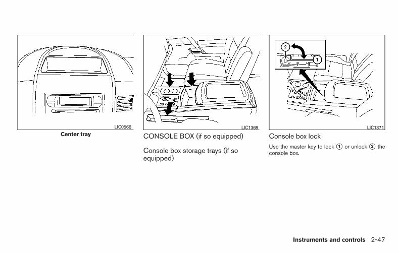
CONSOLE BOX (if so equipped)
Console box storage trays (if soequipped)
Console box lockUse the master key to lock �1 or unlock �2 theconsole box.
Center trayLIC0566 LIC1369 LIC1371
Instruments and controls 2-47

CENTER ARMREST STORAGE (if soequipped)To access the center armrest storage area, lowerthe center armrest and lift the lid.
GLOVE BOXOpen the glove box by pulling the handle.
Use the master key to lock or unlock the glove boxlock (if so equipped). The valet key cannot beused.
WARNING
Keep glove box lid closed while driving tohelp prevent injury in an accident or asudden stop.
LIC0621 LIC0578
2-48 Instruments and controls

SUNGLASSES HOLDER (if soequipped)To open the sunglasses holder, push and release.
WARNING
● Keep the sunglasses holder closedwhile driving to prevent an accident.
CAUTION
● Do not leave sunglasses in the sun-glasses holder while parking in directsunlight. The heat may damage thesunglasses.
● Do not use for anything other thansunglasses.
MAP POCKETSLIC0567 LIC0589
Instruments and controls 2-49

SEATBACK POCKET (if so equipped)The seatback pocket is located on the back of thedriver’s seat. The pocket can be used to storemaps.
OVERHEAD CONSOLE (if soequipped)
Storage bins
WARNING
Keep storage bins closed while driving tohelp prevent injury in an accident or asudden stop.
Push the button to open a storage bin.
Push the lid up to close.
LIC0575Small bin (if so equipped)
LIC0568
Medium bin (if so equipped)LIC0569
2-50 Instruments and controls

CUP HOLDERS
CAUTION
● Avoid abrupt starting and braking whenthe cup holder is being used to preventspilling the drink. If the liquid is hot, itcan scald you or your passenger.
● Use only soft cups in the cup holder.Hard objects can injure you in anaccident.
Position the arm on the adjustable cup holder sothat the cup is held securely.
Front — Type A (if so equipped)LIC1372
Front — Type B (if so equipped)LIC0620
Adjustable (if so equipped)LIC1373
Instruments and controls 2-51

To open the 2nd row cup holders (rear of frontconsole), lower the lid. To close, raise the lid.
Armrest (if so equipped)LIC0622
2nd row (rear of front console)(if so equipped)
LIC0554
2nd row bench (if so equipped)LIC0556
2-52 Instruments and controls

CAUTION
● Do not use bottle holder for any otherobjects that could be thrown about inthe vehicle and possibly injure peopleduring sudden braking or an accident.
● Do not use bottle holder for open liquidcontainers.
GROCERY HOOKS (if so equipped)The grocery hooks allow for standard size plasticgrocery bags to hang side by side.
To access the grocery hooks, fold up the rearbench seat. For additional information, refer to“Folding the rear bench seat” in the “Safety —Seats, seat belts and supplemental restraint sys-tem” section of this manual.
CAUTION
Do not apply a total load of more than18 lbs (8 kg) to a single grocery hook.
Bottle holder — Type A (if so equipped)LIC0558
Bottle holder — Type B (if so equipped)LIC0624 LIC0626
Instruments and controls 2-53

LOCKABLE BEDSIDE STORAGECOMPARTMENT (if so equipped)
To access the bedside storage compartment,hold the key hole cover open and insert themaster key. Turn the key clockwise to unlock thelid.
The tray inside the bedside storage compartmentis adjustable.
The bedside storage compartment will automati-cally lock when the lid is closed. You do not needto use the key.
CAUTION
● Do not store a total load of more than22 lbs (10 kg) inside the storagecompartment.
● Do not use the storage compartment orstorage compartment lid as a step. Do-ing so may damage them.
POWER WINDOWS
WARNING
● Make sure that all passengers havetheir hands, etc. inside the vehicle whileit is in motion and before closing thewindows. Use the window lock switch toprevent unexpected use of the powerwindows.
● Do not leave children unattended insidethe vehicle. They could unknowingly ac-tivate switches or controls and becometrapped in a window. Unattended chil-dren could become involved in seriousaccidents.
The power windows operate when the ignitionswitch is placed in the ON position, or for aperiod of time after the ignition switch is placed inthe OFF position. If the driver’s or passenger’sdoor is opened during this period of time, thepower to the windows is canceled.
LIC0625
WINDOWS
2-54 Instruments and controls
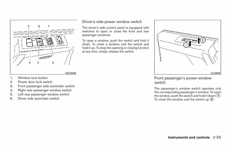
1. Window lock button2. Power door lock switch3. Front passenger side automatic switch4. Right rear passenger window switch5. Left rear passenger window switch6. Driver side automatic switch
Driver’s side power window switchThe driver’s side control panel is equipped withswitches to open or close the front and rearpassenger windows.
To open a window, push the switch and hold itdown. To close a window, pull the switch andhold it up. To stop the opening or closing functionat any time, simply release the switch.
Front passenger’s power windowswitchThe passenger’s window switch operates onlythe corresponding passenger’s window. To openthe window, push the switch and hold it down �1 .To close the window, pull the switch up �2 .
WIC0845 LIC0580
Instruments and controls 2-55

Rear power window switchThe rear power window switches open or closeonly the corresponding windows. To open thewindow, push the switch and hold it down �1 . Toclose the window, pull the switch up �2 .
Locking passengers’ windowsWhen the window lock switch is depressed, onlythe driver’s side window can be opened orclosed. Push it again to cancel the window lockfunction.
Automatic operation
To fully open a window equipped with automaticoperation, press the window switch down to thesecond detent and release it; it need not be held.The window automatically opens all the way. Tostop the window, lift the switch up while thewindow is opening.
To fully close a window equipped with automaticoperation, pull the switch up to the second detentand release it; it need not be held. To stop thewindow, press the switch down while the windowis closing.
Auto-reverse functionThe auto-reverse function can be activated whena window is closed by automatic operation.
Depending on the environment or drivingconditions, the auto-reverse function maybe activated if an impact or load similar tosomething being caught in the window oc-curs.
WARNING
There are some small distances immedi-ately before the closed position whichcannot be detected. Make sure that allpassengers have their hands, etc., insidethe vehicle before closing the window.
If the vehicle’s battery is disconnected, replaced,or jump started, the power window auto-reversefunction may not operate properly. If this occurs,please contact the dealer to re-initialize thepower window auto-reverse system.
If the control unit detects something caught in awindow equipped with automatic operation as itis closing, the window will be immediately low-ered.
LIC0581 LIC0410
2-56 Instruments and controls

REAR SLIDING WINDOW (if soequipped)Squeeze the handles of the lever �1 , then slidethe window open �2 .
REAR POWER WINDOW SWITCH(if so equipped)
To open the rear power window, push in and holdthe switch.
To close the rear power window, pull out and holdthe switch.
To stop the opening or closing function at anytime, simply release the switch.
NOTE:
If the rear power window (if so equipped) islowered while the defroster switch is on,the rear window defroster will automati-cally shut off. The heated outside mirrors (ifso equipped) will remain on. The rear win-dow defroster will automatically turn onwhen the rear power window is fully closedif the switch is on.
LIC0627 LIC1553
Instruments and controls 2-57

POWER MOONROOF
The moonroof will only operate when the ignitionswitch is placed in the ON position. The powermoonroof is operational for a period of time, evenif the ignition switch is placed in the ACC or OFFposition. If the driver’s door or the front passen-ger’s door is opened during this period of time,the power to the moonroof is canceled.
Sliding the moonroofTo fully open the moonroof, push the switch to-ward the open position �3 .
To fully close the moonroof, push the switchtoward the close position �4 .
To open or close the moonroof part way, push theswitch in any direction �5 while the moonroof issliding open or closed to stop it in the desiredposition.
Tilting the moonroof
To tilt the moonroof up, push the tilt switch to-ward the up position �1 .
To tilt the moonroof down, push the tilt switchtoward the down position �2 .
Restarting the moonroof sliding switch
The sliding switch will become inoperable afterthe battery terminal is disconnected, the electri-cal supply interrupted and/or some abnormalitydetected. Use the following reset procedure toreturn moonroof operation to normal.
1. If the moonroof lid is open, push the tiltingswitch repeatedly toward the down position�2 to fully close the lid.
2. Push and hold the tilting switch for morethan 2 seconds toward the down position�2 to reestablish the lid’s home position.
The moonroof should now operate normally.
Auto-reverse function (when closing ortilting down the moonroof)
The auto-reverse function can be activated whenthe moonroof is closed or tilted down by auto-matic operation when the ignition switch isplaced in the ON position or for a period of timeafter the ignition switch is placed in the OFFposition.
Depending on the environment or drivingconditions, the auto-reverse function maybe activated if an impact or load similar tosomething being caught in the moonroofoccurs.
WARNING
There are some small distances immedi-ately before the closed position whichcannot be detected. Make sure that allpassengers have their hands, etc., insidethe vehicle before closing the moonroof.
When closing
If the control unit detects something caught in themoonroof as it moves to the front, the moonroofwill immediately open backward.
WIC0812
MOONROOF (if so equipped)
2-58 Instruments and controls

When tilting down
If the control unit detects something caught in themoonroof as it tilts down, the moonroof will im-mediately tilt up.
If the auto-reverse function malfunctions and re-peats opening or tilting up the moonroof, keeppushing the tilt down switch within 5 secondsafter it happens; the moonroof will fully closegradually. Make sure nothing is caught in themoonroof.
WARNING
● In an accident you could be thrown fromthe vehicle through an open moonroof.Always use seat belts and childrestraints.
● Do not allow anyone to stand up orextend any portion of their body out ofthe moonroof opening while the vehicleis in motion or while the moonroof isclosing.
CAUTION
● Remove water drops, snow, ice or sandfrom the moonroof before opening.
● Do not place heavy objects on themoonroof or surrounding area.
SunshadeOpen and close the sunshade by sliding it for-ward or backward.
If the moonroof does not closeHave your NISSAN dealer check and repair themoonroof.
The interior light has a three-position switch andoperates regardless of ignition switch position.
When the switch is in the ON position �1 , theinterior lights illuminate, regardless of door posi-tion. The lights will go off after a period of timeunless the ignition switch is placed in the ONposition.
Type A (if so equipped)LIC0585
INTERIOR LIGHT
Instruments and controls 2-59

When the switch is in the DOOR or normaloperation position �2 , the interior lights, puddlelights (if so equipped) and cargo light will stay onfor a period of time when:
● The doors are unlocked by the key fob, a keyor the power door lock switch while all doorsare closed and the ignition switch is in theOFF position.
● The driver’s door is opened and then closedwhile the key is removed from the ignitionswitch.
● The key is removed from the ignition switchwhile all doors are closed.
The lights will turn off while the timer is activatedwhen:
● The driver’s door is locked by the key fob, akey, or the power door lock switch.
● The ignition switch is turned ON.
When the switch is in the OFF position �3 , theinterior lights do not illuminate, regardless of doorposition. The puddle lights (if so equipped) andcargo light come on when any front or rear pas-senger door is opened.
The lights will turn off automatically after a periodof time while doors are open to prevent the bat-tery from becoming discharged.
NOTE:
The door step lights (if so equipped) illumi-nate when the driver and passenger doorsare open regardless of the interior lightswitch position. These lights will turn offautomatically after a period of time whiledoors are open to prevent the battery frombecoming discharged.
CAUTION
Do not use for extended periods of timewith the engine stopped. This could resultin a discharged battery.
CONSOLE LIGHT (if so equipped)The console light �1 will turn on whenever theparking lights or headlights are illuminated.
The console light brightness can be adjustedwith the illumination brightness control.
Type B (if so equipped)LIC0630 LIC0587
2-60 Instruments and controls

The personal lights on the overhead console canbe swiveled 360 degrees. To turn on the light,press the button. Press the button again to turnoff the light.
To turn the map lights on, press the switches. Toturn them off, press the switches again.
CAUTION
Do not use for extended periods of timewith the engine stopped. This could resultin a discharged battery.
The HomeLink® Universal Transceiver providesa convenient way to consolidate the functions ofup to three individual hand-held transmitters intoone built-in device.
HomeLink® Universal Transceiver:
● Will operate most Radio Frequency devicessuch as garage doors, gates, home and of-fice lighting, entry door locks and securitysystems.
● Is powered by your vehicle’s battery. Noseparate batteries are required. If the vehi-cle’s battery is discharged or is discon-nected, HomeLink® will retain all program-ming.
When the HomeLink® Universal Trans-ceiver is programmed, retain the originaltransmitter for future programming proce-dures (Example: new vehicle purchases).Upon sale of the vehicle, the programmedHomeLink® Universal Transceiver buttonsshould be erased for security purposes. Foradditional information, refer to “Program-ming HomeLink®” in this section.
LIC0623 LIC0586
PERSONAL LIGHTS (if so equipped) MAP LIGHTS (if so equipped) HOMELINK® UNIVERSALTRANSCEIVER (if so equipped)
Instruments and controls 2-61

WARNING
● Do not use the HomeLink® UniversalTransceiver with any garage dooropener that lacks safety stop and re-verse features as required by federalsafety standards. (These standards be-came effective for opener modelsmanufactured after April 1, 1982). A ga-rage door opener which cannot detectan object in the path of a closing garagedoor and then automatically stop andreverse, does not meet current federalsafety standards. Using a garage dooropener without these features in-creases the risk of serious injury ordeath.
● During the programming procedureyour garage door or security gate willopen and close (if the transmitter iswithin range). Make sure that people orobjects are clear of the garage door,gate, etc. that you are programming.
● Your vehicle’s engine should be turnedoff while programming the HomeLink®Universal Transceiver.
PROGRAMMING HOMELINK®If you have any questions or are having difficultyprogramming your HomeLink® buttons, refer tothe HomeLink® web site at: www.homelink.comor call 1-800-355-3515.
NOTE:
Place the ignition switch in the ACC posi-tion when programming HomeLink®. It isalso recommended that a new battery beplaced in the hand-held transmitter of thedevice being programmed to HomeLink®for quicker programming and accuratetransmission of the radio-frequency.
1. Position the end of your hand-held transmit-ter 1–3 in (2–8 cm) away from theHomeLink® surface, keeping theHomeLink® indicator light �1 in view.
2. Using both hands, simultaneously press andhold the desired HomeLink® button andhand-held transmitter button. DO NOT re-lease until the HomeLink® indicator light �1flashes slowly and then rapidly. When theindicator light flashes rapidly, both buttonsmay be released. (The rapid flashing indi-cates successful programming.)
NOTE:
Some devices may require you to replaceStep 2 with the cycling procedure noted in“Programming HomeLink® for Canadiancustomers and gate openers” in this sec-tion.
LIC2365
2-62 Instruments and controls

3. Press and hold the programmedHomeLink® button and observe the indica-tor light.
● If the indicator light �1 issolid/continuous, programming iscomplete and your device should acti-vate when the HomeLink® button ispressed and released.
● If the indicator light �1 blinks rapidly for2 seconds and then turns to asolid/continuous light, continuewith Steps 4-6 for a rolling code device.A second person may make the followingsteps easier. Use a ladder or other device.
Do not stand on your vehicle to performthe next steps.
4. At the receiver located on the garage dooropener motor in the garage, locate the“learn”or “smart”button (the name and colorof the button may vary by manufacturer but itis usually located near where the hangingantenna wire is attached to the unit). If thereis difficulty locating the button, reference thegarage door opener’s manual.
5. Press and release the “learn” or “smart” but-ton.
6. Return to the vehicle and firmly press andhold the trained HomeLink® button for2 seconds and release. Repeat the“press/hold/release” sequence up to threetimes to complete the training process.HomeLink® should now activate your rollingcode equipped device.
7. If you have any questions or are having diffi-culty programming your HomeLink® buttons,refer to the HomeLink® web site at:www.homelink.com or call 1-800-355-3515.
PROGRAMMING HOMELINK® FORCANADIAN CUSTOMERS ANDGATE OPENERS
Canadian radio-frequency laws require transmit-ter signals to “time-out” (or quit) after severalseconds of transmission – which may not be longenough for HomeLink® to pick up the signalduring training. Similar to this Canadian law,some U.S. gate operators are designed to “tim-eout” in the same manner.
If you live in Canada or you are having difficultiestraining a gate operator or garage door openerby using the “Training” procedures, replace“Programming HomeLink®” Step 2 with thefollowing:
NOTE:
When programming a garage door opener,etc., unplug the device during the “cycling”process to prevent possible damage to thegarage door opener components.
1. For additional information, refer to “Pro-gramming HomeLink®” step 1 in this sec-tion.
2. Using both hands, simultaneously press andhold the desired HomeLink® button and thehand-held transmitter button. During train-ing, your hand-held transmitter may auto-
LIC2366
Instruments and controls 2-63

matically stop transmitting. Continue topress and hold the desired HomeLink® but-ton while you press and re-press (“cycle”)your hand-held transmitter every 2 secondsuntil the frequency signal has been learned.The HomeLink® indicator light will flashslowly and then rapidly after several secondsupon successful training. DO NOT releaseuntil the HomeLink® indicator light flashesslowly and then rapidly. When the indicatorlight flashes rapidly, both buttons may bereleased. The rapid flashing indicates suc-cessful training.Proceed with “Programming HomeLink®”step 3 to complete.If the device was unplugged during the pro-gramming procedure, remember to plug itback in when programming is completed.
OPERATING THE HOMELINK®UNIVERSAL TRANSCEIVERThe HomeLink® Universal Transceiver, after it isprogrammed, can be used to activate the pro-grammed device. To operate, simply press andrelease the appropriate programmedHomeLink® Universal Transceiver button. Theamber indicator light will illuminate while the sig-nal is being transmitted.
For convenience, the hand-held transmitter of thedevice may also be used at any time.
PROGRAMMING TROUBLE-DIAGNOSISIf the HomeLink® does not quickly learn thehand-held transmitter information:
● replace the hand-held transmitter batterieswith new batteries.
● position the hand-held transmitter with itsbattery area facing away from theHomeLink® surface.
● press and hold both the HomeLink® andhand-held transmitter buttons without inter-ruption.
● position the hand-held transmitter 1 -3 inches (26 - 76 mm) away from theHomeLink® surface. Hold the transmitter inthat position for up to 15 seconds. IfHomeLink® is not programmed within thattime, try holding the transmitter in anotherposition – keeping the indicator light in viewat all times.
If you have any questions or are having difficultyprogramming your HomeLink® buttons, refer tothe HomeLink® web site at: www.homelink.comor call 1-800-355-3515.
CLEARING THE PROGRAMMEDINFORMATIONThe following procedure clears the programmedinformation from both buttons. Individual buttonscannot be cleared. However, individual buttonscan be reprogrammed. For additional informa-tion, refer to “Reprogramming a singleHomeLink® button” in this section.
To clear all programming:
1. Press and hold the two outer HomeLink®buttons until the indicator light begins toflash in approximately 10 seconds. Do nothold for longer than 20 seconds.
2. Release both buttons.
HomeLink® is now in the programming modeand can be programmed at any time beginningwith “Programming HomeLink®” - Step 1.
2-64 Instruments and controls

REPROGRAMMING A SINGLEHOMELINK® BUTTONTo reprogram a HomeLink® Universal Trans-ceiver button, complete the following:
1. Press and hold the desired HomeLink® but-ton. DO NOT release the button.
2. The indicator light will begin to flash after20 seconds. Without releasing theHomeLink® button, proceed with “Pro-gramming HomeLink®” - Step 1.
For questions or comments, contact HomeLink®at: www.homelink.com or 1–800–355–3515(except Mexico).
The HomeLink® Universal Transceiver buttonhas now been reprogrammed. The new devicecan be activated by pushing the HomeLink®button that was just programmed. This procedurewill not affect any other programmed HomeLink®buttons.
IF YOUR VEHICLE IS STOLENIf your vehicle is stolen, you should change thecodes of any non-rolling code device that hasbeen programmed into HomeLink®. Consult theOwner’s Manual of each device or call the manu-facturer or dealer of those devices for additionalinformation.
When your vehicle is recovered, you willneed to reprogram the HomeLink® Univer-sal Transceiver with your new transmitterinformation.
FCC Notice:
For USA:
This device complies with Part 15 of theFCC Rules. Operation is subject to the fol-lowing two conditions: (1) This device maynot cause interference, and (2) this devicemust accept any interference received, in-cluding interference that may cause unde-sired operation.
NOTE:
Changes or modifications not expressly ap-proved by the party responsible for compli-ance could void the user’s authority to op-erate the equipment.
For Canada:
This device complies with Industry Canadalicence-exempt RSS standard(s). Opera-tion is subject to the following two condi-tions: (1) this device may not cause inter-ference, and (2) this device must accept anyinterference, including interference thatmay cause undesired operation of the de-vice.
Instruments and controls 2-65

MEMO
2-66 Instruments and controls

3 Pre-driving checks and adjustments
Keys . . . . . . . . . . . . . . . . . . . . . . . . . . . . . . . . . . . . . . . . . . . . . 3-2NISSAN vehicle immobilizer system keys(if so equipped) . . . . . . . . . . . . . . . . . . . . . . . . . . . . . . . . 3-2
Doors . . . . . . . . . . . . . . . . . . . . . . . . . . . . . . . . . . . . . . . . . . . . 3-3Locking with key. . . . . . . . . . . . . . . . . . . . . . . . . . . . . . . . 3-3Locking with inside lock knob . . . . . . . . . . . . . . . . . . . . 3-4Locking with power door lock switch . . . . . . . . . . . . . 3-4Wide Open doors (if so equipped) . . . . . . . . . . . . . . . 3-5Automatic door locks . . . . . . . . . . . . . . . . . . . . . . . . . . . 3-6Child safety rear door lock (if so equipped) . . . . . . . . 3-7
Remote keyless entry system (if so equipped). . . . . . . . . 3-7How to use remote keyless entry system . . . . . . . . . . 3-8
Hood . . . . . . . . . . . . . . . . . . . . . . . . . . . . . . . . . . . . . . . . . . . 3-11Fuel-filler door . . . . . . . . . . . . . . . . . . . . . . . . . . . . . . . . . . . 3-11
Fuel-filler cap . . . . . . . . . . . . . . . . . . . . . . . . . . . . . . . . . 3-11Steering wheel . . . . . . . . . . . . . . . . . . . . . . . . . . . . . . . . . . . 3-14
Tilt operation . . . . . . . . . . . . . . . . . . . . . . . . . . . . . . . . . . 3-14Pedal position adjustment (if so equipped) . . . . . . . . . . 3-14Sun visors . . . . . . . . . . . . . . . . . . . . . . . . . . . . . . . . . . . . . . . 3-15
Vanity mirrors (if so equipped). . . . . . . . . . . . . . . . . . . 3-15Mirrors . . . . . . . . . . . . . . . . . . . . . . . . . . . . . . . . . . . . . . . . . . 3-16
Rearview mirror (if so equipped). . . . . . . . . . . . . . . . . 3-16Automatic anti-glare rearview mirror(if so equipped) . . . . . . . . . . . . . . . . . . . . . . . . . . . . . . . 3-16Outside mirrors . . . . . . . . . . . . . . . . . . . . . . . . . . . . . . . 3-17
Truck box . . . . . . . . . . . . . . . . . . . . . . . . . . . . . . . . . . . . . . . . 3-21Tailgate. . . . . . . . . . . . . . . . . . . . . . . . . . . . . . . . . . . . . . . 3-21Tie down hooks . . . . . . . . . . . . . . . . . . . . . . . . . . . . . . . 3-25
Automatic drive positioner (if so equipped) . . . . . . . . . . 3-25Memory storage function . . . . . . . . . . . . . . . . . . . . . . . 3-26Entry/exit function . . . . . . . . . . . . . . . . . . . . . . . . . . . . . 3-27System operation. . . . . . . . . . . . . . . . . . . . . . . . . . . . . . 3-27
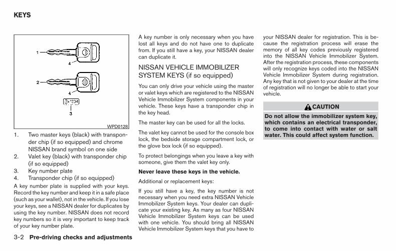
1. Two master keys (black) with transpon-der chip (if so equipped) and chromeNISSAN brand symbol on one side
2. Valet key (black) with transponder chip(if so equipped)
3. Key number plate4. Transponder chip (if so equipped)A key number plate is supplied with your keys.Record the key number and keep it in a safe place(such as your wallet), not in the vehicle. If you loseyour keys, see a NISSAN dealer for duplicates byusing the key number. NISSAN does not recordkey numbers so it is very important to keep trackof your key number plate.
A key number is only necessary when you havelost all keys and do not have one to duplicatefrom. If you still have a key, your NISSAN dealercan duplicate it.
NISSAN VEHICLE IMMOBILIZERSYSTEM KEYS (if so equipped)
You can only drive your vehicle using the masteror valet keys which are registered to the NISSANVehicle Immobilizer System components in yourvehicle. These keys have a transponder chip inthe key head.
The master key can be used for all the locks.
The valet key cannot be used for the console boxlock, the bedside storage compartment lock, orthe glove box lock (if so equipped).
To protect belongings when you leave a key withsomeone, give them the valet key only.
Never leave these keys in the vehicle.
Additional or replacement keys:
If you still have a key, the key number is notnecessary when you need extra NISSAN VehicleImmobilizer System keys. Your dealer can dupli-cate your existing key. As many as four NISSANVehicle Immobilizer System keys can be usedwith one vehicle. You should bring all NISSANVehicle Immobilizer System keys that you have to
your NISSAN dealer for registration. This is be-cause the registration process will erase thememory of all key codes previously registeredinto the NISSAN Vehicle Immobilizer System.After the registration process, these componentswill only recognize keys coded into the NISSANVehicle Immobilizer System during registration.Any key that is not given to your dealer at the timeof registration will no longer be able to start yourvehicle.
CAUTION
Do not allow the immobilizer system key,which contains an electrical transponder,to come into contact with water or saltwater. This could affect system function.
WPD0128
KEYS
3-2 Pre-driving checks and adjustments

When the doors are locked using one of thefollowing methods, the doors cannot be openedusing the inside or outside door handles. Thedoors must be unlocked to open the doors.
WARNING
● Always have the doors locked whiledriving. Along with the use of seat belts,this provides greater safety in the eventof an accident by helping to preventpersons from being thrown from thevehicle. This also helps keep childrenand others from unintentionally open-ing the doors, and will help keep outintruders.
● Before opening any door, always lookfor and avoid oncoming traffic.
● Do not leave children unattended insidethe vehicle. They could unknowingly ac-tivate switches or controls. Unattendedchildren could become involved in seri-ous accidents.
LOCKING WITH KEY
ManualTo lock a door, turn the key toward the front of thevehicle �1 . To unlock, turn the key toward the rear�2 .
Power
The power door lock system allows you to lock orunlock all doors at the same time.
Turning the key toward the front �1 of the vehiclelocks all doors.
Turning the key one time toward the rear �2 of thevehicle unlocks that door. From that position,returning the key to neutral �3 (where the key canonly be removed and inserted) and turning ittoward the rear again �4 within 45 secondsunlocks all doors.
Driver’s sideWPD0311
Driver’s sideLPD0240
DOORS
Pre-driving checks and adjustments 3-3

Opening and closing windowsThe driver’s door key operation allows you toopen and close windows equipped with auto-matic operation at the same time.
● To open the windows, turn the driver’s doorkey toward the rear of the vehicle for longerthan 1 second after the door is unlocked.
● To close the windows, turn the driver’s doorkey toward the front of the vehicle for longerthan 1 second after the door is locked.
Windows stop when the key cylinder is released.
LOCKING WITH INSIDE LOCKKNOBTo lock the door without the key, move the insidelock knob to the lock position �1 , then close thedoor.
To unlock the door without the key, move theinside lock knob to the unlock position �2 .
LOCKING WITH POWER DOORLOCK SWITCHTo lock all the doors without a key, push the doorlock switch (driver’s or front passenger’s side) tothe lock position �1 . When locking the door thisway, be certain not to leave the key inside thevehicle.
To unlock all the doors without a key, push thedoor lock switch (driver’s or front passenger’sside) to the unlock position �2 .
Inside lockLPD0241 WPD0381
3-4 Pre-driving checks and adjustments
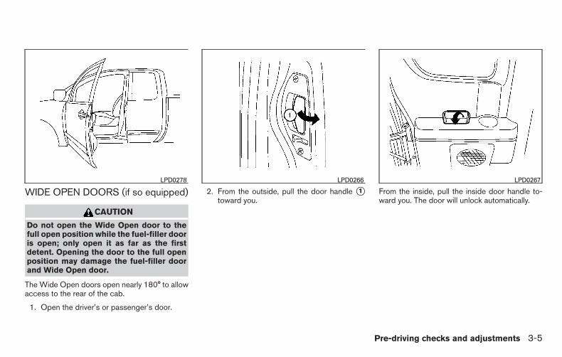
WIDE OPEN DOORS (if so equipped)
CAUTION
Do not open the Wide Open door to thefull open position while the fuel-filler dooris open; only open it as far as the firstdetent. Opening the door to the full openposition may damage the fuel-filler doorand Wide Open door.
The Wide Open doors open nearly 180° to allowaccess to the rear of the cab.
1. Open the driver’s or passenger’s door.
2. From the outside, pull the door handle �1toward you.
From the inside, pull the inside door handle to-ward you. The door will unlock automatically.
LPD0278 LPD0266 LPD0267
Pre-driving checks and adjustments 3-5

3. Open the door to the desired position.
AUTOMATIC DOOR LOCKS● All doors lock automatically when the vehicle
speed reaches 15 MPH (24 km/h).
● All doors unlock automatically when thetransmission is placed in the P (Park) posi-tion.
The automatic unlock function can be de-activated or activated. To deactivate or acti-vate the automatic door unlock system, performthe following procedure:
1. Close all doors.
2. Place the ignition switch in the ON position.
3. Within 20 seconds of performing Step 2,push and hold the power door lock switch tothe position (UNLOCK) for more than5 seconds.
4. When activated, the hazard indicator willflash twice. When deactivated, the hazardindicator will flash once.
5. The ignition switch must be placed in theOFF and ON position again between eachsetting change.
When the automatic door unlock system is deac-tivated, the doors do not unlock when the trans-mission is placed in the P (Park) position. Tounlock the door manually, use the inside lockknob or the power door lock switch (driver’s orfront passenger’s side).
LPD0265
3-6 Pre-driving checks and adjustments

CHILD SAFETY REAR DOOR LOCK(if so equipped)Child safety locks help prevent the rear doorsfrom being opened accidentally, especially whensmall children are in the vehicle.
The child safety lock levers are located on theedge of the rear doors.
When the lever is in the LOCK position, thedoor can be opened only from the outside.
WARNING
● Radio waves could adversely affectelectric medical equipment. Those whouse a pacemaker should contact theelectric medical equipment manufac-turer for the possible influences beforeuse.
● The remote keyless entry key fob trans-mits radio waves when the buttons arepressed. The FAA advises radio wavesmay affect aircraft navigation and com-munication systems. Do not operate theremote keyless entry key fob while onan airplane. Make sure the buttons arenot operated unintentionally when theunit is stored for a flight.
It is possible to lock/unlock all doors, turn theinterior lights on, and activate the panic alarm byusing the key fob from outside the vehicle.
Be sure to remove the key from the vehiclebefore locking the doors.
The key fob can operate at a distance of approxi-mately 33 ft (10 m) from the vehicle. The effectivedistance depends on the conditions around thevehicle.
As many as five key fobs can be used with onevehicle. For information concerning the purchaseand use of additional key fobs, contact a NISSANdealer.
The key fob will not function when:
● the battery is discharged
● the distance between the vehicle and thekey fob is over 33 ft (10 m)
The panic alarm will not activate when thekey is in the ignition switch.
CAUTION
Listed below are conditions or occur-rences which will damage the key fob:
● Do not allow the key fob, which con-tains electrical components, to comeinto contact with water or salt water.This could affect the system function.
● Do not drop the key fob.
● Do not strike the key fob sharplyagainst another object.
● Do not change or modify the key fob.
● Wetting may damage the key fob. If thekey fob gets wet, immediately wipe untilit is completely dry.
LPD0242
REMOTE KEYLESS ENTRY SYSTEM(if so equipped)
Pre-driving checks and adjustments 3-7

● Do not place the key fob for an ex-tended period in an area where tem-peratures exceed 140°F (60°C).
● Do not attach the key fob with a keyholder that contains a magnet.
● Do not place the key fob near equip-ment that produces a magnetic field,such as a TV, audio equipment and per-sonal computers.
If a key fob is lost or stolen, NISSAN rec-ommends erasing the ID code of that keyfob. This will prevent the key fob fromunauthorized use to unlock the vehicle.For information regarding the erasingprocedure, please contact a NISSANdealer.
HOW TO USE REMOTE KEYLESSENTRY SYSTEM
Locking doors
1. Close all windows.
2. Remove the key from the ignition switch.
3. Close the hood and all doors.
4. Press the button on the key fob. Allthe doors lock. The hazard warning lightsflash twice and the horn beeps once toindicate all doors are locked.
● When the button is pressed withall doors locked, the hazard warning lightsflash twice and the horn beeps once as areminder that the doors are alreadylocked.
● If a door is open and you pressthe button, the doors will lockbut the horn will not beep and the hazardlights will not flash.
The horn may or may not beep. For additionalinformation, refer to “Silencing the horn beepfeature” in this section.
LPD0209
3-8 Pre-driving checks and adjustments

Unlocking doors
Press the button on the key fob once.
● Only the driver’s door unlocks.
● The hazard warning lights flash once if alldoors are completely closed with the ignitionswitch in any position except the ON posi-tion.
● The interior lights and puddle lights (if soequipped) turn on and the light timer acti-vates for a period of time when the interiorlight switch is in the DOOR position with theignition switch in any position except the ONposition.
Press the button on the key fob againwithin 5 seconds.
● All doors unlock.
● The hazard warning lights flash once if alldoors are completely closed.
The interior lights can be turned off without wait-ing by inserting the key into the ignition switchand placing it in the ON or START position,locking the doors with the key fob or pushing theinterior light switch to the OFF position.
Auto relock
When the button on the key fob ispressed, all doors will lock automatically within1 minute unless one of the following operations isperformed:
● Any door is opened.
● A key is inserted into the ignition switch andthe switch is cycled from OFF to ON.
Linking the key fob to automatic drivepositioner memory (if so equipped)If the vehicle is equipped with automatic drivepositioner, the key fob can be linked to a memorysetting.
For additional information, refer to “Automaticdrive positioner” in this section.
Using the panic alarmIf you are near your vehicle and feel threatened,you may activate the panic alarm to call attentionby pressing and holding the button on thekey fob for longer than 0.5 seconds.
The panic alarm and headlights will stay on for aperiod of time.
The panic alarm stops when:
● it has run for a period of time, or
● any button is pressed on the key fob.
LPD0210 LPD0211
Pre-driving checks and adjustments 3-9
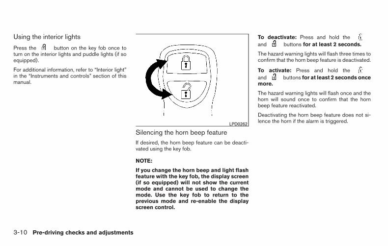
Using the interior lights
Press the button on the key fob once toturn on the interior lights and puddle lights (if soequipped).
For additional information, refer to “Interior light”in the “Instruments and controls” section of thismanual.
Silencing the horn beep featureIf desired, the horn beep feature can be deacti-vated using the key fob.
NOTE:
If you change the horn beep and light flashfeature with the key fob, the display screen(if so equipped) will not show the currentmode and cannot be used to change themode. Use the key fob to return to theprevious mode and re-enable the displayscreen control.
To deactivate: Press and hold theand buttons for at least 2 seconds.
The hazard warning lights will flash three times toconfirm that the horn beep feature is deactivated.
To activate: Press and hold theand buttons for at least 2 seconds oncemore.
The hazard warning lights will flash once and thehorn will sound once to confirm that the hornbeep feature reactivated.
Deactivating the horn beep feature does not si-lence the horn if the alarm is triggered.LPD0262
3-10 Pre-driving checks and adjustments

�1 Pull the hood lock release handle locatedbelow the driver side instrument panel. Thehood will spring up slightly.
�2 Push the lever at the front of the hood to theside as illustrated with your fingertips andraise the hood.
When closing the hood, lower it slowly and makesure it locks into place.
WARNING
● Make sure the hood is completelyclosed and latched before driving. Fail-ure to do so could cause the hood to flyopen and result in an accident.
● If you see steam or smoke coming fromthe engine compartment, to avoid injurydo not open the hood.
FUEL-FILLER CAP
WARNING
● Gasoline is extremely flammable andhighly explosive under certain condi-tions. You could be burned or seriouslyinjured if it is misused or mishandled.Always stop the engine and do notsmoke or allow open flames or sparksnear the vehicle when refueling.
LPD0244 LPD0263
HOOD FUEL-FILLER DOOR
Pre-driving checks and adjustments 3-11

● Do not attempt to top off the fuel tankafter the fuel pump nozzle shuts offautomatically. Continued refueling maycause fuel overflow, resulting in fuelspray and possibly a fire.
● Use only an original equipment typefuel-filler cap as a replacement. It has abuilt-in safety valve needed for properoperation of the fuel system and emis-sion control system. An incorrect capcan result in a serious malfunction andpossible injury. It could also causethe Malfunction Indicator Light(MIL) to come on.
● Never pour fuel into the throttle body toattempt to start your vehicle.
● Do not fill a portable fuel container on atruck bed liner, rubber truck bed mat, orother insulating material. Static elec-tricity can cause an explosion of flam-mable liquid, vapor or gas in any vehicleor trailer. To reduce the risk of seriousinjury or death when filling portable fuelcontainers:
– Always place the container on theground when filling.
– Do not use electronic devices whenfilling.
– Keep the pump nozzle in contactwith the container while you are fill-ing it.
– Use only approved portable fuel con-tainers for flammable liquid.
CAUTION
● Only vehicles with the E-85 filler doorlabel can operate on up to E-85 fuel.Fuel system or other damage can occurif up to E-85 fuel is used in vehicles thatare not designed to run on E-85 fuel. Foradditional information, refer to “FuelRecommendation” in the “Technicaland consumer information” section ofthis manual.
● The LOOSE FUEL CAP warning will ap-pear if the fuel-filler cap is not properlytightened. It may take a few driving tripsfor the message to be displayed. Failureto tighten the fuel-filler cap properlyafter the LOOSE FUEL CAP warning ap-pears may cause the MalfunctionIndicator Light (MIL) to illuminate.
● Failure to tighten the fuel-filler capproperly may cause the Malfunc-tion Indicator Light (MIL) to illuminate.If the light illuminates becausethe fuel-filler cap is loose or missing,tighten or install the cap and continueto drive the vehicle. The lightshould turn off after a few driving trips.If the light does not turn off after afew driving trips, have the vehicle in-spected by a NISSAN dealer.
● For additional information, refer to“Malfunction Indicator Light (MIL)” inthe “Instruments and Controls” sectionin this manual.
● If fuel is spilled on the vehicle body,flush it away with water to avoid paintdamage.
For additional information, refer to “Fuel recom-mendation (without Flexible Fuel Vehicle option)”and “Flexible fuel vehicle (FFV) fuel recommen-dation” in the “Technical and consumer informa-tion” section in this manual.
3-12 Pre-driving checks and adjustments

To remove the fuel-filler cap:
1. Turn the fuel-filler cap counterclockwise toremove.
2. Loop the tether strap around the hook �1while refueling.
To install the fuel-filler cap:
1. Insert the fuel-filler cap straight into the fuel-filler tube.
2. Turn the fuel-filler cap clockwise until asingle click is heard.
Loose Fuel Cap warningThe LOOSE FUEL CAP warning appears in theodometer when the fuel-filler cap is not tightenedcorrectly after the vehicle has been refueled. Itmay take a few driving trips for the message to bedisplayed. To turn off the warning, perform thefollowing:
1. Remove and install the fuel-filler cap as pre-viously described as soon as possible.
2. Tighten the fuel-filler cap until it clicks.
3. Press the loose fuel cap warning reset but-ton �A on the instrument panel located be-hind the steering wheel for about 1 secondto turn off the LOOSE FUEL CAP warning�B after tightening the fuel-filler cap.
LPD0325 LRS2005
Pre-driving checks and adjustments 3-13

TILT OPERATION
WARNING
Do not adjust the steering wheel whiledriving. You could lose control of yourvehicle and cause an accident.
Pull the lock lever toward the driver and hold it toadjust the steering wheel up or down to thedesired position.
Release the lock lever to lock the steering wheelin place.
The accelerator and brake pedals can be ad-justed for driving comfort.
Use the pedal adjusting switch to adjust thebrake and accelerator pedal position away fromthe driver �1 or toward the driver �2 .
The brake and accelerator pedals cannot be ad-justed separately.
WARNING
Do not adjust the pedal position whiledriving. You can lose control of your ve-hicle and cause an accident.
CAUTION
Do not adjust the pedal position with yourfoot on the pedal.
LPD0254 LPD0255
STEERING WHEEL PEDAL POSITION ADJUSTMENT (if soequipped)
3-14 Pre-driving checks and adjustments

�1 To block glare from the front, swing down themain sun visor.
�2 To block glare from the side, remove themain sun visor from the center mount andswing the visor to the side.
�3 To extend the sun visor, slide in or out asneeded.
CAUTION
● Do not store the sun visor before return-ing the extension to its originalposition.
● Do not pull the extension sun visorforcedly downward. VANITY MIRRORS (if so equipped)
To access the vanity mirror, pull the sun visordown and flip open the mirror cover. Some vanitymirrors are illuminated and turn on when themirror cover is open.
WPD0344
WPD0141
SUN VISORS
Pre-driving checks and adjustments 3-15

REARVIEW MIRROR (if so equipped)Use the night position �1 to reduce glare fromthe headlights of vehicles behind you at night.
Use the day position �2 when driving in daylighthours.
WARNING
Use the night position only when neces-sary, because it reduces rear view clarity.
AUTOMATIC ANTI-GLAREREARVIEW MIRROR (if so equipped)The inside mirror is designed so that it automati-cally dims during night time conditions and ac-cording to the intensity of the headlights of thevehicle following you. The automatic anti-glarefeature is activated when the ignition switch is inthe ON position.
The indicator light will illuminate when the auto-matic anti-glare feature is operating.
NOTE:
Do not hang any objects over the sensors�1 or apply glass cleaner to the sensors.Doing so will reduce the sensitivity of thesensors, resulting in improper operation. Type A (if so equipped)
With the ignition switch placed in the ON posi-tion, press the button as described:
● To turn off the anti-glare feature, pressthe button. The indicator light will turnoff.
● To turn on the anti-glare feature, pressthe button again. The indicator lightwill turn on.
The indicator light will illuminate when the auto-matic anti-glare feature is operating.
WPD0126Type A (if so equipped)
LPD0446
MIRRORS
3-16 Pre-driving checks and adjustments

For additional information about the compassand compass features �2 (if so equipped), referto “Compass display” in the “Instruments andcontrols” section of this manual.
Type B (if so equipped)
With the ignition switch in the ON position, pressthe button as described:
● To turn off the automatic anti-glare feature,press the button. The indicator lightwill turn off.
● To turn on the automatic anti-glare feature,press the button again. The indicatorlight will turn on.
The indicator light �2 will illuminate when theautomatic anti-glare feature is operating.
OUTSIDE MIRRORS
WARNING
● Objects viewed in the outside mirror onthe passenger side are closer than theyappear. Be careful when moving to theright. Using only this mirror could causean accident. Use the inside mirror orglance over your shoulder to properlyjudge distances to other objects.
● Do not adjust the mirrors while driving.You could lose control of your vehicleand cause an accident.
Type B (if so equipped)WPD0331
Pre-driving checks and adjustments 3-17

Manual control type (if so equipped)The outside mirror can be moved in any directionfor a better rear view.
Electric control type (if so equipped)The outside mirror remote control will operateonly when the ignition switch is placed in theACC or ON position.
Move the small switch �1 to select the right or leftmirror. Move the large switch �2 to adjust eachmirror to the desired position.
Trailer tow mirrors (if so equipped)
WARNING
Objects viewed in the convex portion ofthe trailer tow mirror are closer than theyappear. Be careful when changing lanes orturning. Using only the convex mirrorcould cause an accident. Use the othermirrors or glance over your shoulder toproperly judge distances to other objects.
Use the outside mirror remote control to adjustthe top portion of the trailer tow mirror.
WPD0170 LPD0237 LPD0279
3-18 Pre-driving checks and adjustments

The lower portion of the trailer tow mirror can bemoved manually in any direction for a better rearview.
Pull the trailer tow mirror outward to extend it tothe desired position for better visibility while tow-ing a trailer.
WARNING
Do not extend or retract mirrors while driv-ing. You may lose control of your vehicleand cause an accident.
CAUTION
Driving in tight spaces with mirrors ex-tended may cause damage to the vehicle.
Manual folding outside mirrors (if soequipped)Pull the outside mirror toward the door to fold it.
LPD0268Type A (if so equipped)
LPD0259
Pre-driving checks and adjustments 3-19

Power folding outside mirrors (if soequipped)
CAUTION
Do not manually fold the power foldingmirrors. Manually folding the mirrors candamage the mirrors.
Push the switch to open or close the mirrors.
If one of the mirrors are manually operated orbumped, the mirror body can become loose atthe pivot point. To correct electronic mirror op-eration, cycle the mirrors by pushing the bottomof the switch until completely closed, then pushthe top of the switch until the mirrors are in theopen position.
Heated mirrors (if so equipped)Some outside mirrors can be heated to defrost,defog, or de-ice for improved visibility. For addi-tional information, refer to “Rear window andoutside mirror (if so equipped) defroster switch”in the “Instruments and controls” section of thismanual.
Type B (if so equipped)LPD0269 LPD2316
3-20 Pre-driving checks and adjustments

TAILGATE
Opening the tailgate
Pull the tailgate handle upward and lower thetailgate. The support cables hold the tailgateopen.
When closing the tailgate, make sure the latchesare securely locked.
Do not drive the vehicle with the tailgatedown, unless equipped with NISSAN’s BedExtender (accessory) or equivalent in theextended position.
For additional information on proper truck boxloading, refer to “Vehicle loading information” inthe “Technical and consumer information” sec-tion of this manual.
WARNING
● It is extremely dangerous to ride in acargo area inside a vehicle. In a colli-sion, people riding in these areas aremore likely to be seriously injured orkilled.
● Do not allow people to ride in any areaof your vehicle that is not equipped withseats and seat belts.
● Be sure everyone in your vehicle is in aseat and using a seat belt properly.
LPD0270
TRUCK BOX
Pre-driving checks and adjustments 3-21

Disconnecting the rear camera (if soequipped)Before removing the tailgate disconnect the rearcamera by performing the following:
1. Open the tailgate to access the rear cameraconnector bracket �1 located on the rearsill.
2. Remove the connector bracket �2 from thesill by pressing the locking tab inward, in thedirection shown, while pulling the bracketapart.
3. Disconnect the chassis wiring harness �3by pressing inward on the locking tab, in thedirection shown, while pulling the connec-tors apart. Hold the connector firmly to pre-vent the connector in the chassis harnessfrom falling into the sill.
4. Take the chassis plug and bracket from theglove box and connect them to the chassiswiring harness to avoid contamination to theterminals which will lead to malfunction ofthe rear camera.
5. Insert the bracket back into the sill.
6. Take the tailgate plug from the glove box andconnect it to the tailgate wiring harness toavoid contamination which will lead to mal-function of the rear camera.
7. Remove the tailgate. For additional informa-tion, refer to “Removing the tailgate” in thissection.
LPD2097
3-22 Pre-driving checks and adjustments

Removing the tailgate
1. Disconnect the wiring harness for the rearcamera (if so equipped). For additional infor-mation, refer to “Disconnecting the rearcamera” in this section.
2. Release the tailgate support cables.
CAUTION
● The tailgate is heavy. Two peopleshould remove or install it. Be carefulnot to drop it during removal.
● After releasing the support cables, donot let the tailgate rest on the bumper.
3. Hold the tailgate at a 45 degree angle.
4. Pull the tailgate out from the left side hinge.
5. Slide the tailgate out of the right side hinge.
Installing the tailgate1. Insert the tailgate into the right side hinge.
2. Hold the tailgate at a 45 degree angle andinsert into the left side hinge.
3. Continue to hold the tailgate at a 45 degreeangle and attach the tailgate support cables.
4. For vehicles with rear camera: Be sure thetailgate harness is not hanging below thetailgate and keep the tailgate open. For ad-ditional information, refer to “Connecting therear camera” in this section before closingthe tailgate.
5. For vehicles without rear camera: Close thetailgate securely.
LPD0271
Pre-driving checks and adjustments 3-23

Connecting the rear camera (if soequipped)
Before closing the tailgate reconnect the rearcamera by performing the following:
1. After attaching the rear tailgate to the truck,keep the tailgate open and check that thetailgate harness is not hanging below thetailgate.
2. Remove the connector bracket �2 from thesill by pressing the locking tab inward, in thedirection shown, while pulling the bracketapart.
3. Disconnect the chassis plug and bracketfrom the chassis wiring harness �3 . Keepthe connector and bracket in a safe placesuch as the glove box.
4. Disconnect the tailgate plug from the tail-gate wiring harness. Keep the tailgate plugin a safe place such as the glove box.
5. Connect the tailgate wiring harness to thechassis wiring harness.
6. Securely fix the rear camera connectorbracket �1 to the rear sill.
7. Close the tailgate securely.
Locking the tailgateTo unlock the tailgate, turn the key toward thepassenger side of the vehicle �1 . To lock, turn thekey toward the driver side �2 .
Both the master key and the valet key can beused to lock and unlock the tailgate.
LPD2097 LPD0272
3-24 Pre-driving checks and adjustments

TIE DOWN HOOKS
For your convenience, tie down hooks are placedat each corner of the truck box. These may beused to help secure cargo loaded into the truckbox.
● The weight of the cargo load must be evenlydistributed over both the front and the rearaxles.
● All cargo should be securely fastened withropes or straps to prevent it from shifting orsliding within the vehicle.
WARNING
● Properly secure all cargo with ropes orstraps to help prevent it from sliding orshifting. In a sudden stop or collision,unsecured cargo could cause personalinjury.
The automatic drive positioner system has twofeatures:
● Memory storage function
● Entry/exit function
LTI0102
AUTOMATIC DRIVE POSITIONER (ifso equipped)
Pre-driving checks and adjustments 3-25

MEMORY STORAGE FUNCTION
Two positions for the driver’s seat, acceleratorand brake pedals, and outside mirrors can bestored in the automatic drive positioner memory.Follow these procedures to use the memory sys-tem.
1. Place the shift lever in the P (Park) position.
2. Place the ignition switch in the ON position.
3. Adjust the driver’s seat, accelerator andbrake pedals, and outside mirrors to thedesired positions by manually operatingeach adjusting switch. For additional infor-mation, refer to “Seats” in the “Safety—
Seats, seat belts and supplemental restraintsystem” section of this manual and “Pedalposition adjustment” and “Outside mirrors”in this section.
During this step, do not place the ignitionswitch in any position other than ON.
4. Push the SET switch and, within 5 seconds,push the memory switch (1 or 2).
The indicator light for the pushed memoryswitch will come on and stay on for approxi-mately 5 seconds after pushing the switch.After the indicator light goes off, the se-lected positions are stored in the selectedmemory (1 or 2).
If a new memory is stored in the same memoryswitch, the previous memory will be deleted.
Linking a key fob to a stored memorypositionEach key fob can be linked to a stored memoryposition (memory switch 1 or 2) with the follow-ing procedure.
1. Follow the steps for storing a memory posi-tion.
2. While the indicator light for the memoryswitch being set is illuminated for 5 sec-onds, press the button on the key fob.
The indicator light will blink. After the indica-tor light goes off, the key fob is linked to thatmemory setting.
With the key removed from the ignition switch,press the button on the key fob. The driv-er’s seat, accelerator and brake pedals, and out-side mirrors will move to the memorized position.
NOTE:
If a new memory position is saved to thememory switch, the key fob automaticallyre-links.
Confirming memory storage● Place the ignition switch in the ON position
and push the SET switch. If the main memoryhas not been stored, the indicator light willcome on for approximately 0.5 seconds.When the memory has stored the position,the indicator light will stay on for approxi-mately 5 seconds.
● If the battery cable is disconnected, or if thefuse opens, the memory storage function willbe canceled and must be restarted before astored memory position can be set again.Drive the vehicle over 25 MPH (40 km/h) torestart the memory storage function. Youcan also restart the memory storage functionusing the following procedure.
LPD0260
3-26 Pre-driving checks and adjustments

1. Connect the battery cable or replace thefuse.
2. Open and close the driver’s door more thantwo times with the ignition switch in theLOCK position.
Once the memory storage function has beenrestarted, you can store a memory position.For additional information, refer to “Memorystorage function” in this section.
Selecting the memorized position
Set the shift lever to the P (Park) position, then:
● Within 45 seconds of opening the driver’sdoor, push the memory switch (1 or 2) or
● Place the ignition switch in the ON positionand push the memory switch (1 or 2).
The driver’s seat, accelerator and brake pedals,and outside mirrors will move to the memorizedposition with the indicator light blinking, and thenthe light will stay on for approximately 5 seconds.
ENTRY/EXIT FUNCTION
This system is designed so that the driver’s seatwill automatically move when the shift lever isplaced in the P (Park) position. This allows thedriver to get into and out of the driver’s seat moreeasily.
The driver’s seat will slide backward:
● When the key is removed from the ignitionswitch and the driver’s door is opened.
● When the driver’s door is opened with theignition switch placed in the LOCK position.
● When the ignition switch is turned fromACC to LOCK with the driver’s door open.
The driver’s seat will return to the previous posi-tion:
● When the key is inserted into the ignitionswitch and the driver’s door is closed.
● When the driver’s door is closed with theignition switch placed in the LOCK position.
● When the ignition switch is turned fromACC to ON while the shift lever is in the P(Park) position.
The entry/exit function can be adjusted or can-celed. See your NISSAN dealer.
Restarting the entry/exit functionIf the battery cable is disconnected or if the fuseopens, the entry/exit function will be disabled.Drive the vehicle over 25 MPH (40 km/h) torestart the entry/exit function. You can also restartthe entry/exit function using the following proce-dure.
1. Connect the battery cable or replace thefuse.
2. Open and close the driver’s door more thantwo times with the ignition switch in theLOCK position.
The entry/exit function should now work properly.
SYSTEM OPERATION
The automatic drive positioner system will notwork or will stop operating under the followingconditions:
● When the vehicle speed is above 4 MPH(7 km/h).
● When any of the memory switches arepushed while the automatic drive positioneris operating.
● When the adjusting switch for the driver’sseat is turned on while the automatic drivepositioner is operating.
● When the seat has already been moved tothe memorized position.
● When no seat position is stored in thememory switch.
● When the shift lever is moved from P (Park)to any other position.
Pre-driving checks and adjustments 3-27
● When the driver’s door remains open morethan 45 seconds and the ignition switch isnot in the ON position.
The automatic drive positioner system can beadjusted and canceled. See your NISSANdealer.
3-28 Pre-driving checks and adjustments

4 Monitor, climate, audio, phone and voicerecognition systems
Control panel buttons — color screen withNavigation System (if so equipped) . . . . . . . . . . . . . . . . . . 4-4
How to use the touch-screen . . . . . . . . . . . . . . . . . . . . 4-5How to use the BACK button . . . . . . . . . . . . . . . . . . . . 4-7How to use the button . . . . . . . . . . . . . . . . . . . 4-7
button. . . . . . . . . . . . . . . . . . . . . . . . . . . . . . . . . . . 4-9How to use the ON-OFF button/VOL(volume) control knob . . . . . . . . . . . . . . . . . . . . . . . . . . . 4-9How to use the CAMERA button . . . . . . . . . . . . . . . . . 4-9
RearView Monitor (if so equipped). . . . . . . . . . . . . . . . . . 4-10How to read the displayed lines . . . . . . . . . . . . . . . . . 4-11Difference between predicted and actualdistances . . . . . . . . . . . . . . . . . . . . . . . . . . . . . . . . . . . . . 4-11Adjusting the screen . . . . . . . . . . . . . . . . . . . . . . . . . . . 4-13Operating tips. . . . . . . . . . . . . . . . . . . . . . . . . . . . . . . . . 4-14
Vents . . . . . . . . . . . . . . . . . . . . . . . . . . . . . . . . . . . . . . . . . . . 4-15Heater and air conditioner (manual)(if so equipped) . . . . . . . . . . . . . . . . . . . . . . . . . . . . . . . . . . 4-15
Controls . . . . . . . . . . . . . . . . . . . . . . . . . . . . . . . . . . . . . . 4-16Controls . . . . . . . . . . . . . . . . . . . . . . . . . . . . . . . . . . . . . . 4-17Heater operation . . . . . . . . . . . . . . . . . . . . . . . . . . . . . . 4-18Air conditioner operation . . . . . . . . . . . . . . . . . . . . . . . 4-19Air flow charts. . . . . . . . . . . . . . . . . . . . . . . . . . . . . . . . . 4-20
Heater and air conditioner (automatic)(if so equipped) . . . . . . . . . . . . . . . . . . . . . . . . . . . . . . . . . . 4-24
Automatic operation . . . . . . . . . . . . . . . . . . . . . . . . . . . 4-25Manual operation . . . . . . . . . . . . . . . . . . . . . . . . . . . . . . 4-25Operating tips. . . . . . . . . . . . . . . . . . . . . . . . . . . . . . . . . 4-26
Servicing air conditioner. . . . . . . . . . . . . . . . . . . . . . . . . . . 4-27Audio system . . . . . . . . . . . . . . . . . . . . . . . . . . . . . . . . . . . . 4-27
Radio . . . . . . . . . . . . . . . . . . . . . . . . . . . . . . . . . . . . . . . . 4-27FM radio reception . . . . . . . . . . . . . . . . . . . . . . . . . . . . 4-27AM radio reception . . . . . . . . . . . . . . . . . . . . . . . . . . . . 4-28Satellite radio reception (if so equipped) . . . . . . . . . 4-28Audio operation precautions . . . . . . . . . . . . . . . . . . . . 4-28

FM/AM radio with compact disc (CD) player(Type A) (if so equipped) . . . . . . . . . . . . . . . . . . . . . . . 4-35FM/AM radio with compact disc (CD) player(Type B) (if so equipped) . . . . . . . . . . . . . . . . . . . . . . . 4-39FM/AM/SAT radio with compact disc (CD)player (Type A) (if so equipped) . . . . . . . . . . . . . . . . . 4-43FM/AM/SAT radio with compact disc (CD)player (Type B) (if so equipped) . . . . . . . . . . . . . . . . . 4-48USB (Universal Serial Bus) Connection Port(models without Navigation System)(if so equipped) . . . . . . . . . . . . . . . . . . . . . . . . . . . . . . . 4-54USB (Universal Serial Bus) Connection Port(models with Navigation System) . . . . . . . . . . . . . . . . 4-56iPod®* player operation without NavigationSystem (if so equipped) . . . . . . . . . . . . . . . . . . . . . . . . 4-58iPod®* player operation with NavigationSystem (if so equipped) . . . . . . . . . . . . . . . . . . . . . . . . 4-61Bluetooth® streaming audio withoutNavigation System (if so equipped) . . . . . . . . . . . . . . 4-64Bluetooth® streaming audio with NavigationSystem . . . . . . . . . . . . . . . . . . . . . . . . . . . . . . . . . . . . . . . 4-65CD care and cleaning . . . . . . . . . . . . . . . . . . . . . . . . . . 4-66Steering wheel switch for audio control(if so equipped) . . . . . . . . . . . . . . . . . . . . . . . . . . . . . . . 4-67
Antenna . . . . . . . . . . . . . . . . . . . . . . . . . . . . . . . . . . . . . . 4-68NissanConnectSM with Mobile Apps(if so equipped) . . . . . . . . . . . . . . . . . . . . . . . . . . . . . . . . . . 4-68
Registering with NissanConnectSM withMobile Apps . . . . . . . . . . . . . . . . . . . . . . . . . . . . . . . . . . 4-68Connect Phone . . . . . . . . . . . . . . . . . . . . . . . . . . . . . . . 4-68Application Download. . . . . . . . . . . . . . . . . . . . . . . . . . 4-69
NISSAN mobile entertainment system (MES)(if so equipped) . . . . . . . . . . . . . . . . . . . . . . . . . . . . . . . . . . 4-69
Digital video disc (DVD) player controls . . . . . . . . . . 4-70Remote control. . . . . . . . . . . . . . . . . . . . . . . . . . . . . . . . 4-71Flip-down screen . . . . . . . . . . . . . . . . . . . . . . . . . . . . . . 4-71Playing a digital video disc (DVD) . . . . . . . . . . . . . . . 4-72Care and maintenance . . . . . . . . . . . . . . . . . . . . . . . . . 4-76How to handle the DVD . . . . . . . . . . . . . . . . . . . . . . . . 4-76
Car phone or CB radio . . . . . . . . . . . . . . . . . . . . . . . . . . . . 4-79Bluetooth® Hands-Free Phone System withoutNavigation System (if so equipped) . . . . . . . . . . . . . . . . . 4-79
Regulatory Information . . . . . . . . . . . . . . . . . . . . . . . . . 4-81Using the system . . . . . . . . . . . . . . . . . . . . . . . . . . . . . . 4-81Control buttons . . . . . . . . . . . . . . . . . . . . . . . . . . . . . . . 4-83Connecting procedure . . . . . . . . . . . . . . . . . . . . . . . . . 4-83Voice commands . . . . . . . . . . . . . . . . . . . . . . . . . . . . . . 4-85Making a call . . . . . . . . . . . . . . . . . . . . . . . . . . . . . . . . . . 4-86

Receiving a call . . . . . . . . . . . . . . . . . . . . . . . . . . . . . . . 4-87During a call . . . . . . . . . . . . . . . . . . . . . . . . . . . . . . . . . . 4-87Ending a call . . . . . . . . . . . . . . . . . . . . . . . . . . . . . . . . . . 4-87Text messaging. . . . . . . . . . . . . . . . . . . . . . . . . . . . . . . . 4-88Bluetooth® settings . . . . . . . . . . . . . . . . . . . . . . . . . . . 4-89Manual control . . . . . . . . . . . . . . . . . . . . . . . . . . . . . . . . 4-90
Bluetooth® Hands-Free Phone System withNavigation System (if so equipped) . . . . . . . . . . . . . . . . . 4-90
Regulatory Information . . . . . . . . . . . . . . . . . . . . . . . . . 4-92Voice commands . . . . . . . . . . . . . . . . . . . . . . . . . . . . . . 4-93Connecting Procedure . . . . . . . . . . . . . . . . . . . . . . . . . 4-93Vehicle phonebook . . . . . . . . . . . . . . . . . . . . . . . . . . . . 4-93Making a call . . . . . . . . . . . . . . . . . . . . . . . . . . . . . . . . . . 4-94Receiving a call . . . . . . . . . . . . . . . . . . . . . . . . . . . . . . . 4-94During a call . . . . . . . . . . . . . . . . . . . . . . . . . . . . . . . . . . 4-94Ending a call . . . . . . . . . . . . . . . . . . . . . . . . . . . . . . . . . . 4-94
Text messaging. . . . . . . . . . . . . . . . . . . . . . . . . . . . . . . . 4-94Bluetooth® settings . . . . . . . . . . . . . . . . . . . . . . . . . . . 4-96Phone settings . . . . . . . . . . . . . . . . . . . . . . . . . . . . . . . . 4-97
NISSAN Voice Recognition System(if so equipped) . . . . . . . . . . . . . . . . . . . . . . . . . . . . . . . . . . 4-98
Using the system . . . . . . . . . . . . . . . . . . . . . . . . . . . . . . 4-98System features . . . . . . . . . . . . . . . . . . . . . . . . . . . . . . . 4-99Bluetooth® Hands-Free Phone Systemvoice commands . . . . . . . . . . . . . . . . . . . . . . . . . . . . .4-100Navigation System voice commands . . . . . . . . . . . .4-101Audio system voice commands. . . . . . . . . . . . . . . . .4-101Information voice commands. . . . . . . . . . . . . . . . . . .4-101My Apps Voice Commands . . . . . . . . . . . . . . . . . . . .4-101Help voice commands . . . . . . . . . . . . . . . . . . . . . . . .4-102Troubleshooting guide . . . . . . . . . . . . . . . . . . . . . . . .4-102

WARNING
● Positioning of the heating or air condi-tioning controls and display controlsshould not be done while driving in or-der that full attention may be given tothe driving operation.
● Do not disassemble or modify this sys-tem. If you do, it may result in accidents,fire, or electrical shock.
● Do not use this system if you notice anyabnormality, such as a frozen screen orlack of sound. Continued use of thesystem may result in accident, fire orelectric shock.
● In case you notice any foreign object inthe system hardware, spill liquid on it,or notice smoke or smell coming from it,stop using the system immediately andcontact your nearest NISSAN dealer. Ig-noring such conditions may lead to ac-cidents, fire or electrical shock.
1. MAP button*
2. Display screen
3. button**
4. button
5. (brightness control) button
6. BACK button
7. ENTER/AUDIO button / TUNE knob
8. ON-OFF button/VOL (volume) control knob
LHA3138
CONTROL PANEL BUTTONS —COLOR SCREEN WITH NAVIGATIONSYSTEM (if so equipped)
4-4 Monitor, climate, audio, phone and voice recognition systems

9. CAMERA button
10. NAV button*
* For additional information, refer to the separateNavigation System Owner’s Manual regardingthe Navigation system control buttons.
** For additional information, refer to the“Bluetooth® Hands-Free Phone System withnavigation system” or “Bluetooth® Hands-FreePhone System without navigation system” re-garding Bluetooth® Hands-Free Phone Systemcontrol button in this section.
When you use this system, make sure the engineis running.
If you use the system with the engine notrunning (ignition ON or ACC) for a longtime, it will discharge the battery, and theengine will not start.
Reference symbols:
“Example” — Words marked in quotes refer to akey shown only on the display. These keys can beselected by touching the screen.
HOW TO USE THE TOUCH-SCREEN
CAUTION
● The glass display screen may break if itis hit with a hard or sharp object. If theglass screen breaks, do not touch it.Doing so could result in an injury.
● To clean the display, never use a roughcloth, alcohol, benzine, thinner or anykind of solvent or paper towel with achemical cleaning agent. They willscratch or deteriorate the panel.
● Do not splash any liquid such as wateror car fragrance on the display. Contactwith liquid will cause the system tomalfunction.
To help ensure safe driving, some functions can-not be operated while driving.
The on-screen functions that are not availablewhile driving will be grayed out or muted.
Park the vehicle in a safe location and then oper-ate the navigation system.
WARNING
● ALWAYS give your full attention todriving.
● Avoid using vehicle features that coulddistract you. If distracted, you couldlose control of your vehicle and causean accident.
Monitor, climate, audio, phone and voice recognition systems 4-5

Touch-screen operation
Menu Item Result
Selecting the item Touch an item to select . To select the “Audio” key, touch the “Audio” key �1 on the screen. Press the BACK button to return tothe previous screen.
Adjusting the item Touch the “+” key or the “�” key to adjust the settings of an item. Touch the up arrow to scroll up the page one item at a time,or touch the double up arrow to scroll up an entire page. Touch the down arrow to scroll down the page one item at a time, ortouch the double down arrow to scroll down an entire page.
Inputting characters Touch the letter or number key. There are some options available when inputting characters.123/ABC Changes the available character set to numbers.Space Inserts a space.Delete Deletes the last inputted character with one touch. Touch and hold the “Delete” key to delete all of the characters.OK Completes the character input.
LHA2916
4-6 Monitor, climate, audio, phone and voice recognition systems
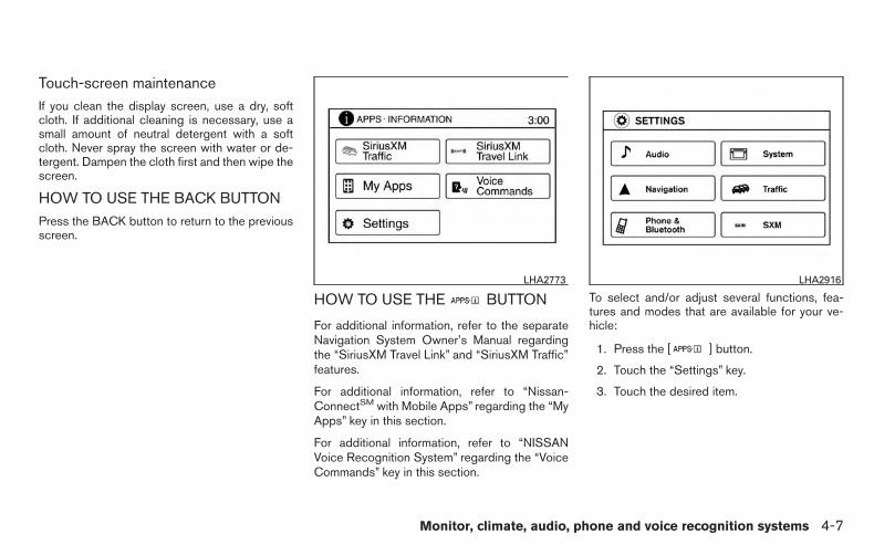
Touch-screen maintenanceIf you clean the display screen, use a dry, softcloth. If additional cleaning is necessary, use asmall amount of neutral detergent with a softcloth. Never spray the screen with water or de-tergent. Dampen the cloth first and then wipe thescreen.
HOW TO USE THE BACK BUTTONPress the BACK button to return to the previousscreen.
HOW TO USE THE BUTTON
For additional information, refer to the separateNavigation System Owner’s Manual regardingthe “SiriusXM Travel Link” and “SiriusXM Traffic”features.
For additional information, refer to “Nissan-ConnectSM with Mobile Apps” regarding the “MyApps” key in this section.
For additional information, refer to “NISSANVoice Recognition System” regarding the “VoiceCommands” key in this section.
To select and/or adjust several functions, fea-tures and modes that are available for your ve-hicle:
1. Press the [ ] button.
2. Touch the “Settings” key.
3. Touch the desired item.
LHA2773 LHA2916
Monitor, climate, audio, phone and voice recognition systems 4-7

Menu item Result
Audio For additional information, refer to “Audio system” in this section.Navigation For additional information, refer to the separate Navigation System Owner’s Manual.Phone & Bluetooth For additional information, refer to “Bluetooth® Hands-Free Phone System with Navigation System” in this section.System Touch this key to select and/or adjust various functions of this system. A screen with additional options will appear.
Display Touch this key to adjust the appearance of the display.Brightness Adjusts the brightness of the display.Display Mode Adjusts to fit the level of lighting in the vehicle. Touch key to cycle through options. “Day” and “Night” modes are suited for the respec-
tive times of day while “Auto” controls the display automatically.Scroll Direction Adjusts the direction of the menu scroll. Choose to either move up or down.
Clock Touch this key to adjust the time.Time Format The clock can be set to 12 hours or 24 hours.Date Format Select from five possible formats for displaying the day, month, and year.Clock Mode Adjust the mode for the clock. “Auto” uses the system’s GPS to automatically maintain the time. “Manual” allows you to set the clock
using the “Set Clock Manually” key.Set ClockManually
Adjust the clock manually, Touch the “+” or “-” keys to adjust the hours, minutes, day, month and year up or down. “Clock Mode” mustbe set to manual for this option to be available.
Daylight Sav-ings Time
Adjusts the daylight savings time on or off.
Time Zone Choose the applicable time zone from the list.Language Touch this key to change the language on the display.Camera Touch this key to change the camera settings.
Display Mode Touch this key to select the touch-screen display mode (day, night, or automatic).Brightness Adjust touch-screen brightness.Contrast Adjust touch-screen contrast.Color Adjust touch-screen color.
4-8 Monitor, climate, audio, phone and voice recognition systems

Menu item Result
Temperature Unit Touch this key to change the temperature unit being displayed (Fahrenheit or Celsius).Touchscreen click Toggles the touchscreen click feature on or off. When activated a click sound will be heard every time a key on the screen is touched.System Beeps Toggle the system beep tones feature on or off. When activated, a beep sound will be heard when a pop-up message appears on the
screen or a button on the unit (such as the button) is pressed and held for 2 seconds.Return to Factory Settings/Clear Memory
Touch this key to return all settings to default and to clear the memory.
Software Licenses Touch this key to display software licensing information.Traffic Touch this key to display traffic settings. For additional information, refer to the separate Navigation System Owner’s Manual.SXM Touch this key to display SXM status information. For additional information, refer to “Audio System” regarding SXM setup in this
section.
BUTTON
To change the display brightness, pressthe button. Pressing the button again willchange the display to day or night display mode.
If no operation is performed within 5 seconds, thedisplay will return to the previous display.
Press and hold the button for more than2 seconds to turn the display off. Press the buttonagain to turn the display on.
HOW TO USE THE ON-OFFBUTTON/VOL (volume) CONTROLKNOBPress the ON-OFF button to turn audio functionon and off. Turn the volume control knob to adjustaudio volume.
HOW TO USE THE CAMERABUTTONFor additional information, refer to “REARVIEWMONITOR” in this section regarding the CAM-ERA button.
Monitor, climate, audio, phone and voice recognition systems 4-9

When the shift lever is shifted into the R (Re-verse) position, the monitor display shows theview to the rear of the vehicle.
WARNING
Failure to follow the warnings and instruc-tions for proper use of the RearViewMonitor could result in serious injury ordeath.
● The RearView Monitor is a conveniencebut it is not a substitute for proper back-ing. Always turn and look out the win-dows, and check mirrors to be sure thatit is safe to move before operating thevehicle. Always back up slowly.
● The system is designed as an aid to thedriver in showing large stationary ob-jects directly behind the vehicle, to helpavoid damaging the vehicle.
● The system cannot completely elimi-nate blind spots and may not show ev-ery object.
● Underneath the bumper and the cornerareas of the bumper cannot be viewedon the RearView Monitor because of itsmonitoring range limitation. The systemwill not show small objects below thebumper, and may not show objectsclose to the bumper or on the ground.
● Objects viewed in the RearView Moni-tor differ from actual distance becausea wide-angle lens is used.
● Objects in a RearView Monitor will ap-pear visually opposite than whenviewed in the rear view and outsidemirrors.
● Make sure that the trunk is securelyclosed when backing up.
● Do not put anything on the rearviewcamera. The rearview camera is in-stalled above the license plate.
● When washing the vehicle with highpressure water, be sure not to spray itaround the camera. Otherwise, watermay enter the camera unit causing wa-ter condensation on the lens, a mal-function, fire or an electric shock.
● Do not strike the camera. It is a preci-sion instrument. Otherwise, it may mal-function or cause damage resulting in afire or an electric shock.
CAUTION
There is a plastic cover over the camera.Do not scratch the cover when cleaningdirt or snow from the cover.
REARVIEW MONITOR (if soequipped)
4-10 Monitor, climate, audio, phone and voice recognition systems
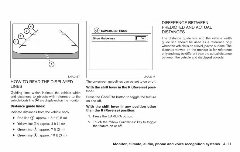
HOW TO READ THE DISPLAYEDLINESGuiding lines which indicate the vehicle widthand distances to objects with reference to thevehicle body line �A are displayed on the monitor.
Distance guide lines:
Indicate distances from the vehicle body.
● Red line �1 : approx. 1.5 ft (0.5 m)
● Yellow line �2 : approx. 3 ft (1 m)
● Green line �3 : approx. 7 ft (2 m)
● Green line �4 : approx. 10 ft (3 m)
The on-screen guidelines can be set to on or off.
With the shift lever in the R (Reverse) posi-tion:
Press the CAMERA button to toggle the featureon and off.
With the shift lever in any position otherthan the R (Reverse) position:
1. Press the CAMERA button.
2. Touch the “Show Guidelines” key to togglethe feature on or off.
DIFFERENCE BETWEENPREDICTED AND ACTUALDISTANCESThe distance guide line and the vehicle widthguide line should be used as a reference onlywhen the vehicle is on a level, paved surface. Thedistance viewed on the monitor is for referenceonly and may be different than the actual distancebetween the vehicle and displayed objects.
LHA0437 LHA2914
Monitor, climate, audio, phone and voice recognition systems 4-11

Backing up on a steep uphill
When backing up the vehicle up a hill, the dis-tance guide lines and the vehicle width guidelines are shown closer than the actual distance.For example, the display shows 3 ft (1.0 m) to theplace �A , but the actual 3 ft (1.0 m) distance on
the hill is the place �B . Note that any object onthe hill is further than it appears on the monitor.
Backing up on a steep downhill
When backing up the vehicle down a hill, thedistance guide lines and the vehicle width guidelines are shown farther than the actual distance.For example, the display shows 3 ft (1.0 m) to theplace �A , but the actual 3 ft (1.0 m) distance on
LHA2326 LHA2327
4-12 Monitor, climate, audio, phone and voice recognition systems

the hill is the place �B . Note that any object onthe hill is closer than it appears on the monitor.
Backing up behind a projecting object
The position �C is shown farther than the position�B in the display. However, the position �C isactually at the same distance as the position �A .The vehicle may hit the object when backing up to
the position �A if the object projects over theactual backing up course.
ADJUSTING THE SCREENThe procedure for adjusting the display settingsof the screen differs depending on the type ofscreen present on the vehicle.
For vehicles without Navigation System
1. Firmly apply the brake and place the shiftlever in R (reverse)
2. Press the ENTER/SETTING button.
3. The screen will display the Brightness set-tings.
4. Turn the TUNE/SCROLL knob to adjust thesetting up or down.
5. Press the ENTER/SETTING button again todisplay the Contrast settings.
6. Turn the TUNE/SCROLL knob to adjust thesetting up or down.
7. Press the ENTER/SETTING button to com-plete the adjustment.
● Do not adjust the display settings of theRearView Monitor while the vehicle is mov-ing.
LHA2328
Monitor, climate, audio, phone and voice recognition systems 4-13

For vehicles with Navigation System
1. Firmly apply the brake and place the shiftlever in R (reverse)
2. Press the button on the control panel.
3. The screen will display the Night settings.
4. Turn the TUNE knob to adjust the setting upor down.
5. Press the button again to access theAuto settings.
6. Turn the TUNE knob to adjust the setting upor down.
● Do not adjust the display settings of theRearView Monitor while the vehicle is mov-ing.
OPERATING TIPS
CAUTION
● Do not use alcohol, benzine or thinnerto clean the camera. This will causediscoloration. To clean the camera,wipe with a cloth dampened with a di-luted mild cleaning agent and then wipewith a dry cloth.
● Do not damage the camera as the moni-tor screen may be adversely affected.
● When the shift lever is shifted to R (Re-verse), the monitor screen automaticallychanges to the RearView Monitor mode.However, the radio can be heard.
● It may take some time until the RearViewMonitor is displayed after the shift lever hasbeen shifted to R (Reverse). Objects may bedistorted momentarily until the RearViewMonitor screen is displayed completely.When the shift lever is returned to a positionother than R (Reverse), it may take sometime until the screen changes. Objects onthe screen may be distorted until they arecompletely displayed.
● When the temperature is extremely high orlow, the screen may not clearly display ob-jects. This is not a malfunction.
● When strong light directly enters the cam-era, objects may not be displayed clearly.
● Vertical lines may be seen in objects on thescreen. This is due to strong reflected lightfrom the bumper. This is not a malfunction.
● The screen may flicker under fluorescentlight. This is not a malfunction.
● The colors of objects on the RearView Moni-tor may differ somewhat from those of theactual object.
● When the contrast of objects is low at night,pressing the ENTER/AUDIO button or theENTER/SETTING button may not changethe brightness.
● Objects on the monitor may not be clear in adark place or at night.
● If dirt, rain or snow attaches to the camera,the RearView Monitor may not display ob-jects. Clean the camera.
● Do not use body wax on the camera window.If body wax does get on the camera window,wipe off the wax with a clean cloth damp-ened with mild detergent diluted with water.
4-14 Monitor, climate, audio, phone and voice recognition systems
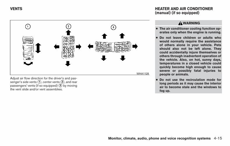
Adjust air flow direction for the driver’s and pas-senger’s side vents �1 , center vents �2 , and rearpassengers’ vents (if so equipped) �3 by movingthe vent slide and/or vent assemblies.
WARNING
● The air conditioner cooling function op-erates only when the engine is running.
● Do not leave children or adults whowould normally require the assistanceof others alone in your vehicle. Petsshould also not be left alone. Theycould accidentally injure themselves orothers through inadvertent operation ofthe vehicle. Also, on hot, sunny days,temperatures in a closed vehicle couldquickly become high enough to causesevere or possibly fatal injuries topeople or animals.
● Do not use the recirculation mode forlong periods as it may cause the interiorair to become stale and the windows tofog up.
WHA1128
VENTS HEATER AND AIR CONDITIONER(manual) (if so equipped)
Monitor, climate, audio, phone and voice recognition systems 4-15

NOTE:
● Odors from inside and outside the vehiclecan build up in the air conditioner unit. Odorcan enter the passenger compartmentthrough the vents.
● When parking, set the heater and air condi-tioner controls to turn off air recirculation toallow fresh air into the passenger compart-ment. This should help reduce odors insidethe vehicle.
CONTROLS1. Fan speed control dial
2. Front window defroster button
3. Rear window defroster switch(if so equipped)
4. Air recirculation button
5. Temperature control dial
6. Max A/C button
7. Air flow control buttons
8. Air conditioner ON/OFF button
Type A (if so equipped)WHA1406
4-16 Monitor, climate, audio, phone and voice recognition systems

CONTROLS
1. Fan speed control dial
2. Front window defroster button
3. Outside mirror defroster switch (if soequipped)
4. Air recirculation button
5. Temperature control dial
6. Max A/C button
7. Air flow control buttons
8. Air conditioner ON/OFF button
Fan control dial
The fan control dial turns the fan on and off, andcontrols fan speed.
Air flow control buttons
The air flow control buttons allow you to selectthe air flow outlets.
MAX A/C — Air flows from center and sidevents with maximum cooling(air conditioning).
— Air flows from center and sidevents.
— Air flows from center and sidevents and foot outlets.
— Air flows mainly from footoutlets.
— Air flows from defroster out-lets and foot outlets.
— Air flows mainly from defrosteroutlets.
Temperature control dial
The temperature control dial allows you to adjustthe temperature of the outlet air. To lower thetemperature, turn the dial to the left. To increasethe temperature, turn the dial to the right.
Air recirculation button
ON position (Indicator light on)Interior air is recirculated inside the vehicle.
Press the button to the ON position when:
● driving on a dusty road.
● to prevent traffic fumes from entering pas-senger compartment.
● for maximum cooling when using the air con-ditioner.
OFF position (Indicator light off)Outside air is drawn into the passenger compart-ment and distributed through the selected outlet.
Type B (if so equipped)LHA3167
Monitor, climate, audio, phone and voice recognition systems 4-17
Use the OFF position for normal heater or airconditioner operation.
Air conditioner button
Start the engine, turn the fan control dial to thedesired position and press the button toturn on the air conditioner. To turn off the airconditioner, press the button again.
The air conditioner cooling function oper-ates only when the engine is running.
Rear window and outside mirror(if so equipped) defroster switchFor additional information about the rear windowor outside mirror defroster switch, refer to “Rearwindow and outside mirror (if so equipped) de-froster switch” in the “Instruments and controls”section of this manual.
HEATER OPERATION
HeatingThis mode is used to direct heated air to the footoutlets. Some air also flows from the defrost outlets.
1. Press the button to the OFF positionfor normal heating. The indicator light onthe button will go off.
2. Press the air flow control button.
3. Turn the fan control dial to the desired position.
4. Turn the temperature control dial to the de-sired position between the middle and thehot position.
VentilationThis mode directs outside air to the side andcenter vents.
1. Press the button to the OFF position.The indicator light on the button willgo off.
2. Press the air flow control button.
3. Turn the fan control dial to the desired posi-tion.
4. Turn the temperature control dial to the de-sired position.
Defrosting or defoggingThis mode directs the air to the defrost outlets todefrost/defog the windows.
1. Press the defrost/defog button .
2. Turn the fan control dial to the desired posi-tion.
3. Turn the temperature control dial to the de-sired position between the middle and thehot position.
● To quickly remove ice or fog from the win-dows, turn the fan control dial to the highestsetting and the temperature control to thefull HOT position.
● When the position is selected, the airconditioner automatically turns on if the out-side temperature is more than 36°F (2°C).This dehumidifies the air which helps defogthe windshield. The mode automati-cally turns off, allowing outside air to bedrawn into the passenger compartment tofurther improve the defogging performance.
Bi-level heating
The bi-level mode directs warmed air to the sideand center vents and to the front and rear flooroutlets.
1. Press the button to the OFF position.The indicator light on the button willgo off.
2. Press the air flow control button.
3. Turn the fan control dial to the desired posi-tion.
4. Turn the temperature control dial to the de-sired position.
4-18 Monitor, climate, audio, phone and voice recognition systems

Heating and defoggingThis mode heats the interior and defogs the wind-shield.
1. Press the air flow control button.
2. Turn the fan control dial to the desired posi-tion.
3. Turn the temperature control dial to the de-sired position between the middle and thehot position.
● When the position is selected, the airconditioner automatically turns on if the out-side temperature is more than 36°F (2°C). Ifthe air flow control button is selectedfor more than 1 minute, the air conditioningsystem will continue to operate until the fancontrol dial is turned to OFF, the vehicle isshut off, or the A/C button is used to turn offthe compressor even if the air flow controldial is turned to a position other thanthe position. This dehumidifies the airwhich helps defog the windshield.The mode automatically turns off, al-lowing outside air to be drawn into the pas-senger compartment to further improve thedefogging performance.
Operating tips
Clear snow and ice from the wiper bladesand air inlet in front of the windshield. Thisimproves heater operation.
AIR CONDITIONER OPERATION
Start the engine, turn the fan control dial to thedesired position, and press the button toactivate the air conditioner. When the air condi-tioner is on, cooling and dehumidifying functionsare added to the heater operation.
The air conditioner cooling function oper-ates only when the engine is running.
Cooling
This mode is used to cool and dehumidify the air.
1. Press the button to the OFF position.
2. Press the air flow control button.
3. Turn the fan control dial to the desired posi-tion.
4. Press the button.
5. Turn the temperature control dial to the de-sired position.
● For quick cooling when the outside tem-perature is high, press the button tothe ON position. Be sure to return theto the OFF position for normal cooling. Theindicator light on the button will go off.You may also select MAX A/C for quickcooling.
Dehumidified heatingThis mode is used to heat and dehumidify the air.
1. Press the button to the OFF position.The indicator light on the button willgo off.
2. Press the air flow control button.
3. Turn the fan control dial to the desired posi-tion.
4. Press the button on.
5. Turn the temperature control dial to the de-sired position.
Monitor, climate, audio, phone and voice recognition systems 4-19
Dehumidified defoggingThis mode is used to defog the windows anddehumidify the air.
1. Press the air flow control button.
2. Turn the fan control dial to the desired posi-tion.
3. Press the button.
When the or positions are se-lected, the air conditioner automatically turns on ifthe outside temperature is more than 36°F (2°C).The air conditioning system will continue to op-erate until the fan control dial is turned to OFF, theair conditioner is turned OFF, or the vehicle isshut off, even if a position other than the airflow control button is selected. This dehumidifiesthe air which helps defog the windshield.The mode automatically turns off, allowingoutside air to be drawn into the passenger com-partment to further improve the defogging perfor-mance.
4. Turn the temperature control dial to the de-sired position.
Operating tips● Keep the windows closed while the air con-
ditioner is in operation.
● After parking in the sun, drive for 2 or 3 min-utes with the windows open to vent hot airfrom the passenger compartment. Then,close the windows. This allows the air con-ditioner to cool the interior more quickly.
● The air conditioning system should beoperated for approximately 10 minutesat least once a month. This helps pre-vent damage to the system due to lackof lubrication.
● A visible mist may be seen coming from theventilators in hot, humid conditions as the airis cooled rapidly. This does not indicate amalfunction.
● If the engine coolant temperaturegauge indicates engine coolant tem-perature over the normal range, turnthe air conditioner off. For additionalinformation, refer to “If your vehicleoverheats” in the “In case of emer-gency” section of this manual.
AIR FLOW CHARTSThe following charts show the button and dialpositions for MAXIMUM AND QUICK heating,cooling or defrosting. For additional informationon heating and cooling, refer to “Heater and airconditioner (manual)” in this section. The airrecirculation ( ) button should alwaysbe in the OFF position for heating anddefrosting.
4-20 Monitor, climate, audio, phone and voice recognition systems

WHA0916 WHA0917
Monitor, climate, audio, phone and voice recognition systems 4-21

WHA0918 WHA0919
4-22 Monitor, climate, audio, phone and voice recognition systems

WHA0920
Monitor, climate, audio, phone and voice recognition systems 4-23

1. Driver temperature control dial
2. A/C ON/OFF button
3. Front window defroster button
4. Fan speed control dial
5. (system off) button
6. Rear window defroster button
7. Air recirculation button
8. Passenger temperature control dial
9. DUAL button
10. Air flow control buttons
11. AUTO button
WARNING
● The air conditioner cooling function op-erates only when the engine is running.
● Do not leave children or adults whowould normally require the assistanceof others alone in your vehicle. Petsshould also not be left alone. Theycould accidentally injure themselves orothers through inadvertent operation ofthe vehicle. Also, on hot, sunny days,temperatures in a closed vehicle couldquickly become high enough to causesevere or possibly fatal injuries topeople or animals.
● Do not use the recirculation mode forlong periods as it may cause the interiorair to become stale and the windows tofog up.
Start the engine and operate the controls toactivate the air conditioner.
NOTE:
● Odors from inside and outside the vehiclecan build up in the air conditioner unit. Odorcan enter the passenger compartmentthrough the vents.
LHA2611
HEATER AND AIR CONDITIONER(automatic) (if so equipped)
4-24 Monitor, climate, audio, phone and voice recognition systems

● When parking, set the heater and air condi-tioner controls to turn off air recirculation toallow fresh air into the passenger compart-ment. This should help reduce odors insidethe vehicle.
AUTOMATIC OPERATION
Cooling or heating (auto)
This mode may be normally used all year round asthe system automatically works to keep a con-stant temperature. Air flow distribution and fanspeed are also controlled automatically.
1. Press the AUTO button on.
2. Turn the temperature dial to the left or rightto set the desired temperature. Driver andpassenger temperatures can be set inde-pendently. Press DUAL to activate dual cli-mate control functions. Turn the passenger’sside temperature control dial to the left orright to set the desired passenger’s tem-perature.
● Adjust the temperature dial to about 75°F(24°C) for normal operation.
● The temperature of the passenger compart-ment will be maintained automatically. Airflow distribution, fan speed and A/C on/offare also controlled automatically.
● A visible mist may be seen coming from thevents in hot, humid conditions as the air iscooled rapidly. This does not indicate a mal-function.
Heating (A/C OFF)
The air conditioner does not activate. When youneed to heat only, use this mode.
1. Press the A/C button.
2. Turn the temperature control dial to set thedesired temperature.
● The temperature of the passenger compart-ment will be maintained automatically. Airflow distribution and fan speed are also con-trolled automatically.
● Do not set the temperature lower than theoutside air temperature. Otherwise, the sys-tem may not work properly.
● Not recommended if windows fog up.
Dehumidified defrosting or defogging
1. Press the defroster control button toturn the system on. The indicator light in thebutton will illuminate.
2. Turn the temperature dial to the left or rightto set the desired temperature.
● To quickly remove ice from the outside of thewindows, turn the manual fan control to themaximum position.
● As soon as possible after the windshield isclean, press the AUTO button to return tothe auto mode.
● When the control is activated, the airconditioner will automatically be turned on atoutside temperatures above 36°F (2°C). If indefrost mode for more than 1 minute, the airconditioning system will continue to operateuntil the fan control is turned OFF, the ve-hicle is shut off or the A/C button is used toturn off the compressor even if an air flowbutton other than is selected. Thisdehumidifies the air which helps defog thewindshield. The air recirculation mode auto-matically turns off, allowing outside air to bedrawn into the passenger compartment tofurther improve the defogging performance.
MANUAL OPERATION
Fan speed control dial
Turn the fan speed control dial left or rightto manually control the fan speed or turn thesystem on or off.
Press the AUTO button to return to automaticcontrol of the fan speed.
Monitor, climate, audio, phone and voice recognition systems 4-25

Air recirculation
Push the air recirculation button to recir-culate interior air inside the vehicle. Push theAUTO button to return to automatic mode.
The air recirculation button will not be activatedwhen the air conditioner is in DEF, floor, orfloor/defrost mode.
Fresh air intake (if so equipped)
Press the fresh air intake button to drawoutside air into the passenger compartment.The indicator light on the button will comeon.
Air flow control
Press the air flow control buttons to manuallycontrol air flow and select the air outlet:
— Air flows from center and sidevents.
— Air flows from center and sidevents and foot outlets.
— Air flows mainly from foot outlets.— Air flows from defroster and foot
outlets.— Air flows from defroster outlets.
To turn system off
Press the /OFF button.
Outside mirror defroster switch (if soequipped)For additional information about the outside mir-ror defroster switch, refer to “Rear window andoutside mirror (if so equipped) defroster switch”in the “Instruments and controls” section of thismanual.
OPERATING TIPS● When the engine coolant temperature and
outside air temperature are low, the air flowfrom the foot outlets may not operate for amaximum of 150 seconds. However, this isnot a malfunction. After the coolant tempera-ture warms up, air flow from the foot outletswill operate normally.
The sunload sensor �1 , located on the top centerof the instrument panel, helps the system main-tain a constant temperature. Do not put anythingon or around this sensor.
LIC0836
4-26 Monitor, climate, audio, phone and voice recognition systems

The air conditioner system in your NISSAN ve-hicle is charged with a refrigerant designed withthe environment in mind.
This refrigerant does not harm the earth’sozone layer.
Special charging equipment and lubricant is re-quired when servicing your NISSAN air condi-tioner. Using improper refrigerants or lubricantswill cause severe damage to your air conditionersystem. For additional information, refer to “Airconditioner system refrigerant and oil recommen-dations” in the “Technical and consumer informa-tion” section of this manual.
A NISSAN dealer is able to service your “environ-mentally friendly” air conditioning system.
WARNING
The air conditioner system contains refrig-erant under high pressure. To avoid per-sonal injury, any air conditioner serviceshould be done only by an experiencedtechnician with proper equipment.
RADIO
With the ignition placed in the ACC or ON posi-tion, press the (power) or ON•OFF buttonto turn the radio on. If you listen to the radio withthe engine not running, the ignition should beplaced in the ACC position.
Radio reception is affected by station signalstrength, distance from radio transmitter, build-ings, bridges, mountains and other external influ-ences. Intermittent changes in reception qualitynormally are caused by these external influences.
Using a cellular phone in or near the vehiclemay influence radio reception quality.
Radio reception
Your NISSAN radio system is equipped withstate-of-the-art electronic circuits to enhance ra-dio reception. These circuits are designed toextend reception range, and to enhance the qual-ity of that reception.
However, there are some general characteristicsof both FM and AM radio signals that can affectradio reception quality in a moving vehicle, evenwhen the finest equipment is used. These char-acteristics are completely normal in a given re-ception area and do not indicate any malfunctionin your NISSAN radio system.
Reception conditions will constantly change be-cause of vehicle movement. Buildings, terrain,signal distance and interference from other ve-hicles can work against ideal reception. De-scribed below are some of the factors that canaffect your radio reception.
Some cellular phones or other devices maycause interference or a buzzing noise to comefrom the audio system speakers. Storing the de-vice in a different location may reduce or elimi-nate the noise.
FM RADIO RECEPTIONRange: FM range is normally limited to 25 – 30 mi(40 – 48 km), with monaural (single channel) FMhaving slightly more range than stereo FM. Exter-nal influences may sometimes interfere with FMstation reception even if the FM station is within25 mi (40 km). The strength of the FM signal isdirectly related to the distance between thetransmitter and receiver. FM signals follow a line-of-sight path, exhibiting many of the same char-acteristics as light. For example, they will reflectoff objects.
Fade and drift: As your vehicle moves away froma station transmitter, the signals will tend to fadeand/or drift.
SERVICING AIR CONDITIONER AUDIO SYSTEM
Monitor, climate, audio, phone and voice recognition systems 4-27

Static and flutter: During signal interference frombuildings, large hills or due to antenna position(usually in conjunction with increased distancefrom the station transmitter), static or flutter canbe heard. This can be reduced by adjusting thetreble control to reduce treble response.
Multipath reception: Because of the reflectivecharacteristics of FM signals, direct and reflectedsignals reach the receiver at the same time. Thesignals may cancel each other, resulting in mo-mentary flutter or loss of sound.
AM RADIO RECEPTIONAM signals, because of their low frequency, canbend around objects and skip along the ground.In addition, the signals can be bounced off theionosphere and bent back to earth. Because ofthese characteristics, AM signals are also sub-ject to interference as they travel from transmitterto receiver.
Fading: Occurs while the vehicle is passingthrough freeway underpasses or in areas withmany tall buildings. It can also occur for severalseconds during ionospheric turbulence even inareas where no obstacles exist.
Static: Caused by thunderstorms, electricalpower lines, electric signs and even traffic lights.
SATELLITE RADIO RECEPTION (if soequipped)When the satellite radio is used for the first timeor the battery has been replaced, the satelliteradio may not work properly. This is not a mal-function. Wait more than 10 minutes with satelliteradio ON and the vehicle outside of any metal orlarge building for satellite radio to receive all ofthe necessary data.
No satellite radio reception is available and “NOSAT” is displayed when the SAT band option isselected unless optional satellite receiver andantenna are installed and a SiriusXM® SatelliteRadio service subscription is active. Satellite ra-dio is not available in Alaska, Hawaii and Guam.
Satellite radio performance may be affected ifcargo carried on the roof blocks the satellite radiosignal.
If possible, do not put cargo over the satelliteantenna.
A build up of ice on the satellite radio antenna canaffect satellite radio performance. Remove theice to restore satellite radio reception. AUDIO OPERATION PRECAUTIONS
LHA0099
4-28 Monitor, climate, audio, phone and voice recognition systems

Compact disc (CD) player
CAUTION
● Do not force a compact disc into the CDinsert slot. This could damage the CDand/or CD player.
● Trying to load a CD with the CD doorclosed could damage the CD and/or CDplayer.
● Only one CD can be loaded into the CDplayer at a time.
● Only use high quality 4.7 in (12 cm)round discs that have the “COMPACTdisc DIGITAL AUDIO” logo on the discor packaging.
● During cold weather or rainy days, theplayer may malfunction due to the hu-midity. If this occurs, remove the CDand dehumidify or ventilate the playercompletely.
● The player may skip while driving onrough roads.
● The CD player sometimes cannot func-tion when the compartment tempera-ture is extremely high or low.Decrease/increase the temperaturebefore use.
● Do not expose the CD to direct sun-light.
● CDs that are in poor condition or aredirty, scratched or covered with finger-prints may not work properly.
● The following CDs may not work prop-erly:
● Copy control compact discs (CCCD)
● Recordable compact discs (CD-R)
● Rewritable compact discs (CD-RW)
● Do not use the following CDs as theymay cause the CD player to malfunc-tion:
● 3.1 in (8 cm) discs with an adapter
● CDs that are not round
● CDs with a paper label
● CDs that are warped, scratched, orhave abnormal edges
● This audio system can only play pre-recorded CDs. It has no capability torecord or burn CDs.
● If the CD cannot be played, one of thefollowing messages will be displayed.
CHECK DISC
● Confirm that the CD is inserted cor-rectly (the label side is facing up,etc.).
● Confirm that the CD is not bent orwarped and it is free of scratches.
PRESS EJECT
This is an error due to excessive tem-perature inside the player. Remove theCD by pressing the EJECT button. Aftera short time, reinsert the CD. The CDcan be played when the temperature ofthe player returns to normal.
UNPLAYABLE
The file is unplayable in this audio sys-tem (only MP3 or WMA (if so equipped)CD).
Monitor, climate, audio, phone and voice recognition systems 4-29

Compact disc with MP3 or WMA (ifso equipped)
Terms
● MP3 — MP3 is short for Moving PicturesExperts Group Audio Layer 3. MP3 is themost well-known compressed digital audiofile format. This format allows for near “CDquality” sound, but at a fraction of the size ofnormal audio files. MP3 conversion of anaudio track from CD-ROM can reduce thefile size by approximately a 10:1 ratio withvirtually no perceptible loss in quality. MP3compression removes the redundant andirrelevant parts of a sound signal that thehuman ear doesn’t hear.
● WMA — Windows Media Audio (WMA)* is acompressed audio format created by Micro-soft as an alternative to MP3. The WMAcodec offers greater file compression thanthe MP3 codec, enabling storage of moredigital audio tracks in the same amount ofspace when compared to MP3s at the samelevel of quality.
● Bit rate — Bit rate denotes the number ofbits per second used by a digital music file.The size and quality of a compressed digitalaudio file is determined by the bit rate usedwhen encoding the file.
● Sampling frequency — Sampling frequencyis the rate at which the samples of a signalare converted from analog to digital (A/Dconversion) per second.
● Multisession — Multisession is one of themethods for writing data to media. Writingdata once to the media is called a singlesession, and writing more than once is calleda multisession.
● ID3/WMA Tag — The ID3/WMA tag is thepart of the encoded MP3 or WMA file thatcontains information about the digital musicfile such as song title, artist, encoding bitrate, track time duration, etc. ID3 tag infor-mation is displayed on the Artist/song titleline on the display.
* Windows® and Windows Media® are regis-tered trademarks and trademarks in the UnitedStates of America and other countries of Micro-soft Corporation of the USA.
Playback order
Music playback order of a CD with MP3 or WMAfiles is as illustrated.
● The names of folders not containing MP3 orWMA files are not shown in the display.
Playback order chartWHA1078
4-30 Monitor, climate, audio, phone and voice recognition systems

● If there is a file in the top level of the disc,“Root Folder” is displayed.
● The playback order is the order in which thefiles were written by the writing software.Therefore, the files might not play in thedesired order.
Specification chart
Supported media CD, CD-R, CD-RWSupported file systems ISO9660 LEVEL1, ISO9660 LEVEL2, Apple ISO, Romeo, Joliet * ISO9660 Level 3 (packet writing) is not supported.
Supportedversions*1
MP3Version MPEG1, MPEG2, MPEG2.5Sampling frequency 8 kHz - 48 kHzBit rate 8 kbps - 320 kbps, VBR
WMA Version WMA7, WMA8, WMA9Sampling frequency 32 kHz - 48 kHzBit rate 48 kbps - 192 kbps, VBR
Tag information ID3 tag VER1.0, VER1.1, VER2.2, VER2.3 (MP3 only)Folder levels Folder levels: 8, Max folders: 255 (including root folder), Files: 512 (Max. 255 files for one folder)Text character number limitation 128 characters
Displayable character codes*201: ASCII, 02: ISO-8859-1, 03: UNICODE (UTF-16 BOM Big Endian), 04: UNICODE (UTF-16 Non-BOM Big Endian), 05:UNICODE (UTF-8), 06: UNICODE (Non-UTF-16 BOM Little Endian)
*1 Files created with a combination of 48 kHz sampling frequency and 64 kbps bit rate cannot be played.
*2 Available codes depend on what kind of media, versions and information are going to be displayed.
Monitor, climate, audio, phone and voice recognition systems 4-31

Troubleshooting guide
Symptom Cause and Countermeasure
Cannot play
Check if the disc was inserted correctly.Check if the disc is scratched or dirty.Check if there is condensation inside the player. If there is, wait until the condensation is gone (about 1 hour) before using the player.If there is a temperature increase error, the CD player will play correctly after it returns to the normal temperature.If there is a mixture of music CD files (CD-DA data) and MP3/WMA files on a CD, only the music CD files (CD-DA data) will be played.Files with extensions other than “.MP3”,“.WMA”, “.mp3” or “.wma” cannot be played. In addition, the character codes and number of characters forfolder names and file names should be in compliance with the specifications.Check if the finalization process, such as session close and disc close, is done for the disc.Check if the disc is protected by copyright.
Poor sound qualityCheck if the disc is scratched or dirty.Bit rate may be too low.
It takes a relatively long timebefore the music startsplaying.
If there are many folders or file levels on the MP3/WMA disc, or if it is a multisession disc, some time may be required before the music starts playing.
Music cuts off or skipsThe writing software and hardware combination might not match, or the writing speed, writing depth, writing width, etc., might not match thespecifications. Try using the slowest writing speed.
Skipping with high bit ratefiles
Skipping may occur with large quantities of data, such as for high bit rate data.
Moves immediately to thenext song when playing
When a non-MP3/WMA file has been given an extension of “.MP3”, “.WMA”, .“mp3”or “.wma”, or when play is prohibited by copyright protection, therewill be approximately 5 seconds of no sound and then the player will skip to the next song.
Songs do not play back inthe desired order
The playback order is the order in which the files were written by the writing software. Therefore, the files might not play in the desired order.
4-32 Monitor, climate, audio, phone and voice recognition systems

USB (Universal Serial Bus)Connection Port (if so equipped)
WARNING
Do not connect, disconnect, or operate theUSB device while driving. Doing so can bea distraction. If distracted you could losecontrol of your vehicle and cause an acci-dent or serious injury.
CAUTION
● Do not force the USB device into theUSB port. Inserting the USB devicetilted or up-side-down into the port maydamage the port. Make sure that theUSB device is connected correctly intothe USB port.
● Do not grab the USB port cover (if soequipped) when pulling the USB deviceout of the port. This could damage theport and the cover.
● Do not leave the USB cable in a placewhere it can be pulled unintentionally.Pulling the cable may damage the port.
The vehicle is not equipped with a USB device.USB devices should be purchased separately asnecessary.
This system cannot be used to format USB de-vices. To format a USB device, use a personalcomputer.
In some jurisdictions, the USB device for the frontseats plays only sound without images for regu-latory reasons, even when the vehicle is parked.
This system supports various USB connectionport devices, USB hard drives and iPod® play-ers. Some USB devices may not be supported bythis system.
● Partitioned USB devices may not play cor-rectly.
● Some characters used in other languages(Chinese, Japanese, etc.) may not appearproperly in the display. Using English lan-guage characters with a USB device is rec-ommended.
General notes for USB use
● Refer to your device manufacturer’s ownerinformation regarding the proper use andcare of the device.
Notes for iPod® use
iPod® is a trademark of Apple Inc., registered inthe U.S. and other countries.
● Improperly plugging in the iPod® may causea checkmark to be displayed on and off(flickering). Always make sure that theiPod® is connected properly.
● An iPod® nano (1st Generation) may remainin fast forward or rewind mode if it is con-nected during a seek operation. In this case,please manually reset the iPod®.
● An iPod® nano (2nd Generation) will con-tinue to fast-forward or rewind if it is discon-nected during a seek operation.
● An incorrect song title may appear when thePlay Mode is changed while using an iPod®nano (2nd Generation).
● Audiobooks may not play in the same orderas they appear on an iPod®.
● Large video files cause slow responses in aniPod®. The vehicle center display may mo-mentarily black out, but will soon recover.
Monitor, climate, audio, phone and voice recognition systems 4-33

● If an iPod® automatically selects large videofiles while in the shuffle mode, the vehiclecenter display may momentarily black out,but will soon recover.
Bluetooth® streaming audio (if soequipped)
● Some Bluetooth® audio devices may not berecognized by the in-vehicle audio system.
● It is necessary to set up the wireless con-nection between a compatible Bluetooth®audio device and the in-vehicle Bluetooth®module before using the Bluetooth® audio.
● Operating procedure of the Bluetooth® au-dio will vary depending on the devices. Referto how to operate your audio device beforeusing it with this system.
● The Bluetooth® audio may be stopped un-der the following conditions:
● Receiving a call on the Hands-FreePhone System.
● Checking the connection to the hands-free phone.
● Do not place the Bluetooth® audio device inan area surrounded by metal or far away fromthe in-vehicle Bluetooth® module to preventtone quality degradation and wireless con-nection disruption.
● While an audio device is connected throughthe Bluetooth® wireless connection, thebattery power of the device may dischargequicker than usual.
● This system supports the Bluetooth® AudioDistribution Profile (A2DP, AVRCP).
BLUETOOTH® is atrademark owned byBluetooth SIG, Inc.and licensed toVisteon and Bosch.
4-34 Monitor, climate, audio, phone and voice recognition systems
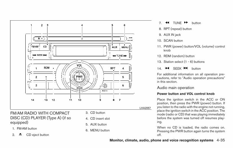
FM/AM RADIO WITH COMPACTDISC (CD) PLAYER (Type A) (if soequipped)
1. FM·AM button
2. CD eject button
3. CD button
4. CD insert slot
5. AUX button
6. MENU button
7. TUNE button
8. RPT (repeat) button
9. AUX IN jack
10. SCAN button
11. PWR (power) button/VOL (volume) controlknob
12. RDM (random) button
13. Station select (1 - 6) buttons
14. SEEK button
For additional information on all operation pre-cautions, refer to �Audio operation precautions�in this section.
Audio main operationPower button and VOL control knob
Place the ignition switch in the ACC or ONposition, then press the PWR (power) button. Ifyou listen to the radio with the engine not running,place the ignition switch in the ACC position. Themode (radio or CD) that was playing immediatelybefore the system was turned off resumes play-ing.
When no CD is loaded, the radio comes on.Pressing the PWR button again turns the systemoff.
LHA2057
Monitor, climate, audio, phone and voice recognition systems 4-35

Turn the VOL control knob to the right to increasevolume or to the left to decrease volume.
MENU button (BASS, TREBLE, FADE,BALANCE and CLOCK)
Press the MENU button to change the mode asfollows:
BAS → TRE → FAD → BAL → CLOCK → BAS
To adjust Bass, Treble, Fade and Balance, pressthe MENU button until the desired mode appears
in the display. Press the SEEK but-ton to adjust Bass and Treble to the desired level.
You can also use the SEEK buttonto adjust Fade and Balance modes. Balance ad-justs the sound between the right and left speak-ers. Since this vehicle is not equipped with rearspeakers, adjusting the fade to the rear of thevehicle will reduce the volume until no sound isplayed.
Once you have adjusted the sound quality to thedesired level, press the MENU button repeatedlyuntil the radio or CD display reappears. Other-wise, the radio or CD display will automaticallyreappear after about 10 seconds.
NOTE:
If the clock is enabled, pressing the MENUbutton will change the mode as follows:BAS → TRE → FAD → BAL → CLOCK →Hour adjustment → Minute adjustment →BAS
For additional information, refer to “Clock set” inthis section.
Clock operation
Press the MENU button until CLOCK is dis-
played; use the SEEK button to turnthe clock display on (CLK ON) or off (CLK OFF).
Clock set
If the clock is not displayed with the ignitionswitch in the ACC or ON position, you need toselect the CLK ON mode. Press the MENU but-ton repeatedly until CLOCK is displayed. Use
the SEEK button to enable CLK ONmode.
1. Press the MENU button repeatedly untilCLOCK mode appears; press theSEEK button until CLK ON appears.
2. Press the MENU button again; the hours willstart flashing.
3. Press the SEEK button to ad-just the hour.
4. Press the MENU button again; the displaywill switch to the minute adjustment mode.
5. The minutes will start flashing. PressSEEK button to adjust the minutes.
6. Press the MENU button again to exit theclock set mode.
The display will return to the regular clock displayafter 10 seconds, or press the MENU buttonagain to return to the regular clock display.
Resetting the time
Hold the MENU button down and then press theTUNE or SEEK button; the time will reset asfollows:
● If the displayed minutes before the reset arein the range of :00 - :29, the hour displayedbefore the reset will stay the same and theminutes will be reset to :00.
● If the displayed minutes before the reset arein the range of :30 - :59, the hour displayedbefore the reset will advance by one hourand the minutes will be reset to :00.
4-36 Monitor, climate, audio, phone and voice recognition systems

For example, if the MENU button and the TUNE orSEEK button are pressed while the time dis-played is between 8:00 and 8:29, the display willbe reset to 8:00. If the buttons were pressedwhile the time was between 8:30 and 8:59, thedisplay will be reset to 9:00. At the same time thedisplay will return to the audio.
FM/AM radio operation
FM·AM button
Press the FM·AM button to change the band asfollows:
FM1 → FM2 → AM → FM1
The FM stereo indicator, ST (STEREO), illumi-nates during FM stereo reception. When thestereo broadcast signal is weak, the radio auto-matically changes from stereo to monaural re-ception.
TUNE buttons:
Manual tuning
Press the TUNE button for less than0.5 seconds for manual tuning.
To move quickly through the channels, press and
hold either TUNE button down formore than 1.5 seconds.
SEEK buttons
SEEK tuning
Press the SEEK button to seekthrough the frequencies. Seek tuning beginsfrom low to high frequencies, or high to lowfrequencies, depending on which button ispressed, and stops at the next broadcasting sta-tion. Once the highest broadcasting station isreached, the radio continues in the seek mode atthe lowest broadcasting station.
Station memory operations
Twelve stations can be set for the FM band (6 forFM1 and 6 for FM2) and 6 stations can be set forthe AM band to the preset buttons.
1. Press the FM-AM button to change to thedesired band.
2. Tune to the desired station using manualTUNE or SEEK tuning. Press and hold any ofthe desired station memory buttons (1 – 6)until a beep sound is heard. (The radio muteswhen the select button is pressed.)
3. The channel indicator will then come on andthe sound will resume. Programming is nowcomplete.
4. Other buttons can be set in the same man-ner.
If the battery cable is disconnected, or if the fuseopens, the radio memory will be canceled. In thatcase, reset the desired stations.
Compact disc (CD) player operation
If the radio is already operating, it automaticallyturns off and the compact disc begins to play.
CD button
When the CD button is pressed with a compactdisc loaded and the radio playing, the radio turnsoff and the last used compact disc starts to play.
TUNE (rewind and fast
forward) buttons
When the TUNE button is pressedwhile the compact disc is playing, the compactdisc plays at an increased speed while rewindingor fast forwarding. When the button is released,the compact disc returns to normal play speed.
SEEK buttons
When is pressed while the compact discis playing, the next track following the presentone starts to play from the beginning.Press several times to skip several tracks.Each time the button is pressed, the CD ad-vances 1 additional track. The track number ap-
Monitor, climate, audio, phone and voice recognition systems 4-37

pears in the display window. (When the last trackon the compact disc is skipped, the first track isplayed.)
When is pressed, the track being playedreturns to the beginning. Press severaltimes to skip back several tracks. Each time thebutton is pressed, the CD moves back one track.
RPT (repeat) button
When the RPT button is pressed while the com-pact disc is being played, the play pattern can bechanged as follows:
1 ←→ Normal
1: The track that is currently playing will be re-peated.
RDM (random) button
When the RDM button is pressed while the com-pact disc is being played, the play pattern can bechanged as follows:
RDM ←→ Normal
RDM: Tracks from the disc that is currently play-ing will be played randomly.
AUX (Auxiliary) button
The AUX IN jack is located on the CD player. TheAUX IN audio input jack accepts any standardanalog audio input such as from a portable cas-sette tape/CD player, MP3 player or laptop com-puters.
Press the AUX button to play a compatible devicewhen it is plugged into the AUX IN jack.
CD EJECT button
When the CD eject button is pressed witha compact disc loaded, the compact disc will beejected.
When the CD eject button is pressedwhile the compact disc is being played, the com-pact disc will eject and the system will turn off.
4-38 Monitor, climate, audio, phone and voice recognition systems

FM/AM RADIO WITH COMPACTDISC (CD) PLAYER (Type B) (if soequipped)
1. CD eject button
2. CD insert slot
3. SCAN button
4. DISP (display) button
5. RPT (repeat) /RDM (random) button
6. MENU button /TUNE/FOLDER knob
7. AUX IN jack
8. AUX button
9. CD button
10. AM button
11. FM button
12. (power) button / VOL (volume) con-trol knob
13. Station select (1 - 6) buttons
14. TRACK button
15. SEEK button
For additional information, refer to “Audio opera-tion precautions” regarding all operation precau-tions in this section.
Audio main operation
(power) button /VOL (volume) con-trol knob
Place the ignition switch in the ACC or ONposition, then press the (power) button. Ifyou listen to the radio with the engine not running,place the ignition in the ACC position. The mode(radio or CD) that was playing immediately beforethe system was turned off resumes playing.
LHA2241
Monitor, climate, audio, phone and voice recognition systems 4-39

When no CD is loaded, the radio comes on.Pressing the (power) button again turnsthe system off.
Turn the VOL (volume) control knob to the right toincrease volume or to the left to decrease volume.
MENU button (Bass, Treble, Balance,Fade, Speed Sensitive Volume and Clock)
Press the MENU button to change the mode asfollows:
Bass → Treble → Balance → Fade → Spd. Sen.Vol. (Speed Sensitive Volume) → AUX IN Volume→ Clock → Clock Adjust
To adjust the Bass, Treble, Fade and Balance,press the MENU button until the desired modeappears in the display. Press the SEEK orTRACK button to adjust the setting to thedesired level (-5 to +5). Balance adjusts thesound between the right and left speakers. Fadeadjusts the sound between the front and rearspeakers.
Once you have adjusted the sound quality to thedesired level, press the MENU button repeatedlyuntil the radio or CD display reappears. Other-wise, the radio or CD display will automaticallyreappear after about 10 seconds.
Speed Sensitive Volume (SSV) adjusts the vol-ume of the audio system as the vehicle’s drivingspeed changes. It can be set as follows:
OFF → LOW → MID → HIGH
DISP (display) button
Press the DISP (display) button while a CD isplaying to change the text shown in the audiodisplay as follows:
For CDs:
Running Time → Album Title: → Artist Name: →Song Title
For MP3 CDs:
Running Time → Folder Title: → Album Title: →Artist Name: → Song Title:
If the text information is too long to fully be dis-played on the screen; press and hold the DISPbutton for longer than 1.5 seconds to scrollthrough the rest of the text.
Press the DISP (display) button while the radio isplaying to toggle the audio display between sta-tion number and RDS.
Clock operation
To turn the clock display on or off, press theMENU button repeatedly until “Clock” appearson the display. Turn the TUNE/FOLDER knob totoggle the setting (ON or OFF).
Clock set
1. Press the MENU button. and turn theTUNE/FOLDER knob until “Adjust Clock”appears on the display.
2. Press the MENU button.
3. “Change Hour” will appear on the screen.Turn the TUNE/FOLDER knob to adjust thehours and then press MENU.
4. “Change Minute” will appear on the screen.Turn the TUNE/FOLDER knob to adjust theminutes and then press MENU.
The display will return to the regular clock displayafter 10 seconds if no further adjustment is per-formed.
4-40 Monitor, climate, audio, phone and voice recognition systems

FM/AM radio operation
AM and FM buttons
Press the AM button to change the band to AM.
If another audio source is playing when the AMbutton is pressed, the audio source playing willautomatically be turned off and the last radiostation played will begin playing.
Press the FM button to change the band asfollows:
FM1 → FM2 → FM1
If another audio source is playing when the FMbutton is pressed, the audio source playing willautomatically be turned off and the last radiostation played will begin playing.
SEEK and TRACK (tuning)
buttons
Press the SEEK button to tune from low tohigh frequencies and stop at the next broadcast-ing station.
Press the TRACK button to tune from highto low frequencies and stop at the next broad-casting station.
Press and hold either button to seek at a fasterspeed.
SCAN (tuning) button
Press the SCAN button. SCAN illuminates in thedisplay window. Scan tuning begins from low tohigh frequencies. Scan tuning stops for 5 sec-onds at each broadcasting station that has suffi-cient signal strength. When scanning, SCANblinks in the display. Pressing the SCAN buttonagain during this 5 second period stops scantuning and the radio remains tuned to that station.
1 to 6 Station memory operations
Twelve stations can be set for the FM band (six forFM1, six for FM2) and six stations can be set forthe AM band.
1. Choose the radio band AM, FM1 or FM2using the AM or FM button.
2. Tune to the desired station using manual,SEEK or SCAN tuning. Press and hold anyof the desired station memory buttons (1 –6) until a beep sound is heard.
3. The channel indicator will then come on andthe sound will resume. Programming is nowcomplete.
4. Other buttons can be set in the same man-ner.
If the battery cable is disconnected or if the fuseopens, the radio memory will be canceled. In thatcase, reset the desired stations.
Compact disc (CD) player operationPlace the ignition switch in the ACC or ONposition, and carefully insert the compact discinto the slot with the label side up. The compactdisc is automatically pulled into the slot and startsto play.
If the radio is already operating, it automaticallyturns off and the compact disc begins to play.
CD button
When the CD button is pressed with a compactdisc loaded and the radio playing, the radio turnsoff and the last used compact disc starts to play.
SEEK and TRACK (Fast
Forward, Rewind) buttons
When the SEEK button or TRACKbutton is pressed while the compact disc is play-ing, the compact disc plays at an increasedspeed while fast forwarding or rewinding. Whenthe button is released, the compact disc returnsto normal play speed.
Monitor, climate, audio, phone and voice recognition systems 4-41

SEEK and TRACK buttons
When the SEEK button is pressed whilethe compact disc is playing, the next track follow-ing the present one starts to play from the begin-ning. Press the SEEK button several timesto skip several tracks. Each time the button ispressed, the CD advances one additional track.The track number appears in the display window.When the last track on the compact disc isskipped, the first track is played.
When the TRACK button is pressed, thetrack being played returns to the beginning.Press the TRACK button several times toskip back several tracks. Each time the button ispressed the CD moves back one track.
RPT (repeat) /RDM (random) button
Press the RPT (repeat) /RDM (random) buttonwhile a compact disc is playing to change theplay pattern as follows:
CD:
TRACK REPEAT → DISC RANDOM → DISCREPEAT
MP3/WMA CD:
FOLDER REPEAT → TRACK REPEAT → DISCRANDOM → FOLDER RANDOM → DISC RE-PEAT
TRACK REPEAT: The track that is currently play-ing will be repeated.
DISC RANDOM: The order of the tracks on thedisc will be mixed during play.
DISC REPEAT: The disc currently playing will berepeated.
FOLDER REPEAT: The tracks in the currentfolder will be repeated.
FOLDER RANDOM: The order of the tracks inthe folder will be mixed during play.
SCAN (CDs) button
Press the SCAN button for less than 1.5 secondsto scan all tracks of the current disc for 10 sec-onds per track. The SCAN icon is flashed duringscan mode.
The scan mode is canceled once it scans throughall tracks on the disc, or if the SCAN button ispressed during scan mode.
CD EJECT button
When the CD EJECT button is pressedwith a compact disc loaded, the compact discwill eject and the last source will be played.
When the CD EJECT button is pressedtwice with a compact disc loaded, the compactdisc will be ejected further for easier CD removal.If the disc is not removed within 20 seconds, thedisc will reload.
AUX (Auxiliary) button
The AUX IN jack is located on the CD player. TheAUX IN audio input jack accepts any standardanalog audio input such as from a portable cas-sette tape/CD player, MP3 player or laptop com-puters.
Press the AUX button to play a compatible devicewhen it is plugged into the AUX IN jack.
Press the MENU button repeatedly until “AUX INVolume” appears on the screen to control theincoming volume level of the auxiliary input de-vice. Turn the TUNE/FOLDER knob to adjust thelevel between 0 and +3.
4-42 Monitor, climate, audio, phone and voice recognition systems

FM/AM/SAT RADIO WITHCOMPACT DISC (CD) PLAYER (TypeA) (if so equipped)
1. CD eject button
2. RPT (repeat) button
3. RDM (random) button
4. Display screen
5. SCAN button
6. SEEK/CAT buttons
7. APPS button
8. BACK button
9. ENTER/SETTING button / TUNE/SCROLLknob
10. Station select (1–6) buttons
11. (power) button / VOL (volume) knob
12. DISP (display) button
13. MEDIA button
14. XM button*
15. FM•AM button
*No satellite radio reception is available when theXM button is pressed to access satellite radiostations unless optional satellite receiver and an-tenna are installed and an SiriusXM® SatelliteRadio service subscription is active. Satellite ra-dio is not available in Alaska, Hawaii or Guam.
For additional information, refer to “Audio opera-tion precautions” regarding all operation precau-tions in this section.LHA3017
Monitor, climate, audio, phone and voice recognition systems 4-43

Audio main operation(power) button / VOL (volume)
Place the ignition switch in the ACC or ONposition and press the (power) buttonwhile the system is off to call up the mode (radio,CD, AUX, Bluetooth® audio, USB or iPod®) thatwas playing immediately before the system wasturned off.
To turn the system off, press the (power)button.
Turn the VOL (volume) control knob to adjust thevolume.
This vehicle may be equipped with Speed Sen-sitive Volume. When this feature is active, theaudio volume changes as the driving speedchanges.
ENTER/SETTING button
Press the ENTER/SETTING button to show theSettings screen on the display. Turn theTUNE/SCROLL knob to navigate the optionsand then press the ENTER/SETTING button tomake a selection.
AudioBass Adjusts the bass to the desired level.Treble Adjusts the treble to the desired level.Balance Adjusts the balance to the desired level. Balance adjusts the sound level between the left and right speakers.Fade Adjusts the fade to the desired level. Fade adjusts the sound level between the front and rear speakers.Speed Sens Vol. (Speed Sensitive Volume) Adjusts the speed sensitive volume function, which increases the volume of the audio system as the speed of
the vehicle increases. Set to “OFF” to disable the feature. The higher the setting, the more the volume in-creases in relation to vehicle speed.
AUX Vol. Choose a setting from 0 to +3 to control the boost of incoming auxiliary device volume. A setting of 0 providesno additional boost in volume. A setting of +3 provides the greatest boost in volume.
Brightness and Contrast Adjust the brightness or contrast to adjust the appearance of the display screen.Clock adjust Press the ENTER/SETTING button to highlight the hours or minutes and then use the TUNE/SCROLL knob to
adjust the value. Press the ENTER/SETTING button again to set the value.On-Screen Clock Toggles ON or OFF the clock display on the upper right corner of the display screen.RDS Display Toggles ON or OFF the RDS information displayed on the screen while the radio is playing.Language Select the desired language for the system from the available options.
Bass, treble, balance and fade can also be adjusted by pressing the ENTER/SETTING button and turning the TUNE/SCROLL control knob to select the itemto adjust. When the desired item is shown on the display, turn the tuning to adjust and then press the ENTER/SETTING button until the display returns tothe main audio screen. If the button is not pressed for approximately 10 seconds, the radio or CD display will automatically reappear.
4-44 Monitor, climate, audio, phone and voice recognition systems

APPS button
Press the APPS button to launch the Smart-phone Integration Mode. For additional informa-tion, refer to “NissanConnectSM with MobileApps” in this section regarding this feature.
For additional information, refer to “Bluetooth®Hands-Free Phone system without Navigation” inthis section regarding connecting your phone.
FM/AM/SAT radio operation
FM·AM button
Press the FM·AM button to change the band asfollows:
AM → FM1 → FM2 → AM
If another audio source is playing when theFM·AM button is pressed, the audio source play-ing will automatically be turned off and the lastradio station played will begin playing.
The FM stereo indicator (STEREO) is shown onthe screen during FM stereo reception. When thestereo broadcast signal is weak, the radio auto-matically changes from stereo to monaural re-ception.
XM band select
Pressing the XM button will change the band asfollows:
XM1* → XM2* → XM3* → XM1* (satellite, if soequipped)
When the XM button is pressed while the ignitionswitch is in the ACC or ON position, the radio willcome on at the last station played.
The last station played will also come on whenthe (power) button is pressed to turn theradio on.
*When the XM button is pressed, the satelliteradio mode will be skipped unless an optionalsatellite receiver and antenna are installed and aSiriusXM® Satellite Radio service subscription isactive. Satellite radio is not available in Alaska,Hawaii and Guam.
If a compact disc is playing when the XM buttonis pressed, the compact disc will automatically beturned off and the last radio station played willcome on.
TUNE/SCROLL knob (Tuning)
Turn the TUNE/SCROLL knob to the left or rightfor manual tuning.
SEEK and TRACK (tuning)
buttons
Press the SEEK button to tune from low tohigh frequencies and stop at the next broadcast-ing station.
Press the TRACK button to tune from highto low frequencies and stop at the next broad-casting station.
Press and hold either button to seek at a fasterspeed.
SCAN (tuning) button
Press the SCAN button. SCAN illuminates in thedisplay window. Scan tuning begins from low tohigh frequencies. Scan tuning stops for 5 sec-onds at each broadcasting station that has suffi-cient signal strength. When scanning, SCANblinks in the display. Pressing the SCAN buttonagain during this 5 second period stops scantuning and the radio remains tuned to that station.
1 to 6 Station memory operations
Six stations can be set for the AM band. Twelvestations can be set for the FM band (six for FM1,six for FM2).
1. Choose the radio band AM, FM1 or FM2using the FM·AM select button.
2. Tune to the desired station using theSEEK button or the TRACK button.Press and hold any of the desired stationmemory buttons (1 – 6) until the presetnumber is updated on the display and thesound is briefly muted.
Monitor, climate, audio, phone and voice recognition systems 4-45

3. The channel indicator will then come on andthe sound will resume. Programming is nowcomplete.
4. Other buttons can be set in the same man-ner.
If the battery cable is disconnected, or if the fuseopens, the radio memory will be canceled. In thatcase, reset the desired stations.
Compact disc (CD) player operation
If the radio is already operating, it automaticallyturns off and the compact disc begins to play.
MEDIA button
With a CD loaded, press the MEDIA button untilthe CD mode is displayed on the screen.
CD/MP3 display mode
While listening to an MP3/WMA CD, certain textmay be displayed on the screen if the CD hasbeen encoded with text information. Dependingon how the MP3/WMA CD is encoded, informa-tion such as Artist, Song and Folder will be dis-played.
The track number and the total number of tracksin the current folder or on the current disc aredisplayed on the screen as well.
SEEK and TRACK (Fast
Forward, Rewind) buttons
When the SEEK button or TRACKbutton is pressed while the compact disc is play-ing, the compact disc plays at an increasedspeed while fast forwarding or rewinding. Whenthe button is released, the compact disc returnsto normal play speed.
SEEK and TRACK buttons
When the SEEK button is pressed whilethe compact disc is playing, the next track follow-ing the present one starts to play from the begin-ning. Press the SEEK button several timesto skip several tracks. Each time the button ispressed, the CD advances one additional track.The track number appears in the display window.When the last track on the compact disc isskipped, the first track is played.
When the TRACK button is pressed, thetrack being played returns to the beginning.Press the TRACK button several times toskip back several tracks. Each time the button ispressed the CD moves back one track.
TUNE/SCROLL knob (MP3/WMA CD only)
If a MP3/WMA CD with multiple folders is play-ing, turn the TUNE/SCROLL knob to changefolders. Turn the knob to the left to skip back afolder. Turn the knob to the right to skip ahead afolder.
RPT (repeat) button
When the RPT (repeat) button is pressed while acompact disc is playing, the play pattern can bechanged as follows:
CD:
1 Track Repeat ←→ OFF
CD with MP3 or WMA:
1 Folder Repeat → 1 Track Repeat → OFF
1 Track Repeat: the current track will be re-peated.
1 Folder Repeat: the current folder will be re-peated.
OFF: No repeat play pattern is applied. The indi-cator on the display will turn off.
The current play pattern of the CD is displayed onthe screen unless no pattern is applied.
4-46 Monitor, climate, audio, phone and voice recognition systems

RDM (random) button
When the RDM (random) button is pressed whilea compact disc is playing, the play pattern can bechanged as follows:
CD:
1 Disc Random ←→ OFF
CD with MP3 or WMA:
1 Disc Random → 1 Folder Random → OFF
1 Disc Random: all tracks on the disc will beplayed randomly.
1 Folder Random: all tracks in the current folderwill be played randomly.
OFF: No random play pattern is applied. Theindicator on the display will turn off.
The current play pattern of the CD is displayed onthe screen unless no pattern is applied.
CD EJECT button
When the CD EJECT button is pressedwith a compact disc loaded, the compact discwill eject and the last source will be played.
When the CD EJECT button is pressedtwice with a compact disc loaded, the compactdisc will be ejected further for easier CD removal.If the disc is not removed within 20 seconds, thedisc will reload.
Additional featuresFor additional information, refer to “iPod® playeroperation without Navigation System” regardingthe iPod® player available with this system in thissection.
For additional information, refer to “USB (Univer-sal Serial Bus) Connection Port (models withoutNavigation System)” regarding the USB connec-tion port available with this system in this section.
For additional information, refer to “Bluetooth®streaming audio without Navigation System”about the Bluetooth® audio interface availablewith this system in this section.
Monitor, climate, audio, phone and voice recognition systems 4-47

FM/AM/SAT RADIO WITHCOMPACT DISC (CD) PLAYER (TypeB) (if so equipped)
1. CD eject button
2. FM-AM button
3. AUX button
4. CD insert slot
5. Backward seek button andForward seek button
6. BACK button
7. AUDIO button / TUNE knob
8. Display screen
9. ON-OFF button / VOL (volume) controlknob
10. CD button
11. SXM button*
*No satellite radio reception is available when theSXM button is pressed to access satellite radiostations unless optional satellite receiver and an-tenna are installed and an SiriusXM® SatelliteRadio service subscription is active. Satellite ra-dio is not available in Alaska, Hawaii and Guam.
For additional information, refer to “Audio opera-tion precautions” regarding all operation precau-tions in this section.
Audio main operationON-OFF button / VOL (volume) control knob
Place the ignition switch in the ACC or ONposition and press the ON-OFF button while thesystem is off to call up the mode (radio, CD, AUX,Bluetooth® audio, USB or iPod®) that was play-ing immediately before the system was turned off.
To turn the system off, press the ON-OFF button.
Turn the VOL (volume) control knob to adjust thevolume.
LHA2895
4-48 Monitor, climate, audio, phone and voice recognition systems
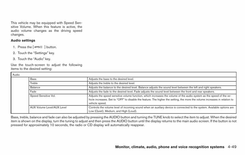
This vehicle may be equipped with Speed Sen-sitive Volume. When this feature is active, theaudio volume changes as the driving speedchanges.
Audio settings
1. Press the [ ] button.
2. Touch the “Settings” key.
3. Touch the “Audio” key.
Use the touch-screen to adjust the followingitems to the desired setting:
AudioBass Adjusts the bass to the desired level.Treble Adjusts the treble to the desired level.Balance Adjusts the balance to the desired level. Balance adjusts the sound level between the left and right speakers.Fade Adjusts the fade to the desired level. Fade adjusts the sound level between the front and rear speakers.Speed Sensitive Vol. Adjusts the speed sensitive volume function, which increases the volume of the audio system as the speed of the ve-
hicle increases. Set to “OFF” to disable the feature. The higher the setting, the more the volume increases in relation tovehicle speed.
AUX Volume Level/AUX Level Controls the volume level of incoming sound when an auxiliary device is connected to the system. Available options areLow (Quiet), Medium, and High (Loud).
Bass, treble, balance and fade can also be adjusted by pressing the AUDIO button and turning the TUNE knob to select the item to adjust. When the desireditem is shown on the display, turn the tuning to adjust and then press the AUDIO button until the display returns to the main audio screen. If the button is notpressed for approximately 10 seconds, the radio or CD display will automatically reappear.
Monitor, climate, audio, phone and voice recognition systems 4-49

SXM settings
To view the SXM settings:
1. Press the [ ] button.
2. Touch the “Settings” key.
3. Touch the “SXM” key.
The signal strength, activation status and otherinformation are displayed on the screen.
FM/AM/SAT radio operationFM·AM button
Press the FM·AM button to change the band asfollows:
AM → FM1 → FM2 → AM
If another audio source is playing when theFM·AM button is pressed, the audio source play-ing will automatically be turned off and the lastradio station played will begin playing.
The FM stereo indicator (STEREO) is shown onthe screen during FM stereo reception. When thestereo broadcast signal is weak, the radio auto-matically changes from stereo to monaural re-ception.
SXM band select
Pressing the SXM button will change the band asfollows:
SXM1* → SXM2* → SXM3* → SXM1* (satellite,if so equipped)
When the SXM button is pressed while the igni-tion switch is in the ACC or ON position, theradio will come on at the last station played.
The last station played will also come on whenthe ON-OFF button is pressed to turn the radioon.
*When the SXM button is pressed, the satelliteradio mode will be skipped unless an optionalsatellite receiver and antenna are installed and aSiriusXM® Satellite Radio service subscription isactive. Satellite radio is not available in Alaska,Hawaii and Guam.
If a compact disc is playing when the SXM buttonis pressed, the compact disc will automatically beturned off and the last radio station played willcome on.
While the radio is in SXM mode, the operationcan be controlled through the touch-screen.Touch the “Channels” key to display a list ofchannels. Touch a channel displayed on the list tochange to that channel. Touch the “Categories”key to display a list of categories. Touch a cat-egory displayed on the list to display optionswithin that category.
Tuning with the touch-screen
When in AM or FM mode, the radio can be tunedusing the touch-screen. To bring up the visualtuner, touch the “Tune” key on the lower rightcorner of the screen. A screen appears with a barrunning from low frequencies on the left to highfrequencies on the right. Touch the screen at thelocation of the frequency you wish to tune and thestation will change to that frequency. To return tothe regular radio display screen, touch the “OK”key.
Tuning with the TUNE knob
The radio can also be manually tuned using theTUNE knob. When in FM or AM mode, turn theTUNE knob to the left for lower frequencies or tothe right for higher frequencies. When in SXMmode, turn the TUNE knob to change the chan-nel.
SEEK tuning
When in FM or AM mode, press theor seek buttons to tune from low to high orhigh to low frequencies and to stop at the nextbroadcasting station.
When in SXM mode, press the orseek buttons to change the category.
4-50 Monitor, climate, audio, phone and voice recognition systems

1 to 6 Station memory operations
Twelve stations can be set for the FM band (six forFM1, six for FM2) and six stations can be set forthe AM band. Eighteen stations can be set for theSXM band (six for SXM1, six for SXM2 & sixSXM3).
1. Choose the radio band AM, FM1 or FM2using the FM·AM select button or choosethe radio band SXM1, SXM2 & SXM3 usingthe SXM button.
2. Tune to the desired station using manual orseek tuning. Press and hold any of the de-sired station memory buttons (1 – 6) until abeep sound is heard.
3. The channel indicator will then come on andthe sound will resume. Programming is nowcomplete.
4. Other buttons can be set in the same man-ner.
If the battery cable is disconnected or if the fuseopens, the radio memory will be canceled. In thatcase, reset the desired stations.
Presets can also be selected by touching thedesired preset number on the screen.
Smart Favorites Preset Setup (if soequipped):
The Smart Favorites feature allows the user todesignate presets, within the SXM1, SXM2 andSXM3 bands, as their Smart Favorites. When anyof the Smart Favorite presets are selected, thecurrent track on that station will play from thebeginning of the song.
To program a Smart Favorite preset:
1. Press the SXM button.
2. Touch the “Setup” key.
3. Touch the “Tune Start” key to activate (ON)or deactivate (OFF) Smart Favorites.
4. Touch the “Add Preset” key to select anavailable preset.
LHA2899 LHA3085
Monitor, climate, audio, phone and voice recognition systems 4-51

For additional information, refer to “1 to 6 stationmemory operations” in this section regarding pre-set memory options.
NOTE:
• Smart Favorites will start functioning onlyafter the audio unit is turned on for a fewminutes.• Tune Start is supported for music chan-nels only.
Replay Screen
The Replay Screen gives the user the ability toreplay, skip, pause or rewind the currently airedtrack.
When the “Replay” key is pressed, the ReplayScreen is prompted.
REPLAY To replay a track from thebeginning, press theseek button. The user cancontinue to press theseek button to replay previ-ous songs, but can only goback as far as the systempermits. The system will warnthe user when they cannotskip any further back by dis-playing “At the End” in thebottom left corner of thescreen.
SKIP To skip a track, pressthe track button. “Live”will appear in the bottom leftcorner of the screen indicat-ing the difference from playtime to live audio.
PAUSE To pause a track, pressthe pause button.
LHA3087
4-52 Monitor, climate, audio, phone and voice recognition systems

REWIND/FASTFOR-WARD
To rewind/ fast forward atrack, hold the or
seek/track button.
Compact disc (CD) player operation
If the radio is already operating, it automaticallyturns off and the compact disc begins to play.
CD button
When the CD button is pressed with the systemoff and the compact disc loaded, the system willturn on and the compact disc will start to play.
When the CD button is pressed with a compactdisc loaded and the radio playing, the radio willautomatically be turned off and the compact discwill start to play.
CD/MP3 display mode
Menu item
CD/MP3 display modeWhile listening to a CD or an MP3/WMA CD, certain text may be displayed (when a CD encoded with text isbeing used). Depending on how the CD or MP3/WMA CD is encoded, the text is displayed listing the artist,album and song title. There are other keys displayed on the screen when a CD is playing:
Random/MixTouch the “Random” key to apply a random play pattern to the CD. If an MP3 CD is playing, touching “Ran-dom” or alternates between Random Folder, and Random All. This text will appear on the display. To cancelRandom/Mix mode, touch the “Random” or “Mix” key until the key is no longer highlighted.
RepeatTouch the “Repeat” key to apply a repeat play pattern to the CD. If an MP3 CD is playing, touching “Repeat”alternates between repeating the current song and repeating the current folder. This text will appear on thedisplay. To cancel Repeat mode, touch the “Repeat” key until the key is no longer highlighted
BrowseTouch the “Browse” key to display the titles on the CD in list format. Touch the title of a song in the list to beginplaying that song. If an MP3 CD is playing, touching the “Browse” key will also list the folders on the disc. Fol-low the procedure for selecting a song with the touch-screen to choose a folder.
Monitor, climate, audio, phone and voice recognition systems 4-53

SEEK (Reverse or Fast
Forward) buttons
Press and hold the or seek buttonsfor 1.5 seconds while the compact disc is playingto reverse or fast forward the track being played.The compact disc plays at an increased speedwhile reversing or fast forwarding. When the but-ton is released, the compact disc returns to nor-mal play speed.
SEEK buttons
Press the seek button while a CD orMP3/WMA CD is playing to return to the begin-ning of the current track. Press the seekbutton several times to skip backward severaltracks.
Press the seek button while a CD orMP3/WMA CD is playing to advance one track.Press the seek button several times to skipforward several tracks. If the last track on a CD isskipped, the first track on the disc is played. If thelast track in a folder of an MP3/WMA CD isskipped, the first track of the next folder is played.
AUX button
The AUX IN audio input port accepts any stan-dard analog audio input such as from a portablecassette tape/CD player, MP3 player or a laptopcomputer. Press the AUX button to play a com-patible device plugged into the AUX IN port.
CD EJECT button
When the CD EJECT button is pressedwith a compact disc loaded, the compact discwill eject and the last source will be played.
If the disc is not removed within 10 seconds, thedisc will reload.
Additional featuresFor additional information, refer to “iPod® playeroperation with Navigation System” regarding theiPod® player available with this system in thissection.
For additional information, refer to “USB (Univer-sal Serial Bus) Connection Port (models withNavigation System)” regarding the USB (Univer-sal Serial Bus) Connection Port available withthis system in this section.
For additional information, refer to “Bluetooth®streaming audio with Navigation System” regard-ing the Bluetooth® audio interface available withthis system in this section.
USB (Universal Serial Bus)CONNECTION PORT (modelswithout Navigation System) (if soequipped)
Connecting a device to the USBConnection Port
WARNING
Do not connect, disconnect, or operate theUSB device while driving. Doing so can bea distraction. If distracted you could losecontrol of your vehicle and cause an acci-dent or serious injury.
LHA2455
4-54 Monitor, climate, audio, phone and voice recognition systems

CAUTION
● To avoid damage and loss of functionwhen using a USB device, note the fol-lowing precautions.
● Do not force the USB device into theUSB port. Inserting the USB devicetilted or up-side-down into the port maydamage the port. Make sure that theUSB device is connected correctly intothe USB port.
● Do not grab the USB port cover (if soequipped) when pulling the USB deviceout of the port. This could damage theport and the cover.
● Do not leave the USB cable in a placewhere it can be pulled unintentionally.Pulling the cable may damage the port.
Refer to your device manufacturer’s owner infor-mation regarding the proper use and care of thedevice.
The USB connection port is located on the centerconsole beneath the heater and air conditionercontrols. Insert the USB device into the connec-tion port.
When a compatible storage device is pluggedinto the connection port, compatible audio fileson the storage device can be played through thevehicle’s audio system.
Audio file operationMEDIA button
Place the ignition switch in the ON or ACCposition and press the MEDIA button to switch tothe USB input mode. If a CD is playing or anotheraudio source is plugged in through the AUX INjack, the MEDIA button toggles between thethree sources.
Play information
Information about the audio files being playedcan be displayed on the display screen of thevehicle’s audio system. Depending on how theaudio files are encoded, information such asFolder, Song and Artist will be displayed.
The track number and number of total tracks inthe folder are displayed on the screen as well.
SEEK/CAT (Reverse or
Fast Forward) buttons
Press and hold the or SEEK/CATbuttons for 1.5 seconds while an audio file on theUSB device is playing to reverse or fast forwardthe track being played. The track plays at an
increased speed while reversing or fast forward-ing. When the button is released, the audio filereturns to normal play speed.
SEEK/CAT and TRACK
buttons
Press the SEEK/CAT button while an au-dio file on the USB device is playing to return tothe beginning of the current track. Press theSEEK/CAT button several times to skipbackward several tracks.
Press the TRACK button while an audiofile on the USB device is playing to advance onetrack. Press the TRACK button severaltimes to skip forward several tracks. If the lasttrack in a folder on the USB device is skipped, thefirst track of the next folder is played.
RDM (random) button
When the RDM (random) button is pressed whilean audio file on the USB device is playing, theplay pattern can be changed as follows:
All Random → 1 Folder Random → OFF
All Random: all tracks on the USB device will beplayed randomly.
1 Folder Random: all tracks in the current folderwill be played randomly.
Monitor, climate, audio, phone and voice recognition systems 4-55

OFF: No random play pattern is applied. Theindicator on the display will turn off.
The current play pattern of the USB device isdisplayed on the screen unless no pattern isapplied.
RPT (repeat) button
When the RPT (repeat) button is pressed whilean audio file on the USB device is playing, theplay pattern can be changed as follows:
1 Folder Repeat → 1 Track Repeat → OFF
1 Track Repeat: the current track will be re-peated.
1 Folder Repeat: the current folder will be re-peated.
OFF: No repeat play pattern is applied. The indi-cator on the display will turn off.
The current play pattern of the USB device isdisplayed on the screen unless no pattern isapplied.
TUNE/SCROLL knob
If there are multiple folders with audio files on theUSB device, turn the TUNE/SCROLL knob tochange folders. Turn the knob to the left to skipback a folder. Turn the knob to the right to skipahead a folder. If there is only one folder of audiofiles on the USB device, turning theTUNE/SCROLL knob in either direction will re-turn to the first track on the USB device.
USB (Universal Serial Bus)CONNECTION PORT (models withNavigation System)
Connecting a device to the USBConnection Port
WARNING
Do not connect, disconnect, or operate theUSB device while driving. Doing so can bea distraction. If distracted you could losecontrol of your vehicle and cause an acci-dent or serious injury.
LHA2455
4-56 Monitor, climate, audio, phone and voice recognition systems

CAUTION
● To avoid damage and loss of functionwhen using a USB device, note the fol-lowing precautions.
● Do not force the USB device into theUSB port. Inserting the USB devicetilted or up-side-down into the port maydamage the port. Make sure that theUSB device is connected correctly intothe USB port.
● Do not grab the USB port cover (if soequipped) when pulling the USB deviceout of the port. This could damage theport and the cover.
● Do not leave the USB cable in a placewhere it can be pulled unintentionally.Pulling the cable may damage the port.
Refer to your device manufacturer’s owner infor-mation regarding the proper use and care of thedevice.
The USB connection port is located on the centerconsole beneath the heater and air conditionercontrols. Insert the USB device into the connec-tion port.
When a compatible storage device is pluggedinto the connection port, compatible audio fileson the storage device can be played through thevehicle’s audio system.
Audio file operationAUX (auxiliary) button
Place the ignition switch in the ON or ACCposition and press the AUX button to switch tothe USB input mode. If another audio source isplaying and a USB connection port device isinserted, press the AUX button until the centerdisplay changes to the USB memory mode.
If the system has been turned off while the USBmemory was playing, push the ON-OFF/VOLcontrol knob to restart the USB memory.
Play information
Information about the audio files being played isshown on the display screen of the vehicle’saudio system. Touch “Browse” to display the listof folders and files on the USB device. Touch thename of a song on the screen to begin playingthat song.
Seeking buttons
Press the seeking button while an audiofile on the USB device is playing to return to thebeginning of the current track. Press theseeking button several times to skip backwardseveral tracks.
LHA1496
Monitor, climate, audio, phone and voice recognition systems 4-57

Press the seeking button while an audiofile on the USB device is playing to advance onetrack. Press the seeking button severaltimes to skip forward several tracks. If the lasttrack in a folder on the USB device is skipped, thefirst track of the next folder is played.
Random and repeat play mode
While files on a USB device are playing, the playpattern can be altered so that songs are repeatedor played randomly.
RandomTouch the “Random” key to apply a random playpattern to the USB device. When the randommode is active, the icon is displayed to theleft of the song title or album name to denotewhich random pattern is applied. To cancel Ran-dom mode, touch the “Random” key untilno icon is displayed.
RepeatTouch the “Repeat” key to apply a repeat playpattern to the USB device. When the repeatmode is active, the icon is displayed to theleft of the song title or album name to denotewhich repeat pattern is applied. To cancel Repeatmode, touch the “Repeat” key until no iconis displayed.
iPod®* PLAYER OPERATIONWITHOUT NAVIGATION SYSTEM (ifso equipped)
Connecting iPod®
WARNING
Do not connect, disconnect, or operate theUSB device while driving. Doing so can bea distraction. If distracted you could losecontrol of your vehicle and cause an acci-dent or serious injury.
CAUTION
● Do not force the USB device into theUSB port. Inserting the USB devicetilted or up-side-down into the port maydamage the port. Make sure that theUSB device is connected correctly intothe USB port.
● Do not grab the USB port cover (if soequipped) when pulling the USB deviceout of the port. This could damage theport and the cover.
● Do not leave the USB cable in a placewhere it can be pulled unintentionally.Pulling the cable may damage the port.
Refer to your device manufacturer’s owner infor-mation regarding the proper use and care of thedevice.
To connect an iPod® to the vehicle so that theiPod® can be controlled with the audio systemcontrols and display screen, use the USB con-nection port located on the center console belowthe heater and air conditioner controls. Connectthe iPod®-specific end of the cable to the iPod®and the USB end of the cable to the USB con-nection port on the vehicle. If your iPod® sup-ports charging via a USB connection, its battery
LHA2455
4-58 Monitor, climate, audio, phone and voice recognition systems

will be charged while connected to the vehiclewith the ignition switch in the ACC or ON posi-tion.
While connected to the vehicle, the iPod® canonly be operated by the vehicle audio controls.
To disconnect the iPod® from the vehicle, re-move the USB end of the cable from the USBconnection port on the vehicle, then remove thecable from the iPod®.
* iPod® is a trademark of Apple Inc., registered inthe U.S. and other countries.
CompatibilityThe following models are compatible:
● iPod® 5th Generation (firmware version 1.3or later)
● iPod® Classic (80GB) (firmware version1.1.2PC or later)
● iPod® Classic (120GB) (firmware version2.0.1PC or later)
● iPod® nano - 1st generation (firmware ver-sion 1.3.1 or later)
● iPod® nano - 2nd generation (firmware ver-sion 1.1.3 or later)
● iPod® nano - 3rd generation (firmware ver-sion 1.1.3PC or later)
● iPod® nano - 4th generation (firmware ver-sion 1.0PC or later)
● iPod® nano - 5th generation (8GB) (firm-ware version 1.0.2PC or later)
● iPod® nano - 5th generation (16GB) (firm-ware version 1.0.1PC or later)
● iPod® nano - 6th generation (8GB) (firm-ware version 1.2PC or later)
● iPod® nano - 6th generation (8GB) (firm-ware version 1.1PC or later)
● iPod® Touch - 1st generation (firmware ver-sion 2.2.1 or later)
● iPod® Touch - 2nd generation (firmwareversion 2.2.1 or later)
● iPod® Touch - 3rd generation (firmware ver-sion 3.1.3 or later)
● iPod® Touch - 4th generation (firmware ver-sion 4.3.5 or later)
● iPhone® 3G (firmware version 4.1 or later)
● iPhone® 3GS (firmware version 4.3 or later)
● iPhone® 4 (firmware version 5.0 or later)
● iPhone® 4S (firmware version 5.1 or later)
● iPad® (firmware version 4.3.2 or later)
● iPad® 2 (firmware version 4.3.3 or later)
Make sure that your iPod® firmware is updated tothe version indicated above.
Audio main operationPlace the ignition switch to the ACC or ONposition. Then, press the CD·AUX or MEDIA but-ton repeatedly to switch to the iPod® mode.
If the audio system is turned off while the iPod® isplaying, the iPod® plays when the audio systemis turned back on.
If the audio system is off, pressing the CD·AUX orMEDIA button turns the audio system on andplays the iPod®.
If the audio system is on, the audio system auto-matically begins playing tracks from the iPod®when it is plugged into the port.
MEDIA button
Press the MEDIA button while the iPod® is con-nected to show the iPod® operation menu on theaudio display. Scroll through the menu list usingthe TUNE/SCROLL knob. PressENTER/SETTING button to select a menu item.Items in the iPod® menu appear on the display inthe following order:
● Now playing
● Playlists
● Artists
Monitor, climate, audio, phone and voice recognition systems 4-59

● Albums
● Songs
● Podcasts
● Genres
● Composers
● Audiobooks
● Shuffle songs
For additional information, refer to the iPod®Owner’s Manual regarding each item.
SEEK/CAT and TRACK buttons
When the SEEK/CAT button orTRACK button is pressed for less than 1.5 sec-onds while the iPod® is playing, the next track orthe beginning of the current track on the iPod®will be played.
When the SEEK/CAT button orTRACK button is pressed for more than 1.5 sec-onds while the iPod® is playing, the iPod® willplay while fast forwarding or rewinding. When thebutton is released, the iPod® will return to thenormal play speed.
REPEAT (RPT)
When the RPT button is pressed while a track isbeing played, the play pattern can be changed asfollows:
Repeat Off → 1 Track Repeat → All Repeat →Repeat Off
1 Track Repeat: the current track will be re-peated.
All Repeat: all songs in the current list are re-peated.
Repeat Off: no repeat play pattern is applied.
RANDOM (RDM)
When the RDM button is pressed while a track isbeing played, the play pattern can be changed asfollows:
Shuffle Off → Track Shuffle → Album Shuffle →Shuffle Off
Track Shuffle: the tracks in the current list will beplayed randomly.
Album Shuffle: the albums in the current list willbe played randomly.
Shuffle Off: no random play pattern is applied.
BACK button
When the BACK button is pressed, it returns tothe previous menu.
4-60 Monitor, climate, audio, phone and voice recognition systems
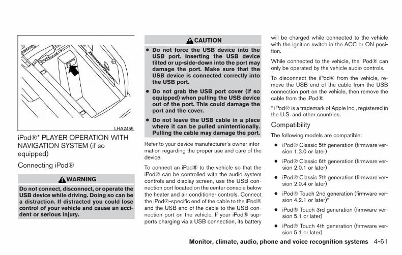
iPod®* PLAYER OPERATION WITHNAVIGATION SYSTEM (if soequipped)
Connecting iPod®
WARNING
Do not connect, disconnect, or operate theUSB device while driving. Doing so can bea distraction. If distracted you could losecontrol of your vehicle and cause an acci-dent or serious injury.
CAUTION
● Do not force the USB device into theUSB port. Inserting the USB devicetilted or up-side-down into the port maydamage the port. Make sure that theUSB device is connected correctly intothe USB port.
● Do not grab the USB port cover (if soequipped) when pulling the USB deviceout of the port. This could damage theport and the cover.
● Do not leave the USB cable in a placewhere it can be pulled unintentionally.Pulling the cable may damage the port.
Refer to your device manufacturer’s owner infor-mation regarding the proper use and care of thedevice.
To connect an iPod® to the vehicle so that theiPod® can be controlled with the audio systemcontrols and display screen, use the USB con-nection port located on the center console belowthe heater and air conditioner controls. Connectthe iPod®-specific end of the cable to the iPod®and the USB end of the cable to the USB con-nection port on the vehicle. If your iPod® sup-ports charging via a USB connection, its battery
will be charged while connected to the vehiclewith the ignition switch in the ACC or ON posi-tion.
While connected to the vehicle, the iPod® canonly be operated by the vehicle audio controls.
To disconnect the iPod® from the vehicle, re-move the USB end of the cable from the USBconnection port on the vehicle, then remove thecable from the iPod®.
* iPod® is a trademark of Apple Inc., registered inthe U.S. and other countries.
CompatibilityThe following models are compatible:
● iPod® Classic 5th generation (firmware ver-sion 1.3.0 or later)
● iPod® Classic 6th generation (firmware ver-sion 2.0.1 or later)
● iPod® Classic 7th generation (firmware ver-sion 2.0.4 or later)
● iPod® Touch 2nd generation (firmware ver-sion 4.2.1 or later)*
● iPod® Touch 3rd generation (firmware ver-sion 5.1 or later)
● iPod® Touch 4th generation (firmware ver-sion 5.1 or later)
LHA2455
Monitor, climate, audio, phone and voice recognition systems 4-61

● iPod® nano - 1st generation (firmware ver-sion 1.3.1 or later)
● iPod® nano - 2nd generation (firmware ver-sion 1.1.3 or later)
● iPod® nano - 3rd generation (firmware ver-sion 1.1.3 or later)
● iPod® nano - 4th generation (firmware ver-sion 1.0.4 or later)
● iPod® nano - 5th generation (firmware ver-sion 1.0.2 or later)
● iPod® nano - 6th generation (firmware ver-sion 1.1 or later)
● iPhone® 3G (firmware version 4.2.1 or later)
● iPhone® 3GS (firmware version 5.1 or later)
● iPhone® 4 (firmware version 5.1 or later)
● iPhone® 4S (firmware version 5.1 or later)
* Some features of this iPod® may not be fullyfunctional.
Make sure that your iPod® firmware is updated tothe version indicated above.
Audio main operationPlace the ignition switch in the ACC or ONposition. Press the AUX button repeatedly toswitch to the iPod® mode.
If the system has been turned off while the iPod®was playing, pressing the VOL/ON·OFF controlknob will start the iPod®.
AUX button
When the AUX button is pressed with the systemoff and the iPod® connected, the system will turnon. If another audio source is playing and theiPod® is connected, press the AUX button re-peatedly until the center display changes to theiPod® mode.
LHA2911
4-62 Monitor, climate, audio, phone and voice recognition systems

Interface
The interface for iPod® operation shown on thevehicle’s audio system display screen is similar tothe iPod® interface. Use the touch-screen,BACK button or the scrolling knob to navigatethe menus on the screen.
When the iPod® is playing, touch the “Menu” keyto bring up the iPod® interface.
Depending on the iPod® model, the followingitems may be available on the menu list screen.For additional information, refer to the iPod®Owner’s Manual regarding each menu item.
● Playlists
● Artists
● Albums
● Genres
● Songs
● Composers
● Audiobooks
● Podcasts
Shuffle and repeat play mode
While the iPod® is playing, the play pattern canbe altered so that songs are repeated or playedrandomly.
ShuffleTouch the “Shuffle” key to apply a random playpattern to the iPod®. When the Shuffle mode isactive, the text is illuminated. Touching the“Shuffle” key once more will display the “Shufflesongs” key. To cancel Shuffle mode, touch the“Shuffle” key again until the text is no longerilluminated.
RepeatTouch the “Repeat” key to apply a repeat playpattern to the iPod®. When the repeat mode isactive, the text is illuminated. Touching the “Re-peat” key once more will display the “Repeat
song” key. To cancel Repeat mode, touch the“Repeat” key again until the text is no longerilluminated.
SEEK/CAT and TRACK buttons
When the SEEK/CAT button orTRACK button is pressed for less than 1.5 sec-onds while the iPod® is playing, the next track orthe beginning of the current track on the iPod®will be played.
When the SEEK/CAT button orTRACK button is pressed for more than 1.5 sec-onds while the iPod® is playing, the iPod® willplay while fast forwarding or rewinding. When thebutton is released, the iPod® will return to thenormal play speed.
LHA2907
Monitor, climate, audio, phone and voice recognition systems 4-63

Scrolling menus
While navigating long lists of artists, albums orsongs in the music menu, it is possible to scrollthe list by the first character in the name. Toactivate character indexing, touch and hold the“A-Z” key in the upper right corner of the screen.Turn the TUNE/SCROLL knob to choose thenumber or letter to jump to in the list and thenpress the ENTER/AUDIO button.
If no character is selected after 2 seconds, thedisplay returns to normal.
BLUETOOTH® STREAMING AUDIOWITHOUT NAVIGATION SYSTEM (ifso equipped)If you have a compatible Bluetooth® audio de-vice that is capable of playing audio files, thedevice can be connected to the vehicle’s audiosystem so that the audio files on the device playthrough the vehicle’s speakers.
Connecting Bluetooth® audio
To connect your Bluetooth® audio device to thevehicle, follow the procedure below:
1. Press the ENTER/SETTING button.
2. Select “Bluetooth”.
3. Select “Add Phone or Device”. This samescreen can be accessed to remove, replaceor select a different Bluetooth® device.
4. The system acknowledges the commandand asks you to initiate connecting from thephone handset. The connecting procedureof the cellular phone varies according toeach cellular phone model. For additional
LHA2279 LHA2775
4-64 Monitor, climate, audio, phone and voice recognition systems

information, refer to the cellular phone Own-er’s Manual. You can also visitwww.nissanusa.com/bluetooth orwww.nissan.ca.com/bluetooth for instruc-tions on connecting NISSAN recommendedcellular phones.
Audio main operationTo switch to the Bluetooth® audio mode, pressthe MEDIA button repeatedly until theBluetooth® audio mode is displayed on thescreen.
The controls for the Bluetooth® audio are dis-played on the screen. Use the Preset 3 button forplay and the Preset 4 button for pause.
BLUETOOTH® STREAMING AUDIOWITH NAVIGATION SYSTEMIf you have a compatible Bluetooth® audio de-vice that is capable of playing audio files, thedevice can be connected to the vehicle’s audiosystem so that the audio files on the device playthrough the vehicle’s speakers.
Connecting Bluetooth® audioTo connect your Bluetooth® audio device to thevehicle, follow the procedure below:
1. Press the [ ] button.
2. Touch the “Settings” key.
3. Touch the “Phone & Bluetooth” key.
4. Touch the “Connect New Device” key.
5. The system acknowledges the commandand asks you to initiate connecting from thephone handset. The connecting procedureof the cellular phone varies according toeach cellular phone model. For additionalinformation, refer to the cellular phone Own-er’s Manual. You can also visitwww.nissanusa.com/bluetooth orwww.nissan.ca.com/bluetooth for instruc-tions on connecting NISSAN recommendedcellular phones.
LHA2924 LHA2844
Monitor, climate, audio, phone and voice recognition systems 4-65

Audio main operationTo switch to the Bluetooth® audio mode, pressthe AUX button repeatedly until the Bluetooth®audio mode is displayed on the screen.
The controls for the Bluetooth® audio are dis-played on the screen.
CD CARE AND CLEANING
● Handle a CD by its edges. Do not bend thedisc. Never touch the surface of the disc.
● Always place the discs in the storage casewhen they are not being used.
● To clean a disc, wipe the surface from thecenter to the outer edge using a clean, softcloth. Do not wipe the disc using a circularmotion.
● Do not use a conventional record cleaner oralcohol intended for industrial use.
● A new disc may be rough on the inner andouter edges. Remove the rough edges byrubbing the inner and outer edges with theside of a pen or pencil as illustrated.
LHA0049
4-66 Monitor, climate, audio, phone and voice recognition systems
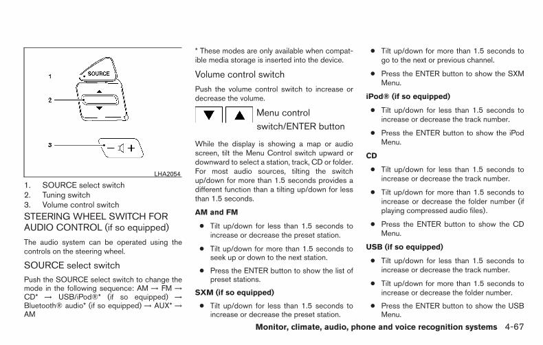
1. SOURCE select switch2. Tuning switch3. Volume control switch
STEERING WHEEL SWITCH FORAUDIO CONTROL (if so equipped)
The audio system can be operated using thecontrols on the steering wheel.
SOURCE select switchPush the SOURCE select switch to change themode in the following sequence: AM → FM →CD* → USB/iPod®* (if so equipped) →Bluetooth® audio* (if so equipped) → AUX* →AM
* These modes are only available when compat-ible media storage is inserted into the device.
Volume control switch
Push the volume control switch to increase ordecrease the volume.
Menu controlswitch/ENTER button
While the display is showing a map or audioscreen, tilt the Menu Control switch upward ordownward to select a station, track, CD or folder.For most audio sources, tilting the switchup/down for more than 1.5 seconds provides adifferent function than a tilting up/down for lessthan 1.5 seconds.
AM and FM
● Tilt up/down for less than 1.5 seconds toincrease or decrease the preset station.
● Tilt up/down for more than 1.5 seconds toseek up or down to the next station.
● Press the ENTER button to show the list ofpreset stations.
SXM (if so equipped)
● Tilt up/down for less than 1.5 seconds toincrease or decrease the preset station.
● Tilt up/down for more than 1.5 seconds togo to the next or previous channel.
● Press the ENTER button to show the SXMMenu.
iPod® (if so equipped)
● Tilt up/down for less than 1.5 seconds toincrease or decrease the track number.
● Press the ENTER button to show the iPodMenu.
CD
● Tilt up/down for less than 1.5 seconds toincrease or decrease the track number.
● Tilt up/down for more than 1.5 seconds toincrease or decrease the folder number (ifplaying compressed audio files).
● Press the ENTER button to show the CDMenu.
USB (if so equipped)
● Tilt up/down for less than 1.5 seconds toincrease or decrease the track number.
● Tilt up/down for more than 1.5 seconds toincrease or decrease the folder number.
● Press the ENTER button to show the USBMenu.
LHA2054
Monitor, climate, audio, phone and voice recognition systems 4-67

Bluetooth® Audio (if so equipped)
● Tilt up/down for less than 1.5 seconds toskip ahead or back to the next song.
● Tilt up/down for more than 1.5 seconds toreverse or fast forward the current song.
AUX
● Press the ENTER button to show the AUXMenu.
ANTENNAThe antenna cannot be shortened, but can beremoved. When you need to remove the antenna,turn the antenna rod counterclockwise.
To install the antenna rod, turn the antenna rodclockwise and hand tighten.
CAUTION
● Always properly tighten the antennarod during installation or the antennarod may break during vehicle operation.
● Be sure that the antenna is removedbefore the vehicle enters an automaticcar wash.
● Be sure to fold down the antenna be-fore the vehicle enters a garage with alow ceiling.
This vehicle is equipped with Smartphone Inte-gration technology. This allows many compatibleSmartphone applications to be displayed andeasily controlled through the vehicle’s touch-screen.
NOTE:
A compatible smartphone and registrationis required to use mobile applications or toaccess connected features of certain ve-hicle applications.
REGISTERING WITHNISSANCONNECTSM WITH MOBILEAPPSTo use the Smartphone Integration feature, it isnecessary for the user to register. In order toregister, visit the NissanConnectSM website,www.nissanusa.com/connect/ orhttps://canada.nissanconnect.com (For Canada)and sign up or create an account through theprompts on the NissanConnectSM with MobileApps. Once registered, download the Nissan-ConnectSM App from your compatible phone’sapplication download source and then log intothe application. If you already have an accountcreated through the App, please log in.
CONNECT PHONETo use this feature, a compatible smartphonemust be connected via Bluetooth® or USB to thevehicle. For additional information on connectingyour phone, refer to Bluetooth® Hands-FreePhone System without Navigation System” or“Bluetooth® Hands-Free Phone System withNavigation System” in this section.
NOTE:
For vehicles with navigation, AppleiPhones REQUIRE the phone to be pluggedin via USB for NissanConnectSM Apps tofunction.For vehicles without Navigation, AppleiPhones must be paired via Bluetooth forNissanConnectSM Apps to function.
NOTE:
For Android phones, NissanConnectSM
Apps REQUIRES the phone to be paired viaBluetooth.
NISSANCONNECTSM WITH MOBILEAPPS (if so equipped)
4-68 Monitor, climate, audio, phone and voice recognition systems

APPLICATION DOWNLOADOnce connected, the NissanConnectSM App willsearch your phone to determine which compat-ible applications are currently installed. The userwill then choose which apps they want to bringinto their vehicle from the list of apps within the“Manage My Apps” section of the Nissan-ConnectSM App on their smartphone. The vehiclewill then download the in-vehicle interface foreach of these compatible applications. Oncedownloaded, the user can access their selectedsmartphone applications through the vehicle in-terface. For additional information on applicationavailability visit www.nissanusa.com/connect/ orwww.canada.nissanconnect.com
WARNING
● The Mobile Entertainment System isdesigned for rear seat passenger view-ing only.
● The driver must not attempt to operatethe Mobile Entertainment System whilethe vehicle is in motion so that full at-tention may be given to vehicleoperation.
CAUTION
● The glass screen on the liquid crystaldisplay may break if hit with a hard orsharp object. If the glass breaks, do nottouch the liquid crystalline material,which contains a small amount of mer-cury. In case of contact with skin, washimmediately with soap and water.
● Use a damp, soft cloth when cleaningthe Mobile Entertainment System com-ponents. Do not use solvents or clean-ing solutions.
Do not attempt to use the system in extremetemperature conditions [below -4°F (-20°C) orabove 158°F (70°C)].
To avoid discharging the vehicle battery, do notoperate the system more than 15 minutes withoutstarting the engine.
LHA0389
NISSAN MOBILE ENTERTAINMENTSYSTEM (MES) (if so equipped)
Monitor, climate, audio, phone and voice recognition systems 4-69

1. EJECT button2. DVD slot3. ENTER button4. NAVIGATION keys5. DISPLAY button6. MENU button7. PLAY/PAUSE button8. STOP button9. Input jacks10. MODE button11. POWER on/off button
DIGITAL VIDEO DISC (DVD) PLAYERCONTROLSFor additional information, refer to “Playing a digi-tal video disc (DVD)” in this section for the func-tion of each button.
1. POWER button2. PAUSE button3. PLAY button4. FAST FORWARD/FAST REVERSE
button5. MENU button
LHA3197
LHA3198
4-70 Monitor, climate, audio, phone and voice recognition systems

6. NAVIGATION keys7. BACK button8. Numeric keypad9. CLEAR button10. ANGLE button11. AUDIO button12. SUBTITLE button13. MODE button14. DISPLAY button15. ENTER button16. TITLE button17. NEXT TRACK/CHAPTER and PREVI-
OUS TRACK/CHAPTER button18. STOP buttonREMOTE CONTROLFor additional information, refer to “Playing a digi-tal video disc (DVD)” in this section for the func-tion of each button.
FLIP-DOWN SCREENThe flip-down screen has a wireless remote con-trol receiver �1 located at the bottom of thescreen.
CAUTION
● The glass screen on the liquid crystaldisplay may break if hit with a hard orsharp object. If the glass screen breaks,do not touch it. Doing so could result inan injury.
● The screen rotates down to view and upinto the housing to store when not inuse. Ensure that the screen is latchedsecurely into the housing when stored.
LHA0315
Monitor, climate, audio, phone and voice recognition systems 4-71

Headphones
Power ON/OFF
Press the power button to turn the headphoneson or off.
Volume control
Turn the volume control knob to adjust the vol-ume.
The headphones will automatically be turned offin 30 seconds if there is no sound during thatperiod. To prevent the battery from being dis-charged, keep the power supply turned off whennot in use.
NOTE:
For optimum infrared headphone perfor-mance, increase the volume on the rearseat controller to the maximum level andadjust the infrared headphone volume us-ing the volume control on the headphones.Using a lower volume setting on the rearseat controller can cause static noise in theinfrared headphones.
PLAYING A DIGITAL VIDEO DISC(DVD)
CAUTION
● Only operate the DVD while the vehicleengine is running. Operating the DVDfor extended periods of time with theengine OFF can discharge the vehiclebattery.
● Do not allow the system to get wet.Excessive moisture such as spilled liq-uids may cause the system tomalfunction.
The driver must not attempt to wear the head-phones while the vehicle is in motion so that fullattention may be given to vehicle operation.
While playing video CD media, this DVD playerdoes not guarantee complete functionality of allvideo CD formats.
With the DVD player, you can hear DVD videos,video CDs and CDs using headphones. Passen-gers in the rear seat can enjoy the sound inde-pendently of the front seat.
Press the AUX button located on the front con-trols to hear the sound of the DVD play throughthe speakers.
SAA0720 SAA0721
4-72 Monitor, climate, audio, phone and voice recognition systems

It is possible to operate the DVD player by remotecontrol.
Headphones are a wireless type and no cablesare necessary. You can use them in almost all theranges in the rear seat. (It is not possible to usethe headphones in the front seat.)
POWER on/off button
With the ignition switch placed in the ACC or ONposition, press the POWER button to turn theDVD player on or off.
Insert the DVD into the slot with the label sidefacing up. The DVD will be guided automaticallyinto the slot.
If the DVD player is off and a DVD is inserted, theDVD player will automatically turn on.
CAUTION
Do not force the compact disc into theslot. This could damage the player.
MODE select button
Press the MODE button to select Audio/Videosource between DVD and AUX input (input jackson the faceplate, Red = right channel audio input,White = left channel audio input, and Yellow =Video input).
The display will show the “AUX” in the upper leftcorner of the display for 4 seconds once themode is changed to AUX.
For additional information on how to use the inputjacks, refer to “Auxiliary input jacks” in this sec-tion.
or PLAY
When the PLAY/PAUSE button on the player orthe PLAY button on the remote control ispressed, the player will play.
In play mode, the display will briefly showon the upper left corner of the display.
FF (Fast Forward), REW
(Remote control only)
Press the FAST FORWARD/FAST REVERSEbuttons to carry out the fast forward or fast re-verse presentation at 5 times normal play speed.
Press the FAST FORWARD/FAST REVERSEbuttons again or PLAY button to resume thenormal play speed.
NEXT
CHAPTER/PREVIOUS
CHAPTER (Remote con-
trol only)
When the (NEXT CHAPTER) button ispressed while the DVD is playing, the programnext to the present one will start to play from itsbeginning. Press several times to skip throughprograms. The DVD will advance the number oftimes the button is pressed. When the(PREVIOUS CHAPTER) button is pressed, theprogram being played returns to its beginning.Press several times to skip back through pro-grams. The DVD will go back the number of timesthe button is pressed.
or PAUSE
When the PLAY/PAUSE button on the player orthe PAUSE button on the remote control ispressed, the player will pause playing of themedia. In pause mode, the player will showon the upper left corner of the display until theplayer is changed to another mode.
Monitor, climate, audio, phone and voice recognition systems 4-73
STOP
Press the STOP button once to stop playing themedia. The display will show in the upperleft corner of the display for 4 seconds, and thelast disc position will be stored. When the PLAYbutton is pressed again, it will resume at thestored disc track and time position.
If the STOP button is pressed again when theplayer is already in Stop mode, it will reinitializethe pointer to the beginning of the disc. In effect,it will ignore the last stored disc position andupon receipt of the next play message, will beginat the Title Menu or at “the beginning of the disc”.
EJECT
When the EJECT button is pressed with the DVDloaded, it will be ejected.
The display will show the EJECT symbol inthe upper left corner of the display for 4 secondsonce the EJECT button is pressed.
If the DVD is not loaded, the display will show“NO DISC”.
If the DVD comes out and is not removed within25 seconds, it will be pulled back into the slot toprotect it.
DISPLAY
If the DISPLAY control is pressed for less than2 seconds, the display menu will appear on thescreen.
● The display menu will remain on the screenfor 10 seconds if no subsequent controlactivations occur.
● Use the NAVIGATION KEYS to navigatewithin the display menu and use ENTER toselect the item.
● Holding the DISPLAY control on the face-plate for longer than approximately 2 sec-onds while in the display menu will reset thedisplay characteristics to their nominal val-ues. (Faceplate feature only)
If the DISPLAY control button on the faceplate ispressed for more than 2 seconds, the mediatrack/time information will be displayed along thebottom of the display. Pressing the DISPLAYcontrol for more than 2 seconds will remove themedia track/time information from the display.(Faceplate feature only)
NAVIGATION KEYS
If media is in PLAY mode, activation of the NAVI-GATION KEYS (Up, Down, Left, and Right) willperform the following functions: nextchapter/track, previous chapter/track, fast re-
verse and fast forward, and the display will
show , , and respec-tively in the upper left corner of the display for4 seconds. (Faceplate feature only)
If media is in PAUSE mode, activation of theNAVIGATION KEYS (Up, Down and Right) willperform the following functions: nextchapter/track, previous chapter/track and slow
forward, and the display will show ,and a forward arrow symbol respectively in theupper left corner of the display for 4 seconds.(Faceplate feature only)
If media is in activated MENU mode, the NAVI-GATION KEYS will be used to navigate Up,Down, Left, and Right within the menu.
If display control menu is on, the NAVIGATIONKEYS will be used to navigate Up, Down, Left,and Right within the menu.
ENTER
In MENU mode, press the ENTER button to se-lect MENU items.
In the display menu, press the ENTER button toselect items for modification, as per the on-screen instructions.
4-74 Monitor, climate, audio, phone and voice recognition systems

MENU
If the media is in PLAY mode and the MENUbutton is pressed, the DVD menu will appear onthe screen. Use the Navigation Keys to navigatewithin the menu and use ENTER to select theitem.
Press the MENU button again to return to PLAYmode.
TITLE (Remote control only)
Press the TITLE button to return the DVD mediato the “title” of the DVD.
Press the TITLE button again to return to theprevious stop point and play.
BACK (Remote control only)
Press the BACK button to exit the current activemenu and return to the previous menu.
SUBTITLE (Remote control only)
Press the SUBTITLE button to call up subtitleselection menu.
Repeatedly press the SUBTITLE button to cyclethrough each available subtitle.
AUDIO (Remote control only)
Press the AUDIO button to call up the audiomenu.
Repeatedly press the AUDIO button to cyclethrough each available audio track.
ANGLE (Remote control only)
Press the ANGLE button to call up the cameraangle menu.
Repeatedly press the ANGLE button to cyclethrough each available angle.
CLEAR (Remote control only)
Press the CLEAR button to clear all numericinputs, if actuated prior to expiration of the3-second timer.
NUMERIC KEYPAD (0–9 & ≥10) (Remotecontrol only)
Press the NUMERIC KEYPAD to directly accessdisc chapters, titles or tracks by inputting theirnumeric value.
Use the “≥10” button to input numbers greaterthan or equal to 10. Up to three digits can beinputted when selecting the chapter/title/tracknumber.
The subsequent actuation of numeric buttons willcontinuously shift the previously input number tothe “left”.
The chapter/title/track number will be automati-cally selected (if valid, based on media content) if3 seconds expire without any keypad inputs.
The operator can cancel the inputchapter/title/track number by actuating theCLEAR control prior to the expiration of the3-second timer.
These functions can be used only for the DVDdiscs which correspond to them.
Auxiliary input jacksThe auxiliary input jacks are located on the controlpanel. Compatible devices such as video games,camcorders and portable video players can beconnected to the auxiliary jacks.
The auxiliary jacks are color coded for identifica-tion purposes.
● Yellow - video input
● White - left channel audio input
● Red - right channel audio input
To view the compatible device connected to theAUX jacks, press the MODE button. For addi-tional information, refer to “Mode select button” inthis section.
Monitor, climate, audio, phone and voice recognition systems 4-75

CARE AND MAINTENANCEUse a lightly dampened, lint free cloth to clean thesurfaces of your NISSAN Mobile EntertainmentSystem (DVD player face, screen, remote control,etc.).
Do not attempt to use the system in extremetemperature conditions [below -4°F (-20°C) orabove 158°F (70°C)].
Do not attempt to operate the system in extremehumidity conditions (less than 10% or more than75%).
CAUTION
● Do not use any solvents or cleaningsolutions when cleaning the videosystem.
● Do not use excessive force on the moni-tor screen.
● Avoid touching or scratching the moni-tor screen as it may become dirty ordamaged.
HOW TO HANDLE THE DVD
CAUTION
● Handle a DVD by its edges. Never touchthe surface of the disc.
● To clean a disc, wipe the surface fromthe center to the outer edge using aclean, soft cloth. Do not wipe the discusing a circular motion.
● Do not use a conventional recordcleaner, benzine, thinner or alcohol in-tended for industrial use.
● A new disc may be rough on its innerand outer edges. Remove the roughedges using the side of a pen or pencilas illustrated.
● Never attempt to use a DVD that hasbeen cracked, deformed, or repaired us-ing adhesive. Doing so may cause dam-age to the equipment.
● Handle the DVD carefully to avoid contami-nation or flaws. Otherwise, signals may notbe read properly.
● Do not write, draw or attach anything on anyside of the DVD.
● Do not store the DVD in locations with directsunlight or in high temperatures or humidity.
● Always place discs in the storage case whenthey are not being used.
● Do not put on any sticker or write anythingon either surface of the DVD.
LHA0049
4-76 Monitor, climate, audio, phone and voice recognition systems
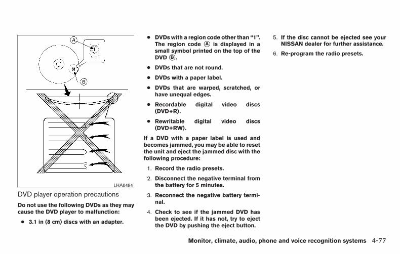
DVD player operation precautions
Do not use the following DVDs as they maycause the DVD player to malfunction:
● 3.1 in (8 cm) discs with an adapter.
● DVDs with a region code other than “1”.The region code �A is displayed in asmall symbol printed on the top of theDVD �B .
● DVDs that are not round.
● DVDs with a paper label.
● DVDs that are warped, scratched, orhave unequal edges.
● Recordable digital video discs(DVD+R).
● Rewritable digital video discs(DVD+RW).
If a DVD with a paper label is used andbecomes jammed, you may be able to resetthe unit and eject the jammed disc with thefollowing procedure:
1. Record the radio presets.
2. Disconnect the negative terminal fromthe battery for 5 minutes.
3. Reconnect the negative battery termi-nal.
4. Check to see if the jammed DVD hasbeen ejected. If it has not, try to ejectthe DVD by pushing the eject button.
5. If the disc cannot be ejected see yourNISSAN dealer for further assistance.
6. Re-program the radio presets.
LHA0484
Monitor, climate, audio, phone and voice recognition systems 4-77

Remote control and headphonesbattery replacement
Replace the battery as follows:
1. Open the lid.
2. Replace batteries with new ones.
● Size AA (remote control)
● Size AAA (headphones)
Make sure that the and ends onthe batteries match the markings inside thecompartment.
3. Close the lid securely.
If the battery is removed for any reasonother than replacement, close the lid se-curely.
● If you will not be using the remote control forlong periods of time, remove the batteries.
● Replacement of the batteries is neededwhen the remote control only functions atextremely close distances to the DVD playeror not at all.
● Be careful not to touch the battery terminal.
● An improperly disposed battery can harmthe environment. Always confirm local regu-lations for battery disposal.
● When changing batteries, do not let dust oroil get on the remote control and head-phones.
FCC Notice:
Changes or modifications not expressly ap-proved by the party responsible for compli-ance could void the user’s authority to op-erate the equipment. This device complieswith Part 15 of the FCC Rules and RSS-210of Industry Canada. Operation is subject tothe following two conditions: (1) This de-vice may not cause harmful interference,and (2) this device must accept any interfer-ence received, including interference thatmay cause undesired operation of the de-vice.
LHA0318 SAA0723
4-78 Monitor, climate, audio, phone and voice recognition systems

When installing a CB, ham radio or car phone inyour vehicle, be sure to observe the followingprecautions; otherwise, the new equipment mayadversely affect the engine control system andother electronic parts.
WARNING
● A cellular phone should not be used forany purpose while driving so full atten-tion may be given to vehicle operation.Some jurisdictions prohibit the use ofcellular phones while driving.
● If you must make a call while your ve-hicle is in motion, the hands free cellu-lar phone operational mode (if soequipped) is highly recommended. Ex-ercise extreme caution at all times sofull attention may be given to vehicleoperation.
● If you are unable to devote full attentionto vehicle operation while talking onthe phone, pull off the road to a safelocation and stop your vehicle.
CAUTION
● Keep the antenna as far away as pos-sible from the electronic controlmodules.
● Keep the antenna wire more than 8 in(20 cm) away from the electronic controlsystem harnesses. Do not route the an-tenna wire next to any harness.
● Adjust the antenna standing-wave ratioas recommended by the manufacturer.
● Connect the ground wire from the CBradio chassis to the body.
● For details, consult a NISSAN dealer.
WARNING
● Use a phone after stopping your vehiclein a safe location. If you have to use aphone while driving, exercise extremecaution at all times so full attention maybe given to vehicle operation.
● If you are unable to devote full attentionto vehicle operation while talking onthe phone, pull off the road to a safelocation and stop your vehicle.
CAUTION
To avoid discharging the vehicle battery,use a phone after starting the engine.
CAR PHONE OR CB RADIO BLUETOOTH® HANDS-FREE PHONESYSTEM WITHOUT NAVIGATIONSYSTEM (if so equipped)
Monitor, climate, audio, phone and voice recognition systems 4-79

Your NISSAN is equipped with the Bluetooth®Hands-Free Phone System. If you have a com-patible Bluetooth® enabled cellular phone, youcan set up the wireless connection between yourcellular phone and the in-vehicle phone module.With Bluetooth® wireless technology, you can
make or receive a hands-free telephone call withyour cellular phone in the vehicle.
Once your cellular phone is connected to thein-vehicle phone module, no other phone con-necting procedure is required. Your phone isautomatically connected with the in-vehicle
phone module when the ignition switch is placedin the ON position with the previously connectedcellular phone turned on and carried in the ve-hicle.
NOTE:
Some devices require the user to acceptconnections to other Bluetooth® devices. Ifyour phone does not connect automatically to the system, consult the phone’sOwner’s Manual for details on device op-eration.
You can connect up to five different Bluetooth®cellular phones to the in-vehicle phone module.However, you can talk on only one cellular phoneat a time.
Before using the Bluetooth® Hands-Free PhoneSystem, refer to the following notes.
● Set up the wireless connection between acompatible cellular phone and the in-vehiclephone module before using the hands-freephone system.
● Some Bluetooth® enabled cellular phonesmay not be recognized or work properly.Please visit www.nissanusa.com/bluetoothor www.nissan.ca/bluetooth for a recom-mended phone list and connecting instruc-tions.
LHA3209
4-80 Monitor, climate, audio, phone and voice recognition systems

● You will not be able to use a hands-freephone under the following conditions:
– Your vehicle is outside of the cellular ser-vice area.
– Your vehicle is in an area where it isdifficult to receive a cellular signal; suchas in a tunnel, in an underground parkinggarage, near a tall building or in a moun-tainous area.
– Your cellular phone is locked to prevent itfrom being dialed.
● When the radio wave condition is not idealor ambient sound is too loud, it may bedifficult to hear the other person’s voice dur-ing a call.
● Do not place the cellular phone in an areasurrounded by metal or far away from thein-vehicle phone module to prevent tonequality degradation and wireless connectiondisruption.
● While a cellular phone is connected throughthe Bluetooth® wireless connection, thebattery power of the cellular phone may dis-charge quicker than usual. The Bluetooth®Hands-Free Phone System cannot chargecellular phones.
● If the hands-free phone system seems to bemalfunctioning, refer to “Troubleshootingguide” in this section. You can also visitwww.nissanusa.com/bluetooth orwww.nissan.ca/bluetooth for troubleshoot-ing help.
● Some cellular phones or other devices maycause interference or a buzzing noise tocome from the audio system speakers. Stor-ing the device in a different location mayreduce or eliminate the noise.
● For additional information, refer to the cellu-lar phone Owner’s Manual regarding thetelephone charges, cellular phone antennaand body, etc.
REGULATORY INFORMATION
FCC Regulatory information
– CAUTION: To maintain compliance withFCC’s RF exposure guidelines, use only thesupplied antenna. Unauthorized antenna,modification, or attachments could damagethe transmitter and may violate FCC regula-tions.
– Operation is subject to the following two con-ditions:
1. This device may not cause interference and
2. this device must accept any interference,including interference that may cause unde-sired operation of the device.
IC Regulatory information
– Operation is subject to the following two con-ditions: (1) this device may not cause interfer-ence, and (2) this device must accept anyinterference, including interference that maycause undesired operation of the device.
– This Class B digital apparatus meets all re-quirements of the Canadian Interference-Causing Equipment Regulations.
BLUETOOTH® is atrademark owned byBluetooth SIG, Inc.and licensed toVisteon.
USING THE SYSTEM
The NISSAN Voice Recognition system allowshands-free operation of the Bluetooth® Hands-Free Phone System.
If the vehicle is in motion, some commands maynot be available so full attention may be given tovehicle operation.
Monitor, climate, audio, phone and voice recognition systems 4-81

InitializationWhen the ignition switch is placed in the ONposition, NISSAN Voice Recognition is initialized,which takes a few seconds. If the button ispressed before the initialization completes, thesystem will announce “Hands-free phone systemnot ready” and will not react to voice commands.
Operating tipsTo get the best performance out of the NISSANVoice Recognition (VR) system, observe the fol-lowing:
● Keep the interior of the vehicle as quiet aspossible. Close the windows to eliminatesurrounding noises (traffic noises, vibrationsounds, etc.), which may prevent the systemfrom recognizing voice commands correctly.
● Wait until the tone sounds before speaking acommand. Otherwise, the command will notbe received properly.
● Start speaking a command within 5 secondsafter the tone sounds.
● Speak in a natural voice without pausingbetween words.
Giving voice commands
To operate NISSAN Voice Recognition, pressand release the button located on thesteering wheel. After the tone sounds, speak acommand.
The command given is picked up by the micro-phone, and voice feedback is given when thecommand is accepted.
● If you need to hear the available commandsfor the current menu again, say “Help” andthe system will repeat them.
● If a command is not recognized, the systemannounces, “Command not recognized.Please try again.”Make sure the command issaid exactly as prompted by the system andrepeat the command in a clear voice.
● If you want to go back to the previous com-mand, you can say “Go back” or “Correc-tion” any time the system is waiting for aresponse.
● You can cancel a command when the sys-tem is waiting for a response by saying,“Cancel” or “Quit.” The system announces“Cancel” and ends the VR session. You canalso press and hold the button on thesteering wheel for 5 seconds at any time toend the VR session. Whenever the VR ses-sion is cancelled, a double beep is played toindicate you have exited the system.
● If you want to adjust the volume of the voicefeedback, press the volume control switches(+ or -) on the steering wheel while beingprovided with feedback. You can also usethe radio volume control knob.
Voice Prompt Interrupt
In most cases you can interrupt the voice feed-back to speak the next command by pressingthe button on the steering wheel. Afterinterrupting the system, wait for a beep beforespeaking your command.
One Shot Call
To use the system faster, you may speak thesecond level commands with the main menucommand on the main menu. For example, pressthe button and after the tone say, “CallRedial”.
4-82 Monitor, climate, audio, phone and voice recognition systems

CONTROL BUTTONS
The control buttons for the Bluetooth® Hands-Free Phone System are located on the steeringwheel.
PHONE/SEND
Press the button to initiatea VR session or answer an incom-ing call.
You can also use the buttonto interrupt the system feedbackand give a command at once. Foradditional information, refer to“Voice commands” and “During acall” in this section.
PHONE/ENDWhile the voice recognition sys-tem is active, press and holdthe button for 5 seconds toquit the voice recognition systemat any time.
Tuning switchWhile using the voice recognitionsystem, tilt the tuning switch up ordown to manually control thephone system.
CONNECTING PROCEDURE
NOTE:
The connecting procedure must be per-formed when the vehicle is stationary. If thevehicle starts moving during the procedure,the procedure will be cancelled.
LHA2454 LHA2775
Monitor, climate, audio, phone and voice recognition systems 4-83

To connect a phone to the Bluetooth® Hands-Free Phone System:
1. Press the SETTING button.
2. Use the TUNE/SCROLL knob to select“Bluetooth” and then press the ENTER but-ton.
Menu Item Result
Bluetooth ON/OFF Allows user to switch Bluetooth on and off. Bluetooth must be turned on in order to connect device.On Turns Bluetooth functionality onOff Turns Bluetooth functionality off
Add Phone or Device Upon pressing this button, a message with a PIN appears on the screen. operate the Bluetooth phone to enter the PIN and complete the con-nection process.
Replace Phone Replace the phone currently connected to the system. This option allows the user to keep any voicetags that were recorded using the previ-ous phone if vehicle is equipped with voice recognition.
The connecting procedure varies according to each phone. For additional information, refer to the phone’s Owner’s Manual for details. You can also visitwww.nissanusa.com/bluetooth or call the NISSAN Consumer Affairs Department for instructions on connecting recommended cellular phones.
4-84 Monitor, climate, audio, phone and voice recognition systems

VOICE COMMANDS
Voice commands can be used to operate theBluetooth® Hands-Free Phone System. Pressthe button and say “Phone” to bring up thephone command menu. The available optionsare:
● Call
● Phonebook
● Recent Calls
● Messaging (if available)
● Show applications (if available)
“Call”
For additional information on the “Call” com-mand, refer to “Making a call” in this section.
“Phonebook”
The following commands are available under“Phonebook”:
● (a name)Say a name in the phonebook to bring up alist of options for that phonebook entry. Thesystem will say the name it interpreted basedon the voice command provided. If the nameis incorrect, say “Correction” to hear anothername.Once the correct phonebook entry is identi-fied, say “Dial” to dial the number or “SendText” to send a text message to that number.Say “Record Name” to record a name for thephonebook entry. Say “Delete Recording” todelete a recorded name for the phonebookentry.
● List NamesSpeak this command to have the system listthe names in the phonebook one by onealphabetically. Say “Dial” to dial the numberof the current name or “Send Text” to send atext message to that number. Say “Next En-try” or “Previous Entry” to move through thelist alphabetically. Say “Record Name” torecord a name for the current phonebookentry. Say “Delete Recording” to delete arecorded name for the current phonebookentry.
● Transfer EntryThis command can be used to transfer mul-tiple contacts at a time. To enable manualcontact transfer capability, set “PhonebookDownload” to “Off” in the Setting menu. Theability to transfer contacts via the OPPBluetooth profile depends on your mobilephone. For additional information, refer toyour phone’s Owner’s Manual.
● Delete EntrySpeak this command to delete an entry inthe phonebook. Choose an entry to deleteby speaking the desired name or say “ListNames”.
“Recent Calls”
The following commands are available under“Recent Calls”:
● Incoming CallsSpeak this command to list the last fiveincoming calls to the vehicle. If the call isfrom an entry in the phonebook, the namewill be displayed. Otherwise, the phonenumber of the incoming call will be dis-played.Say “Dial” to call the number or “Send Text”to send a text message to that number. Say“Next Entry” or “Previous Entry” to movethrough the list of incoming calls.
Monitor, climate, audio, phone and voice recognition systems 4-85

● Missed CallsSpeak this command to list the last fivemissed calls to the vehicle. If the call is froman entry in the phonebook, the name will bedisplayed. Otherwise, the phone number ofthe missed call will be displayed.Say “Dial” to call the number or “Send Text”to send a text message to that number. Say“Next Entry” or “Previous Entry” to movethrough the list of missed calls.
● Outgoing CallsSpeak this command to list the last fiveoutgoing calls from the vehicle. If the callwas to an entry in the phonebook, the namewill be displayed. Otherwise, the phonenumber of the outgoing call will be dis-played.Say “Dial” to call the number or “Send Text”to send a text message to that number. Say“Next Entry” or “Previous Entry” to movethrough the list of outgoing calls.
● RedialSpeak this command to call the last numberdialed.
● Call BackSpeak this command to call the number ofthe last incoming call to the vehicle.
“Messaging”Speak this command to access text messagingfunctions. For additional information on thesecommands, refer to “Text messaging” in this sec-tion.
“Show Applications”Speak this command to display list of smart-phone apps available.
NOTE:
Compatible smartphone and registrationnecessary to access applications. For addi-tional information, refer to “Nissan-ConnectSM with Mobile Apps” in this sec-tion.
MAKING A CALLTo make a call from a phone connected to thevehicle’s Bluetooth® Hands-Free Phone Sys-tem:
NOTE:
Available commands different if system isin Manual Control mode. For additional in-formation, refer to “Manual Control” in thissection.
1. Press the button.
2. The system will prompt you for a command.Say “Call”.
3. Select one of the available voice commandsto continue:
● “(a name)” — Speak the name of a phone-book entry to place a call to that entry. Thesystem will respond with the name it inter-preted from your command and will promptyou to confirm that the name is correct. Say“Yes” to initiate the call or “No” to hear an-other name from the phonebook.
● “List Names” – Speak this command to havethe system list the names in the phonebookone by one alphabetically. Say “Next Entry”or “Previous Entry” to move through the listalphabetically. Say “Select” once desiredcontact is heard and displayed on screen.Say “Dial” to dial the number of the currentname or say “Record Name” to record aname for the current phonebook entry to beassigned.
4-86 Monitor, climate, audio, phone and voice recognition systems

● “Phone Number” — Speak this command toplace a call by inputting numbers. For 7– to10–digit phone number, speak the numbers.Say “Correction” at any time in the processto correct a misspoken or misinterpretednumber. For phone numbers with more dig-its or special characters, say “Special Num-ber”, then speak the digits. Up to 24 digitscan be entered. Available special charactersare “start”, “pound”, “plus”, and “pause”.When finished, say “Dial” to initiate the call.Say “Correction” at any time in the processto correct a misspoken or misinterpretednumber or character.
● “Redial” – Speak this command to dial thenumber of the last outgoing call. The systemwill display “Re-dialing <name/number>”.The name of the phonebook entry will bedisplayed if it available, otherwise the num-ber being re-dialed will be displayed.
● “Call Back” – Speak this command to dialthe number of the last incoming call. Thesystem will display “Calling back<name/number>”. The name of the phone-book entry will be displayed if it available,otherwise the number being called back willbe displayed.
RECEIVING A CALLWhen a call is received by the phone connectedto the vehicle’s Bluetooth® Hands-Free PhoneSystem, the call information is displayed on eitherthe vehicle information display or both the vehicleinformation display and he control panel display.
Press the button to accept the call. Pressthe button to reject the call.
DURING A CALL
While a call is active, press the button toaccess additional options. Speak one of the fol-lowing commands:
● “(numbers)” – Speak numbers and then say“Send” or say “Correction” to change thenumbers entered.
● “Mute On” or “Mute Off” – Speak the com-mand to mute or unmute the system.
● “Transfer Call” – Speak this command totransfer the call to the handset. To transferthe call back from the handset to theBluetooth® Hands-Free Phone System,press the button and confirm whenprompted.
If supported by the phone, the Bluetooth®Hands-Free Phone System allows for call waitingfunctionality. If a call is received while another callis already active, a message will be displayed onthe screen. Press the button to hold theactive call and switch to the second call. Pressthe button to reject the second call.
While the second call is active, pressingthe button will allow the same commandsthat are available during any call and additionalcommands:
● “Switch Call” – Speak this command to holdthe second call and switch back to the origi-nal call.
● “End Other Call” – Speak this command tostay with the second call and end the originalcall.
Press the button to accept the call. Pressthe button to reject the call.
ENDING A CALL
To end an active call, press the button.
Monitor, climate, audio, phone and voice recognition systems 4-87

TEXT MESSAGING
WARNING
● Laws in some jurisdictions may restrictthe use of “Text-to-Speech.” Check localregulations before using the feature.
● Laws in some jurisdictions may restrictthe use of some of the applications andfeatures, such as social networking andtexting. Check local regulations for anyrequirements.
● Use the text messaging feature afterstopping your vehicle in a safe location.If you have to use the feature whiledriving, exercise extreme caution at alltimes so full attention may be given tovehicle operation.
● If you are unable to devote full attentionto vehicle operation while using the textmessaging feature, pull off the road to asafe location and stop your vehicle.
NOTE:
This feature is automatically disabled if theconnected device does not support the Mes-sage Access Profile (MAP). For additionalinformation, refer to the phone’s Owner’sManual for details and instructions.
NOTE:
Some features may or may not be sup-ported depending on connected device.
The system allows for the sending and receivingof text messages through the vehicle interface.
Sending a text message:
1. Press the button.
2. Say “Messaging”.
3. Say “Send Text”.
4. The system will provide a list of availablecommands in order to determine the recipi-ent of the text message. Choose from thefollowing:
● (A name)
● Number
● Incoming Calls
● Outgoing Calls
● Missed Calls
If “Incoming Calls”, “Outgoing Calls”, or“Missed Calls” is selected, the following ad-ditional commands will be displayed:
● Send Text
● Next Entry
● Previous Entry
For additional information, refer to “Voicecommands” in this section.
5. Once a recipient is chosen, the systemprompts for which message to send. Fivepredefined messages and three custommessages are available. To choose one ofthe predefined messages, speak one of thefollowing:
● “Driving, can’t text”
● “Call me”
● “On my way”
● “Running late”
● “Okay”
To send one of the custom messages, say“Custom Message”. If more than one cus-tom message is stored, the system willprompt for the number of the desired cus-tom message. For additional information, re-fer to “Bluetooth® settings” in this section.
Reading a received text message:
1. Press the button.
2. Say “Messaging”.
3. Say “Read Text”.
4-88 Monitor, climate, audio, phone and voice recognition systems

The text message, sender and delivery time areshown on the screen. Use the tuning switch onthe steering wheel to scroll through all text mes-sages if more than one are available. Pressthe button to exit the text message screen.Press the button to access the followingoptions for replying to the text message:
● Call BackSpeak this command to call the sender ofthe text message using the Bluetooth®Hands-Free Phone System.
● Send TextSpeak this command to send a text messageresponse to the sender of the text message.
● Read TextSpeak this command to read the text mes-sage again.
● Previous TextSpeak this command to move to the previ-ous text message (if available).
● Next TextSpeak this command to move to the next textmessage (if available).
NOTE:
Text messages are only displayed if thevehicle speed is less than 5 mph (8 km/h).
BLUETOOTH® SETTINGS
To access and adjust the settings for theBluetooth® Hands-Free Phone System:
1. Press the SETTING button.
2. Use the TUNE/SCROLL knob to select“Bluetooth” and then press the ENTER but-ton:
● BluetoothSelect “On” or “Off” to turn the vehicle’sBluetooth® system on or off.
● Add Phone or DeviceFor additional information, refer to “Con-necting procedure” in this section.
● Delete Phone or DeviceSelect to delete a phone from the displayedlist. The system will ask to confirm beforedeleting the phone.
● Replace PhoneSelect to replace a phone from the displayedlist. When a selection is made, the systemwill ask to confirm before proceeding. Therecorded phonebook for the phone beingdeleted will be saved as long as the newphone’s phonebook is the same as the oldphone’s phonebook.
● Select Phone or DeviceSelect to connect to a previously connectedphone from the displayed list.
● Show Incoming CallsSelect “Driver Only” to have incoming callinformation displayed only in the vehicle in-formation display. Select “Both” to have in-coming call information displayed in both thevehicle information display and the centerdisplay screen.
● Phonebook DownloadSelect to turn on or off the automatic down-load of a connected phone’s phonebook.
● Text MessageSelect to turn on or off the vehicle’s textmessaging feature.
LHA2274
Monitor, climate, audio, phone and voice recognition systems 4-89

● New Text SoundSelect to adjust the volume of the sound thatplays when a new text is received by a phoneconnected to the Bluetooth® Hands-FreePhone System. The setting all the way to theleft indicates that the new text sound will bemuted.
● Show Incoming TextSelect “Driver Only” to have incoming textmessages displayed only in the vehicle infor-mation display. Select “Both” to have incom-ing text messages displayed in both the ve-hicle information display and the centerdisplay screen. Select “None” to have nodisplay of incoming text messages.
● Edit Custom MessagesSelect to set a custom message that will beavailable with the standard options whensending a text message. To set a custommessage, send a text message to your ownphone number while the phone is connectedto the system. Three custom messages canbe set. Custom messages can only be setwhile the vehicle is stationary.
● Auto ReplySelect to turn on or off the Auto Reply func-tion. When enabled, the vehicle will auto-matically send a predefined text message tothe sender when a text message is receivedwhile driving.
● Auto Reply MessageSelect to choose the message that is sentwhen the Auto Reply function is enabled.Choose from “I’m Driving”or one of the threecustom messages stored in the system.
● Vehicle Signature On/OffSelect to choose whether or not the vehiclesignature is added to outgoing text mes-sages from the vehicle. This message can-not be changed or customized.
MANUAL CONTROLWhile using the Voice Recognition system, it ispossible to select menu options by using thesteering wheel controls instead of speaking voicecommands. The manual control mode does notallow dialing a phone number by digits. The usermay select an entry from the Phonebook or Re-cent Calls lists. To re-activate Voice Recognition,exit the manual control mode by pressing andholding the PHONE/END ( ) button. At thattime, pressing the PHONE/SEND ( ) buttonwill start the Hands Free Phone System.
WARNING
● Use a phone after stopping your vehiclein a safe location. If you have to use aphone while driving, exercise extremecaution at all times so full attention maybe given to vehicle operation.
● If you are unable to devote full attentionto vehicle operation while talking onthe phone, pull off the road to a safelocation and stop your vehicle.
CAUTION
To avoid discharging the vehicle battery,use a phone after starting the engine.
BLUETOOTH® HANDS-FREE PHONESYSTEM WITH NAVIGATION SYSTEM(if so equipped)
4-90 Monitor, climate, audio, phone and voice recognition systems

Your NISSAN is equipped with the Bluetooth®Hands-Free Phone System. If you have a com-patible Bluetooth® enabled cellular phone, youcan set up the wireless connection between yourcellular phone and the in-vehicle phone module.With Bluetooth® wireless technology, you can
make or receive a hands-free telephone call withyour cellular phone in the vehicle.
Once your cellular phone is connected to thein-vehicle phone module, no other phone con-necting procedure is required. Your phone isautomatically connected with the in-vehicle
phone module when the ignition switch is placedin the ON position with the connected cellularphone turned on and carried in the vehicle.
You can register up to five different Bluetooth®cellular phones to the in-vehicle phone module.However, you can talk on only one cellular phoneat a time.
NISSAN Voice Recognition system supports thephone commands, so dialing a phone numberusing your voice is possible. For additional infor-mation, refer to “NISSAN Voice Recognition Sys-tem” in this section.
Before using the Bluetooth® Hands-Free PhoneSystem, refer to the following notes.
● Set up the wireless connection between acellular phone and the in-vehicle phonemodule before using the hands-free phonesystem.
● Some Bluetooth® enabled cellular phonesmay not be recognized by the in-vehiclephone module. Please visitwww.nissanusa.com/bluetooth orwww.nissan.ca/bluetooth for a recom-mended phone list and connecting.
LHA3210
Monitor, climate, audio, phone and voice recognition systems 4-91

● You will not be able to use a hands-freephone under the following conditions:
– Your vehicle is outside of the cellular ser-vice area.
– Your vehicle is in an area where it isdifficult to receive cellular signal; such asin a tunnel, in an underground parkinggarage, near a tall building or in a moun-tainous area.
– Your cellular phone is locked to prevent itfrom being dialed.
● When the radio wave condition is not idealor ambient sound is too loud, it may bedifficult to hear the other person’s voice dur-ing a call.
● Immediately after the ignition switch isplaced in the ON position, it may be impos-sible to receive a call for a short period oftime.
● Do not place the cellular phone in an areasurrounded by metal or far away from thein-vehicle phone module to prevent tonequality degradation and wireless connectiondisruption.
● While a cellular phone is connected throughthe Bluetooth® wireless connection, thebattery power of the cellular phone may dis-charge quicker than usual. The Bluetooth®Hands-Free Phone System cannot chargecellular phones.
● For additional information, refer to “Touble-shooting guide” in this section if the handhands-free phone system seems to be mal-functioning. You can also visitwww.nissanusa.com/bluetooth orwww.nissan.ca/bluetooth for troubleshoot-ing help.
● Some cellular phones or other devices maycause interference or a buzzing noise tocome from the audio system speakers. Stor-ing the device in a different location mayreduce or eliminate the noise.
● Refer to the cellular phone owner’s manualregarding the telephone charges, cellularphone antenna and body, etc.
● The signal strength display on the monitorwill not coincide with the signal strengthdisplay of some cellular phones.
REGULATORY INFORMATIONFCC Regulatory information
– CAUTION: To maintain compliance withFCC’s RF exposure guidelines, use only thesupplied antenna. Unauthorized antenna,modification, or attachments could damagethe transmitter and may violate FCC regula-tions.
– Operation is subject to the following two con-ditions:
1. This device may not cause interference and
2. this device must accept any interference,including interference that may cause unde-sired operation of the device.
IC Regulatory information
– Operation is subject to the following two con-ditions: (1) this device may not cause interfer-ence, and (2) this device must accept anyinterference, including interference that maycause undesired operation of the device.
– This Class B digital apparatus meets all re-quirements of the Canadian Interference-Causing Equipment Regulations.
4-92 Monitor, climate, audio, phone and voice recognition systems

BLUETOOTH® is atrademark owned byBluetooth SIG, Inc.and licensed toBosch.
VOICE COMMANDS
You can use voice commands to operate variousBluetooth® Hands-Free Phone System featuresusing the NISSAN Voice Recognition system. Foradditional information, refer to “NISSAN VoiceRecognition System” in this section.
Voice Prompt InterruptWhile using the voice recognition system, thesystem voice can be interrupted to allow the userto speak commands. While the system is speak-ing, press the button on the steeringwheel. The system voice will stop and a tone willbe heard. After the tone, speak desired command(displayed on the touch-screen).
One Shot CallTo use the system faster, you may speak thesecond level commands with the main menucommand on the main menu. For example, pressthe button and after the tone say, “CallRedial”.
CONNECTING PROCEDURE
NOTE:
The connecting procedure must be per-formed when the vehicle is stationary. If thevehicle starts moving during the procedure,the procedure will be cancelled.
1. Press the [ ] button on the controlpanel.
2. Touch the “Settings” key.
3. Touch the “Phone & Bluetooth” key.
4. Touch the “Connect New Device” key.
5. Initiate the connecting process from thehandset. The system will display the mes-sage: “Is PIN XXXXXX displayed on yourBluetooth device?”. If the PIN is displayedon your Bluetooth® device, select “Yes” tocomplete the pairing process.
For additional information, refer to theBluetooth® device’s Owner’s Manual.
VEHICLE PHONEBOOKTo access the vehicle phonebook:
1. Press the button on the control panel.
2. Touch the “Phonebook” key.
3. Choose the desired entry from the displayedlist.
4. The number of the entry will be displayed onthe screen. Touch the number to initiate di-aling.
NOTE:
To scroll quickly through the list, touch the“A-Z” key in the upper right corner of thescreen. Turn the TUNE/SCROLL knob tochoose a letter or number and then pressENTER. The list will move to the first entrythat begins with that number or letter.
LHA2773
Monitor, climate, audio, phone and voice recognition systems 4-93
MAKING A CALL
To make a call, follow the procedure below:
1. Press the button on the control panel.The “Phone” screen will appear on the dis-play.
2. Select one of the following options to make acall:
● “Phonebook”: Select the name from an entrystored in the vehicle phonebook.
● “Call Lists”: Select the name from the in-coming, outgoing or missed.
● “Redial”: Dial the last outgoing call from thevehicle.
● “ ”Input the phone number manuallyusing a keypad displayed on the screen. Foradditional information on how to use thetouch-screen, refer to “How to use thetouch-screen” in this section.
RECEIVING A CALLWhen a call is placed to the connected phone,the display will change to phone mode.
To accept the incoming call, either:
● Press the button on the steeringwheel, or
● Touch the green phone icon on the screen.
To reject the incoming call, either:
● Press the button on the steeringwheel, or
● Touch the red phone icon on the screen.
DURING A CALLWhile a call is active, the following options areavailable on the screen:
● “Handset”Select this option to switch control of thephone call over to the handset.
● “Mute Mic.”Select this option to mute the microphone.Select again to unmute the microphone.
● Red phone ( ) iconSelect to end the phone call.
ENDING A CALL
To end a phone call, select the red phone ( )icon on the screen or press the button onthe steering wheel.
TEXT MESSAGING
WARNING
● Laws in some jurisdictions may restrictthe use of “Text-to-Speech.” Check lo-cal regulations before using thefeature.
● Laws in some jurisdictions may restrictthe use of some of the applications andfeatures, such as social networking andtexting. Check local regulations for anyrequirements.
● Use the text messaging feature afterstopping your vehicle in a safe location.If you have to use the feature whiledriving, exercise extreme caution at alltimes so full attention may be given tovehicle operation.
● If you are unable to devote full attentionto vehicle operation while using the textmessaging feature, pull off the road to asafe location and stop your vehicle.
NOTE:
Some features may or may not be sup-ported depending on connected device.
The system allows for the sending and receivingof text messages through the vehicle interface.
4-94 Monitor, climate, audio, phone and voice recognition systems

Sending a text message:
1. Press the button on the steeringwheel.
2. Say “Phone” after the tone.
3. Say “Send Text” after the tone.
4. The system will provide a list of availablecommands in order to determine the recipi-ent of the text message. Choose from thefollowing:
● To (a name)
● Enter Number
● Missed Calls
● Incoming Calls
● Outgoing Calls
For additional information about these op-tions, refer to “Voice commands” in this sec-tion.
5. Once a recipient is chosen, the systemprompts for which message to send. Ninepredefined messages and three custommessages are available. To choose one ofthe predefined messages, speak one of thefollowing after the tone:
● “Driving, can’t text”
● “Call me”
● “On my way”
● “Running late”
● “Okay”
● “Yes”
● “No”
● “Where are you?”
● “When?”
To send one of the custom messages, say“Custom Messages”. If more than one cus-tom message is stored, the system willprompt for the number of the desired cus-tom message. For additional information onsetting and managing custom text mes-sages, refer to “Bluetooth® settings” in thissection.
Reading a received text message:
1. Press the button on the steeringwheel.
2. Say “Phone” after the tone.
3. Say “Read Text” after the tone.
The text message, sender and delivery time areshown on the screen. Use the tuning switch toscroll through all text messages if more than one
are available. Press the button to exit thetext message screen. Press the button toaccess the following options for replying to thetext message:
● Call BackSpeak this command to call the sender ofthe text message using the Bluetooth®Hands-Free Phone System.
● Send TextSpeak this command to send a text messageresponse to the sender of the text message.
● Read TextSpeak this command to read the text mes-sage again.
● Previous TextSpeak this command to move to the previ-ous text message (if available).
● Next TextSpeak this command to move to the next textmessage (if available).
NOTE:
Text messages are only displayed if thevehicle speed is less than 5 mph (8 km/h).
Monitor, climate, audio, phone and voice recognition systems 4-95

BLUETOOTH® SETTINGS
To access the phone settings:
1. Press the [ ] button.
2. Touch the “Settings” key.
3. Touch the “Phone & Bluetooth” key.
Menu Item Result
Phone Settings For additional information, refer to “Phone settings” in this section.Connect New Device Touch to connect a new Bluetooth® device to the Bluetooth® Hands-Free Phone System.Select Connected Device Touch to choose a Bluetooth® device from a list of those devices connected to the Bluetooth® Hands-Free Phone System.Replace Connected Device Touch to replace a Bluetooth® device from a list of those devices connected to the Bluetooth® Hands-Free Phone System.Delete Connected Device Touch to delete a Bluetooth® device from a list of those devices connected to the Bluetooth® Hands-Free Phone System.Bluetooth Touch to toggle Bluetooth® on and off.
LHA2844
4-96 Monitor, climate, audio, phone and voice recognition systems

PHONE SETTINGS
To access the phone settings:
1. Press the [ ] button.
2. Touch the “Settings” key.
3. Touch the “Phone & Bluetooth” key.
4. Touch the “Phone Settings” key and adjustthe following settings as desired:
● Sort Phonebook By:Touch “First Name” or “Last Name” tochoose how phonebook entries are alpha-betically displayed on the screen.
● Use Phonebook From:Touch “Handset” to use the phone’s phone-book. Select “SIM” to use the phonebook onthe SIM card. Touch “Both” to use bothsources.
● Download Phonebook Now:Touch to download the phonebook to thevehicle from the chosen source.
● Record Name for Phonebook Entry:Touch to record a name for a phonebookentry for use with the NISSAN Voice Recog-nition System.
● Phone Notifications for:Touch “Driver” to have phone notificationsshown in the vehicle information display.Touch “Both” to have phone notificationsshown in both the vehicle information displayand the center display screen.
● Text Messaging:Touch to toggle the text message function-ality on or off.
● Show Incoming Text for:Touch “Driver” to have incoming text notifi-cations shown in the vehicle information dis-play. Touch “Both” to have text notificationsshown in both the vehicle information displayand the center display screen. Touch “Off” toturn off all text notifications.
● Auto Reply:Touch to toggle the auto reply functionalityon or off.
● Auto Reply Message:Touch to indicate preferred message to besent when “Auto Reply” function is activated.
● Use Vehicle’s Signature:Touch to toggle on or off the addition of thevehicle signature to outgoing messages.
● Custom Text Messages:Touch this option to select a custom mes-sage to edit. There are 4 customer messageslots available.
Monitor, climate, audio, phone and voice recognition systems 4-97

The NISSAN Voice Recognition system allowshands-free operation of the systems equipped onthis vehicle, such as the phone and navigationsystems.
To operate NISSAN Voice Recognition, pressthe button located on the steering wheel.When prompted, speak the command for thesystem you wish to activate. The command givenis picked up by the microphone and performedwhen it is properly recognized. NISSAN VoiceRecognition will provide a voice response and amessage in the center display to inform you of thecommand results.
USING THE SYSTEM
InitializationWhen the ignition switch is in the ON position,NISSAN Voice Recognition is initialized, whichtakes a few seconds. When completed, the sys-tem is ready to accept voice commands. Ifthe button is pressed before the initializa-tion completes, the system will announce: “VoiceRecognition System not ready. Please wait.”
Giving voice commands
1. Press the button.
2. The system announces: “Please say a cat-egory like phone or a command like points ofinterest followed by a brand name”. A list ofavailable commands is then spoken by thesystem.
3. After the tone sounds and the face icon onthe display changes, speak a command.Available commands are discussed in thissection.
4. Voice and display feedback are providedwhen the command is accepted.
● If the command is not recognized, the sys-tem announces: “Command not recog-nized”. Repeat the command in a clear voice.
● If you want to cancel the command or goback to the previous menu of commands,press the button. The system will an-nounce: “Cancelling voice recognition” or“Go back” depending on the current menulevel.
● Press the BACK button on the control panelto move back through the menus displayedon the screen.
● If you want to adjust the volume of the voicefeedback, use the volume control switcheson the steering wheel or the volume knob onthe control panel.
● The voice command screen can also beaccessed using the control panel display:
1. Press the [ ] button.
2. Touch the “Voice Commands” key.
LHA3187
NISSAN VOICE RECOGNITIONSYSTEM (if so equipped)
4-98 Monitor, climate, audio, phone and voice recognition systems

Operating tipsTo get the best performance out of NISSANVoice Recognition, observe the following:
● Keep the interior of the vehicle as quiet aspossible. Close the windows to eliminate thesurrounding noises (traffic noises, vibrationsounds, etc.), which may prevent the systemfrom recognizing the voice commands cor-rectly.
● Wait until a tone sounds before speaking acommand. Otherwise, the command will notbe received properly.
● Start speaking a command within 3.5 sec-onds after the tone sounds.
● Speak in a natural voice without pausingbetween words.
SYSTEM FEATURES
NISSAN Voice Recognition can activate the fol-lowing systems:
● Bluetooth® Hands-Free Phone System
● Navigation
● Audio
● Information
● My Apps
For additional information on the navigation sys-tem, refer to the separate Navigation SystemOwner’s Manual.
How to say numbersNISSAN Voice Recognition requires a certainway to speak numbers in voice commands. Referto the following examples.
General rule: Either “zero” or “oh” can be used for“0”.
Phone numbers
Speak phone numbers according to the followingexample. For 1-800-662-6200, say dial numberand then speak the phone number in any of thefollowing formats:
● “one eight oh oh six six two six two oh oh”
● “one eight hundred six six two six two oh oh”
● “one eight zero zero six six two six two oh oh”
For the best voice recognition phone dialing re-sults, say phone numbers as single digits. Also,full numbers can only be spoken for “800”. Forexample, you cannot say 555-6000 as “five fivefive six thousand”.
LHA3515
Monitor, climate, audio, phone and voice recognition systems 4-99

BLUETOOTH® HANDS-FREEPHONE SYSTEM VOICECOMMANDS
To access the Bluetooth® Hands-Free PhoneSystem voice commands:
1. Press the button.
2. Say “Call” and then a name in the vehiclephonebook to call that entry. Otherwise, say“Phone” to access various phone com-mands.
If the Bluetooth® has been set to “Off”, thesystem announces: “Bluetooth® is off. Wouldyou like to turn Bluetooth® on?”
If no phone is connected to the system and thevehicle is stationary, the system announces:“There is no phone connected. Would you like toconnect a phone now?” Say “Yes” to connect aphone. All further Bluetooth® Hands-Free PhoneSystem voice commands are only available if aphone is connected.
If a phone is connected and Bluetooth® is set to“On”, the following voice commands are available:
● Call (a name)
Speak the name of the contact in which youare trying to call. System will confirm correctcontact. Say “Dial” to initiate dialing.
● Dial Number
Allows for up to 24 digits to be dialed. Afterthe number is entered, say “Dial” to initiatedialing. Say “Correction” to correct the num-ber entered. Say “Go Back” to return to themain menu.
● List Phonebook
Starting with the first alphabetical entry inthe vehicle phonebook, the system promptsfor an additional command. Say “Dial” to callthe number of the phonebook entry. Say“Send Text” to send a text message to thenumber of the phonebook entry. Say “NextEntry” to skip to the next alphabetical entry inthe vehicle phonebook, where the same op-tions will then be available.
● Recent Calls
The system prompts for an additional com-mand. Say “Missed Calls”, “Incoming Calls”or “Outgoing Calls” to display a list of suchcalls on the screen.
Speak the number of the entry displayed onthe screen to dial that number or say “NextPage” to view entries on the next page (ifavailable).
● Redial
Redials the last called number.
● Read Text
Reads an incoming text message. For addi-tional information about text messaging withthe Bluetooth® Hands-Free Phone System,refer to “Bluetooth® Hands-Free PhoneSystem with Navigation System” in this sec-tion.
● Send Text
Sends a text message. For additional infor-mation about text messaging with theBluetooth® Hands-Free Phone System, re-fer to “Bluetooth® Hands-Free Phone Sys-tem with Navigation System” in this section.
● Select Phone
The system replies “Please use manual con-trols to continue”. Use manual controls tochange the active phone from among thelisted phones connected to the vehicle.
For additional information about the Bluetooth®Hands-Free Phone System, refer to “Bluetooth®Hands-Free Phone System with Navigation Sys-tem” in this section.
4-100 Monitor, climate, audio, phone and voice recognition systems

NAVIGATION SYSTEM VOICECOMMANDS
The following voice commands are available forthe Navigation System:
● Street Address (address)
● Points of Interest (name)
● POI by Category
● Home
● Address Book
● Previous Destinations
● Enter Address in Steps
● Cancel Route
For additional information about these com-mands, refer to the separate Navigation SystemOwner’s Manual.
AUDIO SYSTEM VOICECOMMANDSTo access the audio system voice commands:
1. Press the button.
2. Say “Audio”
3. Speak a command from the following avail-able commands:
● Play (AM, FM, etc.)
Allows user to select radio band
● Tune AM (number)
Allows user to tune directly to a desired AMfrequency
● Tune FM (number)
Allows user to tune directly to a desired FMfrequency
● SXM channel (number)
Allows user to tune directly to a desiredSXM station (if so equipped)
● CD Track (number)
Allows user to select track to be played
● Play Song (name)
Allows user to select song name to beplayed
● Play Artist (name)
Allows user to select artist to be played
● Play Album (name)
Allows user to select album name to beplayed
For additional information about the audio sys-tem, refer to “Audio system” in this section.
INFORMATION VOICE COMMANDSThe following voice commands are available forthe information functions of the Navigation Sys-tem:
● Traffic
● Fuel Prices
● Stocks
● Movie Listings
● Current Weather
● Weather Map
● 5 — day Forecast
● 6 — hour Forecast
For additional information about these com-mands, refer to the separate Navigation SystemOwner’s Manual.
MY APPS VOICE COMMANDSMany Apps can be accessed using this voicecommand. For additional information, refer to“NissanConnectSM with Mobile Apps” in thissection.
Monitor, climate, audio, phone and voice recognition systems 4-101

HELP VOICE COMMANDSThe following voice commands can be spoken tohave the system provide instructions and tips forusing the NISSAN Voice Recognition system.
● List Commands
● What Can I Say?
● General Help
● Quit
● Exit
TROUBLESHOOTING GUIDE
The system should respond correctly to all voicecommands without difficulty. If problems are en-countered, follow the solutions given in this guidefor the appropriate error. Where the solutions arelisted by number, try each solution in turn, startingwith number one, until the problem is resolved.
Symptom/error message SolutionThe system responds “Command NotRecognized” or the system fails to rec-ognize the command correctly.
1. Ensure that the command format is valid. Use the “List Commands” or “What Can I Say?” command under the “Help” menu.2. Speak clearly without pausing between words and at a level appropriate to the ambient noise level.3. Ensure that the ambient noise level is not excessive (for example, with the windows open or the defroster on).
NOTE:
If it is too noisy to use the phone, it is likely that voice commands will not be recognized.4. If optional words of the command have been omitted, then the command should be tried with these in place.
4-102 Monitor, climate, audio, phone and voice recognition systems

MEMO
Monitor, climate, audio, phone and voice recognition systems 4-103

5 Starting and driving
Precautions when starting and driving. . . . . . . . . . . . . . . . 5-2Exhaust gas (carbon monoxide) . . . . . . . . . . . . . . . . . . 5-2Three-way catalyst. . . . . . . . . . . . . . . . . . . . . . . . . . . . . . 5-2Tire Pressure Monitoring System (TPMS). . . . . . . . . . 5-3On-pavement and off-road drivingprecautions . . . . . . . . . . . . . . . . . . . . . . . . . . . . . . . . . . . . 5-5Avoiding collision and rollover . . . . . . . . . . . . . . . . . . . . 5-6Off-road recovery. . . . . . . . . . . . . . . . . . . . . . . . . . . . . . . 5-6Rapid air pressure loss . . . . . . . . . . . . . . . . . . . . . . . . . . 5-6Drinking alcohol/drugs and driving. . . . . . . . . . . . . . . . 5-7Driving safety precautions . . . . . . . . . . . . . . . . . . . . . . . 5-7
Ignition switch. . . . . . . . . . . . . . . . . . . . . . . . . . . . . . . . . . . . . 5-9Automatic transmission. . . . . . . . . . . . . . . . . . . . . . . . . 5-10Ignition switch positions . . . . . . . . . . . . . . . . . . . . . . . . 5-10NISSAN Vehicle Immobilizer System(if so equipped) . . . . . . . . . . . . . . . . . . . . . . . . . . . . . . . 5-11
Before starting the engine . . . . . . . . . . . . . . . . . . . . . . . . . 5-11Starting the engine . . . . . . . . . . . . . . . . . . . . . . . . . . . . . . . 5-12Driving the vehicle . . . . . . . . . . . . . . . . . . . . . . . . . . . . . . . . 5-13
Engine protection mode . . . . . . . . . . . . . . . . . . . . . . . . 5-13Automatic transmission. . . . . . . . . . . . . . . . . . . . . . . . . 5-14
Parking brake . . . . . . . . . . . . . . . . . . . . . . . . . . . . . . . . . . . . 5-20Cruise control (if so equipped) . . . . . . . . . . . . . . . . . . . . . 5-20
Precautions on cruise control . . . . . . . . . . . . . . . . . . . 5-20Cruise control operations. . . . . . . . . . . . . . . . . . . . . . . 5-21
Break-in schedule . . . . . . . . . . . . . . . . . . . . . . . . . . . . . . . . 5-22Fuel efficient driving tips. . . . . . . . . . . . . . . . . . . . . . . . . . . 5-23Increasing fuel economy. . . . . . . . . . . . . . . . . . . . . . . . . . . 5-24
Using 4–wheel drive (4WD)(if so equipped) . . . . . . . . . . . . . . . . . . . . . . . . . . . . . . . . . . 5-24
Transfer case shifting procedures . . . . . . . . . . . . . . . 5-26Electronic locking rear differential (E-Lock) system(if so equipped) . . . . . . . . . . . . . . . . . . . . . . . . . . . . . . . . . . 5-31Parking/parking on hills. . . . . . . . . . . . . . . . . . . . . . . . . . . . 5-32Power steering . . . . . . . . . . . . . . . . . . . . . . . . . . . . . . . . . . . 5-33Brake system . . . . . . . . . . . . . . . . . . . . . . . . . . . . . . . . . . . . 5-33
Brake precautions . . . . . . . . . . . . . . . . . . . . . . . . . . . . . 5-33Anti-lock Braking System (ABS). . . . . . . . . . . . . . . . . 5-34Brake assist . . . . . . . . . . . . . . . . . . . . . . . . . . . . . . . . . . 5-35
Active brake limited slip (ABLS) system . . . . . . . . . . . . . 5-35Vehicle Dynamic Control (VDC) system . . . . . . . . . . . . . 5-36
Brake force distribution . . . . . . . . . . . . . . . . . . . . . . . . 5-37Rear sonar system (if so equipped) . . . . . . . . . . . . . . . . . 5-38Cold weather driving . . . . . . . . . . . . . . . . . . . . . . . . . . . . . . 5-39
Freeing a frozen door lock . . . . . . . . . . . . . . . . . . . . . . 5-39Antifreeze. . . . . . . . . . . . . . . . . . . . . . . . . . . . . . . . . . . . . 5-39

Battery . . . . . . . . . . . . . . . . . . . . . . . . . . . . . . . . . . . . . . . 5-39Draining of coolant water . . . . . . . . . . . . . . . . . . . . . . . 5-40Tire equipment . . . . . . . . . . . . . . . . . . . . . . . . . . . . . . . . 5-40
Special winter equipment. . . . . . . . . . . . . . . . . . . . . . . 5-40Driving on snow or ice . . . . . . . . . . . . . . . . . . . . . . . . . 5-40Engine block heater (if so equipped) . . . . . . . . . . . . . 5-41
WARNING
● Do not leave children or adults whowould normally require the assistanceof others alone in your vehicle. Petsshould also not be left alone. Theycould accidentally injure themselves orothers through inadvertent operation ofthe vehicle. Also, on hot, sunny days,temperatures in a closed vehicle couldquickly become high enough to causesevere or possibly fatal injuries topeople or animals.
● Properly secure all cargo with ropes orstraps to help prevent it from sliding orshifting. Do not place cargo higher thanthe seatbacks. In a sudden stop or col-lision, unsecured cargo could causepersonal injury.
EXHAUST GAS (carbon monoxide)
WARNING
● Do not breathe exhaust gases; theycontain colorless and odorless carbonmonoxide. Carbon monoxide is danger-ous. It can cause unconsciousness ordeath.
● If you suspect that exhaust fumes areentering the vehicle, drive with all win-dows fully open, and have the vehicleinspected immediately.
● Do not run the engine in closed spacessuch as a garage.
● Do not park the vehicle with the enginerunning for any extended length of time.
● Keep the rear vent windows, liftgates,doors and trunk lids (if so equipped)closed while driving, otherwise exhaustgases could be drawn into the passen-ger compartment. If you must drive withone of these open, follow theseprecautions:
1. Open all the windows.
2. Set the air recirculation but-ton to off and the fan control dial tohigh to circulate the air.
● If electrical wiring or other cable con-nections must pass to a trailer throughthe seal on the liftgate or the body,follow the manufacturer’s recommen-dation to prevent carbon monoxide en-try into the vehicle.
● The exhaust system and body should beinspected by a qualified mechanicwhenever:
a. The vehicle is raised for service.
b. You suspect that exhaust fumes areentering into the passengercompartment.
c. You notice a change in the sound ofthe exhaust system.
d. You have had an accident involvingdamage to the exhaust system, un-derbody, or rear of the vehicle.
THREE-WAY CATALYST
The three-way catalyst is an emission controldevice installed in the exhaust system. Exhaustgases in the three-way catalyst are burned athigh temperatures to help reduce pollutants.
WARNING
● The exhaust gas and the exhaust sys-tem are very hot. Keep people, animalsor flammable materials away from theexhaust system components.
PRECAUTIONS WHEN STARTINGAND DRIVING
5-2 Starting and driving

● Do not stop or park the vehicle overflammable materials such as dry grass,waste paper or rags. They may igniteand cause a fire.
CAUTION
● Do not use leaded gasoline. Depositsfrom leaded gasoline will seriously re-duce the three-way catalyst’s ability tohelp reduce exhaust pollutants.
● Keep your engine tuned up. Malfunc-tions in the ignition, fuel injection, orelectrical systems can cause overrichfuel flow into the three-way catalyst,causing it to overheat. Do not keep driv-ing if the engine misfires, or if notice-able loss of performance or other un-usual operating conditions aredetected. Have the vehicle inspectedpromptly by a NISSAN dealer.
● Avoid driving with an extremely low fuellevel. Running out of fuel could causethe engine to misfire, damaging thethree-way catalyst.
● Do not race the engine while warming itup.
● Do not push or tow your vehicle to startthe engine.
TIRE PRESSURE MONITORINGSYSTEM (TPMS)
Each tire, including the spare (if provided),should be checked monthly when cold and in-flated to the inflation pressure recommended bythe vehicle manufacturer on the vehicle placardor tire inflation pressure label. (If your vehicle hastires of a different size than the size indicated onthe vehicle placard or tire inflation pressure label,you should determine the proper tire inflationpressure for those tires.)
As an added safety feature, your vehicle has beenequipped with a Tire Pressure Monitoring System(TPMS) that illuminates a low tire pressure telltalewhen one or more of your tires is significantlyunder-inflated. Accordingly, when the low tirepressure telltale illuminates, you should stop andcheck all four tires as soon as possible, andinflate them to the proper pressure. Driving on asignificantly under-inflated tire causes the tire tooverheat and can lead to tire failure. Under-inflation also reduces fuel efficiency and tire treadlife, and may affect the vehicle’s handling andstopping ability.
Please note that the TPMS is not a substitute forproper tire maintenance, and it is the driver’sresponsibility to maintain correct tire pressure,
even if under-inflation has not reached the level totrigger illumination of the TPMS low tire pressuretelltale.
Your vehicle has also been equipped with aTPMS malfunction indicator to indicate when thesystem is not operating properly. The TPMS mal-function indicator is combined with the low tirepressure telltale. When the system detects amalfunction, the telltale will flash for approxi-mately one minute and then remain continuouslyilluminated. This sequence will continue uponsubsequent vehicle start-ups as long as the mal-function exists. When the malfunction indicator isilluminated, the system may not be able to detector signal low tire pressure as intended. TPMSmalfunctions may occur for a variety of reasons,including the installation of replacement or alter-nate tires or wheels on the vehicle that preventthe TPMS from functioning properly. Alwayscheck the TPMS malfunction telltale after replac-ing one or more tires or wheels on your vehicle toensure that the replacement or alternate tires andwheels allow the TPMS to continue to functionproperly.
Additional information:
● The TPMS does not monitor the tirepressure of the spare tire.
Starting and driving 5-3
● The TPMS will activate only when the vehicleis driven at speeds above 16 MPH(25 km/h). Also, this system may not detect asudden drop in tire pressure (for example aflat tire while driving).
● The low tire pressure warning light does notautomatically turn off when the tire pressureis adjusted. After your tires are inflated to therecommended pressure, the vehicle must bedriven at speeds above 16 MPH (25 km/h)to activate the TPMS and turn off the low tirepressure warning light. Use a tire pressuregauge to check the tire pressure.
● The CHECK TIRE PRESSURE warning ap-pears in the vehicle information display whenthe low tire pressure warning light is illumi-nated and low tire pressure is detected. TheCHECK TIRE PRESSURE warning turns offwhen the low tire pressure warning lightturns off.
● The CHECK TIRE PRESSURE warningdoes not appear if the low tire pressurewarning light illuminates to indicate a TPMSmalfunction.
● Tire pressure rises and falls depending onthe heat caused by the vehicle’s operationand the outside temperature. Low outsidetemperature can lower the temperature ofthe air inside the tire which can cause alower tire inflation pressure. This may causethe low tire pressure warning light to illumi-nate. If the warning light illuminates, checkthe tire pressure for all four tires.
● You can also check the pressure of all tires(except the spare tire) on the display screen.The order of the tire pressure figures dis-played on the screen does not correspondwith the actual order of the tire position. Foradditional information, refer to “Tire pres-sure” in the “Maintenance and do-it-yourself” section.
● The Tire and Loading Information label (alsoreferred to as the vehicle placard or tireinflation pressure label) is located in thedriver’s door opening.
For additional information, refer to “Low tire pres-sure warning light” in the “Instruments and con-trols” section, “Tire Pressure Monitoring System(TPMS)” in the “In case of emergency” section.
WARNING
● Radio waves could adversely affectelectric medical equipment. Those whouse a pacemaker should contact theelectric medical equipment manufac-turer for the possible influences beforeuse.
● If the low tire pressure warning lightilluminates while driving, avoid suddensteering maneuvers or abrupt braking,reduce vehicle speed, pull off the roadto a safe location and stop the vehicleas soon as possible. Driving with under-inflated tires may permanently damagethe tires and increase the likelihood oftire failure. Serious vehicle damagecould occur and may lead to an accidentand could result in serious personal in-jury. Check the tire pressure for all fourtires. Adjust the tire pressure to therecommended COLD tire pressureshown on the Tire and Loading Informa-tion label to turn the low tire pressurewarning light OFF. If you have a flat tire,replace it with a spare tire as soon aspossible. (For additional information,refer to “Flat tire” in the “In case ofemergency” section for changing a flattire.)
5-4 Starting and driving

● When a spare tire is mounted or a wheelis replaced, tire pressure will not beindicated, the TPMS will not functionand the low tire pressure warning lightwill flash for approximately 1 minute.The light will remain on after 1 minute.Contact your NISSAN dealer as soon aspossible for tire replacement and/orsystem resetting.
● Replacing tires with those not originallyspecified by NISSAN could affect theproper operation of the TPMS.
● Do not inject any tire liquid or aerosoltire sealant into the tires, as this maycause a malfunction of the tire pressuresensors.
CAUTION
Do not place metalized film or any metalparts (antenna, etc.) on the windows. Thismay cause poor reception of the signalsfrom the tire pressure sensors, and theTPMS will not function properly.
Some devices and transmitters may temporarilyinterfere with the operation of the TPMS andcause the low tire pressure warning light to illu-minate.
Some examples are:
– Facilities or electric devices using similar radiofrequencies are near the vehicle.
– If a transmitter set to similar frequencies isbeing used in or near the vehicle.
– If a computer (or similar equipment) or aDC/AC converter is being used in or near thevehicle.
FCC Notice:
For USA:
This device complies with Part 15 of theFCC Rules. Operation is subject to the fol-lowing two conditions: (1) This device maynot cause harmful interference, and (2) thisdevice must accept any interference re-ceived, including interference that maycause undesired operation.
NOTE:
Changes or modification not expressly ap-proved by the party responsible for compli-ance could void the user’s authority to op-erate the equipment.
For Canada:
This device complies with Industry Canadalicense-exempt RSS standard(s). Opera-
tion is subject to the following two condi-tions: (1) this device may not cause harmfulinterference, and (2) this device must ac-cept any interference received, includinginterference that may cause undesired op-eration of the device.
ON-PAVEMENT AND OFF-ROADDRIVING PRECAUTIONS
Utility vehicles have a significantly higherrollover rate than other types of vehicles.
They have higher ground clearance than passen-ger cars to make them capable of performing in avariety of on-pavement and off-road applications.This gives them a higher center of gravity thanordinary vehicles. An advantage of higher groundclearance is a better view of the road, allowingyou to anticipate problems. However, they are notdesigned for cornering at the same speeds asconventional 2-wheel drive vehicles any morethan low-slung sports cars are designed to per-form satisfactorily under off-road conditions. If atall possible, avoid sharp turns at high speeds. Aswith other vehicles of this type, failure to operatethis vehicle correctly may result in loss of controlor vehicle rollover. In a rollover crash, an unbeltedperson is significantly more likely to die than aperson wearing a seat belt.
Starting and driving 5-5

For additional information, refer to “Driving safetyprecautions” in this section.
AVOIDING COLLISION ANDROLLOVER
WARNING
Failure to operate this vehicle in a safeand prudent manner may result in loss ofcontrol or an accident.
Be alert and drive defensively at all times. Obey alltraffic regulations. Avoid excessive speed, highspeed cornering, or sudden steering maneuvers,because these driving practices could cause youto lose control of your vehicle. As with any ve-hicle, loss of control could result in a colli-sion with other vehicles or objects or causethe vehicle to roll over, particularly if the lossof control causes the vehicle to slide side-ways. Be attentive at all times, and avoid drivingwhen tired. Never drive when under the influence ofalcohol or drugs (including prescription or over-the-counter drugs which may cause drowsiness).Always wear your seat belt as outlined in the“Safety – Seats, seat belts and supplemental re-straint system” section of this manual, and alsoinstruct your passengers to do so.
Seat belts help reduce the risk of injury in collisionsand rollovers. In a rollover crash, an unbelted
or improperly belted person is significantlymore likely to be injured or killed than aperson properly wearing a seat belt.
OFF-ROAD RECOVERY
While driving, the right side or left side wheelsmay unintentionally leave the road surface. If thisoccurs, maintain control of the vehicle by follow-ing the procedure below. Please note that thisprocedure is only a general guide. The vehiclemust be driven as appropriate based on the con-ditions of the vehicle, road and traffic.
1. Remain calm and do not overreact.
2. Do not apply the brakes.
3. Maintain a firm grip on the steering wheelwith both hands and try to hold a straightcourse.
4. When appropriate, slowly release the accel-erator pedal to gradually slow the vehicle.
5. If there is nothing in the way, steer the ve-hicle to follow the road while vehicle speedis reduced. Do not attempt to drive the ve-hicle back onto the road surface until vehiclespeed is reduced.
6. When it is safe to do so, gradually turn thesteering wheel until both tires return to the
road surface. When all tires are on the roadsurface, steer the vehicle to stay in the ap-propriate driving lane.
● If you decide that it is not safe to return thevehicle to the road surface based on vehicle,road or traffic conditions, gradually slow thevehicle to a stop in a safe place off the road.
RAPID AIR PRESSURE LOSS
Rapid air pressure loss or a “blow-out” can occurif the tire is punctured or is damaged due tohitting a curb or pothole. Rapid air pressure losscan also be caused by driving on under-inflatedtires.
Rapid air pressure loss can affect the handlingand stability of the vehicle, especially at highwayspeeds.
Help prevent rapid air pressure loss by maintain-ing the correct air pressure and visually inspectthe tires for wear and damage. For additionalinformation, refer to “Wheels and tires” in the“Maintenance and do-it-yourself” section of thismanual. If a tire rapidly loses air pressure or“blows-out” while driving, maintain control of thevehicle by following the procedure below. Pleasenote that this procedure is only a general guide.The vehicle must be driven as appropriate basedon the conditions of the vehicle, road and traffic.
5-6 Starting and driving

WARNING
The following actions can increase thechance of losing control of the vehicle ifthere is a sudden loss of tire air pressure.Losing control of the vehicle may cause acollision and result in personal injury.
● The vehicle generally moves or pulls inthe direction of the flat tire.
● Do not rapidly apply the brakes.
● Do not rapidly release the acceleratorpedal.
● Do not rapidly turn the steering wheel.
1. Remain calm and do not overreact.
2. Maintain a firm grip on the steering wheelwith both hands and try to hold a straightcourse.
3. When appropriate, slowly release the accel-erator pedal to gradually slow the vehicle.
4. Gradually steer the vehicle to a safe locationoff the road and away from traffic if possible.
5. Lightly apply the brake pedal to graduallystop the vehicle.
6. Turn on the hazard warning flashers andcontact a roadside emergency service tochange the tire. For additional information,
refer to “Changing a flat tire” in the “In caseof emergency” section of this manual.
DRINKING ALCOHOL/DRUGS ANDDRIVING
WARNING
Never drive under the influence of alcoholor drugs. Alcohol in the bloodstream re-duces coordination, delays reaction timeand impairs judgement. Driving afterdrinking alcohol increases the likelihoodof being involved in an accident injuringyourself and others. Additionally, if youare injured in an accident, alcohol canincrease the severity of the injury.
NISSAN is committed to safe driving. However,you must choose not to drive under the influenceof alcohol. Every year thousands of people areinjured or killed in alcohol-related collisions. Al-though the local laws vary on what is consideredto be legally intoxicated, the fact is that alcoholaffects all people differently and most peopleunderestimate the effects of alcohol.
Remember, drinking and driving don’t mix! That istrue for drugs (over-the-counter, prescription)and illegal drugs too. Don’t drive if your ability tooperate your vehicle is impaired by alcohol,drugs, or some other physical condition.
DRIVING SAFETY PRECAUTIONS
Your NISSAN is designed for both normal andoff-road use. However, avoid driving in deep wa-ter or mud as your NISSAN is mainly designed forleisure use, unlike a conventional off-road ve-hicle.
Remember that 2-wheel drive models are lesscapable than 4-wheel drive models for roughroad driving and extrication when stuck in deepsnow or mud, or the like.
Please observe the following precautions:
WARNING
● Drive carefully when off the road andavoid dangerous areas. Every personwho drives or rides in this vehicleshould be seated with their seat beltfastened. This will keep you and yourpassengers in position when drivingover rough terrain.
● Do not drive across steep slopes. In-stead drive either straight up or straightdown the slopes. Off-road vehicles cantip over sideways much more easilythan they can forward or backward.
Starting and driving 5-7

● Many hills are too steep for any vehicle.If you drive up them, you may stall. Ifyou drive down them, you may not beable to control your speed. If you driveacross them, you may roll over.
● Do not shift gears while driving ondownhill grades as this could causeloss of control of the vehicle.
● Stay alert when driving to the top of ahill. At the top there could be a drop-offor other hazard that could cause anaccident.
● If your engine stalls or you cannot makeit to the top of a steep hill, never at-tempt to turn around. Your vehicle couldtip or roll over. Always back straightdown in R (Reverse) gear and applybrakes to control your speed.
● Heavy braking going down a hill couldcause your brakes to overheat and fade,resulting in loss of control and an acci-dent. Apply brakes lightly and use a lowgear to control your speed.
● Unsecured cargo can be thrown aroundwhen driving over rough terrain. Prop-erly secure all cargo so it will not bethrown forward and cause injury to youor your passengers.
● Secure heavy loads in the cargo area asfar forward and as low as possible. Donot equip the vehicle with tires largerthan specified in this manual. This couldcause your vehicle to roll over
● Do not grip the inside or spokes of thesteering wheel when driving off-road.The steering wheel could move sud-denly and injure your hands. Insteaddrive with your fingers and thumbs onthe outside of the rim.
● Before operating the vehicle, ensurethat the driver and all passengers havetheir seat belts fastened.
● Lower your speed when encounteringstrong crosswinds. With a higher centerof gravity, your NISSAN is more affectedby strong side winds. Slower speedsensure better vehicle control.
● Do not drive beyond the performancecapability of the tires, even with 4WDengaged.
● For 4WD equipped vehicles, do not at-tempt to raise two wheels off theground and shift the transmission toany drive or reverse position with theengine running. Doing so may result indrivetrain damage or unexpected ve-hicle movement which could result inserious vehicle damage or personalinjury.
● Do not attempt to test a 4WD equippedvehicle on a 2-wheel dynamometer(such as the dynamometers used bysome states for emissions testing), orsimilar equipment even if the other twowheels are raised off the ground. Makesure you inform test facility personnelthat your vehicle is equipped with 4WDbefore it is placed on a dynamometer.Using the wrong test equipment mayresult in drivetrain damage or unex-pected vehicle movement which couldresult in serious vehicle damage or per-sonal injury.
● Accelerating quickly, sharp steeringmaneuvers or sudden braking maycause loss of control.
5-8 Starting and driving

● If at all possible, avoid sharp turningmaneuvers, particularly at high speeds.Your NISSAN 4-wheel drive vehicle hasa higher center of gravity than a passen-ger car. The vehicle is not designed forcornering at the same speeds as pas-senger cars. Failure to operate this ve-hicle correctly could result in loss ofcontrol and/or a rollover accident.
● Always use tires of the same type, size,brand, construction (bias, bias-belted,or radial), and tread pattern on all fourwheels. Install tire chains on the rearwheels when driving on slippery roadsand drive carefully.
● Be sure to check the brakes immedi-ately after driving in mud or water. Foradditonal information, refer to “Wetbrakes” in the “Brake system”in thissection.
● Avoid parking your vehicle on steephills. If you get out of the vehicle and itrolls forward, backward or sideways,you could be injured.
● Whenever you drive off-road throughsand, mud or water as deep as thewheel hub, more frequent maintenancemay be required. For additional infor-mation, refer to “Periodic maintenance”in the “NISSAN Service and Mainte-nance Guide.”
WARNING
● Never remove the ignition key or placethe ignition switch in the LOCK positionwhile driving. The steering wheel willlock (for models without NISSAN ve-hicle immobilizer system). This maycause the driver to lose control of thevehicle and could result in serious ve-hicle damage or personal injury.
IGNITION SWITCH
Starting and driving 5-9

AUTOMATIC TRANSMISSIONThe ignition lock is designed so the ignitionswitch cannot be placed in the LOCK positionand the key cannot be removed until the shiftlever is moved to the P (Park) position.
When removing the key from the ignition switch,make sure the shift lever is in the P (Park) posi-tion.
If the shift lever is not returned to P (Park) posi-tion, the ignition switch cannot be placed in theLOCK position.
To remove the key from the ignition switch:
1. Shift the shift lever to the P (Park) positionwith the ignition switch in the ON position.
2. Place the ignition switch in the LOCK posi-tion.
3. Remove the key from the ignition switch.
If the shift lever is shifted to the P (Park) positionafter the ignition switch is placed in the OFFposition or when the ignition switch cannot beplaced in the LOCK position, proceed as followsto remove the key.
1. Move the shift lever into the P (Park) posi-tion.
2. Place the ignition switch slightly toward theON position.
3. Place the ignition switch in the LOCK posi-tion.
4. Remove the key.
The shift lever is designed so it cannot move outof P (Park) and into any of the other gear posi-tions if the ignition switch is placed in the OFFposition or if the key is removed from the switch.
The shift lever can be moved if the ignitionswitch is in the ON position and the footbrake pedal is depressed.
There is an OFF position between theLOCK and ON positions. The OFF positionis indicated by a “1” on the ignition switch.For models without NISSAN vehicle immo-bilizer system: when the ignition switch isin the OFF position, the steering wheel isnot locked.
In order for the steering wheel to be locked, itmust be turned about 1/8 of a turn clockwisefrom the straight up position.
To lock the steering wheel, turn the ignitionto the LOCK position. Remove the key. Tounlock the steering wheel, insert the keyand turn it gently while rotating the steer-ing wheel slightly right and left.
If the key will not turn from the LOCK posi-tion, turn the steering wheel to the left orright while turning the key to unlock the keycylinder.
IGNITION SWITCH POSITIONS
LOCK: Normal parking position (0)
OFF: (1)
The engine can be turned off without locking thesteering wheel.
ACC: (Accessories) (2)
WSD0041
5-10 Starting and driving

This position activates electrical accessoriessuch as the radio when the engine is not running.
ON: Normal operating position (3)
This position turns on the ignition system and theelectrical accessories.
START: (4)
This position starts the engine. As soon as theengine has started, release the key. It automati-cally returns to the ON position.
NISSAN VEHICLE IMMOBILIZERSYSTEM (if so equipped)
The NISSAN Vehicle Immobilizer System will notallow the engine to start without the use of theregistered key.
If the engine fails to start using a registered key(for example, when interference is caused byanother registered key, an automated toll roaddevice or automatic payment device on the keyring), restart the engine using the following pro-cedures:
1. Leave the ignition switch in the ON positionfor approximately 5 seconds.
2. Turn the ignition switch to the OFF or LOCKposition, and wait approximately 10 sec-onds.
3. Repeat steps 1 and 2.
4. Restart the engine while holding the device(which may have caused the interference)separate from the registered key.
If the no start condition re-occurs, NISSAN rec-ommends placing the registered key on a sepa-rate key ring to avoid interference from otherdevices.
● Make sure the area around the vehicle isclear.
● Check fluid levels such as engine oil, cool-ant, brake fluid, and windshield-washer fluidas frequently as possible, or at least when-ever you refuel.
● Check that all windows and lights are clean.
● Visually inspect tires for their appearanceand condition. Also check tires for properinflation.
● Check that all doors are closed.
● Position seat and adjust headrestraints/headrests.
● Adjust inside and outside mirrors.
● Fasten seat belts and ask all passengers todo likewise.
● Check the operation of warning lights whenthe ignition switch is placed in the ON posi-tion. For additional information, refer to“Warning/indicator lights and audible re-minders” in the “Instruments and controls”section of this manual.
BEFORE STARTING THE ENGINE
Starting and driving 5-11

1. Apply the parking brake.
2. Move the shift lever to P (Park) or N (Neu-tral). P (Park) is recommended.
The shift lever cannot be moved out ofP (Park) and into any of the other gearpositions if the ignition switch isturned to the OFF position or if the keyis removed from the ignition switch.
The starter is designed not to operate ifthe shift lever is in any of the drivingpositions.
3. Crank the engine with your foot off theaccelerator pedal by placing the ignitionswitch in the START position. Release thekey when the engine starts. If the enginestarts, but fails to run, repeat the aboveprocedure.
● If the engine is very hard to start in ex-tremely cold weather or when restarting,depress the accelerator pedal a little (ap-proximately 1/3 to the floor) and hold itand then crank the engine. Release thekey and the accelerator pedal when theengine starts.
● If the engine is very hard to start becauseit is flooded, depress the acceleratorpedal all the way to the floor and hold it.Crank the engine for 5–6 seconds. After
cranking the engine, release the accel-erator pedal. Crank the engine with yourfoot off the accelerator pedal by turn-ing the ignition key to START. Release thekey when the engine starts. If the enginestarts, but fails to run, repeat the aboveprocedure.
CAUTION
Do not operate the starter for more than15 seconds at a time. If the engine doesnot start, turn the key off and wait 10 sec-onds before cranking again, otherwise thestarter could be damaged.
4. Allow the engine to idle for at least 30 sec-onds after starting. Do not race the enginewhile warming it up. Drive at moderatespeed for a short distance first, especially incold weather.
In cold weather, keep the engine running fora minimum of 2–3 minutes before shutting itoff. Starting and stopping the engine over ashort period of time may make the vehiclemore difficult to start.
NOTE:
Care should be taken to avoid situationsthat can lead to potential battery dischargeand potential no-start conditions such as:
1. Installation or extended use of electronicaccessories that consume battery powerwhen the engine is not running (Phone char-gers, GPS, DVD players, etc.)
2. Vehicle is not driven regularly and/or onlydriven short distances. In these cases, thebattery may need to be charged to maintainbattery health.
STARTING THE ENGINE
5-12 Starting and driving

ENGINE PROTECTION MODE
The engine has an engine protection mode toreduce the chance of damage if the coolant tem-perature becomes too high (for example, whenclimbing steep grades in high temperature withheavy loads, such as when towing a trailer).When the engine temperature reaches a certainlevel:
● The engine coolant temperature gauge willmove toward the H position.
● Engine power may be reduced.
● The air conditioning cooling function may beautomatically turned OFF for a short time(the blower will continue to operate).
Engine power and, under some conditions, ve-hicle speed will decrease. Vehicle speed can becontrolled with the accelerator pedal, but thevehicle may not accelerate at the desired speed.The transmission will downshift or upshift as itreaches prescribed shift points. You can alsoshift manually.
As driving conditions change and engine coolanttemperature is reduced, vehicle speed can beincreased using the accelerator pedal, and airconditioning cooling function will automaticallybe turned back ON.
If:
1. The engine coolant temperature is not re-duced.
2. The air conditioning cooling function doesnot turn back ON.
3. The engine oil pressure low/engine coolanttemperature high warning light illumi-nates, this may indicate a malfunction. Movethe vehicle off the road in a safe area andallow the engine to cool. If after checking theoil and coolant, the remains on, do notcontinue to drive and call a NISSAN dealer.
The malfunction indicator light (MIL) may alsocome ON. If only it remains on, you do not needto have your vehicle towed, but have it inspectedsoon by a NISSAN dealer. For additional informa-tion, refer to “Malfunction indicator light (MIL)” inthe “Instruments and controls ” section of thismanual.
WARNING
Overheating can result in reduced enginepower and vehicle speed. The reducedspeed may be lower than other traffic,which could increase the chance of a col-lision. Be especially careful when driving.If the vehicle cannot maintain a safe driv-ing speed, pull to the side of the road in asafe area. Allow the engine to cool andreturn to normal operation. For additionalinformation, refer to “If your vehicle over-heats” in the “In case of emergency” sec-tion of this manual.
CAUTION
Running the engine with the engine oilpressure warning light on could cause se-rious damage to the engine almost imme-diately. Such damage is not covered bywarranty. Turn off the engine as soon as itis safe to do so.
DRIVING THE VEHICLE
Starting and driving 5-13

AUTOMATIC TRANSMISSION
WARNING
● Do not depress the accelerator pedalwhile shifting from P (Park) or N (Neu-tral) to R (Reverse), or L (Low). Alwaysdepress the brake pedal until shifting iscompleted. Failure to do so could causeyou to lose control and have anaccident.
● Cold engine idle speed is high, so usecaution when shifting into a forward orreverse gear before the engine haswarmed up.
● Never shift to P (Park) or R (Reverse)while the vehicle is moving. This couldcause an accident.
● Except in an emergency, do not shift tothe N (Neutral) position while driving.Coasting with the transmission in the N(Neutral) position may cause seriousdamage to the transmission.
CAUTION
● When stopping the vehicle on an uphillgrade, do not hold the vehicle by de-pressing the accelerator pedal. The footbrake should be used for this purpose.
● Do not downshift abruptly on slipperyroads. This may cause a loss of control.
The automatic transmission in your vehicle iselectronically controlled to produce maximumpower and smooth operation.
The recommended operating procedures for thistransmission are shown on the following pages.Follow these procedures for maximum vehicleperformance and driving enjoyment.
Starting the vehicle1. After starting the engine, fully depress the
foot brake pedal before moving the shiftlever out of the P (Park) position.
2. Keep the foot brake pedal depressed andmove the shift lever into a driving gear.
3. Release the foot brake, then gradually startthe vehicle in motion.
The automatic transmission is designed sothe foot brake pedal MUST be depressedbefore shifting from P (Park) to any driveposition while the ignition switch is in theON position.
The shift lever cannot be moved out of theP (Park) position and into any of the othergear positions if the ignition switch isplaced in the LOCK or OFF position.
To move the shift lever:
: Shift while depressing the brake pedal
: Shift without depressing brake pedal
Shifting – console (if so equipped)
After starting the engine, fully depress the brakepedal and move the shift lever out of the P (Park)position.
WSD0187
5-14 Starting and driving

WARNING
Apply the parking brake if the shift lever isin any position while the engine is notrunning. Failure to do so could cause thevehicle to move unexpectedly or roll awayand result in serious personal injury orproperty damage
If the key is turned to the OFF position for anyreason while the vehicle is in N (Neutral), or any D(Drive) position, the key cannot be turned to theLOCK position and be removed from the ignitionswitch. Move the shift lever to the P (Park) posi-tion, then the key can be turned to LOCK.
P (Park)
CAUTION
To prevent transmission damage, use theP (Park) or R (Reverse) position only whenthe vehicle is completely stopped.
Use the P (Park) shift lever position when thevehicle is parked or when starting the engine.Make sure the vehicle is completely stopped.The brake pedal should be depressed tomove the shift lever from N (Neutral) or anydrive position to P (Park). Apply the parkingbrake. When parking on a hill, apply the parkingbrake first, then move the shift lever into the P(Park) position.
R (Reverse)
CAUTION
To prevent transmission damage, use theP (Park) or R (Reverse) position only whenthe vehicle is completely stopped.
Use the R (Reverse) position to back up. Makesure the vehicle is completely stopped beforeselecting the R (Reverse) position. The brakepedal must be depressed to move the shiftlever from P (Park), N (Neutral) or any driveposition to R (Reverse).
N (Neutral)
Neither forward nor reverse gear is engaged. Theengine can be started in this position. You mayshift to N (Neutral) and restart a stalled enginewhile the vehicle is moving.
D (Drive)
Use this position for all normal forward driving.
4 (Fourth gear):
Use this position for driving up and down longslopes where engine braking would be advanta-geous.
Do not downshift into the 4 position at speedsover the following and do not exceed the follow-ing speeds in the 4 position.
4H:
62 MPH (100 km/h)
4LO:
31 MPH (50 km/h)
3 (Third gear)
Use this position for driving up and down longslopes where engine braking would be advanta-geous.
2 (Second gear):
Use this position for hill climbing or engine brak-ing on downhill grades.
Do not downshift into the 2 position at speedsover the following and do not exceed the follow-ing speeds in the 2 position.
2WD and AUTO:
71 MPH (115 km/h) without tow mode
62 MPH (100 km/h) with tow mode
4H:
62 MPH (100 km/h) without tow mode
62 MPH (100 km/h) with tow mode
4LO:
31 MPH (50 km/h) without tow mode
Starting and driving 5-15

27 MPH (44 km/h) with tow mode
1 (Low gear):
Use this position when climbing steep hills slowlyor slow driving through deep snow, sand or mud,or for maximum engine braking on steep downhillgrades.
Do not downshift into the 1 position at speedsover the following and do not exceed the follow-ing speeds in the 1 position.
2WD and AUTO:
43 MPH (70 km/h) without tow mode
37 MPH (60 km/h) with tow mode
4H:
43 MPH (70 km/h) without tow mode
37 MPH (60 km/h) with tow mode
4LO:
19 MPH (30 km/h) without tow mode
16 MPH (27 km/h) with tow mode
To move the shift lever:
: Shift while depressing the brake pedal
: Shift without depressing brake pedal
Shifting – column (if so equipped)
After starting the engine, fully depress the brakepedal and move the shift lever out of the P (Park)position.
WARNING
Apply the parking brake if the shift lever isin any position while the engine is notrunning. Failure to do so could cause thevehicle to move unexpectedly or roll awayand result in serious personal injury orproperty damage.
If the key is turned to the OFF or ACC position forany reason while the vehicle is in N (Neutral), orany D (Drive) position, the key cannot be turnedto the LOCK position and be removed from theignition switch. Move the shift lever to the P (Park)position, then the key can be turned to LOCK.
P (Park)
CAUTION
To prevent transmission damage, use theP (Park) or R (Reverse) position only whenthe vehicle is completely stopped.
Use the P (Park) shift lever position when thevehicle is parked or when starting the engine.Make sure the vehicle is completely stopped.The brake pedal should be depressed tomove the shift lever from N (Neutral) or anydrive position to P (Park). Apply the parkingbrake. When parking on a hill, apply the parkingbrake first, then move the shift lever into the P(Park) position.
LSD2099
5-16 Starting and driving

R (Reverse)
CAUTION
To prevent transmission damage, use theP (Park) or R (Reverse) position only whenthe vehicle is completely stopped.
Use the R (Reverse) position to back up. Makesure the vehicle is completely stopped beforeselecting the R (Reverse) position. The brakepedal must be depressed to move the shiftlever from P (Park), N (Neutral) or any driveposition to R (Reverse).
N (Neutral)
Neither forward nor reverse gear is engaged. Theengine can be started in this position. You mayshift to N (Neutral) and restart a stalled enginewhile the vehicle is moving.
D (Drive)
Use this position for all normal forward driving.
Manual shift mode (if so equipped)
When the manual shift mode button �A ispressed while driving, the transmission enters themanual shift mode. Shift ranges can be selectedmanually.
In the manual shift mode, the shift range is dis-played on the position indicator in the meter. Afterpressing the manual shift mode button, the posi-tion indicator first displays M4 (Fourth)
Shift ranges up or down one by one as follows:
M1←→ M2 ←→ M3 ←→ M4←→D
M4 (Fourth):
For driving up or down long slopes where enginebraking would be advantageous.
Shift ranges up or down one by one as follows:
M1 ←→ M2 ←→ M3 ←→ M4
M4 will be displayed on the position indicator inthe meter.
M3 (Third):
Use for hill climbing or engine braking on downhillgrades.
Shift ranges up or down one by one as follows:
M1 ←→ M2 ←→ M3
M3 will be displayed on the position indicator inthe meter.
M2 (Second):
Use for hill climbing or engine braking on downhillgrades.
Shift ranges up or down one by one as follows:
M1 ←→ M2
M2 will be displayed on the position indicator inthe meter.
WSD0188
Starting and driving 5-17

M1 (First):
Use this position when climbing steep hills slowlyor driving slowly through deep snow, sand ormud, or for maximum engine braking on steepdownhill grades.
M1 will be displayed on the position indicator onthe meter.
● Remember not to drive at high speeds forextended periods of time in lower than M4range. This reduces fuel economy.
When shifting up:
Move the shift lever to the + (up) side. (Shifts tohigher range.)
When shifting down:
Move the shift lever to the � (down) side. (Shiftsto lower range.)
● The transmission will automatically down-shift the gears. (For example, if you select the3rd range, the transmission will shift downbetween the 3rd and 1st gears.)
● Moving the shift lever rapidly to the sameside twice will shift the ranges in succession.
When canceling the manual shift mode:
Press the manual shift mode button �A to returnthe transmission to the normal driving mode.
● In the manual shift mode, the transmis-sion may not shift to the selected gearimmediately because of vehicle speed.The transmission will up or down shiftwhen vehicle speed matches the pro-grammed transmission shift points.This helps maintain driving perfor-mance and reduces the chance of ve-hicle damage or loss of control.
● In the manual shift mode, the transmis-sion will not up shift to a higher gearthan is manually selected. When thevehicle speed decreases, the transmis-sion automatically shifts down andshifts to 1st gear before the vehiclecomes to a stop.
Shift lock releaseIf the battery is discharged, the shift lever may notbe moved from the P (Park) position even with thebrake pedal depressed.
To move the shift lever, release the shift lock. Theshift lever can be moved to N (Neutral). However,for models without the NISSAN vehicle immobi-lizer system, the steering wheel will be lockedunless the ignition switch is turned to the ONposition. This allows the vehicle to be moved ifthe battery is discharged.
Console shift (if so equipped)LSD0090
5-18 Starting and driving

To push the shift lock release, complete the fol-lowing procedure:
1. Turn the ignition key to the LOCK positionand remove the key
2. Apply the parking brake.
3. On vehicles equipped with a column shifter,tilt the steering wheel down to the lowestposition.
4. Remove the shift lock release cover asshown.
5. Use a protective cloth on the end of a smallscrewdriver before inserting it in the shiftlock release slot and pushing down.
6. Move the shift lever to the N (Neutral) posi-tion while holding down the shift lock re-lease.
7. For models without the NISSAN vehicle im-mobilizer system, turn the key to the ONposition to unlock the steering wheel.
8. Now the vehicle may be moved to the de-sired location.
If the shift lever cannot be moved out of P (Park),have a NISSAN dealer check the automatictransmission system as soon as possible.
WARNING
If the shift lever cannot be moved from theP (Park) position while the engine is run-ning and the brake pedal is depressed, thestop lights may not work. Malfunctioningstop lights could cause an accident injur-ing yourself and others.
Accelerator downshift— in D (Drive) position —For passing or hill climbing, depress the accel-erator pedal to the floor. This shifts the transmis-sion down into a lower gear, depending on thevehicle speed.
Fail-safeWhen the fail-safe operation occurs, please notethat the transmission will be locked in any of theforward gears according to the condition.
If the vehicle is driven under extreme con-ditions, such as excessive wheel spinningand subsequent hard braking, the fail-safesystem may be activated. This will occureven if all electrical circuits are functioningproperly. In this case, turn the ignitionswitch OFF and wait for 3 seconds. Thenturn the ignition switch back to the ONposition. The vehicle should return to itsnormal operating condition. If it does notreturn to its normal operating condition,have a NISSAN dealer check the transmis-sion and repair it if necessary.
Column shift (if so equipped)LSD0101
Starting and driving 5-19

WARNING
● Be sure the parking brake is fully re-leased before driving. Failure to do socan cause brake failure and lead to anaccident.
● Do not release the parking brake fromoutside the vehicle.
● Do not use the shift lever in place of theparking brake. When parking, be surethe parking brake is fully engaged.
● Do not leave children unattended in avehicle. They could release the parkingbrake and cause an accident.
To engage: Firmly depress the parking brake.
To release:
1. Firmly apply the foot brake.
2. Move the shift lever to the P (Park) position.
3. Firmly depress the parking brake pedal and itwill release.
4. Before driving, be sure the brake warninglight goes out.
PRECAUTIONS ON CRUISECONTROL
LSD0158
PARKING BRAKE CRUISE CONTROL (if so equipped)
5-20 Starting and driving

1. ACCEL/RES switch2. COAST/SET switch3. CANCEL switch4. ON·OFF switch
● If the cruise control system malfunctions, itcancels automatically. The SET indicatorlight illuminates in the vehicle informationdisplay then blinks to warn the driver. Foradditional information, refer to “Vehicle infor-mation display” in the “Instruments and con-trols” section of this manual.
● If the SET indicator light blinks, push thecruise control ON·OFF switch off and havethe system checked by a NISSAN dealer.
● The SET indicator light may blink when thecruise control ON·OFF switch is pushed ONwhile pushing the ACCEL/RES,COAST/SET, or CANCEL switch. To prop-erly set the cruise control system, use thefollowing procedures.
WARNING
Do not use the cruise control when drivingunder the following conditions:
● When it is not possible to keep thevehicle at a set speed.
● In heavy traffic or in traffic that varies inspeed.
● On winding or hilly roads.
● On slippery roads (rain, snow, ice, etc.).
● In very windy areas.
Doing so could cause a loss of vehiclecontrol and result in an accident.
CRUISE CONTROL OPERATIONSThe cruise control allows driving at a speed be-tween 25 - 89 MPH (40 - 144 km/h) withoutkeeping your foot on the accelerator pedal.
To turn on the cruise control, push theON·OFF switch on. The CRUISE indicator light inthe vehicle information display will illuminate.
To set cruising speed, accelerate the vehicle tothe desired speed, push the COAST/SET switchand release it. The SET indicator light in thevehicle information display will illuminate. Takeyour foot off the accelerator pedal. Your vehiclemaintains the set speed.
● To pass another vehicle, depress the ac-celerator pedal. When you release thepedal, the vehicle returns to the previouslyset speed.
● The vehicle may not maintain the set speedwhen going up or down steep hills. If thishappens, drive without the cruise control.
To cancel the preset speed, use one of thefollowing three methods:
● Push the CANCEL button; the SET indicatorlight in the vehicle information display goesout.
● Tap the brake pedal; the SET indicator lightgoes out.
● Push the ON·OFF switch off. Both theCRUISE indicator light and SET indicatorlight in the vehicle information display go out.
LSD2003
Starting and driving 5-21
The cruise control is automatically canceled andthe SET light in the vehicle information displaygoes out if:
● You depress the brake pedal while pushingthe ACCEL/RES or SET/COAST switch.The preset speed is deleted from memory.
● The vehicle slows down more than 8 MPH(13 km/h) below the set speed.
● You move the shift lever to N (Neutral).
To reset at a faster cruising speed, use one ofthe following three methods:
● Depress the accelerator pedal. When thevehicle attains the desired speed, push andrelease the COAST/SET switch.
● Push and hold the ACCEL/RES switch.When the vehicle attains the speed you de-sire, release the switch.
● Push and release the ACCEL/RES switch.Each time you do this, the set speed in-creases by about 1 MPH (1.6 km/h).
To reset at a slower cruising speed, use oneof the following three methods:
● Lightly tap the brake pedal. When the ve-hicle attains the desired speed, push theCOAST/SET switch and release it.
● Push and hold the COAST/SET switch. Re-lease the switch when the vehicle slows tothe desired speed.
● Push and release the COAST/SET switch.Each time you do this, the set speed de-creases by about 1 MPH (1.6 km/h).
To resume the preset speed, push and re-lease the ACCEL/RES switch. The vehicle re-turns to the last set cruising speed when thevehicle speed is over 25 MPH (40 km/h).
CAUTION
During the first 1,200 miles (2,000 km),follow these recommendations to obtainmaximum engine performance and ensurethe future reliability and economy of yournew vehicle. Failure to follow these rec-ommendations may result in shortenedengine life and reduced engineperformance.
● Avoid driving for long periods at constantspeed, either fast or slow, and do not run theengine over 4,000 RPM.
● Do not accelerate at full throttle in any gear.
● Avoid quick starts.
● Avoid hard braking as much as possible.
● Do not tow a trailer for the first 500 mi(805 km). Your engine, axle or other partscould be damaged.
BREAK-IN SCHEDULE
5-22 Starting and driving

Follow these easy-to-use Fuel Efficient DrivingTips to help you achieve the most fuel economyfrom your vehicle.
1. Use Smooth Accelerator and BrakePedal Application
● Avoid rapid starts and stops.
● Use smooth, gentle accelerator andbrake application whenever possible.
● Maintain constant speed while commut-ing and coast whenever possible.
2. Maintain Constant Speed
● Look ahead to try and anticipate and mini-mize stops.
● Synchronizing your speed with trafficlights allows you to reduce your numberof stops.
● Maintaining a steady speed can minimizered light stops and improve fuel effi-ciency.
3. Use Air Conditioning (A/C) at HigherVehicle Speeds
● Below 40 MPH (64 km/h), it is moreefficient to open windows to cool thevehicle due to reduced engine load.
● Above 40 MPH (64 km/h), it is moreefficient to use A/C to cool the vehicledue to increased aerodynamic drag.
● Recirculating the cool air in the cabinwhen the A/C is on reduces cooling load.
4. Drive at Economical Speeds and Dis-tances
● Observing the speed limit and not ex-ceeding 60 MPH (97 km/h) (where le-gally allowed) can improve fuel efficiencydue to reduced aerodynamic drag.
● Maintaining a safe following distance be-hind other vehicles reduces unnecessarybraking.
● Safely monitoring traffic to anticipatechanges in speed permits reduced brak-ing and smooth acceleration changes.
● Select a gear range suitable to road con-ditions.
5. Use Cruise Control
● Using cruise control during highway driv-ing helps maintain a steady speed.
● Cruise control is particularly effective inproviding fuel savings when driving on flatterrains.
6. Plan for the Shortest Route
● Utilize a map or navigation system to de-termine the best route to save time.
7. Avoid Idling
● Shutting off your engine when safe forstops exceeding 30–60 seconds savesfuel and reduces emissions.
8. Buy an Automated Pass for Toll Roads
● Automated passes permit drivers to usespecial lanes to maintain cruising speedthrough the toll and avoid stopping andstarting.
9. Winter Warm Up
● Limit idling time to minimize impact to fueleconomy.
● Vehicles typically need no more than30 seconds of idling at start-up to effec-tively circulate the engine oil before driv-ing.
● Your vehicle will reach its ideal operatingtemperature more quickly while drivingversus idling.
FUEL EFFICIENT DRIVING TIPS
Starting and driving 5-23

10. Keeping your Vehicle Cool
● Park your vehicle in a covered parkingarea or in the shade whenever possible.
● When entering a hot vehicle, opening thewindows will help to reduce the insidetemperature faster, resulting in reduceddemand on your A/C system.
● Keep your engine tuned up.
● Follow the recommended scheduled main-tenance.
● Keep the tires inflated to the correct pres-sure. Low tire pressure increases tire wearand lowers fuel economy.
● Keep the wheels in correct alignment. Im-proper alignment increases tire wear andlowers fuel economy.
● For vehicles equipped with , use 4Hor 4L position only when necessary. Four-wheel drive operation lowers fuel economy.
● Use the recommended viscosity engine oil.For additional information, refer to “Engineoil and oil filter recommendations” in the“Technical and consumer information” sec-tion of this manual.
WARNING
● For 4WD equipped vehicles, do not at-tempt to raise two wheels off theground and shift the transmission toany drive or reverse position with theengine running. Doing so may result indrivetrain damage or unexpected ve-hicle movement which could result inserious vehicle damage or personalinjury.
● Do not attempt to test a 4WD equippedvehicle on a 2-wheel dynamometer(such as the dynamometers used bysome states for emissions testing), orsimilar equipment even if the other twowheels are raised off the ground. Makesure you inform test facility personnelthat your vehicle is equipped with 4WDbefore it is placed on a dynamometer.Using the wrong test equipment mayresult in drivetrain damage or unex-pected vehicle movement which couldresult in serious vehicle damage or per-sonal injury.
INCREASING FUEL ECONOMY USING 4–WHEEL DRIVE(4WD) (if so equipped)
5-24 Starting and driving

CAUTION
● Do not drive the vehicle in the 4H or 4LOposition on dry hard surface roads. Driv-ing on dry, hard surfaces in 4H or 4LOmay cause unnecessary noise, tire wearand increased fuel consumption.
If the 4WD warning light turns on whenyou are driving on dry hard surfaceroads:
– in the 4H position, shift the 4WD shiftswitch to 2WD.
– in the 4LO position, stop the vehicle,move the shift lever to the N (Neutral)position with the brake pedal de-pressed, and shift the 4WD shiftswitch to 2WD.
● If the warning light is still on after theabove operation, have your vehiclechecked by a NISSAN dealer as soon aspossible.
Starting and driving 5-25

TRANSFER CASE SHIFTINGPROCEDURESThe part time 4WD system provides 3 positions(2WD, 4H and 4LO), so you can select thedesired drive mode according to the driving con-ditions.
2WD or 4WD shift procedure:
4WD Shift SwitchPosition Wheels Driven
Indicator LightUse Conditions 4WD Shift Procedure
4WD shift Transfer 4LO position
2WD
Rear wheels For driving on dry, pavedroads (Economy drive)
Move the 4WD switch.2WD <—> 4H4WD shift indicator light will indicate transfer shiftposition engaged.IT IS NOT NECESSARY TO MOVE THE SHIFT SE-LECT TO THE N POSITION IN THIS OPERATION.PERFORM THIS OPERATION WHEN DRIVINGSTRAIGHT.
4H
4 wheelsFor driving on rocky,sandy or snow-coveredroads
(N) Neutral
*1May blink
(N) Neutral disengagesthe automatic transmis-sion mechanical parkinglock, which will allow thevehicle to roll. Do notleave the transfer shiftposition in (N) Neutral.*2
1. Stop the vehicle.2. With the brake pedal depressed, move the shift
lever to the N position.3. With the brake pedal depressed, depress and
turn the 4WD shift switch to 4LO or 4H.THE TRANSFER CASE DOES NOT ENGAGE BE-TWEEN 4H AND 4LO (OR 4LO TO 4H) UNLESSYOU HAVE FIRST STOPPED THE VEHICLE, DE-PRESSED THE BRAKE PEDAL AND MOVED THESHIFT LEVER TO (N) NEUTRAL. *3
4LO
4 wheels
Illuminated
For use when maximumpower and traction is re-quired (for example: onsteep grades or rocky,sandy, muddy roads)
5-26 Starting and driving

*1: Before moving the shift lever from (N) Neutral, wait until the 4LO indicator light stays on steady. This indicates that the 4WD shift procedure is completedand the transfer gear is correctly set in the 4LO position. If the vehicle is shifted into gear before the indicator is on steady, the transfer gear may grind,not engage correctly or stay in the (N) Neutral position.
- If the 4WD warning light illuminates, perform the following procedure to return the transfer case to correct operating condition.
1. Turn off the engine by turning the ignition switch �OFF�.
2. Start the engine.
- Check that the 4WD warning light turns off. If the 4WD light illuminates, have the system checked by a NISSAN dealer.
3. Apply the parking brake, depress the brake pedal and move the shift lever to (N) Neutral position.
4. With the brake pedal depressed, move the 4WD shift switch to desired mode.
- Be sure to wait until the transfer gear change completes before shifting the shift lever from (N) Neutral position.
*2: While changing in and out of 4LO, the ignition key must be ON and the vehicle’s engine must be running for a shift to take place and for the indicatorlights (4WD shift and 4LO position indicator) to be operable. Otherwise, the shift will not take place and no indicator lights will be on or flashing.
*3: Make sure the transfer 4LO position indicator light turns on when you shift the 4WD shift switch to 4LO. The indicator light will also turn on when4LO is selected. For additional information, refer to “Vehicle Dynamic Control (VDC) system” in this section.
Starting and driving 5-27

The transfer case 4WD shift switch is used toselect either 2WD or 4WD depending on thedriving conditions. There are three types of drivemodes available, 2WD, 4H and 4LO.
The 4WD shift switch electronically controls thetransfer case operation. Rotate the switch tomove between each mode, 2WD, 4H and 4LO.
To change into or out of 4LO, the vehicleMUST be stationary, shift the shift lever to(N) Neutral, and depress the brake pedal.The switch must be pushed and turned toselect 4LO.
WARNING
● When parking, apply the parking brakebefore stopping the engine and makesure that the 4WD shift indicator light ison and the ATP warning light goes off.Otherwise, the vehicle could unexpect-edly move even if the automatic trans-mission is in the P position.
● The 4LO indicator light must stop blink-ing and remain illuminated or turn offbefore shifting the transmission intogear. If the shift lever is shifted from the“N” position to any other gear when the4LO indicator light is blinking, the ve-hicle may move unexpectedly.
CAUTION
● Never shift the 4WD shift switch be-tween 4LO and 4H while driving.
● The 4H position provides greater trac-tion. Avoid excessive speed, as it willcause increased fuel consumption andhigher oil temperatures, and coulddamage drivetrain components. Speedsover 62 MPH (100 km/h) in 4H is notrecommended.
● The 4LO position provides maximumpower and traction. Avoid raising ve-hicle speed excessively, as the maxi-mum speed is approximately 31 MPH(50 km/h).
● When driving straight, shift the 4WDshift switch to the 2WD or 4H position.Do not move the 4WD shift switch whenmaking a turn or reversing.
● Do not shift the 4WD shift switch (be-tween 2WD and 4H) while driving onsteep downhill grades. Use the enginebrake and low automatic transmissiongears (D1 or D2) for engine braking.
● Do not operate the 4WD shift switch(between 2WD and 4H) with the rearwheels spinning.
● Do not drive on dry hard surface roadsin the 4H or 4LO position. Driving on dryhard surfaces in 4H or 4LO may causeunnecessary noise and tire wear.NISSAN recommends driving in the2WD position under these conditions.
● The 4WD transfer case may not beshifted between 4H and 4LO at low am-bient temperatures and the transfer4LO position indicator light may blinkeven when the 4WD shift switch isshifted. After driving for a while you canchange the 4WD transfer case between4H and 4LO.
When driving on rough roads,
● Set the 4WD shift switch to 4H or 4LO.
● Drive carefully according to the road surfaceconditions.
When the vehicle is stuck,
● Set the 4WD shift switch to 4H or 4LO.
● Use the Electronic Locking Rear Differential(E-Lock) system (if so equipped). Turn theswitch ON while the vehicle is stationary andapply the throttle to try to free the vehicle.
5-28 Starting and driving

● If it is difficult to free the vehicle, rock thevehicle back and forth between reverse anddrive gears.
● If the vehicle is stuck deep in mud, placestones or wooden blocks under the tires.Then try the recovery procedures above. Tirechains may be effective.
CAUTION
● Do not spin the tires excessively. Tireswill sink deep into the mud, making itdifficult to free the vehicle.
● Avoid shifting gears with the enginerunning at high speeds as this maycause malfunction. 4WD shift switch operations
● Shift the 4WD shift switch to either the2WD, 4H or 4LO position, depending ondriving conditions.
● If the 4WD shift switch is operatedwhile making a turn, accelerating ordecelerating or if the key switch isturned off while in the 4H or 4LO, youmay feel a jolt. This is not abnormal.
● When the vehicle is stopped after mak-ing a turn, you may feel a slight joltafter the shift lever is shifted to N or P.This occurs because the transfer clutchis released and not because of a mal-function.
CAUTION
● When driving straight, shift the 4WDshift switch to the 2WD or 4H position.Do not move the 4WD shift switch whenmaking a turn or reversing.
● Do not shift the 4WD shift switch whiledriving on steep downhill grades. Usethe engine brake and low automatictransmission gears (D1 or D2) for en-gine braking.
● Do not operate the 4WD shift switchwith the rear wheels spinning.
● Before placing the 4WD shift switch inthe 4H position from 2WD, ensure thevehicle speed is less than 62 MPH(100 km/h). Failure to do so can damagethe 4WD system.
● Never shift the 4WD shift switch be-tween 4LO and 4H while driving.
LSD0145
Starting and driving 5-29

4WD shift indicator light
The 4WD shift indicator light is located in thevehicle information display.
The light should turn off within 1 second afterturning the ignition switch to the ON position.
While the engine is running, the 4WD shift indi-cator light will illuminate the position selected bythe 4WD shift switch.
● The 4WD shift indicator light may blinkwhile shifting from one drive mode tothe other. When the shifting is com-pleted, the 4WD shift indicator light willcome on.
● If the 4WD warning light comes on, the4WD indicator light goes out.
CAUTION
● If the 4WD shift indicator light indica-tion changes to 2WD when the 4WDshift switch is shifted to the 4H positionat low ambient temperatures, the 2WDmode may be being engaged due tomalfunctioning drive system. If the indi-cator does not return to normal and the4WD warning light comes on, have thesystem checked by the nearest NISSANdealer.
4WD warning light
Warning light Comes on or blinkswhen:
Comes on
There is a mal-function in the4–wheel drive
system
Blinksslowly
The difference inwheel rotation is
large
The 4WD warning light is located in the meter.
The 4WD warning light comes on when the keyswitch is turned to ON. It turns off soon after theengine is started.
If any malfunction occurs in the 4WD systemwhen the key switch is ON, the warning light willeither remain illuminated or blink.
If the 4WD warning light comes on, the 4WDshift indicator light goes out.
A large difference between the diameters of frontand rear wheels will make the warning light blinkslowly (about once per 2 seconds). Change the4WD shift switch into 2WD and do not drive fast.
CAUTION
● If the warning light comes on or blinksslowly during operation or rapidly afterstopping the vehicle for a while, haveyour vehicle checked by a NISSANdealer as soon as possible.
● Shifting between 4H and 4LO is notrecommended when the 4WD warninglight turns on.
LSD0147
5-30 Starting and driving

● When the warning light comes on, the2WD mode may be engaged even if the4WD shift switch is in 4H. Be especiallycareful when driving. If correspondingparts are malfunctioning, the 4WDmode will not be engaged even if the4WD shift switch is shifted.
● Do not drive the vehicle in the 4H or 4LOposition on dry hard surface roads. Driv-ing on dry, hard surfaces in 4H or 4LOmay cause unnecessary noise, tire wearand increased fuel consumption.
If the 4WD warning light turns on whenyou are driving on dry hard surface roads:– in the 4H position, shift the 4WD shift
switch to 2WD.– in the 4LO position, stop the vehicle,
move the automatic transmissionshift lever to the N position with thebrake pedal depressed, and shift the4WD shift switch to 2WD.
● If the warning light is still on after theabove operation, have your vehiclechecked by a NISSAN dealer as soon aspossible.
● The transfer case may be damaged ifyou continue driving with the warninglight blinking.
The E-Lock system can provide additional trac-tion and should only be used when a vehicle hasbecome or is becoming stuck. This system oper-ates by electronically “locking” the two rear drivewheels together, allowing them to turn at thesame speed. The system is used when it is notpossible to free a stuck vehicle even when usingthe 4LO position (4-wheel drive vehicles).
When added traction is required, activate theE-Lock system by pushing the switch ON. Foradditional information, refer to “Electronic lockingrear differential (E-Lock) system switch” in the“Instruments and Controls” section of thismanual. Once the system fully engages, the indi-cator light in the instrument panel will remain ON.When the system is activated, both rear wheelswill engage, providing added traction.
The rear wheels may momentarily slip or move toengage the system, and the system will onlyengage up to approximately 4 MPH (7 km/h).Once the vehicle is free, the system should beturned OFF and driving resumed.
The Anti-Lock Brake (ABS) system is disabledand the ABS light illuminates when the E-Locksystem is ON. Also, the Vehicle Dynamic Control(VDC) system is disabled and the VDC lightilluminates when the E-Lock system is ON.
WARNING
● Never leave the E-Lock system ON whendriving on paved or hard-surfacedroads. Turning the vehicle may result inthe rear wheels slipping and result in anaccident and personal injury. After us-ing the E-Lock system to free the ve-hicle, turn the system OFF.
● Use the E-Lock system only when free-ing a stuck vehicle. Try the 4LO positionbefore using the E-Lock system. Neveruse the E-Lock system on a slipperyroad surface such as snow or ice sur-face. Using the E-Lock system whendriving in these road conditions maycause unexpected movement of the ve-hicle during engine braking, accelerat-ing or turning, which may result in anaccident and serious personal injury.
ELECTRONIC LOCKING REARDIFFERENTIAL (E-Lock) SYSTEM (ifso equipped)
Starting and driving 5-31

CAUTION
● After using the E-Lock system, turn theswitch OFF to prevent possible damageto driveline components from extendeduse.
● Do not drive the vehicle at speeds fasterthan 12 MPH (20 km/h) when the sys-tem is engaged. Doing so could damagedrivetrain components.
● Do not turn on the E-lock system whilethe tires are spinning. Doing so coulddamage drivetrain components.
WARNING
● Do not stop or park the vehicle overflammable materials such as dry grass,waste paper or rags. They may igniteand cause a fire.
● Safe parking procedures require thatboth the parking brake be set and thetransmission placed into P (Park). Fail-ure to do so could cause the vehicle tomove unexpectedly or roll away and re-sult in an accident. Make sure the shiftlever has been pushed as far forward asit can go and cannot be moved withoutdepressing the foot brake pedal.
● Never leave the engine running whilethe vehicle is unattended.
● Do not leave children unattended insidethe vehicle. They could unknowingly ac-tivate switches or controls. Unattendedchildren could become involved in seri-ous accidents.
1. Firmly apply the parking brake.
2. Move the shift lever to the P (Park) position.
3. To help prevent the vehicle from rolling intotraffic when parked on an incline, it is a goodpractice to turn the wheels as illustrated.
WSD0050
PARKING/PARKING ON HILLS
5-32 Starting and driving

● HEADED DOWNHILL WITH CURB: �A
Turn the wheels into the curb and move thevehicle forward until the curb side wheelgently touches the curb.
● HEADED UPHILL WITH CURB: �B
Turn the wheels away from the curb andmove the vehicle back until the curb sidewheel gently touches the curb.
● HEADED UPHILL OR DOWNHILL, NOCURB: �C
Turn the wheels toward the side of the roadso the vehicle will move away from the cen-ter of the road if it moves.
4. Place the ignition switch in the LOCK posi-tion.
The power assisted steering uses a hydraulicpump, driven by the engine, to assist steering.
If the engine stops or the drive belt breaks, youwill still have control of the vehicle. However,much greater steering effort is needed, especiallyin sharp turns and at low speeds.
WARNING
If the engine is not running or is turned offwhile driving, the power assist for thesteering will not work. Steering will beharder to operate.
The brake system has two separate hydrauliccircuits. If one circuit malfunctions, you will stillhave braking at two wheels.
BRAKE PRECAUTIONS
Vacuum assisted brakes
The brake booster aids braking by using enginevacuum. If the engine stops, you can stop thevehicle by depressing the brake pedal. However,greater foot pressure on the brake pedal will berequired to stop the vehicle and stopping dis-tance will be longer.
Using the brakes
Avoid resting your foot on the brake pedal whiledriving. This will overheat the brakes, wear out thebrake pads faster, and reduce gas mileage.
To help reduce brake wear and to prevent thebrakes from overheating, reduce speed anddownshift to a lower gear before going down aslope or long grade. Overheated brakes mayreduce braking performance and could result inloss of vehicle control.
POWER STEERING BRAKE SYSTEM
Starting and driving 5-33

WARNING
● While driving on a slippery surface, becareful when braking, accelerating ordownshifting. Abrupt braking or accel-erating could cause the wheels to skidand result in an accident.
● If the engine is not running or is turnedoff while driving, the power assist forthe brakes will not work. Braking will beharder.
Wet brakes
When the vehicle is washed or driven throughwater, the brakes may get wet. As a result, yourbraking distance will be longer and the vehiclemay pull to one side during braking.
To dry the brakes, drive the vehicle at a safespeed while lightly pressing the brake pedal toheat up the brakes. Do this until the brakes returnto normal. Avoid driving the vehicle at highspeeds until the brakes function correctly.
Parking brake break-in
Break-in the parking brake shoes whenever theeffect of the parking brake is weakened or when-ever the parking brake shoes and/or drum/rotorsare replaced, in order to assure the best brakeperformance.
This procedure is described in the vehicle servicemanual and can be performed by a NISSANdealer.
ANTI-LOCK BRAKING SYSTEM(ABS)
WARNING
● The Anti-lock Braking System (ABS) is asophisticated device, but it cannot pre-vent accidents resulting from carelessor dangerous driving techniques. It canhelp maintain vehicle control duringbraking on slippery surfaces. Remem-ber that stopping distances on slipperysurfaces will be longer than on normalsurfaces even with ABS. Stopping dis-tances may also be longer on rough,gravel or snow covered roads, or if youare using tire chains. Always maintain asafe distance from the vehicle in front ofyou. Ultimately, the driver is respon-sible for safety.
● Tire type and condition may also affectbraking effectiveness.
– When replacing tires, install thespecified size of tires on all fourwheels.
– When installing a spare tire, makesure that it is the proper size and typeas specified on the Tire and LoadingInformation label. For additional in-formation, refer to “Tire and LoadingInformation label” in the “Technicaland consumer information” sectionof this manual.
– For additional information, refer to“Wheels and tires” in the “Mainte-nance and do-it-yourself” section ofthis manual.
The Anti-lock Braking System (ABS) controls thebrakes so the wheels do not lock during hardbraking or when braking on slippery surfaces.The system detects the rotation speed at eachwheel and varies the brake fluid pressure to pre-vent each wheel from locking and sliding. Bypreventing each wheel from locking, the systemhelps the driver maintain steering control andhelps to minimize swerving and spinning on slip-pery surfaces.
Using the system
Depress the brake pedal and hold it down. De-press the brake pedal with firm steady pressure,but do not pump the brakes. The ABS will oper-ate to prevent the wheels from locking up. Steerthe vehicle to avoid obstacles.
5-34 Starting and driving

WARNING
Do not pump the brake pedal. Doing somay result in increased stoppingdistances.
Self-test feature
The ABS includes electronic sensors, electricpumps, hydraulic solenoids and a computer. Thecomputer has a built-in diagnostic feature thattests the system each time you start the engineand move the vehicle at a low speed in forward orreverse. When the self-test occurs, you may heara “clunk”noise and/or feel a pulsation in the brakepedal. This is normal and does not indicate amalfunction. If the computer senses a malfunc-tion, it switches the ABS off and illuminates theABS warning light on the instrument panel. Thebrake system then operates normally, but withoutanti-lock assistance.
If the ABS warning light illuminates during theself-test or while driving, have the vehiclechecked by a NISSAN dealer.
Normal operation
The ABS operates at speeds above 3 - 6 MPH (5- 10 km/h). The speed varies according to roadconditions.
When the ABS senses that one or more wheelsare close to locking up, the actuator rapidly ap-plies and releases hydraulic pressure. This actionis similar to pumping the brakes very quickly. Youmay feel a pulsation in the brake pedal and hear anoise from under the hood or feel a vibration fromthe actuator when it is operating. This is normaland indicates that the ABS is operating properly.However, the pulsation may indicate that roadconditions are hazardous and extra care is re-quired while driving.
BRAKE ASSISTWhen the force applied to the brake pedal ex-ceeds a certain level, the brake assist is activatedgenerating greater braking force than a conven-tional brake booster even with light pedal force.
WARNING
The brake assist is only an aid to assistbraking operation and is not a collisionwarning or avoidance device. it is the driv-ers responsibility to stay alert, drive safelyand be in control of the vehicle at all times.
● ABLS system uses automatic braking totransfer power from a slipping drive wheel tothe wheel on the same axle with more trac-tion. The ABLS system applies braking tothe slipping wheel, which helps redirectpower to the other wheel.
● On 4WD models the ABLS system operatesin both 4H and 4LO modes. If 4WD mode isengaged, the ABLS system operates forboth drive axles. On 2WD vehicles, theABLS system operates on the drive axleonly.
● The ABLS system is always ON. In someconditions, the system may automaticallyturn the ABLS system off. If the system isautomatically turned off, normal brake func-tion will continue. ABLS will function evenwhen the VDC system is turned OFF.
● The ABLS does not operate if both wheelson a drive axle are slipping.
ACTIVE BRAKE LIMITED SLIP (ABLS)SYSTEM
Starting and driving 5-35

WARNING
● The ABLS system helps provide in-creased traction, but will not preventaccidents due to abrupt steering opera-tion or by careless driving or dangerousdriving practices. Reduce vehicle speedand be especially careful when drivingand cornering on slippery surfaces. Al-ways drive carefully.
● Do not modify the vehicle’s suspension. Ifsuspension parts such as shock absorb-ers, struts, springs, stabilizer bars, bush-ings and wheels are not NISSAN ap-proved for your vehicle or are extremelydeteriorated, the ABLS system may notoperate properly. This could adversely af-fect vehicle handling performance, andthe slip indicator light may illuminate.
● If brake related parts such as brakepads, rotors and calipers are notNISSAN recommended or are extremelydeteriorated, the ABLS system may notoperate properly and the slip indicatorlight may illuminate.
● If wheels or tires other than the NISSANrecommended ones are used, the ABLSsystem may not operate properly andthe slip indicator light may illuminate.
The Vehicle Dynamic Control (VDC) system usesvarious sensors to monitor driver inputs and ve-hicle motion. Under certain driving conditions,the VDC System helps to perform the followingfunctions:
● Controls brake pressure to reduce wheelslip on one slipping drive wheel so power istransferred to a non slipping drive wheel onthe same axle.
● Controls brake pressure and engine outputto reduce drive wheel slip based on vehiclespeed (traction control function).
● If the 4WD transfer case is shifted into 4LOthe indicator light will come on andthe VDC system will be turned off. For addi-tional information, refer to “Using 4-wheeldrive (4WD)” in this section.
● Controls brake pressure at individual wheelsand engine output to help the driver maintaincontrol of the vehicle in the following condi-tions:
– understeer (vehicle tends to not followthe steered path despite increased steer-ing input)
– oversteer (vehicle tends to spin due tocertain road or driving conditions)
The VDC system can help the driver to maintaincontrol of the vehicle, but it cannot prevent loss ofvehicle control in all driving situations.
When the VDC system operates, the indi-cator in the instrument panel flashes so note thefollowing:
● The road may be slippery or the system maydetermine some action is required to helpkeep the vehicle on the steered path.
● You may feel a pulsation in the brake pedaland hear a noise or vibration from under thehood. This is normal and indicates that theVDC system is working properly.
● Adjust your speed and driving to the roadconditions.
For additional information, refer to “Slip indicatorlight” and ”Vehicle Dynamic Control (VDC) OFFindicator light” in the ”Instruments and controls”section of this manual.
If a malfunction occurs in the system, theindicator light will come on in the instrumentpanel. The VDC system automatically turns offwhen these indicator lights are off.
The VDC OFF switch is used to turn off the VDCsystem. The indicator illuminates to indi-cate the VDC system is off.
VEHICLE DYNAMIC CONTROL (VDC)SYSTEM
5-36 Starting and driving

When the VDC switch is used to turn off thesystem, the VDC system still operates to preventone drive wheel from slipping by transferringpower to a non slipping drive wheel. Theindicator flashes if this occurs. All other VDCfunctions are off and the indicator will notflash.
The VDC system is automatically reset to ONwhen the ignition switch is placed in the offposition then back to the ON position.
The computer has a built in diagnostic featurethat tests the system each time you start theengine and move the vehicle forward or in reverseat a slow speed. When the self-test occurs, youmay hear a clunk noise and/or feel a pulsation inthe brake pedal. This is normal and is not anindication of a malfunction.
WARNING
● The VDC system is designed to help thedriver maintain stability but does notprevent accidents due to abrupt steer-ing operation at high speeds or by care-less or dangerous driving techniques.Reduce vehicle speed and be especiallycareful when driving and cornering onslippery surfaces and always drivecarefully.
● Do not modify the vehicle’s suspension.If suspension parts such as shock ab-sorbers, struts, springs, stabilizer bars,bushings and wheels are not NISSANrecommended for your vehicle or areextremely deteriorated, the VDC systemmay not operate properly. This couldadversely affect vehicle handling per-formance, and the indicator mayflash or the indicator light mayilluminate.
● If brake related parts such as brakepads, rotors and calipers are notNISSAN recommended or are extremelydeteriorated, the VDC system may notoperate properly and the indica-tor light may illuminate.
● If engine control related parts are notNISSAN recommended or are extremelydeteriorated, the indicator lightmay illuminate.
● When driving on extremely inclined sur-faces such as higher banked corners,the VDC system may not operate prop-erly and the indicator may flash orthe indicator light may illuminate.Do not drive on these types of roads.
● When driving on an unstable surfacesuch as a turntable, ferry, elevator orramp, the indicator may flash orthe indicator light may illuminate.This is not a malfunction. Restart theengine after driving onto a stablesurface.
● If wheels or tires other than the NISSANrecommended ones are used, the VDCsystem may not operate properly andthe indicator may flash orthe indicator light may illuminate.
● The VDC system is not a substitute forwinter tires or tire chains on a snowcovered road.
BRAKE FORCE DISTRIBUTION
During braking while driving through turns, thesystem optimizes the distribution of force to eachof the four wheels depending on the radius of theturn.
Starting and driving 5-37
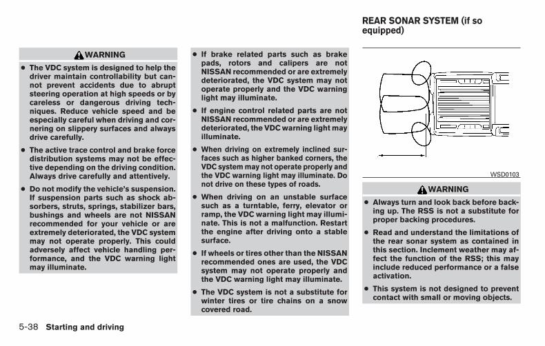
WARNING
● The VDC system is designed to help thedriver maintain controllability but can-not prevent accidents due to abruptsteering operation at high speeds or bycareless or dangerous driving tech-niques. Reduce vehicle speed and beespecially careful when driving and cor-nering on slippery surfaces and alwaysdrive carefully.
● The active trace control and brake forcedistribution systems may not be effec-tive depending on the driving condition.Always drive carefully and attentively.
● Do not modify the vehicle’s suspension.If suspension parts such as shock ab-sorbers, struts, springs, stabilizer bars,bushings and wheels are not NISSANrecommended for your vehicle or areextremely deteriorated, the VDC systemmay not operate properly. This couldadversely affect vehicle handling per-formance, and the VDC warning lightmay illuminate.
● If brake related parts such as brakepads, rotors and calipers are notNISSAN recommended or are extremelydeteriorated, the VDC system may notoperate properly and the VDC warninglight may illuminate.
● If engine control related parts are notNISSAN recommended or are extremelydeteriorated, the VDC warning light mayilluminate.
● When driving on extremely inclined sur-faces such as higher banked corners, theVDC system may not operate properly andthe VDC warning light may illuminate. Donot drive on these types of roads.
● When driving on an unstable surfacesuch as a turntable, ferry, elevator orramp, the VDC warning light may illumi-nate. This is not a malfunction. Restartthe engine after driving onto a stablesurface.
● If wheels or tires other than the NISSANrecommended ones are used, the VDCsystem may not operate properly andthe VDC warning light may illuminate.
● The VDC system is not a substitute forwinter tires or tire chains on a snowcovered road.
WARNING
● Always turn and look back before back-ing up. The RSS is not a substitute forproper backing procedures.
● Read and understand the limitations ofthe rear sonar system as contained inthis section. Inclement weather may af-fect the function of the RSS; this mayinclude reduced performance or a falseactivation.
● This system is not designed to preventcontact with small or moving objects.
WSD0103
REAR SONAR SYSTEM (if soequipped)
5-38 Starting and driving

● The system is designed as an aid to thedriver in detecting large stationary ob-jects to help avoid damaging the ve-hicle. The system will not detect smallobjects below the bumper, and may notdetect objects close to the bumper oron the ground.
● If your vehicle sustains damage to therear bumper fascia, leaving it mis-aligned or bent, the sensing zone maybe altered causing inaccurate measure-ment of obstacles or false alarms.
The Rear Sonar System (RSS) sounds a tone towarn the driver of obstacles near the rear bumperwhen the shift lever is in R (Reverse). The systemmay not detect objects at speeds above 3 mph(5 km/h) and may not detect certain angular ormoving objects.
The RSS detects obstacles up to 5.9 feet (1.8 m)from the rear bumper with a decreased coveragearea at the outer corners of the bumper, (refer tothe illustration for approximate zone coverageareas). As you move closer to the obstacle, therate of the tone increases. When the obstacle isless than 10 inches (25.0 cm) away, the tone willsound continuously. If the RSS detects a station-ary or receding object further than 10 inches(25.0 cm) from the side of the vehicle, the tone
will sound for only 3 seconds. Once the systemdetects an object approaching, the tone willsound again.
The RSS automatically turns on when the shiftlever is placed in R (Reverse) and the ignition isON. The RSS OFF switch on the instrumentpanel allows the driver to turn the RSS on and off.To turn the RSS off, the ignition must be ON, andthe shift lever in R (Reverse). An indicator light onthe switch will illuminate when the system isturned off. If the indicator light illuminates whenthe RSS is not turned off, it may indicate a mal-function in the RSS.
Keep the RSS sensors (located on the rear bum-per fascia) free from snow, ice and large accumu-lations of dirt (do not clean the sensors with sharpobjects). If the sensors are covered, it will affectthe accuracy of the RSS.
FREEING A FROZEN DOOR LOCKTo prevent a door lock from freezing, apply de-icer through the key hole. If the lock becomesfrozen, heat the key before inserting it into the keyhole or use the remote keyless entry key fob (if soequipped).
ANTIFREEZEIn the winter when it is anticipated that the tem-perature will drop below 32°F (0°C), check theantifreeze to assure proper winter protection. Foradditional information, refer to “Engine coolingsystem” in the “Maintenance and do-it-yourself”section of this manual.
BATTERYIf the battery is not fully charged during extremelycold weather conditions, the battery fluid mayfreeze and damage the battery. To maintain maxi-mum efficiency, the battery should be checkedregularly. For additional information, refer to “Bat-tery” in the “Maintenance and do-it-yourself” sec-tion of this manual.
COLD WEATHER DRIVING
Starting and driving 5-39

DRAINING OF COOLANT WATER
If the vehicle is to be left outside without anti-freeze, drain the cooling system, including theengine block. Refill before operating the vehicle.For additional information, refer to “Changingengine coolant” in the “Maintenance and do-it-yourself” section of this manual.
TIRE EQUIPMENT
1. SUMMER tires have a tread designed toprovide superior performance on dry pave-ment. However, the performance of thesetires will be substantially reduced in snowyand icy conditions. If you operate your ve-hicle on snowy or icy roads, NISSAN recom-mends the use of MUD & SNOW or ALLSEASON TIRES on all four wheels. Pleaseconsult a NISSAN dealer for the tire type,size, speed rating and availability informa-tion.
2. For additional traction on icy roads, studdedtires may be used. However, some U.S.states and Canadian provinces prohibit theiruse. Check local, state and provincial lawsbefore installing studded tires.
Skid and traction capabilities of studdedsnow tires on wet or dry surfaces may bepoorer than that of non-studded snow tires.
3. Tire chains may be used. For additional in-formation, refer to “Tire chains” in the “Main-tenance and do-it-yourself” section of thismanual.
SPECIAL WINTER EQUIPMENT
It is recommended that the following items becarried in the vehicle during winter:
● A scraper and stiff-bristled brush to removeice and snow from the windows and wiperblades.
● A sturdy, flat board to be placed under thejack to give it firm support.
● A shovel to dig the vehicle out of snowdrifts.
● Extra washer fluid to refill the windshield-washer fluid reservoir.
DRIVING ON SNOW OR ICE
WARNING
● Wet ice (32°F, 0°C and freezing rain),very cold snow or ice can be slick andvery hard to drive on. The vehicle willhave much less traction or “grip” underthese conditions. Try to avoid driving onwet ice until the road is salted orsanded.
● Whatever the condition, drive with cau-tion. Accelerate and slow down withcare. If accelerating or downshifting toofast, the drive wheels will lose evenmore traction.
● Allow more stopping distance underthese conditions. Braking should bestarted sooner than on dry pavement.
● Allow greater following distances onslippery roads.
● Watch for slippery spots (glare ice).These may appear on an otherwiseclear road in shaded areas. If a patch ofice is seen ahead, brake before reach-ing it. Try not to brake while on the ice,and avoid any sudden steeringmaneuvers.
● Do not use the cruise control (if soequipped) on slippery roads.
● Snow can trap dangerous exhaustgases under your vehicle. Keep snowclear of the exhaust pipe and fromaround your vehicle.
5-40 Starting and driving

ENGINE BLOCK HEATER (if soequipped)
Engine block heaters are used to assist with coldtemperature starting.
The engine block heater should be used whenthe outside temperature is 20°F (-7°C) or lower.
WARNING
● Do not use your engine block heaterwith an ungrounded electrical system ora 2-pronged adapter. You can be seri-ously injured by an electrical shock ifyou use an ungrounded connection.
● Disconnect and properly store the en-gine block heater cord before startingthe engine. Damage to the cord couldresult in an electrical shock and cancause serious injury.
● Use a heavy-duty 3-wire, 3-pronged ex-tension cord rated for at least 10 A. Plugthe extension cord into a Ground FaultInterrupt (GFI) protected, grounded110-VAC outlet. Failure to use theproper extension cord or a groundedoutlet can result in a fire or electricalshock and cause serious personalinjury.
To use the engine block heater:
1. Turn the engine off.
2. Open the hood and unwrap the engine blockheater cord.
3. Plug the engine block heater cord into agrounded 3-wire, 3-pronged extensioncord.
4. Plug the extension cord into a Ground FaultInterrupt (GFI) protected, grounded 110-volt AC (VAC) outlet.
5. The engine block heater must be plugged infor at least 2–4 hours, depending on outsidetemperatures, to properly warm the enginecoolant. Use an appropriate timer to turn theengine block heater on.
6. Before starting the engine, unplug and prop-erly store the cord to keep it away frommoving parts.
Starting and driving 5-41

MEMO
5-42 Starting and driving
6 In case of emergency
Hazard warning flasher switch . . . . . . . . . . . . . . . . . . . . . . 6-2Flat tire . . . . . . . . . . . . . . . . . . . . . . . . . . . . . . . . . . . . . . . . . . . 6-2
Tire Pressure Monitoring System (TPMS). . . . . . . . . . 6-2Changing a flat tire . . . . . . . . . . . . . . . . . . . . . . . . . . . . . 6-3
Jump starting . . . . . . . . . . . . . . . . . . . . . . . . . . . . . . . . . . . . . 6-9
Push starting. . . . . . . . . . . . . . . . . . . . . . . . . . . . . . . . . . . . . 6-11If your vehicle overheats . . . . . . . . . . . . . . . . . . . . . . . . . . . 6-11Towing your vehicle . . . . . . . . . . . . . . . . . . . . . . . . . . . . . . . 6-12
Towing recommended by NISSAN . . . . . . . . . . . . . . 6-12Vehicle recovery (freeing a stuck vehicle) . . . . . . . . . 6-14

Push the switch on to warn other drivers whenyou must stop or park under emergency condi-tions. All turn signal lights flash.
WARNING
● If stopping for an emergency, be sure tomove the vehicle well off the road.
● Do not use the hazard warning flasherswhile moving on the highway unlessunusual circumstances force you todrive so slowly that your vehicle mightbecome a hazard to other traffic.
● Turn signals do not work when the haz-ard warning flasher lights are on.
The flashers will operate with the ignition switchplaced in any position.
Some jurisdictions may prohibit the use ofthe hazard warning flasher switch whiledriving.
TIRE PRESSURE MONITORINGSYSTEM (TPMS)
This vehicle is equipped with TPMS. It monitorstire pressure of all tires except the spare. Whenthe low tire pressure warning light is lit, and theCHECK TIRE PRESSURE warning appears inthe vehicle information display, one or more ofyour tires is significantly under-inflated. Ifequipped, the system also displays pressure ofall tires (except the spare tire) on the displayscreen by sending a signal from a sensor that isinstalled in each wheel. If the vehicle is beingdriven with low tire pressure, the TPMS will acti-vate and warn you of it by the low tire pressurewarning light. This system will activate only whenthe vehicle is driven at speeds above 16 mph(25 km/h). For additional information, refer to“Warning/indicator lights and audible reminders”in the “Instruments and controls” section, “Tirepressure information” in the “Display screen,heater, air conditioner, audio and phone systems”section and “Tire Pressure Monitoring System(TPMS)” in the “Starting and driving” section ofthis manual.
LIC0394
HAZARD WARNING FLASHERSWITCH
FLAT TIRE
6-2 In case of emergency

WARNING
● Radio waves could adversely affectelectric medical equipment. Those whouse a pacemaker should contact theelectric medical equipment manufac-turer for the possible influences beforeuse.
● If the low tire pressure warning lightilluminates while driving, avoid suddensteering maneuvers or abrupt braking,reduce vehicle speed, pull off the roadto a safe location and stop the vehicleas soon as possible. Driving with under-inflated tires may permanently damagethe tires and increase the likelihood oftire failure. Serious vehicle damagecould occur and may lead to an accidentand could result in serious personal in-jury. Check the tire pressure for all fourtires. Adjust the tire pressure to therecommended COLD tire pressureshown on the Tire and Loading Informa-tion label to turn the low tire pressurewarning light OFF. If you have a flat tire,replace it with a spare tire as soon aspossible.
● When a spare tire is mounted or a wheelis replaced, tire pressure will not beindicated, the TPMS will not functionand the low tire pressure warning lightwill flash for approximately 1 minute.The light will remain on after 1 minute.Contact your NISSAN dealer as soon aspossible for tire replacement and/orsystem resetting.
● Replacing tires with those not originallyspecified by NISSAN could affect theproper operation of the TPMS.
● Do not inject any tire liquid or aerosoltire sealant into the tires, as this maycause a malfunction of the tire pressuresensors.
CHANGING A FLAT TIRE
If you have a flat tire, follow the instructions be-low:
Stopping the vehicle
1. Safely move the vehicle off the road andaway from traffic.
2. Turn on the hazard warning flashers.
3. Park on a level surface and apply the parkingbrake. Move the shift lever to P (Park).
4. Turn off the engine.
5. Raise the hood to warn other traffic and tosignal professional road assistance person-nel that you need assistance.
6. Have all passengers get out of the vehicleand stand in a safe place, away from trafficand clear of the vehicle.
WARNING
● Make sure the parking brake is securelyapplied and the shift lever is shifted intoP (Park).
● Never change tires when the vehicle ison a slope, ice or slippery areas. This ishazardous.
● Never change tires if oncoming traffic isclose to your vehicle. Wait for profes-sional road assistance.
In case of emergency 6-3
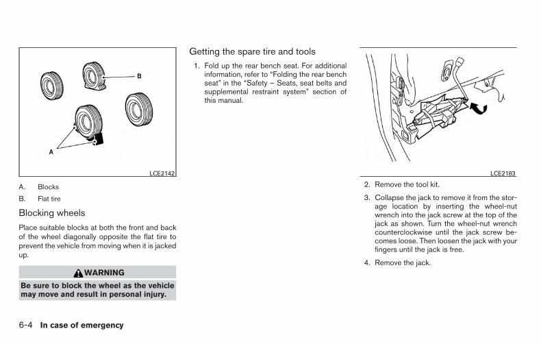
A. Blocks
B. Flat tire
Blocking wheels
Place suitable blocks at both the front and backof the wheel diagonally opposite the flat tire toprevent the vehicle from moving when it is jackedup.
WARNING
Be sure to block the wheel as the vehiclemay move and result in personal injury.
Getting the spare tire and tools1. Fold up the rear bench seat. For additional
information, refer to “Folding the rear benchseat” in the “Safety – Seats, seat belts andsupplemental restraint system” section ofthis manual.
2. Remove the tool kit.
3. Collapse the jack to remove it from the stor-age location by inserting the wheel-nutwrench into the jack screw at the top of thejack as shown. Turn the wheel-nut wrenchcounterclockwise until the jack screw be-comes loose. Then loosen the jack with yourfingers until the jack is free.
4. Remove the jack.
LCE2142 LCE2183
6-4 In case of emergency

5. Assemble the two pieces of the jack rod.Find the oval-shaped opening above themiddle of the license plate. Pass theT-shaped end of the jack rod through theopening and direct it toward the spare tirewinch, located directly above the spare tire.
CAUTION
Do not insert the jack rod straight as it isdesigned to be inserted at an angle asshown.
6. Fit the square end of the jack rod into thesquare hole of the wheel nut wrench to forma handle.
7. Seat the T-shaped end of the jack rod intothe T-shaped opening of the tire winch. Ap-ply pressure to keep the jack rod engaged inthe spare tire winch and turn the jack rodcounterclockwise to lower the spare tire.
8. Once the spare tire is completely lowered,reach under the vehicle, remove the retainerchain and carefully slide the tire from underthe rear of the vehicle.
9. To reinstall the jack and tool kit, reversesteps 1 through 4.
10. Securely store the flat tire in the vehicle.
CAUTION
Be sure to center the spare tire suspend-ing plate on the wheel and then lift thespare tire.
Jacking up vehicle and removing thedamaged tire
WARNING
● Never get under the vehicle while it issupported only by the jack. If it is nec-essary to work under the vehicle, sup-port it with safety stands.
● Use only the jack provided with yourvehicle to lift the vehicle. Do not use thejack provided with your vehicle on othervehicles. The jack is designed for liftingonly your vehicle during a tire change.
● Use the correct jack-up points. Neveruse any other part of the vehicle for jacksupport.
● Never jack up the vehicle more thannecessary.
● Never use blocks on or under the jack.
WCE0150 WCE0151
In case of emergency 6-5

● Do not start or run the engine whilevehicle is on the jack. It may cause thevehicle to move. This is especially truefor vehicles with limited slipdifferentials.
● Do not allow passengers to stay in thevehicle while it is on the jack.
● Never run the engine with a wheel(s) offthe ground. It may cause the vehicle tomove.
Always refer to the illustration for the correctplacement and jack-up points for your specificvehicle model and jack type.
Carefully read the caution label attached tothe jack body and the following instruc-tions.
1. Loosen each wheel nut one or two turns byturning counterclockwise with the wheel nutwrench. Do not remove the wheel nutsuntil the tire is off the ground.
WCE0152
6-6 In case of emergency

2. Place the jack directly under the jack-uppoint as illustrated so the top of the jackcontacts the vehicle at the jack-up point.Align the jack head between the twonotches in the front or the rear as shown.Also fit the groove of the jack head betweenthe notches as shown.
The jack should be used on firm andlevel ground.
3. Install the assembled jack rod into the jackas shown.
4. To lift the vehicle, securely hold the jack leverand rod. Carefully raise the vehicle until thetire clears the ground.
5. Remove the wheel nuts and then remove thetire.
LCE0087
In case of emergency 6-7

Installing the spare tire
The spare tire is designed for emergencyuse. For additional information, refer to“Wheels and tires” in the “Maintenanceand do-it-yourself” section of this manual.
1. Clean any mud or dirt from the surface be-tween the wheel and hub.
2. Carefully put the spare tire on and tightenthe wheel nuts finger tight.
3. With the wheel nut wrench, tighten wheelnuts alternately and evenly as illustrated untilthey are tight (�1 ,�2 ,�3 ,�4 ,�5 ,�6 ).
4. Lower the vehicle slowly until the tiretouches the ground. Then, with the wheelnut wrench, tighten the wheel nuts securelyin the sequence illustrated(�1 ,�2 ,�3 ,�4 ,�5 ,�6 ). Lower the vehiclecompletely.
WARNING
● Incorrect wheel nuts or improperlytightened wheel nuts can cause thewheel to become loose or come off.This could cause an accident.
● Do not use oil or grease on the wheelstuds or nuts. This could cause the nutsto become loose.
● Retighten the wheel nuts when the ve-hicle has been driven for 600 miles(1,000 km) (also in cases of a flat tire,etc.).
As soon as possible, tighten the wheel nutsto the specified torque with a torquewrench.
Wheel nut tightening torque:
101 ft-lb (137 N·m)
The wheel nuts must be kept tightened tospecification at all times. It is recom-mended that wheel nuts be tightened tospecifications at each lubrication interval.
Adjust tire pressure to the COLD pressure.
COLD pressure: After vehicle has beenparked for 3 hours or more or driven lessthan 1 mi. (1.6 km).
COLD tire pressures are shown on the Tireand Loading Information label affixed tothe driver side center pillar.
After adjusting tire pressure to the COLDtire pressure, the display(if so equipped) ofthe tire pressure information may showhigher pressure than the COLD tire pres-sure after the vehicle has been driven morethan 1 mi. (1.6 km). This is because the tirepressure increases as the tire temperaturerises. This does not indicate a system mal-function.
5. Securely store the flat tire, tools and jackingequipment in the vehicle. For additional in-formation about storing the flat tire, refer tothe “Getting the spare tire and tools” sectionof this manual.
WCE0063
6-8 In case of emergency

WARNING
● Always make sure that the spare tireand jacking equipment are properly se-cured after use. Such items can becomedangerous projectiles in an accident orsudden stop.
● The spare tire is designed for emer-gency use. For additional information,refer to “Wheels and tires” in the “Main-tenance and do-it-yourself” section ofthis manual.
To start your engine with a booster battery, theinstructions and precautions below must be fol-lowed.
WARNING
● If done incorrectly, jump starting canlead to a battery explosion, resulting insevere injury or death. It could alsodamage your vehicle.
● Explosive hydrogen gas is always pres-ent in the vicinity of the battery. Keep allsparks and flames away from thebattery.
● Do not allow battery fluid to come intocontact with eyes, skin, clothing orpainted surfaces. Battery fluid is a cor-rosive sulfuric acid solution which cancause severe burns. If the fluid shouldcome into contact with anything, imme-diately flush the contacted area withwater.
● Keep battery out of the reach ofchildren.
● The booster battery must be rated at12 volts. Use of an improperly ratedbattery can damage your vehicle.
● Whenever working on or near a battery,always wear suitable eye protectors (forexample, goggles or industrial safetyspectacles) and remove rings, metalbands, or any other jewelry. Do not leanover the battery when jump starting.
● Do not attempt to jump start a frozenbattery. It could explode and cause se-rious injury.
JUMP STARTING
In case of emergency 6-9

WARNING
Always follow the instructions below. Fail-ure to do so could result in damage to thecharging system and cause personalinjury.
1. If the booster battery is in another vehicle,position the two vehicles to bring their bat-teries near each other.
Do not allow the two vehicles to touch.
2. Apply the parking brake. Move the shift leverto P (Park). Switch off all unnecessary elec-trical systems (lights, heater, air conditioner,etc.).
3. Ensure the vent caps are level and tight.
4. Remove the Fuse/fusible link box and con-nect jumper cables in the sequence illus-trated (�A , �B , �C , �D ).
CAUTION
● Always connect positive (�) to positive(�) and negative (�) to body ground (forexample, strut mounting bolt, enginelift bracket, etc.) — not to the battery.
● Make sure the jumper cables do nottouch moving parts in the engine com-partment and that the cable clamps donot contact any other metal.
5. Start the engine of the booster vehicle andlet it run for a few minutes.
6. Keep the engine speed of the booster ve-hicle at about 2,000 rpm, and start the en-gine of the vehicle being jump started.
CAUTION
Do not keep the starter motor engaged formore than 10 seconds. If the engine doesnot start right away, turn the key off andwait 3 to 4 seconds before trying again.
7. After starting the engine, carefully discon-nect the negative cable and then the positivecable.LCE2187
6-10 In case of emergency

WARNING
Do not push start this vehicle. The 3-waycatalyst may be damaged.
CAUTION
Automatic transmission models cannot bepush-started or tow-started. Attemptingto do so may cause transmission damage.
WARNING
● Do not continue to drive if your vehicleoverheats. Doing so could cause enginedamage or a vehicle fire.
● To avoid the danger of being scalded,never remove the radiator or coolantreservoir cap while the engine is stillhot. When the radiator or coolant reser-voir cap is removed, pressurized hotwater will spurt out, possibly causingserious injury.
● Do not open the hood if steam is com-ing out.
If your vehicle is overheating (indicated by anextremely high temperature gauge reading andthe illumination of the engine oil pressure/enginecoolant temperature high indicator light), or if youfeel a lack of engine power, detect abnormalnoise, etc. take the following steps:
1. Move the vehicle safely off the road, applythe parking brake and move the shift lever toP (Park).
Do not stop the engine.
2. Turn off the air conditioner. Open all thewindows, move the heater or air conditionertemperature control to maximum hot and fancontrol to high speed.
3. Get out of the vehicle. Look and listen forsteam or coolant escaping from the radiatorbefore opening the hood. If steam or coolantis escaping, turn off the engine. Do not openthe hood further until no steam or coolantcan be seen.
4. Open the engine hood.
WARNING
If steam or water is coming from the en-gine, stand clear to prevent gettingburned.
5. Visually check drive belts for damage orlooseness. Also check if the cooling fan isrunning. The radiator hoses and radiatorshould not leak water. If coolant is leaking,the water pump belt is missing or loose, orthe cooling fan does not run, stop the en-gine.
WARNING
Be careful not to allow your hands, hair,jewelry or clothing to come into contactwith, or get caught in, engine belts or theengine cooling fan. The engine cooling fancan start at any time.
PUSH STARTING IF YOUR VEHICLE OVERHEATS
In case of emergency 6-11

6. After the engine cools down, check the cool-ant level in the engine coolant reservoir tankwith the engine running. Add coolant to theengine coolant reservoir tank if necessary.Have your vehicle repaired at a NISSANdealer.
When towing your vehicle, all jurisdictional andlocal regulations for towing must be followed.Incorrect towing equipment could damage yourvehicle. Towing instructions are available from aNISSAN dealer. Local service operators are gen-erally familiar with the applicable laws and proce-dures for towing. To assure proper towing and toprevent accidental damage to your vehicle,NISSAN recommends having a service operatortow your vehicle. It is advisable to have the ser-vice operator carefully read the following precau-tions:
WARNING
● Never ride in a vehicle that is beingtowed.
● Never get under your vehicle after it hasbeen lifted by a tow truck.
CAUTION
● When towing, make sure that the trans-mission, axles, steering system andpowertrain are in working condition. Ifany of these conditions apply, dollies ora flatbed tow truck must be used.
● Always attach safety chains beforetowing.
For additional information about towing your ve-hicle behind a recreational vehicle (RV), refer to“Flat towing” in the “Technical and ConsumerInformation” section of this manual.
TOWING RECOMMENDED BYNISSAN
TOWING YOUR VEHICLE
6-12 In case of emergency
schulzh
Text Box
schulzh
Typewritten Text
** Click HERE to see "Owner's Manual Supplement" beginning on page 2. **
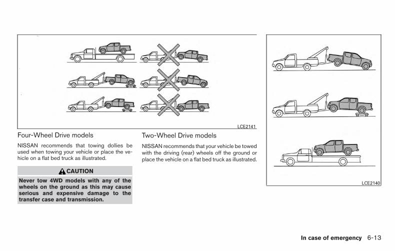
Four-Wheel Drive modelsNISSAN recommends that towing dollies beused when towing your vehicle or place the ve-hicle on a flat bed truck as illustrated.
CAUTION
Never tow 4WD models with any of thewheels on the ground as this may causeserious and expensive damage to thetransfer case and transmission.
Two-Wheel Drive models
NISSAN recommends that your vehicle be towedwith the driving (rear) wheels off the ground orplace the vehicle on a flat bed truck as illustrated.
LCE2141
LCE2140
In case of emergency 6-13
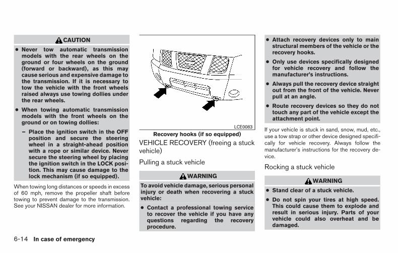
CAUTION
● Never tow automatic transmissionmodels with the rear wheels on theground or four wheels on the ground(forward or backward), as this maycause serious and expensive damage tothe transmission. If it is necessary totow the vehicle with the front wheelsraised always use towing dollies underthe rear wheels.
● When towing automatic transmissionmodels with the front wheels on theground or on towing dollies:
– Place the ignition switch in the OFFposition and secure the steeringwheel in a straight-ahead positionwith a rope or similar device. Neversecure the steering wheel by placingthe ignition switch in the LOCK posi-tion. This may cause damage to thelock mechanism (if so equipped).
When towing long distances or speeds in excessof 60 mph, remove the propeller shaft beforetowing to prevent damage to the transmission.See your NISSAN dealer for more information.
VEHICLE RECOVERY (freeing a stuckvehicle)
Pulling a stuck vehicle
WARNING
To avoid vehicle damage, serious personalinjury or death when recovering a stuckvehicle:
● Contact a professional towing serviceto recover the vehicle if you have anyquestions regarding the recoveryprocedure.
● Attach recovery devices only to mainstructural members of the vehicle or therecovery hooks.
● Only use devices specifically designedfor vehicle recovery and follow themanufacturer’s instructions.
● Always pull the recovery device straightout from the front of the vehicle. Neverpull at an angle.
● Route recovery devices so they do nottouch any part of the vehicle except theattachment point.
If your vehicle is stuck in sand, snow, mud, etc.,use a tow strap or other device designed specifi-cally for vehicle recovery. Always follow themanufacturer’s instructions for the recovery de-vice.
Rocking a stuck vehicle
WARNING
● Stand clear of a stuck vehicle.
● Do not spin your tires at high speed.This could cause them to explode andresult in serious injury. Parts of yourvehicle could also overheat and bedamaged.
Recovery hooks (if so equipped)LCE0083
6-14 In case of emergency

If your vehicle is stuck in sand, snow, mud, etc.,use the following procedure:
1. Turn off the Vehicle Dynamic Control (VDC)system.
2. Activate the Electronic Locking Rear Differ-ential (E-Lock) System (if so equipped).
3. Make sure the area in front and behind thevehicle is clear of obstructions.
4. Turn the steering wheel right and left to clearan area around the front tires.
5. Slowly rock the vehicle forward and back-ward.
● Shift back and forth between R (Reverse)and D (Drive).
● Apply the accelerator as little as possibleto maintain the rocking motion.
● Release the accelerator pedal beforeshifting between R (Reverse) and D(Drive).
● Do not spin the tires above 34 mph(55 km/h) or above 12 mph (20 km/h) ifthe E–Lock System (if so equipped) isengaged.
6. If the vehicle cannot be freed after a fewtries, contact a professional towing serviceto remove the vehicle.
In case of emergency 6-15

MEMO
6-16 In case of emergency

7 Appearance and care
Cleaning exterior . . . . . . . . . . . . . . . . . . . . . . . . . . . . . . . . . . 7-2Washing . . . . . . . . . . . . . . . . . . . . . . . . . . . . . . . . . . . . . . 7-2Waxing . . . . . . . . . . . . . . . . . . . . . . . . . . . . . . . . . . . . . . . . 7-2Removing spots . . . . . . . . . . . . . . . . . . . . . . . . . . . . . . . . 7-3Underbody . . . . . . . . . . . . . . . . . . . . . . . . . . . . . . . . . . . . 7-3Glass . . . . . . . . . . . . . . . . . . . . . . . . . . . . . . . . . . . . . . . . . 7-3Aluminum alloy wheels (if so equipped) . . . . . . . . . . . 7-3Chrome parts . . . . . . . . . . . . . . . . . . . . . . . . . . . . . . . . . . 7-3Tire dressings . . . . . . . . . . . . . . . . . . . . . . . . . . . . . . . . . . 7-3
Cleaning interior. . . . . . . . . . . . . . . . . . . . . . . . . . . . . . . . . . . 7-4
Air fresheners . . . . . . . . . . . . . . . . . . . . . . . . . . . . . . . . . . 7-4Floor mats . . . . . . . . . . . . . . . . . . . . . . . . . . . . . . . . . . . . . 7-4Seat belts . . . . . . . . . . . . . . . . . . . . . . . . . . . . . . . . . . . . . 7-5
Corrosion protection . . . . . . . . . . . . . . . . . . . . . . . . . . . . . . . 7-5Most common factors contributing to vehiclecorrosion . . . . . . . . . . . . . . . . . . . . . . . . . . . . . . . . . . . . . . 7-5Environmental factors influence the rate ofcorrosion . . . . . . . . . . . . . . . . . . . . . . . . . . . . . . . . . . . . . . 7-5Protect your vehicle from corrosion . . . . . . . . . . . . . . . 7-6

In order to maintain the appearance of your ve-hicle, it is important to take proper care of it.
To protect the paint surfaces, please wash yourvehicle as soon as you can:
● after a rainfall to prevent possible damagefrom acid rain
● after driving on coastal roads
● when contaminants such as soot, bird drop-pings, tree sap, metal particles or bugs geton the paint surface
● when dust or mud builds up on the surface
Whenever possible, store or park your vehicleinside a garage or in a covered area.
When it is necessary to park outside, park in ashady area or protect the vehicle with a bodycover.
Be careful not to scratch the paint surfacewhen putting on or removing the bodycover.
WASHINGWash dirt off with a wet sponge and plenty ofwater. Clean the vehicle thoroughly using a mildsoap, a special vehicle soap or general purposedishwashing liquid mixed with clean, lukewarm(never hot) water.
CAUTION
● Do not use car washes that use acid inthe detergent. Some car washes, espe-cially brushless ones, use some acid forcleaning. The acid may react with someplastic vehicle components, causingthem to crack. This could affect theirappearance, and also could cause themnot to function properly. Always checkwith your car wash to confirm that acidis not used.
● Do not wash the vehicle with stronghousehold soap, strong chemical deter-gents, gasoline or solvents.
● Do not wash the vehicle in direct sun-light or while the vehicle body is hot, asthe surface may become water-spotted.
● Avoid using tight-napped or roughcloths, such as washing mitts. Caremust be taken when removingcaked-on dirt or other foreign sub-stances so the paint surface is notscratched or damaged.
Rinse the vehicle thoroughly with plenty of cleanwater.
Inside edges, seams and folds on the doors,hatches and hood are particularly vulnerable to
the effects of road salt. Therefore, these areasmust be cleaned regularly. Take care that thedrain holes in the lower edge of the door areopen. Spray water under the body and in thewheel wells to loosen the dirt and wash awayroad salt.
A damp chamois can be used to dry the vehicle toavoid water spots.
WAXINGRegular waxing protects the paint surface andhelps retain new vehicle appearance. Polishing isrecommended to remove built-up wax residueand to avoid a weathered appearance beforere-applying wax.
A NISSAN dealer can assist you in choosing theproper product.
● Wax your vehicle only after a thorough wash-ing. Follow the instructions supplied with thewax.
● Do not use a wax containing any abrasives,cutting compounds or cleaners that maydamage the vehicle finish.
Machine compounding or aggressive polishingon a base coat/clear coat paint finish may dull thefinish or leave swirl marks.
CLEANING EXTERIOR
7-2 Appearance and care

REMOVING SPOTS
Remove tar and oil spots, industrial dust, insects,and tree sap as quickly as possible from thesurface of the paint to avoid lasting damage orstaining. Special cleaning products are availableat a NISSAN dealer or any automotive accessorystore.
UNDERBODY
In areas where road salt is used in winter, it isnecessary to clean the underbody regularly inorder to prevent dirt and salt from building up andcausing the acceleration of corrosion on the un-derbody and suspension. Before the winter pe-riod and again in the spring, the underseal mustbe checked and, if necessary, re-treated.
GLASS
Use glass cleaner to remove smoke and dust filmfrom the glass surfaces. It is normal for glass tobecome coated with a film after the vehicle isparked in the hot sun. Glass cleaner and a softcloth will easily remove this film.
CAUTION
When cleaning the inside of the windows,do not use sharp-edged tools, abrasivecleaners or chlorine-based disinfectantcleaners. They could damage the electricalconductors, radio antenna elements orrear window defroster elements.
ALUMINUM ALLOY WHEELS (if soequipped)
Wash the wheels regularly with a sponge damp-ened in a mild soap solution, especially duringwinter months in areas where road salt is used. Ifnot removed, road salt can discolor the wheels.
CAUTION
Follow the directions below to avoidstaining or discoloring the wheels:
● Do not use a cleaner that uses strong acidor alkali contents to clean the wheels.
● Do not apply wheel cleaners to thewheels when they are hot. The wheeltemperature should be the same as am-bient temperature.
● Rinse the wheel to completely removethe cleaner within 15 minutes after thecleaner is applied.
CHROME PARTSClean all chrome parts regularly with a non-abrasive chrome polish to maintain the finish.
TIRE DRESSINGSNISSAN does not recommend the use of tiredressings. Tire manufacturers apply a coating tothe tires to help reduce discoloration of the rub-ber. If a tire dressing is applied to the tires, it mayreact with the coating and form a compound. Thiscompound may come off the tire while driving andstain the vehicle paint.
If you choose to use a tire dressing, take thefollowing precautions:
● Use a water-based tire dressing. The coat-ing on the tire dissolves more easily thanwith an oil-based tire dressing.
● Apply a light coat of tire dressing to helpprevent it from entering the tiretread/grooves (where it would be difficult toremove).
● Wipe off excess tire dressing using a drytowel. Make sure the tire dressing is com-pletely removed from the tire tread/grooves.
● Allow the tire dressing to dry as recom-mended by the tire dressing manufacturer.
Appearance and care 7-3

Occasionally remove loose dust from the interiortrim, plastic parts and seats using a vacuumcleaner or soft bristled brush. Wipe the vinyl andleather surfaces with a clean, soft cloth damp-ened in mild soap solution, then wipe clean with adry, soft cloth.
Regular care and cleaning is required in order tomaintain the appearance of the leather.
Before using any fabric protector, read the manu-facturer’s recommendations. Some fabric pro-tectors contain chemicals that may stain orbleach the seat material.
Use a cloth dampened only with water to cleanthe meter and gauge lens.
WARNING
Do not use water or acidic cleaners (hotsteam cleaners) on the seat. This can dam-age the seat or occupant classificationsensor. This can also affect the operationof the air bag system and result in seriouspersonal injury.
CAUTION
● Never use benzine, thinner or any simi-lar material.
● Small dirt particles can be abrasive anddamaging to leather surfaces andshould be removed promptly. Do notuse saddle soap, car waxes, polishes,oils, cleaning fluids, solvents, deter-gents or ammonia-based cleaners asthey may damage the leather’s naturalfinish.
● Never use fabric protectors unless rec-ommended by the manufacturer.
● Do not use glass or plastic cleaner onmeter or gauge lens covers. It may dam-age the lens cover.
AIR FRESHENERS
Most air fresheners use a solvent that could affectthe vehicle interior. If you use an air freshener,take the following precautions:
● Hanging-type air fresheners can cause per-manent discoloration when they contact ve-hicle interior surfaces. Place the air fresh-ener in a location that allows it to hang freeand not contact an interior surface.
● Liquid-type air fresheners typically clip onthe vents. These products can cause imme-diate damage and discoloration whenspilled on interior surfaces.
Carefully read and follow the manufacturer’s in-structions before using the air fresheners.
FLOOR MATS
WARNING
To avoid potential pedal interference thatmay result in a collision or injury:
● NEVER place a floor mat on top of an-other floor mat in the driver frontposition.
● Use only genuine NISSAN floor matsspecifically designed for use in your ve-hicle model. For additional information,refer to your NISSAN dealer.
● Properly position the mats in the floor-well using the floor mat positioning aid.For additional information, refer to �Floormat positioning aid� in this section.
The use of genuine NISSAN floor mats can ex-tend the life of your vehicle carpet and make iteasier to clean the interior. Mats should be main-tained with regular cleaning and replaced if theybecome excessively worn.
CLEANING INTERIOR
7-4 Appearance and care
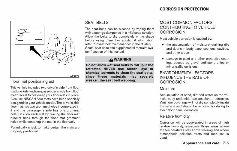
Floor mat positioning aidThis vehicle includes two driver’s side front floormat brackets and one passenger’s side front floormat bracket to help keep your floor mats in place.Genuine NISSAN floor mats have been speciallydesigned for your vehicle model. The driver’s sidefloor mat has two grommet holes incorporated init and the passenger’s side has one grommethole. Position each mat by placing the floor matbracket hook through the floor mat grommetholes while centering the mat in the floorwell.
Periodically check to make certain the mats areproperly positioned.
SEAT BELTSThe seat belts can be cleaned by wiping themwith a sponge dampened in a mild soap solution.Allow the belts to dry completely in the shadebefore using them. For additional information,refer to “Seat belt maintenance” in the “Safety –Seats, seat belts and supplemental restraint sys-tem” section of this manual.
WARNING
Do not allow wet seat belts to roll up in theretractor. NEVER use bleach, dye orchemical solvents to clean the seat belts,since these materials may severelyweaken the seat belt webbing.
MOST COMMON FACTORSCONTRIBUTING TO VEHICLECORROSION
Most vehicle corrosion is caused by:
● the accumulation of moisture-retaining dirtand debris in body panel sections, cavities,and other areas
● damage to paint and other protective coat-ings caused by gravel and stone chips orminor traffic collisions
ENVIRONMENTAL FACTORSINFLUENCE THE RATE OFCORROSION
MoistureAccumulation of sand, dirt and water on the ve-hicle body underside can accelerate corrosion.Wet floor coverings will not dry completely insidethe vehicle and should be removed for drying toavoid floor panel corrosion.
Relative humidityCorrosion will be accelerated in areas of highrelative humidity, especially those areas wherethe temperatures stay above freezing and whereatmospheric pollution exists and road salt isused.
LAI0009
CORROSION PROTECTION
Appearance and care 7-5

TemperatureHigh temperatures accelerate the rate of corro-sion to those parts which are not well ventilated.
Air pollutionIndustrial pollution, the presence of salt in the airin coastal areas, or heavy road salt use acceler-ates the corrosion process. Road salt also accel-erates the disintegration of paint surfaces.
PROTECT YOUR VEHICLE FROMCORROSION
● Wash and wax your vehicle often to keep thevehicle clean.
● Always check for minor damage to the paintand repair it as soon as possible.
● Keep drain holes at the bottom of the doorsopen to avoid water accumulation.
● Check the underbody for accumulation ofsand, dirt or salt. If present, wash with wateras soon as possible.
CAUTION
● NEVER remove dirt, sand or other de-bris from the passenger compartmentby washing it out with a hose. Removedirt with a vacuum cleaner or broom.
● Never allow water or other liquids tocome in contact with electronic compo-nents inside the vehicle as this maydamage them.
Chemicals used for road surface de-icing areextremely corrosive. They accelerate corrosionand deterioration of underbody componentssuch as the exhaust system, fuel and brake lines,brake cables, floor pan and fenders.
In winter, the underbody must be cleanedperiodically.
For additional protection against rust and corro-sion, which may be required in some areas, con-sult a NISSAN dealer.
7-6 Appearance and care

8 Maintenance and do-it-yourself
Maintenance requirements. . . . . . . . . . . . . . . . . . . . . . . . . . 8-2General maintenance . . . . . . . . . . . . . . . . . . . . . . . . . . . . . . 8-2
Explanation of general maintenance items . . . . . . . . . 8-2Maintenance precautions . . . . . . . . . . . . . . . . . . . . . . . . . . . 8-5Engine compartment check locations . . . . . . . . . . . . . . . . 8-6Engine cooling system . . . . . . . . . . . . . . . . . . . . . . . . . . . . . 8-7
Checking engine coolant level . . . . . . . . . . . . . . . . . . . 8-8Changing engine coolant . . . . . . . . . . . . . . . . . . . . . . . . 8-8
Engine oil. . . . . . . . . . . . . . . . . . . . . . . . . . . . . . . . . . . . . . . . . 8-9Checking engine oil level . . . . . . . . . . . . . . . . . . . . . . . . 8-9Changing engine oil . . . . . . . . . . . . . . . . . . . . . . . . . . . 8-10Changing engine oil filter . . . . . . . . . . . . . . . . . . . . . . . 8-12
5-speed automatic transmission fluid . . . . . . . . . . . . . . . 8-13Power steering fluid. . . . . . . . . . . . . . . . . . . . . . . . . . . . . . . 8-13Brake fluid . . . . . . . . . . . . . . . . . . . . . . . . . . . . . . . . . . . . . . . 8-14Windshield-washer fluid. . . . . . . . . . . . . . . . . . . . . . . . . . . 8-14
Windshield-washer fluid reservoir . . . . . . . . . . . . . . . 8-14Battery . . . . . . . . . . . . . . . . . . . . . . . . . . . . . . . . . . . . . . . . . . 8-15
Jump starting . . . . . . . . . . . . . . . . . . . . . . . . . . . . . . . . . 8-17Variable voltage control system. . . . . . . . . . . . . . . . . . . . . 8-17Drive belt . . . . . . . . . . . . . . . . . . . . . . . . . . . . . . . . . . . . . . . . 8-18Spark plugs. . . . . . . . . . . . . . . . . . . . . . . . . . . . . . . . . . . . . . 8-18
Replacing spark plugs . . . . . . . . . . . . . . . . . . . . . . . . . 8-18Air cleaner . . . . . . . . . . . . . . . . . . . . . . . . . . . . . . . . . . . . . . . 8-19
In-cabin microfilter (if so equipped) . . . . . . . . . . . . . . 8-20Windshield wiper blades . . . . . . . . . . . . . . . . . . . . . . . . . . 8-21
Cleaning . . . . . . . . . . . . . . . . . . . . . . . . . . . . . . . . . . . . . 8-21Replacing . . . . . . . . . . . . . . . . . . . . . . . . . . . . . . . . . . . . 8-21
Brakes . . . . . . . . . . . . . . . . . . . . . . . . . . . . . . . . . . . . . . . . . . 8-22Fuses . . . . . . . . . . . . . . . . . . . . . . . . . . . . . . . . . . . . . . . . . . . 8-23
Engine compartment . . . . . . . . . . . . . . . . . . . . . . . . . . . 8-24Passenger compartment . . . . . . . . . . . . . . . . . . . . . . . 8-25
Battery replacement . . . . . . . . . . . . . . . . . . . . . . . . . . . . . . 8-26Key fob (if so equipped) . . . . . . . . . . . . . . . . . . . . . . . . 8-27
Lights . . . . . . . . . . . . . . . . . . . . . . . . . . . . . . . . . . . . . . . . . . . 8-28Headlights . . . . . . . . . . . . . . . . . . . . . . . . . . . . . . . . . . . . 8-28Fog lights (if so equipped) . . . . . . . . . . . . . . . . . . . . . . 8-28Exterior and interior lights. . . . . . . . . . . . . . . . . . . . . . . 8-30
Wheels and tires . . . . . . . . . . . . . . . . . . . . . . . . . . . . . . . . . 8-34Tire pressure. . . . . . . . . . . . . . . . . . . . . . . . . . . . . . . . . . 8-34Tire labeling. . . . . . . . . . . . . . . . . . . . . . . . . . . . . . . . . . . 8-38Types of tires. . . . . . . . . . . . . . . . . . . . . . . . . . . . . . . . . . 8-40Tire chains. . . . . . . . . . . . . . . . . . . . . . . . . . . . . . . . . . . . 8-41Changing wheels and tires . . . . . . . . . . . . . . . . . . . . . 8-41

Your NISSAN has been designed to have mini-mum maintenance requirements with long ser-vice intervals to save you both time and money;however, some day-to-day and regular mainte-nance is essential to maintain your NISSAN’sgood mechanical condition as well as its emis-sions and engine performance.
It is the owner’s responsibility to make sure thatthe scheduled maintenance, as well as generalmaintenance, is performed.
As the vehicle owner, you are the only one whocan ensure that your vehicle receives propermaintenance. You are a vital link in the mainte-nance chain.
Scheduled maintenance
For your convenience, both required and optionalscheduled maintenance items are described andlisted in your “NISSAN Service and MaintenanceGuide”. You must refer to that guide to ensurethat necessary maintenance is performed on yourNISSAN at regular intervals.
General maintenance
General maintenance includes those items whichshould be checked during normal day-to-day op-eration. They are essential for proper vehicle op-eration. It is your responsibility to perform thesemaintenance procedures regularly as prescribed.
Performing general maintenance checks requiresminimal mechanical skill and only a few generalautomotive tools.
These checks or inspections can be done by you,a qualified technician or, if you prefer, a NISSANdealer.
Where to go for service
If maintenance service is required or your vehicleappears to malfunction, have the systemschecked and corrected by a NISSAN dealer.
NISSAN technicians are well-trained specialistswho are kept up-to-date with the latest serviceinformation through technical bulletins, servicetips and in-dealership training programs. Theyare completely qualified to work on NISSAN ve-hicles before they work on your vehicle ratherthan after they have worked on it.
You can be confident that a NISSAN dealer’sservice department performs the best job to meetthe maintenance requirements on your vehicle —in a reliable and economical way.
During the normal day-to-day operation of thevehicle, general maintenance should be per-formed regularly as prescribed in this section. Ifyou detect any unusual sounds, vibrations orsmells, be sure to check for the cause or have aNISSAN dealer do it promptly. In addition, youshould notify a NISSAN dealer if you think thatrepairs are required.
When performing any checks or maintenancework, closely observe the “Maintenance precau-tions” in this section.
EXPLANATION OF GENERALMAINTENANCE ITEMS
Additional information on the followingitems with “ * ” is found in this section.
Outside the vehicle
The maintenance items listed here should beperformed from time to time, unless otherwisespecified.
Doors and engine hood Check that the doorsand engine hood operate properly. Also ensurethat all latches lock securely. Lubricate hinges,latches, latch pins, rollers and links as necessary.Make sure that the secondary latch keeps thehood from opening when the primary latch isreleased.
MAINTENANCE REQUIREMENTS GENERAL MAINTENANCE
8-2 Maintenance and do-it-yourself

When driving in areas using road salt or othercorrosive materials, check lubrication frequently.
Lights* Clean the headlights on a regular basis.Make sure that the headlights, stop lights, taillights, turn signal lights, and other lights are alloperating properly and installed securely. Alsocheck headlight aim.
Road wheel nuts (lug nuts)* When checkingthe tires, make sure no wheel nuts are missing,and check for any loose wheel nuts. Tighten ifnecessary.
Tire rotation* Tires should be rotated every5,000 miles (8,000 km).
Tires* Check the pressure with a gauge oftenand always prior to long distance trips. If neces-sary, adjust the pressure in all tires, including thespare, to the pressure specified. Check carefullyfor damage, cuts or excessive wear.
Tire Pressure Monitoring System (TPMS)transmitter components Replace the TPMStransmitter grommet seal, valve core and capwhen the tires are replaced due to wear or age.
Wheel alignment and balance If the vehicleshould pull to either side while driving on astraight and level road, or if you detect uneven orabnormal tire wear, there may be a need for wheel
alignment. If the steering wheel or seat vibrates atnormal highway speeds, wheel balancing may beneeded.
● For additional information regarding tires,refer to “Important Tire Safety Information”(US) or “Tire Safety Information” (Canada) inthe Warranty Information Booklet.
Windshield Clean the windshield on a regularbasis. Check the windshield at least every sixmonths for cracks or other damage. Have a dam-aged windshield repaired by a qualified repairfacility.
Windshield wiper blades* Check for cracks orwear if they do not wipe properly.
Inside the vehicleThe maintenance items listed here should bechecked on a regular basis, such as when per-forming periodic maintenance, cleaning the ve-hicle, etc.
Additional information on the followingitems with an “*” is found in this section.
Accelerator pedal Check the pedal for smoothoperation and make sure the pedal does not bindor require uneven effort. Keep the floor mat awayfrom the pedal.
Automatic transmission P (Park) positionmechanism On a fairly steep hill check that your
vehicle is held securely with the shift lever in the P(Park) position without applying any brakes.
Brake pedal Check the pedal for smooth opera-tion. If the brake pedal suddenly goes down fur-ther than normal, the pedal feels spongy or thevehicle seems to take longer to stop, see aNISSAN dealer immediately. Keep the floor mataway from the pedal.
Brakes Check that the brakes do not pull thevehicle to one side when applied.
Parking brake Check the parking brake opera-tion regularly. The vehicle should be securely heldon a fairly steep hill with only the parking brakeapplied. If the parking brake needs adjustment,see a NISSAN dealer.
Seats Check seat position controls such as seatadjusters, seatback recliner, etc. to ensure theyoperate smoothly and all latches lock securely inevery position. Check that the headrestraints/headrests move up and downsmoothly and the locks (if so equipped) holdsecurely in all latched positions.
Seat belts Check that all parts of the seat beltsystem (for example, buckles, anchors, adjustersand retractors) operate properly and smoothly,and are installed securely. Check the belt web-bing for cuts, fraying, wear or damage.
Maintenance and do-it-yourself 8-3

Steering wheel Check for changes in the steer-ing system, such as excessive freeplay, hardsteering or strange noises.
Warning lights and chimes Make sure allwarning lights and chimes are operating properly.
Windshield wiper and washer* Check thatthe wipers and washer operate properly and thatthe wipers do not streak.
Windshield defroster Check that the aircomes out of the defroster outlets properly and insufficient quantity when operating the heater orair conditioner.
Under the hood and vehicle
The maintenance items listed here should bechecked periodically (for example, each time youcheck the engine oil or refuel).
Battery* (for seviceable batteries) Check thefluid level in each cell. It should be between theMAX and MIN lines. Vehicles operated in hightemperatures or under severe conditions requirefrequent checks of the battery fluid level.
NOTE:
Care should be taken to avoid situationsthat can lead to potential battery dischargeand potential no-start conditions such as:
1. Installation or extended use of electronicaccessories that consume battery powerwhen the engine is not running (Phone char-gers, GPS, DVD players, etc.)
2. Vehicle is not driven regularly and/or onlydriven short distances. In these cases, thebattery may need to be charged to maintainbattery health.
Brake fluid level* Make sure that the brake fluidlevel is between the MIN and MAX lines on thereservoir.
Engine coolant level* Check the coolant levelwhen the engine is cold.
Engine drive belts* Make sure the drive beltsare not frayed, worn, cracked or oily.
Engine oil level* Check the level after parkingthe vehicle on a level surface with the engine off.Wait more than 10 minutes for the oil to drainback into the oil pan.
Exhaust system Make sure there are no loosesupports, cracks or holes. If the sound of theexhaust seems unusual or there is a smell ofexhaust fumes, immediately have the exhaustsystem inspected by a NISSAN dealer. For addi-tional information, refer to the carbon monoxidewarning in the “Starting and driving” section ofthis manual.
Fluid leaks Check under the vehicle for fuel, oil,water or other fluid leaks after the vehicle hasbeen parked for a while. Water dripping from theair conditioner after use is normal. If you shouldnotice any leaks or if gasoline fumes are evident,check for the cause and have it corrected imme-diately.
Power steering fluid level* and lines Checkthe level when the fluid is cold, with the engineoff. Check the lines for proper attachment, leaks,cracks, etc.
Radiator and hoses Check the front of theradiator and clean off any dirt, insects, leaves,etc., that may have accumulated. Make sure thehoses have no cracks, deformation, rot or looseconnections.
8-4 Maintenance and do-it-yourself

Underbody The underbody is frequently ex-posed to corrosive substances such as thoseused on icy roads or to control dust. It is veryimportant to remove these substances from theunderbody, otherwise rust may form on the floorpan, frame, fuel lines and exhaust system. At theend of winter, the underbody should be thor-oughly flushed with plain water, in those areaswhere mud and dirt may have accumulated. Foradditional information, refer to the “Appearanceand care” section of this manual.
Windshield-washer fluid* Check that there isadequate fluid in the reservoir.
When performing any inspection or maintenancework on your vehicle, always take care to preventserious accidental injury to yourself or damage tothe vehicle. The following are general precau-tions which should be closely observed.
WARNING
● Park the vehicle on a level surface, ap-ply the parking brake securely andblock the wheels to prevent the vehiclefrom moving. Move the shift lever to P(Park)
● Be sure the ignition switch is in the OFFor LOCK position when performing anyparts replacement or repairs.
● If you must work with the engine run-ning, keep your hands, clothing, hairand tools away from moving fans, beltsand any other moving parts.
● It is advisable to secure or remove anyloose clothing and remove any jewelry,such as rings, watches, etc. beforeworking on your vehicle.
● Always wear eye protection wheneveryou work on your vehicle.
● If you must run the engine in an en-closed space such as a garage, be surethere is proper ventilation for exhaustgases to escape.
● Never get under the vehicle while it issupported only by a jack. If it is neces-sary to work under the vehicle, supportit with safety stands.
● Keep smoking materials, flame andsparks away from the fuel tank andbattery.
● On gasoline engine models, the fuelfilter or fuel lines should be serviced bya NISSAN dealer because the fuel linesare under high pressure even when theengine is off.
CAUTION
● Do not work under the hood while theengine is hot. Turn the engine off andwait until it cools down.
● Avoid contact with used engine oil andcoolant. Improperly disposed engineoil, engine coolant and/or other vehiclefluids can damage the environment. Al-ways conform to local regulations fordisposal of vehicle fluid.
MAINTENANCE PRECAUTIONS
Maintenance and do-it-yourself 8-5

● Never leave the engine or automatictransmission related component har-nesses disconnected while the ignitionswitch is in the ON position.
● Never connect or disconnect the batteryor any transistorized component whilethe ignition switch is in the ON position.
This “Maintenance and do-it-yourself” sectiongives instructions regarding only those itemswhich are relatively easy for an owner to perform.
A Genuine NISSAN service manual is also avail-able. Refer to “Owner’s Manual/Service Manualorder information” in the “Technical and con-sumer information” section of this manual.
You should be aware that incomplete or improperservicing may result in operating difficulties orexcessive emissions, and could affect warrantycoverage. If in doubt about any servicing,have it done by a NISSAN dealer.
LDI2482
ENGINE COMPARTMENT CHECKLOCATIONS
8-6 Maintenance and do-it-yourself
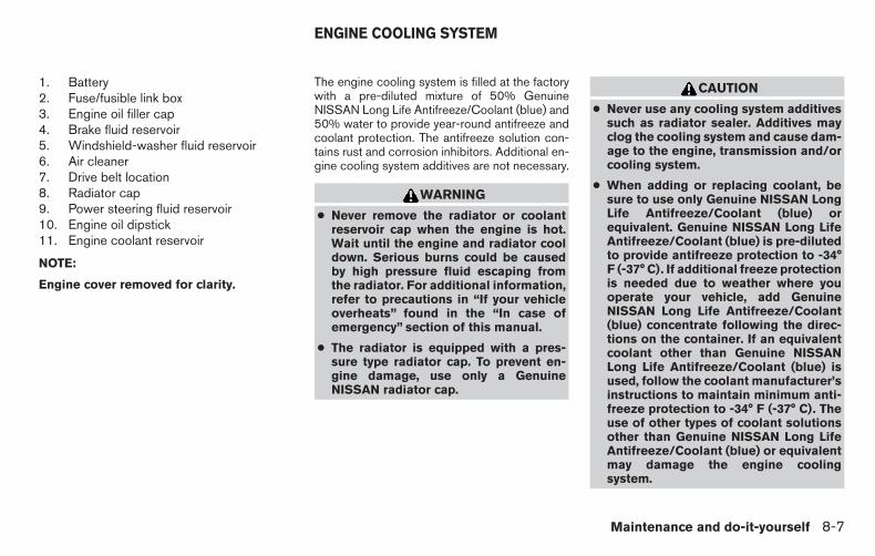
1. Battery2. Fuse/fusible link box3. Engine oil filler cap4. Brake fluid reservoir5. Windshield-washer fluid reservoir6. Air cleaner7. Drive belt location8. Radiator cap9. Power steering fluid reservoir10. Engine oil dipstick11. Engine coolant reservoir
NOTE:
Engine cover removed for clarity.
The engine cooling system is filled at the factorywith a pre-diluted mixture of 50% GenuineNISSAN Long Life Antifreeze/Coolant (blue) and50% water to provide year-round antifreeze andcoolant protection. The antifreeze solution con-tains rust and corrosion inhibitors. Additional en-gine cooling system additives are not necessary.
WARNING
● Never remove the radiator or coolantreservoir cap when the engine is hot.Wait until the engine and radiator cooldown. Serious burns could be causedby high pressure fluid escaping fromthe radiator. For additional information,refer to precautions in “If your vehicleoverheats” found in the “In case ofemergency” section of this manual.
● The radiator is equipped with a pres-sure type radiator cap. To prevent en-gine damage, use only a GenuineNISSAN radiator cap.
CAUTION
● Never use any cooling system additivessuch as radiator sealer. Additives mayclog the cooling system and cause dam-age to the engine, transmission and/orcooling system.
● When adding or replacing coolant, besure to use only Genuine NISSAN LongLife Antifreeze/Coolant (blue) orequivalent. Genuine NISSAN Long LifeAntifreeze/Coolant (blue) is pre-dilutedto provide antifreeze protection to -34°F (-37° C). If additional freeze protectionis needed due to weather where youoperate your vehicle, add GenuineNISSAN Long Life Antifreeze/Coolant(blue) concentrate following the direc-tions on the container. If an equivalentcoolant other than Genuine NISSANLong Life Antifreeze/Coolant (blue) isused, follow the coolant manufacturer’sinstructions to maintain minimum anti-freeze protection to -34° F (-37° C). Theuse of other types of coolant solutionsother than Genuine NISSAN Long LifeAntifreeze/Coolant (blue) or equivalentmay damage the engine coolingsystem.
ENGINE COOLING SYSTEM
Maintenance and do-it-yourself 8-7

● The life expectancy of the factory-fillcoolant is 105,000 miles (168,000 km) or7 years. Mixing any other type of cool-ant other than Genuine NISSAN LongLife Antifreeze/Coolant (blue), includ-ing Genuine NISSAN Long LifeAntifreeze/Coolant (green), or the useof non-distilled water will reduce thelife expectancy of the factory-fill cool-ant. For additional information, refer tothe NISSAN Service and MaintenanceGuide.
CHECKING ENGINE COOLANTLEVEL
Check the coolant level in the reservoir whenthe engine is cold. If the coolant level is belowthe MIN level, add coolant to the MAX level. If thereservoir is empty, check the coolant level in theradiator when the engine is cold. If there isinsufficient coolant in the radiator, fill the radiatorwith coolant up to the filler opening and also addit to the reservoir up to the MAX level.
This vehicle contains Genuine NISSAN Long LifeAntifreeze/Coolant (blue). The life expectancy ofthe factory-fill coolant is 168,000 km(105,000 miles) or 7 years. Mixing any other type
of coolant or the use of non-distilled water willreduce the life expectancy of the factory-fill cool-ant. For additional information, refer to the“NISSAN Service and Maintenance Guide”.
If the cooling system frequently requirescoolant, have it checked by a NISSANdealer.
For additional information on the location of theengine coolant reservoir, refer to “Engine com-partment check locations” in this section.
CHANGING ENGINE COOLANTA NISSAN dealer can change the engine coolant.The service procedure can be found in theNISSAN Service Manual.
Improper servicing can result in reducedheater performance and engine overheat-ing.
WARNING
● To avoid the danger of being scalded,never change the coolant when the en-gine is hot.
● Never remove the radiator or enginecoolant reservoir cap when the engineis hot. Serious burns could be caused byhigh pressure fluid escaping from theradiator.
LDI2578
8-8 Maintenance and do-it-yourself
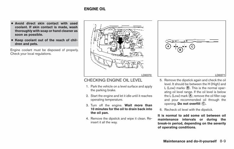
● Avoid direct skin contact with usedcoolant. If skin contact is made, washthoroughly with soap or hand cleaner assoon as possible.
● Keep coolant out of the reach of chil-dren and pets.
Engine coolant must be disposed of properly.Check your local regulations.
CHECKING ENGINE OIL LEVEL1. Park the vehicle on a level surface and apply
the parking brake.
2. Start the engine and let it idle until it reachesoperating temperature.
3. Turn off the engine. Wait more than10 minutes for the oil to drain back intothe oil pan.
4. Remove the dipstick and wipe it clean. Re-insert it all the way.
5. Remove the dipstick again and check the oillevel. It should be between the H (High) andL (Low) marks �B . This is the normal oper-ating oil level range. If the oil level is belowthe L (Low) mark �A , remove the oil filler capand pour recommended oil through theopening. Do not overfill �C .
6. Recheck oil level with the dipstick.
It is normal to add some oil between oilmaintenance intervals or during thebreak-in period, depending on the severityof operating conditions.
LDI0370 LDI0371
ENGINE OIL
Maintenance and do-it-yourself 8-9

CAUTION
Oil level should be checked regularly. Op-erating the engine with an insufficientamount of oil can damage the engine, andsuch damage is not covered by warranty.
CHANGING ENGINE OIL
1. Park the vehicle on a level surface and applythe parking brake.
2. Start the engine and let it idle until it reachesoperating temperature, then turn it off.
3. Remove the oil filler cap �A by turning itcounterclockwise.
4. Place a large drain pan under the drain plug�B .
5. Remove the drain plug �B with a wrench byturning it counterclockwise and completelydrain the oil.
If the oil filter is to be changed, remove andreplace it at this time. For additional informa-tion, refer to “Changing engine oil filter” inthis section.
● Waste oil must be disposed of prop-erly.
● Check your local regulations.
WARNING
● Prolonged and repeated contact withused engine oil may cause skin cancer.
● Try to avoid direct skin contact withused oil. If skin contact is made, washthoroughly with soap or hand cleaner assoon as possible.
● Keep used engine oil out of reach ofchildren.
LDI2610
8-10 Maintenance and do-it-yourself

CAUTION
Be careful not to burn yourself. The engineoil may be hot.
6. Clean and reinstall the drain plug and a newwasher. Securely tighten the drain plug witha wrench. Do not use excessive force.
Drain plug tightening torque:34 N·m (26 ft-lb)
7. Refill engine with recommended oil throughthe oil filler opening, then install the oil fillercap securely.
For additional information on drain and refillcapacity, refer to “Recommendedfluids/lubricants and capacities” in the“Technical and consumer information” sec-tion of this manual.
The drain and refill capacity depends on theoil temperature and drain time. Use thesespecifications for reference only. Always usethe dipstick to determine when the properamount of oil is in the engine.
8. Start the engine. Check for leakage aroundthe drain plug and oil filter. Correct as re-quired.
9. Turn the engine off and wait more than10 minutes. Check the oil level with thedipstick. Add engine oil if necessary.
2WD (if so equipped)LDI2627
Maintenance and do-it-yourself 8-11

CHANGING ENGINE OIL FILTER
1. Park the vehicle on a level surface and applythe parking brake.
2. Turn the engine off.
3. Remove bolts �A and cover.
4. Place a large drain pan under the oil filter �B .
5. Loosen the oil filter with an oil filter wrenchby turning it counterclockwise. Then removethe oil filter by turning it by hand.
CAUTION
Be careful not to burn yourself. The engineoil may be hot.
6. Wipe the engine oil filter sealing surface witha clean rag.
CAUTION
Be sure to remove any old gasket materialremaining on the sealing surface of theengine. Failure to do so could lead to anoil leak and engine damage.
7. Coat the gasket on the new filter with cleanengine oil.
8. Screw on the oil filter until a slight resistanceis felt, then tighten an additional 2/3 turn.
9. Start the engine and check for leakagearound the oil filter. Correct as required.
10. Install cover in reverse order of removal.
11. Turn the engine off and wait more than10 minutes. Check the oil level. Add engineoil if necessary.
4WD (if so equipped)LDI2626
8-12 Maintenance and do-it-yourself

When checking or replacement is required, werecommend your NISSAN dealer for servicing.
CAUTION
● Use Genuine NISSAN Matic S ATF. IfGenuine NISSAN Matic S ATF is notavailable, Genuine NISSAN Matic J ATFmay also be used.
● Using automatic transmission fluidother than Genuine NISSAN Matic SATF or Matic J ATF will cause deteriora-tion in driveability and automatic trans-mission durability, and may damage theautomatic transmission, which is notcovered by the NISSAN new vehicle lim-ited warranty.
The specified automatic transmission fluid is alsodescribed on caution labels located in the enginecompartment.
The fluid level should be checked using the HOTMAX range on the power steering fluid reservoirat fluid temperatures of 122° - 176°F (50° -80°C) or using the COLD MAX range on thepower steering fluid reservoir at fluid tempera-tures of 32° - 86°F (0° - 30°C).
If the fluid is at or below the MIN line, add Genu-ine NISSAN PSF to HOT MAX or COLD MAXdepending on system fluid temperature. Removethe cap and fill through the opening.
CAUTION
● DO NOT OVERFILL.
● Recommended fluid is GenuineNISSAN PSF or equivalent.
WDI0256
5-SPEED AUTOMATICTRANSMISSION FLUID
POWER STEERING FLUID
Maintenance and do-it-yourself 8-13

WARNING
● Use only new fluid from a sealed con-tainer. Old, inferior or contaminatedfluid may damage the brake system.The use of improper fluids can damagethe brake system and affect the vehi-cle’s stopping ability.
● Clean the filler cap before removing.
● Brake fluid is poisonous and should bestored carefully in marked containersout of reach of children.
CAUTION
Do not spill the fluid on any painted sur-faces. This will damage the paint. If fluid isspilled, immediately wash the surface withwater.
Check the fluid level in the reservoir. If the brakefluid is below the MIN line, the brake warning lightwill illuminate. Add brake fluid up to the MAX line.For addition information, refer to “Recommendedfluids/lubricants and capacities� in the “ Techni-cal and consumer information” section of thismanual for the recommended type of brake fluid.
If the brake fluid must be added frequently, thebrake system should be thoroughly checked by aNISSAN dealer. WINDSHIELD-WASHER FLUID
RESERVOIR
Fill the windshield-washer fluid reservoir periodi-cally. Add windshield-washer fluid when the lowwindshield-washer fluid warning light comes on.
To fill the windshield-washer fluid reservoir, liftthe cap off the reservoir and pour the windshield-washer fluid into the reservoir opening.
Add a washer solvent to the washer for bettercleaning. In the winter season, add a windshield-washer antifreeze. Follow the manufacturer’s in-structions for the mixture ratio.
LDI0374 WDI0405
BRAKE FLUID WINDSHIELD-WASHER FLUID
8-14 Maintenance and do-it-yourself

Refill the reservoir more frequently when drivingconditions require an increased amount ofwindshield-washer fluid.
Recommended fluid is Genuine NISSAN Wind-shield Washer Concentrate Cleaner & Anti-freeze or equivalent.
CAUTION
● Do not substitute engine antifreezecoolant for windshield-washer fluid.This may result in damage to the paint.
● Do not fill the windshield-washer fluidreservoir with washer fluid concen-trates at full strength. Some methyl al-cohol based washer fluid concentratesmay permanently stain the grille ifspilled while filling the windshield-washer fluid reservoir.
● Pre-mix washer fluid concentrates withwater to the manufacturer’s recom-mended levels before pouring the fluidinto the windshield-washer fluid reser-voir. Do not use the windshield-washerfluid reservoir to mix the washer fluidconcentrate and water.
● Keep the battery surface clean and dry.Clean the battery with a solution of bakingsoda and water.
● Make certain the terminal connections areclean and securely tightened.
● If the vehicle is not to be used for 30 days orlonger, disconnect the negative (-) batteryterminal cable to prevent discharge.
NOTE:
Care should be taken to avoid situationsthat can lead to potential battery dischargeand potential no-start conditions such as:
1. Installation or extended use of electronicaccessories that consume battery powerwhen the engine is not running (Phone char-gers, GPS, DVD players, etc.)
2. Vehicle is not driven regularly and/or onlydriven short distances. In these cases, thebattery may need to be charged to maintainbattery health.
WARNING
● Do not expose the battery to flames, anelectrical spark or a cigarette. Hydrogengas generated by the battery is explo-sive. Explosive gases can cause blind-ness or injury. Do not allow battery fluidto contact your skin, eyes, fabrics orpainted surfaces. Sulfuric acid cancause blindness or injury. After touch-ing a battery or battery cap, do nottouch or rub your eyes. Thoroughlywash your hands. If the acid contactsyour eyes, skin or clothing, immediatelyflush with water for at least 15 minutesand seek medical attention.
● Do not operate the vehicle if the fluid inthe battery is low. Low battery fluid cancause a higher load on the batterywhich can generate heat, reduce batterylife, and in some cases lead to anexplosion.
● When working on or near a battery, al-ways wear suitable eye protection andremove all jewelry.
● Battery posts, terminals and related ac-cessories contain lead and lead com-pounds. Wash hands after handling.
BATTERY
Maintenance and do-it-yourself 8-15

● Keep battery out of the reach ofchildren.
● Do not tip the battery. Keep the ventcaps tight and the battery level.
1. Remove the vent caps with a screwdriver asshown. Use a cloth to protect the batterycase.
2. Check the fluid level in each cell. If it isnecessary to add fluid, add only distilledwater to bring the level up to the bottom ofthe filler opening. Do not overfill. Reinstallthe vent caps.
WDI0224
WDI0529
8-16 Maintenance and do-it-yourself

Vehicles operated in high temperatures or undersevere conditions require frequent checks of thebattery fluid level.
JUMP STARTINGIf jump starting is necessary, refer to “Jump start-ing” in the “In case of emergency” section of thismanual for additional information. If the enginedoes not start by jump starting, the battery mayhave to be replaced. Contact a NISSAN dealer.
CAUTION
● Do not ground accessories directly tothe battery terminal. Doing so will by-pass the variable voltage control sys-tem and the vehicle battery may notcharge completely.
● Use electrical accessories with the en-gine running to avoid discharging thevehicle battery.
Your vehicle is equipped with a variable voltagecontrol system. This system measures theamount of electrical discharge from the batteryand controls voltage generated by the generator.
The current sensor �A is located near the batteryalong the negative battery cable. If you add elec-trical accessories to your vehicle, be sure toground them to a suitable body ground such asthe frame or engine block area.
WDI0566
VARIABLE VOLTAGE CONTROLSYSTEM
Maintenance and do-it-yourself 8-17

1. Power steering fluid pump pulley2. Automatic belt tensioner pulley3. Water pump pulley4. Cooling fan pulley5. Air conditioner compressor pulley6. Crankshaft pulley7. Generator pulley
WARNING
Be sure the ignition switch is in the OFF orLOCK position before servicing drive belt.The engine could rotate unexpectedly.
1. Visually inspect the belt for signs of unusualwear, cuts, fraying or looseness. If the belt isin poor condition or is loose, have it replacedor adjusted by a NISSAN dealer.
2. Have the belt checked regularly for condi-tion and tension in accordance with themaintenance schedule found in the“NISSAN Service and Maintenance Guide”.
REPLACING SPARK PLUGS
Iridium-tipped spark plugs
It is not necessary to replace iridium-tipped �Aspark plugs as frequently as conventional typespark plugs because they last much longer. Fol-low the maintenance log shown in the “NISSANService and Maintenance Guide”. Do not serviceiridium-tipped spark plugs by cleaning or regap-ping.
● Always replace spark plugs with rec-ommended or equivalent ones.
WDI0661 SDI1895
DRIVE BELT SPARK PLUGS
8-18 Maintenance and do-it-yourself

WARNING
Be sure the engine and ignition switch areoff and that the parking brake is engagedsecurely.
CAUTION
Be sure to use the correct socket to re-move the spark plugs. An incorrect socketcan damage the spark plugs.
If replacement is required, see your NISSANdealer for assistance.
The air cleaner filter should not be cleaned andreused. Replace it according to the maintenancelog shown in the “NISSAN Service and Mainte-nance Guide.”
To remove the air cleaner filter:
�1 Unlatch the clips and move the air cleanercover upward.
2. Remove the air cleaner filter.
3. Wipe the inside of the air cleaner filter hous-ing and the cover with a damp cloth.
NOTE:
After installing a new air cleaner filter,make sure the air cleaner cover is seated inthe housing and latch the clips.
WARNING
● Operating the engine with the aircleaner removed can cause you or oth-ers to be burned. The air cleaner notonly cleans the air, it stops the flame ifthe engine backfires. If it isn’t there, andthe engine backfires, you could beburned. Do not drive with the air cleanerremoved, and be careful when workingon the engine with the air cleanerremoved.
● Never pour fuel into the throttle body orattempt to start the engine with the aircleaner removed. Doing so could resultin serious injury.
WDI0712
AIR CLEANER
Maintenance and do-it-yourself 8-19

IN-CABIN MICROFILTER (if soequipped)The in-cabin microfilter restricts the entry of air-borne dust and pollen particles and reducessome objectionable outside odors. The filter islocated behind the glove box. Refer to the“NISSAN Service and Maintenance Guide” forchange intervals.
To replace the filter, perform the following proce-dure:
1. Remove the two lower glove box hinge pins�A . Remove the glove box from the openingand let it hang by the cord.
2. Remove the filter cover bolt and remove thefilter cover.
3. Remove the old in-cabin microfilters.
WDI0619 LDI0387
8-20 Maintenance and do-it-yourself

NOTE:
The filters are marked with air flow arrows.The end of the filter with the arrow shouldface the rear of the vehicle. The arrowsshould face downward.
4. Insert the first filter into the housing and slideit over to the right. Insert the second filterinto the housing.
5. Install the filter cover.
6. Install the glove box door.
7. Fill out the date information on the smallreplacement label and attach it to the glovebox lid.
CLEANINGIf your windshield is not clear after using thewindshield-washer or if a wiper blade chatterswhen running, wax or other material may be onthe blade or windshield.
Clean the outside of the windshield with a washersolution or a mild detergent. Your windshield isclean if beads do not form when rinsing with clearwater.
Clean each blade by wiping it with a cloth soakedin a washer solution or a mild detergent. Thenrinse the blades with clear water. If your wind-shield is still not clear after cleaning the bladesand using the wiper, replace the blades.
CAUTION
Worn windshield wiper blades can dam-age the windshield and impair drivervision.
REPLACING
Replace the wiper blades if they are worn.
1. Lift the wiper arm away from the windshield.
2. Push the release tab �B then move the wiperblade down the wiper arm to remove.
3. Remove the wiper blade from wiper arm �C .
4. Insert the new wiper blade onto the wiperarm until it clicks into place.
5. Rotate the wiper blade so the dimple is in thegroove.
LDI0404 LDI2486
WINDSHIELD WIPER BLADES
Maintenance and do-it-yourself 8-21

6. Return the wiper to its original position andrelease it until it has made contact with thewindshield.
CAUTION
● After wiper blade replacement, returnthe wiper arm to its original position;otherwise it may be damaged when thehood is opened.
● Make sure the wiper blades contact theglass; otherwise the arms may be dam-aged from wind pressure.
If you wax the surface of the hood, be careful notto let wax get into the windshield-washer nozzle�A . This may cause clogging or improperwindshield-washer operation. If wax gets into thenozzle, remove it with a needle or small pin �B .
If the brakes do not operate properly, have thebrakes checked by a NISSAN dealer.
Self-adjusting brakes
Your vehicle is equipped with self-adjustingbrakes.
The front and rear disc-type brakes self-adjustevery time the brake pedal is applied.
WARNING
See a NISSAN dealer for a brake systemcheck if the brake pedal height does notreturn to normal.
Brake pad wear indicators
The disc brake pads on your vehicle have audiblewear indicators. When a brake pad requires re-placement, a high pitched scraping or screech-ing sound will be heard when the vehicle is inmotion. The noise will be heard whether or not thebrake pedal is depressed. Have the brakeschecked as soon as possible if the wear indicatorsound is heard.
Under some driving or climate conditions, occa-sional brake squeak, squeal or other noise maybe heard. Occasional brake noise during light tomoderate stops is normal and does not affect thefunction or performance of the brake system.
WDI0629
BRAKES
8-22 Maintenance and do-it-yourself

Proper brake inspection intervals shouldbe followed. For additional information regard-ing brake inspections, refer to the appropriatemaintenance schedule information in the“NISSAN Service and Maintenance Guide”.
Two types of fuses are used. Type �A is used inthe fuse boxes in the engine compartment. Type�B is used in the passenger compartment fusebox.
Type �A fuses are provided as spare fuses. Theyare stored in the passenger compartment fusebox.
Type �A fuses can be installed in the enginecompartment and passenger compartment fuseboxes.
If a type �A fuse is used to replace a type �B fuse,the type �A fuse will not be level with the fusepocket as shown in the illustration. This will notaffect the performance of the fuse. Make sure thefuse is installed in the fuse box securely.
Type �B fuses cannot be installed in the under-hood fuse boxes. Only use type �A fuses in theunderhood fuse boxes.
LDI0455 LDI0457
FUSES
Maintenance and do-it-yourself 8-23
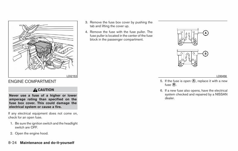
ENGINE COMPARTMENT
CAUTION
Never use a fuse of a higher or loweramperage rating than specified on thefuse box cover. This could damage theelectrical system or cause a fire.
If any electrical equipment does not come on,check for an open fuse.
1. Be sure the ignition switch and the headlightswitch are OFF.
2. Open the engine hood.
3. Remove the fuse box cover by pushing thetab and lifting the cover up.
4. Remove the fuse with the fuse puller. Thefuse puller is located in the center of the fuseblock in the passenger compartment.
5. If the fuse is open �A , replace it with a newfuse �B .
6. If a new fuse also opens, have the electricalsystem checked and repaired by a NISSANdealer.
LDI2153 LDI0456
8-24 Maintenance and do-it-yourself
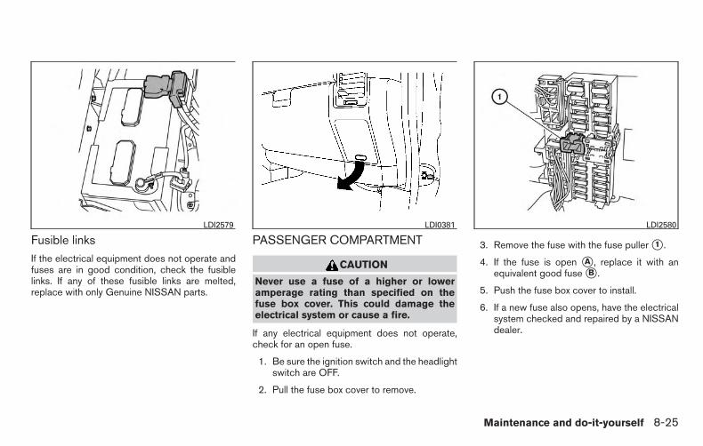
Fusible linksIf the electrical equipment does not operate andfuses are in good condition, check the fusiblelinks. If any of these fusible links are melted,replace with only Genuine NISSAN parts.
PASSENGER COMPARTMENT
CAUTION
Never use a fuse of a higher or loweramperage rating than specified on thefuse box cover. This could damage theelectrical system or cause a fire.
If any electrical equipment does not operate,check for an open fuse.
1. Be sure the ignition switch and the headlightswitch are OFF.
2. Pull the fuse box cover to remove.
3. Remove the fuse with the fuse puller �1 .
4. If the fuse is open �A , replace it with anequivalent good fuse �B .
5. Push the fuse box cover to install.
6. If a new fuse also opens, have the electricalsystem checked and repaired by a NISSANdealer.
LDI2579 LDI0381 LDI2580
Maintenance and do-it-yourself 8-25

Extended storage switch
If any electrical equipment does not operate,remove the extended storage switch and checkfor an open fuse.
NOTE:
The extended storage switch is used forlong term vehicle storage. Even if the ex-tended storage switch is broken it is notnecessary to replace it. Replace only theopen fuse in the switch with a new fuse.
How to remove the extended storageswitch:
1. To remove the extended storage switch, besure the ignition switch is in the OFF orLOCK position.
2. Be sure the headlight switch is in the OFFposition.
3. Remove the fuse box cover.
4. Pinch the locking tabs �1 found on eachside of the storage switch.
5. Pull the storage switch straight out from thefuse box �2 .
CAUTION
Be careful not to allow children to swallowthe battery or removed parts.
LDI0456 LDI2035
BATTERY REPLACEMENT
8-26 Maintenance and do-it-yourself
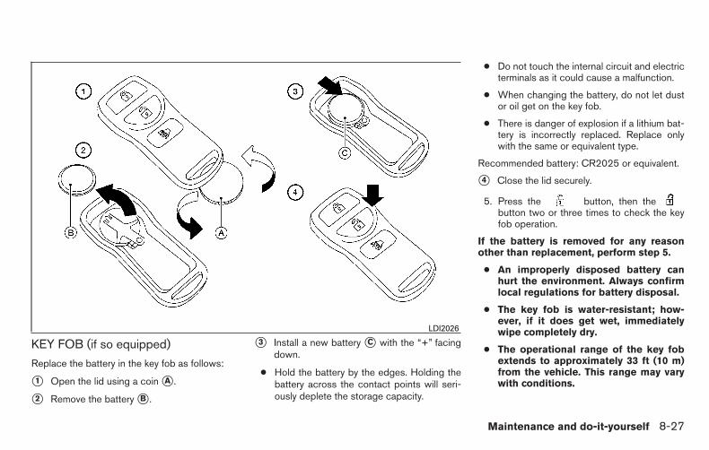
KEY FOB (if so equipped)
Replace the battery in the key fob as follows:
�1 Open the lid using a coin �A .
�2 Remove the battery �B .
�3 Install a new battery �C with the “+” facingdown.
● Hold the battery by the edges. Holding thebattery across the contact points will seri-ously deplete the storage capacity.
● Do not touch the internal circuit and electricterminals as it could cause a malfunction.
● When changing the battery, do not let dustor oil get on the key fob.
● There is danger of explosion if a lithium bat-tery is incorrectly replaced. Replace onlywith the same or equivalent type.
Recommended battery: CR2025 or equivalent.
�4 Close the lid securely.
5. Press the button, then thebutton two or three times to check the keyfob operation.
If the battery is removed for any reasonother than replacement, perform step 5.
● An improperly disposed battery canhurt the environment. Always confirmlocal regulations for battery disposal.
● The key fob is water-resistant; how-ever, if it does get wet, immediatelywipe completely dry.
● The operational range of the key fobextends to approximately 33 ft (10 m)from the vehicle. This range may varywith conditions.
LDI2026
Maintenance and do-it-yourself 8-27

FCC Notice:
For USA:This device complies with Part 15 of theFCC Rules. Operation is subject to the fol-lowing two conditions: (1) This device maynot cause harmful interference, and (2) thisdevice must accept any interference re-ceived, including interference that maycause undesired operation.
Note: Changes or modifications not ex-pressly approved by the party responsiblefor compliance could void the user’s au-thority to operate the equipment.
For Canada:This devise complies with Industry Canadalicence-exempt RSS standard(s). Opera-tion is subject to the following two condi-tions: (1) this device may not cause inter-ference, and (2) this device must accept anyinterference, including interference thatmay cause undesired operation of the de-vice.
HEADLIGHTSReplacing the halogen headlight bulb
The headlight is a semi-sealed beam type whichuses a replaceable headlight (halogen) bulb. Be-cause the headlight assembly must be removedfrom the vehicle for bulb replacement, see yourNISSAN dealer.
CAUTION
● High pressure halogen gas is sealedinside the halogen bulb. The bulb maybreak if the glass envelope is scratchedor the bulb is dropped.
● When handling the bulb, do not touchthe glass envelope.
● DO NOT TOUCH THE BULB WITH BAREHANDS.
● Do not leave the bulb out of the head-light reflector for a long period of timeas dust, moisture and smoke may enterthe headlight body and affect the per-formance of the headlight.
● Aiming is not necessary after replacingthe bulb. When aiming adjustment isnecessary, contact a NISSAN dealer.
NOTE:
Use the same number and wattage asshown in the chart located in the “Exteriorand interior lights” section of this manual.
Fog may temporarily form inside the lens of theexterior lights in the rain or in a car wash. Atemperature difference between the inside andthe outside of the lens causes the fog. This is nota malfunction. If large drops of water collectinside the lens, contact a NISSAN dealer.
FOG LIGHTS (if so equipped)
Replacing the fog light bulb
CAUTION
● High pressure halogen gas is sealedinside the halogen bulb. The bulb maybreak if the glass envelope is scratchedor the bulb is dropped.
● When handling the bulb, do not touchthe glass envelope.
● Use the same number and wattage asoriginally installed as shown in thechart.
LIGHTS
8-28 Maintenance and do-it-yourself

● Do not leave the bulb out of the fog lightfor a long period of time as dust, mois-ture and smoke may enter the fog lightbody and affect the performance of thefog light.
1. Disconnect the negative (-) battery cable.
2. The fog light is accessible in front of the fronttire and behind the bumper.
3. Disconnect the bulb connector �1 .
4. Rotate the bulb counterclockwise and re-move.
5. Remove by pulling it straight out of the foglight assembly. Do not shake or rotate thebulb when removing it. Do not touch theglass envelope.
6. Install in the reverse order of removal.
NOTE:
To adjust the fog light vertical aim: Accessthe aiming screw from underneath the frontbumper. The aiming screw is located on thebottom of the fog light housing. Turn thescrew clockwise to raise the pattern. Turnthe screw counterclockwise to lower thepattern.
LDI0382
Maintenance and do-it-yourself 8-29

EXTERIOR AND INTERIOR LIGHTS
Item Wattage (W) Bulb No.
Headlight assembly*High 65 9005 (HB3)Low 55 9006 (HB4)Park/Turn 28/8 3457KSidemarker 3.8 194
Daytime running lights (Canada only)* 55 9006Front fog light (if so equipped) 27.5 880Puddle light (if so equipped) 9 906LFMap/room lights (front/rear) (if so equipped) 8 –Personal lights (if so equipped) 8 AL67Vanity mirror light (if so equipped) 1.8 –Step light (if so equipped) 3.8 194High-mounted stop light/cargo lights* 12.8 912LFRear combination light
Tail/Stop 27/8 3157KBackup (reversing) 18 921LFTurn 27 3156K
Tailgate light (if so equipped)* 18 921License plate light 5 W5W
* See a NISSAN dealer for replacement.
Always check with the Parts Department at a NISSAN dealer for the latest parts information.
LDI2582
8-30 Maintenance and do-it-yourself

1. Room/map light (if so equipped)2. Personal lights (if so equipped)3. Puddle light (if so equipped)4. Step light (if so equipped)5. License plate light6. Rear combination/tailgate light (if so
equipped)7. High-mount stoplight/cargo lights8. Fog light (if so equipped)9. Headlight assembly/daytime running
light (Canada only)
Replacement proceduresAll other lights are either type A, B, C or D. Whenreplacing a bulb, first remove the lens, lampand/or cover.
Indicates bulb removal
Indicates bulb installation
WDI0263
Maintenance and do-it-yourself 8-31

Use a cloth �1 to protect the housing.
Use a cloth �1 to protect the housing. Use a cloth �1 to protect the housing.
Interior/map lightsLDI0389
Personal lights (If so equipped)LDI0364
Vanity mirror (If so equipped)LDI0385
8-32 Maintenance and do-it-yourself

Use a cloth �1 to protect the housing. Use a cloth �1 to protect the housing.Step light (If so equipped)
LDI0341
Puddle light (If so equipped)LDI0388
License plate lightWDI0411
Maintenance and do-it-yourself 8-33

If you have a flat tire, refer to “Flat tire” inthe “In case of emergency” section of thismanual for additional information.
TIRE PRESSURE
Tire Pressure Monitoring System(TPMS)
This vehicle is equipped with the TirePressure Monitoring System (TPMS). Itmonitors tire pressure of all four tires ex-cept the spare. When the low tire pres-sure warning light is lit and the CHECKTIRE PRESSURE warning appears in thevehicle information display, one or more ofyour tires is significantly under-inflated. Ifequipped, the system also displays pres-sure of all tires (except the spare tire) onthe display screen by sending a signalfrom a sensor that is installed in eachwheel.
The TPMS will activate only when thevehicle is driven at speeds above 16 MPH(25 km/h). Also, this system may not de-tect a sudden drop in tire pressure (forexample a flat tire while driving).
For additional information, refer to“Warning/Indicator Lights and AudibleReminders” in the “Instruments and con-trols” section, “Tire Pressure MonitoringSystem (TPMS)” in the “Starting and driv-ing” section, and “Flat tire” in the “In caseof emergency” section.
Tire inflation pressure
Check the tire pressures (including thespare) often and always prior to long dis-tance trips. The recommended tire pres-sure specifications are shown on theF.M.V.S.S./C.M.V.S.S. certification labelor the Tire and Loading Information labelunder the “Cold Tire Pressure” heading.The Tire and Loading Information label isaffixed to the driver side center pillar. Tirepressures should be checked regularlybecause:
● Most tires naturally lose air over time.
● Tires can lose air suddenly whendriven over potholes or other objectsor if the vehicle strikes a curb whileparking.
Rear combination lightLDI0410
WHEELS AND TIRES
8-34 Maintenance and do-it-yourself

The tire pressures should be checkedwhen the tires are cold. The tires areconsidered COLD after the vehicle hasbeen parked for 3 or more hours, or drivenless than 1 mile (1.6 km) at moderatespeeds.
Incorrect tire pressure, including un-der inflation, may adversely affecttire life and vehicle handling.
WARNING
● Improperly inflated tires can failsuddenly and cause an accident.
● The Gross Vehicle Weight Rating(GVWR) is located on theF.M.V.S.S./C.M.V.S.S. certifica-tion label. The vehicle weight ca-pacity is indicated on the Tire andLoading Information label. Donot load your vehicle beyond thiscapacity. Overloading your ve-hicle may result in reduced tirelife, unsafe operating conditionsdue to premature tire failure, orunfavorable handling character-istics and could also lead to aserious accident. Loading beyondthe specified capacity may alsoresult in failure of other vehiclecomponents.
● Before taking a long trip, orwhenever you heavily load yourvehicle, use a tire pressure gaugeto ensure that the tire pressuresare at the specified level.
● For additional information re-garding tires, refer to “ImportantTire Safety Information” (US) or“Tire Safety Information”(Canada) in the Warranty Infor-mation Booklet.
Maintenance and do-it-yourself 8-35

Tire and loading information label
�1 Seating capacity: The maximum num-ber of occupants that can be seatedin the vehicle.
�2 Vehicle load limit: For additional infor-mation, refer to “Vehicle loading infor-mation” in the “Technical and con-sumer information” section of thismanual.
�3 Original tire size: The size of the tiresoriginally installed on the vehicle atthe factory.
�4 Cold tire pressure: Inflate the tires tothis pressure when the tires are cold.Tires are considered COLD after thevehicle has been parked for 3 or morehours, or driven less than 1 mile(1.6 km) at moderate speeds. Therecommended cold tire inflation is setby the manufacturer to provide thebest balance of tire wear, vehiclehandling, driveability, tire noise, etc.,up to the vehicle’s GVWR.
�5 Tire size - refer to “Tire labeling” inthis section.
�6 Spare tire size.
LDI2007
8-36 Maintenance and do-it-yourself

Checking tire pressure
1. Remove the valve stem cap from thetire.
2. Press the pressure gauge squarelyonto the valve stem. Do not press toohard or force the valve stem side-ways, or air will escape. If the hissingsound of air escaping from the tire isheard while checking the pressure,reposition the gauge to eliminate thisleakage.
3. Remove the gauge.
4. Read the tire pressure on the gaugestem and compare to the specifica-tion shown on the Tire and LoadingInformation label.
5. Add air to the tire as needed. If toomuch air is added, press the core ofthe valve stem briefly with the tip ofthe gauge stem to release pressure.Recheck the pressure and add orrelease air as needed.
6. Install the valve stem cap.
7. Check the pressure of all other tires,including the spare.
Size Cold Tire InflationPressure
Front Original Tire:P265/70R18P275/70R18P275/60R20
250 kPa, 36 PSI
Rear Original Tire:P265/70R18P275/70R18P275/60R20
250 kPa, 36 PSI
Spare Tire:P265/70R18P275/70R18P275/60R20
250 kPa, 36 PSILDI0393
Maintenance and do-it-yourself 8-37

TIRE LABELING
Federal law requires tire manufacturers toplace standardized information on thesidewall of all tires. This information iden-tifies and describes the fundamentalcharacteristics of the tire and also pro-vides the tire identification number (TIN)for safety standard certification. The TINcan be used to identify the tire in case of arecall.
�1 Tire size (example: P215/65R15 95H)
1. P: The “P” indicates the tire is de-signed for passenger vehicles (not alltires have this information).
2. Three-digit number (215): This num-ber gives the width in millimeters ofthe tire from sidewall edge to side-wall edge.
3. Two-digit number (65): This number,known as the aspect ratio, gives thetire’s ratio of height to width.
4. R: The “R” stands for radial.5. Two-digit number (15): This number
is the wheel or rim diameter in inches.6. Two- or three-digit number (95): This
number is the tire’s load index. It is ameasurement of how much weighteach tire can support. You may notfind this information on all tires be-cause it is not required by law.
7. H: Tire speed rating. You should notdrive the vehicle faster than the tirespeed rating.
ExampleWDI0394
ExampleWDI0395
8-38 Maintenance and do-it-yourself

�2 TIN (Tire Identification Number) for anew tire (example: DOT XX XX XXXXXXX)
1. DOT: Abbreviation for the “Depart-ment Of Transportation”. The symbolcan be placed above, below or to theleft or right of the Tire IdentificationNumber.
2. Two-digit code: Manufacturer’sidentification mark.
3. Two-digit code: Tire size.
4. Three-digit code: Tire type code(Optional).
5. Three-digit code: Date of Manufac-ture.
6. Four numbers represent the weekand year the tire was built. For ex-ample, the numbers 3103 means the31st week of 2003. If these numbersare missing then look on the othersidewall of the tire.
�3 Tire ply composition and material
The number of layers or plies of rubber-coated fabric in the tire. Tire manufactur-ers also must indicate the materials in thetire, which include steel, nylon, polyesterand others.
�4 Maximum permissible inflation pres-sure
This number is the greatest amount of airpressure that should be put in the tire. Donot exceed the maximum permissible in-flation pressure.
�5 Maximum load rating
This number indicates the maximum loadin kilograms and pounds that can be car-ried by the tire. When replacing the tireson the vehicle, always use a tire that hasthe same load rating as the factory in-stalled tire.
�6 Term of “tubeless” or “tube type”
Indicates whether the tire requires an in-ner tube (“tube type”) or not (“tubeless”).
ExampleWDI0396
Maintenance and do-it-yourself 8-39

�7 The word “radial”
The word “radial” is shown if the tire hasradial structure.
�8 Manufacturer or brand name
Manufacturer or brand name is shown.
Other Tire-related Terminology
In addition to the many terms that aredefined throughout this section, IntendedOutboard Sidewall is (1) the sidewall thatcontains a whitewall, bears white letteringor bears manufacturer, brand, and/ormodel name molding that is higher ordeeper than the same molding on theother sidewall of the tire, or (2) the out-ward facing sidewall of an asymmetricaltire that has a particular side that mustalways face outward when mounted on avehicle.
TYPES OF TIRES
WARNING
● When changing or replacing tires, besure all four tires are of the same type(i.e., Summer, All Season or Snow) andconstruction. A NISSAN dealer may beable to help you with information abouttire type, size, speed rating andavailability.
● Replacement tires may have a lowerspeed rating than the factory equippedtires, and may not match the potentialmaximum vehicle speed. Never exceedthe maximum speed rating of the tire.
● Replacing tires with those not originallyspecified by NISSAN could affect theproper operation of the low tire pres-sure warning system.
● For additional information regardingtires, refer to “Important Tire Safety In-formation” (US) or “Tire Safety Informa-tion” (Canada) in the Warranty Informa-tion Booklet.
All season tires
NISSAN specifies All Season tires on some mod-els to provide good performance all year, includ-
ing snowy and icy road conditions. All Seasontires are identified by ALL SEASON and/or M&Son the tire sidewall. Snow tires have better snowtraction than All Season tires and may be moreappropriate in some areas.
Summer tires
NISSAN specifies summer tires on some modelsto provide superior performance on dry roads.Summer tire performance is substantially re-duced in snow and ice. Summer tires do not havethe tire traction rating “M&S” on the tire sidewall.
If you plan to operate your vehicle in snowy or icyconditions, NISSAN recommends the use ofSNOW tires or ALL SEASON tires on all fourwheels.
Snow tires
If snow tires are needed, it is necessary to selecttires equivalent in size and load rating to theoriginal equipment tires. If you do not, it canadversely affect the safety and handling of yourvehicle.
Generally, snow tires have lower speed ratingsthan factory equipped tires and may not matchthe potential maximum vehicle speed. Never ex-ceed the maximum speed rating of the tire.
8-40 Maintenance and do-it-yourself

If you install snow tires, they must be the samesize, brand, construction and tread pattern on allfour wheels.
For additional traction on icy roads, studded tiresmay be used. However, some U.S. states andCanadian provinces prohibit their use. Checklocal, state and provincial laws before installingstudded tires. Skid and traction capabilities ofstudded snow tires on wet or dry surfaces may bepoorer than that of non-studded snow tires.
TIRE CHAINS
CAUTION
Tire chains/cables should not be installedon P275/60R20 size tires. Installation ofthe tire chains/cables on P275/60R20 sizetires will cause damage to the vehicle. Ifyou plan to use tire chains/cables, youshould install P265/70R18 size tires onyour vehicle.
Use of tire chains may be prohibited according tolocation. Check the local laws before installingtire chains. When installing tire chains, make surethey are the proper size for the tires on yourvehicle and are installed according to the chainmanufacturer’s suggestions. Use only SAEclass “S” chains. Class “S” chains are used onvehicles with restricted tire to vehicle clearance.Vehicles that can use Class “S” chains are de-
signed to meet the minimum clearances betweenthe tire and the closest vehicle suspension orbody component required to accommodate theuse of a winter traction device (tire chains orcables). The minimum clearances are determinedusing the factory equipped tire size. Other typesmay damage your vehicle. Use chain tensionerswhen recommended by the tire chain manufac-turer to ensure a tight fit. Loose end links of thetire chain must be secured or removed to preventthe possibility of whipping action damage to thefenders or underbody. If possible, avoid fully load-ing your vehicle when using tire chains. In addi-tion, drive at a reduced speed. Otherwise, yourvehicle may be damaged and/or vehicle handlingand performance may be adversely affected.
Tire chains must be installed only on therear wheels and not on the front wheels.
Do not use tire chains on dry roads. Driving withchains in such conditions can cause damage tothe various mechanisms of the vehicle due tosome overstress.
Use only the 2WD range when driving on clearpaved roads.
CHANGING WHEELS AND TIRES
Tire rotation
NISSAN recommends rotating the tiresevery 5,000 miles (8,000 km).
Refer to “Flat tire” in the “In case of emer-gency” section in this manual for tire re-placing procedures.
As soon as possible, tighten thewheel nuts to the specified torquewith a torque wrench.
WDI0258
Maintenance and do-it-yourself 8-41
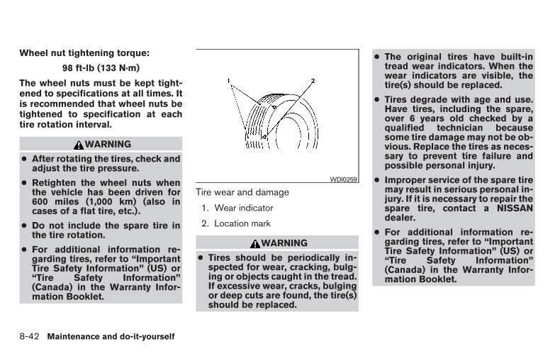
Wheel nut tightening torque:
98 ft-lb (133 N·m)
The wheel nuts must be kept tight-ened to specifications at all times. Itis recommended that wheel nuts betightened to specification at eachtire rotation interval.
WARNING
● After rotating the tires, check andadjust the tire pressure.
● Retighten the wheel nuts whenthe vehicle has been driven for600 miles (1,000 km) (also incases of a flat tire, etc.).
● Do not include the spare tire inthe tire rotation.
● For additional information re-garding tires, refer to “ImportantTire Safety Information” (US) or“Tire Safety Information”(Canada) in the Warranty Infor-mation Booklet.
Tire wear and damage
1. Wear indicator
2. Location mark
WARNING
● Tires should be periodically in-spected for wear, cracking, bulg-ing or objects caught in the tread.If excessive wear, cracks, bulgingor deep cuts are found, the tire(s)should be replaced.
● The original tires have built-intread wear indicators. When thewear indicators are visible, thetire(s) should be replaced.
● Tires degrade with age and use.Have tires, including the spare,over 6 years old checked by aqualified technician becausesome tire damage may not be ob-vious. Replace the tires as neces-sary to prevent tire failure andpossible personal injury.
● Improper service of the spare tiremay result in serious personal in-jury. If it is necessary to repair thespare tire, contact a NISSANdealer.
● For additional information re-garding tires, refer to “ImportantTire Safety Information” (US) or“Tire Safety Information”(Canada) in the Warranty Infor-mation Booklet.
WDI0259
8-42 Maintenance and do-it-yourself

Replacing wheels and tires
When replacing a tire, use the same size, treaddesign, speed rating and load carrying capacityas originally equipped. Recommended types andsizes are shown in “Wheels and tires” in the“Technical and consumer information” section ofthis manual.
WARNING
● The use of tires other than those recom-mended or the mixed use of tires ofdifferent brands, construction (bias,bias-belted or radial), or tread patternscan adversely affect the ride, braking,handling, VDC system, ground clear-ance, body-to-tire clearance, tire chainclearance, speedometer calibration,headlight aim and bumper height.Some of these effects may lead to acci-dents and could result in serious per-sonal injury.
● If your vehicle was originally equippedwith 4 tires that were the same size andyou are only replacing 2 of the 4 tires,install the new tires on the rear axle.Placing new tires on the front axle maycause loss of vehicle control in somedriving conditions and cause an acci-dent and personal injury.
● If the wheels are changed for any rea-son, always replace with wheels whichhave the same off-set dimension.Wheels of a different off-set couldcause premature tire wear, degrade ve-hicle handling characteristics, affect theVDC system and/or interference withthe brake discs. Such interference canlead to decreased braking efficiencyand/or early brake pad wear. Refer to“Wheels and tires” in the “Technical andconsumer information” section of thismanual for wheel off-set dimensions.
● When a spare tire is mounted or a wheelis replaced, tire pressure will not beindicated, the TPMS will not functionand the low tire pressure warning lightwill flash for approximately 1 minute.The light will remain on after 1 minute.Contact your NISSAN dealer as soon aspossible for tire replacement and/orsystem resetting.
● Replacing tires with those not originallyspecified by NISSAN could affect theproper operation of the TPMS.
● Do not install a damaged or deformedwheel or tire even if it has been re-paired. Such wheels or tires could havestructural damage and could fail with-out warning.
● The use of retread tires is notrecommended.
● For additional information regardingtires, refer to “Important Tire Safety In-formation” (US) or “Tire Safety Informa-tion” (Canada) in the Warranty Informa-tion Booklet.
Four-wheel drive models
CAUTION
Always use tires of the same type, size,brand, construction (bias, bias-belted orradial), and tread pattern on all fourwheels. Failure to do so may result in acircumference difference between tires onthe front and rear axles which will causeexcessive tire wear and may damage thetransmission, transfer case and differen-tial gears.
Maintenance and do-it-yourself 8-43
If excessive tire wear is found, it is recommendedthat all four tires be replaced with tires of thesame size, brand, construction and tread pattern.The tire pressure and wheel alignment shouldalso be checked and corrected as necessary.Contact a NISSAN dealer.
Wheel balanceUnbalanced wheels may affect vehicle handlingand tire life. Even with regular use, wheels can getout of balance. Therefore, they should be bal-anced as required.
Wheel balance service should be per-formed with the wheels off the vehicle.Spin balancing the wheels on the vehiclecould lead to mechanical damage.
● For additional information regardingtires, refer to “Important Tire SafetyInformation” (US) or “Tire Safety Infor-mation” (Canada) in the Warranty In-formation Booklet.
Care of wheels● Wash the wheels when washing the vehicle
to maintain their appearance.
● Clean the inner side of the wheels when thewheel is changed or the underside of thevehicle is washed.
● Do not use abrasive cleaners when washingthe wheels.
● Inspect wheel rims regularly for dents orcorrosion. Such damage may cause loss ofpressure or poor seal at the tire bead.
● NISSAN recommends waxing the roadwheels to protect against road salt in areaswhere it is used during winter.
8-44 Maintenance and do-it-yourself
9 Technical and consumer information
Recommended fluids/lubricants and capacities . . . . . . . 9-2Fuel recommendation(without Flexible Fuel Vehicle option). . . . . . . . . . . . . . 9-4Flexible fuel vehicle (FFV) fuelrecommendation (if so equipped). . . . . . . . . . . . . . . . . 9-6Engine oil and oil filter recommendations . . . . . . . . . . 9-7Air conditioner system refrigerant and oilrecommendations . . . . . . . . . . . . . . . . . . . . . . . . . . . . . . 9-8
Specifications. . . . . . . . . . . . . . . . . . . . . . . . . . . . . . . . . . . . . 9-9Engine . . . . . . . . . . . . . . . . . . . . . . . . . . . . . . . . . . . . . . . . 9-9Wheels and tires . . . . . . . . . . . . . . . . . . . . . . . . . . . . . . 9-10Dimensions and weights . . . . . . . . . . . . . . . . . . . . . . . 9-10
When traveling or registering your vehicle inanother country . . . . . . . . . . . . . . . . . . . . . . . . . . . . . . . . . . 9-12Vehicle identification . . . . . . . . . . . . . . . . . . . . . . . . . . . . . . 9-12
Vehicle identification number (VIN) plate . . . . . . . . . 9-12Vehicle identification number(chassis number) . . . . . . . . . . . . . . . . . . . . . . . . . . . . . . 9-12Engine serial number. . . . . . . . . . . . . . . . . . . . . . . . . . . 9-13F.M.V.S.S./C.M.V.S.S. certification label . . . . . . . . . . 9-13Emission control information label . . . . . . . . . . . . . . . 9-13Tire and loading information label. . . . . . . . . . . . . . . . 9-14Air conditioner specification label. . . . . . . . . . . . . . . . 9-14
Installing front license plate . . . . . . . . . . . . . . . . . . . . . . . . 9-14Vehicle loading information . . . . . . . . . . . . . . . . . . . . . . . . 9-15
Terms . . . . . . . . . . . . . . . . . . . . . . . . . . . . . . . . . . . . . . . . 9-15Vehicle load capacity . . . . . . . . . . . . . . . . . . . . . . . . . . 9-15Securing the load. . . . . . . . . . . . . . . . . . . . . . . . . . . . . . 9-17Utili-track™ channel system (if so equipped) . . . . . . 9-18Loading tips . . . . . . . . . . . . . . . . . . . . . . . . . . . . . . . . . . 9-23
Truck-camper loading information . . . . . . . . . . . . . . . . . . 9-23Crew Cab Models . . . . . . . . . . . . . . . . . . . . . . . . . . . . . 9-23King Cab models . . . . . . . . . . . . . . . . . . . . . . . . . . . . . . 9-23Special Body vehicles. . . . . . . . . . . . . . . . . . . . . . . . . . 9-23Location for center of gravity . . . . . . . . . . . . . . . . . . . . 9-24Vehicle load weight capacity . . . . . . . . . . . . . . . . . . . . 9-25Measurement of weights . . . . . . . . . . . . . . . . . . . . . . . 9-25
Towing a trailer . . . . . . . . . . . . . . . . . . . . . . . . . . . . . . . . . . . 9-25Maximum load limits . . . . . . . . . . . . . . . . . . . . . . . . . . . 9-26Towing load/specification. . . . . . . . . . . . . . . . . . . . . . . 9-29Towing safety . . . . . . . . . . . . . . . . . . . . . . . . . . . . . . . . . 9-32Flat towing. . . . . . . . . . . . . . . . . . . . . . . . . . . . . . . . . . . . 9-41
Snow plow . . . . . . . . . . . . . . . . . . . . . . . . . . . . . . . . . . . . . . 9-41Uniform tire quality grading . . . . . . . . . . . . . . . . . . . . . . . . 9-41Emission control system warranty . . . . . . . . . . . . . . . . . . 9-42Reporting safety defects . . . . . . . . . . . . . . . . . . . . . . . . . . 9-43Readiness for inspection/maintenance (I/M) test . . . . . 9-44Event Data Recorders (EDR). . . . . . . . . . . . . . . . . . . . . . . 9-44Owner’s Manual/Service Manual order information . . . 9-45

The following are approximate capacities. The actual refill capacities may be slightly different. When refilling, follow the proceduredescribed in the “Maintenance and do-it-yourself” section to determine the proper refill capacity.
Capacity (Approximate) Recommended Fluids and Lubricants
US measure Imp measure Liter
Fuel 28 gal 23-1/4 gal 105.8 L• For additional information, refer to “Fuel Recommendation (without FlexibleFuel Vehicle Option)” or “Flexible Fuel Vehicle (FFV) Fuel Recommendation”in this section.
Engine oil Drain and refill
VK56DE
With oil filterchange
6-7/8 qt 5-3/4 qt 6.5 L• Engine oil with API Certification Mark• Viscosity SAE 5W-30• For additional information, refer to “Engine oil and oil filter recommenda-tions” in this section.
Without oilfilter change
6-1/2 qt 5-1/2 qt 6.2 L
Cooling system With reservoir 3-1/4 2-5/8 gal12.2 L • Pre-diluted Genuine NISSAN Long Life Antifreeze/Coolant (blue) or
equivalent
Transfer oil 2-1/8 qt 1-3/4 qt 2.0 L
• Genuine NISSAN Matic D ATF recommended•Using fluid other than Genuine NISSAN Matic D ATF will cause deteriora-tion in driveability and transfer durability, and may damage the transfer case,which is not covered by the NISSAN new vehicle limited warranty.
Automatic transmission fluid
Refill to the proper level according to the instructions inthe “Maintenance and do-it-yourself” section.
•Genuine NISSAN Matic S ATF•If Genuine NISSAN Matic S ATF is not available, Genuine NISSAN Matic JATF may also be used. Using automatic transmission fluid other than Genu-ine NISSAN Matic S or J ATF will cause deterioration in driveability and au-tomatic transmission durability, and may damage the automatictransmission, which is not covered by the warranty.
Power steering fluid (PSF)• Genuine NISSAN PSF or equivalent• DEXRON™ VI type ATF may also be used.
Brake fluid• Genuine NISSAN Super Heavy Duty Brake Fluid or equivalent DOT 3• Available in mainland USA through a NISSAN dealer.
RECOMMENDED FLUIDS/LUBRICANTS AND CAPACITIES
9-2 Technical and consumer information

Capacity (Approximate) Recommended Fluids and Lubricants
US measure Imp measure Liter
Front final drive oil 3-3/8 pt 2-7/8 pt 1.6 L
• Genuine NISSAN Differential Oil Hypoid Super GL-5 80W-90 or APIGL-5, Viscosity SAE 80W-90• For hot climates, Viscosity SAE 90 is suitable for ambient temperaturesabove 0° C (32° F).
Rear final drive oil 4-1/4 pt 3-1/2 pt 2.0 L• Genuine NISSAN Differential Oil Synthetic 75W-140 or API GL-5 syn-thetic gear oil, Viscosity SAE 75W-140• See a NISSAN dealer for service for synthetic oil.
Multi-purpose grease — — — • NLGI No. 2 (lithium soap base)
Air conditioning system refrigerant — — —• HFC-134a (R-134a)• For additional information, refer to “Air conditioner specification label” inthis section.
Air conditioning system oil — — —• Genuine NISSAN A/C System Oil Type S or equivalent• For additional information, refer to “Air conditioner specification label” inthis section.
Windshield-washer fluid 1-1/4 gal 1 gal 4.5 L• Genuine NISSAN Windshield Washer Concentrate Cleaner & Antifreezeor equivalent
Technical and consumer information 9-3

FUEL RECOMMENDATION (withoutFlexible Fuel Vehicle option)
Use unleaded regular gasoline with an octanerating of at least 87 AKI (Anti-Knock Index) num-ber (Research octane number 91).
CAUTION
● Only vehicles with the E-85 filler doorlabel can operate on E-85. Fuel systemor other damage can occur if E-85 isused in vehicles that are not designedto run on E-85.
● Using a fuel other than that specifiedcould adversely affect the emissioncontrol system, and may also affect thewarranty coverage.
● Under no circumstances should aleaded gasoline be used, because thiswill damage the three-way catalyst.
● Do not use E-15 or E-85 fuel in yourvehicle. Your vehicle is not designed torun on E-15 or E-85 fuel. Using E-15 orE-85 fuel in a vehicle not specificallydesigned for E-15 or E-85 fuel can ad-versely affect the emission control de-vices and systems of the vehicle. Dam-age caused by such fuel is not coveredby the NISSAN new vehicle limitedwarranty.
● U.S. government regulations requireethanol dispensing pumps to be identi-fied by a small, square, orange andblack label with the common abbrevia-tion or the appropriate percentage forthat region.
Gasoline specificationsNISSAN recommends using gasoline that meetsthe World-Wide Fuel Charter (WWFC) specifi-cations where it is available. Many of the automo-bile manufacturers developed this specificationto improve emission control system and vehicleperformance. Ask your service station manager ifthe gasoline meets the WWFC specifications.
Reformulated gasoline
Some fuel suppliers are now producing reformu-lated gasolines. These gasolines are speciallydesigned to reduce vehicle emissions. NISSANsupports efforts towards cleaner air and sug-gests that you use reformulated gasoline whenavailable.
Gasoline containing oxygenates
Some fuel suppliers sell gasoline containing oxy-genates such as ethanol, MTBE and methanolwith or without advertising their presence.NISSAN does not recommend the use of fuels ofwhich the oxygenate content and the fuel com-patibility for your NISSAN cannot be readily de-termined. If in doubt, ask your service stationmanager.
If you use oxygenate-blend gasoline, please takethe following precautions as the usage of suchfuels may cause vehicle performance problemsand/or fuel system damage.
● The fuel should be unleaded and havean octane rating no lower than thatrecommended for unleaded gasoline.
● If an oxygenate-blend other than metha-nol blend is used, it should contain nomore than 10% oxygenate. (MTBE may,however, be added up to 15%.)
9-4 Technical and consumer information

● E-15 fuel contains more than 10% oxy-genate. E-15 fuel will adversely affectthe emission control devices and sys-tems of the vehicle and should not beused. Damage caused by such fuel isnot covered by the NISSAN new vehiclelimited warranty.
● If a methanol blend is used, it shouldcontain no more than 5% methanol(methyl alcohol, wood alcohol). Itshould also contain a suitable amountof appropriate cosolvents and corro-sion inhibitors. If not properly formu-lated with appropriate cosolvents andcorrosion inhibitors, such methanolblends may cause fuel system damageand/or vehicle performance problems.At this time, sufficient data is not avail-able to ensure that all methanol blendsare suitable for use in NISSAN ve-hicles.
If any driveability problems such as engine stall-ing and difficult hot-starting are experienced afterusing oxygenate-blend fuels, immediatelychange to a non-oxygenate fuel or a fuel with alow blend of MTBE.
Take care not to spill gasoline during refu-eling. Gasoline containing oxygenates cancause paint damage.
E–15 fuel
E-15 fuel is a mixture of approximately 15% fuelethanol and 85% unleaded gasoline. E-15 canonly be used in vehicles designed to run on E-15fuel. Do not use E-15 in your vehicle. U.S. gov-ernment regulations require fuel ethanol dispens-ing pumps to be identified with small, square,orange and black label with the common abbre-viation or the appropriate percentage for thatregion.
E–85 fuelE-85 fuel is a mixture of approximately 85% fuelethanol and 15% unleaded gasoline. E-85 canonly be used in a Flexible Fuel Vehicle (FFV). Donot use E-85 in your vehicle. U.S. governmentregulations require fuel ethanol dispensingpumps to be identified by a small, square, orangeand black label with the common abbreviation orthe appropriate percentage for that region.
Aftermarket fuel additivesNISSAN does not recommend the use of anyaftermarket fuel additives (for example, fuel injec-tor cleaner, octane booster, intake valve depositremovers, etc.) which are sold commercially.Many of these additives intended for gum, varnishor deposit removal may contain active solvents orsimilar ingredients that can be harmful to the fuelsystem and engine.
Octane rating tipsUsing unleaded gasoline with an octanerating lower than recommended can causepersistent, heavy “spark knock.” (“Sparkknock” is a metallic rapping noise.) If se-vere, this can lead to engine damage. If youdetect a persistent heavy spark knock evenwhen using gasoline of the stated octanerating, or if you hear steady spark knockwhile holding a steady speed on levelroads, have a NISSAN dealer correct thecondition. Failure to correct the conditionis misuse of the vehicle, for which NISSANis not responsible.
Incorrect ignition timing may result in sparkknock, after-run and/or overheating, which maycause excessive fuel consumption or enginedamage. If any of the above symptoms are en-countered, have your vehicle checked at aNISSAN dealer.
However, now and then you may noticelight spark knock for a short time whileaccelerating or driving up hills. This is not acause for concern, because you get thegreatest fuel benefit when there is lightspark knock for a short time under heavyengine load.
Technical and consumer information 9-5

FLEXIBLE FUEL VEHICLE (FFV) FUELRECOMMENDATION (if so equipped)
Your vehicle is designed to use (E-85) Fuel Etha-nol, “Regular” unleaded regular gasoline or anypercentage of the two fuels combined.
U.S. government regulations require FuelEthanol dispensing pumps to have a small,square, orange and black label with thecommon abbreviation or the appropriatepercentage for that region.
CAUTION
Use of other fuels such as Fuel Methanolmay cause powertrain damage or a loss ofvehicle performance.
Under no circumstances should a leadedgasoline be used, because this will causedamage to the three-way catalyst.
General information
This information is for Flexible Fuel vehicles (FFV)only. FFV vehicles can be identified by the fuelfiller door label that states Ethanol (E-85) orUnleaded Gasoline Only. This section only cov-ers those subjects that are unique to Flexible Fuelvehicles.
CAUTION
Only vehicles with the E-85 filler door la-bel can operate on E-85. Fuel system orother damage can occur if E-85 is used invehicles that are not designed to run onE-85.
Ethanol Fuel (E-85)
E-85 is a mixture of approximately 85% fuel etha-nol and 15% unleaded gasoline.
WARNING
● Ethanol vapors are extremely flam-mable and could cause serious per-sonal injury.
● Never have any smoking materials lit inor near the vehicle when removing thefuel filler cap or filling the tank.
● Do not use E-85 as a cleaning agent andnever use it near an open flame.
Fuel requirements
Your vehicle will operate on both unleaded regu-lar gasoline with an octane rating of at least87 AKI (Anti-Knock Index) number (Researchoctane number 91), or E-85 fuel, or any mixture ofthese two.
For the best starting and vehicle driveability re-sults, do not continually switch between E-85and unleaded regular gasoline. If you must switchfuels, NISSAN recommends the following:
● do not switch when the fuel gauge indicatesless than 1/4 full
● add more than 5 gallons of fuel
● operate the vehicle immediately after refuel-ing for a period of at least 5 minutes
NOTE:
When the ambient temperature is above90°F (32°C), you may experience hard start-ing and rough idle following start up even ifthe above recommendations are followed.
Starting
The characteristics of E-85 fuel make it unsuit-able for use when ambient temperatures fall be-low 0°F (-18°C). In the range of 0°F (-18°C) to32°F (0°C), you may experience an increase inthe time it takes for you engine to start, and adeterioration in drivability (sags and/or hesita-tions) until the engine is fully warmed up.
9-6 Technical and consumer information

Fuel consumption
Because E-85 fuel contains less energy per gal-lon than gasoline, you will experience an increasein fuel consumption. You can expect your fuelmileage to decrease by about 30% compared togasoline operation.
Replacement parts
Many components in your Flexible Fuel Vehicle(FFV) are designed to be compatible with etha-nol. Always be sure that your vehicle is servicedwith correct ethanol compatible parts.
CAUTION
Replacing fuel system components withnon-ethanol compatible components candamage your vehicle and may also affectthe warranty coverage.
Maintenance
If you operate your vehicle using E-85 fuel, followthe correct maintenance log shown in the“NISSAN Service and Maintenance Guide”.
CAUTION
Do not use ethanol mixture greater than85% in your vehicle. It will cause difficultyin cold starting and may affect drivability.
ENGINE OIL AND OIL FILTERRECOMMENDATIONS
Selecting the correct oil
It is essential to choose the correct grade, qualityand viscosity engine oil to ensure satisfactoryengine life and performance. For additional infor-mation, refer to “Recommended fluids/lubricantsand capacities” in this section. NISSAN recom-mends the use of an energy conserving oil inorder to improve fuel economy.
Select only engine oils that meet the AmericanPetroleum Institute (API) certification or Interna-tional Lubricant Standardization and Approval
Committee (ILSAC) certification and SAE vis-cosity standard. These oils have the API certifica-tion mark on the front of the container. Oils whichdo not have the specified quality label should notbe used as they could cause engine damage.
Oil additives
NISSAN does not recommend the use of oiladditives. The use of an oil additive is not neces-sary when the proper oil type is used and main-tenance intervals are followed.
Oil which may contain foreign matter or has beenpreviously used should not be used.
LTI2061
Technical and consumer information 9-7

Oil viscosityThe engine oil viscosity or thickness changeswith temperature. Because of this, it is importantto select the engine oil viscosity based on thetemperatures at which the vehicle will be oper-ated before the next oil change. Choosing an oilviscosity other than that recommended couldcause serious engine damage.
Selecting the correct oil filterYour new NISSAN vehicle is equipped with ahigh-quality Genuine NISSAN oil filter. Whenreplacing, use a Genuine NISSAN oil filter or itsequivalent for the reason described in “Changeintervals.”
Change intervalsThe oil and oil filter change intervals for yourengine are based on the use of the specifiedquality oils and filters. Using engine oil and filtersthat are not of the specified quality, or exceedingrecommended oil and filter change intervalscould reduce engine life. Damage to the enginecaused by improper maintenance or use of incor-rect oil and filter quality and/or viscosity is notcovered by the NISSAN new vehicle limited war-ranty.
Your engine was filled with a high-quality engineoil when it was built. You do not have to changethe oil before the first recommended changeinterval. Oil and filter change intervals dependupon how you use your vehicle.
Operation under the following conditions mayrequire more frequent oil and filter changes:
● repeated short distance driving at cold out-side temperatures
● driving in dusty conditions
● extensive idling
● towing a trailer
● stop and go commuting
For additional information, refer to the “NISSANService and Maintenance Guide” for the mainte-nance schedule.
AIR CONDITIONER SYSTEMREFRIGERANT AND OILRECOMMENDATIONS
The air conditioner system in your NISSANvehicle must be charged with the refriger-ant HFC-134a (R-134a) and NISSAN A/Csystem oil Type S or the exact equivalents.
CAUTION
The use of any other refrigerant or oil willcause severe damage to the air condition-ing system and will require the replace-ment of all air conditioner systemcomponents.
The refrigerant HFC-134a (R-134a) in yourNISSAN vehicle does not harm the earth’s ozonelayer. Although this refrigerant does not affect theearth’s atmosphere, certain government regula-tions require the recovery and recycling of anyrefrigerant during automotive air conditioner sys-tem service. A NISSAN dealer has the trainedtechnicians and equipment needed to recoverand recycle your air conditioner system refriger-ant.
Contact a NISSAN dealer when servicing your airconditioner system.
9-8 Technical and consumer information
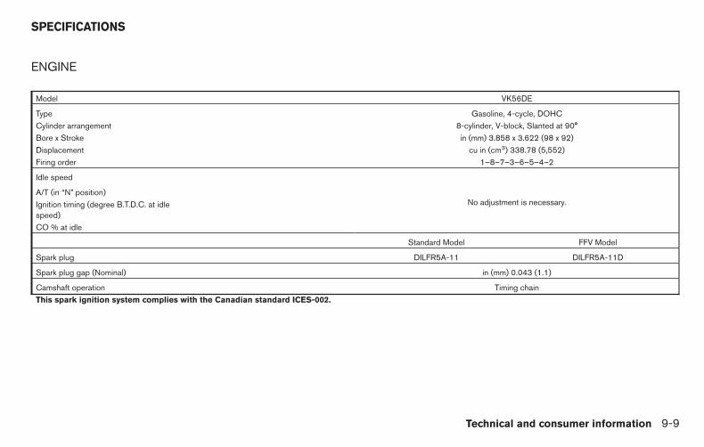
ENGINE
Model VK56DE
Type Gasoline, 4-cycle, DOHCCylinder arrangement 8-cylinder, V-block, Slanted at 90°Bore x Stroke in (mm) 3.858 x 3.622 (98 x 92)Displacement cu in (cm3) 338.78 (5,552)Firing order 1–8–7–3–6–5–4–2
Idle speed
No adjustment is necessary.A/T (in “N” position)Ignition timing (degree B.T.D.C. at idlespeed)CO % at idle
Standard Model FFV Model
Spark plug DILFR5A-11 DILFR5A-11D
Spark plug gap (Nominal) in (mm) 0.043 (1.1)
Camshaft operation Timing chainThis spark ignition system complies with the Canadian standard ICES-002.
SPECIFICATIONS
Technical and consumer information 9-9

WHEELS AND TIRES
Wheels
18 x 8.0JJ
20 x 8.0JJ
Tires
P265/70R18
P275/70R18
P275/60R20
Spare tire Full size
DIMENSIONS AND WEIGHTS
Overall lengthShort wheel base (SWB) in (mm) 224.6 (5,704)Long wheel base (LWB) in (mm) 244.2 (6,204)
Overall width in (mm) 79.5 (2,019)Overall heightKing Cab - SWB 4x2 (S, SV) in (mm) 74.6 (1,896)
4x4 (S, SV) in (mm) 76.1 (1,934)4x4 (Pro-4X) in (mm) 76.6 (1,946)
King Cab - LWB 4x2 (S, SV) in (mm) 74.4 (1,891)4x4 (S, SV) in (mm) 76.0 (1,931)
Crew Cab - SWB 4x2 (S, SV) in (mm) 74.7 (1,898)4x2 (SL) in (mm) 75.1 (1,908)4x4 (S, SV) in (mm) 76.3 (1,939)4x4 (Pro-4X) in (mm) 76.9 (1,954)4x4 (SL) in (mm) 76.7 (1,949)
Crew Cab - LWB 4x2 (S, SV) in (mm) 74.7 (1,898)4x2 (SL) in (mm) 74.9 (1,903)4x4 (S, SV) in (mm) 76.3 (1,939)4x4 (Pro-4X) in (mm) 76.6 (1,946)4x4 (SL) in (mm) 76.4 (1,941)
Front Track18 inch tire in (mm) 67.9 (1,725)20 inch tire in (mm) 68.1 (1,729)
Rear Track18 inch tire in (mm) 67.9 (1,725)20 inch tire in (mm) 68.1 (1,729)
WheelbaseShort wheel base in (mm) 139.8 (3,550)Long wheel base in (mm) 159.5 (4,050)
9-10 Technical and consumer information

Gross vehicle weight rating lb (kg) Refer to the “F.M.V.S.S./C.M.V.S.S.certification label”
on the center pillarbetween the driv-er’s side front and
rear doors.
Gross axle weight ratingFront lb (kg)Rear lb (kg)
Technical and consumer information 9-11
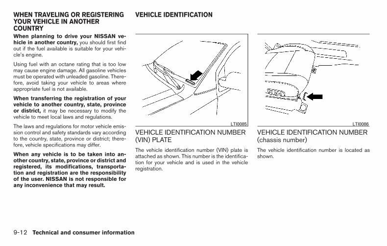
When planning to drive your NISSAN ve-hicle in another country, you should first findout if the fuel available is suitable for your vehi-cle’s engine.
Using fuel with an octane rating that is too lowmay cause engine damage. All gasoline vehiclesmust be operated with unleaded gasoline. There-fore, avoid taking your vehicle to areas whereappropriate fuel is not available.
When transferring the registration of yourvehicle to another country, state, provinceor district, it may be necessary to modify thevehicle to meet local laws and regulations.
The laws and regulations for motor vehicle emis-sion control and safety standards vary accordingto the country, state, province or district; there-fore, vehicle specifications may differ.
When any vehicle is to be taken into an-other country, state, province or district andregistered, its modifications, transporta-tion and registration are the responsibilityof the user. NISSAN is not responsible forany inconvenience that may result.
VEHICLE IDENTIFICATION NUMBER(VIN) PLATEThe vehicle identification number (VIN) plate isattached as shown. This number is the identifica-tion for your vehicle and is used in the vehicleregistration.
VEHICLE IDENTIFICATION NUMBER(chassis number)The vehicle identification number is located asshown.
LTI0085 LTI0086
WHEN TRAVELING OR REGISTERINGYOUR VEHICLE IN ANOTHERCOUNTRY
VEHICLE IDENTIFICATION
9-12 Technical and consumer information

ENGINE SERIAL NUMBERThe number is stamped on the engine as shown.
F.M.V.S.S./C.M.V.S.S.CERTIFICATION LABELThe Federal/Canadian Motor Vehicle SafetyStandard (F.M.V.S.S./C.M.V.S.S.) certification la-bel is affixed as shown. This label contains valu-able vehicle information, such as: (GVWR),(GAWR), month and year of manufacture, (VIN),etc. Review it carefully.
EMISSION CONTROLINFORMATION LABELThe emission control information label is at-tached to the underside of the hood as shown.
WTI0095 WTI0099 WTI0189
Technical and consumer information 9-13

TIRE AND LOADING INFORMATIONLABELThe cold tire pressure is shown on the Tire andLoading Information label. The label is located asshown.
AIR CONDITIONER SPECIFICATIONLABELThe air conditioner specification label is affixed tothe underside of the hood as shown.
Use the following steps to mount the front licenseplate:
1. Make holes on the plastic finisher at thelocation mark (small dimple) using a 0.20 in(5 mm) drill. Apply light pressure to the drill.Install the license plate holder using the twoscrews provided with the holder.
2. Mount the license plate using two M6-14 mm bolts.
License plate bolt tightening torque:3.8 - 4.7 ft-lb (5.10 - 6.37 N·m)
WTI0100 WTI0220 LTI0093
INSTALLING FRONT LICENSE PLATE
9-14 Technical and consumer information

WARNING
● It is extremely dangerous to ridein a cargo area inside a vehicle. Ina collision, people riding in theseareas are more likely to be seri-ously injured or killed.
● Do not allow people to ride in anyarea of your vehicle that is notequipped with seats and seatbelts.
● Be sure everyone in your vehicleis in a seat and using a seat beltproperly.
TERMS
It is important to familiarize yourself withthe following terms before loading yourvehicle:
● Curb Weight (actual weight of yourvehicle) - vehicle weight including:standard and optional equipment, flu-ids, emergency tools, and spare tireassembly. This weight does not in-clude passengers and cargo.
● GVW (Gross Vehicle Weight) - curbweight plus the combined weight ofpassengers and cargo.
● GVWR (Gross Vehicle Weight Rat-ing) - maximum total combinedweight of the unloaded vehicle, pas-sengers, luggage, hitch, trailertongue load and any other optionalequipment. This information is lo-cated on the F.M.V.S.S./C.M.V.S.S.certification label.
● GAWR (Gross Axle Weight Rating) -maximum weight (load) limit specifiedfor the front or rear axle. This informa-tion is located on theF.M.V.S.S./C.M.V.S.S. certificationlabel.
● GCWR (Gross Combined Weightrating) - The maximum total weightrating of the vehicle, passengers,cargo, and trailer.
● Vehicle Capacity Weight, Load limit,Total load capacity - maximum totalweight limit specified of the load(passengers and cargo) for the ve-hicle. This is the maximum combinedweight of occupants and cargo thatcan be loaded into the vehicle. If thevehicle is used to tow a trailer, thetrailer tongue weight must be in-cluded as part of the cargo load. Thisinformation is located on the Tire andLoading Information label.
● Cargo capacity - permissible weightof cargo, the subtracted weight ofoccupants from the load limit.
VEHICLE LOAD CAPACITY
Before driving a loaded vehicle, confirmthat you do not exceed the Gross VehicleWeight Rating (GVWR) or the Gross AxleWeight Rating (GAWR) for your vehicle.Both the GVWR and GAWR are locatedon the F.M.V.S.S./C.M.V.S.S. certificationlabel. For additional information, refer to“Measurement of weights” in this section.
VEHICLE LOADING INFORMATION
Technical and consumer information 9-15

Do not exceed the load limit of your ve-hicle shown as “The combined weight ofoccupants and cargo” on the Tire andLoading Information label. Do not exceedthe number of occupants shown as“Seating Capacity” on the Tire and Load-ing Information label.
To get “the combined weight of occu-pants and cargo”, add the weight of alloccupants, then add the total luggageweight. Examples are shown in the follow-ing illustration.
ExampleLTI0152
9-16 Technical and consumer information
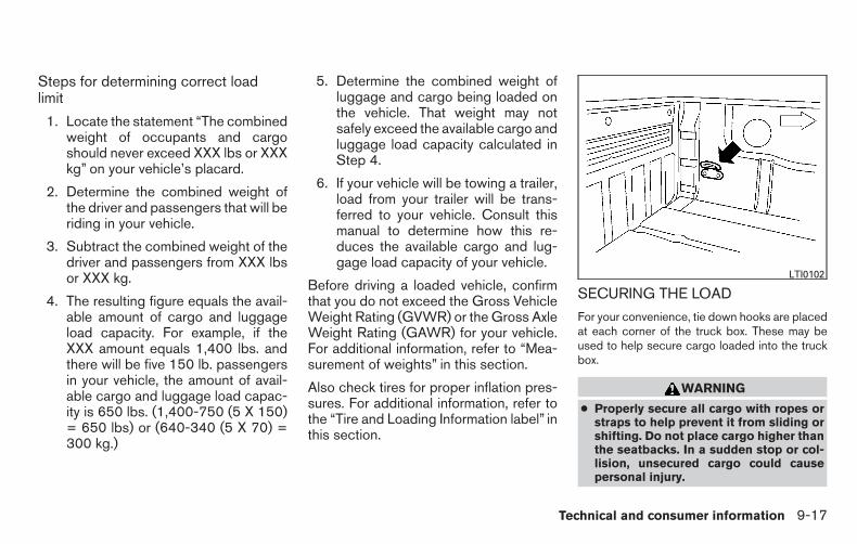
Steps for determining correct loadlimit
1. Locate the statement “The combinedweight of occupants and cargoshould never exceed XXX lbs or XXXkg” on your vehicle’s placard.
2. Determine the combined weight ofthe driver and passengers that will beriding in your vehicle.
3. Subtract the combined weight of thedriver and passengers from XXX lbsor XXX kg.
4. The resulting figure equals the avail-able amount of cargo and luggageload capacity. For example, if theXXX amount equals 1,400 lbs. andthere will be five 150 lb. passengersin your vehicle, the amount of avail-able cargo and luggage load capac-ity is 650 lbs. (1,400-750 (5 X 150)= 650 lbs) or (640-340 (5 X 70) =300 kg.)
5. Determine the combined weight ofluggage and cargo being loaded onthe vehicle. That weight may notsafely exceed the available cargo andluggage load capacity calculated inStep 4.
6. If your vehicle will be towing a trailer,load from your trailer will be trans-ferred to your vehicle. Consult thismanual to determine how this re-duces the available cargo and lug-gage load capacity of your vehicle.
Before driving a loaded vehicle, confirmthat you do not exceed the Gross VehicleWeight Rating (GVWR) or the Gross AxleWeight Rating (GAWR) for your vehicle.For additional information, refer to “Mea-surement of weights” in this section.
Also check tires for proper inflation pres-sures. For additional information, refer tothe “Tire and Loading Information label” inthis section.
SECURING THE LOAD
For your convenience, tie down hooks are placedat each corner of the truck box. These may beused to help secure cargo loaded into the truckbox.
WARNING
● Properly secure all cargo with ropes orstraps to help prevent it from sliding orshifting. Do not place cargo higher thanthe seatbacks. In a sudden stop or col-lision, unsecured cargo could causepersonal injury.
LTI0102
Technical and consumer information 9-17

● Do not load your vehicle any heavierthan the GVWR or the maximum frontand rear GAWRs. If you do, parts of yourvehicle can break, tire damage couldoccur, or it can change the way yourvehicle handles. This could result in lossof control and cause personal injury.
UTILI-TRACK™ CHANNEL SYSTEM(if so equipped)
1. Side channels
2. Header channel
3. Channel sections
4. Floor channels
WARNING
● Properly install and tighten the tie-down cleats into the Utili-track™ chan-nel system. Also, do not attach any ropeor straps directly to the channel. Failureto properly install the tie-down cleats orattaching ropes or straps directly to thechannel can cause the cargo to becomeunsecured. In a sudden stop or colli-sion, unsecured cargo could cause per-sonal injury.
● Properly secure all cargo with ropes orstraps to help prevent it from sliding orshifting. In a sudden stop or collision,unsecured cargo could cause personalinjury.
The Utili-track™ channel system allows you tomove tie-down clamps in the bed to the bestlocation to secure a load.
The tie-down cleats must be installed so theclamp is properly seated in the notches in the rail.If the tie-down cleat is not seated in the notches,it will not be flush with the rail and cannot beproperly tightened. The bolt in the center of thecleat must be tightened hand tight (20 – 40 in-lbs)
LTI0107
9-18 Technical and consumer information

Check the tightness of the tie-down cleat peri-odically during a trip to make sure the center bolthas not become loose.
Install the tie-down cleat as follows:
1. Remove the channel protectors by slidingthem out the back of the truck bed. Properlystore the channel protectors.
2. Loosen the center bolt completely.
3. Insert the cleat into the channel perpendicu-lar to the channel as shown. Then rotate thecleat clockwise 90° and slide it to the de-sired location.
4. Position the cleat so the nubs on the bottomfully seat into the channel detents.
LTI0103
LTI0104
Technical and consumer information 9-19

5. There should be no gap between the bottomof the cleat and the top of the channel.Tighten the center bolt hand tight (20-40 in-lbs ).
WTI0124
9-20 Technical and consumer information

CAUTION
● Install only one cleat per section ofchannel.
● Applying loads at angles to the cleatsgreater then 45° or loads greater than150 lbs. (header and floor channels) or200 lbs. (side channels) may cause dam-age to the channel or bed.
LTI0106
Technical and consumer information 9-21

WARNING
Do not install accessories over the gapbetween the front and rear side channels.Doing this could affect the rear structurein certain rear impacts, which could resultin serious injury.
CAUTION
Properly secure all cargo with ropes orstraps to prevent it from sliding or shifting.Use the channel end stoppers to help se-cure items in the channels from sliding offthe end of the truck bed.
Channel end stoppersThe channel end stoppers should be used to helpprevent accessories installed in the channelsfrom sliding or shifting off the end of the truckbed.
They must be installed so they are properlyseated in the detents in the channel.
1 correct installation, 2 incorrect installationLTI0123 WTI0119
9-22 Technical and consumer information

Install the channels end stoppers as follows:
1. Remove the channel protectors by slidingthem out the back of the truck bed. Properlystore the channel protectors.
2. Loosen the bolt on the center of the endstopper with the provided wrench and insertit into the channel.
3. Position the end stopper to the desired lo-cation on the channel so the nubs on thebottom of the end stopper fully seat into thechannel detents.
4. Tighten the bolt on the center of the endstopper with the provided wrench.
LOADING TIPS
● The GVW must not exceed GVWRor GAWR as specified on theF.M.V.S.S./C.M.V.S.S. certificationlabel.
● Do not load the front and rear axle tothe GAWR. Doing so will exceed theGVWR.
WARNING
● Properly secure all cargo withropes or straps to help prevent itfrom sliding or shifting. Do notplace cargo higher than the seat-backs. In a sudden stop or colli-sion, unsecured cargo couldcause personal injury.
● Do not load your vehicle anyheavier than the GVWR or themaximum front and rear GAWRs.If you do, parts of your vehicle canbreak, tire damage could occur,or it can change the way yourvehicle handles. This could resultin loss of control and cause per-sonal injury.
● Overloading not only can shortenthe life of your vehicle and thetire, but can also cause unsafevehicle handling and longer brak-ing distances. This may cause apremature tire failure whichcould result in a serious accidentand personal injury. Failurescaused by overloading are notcovered by the vehicle’s warranty.
CREW CAB MODELSCrew Cab short wheel base models shouldnot be used to carry a slide-in camper.
KING CAB MODELSThis information is provided for you to properlyinstall a slide-in camper and is based on theNational Highway Traffic Safety Administrationregulations. It is recommended that, before in-stalling the camper, you carefully read the follow-ing information and ensure that the campermeets the specifications.
This information may not apply to some Canadamodel vehicles.
SPECIAL BODY VEHICLESSome vehicles are equipped with commercial orcamper bodies. However, this Owner’s Manualdoes not cover these options. For additional in-formation, refer to the body manufacturer’s in-struction manual.
TRUCK-CAMPER LOADINGINFORMATION
Technical and consumer information 9-23

LOCATION FOR CENTER OFGRAVITY
The illustration indicates the recommendedcargo center of gravity location.
King Cab short wheel base:
L1 = 43.9 in (1,115.7 mm)
Crew Cab long wheel base:
L1 = 47.9 in (1,215.7 mm)
WARNING
Improper loading may be dangerous. If aload is too far back, it can affect handlingcharacteristics. If a load is too far forward,the front axle may be overloaded.
When the truck is used to carry a slide-in camper,the total cargo load of the truck consists of thecamper manufacturer’s weight figure, plus:
● the weight of installed additional camperequipment not included in the campermanufacturer’s weight figure,
● the weight of camper cargo,
● and the weight of occupants in the camper.
The total cargo load should not exceed thetruck’s pay load weight rating and the camper’scenter of gravity should fall within the truck’srecommended center of gravity location wheninstalled.
WTI0195 LTI0129
9-24 Technical and consumer information

WARNING
Overloading or improper loading can ad-versely affect vehicle handling, brakingand performance and may lead toaccidents.
VEHICLE LOAD WEIGHT CAPACITY
The vehicle payload weight capacity shown onthe Tire and Loading Information label, refer to“Tire and Loading Information label” in this sec-tion, indicates the maximum total weight of pas-sengers, optional equipment (air conditioning,trailer hitch, etc) and cargo that your vehicle isdesigned to carry.
Before driving a loaded vehicle, confirm that youdo not exceed the GVWR or the GAWR for yourvehicle. Refer to ’’Vehicle Loading Information’’ inthis section for details.
Also check tires for proper inflation pressures.Refer to the Tire and Loading Information label.
MEASUREMENT OF WEIGHTS
Secure loose items to prevent weightshifts that could affect the balance of yourvehicle. When the vehicle is loaded, driveto a scale and weigh the front and the rearwheels separately to determine axle
loads. Individual axle loads should not ex-ceed either of the gross axle weight rat-ings (GAWR). The total of the axle loadsshould not exceed the gross vehicleweight rating (GVWR). These ratings aregiven on the vehicle certification label. Ifweight ratings are exceeded, move or re-move items to bring all weights below theratings.
WARNING
Overloading or improper loading of atrailer and its cargo can adversely affectvehicle handling, braking and perfor-mance and may lead to accidents.
CAUTION
● Do not tow a trailer or haul a heavy loadfor the first 500 miles (805 km). Yourengine, axle or other parts could bedamaged.
● For the first 500 miles (805 km) that youtow a trailer, do not drive over 50 mph(80 km/h) and do not make starts at fullthrottle. This helps the engine and otherparts of your vehicle wear in at theheavier load.
Your new vehicle was designed to be used pri-marily to carry passengers and cargo. Rememberthat towing a trailer places additional loads onyour vehicle’s engine, drive train, steering, brak-ing and other systems.
A NISSAN Towing Guide (U.S. only) is availableon the website at www.nissanusa.com. Thisguide includes information on trailer towing ca-pability and the special equipment required forproper towing.
TOWING A TRAILER
Technical and consumer information 9-25

MAXIMUM LOAD LIMITSMaximum trailer loadsNever allow the total trailer load to exceed thevalue specified in the “TowingLoad/Specification” chart found in this section.The total trailer load equals trailer weight plus itscargo weight.
● When towing a trailer load of 3,500 lbs.(1,587 kg) or more, trailers with a brakesystem MUST be used.
The maximum GCWR should not exceed thevalue specified in the following “TowingLoad/Specification” chart.
The GCWR equals the combined weight of thetowing vehicle (including passengers and cargo)plus the total trailer load. Towing loads greaterthan these or using improper towing equipmentcould adversely affect vehicle handling, brakingand performance.
The ability of your vehicle to tow a trailer is notonly related to the maximum trailer loads, but alsothe places you plan to tow. Tow weights appro-priate for level highway driving may have to bereduced for low traction situations (for example,on slippery boat ramps).
Temperature conditions can also affect towing.For example, towing a heavy trailer in high outsidetemperatures on graded roads can affect engineperformance and cause overheating. The engineprotection mode, which helps reduce the chanceof engine damage, could activate and automati-cally decrease engine power. Vehicle speed maydecrease under high load. Plan your trip carefullyto account for trailer and vehicle load, weatherand road conditions.
WARNING
Overheating can result in reduced enginepower and vehicle speed. The reducedspeed may be lower than other traffic,which could increase the chance of a col-lision. Be especially careful when driving.If the vehicle cannot maintain a safe driv-ing speed, pull to the side of the road in asafe area. Allow the engine to cool andreturn to normal operation. For additionalinformation, refer to “If your vehicle over-heats” in the “In case of emergency” sec-tion of this manual.
CAUTION
Vehicle damage resulting from impropertowing procedures is not covered byNISSAN warranties.
LTI0161
9-26 Technical and consumer information

Tongue loadWhen using a weight carrying or a weight distrib-uting hitch, keep the tongue load between 10 -15% of the total trailer load or use the trailertongue load specified by the trailer manufacturer.The tongue load must be within the maximumtongue load limits shown in the following “TowingLoad/Specification” chart. If the tongue load be-comes excessive, rearrange cargo to allow forproper tongue load.
King pin loadWhen using a 5th wheel hitch, keep the tongueload between 15 - 25% of the total trailer loadwithin the maximum king pin load limits shown inthe following “Towing Load/Specification” chart.If the king pin load becomes excessive, rearrangecargo to allow for proper king pin load.
Maximum Gross Vehicle Weight(GVW)/maximum Gross Axle Weight(GAW)
The GVW of the towing vehicle must not exceedthe Gross Vehicle Weight Rating (GVWR)shown on the F.M.V.S.S./C.M.V.S.S. certificationlabel. The GVW equals the combined weight ofthe unloaded vehicle, passengers, luggage,hitch, trailer tongue load and any other optionalequipment. In addition, front or rear GAW mustnot exceed the Gross Axle Weight Rating(GAWR) shown on the F.M.V.S.S./C.M.V.S.S.certification label.
WTI0160 CA0036
Technical and consumer information 9-27

Towing capacities are calculated assuming abase vehicle with driver and any options requiredto achieve the rating. Additional passengers,cargo and/or optional equipment, such as thetrailer hitch, will add weight to the vehicle andreduce your vehicle’s maximum towing capacityand trailer tongue load.
The vehicle and trailer need to be weighed toconfirm the vehicle is within the GVWR, FrontGAWR, Rear GAWR, Gross Combined WeightRating (GCWR) and Towing capacity.
All vehicle and trailer weights can be measuredusing platform type scales commonly found attruck stops, highway weigh stations, buildingsupply centers or salvage yards.
To determine the available payload capacity fortongue/king pin load, use the following proce-dure.
1. Locate the GVWR on theF.M.V.S.S./C.M.V.S.S. certification label.
2. Weigh your vehicle on the scale with all ofthe passengers and cargo that are normallyin the vehicle when towing a trailer.
3. Subtract the actual vehicle weight from theGVWR. The remaining amount is the avail-able maximum tongue/king pin load.
To determine the available towing capacity, usethe following procedure.
1. Find the GCWR for your vehicle on the�Towing Load/Specification� chart found inthis section.
2. Subtract the actual vehicle weight from theGCWR. The remaining amount is the avail-able maximum towing capacity.
To determine the Gross Trailer Weight, weighyour trailer on a scale with all equipment andcargo, that are normally in the trailer when it istowed. Make sure the Gross trailer weight is notmore than the Gross Trailer Weight Rating shownon the trailer and is not more than the calculatedavailable maximum towing capacity.
Also weigh the front and rear axles on the scale tomake sure the Front Gross Axle Weight and RearGross Axle Weight are not more than FrontGross Axle Weight and Rear Gross Axle Weighton the F.M.V.S.S./C.M.V.S.S. certification label.The cargo in the trailer and vehicle may need tobe moved or removed to meet the specified rat-ings.
Example:
● Gross Vehicle Weight (GVW) as weighedon a scale - including passengers, cargo andhitch - 6,200 lb. (2,812 kg).
● Gross Vehicle Weight Rating (GVWR) fromF.M.V.S.S./C.M.V.S.S. certification label -7,100 lb. (3,220 kg).
● Gross Combined Weight Rating (GCWR)from “Towing Load/Specification� chart -15,100 lb. (6,848 kg).
● Maximum Trailer towing capacity from “Tow-ing Load/Specification� chart - 9,200 lb.(4,173 kg).
7,100 lb. (3,220 kg) GVWR
– 6,200 lb. (2,812 kg) GVW
= 900 lb. (408 kg) Available for tongue/king pin weight
15,100 lb. (6,848 kg) GCWR
– 6,200 lb. (2,812 kg) GVW
= 8,900 lb. (4,036 kg) Capacity available fortowing
900 lb. (408 kg) Available tongue weight
/ 8,900 lb. (4,036 kg) Available capacity
= 10 % tongue weight
9-28 Technical and consumer information

The available towing capacity may be less thanthe maximum towing capacity due to the passen-ger and cargo load in the vehicle.
Remember to keep trailer tongue weight be-tween 10 - 15% of the trailer weight or within thetrailer tongue load specification recommended
by the trailer manufacturer. If the tongue loadbecomes excessive, rearrange the cargo to ob-tain the proper tongue load. Do not exceed themaximum tongue weight specification shown inthe “Towing load/specification” chart even if thecalculated available tongue weight is greaterthan 15%. If the calculated tongue weight is less
than 10% , reduce the total trailer weight tomatch the available tongue weight.
Always verify that available capacities are withinthe required ratings.
TOWING LOAD/SPECIFICATION
Towing load specification chart with tow package — short wheel base
2WD 4WDKC CC KC CCSV SV SL SV Pro-4X SV Pro-4X SL
Maximum TowingCapacity *1, *2, *3
9,500 lb.(4,309 kg)
9,400 lb.(4,263 kg)
9,200 lb.(4,173 kg)
9,400 lb. (4,263 kg) 9,300 lb.(4,218 kg)
9,300 lb.(4,218 kg)
9,300 lb.(4,218 kg)
9,100 lb. (4,127 kg)
Maximum Tongue load *2, *3 950 lb.(431 kg)
940 lb.(426 kg)
920 lb. (417 kg) 940 lb. (426 kg) 930 lb.(422 kg)
930 lb.(422 kg)
930 lb.(422 kg)
910 lb. (413 kg)
Maximum King pin load 1,425 lb.(646 kg)
1,410 lb.(639 kg)
1,380 lb.(626 kg)
1,410 lb. (639 kg) 1,395 lb.(633 kg)
1,395 lb.(633 kg)
1,395 lb.(633 kg)
1,365 lb. (619 kg)
Maximum Gross CombinedWeight Rating
15,100 lb.(6,849 kg)
15,100 lb.(6,849 kg)
15,100 lb.(6,849 kg)
15,100 lb. (6,849 kg) 15,100 lb.(6,849 kg)
15,100 lb.(6,849 kg)
15,100 lb.(6,849 kg)
15,100 lb.(6,849 kg)
Technical and consumer information 9-29

Towing load specification chart with tow package — long wheel base
2WD 4WDCC CCSV SV
Maximum TowingCapacity *1, *2, *3
9,300 lb. (4,218 kg) 9,100 lb. (4,127 kg)
Maximum Tongue load *2, *3 930 lb. (422 kg) 910 lb. (413 kg)Maximum King pin load 1,395 lb. (633 kg) 1,365 lb. (619 kg)
Maximum Gross Combined Weight Rating 15,100 lb. (6,848 kg) 15,100 lb. (6,848 kg)
Towing load specification chart without tow package — short wheel base
2WD 4WDKC CC KC CC
S SV S SV SL S SV S SV SLMaximum Towing
capacity*1, *2, *37,400 lb. (3,356 kg) 7,400 lb. (3,356 kg) 7,400 lb.
(3,356 kg)7,400 lb.
(3,356 kg)7,100 lb.
(3,220 kg)7,400 lb.
(3,356 kg)7,400 lb.
(3,356 kg)7,300 lb.
(3,111 kg)7,300 lb.
(3,111 kg)7,000 lb.
(3,175 kg)Maximum Tongue load *2,
*3740 lb. (336 kg) 740 lb. (336 kg) 740 lb.
(336 kg)740 lb.
(336 kg)710 lb.
(322 kg)740 lb.
(336 kg)740 lb.
(336 kg)730 lb.
(311 kg)730 lb.
(311 kg)700 lb.
(318 kg)Maximum King pin load 1,110 lb. (504 kg) 1,110 lb. (504 kg) 1,110 lb.
(504 kg)1,110 lb.(504 kg)
1,065 lb.(483 kg)
1,110 lb.(504 kg)
1,110 lb.(504 kg)
1,095 lb.(496 kg)
1,095 lb.(496 kg)
1,050 lb.(476 kg)
Maximum Gross CombinedWeight Rating
12,800 lb. (5,806 kg) 12,800 lb. (5,806 kg) 12,800 lb.(5,806 kg)
12,800 lb.(5,806 kg)
12,800 lb.(5,806 kg)
13,000 lb.(5,897 kg)
13,000 lb.(5,897 kg)
13,000 lb.(5,897 kg)
13,000 lb.(5,897 kg)
13,000 lb.(5,897 kg)
9-30 Technical and consumer information
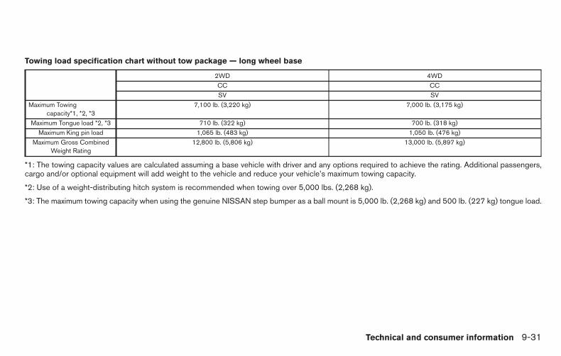
Towing load specification chart without tow package — long wheel base
2WD 4WDCC CCSV SV
Maximum Towingcapacity*1, *2, *3
7,100 lb. (3,220 kg) 7,000 lb. (3,175 kg)
Maximum Tongue load *2, *3 710 lb. (322 kg) 700 lb. (318 kg)Maximum King pin load 1,065 lb. (483 kg) 1,050 lb. (476 kg)
Maximum Gross CombinedWeight Rating
12,800 lb. (5,806 kg) 13,000 lb. (5,897 kg)
*1: The towing capacity values are calculated assuming a base vehicle with driver and any options required to achieve the rating. Additional passengers,cargo and/or optional equipment will add weight to the vehicle and reduce your vehicle’s maximum towing capacity.
*2: Use of a weight-distributing hitch system is recommended when towing over 5,000 lbs. (2,268 kg).
*3: The maximum towing capacity when using the genuine NISSAN step bumper as a ball mount is 5,000 lb. (2,268 kg) and 500 lb. (227 kg) tongue load.
Technical and consumer information 9-31

TOWING SAFETYTrailer hitch
Your vehicle may be equipped with an optionaltrailer tow package. The trailer tow package in-cludes a receiver-type frame mounted hitch. Thishitch is rated for the maximum towing capacity ofthis vehicle when the proper towing equipment isused. Choose a proper ball mount and hitch ballthat is rated for the trailer to be towed. GenuineNISSAN ball mounts and hitch balls are availablefrom your NISSAN dealer.
If your vehicle is not equipped with the optionaltrailer tow package, check the towing capacity ofyour bumper hitch or receiver-type framemounted hitch. Choose a proper hitch for yourvehicle and trailer. A genuine NISSAN trailerhitch is available from your NISSAN dealer. Makesure the trailer hitch is securely attached to thevehicle to help avoid personal injury or propertydamage due to sway caused by crosswinds,rough road surfaces or passing trucks.
A hitch used for towing 5th wheel and goosenecktrailers can also be installed on your vehicle.Contact a professional supplier of towing equip-ment to purchase and have a 5th wheel or goose-neck hitch installed.
WARNING
Trailer hitch components have specificweight ratings. Your vehicle may be ca-pable of towing a trailer heavier than theweight rating of the hitch components.Never exceed the weight rating of thehitch components. Doing so can causeserious personal injury or propertydamage.
Hitch ball
Choose a hitch ball of the proper size and weightrating for your trailer:
● The required hitch ball size is stamped onmost trailer couplers. Most hitch balls alsohave the size printed on the top of the ball.
● Choose the proper class hitch ball based onthe trailer weight.
● The diameter of the threaded shank of thehitch ball must be matched to the ball mounthole diameter. The hitch ball shank shouldbe no more than 1/16” smaller than the holein the ball mount.
● The threaded shank of the hitch ball must belong enough to be properly secured to theball mount. There should be at least 2threads showing beyond the lock washerand nut.
Ball mountThe hitch ball is attached to the ball mount andthe ball mount is inserted into the hitch receiver.Choose a proper class ball mount based on thetrailer weight. Additionally, the ball mount shouldbe chosen to keep the trailer tongue level with theground.
9-32 Technical and consumer information

Bumper towing
The genuine NISSAN step bumper has provi-sions to install a trailer hitch ball and is designedto tow trailers of a maximum weight of 5,000 lb(2,268 kg).
To install a trailer hitch ball cut out the circle in thecenter of the step bumper �A , then remove it toinstall the trailer hitch ball.
Weight carrying hitchesA weight carrying or “dead weight” ball mount isone that is designed to carry the whole amount oftongue weight and gross weight directly on theball mount and on the receiver.
Weight distribution hitch
This type of hitch is also called a “load-leveling”or“equalizing” hitch. A set of bars attach to the ballmount and to the trailer to distribute the tongueweight (hitch weight) of your trailer. Many ve-hicles can’t carry the full tongue weight of a giventrailer, and need some of the tongue weighttransferred through the frame and pushing downon the front wheels. This gives stability to the towvehicle.
A weight-distributing hitch system (Class IV) isrecommended if you plan to tow trailers with amaximum weight over 5,000 lbs (2,268 kg).Check with the trailer and towing equipmentmanufacturers to determine if they recommendthe use of a weight-distributing hitch system.
NOTE:
A weight-distributing hitch system may af-fect the operation of trailer surge brakes. Ifyou are considering use of a weight-distributing hitch system with a surgebrake-equipped trailer, check with thesurge brake, hitch or trailer manufacturerto determine if and how this can be done.
Follow the instructions provided by the manufac-turer for installing and using the weight-distributing hitch system.
General set-up instructions are as follows:
1. Park unloaded vehicle on a level surface.With the ignition on and the doors closed,allow the vehicle to stand for several minutesso that it can level.
2. Measure the height of a reference point onthe front and rear bumpers at the center ofthe vehicle.
3. Attach the trailer to the vehicle and adjustthe hitch equalizers so that the front bumperheight is within 0 - .5 inches (0 – 13 mm) ofthe reference height measured in step 2. Therear bumper should be no higher than thereference height measured in step 2.
WARNING
Properly adjust the weight distributinghitch so the rear of the bumper is nohigher than the measured referenceheight when the trailer is attached. If therear bumper is higher than the measuredreference height when loaded, the vehiclemay handle unpredictably which couldcause a loss of vehicle control and causeserious personal injury or propertydamage.
LTI0131
Technical and consumer information 9-33
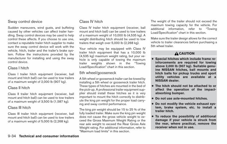
Sway control device
Sudden maneuvers, wind gusts, and buffetingcaused by other vehicles can affect trailer han-dling. Sway control devices may be used to helpcontrol these affects. If you choose to use one,contact a reputable trailer hitch supplier to makesure the sway control device will work with thevehicle, hitch, trailer and the trailer’s brake sys-tem. Follow the instructions provided by themanufacturer for installing and using the swaycontrol device.
Class I hitch
Class I trailer hitch equipment (receiver, ballmount and hitch ball) can be used to tow trailersof a maximum weight of 2,000 lb (907 kg).
Class II hitch
Class II trailer hitch equipment (receiver, ballmount and hitch ball) can be used to tow trailersof a maximum weight of 3,500 lb (1,587 kg).
Class III hitch
Class III trailer hitch equipment (receiver, ballmount and hitch ball) can be used to tow trailersof a maximum weight of 5,000 lb (2,268 kg).
Class IV hitch
Class IV trailer hitch equipment (receiver, ballmount and hitch ball) can be used to tow trailersof a maximum weight of 10,000 lb (4,535 kg). Aweight distributing hitch should be used to towtrailers that weigh over 5,000 lb (2,268 kg).
Your vehicle may be equipped with Class IVtrailer hitch equipment that has a 10,000 lb(4,535 kg) maximum weight rating, but your ve-hicle is only capable of towing the maximumtrailer weights shown in the “TowingLoad/Specification” chart in this section.
5th wheel/gooseneckA 5th wheel or gooseneck trailer can be towed byinstalling a 5th wheel or gooseneck trailer hitch.These types of hitches are mounted in the bed ofthe pick-up. A professional trailer equipment sup-plier should install these hitches as it is veryimportant to mount the hitch correctly to distrib-ute the king pin weight for the proper load carry-ing and sway control performance.
The king pin weight should be 15 to 25 % of thefully loaded trailer. Make sure the king pin weightdoes not cause the gross vehicle weight to ex-ceed the Gross Maximum Weight Rating or therear axle weight to exceed the Rear Gross AxleWeight rating. For additional information, refer to“Maximum load limits” in this section.
The weight of the trailer should not exceed themaximum towing capacity for the vehicle. Foradditional information, refer to “TowingLoad/Specification” chart in this section.
Make sure the trailer design allows for the correctvehicle to trailer clearances before purchasing a5th wheel trailer.
CAUTION
● Special hitches which include frame re-inforcements are required for towingabove 2,000 lb (907 kg). Suitable genu-ine NISSAN hitches, ball mounts andhitch balls for pickup trucks and sportutility vehicles are available at aNISSAN dealer.
● The hitch should not be attached to oraffect the operation of the impact-absorbing bumper.
● Do not use axle-mounted hitches.
● Do not modify the vehicle exhaust sys-tem, brake system, etc. to install atrailer hitch.
● To reduce the possibility of additionaldamage if your vehicle is struck fromthe rear, where practical, remove thereceiver when not in use.
9-34 Technical and consumer information

● Regularly check that all trailer hitchmounting bolts are securely mounted.
● When towing with the hitch ballmounted to the rear bumper, do notmake sharp turns. The trailer may con-tact the bumper and cause damage tothe bumper or trailer.
● When towing a 5th wheel trailer, do notmake sharp turns while driving or back-ing. The trailer may contact the vehicleand cause damage to both the trailerand vehicle.
Tire pressures
● When towing a trailer, inflate the ve-hicle tires to the recommended coldtire pressure indicated on the Tireand Loading Information label.
● Trailer tire condition, size, load ratingand proper inflation pressure shouldbe in accordance with the trailer andtire manufacturer’s specifications.
Safety chains
Always use suitable safety chains between yourvehicle and the trailer. The safety chains shouldbe crossed and should be attached to the hitch,
not to the vehicle bumper or axle. The safetychains can be attached to the bumper if the hitchball is mounted to the bumper. Be sure to leaveenough slack in the chains to permit turningcorners.
Trailer lights
CAUTION
When splicing into the vehicle electricalsystem, a commercially available power-type module/converter must be used toprovide power for all trailer lighting. Thisunit uses the vehicle battery as a directpower source for all trailer lights whileusing the vehicle tail light, stoplight andturn signal circuits as a signal source. Themodule/converter must draw no more that15 milliamps from the stop and tail lampcircuits. Using a module/converter thatexceeds these power requirements maydamage the vehicle’s electrical system.See a reputable trailer dealer to obtain theproper equipment and to have it installed.
Trailer lights should comply with federal and/orlocal regulations. For assistance in hooking uptrailer lights, contact a NISSAN dealer or repu-table trailer dealer. Vehicles equipped with theoptional trailer tow package are equipped with a7-pin trailer harness connector. If your trailer is
equipped with a flat 4-pin connector, an adapterwill be needed to connect the trailer lights to thevehicle. Adapters are available at NISSAN deal-ers, auto parts stores and hitch retailers.
Trailer brakes
When towing a trailer load of 3,500 lbs.(1,587 kg) or more, trailers with a brakesystem MUST be used. However, most statesrequire a separate braking system on trailers witha loaded weight above a specific amount. Makesure the trailer meets the local regulations andthe regulations where you plan to tow.
Several types of braking systems are available.
Surge Brakes - The surge brake actuator ismounted on the trailer tongue with a hydraulic linerunning to each trailer wheel. Surge brakes areactivated by the trailer pushing against the hitchball when the tow vehicle is braking. Hydraulicsurge brakes are common on rental trailers andsome boat trailers. In this type of system, there isno hydraulic or electric connection for brake op-eration between the tow vehicle and the trailer.
Electric Trailer Brakes - Electric braking sys-tems are activated by an electronic signal sentfrom a trailer brake controller (special brake-sensing module). For additional information, referto “Electric trailer brake controller” in this section.
Technical and consumer information 9-35

Have a professional supplier of towing equip-ment make sure the trailer brakes are properlyinstalled and demonstrate proper brake functiontesting.
WARNING
Never connect a trailer brake system di-rectly to the vehicle brake system.
Electric trailer brake controllerTrailers equipped with electric brakes may re-quire the installation of an aftermarket trailerbrake controller.
Your vehicle is equipped with a connector andjumper harness that is specifically designed to beused when installing an aftermarket brake con-troller.
To install the electric trailer brake controllerjumper harness, perform the following proce-dure:
1. Open the driver door. Move the seat to therearmost position.
exampleLTI0117
9-36 Technical and consumer information

2. Apply the parking brake to access thejumper harness connector.
3. Locate the jumper harness connector underthe lower portion of the instrument panel.The connector is taped to the wiring harness�1 as indicated.
● The connector is marked with a white tagwith “elec brake conn”.
Wire color designation for electric trailer brakecontroller jumper harness.
WIRE COLOR NOTERED/GREEN Vehicle stop lamp switch
to trailer brake controller.BLACK Brake controller ground
(-).BROWN/WHITE Trailer brake controller
switched output.RED/BLUE Trailer brake controller
illumination.RED Fused trailer brake con-
troller battery feed (B+).
LTI0118 LTI0115
Technical and consumer information 9-37

4. Peel off the tape and connect the jumperharness to the connector �2 .
5. Release the parking brake.
6. Install the aftermarket electric trailer brakecontroller according to the manufacturer’sinstructions.
Pre-towing tips
● Be certain your vehicle maintains a levelposition when a loaded and/or unloadedtrailer is hitched. Do not drive the vehicle if ithas an abnormal nose-up or nose-downcondition; check for improper tongue load,overload, worn suspension or other possiblecauses of either condition.
● Always secure items in the trailer to preventload shift while driving.
● Keep the cargo load as low as possible inthe trailer to keep the trailer center of gravitylow.
● Load the trailer so approximately 60% of thetrailer load is in the front half and 40% is inthe back half. Also make sure the load isbalanced side to side.
● Check your hitch, trailer tire pressure, ve-hicle tire pressure, trailer light operation, andtrailer wheel lug nuts every time you attach atrailer to the vehicle.
● Be certain your rearview mirrors conform toall federal, state or local regulations. If not,install any mirrors required for towing beforedriving the vehicle.
● Determine the overall height of the vehicleand trailer so the required clearance isknown.
Trailer towing tips
In order to gain skill and an understanding of thevehicle’s behavior, you should practice turning,stopping and backing up in an area which is freefrom traffic. Steering stability and braking perfor-mance will be somewhat different than undernormal driving conditions.
● Always secure items in the trailer to preventload shift while driving.
● Lock the trailer hitch coupler with a pin orlock to prevent the coupler from inadver-tently becoming unlatched.
● Avoid abrupt starts, acceleration or stops.
● Avoid sharp turns or lane changes.
● Always drive your vehicle at a moderatespeed.
● When backing up, hold the bottom of thesteering wheel with one hand. Move yourhand in the direction in which you want thetrailer to go. Make small corrections andback up slowly. If possible, have someoneguide you when you are backing up.
LTI0116
9-38 Technical and consumer information

Always block the wheels on both vehicle andtrailer when parking. Parking on a slope is notrecommended; however, if you must do so:
CAUTION
If you move the shift selector to the P(Park) position before blocking thewheels and applying the parking brake,transmission damage could occur.
1. Apply and hold the brake pedal.
2. Have someone place blocks on the downhillside of the vehicle and trailer wheels.
3. After the wheel blocks are in place, slowlyrelease the brake pedal until the blocks ab-sorb the vehicle load.
4. Apply the parking brake.
5. Shift the transmission into P (Park).
6. Make sure the indicator light (if soequipped) indicates the transfer case is in4H, 4L, or 2H and that the ATP light is off. Ifthe indicator light is flashing, or theATP light is ON, make sure the transmissionis in P (Park) (A/T) and turn the 4WD switchto 2WD or 4H. For additional information,refer to “Automatic transmission park warn-ing light” in the “Instruments and controls”
section and “Using 4-wheel drive (4WD)” inthe “Starting and driving” section.
7. Turn off the engine.
To drive away:
1. Start the vehicle.
2. Apply and hold the brake pedal.
3. Shift the transmission into gear.
4. Release the parking brake.
5. Drive slowly until the vehicle and trailer areclear from the blocks.
6. Apply and hold the brake pedal.
7. Have someone retrieve and store the blocks.
● While going downhill, the weight of thetrailer pushing on the tow vehicle may de-crease overall stability. Therefore, to main-tain adequate control, reduce your speedand shift to a lower gear. Avoid long orrepeated use of the brakes when descend-ing a hill, as this reduces their effectivenessand could cause overheating. Shifting to alower gear instead provides “engine brak-ing” and reduces the need to brake as fre-quently.
● If the engine coolant temperature rises to ahigh temperature, refer to “If your vehicleoverheats” in the “In case of emergency”section of this owner’s manual.
● Trailer towing requires more fuel than normalcircumstances.
● Avoid towing a trailer for your vehicle’s first500 miles (805 km).
● For the first 500 miles (805 km) that you dotow, do not drive over 50 MPH (80 km/h).
● Have your vehicle serviced more often thanat intervals specified in the recommendedMaintenance Schedule in the “NISSAN Ser-vice and Maintenance Guide”.
● When making a turn, your trailer wheels willbe closer to the inside of the turn than yourvehicle wheels. To compensate for this,make a larger than normal turning radiusduring the turn.
● Crosswinds and rough roads will adverselyaffect vehicle/trailer handling, possibly caus-ing vehicle sway. When being passed bylarger vehicles, be prepared for possiblechanges in crosswinds that could affect ve-hicle handling.
Technical and consumer information 9-39

Do the following if the trailer begins to sway:
1. Take your foot off the accelerator pedal toallow the vehicle to coast and steer as straightahead as the road conditions allow. This com-bination will help stabilize the vehicle
– Do not correct trailer sway by steering orapplying the brakes.
2. When the trailer sway stops, gently apply thebrakes and pull to the side of the road in asafe area.
3. Try to rearrange the trailer load so it is bal-anced as described earlier in this section.
● Be careful when passing other vehicles.Passing while towing a trailer requires con-siderably more distance than normal pass-ing. Remember, the length of the trailer mustalso pass the other vehicle before you cansafely change lanes.
● Use the Tow Mode or downshift the trans-mission to a lower gear for engine brakingwhen driving down steep or long hills. Thiswill help slow the vehicle without applyingthe brakes.
● Avoid holding the brake pedal down too longor too frequently. This could cause thebrakes to overheat, resulting in reducedbraking efficiency.
● Increase your following distance to allow forgreater stopping distances while towing atrailer. Anticipate stops and brake gradually.
● NISSAN recommends that the cruise con-trol (if so equipped) not be used while tow-ing a trailer.
● Some states or provinces have specificregulations and speed limits for vehicles thatare towing trailers. Obey the local speedlimits.
● Check your hitch, trailer wiring harness con-nections, and trailer wheel lug nuts after50 miles (80 km) of travel and at every break.
● When launching a boat, don’t allow the wa-ter level to go over the exhaust tail pipe orrear bumper.
● Make sure you disconnect the trailer lightsbefore backing the trailer into the water orthe trailer lights may burn out.
When towing a trailer, final drive gear oilshould be replaced and transmissionoil/fluid should be changed more fre-quently. For additional information, refer tothe “Maintenance and do-it-yourself” sec-tion in this manual.
Tow mode
Using tow mode is recommended when pulling aheavy trailer or hauling a heavy load. Press theTOW MODE switch to activate tow mode. Theindicator light on the TOW MODE switch illumi-nates when tow mode is selected. Press theTOW MODE switch again to turn tow mode off.Tow mode is automatically cancelled when theignition switch is turned OFF.
Tow mode includes the following features:
● Grade logic — Adjusts transmission shiftswhen pulling a trailer or hauling a load up agrade.
● Downhill Speed Control (DSC) — automati-cally downshifts when driving down a gradewith a trailer or heavy load to help controlvehicle speed.
Driving the vehicle in the tow mode with notrailer/load or light trailer/light load will not causeany damage. However, fuel economy may bereduced and the transmission/engine drivingcharacteristics may feel unusual.
When towing a trailer, final drive gear oilshould be replaced and transmissionoil/fluid should be changed more fre-quently. For additional information, refer tothe “Maintenance and do-it-yourself” sec-tion in this manual.
9-40 Technical and consumer information

FLAT TOWING
Towing your vehicle with all four wheels on theground is sometimes called flat towing. Thismethod is sometimes used when towing a vehiclebehind a recreational vehicle, such as a motorhome.
CAUTION
● Failure to follow these guidelines canresult in severe transmission damage.
● Whenever flat towing your vehicle, al-ways tow forward, never backward.
● DO NOT tow any automatic transmis-sion vehicle with all four wheels on theground (flat towing). Doing so WILLDAMAGE internal transmission partsdue to lack of transmission lubrication.
● For emergency towing procedures referto “Towing recommended by NISSAN”in the “In case of emergency” section ofthis manual.
Automatic TransmissionTo tow a vehicle equipped with an automatictransmission, an appropriate vehicle dolly MUSTbe placed under the towed vehicle’s drivewheels. Always follow the dolly manufacturer’srecommendations when using their product.
WARNING
Do not use this vehicle for snowplowing.Installing a snowplow may affect vehiclehandling. This may cause the driver to losecontrol of the vehicle and could result inserious vehicle damage or personal injury.
DOT (Department of Transportation) QualityGrades: All passenger car tires must conform tofederal safety requirements in addition to thesegrades.
Quality grades can be found where applicable onthe tire sidewall between tread shoulder andmaximum section width. For example:
Treadwear 200 Traction AA Temperature A
Treadwear
The treadwear grade is a comparative ratingbased on the wear rate of the tire when testedunder controlled conditions on a specified gov-ernment test course. For example, a tire graded150 would wear one and one-half (1 1/2) timesas well on the government course as a tire graded100. The relative performance of tires dependsupon the actual conditions of their use, however,and may depart significantly from the norm due tovariations in driving habits, service practices anddifferences in road characteristics and climate.
Traction AA, A, B and C
The traction grades, from highest to lowest, areAA, A, B, and C. Those grades represent thetire’s ability to stop on wet pavement as mea-sured under controlled conditions on specifiedgovernment test surfaces of asphalt and con-crete. A tire marked C may have poor tractionperformance.
SNOW PLOW UNIFORM TIRE QUALITY GRADING
Technical and consumer information 9-41

WARNING
The traction grade assigned to this tire isbased on straight-ahead braking tractiontests, and does not include acceleration,cornering, hydroplaning, or peak tractioncharacteristics.
Temperature A, B and C
The temperature grades are A (the highest), B,and C, representing the tire’s resistance to thegeneration of heat, and its ability to dissipate heatwhen tested under controlled conditions on aspecified indoor laboratory test wheel. Sustainedhigh temperature can cause the material of thetire to degenerate and reduce tire life, and exces-sive temperature can lead to sudden tire failure.The grade C corresponds to a level of perfor-mance which all passenger car tires must meetunder the Federal Motor Safety Standard No.109. Grades B and A represent higher levels ofperformance on the laboratory test wheel thanthe minimum required by law.
WARNING
The temperature grade for this tire is es-tablished for a tire that is properly inflatedand not overloaded. Excessive speed,under-inflation, or excessive loading, ei-ther separately or in combination, cancause heat build-up and possible tirefailure.
Your NISSAN vehicle is covered by the followingemission warranties:
For USA
1. Emission Defects Warranty
2. Emissions Performance Warranty
Details of this warranty may be found with othervehicle warranties in your Warranty InformationBooklet which comes with your NISSAN vehicle.If you did not receive a Warranty InformationBooklet, or it is lost, you may obtain a replace-ment by writing to:
● Nissan North America, Inc.Consumer Affairs DepartmentP.O. Box 685003Franklin, TN 37068-5003
For Canada
Emission Control System Warranty
Details of this warranty may be found with othervehicle warranties in your Warranty InformationBooklet which comes with your NISSAN vehicle.If you did not receive a Warranty InformationBooklet, or it is lost, you may obtain a replace-ment by writing to:
● Nissan Canada Inc.5290 Orbitor DriveMississauga, Ontario, L4W 4Z5
EMISSION CONTROL SYSTEMWARRANTY
9-42 Technical and consumer information

For USA
If you believe that your vehicle has a de-fect which could cause a crash or couldcause injury or death, you should immedi-ately inform the National Highway TrafficSafety Administration (NHTSA) in addi-tion to notifying NISSAN.
If NHTSA receives similar complaints, itmay open an investigation, and if it findsthat a safety defect exists in a group ofvehicles, it may order a recall and remedycampaign. However, NHTSA cannot be-come involved in individual problems be-tween you, your dealer, or NISSAN.
To contact NHTSA, you may call the Ve-hicle Safety Hotline toll-free at 1-888-327-4236 (TTY: 1-800-424-9153); goto http://www.safercar.gov; or write to:Administrator, NHTSA, 400 SeventhStreet, SW., Washington, D.C. 20590.You can also obtain other informationabout motor vehicle safety fromhttp://www.safercar.gov.
You may notify NISSAN by contacting ourConsumer Affairs Department, toll-free, at1-800-NISSAN-1.
For Canada
If you believe that your vehicle has a de-fect which could cause a crash or couldcause injury or death, you should immedi-ately inform Transport Canada in additionto notifying NISSAN.
If Transport Canada receives complaints,it may open an investigation, and if it findsthat a safety defect exists in a group ofvehicles, it may request that NISSAN con-duct a recall campaign. However, Trans-port Canada cannot become involved inindividual problems between you, yourdealer, or NISSAN.
You may contact Transport Canada’s De-fect Investigations and Recalls Divisiontoll free at 1-800-333-0510. You mayalso report safety defects online at:https://wwwapps.tc.gc.ca/Saf-Sec-Sur/7/PCDB-BDPP/fc-cp.aspx?lang=eng(English speakers) or
https://wwwapps.tc.gc.ca/Saf-Sec-Sur/7/PCDB-BDPP/fc-cp.aspx?lang=fra(French speakers)
Additional information concerning motorvehicle safety may be obtained fromTransport Canada’s Road SafetyInformation Centre at 1-800-333-0371or online at www.tc.gc.ca/roadsafety(English speakers) orwww.tc.gc.ca/securiteroutiere (Frenchspeakers).
To notify NISSAN of any safety concernsplease contact our Consumer InformationCentre toll free at 1-800-387-0122.
REPORTING SAFETY DEFECTS
Technical and consumer information 9-43
Due to legal requirements in some states andCanadian Provinces, your vehicle may be re-quired to be in what is called the “ready condi-tion” for an Inspection/Maintenance (I/M) test ofthe emission control system.
The vehicle is set to the “ready condition” when itis driven through certain driving patterns. Usually,the ready condition can be obtained by ordinaryusage of the vehicle.
If a powertrain system component is repaired orthe battery is disconnected, the vehicle may bereset to a “not ready” condition. Before taking theI/M test, check the vehicle’sinspection/maintenance test readiness condi-tion. Place the ignition switch in the ON positionwithout starting the engine. If the MalfunctionIndicator Light (MIL) comes on steady for 20 sec-onds and then blinks for 10 seconds , the I/M testcondition is “not ready”. If the MIL does not blinkafter 20 seconds, the I/M test condition is“ready”. Contact a NISSAN dealer to set the“ready condition” or to prepare the vehicle fortesting.
This vehicle is equipped with an Event Data Re-corder (EDR). The main purpose of an EDR is torecord, in certain crash or near crash-like situa-tions, such as an air bag deployment or hitting aroad obstacle, data that will assist in understand-ing how a vehicle’s systems performed. The EDRis designed to record data related to vehicledynamics and safety systems for a short period oftime, typically 30 seconds or less. The EDR in thisvehicle is designed to record such data as:
● How various systems in your vehicle wereoperating;
● Whether or not the driver and passengersafety belts were buckled/fastened;
● How far (if at all) the driver was depressingthe accelerator and/or brake pedal; and,
● How fast the vehicle was traveling.
● Sounds are not recorded.
These data can help provide a better understand-ing of the circumstances in which crashes andinjuries occur. NOTE: EDR data are recorded byyour vehicle only if a nontrivial crash situationoccurs; no data are recorded by the EDR undernormal driving conditions and no personal data(e.g. name, gender, age and crash location) arerecorded. However, other parties, such as lawenforcement, could combine the EDR data withthe type of personally identifying data routinelyacquired during a crash investigation.
To read data recorded by an EDR, special equip-ment is required and access to the vehicle or theEDR is needed. In addition to the vehicle manu-facturer and NISSAN dealer, other parties, suchas law enforcement, that have the special equip-ment, can read the information if they have ac-cess to the vehicle or the EDR. EDR data will onlybe accessed with the consent of the vehicleowner or lessee or as otherwise required or per-mitted by law.
READINESS FOR INSPECTION/MAINTENANCE (I/M) TEST
EVENT DATA RECORDERS (EDR)
9-44 Technical and consumer information

Genuine NISSAN Service Manuals for this modelyear and prior can be purchased. A genuineNISSAN Service Manual is the best source ofservice and repair information for your vehicle.This manual is the same one used by the factory-trained technicians working at NISSAN dealer-ships. Genuine NISSAN Owner’s Manuals canalso be purchased.
For USA
For current pricing and availability of genuineNISSAN Service Manuals, contact:
www.nissan-techinfo.com
For current pricing and availability of genuineNISSAN Owner’s Manuals, contact:
1-800-247-5321
For Canada
To purchase a copy of a genuine NISSAN Ser-vice Manual or Owner’s Manual, for this modelyear and prior, please contact your nearestNISSAN dealer. For the phone number and loca-tion of a NISSAN dealer in your area, call theNISSAN Information Center at 1-800-387-0122and a bilingual NISSAN representative will assistyou.
OWNER’S MANUAL/SERVICEMANUAL ORDER INFORMATION
Technical and consumer information 9-45

MEMO
9-46 Technical and consumer information

10 Index4WD. . . . . . . . . . . . . . . . . . . . . . .5-244WD warning light . . . . . . . . . . . . . . .2-154-Wheel Drive . . . . . . . . . . . . . . . . .5-24
A
Active brake limited slip (ABLS) system . . .5-35Adjusting pedal position . . . . . . . . . . . .3-14Air bag (See supplemental restraintsystem) . . . . . . . . . . . . . . . . . . . . .1-50Air bag system
Front (See supplemental front impactair bag system) . . . . . . . . . . . . . . .1-57
Air bag warning labels . . . . . . . . . . . . .1-65Air bag warning light. . . . . . . . . . .1-65, 2-17Air bag warning light, supplemental . .1-65, 2-17Air cleaner housing filter . . . . . . . . . . . .8-19Air conditioner
Air conditioner operation . . . . . . . . . .4-19Air conditioner service . . . . . . . . . . .4-27Air conditioner specification label . . . . .9-14Air conditioner system refrigerant andoil recommendations . . . . . . . . . . . . .9-8Heater and air conditioner (automatic)(if so equipped) . . . . . . . . . . . . . . .4-24Heater and air conditioner controls . . . .4-25Servicing air conditioner . . . . . . . . . .4-27
Air flow charts. . . . . . . . . . . . . . . . . .4-20Alarm system(See vehicle security system) . . . . . . . . .2-27Anchor point locations . . . . . . . . . . . . .1-30Antenna . . . . . . . . . . . . . . . . . . . . .4-68
Anti-lock brake warning light. . . . . . . . . .2-13Anti-lock Braking System (ABS). . . . . . . .5-34Audible reminders . . . . . . . . . . . . . . .2-20Audio system . . . . . . . . . . . . . . . . . .4-27
AM-FM radio with compact disc(CD) player . . . . . . . . . . . . . . . . .4-35
Audio SystemAM radio reception . . . . . . . . . . . . .4-28
Audio systemBluetooth® audio . . . . . . . . . .4-64, 4-65
Audio SystemBluetooth® streaming audio . . . .4-64, 4-65
Audio systemCompact disc (CD)player . . . . . . . . . .4-37, 4-41, 4-46, 4-53FM/AM radio with compact disc(CD) player . . . . . . . . . . . . . .4-35, 4-39FM-AM radio with compact disc(CD) player . . . . . . . . . . . . . . . . .4-39FM/AM/SAT radio with compact disc (CD)player . . . . . . . . . . . . . . . . .4-43, 4-48
Audio SystemFM radio reception . . . . . . . . . . . . .4-27iPod® Player . . . . . . . . . . . . .4-58, 4-61iPod® player operation . . . . . . .4-58, 4-61
Audio systemRadio . . . . . . . . . . . . . . . . . . . .4-27Steering wheel audio control switch . . .4-67USB interface . . . . . . . . . . . .4-54, 4-56
Audio SystemUSB (Universal Serial Bus) ConnectionPort . . . . . . . . . . . . . . . . . .4-54, 4-56
Autolight switch. . . . . . . . . . . . . . . . .2-34
AutomaticAutomatic drive positioner . .3-25, 3-26, 3-27Automatic power window switch . . . . .2-56Automatic transmission position indicatorlight . . . . . . . . . . . . . . . . . . . . .2-26Driving with automatic transmission . . . .5-14Transmission shift selector lock release . .5-18
Automatic anti-glare inside mirror . . . . . . .3-16Automatic door locks . . . . . . . . . . . . . .3-6Automatic drive positioner . . . .3-25, 3-26, 3-27Automatic transmission fluid temperaturegauge . . . . . . . . . . . . . . . . . . . . . . .2-8AUX jack. . . . . . . . . . . . . .4-38, 4-42, 4-54
B
Back button. . . . . . . . . . . . . . . . . . . .4-7Battery . . . . . . . . . . . . . . . . . .5-39, 8-15
Charge warning light . . . . . . . . . . . .2-14Battery replacement
Key fob . . . . . . . . . . . . . . . . . . .8-26Before starting the engine . . . . . . . . . . .5-11Belt (See drive belt) . . . . . . . . . . . . . .8-18Block heater
Engine . . . . . . . . . . . . . . . . . . . .5-41Bluetooth® audio . . . . . . . . . . . .4-64, 4-65Bluetooth® Hands-Free Phone System withNavigation System . . . . . . . . . . . . . . .4-90Bluetooth® Hands-Free Phone System withoutNavigation System . . . . . . . . . . . . . . .4-79Booster seats . . . . . . . . . . . . . . . . . .1-46

BrakeAnti-lock Braking System (ABS) . . . . . .5-34Brake assist (for Intelligent cruise controlsystem) . . . . . . . . . . . . . . . . . . . .5-35Brake fluid . . . . . . . . . . . . . . . . . .8-14Brake light (See stop light) . . . . . . . . .8-30Brake system. . . . . . . . . . . . . . . . .5-33Brake warning light . . . . . . . . . . . . .2-13Brake wear indicators . . . . . . . .2-20, 8-22Parking brake operation . . . . . . . . . . .5-20Self-adjusting brakes . . . . . . . . . . . .8-22
Brake fluid . . . . . . . . . . . . . . . . . . . .8-14Brakes . . . . . . . . . . . . . . . . . . . . . .8-22Brake system. . . . . . . . . . . . . . . . . . .5-33Break-in schedule . . . . . . . . . . . . . . . .5-22Brightness/contrast button . . . . . . . . . . . .4-9Brightness control
Instrument panel . . . . . . . . . . . . . . .2-36Bulb replacement . . . . . . . . . . . . . . . .8-30
C
Capacities and recommended fuel/lubricants . .9-2Cargo light switch . . . . . . . . . . . . . . . .2-38Cargo (See vehicle loading information) . . . .9-15Car phone or CB radio . . . . . . . . . . . . .4-79CD care and cleaning . . . . . . . . . . . . . .4-66CD player(See audio system) . . . . .4-37, 4-41, 4-46, 4-53Checking bulbs . . . . . . . . . . . . . . . . .2-12Check tire pressure . . . . . . . . . . . . . . .2-27Child restraints . . . . . . .1-24, 1-24, 1-25, 1-27
LATCH (Lower Anchors and Tethers forCHildren) System . . . . . . . . . . . . . .1-27
Precautions on childrestraints. . . . . . . . .1-25, 1-32, 1-39, 1-46Top tether strap anchor point locations . .1-30
Child safety rear door lock . . . . . . . . . . . .3-7Chimes, audible reminders . . . . . . . . . . .2-20Cleaning exterior and interior . . . . . . . .7-2, 7-4Clock . . . . . . . . . . . . . . . . . . .4-36, 4-40
(models without navigation system) . . . .4-40Clock set . . . . . . . . . . . . . . . . . . . . .4-40Clock set/adjustment. . . . .4-7, 4-36, 4-40, 4-44C.M.V.S.S. certification label . . . . . . . . . .9-13Cold weather driving. . . . . . . . . . . . . . .5-39Compact disc (CD)player . . . . . . . . . . . .4-37, 4-41, 4-46, 4-53Console light . . . . . . . . . . . . . . . . . . .2-60Control panel buttons . . . . . . . . . . . . . . .4-4
Back button . . . . . . . . . . . . . . . . . .4-7Brightness/contrast button . . . . . . . . . .4-9Enter button . . . . . . . . . . . . . . . . . .4-4Setting button . . . . . . . . . . . . . . . . .4-7With navigation system . . . . . . . . .4-4, 4-5
ControlsAudio controls (steering wheel). . . . . . .4-67Heater and air conditioner controls. . . . .4-25Heater and air conditioner controls(manual) . . . . . . . . . . . . . . . . . . .4-15
CoolantCapacities and recommendedfuel/lubricants . . . . . . . . . . . . . . . . .9-2Changing engine coolant . . . . . . . . . . .8-8Checking engine coolant level . . . . . . . .8-8Engine coolant temperature gauge . . . . .2-5
Corrosion protection . . . . . . . . . . . . . . .7-5Cruise control . . . . . . . . . . . . . . .5-20, 5-21Cup holders . . . . . . . . . . . . . . . . . . .2-51Curtain side-impact and rollover air bag . . . .1-62
D
Daytime running light system (Canada only) . .2-35Defroster switch
Rear window and outside mirror defrosterswitch. . . . . . . . . . . . . . . . . . . . .2-31
Digital video disc DVD. . . . . . . . . . . . . .4-69Dimensions and weights . . . . . . . . . . . .9-10Dimmer switch for instrument panel . . . . . .2-36Display. . . . . . . . . . . . . . . . . . .2-20, 2-21Display controls (see control panel buttons) . .4-4Door locks . . . . . . . . . . . . . . . . . . . . .3-3Drive belt . . . . . . . . . . . . . . . . . . . . .8-18Drive positioner, Automatic . . . .3-25, 3-26, 3-27Driving
Cold weather driving. . . . . . . . . . . . .5-39Driving with automatic transmission . . . .5-14Precautions when starting anddriving. . . . . . . . . . . . . . . . . . .5-2, 5-7
E
Economy - fuel . . . . . . . . . . . . . . . . . .5-24Electronic locking rear differential (E-Lock)system . . . . . . . . . . . . . . . . . . . . . .5-31Electronic locking rear differential (E-Lock)system switch . . . . . . . . . . . . . . . . . .2-39Emission control information label . . . . . . .9-13Emission control system warranty . . . . . . .9-42Engine
Before starting the engine. . . . . . . . . .5-11Block heater . . . . . . . . . . . . . . . . .5-41Capacities and recommendedfuel/lubricants . . . . . . . . . . . . . . . . .9-2
10-2

Changing engine coolant . . . . . . . . . . .8-8Changing engine oil . . . . . . . . . . . . .8-10Changing engine oil filter . . . . . . . . . .8-12Checking engine coolant level . . . . . . . .8-8Checking engine oil level . . . . . . . . . . .8-9Engine compartment check locations . . . .8-6Engine coolant temperature gauge . . . . .2-5Engine cooling system . . . . . . . . . . . .8-7Engine oil . . . . . . . . . . . . . . . . . . .8-9Engine oil and oil filter recommendation . . .9-7Engine oil pressure gauge . . . . . . . . . .2-7Engine oil viscosity . . . . . . . . . . . . . .9-8Engine serial number . . . . . . . . . . . .9-13Engine specifications . . . . . . . . . . . . .9-9Starting the engine . . . . . . . . . . . . .5-12
Engine coolant temperature gauge . . . . . . .2-5Engine oil pressure gauge . . . . . . . . . . . .2-7Engine oil pressure low/engine coolanttemperature high warning light . . . . . . . . .2-14Enter button . . . . . . . . . . . . . . . . . . . .4-4Event data recorders . . . . . . . . . . . . . .9-44Exhaust gas (Carbon monoxide) . . . . . . . . .5-2Explanation of maintenance items . . . . . . . .8-2Extended storage switch . . . . . . . . . . . .8-26
F
Flashers (See hazard warning flasher switch) . .6-2Flat tire . . . . . . . . . . . . . . . . . . . . . . .6-2Floor mat positioning aid . . . . . . . . . . . . .7-5Fluid
Brake fluid . . . . . . . . . . . . . . . . . .8-14Capacities and recommendedfuel/lubricants . . . . . . . . . . . . . . . . .9-2Engine coolant. . . . . . . . . . . . . . . . .8-7
Engine oil . . . . . . . . . . . . . . . . . . .8-9Power steering fluid . . . . . . . . . . . . .8-13Windshield-washer fluid. . . . . . . . . . .8-14
F.M.V.S.S. certification label. . . . . . . . . . .9-13Fog light switch . . . . . . . . . . . . . . . . .2-37Four-Wheel Drive . . . . . . . . . . . . . . . .5-24Front air bag system(See supplemental restraint system) . . . . . .1-57Front power seat adjustment . . . . . . . . . . .1-4Front seats . . . . . . . . . . . . . . . . . . . . .1-2Fuel
Capacities and recommendedfuel/lubricants . . . . . . . . . . . . . . . . .9-2Fuel economy . . . . . . . . . . . . . . . .5-24Fuel-filler cap. . . . . . . . . . . . . . . . .3-11Fuel-filler lid . . . . . . . . . . . . . . . . .3-11Fuel gauge . . . . . . . . . . . . . . . . . . .2-6Fuel octane rating . . . . . . . . . . . . . . .9-5Fuel recommendation . . . . . . . . . . . . .9-4Loose fuel cap warning . . . . . . . . . . .2-26
Fuel-filler door . . . . . . . . . . . . . . . . . .3-11Fuel gauge . . . . . . . . . . . . . . . . . . . . .2-6Fuses . . . . . . . . . . . . . . . . . . . . . . .8-23Fusible links . . . . . . . . . . . . . . . . . . .8-25
G
Garage door opener, HomeLink® UniversalTransceiver . .2-61, 2-62, 2-63, 2-64, 2-64, 2-65Gas cap . . . . . . . . . . . . . . . . . . . . .3-11Gauge
Automatic transmission fluid temperaturegauge . . . . . . . . . . . . . . . . . . . . .2-8Engine coolant temperature gauge . . . . .2-5Engine oil pressure gauge . . . . . . . . . .2-7
Fuel gauge . . . . . . . . . . . . . . . . . . .2-6Odometer . . . . . . . . . . . . . . . . . . .2-4Speedometer . . . . . . . . . . . . . . . . .2-4Tachometer . . . . . . . . . . . . . . . . . .2-5Trip odometer . . . . . . . . . . . . . . . . .2-4Voltmeter . . . . . . . . . . . . . . . . . . . .2-7
General maintenance . . . . . . . . . . . . . . .8-2Glove box. . . . . . . . . . . . . . . . . . . . .2-48Grocery hooks . . . . . . . . . . . . . . . . . .2-53
H
Hazard warning flasher switch . . . . . . . . . .6-2Headlight and turn signal switch . . . . . . . .2-32Headlight control switch . . . . . . . . . . . .2-33Headlights . . . . . . . . . . . . . . . . . . . .8-28Headphones (See NISSAN mobileentertainment system) . . . . . . . . . . . . . .4-72Head restraints . . . . . . . . . . . . . . . . . .1-9Heated seats . . . . . . . . . . . . . . . . . . .2-38Heater
Heater and air conditioner (automatic)(if so equipped) . . . . . . . . . . . . . . .4-24Heater and air conditioner controls. . . . .4-25Heater operation . . . . . . . . . . .4-18, 4-25
Heater and air conditioner (automatic) . . . . .4-24HomeLink® UniversalTransceiver . .2-61, 2-62, 2-63, 2-64, 2-64, 2-65Hood . . . . . . . . . . . . . . . . . . . . . . .3-11Horn . . . . . . . . . . . . . . . . . . . . . . .2-37
I
Ignition switch . . . . . . . . . . . . . . . . . . .5-9
10-3

Immobilizer system . . . . . . . . . . . .2-28, 5-11Important vehicle information label . . . . . . .9-13In-cabin microfilter . . . . . . . . . . . . . . . .8-20Increasing fuel economy. . . . . . . . . . . . .5-24Indicator lights and audible reminders(See warning/indicator lights and audiblereminders) . . . . . . . . . . . . . . . . .2-12, 2-18Information display . . . . . . . . . . . .2-20, 2-21Inside automatic anti-glare mirror . . . . . . . .3-16Instrument brightness control . . . . . . . . . .2-36Instrument panel . . . . . . . . . . . . . . .0-6, 2-2Instrument panel dimmer switch . . . . . . . .2-36Interior light. . . . . . . . . . . . . . . . . . . .2-59iPod® Player . . . . . . . . . . . . . . .4-58, 4-61ISOFIX child restraints . . . . . . . . . . . . .1-27
J
Jump starting . . . . . . . . . . . . . . . .6-9, 8-17
K
Key . . . . . . . . . . . . . . . . . . . . . . . . .3-2Key fob battery replacement . . . . . . . . . .8-26Keyless entry
Without Intelligent Key system(See remote keyless entry system). . . . . .3-7
KeysNISSAN Vehicle Immobilizer System keys. .3-2
L
LabelsAir conditioner specification label . . . . .9-14C.M.V.S.S. certification label . . . . . . . .9-13Emission control information label . . . . .9-13Engine serial number . . . . . . . . . . . .9-13F.M.V.S.S. certification label. . . . . . . . .9-13Tire and Loading Information label . . . . .9-14Vehicle identification number (VIN) plate. .9-12Warning labels (for SRS) . . . . . . . . . .1-65
LATCH (Lower Anchors and Tethers for CHildren)System . . . . . . . . . . . . . . . . . . . . . .1-27License plate
Installing the license plate . . . . . . . . . .9-14Light
Air bag warning light . . . . . . . . .1-65, 2-17Brake light (See stop light) . . . . . . . . .8-30Bulb replacement . . . . . . . . . . . . . .8-30Charge warning light . . . . . . . . . . . .2-14Console light . . . . . . . . . . . . . . . . .2-60Fog lights . . . . . . . . . . . . . . . . . . .8-28Fog light switch . . . . . . . . . . . . . . .2-37Headlight and turn signal switch . . . . . .2-32Headlight control switch . . . . . . . . . .2-33Headlights . . . . . . . . . . . . . . . . . .8-28Interior light. . . . . . . . . . . . . . . . . .2-59Light bulbs . . . . . . . . . . . . . . . . . .8-28Low tire pressure warning light . . . . . . .2-15Low windshield-washer fluid warninglight . . . . . . . . . . . . . . . . . .2-17, 2-26Passenger air bag and status light . . . . .1-59Personal lights . . . . . . . . . . . . . . . .2-61Security indicator light. . . . . . . . . . . .2-19
Warning/indicator lights and audiblereminders . . . . . . . . . . . . . . .2-12, 2-18
LightsMap lights . . . . . . . . . . . . . . . . . .2-61
LockChild safety rear door lock . . . . . . . . . .3-7Door locks . . . . . . . . . . . . . . . . . . .3-3Power door locks . . . . . . . . . . . . . . .3-4
Loose fuel cap warning . . . . . . . . . . . . .2-26Low fuel warning light . . . . . . .2-15, 2-17, 2-26Low tire pressure warning light . . . . . . . . .2-15Low windshield-washer fluid warninglight . . . . . . . . . . . . . . . . . . . .2-17, 2-26Luggage (See vehicle loading information) . .9-15
M
MaintenanceGeneral maintenance . . . . . . . . . . . . .8-2Inside the vehicle . . . . . . . . . . . . . . .8-3Maintenance precautions . . . . . . . . . . .8-5Outside the vehicle . . . . . . . . . . . . . .8-2Seat belt maintenance. . . . . . . . . . . .1-23Under the hood and vehicle . . . . . . . . .8-4
Maintenance requirements . . . . . . . . . . . .8-2Malfunction indicator light . . . . . . . . . . . .2-18Manual front seat adjustment . . . . . . . . . . .1-3Map lights . . . . . . . . . . . . . . . . . . . .2-61Map pocket. . . . . . . . . . . . . . . . . . . .2-49Memory Seat . . . . . . . . . . . .3-25, 3-26, 3-27Meters and gauges . . . . . . . . . . . . . . . .2-3
Instrument brightness control . . . . . . . .2-36Mirror
Automatic anti-glare inside mirror. . . . . .3-16Outside mirrors . . . . . . . . . . . . . . .3-17
10-4
Rearview . . . . . . . . . . . . . . . . . . .3-16Vanity mirror . . . . . . . . . . . . . . . . .3-15
Moonroof . . . . . . . . . . . . . . . . . . . . .2-58
N
NISSAN mobile entertainment system(MES) . . . . . . . . .4-69, 4-70, 4-71, 4-72, 4-76NISSAN vehicle immobilizer system. . .2-28, 5-11NISSAN voice recognition system . . . . . . .4-98
O
Octane rating (See fuel octane rating). . . . . .9-5Odometer . . . . . . . . . . . . . . . . . . . . .2-4Oil
Capacities and recommendedfuel/lubricants . . . . . . . . . . . . . . . . .9-2Changing engine oil . . . . . . . . . . . . .8-10Changing engine oil filter . . . . . . . . . .8-12Checking engine oil level . . . . . . . . . . .8-9Engine oil . . . . . . . . . . . . . . . . . . .8-9Engine oil and oil filter recommendation . . .9-7Engine oil pressure low/engine coolanttemperature high warning light . . . . . . .2-14Engine oil viscosity . . . . . . . . . . . . . .9-8
One shot call . . . . . . . . . . . . . . .4-82, 4-93Outside mirrors . . . . . . . . . . . . . . . . .3-17Overhead console . . . . . . . . . . . . . . . .2-50Overheat
If your vehicle overheats . . . . . . . . . . .6-11Owner’s manual order form . . . . . . . . . . .9-45Owner’s manual/service manual orderinformation . . . . . . . . . . . . . . . . . . . .9-45
P
ParkingParking brake operation . . . . . . . . . . .5-20Parking/parking on hills . . . . . . . . . . .5-32
Pedal position adjustment. . . . . . . . . . . .3-14Personal lights . . . . . . . . . . . . . . . . . .2-61Power
Front seat adjustment . . . . . . . . . . . . .1-4Power door locks . . . . . . . . . . . . . . .3-4Power outlet . . . . . . . . . . . . . .2-42, 2-44Power rear windows . . . . . . . . . . . . .2-56Power steering fluid . . . . . . . . . . . . .8-13Power steering system . . . . . . . . . . .5-33Power windows . . . . . . . . . . . . . . .2-54Rear power windows . . . . . . . . . . . .2-56
Power inverter switch . . . . . . . . . . . . . .2-40Power outlet . . . . . . . . . . . . . . . .2-42, 2-44Power steering . . . . . . . . . . . . . . . . . .5-33Power steering fluid . . . . . . . . . . . . . . .8-13Precautions
Maintenance precautions . . . . . . . . . . .8-5On-pavement and off-road drivingprecautions . . . . . . . . . . . . . . . . . .5-5Precautions on boosterseats . . . . . . . . . . .1-25, 1-32, 1-39, 1-46Precautions on childrestraints. . . . . . . . .1-25, 1-32, 1-39, 1-46Precautions on seat belt usage . . . . . . .1-14Precautions on supplemental restraintsystem . . . . . . . . . . . . . . . . . . . .1-50Precautions when starting anddriving. . . . . . . . . . . . . . . . . . .5-2, 5-7
Pre-tensioner seat belt system . . . . . . . . .1-64Programmable features . . . . . . . . . . . . . .4-7
Push starting . . . . . . . . . . . . . . . . . . .6-11
R
RadioAM-FM radio with compact disc(CD) player . . . . . . . . . . . . . . . . . .4-35Car phone or CB radio . . . . . . . . . . .4-79FM/AM radio with compact disc(CD) player . . . . . . . . . . . . . . . . . .4-35FM-AM radio with compact disc(CD) player . . . . . . . . . . . . . . . . . .4-39FM/AM radio with compact disc(CD) player . . . . . . . . . . . . . . . . . .4-39FM/AM/SAT radio with compact disc (CD)player . . . . . . . . . . . . . . . . .4-43, 4-48Steering wheel audio control switch . . . .4-67
Readiness for inspection maintenance(I/M) test . . . . . . . . . . . . . . . . . . . . .9-44Rear power windows . . . . . . . . . . . . . .2-56Rear sliding window . . . . . . . . . . . . . . .2-57Rear sonar system . . . . . . . . . . . . . . . .5-38Rear sonar system off switch . . . . . . . . . .2-41Rearview mirror . . . . . . . . . . . . . . . . .3-16RearView Monitor . . . . . .4-10, 4-11, 4-13, 4-14Rear window and outside mirror defrosterswitch. . . . . . . . . . . . . . . . . . . . . . .2-31Recorders
Event data . . . . . . . . . . . . . . . . . .9-44Refrigerant recommendation . . . . . . . . . . .9-8Registering your vehicle in another country . .9-12Remote controller (See NISSAN mobileentertainment system) . . . . . . . . . . . . . .4-71Remote keyless entry system. . . . . . . . . . .3-7Reporting safety defects (US only) . . . . . . .9-43
10-5

S
SafetyChild safety rear door lock . . . . . . . . . .3-7Child seat belts . . . . .1-25, 1-32, 1-39, 1-46Reporting safety defects (US only) . . . . .9-43
Screen (See NISSAN mobile entertainmentsystem) . . . . . . . . . . . . . . . . . . . . . .4-71Seat adjustment
Front manual seat adjustment . . . . . . . .1-3Front power seat adjustment . . . . . . . . .1-4
Seatback pockets . . . . . . . . . . . . . . . .2-50Seat belt
Child safety. . . . . . . . . . . . . . . . . .1-24Infants and small children . . . . . . . . . .1-24Injured Person . . . . . . . . . . . . . . . .1-17Larger children . . . . . . . . . . . . . . . .1-25Precautions on seat belt usage . . . . . . .1-14Pregnant women. . . . . . . . . . . . . . .1-17Pre-tensioner seat belt system . . . . . . .1-64Seat belt extenders . . . . . . . . . . . . .1-23Seat belt maintenance. . . . . . . . . . . .1-23Seat belts . . . . . . . . . . . . . . . .1-14, 7-5Shoulder belt height adjustment . . . . . .1-20Three-point type with retractor . . . . . . .1-17Two-point type without retractor(rear center lap belt) . . . . . . . . . . . . .1-21
Seat belt extenders . . . . . . . . . . . . . . .1-23Seat belt warning light . . . . . . . . . .1-17, 2-17Seats
Adjustment. . . . . . . . . . . . . . . . . . .1-2Automatic drive positioner. . .3-25, 3-26, 3-27Front seats . . . . . . . . . . . . . . . . . . .1-2Heated seats . . . . . . . . . . . . . . . . .2-38Manual front seat adjustment . . . . . . . . .1-3
Security indicator light. . . . . . . . . . . . . .2-19Security system (NISSAN vehicle immobilizersystem), engine start . . . . . . . . . . .2-28, 5-11Security systems
Vehicle security system. . . . . . . .2-27, 2-27Self-adjusting brakes . . . . . . . . . . . . . .8-22Service manual order form . . . . . . . . . . .9-45Servicing air conditioner. . . . . . . . . . . . .4-27Setting button . . . . . . . . . . . . . . . . . . .4-7Shifting
Automatic transmission. . . . . . . .5-14, 5-16Shift lock release. . . . . . . . . . . . . . . . .5-18Shoulder belt height adjustment . . . . . . . .1-20Side air bag system (See supplemental side airbag, curtain and rollover air bag systems) . . .1-62Sonar
Rear system . . . . . . . . . . . . . . . . .5-38Spark plug replacement . . . . . . . . . . . . .8-18Speedometer . . . . . . . . . . . . . . . . . . .2-4Speedometer and odometer . . . . . . . . . . .2-4SRS warning label . . . . . . . . . . . . . . . .1-65Stability control . . . . . . . . . . . . . . . . .5-36Starting
Before starting the engine. . . . . . . . . .5-11Jump starting . . . . . . . . . . . . . .6-9, 8-17Precautions when starting anddriving. . . . . . . . . . . . . . . . . . .5-2, 5-7Push starting . . . . . . . . . . . . . . . . .6-11Starting the engine . . . . . . . . . . . . .5-12
Starting the engine . . . . . . . . . . . . . . .5-12Steering
Power steering fluid . . . . . . . . . . . . .8-13Power steering system . . . . . . . . . . .5-33Tilting steering wheel . . . . . . . . . . . .3-14
Steering wheel . . . . . . . . . . . . . . . . . .3-14Steering wheel audio control switch . . . . . .4-67
Stop light . . . . . . . . . . . . . . . . . . . . .8-30Storage . . . . . . . . . . . . . . . . . . . . . .2-46
Lockable bedside storage compartment . .2-54Overhead storage compartment . . . . . .2-50
Storage bin . . . . . . . . . . . . . . . . . . . .2-50Storage tray . . . . . . . . . . . . . . . . . . .2-46Sunglasses case. . . . . . . . . . . . . . . . .2-49Sunroof . . . . . . . . . . . . . . . . . . . . . .2-58Sunroof (see Moonroof) . . . . . . . . . . . . .2-58Sun visors . . . . . . . . . . . . . . . . . . . .3-15Supplemental air bag warning labels . . . . . .1-65Supplemental air bag warning light . . .1-65, 2-17Supplemental front impact air bag system . . .1-57Supplemental restraint system
Information and warning labels . . . . . . .1-65Precautions on supplemental restraintsystem . . . . . . . . . . . . . . . . . . . .1-50
Supplemental restraint system(Supplemental air bag system) . . . . . . . . .1-50Switch
Autolight switch . . . . . . . . . . . . . . .2-34Automatic power window switch . . . . . .2-56Electronic locking rear differential (E-Lock)system switch . . . . . . . . . . . . . . . .2-39Fog light switch . . . . . . . . . . . . . . .2-37Hazard warning flasher switch . . . . . . . .6-2Headlight and turn signal switch . . . . . .2-32Headlight control switch . . . . . . . . . .2-33Ignition switch . . . . . . . . . . . . . . . . .5-9Instrument brightness control . . . . . . . .2-36Pedal position adjustment switch. . . . . .3-14Power door lock switch . . . . . . . . . . . .3-4Power inverter switch . . . . . . . . . . . .2-40Rear sonar system off switch . . . . . . . .2-41Rear window and outside mirror defrosterswitch. . . . . . . . . . . . . . . . . . . . .2-31
10-6

Steering wheel switch for audiocontrol/Bluetooth® Hands-Free PhoneSystem . . . . . . . . . . . . . . . . . . . .4-67Tow mode switch . . . . . . . . . . . . . .2-42Turn signal switch . . . . . . . . . . . . . .2-36Vehicle dynamic control (VDC) offswitch. . . . . . . . . . . . . . . . . . . . .2-39Windshield wiper and washer switch . . .2-30
T
Tachometer . . . . . . . . . . . . . . . . . . . .2-5Tailgate latch . . . . . . . . . . . . . . . . . . .3-21Temperature gauge
Engine coolant temperature gauge . . . . .2-5Engine oil pressure low/engine coolanttemperature high warning light . . . . . . .2-14
Theft (NISSAN vehicle immobilizer system),engine start . . . . . . . . . . . . . . . .2-28, 5-11Three-way catalyst . . . . . . . . . . . . . . . .5-2Tie down hooks . . . . . . . . . . . . . . . . .3-25Tilting steering wheel . . . . . . . . . . . . . .3-14Tire
Flat tire . . . . . . . . . . . . . . . . . . . . .6-2Spare tire . . . . . . . . . . . . . . . . . . .6-4Tire and Loading Information label . . . . .9-14Tire chains . . . . . . . . . . . . . . . . . .8-41Tire placard. . . . . . . . . . . . . . . . . .9-14Tire pressure . . . . . . . . . . . . . . . . .8-34Tire rotation. . . . . . . . . . . . . . . . . .8-41Tires of 4-wheel drive . . . . . . . . . . . .8-43Types of tires . . . . . . . . . . . . . . . . .8-40Uniform tire quality grading . . . . . . . . .9-41Wheels and tires . . . . . . . . . . . . . . .8-34Wheel/tire size . . . . . . . . . . . . . . . .9-10
Tire pressureLow tire pressure warning light . . . . . . .2-15
Tire Pressure Monitoring System (TPMS) . . . .5-3Towing
2-wheel drive models . . . . . . . . . . . .6-134-wheel drive models . . . . . . . . . . . .6-13Flat towing . . . . . . . . . . . . . . . . . .9-41Towing load/specification . . . . . . . . . .9-29Trailer towing . . . . . . . . . . . . . . . . .9-25
Towing a trailer . . . . . . . . . . . . . . . . . .9-25Towing your vehicle . . . . . . . . . . . . . . .6-12Tow mode switch . . . . . . . . . . . . . . . .2-42Transceiver
HomeLink® UniversalTransceiver . . . . . . .2-61, 2-62, 2-63, 2-64,
2-64, 2-65Transfer case . . . . . . . . . . . . . . . . . . .5-26Transmission
Driving with automatic transmission . . . .5-14Shift selector lock release. . . . . . . . . .5-18
Travel (See registering your vehicle in anothercountry) . . . . . . . . . . . . . . . . . . . . . .9-12Trip odometer . . . . . . . . . . . . . . . . . . .2-4Troubleshooting guide (NISSAN voice recognitionsystem) . . . . . . . . . . . . . . . . . . . . .4-102Truck - camper loading . . . . . . . . . . . . .9-23Turn signal switch . . . . . . . . . . . . . . . .2-36
U
Uniform tire quality grading . . . . . . . . . . .9-41USB interface . . . . . . . . . . . . . . .4-54, 4-56
Audio file operation . . . . . . . . . .4-55, 4-57Using four wheel drive (4WD) . . . . . . . . .5-24
V
Vanity mirror . . . . . . . . . . . . . . . . . . .3-15Variable voltage control system . . . . . . . . .8-18Vehicle dimensions and weights . . . . . . . .9-10Vehicle dynamic control (VDC) off switch . . .2-39Vehicle dynamic control (VDC) system. . . . .5-36Vehicle Dynamic Control (VDC) system . . . .5-36Vehicle identification . . . . . . . . . . . . . . .9-12Vehicle identification number (VIN)(Chassis number) . . . . . . . . . . . . . . . .9-12Vehicle identification number (VIN) plate. . . .9-12Vehicle immobilizer system . . . . . . . .2-28, 5-11Vehicle Information Display. . . . . . . .2-20, 2-21Vehicle loading information . . . . . . . . . . .9-15Vehicle recovery . . . . . . . . . . . . . . . . .6-14Vehicle security system. . . . . . . . . .2-27, 2-27Vehicle security system (NISSAN vehicleimmobilizer system), engine start . . . .2-28, 5-11Vents . . . . . . . . . . . . . . . . . . . . . . .4-15Visors . . . . . . . . . . . . . . . . . . . . . . .3-15Voice Prompt Interrupt . . . . . . . . . .4-82, 4-93Voice recognition system . . . . . . . . . . . .4-98Voltmeter . . . . . . . . . . . . . . . . . . . . . .2-7
W
Warning4WD warning light. . . . . . . . . . . . . .2-15Air bag warning light . . . . . . . . .1-65, 2-17Anti-lock brake warning light . . . . . . . .2-13Battery charge warning light . . . . . . . .2-14Brake warning light . . . . . . . . . . . . .2-13
10-7

Engine oil pressure low/engine coolanttemperature high warning light . . . . . . .2-14Hazard warning flasher switch . . . . . . . .6-2Loose fuel cap warning . . . . . . . . . . .2-26Low fuel warning light . . . . .2-15, 2-17, 2-26Low tire pressure warning light . . . . . . .2-15Low windshield-washer fluid warninglight . . . . . . . . . . . . . . . . . .2-17, 2-26Passenger air bag and status light . . . . .1-59Seat belt warning light . . . . . . . .1-17, 2-17Supplemental air bag warning light .1-65, 2-17TPMS. . . . . . . . . . . . . . . . . . . . . .2-4Vehicle security system. . . . . . . .2-27, 2-27Warning/indicator lights and audiblereminders . . . . . . . . . . . . . . .2-12, 2-18Warning labels (for SRS) . . . . . . . . . .1-65
Warning/indicator lights and audiblereminders . . . . . . . . . . . . . . . . .2-12, 2-18
Audible reminders . . . . . . . . . .2-12, 2-18Checking bulbs . . . . . . . . . . . . . . .2-12Indicator lights . . . . . . . . . . . .2-12, 2-18Warning lights. . . . . . . . . . . . .2-12, 2-18
Warning lights. . . . . . . . . . . . . . .2-12, 2-18Washer switch
Windshield wiper and washer switch . . .2-30Weights (See dimensions and weights) . . . .9-10Wheels and tires . . . . . . . . . . . . . . . . .8-34Wheel/tire size . . . . . . . . . . . . . . . . . .9-10When traveling or registering your vehicle inanother country . . . . . . . . . . . . . . . . .9-12Windows
Locking passengers’ windows . . . . . . .2-56Power rear windows . . . . . . . . . . . . .2-56Power windows . . . . . . . . . . . . . . .2-54Rear power windows . . . . . . . . . . . .2-56Rear sliding window . . . . . . . . . . . . .2-57
Windshield-washer fluid. . . . . . . . . . . . .8-14Windshield wiper and washer switch . . . . .2-30Windshield wiper blades . . . . . . . . . . . .8-21Wiper
Windshield wiper and washer switch . . .2-30Wiper blades. . . . . . . . . . . . . . . . .8-21
10-8

RECOMMENDED FUEL (withoutFlexible Fuel Vehicle [FFV] option):
Use unleaded regular gasoline with an octanerating of at least 87 AKI (Anti-Knock Index) num-ber (Research octane number 91).
CAUTION
● Only vehicles with the E-85 filler doorlabel can operate on E-85. Fuel systemor other damage can occur if E-85 isused in vehicles that are not designedto run on E-85.
● Using a fuel other than that specifiedcould adversely affect the emissioncontrol system, and may also affect thewarranty coverage.
● Under no circumstances should aleaded gasoline be used, because thiswill damage the three-way catalyst.
● Do not use E-15 or E-85 fuel in yourvehicle. Your vehicle is not designed torun on E-15 or E-85 fuel. Using E-15 orE-85 fuel in a vehicle not specificallydesigned for E-15 or E-85 fuel can ad-versely affect the emission control de-vices and systems of the vehicle. Dam-age caused by such fuel is not coveredby the NISSAN new vehicle limitedwarranty.
● U.S. government regulations requireethanol dispensing pumps to be identi-fied by a small, square, orange andblack label with the common abbrevia-tion or the appropriate percentage forthat region.
For additional information, refer to “Recom-mended fluids/lubricants and capacities” in the“Technical and consumer information” section ofthis manual.
FLEXIBLE FUEL VEHICLE (FFV)FUEL RECOMMENDATION (if soequipped):If your vehicle is equipped as a Flexible Fuelvehicle (FFV) your vehicle is designed to use(E-85) Fuel Ethanol, “Regular” unleaded regulargasoline or any percentage of the two fuels com-bined.
CAUTION
● Using a fuel other than that specifiedcould adversely affect the emissioncontrol system, and may also affect thewarranty coverage.
● Under no circumstances should aleaded gasoline be used, because thiswill damage the three-way catalyst.
For additional information, refer to “Recom-mended fluids/lubricants and capacities” in the“Technical and consumer information” section ofthis manual.
ENGINE OIL RECOMMENDATION:● Genuine NISSAN engine oil or equivalent.
● Engine oil with API Certification Mark.
● Viscosity SAE 5W-30
For additional information, refer to “Engine oil andoil filter recommendations” in the “Technical andconsumer information” section of this manual.
GAS STATION INFORMATION

COLD TIRE PRESSURE:Refer to Tire and Loading Information label.
The label is typically located on the driver sidecenter pillar or on the driver’s door. For additionalinformation, refer to “Wheels and tires” in the“Maintenance and do-it-yourself” section of thismanual.
RECOMMENDED NEW VEHICLEBREAK-IN PROCEDURE:During the first 1,200 mi (2,000 km) of vehicleuse, follow the recommendations outlined in the“Break-in schedule” information found in the“Starting and driving” section of this manual. Fol-low these recommendations for the future reli-ability and economy of your new vehicle. Failureto follow these recommendations may result invehicle damage or shortened engine life.

®
2015 TITANOWNER’S MANUAL
For your safety, read carefully and keep in this vehicle.
2015 N
ISS
AN
TIT
AN
A6
0-D
A60-D
Printing : May 2015 (21)
Publication No.: OM1E 0A60U0
Printed in U.S.A.
OM15EA 0A60U1