
Virtual Machine Running Guest Operating Systems Release 6
309
---- ---- - - --- - -- - - --- -- - --- ----- --_ .- Virtual Machine Running Guest Operating Systems Release 6 GC19-6212-6
-
Upload
khangminh22 -
Category
Documents
-
view
0 -
download
0
Transcript of Virtual Machine Running Guest Operating Systems Release 6

--------- - ---- --- - ---- - - ----------_ .- Virtual Machine
Running Guest Operating Systems
Release 6
GC19-6212-6

--------- -------- - ---- - - ---==-=~=
(
Virtual Machine
Running Guest Operating Systems
Release 6
GC19-6212-6

The term "VM/SP High Performance Option" applies to the VM/SP High Performance Option Licensed Program when used in conjunction with VM/System Product Licensed Program.
Seventh Edition (June 1989)
This edition applies to Release 6 of IBM Virtual Machine/System Product High Performance Option (program Number 5664-113). Changes are periodically made to the information contained herein; before using this publication to operate IBM systems, consult the latest IBM System/370, 30xx, 4300, and 9370 Processors Bibliography, GC20-0001, for the editions that are applicable and current.
To order previous editions of this manual, use the following temporary order numbers:
Release 4.2 GTOO-3300-OO
Release 5 GTOO-1894
References in this publication to IBM products, programs, or services do not imply that IBM intends to make these available in all countries in which IBM operates. Any reference to an IBM licensed program in this publication is not intended to state or imply that only IBM's licensed program may be used. Any functionally equivalent program may be used instead.
Publications are not stocked at the address given below; requests for copies of IBM publications should be made to your IBM representative or to the IBM branch office serving your locality.
A form for readers' comments is provided at the back of this publication. If the form has been removed, comments may be addressed to IBM, Dept. 52Q, MS 511, Neighborhood Road, Kingston, N.Y. 12401. IBM may use or distribute any of the information you supply in any way it believes appropriate without incurring any obligation to you.
C Copyright International Business Machines Corporation 1980, 1989. All rights reserved.

Preface
Purpose of This Book This book explains how you can use a single terminal to run operating systems such as VSE, MVS, or VM as 'guest' virtual machines under the supervision of HPO.
Who Should Read This Book The book is intended for the system programmer or operator who has installed the guest system (VM, VSE, or MVS) stand-alone, and now requires assistance to bring up the guest system under the control of VM.
What You Should Know Before Reading This Book This book is not a substitute for training or for having a good basic understanding of the VM system. Therefore, before using this book, you should:
• Be able to operate the guest system on a real machine • Understand basic System/370 data processing techniques • Be familiar with the VM IPL procedure • Understand the concepts and facilities of VM • Be able to operate a VM terminal.
What This Book Contains This publication is organized into three parts, with each operating system discussed exclusively in its own part:
• Part I. VSE/SP Versions 2 and 3 under VM • Part II. MVS/SP™ under VM/SP HPO • Part III. VM under VM • A bibliography • A glossary.
Note: In Part II, the discussion deals entirely with how to bring up MVS under VM/SP HPO; it does not include VM/SP. MVS can operate under VM/SP, but the recommended system is VM/SP HPO.
Where to Find More Information See the Bibliography at the back of this publication for a list of prerequisite and corequisite publications.
MVS/SP is a trademark of the International Business Machines Corporation.
Preface iii

------------- --

(
(
Contents
Part One. VSE/SP under VM ......................................... 1
Chapter 1. Introduction to Running VSE/SP under VM ............... 3 Performance Considerations When Operating a VSEjSP Virtual Machine ..... 5
Configuration Factors Influencing Performance ................... 5 Reducing Paging Activity ................................ 6 Workload Factors Influencing Performance ..................... 6 VM Performance Options ................................ 7 Date and Time Zones in the VSEjSP Virtual Machine ............... 8
Running Multiple VSEjSP Virtual Machines under VM ............ 8
Chapter 2. Defining a Single VSE/SP Virtual Machine ............. 11 Preparing the Host VM System ............................. 12
The VM Directory Entry for the VSEjSP Virtual Machine ........... 12 IPLing the VSE/SP Virtual Machine ........................ 20 Stacking CP Commands in the PROFILE EXEC ................. 21 CP Nucleus Considerations .............................. 21
Preparing the Guest VSE/SP Virtual Machine .................... 22 When to Use MODE=VM .............................. 23 When to Use MODE = 370 .............................. 23 Changes in $ASIPROC ................................ 23 Changes in the $IPLxxx Procedure ......................... 24
Chapter 3. Operating a VSE/SP Virtual Machine .................. 27 Autologging the VSE/SP Virtual Machine ..................... 29 Automated System Initialization (ASI) Procedures ................ 30 Using EXEC Procedures ............................... 31 Issuing CP Commands from the VSE/SP Virtual Machine ........... 32 Interrupting the ASIPROC under VM ....................... 33 Various Uses of the DEDICATE Statement .................... 33 Dedicated Terminal Definitions Nondedicated Terminal Definitions ........................, Spooling Options ................................... . VSEjPOWER under VM .............................. . Controlling Printed Output ............................. . Printer Considerations for the 3203-5 ....................... . Starting the VSEjPOWER Printer ......................... . Varying Devices Off and On Line ........................ . Switching Devices between Systems ........................ . Definition and Use of the Virtual Console Facility ............... . Special Considerations for VSE/SP Users Running Under VM ........ .
Using Virtual Addressability Extension (V AE) .................. . What Supervisor Should I Use with VAE? .............. ' ..... . Should I Run V AE as a V = R Guest or a V = V Guest? ........... . Should I Run One MODE = 370 VAE Guest or Multiple MODE = VM
Guests? ....................................... . 4KB Paging Support for VSE/SP Guests under VM ............. .
34 36 36 37 37 38 39 39 40 40 42 42 42 43
43 44
Contents V

Preferred Machine Assist ................................. 44 . How Preferred Machine Assist Works
Preferred Channels .................................. . Generating a False AP System for the Preferred Machine Assist Guest ... . Preferred Machine Assist Considerations ..................... . General Restrictions for Preferred Machine Assist ............... .
Defining Central Processing Unit IDs for the VSE/SP Virtual Machine Submitting Jobs to the VSE/SP Virtual Machine .................. .
Submitting Jobs under CMS ............................ . Submitting Jobs Using SUBVSE EXEC ..................... . Transferring Output with the VM Writer Task ofVSE/POWER ....... .
Initializing Minidisks .................................. . Case 1: Using DSF for an FBA Device (3370-2) ................ . Case 2: Using DSF for a CKD Device (3350) .................. .
VSE Interface ....................................... . Installing the VSE Interface ............................. . Modules and EXPLAIN Files for the VSE Interface .............. . Overview of VSE Interface Routines ....................... .
Using CMS/DOS with VSE/SP ............................ . How the Library Structure of VSE/SP Restricts CMS Users ....... .. . Using VSE/SP Librarian Functions in CMS/DOS ............. .. . Other CMS/DOS Restrictions When You Use VSE/SP Version 2 or 3
What Features of the Interactive Interface Can a CMS User Use? ....... . Using VM/PASSTHRU ................................ .
How to Switch Between CMS and the Interactive Interface .......... . Time-out Limit of VM/PASSTHRU ....................... . Example of the PASSTHRU EXEC ........................ . PF Key Overrides .................................. .
IPLing the Device Support Facility under VM ................... . Problem Determination and the VSE/SP Virtual Machine ............ .
VSE/SP Virtual Machine DUMP Procedure ................... . Backup/Restore Procedure for the VSE/SP Virtual Machine ........... . Using VM/VCNA in a VSE/SP-under-VM Environment ............. . Using VTAM SNA Console Support (VSCS) in a VSE/SP-under-VM
44 44 45 45 46 50 51 51 51 52 52 53 53 53 54 55 56 56 56 56 57 58 58 58 58 59 60 60 60 61 61 62
Environment ....................................... 63 VTAM Configuration for a VSE/SP Guest " . . . . . . . . . . . . . . . . . .. 64
Migrating from VCNA to VSCS ............................ 65 Possible Networks for Virtual Addressability Extension .......... ;.. 66 Generating a USSTAB for VMfVTAM ....................... 68
ACF/VTAM Version 3 for VSE/SP 2.1.3 ....................... 71 Buffers for ACFfVTAM Version 3 for VSE/AF 2.1.1 .............. 71 Virtual Storage Requirements of ACFfVTAM V3 ................ 71 Setup of a VCTC and Operational Considerations ................ 71 Definitions for VM/VTAM .............................. 71 Defining the Virtual Channel ............................. 72 Defining the VTAMLST for CTC .......................... 72 Other VT AMLSTs ................................... 72 Starting Up VMfVT AM ................................ 74 PROFILE GCS ..................................... 75 VMVTAM GCS .................................... 76 Starting the CTC Major Node .......................... .. 77
vi VM Running Guest Operating Systems
----------.-. ---.--.------.--.---.-~------
f·~·
"'../
, /
d". \~~

Definitions for VSE/SP Systems ............................. 77 Defining the Virtual Channel ............................. 77 Defining the IPLPROC Entry ............................ 77 Defining the B-Book for CTC ............................ 77 Starting the CTC Major Node for a VSE/SP Guest ............... 78
Chapter 4. VSE/SP Virtual Machines Sharing DASD ................ 79 DASD Sharing Considerations for the VSE/SP Virtual Machine ......... 80 Reserve/Release Support ................................. 82 Hardware for DASD Sharing .............................. 85 Using Real Reserve/Release under VM ........................ 89 VSE Sharing DASD with a Stand-alone VSE System ........,....... 90 Virtual Reserve/Release .................................. 91 VSE DASD Sharing without Hardware Switches ................... 93 VM Alternate Path Support and Reserve/Release .................. 95 Sharing Minidisks ..................................... 97 VSE DASD Sharing with Hardware Switches Within One Processor ....... 99
Part Two. MVS/SP under VM/SP HPO ................................ 101
Chapter 5. Introduction to Running MVS/SP under VM/SP HPO ....... 103 The Main Types of MVS Guests ........................... 104 Where MVS Runs in the Real Storage ofVM/SP HPO .............. 105 Specifying How You Want CP to Use Real Storage ................ 106 Using Real Storage above the 16 MB Line ..................... 107 Types of Processors on Which VM/SP HPO Can Run .............. 107
( How You Can Generate CP for Different Modes of Operation ......... 108 Using UP-Generated VM/SP HPO Systems ................... 108 Using AP-Generated VM/SP HPO Systems ................... 108 Using MP-Generated Systems ........................... 108
The Uniprocessor Environment ............................ 109 The Multiprocessor Environment ........................... 111 Processor Control in a Multiprocessor Environment ................ 112
Chapter 6. Defining a Basic MVS/SP Virtual Machine .............. 115 Creating Directory Entries ............................... 116
( Directory Entry Considerations .......................... 116 Virtual Machine Options .............................. 116
General DMKRIO Considerations .......................... 118 V=V Configuration for MVS ............................. 119
Console Definitions ................................. 120 Spooled Unit Record Device Definitions ..................... 121 DASD Definitions .................................. 121 Tape Definitions ................................... 122
V = R Configuration for MVS ............................. 123 Preferred Machine Assist Configuration for MVS ................. 124
Special Directory Considerations for MVS Preferred Guests ......... 125 Address Rules for MVS Preferred Guest Devices .............. 125 Channel Considerations for Preferred Guests .................. 126
Things to Do before IPLing the MVS/SP Virtual Machine ............ 126 How to IPL MVS for a V=V or V=R Guest ................... 127 How to IPL MVS for a Preferred Guest ....................... 127 Using a CMS Profile EXEC to Automatically IPL MVS ............. 127 CP Commands to Know at the MVS/SP Operator's Console .......... 128
Contents vii

Chapter 7. Enhancing MVS/SP Performance Under VM/SP HPO ....... 129 MVS/SP Support in VM/SP HPO . . . . . ... . . . . . . . . . . . . . . . . . . .. 130
Low Address Protection ............................... 130 Common Segment Facility ............................. 130 \,j
Special MVS Instruction and Operation Handling ............... 131 Dynamic Transition to and from Single Processor Mode ........... 131 Using MVS/SP Cross Memory Services . . . . . . . . . . .. . . . . . . . . .. 131 Using MVS/SP Page Fault Assist ......................... 132
Preferred Machine Assist ................................. 132 Using Preferred Machine Assist .......................... 132 Generating a False AP System for the Preferred Machine Assist Guest '" 133 Preferred Machine Assist Considerations ..................... 134 General Restrictions for Preferred Machine Assist ............... 135 Preferred Channels .................................. 141 Control Switch Assist (Extension to Preferred Machine Assist) ........ 141 Restrictions on the Use of Control Switch Assist ................ 142
Configuration Examples for Preferred Machine Assist Systems ......... 144
Chapter 8. More About Operating an MVS/SP Virtual Machine ........ 151, / How to Initialize a DASD for Use by MVS ..................... 153
Case 1: Using DSF for a Dedicated Volume ................... 154 Case 2: Using DSF for a Full-Volume Minidisk ................ 156 Case 3: Using DSF for a Minidisk That Is Less Than a Full Volume .... 156
Using CP Commands to Enhance Performance ................... 157 Problem Determination ................................. 158
Problem Recognition ................................. 158 Status Information for Preferred Machine Assist ................ 158 Service Aids ...................................... 158 /' '\ MVS Dumps ..................................... 159 How to Obtain an MVS Restart Dump ...................... 159 How to Obtain an MVS Stand-alone Dump ................... 159 How to Obtain a VM/SP HPO Dump With Preferred Machine Assist but
not Single Processor Mode ............................ 160 How To Obtain a VM/SP HPO Dump in Single Processor Mode ...... 161 SVC Dumps ...................................... 162 Error Recording and Analysis ........................... 162 CP Trace Table .................................... 162 MVS Trace Table ................................... 163 CP Control Blocks .................................. 163 ./ CP Command Restriction for Problem Determination ............. 163 Trace Table Recording Facility .......................... 163 Summary of How to Approach a Diagnostic Problem ............. 163
Transitions to and from Single Processor Mode .................. 164 How to Put VM/SP HPO in Uniprocessor Mode ................ 164 How to Vary Off Line a 308x, 3090, or 4381 Processor ............ 164 Setting Single Processor Mode On ......................... 164 Setting Single Processor Mode Off . . . . . . .. . . . . . . . . . . . . . . . .. 164 Verifying Single Processor Mode .......................... 165 Restrictions for Single Processor Mode ...................... 165 Warnings for MVS Operators Using SP Mode or Preferred Machine Assist
Without Control Switch Assist .......................... 165
viii VM Running Guest Operating Systems
~-~\
'"

Shadow Tables ...................................... 166 Five Things You Need to Know About Shadow Tables ............. 167 How to Control Shadow Tables for a V = R Guest When Not in Single
Processor Mode ................................... 167 How to Control Shadow Tables for a V = R Guest While in Single Processor
Mode ......................................... 167 How to Control Shadow Tables for a Preferred Machine Assist Guest 168 How to Control Shadow Tables for a V=V Guest ............... 168 Using SET STBYPASS to Define the High-Water Mark ........... 169 Selective Invalidation ................................ 169
AUTOLOG Facility ................................... 171 MVS V = R Virtual Machine Recovery ........................ 173 Preferred Machine Assist Guest Survival .. . . . . . . . . . . . . . . . . . . . .. 174 Guest Survival with Control Switch Assist . . . . . . . . . . . . . . . . . . . 174 Reinitializing After V = R Recovery When Using Control Switch Assist. 174 System Activity Display Frames ......................... 174 Multiple-Access Virtual Machines ........................ 175 Unsupported Devices ............................... 180 Analyzing Performance .............................. 181
MVS under VM/SP HPO Operating Environments ............... 181 3480 Restrictions ................................... 181
Chapter 9. MVS Virtual Machines Sharing DASD ... . . . . . . . . . . . . .. 183 Hardware for DASD Sharing ............................. 184 Reserve/Release CCWs ................................. 185 VM/SP HPO and Dynamic Path Selection ..................... 188 Summary of Reserve/Release CCW Support under VM/SP HPO ........ 188 Real Reserve/Release .................................. 190 Virtual Reserve/Release ................................. 192 VM/SP HPO Alternate Path Support and Reserve/Release ............ 195 Sharing Minidisks .................................... 198 VM/SP HPO Multiprocessor Considerations for Shared DASD ......... 200
Symmetric Multiprocessor Configurations .................... 200 Asymmetric Multiprocessor Configurations ................... 202
Part Three: VM under VM 205
( Chapter 10. Introduction to Running VM under VM ................ 207 Performance Considerations When Operating a Second Level VM System 209
Configuration Factors Influencing Performance .................. 209 Workload Factors Influencing Performance ................... 210
Chapter 11. Defining the First- and Second-Level VM Systems ......... 213 First-Level System Directory ............................ 214 Format/Allocate Session ............................... 220 Setting Up the System Definition Files ...................... 224
Preparing the Second-Level VM System ....................... 229 Second Level System Directory .......................... 230 Building the Second-Level System's CP Nucleus ................ 233 IPLing the Second-Level VM System ....................... 238 Saving Second-Level CMS ......................... 239
Contents ix

Chapter 12. Operating VM under VM ....................... . Operating the Second-Level Virtual Machine ................... .
Issuing CP Commands to the First-Level VM System ............ . Enabling Terminals for a Second-Level VM System ............. . Varying Devices Off line and On line ...................... . Spooling Options When Running VM under VM ............... . Console Specification ............................... . Using DEDICATE Control Statements .................. : .. .
Problem Determination for the Second-Level VM System ........... . Error Recording and Analysis .......................... . Dump Procedure .................................. . Trace Table Recording Facility ......................... . VM/Interactive Problem Control System ..................... .
Backup/Restore Procedure for the Second-Level VM System ......... . Creating a DASD/Dump Restore (DDR) Utility Tape ............ . Using the CMS DDR Command ........................ . DASD/DUMP RESTORE and the Second-Level System .......... . Restoring Your Second-Level System ...................... .
Summary of Changes Reorganization New Functions Documentation
Bibliography ....................................... . VM/SP HPO Library ................................. .
Glossary of Terms and Abbreviations
241 242 242 242 243 244 244 245 245 245 245 246 246 247 247 248 248 249
251 252 252 253
255 257
261
Index ............................................ 283
X VM Running Guest Operating Systems
. .If'"
''''-.J
(,r ", ',,/,

(
(
(
Part One. VSE/SP under VM
The procedures that follow assume that you have your VSE/SP and VM systems up and running; it does not help you bring up either system. If you are not sure of all the basic functions of VM, please review them before you proceed.
VM refers to both VM/SP Release 6 and VM/SP HPO Release 6. When unique considerations occur to either system, they are noted separately.
VSE refers to versions 2, 3, and 4 and later releases of IBM Virtual Storage Extended/System Package (VSE/SP) and IBM Virtual Storage Extended/Access Facility (VSE/AF).
Information about display terminal usage also applies to the IBM 3l38, 3148, and 3158 Display Consoles when used in display mode, unless otherwise noted.
Information pertaining to the IBM 3284 or 3286 printer also pertains to the IBM 3287, 3288, and 3289 printers unless otherwise noted.
Information pertaining to the IBM 2741 terminal also applies to the IBM 3767 terminal, Modell, operating as a 2741, unless otherwise specified.
Part One. VSE/SP under VM 1


{ Chapter 1. Introduction to Running VSE/SP under VM
Performance Considerations When Operating a VSE/SP Virtual Machine 5 Configuration Factors Influencing Performance ................... 5 Reducing Paging Activity ................................ 6 Workload Factors Influencing Performance ..................... 6 VM Performance Options ................................ 7 Date and Time Zones in the VSE/SP Virtual Machine ............... 8
Running Multiple VSE/SP Virtual Machines under VM ............... 8
(
(
(-
Chapter 1. Introduction to Running VSEjSP under VM 3

This section covers both VM/SP and VM/SP HPO. The generic term "VM" refers to both operating systems. Any differences between these systems will be addressed as they occur.
A virtual machine provides an easy, convenient way to run guest operating systems. When you run VSE/SP under VM, you get the functional equivalent of a real processor, main and auxiliary storage, and I/O devices. Because VM is simulating these functions, the simulated system is referred to as a "virtual" machine. This virtual machine is equivalent to an IBM System/370 computing system. When you run a guest VSE system under VM, it is running under the control program (CP) of the VM system.
VM manages the resources of the real computing system so that multiple virtual machines can execute commands at the same time. These virtual machines run independently of each other, and each can use a different operating system or different releases of the same operating system. The operating systems themselves execute as though they were controlling real devices and storage.
VM provides the guest system with a number of capabilities. It can:
• Isolate online and batch production - one VSE/SP virtual machine can be running a CICS/VS system, while another VSE virtual machine runs batch work only. In this mode of operation, a failure in the batch production VSE system does not impact the critical online system.
• Isolate testing and production - one virtual machine can be running production, while a second is. running testing. Here again, the test virtual machine can be re-IPLed without affecting the production system.
• Run multiple batch production systems - this can extend the number of partitions available if extra partitions are required. Alternatively, fewer partitions can be run in each of the virtual machines, thereby spreading the message traffic across several VSE consoles.
VM also offers:
• An outstanding interactive capability • Ease of use (CMS) • A wide range of Information Center products • A true time-sharing environment • Complete isolation characteristics of virtual machines • An environment for enhancing productivity.
Two terms will be used throughout this section:
• Environment refers to the hardware configuration and the resources available to a control program.
• Modes of operation refers to the ways the control program can be operated to let you effectively use the environment.
This section makes distinctions among the different ways in which processors can be generated or operated. It generally does not, for the most part, discuss different processor models.
4 VM Running Guest Operating Systems
',,- -./
1"",,-_/
fl",
'-j

{-
(
Performance Considerations When Operating a VSE/SP Virtual Machine
Installations running VSE/SP under VM as a production environment (as opposed to a test or conversion environment) are naturally concerned with performance. Performance translates into actual production run times and online response times. The following factors affect the performance of a virtual machine:
• The amount of real storage available to the guest
• The amount of contention with other guests and CMS for resources such,as channels, control units, and devices
• The frequency of real interrupts
• The frequency and type of privileged instructions executed
• Whether the virtual machine assist or VM/370 extended control program support hardware is on the machine
• The frequency of START I/O (SIO or SIOF) instructions
• The location of reference within virtual storage
• The amount of fixed-head paging space
• The location of the paging areas on DASD.
The performance of both the VM system and the individual virtual machines running under it can be measured and evaluated. How well the system responds is of prime importance to the general user. How efficiently an individual virtual machine makes use of the storage, processor, and I/O facilities allotted to it is of prime importance to the system analyst.
However, performance characteristics are difficult to predict when VSE is running under VM, because of several complex factors. These factors can be broadly classified into three groups. They are:
• Configuration factors • Operating system workload factors • VM performance factors.
Although a specific virtual machine's performance may not equal that of a real system running stand-alone, in some situations the total throughput obtained in the virtual machine environment will be equal to or better than the throughput obtained on a real system.
Configuration Factors Influencing Performance The following hardware configuration factors influence the performance of an operating system in a virtual machine:
• The amount of real storage available
• The speed, capacity, and number of paging devices
• The amount of channel and control unit competition and the arm rivalry affecting each paging device
• Whether virtual machine assist or VM extended control program support is installed on the hardware and enabled
Chapter 1. Introduction to Running VSE/SP under VM 5

• Interference between system paging devices and devices for processing a user's I/O requests.
When you run VSE in a virtual machine instead of running VSE stand-alone, there is an increased need for real storage, DASD space, and processor speed. VM's need for increased dispatching, scheduling, and paging is relatively small in comparison with the overhead incurred in simulating privileged instructions.
When VSE operates stand-alone, it runs directly on its own hardware and manages its resources through the use of privileged instructions such as SIOF and LPSW. When executing in a virtual machine, VM dispatches VSE in problem state, and any privileged instruction issued by the virtual machine causes a real privileged-instruction exception interrupt. This interrupt either causes machine control to be transferred to VM microcode or it causes CP to simulate the instruction. The amount of work done by VM in analyzing and handling a virtual. machine-initiated interrupt depends upon the type and complexity of the interrupt. Therefore, reducing the number of privileged instructions issued by the virtual machine reduces the amount of extra work VM must do to support the VSE guest.
Virtual machine assist support has been specifically designed to reduce the VM overhead associated with simulating privileged instructions. It is the most effective method for reducing privileged instruction simulation time. The virtual machine assist feature is described in the VM/SP and VM/SP HPO Administration manuals.
VM/370 extended control program support (ECPS: VM/370) is a hardware assist function that provides support over and above that provided by virtual machine assist. It improves VM performance by reducing VM's real supervisor state time, which is needed to support virtual machines. The VM/SP and VM/SP HPO Administration manuals describe the types of assists ECPS provides that certain System/370 models support.
Reducing Paging Activity When a virtual machine refers to virtual storage addresses that are not in real storage, a page fault (and paging activity) occurs. Routines that have widely scattered storage references tend to increase the paging load caused by this virtual. machine.
When possible, modules dependent upon each other as well as the related reference tables, constants, and literals, should be located in the same 4K page. Infrequently used routines such as those that handle unusual error conditions should not be placed near main routines. To minimize paging, reentrant coding techniques should be used whenever possible.
Workload Factors Influencing Performance The following workload factors influence the performance of VSE running within a virtual machine:
• The total number of virtual machines running under VM
• The type of work each virtual machine is doing, especially the amount of I/O processing required.
By measuring and evaluating the effects of these workload factors on a specific configuration, you can anticipate their effect on performance.
6 VM Running Guest Operating Systems
.r
./
I£~" "'-~)

(
(
(
To measure workload perfonnance in a specific configuration, you can use the licensed program called, VM Performance/Monitor Analysis Program (VMMAP). This program plots a number of important system variables (such as processor usage, various contention measurements, and paging rates) against workload measurements for both the CMS and operating systems under VM. For a specific configuration, it allows you to relate processor usage, storage usage, and resource contention to the total system workload in both interactive and batch production environments. By using this analysis program, you can eventually detennine the optimum processor model, storage size, and I/O configuration for a specific workload.
VM Performance Options After measuring the perfonnance of both VM and the virtual machines it supports, the system analyst and the general user can use certain VM perfonnance options. These options create a special perfonnance environment for one or more virtual machines.
The options available to the system analyst are:
• Virtual = Real option 1
• CP SET NORTRANS ON • Locked pages • Reserved page frames • Virtual machine priority • Favored execution • QDROPOFF • Preferred machine assist.
The options available to the general user are:
• Virtual machine assist • VMj370 extended control program support • STBYP ASS command for a virtual machine.
The following options are available to as many virtual machines as desired:
• Favored execution with a specified percentage • Basic favored execution (without a specified percentage) • User priority • Virtual machine assist • VM/370 extended control program support (ECPS: VMj370) • Locked pages • QDROP.
The following option is available to only one virtual machine at a time:
• Virtual = Real option.
The following option is available to only one virtual machine at a time under VMjSP. It is available to multiple virtual machines under VM/SP HPO:
• Reserved page frames option.
I This option cannot be specified in a command. To obtain it, a general user asks the VM system administrator to specify it on the OPTION control statement (VIRT = REAL option) for the user's virtual machine directory entry. The CP nucleus must also be generated with the V = R option.
Chapter I. Introduction to Running VSEjSP under VM 7

The following option is available to only one virtual machine at a time under VM/SP HPO:
• Preferred machine assist.
For information about these options, refer to VM/SP BPO Diagnosis Reference.
VM provides certain CP commands (INDICATE and MONITOR) to allow both VM's and the virtual machine's performance to be tracked and measured. Other commands allow the setting of certain options to improve performance. To reduce and help analyze the data produced by the MONITOR command, the licensed program called VM Performance/Monitor Analysis Program (VMMAP) is available. By using this program, an installation can eventually determine its optimum processor model, storage size, and I/O configuration for a specific workload. For a description of the use of the INDICATE and MONITOR commands, refer to the VM/SP or VM/SP BPO Administration manual.
Date and Time Zones in the VSE/SP Virtual Machine When IPLing the VSE/SP virtual machine, the date and clock fields of the SET DATE CLOCK command are ignored. When VSE/SP tries to set the time of day (TOD) clock to the values specified in the command, VM ignores the attempt.
VSE SET ZONE = should be set to match the offset generated in the VM nucleus so that the VSE time of day will match the VM time of day.
If you do not use the VSE SET ZONE command, then VSE/SP uses ZONE = WEST/OO/OO and assumes that the hardware TOD clock is set to local time.
You can set the zone value on a guest VSE/SP system by issuing the SET ZONE command any time before you enter the SV A command.
The SET CLOCK instruction cannot be simulated and is ignored if issued by a virtual machine.
Running Multiple VSE/SP Virtual Machines under VM In a non-VM environment you might be running one online production VSE partition and one online test partition. These run in different VSE partitions and are dispatched based on the setting of the VSE PRTY command.
The situation may be different when you run VSE under VM. You can set up your present production system as one virtual machine and the test system as a second virtual machine, both running under the control of VM. VM schedules the requests that each virtual machine makes for I/O.
VM allocates time slices of the processor to virtual machines so that each virtual machine receives a comparable amount of processor time. It knows nothing about the programs that may be running within a virtual machine.
When a VSE virtual machine gains control of the processor, it schedules requests from the partitions based on their priority. If your test system runs in a low-priority
8 VM Running Guest Operating Systems
,1----, ~~ . \"lj

(
(
(
partition, it may not get any of its requests serviced if the processor is kept busy servicing higher priority partitions running at the same time.
When the VSE virtual machine's time slice ends, VM:
• Stops the VSE virtual machine, • Schedules another time slice for it at a future time, and • Passes control to the next virtual machine waiting in line.
This process is repeated for every time slice, so that all VSE partitions compete for resources during every time slice given to the VSE machine. In a heavily used system, low priority test partitions may have slow response time.
One approach is to run your VSE test system in its own virtual machine. The test system then receives its own share of the processor, according to the way you design your VM system. You may not have to add DASD to support the environment -the existing DASD can be shared. There are special considerations that should be reviewed (performance and data integrity) before sharing DASD. See "Chapter 4. VSE/SP Virtual Machines Sharing DASD" on page 79.
When running multiple VSE virtual machines under VM, you will want to make sure that you give the right resources to the VSE production virtual machine. You can have the SET FAVOR and SET PRIORITY options benefit the production VSE system rather than the test VSE system.
Chapter 1. Introduction to Running VSEjSP under VM 9

-",-,,\ ',,-)

Chapter 2. Defining a Single VSE/SP Virtual Machine
Preparing the Host VM System ............................. 12 The VM Directory Entry for the VSE/SP Virtual Machine ........... 12
Directory Control Statements ........................... 14 IPLing the VSE/SP Virtual Machine ........................ 20 Stacking CP Commands in the PROFILE EXEC ................. 21 CP Nucleus Considerations ......................... __ . _ _ 21
Updating DMKRIO ................................ 21 Updating DMKSNT ................................ 22 Building a new CP nucleus .. _ . . . . . . . . . . . . . . . . . . . . . . . .. 22
Preparing the Guest VSE/SP Virtual Machine .................... 22 When to Use MODE=VM .............................. 23 When to Use MODE = 370 .............................. 23 Changes in $ASIPROC ................................ 23
(- Changes in the $IPLxxx Procedure ......................... 24
(
(
(~
Chapter 2. Defining a Single VSE/SP Virtual Machine 11

This chapter discusses the necessary changes to both the host (VM) and guest (VSE) operating systems. It first addresses the changes to be made to the VM system; then the changes needed for the guest VSE/SP virtual machine. Ultimately, it shows how to IPL the VSE/SP system under VM.\._ /'
Preparing the Host VM System A sample directory entry for the VSE/SP virtual machine is included in this chapter. (Before you follow these examples, you should evaluate their usefulness to your installation.) An explanation of each directory entry follows the example. An example of how to update the DMKRIO, DMKFCB, and DMKSYS system files is also included.
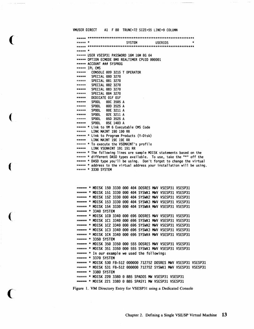
The VM Directory Entry for the VSE/SP Virtual Machine Log on to your VM system and enter or change the directory entry for the VSE/SP virtual machine to include those of the following statements that apply to your installation:
• USER • OPTION • IPL • CONSOLE • SPECIAL • SPOOL • DEDICATE • LINK • MDISK.
A sample directory entry for the VSE/SP virtual machine is shown in Figure 1 on page 13.
12 VM Running Guest Operating Systems
l-~'
'''----/
(
(
VMUSER DIRECT Al F S0 TRUNC=72 SIZE=55 LINE=9 COLUMN
===== ********************************************************** =a=== * SYSTEM USERIDS * ===== ********************************************************** ===== * ===== USER VSESP31 PASSWORD 16M 16M BG 64 ===== OPTION ECMODE BMX REALTIMER CPUID 000001 ===== ACCOUNT III SYSPROG ===== IPL CMS
CONSOLE 009 3215 T OPERATOR SPECIAL 0S0 3270
===== SPECIAL 0S1 3270 SPECIAL 0S2 3270
===== SPECIAL 0S3 3270 SPECIAL 0S4 3270
===== DEDICATE 01F 01F SPOOL 00C 3505 A
===== SPOOL 00D 3525 A SPOOL 00E 3211 A
===== SPOOL 02E 3211 A SPOOL 05D 3525 A
===== SPOOL 05E 1403 A ===== * Link to VM 6 Executable CMS Code ===== LINK MAINT 190 190 RR ===== * Link to Program Products (Y-Disk) ===== LINK MAINT 19E 19E RR ===== * To execute the VSEMAINT's profile ===== LINK VSEMAINT 191 191 RR ===== * The following lines are sample MDISK statements based on the ===== * different DASD types available. To use, take the "*,, off the ===== * DASD type you'll be using. Don't forget to change the virtual ===== * address to the virtual address your installation will be using. ===== * 3330 SYSTEM
===== * MDISK 15e 333e eee 4e4 DOS RES MWV VSESP31 VSESP31 ===== * MDISK 151 333e eee 4e4 SYSWK1 MWV VSESP31 VSESP31 ===== * MDISK 152 333e eee 4e4 SYSWK2 MWV VSESP31 VSESP31 ===== * MDISK 153 333e eee 4e4 SYSWK3 MWV VSESP31 VSESP31 ===== * MDISK 154 333e eee 4e4 SYSWK4 MWV VSESP31 VSESP31 ===== * 334e SYSTEM . ===== * MDISK ICe 334e eee 696 DOS RES MWV VSESP31 VSESP31 ===== * MDISK 1C1 334a aaa 696 SYSWK1 MWV VSESP31 VSESP31 ===== * MDISK 1C2 334a aaa 696 SYSWK2 MWV VSESP31 VSESP31 ===== * MDISK 1C3 334a aaa 696 SYSWK3 MWV VSESP31 VSESP31 ===== * MDISK 1C4 334a eaa 696 SYSWK4 MWV VSESP31 VSESP31 ===== * 335a SYSTEM ===== * MDISK 35a 335a aaa 555 DOS RES MWV VSESP31 VSESP31 ===== * MDISK 351 335a aaa 555 SYSWK1 MWV VSESP31 VSESP31 ===== * In our example we used the following: ===== * 337e SYSTEM ===== * MDISK 53a FB-512 aaaaae 712752 DOS RES MWV VSESP31 VSESP31 ===== * MDISK 531 FB-512 aaeeae 712752 SYSWK1 MWV VSESP31 VSESP31 ===== * 338a SYSTEM ----- * MDISK 22a 338a a 885 SPADOS MW VSESP31 VSESP31 ===== * MDISK 221 338a e 885 SPASY1 MW VSESP31 VSESP31
Figure I. VM Directory Entry for VSESP31 using a Dedicated Console
Chapter 2. Defining a Single VSE/SP Virtual Machine 13

Directory Control Statements I
Note: At logon, as the directory control statements for the user are processed, CP checks the devices represented by each MDISK, CONSOLE, DEDICATE, LINK, SPECIAL and SPOOL statement for a possible conflict with the, .. "../ virtual control unit (VCU) interface. Such a conflict can occur because the VCU can only support one subchannel protocol (shared or nonshared) at a time. For each directory control statement that violates the restriction, CP sends an error message to the user and does not create the virtual device. To avoid this problem, see VM/SP or VM/SP HPO Planning Guide and Reference for a complete listing of the virtual device characteristics.
The USER Statement
USER VSESP31 password 16MB 16MB BG 64
USER VSESP31 Defines userid as VSESP31.
password
16MB 16MB
BG
64
14 VM Running Guest Operating Systems
Password can be changed to the password of your choice.
The first 16MB defines the virtual machine's storage size. The second 16MB entry defines the maximum virtual machine storage size this user can define after logging on the system. The storage is usually set to 16MB to allow maximum VSIZE for the VSE/SP virtual machine.
If you run the VSE/SP guest in MODE = 370, it will do its own paging. In that case, you may want to define a virtual storage size of 6MB or 8MB, to limit the amount of double paging.
Note: The VSE stand-alone utilities (used to install the VSE/SP system) should not be IPLed in a 16MB virtual machine because they cause extreme paging in the VM environment. You may need to use the CP DEFINE storage command.
Class B (resource) is assigned so that the VSE/SP virtual machine user can issue CP ATTACH and DETACH commands. Please refer to VM/SP or VM/SP HPO CP General User Command Reference for a summary of the CP commands allowed by privilege classes G and Any. See the VM/SP or VM/SP HPO CP System Command Reference for a summary all other CP commands (privilege classes A-F).
Class G (general) users control the functions associated with the execution of their virtual machine. The VSE/SP virtual machine is usually assigned with class G privileges; this prevents one VSE guest from interfering with another guest on the VM system.
Note: Generally, a guest user will need only class G authority. If a user has class B authority, unpredictable results occur if he attaches real devices at the same virtual addresses as real addresses.
The priority setting depends on the use of your VSE/SP virtual machine. For example, a VSE virtual machine running teleprocessing will usually have a higher priority than a batch VSE virtual machine. The lower the priority value is numerically, the higher is its relative priority. (The default is 64.)
- .. --~ - .. - ---.---~ .. - ----_ ...... _ ... --.~--~--.. ---... --~~-
/
. ./

(
(-
Note: If you have a high-priority virtual machine, start its priority setting at about 30. If after running at this setting you wish to increase its priority, subtracting ten from the thirty setting will double its priority; adding ten will halve its priority.
The OPTION Statement
OPTION ECMODE BMX REAlTIMER CPUID eeeeel
VM provides several optional services to virtual machines. You can specify these services with the OPTION control statement in the VM directory, or with the CP SET command.
ECMODE
BMX
The ECMODE option allows the virtual machine to use the complete set of VM control registers and the dynamic address translation feature. Programming simulation and hardware features are combined to allow use of all the available features in the hardware.
You must specify the ECMODE option when the VSE/SP virtual machine is:
• Running in extended control mode • Using dynamic address translation (DAT) (except in
MODE=VM) • Using extended control registers other than zero • Addressing I/O channels 6 through 15.
If the ECMODE option is not specified in the directory, you can enter extended control mode by issuing the CP command SET ECMODE ON. For example:
#cp set ecmode on
Note: Setting the ECMODE option does not alter the ECMODE bit of the user's PSW.
The BMX (virtual block multiplexer) option allows the VSE virtual machine to overlap multiple SIO(F) requests on a specified channel path. The selector channel mode is the normal (default) channel mode for virtual machines. When the BMX option is given control, it applies to all channels in the virtual machine, except to channel O. This option can be specified regardless of whether block multiplexer channels are attached to the processor. The CP DEFINE command can be issued to redefine the channel mode for a virtual machine. For example:
#cp define channels bmx
REAL TIMER The REAL TIMER option causes the virtual interval timer to be updated during virtual wait state. In VSE/SP, only VSE/PT uses the interval timer. You should set the REAL TIMER option off unless you are running VSE Performance Tool (VSE/PT). This option will have no effect on the CPU timer or the clock comparator.
When the REAL TIMER option is not in effect, a virtual interval timer reflects virtual processor time and virtual wait time, but not
Chapter 2. Defining a Single VSEjSP Virtual Machine 15

CP time used for services for that virtual machine (such as privileged instructions execution). The more services a virtual machine requires from CP, the greater the difference between the' time represented by the interval timer and the actual time used by ''L /
(and for) the virtual machine. The larger the number of active virtual machines contending for system resources, the greater the difference between virtual machine time and actual elapsed time.
Remember that VSE/SP with PT is unaware that it is running as a guest under VM/SP HPO. What the VSE/PT guest thinks is real time is actually the time of day clock (TOD) and processor timer facility (PT). Elapsed time as measured by the time of <lay clock is accurate. The guest's virtual processor timer runs whenever the guest is dispatched or is in a voluntary wait state. It does not run if the guest is in a CP wait state. Thus, when VM/SP HPO dispatches another virtual machine and later redispatches the VSE/SP guest, VSE does not realize it has stopped running.
If the REAL TIMER option is not specified in the directory entry, you can obtain this timing facility by issuing the CP SET command with the TIMER operand. For example, to turn on the timing facility, issue:
Icp set timer real
To turn off the option, issue:
Icp set timer off
CPUID When VSE guests are sharing resources like DASD, it is necessary to associate a unique CPU identification (CPUID) with each virtual machine to keep track of the resources the system is using. If you do not specify a unique CPUID, it will default to the real system CPUID with the first two characters replaced by "FF". For a complete discussion, refer to "Defining Central Processing Unit IDs for the VSE/SP Virtual Machine" on page 50.
VIRT=REAL Specify the VIRT=REAL option if you use any MODE = 370 guest (for example, V AE) in a V = R machine.
The ACCOUNT Statement
ACCOUNT ##1 SYSPROG
The ACCOUNT control statement defines an account number and a distribution identification (SYSPROG). The account statement is optional. If omitted, both the account number and the distribution code default to the user ID. The ACCOUNT statement must follow the USER statement.
The IPL Statement
IPL CMS
The IPL statement automatically IPLs a system either by name (for saved systems) or by device address. You may want to IPL CMS (as we have done in our sample directory entry in Figure 1 on page 13) to execute the PROFILE EXEC that does your SET and ATTACH commands, thereby setting up the virtual environment.
16 VM Running Guest Operating Systems
--- --------- ~-----------
,I( ~\
\,-,-/

The CONSOLE Statement: The CONSOLE control statement specifies the virtual machine console. In the VSE environment, the way you define the VSE/SP console depends on the following four considerations:
• Will VM and VSE have separate consoles? • Will the VSE console support the VM operations? • Will VSE be autologged? • Will VSE be logged on manually?
In our sample directory, we have dedicated the main processor console to the VSE virtual machine as the VSE operator's console. This means the VSE virtual machine operator sees no changes in operation from when VSE was running stand-alone. You should always try to have a spare screen available in your installation and make it your CP console. If you use this dedicated console approach, the CONSOLE statement for the VSE virtual machine can be defined in the VM directory as:
CONS eeg 3215 T OPERATOR
where OPERATOR is the secondary userid receiving all CP messages for the VSE virtual machine when the primary userid is running disconnected. 009 is the virtual device address of the console in VSE's IPL procedure. The VSE console must be defined in 3215 mode.
The secondary user ID can send CP commands to the disconnected VSE machine. For example, to send an external interrupt command from the secondary user ID, issue:
send vsesp31 cp external 49
The SPECIAL Statement
SPECIAL 9a9 3279
The SPECIAL statement defines a virtual unit with device type and virtual address. Terminall:j.ddresses defined in this way do not really have to be available on the system because they are not real addresses. With the SPECIAL statement in the directory, the DIAL command can be issued to gain access to the guest machine. For an example of how to do this, refer to "Nondedicated Terminal Definitions" on page 36.
Tl'!e DEQICATE Statement: The DEDICATE control statement specifies that a real device is tQ be dedicated to this user ID. A real device can be dedicated to only one user at a ~e. Because of the way the CONSOLE control statement is set up in our sample directory, the DEDICATE control statement must be included in the directory. '
DEDICATE elF cuu
where cuu is the real device address of the terminal to be used as the VSE console and 01 F is the virtual device address.
Following the above concept, the processor console OIF must be disabled before the VSE virtual machine is logged on. (This can be done by having the VSE virtual machine automatically logged on through AUTOLOGI or by having the VM operator issue the CP AUTOLOG command.) When you have the console dedicated, the VM operator has the responsibility of handling all CP requests for the VSE virtual machine (as long as the VSE machine is in disconnected mode). The
Chapter 2. Defining a Single VSE/SP Virtual Machine 17
disadvantage to this type of VSE console operation is that you must have a second screen available in case VSE hangs.
Note: In order to avoid a usage conflict caused by control unit I/O interface protocol, be careful when defining the virtual device address in the DEDICATE statements. Some devices use a shared subchannel protocol and others do not. Therefore, devices must be grouped by control unit within a given channel according to their subchannel usage. CP does not permit you to group devices that use the shared subchannel protocol together with devices that do not use the shared protocol. The following is an example of a virtual machine's DEDICATE statement that would be rejected at logon.
DEDICATE 12E 3eE (3eE is a real 3211) DEDICATE 12F sse (sse is a real 342e tape device)
The virtual addresses of both the 3211 and the tape device indicate the use of control unit (2). A real 3211 printer operates on a nonshared subchannel, and the real 3420 device is designed for shared subchannel operations. By definition the devices are virtual and therefore will share one virtual control unit (VCUBLOK) in CP which has a range of eight devices. When the user logs on, the two dedicate statements results in the second virtual device (12F) not being created and an error message being sent to the user.
Therefore, when defining devices, make sure the devices are defined and separated within their own control unit range and not shared with other devices. This restriction also applies to the CONSOLE, MDISK, SPECIAL, SPOOL, and LINK statements. The effects of the DEDICATE, LINK and MDISK statements depend on the real device configuration at LOGON. To avoid this problem refer to the VM/SP or VM/SP HPO Planning Guide and Reference for a complete listing of virtual device characteristics.
For additional information on the various uses of the DEDICATE control statement refer to Chapter 3 under "Various Uses of the DEDICATE Statement" on page 33.
The SPOOL Statement
SPOOL eeD 3525 A SPOOL eeE 14e3 A SPOOL e2E 3211 A
The SPOOL control statement specifies the unit record device that is to be spooled. Multiple readers, punches, and printers may be specified, each on a separate SPOOL statement.
An entry in the directory is necessary for each unit record device that is not attached to the VSE system but will be used by VSE (except for the VSE dummy devices FEC, FED, FEE, FFC, FFA, FFD, and FFE). You should have matching device type definitions for VM and VSE in the ADD statement. If the definitions do not match, the VSE recorder file will soon fill up. The message:
RECORDER FILE FULL - RUN EREP
will be displayed, indicating that repetitive error handling with non-matching devices filled up the RECORDER FILE.
An example of matching definitions can be seen between Figure 1 on page 13 and 4" Figure 3 on page 24.
Note: For some devices, like 3211s and 3262s, matching definitions are impossible.
18 VM Running Guest Operating.Systems
(
READER
SPOOL 00e 3505 R A
Other virtual reader devices require that you issue READY cuu under some circumstances. They also require that you spool the reader continuously. This entry (CP SPOOL cuu CONT) should be included in the PROFILE EXEC for VSEMAINT. CUU is the address of the virtual reader.
The VSE/POWER reader task should be set to the lowest spooled card reader of the desired class, so that the attention interrupt will be processed correctly.
PRINTER
SPOOL 00E 1403
You should start your POWER print writers with the VM parameter unless you are using a dedicated printer.
For any print writer started with the VM parameter, POWER always sends the FCB as the first part of every print file. Therefore, it does not matter in which sequence the output is printed; the correct FCB will always be used.
The MDISK Statement: The MDISK control statement describes the DASD extent tobe owned by the user on a direct access device. The DASD area assigned with this statement becomes the user's minidisk. The following MDISK statement defines a full FBA device with volid = dosres.
MDISK 540 FB-512 000000 712752 DOSRES MWV VSESP31 VSESP31
VM does not check for overlapping extents in the MDISK statement. Therefore, you must ensure that minidisk extents defined in the VM directory do not overlap each other, or, in the case of 3330, 3340, and 3350 disks, do not overlap the alternate track cylinders.
DASD can be assigned to a virtual machine as a whole volume or as part of a volume. If a whole volume is to be assigned, you can use either the DEDICATE or the MDISK statement. In deciding which statement to use, be aware that the DEDICATE statement allows only one user to access the disk drive through that cuu address, whereas the MDISK statement allows the disk to be shared among virtual machines. If you want to allocate part of a volume, use the MDISK statement. It is also possible to allocate part of a VM volume to VSE and part of a VSE volume to VM. To allocate part of a volume, you will need to set up an MDISK statement for the part of the volume you want VSE to own, and an MDISK for the VM part. Then you will need to initialize the VSE minidisk using the Device Support Facility. You can use the IPL DSF file on Maint's oS' disk to initialize the volume.
Chapter 2. Defining a Single VSEjSP Virtual Machine 19

The LINK Statement:, The LINK control statement makes a device that belongs to another user (userid) available to this virtual machine at logon. If you want to make one volume available to several virtual machines:
• Define the volume for one of the virtual machines with an MDISK statement.
• Define a link to that volume, using the LINK statement for all other virtual machines that use the volume.
Later, if you must move or change that volume, you need oniy update the one MDISK statement; the LINK statements need not be updated. In the directory example, you are linking to the VSEMAINT disk with read-only access authorization.
LINK VSEMAINT 191 191 RR
Upon Completion of Directory Changes: The directory entry is complete. If you made additions or changes you must file the new directory and issue the CMS DIRECT command. The DIRECT command processes the directory file to see if it follows the required format. To actually change or swap the current active VM directory, you must have write access to the system-owned (system residence or IPL device) volume that contains the current directory up to and including the directory cylinders, or to the volume that is to contain the new directory.
Issue:
direct filename
Note: Make sure that your VM virtual devices match the devices of the VSE system. In other words, make sure that the devices defined in the VM directory entry for the VSE user ID match those in the Automated System Initialization (AS!) procedure you use to IPL VSE.
IPLing the VSE/SP Virtual Machine The following is an overview of the logical flow of events during IPL of the VSE/SP virtual machine for which a directory entry is shown in Figure 1 on page 13.
The processor console OIF is disabled by the AUTOLOGI virtual machine. CMS is IPLed and the profile of VSESP31 is executed. As the last statement of the PROFILE EXEC is executed, 540 is IPLed.
After address 540 is IPLed, the IPL routine finds $ASIPROC and selects the procedures specified by the CPUID. The VSE console for VSE operations is dedicated with OIF. The ASIPROC continues without intervention, as if it were running natively in VSE.
As a result of the procedure outlined above, the VSE/SP virtual machine console and the VSE/SP console are on separate devices. Only with the aid of the ·CP command (from the dedicated VSE/SP console) or commands prefIXed with # CP (from the VSE/SP virtual machine console) is it possible to communicate with CPo The secondary user ID (OPERATOR) specified in the VM directory for VSESP31 will be responsible for handling CP requests for the VSE/SP virtual machine. or you can log on to VSESP31 and issue CP commands on behalf of the VSE/SP virtual machine.
20 VM Running Guest Operating Systems
---- .. ---~.---------.----~~~~~- -- .. ---------- ----
\-'-...-.. -

(
(,
(
Stacking CP Commands in the PROFILE EXEC If you want to automate the IPL of the VSE/SP virtual machine, enter the following line at the end of the PROFILE EXEC. It will be the last line to execute.
CP TERM CON 327e SCRN ON BRE GUESTIDEF STORAGE 16MIIPL cuu
From the XEDIT command line (after entering the line above in the exec) type:
set hex on
and press ENTER. From the XEDIT command line type:
ch/I/X'lS'/* *
and press ENTER to change the bar (I) to the equivalent hex code.
From the XEDIT command line type:
file
and press ENTER.
Notes:
1. The bar (I) could be any other character.
2. Whenever you change the last line, you should perform the last three steps again.
CP Nucleus Considerations
Updating DMKRIO
If your VSE/SP system is using devices unsupported by VM, you will have to make changes to the DMKRIO file. If you make any changes to the DMKRIO, DMKFCB, or DMKSNT files, you will have to generate a new CP nucleus. For a complete di.scussion of the system-dependent files, refer to the VM/SP or VM/SP HPO Planning Guide and Reference.
If you don't need to make changes to the system-dependent files, skip the following section and continue with "Preparing the Guest VSE/SP Virtual Machine" on page 22.
In the DMKRIO file you define all the real devices that are attached to the system. If your VSE/SP system is using devices not supported by VM, or if you want the VSE/SP console defined at real address OlF instead of the VM console, you will have to make changes to DMKRIO.
When you have unsupported devices, you must specify them as unsupported in DMKRIO and dedicate them to the VSE/SP system in its DIRECTORY entry. In the DMKRIO file you might have:
RDEVICE ADDRESS=raddr,DEVTYPE=type,CLASS=URI
and
RCTLUNIT ADDRESS=raddr,CUTYPE=UNSUPPORTED
where raddr is the real address of the unsupported device. These devices must have matching entries in the ASIPROC. For unsupported device types you must specify a device subclass in the CLASS operand. For a complete listing of the available subclasses refer to VM/SP or VM/SP HPO Planning Guide and Reference.
Chapter 2. Defining a Single VSE/SP Virtual Machine 21

Updating DMKSNT
Note: When preparing the RDEVICE and RCTLUNIT entries, refer to "Appendix A. Configuration Aid" in VM/SP or VM/SP HPO Planning Guide and Reference.
Along with the changes in DMKRIO, the unsupported device should have a matching entry in the directory. In the sample directory, the entry for an unsupported device would be:
DEDICATE vaddr raddr
where raddr is the real address and vaddr is the virtual address. In this case the VSE/SP virtual machine is responsible for error recovery and error recording procedures.
The changed RIOGEN macro instruction would be:
RIOGEN CONS=616,ALTCONS=(61F,669)
where 010 is now the address of the VM primary console and 01F, 009 are the alternate consoles. These addresses must have been specified in the RDEVICE macro instruction.
You only need to change the DMKSNT file if you intend to save the VSE/SP virtual machine as a saved system. This is generally not done because there is no good starting point from which to save the system.
Building a new CP nucleus If you change the system-dependent files you will have to assemble them using the GENERATE EXEC or the VMF ASM command. GENERATE is a multipurpose EXEC used to generate VM and to perform updating maintenance of CP, CMS, and VM service programs. It can also be used to regenerate the VM system after updating. You can use it to regenerate:
• The directory • The real I/O configuration (DMKRIO) • The system control file (DMKSYS) • The system name table (DMKSNT).
For a complete discussion of the procedure for building a new CP nucleus, with examples, refer to the VM/SP or VM/SP HPO Installation Guide.
Preparing the Guest VSE/SP Virtual Machine VSE/SP contains three pregenerated supervisors. You can use two of these when running VSE/SP under VM:
• $$A$SUPV for MODE=VM • $$A$SUP3 for MODE = 370
You do not need to change or regenerate these supervisors to use them.
22 VM Running Guest Operating Systems
----------",-.'~------ -
/
It '. '4l,j

(
When to Use MODE = VM Use MODE = VM when you want to take full advantage of the VSE handshaking facilities. These include:
• SET PAGEX ON for pseudo page fault handling • One-time only paging (by VM) • One-time only CCW translation (by VM) • PAGE release (DIAGNOSE 10) • BT AM autopoll assist • Disconnected console feature • CPCOM macro.
When to Use MODE = 370 Use MODE = 370 when you want to use Virtual Addressability Extension (VAE) or run V = R. This will give you limited VSE handshaking support:
• SET PAGEX ON • BT AM autopoll assist • CPCOM macro. • PAGE release (DIAGNOSE 10).
Changes in $ASIPROC There are three ways to initialize VSE/SP:
1. $ASIPROC (ASI master procedure)
The search for $ASIPROC.PROC in USYSRS.SYSLIB is always the first test performed by the IPL routine. The IPL routine searches for $ASIPROC and, if $ASIPROC is found, looks for an entry that matches the CPUID. If the CPUID matches, the procedures named are executed.
2. $IPL370 and $$JCL370 (default IPL and JCL procedure names)
The IPL routine executes procedures with these names (if available on the system the $ASIPROC procedure is not found).
3. Prompts (interactive IPL)
If neither 370 procedures nor $ASIPROC are found, the IPL routines prompt the operator for the appropriate IPL/JCL procedures.
To allow an IPL of VSE/SP both natively and under VM, you can catalog an $ASIPROC with two entries in it. The first entry would be for VSE/SP running under VM and the second entry for VSE/SP running stand-alone. To allow an IPL of VSE whether it is running under VM or stand-alone, duplicate the entry for running VSE natively and change the following:
• The real CPUID prefix 00 or 02 to FF or match the CPUID specified in the VM directory entry by adding FF as a prefix and the processor type as a suffix. (For example, compare the CPUID specified in Figure 1 with the example in Figure 2
• The supervisor to MODE = 370.
• The IPL procedure name to the name for the VSE IPL.
Chapter 2. Defining a Single VSE/SP Virtual Machine 23
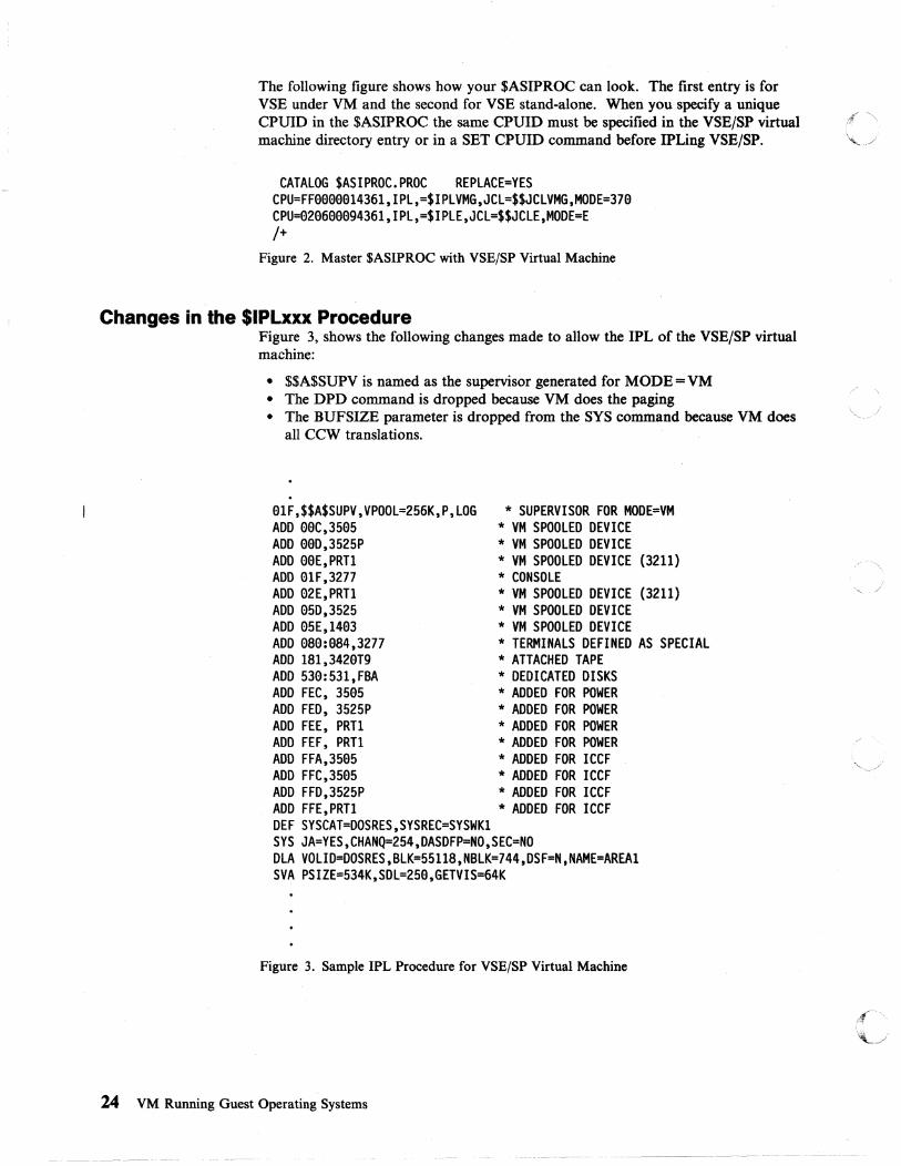
The following figure shows how your $ASIPROC can look. The first entry is for VSE under VM and the second for VSE stand-alone. When you specify a unique CPUID in the $ASIPROC the same CPUID must be specified in the VSE/SP virtual tf ~ machine directory entry or in a SET CPUID command before IPLing VSE/SP. ~
CATALOG $ASIPROC.PROC REPLACE=YES CPU=FF9999914361,IPL,=$IPLVMG,JCL=$$JCLVMG,MODE=379 CPU=929699994361,IPL,=$IPLE,JCL=$$JCLE,MODE=E j+
Figure 2. Master $ASIPROC with VSE/SP Virtual Machine
Changes in the $IPLxxx Procedure Figure 3, shows the following changes made to allow the IPL of the VSE/SP virtual machine:
• $$A$SUPV is named as the supervisor generated for MODE=VM • The DPD command is dropped because VM does the paging • The BUFSIZE parameter is dropped from the SYS command because VM does
all CCW translations.
01F,$$A$SUPV,VPOOL=256K,P,LOG * SUPERVISOR FOR MODE=VM ADD 00C,3505 * VM SPOOLED DEVICE ADD 00D,3525P * VM SPOOLED DEVICE ADD 00E,PRTl * VM SPOOLED DEVICE (3211) ADD 91F,3277 * CONSOLE ADD 92E,PRT1 * VM SPOOLED DEVICE (3211) ADD 950,3525 * VM SPOOLED DEVICE ADD 95E,1403 * VM SPOOLED DEVICE ADD 089:984,3277 * TERMINALS DEFINED AS SPECIAL ADD 181.3420T9 * ATTACHED TAPE ADD 539:531,FBA * DEDICATED DISKS ADD FEC, 3505 * ADDED FOR POWER ADD FED, 3525P * ADDED FOR POWER ADD FEE, PRT1 * ADDED FOR POWER ADD FEF, PRT1 * ADDED FOR POWER ADD FFA,3505 * ADDED FOR ICCF ADD FFC,3595 * ADDED FOR ICCF ADD FFD.3525P * ADDED FOR ICCF ADD FFE.PRT1 * ADDED FOR ICCF DEF SYSCAT=DOSRES,SYSREC=SYSWK1 SYS JA=YES,CHANQ=254.DASDFP=NO,SEC=NO DLA VOLID=DOSRES,BLK=55118,NBLK=744,DSF=N,NAME=AREAl SVA PSIZE=534K,SDL=250,GETVIS=64K
Figure 3. Sample IPL Procedure for VSE/SP Virtual Machine
24 VM Running Guest Operating Systems
.4' I
.'\...j

(
(
(
to
(-
The following PROFILE EXEC is shared by VSEMAINT and VSESP31; it resides on VSEMAINT's 191 disk. VSESP31 has a read-only link to VSEMAINT's 191. Sharing the PROFILE EXEC allows you to update the profile for VSESP31 from the VSEMAINT user ID even while VSE/SP is up and running. We have made some minor changes to the profile for our own environment; you may want to add other commands or users as required for your installation.
&CONTROL OFF * * All IDS execute the following section of the profile. * IDENTI FY (STACK &READ VARS &USERID &ACCOUNT &IF .&USERID EQ .VSESP31 &GOTO -VSESP31 * * The following section is executed by all users except VSESP31. * &HI = Y &LO = -CP SET RUN ON SET RDYMSG SMSG CP LINK MAINT 319 319 RR ALL &IF &RC = 9 &GOTO -ACCESS &TYPE The 319 disk of MAINT can not be linked. &TYPE Remember the read password of MAINT 319 must be &HI ALL &LO &EXIT 4 -ACCESS ACC ·319 P EXEC VSEIPF NOPAN &EXIT * * Only VSESP31 executes the following section. * * -VSESP31 &BEGSTACK * * At this point you can enter other commands to be executed on behalf * of VSESP31. * &END CP IPL 549 * &EXIT
Figure 4. VSEMAINT's Profile When the Console is Dedicated to VSESP3l
Chapter 2. Defining a Single VSEjSP Virtual Machine 2S

''-.. .. /
4:' ~,
lj

(
(
Chapter 3. Operating a VSE/SP Virtual Machine
Autologging the VSE/SP Virtual Machine ............. ...... 29 Operator Issuing CP AUTO LOG Command .......... . ..... 29 Defining AUTOLOGI in the Directory ............. . ..... 29
Automated System Initialization (ASI) Procedures ................ 30 Using EXEC Procedures .......................... 31 Issuing CP Commands from the VSE/SP Virtual Machine ...... 32 Interrupting the ASIPROC under VM .................. 33 Various Uses of the DEDICATE Statement ............... 33 Dedicated Terminal Definitions Nondedicated Terminal Definitions .................. . Spooling Options ........................ .
Spooling Recommendations .................. . VSE/POWER under VM ............ . . . . . . . . . Controlling Printed Output ....................... .
Loading Universal Character Set Buffer ............. . Loading Forms Control Buffer ................ .
Printer Considerations for the 3203-5 .............. . Starting the VSE/POWER Printer ................ . Varying Devices Off and On Line ................ . Switching Devices between Systems ............... . Definition and Use of the Virtual Console Facility ........ . Special Considerations for VSE/SP Users Running Under VM ..... .
Using Virtual Addressability Extension (V AE) ................... . What Supervisor Should I Use with VAE? .................... . Should I Run V AE as a V = R Guest or a V = V Guest? ............ . Should I Run One MODE = 370 V AE Guest or Multiple MODE = VM
Guests? .............................. . 4KB Paging Support for VSE/SP Guests under VM
Preferred Machine Assist ...................... . How Preferred Machine Assist Works Preferred Channels ........................ .
34 36 36 36 37 37 37 38 38 39 39 40 40 42 42 42 43
43 44 44 44 44
Generating a False AP System for the Preferred Machine Assist Guest .... 45 Preferred Machine Assist Considerations ...................... 45 General Restrictions for Preferred Machine Assist ............ .
Defining Central Processing Unit IDs for the VSE/SP Virtual Machine Submitting Jobs to the VSE/SP Virtual Machine ........ .
Submitting Jobs under CMS ........................ . Submitting Jobs Using SUBVSE EXEC ................ . Transferring Output with the VM Writer Task of VSE/POWER
Example of the VM Writer Task ......... . ......... . Initializing Minidisks .................................. .
Case 1: Using DSF for an FBA Device (3370-2) ................ . Case 2: Using DSF for a CKD Device (3350) .................. .
VSE Interface ....................................... . Installing the VSE Interface ....................... . Modules and EXPLAIN Files for the VSE Interface ........ . Overview of VSE Interface Routines ............ .
Using CMS/DOS with VSE/SP ................. . How the Library Structure of VSE/SP Restricts CMS Users Using VSE/SP Librarian Functions in CMS/DOS ...... .
Suggested Alternatives When Using VSE/SP Version 2 or Version 3 Other CMS/DOS Restrictions When You Use VSE/SP Version 2 or 3
46 50 51 51 51 52 52 52 53 53 53 54 55 56 56 56 56 57 57
Chapter 3. Operating a VSE/SP Virtual Machine 27

What Features of the Interactive Interface Can a CMS User Use? ........ 58 Using VM/PASSTHRU ................................. 58
How to Switch Between CMS and the Interactive Interface ........... 58 Time-out Limit of VM/PASSTHRU ........................ 58 Example of the PASSTHRU EXEC ......................... 59 PF Key Overrides ................................... 60
IPLing the Device Support Facility under VM .................... 60 Problem Determination and the VSE/SP Virtual Machine ............. 60
VSE/SP Virtual Machine DUMP Procedure .................... 61 Backup/Restore Procedure for the VSE/SP Virtual Machine ............ 61 USing VMfVCNA in a VSE/SP-under-VM Environment .............. 62 Using VTAM SNA Console Support (VSCS) in a VSE/SP-under-VM
Environment ....................................... 63 VTAM Configuration for a VSE/SP Guest . . . . . . . . . . . . . . . . . . . .. 64
VT AM Restrictions ................................. 64 Migrating from VCNA to VSCS ............................ 65
Possible Networks for Virtual Addressability Extension ............. 66 Generating a USSTAB for VM/VTAM ....................... 68
VTMV3USS ASSEMBLE (US STAB) ...................... 69 ISCUSER LKEDCTRL .............................. 70 DTIUSER3 ASSEMBLE ............................. 70
ACF/VTAM Version 3 for VSE/SP 2.1.3 ....................... 71 Buffers for ACFfVTAM Version 3 for VSE/AF 2.1.1 .............. 71 Virtual Storage Requirements of ACF fVT AM V3 ................ 71 Setup of a VCTC and Operational Considerations ................ 71 Definitions for VMfVT AM .............................. 71 Defining the Virtual Channel ............................. 72 Defining the VT AMLST for CTC .......................... 72 Other VT AMLSTs ................................... 72 Starting Up VM/VTAM ................................ 74 PROFILE GCS ..................................... 75 VMVTAM GCS .................................... 76 Starting the CTC Major Node ............................ 77
Definitions for VSE/SP Systems ............................. 77 Defining the Virtual Channel ............................. 77 Defining the IPLPROC Entry ............................ 77 Defining the B-Book for CTC ............................ 77 Starting the CTC Major Node for a VSE/SP Guest ............... 78
28 VM Running Ouest Operating Systems
;#"--'\
\ .... _./
"'\
\, /

(,
(
Autologging the VSE/SP Virtual Machine AUTOLOG is a convenient way to initiate large production VSE/SP systems with many I/O devices running under VM. The I/O devices needed by the VSE/SP system require considerable contiguous free storage space for the I/O control blocks established by VM. If smaller users have logged onto VM before the large operating VSE/SP system is started, there may be insufficient contiguous free storage space available for the required I/O control blocks. (The logon of the virtual machine will still be completed even if the I/O control blocks cannot be established.) As a result, there may be an insufficient number of I/O devices to run the guest VSE/SP system and its application programs.
To ensure sufficient contiguous free storage space for a large produc.ion VSE/SP system, the virtual machine should be logged on immediately after VM is loaded. This can be done by:
• Having the VM system operator issue the CP AUTOLOG command before enabling user terminals, or by
• Defining the AUTOLOGI virtual machine in the VM directory. The AUTOLOGI virtual machine is automatically logged on immediately after VM is loaded and can be used to log on and load virtual machines that require substantial contiguous storage.
Operator Issuing CP AUTO LOG Command Before enabling user terminals, the VM system operator can issue the CP AUTOLOG command for each production guest virtual machine that requires substantial contiguous free storage. The virtual machine being logged on with the AUTO LOG command must have an automatic IPL defined in its directory and is allowed to issue one read to its virtual console. The virtual machine logged on operates in disconnected mode. The same restraints that apply to any disconnected machine also apply to virtual machines logged on with the AUTOLOG command. To invoke the command, the operator would issue:
AUTOlOG userid password
For more information about the format of the CP AUTOLOG command, refer to VM/SP or VM/SP HPO CP System Command Reference.
Defining AUTOLOG1 in the Directory To use AUTOLOG 1 to initiate several virtual machines, the VM directory statement loads CMS into the AUTOLOGI virtual machine. In the PROFILE EXEC, each CP AUTOLOG command initiates one virtual machine containing a VSE/SP guest operating system. When using the CP AUTOLOG command, the directory entries for the virtual machine referred by the CP AUTOLOG command must contain an IPL statement.
As a result of the CP AUTOLOG command in the PROFILE EXEC, the VSE/SP virtual machine is loaded and runs in disconnected mode. The VSE/SP virtual machine user gains access to the virtual machine by doing one of the following:
• Logging on with the userid specified in the CP AUTOLOG command • Issuing the CP SEND command from the secondary user's console • Issuing the CP DIAL command and specifying the guest userid.
When you log off, the contiguous storage space is relinquished and the virtual machine relinquishes operation. If you want to keep the virtual machine's I/O blocks in contiguous storage, and keep the virtual machine running while you
Chapter 3. Operating a VSE/SP Virtual Machine 29

temporarily give up use of the virtual machine console, issue the CP DISCONN command. To reestablish usage, issue the CP LOGON command to reconnect to the virtual machine. ,(~
Figure 5 shows the AUTOLOGI entry in the VM directory. The IPL statement initializes CMS, causing the execution of the PROFILE EXEC. The VSE/SP virtual machines are automatically logged on in disconnect mode.
USER AUTOLOG1 PASSWORD 512K 1M ABG ACCOUNT ACCTNO BINI IPL CMS
CONSOLE 009 3215 SPOOL 00C 2540 R SPOOL 000 2540 P SPOOL 00E 1403 LINK MAINT 190 190 RR LINK MAINT 19E 19E RR LINK MAINT 190 190 RR MDISK 191 333e 1 1 UDISKA WR RPASS WPASS
Figure 5. AUTOLOGI Entry in VM Directory for VSE/SP Virtual Machines
Figure 6 shows the PROFILE EXEC containing several CP AUTO LOG commands, one for each virtual machine to be loaded. The last CP command in the PROFILE EXEC logs off AUTOLOGI.
/*PROFILE EXEC for AUTOLOGing virtual machine */ TRACE E; ADDRESS COMMAND; CP SPOOL CONSOLE START; CP SET EMSG ON;
/*The following message will inform the operator that the guest */ /*operating systems are being autologged. */
CP MSG OP The guest VSE/SP virtual machines are being autologged. CP ENABLE ALL CP DISABLE elF CP AUTO LOG VSESP31 VSESP31; CP AUTO LOG VSEUSER PASSVSE2; CP LOGOFF EXIT
Figure 6. PROFILE EXEC Containing Several CP AUTOLOG Commands
You can now access these virtual machines through the secondary console (if there is one), or by logging on with userid VSESP31 or VSEUSER2, along with the appropriate password.
Automated System Initialization (ASI) Procedures The ASI procedure allows you to put the required control information into a procedure cataloged in IJSYSRS.SYSLIB and lets the system execute the commands without operator intervention each time an IPL or a partition start-up occurs.
30 VM Running Guest Operating Systems
---.~.-.~--------. ---
'"., . ./
rf--'
'\...j

(
When VSE/SP is running under VM, a few changes have to be made to the $ASIPROC (if you have one). To indicate that a virtual machine is running under VM, the CPUID must have a prefix of FF. For example:
CPU=FF9299964331
where:
The first two digits are the prefix The next six digits are the CPUID The last four digits are the processor type.
If the CPUID of a virtual machine is equal (except for the first two digits) to another CPUID in the master procedure, the entry for the virtual machine must be the first entry within the master procedure as shown below:
CPU=FF9929994331.IPL=$IPLV.JCL=$$JCLH.MODE=379 CPU=929929994331.IPL=$IPLN.JCL=$$JCLH.MODE=E
To allow an IPL of both native VSE/SP and VSE/SP under VM, catalog the $ASIPROC with two entries in it. One entry is for the IPL of the native VSE/SP and the other for the IPL of VSE under VM. To do this, duplicate the entry for running VSE/SP native and change:
• Prefix 02 to FF
• The mode option to MODE = 370 (unless you are already running MODE = 370)
• The IPL procedure name to the name referred by the CPUID with prefix FF
Next, if you are running MODE = VM, drop DPD. (VM does the paging.) Then drop the following parameter from the SYS command:
• BUFSIZE (VM will do all channel control word (CCW) translations.)
The ASI procedures can be reused as long as your system environment remains unchanged. The steps to bringing up a total system is reduced to IPling VM. In exceptional situations, you may have to bypass ASI and perform an interactive system initialization (non-automated).
Note: If you wish to interrupt the execution of the VSE/SP ASIPROC to specify a different supervisor you need to log onto the VM console and issue the CP EXTERNAL command. Issuing this command simulates pressing the interrupt key on the real computer console, or other functions that cause an external interrupt. Control is given to the virtual machine immediately. The format of the EXTERNAL command is:
#cp ext
The external interrupt must be entered before the ASIPROC has been initialized.
USing EXEC Procedures An EXEC procedure is a sequence of commands and other statements that can be processed by CMS. Although certain format and syntax rules apply, the process is the same as when you create any other type of CMS file.
Once an EXEC procedure is stored on direct access storage, the procedure may :>e executed simply by issuing the name of the EXEC file. The only exception to this
Chapter 3. Operating a VSE/SP Virtual Machine ,31

rule is the PROFILE EXEC file. The PROFILE EXEC file is executed automatically when you IPL CMS.
For the VSEjSP virtual machine, a PROFILE EXEC could be used to establish the proper links and SET conunands. For example, you can issue SET FAVOR, SET QUEUE DROP, and SET PRIORITY from a PROFILE EXEC. (To avoid reserving routines in storage that are used only once, such as the initialization routine, do not issue the CP SET RESERVE command from a PROFILE EXEC.) Because the PROFILE EXEC runs automatically, you are relieved of the chore of entering these commands. The following is an example of a PROFILE EXEC that can be used to set up the CP commands mentioned above:
PROFILE EXEC Al F S9 TRUNC=132 SIZE=5 LINE=5 COL=I ALT=9
===== &TRACE OFF ===== CP SET FAVOR ===== CP SET FAVOR S9 ===== CP SET QUEUE DROP OFF ===== CP SET PRIORITY 5
Figure 7. PROFILE EXEC containing CP SET commands
Issuing CP Commands from the VSE/SP Virtual Machine While operating the VSE virtual machine, use CP commands to:
• Communicate with the VM system operator or other virtual machine users. • Query the status of virtual machine devices or spool files. • Attach or detach devices from the virtual machine configuration.
You can communicate with CP by:
• Prefacing the CP command with "# CP", where "#" is the terminallinend character.
Note: At times, CP commands cannot be entered with the #CP function during a VSE IPL because the CCWs used for the reads to the console expect less data than the length of the #CP command entered. In this case, the additional data in the #CP command is truncated and lost.
Notes:
I. You can define the terminal break key by issuing the CP BRKKEY command. PAl is the default. You must be sure that the PF key associated with this function is available on the VSEjSP virtual machine console. Otherwise, choosing a PF key (to activate the breakin function) that does not exist on the VSEjSP virtual machine console will lock out CP mode. Once the break key has been pressed the virtual machine stops. If the SET RUN ON command is not in effect and you wish to return to the VSEjSP virtual machine console, you must issue the CP BEGIN COMMAND. If the CP SET RUN ON command is in effect it allows you to activate the attention key (causing a read of a CP command) without stopping your virtual machine. When the CP command is entered, it is immediately executed and the virtual machine resumes execution.
2. If you have a local 3270 information Display device and your VSEjSP console is in display mode, it is recommended that you issue the CP TERMINAL SCRNSAVE ON and CP TERMINAL CONMODE 3270 commands for your
32 VM Running Guest Operating Systems
(~'
\ ... ~j
.I

(
machine. This allows you to choose whether the guest screen is saved when your virtual machine goes into CP mode. You can enter the two commands together, for example:
cp tenninal conmode 327G scrnsave on
Interrupting the ASIPROC under VM While VSE/SP is IPLing in the virtual machine, you can interrupt its execution by issuing the CP EXT command at any point prior to seeing the following message:
GJ1GI IPL RESTART POINT BYPASSED
Once the above message appears the ASIPROC cannot be interrupted.
To resume IPL after a successful interruption, enter a null line. Wait until the attention has been processed before signaling another one.
Various Uses of the DEDICATE Statement The DEDICATE control statement specifies that a real device is to be dedicated to this userid. A real device can be dedicated to only one user at a time. In the sample directory entry in Figure 1 on page 13, we gave an example of how to dedicate the main processor console to the VSE/SP virtual machine as the VSE/SP operator's console. We will now discuss other uses of the DEDICATE control statement.
Note: You can also use the CP ATTACH command to perform the following functions.
Magnetic Tapes
A device such as a magnetic tape drive can be used by only one virtual machine at a time. You can dedicate the tape drive if only one virtual machine will be using it (for example, for CICS logging), or different users can use it in turns by issuing the CP ATTACH command.
To dedicate the tape drive to one user, specify it in that user's directory. For example:
DEDICATE 181 281
This statement allows the operating system to access the device at real address 281 via a virtual address of 181.
Unit Record Devices
In many cases, spooling represents the most efficient way of handling the unit record input and output of many virtual machines. However, special cases may justify the dedication of a real unit record device to a single virtual machine.
One special case is when the virtual machine's operating system does its own spooling, such as VSE/POWER under VSE. To eliminate double spooling of printer output, include a DEDICATE statement in the virtual machine's directory entry, such as:
DEDICATE GGE GG2
This statement causes VM to pass all virtual printer OOE output directly to the real printer at 002.
Chapter 3. Operating a VSE/SP Virtual Machine 33
Note: If you dedicate unit record devices to a guest, then you must not have a spool entry for that same device.
Remote Devices
You can use the DEDICATE statement to attach remote 3270 Information Display Printers (such as 3262, 3268, 3284, 3286, 3287, and 3289) to a virtual machine. For example, a directory entry can include the statement:
DEDICATE NETwork 12e e1e2
120 is the virtual address of the device in the virtual machine and 0102 is the resource ID as specified in the DMKRIO. Remote 3270 Information Display Systelil Printers can also be attached by the NETWORK ATTACH command. For more details, see the VM/SP or VM/SP HPO Planning Guide and Reference manual.
Unsupported Devices
You can use the DEDICATE statement to put a device that VM does not support into a virtual machine configuration. To dedicate a device, the device must:
• Be physically connected to the VM system
• Be supported by the VSE operating system
• Not violate any of the restrictions contained in the VM restriction section of the VM/SP or VM/SP HPO Planning Guide and Reference manual.
For example, a directory entry can include the statement:
DEDICATE ee7 e12
where real address 012 could represent a real device that is unsupported by VM but is attached to the processor.
The device would be added to VSE as:
ADD ee7.xxxx.EML
Note: The EML parameter is required when defining to VSE a device that is defined to VM as unsupported.
Dedicated Terminal Definitions When the end user is going to use CICS, the terminal can be dedicated to the VSE/SP system. To ensure that the end user gains access to only th(l VSE/SP systelil, the DEDICATE control statement must be in the directory or the terminal should be attached to the VSE/SP virtual machine by an authorized user. The terminal for this end user must be disabled before DEDICATED control statements and CP ATTACH commands are executed. By having an entry for the end user in the A UTOLOG I PROFILE EXEC, the terminal for the end user can be disabled before the IPL of the VSE/SP virtual machine.
The following is an example of a DEDICATE statement entry that can be used in the VM directory for the VSEUSER virtual machine.
34 VM Running Guest Operating Systems
,(~'
-L/

(
VMUSERS DIRECT Al F 80 TRUNC=72 SIZE=55 LINE=9 COLUMN
===== ********************************************************** ===== * SYSTEM USERIDS ===== ********************************************************** ===== USER VSEUSER VSEUSER 16M 16M ABDG ===== ACCOUNT 206 7030/85 ===== IPL CMS ===== OPTION ECMODE BMX 370E REALTIMER CPUID 000001 ===== CONSOLE 009 3215 T OPERATOR ===== SPECIAL 012 3270 ===== SPECIAL 013 3270 ===== * ===== * The following statement dedicates the console to VSEUSER after ===== * the execution of AUTOLOGI disables it. ===== * ===== * ----= DEDICATE 01F 01F =====* ===== * In this VM directory example we are defining device type 2540 ===== * to be the virtual reader. ===== * ===== SPOOL 00C 2540 READER A ===== SPOOL 00D 3525 A ===== SPOOL 00E 14e3 A ===== SPOOL e2C 254e R A ===== SPOOL 02D 3525 A ===== SPOOL e2E 32e3 A ===== LINK MAINT 1ge 1ge RR ===== LINK MAINT 19D 19D RR ===== LINK MAINT 19E 19E RR ===== * ===== * ===== MDISK 24e FB-512 00ee0e 55800e DOSRES MWV VSESP31 VSESP31 ===== MDISK 241 FB-512 e0e0ee 558eee SYSWK1 MWV VSESP31 VSESP31
Figure 8. VM Directory for VSEUSER with Dedicated Console
The next example is the PROFILE EXEC of AUTO LOG I where OIF is being disabled before IPLing VSESP31.
===== &CONTROL OFF ===== CP SLEEP Ie SEC ===== CP AUTOlOG CMSBATCH CMSBATCH IPL CMS PARM BATCH
===== CP DISABLE elF ===== CP AUTO LOG VSEUSER VSEUSER ===== * ===== CP LOGOFF
Figure 9. PROFILE EXEC of AUTOLOGI for Use with a Dedicated VSE/SP Console
Chapter 3. Operating a VSE/SP Virtual Machine 35

Nondedlcated Terminal Definitions If the end user needs the facilities of both CMS and CICS, a SPECIAL control statement must be included in the directory of the VSE/SP virtual machine. The SPECIAL statement must be included for each terminal needing access to CMS and CICS. With the SPECIAL statement in the directory, the CP DIAL command can be used to gain access to the VSE/SP system.
For example, if the VM directory entry for the VSE/SP virtual machine had the following SPECIAL statement:
SPECIAL 012 3270
You could issue:
dial vseuser 012
or
dial vseuser
If you issue the CP DIAL command without a specified address, VM connects the terminal to the first available line as defined in the SPECIAL control statement; the " . j
Spooling Options
line belongs to the specified userid. If no lines are available or if all lines are busy, VM issues an error message and does not make the connection.
The end user will remain connected until one of the following happens:
• The virtual machine logs off using standard logoff procedure • The virtual machine is forcibly logged off • The terminal is powered off/on • The Normal/Test switch is used.
The end user will also get disconnected if the CP RESET command is issued from the VSE/SP virtual console or from a user authorized with the CP RESET command.·
Once disconnected, the end user is free to use the DIAL command to connect to another userid.
Most multiprogramming operating systems have their own spooling subsystem. In VSE/SP this subsystem is VSEjPOWER. Because VM also provides its own spooling, double spooling will occur. This raises the questions of whether an installation should:
• Use only the operating system's spooling subsystem • Use only VM's spooling • Use double spooling.
Spooling Recommendations If an installation has a significant amount of printing or punching to do, it might appear that one of the spooling subsystems should be eliminated. This is not necessarily true.
Use double spooling if:
• You have large quantities of printed output on standard forms, or • DASD space is not a limiting factor.
36 VM Running Guest Operating Systems
I j

(~
(
Many VSE/SP virtual machines spool data and must use a common pool of unit record devices. In this case double spooling will reduce the privilege operations VM must simulate.
For VM to do the spooling for the VSE/SP virtual machine, the spool statement must exist in the VM directory. This statement must match the ADD statement in the VSE/SP ASI procedure.
Note: If possible, generate a scaled-down version of the virtual machine's spooling subsystem, eliminating those functions not used by that virtual machine. Make the I/O buffer sizes as large as possible to cut down on SIO instructions.
Let the VSE/SP virtual machine do the spooling if:
• An installation has only enough DASD spooling space for one spooling subsystem, and
• If only one VSE/SP virtual machine generates significant amounts of spooled output.
Note: If VSE/SP controls the spooling by either attaching or dedicating unit record devices, you must not have a duplicate SPOOL statement in the VM system directory to define the device.
VSE/POWER under VM The VSE/POWER operation remains the same in the VSE environment. VSE/POWER makes no distinction between real or virtual devices and it executes input and output regardless of the devices used. It is advisable that special forms be printed on a dedicated printer to VSE/SP.
Controlling Printed Output Most of the VSE/SP supported printers use a forms control buffer (FCB) to control the length of forms skips. In addition, some printers can be equipped with the universal character set feature that is controlled by the Universal Character Set Buffer (UCB). The following two discussions will describe the effects of loading FCB and UCB while VSE/SP is running under VM.
Loading Universal Character Set Buffer You can load UCB from either VM or VSE/SP. If you are going to load the UCB under VSE/SP the printer needs to be attached to the VSE/SP machine. The UCB can be automatically loaded at IPL time or the LUCB command can be used to load the buffer after VSE/SP has been IPLed. For example, the command:
lucb eee,$$bucbee,fold
will load UCB $$BUCBOO on the printer at OOe, and FOLD will translate lower case to upper case. There are several default UCB's provided by VSE/SP and are documented in VSE/SP Installation.
Chapter 3. Operating a VSE/SP Virtual Machine 37

If you want to load the UCB under VM, use the LOADBUF command:
loadbuf 9ge ues.p64.fold
This command loads the UCB P64 to the printer at address OOE and the FOLD option translates lower case to upper case when printing. The buffer can be loaded at IPL time by adding the above command to AUTOLOG1's PROFILE EXEC.
Note: The printer must be drained prior to loading any buffer under VM.
drain 9ge
Loading Forms Control Buffer There are two recommended ways to use a printer with VSE/SP:
• Dedicate the printer to the VSE/SP guest and start a POWER print writer without the VM parameter. In this case, POWER will load the FCB.
• Share the printer among the VSE/SP guest(s) and VM users. In this case, you should start the POWER print writer with the VM parameter. POWER will send the FCB as part of the print file. POWER will also pass to VM the forms ID and number of copies. You do not need to load the FCBs for any POWER output.
If you want to load the FCB in the real physical printer under VM, you must use the VM LOADBUF command:
loadbuf 9ge feb febl
This command loads the FCB FCBl on the real printer at address OOE. You will find a list of the FCBs available with VM in VM/SP or VM/SP HPO Administration.
If you want to use a special FCB, you must have two identical FCB's with the same name-one created under VSE/SP and the other loaded onto the VM nucleus. You can confirm that the FCB is working by dedicating your printer to VM.
The LOADVFCB command can be used in installations that do not have an FCB-capable printer. The virtual machine's directory entry must indicate a 3203, 3211, 3262, 3289E, or 4245 even though both the program and operating system have a real 1403 printer defined. Then the LOADVFCB command can be used to specify a virtual FCB image for 1403 printers so that programs that use printer overflow sensing can be spooled to disk.
Details on how to load the FCB and UCB in VSE/SP can be found in VSE/SP Installation or VM/SP HPO Administration.
Printer Considerations for the 3203-5 When you run VSE/SP under VM, you must define 3203-5 printers as 3211 printers. Catalog an FCB appropriate for a 3203-5, but use 3211 naming conventions. Otherwise, the virtual printer will be sensed as a 3203-1 and the wrong FCB will be loaded.
38 VM Running Guest Operating Systems
/
/

( Starting the VSE/POWER Printer
When you run VSE/SP under VM, the address you use to start a VSE/pOWER printer must be a virtual device address.
VSE/POWER will load the correct FCB.
Use the following command to start the printer:
s lst,cuu,a"vrn
This starts a list-writer task to print spooled output to the virtual printer with address cuu. The vm operand tells VSE/POWER that the device is a virtual device owned by VM.
When vm is specified, VSE/pOWER:
• Issues NO FORMS CHANGE messages
• Loads FCB
• Spools to the specified userid (DEST = (,userid)
• Prints/punches only one copy
• Tells VM about class, forms name, copies
• Closes the device at end of entry and names the spool file with the VSE/pOWER job name and number.
For more information, refer to VSEjSP Installation.
(~~ Varying Devices Off and On Line Once you IPL the virtual machine, the devices that were not accessible to that machine at IPL are considered off line. However, the operator can attach more devices to this machine and have them placed on line as required. The operator can issue the CP VARY and CP ATTACH commands to make the devices available for use by a particular virtual machine.
For example, if a graphic device is off line and VSEUSER needs the graphic device to be made available, notify the operator via a message:
#cp rnsg op Please attach BaB to VSEUSER as aaa
The operator would issue:
vary online aaa
SYSTEM RESPONSE:
Baa VARIED ONLINE
Operator issues:
attach Baa to vseuser aaa
SYSTEM RESPONSE:
BaB ATTACHED
The operator informs VSEUSER that the graphic device is now attached and ready for use.
Chapter 3. Operating a VSE/SP Virtual Machine 39

Switching Devices between Systems It is possible to switch devices such as tape drives and printers between VM users. For example, you might have a VM system that haS' a VSE/SP virtual machine user (VSEUSER) and a CMS user (CMSUSER). At different times, each system might have the need to use a tape drive and printer. Because a tape drive cannot be shared, the device needs to be attached to one user at a time. If CMSUSER has only class G privileges, a message must be sent to the operator to attach 181 to CMSUSER. For example:
#cp msg op Please attach 181 to CMSUSER as 181
When the tape drive is attached, the operator would notify CMSUSER with the message:
ATTACHED 181 TO CMSUSER AS 181
CMSUSER will have the tape drive for as long as needed. When CMSUSER is finished using the tape drive, issue the following command.
#cp detach 181
As soon as the tape drive is detached, it is available to other users via the ATTACH command.
The printer can be set up in two ways:
• VM does all the printing for its users, or • The VSE/SP system does its own printing.
For a VSE/SP virtual machine to do its own printing, the printer has to be attached to the VSE/SP userid via the CP ATTACH command. (A userid with class G privileges cannot issue the CP ATTACH command. A message must be sent to the operator as shown in the example above.)
Note: If VM was previously doing the printing, the printer must be drained prior to attaching it to the VSEjSP virtual machine. The CP DRAIN command brings the spooling system to a controlled halt, or halts the activities on a device whose spooling status is to be changed. The operator would issue:
drain eee
The CP ATTACH command can now be issued:
attach eee vseuser eee
The printer is now available to VSEUSER for as long as needed. When the VSE/SP virtual machine no longer needs the printer, the printer must be stopped in the VSE/SP machine before detaching it. Issue the POWER command:
pstop eee
and issue the CP command:
detach eee vseuser
Definition and Use of the Virtual Console Facility If you have used the DEDICATE or ATTACH control statements to assign a 3270 terminal for the VSE virtual machine (as shown in sample directory entries above), you need not follow the procedures discussed here. You can use the 3270 defined in the directory in display operator console mode.
Otherwise, to use a 3270 display terminal as the primary console in display operator console mode, either have a SPECIAL statement in the VSE/SP virtual machine's
40 VM Running Guest Operating Systems
"--

(
(
(~
VM/SP directory entry or issue the CP DEFINE GRAF command after logon to VM.
• If the SPECIAL statement is used, it would appear in the directory as:
SPECIAL elF 327e
• If the SPECIAL statement is not used, assume that a local 3270 line has been enabled by the VM operator. Next, issue the following CP DEFINE command:
define graf elf 327e
In either case, after you log onto VM (by using the device specified in the CONSOLE statement) and load the operating system into the virtual machine (by using the IPL command), you must issue the CP DIAL command at the 3270 console that is to be used in display mode. This action logically connects that 3270 console to the operating system.
The CP TERMINAL CONMODE 3270 command can also be used to obtain a display mode console for the VSE/SP virtual machine. The console of the VSE/SP virtual machine is defined in the VM directory as:
CONS elF 3215 T
The following command allows both VM and VSE/SP operator actions from the same screen. Before IPLing the VSE/SP machine you have to define the type of console operation by issuing the CP command:
term conmode 327e
Note: If CMS is running when you issue the CP TERM CONMODE command, CMS will abend.
In addition, specify:
terminal scrnsave on
This command saves the screen before going into CP mode. It is valid only if TERMINAL CONMODE 3270 has been specified. When you return from CP mode, the VSE/SP screen is automatically displayed as it appeared before you entered CP mode.
If you issue:
terminal breakin guestctl
this command prevents CP messages from appearing on the VSE/SP console and gives the operator the impression of running stand-alone. CP messages will be displayed only when:
• Priority messages are to be displayed • The CP function is requested.
Note: The CP TERMINAL CONMODE 3270 command is not supported for 3270 terminals going through a Virtual Telecommunications Access Method (VTAM) service machine or for remote 3270's.
Chapter 3. Operating a VSE/SP Virtual Machine 41

Special Considerations for VSE/SP Users Running Under VM When you use the VSE/SP Display System Activity and the Display Channel and Device Activity dialogues to monitor system activity, remember that:
• The SIO/second rate from Display System Activity may seem unusually high. The dialogue calculates the total I/O rate on the system, including unit record virtual I/O. To specifically monitor disk or tape device activity, use the Display Channel and Device Activity dialogue.
• VSE/SP accounting support is used. Therefore, some VM-simulated privileged instructions are not accounted for, but the data gives you a better overview of the VSE/SP guest virtual machine.
• All data is valid, except for data displayed as the number of events per second (for example, SIO/second). This type of data describes only VSE/SP activity.
• When the VSE/SP guest is running MODE = VM, the dialogue displays zeroes for paging activity. This shows you that only VM handles paging.
• When the VSE/SP guest is running MODE = 370, the paging activity data reflects VSE/SP paging.
Using Virtual Addressability Extension (V AE) VAE stands for virtual addressability extensions. It increases the virtual size of previous VSE/SP releases from 16MB to 40MB (or in the case ofVSE/SP 3.2.0, 128MB). It does this by supporting up to three (or in the case ofVSE/SP 3.2.0, nine) address spaces instead of one. Any address space can have a size up to 16MB as long as the total virtual storage size- of the VSE/SP system is not more than 40MB (or 128MB for VSE/SP 3.2.0). The extended storage layout includes shared system area, shared subsystem partitions, and private partitions. ;I
V AE is supported for the following processors:
• 9373 model 20 • 9375 model 40 and 80 • 9377 model 90 • 4381 models 21, 22, and 23.
VAE works as if it were up to three copies (called spaces) of the total virtual storage; the supervisor selects which space to use. A non-V AE system is like a V AE system with only one space.
When a space is being used, it must have the supervisor, shared subsystem partitions, and SV A in order to run. Each space works as if it had its own copy of the supervisor, shared subsystem partitions, and SV A. However, there is only one SVA, one group of shared subsystem partitions, and one supervisor, which are shared among the spaces.
What Supervisor Should I Use with VAE? When using the VAE option with VSE/SP, you must use the $$A$SUP3 supervisor for MODE = 370. This means only a subset of the VSE handshaking facilities is available. It includes:
• SET PAGEX ON • CPCOM
42 VMRunning Guest Operating Systems
.... _----_._- .. _ .... - •.. - '---' ---_ .. _ .. _---_. ---
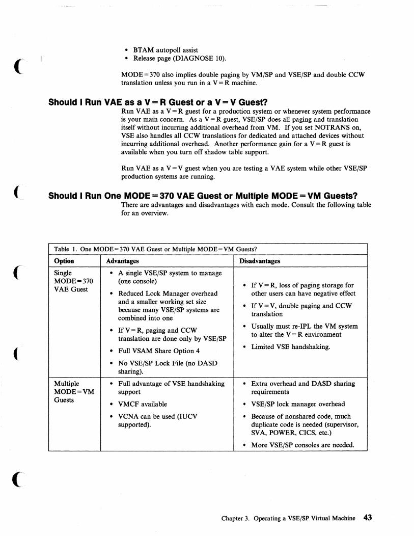
• BT AM autopoll assist • Release page (DIAGNOSE 10).
MODE = 370 also implies double paging by VM/SP and VSE/SP and double CCW translation unless you run in a V = R machine.
Should I Run VAE as a V = R Guest or a V = V Guest? Run V AE as a V = R guest for a production system or whenever system performance is your main concern. As a V = R guest, VSE/SP does all paging and translation itself without incurring additional overhead from VM. If you set NOTRANS on, VSE also handles all CCW translations for dedicated and attached devices without incurring additional overhead. Another performance gain for a V = R guest is available when you tum off shadow table support.
Run V AE as a V = V guest when you are testing a V AE system while other VSE/SP production systems are running.
Should I Run One MODE = 370 VAE Guest or Multiple MODE = VM Guests? There are advantages and disadvantages with each mode. Consult the following table for an overview.
Table 1. One MODE = 370 VAE Guest or Multiple MODE=VM Guests?
Option Advantages Disadvantages
Single • A single VSE/SP system to manage MODE = 370 (one console)
If V = R, loss of paging storage for • VAE Guest • Reduced Lock Manager overhead other users can have negative effect and a smaller working set size • If V = V, double paging and CCW because many VSE/SP systems are
translation combined into one
• Usually must re-IPL the VM system • If V = R, paging and CCW translation are done only by VSE/SP
to alter the V = R environment
• Limited VSE handshaking. • Full VSAM Share Option 4
• No VSE/SP Lock File (no DASD sharing).
Multiple • Full advantage of VSE handshaking • Extra overhead and DASD sharing MODE=VM support requirements Guests
VMCF available VSE/SP lock manager overhead • • • VCNA can be used (IUCV • Because of nonshared code, much
supported). duplicate code is needed (supervisor, SVA, POWER, CICS, etc.)
• More VSE/SP consoles are needed.
Chapter 3. Operating a VSE/SP Virtual Machine 43

4KB Paging Support for VSE/SP Guests under VM VSE/SP will always use a 4KB page size when running under VM, whether in If----\
MODE = 370 or MODE = VM. This pennits operation of VSE/SP in MODE = 370 1"-.../ on processors that support only 4KB paging.
Preferred Machine Assist Preferred machine assist allows a VSE/SP or VSE/ AF guest to run under VM/SP High Performance Option in supervisor state with direct control of its own I/O operations.
Under VM/SP HPO, VSE/SP Version 2.1 can now operate with the preferred machine assist hardware feature. With this support it is possible to run a VSE/SP guest machine with a mode = 370 supervisor supporting up to 40MB of virtual storage in preferred mode together with V = R. Preferred machine assist was designed to provide performance improvements when running VSE/SP 2.1.7 or later releases as a preferred machine assist-supported guest on VM with HPO.
How Preferred Machine Assist Works The VSE/SP preferred guest is dispatched by CP to run in real supervisor state. This cuts down on CP overhead, as CP does not have to simulate most privileged instructions.
Preferred machine assist detennines whether a real interrupt should be handled by CP or VSE/SP.
The VSE/SP preferred guest owns real page 0 and VSE/SP gets interrupts directly. These interrupts include:
• CPU timer and clock comparator interrupts • Program, SVC, and I/O interrupts.
Preferred Channels You can generate VM/SP HPO without including in DMKRIO some of the physically installed channels and their devices. The exclusion of these channels identifies them as preferred channels. They are available to the preferred guest but to r - ,
no other virtual machine or CPo CP can only use devices on preferred channels ~/ when there is another CP-known path to them, or another CP nucleus with a DMKRIO that includes them has been loaded.
When you generate VM/SP HPO for preferred machine assist, do not define in DMKRIO the channels you want used only for VSE/SP I/O. VSE/SP is running natively when it is dispatched and controls the I/O on those channels. VM/SP HPO cannot use them since it does not know about them.
If you run VM/SP HPO with a preferred guest at some times and without one at others, consider keeping alternate copies of DMKRIO and the VM/SP HPO nucleus available. One set should have all channels defined in DMKRIO; the other would leave some undefined for exclusive use by the preferred guest.
44 VM Running Guest Operating Systems
.. -----~--~-.--- -------~~~~--- ~---------------- ---._- --- --

(
Generating a False AP System for the Preferred Machine Assist Guest When running VM/SP HPO on a dyadic processor complex, you may wish to generate CP as an attached processor system. This generation will set up CP so that it can be IPLed on a dyadic processor, but will use only one side of the dyadic complex for I/O. It will treat the other processor as an attached processor and will use it to process CP work and will dispatch virtual machines on it, but it will not recognize any channels configured on the second processor.
You can now set up the preferred machine assist user ID so that it has affinity to the processor generated as an AP. This will ensure that the preferred machine assist guest is always dispatched on the AP. If the real complex is an MP (two channel sets, one for each processor), the preferred machine assist guest will own the entire channel set attached to its processor in preferred machine assist native mode. Thus it can initiate all its I/O directly to the hardware and will receive its interrupts from the hardware without CP intervention (imd consequently without CP overhead).
The major advantage of this environment is that all VM/SP HPO and VSE I/O is physically isolated on different real channel sets. This can make the generation, maintenance, and especially the operation of the two systems easier.
Be aware that there is one important restriction. All preferred machine assist I/O is started to its channel set by the preferred machine assist hardware. Thus each device to which the preferred machine assist guest needs access must have a path through its channel set processor. You cannot use dedicated or attached devices from the CP channel set. Nor can you use dialed terminals from CP, minidisks, or virtual devices of any kind (printers, punches, readers). While the associated commands (ATIACH, DEFINE, DIAL, etc.) do function and all control blocks are created correctly, the preferred machine assist guest cannot reach these devices when it issues I/O instructions. No error messages are issued if you violate the restriction. Thus it is recommended that the "false AP" environment be limited to those installations that wish to run a preferred machine assist production system divorced from CPo
Preferred Machine Assist Considerations Make sure you allocate enough storage below the 16 MB line for the preferred guest. VSE/SP's entire nucleus and all its I/O buffers must be below the 16 MB line.
In an AP or MP environment, you must SET AFFINITY for either of the two processors. If you want the preferred guest to have exclusive use of one processor and part of another, you must run VM/SP HPO in single processor mode. If VM/SP HPO is not in single processor mode, a preferred guest will receive at most slightly less than one processor.
There is one hardware function-the interval timer-that the preferred guest cannot use even though it runs in supervisor state. VM/SP HPO needs the interval timer to control the allocation of time slices, and uses it to regain control from VSE/SP at the end of the VSE time slice.
Note: This means that VSEfPT cannot be run in a VSE/SP guest that is using the preferred machine assist environment.
Chapter 3. Operating a VSE/SP Virtual Machine 4S

o
, , , , , , , , , , , , , , , , , , , , , , , , , , , , , , , , , , , ,
Processor 0
VM/SPHPO VSE
1 2 3 4
RSSIZE = RMSIZE
CP Dynamic Paging Area Extension
16 MB Line CP Free Storage Area
Dynamic Paging Area
CP Nucleus
VSE V=:, R (preferred virtual machine)
VSE Page 0 I
Channels
5 6 7 8 9 A B C D E F
Figure 10. Storage Layout of Preferred Machine Assist System. If you generate VM/SP HPO to use less than 16MB of storage, the storage between its top and 16MB is unusable.
General Restrictions for Preferred Machine Assist " 1. Devices on channels that belong to the preferred machine assist virtual machine)
are not defined to VM/SP HPO at system generation. Because these devices are unknown to VM/SP HPO, the VM/SP HPO system operator cannot vary them online to VM/SP HPO without reinitializing the system and including the devices in DMKRIO.
2. Do not issue DIAGNOSE instructions when running a guest VSE/SP system with preferred machine assist.
3. You must not have CP-owned volumes and VSE/SP volumes on the same strings and control units when you are running a VSE/SP guest with preferred machine assist. A path must exist to the DASD volumes from a VM channel, and from a channel that VM does not know about.
Without such a path, certain events can cause a deadlock. The hardware configuration that permits the deadlock is:
46 VM Running Guest Operating Systems
/
c

(
(
(-
Preferred machine assist-owned channel
CP-owned channel
3880 Storage Control Unit
More DASD devices
Figure 11. Hardware configuration. The position of the device in the diagram is not significant. The preferred machine assist device does not need to be the head-of-string.
The events that cause the deadlock are:
a. The preferred machine assist guest issues an I/O operation to the preferred machine assist device through storage director 1 of the 3880. This operation completes with a unit check, which places 3880 storage director 1 in "contingent allegiance" to the device. This condition is alleviated when the sense is done to read the device status.
b. CP issues an I/O operation to the CP device through storage director 1. This I/O operation (CP console function, spooling, or diagnose minidisk I/O.) is on behalf of the preferred machine assist guest.
1) The CP I/O is not queued to the device with the unit check, so the 3880 rejects it and returns condition code 1 with control unit 'BUSY'.
2) CP queues the I/O operation to be retried when it receives control unit 'END'. The preferred machine assist guest remains in CP wait (console function wait, spooling wait, or execution wait, as appropriate).
CP does not redispatch the preferred machine assist guest since it is in CP wait. The CP wait cannot be cleared until CP receives the control unit END and the pending I/O operation successfully completes.
However, the 3880 does not issue control unit 'END' until sense is finished and clears the unit check. But the sense is not finished until the preferred machine assist guest is dispatched by CPo Therefore, a deadlock occurs.
This situation occurs because each storage director in 3880 Storage Control units has only one register for storing device status information after a unit check. Until the status is read, the storage director cannot accept an I/O operation to another device since that device may also present a unit check and the storage director has no place to store that status information. This is a characteristic of the 3880 Storage Control units. The type and model of the attached direct access storage devices are not relevant. VM/SP HPO treats the 3990s in the same way as it does the 3880s.
Chapter 3. Operating a VSE/SP Virtual Machine 47

The following diagrams give configurations that are not subject to this deadlock:
ConflguraUon 1
Preferred machine assist-owned . channel
CP-owned channel
3880 Storage Control Unit
More DASD devices
ConfiguraHon 2
Preferred machine assist-owned channel
Storage Director 2 1st ~ ____ T-____ ~ ____________ ~3880
CP-owned channel
More DASD devices
Storage Director 2 2nd 3880
Figure 12. Configurations not subject to deadlock. If you can arrange your VSE and CP-owned volumes so that they do not share an internal path, you can avoid these lockouts.
48 VM Running Guest Operating Systems
r" ,""._/

(
(
(
Processor
4381
308x
3090E with PR/SM™
•
•
• •
•
• •
•
•
4. On a 3090 processor, a VSE/SP guest operating system that uses preferred machine assist must be VSE/SP 3.2.0 or a later release .
. VSE/SP Release Function Required
Preferred mac~ne assist with V = R using up to VSE/SP Version 4 Release 1 128MB of virtual storage Y AE with up to 9 address spaces, using a total of up to 128MB of storage YM/370 RSCS support for SNA
Preferred machine assist with V = R using up to VSE/SP Version 3 Release 1 128MB of virtual storage V AE with up to 9 address spaces using a total of up to 128MB VM/370 RSCS support for SNA
Preferred machine assist with V = R using up to VSE/SP Version 2 Release 40MB of virtual storage 1.7 V AE with up to 3 address spaces using up to 16MB of virtual storage
Preferred machine assist with V = R, using up to VSE/SP Version 3 Release 1 40MB of virtual storage
• V AE with up to 9 address spaces using a total of .
•
•
up to 128MB of virtual storage
Preferred machine assist witp. V = R, using up to VSE/SP Version 3 Release 1 40MB of virtual storage V AE with up to 9 address spaces using a total of up to 128MB virtual storage
5. When you are running a preferred machine assist guest, do not use the CP PER command.
6. If the 3990 Model 3 with DASD is on a channel that is not defined to CP via DMKRIO (no RCHANNEL macro), then CP neither intercepts the I/O instructions for the subsystem nor receives interrupts from the subsystem. When the channel is not defined, CP has no control over the use of 3990 Model 3 functions for the subsystem. This restriction occurs because commands to the device over this path, from the V = R machine with preferred machine assist can affect use of the subsystem through other channel interfaces.
Note: Control switch assist, an extension of preferred machine assist is not supported for VSE, except for the I/O interrupt function, which operates independently of the PMA V or PMA options.
For restrictions on generating a VM/SP HPO system with a preferred virtual machine, see VMjSP HPO Planning Guide and Reference.
PRISM is a trademark of the International Business Machines Corporation.
Chapter 3. Operating a VSE/SP Virtual Machine 49

Defining Central Processing Unit IDs for the VSE/SP Virtual Machine When you have several virtual machines sharing DASD, lock files keep. track of system resources. The lock files must include unique central processing unit ID's for each virtual machine running under VM. If you fail to specify unique CPUIDs, all lock files will default to the real system CPUID, and will therefore be ineffective. See "Chapter 4. VSE/SP Virtual Machines Sharing DASD" on page 79 for more about sharing DASD.
By default, each virtual machine running under control of VM will have a processor identification as follows:
FFbbbbbbccccdddd
where:
FF identifies it as a virtual machine running under control of VM
bbbbbb is a real or virtual CPUID
ecce is the processor type (such as, 3090 or 4381)
dddd is all zeroes
Because the six-digit processor identification number is stored in the VSE/SP lock file and used to control DASD sharing and system start-up, the CPUID must be unique for each of the VSE/SP machines. A maximum of 31 sharing CPUIDs is permitted. This allows a maximum of 31 VSE/SP virtual machines to share the same lock file.
The CPUID may be set by the CP SET CPUID command and queried using the CP QUERY CPUID command. Only the six hexadecimal digits containing the CPUID number can be set. Both CP SET CPUID and CP QUERY CPUID are class G commands available to the general user. For more information on these commands refer to VM/SP or VM/SP HPO CP General User Command Reference.
The CPUID mayalso be specified in the VM directory OPTION statement. For example:
===== OPTION •••• CPUID eeeeel
The above entry in the VM directory for the VSE/SP virtual machine will ensure that the CPUID for this virtual machine will always be set correctly. Also, the CPUID can then be used in the VSE UNLOCK command and in the master automated system initiation (ASI) procedure.
The data set name constructed by VSE/AF for the label area includes the first 12 digits of the CPUID. When the same VSEjSP system is run both natively and under control of VM, the data set name will differ in the first two digits (FF instead of the real processor model number).
You should ensure that the job code language (JCL) automated system initialization (ASI) procedure loads the label area every time, because you will have to delete the other label areas when switching between real and virtual VSE/SP machines.
50 VM Running Guest Operating Systems

(
(
SubmiHing Jobs to the VSE/SP Virtual Machine There are two ways of submitting jobs to the VSE/SP virtual machine. You can prepare the job control language (JCL) under CMS using XEDIT and submit the job to the VSE/SP virtual machine for execution, or you can use the SUBVSE EXEC supplied as part of the VSE interface of VSE/SP.
Submitting Jobs under CMS If you are under CMS and you wish to send a job to the VSE/SP virtual machine for execution, create the job stream using XEDIT or the editor of your choice. Before using the virtual punch to punch jobs to the virtual machine, take the precaution of clearing any files that remain in it from previous jobs. The following command ensures that the virtual punch does not have any other punch files in it:
spool punch nocont purge
Now you can spool your punch to VSE/SP virtual machine. In our example it will be VSESP31.
spool punch vsesp31 cl n,
where n is the spool class of the VSESP31 virtual reader. The class can be changed by issuing the CP SPOOL command on the VSESP31 virtual machine. The default class is A. You can now issue the CMS PUNCH command:
punch filename filetype filemode (noh
This sends the job stream to the VSE/SP virtual machine. A job stream spooled to the VSE/SP virtual machine remains in the virtual reader until you instruct the reader to begin reading it. From the VSE/SP console, you must issue the POWER READER TASK START to the virtual reader:
pstart rdr,cuu
The virtual device address must match the one specified in the directory entry for VSE/SP virtual machine.
Submitting Jobs Using SUBVSE EXEC Jobs may be submitted to a VSE/SP virtual machine by using the SUBVSE EXEC.
The format of the SUBVSE EXEC is:
SUBVSE fn ft fm TO user1 FOR user2 ECHO option
where:
user 1 is the ID of the virtual machine to which the job is sent user2 is the ID of the virtual machine to which the echo is sent ECHO option is REPL YjYESjNOjJOB
Optionally, you can enter just the command SUBVSE and fill in the blanks on the panel that is displayed.
When you use SUBVSE, it is your responsibility to add the PDEST/LDEST parameter to the POWER JOB card or add the DEST parameter to the POWER LST /pUN cards.
Chapter 3. Operating a VSE/SP Virtual Machine 51

After you use the SUBVSE EXEC, use the VSEREP module to respond to the outstanding requests you will receive. For example:
vserep vsesp31 9
Note: This command works only if you are using a MODE = VM supervisor.
Transferring Output with the VM Writer Task of VSE/POWER The VM writer task transfers output created in VSEjSP to the CMS user. It is a standard feature of VSEjPOWER 2.2 and later versions.
For the VM writer task to work, you must use either the DEST parameter on the POWER LST/PUN cards or the PDEST/LDEST parameters on the POWER JOB card. When you do this, you can transfer back to the originating CMS user ID all print and punch output of jobs submitted through SUBVSE.
Notes:
I. If an interactive computing and control facility (ICCF) user has a VM user ID / "-with the same name as one of the DEST parameters, the VM user will receive i",-- 7'
the output from the VM writer task.
2. If you start a printer or punch task without the VM parameter, a POWER print writer will issue the CP CLOSE command at the end of each file being spooled.
Example of the YM Writer Task The VM writer task returns the created output to the CMS user ID user2 provided that:
• The CMS user ID user2 exists on the VM system, and
• A virtual printer is started with the same class as specified on the POWER LST/PUN cards and with the VM parameter.
• The DEST (or LDEST or PDEST) for the output is the same as the CMS user ID.
You can issue the PSTART command from the VSEjSP console, or from the CMS user ID using VMCF as follows:
vsecmd vsesp31 pstart lstt9Setvt,vm
Initializing Mlnidisks VSE/SP always uses DOSRES and SYSWK.I as the volume IDs for its system disks. If, under VM, you run several VSE/SP guest machines that do not share DASDs, you will have multiple DOSRES and SYSWKI.
VM, however, does not accept duplicate volume IDs on real disks. To solve this problem, you must have two volume IDs on such disks:
• A uniqile volume ID on the real disk used by VM • The label DOSRES or SYSWKI on a minidisk.
52 VM Running Guest Operating Systems

To set this up:
1. Use the information in VM/SP or VM/SP HPO Planning Guide and Reference to initialize and format the DASDs that will contain the minidisks. This creates the unique volume labels required by VM. For CKD devices, the volume label and allocation byte map are on cylinder o. For FBA devices, the volume label and VTOC are part of the first 16 blocks.
2. In the directory entries for each VSE/SP guest machine, define minidisks on the DASDs you initialized and formatted. Do not define minidisks that start on block or cylinder o. For CKD devices, minidisks can begin at cylinder 1. For FBA devices, they can begin at a MAX-CA boundary following the initial blocks reserved for use by VM.
3. Initialize the minidisks for each VSE/SP guest system. To do this,
a. Log on to VM using the user ID and password for each VSE/SP system.
b. Use DSF to initialize the minidisks as shown in the following two examples. Note that these definitions do not affect the VM information that you created in step 1.
Case 1: Using DSF for an FBA Device (3370-2) IN IT UNIT(cuu} NVFY NOMAP PURGE FBAVTOC(711946,99,1824} VOLID(xxxxxx}
Case 2: Using DSF for a CKD Device (3350)
( VSE Interface
INIT UNIT(cuu} NVFY PURGE MIMIC(MINI(554} DEVTYPE(3358} DVTOC(553,8.38) VOLID(xxxxxx)
Notes:
1. If the above INIT commands are too long to fit into a single line on your screen, use a dash (-) as the continuation character. The system will then prompt you for additional information.
2. You cannot use these DASDs when running VSE/SP in native mode.
The VSE interface provided by VSE/SP Versions 2 and 3 is a set of VSE phases and CMS modules. The interface routines let CMS users operate VSE/SP systems. These routines will work only if you are using a MODE= VM supervisor.
When you operate a VSE/SP system this way, you can:
• Submit jobs from a CMS terminal to a VSE/SP virtual machine and have messages from the job be echoed to a specific job owner (CMS user ID).
• Execute CP commands within JCL statements and have the resulting CP messages routed to the CMS job owner.
• Retrieve up to twenty of the most recent messages from the console of a VSE/SP virtual machine.
Chapter 3. Operating a VSE/SP Virtual Machine S3

• Reply to messages that result from the execution of a job. The job must have a unique job owner (CMS user ID).
• Issue VSE/SP commands to a VSE/SP virtual machine and have the resulting 0' AR (attention routine) messages echoed to the CMS user.
• Issue CP commands for execution in the VSE/SP virtual machine and have the resulting CP messages routed to the CMS job owner.
The VSE interface routines are distributed in USYSRS.SYSLIB. You must obtain these routines from the library and install them on a CMS minidisk.
Installing the VSE Interface Before you can use the VSE interface, you must distribute the following CMS modules and the related EXPLAIN files to all eMS users who are authorized to use the functions. The installation process is described in VSE/SP Installation.
54 VM Running Guest Operating Systems
/ ""',

Modules and EXPLAIN Files for the VSE Interface CMS File CMS File VSE/SP Library Name (fn) Type (ft) Book Name Function
$VMCF.PHASE VSE Interface processing routines.
$VMCFOPN.PHASE VSE Interface initialization routines.
VSEREP MODULE VSEREP.Z Reply to outstanding messages.
VSEMSG MODULE VSEMSG.Z Retrieve messages from VSE/SP system.
VSECMD MODULE VSECMD.Z Execute VSE commands on virtual VSE/SP system.
VSECP MODULE VSECP.Z Execute CP commands on virtual VSE/SP system.
VSEREP EXPLAIN EXPREP.Z VSEREP command HELP panel.
VSEMSG EXPLAIN EXPMSG.Z VSEMSG command HELP panel.
VSECMD EXPLAIN EXPCMD.Z VSECMD command
( HELP panel.
VSECP EXPLAIN EXPCP.Z VSECP command HELP panel.
SUBVSE EXEC SUBVSE.Z Submit a job for execution on a virtual VSE/SP system.
Notes:
1. Be careful about your control of VSECMD and VSECP; they are intended mainly for the system administrator. The other modules and EXPLAIN files can reside on a disk to which all CMS users have access.
( 2. See VSEISP Installation for information on the SKVMVSE skeleton in the
ICCF library 59. You use this skeleton to punch modules, EXPLAINS, and EXECs from VSE to VM.
If the VSE interface is activated during IPL and the console is running in display operator console mode, you cannot use the VSE command SET HC = CREATE since the hard copy file is opened at IPL time and not when the first II JOB statement is encountered.
Chapter 3. Operating a VSE/SP Virtual Machine SS

Overview of VSE Interface Routines
Function Used In Target Environment Comments
VSECP CMS VSE/SP virtual All CP commands allowed. machine
CPCMD VSE VSE/SP virtual Some CP commands allowed. machine
* CP VSE VSE/SP virtual All CP commands allowed. machine
* CP VSE VSE/SP virtual DISCONNECT machine
* CP VSE VSE/SP virtual RECONNECT machine
CPCOM macro VSE VSE/SP virtual All CP commands allowed. machine
VSEMSG CMS VSE/SP system Retrieve VSE/SP SYSLOG.
VSECMD CMS VSE/SP system VSE/SP commands and replies.
VSEREP CMS VSE/SP system Answer outstanding VSE/SP requests.
SUBVSE CMS VSE/SP system Submit jobs to VSE/SP virtual machines.
Using eMS/DOS with VSE/SP CMS/DOS enables the CMS user to take advantage of the interactive facilities of VM to develop programs and then execute them in a virtual machine.
CMS/DOS support in VM is based on the VSE/AF Version 1 licensed program. CMS/DOS contains terms for both CMS (in the form of commands) and VSE/SP (in the form of control cards); it simulates many of the functions of the DOS VSE/AF operating system.
How the Library Structure of VSE/SP Restricts CMS Users VSE/SP Version 2 and Version 3 have different library structures from previous releases of VSE/SP. They also manipulate the library in different ways. Therefore, many CMS/DOS functions cannot be used with VSE/SP Version 2 or Version 3 unless you use alternative methods to those dated earlier than VSE/SP 2.1.
Using VSE/SP Librarian Functions in CMS/DOS You cannot use the following VSE/SP librarian functions from CMS when you are using VSE/SP Version 2 or Version 3:
DSERV ESERV SSERV PSERV RSERV
S6 VM Running Guest Operating Systems
--- ------------ - -. ----------------
'\
/

-----------------
Suggested Alternatives When Using VSE/SP Version 2 or Version 3 1. Use the librarian functions from the interactive interface of VSEjSP Version 2
and Version 3. You cannot use these functions from CMS, therefore, log off or disconnect from the CMS virtual machine and DIAL into the VSEjSP system. (You can do this from terminals that have been defined with the SPECIAL statement in the VM directory.)
To end this session, log off from the interactive interface and log on again to CMS.
To save time in switching between CMS and the interactive interface, you can use VMjPASSTHRU. See "Using VMjPASSTHRU" on page 58 for more information.
2. Another option is to create a CMS file with JCL and librarian statements. You can submit this file to the VSEjSP system and route it back with the VM writer task. See "Transferring Output with the VM Writer Task of VSEjPOWER" on page 52 for more information.
(~ Other eMS/DOS Restrictions When You Use VSE/SP Version 2 or 3
Command or EXEC Restriction Comments
DOSLKED You cannot use this command with You can still use this command the libraries of VSEjSP. when your input is a CMS TEXT
file or a CMS DOSLNK file.
FCOBOL You cannot use this EXEC with You can move the DOSjVS VSE/SP Libraries. compiler to a CMS DOSLIBS
however, the COBOL source program can have no COpy or BASIS statements.
VMFDOS You cannot use this command to VSEjSP SYSIN tape format is still load or scan modules from a supported. VSE/SP distribution library tape.
FETCH You cannot use this command to You can still use this command to fetch a phase from a VSEjSP fetch a phase from a CMS DOSLIB. library.
SET DOS ON You will receive an error message if Use SET DOS ON without filemode mode you use this command with the to activate CMS/DOS.
mode operand.
ASSGN You cannot assign the following You can still use this command to system logical units to a VSE disk: assign all other logical units to input SYSCLB, SYSRLB, SYSSLB with and output devices. VSEjSP.
DLBL IJSYSCL, IJSYSRL, and IJSYSSL You can still use this command to are invalid filenames for VSEjSP identify CMS and VSAM files. libraries.
Chapter 3. Operating a VSE/SP Virtual Machine 57

What Features of the Interactive Interface Can a CMS User Use? A CMS user can use all, some, or none of the facilities of the interactive interface, depending on his interactive interface user profile. This profile is defined by the VSEjSP system administrator. As interactive interface user profiles may vary, so will the selection panels CMS users see.
Using VM/PASSTHRU VMjPass-through is a VM/SP optional licensed program. It enables a virtual machine on one system to pass through to an operating system or application on the same processor or any other processor defined to PASSTHRU.
The VM Pass-through facility runs in a disconnected virtual machine under the control of VM. You can activate it or deactivate it at any time. You usually activate it using AUTOLOGI. The user ID of the PASSTHRU virtual machine can be any name, but usually it is called PVM.
To use the Pass-Through Facility, you can either:
• Execute the PASSTHRU EXEC from the active CMS environment, or • DIAL into the PASSTHRU virtual machine.
The PASSTHRU EXEC is supplied with the VM/Pass-Through licensed program (5748-RCl).
How to Switch Between eMS and the Interactive Interface You again can use VMjPASSTHRU to reach the interactive interface and pass back to CMS. Use either a PF key or a/our-character string (for example, %%%%) to switch back and forth between the interactive interface and CMS.
By using the interactive interface, a CMS user can do many things, such as:
• View the VSE/SP system console from a CMS console • Display VSE/SP system activity • Interactively display VTOC information • Execute CICS transactions • Use the Online Problem Determination dialog • Display VSE/POWER queue entries • Use VSE/ICCF.
Time-out Limit of VM/PASSTHRU The default time-out limit for PASSTHRU is 20 minutes. You can increase it to as much as 9999 seconds (2.7 hours). To do this, redefine the TDISC parameter in the file PVM CONFIG (a file on the PVM machine).
58 VM Running Guest Operating Systems
\
j

Example of the PASSTHRU EXEC
( The following is an example of the PASSTHRU EXEC:
EXEC PASSTHRU NODEA * PVM 11 24 S9 %%%% IIII
The eight parameters of this EXEC are described in the following table.
Parameter Example Description
Name of node NODEA The VM system to where you want to pass through.
Port address * Use * for local use.
Name of PVM The CMS user ID on which PASSTHRU PASSTHRU is installed disconnected virtual machine
(. ... .-'
PF key for capture 11 When you press this PF key (after facility passing through to the destination
machine), a copy of the display is saved in a CMS file called PASSTHRU DATA A. This file is stored on the system from the point at which you started the PASSTHRU EXEC.
Number of lines to 24 be captured
( Width of lines to 80 be captured
Temporary 0/0%%% You can specify either a PF key or a disconnect 4-character string. Use this to switch
between CMS and the interactive interface .
.If you disconnect from a selection panel, you return to that panel. If you disconnect from within a dialogue, you
( return to the initial panel "VSE/SP Function Selection".
Permanent #### You can specify either a PF key or a disconnect 4-character string. This will sign you
off from the other system. With this, you can permanently disconnect from the interactive interface and return to CMS. If you want to use the PASSTHRU EXEC again, you must again sign on to the interactive interface.
Note: IBM recommends that you sign off from the interactive interface before you use the permanent disconnect.
Chapter 3. Operating a VSE/SP Virtual Machine 59

PF Key Overrides If you use a PF key for the capture facility or for the temporary or permanent disconnect, this setting overrides the setting in the interactive interface. For example, if you use PFIO for the capture facility, you cannot use PFIO for the function it represents in the interactive interface.
IPLing the Device Support Facility under VM Use the Device Support Facility service program to format minidisks for use by VSE/SP. The VSE/SP Installation manual describes how you can do this when running VSE/SP under VM.
Problem Determination and the VSE/SP Virtual Machine IBM provides a variety of support services for its hardware and software. In order to obtain prompt service for problems you encounter, you will need to know which resource to use for each major type of problem you experience. Answer the questions posed below to determine what type of problem you have, and what type of support is available to assist you in resolving it.
1. Does the problem involve IBM software or hardware or other software or hardware?
• IBM-Proceed to Question 2. • Other-Refer problem to internal resources or appropriate vendors.
2. Is the problem related to hardware or software?
• Hardware--Contact IBM Customer Service. • Software-Identify the problem source.
The procedure you normally follow to identify the source of a problem is similar for all problems.
Once a problem is detected, observe all the symptoms. Ordinarily these symptoms are error messages, abnormal ends of jobs, loops, wait states, or program checks. Also note special conditions associated with the failure. Such special conditions are
r1:C~
'''--j
likely to include one or more of the following: " "
• A new job running • A recent sysgen • A change in system configuration • A new procedure in use • Something different from the last time the run was made ..
These are the kinds of conditions that may be related to the failure. In all cases, document the symptoms and conditions you observe.
The best procedure in problem determination is to gather enough information so the IBM Support Center can check your problems against problems others have reported. It is likely that someone else has had the same problem. If so, the symptoms you report will quickly lead to the known solution.
60 VM Running Guest Operating Systems

(~
(
(
VSE/SP Virtual Machine DUMP Procedure To get a stand-alone dump of a VSE system proceed as in native mode, with these differences:
1. Issue the CP command CP STORE STATUS instead of doing a machine save. Then issue SET RUN OFF.
2. Attach a tape unit to the VSE/SP machine when you IPL the VSE stand-alone dump program.
Note: The VSE stand-alone dump program must be created in the same environment (MODE = VM or MODE = 370) as the environment being dumped.
If you are using handshaking and the VSE/SP storage is in the virtual machine, you can use the CP VMDUMP command, but you will not be able to use VSE/SP's INFOANA to debug the VSE/SP virtual machine.
You may want to use VSE/SP's INFO/Analysis (INFOANA) to debug VSE/SP problems, but this will require using VSE/SP DUMP utilities. It allows you to
. debug problems interactively, create problem reports on the VSE/SP machine, and go into dump scan mode.
Backup/Restore Procedure for the VSE/SP Virtual Machine VM's DASD Dump/Restore (DDR), TAPE DUMP, MOVEFILE, VMFPLC2 DUMP, and VSE/SP FASTCOPY should be used for backing up and restoring the VM/SP or the VSE system. It is advisable to back up your system on a regular basis. The following chart shows the functions each utility has:
VMDATA VSE/SP DATA . ALL DDR FASTCOPYor
DDR
CMS CMS FAST BACKUP PP, TAPE DUMP, MOVEFILE, VMFPLC2 DUMP, VMTAPE, VMBACKUP
VSAMDATA Access Method Services Access Method SETS Services
Note: You cannot use DDR on a file that was backed up using VSE/FASTCOPY or use VSE/FASTCOPY on a file that was backed up using DDR.
You should take time to plan the backup of your total system. In deciding which backup method to use, ask yourself:
• What type of tape drive will be used in the backup procedure? • How often will the system be backed up?
When backing up CMS minidisks, you might want to consider using the high speed CMS Minidisk Backup and Restore Utility, VMTAPE, or VMBACKUP.
Chapter 3. Operating a VSE/SP Virtual Machine 61
Backing up and restoring VSAM DATA SETS will be handled with the normal access method service utilities in both the VM and the VSE/SP environment.
Note: The VSE/SP system should be shut down before you back it up using DDR.
To take a stand-alone backup in a virtual machine (i.e., MAINT's user ID), you must spool the punch to yourself:
spool punch *
Bring up the DDR:
punch ipl ddr s (noh
Load the DDR into the virtual machine:
ipl eee
Using VM/VCNA in a VSE/SP-under-VM Environment VM/VCNA is an ACF /VT AM application that runs in a VSE/SP partition. The VSE/SP virtual machine controlling the Systems Network Architecture (SNA) is called the VT AM service machine.
The installation steps are shown in Virtual Machine/VTAM Communications Network Application (VCNA) Installation, Operation, and Terminal Use.
VMjVCNA allows the use of an SNA terminal as a console for a virtual machine such as CMS; it is the link between the SDLC protocol on the SNA network and VM.
Figure 13 on page 63 illustrates the data flow of VMjVCNA.
62 VM Running Guest Operating Systems

( .
VM (CP)
------~--. 1 *CCS 1 1 1 ~ 1 1 I
1 1
1 1
1 1
1 I
1 I
1 1 1 1 I
I
VSE Virtual Machine 1 Supervisor
.. - 1-- ..
VSE partition running CICSIVS
VSE partition running POWER
VSE partition Virtual Machines --1--
running VMIVCNA 1 (CMS, VSE, VS1)
VSE partition 1 1
with ACF VTAM 1
1------" 1 1 I SOLC I Protocol I I I
S N A - Network
Figure 13. Data Flow of VM/VCNA
Using VT AM SNA Console Support (VSCS) in a VSE/SP-under-VM Environment
VSCS (VM/SP SNA Console Services) is a component ofVM/VTAM. Together they comprise an alternative to VCNA.
The group control system (GCS) component of VM/SP coordinates a set of VM/VT AM virtual machines. A typical GCS "group" includes:
• A VT AM virtual machine • An RSCS Version 2 virtual machine • An NCCF virtual machine • An NPDA virtual machine • A GCS recovery virtual machine.
Chapter 3. Operating a VSE/SP Virtual Machine 63

VSCS may run as a separate virtual machine in a GCS group, or it may run together with VT AM in the VT AM virtual machine. VSCS supports all the functions of VCNA and has the following advantages:
• A guest operating system is not needed • VSCS installation is simpler than VCNA • VSCS terminals display the VM/SP system. identifier • You can use the 3290 display station • You can use the CP DIAL command on SNA 3270 and 3290 display terminals.
VTAM Configuration for a VSE/SP Guest The following example is a sample directory entry for a VT AM machine.
USER VTAM GCS8598 19M 16M ABCDEFG ACCOUNT 112 BOX94-19 OPTION DIAG98 ECMODE MAXCONN 499 lUCV *CCS P M 19 lUCV ANY P M 9 IPL GCS PARM AUTO LOG CONSOLE 91F 3215 SPOOL 99C 2549 READER * SPOOL 99D 2549 PUNCH A SPOOL 99E 3211 A LINK MAINT 595 595 RR LINK MAINT 298 191 RR LINK MAINT 29A 29A RR
Notes:
1. DIAG98 allows the use of real I/O operations. CCWs are not translated by CP but are provided by VT AM in its virtual machine, thereby providing a fast path .~ ./
VTAM Restrictions
through CP for I/O processing. Because VT AM uses specialized code for this transaction, it requires less CPU time than CP generalized translation. Part of DIAG98 protocol requires that pages containing VTAM buffers be locked.
2. CCS is used by VSCS to communicate with CPo
3. ANY is used by VTAM to communicate with the members of the GCS group.
• VM/VT AM cannot support a TERM CONMODE 3270 console. This means that you should have a non-SNA control unit or a display/printer-adapter (DPA) or a console port in order to have a VSE/SP DOC console.
• You cannot log onto the VT AM virtual machine on an SNA terminal.
64 VM Running Guest Operating Systems
r(~\
''-."

(
(
Migrating from VCNA to VSCS If you decide to migrate from a VCNA environment, as shown in Figure 17 on page 67, to a full SNA environment with VMjVTAM, as shown in Figure 18 on page 68, then you can use the following checklist.
1. Install VMJVT AM.
2. Punch your old VT AM definitions either from your ICCF library or from your system library to the MAINT machine. See Figures 14 and 15 for examples.
3. Start an appropriate printer and punch to get the members sent to MAINT. For example:
s pun,92d,r"vm
or
s lst,92e,r"vm
4. Give each B-Book a VM name such as CDRMROM VTMLST and file all the books on MAINT's 298 disk.
5. Check your startup book and remove the PROMPT statement if there is one. Change or remove your buffer specifications, because VMjVT AM has different kinds of buffers. (See Figure 16 on page 66.)
6. Start VMjVTAM according to "Starting Up VM/VTAM" on page 74.
* $$ JOB JNM=DTS,CLASS=9,DISP=D * $$ LST CLASS=R,DEST={*,MAINT) * $$ PUN CLASS=R,DEST={*,MAINT) II JOB DTS PUNCH DTSMEMBERS TO VM II ASSGN SYS919,DISK,VOL=SYSWK1,SHR I I EXEC DTSUTI L PUN M{44 ATCSTRNB) PUN M{44 ATCCONCD) PUN M{44 VTMAPPL) PUN M{44 SNAROM) PUN M{44 NSNAROM) PUN M{44 PATHROM) PUN M{44 CAROM) PUN M{44 CAROMKJ) PUN M{44 CDRMROM) PUN M(44 CDRSROM) PUN M(44 VTMSW1) END 1& * $$ EOJ
Figure 14. Punching VTAM Definitions to the MAINT Machine (Sample 1)
Chapter 3. Operating a VSE/SP Virtual Machine 65

* $$ JOB JNM=LIBR.CLASs=a.DISP=D * $$ LST CLASS=R.DEST=(*.MAINT) * $$ PUN CLASS=R.DEST=(*.MAINT) // JOB LIBR PUNCH DTSMEMBERS TO VM // EXEC LIBR A S=PRD2. CONFIG PU ATCSTRNB.B PU ATCCONCD.B PU VTMAPPL. B PU SNAROM.B PU NSNAROM.B PU PATHROM.B PU CAROM.B PU CAROMKJ. B PU CDRMROM.B PU CDRSROM.B PU VTMSW1.B /* /& * $$ EOJ
Figure IS. Punching VT AM Defmitions to the MAINT Machine (Sample 2)
vtam d net.bfruse Ready; ISTe971 DISPLAY ACCEPTED IST35eI VTAM DISPLAY - DOMAIN TYPE = BUFFER POOL DATA IST6321 BUFF BUFF CURR CURR MAX MAX TIMES EXP/CONT EXP IST6331 10 SIZE TOTAL AVAIL TOTAL USED EXP THRESHOLD INCR IST3561 loea aa3l1 aa3aa ea3aa aa3aa aaa2a aaaaa aaa5a/----- aaa12 IST3561 LPaa a1a16 aaa12 aaaa9 aaa12 aeee6 eaaaa aaaa3/----- aaaa4 IST3561 wpee aa16a aea13 aaell eaa13 aaaa3 eaaaa aaaal/----- aaa24 IST3561 LFaa ee12a aaaa7 eaaa7 aaaa7 aaaaa aeaaa e9aal/----- aaa32 IST3561 CRPL eel16 ee2ae eal88 ae2ae aae13 egeee aaa3e/----- eae32 IST3561 SFae aae72 eee56 aea52 eee56 eeaa4 aaael aeaal/eele3 eee5l IST3561 spee eel12 eeee2 eeea2 eaee2 eeaae aeaea aeael/----- 9aa34 IST3561 APee e9488 eaele aaee2 eeale eaea8 eaaee eaaal/----- eaea8 IST4491 CSALIMIT = NOLIMIT. CURRENT = aaa228K. MAXIMUM = aaa228K IST5951 IRNLIMIT = NOLIMIT. CURRENT = aaaaaeK. MAXIMUM = aeaaaeK IST3141 END
Figure 16. Buffers for VMfVTAM
Possible Networks for Virtual Addressablllty Extension For installations running with virtual addressability extension (V AE)t the following two figures illustrate possible network scenarios. With the installation of ACF/VTAM Version 3 for VSE/SP, SNA physical units may be owned by a VSE/SP virtual machine running VCNA, while some terminals may establish sessions with a Customer Information Control System (CICS) running in a VSE/SP VAE system. (VCNA does not function in a VAE environment.) Or this VCNA virtual machine can be replaced by a VT AM virtual machine.
66 VM Running Guest Operating Systems
r'\ (L
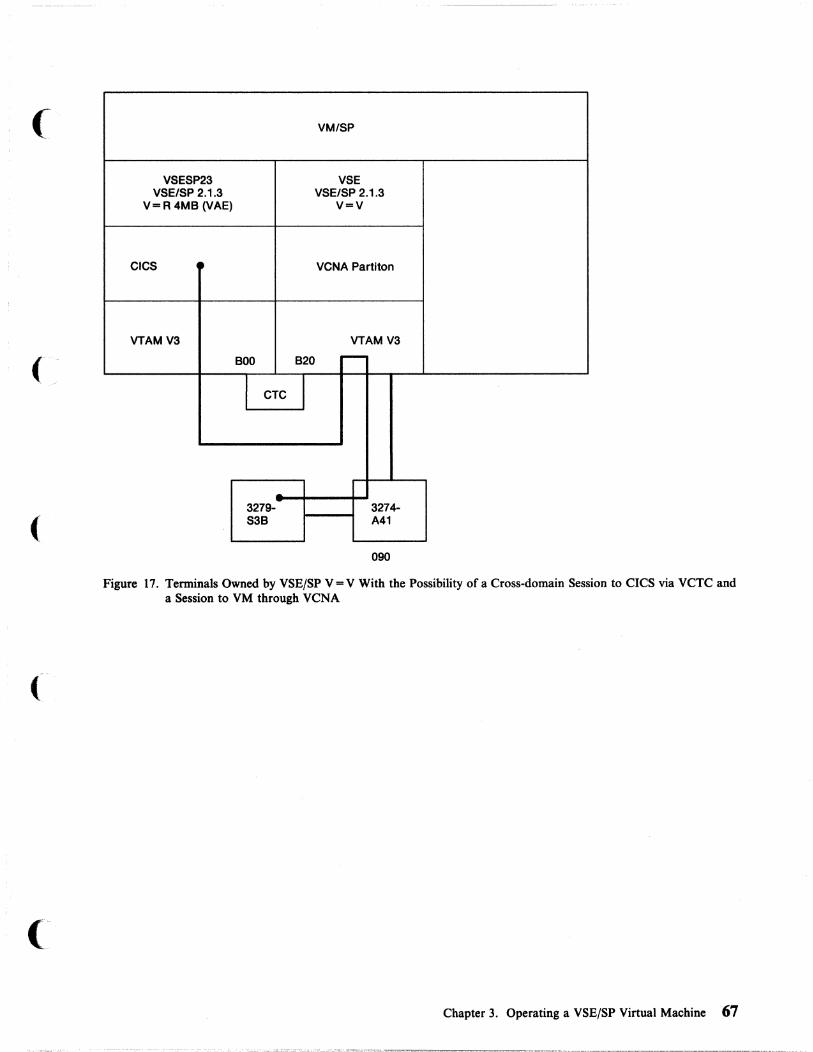
(
(
(
VM/SP
VSESP23 VSE VSE/SP 2.1.3 VSE/SP 2.1.3
V=R 4MB (VAE) V=V
CICS VCNA Partiton
VTAMV3 VTAM V3
BOO B20 ~
I CTC
3279- 3274-S3B A41
090
Figure 17. Terminals Owned by VSE/SP V = V With the Possibility of a Cross-domain Session to CICS via VCTC and a Session to VM through VCNA
Chapter 3. Operating a VSE/SP Virtual Machine 67

CICS
VSESP23 VSE/SP 2.1.3
V= R 4MB (VAE)
VTAM V3
VM/SP
GCS
VM/VTAM
-B20 920
3279-S3B
- 3274-A41
880
Figure 18. Terminals Owned by VM/VTAM With the Possibility of a Cross-domain Session to CICS via VCTC and a Session to VM
Generating a USSTAB for VM/VTAM To make your work easier, generate a new USSTAB. The samples are provided in Figure 19 on page 69.
1. Copy the provided sample USSTAB 'ISTINCDT ASSEMBLE' from MAINT's 298 disk.
2. Change the USSTAB name to VTMV3USS and add your DBOCCICS application.
3. Assemble the new USSTAB:
global maclib vtamac
assemble vtmv3uss
4. Add the USSTAB to the LKEDCTRL file (as, for example, ISUSER LKEDCTRL in Figure 20 on page 70).
5. Link the ISCUSER:
vmflked iscuser
You will get a new ISCUSER LOAD LIB.
68 VM Running Guest Operating Systems
\'--... ..•. /
-",,--- .... /

(
(
VTMV3USS ASSEMBLE (USSTAB)
VTMV3USS USSTAB TABLE=STDTRANS SPACE 4
LOGON USSCMD USSPARM USSPARM USSPARM EJECT
LOGOFF USSCMD USSPARM USSPARM USSPARM EJECT
CMD=LOGON,FORMAT=PLI PARM=APPLID PARM=LOGMODE PARM=DATA
CMD=LOGOFF,FORMAT=PLI PARM=APPLID PARM=TYPE,DEFAULT=UNCOND PARM=HOLD,DEFAULT=YES
UNDIAL USSCMD CMD=UNDIAL,FORMAT=PLI EJECT
VM USSCMD USSPARM USSPARM USSPARM EJECT
CMD=VM,REP=LOGON,FORMAT=BAL PARM=Pl,REP=DATA PARM=LOGMDDE PARM=APPLID,DEFAULT=VM
CICS USSCMD CMD=CICS, REP=LOGON, FORMAT=BAL USSPARM PARM=Pl,REP=APPLID,DEFAULT=DBDCCICS USSPARM PARM=P2,REP=DATA EJECT
IBMTEST USSCMD USSPARM USSPARM EJECT
MESSAGES USSMSG USSMSG USSMSG USSMSG USSMSG USSMSG USSMSG USSMSG USSMSG USSMSG USSMSG USSMSG EJECT
CMD=IBMTEST,FORMAT=BAL PARM=Pl,DEFAULT=18 PARM=P2,DEFAULT=ABCDEFGHIJKLMNOPQRSTUVWXYZ8123456789
MSG=l,TEXT='INVALID COMMAND SYNTAX' MSG=2,TEXT='% COMMAND UNRECOGNIZED' MSG=3,TEXT='% PARAMETER UNRECOGNIZED' MSG=4,TEXT='% PARAMETER INVALID' MSG=5,TEXT='UNSUPPORTED FUNCTION' MSG=6,TEXT='SEQUENCE ERROR' MSG=7,TEXT='SESSION NOT BOUND' MSG=8,TEXT='INSUFFICIENT STORAGE' MSG=9,TEXT='MAGNETIC CARD DATA ERROR' MSG=ll,TEXT='% SESSIONS ENDED' MSG=12,TEXT='REQUIRED PARAMETER OMITTED' MSG=13,TEXT='IBMECHO % '
Figure 19 (Part 1 of 2). VTMV3USS ASSEMBLE (USSTAB)
Chapter 3. Operating a VSE/SP Virtual Machine 69
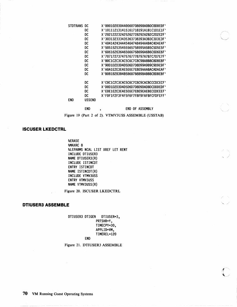
STDTRANS DC DC DC DC DC DC DC DC DC DC DC DC
END
DC DC DC DC USSEND
END
X'999192939449969798999A9seC9D9E9F' X'191112131415161718191A181CIDIEIF' X'292122232425262728292A282C2D2E2F' X'393132333435363738393A383C3D3E3F' X'494142434445464748494A484C4D4E4F' X'595152535455565758595A585C5D5E5F' X'696162636465666768696A686C6D6E6F' X'797172737475767778797A787C7D7E7F' X 'S9CIC2C3C4C5C6C7CSC9SAS8SCSDSESF , X'99DID2D3D4D5D6D7DSD99A989C9D9E9F' X 'A9AIE2E3E4E5E6E7ESE9AAA8ACADAEAF , X'89818283848586878SB9BABBBCBD8E8F'
X'C9CIC2C3C4C5C6C7CSC9CACBCCCDCECF' X'D9DID2D3D4D5D6D7DSD9DAD8DCDDDEDF' X'E9EIE2E3E4E5E6E7ESE9EAEBECEDEEEF' X'F9FIF2F3F4F5F6F7FSF9FAF8FCFDFEFF'
END OF ASSEMBLY
Figure 19 (Part 2 of 2). VTMV3USS ASSEMBLE (USSTAB)
ISCUSER LKEDCTRL
%ERASE %MAXRC S %lEPARMS NCAl liST XREF lET RENT INCLUDE DTIUSER3 NAME DTIUSER3(R) INCLUDE ISTINCDT ENTRY I STI NCDT NAME ISTINCDT(R) INCLUDE VTMV3USS ENTRY VTMV3USS NAME VTMV3USS(R)
Figure 20. ISCUSER LKEDCTRL
DTIUSER3 ASSEMBLE
DTIUSER3 DTIGEN DTIUSER=3.
END
PRTSHR=Y. TIMECPY=39. APPLID=VM. TIMEREl=129
Figure 21. DTIUSER3 ASSEMBLE
70 VM Running Guest Operating Systems
I '~ /
rf-~
~j

(-
(
(
ACF/VTAM Version 3 for VSE/SP 2.1.3 The default buffer size of VFBUF and VPBUF is 4KB. You cannot modify this size. You can, however, change the size of LFBUF.
Buffers for ACF/VTAM Version 3 for VSE/AF 2.1.1
F3 a16 SDsal VTAM DISPLAY - DOMAIN TYPE = BUFFER POOL DATA F3 a16 SG321 BUFF BUFF CURR CURR MAX MAX TIMES EXP/CONT EXP F3 a16 SG331 ID SIZE TOTAL AVAIL TOTAL USED EXP THRESHOLD INCR F3 a16 SDS61 VF 4a96 aaalSP aaa19P N/A aaaasp N/A N/A N/A F3 a16 SDS61 VP 4a96 aaa64P aaa26P N/A aaa44P N/A N/A N/A F3 a16 SDS61 SF aa392 aaa2a aaall aee2e eeee4 eeaae aeee3/----- eae1e F3 e16 SDS61 LF ee343 aeese aea49 eease aae2S eeeea eeee3/----- eael1 F3 e16 SDS61 SP eel12 eeee3 aaee3 eeee3 eeeee eeeaa eeeel/----- eae32 F3 a16 SDS61 LP e1344 eae12 aaees eee12 eeeel eaea1 eaea2/eaaa8 eaee3 F3 a16 SDS61 WP ee184 eea49 aee3l eaa4a eeeas aaee1 aae19/eeeS9 eee2e F3 a16 SF9S1 IRNLIMIT = NOLIMIT, CURRENT = aaeeeea. MAXIMUM = eaeeeee F3 916 SD141 END
Figure 22. Buffers for ACF/VTAM for VSE/AF 2.1.1
Virtual Storage Requirements of ACF/VTAM V3 To bring up VTAM Version 3 with the same nodes and buffer definitions, you will need to increase the virtual and real storage sizes in the VT AM partition. If not enough storage is available, one of the following messages will appear.
F3 e18 SA481 VTAM START REJECTED - INSUFFICIENT STORAGE FOR BUFFERS F3 e18 SB331 VTAM TERMINATION IN PROGRESS F3 e18 SBe21 VTAM IS NOW INACTIVE F3 ee3 EOP $3JCLROM
F3 a16 5B161 MEMBER CAROM NOT FOUND ON VTAM DEFINITION LIBRARY F3 a16 SA611 VARY ACT FOR ID = CAROM FAILED - NODE UNKNOWN TO VTAM
Figure 23. Possible Error Messages in Bringing Up VM/VTAM
Setup of a VCTC and Operational Considerations
Definitions for VM/VTAM All VTAM definitions and profiles reside on MAINTs minidisk 298, which should be linked by the VTAM machine in read-only mode as 191. After maintaining your VTAMLSTs (B-Books), you have to reaccess this disk from the VTAM machine in order to have your changes activated. Therefore, put the following in the PROFILE GCS:
ACC 191 A
Chapter 3. Operating a VSE/SP Virtual Machine 71

Defining the Virtual Channel You can define the virtual CTC in the PROFILE GCS.
DEF CTCA 91313 DEF CTCA 9213
Defining the VTAMLST for CTC
Other VTAMLSTs
S2CTC S2CTCG S2CTCLl S2CTCPl S2CTCL4 S2CTCP4
VBUILD GROUP LINE PU LINE PU
TYPE=CA LNCTL=CTCA,REPLYTO=2S.S,MAXBFRU=(le,3e) ADDRESS=92e PUTYPE=4 ADDRESS=gee PUTYPE=4
Figure 24. CTC VT AMLST
The default value ofREPLYTO= is three seconds. The maximum value is 25.5 seconds.
SSCPID=2
Figure 25. ATCSTROO VTAMLST
SSCPID=2, HOSTSA=2, MAXSUBA=31, CONFIG=YK, CRPLBUF=(2ee"lS"el,3e), IOBUF=(3ee,2S6,4e"el,Se), NOTRACE,TYPE=VTAM
Figure 26. ATCSTRYK VTAMLST
APPLROMV, SNAYK, NSNAROMV, CAYK, PATHYK, CDRMYK, CDRSYK
Figure 27. ATCCONYK VTAMLST
VBUILD TYPE=APPL VM APPL AUTH=(PASS,ACQ,BLOCK),AUTHEXIT=YES,ACBNAME=VM,
PARSESS=YES,PRTCT=VM
Figure 28. APPLROMV VTAMLST
72 VM Running Guest Operating Systems

(
VBUILO TYPE=LOCAL 03274A4l PU CUAOOR=88e,MAXBFRU=l5,VPACING=l,
03279P16 LU D3279Pl7 LU 03279Pl8 LU 03279Pl9 LU
PUTYPE=2,ISTATUS=ACTIVE LOCAOOR=l8,OLOGMOO=04A32793,USSTAB=VTMV3USS LOCAOOR=l9,OLOGMOO=04A32793,USSTAB=VTMV3USS LOCAOOR=2e,OLOGMOO=04A32793,USSTAB=VTMV3USS LOCAOOR=2l,DLOGMOO=04A32793,USSTAB=VTMV3USS
Figure 29. SNAYK VTAMLST
veBe
veBl
veB2
veB3
LBUILO LOCAL CUAOOR=eBe,TERM=3277,FEATUR2=(MOOEL2).
OLOGMOD=S327e,USSTAB=VTMV3USS LOCAL CUADOR=eBl,TERM=3277,FEATUR2=(MOOEL2),
OLOGMOD=S327e,USSTAB=VTMV3USS LOCAL CUADOR=eB2,TERM=3277.FEATUR2=(MODEL2),
DLOGMOD=S327e,USSTAB=VTMV3USS LOCAL CUADDR=eB3.TERM=3277,FEATUR2=(MODEL2).
OLOGMOO=S327e,USSTAB=VTMV3USS
Figure 30. NSNAROMV VTAMLST
S2CTC S2CTCG S2CTCLl S2CTCPl S2CTCL4 S2CTCP4
VBUILO GROUP LINE PU LINE PU
TYPE=CA LNCTL=CTCA,REPLYTO=25.5.MAXBFRU=(le,3e) AOORESS=92e PUTYPE=4 AOORESS=gee PUTYPE=4
Figure 31. CA YK VT AMLST
PATHYK PATH OESTSA=l, ER5=(1,l) , VR5=5
Figure 32. PATHYK VTAMLST
CORMYK VBUILO TYPE=CDRM VMVTAM CORM SUBAREA=2,CORSC=OPT,COROYN=YES,
ISTATUS=ACTIVE,VPACING=2 VSEVTAM CORM SUBAREA=4.CORSC=OPT,COROYN=YES,
ISTATUS=ACTIVE,VPACING=2 SP23VTAM CORM SUBAREA=l,CDRSC=OPT,CDRDYN=YES,
ISTATUS=ACTIVE,VPACING=2
Figure 33. CDRMYK VTAMLST
Chapter 3. Operating a VSE/SP Virtual Machine 73

-,
CORSYK VBUILO TYPE=CORSC ROMACICS CORSC CORM=VSEVTAM VCNA CORSC CORM=VSEVTAM RMS9 CORSC CORM=VSEVTAM RMS1 CORSC CORM=VSEVTAM RMS2 CORSC CORM=VSEVTAM RMS3 CORSC CORM=VSEVTAM LJIe9991 CORSC CORM=VSEVTAM LK199991 CORSC CDRM=VSEVTAM LLl99991 CORSC CORM=VSEVTAM LM199991 CORSC CORM=VSEVTAM OBOCCICS CORSC CORM=SP23VTAM 09S9 CORSC CORM=SP23VTAM 09S1 CORSC CORM=SP23VTAM 09S2 CORSC CORM=SP23VTAM 09S3 CORSC CORM=SP23VTAM LJl88991 CORSC CORM=SP23VTAM LK188991 CORSC CORM=SP23VTAM LL188991 CORSC CORM=SP23VTAM LM1889a1 CORSC CORM=SP23VTAM
Figure 34. CDRSYK VTAMLST
Starting Up VM/VTAM There are two ways to start up VM/VT AM. During your first tests with VM/VTAM, you may want to bring up VTAM manually. The PROMPT parameter in the VT AM startup book is not supported.
1. Make a comment line out of the 'EXEC VMVTAM' in the PROFILE GCS of the VT AM machine. The GCS recovery machine will be autologged by the AUTOLOGI machine. VTAM will be autologged by the GCS recovery machine.
2. Log on to the disconnected VT AM machine.
3. Enter:
VMVTAM xx
where xx is the suffix of your VT AM startup list.
For example:
'VMVTAM YK' will start VTAM with ATCSTRYK VTAMLST after executing ATCSTROO VTAMLST.
Entering just 'VMVTAM' will bring up the default list ATCSTROO VTAMLST.
Another way is not to change the PROFILE GCS of the VTAM machine, but to prevent the GCS recovery machine from autologging the VTAM machine. After the autolog of the GCS recovery machine, logon to the VT AM machine. Mter seeing that GCS has been loaded, you then give the command VMVT AM and answer as you would in OS with R replid suffix, where suffix is the xx of the ATCSTRxx VTAMLST.
To start up VM/VTAM automatically, modify the 'EXEC VMVTAM' statement in the PROFILE GCS to 'EXEC VMVTAM xx', where xx is your startup list. An £\ example is given in "PROFILE GCS" on page 75. I(-J
74 VM Running Guest Operating Systems

PROFILE GCS
(
(-~
/** *** Title-*** PROFILE OF THE VTAM MACHINE *** **/ /** NOW FIND OUT WHICH VTAMLST WE WANT TO USE **/ /** SAY 'WHICH VTAM LIST ARE WE USING TODAY?'
SAY "ENTER IT'S TWO CHARACTER CODE 'XX "' PARSE UPPER PULL LIST NO
**/ -/** *** Set CP options to improve performance of VTAM virtual machine **/
'CP SET QDROP VTAM OFF' /* DON'T FLUSH PAGES WHEN IDLE */ 'CP SET FAVORED VTAM' /* VTAM ALWAYS DISPATCHABLE */ 'CP SET PRIORITY VTAM l' /* GIVE PRIORITY TO VTAM */ 'CP SET PF11 RETRIEVE' /* LET'S REMEMBER A COMMAND */ 'CP SET PF23 RETRIEVE' /* LET'S REMEMBER A COMMAND */ 'CP DEF GRAF 9B9' /* TERMINAL ADDRESSES TO DIAL */ 'CP DEF GRAF 9B1' /* VTAM MACHINE */ 'CP DEF GRAF 9B2' 'CP DEF GRAF 9B3' 'CP DEF CTCA 999' /* VIRTUAL CTC TO VSE */ 'CP DEF CTCA 929' /* VIRTUAL CTC TO VSESP23 * / 'CP LINK MAINT 59F 59F RR RVM4' 'ACC 191 A' /* REACCESS MAINT 298 */
/** *** VTAM initialization **/
'EXEC VMVTAM YK' /* 'CP AUTOLOG RSCS password' Starts RSCS Virtual Machine if any*/
exit 9
Figure 35. PROFILE GCS
Notes:
1. The REXX PULL instruction in conjunction with GCS will make it possible to answer in the OS format; that is, R replied answer.
2. If you activate the REXX PULL instruction, you should change the EXEC VMVTAM YK statement to: EXEC VMVTAM list_no
Chapter 3. Operating a VSE/SP Virtual Machine 7S

VMVTAMGCS
/** *** Title· *** VMVTAM *** *** Function-*** Initialize VM/VTAM and VSCS for use. *** *** Parameters-*** list_value *** *** Returns-*** aa (VTAM has been successfully activated) *** ~a (VTAM activation failed) *** **/
/**
parse source • • exec_name arg list_value. '(' options if list_value = " then
list_value='aa'
*** VTAM initialization **/
'ACC 29A F/F' 'ACC 59F G/G' 'GLOBAL LOADLIB ISCUSER VTAM VSCS RSCS' 'LOADCMD VTAM ISTINVaa'
/**
'LOADCMD VSCS DTISLCMD' 'VTAM START LIST='list value rcode=rc -if rcode ~=a then /* If VTAM start failure
do /* Error, VTAM startup failed say '**ERROR** VTAM initialization failed' exit rcode
end /* Error, VTAM startup failed
*** VSCS initialization **/
'VSCS START PARM=3' rcode=rc
/* Initialize VSCS with user3 /* Save startup return code /* If VTAM start failure if rcode ~ then
do /* Error, VTAM startup failed say '**ERROR** VSCS initialization failed' exit rcode
end exit a
Figure 36. VMVTAM GCS
/* Error, VTAM startup failed
76 VM Running Guest Operating Systems
*/ */
*/
*/ */ */ */
*/
,tf""
\.j
" "
,/
j

(
(
(
(
Starting the CTC Major Node Before you can start the channel-to-channel (CTC) major node, couple the virtual channels together. Issue the following command:
couple 928 vsesp23 b28
This command can work only if the VSESP23 machine is logged on and the appropriate channel B20 is defined. Because VT AM is normally one of the first machines logged on, issuing the couple command from a VSE/SP guest is recommended. Refer to "Starting the CTC Major Node for a VSE/SP Guest" on page 78.
Definitions for VSE/SP Systems
Defining the Virtual Channel The CTC can be defined in the same manner as for VM/VT AM. The appropriate DEF statements are put in the PROFILE EXEC of the VSEMAINT machine which shares its profile with all VSE/SP guest machines.
Defining the IPLPROC Entry The entry for a virtual CTC in the IPLPROC should look like this:
ADD B28,CTCA,EML
The EML option prevents the system from sensing the address at initial IPL. If you do not code this option, you will get an incorrect PUB entry when the CTC is not ready. In this case the system sends the console a message like:
01711 ACTUAL DEVICE TYPE X I FF I FOR B20 INSERTED IN PUB
The following table shows how the system reacts to various status of CTC definitions when you do not use the EML option.
Table 2. PUB Entries for CTC
Situation qvBlO Pub Entry
CTC not defined DEV B20 DOES NOT EXIST Correct
CTC defined CTC B20 NOT READY Incorrect
CTC defined and CTC B20 COUPLE to VT AM 920 Correct coupled
Defining the B-Book for CTC CTC VBUILD TYPE=CA CTCG GROUP LNCTL=CTCA,REPLYTO=25.5,MAXBFRU=(18,38) CTCL4 LINE ADDRESS=B88 CTCP4 PU PUTYPE=4 CTCL2 LINE ADDRESS=B28 CTCP2 PU PUTYPE=4
The definition of the CTC is the same as for VM/VT AM except for the addresses of the channels.
Chapter 3. Operating a VSE/SP Virtual Machine 77

Starting the CTC Major Node for a VSE/SP Guest Before you activate your CTC major node you should make sure that the virtual CTC js coupled to another machine. Put the couple command in the PROFILE f' "\. EXEC of the VSEMAINT machine for every VSE/SP guest machine that uses a ',_?, virtual channel-to-channel (VCTC).
Check the status of the channel by issuing:
q v B29
If the channels are still not coupled, from the VSE/SP console you can issue:
* cp couple b29 vtam 929
It is possible that some intervention will be required on the VMjVT AM console, because VMjVT AM does not activate the CTC major node if the channels have not been coupled at initialization.
78 VM Running Guest Operating Systems
~~--------------- ----
\.._-- /

( Chapter 4. VSE/SP Virtual Machines Sharing DASD
DASD Sharing Considerations for the VSE/SP Virtual Machine ......... 80 Reserve/Release Support ................................. 82 Hardware for DASD Sharing .............................. 85 Using Real Reserve/Release under VM ........................ 89 VSE Sharing DASD with a Stand-alone VSE System ................ 90 Virtual Reserve/Release .................................. 91 VSE DASD Sharing without Hardware Switches ................... 93 VM Alternate Path Support and Reserve/Release .................. 95 Sharing Minidisks ..................................... 97 VSE DASD Sharing with Hardware Switches Within One Processor ....... 99
Chapter 4. VSE/SP Virtual Machines Sharing DASD 79

DASD sharing is possible under VM using the VSE lockfile mechanism. Minidisks that are defined with the multiple write feature can be used by different VM users as shared disks (fu1lpack or partial minidisks).
Resource sharing across systems will function properly only if each sharing virtual machine has a unique CPU identification (CPUID). Therefore, a different CPUID must be defined for each virtual machine. Before IPLing a VSE/SP virtual machine, you must define CPUID in the OPTION control statement, or you can use the CP SET CPUID command. Without this, catastrophic errors will occur in the VSE lock file. See "Defining Central Processing Unit IDs for the VSEjSP Virtual Machine" on page 50 for instructions for using the SET CPUID command.
In general, the benefits of operating in the VSE environment are also realized when operating under the control of VM:
Avoidance of Library Duplicatiou:
• As the number of VSE virtual machines increases, so does the requirement for direct access storage space. In many cases, VSE libraries are duplicated for each of the virtual machines. DASD sharing allows you to save direct access storage space by avoiding duplication of libraries.
Reduction in Maintenance Effort:
• As additional virtual machines are added, additional system programmer time is required to generate and maintain the VSE system. Often, it is necessary to keep several virtual machines synchronized, so service to one virtual machine necessitates the same service to others. With DASD sharing, updates and maintenance need be applied only once.
Shared Spooling:
• When the number of virtual VSE machines exceeds the number of physical printers available, the printer(s) can be switched back and forth between the virtual VSE machines. This requires the operator to insure that a VSE/pOWER printer task is not started for any virtual machine that does not have a real printer available (in cases where, a real attached printer is required). Alternatively, some virtual machine output can be spooled to VM, and the printer switched between VSE/POWER and VM. With the VSEjPOWER shared spooling feature, one set of VSE/pOWER files can be shared among a maximum of nine VSEjSP virtual machines. This allows multiple VSE virtual machines to send their output to a single VSE/pOWER-controlled real printer. This situation is less prone to operator error, because no switching of printers between virtual machines is required.
DASD Sharing Considerations for the VSE/SP Virtual Machine Whatever the benefits of DASD sharing you'd like to bring to your installation, consider the cost of additional complexity, impact on performance, and the potential for data integrity exposures. 'Elements to consider and plan for include:
• System configuration: you must compromise between flexibility and complexity • System design in terms of DASD mapping • Resource and load balancing ·~ro~~~~ f~ • Performance implications '.J
80 VM Running Guest Operating Systems
---~ - ._- .. ~-- ._. -- ---_ ..

(
(
• Operational control of the multi-processor environment • Programming considerations for user resource protection • Data integrity.
Careful planning is necessary to use DASD sharing efficiently and successfully.
If possible, avoid sharing DASD. If this is not possible, aim for a shared DASD design that is as simple as possible.
Many of the factors to be considered in designing a shared DASD system apply equally to nonshared systems. Considerations unique to the DASD sharing environment include:
Hardware Design:
• The internal speed of all processors involved must be well balanced. For instance, the faster machine will probably dominate the slower one. However, there might be a valid configuration if the slow machine is performing a specific task in support of the fast machine, rather than operating as an equal partner. Alternatively, a slow machine can be used to control one or more 3800 printing subsystems, and share SYSRES and spool files with a faster processor. In this case, the amount of interference between the two processors will be minimal and the operator can fully control the subsystem. complete control of the subsystem . . When both processors support similar applications and share the workload on a more nearly equal basis, the power of the processors should be reasonably comparable.
• An adequate I/O configuration should be provided. To achieve appropriate performance and availability, alternate I/O paths must be provided by using a combination of channel and string switching.
Software Design:
Numerous software design considerations influence the overall performance of a system. They become even more complex if multiple systems must coexist.
In order to minimize the SEEK time of DASD devices, the placement of the following system data sets should be evaluated very carefully:
• Lock file (communication area): this file controls the actual file sharing activity. It should be placed on the least active of the shared DASD.
• The volume table of contents (VTOC) for each individual DASD.
• VSE/POWER QUEUE and DATA files (for releases earlier than VSE version 3 only).
To optimize the I/O traffic, the VSE/pOWERDATA file should be split up into multiple extents if the DASD configuration permits this.
In general, all frequently used files on the same spindle should be grouped together. Again, the purpose is to keep the SEEK times as short as possible.
Files not shared between CPUIDs should be placed on a separate DASD string to avoid unnecessary contention for resources.
Chapter 4. VSE/SP Virtual Machines Sharing DASD 81

Special attention must be given to the definition of library chains. Consider:
• Length of library chain • Search sequence within chain • Permanent as opposed to temporary chains.
In order to improve overall system throughput, load the most frequently used phase directory entries into the system directory list, and make the eligible phases core-resident by loading them into the shared virtual area (SV A). Note that you can load SV A-eligible phases from all sublibraries active in the bit generation BG chains.
We strongly recommend careful evaluation of the VSE/SP supervisor and the VSE/POWER generation parameters. In particular, note that the DBLK and TRACKGP parameters in VSE/POWER can significantly influence I/O traffic and therefore system throughput.
Under VM, the DBLK parameter should be set in the range of 4KB to 6KB in order to reduce the number ofVSE/pOWER START I/O's.
If your installation consists of more than one computing system, you might consider sharing some or all DASD among the different VSE systems. Instead of assigning a fixed number of disk drives to each of the different systems, you can combine the total number of drives into a disk pool shared by all VSE systems. DASD sharing among two or more VSE systems has several advantages:
• Library maintenance is easier when only one set of libraries has to be maintained.
• Direct access storage space can be saved, since only one copy of the data is required instead of multiple copies.
Reserve/Release Support The CP component of VM does not issue reserve/release channel command words (CCWs) for itself; neither does CMS. CP issues them only on behalf of the guest operating system that issues the CCWs. VM checks all CCWs passed by guest operating systems running in VM and bases reserve/release CCW processing on:
• The device type
• The presence or lack of alternate path support
• Whether the MDISK statement in the VM directory contains a V in the mode operand.
Depending upon the various combinations of the above items, VM either permits the reserve CCW to execute on the hardware or changes the reserve CCW to a sense CCW. To determine the conditions under which a reserve is changed to a sense CCW, refer to Table 3 on page 83.
Note: Column 8 in Table 3 on page 83 assumes a path to another processor.
82 VM Running Guest Operating Systems
/
rf~'
'--

Table 3. Summary of VM Reserve/Release CCW Support
Integrity Problems
Alternate Resv/Rel Virtual What is Error Integrity with Device Path Hardware Resv/Rel Sent to Condition Problems Multiple Type Online? Present? Defined? Hardware? From CCW? with Links? Paths? 6
Ded 1 No Yes/no - Reserve No/yes - No/N/A
Ded 2 S Yes Yes - Sense No - Yes
Mdisk 1 No Yes No Reserve No Yes No
Mdisk 1 No Yes Yes Reserve No No No
Mdisk No No No Reserve Yes Yes N/A 3 1
Mdisk 4 No No Yes Sense No No N/A
( Mdisk S Yes Yes No Sense No Yes Yes
Mdisk S Yes Yes Yes Sense No No Yes
Notes:
1. Normal operation, during which the command is passed unchanged to the hardware.
2. When the VM system has been generated with alternate path support for the devices, and these alternate paths are online, then CP does not allow the real reserve CCW to be sent to the hardware. This action causes VM to avoid a possible channel lockout. VM does not return any indication that the device was not physically reserved to the operating system issuing the CCW.
3. VM sends the reserve/release CCW unchanged to the hardware. However, without the two-channel switch special feature or string switch, the hardware rejects the command and does not reserve the device. For a complete discussion of the hardware reserve/release feature along the path to the DASD device, please refer to "Hardware for DASD Sharing" on page 85.
4. Before sending the command to the hardware, VM changes reserve CCWs to sense CCWs, and places a virtual reserve on the minidisk. The real device is not reserved. The virtual reserve prevents other operating systems running under the same VM system from accessing the minidisk. However, these same virtual operating systems can virtually reserve other minidisks located on the same real volume.
( Because the reserve/release hardware is not present along the path to the DASD devices, VM's virtual reserve/release processing modifies the reserve CCW to a sense CCW. If the reserve CCW were modified, it would be rejected by the hardware.
5. When alternate paths to a device are online, VM changes the reserve/release CCW to a sense CCW to prevent a possible channel lockout. In an MP environment, a symmetric alternate path is automatically defined. If that symmetrical alternate path is online the reserve CCW is changed to a sense CCW in all cases.
6. This column assumes a path from another processor.
By examining the table, you can determine:
• The device type (dedicated DASD or tape or minidisk)
• Whether alternate paths are online
• Whether the reserve/release hardware feature is present
• Whether virtual reserve/release has been defined for the shared DASD
• What VM sends to the hardware
Chapter 4. VSE/SP Virtual Machines Sharing DASD 83

• Whether the guest virtual machine receives an error condition after issuing a reserve or a release CCW
• Any problems occurring with the use of the LINK statement or with the existence of multiple paths to the shared DASD from the same or different processor.
The following two examples may help you understand how to use the table.
Example 1 of how to use "Summary of VM Reserve/Release CCW Support"
This example refers to row I in Table 3 on page 83.
Column Number Explanation
Column 1
Column 2
Columns 3, 6
Column 4
Column 5
Column 6
Column 7
Column 8
The DASD device is either dedicated or attached to a virtual machine.
No alternate paths are defined or on line to this device.
These columns must be interpreted together:
• When column 3 is Yes, column 6 is No. This means that if the reserve/release hardware exists somewhere along the path to the device, no error condition will be returned by the hardware to CP when a reserve or release CCW is issued by a guest virtual machine to this shared device.
• When column 3 is No, column 6 is Yes. This means that if the reserve/release hardware is not along the path to the device, the hardware will return to CP a COMMAND REJECT reflecting this error to the guest virtual machine that issued the reserve or release.
Virtual reserve/release support is not relevant in this case.
When Ii guest virtual machine issues a reserve CCW to the device, the command is sent unmodified to the hardware.
See the discussion of column 3.
There can be no links to a dedicated volume. This column is not applicable.
Because the reserve CCW is always passed to the hardware, there are no problems with having multiple paths to this device online. For example, there can be more than one path to this device either from the same or from a different system as long as it is not defined as an alternate path.
Example 2 of how to use "Summary of VM Reserve/Release CCW Support"
This example refers to row 5 i~ Table 3 on page 83.
Column 1
Column 2
Columns 3,6
84 VM Running Guest Operating Systems
The DASD device is defined as a minidisk, either full-pack or not.
No alternate paths are defined or online to this device.
The reserve/release hardware feature does not exist along the path to the DASD device. Consequently, a COMMAND REJECT will always be returned to the guest virtual,machine when it issues either a reserve or a release CCW to this DASD device.
/
,/
.."

(
(
(
(
Column 4
Column 5
Column 7
Column 8
Virtual reserve/release support is not specified for this minidisk.
When a guest virtual machine issues a reserve CCW to the device, the command is sent unmodified to the hardware.
A data integrity problem exists if another user links to this minidisk in read/write (R/W) mode expecting that RESERVE CCWs from the minidisk owner will prevent him from corrupting the shared data.
Multiple paths to this minidisk cannot exist because the reserve/release hardware feature such as a two-channel switch or string switch does not exist anywhere along the hardware path to this device.
Hardware for DASD Sharing Knowledge of the DASD hardware supporting the reserve/release hardware feature is crucial to understanding the software DASD sharing mechanism. Therefore, read this topic in its entirety before continuing with "Using Real Reserve/Release under VM" on page 89.
In hardware for DASD sharing, two base configurations are possible. Either you have a common control unit that is equipped with a two-channel or four-channel switch, or you have separate control units. In the latter case, the head-of-string needs a string switch feature.2
2 Technically, the 3380-AA4, -AD4, and -AE4s do not have a string switch feature. However, the equivalent function of a string switch is contained within the dynamic path selection (DPS) feature. This is the only portion of DPS that VM uses.
Chapter 4. VSEjSP Virtual Machines Sharing DASD 85

A. Two-Channel Switch
Processor A I Ch I I I I Dev Dev Dey Dev
I I Head of CU String
I Dev Dev Dey Dev
Processor B Ch I I
B. Siring Switch
Processor A I Ch I I CU I I I I I I
Head of Dey Dev Dev Dev
String Dey Dey Dey Dev
I Processor B I Ch I I CU I I I I I
Figure 37. Two-Channel Switch and String Switch
From a DASD sharing standpoint, the two configurations are similar. The VM software supporting shared DASD does not recognize a difference. The path to the DASD is what matters. Therefore, in Figure 38 on page 87 the channels and the control units are omitted.
Sharing DASD is not restricted to accessibility from different paths and different systems. It is also possible to share the DASD in write mode from different paths. To avoid concurrent update or simultaneous writing - and destroying the DASD contents - the hardware is equipped with reserve/release.
When your hardware has more than one path (for example, either a two-channel switch or a string switch installed along the path from the channel to the DASD), the reserve/release facility can work. If only one path exists for the DASD and neither a two-channel switch nor a string switch exists along that path, the DASD device type will determine whether the hardware will reject the reserve/release commands or not.
For example, IBM 3375s, 3380s, and 3350s will not reject a reserve or release command, whether or not the switching hardware is installed along the path to the device. On the other hand, IBM 3370s and 3330s will issue a COMMAND REJECT to a reserve or release CCW if either a two-channel switch or a string switch does not exist on the path to the DASD.
86 VM Running Guest Operating Systems
/ ""',

(
(
Processor A
GVM1
Processor B
GVM2
Optionally, software can use the hardware reserve/release facility. However, the use of reserve/release CCWs gives greater assurance of data integrity.3
For a better understanding of the way reserve/release works, see Figure 38.
Ch2
247 DSK1
Ch2
1. GVM1 issues a reserve CCW followed by a read CCW for 247.
2. The reserve/release hardware blocks all other paths to 247.
3. GVM2 issues a CCW (it doesn't matter which type) for 247 and receives a device busy from the hardware.
4. GVM1 issues a write and a release CCW for 247.
5. GVM2 receives a device end and re-issues its CCW.
Figure 38. Guest Virtual Machines with Reserve/Release Hardware
A reserve CCW is an I/O command that is sent from an operating system to a channel. It reserves a single DASD to a particular channel on a specific processor for its own exclusive use. This is accomplished through the reserve/release hardware contained in either the DASD control unit or DASD head-of-string. Essentially, the reserve/release hardware restricts access to this particular DASD to a specific channel/control unit/head-of-string path. A reserve CCW is treated as a path reservation.
Once a path is reserved, the device can be accessed only through this path. All access to the device from other systems using a different path results in a device busy condition.
The release CCW is sent via the reserved path only. It ends the path reservation for this user. All paths that received a device busy condition will receive a device end (DE) indicating that the device is now available. The device can now accept I/O operations from all paths.
3 Using reserve/release CCWs is not the only way to ensure data integrity. Additionally, the software can have its own locking system. For example, VSE uses its own software locking mechanism to support shared DASD. The hardware reserve/release facility is used only to protect the VSE lock file.
Chapter 4. VSE/SP Virtual Machines Sharing DASD 87

String Switching and 33758
Processor A Ch CU
3375-01
Head of Dey Dey Dey Dey Head of String
Dey Dey Dey Dey String
3375-A1
Processor B I Ch I I
CU I
I
Figure 39. 3375 Configuration with Two Heads-of-String
With 3375 and 3380-AA4 DASD the situation is slightly different. In Figure 39 we have a 3375 string connected to Processor A through the 3375-DI unit and to Processor B through the 3375-AI unit. Confusion arises when we try to understand how an I/O coming across the path from Processor A through the 3375-01 will detect a device reservation made from Processor B through the 3375-Al.
The DASO does not have reserve/release status information or logic of its own; all the device reservation status information and logic is handled through the 3375 head-of-string.4
When a reserve CCW is sent across the path from Processor A through the 01 unit, the head-of-string updates its device status information and internally sets up the path reservation to that device so that no other path can access it. Also, the Dl unit signals this path reservation status to its corresponding Al unit so that the Al unit can update its reservation status for that shared device. Therefore, both head-of-strings support the device reservation and are aware of the reservation status contained in each other.
The release CCW for this device must be made across the same path as the original reserve CCW in order to be accepted by the hardware. When the D 1 unit receives the release CCW for this device, it releases the path reservation, update its own device status information, and informs the Al unit of this status change. Once again, this device is accessible from all paths.
4 This is one of the main reasons why VM does not have to be concerned with whether the DASD sharing is implemented through a string switch or a two-channel switch. The actual reservation status must be maintained in the head-of-string mechanism. This applies to all IBM DASD such as the 3350s, 3330s, 3370s, 3375s, and 3380s.
88 VM Running Guest Operating Systems
\"'" ,;
If '"'.
'-./

Siring Switching and 3380.
Processor A Ch L I CU
I I I I
I HOS Controller HOS Controller
HOS1 HOS2
3380-AA unit Processor 8 Ch CU
3380-8 unit
3380-8 unit
3380-8 unit
( Figure 40. 3380 AA-4 Configuration (Two Heads-of-String)
(
(
.. ( .....
The 3380-AA4 handles the hardware reserve/release logic in a VM/SP or VM/SP HPO environment just as in the 3375-Al/Dl combination. The 3380 Head-of-string controller, HOSI in Figure 40, corresponds to the 3375-Al and HOS2 corresponds to the 3375-Dl in Figure 39.
Apart from the software, both HOSI and HOS2 can have access to any device on that 3380 string just as the 3375-Al and the 3375-Dl have access to any device on their 3375 string. Functionally, the synchronization of the device reservation status is the same for 3375-Al/Dl combinations and 3380-AA4s.
Neither VM/SP nor VM/SP HPO support the full DPS feature. This prevents VM from using the system-related reserve.
Using Real Reserve/Release under VM Device reservation works for the path to the DASD, whether it comes from different processors or not.
Consider the case in Figure 41 on page 90. Two virtual machines use dedicated paths, each to the same string of DASD. For this to work, you must tell CP that we have each device (and control unit) twice.s
S At IPL time, CP sees two paths and two addresses for this string of DASD. Because the second path is not defined to VM as an alternate path, CP varies omine the devices with the higher addresses. (For example, 340-347.) However, you can vary the devices back online and attach those devices to the second guest operating system (GVM2).
Chapter 4. VSEjSP Virtual Machines Sharing DASD 89

ATTACH 247 GVM1 111 GVM1
J Ch2
VM 247 347
I Ch3 GVM2
ATTACH 347 GVM2 222
RDEVICE ADDRESS = (240,8), DEVTYPE = .. . RDEVICE ADDRESS = (340,8), DEVTYPE = .. . RCTLUNIT ADDRESS = 240, CUTYPE = .. . RCTLUNIT ADDRESS = 340, CUTYPE = .. .
Figure 41. Guest Virtual Machine, Using Reserve/Release on Dedicated Paths (Example 1)
VSE Sharing DASD with a Stand-alone VSE System VSE uses the lock file to logically protect resources against parallel updates by different VSE systems. If separate access paths are available, hardware assistance is / '" necessary to ensure that only one VSE system at a time can write to the lock file. ~.~ /
This hardware assistance is obtained by using reserve/release CCWs. The release CCW will be accepted by the hardware only if it is issued along the same physical path that the reserve CCW traveled. VM itself never uses reserve CCWs. Again, the hardware would reject the release CCW if it came through a different path, and the DASD would never be available. Figure 41 gives us our first rule for DASD sharing under VM.
RULE 1: FOR DEDICATED OR ATTACHED DASD
If the reserve/release hardware IS present and no alternate paths are online, CP sends the reserve/release CCWs unmodified to the hardware. 6
If all paths to a DASD device are dedicated, and if the guest operating systems use reserve/release CCW, then there is no VM data integrity problem. In this respect, running natively or using a dedicated path under VM are functionally equivalent modes of operation.
6 For more information on reserve/release and alternate paths see "VM Alternate Path Support and Reserve/Release" on page 95.
90 VM Running Guest Operating Systems
!t(~--.
I'-_j

(
(
(
Processor A
VSE1
VM
Processor B
VSE2
In Figure 42, we have only one guest operating system (VSEl) sharing DASD with an operating system (VSE) on another processor. The DASD is dedicated to the virtual machine. According to Rule 1, CP sends the reserve/release CCWs unmodified to the hardware. Therefore, data integrity is ensured. (Figure 42 is still valid if VSE is running as a guest system on processor B.)
ATTACH 247 VSE1111
Ch2 I 247
Ch2 J
Figure 42. Reserve/Release on Dedicated Paths (Example 2)
Virtual Reserve/Release
VSE1 -
VM
VSE2 -
Consider the case of two guest operating systems sharing DASD when only one physical path exists from the processor to the DASD device. Under VM, in order to share this device it must be defined as a minidisk for one of the guests. The other guest can link to this minidisk as usual.
VSE1: MDISK 1113330000 DSK1 MWV
247
VSE2: LINK VSE1 111 222 MW
RDEVICE ADDRESS = (240,8), DEVTYPE= ...
RDEVICE ADDRESS = 240, CUTYPE = ...
Figure 43. Virtual Reserve/Release
Chapter 4. VSE/SP Virtual Machines Sharing DASD 91

In Figure 43 on page 91, the use of the hardware's real reserve/release facility leads to an integrity exposure. The reserve/release hardware (if present at all) cannot do its job because the read and write requests from VSEI and VSE2 must travel along the same path.
However, VM has a software simulation facility to handle this: virtual reserve/release. It is valid only for minidisks and is specified by an access mode of MWV within the directory entry.7
For VSE virtual machines using MDISK and LINK you must define access mode MWV for the shared minidisk containing the lock file. Virtual reserve/release ensures that the example in Figure 43 on page 91 works and that the data integrity mechanism of each guest operating system can work just as if it were not running underVM.
Virtual reserve/release functions in CP only. If a guest issues a reserve CCW to protect the device from being accessed by other operating systems on the same processor complex, CP will flag this minidisk as being reserved for that particular virtual machine. It reserves the access to the minidisk, just as the real reserve/release hardware would reserve access to the real disk.8
Because the virtual reserve/release facility executes only in CP, the reserved minidisk can be of any size. It does not need to be a full-pack minidisk.9 Virtual reserve/release can work for several independent minidisks on the same volume as long as the volume is not shared with another processor complex.
If you have specified MWV in your MDISK definition, your guest can issue a reserve CCW and CP will reserve the minidisk accordingly.
RULE 2A: FOR A MINIDISK WITH VIRTUAL RESERVE/RELEASE
If the reserve/release hardware IS present and no alternate paths are online, then CP sends the reserve/release CCWs unmodified to the hardware.10
Because the hardware handles the CCW, a reserve/release for a minidisk will always result in a reserve/release for the whole DASD volume on which this minidisk is defined if no alternate paths are online.
So, in addition to the virtual reserve/release protection in CP, the real reserve/release hardware protects you against access through other paths. These other paths can lead to a different processor or be dedicated paths to the same one. Such a case is explained in Figure 44 on page 93.
7 Note that MWV must be in the MDISK control statement. Putting the MWV in the LINK control statement in the DIRECTORY will be flagged as an error.
8 Virtual reserve/release does not support UNCONDITIONAL RESERVE. If a minidisk with the VIRTUAL RESERVE Option has been reserved by a user and a second user issues an UNCONDITIONAL RESERVE against the same mdisk, the UNCONDTIONAL RESERVE will be treated the same as a DEVICE RESERVE.
9 However, there are several very good reasons for using only full-pack mini disks. These reasons will be discussed later.
10 For more information about reserve/release and alternate path support see "VM Alternate Path Support and Reserve/Release" on page 95.
92 VM Running Guest Operating Systems
,,(' ~',
\~j

(--
(
(
l
Processor A
VM
VSE1 -
VSE2 -
Processor B
VSE3
VSE1: MDISK defined with 'V' option
VSE2: LINK to VSE1's minidisk
247
This can be a dedicated path if VSE3 is run under VM
Figure 44. Virtual and Real Reserve/Release
In Figure 44 there are three operating systems with write access to the same disk. VSEI and VSE2 are under VM and are using virtual reserve/release. VSE3 is executing natively on a separate processor. The configuration shown in Figure 44 works whether VSE3 is executing natively or as a guest on a separate processor.
The locking structure works as desired for all three operating systems.
• VSEI and VSE2 are protected against each other by CPo
• VSE 1 and VSE2 together are protected against VSE3 by the hardware.
Note that the software mechanism works for minidisks. If you do not use full-pack minidisks the hardware still reserves the complete pack. But it is advisable to use full-pack minidisks only, especially if these disks are to be shared by using the . hardware feature. (See "Sharing Minidisks" on page 97.)
VSE DASD Sharing without Hardware Switches For sharing DASD among several VSE virtual machines, it is not necessary for the hardware to be equipped with channel switches or string switches. VM allows multiple access to the same DASD.
The VSE virtual machine tests and adjusts to the environment in the following ways.
• At IPL, VSE issues a release CCW to all of its DASD that have been defined as shared. If the release CCW returns a condition code 0 (CC = 0), VSE allows that disk to be shared and uses its own software locking mechanism to control the sharing.
Chapter 4. VSE/SP Virtual Machines Sharing DASD 93

• VSE does not inform its operator when it disallows certain volumes from being protected because of a check condition code received from the release CCW sent to it at IPL.
• When the release CCW is issued, if all volumes defined as shared return a COMMAND REJECT, VSE informs the operator that the locking facility is not active. As a result, if you want to find out if a particular volume is being protected by the VSE locking mechanism, you must issue the VSE VOLUMES command (after VSE has been initialized under VM) to find out whether that volume retains the shared status you requested. If it does not, you have a data integrity exposure for that volume.
• Lock requests for resources on such DASD are not written to the lock file.
• The integrity of the VSE system is not maintained, because other virtual machines are not notified about the LOCK.
When VSE is running under VM, DASD containing the shared data may be defined as minidisks. Multiple access to the same devices under VM is provided through MDISK or LINK definitions. The shared minidisk containing the lock file to be defined must have access mode MWV on the MDISK definition in the VM directory. If access mode MWV is defined and the DASD does not have hardware switches, VM modifies the reserve/release CCW to a sense CCW. The sense CCW never results in an error code; therefore, VSE accepts the SHR definition for these devices.
RULE 2B: FOR A MINIDISK WITH VIRTUAL RESERVE/RELEASE
If the reserve/release hardware IS NOT present, CP modifies the reserve/release CCWs into sense CCWs before sending them to the hardware.
A sense CCW returns a condition code that is similar to that of a successful reserve or release CCW, but has no effect. If this CCW modification were not made, the guest operating system would receive a COMMAND REJECT and would act as if the devices were not shared. For example, it would no longer issue reserve/release CCWs. But CP is simulating the hardware reserve/release facility, so you want the guest virtual machine to act as if that facility exists.
RULE 3A: FOR A MINI DISK WITHOUT VIRTUAL RESERVE/RELEASE
If the reserve/release hardware IS present and no alternate paths are online, CP sends the reserve/release CCWs unmodified to the hardware. 11
In this case you have no protection from other virtual machines along the same path using a LINK to the minidisk. At IPL, the VSE guest issues a release CCW to find out whether this DASD can be shared (as defined in the ASIPROC). If the reserve/release hardware is not present, the VSE guest operating system will receive a COMMAND REJECT on this first release CCW and will regard the disk as not shared. It will not include for this DASD the shared DASD support provided by the lock file.
11 For alternate path, see "VM Alternate Path Support and Reserve/Release" on page 95.
94 VM Running Guest Operating Systems
r(' "
~.~,/
--- ----- ---,-- - -

(
(
(-
RULE 3B: FOR A MINIDISK WITHOUT VIRTUAL RESERVE/RELEASE
If the reserve/release hardware IS NOT present, CP sends the reserve/release CCWs unmodified to the hardware and the guest virtual machine receives a COMMAND REJECT error condition from the hardware.
VM Alternate Path Support and Reserve/Release
GVM1
VM
GVM2
The previous section describes path protection through real and virtual reserve release. This section explains what happens when a guest virtual machine is linked to a DASD not only by a path whose integrity must be protected, but by an alternate path as well. Consider the case of two guest operating systems wanting to share DASD when one of the paths has an alternate channel or control unit specified (ALTCH or ALTCU in DMKRIO), and this alternate path is online.
RULE 4:
If the defined alternate path to the device is online, CP modifies the reserve CCWs into sense CCWs before sending them to the hardware. ALWAYS!
The release CCWs are sent unmodified.
Ch2 ATTACH 247 GVM1111 (also 447)
Ch4
(ALTCH) X47
Ch3
ATTACH 347 GVM2 222
RDEVICE ADDRESS = (240,8), DEVTYPE = .. . RDEVICE ADDRESS = (340,8), DEVTYPE = .. . RCTLUNIT ADDRESS = 240, CUTYPE = ... , AL TCH = 4
RCTLUNIT ADDRESS = 340, CUTYPE = .. .
Figure 45. Guest Virtual Machines with an Alternate Path and Dedicated Disk
When you attach a device with an alternate path to a virtual machine, CP automatically considers the alternate address as also attached. The guest k1)ows only one address. This means that the guest cannot issue a SIO(F) directly to the alternate path address.
In Figure 45, a reserve CCW issued from GVMI does not go through to the hardware. As a consequence, there is no protection from GVM2 accessing the DASD while GVMI has access to this device in write mode.
Chapter 4. VSE/SP Virtual Machines Sharing DASD 9S

GVM1 ~
VM
GVM2 ~
Warning: CP does not inform the guest operating system of the change made to the reserve CCW. Therefore, the guest operating system sees the disk as shared and protected.
To circumvent this problem, you must suppress the alternate path logic, and be sure that only one path is online. You might want to switch to full-pack minidisks and link tothem with virtual reserve/release.
As another example, consider the case of two guest operating systems sharing DASD (defined as minidisk) with one physical and one alternate path.
GVM1: MDISK defined with V option
Ch2
L DSK1
Ch4 (ALTCH)
GVM2: LINK to GVM1's mlnidlsk
RDEVICE ADDRESS = (240,8), DEVTYPE = ...
RCTLUNIT ADDRESS =240, CUTVPE= ... , ALTCH=4
Figure 46. Alternate Path and Minidisk
The reserve CCWs are modified to sense CCWs before they are sent to the hardware. Protection is still maintained for this environment since it is all done in CPo In this case, the modification is of no importance. However, a problem arises in the following example if the DASD is to be shared with another processor or with a dedicated path on the same processor.
96 VM Running Guest Operating Systems
;f .'''.
(,,-,~

(
(
Proc ... orA GVM1: MDISK as 247 with 'MWV' option
(CP's alternate path is to 447)
GVM1 I""- GVM2: LINK to GVM1's mlnidisk
Ch2 VM
I X47
Ch4 (ALTCH)
GVM2 I""-
Proce •• or B
VSE3
VM: RDEVICE ADDRESS = (240,8), DEVTVPE= ...
RCTLUNIT ADDRESS = 240, CUTYPE = •.. , AL TCH = 4
Figure 47. Alternate Path and Minidisk in Multisystem Environment
In Figure 47, there is no protection against VSE3's accessing the minidisk while one of the guest operating systems (GVMl or GVM2) has an access to this minidisk in write mode. The only solution is to avoid the alternate path.
Sharing Mlnidisks Assume you are running two real processors and at least one of them is running VM along with two guest operating systems, GVMl and GVM2. In such an environment, you can find several minidisks defined on one real pack. Depending on how these minidisks are shared and on the Control Program (CP) running in the guests, severe problems may arise.
Chapter 4. VSE/SP Virtual Machines Sharing DASD 97

Processor A Processor B
VM I I
VOLSER = VOL 1
GVM1 - ~ADDR=146/
MINID1
~ 111/221
.-/ VSE
~ / GVM2 - MINID2
112/222
VM: RDEVICE ADDRESS = 146, DEVTVPE= .. . RCTLUNIT ADDRESS = 140, CUTYPE .. .
GVM1: MDISK 111 ... VOL1 MWV MDISK 112 ... VOL1 MWV
GVM2: LINK GVM1 111 221 LINK GVM1112 222
VSE: access to 146
Figure 48. Sharing Minidisks
Figure 48 shows VM system running on Processor A with two virtual guests sharing two minidisks, MINIDI and MINID2. Both virtual machines have been defined on real pack VOLl (mounted at address. 146) and are using the virtual reserve/release facility. In this example there exists only one path/rom Processor A to VOLl.
Processor B is running native VSE. The native VSE shares the data on MINIDI at the beginning of the real pack. (It can use only this part 0/ the pack.)
The DASD definitions in the ASIPROC must specify whether this DASD can be shared.
To ensure data integrity, the following VSE definitions should be in their respective ASIPROCs:
GYMl
GYM2
ADD 111,33xx,SHR ADD 112,33xx,SHR
ADD 221,33xx,SHR ADD 222,33xx,SHR
98 VM Running Guest Operating Systems
,1(---" \I\._J
~--

(
(
(
VSE
ADD 146,33xx,SHR
During system initialization, VSE checks to see whether the DASD you want to share are on devices that can be shared (for example, those devices where the reserve/release hardware is present). For this reason, VSE sends a release CCW to all DASD addresses defined as shared and checks the condition code. After this, VSE uses reserve/release CCWs only for the lock file. If the reserve/release hardware IS not present, you need to specify MWV for all shared minidisks.
RULE 5:
If you are using a minidisk for your lock file in a multiple-processor VSE environment, no other minidisk on this particular pack can be defined as shared (with the MWV option).
Assume GVMl and VSE are using MINIDI (111/221) for the lock file and the third system (GVM2) is started up. The definitions cause GVM2 to send a release CCW to MINID2. Because virtual reserve/release support is defined for MINID2, CP checks to see whether this minidisk is reserved. No system has made a reservation for this address (VSE uses reserve/release only for the DLF), so the release CCW for MINID2 is sent to the hardware, thereby freeing the whole pack. THIS CAN LEAD TO A DATA INTEGRITY EXPOSURE.
VSE DASD Sharing with Hardware Switches Within One Processor If switchable hardware is available, you should make use of the additional access paths for DASD availability. The ALTCH or ALTCU definitions in the VM DMKRIO and the MDISK/LINK definitions in the directory for the VSE virtual machines still use the primary path for the first try and then switch to the alternates.
If you have enough real channels and DASD, you can define in VM DMKRIO separate access paths and dedicate one path to one VSE virtual machine. Defining separate access paths has some performance advantages over the MDISK and LINK definition. The addresses on the additional access paths must be varied online after VM startup, because VM will vary them offline because of the duplicate volume IDs.
Note: Data integrity can not be maintained if a dedicated pack is used for the lock file and an alternate control unit (AL TCU) or alternate channel (AL TCH) is defined and online.
Chapter 4. VSE/SP Virtual Machines Sharing DASD 99


(
Part Two. MVS/SpTM under VM/SP HPO
The procedures that follow assume you have your MVS and VM/SP HPO systems up and running. This book does not provide any assistance in the tasks involved in bringing up either system.
If you are not sure of all the basic functions of VM/SP HPO, please take the time to review them before you proceed.
MVS Refers to Version 1 of the following releases of MVS/SP:
• MVS/SP-JES2 Release 1 with Release Enhancement (5740 XVS) • MVS/SP-JES3 Release 1 with Release Enhancement • MVS/SP-JES2 Release 3 (5740 XVS) and later releases • MVS/SP-JES3 Release 3.1 (5740-167) and later releases.
Information about display terminal usage also applies to the IBM 3138, 3148, and 3158 Display Consoles when used in display mode, unless otherwise noted.
Information pertaining to the IBM 3284 or 3286 printer also pertains to the IBM 3287, 3288, and 3289 printers unless otherwise noted.
Information pertaining to the IBM 2741 terminal also applies to the IBM 3767 terminal, Modell, operating as a. 2741, unless otherwise specified.
MVS/SP is a trademark of the International Business Machines Corporation.
Part Two. MVS/SPTM under VM/SP HPO 101


Chapter 5. Introduction to Running MVS/SP under VM/SP HPO
The Main Types of MVS Guests ........................... 104 MVS V=V Guests ................................ 104 MVS V = R Guests ................................ 105
Where MVS Runs in the Real Storage ofVM/SP HPO .............. 105 Specifying How You Want CP to Use Real Storage ................ 106 Using Real Storage above the 16 MB Line ..................... 107 Types of Processors on Which VM/SP HPO Can Run .............. 107 How You Can Generate CP for Different Modes of Operation ......... 108
Using UP-Generated VM/SP HPO Systems ................... 108 Using AP-Generated VM/SP HPO Systems ................... 108
Other Considerations When You Use AP Mode ............... 108 Using MP-Generated Systems ........................... 108
Other Considerations When You Use MP Mode .............. 108 The Uniprocessor Environment ............................ 109 The Multiprocessor Environment ........................... 111 Processor Control in a Multiprocessor Environment ................ 112
Chapter 5. Introduction to Running MVS/SP under VM/SP HPO 103

You can use VM/SP HPO in many different ways. How you choose to use it depends on your hardware configuration and the kind of work you want to do.
Running MVS/SP under VM with appropriate hardware enables you to take advantage of MVS/SP program product performance enhancements such as low address protection, the common segment facility and special MVS operation facilities. The ability to select the most efficient combination of hardware configurations and operating modes provides flexibility uniquely available under VM.
A virtual machine provides an easy, convenient way to run guest operating systems. When you run VSE/SP under VM, you get the functional equivalent of a real processor, main and auxiliary storage, and I/O devices. Because VM is simulating these functions, the simulated system is referred to as a "virtual" machine. This virtual machine is equivalent to an IBM System/370 computing system. When you run a guest VSE system under VM, it is running under the control program (CP) of the VM system.
VM manages the resources of the real computing system so that multiple virtual machines can execute commands at the same time. These virtual machines run independently of each other, and each can use a different operating system or different releases of the same operating system. The operating systems themselves execute as though they were controlling real devices and storage.
This section describes the basic ways you can operate VM/SP HPO. It shows you how MVS and VM/SP HPO can exist in the same real system, and how you can take advantage of your processor complex to the greatest benefit of your installation.
Two terms will be used throughout this section:
• Environment refers to the hardware configuration and the resources available to . a control program.
• Modes of operation refers to the ways the control program can be operated to let you effectively use the environment.
This section makes distinctions among the different ways in which processors can be generated or operated. It generally does not for the most part, discuss different processor models.
The Main Types of MVS Guests
MVS V = V Guests
There are many ways to run MVS under VM/SP HPO, but all variations fall into one of two main categories:
• V = V guests, which run in the dynamic paging area of CP • V=R guests, which run in the V=R area ofCP.
The storage of an MVS virtual = virtual (V = V) guest is allocated from the dynamic paging area of CP.
This is the most flexible way of allocating real storage. In this way, only the active working sets of active MVS guests need to be in real storage at any given time. However, since both MVS and CP will perform paging, there is considerable CP
104 VM Running Guest Operating Systems

(-
(
(--
MVS V = R Guests
overhead in managing real storage. CP uses shadow tables to reduce the overhead of double paging, but CP still needs to do work to maintain shadow tables. Shadow table support is described in Part 2, Chapter 7 of this book.
If you have a high-priority MVS virtual machine, you will probably want to dedicate a portion of real storage to it. The real storage in which this guest runs is called the virtual = real area (V=R area) and the guest is called the V=R guest. Because the guest runs in real storage, CP does not need to process page faults for it.
You can run only one V=R guest at a time.
On processors with preferred machine assist, you can run the V = R guest as a preferred guest and improve its performance even more.
Where MVS Runs in the Real Storage of VM/SP HPO The following figure shows how VM/SP HPO accommodates an MVS virtual = real (V = R) guest and more than one MVS virtual = virtual (V = V) guest. This figure focuses on the allocation of storage below the 16 MB line. In this figure, the V = R area is where you can run an MVS guest in real storage. The CP nucleus area is where all resident CP routines are located. The dynamic paging area is where CP uses spool file buffers. It is also used by VMjSP HPO to run virtual machines such as MVS V = V guests or CMS applications, and coqtains pageable CP routines.
Chapter 5. Introduction to Running MVSjSP under VMjSP HPO 105

High Free
Trace
Dynamic Paging Area
Low Free
CPNucleus
V= R Page Zero
V=RArea
CP Page Zero
I
16 Mb Line
[]-+o--{]--+o Control Blocks
History
ICMsl
ICMsl
I I I ~ I MVS I
,,--.... '----"" l J I I J Spool
Buffer
~ '----"" MVS I
LJ ·0 ·LJ Control Blocks
Resident CP
SQA
LPA
CSA
I MVS Nucleus I
ADDRO
Figure 49. Focus on Allocation of Storage Below the 16MB Line. VM/SP HPO accommodates an MVS V = R guest and more than one MVS V = V guest.
Specifying How You Want CP to Use Real Storage Use the SYSCOR macro of DMKSYS ASSEMBLE to tell CP how to maintain real storage. At system generation time, CP will build a CORTABLE to maintain real storage according to your specifications.
The RSSIZE parameter of the SYSCOR macro specifies the size of the CORTABLE. This value is the maximum real storage size that CP will use. RSSIZE is an optional parameter; if you do not specify it, it will default to the value ofRMSIZE.
106 VM Running Guest Operating Systems

(,. -
(
The RMSIZE parameter of the SYSCOR macro specifies the amount of real storage available to VM/SP HPO.
Using Real Storage above the 16 MB Line On processors with more than 16 MB of storage, it is important to use proper values for the RMSIZE and RSSIZE parameters. The combined use of these two values determines the partitioning of real storage between CP and an MVS preferred machine assist guest.
The storage between the 16 MB line and RMSIZE is used by CP as an extension of the dynamic paging area. CP uses this storage for V = V guest virtual machines.
The storage between RMSIZE and the upper storage limit is reserved for the exclusive use of the MVS preferred guest. The only guest operating system that can use the upper storage is MVS/SP Release 1.3.1 and later.
Types of Processors on Which VM/SP HPO Can Run VM/SP HPO can run on the following types of processors:
Processor Types
The two basic types of processor are the uniprocessor and the multiprocessor.
• Uniprocessor: One processor controlling real storage and I/O devices. • Multiprocessor: Two or more processors sharing real storage.
There are several kinds of multiprocessors. They are:
• True multiprocessor (MP): Two processors, each with its own I/O capability, sharing storage. You can partition a true multiprocessor into separate, independent processors under different control programs.
• Attached processor (AP): Two processors, only one of which has I/O capability, sharing storage.
• Dyadic processor: A true multiprocessor or an attached processor sharing central storage and controlled by a single operating system. The processors execute I/O operations through a common element but have access to separate sets of channels. Channel set switching is available so either processor has I/O capability if the other is unavailable because of an error. However, the two processors can not be configured as separate and independent uniprocessors.
• Dual processor: Two processors controlled by a single operating system, sharing central storage, and having separate channels directly attached. Channel set switching is not available, nor can the two processors be configured as independent units under different control programs.
Chapter 5. Introduction to Running MVSjSP under VMjSP HPO 107

How You Can Generate CP for Different Modes of Operation You can generate CP for UP, AP, or MP modes of operation. Before you decide $'\ how to generate CP, consider how you can best use it, the performance implications ',j'
of your choice, and the I/O configuration of your processor.
Using UP-Generated VM/SP HPO Systems You should generate CP in UP mode only for use on UP processors. On AP and MP processors, you should generate VM/SP HPO to run in AP or MP mode regardless of final operational environment.
Using AP-Generated VM/SP HPO Systems In AP mode, VM/SP HPO controls both processors but uses only one channel set for I/O. The attached processor can be used by VM/SP HPO, or can be dedicated to the MVS guest by using single processor mode.
Other Considerations When You Use AP Mode • VM/SP HPO does not support virtual AP mode. If both processors run under
the control of VM/SP HPO, a virtual machine (even a preferred guest) can run only in UP mode and therefore can use no more than 50 percent of the processing capacity of the processor complex.
Note: Single processor mode is not virtual AP mode since VM/SP HPO controls one processor only. The MVS guest runs natively on the other processor.
• There is only one channel set available for VM/SP HPO. Therefore, the maximum number of channels that VM/SP HPO can use for its virtual machines is 32.
• VM/SP HPO can use only one processor for I/O. But if the I/O processor fails and the hardware supports channel set switching, an AP-generated VM/SP HPO system will attempt recovery by switching the channel set to the operational processor.
• A preferred guest with affinity set to the non-IPL processor will have exclusive use of the channels on that processor.
Using MP-Generated Systems In MP mode, VM/SP HPO controls both processors and uses two channel sets for its I/O.
Consider running VM/SP HPO in MP mode if your installation has a heavy VM I/O load. This way, the I/O load can be routed through two channel sets and up to 64 channels.
Other Considerations When You Use MP Mode • VM/SP HPO does not support virtual MP mode. Single processor mode is not
virtual MP mode. In single processor mode, MVS runs in MP mode with one processor running under VM/SP HPO and the other running natively under MVS. If both processors run under the control of VM/SP HPO, an MVS virtual machine will run in UP mode and exploit the power of only 50 percent or less of the entire processor complex.
• There is no channel set switching when you use MP mode.
108 VM Running Guest Operating Systems
\
"- - ./
-- ---------~- ------- ------~ --------------

(
(-
(
• If you are running an MP VMjSP HPO system with a UP preferred guest on one processor, be careful when configuring preferred channels. Since the preferred guest must have affinity to one processor and will have exclusive use of the channels not generated in DMKRIO (the system directory) on that processor; the corresponding channel number on the other processor cannot be used by VM/SP HPO or MVS.
The Uniprocessor Environment The simplest environment in which to run VM/SP HPO is a uniprocessor. On a uniprocessor, you can run an MVS guest in four ways:
• As a V=V guest • As a V=R guest • As a V = R guest with preferred machine assist • As a V = R guest with preferred machine assist and control switch assist.
Figure 50 on page 110 shows a storage layout of a UP system configured to support only V = V guests. This figure shows a single uniprocessor controlled by VM/SP HPO. This is a typical storage layout for a VM/SP HPO system on a uniprocessor with no V = R guest. You can run multiple V = V MVS guests, but the performance of these guests may not be acceptable for production work.
Figure 51 on page 110 shows a storage layout of a UP system configured to support a V = R guest. In this figure, CP owns absolute page zero, and the MVS/SP real page zero resides in the high end of the V = R area. VM/SP HPO still owns the processor, so CP is the only code that runs in supervisor state. Guest operating systems, even a V = R guest, run in real problem state (simulated supervisor state). Note that all I/O on the system is controlled by VM/SP HPO.
Chapter 5. Introduction to Running MVS/SP under VM/SP HPO 109

RMSIZE
CP Dynamic Paging Area Extension
~ I MVS/SP I I VM/SP I HPO
16 MB Line CP Free Storage Area
Dynamic Paging Area
~ I MVS/SP I I VM/SP I HPO
Processor 0 CP Nucleus
VM/SP HPO
I Channels I o 2 3 4 5 6 7 8 9 A B C D E F
Figure 50. Storage Layout of a UP System with No V = R Area
j
RMSIZE
CP Dynamic Paging Area Extension
16 MB Line CP Free Storage Area
Dynamic Paging Area
CP Nucleus
I MVS Page 0
Processor 0 MVS/SPV=R CP Page 0 I
VM/SP HPO
I Channels J o 1 2 3 4 5 6 7 8 9 A B C D E F
Figure 51. Storage Layout of a UP System with a Nonpreferred V = R Guest
110 VM Running Guest Operating Systems

(
(
The Multiprocessor Environment Multiprocessors include true multiprocessors. attached processors. dyadic processors. and dual processors.
To understand the implementation of MVS/SP running under VM/SP HPO. you must understand the hardware facility called prefixing. PrefIxing is the mechanism that allows more than one processor to use a single real storage and share the fIxed storage addresses (page 0) to communicate with the hardware.
Each processor in a multiprocessor complex has a prefix register. The prefIx register allows a range of real addresses from 0-4096 to reside in a different block of real storage than absolute addresses 0-4096. The alternate page O's that give each processor the appearance of its own page 0 are called prefix storage areas.
The following are some multiprocessing considerations:
• When you generate CP as an AP system. channel set switching is available in the event of failure on the IPL processor.
• Channel Set Switching is not available if you generate CP as an MP system or if you are using single processor mode.
• When you generate CP as an AP system. all I/O is done on the side controlled by VM/SP HPO.
• You can generate CP as an AP and still run it in an MP environment. but VM/SP HPO will not use any I/O on the non-IPL side. The I/O on the non-IPL processor can be used by a preferred guest.
• The maximum number of channels on a UP or AP system is 32. If you need more than 32 channels. you will need an MP system.
Chapter 5. Introduction to Running MVS/SP under VM/SP HPO 111

RMSIZE
CP Dynamic Paging Area Extension
16 Mb Line CP PSAO I CP PSA 1 (2)
CP Free Storage Area
EJ I MVS/SP I I VM/SP I HPO
Dynamic Paging Area
Processor 0 CP Page 0 I CP Nucleus Processor 1
VM/SP HPO VM/SP HPO
I Channels I I Channels I O-F O-F
Figure 52. Storage Layout of a Multiprocessor System with No V = R Area. Each processor has its own prefix register and prefix storage area (PSA) to allow both processors to run at the same time and share real storage.
Processor Control in a Multiprocessor Environment When you run VM/SP HPO on a multiprocessor complex, you can give an MVS guest complete control of one processor and part of another. Single processor mode allows you to dedicate a processor to a V = R virtual machine operating system. You can start single processor mode (using the Class A CP command SPMODE) with VM/SP HPO generated as a uniprocessor, or you can generate VM/SP HPO as an AP or MP then vary one processor off line. The V = R virtual machine runs in one processor and has exclusive use of the other processor for MP or AP operations. In other words, the guest operating system runs on two processors instead of one. This improves the guest operating system's productivity.
Because the MVS guest runs in the V = R area in single processor mode, the remaining storage is shared among CP and the other virtual machines. These virtual machines are all dispatched on the VM/SP HPO processor. You must therefore be careful when you decide on the size of the V = R area. Leave enough storage apart from the V = R area to support CMS users and any other virtual machines your installation plans to run.
You should use single processor mode when you need more than 50 percent of the processor complex for an MVS guest.
Note: If you are running MVS/SP Release 3.1 or later, only a preferred machine assist guest can run in single processor mode.
112 VM Running Guest Operating Systems
-----------
rf "' .. 'io...cj

(
(
(~-
With the MVS/SP single processor mode enhancement support in VM/SP HPO, an MVS/SP V = R virtual machine in uniprocessor mode recognizes the MP hardware feature~ That is, the MVS/SP virtual machine can issue the STAP, SPX, STPX and SIGP instructions even though VM/SP HPO is not yet running in single processor mode.
The MVS/SP single processor mode enhancement support in VM/SP HPO makes it easier to switch to and from single processor mode because the MVS/SP V = R machine need not be reinitialized. The VM/SP HPO operator varies the non-IPL processor off line and issues the Class A CP command SPMODE ON to set on single processor mode. The MVS/SP guest can vary the non-IPL processor on line for MVS/SP program execution. Therefore, the MVS/SP V = R machine runs uninterrupted when the operator sets SPMODE ON.
By using the MVS/SP single processor mode enhancement support in VM/SP HPO, the MVS/SP virtual machine can use absolute page 0 when single processor mode is enabled and the virtual machine is prefixing. The MVS/SP guest can use single processor mode enhancement support whether preferred machine assist is active or not. However, MVS/SP guests running when single processor mode is enabled can use a subset of the shadow table bypass assist only when preferred machine assist is not active. This subset of the shadow table bypass assist functions includes:
• STOSM processing (store then OR system mask) • STNSM processing (store then AND system mask).
To avoid TOD clock synchronization problems when running single processor mode, it is recommended that you generate CP as an AP- or MP-system and vary offiine one processor to CP before starting single processor mode.
Once CP is in UP mode, you can issue the CP SPMODE ON command to start single processor mode. VM/SP HPO gives up absolute page 0 and runs prefixed. At this point, you can IPL the MVS guest and run MVS in either AP or MP mode.
On an AP processor, CP overhead is avoided on the non-VM side. But overhead still exists since the I/O must be done on the VM side.
On an MP processor, you can configure all or most of the MVS I/O on the non-VM side, thereby reducing not only the CP overhead needed for I/O but also the CP overhead needed to handle storage management and privileged operation simulation.
Notes:
1. SPMODE for MVS requires preferred machine assist and does not work for VM/SP.
2. Single processor mode cannot improve the output speed of a second-level VM/SP HPO AP or MP system. A VM/SP HPO AP or MP system initialized (at IPL) in the V = R machine with single processor mode runs in uniprocessor mode.
Chapter 5. Introduction to Running MVS/SP under VM/SP HPO 113

RMSIZE
CP Dynamic Paging Area Extension
16 MB Line CPO I Free Storage
Dynamic Paging Area
CP Nucleus
PSAVO I PSA 1 (2)
Processor 0 MVS Page 0 I MVSV=R Area Processor 1
VM/SP HPO MVS/SP
I Channel Set 0 J I Channel Set 1 I O-F O-F
Figure 53. Storage Layout ofa Single Processor Mode System (without Preferred Machine Assist) after IPL of MVS
)
114 VM Running Guest Operating Systems

( Chapter 6. Defining a Basic MVS/SP Virtual Machine
Creating Directory Entries ............................... 116 Directory Entry Considerations .......................... 116 Virtual Machine Options .............................. 116
BMX Option .................................... 117 ECMODE Option ................................. 117 STFIRST Option ................................. 117 VIRT=REAL Option .............................. 117 PMA Option .................................... 117 REAL TIMER Option .............................. 117 370E Option .................................... 118 XMEM Option .................................. 118
General DMKRIO Considerations .......................... 118 V=V Configuration for MVS ............................. 119
( Console Definitions ................................. 120 Using Separate Terminals as Logon and MVS Operator Consoles 120 Using One Terminal as Both Logon and MVS Operator Console 120 MVS Stage 1 I/O Console Considerations .................. 121
Spooled Unit Record Device Definitions ..................... 121 DASD Definitions .................................. 121
DASD Address Considerations ......................... 122 Tape Definitions ................................... 122
Stage 1 I/O and DMKRIO Considerations for Tape Drives ........ 122 V = R Configuration for MVS ............................. 123
( V = R Environment Storage Considerations .................. 123 V = R Preferred Machine Assist Support for 3990 .............. 123 Other Considerations for the V = R Guest .................. 124
Preferred Machine Assist Configuration for MVS ................. 124 Special Directory Considerations for MVS Preferred Guests ......... 125 Address Rules for MVS Preferred Guest Devices ................ 125 Channel Considerations for Preferred Guests .................. 126
Things to Do before IPLing the MVS/SP Virtual Machine ............ 126 How to IPL MVS for a V=V or V=R Guest ................... 127 How to IPL MVS for a Preferred Guest ........................ 127
( Using a CMS Profile EXEC to Automatically IPL MV's ............. 127 Issuing the CP SET RUN ON Command ................... 128
CP Commands to Know at the MVS/SP Operator's Console .......... 128
Chapter 6. Defining a Basic MVS/SP Virtual Machine 115

Creating Directory Entries You need a directory definition for each MVS guest that you want to exist ip the VM/SP HPO system. If you need details on directory entries beyond those in this chapter, refer to VM/SP HPO Planning Guide and Reference.
Directory Entry Considerations . This topic lists VM/SP HPO directory control statements in the logical order of their appearance in a directory entry. It describes statemen~s used for running MVS in a virtual machine. For a complete list of VM/SP HPO directory control statements with descriptions of all their operands and options, see VM/SP HPO Planning Guide and Reference.
USER
ACCOUNT
OPTION
IPL
CONSOLE
MDISK
SPOOL
DEDICATE
LINK
SPECIAL
Virtual Machine Options
Defines a virtual machine and creates a directory entry. The USER control statement specifies the storage size of the MVS guest virtual machine and the class of CP commands it can issue.
Defines an account number and a distribution identification.
Specifies certain options and features for MVS virtual machines.
Automatically loads MVS for a guest virtual machine. The virtual address you specify iti the IPL statement should be the virtual address of the MVS system residence volume.
Defines the virtual console. Specify 3270 on the console control statement if you want to aitemate between 3215 mode for CP commands and 3270 full-screen inode for MVS. Specify a secondary user ID if you want to use the single console image facility to let another user control all messages, replies, and commands for a virtual machine after the primary user disconnects. See "Console Definitions" on page 120 for more information about defining consoles.
Describes the minidisk on a DASD to be owned by the MVS guest.
Specifies the virtual unit record device to be used by the MVS guest if you want to use VM/SP HPO spooling.
Provides an MVS guest with sole use of a real device.
Makes a minidisk that belongs to another user available to this guest at logon.
Adds I/O devices that do not require corresponding real devices. These include virtual consoles, virtual channel-to-channel devices, pseudo timers, and communication lines.
VM/SP HPO provides several optional services to virtual machines. Bear in mind that you must specify some of these options when you run MVS under VM/SP HPO. You can specify these options in the OPTION control statement of the user's directory.
For more information about the OPTION control statement, refer to VM/SP HPO Planning Guide and Reference.
116 VM Running Guest Operating Systems
f "\ I
\,.j

(
(
BMX Option
ECMODE Option
STFIRST Option
VIRT = REAL Option
PMA Option
REAL TIMER Option
Use the virtual block multiplexer option (BMX) to enhance the performance of your MVS guest. An MVS guest with this option can overlap multiple SIO requests on a specified channel path. The BMX option applies to all channels in the virtual machine except to channel o. You can specify this option regardless of whether real block multiplexer channels are attached to the processor or not.
You must specify the ECMODE option when you run MVS under VM/SP HPO. It lets the MVS guest use the complC';te set of virtual System/370 control registers and the dynamic address translation feature of the System/370 processor.
When virtual machine assist is available on the machine, the STFIRST option permits an MVS guest to issue the CP SET STBYP ASS command. Refer to the shadow table guidelines in the next chapter for more information.
You must specify this option for an MVS guest that uses the V = R area.l2
The size of the V = R area must be as large as the largest virtual storage that the installation defines for the virtual machines that are to use the V = R option. Any number of virtual machines running under VM/SP HPO can specify the V = R option. However, only one virtual machine at a time can run in the V = R area. If a virtual machine is using the V = R area when another virtual machine with the V = R option logs on, VM/SP HPO runs the second virtual machine in V = V mode and sends a message informing the user that the V = R area is currently occupied.
The PMA option lets the virtual machine use preferred machine assist or preferred machine assist with control switch assist. It must be in the directory for a guest to specify the PMA option or the PMA V option on the IPL command.
Enter the REAL TIMER option if:
• You want the virtual interval timer to be updated during virtual wait time as well as during virtual processor time, and
• The system does not fully support the S/370 timing facilities, as with the OS/360 system.
MVS uses the time of day (TOD) clock and processor timer (PT) facilities. It does not use the interval timer. The interval timer is not available to a preferred machine assist guest.
12 See VM / SP HPO Installation Guide for the definition of and the requirements for generating a V = R area.
Chapter 6. Defining a Basic MVS/SP Virtual Machine 117

370E Option
XMEM Option
Notes:
1. Normally, a virtual interval timer indicates only the real processor time used by ~.
the virtual machine. ~~J
2. Even when you specify the REAL TIMER option, the virtual interval timer does not give accurate time-of-day values. This is because the virtual interval timer does not reflect real processor time that CP uses to perform required services for that virtual machine.
The 370E option lets an MVS guest use the MVSjSystem Extensions or MVS/System Product functions of VMjSP HPO.
To disable these functions for the VM/SP HPO system, system operators can issue the CP SET S370E OFF command. To disable these functions for themselves, general users can issue the CP SET 370E OFF command.
To display the ON and OFF system status of the MVS/System Extensions or MVSjSystem Product functions, both classes of users can issue the CP QUERY S370E command. To display the ON and OFF status of these functions for themselves, general users can issue theCP QUERY SET command.
The XMEM option allows the MVSjSP (Release 3 or later) virtual machine to use the cross memory facility. MVSjSP cross memory services allows a program to pass control to a different program in another address space, so that data can move directly from one address space to another.
With the 3033 Extension Feature Enhancement to virtual machine assist, a special feature on the 3033 processor with the 3033 Extension Feature (#6850), VM/SP HPO can improve the performance of MVS/SP Release 3 cross memory services. To activate the cross memory services assist for VM/SP HPO, the system operator must issue the CP SET S370E ON XMEM command. The operands on the S370E command are positional when you specify XMEM. The XMEM operand must immediately follow S370E ON. If XMEM is not in the OPTION control statement in the directory entry, the virtual machine user issues the CP SET 370E ON XMEM command to activate the cross memory services assist for the virtual machine.
,/
\<l....... .. /"
General DMKRIO Considerations When you run MVS under VM/SP HPO, the I/O definitions you make in DMKRIO will most likely closely parallel the definitions in yourMVS stage 1 input.
• When you dedicate a device to a non preferred MVS guest, the real address of the device must appear in DMKRIO, and the virtual address of the device must appear in your stage 1 input. If your MVS and VM I/O definitions are parallel, you can specify the same address for the virtual and real addresses in the DEDICATE control statement of the directory, or with the CP ATTACH command after the user is logged on.
118 VM Running Guest Operating Systems
--_. -----_ ....... _. _.-

(
• When you dedicate a device to a preferred MVS guest, making the virtual and real address the same will ensure that MVS can continue to run natively if CP abends.
Note: When you want a preferred MVS guest to have exclusive use of a channel and all its devices, you must delete that channel definition and its device definitions from DMKRIO. A channel that VM/SP HPO does not know about is called a preferred channel. The more preferred channels you have, the better will be the overall performance of the preferred guest, because CP does not have to simulate I/O instructions and handle interrupts for preferred channels.
v = V Configuration for MVS The following is an example of a directory entry for an MVS V = V guest, although most of what is said is true for V = R and preferred guests as well. Differences are pointed out where appropriate.
VMUSERS DIRECT Al F 80 TRUNC=72 SIZE=20 LINE=9 COLUMN
===== * ===== **************************************************** ===== * SYSTEM USERIDS * =--=== **************************************************** =====* ===== USER MVSVV2 PASSWORD 8M 16M G ===== ACCOUNT CMS00003 VM-FLOOR ===== OPTION REALTIMER ECMODE BMX 370E STFIRST = IPL 179 ===== CONSOLE 01F 3215 C ===== * Spooled unit record devices ===== SPOOL 01C 3505 A ===== SPOOL OlD 3525 A ===== SPOOL 010 3211 A ===== * MVS operator's console ===== DEDICATE CCO CCO ===== * MVS system residence volume ===== DEDICATE 179 MVSRES ==--== DEDICATE 1A2 1A2 ===== DEDICATE 1A3 1A3 ===== DEDICATE 170 M30PGE ===== DEDICATE 171 M30SPL ===== DEDICATE 172 M30LIB ===== SPECIAL lAO 3270 ===== SPECIAL 1A1 3270 ===== MDISK 191 333e 275 ee2 H34P3e MR
Figure 54. Sample Directory for MVS V = V Guest
Chapter 6. Defining a Basic MVS/SP Virtual Machine 119

Console Definitions There are two kinds of virtual consoles you can use when running MVS under VM/SPHPO:
• The logon console is the virtual machine console. Use this console to enter ep commands.
• The MVS operator console communicates with MVS. Use this console to enter MVS commands.
You can use two separate terminals as your logon and MVS operator console. or you can use one terminal for both.
Using Separate Terminals as Logon and MYS Operator Consoles If you use separate terminals. your directory entry should look like this:
CONSOLE alF DEDICATE cca cca
The console at virtual address 0 I F is your logon console. From there. you can log onto your guest virtual machine and IPL the guest. You can then disconnect the logon terminal. The terminal at real address ceo is now your MVS operator console.
Using One Terminal as Both Logon and MYS Operator Console If you want to use the same terminal as your logon and MVS operator console. your directory entry should look like this:
CONSOLE cca 327a
Your logon console is at virtual address ceo. The 3270 specification allows the MVS guest to share a locally attached terminal controlled by CPo The MVS guest can use the terminal in full screen mode. while CP shares the terminal and uses it as a line device.
To use this terminal as both a logon console and an MVS operator console:
1. Log onto the guest's virtual machine.
2. The address specified in the CONSOLE statement should match one of the console addresses defined in your MVS stage 1 input as a console or alternate
/
console. If the CONSOLE statement in the directory does not match the ""-. j
address specified in the MVS stage I input. use the CP DEFINE command to correct it.
3. Do not disconnect the virtual machine.
4. Issue:
#cp tenninal conmode 327a scrnsave on
You must be at a local 3270 to issue this command. and you cannot be running through a VT AM service machine.
5. IPL the guest operating system.
120 VM Running Guest Operating Systems
~-.
'-lj

(
(
MVS Stage 1 110 Console Considerations Consider the following before you make your directory definitions for consoles:
The terminal type and real address of the MVS operator console (in this case a 3278 at real address CCO) must be the same as specified in the MVS stage 1 I/O generation. For example:
IODEVICE UNIT=3278,ADDRESS=(CC9,3},MODEL=4, FEATURE=(DOCHAR,AUDALRM,OCKY3277,KB78KEY,SELPEN)
If your virtual console is not defined properly, MVS enters a wait state because it can not find a valid console address or specification.
Spooled Unit Record Device Definitions
DASD Definitions
You may want to dedicate unit record devices to a production system. If you use VM/SP HPO spooling, MVS does not close VM spool files. Your output will not be separated unless you close the spool files manually or with a DIAGNOSE instruction. (And when using preferred machine assist, you cannot issue a DIAGNOSE instruction unless control switch assist is also activated.)
Although you will probably dedicate unit record devices to a single virtual machine, you may choose to use the SPOOL statement to let the devices service all virtual machines.
The virtual addresses of the unit record devices you want to use must be defined as real addresses in your MVS stage 1 I/O generation. For example, if your MVS stage 1 I/O definitions look like this:
IODEVICE UNIT=3595,ADDRESS=9IC IODEVICE UNIT=3525,ADDRESS=9ID IODEVICE UNIT=321I,ADDRESS=919
FEATURE=MULTILINE
your VM/SP HPO directory definitions should look like this:
SPOOL mc 3595 A SPOOL 9ID 3525 A SPOOL 919 3211 A
where A is the VM/SP HPO spool class associated with the device.
You do not need corresponding DMKRIO definitions as long as your unit record devices are spooled instead of dedicated. If you want to dedicate a unit record device, the real address in the DEDICATE statement must correspond to a DMKRIO definition.
To give exclusive use of a DASD to one virtual machine, specify the DEDICATE statement in that user's directory. You can specify the same DEDICATE statement for more than one user, but only the first user to log on will be able to use it.
Chapter 6. Defining a Basic MVSjSP Virtual Machine 121

DASD Address Considerations
Tape Definitions
The virtual DASD addresses you use in a directory must be defined in your MVS stage 1 input as real addresses, whether the volumes are dedicated or shared minidisks.
When you use the DEDICATE statement in a directory for a nonpreferred guest (like the V = V sample guest), you must include the real addresses in the directory in your DMKRIO definitions. In your directory definitions, you can specify the volume label or the volume's real address.
For example, if your stage I input looks like this:
IODEVICE UNIT=3339,ADDRESS=(179,98)
then your DMKRIO definition should look like this:
RDEVICE ADDRESS=(179,98),DEVTYPE=3339,MODEL=1
and your directory definitions might look like this:
DEDICATE 179 M39PGE DEDICATE 179 179 DEDICATE 171 M39SPL or DEDICATE 171 171 DEDICATE 172 M39LIB DEDICATE 172 172
Magnetic tape drives can be used by only one virtual machine at a time. Dedicate a tape drive to a virtual machine (usually a production machine) this way:
DEDICATE 589 589
where the second 580 is the real address of the tape drive.
Stage 1 1/0 and DMKRIO Considerations for Tape Drives Remember, any time you use the DEDICATE statement in a directory, the real address of the dedicated device must appear in DMKRIO ASSEMBLE:
RDEVICE ADDRESS=(589,16),DEVTYPE=3429,MODEL=8,FEATURE=DUALDENS
and the virtual address of the dedicated device (usually the same as the real address) must appear in your stage 1 I/O generation:
IODEVICE UNIT=3429,ADDRESS=(589,16),MODEL=8,FEATURE=(OPT 1699)
It is possible to switch devices such as tape drives and printers among virtual machines. Because these devices cannot be shared, a device must be attached to one user at a time. You can do this by issuing the CP ATTACH and CP DETACH commands.
122 VM Running Guest Operating Systems
\.

(
(-
v = R Configuration for MVS
VMUSERS DIRECT A1 F a0 TRUNC=72 SIZE=20 LINE=9 COLUMN
==== * ===== **************************************************** ===== * SYSTEM USERIDS ===== **************************************************** ===== * ===== USER MVSVR PASSWORD 12M 12M BG ===== ACCOUNT SYS00001 VM-FLOOR
OPTION REALTIMER ECMODE BMX 370E VIRT=REAL ===== CONSOLE 01F 3215 C
IPL 179 ===== * Spooled unit record devices ----- SPOOL 01C 3505 A ===== SPOOL 01D 3525 A ----- SPOOL 010 3211 A ===== * MVS operator's console ----- DEDICATE CC0 CC0 ===== * MVS system residence volume ----- DEDICATE 179 MVSRES ----- DEDICATE 1A2 1A2 ===== DEDICATE 1A3 1A3 ----- DEDICATE 179 M31RES
DEDICATE 170 M30PGE DEDICATE 171 M30SPL DEDICATE 172 M30LIB
Figure 55. Sample Directory for MVS V = R Guest
You must include the VIRT = REAL option in the OPTION statement in the directory of the V = R guest:
OPTION REALTIMER ECMODE BMX 370E VIRT=REAL
v = R Environment Storage Considerations For a V = R guest, you must consider how the location and use of free storage can affect performance. CP free storage in VM/SP HPO is used in a way similar to the way MVS uses SQA. Control blocks and some system routines are resident in the CP free storage area. A shortage of CP free storage can impose severe performance constraints on the entire VM/SP HPO system.
In a VM/SP HPO system, both the V = R area and the CP free storage area must reside below the 16 MB line. When you configure the storage layout of an MVS-under-VM/SP HPO system, you must achieve a proper balance between these vital areas.
v = R Preferred Machine Assist Support for 3990 If the 3990 Model 3 with DASD is on a channel that is not defined to CP via DMKRIO (having no RCHANNEL macro), then CP neither intercepts the I/O instructions for the subsystem nor receives interrupts from the subsystem. When the channel is not defined, CP has no control over the use of 3990 Model 3 functions for the subsystem. This restriction occurs because commands to the device over this
Chapter 6. Defining a Basic MVS/SP Virtual Machine 123
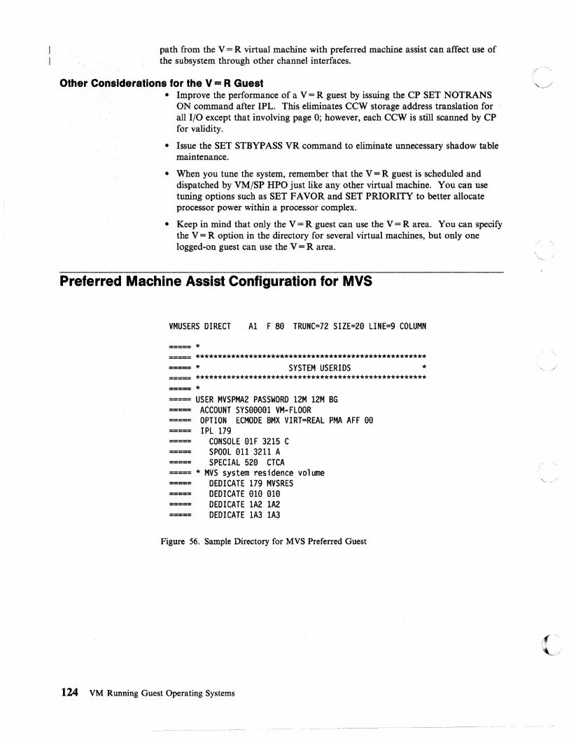
path from the V = R virtual machine with preferred machine assist can affect use of the subsystem through other channel interfaces.
Other Con:slderations for the V = R Guest • Improve the performance of a V = R guest by issuing the CP SET NOTRANS
ON command after IPL. This eliminates CCW storage address translation for all I/O except that involving page 0; however, each CCW is still scanned by CP
. for validity.
• Issue the SET STBYPASS VR command to eliminate unnecessary shadow table maintenance.
• When you tune the system, remember that the V = R guest is scheduled and dispatched by VM/SP HPO just like any other virtual machine. You can use tuning options such as SET FAVOR and SET PRIORITY to better allocate processor power within a processor complex.
• Keep in mind that only the V = R guest can use the V = R area. You can specify the V = R option in the directory for several virtual machines, but only one logged-on guest can use the V = R area.
Preferred Machine Assist Configuration for MVS
VMUSERS DIRECT Al F se TRUNC=72 SIZE=2e LINE=9 COLUMN
===== * ===== **************************************************** ===== * SYSTEM USERIDS * ===== **************************************************** ===== * ===== USER MVSPMA2 PASSWORD 12M 12M BG ===== ACCOUNT SYSeeea1 VM-FLOOR ===== OPTION ECMODE BMX VIRT=REAL PMA AFF aa ===== IPL 179 ===== CONSOLE alF 3215 C ===== SPOOL all 3211 A ===== SPECIAL 52a CTCA ===== * MVS system residence volume ===== DEDICATE 179 MVSRES ===== DEDICATE ala ala ===== DEDICATE lA2 lA2 ===== DEDICATE lA3 lA3
Figure 56. Sample Directory for MVS Preferred Guest
124 VM Running Guest Operating Systems
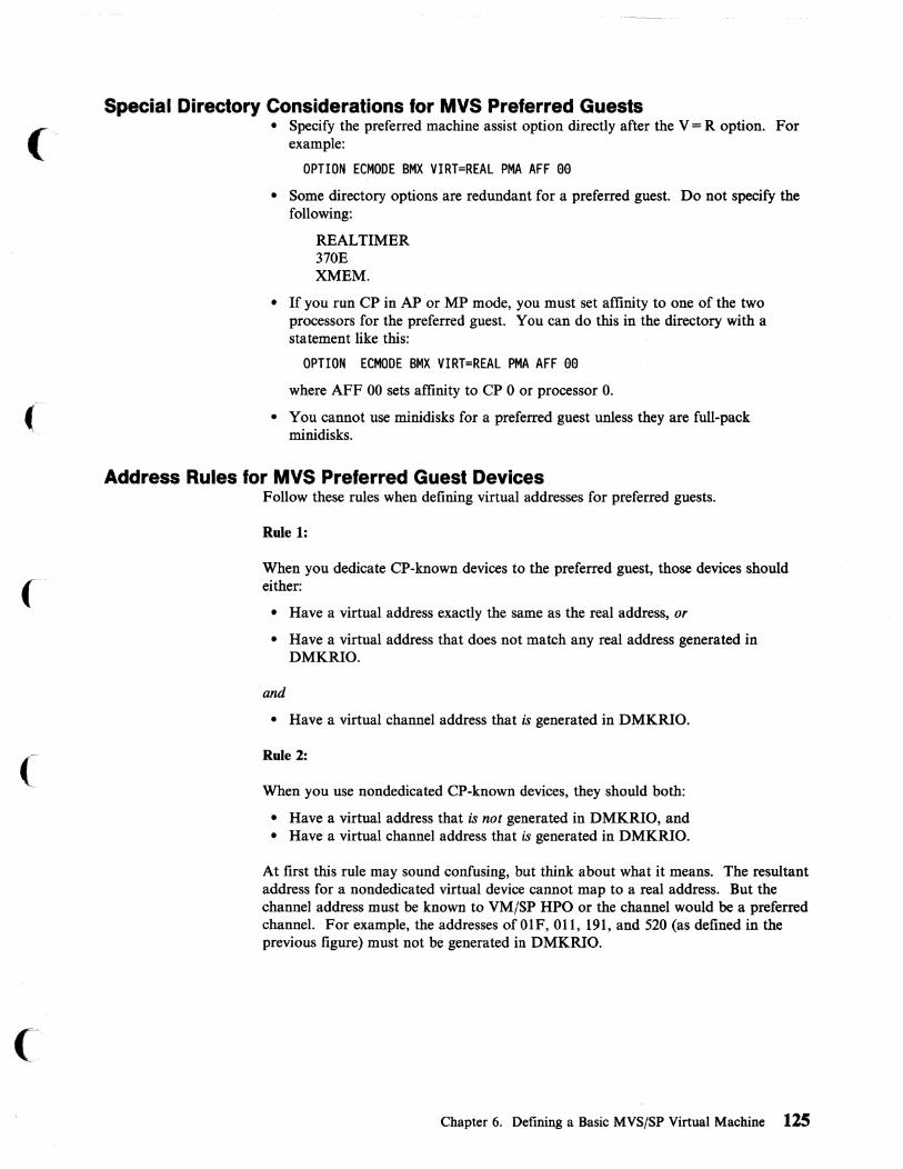
('
(-
(
(:
Special Directory Considerations for MVS Preferred Guests • Specify the preferred machine assist option directly after the V = R option. For
example:
OPTION ECMODE BMX VIRT=REAL PMA AFF ee • Some directory options are redundant for a preferred guest. Do not specify the
following:
REALTIMER 370E XMEM.
• If you run CP in AP or MP mode, you must set affinity to one of the two processors for the preferred guest. You can do this in the directory with a statement like this:
OPTION ECMODE BMX VIRT=REAL PMA AFF ee where AFF 00 sets affinity to CP 0 or processor O.
• You cannot use minidisks for a preferred guest unless they are full-pack minidisks.
Address Rules for MVS Preferred Guest Devices Follow these rules when defining virtual addresses for preferred guests.
Rule 1:
When you dedicate CP-known devices to the preferred guest, those devices should either:
• Have a virtual address exactly the same as the real address, or
• Have a virtual address that does not match any real address generated in DMKRIO.
and
• Have a virtual channel address that is generated in DMKRIO.
Rule 2:
When you use nondedicated CP-known devices, they should both:
• Have a virtual address that is not generated in DMKRIO, and • Have a virtual channel address that is generated in DMKRIO.
At first this rule may sound confusing, but think about what it means. The resultant address for a nondedicated virtual device cannot map to a real address. But the channel address must be known to VM/SP HPO or the channel would be a preferred channel. For example, the addresses ofOlF, 011, 191, and 520 (as defined in the previous figure) must not be generated in DMKRIO.
Chapter 6. Defining a Basic MVS/SP Virtual Machine 125

Channel Considerations for Preferred Guests For the best performance, you should isolate some channels for both MVS and VM/SP HPO. MVS should have enough channels to support a stand-alone, native MVS system. Likewise, VM/SP HPO should have enough channels to handle the requirements of VM/SP HPO and all other nonpreferred guests.
Things to Do before IPLing the MVS/SP Virtual Machine If you use the same console as both the logon console and· the MVS operator console, there are three CP commands you should enter before IPLing MVS. You can use the following CMS EXEC to do this automatically.
CMS EXEC Al F 89 TRUNC=132 SIZE=4 LINE=I COL=I ALT=9
===== &TRACE OFF ===== CP TERM BRKKEY PF12 ===== CP TERM BREAKIN GUESTCTL ===== CP TERM CONMODE 3279 SCRN ON
Figure 57. Sample CMS PROFILE EXEC (VM/SP HPO-MVS/SP)
CP TERM BRKKEY PF12lets you set the CP break key (normally PAl) to another program function (PF) key. This is helpful because MVS uses PAl to retrieve the last command entered. If you do not set the BRKKEY to something other than PAl, you will drop into a CP READ state if you press PAl to retrieve the last command.
CP TERM BREAKIN GUESTCTL prevents CP from interrupting the screen when a message must be displayed at your terminal. For example, if someone sends you a message, the terminal will beep; your MVS console will not be cleared. When you want to display the message, press the break key to drop into CP READ.
CP TERM CONMODE 3270 SCRN ON places your virtual console in 3270 mode. You must include this command when you run a CMS PROFILE EXEC because CMS internally sets your virtual console to a 3215 when it is IPLed. This should be the last command in the PROFILE EXEC because CMS can no longer run once the command is issued. .
You should always specify the SCRN ON portion of the command. It saves the full-screen image if you must go into CP READ.
126 VM Running Guest Operating Systems

(-
(
How to IPL MVS for a V = V or V = R Guest After you have logged on to your virtual machine and before you IPL MVS, make sure your virtual machine size is adequate for this particular session. In the sample directory entry, the USER control statement for the V = V user is:
USER MVSVV2 PASSWORD 8M 16M G
so user MVSVV2 receives eight MD of storage at logon. If you need more storage, in this case you can specify up to 16 MD. If you want 12 MD, issue the command:
define storage as 12m
To IPL MVS in the sample V=V guest, enter the command:
ipl 179
because the directory entry for the V = V guest defined the MVS system residence volume at virtual address 179.
How to IPL MVS for a Preferred Guest There is one difference when you IPL a preferred guest as opposed to a V = V or V = R guest. You must include the PMA option or the PMA V option on the IPL command:
ipl 179 pma
or
ipl 179 pmav
where 179 is the virtual address of the system residence volume.
The IPL device can be on a VM/SP HPO channel or a preferred channel. When you use single processor mode, it must be on the VM-owned processor.
Using a CMS Profile EXEC to Automatically IPL MVS You can use a CMS PROFILE EXEC that IPLs MVS for you when you log on. The EXEC you use should detach your eMS minidisks before it IPLs MVS.
PROF! LE EXEC Al F 80 TRUNC=132 SIZE=11 LINE=6 COL=1 ALT=0
===== &TRACE OFF ===== CP SET RUN ON === CONWAIT ===== DESBUF ===== &STACK CP DET 19E ===== &STACK CP DET 190 ===== &STACK CP DET 191 ===== &STACK CP DET 190 ===== &STACK CP IPL 179 ===== &EXIT
Figure 58. Sample PROFILE EXEC for Automatic IPL of MVS/SP
Chapter 6. Defining a Basic MVS/SP Virtual Machine 127

Issuing the CP SET RUN ON Command Unless you are using CP debug facilities (such as ADSTOP and TRACE commands), you should issue the CP SET RUN ON command. This allows you to ;f ", enter CP commands without stopping your virtual machine. ~".j
CP Commands to Know at the MVS/SP Operator's Console When you run MVS under VM/SP HPO, there are times when you must simulate real processor or hardware functions. Use the following CP commands to simulate these real operator functions. Remember, to execute any CP commands, you must press the break key that you previously defined.
EXT Use the EXT command to create an external interrupt to your virtual machine. It simulates pressing the interrupt key on the real system console. Usually you do this when you lose your virtual console to MVS because of a console switch or a console I/O error.
READY Use the CP READY command to set a device-end interrupt pending for a specified virtual device. This simulates "popping the plug" on a real disk device. You may have to do this on the few occasions when you mount a disk to MVS and the mount message does not disappear.
RESET Use the CP RESET command to clear all pending interrupts from a specified virtual device. You can use this command to drop a dialed terminal from the virtual machine issuing the command.
SYSTEM Use the CP SYSTEM command to simulate the action of the RESET and RESTART buttons on the real computer console, and to clear
,/ "'\
\ "'. /
storage. The operands of this command work as follows: /' "-
• RESET resets all pending interrupts and conditions in the virtual ~'- j
machine.
• RESTART simulates the hardware system RESTART function.
• CLEAR clears virtual storage and virtual keys to binary zeros.
128 VM Running Guest Operating Systems
------- - ---- --_._---_.-

(0
(
Chapter 7. Enhancing MVS/SP Performance Under VM/SP HPO
MVS/SP Support in VMjSP HPO . . . . . . . . . . . . . . . . . . . . . . . . . .. 130 Low Address Protection ............................... 130 Common Segment Facility ............................. 130 Special MVS Instruction and Operation Handling . . . . . . . . . . .. 131
How to Enable MVS/System Extensions Support . . . . . . . . . . .. 131 Dynamic Transition to and from Single Processor Mode ........... 131 Using MVS/SP Cross Memory Services .. ................... 131 Using MVS/SP Page Fault Assist ......................... 132
Preferred Machine Assist ................................ 132 Using Preferred Machine Assist .......................... 132 Generating a False AP System for the Preferred Machine Assist Guest ... 133
Resetting Preferred Machine Assist ...................... 134 Preferred Machine Assist Considerations ..................... 134 General Restrictions for Preferred Machine Assist ............... 135
Restrictions on CP Commands ......................... 138 Examples of Device Address Use Under Preferred Machine Assist .... 140 Documentation .................................. 141
Preferred Channels ............................. 141 Control Switch Assist (Extension to Preferred Machine Assist) ........ 141
Overview ...................................... 141 Running Your Preferred Virtual Machine with Control Switch Assist .. 142
Restrictions on the Use of Control Switch Assist ................ 142 Considerations for Dumping .......................... 143 Migration/Coexistence Characteristics ..................... 143 Supported DIAGNOSE Codes ......................... 144
Configuration Examples for Preferred Machine Assist Systems ......... 144
Chapter 7. Enhancing MVSjSP Performance Under VMjSP HPO 129

MVS/SP Support in VM/SP HPO An MVS system running in a virtual machine can use the MVS/SP Program Package Support in VM/SP HPO if the System/370 Extended Facility or System/370 Extended Feature is on the hardware. This support is not required for a preferred machine assist guest.
The MVS/SP support in VM/SP HPO allows an MVS system running in a virtual machine to use the enhancements in the MVS/System Product-JES3 (program No. 5740-XYN) and the MVS/System Product-JES2 (program No.5740-XYS).
To enable the System/370 Extended Facility, System/370 Extended Feature, and ECPS:MVS,13 use the directory OPTION statement documented in VM/SP HPO Planning Guide and Reference or the class G CP SET command documented in VM/SP HPO CP General User Command Reference.
MVS/SP support includes:
• Low address protection facility • Common segment facility • Special MVS instruction and operation facilities • Single processor mode • MVS/SP cross memory services • MVS/SP page fault assist.
Note: MVS/SP does not support use of the Vector Facility in System/370 mode.
Low Address Protection This feature protects against improper storing through instructions using logical storage addresses in the range 0-511. It prevents inadvertent program destruction of storage locations the processor uses when fetching new PSWs during interrupt processing. Low address protection does not apply to the processor's storing of status (for example, old PSWs or log data), nor does it apply to any channel stores (such as CSW or LCL).
Bit 3 of control register 0 is the low address protection bit and controls whether store instructions using logical addresses in the range 0 to 511 are permitted. When this bit is 0 in real control register 0, store instructions are permitted; when this bit is 1, store instructions are not permitted. When an instruction tries to store at an address in the range 0 to 511 and low address protection applies, the contents of the storage area addressed by the instruction are not modified. Execution of the current instruction is ended or suppressed, and a protection exception occurs.
Common Segment Facility The common segment facility allows addressing segments to be classified as private or common. If bit 30 of the segment table entry for a segment is 1, the segment is a common segment; otherwise it is private. A private segment table entry and the page table it designates can be used with only the segment table origin (STO) that designates the segment table containing the segment table entry. A common segment table entry and the page table it designates can still be used for translating addresses even after you have specified a different STO by changing control register 1.
13 ECPS: MVS is the same as the Extended Facility, except that the low address protection facility and the common segment facility are not included.
130 VM Running Guest Operating Systems
--- ,,"------ -- --'----
,/

(
(
Special MVS Instruction and Operation Handling Special operations and instructions in the MVS/System Extensions Program Package that enhance MVS operations are handled by System/370 Extended Facility or Systemj370 Extended Feature, and are described in the IBM pUblication Systemj370 Extended Facility.
How to Enable MVS/System Extensions Support To enable the MVS/System Extensions support for all virtual machines, use the class A SET S370E ON command. The general user uses the class G SET 370E ON command (or the 370E option of the directory OPTION control statement) to enable the support for a particular virtual machine.
Notes:
1. This process is not necessary for a preferred machine assist guest.
2. The virtual machine must be running with Class A ECMODE on to set 370E on.
Dynamic Transition to and from Single Processor Mode Sometimes an installation will benefit from switching the MVS control program to or from native mode. For example, to obtain the best possible performance from the guest operating system, switch it to native mode. To do different kinds of work simultaneously, switch to the VM/SP HPO environment. For an overview of SPMODE refer to "Transitions to and from Single Processor Mode" on page 164.
Using MVS/SP Cross Memory Services Cross memory services increase the efficiency of communication between address spaces by reducing traffic through the common service area (CSA). Cross memory services are transparent to the user.
MVSjSP Release 3 and later releases support cross memory services for the MVSjSP guest if the virtual machine assist feature and hardware-specific support are available. For processors in which cross memory services are not available, refer to "Using Preferred Machine Assist" on page 132.
Using cross memory services, MVSjSP virtual machine operating systems can:
• Pass control to programs in other address spaces • Move data directly across two defined address spaces • Ease program sharing.
To enable cross memory support on a uniprocessor or one of the processors in an AP or MP configuration, use the class A SET S370E ON XMEM command. The general user can issue the SET 370E ON XMEM command to enable cross memory for the virtual machine. Use the class A QUERY command to determine whether cross memory is active for a particular processor. The general user can use the class G QUERY command to determine whether cross memory is active for the virtual machine.
Cross memory requires a minimum of two shadow tables. Virtual operating systems should use the class G SET STMUL TI command to specify the number of shadow tables they will use. To reduce the overhead incurred in building STOBLOK chains, specify the maximum STMUL TI value, 16.
Note: If the MVSjSP guest is running with !Jreferred machine assist active, the guest uses native cross memory services.
Chapter 7. Enhancing MVS/SP Performance Under VM/SP HPO 131

Refer to VM/SP HPO CP System Command Reference for descriptions of the Class A SET and QUERY commands.
;(--'\ \
Using MVS/SP Page Fault Assist " .. J A page fault occurs when an active page refers to a page in virtual storage. This page translation exception occurs for the MVS/SP V = R guest the first time the guest accesses storage using the GETMAIN macro. VM/SP HPO reduces the time needed by the MVS/SP virtual machine to handle page translation exception interrupts.
MVS/SP operating systems running V = R can use the MVS/SP page fault assist.
MVS/SP page fault assist works with cross memory services. Besides enabling cross memory services, the virtual machine user must issue the class G command SET STBYP ASS VR to start MVS/SP page fault assist.
Preferred Machine As~ist Preferred machine assist allows an MVS/SP. Release 1.1.1 or later guest to run under VM/SP HPO in supervisor state with direct control of its own I/O operations. The MVS preferred guest is dispatched by CP to run in real supervisor state. This cuts down on CP overhead, as CP does not have to simulate most privileged instructions. Preferred machine assist determines whether a real interrupt should be handled by CP or by MVS/SP.
The MVS preferred guest owns real page 0 and MVS/SP gets interrupts directly. These interrupts include:
• CPU timer and clock comparator interrupts • Program, SVC, and I/O interrupts.
Using Preferred Machine Assist With preferred machine assist active, the MVS/SP virtual machine runs in real supervisor state in the V = R area, instead of in problem state, and can use real storage above 16 megabytes to the top of real storage. This feature must be used with the required level of MVS/SP. See Table 4 on page 138 to learn which release of MVS you need for different processors.
Use the SYSCOR macro to partition the use of storage above 16 MB. CP uses the storage between 16 MB and the RMSIZE value for virtual machine paging operations. The preferred machine assist guest uses the storage between the value set by RMSIZE and the end of real storage. (See VM/SP HPO Administration for information about the storage map.)
In real supervisor state, the MVS/SP virtual machine does native I/O operations on channels that preferred machine assist dedicates to the MVS/SP virtual machine. That is, the I/O operations are handled by MVS/SP in the same way as when MVS/SP runs stand-alone (natively) in a processor. CP does not need to do CCW address translation. The MVS/SP preferred machine assist guest owns all channels
132 VM Running Guest Operating Systems
'---~-------,---.~-~------~
/

(
(
(
('"
not defined at system generation time as belonging to VM/SP HPO. CP sets up a mask that corresponds to these channels. Preferred machine assist uses the mask to determine:
• Which I/O operations are allowed to pass directly to the devices. (This depends on which program owns the channel.)
• The routing of I/O interrupts. (This routing also depends on which program owns the channel.)
Besides handling I/O interrupts on channels it owns, the preferred machine assist guest also gets the following external interrupts (with no CP intervention):
• Clock comparator interrupts • CPU timer interrupts.
With preferred machine assist, the MVS/SP virtual machine usually does privileged operations without CP simulation. However, when the MVS/SP virtual machine issues I/O operations to CP- owned channels, preferred machine assist intercepts these instructions for CP simulation. A CP-owned channel is a channel that is generated in DMKRIO and installed on the processor. Preferred machine assist also intercepts certain privileged instructions the MVS/SP virtual machine issues.
Other events that cause preferred machine assist interception are:
• Interval timer interrupts • Pressing the interrupt key • External signals • Time-of-day synchronous check interrupts • Service signals • Emergency signals • External calls.
Generating a False AP System for the Preferred Machine Assist Guest When running VM/SP HPO on a dyadic processor complex, you may wish to generate CP as an attached processor system. This generation will set up CP so that it can be IPLed on a dyadic processor, but will use only one side of the dyadic complex for I/O. It will treat the other processor as an attached processor and will use it to process CP work and will dispatch virtual machines on it, but will not recognize any channels configured on the second processor.
You can now set up the preferred machine assist user ID so that it has affinity to the processor generated as an AP. This will ensure that the preferred machine assist guest is always dispatched on the AP. If the real complex is an MP (two channel sets, one for each processor), the preferred machine assist guest will own the entire channel set attached to its processor in preferred machine assist native mode. Thus it can initiate all its I/O directly to the hardware and will receive its interrupts from the hardware without CP intervention (and consequently without CP overhead).
The major advantage of this environment is that all VM/SP HPO and MVS I/O is physically isolated on different real channel sets. This can make the generation, maintenance, and especially the operation of the two systems easier.
Be aware that there is one important restriction. All preferred machine assist I/O is started to its channel set by the preferred machine assist hardware. Thus each device to which the preferred machine assist guest needs access must have a path through its channel set processor. You cannot use dedicated or attached devices from the CP
Chapter 7. Enhancing MVS/SP Performance Under VM/SP HPO 133

channel set. Nor can you use dialed terminals from CP, minidisks, or virtual devices of any kind (printers, punches, readers). While the associated commands (ATTACH, DEFINE, DIAL, etc.) do function and all control blocks are created ~ correctly, the preferred machine assist guest cannot reach these devices when it issues ,_ j' I/O instructions. No error messages are issued if you violate the restriction. Thus it is recommended that the "false AP" environment be limited to installations that wish to run a preferred machine assist production system divorced from CPo
Resetting Preferred Machine Assist The preferred machine assist feature is reset when the MVS/SP preferred machine assist guest issues:
• SYSTEM RESET • SYSTEM CLEAR • SET ECMODE OFF OR ON • DEFINE STORAGE OR CHANNEL • IPL (of a named system) • IPL (by address with preferred machine assist or PMA V not requested).
Preferred machine assist is also reset if the system operator directs the class B CP '\" / command, VARY OFFLINE PROCESSR with the FORCE option, to a processor to which the preferred machine assist guest has affinity.
Preferred Machine Assist Considerations Make sure you allocate enough storage below the 16 MB line for the preferred guest. MVS must have its entire nucleus and all its I/O buffers below the 16 MB line.
In an AP or MP environment you must SET AFFINITY for either of the two processors. If you want the preferred guest to have exclusive use of one processor and part of another, you must also run VM/SP HPO in single processor mode. If VM/SP HPO is not in single processor mode, a preferred guest will receive at most slightly less than one processor.
There is one hardware function-the interval timer-that the preferred guest cannot use even though it runs in supervisor state. VM/SP HPO needs the interval timer to control the allocation of time slices, and uses i~ to regain control from MVS at the end of the MVS time slice.
If you generate VM/SP HPO to use less than 16MB· of storage, the storage between the top ofVM/SP HPO and the 16MB line is unusable.
The preferred machine assist feature alone ensures that the preferred machine assist guest uses its dispatching time more effectively than other guests. CP allocates real processor time to the virtual machines by using time scheduling algorithms. To improve the performance of the preferred machine assist guest:
• Assign the V = R user a lower priority number (higher priority) on his virtual machine directory control statement than the other virtual machine users have. The priority number ranges from 0 to 99 with 0 having highest priority.
• Use the SET FAVORED command so that the virtual machine at the top of the wait list is dispatched without delay.
If an MVS/SP preferred machine assist guest enters a disabled loop, the CP operator is locked out of the console. Pressing the RESTART button may not be effective. The MVS/SP operator must use established MVS recovery procedures to continue. See OS/VS2 MVS Operator's Library:System Commands.
134 VM Running Guest Operating Systems
\ /
"-- -/

(
f
(
c
Note: A CP restart dump may not be taken when MVS with preferred machine assist is in a disabled loop because the prefix register for the control program processor does not point to the CP PSA. Use the following procedure to break this lockout condition:
1. Hardware-stop both processors.
2. Instruction-step to find the loop instruction.
3. Change one of the loop instructions to a Load Control instruction for control register 6 using the hardware Store instruction. This will cause a control switch, which in turn causes the CP processor prefix register to point to the CP PSA.
4. Instruction-step until the prefix register on the CP processor points to the CP PSA.
5. Use the procedure described in this manual for taking a restart dump.
Applications that use DIAGNOSE X '80 I, unless control switch assist is active, adversely affect the performance of the preferred machine assist guest in single processor mode.
General Restrictions for Preferred Machine Assist 1. Preferred machine assist supports only MVS/SP Version 1 Release 1 with Release
1 Enhancement, or later releases. MVS/SP Version 1 Release 3 or later releases are needed to support extended storage above 16 megabytes. Any attempt to run another system using the preferred machine assist feature may result in CP abending.
2. The MSS Central Server Application Program, a VM/370 Release 6 Program that runs under MVS, cannot run when preferred machine assist is active unless control switch assist is also active.
3. Devices on channels that belong to the preferred machine assist virtual machine are not defined to VM/SP HPO at system generation. Because these devices are unknown to VM/SP HPO, the VM/SP HPO system operator cannot vary them online to VM/SP HPO without reinitializing the system and including the devices in DMKRIO.
4. Do not issue DIAGNOSE instructions when running a guest MVS system with preferred machine assist unless control switch assist is also active and you IPL the guest with the PMA V operand. Otherwise, the results of using a DIAGNOSE in a preferred machine assist environment are unpredictable.
For example, suppose an MVS guest is running with preferred machine assist but not control switch assist. If you issue a DIAGNOSE X '80 I to vary a channel offiine, the DIAGNOSE instruction goes directly to the hardware and the channel is varied offiine. VM/SP HPO is unable to intercept the DIAGNOSE in this case.
5. An MVS V = R guest IPLed with the PMAV operand cannot issue a DIAGNOSE or IUCV instruction from above the 16 MB line, nor can it specify on the operands of such an instruction an address above the 16 MB line.
6. You must not have CP-owned volumes and MVS volumes on the same strings and control units when you are:
• Running an MVS guest with VM is in single processor mode (SPMODE) on multiprocessing systems or
• Running an MVS guest with preferred machine assist on uniprocessors or multiprocessors.
Chapter 7. Enhancing MVS/SP Performance Under VM/SP HPO 135

In either of these two environments, a path must exist to the DASD volumes from a VM channel, and from a channel that VM does not know about. This can be either a channel from the MVS native processor (when running single it· "\ processor mode) or a preferred channel on the VM processor. ',,", . ./
Without such a path certain events can cause a deadlock. The hardware configuration that permits the deadlock is:
Preferred machine assist-owned channel
CP-owned channel
More DASD devices
3880 Storage Control Unit
Figure 59. Hardware configuration. The position of the device in the diagram is not significant. The preferred machine assist device does not need to be the head-of-string.
The events that cause the deadlock are:
a. The preferred machine assist guest issues an 1/0 operation to the preferred machine assist device through storage director 1 of the 3880. This operation '\ completes with a unit check, which places 3880 storage director 1 in " / "contingent allegiance" to the device. This condition is alleviated when the sense is done to read the device status.
b. CP issues an 1/0 operation to the CP device through storage director 1. This 1/0 operation (CP console function, spooling, or diagnose minidisk 1/0) is on behalf of the preferred machine assist guest.
1) The CP 1/0 is not queued to the device with the unit check, so the 3880 rejects it and returns condition code 1 with control unit BUSY.
2) CP queues the 1/0 operation to be retried when it receives control unit END. The preferred machine assist guest remains in CP wait (console function wait, page wait, or execution wait, as is appropriate).
CP does not redispatch the preferred machine assist guest since it is in CP wait. The CP wait cannot be cleared until CP receives the control unit END and the pending 1/0 operation successfully completes.
However, the 3880 does not issue control unit END until sense is finished and clears the unit check. But the sense is not finished until the preferred machine assist guest is dispatched by CPo Therefore, a deadlock occurs.
This situation occurs because each storage director in 3880 Storage Control units has only one register for storing device status information after a unit check. Until the status is read, the storage director cannot accept an 1/0 operation to another device since that device may also present a unit check and the storage director has no place to store that status information. This is a characteristic of Itf'" the 3880 Storage Control units. The type and model of the attached direct ~_/
136 VM Running Guest Operating Systems

(
(
Configuration 1
Preferred machine assist-owned channel
Configuration 2
Preferred machine assist-owned channel
access storage devices is not relevant. VM/SP HPO treats the 3990s in the same way as it does the 3880s.
The following diagrams give configurations that are not subject to this deadlock:
CP-owned channel
3880 Storage Control Unit
More DASD devices
CP-owned channel
Storage Director 2 1st
~----r-----~----------~ 3880 Storage Director 2 2nd
3880
More DASD devices
Figure 60. Configurations not subject to deadlock. If you can arrange your MVS and CP-owned volumes so they do not share an internal path, you can avoid these lockouts.
7. If you start single processor mode on a UP-generated system to IPL with the preferred machine assist or PMA V option, the MVS guest must vary off the native side before issuing SPMODE off.
8. If you are running single processor mode, the MVS guest must issue DIAGNOSE and IUCV instructions from the CP side (not the native side). To accomplish this, the MVS system programmer must set affinity for the program issuing the DIAGNOSE and IUCV instructions.
9. On any processor in which you run MVS preferred machine assist in SP, an MVS guest operating system that uses preferred machine assist or single processor mode must use a release of MVS that would run natively on the processor.
Chapter 7. Enhancing MVS/SP Performance Under VM/SP MPO 137

Table 4. Processor Functions and Required Releases for MVS/SP
Processor
3090
4381 308x
3033
MVS/SP Release Function Required
• Preferred machine assist under VM/SP HPO MVS/SP Version 1 Release 3 • Preferred machine assist with control switch Modification 5
assist • Use of storage above 16 MB by MVS/SP
preferred guest • Use of single processor mode by MVS/SP
preferred guest • Use of dynamic transition to or from single
processor mode by MVS/SP preferred guest
• Preferred machine assist under VM/SP HPO MVS/SP Release 1 • Preferred machine assist with control switch Enhancement
• •
•
•
•
•
• • •
assist Single processor mode Dynamic transition to or from single processor mode
Use of storage above 16 MB by MVS/SP MVS/SP Release 3 preferred guest Use of single processor mode by MVS/SP preferred guest Use of dynamic transition to or from single processor mode by MVS/SP preferred guest
Preferred machine assist MVS/SP Release 1 Enhancement
Use of storage above 16 MB by MVS/SP guest MVS/SP Release 3 Single processor mode Dynamic transition to or from single processor mode
10. When you are running in either single processor mode or as a preferred machine assist guest, do not use the CP PER command.
For information about generating a VM/SP HPO system with a preferred virtual machine, see the VM/SP HPO Planning Guide and Reference manual.
Restrictions on CP Commands If the system uses real storage above 16MB, the system operator can monitor real storage, including the storage above 16MB. The system operator can dump the area above 16MB by abending the system, but not by using the DMCP command. See VM/SP HPO Administration under "Command Use" for a brief outline of the additional functions and restrictions on CP commands related to greater-than-16-megabyte support.
Because the preferred machine assist feature greatly reduces CP simulation overhead for guest operations, some CP functions that usually service a virtual machine are no longer needed or might interfere with the operations of the preferred machine assist guest. To protect the preferred machine assist guest and to ensure its best performance, several CP commands have restrictions when the preferred machine assist feature is active. TheSe restrictions also provide security and integrity to
138 VM Running Guest Operating Systems
/" I
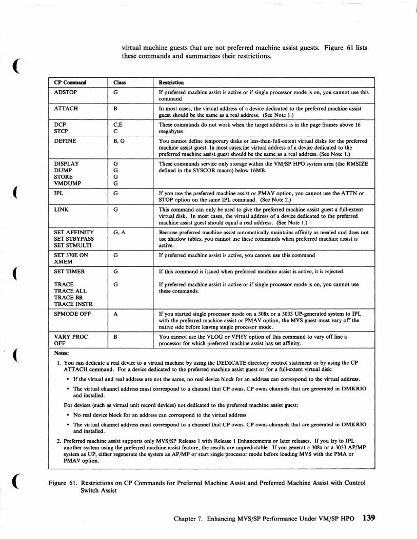
(
CPCommand
ADSTOP
ATTACH
DCP STCP
DEFINE
DISPLAY DUMP STORE VMDUMP
IPL
LINK
SET AFFINITY SET STBYPASS SETSTMULTI
SET 370EON XMEM
SET TIMER
TRACE TRACE ALL TRACEBR TRACEINSTR
SPMODEOFF
VARYPROC OFF
Notes:
virtual machine guests that are not preferred machine assist guests. Figure 61 lists these commands and summarizes their restrictions.
Class Restriction
G If preferred machine assist is active or if single processor mode is on, you cannot use this command.
B In most cases, the virtual address of a device dedicated to the preferred machine assist guest should be the same as a real address. (See Note 1.)
C,E These commands do not work when the target address is in the page frames above 16 C megabytes.
B,G You cannot define temporary disks or less-than-full-extent virtual disks for the preferred machine assist guest. In most cases,the virtual address of a device dedicated to the preferred machine assist guest should be the same as a real address. (See Note 1.)
G These commands service only storage within the VM/SP HPO system area (the RMSIZE G defined in the SYSCOR macro) below 16MB. G G
G If you use the preferred machine assist or PMAV option, you cannot use the ATTN or STOP option on the same IPL command. (See Note 2.)
G This command can only be used to give the preferred machine assist guest a full-extent virtual disk. In most cases, the virtual address of a device dedicated to the preferred machine assist guest should equal a real address. (See Note 1.)
G,A Because preferred machine assist automatically maintains affinity as needed and does not use shadow tables, you cannot use these commands when preferred machine assist is active.
G If preferred machine assist is active, you cannot use this command
G If this command is issued when preferred machine assist is active, it is rejected.
G If preferred machine assist is active or if single processor mode is on, you cannot use these commands.
A If you started single processor mode on a 308x or a 3033 UP-generated system to IPL with the preferred machine assist or PMA V option, the MVS guest must vary otT the native side before leaving single processor mode.
B You cannot use the VLOG or VPHY option of this command to vary otT line a processor for which preferred machine assist has set affinity.
1. You can dedicate a real device to a virtual machine by using the DEDICATE directory control statement or by using the CP ATTACH command. For a device dedicated to the preferred machine assist guest or for a full-extent virtual disk:
• If the virtual and real address are not the same, no real device block for an address can correspond to the virtual address.
• The virtual channel address must correspond to a channel that CP owns. CP owns channels that are generated in DMKRIO and installed.
For devices (such as virtual unit record devices) not dedicated to the preferred machine assist guest:
• No real device block for an address can correspond to the virtual address.
• The virtual channel address must correspond to a channel that CP owns. CP owns channels that are generated in DMKRIO and installed.
2. Preferred machine assist supports only MVS/SP Release I with Release I Enhancements or later releases. If you try to IPL another system using the preferred machine assist feature, the results are unpredictable. If you generat a 308x or a 3033 AP/MP system as UP, either regenerate the system as AP/MP or start single processor mode before loading MVS with the PMA or PMAV option.
Figure 61. Restrictions on CP Commands for Preferred Machine Assist and Preferred Machine Assist with Control Switch Assist
Chapter 7. Enhancing MVS/SP Performance Under VM/SP HPO 139

Examples of Device Address Use Under Preferred Machine Assist For the examples given below, assume the following conditions:
1. At system generation:
a. RDEVICE macros specify real devices at addresses 250 to 255.
b. An RCTLUNIT macro specifies a real control unit at address 250.
c. RCHANNEL macros specify that CP owns channels 0 to 4. Therefore the MVS guest owns channels 5 to 15.
2. Directory entries include:
a. A directory entry for a user named TESTUSR
b. The following MDISK control statement in TESTUSR's directory, indicating that a full pack minidisk is at virtual device address 455:
MDISK 455 3339 9 493 SYSI
3. The physical environment includes:
a. The DASD volume SYSI physically located on spindle 251 b. Some other DASD volume on spindle 252 c. Devices physically located at addresses 250 to 257. (Note that a physical
device may not have a real device block.)
With these conditions in mind, the following command examples show both correct and incorrect use for device addresses under preferred machine assist.
Example 1:
LINK TESTUSR 455 256
This is correct use of device addresses. CP owns channel 2 and there is no real device block for address 256.
Example 2:
LINK TESTUSR 455 255
This is not correct use of device addresses. CP owns channel 2 but there is a real device block for address 255.
Example 3:
LINK TESTUSR 455 251
This is correct use of device addresses. CP owns channel 2. The virtual and real addresses match because the DASD volume SYSI is physically placed at real address 251.
Example 4:
LINK TESTUSR 455 455
This mayor may not be correct use of device addresses. CP owns channel 4. The real device address of 251 does not equal the virtual device address of 455, but if there is no real device block for address 455, this is correct use of device addresses.
140 VM Running Guest Operating Systems
I
\..
(t·~ . . "-~ ../

(
(-
(-
(-
Documentation
Example 5:
ATTACH 252 TESTUSR AS 256
This is correct use of device addresses for the same reason as example 1. However, this is not recommended, because if MVS gets control in native mode, it will get a condition code of 3.
Example 6:
ATTACH 252 TESTUSR AS 251
This is incorrect use of device addresses. CP owns channel 2 but there is a real device block for address 251.
VM/SP HPO Planning Guide and Reference has information about defining the configuration of VM/SP HPO with a preferred machine assist guest.
Preferred Channels You can generate VM/SP HPO without including in DMKRIO some of the physically installed channels and their devices. The exclusion of these channels identifies them as preferred channels. They are available to the preferred guest but to no other virtual machine or CPo CP can use devices on preferred channels only if there is another CP-known path to them, or another CP nucleus with a DMKRIO that includes them has been loaded.
When you generate VM/SP HPO for preferred machine assist, do not define in DMKRIO the channels you want to be used only for MVS I/O. MVS is running natively when it is dispatched and controls the I/O on those channels. VM/SP HPO cannot use them since it does not know about them.
If you run VM/SP HPO with a preferred guest at times, and without one at others, consider keeping alternate copies of DMKRIO and the VM/SP HPO nucleus available. One set should have all channels defined in DMKRIO; the other would leave some undefined for exclusive use by the preferred guest.
Configuration Examples for Preferred Machine Assist Systems beginning on page 144 illustrates preferred channels.
Control Switch Assist (Extension to Preferred Machine ASSist)
Overview Preferred machine assist reduces CP overhead for the V = R machine by allowing the hardware to execute privileged instructions directly. It also allows the virtual machine to handle interrupts directly. Without preferred machine assist, CP would simulate these operations.
Control switch assist extends preferred machine assist. On the 308x, 3090, and 4381 processors, the functions of preferred machine assist that existed before VM/SP HPO Release 4.0 (see "Using Preferred Machine Assist" on page 132) work exactly as before with the following exceptions and additions:
• When the PSW becomes enabled for I/O interrupts for a preferred machine assist guest with or without control switch assist and the preferred machine assist guest has virtual I/O interrupts pending when it is dispatched, a control switch
Chapter 7. Enhancing MVS/SP Performance Under VM/SP HPO 141
occurs. The control switch gives CP control to reflect the I/O interrupt to the preferred machine assist guest efficiently.
• Many CP DIAGNOSE codes can be used by the preferred machine assist guest. They are handled the same way as for a non-preferred machine assist guest.
Note: The unwise use of DIAGNOSE or Virtual Machine Communication Facility (VMCF) can result in extended wait conditions because of the synchronous nature of these commands.
• There is optional support for IUCV which allows the preferred guest with control switch assist to use IUCV functions. The IUCV support lets you communicate with other users or with CP in the same way you would with a non-preferred guest.
• Instruction operation codes X' 83' (DIAGNOSE) and X' B220' (service call) cause a control switch if the preferred machine assist guest has virtual I/O interrupts pending when it is dispatched.
• The PMA V parameter on the IPL command selects control switch assist mode. You must choose between the PMA and the PMA V options; you cannot use both at once.
• IPL simulation uses DIAGNOSE code X '40 I to restore the contents of the virtual machine page in which the IPL simulator runs.
• When CP simulates the STIDP instruction, it returns X' FF' as the version code (bit 0-7) of the processor ID information for a preferred machine assist guest with control switch assist.
After V = R recovery, the MSS Central Server application or any user application that uses VMCF requires reinitializing.
Running Your Preferred Virtual Machine with Control Switch Assist With control switch assist, you can run your MVS/SP V = R virtual machine in one of two ways:
• IPL with the PMA option: IPL [ccuu] PMA • IPL with the PMAV option: IPL [ccuu] PMAV
ccuu is a 3- or 4-digit channel address. The cc represents a one- or two-digit address. The first u represents the control unit. The second u represents the device address.
If you IPL with the PMA option, you receive all the functions of preferred machine assist and the I/O interrupt support.
If you IPL with the PMA V option, you receive all the functions of preferred machine assist, the I/O interrupt support, and the IUCV and CP DIAGNOSE support.
Restrictions on the Use of Control Switch Assist 1. Do not specify STOP or ATTN with preferred machine assist or PMAV.
2. PMAV cannot be specified with preferred machine assist, STOP, or ATTN. An IPL with PMA V specified has the same device and named system restrictions as an IPL with preferred machine assist specified. For directory entry requirements, refer to VM/SP HPO Planning Guide and Reference.
142 VM Running Guest Operating Systems
If'-, ~j

(
(-
(
3. MVS (or systems running under MVS) must not issue a DIAGNOSE instruction from real page 0 or from real storage above 16MB because CP cannot reference this storage. It is owned by the guest virtual machine.
4. MVS (or systems running under MVS) must not issue a DIAGNOSE instruction that specifies real page 0 or a real storage address above 16MB. CP cannot reference this storage because it is owned by the guest virtual machine. (Address operands are specified as guest-real addresses.)
Considerations for Dumping When you use preferred machine assist with control switch assist, you must consider the following:
• If you IPL your MVS guest with the PMA or PMA V option, you must also IPL the dump program with the PMA or PMA V option. If you do not do this, the dump program cannot access real storage above the 16MB line or any device that contains MVS paging data sets that are not on CP-owned channels.
• IBM recommends that you IPL the dump program with the PMA V option for the following reasons:
DIAGNOSE X '40' is supported when you IPL with the PMAV option. It allows CP to save and restore the contents of the virtual machine page in which the IPL simulator runs.
Restoring the original contents of this page allows the MVS stand-alone dump program to dump all the preferred machine assist guest's storage.
When any preferred machine assist guest becomes enabled for I/O interrupts, the control switch addresses a line timeout problem. This timeout problem can occur when an I/O device presents an interrupt for a preferred machine assist guest-owned device on a CP-owned channel. The control switch allows CP to gain control and reflect the I/O interrupt to the virtual machine. (This function is active for preferred machine assist virtual machines if the processor has control switch assist installed. Control switch assist allows a virtual machine to service its own interrupts more efficiently.)
Migration/Coexistence Characteristics You can select either preferred machine assist or preferred machine assist with the control switch assist extension. You may choose to run an MVS V = R machine in either mode if the control switch assist is installed on the processor. The I/O interrupt support is active for either mode on a virtual machine when the control switch assist is on the processor. You do not need to make changes to MVS to allow it to run in a preferred machine assist guest with control switch assist.
Preferred machine assist without the control switch assist has limited utility for many users because it does not provide the CP DIAGNOSE functions available to other virtual machines.
The CP DIAGNOSE codes allow the MVS Job Entry System (JES) to issue CP commands to manipulate VM spool files; the codes allow the MSS Central Server application program to be run on a production MVS system; the codes allow MVS guests to communicate using the Virtual Machine Communication Facility (VMCF) in PMAV mode.
Chapter 7. Enhancing MVSjSP Performance Under VMjSP HPO 143

Supported DIAGNOSE Codes You can use the following DIAGNOSE codes when you IPL with the PMAV option:
Code Description
00 Store extended identifier code
04 Examine real storage
08 Virtual console function
40 Cleanup after virtual IPL by device
4C Generate accounting records
68 VMCF
6C Shadow table maintenance (see Note 1)
78 MSS communication
80 MSSFCALL
Notes:
1. This gives a no-op because page 0 for preferred machine assist with control switeh assist is real page 0 and there are no shadow tables for preferred machine assist and PMA V guests.
2. Using unsupported DIAGNOSE codes gives unpredictable results.
Figure 62. DIAGNOSE Codes Supported
Configuration Examples for Preferred Machine Assist Systems The following examples show I/O configurations with preferred channels for UP, AP, and MP processors. The figures are simplified and do not show complete, detailed string and control unit paths.
Note: Virtual machine system volumes must not exist on control units or strings that have both a virtual machine and a preferred channel path. The examples that follow avoid such a configuration.
144 VM Running Guest Operating Systems
--_ .. - .. _----

(
(
MVS Preferred Virtual Machine
CMS CMS
MVS Test Virtual Machine
Preferred Channels
CP
PMA
VM Channels
r----------------- -----------~ I I 101234567 89ABCDEF I I I
L~!~!~~!! __ ~~-----------------J
Other CPU 3880 X50
~ 3350
...... 3350
650/A50
6511A51
Figure 63. ConfiJUl"ation Example Using Preferred Channels on a UP Processor. Eight channels not defined in DMKRIO are used exclusively by the MVS preferred guest.
Chapter 7. Enhancing MVS/SP Performance Under VM/SP HPO 145

Processor A Processor B
1 !' 1 I
1 \,J 1 1 MVS MVS 1
Test CMS 1 CMS Preferred
Machine 1 Virtual 1 Machine 1 1 1 1
1 1 1
CP 1 CP 1 1 1
PMA (not used) I PMA 1 -, ,
VM Pref erred Channel
Set Cha nnel Set
r------------- -----------------1
! 101+1+1+'" 89 ABC 0 E F i LE~~~~~~~___________ _ ________ J
"'l",.-
X50
650/A50
651/A51
Figure 64. Configuration Example Using Preferred Channels on a False AP Processor
146 VM Running Guest Operating Systems
----------------- - ----

(-
Processor A Processor B
MVS Preferred Virtual Machine
CMS
MVS Test Virtual Machine
Preferred Channels
CP
PMA
----+--_ ..
CP
PMA (not used)
VM/SP HPO Channels
,----------------- -----------,
i 10 +1;·1+ 71 +1+lc 0"," I I Channel Set 1 I L _____________________________ ..1
I Other CPU 3880 X50
- 3350
--- 3350
650/A50
651/A51
Figure 65. Configuration Example Showing Preferred Channels on an AP Processor. VM/SP HPO uses both processors but only eight of the 16 channels. The eight channels not defined in DMKRIO are used exclusively by the MVS preferred guest.
Chapter 7. Enhancing MVSjSP Performance Under VM/SP HPO 147

PrOcessor A. ProcessorS
MVS Preferred Virtual Machine
I I
CMS I . I
I
MVS Test Machine
PMA
Preferred Channels
CP CP
I 1 PMA (not used)
VM Channels
r------~~--------- -----------1 I I 101234567 89ABCDEF I I I I Channel Set 1 I L ___________ ~------------------..a
VM Channels
r-- .... --..... --------, I I I I I 89ABCDEF I I I L ____ i __ ~~~~!~!J
I I --------_.
Other CPU 3880
I I i I I I
t
- 3350
- 3350
X50
650/A50
651/A51
Figure 66. Configuration Example Showing Preferred Channels On an MP Processor. The dotted ii~e from channel set two represents a path that has been varied omine from VM/SP HPO. You must vary off ont! path from VM/SP HPO if you need data sharing between various MVS systems.
148 VM Running Guest Operating Systems

(-
(-
Proce •• or A
MVS Preferred Virtual Machine
PMA
Preferred Channels
I I I I I
CMS I
I I I
CP I I
Proc ••• or B
MVS Preferred Virtual Machine (native processor)
PMA (not used)
VM Channels
r----------------- -----------, I I I I 101234567 89ABCDEF I I I I Channel Set 1 I L ___________ I-_________________ -'
I Other CPU 3880 X50
~ 3350
..... 3350
650/A50
651/A51
Figure 67. Configuration Example Using Single Processor Mode on an AP Processor. Only one processor can perform I/O on an AP.
Chapter 7. Enhancing MVS/SP Performance Under VM/SP HPO 149

Processor A Processor B
Preferred Virtual Machine
MVS Preferred Virtual Machine
MVS Test Virtual Machine (native processor)
Preferred Channels
PMA
CP
I
PMA (not used)
VM Channels
r----------------- -----------, I I
! 10 1 2 3 4 5 6 7 Is 91 AI B I C 0 E F I I Channel Set 1 I L ___________ ~-----------------~
I I
MVS Channels on Processor B (symmetrical to preferred channels
r-- ------------1 I I I I 189ABCDEF I I I L____ __C~~~~~~!J
Other CPU 3880 X50
- 3350 650/A50
- 3350 651/A51
Figure 68. Configuration Example Showing Single Processor Mode on an MP Processor. Both processors can perform I/O on an MP. In this example, channels 8 through 1 are not generated in DMKRIO. They are used symmetrically from MVS on both processors.
150 VM Running Guest Operating Systems
-- ---------~----- --------- ------------------ "-----
/
/

(
(-
(
Chapter 8. More About Operating an MVS/SP Virtual Machine
How to Initialize a DASD for Use by MVS .................... . Case 1: Using DSF for a Dedicated Volume .................. . Case 2: Using DSF for a Full-Volume Minidisk ............... . Case 3: Using DSF for a Minidisk That Is Less Than a Full Volume ... .
Using CP Commands to Enhance Performance .................. . Problem Determination ................................ .
Problem Recognition ................................ . Status Information for Preferred Machine Assist ............... . Service Aids ..................................... . MVS Dumps .................................. . How to Obtain an MVS Restart Dump . . . . . . . . . . . . . . . . . . . . . . How to Obtain an MVS Stand-alone Dump .................. . How to Obtain a VM/SP HPO Dump With Preferred Machine Assist but
not Single Processor Mode ...................... . How To Obtain a VM/SP HPO Dump in Single Processor Mode SVC Dumps ................................ . Error Recording and Analysis ..................... .
How MVS and CP Use SVC 76 .................. . Error Recording in Single Processor Mode and Preferred Machine Assist
CP Trace Table ................................... . MVS Trace Table . . . . . . . . . . . . . . . . . . . . . . . . . . . . . . . . . . . CP Control Blocks .................'................. CP Command Restriction for Problem Determination ............ . Trace Table Recording Facility .................... . Summary of How to Approach a Diagnostic Problem ....... .
Transitions to and from Single Processor Mode ............ . How to Put VM/SP HPO in Uniprocessor Mode .......... . How to Vary Off Line a 308x, 3090, or 4381 Processor ...... . Setting Single Processor Mode On ................... . Setting Single Processor Mode Off . . . . . . . . . . . . . . . . . . . . Verifying Single Processor Mode .................... . Restrictions for Single Processor Mode ................ . Warnings for MVS Operators Using SP Mode or Preferred Machine Assist
Without Control Switch Assist ......................... . Shadow Tables ..................................... .
Five Things You Need to Know About Shadow Tables ........... . How to Control Shadow Tables for a V = R Guest When Not in Single
Processor Mode .................................. . How to Control Shadow Tables for a V = R Guest While in Single Processor
Mode ........................................ . How to Control Shadow Tables for a Preferred Machine Assist Guest How to Control Shadow Tables for a V = V Guest .............. .
Setting the STMUL TI n Parameter ..................... . Setting the USEG xx Parameter ....................... . Setting the CSEG yyy Parameter When Not in Single Processor Mode Setting the CSEG yyy Parameter While in Single Processor Mode
Using SET STBYPASS to Define the High-Water Mark .......... . Selective Invalidation ............................... .
Setting a Precise Value for SET STBYPASS ................ . Shadow Table Restrictions for V = R Guests ...... . . . . . . . Shadow Table Restrictions for V = V Guests
153 154 156 156 157 158 158 158 158 159 159 159
160 161 162 162 162 162 162 163 163 163 163 163 164 164 164 164 164 165 165
165 166 167
167
167 168 168 168 168 169 169 169 169 170 170 171
Chapter 8. More About Operating an MVS/SP Virtual Machine 151
AUTOLOG Facility ................................... 171 Using the CP AUTOLOG Command ..................... 171 Defining AUTOLOGI in the Directory .................... 172 Multiple Systems With AUTOLOGI ..................... 172
MVS V = R Virtual Machine Recovery ........................ 173 Preferred Machine Assist Guest Survival ....................... 174 Guest Survival with Control Switch Assist ... . . . . . . . . . . . . . . . . . .. 174 Reinitializing After V = R Recovery When Using Control Switch Assist .... 174 System. Activity Display Frames ............................ 174 Multiple-Access Virtual Machines ........................... 175 Unsupported Devices ....,............................. 180 Analyzing Performance ................................. 181
MVS under VM/SP HPO Operating Environments ............... 181 3480 Restrictions ................................... 181
152 VM Running Guest Operating Systems
i /
11 " \,-/

(
(
(
(-
How to Initialize a DASD for Use by MVS You must initialize DASD volumes before an operating system can use them. To initialize a full DASD volume or minidisk for use by an MVS guest, use the device support facility (DSF).
You can initialize DASD volumes with Device Support Facility under MVS, or you can run the stand-alone version in a virtual machine. To initialize a DASD volume with the stand-alone version, you must use a DEDICATE statement in the directory to make the volume a part of the virtual machine configuration, or have the operator issue an ATTAcH command for the volume. Minidisks must have MDISK entries in the directory, and the user running Device Support Facility must be properly linked to them.
The stand-alone version of Device Support Facility is provided on the CMS system disk (190) as file IPL DSF S. To execute the program in a virtual machine, take the following steps:
1. Spool your virtual punch to yourself.
2. Punch the file IPL DSF S without a header card.
3. IPL the Device Support Facility program from your virtual reader.
4. Identify your terminal to the Device Support Facility program by pressing ENTER.
5. Respond to the DSF message to define the input device as the console.
6. Respond to the Device Support Facility message to define the output device as the console.
7. Enter the Device Support Facility control statements to perform the initialization.
8. Re-IPL CMS when Device Support Facility finishes.
Chapter 8. More About Operating an MVS/SP Virtual Machine 153

The following is an example of an EXEC that will perform some of these steps for you:
DSF EXEC Al F a0 TRUNC=132 SIZE=20 LINE=5 COL=1 ALT=0
===== &TRACE ERR ===== &TYPE **** SPOOLING DSF TO YOUR READER **** ===== CP SPOOL PUNCH * CLASS I ===== PUNCH IPL DSF * (NOH ===== &IF &RETCODE NE e &GOTO -ERROR ===== &IF &INDEX GT 0 PUNCH &1 &2 &3 (NOH ===== &IF &RETCODE NE 0 &GOTO -ERROR ===== CP SPOOL PUNCH NOCONT CLOSE =====CP SPOOL PUNCH OFF CLASS A ===== CP CLOSE READER ===== CP ORDER READER CLASS I ===== CP SPOOL READER CONT CLASS * NOHOLD ===== &TYPE **** IPLING DSF ===== &TYPE **** WHEN DSF IS FINISHED, RE-IPL CMS ===== CP IPL 00C ===== -ERROR &R = &RETCODE ===== CP SPOOL PUNCH NOCONT PURGE ===== CP SPOOL PUNCH OFF CLASS A ==== &EXIT &R
Figure 69. nSF EXEC for an MVS Virtual Machine
Case 1: Using DSF for a Dedicated Volume , You have a 3350 DASD online at real address 160.
1. Attach it to yourself by issuing:
att 160 *
2. Run the DSF EXEC.
3. Enter the information requested from you as the EXEC executes.
4. When you are prompted to enter the INIT command, you specify:
UNITADDRESS The hexadecimal address of the channel and unit on which "-.,'/ the volume is mounted.
NOVERIFY
DEVICETYPE
VOLID
154 VM Running Guest Operating Systems
To bypass verification of the volume serial number and owner identification.
The type of DASD.
The volume label name.
----- ---------,--------------

(
(
The following example shows how this process works:
ENTER:
att 16B *
SYSTEM RESPONSE:
DASD 16B ATTACH TO CPG 16B Ready;
ENTER:
dsf
SYSTEM RESPONSE:
**** SPOOLING DSF TO YOUR READER **** PUN FILE BB11 TO CPG COpy BB1 NOHOLD BBBI FILE ORDERED **** IPLING DSF **** WHEN DSF IS FINISHED. RE-IPL CMS
ICKBB5E DEFINE INPUT DEVICE. REPLY 'DDDD.CUU' OR 'CONSOLE' ENTER INPUT/COMMAND:
ENTER:
console
SYSTEM RESPONSE:
CONSOLE ICKBB6E DEFINE OUTPUT DEVICE. REPLY 'DDDD.CUU' OR 'CONSOLE' ENTER INPUT/COMMAND:
ENTER:
console
SYSTEM RESPONSE:
CONSOLE ICKDSF - SA DEVICE SUPPORT FACILITIES 6.B ENTER INPUT/COMMAND:
ENTER:
init unitaddress(16B) noverify devicetype(335B) volid(d3350B)
SYSTEM RESPONSE:
INIT UNITADDRESS(160) NOVERIFY DEVICETYPE(3350) VOLID(D335BO) ICKBB7BOI 16B BEING PROCESSED AS LOGICAL DEV = 3350
PHYSICAL DEVICE = 3350 ICK003D REPLY U TO ALTER VOLUME 160 CONTENTS. ELSE T ENTER INPUT/COMMAND:
Chapter 8. More About Operating an MVS/SP Virtual Machine 155
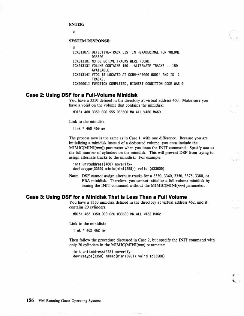
ENTER:
u
SYSTEM RESPONSE:
U ICK01307I DEFECTIVE-TRACK LIST IN HEXADECIMAL FOR VOLUME
033500 ICK01310I NO DEFECTIVE TRACKS WERE FOUND. ICK01313I VOLUME CONTAINS 150 ALTERNATE TRACKS -- 150
AVAILABLE. ICK01314I VTOC IS LOCATED AT CCHH=X'OOOO 0001' AND IS 1
TRACKS. ICK00001I FUNCTION COMPLETED. HIGHEST CONDITION CODE WAS 0
Case 2: Using DSF for a Full-Volume Minldisk You have a 3350 defined in the directory at virtual address 460. Make sure you have a volid on the volume that contains the minidisk:
MDISK 460 3350 000 555 033500 MW ALL W460 M460
Link to the minidisk:
link * 460 460 mw
The process now is the same as in Case 1, with one difference. Because you are initializing a minidisk instead of a dedicated volume, you must include the MIMIC(MINI(nnn)) parameter when you issue the INIT command. Specify nnn as the full number of cylinders on the minidisk. This will prevent DSF from trying to assign alternate tracks to the minidisk. For example:
init unitaddress(460) noverify-devicetype(3350) mimic(mini(555» volid (d33500)
Note: DSF cannot assign alternate tracks for a 3330, 3340, 3350, 3375, 3380, or FBA minidisk. Therefore, you cannot initialize a full-volume minidisk by issuing the INIT command without the MIMIC(MINI(nnn) parameter.
Case 3: USing DSF for a Minidisk That Is Less Than a Full Volume You have a 3350 minidisk defined in the directory at virtual address 462, and it contains 20 cylinders:
MDISK 462 3350 000 020 033500 MW ALL W462 M462
Link to the minidisk:
link * 462 462 row
Then follow the procedure discussed in Case 2, but specify the INIT command with only 20 cylinders in the MIMIC(MINI(nnn) parameter:
init unitaddress(462) noverify-devicetype(3350) mimic(mini (020» volid (d33500)
156 VM Running Guest Operating Systems

(
(-
Using CP Commands to Enhance Performance You can use certain CP commands to aid the performance of MVS guest virtual machines. Bear in mind that improving the performance of one virtual machine may impair the performance of others.
Before using the following commands, refer to the VMjSP HPO CP System Command Reference manua1.
LOCK
SET FAVOR
SETMINWS
SET RESERVE
SET SRM IBUFF
Use the LOCK command to lock permanently in real storage selected pages of a V = V guest's virtual storage. Those pages are excluded from future paging activity. Make sure you have enough page frames available before issuing this command, or you will severely degrade the performance of other virtual machines.
Use the SET FAVOR command to provide a specific percentage of processor time for one or more favored MVS guests. When you specify a percentage of 100, one favored MVS guest is placed at the top of the dispatch queue and held there until it logs off.
Use the SET MINWS command to set the minimum working set size (in number of pages) to a high value for one or more MVS guests.
Use the SET RESERVE command to reserve page frames of real storage for one or more MVS V = V guests.
Use the SET SRM IBUFF command to increase the amount of storage available to MVS V = V guests by limiting the size of the interactive buffer.
SET SRM PREPAGE Use the SET SRM PREPAGE command to control the
SET PRIORITY
number of swap sets that are swapped into main storage when the system adds a virtual machine to queue.
Use the SET PRIORITY command to improve an MVS guest's dispatching priority in relation to that of other users on the system.
Chapter 8. More About Operating an MVS/SP Virtual Machine 157

Problem Determination
Problem Recognition System failures appear in the usual way when you run MVS under VM/SP HPO. Abends, wait states, loops, and incorrect results are the basic indicators of system problems. See VM/SP HPO Diagnosis Guide for a comprehensive description of failure symptoms and how to handle them.
When you run MVS under VM/SP HPO, any of these system failures may occur with either MVS or VM/SP HPO in control of the processor. One special concern is the case of a preferred machine assist guest entering a disabled loop. This prevents the VM system operator from regaining control of the system and entering commands from the master console. It is strongly recommended that you confine any testing of MVS systems to V = V virtual machines.
Status Information for Preferred Machine Assist
Service Aids
An MVS preferred guest runs in real supervisor mode and is able to issue native I/O instructions without having CP intercept and simulate these operations. In addition, MVS exclusively owns a set of preferred guest channels. These channels and their associated devices are not included in DMKRIO. Therefore, no RDEVICE, RCTLUNIT, or RCHANNEL control blocks are generated for preferred guest devices. Status information concerning I/O to these devices can only be obtained from control blocks (such as UCB) maintained by MVS. However, the preferred guest can also access devices known to CP via LINK, ATTACH, or DEDICATE commands. When accessing these devices, CP controls I/O operations and maintains status information.
While operating as the preferred guest, MVS owns the system's absolute page 0, allowing I/O interrupts to be directly reflected by the hardware into MVS's low storage. During CP initialization, CP's page 0 is dynamically relocated to a page above the V = R area to let MVS use absolute page O. A prefix register is used to provide addressability to the relocated CP page O. This occurs on all types (UP, MP, or AP) of processors.
MVS does not have to be modified to run under VM/SP HPO. Because MVS makes no tests during initialization to determine whether it is running natively or under a VM/SP HPO system, no VM/SP HPO handshaking facilities are used. MVS always assumes it is controlling a native processor complex with its associated system resources.
Whenever an abend occurs in CP, the module DMKDMP takes a system abend dump. A system abend dump is also created whenever the system operator presses the PSW Restart key. When you obtain a CP dump:
• Use the CP SET DUMP command to direct an abend dump to an output device and to determine the contents of the dump. SET DUMP AUTO CP will be sufficient for most CP problems. SET DUMP AUTO ALL will include guest as well as CP storage. Remember:
SET DuMp AUTO CP dumps only CP pages.
SET DUMP AUTO ALL dumps all of real storage.
158 VM Running Guest Operating Systems
r e - '
./
,If-"
"-j
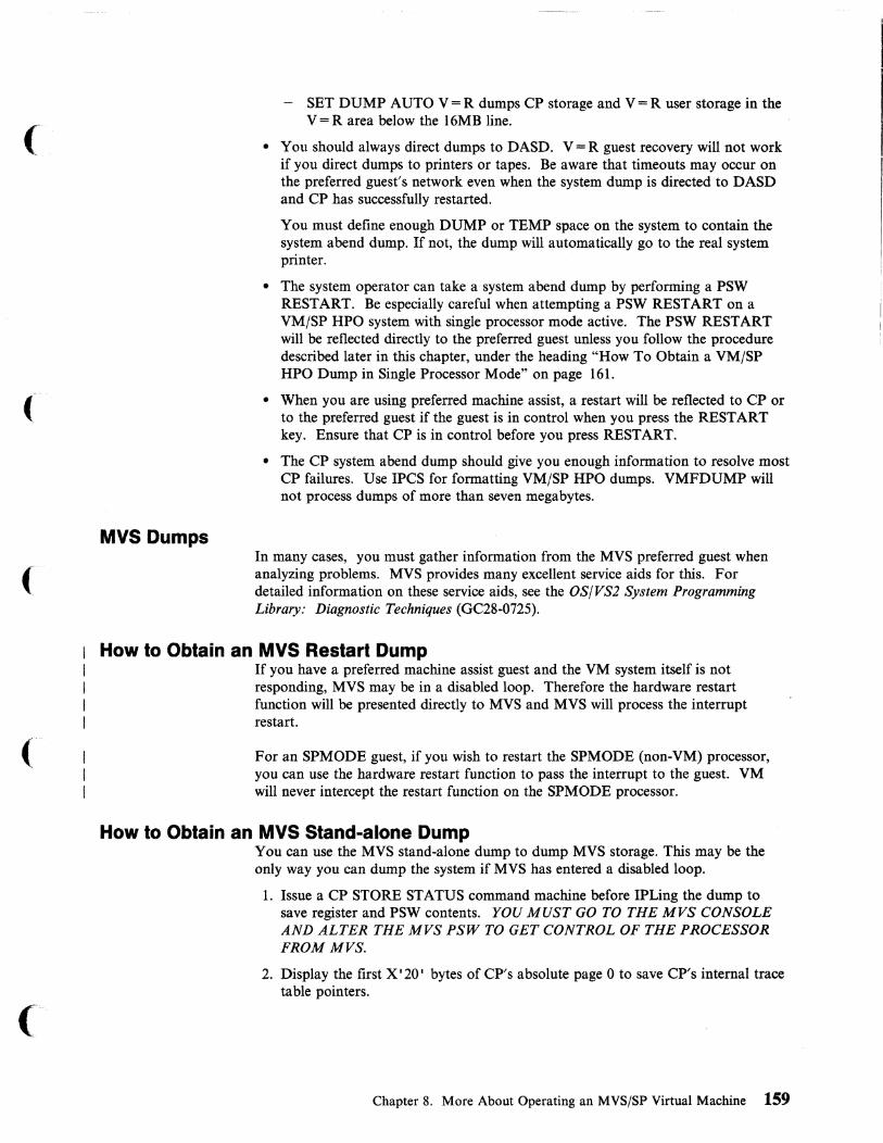
(
(
(
MVS Dumps
- SET DUMP AUTO V=R dumps CP storage and V=R user storage in the V = R area below the 16MB line.
• You should always direct dumps to DASD. V = R guest recovery will not work if you direct dumps to printers or tapes. Be aware that timeouts may occur on the preferred guest's network even when the system dump is directed to DASD and CP has successfully restarted.
You must define enough DUMP or TEMP space on the system to contain the system abend dump. If not, the dump will automatically go to the real system printer.
• The system operator can take a system abend dump by performing a PSW RESTART. Be especially careful when attempting a PSW RESTART on a VMjSP HPO system with single processor mode active. The PSW RESTART will be reflected directly to the preferred guest unless you follow the procedure described later in this chapter, under the heading "How To Obtain a VMjSP HPO Dump in Single Processor Mode" on page 161.
• When you are using preferred machine assist, a restart will be reflected to CP or to the preferred guest if the guest is in control when you press the RESTART key. Ensure that CP is in control before you press RESTART.
• The CP system abend dump should give you enough information to resolve most CP failures. Use IPCS for formatting VMjSP HPO dumps. VMFDUMP will not process dumps of more than seven megabytes.
In many cases, you must gather information from the MVS preferred guest when analyzing problems. MVS provides many excellent service aids for this. For detailed information on these service aids, see the OS/VS2 System Programming Library: Diagnostic Techniques (GC28-0725).
How to Obtain an MVS Restart Dump If you have a preferred machine assist guest and the VM system itself is not responding, MVS may be in a disabled loop. Therefore the hardware restart function will be presented directly to MVS and MVS will process the interrupt restart.
For an SPMODE guest, if you wish to restart the SPMODE (non-VM) processor, you can use the hardware restart function to pass the interrupt to the guest. VM will never intercept the restart function on the SPMODE processor.
How to Obtain an MVS Stand-alone Dump You can use the MVS stand-alone dump to dump MVS storage. This may be the only way you can dump the system if MVS has entered a disabled loop.
1. Issue a CP STORE STATUS command machine before IPLing the dump to save register and PSW contents. YOU MUST GO TO THE MVS CONSOLE AND ALTER THE MVS PSW TO GET CONTROL OF THE PROCESSOR FROM MVS.
2. Display the first X'20' bytes ofCP's absolute page 0 to save CP's internal trace table pointers.
Chapter 8. More About Operating an MVS/SP Virtual Machine 159
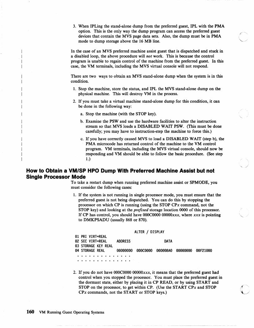
I I I I
3. When IPLing the stand-alone dump from the preferred guest, IPL with the PMA option. This is the only way the dump program can access the preferred guest devices that contain the MVS page data sets. Also, the dump must be in PMA mode to dump storage above the 16 MB line.
In the case of an MVS preferred machine assist guest that is dispatched and stuck in a disabled loop, the above procedure will not work. This is because the control program is unable to regain control of the machine from the preferred guest. In this case, the VM terminals, including the MVS virtual console will not respond.
There are two ways to obtain an MVS stand-alone dump when the system is in this condition.
1. Stop the machine, store the status, and IPL the MVS stand-alone dump on the physical machine. This will destroy VM in the process.
2. If you must take a virtual machine stand-alone dump for this condition, it can be done in the following way:
a. Stop the machine (with the STOP key).
b. Examine the PSW and use the hardware facilities to alter the instruction stream so that MVS loads a DISABLED WAIT PSW. (This must be done carefully; you may have to instruction-step the machine to force this.)
c. If you have correctly caused MVS to load a DISABLED WAIT (step b), the PMA microcode has returned control of the machine to the VM control program. VM terminals, including the MVS virtual console, should now be responding and VM should be able to follow the basic procedure. (See step 1.)
How to Obtain a VM/SP HPO Dump With Preferred Machine Assist but not Single Processor Mode
To take a restart dump when running preferred machine assist or SPMODE, you must consider the following cases:
1. If the system is not running in single processor mode, you must ensure that the preferred guest is not being dispatched. You can do this by stopping the processor on which CP is running (using the STOP CPx command, not the STOP key) and looking at the prefixed storage location 0000 of this processor. If CP has control, you should have OOOCOOOO OOOOOxxx, where xxx is pointing to DMKPSADU (usually 868 or 870).
e1 PRI VIRT=REAL e2 SEC VIRT=REAL e3 STORAGE KEY REAL e4 STORAGE REAL
ALTER / DISPLAY
ADDRESS DATA
eeeeeeee eeeceeee eeeeeSAe eeeeeeee eeF21eee
2. If you do not have OOOCOOOO OOOOOxxx, it means that the preferred guest had control when you stopped the processor. You must place the preferred guest in the dormant state, either by placing it in CP READ, or by using START and STOP on the processor, to get within CPo (Use the START CPx and STOP CPx commands, not the START or STOP keys.)
160 VM Running Guest Operating Systems
---~-- ----~~~- --~--~--
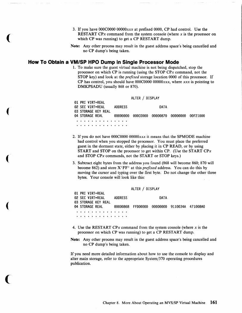
(
3. If you have OOOCOOOO OOOOOxxx at prefixed 0000, CP had control. Use the RESTART CPx command from the system console (where x is the processor on which CP was running) to get a CP RESTART dump.
Note: Any other process may result in the guest address space's being cancelled and no CP dump's being taken.
How To Obtain a VM/SP HPO Dump in Single Processor Mode 1. To make sure the guest virtual machine is not being dispatched, stop the
processor on which CP is running (using the STOP CPx command, not the STOP key) and look at the prefixed storage location 0000 of this processor. If CP has control, you should have OOOCOOOO OOOOOxxx, where xxx is pointing to DMKPSADU (usually 868 or 870).
lU PRI VIRT=REAL a2 SEC VIRT=REAL a3 STORAGE KEY REAL a4 STORAGE REAL
ALTER / DISPLAY
ADDRESS DATA
aaaaaaaa aaaeaeee eaaaaS7a eaeeaaaa aaF21aaa
2. If you do not have OOOCOOOO OOOOOxxx it means that the SPMODE machine had control when you stopped the processor. You must place the preferred guest in the dormant state, either by placing it in CP READ, or by using START and STOP on the processor to get within CPo (Use the START CPx and STOP CPx commands, not the START or STOP keys.)
3. Subtract eight bytes from the address you found (868 will become 860; 870 will become 862) and store X I FF I at this prefixed address. You can do this by moving the cursor and typing over the first byte. Do not change the other three bytes. Your console will look like this:
a1 PRI VIRT=REAL a2 SEC VIRT=REAL 93 STORAGE KEY REAL a4 STORAGE REAL
ALTER / DISPLAY
ADDRESS DATA
aaaaaS6S FFaae9aa aaaaaaaa 911aa34A 471aaSAa
4. Use the RESTART CPx command from the system console (where x is the processor on which CP was running) to get a CP REST ART dump.
Note: Any other process may result in the guest address space's being cancelled and no CP dump's being taken.
If you need more detailed information about how to use the console to display and alter main storage, refer to the appropriate System/370 operating procedures publication.
Chapter 8. More About Operating an MVS/SP Virtual Machine 161

SVCDumps MVS's SVC dumps are a useful source of information about MVS failures. At c--" times, they provide clues to what appear to be hardware problems. Remember, MVS .. ~ does not know that it is running under VM/SP HPO. Certain CP instruction simulation errors may appear to the MVS guest as hardware failures. For very difficult hardware-like errors, you may have to ZAP the MVS system in order to load a disabled wait PSW. This will allow you to dump the MVS system using the MVS stand-alone dump.
Error Recording and Analysis MVS records both hardware and software errors on the SYS1.LOGREC data set. This information is critical to tracing the sequence of events that caused a system failure. Use the information contained in SYSl.LOGREC along with CP's dumps and error recording data for more information concerning system failures.
How MVS and CP Use SVC 76 When MVS runs in a virtual machine, it uses SVC 76 to write error records to the " error recording data sets. However, in a nonpreferred virtual machine, CP intercepts \,_ j
SVC 76 and records the error in its own error recording area. Therefore, error records from MVS reside in this one centralized error recording area. To access the recorded data, use the CMS CPEREP command. For further information about error recording, formatting output from the error recording area with service record file devices, and CPEREP refer to VM/SP OLTSEP and Error Recording Guide.
Error Recording in Single Processor Mode and Preferred Machine Assist
CP Trace Table
When VM/SP HPO is in single processor mode or preferred machine assist mode, CP does not intercept SVC 76 (the error recording SVC) in the preferred guest. Thus, error records for the MVS V = R guest may be in two locations: ./
• The VM/SP HPO error recording cylinders, when SVC 76 is issued in the VM/SP HPO processor, and
• The MVS SYSl.LOGREC data set, when SVC 76 is issued in the non-VM processor.
To find all the error records that pertain to the MVS V = R guest, you must look in both locations. To put the records in chronological sequence, you can check the time and date in each record.
Note: Duplicate error records appear for channel checks reflected on the VM processor. When MVS in the IPL processor issues SVC 76 for a channel check, CP intercepts the SVC 76 and records the error in its error recording cylinders. However, CP then passes the SVC 76 back to MVS for recording in its SYSl.LOGREC data set.
One of the most important areas in any CP dump is the CP internal trace table. This is the key to tracing the sequence of events that precedes a system failure. VM/SP HPO allows the spooling of trace data to an output device. CP does not trace I/O events to preferred guest devices because these instructions are never intercepted and simulated by CP. Detailed information about the CP trace table is available in VM/SP HPO Diagnosis Guide.
162 VM Running Guest Operating Systems

(
(
MVS Trace Table The MVS system trace table is as important as the CP trace table when examining failures for preferred guests. It provides the sequence of events that precedes a system failure.
This trace table will contain all SIOs issued to preferred guest devices, as well as the interrupts received from that I/O. If the preferred guest has issued a LINK, ATTACH, or DEDICATE command to a CP-generated device, you must examine both the CP trace table and the MVS trace table to understand the entire I/O event.
The external, SVC, and program interrupt trace table entries provide additional information concerning the status of the MVS system.
CP Control Blocks Refer to VM/SP HPO CP Data Areas and Control Blocks when examining CP control blocks. Valuable status information about a preferred guest is contained in the PSA, VMBLOK, and the MICBLOK.
When you use CP's dump routine, module DMKDMP will move MVS's absolute page 0 to DMKSLC-4096. It will move CP's page 0 to absolute page O. This occurs in both single processor mode and non-single processor mode. For all system abend dumps, CP's PSA can be found in the first page of storage.
However, when you use the MVS stand-alone dump, there is no movement ofPSAs. The MVS stand-alone dump dumps storage without changing any locations.
CP Command Restriction for Problem Determination You cannot issue ADSTOP or TRACE commands from a preferred guest.
Trace Table Recording Facility The trace table recording facility expands problem determination capability for service personnel and system programmers. The facility uses the CP CPTRAP command to create on a reader spool file a chronological record of selected trace table, virtual machine interface, and CP interface information. Use this facility to help analyze VM/SP HPO problems that you cannot detect with a system dump.
A CMS utility program, TRAP RED, is included as part of the CPTRAP facility. TRAPRED uses the reader file as input, and supports output to either a spooled print file or an interactive terminal display. For additional information on using the CPTRAP facility, refer to VM/SP HPO Diagnosis Guide.
Summary of How to Approach a Diagnostic Problem The following recommendations will help you analyze failures on VM/SP HPO:
In general, approach CP abends and disabled wait states from a CP perspective. Interrogate the abend or wait state code first. System hangs or loops may be more difficult to diagnose. Your initial question should be, "Which system was in control of the system at the time of the failure?"
As a general rule, assume the preferred guest was in control. Gather as much information as possible from the preferred guest. In particular, find the MVS trace table and interrogate the trace entries for an understanding of MVS/SP's perspective
Chapter 8. More About Operating an MVS/SP Virtual Machine 163

on the failure. Always examine all I/O control blocks (such as UCBs and lOBs) for possible hardware errors. Remember that MVS/SP controls all preferred guest devices. ~
Coordinate the examination of the MVS trace table with an interrogation of the CP (VM/SP HPO) internal trace. Understand what has occurred in CP prior to the system failure. Remember that even when MVS is running with preferred machine assist, it continues to operate as a guest machine under CPo CP still controls the scheduling and dispatching of the MVS guest and may have other virtual machines to service. Use both system's trace tables to help diagnose those pro~lems that are unable to be solved with a single system's trace table.
Transitions to and from Single Processor Mode This section discusses the steps involved in placing your VM/SP HPO system in single processor mode. Special considerations and restrictions are also discussed.
How to Put VM/SP HPO in Uniprocessor Mode Before you can use single processor mode, VM/SP HPO must be in UP mode. If you are in AP or MP mode, the system operator must vary a processor off line. Decide which processor is to have native control of MVS and vary it off line.
How to Vary Off Line a 308x, 3090, or 4381 Processor To vary off line a 308x, 3090, or 4381 processor for single processor mode, use the CP command:
vary offline processor nn vlog
If the FORCE or VPHY option or no option of the CP VARY command is used, the processor will be physically varied off line and will require that MVS physically vary on line the processor before you can use it. This may take several minutes.
Setting Single Processor Mode On Once the correct processor is off line, the system operator can then tum on single processor mode by issuing the CP command:
spmode on
After the system operator enables single processor mode, the virtual machine operator must then vary on line the omine or second processor to the MVS virtual machine using the MVS VARY command.
Setting Single Processor Mode Off To get out of single processor mode, the system operator must vary the second processor off line from the MVS virtual machine and issue the CP command:
spmode off
If the system programmer generated VM/SP HPO as an AP/MP system, after setting single processor mode off, the system operator must vary the second processor on line to the VM/SP HPO system. The system operator uses the CP command:
vary online processor nn
VM/SP HPO automatically returns to MP mode and resumes AP or MP applications using the second processor.
164 VM Running Guest Operating Systems
(
('
(
Verifying Single Processor Mode To learn whether VM/SP HPO.is in single processor mode, issue the command:
query spmode
If single processor mode is on, the operator or user will receive a message that indicates single processor mode is active.
Restrictions for Single Processor Mode • There must be a path from the VM processor to the MVS system residence
device.
• Do not specify OPTIONS = (CRH) in the MVS CTRLPROG system generation macro. Single processor mode does not support either real or virtual channel reconfiguration. Thus, if an MVS system is to operate in a virtual machine and use single processor mode, do not generate the system with channel reconfiguration hardware (CRH) support.
• On a 308x or 3090 processor, the MVS VARY PROCESSOR OFFLINE command disconnects the channel set of the processor that was varied off line. That is, if an operator issues VARY PROCESSOR OFFLINE on a 308x or 3090 and the channel set of the real processor is identical to the channel set in the MVS sysgen, the processor that was varied off line will lose its channels. When the operator sets single processor mode off and varies the processor back on line, that processor will not have I/O capabilities. To reconnect the channels, the operator should use the hardware reconfiguration frame on the 308x before varying the processor on line.
Warnings for MYS Operators Using SP Mode or Preferred Machine Assist Without Control Switch Assist
VM/SP HPO cannot intercept the DIAGNOSE instruction for a preferred guest or for the native processor when you are using SPMODE. 308x processors use the hardware DIAGNOSE instruction to vary channels and storage. Therefore:
• Do not use the MVS VARY command to vary ofT line the VM processor, channels, or storage. Varying the VM processor ofT line by MVS may cause an abnormal termination of VM/SP HPO.
• De careful about the increments of storage that you vary ofT line. On some processors, storage can be physically varied only in units of four or eight MD. You can unintentionally affect VM/SP HPO's storage.
• Do not invoke alternate CPU recovery (ACR) to restart the processor on which MVS runs under VM/SP HPO.
• Do not attempt to change the TOO clock setting with the MVS SET CLOCK command. The TOD clock can only be changed by VM/SP HPO at IPL.
• Do not use the MVS command QUIESCE. MVS (not VM/SP HPO) determines which processor the MVS V = R virtual machine dispatches to handle the QUIESCE command. If MVS dispatches the task on the MVS native processor, that processor will issue SIGP STOP and STORE STATUS to the processor VM/SP HPO (CP) is controlling. This puts the CP processor into a manual state. Also, the registers from the SIGP STOP and STORE STATUS commands may not be the registers of the MVS V = R virtual machine. Results are unpredictable if the MVS V = R virtual machine tries to use these registers.
Chapter 8. More About Operating an MVS/SP Virtual Machine 165

Shadow Tables
• Make sure you know which function you will get when you press the RESTART key. When running a preferred guest without single processor mode, pressing the RESTART key will affect whichever control program (MVS or VM/SP HPO) controls the hardware at that time. Therefore:
If you want to force a VM restart, first hit PAl on the VM console of the MVS machine to make sure it is stopped.
If you want the MVS function of the RESTART key, issue:
#cp restart
• In single processor mode, all restart interrupts are passed to MVS. Stopping MVS will not force a VM restart.
• In single processor mode, you must ensure that the VM processor allocates enough processor cycles to the MVS guest. Otherwise, spin loops will result as the MVS guest attempts to keep pace with the native side. To prevent MVS spin loops, use the CP SET FAVOR command to ensure that the MVS guest receives the required amount of processor time.
• The MVS stand-alone dump program may not be able to function properly when it you IPL it in a virtual machine. The IPL simulator uses one page of virtual machine storage for its simulation routines. In nonpreferred MVS guests, a DIAGNOSE is issued to restore the contents of that page. Since a preferred guest cannot issue a DIAGNOSE instruction, that page is not restored. If critical MVS control blocks are located in that page, dump formatting may not be possible.
You should use shadow tables properly for the best performance of an MVS V = V or V = R guest. Shadow tables are page and segment tables created and used by CP to control the virtual storage of MVS.
When MVS runs under VM/SP HPO:
First-level storage
Second-level storage
Third-level storage
is the real storage that VM/SP HPO controls.
is the virtual storage that VM/SP HPO creates and manages for a virtual machine like the MVS system control program.
is the virtual storage in which an MVS V = V guest runs and is managed by MVS.
CP uses shadow tables to map third-level storage addresses to real, or first-level, storage addresses. Without them, CP needs to perform two sets of segment and page table manipulations for V = V guests.
While shadow tables can improve system performance in some environments, they can impair it in others. CP needs to do extra work to maintain them, and in some cases, this extra work is unnecessary. For example, an MVS V = R guest does not benefit from shadow tables because its virtual addresses are equal to real addresses.
Use the following information to control CP's use of shadow tables and to improve the performance of your MVS guest.
166 VM Running Guest Operating Systems
----- -._--_.- ..

(
(
(
Five Things You Need to Know About Shadow Tables Enough Free Storage
The more shadow tables you use, the more free storage you need. Each shadow table for a 16 MB address space requires 1024 bytes of free storage, plus storage for the related page tables.
STFIRST Directory Option You must have this option in the directory of the guest virtual machine if you want to issue the CP SET STBYPASS command.
Specify this directory option only for virtual machines that execute debugged and tested production workloads.
Do not specify this option for guest operating systems or guests running programs that do not follow the programming restrictions for shadow table bypass. These restrictions are listed later in this section.
CP SET STBYP ASS Command This command allows V = R users to eliminate shadow tables. It allows V = V users to reduce shadow table processing. Use this command after you IPL the MVS guest.
CP SET STMULTI Command This command allows V=R or V=V users to have VM/SP HPO maintain multiple shadow tables for a virtual operating system such as MVS that uses multiple segment tables. Use this command after you IPL the MVS guest.
CP QUERY SET Command The response to this command displays current shadow table settings.
How to Control Shadow Tables for a V = R Guest When Not in Single Processor Mode
A V = R guest will perform better without shadow tables. You should issue this command after you IPL a V = R guest:
set stbypass vr
When you issue this command, CP does not create shadow tables for the V = R guest. Instead, CP uses the segment and page tables maintained by MVS.
Since issuing this command eliminates shadow tables, you do not need to issue the CP SET STMUL TI command.
How to Control Shadow Tables for a V = R Guest While in Single Processor Mode
In this mode of operation, VM/SP HPO needs shadow tables to simulate virtual prefixing. Therefore, do not issue SET STBYP ASS VR for a V = R guest while in single processor mode.
However, you should use the CP SET STMULTI command to specify a minimal number of shadow tables. You can specify a value as low as two in this environment; the default value is three. You should also use the CP SET STBYPASS nnnnn K command, described later in this section.
Chapter 8. More About Operating an MVSjSP Virtual Machine 167

How to Control Shadow Tables for a Preferred Machine Assist Guest Preferred machine assist does not use shadow tables. A preferred guest cannot use r ~ .. the CP SET STBYP ASS or the CP SET STMUL TI command. \.. .. j
How to Control Shadow Tables for a V = V Guest v = v guests benefit by using more than one shadow table because MVS has more than one address space. Use the CP SET STMULTI command to create a pool of shadow tables. The syntax of the SET STMUL TI command is:
SET STM n USEG xx CSEG yyy
where:
STMn
USEGxx
CSEGyyy
is the number of shadow tables (one for each MVS address space) that you want CP to maintain. You can specify a number between 1 and 16.
is the number of contiguous shadow page tables (number of segments in the user area) for the V=V guest's dynamic paging area. USEG xx can be set to zero, or range from 8 through 99.
is the number of contiguous segments for the common area (at the high end of an address space) that is shared by all address spaces. CSEG yyy can be set from 0 to 128.
Setting the STMUL TI n Parameter If your MVS guest is using cross memory services, set n equal to 16.
Otherwise specify a number equal to the average number of initiators that are active at one time, plus two. (You add two because there is one address space for JES and one for the master scheduler.)
Setting the USEG xx Parameter To correctly set this parameter, you need to monitor the activity of the page table steal counter in the ECBLOK, which is an extension to the VMBLOK. You will have to experiment with different values over various time periods and use VMMAP to collect the needed data.
Start with a low USEG value and gradually increase it.
• If you observe a high increase in the counter (a three- or four-digit hexadecimal value), keep increasing the USEG value.
• When you observe a small increase in the counter (a two-digit hexadecimal value), the USEG parameter is set correctly.
Using VMMAP is the easiest way to report data about shadow table activity. However, if you want to locate the page table steal counter manually, the procedure is as follows:
1. Enter:
#cp loc userid
User 10 in this command is the name of the user's virtual machine. The system response shows the address of the user's virtual machine block (VMBLOK).
2. Add X I OC I to the VMBLOK address to locate the pointer to the ECBLOK. This the field VMECEXT.
168 VM Running Guest Operating Systems
r(~\
'-J

(
(-
3. Locate the ECBLOK.
4. Add X '7C' to the ECBLOK address to locate the page table steal counter. You will find this counter in the field EXTUPTST.
Setting the CSEG yyy Parameter When Not in Single Processor Mode Define this value to the number of 64KB segments in the MVS common area.
To calculate this value:
I. Run the AMBLIST service aid program to find the beginning address of the PLPA.
2. Subtract the address found in step 1 from X' FFFFFF' and convert it from hexadecimal to decimal.
3. Divide the result from step 2 by 65,536 (64KB) and round it to the nearest 64KB segment.
4. Specify the decimal value in step 3 in the CSEG parameter.
This calculation represents the maximum common area size. However, specifying this size for the CSEG parameter may not provide the best performance.
For better performance, organize the MVS PLPA by packing frequently used modules together and putting them in the high address range of the PLP A. The CSEG value should represent the PLPA size from its highest address to the lower address boundary of the packed area.
Setting the CSEG yyy Parameter While in Single Processor Mode For better performance in single processor mode, use a CSEG value that represents the maximum size of the common area.
To calculate this value:
1. Locate entry CVTSHRVM (X'IAO') in the MVS communication vector table (CVT).
2. Subtract the value in entry CVTSHRVM from X'FFFFFF' and convert the result to decimal.
3. Divide the result from step 2 by 65,536 (64KB) and round it to the nearest 64KB segment.
4. Specify the decimal value in step 3 in the CSEG parameter.
Using SeT STBYPASS to Define the High-Water Mark The high-water mark is the highest limit of the MVS nucleus where the virtual and real addresses are equal. Set this value in the SET STBYP ASS nnnnnK (or nnM) command to reduce the overhead incurred by CP as it maintains shadow tables.
Selective Invalld.-tlon Selective invalidation is a function of shadow table maintenance. It allows CP to invalidate selectively a shadow page table entry when a page frame is stolen or released from an MVS guest.
Selective invalidation always takes place below the high-water mark, which you can specify with the SET STBYPASS command. Above the high-water mark, selective invalidation occurs only when virtual machine assist is off.
Chapter 8. More About Operating an MVSjSP Virtual Machine 169
Setting a Precise Value for SET STBYPASS To determine the precise nnnnn K (or nn M) value, follow this method:
1. Locate entry CVTPVTP (X' 164') in the MVS communication vector table (CVT). This is the address of the page vector table (PVT).
2. Locate entry PVTFPFN (X'10') in the PVT. This is a half-word value that represents the relative block number (RBN) of the first page frame table entry (PFTE) in the page frame table (PFT).
• For a pre-MVS/SP 1.3 guest, the value at PVTFPFN is left-justified and the 12 high-order bits are the 12 high-order bits of a 24-bit address. Thus a value of X' 0960' at PVTFPFN becomes X' 096XXX' in an address. The 12 low-order bits are zeroes, so the result is X '096000' for the address value you are looking for.
• For an MVS/SP 1.3 or later guest virtual machine, the address calculation is different. The value at PVTFPFN is, in this case, right-justified and its 12 low-order bits are the 12 high-order bits of a 24 bit-address. For example, if PVTFPFN contains a value of X' 0096' , drop the first four bits (the first / zero) and begin the 24-bit address with PVTFPFN's last 12 bits. The \" address is now X'096XX'. The 12 low-order bits are zeroes so the resulting address is X' 096000' .
3. Take the X '096000 , and convert it to decimal. The result is 614,400.
4. Divide the decimal value 614,400 by 1024. The result will be the nnnnn K value you are looking for, in this case 600K.
5. Issue the command:
cp set stb 6ElElk
Note: The nearer the value for nnnnn K (or nn M) to the virtual machine size, the greater the reduction in CP overhead.
Shadow Table Restrictions for V = R Guests When shadow tables are eliminated, the following restrictions apply:
• The virtual system's real page 0 must map only to its virtual page O. Otherwise, STBYP ASS VR will be set off and shadow tables will be used instead.
• No virtual machine segment or page tables can start in a relocated page. This means that VM/SP HPO control register 1 and the segment table entries cannot point to the first 4KB of storage.
• The system cannot use the relocated page table entry in these ways:
- by looking at its contents, or
by executing a load real address (LRA) instruction on virtual page 0 (normally mapped to real page 0), unless it uses the condition code returned by the LRA instruction.
• The virtual operating system must have only one page table entry for its real page O. If multiple address spaces are used, the page table must be shared by each address space that uses real page O.
Note: Once relocated by the SET STBYPASS VR command, the virtual operating system must continue to use the relocated page table entry without changing its contents or moving its location.
170 VM Running Guest Operating Systems

(. • Any dump taken of the virtual operating system may contain a relocated page
table entry for page O. Thus, any program designed to read and interpret dumps automatically must handle this condition.
Shadow Table Restrictions for V = V Guests When using shadow table bypass for the V = V user, the following restrictions apply:
• Below the high-water mark, the virtual operating system must map each virtual address, starting from location 0, to its real address.
• When multiple segment tables are used by a virtual operating system, the page tables that correspond to the area below the high-water mark must be common to all segment tables.
• To invalidate entries below the high-water mark, the virtual operating system must specify DIAGNOSE code X I 10 I to release the virtual pages. However, the operating system is not restricted when validating entries below this mark.
• After setting shadow table bypass for the V = V user, the shadow tables are invalidated and rebuilt. Shadow table bypass should be set before using the SET STMUL TI command. Otherwise, the STMUL TI command will be reset by setting shadow table bypass.
AUTOLOG Facility AUTOLOG is a convenient way to log onto MVS production systems with many I/O devices that run under VM/SP HPO. The I/O devices needed by these production systems require considerable contiguous storage space for VM/SP HPO I/O control blocks. If smaller users log on before these larger production systems, there may not be enough contiguous storage space available for the required I/O control blocks. The logon of the production virtual machine will still be completed, but the I/O control blocks may not be established, and there may not be enough I/O devices to run the production system and its application programs.
To avoid this problem, log on such virtual machines immediately after IPLing VM/SP HPO. Do either of the following:
• Have the system operator issue the CP AUTOLOG command before enabling user terminals, or
• Define the AUTOLOGI virtual machine in the directory entry. The AUTOLOGI virtual machine is automatically logged on immediately after VM/SP HPO is IPLed and can be used to log on and IPL virtual machines that need substantial contiguous storage.
Using the CP AUTOLOG Command Before enabling user terminals, the VM system operator can issue the CP AUTOLOG command for each production virtual machine that requires substantial contiguous storage. The directory entry for the user ID indicated by the CP AUTOLOG command must contain an IPL statement for the desired operating system. For more information about the CP AUTO LOG command, refer to VM/SP HPO CP System Command Reference.
Chapter 8. More About Operating an MVS/SP Virtual Machine 171

Defining AUTOLOG1 in the Directory To use AUTOLOGI to log on several virtual machines, define directory statements to load CMS for the AUTOLOGI user 10. The CMS PROFILE EXEC then contains several CP AUTOLOG commands. Each AUTOLOG command initiates one virtual machine containing a production operating system. Each directory entry referred to by the CP AUTOLOG command must contain an IPL statement.
The CP AUTOLOG command in the PROFILE EXEC IPLs the virtual machine. You then gain access to the virtual machine by doing one of the following:
• Logging on with the user 10 specified in the CP AUTOLOG command • Issuing the CP SEND command through the secondary user's console • Issuing the CP DIAL command and specifying the guest user 10.
Multiple Systems With AUTOLOG1 In the following figure, AUTOLOGI initializes CMS in a virtual machine.
USER AUTOLOGI PASSWORD 512K 1M ABG ACCOUNT ACCTNO BINI IPL CMS
CONSOLE e99 3215 SPOOL 99C 2549 R SPOOL geD 2549 P SPOOL eeE 1493 LINK MAINT 190 199 RR LINK MAINT 19E 19E RR LINK MAINT 190 19D RR MDISK 191 3339 1 1 UDISKA WR RPASS WPASS
In the following figure , the CMS PROFILE EXEC has a CP AUTOLOG command for each virtual machine to be IPLed. In this way, the production virtual machines are automatically logged on in disconnect mode by the CMS PROFILE EXEC. Each user 10 identified by the CP AUTOLOG command must also have an IPL CMS statement in its directory entry. The last CP command in the PROFILE EXEC logs off AUTOLOGI.
TRACE E; ADDRESS COMMAND; CP SPOOL CONSOLE START; CP SET EMSG ON;
/* The following message will inform the operator that the guest */ /* operating systems are being autologged. */
CP MSG OP The guest MVS virtual machines are being autologged. CP AUTO LOG MVSUSER PASSWDl; CP AUTO LOG MVSUSER2 PASSWD2; CP AUTO LOG MVSUSER3 PASSWD3; CP ENABLE ALL . CP LOGOFF EXIT
The AUTOLOGI directory entry and PROFILE EXEC permit the MVSUSER, MVSUSER2, and MVSUSER3 virtual machines to log onto the system in disconnect m9de. You access these virtual machines through their secondary user's consoles, if any, or by logging on with the user 10 of MVSUSER, MVSUSER2, or MVSU~f:R3, along with the appropriate password.
172 VM Running Guest Operating Systems
---_._----

(
(
(
(
(--
MVS V = R Virtual Machine Recovery When an MVS V = R guest is running and CP abends, VM/SP HPO allows that guest to resume operation after a CP abend without requiring an IPL. This is called V=R recovery.
During a warm start, VM/SP HPO restores pending interrupts, dedicated I/O devices, I/O control blocks, real storage, single processor mode (including AP/MP support if active), and preferred machine assist support.
VM/SP HPO does not restore any changes that you make to your virtual machine configuration using the CP SET or DEFINE commands. For V=R recovery to work, you should not issue CP commands such as DEFINE STORAGE for the V=R guest.
Note: Because MVS/SP does not support the use of the Vector Facility in 370 mode, V = R recovery does not save vector status and vector registers.
What You Must Do Before CP Abends: CP tries to preserve and restore the environment of the MVS/SP V = R machine if the following conditions are true:
• Dump to disk is allocated through the SET DUMP AUTO command. This ensures that the CP dump facility is directed to disk.
• Module DMKVRR and DMKVRS are in the CP load list. Check the nucleus map; DMKVRR is normally in the V = R load list.
• The V = R machine is logged on when the abend occurs.
• The V = R machine operator issued the CP command SET NOTRANS ON for the V = R guest after the IPL of MVS/SP. This ensures that MVS does not require CP for CCW translation.
If these conditions are met, CP saves the following information about the V = R machine in a buffer page in real storage:
• The V=R machine's VMBLOK and ECBLOK
• All pending external and I/O interrupts for the V = R machine
• The CPU timer value
• The clock comparator value
• A list of all devices dedicated to the V = R machine found in all RDEVBLOKs in the system
• The CACHE OWN status of any 3880 Model 13 or 23 or any 3990 model 3 owned by the V = R guest.
CP saves any instructions replaced during ADSTOP or TRACE command processing.
After the abend, DMKSAV reloads the CP nucleus and CP automatically reinitializes itself. CP then uses the data stored in the buffer page to restore the V = R machine environment. CP logs on the V = R processor as a disconnected virtual machine.
Automatic reinitializing routines execute when an abend occurs. If VM/SP HPO is running in single processor mode when the abend occurs, CP reestablishes single processor mode.
Chapter 8. More About Operating an MVS/SP Virtual Machine 173

When V = R Guest Survival Will Not Work: V = R guest survival is not possible if:
• The V = R guest is the running user that caused the abend.
• The V=R guest is in IOWAIT or EXWAIT.
• You use RESTART to request a dwnp and VM/SP HPO is unable to dwnp, checkpoint, and re-IPL the system. V = R recovery is designed to recover from system abends. A system abend is defined as a situation in which CP itself has decided to request the dwnp and re-IPL.
Preferred Machine Assist Guest Survival When the system is operating with preferred machine assist active, the MVS V = R guest has more recovery power.
In cases that would normally cause CP to enter a disabled wait state, if a preferred guest is running, CP may be able to allow it to continue operation in native mode. This can provide time for an orderly shutdown of the MVS system, and to allow a ,/ " re-IPL of the VM/SP HPO system to be scheduled. ./
Guest Survival with Control Switch Assist If a preferred machine assist with control switch assist guest issues DIAGNOSEs following a survival incident, the DIAGNOSEs are performed on the hardware. This gives unpredictable results.
Reinitializing After V = R Recovery When Using Control Switch Assist
Because the functions provided by control switch assist support are not recovered, you must reinitialize the following after a V = R recovery:
• MSS Central Server application • Any user application that uses lUCY or VMCF.
System Activity Display Frames On 3033, 308x, 3090, and 4381 processors, you can use system activity display (SAD) frames to display processor and channel utilization. The SAD frame is a bar graph that the operator can display at his console.
The system updates the SAD frame every few seconds. When you run VM/SP HPO on a multiprocessor system and are not in single processor mode, the SAD frame will always show 100% utilization for both processors. This is because VM/SP HPO is in an active wait state during which it is continuously looking for work.
To display the time you are spending in an active wait state, examine the SAD frame for the percentage of time spent under PSW key 3 in supervisor state. No IBM system runs under PSW key 3 in supervisor state; therefore any time spent in this mode is active wait time. Consult the operator's guide of the appropriate processor for more information on SAD frames.
174 VM Running Guest Operating Systems
~~~-----

(.
(
Note: For an MVS guest running with preferred machine assist, the activity of any authorized user (such as TSO) that runs under PSW key 3 will be recorded as "wait" time. To obtain accurate values of processor utilization for this user, examine the MONITOR records.
Multiple-Access Virtual Machines Multiple-access programs execute in a virtual machine and directly control terminals. These terminals do not have to be supported by VM/SP HPO as virtual operator consoles, but they can be of any type supported by the program executing. These programs use lines that are either dedicated to the virtual machine (by the directory entry) or assigned to the virtual machine dynamically.
For example: Figure 70 shows two multiple-access systems (controlled by virtual machines MVSI and MVS2). While each system controls real 3277s by using part of the real 3272, the real 3272 appears to both virtual machines as though they each have sole control of it. (The virtual system consoles of MVSl and MVS2 are not shown.)
, MVS1
MVS2
I I I I
VM/SP HPO Control Program
Virtual Virtual 3272 3272
Real 3272
I I Real Real Real Real 3277 3277 3277 3277
. Figure 70. Virtual Devices: Local 3270 Terminals
Chapter 8. More About Operating an MVS/SP Virtual Machine 175

A subset of the lines of a real transmission control unit (TCU) can be defined as virtual lines for a virtual machine, as shown in Figure 71.
MVS1
MVS2
I I I I
VM/SP HPO Control Program
Virtual Virtual 3705 3705
Real 3705
(in emulation mode)
I Data Data Set Set
\.
Figure 71. Virtual Devices: Remote Terminals. Two lines on the real 3705 are defined as "'-_ / virtual lines for two virtual machines named MVSl and MVS2. The remaining lines support virtual operator consoles.
176 VM Running Guest Operating Systems
-- _ .. _--- ---
rr-'" \ll_j

(-
(
(
("
As shown in Figure 72, the virtual machine operating system may be one like MVS, running TSO, IMS, or CICS.
MVS2
VM/SPHPO
Real VM/SP HPO Control Program
3705 lines J 3272
Real 3705
(in emulation mode)
1 1 1 1 Local 3270
"-- - I...- -Data Sets
Figure 72. A Virtual VM/SP HPO Multiple-Access System
To assign a real line as a virtual line, be sure the terminals supported by the virtual machine's operating system are of the same type as those supported by VM/SP HPO as virtual system consoles. To make this assignment, define the virtual lines either in the virtual machine's directory entry (through the SPECIAL control statement) or add them to the logged-on virtual machine (with the CP DEFINE command).
To connect a terminal supported by both VM/SP HPO and a multiple-access system, use the CP DIAL command. Such terminals can be on either non-switched or switched lines. To connect a terminal to the virtual machine, issue:
dial testvm
The VM/SP HPO system matches the terminal type to an equivalent virtual line that is available and enabled. Once a connection is made, the virtual machine controls the terminal to which it is logically connected (in this example, the VM/SP HPO virtual machine). It remains connected until one of the following happens:
• The user logs off using standard logoff procedures.
• The virtual machine is forcibly logged off.
• The user issues one of the following CP commands: RESET, SYSTEM RESET, SYSTEM CLEAR, or IPL.
Once dropped, the user is then free either to logon to VM/SP HPO or to use the CP DIAL command to contact another multiple-access system.
Chapter 8. More About Operating an MVS/SP Virtual Machine 177

Dial-up terminals supported by a multiple-access system may be of a different type than those supported by VM/SP HPO as virtual system consoles. Such terminals must be on switched lines, and the CP DIAL command cannot be used. Users must dial the multiple-access system's telephone numbers directly.
As shown in Figure 73, a communications system can be tested by using multiple virtual machines in place of multiple real machines. For example: While there exists a single two-line 3705 on the real machine, the virtual 3705 units could each be defined as a one-line 3705.
System/370
MVS1
MVS2
I I VM/SP HPO
Virtual 3705 I VI rtual 3705
Real 3705
I I Data Data Set - Set
Communications Line
Figure 73. A Communications Test System
Figure 74 on page 179 illustrates a virtual transmission control unit running remote 3270 units.
When the terminals supported by the multiple-access system are not those supported '" / by VM/SP HPO as virtual operator consoles, the real line must be:
• Defined in the directory entry for the virtual machine through the DEDICATE control statement; for example:
DEDICATE vaddr raddr
where vaddr is the virtual address, and raddr is the real address of the appropriate line appearing on the real transmission control unit,
or
• Attached to the virtual machine by an operator; for example:
attach raddr to vml as vaddr
where raddr is the real address of the appropriate line appearing on the real transmission control unit, and vaddr is the address of the line appearing as generated in the virtual machine operating system.
178 VM Running Guest Operating Systems
if'" " \,_./

(
(
System/370
MVS1
I VM/SP HPO
Vi rtual 3705
I I
Real 3705
Data Set
Communications line
I Data Data Set Set
I - -
3275 3275
- -Figure 74. A Virtual 2703 TCU Controlling Remote 3270 Terminals
If you will be using terminals to log on as a TSO user under MVS, you may want to use the IBM Pass-Through Virtual Machine Facility (PVM) or the DIAL command to access the MVS guest. When you DIAL an MVS virtual machine, you logically attach a terminal to it so that MVS can communicate with the terminal.
In order to DIAL your MVS virtual machine, go to a free VM terminal (one with a VM logo) and clear the screen. Once you are in CP READ, enter:
dial user ID
where user 10 is the MVS guest machine.
This attaches your terminal to the specified user ID. VM/SP HPO will select the first virtual graphics device available as previously defined in the CP directory with the SPECIAL control statements.
Once dialed, the virtual machine is in control of the terminal.
Chapter 8. More About Operating an MVS/SP Virtual Machine 179

The following directory entry represents a multiple-access TSO system configured to handle one to four concurrent remote terminals and one local 3270.
USER TSOSYS PASSWORD 12M 12M BG ACCOUNT SYS00001 VM~FLOOR OPTION REALTIMER ECMODE BMX 370E VIRT=REAL
CONSOLE 01F 3215 C IPL 179
* Spooled unit record devices SPOOL 01C 3505 A SPOOL 010 3525 A SPOOL 010 3211 A
* MVS operator's console DEDICATE cce cce
* MVS system residence volume DEDICATE 179 MVSRES DEDICATE 1A2 1A2 DEDICATE. 1A3 1A3 DEDICATE 179 M31RES DEDICATE 170 M30PGE DEDICATE 171 M30SPL DEDICATE 172 M30LIB
* These four entries define communication paths SPECIAL 0S0 2702 IBM SPECIAL 0S1 2702 IBM SPECIAL 0S2 2702 IBM SPECIAL 0S3 2702 TELE
Figure 75. A Multiple-Access Virtual Machine
Unsupported Devices You can use some I/O devices that VM/SP HPO does not support. An unsupported device is one whose device type is not permitted in the DEVTYPE operand of the RDEVICE macro instruction. To use an unsupported device, you must attach or dedicate the device to a virtual machine. The device cannot, therefore, be shared among users. However, you may use these dedicated devices only under these \" / conditions:
• No timing dependencies exist in the device or the program.
• No dynamically modified channel programs exist in the access method, except when OS/VS TCAM Level 5 is used.
• No special functions need to be provided by VM/SP HPO.
• No other CP restrictions are violated. (Refer to the restrictions list in VM/SP HPO Planning Guide and Reference.)
• The device is generated in the VM/SP HPO nucleus (through the RDEVICE macro instruction with the appropriate CLASS operand).
180 VM Running Guest Operating Systems
------- - --~----- .. -.----

(
Analyzing Performance Use these tools to analyze the performance of MVS under VM/SP HPO:
• Real Time Monitor Program (VM/RTM), 5796-PNA • Virtual Machine Monitor Analysis Program (VMMAP), 5664-191 • Virtual Machine Performance Planning Facility (VMPPF), 5664-179.
For short-term study and problem solving, use VM/RTM. VM/RTM provides an online realtime display of performance indicators.
For long-term trend analysis or capacity planning, use VMMAP. VMMAP is also helpful for analyzing system bottlenecks. It reports on delays for resources, both on a virtual machine basis and a system-wide basis. When using VMMAP, the monitor classes USER, PERFORM, and DAST AP will yield basic data. The RESPONSE and SCHEDULE classes are useful for studying CMS command response.
VMPPF is a modeling facility that allows you to model the effects of changes in workload and hardware configurations.
Within the VM/SP HPO environment, there are many commands you can use to gather performance information. For example, INDICATE commands provide a broad overview of how system resources are being used.
MYS under YM/SP HPO Operating Environments
3480 Restrictions
When you analyze the MVS environment, remember that you have two operating systems running in a single processor. Both VM/SP HPO and MVS are vying for the basic system resources, such as processor, I/O, storage, and paging; each is generating its own accounting information; and each is supplying its own performance information.
Remember that MVS/SP is unaware that it is running as a guest under VM/SP HPO. What the MVS/SP guest thinks is real time is actually the time-of-day clock and processor timer facility. Elapsed time as measured by the time-of-day clock is accurate. The guest's virtual processor timer (VPT) runs whenever the guest is dispatched or is in a voluntary wait state. It does not run if the guest is in a CP wait state. Thus, when VM/SP HPO dispatches another virtual machine and later redispatches the MVS/SP guest, MVS does not realize it has stopped running.
1. When you run MVS under VM/SP HPO, it must use all 3480 devices in MVS's 3420 compatibility mode. This applies to all VM/SP HPO environmentsV=V, V=R, and single processor mode.
2. An MVS guest (V = V and V = R) cannot issue any of the assign-related CCWs to a 3480 device. These CCWS are:
• Set Path Group ID • Sense Path Group ID • Assign • Unassign • Control Access.
Chapter 8. More About Operating an MVS/SP Virtual Machine 181


Chapter 9. MVS Virtual Machines Sharing DASD
Hardware for DASD Sharing ............................. 184 Reserve/Release CCWs ................................. 185 VM/SP HPO and Dynamic Path Selection ..................... 188 Summary of Reserve/Release CCW Support under VM/SP HPO ........ 188 Real Reserve/Release .................................. 190 Virtual Reserve/Release ................................. 192 VM/SP HPO Alternate Path Support and Reserve/Release ............ 195 Sharing Minidisks .................................... 198 VM/SP HPO Multiprocessor Considerations for Shared DASD ......... 200
Symmetric Multiprocessor Configurations .................... 200 Asymmetric Multiprocessor Configurations ................... 202
(
(
Chapter 9. MVS Virtual Machines Sharing DASD 183

Hardware for DASD Sharing
A. Two-Channel Switch
Processor A
Processor B
B. Siring Switch
Processor A
Processor B
Sharing DASD means accessing the same DASD through different paths. In most cases these paths lead from two or more different processors. Two base configurations are possible:
• You have a common control unit which is equipped with a two-channel switch (or four-channel switch), or
• You have separate control units. In this case, the head-of-string needs a string switch feature. 14
Ch I I I Dev Dev Dev Dev
I I Head of CU I String
I Dev Dev Dev Dev
Ch J I
Ch CU I
Head of Dev Dev Dev Dev
String Dev Dev Dev Dev
Ch CU I
Figure 76. Two-Channel Switch and String Switch
From a DASD sharing standpoint, the two configurations are similar. The VM/SP HPO software supporting shared DASD does not recognize a difference. It is the path to the DASD that matters. Therefore, the following figures do not show channels and control units.
Sharing DASD is not restricted only to accessibility from different paths and different systems. It is also possible to share the DASD in write mode from different paths. To avoid concurrent update or simultaneous writing - and destroying the DASD contents-the hardware is equipped with a special feature, reserve/release.
(r--\
~--j
r 14 Technically, the 3380-AA4s do not have a string switch feature. However, the equivalent function of a string switch 1,-_/
is contained within the dynamic path selection (DPS) feature. This is the only portion of DPS that VM/SP HPO supports and uses.
184 VM Running Guest Operating Systems

(~
(
('
Proc ... orA
GVM1
Proceuor B
GVM2
When your hardware has more than one path (for example, either a two-channel switch or a string switch is installed along the path from the channel to the DASD), the reserve/release facility can work. If only one path exists for the DASD and neither a two-channel switch nor a string switch exists along that path, the DASD device type will determine whether the hardware will reject the reserve/release commands or not.
For example, IBM 3375s, 3380s, and 3350s will not reject a reserve or release command, whether or not the switching hardware is installed along the path to the device. On the other hand, IBM 3370s arid 3330s will issue a COMMAND REJECT to a reserve or release CCW if either a two-channel switch or a string switch does not exist on the path to the DASD.
Optionally, CP software can use the hardware reserve/release facility. However, complete protection and data integrity are possible only if reserve/release CCWs are used along all paths.
The following figure shows how reserve/release works:
Ch2
247 DSK1
Ch2
.
1. GVM1 issues a reserve CCW followed by a read CCW for 247.
2. The reserve/release hardware blocks all other paths to 247.
3. GVM2 issues a CCW (it doesn't matter which type) for 247 and receives a device busy from the hardware.
4. GVM1 issues a write and a release CCW for 247.
5. GVM2 receives a device end and re-issues its CCW.
Figure 77. Guest Virtual Machine with Reserve/Release Hardware
Reserve/Release CCWs Reserve/release CCW commands prevent several users of the same data files from simultaneously accessing the same data.
A reserve CCW is an I/O command that is sent from an operating system to a channel. Its purpose is to reserve a single DASD to a particular channel on a specific processor for its own exclusive use. This is obtained through the reserve/release hardware contained in either the DASD control unit or DASD head-of-string.
Chapter 9. MVS Virtual Machines Sharing DASD 185

Essentially, the reserve/release hardware restricts access to this particular DASD to a specific channel or control unit or head-of-string path. Therefore, a reserve CCW is treated as a path reservation. IS Once a path is reserved the device can only be accessed through this path. All access to this device using a different path result in a device busy condition while the device reservation is in effect. Access to other devices on the same string is not affected by this device reservation.
A release CCW is sent through the reserved path only. It ends the path reservation for this user. All paths that received a device busy condition will receive a device end (DE) indicating that the device is now available. The device can now accept I/O operations from all paths.
New IBM DASDs such as the 3375-Al/Dl and the 3380-AA4 can complicate string switching, DASD sharing, and the reserve/release facility. However, this complication can be quickly clarified.
String Switching and 33758
Processor A I Ch
I I CU
I I I I I
3375-D1
Head of Dev Dev Dev Dev Head of String
Dev Dev Dev Dev String
3375-A1
Processor B Ch l I CU
I I I I I
Figure 78. 3375 Configuration with Two Heads-of-String
In Figure 78, a 3375 string is connected to Processor A through the 3375-Dl unit and to Processor B through the 3375-Al unit. Some confusion may arise when you consider how an I/O coming across the path from Processor A through the 3375-01 detects a device reservation that was made from Processor B through the 3375-Al.
IS However, 3380-AA4s are an exception when the full dynamic path selection feature is used. With full support of this feature, MVS can reserve a group of paths to a device. Only MVS uses this feature, VM/SP HPO does not support nor use the full dynamic path selection feature. Also, VM/SP HPO does not allow an MVS guest to use it unless MVS runs as a preferred machine assist guest and the 3380 is only accessed through preferred channels (Le., channels which are known only to the preferred guest and are not defined in DMKRIO).
186 VM Running Guest Operating Systems
/

(
(
(
The actual DASD does not have any reserve/release status information or logic of its own; all the device reservation status information and logic is handled through the 3375 head-of-string.16
When a reserve CCW is sent across the path from Processor B through the D 1 unit, the head-of-string updates its device status information and internally sets up the path reservation to that device so that no other path to that device can access it. Also, the DI unit signals this path reservation status to its corresponding Al unit so that the Al unit can update its reservation status for that shared device. Thus, both heads-of-string support the device reservation.
The release CCW for this device must be sent across the same path as the original reserve CCW in order to be accepted by the hardware. When the 01 unit receives the release CCW for this device, it releases the path reservation, update its own device status information, and informs the Al unit of this status change. Once again, this device is accessible from all paths.
String Switching and 3380s
Processor A I Ch
I I CU
I
I HOS Controller HOS Controller
HOS1 HOS2
3380-AA unit J I I I Processor 8 I Ch I I CU 3380-8 unit
3380-8 unit
3380-8 unit
Figure 79. 3380-AA4 Configuration (Two Heads-of-String: HOSI, HOS2)
16 This is one of the main reasons why VM/SP HPO does not have to be concerned with whether the DASD sharing is implemented through a string switch or a two-channel switch. The actual reservation status has to be maintained in the head-of-string mechanism. This applies to IBM DASD such as 3350s, 3375s, and 3380s.
Chapter 9. MVS Virtual Machines Sharing DASD 187

The 3380-AA4 handles the hardware reserve/release logic in a VM/SP HPO environment just as in the 3375-Al/Dl combination described in the previous example. (See Figure 78 on page 186.) Specifically, the 3380 head-of·string controller, HOSl, corresponds to the 3375·Al and HOS2 corresponds to the 3375-D1.
Apart from the software, both HOSI and HOS2 can access any device on that 3380 string just as the 3375-Al and the 3375-Dl can access to any device on their 3375 string. Functionally, the synchronization of the device reservation status is the same for 3375-Al/Dl combinations and 3380-AA4s.
VM/SP HPO and Dynamic Path Selection It is important to note that this similarity between the 3380-AA4s and the 3375-Al/Dls does not exist under MVS/SP. Under MVS/SP, the 3380·AA4s can use the full dynamic path selection (DPS) feature which includes the hardware support of system-related reserve. This feature allows a group of paths to be reserved by MVS through the 3380-AA4 hardware rather than just a single path.
VM/SP HPO does not support the full DPS feature. This prevents VM/SP HPO from using the system-related reserve. An MVS guest virtual machine can only use DPS if that MVS virtual machine is running as a preferred guest under VM/SP HPO, and all its paths to the 3380·AA4 originate from preferred channels (that is, those channels not defined in DMKRIO but known to the MVS preferred guest).
Summary of Reserve/Release CCW Support under VM/SP HPO The following table summarizes VM/SP HPO's support of reserve/release CCWs if issued by a guest operating system such as MVS. Columns 1 through 4 of the table describe cases, that depend on whether alternate paths are on line, whether the reserve/release hardware feature is present, and whether virtual reserve/release has been defined for the shared DASD. Columns 5 through 8 summarize VM/SP HPO's support of the particular case.
Note: Column 8 assumes a path from another processor.
188 VM Running Guest Operating Systems
)

Table 5. Summary of VM Reserve/Release CCW Support
Integrity Error Integrity Problems
Alternate Resv/Rel Virtual What is Condition Problems with Path Hardware Resv/Rel Sent to From with Multiple
Device Type Online? Present? Defined? Hardware? CCW? Links? Paths?
Ded 1 No Yes/No - Reserve NofYes - No
Ded 25 Yes Yes· - Sense No - Yes
Mdisk 1 No Yes No Reserve No Yes No
Mdisk 1 No Yes Yes Reserve No No No
Mdisk 3 1 No No No Reserve Yes Yes No
Mdisk 4 No No Yes Sense No No No
Mdisk 5 Yes Yes No Sense No Yes Yes
Mdisk 5 Yes Yes Yes Sense No No Yes
Notes:
1. Normal Operation. The command is passed unchanged to the hardware.
2. When the VM/SP HPO system has been generated with alternate path support for those devices and these alternate paths are online, then CP does not allow the real reserve CCW to be sent to the hardware. This action causes VM/SP HPO to avoid a possible channel lockout. VM/SP HPO does not return any indication that the device was not physically reserved to the operating system issuing
( the CCW.
3. Without the two-channel switch special feature, VM/SP HPO sends the reserve/release CCW unchanged to the hardware. However, the hardware rejects the command and does not reserve the device.
4. Before sending the command to the hardware, VM/SP HPO changes reserve CCWs to sense CCWs and places a virtual reserve on the minidisk. The real device is not reserved. The virtual reserve prevents other operating systems running under the same VM/SP HPO system from accessing the minidisk. However, these same virtual operating systems can virtually reserve other minidisks located on the same real volume. Because the reserve/release hardware is not present along the path to the
( DASD devices, VM's virtual reserve/release processing modifies the reserve CCW to a sense CCW. If the reserve CCW had not been modified, it would have been rejected by the hardware.
5. When alternate paths to a device are online, VM/SP HPO changes the reserve/release CCW to a sense CCW to prevent a possible channel lockout. In an MP environment, a symmetric alternate path is automatically defined. If that symmetrical alternate path is online the reserve CCW is changed to a sense CCW in all cases.
Chapter 9. MVS Virtual Machines Sharing DASD 189

To better understand how to use the table, look afthe explanation of the following example. This case is fully covered later on, so for now, concentrate only on the interpretation of the table entries.
The following example shows how to interpret the first line of the reserve/release table:
Column Num~r Explanation
Column 1 The DASD is either dedicated or attached to a virtual machine.
Column 2
Column 3
Column 4
Column 5
Column 6
Column 7
Column 8
Real Reserve/Release
The column heading "Device Type" refers to the way in which the DASD is defined to the virtual machine, either as a minidisk (MDISK) or a dedicated volume.
No alternate paths are defined and on line to this device.
This column must be interpreted with Column 6:
• When column 3 is Y (yes), column 6 is N (no). This means that if the reserve/release hardware exists somewhere along the path to the device, no error condition will be returned by the hardware to CP when a reserve or release CCW is issued by a guest virtual machine to this shared device.
• When column 3 is N (no), column 6 is Y (yes). This means that if the reserve/release hardware does not exist along the path to the device, a COMMAND REJECT will be returned by the hardware to CP and will reflect this error to the guest virtual machine which issued the reserve or release command.
Virtual reserve/release support is not relevant in this case.
When a guest virtual machine issues a reserve command to the device, the reserve is sent unmodified to the hardware.
See the discussion of column 3.
This column is not applicable to this case because one cannot link to a dedicated volume.
Because the reserve CCW is always passed to the hardware, there are no problems with having multiple paths to this device on line. For example, there can be more than one path on line to this device either from the same or from a different system as long as it is not defined as an alternate path.
Real reserve/release support allows several operating systems such as MVS to have data protection on a full volume. This data protection exists whether the operating systems are running as virtual machines under VM/SP HPO or on other processors. The hardware reserves the device when a reserve CCW command is executed.
CP does not issue reserve/release CCWs for itself; neither does CMS. CP issues them only on behalf of guest operating systems (for example, MVS) that issue reserve/release CCWs. Most questions about sharing DASD under VM/SP HPO have to do with the fact that CP does not send the guest's reserve/release CCWs to
/
the hardware in all cases; in other words, CP will modify the CCWs issued by a guest ~ in some cases. The following explanation starts with the easiest case. \\J
190 VM Running Guest Operating Systems

(
(
GVM1
VM/SP HPO
GVM2
Remember that the reservation works for the path to the DASD, whether it comes from a different processor or not.
In Figure 80, two virtual machines use dedicated paths, each to the same string of DASD. To arrange this, you must tell CP that you have each device (and control unit) twice.l7
ATTACH 247 GVM1111
Ch2
247 347
Ch3
ATTACH 347 GVM2 222
RDEVICE ADDRESS = (240,8), DEVTYPE = .. . RDEVICE ADDRESS = (340,8), DEVTYPE = .. . RCTLUNIT ADDRESS = 240, CUTYPE = .. . RCTLUNIT ADDRESS = 340, CUTYPE = .. .
( Figure 80. Guest Virtual Machines with Reserve/Release on Dedicated Paths (Example 1)
(
Figure 80 yields the first rule for DASD sharing under VM/SP HPO (row 1 in the table).
RULE 1: FOR DEDICATED OR ATTACHED DASD
If the reserve/release hardware IS present and no alternate paths are on line, then CP sends the reserve/release CCWs unmodified to the hardware. 18
If all paths to a DASD are dedicated and if the guest operating systems use reserve/release, then there is no VM/SP HPO data integrity problem. Running natively and using a dedicated path under VM/SP HPO are functionally equivalent modes of operation in this respect.
17 At IPL, CP will see two paths and two addresses for this string of DASD. Because the second path is not defined to VM/SP HPO as an alternate path, CP will vary ofT line the higher addressed devices, i.e., 340-347. However, CP will allow you to VARY ONLINE immediately addresses 340-347 and to attach those devices to GVM,2.
18 For more information on reserve/release and alternate paths see "VM/SP HPO Alternate Path Support and Reserve/Release" on page 195.
Chapter 9. MVS Virtual Machines Sharing DASD 191

Proc88sorA
ATTACH 247 GVMllll GVMl
Ch2
VM/SP HPO
247
Processor B
GVM2 Ch2
Figure 81. Guest Virtual Machines with Reserve/Release on Dedicated Paths (Example 2)
In Figure 81, only one virtual machine, GVMl, is sharing DASD with an operating system, GVM2, on another processor. The DASD is dedicated to the virtual machine. According to Rule I, CP sends the reserve/release CCWs unmodified to the hardware. Data integrity is ensured.
Virtual Reserve/Release Virtual reserve/release support allows several operating systems such as MVS to run as virtual machines under the same VM/SP HPO operating system and to have data protection when using the same data files on the same minidisk.
By using virtual reserve/release support, one operating system running in a virtual machine can prevent other operating systems running under the same VM/SP HPO system from accessing the reserved minidisk. However, a minidisk protected by virtual reserve/release support may not be protected from access by an operating system running on other processors.
Consider the case of two guest operating systems sharing DASD when only one physical path exists from the processor to the DASD. Under VM, in order to share this device, you must define it as a minidisk for one of the guests. The other guest will have to issue a CP LINK command to gain access.
192 VM Running Guest Operating Systems
~~- ------------ --- ----

(
GVM1: MDISK 111 3330000 DSK1 MWV GVM1 -
VM/SPHPO 247
GVM2 - GVM2: LINK GVM1 111 222 MW
RDEVICE ADDRESS = (240,8), DEVTYPE = ... RDEVICE ADDRESS = 240, CUTYPE = ...
Figure 82. Guest Virtual Machines with Virtual Reserve/Release
In this example (see Figure 82), the use of the hardware's real reserve/release facility leads to an integrity exposure. The reserve/release hardware - if present at all-cannot do its job since the read and write requests from GVMl and GVM2 must travel along the same path.
However, VM/SP HPO has a software simulation facility for this: virtual reserve/release. It is valid for minidisks only and is specified by a special access mode, MWV. (See Figure 82).19
Virtual reserve/release ensures that the above example works and that the data integrity mechanism of each guest operating system can operate just as if it were not running under VM/SP HPO.
Virtual reserve/release executes in CP only. If a guest issues a reserve CCW to protect the device from being accessed by other operating systems on the same processor complex, CP will flag this minidisk as being reserved for that particular virtual machine. It reserves access to the minidisk, just as the real reserve/release hardware would reserve access to the real disk.20
Since the virtual reserve/release facility executes only in CP, the reserved minidisk can be of any size. It does not need to be a full-pack minidisk. 21
Virtual reserve/release can work for several independent minidisks on the same volume as long as the volume is not shared with another processor complex.
19 Note that MWV must be in the MDISK statement. If you put it in the LINK statement it has no effect, but you will not get a syntax error.
20 Virtual reserve/release does not support UNCONDITIONAL RESERVE. If a minidisk with the VIRTUAL RESERVE option has been reserved by a user and a second user issues and UNCONDITIONAL RESERVE against the same minidisk, the UNCONDITIONAL RESERVE will be treated the same as a DEVICE RESERVE.
21 However, there are several good reasons why you should use full-pack minidisks. These reasons are discussed later in this section.
Chapter 9. MVS Virtual Machines Sharing DASD 193

Processor A
VM/SP HPO
GVM1 ~
GVM2 r--
Processor B
GOS3
If you have specified MWV in your MDISK definition, your guest can issue a reserve CCW and CP will reserve the minidisk accordingly. One question remains: which CCW is sent to the hardware?
This brings up the next rule (row 4 in the table):
RULE 2A: FOR A MINIDISK WITH VIRTUAL RESERVE/RELEASE
If the reserve/release hardware IS present and no alternate paths are online, then CP sends the reserve/release CCWs unmodified to the hardware. 22
Since the hardware handles the CCW, a reserve/release for a minidisk will always result in a reserve/release for the whole DASD volume on which this minidisk is defined if no alternate paths are online.
So, besides the virtual reserve/release protection in CP, you have protection against access through other paths by the real reserve/release hardware. These other paths can lead to a different processor, or to the same one (dedicated path).
GVM1: MDiSK defined with V option
GVM2: LINK to GVM1's minidisk
247
Figure 83. Guest Virtual Machines or Operating Systems with Virtual and Real Reserve/Release
An example is given in Figure 83. Three operating systems have write access to the same disk. GVMl and GVM2 are under VM/SP HPO using virtual reserve/release. GOS3 is executing natively on a separate processor. If GOS3 runs under the same VM/SP HPO also, consider it to be using a dedicated path.
22 For more infonnation about reserve/release and alternate path support see "VM/SP HPO Alternate Path Support and Reserve/Release" on page 195.
194 VM Running Guest Operating Systems
------ -----------
/

(
(
(
The locking structure works properly for all three:
1. GVMl and GVM2 are protected against each other by CPo
2. GVMl and GVM2 together are protected against GOS3 by the hardware.
Note that the software mechanism works for minidisks. If you do not use full-pack minidisks, the hardware still reserves the complete pack. You may want to use full-pack minidisks only, especially if these disks are to be shared by using the hardware feature. (See also "Sharing Minidisks" on page 198.)
Now look at the case where the reserve/release hardware is not present. CP finds out about the presence or absence of this hardware feature by issuing a release CCW to count-key-data (CKD) devices23 either when CP is IPLed or when DASD devices are varied online by the VM/SP HPO system operator.
The following rule applies (row 6 in the table):
RULE 2B: FOR A MINIDISK WITH VIRTUAL RESERVE/RELEASE
If the reserve/release hardware IS NOT present, CP modifies the reserve/release CCWs into sense CCWs before sending them to the hardware.
A sense CCW returns a condition code (CC) which is similar to that of a successful reserve or release CCW. The difference is that the sense CCW does nothing else. If this CCW modification were not done, the guest operating system would receive a COMMAND REJECT and would see the devices as not shared; therefore, it would no longer issue reserve/release CCWs. But as CP is simulating the hardware reserve/release facility, you want the guest virtual machine to act as if the facility exists.
IBM makes a similar recommendation for MVS/SP. For all shared DASD:
• Use either full-pack minidisks with virtual reserve/release defined, or
• Use dedicated packs.
At IPL, MVS/SP issues a release CCW to all of DASD that have been generated as shared.
At IPL, CP issues a release CCW to all its CKD DASD and tapes.
VM/SP HPO Alternate Path Support and Reserve/Release Alternate path support lets you define alternate paths to a tape or DASD unit on the VM/SP HPO processor. This option supports the two-channel switch and the string switch features.
Define alternate paths in DMKRIO for devices that a virtual operating system is to use. When you do this, VM/SP HPO will map I/O requests from a virtual address associated with the virtual machine to one of the real paths to the device as defined
23 CP does not issue a release CCW to Fixed Block Architecture (FBA) devices. Instead, CP checks an extension to the device control block to see if the reserve/release facility is present for these devices.
Chapter 9. MVS Virtual Machines Sharing DASD 195

in DMKRlO. Refer to the section, "Alternate Path Support", in VM/SP HPO Planning Guide and Reference for an explanation of defining alternate paths.
As a rule, alternate path and reserve/release support are mutually exclusive. There is, however, one exception to this rule. At the minidisk level, VM/SP HPO provides virtual reserve/release support in the form of a software locking mechanism. As long as virtual machines under VM/SP HPO use virtual reserve/release between them and as long as other real processors do not share the volume, alternate paths can be defined for the real device.
The previous sections spoke about path protection through real and virtual reserve/release. This one shows what to modify if an alternate path exists for the device you want to protect.
The following rule applies (rows 2,7, and 8 in the table):
RULE 3:
If the defined alternate path to the device is online, then CP modifies the reserve CCWs into sense CCWs before sending them to the hardware.
The release CCWs are sent unmodifr.ed.
This Example Does Not Work. Data Integrity Is Not Ensured.
GVM1 Ch2 ATIACH 247 GVM1111 (also 447)
VM/SP HPO Ch4
(ALTCH) X47
GVM2 Ch3
ATIACH 347 GVM2 222
RDEVICE ADDRESS = (240,8), DEVTYPE = .. .
RDEVICE ADDRESS = (340,8), DEVTYPE = .. . RCTLUNIT ADDRESS = 240, CUTYPE = ... , AL TCH = 4
RCTLUNIT ADDRESS = 340, CUTYPE = .. .
Figure 84. Guest Virtual Machines with Alternate Path and Dedicated Disk
Figure 84 appeared in the discussion of dedicated paths, but now one of the paths has an alternate channel or control unit specified (ALTCH or ALTCU in DMKRIO), and this alternate path is online. When you attach a device with an alternate path to a virtual machine, CP automatically considers the alternate address as attached, too. The guest knows only one address. This means that the guest cannot issue a SIO(F) directly to the alternate path address.
196 VM Running Guest Operating Systems
--- -- --- - ----
;{""
~_/

(-
(
(
GVM1 -
VM/SPHPO
GVM2 -
In this example, no reserve CCWs from GVMl come through to the hardware. As a result, there is no protection from GVM2's accessing the DASD while GVMI has access to this device in write mode. This situation corresponds to row 2 in the table.
An additional problem is that CP does not inform the guest operating system that it has changed the reserve CCW. So the guest sees the disk as shared and protected.
Why does this alternate path restriction exist? If GVMl issues a reserve for 247, the hardware executes this reserve. GVMI has no way of knowing whether its request is actually executed for 247 or 447. It is CP that decides which path to use. The same is true for all subsequent I/Os: if they do not come over the reserved path (Which path will it be?), they are blocked. The release may not work for the same reason. To prevent this possible channel lockout, CP does not send any reserve CCW if an alternate path is online.24 Release CCWs are still sent, but have no effect.
Is there a way around this? Yes. In all cases you must suppress the alternate path: be sure that only one path is online. You may want to switch to full-pack minidisks and links and use virtual reserve/release. But in this case you do not use the path through Channel 4 at all.
This means that the alternate path must not be online. The alternate path can be defined in order to use the hardware reserve/release support. It can be defined in DMKRIO (ALTCH or ALTCU). As long as the alternate path is not online, reserve CCWs are not modified by CPo However, to be on the safe side, tum the hardware switches off before you IPL VM/SP HPO.
GVM1: MDISK defined with V option
Ch2
I DSK1
Ch4 (ALTCH)
GVM2: LINK to GVM1's minidisk
RDEVICE ADDRESS = (240,8), DEVTYPE = ...
RCTLUNIT ADDRESS = 240, CUTYPE= ... , ALTCH=4
Figure 85. Guest Virtual Machines with Alternate Path and Minidisk
Consider another example, shown in Figure 85. It deals with a minidisk for which virtual reserve/release is requested. Again, this is one of the previous figures modified to include an alternate path. Although the reserve CCWs are modified to sense CCWs before they are sent to the hardware, the protection is maintained for
24 MVS has a more elegant solution to this problem. During the time a reserve is active, MVS suppresses all alternate paths to the reserved device.
Chapter 9. MVS Virtual Machines Sharing DASD 197

this environment since it is all done in CPo In other words, the change does not matter to you. This corresponds to row 8 in the table.2s
However, a problem arises if the DASD is to be shared with another processor (or dedicated path), as illustrated in Figure 86.
Example Of Integrity Exposure • Data Is Not Protected
Processor A GVM1: MDISK as 247 with MWVoption
(CP's alternate path Is to 447)
GVM1 ~ GVM2: LINK to GVM1's minidisk
Ch2
I X47
Ch4 (ALTCH)
GVM2 ~
Processor B
GOS3
VM: RDEVICE ADDRESS = (240.8), DEVTYPE = ...
RCTLUNIT ADDRESS = 240, CUTYPE= ... , ALTCH=4
Figure 86. Guest Virtual Machines or Operating Systems with Alternate Path and Minidisk in a Multisystem Environment
In Figure 86, there is no protection against GOS3's accessing the minidisk while one of the guest operating systems has access to this minidisk in write mode. The only solution is to avoid the alternate path, so that CP on Processor A will not modify the reserve CCW to a sense CCW.
Sharing Minidisks Assume you are running two real processors and at least one of them is running VM/SP HPO along with two guest operating systems, GVMl and GVM2. In such an environment you can find several minidisks defined on one real pack. Depending on the sharing of these minidisks and the CPs running in the guests, you can have severe problems.
2S Row 7 in the table is not very important, as you can always specify virtual reserve/release.
198 VM Running Guest Operating Systems
I.. . ,~ ./

In order to follow the details of this example, refer to Figure 87.
(- This Example Does Not Work. Data Integrity Is Not Ensured.
(
Processor A Processor B
VM/SP HPO I I
VOLSER = VOL 1
GVM1 .... "----ADDR = 146~
MINID1
~ 111/221
~ CP3
~ / GVM2 --- MINID2
112/222
VM/SP HPO: RDEVICE ADDRESS = 146, DEVTYPE= .. . RCTLUNIT ADDRESS= 140, CUTYPE .. .
GVM1: MDISK 111 ... VOL 1 MWV MDISK 112 ... VOL1 MWV
GVM2: LINK GVM1 111 221 LINK GVM1112 222
SCP3: access to 146
Figure 87. Sharing Minidisks
In this example, a VM/SP HPO system is running on Processor A with two virtual guests sharing MINIl and MINI2, which have been defined on the real pack, VOLl, mounted on address 146. For the two guests, the virtual reserve/release facility is used. There exists only one path from Processor A to VOLI.
Processor B is running a native CP which wants to share the data in the minidisk MINIl at the beginning of the real pack (and obviously can only use this part of the pack),
When you run MVS/SP, the definitions for DASD sharing are part of I/O generation. MVS systems use ENQ/DEQ, which provides protection only within one software system. But the ENQ/DEQ is automatically converted to a reserve/release if the resource to be protected is found on a DASD which has been defined in I/O generation as shared.
This leads to the following rule:
RULE 4:
In an MVS/SP environment, you can define ONLY ONE minidisk per physical pack as shared.
Chapter 9. MVS Virtual Machines Sharing DASD 199

Consider Figure 87. Assume that all three systems (GVMl and GVM2 under VM/SP HPO on Processor A and CP3 on Processor B) are running. GVMl issues an ENQ for MINH which is converted into a reserve CCW since all devices have been defined as shared. The hardware reserves the pack VOLl. Any access from "J CP3 to VOLl will result in a device busy condition. Now, if GVM2 issues an ENQ/reserve for MINI2, then CP will pass it to the hardware. This does not cause a problem. But it is possible for GVM2 to issue a DEQ/release for MINI2 while GVMl still needs the protection on MINH. Nevertheless, CP will pass the release CCW to the hardware and thus free the pack which will allow access to VOLl for CP3. This creates a data integrity exposure.
VM/SP HPO Multiprocessor Considerations for Shared DASD We have been discussing shared DASD in the context of a uniprocessor (UP) environment. When we discussed cross-system sharing of DASD, it was assumed to be between two loosely coupled UPs. This chapter addresses the tightly-coupled or multiprocessor environment for shared DASD. We will use the generic term MP to refer to all multiprocessor complexes whether they are described as true multiprocessors, dyadic processors, or dual processors.
Refer to Figure 88 on page 202 for an illustration of the following discussion.
From a hardware standpoint, an MP can be configured either symmetrically or asymmetrically.
Symmetric Multiprocessor Configurations A symmetric configuration means that for every path from CPO to a device (for example, X' 120') across CSO (Channel Set 0) there is a matching path from the other processor, CP2, at the same address (X'120') across its own channel set, Channel Set 1 (CSI), to the same device. In general, this symmetry can be achieved for DASD either through a shared control unit with a two-channel switch or through a shared DASD head-of-string with a string switch going to two different control units. However, for an MP system, VM/SP HPO always assumes that this symmetry is achieved only by the existence of a two-channel switch, and not through a string switch. This important assumption is shown in Figure 88 on page 202.
However, if you want DASD symmetry through a string switch and two real control units, then specify ALTCU=primary cuu on the RDEVICE macro:
RDEVICE ADDRESS=(129,8), ••• ALTCU=129
This will cause VM/SP HPO to generate two real control unit blocks for X' 120' instead of one control unit block pointed to by two channels. This is a very special case, which can be used to reflect the real I/O configuration to VM/SP HPO. When you use this particular specification, CP will modify the reserve CCWs to sense CCWs.
In Figure 88 on page 202 you can see that the DMKRIO entries for X' 120' in a symmetric MP environment look exactly like the entries for a UP. However, when DMKRIO is assembled with an MP control file (for example, DMKH6M CNTRL for VM/SP HPO R3.4), an alternate channel is automatically generated for the control unit at X' 120'. It is just as if the ALTCH parameter were specified on the RCTLUNIT macro for X'120', except that instead of pointing to an alternate 1\ channel on the same processor it points to the matching channel (in our case,"\....J
200 VM Running Guest Operating Systems
(
(
(
(
(
Channell) on the other processor (CP2). This occurs whether or not that matching path from the other processor exists.
This gives the following rule for MP-generated systems:
RULE 5:
qyou generate CP as an MP, then a symmetric alternate channel is AUTOMATICALLY definedfor each control unit. Consequently, ALL restrictions and rules for alternate and reserve/release support apply when this symmetric alternate channel path IS ONLINE.
The key qualification in Rule 5 is:
If the automatically generated alternate channel path to a device is online then the reserve CCWs will be changed to sense CCWs. When this condition is met data integrity will not be maintained for cross-system sharing (i.e., DASD sharing between the MP complex and another processor) of DASD.
Furthermore, if symmetric paths to a DASD are online, the reserve CCWs will be changed to sense CCWs. This will preclude the use of the hardware reserve/release facility used with dedicated or attached volumes for shared DASD within a processor complex.
Using Figure 88 on page 202 as an example and assuming that the paths to X '120 I from CPO and CP2 are online we can summarize the DASD sharing exposures as follows:
I. Virtual reserve/release will maintain data integrity for a shared minidisk (defined with the MWV access mode) within an MP processor complex. However, since the reserve CCW will be changed to a sense CCW, data integrity will not be maintained for cross-system sharing, i.e., DASD sharing between the MP complex and another processor.
2. If X '120 I is attached or dedicated, the reserve CCW will be changed to a sense CCW and cross-system data integrity will not be maintained.
If only one path to X I 120 I is online 26 for the MP complex, then the reserve CCW will be sent to the hardware and not changed to a sense. In this case, cross-system data integrity can be maintained.
26 It does not matter if the only online path to X I 120 I is from CPO or CP2.
Chapter 9. MVS Virtual Machines Sharing DASD 201

3081 Processor Complex
CPO Processor 0
CP1 Processor 1
For symmetric MP support:
2-Channel Switch 3880 SO 1 XO'
A2 Unit
382 Units (6 Drives)
RDEVICE ADDRESS = (120.8), DEVTYPE= ...
3880 SO 2 XO'
RCTLUNIT ADDRESS = 120, CUTYPE = 3880, FEATURE= ...
• DMKRIO must have a COPY OPTIONS statement.
• DMKRIO must be assembled with the MP control file (e.g., for VM/SP HPO: VMFASM DMKRIO DMKHn1M).
Figure 88. VM/SP HPO Symmetric DASD Configuration Support
Asymmetric Multiprocessor Configurations In an asymmetric MP environment, the asymmetry is achieved through the hardware. The VMjSP HPO system will still generate a control block for the alternate channel on the other processor whether or not that symmetric path actually exists.
In Figure 89 on page 203 you can see an asymmetric DASD configuration and the required DMKRIO statements. In this case, there is only one path to each device on the string from each processor. The same string of DASD is accessed by both processors at different addresses: CPO accesses the string as X' 120' to X' 127' and CP2 accesses the string as X' 220' to X' 227 '. At IPL, CP will vary X' 220' to X'227' offline because: X'220' to X'227' have duplicate volid's and they are not
''' .... _--
defined on an alternate path. X' 220' through X' 227' can be varied back online /( -", and used as minidisks or as dedicated or attached volumes. "-j
202 VM Running Guest Operating Systems
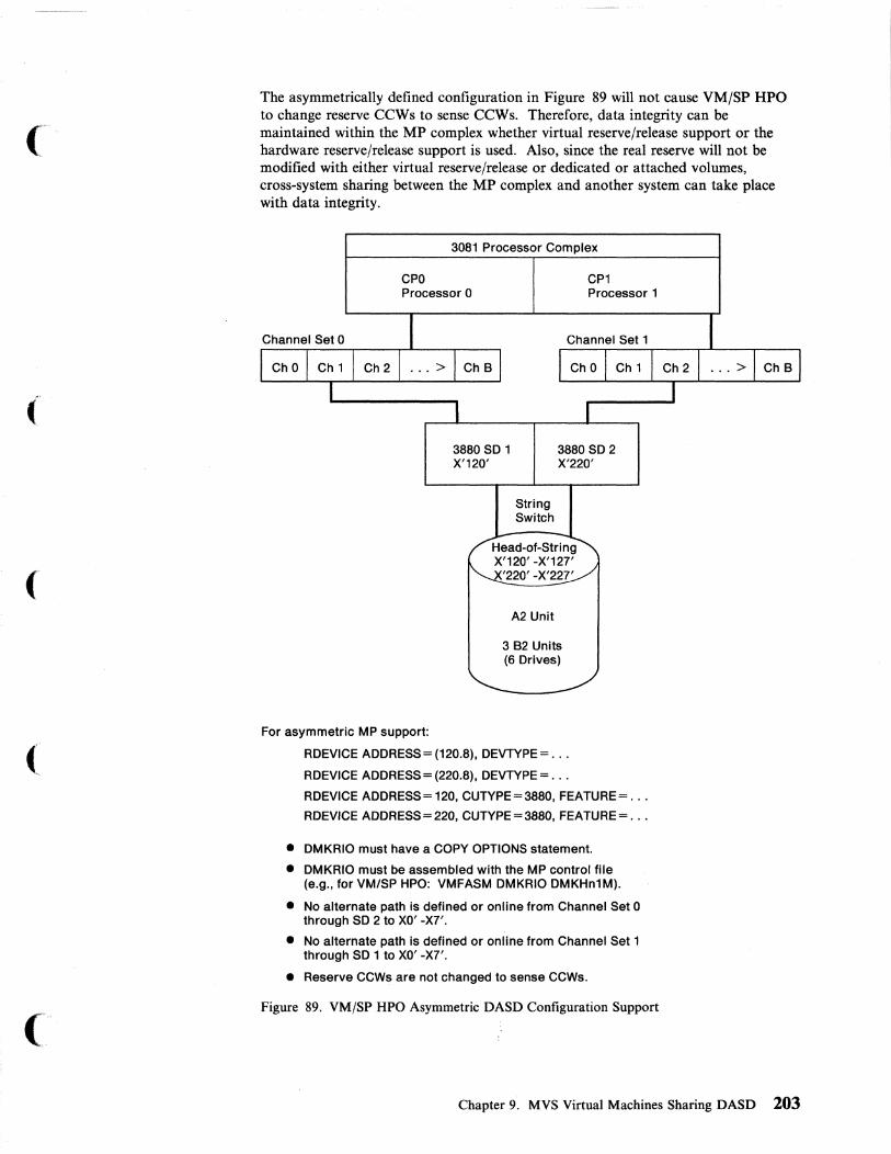
(
(
The asymmetrically defined configuration in Figure 89 will not cause VM/SP HPO to change reserve CCWs to sense CCWs. Therefore, data integrity can be maintained within the MP complex whether virtual reserve/release support or the hardware reserve/release support is used. Also, since the real reserve will not be modified with either virtual reserve/release or dedicated or attached volumes, cross-system sharing between the MP complex and another system can take place with data integrity.
3081 Processor Complex
CPO Processor 0
CP1 Processor 1
3880 SD 1 X'120'
3880 SD 2 X'220'
For asymmetric MP support:
String Switch
A2 Unit
382 Units (6 Drives)
RDEVICE ADDRESS = (120.8), DEVTYPE = .. .
RDEVICE ADDRESS = (220.8), DEVTYPE = .. .
RDEVICE ADDRESS = 120, CUTYPE=3880, FEATURE = .. .
RDEVICE ADDRESS = 220, CUTYPE=3880, FEATURE= .. .
• DMKRIO must have a COpy OPTIONS statement.
• DMKRIO must be assembled with the MP control file (e.g., for VM/SP HPO: VMFASM DMKRIO DMKHn1M).
• No alternate path is defined or online from Channel Set 0 through SD 2 to XO' -X7'.
• No alternate path is defined or online from Channel Set 1 through SD 1 to XO' -X7'.
• Reserve CCWs are not changed to sense CCWs.
Figure 89. VM/SP HPO Asymmetric DASD Configuration Support
Chapter 9. MVS Virtual Machines Sharing DASD 203

3081 Processor Complex
CPO Processor 0
2-Channel Switch 3880 SO 1 X'120'
String Switch
A2 Unit
CP1 Processor 1
2-Channel Switch 3880 SD2 X'220'
382 Units (6 Drives)
RDEVICE ADDRESS= (120.8), DEVTYPE= .. .
RDEVICE ADDRESS = (220.8), DEVTYPE = .. .
RDEVICE ADDRESS = 120, CUTYPE = 3880
RDEVICE ADDRESS = 220, CUTYPE = 3880
Figure 90. VM/SP HPO Symmetric DASD Configuration Support
If all defined paths in Figure 90 are online, then data integrity can only be maintained within the MP complex if virtual reserve/release is used. In no case will data integrity be maintained in a cross-system environment unless all alternate paths are omine.
204 VM Running Guest Operating Systems
rf·~
"'_./

(
(
Part Three: VM under VM
The procedure that follows assumes you have your main VM system up and running. This procedure does not help you bring up that system. If you are not sure of the basic functions of VM, please take the time to review them.
VM refers to both VM/SP Release 6 and VM/SP HPO Release 6. When unique considerations occur to either system they are noted separately.
Information about display terminal usage also applies to the IBM 3138, 3148, and 3158 Display Consoles when used in display mode, unless otherwise noted.
Information pertaining to the IBM 3284 or 3286 printer also pertains to the IBM 3287, 3288, and 3289 printers unless otherwise noted.
Information pertaining to the IBM 2741 terminal also applies to the IBM 3767 terminal, Modell, operating as a 2741, unless otherwise specified.
Part Three: VM under VM 205


Chapter 10. Introduction to Running VM under VM
Performance Considerations When Operating a Second Level VM System 209 Configuration Factors Influencing Performance ................. 209 Workload Factors Influencing Performance ................... 210
(
(
(
Chapter 10. Introduction to Running VM under VM 207

VM provides an easy, convenient way to run guest operating systems. When you run VM (second level) under VM (first level), you get the functional equivalent of a real processor, main and auxiliary storage, and I/O devices. Because VM is simulating these functions, the simulated system is referred to as a "virtual" machine. This virtual machine is equivalent to an IBM System/370 computing system. When you run a system second level, the system is running as a virtual machine under the Control Program (CP) of your first-level VM system.
CP manages the resources of the real computing system in such a way that many people can use the VM system at the same time. These virtual machines execute independently of each other and each can use a different operating system, or different releases of the same operating system. The operating systems themselves execute as though they were controlling real devices and storage.
Running VM second-level provides greater flexibility in managing the system. In this environment you can:
• Test new application programs • Test new releases of VM • Test new maintenance procedures and modifications • Train operators and system programmers.
These activities can be independent of any other work that is running on the system. This independence is achieved through the resource management provided by CPo
One of the biggest advantage of running a second-level VM system is the ability to generate a new system without disturbing normal production activity. System programmers can log on to their own virtual machines and go through the generation steps at their own pace while the daily work is being processed. The System Product Editor can be used to create and update the files that are used during system generation. When the system is tested, it can be placed online, replacing the previous version with minimal disruption to the production activity.
Note: Although you can use a second-level VM system to test new VM releases, service procedures, and modifications, do not use it to create a back-level system.
208 VM Running Guest Operating Systems
-~-~---- -------
;<,---" i -,,- _./
/

Performance Considerations When Operating a Second Level VM ( System
(
Several factors make it hard to predict performance characteristics when VM is running second level. Some of these factors are:
• The frequency of real interruptions
• The frequency and type of privileged instructions
• Whether the virtual machine assist or VM/370 extended control program support is on the machine and enabled
• The frequency of START I/O (SIO) instructions
• The amount of fixed-head paging space
• The amount of caching space
• The location of the paging areas on DASD
• The size of the virtual machine.
The above factors can be broadly classified into two groups:
1. Configuration factors
2. Operating system workload factors.
Configuration Factors Influencing Performance When running VM second level, there is an increased need for real storage, DASD space, processor speed, and so on. The overhead incurred by VM's increased need for dispatching, scheduling, and paging is relatively small in comparison to the increase in overhead from simulating privileged instructions.
When VM operates first level, it runs directly on its own hardware and manages its resources through the use of privileged instructions, such as SIO and Load Program Status Word (LPSW). When executing in second level, VM dispatches the second level VM system in problem state, and any privileged instruction issued by the second level virtual machine causes a real privileged instruction exception interrupt. This interrupt transfers control to the first level VM system, which simulates the instruction. The amount of work done by the first level system in analyzing and handling a second level virtual machine-initiated interrupt depends upon the type and complexity of the interrupt.
Chapter 10. Introduction to Running VM under VM 209

The following hardware configuration factors also influence the performance of a second-level virtual machine:
• The amount of real storage available
• The amount of DASD caching space available
• The speed, capacity, and number of paging devices
• The amount of channel and control unit competition and the arm rivalry affecting each paging device
• Whether virtual machine assist or VM extended control program support is installed on the hardware and enabled
• Interference among system paging devices and devices for processing a user's I/O requests.
Notes:
1. Virtual machine assist support is specifically designed to reduce CP overhead associated with simulating privileged instructions. For more information on virtual machine assist refer to the VM/SP or VM/SP BPO Planning Guide and Reference.
2. VM/370 extended control program support (ECPS: VM/370) is a hardware assist function that provides support over and above that provided by virtual machine assist. It improves VM performance by reducing VM's real supervisor state time, needed to support second-level virtual machines.
Workload Factors Influencing Performance The following workload factors influence the performance of a second-level virtual machine:
• The total number of active virtual machines
• The type of work each virtual machine is doing, especially the amount of I/O processing required.
By measuring and evaluating the effects of these workload factors on a specific configuration, you can anticipate their effect on performance. After measuring the performance of the VM second-level machine, the system programmer can use the VM performance options. These options create a special performance environment for one or more virtual machines. The options allow the system programmer or system operator to redistribute system resources, either to balance them or to favor a particular virtual machine over another.
210 VM Running Guest Operating Systems
- ---- -- -----~~-

('
(
(
The following options are available to only one virtual machine at a time:
• Reserved page frames 27
• Virtual = Real option.
The following options are available to as many virtual machines as desired:
• Favored execution with a specified percentage • Basic favored execution (without a specified percentage) • Priority • Locked pages • QDROPOFF • Virtual machine assist • VM/370 extended control program support (ECPS: VM/370).
For basic information on all but the last two bulleted items refer to VM/SP or VM/SP HPO Diagnosis Reference. For detailed information on the use of options, refer to VM/SP or VM/SP HPO System Command Reference.
VM/SP HPO 3.4 and later releases have added additional running options, (i.e. MINWS, and IBUFF). See VM/SP HPO CP System Command Reference and VM/SP HPO CP Diagnosis Reference for information about these options.
27 VM/SP HPO 3.4 and later releases allow multiple virtual machines to use reserved page frames.
Chapter 10. Introduction to Running VM under VM 211

\,
.1\ ,_./'

Chapter 11. Defining the First- and Second-Level VM Systems
First-Level System Directory ............................ 214 Directory Control Statements .......................... 216
Format/Allocate Session ............................... 220 Setting Up the System Definition Files ...................... 224
Updating DMKRIO for the Second-Level System .............. 224 Updating DMKSNT for the Second-Level System ............. 226 Updating DMKSYS for the Second-Level System .............. 228 Updating DMKFCB for the Second-Level System ............. 228 Updating DMKBOX for the Second-Level System (Optional) ...... 229
Preparing the Second-Level VM System ....................... 229 Second Level System Directory .......................... 230 Building the Second-Level System's CP Nucleus ................ 233 IPLing the Second-Level VM System. . . . . . . . . . . . . . . . . . . . . . .. 238
( Saving Second-Level CMS ............................. 239
(
(
Chapter 11. Defining the First- and Second-Level VM Systems 213

When preparing your second-level system, you can either create a new CP nucleus, or, make a copy of the first-level system's CP nucleus. You will need to create a newCP nucleus if you are testing:
• ~ew devices • ~ew licensed programs that require shared segments • ~ew service levels of VM.
If you need to create a new CP nucleus, you must use the VMFLOAD or SPGE~ procedure. The VMFLOAD procedure creates a CP nucleus in your reader that can
\
be loaded onto your second-level system's SYSRES device. In this chapter, we show the steps involved in bringing up a second-level system when a new CP nucleus is generated with VMFLOAD.
To copy the first-level system's CP nucleus to the DASD you plan to use for your second-level system, you can use DASD Dump Restore (DDR) if:
• The SYSRES volume of the first-level system is the same as it is in the second-level system, and
• The SYSRES packs have the same layout-for example, the same values for SYS~UC, SYSWRM, and so forth.
Make sure that the DMKSYS text deck used in this procedure describes the second-level system's SYSRES.
Log on to your VM system as MA~ (or a user ID that has access to the directory and can issue theCP DIRECT command). Using XEDIT, edit the first-level system's directory file. You will need to create the directory entry that will be running the second-level VM system.
In the directory entry of the first-level system that will be IPLing the second-level system, the following options should be included:
• ECMODE O~ is required to run a second-level system.
• The storage should be defined with a minimum of 8MB to improve performance by reducing the paging done by the second-level VM system.
• The channels should be defined in block (BMX) mode rather than in selector mode. This will improve performance for the second-level VM system.
• The line-end character should be changed to % (or any special character of your choice) to distinguish between issuing first-level and second-level CP commands.
• The REAL TIMER option should be included so that the virtual interval timer can be updated during virtual wait state.
• The console should be defined.
First-Level System Directory VMUSERS DIRECT is the name of our directory containing the entry for the second-level system. Figure 91 on page 215 shows the first-level system's directory entry for the virtual machine that will be operating the second-level system.
214 VM Running Guest Operating Systems
--- ~-~----~
£'\ ~-j

(
'f
(-
(
VMUSERS DIRECT A1 F S9 TRUNC=72 SIZE=32 LINE=9 COLUMN
===== * ===== **************************************************** ==== * SYSTEM-RELATED USERIDS === **************************************************** ==== * ==== USER VMTEST password SM 16M GB 64 % ===== OPTION ECMODE REALTIMER BMX ===== ACCOUNT 1 SYSPROG ===== CONSOLE 9a9 3215 ==== SPOOL C 3595 ===== SPOOL 0 3525 ===== SPOOL E 3211 ===== * Link to Executable CMS Code ===== LINK MAINT 199 19a RR ===== * Link to System Definition Files and Locally Applied Service ===== LINK MAINT 295 192 RR ===== * Link to HELP Code ==== LINK MAINT 190 190 RR ===--= * Link to Program Products (Y-Disk) ==== LINK MAINT 19E 19E RR ===== * Link to Base CP Code and CP Service ----- LINK MAIHT 194 194 RR ===== LINK MAIHT 294 294 RR ===== * Following Entries Are for Base CMS Code and CMS Service ==== LINK MAINT 293 293 RR ==== LINK MAINT 193 193 RR ===== * Following Entries Are the Test VM System. ===== MDISK 123 33S9 919 915 TESTPK MR ===== MDISK 124 33S9 925 915 TESTPK MR ===== * Following Entry Is the User's R/W 'A-disk'. ==== MDISK 191 33S9 949 a29 TESTPK MR ===== SPECIAL 96a 3279
Figure 91. VM Directory Entry for a Second-Level VM System
Chapter 11. Defining the First- and Second-Level VM Systems 215

Directory Control Statements Note: At logon, as the directory control statements for the user are processed, CP
checks the devices represented by each MDISK, CONSOLE, DEDICATE, LINK, SPECIAL, and SPOOL statement for possible conflict with the interface to the virtual control unit. This conflict can occur because the virtual control unit cannot support two different subchannel protocols (shared and nonshared) at the same time. For each directory control statement that violates the restriction, CP sends an error message and does not create the virtual device. To avoid this problem, refer to "Configuration Aid" in the VM/SP or VM/SP HPO Planning Guide and Reference. These books also provide complete lists of directory control statements with descriptions of all their operands and options.
The USER Control Statement
USER VMTEST password 8M 16M GB 64 %
USERVMTEST
password
8M 16M
GB
64
%
216 VM Running Guest Operating Systems
The user statement defines the userid as VMTEST.
Select a unique nonrestricted password.
The lower limit of storage is set to 8MB, with a maximum of 16MB.
We are giving our first-level system user two user classes (G and B). Class G (general) users control the functions associated with the execution of their virtual machines. User class B (resource) is assigned so that the second-level virtual machine user can issue CP ATTACH and DETACH commands. Refer to VM/SP or VM/SP HPO CP General User Command Reference for a summary of privilege class G and any CP commands and to VM/SP or VM/SP HPO CP System Command Reference for a summary of the CP commands allowed for all other privilege classes (A-F).
You can give your VMTEST user ID the user classes that meet your needs, but we recommend that class A not be assigned. Privilege class A users can issue a shutdown command and could accidentally shut down the first-level system.
Sixty-four is the default for the CP priority dispatcher. If the priority setting is not specified, the line-end character will default to the system-defined values.
The line-end character for the first-level system is set to %. We use the percent sign % to communicate with the first-level CP system, and the (default) pound sign # to communicate with second-level CP system. This eases communication between first- and second-level CP systems.
( \~
/ !
/

('
(
(
("
The OPTION Control Statement: VM provides several optional services to virtual machines. You can specify these options with the OPTION control statement in the VM directory, or with the CP SET command.
OPTION ECMODE REALTIMER BMX
ECMODE
REALTIMER
The ECMODE option is required for all VM operating systems running second level. When the ECMODE option is specified for a virtual machine, the saved segments of the virtual operating system can be shared. Setting the ECMODE option does not alter the ECMODE bit of the user's PSW. The ECMODE option allows the virtual machine to use the complete set of control registers and the dynamic address translation feature of the System/370.
If the ECMODE option is not specified in the directory, before you IPL the second-level system, you can issue the CP SET command as follows:
%cp set ecmode on
The REAL TIMER option causes the virtual interval timer to be updated during virtual wait state. With the REAL TIMER option in effect, a virtual interval timer reflects virtual processor time and virtual wait time, but not CP time used for services (such as privileged instructions execution) for that virtual machine. The more services a virtual machine requires from CP, the greater the difference between the time represented by the interval timer and the actual time used by (and for) the virtual machine. The larger the number of active virtual machines contending for system resources, the greater the difference between virtual machine time and actual elapsed time.
If this option is not specified in the directory entry, you can obtain this timing facility by issuing the CP SET command with the TIMER operand. For example, to turn on the timing facility, issue:
%cp set timer real
To turn off the option, issue:
%cp set timer off
Chapter 11. Defining the First- and Second-Level VM Systems 217

BMX The virtual block multiplexer (BMX) option allows the second-level system running in a virtual machine to overlap multiple SIO(F) requests on a specified channel path. When the BMX option is given control, it applies to all channels in the virtual machine except channel o. This option can be specified regardless of whether block multiplexer channels are attached to the processor. The CP DEFINE command can redefine the channel mode for a virtual machine.
If this option is not specified in the directory entry, you can redefine the channel mode of operation by issuing the CP DEFINE command. For example:
%cp define channels bmx
The CONSOLE Control Statement
CONSOLE 889 3215
The CONSOLE statement specifies the console address and device type. The virtual device created by any console statement requires a nonshared virtual control unit. CP does not allow the mix of subchannel protocols, shared and nonshared, on a single virtual control unit. Refer to the "Configuration Aid" in VM/SP or VM/SP HPO Planning Guide and Reference for the list of protocols used by specific devices.
If the first-level system's configuration is used for the second-level system's operation, the console addresses must match. If the first-level system configuration is not used for the second-level system operation, the addresses must match whatever configuration is specified in the second-level VM system's DMKRIO.
If you specify in the console control statement:
CONSOLE 818 3278
you can alternate between 3215 mode for CP commands (first-level) and 3270 full-screen mode for the second-level system (on its operator's console).
In the console control statement, you can specify a secondary user ID. For example:
CONSOLE 818 3278 OPERATOR
When the primary user 10 is running in disconnected mode, the secondary user ID receives all CP messages. Specifying OPERATOR as the secondary user 10, gives the operator added flexibility in an environment where several virtual machines are used. The operator can control several disconnected virtual machines (with the CP SEND command) from one physical terminal.
The SPOOL Control Statement
SPOOL C 3585 SPOOL 0 3525 SPOOL E 3211
218 VM Running Guest Operating Systems
~---~ ~ --~~---

(
(-
The SPOOL statements specify the unit record addresses. If the first-level system configuration is used for the second-level system operation, the unit record addresses for the first- and second-level VM system must match. If the first-level system configuration is not used for the second-level system's operation, the spool addresses must match whatever configuration is specified in the second-level VM system's DMKRIO.
You can use the CP DEFINE command to add unit record devices. For example, you can add a printer to your second-level virtual machine by issuing:
%cp define printer vaddr
The printer is added at the address specified by vaddr.
The SPECIAL Control Statement
SPECIAL 060 3270
The SPECIAL statement allows a user to dial into the second-level system.
The SPECIAL control statement defines a virtual device type and virtual address. Terminal addresses defined in this way do not have to be available on the system, since they are not real addresses.
You can use the CP DEFINE command to create a temporary virtual graphic device for the second-level virtual machine. For example:
%cp def graf cuu
The cuu is the hexadecimal virtual address for the device. After you define the graphic device, you must issue the CP DIAL command in order to use it. The device must be supported by the virtual machine's operating system.
Upon Completion of Directory Changes: If you made additions or changes, you must file the new directory and issue the CMS DIRECT command. The DIRECT command processes the directory file to see if it follows the required format and also writes it to the directory cylinder of the first-level system you are creating. To actually change or swap the current active VM directory, you must have write access to the system-owned (system residence or IPL) device volume that contains the current directory up to and including the directory cylinders, or the volume that is to contain the new directory.
Note: Issuing the DIRECT command causes the system to search the directory for logon passwords that match the list of restricted passwords contained in the RPWLIST DATA file. All passwords that match are changed to NOLOG in the directory before the directory is placed online.
ENTER:
direct vmusers
Chapter 11. Defining the First- and Second-Level VM Systems 219
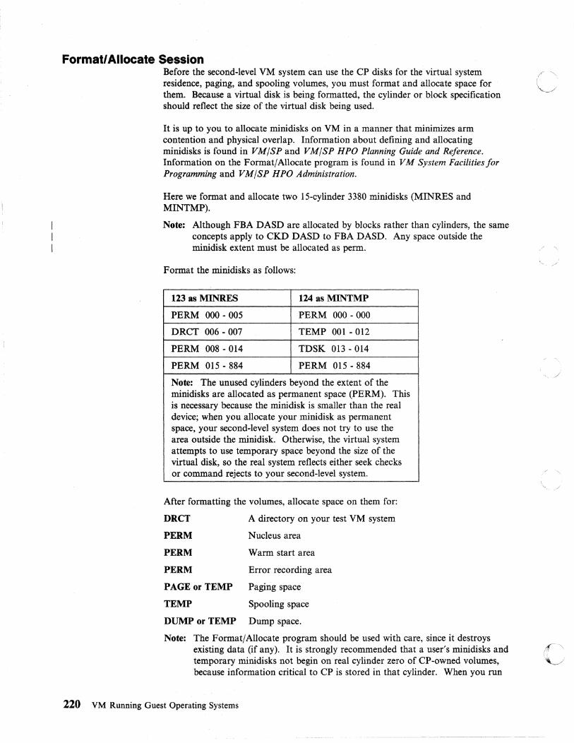
Formatl Allocate Session Before the second-level VM system can use the CP disks for the virtual system (.e
residence, paging, and spooling volumes, you must format and allocate space for ~--./' them. Because a virtual disk is being formatted, the cylinder or block specification should reflect the size of the virtual disk being used.
It is up to you to allocate minidisks on VM in a manner that minimizes arm contention and physical overlap. Information about defining and allocating minidisks is found in VM/SP and VM/SP HPO Planning Guide and Reference. Information on the Format/Allocate program is found in VM System Facilitiesfor Programming and VM/SP HPO Administration.
Here we format and allocate two 15-cylinder 3380 minidisks (MINRES and MINTMP).
Note: Although FBA DASD are allocated by blocks rather than cylinders, the same concepts apply to CKD DASD to FBA DASD. Any space outside the minidisk extent must be allocated as perm. / "
Format the minidisks as follows:
123 as MINRES 124 as MINTMP
PERM 000 - 005 PERM 000 - 000
DRCT 006 - 007 TEMP 001 - 012
PERM 008 - 014 TDSK 013 - 014
PERM 015 - 884 PERM 015 - 884
Note: The unused cylinders beyond the extent of the minidisks are allocated as permanent space (PERM). This is necessary because the minidisk is smaller than the real device; when you allocate your minidisk as permanent space, your second-level system does not try to use the area outside the minidisk. Otherwise, the virtual system attempts to use temporary space beyond the size of the virtual disk, so the real system reflects either seek checks or command rejects to your second-level system. ,/ ',>
After formatting the volumes, allocate space on them for:
DRCT A directory on your test VM system
PERM Nucleus area
PERM Warm start area
PERM Error recording area
PAGE or TEMP Paging space
TEMP Spooling space
DUMP or TEMP Dump space.
Note: The Format/Allocate program should be used with care, since it destroys existing data (if any). It is strongly recommended that a user's minidisks and ~ .. ". temporary minidisks not begin on real cylinder zero of CP-owned volumes,'\...J because information critical to CP is stored in that cylinder. When you run
220 VM Running Guest Operating Systems
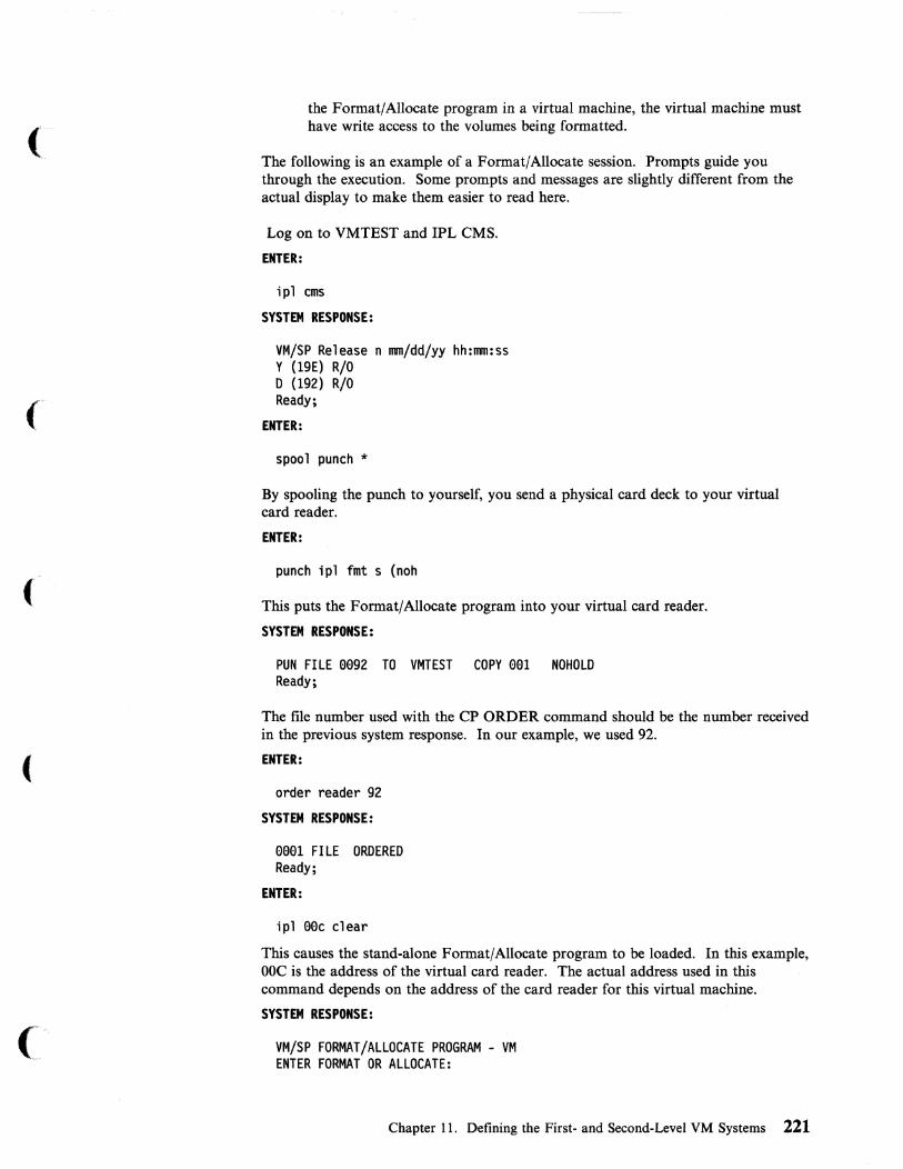
(
the Format/Allocate program in a virtual machine, the virtual machine must have write access to the volumes being formatted.
The following is an example of a Format/Allocate session. Prompts guide you through the execution. Some prompts and messages are slightly different from the actual display to make them easier to read here.
Log on to VMTEST and IPL CMS.
ENTER:
ipl ems
SYSTEM RESPONSE:
VM/SP Release n mm/dd/yy hh:mm:ss y (19E) R/O D (192) R/O Ready;
ENTER:
spool punch *
By spooling the punch to yourself, you send a physical card deck to your virtual card reader.
ENTER:
punch ipl fmt s (noh
This puts the Format/Allocate program into your virtual card reader.
SYSTEM RESPONSE:
PUN FILE ee92 TO VMTEST COPY eel NOHOLD Ready;
The file number used with the CP ORDER command should be the number received in the previous system response. In our example, we used 92.
ENTER:
order reader 92
SYSTEM RESPONSE:
eeel FILE ORDERED Ready;
ENTER:
ipl eec clear
This causes the stand-alone Format/Allocate program to be loaded. In this example, OOC is the address of the virtual card reader. The actual address used in this command depends on the address of the card reader for this virtual machine.
SYSTEM RESPONSE:
VM/SP FORMAT/ALLOCATE PROGRAM - VM ENTER FORMAT OR ALLOCATE:
Chapter 11. Defining the First- and Second-Level VM Systems 221

ENTER:
format
SYSTEM RESPONSE:
FORMAT FUNCTION SELECTED ENTER DEVICE ADDRESS (CUU): Enter--->123
123 is the virtual disk address on which the new system will be built (MINRES).
ENTER DEVICE TYPE: Enter--->33Se
ENTER START CYLINDER (XXX OR XXXX) OR "LABEL": Enter--->eee
ENTER END CYLINDER (XXX OR XXXX): Enter--->e14
ENTER DEVICE LABEL: Enter--->minres
FORMAT STARTED FORMAT DONE eee NO. PAGE RECORDS WITH READ-CHECK ERRORS ENTER FORMAT OR ALLOCATE: Enter--->format
FORMAT FUNCTION SELECTED ENTER DEVICE ADDRESS (CUU): Enter--->124
ENTER DEVICE TYPE: Enter--->33Se
ENTER START CYLINDER (XXX OR XXXX) OR "LABEL": Enter--->eee
ENTER END CYLINDER (XXX OR XXXX): Enter--->e14
ENTER DEVICE LABEL: Enter--->mintmp
FORMAT STARTED FORMAT DONE eee NO. PAGE RECORDS WITH READ-CHECK ERRORS ENTER FORMAT OR ALLOCATE: Enter--->allocate
ALLOCATE FUNCTION SELECTED ENTER DEVICE ADDRESS (CUU): Enter--->123
ENTER DEVICE TYPE: Enter--->33Se
ENTER DEVICE LABEL: Enter--->minres
222 VM Running Guest Operating Systems
------ ----- - ---.-

(
-, ( ''',''
ENTER ALLOCATION DATA FOR VOLUME MINRES TYPE cn CYL
Enter--->perm eee ee5 Enter--->dret ee6 ee7 Enter--->perm ee8 e14 Enter--->perm e15 884 Enter--->end
ALLOCATION RESULTS PERM eee ee5 DRCT ee6 ee7 PERM ee8 e14 PERM e15 884 DEVICE 123 VOLUME MINRES ALLOCATION ENDED
ENTER FORMAT OR ALLOCATE: Enter--->alloeate
ALLOCATE FUNCTION SELECTED ENTER DEVICE ADDRESS (CUU): Enter--->124
ENTER DEVICE TYPE: Enter--->338e
ENTER DEVICE LABEL: Enter--->mintmp
ENTER ALLOCATION DATA FOR VOLUME MINTMP TYPE CYL CYL
Enter--->perm eee ee0 Enter--->temp eel e12 Enter--->tdsk 013 014 Enter--->perm 015 884 Enter--->end
ALLOCATION RESULTS PERM eee 0e0 TEMP eel 012 TDSK e13 014 PERM e15 884 DEVICE 124 VOLUME MINTMP ALLOCATION ENDED ENTER FORMAT OR ALLOCATE:
ENTER:
%ep ipl ems
IPLing CMS gets you out of the Format/Allocate program and back to CMS.
SYSTEM RESPONSE:
VM/SP Release n mm/dd/yy hh:mm:ss Y (19E) R/O o (192) R/O
Ready;
Chapter 11. Defining the First- and Second-Level VM Systems 223

Setting Up the System Definition Files If you are running VM second level for maintenance purposes or application testing, '\ it is preferable that you use the same system definition files (DMKRIO, DMKSNT, '~
and DMKSYS) the first-level system uses. Using the same files ensures that the testing environment matches the first-level system's configuration. The second-level VM directory will differ from the first-level VM directory in that:
• The second-level system's directory needs to have only a subset of the users defined for the first-level VM system.
• The minidisk addresses and volume labels will not match.
If you are running VM under VM for other reasons than those stated above, you can use the same system definition files if the first- and second-level VM system residence volumes have the same DASD type, the same volume identification, and the same locations for the nucleus, error,checkpoint, and warm start cylinders. You may not want to use the same system definition files for both first- and second-level systems if you plan to test new device support or new discontiguous shared systems. /
For our example we create a new nucleus for the second-level VM system. We copy the system-definition files from the first-level system's MAINT D disk (192) onto VMTEST A disk (191). These files will later be modified on the VMTEST A disk to describe the test system's environment. To copy the system definition files, issue the following series of commands:
copyfile dmkrio assemble d = = a copyfile dmksnt assemble d = = a copyfile dmksys assemble d = = a copyfile vmusers direct d = = a r'\
copyfile dmkfcb assemble d = = aj copyfile dmkbox assemble d = = a
Updating DMKRIO for the Second-Level System Use the System Product Editor to edit the DMKRIO file and change the RDEVICE, RCTLUNIT, and RIOGEN to match VMTEST's configuration.
Note: When preparing the RDEVICE and RCTLUNIT entries, refer to the "Configuration Aid" in VM/SP or VM/SP HPO Planning Guide and Reference.
The purpose of the following example is to show the changes necessary to DMKRIO to match VMTEST's configuration. This example in not a complete DMKRIO. All changes or additions to our DMKRIO file are commented.
224 VM Running Guest Operating Systems
.~------------.-----~.- ._--

(
(
RIO TITLE 'DMKRIO 338e' DMKRIO CSECT
RDEVICE ADDRESS=eel,DEVTYPE=3262,MODEL=S,CLASS=(T,A) RDEVICE ADDRESS=ee4,DEVTYPE=32e3,CLASS=A,MODEL=S RDEVICE ADDRESS=eeA,DEVTYPE=3SeS,CLASS=A RDEVICE ADDRESS=eeB,DEVTYPE=3S2S,CLASS=A RDEVICE ADDRESS=eeC,DEVTYPE=3SeS,CLASS=B ~ These three entries match RDEVICE ADDRESS=eeD,DEVTYPE=3S2S,CLASS=(A,C,B) ~ the spool statements in RDEVICE ADDRESS=eeE,DEVTYPE=3211,CLASS=(A,D,F) ~ the first-level directory. RDEVICE ADDRESS=eeF,DEVTYPE=424S,CLASS=A EJECT
RDEVICE ADDRESS=ee9,DEVTYPE=321S ~
RDEVICE ADDRESS=ele,DEVTYPE=3278,MODEL=2A ~ RDEVICE ADDRESS=elS,DEVTYPE=327S,MODEL=2A RDEVICE ADDRESS=e16,DEVTYPE=327S,MODEL=2A EJECT
console address for line mode. console address for full-screen mode.
RDEVICE ADDRESS=(e6e,32),DEVTYPE=3277 ~ This line matches the SPECIAL RDEVICE ADDRESS=eSe,DEVTYPE=UNSP,CLASS=GRAF statement. It allows other RDEVICE ADDRESS=(ege,3),DEVTYPE=327S,MODEL=3 full-screen users of the RDEVICE ADDRESS=(e93,3),DEVTYPE=327S,MODEL=4 second-level system. RDEVICE ADDRESS=(eBe,2),DEVTYPE=27el,ADAPTER=BSCA EJECT
RDEVICE ADDRESS=(12e,16},DEVTYPE=33Se ~ RDEVICE ADDRESS=(14e,2),DEVTYPE=33Se RDEVICE ADDRESS=(lSe,S),DEVTYPE=333e,MODEL=1 RDEVICE ADDRESS=(16e,S),DEVTYPE=333e,MODEL=1 RDEVICE ADDRESS=(17e,S),DEVTYPE=333e,MODEL=11 RDEVICE ADDRESS=(1ge,16),DEVTYPE=338e ~ EJECT
This matches the system you want to IPL.
This is the first-level system's minidisk that can be accessed by the second-level system.
Figure 92 (Part 1 of 2). Example of Changes Necessary to DMKRIO to Match VMTEST's Configuration
Chapter 11. Defining the First- and Second-Level VM Systems 225

RCTLUNIT ADDRESS=000.CUTVPE=3262 RCTLUNIT ADDRESS=008.CUTVPE=2821 - control unit for unit record devices. RCTLUNIT ADDRESS=010.CUTVPE=3274 - control unit for RDEVICE 010. RCTLUNIT ADDRESS=018.CUTYPE';'25el - control unit for RDEVICE elF.
RCTLUNIT ADDRESS=050.CUTVPE=3274.FEATURE=16-DEVICE RCTLUNITADDRESS=060.CUTVPE=3272.FEATURE=32-DEVICE .-- control unit for RCTLUNIT ADDRESS=080.CUTVPE=3274,FEATURE=32-DEVICE RDEVICE 060.
RCTLUNIT ADDRESS=120.CUTVPE=3880,FEATURE=16-DEVICE .-- control unit for RCTLUNIT ADDRESS=140.CUTVPE=3830.FEATURE=32-DEVICE RDEVICE 120. RCTLUNIT ADDRESS=160.CUTVPE=3830.FEATURE=16-DEVICE RCTLUNIT ADDRESS=170.CUTVPE=3830.FEATURE=16-DEVICE RCTLUNIT ADDRESS=190.CUTVPE=3880.FEATURE=16-DEVICE .-- control unit for
RDEVICE 190.
These are the alternate I system consoles. V
RIOGEN CONS=009,ALTCONS=(010.015.016) END I
----- 009 is the primary VM system console.
Figure 92 (Part 2 of 2). Example of Changes Necessary to DMKRIO to Match VMTEST's Configuration
Updating DMKSNT for the Second-Level System The DMKSNT file must be changed to reflect the following:
• MINRES cylinder 0, page 11 through cylinder 1, page 47 is used for saved systems.
• The CMS entry contains:
- SYSNAME=CMS2 (The name of the second-level named, saved CMS segment.)
- VSYSADR= 190
226 VM Running Guest Operating Systems
) 7'

(
(
SYSCYL = 000 the "real" starting cylinder of CMS SYSRES at second level
VSYSRES= MNT190 the first-level CMS 190 volume label
• 190 CMS SYSRES is a minidisk at first-level, but a "real" drive 190 at second -level.
* SNT
*
TITLE 'DMKSNT SPACE
VM REL n 3389 SAMPLE'
********************************************************************** * * * *
THE FOLLOWING ENTRIES ARE BASED ON THE INFORMATION PROVIDED IN THE PLANNING GUIDE AND REFERENCE.
********************************************************************** *
SPACE DMKSNT CSECT
SPACE * * * * * * * *
HEX LOAD ADDRESS FOR SEGMENT 239 = EF9999 THE SPACE FOR CMS IS ALLOCATED ON MINRES, AS FOLLOWS:
( THE ALLOCATIONS ARE BASED ON 159 PAGES/3389 CYLINDER ) CYL 9, PAGE 11 TO CYL 2, PAGE 13 (393 PAGES)
392 PAGES FOR CMS, 1 FOR CP INFORMATION.
********************************************************************** CMS2 NAMESYS SYSNAME=CMS2,
EJECT
END
SYSVOL=MINRES, SYSSTRT=(999,11), SYSPGNM=(9-8,14-34,3824-4995) SYSPGCT=392, SYSHRSG=(239-255) SYSSIZE=256K, VSYSADR=199, SYSCYL=999, PARMRGS=(9-15) VSYSRES=MNT199
Figure 93. Updating DMKSNT for the Second-Level System.
Chapter 11. Defining the First- and Second-Level VM Systems 227

Updating DMKSYS for the Second-Level System The figure below shows an updated CP System Control File (DMKSYS) and highlights the changed entries. For specific information on each macro, refer to VM/SP or VM/SP HPO Planning Guide and Reference.
SYS TITLE PRINT
DMKSYS CSECT SYSOWN SYSRES
SYSMON SYSJRL
'DMKSYS FOR 3380 VM' NOGEN
MINRES.MINTMP <-- CP owned volumes for 2nd-level SYSRES. SYSVOL=MINRES. <-- Minidisk label for 2nd-level system. SYSRES=123. <--- Minidisk address for 2nd-level system. SYSTYPE=3380. <--- Minidisk device type for 2nd-level system. SYSCLR=NO. SYSNUC=012. <--- Minidisk start cylinder for 2nd-level
system. SYSWRM=(002.1). <- Warm start cylinder for 2nd-level system. SYSERR=(003.2). <- Error recording cylinders for 2nd-level
system. SYSCKP=(095.1) <-- Checkpoint cylinder for 2nd-level system.
SYSCOR RMSIZE=16M. AP=NO. MP=NO
SYSOPR SYSOPER=OPERATOR. SYSDUMP=OPERATOR <-- Use OPERATOR userid for second-level
system SYSACNT USERID=DISKACN2. <-- Use DSKACN2 userid for second-level
system OUTPUT=READER. CLASS=C. LIMIT=190
SYSTIME ZONE=4. LOC=WEST. ID=EDT
SYSFORM SYSPCLAS SYSID DEFAULT=VM2NDL SYSORD SYSMIH SYSFCN SYSLOCS END
<------ We have changed the identifier for the second-level system.
Figure 94. Updating DMKSYS for the Second-Level System.
Updating DMKFCB for the Second-Level System Changes to this file may be necessary to ensure consistent printer interface between first- and second-level VM. For this example, no changes were necessary. If you need to make changes to DMKFCB, refer to the DMKFCB module prologue for specific information and to VM/SP or VM/SP HPO Administration.
228 VM Running Guest Operating Systems

(
(:-
(
Updating DMKBOX for the Second-Level System (Optional) Changes to the DMKBOX file are optional, but you may decide to change it to distinguish it from the first-level system's. We used the System Product Editor and changed the logo for our second-level system.
Note: Any maintenance done to this system may cause changes toDMKBOX.
BOX TITLE 'DMKBOX (CP) VM * VIRTUAL MACHINE SYSTEM
NBOXLINI DC CL46 , WELCOME TO THE WORLD OF SECOND LEVEL NBOXLIN2 DC CL46' THIS IS A 2ND LEVEL SYSTEM RUNNING UNDER VM ,
DC CL46' DC CL46' 22222222222222 DC CL46' 2222222222222222 DC CL46' 222 222 DC CL46 , 222 222 DC CL46 , 222 DC CL46 , VVV VVV 222 MMMM MMMM , DC CL46 , VVV VVV 222 MMMM MMMM , DC CL46' VVV VVV 222 MM MN MM MM , DC CL46 , VVV VVV 222 MM MM MM MM , DC CL46 , VVV VVV 222 MM Mftf4 ftf4 , DC CL46' VVVVV 222 MM M MM
, DC CL46 , VVV 222 MM MM , DC CL46 , 222 DC CL46' 2222222222222222222 DC CL46 , 222222222222222222222
NBOXWDTH EQU NBOXLIN2-NBOXLINl @V6GPBRE NBOXLINS EQU (*-NBOXLINl)/NBOXWDTH @V6GPBRE
EJECT ***************************************************************
END
Figure 95. Updating DMKBOX for the Second-Level System (Optional)
Preparing the Second-Level VM System When creating the directory entry for the second-level system, you must consider both the general and unique requirements for the test. For general information about specifying directory entries, refer to VM/SP or VM/SP HPO Planning Guide and Reference.
Note: VM does not check for overlapping extents in the MDISK statement. Therefore, you must ensure that minidisk extents defined in the VM directory do not overlap each other or, in the case of 3330, 3340, and 3350 disks, do not overlap the alternate track cylinders. IF OVERLAP CONDITIONS EXIST, FILE DATA DAMAGE IS INEVITABLE. You can use the
Chapter 11. Defining the First- and Second-Level VM Systems 229

DISKMAP EXEC to check for overlaps and gaps between minidisks. The DISKMAP EXEC is described in the VMjSP and VMjSP HPO Installation Guide.
Second Level System Directory You can add or delete entries to the following sample to suit your own testing needs.
The first non-comment line in the directory must be the address (123) and the volume label (MINRES) of the device on which directory will be written:
* DIRECTORY 123 3380 MINRES * ***************************************************************
Figure 96. Second-Level System Directory Entry
As shown below, MAINT2 has minidisks 123 and 124 with 15 cylinders each. In the first-level directory entry from VMTEST, address 190 is assigned as a minidisk; since the DMKRIO for the second-level system also has address 190 defined, the second-level system will use address 190 as a full DASD. MNT190 is the first-level volume label to CMS and the "real" volume label of the second-level system.
We have also created a one-cylinder minidisk on the MINRES pack at address 191. Label TST191 corresponds to the 191 minidisk of the VMTEST user at first level. The second-level system will get the first-level 191 as MAINT2 291.
230 VM Running Guest Operating Systems
'-'----------------
'''-
(( ", , " ,\j

(
(
(
(
* *************************************************************** * SYSTEM RELATED USERIDS *************************************************************** * USER MAINT2 password 4M 16M ABCDEFG 64
ACCOUNT 1 SYSPROG IPL 1913 CONSOLE elF 3215 SPOOL eec 25413 READER * SPOOL 13130 25413 PUNCH A SPOOL eeE 14133 A MDISK 123 33813 131313 1315 MINRES MW MDISK 124 33813 131313 1315 MINTMP MW MDISK 191 33813 ee9 eel MINRES MW MDISK 291 33813 eee 13133 TST191 MW MDISK 1913 33813 131313 1345 MNT1ge MW ~ The sizes specified in the following MDISK 19E 33813 131313 884 MNT19E MW ~ three minidisk statements depend on MDISK 190 33813 131313 1355 MNT19D MW ~ sizes specified in the first-level L system's directory entry; therefore,
they will vary for your system.
This column represents the second-level volume labels.
This column represents the second-level virtual machine's virtual addresses.
Figure 97. Second-Level System Directory
Our OPERATOR directory entry has links to MAINT2's minidisks with a one-cylinder minidisk on MINRES.
USER OPERATOR password 3M 16M ABCDEG ACCOUNT 2 OPERATOR IPL 1913 CONSOLE 13139 3215 T MAINT SPOOL eec 25413 READER * SPOOL SSD 254S PUNCH A SPOOL eeE 14133 A LINK MAINT2 1913 1913 RR LINK MAINT2 190 190 RR LINK MAINT2 19E 19E RR MDISK 191 33813 SS8 eS1 MINRES MR
Figure 98. Second-Level System Directory
The CMSl user ID also has links to MAINT2's minidisk with one cylinder of its own on MINRES. The CMSI user will IPL CMS2 saved segments when CMS2 has been saved.
Chapter II. Defining the First- and Second-Level VM Systems 231

USER CMS1 password 1M 3M G ACCOUNT 101 USER01 IPL CMS2 CONSOLE 009 3215 SPOOL 00C 2540 READER * SPOOL 000 2540 PUNCH A SPOOL 00E 1403 A LINK MAINT2 190 190 RR LINK MAINT2 190 190 RR LINK MAINT2 19E 19E RR MDISK 191 3380 01e 001 MINRES MR
Figure 99. Second-Level System Directory
We have added one more user ID named DISKACN2 with links to MAINT2's minidisk with a one cylinder minidisk on MINRES. The DISKACN2 will IPL CMS2 saved segments when CMS2 has been saved. (See "Saving Second-Level CMS" on page 239.)
USER DISKACN2 password 1M 3M BG ACCOUNT DISKACNT DISKACNT IPL CMS2 CONSOLE 009 3215 SPOOL 00C 2540 READER * SPOOL 880 2548 PUNCH A SPOOL 88E 1483 A LINK MAINT2 198 198 RR LINK MAINT2 190 190 RR LINK MAINT2 19E 19E RR MDISK 191 3388 811 881 MINRES MR
Figure 100. Second-Level System Directory
File the new directory. You may want to use the DISKMAP EXEC to check for overlaps and gaps between minidisks. Then issue the CMS DIRECT command.
Note: When you issue the DIRECT command, all restricted passwords in the directory file are changed to NOLOG.
ENTER:
direct vmusers
As the directory source file is processed, VM checks for a protocol conflict in those statements that describe virtual devices. If a conflict is detected, CP sends an error message. Only the effects of the T-disk option of the MDISK statement and the CONSOLE, SPECIAL, and SPOOL statements are considered. The effects of the DEDICATE, LINK, and MDISK statements depend on the real device configuration at logon.
232 VM Running Guest Operating Systems
\
\.
./

(
(
(
Building the Second-Level System's CP Nucleus With the minidisk defined in the directory of the second-level system, the nucleus for the second-level system is ready to be built. Before you can use the VMFLOAD command, you must set up the proper disk search order.28
To get system definition files:
ENTER:
access 191 a
SYSTEM RESPONSE:
A (191) RIO Ready;
To get the VM CP Service Program:
ENTER:
access 294 b/a
SYSTEM RESPONSE:
B (294) RIO Ready;
To get base VM CP code:
ENTER:
access 194 cia
SYSTEM RESPONSE:
C (194) RIO Ready;
Query your disks to make sure everything is in order.
ENTER:
query disk
28 HPO users should refer to the VMjSP HPO Installation Guide to establish the proper disk search order.
Chapter 11. Defining the First- and Second-Level VM Systems 233

SYSTEM RESPONSE:
lABEL CUU M STAT CYl TYPE BlKSIZE TST191 191 A R/W 5 3389 1924 MNT294 294 B/A RIO 29 3380 1024 MNT194 194 CIA RIO 21 3389 1924 MNT199 199 S RIO 35 3389 1924 MNT19E 19E YIS RIO 199 3389 1924 Ready;
Figure 101. Example of a System Response
FILES 9
487 577 216 216
BlKS USED-(%) BlKS lEFT 296-13 2929
6273-67 3027 5499-55 4365
11489-71 4786 11489-71 4786
BlK TOTAL 2325 9390 9765
16275 16275
We now must assemble the current level of the DMKBOX (if changed), DMKRIO, DMKSNT, and DMKSYS files with the VMFASM command. The VMFASM procedure updates the specified assembler source files according to the entries in the control file and assembles the updated source.29 When the VMFASM procedure completes, you will have a new text deck that can be used to recreate the CP nucleus.
CHANGES TO DMKRIO
ENTER:
vmfasm dmkrio dmksp
If no errors are found, the system responds:
NO UPDATE FILES FOUND ASMBLING DMKRIO
ASSEMBLER (XF) DONE NO STATEMENTS FLAGGED IN THIS ASSEMBLY DMKRIO TEXT Al CREATED Ready;
If errors are flagged, edit the file with the System Product Editor, make the corrections, and reissue the VMF ASM command.
CHANGES TO DMKSNT
ENTER:
vmfasm dmksnt dmksp
If no errors are found, the system responds:
NO UPDATE FILES FOUND ASMBLING DMKSNT
ASSEMBLER (XF) DONE NO STATEMENTS FLAGGED IN THIS ASSEMBLY DMKSNT TEXT Al CREATED Ready;
If errors are flagged, edit the file, make the corrections, and reissue the VMF ASM command.
29 If you are generating an HPO system, refer to the VM/SP HPO Installation Guide to set up the proper control files for the release of HPO you will be using.
234 VM Running Guest Operating Systems
-- ---------------,,---
('-''\
"',~
'--

(
(
CHANGES TO DMKSYS
ENTER:
vmfasm dmksys dmksp
If no errors are found, the system responds:
NO UPDATE FILES FOUND ASMBLING DMKSYS
ASSEMBLER (XF) DONE NO STATEMENTS FLAGGED IN THIS ASSEMBLY DMKSYS TEXT Al CREATED Ready;
If errors are flagged, edit the file, make the corrections, and reissue the VMF ASM command.
CHANGES TO DMKFCB
ENTER:
vmfasm dmkfcb dmksp
If no errors are found, the system responds:
NO UPDATE FILES FOUND ASMBLING DMKFCB
ASSEMBLER (X F) DONE NO STATEMENTS FLAGGED IN THIS ASSEMBLY DMKFCB TEXT Al CREATED Ready;
If errors are flagged, edit the file, make the corrections, and reissue the VMF ASM command.
CHANGES TO DMKBOX
ENTER:
vmfasm dmkbox dmksp
If no errors are found, the system responds:
NO UPDATE FILES FOUND ASMBLING DMKBOX
ASSEMBLER (XF) DONE NO STATEMENTS FLAGGED IN THIS ASSEMBLY DMKBOX TEXT Al CREATED Ready;
If errors are flagged, edit the file, make the corrections, and reissue the VMF ASM command.
Chapter 11. Defining the First- and Second-Level VM Systems 235

You can now create the CP load deck to be IPLed through the VMFLOAD command. Spool the virtual punch to your card reader.
ENTER:
spool punch *
The above command sends the load deck to the virtual reader.
spool printer *
The above command sends the load map to the virtual reader.
Now, you can issue the VMFLOAD command.
ENTER:
vmfload cp load dmks p30
When the VMFLOAD procedure is complete, the system responds with:
SYSTEM LOAD DECK COMPLETE PUN FILE 9391 TO VMTEST COPY 991 NOHOLD
Ready;
When the message SYSTEM LOAD DECK COMPLETE appears, the load deck is in your virtual reader.
ENTER:
order reader 391
SYSTEM RESPONSE:
9991 FILE ORDERED
ENTER:
spool reader hold
The next step is to write the nucleus on the system residence volume by IPLing the load deck.
ENTER:
ipl 99c clear
When the next message appears, the nucleus has been written on the system residence volume. SYSTEM RESPONSE:
NUCLEUS LOADED ON MINRES --- STARTINGCYL/BLK=912 • LAST CYL/BLK USED=eI3 CP ENTERED; DISABLED WAIT PSW 'ee929ge9 ee999912,
The PSW of X '00020000 00000012' informs you that everything has worked. Once the IPL is complete, close your card reader and printer.
30 VM/SP HPO users should refer to the VM/SP HPO Installation Guide for the correct load list and control file.
236 VM Running Guest Operating Systems
j
/ '\
((, ,~j

(
(
ENTER:
close 00c
The above command closes your card reader.
close 00e
The above command closes your printer.
When you close your printer, the system puts the load map into your reader. The load map contains the real address locations of all the modules in the CP nucleus; this information is used to debug any problems occurring with CPo
PRT FILE 0302 TO VMTEST COPY 001 NOHOLD
ENTER:
ipl ems
SYSTEM RESPONSE:
VM/SP Release n mm/dd/yy hh:mm:ss Y (19E) R/O D (192) R/O Ready;
Query your reader to confirm that both the load deck and the load map are in your reader.
ENTER:
query reader all *
SYSTEM RESPONSE:
ORIGINID FILE CLASS RECORDS CPY HOLD DATE TIME NAME VMTEST 0301 A PUN 00026421 001 NONE mm/dd 09:45:22 LDT VMTEST 0302 A PRT 00009939 001 NONE mm/dd 09:48:17 Ready;
TYPE DIST DMKSAVNC VMTEST
VMTEST
Spoolid 301 contains the load deck and 302 contains the load map. When you issue the READCARD CPNUC MAP command, it reads the first file from your reader; therefore, order your reader to make the load map the first file.
ENTER:
order reader 302
SYSTEM RESPONSE:
0001 FILE ORDERED Ready;
Query your reader to confirm the reordering of the files.
ENTER:
query reader all * SYSTEM RESPONSE:
ORIGINID FILE CLASS RECORDS CPY HOLD DATE TIME NAME VMTEST 0302 A PRT 00009939 001 NONE mm/dd 09:48:17 VMTEST 0301 A PUN 00026421 001 NONE mm/dd 09:45:22 LDT Ready;
TYPE DIST VMTEST
DMKSAVNC VMs EST
Chapter 11. Defining the First- and Second-Level VM Systems 237

Issue the READCARD CPNUC MAP command to create a CMS file from the load map (spoolid 302) generated during the CP nucleus build.
ENTER:
read cpnuc map
SYSTEM RESPONSE:
RECORD LENGTH IS '15e' BYTES. Ready;
IPLing the Second-Level. VM System With few exceptions, IPLing a second-level system is similar to IPLing a first-level VM system. You must verify that the virtual machine configuration matches (by issuing a QUERY VIRTUAL command) or is a subset of the DMKRIO defined for the second-level system. Once this is done, you can IPL the virtual disk containing the CP- nucleus disk 123 in our example.
Note: Attention handling varies with the type of terminal used. Refer to the Terminal Reference for a list and description of the terminals supported by" VM.
IPL VM in the normal fashion, responding where required.
ENTER:
ipl 123 clear
SYSTEM RESPONSE:
VM Release n • Service Level nnnn ; created on mm/dd/yy at hh:mm:ss
It is now hh:mm:ss EDT day mm/dd/yy Change TOD clock (YESINO) :
Enter-->no
The second-level system cannot set the time-of-day clock. Therefore, always reply "no" to the change time-of-day clock question.
DMKCPI9711 System is uniprocessor generated DMKUDR476I System directory loaded from volume MINRES DMKCPI974I No valid override file; using system defaults Start «WARMICKPTIFORCEICOLD) (DRAIN»I (SHUTDOWN) : Enter--->cold
Because this is a test system there is no data or accounting information to be recovered. Therefore, you can perform a cold start unless some specific function requires a warm start.
DMKCPJ9521 e4e96K SYSTEM STORAGE
DMKCPJ957I STORAGE SIZE = 04096 K. DYNAMIC PAGING SIZE = e338e K. FREE STORAGE SIZE = 0252 K.
hh:mm:ss FILES: NO RDR. NO PRT. NO PUN hh:mm:ss FORMATTING ERROR RECORDING AREA
NUCLEUS SIZE = 404 K. TRACE TABLE SIZE = 060 K. VIRTUAL=REAL SIZE = ee0ee K
The above system response is the normal response when you IPL a new system.
238 VM Running Guest Operating Systems

(
(
(
RRRR •••• RING •••• GGGG
DMKCPI966I Initialization complete
Once you IPL the second-level system, you are automatically logged on as the system operator in line mode. At this point you can enable graphic display devices to allow other users to dial into this system and log on to the second-level system. See "Enabling Terminals for a Second-Level VM System" on page 242.
Saving Seco~d-Level eMS To load CMS into your virtual machine you can:
• IPL the CMS system disk, or • IPL a named saved system (in our example, CMS2).
To IPL the CMS system disk (in our example, MAINT2's 190 minidisk), you need 3MB of virtual storage for each user needing CMS. On the other hand, if you save a second-level CMS system, it can be IPLed in 1MB of virtual storage.
Note: For performance reasons, users' virtual machines should be kept to a minimum size.
Using the named, saved system defined earlier in DMKSNT (CMS2), take the following steps to create a second-level, named saved system.
When IPL of the second-level system is complete, you receive the "Initialization complete" message. At this point you must disconnect the system operator. ENTER:
disconn
SYSTEM RESPONSE:
hh:mm:ss disconnect at hh:mm:ss EDT day mm/dd/yy
VM/37fJ ONLINE-RRRR •••• RING •••• GGGG
(Press ENTER)
--PRESS REQUEST KEY TO BEGIN SESSION
Enter one of the following commands:
LOGON useri d DIAL userid
(Example: LOGON VMUSER1) (Example: DIAL VMUSER2)
MSG userid message (Example: MSG VMUSER2 GOOD MORNING) LOGOFF
You must log on as MAINT2, because it owns the CMS system disk (190).
Chapter 11. Defining the First- and Second-Level VM Systems 239

ENTER:
logon rna i nt2
SYSTEM RESPONSE:
Logon at hh:mm:ss EDT day mmjddjyy VMjSP Release n mmjddjyy hh:mm:ss
(press ENTER)
ENTER:
ipl 198 parm savesys crns2
SYSTEM RESPONSE:
SYSTEM SAVED VMjSP Release n mmjddjyy hh:mm:ss
(press ENTER)
SYSTEM RESPONSE:
Ready;
Once the READY message appears, a copy of the second-level named, saved system is saved. Any user of your second-level system can now load CMS into a virtual machine by:
• IPLing the 190 CMS system disk belonging to MAINT2
ipl 198
or
• IPLing CMS2.
ipl crns2
240 VM Running Guest Operating Systems
/-\

( Chapter 12. Operating VM under VM
Operating the Second-Level Virtual Machine .................... 242 Issuing CP Commands to the First-Level VM System ............. 242 Enabling Terminals for a Second-Level VM System .............. 242 Varying Devices Off line and On line ....................... 243 Spooling Options When Running VM under VM ................ 244
First-Level VM System Spooling ........................ 244 Second-Level VM System Spooling . . . . . . . . . . . . . . . . . . .. 244
Console Specification ................................ 244 Using DEDICATE Control Statements . . . . . . . . . . . . . . . . . . . . .. 245
Magnetic Tapes .................................. 245 Remote Devices ............................... 245
Problem Determination for the Second-Level VM System ......... 245 Error Recording and Analysis ........................ 245 Dump Procedure ................................ 245 Trace Table Recording Facility .......................... 246 VM/Interactive Problem Control System ..................... 246
Backup/Restore Procedure for the Second-Level VM System . . . . .. 247 Creating a DASD/Dump Restore (DDR) Utility Tape ..... . . . . . . .. 247 Using the CMS DDR Command ......................... 248 DASD/DUMP RESTORE and the Second-Level System ........... 248 Restoring Your Second-Level System ....................... 249
(
Chapter 12. Operating VM under VM 241

Operating the Second-Level Virtual Machine The virtual machine operation at this level can be confusing. At all times it requires an awareness of what level of VM you are interacting with and what functions you are trying to perform.
Issuing CP Commands to the First-Level VM System While running VM under VM, use CP commands to:
• Communicate with the first-level VM system. • Query the status of virtual machine devices or spool files. • Attach or detach devices from the virtual machine configuration.
You can communicate with CP by either:
• Pressing the A TIN key twice to force a CP read
• Prefixing the CP command with "%CP" where "%" is the line-end character / . assigned in the directory entry of the first-level system. (Use this only in line mode.)
• Pressing the PAl key (if using 3270 console mode).
Enabling Terminals for a Second-Level VM System Most testing can be done by initializing and running tests from the operator's virtual machine. If you want full-screen applications (such as XEDIT and FILELIST) you can enable a graphic device using the following method:
If the directory entry for the first-level system includes a SPECIAL statement, you can then use full-screen mode. You can confirm that the virtual device is defined by issuing a CP QUERY command to first-level CPo
ENTER:
%cp query virtual graf
SYSTEM RESPONSE:
GRAF AT 969
ENTER:
#cp vary online 969
SYSTEM RESPONSE:
969 VARIED ONLINE
ENTER:
#cp enable 969
SYSTEM RESPONSE:
COMMAND COMPLETE
On another terminal (on the same system), issue:
dial vmtest 969
242 VM Running Guest Operating Systems
',< -

(
(
(
Note: If the CP DIAL command is issued without a specified address, VM connects the tenninal to the first line defined in the SPECIAL control statement; the line belongs to the specified user ID. If no lines are available or if all lines are busy, VM issues an error message and does not make the connection.
The test user will remain connected until one of the following happens:
• The virtual machine logs off using standard logoff procedure. • The virtual machine is forcibly logged off. • The tenninal is powered off and on.
The test user will also be disconnected if the CP RESET command is issued from the second-level, virtual console or from a user authorized with the CP RESET command.
Once disconnected, the end user is free to use the DIAL command to connect to another user ID.
Varying Devices Off line and On line Once you IPL the second-level virtual machine, the devices that are not accessible to that machine at IPL are considered off line. However, you can attach more devices to your machine and have them placed on line as required. For example, tape drives can be attached by the first-level machine operator to the virtual machine configuration at the address that matches the configuration of the second-level CP system. You can change these virtual addresses to confonn to your second-level system's DMKRIO by using the CP DEFINE command. The second-level VM operator then issues the CP VARY command.
For example, if a graphic device is off line and VMTEST needs to have the graphic device made available, notify the first-level system operator via a message:
#cp msg op Please attach eae to VMTEST as eae
The first-level system operator would issue:
vary online eae
SYSTEM RESPONSE: (to the first-level system operator):
eae VARIED ONLINE
The first-level system operator issues:
attach eae to vmtest eae
SYSTEM RESPONSE: (to the first-level system operator):
eae ATTACHED TO VMTEST eae
The second-level system operator must issue:
vary online ese
SYSTEM RESPONSE: (to the second-level system operator):
eae VARIED ONLINE
The device is now ready to be used by the second-level VM system. The operator infonns VMTEST that the graphic device is now attached and ready for use.
Chapter 12. Operating VM under VM 243

Note: If the graphic device is a VM-supported terminal, the CP ENABLE command must be issued before the end user can log on to the second level system that is using the device. ('
Spooling Options When Running VM under VM
First-Level YM System Spooling If your virtual machine produces a large volume of unit record output and keeps a unit record device constantly busy, you may want to dedicate a unit record device to that virtual machine. To eliminate double spooling of printer output, include a DEDICATE statement in the first-level system's directory entry, such as:
DEDICATE 00E 002
The above statement causes all output from the second-level system virtual printer OOE to go directly to the real printer at address 002.
You can also have the system operator dynamically dedicate a unit record device to your virtual machine. For example, if your first-level system has a 4245 printer, you can have the operator issue a CP ATTACH command before the second-level system is IPLed. Send the operator a message requesting that cuu be attached to VMTEST as OOF, where OOF is the address of the 4245 printer on the real system.
ENTER:
%cp msg operator Please attach real printer 00F to me as 00F
If the real printer at OOF is not in use by the system or any other virtual machine, the operator issues the ATTACH command.
attach 00F to vmtest as 00F
When the device is attached, VM sends a confirmation message to VMTEST.
PRT 00F ATTACHED
Second-Level YM System Spooling If the virtual machine performs any spooling operations, second level CP is also spooling (unless it has dedicated unit record devices). This double spooling operation does not create a problem. Second level CP detects that it is running in a virtual machine and at the end of each spooled output file issues a CP CLOSE command to first-level CPo This produces real spooled output for virtual spool files.
Notice that double separators occur. For instance, the separator page on virtual printed output includes four pages-two pages for the second-level VM system and two more pages for the separator of the first-level virtual machine on which the virtual CP system is running. The extra set of separator pages can be avoided by using the START command with the NOSEP option on the second-level system.
Console Specification Because the log on console for a virtual machine operates as a 3215, 3210, or 3270, either of the following methods can be used to satisfy the console requirements for your virtual machine:
"-._/
1. In the DMKRIO for the second-level system you are building, define the console r,", '\
device as DEVTYPE 3215 or 3210 in the RDEVICE macro. I. '"~--,/ RDEVICE ADDRESS=009,DEVTYPE=3215
244 VM Running Guest Operating Systems

(
(
(
2. Another approach is to attach a console-type device to your virtual machine and use that device as an alternate second-level console. For example, if your DMKRIO for address 010 defines a DEVTYPE of 3277, attach a real 3277 to your virtual machine as address 010 to function as an alternate second-level console.
RIOGEN CONS=919,ALTCONS=(999,915)
Using DEDICATE Control Statements
Magnetic Tapes
Remote Devices
Use the DEDICATE control statement to provide a virtual machine with a corresponding real device at logon. The virtual machine will have sole use of the dedicated device.
A device such as a magnetic tape drive can be used by only one virtual machine at a time; therefore, specify it in a directory entry with a DEDICATE statement. For example:
DEDICATE 199 299
This statement allows the second-level VM system to access the device at real address 290 through a virtual address of 190.
The DEDICATE statement can be used to attach remote 3270 Information Display System Printers (3284, 3286, 3287, 3262, 3268, and 3289) to a virtual machine. For example, a directory entry can include the statement:
DEDICATE NETwork 96E 9192
where 06E is the virtual address of the device in the virtual machine, and 0102 is the resource ID as specified in DMKRlO. Remote 3270 Information Display System Printers can also be attached by the NETWORK ATTACH command. For more details, see VM/SP or VM/SP BPO CP System Command Reference.
Problem Determination for the Second-Level VM System
Error Recording and Analysis
Dump Procedure
When running VM under VM, all hardware errors are recorded in the error recording area of the first-level system. To access the recorded data, use the CMS CPEREP command. For information about error recording, formatting output from the error recording area with service record file devices, and CPEREP, refer to the OLTSEP and Error Recording Guide.
When running VM under VM there are three levels of storage:
First-level storage
Second-level storage
Third level storage
Real storage
Virtual storage that the first-level VM system creates and manages for a virtual machine
Virtual storage that the second-level VM system creates and manages when running in a virtual machine
Chapter 12. Operating VM under VM 245
To place a dump of the second-level system in its virtual reader, you must:
1. Specify a test system's user ID in the SYSDUMP operand of the SYSOPR system generation macro instruction in DMKSYS.
2. Initialize the second-level CP system by assuming the SET DUMP AUTO CP command (class B) by default.
Note: The second-level system's user ID in the SYSDUMP operand should be OPERATOR, rather than the default of OPERATNS. OPERATOR helps you to readily identify your dumps. It also makes the dump immediately available to the OPERATOR virtual machine user for processing.
For more debugging information, refer to VM/SP or VM/SP HPO Diagnosis Guide.
Trace Table Recording Facility Problem determination capability is expanded to service personnel and system programmers with the trace table recording facility. The facility uses the CP command CPTRAP to create a chronological record of selected trace table, virtual machine interface, and CP interface information on a READER spool file. Use of the facility is intended for the analysis of VM problems that escape detection using a system dump.
A CMS utility program (TRAP RED) is included as part of the CPTRAP facility. TRAP RED uses the READER file as input, and supports output to either a spooled print file or an interactive teliIllinal display. For additional information on using the CPTRAP facility, refer to VMjSP or VM/SP HPO Diagnosis Guide.
VM/lnteractive Problem Control System System programmers can use the Interactive Problem Control System (IPCS) component of VM to reduce the time, effort, and expense of solving software problems. IPCS improves communications between users and the IBM Support Center. With the IPCS facility you can diagnose, report, and manage problems.
Diagnosing Problems: You can diagnose a problem from any VM-supported terminal without waiting for the hard-copy problem data. This is because you can look at disk-resident problem data (in CP and CMS ABEND dumps) as it is generated and at all virtual machine dumps produced as a result of the VMDUMP command.
Reporting Problems: You can reduce the amount of hard-copy problem data and find available fixes for the system faster. This is because IPCS finds duplicate problems on the system and similar problems that IPCS has previously met. IPCS gives you a standard way to report problems.
Managing Problems: You can track and manage problems until they are resolved. With problem and data management facilities, you can:
• Update individual dump reports and their summaries
• Display and print problem reports and status reports
• Print a hard-copy Authorized Program Analysis Report (AP AR) and move the problem data to tape so a user can submit it to IBM.
(1\ Refer to the VM/SP or VM/SP HPO Diagnosis Guide, for more information about i,_./ this VM component, and to VMjSP or VMjSP HPO Interactive Problem Control System for guidance in using IPCS.
246 VM Running Guest Operating Systems
(
(
(
(
Backup/Restore Procedure for the Second-Level VM System
Creating a DASD/Dump Restore (DDR) Utility Tape VM supplies a utility known as VM DASD Dump/Restore (DDR). This program allows the user to dump, restore, copy, or print VM user minidisks and system volumes. The DDR program's five functions are:
1. Dumping part or all of the data from a direct access storage device (DASD) to tape,
2. Transferring data from tapes created by the DDR dump function to a DASD, which must be the same DASD that originally contained the data,
3. Copying data from one device to another of the same type,
4. Printing selected parts of DASD and tape records in hexadecimal and EBCDIC on the virtual printer,
5. Displaying selected parts of DASD and tape records in hexadecimal and EBCDIC on the terminal.
It is recommended that the first file of any DASD backup tape contain a copy of the stand-alone DDR program. This ensures that the system can be restored with the same level of the DDR utility used to make the copy. Also, it is recommended that another tape contain all the VM utilities (such as DDR, Format/Allocate, and the Device Support Facility). This second tape should contain copies of the utilities you have found to be useful. This tape should be used in emergency situations, such as when encountering a bad copy of the DDR utility on a backup tape.
For now, concentrate on putting the stand-alone DDR utility on tape. First, locate a tape that can be used. Remember, this procedure will destroy any information already on the tape; therefore, choose the tape carefully. Mount the tape on a tape drive in read/write mode. Log on as VMTEST and attach the tape drive as 181 to VMTEST. To actually put the DDR utility on the tape, issue the following series of commands:
ipl ems ep rewind 181 filedef input disk ipl ddr s filedef output tap1 (den 6250 movefile input output ep rewind 181
The FILEDEF commands define the input as coming from the file IPL DDR on the CMS system disk, and the output as going to the tape at virtual address 181. The MOVEFILE command then takes a copy of the IPL DDR program and puts it on the tape. By rewinding the tape after the MOVEFILE is completed, you can issue IPL 181 to verify the results of the MOVEFILE. You now have a stand-alone DDR utility tape.
Chapter 12. Operating VM under VM 247

Using the CMS DDR Command When running in CMS, you can use the command version of the DDR utility. The ,/ '\ command version is functionally equivalent to the stand-alone version. The only i"-~J differences are in the way you invoke and end the functions. The command version is invoked by simply issuing the command DDR. The stand-alone version is invoked by loading the tape with the CP IPL command. Both versions are terminated by supplying a null line as input. However, the command version will return to the CMS environment when it terminates, whereas the stand-alone version will end and return to the CP environment.
For further information on the use of the command and on its format and options, see VM/SP HPO Administration or VM System Facilities/or Programming.
DASD/DUMP RESTORE and the Second-Level System Once you have created the stand-alone DDR utility tape, you can proceed to create a backup copy of the MINRES DASD. MINRES contains important system-related areas such as the cylinders for the checkpoint, error and warm start '\ areas, the area reserved for the System Name Table (DMKSNT) entry for CMS2, and several minidisks belonging to such users as OPERATOR, DISKACN2 and MAINT2. To maintain the current level of your system, simply back up this entire volume. You then will be able to recover the second-level system completely if the need arises.
The process of creating a backup copy of the MINRES volume is simple. The copy will be made on the same tape as the DDR utility. Make sure the tape containing the DDR program, created in the last section, is still on the drive and attached to the VMTEST user ID. ",\
Make sure you start the tape at the beginning.
ENTER:
cp rewind 181
When the tape is positioned at the beginning, load the DDR program into storage.
ENTER:
cp ipl 181 clear
SYSTEM RESPONSE:
VM/SP DASD DUMP/RESTORE PROGRAM - VM ENTER CARD READER ADDRESS OR CONTROL STATEMENTS
Request that the message be printed on the terminal.
ENTER:
sysprint cons
You want the input to come from the system volume MINRES at virtual address 123.
ENTER:
input 123 3388 minres
248 VM Running Guest Operating Systems
\,,--j
'. I ',,- - /

(-
(
(
(-,
Specify your output device type and tape density (in this example, 3420 and 6250).
ENTER:
output 181 3429 (mode 6259
The entire volume will be saved.
ENTER:
dump a99 914
SYSTEM RESPONSE:
ENTER NEXT EXTENT OR NULL LINE
ENTER:
< null line>
The null line is entered because all the extents have already been supplied.
SYSTEM RESPONSE:
DUMPING MINRES
Following this message, the system informs you which cylinders or blocks are being written to tape. When the message END OF DUMP appears on the terminal, a null line should be entered to end the DDR program.
When all the information has been dumped to tape, the tape must be rewound and unloaded from the tape drive. You should note the date and time of the DDR backup on the tape and also keep a record of which tape was used for the backup. You may, sometime, need to restore your system, and by keeping records of when backups were made and what tapes were used you can hasten your recovery efforts.
Now that you have successfully saved a copy of the MINRES volume, you can do the same for the MINTMP volume. You can detach the tape at address 181 and put a second tape on that drive. Perform the same steps for creating a stand-alone DDR utility. When you supply the INPUT statement to DDR, specify:
input 124 3389 mintmp
The other DDR statements are identical and when the message END OF DUMP appears on the terminal, the MINTMP volume has been saved.
Restoring Your Second-Level System Restoring the second-level system from the DDR tape is similar to the process followed when creating the backup copy of the MIN RES volume. When you created the backup copy, the INPUT statement specified virtual address 123, and the OUTPUT statement specified virtual address 181; these addresses will be reversed in the restoring procedure. (VMTEST owns the minidisk at virtual address 123, which contains the full system volume MINRES.) Attach the tape containing the MINRES volume and make sure the tape is rewound.
ENTER:
cp rewind 181
When the tape is positioned at the beginning, load the DDR program into storage.
Chapter 12. Operating VM under VM 249

ENTER:
cp ipl 181 clear
SYSTEM RESPONSE:
VM/SP DASD DUMP/RESTORE PROGRAM - VM ENTER CARD READER ADDRESS OR CONTROL STATEMENTS
Request that the information be printed on the terminal.
ENTER:
sysprint cons
Specify your input device type and tape density (in this example, 3420 and 6250).
ENTER:
input 181 342e (mode 625e
Output is to the system volume MINRES at virtual address 123.
ENTER:
output 123 338e minres
Restore everything to tape.
ENTER:
restore all
After the RESTORE command is entered, the message, RESTORING MINRES will appear on the terminal. This eventually is followed by information about which cylinders or blocks are being written to DASD. When the message END OF RESTORE appears on the screen, a null line must be entered to end the DDR program.
When all the information (on the tape) has been restored to the MINRES volume, the tape will be rewound and unloaded from the drive. The old system will be restored and ready for operation.
The steps for restoring the MINTMP volume are identical to those you performed to restore the MINRES volume. Detach the tape containing the MINRES backup and attach the tape containing the MINTMP backup. After DDR has been loaded from the MINTMP backup, issue the same set of input statements to the DDR program. as you did for the MINRES restoration with one exception. Because we are restoring MINTMP, the OUTPUT statement should be:
output 124 338e mintmp
When the END OF RESTORE message appears, the MINTMP volume has been restored, and your second-level system contains exactly what it did when you saved it earlier.
250 VM Running Guest Operating Systems
{1~, ,-~

(
(
(-
Summary of Changes
Summary of Changes
VM/SP HPO and VM/SP Release 5
VM Running Guest Operating Systems
••• ••• I:: II: •••••• I:: I::
VM/SP HPO or VM/SP CP for System Programming
••• ••• ••• ••• ••• ••• ... ... I:: II:
Summary of Changes for GC19-6212-6 As updated August 1988 for VM/SP Release 6 and VM/SP HPO Release 6.
VM Running Guest Operating Systems has been reorganized for Release 6. The figure below shows this reorganization graphically.
Changes made to this release are indicated by revision bars. Look to the left of this paragraph for an example.
VM/SP HPO and VM/SP Release 6
VM Running Guest Operating Systems
•••••• •••••• ••••• 11111
VM/SP HPO or VM/SP Administration·
•••••• • ••••• • ••••• . ..... I:: I::
Introduction to Running VSE/SP Version 2 or 3 Under VM
Defining a Single VSE/SP Virtual Machine Operating a VSE/SP Virtual Machine VSE/SP Virtual Machines Sharing DASD Introduction to Running MVS/SP Under
VM/SP HPO Defining a Basic MVS/SP Virtual Machine Enhancing MVS/SP Performance Under
VM/SP HPO More About Operating an MVS/SP
Virtual Machine MVS Virtual Machines Sharing DASD Introduction to Running VM Under VM Defining the First and Second-Level
VM Systems Operating VM Under VM
{Note: See the CP for System Programming manual reorganization diagram for list of contents
Summary of Changes 251

Summary of Cbanges
Reorganization
New Functions
Preferred Machine Assist Support /"\ !
VSE/SP and VSE/ AF now support preferred machine assist. This information is ~,-",/ taken from the former VM/SP HPO CP for System Programming. Only information on a preferred machine assist guest for VSE is used.
The following information is also taken from the former CP for System Programming.
• MVS/SP Support
- Low Address Protection Common Segment Facility
- Special MVS Instruction Operation Handling - How to Enable MVS/System Extensions Support - Dynamic Transition To and From Single Processor Mode - Using MVS/SP Cross Memory-Services - Using MVS/SP Page Fault Assist
• Performance Improvements
- Generating a False AP System for the Preferred Machine Assist Guest - Resetting Preferred Machine Assist - Preferred Machine Assist Guest Considerations - Restrictions on CP Commands
Examples of Device Address Use Under Preferred Machine Assist - Documentation
• Control Switch Assist (Extension to Preferred Machine Assist)
This information is combined with the information in "Using Preferred Machine Assist with Control Switch Assist Extensions".
• Running Your Preferred Virtual Machine with Control Switch Assist
This information is combined with the information in "Starting Control Switch Assist".
• Considerations for Dumping
This is combined with the information in "System Programmer Considerations".
• SP Mode for Preferred Machine Assist Guests on Multiprocessors
This is combined with the information in "Single Processor Mode and MVS/SP Simulation Extensions".
v = V and V = R Support for 3990
If the 3990 Model 3 with DASD is on a channel that is not defined in DMKRIO to CP, then CP neither intercepts I/O instructions for the subsystem nor receives interrupts from the system. When the channel is not defined, CP has no control over the use of 3990 Model 3 functions for the subsystem. This restriction occurs because commands to the device over this path from the V = R virtual machine with preferred machine assist can affect use of the subsystem through other channel interfaces.
- ..... \
252 VM Running Guest Operating Systems

Documentation
(
(-
Summary of Changes
How to Obtain a Restart Dump
Restart Dumps can be taken for VM, MVS or VSE preferred guests.
Obtaining an MVS Stand-Alone Dump when an MVS Guest is in a Disabled Loop
This information is combined with the information "How to Obtain an MVS Stand-Alone Dump".
Minor editorial and technical changes have been made throughout this book.
Summary of Changes for GCI9-6212-5 As Updated August 1987 for VM/SP Release 5 and VM/SP HPO Release 5
4381 Processor Complex Models 11, 12, 13, and 14
Changed: Hardware Support
The 4381 Processor Complex Models 1, 2, and 3 are replaced and extended by the Models 11, 12, 13, 14, 22, 23, 24, 91E and 92E.
New Models of the 3090 Processor Complex
Changed: Hardware Support
In addition to supporting the 3090 Processor Complex Model 200, VM/SP HPO now supports the 3090 Processor Complex Models 150, 180, 120E, 150E, 180E, 200E, 120S, 150S, 170S 180S and 200S. The 400, 280E, 400E, 250S, 280S and 400S are supported in physically partitioned processing mode only. The 300E, 500E and 600E are supported in logically partitioned processing mode only.
3422 Magnetic Tape Subsystem
Changed: Programming Support
VMjSP HPO provides programming support for the 3422 Magnetic Tape Subsystem.
Documentation Changes
Minor editorial and technical changes have been made throughout this publication.
Summary of Changes for GCI9-6212-4 for VM/SP Release 4 and VM/SP HPO Release 4.2
VSE/SP 2.1
Summary of Changes 253

Summary of Changes
The VSE section of this manual contains updates in support of VSE/SP 2.1. Of particular interest to VSE users running VM are:
• Use of the VSE Interface • How CMS users can use the Interactive Interface • Virtual Addressability Extension (V AE) • The VM Writer Task of VSE/POWER • CMS/DOS for VSE.
New: Programming Support
This support allows an MVS/SP V = R virtual machine guest (Release 1 Enhancement or later) to use IUCV, many DIAGNOSE instructions, and some Service Call instructions. It also reduces line .timeout problems for such guests by letting CP reflect virtual I/O interruptions to the guest.
3090 Processor Complex Support
New: Hardware Support
VM/SP HPO now supports the 3090 Processor Complex Model 200 when operating in System/370 mode as a dyadic processor.
254 VM Running Guest Operating Systems
. ------ ----------------

Bibliography
(
Bibliograpby
Here is a list of IBM books that can help you use your system. If you don't see the book you want in this list, check the IBM System/370, 30xx, 4300, and 9370 Processors, GC20-000 1.
Fundamentals
IBM System/360 Principles of Operation, GA22-6821 IBM System/370 Principles of Operation, GA22-7000 System/370 Vector Operations, SA22-7125 OS/VS and VM/370 Assembler Programmer's Guide, GC33-4021 OS/VS, DOSjVS, and VM/370 Assembler Language, GC33-4010.
Books About VM/SP HPO
The VM/SP BPO Library Guide and Master Index, GC23-0187 describes all the VM/SP HPO books and contains a master index to some of the books in the VM/SP HPO library.
Virtual Machine/System Product High Performance Option:
Library Guide and Master Index, GC23-018.7 Glossary, SC23-0441 Release 6 Guide, SC23-0189 Directory of Programming Interfaces for Customers, GC23-0516 Administration, SC19-6224 Service Guide, SC23-0440 Operator's Guide, SC19-6225 Planning Guide and Reference, SC19-6223 Installation Guide, SC38-0107 Diagnosis Guide, LY27-8061 CP Diagnosis Reference, L Y20-0897 CP Data Areas and Control Blocks, L Y20-0896 CP General User Command Reference, SC19-6227 CP System Command Reference, SC23-0442 System Messages and Codes, SC19-6226 IPCS Guide and Reference, SC23-0443 Quick Reference, SX22-0005.
Virtual Machine/System Product:
Introduction, GC19-6200
CMS Command and Macro Reference, SC19-6209
CMS User's Guide, SC19-621O
CMS Primer, SC24-5236
CMS Primer for Line-Oriented Terminals, SC24-5242
Group Control System Command and Macro Reference, SQ24-5250
VM/SP EXEC 2 Reference, SC24-5219
Terminal Reference, SC19-6206
System Product Editor User's Guide, SC24-5220
Bibliography 255

Bibliography
General Information, GC20-1838
System Product Editor Command and Macro Reference, SC24-5221
System Product Interpreter User's Guide, SC24-5238
System Product Interpreter Reference, SC24-5239
Application Development Guide for CMS, SC24-5286
Application Development Reference for CMS, SC24-5284
Application Migration Guide for CMS, SC24-5366
Application Development Guide for FORTRAN and COBOL, SC24-5247
Connectivity Programming Guide and Reference, SC24-5377
Connectivity Planning, Administration, and Operation, SC24-5378
Programmer's Guide to the Server-Requester Programming Interfacefor VMjSP, SC24-5291
.systems Application Architecture Common Programming Interface Communication Reference, SC26-4399
Introduction to Security, SC24-5316
Support for United States Department of Defense C2 Security, SC24-5384
CMS Data Areas and Control Blocks, LY24-5221
CMS Diagnosis Reference, LY20-0893
CMS Shared File System Administration, SC24-5367.
Virtual Machine:
System Facilities for Programming, SC24-5288 Service Routines Program Logic, L Y20-0890.
DIRMAINT Release 4:
VMjDirectory Maintenance Licensed Program General Information, GC20-1836
VMjDirectory Maintenance Licensed Program Operation and Use, SC23-0437
VMjDirectory Maintenance Licensed Program Diagnosis Reference, LY20-0889.
Virtual Machine/Extended Architecture System Product:
Planning and Administration, SC23-0378.
256 VM Running Guest Operating Systems
' ... ./

(
(
Bibliography
Other Publications
Device Support Facilities User's Guide and Reference (Current Release), GC35-0033
ACF/VTAM:
Network Program Product General Information Manual, GC23-0108 ACF/VT AM System Programmer's Guide, SC38-0258 ACF/VT AM Installation, SC27-0439 Network Program Products Planning, SC23-011O VT AM Installation and Resource Definition, SC23-0111 VT AM Customization, SC23-0 112 VT AM Operation, SC23-0113 VT AM Messages and Codes, SC23-0114 VTAM Programming, SC23-0115 VT AM Diagnosis Guide, L Y30-5601 VT AM Programming for LU 6.2, SC30-3400 VTAM Data Areas (VM), LY30-5593.
VM/pass-Through Facility:
Overview, GC24-5373 Managing and Using, SC24-5374.
VM/SP Remote Spooling Communications Subsystem Networking (RSCS Networking) Version 2:
Remote Spooling Communications Subsystem Networking Version 2:
VM/SP HPO Library
General Information, GH24-5055 Planning and Installation, SH24-5057 Operation and Use, SH24-5058 Messages and Codes, SH24-5196 Diagnosis Reference, L Y24-5228 Exit Customization, SH24-5197.
Figure 102 on page 258 shows the VM/SP HPO Library.
Bibliography 257

Bibliography
Evaluation
VM/SP General InformaUon
GC20-1838-7
Planning
Administration
VMSystem Facllltles'or Programming
SC24-52e8-1
VM/SP Introduction
GC1B-820D-S
Application Development
VM Application Development Guide 'or FORTRAN and COBOL
SC24-5247-3
VM/SP GCS Command and Macro Reference
SC24-5250-2
End Use YM/SP HPO Quick Reference
SX22-000s-e
VMISP System Product Editor Command and Macro Reference SC24-5221-S
YMISP Programmer'. Guide tothe SRPI'or YM/SP
SC24-S2B1-2
VMISP SAACommon Programming Interlace Communications Reference SC28-43S8-1
VMISP CMS Primer
SC24-5231-4
VMISP System Product Interpreter User'. Guide
SC24-8231-4
YM/SP Introduction to Security
SC24-5318-1
YMISP Connectivity Planning, Administration, and Operation
SC24-5378-G
VM/SP Application Development Guide for CMS
SC24-S288-1
YMISP CMS Primer .or LineOriented Terminals
SC24-5242-3
YM/SP Sy.lam Product Interpreter Reference
SC24-523S-3
YMISP CMS Shared File System Admlnstratlon
SC24-5367-G
YMISP Application Migration Guida.or CMS
SC24-5318-0
YMISP CMS User'. Guide
SC18-821D-S
YMISP EXEC 2 Reference
SC24-5218-4
Installation and Service
YM/SP Application Development Reference 'orCMS
SC24-5284-1
Index/Glossary
YM/SP CMS Command Re'erence
SC18-8201-5
YMISP Connectivity Programming Guide and Reference
SC24-5377-G
YMISP HPO Glos.ary
SC23-G441-G
YM/SP System Product Editor U.er's Guide
SC24-5UD-4
YMISP Terminal Reference
GC18 .. aoa-5
one copy of each shaded manual automatically received with product tape
Figure 102 (Part 1 of 2). VM/SP HPO Library
258 VM Running Guest Operating Systems
(
(f~\
'-/

(
{
(
Diagnosis
VIl/SP CIIS Dlagn081s Ref.ranca
L Y20-0883-5
Reference Summaries
Auxiliary Communication Support
VTAM Installation andR .. ourc. Definition
SC23·0111
VTAM Progr.mmlng for LU &.2
SC3D-3400
RSCS O.neral Inform.llon
GH24-50&5
VTAII Customlzallon
SC23·0112
VTAM DataAra .. (VM)
LY30-5583
RSCI PI.nnlng .nd In.tall.tlon
SH24-5057
VM Sarvlc. Routln •• Program Logic
LY20-0890-4
VM/SP CIIS Data Ar ••• .nd Control Blocks
LY24-5221·3
VIl/SPHPO CP Systam Comm.nd Referenc. Summ.ry
SX22-0tJ04..8
VTAII Operation
SC2300113
VTAM Ref.ranc. Summ.ry
LY30-58"
RSCS M .... g .. .ndCod ••
SH24·1119&
VIl/SP CIIS Command Reference Summary
SX24-5220·0
VTAM 1I .... g •• • ndCod ..
SC23-G114
VM/P ... • Through Feellltr Overvl ••
GC24-5373
RSCS Op.r.tlon andU ••
SH24-5058
VII Summary of End Us. Tasks.nd Comm.nds (Poster)
SX24-5173-2
VTAII Programming
SC23·0115
VM/P ... • Through Feell",: M.naglng and Using
SC24-5374
RSCS Dlagnosl. R.'.r.nc.
LY24·5221
one copy of each shaded manual automatically received with product tape
Figure 102 (Part 2 of 2). VM/SP HPO Library
Bibliography
VTAII DI.gnosls Guld •
LY30·5801
RSCS ElIlt Cuatomlz.tlon
SH24-51.7
RSCS Ref.rence Summ.ry
SX24-5135
Bibliography 259

---~-~---
(
(
(
Glossary
Glossary of Terms and Abbreviations
This glossary defines new terms related to VM/SP HPO. This glossary is especially oriented for readers of V M Running Guest Operating Systems. Therefore, some terms already defined in the VM/SP HPO Glossary do not appear here or may be defined slightly differently. Another glossary you may want to reference is the IBM Dictionary of Computing.
A
A disk. In eMS, the primary user disk that is allocated to a eMS user. This read/write disk is used to store files created under eMS; such files are retained until deleted by the user. Synonymous with primary user disk. See also D disk. CMS system disk. virtual disk. S disk, and Y disk, which have special uses; aU other disks (B,C, E-R, T-X, and Z) are optional user disks.
abend. (1) Abnormal end of task. (2) Synonym for abnormal termination.
abend dump. The contents of main storage, or of part of main storage, written to an external medium for the purpose of debugging an error condition that resulted in the termination of a task prior to its normal completion.
abnormal end of task (abend). Termination of a task before its completion because of an error condition that cannot be resolved by recovery facilities while the task is executing.
abnormal termination. The ending of processing before planned termination. Synonymous with abend.
absolute address. The address assigned to a main storage location. An absolute address is used for a storage access without any transformations performed on it.
accept. Allowing a connection to the user's virtual machine from another virtual machine or from the user's own virtual machine.
access mode. A method used by VM to control user access to data files. Access modes allow users to read and write data to a file, or only read data from a file. See also file access mode.
ACF/VTAM. Advanced Communications Function for Virtual Telecommunications Access Method.
active wait. A process in which an idle processor in an AP or MP system scans the dispatch request queues and dispatch lists looking for work.
address translation. In VM/SP HPO, the process of changing the address of an item of data or an
instruction from its virtual storage address to its real storage address. See also dynamic address translation.
Advanced Communications Function for Virtual Telecommunications Access Method (ACF/VTAM). An IBM licensed program that controls communications and flow of data in an SNA network. It provides single-domain, multiple-domain, and interconnected network capability.
AF. Access Facihty.
affinity. The tendency, either specified or implied, of a virtual machine always to be dispatched on the same processor in a dyadic, dual, or multiprocessor system.
alternate console. A console assigned as a backup unit to the system console.
alternate path support. In VM, the selection of a path to a device from any of the available paths, even though the primary path is busy. The selection is made in response to an I/O request for a device, through use of the two-channel switch, the two-channel switch additional features, the four-channel switch, and the string switch hardware feature.
AP. Attached processor.
APA. All-points addressability.
APAR. Authorized program analysis report.
application program. A program written for or by a user that applies to the user's work, such as a program that does inventory control or payroll.
apply. In reference to installation and service, to load down program temporary fix (PTF) files from the tape, reassemble or rename as needed, and produce runnable (ex~cutable) code. The PTF may have been loaded down in a previous step. If that is the case, apply means to reassemble or rename if needed and place the files on the right staging disk for the build step to use, then produce the runnable code.
area. This term is acceptable for storage space when there is no need to differentiate between DASD space on count-key-data devices and FB-512 devices. See also DASDspace.
assembler language. A source language that includes symbolic machine language statements in which there is a one-to-one correspondence with instruction formats and data formats of the computer.
attached processor (AP). A processor that has no I/O capability. An attached processor is always linked to
Glossary of Terms and Abbreviations 261

Glossary
the processor initialized for I/O handling. Note that VM/SP High Performance Option also supports true multiprocessor (MP) configurations.
attention interrupt. An input/output interrupt caused by a terminal user's pressing the attention key (or equivalent). See also signaling attention, attention key.
attention key (ATTN key). A key on some terminals that, when pressed, causes an I/O interrupt in the main processing unit. Also referred to as the A TIN key. See also signaling attention.
ATTN key. Attention key.
authority. In SFS, the permission to access a file or directory. You can have read authority or write authority (which includes read authority). You can also have file pool administration authority, which is the highest level of authority in a file pool.
authorized program. Synonym for privileged program.
authorized program analysis report (APAR). An official request to the responsible IBM Change Team to look into a suspected problem with IBM code. An APAR describes a problem, giving conditions of failure, error messages, abend codes, or other identifiers. It also contains a problem summary and resolution when applicable. See also program temporary fix (PTF).
auxiliary directory. In CMS, an extension of the CMS file directory, which contains the names and locations of certain CMS modules that are not included in the CMS file directory.
auxiliary file. In CMS, a file that contains a list of file types of update files to be applied to a particular source file. See also control file, preferred auxiliary file.
auxiliary storage. Data storage other than main storage; in VM/SP HPO, auxiliary storage may be a DASD or Paging Storag,e.
B
binary digit. Either of the digits 0 or 1 when used in the pure binary numeration system. Synonymous with bit.
bit. (1) Either of the binary digits 0 or 1. See byte. (2) Synonym for binary digit.
block. A unit of DASD space on FB-512 devices. For example, FB-512 devices can be the IBM 9335, 9332, 9313, 3370, and 3310 DASD using fixed-block architecture. Contrast with cylinder.
buffer. An area of storage, temporarily reserved for performing input or output, into which data is read, or from which data is written.
262 VM Running Guest Operating Systems
build. In reference to installation and service, to perform the steps necessary to take derived files and produce runnable code or systems. This is often referred to as the build process.
byte. A unit of storage, consisting of eight adjacent binary digits that are operated on as a unit and constitute the smallest addressable unit in the system.
c #CP. Synonym for escape to CPo
cache. (1) In a processing unit, a high-speed buffer that is continually updated to contain recently accessed contents of main storage. Its purpose is to reduce access time. (2) In the 3880 Storage Control Models 11, 13, 21, and 23, a high-performance, random-access, electronic storage device. The cache is one level of the two-level storage arrangement of the 3880 Models 11, 13,21, and 23; the second level is the DASDs. (3) In the 3990 Storage Control Model 3, basic caching operations are equivalent to those provided by the 3880 Storage Control Models 13 and 23. In addition, cache fast write capability is provided for guest virtual machines. See also cache fast write.
cache fast write. A caching function provided with the 3990 Storage Control Model 3 for guests. It permits write operations to be performed at cache access speed, eliminating the need to write data to DASD immediately. Cache fast write is designed for use with special kinds of data, such as sort work files, that can easily be reconstructed if lost.
cc. Condition code.
CCS. Console communication services.
CCW. Channel command word.
changes. In reference to installation and service, IBM and original equipment manufacturer (OEM) supplied service for their programs (PTFs, APARs, etc.) and user modifications to those programs.
channel. A path in a system that connects a processor and main storage with an I/O device.
channel command word (CCW). A doubleword at the location in main storage specified by the channel address word. One or more CCWs make up the channel program that directs data channel operations.
channel status word (CSW). An area in storage that provides information about the termination of I/O.
channel-set switching. A facility used in some attached processor environments to allow processing to continue in uniprocessor mode on the attached processor after
'- _/
(
(
(
the main processor enters a disabled wait state following an uncorrectable error (a hard machine or channel check), or after the system operator varies the main processor omine. CP switches all active channels on the main processor to the attached processor, and processing continues in uniprocessor mode.
channel-to-channel adapter (CTCA). A hardware device that connects two channels on the same computing system or on different systems.
channel-to-channel (CTC) device. A hardware device used to connect two channels on the same computing system or on different systems. CTC devices include both channel-to-channel adapters (CTCAs) and 3088 Multisystem Communications Units (MCU).
checkpoint. (l) An SFS internal file pool server operation during which the changes recorded on the log minidisks are permanently made to the file pool. (2) A spool file operation that saves the status of a spool file for a checkpoint start.
checkpoint (CKPf) start. A system restart that attempts to recover information about closed spool files previously stored on the checkpoint cylinders. The spool file chains are reconstructed, but the original sequence of spool files is lost. Unlike warm start, CP accounting and system message information is also lost. Contrast with cold start,force start, and warm start.
circumventive service. Information that IBM supplies over the phone or on a tape to circumvent a problem by disabling a failing function until a PTF is available to be shipped as a corrective service fix. See patch and zap.
CKD. Count-key-data.
class. The IBM-defined privilege class when used to identify a command or DIAGNOSE code as used in the phrase "the class A command QUERY."
class override file. A file containing control statements defining changes in the privilege classes of CP commands and/or diagnose codes. The file is used by the override program, DMKOVR, to establish a new class structure of commands under user class restructure (UCR).
clock comparator. A hardware feature (required by VM) that causes an interrupt when the time-of-day clock has equaled or exceeded the value specified by a program or virtual machine.
CMS. Conversational Monitor System.
CMS/DOS. Refers to the functions of CMS that become available when you issue the command SET DOS ON. CMS/DOS is a part of the normal CMS system and is not a separate system. Users who do not use CMS/DOS are sometimes referred to as OS users, since they use the OS simulation functions of CMS.
Glossary
CMS EXEC. An EXEC procedure or EDIT macro written in the CMS EXEC language and processed by the CMS EXEC processor. EXECs may also be written in EXEC2 or REXX (System Product Interpreter) language. Synonymous with CMS program. See also EXEC.
CMS file directory. A directory on each CMS disk that contains the name, format, size, and location of each of the CMS files on that disk. When a disk is accessed using the ACCESS command, its directory is read into virtual storage and identified with any letter from A through Z. Synonymous with master file directory block.
CMS program. Synonym for CMS EXEC.
CMS system disk. The virtual disk (file mode S) located at virtual address 190. It contains the CMS nucleus and the disk-resident CMS commands. The CMS system disk can have extensions; usually as file mode Y.
cold start. A system restart that ignores previous data areas and accounting information in main storage, and the contents of paging and spool files on CP-owned disks. Contrast with warm start, checkpoint start,force start.
command. A request from a user at a terminal for the execution of a particular CP, CMS, RSCS, or IPCS function. A CMS command may also be the name of a CMS file with a filetype of EXEC or MODULE. See also subcommand, user-written CMS command.
command line. The line at th~ bottom of display panels that lets a user enter commands or panel selections, It is prefixed by an arrow (= = = > ).
component. A collection of elements that together form a separate functional unit. A product may contain many components (VM/SP HPO for example has components of CP, CMS, A VS, GCS, TSAF ,and IPCS). A component may be part of many products (CMS spans both the VM/SP and VM/SP HPO products).
component override. Synonym for component parameter override.
component parameter override. A component parameter, defined in a component override area, that updates or replaces a component parameter defined in a component area of the product parameter file. Synonymous with component override and override.
condition code (CC). A code that reflects the result of a previous I/O, arithmetic, or logical operation.
connect. Establish a path to communicate with another virtual machine or with the user's own virtual machine.
Glossary of Terms and Abbreviations 263
----.---------------~----------------

Glossary
console. A device used for communications between the operator or maintenance engineer and the computer.
console communication services (CCS). A group of CP modules that interfaces with the VT AM service machine, providing full VM/SP HPO console capabilities for SNA terminal users.
console function. That subset of CP commands that allows the user to simulate almost all the functions available to an operator at a real system console. Contrast with CP command.
console spooling. See virtual console spooling.
contention. The situation in which two LUs try to allocate a conversation over the same session at the same time.
control block. A storage area that a computer program uses to hold control information.
control file. (I) In CMS, the file that contains records that identify the updates to be applied and the macro libraries, if any, that are needed to assemble that source program. See also auxiliary file. (2) A CMS file that is interpreted and used to direct the flow of a certain process through a series of specific steps. For example, the control file could contain installation steps, default addresses, and PTF prerequisite lists as well as many other items that are necessary.
control program. A computer program designed to schedule and to supervise the execution of programs in a computer system. See also Control Program (CP).
Control Program (CP). The component of VMjSP HPO that manages the resources of a single computer in such a way that multiple computing systems appear to exist. Each virtual machine is the functional equivalent of an operating system.
control section (CSECT). The part of a program specified by the programmer to be a relocatable unit, all elements of which are loaded into adjoining main storage.
control statement. A statement that controls or affects the execution of a program in a data processing system.
control unit. A device that controls input/output operations at one or more devices.
control unit terminal (CUn. An operating mode that allows one logical terminal session. Contrast with distributed functional terminal.
copy file. A file having file type COpy that contains nonexecutable real storage definitions that are referred to by macros and assemble files.
264 VM Running Guest Operating Systems
Conversational Monitor System (CMS). A component of VM that is a conversational operating system. CMS provides general interactive time-sharing, problem solving, and program development capabilities. It operates only under the control of the VM/SP or VMjSP HPO Control Program (CP).
corrective service. The process of loading changes from tape to minidisks and then applying the requested changes. The last step of corrective service is to do the build process (see build).
count-key-data (CKD) device. A disk storage device that stores data formatted with a count field, usually followed by a key field, followed by the actual data of a record. The count field contains the cylinder number, head number, record number, and the length of the data. The key field contains the record's key (search argument).
CPo Control Program.
CP assist. A hardware function available only on a processor that has Extended Control-Program Support (ECPS), that reduces CP overhead by performing the most frequently used tasks of CP routines.
CP command. A request from the terminal user for the execution of programming that controls the user's virtual machine. The VM control program commands are called CP commands. The subset of CP commands that perform console simulation are called console functions.
CP directory. Synonym for VM directory.
CP read. The situation in which the control program (CP) is waiting for a response or request for work from the user. On a typewriter terminal, the keyboard is unlocked; on a display terminal, the screen status area indicates CP READ.
CP trace table. A table used for debugging VM; its size is a multiple of 4096 bytes and is dependent on the size of real storage. This table contains the chronological occurrences of events that take place in the real machine, recorded in a wraparound fashion within the trace table.
CPTRAP. A CP debugging tool that creates a reader spool file of selected trace table entries, CP data, and virtual machine data in the order that they happen. The IPCS commands can help the user access and print this collected data.
CPU. Central processing unit.
CPU timer. A hardware feature that measures elapsed processor time and causes an interruption when a previously specified amount of time has elapsed. The CPU timer is decremented when the processor is executing instructions, is in a wait state, or is executing
r'-~'
i,/

(
program loading instructions, but not when the processor is in a stopped state. A virtual machine that uses the CPU timer must have the ECMODE option active.
CSECT. Control section.
CSW. Channel status word.
CTC. Channel-to-channel device.
CTCA. Channel-to-channel adapter.
CUT. Control unit terminal.
CVT. Communications vector table.
cylinder. A term used to describe specific space on count-key-data direct access storage devices.
D D disk. In CMS, the disk that becomes a user disk with a mode letter of D if the user logs on and a virtual disk at address 192 is defined in the virtual machine configuration.
DASD. Direct access storage device.
DASD Dump Restore (DDR) program. In VM, a service program used to copy all or part of a minidisk onto tape, or to load the contents of a tape onto a minidisk.
DASD space. (1) Area allocated to DASD units on count-key-data devices. (2) Area allocated to DASD units on FB-SI2 devices. Note that DASD space is synonymous with cylinder when there is no need to differentiate between count-key-data devices and FB-SI2 devices. This term applies to VM/370, as well as to the VM/SP and VM/SP HPO licensed programs.
DAT. Dynamic address translation.
DDR. See DASD Dump Restore (DDR) program.
DDR program. In VM, refers to the DASD Dump Restore program.
dedicated device. An I/O device or line that is not being shared among users. The facility may be permanently assigned to a particular virtual machine through a VM directory entry, or temporarily attached by the resource operator to the user's virtual machine.
delimiter. (1) A flag that separates and organizes items of data. Synonymous with separator. (2) A character that groups or separates words or values in a line of input. In VM, normally one or more blank characters are used to separate the command name and each operand or option in the command line. In certain
Glossary
cases, a tab, left parenthesis, or backspace character can also act as a delimiter.
device support facilities. A virtual disk initialization program operating under MVS, VSE, and as a stand-alone program under a native or virtual machine environment. It can initialize a direct-access storage volume so that it can inspect a volume for defective tracks, reformat the volume label and IPL bootstrap and program records, and examine a device with a nonremovable storage mechanism to determine if there are problems with the drive or with reading and writing data stored on the volume.
DIAGNOSE interface. Under VM, a programming mechanism that allows any virtual machine, including CMS, to communicate directly with CP through the DIAGNOSE instruction. Specific interface codes allow a virtual machine to request specific CP services efficiently.
direct access storage device (DASD). A storage device in which the access time is effectively independent of the location of the data.
directory. See auxiliary directory, CMS/ile directory, or VM directory.
disconnect mode. The mode of operation in which a virtual machine is executing without a physical line or terminal connected as an operator console. Any attempt to issue a read to the console causes the virtual machine to be logged off after IS minutes have elapsed, unless the user logs on again within the IS-minute interval. Note that with the single console image facility (SCI F), a user can be disconnected from a primary virtual console but still have console communications through the console of the secondary user.
disk. Refers to a disk that is in your CMS virtual machine configuration. Also referred to as a virtual disk.
disk operating system (DOS). An operating system for computer systems that use disks and diskettes for auxiliary storage of programs and data.
Disk Operating System/Virtual Storage Extended (DOS/VSE). An operating system that is an extension of DOS/VS. A VSE system consists of:
1. Licensed VSE/ Advanced Functions support, and 2. Any IBM-supplied and user-written programs
required to meet the data processing needs of a user.
VSE and the hardware it controls form a complete computing system.
dispatcher. The program in CP that places jobs or tasks into execution. The dispatcher selects the next virtual machine to run and prepares the virtual machine for problem state execution.
Glossary of Terms and Abbreviations 265

Glossary
dispatching. The starting of virtual machine execution.
display device. An I/O device that gives a visual representation of data.
display mode. A type of editing ata display terminal in which an entire screen of data is displayed at once and in which the user can access data through commands or by using a cursor. Contrast with line mode.
display terminal. A terminal with a component that can display information on a viewing surface such as a CRT or gas panel.
distribution code. In the VM directory, a 1- to 8-character identification word that is printed or punched with the userid in the separator page (or punched card) to further identify the location or department of the user.
dormant state. A state in which the active pages of a virtual machine have been paged out.
DOS. Disk operating system.
DOS/VSE. Disk Operating System/Virtual Storage Extended.
DPA. Dynamic paging area.
dual. A processor complex comprising two processors in one unit. Both processors share central storage, are controlled by a single operating system, and communicate directly with each other. A dual configuration differs from a dyadic configuration because the channels in the dual configuration are attached directly to each processor and channel set switching is not provided. The 4381 Model 3 is an example of a dual processor.
dual processor. A processor complex comprising two processors in one unit. Both processors share central storage, are controlled by a single operating system and communicate directly with each other. A dual configuration differs from a dyadic configuration because the channels in the dual configuration are attached directly to each processor and channel set switching is not provided. Contrast with dyadic processor.
dyadic. A system having two processors that cannot be configured into two independent uniprocessors that use separate control programs. For example, the 3081 Processor Complex contains two processing units that share central storage.
dump. To write the contents of part or all of main storage, or part or all of a minidisk, to auxiliary storage or a printer. See abend dump.
dyadic processor (DY). A processor complex comprising two processors in one unit. Both processors
266 VM Running Guest Operating Systems
share central storage, are controlled by a single operating system, communicate directly with each other, execute I/O operations through a common element, and can run with one central processor if the other is removed from the configuration because of an error. A dyadic processor cannot be configured into two independent uniprocessor units. Note that each processor has access to its own assigned channel set. Contrast with dual processor.
dynamic address translation (DAT)~ In System/370 virtual storage systems, the change of a virtual address to a real storage address during execution of an instruction.
dynamic paging area (DPA). The area of real storage that is used by CP for the temporary storage of pages when paging occurs.
E EBCDIC. Extended binary-coded decimal interchange code.
ECMODE. A mode in which all of the features of a System/370 computing system, including dynamic address translation, are operational.
ECPS:VM/370. See Extended Control-Program Support.
edit. To make changes, additions, or deletions to a file that is on a disk, and to make these changes interactively. The edit function is also used to generate information in a file that did not previously exist.
element. (1) In reference to installation and service of a product, a file provided on a program update tape (PUT) as input to the build process (see build). An element is the smallest serviceable unit of a component. There may be several files associated with a given element and each file has the same filename. (2) In a vector, a 32-bit value.
emulation. The use of programming techniques and special machine features to permit a computing system to execute programs written for another system.
Environmental Record Editing and Printing Program (EREP). A program that makes the data contained in the system recorder file available for further analysis.
EREP. Environmental Record Editing and Printing Program.
error recording area. This term refers to the DASD space that the system programmer defines during system generation on the system residence volume that CP uses to record formatted outboard error recordings, machine check records, and channel check records. For count-key-data devices, this area is between 2 and 9

(
(
contiguous cylinders in size; for FB-512 devices, the size of this area can be any number of contiguous pages.
escape to CPo Under VM, a transfer of control to CP when either the terminal user or the machine stops virtual machine operation. This can be accomplished by a CP command (such as #CP), by invoking a DIAGNOSE function, or by signaling attention. Synonymous with #CP. See also DIAGNOSE interface, signaling attention, attention interrupt.
EXEC. An EXEC written using the System Product Interpreter, EXEC2, or CMS EXEC language. See also CMSEXEC.
Expanded Storage. An optional paging assist of the 3090 processor that provides additional storage for paging or swapping. See also Paging Storage.
expanded virtual machine assist. A hardware assist function, available only on a processor that has Extended Control-Program Support (ECPS), that handles many privileged instructions not handled by virtual machine assist, and extends the level of support of certain privileged instructions beyond that provided by virtual machine assist.
extended bioary-coded decimal interchange code (EBCDIC). A set of 256 characters, each represented by 8 bits.
extended control (EC) mode. A mode in which all the features of a System/370 computing system, including dynamic address translation, are operational. See also basic control (BC) mode.
Extended Control-Program Support (ECPS:VM/370). A hardware assist feature available on certain processors, that improves the performance of CP by reducing CP overhead. ECPS:VM/370 consists of CP assist, expanded virtual machine assist, and virtual interval timer assist.
extended storage. Storage above the 16 megabyte line.
F
FB-512. Refers to the IBM 3370 and 3310 Direct Access Storage Device.
FBA. Fixed block architecture.
FCB. Forms control buffer.
file access mode. A filemode number that designates whether the file can be used as a read-only or read/write file by a user. See also filemode. The following are the filemode numbers available to the VM/SP HPO user:
o
1
1
3
4
5
6
Glossary
Limits access to a file to only those other users who have read/write access to the disk. Files having filemode 0 are not listed for another user who links to a disk in read-only mode and requests a list of files on the disk.
Allows general read/write use of the file; this is the default.
Allows general read/write use of the file. Filemode 2 is usually used to group together files on a common disk, such as the system disk.
Causes the file to be erased after it is read.
Causes the file to be written in OS simulated data set format.
Allows general read/write use of the file. Filemode 5 is used to group together files so they can be manipulated as a group.
Causes existing records of a file to be written back to their previous location on the disk rather than to a new location. Filemode 6 eliminates the need for the dual directory scheme of block location on a disk, and reduces the possibilities of errors when one user links to another user's virtual disk.
filemode. A 2-character CMS file identifier field comprising the filemode letter (A through Z) followed by the filemode number (0 through 6). The filemode letter indicates the CMS file directory on which the file resides and whether or not the disk is a user virtual disk or a CMS system disk. The filemode number indicates the access mode of the disk. See also file access mode.
filename. A 1- to 8-character alphameric field, comprised of A-Z, 0-9, and special characters $ # @ + - (hyphen) : (colon) _ (underscore), that is part of the CMS file identifier and serves to identify the file for the user.
fdetype. A 1- to 8-character alphameric field, comprised of A-Z, 0-9, and special characters $ # @ + - (hyphen) : (colon) _ (underscore), that is used as a descriptor or as a qualifier of the filename field in the CMS file identifier. See also reserved file types.
first-level storage. Refers to real main storage. See also second-level storage, third-level storage.
fixed-block architecture (FBA). Those DASD devices whose architecture uses fixed blocks or records of 512 bytes.
fixed-block architecture (FBA) device. A disk storage device that stores data in blocks of fixed size or records; these blocks are addressed by block number relative to ~he beginning of the particular file.
force start. A VM system restart that attempts to recover information about closed spool files that was previously stored on the checkpoint cylinders. All
Glossary of Terms and Abbreviations 267

Glossary
unreadable or invalid spool file information is ignored. Contrast with checkpoint start, warm start, cold start.
forms control buffer (FCB). In the 3800 Printing Subsystem, a buffer for controlling the vertical format of printed output. The FCB is analogous to the punched-paper, carriage-control tape that IBM 1403 Printers use.
free storage. Storage not allocated. The blocks of memory available for temporary use by programs or by the system.
function control block (FCB). In Subsystem Support Services (SSS), a control block that contains information such as a function's status, event control block, task I/O queue, and I/O queue.
G GCS. Group control system.
general register. In CMS, a register that does operations such as binary addition, subtraction, multiplication, and division. General registers primarily compute and modify integers and addresses in a program.
group. Synonym for virtual machine group.
Group Control System (GCS). An operating environment that provides a problem state OS subtasking environment with common storage access for members of a virtual machine group.
guest operating system (GOS). A second operating system that runs on the user's primary operating system. An example of a GOS is VSE running on VM/SP HPO to support VM/VCNA.
guest virtual machine (GVM). A virtual machine in which an operating system is running.
H HELP. An online tool for supplying reference information on commands and messages for VM components.
high-water mark. The highest contiguous address, starting from location zero, where the virtual system's real addresses equal the virtual system's virtual addresses.
HPO. See IBM Virtual Machine/System Product High Performance Option.
268 VM Running Guest Operating Systems
I IBM Virtual Machine/System Product (VM/SP). A licensed program that manages the resources of a single computing system so that multiple computing systems (virtual machines) appear to exist. VM/SP consists of a Control Program (CP), a Conversational Monitor System (CMS), a Group Control System (GCS), an Interactive Problem Control System (IPCS), Advanced Program-to-Program Communications/Virtual Machine Virtual Telecommunications Method (A VS) support, and a Transparent Services Access Facility (TSAF). Note that former VM/370 users continue to have a Remote Spooling Communications Subsystem (RSCS), which spools files to and from remote work stations.
IBM Virtual Machine/System Product High Performance Option (VM/SP HPO). VM/SP HPO is a separately orderable licensed program that can be installed and executed in conjunction with VM/SP. When you install and use VM/SP HPO in conjunction with the prerequisite VM/SP release, you obtain an operating system that extends the capabilities of VM/SP. VM/SP HPO offers enhancements for large system environments. These enhancements include system management performance improvements, additional processor and I/O support, and enhanced MVS/SP support.
ICCF. Interactive Computing and Controlling Facility. / "'.
initial program load (IPL). The initialization procedure that causes an operating system to begin operation. A virtual machine user must IPL the specific operating system into the virtual machine that will be used to control his work. Each virtual machine may be loaded with a different operating system.
initialize. To set counters, switches, addresses, or contents of storage to starting values.
inp!lt/output (I/O). (1) Pertaining to a device whose parts can do an input process and an output process at the same time. (2) Pertaining to a functional unit or channel involved in an input process, output process, or both, concurrently or not, and to the data involved in such a process.
interactive. (1) An application where each user entry calls forth a response from a system or program. (2) A user's virtual machine is classified as interactive if it is in queue 1 or its first queue 2 time slice. See also queue 1 ,queue 2. Contrast with noninteractive.
Interactive Problem Control System (IPCS). A component of VM that permits online problem management, interactive problem diagnosis, online debugging for disk-related CP abend dumps, problem tracking, and problem reporting.

(
interface. A shared boundary between two or more entities. An interface might be a hardware or software component that links two devices or programs together.
internal trace table. See CP trace table.
interrupt. A suspension of a process, such as execution of a computer program, caused by an external event and done in such a way that the process can be resumed.
Inter-User Communication Vehicle (IUCV). A VM/SP or VM/SP HPO generalized CP interface that helps the transfer of messages either among virtual machines or between CP and a virtual machine.
invoke. To start a command, procedure, or program.
I/O. Input/output.
IPCS. Interactive Problem Control System.
IPL. Initial Program Load.
IPL processor. In an attached processor (AP) or multiprocessor (MP) system, the processor on which the control program was first initialized during system generation. Note that both the IPL and the non-IPL processors in a real MP configuration have I/O capabilities.
IUCV. Inter-User Communication Vehicle.
J JES. Job entry subsystem.
job entry subsystem (JES). A system facility for spooling, job queuing, and managing I/O on MVS. Examples are JES2 and JES3.
K K. Kilobyte.
L line mode. The mode of operation of a display terminal that is equivalent to using a typewriter-like terminal. When the CMS editor is used, the terminal displays a chronological log of the CMS EDIT subcommands entered, the lines affected by the editing (unless that is suppressed), and the system responses. When the System Product Editor (XEDIT) is used, full screen editing is the norm but line mode can be used instead. Contrast with display mode.
link. (1) In RSCS, a connection, or ability to communicate, between two adjacent nodes in a network.
Glossary
(2) In TSAF, the physical connection between two systems.
load. In reference to installation and service, to move files from tape to disk.
load map. A map containing the storage addresses of control sections and entry points of a program loaded into storage.
local. Two entities (for example, a user and a server) are said to be local to each other if they belong to the same system within a collection or to the same node within a SNA system.
local service. Changes manually applied to a product or component (that is, not using the program update service or corrective service procedures). See circumventive service and user modification.
lock. (1) A tool for controlling concurrent usage of SFS objects. Implicit locks are acquired and automatically released when you run CMS commands and program functions in SFS. Explicit locks let you control the type and duration of the lock. (2) In AP/MP mode, CP also has a variety of locks to limit access to system resources to a single processor at a time.
log data. Information that a communications program can send to its partner to help diagnose errors.
logical unit (LU). An entity addressable within an SNA-defined network, similar to a node within a VM network. LUs are categorized by the types of communication they support. A TSAF collection in an SNA network is viewed as one or more LUs.
logoff. The procedure by which a user ends a terminal session.
logon. The procedure by which a user begins a terminal session.
LRA. Load real address register.
LU. Logical unit.
M M. Megabyte.
machine. A synonym for a virtual machine running under the control of VM/370 or VM/SP HPO.
machine ID. A 2-byte field that uniquely defines a virtual machine within a virtual machine group. It is sometimes combined with task ID to uniquely identify a task within the virtual machine group.
MACLm. Macro library.
Glossary of Terms and Abbreviations 269

Glossary
MACLIB library. A library that contains macros, copy files, or source program statements for use under CMS. See also macro library (MACLIB).
macro. Synonym for macrodefinition and macroinstruction.
macrodefinition. A set of statements that defines the name of, format of, and conditions for generating a sequence of assembler language statements from a single source statement. Synonymous with macro.
macroinstruction. An assembler language statement that causes the assembler to process a predefined set of statements called a macrodefinition. The statements usually produced from the macrodefinition replace the macroinstruction in the program. Synonymous with macro.
macro library (MACLIB). A library of macrodefinitions and/or copy files. See also MACLIB library.
map. In CMS, the file that contains a CMS output listing, such as:
1. A list of macros in the MACLIB library, including macro size and location within the library.
2. A listing of the directory entries for the DOS/VS system or private source, relocatable, and/or core image libraries.
3. A linkage editor map for CMS/DOS programs. 4. A module map containing entry point locations.
master fde directory block. Synonym for CMS file directory.
MB. Megabyte.
MDISK. Another name for minidisk; also the user directory used to describe a user's storage space.
megabyte (MB). 1,048,576 bytes.
message. Data sent from a source application to a target application program in a conversation.
minidisk. Synonym for virtual disk.
module. A file whose external references have been resolved.
MP. Multiprocessor.
MP support. See multiprocessor (M P).
multiple-access virtual machine. A virtual machine running under VM/SP HPO that supports teleprocessing terminals.
Multiple Virtual Storage (MVS). An alternative name for OS/VS2.
270 VM Running Guest Operating Systems
multiprocessor (MP). A computer using two or more processing units under integrated control.
MVS. Multiple Virtual Storage.
N
named system. A system that has an entry in the CP system name table (DMKSNTBL). The entry in the system name table includes the system name and other pertinent data so that the system can later be saved. See also saved system.
native mode. Refers to running an operating system standalone on the real machine instead of under VM.
NCCF. Network Communication Control Facility.
network. Any set of two or more computers, workstations, or printers linked in such a way as to let data be transmitted between them.
Network Communication Control Facility (NCCF). An IBM product that can control a VM/SP HPO system through the Programmable Operator Facility in a mixed environment.
node. A single processor or a group of processors in a teleprocessing network.
noninteractive. The classification given to a virtual machine depending on this virtual machine's processing characteristics. The scheduler classifies a virtual machine as noninteractive if it is in queue 2 (but not in first queue slice) or in queue 3. Contrast with interactive.
non-IPL processor. In an AP or a MP system, the attached or second processor initialized at system generation time. Note that both the IPL processor and the non-IPL processor in a real MP configuration have I/O capabilities.
NPDA. Network Problem Determination Aid or Application.
nucleus. That part of the CP or CMS that is resident in main storage.
null line. A logical line with a length of zero; usually used to signal the CMS editor to terminate input mode and enter edit mode. In VM, a null line for typewriter terminals is a terminal input line consisting of a return character as the first and only information, or a logical line end symbol as the last character in the data line; For display devices, a null line is indicated by the cursor positioned at the beginning of the user input area or the data in the user input area ending with a logical line end symbol.

(
(
(
o OLTSEP. On Line Test Stand-alone Executive Program.
onUne test stand-alone executive program (OL TSEP). A program IBM uses for I/O maintenance.
operand. Information entered with a command name to define the data on which a command processor operates and to control the execution of the command processor.
Operating System/Virtual Storage (OS/VS). A family of operating systems that control IBM System/360 and System/370 computing systems. OS/VS includes VSl, VS2, MVS/SP, and MVS/XA.
OS. Operating system.
OS/VS. Operating SystemfVirtual Storage.
OS/VS'J.. A virtual storage operating system that is an extension of OS/MVT.
overhead. The additional processor time charged to each virtual machine for the CP functions needed to simulate the virtual machine environment and for paging and scheduling time.
override. Synonym for component parameter override.
override file. See class override file.
p
pack. A set of flat, circular recording surfaces that a disk storage device uses. A disk pack.
page. A fixed-length block that has a virtual address and can be transferred between real storage and auxiliary storage.
page frame. A block of 4096 bytes of real storage that holds a page of virtual storage.
page frame table. A table (called the CORTABLE) that contains an entry for each frame. Each frame table entry describes how the frame is being used.
page table. A table (labeled PAGTABLE) that indicates whether or not a page is in real storage and that correlates virtual addresses with real storage addresses.
page zero. Storage locations 0 to 4095.
paging. Transferring pages between real storage and external page storage.
Glossary
paging area. An area of direct access storage (and an associated area of real storage) that is used by CP for the temporary storage of pages when paging occurs.
Paging Storage. The VMjSP HPO name used in reference to the hardware Expanded Storage assist. See also Expanded Storage.
parameter. A variable that is given a constant value for a specified application and that may denote the application.
part. A eMS file provided on a product tape or service tape as input to the build process. See build. A part is the smallest serviceable unit of a component.
partitioned processing mode. A mode in which a multiprocessor is reconfigured into two separate and independent dyadic processors, each capable of executing an operating system of unique type or version.
password. In VM, a 1- to 8-character symbol that the user is required to supply at the time he logs on to identify himself. The password is normally protected from inadvertent disclosure to unauthorized personnel by not displaying the password or by masking the password as it is keyed in. A password may also be assigned to a virtual disk to control or limit access to that disk.
patch. A circumventive service change applied directly to object code in a text deck in a nucleus.
path. In APPCfVM or IUCV, a connection between two application programs that are on the same or different systems. Paths have names assigned to them.
performance option. One or more functions that can be assigned to a virtual machine to improve its performance, response time (if terminal-oriented) and/or throughput under VMjSP HPO.
PF key. Program function key.
phase. In VSE, the smallest complete unit of executable code that can be loaded into virtual storage.
physical screen. Synonym for screen.
physical unit block (PUB). In a VSE system, an entry in a table containing the channel and device address of a device. There is a physical unit block for each and every physical device available in the systl'm.
PP. Primary paging area.
preferred auxiliary file. In CMS, an auxiliary file that applies to a particular version of a !!ource module to be updated, if multiple versions of the module exist.
Glossary of Terms and Abbreviations 271

Glossary
preferred guest. An MVS/SP or VSE virtual machine that runs with preferred machine assist under VM/SP HPO.
preferred machine assist. A hardware feature available on certain processors and with certain releases of MVS/SP and VSE that improves V = R virtual machine performance. The guest virtual machine operates in supervisor state 'With direct control of its own I/O operations under VM/SP High Performance Option. Note that preferred machine assist, is an extension of virtual machine assist, which eliminates CP simulation of certain instructions and interruptions.
preferred machine assist guest. A virtual machine running in the V = R area of real storage with the preferred machine assist hardware feature enabled.
preferred virtual machine. A particular virtual machine that has one or more of the performance options assigned to it.
prefix storage area (PSA). A storage area where the normal low core IPL, logout, PSW information, the processor model, type, and features, BALR and FREE areas, monitor and trace data, and the needed linkage to virtual machines, real devices, and spool files are stored.
prefIXing. A hardware function that causes real addresses in the range of 0-4095 to correspond to the block of 4K addresses identified by the prefix register for the processor and the block of real addresses starting with the prefix value to correspond to absolute addresses 0-4095. The remaining real addresses are the same as the corresponding absolute addresses.
preventive service. The process of loading the contents of a program update tape (PUT) to minidisks , and applying all changes. The last step of preventive service is to perform the build process (see build).
primary paging (PP) area. An area of paging media allocated as PP by the SYSPAG or SYSXSTOR macro where frequently used pages are paged out. It provides high speed paging.
primary user disk. Synonym for A disk.
printer universal character set. A printer feature that permits a variety of character arrays. Synonymous with universal character set.
privilege class. One or more classes assigned to a virtual machine user in the directory entry; each privilege class specified allows a user to access a logical subset of the CP commands. There are eight IBM-defined privilege classes that correspond to specific administrative functions. They are:
Class A - operations Class B - resource Class C - programmer
272 VM Running Guest Operating Systems
Class D - spooling Class E - analyst Class F - service Class G - general Class H - reserved for IBM use.
The privilege classes can be changed to meet an installation's needs. See also class authority and user class restructure.
privileged instruction simulation. The CP-incurred overhead to handle privileged instructions for virtual machine operating systems that execute as if they were in supervisor state but which are executing in problem state. See also virtual machine assist.
privileged program. A program, called by a group control system application, that operates in supervisor state and can use privileged functions. A privileged program is one that meets either of the following requirements:
• It runs in an authorized virtual machine. • It is called through the AUTHCALL facility.
problem state. A state during which the central processing unit cannot execute I/O and other privileged instructions. VM/SP HPO runs all virtual machines in problem state. See also privileged instruction simulation. Contrast with supervisor state.
process. A systematic sequence of operations to produce a specified result. A process is usually logical, not physical.
product. Any separately installable software program, whether supplied by IBM or otherwise, that is distinct from others and is recognizable by a unique identification code. Common examples of software products include:
5664-173 - Virtual Machine/System Product High Performance Option
5748-F03 - VS/FORTRAN Licensed Program
5748-RCI - VM/Pass-through Product
The product identification code is unique to a given product, but does not identify the release level of that product.
PROFILE EXEC. A special EXEC procedure with a filename of PROFILE which can be created by a user. The procedure is normally executed immediately after CMS is loaded into a virtual machine.
program temporary fix (PTF). Code changes needed to correct a problem reported in an APAR. The corrected code is included in later releases. It includes element replacements (for object code) or element updates (for source code) for elements changed by the fix. It also defines limitations on which the PTF can be included. Each PTF is unique to a given release of a product. If the same problem occurs in multiple releases of a
------------------ ------------ ---------

(
(
(
('
product, a separate PTF is defined for each release. A PTF defines only one replacement or update for each element, regardless of how many APARs are fixed.
program status word (PSW). An area in storage that indicates the order in which instructions are executed, and to hold and indicate the status of the computer system.
program update service. Receiving the contents of a PUT, applying all or some of the changes, and rebuilding the serviced parts. See also preventive service and selective preventive service.
program update tape (PUT). A tape containing a customized collection of service tapes (preventive service) to match the products listed in a customer's ISO (IBM Software Distribution) profile. Each PUT contains cumulative service for the customer's products back to earlier release levels of the product still supported. The tape is distributed to authorized customers of the products at scheduled intervals or on request.
prompt. A displayed message that describes required input or gives operational information.
protocol. A set of rules for communication that are mutually understood and followed by two communicating stations or processes. The protocol specifies actions that can be taken by a station when it receives a transmission or detects an error condition.
PRISM. A hardware function supported by VM/SP HPO, which provides flexible partitioning of the IBM 3090 Processor Complex Enhanced Models into a maximum of four logical partitions.
PSA. Prefix storage area.
pseudo page fault. A facility available with VM/VS handshaking that lets the VSI virtual machine dispatch another task while waiting for a page-in request to be completed for some other task. Without this facility, the whole virtual machine would wait until the page request was satisfied, even if higher priority tasks were ready to execute.
PSW. Program status word.
PSW key. Bits 8 through II in the program status word.
PTF. Program temporary fix.
PUB. Physical unit block.
PUT. Program vpdate tape.
PVM. VM/Pass-Through Facility.
Glossary
Q
quantum. An eighth of a queue 1 slice.
queue-drop. The action by the system scheduler, DMKSCH, or removing a runnable virtual machine from the run list.
queue 1 (Ql). A queue of interactive users from which the dispatcher selects users to run. The virtual machines mayor may not be immediately runnable. The size of queue I is dependent upon the system's multiprogramming level. The time slice given to a Ql user is significantly shorter than that given to a Q2 or Q3 user, but the QI user's virtual machine is dispatched more frequently. Queue 1 is filled from the eligible list. See also interactive, noninteractive, queue 2.
queue 1 (Ql). A queue of interactive or noninteractive users from which the dispatcher selects users to run. The virtual machines mayor may not be runnable. The time slice given to a Q2 user is significantly longer than that given to a QI user, but the Q2 user is dispatched less often since runnable users in Q 1 are selected first. See also interactive, non interactive, queue 1.
R
raddr. The real device address of an I/O device.
read. See CP read, VM read.
read-only access. An access mode associated with a virtual disk that allows a user to read, but not write or update, any file on the disk.
read-only system residence disk. See shared read-only system residence disk.
real address. A main storage address that identifies a location in real storage. When a real address is used for an access to main storage, it is converted, by means of prefixing, to an absolute address.
real machine. The actual processor, channels, storage, and input/output devices required for operation of VM/SP HPO.
real storage. Synonymous with absolute address except for the effects of prefixing. Prefixing converts real storage addresses to absolute storage addresses.
receive. (I) Bringing into the specified buffer data sent to the user's virtual machine from another virtual machine or from the user's own virtual machine. (2) To load service files from a service tape.
records. A term used to describe a spool file generated to represent physical card decks.
Glossary of Terms and Abbreviations 273

Glossary
recovery machine. The first machine to join a virtual machine group. It has responsibility for executing routines that were set with the GCS MACHEXT macro and cleaning up system resources when machines leave the group.
register. See general register.
remote. Two entities (for example, a user and a server) are said to be remote to each other if they belong to different systems within a collection, or to different nodes within a SNA network.
Remote Spooling Communications Subsystem (RSCS). A virtual machine subsystem of VM that provides for the transfer of spool files between VM users, remote stations, and remote and local batch systems in SNA, non-SNA mixed networks.
reply. The answer to a service request that came from the server.
requester. The program that relays a request to another computer through the server-requester programming interface (SRPI). Contrast with server.
resened filetypes. (1) Filetypes recognized by the CMS editors (EDIT and XED IT) as having specific default attributes that include: record size, tab settings, truncation column, and uppercase or lowercase characters associated with that particular filetype. The CMS Editor creates a file according to these attributes. (2) Filetypes recognized by CMS commands; that is, commands that only search for and use particular filetypes, or create one or more files with a particular filetype.
resource. A program, a data file, 'a specific set of files, a device, or any other entity or a set of entities that the user can uniquely identify for application program processing in a VM system. A resource can be identified by up to eight characters.
resource ID. A 1- to 8-character name used to identify a resource.
response time. (1) The time between the submission of an item of work to a computing system and the return of results. (2) In systems with time sharing, the time between the end of a block or line-end character of terminal input and the display of the first character of system response at the terminal.
restricted passwords. Commonly published passwords that are not permitted in the object directory. A user who supplies a restricted password is denied access to the system. These commonly published or restricted passwords are contained in a file called RPWLIST DATA.
Restructured Extended Executor (REXX) language. A general purpose, high-level programming language,
274 VM Running Guest Operating Systems
particularly suitable for EXEC procedures, XEDIT macros, or programs for personal computing. (The language is documented in the VM/SP System Product Interpreter Reference, SC24-5239.) Procedures, XEDIT macros, and programs written in this language are interpreted and executed by the System Product Interpreter.
REXX. Restructured Extended Executor (REXX) language.
route. A connection to another system through a logical link and a number of intermediate systems. In TSAF, a number of links and possible intermediate systems that allow the connection of one system to another.
RSCS. Remote Spooling Communications Subsystem.
s saved system. A special nonrelocatable copy of a virtual machine's virtual storage and associated registers kept on a CP-owned disk and loaded by name instead of by I/O device address. Loading a saved system by name substantially reduces the time it takes to IPL the system in a virtual machine. In addition, a saved system such as CMS can also share one or more 64K segments of reenterable code in real storage among virtual machines. This reduces the cumulative real main storage requirements and paging demands of such virtual machines.
scale. A line on the System Product Editor's (XEDIT) full-screen display, used for column reference.
S disk. See CMS system disk.
SCPo System control programming.
screen. An illuminated display surface; for example, the display surface of a CRT. Synonymous with physical screen.
SCRIPT. See SCRIPTjVS.
SCRIPT /VS. A component of the IBM Document Composition Facility licensed program (available from IBM for a license fee). For additional information on SCRIPT/VS usage, see Document Composition Facility: User's Guide. SH20-9161.
SDLe. Synchronous data limit control.
secondary user. When a user is disconnected - that is, has no virtual console on line - a secondary user may be designated to receive the disconnected user's console messages and to issue commands to the disconnected user's console.

(
(
(
second-level storage. The storage that appears to be real to a virtual machine. See also first-level storage, third-level storage.
segment. (1) A contiguous 64KB area of virtual storage (not necessarily contiguous in real storage) that is allocated to a job or system task.
segment table. A table used in dynamic address translation to control user access to virtual storage segments. Each entry shows the length, location, and availability of a corresponding page table.
selective preventive service. The selective application of PTFs from the PUT. Contrast with preventive service.
separator. Synonymous with delimiter.
server. A program or set of programs executing in a virtual machine and managing access to one or more VM resources; also called a resource manager. Contrast with requester.
server-requester programming interface (SRPI).
1. A protocol between requesters and servers in an enhanced connectivity network. Includes the protocol to define cooperative processing subsystem.
2. The interface that enables enhanced connectivity between requesters and servers in a network.
service. Changing a product after installation. See corrective service, local service, and program update service.
service machine. A virtual machine running a program that provides system-wide services.
service routines. CP or CMS routines used for addressing and updating directories; formatting or initializing disks; or performing disk, tape, or terminal input/output functions.
session. The SNA term for a connection between two LUs. The LUs involved allocate conversations across sessions.
shadow page table. A table that maps real storage allocations (first-level storage) to a virtual machine's virtual storage (third-level storage) for use by the real machine in its paging operations.
shared file system (SFS). A part of CMS that lets users organize their files into groups known as directories and to selectively share those files and directories with other users.
shared read-only system residence disk. A system residence disk that is tailored so that most of the system residence information is read-only and accessible to all relevant virtual machines, leaving a relatively smaller private read/write system disk that must be dedicated to
Glossary
each virtual machine. This technique can substantially reduce the disk requirements of an installation by avoiding needless duplication of disk packs by virtual machines that use the same operating system. See also saved system. Synonymous with read-only system residence disk.
shared system. See saved system, shared read-only system residence disk.
simultaneous peripheral operations online (SPOOL). (1) (Noun) An area of auxiliary storage defined to temporarily hold data during its transfer between peripheral equipment and the processor. (2) (Verb) To use auxiliary storage as a buffer storage to reduce processing delays when transferring data between peripheral equipment and the processing storage of a computer.
signaling attention. Pressing a key or keying in a CP command to present an attention interruption to CP or to a user's virtual machine.
single console image facility (SelF). (1) Enables a user, who is disconnected from a primary virtual console, to continue to have console communications through the console of the secondary user. See also secondary user. (2) Enables a virtual machine operator to control multiple virtual machines from one physical terminal.
single processor mode. In tightly coupled multiprocessing (MP) or attached processor (AP) systems, single processor mode allows an installation to dedicate a processor to an MVS V = R virtual machine. In single processor mode, VM/SP HPO runs in uniprocessor mode in the main processor, and the MVS V = R virtual machine runs under VM/SP HPO in the main processor and has the exclusive use of the other processor for MPor AP operations. However, other virtual machines can operate under VM/SP HPO concurrently with the MVS V = R virtual machine in single processor mode. With certain releases of MVS/SP, the single processor user must also be the preferred guest. Single processor mode should not be confused with VM/SP HPO uniprocessor mode.
SIO. Start I/O.
SNA. Systems Network Architecture.
source file. A file that contains source statements for such items as high-level language programs and data description specifications.
SPOOL. Simultaneous peripheral operations online.
spool file. Data from a virtual machine stored in a virtual card reader, printer, or punch.
spool file class. A I-character class associated with each virtual unit record device. For input spool files, the spool file class allows the user to control which input
Glossary of Terms and Abbreviations 275

Glossary
spool files are read next; and, for output spool files, it allows the spooling operator to better control or reorder the printing or punching of spool files having similar characteristics or priorities. The spool file class value can be A-Z, 0-9, or an asterisk (*).
spoolid. A spool file identification number that is assigned to each user's spool files. Each virtual machine user may have up to 9900 spool files, with the spoolid numbers ranging from 0001 to 9900.
spooling. The processing of files created by or intended for virtual readers, punches, and printers. The spool files can be sent from one virtual device to another, from one virtual machine to another, and to real devices. See also virtual console spooling.
stack. See console stack; program stack.
stand-alone. Pertaining to an operation independent of another device, program, or system.
storage director. Control units of the 3880 Models 11, 13, 21, and 23, and the 3990 Models 1, 2, and 3. They manage the data paths from the channels, through the cache, to the attached DASDs.
storage key. A four-bit control field associated with either 2KB or 4KB blocks of real storage.
subcommand. The commands of processors such as EDIT or System Product Editor (XED IT) and DEBUG that run under CMS.
supervisor caD instruction (SVC). An instruction that interrupts a program being executed and passes control to the supervisor so that it can do a specific service indicated by the instruction.
supervisor state. A state during which the central processing unit can execute input/output and other privileged instructions. In VM/SP HPO, MVS/SP with preferred machine assist and CP can execute in the supervisor state; all virtual machine operating systems execute in problem state. Contrast with problem state.
SV A. Shared virtual area.
SVc. Supervisor call instruction.
syntax. The rules for the construction of a command or program.
system administrator. The person responsible for maintaining a computer system.
system control file. In CP, the file that consists of macro instructions that describe the CP system residence
disk, the real main storage size, the CP-owned DASD volumes, the system operator's userid, and the system timer value.
system control programming (SCP). IBM-supplied programming fundamental to the operation and maintenance of the system. It serves as an interface with IBM licensed programs and user programs and is
. available without additional charge.
system load. The combination of active devices, programs, and users that use the system resources of the processor and storage.
system name table. In CP, the table that contains the name and location of saved systems, including discontiguous shared and nonshared segments.
System Product Editor. The CMS facility, comprising the XEDIT command and XEDIT subcommands and macros, that allows a user to create, modify, and manipUlate CMS disk files.
System Product Interpreter. The component that processes procedures, XEDIT macros, and programs written in the Restructured Extended Executor (REXX) Language.
system restart. The restart that allows reuse of previously initialized areas. System restart usually requires less time than IPL. See also warm start.
System/370. System/370 processors and the 4341, 4381, 303x, 308x, and 3090 processors.
Systems Application Architecture™. A defined set of interfaces, conventions, and protocols that can be used across various IBM systems.
systems network architecture (SNA). The description of the logical structure, formats, protocols, and operational sequences for transmitting information units through and controlling the configuration and operation of networks.
T
T -disk. See temporary disk.
target. One of several ways to identify a line to be searched for by the System Product Editor. Atarget may be specified as an absolute line number, a relative displacement from the current line, a line name, or a string expression.
Systems Application Architecture is a trademark of the International Business Machines Corporation.
276 VM Running Guest Operating Systems
." /
,/

(-
(
temporary disk. In VM, an area on a direct access storage device available to the user for his newly created or stored files until he logs off, at which time the area is released. Temporary disk space is allocated to the user when he logs on or when he issues the CP DEFINE command.
terminal. A device, usually equipped with a keyboard and a display, capable of sending and receiving information over a communications channel. With VM, the terminal is used to communicate with the system.
text deck. An object code file that must be additionally processed to produce executable machine code.
third-level storage. The virtual storage created and controlled by a VSE, OS/VS, or VM/SP HPO virtual machine. See also first-level storage, second-level storage.
time-of-day (TOD) clock. A hardware feature that is required by VM/SP HPO. The TOD clock is incremented once every microsecond, and provides a consistent measure of elapsed time suitable for the indication of date and time; it runs regardless of the processor state (running, wait, or stopped).
time sharing. A method of using a computing system that allows a number of users to execute programs concurrently and to interact with the programs during execution.
time slice. (1) Synonymous with quantum. (2) An entire queue slice.
TOD clock. Time-of-day clock.
trace table. See CP trace table.
transparent. An application-to-server interface is said to be transparent if it is identical for local and remote servers.
TRAPRED. This command accesses the CPTRAP reader file and the data collected in the file.
true multiprocessor. Two processors, each with its own I/O capability, sharing storage. You can partition a true multiprocessor into separate, independent processors under different control programs.
TSO. Time-sharing option.
Teu. Transmission control unit.
Glossary
u ues. Universal character set.
uniprocessor (UP). A computer configuration that consists of a single processor or that uses only one processor of an attached processor (AP) or multiprocessor (MP) system.
uniprocessor mode. This term indicates that there is only one processor in the physical configuration, or that VM/SP HPO uses the facilities of one processor in an attached processor or multiprocessor system. The system operator can alter the VM/SP HPO mode of operation, from attached processor or multiprocessor operation (using more than one processor), to a one-processor operation (and vice versa). The term uniprocessor mode identifies the one-processor operation. Contrast with single processor mode.
universal character set (UeS). A printer feature that permits a variety of character arrays. Synonym for printer universal character set.
universal class card reader. A virtual card reader with a spool file class of * (asterisk) that can read any class of reader, printer, or punch files that have been spooled or transferred to it.
UP. Uniprocessor.
user. A program accessing one or more resources. In a VM system, a user executes in a virtual machine and is identified by a userid.
user class. A privilege category assigned to a virtual machine user in the user's directory entry; each class specified allows access to a logical subset of all the CP commands. See privilege class.
user ID (user identification). A 1- to 8-character alphameric symbol identifying each terminal user. user ID refers to a human user's identifier. When shown in italics (userid), this term denotes a variable to be specified; for example, in a command syntax diagram. Synonymous with userid. See vmid.
userid. See user ID (user identification).
user modification. Any change that a user originates for a product or component.
user-written eMS command. Any CMS file created by a user that has a file type of MODULE or EXEC. Such a file' can be executed as if it were a CMS command by issuing its file name, followed by any operands or options expected by the program or EXEC procedure.
Glossary of Terms and Abbreviations 277

Glossary
v V=R. Synonym for virtual = real.
v = R guest. A virtual machine running with the virtual = real (V = R) option.
vaddr. Virtual device address.
VCNA. VT AM Communications Network Application.
VCTC. virtual channel-to-channel.
vector. A quantity that has magnitude, direction, and sense, and that is commonly represented by a directed line segment whose length represents the magnitude and whose orientation in space represents the direction. When used with the Vector Facility, a vector consists of a nxl element array, each element of which contains 32 bits.
virtual address. An address that refers to virtual storage or a virtual I/O device address, and that must, therefore, be translated into a real storage or I/O device address when it is used.
virtual card reader. CP's simulation on disk of a real card reader. A virtual card reader can read card, punch, or print records of up to 151 characters in length. The virtual device type and I/O device address are normally defined in the VM directory. See also spool file class, universal class card reader.
virtual console. A 3210, 3215, 1052, or 3270 system console simulated on a communications terminal (such as a 2741 or 3278) by CPo The virtual device type and I/O address are defined in the VM directory entry for that virtual machine.
virtual console function. A CP command that is executed through the Diagnose Interface.
virtual console spooling. The writing of console input/output on disk as a printer spool file instead of, or in addition to, having it typed or displayed at the virtual machine console. The console data includes messages, responses, commands, and data from or to CP and the virtual machine operating system. The user can invoke or terminate console spooling at any time and as often as he likes. When the console spool file is closed, it becomes a printer spool file.
virtual device. A device simulated for a virtual machine by CPo The MAXDEV xxxx option on the OPTION directory control statement allows you to attach up to 3277 devices to your virtual machine when VDEVSIZE is 10 doublewords. Without the MAXDEV option, you can attach 410 devices to your virtual machine.
virtual disk. A logical subdivision (or all) of a physical disk pack that has its own virtual device address,
278 VM Running Guest Operating Systems
consecutive virtual cylinders (starting with virtual cylinder zero), and a volume table of contents (VTOC) or disk label identifier. Each user virtual disk is preallocated and defined through a VM directory entry as belonging to some user. Synonymous with minidisk.
virtual interval timer assist. A hardware assist function, available only on a processor that has Extended Control-Program Support, that provides, if desired, a hardware updating of each virtual machine's interval timer at location X I 50 I •
virtual machine (VM). A functional equivalent of a real machine.
virtual machine assist (YMA). A hardware feature available on certain VM/SP HPO-supported System/370 models, that causes a significant reduction in the real supervisor state time used by VM/SP HPO to control the operation of virtual storage systems such as VSE, DOS/VS and OS/VS and, to a lesser extent, CMS, DOS, and OS when executing under VM. VM/SP HPO supervisor state time is reduced because the virtual machine assist feature, instead of VM/SP HPO, intercepts and handles interruptions caused by supervisor call instructions (SVCs), other than SVC 76, and certain privileged instructions. See also Extended Control-Program Support, CP assist, expanded virtual machine assist, virtual interval timer assist.
virtual machine communication facility (YMCF). A CP function that provides a method of communication and data transfer between virtual machines operating under the same VM/SP HPO system.
virtual machine control block (YMBLOK). The CP control block that contains, for each virtual machine, the following types of information: the dispatch and priority level of the virtual machine, the virtual machine's processor registers, preferred virtual machine options currently in effect, and information concerning all other significant activities.
virtual machine group. The concept in the group control system of two or more virtual machines associated with each other through the same named system (e.g. IPL GCSl). Virtual machines in a group share common read/write storage and can communicate with one another through facilities provided by the group control system. Synonymous with group.
Virtual Machine/System Product (VM/SP). A licensed program that controls virtual machines. See IBM Virtual Machine/System Product (VM/SP).
Virtual Machine/System Product High Performance Option (VM/SP HPO). A licensed program that enhances VM/SP for large system environments. See IBM Virtual Machine/System Product High Performance Option (VM/SP HPO).

(
(
virtual macbine/VT AM communications network application (VM/VCNA). A program that runs in the VTAM service machine. VM/VCNA controls the physical appearance of the screen when displaying output on a VM terminal attached to a SNA network.
virtual printer (or punch). A printer (or card punch) simulated on disk by CP for a virtual machine. The virtual device type and 1/0 address are normally defined in the VM directory entry for that virtual machine.
virtual = real area. In VM, that part of real storage, starting with real page I, where a virtual = real machine can execute. CP maintains control of real page zero; only page 0 (zero) of the virtual = real machine is relocated. Only one virtual machine at a time can occupy the virtual = real area. The area must be defined during VM system generation to contain the largest virtual = real machine that is likely to run. See also virtual = real option. .
virtual = real option. A VM performance option that allows a virtual machine to run in VM's virtual = real area. This option eliminates CP paging and, optionally, CCW translation for this virtual machine.
virtual reserve/release. A function tbat allows several operating systems such as MVS, VSE, and VM itself to all run as virtual machines under the same VM operating system and have data protection on a minidisk. It prevents several users of the same data file from simultaneously accessing the same data, particularly when that data is being updated.
virtual storage. Storage space that can be regarded as addressable main storage by the user of a computer system in which virtual addresses are mapped into real addresses. The size of virtual storage is limited by the addressing scheme of the computing system and by the amount of auxiliary storage available, and not by the actual number of main storage locations ..
virtual storage access method (VSAM). An access method for direct or sequential processing of fixed and variable-length records on direct access devices. The records in a VSAM data set or file can be organized in logical sequence by a key field (key sequence), in the physical sequence in which they are written on the data set or file (entry-sequence), or by relative-record number.
virtual storage extended (VSE). The generalized term that indicates the combination of the DOS/VSE system control program and the VSEI Advanced Functions program product. Note that in certain cases, the term DOS is still used as a generic term; for example, disk packs initialized for use with VSE or any predecessor DOS or DOS/VS system are sometimes called DOS disks. Also note that the DOS-like simulation environment provided under the VM/SP CMS component and CMS/DOS exists on VM/SP and
Glossary
VM/SP HPO program products and continues to be called CMS/DOS.
virtual storage extended/priority output writers, execution processors, and input readers (VSE/POWER). An IBM licensed program that primarily spools input and output. The networking functions of the program enable a VSE/SP system to exchange files with or run jobs on another remote processor.
Virtual Telecommunications Access Method (VT AM). An IBM licensed program that controls communication and the flow of data in a computer network. It provides single-domain, multiple-domain, and multiple-network capability. VTAM runs under MVS, OS/VSI, VM/SP, and VSE.
VM. Virtual machine.
VM directory. A CP disk file that defines each virtual machine's normal configuration; the userid, password, normal and maximum allowable virtual storage, CP command privilege class or classes allowed, dispatching priority, logical editing symbols to be used, account number, and CP options desired.
VM read. Tbe situation in which the user's virtual machine is not executing, but is waiting for a response or a request for work from the user. On a typewriter terminal, the keyboard is unlocked; on a display terminal, the screen status area indicates VM READ.
VMBLOK. Virtual machine control block.
VMCF. Virtual Machine Communication Facility.
vmid. Vmid refers to an abstract user's identifier (the RSCS service machine, for example). When shown in italics (vmid), this term denotes a variable to be specified; for example, in a command syntax diagram. See user ID (user identification).
VM/Pass-Tbrough Facility. A facility that lets VM users interactively access remote system and processor nodes. These can be remote IBM 4300 processors, other VM systems, with or without this facility installed, or System/370- compatible non-VM systems.
VM/SP. See IBM Virtual Machine/System Product (VM/SP).
VM/SP directory. A CP disk file that defines each virtual machine's typical configuration; the user ID, password, regular and maximum allowable virtual storage, CP command privilege class or classes allowed, dispatching priority, logical editing symbols to be used, account number, and CP options desired. Synonymous with CP directory.
VM/SP HPO. See IBM Virtual MachinelSystem Product High Performance Option (VMISP HPO).
Glossary of Terms and Abbreviations 279

Glossary
VM/VCNA. Virtual Machine/VTAM Communications X Network Application.
VM/VCNA. Virtual MachinejVT AM Communications Network Application.
voHd. The volume identification label for a disk.
volume identifier (voHd). The volume identification label for a disk.
volume table of contents (VTOC). (1) A table on a direct access volume that describes each data set on the volume. (2) An area on a disk or diskette that describes the location, size, and other characteristics of each file and library on the disk or diskette.
VSAM. Virtual storage access method.
VSCS. VT AM SNA Console Support.
VSE. Virtual storage extended.
VSE/POWER. Virtual Storage Extended/Priority Output Writers, Execution Processors, and Input Readers. A program that facilitates batch processing for VSE.
VSE/PT. Virtual storage extended/performance tool.
VTAM. Virtual Telecommunications Access Method.
VTAM service machine (VSM). A virtual machine that contains an operating system (OS/VSl or DOSjVSE), an access method (ACF /VT AM or ACF /VT AME), and VMjVCNA. VSM forms the interface for SNA communication in VM/SP HPO.
VT AM SNA Console Support (VSCS). A component of ACF /VT AM that lets SNA terminals function as virtual machine consoles.
VTOC. Volume table of contents.
w warm start. (I) The result of an IPL that does not erase previous system data. (2) The automatic reinitialization of the VM/SP HPO control program that occurs if the control program cannot continue processing. Closed spool files and the VM/SP HPO accounting information are not lost. Contrast with cold start, checkpoint start,force start.
working set. The set of user's pages that must be active in order to avoid excessive paging.
280 VM Running Guest Operating Systems
XEDIT. See System Product Editor.
XMEM. This option enables MVS cross memory services for the MVS/SP virtual machine. When specified, the MVS/SP V = R user can use the System/370 extended facility enhancements and cross memory services implemented in Release 3 and all subsequent releases of MVS/SP. Cross memory is initiated when it is present on either or both processors of an attached processor or multiprocessor system. The MVS/SP guest virtual machine thus operates in supervisor state with direct control of its own I/O operations under VM/SP High Performance Option.
v Y disk. An extension of the CMS system disk.
z ZAP. A CMS command that changes or dumps MODULE, LOADLIB, or TXTLIB files. It may be used to change either fixed or variable length MODULE files. It is for use by system support personnel only.
Numerics
2305. Refers to the IBM 2305 Fixed Head Storage Device, Models I and 2.
2741. Refers to the IBM 2741 Terminal. Information on the 2741 also applies to the IBM 3767 Terminal, unless otherwise noted.
3033. Refers to the IBM 3033 Processor.
3090. Refers to the IBM 3090 Processor.
3262. Refers to the IBM 3262 Printer, Models 1 and 11.
3270. Refers to a series ofIBM display devices; for example, the IBM 3275, 3276 Controller Display Station, 3277, 3278, and 3279 Display Stations, the 3290 Information Panel, and the 3287 and 3286 printers. A specific device type is used only when a distinction is required between device types. Information about display terminal usage also refers to the IBM 3138, 3148, and 3158 Display Consoles when used in display mode, unless otherwise noted.
3284. Refers to the IBM 3284 Printer. Information on the 3284 also pertains to the IBM 3286, 3287, 3288, and 3289 printers, unless otherwise noted.
/' "\

(
("
(
(
3289. Refers to the IBM 3289 Model 4 Printer.
3330. Refers to the IBM 3330 Disk Storage Device.
3340. Refers to the IBM 3340 Direct Access Storage Device.
3350. Refers to the IBM 3350 Direct Access Storage Device when used in native mode.
3370. Refers to the IBM 3370 Direct Access Storage Device.
337S. Refers to the IBM 3375 Direct Access Storage Device.
3380. Refers to the IBM 3380 Direct Access Storage Device.
Glossary
34U. Refers to the IBM 3422 Magnetic Tape Subsystem.
3480. Refers to the IBM 3480 Magnetic Tape Subsystem.
3800. Refers to the IBM 3800 Printing Subsystems. A specific device type is used only when a distinction is required between device types.
3880. Refers to the IBM 3880 Storage Control Units.
3990. Refers to the IBM 3990 Direct Access Storage Control.
4245. Refers to the IBM 4245 Printer.
4341. Refers to the IBM 4341 Processor.
4381. Refers to the IBM 4381 Processor.
Glossary of Terms and Abbreviations 281


(
(
Index
A ACCOUNT control statement
MVS guest 116 VSE 16
ACFjVTAM V3 71 buffers 71 for VSE/SP 2.1.3 71
virtual storage 71 ADD 77 address rules
preferred MVS guests 125 allocating real storage 106 alternate CPU recovery (ACR)
when not to use 165 analyzing performance
for MVS guest 181 AP (attached processor)
considerations when using MVS guest 135
generating a false for the preferred machine assist guest 45, 133
restrictions, general VSE/SP guest 46
AP-generated VM/SP HPO systems using for MVS guest 108
ASI See automated system initialization (ASI)
ASIPROC See automated system initialization (ASI)
asymmetric multiprocessor See also multiprocessor DASD sharing with MVS guest 202
ATTACH, CP command 33,34,39,40, 118, 122, 163, 244
AUTOLOG 74 CP command 17,29,30, 171
AUTOLOGl, directory entry MVS virtual machine 172 VSE 29
automated system initialization (ASI) interrupting under VM 31, 33 unsupported devices 21
B b-book 65, 77
CTC 77 backup/restore procedure
VM under VM 247 VSE/SP 61
BEGIN, CP command 32 bibliography 255
BMX option for MVS guest 117 for VM under VM 217 for VSE 15
BRKKEY, CP command 32 buffers
ACF /VT AM V3 for VSE/SP 71 VM/VTAM 66
building a new nucleus
C
for VM under VM 233 for VSE 22
channel set switching 111 CMS PROFILE EXEC
IPLing MVS virtual machines 127 IPLing VSE 29
CMS user using the VSE/SP interactive interface 58
CMS/DOS
Glossary
restrictions when using VSE/SP 2.1 and later 56 using with VSE/SP 56
commands ADD 77 ATTACH 33,34,39,40, 118, 122, 163,244 BEGIN 32 BRKKEY 32 COUPLE 77 CPT RAP 163, 246 DDR 248 DEFINE 15,41, 120,218,243 DIAL 29,36,41, 178,243 DIRECT 20 DISCONN 30 DRAIN 40 EXTERNAL 31, 128 INIT 154 LOADBUF 38 LOADVFCB 38 LOCK 157 LOGON 30 NETWORK ATTACH 34 PER 49, 138 QUERY 118, 167 READY 128 RESET 36, 128,243 SEND 29 SET 15, 16,32,50,80, 117, 118, 128, 158, 166, 167,
173,217 SET FAVORED 157 SET MINWS 157 SET PRIORITY 157 SET RESERVE 157
Index 283

Glossary
commands .( continued) SET SRM IBUFF 157 SET SRM PREPAGE 157 SET STBYPASS 167 SET STBYPASS VR 132 SET STMUL TI 131, 167 SET S370E ON 131 SPMODE 113, 164 STORE STATUS 61,159 SYSTEM 128 TERMINAL 32,41, 126 TERMINAL BREAKIN GUESTCTL 41 VARY_ 39,164,243 VMDUMP 61
common segment facility 130 common service area (CSA) 131 configuration factors influencing performance
VM under VM 209 VSE 5
considerations control switch assist 143
CONS01.E control statement considerations
MVS stage 1 input 121 VM under VM 244
definitions MVS virtual machine 116 VM under VM 218 VSE17
control blocks examining for MVS problems 163
control switch assist 141 considerations 143 extensions 141
preferred machine assist 141 starting 142
controlling printed output VM under VM 244 VSE 37
CORTABLE specifying size i06
COUPLE 77,78 CP macros
GETMAIN 132 RCHANNEL 140
CP nucleus building a new
VM under VM 233 VSE 22
considerations CP recovery, automatic 159 MVS guest 105 VM under VM 224 VSE 21
CP trace table MVS problem determination 162
CPTRAP, CP command 163,246
284 VM Running Guest Operating Systems
CPU identification using CP SET command 50 VSE directory entry 13, 16, 50 $ASIPROC 23, 24, 31
CPUID See CPU identification
cross memory processing for MVS guest 118
cross-memory services 131 CSA (common service area) 131 CTC 66
o DASD Dump Restore (DDR)
and the second-level VM system 248 utility tape, creating in VM 247
DASD sharing MVS virtual machine 121
address considerations 122 alternate path support 195 asymmetric multiprocessing 202 data protection with virtual reserve/release 192 definitions 121 dynamic path selection 188 hardware for 184 initializing 153 multiprocessing considerations with MVS
guest 200 reserve/release CCWs 185 sharing minidisk 198 symmetric multiprocessing 200
VSE virtual machine 80 considerations 80 dedicated or attached 90 hardware for 85 minidisk with virtual reserve/release 92, 94 minidisk without virtual reserve/release 94, 95 reserve/release support 82 sharing minidisk 97 virtual reserve/release 91 with a stand-alone VSE System 90 with hardware switches but within one
processor 99 without hardware switches 93
DDR, CMS command 248 DEDICATE control statement
MVS virtual machine 116 VSE 17,33
dedicated DASD volumes initializing with DSF 154
dedicated terminal definitions 34 DEF 72,77 DEFINE, CP command 15,41, 120,218,243 defining
a basic MVS virtual machine 115 a single VSE virtual machine 12 alternate path to tape or DASD 195
._-_._--_ .. _-._.----------------
(1'\ '-../

(
defining (continued) AUTOLOGI in the directory 29 CPUIDs for the VSE/SP virtual machine 50 first and second-level VM system 214 spool unit record devices 121 virtual console for VSE 40 virtual consoles for MVS guest 120
device address use
under preferred machine assist 140 devices, switching between systems 40 DIAGNOSE code support for MVS guest 143 DIAGNOSE codes
supported when you IPL MVS with the PMA V option 144
DIAGNOSE instruction restrictions preferred machine assist 165 single processor mode 165
DIAL, CP command 29, 36,41, 178, 243 directory control statements
first-level VM system CONSOLE 218 OPTION 217 restriction 216 SPECIAL 219 USER 216
MVS virtual machine ACCOUNT 116 CONSOLE 116 DEDICATE 116 IPL 116 LINK 116 MDISK 116 OPTION 116 SPECIAL 116 SPOOL 116 USER 116
VSE virtual machine ACCOUNT 16 CONSOLE 17 DEDICATE 17 IPL 16 LINK 20 MDISK 19 OPTION 15 restriction 14 SPECIAL 17 SPOOL 18 USER 14
directory entry first-level VM system 214 MVS considerations 116 MVS preferred guest 125 MVS V = R guest 123 MVS V=V guest 119 second-level VM system 230 VSE virtual machine 12 VTAM 64
DIRECT, CMS command 20 DISCONN, CP command 30
Glossary
DMKBOX, updating for the second-level system 229 DMKFCB 228 DMKRIO
considerations MVS stage 1 input 118 MVS virtual machine 118 when defining tape drives 122
updating, for second-level VM system 224 VSE system 21
DMKSNT updating for the second-level VM system 226 updating for the VSE system 22
DMKSYS updating for the second-level VM system 228
DRAIN, CP command 40 DSF EXEC 154 DUMP procedure
MVS guest considerations 158 defining enough space 159 preferred machine assist 160 restart dumps 159 restrictions 159 single processor mode 161 stand-alone 159 SVC 162
second-level VM system 245 VSE/SP virtual machine 61
dumping considerations for control switch assist guest 143
dynamic CP transition to or from native mode 131
dynamic paging area definition of 105
E ECMODE option 117 EML option 77 enabling terminals
second-level systems 242 VSE/SP virtual machine 39
environment for MVS guest definition of 4, 104
error recording and analysis for MVS guest 162 in single processor mode 162 use of SVC 76 by MVS and CP 162 VM under VM 245 VSE virtual machine 22, 34
EXEC procedures, MVS virtual machine 126, 127, 154, 172 VSE/SP virtual machine 31,32,35
EXTERNAL, CP command 31,33, 128
Index 285

Glossary
F FAVORED, CP SET command 157 FCB (forms control buffer), loading 38 first-level VM system
defining 214 directory entry 214 issuing CP commands to 242 spooling 244
format/allocate VM under VM session 220 forms control buffer (FCB), loading 38 free storage requirements
when using shadow tables 167 full-volume minidisks
initializing with DSF 156
G GCS 63
See also PROFILE GCS generating
CP for different modes of operation 108 CP in SPmode 112 false AP system for preferred machine assist
guest 45, 133 GETMAIN macro 132 guest
dumping considerations 143
H hardware for DASD sharing
for MVS guest 184 for VSE guest 85
host VM system, preparing for VM under VM 214 VSE 12
I INIT command 154 initial program load (IPL)
MVS virtual machine 116, 126 directory control statement 116 EXEC procedure 127 preferred guest 127 V=V or V=R guest 127
second-level VM system directory control statement 214
VSE virtual machine 12, 20 device support facility 60 directory control statement 12 EXEC procedure 31
initializing DASD volumes 153 Interactive Interface
PF key overrides 60 using with CMS 58
interval timer 15
286 VM Running Guest Operating Systems
introduction to running MVS under VM/SP HPO 104 VM under VM 208 VSE under VM 4
IPL how to automate for VSE/SP guest 21
IPL command operands
PMAV 142· IPL control statement
VSE 16 IPL (initial program load)
See initial program load (IPL) IPLPROC 77 issuing CP commands to
first-level VM 242 VSE/SP virtual machine 32
IUCV support for MVS guest 142 IUCV support 142
J jobs, submitting VSE
under CMS 51 using SUBVSE EXEC 51
L LFBUF 71 library figure 257 library structure
ofVSE/SP 56 LINK directory control statement
MVS guest 116 VSE 20
LKEDCTRL 68, 70 LOADBUF 38 loading
forms control buffer (FCB) 38 universal character set buffer (UCB) 37
LOADVFCB 38 LOCK command 157 logon console for
MVS guest 120 VSE virtual machine 17, 21, 22
low address protection 130
M macros
GETMAIN 132 RCHANNEL 140
magnetic tape VM under VM 245 VSE 33
MAINT 68,71 major node 77 ,78
o
(r'\ ,j
---_ .. _----

(
(.-
(
MDISK directory control statement MVS guest 116 VSE 19
minidisks initializing 52 sharing 97
MINWS, CP SET command 157 modes of operation for MVS guest 4, lO4 MP-generated VM/SP HPO systems 108 multiple VSE/SP virtual machines under VM 8 multiprocessor
considerations for MVS guest 111 environment 111
MVS guest allocating real storage 106 alternate path support 195 analysis for MVS guest 181 analyzing performance of 181 AP-generated system 108 cross memory processing 118 DASD address considerations 122 DASD sharing overview 183 DIAGNOSE code support 143 DMKRIO general considerations 118 dumps 159 error recording and analysis 162 generating CP for performance 108 hardware for DASD sharing 184 MP-generated system 108 multiprocessing considerations 111 multiprocessor environment III operator console 120 performance, enhancing with CP commands 157 preferred machine assist 124, 132 problem determination 158 production systems 171 real storage above 16 MB 107 reserve/release summary 188 restart dumps 159 shadow tables 166 sharing minidisks 198 single processor mode 112 stage 1 1/0 console 121 stand-alone dump 159 stand-alone dump restrictions 166 storage considerations, V = R 123 tape definitions 122 trace table 163 TSO when running under VM/SP HPO 179 uniprocessor environment lO9 UP-generated system 108 virtual address rules 125 virtual machine options
BMX 117 . ECMODE 117
PMA 117 REAL TIMER 117 STFIRST 117 VIRT=REAL 117
MVS guest (continued) virtual machine options (continued)
XMEM 118 370E 118
VM/RTM, using 181 V= R configuration 123 V = V configuration 104, 119
Glossary
MVS/SP (Multiple Virtual Storage/System Product) cross-memory services 131 defining a basic 115 efficiency of communication 131 page fault assist 132 processor control, multiprocessor environment 112 support 130
MVS/SP. (Multiple Virtual Storage/System Product) support
common segment facility 130 ECPS (Extended Control-Program Support:
VM/370) 130 low address protection 130 special MVS instruction operations 130 System/370 Extended Facility 130
MVS/system extensions support common segment facility 130 enabling 131 low address protection 130 special operations and instructions 131
N native mode
switching to or from 131 nondedicated terminal definitions 36 nucleus building
o
considerations, VSE 21 VMunder VM 233
operating VSE/SP 29
operating procedures second-level VM system 242
operator console MVS guest 120
OPTION directory control statement MVS guest 116 VM under VM 217 VSE 15
p page
fault assist MVS/SP (Multiple Virtual Storage/System
Product) 132 pass-through for MVS guest 179
Index 287
--~----------------- -----.--.-.. -_._-_._.-._-_ ... _--_ .. --- ._ ... _-------_._---_._-

Glossary
PASSTHRU time-out limit of 58 using with VSE/SP 58
PASSTHRU EXEC, example 59 performance
configuration factors influencing 5, 209 VM under VM 209
options dynamic CP transition to or from native
mode 131 using VSE/SP dialogs to monitor 42 VM under VM 209 VSE 5
PER, CP command 49,138 PF key overrides
when using Interactive Interface 60 PMA option
for MVS guest 117 for VSE guest 49
PMA V operand of IPL command 142
preferred channels definition of 44, 119, 141 improving performance 119
preferred machine assist benefits from guest survival 174 channel usage 132 configuration examples 144 considerations when using 45, 134 control switch assist considerations 143 control switch assist migration 143 control switch assist, starting 142 definition of 44, 132 device usage examples 140 directory entry 124 documentation 141 events that preferred machine assist intercepts 133 external interrupts 132 guest, generating a false AP system for 45, 133 how it works 44 multiprocessing 112 optional on the 3033 processor 132 privileged instructions 132 problem determination 158 processors 145, 146, 147, 148, 149 PSW restart, using 159 resetting 134 restrictions on CP commands 138 restrictions, general 46, 165 shadow tables, controlling 168 single processor mode 112 standard on the 308x processor 132 standard on the 3090 processor 132 VSE/SP guest 46 with control switch assist extensions 141
preferred MVS guest channel considerations 126 IPL, how to 127
288 VM Running Guest Operating Systems
preferred MVS guest (continued) special directory considerations 125
prefix register definition of 111
prefix storage area (PSA) prefixing
definition of 111 pregenerated supervisors fQr VSE/SP 22 preparing
first-level VM system 214 guest VSE virtual machine 22 host VM system for VSE 12 second-level VM system 229
printed output, controlling 37 printer considerations for 3203-5 38 PRIORITY, CP SET command 157 problem determination
CP control blocks for MVS guest 163 CP trace table for MVS guest 162 MVS guest, for 158 preferred machine assist, when using 158 problem solving for MVS guest 163 second-level VM system 245 service aids for MVS guest 158 trace table recording facility for MVS 163 trace table, MVS 163 VSE/SP virtual machine 60
processors use of, displaying 174 VM/SP HPO running different types 107
PROFILE EXEC IPLing MVS virtual machines 127 IPLing VSE 29
PROFILE GCS 71, 74, 75 PROMPT 65, 74 PSA (prefix storage area) 111
definition of 111 PSW restart
preferred machine assist 159 single processor mode 159
pubtab1e 77 PVM (VM/Pass-Through Facility) 58
Q QUERY SET command 118, 167 QUIESCE command
when not to use 165
R RCHANNEL macro 140 READY, CP command 128 real storage 71
above 16 MB 107 amount available, specifying 107 CP usage, specifying 106 MVS V = R guest 105

(
real storage (continued) MVS V = V guest 104 SYSCOR macro 106
Real Time Monitor Program, analyzing performance 181
REAL TIMER option MVS virtual machine 117 VSE virtual machine 15
reducing paging activity 6 remote devices
VM under VM 245 VSE 34
reserve CCW definition of
MVS guest 185 VSE 87
reserve/release CCWs MVS virtual machine
DASD sharing 185 dedicated paths 191, 192, 194, 196, 198 hardware 185 how it works 185 real 190 summary of support 188 virtual 192
VSE virtual machine dedicated path 89, 90, 92, 96, 99 hardware 87 how it works 82 summary of support 82 virtual 91
RESERVE, CP SET command 157 RESET, CP command 36, 128,243 RESTART key 166 restoring second~level VM 249 restrictions
CP command for problem determination 163 DSF for full-volume mindisk 156 for CMS users using VSE/SP 2.1 and later 56 preferred machine assist 138
MVS guest 135 shadow table for V = R guest 170 shadow tables for MVS V = V guest 171 single processor mode 165 3480 devices for MVS guest 181
RMSIZE parameter of SYSCOR macro 107 RSCS virtual machine 63 RSSIZE parameter of SYSCOR macro 106 running
S
multiple VSE virtual machines 8 VM under VM 208
SAD frames (system activity display) frames second level VM system
building nucleus 233 DASD/dump restore 248
second level VM system (continued) defining 214 directory 230 nucleus 233 operating procedures 242 performance considerations 209 preparing system 229 problem determination 245 restoring 249 spooling 244 updating
DMKBOX 229 DMKRIO 224 DMKSNT 226 DMKSYS 228
selective invalidation
Glossary
as a function of shadow table maintenance 169 SEND, CP command 29 service aids, for MVS guest 158 SET command 32,50,80, ll7, ll8, 128, 157, 158, 166,
167,217 operands
ECMODE 15 FAVOR 32 PRIORITY 32 QUEUE DROP 32 RESERVE 32 RUN 32 STBYPASS VR 132 STMUlTI 131 S370E ON 131 TIMER 16
SET FAVORED command 157 SET M,INWS command 157 SET PRIORITY command 157 SET RESERVE command 157 SET SRM IBUFF command 157 SET SRM PREPAGE command 157 SET STBYPASS command 167 SET STMUL TI command 167 shadow tables
controlling 167, 168 MVS V=V guest 167, 168 preferred machine assist 168 single processor mode 167
free storage requirements 167 performance, improving 166 restrictions 170, 171
MVS V = R guests 170 MVS V=V guests 171
selective invalidation 169 STFIRST directory option 167 VMMAP 168
sharing minidisks MVS guest 198 VSE 97
single processor mode definition of 112
Index 289

Glossary
single processor mode (continued) error recording 162 obtaining a VM/SP HPO dump 161 PSW restart, using with 159 restrictions 165 setting off/on 164 shadow tables, controlling 167 transitions to and from 164 varying off line a 308x, 3090, or 4381 processor 164 verify, how to 165
SPECIAL directory control statement 17,41 MVS guest 116 VM under VM 219 VSE 17,41
SPMODE, CP command 113, 164 SPOOL directory control statement
MVS guest 116 VSE 18
spooling MVS virtual machine
defining 121 recommendations 121
VM under VM first-I..:vel VM system 244 options 244 second-level VM system 244
VSE options 36 recommendations 36
SRM IBUFF, CP SET command 157 SRM PREP AGE, CP SET command 157 stacking CP commands in PROFILE EXEC for VSE
guest 21 stage I input
console definitions 121 DMKRIO definitions 118 tape drives, defining 122
starting control switch assist 142
starting printers under VM 37
starting the VSE/POWER printer 39 STBYPASS VR operand
of the SET command 132 STBYPASS, CP SET command 167 STFIRST directory option II7, 167 STMUL TI operand
of SET command 131 STMULTI, CP SET command 167 storage considerations
for MVS V = R guest 123 storage layout
comparing VM/SP HPO and MVS 106 multiprocessing with no V = R area 112 MVS nonpreferred guest, example 110 single processor mode w/o preferred machine
assist 114 UP system for MVS V = R guest H 0
290 VM Running Guest Operating Systems
STORE STATUS,CP command 61, 159 submitting jobs
to VSE/SP virtual machine 51 underCMS 51 using SUBVSE EXEC 51
SUBVSE EXEC 51 supervisors
pregenerated for VSE/SP 22 supported DIAGNOSE codes
when you IPL with the PMA V option 144 SVC dumps for MVS guest 162 SVC 76, how MVS and CP use 162 switching between CMS and the interactive
interface 58 switching devices between systems 40 symmetric multiprocessor
DASD sharing with MVS guest 200 SYSCOR macro
using to maintain real storage 106 system activity display frames (SAD) 174 system definition files, changes to 224 system definition files, setting up 224 SYSTEM, CP command 128 SYSl.LOGREC data set
MVS error recording 162 S370E ON operand
of SET command 131
T tape definitions
MVS virtual machine 122 VM under VM 243 VSE/SP virtual machine 33
TERM CONMODE 3270 64 TERMINAL BREAKIN GUESTCTL
for VSE/SP virtual machine 41 terminal definitions
MVS virtual machine dedicated 120 non-dedicated 120
VSE/SP virtual machine dedicated 34 nondedicated 36
TERMINAL, CP command 32,41,126 trace table
problem determination 162, 163 recording facility 163
trace table recording facility 246 transferring output with VM writer task 52 TSO (time sharing option)
using with MVS guest 179
U UCB (universal character set buffer), loading 37 uniprocessor environment .
MVS virtual machine 109
(r'--
~./

(
c:
unit record devices MVS virtual machine 121 VM under VM 226, 244 VSE/SP virtual machine 33, 37
universal character set buffer (UCB), loading 37 unsupported devices
MVS virtual machine 180 VSE 34
UP mode 164 UP-generated VM/SP HPO systems
using for MVS guest 108 updating system dependent files
DMKBOX DMKRIO
VM under VM 224 VSE 21
DMKSNT VM under VM 226 VSE 22
DMKSYS VM under VM 228
USER directory control statement MVS virtual machine 116 VM under VM 216 VSE 14
USSTAB 68,69,70 generation of 68
V varying devices omine/on1ine
MVS guest in single processor mode (308x) 164 VM under VM 243 VSE 39
VARY, CP command 39,164,243 VCNA 66 VCNA, migration to VSCS 65 VCTC
CTC activation 77 b-book 77 definition 71, 77
virtual addressability extension (V AE) possible networks 66 using 42
virtual console facility, definition and use 40 virtual interval timer
MVS virtual machine 118, 138 VSE virtual machine 15
virtual machine directory entry
first-level VM system 214 MVS virtual machine 116 second-level VM system 230 VSE virtual machine 12
options MVS virtual machine 116 VM under VM 214 VSE virtual machine 15
virtual machine (continued) recovery 173 recovery for MVS V = R guest 173
virtual reserve/release 91 data protection 192
virtual storage size 71 VIRT= REAL option
for MVS guest 117 for VSE guest 16
Glossary
VM alternate path support and reserve/release 95 VM performance factors 7 VM under VM 205
additional topics when operating 242 introduction to running 208 spooling options when running 244
VM writer task using to transfer output for VSE/SP virtual
machine 52 VMDUMP, CP command 61 VMMAP
analyzing performance of MVS guest 181 using to collect data about shadow tables 168
VMPPF analyzing performance of MVS guest 181
VMVTAM GCS 76 VM/Interactive Problem Control System 246 VM/PASSTHRU 58 VM/RTM, analyzing performance with 181 VM/VCNA
with VSE/SP under VM 62 VSCS 63 VSE Interface 53, 55 VSEMAINT 77, 78 VSE/POWER
using VM writer task to transfer output 52 VSE/SP
VSE Interface 53 VSE/SP virtual machine
ACF/VTAM version 3 for VSE/SP 2.1.3 71 alternate path support 95 autologging 29 AUTOLOGI 29 automated system initialization 30 backup/restore procedures for 61 configuration factors 5 considerations for 3203-5 38 controlling printed output 37 CP AUTO LOG 29 DASD sharing 80 date and time zones 8 DEDICATE statement 33 dedicated terminal definitions 34 defining a single 12 defining CPUIDs for 50 definitions 77 directory control statements 14 DUMP procedure 61 EXEC procedures 31
Index 291

Glossary
VSE/SP virtual machine (continued) hardware for DASD sharing 85 how to operate 29 interrupting the ASIPROC 33 introduction to running 4 IPLing 20 issuing CP commands from 32 library structure 56 MODE=VM 23 MODE=370 23 modules and EXPLAIN files 55 mUltiple virtual machines under VM 8 nondedicated terminal definitions 36 nucleus considerations 21 paging activity, reducing 6 performance considerations 5 preferred machine assist 44 preparing the guest 22 preparing the host VM 12 problem determination 60 reserve/release 82,89,91,95 running multiple VSE virtual machines 8 sharing minidisks 97 special considerations 41 spooling options 36 spooling recommendations 36 stacking CP commands in PROFILE EXEC 21 submitting jobs to 51 switching between CMS and the interactive
interface 58 switching devices 40 using CMS/DOS 56 using VM/VCNA 62 varying devices 39 virtual addressability extension (V AE) 42 virtual console facility 40 VM directory entry for 12 VM performance factors 7 VT AM configuration 64 VTAM SNA console support (VSCS) 63 $ASIPROC 23 $IPLxxx 24
VTAM configuration for a VSE/SP Guest 64 restrictions 64 service machine 62 startup 74
VTAM.SNA Console Support (VSCS) 63 VTAMLSTs 71
APPLROMV 72 ATCCONYK 72 ATCSTRYK 72 ATCSTROO 72 CAYK 73 CDRMYK 73 CDRSYK 73 NSNAROMV 73 PATHYK 73
292 VM Running Guest Operating Systems
VTAMLSTs (continued) SNAYK 72
V=R necessary conditions 173 virtual machine
recovery 173 virtual machine recovery
information saved 173 when preferred machine assist is active 173
V = R MVS guest definition of 104, 105 directory entry 123 IPL, how to 127 real storage, using 105 recovery, virtual machine 173 specifying size 117 STBYPASS, CP SET command 167 STMULTI, CP SET command 167 storage considerations 123
V = V and V=: R Support V = V MVS gue~t
definition of 104 directory entry 119 IPL, how to 127 shadow tables, controlling 168 STMULTI, CP SET command 167 storage considerations 104
W workload factors influencing performance
VM under VM 210 VSE 6
X XMEM option
for MVS guest 118
Z zones, date and time
VSE virtual machine 8
~umerics ~033
preferred machine assist , optional feature 132
3033 processor 174 308x
preferred machine assist standard feature 132
308x processor 164, 174 3090 .
preferred machine assist standard feature 132
~~~~~~ .. -~~.-

(
(
3090 processor 164, 174 3203-5
printer considerations when running VSE/SP guest 38
3480 devices restrictions for MVS guest 181
370E option for MVS guest 118
3990 MVS Guest 123 V = V and V = R support 123
4381 processor 164,174
Special Characters $ASIPROC
changesin 20,23,31 example 24
$IPLxxx, changes 24 $$A$SUPV
VSE supervisor for MODE = VM 22 $$A$SUP3
VSE supervisor for MODE = 370 22
Glossary
Index 293

r"\ \, ,;/

(
(
E ~
-E.2 CD 1/1
[~ "5-tTO CD :l ~.e
:;::
l58. 1/1 0 .1-c-c E E .2 E -::I
~Cl o ~ -CD ::I..c: 0 0 :E~ 'i 0
CD 1/1 > EE CD 1/1
:Oi 01/1 ~I 0. CD CD~ 1/1 ::s ::I :: OCD u ~
0. C o CD u ~ 1/1 CD CD
o.~ .E..! lila..
i
Virtual Machine Running Guest Operating Systems
Order No. GC19-6212-6
READER'S COMMENT FORM
This manual is part of a library that serves as a reference source for systems analysts, programmers, and operators of IBM systems. You may use this form to communicate your comments about this publication, its organization, or subject matter, with the understanding that IBM may use or distribute whatever information you supply in any way it believes appropriate without incurring any obligation to you. Your comments will be sent to the author's department for whatever review and action, if any, are deemed appropriate .
. Note: Copies of IBM publications are not stocked at the location to which this form is addressed. Please direct any requests for copies of publications, or for assistance in using your IBM system, to your IBM representative or to the IBM branch office serving your locality.
How did you use this publication?
] As an introduction
] As a reference manual
] For another purpose (explain)
As a text (student)
] As a text (instructor)
Is there anything you especially like or dislike about the organization, presentation, or writing in this manual? Helpful comments include general usefulness of the book; possible additions, deletions, and clarifications; specific errors and omissions:
Page Number: Comment:
What is your occupation?
Newsletter number of latest Technical Newsletter (if any) concerning this publication:
o z If you wish a reply, give your name and address:
IBM branch office serving you
Thank you for your cooperation. No postage stamp necessary if mailed in the U.S.A. (Elsewhere, an IBM office or representative will be happy to forward your comments or you may mail directly to the address in the Edition Notice on the back of the title page.)
--------------------------------------------------------------------------

GC19-6212-6
Reader's Comment Form
Fold and Tap.
FOld and Tap.
--...- ------- -------- -. ---- -- ---------_--..._, -e
Please Do Not Staple Fold and Tap.
II I I II NO POSTAGE NECESSARY IF MAILED
IN THE UNITED STATES
BUSINESS REPLY MAIL
FIRST CLASS PERMIT NO. 40 ARMONK, N.Y.
POSTAGE WILL BE PAID BY ADDRESSEE
International Business Machines Corporation Department 52Q, MS 511 Neighborhood Road Kingston, New York 12401
1'1111 •• 1.1.1 •• 111 •••••• 111.1 •• 1.1"1 •• 1,".11.1.1.1
Please Do Not Staple Fold and Tap.
PRINTED IN U.S.A. . .
'.". J
E .... • 0 1: ....
CD III E·-o..::E ·5-0"0 CD CD
( III
~o .- .... .... .... CD 00.. III 0 .L .... ·0 'tJ E CD
E • 2 E .... ::J
~CI 0 ....
.... CD ::J.!: 0 ....
0
( ::E .... ·i 0
III ~ E:E CD III -r:::
..QCD o III .... 1 0.. CD CD .... III ::J ::J :: o CD u ....
0.. r:: o CD u III
::J III
(, CD CD -III 0..0 tI CD .... -VIa..
iD .... 0 z
( ,
:.I.r--'
Virtual Machine Running Guest Operating Systems
Order No. GC19-6212-6
READER'S COMMENT FORM
This manual is part of a library that serves as a reference source for systems analysts, programmers, and operators of IBM systems. You may use this form to communicate your comments about this publication, its organization, or subject matter, with the understanding that IBM may use or distribute whatever information you supply in any way it believes appropriate without incurring any obligation to you. Your comments will be sent to the author's department for whatever review and action, if any, are deemed appropriate.
Note: Copies of IBM publications are not stocked at the location to which this form is addressed. Please direct any requests for copies of publications, or for assistance in using your IBM system, to your IBM representative or to the IBM branch office serving your locality.
How did you use this publication?
] As an introduction
] As a reference manual
] For another purpose (explain)
] As a text (student)
] As a text (instructor)
Is there anything you especially like or dislike about the organization, presentation, or writing in this manual? Helpful comments include general usefulness of the book; possible additions, deletions, and clarifications; specific errors and omissions .
Page Number: Comment:
What is your occupation?
Newsletter number of latest Technical Newsletter (if any) concerning this publication:
If you wish a reply, give your name and address:
IBM branch office serving you
Thank you for your cooperation. No postage stamp necessary if mailed in the U.S.A. (Elsewhere, an IBM office or representative will be happy to forward your comments or you may mail directly to the address in the Edition Notice on the back of the title page.)

GC19-6212-6
Reader's Comment Form
Fold and Tape
Fold and Tapa
--...------- -------- -. ---- -- -,--------------, -<II
Please Do Not Staple Fold and Tapa
IIIII NO POSTAGE NECESSARY IF MAILED
IN THE UNITED STATES
BUSINESS REPLY MAIL
FIRST CLASS PERMIT NO. 40 ARMONK. N.Y.
POSTAGE WILL BE PAID BY ADDRESSEE
International Business Machines Corporation Department 52Q, MS 511 Neighborhood Road Kingston, New York 12401
1 ••• 11 •• 1.1.1 •• 111"'11.111.1 •• 1.1 •• 1 •• 1 •••• 11.1.1.1
Please Do Not staple Fold and Tapa
PRINTED IN U.S.A.