Virtual Human Training Systems based on Direct Demonstration
218
UC Merced UC Merced Electronic Theses and Dissertations Title Immersive Virtual Human Training Systems based on Direct Demonstration Permalink https://escholarship.org/uc/item/67s8s97t Author Camporesi, Carlo Publication Date 2015 Copyright Information This work is made available under the terms of a Creative Commons Attribution License, availalbe at https://creativecommons.org/licenses/by/4.0/ Peer reviewed|Thesis/dissertation eScholarship.org Powered by the California Digital Library University of California
-
Upload
khangminh22 -
Category
Documents
-
view
8 -
download
0
Transcript of Virtual Human Training Systems based on Direct Demonstration

UC MercedUC Merced Electronic Theses and Dissertations
TitleImmersive Virtual Human Training Systems based on Direct Demonstration
Permalinkhttps://escholarship.org/uc/item/67s8s97t
AuthorCamporesi, Carlo
Publication Date2015
Copyright InformationThis work is made available under the terms of a Creative Commons Attribution License, availalbe at https://creativecommons.org/licenses/by/4.0/ Peer reviewed|Thesis/dissertation
eScholarship.org Powered by the California Digital LibraryUniversity of California

University of CaliforniaMerced
Immersive Virtual Human Training Systemsbased on Direct Demonstration
A dissertation submitted in partial satisfactionof the requirements for the degree
Doctor of Philosophy
in
Electrical Engineering and Computer Science
by
Carlo Camporesi
2015

c© Copyright byCarlo Camporesi
2015

The dissertation of Carlo Camporesi is approved, and it is acceptable in quality and
form for publication on microfilm and electronically.
Shawn Newsam
Alberto Cerpa
Marcelo Kallmann, Committee Chair
University of California, Merced
2015
iii

To my parents Romano and Caterina . . .
iv

Acknowledgments
I would like to first express my sincere gratitude to my doctoral advisor andmentor, Professor Marcelo Kallmann. His patient guidance, teaching and insightfulideas inspired me to keep thinking out of the box and at the same time focusingmy efforts on asking the correct questions. Through his supervision, expertise andguidance I have learned and developed skills that now reveal to be true assets for thedevelopment of my professional career. Evidently, I would not be here today withouthis support.
I would like to thank my committee members, Professor Alberto Cerpa and Pro-fessor Shawn Newsam, for the valuable inputs, suggestions, for the support theyprovided me on my research projects and for making important comments to thedraft of this dissertation.
Next, I would like to thank my labmates, colleagues, and co-authors from UCMerced. Thank you Mentar Mahmudi, Yazhou (David) Huang, Robert Backman,Oktar Ozgen, Paola di Giuseppantonio di Franco, Fabrizio Galeazzi, Anthony Popelarand Justin Matthews for your continued support but must importantly for yourfriendship. Some of the work included in this dissertation was only possible throughour collaborations.
I would like to extend my gratitude to all the people closely or remotely involved inthis project and a special thanks to all the participants and students involved duringthe experiments. In particular, I would like to express my gratitude to the PhysicalMedicine and Rehabilitation group of the University of California Davis MedicalCenter (UCDMC) especially Linda Johnson, Alina Nicorici, and Professor Jay J.Han for their continuous support during the development of the Virtual PhysicalTherapy projects. Additionally, I want to thank the UC Merced Graduate andResearch Council, the Center for Information Technology Research In the Interest ofSociety (CITRIS), the National Science Foundation (NSF) and the HSRI San JoaquinValley eHealth Network seed grant funded by AT&T for financially supporting myresearch.
I do not have words strong enough to say how grateful I am to all the manygood people, all my friends, family and extended family that have supported meduring this experience. Paola, Fabrizio (and little Edoardo that came along theway) we shared a roof for many years but the most important outcome is that youalways make me feel at home. Thanks for being the two constants during this greatexperience abroad. To my “perfect virtual wife with hyper efficient organizational
v

skills” Estela Reinoso Maset and to my friends Justin Matthews, Collin Closek andBjørn Larsen, thank you for the encouragement and the affect you always providedme when I most needed it. I am very grateful to Bryce Tahajian that took care ofme during the most critical time preparing the thesis defense and the continuoussupport after this time. To all the great people I met and shared my life withduring this journey, Marco Valesi, Alicia Ramos Jordan, Michael Romano, MapiAsta, Nicola Lercari, Ana Becerril, Nicolo Dell’Unto, Maksym Vladymyrov, Nicoleand Joshua Madfis, Gokce and Gorkem Erinc, Ruthie Xochihua, Amanda Camelo,David Dunham, Bryan Kent, David Wright, Mark and Reyes Mullis and to all themany other friends I could not fit in this list, thank you for being there!
Finally, my most important thanks goes to my parents, Romano Camporesi andCaterina Sartini, I can not begin to thank you for all you have done over the years. Ithank you for your endless support and unconditional love reaching to a level that noone can ever comprehend. Your sacrifices and encouragement have made everythingI have done possible. This work is dedicated to you.
vi

Vita
2015–Present Software Engineer R&D, Avatire Inc., USA.
2008–2014 Graduate Student Researcher & Teaching Assistant, Universityof California Merced, USA.
Summer 2010 Senior Research Associate, School of Creative Media, City Uni-versity of Hong Kong, HK-SAR.
2005–2008 Research Associate, ITABC - National Research Council, Italy.
2004–2005 Research Intern, Visual Information Technology Lab.,CINECA, Bologna.
1998–2005 M.Sc., Computer Graphics, Alma Mater Studiorum Universityof Bologna, Italy.
vii

Relevant Publications
Camporesi C., Kallmann M. - The Effects of Avatars, Stereo Vision and Display Sizeon Reaching and Motion Reproduction. In IEEE Transactions on Visualization andComputer Graphics (TVCG), 2015 (accepted)
Di Giuseppantonio Di Franco P., Camporesi C., Galeazzi F., Kallmann M. - 3DPrinting and Immersive Visualization for Improved Perception and Interaction withPast Material Culture. In Presence: Teleoperators and Virtual Environments, 2015(accepted)
Camporesi C., Kallmann M. - Computing Shortest Path Maps with GPU Shaders.In Proceedings of the Seventh International Conference on Motion in Games (MIG),ACM, pages 97-102, 2014
Kallmann M., Camporesi C., Han J. - VR-Assisted Physical Rehabilitation: Adapt-ing to the Needs of Therapists and Patients. In Virtual Realities Dagstuhl Seminar20013, Springer, 2014
Camporesi C., Popelar A., Kallmann M., Han J. - Motion Parameterization andAdaptation Strategies for Virtual Therapists. In Intelligent Virtual Agents (IVA) -Lecture Notes in Computer Science, volume 8637, pages 99-108, 2014
Camporesi C., Kallmann M., Han J. - VR Solutions for Improving Physical Therapy.In IEEE Virtual Reality (VR) - (poster paper), pages 77-78, 2013
Camporesi C., Kallmann M. - A Framework for Immersive VR and Full-Body AvatarInteraction. In IEEE Virtual Reality (VR) - (poster paper), pages 79-80, 2013
Di Giuseppantonio Di Franco P., Camporesi C., Galeazzi F. - 3D Virtual Dig: a 3DApplication for Teaching Fieldwork in Archaeology. In Internet Archaeology: thepremier e-journal for archaeology, 2012
Kenderdine S., Camporesi C., Forte M. - Rhizome of Western Han Dynasty: anOmni-spatial theatre for archaeology. In Computer Applications and QuantitativeMethods in Archaeology (CAA), pages 141-158, 2011
Camporesi C., Huang Y., Kallmann M. - Interactive Motion Modeling and Param-eterization by Direct Demonstration. In Intelligent Virtual Agents (IVA) - LectureNotes in Computer Science, volume 6356, pages 77-90, 2010
viii

Abstract of the Dissertation
Virtual humans have great potential to become as effective as human trainers inmonitored, feedback-based, virtual environments for training and learning. Thanksto recent advances on motion capture devices and stereoscopic consumer displays,animated virtual characters can now realistically interact with users in a varietyof applications. Interactive virtual humans are in particular suitable for trainingsystems where human-oriented motion skills or human-conveyed information are keyto the learning material.
This dissertation addresses the challenge of designing such training systems withthe approach of motion modeling by direct demonstration and relying on immersivemotion capture interfaces. In this way, experts in a training subject can directlydemonstrate the needed motions in an intuitive way, until achieving the desiredresults.
An immersive full-scale motion modeling interface is proposed for enabling usersto model generic parameterized actions by direct demonstration. The proposed in-terface is based on aligned clusters of example motions, which can be interactivelybuilt until coverage of the target environment. After demonstrating the needed mo-tions, the virtual trainer is then able to synthesize motions that are similar to theprovided examples and at the same time are parameterized to generic targets andconstraints. Hence, autonomous virtual trainers can subsequently reproduce themotions in generic training environments with apprentice users learning the trainingsubject. The presented systems were implemented in a new development middle-ware that is scalable to different hardware configurations, from low-cost solutionsto multi-tile displays, and it is designed to support distributed collaborative immer-sive virtual environments with streamed full-body avatar interactions. An immersivefull-scale motion modeling interface is proposed for enabling users to model genericparameterized actions by direct demonstration. The proposed interface is based onaligned clusters of example motions, which can be interactively built until coverageof the target environment. After demonstrating the needed motions, the virtualtrainer is then able to synthesize motions that are similar to the provided examplesand at the same time are parameterized to generic targets and constraints. Hence,autonomous virtual trainers can subsequently reproduce the motions in generic train-ing environments with apprentice users learning the training subject. The presentedsystems were implemented in a new development middleware that is scalable to dif-ferent hardware configurations, from low-cost solutions to multi-tile displays, and itis designed to support distributed collaborative immersive virtual environments with
ix

streamed full-body avatar interactions.
Given the several possible configurations for the proposed systems, this dissertationalso analyzes the effectiveness of virtual trainers with respect to different choiceson display size, use of avatars, and use of user-perspective stereo vision. Severalexperiments were performed to collect motion data during task performance underdifferent configurations. These experiments expose and quantify the benefits of usingstereo vision and avatars in motion reproduction tasks and show that the use ofavatars improves the quality of produced motions. In addition, the use of avatarsproduced increased attention to the avatar space, allowing users to better observeand address motion constraints and qualities with respect to virtual environments.However, direct interaction in user-perspective leads to tasks executed in less timeand to targets more accurately reached. These and other trade-offs were quantiedand performed in conditions not investigated before.
Finally, the proposed concepts were applied for the practical development of toolsfor delivering monitored upper-body physical therapy. New methods for exercisemodeling, parameterization, and adaptation are presented in order to allow therapiststo intuitively create, edit and re-use customized exercise programs that are responsiveand adaptive to the needs of their patients. The proposed solutions were evaluatedby therapists and demonstrate the suitability of the approach.
x

Table of Contents
1 Introduction . . . . . . . . . . . . . . . . . . . . . . . . . . . . . . . . . . 1
1.1 Motivation . . . . . . . . . . . . . . . . . . . . . . . . . . . . . . . . . 2
1.2 Objective and Contributions . . . . . . . . . . . . . . . . . . . . . . . 5
1.3 Overview of Chapters . . . . . . . . . . . . . . . . . . . . . . . . . . . 7
2 Literature Review . . . . . . . . . . . . . . . . . . . . . . . . . . . . . . 10
2.1 Virtual Reality . . . . . . . . . . . . . . . . . . . . . . . . . . . . . . 10
2.1.1 Virtual Reality history . . . . . . . . . . . . . . . . . . . . . . 13
2.1.2 General purpose Immersive VR architectures . . . . . . . . . . 14
2.1.2.1 Master-Slave architectures . . . . . . . . . . . . . . . 16
2.1.2.2 Client-Server architectures . . . . . . . . . . . . . . . 17
2.1.3 Distributed Virtual Environments . . . . . . . . . . . . . . . . 18
2.2 Kinematic-Based Character Animation . . . . . . . . . . . . . . . . . 20
2.2.1 Motion Graphs . . . . . . . . . . . . . . . . . . . . . . . . . . 21
2.2.2 Motion Parameterization and Reconstruction . . . . . . . . . 22
2.2.3 Learning from Demonstration . . . . . . . . . . . . . . . . . . 26
2.3 Avatar Perception in Virtual Reality . . . . . . . . . . . . . . . . . . 28
2.4 Rehabilitation and Physical Therapy . . . . . . . . . . . . . . . . . . 30
2.4.1 Physiotherapy . . . . . . . . . . . . . . . . . . . . . . . . . . . 31
3 Immersive Motion Modeling Infrastructure . . . . . . . . . . . . . . 33
3.1 Related Work . . . . . . . . . . . . . . . . . . . . . . . . . . . . . . . 34
3.2 System Architecture . . . . . . . . . . . . . . . . . . . . . . . . . . . 36
3.2.1 System Core . . . . . . . . . . . . . . . . . . . . . . . . . . . . 38
3.2.2 Camera Frame . . . . . . . . . . . . . . . . . . . . . . . . . . 39
3.2.3 Network manager . . . . . . . . . . . . . . . . . . . . . . . . . 42
3.2.4 Device Manager, Video Texture Manager and 3D GUI . . . . 47
3.2.5 Character Animation and Motion Reconstruction . . . . . . . 48
xi

3.3 Applications Using the Full-Body Interface . . . . . . . . . . . . . . . 49
3.4 Results . . . . . . . . . . . . . . . . . . . . . . . . . . . . . . . . . . . 50
3.5 Conclusion . . . . . . . . . . . . . . . . . . . . . . . . . . . . . . . . . 55
4 Motion Modeling by Direct Demonstrations . . . . . . . . . . . . . 56
4.1 Related Work . . . . . . . . . . . . . . . . . . . . . . . . . . . . . . . 58
4.2 Motion Capture Interface . . . . . . . . . . . . . . . . . . . . . . . . . 60
4.3 Interactive Motion Modeling Interface . . . . . . . . . . . . . . . . . . 65
4.4 Inverse Blending . . . . . . . . . . . . . . . . . . . . . . . . . . . . . 66
4.5 Database Coverage Visualization and Refinement . . . . . . . . . . . 70
4.5.1 Workspace Volume Visualization . . . . . . . . . . . . . . . . 71
4.5.2 Local Coverage Visualization . . . . . . . . . . . . . . . . . . 71
4.6 Conclusions . . . . . . . . . . . . . . . . . . . . . . . . . . . . . . . . 72
5 Perception and Task Evaluation in Varied Immersive Systems Con-figurations . . . . . . . . . . . . . . . . . . . . . . . . . . . . . . . . . . . . . 75
5.1 Related Work . . . . . . . . . . . . . . . . . . . . . . . . . . . . . . . 76
5.1.1 Evaluation of Immersive Systems . . . . . . . . . . . . . . . . 77
5.1.2 Animated Characters and Avatars . . . . . . . . . . . . . . . . 78
5.2 Experimental Design . . . . . . . . . . . . . . . . . . . . . . . . . . . 78
5.2.1 Apparatus . . . . . . . . . . . . . . . . . . . . . . . . . . . . . 78
5.2.2 Participants . . . . . . . . . . . . . . . . . . . . . . . . . . . . 80
5.2.3 Materials . . . . . . . . . . . . . . . . . . . . . . . . . . . . . 80
5.2.4 Procedure . . . . . . . . . . . . . . . . . . . . . . . . . . . . . 81
5.3 Experiment 1: Reaching Targets . . . . . . . . . . . . . . . . . . . . . 82
5.3.1 Data Collected . . . . . . . . . . . . . . . . . . . . . . . . . . 84
5.3.2 Results . . . . . . . . . . . . . . . . . . . . . . . . . . . . . . . 85
5.3.3 Discussion . . . . . . . . . . . . . . . . . . . . . . . . . . . . . 88
5.4 Experiment 2: Motion Reproduction . . . . . . . . . . . . . . . . . . 90
5.4.1 Data Collected . . . . . . . . . . . . . . . . . . . . . . . . . . 92
5.4.2 Results . . . . . . . . . . . . . . . . . . . . . . . . . . . . . . . 94
xii

5.4.3 Discussion . . . . . . . . . . . . . . . . . . . . . . . . . . . . . 98
5.5 Experiment 3: Motion Modeling . . . . . . . . . . . . . . . . . . . . . 98
5.5.1 Data Collected . . . . . . . . . . . . . . . . . . . . . . . . . . 99
5.5.2 Results and Discussion . . . . . . . . . . . . . . . . . . . . . . 100
5.6 Conclusions . . . . . . . . . . . . . . . . . . . . . . . . . . . . . . . . 101
6 Application to Physical Therapy . . . . . . . . . . . . . . . . . . . . . 104
6.1 Related Work . . . . . . . . . . . . . . . . . . . . . . . . . . . . . . . 106
6.2 Configurations and Features . . . . . . . . . . . . . . . . . . . . . . . 109
6.2.1 Immersive VR Configuration . . . . . . . . . . . . . . . . . . . 110
6.2.2 Low-Cost Configuration . . . . . . . . . . . . . . . . . . . . . 111
6.2.3 Remote Collaboration . . . . . . . . . . . . . . . . . . . . . . 112
6.2.4 Tools for Real-Time Feedback and Post-Analysis . . . . . . . . 113
6.3 Adaptive Exercises . . . . . . . . . . . . . . . . . . . . . . . . . . . . 116
6.3.1 Detection of Geometrical Constraints . . . . . . . . . . . . . . 117
6.3.2 Geometrical Constraint Alignment . . . . . . . . . . . . . . . 119
6.3.3 Detection of Exercise Parameterization . . . . . . . . . . . . . 120
6.3.4 Exercise Parameterization . . . . . . . . . . . . . . . . . . . . 121
6.3.5 Real-Time Adaptation . . . . . . . . . . . . . . . . . . . . . . 124
6.4 Feedback, Results and Discussion . . . . . . . . . . . . . . . . . . . . 126
7 Final Conclusions . . . . . . . . . . . . . . . . . . . . . . . . . . . . . . 130
7.1 Summary of Contributions . . . . . . . . . . . . . . . . . . . . . . . . 130
7.2 Directions for Future Work . . . . . . . . . . . . . . . . . . . . . . . . 133
A 3D Printing and Immersive Visualization for Improved Perceptionand Interaction with Past Material Culture . . . . . . . . . . . . . . . . 136
A.1 Background and Related Work . . . . . . . . . . . . . . . . . . . . . . 137
A.1.1 Studies on how we think with artifacts . . . . . . . . . . . . . 137
A.1.2 The use of technologies for improving the museum experience 139
A.2 Experiment 1 . . . . . . . . . . . . . . . . . . . . . . . . . . . . . . . 141
xiii

A.2.1 Description of the experiment . . . . . . . . . . . . . . . . . . 141
A.2.2 Results . . . . . . . . . . . . . . . . . . . . . . . . . . . . . . . 147
A.3 Experiment 2 . . . . . . . . . . . . . . . . . . . . . . . . . . . . . . . 149
A.3.1 Description of the experiment . . . . . . . . . . . . . . . . . . 149
A.3.2 Results . . . . . . . . . . . . . . . . . . . . . . . . . . . . . . . 150
A.4 Experiment 3 . . . . . . . . . . . . . . . . . . . . . . . . . . . . . . . 152
A.4.1 Description of the experiment . . . . . . . . . . . . . . . . . . 152
A.4.2 Results . . . . . . . . . . . . . . . . . . . . . . . . . . . . . . . 153
A.5 Discussion . . . . . . . . . . . . . . . . . . . . . . . . . . . . . . . . . 156
A.6 Conclusions . . . . . . . . . . . . . . . . . . . . . . . . . . . . . . . . 158
References . . . . . . . . . . . . . . . . . . . . . . . . . . . . . . . . . . . . . 161
xiv

List of Figures
2.1 Simplifed representation of Reality-Virtuality (RV) Continuum. . . . 11
2.2 Examples of Virtual Reality setups . . . . . . . . . . . . . . . . . . . 15
2.3 Character’s motion reconstruction from a reduced marker set . . . . . 24
2.4 Learning from Demonstration: categorization . . . . . . . . . . . . . 27
3.1 The framework running in a low-cost distributed multi-tile wall. . . . 34
3.2 Overall system architecture. . . . . . . . . . . . . . . . . . . . . . . . 36
3.3 Off-axis projection . . . . . . . . . . . . . . . . . . . . . . . . . . . . 40
3.4 Camera Frame configuration file extract . . . . . . . . . . . . . . . . 42
3.5 Rendering cycle synchronization. . . . . . . . . . . . . . . . . . . . . 44
3.6 The communication channel stages . . . . . . . . . . . . . . . . . . . 46
3.7 Objects manipulation through the virtual pointer . . . . . . . . . . . 47
3.8 System benchmark: low bandwidth application . . . . . . . . . . . . 52
3.9 System benchmark: high demand application . . . . . . . . . . . . . . 53
3.10 System benchmark: characters not displayed . . . . . . . . . . . . . . 54
4.1 Motion modeling typical scenario modeled using the system . . . . . 57
4.2 Motion interfaces adopted by the framework . . . . . . . . . . . . . . 61
4.3 System overview . . . . . . . . . . . . . . . . . . . . . . . . . . . . . 66
4.4 Results obtained with different motion clusters . . . . . . . . . . . . . 68
4.5 Inverse blending error visualization . . . . . . . . . . . . . . . . . . . 70
4.6 Workspace Volume Visualization . . . . . . . . . . . . . . . . . . . . 72
4.7 Local Volume Visualization . . . . . . . . . . . . . . . . . . . . . . . 73
4.8 Demonstrating pouring motions . . . . . . . . . . . . . . . . . . . . . 74
5.1 Illustrative snapshots of the experiments . . . . . . . . . . . . . . . . 75
5.2 Experiment 1: variations . . . . . . . . . . . . . . . . . . . . . . . . . 82
5.3 Averaged distance from the targets and trajectories duration . . . . . 86
5.4 Normalized velocity profiles grouped by variations . . . . . . . . . . . 87
xv

5.5 Example trajectories collected in Experiment 1 . . . . . . . . . . . . . 88
5.6 Experiment 2: variations . . . . . . . . . . . . . . . . . . . . . . . . . 91
5.7 Example trajectories collected in Experiment 2 . . . . . . . . . . . . . 94
5.8 Aligned distance profiles . . . . . . . . . . . . . . . . . . . . . . . . . 95
5.9 Aligned velocity profiles . . . . . . . . . . . . . . . . . . . . . . . . . 96
5.10 Experiment 3: variations . . . . . . . . . . . . . . . . . . . . . . . . . 98
5.11 Results from selected usability questions . . . . . . . . . . . . . . . . 100
6.1 Example of a typical paper description of an exercise . . . . . . . . . 104
6.2 Example of a typical tools for measurements . . . . . . . . . . . . . . 105
6.3 VR-based collaborative system . . . . . . . . . . . . . . . . . . . . . . 107
6.4 Immersive Virtual Reality configuration . . . . . . . . . . . . . . . . . 111
6.5 Examples of collaborative sessions . . . . . . . . . . . . . . . . . . . . 112
6.6 Visualization helpers . . . . . . . . . . . . . . . . . . . . . . . . . . . 114
6.7 Example of several feedback tools . . . . . . . . . . . . . . . . . . . . 115
6.8 Modeling session by demonstration using Kinect . . . . . . . . . . . . 117
6.9 Point Constraint . . . . . . . . . . . . . . . . . . . . . . . . . . . . . 118
6.10 Plane Constraint. . . . . . . . . . . . . . . . . . . . . . . . . . . . . . 119
6.11 Example of a typical exercise captured . . . . . . . . . . . . . . . . . 120
6.12 Amplitude parameterization . . . . . . . . . . . . . . . . . . . . . . . 122
6.13 Real-time feedback examples . . . . . . . . . . . . . . . . . . . . . . . 124
6.14 Trajectory compliance . . . . . . . . . . . . . . . . . . . . . . . . . . 125
6.15 Summarized questionnaire answers . . . . . . . . . . . . . . . . . . . 127
6.16 User interface for therapists in clinics setup . . . . . . . . . . . . . . . 129
A.1 Experiment 1: participant in the Look condition . . . . . . . . . . . . 142
A.2 Experiment 1: powerwall condition . . . . . . . . . . . . . . . . . . . 143
A.3 Experiment 1: powerwall objects manipulation . . . . . . . . . . . . . 144
A.4 Experiment 1: 3D prints condition . . . . . . . . . . . . . . . . . . . 145
A.5 Objects selected for the experiment . . . . . . . . . . . . . . . . . . . 146
A.6 3D prints of the objects . . . . . . . . . . . . . . . . . . . . . . . . . 146
xvi

A.7 3D virtual reproductions . . . . . . . . . . . . . . . . . . . . . . . . . 147
A.8 Iconic gestures performed while describing the artifacts . . . . . . . . 152
A.9 Exhibition: stage 1 . . . . . . . . . . . . . . . . . . . . . . . . . . . . 153
A.10 Exhibition: stage 2 . . . . . . . . . . . . . . . . . . . . . . . . . . . . 154
xvii
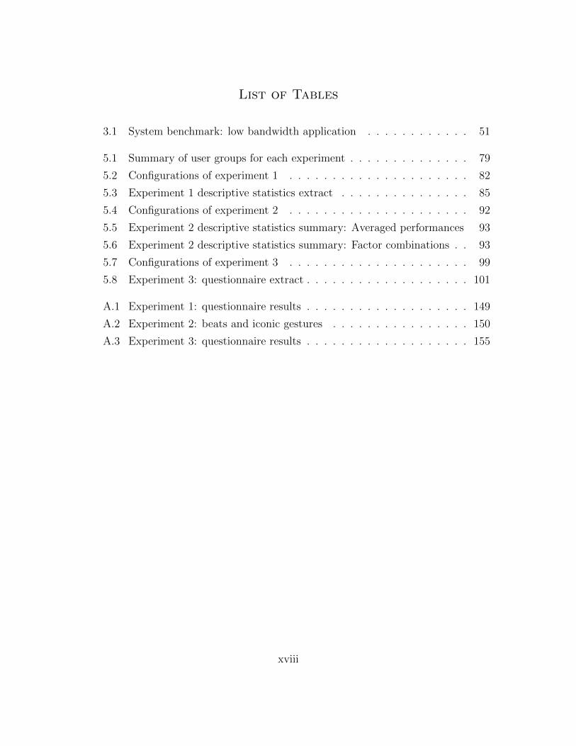
List of Tables
3.1 System benchmark: low bandwidth application . . . . . . . . . . . . 51
5.1 Summary of user groups for each experiment . . . . . . . . . . . . . . 79
5.2 Configurations of experiment 1 . . . . . . . . . . . . . . . . . . . . . 82
5.3 Experiment 1 descriptive statistics extract . . . . . . . . . . . . . . . 85
5.4 Configurations of experiment 2 . . . . . . . . . . . . . . . . . . . . . 92
5.5 Experiment 2 descriptive statistics summary: Averaged performances 93
5.6 Experiment 2 descriptive statistics summary: Factor combinations . . 93
5.7 Configurations of experiment 3 . . . . . . . . . . . . . . . . . . . . . 99
5.8 Experiment 3: questionnaire extract . . . . . . . . . . . . . . . . . . . 101
A.1 Experiment 1: questionnaire results . . . . . . . . . . . . . . . . . . . 149
A.2 Experiment 2: beats and iconic gestures . . . . . . . . . . . . . . . . 150
A.3 Experiment 3: questionnaire results . . . . . . . . . . . . . . . . . . . 155
xviii

CHAPTER 1
Introduction
Virtual Humans are computer-generated interactive entities that should look andbehave as much as possible like real people. Specifically, they should function au-tonomously, perceive their environment and react to events in the virtual (and real)world around them, always responding appropriately. They should interact in a fluid,natural way using the full collection of human verbal and nonverbal communicationchannels. They should model their own and others’ beliefs, desires, and intentionsand they should exhibit emotions. Ultimately, they should do all these things in acoherent, integrated fashion [337]. Virtual humans have great potential to become aseffective as human trainers in monitored, feedback-based, virtual environments fortraining and learning. Interactive virtual humans are in particular suitable for train-ing systems where human-oriented motion skills or human-conveyed information arekey to the learning material.
The aim of this dissertation is to address the challenge of designing such trainingsystems with the approach of motion modeling by direct demonstration and relyingon immersive motion capture interfaces. Thus, experts in a training subject can di-rectly demonstrate the needed motions in an intuitive way, until achieving the desiredresults. To achieve such a system I present in this dissertation an immersive full-scalemotion modeling interface to model generic parameterized actions by direct demon-stration where, subsequently, autonomous virtual trainers can reproduce the motionsin generic training environments with apprentice users learning the training subject.Given the several possible configurations for the proposed systems, the effectivenessof virtual trainers with respect to different choices on use of avatars, and use of 3dvision was analyzed. Finally, the proposed concepts were applied to the applicationof delivering monitored upper-body physical therapy. The proposed solutions wereevaluated by therapists and demonstrate the suitability of the approach.
1

1.1 Motivation
The task of constructing Virtual Humans is complex and requires extensive efforts.Many researchers have focused on this goal over the past decades. Building a vir-tual human requires integrated expertise from different fields and concerted effortsfrom researchers working at cutting edge computer graphics simulation technologiesand from psychologists, linguists, cognitive scientists, and as well expert artists andanimators. Such variety of disciplines is needed in order to create realistic virtualhumans exhibiting autonomy, natural communication, and sophisticated reasoningand behavior.
While the ultimate goal of building the perfect virtual human remains a chal-lenging topic, significant progress has been made. Virtual humans have been studiedand applied in different contexts, such as: dialogue and nonverbal behavior [342, 56],animation and gestures [240, 22, 95], action and dialogue [66, 287, 111]. A commonpoint across these works is to achieve virtual humans that can interact effectivelywith real people but still, many trade-offs related to the employment of virtual hu-mans are still open questions. Understanding how users perceive and interact withvirtual characters in several application design conditions is not clear and manyquestions and settings need to be addressed in order to develop novel and effectiveapplications.
Animated characters, avatars and virtual humans often emerge as key elementsin approaches focusing on replicating human forms of communication. In particular,virtual characters play a significant role in motion-oriented training and rehabilita-tion applications. Virtual Reality training systems started to appear as soon as thefirst Virtual Environment prototypes came to life. Virtual Environments, ImmersiveSystems and Augmented Reality have been extensively applied to train users in avariety of tasks. These new training environments have been reported to be success-fully perceived and to help both trainees and trainers in their roles. A wide varietyof training applications have been developed; for example, applications to simulatehazardous military situations [276, 168], training operators to use specific machinery[308, 139, 373] or to train surgeons in medical procedures [201, 309].
Virtual humans have been applied in training scenarios to convey different typesof information more efficiently, proving to be important in fulfilling the distancebetween a real human trainer and a sterile learning environment based only on pre-sentation of visual information. This gap is prominent in tasks where human-orientedskills, such as leadership, negotiation, cultural awareness, and human-conveyed ac-tions (such as body-language, motions and gestures) must be delivered during the
2

learning process. These skills are based on what is called tacit knowledge [329], thatis, knowledge that is not easily explicated or taught in a classroom setting but insteadis best learned through experience. Currently, these training experiences are usuallydelivered through various human-to-human role-playing exercises and through im-itation. Virtual trainers can effectively replace the human role in many situationsleading to several benefits. Human-based role playing is costly in terms of personnelrequirements and is often done at training centers that may be far away from thestudent’s location. In contrast, virtual exercises can be delivered on any computerdevice, making them available to a student whenever and wherever they are needed,without the need to add additional personnel resources.
Following this approach several training systems have been proposed. For exam-ple Traum et al. [353] proposed a prototype with the goal of exposing junior armyofficers to delicate situations that might occur during the course of a mission butthat typically are not covered in a standard training manual or course (e.g. help-ing civilians during a targeted mission). Beyond rehearsal, another human-orientedskill explored is the possibility of creating virtual humans that could negotiate [354].Similarly, behavioral and negotiation training has been proposed in the context of awork environment where the virtual human occupies a position of authority [290].
The systems described above are complex and they require to integrate a broadrange of technologies, including: speech recognition; natural language understandingand generation; dialogue management; task and domain reasoning; emotion model-ing; speech synthesis; and gesture generation. All of these modules rely on a stronghuman component that involves a large amount of programming effort and time. Inthis process, it is crucial to model the virtual tutor’s behaviors with the ability toconvey information to the trainee in the same manner as a real tutor would conveyit, retaining the original detail and motions’ properties of the expert tutor. As hu-mans we rely on our innate and profound capability of learning through imitation.The imitation learning process, sometimes similar to Programming by Demonstra-tions (PdB) or Learning from Demonstration (LfD) [75, 242], has been addressedfrequently in Robotics and the same approach can be extended to embrace virtualtraining scenarios to enforce behaviors and specifics. In Robotics, the main challengeconsists on the problem of learning a mapping between world state and actions (pol-icy). This policy enables a robot to select an action based upon its current worldstate. Within Imitation learning, a policy is learned from examples, or demonstra-tions, provided by a teacher. Demonstrations can be provided in an indirect manner(where there is no embodiment mapping between the robot and the teacher) or indirect form (where an embodiment mapping between the robot and the teacher ex-ists). Generally speaking, examples are considered as sequences of state-action pairs
3
that are recorded during the teacher’s demonstration of the desired robot behavior.LfD algorithms utilize this dataset of examples to derive a policy that reproducesthe demonstrated behavior.
As previously mentioned, considering the situation where a virtual avatar needsto convey specific actions and gestures to a trainee, what is important is to offer tothe users a situation where, in the modeling phase, experts in the training subject areable to model actions and gestures, without the need of having previous experiencewith the system. The stored example motions can be re-used by the virtual humanduring a training phase with non-expert users and they can be used to naturallydemonstrate motions, and to monitor and analyze user performances.
In light of these needs the Direct Demonstration approach appears to be themost suitable option since it relies only on the subject’s expertise and dexterity.Another important benefit of using pre-recorded motions is to maintain the originalmotions properties and qualities. Several techniques can be adopted in this phase togive to the virtual tutor enough liberty to reproduce these motions with respect, forexample, to arbitrary target locations in new environments and according to differentconstraints. Therefore, the original motions have to be deformed and adapted, alwaysunder the supervision and acceptance of the application expert, in order to enablevirtual humans to automatically deliver a correct and effective learning experiences.Considering this latter case the problem of adapting and conveying information tousers through gestures can be redesigned from a generic decision learning task (wherean action-state policy is no longer necessary) to a motion parameterization problemthat combines realism, flexibility, precise control and ability to adapt to differentenvironments.
In practice, achieving effective implementations of such virtual human trainingsystems requires key design choices to be made and several key factors needs tobe taken into account, for instance: the modeling and training phases have to bequickly interchangeable to allow a fast content modeling and testing; the adoption ofa full scale immersive reality is necessary to grant one-to-one feasible interaction; or,while in some scenarios it may be useful for the user to see his or her own motionsreplicated in an avatar, in some other scenarios avatars may in fact distract the userfrom paying attention to the task at hand. The most appropriate configuration mayalso depend on hardware choices. For example, large full-scale screens, small desktopscreens, and displays with stereo vision influence user performances in avatar-basedscenarios in different ways. Achieving effective implementations of such systemstherefore requires a deeper understanding of the tradeoffs involved among the manypossible configurations.
4

Virtual humans are also key in collaborative environments with remote partici-pants, where a remote instructor may control a local avatar delivering training ma-terial to users. Human instructors can also pre-design training plans to be laterperformed autonomously by a virtual character. Such case is usually a wide adoptedapproach in traditional physical therapy where, after a preliminary step of diagnosticand quantitative measurement a patient is guided by a trained therapist to performspecific therapeutic exercises. The tasks performed are designed according to a re-covery plan, which implies repetitions of exercises and constant progress evaluationboth qualitatively and quantitatively. The traditional physical therapy process isusually intensive, time consuming and dependent on the expertise of the therapist.It also implies the collaboration of the patient who is usually asked to perform thetherapy program multiple times at home with no supervision [19, 250]. Patientsoften perceive the tasks as repetitive and non-engaging, consequently reducing theirlevel of involvement [127, 177]. This fact is related to a number of aspects: lack ofcustomization on how to execute exercises, communication and interaction practicesthat are unsuitable to a particular patient, no clear perception of improvement, lackof coaching and monitoring while at home, etc. Addressing these many aspects isimportant to improve training sessions or therapy outcomes, and in particular to re-duce the risk of injuries due to wrongly executed exercises. Even in this case, motiondemonstration methodologies are suitable to be successfully adopted, allowing ther-apists to intuitively create, edit and re-use customized exercises that are responsiveadaptively to the physical limitations and recovery rates of individual patients.
1.2 Objective and Contributions
The overall objective of this dissertation is to create an effective pipeline for thedevelopment of virtual human training systems with the ability to demonstrate,instruct and deliver training information in immersive virtual environments.
The techniques and models proposed by this pipeline are developed consideringspecific objectives such as: intuitively collect motion capture data from expert userson a specific field for high-fidelity synthesis (direct demonstration approach); preciseparametrization for specified constraints; direct interaction through full-scale immer-sive visualization; employ real-time algorithms for fast responsiveness and real-timeuser interaction and distant collaboration; real observations of users to delineate ap-plication’s key design choices when avatars and immersive visualization is adopted;and, adoption of these techniques on a real training and monitoring scenario such asrehabilitation and physical therapy.
5

The work presented in this dissertation introduces new approaches, techniquesand evaluations which contribute to the achievement of these goals. The specificcontributions are briefly summarized as follow:
• I propose an immersive full-scale motion modeling platform for enabling usersto model generic parameterized actions by direct demonstration. The interfaceproposed allows experts to interactively build training motion dataset in real-time by demonstration. The demonstrated motions can be performed by usersdirectly with respect to specific virtual environments. After demonstrating theneeded motions, the virtual trainer is then able to synthesize new motions forteaching and training purposes for novel users. The motions are parameterizedto generic targets, constraints and they can be reproduced in environmentsdifferent from where they where recorded.
• I performed several experiments, collecting motion data and user evaluations,to analyze the effectiveness of virtual trainers with respect to different choiceson display size, use of avatars, and use of 3D vision. The results show evi-dence that the use of user-perspective stereo vision with direct interaction isthe optimal choice in terms of task accuracy and completion time, when pre-cision tasks are involved (6 times more accurate and 2 times faster) and alsoimproved replication of spatial relationships, both in terms of synchronizationand compliance with the reference motion, even when the task was transferredto the avatar’s space (by a factor of 3). Coupling avatar use with stereo visionresulted in users paying more attention to the motions within the virtual en-vironment, improving the realism and correctness of the motions. In addition,avatar use showed to well improve motion reproduction in the cases wherestereo vision is not present. This factor suggests that in application setupswhere stereo vision is not practical to be used (such as in homes or clinics),the use of avatars will definitively improve the user understanding of motionsdisplayed by virtual tutors. These and other results were quantified and wereperformed in conditions not investigated before in previous work.
• I applied the previously described concepts and guidelines to a concrete sce-nario, developing a set of applications and tools to deliver monitored upper-body physical therapy. New methods for exercise modeling, parameterization,and adaptation are presented in order to allow therapists to intuitively create,edit and re-use customized exercise programs that are responsive to the needsof their patients. In addition, several other factors can be considered to adjusta system to the user’s preferences: from the display of messages, instructions
6

and videos, to the appearance of the virtual character demonstrating the ex-ercises, etc. The system also includes remote networked solutions for allowingtherapists and patients to share motion performances in real-time. The trans-mitted data is lightweight and remote collaboration can well scale to severalpatients at the same time. The proposed solutions were evaluated by therapistsand demonstrate the suitability of the approach.
In addition to the main contributions of this dissertation, the presented systemsand applications were implemented in a new development middleware designed tofacilitate the creation and deployment of Collaborative Immersive Virtual Realityapplications with full-body avatar interactions. The framework is scalable to differ-ent hardware configurations and it defines high-level programming abstractions tohide, simplify and automate several aspects of the creation of distributed virtual re-ality applications. The presented framework demonstrate new interaction paradigmsfor immersive training systems and the system has been tested and compared withother analogous solutions demonstrating similar performances without the use ofcustomized hardware. The framework is also based only on open source libraries orwith source code available.
The results of this research will be useful directly in fields such as virtual reality,computer graphics, computer animation and robotics. In addition, the use of virtualhumans employing motions from real-motion capture information will impact areaswhere the general understanding and perception of human motion is involved suchas psychology, cognitive science and HCI. Finally, as it will be presented in severalchapters of this dissertation, this approach will simplify and improve the deliveryand presentation of human motion practices and can therefore have an impact oneducation, training and the medical area.
1.3 Overview of Chapters
The remainder of this dissertation is organized as follows:
Chapter 2 presents a broad literature review on the fields related to this dis-sertation: virtual reality infrastructures; character animation; real-time motion re-construction; motion perception; and virtual reality applications, with particularemphases on Rehabilitation and Physical Therapy.
Chapter 3 describes the development middleware to create Collaborative Im-mersive Virtual Reality applications with full-body avatar interactions. The Chapter
7

describes, at first, the overall system structure, modules and dependencies involvedhighlighting key properties of the system such as: scalability to generic hardwareconfigurations; integrated with high-end graphics tools; high-level programming ab-stractions; inclusion of advanced tools for full-body character animation, real-timefull-body tracking, and motion transfer to virtual humans and so on. Following abrief overview of some of the developed projects and application, performance testingresults are proposed.
Chapter 4 introduces the methodology and a framework, based on the directdemonstration and parameterization of motions, to empower nonskilled animatorswith the ability to program generic actions and gestures for virtual trainers using afull scale immersive visualization system. The chapter presents the overall conceptexplaining all the implementation details and methodologies involved.
Chapter 5 investigates the influence of different system configurations on userperformances during task execution in immersive virtual environments employingthe motion modeling concept. The investigated configurations varied with respect todisplay size, the use of stereo vision, and the use of avatars, in which case the task istransferred to the avatar space (with the avatar mimicking the motions of the user).The presented systematic study also investigates the use of user-perspective stereovision both in direct interaction mode and in 3rd-person mode with the avatar beingdriven by the user to perform a given task. The Chapter finally highlights benefitsand gives guidelines for the design of applications using direct demonstration andinteraction with 3d vision.
Chapter 6 presents a complete system for the delivery of upper-body physicaltherapy. The system described uses motion demonstration and parameterizationmethodologies to allow therapists to intuitively create, edit and re-use customizedexercises that are responsive to the needs of their patients. The illustrated systemalso present remote networked solutions for allowing therapists and patients to sharemotion performances in real-time. The chapter also presents all the techniques andtools developed for the monitoring, assessment and visualization of a number oftherapy parameters during or after execution of exercises.
Chapter 7 summarizes the dissertation findings together with an analysis of thepromising directions for future research.
Given its close relation to the central topic of this dissertation (and in generalto other important areas such as virtual reality, human perception, and characteranimation) but not directly related to the main topic of motion modeling by demon-stration, the following work is left in the Appendix:
8

Appendix A investigates the advantages of 3D immersive stereoscopic systemand 3D prints for interacting with past material culture over traditional observationof the material without manipulation. Results to these experiments suggest that tra-ditional museum displays limit the experience with past material culture, and revealhow our sample of participants favor engagement, tactile or 3D virtual experiencewith artifacts over a visual non-manipulative experience with authentic objects.
9

CHAPTER 2
Literature Review
This chapter reviews the state of the art of the research related to this dissertation.The presented review provides denitions of basic concepts which are important forthe understanding of the virtual reality field and its history. Virtual Reality systemsand related research are then examined with particular emphases on the technolo-gies adopted, system design differences and related applications. Subsequently, thechapter describes the efforts achieved in the character animation field considering theproblem of solving real-time motion reconstruction from users and direct mappingon virtual avatar. Following evaluation studies on perception and usability of virtualreality systems are then discussed. Finally, a comparison and digression about VRapplications, with particular emphases on Rehabilitation and Physical Therapy, arepresented.
2.1 Virtual Reality
The term virtual reality has found its origin during 1960s but a more formal definitionwas proposed by Howard Rheingold [286]. Rheinghold’s view defines virtual reality(VR) as an experience in which a person is “surrounded by a three-dimensionalcomputer-generated representation, and is able to move around in the virtual worldand see it from different angles, to reach into it, grab it, and reshape it.”
At the present, even though many progress have been achieved toward the devel-opment of VR technologies that can be easily adopted in home environments (suchas: Oculus Rift; Leap and Kinect sensors; Sixsense Stem; etc.), technology is still notready to make computer generated worlds as believable as reality in the same wayscience fiction or scientific VR forecasts were depicting in the past decades. VirtualReality uses computers to create 3D environments in which one can navigate andinteract with the specific goal of simulating reality and the ability to navigate andinteract in computer generated scenes with the possibility of creating reproductionsof real objects or environments for training, entertainment or design purposes [114].
10

In this review and in the rest of this work we adopt the concept and the classifica-tion of VR provided by Milgram et al. [225]. In their manuscript they proposed theidea of a Reality-Virtuality Continuum, a way to understand and classify differenttypes of display technologies. The concept is illustrated in Figure 2.1.
Figure 2.1: Simplifed representation of Reality-Virtuality (RV) Continuum.
The case at the left of the continuum defines any environment consisting solelyof real objects, and includes whatever might be observed when viewing a real-worldscene either directly in person, or through some kind of a window, or via some sortof a (video) display. In the Real Continuum no artificial computer generated stimuliare provided to the user. The case at the right defines environments consisting solelyof virtual objects, examples of which would include conventional computer graphicsimulations, either monitor-based or immersive. In this latter case everything theuser can perceive is artificial. Within this framework it is straight forward to definea generic Mixed Reality (MR) environment as one in which real world and virtualworld objects are presented together within a single display. More specifically, inaugmented reality, most of the images are real while in augmented virtuality, mostof the imagery is computer-generated.
Another source of confusion regarding the concept of VR is whether or how it isdifferent from 3D games. Broadly speaking, games can be considered a subcategoryof VR systems that are focused on the task of entertaining players but keepingthe interface and interaction mechanism simple and well known. However, in thecurrent years, we are starting to witness the interest and adoption from the majorgame and entertainment companies of sophisticated, more advanced and affordable
11

technologies for visualization [258], interaction [224, 186] and user sensing [224, 332].The products delivered are becoming closer to what a virtual reality applicationrequires.
The aspects of reality that have been most prominently explored are the visualand the tracking ones but simulating reality implies different other important com-ponents. For example other important components of our perceptual experience aresounds and tactile feedback. Developing VR systems involves different disciplinesthat address each of the human senses: computer graphics (sight), 3D sound syn-thesis (hearing), and haptics (touch). Smell and taste play important roles in ourdaily life. Several projects to reproduce smell in VR have been proposed but tastehas been less explored due to the complexity of the required technology.
In this line of thinking, three main factors have been identified as the maincontributors that enhance the VR experience from a physical and psychological pointsof view: presence, immersion and multi-modal interaction.
Presence is defined as the degree to which participants subjectively feel andprocess cues translating them in a coherent environment in which we can performsome activities and interact. According to Slater and Wilbur “Presence is a state ofconsciousness, the (psychological) sense of being in the virtual environment” [322].In order to promote presence in a synthetic experience the following aspects mustbe considered: sensory fidelity and richness; degrees of interactivity; and other psy-chological cues [259, 313]. A well-crafted virtual world could change our emotionalstate and make us feel differently according to the type of experience designed.
Immersion is defined by the physical possibility to perceive the virtual environ-ment as in real life through stereoscopy and spatial sound. Immersion is directlyrelated to the physical configuration of the VR application. VR systems can be clas-sified as fully immersive (at least visual and auditory cues are fulfilled by the systemenforcing user isolation from the real world), semi-immersive (visual cues are fulfilledalmost as close as a real experience without isolation), or non-immersive (any othervirtual experience). The challenge for computer graphics researchers is to make thevirtual world look, sound and respond to user interaction in real-time [366]. A com-prehensive description of immersive visualization technologies and hardware can befound in [245].
Multi-modal interaction comprehends any type of natural and usable mech-anism (and related user interfaces) to promote user machine interaction. Accordingto [160], from intuition and from the evolutionary viewpoint, an interaction schemeis based on: the three-dimensional space; involvement of the whole body; and onethat takes advantage of the multimodality of the human sensory system.
12

2.1.1 Virtual Reality history
During the 1960s, as previously mentioned, the first real system to simulate the realworld was developed. The system was developed by the cinematographer MortonHeilig in 1962 and its name was “Sensorama”. It was designed to simulate vehi-cles and it allowed users to sit in front of a screen where they could choose fromdifferent vehicles. The system did not provide any interactivity but did include 3Dphotographic slides, stereo sound and even a wind generator.
In 1965, Ivan Sutherland during his lecture entitled The Ultimate Display [335] inwhich he described how one day the computer would provide a window into virtualworlds. He suggested that a screen should be considered as window upon a virtualworld. The real world is complex and it contains many stimuli which involve manysenses. Subsequently, he built a head-mounted display (HMD) that presented tothe user left and right views of a computer-generated 3D scene. After these initialexperiments Virtual Reality research started to grow finding as main contributorsComputer Scientists as well as Artists. For example, a few years later, the contri-bution of Myron Kruger with a gesture based interactive art project “Videoplace”[175] started the idea of interactive virtual reality or “artificial reality”.
In order to finally find the first system that can be considered a true VirtualReality system we have to move to the 1980s where innovations were supportedby greater accessibility to 16-bit CPUs. The world of VR was at one of its peaksright around 1984 where the Ames Research Center at NASA developed the first pilottraining system for manned space missions VIEW [368]. The VIEW system consistedof a wide-angle stereoscopic display unit, glove-like devices for multiple degree-of-freedom tactile input, speech-recognition technology, gesture-tracking devices, 3Daudio, speech synthesis, computer graphics, and video image generation equipment.
These years mark the maturity of many aspects of computer technology and, tomany degrees, the structural foundation for modern VR/AR technologies. The firstinitiatives to commercialize VR products started in the early 1980s. VPL Researchwas one of the first companies focused on developing VR hardware and software. VPLdeveloped the “DataGlove” integrated with head-mounted displays. Subsequently,other companies arose specializing their business in different aspects from interaction,force-feedback, tracking and pure visualization. As lead companies we find nameslike: Polhemus; Ascension; Virtual Technologies; and Immersion Corp.
Even though the 1980s are considered the peak of VR research and commercial-ization the technology involved and the computational power of machine was notready to fulfill the needs of complex VR applications. During the 1990s the design of
13
the first CAVE system [73] changed the paradigm of Virtual Reality offering a setupless cumbersome than current HMD, easier to interact, providing a large field ofview and depth cues. The CAVE system is based on back-projecting images on wallssurrounding the user. This setup allowed for the first time multi-user immersion andinteraction in a shared virtual space.
Around the 2010s, thanks to the technological advancements and the involvementof major companies (such as Microsoft, Facebook, Intel, Apple, Sony, etc.), it seemswe have finally arrived at affordable, high-quality consumer hardware for VirtualReality. The game and entertainment market is finally at the stage of adopting moresophisticated methods of interaction and visualization for their products such hasOculus RIFT [258], Sixense [319], Virtuix [362] and Microsoft Kinect [224].
2.1.2 General purpose Immersive VR architectures
Since the early 1980s numerous systems have been proposed that aimed to developengines to create VR application and advanced systems. More specifically, immersiveVR systems (iVR) like CAVEs and multi-tile walls (or Powerwalls) started to appearin the 90s and have defined what can be called cluster-based virtual reality.
In the early stage of development, due to lack of hardware power and high taskspecialization, the most common approach chosen consisted of adapting each solutionto Domain-Specific cases (these packages are focusing to specific uses and require-ments or are monolithic packages that offer little flexibility to developers [34, 197])or to create Special-Purpose Architectures to solve a task. For example, high-performance real-time rendering systems have relied on an integrated proprietarysystem architecture, such as the SGI graphics supercomputers [310] or specializedsolutions like PixelFlow [230], MPC Compositor [235], Sepia [203] or Lightning 2[330].
In the following years, this high specialization of both software and hardware leadresearchers toward the development of high level generic infrastructures with the goalof simplifying the workload of programmer and decoupling the application implemen-tation details from the hardware where the application is running on. A large numberof VR development software ranging from low-level programming toolkits to contentcreation systems aimed at non-programmers arouse after the 1990s.
Following, a list of the most representative engines for the development of VRsystem is provided, both commercial and open source. Each system provides differ-ent mechanism abstraction in regards to: display type support (3D Displays, Pro-jectors, Head-Mounted Displays, etc.), rendering techniques (single-pipe, multi-pipe
14

Figure 2.2: Examples of Virtual Reality setups. On the left: CAVE system with fourretroprojected walls using MiddleVR and Unity [141, 355]. On the Right: CarinaNebula displayed in a multiframe LCD powerwall system using CGLX [82].
and cluster-based) and input abstraction.
Single-pipe and Multi-pipe rendering techniques rely on a single machine/workstationconnected to one or more rendering/projection devices. This approach is becomingmore common thanks of the development of more powerful computers and multi-display graphics cards [255, 20]. On the other hands when really high resolutionsurfaces are needed or when the computational power of a single workstation is notenough to generate virtual simulations cluster-based rendering is still the main solu-tion.
A number of algorithms and systems for parallel rendering have been developedin the past. Cluster-based systems can be subdivided in two main categories:
Client-Server (CS) systems have the data and the application state main-tained by the server and subsequently each update is streamed to the clients ondemand (data streaming, distributed rendering calls or rendered buffer streaming).For example, specific algorithms have been developed for cluster-based rendering andcompositing such as [4, 27, 385].
Master-Slave (MS) systems maintain the data mirrored or shared between par-allelized application instances and the application status is maintained synchronizedamong all instances. Some general concepts applicable to cluster parallel renderinghave been presented in [232, 233] (sort-first architecture), [302, 301] (load balancing),[300] (data replication), or [58] (scalability).
15

2.1.2.1 Master-Slave architectures
Of particular note is the CAVELib [73, 72, 57] the first general purpose VR enginedeveloped that introduced the concept of CAVE. Initial versions of its immersiveprojection environment ran on a pair of networked SGI computers. Consequently,the CAVELib includes support for PCs and commodity clusters. CAVELib hidesdisplay setup by running individual render processes for each screen. Applicationsprovide callback functions that insert user specific OpenGL code and in a cluster,application instances are generated in all nodes and synchronizes them by sharinginput signals. CAVELib does not provide any high level abstraction and constructsto the user making the generation of clustered based applications quite complex.
VR Juggler [35] is a a VR toolkit with a level of abstraction similar to CAVELibwhich shields the application developer from the underlying hardware architecture,devices, and operating system. Display abstraction is based on the notion of projec-tion surfaces. Two extensions provide clustering support, NetJuggler [9] and Cluster-Juggler [260]. Both extensions are communicating with the VR Juggler instance andthey are based on the replication of application and data on each cluster node. Theseextensions basically take care of synchronization issues but fail to provide a flexibleconfiguration mechanism that efficiently supports scalable rendering. VR Jugglercontains no high-level geometry library, high level graphics programming constructsor 3D GUI components. Although VR Juggler supports clusters, the user still needsto develop applications considering low level server/client implementations as alsonoted by [327].
Other two extensions of VRJuggler has been proposed during the past few yearstrying to address the main limitations of VRJuggler. The FlowVR platform [10] wasdeveloped based on experience in using VR Juggler in a clustered environment, andemphasizes a data-flow model for distributed real-time interactive computation withhigh modularity. VRJugg LUA [263] was designed a high-level virtual reality applica-tion framework based on LUA scripting language, VR Juggler and OpenSceneGraph.This approach allowed the generation of VR applications for distributed renderingwith the enhancement of a high level Graphics Library. The system design is stillcumbersome and the abstractions mechanisms are not fully developed.
Another popular VR library is Syzygy [305]. Syzygy is a programming toolkitaimed at commodity clusters with a limited multipipe abstraction. The library eitheroffers a high level scene graph architecture, or cluster-based rendering very similarto ClusterJuggler. In comparison to VRJuggler, the library offers a high level ab-straction level considering networked applications but it does not offer higher-levelinteractions. Simulators (especially on the desktop) are still severely limited.
16

HECTOR [369] supports the idea of rapidly prototyping applications using aPython scripting interface. The framework consists of a micro kernel and a com-munication module similar to VRJuggler. Many central components like the eventpropagation system are directly implemented in Python, which makes the systemeasily extendible. This framework proposes an interesting concept, but it seems thatthis project is no longer active. Similarly, AVANGO/NG [176] applies a generic fieldand field container programming interface to a scenegraph based on OpenSceneGraph(originally using SGI Performer), with Python scripting support.
3DVia Virtools used to be a widely used commercial development kit for 3Dapplications that supports many common hardware components and comes with alot of built-in functionality. The VR Library/Publisher module supports client-serverdistribution where the parameters of a scene are synchronized with the server, but itdoes not support a peer-to-peer communication of stand-alone VR/AR applications.The project is now discontinued.
Worth noting, Unity Technologies released a plug-in [141] to run the Unity3D soft-ware [355] on any VR platform, providing at the same time its vast game designernetwork and Asset Store to VR research community. Along with Eon Reality [281]and Worldviz [379] solutions (Eon Icube and Vizard respectively), commercial solu-tions are nowadays available to support researchers in their VR based investigations,on the understanding that they are disposed to invest financially in such, typicalinstallations having yearly maintenance fees most often calculated on a per screenbasis. This limits development flexibility and mutliplatform/multi-configuration uti-lization. The relatively closed nature of these solutions also limits their use in researchoriented applications.
2.1.2.2 Client-Server architectures
One of the first fully-fledged engines, providing high level abstractions and clusterbased rendering, for virtual reality is Chromium [137] (the successor of WireGL[136]). Chrominum provides a powerful and transparent abstraction of the OpenGLAPI, which allows a flexible configuration of display resources. Its main limitationwith respect to scalable rendering is that it is focused on streaming OpenGL com-mands through a network of nodes, often initiated from a single source (commandsand data).
The OpenGL Multipipe SDK (MPK) [33] implements an effective parallel ren-dering API for a shared memory multi-CPU/GPU system. MPK handles multipiperendering by a lean abstraction layer via a conceptual callback mechanism, and that
17

it runs different application tasks in parallel. However, MPK is not designed normeant for rendering nodes separated by a network. MPK focuses on providing aparallel rendering framework for a single applications that are running in parallel onmultiple rendering channels.
Parallel rendering frameworks such as Garuda [246] and Aura [358] show thepotential of the parallel approach but are restricted to a scene graph-type application.
A system that addressed the limitations of the previously mentioned systems isEqualizer [87]. The Equalizer framework does not impose these restrictions and pro-vides enhanced load balancing strategies targeted mainly toward virtual reality-typesystems. However, to leverage these features, in depth knowledge about the Equalizersystem configurations and considerable code changes or application specific adapta-tions are required. With the same implementation philosophy of Equalizer CGLX [82]was developed. CGLX aims to provide an easy-to-use parallel rendering frameworkfor distributed cooperative visualization systems without imposing any restrictionson OpenGL-type applications. CGLX gives users full control over the display config-uration. Hardware-accelerated rendering is natively supported on different operatingsystems.
A totally different approach is proposed by the Scalable Adaptive Graphics En-vironment (SAGE) architecture [148]. SAGE operates on the assumption that anytype of application will send a pixel stream to the SAGE server, which in turn man-ages the tiles and distributes the incoming pixels to the correct portion of a tiledwall. SAGE takes exclusive control of the distributed frame buffer. Thus, to displaya high-resolution visual, another application needs to be running on the same clus-ter, rendering its content in an off-screen buffer, which then can be read back andmapped to a SAGE client. Since read-back operations are expensive, the achievableperformance of this approach is limited.
2.1.3 Distributed Virtual Environments
A distributed virtual environment (DVE), as defined in [190], is a software systemthat allows users in a network to interact with each other by sharing a common viewof their states. As users are geographically distributed over large networks like theInternet and the number of users increases, scalability is a key aspect to consider forreal-time interaction.
The approaches for improving scalability of DVE can be classified into the follow-ing categories [114]: communication architecture, interest management, concurrencystates control, data replication, and load distribution.
18
Communication architecture the communication architecture can be charac-terized as follows: client-server (messages are sent to a server and then the serverdistributes them to all clients); peer-to-peer (users directly exchange messages andmaintain synchronization); or peer-to-server (consistency management is done by aserver and communication among users is performed using multicast).
Interest management Interest-management strategies [30] exploit the fact thatusers do not need to receive all update messages related to the whole world. Instead,they receive only messages in which they are interested. Two possible scenarios arefeasible: world regions (zones) or adaptive radius localization.
Concurrency states control Shared information in DVEs is often replicated ateach user’s site to provide acceptable interactive performance. Replication enablesusers to locally access and update data. On the other hand data has to be maintainedsynchronized, which eventually leads to inconsistent views among users. Approachesto concurrency control have been broadly categorized into pessimistic, optimisticand prediction schemes (most frequently used for spatial positioning changes andupdates).
Data replication Data is replicated by local changes or notification of remotechanges. Three scenarios are possible: preloaded local data; monolithic shared datadownload; and on-line data streaming. The main challenge in partial data replicationis the minimization of scene artifacts due to unavailable data (or partially loadeddata). Two schemes are usually used together: prioritized transfer of objects andcaching (e.g. LODs and CLODs mechanisms [200]) and prefetching techniques.
Load distribution Partitioning a virtual world into multiple regions and dis-tributing the responsibilities for managing the regions across multiple servers cansignificantly reduce the workloads of individual servers. To avoid degradation ofinteractive performance, due to imbalance among servers, dynamic load distribu-tion schemes have been introduced where overloaded servers transfer their excessiveworkloads to less-loaded ones. There are three main approaches: local (the work-load is shared among neighboring servers), global (a main coordinator balances theworkloads in the whole grid), and adaptative dynamic load distribution (overloadedserver balances its workload with a set of servers, beyond its neighboring servers,according to their workload status).
19
2.2 Kinematic-Based Character Animation
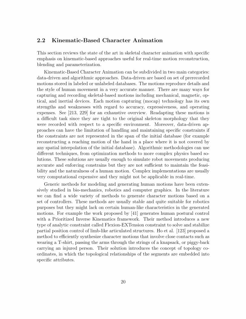
This section reviews the state of the art in skeletal character animation with specificemphasis on kinematic-based approaches useful for real-time motion reconstruction,blending and parameterization.
Kinematic-Based Character Animation can be subdivided in two main categories:data-driven and algorithmic approaches. Data-driven are based on set of prerecordedmotions stored in labeled or unlabeled databases. The motions reproduce details andthe style of human movement in a very accurate manner. There are many ways forcapturing and recording skeletal-based motions including mechanical, magnetic, op-tical, and inertial devices. Each motion capturing (mocap) technology has its ownstrengths and weaknesses with regard to accuracy, expressiveness, and operatingexpenses. See [213, 229] for an exhaustive overview. Readapting these motions isa difficult task since they are tight to the original skeleton morphology that theywere recorded with respect to a specific environment. Moreover, data-driven ap-proaches can have the limitation of handling and maintaining specific constraints ifthe constraints are not represented in the span of the initial database (for examplereconstructing a reaching motion of the hand in a place where it is not covered byany spatial interpolation of the initial database). Algorithmic methodologies can usedifferent techniques, from optimization methods to more complex physics based so-lutions. These solutions are usually enough to simulate robot movements producingaccurate and enforcing constrains but they are not sufficient to maintain the feasi-bility and the naturalness of a human motion. Complex implementations are usuallyvery computational expensive and they might not be applicable in real-time.
Generic methods for modeling and generating human motions have been exten-sively studied in bio-mechanics, robotics and computer graphics. In the literaturewe can find a wide variety of methods to generate character motions based on aset of controllers. These methods are usually stable and quite suitable for roboticspurposes but they might lack on certain human-like characteristics in the generatedmotions. For example the work proposed by [41] generates human postural controlwith a Prioritized Inverse Kinematics framework. Their method introduces a newtype of analytic constraint called Flexion-EXTension constraint to solve and stabilizepartial position control of limb-like articulated structures. Ho et al. [123] proposed amethod to efficiently synthesize character motions that involve close contacts such aswearing a T-shirt, passing the arms through the strings of a knapsack, or piggy-backcarrying an injured person. Their solution introduces the concept of topology co-ordinates, in which the topological relationships of the segments are embedded intospecific attributes.
20
Another example is the whole-body analytical Inverse Kinematic method pro-posed by [154]. In this approach full-body animations of reaching tasks are producedintegrating collision avoidance and customizable body control. The method relies onsearch algorithms for achieving specific postures avoiding joint limits and collisions.Also the problem of generically solving walking sequences and gait has also been ad-dressed. A common method uses path following and sagittal elevation angle controlscoupled with inverse motion synthesis based on barycentric interpolation [334].
As the technology for motion capture becomes more available, the attention hasbeen focused on how to re-use the captured data to generate new motion sequencesto precisely impose modifications and constraints. In this domain a well-known andactive area of research is motion retargeting of motion capture data to differentskeletal characters with or without similar topologies. [124] uses the new conceptof interaction mesh, a structure to represent implicit spatial relationships betweenbody parts and surrounding objects, to minimize local mesh deformations and inter-penetrations within animation frames. Hecker et al. [118] introduces a novel way torecord animations in a morphology independent form. At runtime the system uses anIK solver to animate characters with different skeleton morphologies. On the sameline of research Yamane et al. [384] propose an alternative method for animating non-humanoid characters that leverages motion data from a human subject performingin the style of the target character. The method consists of a statistical mappingfunction learned from a small set of corresponding key poses, and a physics-basedoptimization process to improve the physical realism.
2.2.1 Motion Graphs
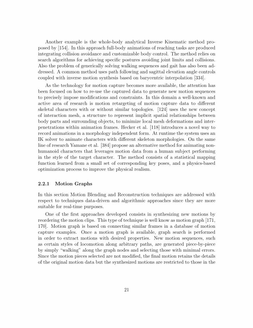
In this section Motion Blending and Reconstruction techniques are addressed withrespect to techniques data-driven and algorithmic approaches since they are moresuitable for real-time purposes.
One of the first approaches developed consists in synthesizing new motions byreordering the motion clips. This type of technique is well know as motion graph [171,170]. Motion graph is based on connecting similar frames in a database of motioncapture examples. Once a motion graph is available, graph search is performedin order to extract motions with desired properties. New motion sequences, suchas certain styles of locomotion along arbitrary paths, are generated piece-by-pieceby simply “walking” along the graph nodes and selecting those with minimal errors.Since the motion pieces selected are not modified, the final motion retains the detailsof the original motion data but the synthesized motions are restricted to those in the
21

motion capture database.
Arikan and Forsyth [14] build a hierarchy of graphs and use a randomized searchto satisfy user constraints. Arikan et al. [15] use dynamic programming to searchfor motions satisfying user annotations. Lee et al. [191] construct a cluster forest ofsimilar frames in order to improve the motion search efficiency. All these methodsrequire quadratic construction time for comparing the similarity between all theframes in the database.
Other extensions of motion graph are focused on improving the search versatility.Heck et al. [117] introduced the new data structure of parametric motion graph,which is capable of dynamically generating the transitions in real-time. Interpola-tion methods have also been used. The method proposed by [298] is based on theinterpolation of two time-scaled paths and involve methods that solve a linear systemof constraints. Cheng et al. [284] proposed a method using optimization techniquesand probability based transitions in the graph to achieve interactive natural tran-sitions between motion clips. Although these methods increase the solution space,they come with the expense of further distorting synthesized motions or they oftenincrease the involved computation time and complexity. Methods employing an In-verse Branch Kinematics to deform the 2D graph branch with Cyclic CoordinateDescent (CCD) solver, so that the branch end reaches the goal with much betterprecision [212], have also been explored.
In addition to the generation of motion graphs that can adapt to different tasksand databases, work on generating better motion graphs (small, fast, and with goodconnectivity as well as smooth transitions) have been proposed, for example, usingiterative sub-graph algorithm has proposed by [390, 391].
2.2.2 Motion Parameterization and Reconstruction
Early studies in motion parameterization found their root in the signal processinganalysis domain. Motions are considered propagation of signals over time and differ-ent techniques, such as, motion filtering, multitarget interpolation, Fourier analysisetc. have been used to extrapolate data, interpolate different motions or to extractand to alter motion styles [356, 370, 48].
Following the signal processing approach a different method to analyze motiondata was proposed by Rose et al. [295]. This approach combines Radial BasisFunction (RBF) with polynomial terms to generate new synthesis with examplescharacterized by emotional expressiveness or control behaviors. A draw back of thisapproach is found when the desired input gets further from the original data resulting
22

to degraded motions.
An extension of this work was proposed in [296]. The presented method applies anefficient inverse-kinematics methodology based on the RBFs interpolation of examplemotions and positions. RBFs can smoothly interpolate given motion examples andthe types and shapes of the basis functions are optimized in order to better satisfythe constraints.
Spatial properties such as feet sliding or hand placements are well addressed bythe geostatistical interpolation method [234], which computes optimal interpolationkernels in accordance with statistical observations correlating the control parametersand the motion samples. Another approach for improving the maintenance of spatialconstraints is to adaptively add pseudoexamples [170] in order to better cover thecontinuous space of the constraint. This random sampling approach however requiressignificant computation and storage in order to meet constraints accurately and isnot suited for handling several constraints. Moreover, the error between the end-effector and specified target still exists. Methods to correct this artifact have beenproposed by [71] through learning feature and IK solver correction.
The Scaled Gaussian Process Latent Variable Model (SGPLVM)[110] providesa specific framework targeting the IK problem which optimizes interpolation ker-nels specifically for generating plausible poses from constrained curves such as posi-tional trajectories of endeffectors. Similarly, [195] presents a technique that interac-tively animates characters performing user-specified tasks with constraints on a low-dimensional latent space. These methods are stable and produce reliable motions,however, the higher computational cost in the training process imposes limitationson applications that involve on-line appending or refining of the dataset.
The problem of parameterizing motions is linked closely to the problem of re-constructing character motions from a low resolution input signals (for example lowresolution signal matched to a high resolution database or reconstruction of motionfrom a reduced marker set motion tracking device) or from a input signal that isdifferent from a motion database (reconstruction of human motions from video cam-era, accelerometers or IR depth information). In addition, the (real-time) controlof virtual characters using mocap data, also known as computer puppetry [314], isanother key challenge in the field of computer animation. Besides the use of high-dimensional optical systems, various controller-based systems have been describedthat allow for generating and reconstructing visually appealing motion sequences onthe basis of low-dimensional sensor input.
Once a motion database is parameterized, for example with the methods previ-ously described, human motions can be reconstructed through search methods. Chai
23

and Hodgins [59] proposed a method to reconstruct user motion in real-time froma reduced and noisy subset of tracked markers. Their method relies on a graph ofnearest neighbors for fast search of the motion examples that are close to the currentcontrol signals and use it to build a local linear model of the motion for interpolation.A similar approach was chosen by Zheng et al. [392] using hidden Markov models(Windowed Viterbi algorithm) to achieve the similar results. Another similar ap-proach was proposed by Tautges et al. [343]. Instead of using the same set of inputsignals (in Chai’s case marker based motion capture data) with a reduced number ofinputs the authors are reconstructing full-body human walking using accelerometers.
Figure 2.3: Character’s motion reconstruction from a reduced marker set proposedby Chai et al. [59].
In Shiratori et at. [315], inertial-based control data is used to specify a smallnumber of free parameters in physically-based character animation. When high-dimension data has to be generated using only low-dimensional control data data-driven approaches especially show promising results. This work has been subse-quently extended using body-mounted cameras to reconstruct the motion of a subject[316].
Human pose estimation from camera based sensors has generated a vast literature(surveyed in [318, 272]). This problem is mostly addressed as a machine learningproblem where, considering a vast number of training set data, new data is param-eterized and the closest data from the data base is then retrieved considering someaccuracy distance. A large number of papers based on this approach improved theregression models, dealt with occlusion and ambiguity, and re-incorporated temporalinformation [239, 357]. Such models, however, classify the whole-body pose in one
24

monolithic function and they require enormous amounts of training data.
One approach to reduce the demand for training data is to divide the body intoparts and attempt to combine the per-part estimates to produce a single pose esti-mate. The first method that allowed the reconstruction system to work in real-time,fit to several body types and not requiring any calibration technique was proposed by[317]. Shotton et al.’s method predicts human pose from a single depth image, with-out depending on information from preceding frames. By designing an intermediaterepresentation in terms of body parts, the difficult pose estimation problem is trans-formed into a simpler per-pixel classification problem, for which efficient machinelearning techniques exist.
Le et al. [185] propose a method based on Laplacian mesh editing [326], which hasproven to be well suited for animating close interactions. Here, interaction meshes[124] are defined with respect to their temporal correlations in the original animation.Motion optimization is achieved by solving two minimization problems. The firstpenalizes deformations that result from Laplacian coordinate manipulation and thesecond preserves the length of motion segments over time.
Ho et al. [122] proposed a method based on two-person motion capture data witha two stage process. First, the postures of the afterwards active interaction partner,i.e the human, and the virtual agent are organized in a kd-tree. This leads to a treewhere each leaf stores pairs of poses that have been obtained in the initial recording.Then, for live human-agent interactions the tree is queried for postures that aresimilar to the current user pose. The character’s pose is morphed to match spatialconstraints by solving a space-time optimization problem with interaction meshes[124]. In doing so a virtual character can react to an ongoing human interaction inreal-time.
On the same line of research Vogt et al. [363] proposed a new scheme for efficientidentification of motions in the prerecorded animation data that are similar to thelive interaction. A global low-dimensional posture space serves to select the mostsimilar interaction example, while local, more detail-rich posture spaces are usedto identify poses closely matching the human motion. Using the interaction meshof the selected motion example, an animation can then be synthesized that takesinto account both spatial and temporal similarities between the prerecorded and liveinteractions.
25

2.2.3 Learning from Demonstration
Learning from Demonstration (LfD), also referred to as Imitation Learning or Pro-gramming by Demonstration (PdB), has become a central topic in the robotics fieldin the past years. LfD spans across general research areas such as human-robotinteraction, machine learning, machine vision and motor control.
LfD find its roots from the Programming by Example concept [75]. Programmingby Example is defined as a way of programming a software system in its own userinterface. The user of the system writes a program by giving an example of whatthe program should do. The system records the sequence of actions, and can per-form it again. Programming by example allows a user to create programs withoutdoing conventional programming. In Robotics, Programming by Demonstrations isconsidered a powerful mechanism for reducing the complexity of search spaces forlearning. When observing either good or bad examples, one can reduce the searchfor a possible solution, by either starting the search from the observed good solution(local optima), or conversely, by eliminating from the search space what is knownas a bad solution. Imitation learning is, thus, a powerful tool for enhancing andaccelerating the learning process.
A wide variety of systems employ the Programming by Demonstration concept.Within LfD, a policy is learned from examples, or demonstrations, provided by ateacher. Examples are defined as sequences of state action pairs that are recordedduring the teacher’s demonstration of the desired robot behavior. LfD algorithmsutilize this dataset of examples to derive a policy that reproduces the demonstratedbehavior. This approach to obtaining a policy is in contrast to other techniques inwhich a policy is learned from experience, for example building a policy based ondata acquired through exploration, as in Reinforcement Learning [26].
There are certain aspects of LfD which are common among all applications todate. One is the fact that a teacher demonstrates execution of a desired behav-ior. The second is that the learner is provided with a set of these demonstrations,and from them derives a policy able to reproduce the demonstrated behavior. Thedemonstration phase (recording) can be performed in two manners:
Presentation or indirect demonstration where there is no embodiment map-ping between the robot and the teacher, because demonstration is performed on theactual robot learner. In this case two scenarios are possible: teleoperation and shad-owing. Teleoperation is a demonstration technique in which the teacher operates therobot learner platform and the robot’s sensors record the execution. The recordingoperation can be done via different media and used in a variety of applications, for
26

Figure 2.4: Learning from Demonstration: categorization of approaches to buildingthe demonstration dataset as proposed Argall et al. [13].
example: via joystick to flying a robotic helicopter [243], object grasping [338, 24],robotic arm assembly tasks [65] or through kinesthetic teaching where robot’s jointsare passive and moved through desired motions [43, 12]. The shadowing techniqueconsists in the robot platform mimicking the teacher’s demonstrated motions whilerecording from its own sensors [76, 241].
Imitation or direct demonstration where there exists an embodiment map-ping between the robot and the teacher, because demonstration is performed on aplatform which is not the robot learner [303]. Also in this case two techniques canbe applied: through sensor on a teacher and by external observations. In the firsttechnique human teachers commonly use their own bodies to perform example exe-cutions by wearing sensors able to record the person’s state and actions or by usingsensors able to infer the user’s pose. This is especially true when working with hu-manoid or anthropomorphic robots, since the body of the robot resembles that ofa human. Example of application of technique has on robot walking [237, 304] orsimulating human which maps to a simulated robot and then to a real robot arm[52] or full-body [108]. The external observation technique relies on data recordedby sensors located externally to the executing platform, meaning that a record map-ping exists [270, 63]. The data recorded under this technique is less precise and lessreliable. The method, however, is more general and is not limited by the overheadof specialized sensors and settings.
Given a dataset of state action examples several methods for deriving a policyusing this data have been developed. In the Robotics domain the most common
27

technique applied relies on: learning an approximation to the state-action mapping(mapping function), or learning a model of the world dynamics and deriving a policyfrom this information (system model). Alternately, a sequence of actions can beproduced by a planner after learning a model of action pre and post conditions(plans). Across all of these learning techniques, minimal parameter tuning and fastlearning times requiring few training examples are desirable. Since the policy learningstep is out of the scope of this dissertation the reader is referred to the extensivereviews on the field presented by the following manuscripts [36, 13, 51].
2.3 Avatar Perception in Virtual Reality
Humans, being highly social creatures, rely heavily on the ability to perceive whatothers are doing and to infer from gestures and expressions what others may beintending to do. The use of avatars (i.e., digital representations of human users)to represent individuals within multi-user immersive virtual environments in real-time has increased considerably in the past decade, underscoring the need to betterunderstand how users experience them visually and cognitively.
Humans communicate and interact in complex ways and through different com-munication channels. An exhaustive overview of the perceptual, motoric, affective,and neural concomitants involved in human communication processes are docu-mented by Blake [38]. Psychologists have showed that people are remarkably skilledin recognizing the features of a person through his or her motions; for example, inidentifying gender [172], emotions [21], or the identity of a known person from justa synthesized silhouette of his or her motions [74].
Many aspects about character animation and avatars have been studied in thecontext of virtual reality applications: different rendering styles, behavioral or anima-tion qualities of characters, user’s perception of objects, embodied cognition, depthperception and visual cues and so on.
For example, the introduction of visual artifacts or the use of an unnatural an-imation has been demonstrated to lead to human negative reactions [45]. Reitsmaet al. [282] presented the results of a study on user sensitivity to errors in animatedhuman motions, and proposed a metric for measuring errors in ballistic human mo-tions. McDonnel et al. [216] analyzed the impact that rendering styles of animatedcharacters have on users, defining possible outcomes per scenario. Other types ofstudies have been performed targeting aspects like how the appearance of charactersaffect the perception of their actions [60] or the perception of bodily emotions [217].
28

The use of virtual avatars in immersive virtual environments has also been exten-sively explored and applied in many fields with investigation on aspects related tobehavior, appearance, interaction, user’s embodiment and ownership [39, 328, 265].Recent work has examined how people come to “inhabit” or embody their avatars,which are virtual representations of themselves [184]. For example, Slater and col-leagues [321] demonstrated that male participants experienced a so-called “bodytransfer illusion” even when their avatars were female. Several studies have demon-strated the persuasive advantage of using virtual selves over generic or unfamiliarvirtual others in the realms of advertising [2], health [91], and financial decisions[121].
One recent study, comparing the persuasive power of IVE with character embodi-ment against traditional media messages, found that traditional IVEs induced/increasedsocial behavioral intentions more effectively that traditional media [3].
The study proposed by Phillips et al. [267] discovered that users who are givena first person avatar in an Non-photorealistically rendered (NPR) immersive virtualenvironments replica judge distances more accurately than users who experience theNPR replica room without an embodiment. Moreover, the latter are not as accurateas users whose distance judgments are made in a photorealistically rendered virtualreplica room.
In traditional Immersive Virtual Reality it has been found that humans are notreliable on distance and depth estimation in virtual reality [16]. A commonly ac-cepted theory behind depth perception in virtual reality is based on the Depth CueTheory [98], which is based on the concept of visual cues.
There are a number of cues that the human visual system uses that result in aperception of depth. Some of these are present even in two dimensional images, forexample: perspective projection, size of known objects, details, occlusion, lightingand shadows etc. There are other cues that are not present in 2D images, theyare: binocular disparity, accommodation (muscle tension needed to change the focallength of the eye lens in order to focus at a particular depth), and convergence(muscle tension required to rotate each eye so that it is facing the focal point).While binocular disparity is considered the dominant depth cue in most people, ifthe other cues are presented incorrectly they can have a strong detrimental effect.
According to Gilliam [99], depth perception results from the integration of visualcues categorized as: pictorial, oculomotor, and stereo depth cues. A more recentextension of this concept was proposed by Swan et al. [336], and states that not onlythe individual visual cues but also the ways these cues are processed by the humanvisual system allows us to create a three-dimensional perceptual world.
29

For the purpose of assessing depth perception cues (and the ability to estimateuser’s depth perception), two types of measurements are considered reliable: theallocentric (distances between objects and a reference point) and the egocentric (dis-tances between objects in relation to the subject) distance [204]. The problem ofdistance perception in virtual environments is often related to two possible scenar-ios: peripersonal (space that can be reached by our hands) and the extrapersonalspace. Research has showed that depth acuity is usually high in peripersonal spacebut low otherwise [275].
In this thesis work, instead of investigating the impact of different renderingstyles, behavioral or animation qualities on users, the main focus is on investigatinghow the use of avatars mimicking the user’s motions influence the successful exe-cution of motor tasks and motion reproduction considering different virtual realityconfigurations. The key motivation of this research is driven by the importance ofthese tasks in several training and rehabilitation applications.
2.4 Rehabilitation and Physical Therapy
Healthcare and health science are one of the biggest adopters of virtual reality whichencompasses many type of applications. For example there are many applicationsin surgery simulation, phobia treatment, post traumatic stress disorder treatment,robotic surgery, nursing, rehabilitation and so on. It is also used to train the nextgeneration of doctors, paramedics and other medical personnel.
The coupling of VR-based new technologies with healthcare have been proven tobring many advantages in different aspects of the healthcare pipeline that both bene-fits patients and practitioners. Professionals can learn new skills as well as refreshingexisting ones in a safe environment, without causing any danger to the patients.Distance collaboration and supervision can be adopted during complex procedures.Visualization technologies allows therapists to better analyze data and scans in aninteractive and progressive manner enhancing and speeding up the diagnosis step.Patients can be advised by Virtual Physician during daily routines and they can besensed and monitored while unsupervised from a real clinician. The development oftechnologies that can be applied to rehabilitation offers tremendous promise for en-hancing functional capacity by eliminating or minimizing the functional limitationsimposed by disability.
Several areas of Health Science have been addressed by Virtual Reality. The fol-lowing sections address only the aspects and works related to VR applied to rehabili-tation and physical therapy since a comprehensive overview of all the efforts achieved
30

in VR health science is out of the scope of this dissertation. For a broader overview onHealth Science related sub-fields the reader is referred to [129, 158, 6, 114, 194, 273].
2.4.1 Physiotherapy
VR-based rehabilitation involves multiple disciplines, including physical therapy,computer science, psychology and communication. VR systems for rehabilitationintegrate haptics and modern sensor technology [120]. Different level of VR-based re-habilitation systems have been developed during the years targeting different types oftarget audiences. More advanced systems used stereoscopic displays, force-feedbackdevices (haptic interfaces), and modern sensing techniques to capture accurate datafor further analysis. These system have been designed as prototypes to be employedin clinics and high-tech facilities [113]. Other prototypes have been designed for abroader scale adoption using simple and inexpensive devices [288, 144]. Much atten-tion has been paid to interactive digital games (i.e. Serious Games) that can providenumerous assets for rehabilitation beyond what is currently available with traditionalmethods [367].
Strategies incorporating the use of various technologies for the people with motordisabilities have been developed for occupational therapy across numerous settings.In particular, virtual reality and motion-based games have been used for rehabilita-tion recently. Industrial motion sensors [17, 312] and, in particular, entertainmentoriented ones [23] such as Nintendo Wii Remote [5, 311] show research evidence thatthey are useful as physical rehabilitation tools. Furthermore, motion-based gamesthat combine motion sensor technology and fun with video games can motivate peo-ple to engage in exercises that games design purposefully [5]. An extensive surveyabout human motion tracking for rehabilitation is provided by [393].
A drawback with motion sensors is that people have to fasten them on limbs, holdthem in the hands or even wear them on the body to detect motions and possiblygenerate force feedback. Wearing sensors can cause inconvenience and discomfort.Computer Vision based technologies started to arise in the past few years. With theintroduction of depth sensors, such as Microsoft Kinect or similar, a marker-less yetstable tracking technique has been improved the horizon of Virtual Rehabilitation.
Chang et al. [62] introduced the possibility of rehabilitating two young adultswith motor impairments using a Kinect-based system in a public school setting. Thetwo participants significantly increased their motivation for physical rehabilitation,thus improving exercise performance during the intervention phases. Lange et al.[180, 183] developed a Kinect-based rehabilitation game to encourage the players to
31

reach out of their static balance base of support. The approach proposed by Roy etal. [297] targets the physical therapy of patients with motor disabilities stemmingfrom cerebral palsy, spinal cord injury, post stroke and hereditary muscle ailmentsamongst others.
Several research projects address the motor rehabilitation needs of post-strokepatients demonstrating the positive effects of serious games with virtual reality tech-nologies on motor-skill improvement for functional deficits such as: reaching [128],hand function [221], and walking [388]. Jung et al. [152] proposed a project todevelop a virtual reality enhanced stroke rehabilitation system (VRSRS). The sys-tem introduces a human factors design in developing a VRSRS for improving thefunctional recovery rate of stroke patients’ upper extremities. Another example, us-ing haptic interfaces was proposed by [77]. Their interface provides 6-DOF resistiveforces on the patient’s foot, in response to Virtual Realitybased exercises. This kindof physiotherapy has demonstrated to be effective and patients improved on clinicalmeasures of strength and endurance after very few sessions.
The combination of haptic interfaces, Web technologies for data transmission, 3Dgraphics, and other multi-modal stimuli can be used to develop tele-rehabilitationsystems. The basic concept is to provide the patient with an interface that will allowus to perform the physiotherapy designed and monitored by a doctor or therapist ina remote location.
An example of such a system is the tele-rehabilitation application presented in[113]. The system is designed to interface a virtual environment, controlled and mon-itored by a therapist in a remote location, with a patient using an haptic device. Thepatient performs exercises defined by the therapist. A virtual window displaying livevideo allows the patient to keep visual contact with people in the remote location. Inaddition, the therapist can design new exercises by means of drawing lines on a PDA;such lines will be transformed into 3D shapes with haptic feedback. The patient willbe able to touch and interact with the 3D shapes, relearning arm coordination skills.Another example of the effectiveness of tele-rehabilitation systems is proposed byPiqueras et al. [268] addressing the problem of monitoring and providing a systemfor distant rehabilitation of patients after post knee arthroplasty surgery. On vir-tual tele-rehabilitation and doctor-patient distanct interaction Kurillo et al. [177]developed a tele-immersion prototype for tele-rehabilitation using real-time stereovision and virtual environments. Stereo reconstruction is used to capture a user’s3D avatar in real-time and project it into a shared virtual environment, enablinga patient and therapist to interact remotely. Captured data can also be used toanalyze the movement and provide feedback to the patient.
32

CHAPTER 3
Immersive Motion Modeling Infrastructure
Collaborative and Immersive Virtual Reality (VR) is becoming increasingly popu-lar in many areas and several software frameworks have been proposed to supportits development. Current solutions are however designed around specific hardware,designed to solve specific problems, and/or designed as a commercial solution. Inaddition, a gap can be often observed between the available capabilities and what isoffered by state of the art graphics engines in terms of qualitative rendering, perfor-mance, or high-level programming tools available to the developer [151].
We present in this chapter a new development middleware to create Collabora-tive Immersive Virtual Reality applications addressing most of these limitations andbased on one of the most successful open source game-oriented rendering enginesOGRE [345]. The framework combines a modern open source game rendering enginewith the flexibility to develop and run executable from simple desktop computersto multi-tiled cave systems in a completely transparent and simple fashion (usingcommodity or more expensive hardware systems).
The system implementation design defines high-level programming abstractionsto hide, simplify and automate most of the system and device related calls anddistributed programming architecture requirements, such as: object state sharing,internal synchronization, object replication, etc. In addition, the system also includesa communication layer designed to enable collaborative interaction between applica-tion instances over the Web. Finally, the system is scalable to generic hardware con-figurations, is integrated with high-end graphics tools, and includes advanced toolsfor full-body character animation, real-time full-body tracking, and motion transferto virtual humans. Such capabilities enable novel full-body interaction metaphorsfor collaborative VR.
Since this solution is completely designed on top of cross-platform Open-Sourcecode (or source code available), the core maintenance process becomes possible andthe system can be adapted or extended to specific or particular implementationsneeds.
In the following paragraphs we present a related work overview and the framework
33

Figure 3.1: The framework running in a low-cost distributed multi-tile wall.
design, explaining in detail the software used and the system architecture as well asdifferent physical setups and interactive research case studies.
3.1 Related Work
Game engines have been adopted extensively as tools to solve and convey researchin many fields due to their unique characteristics with increased interactivity andcompelling graphics performance. Example of successful research, projects and de-velopment directions using game engines for research can be found in [196, 248, 223,29, 289]. This situation had led several researchers to explore the use of game engines
34

to support high-end VR, in particular immersive displays.
In the following paragraphs a related work overview focused on high-end Immer-sive VR systems based on modern Graphics Engine is provided.
Rajlich’s CAVE [278], developed at NCSA, is probably the first immersive im-plementation of a popular computer game Quake II . It has been followed by CAVEQuake III Arena, based on the open source Aftershock engine. Jacobson et al.[145, 146] proposed the first system implementing low-cost VR with CaveUT basedon Unreal Tournament 2004, however no porting to a newer platform seems to beplanned. A similar system has been proposed by [307] using Half-Life 2 game engine.This system provides the full potential of the game engine but it is designed to berunning in a simple screen setup with no distribution. Juarez et al. [151] proposed adistributed environment based on CryEngine 2. Their solution allows the creation ofa low-cost multi projection Cave System with single processing unit but, as a closedsolution, it does not provide cross-platform portability or tools for networked collab-oration. Moreover, they have reported average frame rates less than 20 fps, whichmay not be sufficient to support a comfortable viewing and interaction experience.BlenderCave [94, 269] is the VR extension of the open-source Blender engine butits VR version demonstrated limited rendering performances, without support fordedicated I/O VR peripherals.
More Recently, MiddleVR [141] was released as a middleware extension for Unity3D [355]. MiddleVR is at the present a successful tool providing support for generichardware configurations and the tools of a commercial high-level graphics engine.However, it is a closed commercial solution relying on licensing agreements for devel-opment and distribution and its visual performances do not reach that of the mostadvanced commercial game engines. Kreylos [174] proposed the Vrui toolkit for in-teractive and high performance VR applications. The system is scalable, genericand provides a module for the development of a distributed environment. However,the framework is not integrated with state of the art engines providing advancedrendering effects, character animation tools, and integration with modeling pack-ages. From the same framework tele-immersive systems with focus on high-qualityuser appearance and immersive collaborative applications have also been developed[387, 285]. These systems are based on stereo-cameras generating high-quality 3Dimages or triangulated meshes of the user that are streamed between participants.These systems are specialized for their applications and are also not suitable formulti-user connections due the high bandwidth required.
Finally, CaveUDK [208] presented a high-level VR middleware based on the com-mercial game engine Unreal Engine 3.0 (UE3). The system relies on a distributed
35

architecture reinforced by specific replication patterns to synchronize the user’s pointof view and interactions within a multi-screen installation. The system is flexible andcan be extended to different hardware configurations but the programmer has to takeinto account aspects of data synchronization and object replication. The engine alsorequires monthly subscription or license agreements.
3.2 System Architecture
Four main principles have guided the design of this Immersive Virtual Reality frame-work:
High level abstraction The ability to automatically handle and hide to theapplication developer the low-level communication and hardware-dependent calls,which are needed to maintain networked clusters and their internal rendering mech-anisms synchronized;
Collaborative sessions The ability to connect multiple application instances incollaborative virtual sessions, with support for tracking and controlling avatars andautonomous virtual characters in the shared virtual environment;
Scalability The ability to scale from a single desktop computer to more complexdistributed systems with varied tracking devices, 3D visualization technologies andmulti-platform requirements;
Cross-platform and open code The framework combines and orchestratesdifferent open-source (or open-code with no use restriction for educational and non-commercial usage) and multi-platform (with the exclusion of optional platform de-pendent device driver modules) libraries.
Figure 3.2: Overall system architecture.
36

The framework is implemented in C++ and its main entry point is a derivablecore class. Depending on the functionality required by the application, differentmodules instantiated as managers can be employed (see figure 3.2). The system coreand its modules are highly flexible and the main functionality of each manager canalso be customized from a unified configuration file.
Each module and the core class were modeled using a distributed approach anddesigned to achieve transparent data replication to help the user develop optionalcluster based applications. All of them are designed on top of the network distribu-tion manager. The internal data communication adopted by the manager (for dis-tributed rendering) follows the Master-Slave (MS) communication mechanism withdata replication (design pattern and communication models are explained in detailin section 3.2.3 and 3.2.4).
The framework has been designed to adapt to the type of hardware selectedand the same executable, joining a collaborative session or running in distributedrendering cluster, configures itself automatically.
In the next paragraphs the framework is described thoroughly exposing eachrelevant component architecture and features.
System dependencies
The VR framework developed is a complex system with a broad adaptability todifferent hardware and configurations. Several external low level libraries are orches-trated by the framework. These libraries have been chosen for their adaptability,portability to different platforms and for their unique features compared to similaropen code libraries.
The rendering engine is based on the OGRE Game Engine [345], which providesa wide variety of tools and high-end graphics capabilities. It also supports powerfulscene exporters from all major 3D modelers.
The low-level network communication layer is based on the cross-platform gamenetworking engine RakNet [324]. RakNet was chosen since it is designed to be a highperformance, easy to integrate, and complete solution for games and other applica-tions. RakNet provides a versatile and unified development environment allowing theeasy access and extension of the low-level UDP datagram protocol communication(with the possibility to optionally use reliability, message ordering and sequencingon multiple channels, automatic congestion control, message coalescence, splittingand reassembly of packets and object serialization and deserialization) and it alsoprovides advanced functionalities for the development of networked, large scale and
37

reliable communication (designed for reliable WAN communication over the inter-net). The high level components included and used for several projects consists in:game object serialization, creation and destruction; NAT Punch-through; RemoteProcedure calls, etc.
The Graphsim toolkit [155] provides management of motion capture animations,flexible skeleton classes supporting varied joint parameterizations, animation blend-ing techniques, and diverse character animation algorithms such as for motion plan-ning and analytical inverse kinematics with collision avoidance.
The following libraries are also employed: Bullet Physics [344] to achieve Real-Time physics simulation and Physics based character animation; Qt [81] and FLTK[88] for embedded and stand alone 2D GUI interfaces; TinyXML [109] for XMLconfiguration file parsing; LibVLC [262] for animated 3D textures and video stream-ing; WiiMote Lib [101] for interface with Wii-Mote controllers; ViconSDK [361] forthe integration with Vicon Blade and Vicon Tracker motion capture software; 5DTSDKs [1] for hand tracking with data-gloves; and the Microsoft Kinect SDKs [224]to enable markerless motion capture and gesture recognition through the MicrosoftKinect Sensor.
The platform-dependent tools are driven by an external application included inthe framework (described in Section 3.2.4).
3.2.1 System Core
The application core is a monolithic entity that orchestrates the requested managers,maintaining the shared states, handling the user’s interaction events and providingto the developer a high-level abstraction of the system.
The framework application flow is characterized by four major steps extendingthe common OGRE rendering cycle: the pre-configuration stage; the engine con-figuration stage; the post-configuration stage, and the main application loop. Thefirst three phases are also referred as application bootstrap. Every application stepis exposed to the developer with derivable methods that can be treated as accesspoints to customize each application stage.
During the bootstrap process, the framework initializes all requested modules con-figuring them according to the cluster physical layout, loading and pre-processing allthe requested local resources. During this stage the core determines if an applica-tion instance will be running as an active participant into a shared communication(active participant into a shared session) or, in case of distributed rendering, if anapplication instance is a slave instance waiting to be directed by another entity (for
38

example, each applications running in a distributed rendering cluster are driven bya master application).
Following the bootstrap is the main rendering cycle. The rendering loop followsthe standard update states, render scene, swap buffers mechanics employed by acommon 3D accelerated real-time rendering platform. In case of distributed ren-dering, the master instance drives the rendering by enforcing a synchronized swapstep between each node involved in the rendering process. The rendering step isalways preceded by enforced shared objects data synchronization (see Section 3.2.3for details).
The core class has been designed to be adaptable to several type of applicationdeployment. Each active core instance can be deployed as standalone applicationwhere the window generated is fully controlled by the core itself (this is commondeployment scenario used in video games where the main windows preferably runs infull-screen mode with optional in exclusive input control) or integrated with advanceduser interface system, such as Qt [81] or Fltk [88].
The core class, as previously mentioned, directly depends on four main compo-nents: the camera frame, the device manager, the 3D GUI system and the networkmanager.
3.2.2 Camera Frame
The camera frame module is responsible for creating the physical rendering windowarray and for performing generic virtual camera manipulations. Conveying depthand layout is a key element of a VR system. In a multiview projection system with astrong user centric paradigm such as a CAVE, a powerwall or more genetically in anyuser-perspective stereo vision system, egocentric depth perception is simulated usingbinocular stereopsis and motion parallax. Creating egocentric depth perception in amulti-screen environment using a distributed architecture requires the implementa-tion of a specific camera system.
The camera frame is based on two main components: the virtual reference cameraand the user’s point of view. The reference camera (RC) provides generic distributedcamera control with respect to the virtual scene. The user’s point of view (PoV) com-ponent is responsible for achieving user-perspective stereo rendering. PoV describesthe physical position of the user with respect to the projection system selected andit is then expressed in RC coordinates. PoV maps accurately the topology and ge-ometry of each projection system involved in the rendering and the position of theuser with respect to the virtual scene (PoV is hierarchically connected to RC) to
39

achieve off-axis stereo projections. The Figures in 3.3 show the off-axis stereo pairimage generation with respect to the user point of view and an example of multi-pipe or tiled projection systems. In the presence of distributed rendering the RC andPoV are streamed to each passive rendering client and each rendering node uses thisinformation to generate images accordingly.
Figure 3.3: Off-axis projection to create stereo pairs, note the non symmetric camerafrustums generated.
If the PoV of the user is associated with an input device, acting as a head-tracker, the user will be able to perceive the scene in a metrically correct fashion(user-perspective stereo vision). When the PoV of the user is updated in real-timefrom the head-tracking device, only the primary user will perceive the scene correctlyand extra users looking at the virtual scene, if present, will likely incur in motionsickness and discomfort since the images produced will not be dependent on theirspecific Point of Views. In this modality a hand-controller navigator is used tochange the position of the RC allowing navigation operations in virtual spaces largerthan the physical walking space where the user is tracked. In order to support aminimal safety mechanism to prevent accidental damage to the projection surface aproximity guard control, to warn the user if its input devices get too close to thescreen, is included in the camera frame as a built-in warning.
The system can be configured to achieve multi user stereo vision, similarly on
40

what is achieved in commercial 3D TVs or in 3D movie theaters, by fixing the PoVto a specific position with respect to the screen. In this configuration, in order toaccommodate people with different heights, the PoV is placed, by default, at thecenter of the virtual screen and at a perpendicular distance of 2.5m from it. Thisdistance and position can be adjusted depending on the audience and the experiencerequested by the application.
In all the visualization configurations, the reference frame (RC) is manipulated bycamera manipulators that can be optionally linked to the hand-controlled navigator.These manipulators are customizable entities that can be attached and interchangedas needed.
In order to support a wide range of configurations but still keeping a high levelof abstraction from the projection system employed the virtual screen, window andviewport model was developed. A virtual screen defines the physical surface wherethe 3D scene is projected (the surface can be composed by multiple hardware screensor projection surfaces). Parameters like dimension, margins, position and orienta-tion (with respect to user working space) can be specified (as shown in Figure 3.4).A virtual window is identified with an operating system’s window with a graphicspipeline associated with it (distributed or local). Several windows can be associatedper screen and they can be designated to render any specific rendering nodes (forexample in case of CAVEs or multi-tiled walls). Sub-region rendering can also beassigned to create multi-tiled projections. Finally, a virtual viewport is assigned toa camera and it defines a rectangular viewing region. Any number of viewports canbe created inside a window however, when the system is configured for stereoscopicrendering the specific number of needed viewports is enforced due to physical re-quirements (e.g. 3DTv stereo vision transmission protocol requires a single windowwith two split viewports, etc.).
The screen/window/viewport model can describe a wide range of VR environ-ments. The framework has been tested extensively with passive stereo vision systemswith overlapped windows or dual viewport windows (with multi-cluster synchroniza-tion or multi-pipe) as well as 3DTvs (active and passive) and NVidia 3D vision activestereo [252]. At the present, the system does not support multi-tiled/distributed ac-tive stereo vision, due to lack of testing hardware, but the system can be easilyextended to support this case.
The Camera Frame system also includes a 2D overlay layer designed to level amulti-pipe rendering surface brightness contribution uniformly or through texturealpha blending.
41

Figure 3.4: Camera Frame configuration file extract. This sample code shows theuse of the screen/window/viewport model setup for a distributed rendering clusterwith 6 rendering tiles using passive stereo vision.
3.2.3 Network manager
The network manager and its structures are key components of the framework ar-chitecture and the majority of the modules use them extensively to orchestrate andmaintain distributed and replicated structures between application instances. Thenetwork manager has been designed to accommodate different types and custommade communication engines that can be selected according to specific applicationor system needs.
By default, the framework provides two communication engines. The first en-gine is highly specialized to support internal cluster communication and distributedrendering (master-slave interactions). The second engine is designed to support ageneral purpose communication channel between collaborative application instances(Collaborative Virtual Environments) over the internet (master-master interaction).
The internal communication engine internally defines two communication layerabstractions. The first layer is based on a low-level message passing mechanism andit is designed for the internal core development. This layer is responsible to drive
42

internal core event messages, to maintain the core’s shared states and to maintainthe internal nodes rendering synchronization.
As previously mentioned, this engine (as well as the general purpose communi-cation engine) is based on the game networking engine RakNet. The choice of usingRakNet, as a unified communication platform, instead of using the bare bones UDPor TCP protocols, was driven by the wide flexibility of the features provided bythe library. The main communication protocol used by RakNet is based on UDP,for fast replication of messages through datagrams multicast, and its capability ofproviding communication channels with independent message sequencing, orderingand reliability to support the different type of messages and objects to be serialized,streamed and deserialized. These features simplified the development of the systemand the maintenance of coherent states obviously adding some minimal performancecost. An extended discussion on performances and trade off about these choices arepresented later in this section and also in the Results section 3.4.
When the framework is configure to support distributed rendering the internalcommunication engine is initialized. During this initialization process the enginetakes control of the application core rendering cycle enforcing synchronization be-tween the master application and all the slave nodes participating in the communi-cation. This last step is performed enforcing a sliding window process with mutualwaits between master and slaves during key specific phases. As depicted in Figure3.5, the master node starts broadcasting the high level application states to eachparticipant. After this stage the master application enters in a wait state until itreceives an acknowledgment of completed update and after each rendering phasefrom the clients. When the ready state is achieved the master can signal to eachparticipant to swap their internal buffers and render on screen synchronously.
The system enforces software synchronization between the node since the clusteris designed to not be dependent on a specific hardware solution, adopting commodityand inexpensive solutions.
In our testing environment, the software implementation of the sliding windowsynchronization, without considering the core rendering cost, requires around 3.5ms(std.dev. ±1.25ms on a 7 nodes distributed rendering cluster). The use of a ded-icated software solution to enforce Networked Time Synchronization and MessagePassing Interface (MPI) [159] (or the use of hardware based solutions for distributedclock synchronization such as NI-Sync with IEEE 1588 Precision Time protocols[143]) could be adopted for a strict enforcement of synchronized render calls achiev-ing a synchronization time on the order of 10µs. Conversely, the adoption of suchsynchronization mechanism alone will not be enough to also avoid a possible video
43

Figure 3.5: Rendering cycle synchronization.
desynchronization, between different nodes in the cluster, during the swap phase.The Swap phase is heavily dependent on the internal computational stress that eachgraphics card undergoes during each frame generation (number of triangles displayed,shaders, effects applied, post-processing, anti-aliasing and filtering etc.). A commonsolution is to adopt a dedicated hardware solution designed to synchronize the inter-nal graphics card rendering swap phase (such as Nvidia Frame/Gen Lock protocols[254, 253]) or adopt a high-end graphics card that natively support this feature.The use of such a system would ensure the removal of the software sliding windowsynchronization step.
The second layer of communication has been designed with the goal to simplifythe creation, maintenance and update of user defined networked objects. This layer isresponsible to accept specialized and self-maintained objects called communicationchannels. A communication channel is a derivable class that automatically repli-cates, destroys and updates itself in every peer participating in the communication.The communication channel concept extends the distributed object replica patternenforcing the update of each object during each rendering cycle’s update. The com-munication channel ensures one-way flow synchronization from the source objectsto the each replica object. The communication channel also implements an internalobject remote procedure call mechanism (channel events) that can be enforced at atime of the call or it can be delayed at the time of the global update.
44

The base communication channel class is an abstract class that requires the devel-oper to complete specific class methods triggered during specific object’s life stages.The initialization and update stages are mandatory and they both need to be cus-tomized by the user. The initialization stage is triggered after a new communicationchannel is created (both by the source object and after the distributed creation re-quest of each replica). The update stage is triggered during each application updatestage (this stage is ensured to have all the internal states synchronized with thesource of the channel according to each channel streaming policy).
The distribution of the internal stage of a channel happens in three phases: theconstruction, the update and the destruction serialization. These phases have beenseparated since the serialized data in these stages and the transmission policies can bedifferent (for example the datagram sequencing or the ordering enforcement). Figure3.6 depicts the three stages and the communication between the source object andthe replicas in detail.
Since the serialization and deserialization of data can be a complex and tediousdevelopment step (the developer needs to know low-level details such as: the ob-jects’s serialization structures and how to stream it; who is transmitting and whois receiving; providing mechanisms to save bandwidth and so on) the channel classhas been enhanced with the optional use of autostreams. The autostream class is atempletized structure that, similarly to how the Reference Pointers pattern works, isable to maintain any kind of class or data type but allowing the developer to accessthe class in the same way it would access the original class object. The autostreammain duty consists on extending each stored object to be serialized through a chan-nel and automatically be updated back during the channel deserialization. Anotheradvantage of the autostream class is the maintenance of an internal state historythat will prevent the class from being streamed if its state is not changed.
The autostream pattern is handled by a channel through a registration/unregistrationmechanism. If the channel internal member variables are all handled by the au-tostream pattern the serialization and deserialization mechanism is completely hid-den to the developer extremely simplifying the distributed object’s development andmaintenance.
The second engine provided by the system is the external communication engine.This engine handles object replication between peer applications implementing thestandard distributed object replica pattern provided by the RakNet. The externalengine is designed to be fully reliable in WAN connections and it can be option-ally extended with network compression, security layers and NAT punch-through.In addition, the external communication engine is only designed to maintain data
45

Figure 3.6: This figure depicts the communication channel stages for the objectconstruction, destruction and update. On the left the flow of the source channelobject is shown. On the right the figures show the flow of each replicated object.NM is the Internal Network Engine.
synchronization between instances and does not affect the rendering cycle.
Similarly to the internal communication engine that uses communication channelobjects distributed objects used in the external engine has to extend the communica-tion replica class. After an object has been created by a peer the object is replicatedin each peer being part of the shared session. Modification of an object is done byrequesting changes to the object owner. Concurrency control follows the optimisticscheme [114] allowing users to update objects without conflict checks and thus con-flicts can occur. Autostream pattern is also supported by the external communicationmanager.
46

3.2.4 Device Manager, Video Texture Manager and 3D GUI
The device manager provides a simple mechanism to allocate interaction devices.When an input device is requested a virtual device is created and its device-dependentmessages are translated into a virtualized higher level format.
The framework natively supports mice, keyboards and joysticks. A client-serverextension has been developed to retrieve information from platform-dependent de-vices, such as: Blade’s motion capture streaming, Vicon Tracker’s rigid object stream-ing, data-gloves, 3D-Connexion mice, etc. For any needed device the device manageris connected to a networked service (running in the machine controlling the device)to retrieve the device data. Virtual devices can be optionally assigned to the cameramanipulators, bound to virtual pointers or assigned as head tracking entities.
Virtual pointers are interaction objects that allow the user to interact with thescene: select objects, trigger events and spatially manipulate objects. Virtual point-ers implement a ray casting mechanism (rays are shot from the position and orien-tation of the pointer in space) performed per object or at the object geometry level.Objects can also be registered to raise events, for example: pointer in/over, release,select, attach, etc. The device-pointer binding is a flexible system that decouplesbuttons from motion controllers, allowing different combinations of input devices.
Figure 3.7: Example of objects manipulation through the virtual pointer assigned tothe hand-controlled device.
47

The 3D GUI manager includes primitives for distributed interactive widgets. Cur-rently the system supports specialized widgets like buttons, labels, spin-boxes andsliders. Widgets can be hierarchically arranged inside floating panels or menus, in atree-structured manner. The coexistence of widgets and pointers grants to the usera full scale calibrated immersive interaction model. The framework also providesadvanced pre-built panels, such as for recording and playing captured animationson-line.
The framework also includes synchronized video texture streaming. Supportedformats depend on the codecs installed in the machine, the synchronization betweennodes is achieved through a play rate recovery algorithm. A video stream can bealso mapped in video planes widget and incorporated inside 3D GUI if needed.
3.2.5 Character Animation and Motion Reconstruction
Character animation and motion reconstruction modules provide high level func-tions to enable the design of virtual reality applications based on characters withreal-time animation transfer directly from user’s body postures. Both modules areextending the main framework’s character class. That character class allows theloading of high-resolution skinned models and it is designed to maintain efficientlyeach character’s property over distributed application’s instances. Different formatsfor key-frame animation can be loaded and animations can be interpolated in a dis-tributed way (Animation-Driven), or synthesized at the master node and streamed assynchronized joint values varying over time (Joint-Driven). The character networkedsynchronization is bandwidth efficient and supports automatic determination of min-imal updates.
The character animation module includes 3D widgets to interact with full-bodycharacter animations. The system includes tools to collect, play, record and storesingle motions; as well to trim and annotate motions to be used by diverse motionsynthesis applications. The animation module also includes tools to compute and vi-sualize on-line information from motions being tracked, for example: angles betweenlimbs, end-effector trajectories, and joint range of motion (see Chapter 4).
The motion reconstruction module allows real-time full-body tracking and re-targeting to virtual characters of varied dimensions. The module works coupledwith the device manager querying the specific input devices being used. The mo-tion tracking process can be performed with full-body tracking (through MicrosoftKinect, inertial sensors or Vicon cameras). A motion retargeting calibration andreal-time mapping algorithm from a reduced set of sensors is available based on in-
48

verse kinematics. Finger motions can also be reconstructed from data-gloves. Thereconstruction algorithms follow the solutions discussed in Chapter 6.
3.3 Applications Using the Full-Body Interface
Our framework has been successfully employed on a number of research projects (seefigure 3.1). Several of the projects were able to explore new immersive full-bodyinterfaces and interactions with avatars and virtual characters. Examples are givenbelow.
Motion Modeling This application focuses on training scenarios where the user(expert in the training subject) is able to demonstrate to a virtual human how toperform parameterized motions. Later, during the training phase, the virtual hu-man is able to reproduce the motions in interactive training sessions with apprenticeusers learning the training subject. The system includes new algorithmic solutionsfor motion parameterization and an intuitive motion interface for enabling the di-rect demonstration of parameterized actions and gestures by demonstration (refer toChapter 4 for a detailed description).
Physical Therapy The presented framework is being employed to explore newVR approaches to improve the delivery of upper-body physical therapy. The overallprocess of Adaptive Physical Therapy is explained in details in Chapter 6. The overallapplication is being implemented in two possible configurations: a low-cost hardwaresolution based on Kinect (suitable for home or clinical setups); and a high-end solu-tion based on a Powerwall immersive VR system. The application allows therapiststo create new exercises by direct demonstration, and it then provides automaticinteractive exercise delivery and monitoring with an autonomous virtual therapist.The application also supports networked collaboration between the therapist and thepatient, enabling the possibility of remote consultations .
Interactive Motion Visualization A full-scale visualization tool has also beenimplemented for inspection of the results computed by a full-body motion planningalgorithm [134]. Motions are synthesized from a motion graph algorithm in an en-vironment with obstacles, and then integrated with a motion planner designed tocompute upper-body motions for given tasks. Computed motions can be visualizedin full-scale, and the system also allows interactive adjustment of the underlying mo-tion databases available for the motion graph. Powerful interactions are enabled withthe possible immersive manipulation of the environment, allowing users to closelyevaluate the capabilities and limitations of the involved planning algorithms.
49

Additional Projects Additional applications supported by the framework in-clude: visualization and interaction application for high-resolution laser scanner data,cloud of points and virtual reconstructions; 3D archeological fieldwork video player;visualization of archaeological environments with interactive content navigation anddisplay [157, 192, 79]; studies on perception and user interaction; virtual exhibitions;and tools for virtual teaching and virtual presentations. The framework has also beensuccessfully used by students for development of diverse class projects (for example:physics-based particle simulation project with user perspective-interaction, etc).
3.4 Results
The framework presented has been fine-tuned, tested and evaluated in different phys-ical configurations, from simple desktop computers to distributed clustered environ-ments.
The primary test platform for our immersive virtual reality setup is a six-tilePowerwall arranged in two rows of three panels, and integrated with a 10-camera Vi-con motion capture system. The Powerwall is retro-projected (4.56m by 2.25m) andconsists of seven commodity Linux-based rendering nodes (Pentium Q9550 2.83GHzGeForce GTX 280 4Gb RAM), twelve projectors with circular passive polarizationfilters (1024x768px resolution each), an external windows device server, and a Giga-bit Ethernet. We also performed experiments simulating CAVE-like environments(from the standard 4-wall configurations to more customized multi-tile screen com-positions).
The Powerwall has showed to be well suited for achieving high-resolution in wideworking spaces, for example to accommodate several visitors or when manipulation oflarge scenes is needed. As a comparison, CAVEs provide immersive experiences cov-ering a larger field of view, which minimizes the problem of suspending 3D immersionwhen the user visualizes content near screen borders. The system is compatible withthe NVidia 3D vision system (DirectX mode), and has also been tested extensivelyin a desktop setup with a 3D TV monitor. In addition to Vicon cameras, we havealso experimented with OptiTrack for tracking user motions and the user-perspectivestereo vision. Both systems are based on optical infra-red cameras tracking reflec-tive markers. When conditions are not ideal both suffer from marker occlusion andcamera-marker proximity problems. The probability of such problems to occur isincreased when the capture space is overly small, as in installations in small rooms.
To achieve an immersive visualization system that is effective it is essential toguarantee good synchronization and calibration of user tracking, rendering nodes,
50

and virtual scene scaling with respect to the user workspace. A system calibrationerror on the order of millimeters is enough for an uncomfortable and ineffective 3Dimmersion. Moreover, low latency is a critical feature of a VR system, as it is notonly a negative factor in simulator sickness, but also considerably affects interaction[346]. Consequently, VR systems should support both high rendering refresh rates(>= 30Hz) and high interaction responsiveness (<= 150ms for digital games [150]).
Table 3.1: System benchmarking in the 7 nodes distributed rendering cluster. Thetable shows the application frame rate (FPS), the triangle count, the communicationchannels opened (ch.), averaged rendering time (tr), averaged swap time (ts) andaveraged network time (tn) while progressively loading low bandwidth consumptionAnimation-Driven characters (no.).
no. tri. (K) ch. FPS tr (ms) ts (ms) tn (ms)15 69 42 158 3 1 2.3330 130 57 132 3 2 2.2545 200 72 125 3 3 2.7560 255 87 108 5 2 2.2675 315 102 92 5 3 2.8790 370 117 83 6 4 2.04105 439 132 75 8 3 2.33120 501 147 68 9 3 2.71135 563 162 62 11 3 2.13150 630 177 57 11 4 2.54165 687 192 52 13 4 2.23180 750 207 48 14 4 2.83195 810 222 46 15 4 2.73210 872 237 41 16 5 3.39225 934 252 39 17 6 2.64240 998 267 37 17 7 3.02
Performance experiments were measured to isolate the effectiveness of the channelstate history bandwidth saving mechanism and preservation of the frames per second(FPS) rate.
The first test application developed loads low resolution Animation-Driven char-acters (15K vertices, one 1Kx1K texture, 20 joints) with software skinning and thecharacter animation is synchronized through time and location only (6DOFs in rootjoint and 1 real value expressing the animation time). This test is designed to iso-late the actual system performance during increasing rendering stages with sceneupdates and low bandwidth consumption. Table 3.1 reports the data sampled dur-ing our trial. Fifteen new characters are loaded in the system every 5 seconds. Theautostream mechanism for this trial has been disabled so the channel’s internal com-munication structure and the channel user data are always retransmitted to leverage
51

the serialization construction and update serialization stage. The frame rate andtime sampling are averaged during this period of time.
From the table we can clearly see that the frame rate, rendering time and ren-dering buffers’ swap time massively depend on the number of characters spawnedwhile the network transmission and synchronization time is stable and does not af-fect the rendering time (see also Figures 3.8). The introduction of new characters’channel structures does not significantly affect the rendering performances. With theintroduction in the scene of 240 characters (1 million triangles mapped in softwareskinned skeleton structure) the cluster rendering still maintains an overall frame rateof about 37 frames per second.
0
20
40
60
80
100
120
140
160
180
0 0.1 0.2 0.3 0.4 0.5 0.6 0.7 0.8 0.9 1
Fram
es p
er
Seco
nd
Triangle Count (Millions)
0
0.5
1
1.5
2
2.5
3
3.5
4
0 0.1 0.2 0.3 0.4 0.5 0.6 0.7 0.8 0.9 1
Ne
two
rk t
ime t n
(ms)
Triangle Count (Millions)
Figure 3.8: System benchmark: low bandwidth application. On the left: applicationframe rate progressively decreases during the introduction of new characters. Eachdot represents the introduction of 15 new characters in the scene. On the right: net-work time during a distributed rendering cycle. The introduction of new characters’channel structures does not significantly affect the rendering performances.
The second test application loads high resolution characters (100K vertices, seven2Kx2K pixels textures, 67 joints), software skinning and per joint data transmission(6DOFs in root joint and 3DOFs in other joints). A new character is loaded every 5seconds and the application is benchmarked for 150 seconds. The tested motion didnot affect the finger joints, which represent 70% of the joints. Four types of conditionswhere tested and compared: the system had all the saving bandwidth mechanismsenabled and running in a normal condition; the system running, again, with all thesaving mechanisms enable but without displaying the characters on screen (the onlyextra effort required to the system besides the usual synchronization step consistedof each characters’ skeleton update stage); the application running with the channelsautostream disabled; and the character’s joint history mechanism disabled.
During this test we tracked information such as: bandwidth consumption (bytes
52
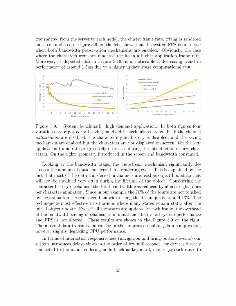
transmitted from the server to each node), the cluster frame rate, triangles renderedon screen and so on. Figure 3.9, on the left, shows that the system FPS is preservedwhen both bandwidth preservation mechanisms are enabled. Obviously, the casewhere the characters were not rendered results in a higher application frame rate.Moreover, as depicted also in Figure 3.10, it is noticeable a decreasing trend inperformance of around 1.5ms due to a higher update stage computational cost.
0
20
40
60
80
100
120
140
160
180
200
2 4 6 8 10 12 14 16 18 20 22 24 26 28
Fram
es
per
Se
con
d
Number of characters
All enabled
Autostream disabled
Hidden
History disabled
0
10
20
30
40
50
60
70
80
2 4 6 8 10 12 14 16 18 20 22 24 26 28
Kb
tra
nsm
itte
d
Number of characters
All enabled
Autostream disabled
Characters hidden
History disabled
Figure 3.9: System benchmark: high demand application. In both figures fourvariations are reported: all saving bandwidth mechanisms are enabled; the channelautostreams are disabled; the character’s joint history is disabled; and the savingmechanism are enabled but the characters are not displayed on screen. On the left:application frame rate progressively decreases during the introduction of new char-acters. On the right: geometry introduced in the screen and bandwidth consumed.
Looking at the bandwidth usage, the autostream mechanism significantly de-creases the amount of data transferred in a rendering cycle. This is explained by thefact that most of the data transferred in channels are used as object bootstrap thatwill not be modified very often during the lifetime of the object. Considering thecharacter history mechanism the total bandwidth was reduced by almost eight timesper character animation. Since in our example the 70% of the joints are not touchedby the animation the real saved bandwidth using this technique is around 13%. Thetechnique is most effective in situations where many states remain static after theinitial object update. Even if all the states are updated at each frame, the overheadof the bandwidth saving mechanism is minimal and the overall system performanceand FPS is not altered. These results are shown in the Figure 3.9 on the right.The internal data transmission can be further improved enabling data compression,however slightly degrading CPU performance.
In terms of interaction responsiveness (navigation and firing-buttons events) oursystem introduces delays times in the order of few milliseconds, for devices directlyconnected to the main rendering node (such as keyboard, mouse, joystick etc.) to
53

120
130
140
150
160
170
180
190
0 2 4 6 8 10 12 14
Fram
es
pe
r Se
con
d
Kb transmitted
Figure 3.10: System benchmark: characters not displayed highlight. A decreasingtrend in frame rate performance is shown due to higher update stage computationalcost.
up to 40 − 50ms for devices connected to the networked device manager (such asgyro sensor, wii-mote controllers etc.). The bottleneck of out configuration consistsin the use of Vicon Blade as our main tracking device for rigid objects with respectto the virtual screen. The tracked objects can be used for different purposes but inour testing setups mainly to track user’s head position (and generate off-axis projec-tion) and directly mapped to the virtual pointers. The use of Vicon Blade version1.7 introduces in the system a quite noticeable lag that slows down the interactionresponsiveness of these two components of about 250ms, slightly introducing smalldiscomfort in the 3D perception during fast interaction or suddenly change of pointof view. The system has been briefly tested with tracking software optimized forreal-time rigid object such as Vicon Tracker and with the employment of differentmotion tracking solution such as OptiTrack. The responsiveness time in these casesdecreases safely under 150ms.
Overall, the performance results of our system demonstrated the appropriatenessof our VR framework implementation regarding rendering performance and end-to-end latency. Moreover, comparing our system with similar solutions, for examplethe Unreal Tournament VR framework proposed by Lugrin et al. [208], we canconclude that we achieved similar results. Their solution has been tested with a fastermachine and dedicated graphics hardware with GenLocking two generations newerthan our commodity solution. Considering the benchmark comparison produced byPassMark/G3D Mark [325] the polygonal processing power of their solution is aboutfour times faster than ours. Our framework solution maintains on average 54fpsusing the interactive model visualization application with around 1 Million visiblepolygons displayed (total cluster time 18ms - 4ms render - 11ms swap time). Their
54
solution was reported to maintain around 45-50fps with between 1.5 to 2.5 Millionvisible triangles in the rendering scene.
3.5 Conclusion
This chapter presented a new software solution for the development of immersivecollaborative virtual reality applications with user-perspective stereoscopic render-ing and interactive full-body characters. The major strengths of the system are itsintegration to a modern and complete graphics rendering engine, its integration withhigh-performance toolkits with source code available (or open-source) that guaran-tees simplified maintenance and upgrades, and its versatility to scale well to differenthardware configurations.
The framework handles most of the distributed programming and collaborativeVR development difficulties thanks to automatic streaming channels and replicamechanisms. Moreover, the framework includes high-end animation and user mo-tion reconstruction tools that sets our system apart from the other open VR frame-works. The number and diversification of the supported applications demonstratethe effectiveness of the proposed framework.
55

CHAPTER 4
Motion Modeling by Direct Demonstrations
A central goal in the area of autonomous virtual humans is to achieve virtual assis-tants that can effectively interact, learn, train, and assist people in a variety of tasks.We focus on the particular problem of modeling motions for interactive training ap-plications requiring complex gestures and actions to be reproduced realistically andwith precise parameterizations with respect to spatial constraints in the environment.
Modeling and parameterization of realistic motions is clearly an important prob-lem in a wide range of applications involving virtual humans. One approach forachieving precise parameterizations is to rely on algorithmically synthesized actionsand gestures [249, 169], however it remains difficult to achieve realistic full-bodyresults and a specific computational model is needed for every action to be sim-ulated. Another important limitation of algorithmic approaches in many trainingapplications is that the motions to be reproduced may only be known by experts inthe subject area of the training. Such cases are clearly better handled by motionmodeling solutions based on motion capture.
Several systems based on motion captured (or hand-crafted) animations havebeen developed and are able to achieve highly realistic results [96, 348]. However theprocess of building the set of needed motions for each given scenario is often time–consuming, and it remains difficult to precisely parameterize pre-defined animationswith respect to spatial constraints.
This chapter proposes an interactive motion modeling framework for addressingthese many difficulties in an integrated fashion. The framework is designed to be usedin two distinct phases: in the modeling phase the user demonstrates to the virtualhuman how to perform parameterized motions, such that in the training phase thevirtual human is then able to reproduce the motions in interactive training sessionswith apprentice users learning the training subject.
The system described in this chapter targets the situation where, in the modelingphase, experts in the training subject are able to model the needed actions andgestures by direct demonstration, without the need of having previous experiencewith the system. In the training phase, the stored example motions are then re-used
56

by the virtual human to train apprentice users. More in detail, the system enablesthe virtual human to reproduce motions with respect to arbitrary target locations inthe environment. Figure 4.1 presents one typical scenario modeled using the system.
(a) (b)
Figure 4.1: (a) In this scenario, during the modeling phase, the user demonstratesseveral examples of pointing motions in order to demonstrate operations with a stereosystem and a telephone. (b) During the training phase, the user requests the virtualhuman to precisely perform the same pointing motions for arbitrary targets, herespecified by the apex of the yellow cone which is controlled via a Wii-Mote con-troller. The training phase is used here to test if the example motions are sufficientlycovering the volume of interest in the scenario. The user can interactively switchbetween the two phases until all required motions are correctly defined. Note thatthe simulated images in this figure appear fuzzy since they are being projected forstereo visualization.
The motion-based interactive framework allows the design of new types of in-teraction techniques, which can be developed according to the training scenario athand. For example, the apprentice may request the virtual human to perform actionsat different locations and under different conditions, feedback can be provided basedon on-line comparisons between the motions from the expert and the apprentice, etc.Such scenarios are clearly applicable to a variety of training applications, for exam-ple, sports training, rehabilitation of motor-impaired patients, training of medicalprocedures, demonstration of generic procedures, delivery of instructions, etc.
The work presented in this chapter addresses the main computational challengesinvolved in building such interactive systems. The proposed framework is based onthree main computational modules:
• First, a real-time motion capture interface is developed for allowing users to
57

interactively model motions by direct demonstration. In order to be effectivefor a variety of situations, our solution includes calibration and mapping froma reduced set of tracking sensors.
• During the motion modeling phase, motions can be recorded and re-playedon-line, allowing users to effectively model generic actions and gestures in anintuitive way. The modeling interface also allows the definition of clusters ofexample motions, in order to represent spatial variations of a same motion.These variations are used during the training phase to precisely parameterizethe motions with respect to arbitrarily given spatial targets.
• Finally, given a cluster of example motions built by the user during the model-ing phase, an optimization technique for computing motions on-line preciselyrespecting arbitrarily given spatial constraints is adopted. The technique isbased on the inverse blending approach. The solution motions are obtainedby blending operations with the example motions in a given cluster, thereforethe solutions remain human-like and similar to the example motions. Thistechnique is critical for achieving precise parameterizations of realistic actionsand gestures, without the need of any pre–computation. Examples are pre-sented with the modeling of pointing and pouring motions, which are preciselyparameterized with respect to arbitrarily given target locations.
The interactive motion modeling framework has been implemented in an immer-sive multi-tile power wall stereo visualization system (shown in Figure 4.1). Theability to perform simulations in a large visualization system is important for achiev-ing immersive full-scale interactions, in analogy to the way humans naturally interactwith each other. As a result our obtained system represents a powerful and intuitiveapproach for programming generic parameterized motions by demonstration.
The chapter is organized as follows: after discussing strictly related work in thenext section, we present the motion capture interface in Section 4.2 and the modelinginterface in Section 4.3. Following, the inverse blending optimization technique ispresented in Section 4.4. Finally, results and conclusions are discussed at the end ofthe chapter.
4.1 Related Work
The approach of direct demonstration of motions, proposed in this dissertation, isstrongly related to several imitation-based learning methods previously applied for
58

different applications in robotics [304, 37] and computer graphics [71, 83]. Thework of Cooper et al. [71] in particular also employs a full-body motion captureinterface for building a database of motions, however with the focus on buildingmotion databases with good coverage for motion controllers, and not on achievingan immersive and interactive system to teach motions to virtual humans. Similarly,Ijspeert et al. [140] proposed a non immersive system to transfer motions froma human to a robot through learned trajectories. The generated motions are notguaranteed to maintain and to reproduce specific aspects and the quality of theintended motion. Moreover, it relies on a cumbersome full-body motion capturedevice and it does not take into account motions with respect to virtual environments.
Several methods have been proposed in the literature for addressing the problemof motion reconstruction from a reduced marker set. A popular approach is toemploy statistical models [392] and machine learning [59] for extracting from a motiondatabase the motion closest to the input signal. The performance of these methodshowever greatly depends on the used databases and they are not suitable for real-time applications. Algorithmic approaches based on simulation or optimization havealso been proposed [383, 153] but are computationally expensive and are not suitablefor achieving human-like motions.
Algorithmic approaches based on Inverse Kinematics (IK) can run in real-timeand may be suitable for motion reconstruction if enough markers are provided tolimit the overall posture space of possible solutions. Inverse Kinematics has alsobeen employed to optimize full–body postures for tracking the input stream from areduced marker set [264, 280]. However the convergence time for iterative Jacobian-based solvers over the full–body of a character may require several iterations and canintroduce lag in a real-time interface. In fact, the approach proposed by [363] eventhough very versatile when the training database covers the user’s motions, suffersfrom a severe lag during the reconstruction (0.4 0.6 sec.).
Our interactive interface focuses on achieving a fast solution for reconstructinghuman-like motions by employing an analytical IK solver [154] applied only to thearms of the character. We then rely on simple mappings from additional markersin order to fully reconstruct upper-body motions very efficiently in real-time. Ourpresent work focuses on modeling upper-body actions but the system can be easilyextended to support lower-body reconstruction.
One of the main purposes of the developed system is to model actions and gesturesto be used in training applications. Previous work on gesture synthesis has mainlyfocused on sequencing pre-defined animations [331, 96, 348], or by algorithmic syn-thesis, such as by employing IK solvers towards specified trajectories [249, 169]. By
59

modeling gestures with motion blending techniques the system is able to achieve thebenefits of both approaches, i.e., realistic animations which can also be parameterizedwith spatial targets.
As previously mentioned in the general review (see chapter 2.2) the topic ofcharacter animation based on motion capture has been extensively studied in theliterature for several applications [15, 170, 298, 171, 191]. Although the majority ofworks focus on the locomotion problem, motion blending (or motion interpolation)has also been well addressed in previous works for modeling gestures and actions.
A specific technique used for addressing spatial constraints is to generate and addpseudo motion examples [170, 296], which however increases the needed computationand storage. The scaled Gaussian process latent variable model [110] optimizes inter-polation kernels specifically for maintaining constraints described by latent spaces.
The main limitation of these methods is that alone they are not able to preciselymeet given spatial constraints. For instance, the active learning methodology [71] re-lies on Inverse Kinematics solvers in addition to blending, however risking to penalizethe obtained realism.
The proposed method for motion parameterization is based on the optimizationof blending weights until best meeting generic spatial constraints defining the targetparameterization. The Inverse Blending method can be seen as a post-processingstep for optimizing a given set of blending weights, which can be initially computedby any motion blending technique. Only error metrics for the spatial constraints toenforce are necessary in order to optimize the blending weights using a given motioninterpolation scheme. The method is able to well parameterize pointing and pouringactions on-line and without the need of any pre–computation.
4.2 Motion Capture Interface
A variety of commercially available solutions are able to map full–body motions toa virtual character in real-time, however the available options are usually expensiveand often require the user to wear cumbersome tracking devices.
For instance, retro-reflective motion capture systems require the user to wear afull–body suit with a number of markers carefully placed; systems based on magneticsensors rely on 15 to 20 magnetic sensors connected with cables; and exo-skeletonsystems are heavy and often restrictive.
The main choices that drove the design of our motion capture interface can besummarized as follow: the ability to reconstruct the user’s upper body motions with
60

the minimal introduction of tracking devices; simple, easy to wear and to calibrate;and, the ability to reuse and take advantage of tracking devices already presentin a user perspective stereo graphics system (e.g. the user’s interaction pointerand the head tracker). Considering the initial requirements, the head tracker andthe interaction pointer already produces a precise estimate of the user’s hand andhead position with respect to the visualization system. In order to estimate theorientation and positioning of the user’s body with respect to the scene as well asderiving the user’s head orientation and position with respect to the user’s lowerbody (waist/hips) an extra tracker is needed. Finally, to estimate non symmetricalarms motions another tracker needs to be included. As shown in Figure 4.2 (a), ourreal-time upper-body motion capture solution is based on tracking four key limbs ofthe user: the two hands, the head, and the lower or mid joint of the spine.
We track both the position and orientation of each of these parts in global coor-dinates. The user wears simple straps with markers on each of the considered bodyparts and we rely on a 10-camera Vicon system for performing the real-time tracking.Although we rely on an instrumented room with cameras, our solution can be portedto any other system able to track these four parts. We also rely on a data glove forcapturing finger motions in real-time.
(a) (b)
Figure 4.2: The figure shows (a) the camera-based motion interface and (b) ourgesture vest interface based on inertial sensors [131].
Before starting an interactive session, a calibration process is necessary in orderto map the user’s body to the skeleton of the virtual human in the scene. We choosenot to adapt the dimensions of the virtual human in order to maintain a consistentdatabase of motions which can be shared by different users.
61

The calibration consists of measuring scaling factors, and requires the user andthe virtual agent to stand in a T–pose posture. Let ei denote the positions of thehands and the head of the user in global coordinates, i = {1, 2, 3}. Let p be theglobal position of a point on the user spine at the same height as the shoulder. Thispoint is computed from the spine and hand markers at T–pose. Similarly, let evi andpv be the same points but computed with respect to the virtual human skeleton.Scaling factors si are then computed with:
si =‖evi − pv‖‖ei − p‖
. (4.1)
The scaling factors are obtained during the T-pose calibration and then appliedduring the modeling phase of the system in order to have the end-effector positionsof the user and the virtual human matching. Each time new readings are processed,each scaling factor si multiplies the translation component of its corresponding bodypart being tracked, after transforming it to local coordinates in respect of the rootjoint.
The following additional operations are then performed on-line in order to com-plete the motion mapping:
• First, the global position of the virtual human is updated according to thetracked spine location of the user. In our current version, we focus only oncapturing upper–body actions and gestures without any locomotion, and so noattention is given for tracking or solving leg motions.
• The spine of the virtual human is bent considering the amount of rotationbetween the tracked spine orientation and the head orientation. This rotationis subdivided by the number of joints being used to represent the spine of thevirtual human, and distributed among these joints, similarly to the approachdescribed by Monheit et al. [231]. The rotation of the head joint is directlymapped from the head markers, which are attached to the polarized glassesused for stereo visualization (see Figure 4.2 (a)).
• The arm posture reconstruction (shoulder, elbow and hand) is performed usinga 7 degrees of freedom fast analytical IK solver considering arm-body collisionavoidance by automatic variation of the arm swivel angle [154]. The solver isapplied considering the placement of the shoulder base joint fixed in respect ofthe spine parent. The swivel angle is set to start at a low default value suchthat the elbows remain low, as is the case in usual arm motions. In some cases
62

when the arm is extended, due to tracking and calibration imprecisions, theIK may report that an end-effector cannot reach its target position, in whichcase we take the closest possible solution. The motion of the fingers is directlymapped from a data-glove. As shown in Figure 4.2 (a), four markers attachedat the extremities of two crossed sticks (fixed on the data-glove) are used fortracking the 6 degrees of freedom hand targets.
The mapping produced by this algorithm is extremely fast and results in veryfluid interactions always running well above 100 frames per second. Due to thereconstruction of the many user’s body degrees of freedom from a minimal trackingsubset of objects the algorithm proposed creates plausible poses that are able tocapture the characteristics of the motion patterns generated by the user but a precisereconstruction of the overall body cannot be guaranteed.
The algorithm is designed to always grant the correct placement of the characterin the scene considering the placement of the user in the working area as well asthe character tracked limbs orientations with respect to the user’s limbs orientations(i.e. for the head and hands). The positioning in space of the character’s limbs inrespect of the character’s hips are granted to reflect correctly the placement of theuser’s hands and head in respect of the user’s hips as long as the user’s pose doesnot introduce spine bending.
The main limitations of the current approach, leading to inaccurate or erroneousposes, are particularly frequent in the cases explained below. When the user poseintroduces spine bending, since we rely on reconstructing the spine joints orientationsthrough uniformly distributing a bending angle, the shoulder placement of charactermay differ from the user’s shoulders placement leading the IK solver to fail reach-ing the target position. In order to maintain continuity in the reconstruction, aspreviously mentioned, the closest reachable point to the target position is selectedproducing straight arm poses that can differ completely from the actual user armpose. Another erroneous case occurs when the user’s hands are very close to theshoulders. In this case the IK solver generates sharp elbow angles and since the armswivel angle always favor lower values the produced arm poses tend to be maintainedparallel to the body. Finally, another failure case is recognizable when the user bendits body maintaining a straight spine.
In order to improve these failure cases and the reconstruction similarity withthe user pose the algorithm could be modified to include more tracking devices.For example, to correctly infer the arm swivel angle and remove any reconstructionambiguity (completely removing the need of using the IK solver) two extra trackers,placed at the shoulder and forearm level can be added to enforce exact fixed rigid
63

configurations for the arms. This approach is similar to the solution proposed anddiscussed by the method adopted in conventional motion magnetic capture solutions[293, 292, 350, 347].
Following this approach, we have in particular experimented with an alternatemotion capture solution based on our portable and easy–to–wear gesture vest proto-type system [131].
This device uses five InnaLabs AHRS sensors [142] to capture the orientationchanges of performers spine, head and a full arm. In addition, the 5DT data glove isused to capture hand shapes, and a Nintendo WiiMote controller is used for providingbasic instructions (record, play, delete, etc) during demonstration of new examplegesture motions. As illustrated in Figure 4.1-right, the sensors are attached on adetachable sleeve.
Each sensor measures its orientation in global coordinates based on tri-axial gyro,accelerometer and magnetometer. Each measured rotation is represented in quater-nion form with respect to the sensor’s canonical reference frame. The maximumupdate rate is 120 Hz in quaternion mode.
Although it is possible to infer and reconstruct whole-body motions with onlya limited number of sensors through models trained on full-range motion capturedatabase [226, 323], the focus of the vest is to capture high quality gesture motionswith enough sensors covering the joints of interest, just like the commercially availablesystems [382, 339] but more cost-effective.
The interface produces very accurate motions, is portable and wireless, and is inparticular well suited for capturing one-arm gestures. Figure 4.2 (b) illustrates oneinteractive modeling section using this equipment. This system is also integratedwith a data glove in order to capture hand shapes.
The main drawback of this solution is that alone it cannot track information inglobal coordinates in respect of our visualization system, making it difficult to beused in our applications related to specification of spatial constraints. When thesystem is integrated with a global tracking device then it becomes perfectly suitablefor our applications. Note that in Figure 4.2 (b) the user is wearing a hat beingtracked by the camera system in order to provide global positioning information.
Depending on the application, and on the availability of additional trackers, ourgesture vest solution represents a suitable alternative for achieving a small, portableand low–cost solution. The system can be in particular effective for large-scale train-ing scenarios with many users, since the sensors scale well and do not suffer fromocclusion limitations.
64

Achieving a fluid interface has showed to be extremely important for the effectiveuse of the system. The proposed use of a reduced marker set allows the accommo-dation of systems with fewer (or lower–cost) cameras and also allows the system tobe ported to other tracking solutions.
4.3 Interactive Motion Modeling Interface
The ability to run our system in integration with a large immersive display is of mainimportance in our interactive interface. It allows the user to interact with full-scalevirtual environments with immersive stereo vision perception, achieving realistic andaccurate reproduction of conditions during both the modeling and training phases.
In order to allow full operation of the system by a single user, our current solutionfor the motion modeling phase focuses on tracking single-arm actions and gesturesperformed by the right arm. In this way the user only wears a data glove on the righthand, and the left hand holds a WiiMote controller which provides control over allthe system functionality, achieving a simple and effective interactive user interface.
By clicking buttons on the WiiMote controller, the user can change the cameraview between several modes, can control the recording and replay of motions, initiatethe definition of clustered example motions, add or delete motions from each cluster,etc.
The definition of clusters of example motions is an important concept of oursystem. The definition of a cluster is necessary for specifying each parameterizedaction or gesture. When the user selects to start a new cluster, every recorded motionbecomes associated with the cluster. Motions in a cluster will be blended during thetraining phase and therefore they have to consistently represent variations of a sametype of motion. For instance, a pointing cluster will contain several pointings of thesame type but each pointing to a different location in the environment.
One important piece of information to be associated to each motion in a clusteris its parameterization frame. For example, this frame will be the stroke frame ofa gesture or the final frame of a one-way pointing motion. The parameterizationframe identifies which frame of the motion is to be parameterized with respect tonew target locations during the training phase. We currently let the user specify thisframe by pressing a button of the WiiMote controller at the right moment with theleft hand, while the motion is being demonstrated with the right arm. The framelocation can be then adjusted forward and backwards interactively if needed. Thissolution is acceptable in several cases but we recognize it may divert the attention
65

of the user from well performing the motion being demonstrated. We therefore alsolet the user to interactively select this frame after the motion is performed. We alsoallow the user to trim the initial and final frames of each recorded example motion.
Clusters of motions can be edited, stored and reloaded as needed. Whenever theuser wishes to test a modeled cluster, the system can be switched to training phaseand the WiiMote controller is then used to specify targets to be solved by inverseblending. In this way the virtual human is able to perform a new motion preciselyreaching given targets and well preserving the quality of the original demonstratedmotions. The WiiMote controller also has a haptic feedback which is used during thetraining phase to tell the user when asked targets are colliding with the environment.
The interconnection of the several modules of our system is further illustratedin Figure 4.3. In the next section we describe our inverse blending optimizationtechnique used during the training phase.
Figure 4.3: Overview of the main parts of the system. The arrows illustrate thedata flow during the modeling and training phases.
4.4 Inverse Blending
The optimization core of the motion modeling approach, as previously introduced,relies on the Inverse Blending technique proposed by Huang et al. [132]. For com-pleteness we describe the approach in this section.
The first step for applying the inverse blending optimization is to model eachspatial constraint of interest with an error metric function f , which measures howwell each constraint is being satisfied at the given parameterization frame. Althoughthe examples presented in this work only use positional constraints for end-effectors,generic types of spatial constraints C can also be taken into account.
66

Constraints can also have an arbitrary number of degrees-of-freedom (DOF),for example, pointing to a distant location imposes a 2–DOF positional constraintenforcing that the pointing line through the finger reaches a desired target, whileprecisely pin-pointing a button on a dial pad needs a 3–DOF positional constraint(the target for pointing), and an optional rotational constraint for determining apreferred pointing orientation style (see Figure 4.4).
The optimization starts by selecting k example motions Mj from the examplemotion cluster that best satisfy the constraint function f , j = {1, . . . , k}. For exam-ple, in a typical reaching task, the k motion examples having the hand joint closestto the target will be selected. For the case of reaching motions, the hand locationat the final pose of the motion is typically used as the parameterization frame. Forgestures, the frame of the gesture stroke point is used.
The optimization procedure is based on a traditional but efficient motion blendingscheme, where an initial blended motion M is obtained with M(w) =
∑kj=1wjMj,
where w = {w1, . . . , wk} are blending weights initialized from a traditional RBFinterpolation scheme. Any suitable kernel function can be used and we employ thepopular exp−‖e‖
2/σ2kernel. Since our optimization runs on-line during interaction
with the user, we do not attempt to optimize kernel functions with respect to theconstraints [295, 234]. Instead, the blending weights are optimized independently ofthe interpolation kernel.
In order to enforce a given constraint C, the goal is to find the optimal setof blending weights w, which produces the minimum error e∗, measured by theconstraint error function f :
e∗ = minwj∈[0,1] f
(k∑j=1
wjMj
). (4.2)
This formulation can also account for multiple constraints by combining the errormetric of each constraint in a single weighted summation. Two coefficients are thenintroduced for each constraint Ci, i = {1, . . . , n}: a normalization coefficient ni and aprioritization coefficient ci. The purpose of coefficient ni is to balance the magnitudeof the different error metrics associated to each constraint. Coefficient ci allows thespecification of relative priorities between the constraints.
The result is essentially a multi-objective optimization problem, with the goalbeing to minimize an error metric composed of the weighted summation of the indi-vidual error metrics:
67

e = minwj∈[0,1]
n∑i=1
(ci ni fi (M (w))) . (4.3)
Independent of the number of constraints being addressed, when constraints arefully satisfied, e→ 0. Figure 4.4 shows several results obtained by the optimizationscheme.
Figure 4.4: The image shows results obtained with three different motion clusters.(a) Pointing motions parameterized by a 2–DOF directional constraint results inprecise pointing to distant targets. (b) Pouring motions can be parameterized by a2–DOF planar constraint specifying the precise location above the pouring target,and an additional constraint specifying an acceptable height range, so that liquidscan correctly flow down into containers. (c) Precise pinpointing to given targets re-quires a 3–DOF positional constraint, with optional rotational constraints for furthercontrolling the final poses obtained. The shown pinpointing examples show differentorientations obtained, which match the x-axis of the tri-axes manipulator.
Several optimization routines were implemented for solving the inverse blendingproblems, including: steepest ascent hill-climbing, the Nelder-Mead method and thegradient descent method [274]. Performance evaluations were conducted by solving5000 inverse blending problems for different scenarios: pointing, pouring and grasp-ing. The Nelder-Mead method [274] has been proved to be the method of choice
68

for our case where k remains below 15. The method requires a simple implemen-tation and can typically achieve optimal blending weights within 2 milliseconds ofcomputation time.
With suitable example motions in a given cluster, inverse blending can producemotions exactly satisfying given spatial constraints and fast enough for real-timeapplications. The several examples presented by this approach demonstrate its suc-cessful execution in different scenarios. To evaluate the performance of our method,a reaching task was designed to measure the errors produced by our method againsta single RBF interpolation, with the 16 reaching motions in the database from Mukaiand Kuriyama [234]. A total of 114 reaching goals (each specifying a 3–DOF po-sitional constraint) were placed evenly on a spherical surface within reach of thecharacter. These goals are highlighted with small yellow dots in Figure 4.5. The endlocations of the hand trajectory in each example motion are shown as gray dots.
For each reaching target on the surfaces shown in Figure 4.5, the RBF interpo-lation alone is used first to generate a reaching motion and record the final handposition where the character actually reaches. These final positions are used to con-struct a mesh grid, which is shown on the upper row of Figure 4.5. Each triangle onthe mesh is colored with respect to the average errors from its vertices, representingthe distance error between the final hand positions and their corresponding reachingtargets. We then use inverse blending optimization to perform the same tasks, andthe mesh constructed is shown on the lower row of Figure 4.5. The reaching motionsgenerated by inverse blending can precisely reach most of the targets, and the mea-sured errors were practically zero across most of the mesh. Only at the boundary ofthe surface the errors start to appear. In this specific task, the radius of the sphericalsurface was set to 80cm, and both methods used eight example motions from thedatabase (k = 8) for computing each reaching task.
It is important to note that the ability of enforcing constraints greatly depends onthe existing variations among the used motion examples being blended. The numberof needed example motions also depend on the size of the target volume space. Thecomputational time required for finding solutions will also depend on the qualityand number of considered motion examples (the k value). However, as showed inour examples, these limitations can be easily addressed by appropriately modelingexample motions, and balancing the coverage vs. efficiency trade-off specifically foreach action being modeled.
69

Figure 4.5: Visualization of errors obtained by RBF interpolation and inverse blend-ing. The upper row shows the results obtained with RBF interpolation. The bluesmooth meshes on the lower row show the inverse blending results, which can easilysatisfy the given 3–DOF positional constraints.
4.5 Database Coverage Visualization and Refinement
Two specific visualization methods, following the ergonomic design approach of usinga palette of colors inside the workspace as visual guidance [386, 291, 389], have beendeveloped to intuitively guide the user during the process of adding new motions torefine the database for improved coverage. The visualization tools developed are anadaptation of the visualization tools proposed by Huang et al. [130] to be used inthe interactive motion modeling framework in real-time.
The presence of these visualization tools in the motion database creation pro-cess is a key factor since the existing variations among the example motions beinginterpolated greatly affects the ability to enforce constraints using inverse blending.It is important to determine which example motions to capture to ensure that awell-built cluster of motions is formed, with good coverage of the regions of interest
70

(ROIs) inside the workspace. To the contrary, defining an overly fine subdivisionof the constraint space with too many examples is inefficient and impractical as itrequires capturing too many example motions to populate a database. Instead, sincesimilar examples can often be interpolated to produce valid new motions with goodquality, a small number of carefully selected example motions is better in providinggood coverage for the ROIs in the workspace. Achieving an efficient database is alsokey to ensure interactivity of the system.
The two visualization methods proposed consist on a global Workspace VolumeVisualization (WV) and a Local Coverage Visualization (LV) to query specific regionof the space interactively.
4.5.1 Workspace Volume Visualization
WV conducts a coarse uniform sampling of the workspace and presents the overallspatial coverage with colored cubes for the entire workspace without the need todefine an overly fine subdivision of the constraint space. Each cube represents areaching target (spatial constraint), and a motion synthesized towards each cube ismeasured by reaching precision (error e∗) using a constraint evaluation function, andthe value e∗ = emax(∈ [0; 1]) is mapped onto a hue color space then assigned to eachcube. For a reasonably sized database WV takes a few seconds to generate, then theuser can immediately spot areas with low coverage by the color of the cubes (red ororange), and add additional motion towards these areas.
4.5.2 Local Coverage Visualization
In certain cases, the global error-based volume visualization is not needed when theuser is fine tuning the coverage of a small region, or when only a small local region isof interest. In addition, the pre-computation time can impose undesirable lags whenediting large motion sets. These can be solved with LV.
LV renders a transparent colored mesh geometry covering a small ROI, delimitingthe coverage evaluation within its volume. It focuses on the local coverage visual-ization taking only milliseconds to be computed, and it is suitable for fine tuningcoverage of smaller volumes when only small local regions are of interest. LV usesthe same color mapping as WV, and the error ratio is assigned to the correspondingvertex. Color on the mesh surface comes from Barycentric color interpolation withGouraud shading.
LV follows the movement of the user’s hand, its size, shape and resolution can be
71

Figure 4.6: Workspace Volume Visualization mode gives an overview of databasecoverage. The sampling density and error threshold can be adjusted for clear viewing.
iteratively changed with the WiiMote controller for either fast sweeping over largeROIs (a table surface) or for carefully checking small ROIs (buttons, etc). LV is alsoable to utilize motions dynamically added to the database in real-time applicationswithout any pre-computation lag. Details on motion synthesis and error evaluationwith spatial constraints can be found in [132].
4.6 Conclusions
The system developed achieves an effective overall design for modeling parameter-ized motions, which are extremely important for several types of applications (seeFigure 4.8). The framework addresses the modeling of generic gestures and actionsto be executed by interactive virtual humans, and furthermore allows non–skilledanimators to intuitively obtain realistic results.
This chapter presented a novel motion modeling framework based on the directdemonstration and parameterization of motions. In particular the chapter presentedseveral algorithmic solutions required for enabling the development of the proposed
72

Figure 4.7: Local Coverage Visualization mode. The rendered surface follows themovement of the user’s hand, ideal for checking small ROIs.
design: a fast procedure for motion mapping from a reduced marker set, an intuitivemotion interface for enabling the direct demonstration of parameterized actions andgestures, and an inverse blending optimization technique able to efficiently achieverealistic and parameterized motions in respect of arbitrarily given targets.
The coverage visualization tools effectively allow the user to observe the databasecoverage immersively within the workspace and during the on-line collection of ex-ample motions. The interactive visualization is able to guide the user to concentrateon capturing motions where they are needed, in regions with less coverage. Theuser can thus intuitively construct suitable databases for parameterized actions orgestures with guaranteed coverage within the specified precision. The platform couldbe adapted for different hardware configurations.
The proposed framework has been implemented in an immersive multi-tile stereovisualization system, achieving a powerful and intuitive interface for programminggeneric parameterized motions by demonstration.
The overall concept of the system has the potential to impact many applications.Our first results open several new opportunities for further development of our inter-
73

Figure 4.8: In this example pouring motions are demonstrated and added to aparameterized pouring action cluster (top sequence). Once completed, the cluster isused to generate new pouring actions to arbitrary locations (bottom sequence).
face design but still several improvements can also be performed. For instance, onedrawback of the parameterization solution adopted is that the ability of enforcingconstraints greatly depends on the existing variations among the motion examplesbeing blended and also the computational time required for finding solutions willalso depend on the quality and number of motion examples. However, as shown inthe system, these limitations are easy to address by appropriately modeling examplemotions, and balancing the coverage versus efficiency trade-off.
Considering future improvements, a two-arms and hands tracking interface canbe easily integrated by including a few voice commands and/or finger and gesturesrecognition. The integration of locomotion would be also beneficial to achieve thescope of creating a generic training system. Automatic locomotion and body posi-tioning algorithms for controlling the virtual human are necessary for creating effec-tive and believable virtual tutors in virtual environments. Moreover, an independentgaze model, as proposed by [133], also appears to be necessary for creating believablevirtual tutors.
74
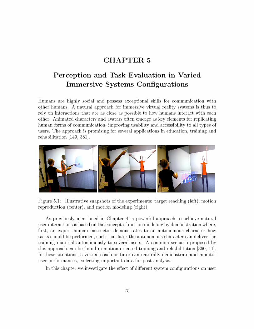
CHAPTER 5
Perception and Task Evaluation in Varied
Immersive Systems Configurations
Humans are highly social and possess exceptional skills for communication withother humans. A natural approach for immersive virtual reality systems is thus torely on interactions that are as close as possible to how humans interact with eachother. Animated characters and avatars often emerge as key elements for replicatinghuman forms of communication, improving usability and accessibility to all types ofusers. The approach is promising for several applications in education, training andrehabilitation [149, 381].
Figure 5.1: Illustrative snapshots of the experiments: target reaching (left), motionreproduction (center), and motion modeling (right).
As previously mentioned in Chapter 4, a powerful approach to achieve naturaluser interactions is based on the concept of motion modeling by demonstration where,first, an expert human instructor demonstrates to an autonomous character howtasks should be performed, such that later the autonomous character can deliver thetraining material autonomously to several users. A common scenario proposed bythis approach can be found in motion-oriented training and rehabilitation [360, 11].In these situations, a virtual coach or tutor can naturally demonstrate and monitoruser performances, collecting important data for post-analysis.
In this chapter we investigate the effect of different system configurations on user
75

performance. Because numerous variations are possible, this research focuses onspecific configurations in three experiments that are particularly relevant to reha-bilitation and training applications. Minimal user instrumentation is important inrehabilitation, thus we have not included experiments with head-mounted displays.
The first experiment focuses on reaching tasks (Figure 5.1-left). Reaching repre-sents an important class of motions used in exercises for rehabilitation of fine armmotor control [349]. The experiment was designed to analyze the effect of differ-ent configurations on the reaching tasks. The chosen configurations reflect typicalchoices that are made in practice, and the obtained results provide new observationsand quantified information on the trade-offs between the varied conditions. For ex-ample, our results are important to guide the choice of adopting an expensive andspace-consuming display configuration instead of a common desktop setup.
The second experiment was designed to analyze the ability to perceive and subse-quently reproduce motions demonstrated by an autonomous virtual character (Figure5.1-center). This scenario is important because motion reproduction is a key activityin several exercise and therapy applications. The motions of several subjects werecaptured and compared under different conditions, providing new information on theeffects of using avatars and stereo vision.
The third experiment is a usability study that analyzes user experiences in acomplete immersive interface to model motions by demonstration (Figure 5.1-right).This study was selected in order to give insight in the usability of the approach inreal applications, for the design of rehabilitation exercises or task-oriented motionsfor generic training scenarios.
The selected tasks and configurations expose new important trade-offs betweendifferent forms of direct task execution and avatar-based visual feedback.
5.1 Related Work
This chapter evaluates specific scenarios with attention on the different ways of em-ploying animated characters and avatars. The addressed factors have only beenstudied before in isolation, and did not investigate the impact of virtual charactersand avatars on task execution. In the following related work analysis we first reviewperception studies related to immersive systems, and then studies related to virtualcharacters.
76

5.1.1 Evaluation of Immersive Systems
The effects of immersive virtual reality on scientific visualization, data analysis andon human interaction have been previously studied in different ways. Depth per-ception through stereoscopy has been demonstrated to reduce time and error, andto improve user performance in spatial tasks [365, 277]. A frequent problem in anytype of virtual environment is distance misestimation [351], which has been detectedin both real workspace measurements and egocentric distances. The reason behindthis behavior is not clear, and it has also been detected in head mounted displays(HMDs) and in stereoscopic wide screen displays (WSDs) [371, 374, 167]. Interest-ingly, Naceri et al. [236] have found distance underestimation to be higher in HMDsthan in WSDs.
Display size has also been investigated, and large displays have been reportedto be beneficial in spatial tasks [341]. In particular, Ball et al. [25] studied theeffectiveness of large high-resolution displays for interactive data visualization, con-cluding that a large display is preferable because it minimizes the use of virtualtools for navigation control. Considering a display physical field of view (PFOV), ithas been shown that a wider PFOV can yield significantly better performance thana smaller PFOV in hand-eye coordination tasks [8], and in search and comparisontasks [18, 25, 244]. PFOV has also a direct impact on spatial awareness, memoryand presence [199]. Ni et al. [244] have conducted experiments showing that largedisplays and high resolutions improve user performance in search and comparisontasks.
Some previous studies have also considered multivariate evaluations of combinedfactors. Stereoscopy and head tracking have been found to have significant impacton spatial understanding [277, 219] but not necessarily on object manipulation tasks[238]. Display and interaction modes have been observed to significantly influence auser strategy and performance in a virtual reality game [218]. The results were infavor of real world settings (high-resolution display with user-perspective interaction)or simple game-like interaction (low resolution display with common mouse/keyboardinteraction).
Evaluation studies are important to guide the development of effective rehabil-itation applications, which have become particularly popular in a number of casesinvolving arm motions, such as in post-stroke rehabilitation [86, 47], reachable spacemeasurement [115], etc. We provide in this research new results on the effects ofdifferent configurations involving animated characters and avatars on reaching andmotion reproduction tasks, which are important tasks in rehabilitation systems.
77

5.1.2 Animated Characters and Avatars
The use of animated characters as mediators in virtual environments is a naturalapproach to replicate human forms of interactions. Human-human communicationcan however be highly complex, involving several multi-modal processes [38]. Inparticular, psychologists have shown that people are remarkably skilled in recognizingthe features of a person through his or her motions; for example, when identifyinggender [172], emotions [21], or the identity of a known person from just a synthesizedmotion silhouette [74].
The subtleties of human perception with respect to virtual characters have beenexplored in different ways. Visual artifacts and unnatural animations have beenobserved to lead to negative user reactions [45], and user sensitivity to errors insynthesized human motions have been studied in the context of ballistic motions[282]. Other types of studies have targeted rendering styles [216] and how characterappearance influences the perception of actions [60] and bodily emotions [217]. Theuse of avatars has also been investigated with respect to user embodiment, ownershipand behavior [39, 328, 265].
Our work focuses on investigating how different ways of using avatars and an-imated characters influence the execution of motion-oriented tasks. The presentedresults expose trade-offs not investigated before, related to task execution in userspace versus avatar space and under different conditions.
5.2 Experimental Design
In this session we describe the overall experimental design of the three reported ex-periments. The experiments are illustrated in Figure 5.1, and they are later describedin detail in sections 5.3, 5.4 and 5.5.
5.2.1 Apparatus
The experiments were performed in our virtual reality lab and they were designedto run in a large immersive stereo vision display wall (UC Merced’s Powerwall) or ina regular desktop machine.
The Powerwall visualization system is a retro-projected surface of 4.56m by 2.25milluminated by twelve projectors (each 1024x768@60Hz) with circular passive polar-ization filters. The projectors are connected to a rendering cluster of six commod-
78

Table 5.1: Summary of user groups for each experiment. Letters F and M in thesecond column specify the number of female and male participants. Experiments arelabeled with the explained 3-letter acronyms.
Group Participants Experiment Label Description of the Corresponding Configuration1 10 (F: 7 M: 3) 1 SLU Stereo vision. Large display. User-perspective direct in-
teraction without the use of an avatar.2 SLT Stereo vision. Large display. Tutor (as an autonomous
virtual character) used to assist with the interaction.2 10 (F: 6 M: 4) 2 MLA Mono vision. Large display. Avatar of the user is dis-
played during the interaction.1 SLA Stereo vision. Large display. Avatar of the user is dis-
played during the interaction.3 10 (F: 5 M: 5) 1 MLA Mono vision. Large display. Avatar of the user is dis-
played during the interaction.3 SLA Stereo vision. Large display. Avatar of the user is dis-
played during the motion recording phase.4 10 (F: 5 M: 5) 2 SLA Stereo vision. Large display. Avatar of the user is dis-
played during the interaction.1 MDA Mono vision. Desktop-based small display. Avatar of the
user is displayed during the interaction.5 10 (F: 3 M: 7) 3 SLN Stereo vision. Large display. No avatar was used during
the motion recording phase.2 MLT Mono vision. Large display. Tutor (as an autonomous
virtual character) used to assist with the interaction.
ity Linux-based rendering nodes (Pentium Q9550 2.83GHz GeForce GTX 280 4GbRAM) driven by a similar main machine controlling the virtual scene being displayed.The cluster is connected through a gigabit ethernet.
The virtual reality lab also contains an optical 10-camera Vicon motion capturesystem that provides sub-millimeter tracking precision. The system was used totrack the user’s head position (for user-perspective stereo rendering), the interactiondevice held by the user, and two other set of markers for tracking the free handand the torso. The upper-body motion of the user was then reconstructed from thetracked information. The interaction device, used primarily for button input, was aNintendo Wii-mote controller.
The desktop configuration consisted of the main node computer previously de-scribed, which was connected to a standard 32 inches display (1920x1080@60Hz),without stereo vision. In each activity the application of the experiment was run-ning in full-screen.
79

5.2.2 Participants
Fifty participants took part on the experiments. The participants were divided ingroups of 10 people randomly generated according to each experiment day and avail-ability. In order to well cover all considered variations, each participant was assignedto perform two different experiments sequentially, with the order of execution ro-tated every five users. It is possible that the choice of reusing participants may haveinfluenced familiarity and thus the results; however, we believe that this effect hasbeen highly minimized due to the unrelated experiments and the varied executionorder. The group assignments and system variations are summarized in Table 5.1.
The participants were undergraduate students selected randomly from a poolof students enrolled in the university’s experiment management system (studentsof Engineering, Natural Sciences, Social Sciences or Humanities disciplines). Thedemographics varied from 18 to 25 years old and 26 participants were female. Becauseof hardware and tracking volume limitations few restrictions were imposed duringthe participant selection: color blind, stereo blind (monocular/flat-vision), motorimpaired or taller than 1.85m. Although the system required the use of the righthand during the reaching tasks, we did not enforce the requirement of having right-handed participants. Four participants were left-handed.
Three questions were used to estimate the familiarity of the participants with theinvolved technologies. A total of 46 out of the 50 participants considered themselvesvery familiar with electronic devices (smartphones, computers, tablets, etc.); 36 par-ticipants declared to be very good with first person shooting and role-play videogames (games where avatars/characters are involved) and 3 knew or had alreadyused an immersive user-perspective stereo vision system before.
5.2.3 Materials
Participants were required to wear or hold four objects with attached markers thatwere tracked by our optical tracking system: the stereo glasses, the Wii-mote con-troller (held with the right hand), a bracelet on the left hand, and a belt. These fourtracked objects were needed to achieve user-perspective stereo vision with calibratedreal-virtual dimensions, and to reconstruct the user’s upper-body motions in his orher avatar in real-time.
Before the start of each activity an instruction sheet was handed to the partic-ipant. The instructions consisted of text and pictures explaining the applicationscenario, the controls, and the task to be performed, in bulleted lists (but well de-
80

tailed) explanations. At the end of each task participants were asked to fill a paperquestionnaire with questions related to preferences, usability and user experience.Questions were both open and based on the Likert scale.
5.2.4 Procedure
Each participant session was organized in four phases: informal demographics ques-tionnaire, introduction to the system and training, first activity, and second activity.Activities were performed in four steps: avatar-user calibration, activity learning,execution, and debriefing. The total time taken per user was around one hour, withshort breaks allowed.
When ready, the participant was equipped with the trackers and positioned to ex-ecute a training scenario with the Powerwall display. The training scenario consistedof a simple user-perspective object manipulation environment that included floatingpanels with a virtual interaction pointer. The scenario allowed the user to manip-ulate virtual objects and get used to the system interface. In general participantstook from 10 to 15 minutes training. The scenario included a virtual room extendingthe real laboratory room (same wall color, carpeting, etc.), and it was designed tominimize distractions from the task. This same background scenario was used in allexperiments.
Following the training step, the instructions sheet for the next activity was handedto the participant. A summarized bulleted list of the task was also provided to helpthe participant memorize the task. Each activity involved minimal memorization ofprocedures, for example: place arms along the body, click button on the controllerwhen ready, raise arm to drive the controller toward a target, click the button whensatisfied, repeat when ready, etc. The participant was allowed to take the needed timereading the instructions and preparing for the task. Activities were each completedin about 5 minutes.
Each activity required a simple calibration procedure where the participant wouldperform a simple T-pose required for mapping his or her dimensions to the avatar,as described in Chapter 4. During the activity, participants were not allowed to stepaway from their initial placement and to communicate with the researcher. Aftereach activity the participant then completed the follow-up questionnaire.
81

5.3 Experiment 1: Reaching Targets
The first experiment investigated the accuracy of reaching virtual targets under dif-ferent configurations. The variations included the avatar use, the screen size, stereovision and the use of user-perspective direct interaction. Forty participants tookpart in the experiment and they were divided in group of 10 participants. Table 5.2summarizes the four variations (with participant’s gender balance), and Figure 5.2illustrates the experiment.
Figure 5.2: Experiment 1 investigated the influence of avatars, stereo vision anddisplay size on user performances during reaching tasks. Variations (see Table 5.2):SLA and MLA (left); SLU (center); and MDA (right).
Among the several combinations possible, only combinations that made sense inpractice, and that could be reasonably implemented, were considered. For example,the small monitor configuration was not suitable for stereo vision because users hadto perform the tasks standing and at a certain distance, and the stereo effect couldbe easily lost due the limited field of view during the interactions.
Table 5.2: Configurations of experiment 1 (G = Group, M = Male, F = Female).Label G M F Screen Stereo Avatar ViewSLU 1 3 7 large yes no first-personSLA 2 4 6 large yes yes third-personMLA 3 5 5 large no yes third-personMDA 4 5 5 small no yes third-person
Three variations of the experiment (SLA, MLA and MDA) included the user’savatar standing in front of a floating surface. The task consisted of reaching virtualtargets spawning on the surface in front of the avatar. The flat semi-transparentsurface had a vertical inclination of 20 degrees and the target objects (white cubes
82

with red concentric circles) appeared on top of it one at a time. The avatar appear-ance was designed to be simplistic and with little facial detail, in order to drive theuser’s attention to the avatar’s motions and to minimize perceptual distractions dueto visualization artifacts or inexpressive gaze or face.
The task made the user to control his or her avatar’s right hand index finger tiptowards the center of the current target cube, being as accurate as possible. Theupper-body motions of the user were directly mapped in real-time to the avatar. Theavatar was thus mimicking the user’s motions and, since the user’s point of view wasfrom behind the avatar, no motion mirroring was implemented.
The user’s point of view was from a lateral/anterior position, such that the wholeworking surface and the avatar’s right arm motion was clearly visible at all times.Proximity and full visibility are important because otherwise the user would experi-ence an additional cognitive that could impact task performance.
The three avatar-based variations differed from each other only by the type ofvisualization. The first group (SLA) worked with a large screen with user perspectivestereo vision enabled, the second group (MLA) worked with the large visualizationsurface without user perspective vision (only simple mono vision), and the thirdgroup (MDA) performed the task in front of a desktop display without stereo vision.In this last variation the users were placed at 1.5m from the main screen, whichwas placed at a comfortable height. This setting was designed to emulate a userinteracting with an inexpensive tracking device such as Microsoft Kinect or similarin a possible home setup. The distance selected is the optimal distance that wouldgrant to the sensor enough field of view to optimally track the user’s body.
Users performing the variation with the avatar and stereo vision (SLA) were ableto perceive the scene in a spatially calibrated and metrically correct fashion. In thisvariation they were placed in front of the screen at a distance that allowed them toperceive the character at the approximate distance of 1m away.
The fourth variation, user-perspective direct interaction (SLU), was similar toSLA but with the virtual avatar not being used and instead the user directly inter-acted with the virtual scene. The working plane and targets were thus perceivedby the participants as directly floating in front of them, enabling the participantsto directly perform pointing actions toward the targets. The virtual pointer wasrendered in the scene always floating at 10cm in front of the interaction controllerand the user was asked to drive the virtual pointer towards the center of each target.
The task execution started with the participant standing in a comfortable restposition with arms down along the body. A new target would appear by pressing abutton in the Wii-mote interaction device. The user was then required to move his
83

or her right arm until the avatar’s index finger would touch the center of the target.The user was asked to pay particular attention on precisely reaching the target’scenter. When the user was satisfied with the positioning, pressing the interactionbutton again would complete the task. These steps were then repeated ten timesper user. The targets appeared in five different locations, regularly distributed inthe surface, but not following any pattern so that the targets were perceived to berandomly placed.
5.3.1 Data Collected
In all variations except SLU, the motions of the avatar were collected and savedfor analysis. Motion files were represented as time series of joint angles expressedlocally in the hierarchical skeletal representation of the avatar. Given the initialscaling calibration parameters, it was possible to reconstruct both global positionsand relative distances to virtual objects such as for measuring the error with respectto reaching the center of the targets. For each motion collected, the global trajectorygenerated by the fingertip of the right arm of the avatar was extracted for analysis.
For the user-perspective direct interaction variation (SLU) the body motion datawere not used and instead the time-stamped global positions and orientations of thevirtual pointer were extracted and collected per action performed. The motions ofthe participants and the virtual pointer trajectory were recorded at 30 frame persecond for all performed activities.
Finger and pointer trajectories were segmented and clustered according to the fivetargets reached. We have noticed that trajectories exhibited two distinctive phases:an approach phase and an adjustment phase. Given a motion M , let tph denote itsphase transition time point. The approach phase of the motion Map is the initialpart of the motion where the user quickly moved his/her arm towards the target,and the adjustment phase Mad is when the user spent time to adjust the end-effectoron the target center as accurately as possible. Transition point tph was manuallyannotated per motion, considering the first occurrence of a sudden deceleration orchange of direction in the trajectory. We have used a rule that analyzes if the groupof frames inside 1 cm diameter sphere (usually 10 to 15 frames) show a sudden changein trajectory direction, of more than 45 degrees. In very few cases in SLU this pointwas not observed and the tph value received the full duration of the motion.
In order to investigate the performances we have considered several descriptiveparameters such as trajectory durations, phase transition times, average velocitiesand accelerations, and distances to the target. Distances to the target were measured
84

from the end-effector position (character’s fingertip or virtual cursor) to the targetcenter. An extract of the descriptive statistic analysis is shown in Table 5.3.
Table 5.3: Experiment 1 descriptive statistics extract. Notation: te: overall trajec-tory duration, de: distance to the target at te, vavg: average velocity, aavg: averageacceleration, tph: time of phase change, tphr: time of phase change relative to te, dph:distance to the target at tph, dσ: standard deviation of the target distance duringMad. Except for the last row, the shown values are mean values with the standarddeviation in parenthesis.
p. unit SLA MDA MLA SLUte s 5.803 (2.06) 6.943 (1.34) 5.963 (1.24) 2.526 (1.28)de m 0.029 (0.04) 0.080 (0.31) 0.100 (0.04) 0.005 (.004)vavg m/s 0.282 (0.08) 0.249 (0.02) 0.271 (0.04) 0.657 (0.12)aavg m/s2 3.420 (2.75) 2.287 (1.59) 3.043 (2.74) 19.03 (7.24)tph s 1.923 (0.69) 2.333 (0.46) 2.229 (0.37) 1.414 (0.36)tphr % 38.22 (10.1) 38.88 (10.9) 41.73 (8.00) 64.24 (14.2)dph m 0.100 (0.06) 0.124 (0.05) 0.162 (0.03) 0.024 (0.01)dσ m 0.064 0.085 0.074 0.016
We have also considered trajectory profiles on distance to the target, velocity, andacceleration at every frame. In order to generate comparable data we have uniformlytime-warped and normalized the profile samples. The readings were grouped byparticipant repetition and by target with the purpose of analyzing if the targetlocation would affect performances. Since the targets were placed in comfortablereaching positions we did not observe any significant difference related to targetplacement.
5.3.2 Results
From our initial analysis we have clearly found, as expected, that users were fasterand more accurate when using the direct interaction configuration using user-perspectivestereo vision (SLU). Figure 5.3 shows the differences in the average time, phase tran-sition time and final distance to the target. In SLU users were almost six timesmore accurate than the best solution using avatars SLA (on the range of 5 ± 4mmagainst 3 ± 0.4cm in SLA) and they were twice as fast (around 2.5 ± 1.3s against5.5 ± 2.0s average time). Considering the difference in phase transition time (tph)SLU participants were 5 times closer to the target’s center already at point tph, incomparison to SLA, which is the best avatar-based configuration. At the end of thetask they were 6 times closer to the targets than in SLA. This fact explains the main
85

difference in velocity and the interval velocity variance during the reaching phasewith a subsequently shorter adjustment period. Figure 5.4 shows the normalizedvelocity profiles resulting from each trajectory clustered and averaged by variationwhere, clearly, SLU is faster than the other three methods and tph occurs closer tothe te.
Figure 5.3: Left: each bar represents the average trajectory duration te for eachvariation in experiment 1. The horizontal segment mark depicts tph in relation tothe average te. Right: each bar represents the average target distance de. In bothgraphs, the vertical line ranges show the standard error.
Considering the three variations with avatar interaction, Table 5.3 reveals that theconfiguration with stereo vision (SLA) offers the best results. Although the overallreaching time and velocity is similar and the adjustment phase can be comparable(only slightly better in SLA), SLA participants generated motions that are threetimes more accurate than the other two variations. Moreover, the reaching phaseduring SLA led to a shorter adjustment phase where the overall standard deviationdistance was lower. Surprisingly, it is possible to observe that the two variations with2D vision are very similar in terms of accuracy, with the accuracy achieved in MLAbeing slightly lower than in MDA. But the group using the small desktop display(MDA: 0.249±0.02m/s) performed each task slower than the group interacting withthe large display (MLA: 0.271± 0.04m/s).
Considering the data gathered from the post-experiment questionnaire (expressedin a Likert scale from 1 to 7), we noticed that participants belonging to MDA ex-pressed a lower level of confidence, in terms of accuracy and awareness of beingprecise, in comparison to the participants using the large display (the system accu-racy perceived in MDA was 3.6 while in the other three variation was higher that5.0). Most of the participants believed that the limitation was given by the setup
86

Figure 5.4: Normalized velocity profiles grouped by variations (circles depict tph).
and they needed extra care to perform the task precisely. It is interesting to noticethat, on the contrary, group MLA (6.1) expressed a level of confidence similar toSLU (6.0) and higher that SLA (5.1), while their real averaged accuracy level wassimilar to MDA and SLA (around 6.0cm of precision).
To support these findings we performed a between subjects One-Way analysis ofvariance (ANOVA) to compare the effect of stereo vision, avatar and display sizeon the participant’s performances (expressed by the following dependent factors: te,tph, tphr, de, dph, vavg, aavg during phases Map and Mad) in SLA, SLU, MLA, andMDA conditions. The test for normality, examining standardized skewness and theShapiro-Wilks test, indicated the data to be statistically normal. The Homogene-ity test (Levene’s test) also reported non–significant variance between the groups.An alpha level of .05 was used for the analysis and the post-hoc analysis was per-formed using a standard Tukey-HSD test for comparison of means and Bonferroni’scorrection.
The analysis showed that there was a statistically significant difference betweengroups for several factors. Considering the averaged time te to reach each target(F (3, 36) = 15.909, p < .001), averaged velocity vavg (F (3, 36) = 22.169, p < .001),averaged acceleration aavg (F (3, 36) = 11.428, p < .001), phase transition time tph(F (3, 36) = 6.992, p < .001) and relative tphr (F (3, 36) = 12.46, p < .001), SLUresulted in faster and shorter motions with respect to the other three variations(Means and Standard Deviations are reported in Table5.3). Considering the distanceto the target de at the end of the averaged trials (F (3, 36) = 15.253, p < .001) the
87

Figure 5.5: Example trajectories collected from one participant in experiment 1.Large (green) spheres represent the targets, and small (blue) spheres represent thestart, the end, and point tph in each trajectory. The show trajectories, in left-rightorder, were collected in configurations SLU, SLA and MLA.
ANOVA showed that there is a significant separation between the performances ofusers under stereo vision (SLU: Mean (M) = 0.005, Standard Deviation (SD) =0.004; SLA: M = 0.029, SD = 0.04) with respect to mono vision (MLA: M = 0.100,SD = 0.04; MDA: M = 0.080, SD = 0.31). Similarly, the same subdivision couldbe found already during the transition phase dph (F (3, 36) = 16.974, p < .001).
Even though the subdivision between the use of large visualization system versusthe desktop setup seemed to be affecting performances, it could not be significantlystated.
5.3.3 Discussion
Based on the results, our observations, and on the comments of the participants wehave drawn several inferences from the evaluation of reaching accuracy.
As expected, users were faster and more accurate when in user-perspective visionwith direct interaction (SLU). Users were 6 times more accurate and 2 times fasterthan the second best case scenario (SLA). In addition, participants were 4 timescloser to each target already at the end of the approaching phase and consequentlythey needed less time to reach each target. These numbers indicate that the use ofthe avatar increased the cognitive load of the participants, since they had to transfertheir arm movement attention to avatar space. Considering these findings we canconclude that direct interaction with user-perspective stereo vision is a better choicefor precision tasks that depend on environment constraints such as reaching for atarget.
88

We can also observe a significant difference in accuracy among the configurationsemploying avatars. Users were 3 times more accurate with the use of stereo visionthan in mono visualization. In addition, users also approached targets more accu-rately (20% closer), resulting in adjustment motions more focused around the targetcenter area. The execution times and the overall execution velocities were similaracross the three variations using the avatar. User perspective stereo vision seemed toimprove the space understanding even when the task is transferred to avatar’s space.
With respect to the difference between small and large displays we cannot stateany significant conclusion. The data however show a trend towards the conclusionthat the groups using large displays do not gain any benefits in terms of accuracy,while their perception of being accurate can be slightly compromised. Participantsperforming reaching tasks in avatar space with mono vision and small display (MDA)were, on average, 10% slower than users performing the same task using a large dis-play (MLA). Similarly, the trajectories generated were 7% longer during the adjust-ment phase and participants using the small display showed an increase in precisionof about 25% in comparison with the users using the large display. They also re-ported that the task performed in this condition was uncomfortable and they neededextra care and attention (3.6 out of 7.0). On the contrary, participants using thelarge display felt overconfident on judging their performances (5.2 out of 7.0). Theybelieved to have precisely reached targets, and spent less time during the adjustmentphase, resulting in a less accurate final position.
Besides the discomfort (small display users) and misestimation (large displayusers) acknowledged in the post experiment questionnaire, several other factors, dueto the physical setup and hardware choices, may have influenced the participants.For example, even though the resolution between the large and small display iscomparable and the distance to the screen has been chosen to provide a similarinteraction setup this choice induces a different field of view as well as pixel perceptionbetween the two media (pixel size and distance to the screen). In addition, theprojection system used for the experiment has a slightly worst performance in termsof pixel sharpness, overall contrast and luminosity in comparison to a high profiledesktop LCD monitor (that becomes even worst when applied to back-projectedsurfaces).
Although these details may have slightly induced participants using the large dis-play to inaccurately perceive the target, our findings are in accordance from resultspresented in previous works proposed by [64] and [294] where large screens did notimprove task performance of users analyzing Three-Dimensional DRMI or navigationof geographical maps. Conversely, reaching interactions, as well as image analysis
89
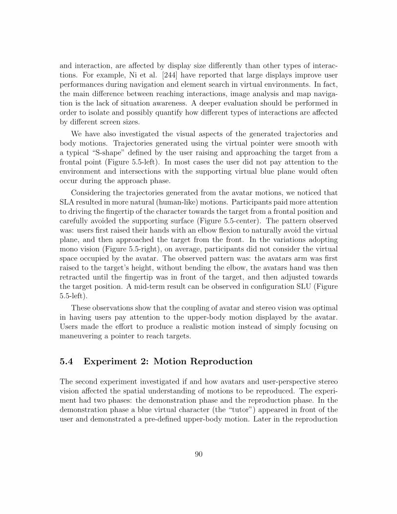
and interaction, are affected by display size differently than other types of interac-tions. For example, Ni et al. [244] have reported that large displays improve userperformances during navigation and element search in virtual environments. In fact,the main difference between reaching interactions, image analysis and map naviga-tion is the lack of situation awareness. A deeper evaluation should be performed inorder to isolate and possibly quantify how different types of interactions are affectedby different screen sizes.
We have also investigated the visual aspects of the generated trajectories andbody motions. Trajectories generated using the virtual pointer were smooth witha typical “S-shape” defined by the user raising and approaching the target from afrontal point (Figure 5.5-left). In most cases the user did not pay attention to theenvironment and intersections with the supporting virtual blue plane would oftenoccur during the approach phase.
Considering the trajectories generated from the avatar motions, we noticed thatSLA resulted in more natural (human-like) motions. Participants paid more attentionto driving the fingertip of the character towards the target from a frontal position andcarefully avoided the supporting surface (Figure 5.5-center). The pattern observedwas: users first raised their hands with an elbow flexion to naturally avoid the virtualplane, and then approached the target from the front. In the variations adoptingmono vision (Figure 5.5-right), on average, participants did not consider the virtualspace occupied by the avatar. The observed pattern was: the avatars arm was firstraised to the target’s height, without bending the elbow, the avatars hand was thenretracted until the fingertip was in front of the target, and then adjusted towardsthe target position. A mid-term result can be observed in configuration SLU (Figure5.5-left).
These observations show that the coupling of avatar and stereo vision was optimalin having users pay attention to the upper-body motion displayed by the avatar.Users made the effort to produce a realistic motion instead of simply focusing onmaneuvering a pointer to reach targets.
5.4 Experiment 2: Motion Reproduction
The second experiment investigated if and how avatars and user-perspective stereovision affected the spatial understanding of motions to be reproduced. The experi-ment had two phases: the demonstration phase and the reproduction phase. In thedemonstration phase a blue virtual character (the “tutor”) appeared in front of theuser and demonstrated a pre-defined upper-body motion. Later in the reproduction
90

phase the user was then asked to reproduce the observed motion (see Figure 5.6).
Figure 5.6: Experiment 2 investigated the influence of avatars and stereo visionduring motion observation (left image) and reproduction (right image).
Before each motion demonstration participants were instructed to memorize themotion they were going to observe, and to pay attention to details like: motion speed,arm key poses, final height of the hands, and torso orientation. The participantswere allowed to watch the demonstrated motion up to three times but they were notallowed to move and simulate the task with their bodies.
The demonstrated motion, or reference motion (Mr), was designed to be simpleand not ambiguous. It consisted of three arm raises. Each raise started by raisingboth arms simultaneously from the rest posture until the hands surpassed the head,with the elbows straight, and then the arms would return to the rest posture. Firsta lateral raise with arms parallel to the coronal plane was performed, then followeda frontal raise parallel to the tutor’s sagittal plane, and then followed a raise exactlyin-between the lateral and frontal raises.
During the reproduction phase the participants then reproduced the motionstogether with the virtual tutor. When the user’s avatar was employed, a red avatarwas displayed mimicking the user’s motions in real-time as in a virtual mirror. In thiscase the tutor avatar was rendered transparently, overlapping (in fact slightly behind)the user’s avatar. The tutor and avatar motions were still clearly distinguishable.Figure 5.6-right shows both avatars being displayed, with the tutor’s arms visibleslightly below the arms of the user’s red avatar.
In order to prepare the participants to promptly start the reproduction fairly
91

Table 5.4: Configurations of experiment 2 (G = Group, M = Male, F = Female).Label G M F Stereo AvatarsSLA 4 5 5 yes user’s avatar and virtual tutor employedSLT 1 3 7 yes only tutor employed, no avatarMLA 2 4 6 no user’s avatar and virtual tutor employedMLT 5 3 7 no only tutor employed, no avatar
in sync with the tutor, a five seconds traffic light was displayed. The participantswere informed that the virtual tutor would start to move immediately after the greenlight.
Similarly to the previous experiment, forty participants took part on the ex-periment and it was performed in four variations (10 participant per variation), asdescribed in Table 5.4. The variations covered the joint combination of employingor not the avatar and the user-perspective stereo vision.
5.4.1 Data Collected
Similarly to experiment 1, the full motions performed by the participants wererecorded for each variation. For each motion, we extracted the trajectories gen-erated by the wrist joints in global coordinates. We denote te as the duration of atrajectory (motion) in time, and tp1 and tp2 as the time values that divide the trajec-tories in the three distinctive motion phases: lateral raise Ml, frontal raise Mf andintermediate raise Mi. Values tp1 and tp2 were manually annotated for each motionand in the reference motion.
The performances were analyzed in terms of time, distance and velocity differ-ences when comparing each recorded trajectory against Mr, and after aligning thetrajectories according to each cyclic phase. The time difference per phase, here de-noted as phase synchronization time, was calculated by subtracting tp1, tp2 and tefrom their Mr counterparts. The obtained differences are denoted as td1, td2 and tde.
Distance and velocity errors were calculated using the following procedure: eachperformed trajectory was subdivided and time-aligned (by uniform time warping)with the corresponding segments Ml, Mf and Mi of the reference motion. Eachtrajectory segment was also uniformly re-sampled. We denote the re-sampled tra-jectories as Sl, Sf and Si. Each trajectory was compared with the correspondingsamples in Mr in order to achieve the error values. Distance errors between corre-sponding samples are denoted as Sdl, Sdf and Sdi; and velocity errors are denoted bySvl, Svf and Svi.
92
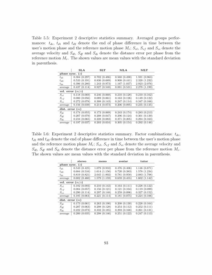
Table 5.5: Experiment 2 descriptive statistics summary. Averaged groups perfor-mances: tde, td1 and td2 denote the end of phase difference in time between theuser’s motion phase and the reference motion phase Mr; Svl, Svf and Svi denote theaverage velocity and Sdl, Sdf and Sdi denote the distance error per phase from thereference motion Mr. The shown values are mean values with the standard deviationin parenthesis.
SLA SLT MLA MLTphase sync. (s)td1 0.384 (0.297) 0.702 (0.486) 0.568 (0.490) 1.591 (0.963)td2 0.533 (0.191) 0.836 (0.689) 0.908 (0.441) 2.320 (1.232)tde 0.396 (0.280) 1.243 (0.973) 1.167 (1.037) 2.923 (2.076)average 0.437 (0.114) 0.927 (0.548) 0.881 (0.531) 2.278 (1.199)
vel. error (m/s)Svl 0.118 (0.069) 0.246 (0.068) 0.210 (0.128) 0.210 (0.162)Svf 0.080 (0.056) 0.089 (0.061) 0.163 (0.126) 0.149 (0.122)Svi 0.272 (0.078) 0.308 (0.143) 0.247 (0.114) 0.347 (0.166)average 0.156 (0.039) 0.214 (0.073) 0.206 (0.095) 0.235 (0.135)
dist. error (m)Sdl 0.174 (0.055) 0.173 (0.069) 0.243 (0.174) 0.283 (0.213)Sdf 0.207 (0.079) 0.208 (0.047) 0.296 (0.124) 0.301 (0.139)Sdi 0.216 (0.065) 0.228 (0.083) 0.371 (0.205) 0.294 (0.163)average 0.197 (0.037) 0.203 (0.034) 0.305 (0.154) 0.292 (0.146)
Table 5.6: Experiment 2 descriptive statistics summary. Factor combinations: tde,td1 and td2 denote the end of phase difference in time between the user’s motion phaseand the reference motion phase Mr; Svl, Svf and Svi denote the average velocity andSdl, Sdf and Sdi denote the distance error per phase from the reference motion Mr.The shown values are mean values with the standard deviation in parenthesis.
stereo mono avatar tutorphase sync. (s)td1 0.543 (0.425) 1.079 (0.910) 0.476 (0.406) 1.146 (0.871)td2 0.684 (0.516) 1.614 (1.156) 0.720 (0.383) 1.578 (1.234)tde 0.819 (0.821) 2.045 (1.892) 0.781 (0.958) 2.083 (1.798)average 0.682 (0.460) 1.579 (1.159) 0.659 (0.455) 1.602 (1.142)
vel. error (m/s)Svl 0.182 (0.093) 0.210 (0.142) 0.164 (0.111) 0.228 (0.122)Svf 0.084 (0.057) 0.156 (0.121) 0.121 (0.104) 0.119 (0.099)Svi 0.290 (0.114) 0.297 (0.148) 0.259 (0.096) 0.327 (0.152)average 0.185 (0.064) 0.221 (0.114) 0.181 (0.075) 0.224 (0.106)
dist. error (m)Sdl 0.173 (0.061) 0.263 (0.190) 0.208 (0.130) 0.228 (0.164)Sdf 0.207 (0.063) 0.298 (0.128) 0.254 (0.112) 0.252 (0.111)Sdi 0.222 (0.073) 0.332 (0.185) 0.293 (0.168) 0.261 (0.131)average 0.200 (0.035) 0.298 (0.146) 0.251 (0.122) 0.247 (0.113)
93

Since the reference motion was designed to be simple and symmetric, as expected,the difference between the left and the right samples was not significant. For thisreason we omit the disjoint analysis between the left and right samples and reportonly the averaged left-right investigation.
Figure 5.7: Trajectories collected from the character’s motions during experiment2. The green trajectory shows the reference motion Mr. The small blue spheresrepresent points tp1 and tp2. Left images: SLT shows fairly separated phases butthe heights of the trajectories did not well correspond to the heights in Mr. Centerimages: MLA shows merged trajectories between phases Mi and Ml. Right images:SLA shows the best results, with the separation space and height traversed by eachphase being closest to Mr.
5.4.2 Results
In our initial descriptive statistics we averaged the participant’s readings by category(Table 5.5 - Variations) and performed a joint analysis between the independentcategories (Table 5.6 - Factors).
From the grouped variations table (Table 5.5) we can infer that participants in thevariations with the avatar (MLA and SLA) showed a better phase synchronizationthan users in the other variations. This effect is also reflected by the velocity error andpartially by the distance error. In this last case, SLA still shows the best result whileMLA users were less accurate. Similarly we can infer the same pattern from the jointfactors sub-table (Table 5.6) where, except for the distance error, during variations
94
using avatars and variations using stereo vision, users had the best performances(time phases synchronization and less velocity profile error).
Figure 5.8: Aligned distance profiles of replicated motions in each variation (orangedots depict td1 and td2).
This effect can also be observed from generated trajectory depicted in Figure5.7. Looking at the trajectories generated in variation SLA, the compliance to thereference motion is maintained similarly to the case of using stereo but without theavatar (SLT), however the height and key poses were better respected in SLA.
Analyzing the average distance compliance with Mr we can infer that partici-pants using the system in mono vision performed in the least accurate fashion, 10cmdifference on average per section. Figure 5.8 shows in detail the averaged distanceprofile of each variation highlighting each phase. When stereo vision was used themotions were closer to the reference motion, in particular, phase Mi (arms raisingdiagonally) was better perceived by the participants. The error from participants inMLA and MLT is clearly higher that the error produced by participants performingin SLT and SLA during Mi. On the contrary, if we consider the factors combinationsub-table this subdivision disappears. An explanation for this behavior can be givenconsidering the joint performance of mono vision and without the avatar, whichrepresents a non-optimal configuration.
Considering the velocity profiles (Figure 5.9) we notice that both variations show-ing the avatar were overall closer to the reference motion profile than the other vari-ations. It is also interesting to notice that in all variations participants anticipatedthe start of the first phase. This fact might have been driven by the implementationchoice of using the virtual traffic light, as they felt driven to start right after the
95

Figure 5.9: Aligned velocity profiles of reference and replicated motions in eachvariation (orange dots depict td1 and td2).
green light appeared instead of waiting for the virtual tutor to start the motion.
From the data collected in the post-experiment questionnaire participants equallyrated, in all the variations, their confidence of having perceived the motion correctly.In terms of reproduction, participants under the conditions without the avatar feltto be slightly less accurate in terms of position and speed (on average 15% less).Conversely, the presence or absence of stereo vision did not affect the users’ level ofconfidence.
After this preliminary study a two-factor (2x2) ANOVA (SS Type III) was per-formed to evaluate the effect of the visualization type and the presence of the avataron the user performances represented by each accuracy measures: td1, td2, tde, Sdl,Sdf , Sdi, Sd (average of the previous three values), Svl, Svf , Svi, and Sv (average ofthe previous three values). The test for normality, examining standardized skewnessand the Shapiro-Wilks test indicated the data to be statistically normal. In orderto meet the Homogeneity assumptions for performing a two-way ANOVA the datawere transformed using a standard natural power transformation (p-values reportedbelow resulted from not significant tests for homogeneity of variance). The reportedestimated means have been back-transformed to reflect the original data and thestandard deviation has been reported as interval (SDI) due to the non-linear backtransformation. An alpha level of .05 was used for the initial analysis.
Considering the distance compliance with the reference motion Mr, the results forthe two-way ANOVA indicated a significant main effect for the visualization type, perphase (Sdl: F (1, 36) = 5.755, p = .022; Sdi: F (1, 36) = 7.360, p = .009) and overall
96

(Sd: F (1, 36) = 10.588, p = .002). A review of the group means for the averageddistance factor (Sd) indicated that the error of the group using user-perspective stereovision (M = 0.197 SDI = [0.175, 0.221]) had a significantly lower level of error thanthe group interacting without stereo (M = 0.258 SDI = [0.229, 0.291]). The analysisconfirmed our initial conclusions and we can state that user-perspective stereo visionresulted in motions with significantly higher compliance to the reference motion.
In addition, we examined the participants capability of respecting key poses intime with the reference motion Mr. Both visualization type and the presence ofthe avatar (disjointly) showed main effects. The visualization type produced a maineffect per phase (td1: F (1, 36) = 5.755, p = .022; tde: F (1, 36) = 9.280, p = .004) andoverall (td: F (1, 36) = 21.016, p < .001). Considering the averaged estimated meanswe can infer that participants in user-perspective condition better respected key times(M = .654 SDI = [.345, .936]) with respect to the other groups without (M = 1.475SDI = [1.184, 1.767]). Similarly, the presence of avatar, also produced main effectsper phases (td1: F (1, 36) = 6.870, p < .013), tde: F (1, 36) = 16.416, p < .001)and overall (td: F (1, 36) = 24.942, p < .001)). The presence of avatar (M = .555SDI = [.264, .847]) helped the user to better respect the original motion key poseswith respect to time in respect to the groups without the avatar (M = 1.565 SDI =[1.274, 1.856]).
Considering the joint factor analysis, in phase td1 and tde, the effect trended to-ward significance (td1: F (1, 36) = 3.225, p < .080 and tdf : F (1, 36) = 3.710, p <.062). Similarly Sdl and Sdf also trended toward significance (Sdl: F (1, 36) =3.449, p < .071 and Sdf : F (1, 36) = 3.527, p < .068). Looking at the estimatedmean comparisons it seems that avatar use (both in time and distance) improved thereproduction of motions when only mono vision was used. However, since there isno statistical significance and the interaction appeared only on subsets of the data,the main estimates have not been dropped.
Finally, considering the velocity profile maintenance ANOVA reported only atrend on the presence of the avatar main effect on the phase Svl (F (1, 36) = 3.449, p <.071). Even though this conclusion could not be supported statistically, by analyzingthe motions visually it is possible to notice that in the presence of the avatar par-ticipants reached more accurately (in terms of distance and timing) peaks and keypoints, resulting in small partial velocity errors. Changes in acceleration could behowever noticed in a few trials, due to users assessing the virtual character’s motionand trying to catch up with the tutor. The motions appeared less fluid in these cases.
97

5.4.3 Discussion
Our study provides evidence that both the use of avatars and stereo vision positivelyaffect motion reproduction tasks.
The presence of avatar and stereo vision both improve the ability to preserve spa-tial alignments when reproducing motions. Training applications represent a typicalscenario where both these conditions would be useful. Accurate motion perceptionis particularly important when demonstrated motions have relationships with theenvironment or objects, in which cases key poses will have to be well perceived inorder to achieve effective training.
We can also observe that the avatar helps driving the improvement of the motionreproduction when stereo vision is not employed. Considering a scenario wheremotion reproduction is performed without stereo vision, displaying an avatar is akey recommendation. This is for instance the case of several applications related todelivery of physical exercises at home, where it is difficult to implement stereo vision.
5.5 Experiment 3: Motion Modeling
The third experiment investigated the usability of a complete interface for immersivemotion modeling by direct demonstration (see Figure 5.10). In this experimentparticipants were asked to perform motions to be performed by a virtual character.
Figure 5.10: Experiment 3 evaluated an immersive motion modeling by demonstra-tion interface. Motion recording with or without avatar (left image) and playback(right image) were evaluated.
98
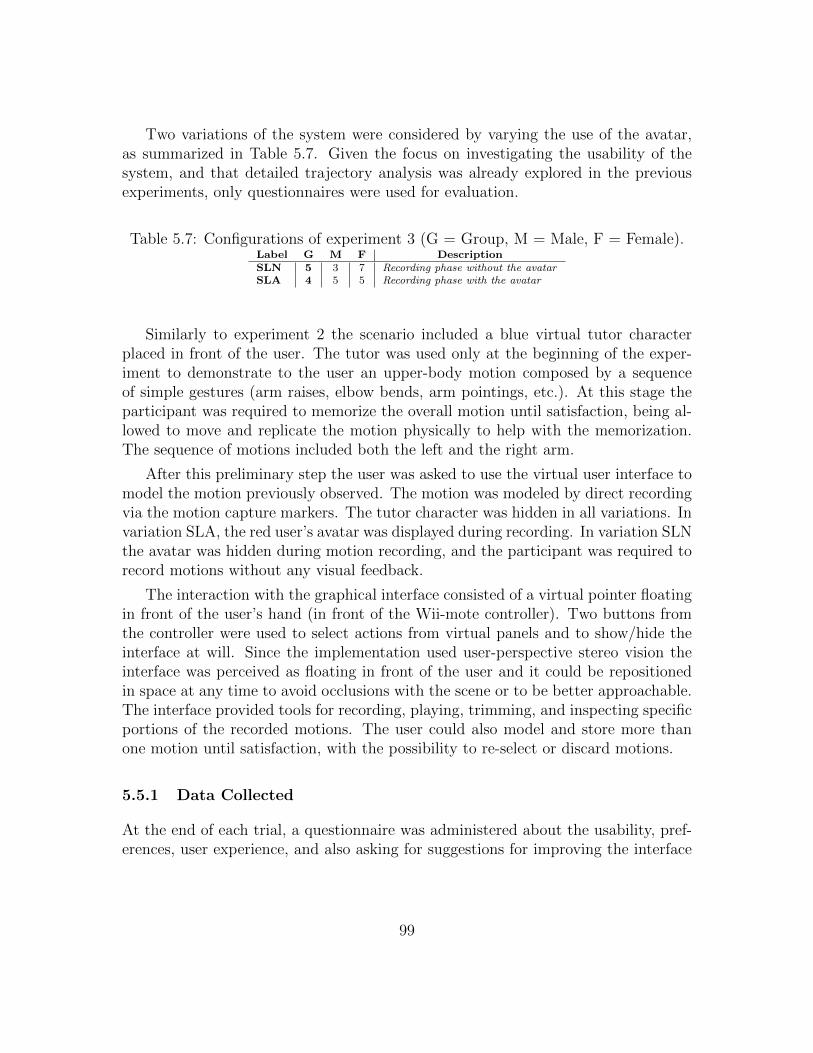
Two variations of the system were considered by varying the use of the avatar,as summarized in Table 5.7. Given the focus on investigating the usability of thesystem, and that detailed trajectory analysis was already explored in the previousexperiments, only questionnaires were used for evaluation.
Table 5.7: Configurations of experiment 3 (G = Group, M = Male, F = Female).Label G M F DescriptionSLN 5 3 7 Recording phase without the avatarSLA 4 5 5 Recording phase with the avatar
Similarly to experiment 2 the scenario included a blue virtual tutor characterplaced in front of the user. The tutor was used only at the beginning of the exper-iment to demonstrate to the user an upper-body motion composed by a sequenceof simple gestures (arm raises, elbow bends, arm pointings, etc.). At this stage theparticipant was required to memorize the overall motion until satisfaction, being al-lowed to move and replicate the motion physically to help with the memorization.The sequence of motions included both the left and the right arm.
After this preliminary step the user was asked to use the virtual user interface tomodel the motion previously observed. The motion was modeled by direct recordingvia the motion capture markers. The tutor character was hidden in all variations. Invariation SLA, the red user’s avatar was displayed during recording. In variation SLNthe avatar was hidden during motion recording, and the participant was required torecord motions without any visual feedback.
The interaction with the graphical interface consisted of a virtual pointer floatingin front of the user’s hand (in front of the Wii-mote controller). Two buttons fromthe controller were used to select actions from virtual panels and to show/hide theinterface at will. Since the implementation used user-perspective stereo vision theinterface was perceived as floating in front of the user and it could be repositionedin space at any time to avoid occlusions with the scene or to be better approachable.The interface provided tools for recording, playing, trimming, and inspecting specificportions of the recorded motions. The user could also model and store more thanone motion until satisfaction, with the possibility to re-select or discard motions.
5.5.1 Data Collected
At the end of each trial, a questionnaire was administered about the usability, pref-erences, user experience, and also asking for suggestions for improving the interface
99

and the overall approach. Except for a few open questions requesting feedback, thequestionnaire consisted of seven-point Likert-scale items. See Table 5.8 for an excerptof the questionnaire. The full motions saved by the participants were also stored butthey were only used to validate if the users performed all the motions required to bemodeled.
5.5.2 Results and Discussion
Since the task of modeling motions by demonstration required to handle a morecomplex interface and implied more steps and familiarization with the system, asexpected, the task was rated by the participants to be more difficult than the tasksin the previous experiments. Looking at the control questions, when asked aboutconfidence on completing the task correctly and confidence on being able to coachthe task to someone else, we observed a 15% decrease of confidence with respect toexperiments 1 and 2. In experiments 1 and 2 the average level of confidence was 6.4out of 7, while in Experiment 3 it was 5.7 out of 7.
Figure 5.11: Results from selected usability questions for Experiment 3. The corre-sponding questions are available in Table 5.8.
Considering the targeted questions and the open comments the users positivelyrated the overall experience. The average rating for the question “Rate how comfort-able you felt during the performance in all the aspects of the activity (1=extremelyuncomfortable, 7=extremely comfortable)” was 5.5.
Figure 5.11 summarizes results of selected questions from the post-activity ques-tionnaire. Q6 highlights the fact that users in SLN wanted additional training beforeengaging in the motion modeling activity. Comments and suggestions also noted thatthey did not know how to behave when the recording phase started. Before the be-
100

ginning of each recording phase the system warned the user with a timer countdownwith textual messages, but this was not sufficient for them to grasp the activity intheir first attempt. After a few trials they were then able to record motions correctly.This fact was also reflected by question Q14 of the SLN questionnaire, where usersexpressed the hypothesis that having an avatar during the recording session wouldhave improved the usability of the system (6.29 out of 7). Users performing in SLAfelt that the avatar helped them to better understand their motions (Q15-SLA 6.57out of 7) and they did not feel distracted by it (Q14-SLA 6.57 out of 7). Theseresults are consistent with experiments 1 and 2.
Table 5.8: Extract of the questionnaire administered in Experiment 3 (likert-scalerated between 1=strongly disagree, 7=strongly agree).
Q5 The interface was simple and easy to understand.Q6 The interface could be used without training.Q7 3D vision is important to model motions.Q9 I would have preferred to use a standard computer.Q13 The approach to model motions was effective.Q14∗ The avatar was distracting while recording.Q14∗∗ Seeing my motions while recording would have helped me.Q15∗ The avatar helped me to be more precise.
(∗SLA only, ∗∗SLN only.)
5.6 Conclusions
The presented experiments have uniquely studied the effectiveness of avatars anduser-perspective stereo vision during task performance. Our results have shown theviability of the approach of direct motion demonstration for modeling and reproduc-ing motions. The correct use of avatars was shown to have great potential to improveperformances in a number of situations; however, we have also observed that thereare critical design choices that highly influence the suitability of the configurationsto different types of interaction needs.
Our experiments confirm that the use of user-perspective stereo vision with directinteraction is the optimal choice in terms of task accuracy and completion time, whenprecision tasks are involved. Direct interaction made users 6 times more accurateand 2 times faster than in other conditions. For example, in the widely adopted
101

scenario of stroke rehabilitation, tasks often involve repeatedly reaching regions inspace. In such cases user-perspective stereo vision will lead to better accuracy whenmeasuring the rehabilitation progress.
User-perspective stereo vision also improved replication of spatial relationshipseven when the task was transferred to the avatar’s space (by a factor of 3). Whenthe task involved motion reproduction, stereo vision showed improvements both interms of synchronization and compliance with the reference motion. The use ofavatars produced increased attention to the avatar space, allowing users to betterobserve and address motion constraints and qualities. Coupling avatar use withstereo vision resulted in users paying more attention to the motions within the virtualenvironment, improving the realism and correctness of the motions. These findingsrepresent key factors to consider when designing applications for distant training incollaborative spaces where the kinesthetic component is fundamental with respect tothe environment.
In addition, avatar use was shown to improve motion reproduction in the caseswhere stereo vision was not present. This factor suggests that in application setupswhere stereo vision is not practical to be used (such as in homes or clinics), the useof avatars will definitively improve the user understanding of motions displayed byvirtual tutors.
In summary, if the involved tasks require generation or reproduction of motionswith desired qualities, such as in training applications where the environment orobjects and tools are key factors, the use of avatars and stereo vision will improvethat ability. However, if the goal is to accomplish tasks no matter the type ofmotions used, direct interaction in user-perspective will be more efficient. Besidesthe additional instrumentation (stereo glasses), stereo vision was shown to be alwaysbeneficial.
The above conclusions were found to be statistically significant and additionalimportant trends and observations were also made. We have noticed that the smalldisplay induced users to not overestimate their capabilities during precision tasks.However, the small display increased their execution time and frustration. Althoughfurther investigation should be performed to fully support this theory, a new guidelineon designing gesture-based game controllers can be drawn. Given that the dimensionsof the target visualization system was observed to affect user expectations, gamecontroller precision and other difficulty settings should be dynamically adjusted withrespect to the display size in order to manage user frustration.
Overall, the presented results provide important new quantification and observa-tions in each of the performed experiments, leading to a new understanding of the
102

trade-offs involved when designing avatar-based training systems.
103

CHAPTER 6
Application to Physical Therapy
Physical therapy is a broad field that addresses the recovery and treatment of in-juries, physical impairments, disabilities, diseases and disorders related to motor andbalance dysfunctions affecting many daily life activities. A rehabilitation processis usually necessary for patients after a specific type of injury involving physical(impingement, surgery, arthritis, etc) or neurological (strokes, neuropathies, etc) im-pairments.
Rehabilitation and physical therapy are optimal when assessment, monitoring,patient engagement, and adherence to the therapy program can be achieved. Intraditional physical therapy different processes are usually involved: physical exam-ination, evaluation, assessment, therapy intervention, monitoring, and modificationof the therapy program according to patient recovery [44].
Figure 6.1: Example of a typical paper description of an exercise given to patients.
While it is clear that VR-based computer systems for therapy delivery have greatpotential to well address most of the limitations of traditional physical therapy (e.g.lack of customization, engagement, supervision, etc.), implementing effective solu-tions involves multiple challenges. In any case, current practices can be certainly
104

improved. For example, Figure 6.1 illustrates how exercises are typically describedin paper to patients when they are given a set of exercises to be executed at home.Paper descriptions suffer from perceptual limitations and lack of interactivity, andmostly important they do not provide monitoring and logging capabilities that arecrucial for determining patient adherence to the program and the effectiveness of theexercises.
Figure 6.2: Example of a typical tool used to measure improvements and paperrepresentation of the measurement.
In traditional physical therapy even the measurements of patient improvementsand monitor is done using mechanics tools (Figure 6.2)
Our approach addresses these challenges in a unified way. We first design motiondemonstration methodologies that allow therapists to intuitively create, edit andre-use customized exercises that are responsive to the needs of their patients. Inthis way we integrate in our systems the ability to configure exercises to particularpatients, both in terms of creating new exercises as needed and in terms of designinghow exercises should adapt to patient preferences, physical limitations, and recoveryrates. In addition, several factors can be considered to adjust a system to the user’spreferences: from the language and pace to display messages and instructions, tothe appearance of the virtual character demonstrating the exercises, etc. Multipleinteraction channels can be customized in order to approach a similar set of com-munication channels that the patient is used to experiencing during his or her dailyhuman-human interactions. Cultural background, social and age groups all play im-portant roles in the wide variation of preferences that can be identified and modeledin VR systems.
105

We describe in this chapter our first steps towards such an adaptive and responsiveinteractive therapy system, discussing adaptive exercise models, motion processingalgorithms, and exercise delivery and monitoring techniques that are able to effec-tively respond to physical limitations and recovery rates of individual patients. Thepresented solutions provide a basic framework to experiment and address a first setof adaptation and customization features, and we focus on adaptation of exercisesfor the shoulder complex. We also present remote networked solutions for allowingtherapists and patients to share motion performances in real-time. The transmitteddata is lightweight and remote collaboration can well scale to several patients at thesame time. The capability of remote sessions is important in order to keep patientsmotivated and engaged in the therapy when they are supposed to work on their ther-apy programs at home. Remote sessions also have great potential to reduce costsand to widen health care delivery.
A number of additional features are also presented for achieving a complete frame-work for therapy modeling, delivery and analysis. Our system provides 3D assessmenttools for monitoring a range of motion, and for allowing the visualization of a numberof therapy parameters during or after execution of exercises. We have implementedour system in two configurations: a low-cost version based on a Kinect sensor and ahigh-end version based on the full-scale immersive Powerwall (see Figure 6.3).
We have collected informal feedback from therapists demonstrating that adaptiveand responsive exercise delivery improves their willingness to adopt the proposedsolutions in their practice.
6.1 Related Work
Over the last decade serious games for rehabilitation have become an importantresearch focus with relevant evidence of benefits [104, 181]. Different types of appli-cations have been developed targeting both specific and broad types of applications[97, 261, 165]. Virtual reality has been successfully applied for rehabilitation of strokepatients [53, 49], and with a different purpose, fitness applications have also emergedfrom videogame interfaces [187] and other custom-made light devices [61].
Perry et al. [266] described the typical workflow of applications with respect toneuro-rehabilitation. The workflow in clinics follows a cyclic process of treatmentplanning (generation), execution (delivery) and performance assessment. The tradi-tional physical therapy protocol follows a similar pattern and the same concept canbe extended to develop applications for physical therapy.
106

Figure 6.3: Our VR-based collaborative system can run in two configurations: ahigh-end immersive setup provides improved motion capture and visualization results(left), while the Kinect-based setup provides a low-cost solution suitable for patientsand therapists using traditional desktop computers (right). The overlapped virtualcharacters represent the user’s avatar and the autonomous character demonstratingexercises, or the user’s avatar and the avatar of the remote participant.
Standard commercial physical therapy packages adopted by clinicians rely onregular media to deliver exercises. The information is usually conveyed throughsimple text information, sequence of images, and/or video recordings. Users are onlycontrolled and assessed while they interact directly with physicians during in-clinicfollow-ups. Patients are therefore many times left unsupervised. The use of newtechnologies to overcome the limitations of standard approaches to physiotherapyis becoming increasingly popular. For example, the prototype product ReflexionVera [116] tracks and monitors users through a lightweight sensor (Microsoft Kinector similar) reporting to the therapist each performance.
Due to the high potential, research relying on the Kinect sensor is being performedto estimate the precision and validity of the device for posture assessment [69] or formotion analysis [92, 40]. Based on these studies, Kinect can be used to reliablytrack some types of motions, in particular upper-body exercises [206]. Exoskeletons,robotic arms with force feedback and more precise, marker based, tracking systemshave also been employed for assisting and monitoring impaired patients; however,involving cumbersome and costly devices is not suitable for widespread use [271, 112,306].
107
In our approach the creation and delivery of a physical therapy program follows aprogramming by direct demonstration strategy. The key benefit is to allow users tointuitively define new exercises as needed. The overall approach has been adopted inmany areas [54, 320, 207], and it involves the need to automatically process capturedmotions according to the goals of the system.
Velloso et al. [360] propose a system that extracts a movement model from ademonstrated motion to then provide high-level feedback during delivery, but with-out motion adaptation to user performances. The YouMove system [11] trains theuser through a series of stages while providing guidance and feedback; however, alsowithout incorporating motion adaptation to user performances. Our approach in-corporates motion adaptation in several ways, allowing greater flexibility to achieveeffective exercises to patients of different learning abilities, impairments, and recoveryrates.
A typical approach for delivering physical therapy exercises is to track user move-ments while a virtual character displays the exercises to be executed. The represen-tations of both the user and the virtual trainer are usually displayed side by side orsuperimposed to display motion differences, improving the learning process and theunderstanding of the movements [126, 377].
Automated systems often allow parameterization capabilities. For instance, Langeet al. [182] describe core elements that a VR-based intervention should address, in-dicating that clinicians and therapists have critical roles to play and VR systemsare tools that must reflect their decisions in terms of taking into account a person’sability to interact with a system, types of tasks, rates of progression, etc. [193, 106].Geurts et al. [97] describe 5 mini-games that can be calibrated and adapted in termsof speed and accuracy. The physical exercises are static and cannot be replaced. Incomparison, our approach is much more comprehensive in that it relies on motioncapture and on processing entire full-body motions for adaptation. By doing so wepropose new motion processing approaches to achieve adaptive motions that are bothcontrollable and realistic.
Significant research on motion capture processing has been performed in thecomputer animation field. Motion blending techniques with motion capture data[171, 170, 296, 209] are popular and provide powerful interpolation-based approachesfor parameterizing motions; however, they require the definition of several motionexamples in order to achieve parameterization. In contrast our proposed techniquesare simple and are designed to provide parameterization of a given single exercisemotion. We rely both on structural knowledge of exercises and on generic constraintdetection techniques, such as detection of fixed points [202, 299] and motion process-
108

ing with Principal Component Analysis (PCA) [100].
Rehabilitation based on tele-consultation between two healthcare services hasbeen studied with different technologies. In physiotherapy, tele-treatment betweenhealthcare and community services using video has been successfully employed instudy cases with elderly with stroke [178] and knee pain [378]. Using virtual realityand serious games, Golomb et al. [103] presented a system for remote rehabilita-tion of hands for in-home use with distributed data sharing. Several studies havealso combined live video of the patient integrated with the virtual environment toaugment the patient’s feeling of presence in the interactive space [49, 164]. In theseapplications video was used to provide visual feedback. This choice however does notallow direct interaction in a virtual space. Data collection of a patient performancealso becomes a difficult task when users are only captured by regular video.
One development using immersive virtual reality and 3D camera imaging recon-struction has been proposed by Kurillo et al. [177]. This hybrid system allows ther-apists and patients to share and interact in the same virtual space. The approachhowever focuses on high-quality rendering and is not suitable as a low-bandwidthsolution for physical therapy. An improvement of this work [256] allows the systemto additionally detect human poses and assist with balance control. Although re-mote collaboration has been explored in different ways, a suitable overall solution forinteractive sessions has not yet been integrated for remote physical therapy sessions.
We present in this chapter our combined approach to achieve exercises that canbe modeled by demonstration, that are responsive to the performances of users, andthat can be exchanged in real-time in low-bandwidth remote therapy sessions bylimiting transmission to joint-angle data.
6.2 Configurations and Features
We describe in this section the main functionality and configurations that we havedeveloped in our system.
Therapists can design exercises and therapy programs, and then use the system todeliver the exercises in different ways. Created exercises and programs can be storedfor further reuse and sharing. When virtual characters autonomously deliver exer-cises, a number of parameters describing adaptation strategies can be customized,and monitoring and logging tools can be enabled as needed. The provided toolsimprove patient understanding, motivation and compliance, and also provide datagathering.
109

Two configurations have been developed, and while the user interface is differentthe functionality remains the same. Both configurations can work offline, where thepatient can only interact with an autonomous virtual (animated) therapist, or online,where remote patients and therapists are tracked simultaneously and their avatarsare displayed in the same virtual space. In all cases a number of analysis tools forreal-time or post-analysis monitoring, feedback and logging are always available.
The software application has been developed based on the Ogre3D graphics ren-dering engine [345] and the VR Framework explained in detail in Chapter 3. Thischoice has allowed us to produce and customize a same application across differentmodalities and platforms. The system can be easily ported to different operatingsystems or to more complex virtual reality settings like CAVEs.
6.2.1 Immersive VR Configuration
Our experimental immersive setup consists of a Powerwall system composed of sixrendering computers, a main rendering node and an external computer driving inputdevices and the motion capture system. The interaction with the application is fullyimmersive; thanks to virtual pointers and a 3D graphical user interface controlled bya Wiimote. See Figures 6.3-left and 6.4.
The high-end configuration allows therapists to immersively model exercises bydemonstration and to experience full-scale visualization of patient performances. Thepatient’s motion can be captured and displayed in real-time or it can be loaded frompreviously logged sessions. The application provides stereo visualization for enhancedcomprehension of the motions and data.
A high-end system configuration also allows the integration of precise tracking ca-pabilities. In our setup the user’s upper body motions are tracked using a 10-cameraVicon motion tracking system. For improved usability, the system is configured toonly track markers attached to the hands, torso and head. The motion is calibratedand mapped to the avatar following simple scaling procedures as described in thework of Camporesi et al. [54]. This solution has been enough to allow us to ex-periment with the system; however, since we reconstruct the motion from a reducedmarker set not all degrees of freedom of the user’s motion can be precisely replicated;in particular, the elbow orbit motion around the shoulder-wrist axis is set to be al-ways in a low-energy position. If precise motion replication is needed, in particularfor cases where avoiding compensatory movements is important, additional markershave to be placed on the user.
In remote connection mode the immersive system allows to achieve full-scale
110
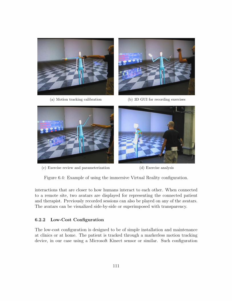
(a) Motion tracking calibration (b) 3D GUI for recording exercises
(c) Exercise review and parameterization (d) Exercise analysis
Figure 6.4: Example of using the immersive Virtual Reality configuration.
interactions that are closer to how humans interact to each other. When connectedto a remote site, two avatars are displayed for representing the connected patientand therapist. Previously recorded sessions can also be played on any of the avatars.The avatars can be visualized side-by-side or superimposed with transparency.
6.2.2 Low-Cost Configuration
The low-cost configuration is designed to be of simple installation and maintenanceat clinics or at home. The patient is tracked through a markerless motion trackingdevice, in our case using a Microsoft Kinect sensor or similar. Such configuration
111

is important because it is simple, portable and suitable for any kind of desktopenvironment. It is also suitable to assist patients in their daily routines in clinicalenvironments. See Figures 6.3-right, 6.8 and 6.16 for examples.
Even though the accuracy of Kinect is limited (the accuracy drops highly whenusers are not facing the camera or when body occlusion occurs) it still provides agood balance between precision, cost and portability [257, 69, 93, 228, 247].
Kinect-based configurations can also be remotely connected to other instances ofthe system for collaborative sessions.
6.2.3 Remote Collaboration
The capability of having patients and therapists to remotely interact is importantbecause it can save travel costs, allow more frequent monitoring, and potentiallyincrease access to health care, in particular to remote areas. The motion of eachuser participating to the virtual collaboration is mapped directly to each respectiveavatar, and the avatars can be superimposed with transparency or appear side-by-side in the applications. See Figure 6.5 for examples.
Figure 6.5: Examples of collaborative sessions. Left: one user is being tracked by thehigh-end system Vicon cameras while the other is being tracked by a Kinect sensor.Right: both users are tracked by Kinect cameras and collaborate with the portableversions of the system running in a desktop and laptop.
The communication between two peers in a collaborative session is based on aclient-server UDP communication schema with added packet ordering, guaranteedcommunication reliability and optional data compression. The server application,
112

after accepting and validating an incoming connection, starts sending informationof the avatar of the current user (sender) and waits for the update of the client’savatar (receiver). For instance, if the therapist application is started as a server,the therapist’s avatar becomes the active character in the communication and thesecond character, the patient’s avatar, becomes a receiving entity. If the patient’sapplication is started as the client, the sender entity becomes the character of thepatient’s application while the tutor/therapist becomes a receiving entity waiting forfurther updates.
During a networked session each active character maintains a history containingits previous poses and the streamed information between the peers is limited tothe information that has changed between the previous frame and the current frame.This feature has been developed to handle communication between peers with limitedbandwidth capabilities.
Feedback and analysis tools (described below) are also available during virtualcollaboration. The therapist can demonstrate exercises, analyze the patient motion,load preset exercises from the database, watch the patient’s performances, record apatient motion in real-time, etc.
6.2.4 Tools for Real-Time Feedback and Post-Analysis
The feedback tools can be activated anytime and they are highly customizable. Forexample, any joint of the character representation can be tracked and considered foranalysis by any tool. Simple commands or text-based configuration files are usedfor customization. Four types of feedback have been developed in order to providevisual and quantitative information about the user motions in real-time or in post-analysis. The four feedback tools provide information with respect to: trajectories,joint angles, distance to target exercises, and range of motion per exercise. See Figure6.6.
Trajectories: trajectory trails of selected joints can be displayed in real-time,and they show the performed trajectory of a joint during a fixed past period oftime (see Figure 6.6(a)), or after each user’s performance, showing the performedtrajectory and the trajectory compliance range with the reference exercise. Thevisualization can be based on fine polygonal segments sampled per frame (for preciseanalysis for example of tremors), or smoothly generated by B-Spline interpolation.
Angle estimation (virtual goniometer): joint angles can be visualized (Fig-ure 6.6(b)) with a floating label showing the angle value and the local lines used tomeasure the angle. In practical goniometry for upper-limb physiotherapy [250] angle
113

(a) Trajectory trails (b) Angles and distances (c) Range of motion
Figure 6.6: Visualization helpers are available for real-time feedback or post-analysisof motions.
measurement is important in order to measure progress and intervention effective-ness, via therapy or via surgery. Therapists can therefore instruct specific movementsto patients and observe or log the achieved measurements. The provided angle mea-surements match the angles measured in practical physiotherapy protocols [250].The proposed angle measurement is simple and yet flexible to accommodate genericneeds.
The angle estimation is calculated as follows: let p1, · · · , p4 ∈ R3 be the globalpositions of the extremities of two dependent (bones sharing a joint) or independentbones, and R1, R2 ∈ SO3 be the user-defined reference frame rotations. The angleestimation between the limbs at the joint in question is obtained with:
φ = arccos((R1 ∗ ‖p2 − p1‖) · (R2 ∗ ‖p4 − p3‖)). (6.1)
The proposed method allows the system to measure any kind of angle by justdefining pairs of joints and optional reference frame rotations. The tracked anglesare specified in the application’s configuration file. It gives to the therapist a flexibleand easy mechanism to identify and customize the visualization. To isolate anglesfor upper-arm flexion (extension or abduction) we track, for instance, the anglegenerated by the scapula/clavicle and humerus, given the scapula bone aligned tothe torso as a consequence of the skeleton hierarchical structure. The measuredangle is the angle between the arm and the “body line” of the user. In defaultbehavior, angles are only displayed when significant motion is detected. In terms ofeffectiveness of using Kinect for upper-limb joint angle estimation, the approach hasbeen tested and validated in a similar context [247].
Distances: colored 3D arrows showing the distance between corresponding pairs
114

of joints, each belonging to a different character, are useful for the patient to trackcompliance with the demonstrated exercises (see Figure 6.6(b)). The feedback isuseful in individual sessions or in remote physical therapy sessions. The distancearrows are employed similarly to the technique proposed by [11]. The arrows areprogrammed to automatically disappear if the corresponding distance is under a giventhreshold, and different colors can be associated to different ranges of thresholds.This is in particular useful for slow exercises where compliance is important. Figure6.7 shows arrow distances enabled together with several angle measurements duringexecution of one exercise.
Figure 6.7: Example of several feedback tools enabled while a patient executes agiven exercise.
Range of motion: Our range of motion visualization (see Figure 6.6(c)) analyzesthe rotation of a selected joint over time. We focus here on the shoulder range ofmotion evaluation due its importance in rehabilitation of shoulder movements.
The 3 degrees of freedom (DOFs) of the shoulder joint orientation are decomposedinto the twist and swing rotation parameterization [105]. The swing motion is thentracked at every frame i, and for each swing orientation si measured, the intersectionpoint pi of the upper-arm skeleton segment at orientation si and a sphere centeredat the shoulder joint is computed. The history of all traversed pi points is visualizedwith colors in the sphere. The sphere is texture-mapped with an image textureinitially fully transparent. For every measured point pi, its position in the textureis determined and the corresponding texture pixel ci has its color changed. Forachieving a clear visualization we employ a relatively high texture resolution and weweight the color increments around ci with a local Gaussian distribution centered atci. The colors are incremented from pure blue to red, providing a colored frequencymap of all traversed swing orientations (see Figure 6.6(c)).
The boundary of the colored map will represent the range of motion executed in agiven exercise. The original points pi are also recorded and are used for geometrically
115

estimating the polygonal boundary describing the full range of motion during asession. This tool provides an excellent way to log improvement of range of motionduring rehabilitation, to observe the patient’s ability to execute precise trajectories,and to observe if there are areas that are avoided for instance due pain or discomfort.In summary the representation provides a frequency history of the space traversed bythe user, and it offers a comprehensive view of the patient’s performance. Frequencymaps collected per exercise can clearly represent patient progress across therapysessions.
6.3 Adaptive Exercises
The option of providing customized exercises by demonstration enables the therapistto go beyond recovery plans limited to a set of predefined exercises. The therapistcan record his or her demonstrations and then trim, save, load, play, and customizethem in different ways. After a validation process the motions can be correctedand/or parameterized. Exercises can then be saved and categorized in a databaseof exercises. The database is used for fast construction of therapy programs using adesktop-mode interface of the application during consultation with patients.
In order to achieve adaptive exercises we need to address exercise parameteriza-tion from the beginning, since the modeling of the exercise motion. Our approach ofmodeling exercises from demonstration (see Figure 6.8) allows exercises to be generic;however, some structure is expected in order for motion processing algorithms to beable to parameterize the motions in real-time.
Given a captured exercise, we propose correction and parameterization techniquesthat allow 1) detection and fine-tuning of key characteristics of the exercise such asalignments and constraints, 2) parameterization of the exercise by detecting modi-fiable properties such as speed, wait times and amplitudes, and 3) real-time motionadaptation by monitoring user performances and updating the exercise parametersin order to improve therapy delivery.
The presented techniques facilitate the process of defining exercises by demon-stration by providing several modeling and correction mechanisms and at the sametime providing parameterization for real-time adaptation. As a result the proposedmethods produce realistic continuous motions that can adapt to user responses inorder to improve motivation and outcomes.
Given a new exercise motion demonstrated to the system, the system will analyzethe motion and detect the parameterizations that can be employed. An input motion
116

Figure 6.8: Illustration of a modeling session by demonstration using the low-costKinect configuration.
is represented as a collection of frames Mi, i ∈ {1, . . . , n}, where each frame Mi isa vector containing the position and the joint angles that define one posture of thecharacter in time.
6.3.1 Detection of Geometrical Constraints
Our constraint detection mechanism is designed for two specific purposes: to helpcorrecting artifacts and noise in the motions, and to provide metrics for quantifyingmotion compliance. The metrics are used to provide visual feedback to the user, toinform the correctness of performed motions, to make decisions during the real-timeadaptation mechanism, and to achieve an overall user performance score for eachsession.
Appropriate constraints are not constraints which are to be absolutely followed.Recorded motions may have unintended movements and imperfections introducedby the capture system. Constraints must be detected despite these fluctuations, andshould be softly enforced so the motion can be made to look correct and also natural.
We analyze the position in space of a specific joint with respect to a frame ofreference F which can be placed at any ancestor joint in the skeleton structure. Thedetection framework can accommodate any desired type of constraint but in thisresearch we focus on two types of constraints: Point and Planar.
The detected constraints are provided to the user and the user then decides 1)if the motion should be modified to better enforce the detected constraint, and 2) if
117

the constraint is to be monitored during real-time execution of the exercise in orderto alert the user every time the constraint is significantly violated. For instance, ifthe elbow joint is detected to be imovable in an exercise, the system will detect thatas a point constraint and may alert the user in real-time everytime the user’s elbowis too far away from its point constraint.
Figure 6.9: Point Constraint. The yellow sphere represents the detection of apoint constraint at the elbow joint. From left to right: the wrist motion trajectory(depicted in green) is corrected to the mean point with 0%, 50%, and 100% correction.
• A Point Constraint (Figure 6.9) describes a child joint that is static relative to itsparent. Let’s Pi, i ∈ {l, . . . , k} be the cloud of points formed by a joint trajectory withrespect to a local frame F generated by re-sampling linearly the motion frames withconstant frame rate. The standard deviation of the cloud of points σ is calculatedand subsequently checked against a specific threshold α. When the condition is metthe current joint is marked as a point constraint and it is represented by the specificpoint located at the mean µ. When a point constraint is detected the ancestor(s)can be then adjusted to enforce the constraint.
• A Plane Constraint (Figure 6.10) detects if a joint moves approximately withina plane. Similarly to the point constraint detection a point cloud is first generated.Then, PCA is applied to the set of points to determine a proper orthogonal decom-position considering the resulting Eigenspace from the covariance. A planar surfaceis then retrieved considering the two Eigenvectors with the highest Eigenvalue λ (themagnitude of λ is used to validate the plane). The average distance of the points fromthis plane is then checked against a threshold β to determine if a plane constraint isappropriate for the given joint.
When a constraint is detected the user is offered a correction percentage to choose.100% correction results in motion which always tries to obey constraints, whereas
118

Figure 6.10: Plane Constraint. The blue axis is the normal direction of the detectedplane constraint affecting the shoulder joint. From left to right: correction level (from0% to 100%) where the elbow trajectory (green trajectories) is gradually collapsedinto a plane.
0% correction results in no modification the original motion. Figures 6.10 and 6.9illustrate results obtained for a Plane and Point constraint respectively.
6.3.2 Geometrical Constraint Alignment
Let i be the index of the frame currently evaluated. Let pi be the position in spaceof the current joint and qi be a quaternion representing the current local orientation.A point constraint is defined considering the orientation qm in the local orienta-tion frame that represents the vector defined by the local point constraint. A pointconstraint is enforced through spherical linear interpolation between qi and qm. Fig-ure 6.9 shows the trajectories generated by the wrist joint collapsing into a pointconstraint.
To apply the plane constraint, we identify the orientation defined by the projec-tion of each point pi to the plane discovered during the detection phase. The planeconstraint is then enforced, similarly to the point constraint, by interpolating theequivalent orientations. Figure 6.10 shows the trajectories generated by the elbowjoint aligning into a plane constraint.
119

6.3.3 Detection of Exercise Parameterization
Consider a typical shoulder flexion exercise where the arm is raised until it reachesthe vertical position or more (initial phase); subsequently the arm is held for a fewseconds (hold phase) and then it relaxes back to a rest position (return phase). Thisis the type of exercise that we seek to parameterize.
The analysis procedure makes the following assumptions: a) each motion Mrepresents one cycle of a cyclic arm exercise; b) the first frame of a motion containsa posture representing the starting point of the exercise; c) the exercise will havedistinct phases: the initial phase (Minit) is when the arm moves from the initialposture towards a posture of maximum exercise amplitude, then the exercise may ornot have a hold phase (Mhold) but at some point the exercise must enter the returnphase (Mend), where the exercise returns to a posture similar to the starting posture.In addition, if the motion contains a hold phase at the point of maximum amplitude,it will mean that an approximately static pose of some duration (the hold phaseduration) exists at the maximum amplitude point. We also consider an optional 4th
phase that can be added to any exercise, the wait phase (Mwait), which is an optionalperiod of time where the character just waits in its rest pose before performing anew repetition of the exercise. Figure 6.11 illustrates a typical exercise that fits ourassumptions.
Figure 6.11: Example of a typical exercise captured from a therapist in one ofour tests with the system. The shown trajectory is the trajectory of the right wristjoint along the entire motion. The initial phase happens between t=0s and t=3s.Then, between t=3s and t=4.85s there is a hold phase at maximum amplitude wherethe therapist is static (but small posture variations are always noticeable). Then,between t=4.85s and t=7.55s we can observe the return phase.
The analysis of the exercise to be parameterized has two main steps: first the armto be parameterized is detected; and then the two motion apices are detected. The
120

apices, or the points of maximum amplitude, are the intersection points between theinitial and return phases with the hold phase (frames t = 3s and t = 4.85 in Figure6.11). These points will be a single apex point if the motion has no hold phase init. If the phases above are executed successfully the input motion is segmented ininitial, return and an optional hold phase, and the motion can be parameterized.
In order to detect which arm to parameterize we extract the global positions of theleft and right wrists along their trajectories. Let Li and Ri respectively denote thesepositions. Since our focus is on arm exercises the wrist represents an obvious distaljoint of the arm kinematic chain to use in our parameterization analysis algorithm.For each wrist trajectory L and R we compute the 3D bounding box of the 3Dtrajectory. The bounding box dimension is used to determine which arm is movingand if the motion can be parameterized. As a result of this process, the analysis willreturn one of the following four options: a) the motion cannot be parameterized;b) the motion will be parameterized by the left/right arm; or d) the motion will beparameterized by both arms (targeting symmetrical exercises).
6.3.4 Exercise Parameterization
If the motion can be parameterized and its type is determined, we then search themotion for the points of maximum amplitude. To detect one apex point we searchfor a frame that indicates a sharp turn in trajectory. Since the motion may or notcontain a hold phase, we perform the search in two steps: a forward search startingfrom M1, and a backward search starting from Mn.
Let i be the index of the current frame being evaluated (Mi). Let T represent thetrajectory of the left or right wrist joint, that is, Ti will be Ri or Li (the trajectory isfirst smoothed through moving mean to reduce sensor noise). In order to determineif Mi represents an apex point we perform the following steps. We discard theinitial points until the distance between two consecutive points becomes greaterthan a specific threshold dt (a threshold of 5cm worked well in practice). We firstcompute the incoming and outgoing direction vectors with respect to Ti, respectively:a = Ti − Ti−1, and b = Ti+1 − Ti. If a or b is a null vector, that means we are in astationary pose and we therefore skip frame Mi and no apex is detected at position i.Otherwise, the angle α between vectors a and b is computed and used to determineif there is a sharp change in direction at position i. If α is greater than a thresholdangle, frame i is considered a probable apex point, otherwise we skip and proceedwith the search. We are using a threshold of 75 degrees and this value has workedwell in all our examples with clear detections achieved. To mark an apex to be
121

definitive we consider the distance between the following k frames to be less than dt.
Figure 6.12: The red trajectory shows the initial phase Minit. The blue trajectoryshows the return phase Mret. The input motion is the same as Figure 6.11. (a)The full (100%) amplitude of the input motion is shown by the trajectories. Twoblack crosses at the end of the trajectories (in almost identical positions) mark thepositions of Apex 1 and Apex 2. (b) The two black crosses now mark the maximumamplitude points in the initial and return trajectories at 75% amplitude. (c,d) In thisfrontal view it is possible to notice that the postures at 75% amplitude in the initialand return phases are different. The hold phase will start by holding the postureshown in (c), and when the hold phase is over, we blend into the return motion atthe posture shown in (d) in order to produce a smooth transition into the returnphase. (e,f) Lateral view.
The test described above is first employed for finding the first apex point bysearching forward all frames (starting from the first frame). The first apex found iscalled Apex 1 and its frame index is denoted as a1. If no apex is found the motioncannot be parameterized. If Apex 1 is successfully found, then the search is employedbackwards starting from the last frame, however not allowing passing beyond Apex1. The second apex found is called Apex 2 (a2). Note that Apex 2 may be the sameas Apex 1, in which case no holding phase is present in the input motion. Afterthe described analysis, the main three portions of the motion have been detected:a) the initial phase is defined by frames {1, 2, . . . , a1} (motion segment Minit); b)the hold phase is defined by frames {a1, a1 + 1, . . . , a2}, if a2 > a1, and nonexistentotherwise; and c) the return phase is defined by frames {a2, a2 + 1, . . . , n} (motionsegment Mret). Once an input motion M is successfully segmented, it can then beparameterized.
122
Amplitude and Hold Phase Parameterization We parameterize amplitudein terms of a percentage of the wrist trajectory: 100% means that the full amplitudeobserved in the input motion M is to be preserved, if 80% is given then the producedparameterized motion should go into hold or return phase when 80% of the originalamplitude is reached, and so on. Let h be the time duration in seconds of the desiredhold duration. When the target amplitude is reached, the posture at the targetamplitude is maintained for the given duration h of the desired hold phase. When thehold phase ends, the posture is blended into the return motion Mret at the currentamplitude point towards the final frame of Mret. See Figure 6.12. The describedoperations are enough to achieve a continuous parameterized motion, however twoundesired effects may happen: a noticeable abrupt stop of Minit or an unnatural startof Mret, because the parameterization may suddenly blend motions to transition atpoints with some significant velocity. To correct this we re-time the segments so thatmotion phases always exhibit ease-in or ease-out profiles.
Behavior During Hold and Wait Phases In order to improve the realism,we add a small oscillatory spine movement mimicking a breathing motion, which isapplied to spine joints during the hold and wait phases. One particular problem thatis addressed here is to produce an oscillatory motion that ends with no contributionto the original pose at the end of the oscillation period. This is needed so that, afterthe oscillation period, the motion can naturally continue towards its next phase andwithout additional blending operations. We thus have to produce oscillations ofcontrolled amplitude and period. This is accomplished with the following function:f(t) = d sin(tπ/d), if d < 1, and sin(tπ/(d/floor(d))) otherwise; where d > 0 is theduration of the oscillation period, which in our case will be the duration of the holdor wait periods.
At the beginning of a hold or wait phase we save the joint angles of the spine ina vector s, and then apply to the spine joints the values of s+ cf(t), where t ∈ [0, d],and c is an amplitude constant. We obtained good behavior with c = 0.007, andonly operating on one degree of freedom of two spine joints: one near the root ofthe character hierarchy, and one about the center of the torso. The used degree offreedom is the one that produces rotations on the sagittal plane of the character.
Overall Parameterization The described procedures allow us to parameterizean input motion M with respect to up to four parameters: amplitude a (in percent-age), hold time h (in seconds), wait time w (in seconds), and speed s (as a multi-plier to the original time parameterization). Given a set of parameters (a, h, w, s),the input motion can be prepared for parameterization very efficiently and then,during execution of the parameterized motion, only trivial blending operations are
123

performed in real-time.
6.3.5 Real-Time Adaptation
When the adaptation mechanism is enabled the system collects information fromthe patient’s performance in real-time and adapts the current exercise in its nextrepetition. In addition, visual feedback is also provided: arrows showing direction ofcorrection for improving motion compliance, constraint violation feedback and alsoan overall performance score with explanatory text (see Figure 6.13).
Figure 6.13: The red character displays the user’s motion and the blue one thetarget exercise. Left: no violated constraints. Center: user is reminded to correctthe elbow. Right: arrows show direction of correction to improve compliance.
Four types of adaptation mechanisms are provided:
• Amplitude Adaptation The range can vary from 75% to 100% of the targetamplitude. The system tracks the distance between the patient’s active end-effectorand the apex at the target amplitude position. If the minimum distance is largerthan the amplitude compliance parameter specified by the therapist, the next exerciseexecution will have the target amplitude lowered to become within the compliancerange. If in a subsequent repetition the user reaches the current (reduced) targetamplitude, then the next target amplitude will be increased towards the originaltarget amplitude.
• Hold Time The hold phase adaptation is designed to adapt the time at holdstance to improve resistance, usually in a posture that becomes difficult to maintainover time. The maximum distance between the target hold point and the performed
124

end-effector position is computed. If above a threshold, the patient is having difficultyin maintaining the posture and the next exercise repetition will have a shorter holdphase duration. If in a subsequent repetition the patient is able to well maintainthe hold posture, then the hold duration is gradually increased back to its previousvalue.
• Speed Execution During patient monitoring, the active position of the pa-tient’s end-effector is tracked and its distance to the demonstrated exercise end-effector is computed for every frame. If the average distance computed across theentire exercise is above a given trajecory compliance threshold (see Figure 6.14), thenext exercise execution speed is decreased. If in a subsequent repetition the differenceis under the threshold the speed will be gradually adjusted back.
• Wait-Time Between Exercises The initial wait time specified by the ther-apist is decreased or increased in order to allow the patient to have an appropriatetime to rest between exercises. A performance metric based on averaging the trajec-tory compliance and the hold phase completion metrics is used to determine how wellthe patient is being able to follow an exercise. If the user is performing the exerciseswell a shorter wait time is selected, otherwise a longer wait time is preferred. In thisway wait times are related to the experienced difficulty in each exercise, and theyadapt to specific individuals and progress rates.
Figure 6.14: From left to right: high, medium and low trajectory compliance.
The described adaptation mechanisms have been identified as a first set of relevantstrategies after many discussions and interactions with therapists. In the next sectionwe present a summary of the main feedback received.
125

6.4 Feedback, Results and Discussion
Since the beginning of the development of our system we have worked closely withtherapists at the University of California Davis Medical Center to validate the com-plete therapy creation, delivery and adaptation pipeline. This joint collaboration wasalso critical to identify the described ways to delivery and adapt the therapy planto patients. We gathered feedback in two phases. In the first phase, focus groupswere held and open ended questions elicited multiple responses of major factors thatshould be considered in exercise prescription. In the second phase we demonstratedthe current prototype application and then asked the therapists for their feedback.
In the first phase questionnaires were distributed to 40 staff therapists askingabout the importance of individualized interactions, the factors used to determinecorrectness of performed exercises, and the motivational and adaptation strategiescommonly used by therapists. For each question, the therapists were asked to rankthe factors identified in the first phase between 1 (not important) and 5 (highestimportance). The factors that were ranked 4 or 5 by more than 20 therapists aresummarized in Figure 6.15 for selected questions.
From the collected data summarized in Figure 6.15 it is possible to make sev-eral observations. Performing exercises in a correct manner is largely related tobeing close to the prescribed exercises, what is translated in terms of not havingcompensatory movements and maintaining correct postures and trajectories. Thevisual feedback tools that were described well address these issues. In addition, theproposed constraint detection methods for real-time warning if the user performsmotions that do not respect constraints also well address enforcing correct executionof exercises.
One point that cannot be addressed by therapy systems that only give visualoutput is to provide tactile feedback. However we point out that tactile feedback wasconsidered as important as visual feedback, which is well addressed by our system.The fact that visual and audio feedback were highly ranked is also important becauseit indicates that they may well compensate for the lack of tactile feedback, which isat the same time a desirable characteristic of the system from a safety perspective.
Several causes were cited as reasons justifying the need for exercise adaptation,for example, the patient’s ability to learn, patient improvement, decreased pain, in-creased strength, etc. The proposed adjustment of wait and hold times, exercisespeed and amplitude provide direct ways to adapt the exercise as the patient pro-gresses. In particular, it is also important to adapt in a constant basis given thepatient’s ability to learn the exercises. At the beginning of an exercise set it is of-
126

no compensatory movements 36ability to maintain a correct posture 34correctly performed trajectories 32pain level 27
provide tactile feedback 36provide visual feedback 35provide verbal instructions 28provide pictures 23
Factors for determining if a patient is performing an
exercise correctly
Strategies to improve the patient's ability to perform an
exercise correctlyprovide written instructions 23
Factors that would influence a change in the way the therapy
is provided
patient's ability to learn 37poor performance on repeated basis 35patient does not understand 34increase in pain 34comorbidities 27contractures 26patient request 24
Strategies that help improve the motivation of the patient to
correctly perform the exercises
visible improvement achieved 37functional outcome improved 37verbal encouragement 33decreased pain 33comorbidities 27reaching set goals 25relational conversations 21
Factors that influence how to adapt an existing exercise over
multiple sessions
existence of pain 35increased strength 33increased stability 33consistency with exercises 30patient's athletic ability 29range of motion 28patient's communication 28
Figure 6.15: Summarized responses. The numbers show how many therapists (out of 40)
rated each factor as 4 or 5.
ten observed that patients need more time to assimilate an exercise while at theend of a set the patients are well able to perform them quicker and with less waittimes. The same can be observed in subsequent sessions, however usually with pro-gressively faster learning rates. The proposed adaptation methods are capable toadjust to patients as needed, thus significantly improving correct exercise execution,improvement observation, engagement, and adherence to the therapy program.
In the second phase we asked questions to the participants before and after theysaw the capabilities of our system. The questionnaire consisted of generic questionsas follow up of the first phase questionnaire as well open-ended suggestions andpreferences to improve the current setup. At first only 45% of the participants were
127

confident that patients do exercises consistently and correctly at home, but afterseeing our system (and if our system was to be employed) that percentage raised to70%. When asked about the importance of modifying exercises during the progress ofthe therapy, 70% cited as very important and after seeing our system this percentagewas even raised to 85%.
These results indicate that adaptation is an important factor for achieving VR-based therapy systems that have real potential to be adopted. While the presentedsolutions provide only first results towards addressing adaptation strategies, we hopethat the described framework and adaptation techniques provide a significant steptowards the right direction.
128

(a) Interface for patients to start a single exerciseor the daily recovery plan
(b) Example of exercise demonstrated to the pa-tient through video
(c) Interface to generate therapy plans for pa-tients with the possibility to enable the exerciseparameterization
(d) Parameterization interface of a single exer-cise with motion preview
Figure 6.16: Examples of the user interface for therapists (sub-figures [c,d]) andpatients (sub-figures [a,b]) in the low-cost solution for in-clinics setup.
129

CHAPTER 7
Final Conclusions
Realistic and interactive virtual humans designed to deliver motion based informationin training systems are challenging to create. Nevertheless, virtual humans havegreat potential to become as effective as human trainers in monitored, feedback-based, virtual environments for training and learning where human-oriented motionskills or human-conveyed information are key to the learning material. In this finalchapter I discuss some of the key points of my work with concluding remarks.
In this dissertation, I have presented new approaches to develop virtual humantraining systems based on direct demonstrations. The system achieves an effectiveoverall design for modeling and demonstrating parameterized motions; combiningrealism, flexibility and adaptability for several training scenarios. Additionally, I havedelineated several guidelines for the employment of avatars in immersive training andrehabilitation systems and I have applied these findings to the concrete scenario ofdelivering upper-body physical therapy.
While the ultimate goal of building the perfect Virtual Human designed for train-ing still needs to be brought to life, significant achievements toward this goal arepresented by this dissertation.
7.1 Summary of Contributions
The most important results of this dissertation can be largely summarized consideringas described in the following paragraphs.
First, we introduced an immersive motion modeling platform based on the directdemonstration and parameterization of motions where experts in a specific field canmodel actions and gestures by demonstration, without the need of having previousexperience with the system, and directly inside a virtual environment. The interfaceproposed allows to interactively build clusters of example motions in real-time bydemonstration. After demonstrating the needed motions, the virtual trainer is thenable to synthesize motions that are similar to the provided examples and at the
130

same time that are parameterized to generic targets and constraints, and they canalso be reproduced in environments different from where they where recorded. Theproposed approach is based on blending a set of consistent time-aligned examplemotion sequences and the blending weights are directly optimized until the specifiedconstraints are best met (this process in general takes a few milliseconds dependingon the dataset recorded). This reproduction phase can be adopted for training ofnon-expert subjects.
Second, I performed several experiments, collecting motion data and user experi-ence, to analyze the effectiveness of virtual trainers with respect to different choiceson display size, use of user perspective stereo vision, and the use of avatars, inwhich case the task is transferred to the avatar space (with the avatar mimicking themotions of the user). The systematic study investigated the use of user-perspectivestereo vision both in direct interaction mode and in 3rd-person mode with the avatarbeing driven by the user to perform a given task.
Several conclusions can be drawn by this study but in summary, if the involvedtasks require generation or reproduction of motions with desired qualities, such asin training applications where the environment or objects and tools are key factors,the use of avatars and stereo vision will improve that ability. However, if the goalis to accomplish tasks no matter the type of motions used, direct interaction inuser-perspective will be more efficient.
In addition other important remarks can be highlighted:
• User-perspective stereo vision with direct interaction is the optimal choice interms of task accuracy and completion time during precision tasks (users were6 times more accurate and 2 times faster); when the task was transferred tothe avatar’s space users were 3 times more accurate.
• User-perspective stereo vision, when the task involved motion reproduction,showed users’ improvements both in terms of synchronization and compliancewith the reference motion.
• The use of avatars produced increased attention to the avatar space, allowingusers to better observe and address motion constraints and qualities.
• Coupling avatar use with stereo vision resulted in users paying more attentionto the motions within the virtual environment, improving the realism and cor-rectness of the motions. These findings represent key factors to consider whendesigning applications for distant training in collaborative spaces where thekinesthetic component is fundamental with respect to the environment.
131

• The use of avatars was shown to improve motion reproduction in the caseswhere stereo vision was not present. This factor suggests that in applicationswhere stereo vision is not practical to be used (such as in homes or clinics), theuse of avatars can improve the understanding of motions displayed by virtualtutors.
• The use of small displays induced users to not overestimate their capabilitiesduring precision tasks however, increasing their execution time and frustration.
We have also observed that there are critical design choices that highly influencethe suitability of the system to different types of interaction needs. For example,during the motion modeling phase of our direct demonstration framework, users willbenefit from the combined adoption of user-perspective stereo vision and avatar ifthe task involves modeling of gestures with respect to a given scenario or duringobject manipulation. Moreover, trainees that have to reproduce motions during ademonstration phase benefit from the presence of an avatar mimicking their motion.
Finally, we applied the previously described concepts and guidelines to developapplications and tools to the practical scenario of delivering monitored upper-bodyphysical therapy. New methods for exercise modeling, parameterization, and adap-tation are presented in order to allow therapists to intuitively create, edit and re-usecustomized exercise programs that are responsive and adaptive to the needs of theirpatients. Exercises can be configured to particular patients, both in terms of creat-ing new exercises as needed and in terms of designing how exercises should adapt topatient preferences, physical limitations, and recovery rates. The proposed solutionswere evaluated by therapists and demonstrate the suitability of the approach.
In addition to the main contributions, in order to develop these collaborativeand immersive virtual training systems with full-body avatar interaction and directdemonstration we introduced a new development middleware based on a popularand advanced open-source game engine. The infrastructure is scalable to differenthardware configurations and defines high-level programming abstractions to hide,simplify and automate several aspects of the creation of distributed virtual realityapplications. The system has been tested and compared with other analogous solu-tions demonstrating similar performances without the use of customized hardware.
In summary, this dissertation contributes to both substantive as well as method-ological questions related to the evaluation and the adoption of virtual humans intraining scenarios using the direct demonstration approach.
132

7.2 Directions for Future Work
The immersive motion modeling techniques and applications presented in this dis-sertation demonstrated the successful overcoming of several challenges related to thedevelopment of virtual human training systems based on direct demonstrations. Fu-ture research directions can be identified from the findings and remarks provided bythis dissertation. We envision several possible directions for extending the presentedwork.
The approach of modeling motions by direct demonstration has great potentialto be effectively employed in a number of applications; however, there is room forfuture research in all the aspects involved in the process. Considering the user’smotion reconstruction from reduced marker set (or more generically from any motionreconstruction sensor connected to the system) motions should be validated againsta set of measurements that objectively evaluates the degree of reliability on eachtracked body part.
Several approaches have been explored using a database of motions to assistwith motion reconstruction by querying a latent space built from the motions in thedatabase. The possibility of using the user’s motion as an input to the optimizationsearch in the latent can provide a high-quality way to synthesize complete posturesfrom the incomplete input user posture. The challenge to be addressed is to achievereal-time performances for use in interactive systems and also optimizing and refiningthe coverage of the space.
In addition to this, the integration in the motion modeling phase of learning poli-cies will be necessary in order to categorize and parameterize motions not only interms of motion synthesis but also in terms of concatenation and sequences (whereactions are composed by sequences of motions and gestures strictly connected byrelations). The imitation problem can then be restated as the multi-modal imitationof complex motor actions that involves learning a sequence of primitives and inter-connection probabilities. Having a complete policy and a graph connection structurewould also be beneficial for modeling of complex virtual trainers’ behaviors (suchas speech correlated with gestures) that are, at the present, modeled manually byanimators.
Another promising and current research direction is based on the integration ofdynamic models in the motion demonstration phase. The integration of physicallysimulated stimuli to the employed motion generation algorithms would produce vir-tual trainers that are responsive to the environment (due collisions and gravity forces)and would as well generate motions dynamically feasible when interacting with or
133

holding objects. For example, this would be useful in the case of generating virtualexercises coupled with physical therapy tools such as elastic bands for resistancetraining. Additional examples include complementing the motion synthesis in sce-narios with limited motion capture examples.
On the same note, another important extension that will lead to several new re-search opportunities is the generation of parameterized motions of a virtual trainer(feedback, environment or tools/objects states) in response to the actions performedby a user’s motions in real-time. For example, consider the complex scenario oftraining medical practices (e.g. CPR); in this case more than one virtual trainer canbe involved introducing the new challenge of synthesizing motions with orchestra-tion. The goal would still be to maintain the fidelity of the original motions andat the same time coordinating and parameterizing gestures in accordance with thetrainee performance. In addition, another example can be seen considering the caseof training students on archeology excavation practices. The motion produced bythe virtual trainer should be adapted to the changes made to the environment inaccordance to specific gestures, actions or important gestures’ strokes. A popularapproach to address these challenges in Computer Animation is the adoption of In-teraction Meshes [122]. While this method works well in practice it requires actionand feedback modeling for both virtual trainer and trainee before hand. In this casethe extensibility of the application would be compromised since the modeling phasewould require modeling both actions and behaviors going against the assumption ofmodeling only expert users’ motions by demonstration.
Even though our approach to immersive and home-based VR for physical therapyefficiently improves many aspects in the process of delivering ad-hoc physical therapyseveral key questions remain to be addressed if the promise of mass distributed VRphysical therapy is to become a reality. First, we need to better understand more indepth if and in which conditions VR and avatar-based rehabilitation systems improvethe patient adherence to the therapy and ultimately his or her recovery. Due to theimportance and difficulty of evaluating the quality of the result and the effectivenessof the applied techniques in real training and rehabilitation scenarios, a consistentand systematic evaluation and analysis of the overall systems should be performed,considering the overall recovery period as well with patients engaging in normalprocedures during standard physical therapy. The evaluation procedure and trialsshould also not only consider the viability of the technologies applied but also thepatient outcomes. Fundamental questions regarding the provision of therapy can alsobe investigated employing standardized technology-based rehabilitation practices, forexample timing of therapy, impact of lesion location, type of learning (e.g. implicitvs. explicit), feedback type and schedule, and so on.
134

Second, the human-computer interface as well as the exercise delivery and ac-quisition components are also important aspects that would lead to novel research,where methods need to be developed to ensure that VR applications work as wellat home as in laboratory settings. The adoption of a more precise, non-invasive andstable tracking system will enable complex physical therapy scenarios where objectswould not interfere with the therapy delivery system (e.g. steps, bars, weights, chairsand so on). New displays such as auto-stereoscopic displays (no glasses needed) arelikely to provide a more user-friendly component that is much less prone to causeproblems or to disrupt home-based training or in clinics maintenance. There is also aclear need for studies to help develop protocols for managing and deploying the over-all therapy solution considering dierent populations in terms of disabilities, ethnicity,age, personal preferences, etc.
Finally, another key factor for delivering effective physical therapy consists onmaintaining the user’s expectation high during the overall recovery period. This factcould be addressed by introducing in the common VR based pipeline social method-ologies employed in popular collaborative video games (mmorpgs, social networkgames and freemium services) such as shared rewards, leader boards and winningpolicies. The social components in games are the most prominent and importantfactor nowadays that make a game successful and defines its longevity. For exam-ple, introducing physical therapy tasks to retrieve points that can then subsequentlyspent in a common game mechanism with storyline and shared interaction mecha-nisms (e.g. Farmville or similar titles) that would increase users’ expectations andmotivation. This reward based system should be publicly connected in order toalso allow post-therapy community interaction with patients and clinicians (chats,rewards exchange and public in-game posts and achievements).
135

APPENDIX A
3D Printing and Immersive Visualization for
Improved Perception and Interaction with Past
Material Culture
The work presented in this appendix is not directly related to the topic of avatar-based training systems; however, it involves perception studies relevant to the topicof this dissertation. It was developed in collaboration with researchers in archeology[78].
Object manipulation is an important element in understanding and interpretingpast material culture. Tactile perception of physical qualities is important for feeling,interpreting, and understanding ancient artifacts. However, sight is often given pri-ority over the other senses when people experience with such kind of objects. Visitorsof archaeological sites and museums are usually not allowed to touch archaeologicalremains for obvious reasons of conservation and preservation. Curatorial restrictionsare intrinsic to ancient artifacts; however, they deprive visitors of “the possibili-ties to grasp the objects’ material, sensorially perceptible characteristics, which arepre-existing and inherent, real and physical” [85].
In order to overcome the limitations related to the inability of handling objects inmuseums and archaeological areas, 3D technologies have been employed to providenew ways to experience with our material past. Significant recent efforts in this areahave been made to well reproduce sensorial experiences with past material culture.Immersive virtual reality systems are one of the ways in which people can graspthe materiality of the past by interacting with virtual reproductions of artifacts.Even if tactile feedback is not present, virtual manipulation experiences are richand the approach has been increasingly used in museums and research labs. Inaddition, museums and research facilities have recognized the value of 3D printing forresearch and for the presentation of artifacts to the general public. These new waysof presentation enhance multiple sensorial experiences with our past, and presentnew research questions on how people negotiate with the inauthentic.
In order to correctly explore the benefit of these new technologies, it is important
136

to understand how experiences with 3D digital copies in a virtual environment andwith real 3D prints differ from the usual visual experience people have with origi-nal artifacts preserved and displayed inside museums. We present in this chapterthree experiments designed to investigate these points. We are particularly inter-ested in how people interact with 3D digital copies of artifacts, 3D prints and digitalreconstructions in an immersive stereoscopic system, and how these experiences dif-fers from the visual experience with original artifacts and with tactile experienceswith 3D prints. Even though many studies in computer and cognitive sciences haveexplored how people perceive specific characteristics of objects (e.g., weight, size,density etc.) through visual, tactile, and virtual experiences, little is known abouthow people perceive past material culture through the senses, and how experiencingancient artifacts through different media affects the perception of our past. Througha set of experiments designed to investigate how people respond to 3D virtual andprinted replicas of artifacts, this research addresses perception of artifacts with thegoal of identifying improved experiences for displays in museums.
The remainder of the chapter is organized as follows. Section A.1 discusses re-lated work. Section A.2 presents the first experiment, which investigates how peopleperceive physical characteristics of ancient artifacts and how different media affectthis perception. Section A.3 describes the second experiment, which investigateshow people describe artifacts through bodily movements and how different mediaaffect the production of gestures. This experiment evaluates the concept that ges-tures and words are both part of a thinking process [220]. The analysis of gesturestherefore helps to understand how people think and engage with artifacts and theirvirtual and 3D printed counterparts. Section A.4 presents the third experiment,which investigates how people engage with artifacts in different media states. Thisexperiment was designed to collect metacognitive information on how participantsconsidered each experience to be useful for the perception and understanding of theartifacts, and how engaging the experience was perceived to be in each condition.Finally, Section A.5 discusses major findings and Section A.6 concludes the chapterand proposes future research.
A.1 Background and Related Work
A.1.1 Studies on how we think with artifacts
Scholars in psychology and cognitive sciences argue that when people engage withmaterial objects, they think with them [68, 138, 179, 251, 279, 333, 359, 372]. To
137

explore how people use objects as vehicle of thought, Kirsh [161, 163] used theexample of a 6-piece puzzle. In a physical condition, people can move these sixpieces and physically try to assemble them and create an image. In a mental imagerycondition (i.e., when people cannot touch the pieces), people virtually move thesepieces in their head (i.e., mental rotation and assembly). Both activities (i.e., thephysical and the mental) show how our thoughts include material objects [163]. Whenwe think through external representations, we can compare objects, build on them,rearrange them (as shown by the example of the puzzle), recast them, and performother kinds of manipulations. Through these activities we are able to deepen ourunderstanding of objects. According to Kirsh [163] however, all these argumentsfocus on material vehicles that represent propositional thought (i.e., abstract logic),and artifacts may mediate thought differently. They may have more to do with non-linguistic thinking. The question here is: “How do people co-opt non-propositionalobjects for thought?” ([163]; emphasis original). In other words, how do peopleengage with material objects?
Tactile perception of a real-life object is usually an active experience involvinginformation gathered from a variety of senses related to touch, such as texture andtemperature, as well as movement and position of the hands and fingers during iden-tification [98]. Touch provides an understanding of shape, size, and weight, andit is through this sense that people develop an understanding of other propertiessuch as density, and all key properties for the exploration of artifacts [84, 162]. Forexample, assessing the weight of an object can be critical for determining its func-tion. Through several experiments Klatzky and colleagues have shown that peopleare relatively competent at recognizing objects haptically (i.e., through the senseof touch). In one experiment Klatzky [166] asked blindfolded people to recognizecommon objects just by touching them, and these people did so with very few in-accuracies. Subsequent studies clarified how people haptically explore objects torecognize them. These studies show how people actively explore their environment,executing a series of specific classes of hand movements in search of the percep-tual attributes (i.e., texture, size, weight, etc.) of objects [189]. However, similarstudies have shown the perception of certain characteristics is not merely a hapticphenomenon. Some experiments have shown, for instance, that when two equallyheavy objects of different sizes are lifted, the smaller object is perceived as beingheavier (size-weight illusion; [119]). This finding demonstrates a visual bias affectingthe perception of artifacts. Heineken et al. [119] have also shown that an object’sweight estimation is affected by the medium selected to present the object (e.g., 3Ddigital reproduction vs tactile experience with original objects) and that the morepresence is experienced in a computer generated environment, the more realistic dig-
138

ital objects appear. A complete digression on tactile and haptic illusion can be foundin the survey proposed by Lederman et al. [188].
Tactile experience is also considered an effective means to interpret ancient ar-tifacts. MacGregor [210] suggested that a haptic analysis of material culture is anavenue available to the archaeological interpretation of past sensory orders, and thatthis analysis is conceptually and functionally different from analyses made usingstatic visual images. For instance, when scholars studied carved stone balls circulat-ing in the Aberdeenshire region of Scotland during the third and second millenniaBC (1852-55 BC) they frequently made reference to their appearance (decorationand number of knobs) in support of the interpretation that these balls were used ina ceremonial context to enhance the social status of those holding them. Clearly,scholars privileged vision above all other senses. According to MacGregor, however,when someone holds a carved stone ball decorated with knobs and rotates it quickly,the object visually takes another form, becoming a complete sphere (i.e., the knobsvisually disappear). This transformation of the objects could have been witnessed bya much larger group of people and may have been considered magical. In this case,the haptic analysis of the balls results in a new interpretation of the object function.
A.1.2 The use of technologies for improving the museum experience:haptic interfaces, augmented reality, virtual reality, and rapid pro-totyping techniques
The studies discussed above show how important it is to manipulate objects in orderto activate thinking processes that help with the interpretation of past materialculture. To respond to this need of physical manipulation, computer scientists havesought to develop complex systems that simulate the tactile experience with real-lifeobjects. Over more than twenty years, they have designed devices able to reproducethe feel of physical contact with objects and the perception of tactile stimuli (i.e.,haptic interfaces and force-feedback). Haptic Interfaces (from now on HI) and force-feedback have been widely studied in the last 20 years [50, 107, 147], and have beencommercialized by companies such as Sensable and Immersion. Haptic systems havebeen designed for experimenting with texture feeling [227, 70] or with weight feelingintegrated in immersive virtual environments [135]. A few studies show how HI canbe applied to create virtual art and archaeology exhibitions wherein users interactwith both the visual and haptic senses [46, 32, 340, 214, 205, 375].
Although many projects in computer science have been concerned with repro-ducing real-life tactile experiences with material culture, these projects do not yet
139

allow a widespread use of HI for 3D museum and research applications in heritageand archaeology.
Nonetheless, museums are keen on presenting their collections through the use ofnew technologies, to attract diverse audiences. Another key element to fill the gapbetween real and digital is augmented reality. Augmented reality (AR) is a real-timeview of real-world environments augmented by computer-generated sensory inputsuch as sound, video, and graphics. Augmented reality, unlike virtual reality (VR),tries to enrich reality instead of just reproducing it [156, 211, 31]. As a result, thetechnology enhances one’s current perception of reality. The effects of immersivevirtual reality on scientific visualization, data analysis and in human interactiontasks have been studied extensively (for an example of these effects in the domain ofarchaeology see Di Giuseppantonio Di Franco et al. [80]). Depth perception in VRhave been demonstrated to reduce time, errors and to improve user’s performancesinvolving spatial tasks [277, 365] as well inducing a better performance for objectmanipulation [198, 364]. However, systematic underestimation of distances was foundboth with respect to real workspace measurements and to egocentric distances [351,371, 374].
Tactile augmentation is considered an effective alternative mixed-reality tech-nique for introducing tactile cues [125, 89, 147, 205]. This technique is very effectivewith dedicated hardware appliances in dedicated exhibit spaces such as CAVE envi-ronments, dark rooms, virtual theaters, etc. (for instance, Kenderdine et al. [157];Forte [90]; Carrozzino et al. [55]). Economic resources and multidisciplinary col-laborations are however not always available in order to create and maintain suchcomplex dedicated hardware. To respond to the increased interests of this kind oftechniques from museum experts, some scholars have designed systems that allowmuseum specialists to build and manage virtual and augmented reality exhibitionsin an efficient and timely manner, just using a database of 3D models of artifacts[376].
Tactile perception of ancient artifacts is now achievable thanks to advance intechnologies, which made it possible to physically reproduce ancient artifacts using3D printers. Three-dimensional digital copies of artifacts can be printed using RapidPrototyping (RP) techniques. RP is the process whereby physical objects are createdfrom computer-generated programs (i.e., CAD, 3D Studio Max, etc.) using prototype3D machines that can build a 3D object out of liquid, solid, or powder material. RPis applied to many fields, such as, architecture, education, healthcare, etc. [67, 42].Recently, this technique has been used in projects concerned with preservation andreproduction of cultural heritage. For instance, a few companies are now experi-
140

menting with art museums to 3D print famous paintings with high quality colors,to capture the “physical presence of these paintings” [7, 283]. With the notion of“physical presence”, some scholars suggest that texture/relief is as important as col-ors to understand the uniqueness of a painting. Van Gogh, for instance, used thicklayers of colors (i.e., a thick impasto) to create games of lights and shadows in hispaintings.
While several works have explored the use of virtual reality replicas or 3D printsin different ways, no study has been performed to date with the specific goal of under-standing the advantages and trade-offs in using these modalities for the perceptionof artifacts. Given the significant recent increase in the number of projects reportedin the literature that incorporate 3D digital replicas and/or 3D prints of artifacts, in-vestigating the value of these new technologies for the perception of our past becomesextremely relevant and important. The main contribution of this work is thereforeto provide a first study focused on understanding the benefits given by these newtechnologies. We are not aware of previous work investigating the same questions asthe ones addressed in this chapter. The next sessions present our experiments andresults.
A.2 Experiment 1
A.2.1 Description of the experiment
In this first experiment we have investigated how people perceive archaeological ob-jects under different interaction modes: (1) visual examination, (2) three-dimensionalimmersive visualization, and (3) three-dimensional printed replica interaction. Thisexperiment was designed to uncover which medium best enables the perception ofthe innate qualities of an artifact. In this experiment we have collected informa-tion about how people describe and interact with objects reproduced using differentmedia:
1. Look (i.e., real-life visual examination) condition: participants viewed objectsin a display case of 25x25cm located on a table. (Fig. A.1). A caption withinformation on provenience, age, and size of each object was placed outside thedisplay, 3 cm behind it. The participants in this condition were asked to standin front of the display windows, look at each object, read the caption, and then,looking at the camera, describe the object and eventually guess the functionof this object in the past. The camera was located on the opposite site of the
141

table (i.e. opposite in relation to the subject). While they were describing theobjects participants were left alone in the room.
Figure A.1: Participant in the Look condition.
2. Powerwall (i.e., 3D immersive visualization) condition: participants interactedwith 3D digital copies of objects visualized in an immersive stereovision sys-tem (Fig. A.2). The Powerwall is a retro-projected surface of 4.56x2.25milluminated by twelve projectors (each 1024x768@60Hz) with circular passivepolarization filters. The projectors are connected to a rendering cluster of sixcommodity Linux-based rendering nodes (Pentium Q9550 2.83GHz GeForceGTX 280 4Gb RAM) driven by a similar main machine controlling the virtualscene being displayed. The dimensions of the objects and scenes are preservedand perceived by the user as in a real-life experience.
The 3D digital copies were made using a Next Engine desktop triangulationlaser scanner and then optimized and imported in the Powerwall framework(1.6 million triangles and 400 Mb compressed textures in total).
In this condition, participants were asked to interact with one object at a timeand then, when they felt ready, to look at a camera and describe each object
142

Figure A.2: Powerwall condition. a) Changing light condition to explore objects.b) Manipulating objects (objects appear big on the screen due to off-axis parallaxprojection but the user perceives it as in real-life); c) Interacting with the objectswithout original colors (note the floating virtual menu in front of the user).
and then guess its function in the past. Object captions were placed in on adesk close to the participant, in the same appearance order of the objects inthe application. The camera was located on the right side of the Powerwallscreen, about 2.0m from the presenters. In this condition, participants hadthe option to manipulate the objects interactively and select specific actionsthrough a virtual floating menu. As shown in Figure A.2 the user controls avirtual pointer in the scene (red cone) directly mapped to the position in spaceof the remote controller. The pointer is perceived by the user as floating infront of the controller being held. The user is able to manipulate each objectby selecting it with the virtual pointer, similar to real-life manipulations (Fig.A.2a-b). Through a virtual menu that can be opened and removed at will
143

(Fig.A.2c), two types of action are possible (Fig. A.3): removing original colors(i.e., texture) to appreciate the 3D model geometry mesh, and changing lightconditions (environmental or torch light simulation and light source colors). Avirtual scale did not accompany the objects displayed during the experiment.
Figure A.3: Highlight of object manipulation and visualization in the Powerwallin dark environmental light condition. The red cone represents the user’s pointerdesigned to interact with the scene (objects and menu 3D interaction and lightsrepositioning). Left: The user is moving the light source to enhance objects details.Right: similar situation where the objects textures where removed to analyze thepolygonal representation.
3. 3D prints (i.e., 3D printed haptic) condition: participants touched 3D printedcopies of original artifacts (Fig. A.4). The prints were located on a tableand the caption was placed 3cm behind them. Participants in this conditionwere asked to take one object at a time in their hands and, while touching theobject, describe it looking at the camera, which was on the other side of thetable. While they were describing the objects, participants were left alone in theroom. The 3D prints were made using a ZCorp rapid prototyping technique,which allows for photo-realistic, color design prints and have a resolution ofup to 650x540 DPI. The material used is a powder that is combined with anadhesive and simultaneously embedded with an ink jet print head. Finally,the part can be finished using infiltrants including wax, cyanoacrylate (superglue), and epoxy materials, which increase the 3D parts’ strength and createthe desired finish to ensure durability and more vivid colors. The printedproduct is a hard, rigid material that is slightly delicate and not suited forstructural parts under great load. While these prints can reproduce size, shapedetails and color grain with a high level of accuracy, it has some known issuesin the reproduction of tonality (the colors are usually faded) and is unable to
144

reproduce the weight of original objects. Nonetheless, by fortune, the only 3Dprint, whose weight consistently differed from the weight of the original (aboutthree times heavier), is the Buddhist one. In this case, the original artifact ismade of a considerably light type of wood.
Figure A.4: Participant in the 3D prints condition.
Sixty people participated in this study. All were undergraduate students whoreceived extra credit in a class. Half the participants were female. All were highlyproficient English speakers with normal or corrected vision.
Participants either in the Look or 3D prints conditions were left alone in a labfacility, free to interact with artifacts displayed using a unique medium and thencompleted a questionnaire to explain their experience with each object. Participantsin the Power Wall condition were left alone in the Virtual Reality lab, in front ofthe Powerwall. After they interacted with the 3D digital replicas they completeda questionnaire to explain their experience with each object. The questionnaireswere analyzed in order to determine which type of interaction (physical or virtual)best serves research and presentation needs of archaeological material to the general
145

public. Each participant was in only one condition, for instance, only in the Lookcondition or only in the 3D print condition.
Four artifacts made from a range of different materials and coming from differentgeographic areas and chronological contexts, were selected for the experiment, withthe aim of evaluating the degree to which the techniques of 3D scanning and printingare perceived differently for different materials (e.g., stone, pottery, etc.), shape, andother physical qualities such as weight, density, and so on. The artifacts selectedwere: a. Buddhist ritual object from Nepal; b. grinding stone from California; c.ceramic vessel from Ethiopia; d. projectile point from California (Figs. A.5A.6A.7).
Figure A.5: Objects selected for the experiment: a. Buddhist ritual object fromNepal; b. Grinding stone from California; c. Ceramic vessel from Ethiopia; d.Projectile point from Californian.
Figure A.6: 3D prints of the objects selected for the experiment: a. Buddhistritual object from Nepal; b. Grinding stone from California; c. Ceramic vessel fromEthiopia; d. Projectile point from California.
Below we report a few of the most interesting findings we observed in our data.
146

Figure A.7: 3D virtual reproductions of the objects selected for the experiment: a.Buddhist ritual object from Nepal; b. Grinding stone from California; c. Ceramicvessel from Ethiopia; d. Projectile point from California.
A.2.2 Results
We conducted an analysis of responses using one-way ANOVA with the three between-subjects perceptual condition factors (individual comparisons where performed throughTukey’s HSD and Bonferroni tests). The ANOVA analysis compares mean differencesamong three or more experimental conditions. In this experiment the null hypothesisstates that the means of all conditions are not statistically different from one another.The null hypothesis is rejected when at least one of the means being compared issignificantly different from the others, which is indicated by a resulting p-value ofless than .05. We used one-way ANOVA for each of the following questions (see tableA.1 for mean values and standard deviations):
Q1. How heavy is this object compared to an apple? (likert scale with 1 being“very heavy” and 9 being “very light”)
Overall, for the case of the grinding stone, F (2, 57) = 4.38; p = .017, participants
147

in the 3D prints condition perceived the objects heavier than participants in theLook condition. In addition, looking at the trend proposed by the other objects asimilar pattern can be recognized. Participants in the Powerwall condition perceivedthe objects’ weight similarly, but not significantly, than participants in the LookCondition.
Q2. How easy was to appreciate the colors of this object? (Likert scale with 1being very difficult, and 9 very easy)
Participants in the Look and Powerwall condition found it easier to perceive thecolors of the objects than participants in the 3D prints condition. The differencewas found significant only considering the results from the data retrieved from theProjectile Point, F (2, 57) = 3.61; p = .034. However, even in this case, all the meanswhere similarly showing the same pattern.
Q3. How big is this object compared to an apple? (Likert scale with 1 being verysmall and 9 being very large)
Participants in the Powerwall condition perceived both the Buddhist ritual ob-ject, F (2, 57) = 4.79; p = .012, and the Grinding stone, F (2, 57) = 3.91; p = .026,smaller than participants in the Look condition. A similar trend can be seen con-sidering the case of the the 3D prints condition where participants also perceivedboth the Buddhist ritual object and the Grinding stone bigger than participants inthe Powerwall condition, but in this case the difference is not significant. Even forthe Ceramic vessel a similar tendency can be seen even though, as shown by theprojectile point data, participants in all conditions selected similar values (Average:Proj. point 1.2-1.7; Ceramic vessel 8.1-8.7) to define the size of these objects.
Q4. What is the texture of this object? (Likert scale with 1 being smooth and 9rough)
Participants in the Look condition perceived the Projectile point as significantlysmoother than participants in the Powerwall and 3D prints conditions, F (2, 57) =4.41; p = .017. This result seems to be in contrast with the tendency shown bythe other two objects, nonetheless the tendency was not statistically significant.Conclusions are summarized in Section A.6.
148

Table A.1: Mean values and standard deviations of the Likert scale questionnaire (a.Buddhist Ritual object; b. grinding stone; c. ceramic vessel; d. projectile point).
ConditionsPowerwall 3D Prints Look
Questions M SD M SD M SD
Q1
a 6.6 1.63 6.8 1.61 6.65 1.63b 7.45 2.01 6.65 1.35 8.05 .94c 7.3 1.56 6.8 1.76 7.4 1.76d 2.0 1.17 1.35 0.49 1.6 1.09
Q2
a 7.1 2.02 6.75 2.17 7.15 2.03b 7.4 2.04 6.15 2.54 7.05 2.63c 7.0 2.34 6.65 2.41 7.1 1.97d 6.95 1.67 6.75 2.09 8.15 1.53
Q3
a 6.65 1.09 7.4 1.14 7.7 1.08b 5.9 1.68 6.65 1.14 7.05 1.05c 8.15 0.99 8.45 0.76 8.7 0.80d 1.65 1.04 1.4 0.59 1.25 0.55
Q4
a 5.7 2.11 5.2 1.61 6.35 1.76b 5.55 2.66 5.3 2.05 6.05 1.7c 5.9 2.75 5.0 2.38 6.3 2.41d 5.95 2.42 5.75 2.19 3.9 2.59
A.3 Experiment 2
A.3.1 Description of the experiment
In the second experiment we have examined how people use gestures to describeobjects in different modes: (1) traditional visual examination, (2) 3D immersivevisualization, and (3) 3D printed replica interaction. The goal of this second exper-iment was to analyze when and how gestures were used in discourse about artifactsdisplayed in varied media.
We had participants interacting with objects in the same conditions as describedin the previous experiment: Look, Powerwall, and 3D prints. Thirty people partic-ipated in the study (the number of participants was determined based on previousstudies; e.g., [215]). All were undergraduate students who received extra credit in aclass. Half the participants were female. All were highly proficient English speakerswith normal or corrected vision.
Participants were video recorded during the experiments (in the Virtual Realitylab or in another lab) and before starting each activity they completed two surveys:a demographic survey (age, major area of study, etc.) and a survey about theirprevious experience with artifacts (real or digital). After the surveys were completed
149

they were given verbal instructions and then were left alone during the experiment,in order to let them feel more comfortable in front of the camera.
Interviews were video recorded (with audio). The gestures in the videos wereanalyzed in order to determine which type of interaction condition is most suitable forresearch. Our analysis compared how participants gestured while talking about theartifacts. Gestures are believed to facilitate reasoning and learning [102, 215] and canhelp in describing abstract objects [28]. Gesture scholars often distinguish betweenbeat gestures and iconic gestures. Beat gestures are rhythmic hand movements thatconvey no semantic information, but are believed to facilitate lexical access [173].
When describing an artifact, for instance, a person might make three short re-peated gestures to help formulate what she is trying to say (e.g., shaking one hand).Iconic gestures are manual movements that convey visual-spatial information aboutthe topic of discourse [220]. While describing the function of a grinding stone, forinstance, a person might say, “this is for grinding corn”, while making a gesture thatdepicts the action of grinding.
Each subject participated in only one condition. Below we report a few of themost interesting findings we have observed in our data.
A.3.2 Results
Our in-depth analysis examined when and how iconic and beat gestures were used indiscourse about artifacts displayed in varied media. Table A.2 shows the values foraverage number of gestures produced by each group of participants in each condition.Participants produced more iconic gestures in the 3D prints condition and fewer inthe Powerwall condition, but the difference was not significant.
Participants used more beat gestures in the Powerwall condition than in all otherconditions. This finding was reliable when comparing Powerwall to both Look and3D prints conditions, F (2, 27) = 4.31; p = .024.
Table A.2: Mean and standard deviation of beat and iconic gestures produced byparticipants while talking about the artifacts.
Beat IconicConditions M SD M SDPowerwall 28.1 13.75 3.9 3.483D prints 8.1 18.42 5.9 3.51Look 7.8 6.23 5.3 4.69
150

Subsequently, we classified types of iconic gestures used by participants whiledescribing the artifacts. Gestures were mainly used to describe motion. Iconic ges-tures conveying motion were frequently used to give information about the functionof an object. For instance, while talking about a projectile point, a few participantssaid: “It was used for hunting” and then mimicked the action of throwing a spearor dart to kill an animal. Similarly, while describing a grinding stone, some par-ticipants mimicked the circular motion performed by people to grind seeds or othervegetal foods. Gestures included describing the original context in which the objectwas likely used; for instance, some people visually described the shape of a metate(i.e., milling slab) in association with the grinding stone (believed to be a mono) orassociated the latter to the Buddhist object, when this was believed to be a metate(Fig. A.8a).
Participants often used gestures while talking about how the artifact was manu-factured; for example, while describing the projectile point, a few participants sim-ulated the flaking process. Iconic gestures were also used to define the shape of anobject and/or stress elements of shape (Fig. A.8b). In the case of a pot, an objectmissing part of the lip and handle, gestures helped to stress the shape of the missingparts. Some participants performed iconic gestures while talking about textures andmaterials of an object. Iconic gestures also helped some people convey the size ofan object, especially in cases where it was difficult to determine object scale (Fig.A.8c).
A few other observations on how participants interacted with various media arein order. All participants in the Look condition seemed more uncomfortable wheninteracting with artifacts than their peers in the other conditions. In viewing theobjects displayed in cases, they often leaned close to examine specific details. At thesame time, though, they kept their hands far from the case. Some participants puttheir hands behind their back, and others, rested their hands on the table. Someparticipants shyly touched cases with their fingertips and then quickly retractedthem.
Participants in the Powerwall condition could interact with 3D replicas of artifactswith the remote controller. They were able to virtually manipulate the artefactbefore describing it, but they were asked not to touch the remote controller whiletalking. Observing the videos, we noticed that during the stage of interaction withthe artifacts (i.e., before talking) most participants behaved as if they were touchingthe objects (i.e., as if the objects were “real”, holding the object with the remotecontroller while touching it with the free hand). However, even though instructed,while talking about these objects in front of the camera, participants found it difficult
151

Figure A.8: Iconic gestures performed while describing the artifacts. A. describingthe function of the grinding stone (mono) in association with the Buddhist object(considered to be a metate); b. describing the shape of the ceramic vessel; c. definingthe size of the Buddhist object (compared to a hand).
not to touch the remote controller. Finally, 3D print participants interacted with 3Dprints as they would with real-life objects.
For interpretations of these results see discussions and conclusions (Sections A.5and A.6).
A.4 Experiment 3
A.4.1 Description of the experiment
In April of 2014, we organized an exhibition titled “What are you ‘Looking’ at: Expe-riencing Ancient Artifacts”. Through hands-on 3D virtual and material interactionwith ancient artifacts, the exhibition was aimed at problematizing the archaeologicaldisplay and showing how our perception of the past is affected by the medium usedto present it.
All participants were first brought to the Powerwall room (stage 1), where theyinteracted with 3D digital replicas of artifacts through the immersive system (see
152
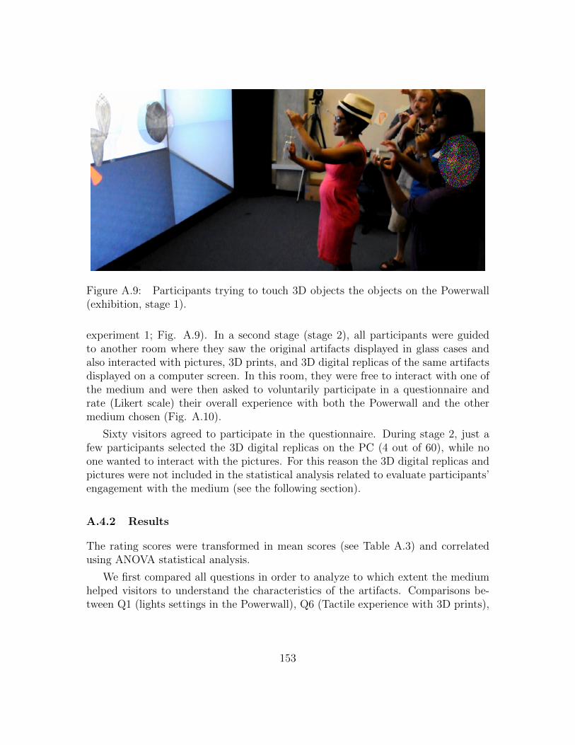
Figure A.9: Participants trying to touch 3D objects the objects on the Powerwall(exhibition, stage 1).
experiment 1; Fig. A.9). In a second stage (stage 2), all participants were guidedto another room where they saw the original artifacts displayed in glass cases andalso interacted with pictures, 3D prints, and 3D digital replicas of the same artifactsdisplayed on a computer screen. In this room, they were free to interact with one ofthe medium and were then asked to voluntarily participate in a questionnaire andrate (Likert scale) their overall experience with both the Powerwall and the othermedium chosen (Fig. A.10).
Sixty visitors agreed to participate in the questionnaire. During stage 2, just afew participants selected the 3D digital replicas on the PC (4 out of 60), while noone wanted to interact with the pictures. For this reason the 3D digital replicas andpictures were not included in the statistical analysis related to evaluate participants’engagement with the medium (see the following section).
A.4.2 Results
The rating scores were transformed in mean scores (see Table A.3) and correlatedusing ANOVA statistical analysis.
We first compared all questions in order to analyze to which extent the mediumhelped visitors to understand the characteristics of the artifacts. Comparisons be-tween Q1 (lights settings in the Powerwall), Q6 (Tactile experience with 3D prints),
153

Figure A.10: Participants interacting with original artifacts inside cases (left) andwith 3D prints (right; exhibition stage 2).
and Q10 (visual experience with original objects) revealed no statistical differencebetween the three conditions. However, looking at the means, we noticed that whilethese values almost coincided when observing Powerwall and Look conditions, theyare slightly higher in the 3D prints condition (i.e., the tactile experience was ratedhigher).
When comparing Q2 (removing color from digital artifacts in the PW) to Q6(Tactile experience with 3D prints), and Q10 (visual experience with original objects)revealed statistical difference between 3D prints and Powerwall conditions, F (2, 54) =3.52; p = .037.
In summary, the possibility of changing light settings in the Powerwall was con-sidered almost as useful as touching 3D prints or looking at original artifacts for theunderstanding of the objects’ physical qualities. On the other hand, the ability ofremoving original colors from the 3D digital models was not considered as effectiveas touching 3D prints.
Second, we compared all questions in order to analyze which of the three con-ditions/media participants considered most helpful for the artifacts’ understanding(Q3, Q7, Q11). Statistical analysis showed no reliable difference between the threeconditions. However the mean values for Powerwall and 3D prints conditions werehigher suggesting how these conditions were considered slightly more helpful thanLook to appreciate the artifacts.
154

Table A.3: Questionnaire Experiment 3 excerpt. Likert scale with 1 being StronglyDisagree and 9 being Strongly Agree.
PowerwallM SD
Q1. The possibility to select appropriate lights improved my understanding of the artifactscharacteristics
7.45 1.54
Q2. The possibility to remove original colors of the artifacts improved my understanding ofthe artifacts characteristics
6.5 2.37
Q3. The ability to use the Powerwall (full scale 3D screen) was very helpful compared to atraditional museum display
7.8 1.7
Q4. The Powerwall system seems to be a good approach to interact with ancient artifacts 8.2 1.11Q5. This experience with 3D digital artifacts was engaging 8.9 0.31
3D PrintsQ6. The possibility to touch 3D printed artifacts improved my understanding of the artifactscharacteristics
8.00 1.08
Q7. The ability to interact with 3D printed artifacts was very helpful compared to interactingwith 3D digital artifacts in the Powerwall
7.6 1.5
Q8. 3D prints seem to be a good approach to interact with ancient artifacts 8.05 1.05Q9. This experience with 3D prints was engaging 8.3 0.86
LookQ10. The possibility to look at original artifacts through a display improved my understand-ing of the artifacts’ characteristics
7.47 1.74
Q11. The ability to look at the artifacts was very helpful compared to interacting with 3Ddigital copies in the Powerwall
6.64 1.98
Q12. Traditional display seems to be a good approach to interact with ancient artifacts 7.35 2.12Q13. This experience with original artifacts was engaging 7.12 2.20
Third, comparing questions aiming at rating the overall effectiveness of eachmedium (Q4, Q8, Q12), we did not find any reliable difference. However, on averagethe Powerwall and 3D prints were considered slightly more effective than Look tointeract with ancient artifacts.
Finally, when comparing all questions aimed at rating engagement within eachcondition, we found that the Powerwall and 3D prints conditions were consideredsignificantly more engaging than the Look condition, F (2, 54) = 8.58; p = .001. Thequestionnaire ended with a multiple choice question in which we asked participantsto compare the experience they had with the Powerwall to that they had with themedium selected during stage 2, and an open-ended question in which we asked toexplain why they preferred a particular experience. As mentioned before picturesand 3D replicas on PC screen were not included in the analysis, since just a fewparticipants interacted with these two media (3D digital copies on a PC: 4 out of60; pictures: 0). Yet, it is interesting to notice that 3 out of the 4 participantswho interacted with the 3D digital copies on the PC screen preferred the Powerwall
155

experience and one was neutral.
Comparisons between Powerwall and the remaining conditions (Look and 3Dprints) revealed that participants interacting with original artifacts exhibited in glasscases preferred the experience with the Powerwall, X2(2, N = 18) = 2.12, p = 0.03.Most of the participants who expressed their preference for 3D prints and Powerwallexplained that these experiences were more engaging because they could touch (i.e.,with the 3D prints) or “almost” touch the objects (i.e. in the Powerwall).
A.5 Discussion
The presented studies investigated how different presentation modalities influencethe understanding of artifacts. We were especially interested in how people wouldinteract with, understand, and describe objects with three different conditions: visualexperience with authentic artifacts, 3D digital reconstructions in the Powerwall, and3D prints. Participants described ancient artifacts in front of a video camera.
The results from our experiments show how the different presentation modalitiesaffect the perception of different characteristics of the objects. With respect toweight information, our findings show that, in an immersive 3D reality situationparticipants perceive objects’ weight similarly to what people would perceive in amuseum (i.e., looking at original artifacts located in a case). In both cases theweight estimation relies on pure visual cues that, in our opinion, would force theparticipant to think about the original material more carefully. Moreover, similarlyto the discussion presented by [119], Immersive VR systems expose users to visualcues that make it difficult to estimating the weight of an object. In the VR mediumthe weight estimation is similar to the real looking scenario. Using 3D Prints theparticipant may have based its judgment on the actual weight of the object held.However, because of the unavailability of the original artifacts we could not comparethe weight estimation of the three media with an estimation of the weights from theoriginals.
With regard to color information (color grain, variation, and tonality) of the arti-facts selected for the experiment, Powerwall and Look conditions give a similar levelof perception, indicating the ability of the Powerwall system to well display this kindof information. This finding is reinforced by the fact that participants in experi-ment 2 indicated light variation as an effective means to perceive and understandthe artifacts.
With respect to size, the Look, Powerwall and 3D prints conditions show very
156

similar results for both the ceramic vessel and the projectile point, which have a sizenot at all close to that of the reference object (an apple). For the grinding stoneand the Buddhist objects instead, whose size is closer to that of the reference point,statistical analysis shows how these two objects are considered significantly smallerin the Powerwall than in the Look condition. This finding reinforces the idea thatdistance and size misestimation in immersive virtual environments is higher thanin real scenarios (Naceri et al. [236] & Thompson et al. [351]), even for virtualreconstruction of archaeological objects.
Regarding texture qualities, the projectile point is the only one of the objectsused for the experiment for which we found a reliable difference when we comparedparticipants in the Powerwall and 3D prints conditions to participants in the Lookcondition. The latter participants, in fact, perceived this object as considerablysmoother than their peers in the other two conditions. Our finding suggests thatin presence of small, bright, and light-colored objects, visual cues are not enough toaccurately perceive texture qualities. Based on this finding while participants in theLook condition could grasp the sense of texture of the objects only based on visualcues, participants in the Powerwall could rely on multi-visualization tools, such asdifferent light settings and the possibility to zoom in and remove original colorsfrom the 3D models, to grasp textural information. To reinforce this statement wefound that more than one participant stressed the importance of removing colorsand changing light settings for perceiving texture qualities. One participant said:“watching the chrome object [i.e., object without original colors], I was able to seedifferent, other details that I was not able to see with the original colors” (emphasison the original interview).
The qualitative analysis of gestures (experiment n. 2) shows that, in absenceof a tactile experience, people produce some stereotypical iconic gestures to mimicactions they would perform if they were actually touching the artifacts. The iconicgestures performed often convey spatial information; they help people mimic objectmanufacturing and function. Gestures can also be used to describe details of shapeand also help people figure out the size of an object.
As noted, when people described objects they also produced beat gestures (whichdo not convey any meaning per se). The results of this experiment show how partic-ipants looking at original artifacts inside cases generated the fewest gestures.
Conversely, participants interacting with objects in the Powerwall used the high-est number of beat gestures. The high number of beat gestures was reliably differentfrom the number of gestures produced by participants in the Look and 3D printscondition. The difference with the 3D prints does not really surprise, since partic-
157

ipants were talking while holding the objects, thus it was more difficult for themto perform gestures. What is more surprising is the difference between Look andPowerwall conditions. In both cases participants had their hands free while talk-ing. It is possible that the cases represented a psychological barrier that inhibitedparticipants’ direct experience with the objects. This idea is reinforced by the factthat, when they interacted with these objects, they kept their hands far from thecase (i.e., they seemed afraid of touching it) (see Figure A.2). Conversely, followingKrauss [173], who argued that beat gestures often facilitate lexical access, it is pos-sible that the high number of beat gestures reflects a lack of certainty about artifactdetails (i.e., participants were less certain about what they were talking about, butit might also indicate that in the immersive system participants recognized a differ-ence, a frame, between the physical and the virtual world and tried to fill this gapusing gestures. Another suggestive explanation, which would need further analysis,might be linked with the engagement participants had while interacting with thePowerwall, how demonstrated by the results of Experiment 3. In that case the highnumber of beat gestures might be directly correlated with the excitement people hadwhile interacting with the Powerwall.
Experiment 3 was mainly designed to collect metacognitive information on howuseful the participants considered each experience for the perception and understand-ing of the artifacts proposed and how engaging the experience with each conditionwas. Overall Powerwall and 3D prints were considered more helpful and more en-gaging than the visual experience with real artifacts.
A.6 Conclusions
We presented three experiments aimed at understanding how people, interact, per-ceive and engage with past material culture in different media states. Our resultsdemonstrate the potential of new technologies and help design best practices anddesign choices for improving museum displays in museums and other exhibitions.
Results from experiment 1, which focused on the perception of specific character-istics of ancient artifacts in different media states, revealed that the media selectedfor the experiment affect the perception of physical qualities of artifacts in differ-ent ways. The immersive experience with the Powerwall and visual experience withoriginal artifacts resulted in similar perception patterns for color and weight; thesecharacteristics are difficult to perceive with the 3D prints; as a result, the misinter-pretation of weight and color might also bring to misinterpretation of other qualities(e.g., material) and of the function of the artifacts. While experiencing the objects
158

in the powerwall resulted in size misinterpretation, it was a useful mean to recognizetexture qualities, especially for small and bright objects.
Results from experiment 2, aimed at investigating how we describe and interactwith ancient artifacts through our body, suggests that traditional museum settingsmay diminish or limit museum users degree of engagement with ancient artifacts.
The latter finding seems reinforced from the results of experiment 3, which giveus insights into people’s engagement with artifacts through different media. Theseresults suggest that, in absence of a tactile experience with original artifacts, our sam-ple of participants favored a tactile or semi-tactile experience with replicas to thevisual experience with original ancient objects. In other words, these participantswere ready to negotiate with the inauthentic in order to have a tactile embodiedexperience. Even though some of these results might seem obvious to scholars whodesign and test immersive systems, they can be noteworthy for scholars in the her-itage, archaeology and museum domains. This is because ancient artifacts are aunique type of objects, which carry information about past cultures. Thus, we ex-pected that authentic artifacts displayed in a case would trigger emotions that 3Dcopies (virtual and real) could not equal. On the contrary our findings show thatthe conditions Powerwall and 3D prints were most appreciated, suggesting how oursample of participants are more concerned with experiencing an object through thesenses rather than having the original in front of them. Similar findings have beenreported by other studies ([380, 222, 352]).
Our findings bring us to re-consider how we approach museum displays today,since visitors seem to claim for an active experience with the past, which empha-sizes a kinesthetic engagement with the museum environment. These findings alsosuggest that although new technologies are not yet able to reproduce in full the per-ception that people would have manipulating original artifacts, these technologiesproduce excitement and engagement, encouraging curiosity, attention, and desire forknowledge of past material culture.
Our study represents a starting point for the creation of a protocol or methodologythat envisages the integration of different technologies within a museum. It wouldbe interesting, for instance, to see what happens to perception, engagement, andunderstanding if visitors interact with an object in a 3D immersive environment, orthrough a 3D print first, and then visit the showcase in which the original counterpartis showcased.
In sum this analysis shows that people like to engage with new technologies tounderstand ancient artifacts and point to the integrated use of traditional display,3D immersive systems, and 3D prints as an effective way to increase perception, un-
159

derstanding, and engagement with artifacts, as well as favoring a diverse populationof museum visitors.
While our current work uncovers some first observations in this area, there isplenty of further development worth exploring. It would be critical, for instance,to investigate what may be influences (ethnicity, gender, education, socio-economicbackground) in varying perceptions of authenticity in relation to objects, virtual andreal. And importantly, how these results might vary across cultures. It would alsobe interesting to explore how people with particular affiliation with tangible heritageinteract with both authentic objects and their reproductions in different media states.
160

References
[1] 5dt. 5dt Data Gloves, 2014 (accessed September 20, 2014).http://www.5dt.com.
[2] S.J. Ahn and J.N. Bailenson. Self-endorsing versus other-endorsing in virtualenvironments. Journal of Advertising, 40(2):93–106, 2011.
[3] S.J. Ahn, J.N. Bailenson, and D. Park. Short-and long-term effects of embod-ied experiences in immersive virtual environments on environmental locus ofcontrol and behavior. Computers in Human Behavior, 39:235–245, 2014.
[4] J. Ahrens and J. Painter. Efficient sort-last rendering using compression-basedimage compositing. In in Proceedings of the 2nd Eurographics Workshop onParallel Graphics and Visualization, pages 145–151, 1998.
[5] G. Alankus, R. Proffitt, C. Kelleher, and J. Engsberg. Stroke therapy throughmotion-based games: A case study. In Proceedings of the 12th InternationalACM SIGACCESS Conference on Computers and Accessibility, ASSETS ’10,pages 219–226, New York, NY, USA, 2010. ACM.
[6] A. Alaraj, M. Lemole, J. Finkle, R. Yudkowsky, A. Wallace, C. Luciano,P. Banerjee, S. Rizzi, and F. Charbel. Virtual reality training in neurosurgery:Review of current status and future applications. Surgical Neurology Interna-tional, 2(1):52, 2011.
[7] D. Alberge. Van Gogh in 3D? A replica could be yours for22,000. Museum develops hi-tech replicas of Dutch master accu-rate right down to the frame, 2014 (accessed September 20, 2014).http://www.theguardian.com/artanddesign/2013/aug/24/3d-replicas-van-gogh.
[8] P.L. Alfano and G.F. Michel. Restricting the field of view: perceptual andperformance effects. Perceptual and motor skills, 70(1):35–45, Feb 1990.
[9] J. Allard, V. Gouranton, L. Lecointre, E. Melin, and B. Raffin. Net juggler:running vr juggler with multiple displays on a commodity component cluster.In Virtual Reality, 2002. Proceedings. IEEE, pages 273–274, 2002.
[10] J. Allard, C. Menier, E. Boyer, and B. Raffin. Running large vr applications ona pc cluster: The flow vr experience. In Proceedings of the 11th Eurographics
161

Conference on Virtual Environments, EGVE’05, pages 59–68, Aire-la-Ville,Switzerland, Switzerland, 2005. Eurographics Association.
[11] F. Anderson, T. Grossman, J. Matejka, and G.W. Fitzmaurice. YouMove:enhancing movement training with an augmented reality mirror. In Proceedingsof User Interface Software and Technology (UIST), pages 311–320. ACM, 2013.
[12] B.D. Argall, B. Browning, and M. Veloso. Learning by demonstration withcritique from a human teacher. In Proceedings of the ACM/IEEE internationalconference on Human-robot interaction, pages 57–64. ACM, 2007.
[13] B.D. Argall, S. Chernova, M. Veloso, and B. Browning. A survey of robotlearning from demonstration. Robotics and Autonomous Systems, 57(5):469–483, May 2009.
[14] O. Arikan and D.A. Forsyth. Synthesizing constrained motions from examples.ACM Transactions on Graphics, 21(3):483–490, 2002.
[15] O. Arikan, D.A. Forsyth, and J.F. O’Brien. Motion synthesis from annotations.In ACM SIGGRAPH 2003 Papers, SIGGRAPH ’03, pages 402–408, New York,NY, USA, 2003. ACM.
[16] C. Armbruster, M. Wolter, T. Kuhlen, W. Spijkers, and B. Fimm. Depthperception in virtual reality: distance estimations in peri and extrapersonalspace. Cyberpsychology Behavior, 11(1):9–15, Feb 2008.
[17] S. Arteaga, J. Chevalier, A. Coile, A.W. Hill, S. Sali, S. Sudhakhrisnan, andS.H. Kurniawan. Low-cost accelerometry-based posture monitoring system forstroke survivors. In Proceedings of the 10th International ACM SIGACCESSConference on Computers and Accessibility, Assets ’08, pages 243–244, NewYork, NY, USA, 2008. ACM.
[18] K.W. Arthur. Effects of field of view on performance with head-mounted dis-plays. Doctor of Philosophy, Computer Science. The University of North Car-olina at Chapel Hill, 2000.
[19] American Physical Therapy Association. Guide to Physical Therapist Practice.Rev 2nd Ed. American Physical Therapy Association, Alexandria, VA, 1999.
[20] ATI. ATI Eyefinity Technology, 2014 (accessed September 20, 2014).http://www.amd.com/en-us/innovations/software-technologies/eyefinity.
162

[21] A.P. Atkinson, W.H. Dittrich, A.J. Gemmell, and A.W. Young. Emotion per-ception from dynamic and static body expressions in point-light and full-lightdisplays. Perception, 33(6):717–746, 2004.
[22] N.I. Badler, C.B. Phillips, and B.L. Webber. Simulating Humans: ComputerGraphics Animation and Control. Oxford University Press, Inc., New York,NY, USA, 1993.
[23] M. Balaam, S. Rennick Egglestone, G. Fitzpatrick, T. Rodden, A. Hughes,A. Wilkinson, T. Nind, L. Axelrod, E. Harris, I. Ricketts, et al. Motivatingmobility: designing for lived motivation in stroke rehabilitation. In Proceedingsof the SIGCHI Conference on Human Factors in Computing Systems, pages3073–3082. ACM, 2011.
[24] B.D. Balaguer and S. Carpin. A learning method to determine how to approachan unknown object to be grasped. International Journal of Humanoid Robotics,8(03):579–606, 2011.
[25] R. Ball and C. North. Effects of tiled high-resolution display on basic visualiza-tion and navigation tasks. In CHI ’05 Extended Abstracts on Human Factorsin Computing Systems, CHI EA ’05, pages 1196–1199, New York, NY, USA,2005. ACM.
[26] A.G. Barto. Reinforcement learning: An introduction. MIT press, 1998.
[27] D. Bartz, X. Pueyo, and E. Reinhard. Out-of-core sort-first parallel render-ing for cluster-based tiled displays. In in Proceedings of the 4th EurographicsWorkshop on Parallel Graphics and Visualization, 2002.
[28] J. B. Bavelas, N. Chovil, D. A. Lawrie, and A. Wade. Interactive gestures.Discourse processes, 15(4):469–489, 1992.
[29] F. Bellotti, B. Kapralos, K. Lee, P. Moreno-Ger, and R. Berta. Assessment inand of serious games: An overview. Advances in Human-Computer Interaction,2013:1:1–1:1, January 2013.
[30] S. Benford, J. Bowers, L. E. Fahln, C. Greenhalgh, J. A. Mariani, and T. Rod-den. Networked virtual reality and cooperative work. Presence, 4(4):364–386,1995.
[31] H. Benko, E.W. Ishak, and S. Feiner. Collaborative mixed reality visualiza-tion of an archaeological excavation. In Mixed and Augmented Reality, 2004.
163

ISMAR 2004. Third IEEE and ACM International Symposium on, pages 132–140, Nov 2004.
[32] M. Bergamasco. Le musee des formes pures. In 8th IEEE International Work-shop on Robot and Human Interaction, RO-MAN, volume 99, pages 27–29,1999.
[33] P. Bhaniramka, P.C.D. Robert, and S. Eilemann. Opengl multipipe sdk: atoolkit for scalable parallel rendering. In Visualization, 2005. VIS 05. IEEE,pages 119–126, Oct 2005.
[34] A. Bierbaum and C. Just. Software tools for virtual reality application devel-opment. In Proceedings of the 25th Annual Conference on Computer Graphicsand Interactive Techniques, SIGGRAPH ’98, pages 3.1–3.45, New York, NY,USA, July 1998. ACM.
[35] A. Bierbaum, C. Just, P. Hartling, K. Meinert, A. Baker, and C. Cruz-Neira.Vr juggler: A virtual platform for virtual reality application development. InProceedings of the Virtual Reality 2001 Conference (VR’01), VR ’01, pages89–, Washington, DC, USA, 2001. IEEE Computer Society.
[36] A. Billard, S. Calinon, R. Dillmann, and S. Schaal. Robot programming bydemonstration. In B. Siciliano and O. Khatib, editors, Springer Handbook ofRobotics, pages 1371–1394. Springer Berlin Heidelberg, 2008.
[37] A. Billard and M.J. Mataric. Learning human arm movements by imitation:Evaluation of a biologically inspired connectionist architecture. Robotics andAutonomous Systems, 37:2-3:145–160, November, 30 2001.
[38] R. Blake and M. Shiffrar. Perception of Human Motion. Annual Review ofPsychology, 58(1):47–73, 2007.
[39] J. Blascovich and J.N. Bailenson. Infinite Reality - Avatars, Eternal Life, NewWorlds, and the Dawn of the Virtual Revolution. William Morrow, New York,2011.
[40] B. Bonnechere, B. Jansen, P. Salvia, H. Bouzahouene, L. Omelina, J. Cornelis,M. Rooze, and S. Van Sint Jan. What are the current limits of the kinect sensor.In Proc 9th Intl Conf. Disability, Virutal Reality & Associated Technologies,Laval, France, pages 287–294, 2012.
164

[41] R. Boulic and D. Raunhardt. Integrated analytic and linearized inverse kine-matics for precise full body interactions. In Arjan Egges, Roland Geraerts, andMark Overmars, editors, Motion in Games, volume 5884 of Lecture Notes inComputer Science, pages 231–242. Springer Berlin Heidelberg, 2009.
[42] S. Bradshaw, A. Bowyer, and P. Haufe. The intellectual property implicationsof low-cost 3d printing. ScriptEd, 7(1):5–31, 2010.
[43] C. Breazeal, M. Berlin, A. Brooks, J. Gray, and A.L. Thomaz. Using perspec-tive taking to learn from ambiguous demonstrations. Robotics and AutonomousSystems, 54(5):385–393, 2006.
[44] O. Breeben. Introduction to Physical Therapy for Physical Therapy Assistants.Jones and Barlett, Sudbury, MA, 2007.
[45] H. Brenton, M. Gillies, D. Ballin, and D. Chatting. The uncanny valley: doesit exist. In 19th British HCI Group Annual Conference: workshop on human-animated character interaction, 2005.
[46] S.A. Brewster. The impact of haptic touchingtechnology on cultural applica-tions. In Proceedings of EVA, volume 1, pages 1–14, 2001.
[47] Jurgen Broeren, Martin Rydmark, and Katharina Stibrant Sunnerhagen. Vir-tual reality and haptics as a training device for movement rehabilitation afterstroke: a single-case study. Archives of physical medicine and rehabilitation,85(8):1247–1250, 2004.
[48] A. Bruderlin and L. Williams. Motion signal processing. In Proceedings of the22Nd Annual Conference on Computer Graphics and Interactive Techniques,SIGGRAPH ’95, pages 97–104, New York, NY, USA, 1995. ACM.
[49] J.W. Burke, M. McNeill, D. Charles, P. Morrow, J. Crosbie, and S. Mc-Donough. Serious games for upper limb rehabilitation following stroke. InProceedings of the 2009 Conference in Games and Virtual Worlds for SeriousApplications, VS-GAMES ’09, pages 103–110, Washington, DC, USA, 2009.IEEE Computer Society.
[50] P. Buttolo, P. Stewart, and Y. Chen. Force-enabled sculpting of cad mod-els. Proceedings of ASME (American Society of Mechanical Engineers)IMECE2000, International Mechanical Engineering Congress and Exposition,2000.
165

[51] S. Calinon. Robot programming by demonstration. EPFL Press, 2009.
[52] S. Calinon and A. Billard. Incremental learning of gestures by imitation in ahumanoid robot. In Proceedings of the ACM/IEEE International Conferenceon Human-robot Interaction, HRI ’07, pages 255–262, New York, NY, USA,2007. ACM.
[53] M. Cameirao, B. Bermudez, and P. Verschure. Virtual reality based upperextremity rehabilitation following stroke: a review. Journal of CyberTherapy& Rehabilitation, 1(1):63–74, 2008.
[54] C. Camporesi, Y. Huang, and M. Kallmann. Interactive motion modeling andparameterization by direct demonstration. In Proceedings of the 10th Interna-tional Conference on Intelligent Virtual Agents, IVA’10, pages 77–90, Berlin,Heidelberg, 2010. Springer-Verlag.
[55] M. Carrozzino and M. Bergamasco. Beyond virtual museums: Experienc-ing immersive virtual reality in real museums. Journal of Cultural Heritage,11(4):452–458, 2010.
[56] J. Cassell. Embodied conversational agents: Representation and intelligencein user interfaces. Artificial Intelligence Magazine, 22(4):67–83, October 2001.
[57] CAVELib. CAVELib virtual reality software, 2014 (accessed September 20,2014). http://www.mechdyne.com/cavelib.aspx.
[58] X. Cavin, C. Mion, and A Filbois. Cots cluster-based sort-last rendering:performance evaluation and pipelined implementation. In Visualization, 2005.VIS 05. IEEE, pages 111–118, Oct 2005.
[59] J. Chai and J.K. Hodgins. Performance animation from low-dimensional con-trol signals. In SIGGRAPH ’05: ACM SIGGRAPH 2005 Papers, pages 686–696, New York, NY, USA, 2005. ACM.
[60] T. Chaminade, J.K. Hodgins, and M. Kawato. Anthropomorphism influencesperception of computer-animated characters’s actions. In Social Cognitive andAffective Neuroscience. Books (MIT Press, 2007.
[61] C. Chang. The design of a shoulder rehabilitation game system. In 2010 IETInternational Conference on Frontier Computing. Theory, Technologies andApplications, pages 151–156, 2010.
166

[62] Y. Chang, S. Chen, and J. Huang. A kinect-based system for physical reha-bilitation: A pilot study for young adults with motor disabilities. Research inDevelopmental Disabilities, 32(6):2566 – 2570, 2011.
[63] A. Chella, H. Dindo, and I. Infantino. A cognitive framework for imitationlearning. Robotics and Autonomous Systems, 54(5):403–408, 2006.
[64] J. Chen, H. Cai, A. P. Auchus, and D. H. Laidlaw. Effects of stereo andscreen size on the legibility of three-dimensional streamtube visualization.IEEE Transactions on Visualization and Computer Graphics, 18(12):2130–2139, 2012.
[65] J. Chen and A. Zelinsky. Programing by demonstration: Coping with sub-optimal teaching actions. The International Journal of Robotics Research,22(5):299–319, 2003.
[66] C.C. Chiu and S. Marsella. A style controller for generating virtual humanbehaviors. In The 10th International Conference on Autonomous Agents andMultiagent Systems - Volume 3, AAMAS ’11, pages 1023–1030, Richland, SC,2011. International Foundation for Autonomous Agents and Multiagent Sys-tems.
[67] C.K. Chua, K.F. Leong, and C.S. Lim. Rapid Prototyping: Principles andApplications. World Scientific, 2010.
[68] A. Clark. Natural-born cyborgs: Minds, technologies, and the future of humanintelligence. Oxford University Press, 2004.
[69] R.A. Clark, Y. Pua, K. Fortin, C. Ritchie, K.E. Webster, L. Denehy, and A.L.Bryant. Validity of the microsoft kinect for assessment of postural control.Gait & posture, 36(3):372–377, 2012.
[70] C. Colwell, H. Petrie, D. Kornbrot, A. Hardwick, and S. Furner. Haptic virtualreality for blind computer users. In Proceedings of the Third International ACMConference on Assistive Technologies, Assets ’98, pages 92–99, New York, NY,USA, 1998. ACM.
[71] S. Cooper, A. Hertzmann, and Z. Popovic. Active learning for real-time motioncontrollers. In ACM SIGGRAPH 2007 Papers, SIGGRAPH ’07, New York,NY, USA, 2007. ACM.
167

[72] C. Cruz-Neira, D. J. Sandin, and T. A. DeFanti. Surround-screen projection-based virtual reality: the design and implementation of the cave. In Proc. ofthe 20th annual conference on Computer graphics and interactive techniques,SIGGRAPH ’93, pages 135–142, New York, NY, USA, 1993. ACM.
[73] C. Cruz-Neira, D. J. Sandin, T. A. DeFanti, R. V. Kenyon, and J. C. Hart. Thecave: audio visual experience automatic virtual environment. Communicationsof the ACM, 35(6):64–72, 1992.
[74] J.E. Cutting and L.T. Kozlowski. Recognizing Friends By Their Walk - GaitPerception Without Familiarity Cues. Bulletin Of The Psychonomic Society,9(5):353–356, 1977.
[75] A. Cypher and D.C. Halbert. Watch what I do: programming by demonstra-tion. MIT press, 1993.
[76] J. Demiris and G. Hayes. Imitation as a dual-route process featuring predic-tive and learning components; a biologically plausible computational model.Imitation in animals and artifacts, page 327, 2002.
[77] J.E. Deutsch, J. Latonio, G.C. Burdea, and R. Boian. Post-stroke rehabilita-tion with the rutgers ankle system: A case study. Presence: Teleoper. VirtualEnviron., 10(4):416–430, August 2001.
[78] P. Di Giuseppantonio Di Franco, C. Camporesi, F. Galeazzi, and M. Kall-mann. 3d printing and immersive visualization for improved perception andinteraction with past material culture. Presence: Teleoperators and VirtualEnvironments, in printing, 2015.
[79] P. Di Giuseppantonio Di Franco and F. Galeazzi. Western han dynasty muraltombs:from the use of integrated technologies to the cybermap. In Proceedingsof the 38th Annual Conference on Computer Applications and QuantitativeMethods in Archaeology,, volume 2494 of CAA 2010. BAR International, 2013.
[80] P. Di Giuseppantonio Di Franco, F. Galeazzi, and C. Camporesi. 3d virtual dig:a 3d application for teaching fieldwork in archaeology. In Internet Archaeology,32, 2012.
[81] Digia. Qt Project, 2014 (accessed September 20, 2014). http://qt-project.org.
168

[82] K.U. Doerr and F. Kuester. Cglx: A scalable, high-performance visualizationframework for networked display environments. Visualization and ComputerGraphics, IEEE Transactions on, 17(3):320–332, March 2011.
[83] M. Dontcheva, G. Yngve, and Z. Popovic. Layered acting for character anima-tion. ACM Transactions on Graphics, 22(3):409–416, 2003.
[84] R. Doonan and M. Boyd. Contact: digital modelling of object and process inartefact teaching. Touch in Museums: policy and practice in object handling,pages 107–120, 2008.
[85] S. Dudley. Museum materialities: Objects, engagements, interpretations.Routledge, 2013.
[86] P.S. Dukes, A. Hayes, L.F. Hodges, and M. Woodbury. Punching ducks forpost-stroke neurorehabilitation: System design and initial exploratory feasibil-ity study. In 3D User Interfaces (3DUI), 2013 IEEE Symposium on, pages47–54, March 2013.
[87] S. Eilemann, M. Makhinya, and R. Pajarola. Equalizer: A scalable parallel ren-dering framework. Visualization and Computer Graphics, IEEE Transactionson, 15(3):436 –452, may-june 2009.
[88] FLTK. FLTK: Fast Light Toolkit, 2014 (accessed September 20, 2014).http://www.fltk.org.
[89] S. Follmer, D. Leithinger, A. Olwal, A. Hogge, and H. Ishii. inform: dynamicphysical affordances and constraints through shape and object actuation. InUIST, pages 417–426, 2013.
[90] M. Forte. La villa di Livia: un percorso di ricerca di archeologia virtuale,volume 41. L’Erma di Bretschneider, 2007.
[91] J. Fox and J.N. Bailenson. Virtual self-modeling: The effects of vicarious rein-forcement and identification on exercise behaviors. Media Psychology, 12(1):1–25, 2009.
[92] M. Gabel, R. Gilad-Bachrach, E. Renshaw, and A. Schuster. Full body gaitanalysis with kinect. In Engineering in Medicine and Biology Society (EMBC),2012 Annual International Conference of the IEEE, pages 1964–1967. IEEE,2012.
169

[93] B. Galna, G. Barry, D. Jackson, D. Mhiripiri, P. Olivier, and L. Rochester.Accuracy of the microsoft kinect sensor for measuring movement in peoplewith parkinson’s disease. Gait & Posture, 39(4):1062 – 1068, 2014.
[94] J. Gascon, J.M. Bayona, J.M Espadero, and M.A. Otaduy. Blendercave: Easyvr authoring for multi-screen displays. In Proceedings of the Ibero-AmericanSymposium in Computer Graphics, SIACG 2011, Otaduy, Spain, 2011. GeorgiaInstitute of Technology.
[95] D. M. Gavrila. The visual analysis of human movement: A survey. ComputerVision and Image Understanding, 73(1):82–98, January 1999.
[96] P. Gebhard, M. Kipp, M. Klesen, and T. Rist. What are they going to talkabout? towards life-like characters that reflect on interactions with users. InProc. of the 1st International Conference on Technologies for Interactive DigitalStorytelling and Entertainment (TIDSE’03), 2003.
[97] L. Geurts, V. Vanden Abeele, J. Husson, F. Windey, M. Van Overveldt, J. An-nema, and S. Desmet. Digital games for physical therapy: fulfilling the needfor calibration and adaptation. In Proceedings of the fifth international confer-ence on Tangible, embedded, and embodied interaction, pages 117–124. ACM,2011.
[98] J.J. Gibson. The ecological approach to visual perception. Houghton Mifflin,1979.
[99] B. Gilliam. The perception of spatial layout from static optical information.In Perception of Space and Motion. W. Epstein and S. Rogers, eds. - AcademicPress, Inc, 1995.
[100] P. Glardon, R. Boulic, and D. Thalmann. D.: A coherent locomotion engineextrapolating beyond experimental data. In Proceedings of Computer Anima-tion and Social Agent, pages 73–84, 2004.
[101] gl.tter. WiiYourself !, 2014 (accessed September 20, 2014).http://wiiyourself.gl.tter.org.
[102] S. Goldin-Meadow. Hearing gesture: How our hands help us think. HarvardUniversity Press, 2005.
170

[103] M. R. Golomb, B. C. McDonald, S. J. Warden, J. Yonkman, A. J. Saykin,B. Shirley, M. Huber, B. Rabin, M. Abdelbaky, M. E. Nwosu, M. Barkat-Masih, and G. C. Burdea. In-home virtual reality videogame telerehabilitationin adolescents with hemiplegic cerebral palsy. Archives of physical medicineand rehabilitation, 91(1):1–8, Jan 2010.
[104] M.R. Golomb, M. Barkat-Masih, B. Rabin, M. AbdelBaky, M. Huber, andG. Burdea. Eleven months of home virtual reality telerehabilitation - lessonslearned. In Virtual Rehabilitation International Conference, 2009, pages 23–28,June 2009.
[105] F.S. Grassia. Practical parameterization of rotations using the exponentialmap. J. Graph. Tools, 3(3):29–48, March 1998.
[106] M. Grealy and B. Nasser. The use of virtual reality in assisting rehabilitation.Advances in Clinical Neuroscience and Rehabilitation, 13(9):19–20, 2013.
[107] A.D. Gregory, S.A. Ehmann, and M.C. Lin. intouch: interactive multireso-lution modeling and 3d painting with a haptic interface. In Virtual Reality,2000. Proceedings. IEEE, pages 45–52, 2000.
[108] DavidB. Grimes and RajeshP.N. Rao. Learning actions through imitation andexploration: Towards humanoid robots that learn from humans. In B. Send-hoff, E. Krner, O. Sporns, H. Ritter, and K. Doya, editors, Creating Brain-LikeIntelligence, volume 5436 of Lecture Notes in Computer Science, pages 103–138. Springer Berlin Heidelberg, 2009.
[109] Grinning Lizard. Tiny XML, 2014 (accessed September 20, 2014).http://www.grinninglizard.com/tinyxml.
[110] K. Grochow, S.L. Martin, A. Hertzmann, and Z. Popovic. Style-based inversekinematics. ACM Trans. Graph., 23(3):522–531, August 2004.
[111] R.E. Guadagno, J. Blascovich, J.N. Bailenson, and C. Mccall. Virtual hu-mans and persuasion: The effects of agency and behavioral realism. MediaPsychology, 10(1):1–22, 2007.
[112] A. Gupta and M.K. OMalley. Robotic Exoskeletons for Upper Extremity Reha-bilitation, pages 371–396. I-Tech Education and Publishing, Vienna, Austria,2007.
171

[113] M. Gutierrez, P. Lemoine, D. Thalmann, and F. Vexo. Telerehabilitation:Controlling haptic virtual environments through handheld interfaces. In Pro-ceedings of the ACM Symposium on Virtual Reality Software and Technology,VRST ’04, pages 195–200, New York, NY, USA, 2004. ACM.
[114] M. Gutierrez, F. Vexo, and D. Thalmann. Stepping into Virtual Reality.Springer-Verlag TELOS, Santa Clara, CA, USA, 1 edition, 2008.
[115] J.J. Han, G. Kurillo, R.T. Abresch, E. de Bie, A. Nicorici Lewis, and R. Bajcsy.Upper extremity 3d reachable workspace analysis in dystrophinopathy usingkinect. Muscle & nerve, 2015.
[116] Reflexion Health, 2014 (accessed September 20, 2014).http://www.reflexionhealth.com.
[117] R. Heck and M. Gleicher. Parametric motion graphs. In Proceedings of the2007 Symposium on Interactive 3D Graphics and Games, I3D ’07, pages 129–136, New York, NY, USA, 2007. ACM.
[118] C. Hecker, B. Raabe, R.W. Enslow, J. DeWeese, J. Maynard, and K. van Prooi-jen. Real-time motion retargeting to highly varied user-created morphologies.ACM Trans. Graph., 27(3):27:1–27:11, August 2008.
[119] E. Heineken and F. P. Schulte. Seeing size and feeling weight: The size-weightillusion in natural and virtual reality. Human Factors: The Journal of theHuman Factors and Ergonomics Society, 49(1):136–144, 2007.
[120] B. Herbelin, P. Benzaki, F. Riquier, O. Renault, and D. Thalmann. Usingphysiological measures for emotional assessment: a computer-aided tool forcognitive and behavioural therapy. In ICDVRAT 2004, VRLAB-CONF-2007-010, pages 307–314, 2004.
[121] H.E. Hershfield, D.G. Goldstein, W.F. Sharpe, J. Fox, L. Yeykelis, L.L.Carstensen, and J.N. Bailenson. Increasing saving behavior through age-progressed renderings of the future self. Journal of Marketing Research,48(SPL):S23–S37, 2011.
[122] E.S.L. Ho, J.C.P. Chan, T. Komura, and H. Leung. Interactive partner controlin close interactions for real-time applications. ACM Transactions on Multi-media Computing, Communications, and Applications (TOMCCAP), 9(3):21,2013.
172

[123] E.S.L. Ho and T. Komura. Character motion synthesis by topology coordi-nates. Computer Graphics Forum, 28:299–308, 2009.
[124] E.S.L. Ho, T. Komura, and C. Tai. Spatial relationship preserving charactermotion adaptation. ACM Trans. Graph., 29(4):33:1–33:8, July 2010.
[125] H.G. Hoffmann. Physically touching virtual objects using tactile augmenta-tion enhances the realism of virtual environments. In Virtual Reality AnnualInternational Symposium, 1998. Proceedings., IEEE 1998, pages 59–63. IEEE,1998.
[126] M.K. Holden. Virtual environments for motor rehabilitation: review. Cyberp-sichology and Behavior, 8(3):187–211, 2005.
[127] M.K. Holden, T.A. Dyar, and E. Schwamm, L.and Bizzi. Virtual-environment-based telerehabilitation in patients with stroke. Presence: Teleoperators andVirtual Environments, 14(2):214–233, April 2005.
[128] M.K. Holden, E. Todorov, J. Callahan, and E. Bizzi. Virtual environmenttraining improves motor performance in two patients with stroke: case report.Journal of Neurologic Physical Therapy, 23(2):57–67, 1999.
[129] E.J.S. Hovenga. Health Informatics: An Overview. Studies in health technol-ogy and informatics. IOS Press, 2010.
[130] Y. Huang, C. Camporesi, and M. Kallmann. Immersive interfaces for build-ing parameterized motion databases. In Proceedings of the 12th InternationalConference on Intelligent Virtual Agents, IVA’12, pages 474–476, Berlin, Hei-delberg, 2012. Springer-Verlag.
[131] Y. Huang and M. Kallmann. Interactive demonstration of pointing gestures forvirtual trainers. In Proceedings of 13th International Conference on Human-Computer Interaction, San Diego, CA, 2009.
[132] Y. Huang and M. Kallmann. Motion parameterization with inverse blending.In Proceedings of the Third International Conference on Motion in Games,MIG’10, pages 242–253, Berlin, Heidelberg, 2010. Springer-Verlag.
[133] Y. Huang and M. Kallmann. Planning motions for virtual demonstrators. InTimothy Bickmore, Stacy Marsella, and Candace Sidner, editors, IntelligentVirtual Agents, volume 8637 of Lecture Notes in Computer Science, pages 190–203. Springer International Publishing, 2014.
173

[134] Y. Huang, M. Mahmudi, and M. Kallmann. Planning humanlike actions inblending spaces. In Intelligent Robots and Systems (IROS), 2011 IEEE/RSJInternational Conference on, pages 2653–2659, Sept 2011.
[135] J. Hummel, J. Dodiya, R. Wolff, A. Gerndt, and T. Kuhlen. An evaluation oftwo simple methods for representing heaviness in immersive virtual environ-ments. In 3D User Interfaces (3DUI), 2013 IEEE Symposium on, pages 87–94.IEEE, 2013.
[136] G. Humphreys, I. Buck, M. Eldridge, and P. Hanrahan. Distributed renderingfor scalable displays. In Supercomputing, ACM/IEEE 2000 Conference, pages30–30, Nov 2000.
[137] G. Humphreys, M. Houston, R. Ng, R. Frank, S. Ahern, P.D. Kirchner, andJ.T. Klosowski. Chromium: a stream-processing framework for interactiverendering on clusters. ACM Trans. Graph., 21(3):693–702, July 2002.
[138] E. Hutchins. Material anchors for conceptual blends. Journal of pragmatics,37(10):1555–1577, 2005.
[139] iCinema: centre for Interactive Cinema Research. iCASTS - MiningVR, 2014(accessed September 20, 2014). http://www.icinema.unsw.edu.au.
[140] A.J. Ijspeert, J. Nakanishi, and S. Schaal. Movement imitation with nonlineardynamical systems in humanoid robots. In Robotics and Automation, 2002.Proceedings. ICRA ’02. IEEE International Conference on, volume 2, pages1398–1403, 2002.
[141] i’m in VR. Middle VR: Unity VR Plug-In, 2014 (accessed September 20, 2014).http://www.imin.fr/middlevr.
[142] InnaLabs. InnaLabs miniAHRS m2 Users Manual, 2014 (accessed September20, 2014). http://www.innalabs.com.
[143] National Instruments. Introduction to Distributed Clock Synchronization andthe IEEE 1588 Precision Time Protocol, 2014 (accessed September 20, 2014).http://www.ni.com/white-paper/2822/en/.
[144] D. Jack, R. Boian, A. Merians, S.V. Adamovich, M. Tremaine, M. Recce, G.C.Burdea, and H. Poizner. A virtual reality-based exercise program for strokerehabilitation. In Proceedings of the Fourth International ACM Conference on
174

Assistive Technologies, Assets ’00, pages 56–63, New York, NY, USA, 2000.ACM.
[145] J. Jacobson, M. Le Renard, J. Lugrin, and M. Cavazza. The caveut system:immersive entertainment based on a game engine. In Proceedings of the 2005ACM SIGCHI International Conference on Advances in computer entertain-ment technology, ACE ’05, pages 184–187, New York, NY, USA, 2005. ACM.
[146] J. Jacobson and M. Lewis. Game engine virtual reality with caveut. Computer,38(4):79–82, April 2005.
[147] G. Jansson. Can a haptic force feedback display provide visually impairedpeople with useful information about texture roughness and 3d form of virtualobjects? In Proceedings of the 2nd European conference on disability, virtualreality, and associated technologies (ECDVRAT), pages 105–111, 1998.
[148] B. Jeong, L. Renambot, R. Jagodic, R. Singhm, J. Aguilera, A. Johnson, andJ. Leigh. High-performance dynamic graphics streaming for scalable adaptivegraphics environment. In SC 2006 Conference, Proceedings of the ACM/IEEE,pages 24–24, Nov 2006.
[149] W. L. Johnson, J. W. Rickel, and J. C. Lester. Animated pedagogical agents:Face-to-face interaction in interactive learning environments. InternationalJournal of Artificial intelligence in education, 11(1):47–78, 2000.
[150] S. Jorg, A. Normoyle, and A. Safonova. How responsiveness affects players’perception in digital games. In Proceedings of the ACM Symposium on AppliedPerception, SAP ’12, pages 33–38, New York, NY, USA, 2012. ACM.
[151] A. Juarez, B. Schonenberg, and C. Bartneck. Implementing a low-cost cavesystem using the cryengine2. Entertainment Computing, 1(3-4):157–164, 2010.
[152] Y. Jung, S. Yeh, and J. Stewart. Tailoring virtual reality technology for strokerehabilitation: A human factors design. In CHI ’06 Extended Abstracts onHuman Factors in Computing Systems, CHI EA ’06, pages 929–934, New York,NY, USA, 2006. ACM.
[153] S. Kagami, F. Kanehiro, Y. Tamiya, M. Inaba, and H. Inoue. Autobalancer:An online dynamic balance compensation scheme for humanoid robots. InFourth Int. Workshop on Algorithmic Foundations on Robotics, 2000.
175

[154] M. Kallmann. Analytical inverse kinematics with body posture control. Com-puter Animation and Virtual Worlds (CAVW), 19(2):79–91, 2008.
[155] M. Kallmann. GraphSim, 2014 (accessed September 20, 2014).http://graphics.ucmerced.edu/software.html.
[156] C. Kayalar and S. Balcısoy. Augmented reality based user interfaces to as-sist fieldwork on excavation sites. On the Road to Reconstructing the Past.Computer Applications and Quantitative Methods in Archaeology (CAA). Pro-ceedings of the 36th International Conference, pages 307–311, 2008.
[157] S. Kenderdine, C. Camporesi, and M. Forte. Rhizome of western han: anomnispatial theatre for archaeology. In Computer Applications and Quanti-tative Methods in Archaeology (CAA). Proceedings of the 39th InternationalConference, Amsterdam, 2011. Pallas Publications.
[158] E. A. Keshner. Virtual reality and physical rehabilitation: a new toy or a newresearch and rehabilitation tool? J Neuroengineer Rehabilitation, 1(1):8, Dec2004.
[159] T. Kielmann, H. E. Bal, S. Gorlatch, K. Verstoep, and R. F.H. Hofman. Net-work performance-aware collective communication for clustered wide-area sys-tems. Parallel Computing, 27(11):1431–1456, 2001.
[160] G. Kim. Designing Virtual Reality Systems: The Structured Approach.Springer-Verlag New York, Inc., Secaucus, NJ, USA, 2005.
[161] D. Kirsh. Problem solving and situated cognition. In Robbins, P., and Aydede,M. (Eds.), The Cambridge Handbook of Situated Cognition, pages 264–307,2009.
[162] D. Kirsh. Comparing tangible and virtual exploration of archaeological objects.In Forte, M. (Ed.), Cyber-Archaeology, 2177:119–124, 2010.
[163] D. Kirsh. Thinking with external representations. In Cognition Beyond theBrain, pages 171–194. Springer, 2013.
[164] R. Kizony, N. Katz, et al. Adapting an immersive virtual reality systemfor rehabilitation. The Journal of Visualization and Computer Animation,14(5):261–268, 2003.
176
[165] R. Kizony, P.L. Weiss, Y. Feldman, M. Shani, O. Elion, R. Kizony, P.L. Weiss,R. Kizony, S. Harel, and I. Baum-Cohen. Evaluation of a tele-health systemfor upper extremity stroke rehabilitation. In Virtual Rehabilitation (ICVR),2013 International Conference on, pages 80–86, Aug 2013.
[166] R. L. Klatzky, S. J. Lederman, and V. A. Metzger. Identifying objects bytouch: An expert system. Perception & Psychophysics, 37(4):299–302, 1985.
[167] J.M. Knapp and J.M. Loomis. Limited field of view of head-mounted displaysis not the cause of distance underestimation in virtual environments. Presence:Teleoperators and Virtual Environments, 13(5):572–577, October 2004.
[168] B.W. Knerr, D.R. Lampton, M. Thomas, B.D. Corner, and J.R. Grosse. Vir-tual environments for dismounted soldier simulation, training, and missionrehearsal: Results of the fy 2002 culminating event. Technical report, DTICDocument, 2003.
[169] S. Kopp and I. Wachsmuth. Model-based animation of co-verbal gesture. Com-puter Animation, 2002. Proceedings of, pages 252–257, 2002.
[170] L. Kovar and M. Gleicher. Automated extraction and parameterization ofmotions in large data sets. SIGGRAPH ’04: ACM SIGGRAPH 2004 Papers,pages 559–568, 2004.
[171] L. Kovar, M. Gleicher, and F. Pighin. Motion graphs. ACM Trans. Graph.,21(3):473–482, 2002.
[172] L.T. Kozlowski and J.E. Cutting. Recognizing the gender of walkers frompoint-lights mounted on ankles: Some second thoughts. Perception & Psy-chophysics, 23(5):459–459, 1978.
[173] R. M. Krauss. Why do we gesture when we speak? Current Directions inPsychological Science, 7:54–60, 1998.
[174] O. Kreylos. Environment-independent vr development. In Proc. of the 4thInternational Symposium on Advances in Visual Computing, ISVC ’08, pages901–912, Berlin, Heidelberg, 2008. Springer-Verlag.
[175] M. W. Krueger, T. Gionfriddo, and K. Hinrichsen. Videoplacean artificialreality. In ACM SIGCHI Bulletin, volume 16, pages 35–40. ACM, 1985.
177
[176] R. Kuck, J. Wind, K. Riege, and M. Bogen. Improving the avango vr/arframework: Lessons learned. In 5th Workshop of the GI-VR/AR Group, pages209–220. Shaker, 2008.
[177] G. Kurillo, T. Koritnik, T. Bajd, and R. Bajcsy. Real-time 3d avatars for tele-rehabilitation in virtual reality. Studies in health technology and informatics,163:290296, 2011.
[178] J.C.K. Lai, J. Woo, E. Hui, and W.M. Chan. Telerehabilitationa new model forcommunity-based stroke rehabilitation. Journal of telemedicine and telecare,10(4):199–205, 2004.
[179] G. Lakoff and M. Johnson. Philosophy in the flesh: The embodied mind andits challenge to western thought. Basic books, 1999.
[180] B. Lange, C. Chang, E. Suma, B. Newman, A.S. Rizzo, and M. Bolas. Devel-opment and evaluation of low cost game-based balance rehabilitation tool usingthe microsoft kinect sensor. In Engineering in Medicine and Biology Society,EMBC, 2011 Annual International Conference of the IEEE, pages 1831–1834.IEEE, 2011.
[181] B. Lange, S. M. Flynn, and A.S. Rizzo. Game-based telerehabilitation. Euro-pean journal of physical and rehabilitation medicine, 45(1):143–151, Mar 2009.
[182] B. Lange, S. Koenig, C. Chang, E. McConnell, E. Suma, M. Bolas, and A.S.Rizzo. Designing informed game-based rehabilitation tasks leveraging advancesin virtual reality. Disability and rehabilitation, 34(22):1863–1870, 2012.
[183] B. Lange, S. Koenig, E. McConnell, C. Chang, R. Juang, E. Suma, M. Bo-las, and A.S. Rizzo. Interactive game-based rehabilitation using the microsoftkinect. In Virtual Reality Short Papers and Posters (VRW), 2012 IEEE, pages171–172. IEEE, 2012.
[184] J. Lanier. Virtually there. Scientific American, 284(4):66–75, 2001.
[185] T. Le Naour, N. Courty, and S. Gibet. Spatiotemporal coupling with the 3d+ tmotion laplacian. Computer Animation and Virtual Worlds, 24(3-4):419–428,2013.
[186] Leap. Leap Motion, 2014 (accessed September 20, 2014).https://www.leapmotion.com.
178

[187] R.S. Leder, G. Azcarate, R. Savage, S. Savage, L.E. Sucar, D. Reinkensmeyer,C. Toxtli, E. Roth, and A. Molina. Nintendo wii remote for computer simulatedarm and wrist therapy in stroke survivors with upper extremity hemipariesis.In Virtual Rehabilitation, 2008, page 74, 2008.
[188] S. J. Lederman and L. A. Jones. Tactile and haptic illusions. Haptics, IEEETransactions on, 4(4):273–294, 2011.
[189] S. J. Lederman and R. L. Klatzky. Haptic classification of common objects:Knowledge-driven exploration. Cognitive psychology, 22(4):421–459, 1990.
[190] D. Lee, M. Lim, S. Han, and K. Lee. Atlas: A scalable network framework fordistributed virtual environments. Presence, 16(2):125–156, April 2007.
[191] J. Lee, J. Chai, P.S.A. Reitsma, J.K. Hodgins, and N.S. Pollard. Interactivecontrol of avatars animated with human motion data. ACM Trans. Graph.,21(3):491–500, 2002.
[192] N. Lercari. Nuove forme di comunicazione per nu.m.e. In Francesca Bocchi andRosa Smurra, editors, La Storia della Citta per il Museo Virtuale di Bologna.Un decennio di Ricerche nel Dottorato di Storia e Informatica, pages 217–225.Bononia University Press, 2010.
[193] D.E. Levac and J. Galvin. When is virtual reality therapy? Archives ofPhysical Medicine and Rehabilitation, 94(4):795–798, 2013.
[194] A.I. Levine, S. DeMaria, A.D. Schwartz, and A.J. Sim. The ComprehensiveTextbook of Healthcare Simulation. Springer, 2013.
[195] S. Levine, J.M. Wang, A. Haraux, Z. Popovic, and V. Koltun. Continu-ous character control with low-dimensional embeddings. ACM Trans. Graph.,31(4):28:1–28:10, July 2012.
[196] M. Lewis and J. Jacobson. Game engines in scientific research. Commun.ACM, 45(1):27–31, January 2002.
[197] P.P. Li, S. Whitman, R. Mendoza, and J. Tsiao. Parvox-a parallel splattingvolume rendering system for distributed visualization. In Parallel Rendering,1997. PRS 97. Proceedings. IEEE Symposium on, pages 7–14, 113–14, Oct1997.
179

[198] C.J. Lin, T. Sun, H. Chen, and P. Cheng. Evaluation of visually-controlledtask performance in three dimension virtual reality environment. In RandallShumaker, editor, Virtual and Mixed Reality, volume 5622 of Lecture Notes inComputer Science, pages 465–471. Springer Berlin Heidelberg, 2009.
[199] J.J.. Lin, H.B. Duh, D.E. Parker, H. Abi-Rached, and T.A. Furness. Effectsof field of view on presence, enjoyment, memory, and simulator sickness in avirtual environment. In Virtual Reality, 2002. Proceedings. IEEE, pages 164–171, 2002.
[200] P. Lindstrom, D. Koller, W. Ribarsky, L. F. Hodges, N. Faust, and G. A.Turner. Real-time, continuous level of detail rendering of height fields. In Pro-ceedings of the 23rd Annual Conference on Computer Graphics and InteractiveTechniques, SIGGRAPH ’96, pages 109–118, New York, NY, USA, 1996. ACM.
[201] A. Liu, F. Tendick, K. Cleary, and C. Kaufmann. A survey of surgical simu-lation: Applications, technology, and education. Presence: Teleoperators andVirtual Environments, 12(6):599–614, December 2003.
[202] K.C. Liu and Z. Popovic. Synthesis of complex dynamic character motion fromsimple animations. ACM Trans. Graph., 21(3):408–416, July 2002.
[203] S. Lombeyda, L. Moll, M. Shand, D. Breen, and A. Heirich. Scalable interac-tive volume rendering using off-the-shelf components. In Parallel and Large-Data Visualization and Graphics, 2001. Proceedings. IEEE 2001 Symposiumon, pages 115–158, Oct 2001.
[204] J.M. Loomis, J.A. Da Silva, J.W. Philbeck, and S.S. Fukusima. Visual per-ception of location and distance. Current Directions in Psychological Science,5:72–77, 1996.
[205] C. Loscos, F. Tecchia, A. Frisoli, M. Carrozzino, H. R. Widenfeld, D. Swapp,and M. Bergamasco. The museum of pure form: touching real statues in animmersive virtual museum. In Proceedings of the 5th International conferenceon Virtual Reality, Archaeology and Intelligent Cultural Heritage, pages 271–279. Eurographics Association, 2004.
[206] L.P. Lowes, L.N. Alfano, B.A. Yetter, L. Worthen-Chaudhari, W. Hinchman,J. Savage, P. Samona, K.M. Flanigan, and J.R. Mendell. Proof of concept of theability of the kinect to quantify upper extremity function in dystrophinopathy.PLoS currents, 5, 2013.
180

[207] H. Lu and Y. Li. Gesture coder: a tool for programming multi-touch ges-tures by demonstration. In Proceedings of the 2012 ACM annual conferenceon Human Factors in Computing Systems, pages 2875–2884. ACM, 2012.
[208] J. Lugrin, F. Charles, M. Cavazza, M. Le Renard, J. Freeman, and J. Lessiter.Caveudk: A vr game engine middleware. In Proceedings of the 18th ACMSymposium on Virtual Reality Software and Technology, VRST ’12, pages 137–144, New York, NY, USA, 2012. ACM.
[209] W. Ma, S. Xia, J.K. Hodgins, X. Yang, C. Li, and Z. Wang. Modelingstyle and variation in human motion. In Proceedings of the ACM SIG-GRAPH/Eurographics Symposium on Computer Animation (SCA), 2010.
[210] G. MacGregor. Making sense of the past in the present: a sensory analysis ofcarved stone balls. World archaeology, 31(2):258–271, 1999.
[211] N. Magnenat-Thalmann and G. Papagiannakis. Virtual worlds and augmentedreality in cultural heritage applications. In Baltsavias, M., Gruen, A., VanGool, L., Pateraki, M. (Eds.), Recording, Modeling, and Visualization of Cul-tural Heritage: Proceedings of the International Workshop, pages 419–430,2005.
[212] M. Mahmudi and M. Kallmann. Feature-based locomotion with inverse branchkinematics. In Proceedings of the 4th International Conference on Motion inGames, MIG’11, pages 39–50, Berlin, Heidelberg, 2011. Springer-Verlag.
[213] R. Maiocchi. 3-d character animation using motion capture. In Nadia Mag-nenat Thalmann and Daniel Thalmann, editors, Interactive Computer Anima-tion, pages 10–39, Upper Saddle River, NJ, USA, 1996. Prentice-Hall, Inc.
[214] T. H. Massie and J. K. Salisbury. The phantom haptic interface: A devicefor probing virtual objects. In Proceedings of the ASME winter annual meet-ing, symposium on haptic interfaces for virtual environment and teleoperatorsystems, volume 55, pages 295–300. Chicago, IL, 1994.
[215] T. Matlock, D. Sparks, J. L. Matthews, J. Hunter, and S. Huette. Smashingnew results on aspectual framing: How people talk about car accidents. Studiesin Language, 36(3):699–720, 2012.
[216] R. McDonnell, M. Breidt, and H.H. Bulthoff. Render me real?: investigatingthe effect of render style on the perception of animated virtual humans. ACMTrans. Graph., 31(4):91:1–91:11, July 2012.
181

[217] R. McDonnell, S. Jorg, J. McHugh, F.N. Newell, and C. O’Sullivan. Investi-gating the role of body shape on the perception of emotion. ACM Transationson Applied Perception, 6(3):14:1–14:11, September 2009.
[218] R.P. McMahan, D.A. Bowman, D.J. Zielinski, and R.B. Brady. Evaluatingdisplay fidelity and interaction fidelity in a virtual reality game. IEEE Trans-actions on Visualization and Computer Graphics, 18(4):626–633, April 2012.
[219] R.P. McMahan, D. Gorton, J. Gresock, W. McConnell, and D.A. Bowman.Separating the effects of level of immersion and 3d interaction techniques. InProceedings of the ACM Symposium on Virtual Reality Software and Technol-ogy, VRST ’06, pages 108–111, New York, NY, USA, 2006. ACM.
[220] D. McNeill. Gesture and thought. University of Chicago Press, 2008.
[221] A.S. Merians, D. Jack, R. Boian, M. Tremaine, G.C. Burdea, S.V. Adamovich,M. Recce, and H. Poizner. Virtual reality–augmented rehabilitation for pa-tients following stroke. Journal of Physical Therapy, 82(9):898–915, 2002.
[222] D. Michael, N. Pelekanos, I. Chrysanthou, P. Zaharias, L. L. Hadjigavriel, andY. Chrysanthou. Comparative study of interactive systems in a museum. InDigital Heritage, pages 250–261. Springer, 2010.
[223] D.R. Michael and S.L. Chen. Serious Games: Games That Educate, Train,and Inform. Muska & Lipman/Premier-Trade, 2005.
[224] Microsoft. Microsoft Kinect SDK, 2014 (accessed September 20, 2014).http://www.microsoft.com/en-us/kinectforwindows.
[225] P. Milgram, H. Takemura, A. Utsumi, and F. Kishino. Augmented reality: Aclass of displays on the reality-virtuality continuum. In Photonics for IndustrialApplications, pages 282–292. International Society for Optics and Photonics,1995.
[226] J. Min, H. Liu, and J. Chai. Synthesis and editing of personalized stylistichuman motion. In Proceedings of the 2010 ACM SIGGRAPH Symposium onInteractive 3D Graphics and Games, I3D ’10, pages 39–46, New York, NY,USA, 2010. ACM.
[227] M. Minsky, O. Ming, O. Steele, F. P. Brooks Jr, and M. Behensky. Feelingand seeing: issues in force display. ACM SIGGRAPH Computer Graphics,24(2):235–241, 1990.
182

[228] A. Mobini, S. Behzadipour, and M. Saadat Foumani. Accuracy of Kinect’sskeleton tracking for upper body rehabilitation applications. Disabil RehabilAssist Technol, 9(4):344–352, Jul 2014.
[229] T.B. Moeslund, A. Hilton, and V. Kruger. A survey of advances in vision-based human motion capture and analysis. Comput. Vis. Image Underst.,104(2):90–126, November 2006.
[230] S. Molnar, J. Eyles, and J. Poulton. Pixelflow: High-speed rendering usingimage composition. In Proceedings of the 19th Annual Conference on ComputerGraphics and Interactive Techniques, SIGGRAPH ’92, pages 231–240, NewYork, NY, USA, 1992. ACM.
[231] G. Monheit and N.I. Badler. A kinematic model of the human spine and torso.IEEE Comput. Graph. Appl., 11(2):29–38, 1991.
[232] C. Mueller. The sort-first rendering architecture for high-performance graphics.In Proceedings of the 1995 Symposium on Interactive 3D Graphics, I3D ’95,pages 75–ff., New York, NY, USA, 1995. ACM.
[233] C. Mueller. Hierarchical graphics databases in sort-first. In Parallel Rendering,1997. PRS 97. Proceedings. IEEE Symposium on, pages 49–57, 117, Oct 1997.
[234] T. Mukai and S. Kuriyama. Geostatistical motion interpolation. ACM Trans.Graph., 24(3):1062–1070, July 2005.
[235] S. Muraki, M. Ogata, K. Ma, K. Koshizuka, K. Kajihara, X. Liu, Y. Nagano,and K. Shimokawa. Next-generation visual supercomputing using pc clusterswith volume graphics hardware devices. In Proceedings of the 2001 ACM/IEEEConference on Supercomputing, SC ’01, pages 51–51, New York, NY, USA,2001. ACM.
[236] A. Naceri, R. Chellali, F. Dionnet, and S. Toma. Depth perception withinvirtual environments: A comparative study between wide screen stereoscopicdisplays and head mounted devices. In Future Computing, Service Computa-tion, Cognitive, Adaptive, Content, Patterns, 2009. COMPUTATIONWORLD’09. Computation World:, pages 460–466, 2009.
[237] J. Nakanishi, J. Morimoto, G. Endo, G. Cheng, S.n Schaal, and M. Kawato.Learning from demonstration and adaptation of biped locomotion. Roboticsand Autonomous Systems, 47(2):79–91, 2004.
183
[238] M. Narayan, L. Waugh, X. Zhang, P. Bafna, and D. Bowman. Quantifying thebenefits of immersion for collaboration in virtual environments. In Proceedingsof the ACM Symposium on Virtual Reality Software and Technology, VRST’05, pages 78–81, New York, NY, USA, 2005. ACM.
[239] R. Navaratnam, AW. Fitzgibbon, and R. Cipolla. The joint manifold modelfor semi-supervised multi-valued regression. In Computer Vision, 2007. ICCV2007. IEEE 11th International Conference on, pages 1–8, Oct 2007.
[240] M. Neff, M. Kipp, I. Albrecht, and H. Seidel. Gesture modeling and animationbased on a probabilistic re-creation of speaker style. ACM Transactions onGraphics, 27(1):5:1–5:24, March 2008.
[241] U. Nehmzow, O. Akanyeti, C. Weinrich, T. Kyriacou, and S.A. Billings. Robotprogramming by demonstration through system identification. In IEEE/RSJInternational Conference on Intelligent Robots and Systems, 2007. IROS 2007.,pages 801–806. IEEE, 2007.
[242] C.G. Nevill-Manning. Programming by demonstration. New Zealand Journalof Computing, 4(2):15–24, 1993.
[243] A.Y. Ng, A. Coates, M. Diel, V. Ganapathi, J. Schulte, B. Tse, E. Berger, andE. Liang. Autonomous inverted helicopter flight via reinforcement learning. InExperimental Robotics IX, pages 363–372. Springer, 2006.
[244] T. Ni, D.A. Bowman, and J. Chen. Increased display size and resolution im-prove task performance in information-rich virtual environments. In Proceed-ings of Graphics Interface 2006, GI ’06, pages 139–146, Toronto, Ont., Canada,Canada, 2006. Canadian Information Processing Society.
[245] T. Ni, G. S. Schmidt, O. G. Staadt, M. A. Livingston, R. Ball, and R. May. Asurvey of large high-resolution display technologies, techniques, and applica-tions. In Proceedings of the IEEE conference on Virtual Reality, VR ’06, pages223–236, Washington, DC, USA, 2006. IEEE Computer Society.
[246] P.H. Nirnimesh and P.J. Narayanan. Garuda: A scalable tiled display wall us-ing commodity pcs. Visualization and Computer Graphics, IEEE Transactionson, 13(5):864 –877, sept.-oct. 2007.
[247] M. Nixon, Y. Chen, and A. Howard. Quantitative evaluation of the microsoftkinect for use in an upper extremity virtual rehabilitation environment. In
184

International Conference on Virtual Rehabilitation (ICVR), Philadelphia, PA,U.S.A., May 2013.
[248] S.S. Noh, S.D. Hong, and J.W. Park. Using a game engine technique to produce3d entertainment contents. In Proceedings of the 16th International Conferenceon Artificial Reality and Telexistence–Workshops, ICAT ’06, pages 246–251,Washington, DC, USA, 2006. IEEE Computer Society.
[249] T. Noma, L. Zhao, and N.I. Badler. Design of a virtual human presenter. IEEEComputer Graphics and Applications, 20(4):79–85, 2000.
[250] C. Norkin. Measurement of Joint Motion. A Guide to Goniometry. F.A. DavisCompany, Philadelphia, PA, 2003.
[251] D. A. Norman. Les artefacts cognitifs. In Conein, B., Dodier, N., & Thvenot,L. (Eds.), Raisons pratiques n.4. Les objets dans laction, 4(1993):15–34, 1993.
[252] NVidia. NVidia 3D vision, 2014 (accessed September 20, 2014).http://www.nvidia.com/object/3d-vision-main.html.
[253] NVidia. NVidia FrameLock, 2014 (accessed September 20, 2014).http://www.nvidia.com/object/IO 10794.html.
[254] NVidia. NVidia GenLock, 2014 (accessed September 20, 2014).http://www.nvidia.com/object/IO 10793.html.
[255] NVidia. NVidia Mosaic, 2014 (accessed September 20, 2014).http://www.nvidia.com/object/nvidia-mosaic-technology.html.
[256] S. Obdrzalek, G. Kurillo, J. Han, T. Abresch, and R. Bajcsy. Real-time humanpose detection and tracking for tele-rehabilitation in virtual reality. Stud HealthTechnol Inform, 173, 2012.
[257] S. Obdrzalek, G. Kurillo, F. Ofli, R. Bajcsy, E. Seto, H. Jimison, and M. Pavel.Accuracy and robustness of kinect pose estimation in the context of coaching ofelderly population. In Engineering in Medicine and Biology Society (EMBC),2012 Annual International Conference of the IEEE, pages 1188–1193, Aug2012.
[258] Oculus VR. Oculus Rift, 2014 (accessed September 20, 2014).http://www.oculusvr.com.
185

[259] International Society of Presence Research (ISPR). What is Presence?, 2014(accessed August 20, 2014). http://ispr.info.
[260] E. C. Olson. Cluster juggler - pc cluster virtual reality - m.sc. thesis, 2002.
[261] L. Omelina, B. Jansen, B. Bonnechre, S. Van Sint Jan, and J. Cornelis. Seriousgames for physical rehabilitation: designing highly configurable and adaptablegames. In Proc 9th Intl Conf. Disability, Virutal Reality & Associated Tech-nologies, Laval, France, 2012.
[262] VideoLan Organization. VideoLan library, 2014 (accessed September 20, 2014).http://www.videolan.org.
[263] R.A. Pavlik and J.M. Vance. Vr jugglua: A framework for vr applicationscombining lua, openscenegraph, and vr juggler. In Software Engineering andArchitectures for Realtime Interactive Systems (SEARIS), 2012 5th Workshopon, pages 29–35, March 2012.
[264] M. Peinado, D. Meziat, D. Maupu, D. Raunhardt, D. Thalmann, and R. Boulic.Full-Body Avatar Control with Environment Awareness. IEEE ComputerGraphics And Applications, 29:62–75, 2009.
[265] D. Perez-Marcos, M. Solazzi, W. Steptoe, O. Oyekoya, A. Frisoli, T. Weyrich,A. Steed, F. Tecchia, M. Slater, and M. V. Sanchez-Vives. A fully immersiveset-up for remote interaction and neurorehabilitation based on virtual bodyownership. Frontiers in Neurology, 3:110, 2012.
[266] J.C. Perry, J. Andureu, F.I. Cavallaro, J. Veneman, S. Carmien, and T. Keller.Effective game use in neurorehabilitation: user-centered perspectives. Hand-book of Research on Improving Learning and Motivation through EducationalGames, IGI Global, 2010.
[267] L. Phillips, B. Ries, M. Kaeding, and V. Interrante. Avatar self-embodimentenhances distance perception accuracy in non-photorealistic immersive virtualenvironments. In Proceedings of the 2010 IEEE Virtual Reality Conference, VR’10, pages 115–1148, Washington, DC, USA, 2010. IEEE Computer Society.
[268] M. Piqueras, E. Marco, M. Coll, F. Escalada, A. Ballester, C. Cinca, R. Bel-monte, and J. M. Muniesa. Effectiveness of an interactive virtual telerehabili-tation system in patients after total knee arthoplasty: a randomized controlledtrial. Journal of Rehabilitation Medicine, 45(4):392–396, Apr 2013.
186

[269] D. Poirier-Quinot, D. Touraine, and B.F.G. Katz. Blendercave: A multimodalscene graph editor for virtual reality. In Proceedings of the International Con-ference on auditory Display, ICaD 2013, odz, Poland, 2013. Georgia Instituteof Technology.
[270] N.S. Pollard and J.K. Hodgins. Generalizing demonstrated manipulation tasks.In Algorithmic Foundations of Robotics V, pages 523–540. Springer, 2004.
[271] V.G. Popescu, G.C. Burdea, M. Bouzit, and V.R. Hentz. A virtual-reality-based telerehabilitation system with force feedback. Information Technologyin Biomedicine, IEEE Transactions on, 4(1):45–51, March 2000.
[272] R. Poppe. Vision-based human motion analysis: An overview. Comput. Vis.Image Underst., 108(1-2):4–18, October 2007.
[273] B. Preim and D. Bartz. Visualization in medicine: theory, algorithms, andapplications. Morgan Kaufmann, 2007.
[274] W.H. Press, S.A. Teukolsky, W.T. Vetterling, and B.P. Flannery. NumericalRecipes 3rd Edition: The Art of Scientific Computing. Cambridge UniversityPress, New York, NY, USA, 2007.
[275] F.H. Previc. The neuropsychology of 3-D space. Psychological Bulletin,124(2):123–164, Sep 1998.
[276] J. Psotka. Immersive training systems: Virtual reality and education andtraining. Instructional Science, 23(5-6):405–431, 1995.
[277] E.D. Ragan, R. Kopper, P. Schuchardt, and D.A. Bowman. Studying theeffects of stereo, head tracking, and field of regard on a small-scale spatialjudgment task. IEEE Transactions on Visualization and Computer Graphics,19(5):886–896, May 2013.
[278] P. Rajlich. Cave Quake II, 2014 (accessed September 20, 2014).http://www.visbox.com/prajlich/caveQuake.
[279] J. J. Ratey. A user’s guide to the brain: Perception, attention, and the fourtheatres of the brain. Vintage Books, 2001.
[280] D. Raunhardt and R. Boulic. Motion constraint. The Visual Computer, 25(5-7):509–518, 2009.
187

[281] EON Reality. EON Icube, 2014 (accessed September 20, 2014).http://www.eonreality.com.
[282] P.S.A. Reitsma and N.S. Pollard. Perceptual metrics for character anima-tion: sensitivity to errors in ballistic motion. ACM Transactions on Graphics,22(3):537–542, July 2003.
[283] Relievo. The Relievo Collection. Premium Replica of Van Gogh Masterpieces,2014 (accessed September 20, 2014). http://vangoghinternational.com.
[284] C. Ren, L. Zhao, and A. Safonova. Human motion synthesis with optimization-based graphs. Comput. Graph. Forum, 29(2):545–554, 2010.
[285] S. Rhee, R. Ziegler, J. Park, M. Naef, and M. Gross. Low-cost telepresencefor collaborative virtual environments. in IEEE Transactions of Visualizationand Computer Graphics (TVCG), 13:156–166, 2007.
[286] H. Rheingold. Virtual Reality. Simon & Schuster, Inc., New York, NY, USA,1991.
[287] J. Rickel and W. L. Johnson. Animated agents for procedural training invirtual reality: Perception, cognition, and motor control. Applied ArtificialIntelligence, 13:343–382, 1998.
[288] U. Ritterfeld, M. Cody, and P. Vorderer. Serious Games: Mechanisms andEffects. Taylor & Francis, 2010.
[289] A.S. Rizzo, B.S. John, B. Newman, J. Williams, A. Hartholt, C. Lethin, andJ.G. Buckwalter. Virtual reality as a tool for delivering PTSD exposure therapyand stress resilience training. Military Behavioral Health, 1:48–54, 2012.
[290] A. Robb, C. White, A. Cordar, A. Wendling, S. Lampotang, and B. Lok. Aqualitative evaluation of behavior during conflict with an authoritative virtualhuman. In Timothy Bickmore, Stacy Marsella, and Candace Sidner, editors,Intelligent Virtual Agents, volume 8637 of Lecture Notes in Computer Science,pages 397–409. Springer International Publishing, 2014.
[291] I. Rodriguez, M. Peinado, R. Boulic, and D. Meziat. Bringing the humanarm reachable space to a virtual environment for its analysis. In Multime-dia and Expo, 2003. ICME’03. Proceedings. 2003 International Conference on,volume 1, pages I–229. IEEE, 2003.
188

[292] D. Roetenberg, H. Luinge, and P. Slycke. Xsens mvn: full 6dof human mo-tion tracking using miniature inertial sensors. xsens motion technologies bv.Technical report, Xsens 3D Motion Tracking, 2009.
[293] D. Roetenberg, H. Luinge, and P. Veltink. Inertial and magnetic sensing ofhuman movement near ferromagnetic materials. In Proceedings of the 2NdIEEE/ACM International Symposium on Mixed and Augmented Reality, IS-MAR ’03, pages 268–, Washington, DC, USA, 2003. IEEE Computer Society.
[294] M. Rønne Jakobsen and K. Hornbæk. Sizing up visualizations: Effects of dis-play size in focus+context, overview+detail, and zooming interfaces. In Pro-ceedings of the SIGCHI Conference on Human Factors in Computing Systems,CHI ’11, pages 1451–1460, New York, NY, USA, 2011. ACM.
[295] C.F. III Rose, M.F. Cohen, and B. Bodenheimer. Verbs and adverbs: Multi-dimensional motion interpolation. IEEE Comput. Graph. Appl., 18(5):32–40,September 1998.
[296] C.F. III Rose, P.P.J. Sloan, and M.F. Cohen. Artist-directed inverse-kinematicsusing radial basis function interpolation. Computational Graphics Forum,20(3):239–250, 2001.
[297] A.K. Roy, Y. Soni, and S. Dubey. Enhancing effectiveness of motor reha-bilitation using kinect motion sensing technology. In Global HumanitarianTechnology Conference: South Asia Satellite (GHTC-SAS), 2013 IEEE, pages298–304. IEEE, 2013.
[298] A. Safonova and J.K. Hodgins. Construction and optimal search of interpolatedmotion graphs. In SIGGRAPH ’07: ACM SIGGRAPH 2007 papers, page 106,New York, NY, USA, 2007. ACM.
[299] M. Salvati, B. Le Callennec, and R. Boulic. A Generic Method for GeometricContraints Detection. In Eurographics, 2004.
[300] R. Samanta, T. Funkhouser, and K. Li. Parallel rendering with k-way replica-tion. In Parallel and Large-Data Visualization and Graphics, 2001. Proceed-ings. IEEE 2001 Symposium on, pages 75–153, Oct 2001.
[301] R. Samanta, T. Funkhouser, K. Li, and J.P. Singh. Hybrid sort-first and sort-last parallel rendering with a cluster of pcs. In Proceedings of the ACM SIG-GRAPH/EUROGRAPHICS Workshop on Graphics Hardware, HWWS ’00,pages 97–108, New York, NY, USA, 2000. ACM.
189

[302] R. Samanta, J. Zheng, T. Funkhouser, K. Li, and J. P. Singh. Load balanc-ing for multi-projector rendering systems. In Proceedings of the ACM SIG-GRAPH/EUROGRAPHICS Workshop on Graphics Hardware, HWWS ’99,pages 107–116, New York, NY, USA, 1999. ACM.
[303] S. Schaal. Is imitation learning the route to humanoid robots? Trends incognitive sciences, 3(6):233–242, 1999.
[304] S. Schaal, A. Ijspeert, and A. Billard. Computational approaches to motorlearning by imitation. The Neuroscience of Social Interaction, 1431:199–218,2003.
[305] B. Schaeffer and C. Goudeseune. Syzygy: native pc cluster vr. In VirtualReality, 2003. Proceedings. IEEE, pages 15 – 22, march 2003.
[306] C. Schonauer, T. Pintaric, and H. Kaufmann. Full body interaction for seriousgames in motor rehabilitation. In Proceedings of the 2nd Augmented HumanInternational Conference, AH ’11, pages 4:1–4:8, New York, NY, USA, 2011.ACM.
[307] T. Schou and H.J. Gardner. A wii remote, a game engine, five sensor bars anda virtual reality theatre. In Proceedings of the 19th Australasian conferenceon Computer-Human Interaction: Entertaining User Interfaces, OZCHI ’07,pages 231–234, New York, NY, USA, 2007. ACM.
[308] M.T. Schultheis and R.R. Mourant. Virtual reality and driving: The road tobetter assessment for cognitively impaired populations. Presence: Teleopera-tors and Virtual Environments, 10(4):431–439, 2001.
[309] N.E. Seymour, A.G. Gallagher, S.A. Roman, M.K. O’Brien, V.K. Bansal, D.K.Andersen, and R.M. Satava. Virtual reality training improves operating roomperformance: results of a randomized, double-blinded study. Annals of surgery,236(4):458, 2002.
[310] SGI. SGI Onyx2, 2014 (accessed September 20, 2014). http://www.sgi.com.
[311] C. Shih, M. Chang, and C. Shih. A limb action detector enabling people withmultiple disabilities to control environmental stimulation through limb actionwith a nintendo wii remote controller. Research in Developmental Disabilities,31(5):1047 – 1053, 2010.
190

[312] C. Shih, M. Chang, and C. Shih. A new limb movement detector enablingpeople with multiple disabilities to control environmental stimulation throughlimb swing with a gyration air mouse. Research in Developmental Disabilities,31(4):875 – 880, 2010.
[313] W. Shim and G. Kim. Designing for presence and performance: The case ofthe virtual fish tank. Presence, 12(4):374–386, Aug 2003.
[314] H.J. Shin, J. Lee, S.Y. Shin, and M. Gleicher. Computer puppetry: Animportance-based approach. ACM Trans. Graph., 20(2):67–94, April 2001.
[315] T. Shiratori and J.K. Hodgins. Accelerometer-based user interfaces for thecontrol of a physically simulated character. In ACM SIGGRAPH Asia 2008Papers, SIGGRAPH Asia ’08, pages 123:1–123:9, New York, NY, USA, 2008.ACM.
[316] T. Shiratori, H.S. Park, L. Sigal, Y. Sheikh, and J.K. Hodgins. Motion cap-ture from body-mounted cameras. ACM Trans. Graph., 30(4):31:1–31:10, July2011.
[317] J. Shotton, T. Sharp, A. Kipman, A. Fitzgibbon, M. Finocchio, A. Blake,M. Cook, and R. Moore. Real-time human pose recognition in parts fromsingle depth images. Commun. ACM, 56(1):116–124, January 2013.
[318] M. Siddiqui and G. Medioni. Human pose estimation from a single view point,real-time range sensor. In Computer Vision and Pattern Recognition Work-shops (CVPRW), 2010 IEEE Computer Society Conference on, pages 1–8, June2010.
[319] Sixense. Stem System, 2014 (accessed September 20, 2014).http://sixense.com.
[320] A. Skoglund, B. Iliev, and R. Palm. Programming-by-demonstration of reach-ing motions - a next-state-planner approach. Robotics and Autonomous Sys-tems, 58(5):607–621, 2010.
[321] M. Slater, B. Spanlang, M. V. Sanchez-Vives, and O. Blanke. First personexperience of body transfer in virtual reality. PloS one, 5(5):e10564, 2010.
[322] M. Slater and S. Wilbur. A framework for immersive virtual environments(five): Speculations on the role of presence in virtual environments. PresenceTeleoperators and Virtual Environments, 6(6):603–616, 1997.
191

[323] R. Slyper and J.K. Hodgins. Action capture with accelerometers. In Proceed-ings of the 2008 ACM SIGGRAPH/Eurographics Symposium on ComputerAnimation, SCA ’08, pages 193–199, Aire-la-Ville, Switzerland, Switzerland,2008. Eurographics Association.
[324] Jenkins Software. RakNet - Multiplayer game network engine, 2014 (accessedSeptember 20, 2014). http://www.jenkinssoftware.com.
[325] PassMark Software. Videocard Benchmarks - NVidia Geforce 280GTX vs NVidia Quadro 5000, 2014 (accessed September 20, 2014).http://www.videocardbenchmark.net.
[326] O. Sorkine, D. Cohen-Or, Y. Lipman, M. Alexa, C. Rossl, and H. Seidel.Laplacian surface editing. In Proceedings of the 2004 Eurographics/ACM SIG-GRAPH symposium on Geometry processing, pages 175–184. ACM, 2004.
[327] O. G. Staadt, J. Walker, C. Nuber, and B. Hamann. A survey and performanceanalysis of software platforms for interactive cluster-based multi-screen render-ing. In Proceedings of the Workshop on Virtual Environments 2003, EGVE ’03,pages 261–270, New York, NY, USA, 2003. ACM.
[328] W. Steptoe, A. Steed, and M. Slater. Human tails: Ownership and control ofextended humanoid avatars. IEEE Transactions on Visualization and Com-puter Graphics, 19(4):583–590, 2013.
[329] R.J. Sternberg. Practical Intelligence in Everyday Life. Cambridge UniversityPress, 2000.
[330] G. Stoll, M. Eldridge, D. Patterson, A. Webb, S. Berman, R. Levy, C. Caywood,M. Taveira, S. Hunt, and P. Hanrahan. Lightning-2: A high-performancedisplay subsystem for pc clusters. In Proceedings of the 28th Annual Conferenceon Computer Graphics and Interactive Techniques, SIGGRAPH ’01, pages 141–148, New York, NY, USA, 2001. ACM.
[331] M. Stone, D. DeCarlo, I. Oh, C. Rodriguez, A. Stere, A. Lees, and C. Bregler.Speaking with hands: creating animated conversational characters from record-ings of human performance. ACM Transactions on Graphics, 23(3):506–513,2004.
[332] Structure. Structure Mobile Sensor, 2014 (accessed September 20, 2014).http://structure.io.
192

[333] L. A. Suchman. Plans and situated actions: the problem of human-machinecommunication. Cambridge university press, 1987.
[334] H.C. Sun and D.N. Metaxas. Automating gait generation. In Proceedings ofthe 28th Annual Conference on Computer Graphics and Interactive Techniques,SIGGRAPH ’01, pages 261–270, New York, NY, USA, 2001. ACM.
[335] I. E. Sutherland. The ultimate display. IFIP Congress, pages 506–508, 1965.
[336] J.E. Swan II, A. Jones, E. Kolstad, M.A. Livingston, and H.S. Smallman.Egocentric depth judgments in optical, see-through augmented reality. IEEETransactions on Visualization and Computer Graphics, 13(3):429–442, May2007.
[337] W.R. Swartout. Lessons learned from virtual humans. AI Magazine, pages9–20, 2010.
[338] J.D. Sweeney and R. Grupen. A model of shared grasp affordances fromdemonstration. In Humanoid Robots, 2007 7th IEEE-RAS International Con-ference on, pages 27–35. IEEE, 2007.
[339] Synertial. IGS 180, 2014 (accessed September 20, 2014).http://www.synertial.com.
[340] Cyber Glove Systems. CyberGrasp force feed-back system, 2014 (accessed September 20, 2014).http://www.cyberglovesystems.com/products/cybergrasp/overview.
[341] D.S. Tan, D. Gergle, P. Scupelli, and R. Pausch. With similar visual angles,larger displays improve spatial performance. In Proceedings of the SIGCHIConference on Human Factors in Computing Systems, CHI ’03, pages 217–224, New York, NY, USA, 2003. ACM.
[342] J. Tanenbaum, M.S. El-Nasr, and M. Nixon. Nonverbal Communication inVirtual Worlds: Understanding and Designing Expressive Characters. LULUPress, 2014.
[343] J. Tautges, A. Zinke, B. Kruger, J. Baumann, A. Weber, T. Helten, M. Muller,H. Seidel, and B. Eberhardt. Motion reconstruction using sparse accelerometerdata. ACM Trans. Graph., 30(3):18:1–18:12, May 2011.
193

[344] Bullet Team. Bullet: Real-Time Physics Simulation, 2014 (accessed September20, 2014). http://bulletphysics.org.
[345] OGRE Team. OGRE: Object-Oriented Graphics Rendering Engine, 2014 (ac-cessed September 20, 2014). http://www.ogre3d.org.
[346] R.J. Teather, A Pavlovych, W. Stuerzlinger, and IS. MacKenzie. Effects oftracking technology, latency, and spatial jitter on object movement. In 3DUser Interfaces, 2009. 3DUI 2009. IEEE Symposium on, pages 43–50, March2009.
[347] D. Thewlis, C. Bishop, N. Daniell, and G. Paul. Next generation low-costmotion capture systems can provide comparable spatial accuracy to high-endsystems. Journal of applied biomechanics, 29(1):112–117, 2013.
[348] M. Thiebaux, A. Marshall, S. Marsella, and M. Kallmann. Smartbody: Be-havior realization for embodied conversational agents. In Seventh InternationalJoint Conference on Autonomous Agents and Multi-Agent Systems (AAMAS),2008.
[349] Gergory T Thielman, Catherine M Dean, and AM Gentile. Rehabilitation ofreaching after stroke: task-related training versus progressive resistive exercise.Archives of physical medicine and rehabilitation, 85(10):1613–1618, 2004.
[350] S.B. Thies, P. Tresadern, L. Kenney, D. Howard, J.Y. Goulermas, C Smith, andJ Rigby. Comparison of linear accelerations from three measurement systemsduring reach & grasp. Medical engineering & physics, 29(9):967–972, 2007.
[351] W.B. Thompson, P. Willemsen, A.A. Gooch, S.H. Creem-Regehr, J.M. Loomis,and A.C. Beall. Does the quality of the computer graphics matter when judgingdistances in visually immersive environments. Presence: Teleoperators andVirtual Environments, 13(5):560–571, October 2004.
[352] L. P. Tost and M. Economou. Worth a thousand words? the usefulness ofimmersive virtual reality for learning in cultural heritage settings. InternationalJournal of Architectural Computing, 7(1):157–176, 2009.
[353] D. Traum and J. Rickel. Embodied agents for multi-party dialogue in immer-sive virtual worlds. In Proceedings of the First International Joint Conferenceon Autonomous Agents and Multiagent Systems: Part 2, AAMAS ’02, pages766–773, New York, NY, USA, 2002. ACM.
194

[354] D. Traum, W. Swartout, S. Marsella, and J. Gratch. Fight, flight, or negotiate:Believable strategies for conversing under crisis. In Themis Panayiotopoulos,Jonathan Gratch, Ruth Aylett, Daniel Ballin, Patrick Olivier, and ThomasRist, editors, Intelligent Virtual Agents, volume 3661 of Lecture Notes in Com-puter Science, pages 52–64. Springer Berlin Heidelberg, 2005.
[355] Unity. Unity - Game Engine, 2014 (accessed September 20, 2014).http://unity3d.com.
[356] M. Unuma, K. Anjyo, and R. Takeuchi. Fourier principles for emotion-basedhuman figure animation. In Proceedings of the 22Nd Annual Conference onComputer Graphics and Interactive Techniques, SIGGRAPH ’95, pages 91–96,New York, NY, USA, 1995. ACM.
[357] R. Urtasun and T. Darrell. Sparse probabilistic regression for activity-independent human pose inference. In Computer Vision and Pattern Recogni-tion, 2008. CVPR 2008. IEEE Conference on, pages 1–8, June 2008.
[358] T. Van der Schaaf, L. Renambot, D. Germans, H. Spoelder, and H. Bal. Re-tained mode parallel rendering for scalable tiled displays. In Immersive Pro-jection Technologies Symp., 2002.
[359] F. J. Varela, E. Rosch, and E. Thompson. The embodied mind: Cognitivescience and human experience. MIT press, 1992.
[360] E. Velloso, A. Bulling, and H. Gellersen. Motionma: Motion modelling andanalysis by demonstration. In Proceedings of the SIGCHI Conference on Hu-man Factors in Computing Systems, CHI ’13, pages 1309–1318, New York, NY,USA, 2013. ACM.
[361] VICON. VICON Solutions, 2014 (accessed September 20, 2014).http://www.vicon.com.
[362] Virtuix. Virtuix Omni, 2014 (accessed September 20, 2014).http://www.virtuix.com.
[363] D. Vogt, S. Grehl, E. Berger, H. Ben Amor, and B. Jung. A data-driven methodfor real-time character animation in human-agent interaction. In TimothyBickmore, Stacy Marsella, and Candace Sidner, editors, Intelligent VirtualAgents, volume 8637 of Lecture Notes in Computer Science, pages 463–476.Springer International Publishing, 2014.
195

[364] C. Ware and R. Balakrishnan. Reaching for objects in vr displays: Lag andframe rate. ACM Trans. Comput.-Hum. Interact., 1(4):331–356, December1994.
[365] C. Ware and P. Mitchell. Reevaluating stereo and motion cues for visualizinggraphs in three dimensions. In Proceedings of the 2nd Symposium on AppliedPerception in Graphics and Visualization, APGV ’05, pages 51–58. ACM, 2005.
[366] S. Weisband and S. Kiesler. Self disclosure on computer forms: meta-analysisand implications. In CHI ’96: Proceedings of the SIGCHI conference on Humanfactors in computing systems, pages 3–10, New York, NY, USA, 1996. ACM.
[367] P. L. Weiss and N. Katz. The potential of virtual reality for rehabilitation.Journal of Rehabilitation Research and Development, 41(5):vii–x, Sep 2004.
[368] E. M. Wenzel, S. S. Fisher, P. K. Stone, and S. H. Foster. A system for three-dimensional acoustic ”visualization” in a virtual environment workstation. InProceedings of the 1st Conference on Visualization ’90, VIS ’90, pages 329–337,Los Alamitos, CA, USA, 1990. IEEE Computer Society Press.
[369] G. Wetzstein, M. Gollner, S. Beck, F. Weiszig, S. Derkau, J. P. Springer, andB. Frohlich. Hector - scripting-based vr system design. In ACM SIGGRAPH2007 Posters, SIGGRAPH ’07, New York, NY, USA, 2007. ACM.
[370] D.J. Wiley and J.K. Hahn. Interpolation synthesis of articulated figure motion.IEEE Comput. Graph. Appl., 17(6):39–45, November 1997.
[371] P. Willemsen, M.B. Colton, S.H. Creem-Regehr, and W.B. Thompson. Theeffects of head-mounted display mechanical properties and field of view ondistance judgments in virtual environments. ACM Transactions on AppliedPerception, 6(2):8:1–8:14, March 2009.
[372] B. G. Wilson and K. M. Myers. Situated cognition in theoretical and practicalcontext. In Jonassen, D. H., & Land S. M. (Eds.) Theoretical foundations oflearning environments, pages 57–88, 2000.
[373] B.H. Wilson, R.R. Mourant, M. Li, and W. Xu. A virtual environment fortraining overhead crane operators: real-time implementation. IIE Transac-tions, 30(7):589–595, 1998.
196

[374] B.G. Witmer and P.B. Kline. Judging perceived and traversed distance invirtual environments. Presence: Teleoperators and Virtual Environments,7(2):144–167, April 1998.
[375] D.F. Witmer, R.W. Colman, and S.L. Katzman. Measuring internet audiences:Patrons of an on-line art museum. Doing internet research: Critical issues andmethods for examining the net, pages 163–178, 1999.
[376] R. Wojciechowski, K. Walczak, M. White, and W. Cellary. Building virtualand augmented reality museum exhibitions. In Proceedings of the ninth inter-national conference on 3D Web technology, pages 135–144. ACM, 2004.
[377] D. Wollersheim, M. Merkes, N. Shields, P. Liamputtong, L. Wallis, F. Reynolds,and L. Koh. Physical and psychosocial effects of wii video game use amongolder women. International Journal of Emerging Technologies and Society,8(2):85–98, 2010.
[378] Y.K. Wong, E. Hui, and J. Woo. A community-based exercise programme forolder persons with knee pain using telemedicine. Journal of telemedicine andtelecare, 11(6):310–315, 2005.
[379] Worldviz. Vizard vr software toolkit, 2014 (accessed September 20, 2014).http://www.worldviz.com/products/vizard.
[380] M. Wrzesien and M. Alcaniz Raya. Learning in serious virtual worlds: Eval-uation of learning effectiveness and appeal to students in the e-junior project.Computers and Education, 55(1):178–187, August 2010.
[381] Y. Wu, S. V. Babu, R. Armstrong, J. W. Bertrand, J. Luo, T. Roy, S. B. Daily,L. C. Dukes, L. F. Hodges, and T. Fasolino. Effects of virtual human animationon emotion contagion in simulated inter-personal experiences. Visualizationand Computer Graphics, IEEE Transactions on, 20(4):626–635, 2014.
[382] XSens. Xsens MVN, 2014 (accessed September 20, 2014).http://www.xsens.com.
[383] K.I. Yamaguchi, J.A. Takanishi. Development of a biped walking robot com-pensating for three-axis moment by trunk motion. Proc. IEEE/RSJ Int. Conf.Intelligent Robots and Systems, pages 561–566, 1993.
197

[384] K. Yamane, Y. Ariki, and J. Hodgins. Animating non-humanoid char-acters with human motion data. In Proceedings of the 2010 ACM SIG-GRAPH/Eurographics Symposium on Computer Animation, SCA ’10, pages169–178, Aire-la-Ville, Switzerland, Switzerland, 2010. Eurographics Associa-tion.
[385] D. Yang, J. Yu, and Y. Chung. Efficient compositing methods for the sort-last-sparse parallel volume rendering system on distributed memory multicom-puters. The Journal of Supercomputing, 18(2):201–220, 2001.
[386] J. Yang, T. Sinokrot, K. Abdel-Malek, S. Beck, and K. Nebel. Workspace zonedifferentiation and visualization for virtual humans. Ergonomics, 51(3):395–413, 2008.
[387] Z. Yang, B. Yu, W. Wu, R. Diankov, and R. Bajscy. Collaborative dancingin tele-immersive environment. In Proceedings of the 14th annual ACM inter-national conference on Multimedia, MULTIMEDIA ’06, pages 723–726, NewYork, NY, USA, 2006. ACM.
[388] S.H. You, S.H. Jang, Y. Kim, M. Hallett, S.H. Ahn, Y. Kwon, J.H. Kim,and M.Y. Lee. Virtual reality–induced cortical reorganization and associatedlocomotor recovery in chronic stroke an experimenter-blind randomized study.Stroke, 36(6):1166–1171, 2005.
[389] F. Zacharias, I.S. Howard, T. Hulin, and G. Hirzinger. Workspace comparisonsof setup configurations for human-robot interaction. In Intelligent Robots andSystems (IROS), 2010 IEEE/RSJ International Conference on, pages 3117–3122. IEEE, 2010.
[390] L. Zhao, A. Normoyle, S. Khanna, and A. Safonova. Automatic construc-tion of a minimum size motion graph. In Proceedings of the 2009 ACM SIG-GRAPH/Eurographics Symposium on Computer Animation, SCA ’09, pages27–35, New York, NY, USA, 2009. ACM.
[391] L. Zhao and A. Safonova. Achieving good connectivity in motion graphs.Graph. Models, 71(4):139–152, July 2009.
[392] Y. Zheng, Y. Hicks, D. Marshall, and D. Cosker. Real-time generation of inter-active virtual human behaviours. In AlpeshKumar Ranchordas, HlderJ. Arajo,JooMadeiras Pereira, and Jos Braz, editors, Computer Vision and ComputerGraphics. Theory and Applications, volume 24 of Communications in Com-puter and Information Science, pages 70–82. Springer Berlin Heidelberg, 2009.
198

[393] H. Zhou and H. Hu. Human motion tracking for rehabilitation a survey.Biomedical Signal Processing and Control, 3(1):1 – 18, 2008.
199