VIP 80 - 1st Machine Tool Accessories
152
REL. DATA COD. S/N VIP 80 MANUAL FOR USE AND MAINTENANCE GB 1 03/11/99 805005440
-
Upload
khangminh22 -
Category
Documents
-
view
0 -
download
0
Transcript of VIP 80 - 1st Machine Tool Accessories

VIP 80
REL
S/N
GB
MANUAL FOR USE AND MAINTENANCEDATA COD
. 1 03/11/99 . 805005440
302.
088
GENIUS 112GENIUS 226
GUÍA OPERATIVA DEL TECLADOE
REL
S/N
PARA EL TECNICO AUTORIZADO
DATA COD
. 1 29/05/00 . 227005505
302.
028
VIP 80
AUTOMATICBAR FEEDER
IEMCA division of IGMI S.p.A.
48018 - Faenza (RA) - ITALYVia Granarolo, 167 Tel. 0546/698000 - Fax. 0546/46338 ufficio commerciale
0546/46224 centralino
TLX 550879
MANUAL FOR USE AND MAINTENANCEGB

302.
088
GENIUS 112GENIUS 226
GUÍA OPERATIVA DEL TECLADOE
REL
S/N
PARA EL TECNICO AUTORIZADO
DATA COD
. 1 29/05/00 . 227005505
302.
028
INDEX
Any operations m
1 GENERAL INFORMATION1.1. MANUAL PURPOSE...................................... 4
1.2. MANUFACTURER AND MACHINE IDENTIFICATION .......................................... 5
1.3. TECHNICAL ASSISTANCE ............................ 5
1.4. ANNEXES ENCLOSED.................................. 5
2 TECHNICAL SPECIFICATIONS2.1. DESCRIPTION OF MODELS.......................... 6
2.2. GENERAL MACHINE DESCRIPTION.............. 62.2.1 Main parts ..................................................... 7
2.3. WORKING CYCLE - GENERAL DESCRIPTION ............................. 8
2.4. SAFETY DEVICES ...................................... 11
2.5. SAFETY LABELS - POSITION AND DESCRIPTION .................................... 11
2.6. TECHNICAL SPECIFICATIONS.................... 122.6.1 Noise levels................................................. 12
2.7 AXIAL DISPLACEMENT DEVICE.................. 13
3 SAFETY PROCEDURES - GENERAL INFORMATION
3.1. SAFETY GENERAL INSTRUCTIONS............ 14
3.2. HANDLING AND INSTALLATION - SAFETY PROCEDURES.............................. 14
3.3. ADJUSTMENTS AND SETTING UP - SAFETY PROCEDURES.............................. 14
3.4. USE AND OPERATION - SAFETY PROCEDURES.............................. 14
3.5. MACHINE MAINTENANCE - SAFETY PROCEDURES.............................. 15
4 HANDLING AND INSTALLATION4.1. PACKAGING............................................... 16
4.2. LIFTING...................................................... 16
4.3. MACHINE SETTING - CHARACTERISTICS... 18
4.4. PREPARING THE BAR FEEDER FOR INSTALLATION ........................................... 19
4.5. INSTALLATION - FOREWORD..................... 204.5.1 Positioning .................................................. 204.5.2 Height - Adjustment...................................... 214.5.3 Alignment - Levelling .................................... 224.5.4 Fixing the feeder to the lathe ......................... 22
- 2 -
rations described in paragraphs preceded by this symbol say be carried out by either a skilled operator or a professio
4.5.5 Bar passage guide - Installation..................... 23
4.6. PNEUMATIC CONNECTION ........................ 23
4.7. ELECTRIC CONNECTION ........................... 24
4.8. ADDITIONAL PUSH-BUTTON PANEL - INSTALLATION........................................... 24
4.9. SELF-LEARNING VALUES - ENTRY INTO PROGRAM............................. 24
5 ADJUSTMENTS AND SETUP5.1. ADJUSTMENT AND SETUP - FOREWORD... 26
5.2. GENERAL ADJUSTMENTS - FOREWORD.... 265.2.1 Feed chain - Adjustment ............................... 265.2.2 Bar pusher working position - Adjustment ....... 27
5.3. ADJUSTMENTS ACCORDING TO BAR TYPE - FOREWORD............................ 27
5.3.1 Reduction sleeves - Diameter change-over..... 275.3.2 Magazine inclination - Adjustment.................. 295.3.3 Bar selection - Adjustment ............................ 295.3.4 Covering frame - Adjustment......................... 295.3.5 Guide lifting limit switch - Adjustment. ............ 305.3.6 Bar pusher - Selection and installation ........... 315.3.7 (Optional) Bar passage guide - Adjustment..... 31
6 USE AND OPERATION6.1. PUSH-BUTTON PANEL - DESCRIPTION
OF CONTROLS........................................... 32
6.2. ADDITIONAL PUSH-BUTTON PANEL - DESCRIPTION OF CONTROLS.................... 37
6.3. BAR STOCK - CHARACTERISTICS AND PREPARATION........................................... 38
6.4. TOOLING AND STARTING THE AUTOMATIC CYCLE - OPERATION SEQUENCE .............. 39
6.4.1 Bar magazine - Loading................................ 396.4.2 Starting the automatic cycle .......................... 40
6.5. FEEDER STOP ........................................... 42
6.6. STARTING THE AUTOMATIC CYCLE FOL-LOWING MANUAL CYCLE OPERATIONS..... 42
6.7. STARTING THE AUTOMATIC CYCLE - RESUMING WORK FOLLOWING A SWITCHING OFF ....................................... 43
6.8. NDICATOR LIGHTS - DESCRIPTION OF
INDICATION..................... 44
hould be carried out by a skilled operator. All the other ope-nal user.

INDEX
302.
028
7 MACHINE MAINTENANCE7.1. MAINTENANCE - GENERAL RULES ............ 46
7.2. PERIODIC MAINTENANCE - TABLE............. 477.2.1 Air filter unit - Check..................................... 477.2.2 Revolving tip - Inspection.............................. 487.2.3 Lubricating points......................................... 49
8 TROUBLES - CAUSES - REMEDIES8.1. GENERAL TROUBLES ................................ 50
8.2. BAR MAGAZINE - TROUBLES ..................... 50
8.3. BAR FEEDING - TROUBLES........................ 50
9 PART REPLACEMENT9.1. FEED CHAIN - REPLACEMENT ................... 52
9.2. CARRIAGE BACK LIMIT SENSOR -
REPLACEMENT.......................................... 52
9.3. KEYBOARD BATTERY - REPLACEMENT...... 53
9.4. PLC BATTERY- REPLACEMENT ................. 53
9.5. FEED MOTOR DRIVE - REPLACEMENT ...... 54
9.6. SENSOR OF THE SHORT FEED DOOR -
REPLACEMENT.......................................... 55
INDEX ANALYTICAL.................................... 56
- 3 -
Any operations described in paragraphs preceded by this symbol srations may be carried out by either a skilled operator or a professio
hould be carried out by a skilled operator. All the other ope-nal user.

302.
028
1
1 G 1ENERAL INFORMATION
Before carrying out any servicing whatsoever on the machine , it is of the utmost importance to read this
manual carefully.
1.1. MANUAL PURPOSE
This manual has been written and supplied by themanufacturer and is integral part of the machine and ofits equipment.
The compliance with the instructions contained hereinensures the operator and machine safety as well as arunning economy and a longer life of the machine itself.
Information contained herein is aimed both at thetrained operator(1) and skilled(2) engineer.
In order to allow a quick search of contents, consult thedescriptive index.
Particularly important parts of this manual have beenhighlighted in bold type and preceded by the followingsymbols:
Danger-Warning: shows impending danger whichmight cause serious harm, hence it is necessary to paythe greatest attention.
Caution - Precaution: in order to avoid accidentsor damages to property, suitable measures shall beadopted.
Information: technical instructions havingparticular importance.
(1) Operators in charge of the machine running, having a specific know-ledge of the field in which the machine is to be used.
(2) Engineers having experience, technical skill and knowledge of thelegislative rules and regulations, who are able to carry out the neces-sary servicing as well as to detect and avoid dangers when handling,installing, using and servicing the machine.
- 4 -

GENERAL INFORMATION 1
302.
028
1
M
G
E
A
LC28.001 Ec.0
D
F
B
H N
1.2. MANUFACTURER AND MACHINE IDENTIFICATION (fig. 1)
A - Manufacturer’s identification
B - CE conformity marking
C - Year of manufacture
D - Machine model
E - Serial number
F - Feeding voltage
G - Mains frequency
H - Amperage
L - Alternate driving voltage
M - Direct driving voltage
N - Weight.
Always provide the Manufacturer with the above mentioned specifications in order to obtain information
or whenever ordering spare parts, etc.
1.3. TECHNICAL ASSISTANCE
Whenever necessary, please apply to one of theTechnical Assistance Departments listed in the annexenclosed herein.
As far as technical servicing relevant to the bar feeder is concerned, always specify the technical data printed on
the machine nameplate.
1.4. ANNEXES ENCLOSED
– Technical assistance departments list.
– Electric diagram.
– Pneumatic diagram.
– Push-button panel operation guide.
– Instructions for lathe connection.
- 5 -

302.
028
2
2 T ECHNICAL SPECIFICATIONS22.1. DESCRIPTION OF MODELS
VIP 80 bar feeders are available in two models, accor-ding to the max. length of the bar to feed.
(*) Model supplied upon request and for special installations only, to be agreed upon from time to time.
2.2. GENERAL MACHINE DESCRIPTION
The automatic bar feeder VIP 80 is used in themachine-tooling sector and specifically toautomatically feed a lathe.
It can feed either round, hexagonal or square barshaving a max length contained within the lathe spindlelength.
Its working cycle is handled by an integrated PLC in thecontrol board, which is able to dialogue with the lathecontrol system.
The main digital push-button panel makes programmingeasier.
The removable additional push-button panel makes itpossible to control the main functions without any needto move away from the lathe.
Ejection of bar remnants is obtained through either thebar pusher feed or the next bar feed.
Changing over from one diameter to another is veryeasy and fast. It takes only a few minutes.
The bar feeder has been designed so as to allow quickchange of the spindle reduction sleeves.
Model Type Max. bar length (mm)
VIP 80 14 1400
15 (*) 1560
- 6 -

TECHNICAL SPECIFICATIONS 2
-
302.
028
1
F
N
•
••
C
•
A
Q
- 7
2.2.1 Main parts (fig. 1)
A - Magazinewhere bars are stored.
B - Bar lifting deviceit lifts the first bar and moves it from the magazineon to the guide channel.
C - Bar selectorit lifts the first bar as this is lifted by the device B.All the other bars remain in the magazine.
D - Guideit guides the bar as it is inserted into the lathespindle.
E - Stock guide tube lifting/lowering deviceit lifts/lowers the stock guide tube.
F - Bar pusheras a result of the feeding stroke, it pushes barsinto the lathe.
G - Bar pusher lifting/lowering deviceit lifts/lowers the bar pusher.
H - Prefeed and feed carriageit prefeeds and feeds bars.
L - Motorit powers the carriage H.
M - Main push-button panelit controls and programs all feeder functions.
N - Additional push-button panelit makes it possible to control the main functionswithout any need to move away from the lathe.
28.002 Ec.2
•
P •
•E
L
H
M
BD
G

TECHNICAL SPECIFICATIONS230
2.02
8
228.003 Ec.0
A
B
•
C
328.004 Ec.0
B
C •
428_005_1
••
BD
P - Switch cabinetit contains the electrical control panel.
Q - Bar passage guide (OPTIONAL)this device, equipped with a guard, is necessarywhenever there is a considerable gap between thefeeder and the lathe.It is used to guide the bar while it covers thedistance between the feeder and the lathe, thusimproving bar feeding into the spindle.
2.3. WORKING CYCLE - GENERAL DESCRIPTION
The automatic control system controls machinemovements according to the following sequence:
– The bar lifting device A lifts the first bar B in the magazine. The bar falls into guide C (fig. 2).
– The guide C rises. The axis of the bar B is positioned along the spindle axis (fig. 3).
– The prefeed carriage D inserts the bar B into the lathe.The prefeed carriage strokes back (fig. 4).
- 8 -

TECHNICAL SPECIFICATIONS 2
302.
028
528.006 Ec.0
C
628.007 Ec.0
E •
728_008_1
• •D
E
828_009_1
E
B
••
– The guide C sinks (fig. 5).
– The bar pusher E sinks; the bar-pusher axis is positioned along the spindle axis (fig. 6).
– The bar pusher E is engaged in the carriage D (fig. 7).
– The bar pusher E causes the bar B to move on according to the lathe impulses until it comes to an end (fig. 8).
- 9 -

TECHNICAL SPECIFICATIONS230
2.02
8
928_010_1
••
E
B
1028_011_1
••
E F
G F
••
1128_012_1
•
E E
– After each feeding, the bar pusher E moves back from the bar B (fig. 9).
– The bar remnant F is ejected either directly by the bar pusher E or by the next bar G which is fed on (fig. 10).
– The bar pusher E strokes back and rises (fig. 11).
– The feeder begins a new automatic working cycle.
- 10 -
TECHNICAL SPECIFICATIONS 2
302.
028
1228_013_2
S85 S86 S61
•
CS61
A-S85
B-S86
1328_014_2
A B
C D
B
B
CB
B
BA
D
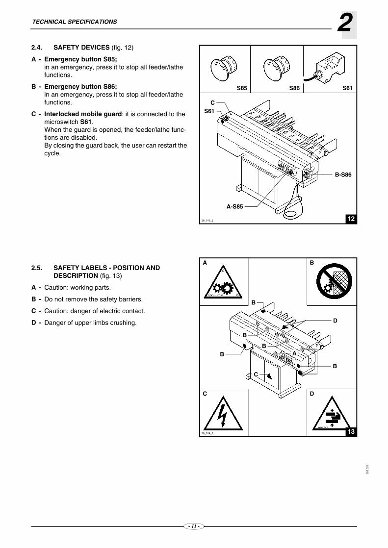
2.4. SAFETY DEVICES (fig. 12)
A - Emergency button S85;in an emergency, press it to stop all feeder/lathe functions.
B - Emergency button S86;in an emergency, press it to stop all feeder/lathe functions.
C - Interlocked mobile guard: it is connected to the microswitch S61.When the guard is opened, the feeder/lathe func-tions are disabled.By closing the guard back, the user can restart the cycle.
2.5. SAFETY LABELS - POSITION AND DESCRIPTION (fig. 13)
A - Caution: working parts.
B - Do not remove the safety barriers.
C - Caution: danger of electric contact.
D - Danger of upper limbs crushing.
- 11 -

TECHNICAL SPECIFICATIONS230
2.02
8
Model14 15
ø 5 mmø 80 mm250 mm
1400 mm 1560 mm750 mm
ø12 (10) - 15 (12) - 21 (18) mmMAX 750 mm/sMAX 750 mm/s
16s230/400 Volt24 Volt D.C.
1,5 KW6 bar
450 kg
14
2.6. TECHNICAL SPECIFICATIONS (fig. 14)
2.6.1 Noise levels
Usually, the bar feeder does not cause any acousticnoise during machining, since the bar rotates insidethe lathe spindle.
During the bar feeding, with the bar feeder under normalconditions, the max. noise peaks average 85 dbA (mea-surement performed in compliance with the internatio-nal standards).
Min. bar diameterMax. bar diameterMin. bar lengthMax. bar lengthMagazine capacity (working width)
Bar pusher diameterFeeding speed (adjustable)Return speed (adjustable)Bar change-over timeInput voltageControl voltageInstalled powerAir pressureWeight
28_015_2
- 12 -

TECHNICAL SPECIFICATIONS230
2.02
8
528_089_0
A
CB
2.7. AXIAL DISPLACEMENT DEVICE - DESCRIPTION (FIG.5)
t allows the feeder to be moved away from the lathe toallow maintenance, cleaning or any other servicing ofthe lathe.
Release and rotate lever A for conveying.
DANGER - WARNING: Make sure that safety hook B has passed block C, in order to prevent the bar feeder
from sliding freely over the guides.
To move the bar feeder back to working position, rele-ase safety hook B and move lever A to its initial posi-tion after conveying.
CAUTION: In order to guarantee a good working, keep axial displacement bars cleaned and lubricated.
- 13 -

3 S
AFETY PROCEDURES - GENERAL INFORMATION302.
028
3.1. SAFETY GENERAL INSTRUCTIONS
It is of the utmost importance to read carefully this manual before carrying out any installation, use,
maintenance or other servicing on the machine. The compliance with the instructions contained herein
ensures safety both of man and machine.
❑ Both the operator and skilled engineer in chargeshall keep to their task.
❑ Do not tamper with the safety devices for any rea-son whatsoever.
❑ Safety labour regulations issued by each countryauthority shall be strictly complied with.
❑ IEMCA declines any liability whatsoever for dama-ges to people or property due to the non-obser-vance of the above mentioned regulations.
3.2. HANDLING AND INSTALLATION - SAFETY PROCEDURES
❑ Machine shall be handled using suitable meansand methods.
❑ People shall not stand underneath a suspendedload, within the crane, lift truck or other suitablemeans of lifting or transportation operating range.
❑ The working and bar feeding area shall be delimi-ted in order to prevent collisions between the ope-rator and transportation or handling means, if any,either of the materials to be machined or othermaterial.
❑ A proper machine installation, as well as lightingand cleaning of the area, are of the utmost impor-tance as far as personal safety is concerned.
❑ The electric system connection shall be carried outby skilled personnel only.
❑ Make sure the electric system is earth connectedthrough a suitable cable.
- 1
3.3. ADJUSTMENTS AND SETTING UP - SAFETY PROCEDURES
❑ Carry out the adjustments according to the useand maintenance manual.
❑ Do not change the working parameters to obtainperformances different from those designed andtested.
❑ Do not adjust the machine when it is runningunless otherwise specified in the use and mainte-nance manual.
❑ Do not feed the machine with barstocks havingdimensions different from those recommended bythe manufacturer.
❑ Do not use hoses as grips.
3.4. USE AND OPERATION - SAFETY PROCEDURES
❑ The working area around the machine shall alwaysbe kept clean and empty in order to allow an imme-diate access to the emergency devices, thusallowing the bar feeding operations without cau-sing danger and hindrance.
❑ Carry out the starting cycle sequence as recom-mended.
❑ Do not introduce hands or other parts near orinside running parts or energised parts of themachine.
❑ Take off bracelet, watch, ring and tie.
❑ Whenever necessary, use strong working 5 fingergloves, which do not reduce sensitivity and grip-ping.
❑ Use working shoes as well as personal protectionsas provided for by the accident prevention regula-tions in force in every country.
❑ Personnel in charge of maintenance shall be infor-med should the machine fail to work properly.
❑ Before starting the machine, make sure that thereis no personnel carrying out maintenance or clea-ning operations.
4 -

SAFETY PROCEDURES - GENERAL INFORMATION 3
302.
028
3.5. MACHINE MAINTENANCE - SAFETY PROCEDURES
❑ Non-authorised people are not allowed to carry outmaintenance.
❑ Read carefully this manual before carrying out anymaintenance whatsoever.
❑ Do not lubricate, repair or adjust the machineduring its working cycle, unless otherwise specifiedby this manual.
❑ Stop the machine in accordance with the safetyprocedures before carrying out lubrication.
❑ Do not light the working area with matches, lightersor torches when servicing the machine usinginflammable fluids.
❑ Preserve the exhausted oil in suitable containersand deliver it to stocking and disposal of pollutingwastes companies.Do not pollute environment.
❑ Use original IEMCA spare parts only.
- 15 -

3
4 H ANDLING AND INSTALLATION302.
028
C
1
4.1. PACKAGING (fig. 1)
The machine can come in three different packagings:
A - With no packaging.
B - On a pallet: the feeder is placed on a pallet and wrapped in protective film.
C - In a case: the feeder is placed in a case and wrapped in protective film.
4.2. LIFTING
DANGER - WARNING: Lifting and handling operations should be carried out with suitable equipment by skilled
staff specially trained for this kind of manoeuvres.
According to the type of packaging used, lifting shouldbe carried out as follows.
A B
28_016_2.bmp
- 16 -

HANDLING AND INSTALLATION430
2.02
8
2
C
A
328_018_2.bmp
❏ Lifting with no packaging (fig. 2)
– Install the two round-eye eyebolts A with threaded stem (type 1 UNI - ISO 3266 M20).
– Fit a wooden pad B.
– Lift the bar pusher support C to prevent it from being damaged.
– Use a hook-up lifting device having a suitable capacity.
❏ Lifting with pallet (fig. 3)
Use a hook-up lifting device of suitable capacity.
28_017_2.bmp
B
A
- 17 -

HANDLING AND INSTALLATION 4
302.
028
428.019 Ec.0
528_020_1.bmp
A
B
❏ Lifting with case (fig. 4)
Use a hook-up lifting device of suitable capacity.
4.3. MACHINE SETTING - CHARACTERISTICS (fig. 5)
– The floor should be stable and well-levelled so asto allow good anchoring to the ground.
– Select an area having a suitable size according tothe type of feeder used. The dimensions shown inthe figure have been calculated by taking intoaccount the feeder overall dimensions and theminimum clearance required to walk around themachine.
– The working A and feeding area B should beproperly delimited in order to avoid any possibilecollisions between the operator and the transport/handling means travelling near the machine.
– The selected area should be suitably lit and havean electric/pneumatic power outlet.
- 18 -

HANDLING AND INSTALLATION430
2.02
8
628.025 Ec.1
AB
7
C•
D
828.023 Ec.0
G F
G
•
•
E
4.4. PREPARING THE BAR FEEDER FOR INSTALLATION
Before positioning and installing the bar feeder closeto the lathe, do the following:
– Lift the bar feeder and assemble plates A and feet B (fig. 6).
– lift the magazine C and install the foot D as shown in figure 7 ;
– insert the pin E (fig. 8). Install the keep plate F. Remove the supports G.
Keep the supports (G) in case you need to transport the feeder in the future.
28.022 Ec.1
- 19 -

HANDLING AND INSTALLATION 4
302.
028
9
1128_024_2.bmp
In case of axial displacement foot "D" is fixed
directly to the base.
– lift the magazine C and install the foot D as shown in figure 9;
DANGER - WARNING: The bar feeder should be fixed to the floor before loading bars in the magazine;
moreover, the maximum bar weight limit should be complied with. Before clearing the bar feeder from the floor all bars should be removed form the magazine.
4.5. INSTALLATION - FOREWORD
Bar feeder installation imply several operations listedand described here below.
4.5.1 Positioning4.5.2 Height - Adjustment4.5.3 Alignment - Levelling4.5.4 Fixing the feeder to the lathe4.5.5 Bar passage guide - Installation
4.5.1 Positioning
– Position the bar feeder behind the lathe (fig. 11), considering the dimensions of the bar guide and of its guard (paragraph 4.5.5).
D
C
28_082_1
- 20 -

HANDLING AND INSTALLATION430
2.02
8
1228_027_1.bmp
B
A
A B
1328_028_1.bmp
1428_083_0.bmp
4.5.2 Height - Adjustment
The working axis height is normally adjusted to thelathe height at the Manufacturer's premises.
Should you need to adjust it, proceed as follows:
– tighten the lifting belts and remove screws A (fig. 12);
– lift the feeder to the height X (fig13 -14); see table below:
– tighten the screws A and remove the eyebolts B.
For higher adjustments, shims are available that can be placed under the foot supports (ask IEMCA Service staff).
SCREWS POSITIONX (mm)
Slots Holes
1 and 3 A 870 - 9072 and 4 B 908 - 9392 and 4 A 940 - 9773 and 5 B 978 - 10093 and 5 A 1010 - 10474 and 6 B 1048 - 10794 and 6 A 1080 - 11175 and 7 B 1118 - 11495 and 7 A 1150 - 1187
- 21 -

HANDLING AND INSTALLATION 4
302.
028
1528.029 Ec.2
D
E•
1628.030 Ec.0
H
F
G
H L
1728.033 Ec.0
4.5.3 Alignment - Levelling
Alignment between the feeder and the lathe is a keystep, therefore, it should be carried out by experiencedpersonnel with the greatest accuracy.
CAUTION: Bad alignment can be the main cause of faulty operation and of the resulting damage.
– Control the bar pusher D (fig. 15) out and check its alignment at lathe spindle E inlet.
– Check feeder levelling.
– For height adjustments, turn the screws F (fig. 16). For lateral adjustments, give calibrated blows on the side of the base foot with a mallet.
– Tighten the nuts G.
– Drill a hole in the floor and fasten the plates H with the expansion plugs.
– Fasten the base to the plates using the tie rods L .
– Finally, double-check the alignment.
4.5.4 Fixing the feeder to the lathe
Should the floor be in such a condition so as not toguarantee a good anchorage of the feeder, fasten thefeeder to the lathe.
Fig. 17 shows a generic example. For more details, askthe "IEMCA Service staff".
- 22 -

HANDLING AND INSTALLATION430
2.02
8
1828.031 Ec.1
B
A
1928.032 Ec.0
D
•
2022.080 Ec.0
•
•
•
E
FB
A
MAX
C
D
4.5.5 Bar passage guide - Installation (fig. 18)
– Saw the guide of the length L necessary to coverthe distance between bar feeder and lathe spindle.
– Position it in its seat.
– Adjust the guide height. The bar axis (resting on thebar) should be aligned with the feeding axis.
– To adjust, turn screw A.
– Tighten the nuts B.
DANGER - WARNING: it is critical to install the protection guard to guarantee safety.
– Cut the guard D (fig. 19) to a length L necessary tocover the distance between the feeder and the
lathe.
– Fix the guard with screws.
4.6. PNEUMATIC CONNECTION
– Unscrew plug B or cup C to fill the tank of lubricator A (fig. 20); the oil level shall reach the MAX. refe-rence.Oil properties: 9 to 11 cSt at 40°C ISO VG 10.
– Connect pipe D of the compressed air ductwork system as shown in the figure. Adjust pressure at 6 bar by means of knob E.
– Check the air lubrication (1-12 drops per 1000 l air); adjust through screw F.
LUBE OIL TABLE
BP ENERGOL HP10
SHELLTELLUS C10
MOBILDTE 21
ESSOSPINESSO 10
- 23 -

HANDLING AND INSTALLATION 4
302.
028
2128_035_2.bmp
4.7. ELECTRIC CONNECTION
DANGER - WARNING: This type of intervention should only be entrusted to qualified personnel with specific
skills in accordance with the applicable regulations and standards.
As a rule, the feeder comes equipped with a multipolarelectric plug to be plugged into the specially providedlathe socket (check the "Wiring diagram" if needed).
4.8. ADDITIONAL PUSH-BUTTON PANEL - INSTALLATION (fig. 21)
The additional push-button panel can be removed fromits housing.
According to working requirements, it can be installednearby the lathe push-button panel.
4.9. SELF-LEARNING VALUES - ENTRY INTO PROGRAM
Self-learning values depend on type and dimension ofthe lathe to which the bar feeder has been fitted.
Said operation is necessary, since the bar moves accor-ding to these values.
For detailed information relevant to this operation, seethe “Push-button panel instruction manual".
- 24 -

HANDLING AND INSTALLATION 4
302.
028
- 25 -

302.
028
4
5 A DJUSTMENTS AND SETUP3128.036 Ec.0
A
A
5.1. ADJUSTMENT AND SETUP - FOREWORD
DANGER - WARNING: Unless otherwise stated in this manual, do not adjust the feeder when it is working.
Besides normal adjustments which may becomenecessary over its service life, this machine shouldalso be adjusted to suit its required type of work.
According to bar size and type of work, machine setupmay include the replacement of a few parts.
These interventions are divided into and describedunder:
– general adjustments (paragraph 5.2.);
– adjustments according to bar type (paragraph 5.3.).
5.2. GENERAL ADJUSTMENTS - FOREWORD
These are all the operations necessary for feedersmooth working. They can include maintenanceoperations, operations required to fix a problem oroperations required after replacing a machine part orunit.
5.2.1 Feed chain - Adjustment.
5.2.2 Bar pusher axis - Adjustment.
5.2.1 Feed chain - Adjustment (fig. 1)
– Remove the front guard.
– Loosen the screws A.
– Tighten the chain to an appropriate extent.
– Tighten the screws A.
- 26 -

ADJUSTMENTS AND SETUP 5
302.
028
228.037 Ec.0
A
B C
G
E
D
F
5.2.2 Bar pusher working position - Adjustment (fig. 2)
When the bar pusher A has been lowered, the grooveon lever B must be aligned with the carriage pin C.
To adjust the bar pusher working position:
– remove the rear guard;
– remove the pin D and pull the lever E;
– loosen the nut F. Then, either tighten or loosen the fork pin G depending on what you need to do;
– tighten the nut F and fit the pin D again.
5.3. ADJUSTMENTS ACCORDING TO BAR TYPE - FOREWORD
They include all the preliminary adjustments that mustbe made according to the diameter, length and sectiontype of the bar to be machined.
5.3.1 Reduction sleeves - Diameter change-over.5.3.2 Magazine inclination - Adjustment.5.3.3 Bar selection - Adjustment.5.3.4 Covering frame - Adjustment.5.3.5 Guide lifting limit switch - Adjustment.5.3.6 Bar pusher - Selection and installation.5.3.7 Bar passage guide (optional) - Adjustment.
5.3.1 Reduction sleeves - Diameter change-over
To support bars in the lathe, it is advisable to insertreduction sleeves into the spindle.
Their inner diameter shall be equal to the bar pusherdiameter + 1 mm.
Example:to make sure that ø12 mm bar pusher never touchesthe spindle inner part, the inner diameter of the spindleliners must be at least 13 mm.
- 27 -

ADJUSTMENTS AND SETUP530
2.02
8
328_038_1.bmp
To be able to carry out the replacement, clear the frontpart of the feeder by proceeding as follows:
– Pressto start the feeder.
– Pressto select the manual cycle.
– The feeder can be in two positions: guide lifted or bar pusher lowered. Lower the guide or lift the bar pusher.To lower the guidepress
To lift the bar pusher press
– Open the rear guard (fig. 5).
– Change the reduction sleeves.
– Restore the initial condition.
- 28 -

ADJUSTMENTS AND SETUP 5
302.
028
428_044_1
B
A
C
528.045 Ec.0
C
A B
E
•
•
D
628.046 Ec.0
B
A
F
E
E
DC
A
5.3.2 Magazine inclination - Adjustment (fig. 4)
Adjust the magazine inclination according to the bardiameter verifying its angle by means of index C.
The data shown in the table refer to round bars. To work bars having a different shape, increase inclination. In the
initial working phases, experiment until you find the ideal inclination.
To adjust inclination, use handle B.
5.3.3 Bar selection - Adjustment (fig. 5)
Bar C is lifted by device B.
Thus, the position of bar catches A must allow thelifting of bar C only, preventing bar D from being lifted.
For adjustment use knob E.
5.3.4 Covering frame - Adjustment (fig. 6)
Bar C is lifted by device B.
Thus, the position of frame A must allow the passageof bar C keeping bar D.
To adjust the frame position, loosen the knobs E. Then,lift/lower the frame A using handle F.
After finding the right position, tighten the knobs E.
BAR DIAMETER (mm)
INCLINATION (A)
ø5÷15 22°ø16÷53 16°ø54÷70 10°ø71÷80 5°
- 29 -

ADJUSTMENTS AND SETUP530
2.02
8
728_047_1.bmp
A
BA
828.048 Ec.1
B
C
D
5.3.5 Guide lifting limit switch - Adjustment. (fig. 7)
When the bar A, is on the lifted guide B, its axis mustcoincide with the loading axis. The lifting limit switchmust be adjusted according to the stock diameter andshape.
To adjust it, proceed as follows:
– pressto start the feeder;
– pressto select the manual function;
– press to lift the guide;
– adjust the guide lifting limit stop through screw C (fig. 8) and check the adjustment through the gra-duated scale D.
- 30 -

ADJUSTMENTS AND SETUP 5
302.
028
928.049 Ec.2
E
D CE
FH
G
1028.050 Ec.1
A
B
5.3.6 Bar pusher - Selection and installation (fig. 9)
Install a bar pusher with a diameter which is suitablefor the bar diameter (see table below).
To install the bar pusher, proceed as follows:
– Open the front guard.
– Install the fore bush C in the seat of lever D. The bar pusher E must be inserted into bush C.
– Introduce the rear part of bar pusher E into lever F housing, tighten screw G and nut H.
– Close the guard.
5.3.7 (Optional) Bar passage guide - Adjustment (fig. 10)
– Screw out the screws A.
– Adjust the guide height. The axis of the bar restingon it should be aligned with the feeding axis.Adjust by screwing out the nut A and manuallyadjust the position of screw B.To adjust, turn screw B.
– Tighten screws A.
BAR DIAMETER (mm)
ØA - ROD DIAMETER (MM)
ØB - BEARING DIAMETER (MM)
5÷12 10 1210÷19 12 1516÷80 18 21
- 31 -
302.
028
5
6 U SE AND OPERATION4A
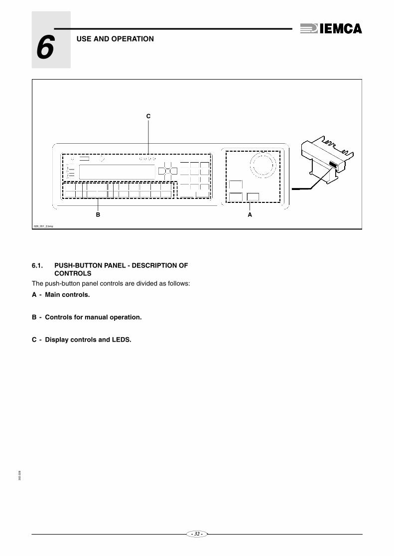
6.1. PUSH-BUTTON PANEL - DESCRIPTION OF CONTROLS
The push-button panel controls are divided as follows:
A - Main controls.
B - Controls for manual operation.
C - Display controls and LEDS.
028_051_2.bmp
B
C
- 32 -

USE AND OPERATION 6
- 33 -
302.
028
❑ Main controls
1 - Green lighted push-button; it startsthe feeder. Press the key and keep itpressed until the indicator light corre-sponding to the key itself turns on.
2 - Red push-button; it stops the feeder.
3 - Key-operated two-position selectorPosition : the push-button panel isenabled for the “message display” mo-de.Position : push-button panel enabledto data entering mode.
-4 - Emergency push-button; it stopsthe feeder. The feeder can be re-started only after the push-buttonhas been manually released.
56_002_0.tif
1
2 3
4

USE AND OPERATION630
2.02
8
- 34 -
❑ Programming and manual functions controls
1- Key to select bar feeder manual operation.
2- Key to select bar feeder automatic opera-tion.
3- Key to select the bar feeder semiautoma-tic function.
4- Key to control a step-by-step operatingcycle. If pressed, the bar feeder performsthe first step, if pressed again the bar fee-der performs the second step, and so on.
5- Key to lift the bar lifting device
6- Key to lower the bar lifting device
7- Key lifting the guide
8- Key lowering the guide
11- Key for bar pusher backward manualmotion at high speed.
12- Key for bar pusher backward manualmotion at low speed.
13- Key for bar pusher forward manualmotion at low speed.
14- Key for bar pusher forward manualmotion at high speed.
15- Key for “BAR FEEDER ZERO SETTING”.
It must be pressed only after key
has been pressed; once the
carriage has started moving, they can
be released.
16- TKey to adjust the motor for the barpusher motion. Never press it duringdaily operation of bar feeder.
17- Bar pusher lifting key
18- Bar pusher lowering key
19- “RESET” key.
20- Key to recall “MAIN MENU”.
28_053_2.bmp
S 73
20MAIN

USE AND OPERATION 6
- 35 -
302.
028
❑ Display controls and LEDS
1 - Key for numerical value 1.
2 - Key for numerical value 2.
3 - Key for numerical value 3 and to accessthe date and hour programming mode.
4 - Key for numerical value 4.
5 - Key for numerical value 5.
6 - Key for numerical value 6 and to accessprotected parameter entering mode.
7 - Key for numerical value 7.
8 - Key for numerical value 8.
9 - Key for numerical value 9.
10 - Key for numerical value 0 or to recall se-lection cursor.
11 - Key for “minus” or “plus” sign.
12 - Key for “comma” sign.
13 - Key for “CLEAR” function:• to stop selection function,• to return to the value which had been
displayed before the non-confirmedmodification,
• to return to the screenful displayedafter the date and time programming.
14 - Key for “ENTER” function to confirmentered data.
15 - Key to recall the previous parameter or tomove the selection cursor left.
16 - Key to recall the next parameter or tomove the selection cursor right.
17 - Key to scroll page upwards or to move se-lection cursor upwards or to increase byone the value in the date and hour pro-gramming mode.
18 - Key to scroll page downwards or to moveselection cursor downwards or to decrea-se by one the value in the date and hour
1 2 3
4 5 6
7 8 9
+/- 0 •F( )
!?
141011 1213
18
2019 21 22 15 17 162423 25
IDM - 36.004 Ec. 0
1
2
3
4
5
6
7
8
9
0
+/-F( )
•

USE AND OPERATION630
2.02
8
- 36 -
19 - Red LED:OFF mode - It indicates that there is nodisplay warning;ON mode - It indicates that there isdisplay warning.
20 - Green LED:BLINK mode - signals that the displaydoes not interact with the PLC correctly;ON mode - signals that the display inte-racts with the PLC correctly.
21 - LED not enabled.
22 - Green LED:OFF mode - signals that the display is notactive;ON mode - signals that the display isactive.
23 - Green LED:OFF mode - signals that no key is pres-sed;ON mode - signals that any key is pres-sed.
---------------Red LED:---------------BLINK mode - It signals that the keyboard
-------------battery is flat (chapter 9).---------------ON mode - It signals severe keyboard
trouble
24 - Key not enabled.
25 - Display.
!
?

USE AND OPERATION 6
- 37 -
302.
028
6.2 ADDITIONAL PUSH-BUTTON PANEL -DESCRIPTION OF CONTROLS
26 - Selector for switching from the automatic cycle tothe manual cycle and vice versa:
position : manual cycleposition : automatic cycle.
27 - Carriage progress/return selector:position <<< : carriage returnposition >>> : carriage progress.
28 - Emergency push-button. It stops the feeder. Thefeeder can be restarted only after the push-buttonhas been manually released.
28_055_2.bmp

USE AND OPERATION630
2.02
8
Model14 15
ø 5 mmø 80 mm250 mm
1400 mm 1560 mm
628.056 Ec.2
BAC
•
••
6.2.
6.3. BAR STOCK - CHARACTERISTICS AND PREPARATION
The bar stocks must comply with the features shown inthe table.
DANGER - WARNING: The maximum stock length must be contained within the lathe spindle length.
CAUTION: Do not feed bars having a different size than that prescribed by the Manufacturer.
❏ Bars
– Bars should not have too much excess flash at their fore end. This would affect their feeding into the lathe collet.
❏ Tubes
– Tubes should not have too much excess flash at their fore end. This would affect their feeding into the lathe collet.
– Prepare a cap A (fig. 6) to mount into the rear end of the tube B in order to avoid that:– the thrust of the bar pusher C is not transmitted to
the tube B.– the lathe coolant flows out in the feeder.
Min. bar diameterMax. bar diameterMin. bar lengthMax. bar length
- 38 -

USE AND OPERATION 6
302.
028
728_057_1.bmp
B
C
A
A
828_059_2.bmp
A
B
6.4. TOOLING AND STARTING THE AUTOMATIC CYCLE - OPERATION SEQUENCE
Bar feeder tooling and automatic cycle startingsequence for the first bar feeder start, are to be foundbelow.
– Adjust the feeder according to the type of bar to be machined (paragraph 5.3.).
– Program the feeder according to the type of work to be carried out (read the "Push-button panel opera-tion guide").
– Prepare the bar stock (paragraph 6.3.).
– Load the bar magazine (paragraph 6.4.1).
– Start the automatic cycle (paragraph 6.4.2).
6.4.1 Bar magazine - Loading
CAUTION: do not lift any loads exceeding the weight prescribed by the standards in force.
To load the bars in the magazine, proceed as follows:
– If necessary, lift the covering frame; loosen the two knobs A (fig. 7) and lift the frame B using handle C.
– Load the magazine completely or in part, according to your own needs.When lowered, thick bars must be supported.
CAUTION: max. total allowed weight of bars loaded in magazine is 240 Kg.
– Place the bars in the magazine as shown in figure 8:A - arrangement for short bars B - arrangement for long bars.
- 39 -

USE AND OPERATION630
2.02
8
956_002_0.TIF
6.4.2 Starting the automatic cycle (fig. 9)
– Switch on power supply from lathe.
– To start bar feeder press (till indicator turns on)
– Pressto select the manual function.
– Perform the "BAR FEEDER ZERO SETTING" as follows:press
– Press to lift the bar pusher.
– Pressto drop the first bar into the guide.
028_053_2
--+
- 40 -

USE AND OPERATION 6
302.
028
– Press to lower the bar lifting device again.
– Press to lift the guide.
– Pressto prefeed the bar.
– Pressto move the carriage back to its end-of-stroke position.
– Press to lower the guide.
– Press to lower the bar pusher.
– Pressto let the bar fore end come out of the lathe collet by a few millimetres.
– Pressto select the automatic function. The bar will be fed on according to the selected program.
– Start the lathe cycle.
– The lathe collet closes, thus starting the machining. From now on, bars will be fed automatically as long as there are bars available or according the selected program.
– If you wish to restock bars in the magazine during machining, proceed as described in paragraph 6.4.1.
- 41 -

USE AND OPERATION630
2.02
8
6.5. FEEDER STOP
CAUTION: After the feeder has stopped, do not move it manually. Use the push-buttons.
❑ Feeder emergency stop
CAUTION: if the emergency stop is used during lathe machining, before resuming work make sure that the sudden stop has not created any hazardous condition (e.g., if the tool was cutting chips, move the tool away
from the workpiece before restarting the lathe).
To stop the feeder in an emergency, press an emer-gency push-button, either that of the lathe or that of thefeeder.
❑ Feeder stop at work end
CAUTION: Do not use emergency buttons for normal machine stop.
– Complete the operations in your work schedule.
– Stop the feeder by pressing the but-ton.
– Stop the lathe.
6.6. STARTING THE AUTOMATIC CYCLE FOLLOWING MANUAL CYCLE OPERATIONS (fig. 9)
It is the automatic cycle starting following: manualmovements, parameter changes, servicing, etc.
When performing said operations, the lathe is in an“ALARM" mode, therefore follow the procedure below.
❏ The bar feeder must be in MANUAL mode,ready to start the automatic cycle.Set the bar feeder on the "WORK" phase
Press
- 42 -

USE AND OPERATION 6
302.
028
Otherwise, messages showing the operations toperform will be accordingly displayed.
❏ The bar feeder must shift to the AUTOMATICmode, ready to receive the signal from lathe.Bring the bar feeder to the "BAR FEEDER WAI-TING" phase.
Press
Should the bar feeder be set, it shifts automaticallyin the "BAR FEEDER WAITING" phase.Otherwise, messages showing the operations toperform will be accordingly displayed.
6.7. STARTING THE AUTOMATIC CYCLE - RESUMING WORK FOLLOWING A SWITCHING OFF (fig. 9)
❏ If the carriage has been moved while the barfeeder was not powered:
– Switch on power supply from lathe.
– Pressto start the bar feeder.
– Pressto perform the "BAR FEEDER ZERO SETTING".
– Bring the carriage to the starting position.
– Press
❏ If the carriage has not been shifted while themachine was not powered:
– Switch on power supply from lathe.
– Press to start the bar feeder.
– Press
+
- 43 -

USE AND OPERATION630
2.02
8
6.8. PERFORMING A “STEP BY STEP” CYCLE
IntroductionThis mode can be used for many reasons, as forinstance;
– to check a complete bar change cycle;
– to check the bar feeder mechanics;
– to load a single bar with the intent of checking the facing;
– eccetera.
Procedure
– Press to start the bar feeder;
– Press to select the semi-automatic cycle;
– Press to select automatic cycle;
– Press , the bar feeder performs the first step;
– Press , the bar feeder performs the second
step , and so on.
- 44 -

USE AND OPERATION630
2.02
8
34.103 Ec. 0
6.9. INDICATOR LIGHTS - Description of indications
Red light; signals that the bar feeder is not operating,or that it is in the manual mode.
Green light; it indicates that the bar feeder is in the au-tomatic mode.
Blue light; signals that the bar feeder is carrying out thebar change, that it is not operating, or that manualmotions are being carried out.
- 45 -

6
7 M ACHINE MAINTENANCE5302.
028
7.1. MAINTENANCE - GENERAL RULES
DANGER - WARNING: carry out machine maintenance and cleaning while the machine is off.
Regular cleaning and maintenance are critical toensure smooth operation and longer machine servicelife.
It is recommended to regularly and effectively clean themachine, its accessories and work area, which alsoincreases operator's safety.
Do not use petrol or solvents which would damage thepainted and transparent parts, the cable sheaths etc.
Oxidation can damage metal parts and electric equipment.
To protect the machine when you expect not to use itfor long periods of time, disconnect it from mainsvoltage and from compressed air supply and cover itwith a suitable protective sheet.
Any protection used should not be fully closed or sealedat the base; it should have ventilation holes to makesure that air within the envelope cannot condense dueto lack of circulation.
- 46 -
MACHINE MAINTENANCE730
2.02
8
128.081 Ec.0
MAX
•
A
GE
• F
•
B C
D
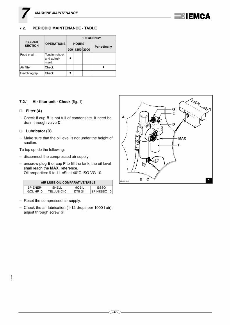
7.2. PERIODIC MAINTENANCE - TABLE
7.2.1 Air filter unit - Check (fig. 1)
❑ Filter (A)
– Check if cup B is not full of condensate. If need be,drain through valve C.
❑ Lubricator (D)
– Make sure that the oil level is not under the height ofsuction.
To top up, do the following:
– disconnect the compressed air supply;
– unscrew plug E or cup F to fill the tank; the oil level shall reach the MAX. reference.Oil properties: 9 to 11 cSt at 40°C ISO VG 10.
– Reset the compressed air supply.
– Check the air lubrication (1-12 drops per 1000 l air);adjust through screw G.
FEEDER SECTION
OPERATIONS
FREQUENCY
HOURSPeriodically
200 1250 2000
Feed chain Tension check and adjust-ment
•
Air filter Check •Revolving tip Check •
AIR LUBE OIL COMPARATIVE TABLE
BP ENER-GOL HP10
SHELLTELLUS C10
MOBILDTE 21
ESSOSPINESSO 10
- 47 -

MACHINE MAINTENANCE 7
302.
028
228.075 Ec.2
A
B
C
328.076 Ec.2
E
D
7.2.2 Revolving tip - Inspection
– Make the front end of the bar pusher come out of bushing A (fig.2).
– Open the rear guard.
– Make sure that shaft B and bearing C turn properly with no excessive backlash.
In case of excessive backlashes, do the following:
– remove the bar pusher from its housing (see paragraph 5.3.6);
– remove pin E (fig.3), replace revolving tip D and set a new pin.
- 48 -
MACHINE MAINTENANCE730
2.02
8
4
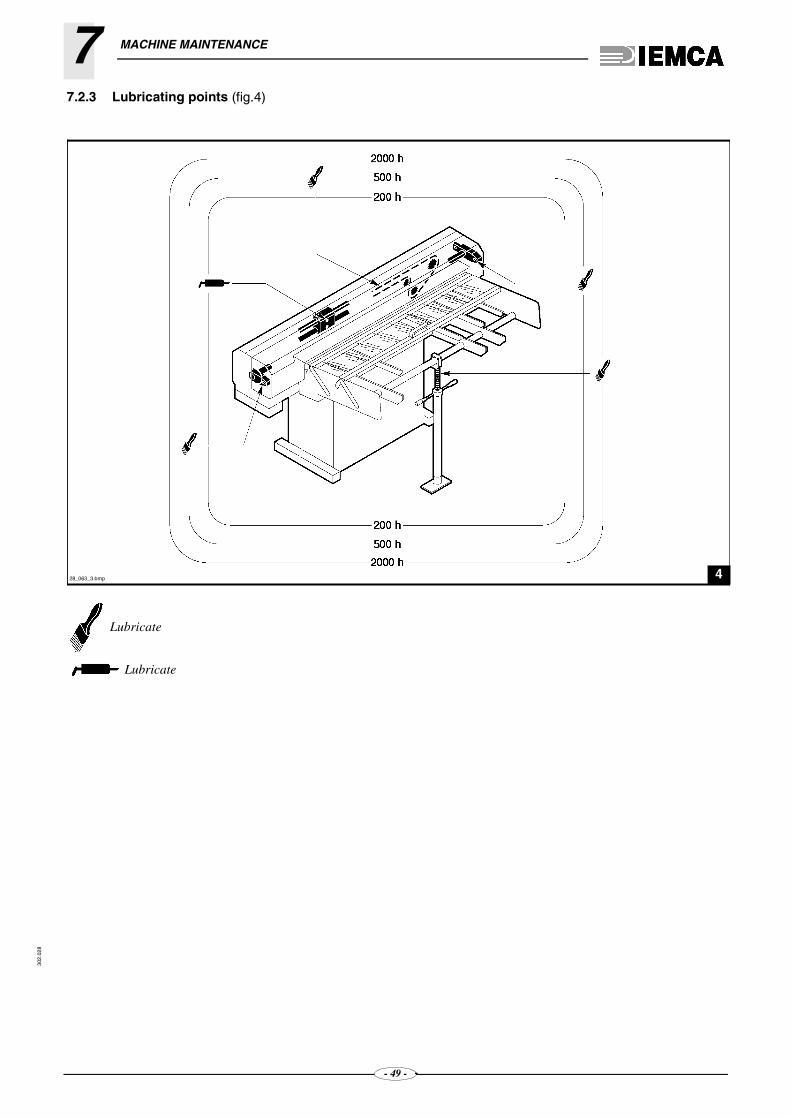
7.2.3 Lubricating points (fig.4)
Lubricate
Lubricate
28_063_3.bmp
- 49 -

302.
028
7
8 T ROUBLES - CAUSES - REMEDIES8.1. GENERAL TROUBLES
CauseNo power input.
CureRemedyCheck electric connection.
CauseThe guard is open.
CureRemedyClose guard.
CauseEmergency devices operated.
CureRemedyReset emergency devices.
CauseMotor thermal cutout tripped.
CureRemedyReset motor overload cutout using special buttons.
CauseNo lathe signal.
CureRemedyCheck electric connection to lathe.
CauseNo air.
CureRemedyCheck air system.
CauseMotor thermal cutout tripped.
CureRemedyRemset the motor overload cutout using special buttons.
THE FEEDER WILL NOT START
FEEDER IN STARTING STATUS BUTAUTOMATIC CYCLE WON'T START
THE PNEUMATIC DEVICES DO NOT RESPOND
PREFEEDING AND FEEDING STOP SUDDENLY
- 50
8.2. BAR MAGAZINE - TROUBLES
CauseThe magazine covering frame is too low.
CureRemedyAdjust the position of the covering frame.
CauseWrong setting of the bar selector.
CureRemedyAdjust the selector.
CauseThe magazine is not inclined enough.
CureRemedyTilt the magazine.
CauseWrong setting of the bar selector and/or of the magazine covering frame.
CureRemedyAdjust the selector and/or the covering frame position.
8.3. BAR FEEDING - TROUBLES
CauseWrong setting of the guide lifting limit switch.
CureRemedyAdjust the limit switch.
THE BAR WON'T ENTER MAGAZINE DURING LOADING
THE FIRST BAR IN THE MAGAZINE IS NOT LIFTED
THE SECOND BAR IN THE MAGAZINE IS LIFTED TOGETHER WITH THE FIRST
THE BAR HAS DIFFICULTIES IN ENTERING THE LATHE SPINDLE
-

TROUBLES - CAUSES - REMEDIES 8
302.
028
CauseBar passage guide adjustment too high.
CureRemedyAdjust bar passage guide to right height.
CauseFeeder not aligned with lathe.
CureRemedyCheck and correct alignment.
CauseThe bar is too long.
CureRemedyThe max. length must correspond to the max. length contained in the lathe spindle.
CauseExcessive flash at bar end.
CureRemedyRemove bar flash before feeding.
CauseWrong setting of the bar pusher working position.
CureRemedyAdjust the bar pusher working position.
THE CARRIAGE WON'T COMPLETE ITS PREFEED STROKE
THE BAR PUSHER WON'T REACH THE REAR END-OF-STROKE
BAR HAS DIFFICULTIES IN ENTERING LATHE COLLET
- 51 -

302.
028
8
9 PA RT REPLACEMENT6128.064 Ec.0A
B
228.065 Ec.2
B
A
A
B
D
C
9.1. FEED CHAIN - REPLACEMENT (fig. 1)
– Remove the front guard.
– Slacken the chain (see paragraph 5.2.1).
– Remove the fork pin A and the link B.
– Replace the chain.
– Fit the link B and the fork pin A back in their posi-tion.
– Stretch the chain (see paragraph 5.2.1).
– Install the front guard.
9.2. CARRIAGE BACK LIMIT SENSOR - REPLACEMENT (fig. 2)
– Remove the front guard.
– Replace the sensor A and fit the new sensor by pro-ceeding as follows:
1 - keep the sensor 1 mm far from plate B;
2 - moving carriage C backwards, the sensor LED shall turn on when the carriage abuts against lever D. The display shall show a -3,0 to -4,0 mm displacement.
- 52 -

PART REPLACEMENT 9
302.
028
328_087_0.bmp
D
A
C
4
AB
9.3. KEYBOARD BATTERY REPLACEMENT (fig. 3)
Replace the battery every year or when battery signal-ling lamp 23- sends a blinking red signal.
INFORMATION: If no replacement takes place, date and hour disappear from the display.
Replace the battery as follows:
– Cut off the bar feeder supply.
– Unscrew the key-board’s panel A.
– With a screwdriver, loosen the 4 corner screws B in the rear double housing C holding the communica-tion ports.
– Remove the double rear housing C keeping it paral-lel to the surface it was fastened to.
– Remove the battery D from its compartment.
– Insert the new battery (type CR2430 3 volts, lithium)
DANGER - WARNING: Battery explosion danger if inserted with reversed polarity.
– Fix the double housing C to the panel again and tighten the 4 screws B.
– Connect the bar feeder and check that the battery charge is signalled.
9.4. SOSTITUZIONE BATTERIA PLC (fig.4)
Replace the battery every year.
When the message "PLC battery exhausted" appears on the display of the control panel, replace the battery
within a day. If no replacement takes place, the data of the "PLC/CN software" are cancelled.
Replace the battery as follows:
– Loosen plug "A" and extract battery "B" from its compartment.
– Insert new battery (type AA 3,6 volts, lithium) cor-rectly and screw plug "A" tight.
?
- 53 -

PART REPLACEMENT930
2.02
8
528_090 Ec.1
BILA
9.5. FEED MOTOR DRIVE - Replacement
– Disconnect power and remove the faulty drive A from its seat (fig. 5); settle the new drive and power the feeder back on.
– Motor setting should now be checked (function T. offset); this operation is also necessary if one of the boards needs replacement.
– Move the bar-pusher to a position where it can move forwards or backwards.
press: with bar feeder in “MANUAL MODE”.
the bar-pusher should not move (not even by decimaldisplacements, see the display).
– If bar pusher travel does not stop within few seconds, motor set-up must be performed.
DANGER - WARNING: live control panel, danger of electric contact.
Turn the screw (BIL) clockwise or counterclockwisewith small sharp movements until the bar-pusher isstopped.
– Check the setting that you have carried out:
press: with bar feeder in “MANUAL MODE”.
the bar-pusher should not move (not even by decimaldisplacements, see the display).
– Restore the bar feeder initial conditions.
- 54 -

PART REPLACEMENT 9
302.
028
628_079_3.bmp
B A
9.6. SENSOR OF THE SHORT FEED DOOR - REPLACEMENT (Fig. 6)
– Open the rear guard.
– Replace sensor A keeping 1 mm distance from came B.
- 55 -

302.028
ANALYTICAL INDEX
AAdditional push-button panel, description of controls,
37- push-button panel, installation, 24Adjustment according to bar type, foreword, 27- and set up, foreword, 26- and setting up safety procedures, 14- of the bar passage guide, 31- of the bar pusher working position, 27- of the bar selection, 29- of the covering frame, 29- of the feed chain, 26- of the guide lifting limit switch, 30- of the magazine inclination, 29Air filter unit, check, 47Alignment, levelling, 22Annexes enclosed, 5Automatic cycle, starting after manual cycle opera-
tions, 42- cycle, starting after resuming work following a
switching off, 43- cycle, starting, 40Axial displacement device, description,13
BBar feeder and manufacturer, identification, 5- feeder maintenance, safety procedures, 15- feeder stop, 42- feeder, general description, 6- feeding, troubles, 50- magazine, inclination adjustment, 29- magazine, loading, 39- magazine, troubles, 50- passage guide (optional), adjustment, 31- passage guide, installation, 23- pusher working position, adjustment, 27- pusher, adjustment of the working position, 27- pusher, selection and installation, 31- selection, adjustment, 29- stock, characteristics and preparation, 38Battery, keyboard, replacement, 53
CCarriage, replacement of the back limit sensor, 52Characteristics and preparation of the bar stock, 38- of the bar feeder setting, 18Checking the air filter unit, 47- the revolving tip, 48Controls of the additional push-button panel, descrip-
tion, 37- of the push-button panel, description, 32Covering frame, adjustment, 29
DDescription of models, 6- of the axial displacement, 13- of the controls of the additional push-button panel,
37
- of the controls of the push-button panel, 32- of the main parts, 7Diameter change-over of the reduction sleeves, 27
EElectric connection power supply, connection, 24- connection, 24
FFeed chain, adjustment, 26- chain, replacement, 52- motor, drive replacement, 54Fixing the bar feeder to the lathe, 22
GGeneral adjustments, foreword, 26- description of the bar feeder, 6- description of the working cycle, 8- troubles, 50Guide lifting limit switch, adjustment, 30- , adjustment of the lifting limit switch, 30
HHandling and installation, safety procedures, 14Height, adjustment, 21
IIdentification of the manufacturer and the bar feeder,
5Indicator lights, 44Installation of the additional push-button panel, 24- of the bar passage guide, 23- , alignment and levelling, 22- , fixing the bar feeder to the lathe, 22- , foreword, 20- , height adjustment, 21- , positioning, 20- , preparing the bar feeder, 19
KKeyboard battery, replacement, 53
LLifting, 16Loading the bar magazine, 39Lubricating points, 49
MMagazine inclination, adjustment, 29Main parts, 7Maintenance, general rules, 46Manual purpose, 4Manufacturer and bar feeder, identification, 5Models, description, 6
56

ANALYTICAL INDEX302.028
NNoise levels, 12
OOperation sequence for tooling and starting the auto-
matic cycle, 39
PPackaging, 16Periodic maintenance, table, 47PLC battery replacement, 53Pneumatic connection, 23- supply, connection, 23Position and description of the safety labels, 11Positioning, 20Preparation and characteristics of the bar stock, 38Preparing the bar feeder for installation, 19Program entry of the self-learning values, 24Push-button panel, description of controls, 32
RReduction sleeve, diameter change-over, 27Replacement of the carriage back limit sensor, 52- of the feed chain, 52- of the feed motor drive, 54- of the keyboard battery, 53- of the PLC battery , 53- of the short feed door sensor, 55Revolving tip, inspection, 48
SSafety devices, 11- labels, position and description, 11- , general instructions, 14Selection and installation of the bar pusher, 31Self-learning values, entry into program, 24Sensor of the carriage back limit, replacement, 52- of the short feed door, replacement, 55Setting the bar feeder, characteristics, 18Short feed door, sensor replacement, 55Starting the automatic cycle and tooling, operation se-
quence, 39- the automatic cycle following manual cycle opera-
tions, 42- the automatic cycle, 40- the automatic cycle, resuming work following a
switching off, 43
TTable of the periodic maintenance, 47Technical assistance, 5- specifications, 12Tooling and starting the automatic cycle, operation se-
quence, 39Troubles of the bar feeding, 50- of the bar magazine, 50
UUse and operation, safety procedures, 14
WWorking cycle, general description, 8
57

VIP 80
AUTOMATIC BAR FEEDER
PUSH-BUTTON PANEL OPERATION GUIDEGB
03/11/99

302.
088
GENIUS 112GENIUS 226
GUÍA OPERATIVA DEL TECLADOE
REL
S/N
PARA EL TECNICO AUTORIZADO
DATA COD
. 1 29/05/00 . 227005505
302.061
INDEX
1
1 GENERAL INFORMATION1.1. PUSH BUTTON PANEL - CONTROL DESCRIPTION ........................................................3
1.2 MAIN SCREENFUL - DESCRIPTION..................................................................................8
1.3. DATE AND CLOCK - PROGRAMMING ............................................................................10
2 INSTALLATION PROCEDURE2.1. OPERATOR PARAMETERS - DESCRIPTION AND SETTING ........................................13
2.1.1 Operator parameters - Description.....................................................................................17
2.2. ERRORS - CAUSES - SOLUTIONS..................................................................................37
2.3. PROGRAMME IDENTIFICATION DATA - DISPLAYING PROCEDURES........................53
3 SETUP INFORMATION3.1. PROTECTED PARAMETERS FOR SETTING-UP - Description.......................................55
3.1.1 Description of bar feeder phase parameters......................................................................59
3.1.2 Description of reference value parameters ........................................................................62
3.1.3 Axis function parameter description ...................................................................................65
3.1.4 Interface parameters - Description.....................................................................................69
3.1.5 Description of generic parameters .....................................................................................70
4 INFORMATION AIMED AT THE AUTHORISED TECHNICIAN
4.1 PROTECTED PARAMETERS FOR SETTING-UP - ENTERING AND CHECKING..........75
4.1.1 Protected parameters entry mode......................................................................................77
4.2. PROCEDURE FOR ENTERING DEFAULT VALUES IN THE PARAMETER ...................79
REQUEST FOR ASSISTANCE
A LIST OF GENERIC PARAMETERS
B LIST OF BAR FEEDER PHASE PARAMETERS
C LIST OF REFERENCE VALUE PARAMETERS
D LIST OF AXIS FUNCTION PARAMETERS
E LIST OF INTERFACE PARAMETERS
F LIST OF GENERIC PARAMETERS
G HARDWARE IDENTIFICATION DATA
The pages of this paragraph may not be enclosed. The manufacturer reserves the right to spread the infor-mation contained in this paragraph.
(*)(*)
(*)
(*)

302.061
2

3
302.061
1
GENERAL INFORMATION1.1. PUSH BUTTON PANEL - Control description
A - Main controls.
B - Controls for manual operation.
C - Display controls and LEDs.
028_051 Ec.2
AB
C

1GENERAL INFORMATION302.061
❑ Main controls
1 - Green lighted push-button; it star-ts the feeder. Press the key andkeep it pressed until the indicator li-ght corresponding to the key itselfturns on.
2 - Red push-button; it stops the fee-der.
3 - Key-operated two-position se-lectorPosition : the push-button panelis enabled for the “message display”mode.Position : push-button panel ena-bled to data entering mode.
4 - Emergency push-button;it stops the feeder. The fee-der can be restarted onlyafter the push-button hasbeen manually released.
S 73
4
3256_002 Ec.1
1
4

1GENERAL INFORMATION302.061
❑ Programming and manual functions controls
1 - Key to select bar feeder manual opera-tion.
2 - Key to select bar feeder automatic opera-tion.
3 - Key for selecting semiautomatic functio-ning of the bar feeder. Pressing it selects the function, pressing it again cuts off the selection.
4 - Key to control a step-by-step operating cycle. If pressed, the bar feeder performs the first step, if pressed again the bar feeder performs the second step, and so on.
5 - Key to lift the bar lifting device.
6 - Key to lower the bar lifting device.
7 - Key to lifting guide channel.
8 - Key to lowering guide channel.
10- Key for inserting default values in the parameters according to a special proce-dure.
11 - Key for manual forward movement of bar pusher at high speed.
12 - Key for manual forward movement of bar pusher at low speed.
13- Key for manual backward movement of bar pusher at low speed.
14- Key for manual backward movement of bar pusher at high speed.
15- Key for “BAR FEEDER ZERO SET-
TING”. It must be pressed only after key
has been pressed; once the car-
riage has started moving, they can be
released.
16- Key to adjust the motor for the bar pusher motion. Never press it during daily operation of bar feeder.
17- Key for bar pusher lifting.
18- Key for bar pusher lowering.
19- Key to “RESET”.
20 - Key to recall “MAIN MENU”.
S 73
20MAIN
IDM - 61.003 Ec. 0
5

1GENERAL INFORMATION302.061
6
❑ Display controls and LEDs
1 - Key for numerical value 1.
2 - Key for numerical value 2.
3 - Key for numerical value 3 and to accessthe date and hour programming mode.
4 - Key for numerical value 4.
5 - Key for numerical value 5.
6 - Key for numerical value 6 and to accessprotected parameter entering mode.
7 - Key for numerical value 7.
8 - Key for numerical value 8.
9 - Key for numerical value 9.
10 - Key for numerical value 0 or to recall selec-tion cursor.
11 - Key for “greater” or “less” sign or for di-splaying “Push-button panel Software”and “PLC/CN Software” identification data.
12 - Key for “comma” sign.
13 - Key for “CLEAR” function:• to stop selection function,• to return to the value which had been
displayed before the non-confirmedmodification,
• to return to the page shown after set-ting date and time.
14 - Key for “ENTER” function to confirm en-tered data.
15 - Key to recall the previous parameter or tomove the selection cursor left.
16 - Key to recall the next parameter or to movethe selection cursor right.
17 - Key to scroll page upwards or to move se-lection cursor upwards or to increase byone the value in the date and hour pro-gramming mode.
18 - Key to scroll page downwards or to moveselection cursor downwards or to decreaseby one the value in the date and hour pro-gramming mode.
1
2
3
4
5
6
7
8
9
0
+/-F( )
•
1 2 3
4 5 6
7 8 9
+/- 0 •F( )
!?
141011
20192423 21 22 15 17 16
18
1213
25
IDM - 36.004 Ec. 0

1GENERAL INFORMATION302.061
19 - Red LED:OFF mode - indicates that there is no si-gnal on the display;ON mode - indicates that there is a signalon the display.
20 - Green LED:BLINK mode - signals that the display doesnot interact with the PLC correctly;ON mode - signals that the display inte-racts with the PLC correctly.
21 - LED not enabled.
22 - Green LED:OFF mode - signals that the display is notactive;ON mode - signals that the display is acti-ve.
23 - Green LED:OFF mode - signals that no key is pressed;ON mode - signals that any key is pressed.Red LED:status BLINK - indicates that the keyboardbattery needs to be replaced;ON state - indicates serious problems inthe keyboard.
24 - Key not enabled.
25 - Display.
!
?
1 2 3
4 5 6
7 8 9
+/- 0 •F( )
!?
141011
20192423 21 22 15 17 16
18
1213
25
IDM - 36.004 Ec. 0
7

1GENERAL INFORMATION302.061
1.2. MAIN SCREENFUL - Description
When loading is on, the following screenful appears on the display:
it appears:
press:
it appears:
press: to return to the initial screenful
❑ If the operator needs to reset the workpiece counter
Display the screenful:
it appears:
MA N U A L MO D EB a r f e e d e r w a i t i n g
P o s i t i o n f r o m ‘ F ’ i d e a l 1 4 4 . 6 6 ( mm )P o s i t i o n f r o m ‘ 0 ’ 3 . 3 4 ( mm )
P o s i t i o n f r o m ‘ F ’ i d e a l 1 4 4 . 6 6 ( mm )P o s i t i o n f r o m ‘ 0 ’ 3 . 3 4 ( mm )
S p e e d ( mm / s e c )T o t a l w o r k p i e c e s 5 0
P o s i t i o n f r o m ‘ F ’ i d e a l 1 4 4 . 6 6 ( mm )P o s i t i o n f r o m ‘ 0 ’ 3 . 3 4 ( mm )
S p e e d 0 ( mm / s e c )T o t a l w o r k p i e c e s 5 0
8

1GENERAL INFORMATION302.061
Press:
it appears:
type password(not displayed):
if code iswrong
it appears:
wait for some seconds and repeat.
if code is correct, the last screenful displayed appears.
Press:
it appears:
To stop the reset function
press:
the parameter value stops blinking. Besides, if the value has been modified butthe modification has not been saved, the valid value is the one preceding themodification.
To start the reset function
press:
6
P A S S WOR D : 1 5 . 0
0510 plus
P A S S WOR D : 1 5 . 0* * * *
0
P o s i t i o n f r o m ‘ F ’ i d e a l 1 4 4 . 6 6 ( mm )P o s i t i o n f r o m ‘ 0 ’ 3 . 3 4 ( mm )
S p e e d 0 ( mm / s e c )T o t a l w o r k p i e c e s 5 015 0
plus0
9

1GENERAL INFORMATION302.061
1.3. DATE AND CLOCK - Programming
Access data entering mode
turn the selector: onto position
recall “MAIN MENU”
press:
it appears:
Enter date and time programming mode
press:
it appears:
If date and time programming is needed
Day setting
press:
press:
Month setting
press:
press:
Year setting
press:
press:
20MAIN
* * * ME N U * * *5 - 0 2 - 0 0 1 2 : 0 9 : 4 0
( G B ) ( P a r . 0 ) ( C o d e 0 ) → ) Mo v e– – – – – – – – – – – – – – – – – – – – – – – – – – – – – – – – – – – – – – – –
3
T I ME 1 2 : 0 9 : 4 0D A T E 5 - 0 2 - 0 015
or
or
or
10

1GENERAL INFORMATION302.061
Hour setting
press:
press:
Minutes setting
press:
press:
Seconds setting
press:
press:
If only one value programming is needed
For instance, if only the hour programming is needed
press: more than once to move the selecting cursor onto the hour value.
Hour setting
press:
Exiting from date and time programming mode
Recall “MAIN MENU”
press:
exit from data entering mode
turn the selector: onto position
or
or
or
or
11

1GENERAL INFORMATION302.061
12

302.061
2
INSTALLATION PROCEDURE13
2.1. OPERATOR PARAMETERS - Description and setting
IntroductionThese parameters concern programming of the bar feeder automatic cycle;the relative values must be entered on the basis of work requirements andtype of machine to which the bar feeder is connected.
CAUTION: each parameter has a specific default value (preset value). If the ope-rator does not change these values, the bar feeder performs the automatic cycleaccording to them.
INFORMATION: it is not necessary to enter all parameter values; whether theyare to be partially or totally entered depends on the type of lathe or the type ofprocess adopted.
Some parameters concern the machining phase or the bar change phase.During the machining phase, the lathe is fed by the bar feeder.During the bar change phase, the bar feeder carries out the bar change.
❑ Accessing the parameters
Access to data entering
turn the selector: onto position
recall “MAIN MENU”press:
it appears:
20MAIN
* * * ME N U * * *5 - 0 2 - 0 0 1 2 : 0 9 : 4 0
( G B ) ( P a r . 0 ) ( C o d e 0 ) → ) Mo v e– – – – – – – – – – – – – – – – – – – – – – – – – – – – – – – – – – – – – – – –
date time
language in whichinformation is displayed
operations that canbe carried out

2INSTALLATION PROCEDURE302.061
❑ Selecting the parameters in sequence
press: or
appears. Ex:
❑ Selecting the parameter required
the parameter value blinkspress:
appears:
press:
appears:
enter the number of theparameter required. Example:
appears. Ex:
( mm )n o . 1 B a r e n d a d j u s t m e n t
I n s ) P r e s s E N T E R ) t o c o n f i r m ←→ ) Mo v e– – – – – – – – – – – – – – – – – – – – – – – – – – – – – – – – – – – – – – – –
parameter
operations that can be carried out
20MAIN
* * * ME N U * * *5 - 0 2 - 0 0 1 2 : 0 9 : 4 0
( G B ) ( P a r . 0 ) ( C o d e 0 ) → ) Mo v e– – – – – – – – – – – – – – – – – – – – – – – – – – – – – – – – – – – – – – – –
0
* * * ME N U * * *5 - 0 2 - 0 0 1 2 : 0 9 : 4 0
( G B ) ( P a r . 0 ) ( C o d e 0 ) → ) Mo v e– – – – – – – – – – – – – – – – – – – – – – – – – – – – – – – – – – – – – – – –
10
20 plus
( s e c )n o . 2 0 C y c l e s t a r t l a g
I n s ) P r e s s E N T E R ) t o c o n f i r m ←→ ) Mo v e– – – – – – – – – – – – – – – – – – – – – – – – – – – – – – – – – – – – – – – –
14

2INSTALLATION PROCEDURE302.061
❑ Entering or modifying the operator parameter value
The required parameter should be displayed
Ex:
select the parameter value by recalling the selecting cursor
press:
the parameter value blinks
Ex:
type the value toassign. Ex:
the value in inches will be shown automatically, or, if the value is entered ininches, it will be shown in millimetres (mm)
it appears:
Suspending the selection function
press:
the parameter value stops blinking. Besides, if the value has been modified butthe modification has not been saved, the valid value is the one preceding themodification.
❑ Subparameters
Some parameters have subparameters.To access the subparameters, scroll down the parameter screen image
press many times:
to return to the parameter screen image
press many times:
1 1 5 ( mm )n o . 1 B a r e n d a d j u s t m e n t
I n s ) P r e s s E N T E R ) t o c o n f i r m ←→ ) Mo v e– – – – – – – – – – – – – – – – – – – – – – – – – – – – – – – – – – – – – – – –
0
1 1 5 ( mm )n o . 1 B a r e n d a d j u s t m e n t
I n s ) P r e s s E N T E R ) t o c o n f i r m ←→ ) Mo v e– – – – – – – – – – – – – – – – – – – – – – – – – – – – – – – – – – – – – – – –
11 1 5
120 plus
1 2 0 ( mm )n o . 1 B a r e n d a d j u s t m e n t
I n s ) P r e s s E N T E R ) t o c o n f i r m ←→ ) Mo v e– – – – – – – – – – – – – – – – – – – – – – – – – – – – – – – – – – – – – – – –
15

2INSTALLATION PROCEDURE302.061
16
❑ Entering or modifying the subparameter values
The desired subparameter must be displayed.
press:
The subparameter value blinks
appears. Ex:
type the valueto assign. Ex:
it appears:
Suspending the selection function
premere:
The subparameter value stops blinking. In addition, if the value has been mo-dified without saving, the valid value will be the previous one.
❑ Quitting the operator parameters
Exit from data entering mode
turn the selector: onto position
C o n n e c t i o n a c c e l e r a t i o n 1 1 0 0 ( mm / s e c * s e c )N e w s p e e d 1 0 0 0 ( mm / s e c )
N e w s p e e d p o i n t 8 0 0 ( mm )
0
C o n n e c t i o n a c c e l e r a t i o n 1 1 0 0 ( mm / s e c * s e c )N e w s p e e d 1 0 5 0 ( mm / s e c )
N e w s p e e d p o i n t 8 0 0 ( mm )
1 5 . 01 0 0 0
1050 plus
C o n n e c t i o n a c c e l e r a t i o n 1 1 0 0 ( mm / s e c * s e c )N e w s p e e d 1 0 5 0 ( mm / s e c )
N e w s p e e d p o i n t 8 0 0 ( mm )

17
2INSTALLATION PROCEDURE302.061
❑ Parameters with self-learned values
A default value is assigned to the parameters.Actually, some parameters are self-learned variables of the PLC, which varyduring normal bar feeder operation.
On the screenful reproduced on this manual, the self-learned value is repre-sented by an asterisk (*).
INFORMATION: the values assigned to the parameters are organized into two categories. The first one compri-ses the values referring to the motor speed reduction ratio of reducer to 1/6 (standard values);the second one ( values in bracktes ) includes the values referring to the motor speed reductionratio of the reduce to 1/4.

2INSTALLATION PROCEDURE302.061
2.1.1 Operator parameters - Description
Defines the position of the point at which the bar feeder mustsend the "END OF BAR" signal to the lathe.It is a value referred to point F (maximum bar pusher feedpoint), and corresponds to the length of the workpiece plus thethickness of the cutting tool.
Defines the movement of the bar head with referenceto point C (facing point).Both positive and negative values can be entered.
Defines the facing. 1 - “In position”; the bar is positioned at the point defined in parameter 2.0 - “To the stop”; the bar moves past the point defined in parameter 2 until
it meets the bar stop or the tool.
1Phase
machining
: > 1 0 0 ( mm ) ( i n c h e s )n o . 1 B a r e n d a d j u s t m e n t
IDM - 61.006 Ec.0
Parameter 1
2Phase
bar change
: > 0 ( mm ) 0 ( i n c h e s )n o . 2 F a c i n g l e n g t h
C
IDM - 61.007 Ec.0
Parameter 2(positive value)
Parameter 2(negative value)
3Phase
bar change
: > 0n o . 3 F a c i n g m o d e
18

2INSTALLATION PROCEDURE302.061
19
With each feed, it checks that the bar feeding corresponds tothe value set at parameter 6 while remaining within the tole-rance set at parameter 4. If for any reason this does not hap-pen, when the lathe disables the “FEEDING” signal the barfeeder goes into “ALARM”.Set the tolerance.
INFORMATION: this control is not active for the first pie-ce during the bar change phase, nor for the first piece whenswitching from manual cycle to automatic cycle.
With each feed, it checks that the bar feeding does not exceedthe value set at parameter 6, added to the value set at para-meter 5. If for any reason this does not happen, the bar feedergoes into “ALARM”.
Set the tolerance.
INFORMATION: On sliding headstock lathes, this parame-ter can be used to check for tool damage. Set this value to a fewmillimetres (max. 5 mm).
: > 0 ( mm ) 0 ( i n c h e s )n o . 4 S h o r t f e e d s a f e t y4
Phase
machining
IDM - 61.024 Ec.0
parameter 4
parameter 6
5Phase
machining
: > 0 ( mm ) 0 ( i n c h e s )n o . 5 L o n g f e e d s a f e t y
IDM - 61.025 Ec.0
parameter 5
parameter 6

2INSTALLATION PROCEDURE302.061
It defines the feeding controlat every open collet.This parameter is restrictedby the value set at parameter35.When parameter 35 is set on0, it is necessary to set a va-lue at parameter 6.
6Phase
machining
> 0 ( mm ) ( i n c h e s )n o . 6 Wo r k p i e c e l e n g t h :
parameter 7
parameter 35 = 0
parameter 6
parameter 7
parameter 35 = 1
parameter 6
parameter 35 = 2
parameter 7
20

2INSTALLATION PROCEDURE302.061
It defines the speed value in “FEEDING”. Accepted values range from 0 to 500 mm/sec.
Acceleration related to parameter 7. Accepted values range from 0 to 500 mm/sec2.
At the “FEEDING” signal from the lathe, the bar pusher keeps running for theset time.
Example of application: It must be used when the mechanical opening movement of the collet is slow (double-cone collet).
After the issue of the “COLLET CLOSED” signal by the lathe, the bar pushercontinues to push for the set time.
Example of application: it must be used when the mechanical closing movement of the collet is slow (double-cone collet).
Defines the length of the slow speed section before the entry into thecollet. This value is referred to point C (facing point).Along this section the bar moves at the collect entry speed (parameter 12).
7Phase
machining
: > 2 0 0 ( mm / s e c )n o . 7 O p e n c o l l e t s p e e d
( 1 0 0 )
8Phase
machining
: > 5 0 0 ( mm / s e c * s e c )n o . 8 O p e n c o l l e t a c c e l e r a t i o n
( 2 8 0 )
9Phase
machining
: > 0 ( s e c )n o . 9 O p e n c o l l e t t h r u s t d e l a y
10Phase
machining
: > 1 ( s e c )n o . 1 0 C l o s e d c o l l e t t h r u s t d e l a y
11Phase
bar change
: > 2 0 0 ( mm ) ( i n c h e s )n o . 1 1 C o l l e t e n t r y s l o w i n g d o w n
C Parameter 11
IDM - 61.009 Ec.0
21

2INSTALLATION PROCEDURE302.061
Defines the slow speed value in the slow speed section (parameter 11).Accepted values range from 0 to 500 mm/sec.
Defines the value of the push used by the bar pusher to feed the bar in thecollect of the lathe. It is active in the slow speed section (parameter 11).Accepted values range from 0 to 550.The smaller the value set for parameter 13, the greater the torque deliveredby the feeding motor.
INFORMATION: the above description applies to bar feeders equipped withthe adjusting board n. ARTECO B5N23 cod. 32020013. Otherwise, bar fee-ders self-learn the maximum thrust value of the bar change.
Defines the number of impulses applied to the bar to assist its feeding intothe collet of the lathe.
Acts anywhere in the slow speed section (parameter 11).Stage sequence:– The bar moves forward in the slow speed section;– The bar meets the obstacle (the collet). Impulses start;– The bar enters the collet.
INFORMATION: should the bar meet other obstacles before leaving theslowdown path, the bar feeder goes into “ALARM”.
Defines the forward and backward strokes of the impulses (parameter 14).
12Phase
bar change
: > 2 0 0 ( mm / s e c )n o . 1 2 C o l l e t e n t r y s p e e d
( 1 0 0 )
13Phase
bar change
: > 1 5 0n o . 1 3 C o l l e t i n l e t t o r q u e
: > 1 0n o . 1 4 I m p u l s e n u m b e r14
Phase
bar change
15Phase
bar change
: > 1 0 ( mm ) ( i n c h e s )n o . 1 5 I m p u l s e s t r o k e
22

2INSTALLATION PROCEDURE302.061
Defines the duration of the ON impulse received by the lathe to turn the spindle.It is required to facilitate the feed of shaped bars into the collet.Stage sequence:– The bar moves forward in the slow speed section (parameter 11);– The bar meets the obstacle (the collet) and the lathe receives the spindle rotation impulse of the set duration;– The spindle slows down and stops (having the time defined at parameter 19);– The bar receives the feed impulse;– If the bar enters the collet, the cycle continues;– If the bar does not enter into the collet, the previous stages are repeated.
Defines the duration of the OFF impulse received by the lathe to slow downand stop the spindle before the subsequent rotation impulse (see descriptionof stages at parameter 18).
When the bar reaches its facing position (parameter 2), there can be a delayof the lathe “CYCLE START” signal corresponding to the value set (K15).
Example of application: A “CYCLE START” signal delay may be neces-sary if the spindle requires some time to reach its correct operating spe-ed.
Defines bar remnant handling.0 - “Not enabled”1 - “Ejection”2 - “Bar change advance”
0 - “Not enabled”Mode 0 is not enabled.
18Phase
bar change
: > 0 , 5 ( s e c )n o . 1 8 S p i n d l e i m p u l s e s o n
19Phase
bar change
: > 2 ( s e c )n o . 1 9 S p i n d l e i m p u l s e s o f f
20Phase
bar change
: > 1 ( s e c )n o . 2 0 C y c l e s t a r t d e l a y
21Phase
bar change
: > 1n o . 2 1 R e m n a n t h a n d l i n g
23

2INSTALLATION PROCEDURE302.061
Mode 1 - “Ejection” or 2 - “Bar change advance”
Introduction
These modes can be implementedonly if the lathe allows subprograms.
The subprogram must move away thestop after the “bar end” signal.
When the stop is moved away, the barremnant can be ejected from the latheside.
1 - “Ejection”Either of two options are possible:a) Ejection with the new bar.b) Ejection with the bar pusher.
a) Ejection with the new bar.Stage sequence:
Phase 1 - The lathe receives the “END OF BAR” si-gnal from the bar feeder, it completes thelast workpiece, then enters the subpro-gram (bar stop removal) and displays the“FEEDING” and “BAR CHANGE” signals;
Phase 2a - The bar pusher moves forward until point F(max. bar pusher feed point) and the barfeeder carries out the bar change;
Phase 3a - The new bar, in its forward movement,ejects the bar remnant and moves to thefacing position.
b) Ejection with the bar pusher. Move point F (max. bar pusher feed point, parameter29) flush with the collet.
Stage sequence:Phase 1 - The lathe receives the “END OF BAR” si-
gnal from the bar feeder, it completes thelast workpiece, then enters the subpro-gram (bar stop removal) and displays the“FEEDING” and “BAR CHANGE” si-gnals;
Phase 2b - The bar pusher moves forward to point Fand ejects the bar remnant. The bar fee-der performs the bar change.
PROGRAM
SUBPROGRAM
IDM - 61.014 Ec.0
Phase 1
F
IDM - 61.015 Ec.0
Phase 2a
Phase 3a
IDM - 61.016 Ec.0
FF
Phase 2b
24

2INSTALLATION PROCEDURE302.061
25
2 - “Bar change advance”Allows the bar feeder to perform the bar change while the lathe is beginning the machining of the last workpiece.The bar change starts in advance, without waiting for the end of the machining of the last workpiece and that thebar pusher has reached point F. The bar remnant is ejected with the new bar.
Conditions required.- Set the interface signal 85, “LOADING CYCLE”, to position 1 (=NC), which is already set by default, then set
parameter 21, “FEEDING HANDLING”, to mode 2- Use the “LOADING CYCLE” signal from the lathe (if available).
Description of how the stages take place:– The lathe receives the "BAR END" signal with the above conditions.– the bar feeder actuates the bar pusher return, inserts the new bar into the guide channels and waits for the “FE-
EDING” and “BAR CHANGE” signals.– the lathe has machined the last workpiece, so it enters the subprogram (bar stop removal) and the “FEEDING”
and “BAR CHANGE” signals appear on the display.– The new bar, in its forward movement, ejects the bar remnant and moves to the facing position.
This is the maximum time span of the “FEEDING” (“OPEN COLLET”) phase.If for any reason the feed enabling signal (the “FEEDING” signal from the la-the) for the bar feeder exceeds the set time, the bar feeder goes into “ALARM.
Maximum machining time of a piece.If for any reason the workpiece machining takes longer than the set time, thebar feeder goes into “ALARM”.
Controls the bar-pusher backwards movement occurring duringlathe “COLLET CLOSING” phase.For fixed headstock and sliding steady rest lathes; set a fewmillimetres shift, to avoid any contact between the bar-pusher andthe bar during machining.
22Phase
machining
: > 0 ( s e c )n o . 2 2 O p e n c o l l e t t i m e o u t
23Phase
machining
: > 0 ( s e c )n o . 2 3 Wo r k p i e c e t i m e o u t
25Phase
machining
: > 1 0 ( mm )n o . 2 5 b a r p u s h e r r e t u r n c o l l e t c l o s e d
31.059 Ec.1

2INSTALLATION PROCEDURE302.061
Sliding headstock lathes: enter the headstock stroke value, ad-ding some millimetres to avoid any contact between the bar-pu-sher and the bar during machining.
0 - The parameter function is overridden.>0 - When the set number of workpieces is reached, the bar feeder stops the lathe in “FEEDING”.Value>0 - Example of application.
Set 1000 workpieces
it appears:
Start the working cycle.After 1000 machined workpieces, the bar feeder stops the lathe.
it appears:
To reactivate the working cycle, the value within brackets must be reset.
0 - The parameter function is overridden.
>0 - After the set number of minutes, the bar feeder stops the lathe in “FEEDING”.
Headstock stroke +2÷3 mm Headstock stroke
31.060 Ec.1
26Phase
machining
: > 0 ( 0 )n o . 2 6 Wo r k p i e c e s p r i o r t o l a t h e s t o p
: > 1 0 0 0 ( 0 )n o . 2 6 Wo r k p i e c e s p r i o r t o l a t h e s t o p
: > 1 0 0 0 ( 1 0 0 0 )n o . 2 6 Wo r k p i e c e s p r i o r t o l a t h e s t o p
27Phase
machining
: > 0 ( m i n )n o . 2 7 M i n u t e s p r i o r t o l a t h e s t o p
26

2INSTALLATION PROCEDURE302.061
27
Defines the positive or negative corrections of point F (max. barpusher feed point).
Application examples: - it is required when ejecting with the bar pusher (point b, para-
meter 21);- it is required when the lathe collet is replaced with one having
different dimensions.
When the operator corrects the F point, parameter 1 is modifiedas shown in the picture; it is then necessary to check and, if re-quired, correct the value of parameter 1.
29Phase
machining
: > 0 ( mm ) ( i n c h e s )n o . 2 9 Ma x . f e e d i n g p o s i t i o n m o d i f i c a t i o n
F
IDM - 61.017 Ec.0
No adjustment
With adjustment +for ex. +10
With adjustment -for ex. -10
F
F
IDM - 61.018 Ec.0
F

2INSTALLATION PROCEDURE302.061
Defines the language of the messages on screen.• Italiano• Français• English• Deutsch• Español
1 - (RETURN)2 - (K13 IMMEDIATE)3 - (IMMEDIATE RETURN)4 - (FEEDING)5 - (K1 ENABLED)
INFORMATION: the five modes signals described below refer to parameter21 in the 0 - “Removal” or 1 - “Ejection” mode. When parameter 21 is in the2 - “Bar change advance” mode, the signals do not change but the bar feederbehaves according to the description at this parameter.
30Phase
/
: > 1n o . 3 0 L a n g u a g e 1 I - 2 G B - 3 D - 4 F - 5 E
31Phase
machining/bar change
: > 1n o . 3 1 B a r f e e d e r i n t e r f a c e c o n t r o l
28

2INSTALLATION PROCEDURE302.061
As soon as the bar feeder reaches the “BAR END” position, it activates relayK1 lathe “COLLET CLOSING”.
With the next “COLLET OPENING”, the bar feeder receives the “FEEDING”and “BAR CHANGE” signals.
With “BAR CHANGE-OVER” signal activated, relays K13 and K19B are alsoactivated.
INFORMATION: in the CNC lathes which do not show the “BAR CHAN-GE” signal, transfer the “FEEDING” signal also to the pre-set clamp forthe “BAR CHANGE”.
Interface signal cycle diagram
1 - (RETURN)
61.027 Ec.0
MACHINING
Feed (OPEN COLLET)
BAR CHANGE-OVER
parameter 1End of material detected by the encoder
K1BAR END
K13CYCLE STOP
K19BCONTINUOUS CYCLE STOPB
AR
CH
AN
GE
-OV
ER
BAR CHANGE-OVER CYCLE
Bar feeder at the rear limit switch
t (time adjustable through parameter 38)
t (time adjustable through parameter 37)
K15CYCLE START
K101ST CYCLE DESACTIVATION
K10A2ND CYCLE DESACTIVATION
K29SPINDLE IMPULSES
CY
CL
E S
TA
RT
MACHINING
SPINDLE STOPK30
29
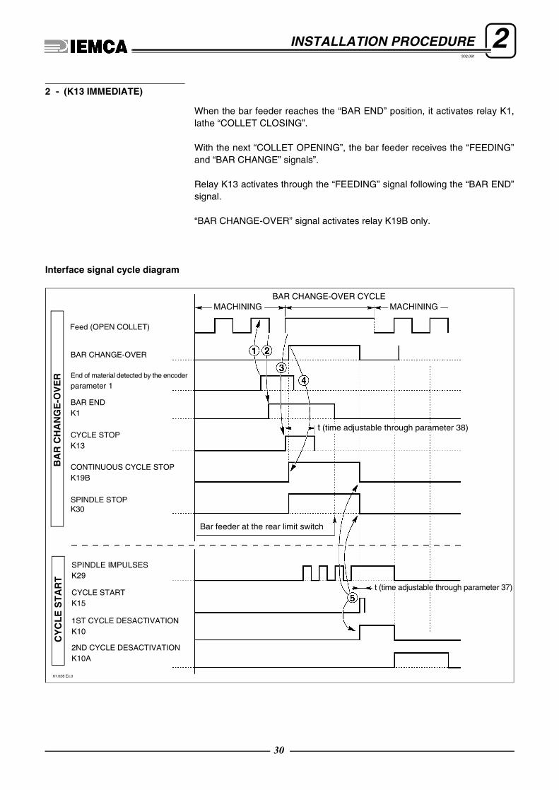
2INSTALLATION PROCEDURE302.061
When the bar feeder reaches the “BAR END” position, it activates relay K1,lathe “COLLET CLOSING”.
With the next “COLLET OPENING”, the bar feeder receives the “FEEDING”and “BAR CHANGE” signals”.
Relay K13 activates through the “FEEDING” signal following the “BAR END”signal.
“BAR CHANGE-OVER” signal activates relay K19B only.
Interface signal cycle diagram
2 - (K13 IMMEDIATE)
61.028 Ec.0
MACHINING
Feed (OPEN COLLET)
BAR CHANGE-OVER
parameter 1End of material detected by the encoder
K1BAR END
K13CYCLE STOP
K19BCONTINUOUS CYCLE STOPB
AR
CH
AN
GE
-OV
ER
BAR CHANGE-OVER CYCLE
t (time adjustable through parameter 38)
t (time adjustable through parameter 37)
K15CYCLE START
K101ST CYCLE DESACTIVATION
K10A2ND CYCLE DESACTIVATION
K29SPINDLE IMPULSES
CY
CL
E S
TA
RT
MACHINING
Bar feeder at the rear limit switch
SPINDLE STOPK30
30

2INSTALLATION PROCEDURE302.061
During lathe “OPEN COLLET” feeding, when the bar feeder detects the “BAREND” signal, relays K1-K13-K19B activates at the same time, thus allowingthe bar feeder to perform the “BAR CHANGE-OVER”.
Interface signal cycle diagram
3 - (IMMEDIATE RETURN)
t (time adjustable through parameter 37)
61.029 Ec.0
MACHINING
Feed (OPEN COLLET)
BAR CHANGE-OVER
parameter 1End of material detected by the encoder
K1BAR END
K13CYCLE STOP
K19BCONTINUOUS CYCLE STOP
BA
R C
HA
NG
E-O
VE
R
BAR CHANGE-OVER CYCLE
Bar feeder at the rear limit switch
t (time adjustable through parameter 38)
K15CYCLE START
K101ST CYCLE DESACTIVATION
K10A2ND CYCLE DESACTIVATION
K29SPINDLE IMPULSES
CY
CL
E S
TA
RT
MACHINING
SPINDLE STOPK30
31

2INSTALLATION PROCEDURE302.061
As far as “BAR CHANGE-OVER” signal control is concerned, this option dif-fers from option 1 - (RETURN).
Said signal controls more bar-pusher feeding movements, whenever they arerequired by lathe during workpiece machining.
In this condition, the “BAR CHANGE” controls the feeding of the bar feederand disables its return. The bar feeder return depends on the “FEEDING” si-gnal.
Interface signal cycle diagram
4 - (FEEDING)
61.030 Ec.0
MACHINING
Feed (OPEN COLLET)
parameter 1End of material detected by the encoder
K1BAR END
K13CYCLE STOP
K19BCONTINUOUS CYCLE STOP
BA
R C
HA
NG
E-O
VE
R
BAR CHANGE-OVER CYCLE
t (time adjustable through parameter 38)
t (time adjustable through parameter 37)
K15CYCLE START
K101ST CYCLE DESACTIVATION
K10A2ND CYCLE DESACTIVATION
K29SPINDLE IMPULSES
CY
CL
E S
TA
RT
MACHINING
2nd feed
WORK-PIECE
Bar feeder at the rear limit switch
SPINDLE STOPK30
32

2INSTALLATION PROCEDURE302.061
This option allows the lathe to check, at any cycle, if the bar feeder has rea-ched the “BAR END” position, thus activating relay K1.
Relays K13-K19B are activated at the following collet opening, through the“FEEDING” signal.
The return is controlled by the “FEEDING” signal.
Interface signal cycle diagram
5 - (K1 ENABLED)
61.031 Ec.0
MACHINING
Feed (OPEN COLLET)
BAR CHANGE-OVER
parameter 1End of material detected by the encoder
K1BAR END
K13CYCLE STOP
K19BCONTINUOUS CYCLE STOP
BA
R C
HA
NG
E-O
VE
R
BAR CHANGE-OVER CYCLE
Bar feeder at the rear limit switch
t (time adjustable through parameter 38)
t (time adjustable through parameter 37)
K15CYCLE START
K101ST CYCLE DESACTIVATION
K10A2ND CYCLE DESACTIVATION
K29SPINDLE IMPULSES
CY
CL
E S
TA
RT
MACHINING
SPINDLE STOPK30
33

2INSTALLATION PROCEDURE302.061
The bar end signal K1 is sent to the lathe as soon as the bar feeder detectsthe end of the bar.
0 - At the “FEEDING” signal the K2 relay is disabled when the bar feedingis performed; it is enabled when the bar reaches the bar stop (bar stopencoder).
1 - The K2 relay is enabled when the bar feeding is performed and disabledwhen the bar reaches the bar stop (bar stop encoder).
This is the thrust used during the FEEDING phase.
32Fase
machining
: > 0n o . 3 2 K 1 i mm e d i a t e e x i t
33Phase
machining
: > 0n o . 3 3 K 2 i n v e r s i o n
34Phase
machining
: > 3 0 0n o . 3 4 F e e d i n g t o r q u e
( 2 0 0 )
34

2INSTALLATION PROCEDURE302.061
Subparameters
0 - It actuates the feeding on the lathe’s bar stop.1 - It actuates the workpiece feeding, by the value set at Subparameters “Workpiece lenght”.2 - It actuates a workpiece feeding by the value set at Subparameters“Workpiece lenght”, it stops at a few millimetres from the bar stop, it performsanother feeding until the bar stop, on condition that the FEEDING signal is on.
35Phase
machining
: > 0n o . 3 5 F i x e d w o r k p i e c e f e e d i n g
C u t t i n g t o o l l e n g h t 3Wo r k p i e c e l e n g h t 9 7
61_034 Ec.0
parameter 35 = 1
parameter 35 = 2parameter 7
parameter 7
subparameterWorkpiece length
subparameterWorkpiece length
35

2INSTALLATION PROCEDURE302.061
Turns off the signalling of parameter 35 in position 1 at every use.
Defines the duration of the CYCLE START signal.
Defines the duration of the CYCLE STOP signal.
During bar change the signal stops the spindle.0 - The relay is disabled during bar change.1 - The relay remains always enabled.
36Phase
machining
: > 1n o . 3 6 K 1 5 D i s a b l i n g
37Phase
machining/bar change
: > 2 ( s e c )n o . 3 7 K 1 5 t i m e
38Phase
bar change
: > 5 ( s e c )n o . 3 8 K 1 3 t i m e
39Phase
bar change
: > 0n o . 3 9 S p i n d l e s t o p
36

2INSTALLATION PROCEDURE302.061
Subparameters
0 - Off1 - OnThis function is available when the lathe handles the workpiece feeding.In this case the bar feeder, having loaded the bar, stores the bar working len-gth and consequently the number of workpieces. The bar pusher moves back to the zero point and signals the end of bar tothe lathe only when the stored workpiece amount has been reached.Then, according to the value set in parameter 21 (REMNANT HANDLING),the bar feeder actuates the bar change.
INFORMATION: Once this parameter values are modified, the operatormust press the key to reset the previously set values.
INFORMATION: The subparameter "Sub-spindle feeding torque" mustbe set at a minimum value (0=MAX, 500=MIN). This will allow the bar pu-sher to reach the bar.
CAUTION: for a correct operation, the feed chain must be adequately tensioned.
Timing of the “BAR PUSHER RETURN” signal.
Subparameters
It allows changing the “NEW SPEED” in the “1st FEEDING” phase.
40Phase
machining
: > 0n o . 4 0 S u b s pi n d l e m o d e
C u t t i n g t o o l l e n g h t 3Wo r k p i e c e l e n g h t 9 7
S u b - s p i n d l e f e e d i n g t o r q u e 4 5 0N u m b e r o p e n i n g c o l le t w o r k pi e c e p r o g r a m 1
42Phase
bar change
: > 1 ( s e c )n o . 4 2 B a r p u s h e r r e t u r n p a u s e
43Phase
bar change
: >n o . 4 3 F i r s t f e e d i n g s p e e d c h a n g e
C o n n e c t i o n a c c e l e r a t i o n * ( mm / s e c * s e c )N e w s p e e d 9 0 0 ( 8 0 0 ) ( mm / s e c )
N e w s p e e d p o i n t * ( mm )
37

2INSTALLATION PROCEDURE302.061
2.2. ERRORS - CAUSES - SOLUTIONS
The display may signal the occurrence of errors during the calibration of the bar feeder or the machining of pieces.These errors may be the result of incorrect programming, operational errors, or mechanical or electrical faults.When errors are detected, the bar feeder stops. To restore automatic cycle proceed as follows: – Restore the manual cycle. – Eliminate the cause of the error. – Restore the automatic cycle.The table below lists the error messages, their possible causes and the corresponding solutions.
INFORMATION: All error signals must be reset by pushing the key.
CAUSE SOLUTION
A ZERO AXIS was attempted without first pressing the start button.
Press push-button and key at the
same time to start the bar feeder.
ERROR CAUSE SOLUTION
The bar pusher or the 1st feeding carriage motion does not perform the stroke within the set time.
The bar pusher or the first feeding carriage are not moving correctly.
Check the free and unimpeded move-ment of bar pusher, first feeding car-riage and chains.
Encoder fault.
Check that the encoder is driven cor-rectly.
Check on the display the position of the bar pusher carriage, and verify that the position change indicated corresponds to the actual movement.
1 P r e s s s t a r t f i r s t
2 E r r o r : w r o n g b a r p u s h e r m o v e m e n t
38

2INSTALLATION PROCEDURE302.061
ERROR CAUSE SOLUTION
The carriage has stopped moving.The bar pusher stop interface signal from the lathe is present.
Check the “INTERFACE FROM LATHE” signal.
Check the wiring.
CAUSE SOLUTION
The bar feeder magazine is empty. Fill the bar feeder magazine.
E r r o r : f e e d s t o p3
4 ( E r r o r : . . . )
5 ( E r r o r : . . . )
6 ( E r r o r : . . . )
7 E r r o r : n o b a r
39

2INSTALLATION PROCEDURE302.061
ERROR CAUSE SOLUTION
The bar met the first obstacle in the section defined by parameter 11 and was not able to continue.
The bar cannot go through the collet or the bushing of the lathe.
Check the diameter of the bushing.
If a shaped bar is being machined, check that the introduction area is suitable on the bar entry on the rear of the collet.
If the bar is shaped, check the revo-lutions of the spindle and that the impulse sequence is correct.
Check the torque of the clutch (parameter 13) and the feed set (parameter 12).
Encoder fault.
Check that the encoder is driven correctly in the rotation .
Check on the display the position of the bar pusher carriage, and verify that the position change indicated corresponds to the actual move-ment.
8c o l l e tE r r o r : t h e b a r f a i l s t o e n t e r i n t o t h e
Cparameter 11
IDM - 61.019 Ec.0
40

2INSTALLATION PROCEDURE302.061
ERROR CAUSE SOLUTION
At the beginning of the first feeding stroke, the short feed gate is not closed.
The gate could not close because of an obstacle.
Check that the area is free from obstruction (swarf, bar remnants, chips). Close the gate manually checking for obstructions.
Gate closed sensor fault.Check that when the gate moves, the sensor is triggered.
ERROR CAUSE SOLUTION
After “collet closed” the bar is at a position lower than that given by parameter 6 minus parameter 4.
The value of parameter 4 is too low.
Check the value of parameter 4 based on the length of the workpiece to be machined.
The collet lathe does not open correctly.
Check the correct opening of the collet lathe (at least 0.5 mm).
The push on the bar is not suffi-cient.
Check the values of parameter 4, and parameter 6.
Encoder fault.
Check that the encoder is driven cor-rectly in the rotation.
Check on the display the position of the bar pusher carriage, and verify that the position change indicated corresponds to the actual movement.
9 E r r o r : g a t e o p e n
10 E r r o r : s h o r t f e e d
parameter
IDM - 61.022 Ec.0
parameter
error 10
41

2INSTALLATION PROCEDURE302.061
ERROR CAUSE SOLUTION
During feed, the bar is at a position past that given by parameter 5 plus parameter 6.
The value of parameter 5 is too high.
Check the value of parameter 5 based on the length of the piece to be machined.
The lathe bar stop is not in the cor-rect position.
Check the correct position of the bar stop on the lathe.
Encoder fault.
Check that the encoder is driven correctly in the rotation .
Check on the display the position of the bar pusher carriage, and verify that the position change indicated corresponds to the actual move-ment.
ERROR CAUSE SOLUTION
The bar moves along the section defined at parameter 11, clears the first obstacle (the collet), but stops when it meets a second obstacle (bushing or other).
The bar has met with an obstacle past the impulse window (10 mm)..
Check the play of the bushing and the presence of foreign bodies (bar scraps or tool chips).
The push on the bar is not sufficient. Check the value of parameter 13.
Encoder fault.
Check that the encoder is driven correctly in the rotation .
Check on the display the position of the bar pusher carriage, and verify that the position change indicated corresponds to the actual move-ment.
11 E r r o r : l o n g f e e d
IDM - 61.023 Ec.0
parameter parameter
error 11
12 E r r o r : s t a t i o n a r y p o s i t i o n a f t e r i m p u l s e s
Cparameter 11
IDM - 61.020 Ec.0
42

2INSTALLATION PROCEDURE302.061
CAUSE SOLUTION
The amount of pieces set has been reached.Reset the number of workpieces at parameter 26, then restart.
ERROR CAUSE SOLUTION
The bar feeder is in AUTOMATIC MODE and the feed signal is active, but the bar feeder does not feed the bar.
One of the lathe door enabling the signal is open.
Check that the lathe door are clo-sed.
The “CLOSED DOOR” signal does not reach the bar feeder card.
Check the lathe output signal input-ted in the PLC (wire number, port)
The bar pusher stop interface signal from the lathe is present.
Check the “INTERFACE FROM LATHE” signal.
ERROR CAUSE SOLUTION
The lathe has stopped with the feed signal ON.
While in AUTOMATIC MODE, the lathe collet has remained open for a time longer than the value set in parameter 22.
Check the value of parameter 22, in relation to the actual time of “FEE-DING”.
13 ( E r r o r : . . . )
P r e s e t q . t y r e a c h e d , r e s e t ! ! !14
E r r o r : d o o r s a f e t y15
16 E r r o r : o p e n c o l l e t t i m e o u t
43

2INSTALLATION PROCEDURE302.061
ERROR CAUSE SOLUTION
The safety devices of the lathe are disabled.
The interface from lathe signal, which stops the bar feeder, is absent.
Check the “SAFETY FROM LATHE” interface signal.Check the lathe safety devices.
ERROR CAUSE SOLUTION
The bar feeder stopped and the K1, K2 LED of the K35 safety unit is also switched off.
An emergency stop push-button has been pressed.
Check the status of the emergency stop push-button.
An emergency signal from the lathe is active.
Check if the sequence of signals from the lathe is continuous: All the signals must either be open or clo-sed.
One of the covers of lathe or bar fee-der is open. Check that all covers are closed.
ERROR CAUSE SOLUTION
The bar feeder stopped or does not start.
No air.Check the pressure switch and the air system pressure.
17 E r r o r : s a f e t y f r o m l a t h e
18 E r r o r : b a r f e e d e r e m e r g e n c y
E r r o r : a i r p r e s s u r e s w i t c h19
44

2INSTALLATION PROCEDURE302.061
ERROR CAUSE SOLUTION
The short feed flag was not knocked down.
No bar.Load new bars into the bar feeder magazine.
ERROR CAUSE SOLUTION
The guide channel lifting levers do not lower.
During the BAR CHANGE the guide channel did not lower or the bar drop control did not switch off.
Check the cylinder motion.
Check the lever lifting and channel lifting sensors.
ERROR CAUSE SOLUTION
The machining cycle lasted longer than the time set in parameter 23.
The machining cycle required more time than set in parameter 23.
Check the settings of parameter 23 based on the actual work cycle.
The machining cycle was stopped or slowed down.
Check the effective length of the work cycle and ensure that it is not stopped or slowed down.
20 E r r o r : f l a g n o t k n o c k e d
21 E r r o r : n o l e v e r l o w e r i n g
22 E r r o r : w o r k p i e c e t i m e o u t
45

2INSTALLATION PROCEDURE302.061
ERROR CAUSE SOLUTION
The lathe failed to the thread on the current piece.
Threading device fault.Check the correct operation of the device on the lathe.
Threading device fault.Check the correct operation of the device (S99).
The bar did not move forward at the last "COLLET OPENING”.
Check the correct opening of the lathe collet and the push of the bar loader (parameter 34).
ERROR CAUSE SOLUTION
The lathe is not in AUTOMATIC mode.
An interface signal from the lathe is keeping the bar loader in MANUAL MODE.
Check the “INTERFACE FROM LATHE” signal.
23 E r r o r : t h r e a d s a f e t y
24 E r r o r : m a n / a u t f r o m l a t h e
25 ( E r r o r : . . . )
46

2INSTALLATION PROCEDURE302.061
ERROR CAUSE SOLUTION
The feed motor has stopped and is not restarting.
There is a problem with the drive of the motor.
Check the drive: The green LED of the control panel must be lighted.
The motor is shorted Check the shorted motor.
The temperature of the drive heat sink has reached the maximum per-missible value
Let the drive cool and wait about 15 minutes before powering on again.Check if the problem occurs again.
ERROR CAUSE SOLUTION
During the facing stroke, the bar has met an obstacle before reaching the section defined by parameter 11. There is an obstacle in the spindle
Check that there are no impedi-ments, or diameter differences such as to prevent the movement of the bar .
Check the number of revolutions of the spindle.
Encoder fault.
Check that the encoder is driven correctly in the rotation.
Check on the display the position of the bar pusher carriage, and verify that the position change indicated corresponds to the actual movement.
Card fault.Contact IEMCA technical assi-stance.
26 E r r o r : p r o t e c t e d m o t o r d r i v e
27i m p u l s e sE r r o r : s t a t i o n a r y p o s i t i o n b e f o r e
C parameter 11
IDM - 61.021 Ec.0 facing flag
47

2INSTALLATION PROCEDURE302.061
ERROR CAUSE SOLUTION
The bar feeder has stopped due to a fault.
Examples: Wrong bar-pusher move-ment, bar not loaded in collet, bar remnant missing, bar missing, etc..
Correct fault and reset with STOP push-button.
ERROR CAUSE SOLUTION
The bar feeder is not locked but is running.
The axial displacement device is not locked.
Lock the axial displacement device.
The sensor is not providing the OK signal.
Check that the sensor issues the signal when the axial displacement device is locked.
Check the correct operation of the sensor.
ERROR CAUSE CURE
After the key has been
pressed on the bar feeder keybo-ard, this message appears.
The “MANUAL” mode was actuated from the remote control panel on the lathe.
Move the selector switch of the remote control panel to the “AUTO-MATIC” position.
28 R e s e t w i t h S T O P ! ! !
29 E r r o r : a x i a l d i s p l a c e m e n t n o t l o c k e d
30 ( E r r o r : . . . )
31 E r r o r : Ma n u a l f r o m c o n t r o l p a n e l
48

2INSTALLATION PROCEDURE302.061
ERROR CAUSE CURE
After the selector switch on the remote control panel has been tur-ned to the “AUTOMATIC” position, this message appears.
The “MANUAL” mode was actuated from the keyboard on the bar fee-der.
To actuate the “AUTOMATIC” mode press the push-button on
the bar feeder keyboard.
CAUSE CURE
No value was set at parameter 40. Enter the values in the subparameters.
ERROR CAUSE SOLUTION
During the 1st feeding stroke the short feed control gate detected a bar which is too long.
The bar exceeds the maximum loa-dable length of bars.
Load bars of the maximum length allowed, which corresponds to the maximum length inside the lathe spindle.
32 E r r o r : Ma n u a l f r o m k e y b o a r d
33 ( E r r o r : s u b - s p i n d l e p a r a m e t e r s w r o n g
34 ( E r r o r : . . . )
35 E r r o r : b a r t o o l o n g
49

2INSTALLATION PROCEDURE302.061
ERROR CAUSE SOLUTION
The bar feeder does not actuate the function.
The bar reached the facing position, but the lathe did not restart.
Check the K15 interface signal: "Cycle Start".
Check the lathe.
CAUSE SOLUTION
When the operator presses the AUTOMATIC push-but-ton to actuate a bar change, the FEEDING signal is not received.
Check the corresponding interface signal.
Open the collet.
36 E r r o r : f a c i n g t i m e o u t
37 ( E r r o r : . . . )
38 ( E r r o r : . . . )
39 E r r o r : c o l l e t n o t o p e n
50

2INSTALLATION PROCEDURE302.061
CAUSE SOLUTION
It indicates that the bar pusher is not in the correct posi-tion.
Using the keyboard controls, regain the correct posi-tion.
ERROR CAUSE SOLUTION
The bar pusher does not go down.An attempt was made to lower the bar pusher with the bar pusher car-riage out of position.
Move the bar pusher carriage to the lower position.
CAUSE
Signals that the bar pusher carriage has returned.
ERROR CAUSE SOLUTION
Bar change was not completed in the expected time.
To monitor unexpected mechanical or electrical faults, a checking system stops the machine if the bar change cycle is not completed within a set time.
Verify the nature of the fault and restart the work cycle.In case of serious faults, contact IEMCA technical assistance.
40 E r r o r : b a r p u s h e r d o w n w a r d
41 ( E r r o r : . . . )
42 Mo v e c a r r i a g e t o b a c k l i m i t s t o p ! ! !
43 C a r r i a g e t o b a c k l i m i t s t o p ! ! !
44 F a i l u r e d u r i n g b a r c h a n g e
51

2INSTALLATION PROCEDURE302.061
ERROR CAUSE SOLUTION
Signals that the charge of the PLC batter is low.
Battery charge low.Replace the battery within one day (See Chapter 9 of the Use and Maintenance Manual).
ERROR SOLUTION
It indicates that the bar guide is not in the correct position.
Using the keyboard controls, regain the correct position by lowering the bar pusher.
ERROR SOLUTION
It indicates that the bar pusher is not in the correct position. Using the keyboard controls, regain the correct position.
ERROR CAUSE SOLUTION
The bar pusher did not move from the "UPWARD" to the "DOWNWARD" position.
The movement is hindered by an obstacle. Remove the obstacle.
The S2 microswitch (the bar pusher downwards device) is out of position or damaged.
Check the microswitch position or replace the microswitch.
45 P L C b a t t e r y e x h a u s t e d
46 B a r f e e d e r l i f t e d
47 B a r d r o p c o n t r o l o n
48 B a r p u s h e r u p w a r d
52

2INSTALLATION PROCEDURE302.061
2.3. PROGRAMME IDENTIFICATION DATA - Displaying procedures
The four programs installed in the bar feeder are as follows:- Push-button panel Firmware;- Push-button panel Software;- PLC/CN Software.- PLC/CN Firmware.For various reasons (e.g., request for assistance) it may be useful to displaythe identification data of the first three programs listed, according to the fol-lowing procedure. As regards the “PLC/CN Firmware” displaying the identifi-cation data is not particularly important.
❑ To display “Push-button panel Firmware” identification dataDisconnect power supply
Connect power supply again
it appears for afew seconds:
❑ To display “Push-button panel Software” and “PLC/CN Software” and “PLC/CN Fir-mware” identification data
turn the selector: onto position
press and keep pressed
it appears:
identification data of the push-button panel firmware
O P E R A T I ON MOD EU n i O P X X . X X
+/-F( )
| S wO P : X X X X X X & S w C N C : X X X X X X |
– – – – – – – – – – – [ X X X X X X R . X X ] – – – – – – – – – – –
– – – – – – – – – – – – – – – – – – – – – – – – – – – – – – – – – – – –
| F w : v . X X X X |
identification data of the push-button panel software
identification data of the PLC software
identification data of the PLC firmware
53

302.
088
GENIUS 112GENIUS 226
GUÍA OPERATIVA DEL TECLADOE
REL
S/N
PARA EL TECNICO AUTORIZADO
DATA COD
. 1 29/05/00 . 227005505
55
302.061
3 SETUP INFORMATION3.1. PROTECTED PARAMETERS FOR SETTING-UP - Description
ForewordThese parameters affect the bar feeder configuration and the bar feeder-lathe inter-face. Entering or modifying the value of such parameters is mainly required duringthe installation of the bar feeder, performed by an authorised technician.
CAUTION: Each parameter has a specific default value (preset value). If theoperator does not change these values, the bar feeder performs the automaticcycle according to them
INFORMATION: It is possible to enter or modify these parameter values only inthe appropriate data entering mode.To enter this mode, the procedure described in section 4.1.1 must be followed.This section’s pages are only destined to authorised technicians and might not beattached to this manual. It is the exclusive right of the manufacturer to distributethe information included herein.
During daily bar feeder utilization these parameters must not be modified.
The protected set-up parameters are made up of four sections:• Bar feeder phase parameters (paragraph 3.1.1);• Reference value parameters (paragraph 3.1.2);• Axis function parameters (paragraph 3.1.3);• Interface parameters (paragraph 3.1.4).• Parameters for generics (paragraph 3.1.5);

3SETUP INFORMATION302.061
❑ Accessing the setup protected parameters
Access the data entering mode
turn the selector: onto position
recall “MAIN MENU”press:
it appears:
press:
type access code:
if code iswrong, itappears:
wait a few seconds and repeat
if the code iscorrect, the firstprotected para-meter appears:
20MAIN
date time
language in which information is displayed
operations that canbe carried out
* * * ME N U * * *5 - 0 2 - 0 0 1 2 : 0 9 : 4 0
( G B ) ( P a r . 0) ( C o d e 0 ) → ) Mo v e– – – – – – – – – – – – – – – – – – – – – – – – – – – – – – – – – – – – – – – –
0 plus
0510 plus
* * * ME N U * * *5 - 0 2 - 0 0 1 2 : 0 9 : 4 0
( G B ) ( P a r . 0 ) ( C o d e X X X X ) → ) Mo v e– – – – – – – – – – – – – – – – – – – – – – – – – – – – – – – – – – – – – – – –
1* * * *
R E T U R Nn . 4 6 P HA S E 1
56

3SETUP INFORMATION302.061
❑ General procedures
Selecting the parameters in sequence
press: or
it appears. Ex:
Selecting the parameter required
Recall “MAIN MENU”press:
it appears:
press:
it appears:
enter the number of the parame-ter required. Example:
it appears. Ex:
Z E RO A X I Sn . 4 7 P h a s e 2
20MAIN
* * * ME N U * * *5 - 0 2 - 0 0 1 2 : 0 9 : 4 0
( G B ) ( P a r . 0) ( C o d e 0 ) → ) Mo v e– – – – – – – – – – – – – – – – – – – – – – – – – – – – – – – – – – – – – – – –
0
* * * ME N U * * *5 - 0 2 - 0 0 1 2 : 0 9 : 4 0
( G B ) ( P a r . ) ( C o d e 0 ) → ) Mo v e– – – – – – – – – – – – – – – – – – – – – – – – – – – – – – – – – – – – – – – –
10
60 più
( mm ) ( i n c h e s )n o . 6 0 1 s t F e e d i n g v a l u e ( B )
57

3SETUP INFORMATION302.061
❑ Subparameters
Some parameters have subparameters.To access the subparameters, scroll down the parameter screen image
press many times:
to return to the parameter screen image
press many times:
❑ Parameters with self-learned values
A default value is assigned to the parameters.Actually, some parameters are self-learned variables of the PLC, which varyduring normal bar feeder operation.
On the screenful reproduced on this manual, the self-learned value is repre-sented by an asterisk (*).
INFORMATION: the values assigned to the parameters are organized into two categories. The first one com-prises the values referring to the motor speed reduction ratio of reducer to 1/6 (standard va-lues); the second one ( values in bracktes ) includes the values referring to the motor speedreduction ratio of the reduce to 1/4.
❑ Quitting the setup protected parameters
Recall “MAIN MENU”
press:
Exit from data entering mode
turn the selector: onto position
20MAIN
58
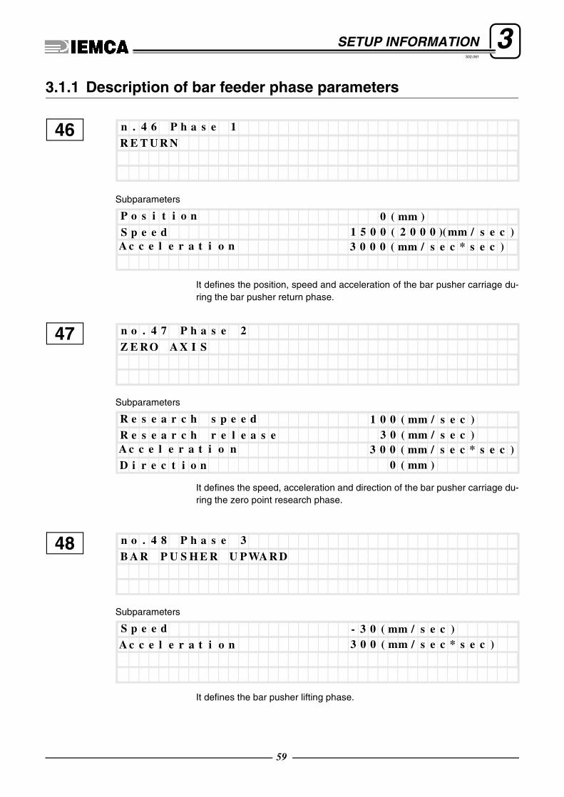
3SETUP INFORMATION302.061
3.1.1 Description of bar feeder phase parameters
Subparameters
It defines the position, speed and acceleration of the bar pusher carriage du-ring the bar pusher return phase.
Subparameters
It defines the speed, acceleration and direction of the bar pusher carriage du-ring the zero point research phase.
Subparameters
It defines the bar pusher lifting phase.
46R E T U R Nn . 4 6 P h a s e 1
S p e e d 1 5 0 0 ( 2 0 0 0 )( mm / s e c )P o s i t i o n 0 ( mm )
A c c e l e r a t i o n 3 0 0 0 ( mm / s e c * s e c )
47Z E RO A X I Sn o . 4 7 P h a s e 2
R e s e a r c h r e l e a s e 3 0 ( mm / s e c )R e s e a r c h s p e e d 1 0 0 ( mm / s e c )
D i r e c t i o n 0 ( mm )A c c e l e r a t i o n 3 0 0 ( mm / s e c * s e c )
48B A R P U S H E R U P WA R Dn o . 4 8 P h a s e 3
A c c e l e r a t i o n 3 0 0 ( mm / s e c * s e c )S p e e d - 3 0 ( mm / s e c )
59

3SETUP INFORMATION302.061
60
The phase during which the bar from the magazine is loaded on the guide.
The phase during which the guide is lifted and centred with reference to the spindle.
Subparameters
It defines the position, speed and acceleration of the bar pusher carriage du-ring the 1st feeding phase (see parameter 43).
49B A R L OA D I NGn o . 4 9 P h a s e 4
50GU I D E C HA N N E L L I F T I N Gn o . 5 0 P HA S E 5
511 s t F E E D I NGn o . 5 1 P HA S E 6
S p e e d 1 0 0 ( mm / s e c )P o s i t i o n * ( mm )
A c c e l e r a t i o n 2 8 0 ( mm / s e c * s e c )

3SETUP INFORMATION302.061
Subparameters
It defines the position, speed and acceleration of the bar pusher carriage du-ring the return phase, following the 1st feeding.
Subparameters
The phase during which the bar pusher is lowered.
Subparameters
It defines the bar’s position, speed and acceleration during the facing phase(see parameter 88)
52R E T U R N A F T E R 1 s t F E E D I N Gn o . 5 2 P h a s e 7
S p e e d 1 5 0 0 ( 2 0 0 0) ( mm / s e c )P o s i t i o n * ( mm )
A c c e l e r a t i o n 3 0 0 0 ( mm / s e c * s e c )
53B A R P U S H E R D OWNWA R Dn o . 5 3 P h a s e 8
A c c e l e r a t i o n 3 0 0 ( 4 0 0 0 )( mm / s e c * s e c )S p e e d - 3 0 ( mm / s e c )
54F A C I N Gn o . 5 4 P h a s e 9
S p e e d 4 0 0 ( 1 0 0 )( mm / s e c )P o s i t i o n * ( mm )
A c c e l e r a t i o n 3 0 0 ( 2 8 0 )(mm / s e c * s e c )
61

3SETUP INFORMATION302.061
62
3.1.2 Description of reference value parameters
It defines the maximum length of the loadable bar.
This is the 1st feeding stroke value, i.e. the distance between points 0 and B.
571 2 0 0 ( mm ) ( i n c h e s )
n o . 5 7 Ma x . b a r l e n g h t
601 6 2 2 ( mm ) ( i n c h e s )
n o . 6 0 1 s t F E E D I N G V A L U E ( B )
42
1
65
7 8
6
9 10
I
II
III
31.014 Ec.3
3
Legend:I - Fixed headstock lathe
II - Sliding headstock lathe III - Sliding steady rest lathe1 - Carriage “backwards” 2 - Bar-pusher “backwards”3 - Carriage “forwards”4 - Short feed door
5 - Bar-pusher “forwards”6 - Spindle7 - Headstock “backwards”8 - Headstock “forwards”9 - Steady rest “backwards”
10 - Steady rest “forwards”
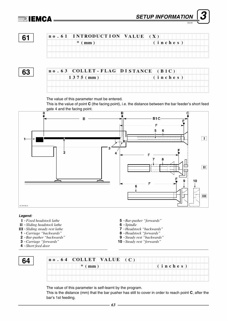
3SETUP INFORMATION302.061
The value of this parameter must be entered.This is the value of point C (the facing point), i.e. the distance between the bar feeder’s short feedgate 4 and the facing point.
The value of this parameter is self-learnt by the program.This is the distance (mm) that the bar pusher has still to cover in order to reach point C, after thebar’s 1st feeding.
61* ( mm ) ( i n c h e s )
n o . 6 1 I N T ROD U C T I ON V A L U E ( X )
631 3 7 5 ( mm ) ( i n c h e s )
n o . 6 3 C O L L E T - F L A G D I S T A N C E ( B 1 C )
42
1
65
7 8
6
9 10
I
II
III
31.014 Ec.3
3
Legend:I - Fixed headstock lathe
II - Sliding headstock lathe III - Sliding steady rest lathe1 - Carriage “backwards” 2 - Bar-pusher “backwards”3 - Carriage “forwards”4 - Short feed door
5 - Bar-pusher “forwards”6 - Spindle7 - Headstock “backwards”8 - Headstock “forwards”9 - Steady rest “backwards”
10 - Steady rest “forwards”
64* ( mm ) ( i n c h e s )
n o . 6 4 C O L L E T V A L U E ( C )
63

3SETUP INFORMATION302.061
The value of this parameter is self-learnt by the program.Value given by adding the value of point C and the value of parameter 2.
The value of this parameter is self-learnt by the program.This is the value of point F (the maximum bar pusher feed point), i.e. the distance between the barpusher’s rear end in the “completely backward” position and the maximum bar pusher feed point..
Position of the feeding carriage during the bar pusher lifting phase.
65* ( mm ) ( i n c h e s )
n o . 6 5 C O L L E T + F A C I NG V A L U E ( C I )
661 3 5 0 ( mm ) ( i n c h e s )
n o . 6 6 MA X . F E E D V A L U E ( F )
68* ( mm ) ( i n c h e s )
n o . 6 8 GU I D E CH A N N E L O P E N I N G MA X . V A L U E
64

3SETUP INFORMATION302.061
65
3.1.3 Axis function parameter description
INFORMATION: Once the parameter values are set, the power supply must be disabled and then enabled again,if the set values are to be self-learned.It is recommended to avoid changing these parameters; if a change is necessary, call the IEMCA service depart-ment.
Subparameters
70 n o . 7 0 A x i s p a r a m e t r i n g
I n v E n 1Mm I m p 2 8 5 7 , 5 ( mm / i m p . )
T i p A b 6I n v V o 0
T y A z z 1T o d A b 0
V e l M x 1 6 6 6 ( 2 5 0 0) ( mm /s e c )P D f h 1 ( mm )
A l g C o 0D e c Em 6 0 0 0 ( mm / s e c * s e c )
E r r E c 3 0 0 0 ( mm )P r c F d 0 ( % )
K P P 1 4 0K P M 1 5 0
KD 0K I 1
I n L i m 1C l e E i 1
T P 0 , 0 6 ( mm )I P 0 , 0 0 ( mm )

3SETUP INFORMATION302.061
Subparameters
It defines the speed of the bar pusher carriage related to key n. 13 on the push-button panel.
Subparameters
It defines the speed of the bar pusher carriage related to key n. 12 on the push-button panel.
Version Fc Max
141630
15
T i m S t 1 0 0 ( s e c / 1 0 0 0 )E p s S t 0 , 5 0 ( mm )
F c Ma x 1 6 3 0 ( mm )F c M i n - 1 2 ( mm )
71 n o . 7 1 S l o w f o r w a r d m o t i o n
A c c e l e r a t i o n 2 0 0 0 ( mm / s e c * s e c )S p e e d 2 0 0 ( mm / s e c )
72 n o . 7 2 S l o w b a c k w a r d m o t i o n
A c c e l e r a t i o n 2 0 0 0 ( mm / s e c * s e c )S p e e d - 2 0 0 ( mm / s e c )
66

3SETUP INFORMATION302.061
Subparameters
It defines the speed of the bar pusher carriage related to key n. 14 on the push-button panel.
Subparameters
It defines the speed of the bar pusher carriage related to key n. 11 on the push-button panel.
Subparameter
73 n o . 7 3 F a s t f o r w a r d m o t i o n
A c c e l e r a t i o n 2 0 0 0 ( mm / s e c * s e c )S p e e d 5 0 0 ( mm / s e c )
74 n o . 7 4 F a s t b a c k w a r d m o t i o n
A c c e l e r a t i o n 2 0 0 0 ( mm / s e c * s e c )S p e e d - 5 0 0 ( mm / s e c )
76 n o . 7 6 Z e r o r e s e a r c h m o t i o n
( s e e p a r a m e t e r N o . 4 7 )
67

3SETUP INFORMATION302.061
Subparameters
Subparameters
It defines the value of the clutch thrust.
It reverses the motioning direction of parameters 71,72,73 and 74.
Value Feed receiving the “reinforced clutch” device (Volt)
0 0
50 9,1
100 8,1
200 6,1
300 4,1
400 2,1
550 0,1
77 n o . 7 7 T h r u s t v a l u e p a i r c h e c k s e l e c t i o n
Ma n u a l t h r u s t v a l u e p a i r 1 5 0T h r u s t v a l u e f o r b a r c h a n g e 5 0
F e e d i n g t o r q u e 3 0 0( 2 0 0)C o l l e t i n l e t t o r q u e 1 5 0
T h r u s t v al u e p ai r b a r p u s h e r m o t i o n 3 0 0S u b s pi n d l e f e e di n g v a l u e p a i r 3 5 0
84: > 1n o . 8 4 O p p o s i t e k e y b o a r d
68

3SETUP INFORMATION302.061
3.1.4 Interface parameters - Description
Subparameters
It defines how to handle the interface signals from lathe to bar feeder.
85 n o . 8 5 I n t e r f a c e s i g n a l s
B a r c h a n g e ( 0 = N O / 1 = N C ) 0F e e d ( 0 = N O / 1 = N C ) 0
L o a d i n g c y c l e ( 0 = N O / 1 = N C ) 1Ma n u a l / a u t . f r o m l a t h e ( 0 = N O / 1 = N C ) 0
T h r e a d i n g s a f e t y ( 0 = N O / 1 = N C ) 0F e e d s t o p ( 0 = N O / 1 = N C ) 0 ( 0 )
S a f e t y f r o m l a t h e ( 0 = N O / 1 = N C ) 1S t a r t f r o m l a t h e ( 0 = N O / 1 = N C ) 0
S t a r t u p s a f e t y ( 0 = K 3 7 / 1 = K 1 6 6 ) 1D o o r s a f e t y ( 0 = N O / 1 = N C ) 0
C h a n g e mm< - - > i n c h e s ( 0 = mm / 1 =i n c h e s ) 0S t a r t u p s t a r t ( 0 = N O / 1 = N C ) 0
69

3SETUP INFORMATION302.061
3.1.5 Description of generic parameters
Subparameters
It defines the speed and acceleration with which the bar, during the 1st feeding, is carried to point B.
87 n o . 8 7 F i r s t f e e d i n g s p e e d c h a n g e
C o n n e c t i o n a c c e l e r a t . 8 0 0 ( 3 0 0 )( mm / s e c * s e c )N e w s p e e d 9 0 0 ( 8 0 0 )( mm / s e c )
N e w s p e e d p o i n t 6 0 0 ( 8 0 0 )( mm / s e c )
a51/87=acceleration parameter 51/87V51/87=speed parameter 51/87par_87vip.tif
parameter 87parameter 87
New speedpoint
70

3SETUP INFORMATION302.061
Subparameters
It defines the speed and acceleration with which the bar is fed along the path set at parameter 11.
0 - disabled1 - enabled.To operate this mode, the parameter 35 must be set to 1, the parameter 6 to 200 mm (for instance)and the parameter 85 (“Bar change”) to 1.
88 n o . 8 8 F a c i n g s p e e d c h a n g e
C o n n e c t i o n a c c e l e r a t . 2 0 0 0 (5 0 0 )( mm / s e c * s e c )N e w s p e e d ( s e e p a r a m . N o . 1 2 ) * ( mm / s e c )
N e w s p e e d p o i n t * ( mm / s e c)
a54=acceleration parameter 54V12=speed parameter 12
V54=speed parameter 54
par_88vip.tif
parameter 87parameter 11
parameter 54
parameter 88
89: > 0n o . 8 9 E x h i b i t i o n d e m o
71

3SETUP INFORMATION302.061
0 - K37 enabled with guide channels closed in manual mode.1 - Bar feeder in manual mode and lathe in automatic mode.
0The bar feeder goes into "ALARM" when, in "MANUAL" cycle, movements are performed (e.g.:"bar pusher lifting", "guide channel lifting"). The bar feeder exits from the "WORKING" phase, whi-ch will need to be reset. "BAR FEEDER WAITING" will appear on the display.
1If the bar feeder is in manual mode, at the feeding first signal it goes into “ALARM”.
CAUTION: With the “MANUAL/AUTOMATIC” signal from lathe, if the bar feeder is in “MA-NUAL” mode from lathe, this safety is off.
Subparameters
It defines the speed and acceleration with which the carriage is pushed back when the bar pusheris lifted or lowered.
90: > 0n o . 9 0 Wr o n g b a r f e e d e r p h a s e
92 n o . 9 2 B a r p u s h e r b a c k w a r d m o t i o n
A c c e l e r a t i o n 3 0 0 ( mm / s e c * s e c )S p e e d - 3 0 ( mm / s e c )
72

3SETUP INFORMATION302.061
Tolerance referred to parameter 46.
Tolerance referred to parameter 60.
Tolerance referred to parameter 68.
96: > 4 ( mm )n o . 9 6 R e t u r n s a f e t y < – > P . 4 6 D
97: > 4 ( mm )n o . 9 7 1 s t F e e d i n g s a f e t y < – > P . 6 0
98: > 4 ( mm )n o . 9 8 R e t u r n a f t e r 1 s t f e e d . s a f e t y < – > P . 6 8
73


302.061
REQUEST FOR ASSISTANCE
For requests for assistance, send the list of parame-ters compiled, together with the values assigned (atta-chments A, B, C, D, E, F), to the IEMCA service.
It is also necessary to transmit the identification data ofthe HARDWARE installed in the bar feeder (attach-ment G).
❑ Example of filling in
302.061


302.061
A
Customer Date
Bar feeder model Y/N
Machine tool model
no. par.
Description of parametersDefaultvalue
Assigned value
Page
1 Bar end adjustment 100 mm-inch 18
2 Facing length 0 mm-inch 18
3 Facing mode 0 18
4 Short feed safety 0 mm-inch 19
5 Long feed safety 0 mm-inch 19
6 Workpiece lenght 0 mm-inch 20
7 Open collet speed 200 mm/sec 21
8 Open collet acceleration 500 mm/sec2 21
9 Open collet thrust delay 0 sec 21
10 Closed collet thrust delay 1 sec 21
11 Collet entry slowing down 200 mm-inch 21
12 Collet entry speed 200 mm/sec 22
13 Collet inlet torque 150 22
14 Impulse number 10 22
15 Impulse stroke 10 mm-inch 22
18 Spindle impulses on 0,5 sec 23
19 Spindle impulses off 2 sec 23
20 Cycle start delay 1 sec 23
21 Remnant handling 1 23
22 Open collet timeout 0 sec 25
23 Workpiece timeout 0 sec 25
25 Bar pusher return collet closed 10 26
26 Workpieces prior to lathe stop 0 27
27 Minutes prior to lathe stop 0 min 27
29 Max. feeding position modification 0 mm-inch 28
30 Language 1I - 2GB - 3D 1 29
31 Bar feeder interface control 1 29
LIST OF GENERIC PARAMETERS

302.061
A
no. par.
Description of parametersDefaultvalue
Assigned value
Page
32 k1 immediate exit 0 34
33 k2 inversion 0 34
34 Feeding torque 300 34
35
Fixed workpiece feeding 035Workpiece lenght 97
Cutting tool lenght 3
36 k15 Disabling 1 36
37 K15 time 2 sec 36
38 K13 time 5 sec 36
39 Spindle stop 0 36
41
Sub spindle mode 0 mm-inch
37Workpiece lenght 97
Cutting tool lenght 3
Number opening collet workpiece program 1
Sub-spindle feeding torque 350
42 Bar pusher return pause 1 sec 37
43
First feeding speed change
37New speed 900 mm/sec
Connection acceleration 800 mm/sec2
New speed point 600 mm

302.061
B
Customer Date
Bar feeder model Y/N
Machine tool model
no. par.
Description of parametersDefaultvalue
Assigned value
Page
46
Phase 1 - RETURN
59Position 0 mm
Speed 1500 mm/sec
Acceleration 3000 mm/sec2
47
Phase 2 - ZERO AXIS
59
Research speed 100 mm
Release speed 30 mm/sec
Acceleration 300 mm/sec2
Direction 0
48
Phase 3 - BAR PUSHER UPWARD59Speed -30 mm/sec
Acceleration 300 mm/sec2
49 Phase 4 - BAR LOADING 60
50 Phase 5 - GUIDE CHANNEL LIFTING 60
51
Phase 6 - FIRST FEEDING
60Position 1621 mm
Speed 100 mm/sec
Acceleration 280 mm/sec2
52
Phase 7 - RETURN AFTER FIRST FEEDING
61Position 0 mm
Speed 1500 mm/sec
Acceleration 3000 mm/sec2
53
Phase 8 -BAR PUSHER DOWNWARD 61
Speed -30 mm/sec
Acceleration 300 mm/sec2
54
Phase 9 - FACING
61Position 690 mm
Speed 400 mm/sec
Acceleration 300 mm/sec2
LIST OF BAR FEEDER PHASE PARAMETERS

302.061
B

302.061
Customer Date
Bar feeder model Y/N
Machine tool model
no. par.
Description of parametersDefaultvalue
Assigned value
Page
57 Max . bar lenght 1200 mm-inch 62
60 First feeding value (B) 1622 mm-inch 62
61 Bar loading value (X) / mm-inch 63
63 Collet-flag distance (B1C) 1375 mm-inch 63
64 Collet value (C) 365,74 mm-inch 63
65 Collet + facing value (CI) 365,74 mm-inch 64
66 Max. feed value (F) 1350 mm-inch 64
68 Guide channel opening max. value 0 mm-inch 64
LIST OF REFERENCE VALUE PARAMETERS
C


302.061
D
Customer Date
Bar feeder model Y/N
Machine tool model
no. par.
Description of parametersDefaultvalue
Assigned value
Page
70
Axis parametring
65
MmImp 2857,5 mm/imp.
InvEn 1
InvVo 0
TipAb 6
TodAb 0
TyAzz 1
PDfh 1 mm
VelMx 1666 mm/sec
DecEm 6000 mm/sec2
AlgCo 0
PrcFd 0 %
ErrEc 3000 mm
KPM 150
KPP 140
KI 1
KD 0
CleEi 1
InLim 1
IP 0 mm
TP 0,06 mm
EpsSt 0,50 mm
TimSt 100 sec/1000
FcMin -12 mm
FcMax 1630 mm
71
Slow forward motion
66Speed 200 mm/sec
Acceleration 2000 mm/sec2
72
Slow backward motion
66Speed -200 mm/sec
Acceleration 2000 mm/sec2
LIST OF AXIS FUNCTION PARAMETERS

302.061
D
no. par.
Description of parametersDefaultvalue
Assigned value
Page
73
Fast forward motion
67Speed 500 mm/sec
Acceleration 2000 mm/sec2
74
Fast backward motion
67Speed -500 mm/sec
Acceleration 2000 mm/sec2
76 Zero point research motion 67
77
Thrust value pair check selection
68
Thrust value for bar change 50
Manual thrust value pair 150
Collet inlet torque 150
Feeding torque 200
Sub spindle feeding value pair 350
Thrust value pair bar pusher motion 300
84 Opposite keyboard 1 68

302.061
Customer Date
Bar feeder model Y/N
Machine tool model
no. par.
Description of parametersDefaultvalue
Assigned value
Page
85
Interface signals
69
Feed 0
Bar change 0
Manual/automatic from lathe 0
Loading cycle 1
Feed stop 0
Threading safety 0
Start from lathe 0
Safety from lathe 1
Door safety 0
Startup safety 0
Startup start 0
LIST OF INTERFACE PARAMETERS
E

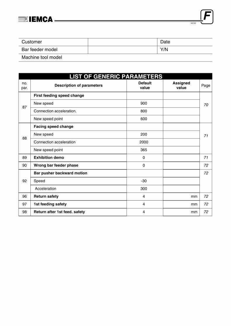
302.061
Customer Date
Bar feeder model Y/N
Machine tool model
no. par.
Description of parametersDefaultvalue
Assigned value Page
87
First feeding speed change
70New speed 900
Connection acceleration. 800
New speed point 600
88
Facing speed change
71New speed 200
Connection acceleration 2000
New speed point 365
89 Exhibition demo 0 71
90 Wrong bar feeder phase 0 72
92
Bar pusher backward motion 72
Speed -30
Acceleration 300
96 Return safety 4 mm 72
97 1st feeding safety 4 mm 72
98 Return after 1st feed. safety 4 mm 72
LIST OF GENERIC PARAMETERS
F


302.061
Customer Date
Bar feeder model Y/N
Machine tool model
PLC card serial number:
Enabling card serial number:
EEPROM model:
HARDWARE IDENTIFICATION DATA
G