Video sensor network for real-time traffic monitoring and surveillance
10
Published in IET Intelligent Transport Systems Received on 13th November 2008 Revised on 20th August 2009 doi: 10.1049/iet-its.2008.0092 ISSN 1751-956X Video sensor network for real-time traffic monitoring and surveillance T. Semertzidis K. Dimitropoulos A. Koutsia N. Grammalidis Informatics and Telematics Institute, Centre for Research and Technology Hellas, 1st km Thermi-Panorama Road, Thessaloniki 57001, Greece E-mail: [email protected] Abstract: Sensor networks and associated infrastructures become ever more important to the traffic monitoring and control because of the increasing traffic demands in terms of congestion and safety. These systems allow authorities not only to monitor the traffic state at the detection sites, but also to obtain real-time related information (e.g. traffic loads). This study presents a real-time vision system for automatic traffic monitoring based on a network of autonomous tracking units (ATUs) that capture and process images from one or more pre-calibrated cameras. The proposed system is flexible, scalable and suitable for a broad field of applications, including traffic monitoring of tunnels at highways and aircraft parking areas at airports. Another objective of this work is to test and evaluate different image processing and data fusion techniques in order to be incorporated to the final system. The output of the image processing unit is a set of information for each moving object in the scene, such as target ID, position, velocity and classification, which are transmitted to a remote traffic control centre, with remarkably low bandwidth requirements. This information is analysed and used to provide real-time output (e.g. alerts, electronic road signs, ramp meters etc.) as well as to extract useful statistical information (traffic loads, lane changes, average velocity etc.). 1 Introduction Increasing traffic demands render necessary the use of intelligent systems for monitoring, control and management of traffic. These systems support traffic data collection mechanisms along with intelligent incident detection and prediction models as well as dynamic applications of data analysis techniques for target classification. Improved management of traffic is expected to alleviate present and future congestion and safety problems in a broad field of traffic applications (highways, airports etc.). One approach for addressing this need is by using new imaging technologies stemming from the significant advances in the field of computer vision. Video surveillance along with advanced computer vision methods is already in use and provides significant aid to human traffic control operators in traffic monitoring and management tasks. However, robust and accurate detection and tracking of moving objects still remains a difficult problem for the majority of computer vision applications. Especially in the case of outdoor video surveillance, such as traffic monitoring, the visual tracking problem is particularly challenging because of illumination of background changes, occlusion problems etc. Many commercial and research systems use video processing, aiming to solve specific problems in traffic monitoring. An efficient application for monitoring and surveillance from multiple cameras is the reading people tracker (RPT) [1], which was later used as a base for the development of a system called AVITRACK, which monitors airplane servicing operations [2]. An example of a commercial system for monitoring and controlling road traffic is Autoscopew Solo Wide Area Video Vehicle Detection System [3], which was also used in the FP5 INTERVUSE project [4], for the development of an artificial vision network-based system for monitoring the ground traffic at airports. Other commercial products for road traffic monitoring are VisioPad [5], VideoTrak 910 [6], TraffiCam [7], Vantage Iteris Monitoring Video Detection System [8] and ABT2000 [9]. In Vitus-1 study [10], more video-based systems especially for tunnel IET Intell. Transp. Syst., 2010, Vol. 4, Iss. 2, pp. 103–112 103 doi: 10.1049/iet-its.2008.0092 & The Institution of Engineering and Technology 2010 www.ietdl.org
Transcript of Video sensor network for real-time traffic monitoring and surveillance
IEdo
www.ietdl.org
Published in IET Intelligent Transport SystemsReceived on 13th November 2008Revised on 20th August 2009doi: 10.1049/iet-its.2008.0092
ISSN 1751-956X
Video sensor network for real-time trafficmonitoring and surveillanceT. Semertzidis K. Dimitropoulos A. Koutsia N. GrammalidisInformatics and Telematics Institute, Centre for Research and Technology Hellas, 1st km Thermi-Panorama Road,Thessaloniki 57001, GreeceE-mail: [email protected]
Abstract: Sensor networks and associated infrastructures become ever more important to the traffic monitoringand control because of the increasing traffic demands in terms of congestion and safety. These systems allowauthorities not only to monitor the traffic state at the detection sites, but also to obtain real-time relatedinformation (e.g. traffic loads). This study presents a real-time vision system for automatic traffic monitoringbased on a network of autonomous tracking units (ATUs) that capture and process images from one or morepre-calibrated cameras. The proposed system is flexible, scalable and suitable for a broad field of applications,including traffic monitoring of tunnels at highways and aircraft parking areas at airports. Another objective ofthis work is to test and evaluate different image processing and data fusion techniques in order to beincorporated to the final system. The output of the image processing unit is a set of information for eachmoving object in the scene, such as target ID, position, velocity and classification, which are transmitted to aremote traffic control centre, with remarkably low bandwidth requirements. This information is analysed andused to provide real-time output (e.g. alerts, electronic road signs, ramp meters etc.) as well as to extractuseful statistical information (traffic loads, lane changes, average velocity etc.).
1 IntroductionIncreasing traffic demands render necessary the use ofintelligent systems for monitoring, control andmanagement of traffic. These systems support traffic datacollection mechanisms along with intelligent incidentdetection and prediction models as well as dynamicapplications of data analysis techniques for targetclassification. Improved management of traffic is expectedto alleviate present and future congestion and safetyproblems in a broad field of traffic applications (highways,airports etc.). One approach for addressing this need is byusing new imaging technologies stemming from thesignificant advances in the field of computer vision. Videosurveillance along with advanced computer vision methodsis already in use and provides significant aid to humantraffic control operators in traffic monitoring andmanagement tasks. However, robust and accurate detectionand tracking of moving objects still remains a difficultproblem for the majority of computer vision applications.Especially in the case of outdoor video surveillance, such as
T Intell. Transp. Syst., 2010, Vol. 4, Iss. 2, pp. 103–112i: 10.1049/iet-its.2008.0092
traffic monitoring, the visual tracking problem isparticularly challenging because of illumination ofbackground changes, occlusion problems etc.
Many commercial and research systems use videoprocessing, aiming to solve specific problems in trafficmonitoring. An efficient application for monitoring andsurveillance from multiple cameras is the reading peopletracker (RPT) [1], which was later used as a base for thedevelopment of a system called AVITRACK, whichmonitors airplane servicing operations [2]. An example of acommercial system for monitoring and controlling roadtraffic is Autoscopew Solo Wide Area Video VehicleDetection System [3], which was also used in the FP5INTERVUSE project [4], for the development of anartificial vision network-based system for monitoring theground traffic at airports. Other commercial products forroad traffic monitoring are VisioPad [5], VideoTrak 910[6], TraffiCam [7], Vantage Iteris Monitoring VideoDetection System [8] and ABT2000 [9]. In Vitus-1 study[10], more video-based systems especially for tunnel
103
& The Institution of Engineering and Technology 2010
10
&
www.ietdl.org
applications are presented. Moreover, several studies havebeen made on the evaluation of traffic video systems.Specifically, the University of Utah has summarised a statusof detector technologies [11], whereas the NIT project(non-intrusive technologies) of University of Minnesotaevaluates technologies for traffic detection [12]. Recently,the Texas Transportation Institute has presented aninvestigation of vehicle detector performance, in which fourvideo image vehicle detection systems are tested [13].
In this paper, we present a novel multi-camera videosurveillance system, which supports functionalities such asdetection, tracking and classification of objects movingwithin the supervised area. Whereas the majority of existingcommercial and research traffic surveillance systems havebeen designed to cope with specific scenarios, the proposedsystem is applicable to a broad field of traffic surveillanceapplications (highways, airports, tunnels etc.). Its mainadvantages are extensibility, parameterisation and itscapability to support various image processing and datafusion techniques so as to be easily adaptable to differenttraffic conditions.
More specifically, the system is based on a network ofintelligent autonomous tracking units (ATUs), whichcapture and process images from a network of pre-calibrated visual sensors. ATUs provide results to a centralsensor data fusion (SDF) server, which is responsible fortracking and visualising moving objects in the scene as wellas collecting statistics and providing alerts when specificsituations are detected. In addition, depending on theavailable network bandwidth, images captured from specificvideo sensors may also be coded and transmitted to theSDF server, to allow inspection by a human observer (e.g.traffic controller). The topology of the ATUs networkvaries in each application depending on the existinginfrastructure, geomorphologic facts and/or bandwidth aswell as cost limitations. The network architecture is based ona wired or wireless transmission control protocol and internetprotocol suite (TCP/IP) connection. These topologies can becombined to produce a hybrid network of ATUs. Theproposed solution has been developed within the frameworkof TRAVIS (TRAffic VISual monitoring) research project. Inour previous publications [14–16], we presented evaluationresults from the supported image processing and data fusiontechniques. In this paper, we focus on the evaluation of theoverall system’s performance in two completely differenttraffic scenarios such as tunnels and airports.
2 ATUsEach ATU is a powerful processing unit (PC or embeddedPC), which periodically obtains frames from one or morevideo sensors. The video sensors are standard closed-circuittelevision (CCTV) cameras equipped with a casingappropriate for outdoor use and telephoto lenses for distantobservation. They are also static (fixed field of view) andpre-calibrated. Each ATU consists of the following modules:
4The Institution of Engineering and Technology 2010
† Calibration module (off-line unit to calibrate each videosensor): To obtain the exact position of the targets in thereal world, the calibration of each camera is required, sothat any point can be converted from image coordinates(measured in pixels from the top left corner of the image)to ground coordinates and vice versa. A calibrationtechnique, which is based on a 3 � 3 homographictransformation and uses both points and linescorrespondences, was used [17]. The observed targets aresmall with respect to the distance from the video sensorsand they are moving on a ground surface, which thereforecan be approximated by a plane. For the calibration of acamera the world coordinates of at least four points (orlines) within its field of view as well as their correspondingimage coordinates are required. In case of cameras withpartially overlapping field of views relative calibration withrespect to an already calibrated camera can be used. Forthis purpose, a tool for calibrating camera pairs withpartially overlapping field of views was developed. The toolvisualises the camera views, one of which is the calibratedview according to which the other camera is calibrated. Itthen allows the user to specify corresponding points on thetwo views before it warps them on the ground plane asshown in Fig. 1. The procedure is repeated until allcameras with partially overlapping field of views arecalibrated.
† Background extraction and update module: Each ATU ofthe system can automatically deal with background changes(e.g. grass or trees moving in the wind) or lighting changes(e.g. day, night etc.) supporting several robust backgroundextraction algorithms, namely mixture of Gaussiansmodelling [18], Bayes algorithm [19], Lluis–Miralles–Bastidas method [20] and non-parametric modelling [21].In experimental results presented in our previouspublications [14, 15], the non-parametric modellingemerges as the one having the best trade-off betweenresults quality and execution times.
† Foreground segmentation module: Connected componentlabelling is applied to identify individual foreground objects.
† Blob tracking module (optional): The multiple hypothesistracker [22] was used, although association and tracking ofvery fast moving objects may be problematic.
† Blob classification module: A set of classes of movingobjects (e.g. ‘person’, ‘car’ etc.) is initially defined for eachapplication. Then, each blob is classified by calculating itsmembership probability of each class, using a previouslytrained back-propagation neural network. Specifically, nineattributes, characteristic of its shape and size, are used asinput to a neural network: the two sizes of the major andminor axes of the blob’s ellipse and the seven Hu moments[23] of the blob that are invariant to both rotations andtranslations. The number of outputs of the neural networkequals to the predefined number of classes. The class isdetermined by the maximum output value.
IET Intell. Transp. Syst., 2010, Vol. 4, Iss. 2, pp. 103–112doi: 10.1049/iet-its.2008.0092

IEd
www.ietdl.org
Figure 1 Two camera views with partially overlapping field of views inserted in the calibration tool and the final output aftercalibration
a Right view with corresponding pointb Left view with corresponding pointc Two views are warped on the ground plane
o
† Three-dimensional observation extraction module: It usesthe available camera calibration information to estimate theaccurate position of targets in the scene. Since the cameracalibration is based on homographies, an estimate for theposition (xw, yw) of a target in the world coordinates can bedirectly determined from the centre of each blob. Eachobservation is also associated with a reliability matrix R,depending on the camera geometry and its position at thecamera plane. This matrix is calculated using the calibrationinformation [24]
R(xw, yw) ¼ J (xc, yc)LJ (xc, yc)T (1)
where L is the measurement covariance at location (xc, yc) onthe camera plane, which is assumed to be a fixed diagonalmatrix and J is the Jacobian matrix of the partial derivativesof the mapping functions between the camera and theworld coordinate systems. Supposing that gx and gy are thetwo mapping functions with gx(xc, yc) ¼ xw andgy(xc, yc) ¼ yw, then the Jacobian matrix is defined as
J (xc, yc) ¼
@gx(xc, yc)
@xc
@gx(xc, yc)
@yc
@gy(xc, yc)
@xc
@gy(xc, yc)
@yc
26664
37775
T Intell. Transp. Syst., 2010, Vol. 4, Iss. 2, pp. 103–112i: 10.1049/iet-its.2008.0092
The final output of each ATU is a small set of parameters(ground coordinates, classification, reliability), which istransmitted to the SDF server through wired or wirelesstransmission. If the foreground map fusion technique isused, a greyscale image is provided at each polling cycle,indicating the probability for each pixel to belong to theforeground.
3 Network communicationsThe TRAVIS system is based on client–server networkmodel where each ATU acts as a client to the SDFlistening server. The clients are connected to the server viaa wired connection or a wireless point-to-point or point-to-multipoint wifi/wimax connection. The ATUs are remotelycontrolled from the SDF server through a signallingchannel that enables the SDF server user to start/stopcapture of frames, change operational mode, capture cycleand other parameters. The signalling channel has beenimplemented in order to separate data transmission of theATUs from control signals sent by SDF.
Data fusion and multiple hypotheses tracking algorithms,run by the SDF server, require synchronised capture offrames of the scene using a constant sampling period. Tofulfil this requirement, the network time protocol (NTP) is
105
& The Institution of Engineering and Technology 2010

10
&
www.ietdl.org
used in order to synchronise system clocks of each computerin the TRAVIS network with reference to server’s systemclock. For this configuration, the SDF server was set asstratum 1 clock level in the NTP hierarchy, whereas everyATU set at stratum 2 clock level.
Even with synchronised system clocks, a capture commandfrom the server will not arrive at every ATU on the samemoment of time because of network latency, computerprocess delays and so on, which makes the coinstantaneousframe grabbing from all ATUs with millisecond accuracyimpossible. For this reason, a synchronised captureprocedure is used, which was first proposed in Litos et al.[25]. According to this algorithm, after the synchronisationof the system clocks, the SDF server sends to each ATU aspecific timestamp, indicating the time in the future whenthe ATUs will start capturing frames as well as the value ofthe (constant) frame sampling period.
3.1 Handshake procedure
After installation, all ATUs in the TRAVIS network are setin standby mode. At this phase, each ATU is listening in auser datagram protocol (UDP) port, defined during theinstallation procedure, for command by the server. WhenSDF server user clicks the start capturing button thehandshake procedure starts and a command is sent throughthe signalling channel notifying the ATUs for SDF’s IPaddress and port number. The next step is for ATUs torequest TCP connection from the listening SDF server.After all connections have been established and themeeting time has been reached, the system enters normaloperation. In the normal operation phase, SDF and ATUsoftware maintain timers to control frame capture andsynchronisation.
This handshake scheme simplifies both first installationand re-configuration of the nodes of TRAVIS network, since
† The SDF or ATU IP addresses are not a-priori required.
† Only the UDP port number where ATUs listen needs tobe known a-priori.
† The SDF creates a list of the connected ATUs and waitsfor their data.
3.2 Synchronisation maintenance
During normal operation, the ATUs calculate the timestampfor capturing every next frame in order to keep beingsynchronised to each other. After capturing the frame, imageprocessing techniques, as presented at previous section, areapplied to the captured frame, observations are extracted andfinally a packet is sent to SDF. On the other side, the serverreceives one packet from every ATU, checks the timestampsto certify that frames are synchronised and determines thatdata are ready to be fused. If one of the ATUs does not
6The Institution of Engineering and Technology 2010
complete frame processing within the available time cycle(abnormal function), the time window for sending data is lostand the data will arrive at the SDF server with delay. In thiscase, this packet is discarded from the server, while the ATUwill wait for the next valid window to capture a new frameand thus re-synchronise with the rest.
3.3 Secondary video streaming system
As a secondary backup system, the ATUs support on demandmedia streaming directly to the control centre, where SDFserver is installed, in order to assist operators when anaccident or other abnormal situation is reported.Depending on the available bandwidth, this secondarybackup system is able to stream compressed video or just anumber of compressed images. The application installed atthe control centre may render this input as Motion JPEG,MPEG4 or any other available format and present it in anew window. This service allows the operator to select thespecific ATU, watch the scene and validate the alarm.
4 SDF serverThe SDF server collects information from all ATUs using aconstant polling cycle, produces fused estimates of theposition and velocity of each moving target and tracks thesetargets using a multi-target tracking algorithm. It alsoproduces a synthetic ground situation display, collectsstatistical information about the moving targets and providesalerts when specific situations (e.g. accidents) are detected.
4.1 Data fusion
A target present simultaneously in the field of view ofmultiple cameras will result in multiple observationsbecause of the fact that the blob centres of the same objectin two different cameras correspond to close but different3-D points. The system supports two different techniquesfor grouping together all the observations that correspondto the same target. The first technique is the grid-basedfusion, which uses a grid to separate the overlap area incells. Optimal values for the cell size are determinedconsidering the application requirements (e.g. car size).Observations belonging to the same cell or to neighbouringcells are grouped together to a single fused observation [14].
The second technique is called foreground map fusion. Inthis technique, as mentioned in Section 2, each ATUprovides the SDF server with one greyscale image perpolling cycle, indicating the probability for each pixel tobelong to the foreground. The SDF server fuses these mapstogether by warping them to the ground plane andmultiplying them [26]. The fused observations are thengenerated from these fused maps using connectedcomponent analysis and classification information iscomputed as in the ATU’s blob classification module.Although this technique has increased computationaland network bandwidth requirements, when compared to
IET Intell. Transp. Syst., 2010, Vol. 4, Iss. 2, pp. 103–112doi: 10.1049/iet-its.2008.0092

IEdo
www.ietdl.org
grid-based fusion, it can very robustly resolve occlusionsbetween multiple views and provide more accurate results[14, 15],
4.2 Multiple target tracking
The tracking unit is based on the multiple hypothesistracking (MHT) algorithm, which starts tentative tracks onall observations and uses subsequent data to determinewhich of these newly initiated tracks are valid. Specifically,MHT [27] is a deferred decision logic algorithm in whichalternative data association hypotheses are formed wheneverthere are observation-to-track conflict situations. Then,rather than combining these hypotheses, the hypotheses arepropagated in anticipation that subsequent data will resolvethe uncertainty. Generally, hypotheses are collections ofcompatible tracks. Tracks are defined to be incompatible ifthey share one or more common observation. MHT is astatistical data association algorithm that integrates thecapabilities of (i) track initiation: automatic creation of newtracks as new targets are detected; (ii) track termination:automatic termination of a track when the target is nolonger visible for an extended period of time; (iii) trackcontinuation: continuation of a track over several frames inthe absence of observations; (iv) explicit modelling ofspurious observations; and (v) explicit modelling ofuniqueness constraints: an observation may only beassigned to a single track at each polling cycle and vice versa.
Specifically, the tracking unit was based on a fastimplementation of the MHT algorithm [22]. A 2-DKalman filter was used to track each target and additionalgating computations are performed to discard observation –track pairs. More specifically, a ‘gate’ region is definedaround each target at each frame and only observationsfalling within this region are possible candidates to updatethe specific track. The accurate modelling of the targetmotion is very difficult, since a target may stop, move,accelerate and so on. Since only position measurements areavailable, a simple four-state (position and velocity alongeach axes) CV (constant velocity) target motion model inwhich the target acceleration is modelled as white noiseprovides satisfactory results.
5 Experimental resultsTwo prototypes were installed, each focusing on a differentaspect of traffic monitoring (airports, tunnels at highways).Extensive tests were made during pilot installations both at‘Macedonia’ airport of Thessaloniki, Greece and at a tunnelnear Piraeus harbour of Athens, in order to optimise theproposed system for each application. The maximumvehicle speed that the system can detect depends on theinstallation, while the system can cope well with smallvelocities. Parameters that affect the maximum speedlimitation are the area of coverage and the frame rate of thesystem. For example, a system configured to run at 2 f/sand cover road distance of 40 m can estimate target
T Intell. Transp. Syst., 2010, Vol. 4, Iss. 2, pp. 103–112i: 10.1049/iet-its.2008.0092
velocities up to 144 km/h. In the following subsections, thetwo prototype installations are discussed.
5.1 Airport prototype system
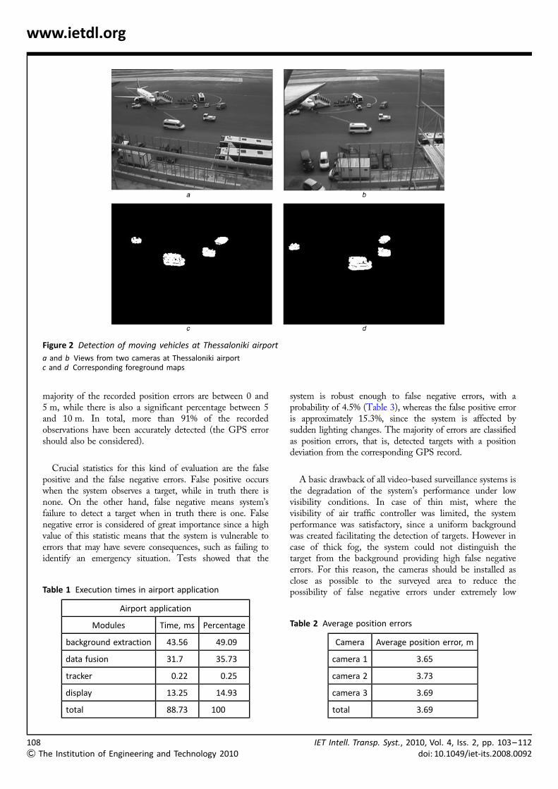
The first prototype system concerns the traffic control ofaircraft parking areas (APRON). The system calculates theposition, velocity and direction of the targets and classifiesthem according to their type (car, man, long vehicle etc.).Alerts are displayed in case of potentially dangeroussituations, such as speeding. This application also providesa graphical display of the ground situation at the APRON.This information can be accessible by the respective personresponsible, even if they are situated in a distant area, withno direct eye-contact to the APRON. The prototypesystem installed at ‘Macedonia’ airport of Thessalonikiconsists of three cameras, which were installed at the fourthfloor of the control tower, mounted at the balcony ledge.The cameras cover a great percentage of the APRON area(approximately 25 000 m2), while focusing in parking placenumber 4 of the airport APRON. The two ATUs (oneATU is connected with two cameras) and the SDF serverwere placed in the APRON control room of the tower andare interconnected through an Ethernet network. Fig. 2presents the views from two of the cameras installed atThessaloniki airport and the corresponding foregroundmaps using the non-parametric modelling method.
Table 1 presents the execution times per frame of the basicmodules of the system for the airport application and thepercentage of time spent at each procedure. All times havebeen acquired using the non-parametric modelling methodand the map fusion mode. The execution times are in therange of milliseconds, which shows that the proposedsolution is suitable for real-time traffic surveillance at airports.
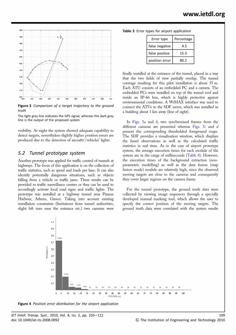
In order to analyse the results acquired by the system,ground truth data had to be acquired. For the airportprototype, tests have been conducted using cars equippedwith global positioning system (GPS) devices. The groundtruth data have been correlated with the system results andthen inserted into a database, along with relevantenvironmental parameters. A test analysis tool has also beenimplemented in order to calculate and display variousstatistics that can be acquired by comparing the results ofthe system with ‘ground truth’. Table 2 presents the averageposition error for each camera as well as the averageposition error of the system. Hence, the theoreticalobtainable accuracy of the system is approximately 3.69 m,which compares favourably to the performance of surface-movement radars (less than 7.5 m) according to the ICAOspecifications [28]. Fig. 3 presents the trajectory of afollow-up car (equipped with a GPS) moving on the yellowline of the parking position 4 and the correspondingtrajectory estimated by the proposed system.
The position error distribution for the three camerasinstalled at the airport application is shown in Fig. 4. The
107
& The Institution of Engineering and Technology 2010
10
&
www.ietdl.org
Figure 2 Detection of moving vehicles at Thessaloniki airport
a and b Views from two cameras at Thessaloniki airportc and d Corresponding foreground maps
majority of the recorded position errors are between 0 and5 m, while there is also a significant percentage between 5and 10 m. In total, more than 91% of the recordedobservations have been accurately detected (the GPS errorshould also be considered).
Crucial statistics for this kind of evaluation are the falsepositive and the false negative errors. False positive occurswhen the system observes a target, while in truth there isnone. On the other hand, false negative means system’sfailure to detect a target when in truth there is one. Falsenegative error is considered of great importance since a highvalue of this statistic means that the system is vulnerable toerrors that may have severe consequences, such as failing toidentify an emergency situation. Tests showed that the
Table 1 Execution times in airport application
Airport application
Modules Time, ms Percentage
background extraction 43.56 49.09
data fusion 31.7 35.73
tracker 0.22 0.25
display 13.25 14.93
total 88.73 100
8The Institution of Engineering and Technology 2010
system is robust enough to false negative errors, with aprobability of 4.5% (Table 3), whereas the false positive erroris approximately 15.3%, since the system is affected bysudden lighting changes. The majority of errors are classifiedas position errors, that is, detected targets with a positiondeviation from the corresponding GPS record.
A basic drawback of all video-based surveillance systems isthe degradation of the system’s performance under lowvisibility conditions. In case of thin mist, where thevisibility of air traffic controller was limited, the systemperformance was satisfactory, since a uniform backgroundwas created facilitating the detection of targets. However incase of thick fog, the system could not distinguish thetarget from the background providing high false negativeerrors. For this reason, the cameras should be installed asclose as possible to the surveyed area to reduce thepossibility of false negative errors under extremely low
Table 2 Average position errors
Camera Average position error, m
camera 1 3.65
camera 2 3.73
camera 3 3.69
total 3.69
IET Intell. Transp. Syst., 2010, Vol. 4, Iss. 2, pp. 103–112doi: 10.1049/iet-its.2008.0092
IEd
www.ietdl.org
visibility. At night the system showed adequate capability todetect targets, nevertheless slightly higher position errors areproduced due to the detection of aircrafts’/vehicles’ lights.
5.2 Tunnel prototype system
Another prototype was applied for traffic control of tunnels athighways. The focus of this application is on the collection oftraffic statistics, such as speed and loads per lane. It can alsoidentify potentially dangerous situations, such as objectsfalling from a vehicle or traffic jams. These results can beprovided to traffic surveillance centres or they can be used toaccordingly activate local road signs and traffic lights. Theprototype was installed at a highway tunnel near PiraeusHarbour, Athens, Greece. Taking into account existinginstallation constraints (limitations from tunnel authorities,slight left turn near the entrance etc.) two cameras were
Figure 3 Comparison of a target trajectory to the groundtruth
The light grey line indicates the GPS signal, whereas the dark greyline is the output of the proposed system
T Intell. Transp. Syst., 2010, Vol. 4, Iss. 2, pp. 103–112oi: 10.1049/iet-its.2008.0092
finally installed at the entrance of the tunnel, placed in a waythat the two fields of view partially overlap. The tunnelcoverage resulting for this pilot installation is about 35 m.Each ATU consists of an embedded PC and a camera. Theembedded PCs were installed on top of the tunnel roof andinside an IP-66 box, which is highly protective againstenvironmental conditions. A WiMAX interface was used toconnect the ATUs to the SDF server, which was installed ina building about 1 km away (line of sight).
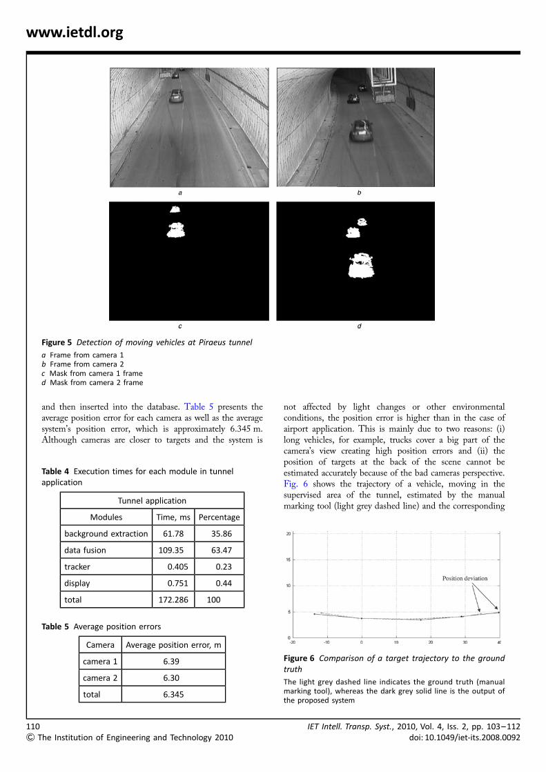
In Figs. 5a and b, two synchronised frames from thedifferent cameras are presented whereas Figs. 5c and dpresent the corresponding thresholded foreground maps.The SDF provides a visualisation window, which displaysthe fused observations as well as the calculated trafficstatistics in real time. As in the case of airport prototypesystem, the average execution times for each module of thesystem are in the range of milliseconds (Table 4). However,the execution times of the background extraction (non-parametric modelling) as well as the data fusion (mapfusion mode) module are relatively high, since the observedmoving targets are close to the cameras and consequentlythey cover larger regions on the camera frame.
For the tunnel prototype, the ground truth data werecollected by viewing image sequences through a speciallydeveloped manual marking tool, which allows the user tospecify the correct position of the moving targets. Theground truth data were correlated with the system results
Table 3 Error types for airport application
Error type Percentage
false negative 4.5
false positive 15.3
position error 80.2
Figure 4 Position error distribution for the airport application
109
& The Institution of Engineering and Technology 2010
11
&
www.ietdl.org
Figure 5 Detection of moving vehicles at Piraeus tunnel
a Frame from camera 1b Frame from camera 2c Mask from camera 1 framed Mask from camera 2 frame
and then inserted into the database. Table 5 presents theaverage position error for each camera as well as the averagesystem’s position error, which is approximately 6.345 m.Although cameras are closer to targets and the system is
Table 4 Execution times for each module in tunnelapplication
Tunnel application
Modules Time, ms Percentage
background extraction 61.78 35.86
data fusion 109.35 63.47
tracker 0.405 0.23
display 0.751 0.44
total 172.286 100
Table 5 Average position errors
Camera Average position error, m
camera 1 6.39
camera 2 6.30
total 6.345
0The Institution of Engineering and Technology 2010
not affected by light changes or other environmentalconditions, the position error is higher than in the case ofairport application. This is mainly due to two reasons: (i)long vehicles, for example, trucks cover a big part of thecamera’s view creating high position errors and (ii) theposition of targets at the back of the scene cannot beestimated accurately because of the bad cameras perspective.Fig. 6 shows the trajectory of a vehicle, moving in thesupervised area of the tunnel, estimated by the manualmarking tool (light grey dashed line) and the corresponding
Figure 6 Comparison of a target trajectory to the groundtruth
The light grey dashed line indicates the ground truth (manualmarking tool), whereas the dark grey solid line is the output ofthe proposed system
IET Intell. Transp. Syst., 2010, Vol. 4, Iss. 2, pp. 103–112doi: 10.1049/iet-its.2008.0092
IETdo
www.ietdl.org
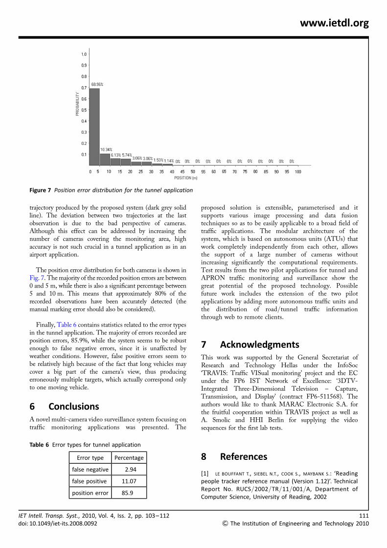
Figure 7 Position error distribution for the tunnel application
trajectory produced by the proposed system (dark grey solidline). The deviation between two trajectories at the lastobservation is due to the bad perspective of cameras.Although this effect can be addressed by increasing thenumber of cameras covering the monitoring area, highaccuracy is not such crucial in a tunnel application as in anairport application.
The position error distribution for both cameras is shown inFig. 7. The majority of the recorded position errors are between0 and 5 m, while there is also a significant percentage between5 and 10 m. This means that approximately 80% of therecorded observations have been accurately detected (themanual marking error should also be considered).
Finally, Table 6 contains statistics related to the error typesin the tunnel application. The majority of errors recorded areposition errors, 85.9%, while the system seems to be robustenough to false negative errors, since it is unaffected byweather conditions. However, false positive errors seem tobe relatively high because of the fact that long vehicles maycover a big part of the camera’s view, thus producingerroneously multiple targets, which actually correspond onlyto one moving vehicle.
6 ConclusionsA novel multi-camera video surveillance system focusing ontraffic monitoring applications was presented. The
Table 6 Error types for tunnel application
Error type Percentage
false negative 2.94
false positive 11.07
position error 85.9
Intell. Transp. Syst., 2010, Vol. 4, Iss. 2, pp. 103–112i: 10.1049/iet-its.2008.0092
proposed solution is extensible, parameterised and itsupports various image processing and data fusiontechniques so as to be easily applicable to a broad field oftraffic applications. The modular architecture of thesystem, which is based on autonomous units (ATUs) thatwork completely independently from each other, allowsthe support of a large number of cameras withoutincreasing significantly the computational requirements.Test results from the two pilot applications for tunnel andAPRON traffic monitoring and surveillance show thegreat potential of the proposed technology. Possiblefuture work includes the extension of the two pilotapplications by adding more autonomous traffic units andthe distribution of road/tunnel traffic informationthrough web to remote clients.
7 AcknowledgmentsThis work was supported by the General Secretariat ofResearch and Technology Hellas under the InfoSoc‘TRAVIS: Traffic VISual monitoring’ project and the ECunder the FP6 IST Network of Excellence: ‘3DTV-Integrated Three-Dimensional Television – Capture,Transmission, and Display’ (contract FP6-511568). Theauthors would like to thank MARAC Electronic S.A. forthe fruitful cooperation within TRAVIS project as well asA. Smolic and HHI Berlin for supplying the videosequences for the first lab tests.
8 References
[1] LE BOUFFANT T., SIEBEL N.T., COOK S., MAYBANK S.: ‘Readingpeople tracker reference manual (Version 1.12)’. TechnicalReport No. RUCS/2002/TR/11/001/A, Department ofComputer Science, University of Reading, 2002
111
& The Institution of Engineering and Technology 2010
11
&
www.ietdl.org
[2] THIRDE D., BORG M., FERRYMAN J., ET AL.: ‘A real-time sceneunderstanding system for airport apron monitoring’. Proc.Fourth IEEE Int. Conf. on Computer Vision Systems,January 2006
[3] MICHALOPOULOS P.G.: ‘Vehicle detection video throughimage processing: the autoscope system’, IEEE Trans. Veh.Technol., 1991, 40, (1), pp. 21–29
[4] PAVLIDOU N., GRAMMALIDIS N., DIMITROPOULOS K., ET AL.: ‘Usingintelligent digital cameras to monitor aerodrome surfacetraffic’, IEEE Intell. Syst., 2005, 20, (3), pp. 76–81
[5] Citylog: http://www.citilog.fr, accessed September2008
[6] Peek Traffic: http://www.peek-traffic.com, accessedSeptember 2008
[7] Traficon: http://www.traficon.com, accessed September2008
[8] Iteris – Odetics IST: http://www.iteris.com/, accessedSeptember 2008
[9] ArtiBrain: http://www.artibrain.at, accessed September2008
[10] SCHWABACH H., HARRER M., HOLZMANN W., ET AL.: ‘Videobased image analysis for tunnel safety – vitus-1: a tunnelvideo surveillance and traffic control system’. 12th WorldCongress Intelligent Transport Systems, November 2005
[11] MARTIN P., FENG Y., WANG X.: ‘Detector technologyevaluation’Department of Civil and EnvironmentalEngineering, University of Utah Traffic Laboratory, FinalReport, November 2003
[12] Minnesota Department of Transportation: ‘Evaluationof non-intrusive technologies for traffic detection, Phase II’,November 2004. Available at: http://projects.dot.state.mn.us/nit/index.html
[13] MIDDLETON D., PARKER R., LONGMIRE R.: ‘Investigation ofvehicle detector performance and ATMS interface’. Report0-4750-2, Project Title: Long-Term Research into VehicleDetection Technologies, March 2007
[14] KOUTSIA A., SEMERTZIDIS T., DIMITROPOULOS K., GRAMMALIDIS N.,GEORGOULEAS K.: ‘Automated visual traffic monitoring andsurveillance through a network of distributed units’. ISPRS2008, Beijing, China, July 2008
[15] KOUTSIA A., SEMERTZIDIS T., DIMITROPOULOS K., GRAMMALIDIS N.,GEORGOULEAS K.: ‘Intelligent traffic monitoring andsurveillance with multiple cameras’. Sixth Int. Workshopon Content-Based Multimedia Indexing (CBMI 2008), June2008
2The Institution of Engineering and Technology 2010
[16] SEMERTZIDIS T., KOUTSIA A., DIMITROPOULOS K., ET AL.: ‘TRAVIS:an efficient traffic monitoring system’. 10th Int. Conf. onApplications of Advanced Technologies in Transportation,May 2008
[17] DIMITROPOULOS K., GRAMMALIDIS N., SIMITOPOULOS D., PAVLIDOU N.,STRINTZIS M.: ‘Aircraft detection and tracking usingintelligent cameras’. IEEE Int. Conf. on Image Process, 2005,pp. 594–597
[18] KAEWTRAKULPONG P., BOWDEN R.: ‘An improved adaptivebackground mixture model for real-time tracking withshadow detection’. Second European Workshop onAdvanced Video-based Surveillance Systems, 2001
[19] LI L., HUANG W., GU I.Y.H., TIAN Q.: ‘Foregroundobject detection from videos containing complexbackground’. Proc. 11th ACM Int. Conf. on Multimedia,2003, pp. 2–10
[20] LLUIS J., MIRALLES X., BASTIDAS O.: ‘Reliable real-timeforeground detection for video surveillance application’.Proc. Third ACM Int. Workshop on Video Surveillance andSensor Networks, 2005, pp. 59 – 62
[21] ELGAMMAL A., HARWOOD D., DAVIS L.: ‘Non-parametric modelfor background subtraction.computer vision’. SixthEuropean Conf. on Computer Vision, June/July 2000
[22] COX J., HINGORANI S.L.: ‘An efficient implementationof Reid’s multiple hypothesis tracking algorithmand its evaluation for the purpose of visual tracking’,IEEE Trans. Pattern Anal. Mach. Intell., 1996, 18,pp. 138–150
[23] HU M.-K.: ‘Visual pattern recognition by momentinvariants’, IRE Trans. Inf. Theory, 1962, 8, pp. 179–187
[24] BORG M., THIRDE D., FERRYMAN J., ET AL.: ‘Visual surveillancefor aircraft activity monitoring’. VS-PETS 2005, Beijing,China
[25] LITOS G., ZABULIS X., TRIANTAFYLLIDIS G.A.: ‘Synchronousimage acquisition based on network synchronization’.IEEE Workshop on Three-Dimensional Cinematography,2006
[26] KHAN S., SHAH M.: ‘A multiview approach totracking people in crowded scenes using a planarhomography constraint’. Ninth European Conf. onComputer Vision, 2006
[27] BLACKMAN S., POPOLI R.: ‘Design and analysis of moderntracking systems’ (Artech House, Boston, USA, 1999)
[28] ICAO Document AN-Conf/11-IP/4: Manual ofadvanced surface movement, guidance, and controlsystems (A-SMGCS)
IET Intell. Transp. Syst., 2010, Vol. 4, Iss. 2, pp. 103–112doi: 10.1049/iet-its.2008.0092