
All-sky imaging polarimeter measurements of visible and NIR skylight at Mauna Loa, Hawaii
Upload
khangminh22Category
view
0download
0
VFRBookThismaterialisintendedsolelyforinternalusebyMaunaLoaHelicoptersandisnotfordistribu=on.MaunaLoaHelicoptersisnotresponsiblefor,andexpresslydisclaimsallliabilityfor,damagesofanykindarisingoutofuse,referenceto,orrelianceonanyinforma=oncontainedinthisdocument.Whiletheinforma=oncontainedwithinthedocumentisperiodicallyupdated,noguaranteeisgiventhattheinforma=onprovidediscorrect,complete,andup-to-date.Ownershipofallmaterialsisheldbyoriginalcopyrightholders.

Bibliography
HelicopterFlyingHandbook.OklahomaCity:UnitedStatesDepartmentofTransporta=on,FederalAvia=onAdministra=on,2012.
Pilot’sHandbookofAeronau:calKnowledge.OklahomaCity:UnitedStatesDepartmentofTransporta=on,FederalAvia=onAdministra=on,2008.
FederalAvia:onRegula:onsandAeronau:calInforma:onManual.Newcastle,Washington:Avia=onSuppliesandAcademicsInc.,2015.
AircraBWeight&BalanceHandbook.OklahomaCity:UnitedStatesDepartmentofTransporta=on,FederalAvia=onAdministra=on,2007.
RobinsonR-22PilotOpera:ngHandbook.Torrance,California:RobinsonHelicopterCompany,1979.
Wagtendonk,W.J.PrinciplesofHelicopterFlight.Newcastle,Washington:Avia=onSuppliesandAcademicsInc.,2006-2011.
GFDInstrument/CommercialTextbook.Englewood,CO:JeppesenSandersonInc.,1998-2006.
Avia:onWeather.PublishedjointlybytheFAAFlightStandardsServiceandtheNa=onalWeatherService(NWS).Newcastle,Washington:Avia=onSuppliesandAcademicsInc.,1975.
Avia:onWeatherServices,AdvisoryCircular00-45G,Change1.PublishedjointlybytheNa=onalWeatherService(NWS)andtheFederalAvia=onAdministra=on(FAA).Newcastle,Washington:Avia=onSuppliesandAcademicsInc.,2010.
Swan,John.RobinsonR22:APilot’sGuide.Newcastle,Washington:Avia=onSuppliesandAcademicsInc.,2001.

Lesson #1: Helicopter Components
This lesson will introduce the student to the components, systems and instruments of the Robinson R22. The student will also gain an understanding of the SFAR 73 to Part 61.
Objective

Lesson #1: Helicopter Components
Airframe • The primary fuselage structure is made of welded steel
tubing and riveted aluminum panels.
Fiberglass Thermo Plastic
• The materials used for some of the non-structural components of the R22 such as doors, ducts, fairings and secondary cabin structures
Firewall • Is a stainless steel plating situated forward and above the
engine compartment to provide added structural protection as well as separation to the pilot and cabin in case of engine fire.
Structural

Lesson #1: Helicopter Components
Tail Cone • Is an aluminum monocoque structure in which the skin carries
the primary load. • Dents or damage in the skin of the tail cone create weakness
in the conical structure preventing it to withstand its maximum leverage.
• During pre-flight it is important to inspect the tail cone for any damages and report any findings to your instructor or maintenance.
Stabilizer • Both vertical and horizontal, improve aircraft stability in cruise
flight. - The vertical stabilizer helps improve left/right yaw stability. - The horizontal stabilizer helps fore/aft rotation during
forward flight.
Structural

Lesson #1: Helicopter Components
Skids • The R22 has skid type landing gear built to spring and yield. • Hard landings are absorbed by elastic flexing of the cross
tubes. • Extremely heavy landings will cause the cross tubes to yield,
causing the four struts to hinge, up and out. • Skids Shoes are are placed at three different positions on
the underneath side of each skid to prevent wear due to ground run and general use.
• Preflight Note - Yielding in the cross tubes can be measured by the
height of the tail strike guard (stinger). - If it’s less than 34” off the ground when sitting empty,
the cross tubes must be replaced on Beta and Beta II’s. - Wearing of the skid shoes should also be checked.
When the thinnest point is less than 1/16” they should be replaced. (thickness of the pre-flight checklist)
Exterior Dimensions • Width including skids = 76” • Height (ground to the top of the
Structural

Lesson #1: Helicopter Components
Main Rotor • The main rotor consists of two blades attached to the hub
by coning hinges. • The hub is attached to the rotor shaft by a teeter hinge.
Rotor Hub • The main rotor blades are mounted to the main rotor hub
by the Blade Grips. • Inside the hermetically sealed blade grip housing, at the
blade root, is where you will be able to find the spindle bearings which allow for a pitch change (feathering).
Teeter Hinge • The center most hinge, allows rotor hub and thus the rotor
disc to teeter as one unit. • Flap in unison so when one flaps up the other flaps down
(see-saw).
Rotor Hub • Unique to Robinson, allow the blades to cone. • Other helicopters eliminate this hinge through the use of
the flapping hinge or by having blades that can bend and flex.
Rotor System

Lesson #1: Helicopter Components
Pitch Horn • The structure that protrudes from the blade grips and
allows control inputs (collective and cyclic) to change the pitch angle of the blades (feather).
Pitch Link • The connector arms between the swashplate and pitch
horns.
Rotor System

Lesson #1: Helicopter Components
Swashplate • The mechanical link between the stationary controls and
the rotor blades.
• This allows the control inputs from the cyclic and/or collective, to change the pitch of the blades.
• Lower ‘stationary’ swash plate: is connected to the control rods which are mechanically linked to the controls (cyclic and collective).
• Upper ‘rotating’ swash plate: connected to the pitch links which transfer the control inputs to the blades.
• The upper and lower swashplates interface through the use of a uniball-bearing allowing for the upper swashplate to rotate freely on the lower swashplate.
• Inputs from the cyclic, change the pitch at different positions of the blades path. (at one point during the Cycle of rotation).
• Inputs from the collective change the pitch of the blades evenly (Collectively) throughout its rotation.
Rotor System

Lesson #1: Helicopter Components
Main Rotor Blades • 25’2” in diameter
• Chord (width) of 7”
• Twist of -8° from root to tip
• All Metal Composition: - “D” shaped stainless steal leading edge called the D-
spar - Aluminum honeycomb filler - Aluminum skin.
• Symmetrical blades - Upper and lower camber are symmetrical.
• Normal Operating Blade speed: - 104% tach = 530 Actual RPM - Tip Speed @ 100% = 672 FPS - Delamination is a rare occurrence when the skins
begin to de-bond (separate) at the skin-to-spar bond lines.
Rotor System

Lesson #1: Helicopter Components
Tail Rotor Blades • All metal construction; forged aluminum root fittings with
wrap around aluminum skins • Asymmetrical in structure • The Tail Rotor diameter is 3’6” wide and has a chord of 4”
with zero twist. • The Tail Rotor has a fixed coning angle of 1 degree 11
minutes rather than having a coning hinge.
Semi-rigid System • Blades are able to feather and teeter. • Utilizes an Offset Teetering Hub (Delta Hinge) which is
constructed at about a 45 degree angle in order to allow pitch change when the tail rotor flaps. - The 45˚ is the angle of the blades flapping axis, that
allows for pitch angle change. - As a result, the Delta Hinge allows the tail rotor to be
closer to the tail boom because the combination of teeter and pitch change corrects for aerodynamic forces more efficiently.
Tail Rotor tip speed @ 100% = 599 FPS
Rotor System

Lesson #1: Helicopter Components
Power Plant
• Models: Lycoming 0-320 (Beta) or, Lycoming 0-360 (Beta II)
• Type: Four Cylinder, horizontally opposed, direct drive air cooled, carbureted, normally aspirated.
• 0-320 B2C - 160 BHP @2700 RPM (Alpha & Beta)
• 0-360 J2A - 145 BHP (derated by lycoming from 180 BHP) @2700 RPM (Beta II)
• Maximum Continuous Power (MCP) rating: 124 BHP @ 2652 RPM (104% tachometer)
• 5 Minute TakeOff Power (TOP) rating for Beta & Beta II only: 131 BHP @ 2652 RPM
Power / Drive System

Lesson #1: Helicopter Components
Power Plant • Engine Deration, Why?
- Increase capability when operating at higher altitude.
- Increase the life of the engine and life limited parts.
- Less stress on the rest of the helicopter components along with a lighter construction.
- Allows you to use smaller/less robust parts which helps cut down on weight.
- As a result, Lycoming was able to make certain engine components out of lighter weight materials and thinned out the cylinder walls.
• How is it limited to the 124/131 BHP ratings by Robinson?
- The limitations are complied with by following the MAP chart, which tells you how much pressure (�Hg) you can pull and is read off the MAP gauge.
- By not pulling too much power (collective).
Power / Drive System

Lesson #1: Helicopter Components
Power Plant • Normally Aspirated
- The combustion air entering the engine is not forced, rather it depends on a partial vacuum to draw air into the intake. Induction air passes through a flexible duct to the carburetor air box.
• Cooling System - A squirrel-cage fan mounted to the engine output
shaft that supplies cooling air to the cylinders and oil cooler via a fiberglass and aluminum shroud. Ducts from the shroud supply cooling air to the alternator and main rotor gear box.
• Reciprocating Engine - A series of pistons connected to a rotating crankshaft.
As the pistons move up and down the crankshaft rotates.
- The reciprocating engine gets its name from the back and forth movement of the internal parts.
- Four different cycles that the four stroke engine undergoes to produce power; Intake, Compression, Power and Exhaust.
Power / Drive System

Lesson #1: Helicopter Components
Power Plant • Detonation (knocking)
- An uncontrolled explosive burn of the air fuel mixture within the combustion chamber, instead of the normal, smooth even burn. > Causes - high power setting, lean mixture and a
lower grade of fuel (low octane) > Effects - engine overheating, roughness and loss
of power > Corrections - reduce power, never use lower than
specified fuel grades • Pre-ignition
- The ignition of the mixture prior to the spark plug firing. Other common ignition sources other than the spark plug firing are overheated spark plug tip or carbon deposits in the combustion chamber.
- Cause reduced engine power, high temps, may cause engine damage from the excessive pressure in the heads.
- Corrections - cool the engine, reduce power, use proper fuel, check spark plugs.
Power / Drive System

Lesson #1: Helicopter Components
Carburetor • Mixes the air with the fuel and supplies the chemically correct
fuel/air mixture to the cylinders.
• Located under the engine and receives air from an air scoop.
• Heated air comes from a scoop mounted around the exhaust.
• Carb-Icing (RFH 5-7) - Cooling due to fuel vaporization - Increasing air velocity which decreases air pressure in
the Venturi causes a sharp drop in temperature. - If the air is moist, the water vapor in the air may
condense. When the temperature in the carburetor is at or below freezing.
- Carburetor ice may form on internal surfaces, including the throttle valve.
Power / Drive System

Lesson #1: Helicopter Components
Carburetor • Carb Heat is activated by a control knob in the cockpit
which supplies hot air to the Carb to prevent ice formation.
- Carb Heat should be used when the manifold pressure is below 18 in. regardless of the Carburetor Temp Gauge
- At 18� of MAP a second “Venturi affect” is created by the butterfly valve because it is in a slightly closed position.
- The temperature sensor (located before this Venturi affect) can�t detect these cold temperature changes.
• Carb Heat Gauge - indicates when to apply carburetor heat to
prevent Icing.
Power / Drive System

Lesson #1: Helicopter Components
Transmission / Drive System • Transfers energy from engine to rotors
• Lower Sheave - Bolted directly to the engine output shaft
• V-Belts - 2 double V-belts transfer power to the upper
sheave when tight
• Clutch Actuator - Moves the upper sheave and drive shaft up to
tension the belts in order to turn the rotors.
• Clutch light - Indicates clutch actuator is working whether
tensioning or de-tensioning.
• Clutch Fuse (inside right cowling) - Protects the motor from over-load. When fuse
blows the light inside the cockpit will illuminate.
Power / Drive System

Lesson #1: Helicopter Components
Transmission / Drive System • Clutch Circuit Breaker (In the cockpit)
- Allows the pilot to turn the actuator system off during the emergency procedure of the light illuminating in excess of its limitation.
• Upper Sheave - Contains a free wheeling unit (sprag clutch) which provides
automatic disengagement of the rotor system from the engine when engine RPM is less than rotor RPM.
- One-way clutch that allow the blades to spin freely in one direction incase of engine failure.
• Upper/Lower sheaves - Different sizes in order to have correct blade speed (.8536
to 1)
• Flex Couplings (3) - Allows drive system to flex up and down and allow for any
misalignments
• Dampener Assembly - Lightly loaded hanger on tail rotor drive shaft, reduces
oscillations.
Power / Drive System

Lesson #1: Helicopter Components
Gear Boxes • Convert the engine RPM to the ideal main/tail rotor RPM and
changes axis of rotation.
• Main rotor gear box - 11:47 reducing ratio. - Air cooled - Gear box fluid (splash lubricated) - Over Temp Warning Light - Chip Warning Light
> Magnetic portion attracts metal particles that completes the circuit to the warning light on the instrument panel
• Tail Rotor Gear Box - 3:2 speed increases - Air Cooled - Gear box fluid (Splash lubricated) - Chip Light
Power / Drive System

Lesson #1: Helicopter Components
Gear Boxes continued • Vibrations can be a key indication of what the helicopter is doing
and what function of the helicopter is being affected.
• What type of vibrations: - Tail Rotor = Medium Frequency (medium/high) - Main Rotor = Low Frequency - Engine = High Frequency
Power / Drive System

Lesson #1: Helicopter Components
Oil System • Oil System is designed to provide for lubrication,
cooling, sealing, cleansing and protection against corrosion.
• Type & quantity - Quantity: 4-6 quarts (if checking the oil
after the engine has been running, it may take up to 10 minutes for the oil to return to the sump)
- Mineral oil - used for the first 50 hr of an over-hauled engine
- Ashless disbursement - used for the remaining time until the next over-haul
• Oil Weight = 7.5 lb per gallon
• Viscosity - The thickness at certain temperatures - SAE 30 would indicate the flow rate at
operating temperature (210 degree) - 5 w 30 would indicate a flow rate of 5 at
winter temperatures and a flow rate of 30 at normal operating temperature.
- 30 = a slower flow rate / 5 = a faster flow rate.
Oil & Fuel System

Lesson #1: Helicopter Components
Fuel System • Fuel is gravity-fed and includes fuel tanks, a shut-off
valve in the cabin behind the left seat, a gascolator and a tank air vent (located inside the mast fairing).
• Fuel Drains are located on both the main tank and auxiliary tank as well as the gascolator. - Drains are designed to check for water,
sediment and fuel type/grade.
• Fuel Gauge is electrically operated by a float-type transmitter in the tank. When the gauge reads “E” the tank is empty except for a small amount of unusable fuel.
• The low fuel warning light is actuated by a separate electric sender located on the bottom of the tank and indicates approx. 1 gallon of useable fuel remaining.
• The Auxiliary Tank is interconnected with the main tank so one valve controls the flow from both tanks.
• The Auxiliary Tank has its own separate Air Vent, strainer fuel gauge, float type transmitter and Sump Drain.
Oil & Fuel System

Lesson #1: Helicopter Components
Fuel System • Fuel Grades
- 80/87 grade aviation fuel (0-320-A2B and -A2C engines only)
- 91/96 grade aviation fuel (All Engines) (purple) - 100LL grade aviation fuel (All Engines)** (blue) - 100/130 grade aviation Fuel (0-320 B2C and 0-360-
J2A engines) (green)
• Fuel Tank Capacity - Main Tank Total Capacity - 19.8 US Gal. (75 L) - Main Tank Usable Capacity - 19.2 US Gal. (73 L) - Opt. Aux Tank Total Capacity - 10.9 US Gal. (41 L) - Opt. Aux Tank Usable Capacity - 10.5 US Gal (40 L) - Volume Remaining After Aux Tank is empty - 8.7 US
Gallons
Oil & Fuel System

Lesson #1: Helicopter Components
Fuel System
• Fuel Consumption - average 9 gal/hr
• Fuel Weight - 6 lb/gal
• Octane level - Octane is the amount of pressure that you can put on a fuel mixture.
- Lower = less pressure required for combustion
- Higher octane = more compressible before combustion
- A measure of how likely a gasoline will self ignite (higher octane #, less likely)
• Refueling procedure
- Always shutdown engine / Memorize colors / Be careful of contaminants / Connect ground wire / Replace caps (ensure tight) / Remove ground wire / Fuel based on need and weight and balance
Oil & Fuel System

Lesson #1: Helicopter Components
Cyclic • Controls Ground track
• Cyclic inputs are directed to the swashplate which then move to the MR system.
• Cyclic is used to tilt the main rotor disc in the direction of desired movement of the helicopter by changing the pitch of the blade at a particular point in the cycle of rotation.
Pedals (Anti-torque) • Pedals are connected to push pull tubes which control the
tail rotor blades pitch angle
• Makes changes the amount of horizontal thrust created.
• Controls heading in a hover, Trim in forward flight
• Left Pedal = nose left / Right Pedal = nose right
Flight Controls
**Usepush/pulltubesandbellcranksw/sealedbearingsorselflubricatedteflonrodends,tominimizemaintenance.

Lesson #1: Helicopter Components
Collective • The Collective is a hand break style lever, with a twist grip
throttle, and a governor switch at the end.
• The pitch of the blades is increased collectively across the entire rotor system as the collective is raised creating more lift out of the blades.
Throttle • Twist grip style control at the end of the collective that can be
maintained manually but is typically controlled automatically by the governor.
• Governor - Electrical motor that maintains constant RPM�s
through all phases of powered flight. - Activated once RPM is above 80%, GOV OFF
illuminates when in the OFF position. - Can be manually controlled in the event of
Governor failure. - Over gripping the throttle can override the
Governor. - Flight with governor off prohibited with the exception
to an in-flight system malfunction or emergency training purposes.
• Correlator - Mechanical linkage that increases/decreases
throttle when up/down collective inputs are applied.
• Throttle control not as accurate at altitude. (altitude affects mixture)
Flight Controls

Lesson #1: Helicopter Components
Battery • 12 Volt 25 Ampere Battery located in the engine bay or under the instrument panel depending on the model of R22.
- 1 - starts engine
- 2 - stores electrical energy as emergency power in the event of an alternator failure (about 20 minutes available)
- 3 - supplying power (about 3 volts) to the Alternator
Alternator • Alternator is an engine driven electric generator and is the primary source of power for the electrical system in normal operations. It
also functions to maintain battery charge.
• 14 Volt 60 Ampere alternator which is governed by a voltage regulator which controls the 14V output for the 12V system
• Equipped with on/off switch used to engage, disengage or reset the Alternator, Warning Light to signify its working order, Ammeter (Electricity Flow gauge) which indicates the current in Amperes, to and from the battery. Power into or out of the battery determines if the alternator is working. Could also be faulty wiring or relay portraying a false alternator failure.
• Over voltage relay protects the electrical system from any over voltage conditions or surges like a circuit breaker. In this situation the alternator will be isolated and appears to have failed. Reset relay by switching Alt Switch off for 1 sec, then back on.
• Alternator requires about 3 volts from the battery to produce a magnetic field for it to operate.
Electrical System

Lesson #1: Helicopter Components
Circuit Breakers • A switch that protects against over voltage/over current.
• Located on the ledge just forward of the passenger seat.
• Marked to indicate their function and Amperage
• They are the push to reset type.
• If it trips wait for a few seconds to let it cool and then reset it.
• If continual pops occur it should not be reset again.
Magnetos (x2) • Small electrical AC generators which are driven by the crankshaft rotation to provide a very high voltage current to a distributor
which is directed to the spark plugs.
- Independent of the electrical system, Magnetos provide sparks for the spark plugs in order for the engine to run.
- Why two magnetos? (safety) redundancy
- Why 8 spark plugs? 2 per cylinder for more efficiency, and (safety) redundancy
- Loss of one Magneto = reduction in RPM, MAP rise because you will need to pull more power, to maintain flight, and engine roughness.
- Right magneto powers engine tachometer
- Test magnetos on run up by turning key to the left and right magneto to single each one out. Observe the proper amount of drop in RPM**
Electrical System

Lesson #1: Helicopter Components
Ignition System • Composed of an ignition switch, two magnetos with two sets of points installed in each, a vibrator switch (shower of sparks) or
impulse coupling to aid in the starting, the starter relay and the battery.
• Left magneto has 2 sets of contact points. One is adjusted 25 degrees BTDC, used for normal operation. The other set, the “retard position” is adjusted to open 25 degrees later, at TDC (only used for starting).
• Right Magneto has 2 sets of contact points. One is adjusted 25 degrees BTDC, used for normal operation. The other set provides signal for the engine tach and governor system.
• Ignition Switch has 5 set positions:
- “Off” - internally grounds both magnetos making them both inoperative.
- “Right” - allows the right magneto to operate and left magneto inoperative.
- “Left” - allows the left magneto to operate and right magneto inoperative.
- “Both” - allows both left and right magneto to operate.
- “Start” (Detent) - spring loaded position right of the “both” position
> Only use the left magneto for starting, so we ground the right magneto from providing signal 25 degrees BTDC.
> Bypass the left magneto main breaker points and use the “retard points” to allow the ignition event to happen at TDC
> Battery activate the shower of sparks in the starter vibrator supplying sufficient power to the left magneto.
> Battery also energize the engine starter relay, which powers the starter motor
Electrical System

Lesson #1: Helicopter Components
Ignition System Diagram
Electrical System

Lesson #1: Helicopter Components
Aircraft Lights • Either a red, white, or a red and white strobe anti-collision light, mounted on the tail
boom.
• Two Navigation lights below each door and one at the end of the tail boom.
- Navigation lights are colored to assist in right of way rules.
> Red on the left (port) side
> Green on the right (starboard) side o Approaching an aircraft on your right will indicate a red light, proving
the other aircraft has the right of way. o Approaching an aircraft on your left will indicate a green light,
proving your aircraft has the right of way. o Remember when looking at an oncoming aircraft “red, right,
returning”
• Two landing lights are installed in the nose. They are set at different vertical angles to improve the pilots night vision as well as an element of redundancy.
• Landing lights only work when the clutch is in the engaged position.
• The instruments and switches are illuminated by post and internal lights, intensity being controlled by a rotary dimmer switch on the instrument console. Only function when navigation lights switch is in the on position.
• A map light is mounted above and to the left of the pilots head for both the cabin and instrument panel in the event of instrument light failure.
Electrical System

Lesson #1: Helicopter Components
Engine • Dual Tachometer
- Each tachometer has a separate circuit breaker and is completely independent from the other.
- With Master Battery Switch and Alternator Switch Off, the tachometer bus continues to receive power from the battery through a bypass circuit as long as the clutch switch is in the engaged position.
- Tachometers will not operate if Battery runs flat.
- Color Code for Instrument Markings:
> Red: Indicates operating limits.
> Yellow: Indicates Precautionary/Special operating procedure range
> Green: Indicates normal operating ranges
- Overspeed Safety Notice 36/causes
Instruments / Gauges (Function, Markings and Limitations)

Lesson #1: Helicopter Components
Engine continued • Engine Tachometer
- Signal is provided by right magneto breaker points.
- 105%-110% - Red Line
- 104% - Maximum RPM
- 101%-104% - Normal Operation (or 97%-104% on older versions)
- 90%-100% - insufficient power
- 60%-70% - yellow arc (area of sympathetic resonance)
- Overspeed is when the engine is operated over the normal operating limits. Operating in these ranges exceeds the limits of the helicopter components and may cause damage.
Instruments / Gauges (Function, Markings and Limitations)

Lesson #1: Helicopter Components
Engine continued • Rotor Tachometer
- Provided by magnetic sensors on the main gearbox drive yoke.
- 110% - Upper Red Line
- 104%-110% - Upper yellow arc
- 101%-104% Green Arc (or 97%-104% on older versions)
- 90%-100% - Yellow Arc
- 90% - Lower Red Arc
- 60%-70% - Yellow Arc - Sympathetic Resonance
- Overspeed - rotor systems exceed there maximum blade speeds. This can affect the components of the helicopter, especially the spindle bearings due to the excessive centrifugal force applied.
- Overspeed can occur when abrupt collective inputs are given or in aggressive flares when rotor RPM�s are not monitored closely
Instruments / Gauges (Function, Markings and Limitations)

Lesson #1: Helicopter Components
Engine continued • Manifold Pressure (MAP)
- Absolute pressure in Hg.
- Indicates how hard the engine is working.
- Manifold is a chamber used to distribute the pre-mixed air and fuel to the cylinders
- The amount of pressure in that chamber will indicate the amount of power being produced by the engine.
- As Collective is applied up, the pitch of the blades increase, thus drag increases, requiring more throttle which is done through the correlator. More throttle means more mixture is being sent to the manifold, raising the manifold pressure.
- Manifold Pressure settings; 5 Minute Take Off Power and Maximum Continuous Power can be calculated using the chart and a given temperature and altitudes
Instruments / Gauges (Function, Markings and Limitations)

Lesson #1: Helicopter Components
Engine continued • Oil Pressure/Oil emergency Light
- 25 psi - Lower Red Line - 25-55 psi - Lower Yellow Arc - 55-95 psi - Green Arc - 95-115 psi - Upper yellow arc - 115 psi - Upper Red Line - Oil emergency Light indicates loss of engine power or oil
pressure. Check engine pressure gauge, and if pressure loss is confirmed, land immediately. Continued operation without oil pressure will cause serious damage and engine failure may occur.
• Oil Temp Gauge - Oil Temp indicates the temperature of the oil in the engine.
Minimum is 75 degrees F and maximum is 245 degrees F - Excessive oil temperatures indicates that the cooling system is
not working effectively or that there is not enough oil in the system.
• Cylinder Head Temperature (CHT) - 200-500 degrees F - Green Arc - 500 degrees F - Red Arc - Indicates the temperatures within the cylinder heads
Instruments / Gauges (Function, Markings and Limitations)

Lesson #1: Helicopter Components
• A system of pressure sensitive instruments that are used to determine airspeed (ASI), altitude (ALT) and vertical speed (VSI).
• Static Tube: located inside the aft cowling in the R22 which supplies Static Pressure (Ambient Air Pressure) which is used for all 3 instruments.
• Pitot Tube: pointed into the air flowing around the aircraft (on the MR mast), which supplies Pitot Pressure (Ram Air Pressure) which is used for the ASI.
Pitot Static System

Lesson #1: Helicopter Components
Pitot Static System
Vertical Speed Indicator (VSI) • Static system supplies static air pressure to
an expandable diaphragm which connects to the instrument via a mechanical linkage.
• Uses a calibrated leak to allow the pressure to equilibrate once the aircraft stabilizes in altitude.
• Calibrated leak causes a delay - Trend - the immediate indication of vertical
speed - Rate - the indication of a stabilized vertical
speed
Altimeter (ALT) • Aneroid Wafer is connected to the
instrument via a mechanical linkage. • Kollsman Window is used to set the
pressure (current sea level pressure) in the Aneroid Wafer.
• Set pressure is compared to static pressure, giving an altitude reading.
Airspeed Indicator (ASI) • Indications change based on Dynamic
Pressure which is the difference between Ram Air and Static Pressure.
• Ram Air Pressure entering diaphragm via the pitot tube.
• The instrument case contains static pressure via the static tube which surrounds the diaphragm.
• No Ram Air = zero airspeed • Increase Ram Air = increase airspeed • Airspeed reads slower than ground speed at
altitude due to lower molecule density.

Lesson #1: Helicopter Components
Airspeed Indicator • Provides pilot with airspeed, much like a speedometer. • Green = Safe Operating range depending on Height above the
ground (Height Velocity Diagram: POH 5-11). • Red = Velocity Never Exceed (VNE) at 102 KIAS • Measures difference between the pitot pressure and the static
pressure. • Forward Movement/Head Wind = Ram Air Pressure • Diaphragm expands with more pressure which then turns the needle
to indicate speed.
Normal Airspeeds for the R22 (published by Robinson) - 60 KIAS - normal Takeoff and Climb A/S - 53 KIAS - best rate of climb A/S - 83 KIAS - max range A/S - 65 KIAS - normal A/S in an autorotation. - 75 KIAS - max glide in an autorotation A/S
Air Speed Definitions - Knots Indicated Air Speed (KIAS) - Air Speed shown on the ASI - Knots Calibrated Air Speed (KCAS) - KIAS corrected for instrument
and position errors (POH 5-2) - Knots True Air Speed (KTAS) - KCAS corrected for non-standard
pressure and temp. (ISA)/(E6B) � At altitude, pressure or air molecules density decreases causing A.S.
to read slower than actual. - Ground Speed (GS) - KTAS corrected for wind. (E6B) � Wind can increase or decrease A.S. depending on the Wind Direction
Pitot Static System

Lesson #1: Helicopter Components
Vertical Speed Indicator (VSI) • Indicates rate of climb or decent in feet per minute (FPM) using only the static source.
- VSI indications are delayed. - Trend: the initial movements. - Rate: once the trend is stabilized the rate is shown.
• How It Works - Measures how fast you are climbing or descending by measuring how fast static pressure is changing. - Static Air Pressure enters the diaphragm. - The diaphragm is momentarily able to expand or contract due to changing static air pressure indicating a climb or descent. - The air surrounding the diaphragm then is able to equilibrate through the calibrated leak which limits how fast the pressure
equalizes.
Pitot Static System

Lesson #1: Helicopter Components
Altimeter • Indicates altitude in feet by comparing the selected pressure level (sea level or 29.92 when above 18,000’) to ambient pressure. • How It Works
- The altimeter has a sealed aneroid wafer (diaphragm) which contains a set pressure - As static pressure changes the diaphragm expands or contracts - Static pressure around the diaphragm decreases during a climb causing it to expand
> Standard pressure lapse rate (atmospheric pressure) – 1” Hg per 1000’ elevation > Increase in atmospheric pressure = decrease in elevation > Decrease in atmospheric pressure = increase in elevation
Pitot Static System

Lesson #1: Helicopter Components
Altimeter
• Kollsman Window - Small adjustable sub-scale that allows pilots to select pressure level from
which altitude will be measured. o Constitutes a sensitive altimeter.
- Older altimeters didn’t have adjustments. Always adjusted to Standard pressure (29.92).
o So when flying in non-standard pressure the altimeter would read incorrectly.
• Altitude Definitions - Absolute Altitude - Height of the aircraft above the terrain over which it
is flying (AGL). - Indicated Altitude - Reading on the altimeter for pilot’s set pressure
setting @ MSL. - Pressure Altitude - True altitude corrected for non-standard pressure
(29.92 inHg). - Density Altitude - Pressure altitude corrected for non-standard
temperature. - True Altitude - Actual height above Mean Sea Level (MSL).
Pitot Static System

Lesson #1: Helicopter Components
Importance of the Kollsman Window • Flying into Lower or higher pressure levels without making change on the altimeter can lead to false altitude readings
• This animation assumes the pilot is going to maintain the same indicated altitude through out the flight.
Pitot Static System
1000’ indicated
1000’ indicated
1000’ indicated

Lesson #1: Helicopter Components
Importance of the Kollsman Window • By adjusting Kollsman window display to match pressure levels, altimeter readings will be an accurate indication of Aircraft Height
(MSL).
Pitot Static System
1000’ indicated
1000’ indicated
1000’ indicated

Lesson #1: Helicopter Components
Pitot Static System
Error Inst. Effect Reason Inst. Effect Reason Inst. Effect Reason
Pitot Blockage
VSI No change No p i t o t t ube usage A l t No change No p i t o t t ube usage ASI Need le reads ze ro No change
No ram p ressu re , d ra in a l l ows s ta t i c p ressu re and p i t o t
p ressu re t o equa l i ze du r i ng p ressu re change .
Pitot and Drain
Blockage
VSI No change No p i t o t t ube usage A l t No change No p i t o t t ube usage ASI Need le f r eeze Need le r i se on i nc l i ne
Need le d rop on dec l i ne
D iaph ragm p ressu re rema ins cons tan t un less s ta t i c
p ressu re changes .
Static Blockage
VSI Need le f r eezes a t ze ro
S ta t i c p ressu re doesn ’ t change . Bo th s ta t i c p ressu re
and d iaph ragm p ressu re equa l i ze .
A l t Need le f r eezes S ta t i c p ressu re doesn ‘ t change . Bo th s ta t i c p ressu re and d iaph ragm p ressu re a re
t he same.
ASI H igh A /S du r i ng dec l i ne
Low A /S du r i ng i nc l i ne
S ta t i c p ressu re doesn ’ t change . S ta t i c p ressu re i s
unab le t o i nc rease o r dec rease du r i ng a l t i t ude
change .
Alternate Static
VS I Tempora ry r i se In i t i a l l y s ta t i c p ressu re w i l l appea r l ow and then i t w i l l
equa l i ze .
A l t Reads h ighe r S ta t i c p ressu re i n t he cockp i t i s l ower t han the t yp i ca l s ta t i c
sou rce . Ven tu r i a round cockp i t . Expands the
d iaph ragm more .
AS I A /S reads h igh S ta t i c p ressu re i n t he cockp i t i s l ower t han the t yp i ca l s ta t i c
sou rce . Ven tu r i a round cockp i t . Expands the
d iaph ragm more .
Break VSI Glass
VSI Tempora ry d rop (oppos i t e )
D iaph ragm becomes the c losed ce l l and i ns t rumen t
senses the p ressu re change , so read ing i s oppos i t e .
A l t Read h ighe r S ta t i c p ressu re i n t he cockp i t i s l ower t han the t yp i ca l s ta t i c
sou rce . Ven tu r i a round cockp i t . Expands the
d iaph ragm more . I nd i c . l ags .
AS I A /S reads h igh S ta t i c p ressu re i n t he cockp i t i s l ower t han the t yp i ca l s ta t i c
sou rce . Ven tu r i a round cockp i t . Expands the
d iaph ragm more . I nd i c . Lags .

Lesson #1: Helicopter Components
Magnetic Compass
Magnetic Compass: • A direction seeking instrument • Contains a compass card labeled in 360° layout. • The compass card maintains its alignment with Magnetic North. • Helicopter turns about the compass card • Read by using the lubber line and the corresponding 360° indication on the compass card.
Magnetism:
• The earth has magnetic fields which connects the South Pole to North Pole by invisible lines �flux�. - The lines parallel the earth at the equator and dip down 90° at the poles. - A magnet free to rotate, will line up with the flux lines. - The North seeking end will always be directed to magnetic North.
Whiskey Compass Construction:
• 2 magnets mounted on a beveled float with a compass card wrap. (beveled to reduce oscillations)
• The float is mounted on a pivot point (underslung) in a sealed bowl of fluid.
• Turn opposite the indication on the compass card.
Vertical Card Compass Construction:
• Same concept as a whiskey compass
• In addition there is a mechanical linkage connecting it to a vertical display.
• Turn to the indication on the vertical compass card.
Lesson #1: Helicopter Components
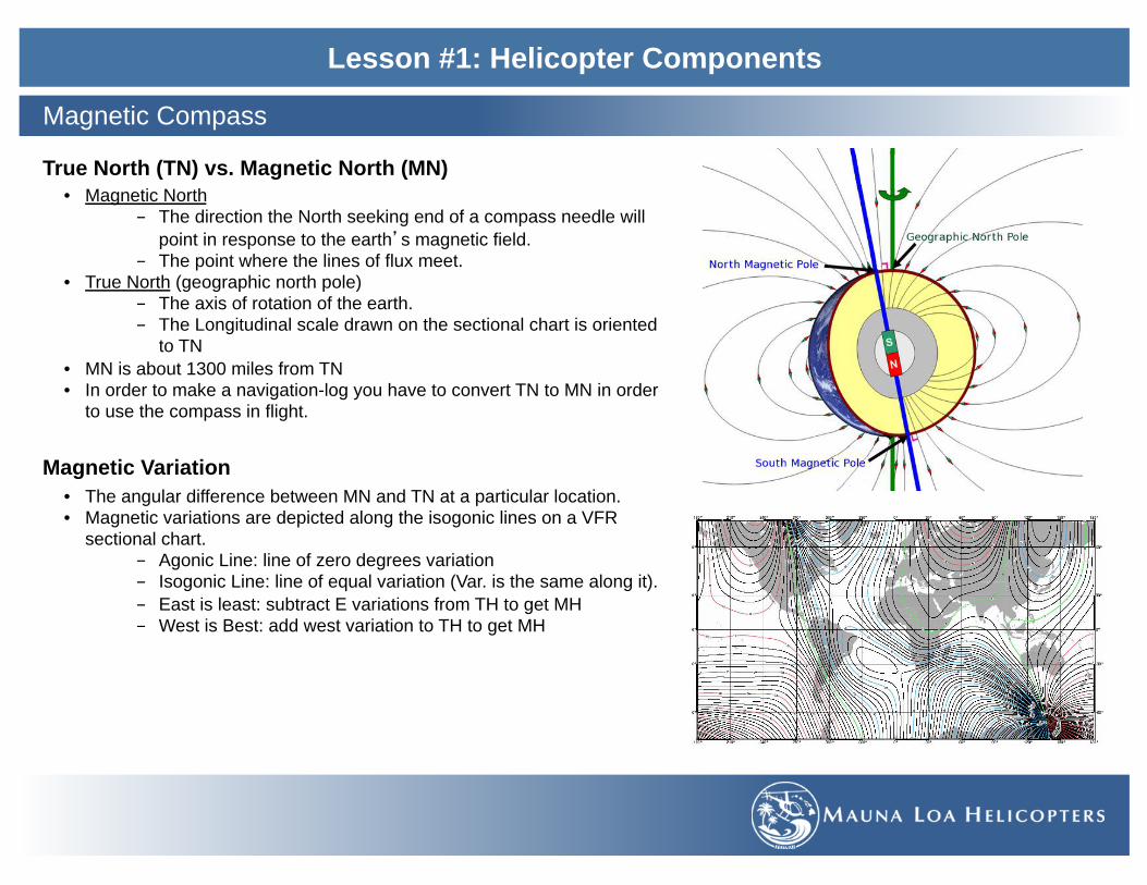
True North (TN) vs. Magnetic North (MN) • Magnetic North
- The direction the North seeking end of a compass needle will point in response to the earth�s magnetic field.
- The point where the lines of flux meet. • True North (geographic north pole)
- The axis of rotation of the earth. - The Longitudinal scale drawn on the sectional chart is oriented
to TN • MN is about 1300 miles from TN • In order to make a navigation-log you have to convert TN to MN in order
to use the compass in flight.
Magnetic Variation
• The angular difference between MN and TN at a particular location. • Magnetic variations are depicted along the isogonic lines on a VFR
sectional chart. - Agonic Line: line of zero degrees variation - Isogonic Line: line of equal variation (Var. is the same along it). - East is least: subtract E variations from TH to get MH - West is Best: add west variation to TH to get MH
Magnetic Compass

Lesson #1: Helicopter Components
Compass Deviation • An error generated from other magnetic fields in the helicopter
produced by metal components and electronics. • Compass Deviation can change depending on:
- The direction of flight (orientation of the magnets) - What electronic equipment is on.
• Mechanics adjust the compensating magnets to minimize these errors • If they cannot be eliminated, they will use a correction card to show
deviation error for those situations.
Magnetic Dip
• The compass magnets will align with the lines of flux both horizontally and vertically
• At the equator the compass sits parallel (0° dip at the equator). • At more northerly latitudes the lines of flux dip more vertically into the
earth. • As you fly further from the equator the float dips more and more into
the earth (Up to 90° at the poles). • The underslung design reduces the dip affect in the mid latitudes by
maintaining a minimal center of mass change. • If the compass was free to dip, there would be large errors in compass
readings.
Magnetic Compass

Lesson #1: Helicopter Components
West Heading • At latitudes above the equator, the north seeking end of the magnet may dip
slightly toward the earth, as a result the CG shifts toward the south seeking end of the magnet.
• Acceleration causes the float to rotate clockwise and Deceleration causes the float to rotate counterclockwise for two reasons;
• 1st Due to inertia or the CG being greater on the south seeking side, it will cause a rotation.
• 2nd Since the compass has tilted, it is free to rotate and will align with the lines of flux.
Magnetic Compass
Acceleration / Deceleration Errors • Occurs on an East or West headings. • A.N.D.S.
- Accelerate / North - Decelerate / South
East Heading • At latitudes above the equator, the north
seeking end of the magnet may dip slightly toward the earth, as a result the CG shifts toward the south seeking end of the magnet.
• Acceleration causes the float to rotate counterclockwise and Deceleration causes the float to rotate clockwise for two reasons;
• 1st Due to inertia or the CG being greater on the south seeking side, it will cause a rotation.
• 2nd Since the compass has tilted, it is free to rotate and will align with the lines of flux.

Lesson #1: Helicopter Components
Turning Errors from North or South (Lead/Lag) • The needle Lags when turning from the North
- As we turn from North we initiate a angle of bank. - The north seeking end of the magnets wants to continue to dip
down toward the earth. - Shows an indication opposite the direction of turn (lag). - The error will correct itself as you continue to turn.
• The needle Leads when turning from the South - As we turn from South we initiate a angle of bank. - The north seeking end of the magnets wants to continue to dip
down toward the earth. - Shows an indication ahead of the direction of our turn (lead). - The error will correct itself as you continue to turn.
Turning Errors to North or South (U.N.O.S.) • Undershoot North
- On an E or W heading turning to the N, we want to under shoot our desired heading.
- As we roll out of our turn the compass card will catch up and show N.
- Compass card is going to be lagging. • Overshoot South
- On an E or W heading turning to the S, we want to over shoot our desired heading.
- As we roll out of our turn the compass card will fall back and show S.
- Compass card is going to be leading.
Magnetic Compass
Northheading:-N.seekingenddipstowardearth.
TurntotheEast:-Bankini=atedtotheright-N.alagindica=on

Lesson #1: Helicopter Components
During banked turns, the dip error pulls the north seeking end of the compass toward the earth causing the compass indication to �Lag” during turns to/from N and “Lead� during turns to/from S.
• 1st At the initiation of a turn, the compass card will begin to rotate due to the inertia or the CG being greater on the south seeking side.
• 2nd Since the compass has been tilted in a banked turn, it is free to rotate and will align with the lines of flux vertically. (take the path of least resistance..
To correct for these errors, there are a few things to know: • First, to reach a desired heading, when in a turn, we must anticipate the
time it takes to roll out of the turn. - This is referred to as, Rollout, and is approximately equal to ½
the bank angle used in the turn. - Rollout will be needed to reach any desired heading.
• Secondly, the dip error present, is approximately equivalent to the latitude at which the aircraft is flying in.
• Undershoot North and Overshoot South
Knowing this, we can now anticipate and correct for the errors using simple equations
• ± Latitude, ± 1/2 bank or (Latitude ± ½ bank angle)
As the aircraft is leveled out, the compass will correct for the Leading or Lagging dip error
Magnetic Compass
180˚
TurningtoaSheading
190˚200˚
360˚
TurningtoaNheading
330˚
320˚
InaturnfromtheEtoS,wewillneedtoaddtheLa=tudeandsubtracttherollout.180˚+20˚-10˚=190˚
InaturnfromtheWtoN,wewillneedtosubtracttheLa=tudeandsubtracttherollout.360˚-20˚-10˚=330˚

Lesson #1: Helicopter Components
Note: Turning error exists 100% at North or South and 0% at East or West
Since the turning errors caused by the draw from the magnetic lines of flux have no effect on a direct East or West heading, the rollout point should begin around a point equal to ½ the bank angle prior to desired heading.
If the bank angle being used is 20˚ then the rollout should begin 10˚ prior to desired heading
Magnetic Compass
ToensurethataWestheadingisreachedwhentheturniscomplete,theaircraemustbegintorolloutoftheturnearly.
270˚
TurningtoaWheading
Rolloutpoint@260˚
090˚
TurningtoaEheading Rolloutpoint
@080˚
ToensurethataEastheadingisreachedwhentheturniscomplete,theaircraemustbegintorolloutoftheturnearly.

Lesson #1: Helicopter Components
Energy Management • Autorotation: state of flight in which
the rotor system is driven solely by the up-flow of air.
• With the up-flow of air, the helicopter utilizes two types of energy, potential energy (PE) and kinetic energy (KE).
Potential Energy • Stored in altitude above the ground. • PE = Weight x Height • PE (altitude) can be used to:
- Create kinetic energy in forward A/S and RPM
- Maneuver to a landing spot
Kinetic Energy • Is stored in RPM and Airspeed • Any mass that has motion has Kinetic
Energy. • KE = 1/2m V2 (m = mass) (V2 =
velocity squared) • Kinetic Energy in Forward airspeed is
used to: - Maintain RPM while entering a
flare in a autorotation • Kinetic Energy RPM is used to:
- Cushion the landing after the flare
- RPM KE will be used quickly because of drag from the increased pitch angle used
SFAR 73 Awareness Training

Lesson #1: Helicopter Components
Rotor RPM Decay • Rotor RPM is below normal operating range (101%-104%) • Causes: pulling more power than available, rolling throttle
the wrong way or overriding the governor by griping the throttle too tight.
• Recognition: Look - Light, Tachometer, Descent Listen - Engine noises, Horn and Main rotor noises Feel - Vibrations, Descent, and Yaw
• Recovery: simultaneously lower collective & roll on throttle
Low Rotor RPM (avoid by detecting RRPM decay early and timely recovery)
• Risk: blade stall - unrecoverable point in Rotor RPM (below 80% +1% per 1000’ DA)
Low G Hazards • Low G occurs when the rotor disc becomes unloaded • Cause: pushovers or severe updrafts/ downdrafts • Recognition: weightless feeling, butterflies • Recovery: aft cyclic to reload the rotor system then correct
for the roll
Mast Bumping • If left cyclic to correct for the roll is applied before reloading
the rotor disc, or if no action is taken to reload the disc. • Rotor hub can make contact with the rotor mast causing
damage or separation.
SFAR 73 Awareness Training
hgp://www.gyronimosystems.com/SFAR/
Conclusion:-Bewareofthesedangeroussitua=onsandavoidthem-Belightonthecontrolsandsmoothonyourinputs(gentlegriponthethrogle)-Maintainasafeal=tudeandA/Satall=mes(flyinsafeareaoftheH/VDiagram

Lesson #1: Helicopter Components
Low G Hazards (reading SN-11 and SN-29) • Rotor system is unloaded due to a sudden reduction in total thrust causing a weightless condition.
- Weightless situation will result in a dangerous flight attitude.
• Causes: - Push-Over: abrupt forward cyclic during a climb or straight and level flight. - Severe turbulence, downdrafts or updrafts to down drafts
• Effects: - Rotor thrust is reduced - nose low attitude. - Translating tendency causes a right roll and left yaw
> Torque is reduced, TR thrust above the CG and parasite drag cause the helicopter to yaw left and roll right.
SFAR 73 Awareness Training
VectorDiagramscanbeusedtoshowthedecreaseinlie(AOAdecreaseduetoachangeininducedflow).
✴ Leadingwithlateralcyclicbeforethediscisloadedmayonlyexpeditemastbumpingfromoccurring
Correc=on:1. Lightaecyclictoreloadrotorsystem2. Then,leecyclictocorrecttherightroll

Lesson #1: Helicopter Components
Mast Bumping (100% pilot error) • Mast bumping is when the rotor hub teeters/flaps so great, that it contacts the rotor mast
• This can occur on an unloaded rotor system, by applying lateral cyclic or by the rolling movement of the fuselage - Main rotor system doesn‘t produce thrust due to small angle of attack (change in relative wind)
• Severe damage is likely even potentially chopping off the rotor hub - Spindle Bearings/Coning Hinge make contact with the main rotor shaft.
• Pertains to 2 bladed rotor systems
• Causes: - incorrect inputs or no input during a low-G condition. - Excessive blade teetering/flapping - Gust, wind, turbulence - Abrupt cyclic inputs
SFAR 73 Awareness Training

Lesson #1: Helicopter Components
Rotor RPM Decay (100% pilot error excluding mechanical issues)
• Rotor RPM�s drop below normal operating limits (below green arc)
• R22 Low inertia rotor system
Causes • Over-pitching: puling more pitch than power available
due to High DA, High GW (exceeding performance limits)
• Rolling throttle the wrong way • Over-riding the governor
Recognition:
Correction by simultaneously:
SFAR 73 Awareness Training
Conclusion:- Bewareofthesedangeroussitua=onsandavoidthem- Belightonthecontrolsandsmoothonyourinputs(gentlegriponthethrogle)-Maintainasafeal=tudeandA/Satall=mes(flyinsafeareaoftheH/VDiagram
Look Listen Feel§ Rotor Tachometer drops § Left Yaw § Descent § Low RRPM Light
§ Engine Noise § Transmission Noise § Low RRPM Horn
§ Engine Vibrations § Descent § Left Yaw
Low Rotor RPM – Blade Stall • RotorStallisacompletelossofliefromRPMDecay• Recovery:Notpossibleifstalledcompletely
What Happens • Bladesstallat80%RRPM@SeaLevel- Cri=calangleofagackisexceededduetoRWcomingfrom
below(up-flow)- Increaseindrag- Insufficientcentrifugalforcetomaintainbladerigidity
• 80%+1%per1000�Al=tude- Lowerairdensitycausestheairtoseparatesooner
Causes • Notreac=ngRPMDecayquickenough• Reacting to low RPM Decay the wrong way
• Lowercollec=ve-decreasedragandspeedupblades• Rollonthrogle-eyesontachometer(overspeed)• AeCyclicinforwardflightifneeded-flareeffect

Lesson #1: Helicopter Components
Discussion on related topics 1. ________________________________________________________________________________________________________
2. ________________________________________________________________________________________________________
3. ________________________________________________________________________________________________________
Completion Standards
This lesson will be complete when by oral examination the student displays an understanding of the material presented.
Instructors Comments and Recommendations:
___________________________________________________________________________________________________________
___________________________________________________________________________________________________________
___________________________________________________________________________________________________________
___________________________________________________________________________________________________________
Review

Lesson #2: The Principles of Helicopter Flight
The Student will gain a basic understanding of basic aerodynamics and the principles of helicopter flight.
Objective

Lesson #2: The Principles of Helicopter Flight
Airfoil • Any surface, such as an airplane wing or a helicopter rotor blade which provides aerodynamic forces when moving
through a stream of air. • Any surface designed to obtain a useful reaction from the air through which it moves. (Principles of Helicopter Flight) • Any surface designed to obtain a useful reaction of lift, or negative lift, as it moves though the air (Helicopter Flying Handbook)
Symmetrical Airfoil • An airfoil having similar upper and lower curvatures.
• An airfoil having the same shape on the top and bottom. (Helicopter Flying Handbook)
Asymmetrical Airfoil • Upper and lower curvatures are not the same.
• Airfoil has different upper and lower surfaces, with a greater curvature of the airfoil above the chord line than below.
Airfoils

Lesson #2: The Principles of Helicopter Flight
Camber • The mean camber line is the curve that is halfway between the upper and lower surfaces of an airfoil.
Center of Pressure • The point where the resultant of all the aerodynamic forces acting on an airfoil intersects the chord.
Airfoils

Lesson #2: The Principles of Helicopter Flight
Leading Edge • The forward most tip of the airfoil which make contact
with the relative wind first.
Trailing Edge • The rearward most edge of the airfoil.
Blade Span • The distance from the rotor hub to the blade tip.
Chord Line • An imaginary straight line between the blade leading
and trailing edge of an airfoil section.
Airfoils

Lesson #2: The Principles of Helicopter Flight
Tip Path Plane • Is the circular plane outlined by the rotor blade tips as
they make a cycle of rotation.
Plane of Rotation • The plane in which the rotor hub rotates. It is
perpendicular to the Axis of Rotation.
Axis of Rotation (AoR) • Is the imaginary line about which the rotor rotates.
• Represented by a line drawn through the center of, and perpendicular to the plane of rotation. (this is not to be confused with the rotor mast)
Airfoils
CL
IFAoA
Rot.RW
AoR
Res.RWPitchAngle

Lesson #2: The Principles of Helicopter Flight
Rotational Relative Wind (Rot. RW) • Airflow velocity over the blades as a result of blade rotation. • Rot RW is slower at the root than at the tip. • Rot RW is always parallel and opposite to the plane of
rotation.
Induced Flow (IF) • The component of air moving vertically down through the
rotor system resulting from the production lift.
Resultant Relative Wind (Res. RW) • A resultant airflow velocity as a result of blade rotation,
induced flow, blade flap, along with airspeed and wind velocities.
• Airflow from rotation that is modified by induce flow. (HFH)
Pitch Angle (Angle of Incidence) • The angle between the Chord Line and the Rotational RW. • As collective is raised pitch angle is increased.
Angle of Attack (AoA) • Is the angle between the CL and the Resultant RW. • Any increase in AoA increases lift until the critical angle
(stall angle) is reached.
Airfoils
CL
IFAoA
Rot.RW
AoR
Res.RWPitchAngle

Lesson #2: The Principles of Helicopter Flight
Lift • Vertical force created by the affect of airflow as it passes
around an airfoil. • Lift counteracts weight.
Weight • Opposes lift and is caused by the downward pull of gravity. • Equivalent to the actual weight of the helicopter. It acts
downward toward the center of the earth.
Thrust • The force that propels the helicopter through the air and is
produced by the rotor blades.
Drag • Force opposing thrust, and is the retarding force created by
the development of lift and movement. • An aerodynamic force on a body acting parallel and
opposite to relative wind.
The Four Forces

Lesson #2: The Principles of Helicopter Flight
Bernoulli’s Principle - In a streamlined flow of fluid, the sum of all energies is a constant.
• As air velocity increases the pressure decreases.
• Air traveling over the upper surface of the airfoil moves faster as it acts as a venturi.
• Creates a lower pressure on the upper surface than the lower surface, thus creating lift.
Factors Affecting Lift
Newton’s Third Law of Motion - For every action there is an equal and opposite reaction.
• Deflection of airflow downward has an equal and opposite reaction creating lift on the rotor system.

Lesson #2: The Principles of Helicopter Flight
Lift Equation
• CL = Coefficient of Lift
- The potential of an object to produce lift.
- Determined by:
> Shape - the ability to bend air smoothly
> AoA determines the amount of lift produced
> Critical Angle of Attack = Stall Angle
• ½ - A constant
• ρ = Air Density under which the helicopter operates
• V2 = Velocity Squared - The speed of relative wind (RPM’s, Airspeed and Wind)
• S = Surface Area - The surface area of the airfoil
Factors Affecting Lift
Lie=CL1/2ρV2S
- Exampleof:
� 10x1/2(10)x102x10=50,000� 9x1/2(10)x102x10=45,000� 10x1/2(10)x92x10=40,500

Lesson #2: The Principles of Helicopter Flight
Profile Drag • Frictional resistance of the blades passing through the air. • No significant change due to change in AoA. • Increases moderately as airspeed increases. • Made up of:
- Form drag - size and shape of the airfoil - Skin friction - microscopic surface roughness
Induced Drag • Created by producing lift due to the vortices and IF. • Induced drag decreases as A/S increases. • Vortices create turbulent less clean/efficient air as well as
contribute to induced flow. (IF changes AoA).
Parasite Drag • Created by all non-lift producing part of the helicopter. • Created by the form or shape of helicopter parts. • Parasite drag increases with speed.
Total Drag • The sum of all three drag forces. • As A/S increases parasite drag increases, induced drag
decreases. • Profile drag remain relatively constant throughout the speed
range with some increase at higher airspeeds.
Factors Affecting Drag: Types of Drag

Lesson #2: The Principles of Helicopter Flight
Drag Equation
• CD = Coefficient of Drag - The potential of an object to produce drag. - Determined by:
> Shape of an airfoil (profile drag) > Angle of Attack (induced drag)
• 1/2 - A constant • ρ = Air Density under which the helicopter operates • V2 = Velocity Squared
- The speed of relative wind (RPM’s, Airspeed and Wind) - Drag decreases as air speed decreases until 53 kts then it
increases. • S = Surface Area of an airfoil
- longer airfoil = more drag
Drag can be controlled by AoA and Airspeed (RPM�s + A/S)
• Lift / Drag Ratio - Angle of attack increases lift but also drag - Best Lift / Drag Ratio - most amount of lift with the least
amount of drag - Lift / Drag Max - Critical Angle of Attack
Factors Affecting Drag
Drag=CD1/2ρV2S

Lesson #2: The Principles of Helicopter Flight
Longitudinal Axis – Roll • The pivot point about which an aircraft rolls. The axis runs fore and aft through the length (nose to tail) of the aircraft.
Lateral Axis – Pitch • The pivot point about which the aircraft pitches. Pitch is the up and down motion of the nose of the aircraft. The pitch axis runs left
to right of the aircraft (wing tip to wing tip). It is perpendicular to and intersects the roll axis.
Vertical Axis – Yaw • The pivot point at which the aircrafts heading turn left or right (Yaw). The vertical axis runs from top to bottom and is perpendicular
to the Longitudinal and Lateral Axes.
The Three Axes of Movement

Lesson #2: The Principles of Helicopter Flight
Define torque • Something that produces or tends to produce torsion or rotation; the moment of a force or system of forces tending to cause
rotation.
Newton’s Third Law of Motion • States that for every action there is an equal and opposite reaction. • For a helicopter with blades that rotate counter clockwise, there will be a force that turns the helicopter clockwise (opposite the
rotation of the blades when producing lift) which is torque.
Affect of Torque • In helicopters with a single rotor system is the tendency
of the helicopter to turn in the opposite direction of the main rotor rotation.
Tail Rotor Thrust / Controlling Torque • Tail Rotor Thrust - the horizontal force provided by the
variable pitch tail rotor (anti-torque rotor). • The TR controls torque by producing thrust which opposes
torque allowing the helicopter to remain stationary.
Torque

Lesson #2: The Principles of Helicopter Flight
Flap • The ability of the rotor blade to move in a vertical direction. Blades may flap independently or in unison. • Rotor blade attach to the rotor hub by a horizontal hinge (flapping hinge) which allows the blades to flap up and down
independently of each other.
Teeter • Rotor hubs are attached to a teeter hinge allowing the blades to teeter up and down in unison. (teeter totter, Seesaw)
Feather • The action that changes the pitch angle of the rotor blades by rotating them around their span-wise axis. • Rotor blades are able to rotate along there span-wise axis allowing the airfoil to change their pitch angle.
Lead/Lag • The fore and aft movement of the rotor blade in the plane of rotation. • Blades are connected to a vertical hinge (drag or lag hinge) which allows each blade to lead or lag back and forth in the plane of
rotor disc independent of each other
Rotor Systems

Lesson #2: The Principles of Helicopter Flight
Semi-Rigid
• Consists of two blades • Able to feather independently and
teeter/flap as a unit • Is the type of rotor system on an
R22 • R22 is different from other semi-rigid
systems due to the coning hinges • Advantages
- Cheap and easy to maintain - Small storage space - Light
• Disadvantages - Low G mast bumping
Fully Articulated • Made up of three or more blades • Able to feather, flap, and Lead and
Lag independent of each other. • Advantages
- Smooth flight conditions - No mast bumping
• Disadvantages - Ground Resonance - High maintenance cost - Heavy
Rigid • Made up of three or more blades • Feathers on hinges • Blades absorb the operating loads of
flapping and lead/lag through bending rather than hinges
• They are mechanically more simple but more expensive due to the structural complexity of the blades
• Advantages - No mast bumping - Reliable and easy to maintain
• Disadvantages - Expensive - More vibration
Rotor Systems

Lesson #2: The Principles of Helicopter Flight
Sympathetic Resonance • Occurs in the R22 between 60-70% RPM. This type of vibration occurs when the main rotor’s frequencies interact with the
frequencies of the tail rotor. • The two frequencies can create a state of harmonic oscillation where they begin to become additive. • The results can cause the drive shaft in the tail boom to start vibrating and oscillating violently and can cause damage. • The preventative action is to not let the main rotor RPM stay in the 60-70% range, hence the corresponding yellow band on the
tachometer.
Ground Resonance • A vibration of large amplitude resulting from a deliberate or unintentional
oscillation of the helicopter from ground contact or when resting on the ground.
• The onset of ground resonance is recognizable by a slow rocking of the fuselage. If no remedial action is taken at an early stage, the degree of vibration may rapidly increase until the helicopter sustains major damage.
• Corrections would be to, initiate lift-off if power and rotor RPM permit. If that is not possible, the pilot should immediately shut down and apply rotor brakes and/or wheel brakes.
Vibrations

Lesson #2: The Principles of Helicopter Flight
Low Frequency • Usually originate from the main rotor system. These vibrations can be felt through the cyclic control, the airframe or both. • Main rotor vibrations are typically felt as an up and down motion
- Note: engine vibrations can be low frequency when ignition related such as plugs or magnetos (reciprocating)
Medium (Tail Rotor) High (Engine) Frequency • Due to out-of-balance components that rotate at a high RPM, such as the tail rotor, engine, cooling fan, or components of the
drive train including the transmission, drive shaft, bearings, pulleys and belts. • Tail rotor vibrations can be felt through the pedals as long as there are no hydraulic actuators which can dampen these vibrations. • Engine vibrations are felt in the seat and lower back.
Vibrations

Lesson #2: The Principles of Helicopter Flight
Discussion on related topics 1. ________________________________________________________________________________________________________
2. ________________________________________________________________________________________________________
3. ________________________________________________________________________________________________________
Completion Standards
This lesson will be complete when by oral examination the student displays an understanding of the material presented.
Instructors Comments and Recommendations:
___________________________________________________________________________________________________________
___________________________________________________________________________________________________________
___________________________________________________________________________________________________________
___________________________________________________________________________________________________________
Review

Lesson #3: The Principles of Helicopter Flight
The Student will continue to gain an understanding of the principles of helicopter flight.
Objective

Lesson #3: The Principles of Helicopter Flight
Four Forces (assuming no wind) • Lift and Thrust produced by the rotor system act straight up and must equal the weight and drag which acts straight down. • If lift/thrust is greater than weight/drag, the helicopter gains altitude. • If lift/thrust is less than weight/drag, the helicopter loses altitude.
Axis of Rotation • The axis of rotation is vertical.
Hovering Flight

Lesson #3: The Principles of Helicopter Flight
Translating Tendency/Drift • The tendency for a helicopter to drift in the direction of the
tail rotor thrust during hovering flight.
Translating Tendency is compensated by: • Manual inputs by the pilot:
- Cyclic inputs made opposite the direction of TR thrust to counteract the drift.
• Main rotor mast is rigged: - Axis of rotation would have a built in tilt opposite tail
rotor thrust, thus producing a small sideward thrust.
• Flight controls are rigged: - Rotor disc is tilted slightly opposite tail rotor thrust
when the cyclic is centered
Hovering Flight
RotorBladesTorqueEffectTRThrustDrie
DRIFT

Lesson #3: The Principles of Helicopter Flight
Hovering Flight
• A counterclockwise rotating main rotor system will cause the left skid to hang lower while hovering (opposite for a clockwise rotating rotor system)
• Left skid will lift off last during pick up and set down first on set down. (Left skid Low)
• Tail rotor location: - Tail rotors located lower than the MR’s plane of rotation, will
cause a slight, fuselage roll, which will direct lift to help counteract drift

Lesson #3: The Principles of Helicopter Flight
Pendular Action • The lateral or longitudinal oscillation of the fuselage due to it being
suspended from the MR system. • Since the fuselage of the helicopter, with a single main rotor, is
suspended from a single point and has a considerable mass, it is free to oscillate both longitudinally or laterally in the same way as a pendulum.
• Pendular action is exaggerated by rough or over controlled cyclic inputs.
Blade Coning • An upward sweep of rotor blades as a result of lift and centrifugal
force. • The coning angle is determined by the resultant force of lift and
centrifugal force • Centrifugal force is the force outward from the rotor hub when the
blades are moving. - Higher RRPM produces more centrifugal force which gives the
blades their strength and rigidity. • Coning can be accentuated in situations of:
- Low RRPM, High GW and High load factor. • Coning is allowed through blade bending, the flapping hinge, the
coning hinge or a combination thereof.
Hovering Flight

Lesson #3: The Principles of Helicopter Flight
The tendency of a rotor blade to change its rotational velocity (RPM) when the Center of Mass (CM) moves closer or further from the Center of Rotation.
• When the blades cone up, the center of mass moves closer to the Center of Rotation causing an increase in RPM (ice skater)
Coriolis Effect (Law of Conservation of Angular Momentum)
• When the blades cone, the CM shifts closer or further from the AoR causing a change in the blades rotational velocity (RPM).
• An increase in G-Force will cause the blades to cone up, therefore increase the RRPM (Flare, Turns etc.)
¨ Pilot arrest the increase in RPM with an increase in collective pitch
¨ Or bring their nose high attitude back to normal
• A decrease in G-Force will cause the blades to cone less, therefore decrease the RRPM (nose drop in Auto etc.)
¨ Pilot arrest the decrease in RPM with a decrease in collective pitch
¨ Or bring their nose low attitude back to normal

Lesson #3: The Principles of Helicopter Flight
Fully Articulated vs. Semi-Rigid Underslung Rotor System
Fully Articulated and Rigid Rotor Systems • When the blades flap the CM shifts closer or further from
the Center of Rotation causing change in the blades rotational velocity (RPM).
• Lead/Lag hinges and/or blade construction allows for these accelerating/decelerating forces of the individual blades.
Underslung Semi-rigid rotor system • When the blades flap the CM maintains its relation to the
Center of Rotation preventing a change in rotational velocity (RPM).
• Lead/Lag hinges and/or expensive blade construction are not required to compensate for these accelerating/decelerating forces.
Thehubmovesinthedirec=onoftheup-flap
maintainingthedistanceoftheCMfromtheCenterof
Rota=on.
Asthebladeflapsdownhubmovestowardthemastmaintainingthe
distanceoftheCMfromtheCenterof
Rota=on.
Additional Notes: Hookes Joint Effect (PHF 79) • Tippathplanemaintainsthesamediscareaeventhoughtheangulardifferencebetweenthebladesaredifferent.• Itjustshiesinthedirec=onofflight(advancingbladeleadandretrea=ngbladelags).

Lesson #3: The Principles of Helicopter Flight
Ground Effect • Any increase in rotor efficiency due to the proximity of the ground. • Occurs when the aircraft is within 1 rotor diameter of the ground due to a change in induced flow.
Hovering Flight
Out of Ground Effect (OGE) • Greater than 1 rotor diameter from the ground. • No interruption to the downward airflow pattern acting
to increase the induced flow. • Allows for full vortex generation decreasing the
effective blade area.
In Ground Effect (IGE) • Less than 1 rotor diameter above the ground, over a
hard smooth surface 2 diameters wide. • The ground interrupts the downward flow of air acting
to reduce the induced flow. ¨ Due to the surface pressure and ground friction.
• Downward & outward airflow pattern acts to restrict full vortex generation; increasing affective blade area.
• Increased AoA for the same pitch angle.

Lesson #3: The Principles of Helicopter Flight
Hovering Flight
Factors that reduce ground effect • Water, rough terrain, boulder, rocks, tall grass,
pinnacles, confined areas if smaller than 2 rotor diameter, sloping terrain >2˚.
Factors that increase ground effect • Smooth, flat, hard surfaces • Greater surface area. • The closer to the ground, the greater the ground effect

Lesson #3: The Principles of Helicopter Flight
Hovering Flight
Forward, Sideward and Rearward Hovering

Lesson #3: The Principles of Helicopter Flight
Gyroscopic Precession • When a force is applied to a rotating body, the deflection will be manifested 90 degree later in the direction of rotation
• Gyroscopic Precession affects the rotating blades of a helicopter.
• Pitch angle change applied at 3 o’clock will be manifested at 12 o’clock in a rotor system rotating counter clockwise.
Hovering Flight

Lesson #3: The Principles of Helicopter Flight
Four Forces in Forward Flight • Lift vs. Weight:
- Forces that determine whether the aircraft is going to climb, descend or maintain altitude.
• Thrust vs. Drag: - Forces that determine whether the aircraft is going to
accelerate, decelerate or maintain airspeed.
• Resultant Lift/Thrust (Total Rotor Thrust) - Combined force of lift acting upward and thrust acting
horizontally in the direction of flight. • Resultant weight/drag:
- Combined forced derived from weight acting downward and drag acting horizontally against the direction of flight.
• Un-accelerated level flight: - Resultant lift-thrust force equals the resultant weight-
drag force. • Accelerated or Decelerated level flight:
- Resultant lift-thrust force is greater or less than the resultant weight-drag force.
Note: In any steady state flight, all forces are equal.
Forward Flight

Lesson #3: The Principles of Helicopter Flight
Overview of Powered Flight
Forward Flight
0kts
VNE
0kts 12kts 15kts 24kts 53kts102kts<3000’
Sta=onaryHover Transla=onalLie TransverseFlowEffect Effec=veTransla=onalLie
ParasiteDragbeginstoreduceperformance
Retrea=ngBladeStall
�Transla=onalLie�(Anywind-speedcomingintotherotorsystem),when>53ktsthereisnolongeranincreaseinperformanceduetoParasiteDrag

Hover Flight Translational Lift Transverse Flow Effect Effective Translational Lift
• To start forward movement from a hover by tilting the total rotor thrust forward.
• Induced flow is vertical • Larger pitch angle • Vortices all around the disc • Induced flow is completely vertical
• Additional lift gained due to horizontal movement of the AC or surface wind.
• Any movement or wind create somewhat of a horizontal airflow across both the MR and TR systems.
• Vertical IF decreases as the airflow becomes more horizontal creating a larger AoA.
• Rotor system vortices begin to recede.
• Transition phase of flight with a difference in lift in the fore & aft portions of the rotor disc
• Unequal lift across the disc causes vibrations
• As A/S increases the helicopter responds by: Right Roll - Gyroscopic Precession, Nose pitch up - TL and increased vibration
• Corrected with fwd/left cyclic input to push through this phase into ETL.
• Increase in rotor system efficiency due to the horizontal RW across the entire rotor disc and near zero IF.
• Occurs with a RW of about 16-24 KIAS. • MR and TR outrun the vortices operating
in cleaner air (reduced induced drag). • AoA increases due to reduced vertical IF. • Transition into ETL can be recognized by
a left yaw and nose pitch up and vibrations.
• Correct by R pedal & fwd/left cyclic.
Lesson #3: The Principles of Helicopter Flight
Hover to ETL
++++-
-CL
IFAoARes. RW
Rot. RW
AoR
AoA
AoRCL
AoAIFRes. RW
Rot. RWIFRot. RW
Res. RW
CL
-

Lesson #3: The Principles of Helicopter Flight
Translational Lift • Additional lift gained due to horizontal movement of the aircraft or surface winds. • Any movement or wind create a more horizontal airflow across both the MR and TR systems. • Vertical Induced Flow decreases as airflow becomes more horizontal, creating a greater AoA for the same collective pitch setting. • MR system vortices begin to recede in the forward portion of the disc.
Forward Flight
Downwindvortexbeginstodissipateandinducedflowdownthroughtherotordiscismorehorizontalthaninahover.
DifferencesininducedflowcauseachangeinAoA
CL
IFAoA
Res. RW
Rot. RW
AoRCL
IFAoARes. RWRot. RW
AoR
HoverFlightDiagram Transla=onalLieFlightDiagram

Lesson #3: The Principles of Helicopter Flight
Transverse Flow Effect (TFE) • The difference in lift between the fore and aft portions of the disc. • Acceleration in forward A/S causes vertical IF to drop significantly in the fore part of the disc and remain the same in the aft part
of the disc. • Due to gyroscopic precession the max increase in lift at the fore portion of the rotor disc is felt 90° in the direction of rotation,
causing the tendency for the helicopter to roll slightly to the right as it accelerates through 20 KIAS. • TFE is recognized by increased vibrations at airspeeds just less than ETL
Forward Flight
CL
IFAoA
Res. RW
Rot. RW
AoR CL
IFAoA
Res. RW
Rot. RW
AoR
IF IF

Lesson #3: The Principles of Helicopter Flight
Effective Translational Lift (ETL) • The increase in rotor system efficiency due to an increase in horizontal relative wind across the entire rotor disc.
- Occurs with relative winds of about 16-24 KIAS (Forward airspeed and/or wind). - Horizontal RW allows both the MR and TR to outrun the vortices therefore operating in cleaner air (reduced induced drag). - Rotor system is more efficient due to a smaller vertical IF increasing the AoA for the same collective setting. - Efficiency continues to increase until the L/D max (53 KIAS) is reached, where total drag is at its lowest point. - Recognized by a left yaw and nose pitch up/ helicopter tries to climb. - Correct by giving right pedal and forward/left cyclic.
Forward Flight

Lesson #3: The Principles of Helicopter Flight
Dissymmetry of Lift • The difference in lift between the advancing and retreating halves of the rotor disc due to different velocities of relative wind. • Counterclockwise rotating rotor systems advance on the right and retreat on the left.
• Advancing Side: - Res. RW = Tip Speed + Relative Wind (Forward Airspeed and/or wind).
• Retreating Side: - Res. RW = Tip Speed - Relative Wind (Forward Airspeed and/or wind).
Forward Flight
B
C A
D
100 KIAS 100 RW100 RW
400 KT Tip Speed
400 KT Tip Speed
Advancing Blade 400 KT + 100 RW 500 KT Res RW
Retreating Blade 400 KT - 100 RW 300 KT Res RW
Lookingatthelieequa=onshowushowmuchofarole�V2
�playsintheproduc=onoflie.
Lie=CL1/2ρV2S
Ifthehelicopterwasincapableforcompensa=ngfordissymmetryoflietherewouldbeagreateramountoflieontheadvancingsidecausingthenosetopitchupduetogyroscopicprecession,limi=ngourabilitytoproducemore
forwardA/S.

Lesson #3: The Principles of Helicopter Flight
Blade Flapping – Eliminating Dissymmetry of Lift • In order to solve the velocity problem we must look at the lift formula.
- ½ ρ(air density) and S (surface area) are all constant (negligible). - CL (coefficient of lift which relates to AoA) is not constant.
• Blade Flapping - The rotor system compensates for the dissymmetry of lift and creates equal amount of lift across the rotor system through
blade flapping - More lift on the advancing side causes the blade to flap up, decreasing the AoA (CL) therefore helping to equalize lift across
the disc. - Less lift on the retreating side causes the blade to flap down, increasing the AoA (CL) therefore helping to equalize lift across
the disc.
Forward Flight
B
C A
D
• Blade velocity is minimum
• Rate of flapping down is maximum
• CL (AoA) is maximum
• Blade velocity is maximum
• Rate of flapping up is maximum
• CL (AoA) is minimum
Lie=CL1/2ρV2S
(Highest Rate of Down Flap= Increase in AoA) (Highest Rate of Up Flap= Decrease in AoA)

Lesson #3: The Principles of Helicopter Flight
Retreating Blade Stall • Potentially hazardous condition caused by an excessive forward speed which causes an excessive angle of attack on the
retreating blade.
• A stall that begins at the tips of the retreating blade due to a High AoA.
• As A/S increases, blade flapping continues until the critical AoA is reached, at which point the blade begins to stall.
• There is also an area near the root that stalls due to the slow relative airflow caused by the forward airspeed.
• Indications: - Vibrations - Pitching Up of the nose (gyroscopic precession) - Rolling motion (likely toward the retreating blade).
• Causes: - Exceeding the VNE - High Weight - Low Rotor RPM - High Density Altitude - Steep or abrupt turns.
• Recovery: - Lower collective to decrease the AoA to prevent
further accentuating the stall - Ensure RPM are 104% - Then gentle apply aft cyclic to decrease A/S
Forward Flight
B
C A

Lesson #3: The Principles of Helicopter Flight
Loss of Tail Rotor Effectiveness • Tail rotor is unable to provide adequate thrust to maintain directional control when (below ETL) under certain wind condition. • Is not a tail rotor failure! • Three Types of Wind Induced LTE:
Forward Flight
MRDiscInterference:• Leequarterlywindsof10-30ktscausethe
MRvor=cestobeblownintotheTRcausingLTE.
WeatherCockStability:
• Thehelicopteragemptstoweathervaneitsnoseintotherela=vewind.
TailRotorVortexRingState:
• WindforcestheTRvor=cesbackintoitselfcausingaLTEduetothisturbulentair.

Lesson #3: The Principles of Helicopter Flight
A state of powered flight where the helicopter descends rapidly even though sufficient power may exists. • Helicopter settles into its own downwash and vortices • 3 Requirements:
- Vertical decent of 300’/min or greater - Must have power applied (20% or more) - A/S is less than ETL
• Indications: - Increased vibrations - Trim String Drop (Loss of ETL) - Un-commanded pitch, roll and yawing - Little cyclic authority - Decent rate of 300’/min or greater
• Recovery: (eliminate one of the 3 requirements) - Forward cyclic for airspeed - ASI & trim strings come alive, change attitude to climb profile, then bring in
pitch power to stop rate of descent and get back in safe operating profile.
• Pulling more pitch/power will only worsen the situation.
• Caution Areas - OGE hovering with a descent rate - Approaches with a tail wind - Steep approaches with high descent rate
Settling with Power (MR Vortex Ring State)

Lesson #3: The Principles of Helicopter Flight
A state of powered flight where the helicopter descends rapidly even though sufficient power may exists. • Induced flow and up flow create a resultant flow that is different at the tips compared
to the rotor hub.
• At the tips: - Air flows down through the rotor disc and
vortices circulate from blade tips into the rotor disc.
• At the Blade root: - Airflow is up through the rotor disc and vortices
form from the blade roots out to the rotor disc.
• Causes a reduction in the effective area of the blade that is producing lift.
• If allowed to continue, the two areas of vortices will grow until they envelope the entire blade.
Settling with Power (MR Vortex Ring State)
OGEHoverAirflowisdownthroughthedisc
300�/Minupflow

Lesson #3: The Principles of Helicopter Flight
Discussion on related topics 1. ________________________________________________________________________________________________________
2. ________________________________________________________________________________________________________
3. ________________________________________________________________________________________________________
Completion Standards
This lesson will be complete when by oral examination the student displays an understanding of the material presented.
Instructors Comments and Recommendations:
___________________________________________________________________________________________________________
___________________________________________________________________________________________________________
___________________________________________________________________________________________________________
___________________________________________________________________________________________________________
Review

Lesson #4: Aerodynamics
During this lesson the student will be introduced to the aerodynamics and principles of an autorotation to include turns, loads and descents along with energy management and it’s importance.
Objective

Lesson #4: Aerodynamics
Components of a Turn • Bank
- Tilting of the helicopter and rotor system to initiate and maintain a turn.
• Vertical Component - Lift acting upward and opposing weight
• Horizontal Component - Centripetal Force or the force acting horizontally
inward toward center of the turn and opposes Centrifugal Force (inertia)
• Total Rotor Thrust - Force that acts perpendicular to the plane of rotation. - Can be divided into a vertical and horizontal forces.
The Turn
Weight and Centrifugal Force in a Turn • As a helicopter turns centrifugal force (inertia) is developed. • Centrifugal Force along with Aircraft Weight creates a
resultant force called Load Factor • In order to turn and maintain altitude TRT has to increase in
order to match or exceed weight and centrifugal forces.
Angle of Bank vs. Angle of Attack (AoA) • As the TRT is tilted in the direction of the turn the vertical
component (Lift) is reduce. • Increasing AoA increases the TRT thus increasing the vertical
component of lift to maintain altitude. (increase collective pitch)
Centripetal Force Centripetal
Force
Total Rotor Thrust Total Rotor
ThrustLiftLiftTotal Rotor Thrust

Lesson #4: Aerodynamics
Load Factor • The load supported by the main rotor system divided by the
GW of the heli. • G-Force or load factor is gravitational force that opposes the
TRT.
Components of Load Factor • Gross Weight - the weight of the helicopter and its load. • Centrifugal force - the horizontal inertial force that pulls away
from the AoR of a turn.
The Turn
Lift Total Rotor Thrust Total Rotor Thrust Total Rotor Thrust
Centripetal Force Centripetal Force
Centrifugal Force Centrifugal Force
Gross Weight Gross Weight Gross Weight Load Factor
Lift
Load Factor

Lesson #4: Aerodynamics
The Turn
Flight Conditions and Load Factor • Straight and Level Flight (in smooth air) - no turns or altitude
changes: - Main rotor system is supporting only the actual total
weight of the helicopter, a load factor of 1. • Turns - Bank angle causes a change in flight direction:
- Angle of bank increases, causing the Load factor to increase.
- MR disc is supporting the total weight of the helicopter plus the inertial force of sideward horizontal momentum.
• Flares - TRT tilts aft in order to slow the helicopter: - Rotor disc tilts aft causing the Load factor to increase. - MR disc is supporting the total weight of the helicopter
plus the inertial force of forward horizontal momentum.
• Angle of Bank or Turbulence & Load Factor: - Angle of bank and/or Turbulence both cause an inertial
force. - Inertial force plus the GW of the aircraft results in an
increase in load factor. - Changing the angle of bank from 0°-60° increases the
Load Factor from 1 G to 2 G’s. • Adverse circumstances & load factor:
- High DA, Gusty Air, High GW and poor pilot technique may cause a situation where sufficient power is not available to maintain altitude or airspeed.
- Execute shallow bank turns in order to ensure reserve power.
Lift Total Rotor Thrust Total Rotor Thrust Total Rotor Thrust
Centripetal Force Centripetal Force
Centrifugal Force Centrifugal Force
Gross Weight Gross Weight Gross Weight Load Factor
Lift
Load Factor

Lesson #4: Aerodynamics
The Turn
Angle of Bank vs. Rate of Turn • Rate of turn - the number of degrees the nose passes around the horizon per unit of time. • As the angle of bank increases, the rate of turn increases causing the radius of the turn to decrease. • If the angle of bank decreases, the rate of turn decreases and the radius of the turn increases. • Constant Angle of bank:
- faster airspeed = larger radius, slower rate of turn - slower airspeed = smaller radius, faster rate of turn
• Constant Airspeed: - smaller angle of bank = larger radius, slower rate of turn - larger angle of bank = smaller radius, faster rate of turn
StandardRateTurn(2minturn)-3°/sec(15°bank)
� Increasingairspeedrequiresagreaterangleofbankinordertomaintaina2minturn.
� Formulas:[TAS/10+5]or[TAS/10+1/2TAS/10]
SteepTurn-30°bank

Lesson #4: Aerodynamics
Autorotative Descents
Autorotation: A state of flight in which the rotor blades are driven solely by aerodynamic forces resulting from rate of descent and an upward flow of air through the rotor disc.
Sprag Clutch: Allows for an autorotation by automatically disengaging the rotor system from the engine.
Direction of Airflow: Airflow is from below the disc, no longer being pulled down from above by the rotors.
CL
IFAoA
Res. RW
Rot. RW
AoRCL
RoDF
AoA
Res. RW
Rot. RW
AoRVectorDiagramforforwardandautorotaDveflightcomparingtheeffectsofInducedFlowandRoDF.
IF RODF
PowerFlight:- AirflowdrawndownthroughtheMR(inducedflow).- Rotorsystemisdrivenbytheengine.
Autorota=on:- AirflowforcedupthroughtheMRduetoourdescentrate.- RotorsystemdrivenbyRateofDescentFlow(RODF)

Lesson #4: Aerodynamics
Autorotative Descents
Three Regions of the Rotor Disc • Driven Region, Driving Region and the
Stalled Region
• Created by the differences in rotational velocity and blade twist.

Lesson #4: Aerodynamics
Autorotative Descents
A. DrivenRegion(RetardingForce)- Neartheblade=ps,withthefastestrota=onalvelocity- Producesalargeamountoflie- Producesalargeamountofdrag- Lie/DragRa=obringsTAFaeoftheAxisofRota=on- Resultsinanoverallretardingforce(slowsbladedown)
C. DrivingRegion(Accelera=ngForce)- Middleoftheblades,withaslowerrota=onalvelocity- Producesalargeamountoflie- Producesligledrag- Lie/DragRa=obringsTAFforwardoftheAxisofRota=on- Resultsinanoverallaccelera=ngforce(speedsbladeup)
E. StallRegion(RetardingForce)- Atthebladeroots,withtheslowestrota=onalvelocity- Producesligletonolie(stalledAoA)- Producesalotofdrag- Lie/DragRa=obringstheTAFaeoftheAxisofRota=on- Resultsinanoverallretardingforce(slowsthebladedown)
B. /D.PointofEquilibrium- Lie/DragRa=obringsTAFin-linewiththeAxisofRota=on- Resultsinaneutralforce(notretardingoraccelera=ng)
CL
Res RWRot RW
RoDF
AoA
Res RW
AoA
AoR
AoA
AoRRes RW
TAF
AoA
TAFCL
CL
CL
Rot RW
Rot RW
Rot RW
Drag
Drag
Drag
RoDF
RoDF
RoDF
Lift
Lift
Lift
Drag
Lift
TAF
TAF

Lesson #4: Aerodynamics
Autorotative Descents
• With a change in pitch (collective raised), the TAF will shift aft along the entire blade resulting in a retarding force which will slow the blade.
• Shown as the red line on the diagram
• With a change in pitch (collective lowered), the TAF will shift forward along the entire blade resulting in a accelerating force which will speeds the blade.
• Shown as the green line on the diagram

Lesson #4: Aerodynamics
Autorotative Descents
Airspeed & RPM Control
Collec=veInputsusedtocontroldescentrateandrotorRPM(constant)
- Raisingthecollec=vedecreasesdescentrate(toacertainpoint)androtorRPM
- Loweringcollec=veincreasesdescentrateandrotorRPM
CyclicInputs-usedtocontrolairspeedbutalsoaffectsrotorRPM(momentarily)
- ForwardcyclicincreasesairspeedanddecreasesrotorRPM
- AecyclicdecreasesairspeedandincreasesrotorRPM
ForwardAe
PedalInputsareusedtocontrolheadingandtominimizeparasitedrag(trimstrings).
- RightpedalandLeepedal

Lesson #4: Aerodynamics
Autorotative Descents
Rotor RPM • During Turns
- Load factor increases, RRPM increases, Descent Rate increases. - The tighter the turn the higher the load factor, the higher the RRPM
and the higher the descent rate.
• During Flares - Begin to reduce the decent rate and forward A/S by tilting the TRT
aft. - Aft cyclic is applied slowly and the RRPM continue to build as more
air is forced through the rotor system. - Angle of attack increases due to change in RRW. - Coriolis affect due to blade coning causes CM to be closer to the
AoR also causing RRPM build.
• During Landing - The helicopter in an autorotation uses the energy stored (RPM/
Inertia) to decrease the rate of descent and make a soft landing. - Rotor RPM is used by pulling collective pitch prior to touch down.
• Updrafts and Downdrafts - Updrafts: Increase RoDF, Increase AoA, moves the TAF forward,
Increasing RRPM - Downdrafts: Decrease RoDF, Decrease AoA, moves the TAF aft,
Decreasing RRPM

Lesson #4: Aerodynamics
Autorotative Descents
Asaresultofdifferingrela=vewindspeedsduringforwardflight,theautorota=veregionsshietowardtheretrea=ngsideofthedisc.
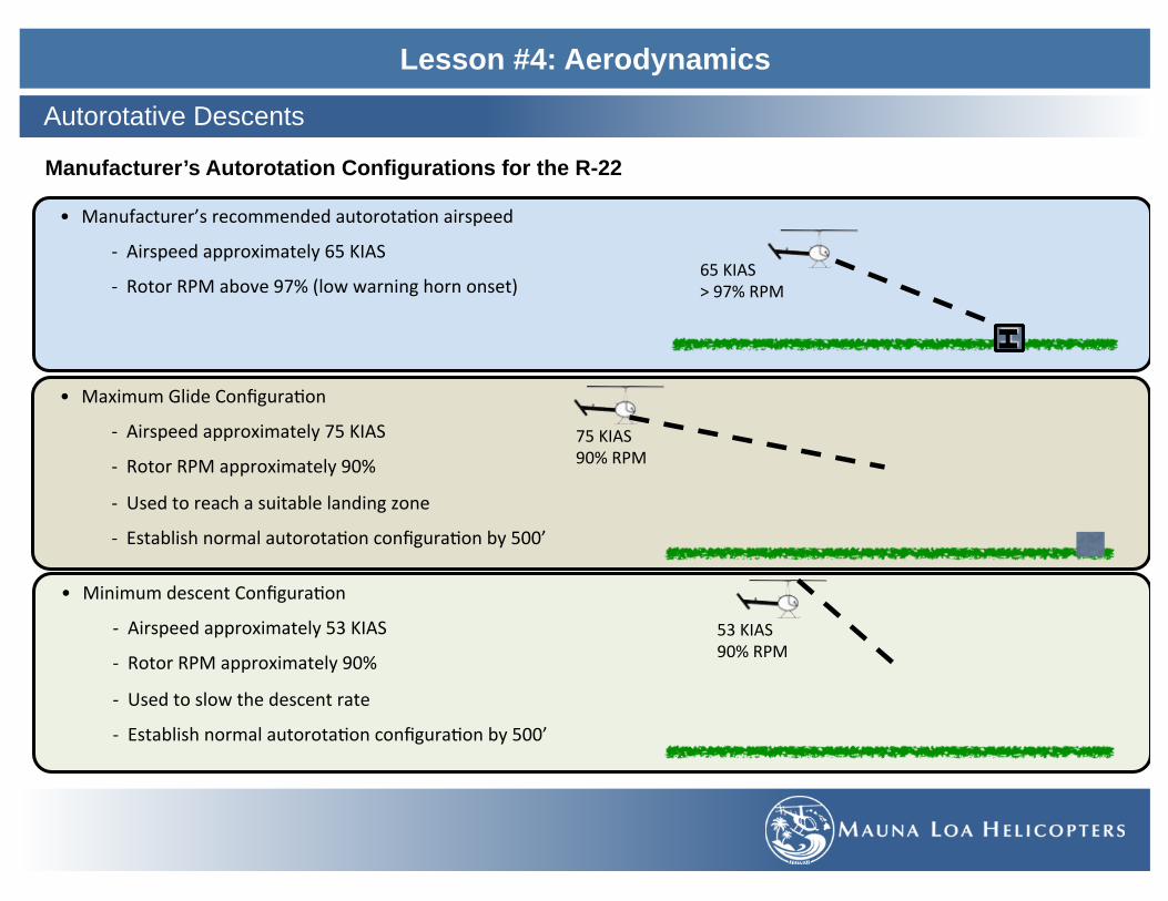
• MaximumGlideConfigura=on
- Airspeedapproximately75KIAS
- RotorRPMapproximately90%
- Usedtoreachasuitablelandingzone
- Establishnormalautorota=onconfigura=onby500’
Lesson #4: Aerodynamics
Autorotative Descents
Manufacturer’s Autorotation Configurations for the R-22
• MinimumdescentConfigura=on
- Airspeedapproximately53KIAS
- RotorRPMapproximately90%
- Usedtoslowthedescentrate
- Establishnormalautorota=onconfigura=onby500’
• Manufacturer’srecommendedautorota=onairspeed
- Airspeedapproximately65KIAS
- RotorRPMabove97%(lowwarninghornonset)
H
65KIAS>97%RPM
53KIAS90%RPM
75KIAS90%RPM
H
65KIAS>97%RPM
H
65KIAS>97%RPM

Lesson #4: Aerodynamics
Autorotative Descents
Hover Autorotation • Used in the event of an engine failure or driveline failure during a hover..
• Torque Effect - Torque produced in a hover is no longer acting on the helicopter when engine is disengaged from the main rotor system. - Anti-torque pedals need to be adjusted in order to maintain heading.
• Translating Tendency of Drift - A decrease in tail rotor thrust occurs from the loss of engine power. As TR thrust decreases the helicopter has less of a
tendency to drift due to that change in thrust. - In a hover autorotation a slight right cyclic is required to lessen the natural inputs used to compensate for translating
tendency.
• Kinetic Energy in RRPM - Pull Collective to cushion the landing using the remaining RRPM
• HoverAutorota=onControlInputs
- Rollthrogleoffintodetent/overtravelsprings(simulatedhoverauto).
- Rightpedaltomaintainheading.
- Rightcyclictoreducedrie.
- Raisecollec=vetocushionthelanding.

Lesson #4: Aerodynamics
Autorotative Descents (SFAR 73 Awareness Training)
Energy Management • The practice in which the pilot stores enough potential energy (PE) and kinetic energy (KE) to glide safely in case of an engine
failure (autorotation). • Autorotation: state of flight in which the rotor system is driven solely by the up flow of air.
Potential Energy - Stored in altitude above the ground - PE = Weight x Height - PE (altitude) can be used to:
o Create kinetic energy in forward A/S and RPM o Maneuver to a landing spot
Kinetic Energy - Is stored in RPM and Airspeed - Any mass that has motion has Kinetic Energy. - KE = 1/2m v² (m = mass) (v² = velocity squared) - Kinetic Energy in Forward airspeed is used to:
o Maintain RPM while entering a flare in an autorotation. - Kinetic Energy in RPM is used to:
o Cushion the landing after the flare. o RPM KE will be used quickly because of drag from
the increased pitch angle used.

Lesson #4: Aerodynamics
Autorotative Descents
Height Velocity Diagram (POH 5-11) • A diagram published by the helicopter manufacturer showing shaded areas
that should be avoided (combination of height and airspeed). • Slow airspeed at altitude does not provide enough kinetic energy for a safe
autorotation outcome in the event of engine failure • Higher airspeed at low altitude does not provide enough potential energy for
a safe autorotation outcome in the event of engine failure. Likely to have a tail boom strike and not be able to stop forward momentum resulting in a rollover.
• Based on the average Private Pilot

Lesson #4: Aerodynamics
Discussion on related topics 1. ________________________________________________________________________________________________________
2. ________________________________________________________________________________________________________
3. ________________________________________________________________________________________________________
Completion Standards
This lesson will be complete when by oral examination the student displays an understanding of the material presented.
Instructors Comments and Recommendations:
___________________________________________________________________________________________________________
___________________________________________________________________________________________________________
___________________________________________________________________________________________________________
___________________________________________________________________________________________________________
Review

Lesson #5: Pilots Operating Handbook & Helicopter Performance
During this lesson the student will be introduced to the Helicopter Flight Manual and Helicopter Performance.
Objective

Lesson #5: Pilots Operating Handbook & Helicopter Performance
The R22 Helicopter Flight Manual
Operation Limitations • Instrument Markings (POH 2-1, 2-8, 2-9)
- Green: normal operating ranges - Yellow: precautionary or special operating ranges - Red: Operating Limits
• Airspeed Limits (POH 2-1) - Never Exceed Airspeed (VNE)
• Rotor Speed Limits (POH 2-2) - Power On Limitations - Power Off Limitations - Sympathetic Resonance Notice
• Power-Plant Limitations (POH 2-2) • Weight Limits / Center of Gravity Limits (POH 2-3) • Flight and Maneuver Limitations (POH 2-6) • Type of Operations (POH 2-7)
- VFR Day - VFR Nights when…
Fuel Limitations (POH 2-8, 2-9) • Approved Fuel Grades • Fuel Capacity
Placards (POH 2-10 to 2-14)
FAA AD 95-26-04 (POH 2-15)
Operating Procedures • Emergency Procedures (POH Section 3) • Takeoff and landing procedures (POH 4-8, 4-12) • Checklist
- Preflight (POH 4-1) - Engine Starting and Run-Up (POH 4-7) - Engine Shutdown (POH 4-12)
• Performance Information - Performance Charts (POH Section 5) - Types of Charts - CAS, DA, IGE, OGE, HV Diagram - Interpretation of Charts - make scenarios - Placard Information (POH 2-10 to 2-14)

Lesson #5: Pilots Operating Handbook & Helicopter Performance
The R22 Helicopter Flight Manual
International Standard Atmosphere (ISA) • Standard atmosphere is a hypothetical atmosphere based on
climatological averages comprised of numerous physical constants.
- Standard Pressure = 29.92”Hg - Standard Temperature = 15° C - Standard Lapse Rate = 2° degrees C per 1000’ - Standard Pressure Lapse Rate = 1” per 1000’
• It has been established to provide a common reference for temperature and pressure.

Lesson #5: Pilots Operating Handbook & Helicopter Performance
The R22 Helicopter Flight Manual
Helicopter Performance • Helicopter performance is dependent on the power output of
the engine and the lift production of the rotor system. • Any factors that affect the engine or the rotor efficiency affects
performance. • Factors Affecting Performance: (High, Hot, Humid and Heavy)
• Air Density - is the amount of air molecules for a certain volume of air.
o Increase air density - Increase Heli performance.
o Decrease air density - Decrease Heli performance.
• Atmospheric Pressure o Pressure setting for a given location on a given day. o Lower pressure indicates that the air is less dense o High pressure indicates that the air is more dense.
• Temperature (Heat) o As warm air expands, the air molecules move further
apart creating less dense air (lowers performance). o As cool air contracts, the molecules move closer
together creating denser air (increases performance). • Moisture (Humidity)
o Water vapor weighs less than dry air. o Increase moisture - decrease air density - decrease
performance.

Lesson #5: Pilots Operating Handbook & Helicopter Performance
The R22 Helicopter Flight Manual
Performance • Pressure Altitude (PA) - the height above the standard datum plane (SDP) or true altitude corrected for non-standard pressure.
- Calculation
- Calculation – for an altitude of 1000’
• Density Altitude (DA) - the altitude above MSL at which a given atmospheric density occurs in the standard pressure. (press. alt. corrected for nonstandard temperature)
- High DA: o Refers to thin air and decreased helicopter performance. o Contributing factors are: high elevation, low atmospheric pressure, high temperature and high humidity.
- Low DA: o Refers to dense air and increased helicopter performance. o Contributing factors are: low elevation, high atmospheric pressure, low temperature and low humidity.
• Computing DA on Chart - Determined by using Temp and PA on an E6B. - Determined by using Temp and PA on a DA Graph. - Determined by adding 120’ for every degree in temperature difference between the actual vs the standard temperature at the given
altitude. • Effect on hovering, takeoff and rate of climb
- DA is directly correlated to power required. - As DA increases more power is required. - Rate of climb and takeoff performance are also inversely affected by an increased DA.
(STDPressure)-(AtmosphericPressure)=Y
(Yx1000)=Z
(Z+TrueAl=tude)=PressureAl=tude
(29.92inHg)-(30.12inHg)=-0.20
(-0.20x1000)=-200
(-200+1000�)=800�PA

Lesson #5: Pilots Operating Handbook & Helicopter Performance
The R22 Helicopter Flight Manual
Effect of Gross Weight • Weight is the force that opposes Lift.
- Increased weight - Increased power required to produce adequate lift. - As weight increases, performance decreases.
• Power Available - Higher gross weight requires more AoA which requires more power.
• Hovering Ceiling - Higher gross weight decreases the maximum hover altitude. - Due to power limitations, hover may become impossible.
• Takeoff and Rate of Climb - Higher gross weight decreases the rate of climb.
Effect of Wind • Wind direction and velocity also affect hovering, take-off, and climb performance. • Translational lift
- Occurs anytime there is relative airflow over the rotor disc. - Relative airflow is caused by helicopter movement or by the wind. - Wind speed increases, translational lift increases, resulting in less power required to hover.
• Strong and Gusty Wind - can decrease directional stability. • Wind Direction
- Headwind - decrease in power required to hover, take off and better rate of climb. Affects (slows down) forward groundspeed due to the force that is flown against.
- Crosswind - translational lift is still achieved but more tail rotor thrust will be required to maintain directional control which can affect power required.
- Tailwind - translational lift is still achieved but tail rotor thrust will be required to maintain directional control which can affect power required. Tail wind takeoff requires more power.

Lesson #5: Pilots Operating Handbook & Helicopter Performance
Performance Plan
PHKOtoPHSF-40min-40NM
6190�
29.92�Hg(ISA)30.36�[email protected]�
PA=5750�
TA=6,190�
KONAATIS30.01�Hg28°C
Bradshaw30.36�HgTemp:18°CPA:5750�DA:7450�
Conditions For Flight
• Aircraft N8379Z R22 Beta - 9 GPH - 40 mins en-route - 40 NM
• PHKO Altimeter Setting: 30.01�Hg • PHKO Temp: 28 °C • PHKO Field Elevation: 47� • Bradshaw Altimeter Setting: 30.36�Hg • Bradshaw Airfield Temp: 18 °C • Bradshaw Field Elevation: 6190�
• A/C Basic Empty Weight = 860.85 lbs • Pilot + baggage = 200 lbs • Passenger + Baggage = 150 lbs • Fuel (+30 min) = 14 gal
• PHKO to Bradshaw = 6.0 gal • Startup/Shutdown = 3.0 gal • 30 min Reserve = 5.0 gal
• Trip Fuel Wt (6lbs/gal) = 84 lbs • GW @ PHKO: 1294.85 LBS • GW @ SPOT: 1249.85 LBS
• PA @ SPOT: 5750� • DA @ SPOT: 7450� • IGE: 1370 lbs • OGE: 1290 lbs • Max Cont. MAP: 22.3�HG • 5 min TO MAP: 22.7�HG • VNE: 89 KIAS • Auto RPM Stall: 87%
GOorNOGO?

Lesson #5: Pilots Operating Handbook & Helicopter Performance
Performance Plan
______to______-___min-___NM
___________________�HgTemp:___°CPA:______�DA:______�
Conditions For Flight
• Aircraft _________ R22 Beta - ____ GPH - ____ mins en-route - ____ NM
• PHKO Altimeter Setting: ______�Hg • PHKO Temp: ______°C • PHKO Field Elevation: _____’ • Bradshaw Altimeter Setting: ______�Hg • Bradshaw Airfield Temp: _____°C • Bradshaw Field Elevation: ______�
• A/C Basic Empty Weight = ______ lbs • Pilot + baggage = _____ lbs • Passenger + Baggage = ____ lbs • Fuel (+30 min) = ____ gal
• PHKO to Bradshaw = ____ gal • Startup/Shutdown = ____ gal • 30 min Reserve = ____ gal
• Trip Fuel Wt (6lbs/gal) = ____ lbs • GW @ PHKO: ______ lbs • GW @ SPOT: ______ lbs
• PA @ SPOT: ____’ • DA @ SPOT: ____� • IGE: _____ lbs • OGE: _____lbs • Max Cont. MAP: ____�HG • 5 min TO MAP: ____�HG • VNE: ____ KIAS • Auto RPM Stall: _____%
GOorNOGO?
___________________�HgTemp:___°CPA:______�DA:______�

Lesson #5: Pilots Operating Handbook & Helicopter Performance
Discussion on related topics 1. ________________________________________________________________________________________________________
2. ________________________________________________________________________________________________________
3. ________________________________________________________________________________________________________
Completion Standards
This lesson will be complete when by oral examination the student displays an understanding of the material presented.
Instructors Comments and Recommendations:
___________________________________________________________________________________________________________
___________________________________________________________________________________________________________
___________________________________________________________________________________________________________
___________________________________________________________________________________________________________
Review

Lesson #6: Weight and Balance
During this Lesson the student will be introduced to weight and balance theory and computations.
Objective

Lesson #6: Weight and Balance
Weight and Balance Definitions
Basic Empty Weight • The weight of the helicopter, optional equipment,
unusable fuel and all the operating fluids including engine and transmission oil and hydraulic fluid.
Gross Weight • The sum of the basic empty weight and the useful
load.
Useful Weight • The weight of the pilot, co-pilot, passengers,
baggage and useable fuel.
Max Gross Weight • The maximum allowable weight of the helicopter.
Internal max gross weight refers to the weight within the helicopter structure and external gross weight refers to the weight of the helicopter with an external load.
• Published in the POH for each make and model. 1370 lbs. for the R22 Beta and Beta II

Lesson #6: Weight and Balance
Weight and Balance Definitions
Datum • An imaginary vertical plane or line, established by the manufactures, from which all measurements of arm are taken. • In the R22 the reference datum is 100” forward of the main rotor shaft centerline.

Lesson #6: Weight and Balance
Weight and Balance Definitions
Arm • The horizontal distance in inches from the reference datum line to the
CG of an item. The algebraic sign is (+) if measured aft of the datum line and (-) if measured forward of the datum line.
Moment • The product of the weight of an item multiplied by its arm and is
expressed in pound-inches (in-lb).
Center of Gravity • The point about which an aircraft would balance if it were possible to
suspend it at that point. It is the mass center of the aircraft, or the theoretical point at which the entire weight of the aircraft is assumed to be concentrated.

Lesson #6: Weight and Balance
Weight and Balance Determinations
Computation Method – Longitudinal / Lateral • The use of simple mathematics to solve weight and balance problems both longitudinally and laterally. • Weight x Arm = Moment • Total Moment / Total Weight = Center of Gravity • Example:

Lesson #6: Weight and Balance
Weight and Balance Determinations
Graph Method • The method of determining the loaded weight and center
of gravity that uses a graph provided by the manufactures. For simplicity the moment may sometimes be divided by 100, 1000 or 10000.
• The graphs are used to calculate the moments and determine if within the CG Limits.
• Example: Provided info (Front Seat = 340 lbs., Rear Seat = 300 lbs., Fuel = 40 gal., Baggage = 20 lbs.)

Lesson #6: Weight and Balance
Weight and Balance Determinations
Table Method • The table method applies the same principles as the
computational method and the graph method. • Information and limitations are contained in the tables
provided by the manufacturers. • Example: provided info (total weight = 2799 lbs. and total
moment = 2278 / 100)

Lesson #6: Weight and Balance
Weight and Balance Management
Weight Adjustment • Maintaining an aircraft within limits regarding weight and balance requires the consideration of the weight of the basic helicopter,
crew, passengers, cargo and fuel. • In order to be within limits weight may need to be added or subtracted in order to ensure safe flight.
Center of Gravity Adjustment • The position of the weight in the aircraft is important to understand. Loading the aircraft differently can either bring the CG within
or outside of the Center of Gravity ranges provided by the manufacturer.
Fuel Burn Off • Depending on the placement of the fuel tanks, burn-off can affect the CG of the aircraft. • It is important to calculate the full fuel and empty fuel CG to ensure that flight is within CG limits throughout the entire flight.
Effect of Out-of Balance Loading • Forward CG
- Forward CG occurs when loaded heavier in the forward portion of the aircraft without proper ballasts to offset the weight. • The helicopter will have a nose low attitude and will require excessive rearward displacement of the cyclic in order to maintain a
stable hover. • Forward CG may not allow for sufficient cyclic control to decelerate during flight or flare during an autorotation.
Aft CG • Aft CG occurs when loaded heavier in the rearward portion of the aircraft without proper ballasts to offset the weight. • The helicopter will have a nose up attitude and will require excessive forward displacement of the cyclic in order to maintain a
stable hover. • Aft CG may not allow for sufficient cyclic control when trying to flying in the upper allowable airspeed ranges or during gusty or
rough wind conditions.

Lesson #6: Weight and Balance
Discussion on related topics 1. ________________________________________________________________________________________________________
2. ________________________________________________________________________________________________________
3. ________________________________________________________________________________________________________
Completion Standards
This lesson will be complete when by oral examination the student displays an understanding of the material presented.
Instructors Comments and Recommendations:
___________________________________________________________________________________________________________
___________________________________________________________________________________________________________
___________________________________________________________________________________________________________
___________________________________________________________________________________________________________
Review

Lesson #7: Stage 1 Review
This lesson will be a review of the materials presented in lesson 1 through 6, in preparation for the stage 1 written examination.
Objective

Lesson #7: Stage 1 Review
This lesson and stage 1 will be complete when the student has passed the stage 1 written exam, with a minimum score of 80%.
Completion Standards

Lesson #8: Elements of Weather I
During this lesson the student will be introduced to the elements related to weather information.
Objective

Lesson #8: Elements of Weather I
Composition • Atmosphere contains a mixture of gases in which there
percentages may vary slightly depending on the amount of moisture: - 78% Nitrogen - 21% Oxygen - 1% other gases (Argon, Carbon Dioxide, Neon, Helium,
and other) - 0-5% Water Vapor (changing the other proportions
respectively)
The Earth’s Atmosphere

Lesson #8: Elements of Weather I
Composition • Troposphere:
- Heights from the surface to about 25,000’ (poles) - 65,000’ (equator) > Change in heights is due to the temperature/air
density differences from the equator to the poles. - Contains the majority of all weather experienced on earth. - Temperature decreases 2°C for every 1000’ of altitude.
• Tropopause: - Thin layer marking the boundary between the troposphere
and the stratosphere. - Traps moisture and associated weather. - Height varies with latitude and season of the year. - It’s commonly associated with Jet Stream and clear air
turbulence • Stratosphere:
- The layer above the tropopause that is defined by it’s relatively small changes in temperature with height except for a warming trend near the top.
- Little weather exists and remains relatively clear, only severe thunderstorms can occasionally extend into it.
• Mesosphere: - 160,000’ - 280,000’
• Thermosphere: - 280,000’ up to space (350mile)
• Jet Stream: - A band of fast moving air that circulates the northern and
southern hemispheres and is located at the tropopause.
The Earth’s Atmosphere

Lesson #8: Elements of Weather I
International Standard Atmosphere (ISA) • The ISA is a model that defines values for atmospheric
temperature and pressure. • It was established to provide a common reference
point and is the common standard for calibrating the pressure altimeter and developing aircraft performance data.
• Created by the International Organization for Standardization (ISO)
• Temperature: 15°C (59°F) • Pressure: 29.92” Hg (1013.25 mb)
The Earth’s Atmosphere

Lesson #8: Elements of Weather I
Temperature Measurement • Temperature is a measurement of energy
(Heat) calculated by thermometers. - In aviation Celsius is used.
• During the day: “Solar Radiation” - earth receives heat from the sun.
• During the night: “Terrestrial Radiation” - earth radiates heat.
• SAT (Surface Air Temperature) - Measured 5’ above the ground in the
shade • OAT (Outside Air Temperature)
- Measured by the aircraft and displayed on the console.
Temperature Lapse Rate • Temperature lapse rate is the rate at which
temperature decreases as altitude increases in the troposphere.
• Temperature is warmer at the surface and progressively cooler with altitude.
• A temperature inversion may exist, this is where temperature increases with altitude
Temperature
Freezing=0°Cor32°FBoiling=100°Cor212°F
StandardLapseRate• 2°Cper1000’
DryAdiaba=cLapseRate:• 3°Cper1000’
SaturatedAdiaba=cLapseRate:• 1.1-2.8°Cper1000’

Lesson #8: Elements of Weather I
Atmospheric Pressure Measurement • Atmospheric Pressure - force per unit area exerted by the weight of the
atmosphere - 14.7 lbs per square inch of the atmosphere
• Measured by a barometer: scientific instrument used to measure changes in barometric pressure. - Mercurial Barometer as atmospheric pressure changes the fluid is
forced up or down the evacuated tube displaying a pressure reading. > Mercury is used because it is the heaviest liquid allowing
instrument size to be manageable. (Water = 34’ @MSL) • Aneroid Barometer - pressure change is exerted on a sensitive aneroid
cell wafer which produces a mechanical device to display a reading.
Atmospheric Pressure and Altimetry
PressureUnitsInchesofMercury -inHgor“HgMillibar -mbConversion -1inHg=34mb

Lesson #8: Elements of Weather I
Sea Level Pressure • The pressure setting at Sea Level which is continually changing. • Also known as Mean Sea Level (MSL) • MSL is the average height of the sea considering the tidal average.
- SLP/MSL is provided by the weather services or AWOS/ATIS broadcasts - Allows for a comparable pressure reading when flying from station to station
Station Pressure • Is the actual atmospheric pressure at the station.
- Barometric reading at the station
Atmospheric Pressure and Altimetry

Lesson #8: Elements of Weather I
Pressure Lapse Rate • The expected decrease in pressure as you go up in altitude. • Increase in altitude causes air to weight less (less Dense) • Decrease in air density cause a pressure decrease
- ⬆ 1000’ altitude = ⬇ air density = ⬇ pressure 1 inHg. - @ 18,000’ pressure is half compared to MSL
Pressure Variations
Airexpandsasitbecomeswarmer=lessdenseAircontractsasitbecomescooler=moredense
Pressure Variations (Temperature) • Unequal heating of the earth’s surface modifies air density
creating pressure change. • Pressure changes at the surface of the earth, existing in
both High and Low pressures.
Adjusting altimeter settings ensures accurate altimeter reading.
• Fly from High to Low pressure (“High to Low, look out below”) • Fly from Low to High (“Low to High, you’re in the sky”)

Lesson #8: Elements of Weather I
Pressure Systems • Meteorologists plot pressure readings on maps by
connecting equal lines of pressure known as Isobars. • Isobars are lines of equal pressures measured in millibars
and usually drawn at 4 millibar intervals - Further apart indicate weak pressure differences. - Closely spaced, indicate stronger pressure differences. - Pressures shown are reduced to Sea Level.
Low Pressure System • A center of lowest pressure relative to its surroundings. • Cyclone = counter clockwise rotation • Areas of rising air, inward circulation and is replenished by a
high pressure system. • Encourages bad weather (cloudiness, wind & Precipitation)
High Pressure System • A center of highest pressure relative to its surroundings. • Anti cyclone = clockwise rotation. • Areas of descending air, outward circulation and must be
replenished from above. • Encourages good weather favors dissipation of cloudiness.
Atmospheric Pressure and Altimetry

Lesson #8: Elements of Weather I
Trough • An elongated area of low pressure.
Ridge • An elongated area of high pressure.
Col • A neutral area between two highs or two lows • An intersection of a ridge and a trough.
Atmospheric Pressure and Altimetry

Lesson #8: Elements of Weather I
Basic Theory of General Circulation • Weather is caused by the differences in temperature
across the globe • These differences in temperature, set in motion a
movement of air as pressures change and attempt to equalize, causing wind.
• Warm air rises and cool air descends • As air is heated at the equator and begins to rise, it starts
a circulation of air • known as convective currents (convection cells).
- Warm air expands and becomes light or less dense. - Lifting from the ground (equator) - Cold air contracts and becomes heavier or more
dense. - Lowering to the ground (poles)
• The difference in latitude and the affects of the earth spinning, breaks this global circulation into three cells per hemisphere.
Three elements that affect global circulation patterns
1. Pressure Gradient Force 2. Coriolis Force 3. Friction Effect
Winds
Earth model represents the basic theory of global circulation assuming no rotation of the earth (Coriolis Force) and without landmasses.

Lesson #8: Elements of Weather I
Pressure Gradient Force (PGF) • PGF is the net force that is directed from a high to low pressure. • It is due to the change in pressure measured over a given distance. • Pressure data is shown on weather charts using isobars
- These isobars usually curve and often join around cells of high and low pressure.
- Closely spaced isobars indicate a stronger pressure gradient force and higher wind velocity.
- Widely spaced isobars indicate a weak pressure gradient force and lighter wind velocity.
• Pressure Gradient Force can be thought of similarly to topography lines on a map. - When the lines are close together, the terrain will have a steep gradient.
• Wind Direction is always from areas of higher pressure to areas of lower pressure, perpendicular to the isobars (assuming no rotation of the earth or friction of the earth’s surface).
• Coriolis Effect counterbalances PGF which then redirects the wind.
Winds
Cool,Dense,HighPressureArea
Warm,LessDense,LowPressureArea

Lesson #8: Elements of Weather I
Coriolis Force • Coriolis Force can be described as an apparent deflection of moving objects not connected to the rotating body • It is an influence of the earths rotation on an object moving through the atmosphere (Wind, missiles, jets…..). • The law of the conservation of angular momentum states that a body in rotating motion will increase or decrease its rotational
speed as it moves closer or farther away from its axis of rotation. - Angular momentum = Radius x Mass x Rotational Velocity
• As a result, when air is set in motion by the PGF from a high to low, winds are “forced” or deflected to the right in the northern hemisphere.
• This is because the Earths rotational velocity is faster at the equator and slower toward the poles. • Coriolis has the greatest affect with higher wind speed and/or closest to the poles. • Deflection is opposite in the Southern Hemisphere • http://www.youtube.com/watch?v=QfDQeKAyVag • If undisturbed, coriolis force will cause wind
to eventually parallel the isobars. • As air flows out of a high pressure area or into a low pressure
in the Northern Hemisphere, Coriolis Force will deflect it to the right
• This results in a clockwise circulation leaving a high and a counterclockwise (cyclonic) circulation entering a Low.
Winds
Axisofrota=on
L
H

Lesson #8: Elements of Weather I
Friction Effect • Winds near the surface is influenced by the ground
(typically 2000’ AGL and below). • This influence is caused by the friction at the
Earth’s surface • Friction acts in the opposite direction of the wind
velocity. • Different Surface conditions affect the degree to
which airflow is influenced. • Friction acts to retard the motion of the wind and as
a result, weakens the effect of Coriolis Force. • PGF + Coriolis Force + Surface Friction creates a
Resultant Wind which causes surface winds to cross the isobars at an angle.
• A new balance is achieved and the sum of the Friction and Coriolis force balance the pressure gradient force closer to the low pressure.
Winds

Lesson #8: Elements of Weather I
Global Wind Patterns • The difference in latitude and the affects of the earth spinning,
breaks the global circulation into three cells per hemisphere.
The Hadley Cell (0º-30º) • At the equator, warm air rises and splits outward to move aloft
when reaching the tropopause. (Low pressure) • Around 30° latitude the air has cooled sufficiently to begin
sinking. • The cold air that is descending, forms a Hhigh at the surface
known as the Subtropical High • As it reaches the surface the flow splits off to return to the
equatorial zone to complete the cell movement.
Winds

Lesson #8: Elements of Weather I
The Ferrel Cell (30º-60º) • The Subtropical high pulls upper air from the 30˚-60˚ and
forces it downward. • The downward air then splits at the surface and heads
toward the pole. • The air warms near the surface and at the 60° latitude
begins to rise. • The warm air reaching altitude then splits to move toward
the equator and pole. • As it moves toward the equator it cools and rejoins the air
from the Hadley Cell (High pressure) to complete its circulation pattern.
The Polar Cell (60º-Poles) • Air at the 60° latitude (Subpolar Low) is a Low pressure
area, and rises. • The air moves toward the pole at altitudes and cools
progressively. • This air sinks around the poles, forming a surface high of
much colder air. • The air then continues the circulation pattern and goes back
toward the Subpolar Low.
Winds

Lesson #8: Elements of Weather I
Local Wind Patterns • Having looked at Global Wind Patterns we can apply the same principle of uneven heating to a much smaller scale • Local terrain features such as bodies of water and mountains influence local winds/weather (Local Patterns)
Winds
Sea Breeze – wind blowing onshore from the cool air over the sea
• Land heats faster than water, therefore land is usually a warmer surface during the day.
• The air over the land is heated from below and rises, pulling the cooler air from the water to replace the rising parcel of air.
• Sea Breezes are usually 10-20 kts during the warmest part of the day.
Land Breeze – wind blowing offshore from the cooler land to the sea
• Land also cools faster than a body of water, and is cooler at night than water.
• The warmer air over the water rises, pulling air from the land to replace this parcel of rising air.
• Land breezes are usually weaker than a sea breeze due to smaller temperature gradients.

Lesson #8: Elements of Weather I
Winds
Valley Breezes – the upslope flow of air • Air in contact with the sloped ground heats up faster
than the air further from the slopes. • Cooler air further from the slope is more dense and
settles downward replacing the warmer air closer to the valley sides.
• Winds reaching 5-20 kts.
Mountain Breeze – the downslope flow of air • At night, air in contact with the mountain slope is
cooled by terrestrial radiation and becomes heavier than the adjacent air.
• The cooler/heavier air then descends down the mountain slope and displaces the air in the valley.
• Wind reaching 5-20 kts.

Lesson #8: Elements of Weather I
Katabatic – the gravitational flow of cooler air from higher surrounding terrain
• Stronger than mountain breezes. • Air that has risen to a high altitude can reach cold
temperatures and is dry. • Once cooled it will begin to descend rapidly due to its
weight and density. • Downslope winds will be strongest in a dry climate with
high terrain when skies are clear and winds aloft are weak.
• Katabatic Winds are commonly given local names depending on their geographic location.
Winds
Wind Shear • An area where two wind systems are moving in the
opposite direction or at different velocities. • They rub and mix where they make contact. • Expect turbulence. • Look for signs on the earth surface. • Shear lines on the water.
Rising and Descending currents (convective currents)
• Areas of rising or descending air can affect local circulations.
• Planted field, roads, parking lots, lava Fields, etc. • May cause you to over/undershoot landing zones.

Lesson #8: Elements of Weather I
Jet Stream – a fast flowing current of air found in the atmosphere; associated with the tropopause
• In each hemisphere there is a polar Jet stream and a sub-tropical Jet stream (4 total globally).
• Jet streams are caused by a combination of the earth’s rotation and atmospheric heating; found near boundaries of adjacent air masses with significant differences in temperature. - Polar jet streams are typically 7-12km above sea level.
> Located between 30° and 60°N latitudes. > Moves northward in the winter and south in the
summer. - Sub-tropical jet streams are typically 10-16km above sea
level. > Located around the 30°N latitude. > Remains fairly constant spatially year round.
- Jet stream segments move with pressure ridges and troughs of the upper atmosphere.
- The air travels in a ‘corkscrew’ path around the Jet stream core with the upward motion on the equatorial side (southern in the northern hemisphere)..
• The width of a Jet stream is typically a few hundred km with a vertical thickness of less than 5km.
• The path of a Jet stream has a meandering shape and wind direction is broadly from West to East (at a speed greater than 50kts [by definition]).
• Used by airliners, jets, and also birds to travel faster (tailwind)
Winds

Lesson #8: Elements of Weather I
Physical States • 3 physical states: Liquid (Water), Gas (Water Vapor) and Solid (Ice) • Evaporation: heat is added to water changing it to a gas. • Sublimation: changing of ice directly to a gas skipping the liquid
phase. • Condensation: air becomes saturated and water vapor in the air
becomes liquid. • Deposition: water vapor freezes directly to ice.
• Melting and Evaporation require Energy (heat) to be added • Freezing and Condensation release Energy (heat)
Measurements • Relative Humidity
- The amount of moisture in the air, compared to the maximum amount of moisture that the air could hold at that particular temperature.
• Dew Point - The temperature at which the water vapor in a volume of air is
saturated, condensation and physical display of moisture is likely.
• Temperature Dew Point Spread - The difference between the Temperature and the dew point
indicating how close the air is to saturation. - The lower the number, the closer to saturation.
• Condensation Level or Cloud Base - The altitude at which the temperature and dew point converge.
> Equation: (Temp C - Dew Point C) / 2.5 x 1000
Moisture

Lesson #8: Elements of Weather I
Condensation • Clouds and Fog
- Clouds are composed of very small droplets of water or ice crystals suspended in the air. - Formed by saturated air masses cooling below the temperature dew point, at that dew point condensation changes water
vapors to a visible state. - Cloud Condensation Nuclei (CCN) are particles in the air (dust, salt, combustion byproducts) which facilitate condensation by
providing a condensation surface. > Some CCN have an affinity for water and can induce condensation before full saturation.
- Fog are clouds that form near the earth’s surface. - The three requirements for a cloud:
> Water Vapor > Method of Cooling (Condensation) > Cloud Condensation Nuclei
Clouds & Fog

Lesson #8: Elements of Weather I
Structure and Formation
Clouds & Fog
Cumulus • Formed by vertical currents in
unstable air. • Characterizedbylumpy,billowyappearance.
Stratus • Formed by the cooling of a
stable layer. • Characterized by uniform
sheet-like appearance.
Nimbus/Nimbo • Indicates a cloud producing
precipitation.
Lenticular • Stationary lens shaped clouds
that form at high altitudes. Indicate high winds.
• Associated with moist air flowing over a mountain.

Lesson #8: Elements of Weather I
Family of clouds • Low Clouds:
- Clouds at the surface to about 6,500’ - Stratus, Stratocumulus, Nimbostratus
• Mid Clouds: Alto - Cloud range about 6,500’ - 20,000’ - Altostratus, Altocumulus
• High Clouds: Cirrus - Cloud base beginning above 20,000’ - Cirrus, Cirrostratus, Cirrocumulus
• Clouds with extensive vertical Development: - Cloud base around 1,000’-10,000’ and tops
sometimes exceeding 60,000’ - Cumulus, towering cumulus, Cumulonimbus
(thunderstorms) - Towering Cumulus and Cumulonimbus are
associated with unstable and unfavorable flight conditions.
Clouds & Fog

Lesson #8: Elements of Weather I
Radiation Fog • Terrestrial Radiation cools the earth’s surface. • Adjacent air over the ground is cooled. • Temperatures can eventually drop to the dew point and fog forms. • Occurs on clear and calm nights
Advection Fog • Air passes over a cool surface by advection (wind) and is cooled. • Fog is formed when the moist air drops in temperature due to the cold
surface and condenses. • Occurs along coastal area and can be over land or water. • Fog deepens as wind speed increases up to 15 knots.
Precipitation Induced Fog • Relatively warm rain or drizzle falls through cool air. • Evaporation of the precipitation saturates the air and continues to cool
forming fog.
Steam Fog • Cold dry air passes from the land over comparatively warm ocean waters. • Evaporation supplied by the warm ocean produces water vapor and the
cold air provokes condensations. (maybe even ice crystals) • Breath in the winter
Upslope Fog • Parcel of air moves up sloping terrain. • Air is cooled adiabatically
Ice Fog • Forms only in really cold temperatures (arctic regions; Alaska) • Water vapor turns directly into tiny ice crystals when temperature reaches
dewpoint
Clouds & Fog

Lesson #8: Elements of Weather I
Precipitation • When water mass grows to a size where the atmosphere can
no longer support their weight.
• An all inclusive term denoting drizzle, rain, ice pellets, hail and ice crystals.
• Rain or Drizzle - water droplets that fall as a liquid. - Virga - occur in areas of low relative humidity where rain
evaporates before reaching the ground. - Freezing Rain - rain remains in liquid form even though
temperatures are below freezing but then this supercooled water freezes on contact with an aircraft or object.
• Ice Pellets - water droplets that freeze as they descend through freezing temps and typically bounce off your aircraft. - Indicative of freezing rain or warmer temperatures at
higher altitudes.
• Hail - formed in clouds with strong vertical currents. The water droplets are carried up and down increasing in size as they collide and freeze with water droplets. - Can grow as large as 5” and weigh up to 1.5 lbs. - Hail falls once these frozen water droplets cannot be
supported by these strong vertical currents. - Can cause significant damage to aircraft.
• Ice Crystals or Snow - forms through the process of deposition; transitioning from water vapor to ice. - Snow will fall to the ground in frozen form unless air
temperatures do not remain below freezing in which they well melt and fall as rain.
Dew and Frost • Occurs on cool, still nights when surface features, objects and
vegetation cool to temps below the dew point of the surrounding air.
• Dew - water vapor condenses on the cold surfaces. (grass, aircraft, bushes, trees) - Wet lawn in the morning
• Frost - water vapor change directly to ice on a surface that is below freezing. - In order for frost to form, the dew point must be below
freezing.
Moisture

Lesson #8: Elements of Weather I
Unstable Air • Can be lifted: orographically, frontally or convectively
(uneven heat exchanges) • Environmental Lifting Causes
- Differences in moisture content and temperature which changes air density.
• Air with a higher moisture content cools at a slower rate so it must rise higher in order to cool to its surrounding air.
Terms • Latent Heat - during the stage of state change heat is
released from the saturated parcel of air warming the surrounding air causing a slower rate of cooling.
• Adiabatic Cooling - cooling from air expanding. - Rising air expands because the atmospheric pressure
is lower.
Stability
Theatmosphere’sresistancetover=calmo=on.–Stable parcel of air resists vertical movement and unstable parcel of air has a tendency to rise.
Stable Air
• Resists the tendency to rise or descend due to stable qualities.
• The combined effect of temperature and moisture determine the stability of the air and often the weather.
• Warm and Moist = unstable air (tropical environment - thunderstorms)
- Warming from below • Cool and Dry = stable air (polar region in the winter)
- Temperature Inversion (warmer above)
Causes of Unstable Air: Signs of Unstable Air:
Warm Temperature Moist Air Unequal Heating Lifting Action Warming From Below
Cumuliform Clouds (grow in vertical currents) Showery Precipitation Rough Air (Turbulence) Good Visibility
Causes of Stable Air: Signs of Stable Air:
Cool Temperature Dry Air Equal Heating No Lifting Action Cooling From Below
Stratiform Clouds (Horizontal Layers) Continuous Precipitation Smooth Air Fair to Poor Visibility

Lesson #8: Elements of Weather I
Stable Parcel of Air • A parcel of air that resists vertical movement. • Stability is determined by comparing the environmental lapse
rate to the lapse rate of that particular air parcel. • The parcel of air below is warmer than the air parcel above
causing it to initially rise. • The rising parcel of air reaches equilibrium and it able to stabilize
sooner in stable air
Factor creating stable conditions • Low moisture content
- Less moisture causes faster rate of cooling. • Low temperature • High atmospheric pressure
- High pressure systems are associated with good weather. Less convective.
Dry Adiabatic Lapse Rate • The lapse rate used when the parcel of air is <100% saturated.
Stability
StableParcelofAir
1000�
2000�
MSL
3000�
4000�
23°C(�2.0)
21°C(�1.0)
25°C(�3.0)
19°C(�0.0)
17°C(�0.0)
28°C
16°C
19°C
22°C
25°C
Environm
entalLapseRate(2°C/1000�)
DryAdiaba=
cLapseRa
te
(3°C/10
00�)

Lesson #8: Elements of Weather I
Unstable Parcel of Air • A parcel of air that is unable to resist vertical movement. • Stability is determined by comparing the environmental lapse
rate to the lapse rate of that particular air parcel. • The parcel of air below is warmer than the air parcel above
causing it to rise. • Unstable air requires more lifting to reach equilibrium.
Factor creating unstable conditions • High moisture content
- Air is less dense causing a lifting action. - More moisture causes slower rate of cooling.
• High temperature - Air is less dense causing a lifting action. - Parcels of air with a higher temperature than the
environment also causes a lifting action. • Low atmospheric pressure
- Low pressure systems cause a counterclockwise rotating lifting action.
Saturated Adiabatic Lapse Rate • The lapse rate used when the parcel of air is 100% saturated. • Latent heat (state change) is the reason for a change lapse rate
when saturation is reached.
Stability
UnstableParcelofAir
1000�
2000�
MSL
3000�
4000�
23°C(�2.0)
21°C(�2.5)
25°C(�3.0)
19°C(�3.0)
17°C(�3.5)
28°C
20.5°C
22°C
23.5°C
25°C
Environm
entalLapseRate(2°C/1000�)
Airparcelreaches100%satura=on
DryAdiaba=
cLapseRa
te
(3°C/10
00�)
SaturatedAdiaba=
cLapseRa
te
(1.5°C/10
00�)

Lesson #8: Elements of Weather I
Discussion on related topics 1. ________________________________________________________________________________________________________
2. ________________________________________________________________________________________________________
3. ________________________________________________________________________________________________________
Completion Standards
This lesson will be complete when by oral examination the student displays an understanding of the material presented.
Instructors Comments and Recommendations:
___________________________________________________________________________________________________________
___________________________________________________________________________________________________________
___________________________________________________________________________________________________________
___________________________________________________________________________________________________________
Review

Lesson #9: Elements of Weather II
During this lesson the students will use their recent basic weather knowledge to understand the weather happenings and the hazards to the aircraft.
Objective

Lesson #9: Elements of Weather II
Air Masses
AIR MASS TYPE CHARACTERISTICS
A Arctic Bitter cold, dry
cA Continental Arctic Bitter cold, very dry
cP Continental Polar Very cold, dry
cAA Continental Antarctic Bitter cold, dry
cT Continental Tropical Warm, dry
mP Maritime Polar Cold, humid
mT Maritime Tropical Warm, humid
mE Maritime Equatorial Hot, humid
Air Masses • A mass of air with fairly uniform characteristics of pressure, temperature,
humidity and stability. • Usually forms when air can remain relatively stationary allowing the mass
of air to take on the properties of the underlying surface. Source Regions
• Are the underlying area in which the air mass above inherits it’s properties. - Polar Regions, Tropical Oceans, Dry Deserts
• Air Masses forming over land tend to be stable. • Air Masses forming over water tend to be unstable.
Air Mass Modification • The process of an air mass moving and taking on the characteristic
of a new source region. (Temperature, pressure, Humidity and/or Stability)
• The degree of modification depends on: - Speed of air mass, Nature of source region,
Temperature difference and Depth of the air mass • Ways air masses are modified:
- Warming from below: generating instability - Cooling from below: increasing stability - Addition of water vapor: can raise dew point
to saturation. - Subtraction of water vapor: process of condensation
and precipitation.
Classification and Characteristics of Air Masses • Polar or Tropical “temperature based” • Maritime or Continental “moisture based”
GlobalSourceRegions:Classifica=onsandCharacteris=cs

Lesson #9: Elements of Weather II
Fronts
Frontal weather varies from clear skies to extreme hazards (hail, turbulence, icing, low clouds & poor visibility).
• Weather conditions are dependent on: - The amount of moisture available. - The degree of stability of the air that is forced upward. - The slope of the front. - The speed of the frontal movement. - The upper wind flow.
Direc=on
of
Movem
ent
WeatherFrontSymbols

Lesson #9: Elements of Weather II
Fronts
Cold Fronts – The leading edge of an advancing cold air mass • The colder/denser air mass moves along the earth’s surface and forces the warmer less dense air mass upward creating
associated weather. • Steep frontal boundary due to the friction at the surface. • Cold front meeting unstable air are typically associated
with clouds with vertical development, intense showers, thunderstorms and various precipitation.
• After a cold front passes typical conditions are clear skies, cooler temperatures and good visibility.
Fast Moving Cold Fronts • Pushed by intense high pressure system located well
behind the front. • Friction slows the movement at the surface, causing the
front’s leading edge to bulge and steepen its slope. • These fronts can be particularly hazardous due to the
wide difference in moisture and temperature between the 2 air masses.
Slow Moving Cold Fronts • The front’s leading edge is much shallower than that
of a fast moving cold front. • When meeting unstable air the weather development
can be behind the advancing front creating embedded cumulonimbus and thunderstorms making these conditions extremely hazardous.

Lesson #9: Elements of Weather II
Fronts
Warm Fronts – The leading edge of an advancing warm air mass
• Warm advancing air masses move over the top of cooler air at the surface.
• They move much slower than cold fronts. • The cold air mass being over taken is more dense
and therefor hugs the ground. • The warm air mass overtakes the cold air and
develops a shallow, gradual slope. • Typical weather associated with a warm front is
clouds, precipitation and poor visibility (intensity and type dependent on the stability of the air mass).
Warmfrontswithstableairareassociatedwithstra=formcloudsandmoderateprecipita=onextendingfromthesurfaceofthefront.
WarmAir(Stable)
Warmfrontswithunstableairareassociatedwithcumuliformcloudsandheavyprecipita=onnearthesurfaceofthefront.
WarmAir(Unstable)

Lesson #9: Elements of Weather II
Fronts
Stationary Fronts – When neither front is replacing the other • A boundary between 2 different air masses, neither of which is strong enough to replace the other. • They tend to remain in the same area for extended periods of time and can influence local flying conditions for several days. • Wind tends to run parallel to the frontal zone. • Hazy visibility can be expected. • Mixed weather associated with stationary fronts are usually expected to

Lesson #9: Elements of Weather II
Fronts
Occluded Front – Fast moving cold front catches up to a slow moving warm front • Warm front Weather prevails, but is immediately followed by cold front weather.

Lesson #9: Elements of Weather II
Fronts
Cold Front Occlusion • Fast moving cold front is colder than the air ahead of the slow moving warm front. • The cold air replaces the cool air and forces the warm front aloft.
Warm Front Occlusion • Fast moving cold front is warmer than the air ahead of the slow moving warm front. • The cold air rides up over the slow moving warm front, forcing the cold front aloft.

Lesson #9: Elements of Weather II
Turbulence
Turbulent Atmosphere • Contains air currents which vary greatly over short distances. • Ranging from mild eddies to strong currents of relatively large
dimensions.
Turbulence • The jostling movement of the aircraft due to the turbulent
atmosphere. • Ranges from bumpiness to severe jolts which can structurally
damage the aircraft.
Dealing with Turbulence • Know where to expect turbulence in order to be one step
ahead. • Reduce airspeed according to POH when flying in turbulence. • Turbulence in the R22 can be dangerous depending on the
conditions. Low Rotor RPM, Low G & Mast Bumping.
Types of Turbulence • Convective Currents • Obstructions to Wind Flow • Wind Shear • Wake Turbulence
Convective Currents • Common cause of low altitude turbulence. • Different surfaces radiate heat in varying amounts causing the
air to be heated unevenly (convective currents) - Plowed ground, rocks, sand, parking lots give off large
amounts of heat. - Water, trees and other areas of vegetation tend to absorb
and retain heat. • Heat differences between surfaces cause local vertical air
movements known and updrafts and down drafts.
ProperAc=on:Reduceairspeedtomaneuveringairspeed(between60ktsand0.7Vnebutnolessthan57KIAS),avoidovercontrolling,smoothoncontrols,posi=oncyclicarmonyourlegorkneeandifturbulenceistoostrongmakealanding.

Lesson #9: Elements of Weather II
Turbulence
Obstructions of Wind Flow • Buildings, trees and rough terrain are examples of obstructions of wind, which cause the formation of eddies. • Turbulence associated with obstructed wind flow is referred to as “Mechanical Turbulence”. • Mechanical Turbulence intensities can vary depending on the roughness of the obstruction and wind speed. • Turbulence is greater with faster winds & rougher surfaces.

Lesson #9: Elements of Weather II
Turbulence
Mountain (standing) Wave • Smooth/Stable air crosses a mountain ridge. • Creates a layered wave pattern on the leeward side of the
mountain ridge. • The waves remain stationary while the wind blows rapidly
through them. • May extend more than 100 miles downwind the ridge. • Wave crests may extend well above the highest mountain
(sometimes up to the stratosphere). • Expect dangerous turbulence (updrafts & downdrafts) • Lenticular clouds may be a good indication
Development • Strong wind and humid air is deflected up the windward
slope and down the leeward side. • Creates Lenticular Clouds (lens shaped) over the top of
the mountain which appear to be motionless. • Air over the crest of the ridge creates a down draft with
rotor circulation. • Downdrafts on the leeward side may produce rotor clouds.

Lesson #9: Elements of Weather II
Turbulence
Wind Shear • Wind shear generates eddies between two wind currents of
differing velocities (wind speed, wind direction or both). • May occur at any level in the atmosphere along a vertical or
horizontal plane.
Wind Shear with a low-level temperature inversion: • Temperature inversions form near the surface on clear nights
with calm or light surface winds. • Wind above the inversion maybe relatively strong. • Eddies form between the two layers. • Updrafts, Downdrafts and Airspeed fluctuations can be
hazardous in flight.
Wind Shear in a frontal zone: • Wind changes abruptly in the frontal zone. • Difference in wind speeds and/or directions cause wind shear
turbulence. • The degree of turbulence depends on the magnitude of the
wind shear.
Clear Air Turbulence: • Usually encountered above 15,000’ however it can take place
at any altitude. • “Clear Air” meaning it is often presented with no visual
warning. • Associated with jet stream or strong circulation at high
altitudes. - Jet stream - a narrow band of high altitude winds near
the tropopause. • Typically found in thin layers less than 2000’ deep, a few tens
of miles wide and more than 50 miles long. • Often occurs in short bursts as aircrafts intersect thin, sloping,
turbulent layers.

Lesson #9: Elements of Weather II
Turbulence
Wake Turbulence • The turbulent condition behind and below an
aircraft producing lift. • Rotary motions (wingtip vortices) are by-products
of an aircrafts airfoil generating lift. • Vortices spread downward and outward from the
flight path. Also drifts with wind. • The greatest wake turbulence danger is with:
- large/heavy aircraft - operating at low speeds - high angles of attack - In a clean configuration. (no flaps or gear
down) • Always allow time for wake turbulence to
dissipate. • Always be above the flight path and at a safe
distance from the vortices.
Jet Blast • Highly Accelerated & Hot Exhaust Gases. • Be attentive behind jets/airplane with running
turbine engines.

Lesson #9: Elements of Weather II
Turbulence
Categories of Turbulence Intensity & Pilot Reporting
Intensity Aircraft Reaction Reaction Inside the Aircraft Reporting Term-Definition
Light Turbulence that momentarily causes slight, erratic changes in altitude and/or attitude (pitch,roll,yaw). Reports as Light Turbulence; OR Turbulence that causes slight, rapid and somewhat rhythmic bumpiness without appreciable changes in altitude or attitude. Report as Light Chop.
Occupants may feel a slight strain against belts or shoulder straps. Unsecured objects may be displaced slightly. Food Service may be conducted and little or no difficulty is encountered in walking.
Occasional - Less than 1/3 of the time. Intermittent - 1/3 - 2/3 of the time. Continuous - More than 2/3 of the time.
Moderate Turbulence that is similar to light turbulence but of greater intensity. Changes in altitude and/or attitude occur but the aircraft remains in positive control at all times. It usually causes variations in indicated airspeed. Report as Moderate Turbulence; OR Turbulence that is similar to Light Chop but of greater intensity. It causes rapid bumps and jolts without appreciable changes in aircraft altitude and/or attitude. Report as Moderate Chop.
Occupants feel definite strains against seat belts or shoulder straps. Unsecured objects are dislodged. Food service and walking are difficult.
Note: 1. Pilot should report location(s), Time (UTC), intensity, weather in or near clouds, altitude, type of aircraft and when applicable, duration of turbulence. 2. Duration may be based on time between two locations or over a single location. All locations should be readily identifiable. Examples: a. Over Omaha. 1232Z, Moderate Turbulence, in cloud, FL 310, B737. b. From 50 miles S of Albuquerque to 30 miles N of Phoenix, 1210Z to 1250Z, occasional Moderate Chop, FL 330, DC8.
Severe Turbulence that causes large, abrupt changes in altitude and/or attitude. it usually causes large variations in indicated airspeed. Aircraft may be momentarily out of control. Report as Severe Turbulence.
Occupants are forced violently against seat belts or shoulder straps. Unsecured objects are tossed about. Food and walking are impossible.
Extreme Turbulence in which the aircraft is violently tossed about and is particularly impossible to control. It may cause structural damage. Report as Extreme Turbulence.
High Level turbulence (normally above 15,000 feet ASL) not associated with cumuliform cloudiness, including thunderstorms, should be reported as CAT (clear air turbulence) preceded by the appropriate intensity, or light/moderate chop.

Lesson #9: Elements of Weather II
Structural Icing
The frozen build up of ice on any exposed surface of an aircraft.
Clear Ice • May develop in area of large water droplets
which are found in cumulus clouds or in freezing rain.
• The water droplets flow over the aircraft structure and slowly freeze.
• Serious condition because of the significant rate of accumulation.
• Adheres tenaciously and is more difficult to remove.
Rime Ice • Normally encountered in stratus clouds and
results from instantaneous freezing of tiny water droplets striking the aircraft’s surface.
• Opaque appearance caused by the air trapped in the water droplets as they freeze.
• Major hazard is its ability to change the shape of an airfoil and destroy lift.
• Freezes instantly and freezes on the leading edge of the airfoil but does not flow back over the wing and tail surfaces.

Lesson #9: Elements of Weather II
Structural Icing
The frozen build up of ice on any exposed surface of an aircraft.
Mixed Ice • Is a combination of both Clear Ice and
Rime Ice.
Frost • An accumulation of moisture that has
frozen on an aircraft’s surface while on the ground.
• Simply condensation that has frozen or deposition of ice directly on the aircraft’s surface.
• Inspect and remove any ice in the preflight.

Lesson #9: Elements of Weather II
Structural Icing
Structural icing reduces aircraft efficiency • Increased Weight • Reduced Lift • Decreasing Thrust • Increasing Drag
Structural icing may also cause: • Windshield Icing • Rotor Hub and Blade Icing • Impair Engine Performance • False Indications on the Instruments • Loss of Radio Communication • Loss of Operation of Control Surfaces, Brakes, Landing
Gear
Intensity • Trace - ice is perceptible, but accumulation is nearly
balanced by its rate of sublimation. • Light - accumulation can be a problem during prolonged
exposure if not equipped for de-icing. • Moderate - even short exposure becomes potentially
hazardous unless de-icing equipment is used. • Severe - rate of ice accumulation is greater than de-icing
equipment capabilities.
Prevention and Elimination • Stay clear of clouds, especially in low temperatures. • Ice pellets at the surface is an indication of freezing rain
aloft. • Wet snow indicates temperatures above freezing at
current altitude. • Icing can be expected when flying in the vicinity of a front
(low temperature). • If icing is suspected or apparent fly to an altitude with
higher temperatures OR land immediately. • due to a loss of aerodynamic efficiency avoid abrupt
maneuvers. • Remove Ice before flight.

Lesson #9: Elements of Weather II
Thunderstorms
Conditions necessary for formation
Cumulus Stage • Every thunderstorm begins with a cumulus
cloud. • The key feature is an updraft varying in strength
(may exceed 3000 fpm). • Begins to form small water droplets/ice crystals. • Latent heat is released causing continued
vertical growth. • As the clouds grow, the water droplets grow. • Mature stage starts when water droplets begin
to fall to the surface (updrafts no longer can suspend the precipitation).
MoistAir(sufficientWaterVapor)
UnstableAir(unstableLapseRate)
LieingForce(surfacehea=ng,convergingwinds,slopingterrain,frontalsurfaceorcombina=on)
Formation and Life Cycle
Mature Stage • Precipitation begins to fall creating
downdrafts (cools surrounding air). • Updrafts (may exceed 6000 fpm) • Downdrafts (may exceed 2500 fpm) • Down drafting air spreads out at the
surface causing a sharp drop in temperature and rise in air pressure.
• Creates strong gusty surface winds, strong vertical wind shear & Turbulence.
• Reaches the greatest intensity during this stage.
Dissipating Stage • Characterized by downdrafts • Top of the clouds blow off by
upper wind creating familiar anvil shape.
• Storm dies rapidly once all precipitation has fallen and downdrafts have ceased.
• When rain has ended - the dissipating stage is complete.

Lesson #9: Elements of Weather II
Thunderstorms
Thunderstorm Hazards • Thunderstorm electricity (lightning and precipitation static)
- Lightning strikes can damage electrical equipment and structure
- Can blind the pilot - Can induce compass errors
• Hail and/or heavy rain - Supercooled drops above freezing level begin to freeze - Frozen drop begin to grow when in contact with other
drops - Can be observed outside of the thunderstorm
• Turbulence, Wind Shear and Gusty Surface Winds - Unfavorable flight conditions within and surrounding the
thunderstorm • Icing
- Supercooled water can freeze to aircraft causing structural icing
• Low Ceiling and Visibility - Restricted flights (VFR & IFR)
• Tornadoes - Initial rotating motion ends in an extremely concentrated
vortex - Winds can exceed 200 kts (extremely dangerous) - Associated with steady state thunderstorms - Funnel clouds (do not reach surface) Tornadoes (reach
the surface)
• Squall Lines - Non-frontal narrow band of active thunderstorms - Often developed ahead of a cold front in moist, unstable
air - Often contains several steady state thunderstorms and
presents the single most intense weather hazard to aircrafts
Avoidance Problems • Always fly around a thunderstorm • Avoid hail and turbulence associated by keeping a 20 mile
minimum distance. • Flying between two thunderstorms requires 20 miles from
each or 40 miles between them • No landing or taking off in a thunderstorm (turbulence) • Frequent and vivid lightning often indicates a thunderstorm • Do not try and over fly thunderstorms due to their vertical
nature • Remember embedded thunderstorms may not be visible in
low level flights

Lesson #9: Elements of Weather II
Discussion on related topics 1. ________________________________________________________________________________________________________
2. ________________________________________________________________________________________________________
3. ________________________________________________________________________________________________________
Completion Standards
This lesson will be complete when by oral examination the student displays an understanding of the material presented.
Instructors Comments and Recommendations:
___________________________________________________________________________________________________________
___________________________________________________________________________________________________________
___________________________________________________________________________________________________________
___________________________________________________________________________________________________________
Review

Lesson #10: Weather Services
During this lesson the students will learn to interpret and apply aviation weather reports and forecasts prepared by the National Weather Services (NWS).
Objective

Lesson #10: Weather Services
Methods for collecting weather data (Surface)
Automated Weather Observation System (AWOS) • Automated weather data gathering system providing up-to-
date weather conditions. • Widely used at non-towered airports or those airports not
served by ASOS. • Uses various sensors, a voice synthesizer and a radio
transmitter to provide real-time weather data. • Up to the minute data can be obtained by monitoring
phone and radio transmissions. • Transmits information via VHF and/or Telephone
- VHF Transmissions can be received within 25NM up to 10,000’ AGL
• eg. Waimea @120.0 MHz or (808)887-8127 • Locations published:
- AFD, Sectional Charts and www.airnav.com/airports
AWOS Type AWOS Description
AWOS A Reports only Altimeter Setting.
AWOS AV Reports Altimeter Setting and Visibility.
AWOS-1 AWOS A + Wind Speed, Direction and Gusts, Temperature, Dewpoint and Density Altitude.
AWOS-2 AWOS-1 + Visibility Information.
AWOS-3 AWOS-2 + Cloud and Ceiling Data.
AWOS-3P AWOS-3 + Precipitation Identification Sensor.
AWOS-3T AWOS-3 + Lightning Detection.
AWOS-3P/T AWOS-3 + Present Weather and Lightning Detection.
AWOS-4 AWOS-3 + Precipitation Occurrence, Type and Accumulation, Freezing Rain, Thunderstorm, and Runway Surface Sensors.

Lesson #10: Weather Services
Methods for collecting weather data (Surface)
Automated Weather Observation System (ASOS) • Is the primary automated weather data gathering system in
the US. • Widely used at larger airports with control towers. • Uses various sensors, a voice synthesizer and a radio
transmitter to provide real-time weather data. • Up to the minute data can be obtained by monitoring
phone and/or radio transmissions. • Transmits information via VHF or Telephone • VHF Transmissions can be received within 25NM up to
10,000’ AGL • eg. Kona ATIS @127.4 MHz or (808)329-0412 • Locations published:
- AFD, Sectional Charts and www.airnav.com/airports
ASOS(ElementsReported)
Wind Cloud/Ceiling
Visibility Precipita=onIden=fica=on
TemperatureDewpoint RainfallAccumula=on
Al=meter FreezingRainOccurrence
DensityAl=meter Remarks
PrimarydifferencebetweenthemoreadvancedAWOSandASOS:
• Newersystem
• Providingatleastthesameamountofinforma=onasanAWOS4
NOTE

Lesson #10: Weather Services
Methods for collecting weather data (Surface)
Radar • The NWS, FAA and DOD have a
network of radar sites that detect coverage, intensity and movement of precipitation.
• Scheduled radar observations are taken and transmitted hourly.
• Special radar reports can be issued to supplement the hourly transmittal.
How Radar Works • Pulse of radar energy is transmitted
from a rotating antenna in a circle around a radar site.
• Signal is reflected (echo) back to the radar antenna when it encounters precipitation.
• The echoes are then used to show the location, size and shape of the returns as well as the direction of the cell movement.

Lesson #10: Weather Services
Methods for collecting weather data (Upper Air)
Radiosonde Rawinsonde Dropsonde
‣ Composedofacubicinstrumenta=onpackagesuspendedfromaheliumorhydrogenfilledballoon.
- Instrumentpackageconsistsofaradiotransmiger,GPSandPressure,TemperatureandHumiditySensor.
‣ Oncereleasedrisesat1000fpm
‣ Gathersweatherinforma=onuponascent
- Temperature,Pressure,Rela=veHumidity,Al=tude,WindSpeed&Direc=onandGeographicPosi=on
‣ Weatherdataisbroadcastedbacktothegroundsta=on.
‣ Launched2xdaily7daysaweek.
‣ Travelsfornearly2hoursuptonearly100,000�intheatmosphere.
‣ Ballonexpandsupto20�indiameter,thenpopsandfallsbacktothesurfaceviaparachute.
‣ Doesnotgetre-usedgenerallyduetoit’slandingloca=on
‣ Isaradiosondetrackedbymeteorologistatgroundsta=onsbyuseofdirec=onfindingantennas.
‣ Primarilyusedtomonitorvaria=onsinwinddirec=onandspeed.
‣ Composedofacubicinstrumenta=onpackagesuspendedfromaparachute.
- Instrumentpackageconsistsofaradiotransmiger,GPSandPressure,TemperatureandHumiditySensors.
‣ Unitisdroppedfromanaircrae.
‣ Weatherdataisusuallytransmigedbywayofradiotransmissiontoacomputerintheaircrae.
‣ Oeenusedfortrackingstormandhurricanes.
‣ Typically1000-1500aredropped.
‣ Eachdropsondetakesabout3-5minutestoreachtheground.
‣ Typicallyprovidesver=calprofilesof
- Temperature,Pressure,DewpointandWind

Lesson #10: Weather Services
Methods for collecting weather data (Upper Air)
PIREP • Real time source of information in the upper air regarding hazardous weather. • Turbulence, Icing, Cloud Heights, Sky Coverage, Temperature and Wind. • Information is gathered and filed by pilots in flight. • Usually relayed by radio to the nearest ground stations (ARTCCs, CWSUs or FSS) • Appear as Upper-Air (UA) or Urgent Upper Air (UUA) • PIREPs normally contain: • Location, Time, Flight Level, Aircraft Type and Weather Phenomenon

Lesson #10: Weather Services
Methods for collecting weather data (Upper Air)
Satellite Observations • Consists of some of the most recognizable weather products. • Weather satellites produce 3 types of images:
- Visible Images - determine the presence of clouds including information on their shape and texture.
- Infrared (IR) - depict the heat radiation emitted by the various cloud tops and the earth’s surface.
- Water vapor - special type of IR image. Measure temperature of clouds and water vapor.
• Weather satellites carry sensors which can also record: - Cloud patterns, temperatures, water vapor concentrations,
upper air winds, rainfall, and life cycles of storms. • Weather Satellites:
- Polar Orbiting - Covering the entire earth asynchronously. - Geostationary - Hovering over the same spot on the equator.
• Satellite images can be found on the internet through NOAA: http://adds.aviationweather.gov/satellite/
High Altitude Weather Station • Also helpful in upper air observation based on the information
gathered at altitude. • eg. Mauna Kea Observatory - collecting weather data at the
summit (13,796’)

Lesson #10: Weather Services
Prior / Current Weather Conditions
Automated Terminal Information System (ATIS) • Continuous broadcast of recorded non-controlled information at
busier airports (usually at towered airports) • Based on the ASOS report • Contains weather information as well as other pertinent aviation
information. - May contain NOTAMs (explained later in this lesson)
• Available over radio frequency (VFH) - Published in the A/FD, Sectional Charts or www.airnav.com/
airports - eg. KONA ATIS - frequency 127.4
• Pilots listen to ATIS before contacting tower before taking off from airport or entering the airport airspace. - reduces controllers workload and reduces radio congestion.
• Recording is updated hourly in fixed intervals (53 minutes past the hour) or when there is significant change in information. (SPECI)
• Pilots will indicate that they have the current information by say “with information ___” - ATIS broadcasts are designated ICAO alphabet identification
letters. (eg. information Bravo) • ATIS is a method used to broadcast what is collected in an ASOS

Lesson #10: Weather Services
Prior / Current Weather Conditions (Textual)
METAR - Surface Aviation Weather Observations (METARs - Meteorological Aerodrome Reports)
• Report containing observations of current weather at individual ground stations.
• Is updated hourly in fixed intervals (53 minutes past the hour) or when there is significant change in information.
• Made up of government and private contracted facilities providing current up-to-date weather information.
• METAR code has been adopted world wide. • Minor differences can be made depending on each country. • METAR’s can be obtained from
www.aviationweather.gov/adds/metars/
Exampleof2METARreportsofKonaAirport(PHKO)andKahuluiAirport(PHOG)

Lesson #10: Weather Services
Prior / Current Weather Conditions (Textual)
Section Description
1) Types of Reports -Routine METAR Report - issued every hour. -SPECI Report - an unscheduled report indicating a significant change in one or more of the reported elements.
2) Station Identifier -Four digit code established by the International Civil Aviation Organization (ICAO) -In the 48 Contiguous States it is a 3 letter identifier following the letter �K�. -Other regions including Alaska and Hawaii use the first 2 letters to indicate region and country or state.(eg. Alaska = PA, Hawaii = PH) Kona Airport = PHKO
3) Date/Time of Report -6 digit group followed by a Z, First 2 indicate the date. Last 4 indicate the date. Z indicates Zulu Time (UTC)
4) Modifier -AUTO used to denote that the METAR was created by a totally automated weather observation system. -A01 & A02 indicate the type of auto sensor used (in RMK�s). -COR used to indicate a corrected METAR and replaces a previously disseminated report.
5) Wind -A five digit group (first 3 #�s represent direction and last 2 #�s represent speed) -6 numbers are used if wind speeds exceed 99 kts -VRB means wind direction is variable. -�G� represents wind gusts and is followed by a gust speed. (not always shown) -�KT� simply means knots and will always be at the end.
6) Visibility -Reported in Statute Miles (SM) -Typically ranges from <1/4SM to >10SM
7) Present Weather
-Qualifiers:: consisting of Intensity/Proximity and Descriptor -Weather Phenomenon:consisting of Precipitation, Obscuration and Other
8) Sky Conditions -The amount of clouds covering the sky (reported in eighths) -SKC (manual) or CLR (auto) - Clear Skies -FEW - Cloud Coverage is greater than zero - 2/8 -SCT - Scattered clouds covering 3/8-4/8 of the sky. -BKN - Broken clouds covering 5/8-7/8 of the sky. -OVC - Overcast sky -Height is shown by a 3 digit number reported in hundreds of feet AGL. -Type of clouds reported with their height (eg. Towering Cumulus (TCU) or Cumulonimbus (CB) -Ceiling defined as the lowest layer of clouds reported as BKN, OVC or vertical visibility into an obstruction (FG/HZ).
9) Temperature Dewpoint -Temperature and Dewpoint are reported after sky conditions. -Temperatures below 0°C are prefixed by an �M� -Temperature to the nearest 1/10 may be in the RMK�s
10) Altimeter -�A� + 4 digit number. (Measurement in inHg) -Changing Pressure may be indicated in the RMK�s Pressure Rising Rapidly = PRESRR and Pressure Falling Rapidly = PRESFR
11) Remarks -Begins with �RMK� -Additional information like: Wind Data, Beginning/Ending WX Phenomenon, Pressure Information, Equipment Needs Maintenance ($) and other important info.
METAR PHKO 190153Z – 24015G26KT 10SM – SCT100 27/18 A3001 RMK A02 SLP161 T026701833

Lesson #10: Weather Services
Prior / Current Weather Conditions (Textual)
METAR Codes for the present weather section of a METAR
AIM7-1-30KeytoAerodromeForecasts(TAF�s)andAvia=onRou=neWeatherReports(METARs)
PHAKFig.12-8DescriptorsandweatherphenomenausedinatypicalMETAR

Lesson #10: Weather Services
Prior / Current Weather Conditions (Textual)
Radar Weather Report - Contains information about precipitation observed by weather radar. • This information can be up to 80 minutes old and should be used only if no other radar information is not available.
Weather Report Sections Description
Location Identifier **3 letter IATA (International Air Transport Association) Code.
Time **4 digit UTC (Universal Time Coordinated).
Configuration Tree Types of configurations can be reported individually or on the same report: **Cell - A single convective echo. **LN(line) - A convective echo that contains heavy or greater intensity precipitation, Is at least 30 miles long, Length is at least 4x greater than length and contains at least 25% coverage. **AREA - A group of echoes of similar type, not classified as a line.
Coverage **Coded in single digits representing tenths of coverage of precipitation. **Displayed just before precipitation type and intensity.
Precipitation Type **Precipitation Type is determined by computer model. Reportable Types: Rain (R), Rain Shower (RW), Snow (S), Snow Shower (SW) & Thunderstorm (T)
Intensity **4 precipitation intensities can be reported: See Reportable Intensities Table. **Displayed just after precipitation type.
Location **Both an Area and a Line are coded by 2 end point and a width that defines a rectangle. Each end point is defined by an AZRAN. **A cell is defined by a single point and a diameter. The point is defined by an AZRAN.
Maximum Top (MT or MTS) **Denotes the altitude and location of the top of the highest precipitation echo. **MT - determined by Radar Data only, MTS - Determined by Satellite and Radar Data. **Maximum Top is coded with a 3 digit in hundreds of feet MSL **Location coded by AZRAN relative to the radar site.
Cell Movement (C) **4 digit number: First 2 numbers represent the direction of cell movement in ten degrees. Last 2 numbers represents the speed in knots.
Remarks **Information about the radar�s status and type of reports. **Currently, all weather radar reports are automated.
Digital Section **Primarily used to create the Radar Summary Chart. **Can also be used to determine precipitation location and intensity.
RadarWeatherReport(SD/ROB)Area,Line(LN)andCellLoca=onExamples
The�=�denotestheradarloca=on)
TLX 195 LN 8 TRW ++ 86/40 164/60 20w MTS 570 159/65 C2425 AUTO ^M01 No2 0N3

Lesson #10: Weather Services
Prior / Current Weather Conditions (Textual)
Radar Weather Report Example
GRB1135AREA4TRW+9/101133/7654WMT31045/47C2428AUTO
Reported Data Explanation
GRB Green Bay, Wisconsin
1135 Time 1135 UTC
AREA An Area of echoes
4TRW+ 4/10 coverage containing thunderstorms and heavy rain showers
9/101 133/76 Area is defined by points (referred from GRB Radar Site) at 9°, 101NM and 133°, 76NM These point plotted on a map and connected with a straight line, define the center line of the echo pattern.
54W The width of the echo is 54NM (ie. 27NM on either side of the centerline.
MT 310 45/47 Maximum Top was 31,000� MSL located at 45° and 47NM from GRB Radar.
C2428 Cell Movement was from 240° at 28 knots
AUTO Automated Weather Report

Lesson #10: Weather Services
Prior / Current Weather Conditions (Graphical)
Radar Summary Chart • A computer generated chart which graphically
depicts a collection of radar weather reports (SDs).
• Echo intensities are shown by contours. • The chart also shows:
- Lines and cells of hazardous thunderstorms.
- Echo heights of the tops and bases of precipitation.
• Limitations: - Detects precipitation only, (liquid or
frozen) does not detect all cloud formations.
- Chart depicts conditions that existed at a valid time. Will not depict any forecasted information or hazardous weather that may have developed rapidly.
• http://aviationweather.gov/iffdp/misc

Lesson #10: Weather Services
Prior / Current Weather Conditions (Graphical)
Radar Weather Chart Example

Lesson #10: Weather Services
Prior / Current Weather Conditions (Graphical)
Radar Weather Images • Computer generated composite images which can provide valuable real-time weather information. • Radar images from several locations are combined.
- Increases the viewing distance. - Gives a more complete picture of the weather.
• Improves a single Radar’s limited viewing distance. • May be looped to see a trend and movement
http://radar.weather.gov/radar_lite.php?product=NCR&loop=no&rid=hkm

Lesson #10: Weather Services
Prior / Current Weather Conditions (Graphical)
Surface Weather Chart (Surface Analysis Chart) • Weather chart that provides a view of weather elements
over a geographic area at a specified time. • Based on information from ground-based weather stations. • Surface Weather Charts have special symbols that show
frontal systems, high/low pressure locations, isobars, temperature/dewpoint, wind direction and speed, cloud cover, precipitation, local weather.
• Chart is prepared and transmitted every 3 hrs.
http://www.hpc.ncep.noaa.gov/html/sfc2.shtml http://www.prh.noaa.gov/hnl/pages/analyses.php (N. Pacific)
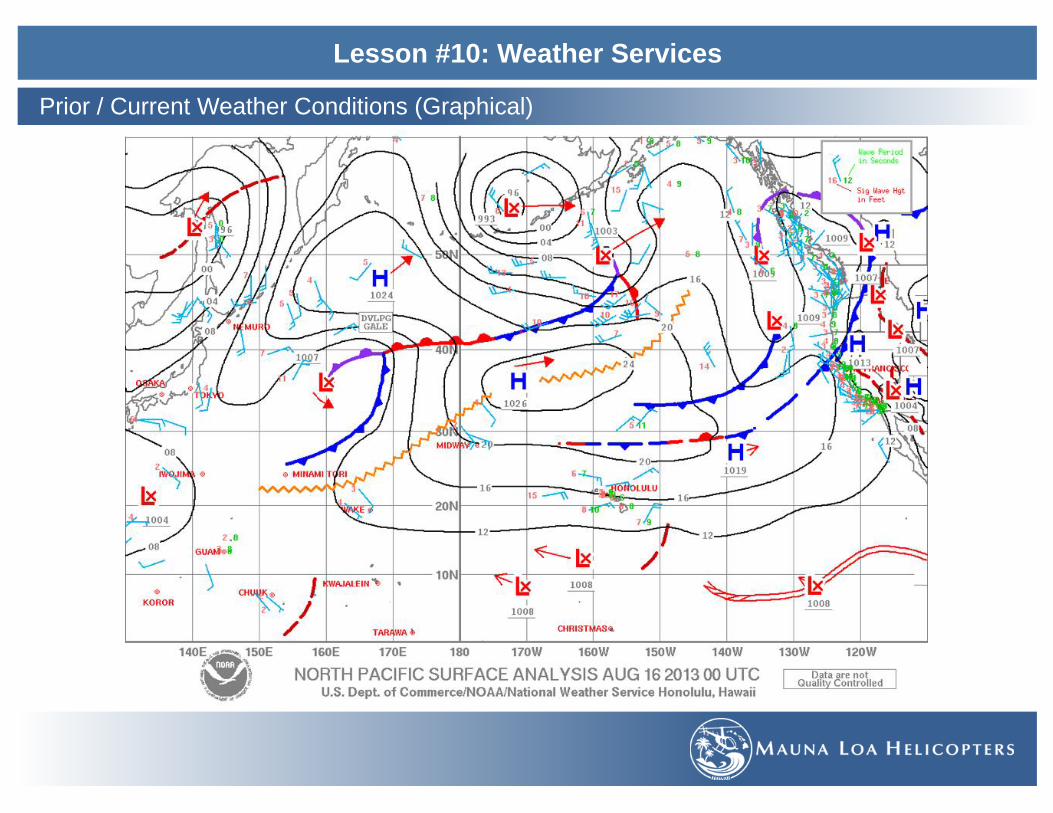
Lesson #10: Weather Services
Prior / Current Weather Conditions (Graphical)

Lesson #10: Weather Services
Prior / Current Weather Conditions (Graphical)
Weather Depiction Chart • A Computer prepared chart compiled from surface observations stations. • Begins at 0100Z each day and is transmitted at 3 hour intervals. • Chart depicts areas of restricted visibility and low ceilings.
- IFR: Ceiling < 1000’ and/or visibility < 3 miles. Hatched area outlined by a smooth line. - MVFR: Ceiling 1000-3000’ inclusive and/or visibility 3-5 miles inclusive. Non-hatched area outlined by a smooth line. - VFR: No ceiling or ceiling > 3000’ and visibility > 5 miles. Not outlined.
• Also contains information of frontal activity and abbreviated version of station models. • Good for long XC planning to get a big picture • Available in download format (Not in Hawaii):
http://aviationweather.gov/iffdp/misc

Lesson #10: Weather Services
Prior / Current Weather Conditions (Graphical)

Lesson #10: Weather Services
Prior / Current Weather Conditions (Graphical)
Satellite Weather Images
Visible Water Vapor
Infrared

Lesson #10: Weather Services
Prior / Current Weather Conditions (Graphical)
Composite Moisture Stability Chart (Lifted Index Analysis) • Composed of 4 panels which depict:
- Stability / Precipitable Water / Average Relative Humidity / Freezing Level • Issued 4x daily @ 0000Z and 1200Z • Available at: http://weather.noaa.gov/fax/miscella.shtml
Stability Panel (Upper Left)
- K Index (KI) - Provides moisture and stability info, plotted below station symbol High positive KI signifies moist unstable air (+20 or more) / Low or negative KI implies dry stable air (less than +20) KI is indicator of probability of thunderstorms Higher KIs imply higher probabilities - Lifted Index (LI) - Common measure of atmospheric stability, plotted above station symbol Positive LI means lifted surface parcel of air is stable / Negative LI means lifted surface parcel is unstable Station circles are blackened for LI values of zero or less Low and negative LIs indicators of intensities of thunderstorms
Precipitable Water Panel
(Upper Right)
- Analysis of quantity of water vapor in the atmosphere from surface to 500mb (18k ft MSL) - Precipitation water values are plotted above each station symbol to nearest hundredth of an inch - Percent relative to normal for month plotted below station symbol - Black circles indicate stations with precipitation water values of 1.00" or more - Isopleths of precipitation are drawn and labeled for every 0.25" - ".72/196" indicates that 72 hundredths of an inch of precipitation present, which is 196% or normal for any day during this month
Freezing Level Panel (Lower Left)
- Freezing level is height above MSL at which temp is 0C - During very cold periods, all temps over station may be below freezing and there would be no freezing level - Stations may have more than one freezing level - Observed freezing levels are plotted on chart in hundreds of feet MSL - BF is plotted on chart to indicated below-freezing temps at surface
Average Relative Humidity Panel (Lower Right)
- Relative humidity is ratio of quantity of water vapor in sample of air compared to air's capacity to hold water expressed in percent - Air with high relative humidity often contain clouds and may produce precipitation. - Blackened circle indicate stations with humidity of 50% of higher

Lesson #10: Weather Services
Prior / Current Weather Conditions (Graphical)

Lesson #10: Weather Services
Prior / Current Weather Conditions (Graphical)
Constant Pressure Analysis Chart • An upper air weather map which is referenced to a specific pressure level. • Measured at six pressure altitude levels from 850mb (~5,000’) to 200mb (~39,000’). • Issued 2x daily (1200Z and 0000Z) • The observed data for each reporting location is plotted on the chart.
- Observed temperature and temperature dewpoint spread (°C) - Wind Direction (True North) - Wind Speed (knots) - Height of the pressure surface (meters) - Changes in the height over the previous
12 hours • Available at:
https://www.aviationweather.gov/sitemap/ Standard [email protected]

Lesson #10: Weather Services
Weather Forecasts (Textual)
Terminal Aerodrome Forecasts (TAF) • A source that estimates what the weather will be for a specific time frame at a specific airport. • Textual report is update 4x a day (0000Z, 0600Z, 1200Z & 1800Z) and is valid for 24-hours • Usually available at larger airports. • Utilizes some descriptors and abbreviations similar to that of METARs.
SecDon ContentTypeofReport Rou=neforecast(TAF)orAmendedforecast(TAFAMD)
ICAOsta=onIden=fier SameasMETAR(PHKOforKonaAirport)
Date&TimeofOrigin 6numbercode:first2#�s=dateandlast4#�s=UTC=me
ValidPeriodDate&Time 6numbercode:first2#�s=date,next2#�sbeginning=meandlast2#�s=ending=me
ForecastWind 5#code:first3#�s=direc=on(truenorth)andthelast2#�s=speed(kts)
ForecastVisibility DistanceofvisibilityprovidedinStatuteMiles(SM),wholenumbersorfrac=ons,P=Plus(P6SM)
ForecastSignificantWeather Includesforecastedweatherphenomenon,ifnoweatherisforecasteditisomiged.
ForecastSkyCondi=ons SameasMETAR,onlyCumulonimbus(CB)areforecasted.
ForecastChangeGroup FROM(FM)-rapidandsignificantchangewithin1hourBecoming(BECMG)-gradualchangeinweatherwithin2hourTemporary(TEMPO)-temporaryfluctua=oninweatherwithin1hour.
ProbabilityForecast Givenpercentagethatdescribestheprobabilityofthunderstormsandprecipita=oneg.PROB3001042SMTSRAOVC010CBeg.translated:30%chanceofathunderstormwithmoderaterain,2statutemilesvisibilityandanovercastlayerofcumulonimbuscloudsat1000�AGLbetween0100Zand0400Z.
Kona Airport TAF

Lesson #10: Weather Services
Weather Forecasts (Textual)
Area Forecasts (AF) • covers general weather conditions over several states or a known geographical area (Hawaii/Alaska). • Issued 3x daily covers an 18-hour period (4x daily for Hawaii)
- Synopsis (18 hours) - VFR Clouds and weather (12 hours + 6 hour outlook)
• Good information for enroute weather and for smaller airports that do not have TAF. • Consists of several sections
SecDon DescripDon
v Communica=onsandProductHeaderSec=on
o ThesourceoftheAreaForecasto DateandTimeofIssuanceo ValidForecastTimeo AreaofCoverage
v Precau=onaryStatementSec=on
o IFRCondi=onso MountainObscura=ono ThunderstormHazardso Statementsmadehereregardingheight(MSL)otherwise
willbenoted(AGLorCIG)
v SynopsisSec=on o Givesabriefsummaryiden=fyingtheloca=onandmovementofpressuresystems,frontsandcircula=onpagerns.
v VFRCloudsandWeatherSec=on
o Listsexpectedskycondi=ons,visibilityandweatherforthenext12hoursandanoutlookforthefollowing6hours.
o ExpectedweatherforVFR,MVFRandIFRo IFR:Ceiling<1000�and/orvisibility<3SMo MarginalVFR:Ceilingfrom1000�to3000�and/orVisibility
from3to5SM
A
BC
D

Lesson #10: Weather Services
Weather Forecasts
Inflight Weather Advisories • Forecasts of potentially hazardous weather. • Provided prior to departure as part of flight planning and also to enroute aircrafts. • Available in 3 forms: AIRMET, SIGMET and CONVECTIVE SIGMET
AIRMET (WA) - Airman’s Meteorological Info • Contains information for all aircraft. • Weather information is considered potentially
hazardous to light (all) aircraft or aircraft with limited operational capabilities.
• Issued every 6 hours with amendments issued as necessary.
• Each AIRMET issuance is assigned an “update #”
• Three Types of AIRMETs: - SIERRA - IFR conditions (Ceilings
<1000’ and/or Visibility <3miles) and/or extensive mountain obscuration.
- TANGO - moderate turbulence, surface winds of 30 knots or greater & non-convective low-level wind shear.
- ZULU - moderate icing and provides freezing level heights.
SIGMET (WS) - Significant Meteorological Info
• Contains information for all aircraft. • Potentially hazardous non-convective
weather. • An unscheduled forecast that is valid for 4
hours. • Hurricane SIGMETS are valid for 6 hours. • Each SIGMET is assigned an alphanumeric
ID (Papa1, P2 etc) until phenomenon ends. • SIGMETS include:
- Severe Icing (not associated with thunderstorms)
- Severe or extreme turbulence - Clear-Air Turbulence (CAT) - Dust-storms and sandstorms lowering
visibility to < 3 miles - Volcanic Ash.
Convective SIGMET (WST) - Convective Significant Meteorological Info
• Hazardous convective weather information significant to all aircraft.
• Consists of either an observation and a forecast or just a forecast.
• Issued for the conterminous US divided into East (E), Central (C) and West (W).
• Issued as needed (not available in Hawaii) • Valid for 2 hours • Convective SIGMETs include:
- Tornadoes - Lines of thunderstorms - Thunderstorms over wide areas - Embedded thunderstorms - Hail ≥ 3/4” in diameter - Wind gusts of 50 knots or greater

Lesson #10: Weather Services
Weather Forecasts (Textual)
Winds Aloft Table (FB) • Provide wind and temperature forecasts for specific locations in the US including Hawaii and Alaska. • Forecasted 2x daily based on radiosonde upper air observations (0000Z & 1200Z) • Winds/Temps Aloft Available at:
http://aviationweather.gov/products/nws/winds/ • Conditions are displayed for selected altitudes using a 6-digit group to include:
- Wind Direction (in 10‘s of degrees referenced to TN) - Wind Speed (knots) - Temperature (°C and negative above 24.000’)
• Temperatures are not forecasted for the 3,000’ level or any level within 2,500’ of the station elevation. • Wind Groups are omitted when the level is within 1,500’ of the station elevation. • “9900” - indicates winds light and variable, < 5 kts. • “0000” - indicates calm winds. • Wind Speeds 100-199kts are displayed by:
- adding 50 to wind direction - subtracting 100 from the wind speed
• Wind speed 200 kts or greater are displayed as 199 kts.
WindsAloefortheHawaiianIslands

Lesson #10: Weather Services
Weather Forecasts (Graphical)
Winds and Temps Aloft Chart • A depiction of the Winds/Temps report. • Gives a visual indication of wind patterns, speed and temperatures. • Available online at: http://www.aviationweather.gov/adds/winds/
NOTE:ADDStemp/windchartssupplement,butdonotsubs=tutefor,theofficialwindsandtemperaturealoeforecastcontainedintheFBproduct.

Lesson #10: Weather Services
Weather Forecasts (Graphical)
Low Level Significant Weather Prognostic Chart
• Designed for flight planning. • Helps to avoid areas of low visibility, low
ceilings and regions of turbulence and icing. • Valid from the surface to 400mb pressure
level. • Issued 4x daily (0000Z, 0600Z, 1200Z and
1800Z) • Available at: • http://www.aviationweather.gov/products/swl/
- SIGNIFICANTWEATHERPANELS(upperpanels)showareasofnon-convec=veturbulenceandfreezinglevelsaswellasIFRandMVFRweatherfromSFC-400mb.
- SURFACEPROGPANELS(lowerpanels)showstandardsymbolsforfrontsandpressurecentersaswellasareasofforecastedprecipita=on.

Lesson #10: Weather Services
Weather Forecasts (Graphical)
Convective Outlook - 48-hour forecast of thunderstorm activity. • Day 1 Panel depicts the outlook for general thunderstorm activity and severe thunderstorms for the first 24-hour period from
1200Z - 1200Z the following day. - Issued 5x daily (0600Z, 1300Z, 1630Z, 2000Z and 0100Z)
• Day 2 Panel depicts the forecast for the second day beginning a 1200Z - Issued 2x daily (0830Z STD Time and 1730Z)
• Both Day 1 and Day 2 panels outline: - Areas of convective activity. - The associated risk factor. - Areas of general thunderstorms.
• Also included is the convective outlook (AC) which is a textual report providing detail of the Convective Outlook Chart. • Severe thunderstorm criteria include surface winds of 50 kts or higher, hail 1/4” in diameter or greater and tornadoes.
Chart Notation DescriptionLine with Arrowhead Depicts forecast general thunderstorm activity.
When facing the direction of the arrow thunderstorm activity is expected to be to the right.
Outlined Area Area of greater risk for convective activity. Associated risk is indicated inside the outlined region.
SLGT (Slight) Implies well-organized severe thunderstorms in small numbers or lower coverage.
MDT (Moderate) Indicates a potential for a greater concentration of severe thunderstorms than the slight risk and in most cases is more intense.
HIGH Suggests a major severe weather outbreak is expected. Expectations of either concentrations of tornadoes or an enhanced likelihood of a long-lived wind event with the potential of higher end wind gusts (+80 mph) and structural damage.
SEE TEXT When severe storm coverage or intensity is not expected to be sufficient for a SLGT risk but some threat exists.

Lesson #10: Weather Services
Weather Forecasts (Graphical)
Convective Weather Outlook Day 1

Lesson #10: Weather Services
Weather Forecasts (Graphical)
Convective Weather Outlook Day 2

Lesson #10: Weather Services
NOTAM (Notices to Airmen)
NOTAM • Time critical, aeronautical information that could affect pilot’s decision to fly. • Information can be temporary or newer than the most recent printed publications. • Information is pertinent to the route of flight. • Keep pilots informed of pertinent information and/or changes with regards to their flight. • https://pilotweb.nas.faa.gov/PilotWeb/
NOTAM-D (Distant)
• Notices are disseminated to all navigational facilities that are part of the National Airspace System, all public use airports, sea plane bases and heliports listed in the A/FD.
• Available through any FSS and DUATS. • Some items that are covered:
– Runway closures – Changes in Frequencies – Non-service of navigational aid
NOTAM-FDC (Federal)
• Desseminnates information that is regulatory in nature. • Available through FSS and DUATS. • Examples of information included:
– Amendments in aeronautical charts – Changes in instrument approacheds – Temporary Flight Restrictions
Military NOTAM
• Notices pertaining to U.S. Air Force, Army, Marin and Navy navigational aid/airports that are part of the National Airspace System.

Lesson #10: Weather Services
Methods of Obtaining Weather Info
Flight Service Station (FSS) • Primary source of preflight weather information. • Preflight weather briefs can be obtained by calling the automated FSS (AFSS) 24 hours a day @ 1(800)-WX-BRIEF • Areas not served by AFSS may utilize NWS facilities to provide pilot weather briefings.
Telephone Information Briefing System (TIBS) • Prepared and disseminated by selected AFSS. • Intended to be used as a preliminary tool and not to replace
a standard briefing. • Provides a continuous telephone recordings of:
- Area and/or meteorological briefings - Airspace procedures - Special aviation-oriented announcements - METAR and TAF info may also be included.
Direct User Access Terminal System (DUATs) • Funded by the FAA • Free service to any pilot with a medical certificate. • Provides direct access to weather briefings and
filing flight plans. • http://www.duats.com • Create an account with a medical certificate number.
Standard Briefing • The most complete of the briefings and provides an overall weather
picture. • Should be obtained prior to departure as part of a pre-flight planning. • Contains:
- Adverse Conditions - VFR Not Recommended - Synopsis Current Conditions - Enroute Forecasts - Destination Forecast - Winds and Temps Aloft - Notices to Airmen - ATC Delays - Request for PIREPS - EFAS - Other Information
Outlook Briefing • Should be requested when a planned departure is 6 hours or more away. • Useful information that can influence route, altitude or even go/no go
decisions
Abbreviated Briefing • The shortened version of the Standard Briefing • Should be used in the event of a delay or for weather updates.

Lesson #10: Weather Services
Methods of Obtaining Weather Info
En-route Flight Advisory System (EFAS) or Flight Watch • Provides en-route weather information upon request.
• Acts as the central collection and distribution point for PIREPs. • EFAS can be contacted between 6am and 10pm almost anywhere in the
conterminous US.
• When flying between 5,000’ AGL and 17,500’ MSL use common frequency 122.0 MHz
• At 18,000’ MSL and above there are different frequencies for different ARTCC regions.
• Contacting “Flight Watch”
- State the name of the ARTCC serving the area, your tail number and the name of the VOR nearest your position (or the frequency you are calling on).
Hazardous In-flight Weather Advisory System (HIWAS) • A continuous broadcast of summarized hazardous weather advisories
over selected VORs. • Broadcasts contain information of AIRMETs, SIGMETs, Convective
SIGMETs, Severe Weather Forecast Alerts (AWW) and Center Weather Advisories (CWA)
• Noted on a sectional chart with a “circle H” symbol
Center Weather Advisory (CWA) • An unscheduled advisory issued by an ARTCC to alert pilots of existing
or anticipated adverse weather conditions within the next 2 hours. • CWA can exist prior to, or regardless of AIRMETs or SIGMETs.
• ARTCC broadcasts CWAs once on all but emergency frequencies when any part of the described area is within 150 miles of the airspace under ARTCC jurisdiction.
• In terminal areas, local control and approach control may limit these broadcasts to within 50 miles.
Transcribed Weather Broadcasts (TWEB) • Provides continuous aeronautical and meteorological information
transmitted over selected VORs and NDBs. • Broadcast includes specially prepared NWS forecasts, in-flight
advisories, winds aloft, and preselected information such as weather reports, NOTAMs and special notices.
• Typically TWEBs are used for in-flight information purposes.
• VORs and NDBs that transmit TWEBs have a “circled T” inside the communications boxes on sectional charts

Lesson #10: Weather Services
Wx Services Chart
Name Abbrev. Information Provided Issued Valid for Where to get it Notes Source
Automatic Weather Observation System AWOS
current weather: alt, wind, temp, dewpoint, density alt, vis, ceiling continuous radio / telephone continuous broadcast, freq in A/FD AIM 7-1-12
Automatic Surface Observation System ASOS
current weather: alt, wind, temp, dewpoint, density alt, vis, ceiling, precip continuous radio / telephone continuous broadcast, freq in A/FD AIM 7-1-12
Automatic Terminal Information Service ATIS
current weather: ceiling, vis, temp, dewpoint, wind(mag), alt, rwy in use
every hour / when conditions change 1 hr radio
continuous broadcast, freq in A/FD based on METAR / SPECI AIM 4-1-13
Aviation Routine Weather Report METAR
surface weather: a/d ID, time, wind, visibility, RVR, current wx, sky cond, temp, dewpoint, altimeter setting
every hour 1 hr DUATS / FSS used for ATIS recording AC 00-45F pg 3-1
Aviation Selected Special Weather Report SPECI
surface weather same as METAR plus plain language explanation as needed between METAR 1 hr DUATS / FSS
non routine, used to report significant weather changes between METAR issuances AC 00-45F pg 3-1
Pilot Report PIREP observed wx in the air unscheduled DUATS / FSS / ATC UA: routine / UUA: urgent AC 00-45F pg 3-32
Radar Weather Report SD/ROB precipitation: location, intensity and type every hour 1 hr DUATS no cloud information AC 00-45F pg 3-45
Surface Analysis Chartsea level pressure, highs, lows, ridges and troughs, fronts, wind, temp, wx
8x daily (3 hrs intervals) 00-03-06-09-12 prh.noaa.gov/hnl/pages/analyses.php AC 00-45F pg 5-1
Weather Depiction Chartcond at selected METAR stations analysis of weather flying categories
8x daily (3 hrs intervals) 01-04-07-10-13 weather.noaa.gov vis, present wx, sky cover, ceiling AC 00-45F pg 5-42
Radar Summary Chartprecipitation: type, cell movement, max tops, location of line echoes every hour 1 hr weather.noaa.gov based on Radar Weather Report AC 00-45F pg 5-50
Aviation Area Forecast FAsynopsis, sky condition, visibility, wx, significnt wind, outlook 3x daily (4x in HI) 18 hrs
aviationweather.gov DUATS
12 hour specific + 6hour outlook (IFR, MVFR, VFR) wx for area the size of several states AC 00-45F pg 7-1
Terminal Aerodrome Forecast TAF
expected wx within 5 SM of a/d: a/d ID, valid period, wind, visibility, wx, sky cond
4x daily (6 hr intervals) 00-06-12-18 24 or 30 hrs DUATS / FSS good source for destination wx AC 00-45F pg 7-19
Wind and Temperature Aloft Forecast FB wind velocity and direction (true), temperature 4x daily
6, 12 or 24 hrs
aviationweather.gov DUATS AC 00-45F pg 7-38

Lesson #10: Weather Services
Wx Services Chart
Name Abbrev. Information Provided Issued Valid for Where to get it Notes Source
Low Level Significant Weather Chart SIGWX
forecast: weather flying categories, turbulence, freezing levels 4x daily 12 & 24 hours aviationweather.gov NONE in HI AC 00-45F pg 8-8
Surface Prognostic Chartforecast of surface pressure systems, fronts and precipitation
4x daily 2x daily
12 & 24 hr 36 & 48 hr aviationweather.gov
shows a snapshot of wx forecast at 12,24, 36 and 48 hours NONE in HI AC 00-45F pg 8-1
AIRMET WAS: IFR conditions or mtn obscuration T: moderate turbulence or 30+ knots wind Z: moderate icing
4x daily 6 hrs DUATS / FSS / ATISAC 00-45F pg 6-20 AIM 7-1-6
SIGMET WSsevere icing / turbulence, dust/sand storm, volcanic ashes as needed 4 hrs DUATS / FSS / ATIS
also issued in HI for tornadoes, TS lines, embedded TS, hail 3/4�+
AC 00-45F pg 6-1 AIM 7-1-6
Convective SIGMET WSTtornadoes, TS lines, embedded TS, hail 3/4�+, 50+ knots wind as needed 2 hrs DUATS / FSS / ATIS none in HI
AC 00-45F pg 6-7 AIM 7-1-6
Center Weather Advisory CWAexpected adverse conditions approaching AIRMET or SIGMET criteria as needed 2 hrs DUATS / FSS short notice for use in flight
AC 00-45F pg 6-31 AIM 7-1-6
Hazardous Inflight Weather Advisory Service HIWAS hazardous weather as needed
Broadcast - 24/7
broadcast over selected NAVAIDs
summary of AIRMET, SIGMET and urgent PIREP 150 mile broadcast radius
AC 00-45F pg 1-9 AIM 7-1-10
Convective Outlook ACsevere TS risk - day 1 areas of TS - day 2 forecast areas of convection - day 3
5x daily, 2x daily, 1x daily
DUATS / FSSday 1 valid 24 hours from first issuance forecast potential TS NONE in HI
AC 00-45F pg 6-37
Telephone Information Briefing Service TIBS
weather for 50+ NM radius similar to weather briefing when conditions change AFSS
AFD lists TIBS numbers continuous telephone recording not intended to replace standard briefing
AC 00-45F pg 1-8
En Route Flight Advisory Service EFAS weather info for specific flight on pilot request radio 122.0 callsign Flight Watch AC 00-45F pg 1-10
Weather briefingadverse cond (TS, icing, turb, wind shear), current cond, forecast, en route & dest, Wx, FB, Notams, synopsis, ATC delays, VNR
on pilot requestDUATS / FSS / 1-800-WX-BRIEF
use for wx information before a flight Abbreviated, Standard, Outlook VNR=VFR Not Recommanded
AC 00-45F pg 1-7
Transcribed Weather Forecast TWEB summary of weather
4x daily (6 hour intervals) 02, 08, 14, 20 12 hrs
broadcast over VOR, NDB Alaska ONLY AIM 7-1-9
Notice to Airmen NOTAMairport changes, obstructions - D approach, reg changes, TFRs - FDC daily as needed varies DUATS / FSS / ATIS D: distant , FDC, Military, Pointer AIM 5-1-3

Lesson #10: Weather Services
Discussion on related topics 1. ________________________________________________________________________________________________________
2. ________________________________________________________________________________________________________
3. ________________________________________________________________________________________________________
Completion Standards
This lesson will be complete when by oral examination the student displays an understanding of the material presented.
Instructors Comments and Recommendations:
___________________________________________________________________________________________________________
___________________________________________________________________________________________________________
___________________________________________________________________________________________________________
___________________________________________________________________________________________________________
Review

Lesson #11: E6B Flight Computer
During this lesson the students will be introduced to the E6B Flight Computer and its use in navigational computations.
Objective

Lesson #11: E6B Flight Computer
Calculator Side
Explanation of Markings
OFF-COURSEcorrec=on
FlightPlanInforma=on
SpecialEquip.Suffix
WindComponentGrid
CrosswindCorrec=on
StatuteMiles-Sec=onalChartandWorld
Aeronau=calChart
Nau=calMiles-Sec=onalChartandWorld
Aeronau=calChart
TemperatureConversion
Descrip=onforAl=tudeCorrec=on.
Descrip=onforAirspeedCorrec=on.
DensityAl=tude
Informa=onforusing��60RATE�-�60pointstowardouterscale(Numerator)-innerscaleisdenominator(gal/hr)
Numbersaroundthescaleshavedifferentmeaningdependingonthecontextoftheproblem.

Lesson #11: E6B Flight Computer
Calculator Side
Mileage Conversion • eg. 145 Nautical Mile (NM) = 269 Kilometer (KM)
115StatuteMiles(SM)=___Kilometer(KM)
- Set115(InnerScale)totheSTATarrow(OuterScale)- ReadunderKMarrow(OuterScale)thevalue185(InnerScale)
90Knots(Kts)=___MilesperHour(MPH)
- Set90NM/hr(InnerScale)totheNAUTarrow(OuterScale)
- ReadunderSTATarrow(OuterScale)thevalue104(InnerScale)
Speed Conversions • eg. 145 Nautical Mile (NM) = 269 Kilometer (KM)

Lesson #11: E6B Flight Computer
Calculator Side
Time Computations • Ground Speed = 150 Kts • Distance = 245 NM • Time = ___ Hr
- Set “60 Rate” (Inner Scale) to 150 Kts (Outer Scale)
- Read 245 NM (Outer Scale) to the value 1:38 (Inner Scale)
Distance Computations • Ground Speed = 125 Kts • Fuel Endurance = 4.5 Hrs • Distance = ___ NM
- Set “60 Rate” (Inner Scale) to 125 Kts (Outer Scale)
- Read 4:30 Hr (Inner Scale) to the value 564 (Outer Scale)
Speed Computations • Time = 13 Minutes • Distance = 26 NM • Ground Speed = ___ Kts
- Set 13 Minutes (Inner Scale) opposite to 26 NM (Outer Scale)
- Read at “60 Rate” (Inner Scale) to the value 120 (Outer Scale)

Lesson #11: E6B Flight Computer
Calculator Side
Fuel Consumption (Endurance) • Fuel Consumption = 8.4 gal/hr • Useable Fuel = 64 gal • Endurance = ___ Hr
- Set “60 Rate” (Inner Scale) to 8.4 gal/hr (Outer Scale)
- Read 64 gal (Outer Scale) to value 7:37 hrs (Inner Scale)
Airspeed Computations (True Airspeed) Pressure Altitude=15,000’
• Outside Air Temperature = -15°C • Calibrated Airspeed = 145 kts • True Airspeed = ___ kts
- Set PA (15,000’) opposite OAT (-15°C) - Read 145 kts (Inner Scale) to value 183
kts (Outer Scale)

Lesson #11: E6B Flight Computer
Calculator Side
True Altitude Computations • Indicated Altitude = 12,000’ • Station Altitude = 5,000’ (above MSL) • Pressure Altitude = 10,000’ (Kollsman Window
Set to 29.92) • Outside Air Temperature = -19°C • True Altitude = ___’
- 12,000’ - 5,000’ = 7,000’ (ceiling to station) - Set 10,000’ opposite to -19°C (left window) - Read 70 (Inner Scale) to value 66 (Outer
Scale) = 6,600’ correction. - True Altitude: 5,000’ + 6,600’ = 11,600’
Density Altitude Computations • Pressure Altitude = 10,000’ (Kollsman Window
Set to 29.92) • Outside Air Temperature = -20°C • Density Altitude = ___
- Set PA (10,000’) opposite OAT (-20°C) - Read at Density Altitude Window = 8,000’

Lesson #11: E6B Flight Computer
Wind Face Side
Explanation of Markings Information for determining Ground Speed (GS) and True Heading (TH)
Graph containing speed arcs and wind correction angles
True Index Marking
Compass Markings
Transparent Disc with a grommet in the middle.
Add: West Variation & Right Wind Correction Angles (WCA)
Subtract: East Variation & Left Wind Correction Angles (WCA)

Lesson #11: E6B Flight Computer
Wind Face Side
The Wind Triangle • Air Vector • Ground Vector • Wind Vector
Air Vector (True Heading / True Airspeed)
Drift Angle
Converting between True Course to True Heading

Lesson #11: E6B Flight Computer
Wind Face Side
Ground Speed (GS) / Wind Correction Angle (WCA) / True Heading (TH)
• True Airspeed (TAS) = 80 kts
• True Course (TC) = 125°
• Wind Direction = 240°
• Wind Velocity = 15 kts
• GS = ___ kts
• WCA = ___ °R or °L
• TH = ___ ° - Set 240° Wind Direction to True Index - Mark 15 kts Wind Velocity up from Grommet - Set 125° (TC) to True Index - Slide mark to 80 kts (TAS Arc) - Read GS at Grommet = 85 kts - Read WCA at mark = 10 ° Right (+) - TH: 125° + 10° = 135°

Lesson #11: E6B Flight Computer
Wind Face Side
Wind Direction (WD) and Wind Velocity (WV)
• True Heading (TH) = 135°
• True Course (TC) = 130°
• True Airspeed (TAS) = 135 kts
• Ground Speed (GS) = 140 kts
• WV = ___ kts
• WCA = ___ °R or °L
• WD = ___ ° - Find WCA: 135° - 130° = +5° (right) - Set grommet to Ground Speed 140 kts - 130° (TC) to True Index - Mark spot at 5° (right) 135 kts (TAS) - Turn mark to the middle line.
- WD read at True Index = 248° - WV difference between Grommet and Mark =
13 kts

Lesson #11: E6B Flight Computer
SFAR 73
SFAR - Awareness Training Video Discussion on Related Topics and Safety Notices
• Go through POH 10
Awareness Training Written Test

Lesson #11: E6B Flight Computer
Discussion on related topics 1. ________________________________________________________________________________________________________
2. ________________________________________________________________________________________________________
3. ________________________________________________________________________________________________________
Completion Standards
This lesson will be complete when by oral examination the student displays an understanding of the material presented.
Instructors Comments and Recommendations:
___________________________________________________________________________________________________________
___________________________________________________________________________________________________________
___________________________________________________________________________________________________________
___________________________________________________________________________________________________________
Review

Lesson #12: Aeronautical Information Manual
During this lesson the students will be introduced to the Aeronautical Information Manual (AIM) along with the Airport Facilities Directory (AFD), the Advisory Circular System and Aeronautical Decision Making and Judgement.
Objective

Lesson #12: Aeronautical Information Manual
Air Navigation - Chapter 1
• NDBisdepictedonAeronau=calchartswiththissymbol
Equipmentfindsthedirec=onofthestrongestsignaloftheNDBandshowsthisonacompassrose.
• Nondirectional Radio Beacon (NDB)
- The oldest form of electronic navigational aids.
- Allows navigation TO/FROM the ground-based station.
- Transmits on Low/Medium Frequencies from the ground station to the aircraft’s Automatic Direction Finder (ADF).
- NDB range is dependent on the operating power.
Navigational Aids (Ch 1 Sec 1)
Nondirectional Radio Beacon (NDB) AIM 1-1-2
VHF Omni-Directional Range (VOR) AIM 1-1-3
VOR Receiver Check AIM 1-1-4
Tactical Air Navigation (TACAN) AIM 1-1-5
VOR/TACAN (VORTAC) AIM 1-1-6
Distance Measuring Equipment (DME) AIM 1-1-7
Navigation Aid (NAVAID) Service Volume AIM 1-1-8
Instrument Landing System (ILS) AIM 1-1-9
Simplified Direction Finder (SDF) AIM 1-1-10
Microwave Landing System (MLS) AIM 1-1-11
NAVAID Identifier Removal During Maintenance AIM 1-1-12
User Reports on NAVAID Performance AIM 1-1-13
Long Range Navigation (LORAN) AIM 1-1-15
VHF Direction Finder AIM 1-1-16
Inertial Reference Unit (IRU) Inertial Navigation System (INS) and Attitude Heading Reference System (AHRS) AIM 1-1-17
Doppler Radar AIM 1-1-18
Global Positioning System (GPS) AIM 1-1-19
Receiver Autonomous Integrity Monitoring (RAIM) AIM 1-1-19
Wide Area Augmentation System (WAAS) AIM 1-1-20
Ground Based Augmentation System (GBAS) Landing System (GLS) AIM 1-1-21
Precision Approach System other than ILS, GLS, and MLS AIM 1-1-22
Area Navigation (RNAV) AIM 1-2-1

Lesson #12: Aeronautical Information Manual
Air Navigation - Chapter 1
VHF Omni-Directional Range (VOR) • The backbone for guidance to pilots operating under both VFR
and IFR operations • Continuously transmits navigation signals.
- 360 magnetic courses TO the station and 360 radials FROM the station.
• VOR transmissions are line-of-sight dependent.
Tactical Air Navigation (TACAN) • Navigational system employed by the US Military. • It is a more accurate version of the VOR/DME system.
VHF Omni-Directional Range/Tactical Air Navigation (VORTAC)
• Station composed of both VOR and TACAN. • Used for both Civilian Aviation as well as Military Information.
The VOR Beacon tells the equipment what course to fly to intercept the beacon.
VOR VOR-DME VORTAC

Lesson #12: Aeronautical Information Manual
Air Navigation - Chapter 1
Distance Measuring Equipment (DME) • A way of obtaining your distance to a Navigation Station. • DME receivers transmit paired pulses to a ground station.
The distance is calculated by the time it takes the signal to travel to the station and return.
• DME signals is straight line distance providing a slant range, not horizontal. (1NM high over the station (6000’) = 1NM from DME)
• Limited to Line-of-Sight conditions.
Instrument Landing System (ILS) • Provides a precise approach path for alignment and decent
of an aircraft on final approach to a runway. • Consists of 3 functional parts:
- Guidance information: lateral (localizer) and vertical (glide-slope).
- Range Information: Marker Beacon and DME - Visual Information: Approach Lights, Touchdown and
Centerline Lights and Runway Lights

Lesson #12: Aeronautical Information Manual
Air Navigation - Chapter 1
Global Positioning System (GPS) • A Satellite-based radio navigational, positioning and time
transfer system operated by the DOD. • Consists of 24 satellites orbiting the earth. • Europe is building their own network (Galileo). • Russia has its own satellites. • Newest Receivers can use signals from all the different
systems, to increase precision. • Provides information such as location, distance,
groundspeed, bearing and estimated time in route. • Preprogrammed with waypoints and airports to be dialed
into. • Utilizes a series of satellites orbiting the earth which are
designed and coordinated to have at least 4 with in line of sight from almost any location on earth.
• Satellites have an atomic clock (most accurate) inside and transmit the time.
• Receiver receives those signals and can triangulate its position in space.
• Number of satellites changes the precision and capabilities of the GPS.
• 3 Satellites used to attain 2D triangulation • 4 Satellites used for 3D triangulation (includes altitude) • 5 Satellite allows for RAIM • 6 Satellite allows for RAIM with the ability to pinpoint and
remove particular corrupt satellite signals.
Receiver Autonomous Integrity Monitoring (RAIM) • Used to determine whether or not a satellite is providing a
corrupt signal. • Validates the GPS signal being received.
Wide Area Augmentation system (WAAS) • FAA developed to improve the accuracy, integrity and
availability of GPS signals. • Uses ground based (fixed) stations to increase precision.

Lesson #12: Aeronautical Information Manual
Aeronautical Lighting and Markings - Chapter 2
Visual Approach Slope Indicator (VASI) • Light system arranged to provide visual decent guidance during
an approach to a runway. • Provides safe obstruction clearance within 10° of the extended
runway centerline. • Shown through a configuration of lights indicating ABOVE, ON
or BELOW glide path.
Airport and Heliport Lighting (Ch 2 Sec 1)
Visual Approach Slope Indicator (VASI) AIM 2-1-2a
Precision Approach Path Indicator (PAPI) AIM 2-1-2b
Tri-Color Systems AIM 2-1-2c
Pulsating Systems AIM 2-1-2d
Alignment of Elements Systems AIM 2-1-2e
Runway End Identifier Lighting (REIL) AIM 2-1-3
Run Edge Light Systems AIM 2-1-4
In-Runway Lighting AIM 2-1-5
Runway Status Lights (RWSL) System AIM 2-1-6
Stand Alone Final Approach Runway Occupancy Signal AIM 2-1-8
Pilot Control of Airport Lighting AIM 2-1-9
Airport/Heliport Beacons AMI 2-1-10
Taxiway Lights AIM 2-1-11
2-Bar VASI
3-Bar VASI
VASI Variations
• Memory Tool - Red over Red:------------------------- you’re Dead - Red over White------------------------ you’re alright - White over White ---------------------- fly all night.

Lesson #12: Aeronautical Information Manual
Aeronautical Lighting and Markings - Chapter 2
Precision Approach Path Indicator (PAPI) • Single row of 2 or 4 lights used similarly to the VASI. • Lights are usually installed on the left-hand side of the
runway. • Effective visual range of about 5 miles during the day and 20
miles at night.
Tri-Color System
• Normally consists of a single light unit projecting a three-color visual approach path.
• Effective visual range of about 1/2-1 mile during the day and 5 miles at night.
• Indication: - Below Glide Path: Amber Light - On Glide Path: Green Light - Above Glide Path: Red Light

Lesson #12: Aeronautical Information Manual
Aeronautical Lighting and Markings - Chapter 2
Runway Lighting • Runway Centerline Lights
- Spaced 50’ apart and are white until the last 3000’ - 3000’-1000’ they alternate between red and white. - Last 1000’ the lights are red.
• Touchdown Zone Lights - Installed to indicate touchdown zone when flying in
adverse conditions. - Steady white lights which start 100’ beyond the landing
threshold and extend 3000’ beyond the threshold or to the midpoint of the runway, which ever is less.
- Taxiway lights are generally blue
Pilot Controlled Lighting • Radio controlled lighting by keying the aircrafts microphone
on the airports radio frequency. • Often available at locations without specified hours for
lighting. • Usually when there is no control tower/FSS or when control
tower or FSS is closed • *L on the sectional chart indicates pilot controlled lightning
available
Key Mike Function
7 times with 5 seconds Highest intensity available
5 times with 5 seconds Medium or lower intensity (Lower REIL or REIL off)
3 times within 5 seconds Lowest intensity available (Lower REIL or REIL off)

Lesson #12: Aeronautical Information Manual
Aeronautical Lighting and Markings - Chapter 2
Airport/Heliport Beacons • They have a vertical light distribution to make them most effective from 1°-10° above the horizon, however they can be seen well
above and below this peak spread. • Rotates at a constant speed which produces the visual effect of flashes at regular intervals. • Light color and Intervals may vary depending on the point of interest.
- Intervals > 24-30/min = beacons marking airports, landmarks, and points of federal airways. > 30-45/min = beacons marking heliports.
- Colors > White and Green = Lighted Land Airports > White and Yellow = Lighted Water Airport > Green, Yellow and White = Lighted Heliport > White, White and Green = Military Airport

Lesson #12: Aeronautical Information Manual
Aeronautical Lighting and Markings - Chapter 2
Runway Markings • Runway Designators
- Numbers determined from the approach direction - Runway with an approach direction of 243 = “Runway 24”. - Runway with an approach direction of 178 = “Runway 18”. - Letters “L” - left, “R” - Right and “C” Center (If parallel runways exist)
• Runway Centerline - Line down the center of the runway to provide guidance during takeoff and landing.
• Runway Aiming Point - Visual aiming point for the landing aircraft.
• Runway Touchdown Zone - Identify touchdown zones for landing; spaced in 500’ increments.
• Runway Side Stripe - Show the edges of the runway.
• Runway Threshold - Identifies the beginning of the runway suitable for landing. - Symmetrical lines, width info can be found in the AFD - # of lines can also indicate runway width Info to the pilot.
> 4=60’ wide / 6=75’ wide / 8=100’ wide / 12=150’ wide / 16=200’ wide • Blast Pad
- Portion of pavement that is designed to allow jet and prop blast to diminish. - Not constructed to withstand weight of an aircraft.
Airport and Heliport Markings (Ch 2 Sec 3)
Runway Markings AIM 2-3-3
Taxiway Markings AIM 2-3-4
Holding Position Markings AIM 2-3-5
Other Markings AIM 2-3-6
Runway Designator
Blast Pad
Touchdown Zone
Aiming Point
Runway Centerline
Runway Threshold
500’
1,000’
1,500’ Side Stripe

Lesson #12: Aeronautical Information Manual
Aeronautical Lighting and Markings - Chapter 2
Taxiway Markings • Normal Centerline
- Solid yellow line to act as a visual cue for normal taxiing operations. • Enhanced Centerline
- Parallel lines of dashes marked on either side of the normal centerline. - Present in certain area 150’ prior to runway holding position markings.
• Taxiway Edge Marking - Lines that define the edges of the taxiway - Continuous Marking: double yellow that defines the taxiway edge from
shoulders or some other abutting paved surface. - Dashed Markings: dashed double lines that define the taxiway edge on
a paved surface where adjoining pavement is intended for use by an AC.
• Taxi Shoulder Marking - Bordering pavement that is not intended for aircraft use and may not be
able to support the weight of an aircraft. • Surface Painted Taxiway Direction Signs
- Painted markings with a yellow background and black inscriptions that are used to supplement or replace signs when necessary.
• Surface Painted Location Sign - Painted markings with a black background and yellow inscriptions
located to the right of the centerline. • Geographic Position Markings
- A circle with a black outer ring, a white inner ring, a pink background and black inscription.
- Used along low visibility taxi routes, positioned to the left of the centerline & used to provide location information to taxiing aircrafts.

Lesson #12: Aeronautical Information Manual
Aeronautical Lighting and Markings - Chapter 2
Hold Position Markings • Hold Position Markings (taxiways / runways / approach areas)
- Where the aircraft is required to stop when approaching a runway - Solid line side requires permission to cross and dashed side does not.
• ILS Hold Short - When the ILS Critical Area is being protected the pilot should stop so no
part of the aircraft extends beyond the hold position marking. • Taxiway/Taxiway Intersection Hold Short
- Single dashed line extending across the taxiway where ATC normally holds aircrafts.
- When Instructed by ATC to “Hold Short of Taxiway” no part of the aircraft should extend beyond the hold position marking.
• Surface Painted Holding Position Signs - Red background with white inscriptions; supplement hold position signs. - Located to the left of the taxiway centerline on the holding side and prior
to the holding position marking.

Lesson #12: Aeronautical Information Manual
Aeronautical Lighting and Markings - Chapter 2
Other Markings • VOR Receiver Checkpoint Markings
- Allows a pilot to check aircraft instruments with navigational aid signals. - Consists of a painted circle with an arrow in the middle; aligned in the
direction of the checkpoint azimuth. • Vehicle Roadway Marking (See Taxiway Markings Picture)
- Define a pathway for vehicle operations in areas that are also intended for aircraft use.
- Consists of solid or zippered white lines and a dashed white center line to define the lanes.
• Non-movement Area Boundary Marking - Delineate the movement area (area under air traffic control). - Consist of one solid yellow and one dashed yellow line. - Solid line is on the non-movement side and the dashed line is on the
movement side. • Permanently Closed Runway or Taxiway Marking
- Lighting circuits will be disconnected, Runway thresholds, designations and touchdown markings will be obliterated and yellow “X” will be placed at each end of the runway and every 1000’ interval.
• Temporarily Closed Runway or Taxiway - Yellow “X” are placed at either end of the runway.
• Heliport Landing Area - The Letter “H” is used to identify Landing and Takeoff areas at public
use Heliports and is aligned with intended direction of approach.

Lesson #12: Aeronautical Information Manual
Aeronautical Lighting and Markings - Chapter 2
Sign and Markings with Descriptions

Lesson #12: Aeronautical Information Manual
Airspace - Chapter 3
Hierarchy of Overlapping Airspace • When overlapping airspace designations exist the more restrictive airspace designations apply.
- Class A is more restrictive than B, C, D, E and G (No Class A over Hawaii) - Class B is more restrictive than C, D, E and G - Class C is more restrictive than D, E and G - Class D is more restrictive than E and G - Class E is more restrictive than G
General Airspace (Ch 3 Sec 1)
General Dimensions of Airspace Segments
AIM 3-1-2
Hierarchy of Overlapping Airspace Designations
AIM 3-1-3
Basic VFR Weather Minimums AIM 3-1-4
VFR Cruising Altitudes and Flight Levels AIM 3-1-5

Lesson #12: Aeronautical Information Manual
Airspace - Chapter 3
Controlled Airspace
• Class G Airspace (AIM 3-3-1) - Can be defined as that airspace which has not been designated as Class A, B, C, D and E. - Extends from the surface up to the overlying Class E airspace.
Uncontrolled Airspace (Ch 3 Sec 3)
• Class A Airspace (AIM 3-2-2) - The airspace from 18,000’ MSL up to and including FL600 including the airspace overlying the waters within 12NM of the Coastal Continental US
and AK. - Unless otherwise authorized, all operation in Class A airspace will be conducted under IFR.
• Class B Airspace (AIM 3-2-3) - The airspace from the surface to 10,000’ MSL surrounding the nation’s busiest airports. - Tailored to the needs of a particular area and consists of a surface area and 2 or more layers.
• Class C Airspace (AIM 3-2-4) - The airspace from the surface to 4’000 above the airport elevation surrounding those airports with an operational CT equipped with a radar approach
control, providing radar vectoring and sequencing for all IFR and VFR aircraft. - Usually consists of a 5NM radius core extending from the surface to 4000’ above airport elevation. - There is also a 10NM outer shelf extending no lower than 1200’ up to 4000’ above airport elevation.
• Class D Airspace (AIM 3-2-5) - Airspace that extends from the surface up to 2500’ above airport elev. surrounding those airports that have an operational CT. - Normally Class D airspace has a radius of 4NM
• Class E Airspace (AIM 3-2-6) - Defined as controlled airspace that is not Class A, B, C and D. - Can extend from the surface up to but not including 18000’ MSL

Lesson #12: Aeronautical Information Manual
Airspace - Chapter 3
VFR Requirements (AIM 3-3-2) • Minimum flight visibility and distance from clouds (91.155) • Cruising Altitudes 91.159
IFR Requirements (AIM 3-3-3) • Cruising Altitudes 91.179(b)
VFR Cruising Altitudes and Flight Levels
Magnetic Ground Course > 3,000’ AGL but < 18,000’ MSL
0º – 179º Odd thousand MSL, plus 500’ (3,500’, 5,500’, 7,500’ etc.
180º – 359º Even thousand MSL, plus 500’ (4,500’, 6,500’, 8,500’, etc.
IFR Cruising Altitudes and Flight Levels (Class GZ)
Magnetic Ground Course < 18,000’ MSL
0º – 179º Odd thousand MSL (3,000’, 5,000’, 7,000’ etc.)
180º – 359º Even thousand MSL (2,000’, 4,000’, 6,000’, etc.)
Class Airspace Entry Requirements Equipment Minimum Pilot Certificate
A ATC clearance IFR equipped Instrument Rating
B ATC clearance Two-way radio, transponder with
altitude reporting capability
Private – However, a student or recreational pilot may operate at other than the primary airport if
seeking private pilot certification and if regulatory requirements are met.
C Two-way radio communications prior
to entry Two-way radio, transponder with
altitude reporting capability No specific requirement
D Two-way radio communications prior
to entry Two-way radio No specific requirement
E None for VFR No specific requirement No specific requirement
F None No specific requirement No specific requirement

Lesson #12: Aeronautical Information Manual
Airspace - Chapter 3

Lesson #12: Aeronautical Information Manual
Airspace - Chapter 3
Special Use Airspace (Ch 3 Sec 4)
Prohibited Areas AIM 3-4-2
Restricted Areas AIM 3-4-3
Warning Areas AIM 3-4-4
Military Operations Area (MOA) AIM 3-4-5
Alert Areas AIM 3-4-6
Controlled Firing Areas (CFA) AIM 3-4-7
Prohibited Areas • Airspace within flights of aircraft are prohibited. • Established security or other reasons associated with national
welfare. • Published in the Federal Register and are depicted in
aeronautical charts.
Restricted Areas • Airspace within which flights of aircraft is subject to restrictions. • Can contain unusual, often invisible hazards to aircraft such as
artillery firing, aerial gunnery, or guided missiles. • Prior permission from the controlling agency is required. • Published in the Federal Register and depicted on aeronautical
charts.
Military Operations Area (MOA) • MOA’s consist of airspace of defined vertical and lateral limits
established for the purpose of separating certain military training from IFR traffic.
• MOA’s are depicted on aeronautical charts. • VFR traffic should contact any FSS within 100NM of an area to
obtain real-time information concerning the MOA hours of operation.
Warning Areas • Designated to warn pilots of the potential danger. • Extends from 3NM outward from the US Coast. • Contains activity that may be hazardous to nonparticipating
aircraft.
Alert Area • Airspace that may contain a high volume of pilot training or an
unusual type of aerial activity. • Depicted on aeronautical charts. • All pilots should be particular alert when flying in these area
and are responsible for collision avoidance.
Controlled Firing Area • Airspace which contains activities that are suspended
immediately when spotter planes, radar, or ground lookout positions indicate an aircraft may be approaching the area.
• CFAs are not charted.

Lesson #12: Aeronautical Information Manual
Airspace - Chapter 3
Airport Advisory/Information Services • An area within 10SM of an airport where a control tower is not
operating but where an FSS is located. • FSS provides advisory service to arriving & departing aircraft.
Military Training Routes (MTR) • Developed to allow the military to conduct low-level and high-level
training (in excess of 250 knots.) • Routes above 1500’ AGL are primarily flown IFR and routes below
1500’ are primarily flown VFR. • IR = IFR Route and VR = VFR Route • 4 #’s = no segment above 1500’ and 3 #’s = one or more segment
above 1500’ • “Four – on the floor” ; “Three – Above the trees” • Pilots planning on crossing MTRs should use extreme caution and
contact FSS to check route activity status.
Temporary Flight Restrictions (TFR) • A restriction on an area of airspace due to presidents, special
events, natural disasters or other unusual event. • Dimensions and restrictions for TFRs vary. • Distributed via FDC NOTAMs
Parachute Jump Aircraft Operations • Airspace that is used for parachute jumping and is published in the
AFD. • Frequently used areas are depicted on sectional charts.
Published VFR Routes • VFR routes for transitioning around, under and through comp
Terminal Radar Service Area (TRSA) • Airspace where radar and ATC services are available to pilots flying
IFR/VFR to help maintain aircraft separation. • Does not fit into any of the existing US classifications of airspace
and has been classified non-Part 71. • Participation in TRSA is optional.
National Security Areas • Defined airspace where there is a requirement for increased
security and safety of ground facilities. • Pilots are requested to voluntarily avoid these areas. • When necessary flights may be temporarily prohibited.
Other Airspace Areas (Ch 3 Sec 5)
Airport Advisory Information Services AIM 3-5-1
Military Training Routes (MTR) AIM 3-5-2
Temporary Flight Restrictions (TFR) AIM 3-5-3
Parachute Jump Aircraft Operations AIM 3-5-4
Published VFR Routes AIM 3-5-5
Terminal Radar Service Area AIM 3-5-6
National Security Area AIM 3-5-7

Lesson #12: Aeronautical Information Manual
Air Traffic Control Chapter 4
Other Airspace Areas (Ch 4 Sec 1)
Air Route Traffic Control Center AIM 4-1-1 Automatic Terminal Information Services (ATIS) AIM 4-1-13
Control Tower AIM 4-1-2 Automatic Flight Info Service (AFIS) AK FSS’s Only AIM 4-1-14
Flight Service Station AIM 4-1-3 Radar Traffic Information Services AIM 4-1-15
Recording and Monitoring AIM 4-1-4 Safety Alert AIM 4-1-16
Commu. Release of IFRAC Landing at Airport w/o Operating CT’s AIM 4-1-5 Radar Assistance to VFR Aircraft AIM 4-1-17
Pilot Visitis to Air Traffic Facilities AIM 4-1-6 Terminal Radar Services for VFR Aircraft AIM 4-1-18
Operation Take-Off and Operation Raincheck AIM 4-1-7 Tower En Route Control (TEC) AIM 4-1-19
Approach Control service for VFR Arriving Aircraft AIM 4-1-8 Transponder Operations AIM 4-1-20
Traffic Advisory Practices at Airports w/o Operating CT AIM 4-1-9 Hazardous Area Reporting Service AIM 4-1-21
IFR Approaches/Ground Vehicle Operations AIM 4-1-10 Airport Reservation Ops & Speci Traffic Mgmt Programs AIM 4-1-22
Designated UNICOM/MULTICOM Frequencies AIM 4-1-11 Requests for Waivers and Authorizations from 14 CFR AIM 4-1-23
Use of UNICOM for ATC Purposes AIM 4-1-12 Weather System Processor AIM 4-1-24
Airport and Heliport Operations (Ch 4 Sec 3)
General AIM 4-3-1 Communications AIM 4-3-14
Airports w/ an Operating Control Tower AIM 4-3-2 Gate Holding Due to Departure Delays AIM 4-3-15
Traffic Patterns AIM 4-3-3 VFR Flights in Terminal Areas AIM 4-3-16
Visual Indicators at Airports without an Operating Control Tower AIM 4-3-4 VFR Helicopter Operations at Controlled Airports AIM 4-3-17
Unexpected Maneuvers in the Airport Traffic Pattern AIM 4-3-5 Taxiing AIM 4-3-18
Use of Runways/Declared Distances AIM 4-3-6 Taxiing During Low Visiblilty AIM 4-3-19
Low Level Wind Shear/Microburst Detection Systems AIM 4-3-7 Exiting the Runway After Landing AIM 4-3-20
Braking Action Reports and Advisories AIM 4-3-8 Practice Ibnstrument Approaches AIM 4-3-21
Runway Friction Reports and Advisories AIM 4-3-9 Option Approaches AIM 4-3-22
Intersection Takeoffs AIM 4-3-10 Use of Aircraft Lights AIM 4-3-23
Pilot Responsibilities when Conducting Land & Hold Short Operations (LAHSO)
AIM 4-3-11 Flight Inspection/”Flight Check” Aircraft in Terminal Areas AIM 4-3-24
Low Approach AIM 4-3-12 Hand Signals AIM 4-3-25
Traffic Control Light Gun Signals AIM 4-3-13 Operations at Uncontrolled Airports with ASOS/AWOS AIM 4-3-26

Lesson #12: Aeronautical Information Manual
Emergency Procedures Chapter 6
General Emergency Procedure
Pilot Responsibility and Authority AIM 6-1-1 Emergency Conditions – Request Assistance Inmmediately AIM 6-1-2
Emergency Services Available to Pilots
Radar Services for VFR Aircraft in Difficulty AIM 6-2-1 Emergency Locator Transmitter AIM 6-2-5
Transponder Emergency Operation 7700 AIM 6-2-2 FAA K-9 Explosives Detection Team Program AIM 6-2-6
Direction Finding Instrument Approach Procedure AIM 6-2-3 Search and Rescue AIM 6-2-7
Interceptor and Escort AIM 6-2-4
Distress and Urgency Procedures
Distress and Urgency Communications AIM 6-3-1 Special Emergency (Air Piracy) AIM 6-3-4
Obtaining Emergency Assistance AIM 6-3-2 Fuel Dumping AIM 6-3-5
Two Way Radio Communication Failure
Two-Way Radio Communication Failure AIM 6-4-1 Reestablishing Radio Contact AIM 6-4-3
Transponder Operations During Two-Way Communication Failure AIM 6-4-2
Aircraft Rescue and Fire Fighting
Discrete Emergency Frequency AIM 6-5-1 ARFF Emergency Hand Signals AIM 6-5-3
Radio Call Signs AIM 6-5-2

Lesson #12: Aeronautical Information Manual
Airport Facility Directory (A/FD) Pacific Chart Supplement (PCS)
Airport/Facility Directory (A/FD) (AIM 9-1-4) • Comprehensive source of flight information containing descriptive
data on airports, heliports, seaplane bases, NAVAIDs, communications data, weather data sources, airspace, special notices and operational procedures.
• It’s a 7-volume booklet series which are divided into regions. • They are reissued every 56 days and are designed to be used in
conjunction with aeronautical charts. • Airports are listed alphabetically within the directory by state and
then city associated with the airport. • A/FD sample and legend are available at the front of the booklet to
help the reader interpret the data. • Used as a good source of information for preflight planning and
familiarization of airports. • In Hawaii the PCS is available to pilots which includes both the
Airport/Facility Directory A/FD and the Terminal Procedure Publication (TPP)

Lesson #12: Aeronautical Information Manual
Advisory Circular System (AC)
Advisory Circular • The FAA has developed a systematic means of providing pilots with non-regulatory information of interest. • Advisory Circulars (AC) are issued to provide guidance and information on a variety of subjects including aircraft operations, control
procedures as well as instruction. • These subject areas have associated identification numbers that correspond to the Federal Aviation Regulations (FAR) • 00: General • 20: Aircraft • 60: Airmen • 70: Airspace • 90: Air Traffic & General Operating Rules • 120:Air Carriers, Air Travel Clubs and Operators for Compensation or Hire Certification and Operations • 140: School and Other Certified Agencies • 150: Airports Series • Navigational Facilities
• Advisory Circulars are available to all pilots and may be ordered through the Department of Transportation US Government Printing Office or can be found online.

Lesson #12: Aeronautical Information Manual
Aeronautical Decision Making and Judgement
“ADM is a systematic approach to the mental process used by aircraft pilots to consistently determine the best course of action in response to a given set of circumstances.”
• ADM places an emphasis on the pilot decision process. • Often times the cause of an accident can described as a “Pilot Error” or “Human Factors” • Human Factors can be more relevant since it is usually not just one, but rather a chain of events that leads to an accident.
“Error Chain” (Poor Judgment Chain) • Term used to describe the concept of contributing factors in a human factors - related accident. • Many decisions are made throughout a flight. • As the chain of events unfold, each poor decision leaves the pilot with fewer options for the remainder of the flight.
(eg. Heli Flying Handbook 14-3)
Breaking the “Error Chain” • Breaking one link in the chain normally is all that is necessary to change the outcome of the sequence of events. • That one link is one decision that can be made to steer the pilot away from the event or accident.
DECIDE Model • Based on the principle that a good decision results when pilots:
- gather all available information - review it - analyze the options - select a course of action - evaluate the course of action for correctness

Lesson #12: Aeronautical Information Manual
Aeronautical Decision Making and Judgement
Risk Management • Risk is the probability and severity of an accident or loss from
exposure to various hazards, including injury to people and loss of resources.
• There are 4 components of a flight that are necessary for an accurate perception of the overall situation: - Pilot - Aircraft - Environment - External Pressure (Operation)
Assessing Risk • Every flight has a certain level of risk and associated hazards. • It may be difficult to differentiate between Low/High risk flights. • STUDY NTSB FACTUAL REPORTS • Majority of Fatal Accident are the result of: • Maneuver Flights, Weather, Decision Making Flaws, Wire Strikes,
etc.

Lesson #12: Aeronautical Information Manual
Aeronautical Decision Making and Judgement
Pilot Self Assessment • As PIC the pilot is responsible for the Final Authority of the aircraft. • Know your own limitations and set personal minimums ahead of a
flight in order to Go/No-Go criteria set. • (wind, visibility, Ceiling, VFR Weather, IFR Weather, Stress, Sleep,
Illness …) • Use a personal checklist based on experience, currency and
comfort to mitigate risks. • IM SAFE and Personal Minimum Checklist (FAA) • Use that time for pre-flight to also change “gears” from daily life to
being a pilot!!!
Pilot Hazardous Attitude • Attitude can be defined as a personal motivational predisposition
to respond to persons, situations or event in a given manner. • Lead to poor decision making and unnecessary risk. • Important to evaluate your decision to make sure there are no
hazardous influences. • Antidotes are the solutions to each Hazardous Attitude.
Hazardous Attitude Antidote
MACHO – Steve often brags to his friends about his skills as a pilot and how close to the ground he flies. During a local pleasure flight in his single-engine airplane, he decides to buzz some friends BBQ’ing a a nearby park.
Taking chances is foolish
ANTI-AUTHORITY – Although he knows that flying so low to the ground is prohibited by the regulations, he feels that the regulations are too restrictive in some circumstances.
Follow the rules, they are usually right.
INVULNERABILITY – Steve is not worried about an accident since he has flown this low many times before and he hasn’t had any problems before.
It could happen to me.
IMPULSIVITY – As he buzzes the park, the airplane doesn’t climb as well as he anticipated. Without thinking he pulls back hard on the yokes. The A/S drops and the airplane is close to stalling as the wing brushes a power line.
Not so fast, think first.
RESIGNATION – Although Steve manages to recover the wing sustains minor damage. Steve thinks to himself, “It doesn’t really matter how much effort I put in – the end result is the same whether I really try or not.”
I’m not helpless, I can make a difference.

Lesson #12: Aeronautical Information Manual
Aeronautical Decision Making and Judgement
Pilot Stess • Stress = the bodies response to demands placed upon it.
- Normal response to life situations - Some stress is good, too much stress is hazardous - Can be positive for performance depending on the level of
stress (keeps a person alert and prevents complacency). - Good cockpit stress management starts with good life stress
management.
Physical Condition • Is your body willing and able to do the work involved for that
particular operation. • Sleep, illness, alcohol, aches, pains, medication, general health
are all considerations to remember before getting into the cockpit.
Stressors
Environmental (Physical Stress) Conditions associated with the environment, such as temperature and humidity extremes, noise, vibration, and lack of oxygen.
Physiological Stress Physical conditions, such as fatigue, lack of physical fitness, sleep loss, missed meals (leading to low blood sugar levels), and illness.
Psychological Stress Social or emotional factors, such as a death in the family, a divorce, a sick child, or a demotion at work. This type of stress may also be related to mental workload, such as analyzing a problem, navigating an aircraft, or making decisions.
Stress Curve

Lesson #12: Aeronautical Information Manual
Aeronautical Decision Making and Judgement
Aircraft/Airworthiness • Another part of the risk assessment that is key to process prior to
flying. - In many cases this is incorporated in a comprehensive flight
plan and preflight. • Power
- Have a performance plan or know your limitation regarding power.
- consider the conditions of the flight and understand how and why your aircraft is going to respond the way it does.
• Fuel - Plan you flight with fuel in mind. - Flight with less than minimum fuel is never reasonable.
• Equipment - Be familiar with your aircraft and the resources available to
you. - Use checklists (preflight, start-up, shut-down, etc) - Knowing how to use your GPS, Radios, Avionics and Aircraft
before you get into a situation will prepare you for situations where time is limited and prompt responses are necessary.
- Set radio frequencies well in advance
Environment • Weather
- Wind speed and direction is important for runway use during patterns, landing and take off.
- Cloud base and coverage is important to stay within weather minimums for particular airspace and personal minimums.
- Storm and Icing Weather is also strongly emphasized for safe flight.
- Listen to ATIS/AWOS Frequencies prior to arrival to be prepared.
• ATC - Can be used to reduce pilot workload by providing traffic
advisories, radar vectors and assistance in emergency situations.
- Monitor Tower frequencies - May also increase the workload if the pilot gets behind or is
unprepared • FSS
- Can provide updates on weather, answer questions about airport conditions and offer direction finding assistance.
• Landing Surface - Use up-to date charts and publications to have pertinent
airport information.

Lesson #12: Aeronautical Information Manual
Aeronautical Decision Making and Judgement
Operational Pitfalls • Number of classic behavioral traps which pilots can fall into. • Commonly caused by the pressures of that particular flight operation being conducted • eg. trying to complete a flight as planned, pleasing passengers, and meeting schedules. • Awareness of these pitfalls can help to avoid dangerous situations. • Process the risks involved prior to being in that particular situation in order to counteract these pitfalls and ultimately minimize the risk.

Lesson #12: Aeronautical Information Manual
Aeronautical Decision Making and Judgement
Situational Awareness • The accurate perception of the operational and environmental
factors that affect the aircraft, pilot and passengers during a specific period of time.
• Stay ahead of the aircraft and the situation by understanding these factors and their future impact on the flight.
• Know the status of the aircraft systems, the pilot and the passengers.
• Be keen to the spatial orientation of the aircraft and its relationship to terrain, traffic, weather, and airspace.
• Be aware of the overall picture and not get fixated on one perceived significant factor. (Tunnel Vision)
Obstacle to Maintaining Situational Awareness • Fatigue, Stress or Workload: can cause fixation rather than
maintaining overall awareness. • eg. fatigue can result is degradation of attention and
concentration, impaired coordination and decreased ability to communicate.
• Distractions: can divert the pilot’s attention from monitoring the instruments or scanning outside of the aircraft.
• eg. faulty gauge attains pilots attention and controlling the aircraft is neglected.
• Complacency: When activities unnoticeably become routine, there is a tendency to relax and not put the same emphasis and effort toward performance.
• eg. Am I still using checklists? Did I check NOTAMS before every flight? Did I feel that vibration before or is it new? If so, has it been checked?
Knowing your surroundings can help prevent horrific events like backing into a spinning prop! Indiana Jones and the Raiders of the Lost Ark

Lesson #12: Aeronautical Information Manual
Discussion on related topics 1. ________________________________________________________________________________________________________
2. ________________________________________________________________________________________________________
3. ________________________________________________________________________________________________________
Completion Standards
This lesson will be complete when by oral examination the student displays an understanding of the material presented.
Instructors Comments and Recommendations:
___________________________________________________________________________________________________________
___________________________________________________________________________________________________________
___________________________________________________________________________________________________________
___________________________________________________________________________________________________________
Review

Lesson #13: Airport / Heliport Operations
This lesson will help increase the student’s understanding of airport and heliport operations, facilities and services available to pilots.
Objective

Lesson #13: Airport / Heliport Operations
Airports and Heliports
Runway Numbering (Review) • Q #1: You are flying into an airport that has an approach direction
of 174° what would the Runway number be? • Q #2: Runway 07 R tells you what information?
Active Runways • This is the runway that will be used for landing and taking off. • Determined by the prevailing winds at that time. • Active Runway can be determined from the current ATIS.
Runway and Heliport Markings (Review) • Q #1: Spots A, B, C and D point to what marking?
• Q #2: This symbol designates what?
• Q #3: This symbol designates what?
A B C D

Lesson #13: Airport / Heliport Operations
Airports and Heliports
Taxiways (Review) • Transition aircraft from parking areas to runways. • Use Yellow Markings • Q #1: What does the dashed line on either side of the centerline
indicate. • Q #2: What does the marking across the taxiway mean?
Parking Areas • Area designated for parking. • fig. - H = landing area and circles indicated individual aircraft
parking spots.
Field Elevation • Can be found on aeronautical chart and in the A/FD • Indicated the highest point of the usable runway and is in True
Altitude above MSL.
Wind Direction Indicator • Important to know and check wind direction. • 3 Types of indicators:
- Wind Sock: direction & speed (primary indicator) - Tetrahedron: only direction indications - Wind Tee: only direction indications
• Located in central locations near/around the runway. • Wind information is also provided by ATIS, ATC and FSS

Lesson #13: Airport / Heliport Operations
Airports and Heliports
Airport and Heliport Lighting • Wind Sock w/ Light
VASI (Visual Approach Slope Indicator)
Tri-Color
Rotating Beacons
General Airport Lights • Q: Non-Movement Area? • A: Where you don’t need clearance to operate. (ramp)
VASI (Visual Approach Slope Indicator)

Lesson #13: Airport / Heliport Operations
Airports and Heliports
Traffic Pattern • Airplanes
- Uncontrolled Airport use segmented circle visual indicator. - Controlled Airport refer primarily on ATC/ATIS Instruction. - Airplane pattern altitude is usually 1000’ AGL and left traffic - Altitude should be maintained. - Traffic patterns Info can be found in the A/FD.
• Helicopters - Helicopter operations should avoid the flow of fixed wing
aircraft. - Helicopter pattern altitude is usually 500’ AGL and right traffic - Operations may be conducted from: runways, taxiways,
portion of a landing strip, or any clear area. - ATC will issue takeoff clearance from specific areas if traffic
permits. - Be aware of wind and exercise caution. - Control Tower communication is necessary for safe and
efficient operations. - MLH - use helicopter patterns @ 500’ AGL (Kona Chart) and
left traffic

Lesson #13: Airport / Heliport Operations
Airports and Heliports
Components to a Basic Traffic Pattern • Takeoff – Upwind • Crosswind • Downwind • Base • Final Approach

Lesson #13: Airport / Heliport Operations
Airports and Heliports

Lesson #13: Airport / Heliport Operations
Radio Communications
Frequency Assignment Plan • Very High Frequency (VHF). • Operates between 118.0 and 136.975. • They use either 360 or 720 channels. • Limited to Line of sight transmissions.
Radio Technique • Listen before you transmit:
- Monitor the frequency or ATIS for information you may need to reduce radio congestion.
• Think before you key the transmitter: - Know what you want to say prior to transmitting to reduce
radio air time. • Position you microphone close to your lips:
- Increases clarity and ensures your call will be heard. • Be Patient:
- Controllers are busy and maybe working for you or other pilots or both at the same time.
• Be alert to the sounds or lack of in your receiver: - Allows you to know transmissions are getting across without
interruption (stuck mic, etc). • Be sure you are within the performance range of your equipment:
- VHF Communications are limited to line of site and higher altitudes increase its range.
Contact Procedure • Who Am I Calling... • Who Am I... • Where Am I... • What Do I Need... • Current ATIS
Initial Call Up from Ramp “Kona Tower Helicopter 4-6-1-Hotel South Ramp at Charlie request Left Closed Traffic with Information Uniform”
Call Up from Old Airport “Kona Tower Helicopter 4-6-1-Hotel Over Old Airport Request Full Stop South Alpha with Information Victor”
Position Report “Big Island Traffic Helicopter 4-6-1-Hotel Over Kiholo Bay at 1,500’ North Bound for A Bay”
Activating Flight Plan (Kona) “HCF Helicopter 4-6-1-Hotel with you on 126.0.” “Helicopter 4-6-1-Hotel Go Ahead” “I’d Like To Open My Flight Plan From Kona to Hilo” “Helicopter 4-6-1-Hotel Flight Plan Has Been Activated”

Lesson #13: Airport / Heliport Operations
Radio Communications
Microphone Technique • Keep the Microphone close to your lips. • Speak in a normal voice for clear transmissions. • Be clear and concise for good communication and efficient air time usage. • Short pause before and after speaking to ensure your full message is
transmitted.
Stuck Mic • Occurs when the radio continues to transmit even
though you have released the button. • Can be identified by the red light still illuminated on
the radio or a “TX”.
Aircraft Call Signs • Always use full call sign unless after your first transmission ATC has abbreviated your call sign. • If flying Helicopter 8-3-7-9-Zulu • Use full call sign on initial call up and there after unless ATC shortens it on response. • Abbreviated Call sign should use the last three letter/#’s of the tail number. eg. Helicopter 7-9-Zulu
Civil Aircraft • Aircraft Type, Model or Manufacture Name • Digits and Letter of Tail Number (no “N”) • eg. Helicopter-4-5-1-Hotel
Experimental Aircraft • Add suffix EXPERIMENTAL • eg. Helicopter-4-6-1-Hotel-Experimental
Air Taxi or commercial operators without an approved call sign
• Add prefix Tango • eg. Tango-Helicopter-4-6-1-Hotel
Air Carriers & Commuter Air Carriers • Use their own authorized call sign • Shaka-2-5
Military Aircraft • Use a variety of systems including serial numbers, word call signs and a combination of letters and numbers. • Army Copter 4-8-9-3-1
Air Ambulance • Use prefix Life Guard • Should only be used for an aircraft on a mission of urgent medical nature and only for that portion of the flight. • Life Guard 3-0-7
Student Pilot • Use the suffix Student Pilot • Helicopter 4-6-1-Hotel-Student Pilot

Lesson #13: Airport / Heliport Operations
Radio Communications
Radio Phraseology – Common Terms used during Radio Communication to ensure safety and efficiency.
hgp://www.faa.gov/air_traffic/publica=ons/atpubs/PCG/pcg.pdf
Say Again Request to repeat previous call
Stand By Pause for a few seconds, does not mean you are clear
Over (not really used) Transmission is ended, I expect a response
Affirmative Yes
Negative No or permission not granted
That is Correct The understanding you have is correct
Wilco (do not use) I received your message, understand, and will comply
Unfamiliar Not familiar with the area or procedure
Unable Inability to comply with an instruction, request, or clearance
Student Pilot The pilot is a student, expect unfamiliarity
Change to Frequency Change to a specific frequency
Speak Slower Request to reduce speech rate
Clear to Land ATC authorization for an aircraft to land
Clear to Takeoff ATC authorization for an aircraft to depart
Clear for the Option ATC authorization for an aircraft to make a touch-and-go, low approach, missed approach, stop-and-go, or full stop
Clear to Touch & Go ATC authorization for an aircraft to touch-and-go
Mid Field Point half way down the runway
Abeam A general position 90º left or right of the aircraft
Phonetic Alphbet
A ALPHA J JULIET S SIERRA
B BRAVO K KILO T TANGO
C CHARLIE L LIMA U UNIFORM
D DELTA M MIKE V VICTOR
E ECHO N NOVEMBER W WHISKEY
F FOXTROT O OSCAR X XRAY
G GOLF P PAPA Y YANKEE
H HOTEL Q QUEBEC Z ZULU
I INDIA R ROMEO
Used to reduce interpretation errors. • B, C, D, E, G, P, T, V, Z could all be potentially misleading

Lesson #13: Airport / Heliport Operations
Radio Communications
Light Gun Signals (Used during radio failure)
• Try to land outside Class B, C or D airspace. • Contact tower (telephone) and advise them
of your situation and intention to land. • Squawk 7600 on transponder “Radio Failure” • Determine flow of traffic and enter pattern
looking for other traffic and light gun signals.
Controlled Airports and Heliports • Automatic Terminal Information Service (ATIS)
- Continuous broadcast of non-controlled information. - Includes weather, wind, active runway, remarks, broadcast
identification (Charlie) - Check before entering and exiting the airspace and notify the
controller you have information “Charlie”. • Control Tower
- Responsible for an orderly flow of traffic on and in the vicinity of an airport.
• Clearance Delivery - At most B and C airports. - Contact them after obtaining ATIS for takeoff. - Tell them your location, desired departure and ATIS. - They provide a clearance and a departure frequency. - Airplanes then contact ground control for taxiing. - Otherwise taxi/hover with caution to departure point.
• Ground Control - At most B and C airports and many D airports. - Used by pilots needing clearance to taxi in movement areas or
needing progressive instructions for taxiing. - Otherwise taxi in non-movement areas with caution to place of
intended departure and then contact tower for takeoff clearance. • Approach Control
- At most B and C airports and some D airports. - Used to maintain separation for arriving aircrafts. - Inform you about wind, runway, altimeter setting and give you
squawk code. - Provide you with next frequency (tower) - Contact Approach Control prior to entering airport airspace.
• Departure Control - At most B and C airports and some D airports. - Used to maintain traffic separation for departing aircraft around
airport’s airspace. - Tower control provides squawk code and then hands you over to
Departure Control. - They clear you out of the area.
Signal Aircraft in Flight Aircraft on Ground Ground Vehicle
Steady Green Cleared to Land Clear to Takeoff Cleared to Cross/ Proceed/Go
Flashing Green Return to Landing (then Green) Cleared to Taxi Not Applicable
Steady Red Give way/ Continue Circling Stop Stop
Flashing Red Airport Unsafe, Do Not Land Taxi Clear of Runway Clear the Taxiway/Runway
Flashing White Not Applicable Return to Ramp Return to Starting Point
Alternate Red & Green Exercise Extreme Caution!!! Exercise Extreme Caution!!! Exercise Extreme Caution!!!

Lesson #13: Airport / Heliport Operations
Airport and Heliport Communications
Uncontrolled Airports and Heliports • Air Route Traffic Control Center (HCF)
- Facility established to provide air traffic control to aircraft operating on IFR flight plans.
• Common Traffic Advisory Frequency (CTAF) - Designated Frequency for the purpose of traffic advisory and stating
intentions at non-towered airports or when towers are closed. - Two common types of allocations:
> Unicom and Multicom. • Unicom
- A type of CTAF that allows for air and ground communication. - There is a base station that allows for the possibility to communicate
with ground. • Multicom
- Means the airport doesn’t have a designated base station with an operator.
- Used as a CTAF for pilots to broadcast their position and intentions. - Commonly 122.9 (eg. Waimea, Upolu)
• AWOS - Provides automated weather information to pilots operating in the
vicinity of the airport.

Lesson #13: Airport / Heliport Operations
Other ATC Facilities and Services
Air Route Traffic Control Center • Provides traffic control for pilots operating under IFR flight plans within controlled airspace, principally during the en route phase of flight. • Certain advisory/assistance services may be provided to VFR aircraft.
- No guarantee, dependent on traffic workload and radar contact. • In Hawaii ARTCC is Honolulu Control Facility (HCF)
- Control of en route air-traffic, arrivals, departures, and over flights in and around the numerous airports of Hawaii. - VFR Flight Following:
> Advisory service to help pilots maintain visual separation from other traffic. > Radar contact.

Lesson #13: Airport / Heliport Operations
FSS Services Available
Flight Service Station (FSS) • Air Traffic Facility that provides information and services to aircraft
pilots before, during and after flights. - Weather briefings - En-route weather - Receive and process IFR/VFR flight plans - Relay ATC clearances - Issue NOTAMs - Assist in lost aircraft, emergency situation and VFR search
and rescue. • Remote Communications Outlet (RCO)
- Remote aviation band radio transceivers, established to extend the communication capabilities.
- The outlet is used to make a radio call to the outlet as though you are contacting FSS directly.
- Kona - contact RCO 122.45 (Honolulu Radio) • Contacting FSS
- By Telephone @ (800)WX-BRIEF - By Radio - “T” = Transmit Only / “R” = Receive Only
“Flight Watch” • AKA. En Route Flight Advisory Service (EFAS) • Provide weather data tailored to the type, altitude and route of
flight being conducted. • Common Radio Frequency of 122.0 is used across the US below
18,000’. • Hawaii uses FSS (Honolulu Radio)
Transcribed Weather Broadcast (TWEB) • Available in Alaska Only • Provides continuous aeronautical and meteorological information
over selected VORs and NDBs. • Includes NWS forecasts, in-flight advisories, winds aloft and
preselected information (WX reports, NOTAMs and special notices).
• Indicated on a sectional chart by a “T” in the upper right hand corner of navaid boxes.

Lesson #13: Airport / Heliport Operations
Emergency Procedures
Emergency Locator Transmitter (ELT) • Developed to locate downed aircraft by directly informing Search
& Rescue Facilities. • Activates on aircraft’s impact with the ground • Operate on 121.5 243.0 and 406 (digital) MHz for at least 48 hours • Monitor radio frequency 121.5 prior to engine shutdown at the end
of each flight (minimize false alarms). • Non-rechargeable batteries only, should be replaced when 50%
charge remaining or when in use for more than 1 hr. • Digital 406 MHz ELTs
- Optimized for accurate Satellite location (10x smaller area to search).
- Has decreased the average location time dramatically. - Able to transmit a discrete digital code making aircraft ID
possible.
Personal Locator Beacon (PLB) • Similar to an ELT only that it is not fixed to the aircraft and it is not
activated on impact. • Activated manually by the pilot when deemed necessary. • Transmits on the same frequencies and is also available with GPS
functionality. • Most models are water proof and can float. • In water situations they wont sink to the bottom with the aircraft. • Also capable of discrete signal to identify pilot involved.
Emergency VHF Frequency – 121.5 MHz (AIM 6-3-1) • Monitored by: military towers, most civil towers, FSS, radar
facilities and airliners/civil aircraft. • Distress Call = “MAYDAY, MAYDAY, MAYDAY”
- potentially life threatening. • Urgency Call = “PAN-PAN, PAN-PAN, PAN-PAN”
- hazardous condition, notification is informative.
Transponder Codes
7700 Emergency ”77 Going to Heaven”
7600 Radio Failure ”76 In a Fix” or “Radio Tricks”
7500 Hijacking ”75 Taken Alive”

Lesson #13: Airport / Heliport Operations
Discussion on related topics 1. ________________________________________________________________________________________________________
2. ________________________________________________________________________________________________________
3. ________________________________________________________________________________________________________
Completion Standards
This lesson will be complete when by oral examination the student displays an understanding of the material presented.
Instructors Comments and Recommendations:
___________________________________________________________________________________________________________
___________________________________________________________________________________________________________
___________________________________________________________________________________________________________
___________________________________________________________________________________________________________
Review

Lesson #14: Stage II Review
This lesson will be a review of material presented in lessons 8 through 13 in preparation for the Stage II written examination.
Objective

Lesson #14: Stage II Review
Completion Standards
This lesson and stage II will be complete when the student has passed the stage II written examination, covering the material presented in lesson 8 through 13, with a minimum score of 80%.

Lesson #15: VFR Sectional Charts and Navigation
This lesson will introduce VFR charts and the navigation plotter, and their use in planning and conducting cross-country flights.
Objective

Lesson #15: VFR Sectional Charts and Navigation
Types of VFR Charts
Sectional Chart (SEC) • Designed for pilots flying under VFR. • Scale 1” = 6.86 NM (1:500,000) • 60”x20” folded to 5”x10” • Revised Semi-Annually (except most AK Charts are annual) • The legend contains a comprehensive grouping of symbols to
help identify aeronautical, topographical and obstruction information.
• Acts similarly to a road map and should be studied by the pilot.
VFR Termainal Area Chart (TAC) • Designed when flying in or near class B airspace. • Indicated by a white 1/4” masked line bordering the area
covered. • Scale 1” = 3.43 NM (1:250,000) • Revised Semi-Annually • Provides information in greater detail and clarity.
Inset • Used in Honolulu • Shown by a white 1/8” line bordering the area cover. • Displayed on Sectional chart.
World Aeronautical Chart (WAC) • Designed for pilots flying faster at higher altitudes. • Covers land areas of the world and contains less detail. • Scale 1” = 13.75 NM (1:1,000,000) • Revised Annually
Helicopter Route Charts • Provides current aeronautical information useful to helicopter
pilots navigation in high concentration of helicopter activity. • Includes helicopter routes, 4 classes of heliports with associated
frequency and lighting capabilities. • Contains symbols, roads and geographical features. • Revised less often (current for several years)
Other Types if VFR Charts • U.S. Gulf Coast VFR Aeronautical Charts • Grand Canyon VFR Aeronautical Charts

Lesson #15: VFR Sectional Charts and Navigation
VFR Chart Symbols and Markings
Latitude (Parallels) • Lines parallel to the equator • Indicate the angular difference from the equator to
the poles. • 90° N = North Pole • 90° S = South Pole • Equal distance between lines of latitude.
Longitude (Meridians) • Lines “parallel” to the Prime Meridian and
perpendicular to the Equator • Prime Meridian = 0° (Greenwich, England) • 180° East • 180° West
Magnetic Variation
Topography
National Airspace System
Navigational Aids
Aerodromes, Heliports and Flight Service Stations
Legend (other markings)

Lesson #15: VFR Sectional Charts and Navigation
Navigational Plotter
Mileage Scale • SM vs NM • SEC vs WAC
Azimuth Scale • 360 degree spinning wheel. • Align with True North
Plot and Measure Courses • Use Course Indicator • Read the Azimuth

Lesson #15: VFR Sectional Charts and Navigation
Application of Navigation Methods
Pilotage (Red) • Navigation by reference to landmarks or check point
on the ground. • Looking out the windscreen and comparing what you
see on the ground to what you see on the charts. • Visual references allow you to navigate the aircraft
from point to point.
Dead Reckoning (Blue) • Navigation solely by means of computations. • Based on Time, Ground Speed, Distance and
Direction. • How people navigated over the ocean in the early
days when they couldn‘t receive any radio signals. • Calculations can be confirmed by use of Pilotage,
referencing checkpoints and making corrections to the computations as necessary.

Lesson #15: VFR Sectional Charts and Navigation
Lost Procedures and Diversions
Lost Procedure (5 C’s) • Climb - get altitude to improve sight and radio performance • Communicate - get ahold of someone on the radio • Confess - tell someone your situation (you are lost) • Comply - do what they say • Conserve - be efficient with fuel
Diversion • Step 1
- Identify New Location - Start Timer - Turn in the general direction - Slow to 60 Kts GS
• Step 2 - Figure out heading using nearest VOR - Figure out distance - Figure out time to destination (1 minute per mile @ 60 Kts GS) - Adjust altitude to terrain appropriately
• Step 3 - Go/No-Go decision based on fuel and weather conditions
GPS • Nearest VOR or airport can provide bearing and distance • to that programmed spot. • Knowing the radial and distance to fly from the new LZ to that
programmed location can help.

Lesson #15: VFR Sectional Charts and Navigation
Discussion on related topics 1. ________________________________________________________________________________________________________
2. ________________________________________________________________________________________________________
3. ________________________________________________________________________________________________________
Completion Standards
This lesson will be complete when by oral examination the student displays an understanding of the material presented.
Instructors Comments and Recommendations:
___________________________________________________________________________________________________________
___________________________________________________________________________________________________________
___________________________________________________________________________________________________________
___________________________________________________________________________________________________________
Review

Lesson #16: Radio Navigation
This lesson will introduce radio navigation and its application in cross-country flight.
Objective

Lesson #16: Radio Navigation
VFR Omni-Directional Range (VOR)
VHF Omni-Directional Range System (VOR) • Radio Navigation between a ground station and an on board receiver. • This is the primary NAVAID for IFR and is the foundation for the IFR System. • The station transmits a magnetic bearing in all directions (omni-directional)
- Each degree of the compass called radials. (Provides 360° azimuth, like spokes on a bike) • VOR evolved from the NDB • Primarily used to navigate TO or FROM the station accurate to +/- 1° • VHF frequency Band of 108.0-117.95MHz • ID by voice recordings or Morse code. • 60 to 1 rule, at 60 miles from the station there is 1 mile between the radials
Terminal:12,000�andbelow.RadialDistance-25NM
LowAl=tude:18,000�andbelow.RadialDistance-40NM
HighAl=tude:60,000�andbelow.RadialDistance-40-100NM
ThreeClasses
VOR
VOR-DME
VORTAC
ThreeTypes

Lesson #16: Radio Navigation
VFR Omni-Directional Range (VOR)
VOR Receiver • Onboard receiver is tuned to a particular station to receive VHF signals
and translate them for the Instrument to provide navigational information.
VOR Instrument Components • Omni Bearing Selector (OBS)
- Knob that allows the pilot to select the desired course to be flown. • Course Deviation Indicator (CDI)
- Needle centers when the aircraft is on selected radial/reciprocal. • Track Bar Deflections
- 5 tick marks left and right indicating for far off course the aircraft is from the selected radial.
- 2° off course per mark. - Full deflection left or right would indicate 10° off course.
• TO/FROM Indicator - Indicates TO or FROM station. - TO = If you fly the selected course, it will bring you TO the
station. - FROM = If you fly the selected course, it will bring you TO the
station. - FROM Head -- TO Tail (for orientation) - A FROM flag (needle centered) you read what radial you are on
at the top of the instrument (Head). - A TO flag (needle centered) you read the radial from the bottom
of the instrument (Tail). • NAV Flag
- Indicates when the VOR Signal is unreliable or over the station.

Lesson #16: Radio Navigation
VFR Omni-Directional Range (VOR)
Horizontal Situation Indicator (HSI) • Combines a heading indicator and slope indicator with a VOR
receiver. • Reduces pilot workload by providing heading, course reference,
course deviation and glide slope information.
• Lubber Line - Indicates aircrafts magnetic heading on compass card.
• Compass Warning Flag (HDG Flag) - Red warning flag, indicates loss of power to the gyro. - Heading info is unusable but course info remains valid.
• Course Select Pointer - Indicates the course selected by the pilot.
• TO/FROM indicator - White arrow indicating aircraft course either TO or FROM the
VOR station. • Glide Slope pointer and deviation indicator
- Used to show glide slope track and how for off the aircraft is. • Heading Select Knob
- Rotating this knob sets the heading bug. • Compass Card
- Azimuth card that rotates as the aircraft changes MH. - Must be set at the start of each flight to agree with the
magnetic compass heading. • NAV Flag
- Shows inadequate VOR signal or loss of power to meter circuit.
- Course info is unusable but heading info remains valid. • HDG Bug
- Marking indicates the heading selected by the pilot. - Moves about the instrument with the compass card.
• Course Deviation Bar (CDI) - Indicates deviation from the selected course.
• Course Deviation Scale - Series of marks show how far the aircraft is off course.
• Course Select Knob - Rotating knob sets course pointer to a selected course.

Lesson #16: Radio Navigation
VFR Omni-Directional Range (VOR)
VOR Radials • Projects radials from the station in all directions. • Radials are referenced in Magnetic North (001°-360°) • Radials become further apart as they get further from the station. • 60 to 1 Rule say @ 60 mile from the station the radials will be 1 mile apart.
Each radial is made of 2 signals. - Variable Signal - Rotating signal that is transmitted for every radial around the 360° azimuth. Rotates about 30x/sec.
- Reference Signal - non-directional wave that is transmitted in all directions every time the variable phase passes by magnetic north.
- VOR equipment measures the phase difference between the two signals to determine what radial the aircraft is on.
http://www.digitalflightinstructor.com/how-a-vor-works/

Lesson #16: Radio Navigation
VFR Omni-Directional Range (VOR)
Position Fixing • Tune in the frequency of the VOR • Pull out the Ident button and listen for the station identifier Morse code.
• Find your location by turning the OBS until the CDI centers • (FROM Head / TO Tail) • FROM Indication the radial you are on is at the Top (Head of the CDI) • TO Indication the radial you are on is at the Bottom (Tail of the CDI) • Nav Flag indicates the signal is not strong enough, zone of confusion
(station passage) or an incorrect frequency has been set.
Cross Referencing • Use the position fixing technique for 2 different VOR stations. • Able to find a more definite position by referencing 2 VORs. • Referencing 2 VOR stations pin points locations to an intersection rather
than just a radial.
- IfnovoiceormorsecodethentheVORisinoperable.
- Testmorsecode(-....-)meanstheVORisnogoodorundergoingmaintenance.
- Alterna=ngVORandTESTsignalmeansDMEisworking,butnottheVOR.
270-R
180-R
360-R
090-R270-R
180-R
360-R
090-R
045-R 315-R
VOR#1 VOR#2
315-R
135-R
270-R
180-R
360-R
090-R
Posi=on-CDIcenteredonradial315-Fromindica=on

Lesson #16: Radio Navigation
VFR Omni-Directional Range (VOR)
Intercepting a Radial • Turn the OBS to the desired Radial and and note the CDI deflection • Turn in the direction of the CDI deflection (compass direction) to intercept
radial. • As CDI moves closer to center, slowly turn your heading to match radial. • Wind Correction angle may need to be applied in order to stay on course.
Track TO the Station • Tune in the VOR Station. • Identify the station by voice or Morse code. • Turn the OBS until the CDI centers with a TO indication. • Fly the Magnetic Heading displayed when CDI centered. • If the CDI deflect left or right, fly toward the needle.
- Thereisnosetmethodforintercep=ngaradialaseachsitua=ondiffersslightly.
- Asageneralrule,neverhaveaninterceptangleofmorethan45°andinanapproachaninterceptanglemorethan10°
020-R
200-R
270-R
180-R
360-R
090-R
Tracking to the Station • CDI centered on 200-R • TO indication • MH to the station 200°
(assuming no wind)
020-R
270-R
180-R
360-R
090-R
Intercepting a Radial • Set OBS to 045-R and fly it. • CDI will be deflected towards East • Fly towards East until the CDI
centers indicating you are on the radial
• Then fly selected radial
045-R

Lesson #16: Radio Navigation
VFR Omni-Directional Range (VOR)
Time to Station (Wingtip Bearing Change Method) • Position the aircraft at a 90° angle from the station. • Measure the time between a certain number of radials crossed. • Equation:
• Example: • 2min to cross 030° and 040° (120sec) • 10° radial distance • 120sec / 10° = 12min
TimebetweenRadials(sec)
DegreeinRadialschanged÷ = TimetoSta=on
(min)
Time to Station (Isosceles Triangle Method) • When inbound on a radial rotate the OBS 10° left (or right). • Turn 10° to the left (or right) and note the time. • Maintain heading until the CDI centers and note the time. • Time to the station = Time taken to complete 10° of bearing
change.
Distance to the Station
270-R
180-R
360-R
090-R
045-R 055-R
5mintothesta=on
5mintochangebearingby10°
)True Airspeed (Kts) X Time To Station (min) Distance to Station (NM) =(
Degrees in Radials changed

Lesson #16: Radio Navigation
VOR Errors
Reverse Sensing • Reverse sensing: displaying ‘backward/opposite’ information. • Only occurs with the HSI when it’s not ‘slaved’ or when flying the Head of the OBS needle
on a back course. • Occurs with the VOR receiver either when
- The receiver and the aircraft heading differ by 90° - The Pilot is flying the head of the needle with a FROM indication - Only happens if you think about left/right instead of compass directions
• Flytothecompassdirec=onoftheCDIdeflec=on(notlee/right)
• Don’tflytothesta=onwithafromindica=on,ifthishappenstwisttheOBS180degrees
Cone of Confusion • Cone of confusion is the name given to the area protruding directly upwards out of the VOR • Indicated by CDI and TO/FROM indicators flickering and then a NAV flag • This would also be an indication of station passage
Line of Sight • Low altitude, signals are sent upwards at an angle • Obstructing Terrain, VOR’s must have line of sight to work

Lesson #16: Radio Navigation
VFR Omni-Directional Range (VOR)
Altitudes that guarantee VOR Reception (plotted on IFR Charts)
VOR Testing (VODGA) • VOR Receivers must be tested every 30 days for IFR use.
(FAR 91.171)
Minimum En Route Altitude (MEA)
Ensures NAVAID reception between fixes and obstacle clearance.
Minimum Obstacle Clearance (MOCA)
Guarantees VOR reception if you are within 22 NM of the station
Minimum Reception Altitude (MRA)
The lowest altitude above sea level at which acceptable navigational signal coverage is received.
V-VOT FAR 91.171 (b)(1)
• VOR Check Site allows you to check accuracy regardless of your position relative to the VOR.
• Nearest VOT to KOA would be at HNL.
• Allowable margin of error = 4º
O-Own FAR 91.171 (b)(4)
• Find a known spot on the sectional chart and fly over it noting the radial it should be on.
• Allowable margin of error = 6º
D-Dual FAR 91.171 (c)
• Compare the indication of 2 receivers that are independent of each other but use one antenna.
• Allowable margin of error = 4°
G-Ground FAR 91.171 (b)(2)
• A point on an airport published in the A/FD, compare published radial to your receiver.
• Allowable margin of error = 4°
A-Airborne FAR 91.171 (b)(3)
• Check point in the air (victor airway) compare published radial to receiver indication.
• Allowable margin of error = 6°
VOR Check Documentation (PEDS) FAR 91.171 (d)
P – Position
E – Error
D – Date
S - Signatures

Lesson #16: Radio Navigation
Distance Measuring Equipment (DME)
What it Does • Provides pilot with the slant distance of the aircraft from
the station.
• Can also calculate the aircrafts speed in Kts and minutes to the station.
Operational Information • VHF Frequency 962-1213 MHz, limited to line of sight condition.
• Tune in to a DME the same way you would a VOR.
How It Works • The aircrafts DME transmits interrogating radio frequency pulses,
which are received by the DME antenna at the ground facility.
• The signal triggers ground receiver equipment to respond back to the interrogating aircraft.
• The airborne DME equipment measures the elapsed time between the signal sent by the aircraft and the signal received from the ground facility.
• The time measurement is then converted to distance (NM).
• Aircraft speed (Kts) and time to station (Min) can also be calculated.
DME Errors • Ground Speed and Time to Station are only accurate when flying
TO or FROM the ground station.
• If you are flying away from the station distance will be accurate but time will be time from the station.
• Slant Range Errors (occur closer to the station)
- Groundspeed may drop below actual groundspeed
- Distance to the station may be inaccurate due to altitude

Lesson #16: Radio Navigation
Area Navigation (RNAV)
What it Does • A method of navigation that allows an aircraft to choose any course within a network of navigation beacons, rather than navigate directly to and
from the beacons.
• Some advantages include reducing fuel cost, reducing flight time and decreasing ATC workload.
Operational Information • Requires a way to measure the distance from the VOR to your virtual waypoint such as DME.
• Requires a form of equipment to calculate the Lat and Long of your virtual waypoint such as GPS or Inertial Navigation System (INS).
How It Works • The pilot would establish the virtual way point & distance from the VOR and the VOR radial and enter it into the onboard equipment.
• With the information provided the computer would calculate the flight path that the pilot would then fly.
Station #1 R360 / 20 DME Station #2
R180 / 6 DME Station #3 R180 / 10 DME
Departure
Arrival

Lesson #16: Radio Navigation
Automatic Direction Finder (ADF)
Automatic Direction Finder (ADF) • Instrument that automatically and continuously displays
directional information to navigate the aircraft from current position to the station.
• ADF receivers are tuned to NDB stations in the LW band between 190-535kHz.
• May be used to either “home” or “track” to a station.
Relative Bearing (azimuth needle) The angular difference between a line drawn through the aircraft (heading) and a line drawn from the aircraft to the station.
Magnetic Bearing The angular difference between a line drawn from the aircraft to Magnetic North and a line drawn from the aircraft to the station. The magnetic course to be flown to directly intercept the NDB Station.
ADF Receivers
Fixed Compass Card - The compass card is fixed and
cannot rotate. - Needle rotates and aligns with
the relative bearing to the station.
- 0° always straight up at the nose of the aircraft.
- MH + RB = MB - (My House + youR Beer = My
Beer)
Rotatable Compass Card - The compass card can be rotated by a knob. - Used to position Magnetic Heading at the top of instrument.
- Needle points to the MB - (card adjusted to MH)
Single Needle Radio Magnetic Indicator
- Magnetic information is adjusted automatically through gyros so no knob is required to adjust MH.
- Needle points to the MB
- (card automatically adjusted to MH)
Dual Needle Radio Magnetic Indicator
- Same as the single needle RMI accept for the second needle which points to an NDB or VOR.
- Useful to obtain aircraft location.

Lesson #16: Radio Navigation
Automatic Direction Finder (ADF)
Homing • Flying to the station on the heading required to keep the needle pointing directly
to the 0° (straight ahead) position.
• Tune and Identify the station then fly with the needle pointing to the 0° position.
• No wind correction angle is considered and the aircraft can be blown off course even though it is still pointing in the direction of the station.
Tracking • Following a straight line geographic path by establishing a heading that will
maintain a desired track.
• Uses ADF and wind correction angle to fly a straight line to the station.
To Track Inbound: 1. Turn to the heading that will produce a 0° relative bearing
2. Maintain that heading until on/off course drift is indicated by the needle.
3. Turn and add wind correction angle.
To Track Outbound: 1. Turn in the direction of needle deflection to intercept the MB. Your intercept
angle must be > than your drift angle.
2. It is standard to double your relative bearing when turning towards your course.
3. The aircraft is on track as long as the RB remains the same number of degrees as the wind correction angle.
Wind
TrackingHoming
Intend
edFlightPath

Lesson #16: Radio Navigation
Automatic Direction Finder (ADF)
Nondirectional Radio Beacon (NDB) • The oldest form of electronic navigational aids.
• Allows navigation TO/FROM the ground-based station.
• Transmits on Low/Medium Frequencies from the ground station to the aircraft’s Automatic Direction Finder (ADF).
• NDB range is dependent on the operating power.
• NDB doesn't have to be line of sight
• Signal may be received around the globe
• You may tune in also a radio station and home in on that
• Continuously listen to the signal for accuracy
• Signal is subject to many errors:
- deflections, static, precipitation, thunderstorms etc.
NDB is depicted on Aeronautical charts with this symbol

Lesson #16: Radio Navigation
Air Navigation – Chapter 1
Global Positioning System (GPS) • A Satellite-based radio navigational, positioning and time transfer
system operated by the DOD.
• Consists of 24 satellites orbiting the earth.
• Europe is building their own network (Galileo).
• Russia has its own satellites.
• Newest Receivers can use signals from all the different systems, to increase precision.
• Provides information such as location, distance, groundspeed, bearing and estimated time in route.
• Preprogrammed with waypoints and airports to be dialed into.
• Utilizes a series of satellites orbiting the earth which are designed and coordinated to have at least 4 with in line of sight from almost any location on earth.
• Satellites have an atomic clock (most accurate) inside and transmit the time.
• Receiver receives those signals and can triangulate its position in space.
• Number of satellites changes the precision and capabilities of the GPS.
• 3 Satellites used to attain 2D triangulation
• 4 Satellites used for 3D triangulation (includes altitude)
• 5 Satellite allows for RAIM
• 6 Satellite allows for RAIM with the ability to pinpoint and remove particular corrupt satellite signals.
Receiver Autonomous Integrity Monitoring (RAIM) • Used to determine whether or not a satellite is providing a corrupt
signal.
• Validates the GPS signal being received.
Wide Area Augmentation System (WAAS) • FAA developed to improve the accuracy, integrity and availability
of GPS signals. • Uses ground based (fixed) stations to increase precision.

Lesson #16: Radio Navigation
ATC Services Available to Pilots
Radar • Designed to detect aircraft for ATCs primary function: Aircraft
Separation
• Consists of a transmitter and a receiver unit with a rotating antenna or shield.
• Sends out electromagnetic waves and receives waves that are deflected off an object.
• Can also detect precipitation.
Radar Vectors • A heading issued to an aircraft, for the purpose of providing
navigational radar guidance.
• Can be used for approach, departure, traffic separation or lost procedures.
• Requires a transponder in the aircraft along with ATC to tell you vector information.
• Disadvantage of radar vectoring is that it increases ATCs workload.
ASR • An approach control radar used to detect and display an aircrafts
position in the terminal area.
• Capable of reliably detecting and tracking aircraft at altitudes below 25,000’ and within 40-60NM of their airport.
• Useful for sequencing aircraft on approach (lining up aircraft and maintaining separation)
• Consists of 2 electronic subsystems:
- Primary Surveillance Radar (PSR)
> Rotating radar shield that sends out electromagnetic waves.
> Receives aircrafts deflected waves
> Shows blips or areas on the radar screen.
> Provides data about precipitation location & intensity
- Secondary Surveillance Radar (SSR)
> Second radar shield on top of primary shield
> Receives aircraft data e.g. barometric altitude, identification code, emergency conditions via transponder (mode C)

Lesson #16: Radio Navigation
ATC Services Available to Pilots
Transponder • Most commonly equipped with a four position knob; OFF, STBY,
ON, ALT and TEST along with a separate IDENT button.
Direction Finding (DF) Steers • A way that FSS can reorient a pilot.
• FSS will ask the pilot to keys the mic for 10-15 sec and then say N-###
• DF Equipment homes in on the transmission and provides a bearing to the transmitter (like ADF)
• Pinpointing aircrafts location can be accomplished with multiple FSS stations or by using the bearing change method.
Phraseology
Squawk (number) Operate radar beacon transponder on designated code.
Ident Engage the Ident feature of the transponder.
Squawk (number) and Ident Operate transponder on specified code and engage the Ident feature.
Squawk Standby Switch transponder to standby position.
Squawk Altitude Activate altitude reporting (Mode C).
Stop Altitude Squawk Deactivate automatic altitude reporting.
Stop Squawk Switch off transponder
Squawk Mayday Operate transponder the emergency code (7700)
Squawk VFR Operate transponder on VFR Code (1200)
Codes
1200 VFR Operation
7500 Hijacking
7600 Radio Failure
7700 Emergency
Modes
Mode A Has 4,096 4-digit discrete codes that can be sent back to ATC as a MODE A reply. Ground Control is able to identify and locate aircraft.
Mode C Capable of Mode A features plus aircraft altitude information (100’ increments).
Mode S Capable of Mode A and Mode C features plus identification information (aircraft type and tail #).

Lesson #16: Radio Navigation
Discussion on related topics 1. ________________________________________________________________________________________________________
2. ________________________________________________________________________________________________________
3. ________________________________________________________________________________________________________
Completion Standards
This lesson will be complete when by oral examination the student displays an understanding of the material presented.
Instructors Comments and Recommendations:
___________________________________________________________________________________________________________
___________________________________________________________________________________________________________
___________________________________________________________________________________________________________
___________________________________________________________________________________________________________
Review

Lesson #17: XC Flight Planning
This lesson will incorporate the subjects of previous lessons into the planning of a cross-country flight.
Objective

Lesson #17: XC Flight Planning
Charts and Plot Course
Chart Selection • Decide where you are going and the route that you are taking.
• Obtain the charts that would be most ideal for the route of flight. (LAX would have SEC Chart, Helicopter Route Chart, and Terminal Area Chart )
• Plot your course including checkpoints to use as GS checks and Navigational Aids (Departure point, waypoints and destination).
• Using your plotter to determine True Course and distance between checkpoints.
Example Information • Flight plan from PHKO to PHTO (via Waypoint Jason, PHMU,
Honakaa, Laupahoehoe and Akaka Falls). • Using the Hawaii VFR Sectional Chart draw intended flight path. • Determine Distances and True Course with the aviation plotter.
070º 10NM 105º 14NM

Lesson #17: XC Flight Planning
Wx Information
Obtain current and forecasted weather along the entire route of flight. • Use multiple sources along a with weather briefing (required based on 91.103).
• Flight Planning Weather: wind direction, wind velocity, temperature at cruising altitude and sky coverage/ceiling (determining altitude).
http://www.wunderground.com/weatherstation/about.asp Collection of weather stations to get the overall idea of weather.
wunder ground weather
http://www.prh.noaa.gov/hnl/pages/gfe_graphics.php?island=bi Winds, Temps, Precipitation and Sky conditions.
NOAA
http://aviationweather.gov/adds/tafs/
http://mkwc.ifa.hawaii.edu/ Web Cam can also give you a general idea local weather, especially area you can’t see. http://www.duats.com/index.php?action=wxStandardLow

Lesson #17: XC Flight Planning
Navigation Log
Preflight Section of the Flight Planner Sheet. • Enter departure airport, checkpoints and arrival airport.
• Enter true course for each leg
• Determine and enter cruising altitude (based on terrain, obstruction, airspace and weather).
• Enter the wind direction and velocity
• Enter Temperature at intended altitude
• Enter your planned true airspeed
• Enter the computed wind correction angle
• Enter the computed True Heading in the top box
• Enter the magnetic variation in the lower box
• Enter the computed magnetic heading in the top box (true heading +/- mag var)
• Enter the aircraft compass card deviation in the lower box
• Enter the computed compass heading (+/- compass deviation)
PHKO
JASON
PHMU
PHTO
Honokaa
Laupahoehoe
Akaka Falls
043
064
070
101
135
135
2000
2000’
2000’
3500’
3500’
2000’
045°
270°
045°
045°
45°
045°
10kts
05kts
10kts
15kts
15kts
10kts
18°c
18°c
18°c
14°c
14°c
18°c
75kts
75kts
75kts
76kts
75kts
75kts
-7°
-3°
-6°
-5°
-4°
-7°
10°e
10°e
10°e
10°e
10°e
10°e
0°
0°
0°
0°
0°
0°
40°
60°
65°
95°
128°
128°
30°
50°
55°
85°
118°
118°

Lesson #17: XC Flight Planning
Navigation Log
Upper Flight Information Table • Allows you to enter information you receive before
takeoff.
• ATIS information, Temperature, Winds, Altimeter Setting, Active Runway or Cleared Runway, Actual Takeoff Time and Hobbs Data
• En Route Section of the Flight Planner Sheet
• Enter the distance of leg
• Enter the computed ground speed for each leg
• Enter your estimated time en route for each leg
• Enter your estimated time of arrival for each checkpoint
• Enter fuel expected to be used for each leg
• Enter the fuel that is remaining after that checkpoint has been reached
• Be sure to include fuel for startup/taxi, shutdown/taxi and minimum reserve (20 minutes per FARs and 30 minutes per MLH).
• Navigation aid can be enter (frequency, morse code, bearings and squawks) PHTO
PHKO
Honakaa
JASON
Akaka Falls
PHMU
Laupahoehoe
14nm
13nm
10nm
14nm
10nm
10nm
71kts
61kts
76kts
64kts
76kts
80kts
118°
30°
85°
55°
50°
118°
12min
9min
8min
12min
8min
11min
1.8 g
1.4 g
1.2 g
1.8 g
1.2 g
1.6 g
10:44
10:32
10:52
10:23
11:00
10:11
18.4 g
16.6 g
15.2 g
13.4 g
12.2 g
11.0 g
71nm 60min 17 g
minimum reserve (30min)
Shutdown & taxi (10min)
Start Up & taxi (10min) 1.5 g
1.5 g
9.5 g
8.0 g
3.0 g
5.0 g
10nm
57nm
20nm
34nm
0nm
44nm

Lesson #17: XC Flight Planning
Airport Information
Airport Information • Sectional chart: Contain helpful information (frequencies, field elevations, airspace designations, etc).
• A/FD: Main source for specific information for airports.
• Aeronautical Information Manual: Used for clarifications, background and encoding information.
• Hawaii VFR Guide: Contains procedural information and useful when unfamiliar with flying in the islands
• WWW.AIRNAV.COM: Comprehensive online source of airport information.
Terminal Information Section of the Flight Planner Sheet • Table used to enter information that will be valuable throughout the flight.
• Include Air Field, Airfield Elevation, RWY #’s and Length, Radio Frequencies (ATIS and CT or CTAF)
NOTES: include flight plan frequencies, other communication frequencies, fuel contact information, CT phone numbers, school phone number, etc.
• May be helpful to draw or bring airport diagrams just in case.
PHKO
PHMU
PHTO
47’
2671’
38’
35/17 11,000’
25/07 5197’
26/08 9800’
ATIS 127.4 / CT 120.3
AWOS 120.0 / CTAF 122.9
ATIS 126.4/APP 119.7/CT 118.1
~FSS open Flight plan 122.45/ FSS close flight plan 122.6 or (800)wx-brief
~Big Island Traffic 127.05
~100 Grade Fuel (m-f 8am-5pm) Call (808)961-6601

Lesson #17: XC Flight Planning
Flight Plan (AIM 5-1-4)
Flight Plan section of the Flight Planner Sheet 1. Check IfR, VFR or DVFR
2. Full Aircraft Tail Number that you will fly
3. Aircraft Type and special equipment (listed in box on Flight Plan)
4. Computed True Airspeed at cruising altitude
5. Departure Airport
6. Proposed departure time in UTC (conversion table in box on flight plan)
7. Intended cruising altitude. If multiple altitude during flight you can indicate VFR
8. Enter route by indicating checkpoints used for flight
9. List Destination Airport
10. List your estimated time en route
11. List any helpful remark (any special equipment)
12. List fuel onboard, including reserve
13. Alternative airports, if desired
14. Enter Name, Number and Operator
15. Enter Operator and Number
16. Enter the color of aircraft
N333PJ R22/U 75 KOA-KONA 20:00z 02
KONA - JASON - WAIMEA - LAUPAHOEHOE - HILO
ITO-HILO 1 30 Life Vests, PLB
2 30 WAIMEA
Sean Hardesty - (808)283-5476 - MLH
Mauna Loa Helicopter (808)334-1234 2
Orange w/ White accent
✓
Filing Flight Plan • Call FSS at 1(800) WX-BRIEF or on DUATS
Activating Flight Plan • Call FSS using onboard radio via published freq.
Extending Flight Plan • Call FSS using onboard radio via published freq.
• See A/FD “change of flight plan”
• “Amending flight plan
Canceling or Closing Flight Plan • Call FSS (radio or telephone) or Call “Tower”
• Forgetting to close flight plan will activate SAR within 30 minutes of ETA

Lesson #17: XC Flight Planning
Preflight Considerations
Documents (Aircraft) • A
• R
• O
• W
Documents (Pilot) • S • I
• M • M
• I • C
• L
• E
Weight and Balance • Prepare a weight and balance
Inspections • 100
• P
• A
• S
• T
• V
• A
• L
• T
Performance Plan • Prepare a performance plan to include:
- IGE vs OGE
- Vne
- Fuel Requirements
- A/C weight at takeoff
- A/C weight at destination
- Temperature at spot
- Pressure Altitude at Spot
- Density Altitude at Spot
- Aircraft Limitations
Equipment • C • C
• A • R
• M • O
• A • C
• F • A
• O • A
• O • W
• T • G
• S
FADWAR (91.103) • FUEL
• ALTERNATE
• DELAYS
• WEATHER BRIEFING
• AIRCRAFT PERFORMANCE
• RUNWAY LENGTH

Lesson #17: XC Flight Planning
Discussion on related topics 1. ________________________________________________________________________________________________________
2. ________________________________________________________________________________________________________
3. ________________________________________________________________________________________________________
Completion Standards
This lesson will be complete when by oral examination the student displays an understanding of the material presented.
Instructors Comments and Recommendations:
___________________________________________________________________________________________________________
___________________________________________________________________________________________________________
___________________________________________________________________________________________________________
___________________________________________________________________________________________________________
Review

Lesson #18: FARs and Physiological Factors
This lesson reviews the Federal Aviation Regulations discussed as an integral part of previous lessons and introduces other regulations applicable to the private pilot’s certification. In addition the student will be introduced to physiological factors which can effect the comfort and safety of the pilot and his passengers.
Objective

Lesson #18: FARs and Physiological Factors
Private Level Federal Aviation Regulations
Far Part 1: Definitions and Abbreviations
1.1 1.2
Far Part 21: Certification Procedures for products and parts
21.181
Far Part 39: Airworthiness Directives
39.3
Far Part 43: Maintenance, Preventative Maintenance, Rebuilding & Alterations
All
Far Part 61: Certification Pilots & Instructors
61.3 61.60
61.15 61.69
61.23 61.95
61.31 61.101
61.56 61.113
61.57
Far Part 71: Designation of Class A, B, C, D and E Airspace Areas; Air Traffic Service Routes; and Reporting Points
71.5
71.71
Far Part 91: General Operating and Flight Rules
91.3 91.117 91.151 91.307
91.7 91.119 91.155 91.309
91.9 91.121 91.157 91.313
91.15 91.123 91.159 91.319
91.17 91.125 91.203 91.403
91.103 91.126 91.205 91.405
91.105 91.127 91.207 91.407
91.107 91.129 91.209 91.409
91.111 91.130 91.211 91.413
91.113 91.131 91.215 91.417
91.115 91.135 91.303
NTSB Part 830: Accident Reporting
830.5
830.10
830.15

Lesson #18: FARs and Physiological Factors
Physiological Factors
Fatigue • Continues to be one of the most treacherous hazards to flight
safety.
• Common effect of fatigue:
• loss of attention and concentration
• impaired coordination
• decreased ability to communicate
• Physical Fatigue: sleep loss, exercise or physical work.
• Mental Fatigue: stress or prolonged performance of cognitive work.
Acute Fatigue • Short term and normal to everyday life.
• Causes:
- Lack of sleep
- Physical Stress and Period of strenuous effort
- Mild Hypoxia
- Psychological Stress and Excitement
• Prevention/Cure
- Adequate Rest
- Proper Diet
- Regular Sleep
Chronic Fatigue • Extends over longer periods of time and often has psychological roots.
• Caused by continuous high stress levels
• Presents itself in the form of weakness, tiredness, palpitations of the heart, breathlessness, headaches or irritability.
• Not relieved by proper diet and adequate rest and sleep
• Often requires treatment by a psychologist.

Lesson #18: FARs and Physiological Factors
Physiological Factors
Hypoxia – “reduced oxygen” • A state of oxygen deficiency in the body sufficient to impair functions
of the brain and other organs.
• In extreme conditions it can result in tissue death.
• The most vulnerable organ in the body is the brain which can experience effects in less extreme conditions.
Signs and Symptoms of Hypoxia • Impaired Judgement
• Impaired Reactions
• Fatigue
• Euphoria
• Dizziness
• Headache
• Drowsiness
• Tunnel Vision
• Blue Lips
• Passing Out
• Death
Treatment for Hypoxia • Administer Supplemental Oxygen
• If supplemental oxygen is not available:
- Descend to lower altitudes.
- Open cabin vents
- Make a precautionary landing
• Think of the different type of Hypoxia then trouble shoot the causes.
• Most likely going to be related to elevation or carbon monoxide.
Four Types of Hypoxia Based on Their Causes
Hypoxic Hypoxia Hypemic Hypoxia Stagnant Hypoxia (ischemia) Histotoxic Hypoxia
Cause: Insufficient oxygen available to the body. EXAMPLE: • Blocked airway • Drowning • Collapsed or damaged
lungs • Reduced partial pressure
of oxygen at attitudes
Cause: Blood is unable to bind or carry enough oxygen for the body. EXAMPLE: • Low blood volume
(bleeding out or donating blood)
• Blood disease (Anemia) • Oxygen binding site
unable to hold oxygen (Carbon Monoxide Poisoning)
Cause: Oxygen rich blood is not flowing to the body. EXAMPLE: • Body unable to overpower
G forces • Arm falls asleep due to
decreased blood flow • Decreased output from the
heart (shock/trauma) • Cold temps reducing flow
Cause: Body tissues or cells (histo) unable to use oxygen. EXAMPLE: • Effect of alcohol • Effect of drugs (narcotics,
poison)

Lesson #18: FARs and Physiological Factors
Physiological Factors
Hyperventilation • Excessive breathing or fast respiratory rate.
- Hyper = excessive rate or fast
- Ventilation = breath or breathing
• Caused by a source of panic or fright, conscious decision to breathe faster or by physiological condition.
• Produces an abnormally low concentration of carbon dioxide.
- Tells the body that oxygen levels are high and the body can reduce blood flow by constricting blood vessels.
Common Symptoms
• Visual impairments • Unconsciousness • Dizziness or lightheaded • Tingling sensation • Hot and cold sensation • Muscle spasm
Treatment
• Restore normal breathing rate • Breathe into a paper bag to
increase level of carbon dioxide • Often quick to recover from

Lesson #18: FARs and Physiological Factors
Physiological Factors
Carbon Monoxide (CO) Poisoning • Carbon Monoxide (CO) is a colorless and odorless gas produced by internal combustion engines.
• CO has much higher affinity for hemoglobin compared to oxygen (about 200 times).
• CO fills the binding sites in hemoglobin preventing oxygen from entering the body.
• CO can take up to 48 hours to leave the body once bound.
• CO Poisoning can lead to death depending on the severity of the exposure.
• Heater and defrost vents could be a way for CO to enter the cabin.
Signs and Symptoms
• Headache • Blurred Vision • Loss of Muscle Power • Dizziness • Drowsiness
Correct Action
• Turn of the heater or defroster • Open fresh air vents • Use supplemental oxygen if
available • Land if possible
The smell of exhaust is a good sign for possible exposure, however CO may be present without exhaust smell.

Lesson #18: FARs and Physiological Factors
Physiological Factors
Supplemental Oxygen Requirements (Far 91.211) • The use of oxygen at altitude is necessary because of the potential for a loss of consciousness.
• Certain flight conditions have been predetermined in which oxygen is required:
- Flight between 12,500’ MSL and 14,000’ MSL for more than 30 minutes
> Minimum flight crew members must use supplemental oxygen
- Flight above 14,000’ MSL
> Minimum flight crew members must use supplemental oxygen at all times
- Flight above 15,000’ MSL
> All occupants must be provided supplemental oxygen.
Altitude
45,000’ MSL-
40,000’ MSL-
35,000’ MSL-
30,000’ MSL-
28,000’ MSL-
25,000’ MSL-
22,000’ MSL-
20,000’ MSL-
Time of Useful Conciousness
9-15 Seconds
15-20 Seconds
30-60 Seconds
1-2 Minutes
2.5-3 Minutes
3-5 Minutes
5-10 Minutes
30 Minutes or more

Lesson #18: FARs and Physiological Factors
Physiological Factors
Alcohol • Ethyl Alcohol(ETOH) is the chemical component in alcoholic
beverages.
• Acts as a central nervous system depressant.
• Quickly absorbed into the body through the digest tract.
• Takes about 3 hours to rid the body of the alcohol in one drink.
• Due to the complex nature of piloting an aircraft even small amounts of alcohol can greatly effect the outcome of a flight and have detrimental consequences.
• A state of being hangover is still considered being under the influence of alcohol and greatly affects the pilots ability to fly.
• Far part 91 declares an 8 hour bottle to throttle or .04 percent or greater alcohol limit although more conservative guidelines are recommended.
• 1Oz of alcohol can equate to an additional 2000’ of physiological altitude
Drugs • A wide range of drugs can be taken for medical reasons and can
also have a great effect on a pilots ability to perform.
• It is important to consider the drugs being taken as well as the condition they
• are taken for.
• Impairments Include:
• Drugs can be broken down into many classification but generally:
- Prescription Drugs
- Over-The-Counter Drugs
- Illegal drugs
• FARs prohibit pilots from performing crew-member duties while using any medication that affect the body in anyway contrary to safety.
• When in doubt regarding the effects of any medication, consult an Aviation Medical Examiner (AME) before flying.
• Impair judgement • Decrease sense of responsibility • Affect coordination • Constrict visual field • Diminish memory • Reduce reasoning power • Lower attention span • Decrease speed/strength of muscular power • Lessen the efficiency of eye movements while reading • Increase frequency of errors • Increase vision and hearing impairments
• Judgement • Memory • Alertness • Coordination • Vision • Ability to make calculations

Lesson #18: FARs and Physiological Factors
Physiological Factors
Adverse Affects of Various Drugs • Pilot Handbook of Aeronautical Knowledge
Page 16-15, Figure 16.9
Effects of Drugs and Alcohol • Can be greatly enhanced when at all altitudes.

Lesson #18: FARs and Physiological Factors
Physiological Factors
Spatial Disorientation • A state of temporary confusion resulting from misleading information
being sent to the brain by various sensory organs.
• It is an incorrect mental image of what is actually happening.
• Lack of orientation with regards to the position, attitude and movement of the aircraft in space.
• Collectively the three integrated systems provide the information required to understand its physical orientation.
Three Integrated Systems (combined signal is sent to the brain) • Visual System:
- Sight is the element of position based on what is seen.
- The primary sense that confirms the other system’s signals.
- Without the visual system the vestibular system becomes unreliable.
- In IFR (no visual reference, rely solely on instruments for normal flight).
• Vestibular System:
- Portion of the inner ear which provides information about balance and rotational movements.
- Signals from this system are sent to the brain to interpret motion.
• Somatosensory System:
- Nerves in the skin, muscles and joints along with hearing sense position based on gravity, feeling and sound.
- eg. feeling of light in the seat when in Low G conditions

Lesson #18: FARs and Physiological Factors
Physiological Factors
Vision • The most important sense for safe flight.
• Operates much like a camera with different components taking care of different functions (lighting, color, focus).
Cornea
• Transparent outer window which is the primary focusing element of the eye.
Pupil
• The dark center portion where light enters the eye
Iris
• The color portion of the eye, and is responsible for dilating and constricting the pupil to allow more or less light in the eye.
Lens
• Directly behind the iris and performs delicate focusing of light on the retina.
Retina
• The membrane lining the back of the eye that contain photoreceptor cells. • Photoreceptors send impulses to the brain via the optic nerve.
Cones (Day)
• Responsible for color vision and higher light intensity conditions. • Located throughout the retina and highly concentrated in the fovea. • Provide fine detail and color in high light situations.
Rods (Night)
• Unable to discern color but are very sensitive in low light conditions. • Downfall is that they are impaired by higher intensity light and take time to
readjust to low light conditions (up to 30min). -rhodopsin-
Fovea
• An area of the retina that has high concentration of cones and no rods. • Responsible for visual detail and sharp central vision.

Lesson #18: FARs and Physiological Factors
Physiological Factors
Blind Spot • The area where the optic nerve enter the eyeball has no
rods or cones.
• Leaves a blind spot in the field of vision which is normally compensated for by
• the other eye.
• Example provided in PHAK fig. 16-13
Empty Field Myopia • Condition that usually occurs when flying above the clouds or in haze providing nothing specific to focus on outside the aircraft.
• Eyes tend to relax and seek a comfortable focal distance (10-30 feet).
• Prevent Empty Field Myopia by searching out and focusing on distant light sources (Scanning).
Night Blind Spot • Located in the center of the field of vision.
• Caused by the concentration of cones at the fovea reducing visual performance at night in the center of field of vision.
• At night the rods must be exposed to the object for clarity.
• This can be done by looking 5°-10° off center exposing the rods to the image (Off-center viewing).

Lesson #18: FARs and Physiological Factors
Physiological Factors
Autokinesis • Condition caused by staring at a single point of light against a dark background for more than a few seconds.
• After a few moments, the light appears to move on its own.
• Can be prevented by focusing on objects at varying distances and conducting a normal scan pattern.
False Horizon • Occurs when the natural horizon is obscured or not apparent.
• Can be generated by confusing bright stars or city/street lights.
Landing Illusions • Featureless Terrain Illusion: caused by an absence in ground features (water, darkened areas, snow) creating an illusion of higher than actual
altitude causing a lower than normal approach.
• Atmospheric Illusion: rain on the windscreen, haze or fog can create an illusion of being further and higher from the LZ causing a lower than normal approach.
• Ground Light Illusion: lights along a straight path (roads, trains, shoreline) can be mistaken for runways. Bright lights can create the illusion of being too low causing higher than normal approaches.
Considerations for Night Flight • Keep eyes adapted to darkness
• Avoid bright light before and during flight
• Allow eyes to adapt to darkness for 30 minutes prior to flying
• Use a dim white light or red/green light to preserve night vision
• Adjust cockpit lights to minimal brightness
• Consume a healthy diet (Vitamin A and C)
• Maintain general physical health
• Avoid CO, Smoking, Drugs, Hypoxic Conditions

Lesson #18: FARs and Physiological Factors
Physiological Factors
Outer Ear (external portion) • Consists of the ear flap and the auditory canal.
• Exposed to the environmental pressure felt during altitude changes.
Middle Ear • Small cavity located in the bone of the skull.
• Blocked off from the external ear (environmental pressure) by the ear drum.
• Pressures in the middle ear are usually equalized through the Eustachian tube which leads from each ear to the back of the throat.
• Increase in altitude decreases external pressure requiring gases to be let out of the middle ear to allow for equalization.
• Decrease in altitude increases external pressure requiring gases to be let into the middle ear to allow for equalization.
• Pressures may not be able to equalize if the pilot has a ear infection, cold, or sore throat potentially causing pain, damage to the ear drum or even a reduction in hearing sensitivity.

Lesson #18: FARs and Physiological Factors
Physiological Factors
Middle Ear Block • Trapped gas (air) expansion accounts for ear pain and sinus pain,
as well as a temporary reduction in hearing.
• Eustachian tube normally closed, but opens when chewing, yawning, or swallowing.
• May not be able to equalize pressure in the ears if pilot has a cold, ear infection, or sore throat.
• During a climb, middle ear air pressure may exceed the pressure of the air in the external ear canal, causing the eardrum to bulge outward.
• During descent, the reverse happens. While the pressure of the air in the external ear canal increases, the middle ear cavity, which equalized with the lower pressure at altitude, is at lower pressure than the external ear canal. This results in the higher outside pressure, causing the eardrum to bulge inward.
Sinus Block • Similar to the middle ear, sinuses equalize pressure through small
openings that connect sinuses to the nasal passages.
• Congestion from an upper respiratory infection such as a cold can block an opening and slow equalization.
• Can cause pain in the sinus areas above each eyebrow, in each upper cheek, or even cause upper teeth to ache.
• Can be avoided by not flying with upper respiratory infection.

Lesson #18: FARs and Physiological Factors
Physiological Factors
Inner Ear (Vestibular Apparatus) • Consists of the Cochlea (important for hearing and the Semicircular Canals important for balance and spatial orientation)
• Three different semicircular canals cover the three different axes of rotation (Pitch, Roll and Yaw).
• Fluid in these canals move due to movement of the body which pass by little hairs which send signal to the brain (Fluid remains stationary, we rotate around it)
• Otolith is another component of the inner ear which contains fluid and is sensitive to gravity and linear accelerations.

Lesson #18: FARs and Physiological Factors
Physiological Factors
Vestibular Illusions
The Leans
• The roll or lean of an aircraft can be misleading due to a lack of movement of the fluid in the semicircular canal. • Slowly entering bank angle can cause no movement causing the brain to interpret no angle of bank causing disorientation and hazardous responses.
Coriolis Illusion
• Movement of the head while in a spiraling turn can cause the brain to perceive movement in the opposite direction based on the movement of the fluid. • Often corrections are made that are detrimental to safe flight.
Graveyard Spiral
• Maintaining an angle of bank in a constant rate turn can cause fluid to stabilize creating the illusion of not turning. • During recovery the pilot will experience the sensation of a turn in the opposite direction instigating hazardous responses.
Somatogravic Illusion
• Rapid acceleration (takeoff) stimulates the otolith organ similar to tilting the head back. • Creates an illusion of a nose-up attitude (especially w/o visual cues). • Causes the pilot to push the sircraft into a nose-low attitude (ground strike) or to respond back into a nose-up attitude possibly leading to a stall.
Inversion Illusion
• An abrupt change from climb to straight-and-level flight can stimulate the otolith organ enough to create the illusion of tumbling backwards. • The pilot may push the aircraft abruptly into a nose-low attitude, possibly intensifying the illusion.
Elevator Illusion
• An abrupt upward vertical acceleration (updraft) can stimulate the otolith organ to create the illusion of a climb. - Pilot is likely to respond by pushing the aircraft into a nose-low attitude.
• An abrupt downward vertical acceleration (downdraft) can stimulate the otolith organ to create the illusion of a decline. - Pilot is likely to pull the aircraft into a nose-up attitude.

Lesson #18: FARs and Physiological Factors
Physiological Factors
Motion Sickness • An unpleasant sick feeling that is experienced when the brain
receives conflicting messages about the state of the body.
• Typically experienced during the initial flights but generally goes away within the first few flights after the body gets acclimated to the sensation of flight.
• Can be exaggerated by anxiety and stress associated with flying.
• Symptoms:
- General discomfort
- Nausea
- Paleness
- Sweating
- Vomiting
• To alleviate motion sickness in flight:
- Open fresh air vents
- Focus on objects outside the aircraft (horizon)
- Avoid unnecessary head movements
- Fly smoothly and avoid unnecessary maneuvers
Altitude Induced Decompression Sickness (DCS) • Condition resulting from exposure to low barometric pressures
that cause inert gases normally in the body to come out of solution and form bubbles.
• The most common symptom is joint pain (“The Bends”).
• Response to condition in flight:
- Oxygen @ 100%
- Land as soon as possible
- If joint pain, don’t move around to alleviate pain
- Seek medical attention from someone specialized or familiar with hyperbaric medicine.
SCUBA Diving • During the dive the individual is subjected to increased pressure,
which allows more Nitrogen to dissolve in the body tissue and fluids.
• Transitioning immediately from dive to flight produces a great difference in pressure over a short period of time.
• Allows for more inert gases to form bubbles.
• Divers who want to fly after diving should allow the body sufficient time for the body to rid itself of excess Nitrogen absorbed during diving.
Non-controlled ascent Controlled ascent
Wait 12 hours before going up to 8,000’ MSL and wait 24 hours above 8,000’ MSL
Wait at least 24 hours before any flight

Lesson #18: FARs and Physiological Factors
Physiological Factors
Pilot Stress • Stress = the bodies response to demands placed upon it.
• Normal response to life situations
• Can be positive for performance depending on the level
• of stress (keeps a person alert and prevents complacency).
• Good cockpit stress management starts with good life
• stress management.
Anxiety • Psychological and physiological state characterized by
emotional, cognitive and behavioral components.
• Can be caused by stress
• Can create feelings of fear, worry, uneasiness and dread.
• Potentially severe and could require medical attention.
• Anxiety Triggers
- Getting lost
- Accidents, injury, death
- Emergency situation
• How to control Anxiety
- Mentally prepare for flight
- Try to relax and think rationally during flight
Stressors
Environmental Stress (Physical) Conditions associated with the environment, such as temperature and humidity extremes, noise, vibration, and lack of oxygen.
Physiological Stress Physical conditions, such as fatigue, lack of physical fitness, sleep loss, missed meals (leading to low blood sugar levels), and illness.
Psychological Stress Social or emotional factors, such as a death in the family, a divorce, a sick child, or a demotion at work. This type of stress may also be related to mental workload, such as analyzing a problem, navigating an aircraft, or making decisions.

Lesson #18: FARs and Physiological Factors
Discussion on related topics 1. ________________________________________________________________________________________________________
2. ________________________________________________________________________________________________________
3. ________________________________________________________________________________________________________
Completion Standards
This lesson will be complete when by oral examination the student displays an understanding of the material presented.
Instructors Comments and Recommendations:
___________________________________________________________________________________________________________
___________________________________________________________________________________________________________
___________________________________________________________________________________________________________
___________________________________________________________________________________________________________
Review

Lesson #19: Stage III Review
This lesson will be a review of material presented in lessons 1-18 in preparation for the stage III and final written examination.
Objective

Lesson #19: Stage III Review
Completion Standards
This lesson and stage III will be complete when the student has passed the stage III and final written examination, covering the material presented in lesson 1-18 with a minimum score of 80%.
Copyright © 2022 FDOKUMEN