Very long single- and few-walled boron nitride nanotubes via the pressurized vapor/condenser method
15
(Accepted by the journal “Nanotechnology,” Oct 26, 2009) Very Long Single and Few-walled Boron Nitride Nanotubes via the Pressurized Vapor/Condenser Method Michael W. Smith ' , Kevin C. Jordan 2 , Cheol Park 3 , Jae-Woo Kim3 , Peter T. Lillehei ' , Roy Crooks 3 , Joycelyn S. Harrison 4 Affiliations: 1 NASA Langley Research Center, Hampton, VA 23681, USA. 2Thomas Jefferson National Accelerator Facility, Newport News, Virginia 23606, USA. 3 National Institute of Aerospace, 100 Exploration Way, Hampton VA 23666, USA. 4Air Force Office of Scientific Research, Washington, DC. E-mail: (synthesis) [email protected] (analysis) [email protected] Abstract A new method for producing long, small diameter, single and few-walled, boron nitride nanotubes (BNNTs) in macroscopic quantities is reported. The pressurized vapor/condenser (PVC) method produces, without catalysts, highly crystalline, very long, small diameter, BNNTs. Palm-sized, cotton-like masses of BNNT raw material were grown by this technique and spun directly into centimeters-long yarn. Nanotube lengths were observed to be 100 times that of those grown by the most closely related method. Self-assembly and growth models for these long BNNTs are discussed. 1. Introduction Boron nitride nanotubes (BNNTs) are desired for their exceptional mechanical, electronic, thermal, structural, textural, optical, and quantum properties. Golberg et al., [1] gives a detailed review of possible applications for BNNTs. To date, BNNTs have been grown by a number of techniques which can be divided into two broad categories based on the class of material produced and the temperature employed. One is the high temperature category in which energy is concentrated into a boron (B) or boron nitride (BN) target at a level which can vaporize elemental boron. BNNTs form when the liberated vapors react with nitrogen and condense into solid state. This energy can be provided by a laser [2-6] or generated by an arc discharge [7-9]. Only small quantities (milligrams) of material have been produced by this high temperature method, but the tubes are of high quality. High temperature BNNTs are highly crystalline, have one or just a few walls, and most importantly, the tube walls have few defects and are parallel to the axis of the nanotube. The second broad category of BNNT synthesis is the low temperature method, applied between 600 ˚ C and 1700 ˚ C, well below the vaporization temperature of pure B (over 4000 ˚ C , depending on ambient pressure). The low
-
Upload
saintleouniversity -
Category
Documents
-
view
1 -
download
0
Transcript of Very long single- and few-walled boron nitride nanotubes via the pressurized vapor/condenser method

(Accepted by the journal “Nanotechnology,” Oct 26, 2009)
Very Long Single and Few-walled Boron Nitride Nanotubesvia the Pressurized Vapor/Condenser Method
Michael W. Smith' , Kevin C. Jordan2, Cheol Park3, Jae-Woo Kim3, Peter T.Lillehei' , Roy Crooks 3
, Joycelyn S. Harrison4
Affiliations:1NASA Langley Research Center, Hampton, VA 23681, USA.2Thomas Jefferson National Accelerator Facility, Newport News, Virginia 23606, USA.3National Institute of Aerospace, 100 Exploration Way, Hampton VA 23666, USA.4Air Force Office of Scientific Research, Washington, DC.
E-mail:(synthesis) [email protected](analysis) [email protected]
Abstract
A new method for producing long, small diameter, single and few-walled, boron nitridenanotubes (BNNTs) in macroscopic quantities is reported. The pressurizedvapor/condenser (PVC) method produces, without catalysts, highly crystalline, very long,small diameter, BNNTs. Palm-sized, cotton-like masses of BNNT raw material weregrown by this technique and spun directly into centimeters-long yarn. Nanotube lengthswere observed to be 100 times that of those grown by the most closely related method.Self-assembly and growth models for these long BNNTs are discussed.
1. Introduction
Boron nitride nanotubes (BNNTs) are desired for their exceptional mechanical,electronic, thermal, structural, textural, optical, and quantum properties. Golberg et al.,[1] gives a detailed review of possible applications for BNNTs. To date, BNNTs havebeen grown by a number of techniques which can be divided into two broad categoriesbased on the class of material produced and the temperature employed. One is the hightemperature category in which energy is concentrated into a boron (B) or boron nitride(BN) target at a level which can vaporize elemental boron. BNNTs form when theliberated vapors react with nitrogen and condense into solid state. This energy can beprovided by a laser [2-6] or generated by an arc discharge [7-9]. Only small quantities(milligrams) of material have been produced by this high temperature method, but thetubes are of high quality. High temperature BNNTs are highly crystalline, have one orjust a few walls, and most importantly, the tube walls have few defects and are parallel tothe axis of the nanotube. The second broad category of BNNT synthesis is the lowtemperature method, applied between 600 ˚ C and 1700 ˚ C, well below the vaporizationtemperature of pure B (over 4000 ˚ C , depending on ambient pressure). The low
temperature synthesis methods include ball-milling and chemical vapor deposition(CVD). In ball-milling, finely-milled precursor powders of B and catalyst are annealedin an N2 or ammonia gas atmosphere, sprouting nanostructures on their surfaces [10-13].In CVD, a B-containing vapor, for example B2O2, reacts with a nitrogen-containing gas,for example ammonia, to deposit nanostructures on a substrate placed in a furnace [14-16]. Hundreds of milligrams to grams of raw material can be produced by ball-millingand CVD and the nanostructures contain a very high fraction of hexagonal BN (h-BN).However, typical diameters of CVD and ball-mill BNNTs are about an order ofmagnitude greater than those grown by high-temperature techniques (~50 nm, vs. ~5 nm)and these tubes frequently have wavy walls, elbows, herringbone, or bamboo-likemorphologies.
In this paper we introduce a new high temperature synthesis technique which is scalableto gram quantities, and preserves the desirable morphology of a small diameter, few-walled tube. In addition, the technique produces tubes of extraordinary length, giving theraw material the appearance of conventional textile fibers. This appearance is furtherreinforced by natural, macroscopic alignment of the as-grown material, facilitating newprocessing paths, for instance the spinning of yarns, which is demonstrated.
2. Experimental Method
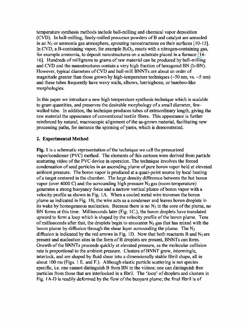
Fig. 1 is a schematic representation of the technique we call the pressurizedvapor/condenser (PVC) method. The elements of this cartoon were derived from particlescattering video of the PVC device in operation. The technique involves the forcedcondensation of seed particles in an ascending plume of pure boron vapor held at elevatedambient pressure. The boron vapor is produced at a quasi-point source by local heatingof a target centered in the chamber. The large density difference between the hot boronvapor (over 4000 C) and the surrounding high pressure N 2 gas (room temperature)generates a strong buoyancy force and a narrow vertical plume of boron vapor with avelocity profile as shown in Fig. 1A. When a cooled metal wire traverses the boronplume as indicated in Fig. 1B, the wire acts as a condenser and leaves boron droplets inits wake by homogeneous nucleation. Because there is no N 2 in the core of the plume, noBN forms at this time. Milliseconds later (Fig. 1C.), the boron droplets have translatedupward to form a loop which is shaped by the velocity profile of the boron plume. Tensof milliseconds after that, the droplets begin to encounter N 2 gas that has mixed with theboron plume by diffusion through the shear layer surrounding the plume. The N 2
diffusion is indicated by the red arrows in Fig. 1D. Now that both reactants B and N2 arepresent and nucleation sites in the form of B droplets are present, BNNTs can form.Growth of the BNNTs proceeds quickly at elevated pressure, as the molecular collisionrate is proportional to the ambient pressure. Clusters of BNNT grow, intermingle,interlock, and are shaped by fluid shear into a dimensionally stable fibril shape, all inabout 100 ms (Figs. 1 E. and F.). Although elastic particle scattering is not speciesspecific, i.e. one cannot distinguish B from BN in the videos; one can distinguish freeparticles from those that are interlocked in a fibril. The ‘loop’ of droplets and clusters inFig. 1A-D is readily deformed by the flow of the buoyant plume; the final fibril is of
fixed length and appears in the video visualizations as a thread, or streamer, attached byone end to the condenser, giving the appearance of a flag flapping in the wind.
The PVC technique can be employed with many variations. The heat source, the targetmaterial, the pressure, and the condenser material and geometry can take numerousforms. In the current work, PVC synthesis runs were conducted at N 2 pressures between2 and 20 times atmospheric pressure. Boron vapor was produced with two differentheating sources: a 1 kW free electron laser [ 17] operating at a wavelength of 1.6 µm anda kW-class commercial welding laser operating at 10.6 µm. Successful target materialsincluded hot-pressed BN, cold-pressed BN, amorphous B powders and cast B.Successful condensers were made from BN, B, stainless steel, copper, niobium, andtungsten in various forms of surfaces, wires, sheets, ribbons, and rods. No catalyst wasever employed and the wide variety of successful condenser surfaces demonstrated thatthe condenser simply acted as a cooler and not a catalytic surface.
3. Results and Discussion
A typical fibril grown by the PVC scheme outlined in Fig. 1 was approximately 1 mm indiameter by 10 cm in length. Such fibrils could be grown in a continuous assembly lineby repeatedly intercepting the B plume with a moving condenser. Fig. 2 shows theresults of such a production run. This 60 mg mass of many individual BNNT fibrils wasproduced by translating the metal condenser about 20 cm over the course of about 30minutes of continuous running. In Fig. 2, the fibrils exhibit natural alignment along theaxis of growth, giving the raw material the appearance of combed cotton. The process offibril formation is efficient, as the mass of the BNNT raw material is typically equal toaround 80% of the mass loss of the boron source target.
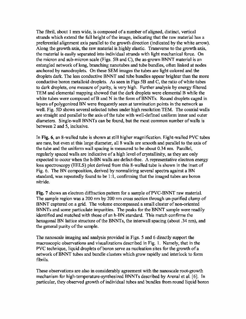
In Fig. 3A a 200 mg sample of as-grown PVC-BNNT material is shown. The materialhas an unusually low density. In the current case 200 mg fills a 10 cm by 10 cm jar,indicating that the PVC-grown BNNT product has a much higher surface area thanpreviously available (e. g. by ball-mill or CVD techniques).
Carbon nanotube (CNT) yarns have been reported, spun from 100 µm long CNT arrays,CVD forests, or fibrils [ 18-21 ]. Analogous to CNT yarns we report a BNNT yarn, thefirst to our knowledge. As shown in Fig. 3B, it was about 3 cm in length and spundirectly from PVC-grown BNNT raw material. A group of fibrils weighing about 10 mg(representing —5 minutes of synthesis time) was separated from a mass of raw material,drawn slightly in the growth direction, and finger-twisted to form a simple one-ply yarnwith a twist angle of about 45 degrees. Before twisting, the mass of fibrils was delicateto the touch with little mechanical strength. After twisting, the same mass of materialcould readily support a small load (a —6 g coin), clearly demonstrating the structuralreinforcement due to spinning.
A measurement of the length of the tubes composing the yarn was of great interest. SinceBNNTs have a band gap around 5.5 eV, they are not sufficiently conductive to be imagedby SEM when they are separated as individual tubes. So, for a direct measurement oftube length PVC-BNNTs were mixed into a special polymer matrix, and then imaged by
SEM (to be shown in a future report). BNNT bundles only a few nanometers in diameterand at least 100 µm long were seen at a fracture surface in the polymer matrix. The endsof such tube bundles were not visible at the fracture surface, being buried deep in thepolymer. Thus, the full length of the bundles could not be determined by this technique,though lengths much greater than 100 µm were implied.
Although a direct measurement of total BNNT length was not made with in-polymerimaging, an estimate can be derived by considering the nature of staple fibers in yarns.The manner in which staple fibers are spun to produce strong yarns is understoodtheoretically [19]. Longer staple fibers produce stronger yarns, as does more frictionbetween staple fibers and smaller yarn diameters. Spinning does little to increasemechanical strength if the staple fiber length to yarn diameter ratio drops to unity. Noreinforcing effect occurs unless the staple fibers are long enough to lock around eachother. So, because the current BNNT staple fibers can successfully be spun into 1 mmdiameter yarns, a length of at least 1 mm is implied. To bracket this comparison,commercial cotton thread is spun from staple fibers with an average length of around 28mm’s [22]. The current BNNT yarn has an intermediate strength between zero and thatof cotton thread. So by crude interpolation, one can expect a staple BNNT length of atleast several millimeters.
It should be noted that the BNNT yarn is presented not to suggest its immediate practicalapplication, but to demonstrate a unique property of PVC-grown BNNT material.Considerable improvement in a practical yarn can be expected through a more refinedspinning process that includes purifying the raw material to increase frictional lockingand smaller, tighter plies. However, even in its current form this is a notabledevelopment as for many applications a fabric or macroscopic fiber is an advantageousform—armor, spacesuits, and aerospace structural layups, for instance. For these, theready processing of PVC-BNNTs by textile techniques suggests considerableopportunity.
For other applications high temperature and oxidation resistance will be of paramountimportance, for example for spaceflight re-entry heat shields or jet engine parts. To thisend, the thermal stability of raw PVC-BNNTs was studied with a thermogravimetricanalyzer (TGA). Fig. 4 shows TGA spectra of PVC-BNNTs in air and nitrogen,respectively. The BNNT tubes were stable even up to 1000 ˚ C with slight weight gainbecause of oxidation in air. For comparison, CNTs are completely decomposed above400 ˚ C in air. The left inset in Fig. 4 shows the oxidized BNNTs remaining after the TGArun in air; the right inset reveals details of these oxidized BNNTs at higher magnification.The gained weight above 800 ˚ C was determined by FTIR to be B2O3 (as also observed byHan et al. [23]). The possibility that the oxidation only affects the outer layer of multi-wall BNNTs is interesting and worthy of investigation, as such a layer may act as aprotective coating in high temperature applications.
Next, nanoscale properties if the PVC-BNNTs are reported. Figs. 5A-D show the rawmaterial under increasing levels of magnification. In Fig 5A, a scanning electronmicroscope (SEM) image of a short section of a single as-grown BNNT fibril is shown.
The fibril, about 1 mm wide, is composed of a number of aligned, distinct, verticalstrands which extend the full height of the image, indicating that the raw material has apreferential alignment axis parallel to the growth direction (indicated by the white arrow).Along the growth axis, the raw material is highly elastic. Transverse to the growth axis,the material is easily separated into individual strands with light mechanical force. Onthe micron and sub-micron scale (Figs. 5B and C), the as-grown BNNT material is anentangled network of long, branching nanotubes and tube bundles, often linked at nodesanchored by nanodroplets. On these SEM images the tubes are light colored and thedroplets dark. The less conductive BNNT and tube bundles appear brighter than the moreconductive boron metalloid droplets. As seen in Figs 5B and C, the ratio of white tubesto dark droplets, one measure of purity, is very high. Further analysis by energy filteredTEM and elemental mapping showed that the dark droplets were elemental B while thewhite tubes were composed of B and N in the form of BNNTs. Round droplets caged inlayers of polygonized BN were frequently seen at termination points in the network aswell. Fig. 5D shows several selected tubes under high resolution TEM. The coaxial wallsare straight and parallel to the axis of the tube with well-defined uniform inner and outerdiameters. Single-wall BNNTs can be found, but the most common number of walls isbetween 2 and 5, inclusive.
In Fig. 6, an 8-walled tube is shown at still higher magnification. Eight-walled PVC tubesare rare, but even at this large diameter, all 8 walls are smooth and parallel to the axis ofthe tube and the uniform wall spacing is measured to be about 0.34 nm. Parallel,regularly spaced walls are indicative of a high level of crystallinity, as they are onlyexpected to occur when the h-BN walls are defect-free. A representative electron energyloss spectroscopy (EELS) plot derived from this 8-walled tube is shown in the inset ofFig. 6. The BN composition, derived by normalizing several spectra against a BNstandard, was repeatedly found to be 1:1, confirming that the imaged tubes are boronnitride.
Fig. 7 shows an electron diffraction pattern for a sample of PVC-BNNT raw material.The sample region was a 200 nm by 200 nm cross section through un-purified clump ofBNNT captured on a grid. The volume encompassed a small cluster of non-orientedBNNTs and some particulate impurities. The peaks for the BNNT sample were readilyidentified and matched with those of an h-BN standard. This match confirms thehexagonal BN lattice structure of the BNNTs, the interwall spacing (about .34 nm), andthe general purity of the sample.
The nanoscale imaging and analysis provided in Figs. 5 and 6 directly support themacroscopic observations and visualizations described in Fig. 1. Namely, that in thePVC technique, liquid droplets of boron serve as nucleation sites for the growth of anetwork of BNNT tubes and bundle clusters which grow rapidly and interlock to formfibrils.
These observations are also in considerably agreement with the nanoscale root-growthmechanism for high-temperature-synthesized BNNTs described by Arenal et al. [6]. Inparticular, they observed growth of individual tubes and bundles from round liquid boron
nanoparticles coated with cages of BN. But, in contrast to the PVC case, theirexperiments were carried out at low ambient pressure (sub-atmospheric) and the borondroplets formed only through natural cooling. These appear to be the two criticaldifferences which inhibit the growth of very long BNNTs. Although further species-specific measurements will be required to provide verification, the particle scatteringvisualization and the analysis of the PVC BNNT raw material suggest that PVC tubesgrow longer for two reasons. One, there is a longer residence time for seed particles in thereaction zone, both because the reaction zone is elongated in the PVC geometry andbecause forced condensation of the seed particles upstream of the reaction zonemaximizes the available transit time. And two, BN formation occurs at a higher rate inthe PVC technique because the molecular collision rate is proportional to the chamberpressure. In summary, relatively long tubes form when a relatively high B-N reactionrate is sustained over a relatively long time. The self-assembly mechanism appears to bethe same as observed by Arenal, but it is accelerated and prolonged in the PVC scheme.
5. Conclusions
We have demonstrated a new and conceptually simple method of producingextraordinarily long, highly crystalline BNNTs in bulk called the PVC method. Newclues to the nature of BNNT growth were gleaned from this unique production methodand used to extend an existing model of self-assembly. The BNNTs formed by the PVCmethod have three important characteristics. One, they grow without catalyst using onlyB and N2 as the reactants, eliminating the need to use acid or other destructivepurification treatments to remove metals or carbon. Two, they have natural alignment onthe macroscopic scale, producing an as-grown appearance similar to cotton fiber. Thisallows them to be processed with well-known textile techniques as demonstrated by thespinning of yarn. And three, and most importantly, they are highly crystalline with smalldiameters and extraordinary lengths. Such a morphology can be expected to fulfill manytheoretical predictions of desirable mechanical, electronic, thermal, optical, piezo, andelectronic properties, in practical applications.
Acknowledgements
This work was supported in part by the NASA Langley Creativity and InnovationProgram, the NASA Subsonic Fixed Wing program, Thomas Jefferson NationalAccelerator Facility (DOE contract number DE-AC05-06OR23177), and TheCommonwealth of Virginia. Special thanks to the FEL Division of JLab for hosting theexperiments.
[1] D. Golberg , Y. Bando , C. C. Tang, C. Y. Zhi, Adv. Mater., 2007, 19, 2413.
[2] D. Golberg, A. Rode, Y. Bando, M. Mitome, E. Gamaly and B. Luther-Davies,App Phys Lett. 1996, 69, 2045-2047.
[3] T. Laude, Y Matsui, A. Marraud, B. Jouffrey, Appl Phys Let. 2000, 76, 3239.

[4] T. Laude, thesis Ecole Centrale Paris. Boron Nitride Nanotubes Grown by Non-Ablative Laser Heating: Synthesis, Characterization and Growth Process, 2001.
[5] R. S. Lee, J. Gavillet, M. Lamy de la Chapelle, A. Loiseau, J.-L. Cochon D.Pigache, J. Thibault, F. Willaime, Phys Rev B. 2001, 64, 121405-1.
[6] R. Arenal, O. Stephan, J-L. Cochon, A. Loiseau,. J. Am. Chem. Soc. 2007, 129,16183-16189.
[7] Nasreen G. Chopra, R. J. Luyken, K. Cherrey, Vincent H. Crespi, Marvin L.Cohen, Steven G. Louie, and A. Zettl, Science, 1995, 269. 966 – 967.
[8] M. V. P. Altoe, J. P. Sprunck, J.-C. P. Gabriel, K. Bradley, J. of Mat. Sci., 2003,38, 4805.
[9] C. M. Lee et al., Current App Phys. 2005, 6, 166.
[10] J. Hurst and Gorican Developments in Advanced Ceramics and Composites:Ceramic Engineering and Science Proceedings, 26, 8.
[11] Narottam P. Bansal and Janet B. Hurst Sung R. Choi, NASA/TM—2005-213874
[ 12] Jun Yu, Bill C. P. Li, and Ying Chen, J. of Mat. Sci. 2007, 42, 4025.
[13] Hua Chen , Ying Chen, Yun Liu, Lan Fu, Cheng Huang, David Llewellyn, Chem.Phys. Lett. 2008, 463, 130.
[14] Chunyi Zhi, Yoshio Bando, Chengchun Tan and Dmitri Golberg, Solid StateCommunications, 2005, 135, 67.
[15] Jiesheng Wang, Vijaya K. Kayastha, Yoke Khin Yap, Zhiyong Fan, Jia G.Lu, Zhengwei Pan, Ilia N. Ivanov, Alex A. Puretzky, and David B. Geohegan,Nano Lett., 2005, 5 (12), 2528.
[16] Chee Huei Lee, JieshengWang, Vijaya K Kayatsha,Jian Y Huang and Yoke Khin Yap, Nanotechnology, 2008, 19, 455605.
[17] G. R. Neil, C. Behre, S. Benson, M. Bevins, G. Biallas, J Boyce, J Coleman, L. A.Dillon-Townes, D. Douglas, H. F. Dylla, R. Evans, A. Grippo, D Gruber, J. Gubeli, D.Hardy, C. Hernandez-Garcia, K Jordan, M. Kelley, L. Merminga, J. Mammosser, W.Moore, N. Nishimori, E. Pozdeyev, J Preble, R. Rimmer, M. Shinn, T. Siggins, C.Tennant, R Walker, G. P. Williams, S. Zhang, Nuclear Instr. and Methods in Phy. Res.,2006, A557, 9.
[ 18] L. X. Zheng, M. J. O'Connell, S. K. Doorn, X. Z. Liao, Y. H. Zhao, E. A.Akhadov, M. A. Hoffbauer. Nature Materials, 2004, 3, 673.

[19] Mei Zhang, Ken R. Atkinson, Ray H. Baughman. Science, 2004, 306, 1358.
[20] Qingwen Li, Xiefei Zhang, Raymond F. DePaula, Lianxi Zheng, Yonghao Zhao,Liliana Stan, Terry G. Holesinger, Paul N. Arendt, Dean E. Peterson, and Yuntian T. ZhuAdv. Mat. 2006, 18, 3160.
[21] Kaili Jiang, Qunqing Li, Shoushan Fan, Nature, 2002, 419, 801.
[22] National Cotton Council of America, Cordova, TN, 38016.
[23] W.-Q. Han, W. Mickelson, J. Cumings, A. Zettl, Appl. Phys. Lett. 81, 1110 (2002)

A. B. C.
D E F.
'^ s
. .
f
s '' I 1%
l ^ ^
Syr( ,. ^ 'I 'i
` 46iddd.^ ! ^^
III
^
1 r ^ •^
B Plume Condensation of Translation of Growth of BNNT Shear of BNNT Consolidation intoB droplets B droplets from droplets clusters BNNT fibril
Elapsed Time ~ 100 ms
Figure 1. Schematic showing the stages of growth of BNNT fibrils via the PVC method.A.) Velocity profile of the buoyant boron vapor plume (not to scale). B.) Condenser(metal wire normal to the page, indicated by small arrow) traverses plume, leaving trail ofboron droplets in its wake. C.) Droplets translate downstream (downstream = up in thiscase), in accordance with the velocity profile. D.) BNNTs nucleate and grow fromdroplets. E.) Growth continues as BNNT clusters shear in the flow and begin tointerconnect. F.) Fibril takes its final shape as BNNT clusters consolidate into singlenetworked structure.

Figure 2. The results of a 200 mg PVC BNNT production run. The unprocessed materialhas the appearance of cotton balls, though the texture is somewhat softer and the materialfiner-grained.
Figure 3. A.) 200 mg of PVC-grown BNNT raw material and yarn. B.) A ~1 mmdiameter, 3 cm long BNNT yarn spun directly from PVC-grown BNNT raw material.

Figure 4. Thermogravimetric analysis showing the stability of PVC-BNNTs at hightemperature. Insets show the resulting product after heating to 1000 C at low (left) andhigh (right) magnification.

Figure 5. Scanning (A-C) and transmission (D) electron microscope images showing thestructure of PVC-grown BNNT fibrils at increasing magnifications. A.) The growthdirection, parallel to the BNNT fibrils, is indicated by the white arrow. C.) An arrowmarks a round, solidified boron droplet. D.) Typical 1, 3, and 5 wall tube are shown.Although as many as 8 walls have been observed (see Fig. 6), 2 to 5 walls are mostcommon.

Figure 6. (A) High resolution TEM image of an 8-walled BNNT. Inset is an EELSspectrum showing 1:1 ratio of B to N.

1.675 1.18
2.05 PVC--BNNTs h-BN standard Deviation2 d spacing (A) (A) HKL
3.416
3.416 3.3281 {002} 2.64%
2.052 2.0619 {101} -0.48%
1.675 1.6636 {004} 0.69%
1.183 1.1720 {112} 0.94%
Figure 7. An electron diffraction pattern for PVC-BNNTs (left side of figure), shows themajor bands representing the hexagonal lattice structure. The table (right side) comparesthe band locations of PVC-BNNTs to those of an h-BN standard. Agreement is within1% for all but the fundamental peak which represents the interlayer graphene spacing (~.34 nm = 3.4 Å). This difference may be real, and due to the curvature of the h-N layersin the BNNTs relative to the planar layers in the h-BN standard.