Veritas InfoScale™ 7.3 Disaster Recovery Implementation Guide
243
Veritas InfoScale™ 7.3 Disaster Recovery Implementation Guide - Linux
-
Upload
khangminh22 -
Category
Documents
-
view
19 -
download
0
Transcript of Veritas InfoScale™ 7.3 Disaster Recovery Implementation Guide
Veritas InfoScale™ 7.3Disaster RecoveryImplementation Guide -Linux
Last updated: 2017-05-31
Legal NoticeCopyright © 2017 Veritas Technologies LLC. All rights reserved.
Veritas and the Veritas Logo are trademarks or registered trademarks of Veritas TechnologiesLLC or its affiliates in the U.S. and other countries. Other names may be trademarks of theirrespective owners.
This product may contain third party software for which Veritas is required to provide attributionto the third party (“Third Party Programs”). Some of the Third Party Programs are availableunder open source or free software licenses. The License Agreement accompanying theSoftware does not alter any rights or obligations you may have under those open source orfree software licenses. Refer to the third party legal notices document accompanying thisVeritas product or available at:
https://www.veritas.com/about/legal/license-agreements
The product described in this document is distributed under licenses restricting its use, copying,distribution, and decompilation/reverse engineering. No part of this document may bereproduced in any form by any means without prior written authorization of Veritas TechnologiesLLC and its licensors, if any.
THE DOCUMENTATION IS PROVIDED "AS IS" AND ALL EXPRESS OR IMPLIEDCONDITIONS, REPRESENTATIONS AND WARRANTIES, INCLUDING ANY IMPLIEDWARRANTY OF MERCHANTABILITY, FITNESS FOR A PARTICULAR PURPOSE ORNON-INFRINGEMENT, ARE DISCLAIMED, EXCEPT TO THE EXTENT THAT SUCHDISCLAIMERS ARE HELD TO BE LEGALLY INVALID. VERITAS TECHNOLOGIES LLCSHALL NOT BE LIABLE FOR INCIDENTAL OR CONSEQUENTIAL DAMAGES INCONNECTION WITH THE FURNISHING, PERFORMANCE, OR USE OF THISDOCUMENTATION. THE INFORMATION CONTAINED IN THIS DOCUMENTATION ISSUBJECT TO CHANGE WITHOUT NOTICE.
The Licensed Software and Documentation are deemed to be commercial computer softwareas defined in FAR 12.212 and subject to restricted rights as defined in FAR Section 52.227-19"Commercial Computer Software - Restricted Rights" and DFARS 227.7202, et seq."Commercial Computer Software and Commercial Computer Software Documentation," asapplicable, and any successor regulations, whether delivered by Veritas as on premises orhosted services. Any use, modification, reproduction release, performance, display or disclosureof the Licensed Software and Documentation by the U.S. Government shall be solely inaccordance with the terms of this Agreement.
Veritas Technologies LLC500 E Middlefield RoadMountain View, CA 94043
http://www.veritas.com
Technical SupportTechnical Support maintains support centers globally. All support services will be deliveredin accordance with your support agreement and the then-current enterprise technical supportpolicies. For information about our support offerings and how to contact Technical Support,visit our website:
https://www.veritas.com/support
You can manage your Veritas account information at the following URL:
https://my.veritas.com
If you have questions regarding an existing support agreement, please email the supportagreement administration team for your region as follows:
[email protected] (except Japan)
DocumentationMake sure that you have the current version of the documentation. Each document displaysthe date of the last update on page 2. The latest documentation is available on the Veritaswebsite:
https://sort.veritas.com/documents
Documentation feedbackYour feedback is important to us. Suggest improvements or report errors or omissions to thedocumentation. Include the document title, document version, chapter title, and section titleof the text on which you are reporting. Send feedback to:
You can also see documentation information or ask a question on the Veritas community site:
http://www.veritas.com/community/
Veritas Services and Operations Readiness Tools (SORT)Veritas Services and Operations Readiness Tools (SORT) is a website that provides informationand tools to automate and simplify certain time-consuming administrative tasks. Dependingon the product, SORT helps you prepare for installations and upgrades, identify risks in yourdatacenters, and improve operational efficiency. To see what services and tools SORT providesfor your product, see the data sheet:
https://sort.veritas.com/data/support/SORT_Data_Sheet.pdf
Section 1 Introducing Storage Foundation andHigh Availability Solutions for disasterrecovery ..................................................................... 10
Chapter 1 About supported disaster recovery scenarios .......... 11
About disaster recovery scenarios ................................................... 11About campus cluster configuration .................................................. 14
VCS campus cluster requirements ............................................. 14How VCS campus clusters work ................................................ 15Typical VCS campus cluster setup ............................................. 19
About replicated data clusters ......................................................... 21How VCS replicated data clusters work ....................................... 22
About global clusters ..................................................................... 23How VCS global clusters work .................................................. 23User privileges for cross-cluster operations .................................. 24VCS global clusters: The building blocks ..................................... 25
Disaster recovery feature support for components in the VeritasInfoScale product suite ............................................................ 33
Virtualization support for Storage Foundation and High AvailabilitySolutions 7.3 products in replicated environments ......................... 34
Chapter 2 Planning for disaster recovery ....................................... 36
Planning for cluster configurations ................................................... 36Planning a campus cluster setup ............................................... 36Planning a replicated data cluster setup ...................................... 37Planning a global cluster setup .................................................. 38
Planning for data replication ........................................................... 38Data replication options ........................................................... 38Data replication considerations .................................................. 39
Contents
Section 2 Implementing campus clusters ........................ 40
Chapter 3 Setting up campus clusters for VCS and SFHA........................................................................................... 41
About setting up a campus cluster configuration ................................. 41Preparing to set up a campus cluster configuration ........................ 41Configuring I/O fencing to prevent data corruption ......................... 42Configuring VxVM disk groups for campus cluster configuration
..................................................................................... 42Configuring VCS service group for campus clusters ....................... 44Setting up campus clusters for VxVM and VCS using Veritas
InfoScale Operations Manager ............................................ 45Fire drill in campus clusters ............................................................ 46About the DiskGroupSnap agent ..................................................... 47About running a fire drill in a campus cluster ...................................... 47
Configuring the fire drill service group ......................................... 47Running a successful fire drill in a campus cluster ......................... 48
Chapter 4 Setting up campus clusters for SFCFSHA,SFRAC ........................................................................... 50
About setting up a campus cluster for disaster recovery for SFCFSHAor SF Oracle RAC .................................................................. 50
Preparing to set up a campus cluster in a parallel cluster databaseenvironment .......................................................................... 53
Configuring I/O fencing to prevent data corruption ............................... 54Configuring VxVM disk groups for a campus cluster in a parallel cluster
database environment ............................................................. 56Configuring VCS service groups for a campus cluster for SFCFSHA
and SF Oracle RAC ................................................................ 60Tuning guidelines for parallel campus clusters .................................... 61Best practices for a parallel campus cluster ....................................... 61
Section 3 Implementing replicated data clusters........................................................................................... 63
Chapter 5 Configuring a replicated data cluster using VVR........................................................................................... 64
About setting up a replicated data cluster configuration ........................ 64About typical replicated data cluster configuration ......................... 64
5Contents
About setting up replication ...................................................... 65Configuring the service groups .................................................. 66Configuring the service group dependencies ................................ 67
About migrating a service group ...................................................... 67Switching the service group ...................................................... 68
Fire drill in replicated data clusters ................................................... 68
Chapter 6 Configuring a replicated data cluster usingthird-party replication .................................................. 69
About setting up a replicated data cluster configuration using third-partyreplication ............................................................................. 69
About typical replicated data cluster configuration using third-partyreplication ............................................................................. 70
About setting up third-party replication .............................................. 70Configuring the service groups for third-party replication ....................... 71Fire drill in replicated data clusters using third-party replication .............. 71
Section 4 Implementing global clusters ............................ 72
Chapter 7 Configuring global clusters for VCS and SFHA........................................................................................... 73
Installing and Configuring Cluster Server ........................................... 73Setting up VVR replication .............................................................. 73
About configuring VVR replication .............................................. 74Best practices for setting up replication ....................................... 74Creating a Replicated Data Set ................................................. 76Synchronizing the Secondary and starting replication ..................... 92Starting replication when the data volumes are zero initialized
..................................................................................... 98Setting up third-party replication ...................................................... 99Configuring clusters for global cluster setup ....................................... 99
Configuring global cluster components at the primary site ............. 100Installing and configuring VCS at the secondary site .................... 101Securing communication between the wide-area connectors ......... 101Configuring remote cluster objects ........................................... 103Configuring additional heartbeat links (optional) .......................... 103Configuring the Steward process (optional) ................................ 104
Configuring service groups for global cluster setup ............................ 107Configuring VCS service group for VVR-based replication ............. 108Configuring a service group as a global service group .................. 111
Fire drill in global clusters ............................................................. 112
6Contents
Chapter 8 Configuring a global cluster with StorageFoundation Cluster File System HighAvailability, Storage Foundation for OracleRAC, or Storage Foundation for Sybase CE.......................................................................................... 113
About global clusters ................................................................... 114About replication for parallel global clusters using Storage Foundation
and High Availability (SFHA) Solutions ...................................... 114About setting up a global cluster environment for parallel clusters ......... 115Configuring the primary site .......................................................... 116Configuring the secondary site ...................................................... 119
Configuring the Sybase ASE CE cluster on the secondary site.................................................................................... 125
Setting up replication between parallel global cluster sites ................... 125Testing a parallel global cluster configuration .................................... 132
Chapter 9 Configuring global clusters with VVR and StorageFoundation Cluster File System HighAvailability, Storage Foundation for OracleRAC, or Storage Foundation for Sybase CE.......................................................................................... 134
About configuring a parallel global cluster using Volume Replicator(VVR) for replication .............................................................. 135
Setting up replication on the primary site using VVR .......................... 137Creating the data and SRL volumes on the primary site ................ 137Setting up the Replicated Volume Group on the primary site .......... 138
Setting up replication on the secondary site using VVR ....................... 140Creating the data and SRL volumes on the secondary site ............ 141Editing the /etc/vx/vras/.rdg files ............................................... 141Setting up IP addresses for RLINKs on each cluster .................... 142Setting up the disk group on secondary site for replication ............. 143
Starting replication of the primary site database volume to thesecondary site using VVR ....................................................... 145
Configuring Cluster Server to replicate the database volume usingVVR ................................................................................... 147Modifying the Cluster Server (VCS) configuration on the primary
site .............................................................................. 152Modifying the VCS configuration on the secondary site ................. 159Configuring the Sybase ASE CE cluster on the secondary site
.................................................................................... 165
7Contents
Replication use cases for global parallel clusters ............................... 167
Section 5 Configuring for disaster recovery incloud environments .......................................... 174
Chapter 10 Replication scenarios ..................................................... 175
About replication in AWS cloud environments ................................... 175Replication from on-premise to cloud .............................................. 176Replication across Availability Zones within the same region ............... 177Replication across regions ............................................................ 178Replication across multiple Availability Zones and regions (campus
cluster) ............................................................................... 180
Chapter 11 Setting up replication for cloud environments ......... 183
Setting up replication from on-premise to cloud environments .............. 183Setting up replication across AZs within the same region .................... 186Setting up replication across regions ............................................... 187Setting up replication across multiple Availability Zones and regions
(campus cluster) ................................................................... 188
Section 6 Reference ...................................................................... 194
Appendix A Sample configuration files ............................................. 195
Sample Storage Foundation for Oracle RAC configuration files ............ 195sfrac02_main.cf file ............................................................... 195sfrac07_main.cf and sfrac08_main.cf files .................................. 196sfrac09_main.cf and sfrac10_main.cf files .................................. 198sfrac11_main.cf file ............................................................... 201sfrac12_main.cf and sfrac13_main.cf files .................................. 202Sample fire drill service group configuration ............................... 205
About sample main.cf files for Storage Foundation (SF) for Oracle RAC.......................................................................................... 207Sample main.cf for Oracle 10g for CVM/VVR primary site ............. 208Sample main.cf for Oracle 10g for CVM/VVR secondary site ......... 213
About sample main.cf files for Storage Foundation (SF) for SybaseASE CE .............................................................................. 218Sample main.cf for a basic Sybase ASE CE cluster configuration
under VCS control with shared mount point on CFS forSybase binary installation ................................................. 218
8Contents
Sample main.cf for a basic Sybase ASE CE cluster configurationwith local mount point on VxFS for Sybase binary installation.................................................................................... 223
Sample main.cf for a primary CVM VVR site ............................... 227Sample main.cf for a secondary CVM VVR site ........................... 234
Index .................................................................................................................. 240
9Contents
Introducing StorageFoundation and HighAvailability Solutions fordisaster recovery
■ Chapter 1. About supported disaster recovery scenarios
■ Chapter 2. Planning for disaster recovery
1Section
About supported disasterrecovery scenarios
This chapter includes the following topics:
■ About disaster recovery scenarios
■ About campus cluster configuration
■ About replicated data clusters
■ About global clusters
■ Disaster recovery feature support for components in the Veritas InfoScale productsuite
■ Virtualization support for Storage Foundation and High Availability Solutions 7.3products in replicated environments
About disaster recovery scenariosStorage Foundation offers cost–effective, short-distance disaster recovery withactive configurations and long distance replication solutions to effectively managedisaster recovery requirements.
This guide describes how to configure campus clusters, global clusters, andreplicated data clusters (RDC) for disaster recovery failover using the followingStorage Foundation and High Availability Solutions products:
■ Storage Foundation Cluster File System High Availability (SFCFSHA)
■ Storage Foundation™ for Oracle® RAC (SF Oracle RAC)
■ Storage Foundation™ for Sybase® Adaptive Server Enterprise Cluster Edition(SF Sybase CE)
1Chapter
■ Cluster Server (VCS)
■ Volume Replicator (VVR)
Note: Disaster recovery scenarios for SF Sybase CE have only been tested andare only supported using Veritas Cluster Volume Manager and Volume Replicator.
See the Storage Foundation Cluster File System High Availability Administrator'sGuide for more information on configuring SFCFSHA.
See the Storage Foundation for Oracle RAC Administrator's Guide for moreinformation on configuring SF Oracle RAC.
See the Storage Foundation for SF Sybase ASECE Administrator's Guide for moreinformation on configuring SF Sybase CE.
See the Cluster Server Administrator's Guide for more information on configuringVCS.
See the Veritas InfoScale™Replication Administrator’s Guide for more informationon configuring VVR.
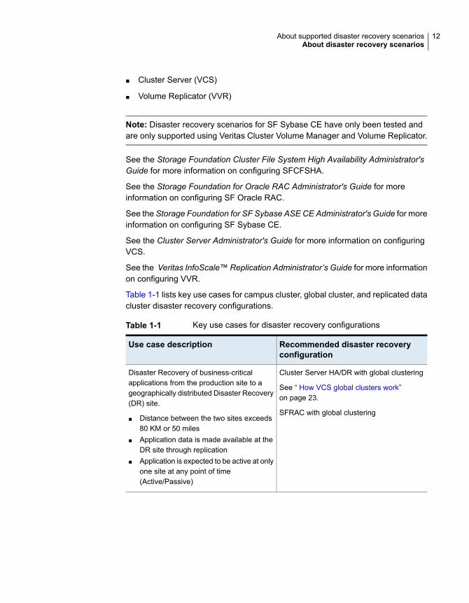
Table 1-1 lists key use cases for campus cluster, global cluster, and replicated datacluster disaster recovery configurations.
Table 1-1 Key use cases for disaster recovery configurations
Recommended disaster recoveryconfiguration
Use case description
Cluster Server HA/DR with global clustering
See “ How VCS global clusters work”on page 23.
SFRAC with global clustering
Disaster Recovery of business-criticalapplications from the production site to ageographically distributed Disaster Recovery(DR) site.
■ Distance between the two sites exceeds80 KM or 50 miles
■ Application data is made available at theDR site through replication
■ Application is expected to be active at onlyone site at any point of time(Active/Passive)
12About supported disaster recovery scenariosAbout disaster recovery scenarios
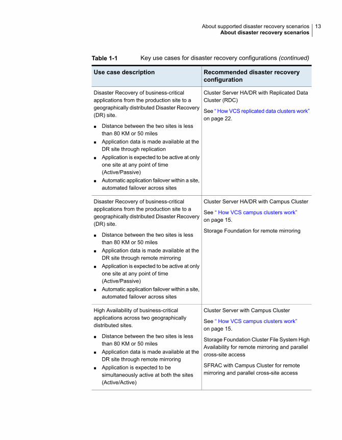
Table 1-1 Key use cases for disaster recovery configurations (continued)
Recommended disaster recoveryconfiguration
Use case description
Cluster Server HA/DR with Replicated DataCluster (RDC)
See “ How VCS replicated data clusters work”on page 22.
Disaster Recovery of business-criticalapplications from the production site to ageographically distributed Disaster Recovery(DR) site.
■ Distance between the two sites is lessthan 80 KM or 50 miles
■ Application data is made available at theDR site through replication
■ Application is expected to be active at onlyone site at any point of time(Active/Passive)
■ Automatic application failover within a site,automated failover across sites
Cluster Server HA/DR with Campus Cluster
See “ How VCS campus clusters work”on page 15.
Storage Foundation for remote mirroring
Disaster Recovery of business-criticalapplications from the production site to ageographically distributed Disaster Recovery(DR) site.
■ Distance between the two sites is lessthan 80 KM or 50 miles
■ Application data is made available at theDR site through remote mirroring
■ Application is expected to be active at onlyone site at any point of time(Active/Passive)
■ Automatic application failover within a site,automated failover across sites
Cluster Server with Campus Cluster
See “ How VCS campus clusters work”on page 15.
Storage Foundation Cluster File System HighAvailability for remote mirroring and parallelcross-site access
SFRAC with Campus Cluster for remotemirroring and parallel cross-site access
High Availability of business-criticalapplications across two geographicallydistributed sites.
■ Distance between the two sites is lessthan 80 KM or 50 miles
■ Application data is made available at theDR site through remote mirroring
■ Application is expected to besimultaneously active at both the sites(Active/Active)
13About supported disaster recovery scenariosAbout disaster recovery scenarios
About campus cluster configurationThe campus cluster configuration provides local high availability and disasterrecovery functionality in a single VCS cluster. This configuration uses data mirroringto duplicate data at different sites. There is no Host or Array base replicationinvolved.
VCS supports campus clusters that employ disk groups mirrored with Veritas VolumeManager.
VCS campus cluster requirementsReview the following requirements for VCS campus clusters:
■ You must install VCS.
■ You must have a single VCS cluster with at least one node in each of the twosites, where the sites are separated by a physical distance of no more than 80kilometers. When the sites are separated more than 80 kilometers, you can runGlobal Cluster Option (GCO) configuration.
■ You must have redundant network connections between nodes. All paths tostorage must also be redundant.
Veritas recommends the following in a campus cluster setup:
■ A common cross-site physical infrastructure for storage and LLT privatenetworks.Veritas recommends a common cross-site physical infrastructure for storageand LLT private networks
■ Technologies such as Dense Wavelength Division Multiplexing (DWDM) fornetwork and I/O traffic across sites. Use redundant links to minimize theimpact of network failure.
■ You must install Veritas Volume Manager with the FMR license and the SiteAwareness license.
■ Veritas recommends that you configure I/O fencing to prevent data corruptionin the event of link failures.See the Cluster Server Configuration and Upgrade Guide for more details.
■ You must configure storage to meet site-based allocation and site-consistencyrequirements for VxVM.
■ All the nodes in the site must be tagged with the appropriate VxVM sitenames.
■ All the disks must be tagged with the appropriate VxVM site names.
14About supported disaster recovery scenariosAbout campus cluster configuration
■ The VxVM site names of both the sites in the campus cluster must be addedto the disk groups.
■ The allsites attribute for each volume in the disk group must be set to on.(By default, the value is set to on.)
■ The siteconsistent attribute for the disk groups must be set to on.
■ Each host at a site must be connected to a storage switch. The switch musthave access to storage arrays at all the sites..
■ In environments where the Flexible Storage Sharing (FSS) feature is being used,nodes may not be connected to an external storage switch. Locally attachedstorage needs to be exported to enable network sharing with nodes within andacross the site. For more details on FSS, see the Storage Foundation ClusterFile System High Availability Administrator's Guide.
■ SF Oracle RAC campus clusters require mirrored volumes with storage allocatedfrom both sites.
How VCS campus clusters workThis topic describes how VCS works with VxVM to provide high availability in acampus cluster environment.
In a campus cluster setup, VxVM automatically mirrors volumes across sites. Toenhance read performance, VxVM reads from the plexes at the local site wherethe application is running. VxVM writes to plexes at both the sites.
In the event of a storage failure at a site, VxVM detaches all the disks at the failedsite from the disk group to maintain data consistency. When the failed storagecomes back online, VxVM automatically reattaches the site to the disk group andrecovers the plexes.
See the Storage Foundation Cluster File System High Availability Administrator'sGuide for more information.
When service group or system faults occur, VCS fails over service groups basedon the values you set for the cluster attribute SiteAware and the service groupattribute AutoFailOver.
For campus cluster setup, you must define sites and add systems to the sites thatyou defined. A system can belong to only one site. Sit e definitions are uniformacross VCS, You can define sites Veritas InfoScale Operations Manager, andVxVM. You can define site dependencies to restrict connected applications to failover within the same site.
You can define sites by using:
■ Veritas InfoScale Operations Manager
15About supported disaster recovery scenariosAbout campus cluster configuration
For more information on configuring sites, see the latest version of the VeritasInfoScale Operations Manager User guide.
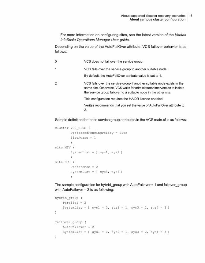
Depending on the value of the AutoFailOver attribute, VCS failover behavior is asfollows:
VCS does not fail over the service group.0
VCS fails over the service group to another suitable node.
By default, the AutoFailOver attribute value is set to 1.
1
VCS fails over the service group if another suitable node exists in thesame site. Otherwise, VCS waits for administrator intervention to initiatethe service group failover to a suitable node in the other site.
This configuration requires the HA/DR license enabled.
Veritas recommends that you set the value of AutoFailOver attribute to2.
2
Sample definition for these service group attributes in the VCS main.cf is as follows:
cluster VCS_CLUS (
PreferredFencingPolicy = Site
SiteAware = 1
)
site MTV (
SystemList = { sys1, sys2 }
)
site SFO (
Preference = 2
SystemList = { sys3, sys4 }
)
The sample configuration for hybrid_group with AutoFailover = 1 and failover_groupwith AutoFailover = 2 is as following:
hybrid_group (
Parallel = 2
SystemList = { sys1 = 0, sys2 = 1, sys3 = 2, sys4 = 3 }
)
failover_group (
AutoFailover = 2
SystemList = { sys1 = 0, sys2 = 1, sys3 = 2, sys4 = 3 }
)
16About supported disaster recovery scenariosAbout campus cluster configuration
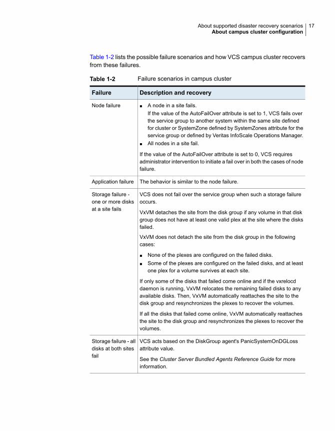
Table 1-2 lists the possible failure scenarios and how VCS campus cluster recoversfrom these failures.
Table 1-2 Failure scenarios in campus cluster
Description and recoveryFailure
■ A node in a site fails.If the value of the AutoFailOver attribute is set to 1, VCS fails overthe service group to another system within the same site definedfor cluster or SystemZone defined by SystemZones attribute for theservice group or defined by Veritas InfoScale Operations Manager.
■ All nodes in a site fail.
If the value of the AutoFailOver attribute is set to 0, VCS requiresadministrator intervention to initiate a fail over in both the cases of nodefailure.
Node failure
The behavior is similar to the node failure.Application failure
VCS does not fail over the service group when such a storage failureoccurs.
VxVM detaches the site from the disk group if any volume in that diskgroup does not have at least one valid plex at the site where the disksfailed.
VxVM does not detach the site from the disk group in the followingcases:
■ None of the plexes are configured on the failed disks.■ Some of the plexes are configured on the failed disks, and at least
one plex for a volume survives at each site.
If only some of the disks that failed come online and if the vxrelocddaemon is running, VxVM relocates the remaining failed disks to anyavailable disks. Then, VxVM automatically reattaches the site to thedisk group and resynchronizes the plexes to recover the volumes.
If all the disks that failed come online, VxVM automatically reattachesthe site to the disk group and resynchronizes the plexes to recover thevolumes.
Storage failure -one or more disksat a site fails
VCS acts based on the DiskGroup agent's PanicSystemOnDGLossattribute value.
See the Cluster Server Bundled Agents Reference Guide for moreinformation.
Storage failure - alldisks at both sitesfail
17About supported disaster recovery scenariosAbout campus cluster configuration
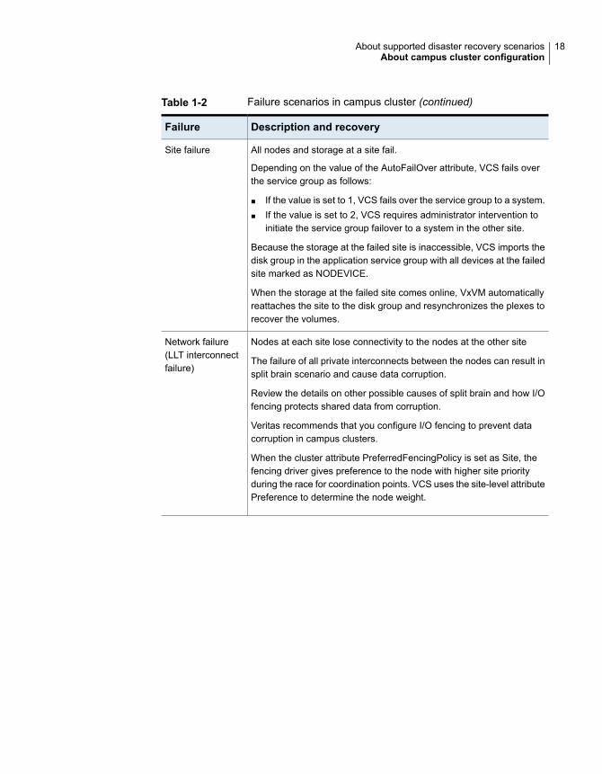
Table 1-2 Failure scenarios in campus cluster (continued)
Description and recoveryFailure
All nodes and storage at a site fail.
Depending on the value of the AutoFailOver attribute, VCS fails overthe service group as follows:
■ If the value is set to 1, VCS fails over the service group to a system.■ If the value is set to 2, VCS requires administrator intervention to
initiate the service group failover to a system in the other site.
Because the storage at the failed site is inaccessible, VCS imports thedisk group in the application service group with all devices at the failedsite marked as NODEVICE.
When the storage at the failed site comes online, VxVM automaticallyreattaches the site to the disk group and resynchronizes the plexes torecover the volumes.
Site failure
Nodes at each site lose connectivity to the nodes at the other site
The failure of all private interconnects between the nodes can result insplit brain scenario and cause data corruption.
Review the details on other possible causes of split brain and how I/Ofencing protects shared data from corruption.
Veritas recommends that you configure I/O fencing to prevent datacorruption in campus clusters.
When the cluster attribute PreferredFencingPolicy is set as Site, thefencing driver gives preference to the node with higher site priorityduring the race for coordination points. VCS uses the site-level attributePreference to determine the node weight.
Network failure(LLT interconnectfailure)
18About supported disaster recovery scenariosAbout campus cluster configuration
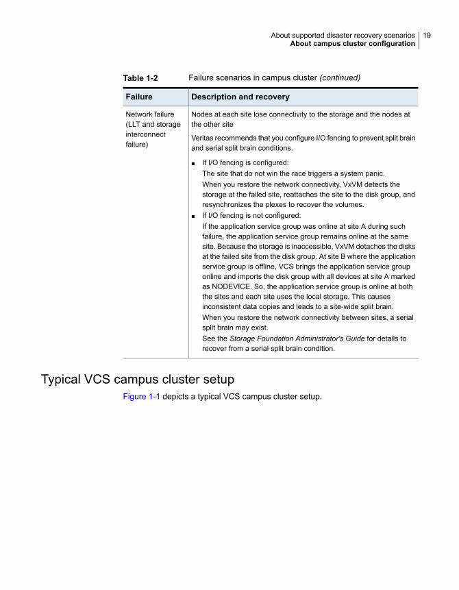
Table 1-2 Failure scenarios in campus cluster (continued)
Description and recoveryFailure
Nodes at each site lose connectivity to the storage and the nodes atthe other site
Veritas recommends that you configure I/O fencing to prevent split brainand serial split brain conditions.
■ If I/O fencing is configured:The site that do not win the race triggers a system panic.When you restore the network connectivity, VxVM detects thestorage at the failed site, reattaches the site to the disk group, andresynchronizes the plexes to recover the volumes.
■ If I/O fencing is not configured:If the application service group was online at site A during suchfailure, the application service group remains online at the samesite. Because the storage is inaccessible, VxVM detaches the disksat the failed site from the disk group. At site B where the applicationservice group is offline, VCS brings the application service grouponline and imports the disk group with all devices at site A markedas NODEVICE. So, the application service group is online at boththe sites and each site uses the local storage. This causesinconsistent data copies and leads to a site-wide split brain.When you restore the network connectivity between sites, a serialsplit brain may exist.See the Storage Foundation Administrator's Guide for details torecover from a serial split brain condition.
Network failure(LLT and storageinterconnectfailure)
Typical VCS campus cluster setupFigure 1-1 depicts a typical VCS campus cluster setup.
19About supported disaster recovery scenariosAbout campus cluster configuration
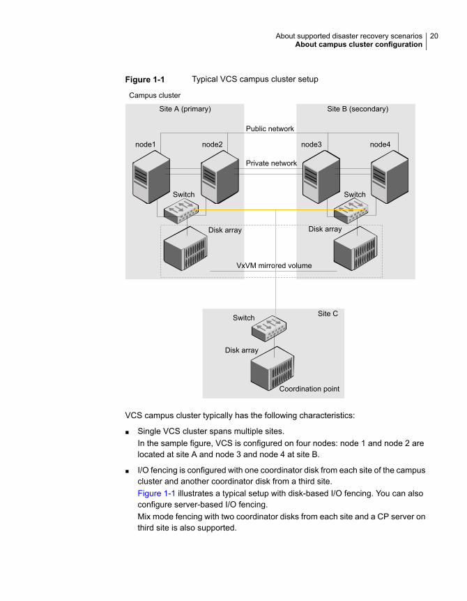
Figure 1-1 Typical VCS campus cluster setup
Site A (primary) Site B (secondary)
node1 node2 node3 node4
Public network
Private network
Switch Switch
Disk array Disk array
Site C
VxVM mirrored volume
Disk array
Campus cluster
Switch
Coordination point
VCS campus cluster typically has the following characteristics:
■ Single VCS cluster spans multiple sites.In the sample figure, VCS is configured on four nodes: node 1 and node 2 arelocated at site A and node 3 and node 4 at site B.
■ I/O fencing is configured with one coordinator disk from each site of the campuscluster and another coordinator disk from a third site.Figure 1-1 illustrates a typical setup with disk-based I/O fencing. You can alsoconfigure server-based I/O fencing.Mix mode fencing with two coordinator disks from each site and a CP server onthird site is also supported.
20About supported disaster recovery scenariosAbout campus cluster configuration
■ The shared data is located on mirrored volumes on a disk group configuredusing Veritas Volume Manager.
■ The volumes that are required for the application have mirrors on both the sites.
■ All nodes in the cluster are tagged with the VxVM site name. All disks that belongto a site are tagged with the corresponding VxVM site name.
■ The disk group is configured in VCS as a resource of type DiskGroup and ismounted using the Mount resource type.
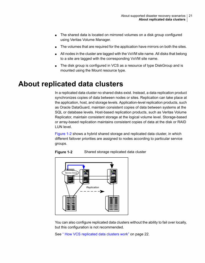
About replicated data clustersIn a replicated data cluster no shared disks exist. Instead, a data replication productsynchronizes copies of data between nodes or sites. Replication can take place atthe application, host, and storage levels. Application-level replication products, suchas Oracle DataGuard, maintain consistent copies of data between systems at theSQL or database levels. Host-based replication products, such as Veritas VolumeReplicator, maintain consistent storage at the logical volume level. Storage-basedor array-based replication maintains consistent copies of data at the disk or RAIDLUN level.
Figure 1-2 shows a hybrid shared storage and replicated data cluster, in whichdifferent failover priorities are assigned to nodes according to particular servicegroups.
Figure 1-2 Shared storage replicated data cluster
Replication
Service Group
You can also configure replicated data clusters without the ability to fail over locally,but this configuration is not recommended.
See “ How VCS replicated data clusters work” on page 22.
21About supported disaster recovery scenariosAbout replicated data clusters
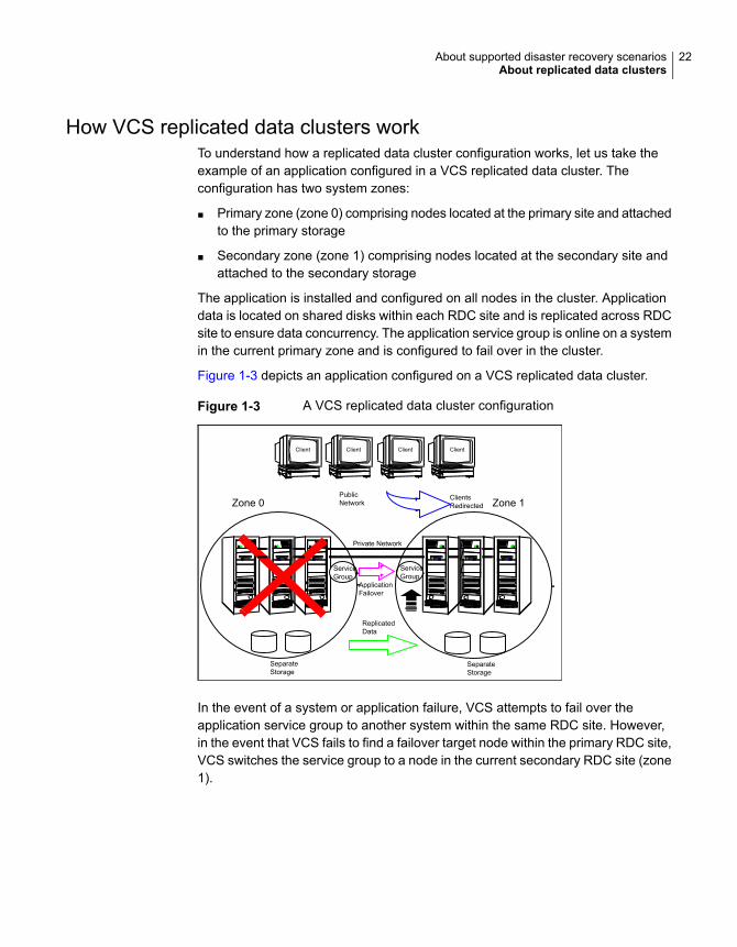
How VCS replicated data clusters workTo understand how a replicated data cluster configuration works, let us take theexample of an application configured in a VCS replicated data cluster. Theconfiguration has two system zones:
■ Primary zone (zone 0) comprising nodes located at the primary site and attachedto the primary storage
■ Secondary zone (zone 1) comprising nodes located at the secondary site andattached to the secondary storage
The application is installed and configured on all nodes in the cluster. Applicationdata is located on shared disks within each RDC site and is replicated across RDCsite to ensure data concurrency. The application service group is online on a systemin the current primary zone and is configured to fail over in the cluster.
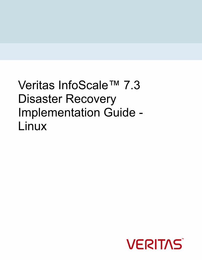
Figure 1-3 depicts an application configured on a VCS replicated data cluster.
Figure 1-3 A VCS replicated data cluster configuration
PublicNetwork
SeparateStorage
SeparateStorage
Client Client Client Client
ReplicatedData
ClientsRedirected
ApplicationFailover
Zone 0 Zone 1
Private Network
ServiceGroup
ServiceGroup
In the event of a system or application failure, VCS attempts to fail over theapplication service group to another system within the same RDC site. However,in the event that VCS fails to find a failover target node within the primary RDC site,VCS switches the service group to a node in the current secondary RDC site (zone1).
22About supported disaster recovery scenariosAbout replicated data clusters
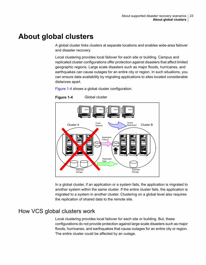
About global clustersA global cluster links clusters at separate locations and enables wide-area failoverand disaster recovery.
Local clustering provides local failover for each site or building. Campus andreplicated cluster configurations offer protection against disasters that affect limitedgeographic regions. Large scale disasters such as major floods, hurricanes, andearthquakes can cause outages for an entire city or region. In such situations, youcan ensure data availability by migrating applications to sites located considerabledistances apart.
Figure 1-4 shows a global cluster configuration.
Figure 1-4 Global cluster
PublicNetwork
SeparateStorage
SeparateStorage
Client Client Client Client
ReplicatedData
ClientsRedirected
ApplicationFailover
OracleGroup
Cluster A Cluster B
OracleGroup
In a global cluster, if an application or a system fails, the application is migrated toanother system within the same cluster. If the entire cluster fails, the application ismigrated to a system in another cluster. Clustering on a global level also requiresthe replication of shared data to the remote site.
How VCS global clusters workLocal clustering provides local failover for each site or building. But, theseconfigurations do not provide protection against large-scale disasters such as majorfloods, hurricanes, and earthquakes that cause outages for an entire city or region.The entire cluster could be affected by an outage.
23About supported disaster recovery scenariosAbout global clusters
In such situations, VCS global clusters ensure data availability by migratingapplications to remote clusters located considerable distances apart.
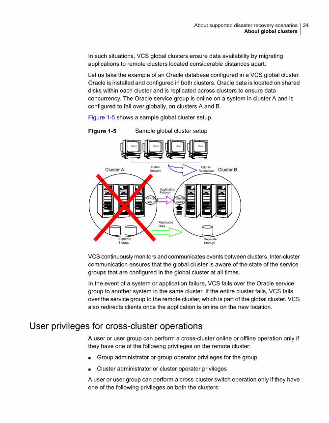
Let us take the example of an Oracle database configured in a VCS global cluster.Oracle is installed and configured in both clusters. Oracle data is located on shareddisks within each cluster and is replicated across clusters to ensure dataconcurrency. The Oracle service group is online on a system in cluster A and isconfigured to fail over globally, on clusters A and B.
Figure 1-5 shows a sample global cluster setup.
Figure 1-5 Sample global cluster setup
PublicNetwork
SeparateStorage
Client Client Client Client
ReplicatedData
ClientsRedirected
ApplicationFailover
OracleGroup
Cluster A Cluster B
OracleGroup
SeparateStorage
VCS continuously monitors and communicates events between clusters. Inter-clustercommunication ensures that the global cluster is aware of the state of the servicegroups that are configured in the global cluster at all times.
In the event of a system or application failure, VCS fails over the Oracle servicegroup to another system in the same cluster. If the entire cluster fails, VCS failsover the service group to the remote cluster, which is part of the global cluster. VCSalso redirects clients once the application is online on the new location.
User privileges for cross-cluster operationsA user or user group can perform a cross-cluster online or offline operation only ifthey have one of the following privileges on the remote cluster:
■ Group administrator or group operator privileges for the group
■ Cluster administrator or cluster operator privileges
A user or user group can perform a cross-cluster switch operation only if they haveone of the following privileges on both the clusters:
24About supported disaster recovery scenariosAbout global clusters
■ Group administrator or group operator privileges for the group
■ Cluster administrator or cluster operator privileges
VCS global clusters: The building blocksVCS extends clustering concepts to wide-area high availability and disaster recoverywith the following:
■ Remote cluster objectsSee “ Visualization of remote cluster objects” on page 25.
■ Global service groupsSee “About global service groups” on page 25.
■ Global cluster managementSee “About global cluster management” on page 26.
■ SerializationSee “About serialization–The Authority attribute” on page 27.
■ Resiliency and right of waySee “About resiliency and "Right of way"” on page 28.
■ VCS agents to manage wide-area failoverSee “ VCS agents to manage wide-area failover” on page 28.
■ Split-brain in two-cluster global clustersSee “About the Steward process: Split-brain in two-cluster global clusters”on page 31.
■ Secure communicationSee “ Secure communication in global clusters” on page 32.
Visualization of remote cluster objectsVCS enables you to visualize remote cluster objects using any of the supportedcomponents that are used to administer VCS such as VCS CLI and Veritas InfoScaleOperations Manager
You can define remote clusters in your configuration file, main.cf. The RemoteCluster Configuration wizard provides an easy interface to do so. The wizard updatesthe main.cf files of all connected clusters with the required configuration changes.
About global service groupsA global service group is a regular VCS group with additional properties to enablewide-area failover. The global service group attribute ClusterList defines the list ofclusters to which the group can fail over. The service group must be configured on
25About supported disaster recovery scenariosAbout global clusters
all participating clusters and must have the same name on each cluster. The GlobalGroup Configuration Wizard provides an easy interface to configure global groups.
VCS agents manage the replication during cross-cluster failover.
See “ VCS agents to manage wide-area failover” on page 28.
About global cluster managementVCS enables you to perform operations (online, offline, switch) on global servicegroups from any system in any cluster. You must log on with adequate privilegesfor cluster operations.
See “User privileges for cross-cluster operations” on page 24.
You can bring service groups online or switch them to any system in any cluster.If you do not specify a target system, VCS uses the FailOverPolicy to determinethe system.
Management of remote cluster objects is aided by inter-cluster communicationenabled by the wide-area connector (wac) process.
About the wide-area connector processThe wide-area connector (wac) is a failover Application resource that ensurescommunication between clusters.
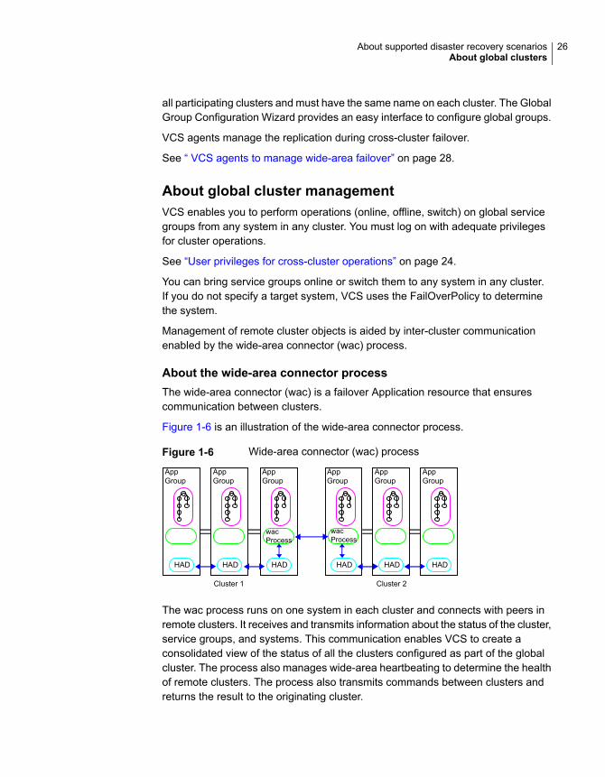
Figure 1-6 is an illustration of the wide-area connector process.
Figure 1-6 Wide-area connector (wac) process
AppGroup
HAD
AppGroup
HAD
wacProcess
Cluster 1 Cluster 2
AppGroup
HAD
wacProcess
AppGroup
HAD
AppGroup
HAD
AppGroup
HAD
The wac process runs on one system in each cluster and connects with peers inremote clusters. It receives and transmits information about the status of the cluster,service groups, and systems. This communication enables VCS to create aconsolidated view of the status of all the clusters configured as part of the globalcluster. The process also manages wide-area heartbeating to determine the healthof remote clusters. The process also transmits commands between clusters andreturns the result to the originating cluster.
26About supported disaster recovery scenariosAbout global clusters
VCS provides the option of securing the communication between the wide-areaconnectors.
See “ Secure communication in global clusters” on page 32.
About the wide-area heartbeat agentThe wide-area heartbeat agent manages the inter-cluster heartbeat. Heartbeatsare used to monitor the health of remote clusters. VCS wide-area hearbeat agentsinclude Icmp and IcmpS. While other VCS resource agents report their status toVCS engine, heartbeat agents report their status directly to the WAC process. Theheartbeat name must be the same as the heartbeat type name. You can add onlyone heartbeat of a specific heartbeat type.
See “Sample configuration for the wide-area heartbeat agent” on page 27.
You can create custom wide-area heartbeat agents. For example, the VCSreplication agent for SRDF includes a custom heartbeat agent for Symmetrix arrays.
You can add heartbeats using the hahb -add heartbeatname command andchange the default values of the heartbeat agents using the hahb -modify
command.
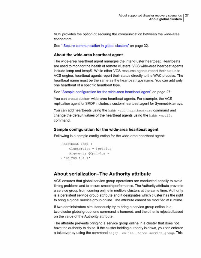
Sample configuration for the wide-area heartbeat agentFollowing is a sample configuration for the wide-area heartbeat agent:
Heartbeat Icmp (
ClusterList = {priclus
Arguments @Cpriclus =
{"10.209.134.1"
)
About serialization–The Authority attributeVCS ensures that global service group operations are conducted serially to avoidtiming problems and to ensure smooth performance. The Authority attribute preventsa service group from coming online in multiple clusters at the same time. Authorityis a persistent service group attribute and it designates which cluster has the rightto bring a global service group online. The attribute cannot be modified at runtime.
If two administrators simultaneously try to bring a service group online in atwo-cluster global group, one command is honored, and the other is rejected basedon the value of the Authority attribute.
The attribute prevents bringing a service group online in a cluster that does nothave the authority to do so. If the cluster holding authority is down, you can enforcea takeover by using the command hagrp -online -force service_group. This
27About supported disaster recovery scenariosAbout global clusters
command enables you to fail over an application to another cluster when a disasteroccurs.
Note: A cluster assuming authority for a group does not guarantee the group willbe brought online on the cluster. The attribute merely specifies the right to attemptbringing the service group online in the cluster. The presence of Authority does notoverride group settings like frozen, autodisabled, non-probed, and so on, that preventservice groups from going online.
You must seed authority if it is not held on any cluster.
Offline operations on global groups can originate from any cluster and do not requirea change of authority to do so, because taking a group offline does not necessarilyindicate an intention to perform a cross-cluster failover.
About the Authority and AutoStart attributesThe attributes Authority and AutoStart work together to avoid potential concurrencyviolations in multi-cluster configurations.
If the AutoStartList attribute is set, and if a group’s Authority attribute is set to 1,the VCS engine waits for the wac process to connect to the peer. If the connectionfails, it means the peer is down and the AutoStart process proceeds. If theconnection succeeds, HAD waits for the remote snapshot. If the peer is holding theauthority for the group and the remote group is online (because of takeover), thelocal cluster does not bring the group online and relinquishes authority.
If the Authority attribute is set to 0, AutoStart is not invoked.
About resiliency and "Right of way"VCS global clusters maintain resiliency using the wide-area connector process andthe ClusterService group. The wide-area connector process runs as long as thereis at least one surviving node in a cluster.
The wide-area connector, its alias, and notifier are components of the ClusterServicegroup.
VCS agents to manage wide-area failoverVCS agents now manage external objects that are part of wide-area failover. Theseobjects include replication, DNS updates, and so on. These agents provide a robustframework for specifying attributes and restarts, and can be brought online uponfail over.
28About supported disaster recovery scenariosAbout global clusters

The DNS agent updates the canonical name-mapping in thedomain name server after a wide-area failover.
See the Cluster Server Bundled Agents Reference Guide formore information.
DNS agent
29About supported disaster recovery scenariosAbout global clusters
You can use the following VCS agents for Volume Replicatorin a VCS global cluster setup:
■ RVG agentThe RVG agent manages the Replicated Volume Group(RVG). Specifically, it brings the RVG online, monitorsread-write access to the RVG, and takes the RVG offline.Use this agent when using Volume Replicator forreplication.
■ RVGPrimary agentThe RVGPrimary agent attempts to migrate or take overa Secondary site to a Primary site following an applicationfailover. The agent has no actions associated with theoffline and monitor routines.
■ RVGShared agentThe RVGShared agent monitors the RVG in a sharedenvironment. This is a parallel resource. The RVGSharedagent enables you to configure parallel applications touse an RVG in a cluster. The RVGShared agent monitorsthe RVG in a shared disk group environment.
■ RVGSharedPri agentThe RVGSharedPri agent enables migration and takeoverof a Volume Replicator replicated data set in parallelgroups in a VCS environment. Bringing a resource of typeRVGSharedPri online causes the RVG on the local hostto become a primary if it is not already.
■ RVGLogowner agentThe RVGLogowner agent assigns and unassigns a nodeas the logowner in the CVM cluster; this is a failoverresource. The RVGLogowner agent assigns or unassignsa node as a logowner in the cluster. In a shared disk groupenvironment, currently only the cvm master node shouldbe assigned the logowner role.
■ RVGSnapshot agentThe RVGSnapshot agent, used in fire drill service groups,takes space-optimized snapshots so that applications canbe mounted at secondary sites during a fire drill operation.See the Veritas InfoScale™ Replication Administrator’sGuide for more information.
In a CVM environment, the RVGShared agent, RVGSharedPriagent, RVGLogOwner agent, and RVGSnapshot agent aresupported. For more information, see the Cluster ServerBundled Agents Reference Guide.
VCS agents for VolumeReplicator
30About supported disaster recovery scenariosAbout global clusters
VCS provides agents for other third-party array-based orapplication-based replication solutions. These agents areavailable in the High Availability Agent Pack software.
See the agent pack documentation for a list of replicationtechnologies that VCS supports.
VCS agents for third-partyreplication technologies
About the Steward process: Split-brain in two-clusterglobal clustersFailure of all heartbeats between any two clusters in a global cluster indicates oneof the following:
■ The remote cluster is faulted.
■ All communication links between the two clusters are broken.
In global clusters with three or more clusters, VCS queries the connected clustersto confirm that the remote cluster is truly down. This mechanism is called inquiry.
In a two-cluster setup, VCS uses the Steward process to minimize chances of awide-area split-brain. The process runs as a standalone binary on a system outsideof the global cluster configuration.
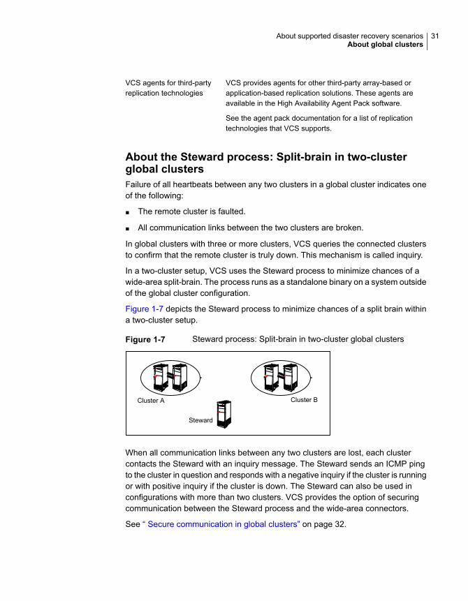
Figure 1-7 depicts the Steward process to minimize chances of a split brain withina two-cluster setup.
Figure 1-7 Steward process: Split-brain in two-cluster global clusters
Cluster A Cluster B
Steward
When all communication links between any two clusters are lost, each clustercontacts the Steward with an inquiry message. The Steward sends an ICMP pingto the cluster in question and responds with a negative inquiry if the cluster is runningor with positive inquiry if the cluster is down. The Steward can also be used inconfigurations with more than two clusters. VCS provides the option of securingcommunication between the Steward process and the wide-area connectors.
See “ Secure communication in global clusters” on page 32.
31About supported disaster recovery scenariosAbout global clusters
In non-secure configurations, you can configure the steward process on a platformthat is different to that of the global cluster nodes. Secure configurations have notbeen tested for running the steward process on a different platform.
For example, you can run the steward process on a Windows system for a globalcluster running on Linux systems. However, the VCS release for Linux contains thesteward binary for Linux only. You must copy the steward binary for Windows fromthe VCS installation directory on a Windows cluster, typically C:\Program
Files\VERITAS\Cluster Server.
A Steward is effective only if there are independent paths from each cluster to thehost that runs the Steward. If there is only one path between the two clusters, youmust prevent split-brain by confirming manually via telephone or some messagingsystem with administrators at the remote site if a failure has occurred. By default,VCS global clusters fail over an application across cluster boundaries withadministrator confirmation. You can configure automatic failover by setting theClusterFailOverPolicy attribute to Auto.
For more information on configuring the Steward process, see the Cluster ServerAdministrator's Guide.
The default port for the steward is 14156.
Secure communication in global clustersIn global clusters, VCS provides the option of making the following types ofcommunication secure:
■ Communication between the wide-area connectors.
■ Communication between the wide-area connectors and the Steward process.
For secure authentication, the wide-area connector process gets a security contextas an account in the local authentication broker on each cluster node.
The WAC account belongs to the same domain as HAD and Command Server andis specified as:
name = WAC
domain = VCS_SERVICES@cluster_uuid
You must configure the wide-area connector process in all clusters to run in securemode. If the wide-area connector process runs in secure mode, you must run theSteward in secure mode.
32About supported disaster recovery scenariosAbout global clusters
Disaster recovery feature support for componentsin the Veritas InfoScale product suite
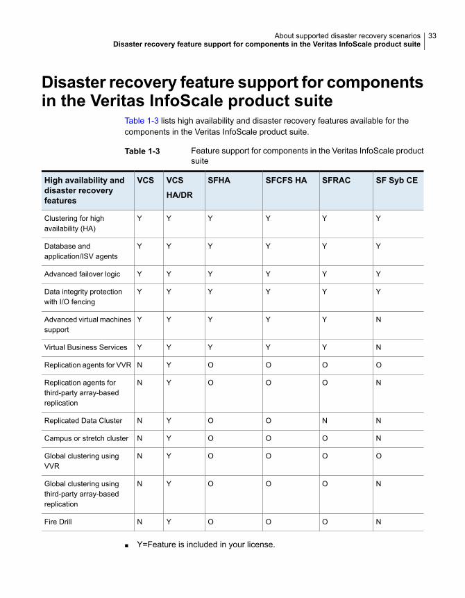
Table 1-3 lists high availability and disaster recovery features available for thecomponents in the Veritas InfoScale product suite.
Table 1-3 Feature support for components in the Veritas InfoScale productsuite
SF Syb CESFRACSFCFS HASFHAVCS
HA/DR
VCSHigh availability anddisaster recoveryfeatures
YYYYYYClustering for highavailability (HA)
YYYYYYDatabase andapplication/ISV agents
YYYYYYAdvanced failover logic
YYYYYYData integrity protectionwith I/O fencing
NYYYYYAdvanced virtual machinessupport
NYYYYYVirtual Business Services
OOOOYNReplication agents for VVR
NOOOYNReplication agents forthird-party array-basedreplication
NNOOYNReplicated Data Cluster
NOOOYNCampus or stretch cluster
OOOOYNGlobal clustering usingVVR
NOOOYNGlobal clustering usingthird-party array-basedreplication
NOOOYNFire Drill
■ Y=Feature is included in your license.
33About supported disaster recovery scenariosDisaster recovery feature support for components in the Veritas InfoScale product suite
■ O=Feature is not included in your license but may be licensed separately.
■ N=Feature is not supported with your license.
The following components support multiple third-party replication options:
■ Cluster Server (VCS)
■ Storage Foundation High Availability (SFHA)
■ Storage Foundation Cluster File System High Availability (SFCFSHA)
■ Storage Foundation for Oracle RAC (SF Oracle RAC)
Storage Foundation for Sybase CE supports VVR replication only at this time.
For current information on third-party replication support:
See: https://sort.veritas.com/agents and select Replication Agents under Agenttype.
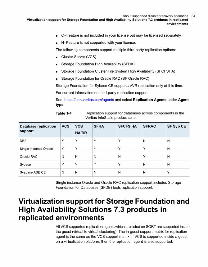
Table 1-4 Replication support for databases across components in theVeritas InfoScale product suite
SF Syb CESFRACSFCFS HASFHAVCS
HA/DR
VCSDatabase replicationsupport
NNYYYYDB2
NYYYYYSingle instance Oracle
NYNNNNOracle RAC
NNYYYYSybase
YNNNNNSyabase ASE CE
Single instance Oracle and Oracle RAC replication support includes StorageFoundation for Databases (SFDB) tools replication support.
Virtualization support for Storage Foundation andHigh Availability Solutions 7.3 products inreplicated environments
All VCS supported replication agents which are listed on SORT are supported insidethe guest (virtual to virtual clustering). The in-guest support matrix for replicationagent is the same as the VCS support matrix. If VCS is supported inside a gueston a virtualization platform, then the replication agent is also supported.
34About supported disaster recovery scenariosVirtualization support for Storage Foundation and High Availability Solutions 7.3 products in replicated
environments
For Linux:
Supported Linux virtualization technologies:
■ Kernel-based Virtual Machine (KVM) technology for Red Hat Enterprise Linux(RHEL) and SUSE Linux Enterprise Server (SLES)
■ Red Hat Enterprise Virtualization (RHEV)
■ Microsoft Hyper-V
■ Oracle Virtual Machine (OVM)
Pre-requisite for replication agent support in virtual environments:
Data disks must be made visible to the guest as pass-through devices, such asVMware to RDM, LDOM to Physical Disk or Disk Lun without slice option.
Exception:
Firedrill functionality is not supported in virtual environments for the followingreplication agents:
■ EMC MirrorView
■ HP-UX EVA CA
Only Firedrill functionality is affected: these replication agents can be used tomanage replication inside guests.
35About supported disaster recovery scenariosVirtualization support for Storage Foundation and High Availability Solutions 7.3 products in replicated
environments
Planning for disasterrecovery
This chapter includes the following topics:
■ Planning for cluster configurations
■ Planning for data replication
Planning for cluster configurationsStorage Foundation and High Availability Solutions provides various disasterrecovery configurations, such as campus clusters, global clusters for multi-siteclusters. In multi-site clusters, the nodes can be placed in different parts of a building,in separate buildings, or in separate cities. The distance between the nodes dependson the type of disaster from which protection is needed and on the technology usedto replicate data. Storage Foundation and High Availability supports variousreplication technologies for data replication.
To protect clusters against outages caused by disasters, the cluster componentsmust be geographically separated.
Planning a campus cluster setupA campus cluster is also known as a stretch cluster or remote mirror configuration.In a campus cluster, the hosts and storage of a cluster span multiple sites separatedby a few miles.
Keep in mind the following best practices when you configure a Storage Foundationcampus cluster:
■ Campus cluster sites are typically connected using a redundant high-capacitynetwork that provides access to storage and private network communication
2Chapter
between the cluster nodes. A single DWDM link can be used for both storageand private network communication.
■ Tag the disks or enclosures that belong to a site with the corresponding VxVMsite name. VxVM allocates storage from the correct site when creating or resizinga volume and when changing a volume’s layout if the disks in the VxVM diskgroup that contain the volume are tagged with the site name.
■ Tag each host with the corresponding VxVM site name. Make sure the readpolicy of the volumes is set to SITEREAD. This setting ensures that the reads onthe volumes are satisfied from the local site’s plex.
■ Turn on the allsites attribute for all volumes that have data required by theapplication, to make sure they are evenly mirrored. Each site must have at leastone mirror of all volumes hosting application data, including the FlashSnap logvolume.
■ Turn on the siteconsistent attribute for the disk groups and the volumes toenable site-aware plex detaches. Snapshot volumes need not be site-consistent.
■ In the case of a two-site campus cluster, place the third coordinator disk on thethird site. You may use iSCSI disk on the third site as an alternative to DarkFiber connected FC-SAN or a Coordination Point Server (CPS), as a thirdcoordination point.
■ Make sure that a DCO log version 20 or higher is attached to the volumes toenable Fast Resync operations.
■ Set the CVM disk detach policy as global or local for all disk groups containingdata volumes.For OCR and voting disk, it is recommended to have the disk group policy aslocal detach policy.
Planning a replicated data cluster setupThe VCS replicated data cluster (RDC) configuration allows you to provide a robustand easy-to manage disaster recovery protection for your applications. For exampleyou can convert a single instance database configured for local high availability ina VCS cluster to a disaster-protected RDC infrastructure using Volume Replicatoror a supported third-party replication technology to replicate changed data.
Keep in mind the following best practicies when you configure an RDC:
■ Make sure the sites and systems at each site are identified correctly for usewhen defining system zones in an RDC.
■ Make sure there are dual dedicated LLT links between the replicated nodes.
37Planning for disaster recoveryPlanning for cluster configurations
■ Since the sites used in the RDC configuration are within metro limits,synchronous replication is typically used. Make sure the replication technologythat you plan to use supports synchronous replication mode.
The RDC can also be configured using supported third-party replication technologies.
See “Planning for data replication” on page 38.
Planning a global cluster setupGlobal clusters provide the ability to fail over applications between geographicallydistributed clusters when a disaster occurs.
Global clustering involves two steps:
1. Replication of data between the sites
2. Configuring VCS clusters at the geographically distant sites and establishinga global cluster connection between them
The following aspects need to be considered when you design a disaster recoverysolution:
■ The amount of data lost in the event of a disaster (Recovery Point Objective)
■ The acceptable recovery time after the disaster (Recovery Time Objective)
Planning for data replicationWhen planning for data replication, it is important to review the various hardwareand software replication technologies and to review important considerationsincluding the required level of data throughput.
Data replication optionsDisaster recovery solutions support various hardware and software replicationtechnologies.
■ Hitachi True Copy■ IBM Metro Mirror■ IBM SVC■ EMC Mirrorview
Examples of hardwarereplication options
■ Volume Replicator (VVR)■ Oracle Data Guard
Examples of softwarereplication options
38Planning for disaster recoveryPlanning for data replication
A complete list of supported replication technologies is listed on the Veritas Website:
https://sort.veritas.com/agents
Data replication considerationsWhen you choose a replication solution, one of the important factors that you needto consider is the required level of data throughput. Data throughput is the rate atwhich the application is expected to write data. The impact of write operations onreplication are of more significance than that of the read operations.
In addition to the business needs discussed earlier, the following factors need tobe considered while choosing the replication options:
■ Mode of replication
■ Network bandwidth
■ Network latency between the two sites
■ Ability of the remote site to keep up with the data changes at the first site
39Planning for disaster recoveryPlanning for data replication
Implementing campusclusters
■ Chapter 3. Setting up campus clusters for VCS and SFHA
■ Chapter 4. Setting up campus clusters for SFCFSHA, SFRAC
2Section

Setting up campusclusters for VCS andSFHA
This chapter includes the following topics:
■ About setting up a campus cluster configuration
■ Fire drill in campus clusters
■ About the DiskGroupSnap agent
■ About running a fire drill in a campus cluster
About setting up a campus cluster configurationYou must perform the following tasks to set up a campus cluster:
■ Preparing to set up a campus cluster configuration
■ Configuring I/O fencing to prevent data corruption
■ Configuring VxVM disk groups for campus cluster configuration
■ Configuring VCS service group for campus clusters
Preparing to set up a campus cluster configurationBefore you set up the configuration, review the VCS campus cluster requirements.
See “ VCS campus cluster requirements” on page 14.
3Chapter
To prepare to set up a campus cluster configuration
1 Set up the physical infrastructure.
■ Set up access to the local storage arrays and to remote storage arrays oneach node.
■ Set up private heartbeat network.
See “ Typical VCS campus cluster setup” on page 19.
2 Install VCS on each node to form a cluster with at least one node in each ofthe two sites.
See the Cluster Server Configuration and Upgrade Guide for instructions.
3 Install VxVM on each node with the required licenses.
See the Storage Foundation and High Availability Configuration and UpgradeGuide for instructions.
Configuring I/O fencing to prevent data corruptionPerform the following tasks to configure I/O fencing to prevent data corruption inthe event of a communication failure.
See the Cluster Server Configuration and Upgrade Guide for more details.
To configure I/O fencing to prevent data corruption
1 Set up the storage at a third site.
You can extend the DWDM to the third site to have FC SAN connectivity tothe storage at the third site. You can also use iSCSI targets as the coordinatordisks at the third site.
2 Set up I/O fencing.
Configuring VxVM disk groups for campus cluster configurationConfigure the campus cluster sites and configure VxVM disk groups for remotemirroring. You can also configure VxVM disk groups for remote mirroring usingVeritas InfoScale Operations Manager.
Note: In AWS environments where nodes span multiple Availability Zones, FSSvolumes in campus cluster configurations can be used as an alternative to datareplication using VVR for achieving high data availability across AZs. In thisFSS-campus cluster configuration, site tags can be added based on the name ofthe Availability Zone to make data highly available during AZ failures.
42Setting up campus clusters for VCS and SFHAAbout setting up a campus cluster configuration
See the Storage Foundation Cluster File System High Availability Administrator'sGuide for more information on the VxVM commands.
To configure VxVM disk groups for campus cluster configuration
1 Set the site name for each host:
# vxdctl set site=sitename
The site name is stored in the /etc/vx/volboot file. Use the following commandto display the site names:
# vxdctl list | grep siteid
2 Set the site name for all the disks in an enclosure:
# vxdisk settag site=sitename encl:enclosure
To tag specific disks, use the following command:
# vxdisk settag site=sitename disk
3 Verify that the disks are registered to a site.
# vxdisk listtag
4 Create a disk group with disks from both the sites.
# vxdg -s init diskgroup siteA_disk1 siteB_disk2
5 Configure site-based allocation on the disk group that you created for eachsite that is registered to the disk group.
# vxdg -g diskgroup addsite sitename
6 Configure site consistency on the disk group.
# vxdg -g diskgroup set siteconsistent=on
7 Create one or more mirrored volumes in the disk group.
# vxassist -g diskgroup make volume size nmirror=1/2
With the Site Awareness license installed on all hosts, the volume that youcreate has the following characteristics by default:
43Setting up campus clusters for VCS and SFHAAbout setting up a campus cluster configuration
■ The allsites attribute is set to on; the volumes have at least one plex ateach site.
■ The volumes are automatically mirrored across sites.
■ The read policy rdpol is set to siteread.
■ The volumes inherit the site consistency value that is set on the disk group.
Configuring VCS service group for campus clustersFollow the procedure to configure the disk groups under VCS control and set upthe VCS attributes to define failover in campus clusters.
To configure VCS service groups for campus clusters
1 Create a VCS service group (app_sg) for the application that runs in the campuscluster.
hagrp -add app_sg
hagrp -modify app_sg SystemList node1 0 node2 1 node3 2 node4 3
2 Set up the system zones or sites. Configure the SystemZones attribute for theservice group. Skip this step when sites are configured through Veritas InfoScaleOperations Manager.
hagrp -modify app_sg SystemZones node1 0 node2 0 node3 1 node4 1
3 Set up the group fail over policy. Set the value of the AutoFailOver attributefor the service group.
hagrp -modify app_sg AutoFailOver 2
4 For the disk group you created for campus clusters, add a DiskGroup resourceto the VCS service group app_sg.
hares -add dg_res1 DiskGroup app_sg
hares -modify dg_res1 DiskGroup diskgroup_name
hares -modify dg_res1 Enabled 1
5 Configure the application and other related resources to the app_sg servicegroup.
6 Bring the service group online.
44Setting up campus clusters for VCS and SFHAAbout setting up a campus cluster configuration
Setting up campus clusters for VxVM and VCS using VeritasInfoScale Operations Manager
Before configuring VxVM and VCS disk groups for campus clusters using VeritasInfoScale Operations Manager, you must remove the site tag from the disk groupor cluster, as well as remove any tagging set by Veritas InfoScale OperationsManager.
See the Veritas InfoScale Operations Manager User guide for more information onusing Multi Site Management in Veritas InfoScale Operations Manager to managecampus clusters across Storage Foundation and Cluster Server objects.
To remove VxVM site tag information
1 Determine which site a host belongs to, and execute the following commandon each host:
# vxdctl list | grep siteid
2 Remove the defined site name from each host:
# vxdctl [-F] unset site
The -F option is required if any imported disk groups are registered to the site.
3 Optionally, turn off auto-tagging on the disk group:
# vxdg -g diskgroup set autotagging=off
4 Verify if site consistency has been enabled for the disk group:
# vxdg list diskgroup | grep siteconsistent
5 Turn off the site consistency requirement for the disk group:
# vxdg -g diskgroup set siteconsistent=off
6 Identify the site record for each site with the disk group:
# vxprint -g diskgroup | grep ^SR
7 Unregister the site record for each site with the disk group:
# vxdg -g diskgroup rmsite sitename
8 List the site tags for the disk group:
# vxdg listtag [diskgroup]
45Setting up campus clusters for VCS and SFHAAbout setting up a campus cluster configuration
9 Remove the site tag from the disk group:
# vxdg [-g diskgroup] rmtag [encl:enclosure] site=sitename
10 Check which disks or enclosures are registered to the site:
# vxdisk [-g diskgroup] listtag
11 Remove the site tag from the disk or enclosure:
# vxdisk rmtag site=sitename disk|encl:enclosure
To remove VCS site tag information
1 Make the cluster configuration writable.
# haconf -makerw
2 List the site tagging information on the cluster.
# hasite -list
3 Remove the site tagging information from the cluster.
# hasite -modify sitename SystemList -delete -keys
# hasite -delete sitename
4 Dump the configuration.
# haconf -dump -makero
Fire drill in campus clustersFire drill tests the disaster-readiness of a configuration by mimicking a failoverwithout stopping the application and disrupting user access.
The process involves creating a fire drill service group, which is similar to the originalapplication service group. Bringing the fire drill service group online on the remotenode demonstrates the ability of the application service group to fail over and comeonline at the site, should the need arise.
Fire drill service groups do not interact with outside clients or with other instancesof resources, so they can safely come online even when the application service
46Setting up campus clusters for VCS and SFHAFire drill in campus clusters
group is online. Conduct a fire drill only at the remote site; do not bring the fire drillservice group online on the node hosting the original application.
About the DiskGroupSnap agentThe DiskGroupSnap agent verifies the VxVM disk groups and volumes for siteawareness and disaster readiness in a campus cluster environment. To perform afire drill in campus clusters, you must configure a resource of type DiskGroupSnapin the fire drill service group.
Note: To perform fire drill, the application service group must be online at the primarysite.
During fire drill, the DiskGroupSnap agent does the following:
■ For each node in a site, the agent correlates the value of the SystemZonesattribute for the application service group to the VxVM site names for that node.
■ For the disk group in the application service group, the agent verifies that theVxVM site tags are defined for the disk group.
■ For the disk group in the application service group, the agent verifies that thedisks at the secondary site are not tagged with the same VxVM site name asthe disks at the primary site.
■ The agent verifies that all volumes in the disk group have a plex at each site.
See the Cluster Server Bundled Agents Reference Guide for more information onthe agent.
About running a fire drill in a campus clusterThis topic provides information on how to run a fire drill in campus clusters.
Do the following tasks to perform fire drill:
■ Configuring the fire drill service group
■ Running a successful fire drill in a campus cluster
Configuring the fire drill service groupThis topic provides information on how to configure the fire drill service group.
47Setting up campus clusters for VCS and SFHAAbout the DiskGroupSnap agent
To configure the fire drill service group
1 Configure a fire drill service group similar to the application service group withthe following exceptions:
■ The AutoFailOver attribute must be set to 0.
■ Network-related resources must not be configured.
■ The disk group names for the DiskGroup and the Mount resources in thefire drill service group must be appended with "_fd".For example, if the value of the DiskGroup attribute in the application servicegroup is ccdg, then the corresponding value in the fire drill service groupmust be ccdg_fd.If the value of the BlockDevice attribute for the Mount resource in theapplication service group is /dev/vx/dsk/ccdg/ccvol, then the correspondingvalue in the fire drill service group must be /dev/vx/dsk/ccdg_fd/ccvol.
2 Add a resource of type DiskGroupSnap. Define the TargetResName and theFDSiteName attributes for the DiskGroupSnap resource.
See the Cluster Server Bundled Agent Reference Guide for attributedescriptions.
3 Create a dependency such that the DiskGroup resource depends on theDiskGroupSnap resource.
4 Create a group dependency such that the fire drill service group has an offlinelocal dependency on the application service group.
Running a successful fire drill in a campus clusterBring the fire drill service group online on a node within the system zone that doesnot have the application running. Verify that the fire drill service group comes online.This action validates that your solution is configured correctly and the productionservice group will fail over to the remote site in the event of an actual failure (disaster)at the local site.
You must take the fire drill service group offline before you shut down the node orstop VCS locally on the node where the fire drill service group is online or wherethe disk group is online. Otherwise, after the node restarts you must manuallyreattach the fire drill site to the disk group that is imported at the primary site.
Note: For the applications for which you want to perform fire drill, you must set thevalue of the FireDrill attribute for those application resource types to 1. After youcomplete fire drill, reset the value to 0.
48Setting up campus clusters for VCS and SFHAAbout running a fire drill in a campus cluster
To run a successful fire drill
1 Override the FireDrill attribute at the resource level for resources of the fire drillservice group.
2 Set the FireDrill attribute for the application resources to 1. This prevents theagent from reporting a concurrency violation, when the application servicegroup and the fire drill service group are online at the same time.
3 Bring the fire drill service group online.
If the fire drill service group does not come online, review the VCS engine logto troubleshoot the issues so that corrective action can be taken as necessaryin the production service group.
Warning: You must take the fire drill service group offline after you completethe fire drill so that the failover behavior of the application service group is notimpacted. Otherwise, when a disaster strikes at the primary site, the applicationservice group cannot fail over to the secondary site due to resource conflicts.
4 After you complete the fire drill, take the fire drill service group offline.
5 Reset the Firedrill attribute for the resource to 0.
6 Undo or override the Firedrill attribute from the resource level.
49Setting up campus clusters for VCS and SFHAAbout running a fire drill in a campus cluster
Setting up campusclusters for SFCFSHA,SFRAC
This chapter includes the following topics:
■ About setting up a campus cluster for disaster recovery for SFCFSHA or SFOracle RAC
■ Preparing to set up a campus cluster in a parallel cluster database environment
■ Configuring I/O fencing to prevent data corruption
■ Configuring VxVM disk groups for a campus cluster in a parallel cluster databaseenvironment
■ Configuring VCS service groups for a campus cluster for SFCFSHA and SFOracle RAC
■ Tuning guidelines for parallel campus clusters
■ Best practices for a parallel campus cluster
About setting up a campus cluster for disasterrecovery for SFCFSHA or SF Oracle RAC
Campus clusters:
■ Are connected using a high speed cable that guarantees network access betweenthe nodes
4Chapter
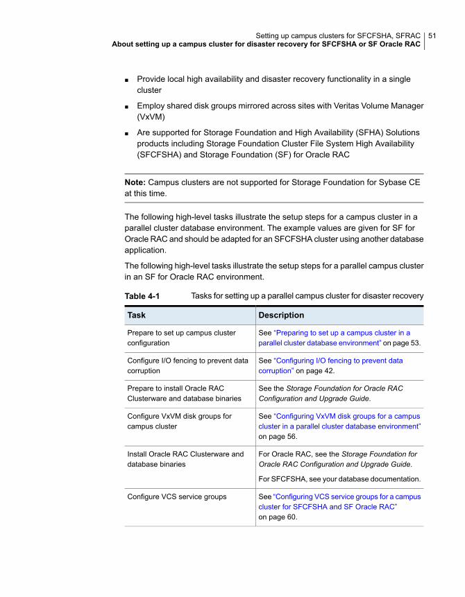
■ Provide local high availability and disaster recovery functionality in a singlecluster
■ Employ shared disk groups mirrored across sites with Veritas Volume Manager(VxVM)
■ Are supported for Storage Foundation and High Availability (SFHA) Solutionsproducts including Storage Foundation Cluster File System High Availability(SFCFSHA) and Storage Foundation (SF) for Oracle RAC
Note: Campus clusters are not supported for Storage Foundation for Sybase CEat this time.
The following high-level tasks illustrate the setup steps for a campus cluster in aparallel cluster database environment. The example values are given for SF forOracle RAC and should be adapted for an SFCFSHA cluster using another databaseapplication.
The following high-level tasks illustrate the setup steps for a parallel campus clusterin an SF for Oracle RAC environment.
Table 4-1 Tasks for setting up a parallel campus cluster for disaster recovery
DescriptionTask
See “Preparing to set up a campus cluster in aparallel cluster database environment” on page 53.
Prepare to set up campus clusterconfiguration
See “Configuring I/O fencing to prevent datacorruption” on page 42.
Configure I/O fencing to prevent datacorruption
See the Storage Foundation for Oracle RACConfiguration and Upgrade Guide.
Prepare to install Oracle RACClusterware and database binaries
See “Configuring VxVM disk groups for a campuscluster in a parallel cluster database environment”on page 56.
Configure VxVM disk groups forcampus cluster
For Oracle RAC, see the Storage Foundation forOracle RAC Configuration and Upgrade Guide.
For SFCFSHA, see your database documentation.
Install Oracle RAC Clusterware anddatabase binaries
See “Configuring VCS service groups for a campuscluster for SFCFSHA and SF Oracle RAC”on page 60.
Configure VCS service groups
51Setting up campus clusters for SFCFSHA, SFRACAbout setting up a campus cluster for disaster recovery for SFCFSHA or SF Oracle RAC
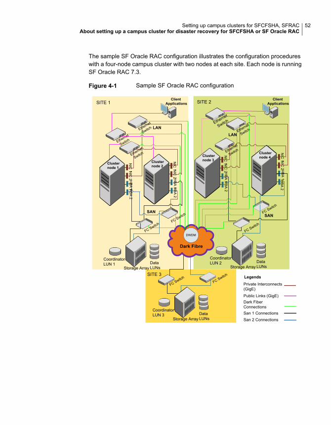
The sample SF Oracle RAC configuration illustrates the configuration procedureswith a four-node campus cluster with two nodes at each site. Each node is runningSF Oracle RAC 7.3.
Figure 4-1 Sample SF Oracle RAC configuration
LANLAN
Dark Fibre
SITE 1 SITE 2
SITE 3
Physical view of 4-node SFRACCampus Cluster
NIC
1 NIC
2H
BA
2H
BA
1
Clusternode 1
NIC
1 NIC
2H
BA
2H
BA
1
Clusternode 2
NIC
1 NIC
2H
BA
2H
BA
1
Clusternode 3
NIC
1 NIC
2H
BA
2H
BA
1
Clusternode 4
ClientApplications
ClientApplications
Ethernet
Switch
Ethernet
Switch
Ethernet
Switch
Ethernet
Switch
Ethernet
Switch
Ethernet
Switch
FC SwitchFC Switch
FC Switch
FC Switch
CoordinatorLUN 1 Data
LUNsStorage Array
CoordinatorLUN 2 Data
LUNsStorage Array
CoordinatorLUN 3 Data
LUNsStorage Array
FC SwitchFC Switch
DWDM
Private Interconnects(GigE)
San 2 Connections
Legends
Dark FiberConnectionsSan 1 Connections
Public Links (GigE)
SANSAN
52Setting up campus clusters for SFCFSHA, SFRACAbout setting up a campus cluster for disaster recovery for SFCFSHA or SF Oracle RAC
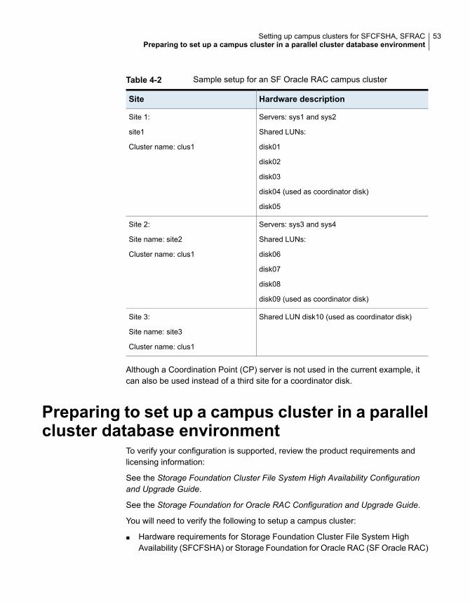
Table 4-2 Sample setup for an SF Oracle RAC campus cluster
Hardware descriptionSite
Servers: sys1 and sys2
Shared LUNs:
disk01
disk02
disk03
disk04 (used as coordinator disk)
disk05
Site 1:
site1
Cluster name: clus1
Servers: sys3 and sys4
Shared LUNs:
disk06
disk07
disk08
disk09 (used as coordinator disk)
Site 2:
Site name: site2
Cluster name: clus1
Shared LUN disk10 (used as coordinator disk)Site 3:
Site name: site3
Cluster name: clus1
Although a Coordination Point (CP) server is not used in the current example, itcan also be used instead of a third site for a coordinator disk.
Preparing to set up a campus cluster in a parallelcluster database environment
To verify your configuration is supported, review the product requirements andlicensing information:
See the Storage Foundation Cluster File System High Availability Configurationand Upgrade Guide.
See the Storage Foundation for Oracle RAC Configuration and Upgrade Guide.
You will need to verify the following to setup a campus cluster:
■ Hardware requirements for Storage Foundation Cluster File System HighAvailability (SFCFSHA) or Storage Foundation for Oracle RAC (SF Oracle RAC)
53Setting up campus clusters for SFCFSHA, SFRACPreparing to set up a campus cluster in a parallel cluster database environment
■ License requirements: in addition to your product with HA/DR, you will need:
■ FlashSnap license
■ Site awareness license
With keyless licensing, your enterprise product keys enable all of the above features.
The following preparation must be completed before configuring the campus cluster.
To prepare to set up a campus cluster
1 Configure the physical infrastructure for campus cluster:
■ Set up access to the local storage arrays and to remote storage arrays oneach node. The storage link will extend to the third site as well.In environments using the Flexible Storage Sharing (FSS) feature, this stepis not mandatory. For more details on FSS, see the Storage FoundationCluster File System Administrator's Guide.
■ Set up the private heartbeat networkSee “ Typical VCS campus cluster setup” on page 19.
2 Install the operating system on all the nodes of the cluster.
See your operating system documenation.
3 Install and configure either SFCFSHA or SF Oracle RAC on all nodes on boththe sites.
See the Storage Foundation Cluster File System High Availability Configurationand Upgrade Guide.
See the Storage Foundation for Oracle RACConfiguration and Upgrade Guide.
For a setup example, steps are provided to install and configure SF OracleRAC 7.3 on all four nodes. Your installation and configuration steps willnecessarily differ to reflect your configuration details.
Configuring I/O fencing to prevent data corruptionPerform the following tasks to configure I/O fencing to prevent data corruption inthe event of a communication failure.
To configure I/O fencing to prevent data corruption
1 After installing and configuring SFCFSHA or SF Oracle RAC, configure I/Ofencing for data integrity.
See the Storage Foundation Cluster File System High Availability Configurationand Upgrade Guide.
54Setting up campus clusters for SFCFSHA, SFRACConfiguring I/O fencing to prevent data corruption
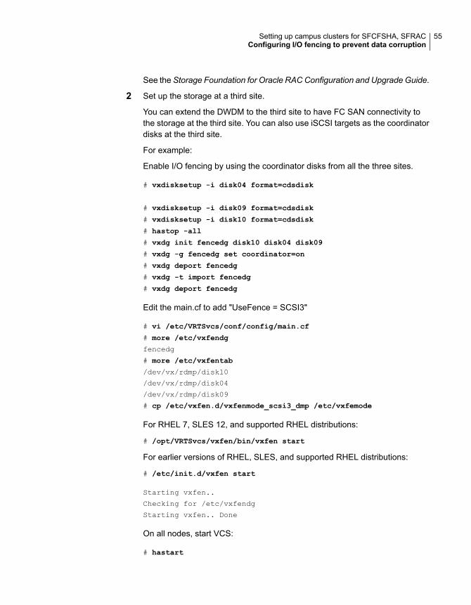
See the Storage Foundation for Oracle RACConfiguration and Upgrade Guide.
2 Set up the storage at a third site.
You can extend the DWDM to the third site to have FC SAN connectivity tothe storage at the third site. You can also use iSCSI targets as the coordinatordisks at the third site.
For example:
Enable I/O fencing by using the coordinator disks from all the three sites.
# vxdisksetup -i disk04 format=cdsdisk
# vxdisksetup -i disk09 format=cdsdisk
# vxdisksetup -i disk10 format=cdsdisk
# hastop -all
# vxdg init fencedg disk10 disk04 disk09
# vxdg -g fencedg set coordinator=on
# vxdg deport fencedg
# vxdg -t import fencedg
# vxdg deport fencedg
Edit the main.cf to add "UseFence = SCSI3"
# vi /etc/VRTSvcs/conf/config/main.cf
# more /etc/vxfendg
fencedg
# more /etc/vxfentab
/dev/vx/rdmp/disk10
/dev/vx/rdmp/disk04
/dev/vx/rdmp/disk09
# cp /etc/vxfen.d/vxfenmode_scsi3_dmp /etc/vxfemode
For RHEL 7, SLES 12, and supported RHEL distributions:
# /opt/VRTSvcs/vxfen/bin/vxfen start
For earlier versions of RHEL, SLES, and supported RHEL distributions:
# /etc/init.d/vxfen start
Starting vxfen..
Checking for /etc/vxfendg
Starting vxfen.. Done
On all nodes, start VCS:
# hastart
55Setting up campus clusters for SFCFSHA, SFRACConfiguring I/O fencing to prevent data corruption
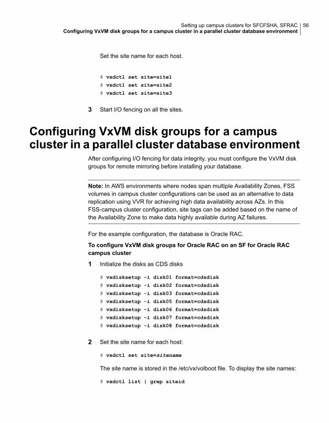
Set the site name for each host.
# vxdctl set site=site1
# vxdctl set site=site2
# vxdctl set site=site3
3 Start I/O fencing on all the sites.
Configuring VxVM disk groups for a campuscluster in a parallel cluster database environment
After configuring I/O fencing for data integrity, you must configure the VxVM diskgroups for remote mirroring before installing your database.
Note: In AWS environments where nodes span multiple Availability Zones, FSSvolumes in campus cluster configurations can be used as an alternative to datareplication using VVR for achieving high data availability across AZs. In thisFSS-campus cluster configuration, site tags can be added based on the name ofthe Availability Zone to make data highly available during AZ failures.
For the example configuration, the database is Oracle RAC.
To configure VxVM disk groups for Oracle RAC on an SF for Oracle RACcampus cluster
1 Initialize the disks as CDS disks
# vxdisksetup -i disk01 format=cdsdisk
# vxdisksetup -i disk02 format=cdsdisk
# vxdisksetup -i disk03 format=cdsdisk
# vxdisksetup -i disk05 format=cdsdisk
# vxdisksetup -i disk06 format=cdsdisk
# vxdisksetup -i disk07 format=cdsdisk
# vxdisksetup -i disk08 format=cdsdisk
2 Set the site name for each host:
# vxdctl set site=sitename
The site name is stored in the /etc/vx/volboot file. To display the site names:
# vxdctl list | grep siteid
56Setting up campus clusters for SFCFSHA, SFRACConfiguring VxVM disk groups for a campus cluster in a parallel cluster database environment
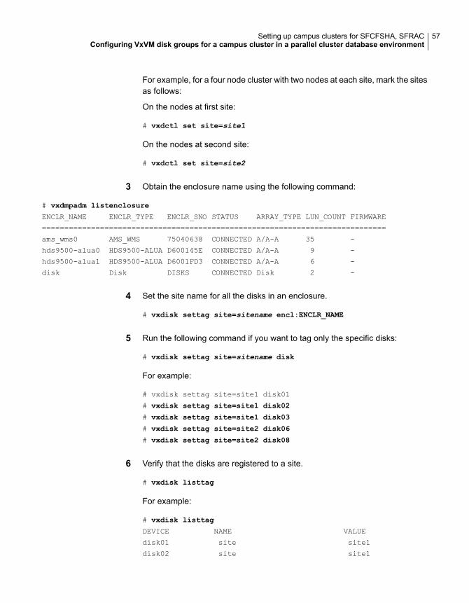
For example, for a four node cluster with two nodes at each site, mark the sitesas follows:
On the nodes at first site:
# vxdctl set site=site1
On the nodes at second site:
# vxdctl set site=site2
3 Obtain the enclosure name using the following command:
# vxdmpadm listenclosure
ENCLR_NAME ENCLR_TYPE ENCLR_SNO STATUS ARRAY_TYPE LUN_COUNT FIRMWARE
=============================================================================
ams_wms0 AMS_WMS 75040638 CONNECTED A/A-A 35 -
hds9500-alua0 HDS9500-ALUA D600145E CONNECTED A/A-A 9 -
hds9500-alua1 HDS9500-ALUA D6001FD3 CONNECTED A/A-A 6 -
disk Disk DISKS CONNECTED Disk 2 -
4 Set the site name for all the disks in an enclosure.
# vxdisk settag site=sitename encl:ENCLR_NAME
5 Run the following command if you want to tag only the specific disks:
# vxdisk settag site=sitename disk
For example:
# vxdisk settag site=site1 disk01
# vxdisk settag site=site1 disk02
# vxdisk settag site=site1 disk03
# vxdisk settag site=site2 disk06
# vxdisk settag site=site2 disk08
6 Verify that the disks are registered to a site.
# vxdisk listtag
For example:
# vxdisk listtag
DEVICE NAME VALUE
disk01 site site1
disk02 site site1
57Setting up campus clusters for SFCFSHA, SFRACConfiguring VxVM disk groups for a campus cluster in a parallel cluster database environment
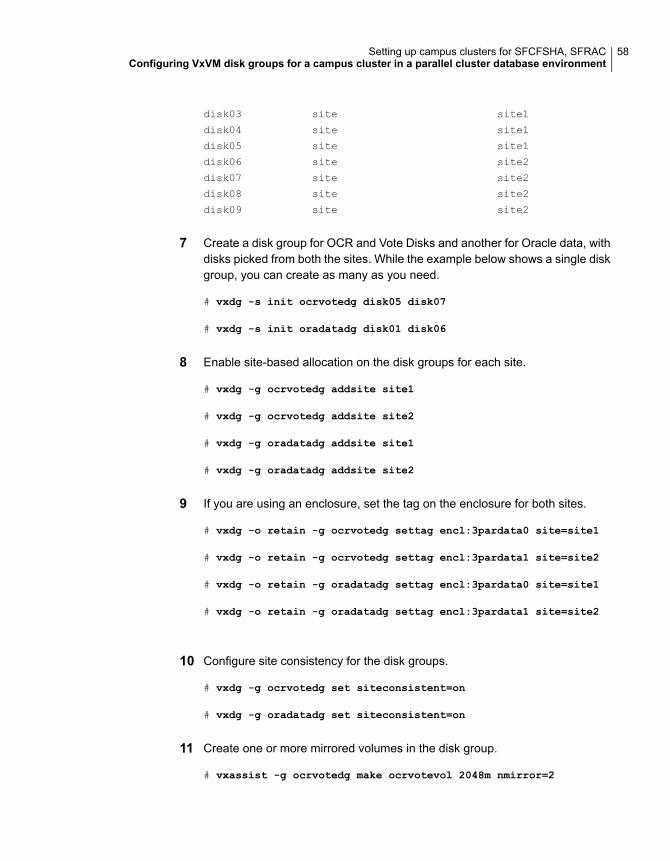
disk03 site site1
disk04 site site1
disk05 site site1
disk06 site site2
disk07 site site2
disk08 site site2
disk09 site site2
7 Create a disk group for OCR and Vote Disks and another for Oracle data, withdisks picked from both the sites. While the example below shows a single diskgroup, you can create as many as you need.
# vxdg -s init ocrvotedg disk05 disk07
# vxdg -s init oradatadg disk01 disk06
8 Enable site-based allocation on the disk groups for each site.
# vxdg -g ocrvotedg addsite site1
# vxdg -g ocrvotedg addsite site2
# vxdg -g oradatadg addsite site1
# vxdg -g oradatadg addsite site2
9 If you are using an enclosure, set the tag on the enclosure for both sites.
# vxdg -o retain -g ocrvotedg settag encl:3pardata0 site=site1
# vxdg -o retain -g ocrvotedg settag encl:3pardata1 site=site2
# vxdg -o retain -g oradatadg settag encl:3pardata0 site=site1
# vxdg -o retain -g oradatadg settag encl:3pardata1 site=site2
10 Configure site consistency for the disk groups.
# vxdg -g ocrvotedg set siteconsistent=on
# vxdg -g oradatadg set siteconsistent=on
11 Create one or more mirrored volumes in the disk group.
# vxassist -g ocrvotedg make ocrvotevol 2048m nmirror=2
58Setting up campus clusters for SFCFSHA, SFRACConfiguring VxVM disk groups for a campus cluster in a parallel cluster database environment
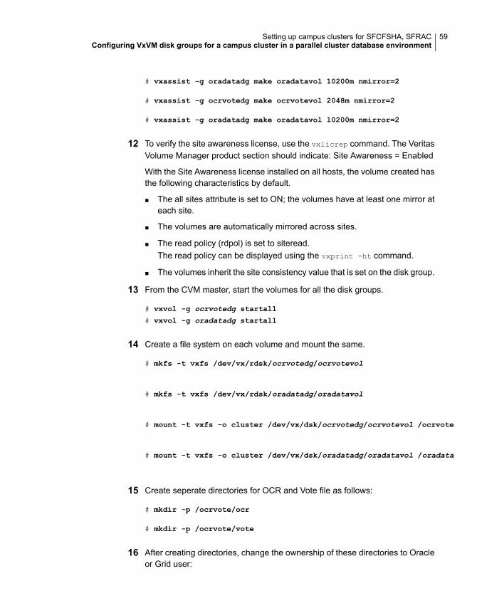
# vxassist -g oradatadg make oradatavol 10200m nmirror=2
# vxassist -g ocrvotedg make ocrvotevol 2048m nmirror=2
# vxassist -g oradatadg make oradatavol 10200m nmirror=2
12 To verify the site awareness license, use the vxlicrep command. The VeritasVolume Manager product section should indicate: Site Awareness = Enabled
With the Site Awareness license installed on all hosts, the volume created hasthe following characteristics by default.
■ The all sites attribute is set to ON; the volumes have at least one mirror ateach site.
■ The volumes are automatically mirrored across sites.
■ The read policy (rdpol) is set to siteread.The read policy can be displayed using the vxprint -ht command.
■ The volumes inherit the site consistency value that is set on the disk group.
13 From the CVM master, start the volumes for all the disk groups.
# vxvol -g ocrvotedg startall
# vxvol -g oradatadg startall
14 Create a file system on each volume and mount the same.
# mkfs -t vxfs /dev/vx/rdsk/ocrvotedg/ocrvotevol
# mkfs -t vxfs /dev/vx/rdsk/oradatadg/oradatavol
# mount -t vxfs -o cluster /dev/vx/dsk/ocrvotedg/ocrvotevol /ocrvote
# mount -t vxfs -o cluster /dev/vx/dsk/oradatadg/oradatavol /oradata
15 Create seperate directories for OCR and Vote file as follows:
# mkdir -p /ocrvote/ocr
# mkdir -p /ocrvote/vote
16 After creating directories, change the ownership of these directories to Oracleor Grid user:
59Setting up campus clusters for SFCFSHA, SFRACConfiguring VxVM disk groups for a campus cluster in a parallel cluster database environment

# chown -R user:group /ocrvote
Also change the ownership of /oradata to Oracle user:
# chown user:group /oradata
Note: One Vote Disk is sufficient since it is already mirrored by VxVM.
17 Install your database software.
For Oracle RAC:
■ Insall Oracle Clusterware/GRID
■ Install Oracle RAC binaries
■ Perform library linking of Oracle binaries
■ Create the database on /oradata. For detailed steps,See the Storage Foundation for Oracle RAC Configuration and UpgradeGuide.
Configuring VCS service groups for a campuscluster for SFCFSHA and SF Oracle RAC
Follow the procedure below to configure the disk groups under Storage Foundation(SF) for Oracle RAC control and set up the Cluster Server (VCS) attributes to defineparallel applications in campus clusters. The Cluster Volume Manager (CVM) andOracle service groups can be configured by editing the VCS configuration file, themain.cf, to define the service groups.
To configure the VCS service groups
1 Configure the disk groups under SFCFSHA or SF Oracle RAC control and setup the VCS attributes to define parallel applications in campus clusters. TheCVM and Oracle service groups can be configured by editing the VCSconfiguration file, main.cf, to define the service groups.
2 Configure the SystemZones attribute in the service group definition as explainedpreviously.
See “Configuring VCS service group for campus clusters” on page 44.
60Setting up campus clusters for SFCFSHA, SFRACConfiguring VCS service groups for a campus cluster for SFCFSHA and SF Oracle RAC
3 Group the hosts at each physical site into a single logical SystemZone. Thiswill enable the failover applications to try to come up on local nodes beforethey try to come up on a remote site.
Not all SFCFSHA or SF Oracle RAC service groups are parallel. In the sampleconfiguration file, hosts sys1 and sys2 should be configured in zone 0 andhosts sys3 and sys4 in zone 1. In the event of a failure, this setting instructsVCS to failover the group first within the same site and then across the sites.
4 After configuring your service groups and before putting your configuration intoproduction, you can verify your configuration resilience by means of testingvarious failure scenarios.
See “sfrac11_main.cf file” on page 201.
Tuning guidelines for parallel campus clustersAn important consideration while tuning a campus cluster in a Storage FoundationCluster File System High Availability (SFCFS HA) or Storage Foundation (SF) forOracle RAC environment is setting the LLT peerinact time. Follow the guidelinesbelow to determine the optimum value of peerinact time:
■ Calculate the roundtrip time using lltping (1M).
■ Evaluate LLT heartbeat time as half of the round trip time.
■ Set the LLT peer trouble time as 2-4 times the heartbeat time.
■ LLT peerinact time should be set to be more than 4 times the heart beat time.
Best practices for a parallel campus clusterThe following best practices ensure a robust Storage Foundation Cluster File SystemHigh Availability (SFCFS HA) or Storage Foundation (SF) for Oracle RAC campuscluster:
■ Tag all the mirrored volumes in the campus cluster with appropriate site names.VxVM allocates storage from the correct site when creating or resizing a volumeand when changing a volume’s layout if the volume is tagged with site name.
■ All volumes that have data required by the application must be evenly mirrored.Each site must have at least one mirror of all volumes hosting application data,including the FlashSnap log volume.In Flexible Storage Sharing (FSS) environments, if possible, use multiple mirrorsat each site since storage availability is tied to host availability due to local DASor internal disks being used. For more details on FSS, see the StorageFoundation Cluster File System Administrator's Guide.
61Setting up campus clusters for SFCFSHA, SFRACTuning guidelines for parallel campus clusters
■ Do not enable site consistency on VxVM snapshot volumes.
■ Use redundant links for storage and private interconnects. DWDM can be usedfor storage and heartbeat together. Another redundant DWDM link can be usedto prevent single point of failure. Separate switches and multiplexer /de-multiplexer devices should be used.
■ Use Coordination Point Server as the third coordination point.
■ Use the procedure for online replacement of coordination points, to replace diskbased or Coordination Point Server based coordination points.
62Setting up campus clusters for SFCFSHA, SFRACBest practices for a parallel campus cluster
Implementing replicateddata clusters
■ Chapter 5. Configuring a replicated data cluster using VVR
■ Chapter 6. Configuring a replicated data cluster using third-party replication
3Section
Configuring a replicateddata cluster using VVR
This chapter includes the following topics:
■ About setting up a replicated data cluster configuration
■ About migrating a service group
■ Fire drill in replicated data clusters
About setting up a replicated data clusterconfiguration
This topic describes the steps for planning, configuring, testing, and using the VCSRDC configuration to provide a robust and easy-to-manage disaster recoveryprotection for your applications. It describes an example of converting a singleinstance Oracle database configured for local high availability in a VCS cluster toa disaster-protected RDC infrastructure. The solution uses Volume Replicator toreplicate changed data.
About typical replicated data cluster configurationFigure 5-1 depicts a dependency chart of a typical RDC configuration.
5Chapter
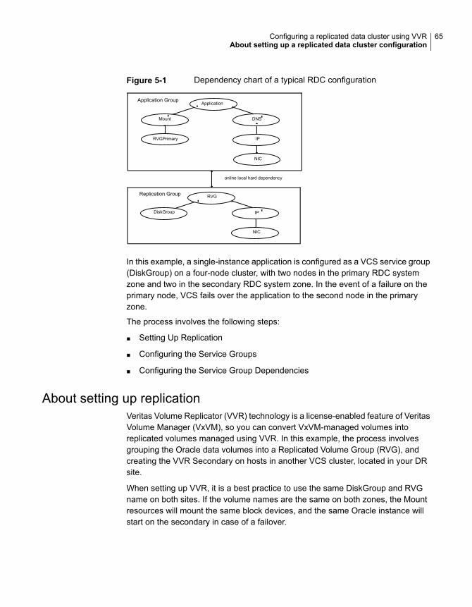
Figure 5-1 Dependency chart of a typical RDC configuration
RVGPrimary
DNS
IP
Application Group
NIC
IP
NIC
RVG
DiskGroup
Replication Group
Application
Mount
online local hard dependency
In this example, a single-instance application is configured as a VCS service group(DiskGroup) on a four-node cluster, with two nodes in the primary RDC systemzone and two in the secondary RDC system zone. In the event of a failure on theprimary node, VCS fails over the application to the second node in the primaryzone.
The process involves the following steps:
■ Setting Up Replication
■ Configuring the Service Groups
■ Configuring the Service Group Dependencies
About setting up replicationVeritas Volume Replicator (VVR) technology is a license-enabled feature of VeritasVolume Manager (VxVM), so you can convert VxVM-managed volumes intoreplicated volumes managed using VVR. In this example, the process involvesgrouping the Oracle data volumes into a Replicated Volume Group (RVG), andcreating the VVR Secondary on hosts in another VCS cluster, located in your DRsite.
When setting up VVR, it is a best practice to use the same DiskGroup and RVGname on both sites. If the volume names are the same on both zones, the Mountresources will mount the same block devices, and the same Oracle instance willstart on the secondary in case of a failover.
65Configuring a replicated data cluster using VVRAbout setting up a replicated data cluster configuration
Configuring the service groupsThis topic describes how to configure service groups.
To configure the replication group
1 Create a hybrid service group (oragrp_rep) for replication.
2 Copy the DiskGroup resource from the application to the new group. Configurethe resource to point to the disk group that contains the RVG.
3 Configure new resources of type IP and NIC.
4 Configure a new resource of type RVG in the service group.
5 Set resource dependencies as per the following information:
■ RVG resource depends on the IP resource
■ RVG resource depends on the DiskGroup resourceIP resource depends on the NIC resource
6 Set the SystemZones attribute of the child group, oragrp_rep, such that allnodes in the primary RDC zone are in system zone 0 and all nodes in thesecondary RDC zone are in system zone 1.
To configure the application service group
1 In the original Oracle service group (oragroup), delete the DiskGroup resource.
2 Add an RVGPrimary resource and configure its attributes.
Set the value of the RvgResourceName attribute to the name of the RVG typeresource that will be promoted and demoted by the RVGPrimary agent.
Set the AutoTakeover and AutoResync attributes from their defaults as desired.
3 Set resource dependencies such that all Mount resources depend on theRVGPrimary resource. If there are a lot of Mount resources, you can set theTypeDependencies attribute for the group to denote that the Mount resourcetype depends on the RVGPRimary resource type.
66Configuring a replicated data cluster using VVRAbout setting up a replicated data cluster configuration
4 Set the SystemZones attribute of the Oracle service group such that all nodesin the primary RDC zone are in system zone 0 and all nodes in the secondaryRDC zone are in zone 1. The SystemZones attribute of both the parent andthe child group must be identical.
5 If your setup uses BIND DNS, add a resource of type DNS to the oragroupservice group. Set the Hostname attribute to the canonical name of the hostor virtual IP address that the application uses on that cluster. This ensuresDNS updates to the site when the group is brought online. A DNS resourcewould be necessary only if the nodes in the primary and the secondary RDCzones are in different IP subnets.
Configuring the service group dependenciesSet an online local hard group dependency from application service group to thereplication service group to ensure that the service groups fail over and switchtogether.
1 In the Cluster Explorer configuration tree, select the cluster name.
2 In the view panel, click the Service Groups tab. This opens the service groupdependency graph.
3 Click Link.
4 Click the parent group oragroup and move the mouse toward the child group,oragroup_rep.
5 Click the child group oragroup_rep.
6 On the Link Service Groups dialog box, click the online local relationship andthe hard dependency type and click OK.
About migrating a service groupIn the RDC set up for the Oracle database, consider a case where the primary RDCzone suffers a total failure of the shared storage. In this situation, none of the nodesin the primary zone see any device.
The Oracle service group cannot fail over locally within the primary RDC zone,because the shared volumes cannot be mounted on any node. So, the servicegroup must fail over, to a node in the current secondary RDC zone.
The RVGPrimary agent ensures that VVR volumes are made writable and the DNSagent ensures that name services are resolved to the DR site. The application canbe started at the DR site and run there until the problem with the local storage iscorrected.
67Configuring a replicated data cluster using VVRAbout migrating a service group
If the storage problem is corrected, you can switch the application to the primarysite using VCS.
Switching the service groupBefore switching the application back to the original primary RDC zone, you mustresynchronize any changed data from the active DR site since the failover. Thiscan be done manually through VVR or by running a VCS action from theRVGPrimary resource.
To switch the service group
1 In the Service Groups tab of the configuration tree, right-click the resource.
2 Click Actions.
3 Specify the details of the action as follows:
■ From the Action list, choose fbsync.
■ Click the system on which to execute the action.
■ Click OK.
This begins a fast-failback of the replicated data set. You can monitor the valueof the ResourceInfo attribute for the RVG resource to determine when theresynchronization has completed.
4 Once the resynchronization completes, switch the service group to the primarycluster. In the Service Groups tab of the of the Cluster Explorer configurationtree, right-click the service group.
5 Click Switch To and select the system in the primary RDC zone to switch toand click OK.
Fire drill in replicated data clustersYou can use fire drills to test the configuration's fault readiness by mimicking afailover without stopping the application in the primary data center. To set up adisaster recovery fire drill, you have the option to create and configure the fire drillservice group manually, or using the Fire Drill Setup wizard.
See the Cluster Server Administrator's Guide.
68Configuring a replicated data cluster using VVRFire drill in replicated data clusters
Configuring a replicateddata cluster usingthird-party replication
This chapter includes the following topics:
■ About setting up a replicated data cluster configuration using third-partyreplication
■ About typical replicated data cluster configuration using third-party replication
■ About setting up third-party replication
■ Configuring the service groups for third-party replication
■ Fire drill in replicated data clusters using third-party replication
About setting up a replicated data clusterconfiguration using third-party replication
The VCS replicated data cluster (RDC) configuration provides robust and easy-tomanage disaster recovery protection for your applications. You can convert anapplication configured for local high availability in a VCS cluster to adisaster-protected RDC infrastructure. When configuring an RDC you can use asupported third-party replication technology to replicate application data.
Review the best practices and planning considerations prior to setting up an RDCusing third-party replication.
See “Planning for data replication” on page 38.
See “Planning a replicated data cluster setup” on page 37.
6Chapter
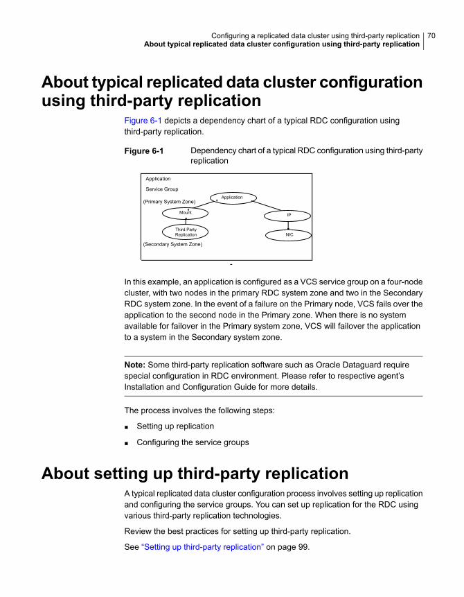
About typical replicated data cluster configurationusing third-party replication
Figure 6-1 depicts a dependency chart of a typical RDC configuration usingthird-party replication.
Figure 6-1 Dependency chart of a typical RDC configuration using third-partyreplication
Third PartyReplication
IP
Application
NIC
Application
Mount
Service Group
(Primary System Zone)
(Secondary System Zone)
In this example, an application is configured as a VCS service group on a four-nodecluster, with two nodes in the primary RDC system zone and two in the SecondaryRDC system zone. In the event of a failure on the Primary node, VCS fails over theapplication to the second node in the Primary zone. When there is no systemavailable for failover in the Primary system zone, VCS will failover the applicationto a system in the Secondary system zone.
Note: Some third-party replication software such as Oracle Dataguard requirespecial configuration in RDC environment. Please refer to respective agent’sInstallation and Configuration Guide for more details.
The process involves the following steps:
■ Setting up replication
■ Configuring the service groups
About setting up third-party replicationA typical replicated data cluster configuration process involves setting up replicationand configuring the service groups. You can set up replication for the RDC usingvarious third-party replication technologies.
Review the best practices for setting up third-party replication.
See “Setting up third-party replication” on page 99.
70Configuring a replicated data cluster using third-party replicationAbout typical replicated data cluster configuration using third-party replication
Once the replication is configured, verify that the replicated storage is visible to allthe nodes in the cluster according to the system zones.
Configuring the service groups for third-partyreplication
The original application service group will have the required application, storage,and network resources configured. You must set the SystemZones attribute of theapplication service group so that all the nodes in the Primary RDC zone are insystem zone 0 and all nodes in the Secondary RDC zone are in zone 1.
To configure the service groups for third-party replication
1 Add the replication resource to the application service group
2 Configure the replication agent resources using guidelines from the replicationagent's Installation and Configuration Guide
3 Localize the required resource attributes as per system-zone requirements.
4 Set the dependency between the storage (mount) resource and the replicationresource.
Fire drill in replicated data clusters usingthird-party replication
A fire drill procedure verifies the fault-readiness of a disaster recovery configuration.This procedure is performed without stopping the application at the Primary siteand disrupting user access.
A fire drill is performed at the Secondary site using a special service group for firedrills. The fire drill service group is identical to the application service group, butuses a fire drill resource in place of the replication agent resource. The fire drillservice group uses a copy of the data that is used by the application service group.
Almost all third-party replication agents have a corresponding fire drill agent bundledwith them. These fire drill agents are responsible for taking a snapshot inside thestorage array and importing the snapshot disks on the hosts. The fire drill agentsare named similar to the replication agents with the suffix “Snap” appended to theagent name. For example, the fire drill agent for EMC SRDF is SRDFSnap and thefire drill agent for Hitachi TrueCopy (HTC) agent is HTCSnap.
For more information about configuring fire drills, please refer the Installation andConfiguration Guide of the appropriate third-party replication agent.
71Configuring a replicated data cluster using third-party replicationConfiguring the service groups for third-party replication
Implementing globalclusters
■ Chapter 7. Configuring global clusters for VCS and SFHA
■ Chapter 8. Configuring a global cluster with Storage Foundation Cluster FileSystem High Availability, Storage Foundation for Oracle RAC, or StorageFoundation for Sybase CE
■ Chapter 9. Configuring global clusters with VVR and Storage Foundation ClusterFile System High Availability, Storage Foundation for Oracle RAC, or StorageFoundation for Sybase CE
4Section
Configuring global clustersfor VCS and SFHA
This chapter includes the following topics:
■ Installing and Configuring Cluster Server
■ Setting up VVR replication
■ Setting up third-party replication
■ Configuring clusters for global cluster setup
■ Configuring service groups for global cluster setup
■ Fire drill in global clusters
Installing and Configuring Cluster ServerTo create a global cluster environment, you must first install and configure ClusterServer (VCS) at the primary site, and then set up the application for high availabilityon both the primary and secondary sites. You can install and configure VCS usingthe script-based installer, the Web-based installer, response files, or manually.
For more information on installing and configuring VCS, see the Cluster ServerConfiguration and Upgrade Guide.
Setting up VVR replicationAfter you have configured a VCS cluster at the primary site, and have set up theapplication for high availability on both the primary and secondary sites, you mustset up data replication.
7Chapter
About configuring VVR replicationYou can configure and administer Volume Replicator (VVR) using one of thefollowing interfaces:
You can use the command line interface of VVRto configure, administer, and monitor VVR in adistributed environment.
This guide gives instructions on configuring,administering, and monitoring VVR using theVeritas product installer.
Command line interface (CLI)
This topic explains how to set up a Replicated Data Set (RDS) using thecommand-line interface. VVR enables you to set up replication either when the datavolumes are zero initialized or contain valid data. Make sure you follow the bestpractices or recommendations described to ensure successful configuration of VVR.
Detailed examples are also available on how to configure and set up a simple VVRconfiguration. Read this information before you start setting up replication.
Before setting up a Replicated Data Set, decide how you plan to lay out your VVRconfiguration.
To configure and set up replication, perform the following tasks in the orderpresented below.
See “Creating a Replicated Data Set” on page 76.
See “Synchronizing the Secondary and starting replication” on page 92.
Note: The procedure to set up replication is the same either when the applicationis running or stopped, unless noted otherwise.
Best practices for setting up replicationSet up replication according to the following best practices:
■ Create one RVG for each application, rather than for each server. For example,if a server is running three separate databases that are being replicated, createthree separate RVGs for each database. Creating three separate RVGs helpsto avoid write-order dependency between the applications and provides threeseparate SRLs for maximum performance per application.
■ Create one RVG per disk group. Creating one RVG per disk group enables youto efficiently implement application clustering for high availability, where onlyone RVG needs to be failed over by the service group. If the disk group containsmore than one RVG, the applications using the other RVGs would have to be
74Configuring global clusters for VCS and SFHASetting up VVR replication
stopped to facilitate the failover. You can use the Disk Group Split feature tomigrate application volumes to their own disk groups before associating thevolumes to the RVG.
■ Plan the size and layout of the data volumes based on the requirement of yourapplication.
■ Plan the size of the network between the Primary and each Secondary host.
■ Lay out the SRL appropriately to support the performance characteristics neededby the application. Because all writes to the data volumes in an RVG are firstwritten to the SRL, the total write performance of an RVG is bound by the totalwrite performance of the SRL. For example, dedicate separate disks to SRLsand if possible dedicate separate controllers to the SRL.
■ Size the SRL appropriately to avoid overflow.The Volume Replicator Advisor (VRAdvisor), a tool to collect and analyzesamples of data, can help you determine the optimal size of the SRL.
■ Include all the data volumes used by the application in the same RVG. This ismandatory.
■ Provide dedicated bandwidth for VVR over a separate network. The RLINKreplicates data critical to the survival of the business. Compromising the RLINKcompromises the business recovery plan.
■ Use the same names for the data volumes on the Primary and Secondary nodes.If the data volumes on the Primary and Secondary have different names, youmust map the name of the Secondary data volume to the appropriate Primarydata volume.
■ Use the same name and size for the SRLs on the Primary and Secondary nodesbecause the Secondary SRL becomes the Primary SRL when the Primary roleis transferred.
■ Mirror all data volumes and SRLs. This is optional if you use hardware-basedmirroring.
■ The vradmin utility creates corresponding RVGs on the Secondary of the samename as the Primary. If you choose to use the vxmake command to create RVGs,use the same names for corresponding RVGs on the Primary and Secondarynodes.
■ Associate a DCM to each data volume on the Primary and the Secondary if theDCMs had been removed for some reason. By default, the vradmin createpri
and vradmin addsec commands add DCMs if they do not exist.
■ In a shared disk group environment, currently only the cvm master node shouldbe assigned the logowner role. It is recommended to enable the PreOnline
75Configuring global clusters for VCS and SFHASetting up VVR replication
trigger for the RVGLogOwner agent, so that the VVR logowner always resideson the CVM master node.
■ In a shared disk group environment, currently only the cvm master node shouldbe assigned the logowner role.
■ The on-board write cache should not be used with VVR. The application mustalso store data to disk rather than maintaining it in memory. The takeover system,which could be a peer primary node in case of clustered configurations or thesecondary site, must be capable of accessing all required information. Thisrequirement precludes the use of anything inside a single system inaccessibleby the peer. NVRAM accelerator boards and other disk caching mechanismsfor performance are acceptable, but must be done on the external array andnot on the local host.
Creating a Replicated Data SetTo create a Replicated Data Set (RDS), perform the following tasks in the orderpresented below:
■ Create a Primary Replicated Volume Group (RVG) of the RDSYou can also associate volume-set component volumes to an RDS.
■ Add a Secondary to the RDS
■ Change the Replication Settings for the Secondary
In a shared disk group environment, the vradmin, vrstat, and vrnotify commandscan be issued on any node in the cluster. However, the vradmin createpri, vxibc,vxrlink (other than informational commands), and vxrvg commands must beissued from the CVM master node.
In a SAN disk group environment, the vradmin commands can be issued on thevolume server or the volume client, provided the data volumes are attached to thehost on which the commands are issued.
Creating a Primary RVG of an RDSThe first step in creating an RDS is creating its Primary RVG. VVR enables you tocreate a Primary RVG of an RDS using the vradmin createpri command.
The vradmin createpri command enables you to associate existing data volumesand the Storage Replicator Log (SRL) to the Primary RVG.
The vradmin createpri command performs the following operations:
■ Creates the Primary RVG on the host on which the command is issued.
■ Enables or starts the Primary RVG.
76Configuring global clusters for VCS and SFHASetting up VVR replication
■ Associates DCMs to the data volumes in the RVG.
■ Associates the specified data volumes and SRL to the RVG.
■ Associates the specified volume sets (if any) to the RVG.
Note: Specify the volume set name in the command, not the names of eachcomponent volume. Specifying the component volume name causes thecommand to fail.
VVR does not support RAID-5 volumes, that is, volumes with usage type raid5 arenot supported. Data volumes must be of usage type gen or fsgen. However, datavolumes can be configured on hardware-based RAID-5 disks.
Dirty Region Logs (DRLs) are not needed with VVR because VVR uses the SRLto recover volumes, not the DRLs. If any of the data volumes or the SRL has aDRL, the vradmin createpri command removes the DRL before the data volumeis associated to the RVG.
By default, the vradmin createpri command adds DCMs to the data volumes, ifthey have not already been added. The vradmin createpri command creates theDCM of an appropriate default size based on the size of the volume and mirrorsthe DCM by default. To create and add a DCM of a size that is different from thedefault, associate the DCM of the required size to the data volumes before runningthe vradmin createpri command.
Note: The vradmin createpri command will fail if there are not enough drives tomirror the DCM. You may need to associate the DCM to an appropriately sizeddata volume.
The -nodcm option when used with the vradmin createpri command associatesdata volumes to the RVG but does not add DCMs to the data volumes.
If you want to associate additional volumes to the RVG after creating the RVG, usethe vradmin addvol command.
Prerequisites for creating a Primary RVG of an RDSBefore creating a Primary RVG of an RDS, the following prerequisites must be met:
■ The data volumes and SRL must exist on the Primary. If the data volumes andSRL do not exist on the Primary, create them. To associate a volume set to theRVG, the volume set must exist on the Primary.
■ The SRL cannot be a volume set or a component volume of a volume set.
77Configuring global clusters for VCS and SFHASetting up VVR replication
■ The data volumes and SRL must be started. If the data volumes and SRL arenot started, start them. When a data volume is started, its state is active.
■ The data volumes used by the application must exist in the same RVG. Includethe data volumes used by the application in the same RVG.
■ In a SAN disk group environment, if the application resides on the volume client,all the Primary data volumes must be attached to the volume client or unattachedfrom the volume client.
■ Make sure you include the appropriate loopback address(es) in the /etc/hosts
file.
■ If your environment only uses IPv4, you must include an IPv4 loopbackaddress in the /etc/hosts file. The following is a sample entry:
127.0.0.1 localhost loopback
■ If your environment only uses IPv6, you must include an IPv6 loopbackaddress in the /etc/hosts file.
::1 localhost6.localdomain6 localhost6 loopback
■ If your environment uses both IPv4 and IPv6, the /etc/hosts file mustinclude both loopback addresses.
127.0.0.1 localhost loopback
::1 localhost6.localdomain6 localhost6 loopback
To create a Primary RVG of an RDS
Issue the following command on the host on which you want to create the PrimaryRVG:
# vradmin -g diskgroup createpri rvgname \
dv01_name,dv02_name... srl_name
The argument rvgname is the name of the RVG to be created.
The argument dv01_name,dv02_name,... is a comma-separated list of the namesof the data volumes to be associated to the RVG. Each item can be an independentdata volume name, or the name of a volume set. To associate a volume set to theRVG, specify the name of the volume set, not the names of the individual componentvolumes.
78Configuring global clusters for VCS and SFHASetting up VVR replication
Note: In previous releases, component volumes could be associated directly to anRVG. Beginning in Release 5.0, the volume set itself is associated to the RVG,enabling VVR to verify consistency between the volume sets on the Primary andthe Secondary RVGs. The vradmin createpri command fails if a componentvolume of the volume set and the volume set itself are each specified for an RVG.
The argument srl_name is the name of the SRL to be associated to the RVG.
Use -nodcm option if you do not want DCMs to be added to the data volumes. Bydefault, DCMs are added automatically.
Example - Creating a Primary RVG containing a data volumeThis example shows how to create a Primary RVG hr_rvg in the disk group hrdg,which contains the data volumes hr_dv01 and hr_dv02, and the volume hr_srl
that is to be used as the SRL. This example automatically adds DCMs to the datavolumes.
# vradmin -g hrdg createpri hr_rvg hr_dv01,hr_dv02 hr_srl
Example - Creating a Primary RVG containing a volume setThis example shows how to create a Primary RVG hr_rvg in the disk group hrdg,which contains the volume set hr_vset, the data volumes hr_dv01 and hr_dv02,and the volume hr_srl that is to be used as the SRL.
# vradmin -g hrdg createpri hr_rvg hr_dv01,hr_dv02,hr_vset \
hr_srl
If the volume set includes the component volumes hr_vsetdv01 and hr_vsetdv02,these volumes are associated to the RVG hr_rvg. This example automatically addsDCMs to the data volumes, including the component volumes hr_vsetdv01 andhr_vsetdv02.
Adding a Secondary to an RDSAfter creating the Primary RVG of the RDS, go on to adding a Secondary. Use thevradmin addsec command to add a Secondary RVG to an RDS. This commandcan also be used to add additional Secondary RVGs. The vradmin addsec
command can be issued from any host that is already in the RDS.
Note: Run the vradmin addsec from the Primary node. If you run this commandfrom the node being added as the Secondary, the command fails.
79Configuring global clusters for VCS and SFHASetting up VVR replication

The vradmin addsec command performs the following operations by default:
■ Creates and adds a Secondary RVG of the same name as the Primary RVG tothe specified RDS on the Secondary host. By default, the Secondary RVG isadded to the disk group with the same name as the Primary disk group. Usethe option -sdg with the vradmin addsec command to specify a different diskgroup on the Secondary.
■ If any of the data volumes or the SRL on the Secondary has a DRL, the DRL isremoved before the data volume is associated to the RVG. DRLs are not neededwith VVR because VVR uses the SRL to recover volumes, not the DRLs.
■ Automatically adds DCMs to the Primary and Secondary data volumes if theydo not have DCMs. Use the -nodcm option to specify that DCMs are not to beadded to the data volumes.The vradmin addsec command creates the DCM of an appropriate default sizebased on the size of the volume and mirrors the DCM by default. To create andadd a DCM of a size that is different from the default, associate the DCM of therequired size to the data volumes before running the vradmin addsec command.
■ Associates to the Secondary RVG, existing data volumes of the same namesand sizes as the Primary data volumes; it also associates an existing volumewith the same name as the Primary SRL, as the Secondary SRL.
■ If the Primary RVG includes a volume set, the vradmin addsec commandassociates the corresponding volume set to the Secondary, if the volume setexists on the Secondary. The volume set on the Secondary must include volumesof the same name, lengths and indices as the component volumes on thePrimary. If the volume set exists on the Secondary and the volume setconfiguration is correct except that it does not include all of the componentvolumes corresponding to those in the volume set on the Primary, the vradmin
addsec command attempts to add the remaining component volumes to thevolume set on the Secondary and then associate the volume set to the SecondaryRVG. This command succeeds if all of the remaining component volumes existon the Secondary with the same names, lengths, and indices as the componentvolumes on the Primary. However, if any of the component volumes do not existon the Secondary or have a mismatched name, length, or index, the vradmin
addsec command fails with the appropriate error message.If the volume set does not exist on the Secondary, but the component volumesexist with the same names, lengths, and indices, the vradmin addsec commandcreates the volume set on the Secondary and then associates it to the SecondaryRVG.
■ Creates and associates to the Primary and Secondary RVGs respectively, thePrimary and Secondary RLINKs with default RLINK namesrlk_remotehost_rvgname. If you choose to use names other than the default,
80Configuring global clusters for VCS and SFHASetting up VVR replication
use the prlink and srlink attributes of the vradmin addsec command tospecify the Primary and Secondary RLINK names.See “Example - Creating a Primary RVG containing a volume set” on page 79.
Note: For replication in asynchronous mode with secondary logging, the SRL sizeon both the Primary and Secondary must be the same.
Best practices for adding a Secondary to an RDSWhen you add a Secondary to an RDS, we recommend the following best practices:
■ Determine the network and IP addresses to use. Add all participating systemnames and IP addresses to the /etc/hosts files on each system or to the nameserver database of your name service. Make sure the IP addresses are available(that is, plumbed and up) on the appropriate hosts for your configuration.
■ Plan ahead for application clustering by configuring the IP addresses used forreplication as virtual IP addresses. For each replicated data set, the Primaryand the Secondary cluster should each have one unique virtual IP address touse as the address for the RLINK. If you do this, you can place VVR undercluster control without having to modify the IP address of the RLINK later.Changing the IP address of an RLINK requires pausing replication.
■ Plan the bandwidth of the network based on your requirement. You can chooseto use either the UDP protocol or TCP protocol for network communicationbetween the Primary and Secondary. Also, plan to operate in a firewallenvironment.
■ We recommend that you use the following naming conventions for RLINKs. Bydefault, VVR follows the following naming conventions for RLINKs:Primary RLINK: rlk_remotehost_rvgname. For example:rlk_london_hr_rvg
Secondary RLINK: rlk_remotehost_rvgname. For example:rlk_seattle_hr_rvg
■ If you have multiple secondaries in your RDS setup, VVR automatically createsRLINKs between ever pair of secondaries. By doing this, the additionalsecondaries will be automatically added to the RDS after the migrate operationhas completed successfully.
■ Associate a DCM to each data volume on the Primary and the Secondary touse the SRL Protection and Failback Logging features.
Prerequisites for adding a Secondary to an RDSOn the Secondary to be added, do the following:
81Configuring global clusters for VCS and SFHASetting up VVR replication
■ Create a disk group with the same name as the Primary disk group.
■ Create data volumes of the same names and lengths as the Primary datavolumes.
■ Create an SRL of the same name as the Primary SRL. Note that the SRL cannotbe a volume set or a component volume of a volume set.
■ If the Primary RVG includes a volume set, make sure that the componentvolumes on the Secondary to be added have identical names, lengths, andindices as the component volumes on the Primary.
■ Make sure the /etc/vx/vras/.rdg file on the Secondary host to be added tothe RDS contains the Primary disk group ID. Ensure that each disk group IDentry in the .rdg file is on a separate line.Refer to the .rdg file for the sample format for the disk group ID entry.The vradmin addsec command checks whether the Primary RVG is authorizedto create a corresponding Secondary RVG on the specified Secondary host. APrimary is determined as authorized if the /etc/vx/vras/.rdg file on thespecified Secondary host contains the Primary disk group ID. If the Primarycontains multiple RVGs in the same disk group, only one entry is required. Aplus (+) sign in the /etc/vx/vras/.rdg file on the Secondary host indicatesthat all Primary RVGs on all hosts are authorized to create a Secondary RVGon the specified Secondary host.The /etc/vx/vras/.rdg file on the Secondary host is only used for authorizationchecking when a Secondary is added, or when remote data volumes aresynchronized or verified. To perform these operations after a Secondary takesover from the Primary, the original Primary host should also have an/etc/vx/vras/.rdg file containing the disk group ID for the new Primary host.To display the Primary disk group ID, issue the following command on thePrimary host:
# vxprint -l diskgroup
For example, to enable host seattle to create an RVG on Secondary hostlondon the .rdg file on the host london must have the following entries, eachon a new line.1083007373.10.seattle
■ In a SAN disk group environment, if the application resides on the volume client,the Secondary data volumes must be attached to the corresponding volumeclient on the Secondary.
■ In a SAN disk group environment, if the application resides on the volume client,the Primary volume server must have network connection to the Secondaryvolume server and Secondary volume client.
82Configuring global clusters for VCS and SFHASetting up VVR replication
■ In a SAN disk group environment, if the application resides on the volume client,the hostname or IP address for the Secondary must be available on the volumeclient on the Secondary.
■ In a SAN disk group environment, if the application resides on the volume server,the hostname or IP address for the Secondary must be available on the volumeserver on the Secondary.
To add a Secondary to an RDS
# vradmin -g local_diskgroup addsec local_rvgname pri_hostname \
sec_hostname
The argument local_diskgroup is the name of the disk group on the local host.
The argument local_rvgname is the name of the RVG on the local host.
The arguments pri_hostname and sec_hostname are either resolvable hostnamesor IP addresses for the Primary and the Secondary hosts. These names are usedas local_host and remote_host attributes while creating RLINKs. The local_host
and remote_host specify the network connection to use for the Primary andSecondary RLINKs.
Use the -nodcm option if you do not want to add DCMs to the data volumes. Bydefault, DCMs are automatically added unless the -nodcm option is specified.
Note: By default, SRL protection on the new Primary and Secondary RLINKs is setto autodcm. If you specify the -nodcm option, the vradmin addsec command disablesSRL protection.
Note that the Secondary RVG is added to the disk group with the same name asthe Primary disk group, unless specified otherwise using the -sdg option.
Example 1:
This example shows how to add a Secondary host london_priv to the RDS, whichcontains the RVG hr_rvg. For replication, this example uses a private network withthe Primary hostname seattle_priv, Secondary hostname london_priv. On theSecondary, the RVG is added to the same disk group as the Primary, that is, hrdg.This example automatically adds DCMs to the data volumes.
# vradmin -g hrdg addsec hr_rvg seattle_priv london_priv
Example 2:
This example shows how to add the Secondary host london_priv to the RDS,which contains the RVG hr_rvg. It creates the Secondary with the specific Primary
83Configuring global clusters for VCS and SFHASetting up VVR replication
and Secondary RLINK names to_london and to_seattle. The RLINK connectsthe Primary host seattle_priv and the Secondary host london_priv. On theSecondary, the RVG is added to the same disk group as the Primary, that is, hrdg.
# vradmin -g hrdg addsec hr_rvg seattle_priv london_priv \
prlink=to_london srlink=to_seattle
Example 3:
This example shows how to add a Secondary host london-v6_priv to the RDS,which contains the RVG hr_rvg. For replication, this example uses a private IPv6network with the Primary hostname seattle-v6_priv, Secondary hostnamelondon-v6_priv. Both hostnames london-v6_priv and seattle-v6_priv resolveto IPv6 addresses belonging to the private IPv6 network. On the Secondary, theRVG is added to the same disk group as the Primary, that is, hrdg. This exampleautomatically adds DCMs to the data volumes.
# vradmin -g hrdg addsec hr_rvg seattle-v6_priv london-v6_priv
Example 4:
This example shows how to add a Secondary host london-v6 to the RDS, whichcontains the RVG hr_rvg. It creates the Secondary with the specific Primary andSecondary RLINK names to_london-v6 and to_seattle-v6. The RLINK connectsthe Primary host seattle-v6 and the Secondary host london-v6, which resolveto IPv6 addresses aaaa:bbbb:cccc:dddd:eeee:ffff:gggg:hhhh and
pppp:qqqq:rrrr:ssss:wwww:xxxx:yyyy:zzzz respectively. On the Secondary,the RVG is added to the same disk group as the Primary, that is, hrdg. This examplealso automatically adds DCMs to the data volumes.
# vradmin -g hrdg addsec hr_rvg aaaa:bbbb:cccc:dddd:eeee:ffff:gggg:hhhh \
pppp:qqqq:rrrr:ssss:wwww:xxxx:yyyy:zzzz prlink=to_london-v6 \
srlink=to_seattle-v6
Changing the replication settings for a SecondaryWhen you add a Secondary to an RDS, the default replication attributes of theSecondary are set to synchronous=off, latencyprot=off, srlprot=autodcm,packet_size=8400 and bandwidth_limit=none.
To display the default replication settings for the Secondary, use the following formof the vxprint command:
vxprint -g diskgroup -Pl
84Configuring global clusters for VCS and SFHASetting up VVR replication
If you are using the UDP protocol, this form of the vxprint command also showsthe default packet size.
You can set up the replication mode, latency protection, SRL protection, transportprotocol, packet size, and the bandwidth used by VVR using the replication attributes,such as synchronous, latencyprot, and srlprot. These attributes are of the formattribute=value. Each attribute setting could affect replication and must be setup with care.
The vradmin set command enables you to change the replication settings betweenthe Primary and a Secondary. This command can be issued from any host in theRDS. It enables you to perform the following tasks:
■ See “Setting the mode of replication for a Secondary” on page 85.
■ See “Setting the latency protection for a Secondary” on page 86.
■ See “Setting the SRL overflow protection for a Secondary” on page 88.
■ See “Setting the network transport protocol for a Secondary” on page 89.
■ See “Setting the packet size for a Secondary” on page 89.
■ See “Setting the bandwidth limit for a Secondary” on page 90.
The vradmin set command changes the corresponding attributes on both thePrimary and Secondary RLINK. The attributes synchronous, latencyprot, andsrlprot are only active on the Primary RLINK; however, the Secondary attributesare already set up and ready for use if the Primary role is transferred to theSecondary.
Setting the mode of replication for a SecondaryYou can set up VVR to replicate to a Secondary in synchronous or asynchronousmode by setting the synchronous attribute of the RLINK to override, or offrespectively.
Setting the synchronous attribute to override puts the RLINK in synchronousmode. During normal operation, VVR replicates in synchronous mode, but if theRLINK becomes inactive due to a disconnection or administrative action, VVRswitches temporarily to asynchronous mode and continues to receive updates fromthe application and store them in the SRL. After the connection is restored and theSRL is completely drained, the RLINK automatically switches back to synchronousmode. Most system administrators set the synchronous attribute to override.
The vradmin command does not allow you to set the synchronous attribute to fail.Use the vxedit command to set the attribute synchronous=fail. For moreinformation on using the vxedit command, refer to the vxedit manual page.
85Configuring global clusters for VCS and SFHASetting up VVR replication
Caution: if you use the synchronous=fail mode.
To enable asynchronous mode of replication
To set the replication to asynchronous mode, set the synchronous attribute to off.
# vradmin -g diskgroup set local_rvgname sec_hostname
synchronous=off
The argument local_rvgname is the name of the RVG on the local host andrepresents its RDS.
The argument sec_hostname is the name of the Secondary host displayed in theoutput of the vradmin printrvg command. If the RDS contains only one Secondary,the argument sec_hostname is optional.
Example - Setting themode of replication to asynchronous for an RDSTo set the mode of replication to asynchronous for the RDS hr_rvg between thePrimary seattle and the Secondary london, issue the following command on anyhost in the RDS:
# vradmin -g hrdg set hr_rvg london synchronous=off
To enable synchronous mode of replication
To set the synchronous attribute of the RLINK to override, use the followingcommand:
# vradmin -g diskgroup set local_rvgname sec_hostname \
synchronous=override
Example - Setting the mode of replication to synchronous for an RDSTo set the mode of replication to synchronous for the RDS hr_rvg between thePrimary seattle and the Secondary london, issue the following command on anyhost in the RDS:
# vradmin -g hrdg set hr_rvg london synchronous=override
Setting the latency protection for a SecondaryThe vradmin set command enables you to set the latencyprot attribute tooverride, fail, or off; it also enables you to specify a latency_high_mark anda latency_low_mark, which indicate when the protection becomes active or inactive.
Set the latencyprot attribute to enable latency protection between a Primary anda Secondary.
86Configuring global clusters for VCS and SFHASetting up VVR replication
Note: Before enabling latency protection, be sure you understand how latencyprotection works when the Primary and Secondary are connected or disconnected.
To enable latency protection
1 Set the latencyprot attribute of the corresponding RLINKs on the Primaryand Secondary.
To set the latencyprot attribute to override:
# vradmin -g diskgroup set local_rvgname sec_hostname \
latencyprot=override
To set the latencyprot attribute to fail:
# vradmin -g diskgroup set local_rvgname sec_hostname \
latencyprot=fail
2 Set the latency_high_mark and the latency_low_mark attributes:
# vradmin -g diskgroup set local_rvgname sec_hostname \
latency_high_mark=high_mark
# vradmin -g diskgroup set local_rvgname sec_hostname \
latency_low_mark=low_mark
The argument local_rvgname is the name of the RVG on the local host andrepresents the RDS.
The argument sec_hostname is the name of the Secondary host as displayedin the output of the vradmin printrvg command.
Note that the value of latency_high_mark must be greater than the value oflatency_low_mark. We recommend that the difference between the value oflatency_high_mark and the value of latency_low_mark be a small number,for example, 50.
To disable latency protection
◆ Setting the latencyprot attribute to off disables latency protection. This doesnot limit the number of waiting updates in the SRL.
To set the latencyprot attribute to off:
# vradmin -g diskgroup set local_rvgname sec_hostname
latencyprot=off
87Configuring global clusters for VCS and SFHASetting up VVR replication
The argument local_rvgname is the name of the RVG on the local host andrepresents the RDS.
The argument sec_hostname is the name of the Secondary host as displayed inthe output of the vradmin printrvg command.
Setting the SRL overflow protection for a SecondaryVVR provides the following modes of SRL overflow protection: autodcm, dcm,override, fail, and off.
To enable SRL overflow protection
◆ Set the srlprot attribute of the corresponding RLINK to either autodcm, dcm,override, or fail.
■ To set the srlprot attribute to autodcm, use the following command:
# vradmin -g diskgroup set local_rvgname sec_hostname \
srlprot=autodcm
■ To set the srlprot attribute to dcm, use the following command:
# vradmin -g diskgroup set local_rvgname sec_hostname \
srlprot=dcm
■ To set the srlprot attribute to override, use the following command:
# vradmin -g diskgroup set local_rvgname sec_hostname \
srlprot=override
■ To set the srlprot attribute to fail, use the following command:
# vradmin -g diskgroup set local_rvgname sec_hostname \
srlprot=fail
■ To set the srlprot attribute to off, use the following command:
# vradmin -g diskgroup set local_rvgname sec_hostname \
srlprot=off
The argument local_rvgname is the name of the RVG on the local host andrepresents the RDS.
The argument sec_hostname is the name of the Secondary host as displayedin the output of the vradmin printrvg command.
88Configuring global clusters for VCS and SFHASetting up VVR replication
Setting the network transport protocol for a SecondaryThe value specified for the protocol attribute determines the protocol that will beused to communicate between the hosts. You can specify one of the followingvalues for the protocol attribute.
■ UDP—The hosts communicate using the UDP/IP protocol.VVR automatically calculates the checksum for each data packet it replicates.
■ TCP—The hosts communicate using the TCP/IP protocol, which is the default.If a protocol is not specified, then TCP is used as the protocol of communicationbetween hosts.If you specify TCP, the VVR checksum is automatically disabled. VVR relies onthe TCP checksum mechanism instead. Also, if a node in a replicated data setis using a version of VVR earlier than 5.1 SP1, VVR calculates the checksumregardless of the network protocol.
■ STORAGE—Used for bunker replication. The Primary host and the bunker SRLcommunicate using STORAGE protocol. If the storage is directly accessible bythe Primary, for example, DAS or NAS, set the protocol to STORAGE. If thebunker is replicating over IP, the protocol can be set to UDP or TCP.
Note: UDP, TCP, and STORAGE are case sensitive.
To set the network protocol
◆ To set the protocol for RDSs in disk group of version 110 or above, the followingvradmin command can be used:
# vradmin -g diskgroup set local_rvgname sec_hostname \
protocol=protocol_name
The argument protocol_name is the name of the protocol that the Primary willuse to replicate to the Secondary. The protocol can be set to either TCP orUDP.
Setting the packet size for a SecondaryThe packet size determines the number of bytes in a packet that are sent to theSecondary host. The packet size can be changed using the packet_size attributefor UDP mode only. If the protocol is set to TCP, the data is sent using the TCPstream.
for more information on the packet_size attribute.
89Configuring global clusters for VCS and SFHASetting up VVR replication
To set the packet size
◆ # vradmin -g diskgroup set local_rvgname
sec_hostname \
packet_size=n
The argument local_rvgname is the name of the RVG on the local host andrepresents the RDS.
The argument sec_hostname is the name of the Secondary host as displayedin the output of the vradmin printrvg command.
The argument n represents the packet size in bytes.
The minimum value for the packet_size is 1300 bytes.
The maximum value of the packet_size is 65464 bytes.
Example - Setting the packet size between the Primary and SecondaryTo set the packet size between the Primary host seattle and the Secondary hostlondon to 1400 bytes, issue the following command on any host in the RDS:
# vradmin -g hrdg set hr_rvg london packet_size=1400
Setting the bandwidth limit for a SecondaryUse the bandwidth_limit attribute of the vradmin set command to set the limiton the network bandwidth used to replicate from the Primary to the Secondary. Ifbandwidth_limit is set to none, then VVR uses the available network bandwidth.The default value is none. To limit the network bandwidth used by VVR whensynchronizing volumes that are not part of an RDS, use the bandwidth_limit
attribute of the vradmin syncvol command.
To control the network bandwidth used for replication
◆ To limit the bandwidth used for replication between the Primary and aSecondary in an RDS, issue the following command on any host in the RDS.In the command, you can either use the units of bandwidth kbps, mbps, or gbps,or abbreviate the units of bandwidth to k, m, g, respectively. The default unit ofbandwidth is bits per second (bps).
# vradmin -g diskgroup set local_rvgname sec_hostname \
bandwidth_limit=value
The argument local_rvgname is the name of the RVG on the local host andrepresents the RDS.
90Configuring global clusters for VCS and SFHASetting up VVR replication
The argument sec_hostname is the name of the Secondary host as displayed inthe output of the vradmin printrvg command.
Example: Limiting network bandwidth between the Primary and theSecondaryTo limit the bandwidth to 30 mbps for the RDS hr_rvg between the Primary seattleand the Secondary london, issue the following command on any host in the RDS:
# vradmin -g hrdg set hr_rvg london bandwidth_limit=30mbps
To disable Bandwidth Throttling for a Secondary
◆ To disable Bandwidth Throttling for a Secondary in an RDS, issue the followingcommand on any host in the RDS:
# vradmin -g diskgroup set local_rvgname sec_hostname \
bandwidth_limit=none
The argument local_rvgname is the name of the RVG on the local host andrepresents the RDS.
The argument sec_hostname is the name of the Secondary host as displayed inthe output of the vradmin printrvg command.
Example: Disabling Bandwidth Throttling between the Primary andthe SecondaryTo disable Bandwidth Throttling for replication between the Primary seattle andthe Secondary london of RDS hr_rvg, issue the following command on any hostin the RDS:
# vradmin -g hrdg set hr_rvg london bandwidth_limit=none
To control the network bandwidth used to synchronize volumes
◆ To limit the network bandwidth used by VVR when synchronizing volumes thatare not part of an RDS, issue the following command:
# vradmin -g diskgroup syncvol local_vols_list \
remote_hostname.... bandwidth_limit=value
The argument local_vols_list is a comma-separated list of volumes on the localhost. The names of the volumes on the local and remote hosts are assumed to bethe same.
91Configuring global clusters for VCS and SFHASetting up VVR replication
The argument remote_hostname is a space-separated list of names of the remotehosts on which the volumes to be resynchronized reside. It must be possible for IPto resolve the remote host names.
Example: Limiting network bandwidth used by VVR when using fullsynchronizationThis example shows how to limit the network bandwidth used by VVR when usingfull synchronization to synchronize the remote volumes on host london with thelocal volumes hr_dv01, hr_dv02, hr_dv03 in the disk group hrdg on the local hostseattle. The names of the disk group and the volumes on the remote host are thesame as the names of the disk group and volumes on the local host.
# vradmin -g hrdg -full syncvol hr_dv01,hr_dv02,hr_dv03 london \
bandwidth_limit=10mbps
Synchronizing the Secondary and starting replicationThis section explains how to synchronize the Secondary and start replication.
Methods to synchronize the SecondaryYou can synchronize the Secondary using the network, using block-level tapebackup or by physically moving disks to the Secondary. Automatic synchronizationis the recommended method to synchronize the Secondary. Use one of the followingmethods to synchronize the Secondary depending on your environment:
■ Using the network
■ Automatic synchronization
■ Full synchronization with Storage Checkpoint
■ Difference-based synchronization with Storage Checkpoint
■ Using block-level tape backup
■ Block-level tape backup and checkpointing
■ Moving disks physically
■ Disk Group Split and Join
The following tables explain when and how to use the different synchronizationmethods:
Using the network to synchronize the SecondaryYou can synchronize the Secondary over the network either when the applicationis active or inactive. SmartMove is supported with each of these methods.
92Configuring global clusters for VCS and SFHASetting up VVR replication
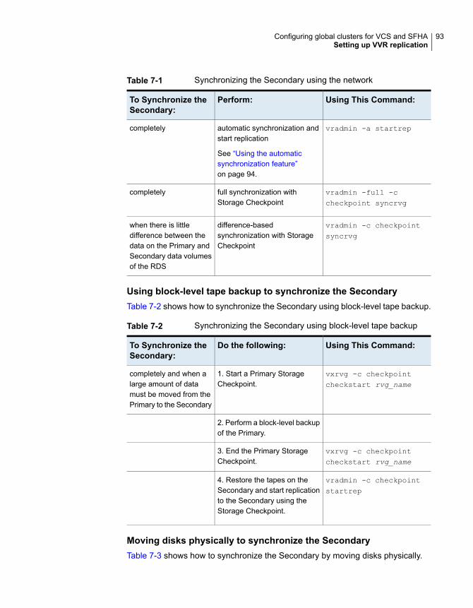
Table 7-1 Synchronizing the Secondary using the network
Using This Command:Perform:To Synchronize theSecondary:
vradmin -a startrepautomatic synchronization andstart replication
See “Using the automaticsynchronization feature”on page 94.
completely
vradmin -full -ccheckpoint syncrvg
full synchronization withStorage Checkpoint
completely
vradmin -c checkpointsyncrvg
difference-basedsynchronization with StorageCheckpoint
when there is littledifference between thedata on the Primary andSecondary data volumesof the RDS
Using block-level tape backup to synchronize the SecondaryTable 7-2 shows how to synchronize the Secondary using block-level tape backup.
Table 7-2 Synchronizing the Secondary using block-level tape backup
Using This Command:Do the following:To Synchronize theSecondary:
vxrvg -c checkpointcheckstart rvg_name
1. Start a Primary StorageCheckpoint.
completely and when alarge amount of datamust be moved from thePrimary to the Secondary
2. Perform a block-level backupof the Primary.
vxrvg -c checkpointcheckstart rvg_name
3. End the Primary StorageCheckpoint.
vradmin -c checkpointstartrep
4. Restore the tapes on theSecondary and start replicationto the Secondary using theStorage Checkpoint.
Moving disks physically to synchronize the SecondaryTable 7-3 shows how to synchronize the Secondary by moving disks physically.
93Configuring global clusters for VCS and SFHASetting up VVR replication
Table 7-3 Synchronizing the Secondary by moving disks physically
Using This Command:Use This FeatureTo Synchronize theSecondary:
Disk Group Split and Joincompletely by physicallymoving disks from thelocation of the Primaryhost to the location ofSecondary host
Using the automatic synchronization featureThe Automatic Synchronization feature enables you to transfer the data on thePrimary to the Secondary over the network. You can synchronize the Secondaryusing automatic synchronization either when the application is active or inactive.
The Automatic Synchronization procedure transfers data in the Primary data volumesto the Secondary by reading the Primary data volumes from start to finish andsending the data to the Secondary.
Note: Automatic Synchronization does not maintain the order of writes; therefore,the Secondary is inconsistent until the process is complete.
The Secondary becomes consistent after the automatic synchronization completes.To use Automatic Synchronization successfully, the network must be sizedappropriately. Note that the synchronization will complete only if the Primary receiveswrites at a lesser rate than they can be sent to the Secondary. If the Primary receiveswrites at a faster rate than they can be sent to the Secondary, the synchronizationmight never complete, especially if the writes are dispersed widely in the volume.
This feature enables you to synchronize multiple Secondary hosts at the same time.When performing automatic synchronization to multiple Secondary hosts,synchronization proceeds at the rate of the slowest network.
VVR pauses synchronization if the Secondary fails or the network disconnects. Ifthe Primary fails while synchronization is in progress, the synchronization continuesfrom the point at which it had stopped when the Primary recovers.
Prerequisite for using Automatic Synchronization
■ Each data volume in the Primary RVG must have a DCM associated to it. If datavolumes do not have DCMs, an attempt to automatically synchronize aSecondary fails.
The vradmin startrep command when used with the option -a enables you tostart replication and automatically synchronize the Secondary data volumes with
94Configuring global clusters for VCS and SFHASetting up VVR replication
the Primary data volumes in an RDS; it brings the Secondary data volumesup-to-date with the Primary data volumes. You can use this command to synchronizethe Secondary when the data volumes contain data and when the application isactive or inactive. Replication to another Secondary can be started only after thisautomatic synchronization completes.
The vradmin startrep command can be issued from any host in the RDS. Tocheck the status and progress of the automatic synchronization, use the vxrlink
status command on the Primary RLINK.
To synchronize the Secondary and start replication using automatic synchronization,issue the following command:
# vradmin -g diskgroup -a startrep local_rvgname sec_hostname
The argument local_rvgname is the name of the RVG on the local host andrepresents its RDS.
The argument sec_hostname is the name of the Secondary host displayed in theoutput of the vradmin printrvg command. If the RDS contains only one Secondary,the sec_hostname is optional.
Example—Using the Automatic Synchronization Feature
In this example, the data volumes in the Primary RVG hr_rvg on host seattlecontain valid data and the application is active. To start replication and synchronizethe Secondary RVG hr_rvg on host london, issue the following command:
# vradmin -g hrdg -a startrep hr_rvg london
Notes on using automatic synchronizationObserve the following notes about using automatic synchronization:
■ If you associate a new volume to an RDS while automatic synchronization is inprogress, VVR does not automatically synchronize the newly associated datavolume.
■ In an RDS containing multiple Secondaries that have SRL overflow protectionset to dcm, more than one Secondary may require the use of the DCM. If oneSecondary is undergoing automatic synchronization and the RLINK of anotherSecondary is about to overflow, the Automatic Synchronization is abandonedand the DCM becomes active for the overflowing RLINK.
■ If you try to automatically synchronize a new RLINK while an existing RLINK isusing the DCM mechanism, the automatic synchronization fails.
■ To remove a Secondary from a DCM resynchronization process, detach thecorresponding Primary RLINK.
95Configuring global clusters for VCS and SFHASetting up VVR replication
■ If you try to dissociate a DCM from a data volume while the DCM is in use, theoperation fails.
■ If the DCM is detached because of I/O errors while the DCM is in use, theresynchronization is abandoned and the RLINKs that are being synchronizedare detached.
■ You can use automatic synchronization with SmartMove. This combination letsdeploy your disaster recovery site must faster because you are replicating farless data.See “About SmartMove for VVR” on page 96.
Example for setting up replication using automaticsynchronizationThis example assumes that the RDS has been created using the example procedure.
You can synchronize the Secondary using automatic synchronization when theapplication is active or inactive.
To setup replication using automatic synchronization
◆ Start Secondary synchronization and replication using automatic synchronizationby issuing the following command from any host in the RDS:
# vradmin -g hrdg -a startrep hr_rvg london
About SmartMove for VVRThe SmartMove for VVR feature enables VVR to leverage information from VxFSknowledge of the file system blocks in use to optimize the time and networkbandwidth required for initial synchronization of replicated volumes. This feature isavailable if there is a VxFS file system mounted on top of the volume that is beingsynchronized.
If you use SmartMove with automatic synchronization, you can deploy the disasterrecovery site faster because you are replicating far less data than the storageprovisioned on the system. To use automatic synchronization with SmartMove ina cluster volume replication (CVR) environment, the file system must be mountedon the logowner.
The default behavior is to use the SmartMove for VVR feature for initialsynchronization. The commands that use SmartMove during initial synchronizationare vradmin syncrvg/syncvol/startrep and vxrlink -a att.
96Configuring global clusters for VCS and SFHASetting up VVR replication
To turn off SmartMove
◆ Enter:
# vxtune usefssmartmove none
The vradmin verifydata command has also been enhanced to leverage VxFSknowledge of file system blocks in use for verification.
About thin storage reclamation and VVRThin storage helps you optimize your array capacity by allocating storage toapplications only when it is needed. When files are created and written to in the filesystem, storage is allocated from a free storage pool on the array.
However, when you delete files on the host, the storage is not automatically returnedto the pool. The result is large amounts of allocated storage on the array that isnow unused. You must reclaim this storage manually.
See “Determining if a thin reclamation array needs reclamation” on page 98.
In a VVR environment, you can reclaim storage on volumes configured under anRVG. You can reclaim storage at the disk, disk group, or file system level.
Thin storage reclamation is only supported for LUNs that have the thinrclm
attribute. VxVM automatically discovers LUNs that support thin reclamation fromthin-capable storage arrays. On the host, you can list devices that have the thinonly
or thinrclm attributes.
Thin storage reclamation is not supported on volumes in an RVG that has full instantor space-optimized snapshots that are associated to it. The reclaim command maycomplete without an error, but the storage space is not reclaimed. Thin storagereclamation is not supported as reclamation on the volume triggers a data transferfrom the primary volume to the snapshot volume. Moving this data to the snapshotvolume triggers storage allocation at the backend. If there are multiple snapshots,copies of the same data are maintained, which requires more storage than reclaimed.In the case of space-optimized snapshots, the cache object size increases as itcopies all the reclaimable data to the space-optimized snapshot.
If you have used Storage Foundation thin storage reclamation in another context,the commands are identical when you use it in a VVR environment.
When you use thin reclamation with VVR, keep in mind the following:
■ The VxFS file system must be mounted on the Primary site before you canperform thin reclamation on the volume.
97Configuring global clusters for VCS and SFHASetting up VVR replication
■ When you reclaim storage on the Primary site, it is automatically reclaimed onthe Secondary site - unless the Primary site is in DCM mode or when autosyncis running. The Primary site goes into DCM mode when its SRL overflows.
■ You can reclaim storage on the Primary and Secondary sites even if the sitesuse different types of arrays. The arrays can have different fixed size physicalstorage allocation units.
■ You can reclaim storage during a rolling upgrade with no impact on your systems.
For detailed information on thin storage, as well procedures for reclaiming thinstorage, see Veritas InfoScale™ Solutions Guide.
Determining if a thin reclamation array needs reclamationYou can only perform thin storage reclamation on LUNs that have the thinrclm
attribute. An array may be a good candidate for reclamation if:
■ Your array-specific commands indicate that storage is nearing the maximum;for example, 90% is used.
■ You receive an alert from the array that a certain storage level has been reached.
Even if storage capacity is reaching the maximum, that does not necessarily meanthere is any data to reclaim; the data could still be needed. You should investigatefurther to determine if there are large blocks of deleted or unused data. If there are,run thin reclamation.
For more information reclaiming storage, see Veritas InfoScale™ Solutions Guide.
Starting replication when the data volumes are zero initializedUse the option -f with the vradmin startrep command to start replication whenthe Primary and Secondary data volumes are zero initialized. The vradmin startrep
command can be issued from any host in an RDS.
To start replication to a Secondary in an RDS when the data volumes are zeroinitialized:
# vradmin -g diskgroup -f startrep local_rvgname sec_hostname
The argument local_rvgname is the name of the RVG on the local host andrepresents its RDS.
The argument sec_hostname is the name of the Secondary host as displayed inthe output of the vradmin printrvg command. If the RDS contains only oneSecondary, the sec_hostname is optional.
98Configuring global clusters for VCS and SFHASetting up VVR replication
Example: Starting replication when the data volumes arezero initializedTo start replication from the Primary RVG hr_rvg on seattle to the SecondaryRVG on host london when the data volumes are zero initialized, issue the followingcommand from any host in the RDS:
# vradmin -g hrdg -f startrep hr_rvg london
Note: The -f option can be used to stop the initial sync of the Primary andSecondary volumes if they already contain the same data.
Setting up third-party replicationReplication can be set up using VVR or various third-party replication technologies.
Set up replication according to the following best practices:
■ Set up the replication. If you plan to use third-party software replicationtechnology (Oracle Dataguard, IBM DB2HADR, etc.) or third-party hardwarereplication technology (EMC SRDF, Hitachi TrueCopy, IBM SVCCopyServices,etc.), review the vendor documentation for planning and configuring replication.
■ Once the replication is configured, verify that the replicated storage is visible toall the nodes in the cluster(s).
■ Verify that the storage vendor tools (CLIs or APIs) are installed on the VCSnodes as recommended in the respective replication agents Installation andConfiguration Guide. For example, install RAID Manager CCI on each of thecluster nodes if you are using HITACHI TrueCopy replication.
■ Download and install the required VCS replication agent fromhttps://sort.veritas.com/agents.
■ Configure the replication agent resources using guidelines from the replicationagent's Installation and Configuration Guide.
■ Using the scenarios provided in the Install and Configuration Guide, test failoverfor the configuration.
Configuring clusters for global cluster setupPerform the following steps to configure the clusters for disaster recovery:
■ Configure global cluster components at the primary siteSee “Configuring global cluster components at the primary site” on page 100.
99Configuring global clusters for VCS and SFHASetting up third-party replication
■ Install and configure VCS at the secondary siteSee “Installing and configuring VCS at the secondary site” on page 101.
■ Secure communication between the wide-area connectorsSee “Securing communication between the wide-area connectors” on page 101.
■ Configure remote cluster objectsSee “Configuring remote cluster objects” on page 103.
■ Configure additional heartbeat links (optional)See “Configuring additional heartbeat links (optional)” on page 103.
■ Configure the Steward process (optional)See “Configuring the Steward process (optional)” on page 104.
Configuring global cluster components at the primary sitePerform the following steps to configure global cluster components at the primarysite.
If you have already completed these steps during the VCS cluster configuration atthe primary site, then proceed to the next task to set up a VCS cluster at thesecondary site.
See “Installing and configuring VCS at the secondary site” on page 101.
Run the GCO Configuration wizard to create or update the ClusterService group.The wizard verifies your configuration and validates it for a global cluster setup.
To configure global cluster components at the primary site
1 Start the GCO Configuration wizard.
# gcoconfig
The wizard discovers the NIC devices on the local system and prompts you toenter the device to be used for the global cluster.
2 Specify the name of the device and press Enter.
3 If you do not have NIC resources in your configuration, the wizard asks youwhether the specified NIC will be the public NIC used by all systems.
Enter y if it is the public NIC; otherwise enter n. If you entered n, the wizardprompts you to enter the names of NICs on all systems.
4 Enter the virtual IP to be used for the global cluster.
You must use either IPv4 or IPv6 address. VCS does not support configuringclusters that use different Internet Protocol versions in a global cluster.
100Configuring global clusters for VCS and SFHAConfiguring clusters for global cluster setup
5 If you do not have IP resources in your configuration, the wizard does thefollowing:
■ For IPv4 address:The wizard prompts you for the netmask associated with the virtual IP. Thewizard detects the netmask; you can accept the suggested value or enteranother value.
■ For IPv6 address:The wizard prompts you for the prefix associated with the virtual IP.
6 The wizard starts running commands to create or update the ClusterServicegroup. Various messages indicate the status of these commands. After runningthese commands, the wizard brings the ClusterService group online.
7 Verify that the gcoip resource that monitors the virtual IP address for inter-clustercommunication is online.
# hares -state gcoip
Installing and configuring VCS at the secondary sitePerform the following steps to set up a VCS cluster at the secondary site.
To install and configure VCS at the secondary site
1 At the secondary site, install and configure VCS cluster.
Note the following points for this task:
■ During VCS configuration, answer the prompts to configure global cluster.This step configures the virtual IP for inter-cluster communication.
See the Cluster Server Configuration and Upgrade Guide for instructions.
2 Verify that the gcoip resource that monitors the virtual IP address for inter-clustercommunication is online.
# hares -state gcoip
Securing communication between the wide-area connectorsPerform the following steps to configure secure communication between thewide-area connectors.
101Configuring global clusters for VCS and SFHAConfiguring clusters for global cluster setup
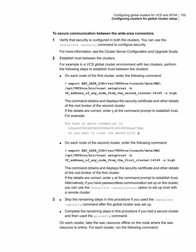
To secure communication between the wide-area connectors
1 Verify that security is configured in both the clusters. You can use theinstallvcs -security command to configure security.
For more information, see theCluster Server Configuration and Upgrade Guide.
2 Establish trust between the clusters.
For example in a VCS global cluster environment with two clusters, performthe following steps to establish trust between the clusters:
■ On each node of the first cluster, enter the following command:
# export EAT_DATA_DIR=/var/VRTSvcs/vcsauth/data/WAC;
/opt/VRTSvcs/bin/vcsat setuptrust -b
IP_address_of_any_node_from_the_second_cluster:14149 -s high
The command obtains and displays the security certificate and other detailsof the root broker of the second cluster.If the details are correct, enter y at the command prompt to establish trust.For example:
The hash of above credential is
b36a2607bf48296063068e3fc49188596aa079bb
Do you want to trust the above?(y/n) y
■ On each node of the second cluster, enter the following command:
# export EAT_DATA_DIR=/var/VRTSvcs/vcsauth/data/WAC
/opt/VRTSvcs/bin/vcsat setuptrust -b
IP_address_of_any_node_from_the_first_cluster:14149 -s high
The command obtains and displays the security certificate and other detailsof the root broker of the first cluster.If the details are correct, enter y at the command prompt to establish trust.Alternatively, if you have passwordless communication set up on the cluster,you can use the installvcs -securitytrust option to set up trust witha remote cluster.
3 Skip the remaining steps in this procedure if you used the installvcs
-security command after the global cluster was set up.■
■ Complete the remaining steps in this procedure if you had a secure clusterand then used the gcoconfig command.
On each cluster, take the wac resource offline on the node where the wacresource is online. For each cluster, run the following command:
102Configuring global clusters for VCS and SFHAConfiguring clusters for global cluster setup
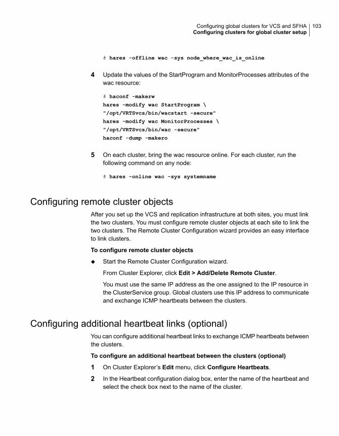
# hares -offline wac -sys node_where_wac_is_online
4 Update the values of the StartProgram and MonitorProcesses attributes of thewac resource:
# haconf -makerw
hares -modify wac StartProgram \
"/opt/VRTSvcs/bin/wacstart -secure"
hares -modify wac MonitorProcesses \
"/opt/VRTSvcs/bin/wac -secure"
haconf -dump -makero
5 On each cluster, bring the wac resource online. For each cluster, run thefollowing command on any node:
# hares -online wac -sys systemname
Configuring remote cluster objectsAfter you set up the VCS and replication infrastructure at both sites, you must linkthe two clusters. You must configure remote cluster objects at each site to link thetwo clusters. The Remote Cluster Configuration wizard provides an easy interfaceto link clusters.
To configure remote cluster objects
◆ Start the Remote Cluster Configuration wizard.
From Cluster Explorer, click Edit > Add/Delete Remote Cluster.
You must use the same IP address as the one assigned to the IP resource inthe ClusterService group. Global clusters use this IP address to communicateand exchange ICMP heartbeats between the clusters.
Configuring additional heartbeat links (optional)You can configure additional heartbeat links to exchange ICMP heartbeats betweenthe clusters.
To configure an additional heartbeat between the clusters (optional)
1 On Cluster Explorer’s Edit menu, click Configure Heartbeats.
2 In the Heartbeat configuration dialog box, enter the name of the heartbeat andselect the check box next to the name of the cluster.
103Configuring global clusters for VCS and SFHAConfiguring clusters for global cluster setup
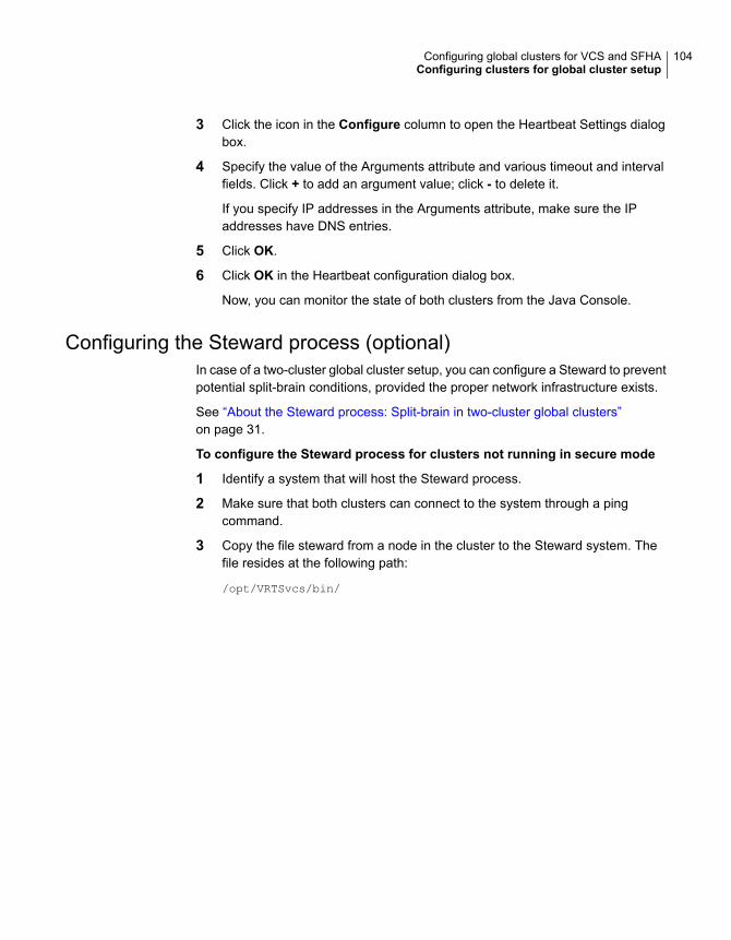
3 Click the icon in the Configure column to open the Heartbeat Settings dialogbox.
4 Specify the value of the Arguments attribute and various timeout and intervalfields. Click + to add an argument value; click - to delete it.
If you specify IP addresses in the Arguments attribute, make sure the IPaddresses have DNS entries.
5 Click OK.
6 Click OK in the Heartbeat configuration dialog box.
Now, you can monitor the state of both clusters from the Java Console.
Configuring the Steward process (optional)In case of a two-cluster global cluster setup, you can configure a Steward to preventpotential split-brain conditions, provided the proper network infrastructure exists.
See “About the Steward process: Split-brain in two-cluster global clusters”on page 31.
To configure the Steward process for clusters not running in secure mode
1 Identify a system that will host the Steward process.
2 Make sure that both clusters can connect to the system through a pingcommand.
3 Copy the file steward from a node in the cluster to the Steward system. Thefile resides at the following path:
/opt/VRTSvcs/bin/
104Configuring global clusters for VCS and SFHAConfiguring clusters for global cluster setup
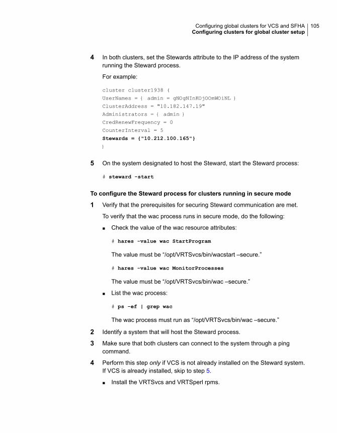
4 In both clusters, set the Stewards attribute to the IP address of the systemrunning the Steward process.
For example:
cluster cluster1938 (
UserNames = { admin = gNOgNInKOjOOmWOiNL }
ClusterAddress = "10.182.147.19"
Administrators = { admin }
CredRenewFrequency = 0
CounterInterval = 5
Stewards = {"10.212.100.165"}
}
5 On the system designated to host the Steward, start the Steward process:
# steward -start
To configure the Steward process for clusters running in secure mode
1 Verify that the prerequisites for securing Steward communication are met.
To verify that the wac process runs in secure mode, do the following:
■ Check the value of the wac resource attributes:
# hares -value wac StartProgram
The value must be “/opt/VRTSvcs/bin/wacstart –secure.”
# hares -value wac MonitorProcesses
The value must be “/opt/VRTSvcs/bin/wac –secure.”
■ List the wac process:
# ps -ef | grep wac
The wac process must run as “/opt/VRTSvcs/bin/wac –secure.”
2 Identify a system that will host the Steward process.
3 Make sure that both clusters can connect to the system through a pingcommand.
4 Perform this step only if VCS is not already installed on the Steward system.If VCS is already installed, skip to step 5.
■ Install the VRTSvcs and VRTSperl rpms.
105Configuring global clusters for VCS and SFHAConfiguring clusters for global cluster setup
■ If the cluster UUID is not configured, configure it by using/opt/VRTSvcs/bin/uuidconfig.pl.
■ On the system that is designated to run the Steward process, run theinstallvcs -securityonenode command.The installer prompts for a confirmation if VCS is not configured or if VCSis not running on all nodes of the cluster. Enter y when the installer promptswhether you want to continue configuring security.For more information about the -securityonenode option, see the ClusterServer Configuration and Upgrade Guide.
5 Generate credentials for the Steward using/opt/VRTSvcs/bin/steward_secure.pl or perform the following steps:
# unset EAT_DATA_DIR
# unset EAT_HOME_DIR
# /opt/VRTSvcs/bin/vcsauth/vcsauthserver/bin/vssat createpd -d
VCS_SERVICES -t ab
# /opt/VRTSvcs/bin/vcsauth/vcsauthserver/bin/vssat addprpl -t ab
-d VCS_SERVICES -p STEWARD -s password
# mkdir -p /var/VRTSvcs/vcsauth/data/STEWARD
# export EAT_DATA_DIR=/var/VRTSvcs/vcsauth/data/STEWARD
# /opt/VRTSvcs/bin/vcsat setuptrust -s high -b localhost:14149
6 Set up trust on all nodes of the GCO clusters:
# export EAT_DATA_DIR=/var/VRTSvcs/vcsauth/data/WAC
# vcsat setuptrust -b <IP_of_Steward>:14149 -s high
7 Set up trust on the Steward:
# export EAT_DATA_DIR=/var/VRTSvcs/vcsauth/data/STEWARD
# vcsat setuptrust -b <VIP_of_remote_cluster1>:14149 -s high
# vcsat setuptrust -b <VIP_of_remote_cluster2>:14149 -s high
106Configuring global clusters for VCS and SFHAConfiguring clusters for global cluster setup
8 In both the clusters, set the Stewards attribute to the IP address of the systemrunning the Steward process.
For example:
cluster cluster1938 (
UserNames = { admin = gNOgNInKOjOOmWOiNL }
ClusterAddress = "10.182.147.19"
Administrators = { admin }
CredRenewFrequency = 0
CounterInterval = 5
Stewards = {"10.212.100.165"}
}
9 On the system designated to run the Steward, start the Steward process:
# /opt/VRTSvcs/bin/steward -start -secure
To stop the Steward process
◆ To stop the Steward process that is not configured in secure mode, open anew command window and run the following command:
# steward -stop
To stop the Steward process running in secure mode, open a new commandwindow and run the following command:
# steward -stop -secure
Configuring service groups for global clustersetup
Perform the following steps to configure the service groups for disaster recovery.
To configure service groups
1 At the secondary site, set up the application for high availability.
Configure VCS service groups for the application. Create a configuration thatis similar to the one in the first cluster.
■ You can do this by either using Cluster Manager (Java Console) to copyand paste resources from the primary cluster, or by copying the configurationfrom the main.cf file in the primary cluster to the secondary cluster.
107Configuring global clusters for VCS and SFHAConfiguring service groups for global cluster setup
■ Make appropriate changes to the configuration. For example, you mustmodify the SystemList attribute to reflect the systems in the secondarycluster.
■ Make sure that the name of the service group (appgroup) is identical inboth clusters.
2 To assign remote administration privileges to users for remote clusteroperations, configure users with the same name and privileges on both clusters.
See “User privileges for cross-cluster operations” on page 24.
3 If your setup uses BIND DNS, add a resource of type DNS to the applicationservice group at each site.
Refer to the Cluster Server Bundled Agent’s Reference Guide for more details.
4 At each site, perform the following depending on the replication technologyyou have set up:
■ Volume ReplicatorConfigure VCS to manage and monitor Replicated Volume Groups (RVGs).See “Configuring VCS service group for VVR-based replication” on page 108.
■ A supported third-party replication technologyInstall and configure the corresponding VCS agent for replication.See the Installation and Configuration Guide for the corresponding VCSreplication agent for instructions.
Configuring VCS service group for VVR-based replicationPerform the following steps to configure VCS to monitor Volume Replicator (VVR).Then, set an online local hard group dependency from application service group(appgroup) to replication service group (appgroup_rep) to ensure that the servicegroups fail over and switch together.
To create the RVG resources in VCS
1 Create a new service group, say appgroup_rep.
2 Copy the DiskGroup resource from the appgroup to the new group.
3 Configure new resources of type IP and NIC in the appgroup_rep service group.The IP resource monitors the virtual IP that VVR uses for replication.
4 Configure a new resource of type RVG in the new (appgroup_rep) servicegroup.
108Configuring global clusters for VCS and SFHAConfiguring service groups for global cluster setup
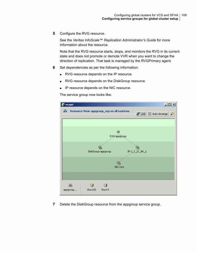
5 Configure the RVG resource.
See the Veritas InfoScale™ Replication Administrator’s Guide for moreinformation about the resource.
Note that the RVG resource starts, stops, and monitors the RVG in its currentstate and does not promote or demote VVR when you want to change thedirection of replication. That task is managed by the RVGPrimary agent.
6 Set dependencies as per the following information:
■ RVG resource depends on the IP resource.
■ RVG resource depends on the DiskGroup resource.
■ IP resource depends on the NIC resource.
The service group now looks like:
7 Delete the DiskGroup resource from the appgroup service group.
109Configuring global clusters for VCS and SFHAConfiguring service groups for global cluster setup
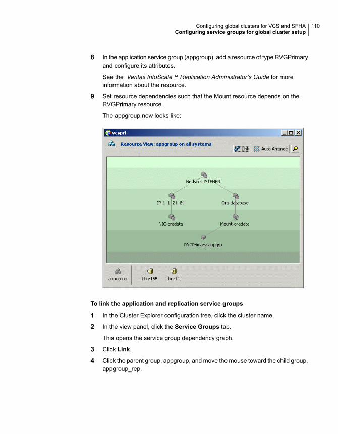
8 In the application service group (appgroup), add a resource of type RVGPrimaryand configure its attributes.
See the Veritas InfoScale™ Replication Administrator’s Guide for moreinformation about the resource.
9 Set resource dependencies such that the Mount resource depends on theRVGPrimary resource.
The appgroup now looks like:
To link the application and replication service groups
1 In the Cluster Explorer configuration tree, click the cluster name.
2 In the view panel, click the Service Groups tab.
This opens the service group dependency graph.
3 Click Link.
4 Click the parent group, appgroup, and move the mouse toward the child group,appgroup_rep.
110Configuring global clusters for VCS and SFHAConfiguring service groups for global cluster setup
5 Click the child group appgroup_rep.
6 In the Link Service Groups dialog box, click the online local relationship andthe hard dependency type and click OK.
Configuring a service group as a global service groupRun the Global Group Configuration wizard to configure the application servicegroup (appgroup) as a global group.
To create the global service group
1 In the service group tree of Cluster Explorer, right-click the application servicegroup (appgroup).
2 Select Configure As Global from the menu.
3 Enter the details of the service group to modify (appgroup).
4 From the Available Clusters box, click the clusters on which the group cancome online. The local cluster is not listed as it is implicitly defined to be partof the ClusterList. Click the right arrow to move the cluster name to theClusterList box.
5 Select the policy for cluster failover:
■ Manual prevents a group from automatically failing over to another cluster.
■ Auto enables a group to automatically fail over to another cluster if it isunable to fail over within the cluster, or if the entire cluster faults.
■ Connected enables a group to automatically fail over to another cluster ifit is unable to fail over within the cluster.
6 Click Next.
7 Enter or review the connection details for each cluster.
Click the Configure icon to review the remote cluster information for eachcluster.
8 Enter the IP address of the remote cluster, the IP address of a cluster system,or the host name of a cluster system.
9 Enter the user name and the password for the remote cluster and click OK.
10 Click Next.
11 Click Finish.
12 Save the configuration.
The appgroup service group is now a global group and can be failed overbetween clusters.
111Configuring global clusters for VCS and SFHAConfiguring service groups for global cluster setup
Fire drill in global clustersA fire drill procedure verifies the fault-readiness of a disaster recovery configuration.This procedure is performed without stopping the application at the Primary siteand disrupting user access.
A fire drill is performed at the Secondary site using a special service group for firedrills. The fire drill service group is identical to the application service group, butuses a fire drill resource in place of the replication agent resource. The fire drillservice group uses a copy of the data that is used by the application service group.
Almost all of the replication agents have a corresponding fire drill agent bundledwith them. These fire drill agents are responsible for taking a snapshot inside thestorage array and importing the snapshot disks on the hosts. The fire drill agentsare named similar to the replication agents with the suffix “Snap” appended to theagent name. For example, the fire drill agent for EMC SRDF is SRDFSnap and thefire drill agent for Hitachi TrueCopy (HTC) agent is HTCSnap.
For more information about configuring fire drills, please refer the Installation andConfiguration Guide of the appropriate replication agent.
112Configuring global clusters for VCS and SFHAFire drill in global clusters
Configuring a globalcluster with StorageFoundation Cluster FileSystem High Availability,Storage Foundation forOracle RAC, or StorageFoundation for Sybase CE
This chapter includes the following topics:
■ About global clusters
■ About replication for parallel global clusters using Storage Foundation and HighAvailability (SFHA) Solutions
■ About setting up a global cluster environment for parallel clusters
■ Configuring the primary site
■ Configuring the secondary site
■ Setting up replication between parallel global cluster sites
■ Testing a parallel global cluster configuration
8Chapter
About global clustersGlobal clusters provide the ability to fail over applications between geographicallydistributed clusters when disaster occurs. This type of clustering involves migratingapplications between clusters over a considerable distance. You can set up HA/DRusing hardware-based or software-based replication technologies.
You may add this license during the installation or at any time after the installationcompletes.
About replication for parallel global clusters usingStorage Foundation and High Availability (SFHA)Solutions
Global clusters provide the ability to fail over applications between geographicallydistributed clusters when disaster occurs. This type of clustering involves migratingapplications between clusters over a considerable distance. You can set up HA/DRusing hardware-based or software-based replication technologies.
You can set up a primary cluster for replication to a secondary cluster by configuringglobal VCS service groups and using a replication technology. The database clusterat the secondary site can be a single node cluster. For example, you can have atwo-node cluster on the primary site and a two-node or single-node cluster on thesecondary site.
You can use one of the following replication technologies:
■ Veritas Volume Replicator (VVR), which provides host-based volume replication.Using VVR you can replicate data volumes on a shared disk group in StorageFoundation Cluster File System High Availablity (SFCFS HA), StorageFoundation for Oracle RAC (SF Oracle RAC), or Storage Foundation for SybaseASE CE (SF Sybase CE).
■ Supported hardware-based replication technologies. Using hardware-basedreplication you can replicate data from a primary array to a secondary array.
To verify your configuration is supported, review the product requirements andlicensing information:
See the Storage Foundation Cluster File System High Availability Configurationand Upgrade Guide.
See the Storage Foundation for Oracle RAC Configuration and Upgrade Guide.
See the Storage Foundation for Sybase ASE CEConfiguration and Upgrade Guide.
114Configuring a global cluster with Storage Foundation Cluster File System High Availability, Storage Foundation forOracle RAC, or Storage Foundation for Sybase CE
About global clusters
To confirm the compatibility of your hardware, see the current compatibility list inthe Veritas Technical Support website:
https://www.veritas.com/support/en_US/article.000126344
SFCFSHA and SF Oacle RAC support multiple third-party replication options.
Storage Foundation for Sybase CE supports VVR replication only at this time.
For current information on third-party replication support:
See: https://sort.veritas.com/agents and select Replication Agents under Agenttype.
Notes:
■ SF Sybase CE supports replication with VVR only.
■ Check your vendor's compatibility list for the supported software versions. Thesupport listed above only exists if the host, HBA, and array combination is inyour vendor's hardware compatibility list. Check your array documentation.
■ All arrays must support SCSI-3 persistent reservations.
The Veritas replication agents provide application failover and recovery support toyour replication configuration in environments where data is replicated betweenclusters.
VCS replication agents control the direction of replication. They do not monitor theprogress or status of replication. The replication agents manage the state ofreplicated devices that are attached to global cluster nodes. The agents make surethat the system which has the resource online also has safe and exclusive accessto the configured devices.
For more current information on the replicated agents:
See the Cluster Server Bundled Agents Guide
About setting up a global cluster environment forparallel clusters
Configuring a global cluster for environment with parallel clusters requires thecoordination of many component setup tasks. The procedures provided here areguidelines. Refer to your product installation guide for your product installation andbasic configuration for each cluster. You will need this guide to configure a globalcluster environment and replication between the two configured clusters.
115Configuring a global cluster with Storage Foundation Cluster File System High Availability, Storage Foundation forOracle RAC, or Storage Foundation for Sybase CE
About setting up a global cluster environment for parallel clusters
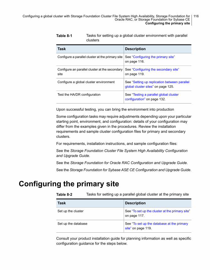
Table 8-1 Tasks for setting up a global cluster environment with parallelclusters
DescriptionTask
See “Configuring the primary site”on page 116.
Configure a parallel cluster at the primary site
See “Configuring the secondary site”on page 119.
Configure an parallel cluster at the secondarysite
See “Setting up replication between parallelglobal cluster sites” on page 125.
Configure a global cluster environment
See “Testing a parallel global clusterconfiguration” on page 132.
Test the HA/DR configuration
Upon successful testing, you can bring the environment into production
Some configuration tasks may require adjustments depending upon your particularstarting point, environment, and configuration: details of your configuration maydiffer from the examples given in the procedures. Review the installationrequirements and sample cluster configuration files for primary and secondaryclusters.
For requirements, installation instructions, and sample configuration files:
See the Storage Foundation Cluster File System High Availability Configurationand Upgrade Guide.
See the Storage Foundation for Oracle RAC Configuration and Upgrade Guide.
See the Storage Foundation for Sybase ASE CEConfiguration and Upgrade Guide.
Configuring the primary siteTable 8-2 Tasks for setting up a parallel global cluster at the primary site
DescriptionTask
See “To set up the cluster at the primary site”on page 117.
Set up the cluster
See “To set up the database at the primarysite” on page 119.
Set up the database
Consult your product installation guide for planning information as well as specificconfiguration guidance for the steps below.
116Configuring a global cluster with Storage Foundation Cluster File System High Availability, Storage Foundation forOracle RAC, or Storage Foundation for Sybase CE
Configuring the primary site
See the Storage Foundation Cluster File System High Availability Configurationand Upgrade Guide.
See the Storage Foundation for Oracle RAC Configuration and Upgrade Guide.
See the Storage Foundation for Sybase ASE CEConfiguration and Upgrade Guide.
You can use an existing parallel cluster or you can install a new cluster for yourprimary site. If you are using an existing cluster as the primary and you want to setup a global cluster, skip the steps below and proceed to configure your secondarycluster.
See “Configuring the secondary site” on page 119.
If you do not have an existing cluster and you are setting up two new sites for aglobal cluster, follow the steps below.
To set up the cluster at the primary site
1 Install and configure servers and storage.
2 If you are using hardware-based replication, install the sofware for managingyour array.
3 Verify that you have the correct installation options enabled, whether you areusing keyless licensing or installing keys manually. You must have the GCOoption enabled for a global cluster. If you are using VVR for replication, youmust have it enabled.
4 Prepare, install, and configure your Storage Foundation and High Availability(SFHA) Solutions product according to the directions in your product'sinstallation guide.
For a multi-node cluster, configure I/O fencing.
5 Verify the CVM group is online on all nodes in the primary cluster.
# hagrp -state cvm
6 Set storage connectivity for volume asymetry and I/O shiping for DCO logspolicies for the disk group.
7 Prepare systems and storage for a global cluster. Identify the hardware andstorage requirements before installing your database software.
For SFCFSHA, you will need to set up:
■ Local storage for database software
■ Shared storage for resources which are not replicated as part of thehardware-based or host-based replication
117Configuring a global cluster with Storage Foundation Cluster File System High Availability, Storage Foundation forOracle RAC, or Storage Foundation for Sybase CE
Configuring the primary site
■ Replicated storage for database files
For SF Oracle RAC, you will need to set up:
■ Local storage for Oracle RAC and CRS/GRID binaries
■ Shared storage for OCR and Vote disk which is not replicated as part ofthe hardware-based or host-based replication
■ Replicated shared storage for database files
For SF Sybase CE, you will need to set up:
■ Shared storage for File sSystem and Cluster File System for Sybase ASECE binaries which is not replicated
■ Shared storage for the quorum device which is not replicated
■ Replicated storage for database files
■ Verify the configuration using procedures in the Storage Foundation forSybase ASE CE Configuration and Upgrade Guide.
8 For SFCFSHA, install and configure your database binaries. Consult yourdatabase documentation.
Note:Resources which will not be replicated must be on non-replicated sharedstorage.
After successful database installation and configuration, verify that databaseresources are up on all nodes.
9 For Oracle RAC, see the instructions in the Storage Foundation for OracleRAC Configuration and Upgrade Guide for installing, configuring, and linkingOracle database binaries:
■ Oracle Clusterware/Grid Infrastructure software
■ Oracle RAC database software
■ The Oracle RAC binary versions must be exactly same on both sites.
Note: OCR and Vote disk must be on non-replicated shared storage.
After successful Oracle RAC installation and configuration, verify that CRSdaemons and resources are up on all nodes.
118Configuring a global cluster with Storage Foundation Cluster File System High Availability, Storage Foundation forOracle RAC, or Storage Foundation for Sybase CE
Configuring the primary site
$GRID_HOME/bin/crsctl stat res -t
10 For SF Sybase CE, see the instructions in the Storage Foundation for SybaseASECEConfiguration and Upgrade Guide for installing and configuring SybaseASE CE binaries.
Note the following configuration requirements:
■ The quorum device must be on non-replicated shared storage.
■ The Sybase binary versions must be exactly same on both sites, includingthe ESD versions.
■ Configure Sybase binaries mounts/volumes under VCS control manuallyon the secondary site.
To set up the database at the primary site
1 Identify the disks that will be replicated, create the required CVM disk group,volume, and file system.
2 Create the database on the file system you created in the previous step.
3 Configure the VCS service groups for the database.
4 Verify that all VCS service groups are online.
Configuring the secondary siteThe setup requirements for the secondary site parallel the requirements for theprimary site with a few additions or exceptions as noted below.
Table 8-3 Tasks for setting up a parallel global cluster at the secondary site
DescriptionTask
See “To set up the cluster on secondary site”on page 120.
Set up the cluster
See “To set up the SFCFSHA database forthe secondary site” on page 122.
See “To set up the Oracle RAC database forthe secondary site” on page 123.
See “To set up the Sybase ASE CE databasefor the secondary site” on page 125.
Set up the database
Important requirements for parallel global clustering:
■ Cluster names on the primary and secondary sites must be unique.
119Configuring a global cluster with Storage Foundation Cluster File System High Availability, Storage Foundation forOracle RAC, or Storage Foundation for Sybase CE
Configuring the secondary site
■ You must use the same OS user and group IDs for your database for installationand configuration on both the primary and secondary clusters.
■ For Oracle RAC, you must use the same directory structure, name, permissionsfor the CRS/GRID and database binaries.
You can use an existing parallel cluster or you can install a new cluster for yoursecondary site.
Consult your product installation guide for planning information as well as specificconfiguration guidance for the steps below.
See the Storage Foundation Cluster File System High Availability Configurationand Upgrade Guide.
See the Storage Foundation for Oracle RAC Configuration and Upgrade Guide.
See the Storage Foundation for Sybase ASE CEConfiguration and Upgrade Guide.
To set up the cluster on secondary site
1 Install and configure servers and storage.
2 If you are using hardware-based replication, install the sofware for managingyour array.
3 Verify that you have the correct installation options enabled, whether you areusing keyless licensing or installing keys manually. You must have the GCOoption for a global cluster. If you are using VVR for replication, you must haveit enabled.
4 Prepare, install, and configure your Storage Foundation and High Availability(SFHA) Solutions product according to the directions in your product'sinstallation guide.
For a multi-node cluster, configure I/O fencing.
5 For a single-node cluster, do not enable I/O fencing. Fencing will run in disabledmode.
6 Prepare systems and storage for a global cluster. Identify the hardware andstorage requirements before installing your database software.
For SFCFSHA, you will need to set up:
■ Local storage for database software
■ Shared storage for resources which are not replicated as part of thehardware-based or host-based replication
■ Replicated storage for database files
■ You must use the same directory structure, name, permissions for thequorum and database binaries as on the primary.
120Configuring a global cluster with Storage Foundation Cluster File System High Availability, Storage Foundation forOracle RAC, or Storage Foundation for Sybase CE
Configuring the secondary site
For SF Oracle RAC, you will need to set up:
■ Local storage for Oracle RAC and CRS binaries
■ Shared storage for OCR and Vote disk which is not replicated as part ofthe hardware-based or host-based replication
■ Replicated shared storage for database files
■ You must use the same directory structure, name, permissions for theCRS/GRID and database binaries as on the primary.
For SF Sybase CE, you will need to set up:
■ Shared storage for File sSystem and Cluster File System for Sybase ASECE binaries which is not replicated
■ Shared storage for the quorum device which is not replicated
■ Replicated storage for database files
■ You must use the same directory structure, name, permissions for thequorum and database binaries as on the primary.
■ Verify the configuration using procedures in the Storage Foundation forSybase ASE CE Configuration and Upgrade Guide.
Note: You must use the same directory structure, name, permissions for theCRS/GRID and database binaries.
7 For SFCFSHA, install and configure your database binaries. Consult yourdatabase documentation.
Note:Resources which will not be replicated must be on non-replicated sharedstorage.
After successful database installation and configuration, verify that databaseresources are up on all nodes.
8 For Oracle RAC, see the instructions in the Storage Foundation for OracleRAC Configuration and Upgrade Guide for installing and configuring:
■ Oracle Clusterware/Grid Infrastructure software
■ Oracle RAC database software
■ The Oracle RAC binary versions must be exactly same on both sites.
121Configuring a global cluster with Storage Foundation Cluster File System High Availability, Storage Foundation forOracle RAC, or Storage Foundation for Sybase CE
Configuring the secondary site
Note: OCR and Vote disk must be on non-replicated shared storage.
After successful Oracle RAC installation and configuration, verify that CRSdaemons and resources are up on all nodes.
$GRID_HOME/bin/crsctl stat res -t
9 For SF Sybase CE, see the instructions in the Storage Foundation for SybaseASECEConfiguration and Upgrade Guide for installing and configuring SybaseASE CE binaries.
Note the following configuration requirements:
■ The quorum device must be on non-replicated shared storage.
■ The Sybase binary versions must be exactly same on both sites, includingthe ESD versions.
■ Configure Sybase Binaries mounts/volumes under VCS control manuallyon the secondary site.
Do not create the database. The database will be replicated from the primary site.
To set up the SFCFSHA database for the secondary site
1 If you are using hardware-based replication, the database, disk group, andvolumes will be replicated from the primary site.
Create the directory for the CFS mount point which will host the database dataand control files.
2 If you are using VVR for replication, create an identical disk group and volumesfor the replicated content with the same names and size as listed on the primarysite.
Create the directories for the CFS mount points as they are on the primarysite. These will be used to host the database and control files when the failoveroccurs and the secondary is promoted to become the primary site.
3 Create subdirectories for the database as you did on the primary site.
122Configuring a global cluster with Storage Foundation Cluster File System High Availability, Storage Foundation forOracle RAC, or Storage Foundation for Sybase CE
Configuring the secondary site
To set up the Oracle RAC database for the secondary site
1 If you are using hardware-based replication, the database, disk group, andvolumes will be replicated from the primary site.
Create the directory for the CFS mount point which will host the database dataand control files.
2 If you are using VVR for replication, create an identical disk group and volumesfor the replicated content with the same names and size as listed on the primarysite.
Create the directories for the CFS mount points as they are on the primarysite. These will be used to host the database and control files when the failoveroccurs and the secondary is promoted to become the primary site.
3 On each node in the cluster, copy the initialization files (pfiles,spfiles) from theprimary cluster to the secondary cluster maintaining the same directory path.
For example, copy init$ORACLE_SID.ora and orapw$ORACLE_SID.ora from$ORACLE_HOME/dbs at the primary to $ORACLE_HOME/dbs at thesecondary.
4 As Oracle user, create the following subdirectories on the secondary site toparallel the directories on the primary site:
$ mkdir -p $ORACLE_BASE/diag
$ mkdir -p $ORACLE_BASE/admin
$ mkdir -p $ORACLE_BASE/admin/adump
On both the primary and secondary sites, edit the file:
$ORACLE_HOME/dbs/init$ORACLE_SID.ora
as
remote_listener = 'SCAN_NAME:1521'
SPFILE=<SPFILE NAME>
5 Configure listeners on the secondary site with same name as on primary. Youcan do this by one of the following methods:
■ Copy the listener.ora and tnsnames.ora files from the primary site andupdate the names as appropriate for the secondary site.
■ Use Oracle's netca utility to to configure the listener.ora and tnsnames.orafiles on the secondary site.
123Configuring a global cluster with Storage Foundation Cluster File System High Availability, Storage Foundation forOracle RAC, or Storage Foundation for Sybase CE
Configuring the secondary site
6 On the secondary site, register the database using the srvctl command asthe database software owner.
Registering the database only has to be done once from any node in thesecondary cluster.Use the following command as the Oracle database softwareowner
$ $ORACLE_HOME/bin/srvctl add database -d database_name -o oracle_home
7 To prevent automatic database instance restart, change the Managementpolicy for the database (automatic, manual) to MANUAL using the srvctl
command:
$ $ORACLE_HOME/bin/srvctl modify database -d database_name -y manual
You need only perform this change once from any node in the cluster.
8 Register the instances using srvctl command. Execute the following commandon each node:
$ $ORACLE_HOME/bin/srvctl add instance -d database_name \
-i instance_name -n node-name
If the secondary cluster has more than one node, you must add instances usingthe srvctl command.
For example, if the database instance name is racdb, the instance name onsys3 is racdb1 and on sys4 is racdb2.
$ $ORACLE_HOME/bin/srvctl add instance -d racdb -i racdb1 -n sys3
$ $ORACLE_HOME/bin/srvctl add instance -d racdb -i racdb2 -n sys4
9 Register all other resources (for example listener, ASM, service) present incluster/GRID at the primary site to the secondary site using the srvctl
command or crs_register. For command details, see Oracle documentationat Metalink.
124Configuring a global cluster with Storage Foundation Cluster File System High Availability, Storage Foundation forOracle RAC, or Storage Foundation for Sybase CE
Configuring the secondary site
To set up the Sybase ASE CE database for the secondary site
1 Create the directories for the CFS mount points as they are on the primarysite. These will be used to host the database files when the failover occurs andthe secondary is promoted to become the primary site.
2 Create an identical disk group and volumes for the replicated content with thesame names and size as listed on the primary site.
Configuring the Sybase ASE CE cluster on the secondary siteBefore bringing Sybase ASE CE online at the secondary site, you must configurethe Sybase ASE CE cluster on the secondary site.
■ Modify the Sybase ASE CE configuration files to match the secondary siteenvironment.
■ Build the new quorum device for the secondary site.
■ For configuration details: See “Configuring the Sybase ASE CE cluster on thesecondary site” on page 165.
Setting up replication between parallel globalcluster sites
You have configured Cluster Server (VCS) service groups for the database on eachcluster. Each cluster requires an additional virtual IP address associated with thecluster for cross-cluster communication. The VCS installation and creation of theClusterService group typically involves defining this IP address.
Configure a global cluster by setting:
■ Heartbeat
■ Wide area cluster (wac)
■ GCO IP (gcoip)
■ remote cluster resources
125Configuring a global cluster with Storage Foundation Cluster File System High Availability, Storage Foundation forOracle RAC, or Storage Foundation for Sybase CE
Setting up replication between parallel global cluster sites
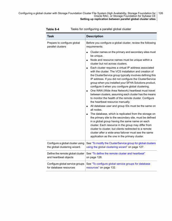
Table 8-4 Tasks for configuring a parallel global cluster
DescriptionTask
Before you configure a global cluster, review the followingrequirements:
■ Cluster names on the primary and secondary sites mustbe unique.
■ Node and resource names must be unique within acluster but not across clusters.
■ Each cluster requires a virtual IP address associatedwith the cluster. The VCS installation and creation ofthe ClusterService group typically involves defining thisIP address. If you did not configure the ClusterServicegroup when you installed your SFHA Solutions product,configure it when you configure global clustering.
■ One WAN (Wide Area Network) heartbeat must travelbetween clusters, assuming each cluster has the meansto monitor the health of the remote cluster. Configurethe heartbeat resource manually.
■ All database user and group IDs must be the same onall nodes.
■ The database, which is replicated from the storage onthe primary site to the secondary site, must be definedin a global group having the same name on eachcluster. Each resource in the group may differ fromcluster to cluster, but clients redirected to a remotecluster after a wide-area failover must see the sameapplication as the one in the primary cluster.
Prepare to configure globalparallel clusters
See “To modify the ClusterService group for global clustersusing the global clustering wizard” on page 127.
Configure a global cluster usingthe global clustering wizard.
See “To define the remote cluster and heartbeat”on page 128.
Define the remote global clusterand heartbeat objects
See “To configure global service groups for databaseresources” on page 132.
Configure global service groupsfor database resources
126Configuring a global cluster with Storage Foundation Cluster File System High Availability, Storage Foundation forOracle RAC, or Storage Foundation for Sybase CE
Setting up replication between parallel global cluster sites
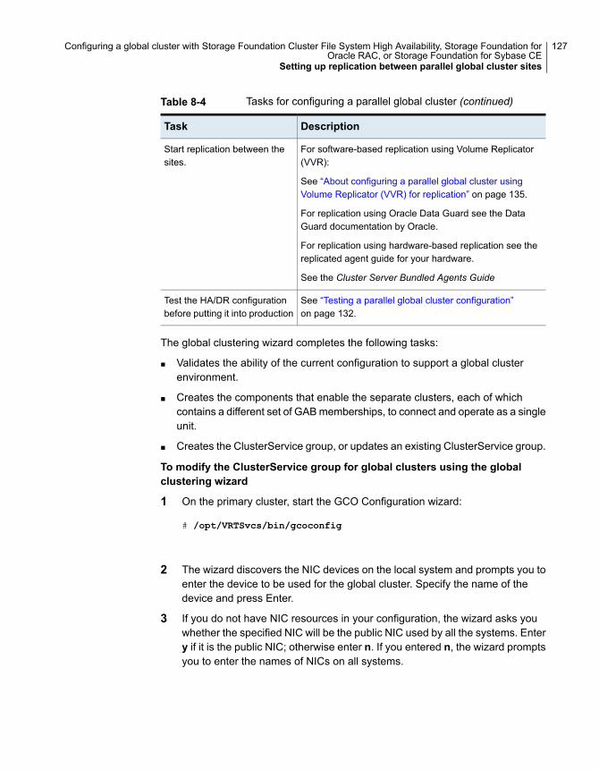
Table 8-4 Tasks for configuring a parallel global cluster (continued)
DescriptionTask
For software-based replication using Volume Replicator(VVR):
See “About configuring a parallel global cluster usingVolume Replicator (VVR) for replication” on page 135.
For replication using Oracle Data Guard see the DataGuard documentation by Oracle.
For replication using hardware-based replication see thereplicated agent guide for your hardware.
See the Cluster Server Bundled Agents Guide
Start replication between thesites.
See “Testing a parallel global cluster configuration”on page 132.
Test the HA/DR configurationbefore putting it into production
The global clustering wizard completes the following tasks:
■ Validates the ability of the current configuration to support a global clusterenvironment.
■ Creates the components that enable the separate clusters, each of whichcontains a different set of GAB memberships, to connect and operate as a singleunit.
■ Creates the ClusterService group, or updates an existing ClusterService group.
To modify the ClusterService group for global clusters using the globalclustering wizard
1 On the primary cluster, start the GCO Configuration wizard:
# /opt/VRTSvcs/bin/gcoconfig
2 The wizard discovers the NIC devices on the local system and prompts you toenter the device to be used for the global cluster. Specify the name of thedevice and press Enter.
3 If you do not have NIC resources in your configuration, the wizard asks youwhether the specified NIC will be the public NIC used by all the systems. Entery if it is the public NIC; otherwise enter n. If you entered n, the wizard promptsyou to enter the names of NICs on all systems.
127Configuring a global cluster with Storage Foundation Cluster File System High Availability, Storage Foundation forOracle RAC, or Storage Foundation for Sybase CE
Setting up replication between parallel global cluster sites
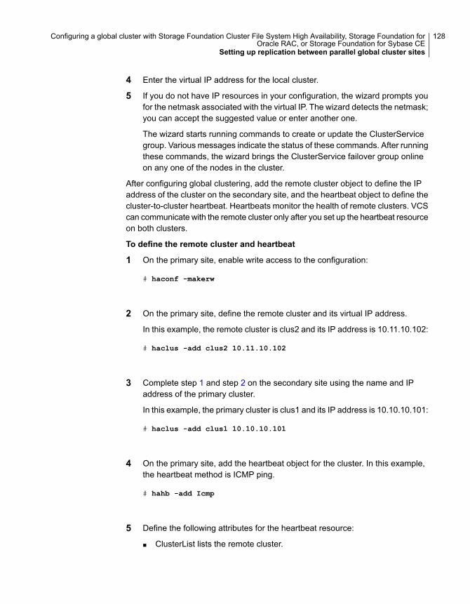
4 Enter the virtual IP address for the local cluster.
5 If you do not have IP resources in your configuration, the wizard prompts youfor the netmask associated with the virtual IP. The wizard detects the netmask;you can accept the suggested value or enter another one.
The wizard starts running commands to create or update the ClusterServicegroup. Various messages indicate the status of these commands. After runningthese commands, the wizard brings the ClusterService failover group onlineon any one of the nodes in the cluster.
After configuring global clustering, add the remote cluster object to define the IPaddress of the cluster on the secondary site, and the heartbeat object to define thecluster-to-cluster heartbeat. Heartbeats monitor the health of remote clusters. VCScan communicate with the remote cluster only after you set up the heartbeat resourceon both clusters.
To define the remote cluster and heartbeat
1 On the primary site, enable write access to the configuration:
# haconf -makerw
2 On the primary site, define the remote cluster and its virtual IP address.
In this example, the remote cluster is clus2 and its IP address is 10.11.10.102:
# haclus -add clus2 10.11.10.102
3 Complete step 1 and step 2 on the secondary site using the name and IPaddress of the primary cluster.
In this example, the primary cluster is clus1 and its IP address is 10.10.10.101:
# haclus -add clus1 10.10.10.101
4 On the primary site, add the heartbeat object for the cluster. In this example,the heartbeat method is ICMP ping.
# hahb -add Icmp
5 Define the following attributes for the heartbeat resource:
■ ClusterList lists the remote cluster.
128Configuring a global cluster with Storage Foundation Cluster File System High Availability, Storage Foundation forOracle RAC, or Storage Foundation for Sybase CE
Setting up replication between parallel global cluster sites
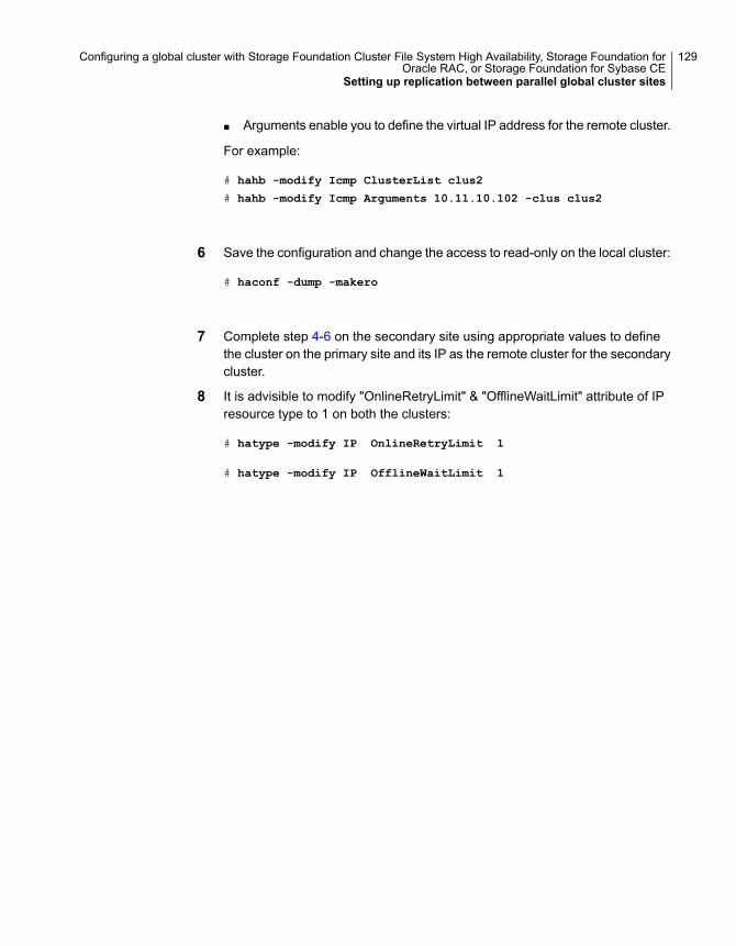
■ Arguments enable you to define the virtual IP address for the remote cluster.
For example:
# hahb -modify Icmp ClusterList clus2
# hahb -modify Icmp Arguments 10.11.10.102 -clus clus2
6 Save the configuration and change the access to read-only on the local cluster:
# haconf -dump -makero
7 Complete step 4-6 on the secondary site using appropriate values to definethe cluster on the primary site and its IP as the remote cluster for the secondarycluster.
8 It is advisible to modify "OnlineRetryLimit" & "OfflineWaitLimit" attribute of IPresource type to 1 on both the clusters:
# hatype -modify IP OnlineRetryLimit 1
# hatype -modify IP OfflineWaitLimit 1
129Configuring a global cluster with Storage Foundation Cluster File System High Availability, Storage Foundation forOracle RAC, or Storage Foundation for Sybase CE
Setting up replication between parallel global cluster sites

9 Verify cluster status with the hastatus -sum command on both clusters.
# hastatus -sum
130Configuring a global cluster with Storage Foundation Cluster File System High Availability, Storage Foundation forOracle RAC, or Storage Foundation for Sybase CE
Setting up replication between parallel global cluster sites
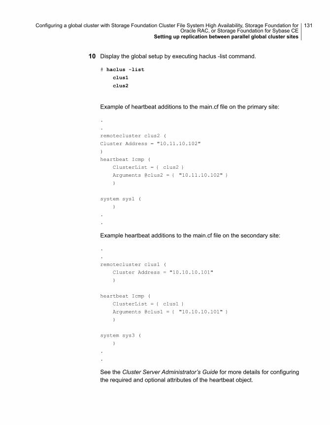
10 Display the global setup by executing haclus -list command.
# haclus -list
clus1
clus2
Example of heartbeat additions to the main.cf file on the primary site:
.
.
remotecluster clus2 (
Cluster Address = "10.11.10.102"
)
heartbeat Icmp (
ClusterList = { clus2 }
Arguments @clus2 = { "10.11.10.102" }
)
system sys1 (
)
.
.
Example heartbeat additions to the main.cf file on the secondary site:
.
.
remotecluster clus1 (
Cluster Address = "10.10.10.101"
)
heartbeat Icmp (
ClusterList = { clus1 }
Arguments @clus1 = { "10.10.10.101" }
)
system sys3 (
)
.
.
See the Cluster Server Administrator’s Guide for more details for configuringthe required and optional attributes of the heartbeat object.
131Configuring a global cluster with Storage Foundation Cluster File System High Availability, Storage Foundation forOracle RAC, or Storage Foundation for Sybase CE
Setting up replication between parallel global cluster sites
To configure global service groups for database resources
1 Configure and enable global groups for databases and resources.
■ Configure VCS service groups at both sites.
■ Configure the replication agent at both sites.
■ For SF Oracle RAC, make the Oracle RAC service group a global servicegroup, enabling failover across clusters.
■ For SF Sybase CE, make the database service group (sybasece) a globalservice group, enabling failover across clusters.
■ For example:See “Modifying the Cluster Server (VCS) configuration on the primary site”on page 152.
2 To test real data in an environment where HA/DR has been configured,schedule a planned migration to the secondary site for testing purposes.
For example:
See “To migrate the role of primary site to the remote site” on page 168.
See “To migrate the role of new primary site back to the original primary site”on page 169.
3 Upon successful testing, bring the environment into production.
For more information about VCS replication agents:
See the Cluster Server Bundled Agents Guide
For complete details on using VVR in a shared disk environment:
See the Veritas InfoScale™ Replication Administrator’s Guide.
Testing a parallel global cluster configurationVeritas recommends testing before putting a global cluster configuration intoproduction.
To test a planned failover
1 Offline the VCS service group for the database on the cluster at the primarysite.
2 Online the VCS service group for the database on the cluster at the secondarysite.
132Configuring a global cluster with Storage Foundation Cluster File System High Availability, Storage Foundation forOracle RAC, or Storage Foundation for Sybase CETesting a parallel global cluster configuration
To test distaster recovery at the recovery site
1 Plan downtime to test the disaster recovery configuration.
2 Simulate a disaster at the primary site.
For example:
Shut down the hosts and storage arrays at the primary. If you can not shutdown the storage arrays, disconnect the replication link between the sites.
3 Use VCS to fail over the database to the cluster at the secondary site.
To test failback on the primary site
1 Offline the VCS service group for the database on the cluster at the secondarysite.
2 If the nodes and storage are down, restart the nodes and the storage array atthe primary site.
3 Reconnect the replication link if it was broken.
4 Resynchronize the data from the secondary to make sure the data at the primarysite is current.
5 Bring the VCS service group online at the primary site.
133Configuring a global cluster with Storage Foundation Cluster File System High Availability, Storage Foundation forOracle RAC, or Storage Foundation for Sybase CETesting a parallel global cluster configuration
Configuring global clusterswith VVR and StorageFoundation Cluster FileSystem High Availability,Storage Foundation forOracle RAC, or StorageFoundation for Sybase CE
This chapter includes the following topics:
■ About configuring a parallel global cluster using Volume Replicator (VVR) forreplication
■ Setting up replication on the primary site using VVR
■ Setting up replication on the secondary site using VVR
■ Starting replication of the primary site database volume to the secondary siteusing VVR
■ Configuring Cluster Server to replicate the database volume using VVR
■ Replication use cases for global parallel clusters
9Chapter
About configuring a parallel global cluster usingVolume Replicator (VVR) for replication
Configuring a global cluster for environment with parallel clusters using VolumeReplicator requires the coordination of many component setup tasks. The taskslisted below are guidelines.
Before configuring two clusters for global clustering, you must verify that:
■ You have the correct installation options enabled for your Storage Foundationsand High Availability (SFHA) Solutions product, whether you are using keylesslicensing or installing keys manually. You must have the GCO option for a globalcluster and VVR enabled.Review your product requirements and licensing information.
■ Both clusters have your SFHA Solutions product software installed andconfigured.See “Configuring the primary site” on page 116.See “Configuring the secondary site” on page 119.
Note: You can install and configure both clusters at the same time, or you canconfigure the second cluster at a later time than the first.
You you can use this guide to configure a global cluster environment and replicationbetween the two clusters. For installation and configuration information:
See the Storage Foundation Cluster File System High Availability Configurationand Upgrade Guide.
See the Storage Foundation for Oracle RAC Configuration and Upgrade Guide.
See the Storage Foundation for Sybase ASE CEConfiguration and Upgrade Guide.
With two clusters installed and configured , you are ready to configure a globalcluster environment using VVR. You must perform the following tasks to modifyboth cluster configurations to support replication in the global cluster environment.
135Configuring global clusters with VVR and Storage Foundation Cluster File System High Availability, Storage Foundationfor Oracle RAC, or Storage Foundation for Sybase CE
About configuring a parallel global cluster using Volume Replicator (VVR) for replication
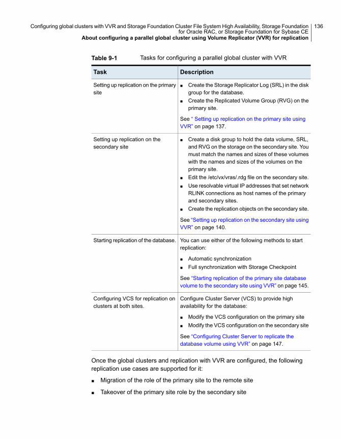
Table 9-1 Tasks for configuring a parallel global cluster with VVR
DescriptionTask
■ Create the Storage Replicator Log (SRL) in the diskgroup for the database.
■ Create the Replicated Volume Group (RVG) on theprimary site.
See “ Setting up replication on the primary site usingVVR” on page 137.
Setting up replication on the primarysite
■ Create a disk group to hold the data volume, SRL,and RVG on the storage on the secondary site. Youmust match the names and sizes of these volumeswith the names and sizes of the volumes on theprimary site.
■ Edit the /etc/vx/vras/.rdg file on the secondary site.■ Use resolvable virtual IP addresses that set network
RLINK connections as host names of the primaryand secondary sites.
■ Create the replication objects on the secondary site.
See “Setting up replication on the secondary site usingVVR” on page 140.
Setting up replication on thesecondary site
You can use either of the following methods to startreplication:
■ Automatic synchronization■ Full synchronization with Storage Checkpoint
See “Starting replication of the primary site databasevolume to the secondary site using VVR” on page 145.
Starting replication of the database.
Configure Cluster Server (VCS) to provide highavailability for the database:
■ Modify the VCS configuration on the primary site■ Modify the VCS configuration on the secondary site
See “Configuring Cluster Server to replicate thedatabase volume using VVR” on page 147.
Configuring VCS for replication onclusters at both sites.
Once the global clusters and replication with VVR are configured, the followingreplication use cases are supported for it:
■ Migration of the role of the primary site to the remote site
■ Takeover of the primary site role by the secondary site
136Configuring global clusters with VVR and Storage Foundation Cluster File System High Availability, Storage Foundationfor Oracle RAC, or Storage Foundation for Sybase CE
About configuring a parallel global cluster using Volume Replicator (VVR) for replication
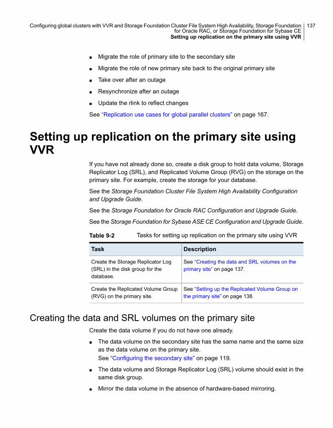
■ Migrate the role of primary site to the secondary site
■ Migrate the role of new primary site back to the original primary site
■ Take over after an outage
■ Resynchronize after an outage
■ Update the rlink to reflect changes
See “Replication use cases for global parallel clusters” on page 167.
Setting up replication on the primary site usingVVR
If you have not already done so, create a disk group to hold data volume, StorageReplicator Log (SRL), and Replicated Volume Group (RVG) on the storage on theprimary site. For example, create the storage for your database.
See the Storage Foundation Cluster File System High Availability Configurationand Upgrade Guide.
See the Storage Foundation for Oracle RAC Configuration and Upgrade Guide.
See the Storage Foundation for Sybase ASE CEConfiguration and Upgrade Guide.
Table 9-2 Tasks for setting up replication on the primary site using VVR
DescriptionTask
See “Creating the data and SRL volumes on theprimary site” on page 137.
Create the Storage Replicator Log(SRL) in the disk group for thedatabase.
See “Setting up the Replicated Volume Group onthe primary site” on page 138.
Create the Replicated Volume Group(RVG) on the primary site.
Creating the data and SRL volumes on the primary siteCreate the data volume if you do not have one already.
■ The data volume on the secondary site has the same name and the same sizeas the data volume on the primary site.See “Configuring the secondary site” on page 119.
■ The data volume and Storage Replicator Log (SRL) volume should exist in thesame disk group.
■ Mirror the data volume in the absence of hardware-based mirroring.
137Configuring global clusters with VVR and Storage Foundation Cluster File System High Availability, Storage Foundationfor Oracle RAC, or Storage Foundation for Sybase CE
Setting up replication on the primary site using VVR
To create the data volume on the primary site
◆ In the disk group created for the database, create a data volume for the dataon primary site. In the examples below, the dbdata_vol volume on the primarysite is 12 GB:
# vxassist -g dbdatadg make dbdata_vol 12000M disk1 disk2
Create the SRL. The SRL is a volume in the Replicated Volume Group (RVG). TheRVG also holds the data volumes for replication.
■ The SRL on the secondary site has the same name and the same size as theSRL on the primary site.
■ You must create SRLs on disks without other volumes.
■ Mirror SRLs and in the absence of hardware-based mirroring.
In the example procedure below, dbdatadg is the disk group and dbdatavol is thedata volume to be replicated.
To create the SRL volume on the primary site
1 On the primary site, determine the size of the SRL volume based on theconfiguration and amount of use.
See the Storage Foundation and High Availability Solutions ReplicationAdministrator's Guide for details.
2 Issue the following command:
# vxassist -g dbdatadg make dbdata_srl 6800M disk4 disk5
Note: Assume that for the example setup that disk4 and disk5 are alreadyadded and are part of the same disk group. They are used in this step formirroring and creation of the SRL.
3 If the SRL volume is not already started, start the SRL volume by starting allvolumes in the disk group:
# vxvol -g dbdatadg startall
Setting up the Replicated Volume Group on the primary siteBefore creating the Replicated Volume Group (RVG) on the primary site, makesure the volumes and Cluster Volume Manager (CVM) group are active and online.
138Configuring global clusters with VVR and Storage Foundation Cluster File System High Availability, Storage Foundationfor Oracle RAC, or Storage Foundation for Sybase CE
Setting up replication on the primary site using VVR
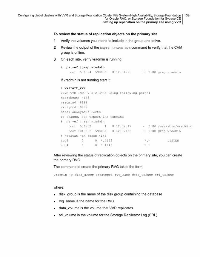
To review the status of replication objects on the primary site
1 Verify the volumes you intend to include in the group are active.
2 Review the output of the hagrp -state cvm command to verify that the CVMgroup is online.
3 On each site, verify vradmin is running:
# ps -ef |grep vradmin
root 536594 598036 0 12:31:25 0 0:00 grep vradmin
If vradmin is not running start it:
# vxstart_vvr
VxVM VVR INFO V-5-2-3935 Using following ports:
heartbeat: 4145
vradmind: 8199
vxrsyncd: 8989
data: Anonymous-Ports
To change, see vrport(1M) command
# ps -ef |grep vradmin
root 536782 1 0 12:32:47 - 0:00 /usr/sbin/vradmind
root 1048622 598036 0 12:32:55 0 0:00 grep vradmin
# netstat -an |grep 4145
tcp4 0 0 *.4145 *.* LISTEN
udp4 0 0 *.4145 *.*
After reviewing the status of replication objects on the primary site, you can createthe primary RVG.
The command to create the primary RVG takes the form:
vradmin -g disk_group createpri rvg_name data_volume srl_volume
where:
■ disk_group is the name of the disk group containing the database
■ rvg_name is the name for the RVG
■ data_volume is the volume that VVR replicates
■ srl_volume is the volume for the Storage Replicator Log (SRL)
139Configuring global clusters with VVR and Storage Foundation Cluster File System High Availability, Storage Foundationfor Oracle RAC, or Storage Foundation for Sybase CE
Setting up replication on the primary site using VVR
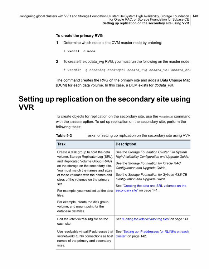
To create the primary RVG
1 Determine which node is the CVM master node by entering:
# vxdctl -c mode
2 To create the dbdata_rvg RVG, you must run the following on the master node:
# vradmin -g dbdatadg createpri dbdata_rvg dbdata_vol dbdata_srl
The command creates the RVG on the primary site and adds a Data Change Map(DCM) for each data volume. In this case, a DCM exists for dbdata_vol.
Setting up replication on the secondary site usingVVR
To create objects for replication on the secondary site, use the vradmin commandwith the addsec option. To set up replication on the secondary site, perform thefollowing tasks:
Table 9-3 Tasks for setting up replication on the secondary site using VVR
DescriptionTask
See the Storage Foundation Cluster File SystemHigh Availability Configuration and Upgrade Guide.
See the Storage Foundation for Oracle RACConfiguration and Upgrade Guide.
See the Storage Foundation for Sybase ASE CEConfiguration and Upgrade Guide.
See “Creating the data and SRL volumes on thesecondary site” on page 141.
Create a disk group to hold the datavolume, Storage Replicator Log (SRL),and Replicated Volume Group (RVG)on the storage on the secondary site.You must match the names and sizesof these volumes with the names andsizes of the volumes on the primarysite.
For example, you must set up the datafiles.
For example, create the disk group,volume, and mount point for thedatabase datafiles.
See “Editing the /etc/vx/vras/.rdg files” on page 141.Edit the /etc/vx/vras/.rdg file on theeach site.
See “Setting up IP addresses for RLINKs on eachcluster” on page 142.
Use resolvable virtual IP addresses thatset network RLINK connections as hostnames of the primary and secondarysites.
140Configuring global clusters with VVR and Storage Foundation Cluster File System High Availability, Storage Foundationfor Oracle RAC, or Storage Foundation for Sybase CE
Setting up replication on the secondary site using VVR
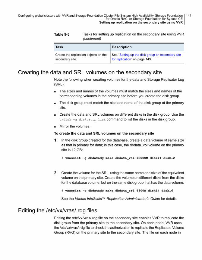
Table 9-3 Tasks for setting up replication on the secondary site using VVR(continued)
DescriptionTask
See “Setting up the disk group on secondary sitefor replication” on page 143.
Create the replication objects on thesecondary site.
Creating the data and SRL volumes on the secondary siteNote the following when creating volumes for the data and Storage Replicator Log(SRL):
■ The sizes and names of the volumes must match the sizes and names of thecorresponding volumes in the primary site before you create the disk group.
■ The disk group must match the size and name of the disk group at the primarysite.
■ Create the data and SRL volumes on different disks in the disk group. Use thevxdisk -g diskgroup list command to list the disks in the disk group.
■ Mirror the volumes.
To create the data and SRL volumes on the secondary site
1 In the disk group created for the database, create a data volume of same sizeas that in primary for data; in this case, the dbdata_vol volume on the primarysite is 12 GB:
# vxassist -g dbdatadg make dbdata_vol 12000M disk11 disk12
2 Create the volume for the SRL, using the same name and size of the equivalentvolume on the primary site. Create the volume on different disks from the disksfor the database volume, but on the same disk group that has the data volume:
# vxassist -g dbdatadg make dbdata_srl 6800M disk14 disk16
See the Veritas InfoScale™ Replication Administrator’s Guide for details.
Editing the /etc/vx/vras/.rdg filesEditing the /etc/vx/vras/.rdg file on the secondary site enables VVR to replicate thedisk group from the primary site to the secondary site. On each node, VVR usesthe /etc/vx/vras/.rdg file to check the authorization to replicate the Replicated VolumeGroup (RVG) on the primary site to the secondary site. The file on each node in
141Configuring global clusters with VVR and Storage Foundation Cluster File System High Availability, Storage Foundationfor Oracle RAC, or Storage Foundation for Sybase CE
Setting up replication on the secondary site using VVR
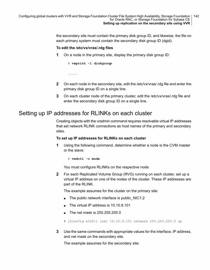
the secondary site must contain the primary disk group ID, and likewise, the file oneach primary system must contain the secondary disk group ID (dgid).
To edit the /etc/vx/vras/.rdg files
1 On a node in the primary site, display the primary disk group ID:
# vxprint -l diskgroup
.....
2 On each node in the secondary site, edit the /etc/vx/vras/.rdg file and enter theprimary disk group ID on a single line.
3 On each cluster node of the primary cluster, edit the /etc/vx/vras/.rdg file andenter the secondary disk group ID on a single line.
Setting up IP addresses for RLINKs on each clusterCreating objects with the vradmin command requires resolvable virtual IP addressesthat set network RLINK connections as host names of the primary and secondarysites.
To set up IP addresses for RLINKs on each cluster
1 Using the following command, determine whether a node is the CVM masteror the slave:
# vxdctl -c mode
You must configure RLINKs on the respective node.
2 For each Replicated Volume Group (RVG) running on each cluster, set up avirtual IP address on one of the nodes of the cluster. These IP addresses arepart of the RLINK.
The example assumes for the cluster on the primary site:
■ The public network interface is public_NIC1:2
■ The virtual IP address is 10.10.9.101
■ The net mask is 255.255.255.0
# ifconfig eth0:1 inet 10.10.9.101 netmask 255.255.255.0 up
3 Use the same commands with appropriate values for the interface, IP address,and net mask on the secondary site.
The example assumes for the secondary site:
142Configuring global clusters with VVR and Storage Foundation Cluster File System High Availability, Storage Foundationfor Oracle RAC, or Storage Foundation for Sybase CE
Setting up replication on the secondary site using VVR
■ The public network interface is public_NIC1:1
■ virtual IP address is 10.11.9.102
■ net mask is 255.255.255.0
4 Define the virtual IP addresses to correspond to a host name in the virtualcluster on the primary site and a host name in the virtual cluster on thesecondary site.
Update the /etc/hosts file on all the nodes on both the primary and secondarysites.
The examples assume:
■ clus1 has IP address 10.10.9.101
■ clus2 has IP address 10.11.9.102
5 Use the ping command to verify the links are functional.
Setting up the disk group on secondary site for replicationCreate the replication objects on the secondary site from the master node of theprimary site, using the vradmin command.
To set up the disk group on the secondary site for replication
1 Issue the command in the following format from the cluster on the primary site:
# vradmin -g dg_pri addsec rvg_pri pri_host sec_host
where:
■ dg_pri is the disk group on the primary site that VVR will replicate. Forexample: dbdata_vol
■ rvg_pri is the Replicated Volume Group (RVG) on the primary site. Forexample: dbdata_rvg
■ pri_host is the virtual IP address or resolvable virtual host name of thecluster on the primary site.For example: 10.10.9.101 or clus1
■ sec_host is the virtual IP address or resolvable virtual host name of thecluster on the secondary site.For example: 10.11.9.102 or clus2
For example, the command to add the cluster on the primary site to theReplicated Data Set (RDS) is:
143Configuring global clusters with VVR and Storage Foundation Cluster File System High Availability, Storage Foundationfor Oracle RAC, or Storage Foundation for Sybase CE
Setting up replication on the secondary site using VVR
vradmin -g dbdatadg addsec dbdata_rvg clus1 clus2
or
vradmin -g dbdatadg addsec dbdata_rvg 10.10.9.101 10.11.9.102
On the secondary site, the above command performs the following tasks:
■ Creates an RVG within the specified disk group using the same name asthe one for the primary site
■ Associates the data and Storage Replicator Log (SRL) volumes that havethe same names as the ones on the primary site with the specified RVG
■ Adds a data change map (DCM) for the data volume
■ Creates cluster RLINKs for the primary and secondary sites with the defaultnames; for example, the "primary" RLINK created for this example isrlk_dbdata_clus2_dbdata_rvg and the "secondary" RLINK created isrlk_dbdata_clus1_dbdata_rvg.If you use 10.10.9.101 and 10.11.9.102, creates cluster RLINKs for theprimary and secondary sites with the default names; for example, the"primary" RLINK created for this example is rlk_10.11.9.102_dbdata_rvgand the "secondary" RLINK created is rlk_10.10.9.101_dbdata__rvg.
2 Verify the list of RVGs in the RDS by executing the following command.
# vradmin -g dbdatadg -l printrvg
For example:
Replicated Data Set: dbdata_rvg
Primary:
HostName: 10.180.88.187 <localhost>
RvgName: dbdata_rvg
DgName: dbdata_vol
datavol_cnt: 1
vset_cnt: 0
srl: dbdata_srl
RLinks:
name=rlk_clus2_dbdata_rvg, detached=on,
synchronous=off
Secondary:
HostName: 10.190.99.197
RvgName:dbdata_rvg
DgName: dbdatadg
datavol_cnt: 1
vset_cnt: 0
144Configuring global clusters with VVR and Storage Foundation Cluster File System High Availability, Storage Foundationfor Oracle RAC, or Storage Foundation for Sybase CE
Setting up replication on the secondary site using VVR
srl: dbdata_srl
RLinks:
name=rlk_clus1_dbdata_rvg, detached=on,
synchronous=off
Note: Once the replication is started the value of the detached flag will changethe status from ON to OFF.
Starting replication of the primary site databasevolume to the secondary site using VVR
When you have both the primary and secondary sites set up for replication, youcan start replication from the primary site to the secondary site.
Start with the default replication settings:
■ Mode of replication: synchronous=off
■ Latency Protection: latencyprot=off
■ Storage Replicator Log (SRL) overflow protection: srlprot=autodcm
■ Packet size: packet_size=8400
■ Network protocol: protocol=TCP
Method of initial synchronization:
■ Automatic synchronization
■ Full synchronization with Storage Checkpoint
For guidelines on modifying these settings and information on choosing the methodof replication for the initial synchronization:
See the Veritas InfoScale™ Replication Administrator’s Guide
Use the vradmin command to start replication or the transfer of data from the primarysite to the secondary site over the network. Because the cluster on the secondarysite uses only one host name, the command does not require the sec_host argument.
To start replication using automatic synchronization
◆ From the primary site, use the following command to automatically synchronizethe Replicated Volume Group (RVG) on the secondary site:
vradmin -g disk_group -a startrep pri_rvg sec_host
145Configuring global clusters with VVR and Storage Foundation Cluster File System High Availability, Storage Foundationfor Oracle RAC, or Storage Foundation for Sybase CE
Starting replication of the primary site database volume to the secondary site using VVR
where:
■ disk_group is the disk group on the primary site that VVR will replicate
■ pri_rvg is the name of the Replicated Volume Group (RVG) on the primarysite
■ sec_host is the virtual host name for the secondary site
For example:
# vradmin -g dbdatadg -a startrep dbdata_rvg clus2
Use the vradmin command with the Storage Checkpoint option to start replicationusing full synchronization with Storage Checkpoint.
To start replication using full synchronization with Storage Checkpoint
1 From the primary site, synchronize the RVG on the secondary site with fullsynchronization (using the -c checkpoint option):
vradmin -g disk_group -full -c ckpt_name syncrvg pri_rvg sec_host
where:
■ disk_group is the disk group on the primary site that VVR will replicate
■ ckpt_name is the name of the Storage Checkpoint on the primary site
■ pri_rvg is the name of the RVG on the primary site
■ sec_host is the virtual host name for the secondary site
For example:
# vradmin -g dbdatadg -c dbdata_ckpt syncrvg dbdata_rvg clus2
2 To start replication after full synchronization, enter the following command:
# vradmin -g dbdatadg -c dbdata_ckpt startrep dbdata_rvg clus2
Verify that replication is properly functioning.
146Configuring global clusters with VVR and Storage Foundation Cluster File System High Availability, Storage Foundationfor Oracle RAC, or Storage Foundation for Sybase CE
Starting replication of the primary site database volume to the secondary site using VVR

To verify replication status
1 Check the status of VVR replication:
# vradmin -g disk_group_name repstatus rvg_name
2 Review the flags output for the status. The output may appear as connected
and consistent. For example:
# vxprint -g dbdatadg -l rlk_clus2_dbdata_rvg
Rlink: rlk_clus2_dbdata_rvg
info: timeout=500 packet_size=8400 rid=0.1078
latency_high_mark=10000 latency_low_mark=9950
bandwidth_limit=none
state: state=ACTIVE
synchronous=off latencyprot=off srlprot=autodcm
.
.
protocol: UDP/IP
checkpoint: dbdata_ckpt
flags: write enabled attached consistent connected
asynchronous
Configuring Cluster Server to replicate thedatabase volume using VVR
After configuring both clusters for global clustering and setting up the database forreplication, configure Cluster Server (VCS) to provide high availability for thedatabase. Specifically, configure VCS agents to control the cluster resources,including the replication resources.
Table 9-4 Tasks for configuring VCS to replicate the database volume usingVVR
DescriptionTask
See “Modifying the Cluster Server (VCS) configuration onthe primary site” on page 152.
Modify the VCS configurationon the primary site
See “Modifying the VCS configuration on the secondarysite” on page 159.
Modifying the VCSconfiguration on the secondarysite
The following resources must be configured or modified for replication:
147Configuring global clusters with VVR and Storage Foundation Cluster File System High Availability, Storage Foundationfor Oracle RAC, or Storage Foundation for Sybase CE
Configuring Cluster Server to replicate the database volume using VVR
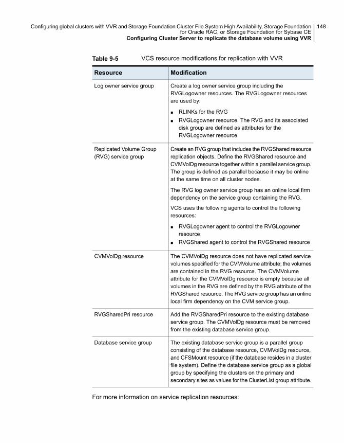
Table 9-5 VCS resource modifications for replication with VVR
ModificationResource
Create a log owner service group including theRVGLogowner resources. The RVGLogowner resourcesare used by:
■ RLINKs for the RVG■ RVGLogowner resource. The RVG and its associated
disk group are defined as attributes for theRVGLogowner resource.
Log owner service group
Create an RVG group that includes the RVGShared resourcereplication objects. Define the RVGShared resource andCVMVolDg resource together within a parallel service group.The group is defined as parallel because it may be onlineat the same time on all cluster nodes.
The RVG log owner service group has an online local firmdependency on the service group containing the RVG.
VCS uses the following agents to control the followingresources:
■ RVGLogowner agent to control the RVGLogownerresource
■ RVGShared agent to control the RVGShared resource
Replicated Volume Group(RVG) service group
The CVMVolDg resource does not have replicated servicevolumes specified for the CVMVolume attribute; the volumesare contained in the RVG resource. The CVMVolumeattribute for the CVMVolDg resource is empty because allvolumes in the RVG are defined by the RVG attribute of theRVGShared resource. The RVG service group has an onlinelocal firm dependency on the CVM service group.
CVMVolDg resource
Add the RVGSharedPri resource to the existing databaseservice group. The CVMVolDg resource must be removedfrom the existing database service group.
RVGSharedPri resource
The existing database service group is a parallel groupconsisting of the database resource, CVMVolDg resource,and CFSMount resource (if the database resides in a clusterfile system). Define the database service group as a globalgroup by specifying the clusters on the primary andsecondary sites as values for the ClusterList group attribute.
Database service group
For more information on service replication resources:
148Configuring global clusters with VVR and Storage Foundation Cluster File System High Availability, Storage Foundationfor Oracle RAC, or Storage Foundation for Sybase CE
Configuring Cluster Server to replicate the database volume using VVR
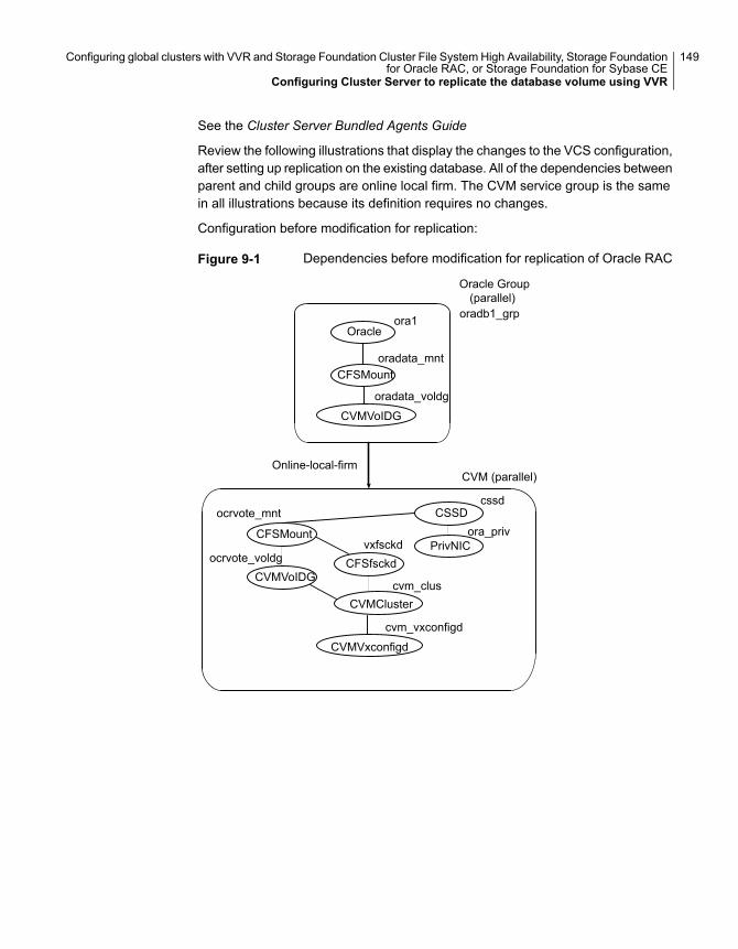
See the Cluster Server Bundled Agents Guide
Review the following illustrations that display the changes to the VCS configuration,after setting up replication on the existing database. All of the dependencies betweenparent and child groups are online local firm. The CVM service group is the samein all illustrations because its definition requires no changes.
Configuration before modification for replication:
Figure 9-1 Dependencies before modification for replication of Oracle RAC
Oracle Group(parallel)
PrivNIC
CSSDcssd
CVM (parallel)
Oracleora1
CFSMountoradata_mnt
oradata_voldg
CVMVoIDGCFSfsckd
oradb1_grp
Online-local-firm
CFSMount
CVMVoIDG
ocrvote_mnt
ocrvote_voldg
CVMCluster
CVMVxconfigd
cvm_vxconfigd
cvm_clus
ora_privvxfsckd
149Configuring global clusters with VVR and Storage Foundation Cluster File System High Availability, Storage Foundationfor Oracle RAC, or Storage Foundation for Sybase CE
Configuring Cluster Server to replicate the database volume using VVR
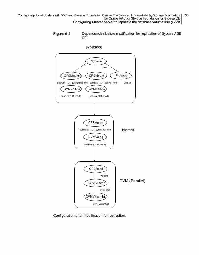
Figure 9-2 Dependencies before modification for replication of Sybase ASECE
Sybase
CFSMount
CVMVoIDG
quorum_101_quorumvol_mnt
quorum_101_voldg
CFSMount
CVMVoIDG
sybdata_101_sybvol_mnt
Process
sybdata_101_voldg
sybasece
ase
vxfend
CVMVoldg
CFSMount
sybbindg_101_voldg
sybbindg_101_sybbinvol_mnt
CVMCluster
CFSfsckd
CVMVxconfigd
cvm_clus
vxfsckd
cvm_vxconfigd
CVM (Parallel)
binmnt
Configuration after modification for replication:
150Configuring global clusters with VVR and Storage Foundation Cluster File System High Availability, Storage Foundationfor Oracle RAC, or Storage Foundation for Sybase CE
Configuring Cluster Server to replicate the database volume using VVR
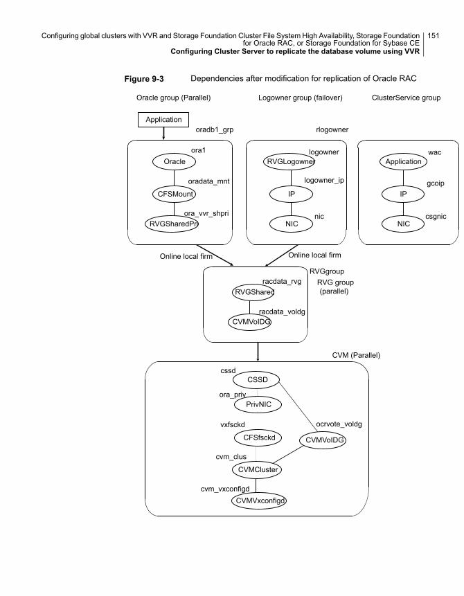
Figure 9-3 Dependencies after modification for replication of Oracle RAC
PrivNIC
CSSD
CVMVxconfigd
cssd
ora_priv
cvm_clus
CVM (Parallel)
CVMVoIDG
ocrvote_voldg
CFSfsckd
CVMCluster
CVMVoIDG
racdata_rvg
racdata_voldg
Oracleora1
CFSMount
RVGSharedPri
oradata_mnt
RVGLogownerlogowner
IP
NICnic
Applicationwac
IP
NIC
gcoip
csgnic
Application
Oracle group (Parallel) Logowner group (failover) ClusterService group
oradb1_grp rlogowner
RVG group(parallel)
Online local firm Online local firm
RVGgroup
RVGShared
logowner_ip
ora_vvr_shpri
cvm_vxconfigd
vxfsckd
151Configuring global clusters with VVR and Storage Foundation Cluster File System High Availability, Storage Foundationfor Oracle RAC, or Storage Foundation for Sybase CE
Configuring Cluster Server to replicate the database volume using VVR
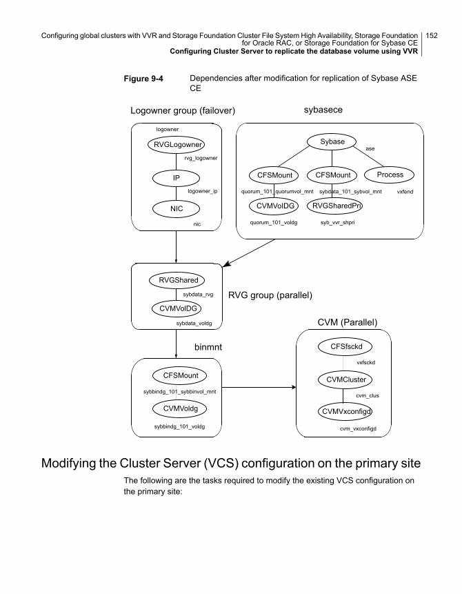
Figure 9-4 Dependencies after modification for replication of Sybase ASECE
RVGLogowner
rvg_logowner
IP
NIC
logowner_ip
nic
RVGShared
CVMVolDG
Sybase
CFSMount
CVMVoIDG
quorum_101_quorumvol_mnt
quorum_101_voldg
CFSMount
RVGSharedPri
sybdata_101_sybvol_mnt
Process
syb_vvr_shpri
sybasece
ase
vxfend
sybdata_rvg
sybdata_voldg
CVMVoldg
CFSMount
sybbindg_101_voldg
sybbindg_101_sybbinvol_mnt
CVMCluster
CFSfsckd
CVMVxconfigd
cvm_clus
vxfsckd
cvm_vxconfigd
CVM (Parallel)
Logowner group (failover)
RVG group (parallel)
binmnt
logowner
Modifying the Cluster Server (VCS) configuration on the primary siteThe following are the tasks required to modify the existing VCS configuration onthe primary site:
152Configuring global clusters with VVR and Storage Foundation Cluster File System High Availability, Storage Foundationfor Oracle RAC, or Storage Foundation for Sybase CE
Configuring Cluster Server to replicate the database volume using VVR
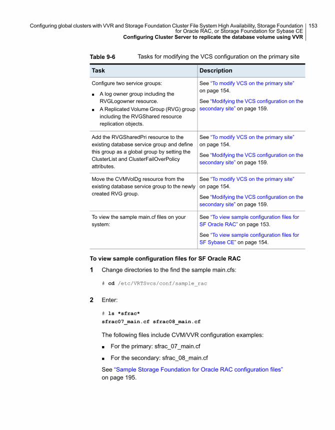
Table 9-6 Tasks for modifying the VCS configuration on the primary site
DescriptionTask
See “To modify VCS on the primary site”on page 154.
See “Modifying the VCS configuration on thesecondary site” on page 159.
Configure two service groups:
■ A log owner group including theRVGLogowner resource.
■ A Replicated Volume Group (RVG) groupincluding the RVGShared resourcereplication objects.
See “To modify VCS on the primary site”on page 154.
See “Modifying the VCS configuration on thesecondary site” on page 159.
Add the RVGSharedPri resource to theexisting database service group and definethis group as a global group by setting theClusterList and ClusterFailOverPolicyattributes.
See “To modify VCS on the primary site”on page 154.
See “Modifying the VCS configuration on thesecondary site” on page 159.
Move the CVMVolDg resource from theexisting database service group to the newlycreated RVG group.
See “To view sample configuration files forSF Oracle RAC” on page 153.
See “To view sample configuration files forSF Sybase CE” on page 154.
To view the sample main.cf files on yoursystem:
To view sample configuration files for SF Oracle RAC
1 Change directories to the find the sample main.cfs:
# cd /etc/VRTSvcs/conf/sample_rac
2 Enter:
# ls *sfrac*
sfrac07_main.cf sfrac08_main.cf
The following files include CVM/VVR configuration examples:
■ For the primary: sfrac_07_main.cf
■ For the secondary: sfrac_08_main.cf
See “Sample Storage Foundation for Oracle RAC configuration files”on page 195.
153Configuring global clusters with VVR and Storage Foundation Cluster File System High Availability, Storage Foundationfor Oracle RAC, or Storage Foundation for Sybase CE
Configuring Cluster Server to replicate the database volume using VVR
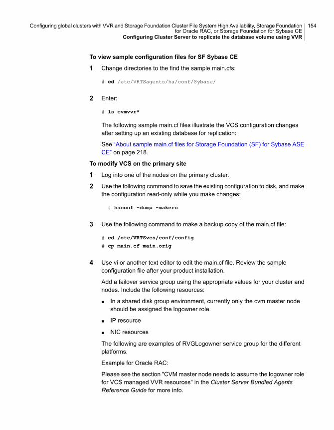
To view sample configuration files for SF Sybase CE
1 Change directories to the find the sample main.cfs:
# cd /etc/VRTSagents/ha/conf/Sybase/
2 Enter:
# ls cvmvvr*
The following sample main.cf files illustrate the VCS configuration changesafter setting up an existing database for replication:
See “About sample main.cf files for Storage Foundation (SF) for Sybase ASECE” on page 218.
To modify VCS on the primary site
1 Log into one of the nodes on the primary cluster.
2 Use the following command to save the existing configuration to disk, and makethe configuration read-only while you make changes:
# haconf -dump -makero
3 Use the following command to make a backup copy of the main.cf file:
# cd /etc/VRTSvcs/conf/config
# cp main.cf main.orig
4 Use vi or another text editor to edit the main.cf file. Review the sampleconfiguration file after your product installation.
Add a failover service group using the appropriate values for your cluster andnodes. Include the following resources:
■ In a shared disk group environment, currently only the cvm master nodeshould be assigned the logowner role.
■ IP resource
■ NIC resources
The following are examples of RVGLogowner service group for the differentplatforms.
Example for Oracle RAC:
Please see the section "CVM master node needs to assume the logowner rolefor VCS managed VVR resources" in the Cluster Server Bundled AgentsReference Guide for more info.
154Configuring global clusters with VVR and Storage Foundation Cluster File System High Availability, Storage Foundationfor Oracle RAC, or Storage Foundation for Sybase CE
Configuring Cluster Server to replicate the database volume using VVR
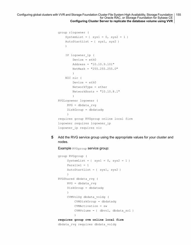
group rlogowner (
SystemList = { sys1 = 0, sys2 = 1 }
AutoStartList = { sys1, sys2 }
)
IP logowner_ip (
Device = eth0
Address = "10.10.9.101"
NetMask = "255.255.255.0"
)
NIC nic (
Device = eth0
NetworkType = ether
NetworkHosts = "10.10.8.1"
)
RVGLogowner logowner (
RVG = dbdata_rvg
DiskGroup = dbdatadg
)
requires group RVGgroup online local firm
logowner requires logowner_ip
logowner_ip requires nic
5 Add the RVG service group using the appropriate values for your cluster andnodes.
Example RVGgroup service group:
group RVGgroup (
SystemList = { sys1 = 0, sys2 = 1 }
Parallel = 1
AutoStartList = { sys1, sys2 }
)
RVGShared dbdata_rvg (
RVG = dbdata_rvg
DiskGroup = dbdatadg
)
CVMVolDg dbdata_voldg (
CVMDiskGroup = dbdatadg
CVMActivation = sw
CVMVolume = { dbvol, dbdata_srl }
)
requires group cvm online local firm
dbdata_rvg requires dbdata_voldg
155Configuring global clusters with VVR and Storage Foundation Cluster File System High Availability, Storage Foundationfor Oracle RAC, or Storage Foundation for Sybase CE
Configuring Cluster Server to replicate the database volume using VVR
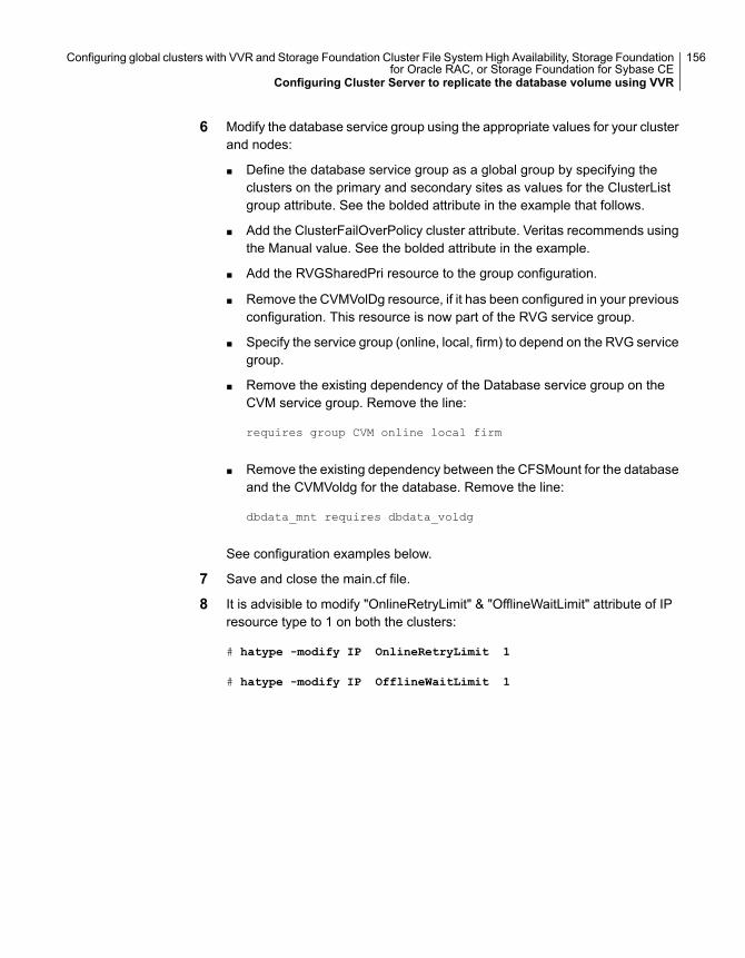
6 Modify the database service group using the appropriate values for your clusterand nodes:
■ Define the database service group as a global group by specifying theclusters on the primary and secondary sites as values for the ClusterListgroup attribute. See the bolded attribute in the example that follows.
■ Add the ClusterFailOverPolicy cluster attribute. Veritas recommends usingthe Manual value. See the bolded attribute in the example.
■ Add the RVGSharedPri resource to the group configuration.
■ Remove the CVMVolDg resource, if it has been configured in your previousconfiguration. This resource is now part of the RVG service group.
■ Specify the service group (online, local, firm) to depend on the RVG servicegroup.
■ Remove the existing dependency of the Database service group on theCVM service group. Remove the line:
requires group CVM online local firm
■ Remove the existing dependency between the CFSMount for the databaseand the CVMVoldg for the database. Remove the line:
dbdata_mnt requires dbdata_voldg
See configuration examples below.
7 Save and close the main.cf file.
8 It is advisible to modify "OnlineRetryLimit" & "OfflineWaitLimit" attribute of IPresource type to 1 on both the clusters:
# hatype -modify IP OnlineRetryLimit 1
# hatype -modify IP OfflineWaitLimit 1
156Configuring global clusters with VVR and Storage Foundation Cluster File System High Availability, Storage Foundationfor Oracle RAC, or Storage Foundation for Sybase CE
Configuring Cluster Server to replicate the database volume using VVR
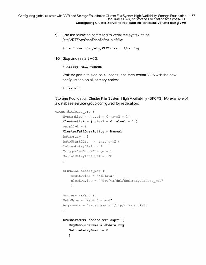
9 Use the following command to verify the syntax of the/etc/VRTSvcs/conf/config/main.cf file:
# hacf -verify /etc/VRTSvcs/conf/config
10 Stop and restart VCS.
# hastop -all -force
Wait for port h to stop on all nodes, and then restart VCS with the newconfiguration on all primary nodes:
# hastart
Storage Foundation Cluster File System High Availability (SFCFS HA) example ofa database service group configured for replication:
group database_grp (
SystemList = { sys1 = 0, sys2 = 1 }
ClusterList = { clus1 = 0, clus2 = 1 }
Parallel = 1
ClusterFailOverPolicy = Manual
Authority = 1
AutoStartList = { sys1,sys2 }
OnlineRetryLimit = 3
TriggerResStateChange = 1
OnlineRetryInterval = 120
)
CFSMount dbdata_mnt (
MountPoint = "/dbdata"
BlockDevice = "/dev/vx/dsk/dbdatadg/dbdata_vol"
)
Process vxfend (
PathName = "/sbin/vxfend"
Arguments = "-m sybase -k /tmp/vcmp_socket"
)
RVGSharedPri dbdata_vvr_shpri (
RvgResourceName = dbdata_rvg
OnlineRetryLimit = 0
)
157Configuring global clusters with VVR and Storage Foundation Cluster File System High Availability, Storage Foundationfor Oracle RAC, or Storage Foundation for Sybase CE
Configuring Cluster Server to replicate the database volume using VVR
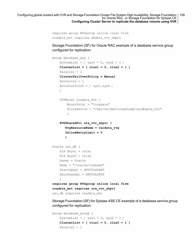
requires group RVGgroup online local firm
oradata_mnt requires dbdata_vvr_shpri
Storage Foundation (SF) for Oracle RAC example of a database service groupconfigured for replication:
group database_grp (
SystemList = { sys1 = 0, sys2 = 1 }
ClusterList = { clus1 = 0, clus2 = 1 }
Parallel = 1
ClusterFailOverPolicy = Manual
Authority = 1
AutoStartList = { sys1,sys2 }
)
CFSMount oradata_mnt (
MountPoint = "/oradata"
BlockDevice = "/dev/vx/dsk/oradatadg/racdbdata_vol"
)
RVGSharedPri ora_vvr_shpri (
RvgResourceName = racdata_rvg
OnlineRetryLimit = 0
)
Oracle rac_db (
Sid @sys1 = vrts1
Sid @sys2 = vrts2
Owner = Oracle
Home = "/oracle/orahome"
StartUpOpt = SRVCTLSTART
ShutDownOpt = SRVCTLSTOP
)
requires group RVGgroup online local firm
oradata_mnt requires ora_vvr_shpri
rac_db requires oradata_mnt
Storage Foundation (SF) for Sybase ASE CE example of a database service groupconfigured for replication:
group database_group (
SystemList = { sys1 = 0, sys2 = 1 }
ClusterList = { clus1 = 0, clus2 = 1 }
Parallel = 1
158Configuring global clusters with VVR and Storage Foundation Cluster File System High Availability, Storage Foundationfor Oracle RAC, or Storage Foundation for Sybase CE
Configuring Cluster Server to replicate the database volume using VVR
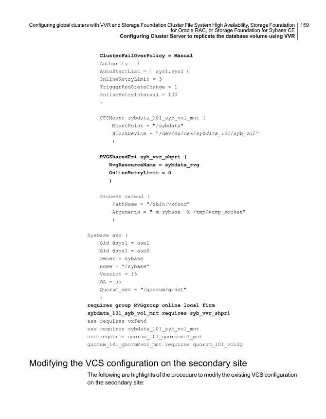
ClusterFailOverPolicy = Manual
Authority = 1
AutoStartList = { sys1,sys2 }
OnlineRetryLimit = 3
TriggerResStateChange = 1
OnlineRetryInterval = 120
)
CFSMount sybdata_101_syb_vol_mnt (
MountPoint = "/sybdata"
BlockDevice = "/dev/vx/dsk/sybdata_101/syb_vol"
)
RVGSharedPri syb_vvr_shpri (
RvgResourceName = sybdata_rvg
OnlineRetryLimit = 0
)
Process vxfend (
PathName = "/sbin/vxfend"
Arguments = "-m sybase -k /tmp/vcmp_socket"
)
Syabase ase (
Sid @sys1 = ase1
Sid @sys1 = ase2
Owner = sybase
Home = "/sybase"
Version = 15
SA = sa
Quorum_dev = "/quorum/q.dat"
)
requires group RVGgroup online local firm
sybdata_101_syb_vol_mnt requires syb_vvr_shpri
ase requires vxfend
ase requires sybdata_101_syb_vol_mnt
ase requires quorum_101_quorumvol_mnt
quorum_101_quorumvol_mnt requires quorum_101_voldg
Modifying the VCS configuration on the secondary siteThe following are highlights of the procedure to modify the existing VCS configurationon the secondary site:
159Configuring global clusters with VVR and Storage Foundation Cluster File System High Availability, Storage Foundationfor Oracle RAC, or Storage Foundation for Sybase CE
Configuring Cluster Server to replicate the database volume using VVR
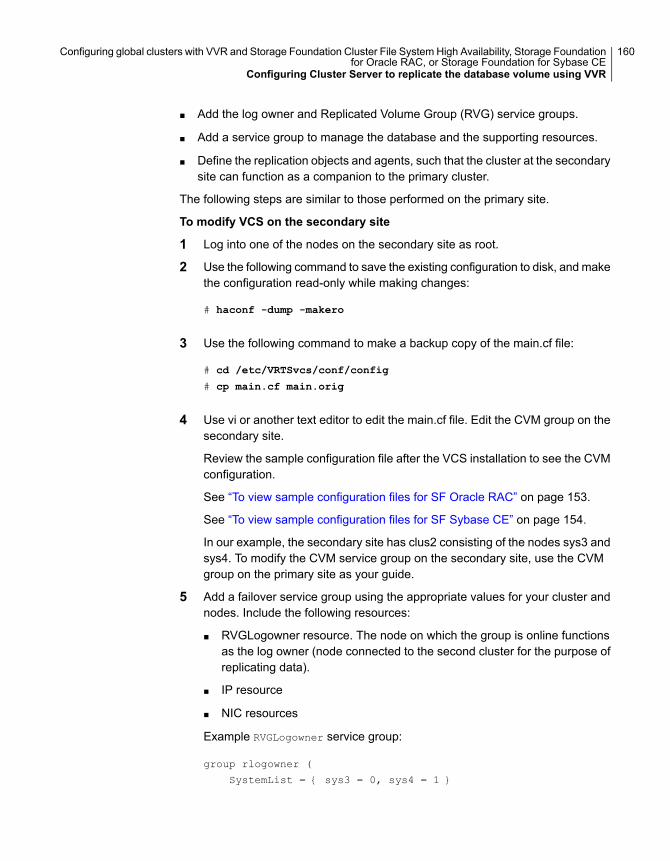
■ Add the log owner and Replicated Volume Group (RVG) service groups.
■ Add a service group to manage the database and the supporting resources.
■ Define the replication objects and agents, such that the cluster at the secondarysite can function as a companion to the primary cluster.
The following steps are similar to those performed on the primary site.
To modify VCS on the secondary site
1 Log into one of the nodes on the secondary site as root.
2 Use the following command to save the existing configuration to disk, and makethe configuration read-only while making changes:
# haconf -dump -makero
3 Use the following command to make a backup copy of the main.cf file:
# cd /etc/VRTSvcs/conf/config
# cp main.cf main.orig
4 Use vi or another text editor to edit the main.cf file. Edit the CVM group on thesecondary site.
Review the sample configuration file after the VCS installation to see the CVMconfiguration.
See “To view sample configuration files for SF Oracle RAC” on page 153.
See “To view sample configuration files for SF Sybase CE” on page 154.
In our example, the secondary site has clus2 consisting of the nodes sys3 andsys4. To modify the CVM service group on the secondary site, use the CVMgroup on the primary site as your guide.
5 Add a failover service group using the appropriate values for your cluster andnodes. Include the following resources:
■ RVGLogowner resource. The node on which the group is online functionsas the log owner (node connected to the second cluster for the purpose ofreplicating data).
■ IP resource
■ NIC resources
Example RVGLogowner service group:
group rlogowner (
SystemList = { sys3 = 0, sys4 = 1 }
160Configuring global clusters with VVR and Storage Foundation Cluster File System High Availability, Storage Foundationfor Oracle RAC, or Storage Foundation for Sybase CE
Configuring Cluster Server to replicate the database volume using VVR
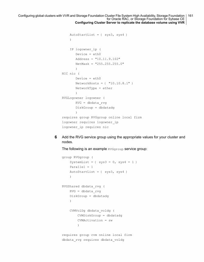
AutoStartList = { sys3, sys4 }
)
IP logowner_ip (
Device = eth0
Address = "10.11.9.102"
NetMask = "255.255.255.0"
)
NIC nic (
Device = eth0
NetworkHosts = { "10.10.8.1" }
NetworkType = ether
)
RVGLogowner logowner (
RVG = dbdata_rvg
DiskGroup = dbdatadg
)
requires group RVGgroup online local firm
logowner requires logowner_ip
logowner_ip requires nic
6 Add the RVG service group using the appropriate values for your cluster andnodes.
The following is an example RVGgroup service group:
group RVGgroup (
SystemList = { sys3 = 0, sys4 = 1 }
Parallel = 1
AutoStartList = { sys3, sys4 }
)
RVGShared dbdata_rvg (
RVG = dbdata_rvg
DiskGroup = dbdatadg
)
CVMVolDg dbdata_voldg (
CVMDiskGroup = dbdatadg
CVMActivation = sw
)
requires group cvm online local firm
dbdata_rvg requires dbdata_voldg
161Configuring global clusters with VVR and Storage Foundation Cluster File System High Availability, Storage Foundationfor Oracle RAC, or Storage Foundation for Sybase CE
Configuring Cluster Server to replicate the database volume using VVR
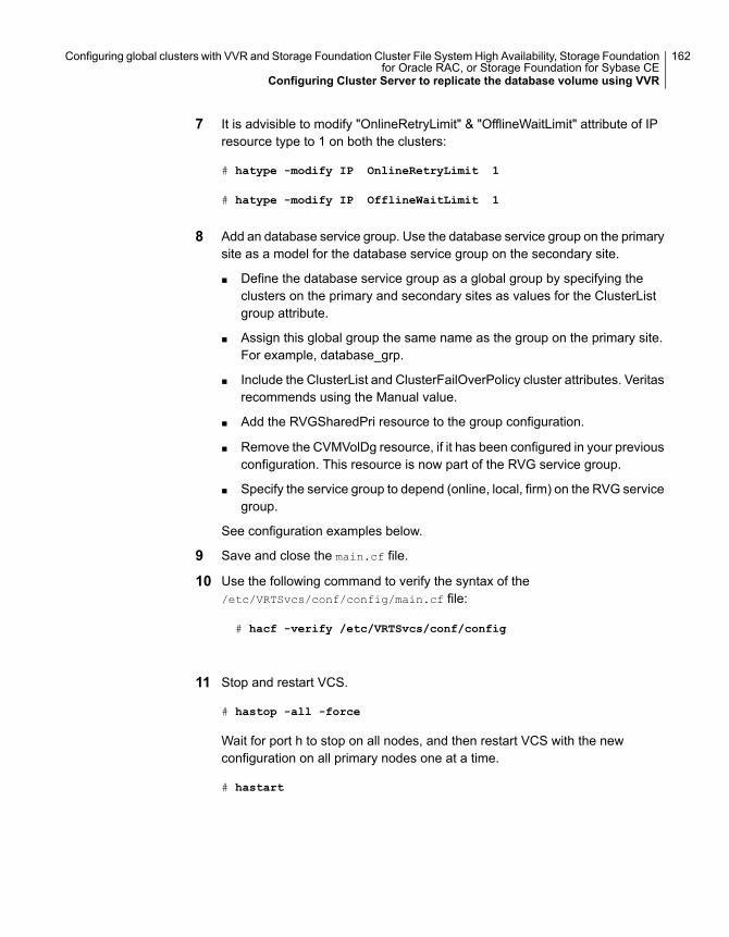
7 It is advisible to modify "OnlineRetryLimit" & "OfflineWaitLimit" attribute of IPresource type to 1 on both the clusters:
# hatype -modify IP OnlineRetryLimit 1
# hatype -modify IP OfflineWaitLimit 1
8 Add an database service group. Use the database service group on the primarysite as a model for the database service group on the secondary site.
■ Define the database service group as a global group by specifying theclusters on the primary and secondary sites as values for the ClusterListgroup attribute.
■ Assign this global group the same name as the group on the primary site.For example, database_grp.
■ Include the ClusterList and ClusterFailOverPolicy cluster attributes. Veritasrecommends using the Manual value.
■ Add the RVGSharedPri resource to the group configuration.
■ Remove the CVMVolDg resource, if it has been configured in your previousconfiguration. This resource is now part of the RVG service group.
■ Specify the service group to depend (online, local, firm) on the RVG servicegroup.
See configuration examples below.
9 Save and close the main.cf file.
10 Use the following command to verify the syntax of the/etc/VRTSvcs/conf/config/main.cf file:
# hacf -verify /etc/VRTSvcs/conf/config
11 Stop and restart VCS.
# hastop -all -force
Wait for port h to stop on all nodes, and then restart VCS with the newconfiguration on all primary nodes one at a time.
# hastart
162Configuring global clusters with VVR and Storage Foundation Cluster File System High Availability, Storage Foundationfor Oracle RAC, or Storage Foundation for Sybase CE
Configuring Cluster Server to replicate the database volume using VVR
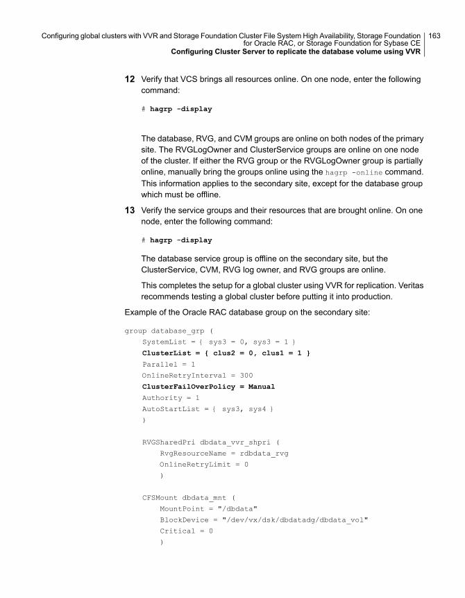
12 Verify that VCS brings all resources online. On one node, enter the followingcommand:
# hagrp -display
The database, RVG, and CVM groups are online on both nodes of the primarysite. The RVGLogOwner and ClusterService groups are online on one nodeof the cluster. If either the RVG group or the RVGLogOwner group is partiallyonline, manually bring the groups online using the hagrp -online command.This information applies to the secondary site, except for the database groupwhich must be offline.
13 Verify the service groups and their resources that are brought online. On onenode, enter the following command:
# hagrp -display
The database service group is offline on the secondary site, but theClusterService, CVM, RVG log owner, and RVG groups are online.
This completes the setup for a global cluster using VVR for replication. Veritasrecommends testing a global cluster before putting it into production.
Example of the Oracle RAC database group on the secondary site:
group database_grp (
SystemList = { sys3 = 0, sys3 = 1 }
ClusterList = { clus2 = 0, clus1 = 1 }
Parallel = 1
OnlineRetryInterval = 300
ClusterFailOverPolicy = Manual
Authority = 1
AutoStartList = { sys3, sys4 }
)
RVGSharedPri dbdata_vvr_shpri (
RvgResourceName = rdbdata_rvg
OnlineRetryLimit = 0
)
CFSMount dbdata_mnt (
MountPoint = "/dbdata"
BlockDevice = "/dev/vx/dsk/dbdatadg/dbdata_vol"
Critical = 0
)
163Configuring global clusters with VVR and Storage Foundation Cluster File System High Availability, Storage Foundationfor Oracle RAC, or Storage Foundation for Sybase CE
Configuring Cluster Server to replicate the database volume using VVR
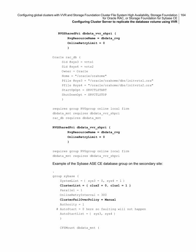
RVGSharedPri dbdata_vvr_shpri (
RvgResourceName = dbdata_rvg
OnlineRetryLimit = 0
)
Oracle rac_db (
Sid @sys3 = vrts1
Sid @sys4 = vrts2
Owner = Oracle
Home = "/oracle/orahome"
Pfile @sys3 = "/oracle/orahome/dbs/initvrts1.ora"
Pfile @sys4 = "/oracle/orahome/dbs/initvrts2.ora"
StartUpOpt = SRVCTLSTART
ShutDownOpt = SRVCTLSTOP
)
requires group RVGgroup online local firm
dbdata_mnt requires dbdata_vvr_shpri
rac_db requires dbdata_mnt
RVGSharedPri dbdata_vvr_shpri (
RvgResourceName = dbdata_rvg
OnlineRetryLimit = 0
)
requires group RVGgroup online local firm
dbdata_mnt requires dbdata_vvr_shpri
Example of the Sybase ASE CE database group on the secondary site:
.
group sybase (
SystemList = { sys3 = 0, sys4 = 1 }
ClusterList = { clus2 = 0, clus1 = 1 }
Parallel = 1
OnlineRetryInterval = 300
ClusterFailOverPolicy = Manual
Authority = 1
# AutoStart = 0 here so faulting will not happen
AutoStartList = { sys3, sys4 }
)
CFSMount dbdata_mnt (
164Configuring global clusters with VVR and Storage Foundation Cluster File System High Availability, Storage Foundationfor Oracle RAC, or Storage Foundation for Sybase CE
Configuring Cluster Server to replicate the database volume using VVR
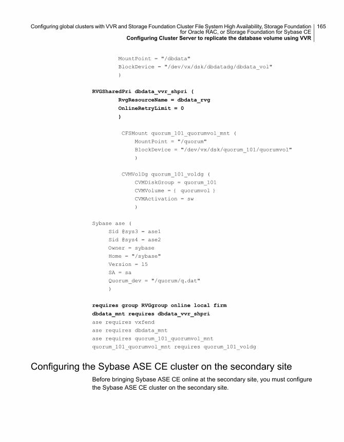
MountPoint = "/dbdata"
BlockDevice = "/dev/vx/dsk/dbdatadg/dbdata_vol"
)
RVGSharedPri dbdata_vvr_shpri (
RvgResourceName = dbdata_rvg
OnlineRetryLimit = 0
)
CFSMount quorum_101_quorumvol_mnt (
MountPoint = "/quorum"
BlockDevice = "/dev/vx/dsk/quorum_101/quorumvol"
)
CVMVolDg quorum_101_voldg (
CVMDiskGroup = quorum_101
CVMVolume = { quorumvol }
CVMActivation = sw
)
Sybase ase (
Sid @sys3 = ase1
Sid @sys4 = ase2
Owner = sybase
Home = "/sybase"
Version = 15
SA = sa
Quorum_dev = "/quorum/q.dat"
)
requires group RVGgroup online local firm
dbdata_mnt requires dbdata_vvr_shpri
ase requires vxfend
ase requires dbdata_mnt
ase requires quorum_101_quorumvol_mnt
quorum_101_quorumvol_mnt requires quorum_101_voldg
Configuring the Sybase ASE CE cluster on the secondary siteBefore bringing Sybase ASE CE online at the secondary site, you must configurethe Sybase ASE CE cluster on the secondary site.
165Configuring global clusters with VVR and Storage Foundation Cluster File System High Availability, Storage Foundationfor Oracle RAC, or Storage Foundation for Sybase CE
Configuring Cluster Server to replicate the database volume using VVR
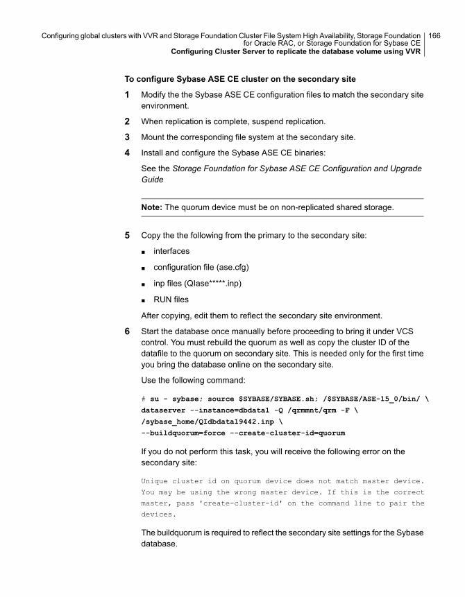
To configure Sybase ASE CE cluster on the secondary site
1 Modify the the Sybase ASE CE configuration files to match the secondary siteenvironment.
2 When replication is complete, suspend replication.
3 Mount the corresponding file system at the secondary site.
4 Install and configure the Sybase ASE CE binaries:
See the Storage Foundation for Sybase ASE CE Configuration and UpgradeGuide
Note: The quorum device must be on non-replicated shared storage.
5 Copy the the following from the primary to the secondary site:
■ interfaces
■ configuration file (ase.cfg)
■ inp files (QIase*****.inp)
■ RUN files
After copying, edit them to reflect the secondary site environment.
6 Start the database once manually before proceeding to bring it under VCScontrol. You must rebuild the quorum as well as copy the cluster ID of thedatafile to the quorum on secondary site. This is needed only for the first timeyou bring the database online on the secondary site.
Use the following command:
# su - sybase; source $SYBASE/SYBASE.sh; /$SYBASE/ASE-15_0/bin/ \
dataserver --instance=dbdata1 -Q /qrmmnt/qrm -F \
/sybase_home/QIdbdata19442.inp \
--buildquorum=force --create-cluster-id=quorum
If you do not perform this task, you will receive the following error on thesecondary site:
Unique cluster id on quorum device does not match master device.
You may be using the wrong master device. If this is the correct
master, pass 'create-cluster-id' on the command line to pair the
devices.
The buildquorum is required to reflect the secondary site settings for the Sybasedatabase.
166Configuring global clusters with VVR and Storage Foundation Cluster File System High Availability, Storage Foundationfor Oracle RAC, or Storage Foundation for Sybase CE
Configuring Cluster Server to replicate the database volume using VVR
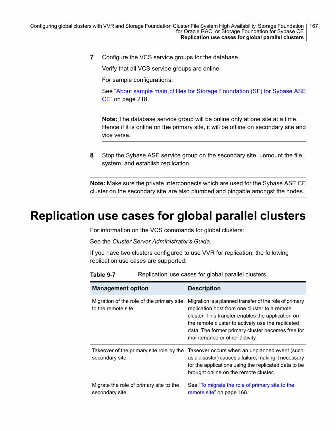
7 Configure the VCS service groups for the database.
Verify that all VCS service groups are online.
For sample configurations:
See “About sample main.cf files for Storage Foundation (SF) for Sybase ASECE” on page 218.
Note: The database service group will be online only at one site at a time.Hence if it is online on the primary site, it will be offline on secondary site andvice versa.
8 Stop the Sybase ASE service group on the secondary site, unmount the filesystem, and establish replication.
Note: Make sure the private interconnects which are used for the Sybase ASE CEcluster on the secondary site are also plumbed and pingable amongst the nodes.
Replication use cases for global parallel clustersFor information on the VCS commands for global clusters:
See the Cluster Server Administrator's Guide.
If you have two clusters configured to use VVR for replication, the followingreplication use cases are supported:
Table 9-7 Replication use cases for global parallel clusters
DescriptionManagement option
Migration is a planned transfer of the role of primaryreplication host from one cluster to a remotecluster. This transfer enables the application onthe remote cluster to actively use the replicateddata. The former primary cluster becomes free formaintenance or other activity.
Migration of the role of the primary siteto the remote site
Takeover occurs when an unplanned event (suchas a disaster) causes a failure, making it necessaryfor the applications using the replicated data to bebrought online on the remote cluster.
Takeover of the primary site role by thesecondary site
See “To migrate the role of primary site to theremote site” on page 168.
Migrate the role of primary site to thesecondary site
167Configuring global clusters with VVR and Storage Foundation Cluster File System High Availability, Storage Foundationfor Oracle RAC, or Storage Foundation for Sybase CEReplication use cases for global parallel clusters
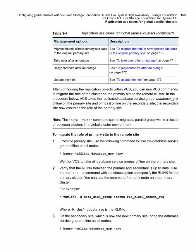
Table 9-7 Replication use cases for global parallel clusters (continued)
DescriptionManagement option
See “To migrate the role of new primary site backto the original primary site” on page 169.
Migrate the role of new primary site backto the original primary site
See “To take over after an outage” on page 171.Take over after an outage
See “To resynchronize after an outage”on page 172.
Resynchronize after an outage
See “To update the rlink” on page 173.Update the rlink
After configuring the replication objects within VCS, you can use VCS commandsto migrate the role of the cluster on the primary site to the remote cluster. In theprocedure below, VCS takes the replicated database service group, database_grp,offline on the primary site and brings it online on the secondary site; the secondarysite now assumes the role of the primary site.
Note: The hagrp -switch command cannot migrate a parallel group within a clusteror between clusters in a global cluster environment.
To migrate the role of primary site to the remote site
1 From the primary site, use the following command to take the database servicegroup offline on all nodes.
# hagrp -offline database_grp -any
Wait for VCS to take all database service groups offline on the primary site.
2 Verify that the RLINK between the primary and secondary is up to date. Usethe vxrlink -g command with the status option and specify the RLINK for theprimary cluster. You can use the command from any node on the primarycluster.
For example:
# vxrlink -g data_disk_group status rlk_clus2_dbdata_rvg
Where rlk_clus1_dbdata_rvg is the RLINK.
3 On the secondary site, which is now the new primary site, bring the databaseservice group online on all nodes:
# hagrp -online database_grp -any
168Configuring global clusters with VVR and Storage Foundation Cluster File System High Availability, Storage Foundationfor Oracle RAC, or Storage Foundation for Sybase CEReplication use cases for global parallel clusters
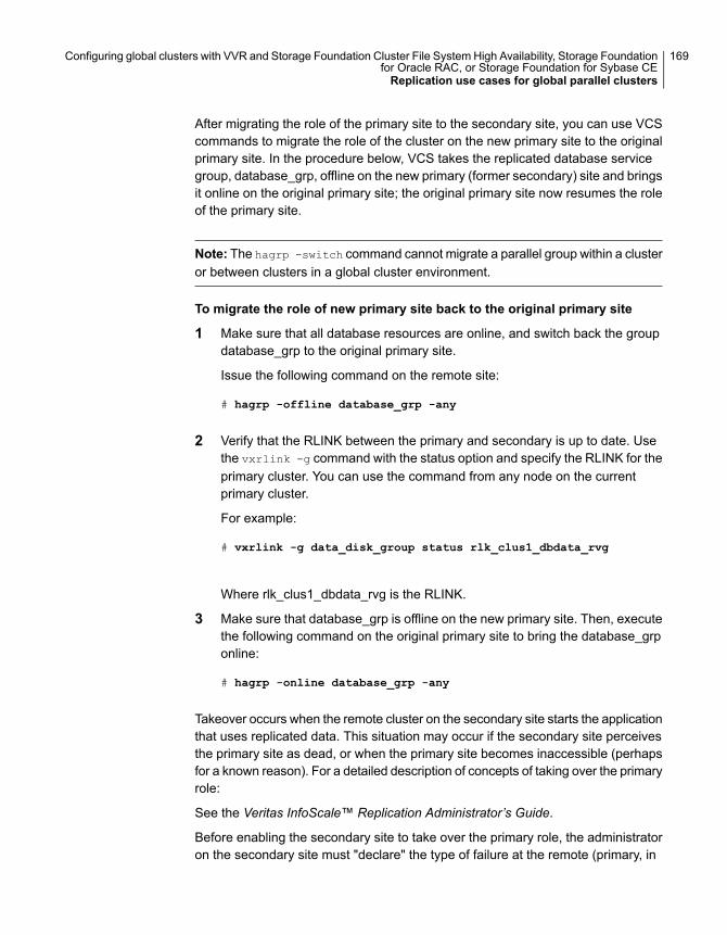
After migrating the role of the primary site to the secondary site, you can use VCScommands to migrate the role of the cluster on the new primary site to the originalprimary site. In the procedure below, VCS takes the replicated database servicegroup, database_grp, offline on the new primary (former secondary) site and bringsit online on the original primary site; the original primary site now resumes the roleof the primary site.
Note: The hagrp -switch command cannot migrate a parallel group within a clusteror between clusters in a global cluster environment.
To migrate the role of new primary site back to the original primary site
1 Make sure that all database resources are online, and switch back the groupdatabase_grp to the original primary site.
Issue the following command on the remote site:
# hagrp -offline database_grp -any
2 Verify that the RLINK between the primary and secondary is up to date. Usethe vxrlink -g command with the status option and specify the RLINK for theprimary cluster. You can use the command from any node on the currentprimary cluster.
For example:
# vxrlink -g data_disk_group status rlk_clus1_dbdata_rvg
Where rlk_clus1_dbdata_rvg is the RLINK.
3 Make sure that database_grp is offline on the new primary site. Then, executethe following command on the original primary site to bring the database_grponline:
# hagrp -online database_grp -any
Takeover occurs when the remote cluster on the secondary site starts the applicationthat uses replicated data. This situation may occur if the secondary site perceivesthe primary site as dead, or when the primary site becomes inaccessible (perhapsfor a known reason). For a detailed description of concepts of taking over the primaryrole:
See the Veritas InfoScale™ Replication Administrator’s Guide.
Before enabling the secondary site to take over the primary role, the administratoron the secondary site must "declare" the type of failure at the remote (primary, in
169Configuring global clusters with VVR and Storage Foundation Cluster File System High Availability, Storage Foundationfor Oracle RAC, or Storage Foundation for Sybase CEReplication use cases for global parallel clusters
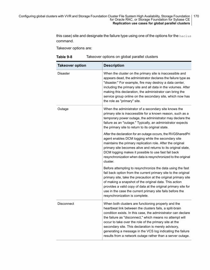
this case) site and designate the failure type using one of the options for the haclus
command.
Takeover options are:
Table 9-8 Takeover options on global parallel clusters
DescriptionTakeover option
When the cluster on the primary site is inaccessible andappears dead, the administrator declares the failure type as"disaster." For example, fire may destroy a data center,including the primary site and all data in the volumes. Aftermaking this declaration, the administrator can bring theservice group online on the secondary site, which now hasthe role as "primary" site.
Disaster
When the administrator of a secondary site knows theprimary site is inaccessible for a known reason, such as atemporary power outage, the administrator may declare thefailure as an "outage." Typically, an administrator expectsthe primary site to return to its original state.
After the declaration for an outage occurs, the RVGSharedPriagent enables DCM logging while the secondary sitemaintains the primary replication role. After the originalprimary site becomes alive and returns to its original state,DCM logging makes it possible to use fast fail backresynchronization when data is resynchronized to the originalcluster.
Before attempting to resynchronize the data using the fastfail back option from the current primary site to the originalprimary site, take the precaution at the original primary siteof making a snapshot of the original data. This actionprovides a valid copy of data at the original primary site foruse in the case the current primary site fails before theresynchronization is complete.
Outage
When both clusters are functioning properly and theheartbeat link between the clusters fails, a split-braincondition exists. In this case, the administrator can declarethe failure as "disconnect," which means no attempt willoccur to take over the role of the primary site at thesecondary site. This declaration is merely advisory,generating a message in the VCS log indicating the failureresults from a network outage rather than a server outage.
Disconnect
170Configuring global clusters with VVR and Storage Foundation Cluster File System High Availability, Storage Foundationfor Oracle RAC, or Storage Foundation for Sybase CEReplication use cases for global parallel clusters
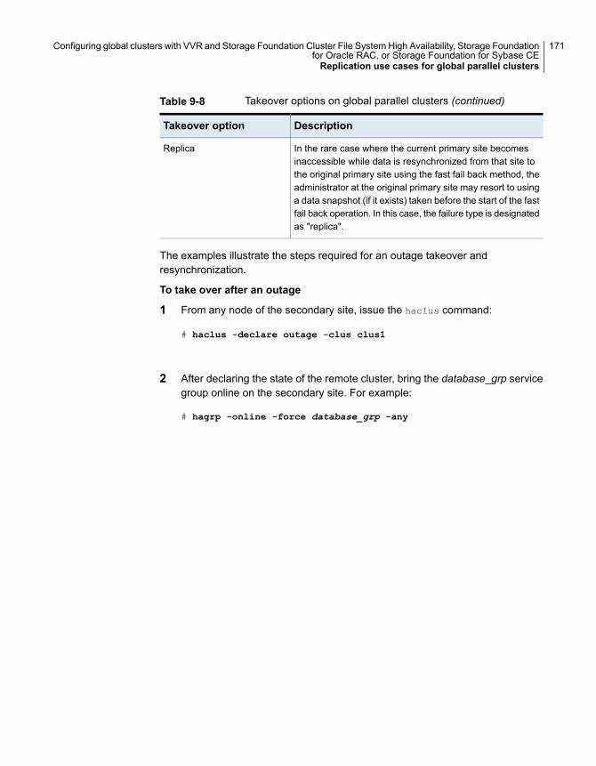
Table 9-8 Takeover options on global parallel clusters (continued)
DescriptionTakeover option
In the rare case where the current primary site becomesinaccessible while data is resynchronized from that site tothe original primary site using the fast fail back method, theadministrator at the original primary site may resort to usinga data snapshot (if it exists) taken before the start of the fastfail back operation. In this case, the failure type is designatedas "replica".
Replica
The examples illustrate the steps required for an outage takeover andresynchronization.
To take over after an outage
1 From any node of the secondary site, issue the haclus command:
# haclus -declare outage -clus clus1
2 After declaring the state of the remote cluster, bring the database_grp servicegroup online on the secondary site. For example:
# hagrp -online -force database_grp -any
171Configuring global clusters with VVR and Storage Foundation Cluster File System High Availability, Storage Foundationfor Oracle RAC, or Storage Foundation for Sybase CEReplication use cases for global parallel clusters
To resynchronize after an outage
1 On the original primary site, create a snapshot of the Replicated Volume Group(RVG) before resynchronizing it in case the current primary site fails duringthe resynchronization. Assuming the disk group is data_disk_group and theRVG is dbdata1_rvg, type:
# vxrvg -g data_disk_group -F snapshot dbdata_rvg1
See the Veritas InfoScale™ Replication Administrator’s Guide for details onRVG snapshots.
2 Resynchronize the RVG. From any node of the current primary site, issue thehares command and the -action option with the fbsync action token toresynchronize the RVGSharedPri resource. For example:
# hares -action dbdata_vvr_shpri fbsync -sys sys3
# vxdctl -c mode
3 Perform one of the following commands, depending on whether theresynchronization of data from the current primary site to the original primarysite is successful:
■ If the resynchronization of data is successful, use the vxrvg command withthe snapback option to reattach the snapshot volumes on the original primarysite to the original volumes in the specified RVG:
# vxrvg -g data_disk_group snapback dbdata_rvg1
■ A failed attempt at the resynchronization of data (for example, a disasterhits the primary RVG when resynchronization is in progress) could generateinconsistent data.You can restore the contents of the RVG data volumes from the snapshottaken in step 1:
# vxrvg -g data_disk_group snaprestore dbdata_rvg1
If the rlink is not up to date, use the hares -action command with the resync
action token to synchronize the RVG.
172Configuring global clusters with VVR and Storage Foundation Cluster File System High Availability, Storage Foundationfor Oracle RAC, or Storage Foundation for Sybase CEReplication use cases for global parallel clusters

To update the rlink
◆ The following command example is issued on any node (sys1, in this case) inthe primary cluster, specifying the RVGSharedPri resource, dbdata_vvr_shpri:
# hares -action dbdata_vvr_shpri resync -sys sys1
173Configuring global clusters with VVR and Storage Foundation Cluster File System High Availability, Storage Foundationfor Oracle RAC, or Storage Foundation for Sybase CEReplication use cases for global parallel clusters
Configuring for disasterrecovery in cloudenvironments
■ Chapter 10. Replication scenarios
■ Chapter 11. Setting up replication for cloud environments
5Section
Replication scenariosThis chapter includes the following topics:
■ About replication in AWS cloud environments
■ Replication from on-premise to cloud
■ Replication across Availability Zones within the same region
■ Replication across regions
■ Replication across multiple Availability Zones and regions (campus cluster)
About replication in AWS cloud environmentsVeritas storage sharing and replication technologies in tandem with cloud servicesoffer scalable, cost-effective disaster recovery options for your business. WithVeritas volume replication and Flexible Storage Sharing (FSS) technologies, youcan leverage the cloud as a DR site and replicate application data to or within thecloud without incurring the infrastructural costs needed to maintain a second physicalsite.
You can replicate data across Availability Zones and regions for both standaloneand clustered systems. You can form clusters across Availability Zones within aregion using FSS, a technology that enables seamless cluster-wide sharing of localstorage over the network.
In the event of failures—node, storage, or Availability Zone— data will always beavailable.
Replication from on-premise to cloudVeritas replication technologies (VVR/CVR) provide seamless data migration fromyour on-premises data center to the cloud environment. Using VVR/CVR, you can
10Chapter
also configure the on-premise data center as the primary site and the cloudenvironment as the secondary site to manage disaster recovery requirements.
Replication within a regionIn this scenario, replication is set up in different Availability Zones but within thesame region. In the event of an Availability Zone failure, VVR/CVR replicates datato the second Availability Zone thus continuing to keep the applications up andrunning.
Replication across regionsIf all your application data and workloads are migrated to the cloud, VVR/CVRenables you to use the cloud as a DR site. You can configure the primary site inone region of AWS and the secondary site in another region of AWS for disasterrecovery. With CVR, the cluster can span across Availability Zones, protecting yourdata from Availability Zone failures.
Managing AWS resourcesAutomated IP configuration services by the Veritas AWSIP agent enables you toeasily configure and manage your AWS IP resources—private IP (PIP), elastic IP(EIP), and overlay IP (OIP)— in the cloud.
The agent performs the following functions:
■ Associates and disassociates the private IP address from the Elastic NetworkInterface (ENI)
■ Associates public IP address and configures the private IP along with the elasticIP
■ Manages the route table for overlay IP address for fail over across subnets
Replication from on-premise to cloudIn this scenario, data is replicated from on premise systems to cloud.
Pre-requisites for replicationYou must meet the following requirements before setting up replication fromon-premise to cloud. This configuration assumes a clustered environment that usesCVR for replication.
■ Open ports for the communication between on premise and AWS cloud clustersin those subnets where the primary and secondary clusters are configured.
■ The virtual private IP addresses must be plumbed on both master nodes.
■ The virtual private IP addresses must be configured within the subnet.
176Replication scenariosReplication from on-premise to cloud
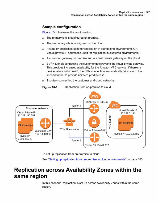
Sample configurationFigure 10-1 illustrates the configuration.
■ The primary site is configured on premise.
■ The secondary site is configured on the cloud.
■ Private IP addresses used for replication in standalone environments ORVirtual private IP addresses used for replication in clustered environments.
■ A customer gateway on premise and a virtual private gateway on the cloud
■ 2 VPN tunnels connecting the customer gateway and the virtual private gateway.This provides increased availability for the Amazon VPC service. If there's adevice failure within AWS, the VPN connection automatically fails over to thesecond tunnel to provide uninterrupted access.
■ 2 routers connecting the customer and cloud networks.
Figure 10-1 Replication from on-premise to cloud
VPN Connection
Tunnel 1
Tunnel 2
Private IP 10.239.5.180
Virtual Private IP10.239.5.191
VP
CS
ubne
t
Router 85.154.47.112
Router 85.154.33.35
Virtual Private G/W
SF instancesSF instances
Customer networkVirtual Private IP10.209.155.252
Private IP10.209.155.40
Customer G/W199.43.189.16
To set up replication from on-premise to cloud:
See “Setting up replication from on-premise to cloud environments” on page 183.
Replication across Availability Zones within thesame region
In this scenario, replication is set up across Availability Zones within the sameregion.
177Replication scenariosReplication across Availability Zones within the same region
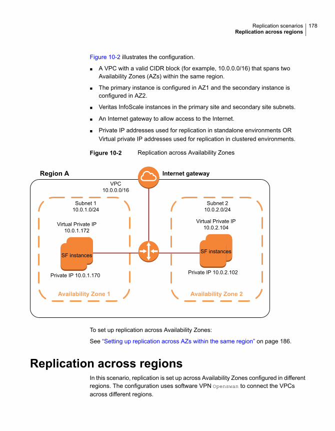
Figure 10-2 illustrates the configuration.
■ A VPC with a valid CIDR block (for example, 10.0.0.0/16) that spans twoAvailability Zones (AZs) within the same region.
■ The primary instance is configured in AZ1 and the secondary instance isconfigured in AZ2.
■ Veritas InfoScale instances in the primary site and secondary site subnets.
■ An Internet gateway to allow access to the Internet.
■ Private IP addresses used for replication in standalone environments ORVirtual private IP addresses used for replication in clustered environments.
Figure 10-2 Replication across Availability Zones
Availability Zone 1 Availability Zone 2
Internet gateway
SF instancesSF instances
Private IP 10.0.1.170 Private IP 10.0.2.102
Virtual Private IP10.0.1.172
Virtual Private IP10.0.2.104
Subnet 110.0.1.0/24
Subnet 210.0.2.0/24
Region AVPC
10.0.0.0/16
To set up replication across Availability Zones:
See “Setting up replication across AZs within the same region” on page 186.
Replication across regionsIn this scenario, replication is set up across Availability Zones configured in differentregions. The configuration uses software VPN Openswan to connect the VPCsacross different regions.
178Replication scenariosReplication across regions
Figure 10-3 illustrates the configuration for replication across regions.
■ Two VPCs with valid CIDR blocks (for example, 10.30.0.0/16 and 10.60.0.0/16respectively) that are located in two different regions.
■ The primary instance belongs to AZ1 of region A and the secondary instancebelongs to AZ1 of region B.
■ Veritas InfoScale instances in each AZ.
■ A VPN tunnel is established between two VPCs in two different regions usingsoftware VPN. Here, we have used OpenSwan software VPN. This is a secureIPSec tunnel.
■ Elastic IP addresses (EIP) to connect the two VPN instances
■ Private IP addresses used for replication in standalone environments ORVirtual private IP addresses used for replication in clustered environments.
179Replication scenariosReplication across regions
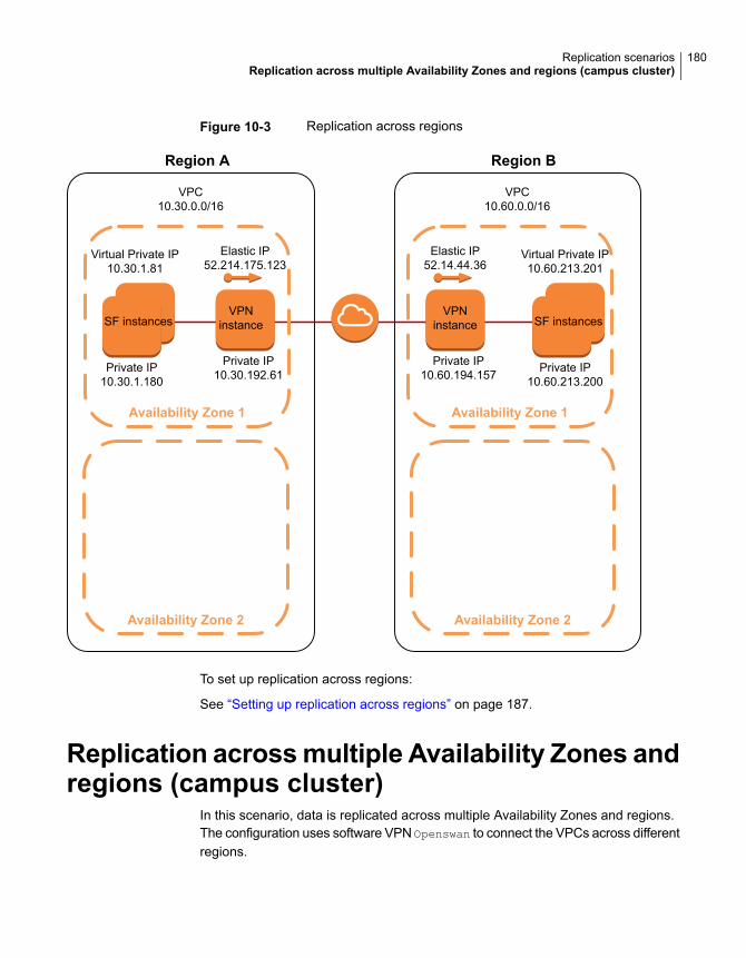
Figure 10-3 Replication across regions
Availability Zone 2
Region A
Availability Zone 1
SF instances
Private IP10.30.1.180
Virtual Private IP10.30.1.81
Private IP10.30.192.61
Elastic IP52.214.175.123
VPC10.30.0.0/16
Availability Zone 2
Region B
Availability Zone 1
Private IP10.60.194.157
Elastic IP52.14.44.36
VPC10.60.0.0/16
VPNinstance SF instances
Private IP10.60.213.200
Virtual Private IP10.60.213.201
VPNinstance
To set up replication across regions:
See “Setting up replication across regions” on page 187.
Replication acrossmultiple Availability Zones andregions (campus cluster)
In this scenario, data is replicated across multiple Availability Zones and regions.The configuration uses software VPN Openswan to connect the VPCs across differentregions.
180Replication scenariosReplication across multiple Availability Zones and regions (campus cluster)
Figure 10-4 illustrates the configuration for replication across multiple AvailabilityZones and regions.
■ Two VPCs with valid CIDR blocks (for example, 10.30.0.0/16 and 10.60.0.0/16respectively) that are located in two different regions.
■ The primary instance belongs to AZ1 of region 1 and the secondary instancebelongs to AZ2 of region 2.
■ Veritas InfoScale instances in each AZ.
■ The primary Instance communicates with the secondary Instance using VPNinstances at both ends.
■ A VPN tunnel to secure communication between the instances across VPCs.
■ Elastic IP addresses (EIP) to connect the two VPN instances
■ Private IP addresses used for replication in standalone environments OROverlay IP addresses used for replication in clustered environments.
181Replication scenariosReplication across multiple Availability Zones and regions (campus cluster)
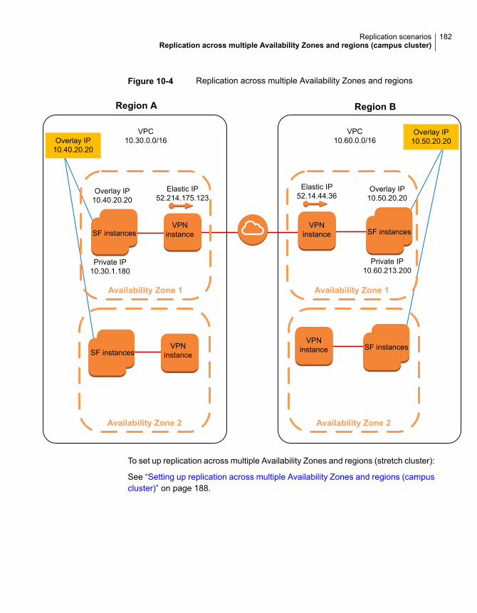
Figure 10-4 Replication across multiple Availability Zones and regions
Availability Zone 2
Region A
Availability Zone 1
SF instances
Private IP10.30.1.180
Overlay IP10.40.20.20
Elastic IP52.214.175.123
VPC10.30.0.0/16
Availability Zone 2
Region B
Availability Zone 1
Elastic IP52.14.44.36
VPC10.60.0.0/16
VPNinstance SF instances
Private IP10.60.213.200
Overlay IP10.50.20.20
SF instancesVPN
instance
VPNinstance
VPNinstance SF instances
Overlay IP10.50.20.20Overlay IP
10.40.20.20
To set up replication across multiple Availability Zones and regions (stretch cluster):
See “Setting up replication across multiple Availability Zones and regions (campuscluster)” on page 188.
182Replication scenariosReplication across multiple Availability Zones and regions (campus cluster)
Setting up replication forcloud environments
This chapter includes the following topics:
■ Setting up replication from on-premise to cloud environments
■ Setting up replication across AZs within the same region
■ Setting up replication across regions
■ Setting up replication across multiple Availability Zones and regions (campuscluster)
Setting up replication from on-premise to cloudenvironments
Perform the steps in the following procedure to set up replication from on-premiseto cloud environments.
To set up replication from on-premise to cloud environments
1 Create a VPC with a valid CIDR block, for example 10.239.0.0/16.
2 Add a subnet in the Availability Zone.
3 Create the EC2 instance.
4 Configure the virtual private gateway and attach it to the VPC.
5 Configure the customer gateway.
11Chapter
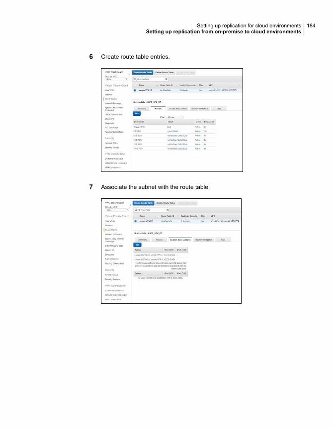
6 Create route table entries.
7 Associate the subnet with the route table.
184Setting up replication for cloud environmentsSetting up replication from on-premise to cloud environments
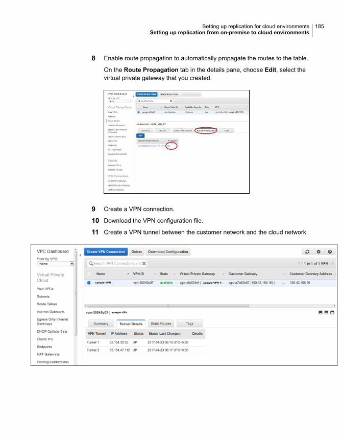
8 Enable route propagation to automatically propagate the routes to the table.
On the Route Propagation tab in the details pane, choose Edit, select thevirtual private gateway that you created.
9 Create a VPN connection.
10 Download the VPN configuration file.
11 Create a VPN tunnel between the customer network and the cloud network.
185Setting up replication for cloud environmentsSetting up replication from on-premise to cloud environments
12 Set up replication between the on-premise and cloud instances.
For instructions, see the chapter Setting up replication in the Veritas InfoScaleReplication Administrator's Guide.
13 Verify the status of replication.
# vradmin -g dg_name repstatus rvg_name
Ensure that the replication status shows:
Replication status: replicating (connected)
Setting up replication across AZs within the sameregion
Perform the steps in the following procedure to set up replication across AZs withinthe same region.
To set up replication in cloud environments
1 Create a VPC with a valid CIDR block, for example, 10.0.0.0/16.
2 Create the internet gateway and attach it to the VPC.
3 Modify the VPC route table such that the two instances across availability zonescan communicate with each other using private IP addresses.
4 Create two subnets—one subnet for the primary site in AZ1 and the secondsubnet for the secondary site in AZ2 with valid CIDR range, for example10.0.1.0/24 and 10.0.2.0/24 respectively.
5 Launch the EC2 instances in the primary and secondary subnets. Install VeritasInfoScale on the instances.
Note: For standalone environments, private IP addresses are used forreplication.
For clustered environments, virtual private IP addresses are used for replication.
6 Set up the AWSIP agent resource to manage the virtual private IP address(VPIP) configuration.
For detailed instructions, see the Cluster Server Administrator's Guide.
186Setting up replication for cloud environmentsSetting up replication across AZs within the same region
7 Verify connectivity between the virtual private IP addresses of the instances.
# ping PIP
# ping VPIP
8 Set up replication between the instances using private IP address or virtualprivate IP address.
For instructions, see the chapter Setting up replication in the Veritas InfoScaleReplication Administrator's Guide.
9 Verify the status of replication.
# vradmin -g dg_name repstatus rvg_name
Ensure that the status shows:
Replication status: replicating (connected)
Setting up replication across regionsPerform the steps in the following procedure to set up replication across regions.
To set up replication across regions
1 Create two VPCs with valid CIDR blocks in different regions, for example,10.30.0.0/16 and 10.60.0.0/16 respectively.
2 Create the primary site EC2 instance.
3 Create the primary site VPN instance, which belongs to the same VPC as thatof the primary EC2 instance.
4 Modify the route table on the primary site. Ensure that the route table entrydirects the secondary site traffic through the primary site VPN instance.
5 Create the secondary site EC2 instance.
6 Create the secondary site VPN instance, which belongs to the same VPC asthat of the secondary EC2 instance.
7 Modify the route table on the secondary site. Ensure that the route table entrydirects the primary site traffic through the secondary site VPN instance.
8 Set up connectivity across regions using software VPN. The sampleconfiguration uses Openswan.
Perform the following steps:
187Setting up replication for cloud environmentsSetting up replication across regions
■ Install the Openswan packages on the primary and secondary VPNinstances.
■ Configure the /etc/ipsec.conf and /etc/ipsec.secrets files.
Note: The /etc/ipsec.conf file contains information about the private IPaddress of the VPN instance, the subnet range of the left subnet, elasticIP address of the destination VPN, the subnet range of the destination rightsubnet.
The /etc/ipsec.secrets file contains the secret key. This key must bethe same on both VPN sites.
■ Restart the IPSec service.
# service ipsec restart
■ Add the IPSec connection.
# ipsec auto --add vpc2vpcConnection
# ipsec auto --up vpc2vpcConnection
■ Enable IPSec forwarding.
# sysctl -w net.ipv4.ip_forward=1
9 Set up replication between the instances using the private IP address or virtualprivate IP address.
For instructions, see the chapter Setting up replication in the Veritas InfoScaleReplication Administrator's Guide.
10 Verify the status of replication.
# vradmin -g dg_name repstatus rvg_name
Ensure that the replication status shows:
Replication status: replicating (connected)
Setting up replication acrossmultiple AvailabilityZones and regions (campus cluster)
Perform the steps in the following procedure to set up replication across regions.
188Setting up replication for cloud environmentsSetting up replication across multiple Availability Zones and regions (campus cluster)
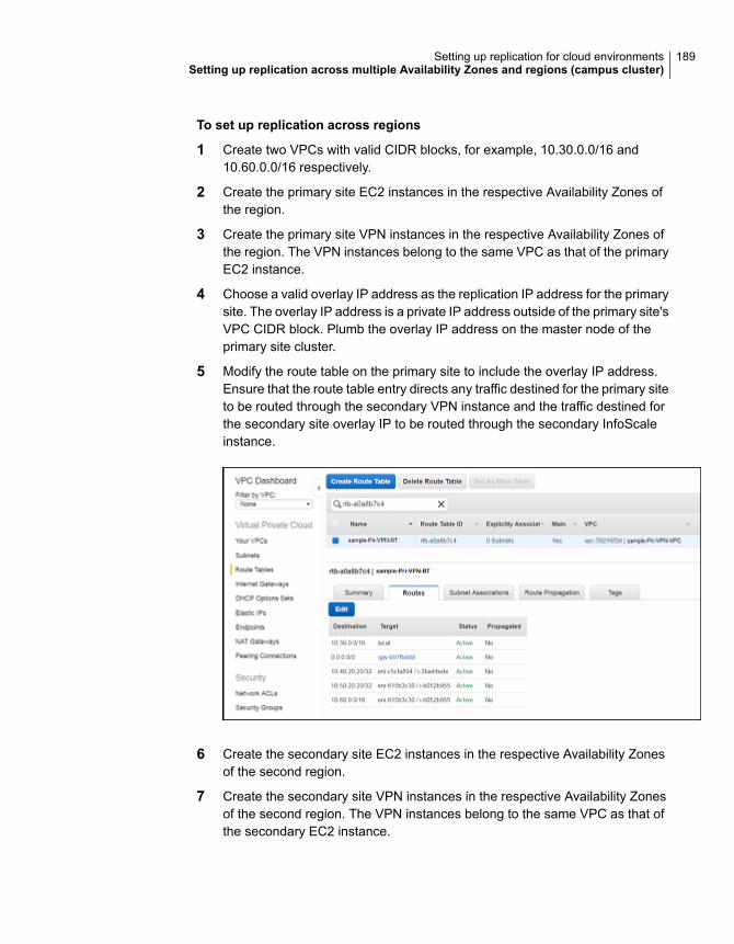
To set up replication across regions
1 Create two VPCs with valid CIDR blocks, for example, 10.30.0.0/16 and10.60.0.0/16 respectively.
2 Create the primary site EC2 instances in the respective Availability Zones ofthe region.
3 Create the primary site VPN instances in the respective Availability Zones ofthe region. The VPN instances belong to the same VPC as that of the primaryEC2 instance.
4 Choose a valid overlay IP address as the replication IP address for the primarysite. The overlay IP address is a private IP address outside of the primary site'sVPC CIDR block. Plumb the overlay IP address on the master node of theprimary site cluster.
5 Modify the route table on the primary site to include the overlay IP address.Ensure that the route table entry directs any traffic destined for the primary siteto be routed through the secondary VPN instance and the traffic destined forthe secondary site overlay IP to be routed through the secondary InfoScaleinstance.
6 Create the secondary site EC2 instances in the respective Availability Zonesof the second region.
7 Create the secondary site VPN instances in the respective Availability Zonesof the second region. The VPN instances belong to the same VPC as that ofthe secondary EC2 instance.
189Setting up replication for cloud environmentsSetting up replication across multiple Availability Zones and regions (campus cluster)
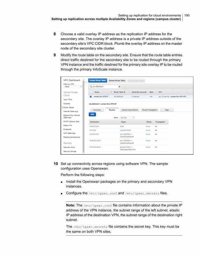
8 Choose a valid overlay IP address as the replication IP address for thesecondary site. The overlay IP address is a private IP address outside of thesecondary site's VPC CIDR block. Plumb the overlay IP address on the masternode of the secondary site cluster.
9 Modify the route table on the secondary site. Ensure that the route table entriesdirect traffic destined for the secondary site to be routed through the primaryVPN instance and the traffic destined for the primary site overlay IP to be routedthrough the primary InfoScale instance.
10 Set up connectivity across regions using software VPN. The sampleconfiguration uses Openswan.
Perform the following steps:
■ Install the Openswan packages on the primary and secondary VPNinstances.
■ Configure the /etc/ipsec.conf and /etc/ipsec.secrets files.
Note: The /etc/ipsec.conf file contains information about the private IPaddress of the VPN instance, the subnet range of the left subnet, elasticIP address of the destination VPN, the subnet range of the destination rightsubnet.
The /etc/ipsec.secrets file contains the secret key. This key must bethe same on both VPN sites.
190Setting up replication for cloud environmentsSetting up replication across multiple Availability Zones and regions (campus cluster)
■ Restart the IPSec service.
# service ipsec restart
■ Add the IPSec connection.
# ipsec auto -add vpc2vpcConnection
# ipsec auto -up vpc2vpcConnection
■ Enable IPSec forwarding.
# sysctl -w net.ipv4.ip_forward=1
191Setting up replication for cloud environmentsSetting up replication across multiple Availability Zones and regions (campus cluster)
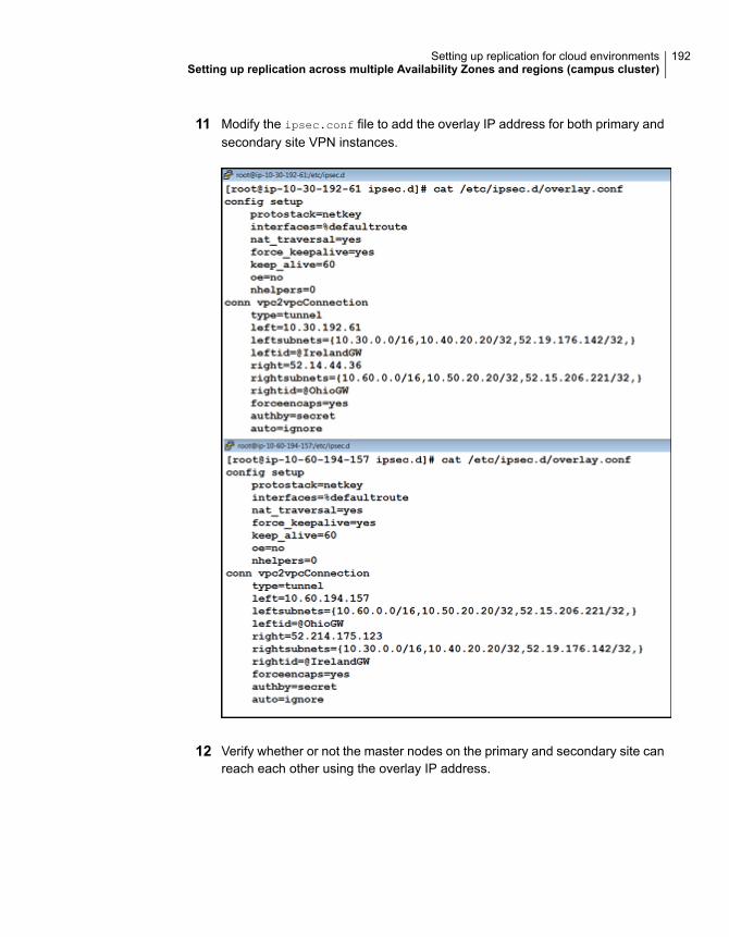
11 Modify the ipsec.conf file to add the overlay IP address for both primary andsecondary site VPN instances.
12 Verify whether or not the master nodes on the primary and secondary site canreach each other using the overlay IP address.
192Setting up replication for cloud environmentsSetting up replication across multiple Availability Zones and regions (campus cluster)
13 Set up replication between the primary and secondary sites.
For instructions, see the chapter Setting up replication in the Veritas InfoScaleReplication Administrator's Guide.
14 Verify the status of replication.
# vradmin -g dg_name repstatus rvg_name
Ensure that the RLINK is in CONNECT state and the replication status shows:
Replication status: replicating (connected)
193Setting up replication for cloud environmentsSetting up replication across multiple Availability Zones and regions (campus cluster)
Reference
■ Appendix A. Sample configuration files
6Section
Sample configuration filesThis appendix includes the following topics:
■ Sample Storage Foundation for Oracle RAC configuration files
■ About sample main.cf files for Storage Foundation (SF) for Oracle RAC
■ About sample main.cf files for Storage Foundation (SF) for Sybase ASE CE
Sample Storage Foundation for Oracle RACconfiguration files
Storage Foundation for Oracle RAC provides several sample configuration filesillustrating various scenarios. You may use the sample files as a guideline for settingup your cluster environment. These sample files are located at/etc/VRTSvcs/conf/sample_rac/.
This section briefly describes each of the sample files and illustrates the servicegroup configuration for each of them. The section does not include a copy of themain.cf files.
The following sample files are useful references for disaster recovery use cases:
■ sfrac02_main.cf file
■ sfrac11_main.cf file
■ See “Sample fire drill service group configuration” on page 205.
sfrac02_main.cf fileThis sample file describes the following configuration:
■ A two node Storage Foundation for Oracle RAC cluster.
■ The Oracle database is stored on CFS.
AAppendix
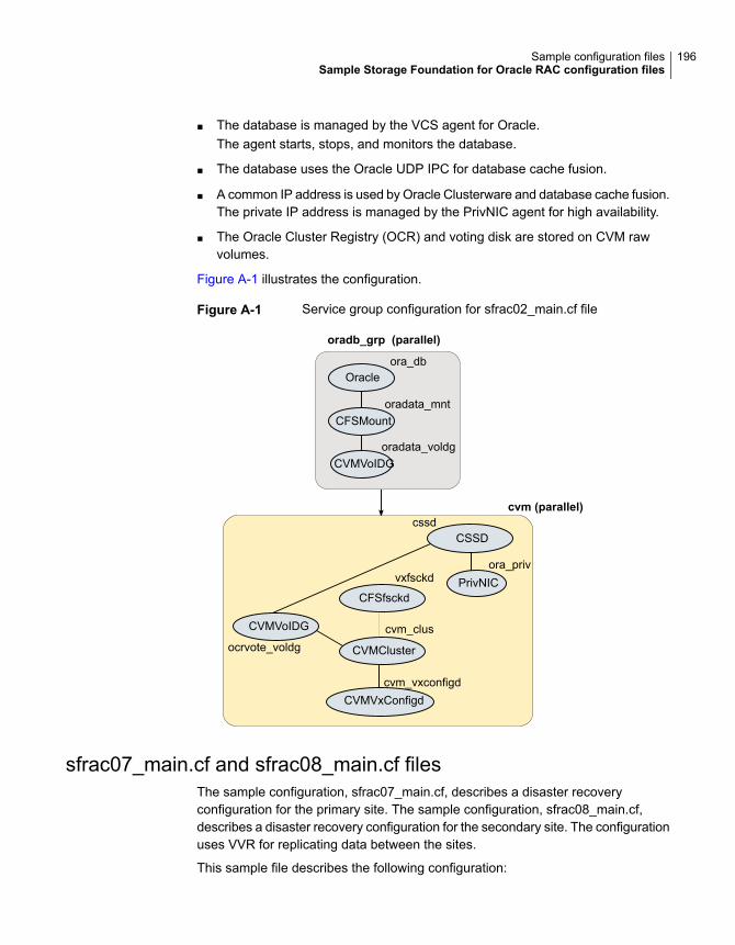
■ The database is managed by the VCS agent for Oracle.The agent starts, stops, and monitors the database.
■ The database uses the Oracle UDP IPC for database cache fusion.
■ A common IP address is used by Oracle Clusterware and database cache fusion.The private IP address is managed by the PrivNIC agent for high availability.
■ The Oracle Cluster Registry (OCR) and voting disk are stored on CVM rawvolumes.
Figure A-1 illustrates the configuration.
Figure A-1 Service group configuration for sfrac02_main.cf file
oradb_grp (parallel)
cvm (parallel)
CVMCluster
CSSD
CFSfsckd
cssd
ora_privvxfsckd
cvm_clus
cvm_vxconfigd
ocrvote_voldg
CVMVoIDG
Oracleora_db
CFSMount
CVMVoIDG
oradata_mnt
oradata_voldg
CVMVxConfigd
PrivNIC
sfrac07_main.cf and sfrac08_main.cf filesThe sample configuration, sfrac07_main.cf, describes a disaster recoveryconfiguration for the primary site. The sample configuration, sfrac08_main.cf,describes a disaster recovery configuration for the secondary site. The configurationuses VVR for replicating data between the sites.
This sample file describes the following configuration:
196Sample configuration filesSample Storage Foundation for Oracle RAC configuration files
■ Two Storage Foundation for Oracle RAC clusters, comprising two nodes each,hosted at different geographical locations.
■ A single Oracle database that is stored on CFS.
■ The database is managed by the VCS agent for Oracle.The agent starts, stops, and monitors the database.
■ The database uses the Oracle UDP IPC for database cache fusion.
■ A common IP address is used by Oracle Clusterware and database cache fusion.The private IP address is managed by the PrivNIC agent for high availability.
■ One virtual IP address must be configured under the ClusterService groupon each site for inter-cluster communication.
■ The Oracle Cluster Registry (OCR) and voting disk are stored on CFS.
■ Volume Replicator (VVR) is used to replicate data between the sites.
■ The shared volumes replicated across the sites are configured under the RVGgroup.
■ The replication link used by VVR for communicating log information betweensites are configured under the rlogowner group. This is a failover group, andremains online from the cvm master node. The PreOnline trigger for theRVGLogOwner agent should be enabled.
■ The database group will be online on the primary cluster. The RVGSharedPriresource determines where the database group will be brought online.
■ The database group is configured as a global group by specifying the clusterson the primary and secondary sites as values for the ClusterList group attribute.
Figure A-2 illustrates the configuration. The service group configuration is the sameon the primary and secondary site. The availability of groups (online/offline) differbetween the sites.
197Sample configuration filesSample Storage Foundation for Oracle RAC configuration files
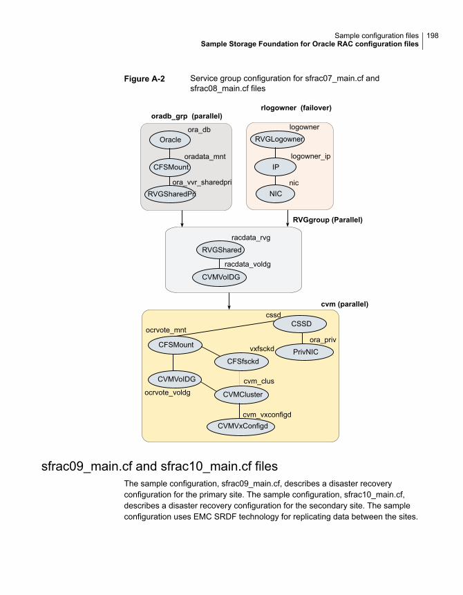
Figure A-2 Service group configuration for sfrac07_main.cf andsfrac08_main.cf files
oradb_grp (parallel)
cvm (parallel)
CVMCluster
CSSD
CFSfsckd
cssd
ora_privvxfsckd
cvm_clus
cvm_vxconfigd
CFSMount
ocrvote_mnt
ocrvote_voldg
CVMVoIDG
Oracleora_db
CFSMount
RVGSharedPri
oradata_mnt
ora_vvr_sharedpri
CVMVxConfigd
PrivNIC
logowner
logowner_ip
nic
rlogowner (failover)
RVGLogowner
IP
NIC
racdata_rvg
RVGgroup (Parallel)
RVGShared
CVMVoIDG
racdata_voldg
sfrac09_main.cf and sfrac10_main.cf filesThe sample configuration, sfrac09_main.cf, describes a disaster recoveryconfiguration for the primary site. The sample configuration, sfrac10_main.cf,describes a disaster recovery configuration for the secondary site. The sampleconfiguration uses EMC SRDF technology for replicating data between the sites.
198Sample configuration filesSample Storage Foundation for Oracle RAC configuration files
Note: You can use other supported hardware-based replication technologies withthis configuration.
This sample file describes the following configuration:
■ Two Storage Foundation for Oracle RAC clusters, comprising two nodes each,hosted at different geographical locations.
■ A single Oracle database that is stored on CFS.
■ The database is managed by the VCS agent for Oracle.The agent starts, stops, and monitors the database.
■ The database uses the Oracle UDP IPC for database cache fusion.
■ A common IP address is used by Oracle Clusterware and database cache fusion.The private IP address is managed by the PrivNIC agent for high availability.
■ One virtual IP address must be configured under the ClusterService groupon each site for inter-cluster communication.
■ The Oracle Cluster Registry (OCR) and voting disk are stored on CFS.
■ EMC SRDF is used to replicate data between the sites.
■ The SRDF disk groups that are replicated across the sites using SRDFtechnology and the replication mode are specified under the SRDF resource inthe database group. The CVM disk group that comprises the SRDF disk groupmust be configured under the CVMVolDg resource in the database group.
■ The database group will be online on the primary cluster. The SRDF resourcedetermines where the database group will be brought online.
■ The database group is configured as a global group by specifying the clusterson the primary and secondary sites as values for the ClusterList group attribute.
Figure A-3 illustrates the configuration on the primary site.
199Sample configuration filesSample Storage Foundation for Oracle RAC configuration files

Figure A-3 Service group configuration for sfrac09_main.cf file
oradb_grp (parallel)
cvm (parallel)
CVMCluster
CSSD
CFSfsckd
cssd
ora_privvxfsckd
cvm_clus
cvm_vxconfigd
CFSMount
ocrvote_mnt
ocrvote_voldg
CVMVoIDG
Oracleora_db
CFSMountoradata_mnt
oradata_voldg
CVMVxConfigd
PrivNIC
CVMVolDG
SRDFgc_srdf
Figure A-4 illustrates the configuration on the secondary site.
200Sample configuration filesSample Storage Foundation for Oracle RAC configuration files
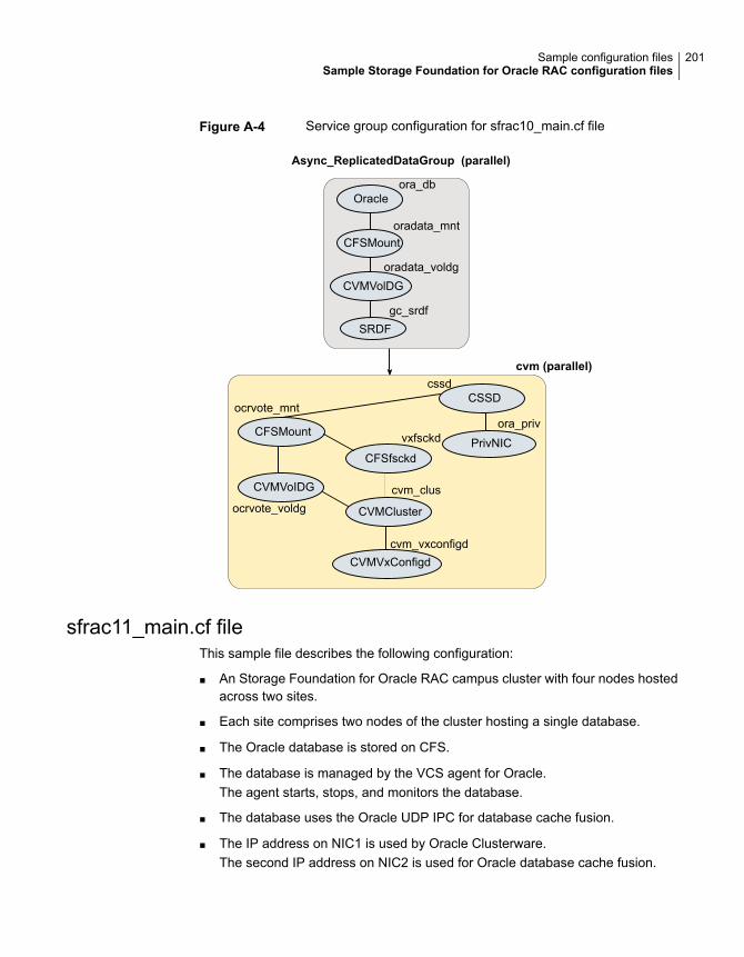
Figure A-4 Service group configuration for sfrac10_main.cf file
cvm (parallel)
CVMCluster
CSSD
CFSfsckd
cssd
ora_privvxfsckd
cvm_clus
cvm_vxconfigd
CFSMount
ocrvote_mnt
ocrvote_voldg
CVMVoIDG
Oracleora_db
CFSMountoradata_mnt
oradata_voldg
CVMVxConfigd
PrivNIC
CVMVolDG
SRDFgc_srdf
Async_ReplicatedDataGroup (parallel)
sfrac11_main.cf fileThis sample file describes the following configuration:
■ An Storage Foundation for Oracle RAC campus cluster with four nodes hostedacross two sites.
■ Each site comprises two nodes of the cluster hosting a single database.
■ The Oracle database is stored on CFS.
■ The database is managed by the VCS agent for Oracle.The agent starts, stops, and monitors the database.
■ The database uses the Oracle UDP IPC for database cache fusion.
■ The IP address on NIC1 is used by Oracle Clusterware.The second IP address on NIC2 is used for Oracle database cache fusion.
201Sample configuration filesSample Storage Foundation for Oracle RAC configuration files
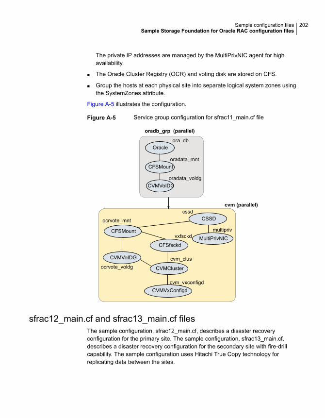
The private IP addresses are managed by the MultiPrivNIC agent for highavailability.
■ The Oracle Cluster Registry (OCR) and voting disk are stored on CFS.
■ Group the hosts at each physical site into separate logical system zones usingthe SystemZones attribute.
Figure A-5 illustrates the configuration.
Figure A-5 Service group configuration for sfrac11_main.cf file
oradb_grp (parallel)
cvm (parallel)
CVMCluster
CSSD
CFSfsckd
cssd
multiprivvxfsckd
cvm_clus
cvm_vxconfigd
ocrvote_voldg
CVMVoIDG
Oracleora_db
CFSMount
CVMVoIDG
oradata_mnt
oradata_voldg
CVMVxConfigd
MultiPrivNICCFSMount
ocrvote_mnt
sfrac12_main.cf and sfrac13_main.cf filesThe sample configuration, sfrac12_main.cf, describes a disaster recoveryconfiguration for the primary site. The sample configuration, sfrac13_main.cf,describes a disaster recovery configuration for the secondary site with fire-drillcapability. The sample configuration uses Hitachi True Copy technology forreplicating data between the sites.
202Sample configuration filesSample Storage Foundation for Oracle RAC configuration files
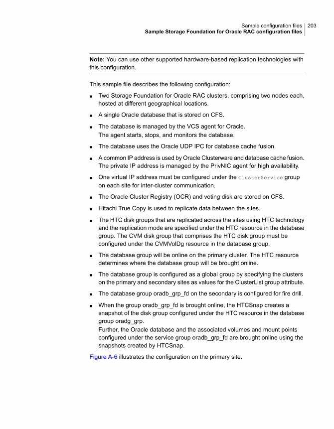
Note: You can use other supported hardware-based replication technologies withthis configuration.
This sample file describes the following configuration:
■ Two Storage Foundation for Oracle RAC clusters, comprising two nodes each,hosted at different geographical locations.
■ A single Oracle database that is stored on CFS.
■ The database is managed by the VCS agent for Oracle.The agent starts, stops, and monitors the database.
■ The database uses the Oracle UDP IPC for database cache fusion.
■ A common IP address is used by Oracle Clusterware and database cache fusion.The private IP address is managed by the PrivNIC agent for high availability.
■ One virtual IP address must be configured under the ClusterService groupon each site for inter-cluster communication.
■ The Oracle Cluster Registry (OCR) and voting disk are stored on CFS.
■ Hitachi True Copy is used to replicate data between the sites.
■ The HTC disk groups that are replicated across the sites using HTC technologyand the replication mode are specified under the HTC resource in the databasegroup. The CVM disk group that comprises the HTC disk group must beconfigured under the CVMVolDg resource in the database group.
■ The database group will be online on the primary cluster. The HTC resourcedetermines where the database group will be brought online.
■ The database group is configured as a global group by specifying the clusterson the primary and secondary sites as values for the ClusterList group attribute.
■ The database group oradb_grp_fd on the secondary is configured for fire drill.
■ When the group oradb_grp_fd is brought online, the HTCSnap creates asnapshot of the disk group configured under the HTC resource in the databasegroup oradg_grp.Further, the Oracle database and the associated volumes and mount pointsconfigured under the service group oradb_grp_fd are brought online using thesnapshots created by HTCSnap.
Figure A-6 illustrates the configuration on the primary site.
203Sample configuration filesSample Storage Foundation for Oracle RAC configuration files
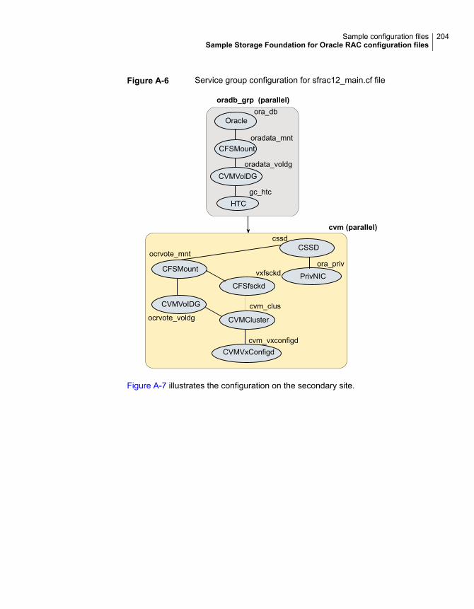
Figure A-6 Service group configuration for sfrac12_main.cf file
oradb_grp (parallel)
cvm (parallel)
CVMCluster
CSSD
CFSfsckd
cssd
ora_privvxfsckd
cvm_clus
cvm_vxconfigd
CFSMount
ocrvote_mnt
ocrvote_voldg
CVMVoIDG
Oracleora_db
CFSMountoradata_mnt
oradata_voldg
CVMVxConfigd
PrivNIC
CVMVolDG
HTCgc_htc
Figure A-7 illustrates the configuration on the secondary site.
204Sample configuration filesSample Storage Foundation for Oracle RAC configuration files
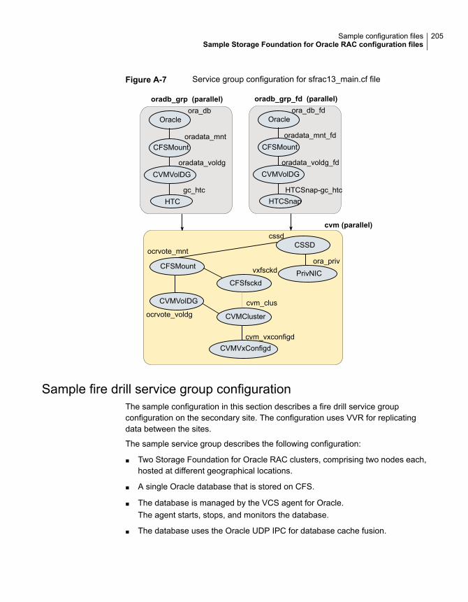
Figure A-7 Service group configuration for sfrac13_main.cf file
oradb_grp (parallel)
cvm (parallel)
CVMCluster
CSSD
CFSfsckd
cssd
ora_privvxfsckd
cvm_clus
cvm_vxconfigd
CFSMount
ocrvote_mnt
ocrvote_voldg
CVMVoIDG
Oracleora_db
CFSMountoradata_mnt
oradata_voldg
CVMVxConfigd
PrivNIC
CVMVolDG
HTCgc_htc
oradb_grp_fd (parallel)
Oracleora_db_fd
CFSMountoradata_mnt_fd
oradata_voldg_fdCVMVolDG
HTCSnapHTCSnap-gc_htc
Sample fire drill service group configurationThe sample configuration in this section describes a fire drill service groupconfiguration on the secondary site. The configuration uses VVR for replicatingdata between the sites.
The sample service group describes the following configuration:
■ Two Storage Foundation for Oracle RAC clusters, comprising two nodes each,hosted at different geographical locations.
■ A single Oracle database that is stored on CFS.
■ The database is managed by the VCS agent for Oracle.The agent starts, stops, and monitors the database.
■ The database uses the Oracle UDP IPC for database cache fusion.
205Sample configuration filesSample Storage Foundation for Oracle RAC configuration files
■ A common IP address is used by Oracle Clusterware and database cache fusion.The private IP address is managed by the PrivNIC agent for high availability.
■ One virtual IP address must be configured under the ClusterService groupon each site for inter-cluster communication.
■ The Oracle Cluster Registry (OCR) and voting disk are stored on CFS.
■ Volume Replicator (VVR) is used to replicate data between the sites.
■ The shared volumes replicated across the sites are configured under the RVGgroup.
■ The replication link used by VVR for communicating log information betweensites are configured under the rlogowner group. This is a failover group, andremains online from the cvm master node. The PreOnline trigger for theRVGLogOwner agent should be enabled.Please see the section "CVM master node needs to assume the logowner rolefor VCS managed VVR resources" in the Cluster Server Bundled AgentsReference Guide for more info.
■ The database group is configured as a global group by specifying the clusterson the primary and secondary sites as values for the ClusterList group attribute.
■ The fire drill service group oradb_grp_fd creates a snapshot of the replicateddata on the secondary site and starts the database using the snapshot. An offlinelocal dependency is set between the fire drill service group and the applicationservice group to make sure a fire drill does not block an application failover incase a disaster strikes the primary site.
Figure A-8 illustrates the configuration.
206Sample configuration filesSample Storage Foundation for Oracle RAC configuration files
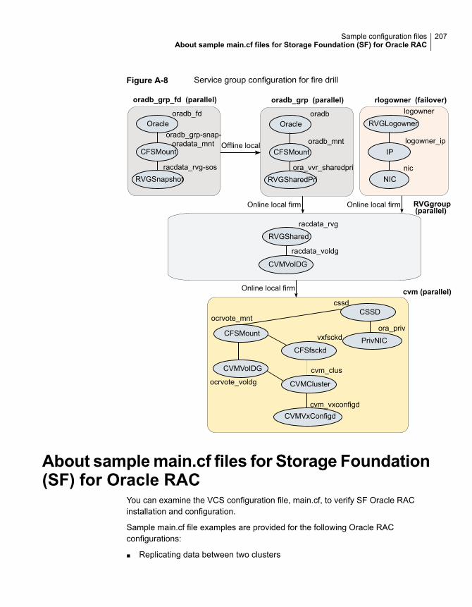
Figure A-8 Service group configuration for fire drill
oradb_grp (parallel)
cvm (parallel)
CVMCluster
CSSD
CFSfsckd
cssd
ora_privvxfsckd
cvm_clus
cvm_vxconfigd
CFSMount
ocrvote_mnt
ocrvote_voldg
CVMVoIDG
Oracleoradb
CFSMount
RVGSharedPri
oradb_mnt
ora_vvr_sharedpri
CVMVxConfigd
PrivNIC
logowner
logowner_ip
nic
rlogowner (failover)
RVGLogowner
IP
NIC
racdata_rvg
RVGShared
CVMVoIDG
racdata_voldg
oradb_grp_fd (parallel)
Oracleoradb_fd
CFSMount
RVGSnapshot
oradb_grp-snap-oradata_mnt
racdata_rvg-sos
Offline local
Online local firm Online local firm
Online local firm
RVGgroup(parallel)
About samplemain.cf files for Storage Foundation(SF) for Oracle RAC
You can examine the VCS configuration file, main.cf, to verify SF Oracle RACinstallation and configuration.
Sample main.cf file examples are provided for the following Oracle RACconfigurations:
■ Replicating data between two clusters
207Sample configuration filesAbout sample main.cf files for Storage Foundation (SF) for Oracle RAC
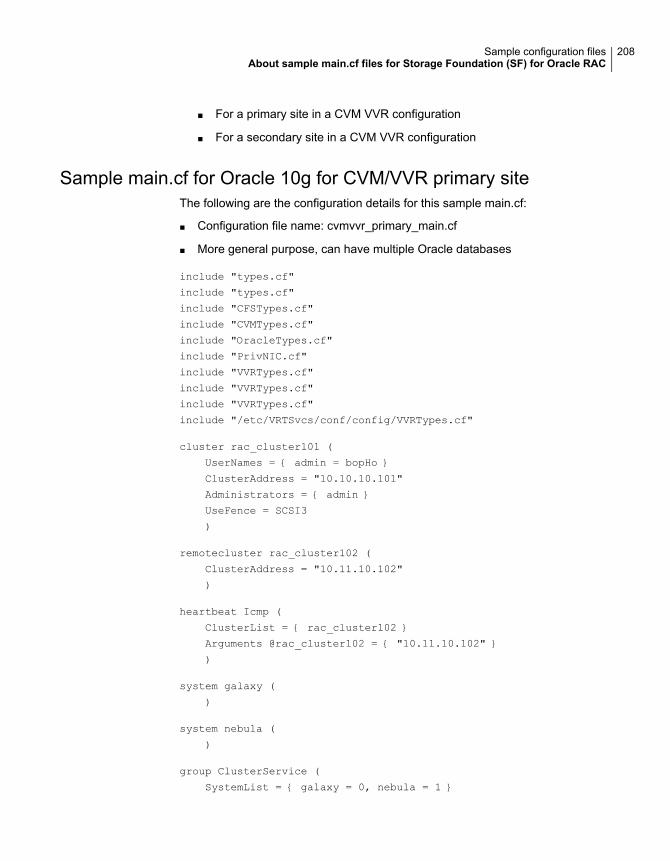
For a primary site in a CVM VVR configuration■
■ For a secondary site in a CVM VVR configuration
Sample main.cf for Oracle 10g for CVM/VVR primary siteThe following are the configuration details for this sample main.cf:
■ Configuration file name: cvmvvr_primary_main.cf
■ More general purpose, can have multiple Oracle databases
include "types.cf"
include "types.cf"
include "CFSTypes.cf"
include "CVMTypes.cf"
include "OracleTypes.cf"
include "PrivNIC.cf"
include "VVRTypes.cf"
include "VVRTypes.cf"
include "VVRTypes.cf"
include "/etc/VRTSvcs/conf/config/VVRTypes.cf"
cluster rac_cluster101 (
UserNames = { admin = bopHo }
ClusterAddress = "10.10.10.101"
Administrators = { admin }
UseFence = SCSI3
)
remotecluster rac_cluster102 (
ClusterAddress = "10.11.10.102"
)
heartbeat Icmp (
ClusterList = { rac_cluster102 }
Arguments @rac_cluster102 = { "10.11.10.102" }
)
system galaxy (
)
system nebula (
)
group ClusterService (
SystemList = { galaxy = 0, nebula = 1 }
208Sample configuration filesAbout sample main.cf files for Storage Foundation (SF) for Oracle RAC
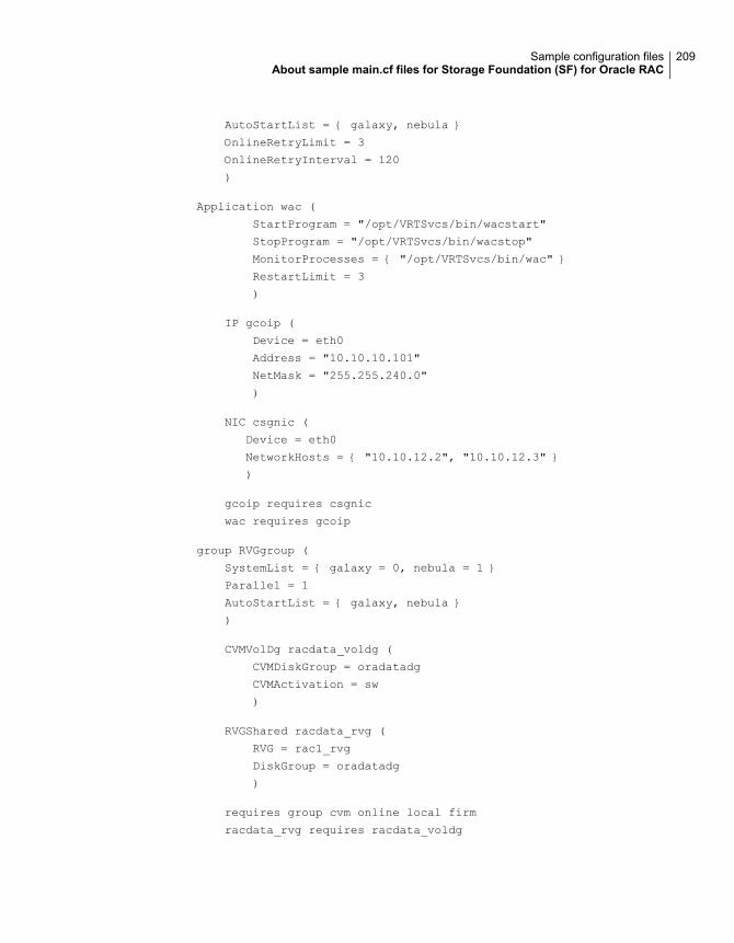
AutoStartList = { galaxy, nebula }
OnlineRetryLimit = 3
OnlineRetryInterval = 120
)
Application wac (
StartProgram = "/opt/VRTSvcs/bin/wacstart"
StopProgram = "/opt/VRTSvcs/bin/wacstop"
MonitorProcesses = { "/opt/VRTSvcs/bin/wac" }
RestartLimit = 3
)
IP gcoip (
Device = eth0
Address = "10.10.10.101"
NetMask = "255.255.240.0"
)
NIC csgnic (
Device = eth0
NetworkHosts = { "10.10.12.2", "10.10.12.3" }
)
gcoip requires csgnic
wac requires gcoip
group RVGgroup (
SystemList = { galaxy = 0, nebula = 1 }
Parallel = 1
AutoStartList = { galaxy, nebula }
)
CVMVolDg racdata_voldg (
CVMDiskGroup = oradatadg
CVMActivation = sw
)
RVGShared racdata_rvg (
RVG = rac1_rvg
DiskGroup = oradatadg
)
requires group cvm online local firm
racdata_rvg requires racdata_voldg
209Sample configuration filesAbout sample main.cf files for Storage Foundation (SF) for Oracle RAC
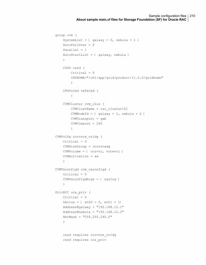
group cvm (
SystemList = { galaxy = 0, nebula = 1 }
AutoFailOver = 0
Parallel = 1
AutoStartList = { galaxy, nebula }
)
CSSD cssd (
Critical = 0
CRSHOME="/u01/app/grid/product/11.2.0/gridhome"
)
CFSfsckd vxfsckd (
)
CVMCluster cvm_clus (
CVMClustName = rac_cluster101
CVMNodeId = { galaxy = 1, nebula = 2 }
CVMTransport = gab
CVMTimeout = 200
)
CVMVolDg ocrvote_voldg (
Critical = 0
CVMDiskGroup = ocrvotedg
CVMVolume = { ocrvol, votevol }
CVMActivation = sw
)
CVMVxconfigd cvm_vxconfigd (
Critical = 0
CVMVxconfigdArgs = { syslog }
)
PrivNIC ora_priv (
Critical = 0
Device = { eth0 = 0, eth1 = 1}
Address@galaxy = "192.168.12.1"
Address@nebula = "192.168.12.2"
NetMask = "255.255.240.0"
)
cssd requires ocrvote_voldg
cssd requires ora_priv
210Sample configuration filesAbout sample main.cf files for Storage Foundation (SF) for Oracle RAC
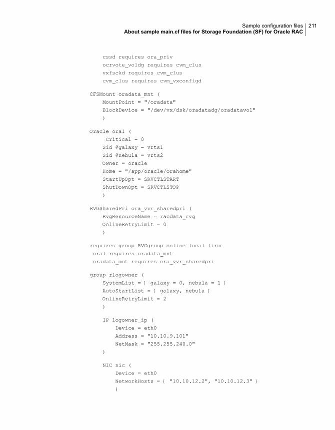
cssd requires ora_priv
ocrvote_voldg requires cvm_clus
vxfsckd requires cvm_clus
cvm_clus requires cvm_vxconfigd
CFSMount oradata_mnt (
MountPoint = "/oradata"
BlockDevice = "/dev/vx/dsk/oradatadg/oradatavol"
)
Oracle ora1 (
Critical = 0
Sid @galaxy = vrts1
Sid @nebula = vrts2
Owner = oracle
Home = "/app/oracle/orahome"
StartUpOpt = SRVCTLSTART
ShutDownOpt = SRVCTLSTOP
)
RVGSharedPri ora_vvr_sharedpri (
RvgResourceName = racdata_rvg
OnlineRetryLimit = 0
)
requires group RVGgroup online local firm
ora1 requires oradata_mnt
oradata_mnt requires ora_vvr_sharedpri
group rlogowner (
SystemList = { galaxy = 0, nebula = 1 }
AutoStartList = { galaxy, nebula }
OnlineRetryLimit = 2
)
IP logowner_ip (
Device = eth0
Address = "10.10.9.101"
NetMask = "255.255.240.0"
)
NIC nic (
Device = eth0
NetworkHosts = { "10.10.12.2", "10.10.12.3" }
)
211Sample configuration filesAbout sample main.cf files for Storage Foundation (SF) for Oracle RAC
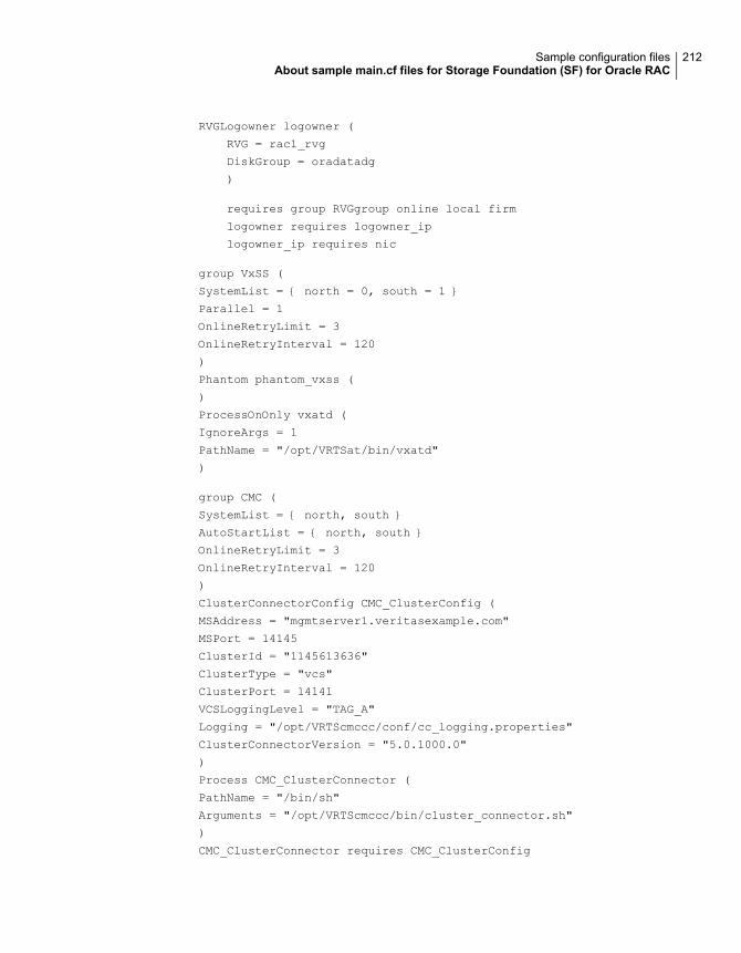
RVGLogowner logowner (
RVG = rac1_rvg
DiskGroup = oradatadg
)
requires group RVGgroup online local firm
logowner requires logowner_ip
logowner_ip requires nic
group VxSS (
SystemList = { north = 0, south = 1 }
Parallel = 1
OnlineRetryLimit = 3
OnlineRetryInterval = 120
)
Phantom phantom_vxss (
)
ProcessOnOnly vxatd (
IgnoreArgs = 1
PathName = "/opt/VRTSat/bin/vxatd"
)
group CMC (
SystemList = { north, south }
AutoStartList = { north, south }
OnlineRetryLimit = 3
OnlineRetryInterval = 120
)
ClusterConnectorConfig CMC_ClusterConfig (
MSAddress = "mgmtserver1.veritasexample.com"
MSPort = 14145
ClusterId = "1145613636"
ClusterType = "vcs"
ClusterPort = 14141
VCSLoggingLevel = "TAG_A"
Logging = "/opt/VRTScmccc/conf/cc_logging.properties"
ClusterConnectorVersion = "5.0.1000.0"
)
Process CMC_ClusterConnector (
PathName = "/bin/sh"
Arguments = "/opt/VRTScmccc/bin/cluster_connector.sh"
)
CMC_ClusterConnector requires CMC_ClusterConfig
212Sample configuration filesAbout sample main.cf files for Storage Foundation (SF) for Oracle RAC
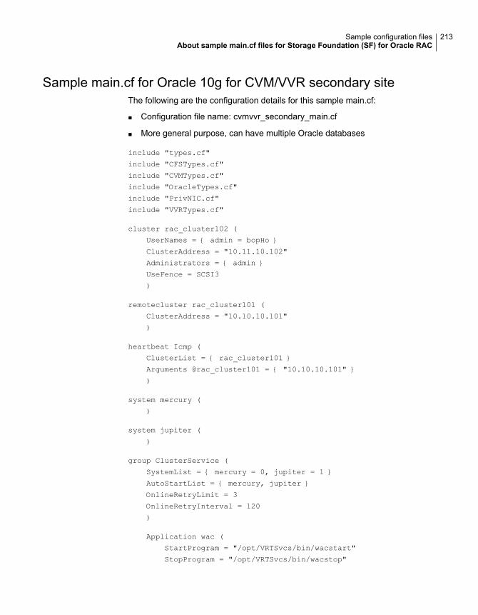
Sample main.cf for Oracle 10g for CVM/VVR secondary siteThe following are the configuration details for this sample main.cf:
■ Configuration file name: cvmvvr_secondary_main.cf
■ More general purpose, can have multiple Oracle databases
include "types.cf"
include "CFSTypes.cf"
include "CVMTypes.cf"
include "OracleTypes.cf"
include "PrivNIC.cf"
include "VVRTypes.cf"
cluster rac_cluster102 (
UserNames = { admin = bopHo }
ClusterAddress = "10.11.10.102"
Administrators = { admin }
UseFence = SCSI3
)
remotecluster rac_cluster101 (
ClusterAddress = "10.10.10.101"
)
heartbeat Icmp (
ClusterList = { rac_cluster101 }
Arguments @rac_cluster101 = { "10.10.10.101" }
)
system mercury (
)
system jupiter (
)
group ClusterService (
SystemList = { mercury = 0, jupiter = 1 }
AutoStartList = { mercury, jupiter }
OnlineRetryLimit = 3
OnlineRetryInterval = 120
)
Application wac (
StartProgram = "/opt/VRTSvcs/bin/wacstart"
StopProgram = "/opt/VRTSvcs/bin/wacstop"
213Sample configuration filesAbout sample main.cf files for Storage Foundation (SF) for Oracle RAC
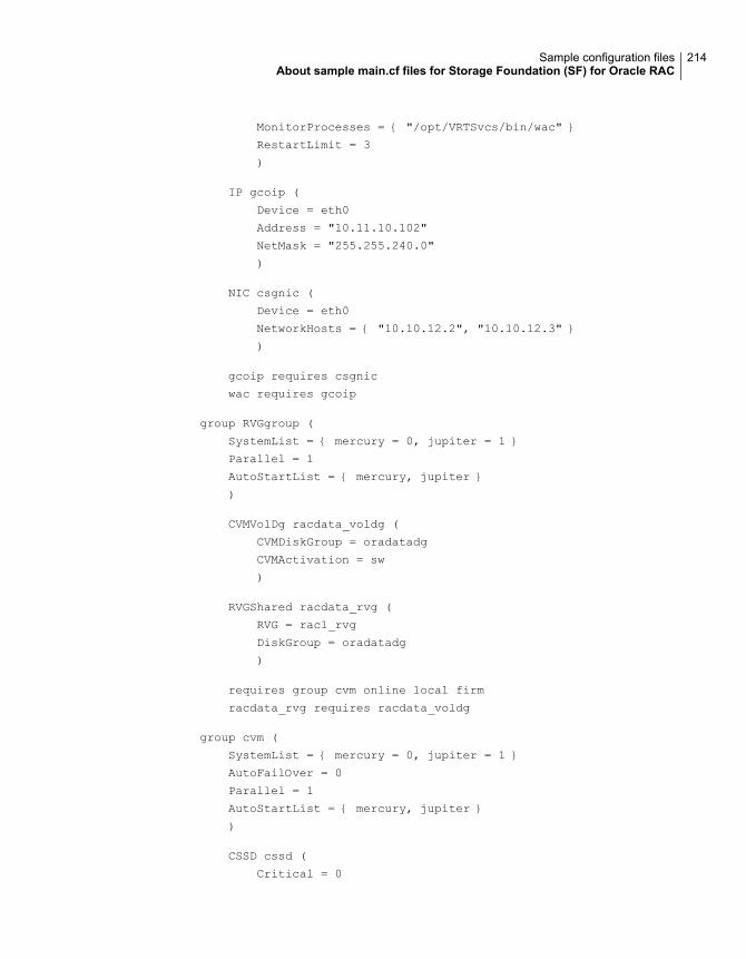
MonitorProcesses = { "/opt/VRTSvcs/bin/wac" }
RestartLimit = 3
)
IP gcoip (
Device = eth0
Address = "10.11.10.102"
NetMask = "255.255.240.0"
)
NIC csgnic (
Device = eth0
NetworkHosts = { "10.10.12.2", "10.10.12.3" }
)
gcoip requires csgnic
wac requires gcoip
group RVGgroup (
SystemList = { mercury = 0, jupiter = 1 }
Parallel = 1
AutoStartList = { mercury, jupiter }
)
CVMVolDg racdata_voldg (
CVMDiskGroup = oradatadg
CVMActivation = sw
)
RVGShared racdata_rvg (
RVG = rac1_rvg
DiskGroup = oradatadg
)
requires group cvm online local firm
racdata_rvg requires racdata_voldg
group cvm (
SystemList = { mercury = 0, jupiter = 1 }
AutoFailOver = 0
Parallel = 1
AutoStartList = { mercury, jupiter }
)
CSSD cssd (
Critical = 0
214Sample configuration filesAbout sample main.cf files for Storage Foundation (SF) for Oracle RAC
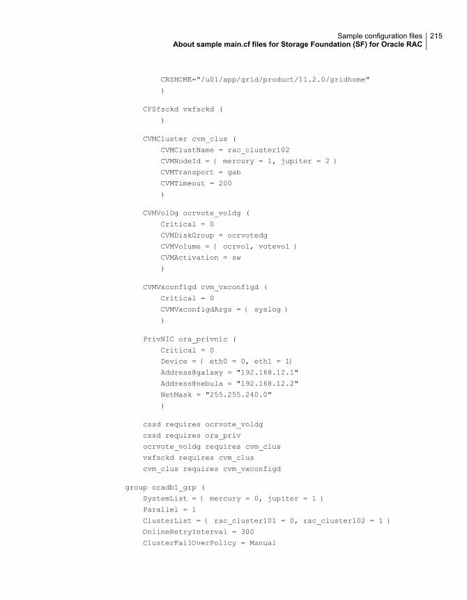
CRSHOME="/u01/app/grid/product/11.2.0/gridhome"
)
CFSfsckd vxfsckd (
)
CVMCluster cvm_clus (
CVMClustName = rac_cluster102
CVMNodeId = { mercury = 1, jupiter = 2 }
CVMTransport = gab
CVMTimeout = 200
)
CVMVolDg ocrvote_voldg (
Critical = 0
CVMDiskGroup = ocrvotedg
CVMVolume = { ocrvol, votevol }
CVMActivation = sw
)
CVMVxconfigd cvm_vxconfigd (
Critical = 0
CVMVxconfigdArgs = { syslog }
)
PrivNIC ora_privnic (
Critical = 0
Device = { eth0 = 0, eth1 = 1}
Address@galaxy = "192.168.12.1"
Address@nebula = "192.168.12.2"
NetMask = "255.255.240.0"
)
cssd requires ocrvote_voldg
cssd requires ora_priv
ocrvote_voldg requires cvm_clus
vxfsckd requires cvm_clus
cvm_clus requires cvm_vxconfigd
group oradb1_grp (
SystemList = { mercury = 0, jupiter = 1 }
Parallel = 1
ClusterList = { rac_cluster101 = 0, rac_cluster102 = 1 }
OnlineRetryInterval = 300
ClusterFailOverPolicy = Manual
215Sample configuration filesAbout sample main.cf files for Storage Foundation (SF) for Oracle RAC
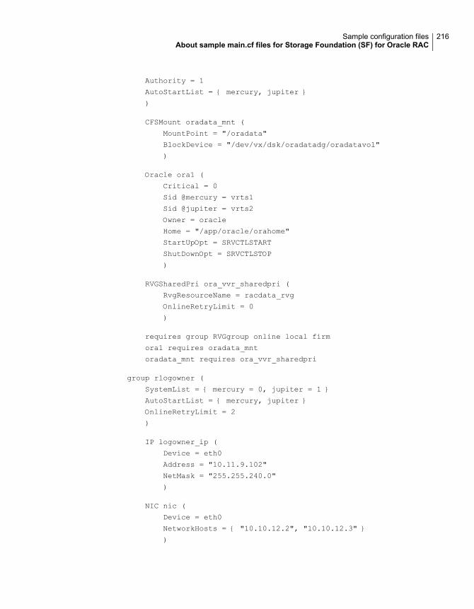
Authority = 1
AutoStartList = { mercury, jupiter }
)
CFSMount oradata_mnt (
MountPoint = "/oradata"
BlockDevice = "/dev/vx/dsk/oradatadg/oradatavol"
)
Oracle ora1 (
Critical = 0
Sid @mercury = vrts1
Sid @jupiter = vrts2
Owner = oracle
Home = "/app/oracle/orahome"
StartUpOpt = SRVCTLSTART
ShutDownOpt = SRVCTLSTOP
)
RVGSharedPri ora_vvr_sharedpri (
RvgResourceName = racdata_rvg
OnlineRetryLimit = 0
)
requires group RVGgroup online local firm
ora1 requires oradata_mnt
oradata_mnt requires ora_vvr_sharedpri
group rlogowner (
SystemList = { mercury = 0, jupiter = 1 }
AutoStartList = { mercury, jupiter }
OnlineRetryLimit = 2
)
IP logowner_ip (
Device = eth0
Address = "10.11.9.102"
NetMask = "255.255.240.0"
)
NIC nic (
Device = eth0
NetworkHosts = { "10.10.12.2", "10.10.12.3" }
)
216Sample configuration filesAbout sample main.cf files for Storage Foundation (SF) for Oracle RAC
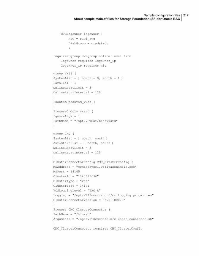
RVGLogowner logowner (
RVG = rac1_rvg
DiskGroup = oradatadg
)
requires group RVGgroup online local firm
logowner requires logowner_ip
logowner_ip requires nic
group VxSS (
SystemList = { north = 0, south = 1 }
Parallel = 1
OnlineRetryLimit = 3
OnlineRetryInterval = 120
)
Phantom phantom_vxss (
)
ProcessOnOnly vxatd (
IgnoreArgs = 1
PathName = "/opt/VRTSat/bin/vxatd"
)
group CMC (
SystemList = { north, south }
AutoStartList = { north, south }
OnlineRetryLimit = 3
OnlineRetryInterval = 120
)
ClusterConnectorConfig CMC_ClusterConfig (
MSAddress = "mgmtserver1.veritasexample.com"
MSPort = 14145
ClusterId = "1145613636"
ClusterType = "vcs"
ClusterPort = 14141
VCSLoggingLevel = "TAG_A"
Logging = "/opt/VRTScmccc/conf/cc_logging.properties"
ClusterConnectorVersion = "5.0.1000.0"
)
Process CMC_ClusterConnector (
PathName = "/bin/sh"
Arguments = "/opt/VRTScmccc/bin/cluster_connector.sh"
)
CMC_ClusterConnector requires CMC_ClusterConfig
217Sample configuration filesAbout sample main.cf files for Storage Foundation (SF) for Oracle RAC
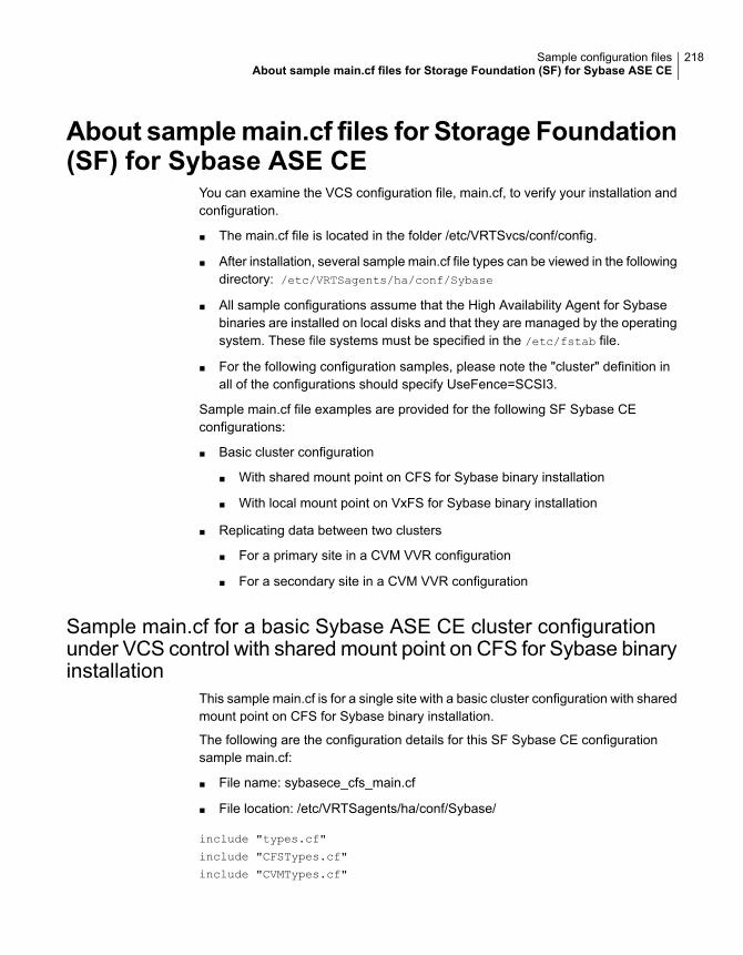
About samplemain.cf files for Storage Foundation(SF) for Sybase ASE CE
You can examine the VCS configuration file, main.cf, to verify your installation andconfiguration.
■ The main.cf file is located in the folder /etc/VRTSvcs/conf/config.
■ After installation, several sample main.cf file types can be viewed in the followingdirectory: /etc/VRTSagents/ha/conf/Sybase
■ All sample configurations assume that the High Availability Agent for Sybasebinaries are installed on local disks and that they are managed by the operatingsystem. These file systems must be specified in the /etc/fstab file.
■ For the following configuration samples, please note the "cluster" definition inall of the configurations should specify UseFence=SCSI3.
Sample main.cf file examples are provided for the following SF Sybase CEconfigurations:
■ Basic cluster configuration
■ With shared mount point on CFS for Sybase binary installation
■ With local mount point on VxFS for Sybase binary installation
■ Replicating data between two clusters
■ For a primary site in a CVM VVR configuration
■ For a secondary site in a CVM VVR configuration
Sample main.cf for a basic Sybase ASE CE cluster configurationunder VCS control with shared mount point on CFS for Sybase binaryinstallation
This sample main.cf is for a single site with a basic cluster configuration with sharedmount point on CFS for Sybase binary installation.
The following are the configuration details for this SF Sybase CE configurationsample main.cf:
■ File name: sybasece_cfs_main.cf
■ File location: /etc/VRTSagents/ha/conf/Sybase/
include "types.cf"
include "CFSTypes.cf"
include "CVMTypes.cf"
218Sample configuration filesAbout sample main.cf files for Storage Foundation (SF) for Sybase ASE CE
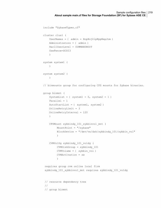
include "SybaseTypes.cf"
cluster clus1 (
UserNames = { admin = HopHojOlpKppNxpJom }
Administrators = { admin }
HacliUserLevel = COMMANDROOT
UseFence=SCSI3
)
system system1 (
)
system system2 (
)
// binmounts group for configuring CFS mounts for Sybase binaries.
group binmnt (
SystemList = { system1 = 0, system2 = 1 }
Parallel = 1
AutoStartList = { system1, system2 }
OnlineRetryLimit = 3
OnlineRetryInterval = 120
)
CFSMount sybbindg_101_sybbinvol_mnt (
MountPoint = "/sybase"
BlockDevice = "/dev/vx/dsk/sybbindg_101/sybbin_vol"
)
CVMVolDg sybbindg_101_voldg (
CVMDiskGroup = sybbindg_101
CVMVolume = { sybbin_vol }
CVMActivation = sw
)
requires group cvm online local firm
sybbindg_101_sybbinvol_mnt requires sybbindg_101_voldg
// resource dependency tree
//
// group binmnt
219Sample configuration filesAbout sample main.cf files for Storage Foundation (SF) for Sybase ASE CE
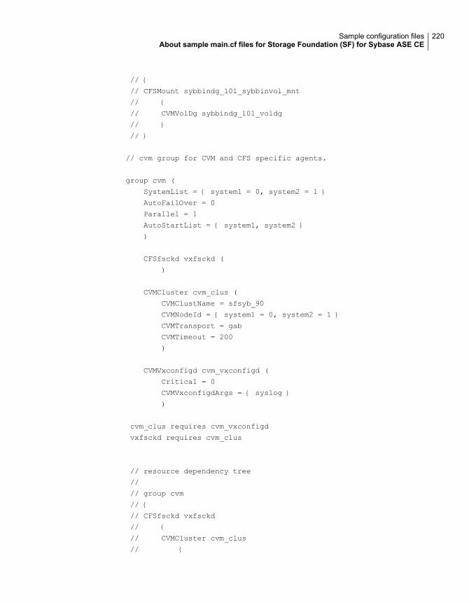
// {
// CFSMount sybbindg_101_sybbinvol_mnt
// {
// CVMVolDg sybbindg_101_voldg
// }
// }
// cvm group for CVM and CFS specific agents.
group cvm (
SystemList = { system1 = 0, system2 = 1 }
AutoFailOver = 0
Parallel = 1
AutoStartList = { system1, system2 }
)
CFSfsckd vxfsckd (
)
CVMCluster cvm_clus (
CVMClustName = sfsyb_90
CVMNodeId = { system1 = 0, system2 = 1 }
CVMTransport = gab
CVMTimeout = 200
)
CVMVxconfigd cvm_vxconfigd (
Critical = 0
CVMVxconfigdArgs = { syslog }
)
cvm_clus requires cvm_vxconfigd
vxfsckd requires cvm_clus
// resource dependency tree
//
// group cvm
// {
// CFSfsckd vxfsckd
// {
// CVMCluster cvm_clus
// {
220Sample configuration filesAbout sample main.cf files for Storage Foundation (SF) for Sybase ASE CE
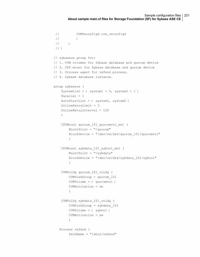
// CVMVxconfigd cvm_vxconfigd
// }
// }
// }
// sybasece group for:
// 1. CVM volumes for Sybase database and quorum device
// 2. CFS mount for Sybase database and quorum device
// 3. Process agent for vxfend process.
// 4. Sybase database instance.
group sybasece (
SystemList = { system1 = 0, system2 = 1 }
Parallel = 1
AutoStartList = { system1, system2 }
OnlineRetryLimit = 3
OnlineRetryInterval = 120
)
CFSMount quorum_101_quorumvol_mnt (
MountPoint = "/quorum"
BlockDevice = "/dev/vx/dsk/quorum_101/quorumvol"
)
CFSMount sybdata_101_sybvol_mnt (
MountPoint = "/sybdata"
BlockDevice = "/dev/vx/dsk/sybdata_101/sybvol"
)
CVMVolDg quorum_101_voldg (
CVMDiskGroup = quorum_101
CVMVolume = { quorumvol }
CVMActivation = sw
)
CVMVolDg sybdata_101_voldg (
CVMDiskGroup = sybdata_101
CVMVolume = { sybvol }
CVMActivation = sw
)
Process vxfend (
PathName = "/sbin/vxfend"
221Sample configuration filesAbout sample main.cf files for Storage Foundation (SF) for Sybase ASE CE

Arguments = "-m sybase -k /tmp/vcmp_socket"
)
Sybase ase (
Server @system1 = ase1
Server @system2 = ase2
Owner = sybase
Home = "/sybase"
Version = 15
SA = sa
Quorum_dev = "/quorum/q.dat"
)
requires group binmnt online local firm
ase requires quorum_101_quorumvol_mnt
ase requires sybdata_101_sybvol_mnt
ase requires vxfend
quorum_101_quorumvol_mnt requires quorum_101_voldg
sybdata_101_sybvol_mnt requires sybdata_101_voldg
// resource dependency tree
//
// group sybasece
// {
// Sybase ase
// {
// CFSMount quorum_101_quorumvol_mnt
// {
// CVMVolDg quorum_101_voldg
// }
// CFSMount sybdata_101_sybvol_mnt
// {
// CVMVolDg sybdata_101_voldg
// }
// Process vxfend
// }
// }
222Sample configuration filesAbout sample main.cf files for Storage Foundation (SF) for Sybase ASE CE
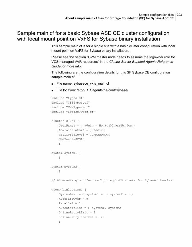
Sample main.cf for a basic Sybase ASE CE cluster configurationwith local mount point on VxFS for Sybase binary installation
This sample main.cf is for a single site with a basic cluster configuration with localmount point on VxFS for Sybase binary installation.
Please see the section "CVM master node needs to assume the logowner role forVCS managed VVR resources" in the Cluster Server Bundled Agents ReferenceGuide for more info.
The following are the configuration details for this SF Sybase CE configurationsample main.cf:
■ File name: sybasece_vxfs_main.cf
■ File location: /etc/VRTSagents/ha/conf/Sybase/
include "types.cf"
include "CFSTypes.cf"
include "CVMTypes.cf"
include "SybaseTypes.cf"
cluster clus1 (
UserNames = { admin = HopHojOlpKppNxpJom }
Administrators = { admin }
HacliUserLevel = COMMANDROOT
UseFence=SCSI3
)
system system1 (
)
system system2 (
)
// binmounts group for configuring VxFS mounts for Sybase binaries.
group binlocalmnt (
SystemList = { system1 = 0, system2 = 1 }
AutoFailOver = 0
Parallel = 1
AutoStartList = { system1, system2 }
OnlineRetryLimit = 3
OnlineRetryInterval = 120
)
223Sample configuration filesAbout sample main.cf files for Storage Foundation (SF) for Sybase ASE CE
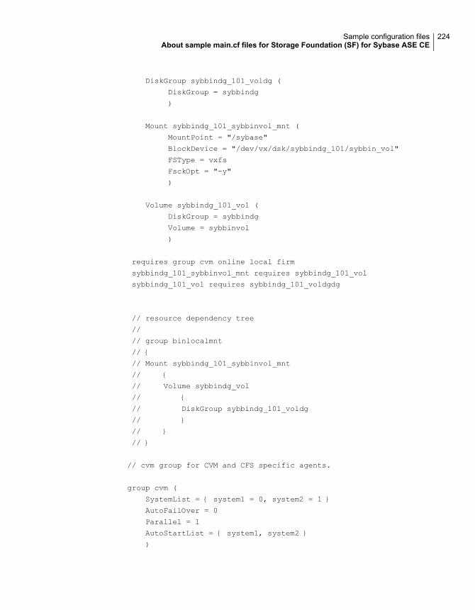
DiskGroup sybbindg_101_voldg (
DiskGroup = sybbindg
)
Mount sybbindg_101_sybbinvol_mnt (
MountPoint = "/sybase"
BlockDevice = "/dev/vx/dsk/sybbindg_101/sybbin_vol"
FSType = vxfs
FsckOpt = "-y"
)
Volume sybbindg_101_vol (
DiskGroup = sybbindg
Volume = sybbinvol
)
requires group cvm online local firm
sybbindg_101_sybbinvol_mnt requires sybbindg_101_vol
sybbindg_101_vol requires sybbindg_101_voldgdg
// resource dependency tree
//
// group binlocalmnt
// {
// Mount sybbindg_101_sybbinvol_mnt
// {
// Volume sybbindg_vol
// {
// DiskGroup sybbindg_101_voldg
// }
// }
// }
// cvm group for CVM and CFS specific agents.
group cvm (
SystemList = { system1 = 0, system2 = 1 }
AutoFailOver = 0
Parallel = 1
AutoStartList = { system1, system2 }
)
224Sample configuration filesAbout sample main.cf files for Storage Foundation (SF) for Sybase ASE CE
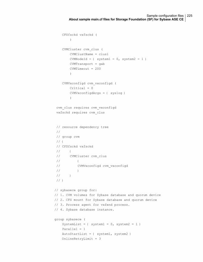
CFSfsckd vxfsckd (
)
CVMCluster cvm_clus (
CVMClustName = clus1
CVMNodeId = { system1 = 0, system2 = 1 }
CVMTransport = gab
CVMTimeout = 200
)
CVMVxconfigd cvm_vxconfigd (
Critical = 0
CVMVxconfigdArgs = { syslog }
)
cvm_clus requires cvm_vxconfigd
vxfsckd requires cvm_clus
// resource dependency tree
//
// group cvm
// {
// CFSfsckd vxfsckd
// {
// CVMCluster cvm_clus
// {
// CVMVxconfigd cvm_vxconfigd
// }
// }
// }
// sybasece group for:
// 1. CVM volumes for Sybase database and quorum device
// 2. CFS mount for Sybase database and quorum device
// 3. Process agent for vxfend process.
// 4. Sybase database instance.
group sybasece (
SystemList = { system1 = 0, system2 = 1 }
Parallel = 1
AutoStartList = { system1, system2 }
OnlineRetryLimit = 3
225Sample configuration filesAbout sample main.cf files for Storage Foundation (SF) for Sybase ASE CE
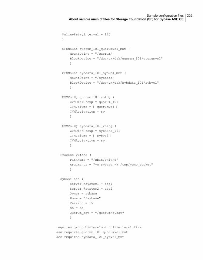
OnlineRetryInterval = 120
)
CFSMount quorum_101_quorumvol_mnt (
MountPoint = "/quorum"
BlockDevice = "/dev/vx/dsk/quorum_101/quorumvol"
)
CFSMount sybdata_101_sybvol_mnt (
MountPoint = "/sybdata"
BlockDevice = "/dev/vx/dsk/sybdata_101/sybvol"
)
CVMVolDg quorum_101_voldg (
CVMDiskGroup = quorum_101
CVMVolume = { quorumvol }
CVMActivation = sw
)
CVMVolDg sybdata_101_voldg (
CVMDiskGroup = sybdata_101
CVMVolume = { sybvol }
CVMActivation = sw
)
Process vxfend (
PathName = "/sbin/vxfend"
Arguments = "-m sybase -k /tmp/vcmp_socket"
)
Sybase ase (
Server @system1 = ase1
Server @system2 = ase2
Owner = sybase
Home = "/sybase"
Version = 15
SA = sa
Quorum_dev = "/quorum/q.dat"
)
requires group binlocalmnt online local firm
ase requires quorum_101_quorumvol_mnt
ase requires sybdata_101_sybvol_mnt
226Sample configuration filesAbout sample main.cf files for Storage Foundation (SF) for Sybase ASE CE
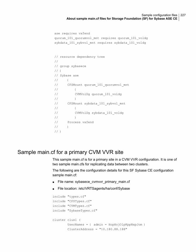
ase requires vxfend
quorum_101_quorumvol_mnt requires quorum_101_voldg
sybdata_101_sybvol_mnt requires sybdata_101_voldg
// resource dependency tree
//
// group sybasece
// {
// Sybase ase
// {
// CFSMount quorum_101_quorumvol_mnt
// {
// CVMVolDg quorum_101_voldg
// }
// CFSMount sybdata_101_sybvol_mnt
// {
// CVMVolDg sybdata_101_voldg
// }
// Process vxfend
// }
// }
Sample main.cf for a primary CVM VVR siteThis sample main.cf is for a primary site in a CVM VVR configuration. It is one oftwo sample main.cfs for replicating data between two clusters.
The following are the configuration details for this SF Sybase CE configurationsample main.cf:
■ File name: sybasece_cvmvvr_primary_main.cf
■ File location: /etc/VRTSagents/ha/conf/Sybase
include "types.cf"
include "CFSTypes.cf"
include "CVMTypes.cf"
include "SybaseTypes.cf"
cluster clus1 (
UserNames = { admin = HopHojOlpKppNxpJom }
ClusterAddress = "10.180.88.188"
227Sample configuration filesAbout sample main.cf files for Storage Foundation (SF) for Sybase ASE CE
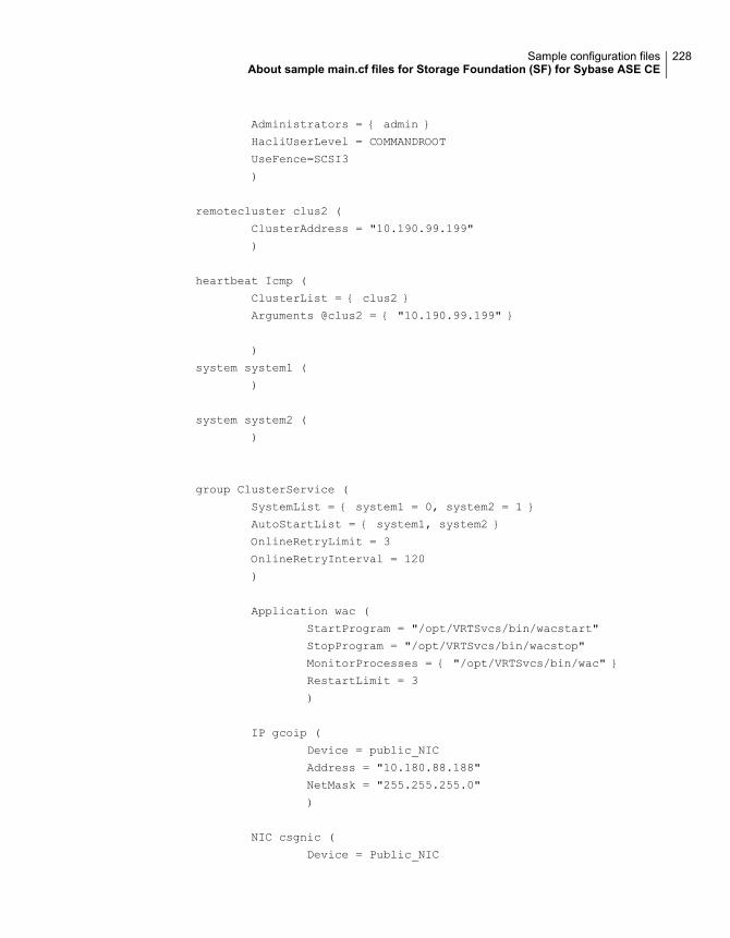
Administrators = { admin }
HacliUserLevel = COMMANDROOT
UseFence=SCSI3
)
remotecluster clus2 (
ClusterAddress = "10.190.99.199"
)
heartbeat Icmp (
ClusterList = { clus2 }
Arguments @clus2 = { "10.190.99.199" }
)
system system1 (
)
system system2 (
)
group ClusterService (
SystemList = { system1 = 0, system2 = 1 }
AutoStartList = { system1, system2 }
OnlineRetryLimit = 3
OnlineRetryInterval = 120
)
Application wac (
StartProgram = "/opt/VRTSvcs/bin/wacstart"
StopProgram = "/opt/VRTSvcs/bin/wacstop"
MonitorProcesses = { "/opt/VRTSvcs/bin/wac" }
RestartLimit = 3
)
IP gcoip (
Device = public_NIC
Address = "10.180.88.188"
NetMask = "255.255.255.0"
)
NIC csgnic (
Device = Public_NIC
228Sample configuration filesAbout sample main.cf files for Storage Foundation (SF) for Sybase ASE CE
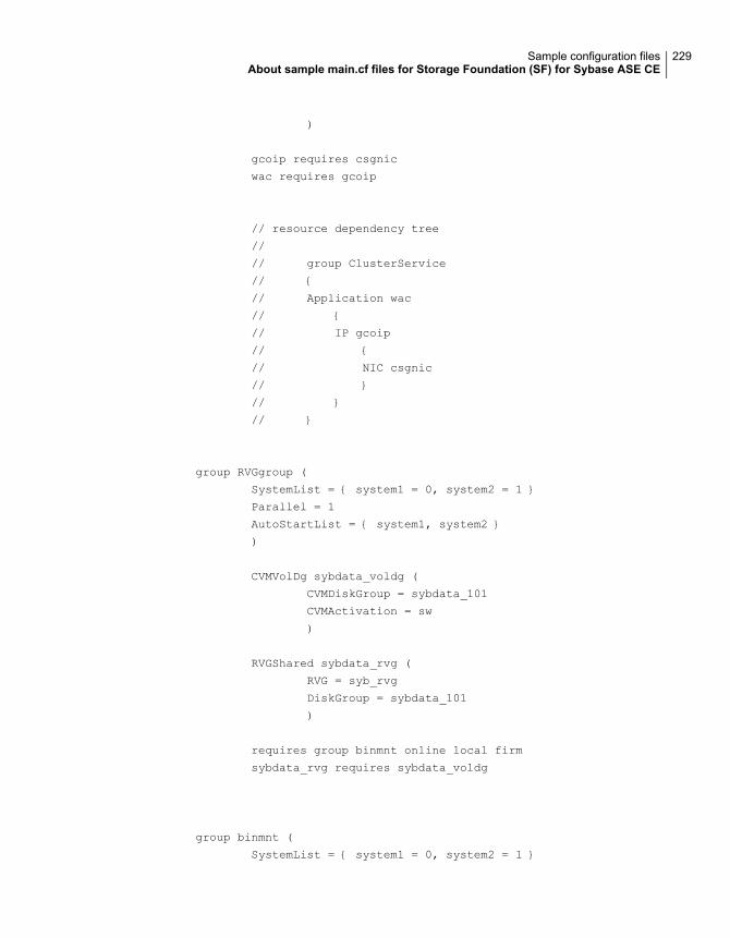
)
gcoip requires csgnic
wac requires gcoip
// resource dependency tree
//
// group ClusterService
// {
// Application wac
// {
// IP gcoip
// {
// NIC csgnic
// }
// }
// }
group RVGgroup (
SystemList = { system1 = 0, system2 = 1 }
Parallel = 1
AutoStartList = { system1, system2 }
)
CVMVolDg sybdata_voldg (
CVMDiskGroup = sybdata_101
CVMActivation = sw
)
RVGShared sybdata_rvg (
RVG = syb_rvg
DiskGroup = sybdata_101
)
requires group binmnt online local firm
sybdata_rvg requires sybdata_voldg
group binmnt (
SystemList = { system1 = 0, system2 = 1 }
229Sample configuration filesAbout sample main.cf files for Storage Foundation (SF) for Sybase ASE CE
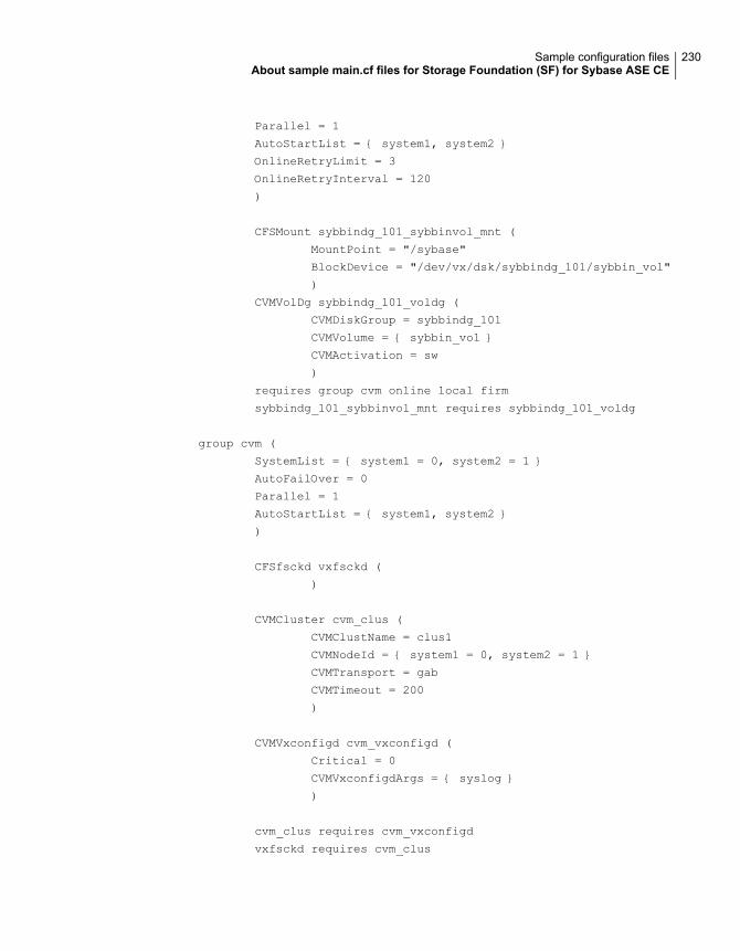
Parallel = 1
AutoStartList = { system1, system2 }
OnlineRetryLimit = 3
OnlineRetryInterval = 120
)
CFSMount sybbindg_101_sybbinvol_mnt (
MountPoint = "/sybase"
BlockDevice = "/dev/vx/dsk/sybbindg_101/sybbin_vol"
)
CVMVolDg sybbindg_101_voldg (
CVMDiskGroup = sybbindg_101
CVMVolume = { sybbin_vol }
CVMActivation = sw
)
requires group cvm online local firm
sybbindg_101_sybbinvol_mnt requires sybbindg_101_voldg
group cvm (
SystemList = { system1 = 0, system2 = 1 }
AutoFailOver = 0
Parallel = 1
AutoStartList = { system1, system2 }
)
CFSfsckd vxfsckd (
)
CVMCluster cvm_clus (
CVMClustName = clus1
CVMNodeId = { system1 = 0, system2 = 1 }
CVMTransport = gab
CVMTimeout = 200
)
CVMVxconfigd cvm_vxconfigd (
Critical = 0
CVMVxconfigdArgs = { syslog }
)
cvm_clus requires cvm_vxconfigd
vxfsckd requires cvm_clus
230Sample configuration filesAbout sample main.cf files for Storage Foundation (SF) for Sybase ASE CE
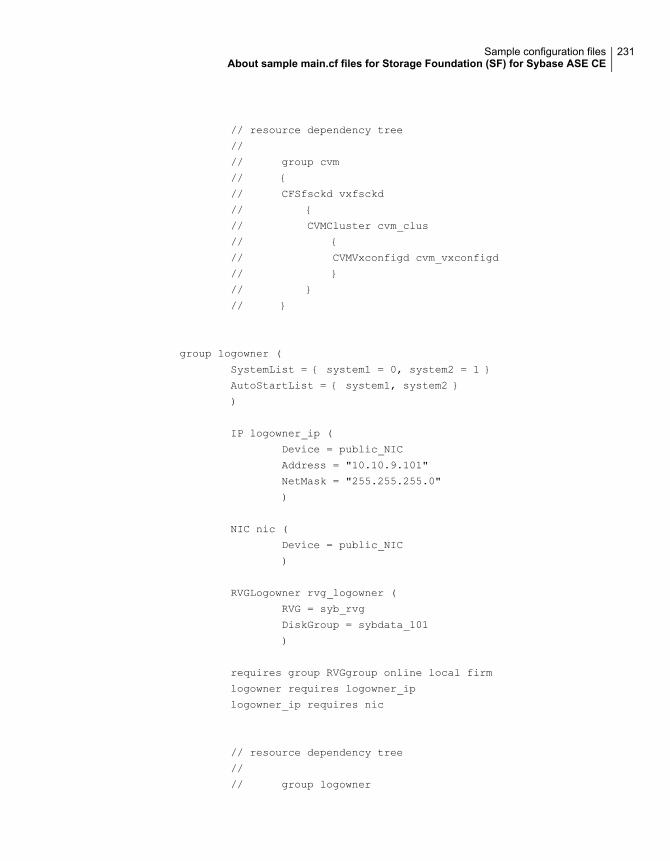
// resource dependency tree
//
// group cvm
// {
// CFSfsckd vxfsckd
// {
// CVMCluster cvm_clus
// {
// CVMVxconfigd cvm_vxconfigd
// }
// }
// }
group logowner (
SystemList = { system1 = 0, system2 = 1 }
AutoStartList = { system1, system2 }
)
IP logowner_ip (
Device = public_NIC
Address = "10.10.9.101"
NetMask = "255.255.255.0"
)
NIC nic (
Device = public_NIC
)
RVGLogowner rvg_logowner (
RVG = syb_rvg
DiskGroup = sybdata_101
)
requires group RVGgroup online local firm
logowner requires logowner_ip
logowner_ip requires nic
// resource dependency tree
//
// group logowner
231Sample configuration filesAbout sample main.cf files for Storage Foundation (SF) for Sybase ASE CE
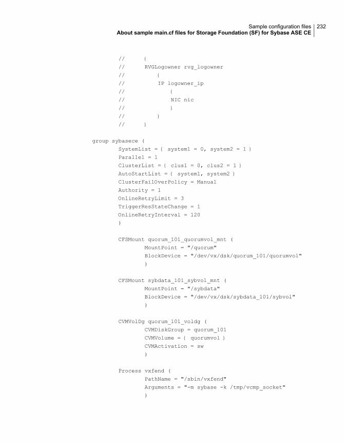
// {
// RVGLogowner rvg_logowner
// {
// IP logowner_ip
// {
// NIC nic
// }
// }
// }
group sybasece (
SystemList = { system1 = 0, system2 = 1 }
Parallel = 1
ClusterList = { clus1 = 0, clus2 = 1 }
AutoStartList = { system1, system2 }
ClusterFailOverPolicy = Manual
Authority = 1
OnlineRetryLimit = 3
TriggerResStateChange = 1
OnlineRetryInterval = 120
)
CFSMount quorum_101_quorumvol_mnt (
MountPoint = "/quorum"
BlockDevice = "/dev/vx/dsk/quorum_101/quorumvol"
)
CFSMount sybdata_101_sybvol_mnt (
MountPoint = "/sybdata"
BlockDevice = "/dev/vx/dsk/sybdata_101/sybvol"
)
CVMVolDg quorum_101_voldg (
CVMDiskGroup = quorum_101
CVMVolume = { quorumvol }
CVMActivation = sw
)
Process vxfend (
PathName = "/sbin/vxfend"
Arguments = "-m sybase -k /tmp/vcmp_socket"
)
232Sample configuration filesAbout sample main.cf files for Storage Foundation (SF) for Sybase ASE CE
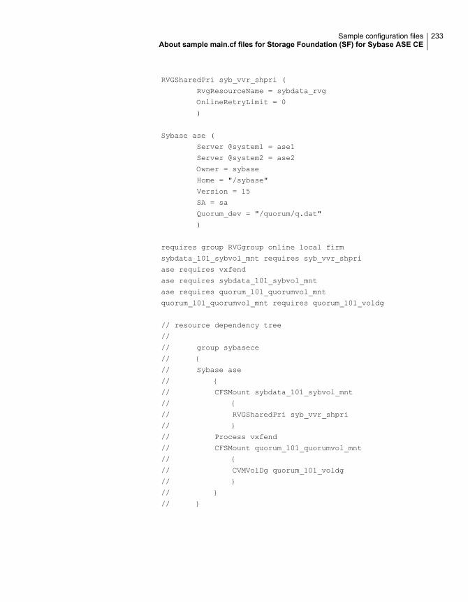
RVGSharedPri syb_vvr_shpri (
RvgResourceName = sybdata_rvg
OnlineRetryLimit = 0
)
Sybase ase (
Server @system1 = ase1
Server @system2 = ase2
Owner = sybase
Home = "/sybase"
Version = 15
SA = sa
Quorum_dev = "/quorum/q.dat"
)
requires group RVGgroup online local firm
sybdata_101_sybvol_mnt requires syb_vvr_shpri
ase requires vxfend
ase requires sybdata_101_sybvol_mnt
ase requires quorum_101_quorumvol_mnt
quorum_101_quorumvol_mnt requires quorum_101_voldg
// resource dependency tree
//
// group sybasece
// {
// Sybase ase
// {
// CFSMount sybdata_101_sybvol_mnt
// {
// RVGSharedPri syb_vvr_shpri
// }
// Process vxfend
// CFSMount quorum_101_quorumvol_mnt
// {
// CVMVolDg quorum_101_voldg
// }
// }
// }
233Sample configuration filesAbout sample main.cf files for Storage Foundation (SF) for Sybase ASE CE
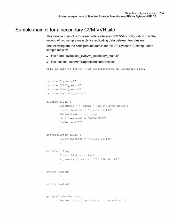
Sample main.cf for a secondary CVM VVR siteThis sample main.cf is for a secondary site in a CVM VVR configuration. It is thesecond of two sample main.cfs for replicating data between two clusters.
The following are the configuration details for this SF Sybase CE configurationsample main.cf:
■ File name: sybasece_cvmvvr_secondary_main.cf
■ File location: /etc/VRTSagents/ha/conf/Sybase
This is main.cf for CVM VVR configuration on Secondary site.
--------------------------------------------------------------
include "types.cf"
include "CFSTypes.cf"
include "CVMTypes.cf"
include "SybaseTypes.cf"
cluster clus2 (
UserNames = { admin = HopHojOlpKppNxpJom }
ClusterAddress = "10.190.99.199"
Administrators = { admin }
HacliUserLevel = COMMANDROOT
UseFence=SCSI3
)
remotecluster clus1 (
ClusterAddress = "10.180.88.188"
)
heartbeat Icmp (
ClusterList = { clus1 }
Arguments @clus1 = { "10.180.88.188" }
)
system system3 (
)
system system4 (
)
group ClusterService (
SystemList = { system3 = 0, system4 = 1 }
234Sample configuration filesAbout sample main.cf files for Storage Foundation (SF) for Sybase ASE CE
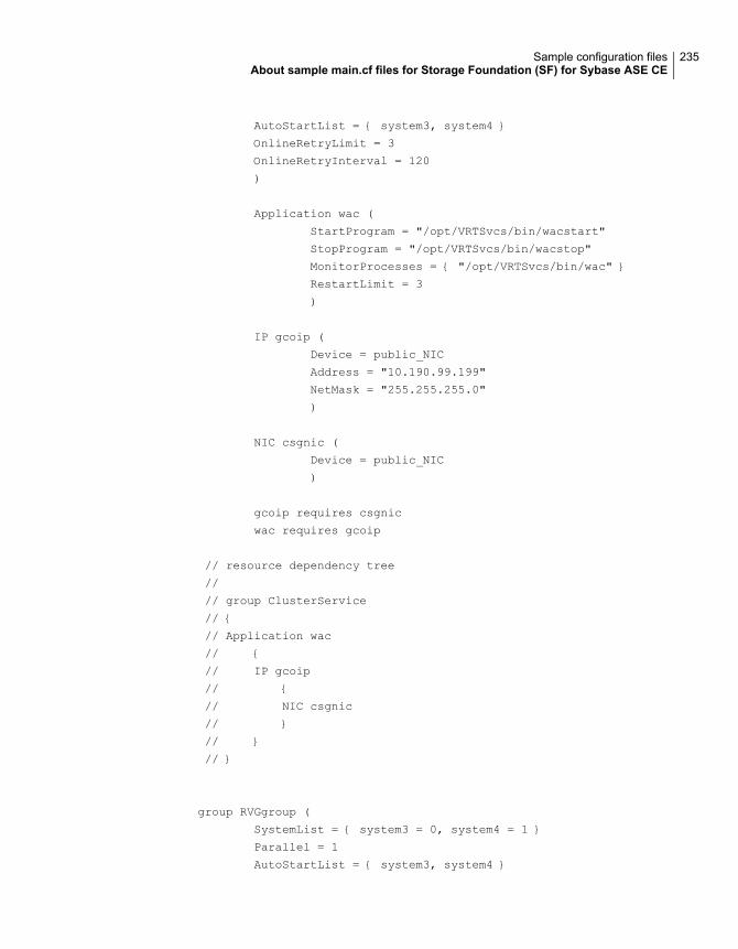
AutoStartList = { system3, system4 }
OnlineRetryLimit = 3
OnlineRetryInterval = 120
)
Application wac (
StartProgram = "/opt/VRTSvcs/bin/wacstart"
StopProgram = "/opt/VRTSvcs/bin/wacstop"
MonitorProcesses = { "/opt/VRTSvcs/bin/wac" }
RestartLimit = 3
)
IP gcoip (
Device = public_NIC
Address = "10.190.99.199"
NetMask = "255.255.255.0"
)
NIC csgnic (
Device = public_NIC
)
gcoip requires csgnic
wac requires gcoip
// resource dependency tree
//
// group ClusterService
// {
// Application wac
// {
// IP gcoip
// {
// NIC csgnic
// }
// }
// }
group RVGgroup (
SystemList = { system3 = 0, system4 = 1 }
Parallel = 1
AutoStartList = { system3, system4 }
235Sample configuration filesAbout sample main.cf files for Storage Foundation (SF) for Sybase ASE CE
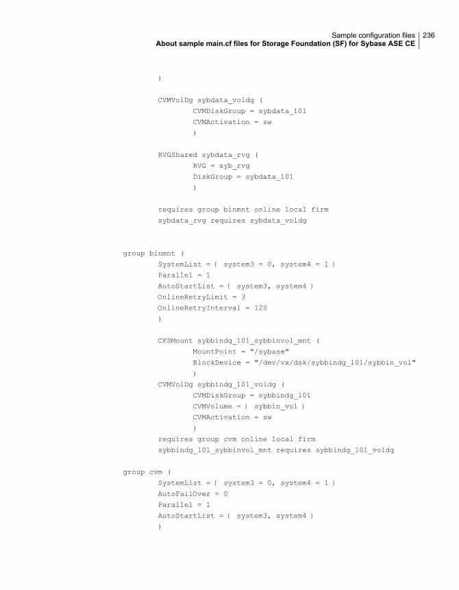
)
CVMVolDg sybdata_voldg (
CVMDiskGroup = sybdata_101
CVMActivation = sw
)
RVGShared sybdata_rvg (
RVG = syb_rvg
DiskGroup = sybdata_101
)
requires group binmnt online local firm
sybdata_rvg requires sybdata_voldg
group binmnt (
SystemList = { system3 = 0, system4 = 1 }
Parallel = 1
AutoStartList = { system3, system4 }
OnlineRetryLimit = 3
OnlineRetryInterval = 120
)
CFSMount sybbindg_101_sybbinvol_mnt (
MountPoint = "/sybase"
BlockDevice = "/dev/vx/dsk/sybbindg_101/sybbin_vol"
)
CVMVolDg sybbindg_101_voldg (
CVMDiskGroup = sybbindg_101
CVMVolume = { sybbin_vol }
CVMActivation = sw
)
requires group cvm online local firm
sybbindg_101_sybbinvol_mnt requires sybbindg_101_voldg
group cvm (
SystemList = { system3 = 0, system4 = 1 }
AutoFailOver = 0
Parallel = 1
AutoStartList = { system3, system4 }
)
236Sample configuration filesAbout sample main.cf files for Storage Foundation (SF) for Sybase ASE CE
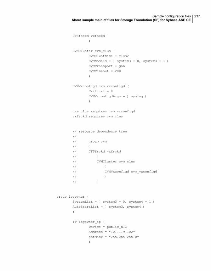
CFSfsckd vxfsckd (
)
CVMCluster cvm_clus (
CVMClustName = clus2
CVMNodeId = { system3 = 0, system4 = 1 }
CVMTransport = gab
CVMTimeout = 200
)
CVMVxconfigd cvm_vxconfigd (
Critical = 0
CVMVxconfigdArgs = { syslog }
)
cvm_clus requires cvm_vxconfigd
vxfsckd requires cvm_clus
// resource dependency tree
//
// group cvm
// {
// CFSfsckd vxfsckd
// {
// CVMCluster cvm_clus
// {
// CVMVxconfigd cvm_vxconfigd
// }
// }
group logowner (
SystemList = { system3 = 0, system4 = 1 }
AutoStartList = { system3, system4 }
)
IP logowner_ip (
Device = public_NIC
Address = "10.11.9.102"
NetMask = "255.255.255.0"
)
237Sample configuration filesAbout sample main.cf files for Storage Foundation (SF) for Sybase ASE CE
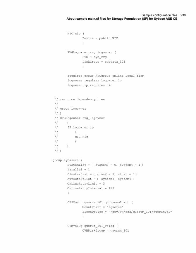
NIC nic (
Device = public_NIC
)
RVGLogowner rvg_logowner (
RVG = syb_rvg
DiskGroup = sybdata_101
)
requires group RVGgroup online local firm
logowner requires logowner_ip
logowner_ip requires nic
// resource dependency tree
//
// group logowner
// {
// RVGLogowner rvg_logowner
// {
// IP logowner_ip
// {
// NIC nic
// }
// }
// }
group sybasece (
SystemList = { system3 = 0, system4 = 1 }
Parallel = 1
ClusterList = { clus2 = 0, clus1 = 1 }
AutoStartList = { system3, system4 }
OnlineRetryLimit = 3
OnlineRetryInterval = 120
)
CFSMount quorum_101_quorumvol_mnt (
MountPoint = "/quorum"
BlockDevice = "/dev/vx/dsk/quorum_101/quorumvol"
)
CVMVolDg quorum_101_voldg (
CVMDiskGroup = quorum_101
238Sample configuration filesAbout sample main.cf files for Storage Foundation (SF) for Sybase ASE CE
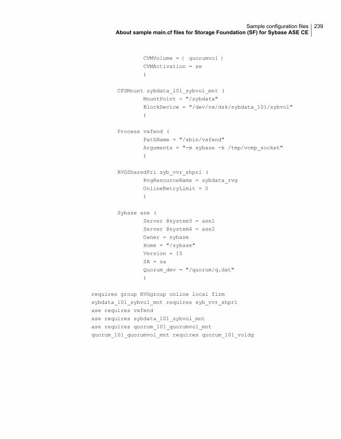
CVMVolume = { quorumvol }
CVMActivation = sw
)
CFSMount sybdata_101_sybvol_mnt (
MountPoint = "/sybdata"
BlockDevice = "/dev/vx/dsk/sybdata_101/sybvol"
)
Process vxfend (
PathName = "/sbin/vxfend"
Arguments = "-m sybase -k /tmp/vcmp_socket"
)
RVGSharedPri syb_vvr_shpri (
RvgResourceName = sybdata_rvg
OnlineRetryLimit = 0
)
Sybase ase (
Server @system3 = ase1
Server @system4 = ase2
Owner = sybase
Home = "/sybase"
Version = 15
SA = sa
Quorum_dev = "/quorum/q.dat"
)
requires group RVGgroup online local firm
sybdata_101_sybvol_mnt requires syb_vvr_shpri
ase requires vxfend
ase requires sybdata_101_sybvol_mnt
ase requires quorum_101_quorumvol_mnt
quorum_101_quorumvol_mnt requires quorum_101_voldg
239Sample configuration filesAbout sample main.cf files for Storage Foundation (SF) for Sybase ASE CE
Symbolsdatabase replication 145
Aadding a Secondary
best practices 81using command line 79
agentsHeartbeat 27Wide-Area Heartbeat 27
associating SRL to a Primary RVGusing command line 76
asynchronous replicationsetting up 86
Authority attributeabout 27
autodcmsrlprot setting 88
Automatic Synchronizationsynchronizing Secondary example 96
Bbackup
block-level tape 93bandwidth limit
controllingused for replication. See using command
lineused to synchronize volumes. See using
command lineBandwidth Throttling 90
See also bandwidth limitabout 90disabling
using command line 91block-level tape backup 93
Ccampus cluster
using Veritas™ InfoScale Operations Manager 45
commandsgcoconfig 127vradmin 146vxassist 138, 141vxvol 138
configurationsglobal cluster 23replicated data 21shared storage/replicated data 21
Configuring global clusterstasks 115
creating a Primary RVGusing command line 76
creating Replicated Data Setusing command line 74
creating RVGsusing vradmin vs. vxmake 75
Ddcm
srlprot settingchanging 88
disabling Bandwidth Throttling 91disaster recovery
scenarios 11use cases 11
disk groupsdisplaying disk group ID 82
Eexamples
using command linesetting up replication 96
Ffail
srlprot setting 88firewalls
using VVR in 81
Index
Ggcoconfig command 127global cluster configuration 23global clusters
about 114configuration
using VVR 125configuration examples 147configuring VCS service groups 125fire drill 112illustration of dependencies 147migration 167operation 23overview 115replicating database volumes 147requirements 114reverse migration 167takeover 167
groupslog owner 147RVG 147
GUIs, VVRabout 74
HHeartbeat agent 27high mark
latencysetting. See using command line
Iinterfaces of VVR
about 74
Llatency low and high mark
settingusing command line 86
latency protectiondisabling
using command line 87enabling
using command line 87low mark
latencysetting. See using command line
Mmodes of replication
setting 85
Nnetwork transport protocol
attributeSTORAGE 89TCP 89UDP 89
planning 81setting 89
Ooff
mode of replication 85srlprot setting 88
overflow protectionSRL 88
overridesrlprot setting 88
Ppacket size
setting 89Primary RVG
creatingusing command line 76
primary sitecreating SRL volume 137setting up 116setting up replication objects 138VCS configuration 152, 159
protocolnetwork 81
RRAID-5 volumes and VVR 77RDS
creatingusing command line 76
Recovering After a Disaster 67replicated data clusters
about 21fire drill 68planning 37
241Index
replicated data clusters (continued)third-party replication
about 69configuring service groups 71fire drill 71setting up 70
replicated data configuration 21replication
automatic synchronization 145full synchronization with Storage Checkpoint 145modifying VCS configuration 147setting up primary site 116setting up secondary site 119starting 92supported hardware 114supported software 114supported technologies 114using VVR 137verifying status 145
replication settingsdefaults 85latency protection 86packet size 89SRL overflow protection 88
resourcesCVMVolDg 147RVGSharedPri 147
RLINKconfiguring 84
Ssample SF Sybase CE configuration files. Seemain.cf
samplesSecondary 92
See also synchronizing Secondaryadding 79
secondary siteconfiguring replication 140creating SRL volume 141setting up 119setting up disk groups 143setting up RLINKs 142
service groupsVCS, for global clusters 125
setvradmin keyword 85
setting bandwidth limitusing command line 90
setting network transport protocol 89
setting packet size 89shared storage/replicated data configuration 21SmartMove for VVR 96
Turn off 97split-brain
in global clusters 31SRL
associating to a Primary RVGusing command line 76
SRL overflow protectionexplanation 88modes of 88
srlprotsrlprot=dcm
override. See autodcmstarting replication 92startrep
vradmin keyword 95steward process
about 31synchronizing Secondary
automatic synchronizationexample 96
synchronous replicationsetting up 86synchronous=off 86synchronous=override 86
Ttape backups
block-level 93TCP protocol 81Turn off
SmartMove for VVR 97
UUDP protocol 81usage types
VVR volumes 77
VVCS
configuration, for database volumereplication 147
configuring service groups 125illustration of global cluster dependencies 147
VCS configurationfor replication 147
242Index
VCS Global cluster option. See GCOVeritas Volume Replicator. See VVRvradmin command 146vradmin utility
addsec 79createpri 76–77creating RVGs 75set 85startrep 95
VVRconfiguration examples 147configuring global clusters 125database replication 145database volume replication
configuring VCS 147defining heartbeat cluster objects 128defining remote clusters 128global cluster overview 135primary site
creating SRL volume 137setting up replication objects 138
replicationusing automatic synchronization 145using full synchronization with Storage
Checkpoint 145secondary site
configuring replication 140creating SRL volume 141setting up disk groups 143setting up RLINKs 142
setting up primary site 116setting up replication 73, 137setting up secondary site 119setting up third-party replication 99VCS configuration
CVMoIDG resource 147database service group 147log owner group 147primary site 152RVG group 147RVGSharedPri resource 147secondary site 159
verifying replication 145VVR GUIs
about 74vxassist command 138, 141vxedit command
set keywordsetting synchronous=fail 85
vxmake commandcreating RVGs 75
vxvol command 138
Wwac 26wide-area connector 26wide-area failover 23
VCS agents 28Wide-Area Heartbeat agent 27
243Index