Vega DC Instruction Manual 17150-18 - TDK-Lambda EMEA
26
Page 1 of 23 17150 issue 18, Nov 2021 Vega DC Instruction Manual ENGLISH General Safety Instructions: READ SAFETY INSTRUCTIONS Servicing: These products are not customer serviceable. TDK-Lambda UK LTD. and their authorised agents only are permitted to carry out repairs. Critical Components: These products are not authorised for use as critical components in nuclear control systems, life support systems or equipment for use in hazardous environments without the express written approval of the Managing Director of TDK-Lambda EMEA. Product Usage: These products are designed for use within a host equipment which restricts access to authorised competent personnel. This product is a component power supply and is only to be installed by qualified persons within other equipment and must not be operated as a stand alone product. This product is for sale to business to business customers and can be obtained via distribution channels. It is not intended for sale to end users. This product is a component power supply and does not fall within the scope of the EMC directive. Compliance with the EMC directive must be considered in the final installation. Please contact your local TDK-Lambda office. Environmental: These products are IPX0, and therefore chemicals/solvents, cleaning agents and other liquids must not be used. Environment: This power supply is a switch mode power supply for use in applications within a Pollution Degree 2, overvoltage category II environment. Material Group IIIb PCB’s are used within it. Thermal evaluation should be considered for products operating at altitudes above 2000M. Output Loading: The output power taken from the power supply must not exceed the rating stated on the power supply label, except as stated in the product limitations in this instruction manual. Input Parameters: This product must be operated within the input parameters stated in the product limitations in this instruction manual. End of Life Disposal: The unit contains components that require special disposal. Make sure that the unit is properly disposed of at the end of its service life and in accordance with local regulations. This product is a component power supply and is only to be installed by qualified persons within other equipment and must not be operated as a stand alone product. This product is for sale to business to business customers and can be obtained via distribution channels. It is not intended for sale to end users. This product is a component power supply and does not fall within the scope of the EMC directive. Compliance with the EMC directive must be considered in the final installation. Please contact your local TDK-Lambda office
-
Upload
khangminh22 -
Category
Documents
-
view
2 -
download
0
Transcript of Vega DC Instruction Manual 17150-18 - TDK-Lambda EMEA
Page 1 of 23 17150 issue 18, Nov 2021
Vega DC Instruction Manual
ENGLISH General Safety Instructions:
READ SAFETY INSTRUCTIONS Servicing: These products are not customer serviceable. TDK-Lambda UK LTD. and their authorised agents only are permitted to carry out repairs. Critical Components: These products are not authorised for use as critical components in nuclear control systems, life support systems or equipment for use in hazardous environments without the express written approval of the Managing Director of TDK-Lambda EMEA. Product Usage: These products are designed for use within a host equipment which restricts access to authorised competent personnel. This product is a component power supply and is only to be installed by qualified persons within other equipment and must not be operated as a stand alone product. This product is for sale to business to business customers and can be obtained via distribution channels. It is not intended for sale to end users. This product is a component power supply and does not fall within the scope of the EMC directive. Compliance with the EMC directive must be considered in the final installation. Please contact your local TDK-Lambda office. Environmental: These products are IPX0, and therefore chemicals/solvents, cleaning agents and other liquids must not be used. Environment: This power supply is a switch mode power supply for use in applications within a Pollution Degree 2, overvoltage category II environment. Material Group IIIb PCB’s are used within it. Thermal evaluation should be considered for products operating at altitudes above 2000M. Output Loading: The output power taken from the power supply must not exceed the rating stated on the power supply label, except as stated in the product limitations in this instruction manual. Input Parameters: This product must be operated within the input parameters stated in the product limitations in this instruction manual. End of Life Disposal: The unit contains components that require special disposal. Make sure that the unit is properly disposed of at the end of its service life and in accordance with local regulations. This product is a component power supply and is only to be installed by qualified persons within other equipment and must not be operated as a stand alone product. This product is for sale to business to business customers and can be obtained via distribution channels. It is not intended for sale to end users. This product is a component power supply and does not fall within the scope of the EMC directive. Compliance with the EMC directive must be considered in the final installation. Please contact your local TDK-Lambda office

Page 2 of 23 17150 issue 18, Nov 2021
Vega DC Instruction Manual
RISK OF ELECTRIC SHOCK High Voltage Warning: Dangerous voltages are present within the power supply. The professional installer must protect service personnel from inadvertent contact with these dangerous voltages in the end equipment. WARNING: When INSTALLED in a Class 1 end equipment, this product must be reliably earthed and professionally installed. The (+) or (-) output(s) can be earthed or left floating. The unit cover(s)/chassis must not be made user accessible. The mains input connector is not acceptable for use as field wiring terminals. Do not use mounting screws, which penetrate the unit more than 4.5mm. Special earthing screws are used on these products which connect the cover to the chassis. They must not be removed. If they are removed by mistake, they must be replaced with new ones and the product tested for earth bonding. An internal fuse protects the unit and must not be replaced by the user. In case of internal defect, the unit must be returned to TDK-Lambda UK LTD or one of their authorised agents. A suitable mechanical, electrical and fire enclosure must be provided by the end use equipment for mechanical, electric shock and fire hazard protection. Energy Hazards: Certain modules are capable of providing hazardous energy (240VA) according to output voltage setting. Final equipment manufacturers must provide protection to service personnel against inadvertent contact with these module output terminals. If set such that hazardous energy can occur then the module terminals or connections must not be user accessible. The power supply contains dangerous voltages and should only be handled by qualified personnel when the power supply has been disconnected from the mains supply voltage for more than 3 minutes
HOT SURFACE External Hot Surfaces: In accordance with local regulations for Health and Safety at work, manufacturers have an obligation to protect service engineers as well as users. In order to comply with this, a label must be fitted to these products which is clearly visible to service personnel accessing the overall equipment, and which legibly warns that surfaces of these products may be hot and must not be touched when the products are in operation. The unit may be mounted in any orientation except inverted (mounted on its top) or vertical with the airflow downwards. The ventilation openings on these products must not be impeded. Ensure that there is at least 50mm spacing between any obstruction and the ventilation openings. The unit cover/chassis is designed to protect skilled personnel from hazards. They must not be used as part of the external covers of any equipment where they may be accessible to operators, since under full load conditions, part or parts of the unit chassis may reach temperatures in excess of those considered safe for operator access.

Page 3 of 23 17150 issue 18, Nov 2021
Vega DC Instruction Manual
DEUTSCH Allgemeine Sicherheitsvorschriften:
LESEN SIE DIE SICHERHEITSVORSCHRIFTEN Wartung: Diese Produkte können nicht durch den Kunden gewartet werden. Nur TDK-Lambda UK LTD. und deren zugelassene Vertriebshändler sind zur Durchführung von Reparaturen berechtigt. Kritische Komponenten: Diese Produkte sind nicht für die Verwendung als kritische Komponenten in nuklearen Kontrollsystemen, Lebenserhaltungssystemen oder Geräten in gefährlichen Umgebungen geeignet, sofern dies nicht ausdrücklich und in Schriftform durch den Geschäftsführer von TDK-Lambda EMEA genehmigt wurde. Produktverwendung: Diese Produkte sind zur Verwendung innerhalb von Host-Anlagen gedacht, die einen auf das Fachpersonal beschränkten Zugang haben. Dieses Produkt ist eine Stromversorgungs-Komponente und sie darf nur von qualifiziertem Personal in andere Geräte eingebaut werden und sie darf NICHT als eigenständiges ("Stand-Alone") Gerät betrieben werden. Dieses Produkt ist für den Verkauf an Geschäftskunden entwickelt worden und es kann über Distributionskanäle bezogen werden. Es ist NICHT für den Verkauf an Endkunden gedacht und konzipiert. Dieses Produkt ist eine Stromversorgungsbaugruppe und sie fällt NICHT in den Bereich der EMV Direktive. Die Konformität mit der EMV Richtlinie muss in der finalen Gesamtinstallation betrachtet werden. Bitte kontaktieren Sie Ihr regionales TDK-Lambda Vertriebsbüro im Falle von Rückfragen. Umwelt: Diese Produkte sind IPX0, aus diesem Grund dürfen keine Chemikalien/Lösungsmittel, Reinigungsmittel und andere Flüssigkeiten verwendet werden. Umgebung: Dieses Netzteil ist ein Schaltnetzteil zur Verwendung in einer Umgebung mit einem Verschmutzungsgrad 2, Überspannungskategorie II. Materialgruppe IIIb mit darin verwendeten PCBs. Bei Einsatz der Geräte über 2.000m Höhe muss eine ausreichende Kühlung gewährleistet werden. Ausgangsstrom: Der Ausgangsstrom des Netzteiles darf die Leistung, die auf dem Label des Netzteiles vermerkt ist, nur dann überschreiten, wenn dies in den Produktgrenzen dieses Handbuches ausgezeichnet ist. Eingangsparameter: Dieses Produkt muss innerhalb der Eingangsparameter, die in den Produktgrenzen dieses Handbuches angegeben sind, betrieben werden. Entsorgung am Ende der Betriebszeit: Das Gerät enthält Komponenten die unter Sondermüll fallen. Das Gerät muss am Ende der Betriebszeit ordnungsgemäß und in Übereinstimmung mit den regionalen Bestimmungen entsorgt werden. Dieses Produkt ist eine Stromversorgungs-Komponente und sie darf nur von qualifiziertem Personal in andere Geräte eingebaut werden und sie darf NICHT als eigenständiges ("Stand-Alone") Gerät betrieben werden. Dieses Produkt ist für den Verkauf an Geschäftskunden entwickelt worden und es kann über Distributionskanäle bezogen werden. Es ist NICHT für den Verkauf an Endkunden gedacht und konzipiert. Dieses Produkt ist eine Stromversorgungsbaugruppe und sie fällt NICHT in den Bereich der EMV Direktive. Die Konformität mit der EMV Richtlinie muss in der finalen Gesamtinstallation betrachtet werden. Bitte kontaktieren Sie Ihr regionales TDK-Lambda Vertriebsbüro im Falle von Rückfragen.
Page 4 of 23 17150 issue 18, Nov 2021
Vega DC Instruction Manual
GEFAHR DURCH ELEKTRISCHEN SCHLAG Hochspannungswarnung: Innerhalb des Netzteiles gibt es gefährliche Spannungen. Der Elektroinstallateur muss das Wartungspersonal vor versehentlichem Kontakt mit den gefährlichen Spannungen im Endgerät schützen. WARNUNG! Falls Sie unser Netzgerät in eine Anwendung mit Schutzklasse 1 eingebaut haben, stellen Sie sicher, dass es fachgerecht installiert und zuverlässig geerdet ist. Die (+) oder (-) Ausgänge können geerdet werden oder unangeschlossen bleiben. Die Abdeckung des Gerätes/das Gehäuse darf für den Benutzer nicht zugänglich sein. Der Haupteingangsanschluss ist nicht für die Verwendung als Feldverdrahtungsanschluss geeignet. Verwenden Sie keine Befestigungsschrauben, die mehr als 4.5mm in das Gerät eindringen. Zur Befestigung der Abdeckung am Gehäuse werden für diese Produkte spezielle Erdungsschrauben verwendet. Diese dürfen nicht entfernt werden. Sollten sie versehentlich entfernt werden, müssen sie durch neue ersetzt und das Produkt auf Erdschluss geprüft werden. Eine interne Sicherung schützt das Gerät und darf durch den Benutzer nicht ausgetauscht werden. Im Fall von internen Defekten muss das Gerät an TDK-Lambda UK LTD oder einen der autorisierten Vertriebshändler zurückgeschickt werden. Ein geeignetes mechanisches, elektrisches und brandgeschütztes Gehäuse muss als Schutz vor der Gefahr von mechanischen Risiken, Stromschlägen und Brandschutz in dem Endgerät vorgesehen werden. Gefahren durch elektrische Energie: Von bestimmten Modulen kann je nach Einstellung der Ausgangsspannung gefährliche elektrische Energie ausgehen (240 VA). Die Endgerätehersteller müssen einen Schutz für Servicepersonal vor unbeabsichtigtem Kontakt mit den Ausgangsanschlüssen dieser Module vorsehen. Kann aufgrund der Einstellung gefährliche elektrische Energie auftreten, dürfen die Modulanschlüsse für den Benutzer nicht zugänglich sein. Das Netzteil steht unter hoher Spannung und sollte deshalb mindestens 3 Minuten vom Netz getrennt sein. Die Bedienung darf nur durch Fachpersonal erfolgen
HEISSE OBERFLÄCHEN Äußere heiße Oberflächen: In Übereinstimmung mit den regionalen Bestimmungen für Gesundheit und Sicherheit bei der Arbeit ist der Hersteller für den Schutz von Wartungspersonal und Benutzern verantwortlich. Um diesen Bestimmungen gerecht zu werden, muss auf den Produkten ein Label angebracht werden, das deutlich sichtbar für das Wartungspersonal mit Zugriff auf die gesamte Anlage ist, und das gut lesbar auf die eventuell heiße Oberfläche des Gerätes hinweist und das Berühren des Produktes in Betrieb untersagt. Das Gerät darf in jeder Position befestigt werden, mit Ausnahme über Kopf (umgekehrt) oder vertikal mit dem Luftstrom abwärts. Die Belüftungsöffnungen an diesem Produkt dürfen nicht blockiert werden. Achten Sie darauf, dass mindestens 50 mm Abstand zwischen Hindernissen und den Belüftungsöffnungen bleibt. Die Geräteabdeckung/das Gehäuse ist so entworfen, dass das Fachpersonal vor Gefahren geschützt wird. Sie dürfen nicht als Teil der externen Abdeckung für Geräte verwendet werden, die für den Betreiber zugänglich sein müssen, da Teile oder das gesamte Gerätegehäuse unter voller Auslastung übermäßige Temperaturen erreichen kann, die für den Zugang des Betreibers nicht mehr als sicher betrachtet werden.

Page 5 of 23 17150 issue 18, Nov 2021
Vega DC Instruction Manual
FRANÇAIS Consignes générales de sécurité:
LIRE LES CONSIGNES DE SECURITE Entretien: Ces produits ne peuvent pas être réparés par l’utilisateur. Seuls, TDK-Lambda UK LTD et ses agents agréés sont autorisés à effectuer des réparations. Composants critiques: Ces produits ne doivent pas être utilisés en tant que composants critiques dans des systèmes de commande nucléaire, dans des systèmes de sauvetage ou dans des équipements utilisés dans des environnements dangereux, sans l'autorisation écrite expresse du directeur général de TDK-Lambda EMEA. Utilisation du produit: Ces produits sont conçus pour être utilisés dans un équipement hôte dont l'accès n'est autorisé qu'aux personnes compétentes. Ce produit est une alimentation considérée comme un composant devant être installé par des personnes qualifiées, dans un autre équipement. Il ne doit pas être utilisé en tant que produit fini. Ce produit est destiné à la vente entre entreprises et peut être obtenu via des canaux de distribution. Il n’est pas prévu à la vente pour les particuliers. Ce produit est une alimentation considérée comme un composant, il ne relève pas du champ d’application de la directive CEM. Le respect de la directive CEM doit être pris en compte dans l’installation finale. Veuillez contacter votre bureau TDK-Lambda le plus proche. Environnement: Ces produits sont IPX0, et donc on ne doit pas utiliser des produits chimiques/solvants, des produits de nettoyage et d'autres liquides. Environnement fonctionnel: Cette alimentation fonctionne en mode commutation pour utilisation dans des applications fonctionnant dans un environnement avec Degré de Pollution 2 et catégorie de surtension II. Elle utilise des cartes des circuits imprimés (PCB) de Groupe IIIb. Une étude thermique doit être envisagée pour une utilisation des produits au-dessus de 2000 mètres d'altitude. Intensité soutirée: L'intensité soutirée de l'alimentation ne doit pas dépasser l'intensité nominale marquée sur la plaque signalétique, sauf indications contraires dans les limitations du produit décrit dans ce manuel. Paramètres d'entrée: Ce produit doit être utilisé à l'intérieur des paramètres d'entrée indiqués dans les limitations du produit dans ce manuel. Elimination en fin de vie: L'alimentation contient des composants nécessitant des dispositions spéciales pour leur élimination. Vérifiez que cette alimentation est mise au rebut correctement en fin de vie utile et conformément aux réglementations locales en vigueur. Ce produit est une alimentation considérée comme un composant devant être installé par des personnes qualifiées, dans un autre équipement. Il ne doit pas être utilisé en tant que produit fini. Ce produit est destiné à la vente entre entreprises et peut être obtenu via des canaux de distribution. Il n’est pas prévu à la vente pour les particuliers. Ce produit est une alimentation considérée comme un composant, il ne relève pas du champ d’application de la directive CEM. Le respect de la directive CEM doit être pris en compte dans l’installation finale. Veuillez contacter votre bureau TDK-Lambda le plus proche.
Page 6 of 23 17150 issue 18, Nov 2021
Vega DC Instruction Manual
RISQUE DE CHOC ELECTRIQUE Attention-Danger haute tension: Des tensions dangereuses sont présentes dans l'alimentation. L'installateur doit protéger le personnel d'entretien contre un contact involontaire avec ces tensions dangereuses dans l'équipement final. AVERTISSEMENT: Si ce produit est installé dans un équipement final de classe I, il doit être mis à la terre de manière fiable et installé par un professionnel averti. Les sorties (+) ou (-) peuvent être raccordées à la terre ou laissées flotttantes. Le couvercle/châssis de l'alimentation ne doit pas être accessible à l'utilisateur. Le connecteur d'entrée d'alimentation principale ne doit pas être utilisé comme borne de raccordement. N'utilisez pas de vis pénétrant dans le module sur une profondeur supérieure à 4.5 mm. Des vis de terre spéciales sont utilisées sur ces produits pour raccorder le couvercle au châssis. Elles ne doivent pas être enlevées. Si elles sont enlevées par erreur, elles doivent être remplacées et le produit doit être testé pour vérifier que le raccordement à la terre est correct. Un fusible interne protège le module et ne doit pas être remplacé par l'utilisateur. En cas de défaut interne, le module doit être renvoyé à TDK-Lambda UK LTD ou l'un de ses agents agréés. Une enceinte appropriée doit être prévue par l'utilisateur final pour assurer la protection contre les chocs mécaniques, les chocs électriques et l'incendie. Energies dangereuses : Certains modules peuvent générer une énergie dangereuse (240 VA) selon le réglage de tension de sortie. Le fabricant de l'équipement final doit assurer la protection des techniciens d'entretien contre un contact involontaire avec les bornes de sortie de ces modules. Si une telle tension dangereuse risque de se produire, les bornes ou les connexions du module ne doivent pas être accessibles par l'utilisateur. L’alimentation délivre des tensions dangereuses et doit seulement être manipulée par du personnel qualifié quand celle-ci a été déconnectée du secteur pendant plus de 3 minutes.
SURFACE CHAUDE Surfaces chaudes extérieures: Conformément aux réglementations locales concernant la santé et la sécurité sur les lieux de travail, les fabricants doivent protéger les techniciens d'entretien et les utilisateurs. Pour cela, une plaque signalétique doit être installée sur ces produits, et cette plaque doit être bien visible pour les techniciens d'entretien intervenant sur l'équipement, et elle doit indiquer de manière bien visible que les surfaces de ces produits peuvent être chaudes et qu'elles ne doivent pas être touchées lorsque les produits fonctionnent. Le module peut être monté suivant une orientation quelconque, sauf en position inversée (monté sur son sommet) ou en position verticale avec écoulement d'air descendant. Les orifices de ventilation sur ces produits ne doivent pas être obstrués. Vérifiez qu'il y a un espace libre d'au moins 50 mm entre une obstruction et les orifices de ventilation. Le couvercle et le châssis du module sont conçus pour protéger des personnels expérimentés. Ils ne doivent pas être utilisés comme couvercles extérieurs d'un équipement, accessible aux opérateurs car en condition de puissance maximum, des parties du châssis peuvent atteindre des températures considérées comme dangereuses pour l'opérateur.
Page 7 of 23 17150 issue 18, Nov 2021
Vega DC Instruction Manual
ITALIANO Norme generali di sicurezza:
SI PREGA DI LEGGERE LE NORME DI SICUREZZA Manutenzione: Il cliente non può eseguire alcuna manutenzione su questi prodotti. L'esecuzione delle eventuali riparazioni è consentita solo a TDK-Lambda UK LTD e ai suoi agenti autorizzati. Componenti critici: Non si autorizza l'uso di questi prodotti come componenti critici all'interno di sistemi di controllo nucleari, sistemi necessari alla sopravvivenza o apparecchiature destinate all'impiego in ambienti pericolosi, senza l'esplicita approvazione scritta dell'Amministratore Delegato di TDK-Lambda EMEA. Uso dei prodotti: Questi prodotti sono progettati per l'uso all'interno di un'apparecchiatura ospite che limiti l'accesso al solo personale competente e autorizzato. Questo prodotto è da considerarsi come un alimentatore professionale componente e come tale deve essere installato da personale qualificato all'interno di altre apparecchiature e non può essere utilizzato come prodotto indipendente. Questo prodotto non è inteso per la vendita al dettaglio o agli utilizzatori finali. Questo alimentatore è da considerarsi come un componente e come tale non è assogettato dagli scopi della direttiva EMC. Conformità alla direttiva EMC deve essere considerata nell'installazione finale di utilizzo. Gli uffici di TDK-Lambda Sas Succursale Italiana sono a vostra disposizione per ulteriori ragguagli. Condizioni ambientali: Questi prodotti sono classificati come IPX0, dunque non devono essere utilizzati sostanze chimiche/solventi, prodotti per la pulizia o liquidi di altra natura. Ambiente: Questo prodotto è un alimentatore a commutazione, destinato all'uso in applicazioni rientranti in ambienti con le seguenti caratteristiche: Livello inquinamento 2, Categoria sovratensione II. Questo prodotto contiene schede di circuiti stampati in materiali di Gruppo IIIb. La valutazione delle prestazioni termiche del prodotto dev'essere considerata separatamente per le applicazioni che prevedono un'utilizzo dell'alimentatore ad altitudine superiore ai 2000 metri. Carico in uscita: La potenza in uscita ottenuta dall'alimentatore non deve superare la potenza nominale indicata sulla targhetta dell'alimentatore, fatto salvo dove indicato nei limiti per i prodotto specificati in questo manuale. Parametri di alimentazione: Questo prodotto deve essere utilizzato entro i parametri di alimentazione indicati nei limiti per il prodotto, specificati in questo manuale. Smaltimento: L'unità contiene componenti che richiedono procedure speciali di smaltimento. Accertarsi che l'unità venga smaltita in modo corretto al termine della vita utile e nel rispetto delle normative locali. Questo prodotto è da considerarsi come un alimentatore professionale componente e come tale deve essere installato da personale qualificato all'interno di altre apparecchiature e non può essere utilizzato come prodotto indipendente. Questo prodotto non è inteso per la vendita al dettaglio o agli utilizzatori finali. Questo alimentatore è da considerarsi come un componente e come tale non è assogettato dagli scopi della direttiva EMC. Conformità alla direttiva EMC deve essere considerata nell'installazione finale di utilizzo. Gli uffici di TDK-Lambda Sas Succursale Italiana sono a vostra disposizione per ulteriori ragguagli.
Page 8 of 23 17150 issue 18, Nov 2021
Vega DC Instruction Manual
RISCHIO DI SCOSSA ELETTRICA Avvertimento di alta tensione: All'interno dell'alimentatore sono presenti tensioni pericolose. Gli installatori professionali devono proteggere il personale di manutenzione dal rischio di contatto accidentale con queste tensioni pericolose all'interno dell'apparecchiatura finale. ATTENZIONE: Se installato in un’attrezzatura di classe I, questo prodotto deve essere collegato a terra in modo affidabile ed installato in modo professionale. Le uscite (+) o (-) possono essere messa a terra o lasciate isolate. I coperchi/il telaio dell'unità non devono essere accessibili da parte dell'utente. Il connettore dell'alimentazione principale non può essere utilizzato come terminale di collegamento di campo. Non utilizzare viti che penetrano nell'unità per più di 4.5 mm. Per questi prodotti vengono usate viti speciali di messa a terra, che collegano il coperchio al telaio. Tali viti non devono essere rimosse. Se le viti vengono tolte per errore, vanno sostituite con nuove viti ed occorre testare il prodotto per verificarne il collegamento a massa. Un fusibile interno protegge l'unità e non deve essere sostituito dall'utente. Nell'eventualità di un difetto interno, restituire l'unità a TDK-Lambda UK LTD o a uno dei suoi agenti autorizzati. L'apparecchiatura finale deve includere una recinzione meccanica, elettrica e antincendio per proteggere dai pericoli di natura meccanica, dalle scosse elettriche e dai pericoli di incendio. Pericoli energetici: Alcuni moduli sono in grado di erogare energia pericolosa (240 VA) a seconda della tensione in uscita impostata. I produttori delle apparecchiature finali sono tenuti a proteggere il personale di manutenzione dal rischio di contatto accidentale con questi terminali dei moduli di uscita. Se impostati su livelli che non escludono l'erogazione di energia pericolosa, questi terminali o collegamenti non devono risultare accessibili da parte dell'utente. L'alimentatore contiene tensioni pericolose e deve essere gestito da personale qualificato previo scollegamento dalla tensione di rete da più di 3 minuti
SUPERFICIE CALDA Superfici esterne calde: Coerentemente con le norme locali in materia di salute & sicurezza professionali, i produttori sono tenuti a salvaguardare i tecnici di manutenzione, e inoltre gli utenti. Per far fronte a tali obblighi, i prodotti devono presentare una targhetta, chiaramente visibile al personale di manutenzione che accede all'apparecchiatura nel complesso e che risulti inoltre leggibile e avverta gli addetti del rischio che le superfici di questi prodotti possono scottare e non vanno toccate con i prodotti in funzione. L'unità può essere installata in qualunque orientamento, ma non in posizione capovolta o in posizione verticale con il flusso dell'aria rivolto verso il basso. Le griglie di ventilazione su questi prodotti non devono essere ostruite. Verificare che vi sia una distanza minima di 50 mm fra le griglie di ventilazione e qualsiasi eventuale ostruzione.
Page 9 of 23 17150 issue 18, Nov 2021
Vega DC Instruction Manual
Il coperchio/telaio dell'unità è realizzato per proteggere il personale esperto dai pericoli. Non deve essere usato come parte degli involucri esterni di qualsiasi apparecchiatura, se risulta accessibile da parte degli addetti, poiché è possibile che in condizioni di pieno carico una o più parti del telaio dell'unità giunga/giungano a temperature superiori ai limiti considerati sicuri per l'accesso da parte degli addetti.

Page 10 of 23 17150 issue 18, Nov 2021
Vega DC Instruction Manual
ESPAÑOL Instrucciones generales de seguridad:
LEA LAS INSTRUCCIONES DE SEGURIDAD Servicio: Estos productos no pueden ser reparados por los clientes. TDK-Lambda UK LTD. y sus agentes autorizados son los únicos que pueden llevar a cabo las reparaciones. Componentes fundamentales: Estos productos no pueden ser utilizados como componentes fundamentales en sistemas de control nuclear, sistemas de soporte vital o equipos a utilizar en entornos peligrosos sin el consentimiento expreso por escrito del Director General de TDK-Lambda EMEA. Uso de los productos: Estos productos han sido diseñados para ser utilizados en un equipo central que restrinja el acceso al personal cualificado autorizado. Este producto es una fuente de alimentación y sólo puede ser instalado por personal cualificado dentro de otros equipos y no debe ser tratado como un producto independiente. Este producto debe ser vendido entre empresas profesionales y solo puede obtenerse a través de los canales de distribución .No está destinado para la venta a usuarios finales Este producto es una fuente de alimentación y no se ve afectada por la directiva EMC . El cumplimiento de la directiva EMC se debe considerar en la instalación final . Por favor, póngase en contacto con su oficina local de TDK – Lambda. Medioambiental: Estos productos son IPX0 y, por tanto, no pueden utilizarse sustancias químicas/disolventes, agentes de limpieza ni otros líquidos. Medio ambiente: Esta fuente de alimentación es una fuente de alimentación de modo conmutado a utilizar en aplicaciones dentro de un entorno con un Grado de contaminación 2 y una Categoría de sobretensión II. En él se utilizan policloruros de bifenilo del Grupo de materiales IIIb. Una evaluación térmica debe ser considerada para una utilización de los productos por encima de 2000 metros de altitud. Carga de salida: La potencia de salida tomada de la fuente de alimentación no puede sobrepasar el valor nominal indicado en la etiqueta de la fuente de alimentación, excepto en los casos indicados en las limitaciones del producto en este manual. Parámetros de entrada: Este producto debe ser utilizado dentro de los parámetros de entrada indicados en las limitaciones del producto en este manual. Desecho de la unidad: La unidad contiene componentes que deben ser desechados de una manera especial. Asegúrese de desechar correctamente la unidad al final de su vida útil y conforme a las normas locales vigentes. Este producto es una fuente de alimentación y sólo puede ser instalado por personal cualificado dentro de otros equipos y no debe ser tratado como un producto independiente. Este producto debe ser vendido entre empresas profesionales y solo puede obtenerse a través de los canales de distribución .No está destinado para la venta a usuarios finales Este producto es una fuente de alimentación y no se ve afectada por la directiva EMC . El cumplimiento de la directiva EMC se debe considerar en la instalación final . Por favor, póngase en contacto con su oficina local de TDK - Lambda
Page 11 of 23 17150 issue 18, Nov 2021
Vega DC Instruction Manual
PELIGRO DE DESCARGAS ELÉCTRICAS Advertencia de alta tensión: En esta fuente de alimentación hay tensiones peligrosas. El instalador profesional debe proteger al personal de servicio contra cualquier contacto accidental con estas tensiones peligrosas en el equipo final. ADVERTENCIA: La instalación de este producto en un equipo de clase I la deben llevar a cabo profesionales y el producto debe estar conectado a tierra. La salida o salidas (+) o (-) pueden conectarse a tierra o se las puede dejar flotando. Debe impedirse el acceso de los usuarios a la cubierta o cubiertas y al chasis de la unidad. El conector de entrada de la red no es apto para ser utilizado a modo de bornes de cableado de campo. No utilice tornillos de montaje susceptibles de penetrar en la unidad más de 4.5 mm. Con estos productos se utilizan unos tornillos de puesta a tierra especiales que conectan la cubierta al chasis. No se deben quitar en ningún caso. En caso de quitarlos por error, hay que reemplazarlos por unos nuevos y comprobar la conexión a tierra del producto. Un fusible interno protege la unidad y este no debe ser nunca reemplazado por el usuario. En caso de existir algún defecto interno, la unidad debe ser enviada a TDK-Lambda UK LTD o a uno de sus agentes autorizados. El equipo de uso final debe constituir un recinto de protección mecánica, eléctrica y contra incendios de protección mecánica, contra descargas eléctricas y contra el peligro de incendios. Peligros de energía: Algunos módulos pueden generar energía peligrosa (240VA) dependiendo de la configuración de la tensión de salida. Los fabricantes de equipos finales deben proteger al personal de servicio contra un contacto accidental con estos bornes de salida de los módulos. Si se configura de modo que pueda generarse energía peligrosa, hay que evitar que el usuario pueda acceder a los bornes o conexiones del módulo. El suministro eléctrico contiene tensiones peligrosas y, en caso de que se haya desconectado de la alimentación principal durante más de 3 minutos, deberá ser manipulado únicamente por personal cualificado.
SUPERFICIE CALIENTE Superficies externas calientes: Según las normas locales relativas a la Salud y Seguridad en el trabajo, los fabricantes están obligados a proteger a los ingenieros de servicio además de a los usuarios. Para que esto se cumpla, debe colocarse una etiqueta en estos productos que pueda ser vista claramente por el personal de servicio que accede al equipo general, y con advertencias legibles de que las superficies de estos productos pueden estar calientes y no deben tocarse cuando los productos se encuentran en funcionamiento. La unidad se puede montar en cualquier orientación excepto invertida (montada sobre su parte de arriba) o vertical con los orificios para el flujo de aire mirando hacia abajo. Las aberturas de ventilación de estos productos no deben obstruirse jamás. Asegúrese de que quede una separación de 50 mm por lo menos entre cualquier obstrucción y las aberturas de ventilación.
Page 12 of 23 17150 issue 18, Nov 2021
Vega DC Instruction Manual
La cubierta/chasis de la unidad ha sido diseñada para que proteja a las personas cualificadas de los peligros. No deben ser utilizadas como parte de las cubiertas externas de cualquier equipo al que pueden acceder los operarios, ya que bajo unas condiciones de carga completa, la pieza o piezas del chasis de la unidad pueden alcanzar temperaturas superiores a las consideradas seguras para el acceso de los operarios.
Page 13 of 23 17150 issue 18, Nov 2021
Vega DC Instruction Manual
PORTUGUÊS Instruções gerais de segurança:
LEIA AS INSTRUÇÕES DE SEGURANÇA Manutenção: Estes produtos não são podem ser submetidos a manutenção por parte do cliente. Apenas a TDK-Lambda UK LTD e os seus agentes autorizados têm permissão para realizar reparações. Componentes essenciais: Não é autorizada a utilização destes produtos como componentes essenciais de sistemas de controlo nuclear, sistemas de suporte de vida ou equipamento para utilização em ambientes perigosos sem a expressa autorização por escrito do Director-Geral da TDK-Lambda EMEA. Utilização do produto: Estes produtos foram concebidos para utilização dentro de um equipamento de alojamento que apenas permita o acesso a pessoal qualificado autorizado. Este produto é uma alimentaçao considerado com um componente para ser instalado por pessoas qualificadas, em outros equipamentos. Não deve ser usado como um produto acabado. Este produto é destinado para venda entre as empresas e pode ser obtido através de canais de distribuição. Não se destina à venda aos particulares Este produto é uma alimentaçao considerado com um componente, não é dentro do appliquation âmbito da directiva CEM. Conformidade com a directiva CEM devem ser considerados na instalação final. Entre em contacto com seu escritório TDK-Lambda mais próximo. Ambiental: Estes produtos são IPX0 e, como tal, não se devem utilizar químicos/solventes, agentes de limpeza e outros líquidos. Ambiente: Esta fonte de alimentação é uma fonte de alimentação do modo de comutação para utilização em aplicações com um Nível de Poluição 2 e ambientes da categoria de sobretensão II. São utilizadas placas de circuitos impressos do grupo de materiais IIIb. Uma avaliação térmica deveria ser considerada para um uso dos produtos sobre 2000 metros de altitude. Carga de saída: A potência de saída extraída da fonte de alimentação não deve exceder a classificação assinalada na etiqueta da fonte de alimentação, excepto quando indicado nas limitações do produto neste guia. Parâmetros de entrada: Este produto deve ser utilizado dentro dos parâmetros de entrada indicados nas limitações do produto neste guia. Eliminação no fim de vida: A unidade contém componentes que necessitam de procedimentos especiais de eliminação. Certifique-se de que a unidade é devidamente eliminada no fim da sua vida útil e que tal é feito em conformidade com os regulamentos locais. Este produto é uma alimentaçao considerado com um componente para ser instalado por pessoas qualificadas, em outros equipamentos. Não deve ser usado como um produto acabado. Este produto é destinado para venda entre as empresas e pode ser obtido através de canais de distribuição. Não se destina à venda aos particulares Este produto é uma alimentaçao considerado com um componente, não é dentro do appliquation âmbito da directiva CEM.

Page 14 of 23 17150 issue 18, Nov 2021
Vega DC Instruction Manual
Conformidade com a directiva CEM devem ser considerados na instalação final. Entre em contacto com seu escritório TDK-Lambda mais próximo
RISCO DE CHOQUE ELÉCTRICO Aviso de alta tensão: Estão presentes tensões perigosas dentro da fonte de alimentação. O profissional que realizar a instalação deve proteger o pessoal de assistência contra contactos inadvertidos com estas tensões perigosas do equipamento final. AVISO: Quando instalado num equipamento de Classe I, este produto deve ser ligado à terra de forma fiável e instalado por um profissional. As saídas (+) e (-) podem ser ligadas à terra ou deixadas soltas. O chassis/cobertura(s) da unidade não deve estar acessível ao utilizador. O conector de entrada de alimentação não deve ser utilizado como terminal de cablagens no local. Não utilize parafusos de montagem, uma vez que estes penetrarão na unidade em mais do que 4.5 mm. Nestes produtos utilizam-se parafusos especiais de ligação à terra, que ligam a cobertura ao chassis. Não devem ser removidos. Se forem removidos por engano, deverão ser substituídos por parafusos novos, devendo-se testar a ligação à terra do produto. Existe um fusível interno que protege a unidade e que não deve ser substituído pelo utilizador. Em caso de defeito interno, a unidade deve ser devolvida à TDK-Lambda UK LTD ou a um dos seus agentes autorizados. O equipamento de utilização final deve fornecer um bastidor com protecção mecânica, eléctrica e contra incêndios adequada. Perigos de energia: Alguns módulos tem a capacidade de fornecer energia perigosa (240 VA), de acordo com a configuração da tensão de saída. O equipamento final do fabricante deve garantir que o pessoal de assistência está protegido contra contactos inadvertidos com estes terminais de saída do módulo. Se essa energia perigosa for produzida, as ligações e os terminais do módulo não devem ser acessíveis pelos utilizadores. A fonte de alimentação contém tensões perigosas e apenas deve ser manuseada por pessoal qualificado quando a fonte de alimentação tiver sido desligada da tensão de alimentação elétrica há mais de 3 minutos.
SUPERFÍCIE QUENTE Superfícies quentes externas: Segundo com os regulamentos locais sobre saúde e segurança no local de trabalho, os fabricantes têm a obrigação de proteger os técnicos de manutenção, bem como os utilizadores. De forma a respeitar este regulamento, estes produtos deverão ter uma etiqueta que seja facilmente visível ao pessoal de assistência que aceda ao equipamento em geral, e que alerte, de forma legível, para o facto de as superfícies destes produtos poderem estar quentes, não devendo ser tocadas quando os produtos estão em funcionamento. A unidade pode ser instalada em qualquer posição, excepto invertida (montada sobre a parte superior), ou na posição vertical, com o fluxo de ar dirigindo-se para baixo. As aberturas de ventilação destes produtos não devem ser obstruídas. Certifique-se de que existe um espaçamento de pelo menos 50 mm entre qualquer obstrução e as aberturas de ventilação.
Page 15 of 23 17150 issue 18, Nov 2021
Vega DC Instruction Manual
O chassis/cobertura da unidade está concebido de forma a proteger o pessoal especializado de perigos. Não devem ser utilizados como parte das coberturas externas de qualquer equipamento em que possam estar acessíveis aos operadores, uma vez que em condições de carga máxima, algumas peças do chassis da unidade podem atingir temperaturas superiores às consideradas seguras para o acesso do operador.
Page 16 of 23 17150 issue 18, Nov 2021
Vega DC Instruction Manual
Environmental Specifications: Description Operation Storage
Use Indoor - Temperature 0°C - +50°C (derating at 2.5%/°C 50 to 65°C, not
covered by approvals) -40°C - +70°C
Humidity 5 - 95% RH, non-condensing 5 - 95% RH, non-condensing Altitude -200m - 5000m -200m - 5000m
Pressure 70kPa - 106kPa* 54kPa - 106kPa* Orientation ALL* ALL
Material Group IIIb Pollution Degree 2
Overvoltage Category II Class I
Weight 2 kg (Dependent on configuration) IP Rating IPX0
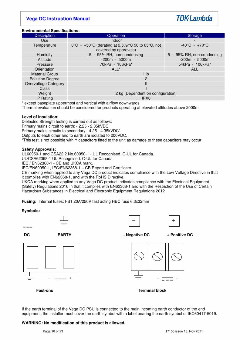
* except baseplate uppermost and vertical with airflow downwards Thermal evaluation should be considered for products operating at elevated altitudes above 2000m Level of Insulation: Dielectric Strength testing is carried out as follows: Primary mains circuit to earth: - 2.25 - 2.35kVDC Primary mains circuits to secondary: -4.25 - 4.35kVDC* Outputs to each other and to earth are isolated to 200VDC. *This test is not possible with Y capacitors fitted to the unit as damage to these capacitors may occur. Safety Approvals: UL60950-1 and CSA22.2 No.60950-1 - UL Recognised. C-UL for Canada. UL/CSA62368-1 UL Recognised. C-UL for Canada IEC / EN62368-1 - CE and UKCA mark. IEC/EN60950-1, IEC/EN62368-1 – CB Report and Certificate. CE marking when applied to any Vega DC product indicates compliance with the Low Voltage Directive in that it complies with EN62368-1, and with the RoHS Directive. UKCA marking when applied to any Vega DC product indicates compliance with the Electrical Equipment (Safety) Regulations 2016 in that it complies with EN62368-1 and with the Restriction of the Use of Certain Hazardous Substances in Electrical and Electronic Equipment Regulations 2012 Fusing: Internal fuses: FS1 20A/250V fast acting HBC fuse 6.3x32mm Symbols:
DC EARTH - Negative DC + Positive DC
Fast-ons Terminal block If the earth terminal of the Vega DC PSU is connected to the main incoming earth conductor of the end equipment, the installer must cover the earth symbol with a label bearing the earth symbol of IEC60417-5019. WARNING: No modification of this product is allowed.
- +
- +
- +
Page 17 of 23 17150 issue 18, Nov 2021
Vega DC Instruction Manual
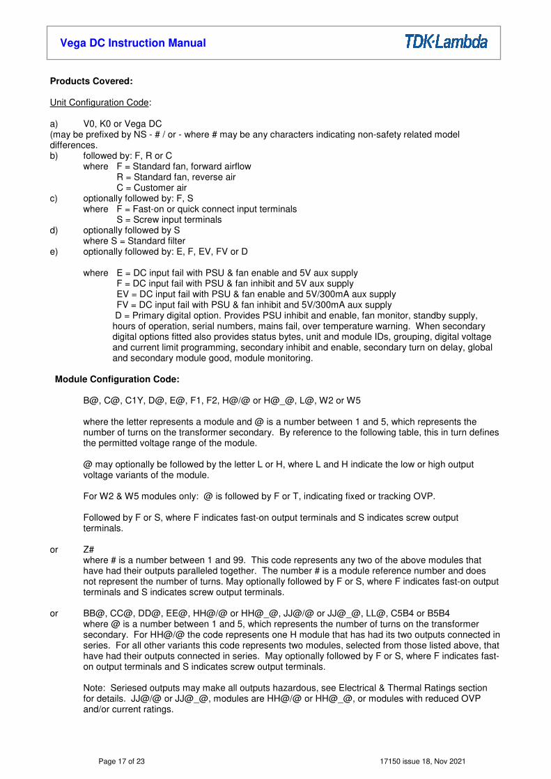
Products Covered: Unit Configuration Code: a) V0, K0 or Vega DC (may be prefixed by NS - # / or - where # may be any characters indicating non-safety related model differences. b) followed by: F, R or C where F = Standard fan, forward airflow R = Standard fan, reverse air C = Customer air c) optionally followed by: F, S where F = Fast-on or quick connect input terminals S = Screw input terminals d) optionally followed by S where S = Standard filter e) optionally followed by: E, F, EV, FV or D where E = DC input fail with PSU & fan enable and 5V aux supply F = DC input fail with PSU & fan inhibit and 5V aux supply EV = DC input fail with PSU & fan enable and 5V/300mA aux supply FV = DC input fail with PSU & fan inhibit and 5V/300mA aux supply D = Primary digital option. Provides PSU inhibit and enable, fan monitor, standby supply,
hours of operation, serial numbers, mains fail, over temperature warning. When secondary digital options fitted also provides status bytes, unit and module IDs, grouping, digital voltage and current limit programming, secondary inhibit and enable, secondary turn on delay, global and secondary module good, module monitoring.
Module Configuration Code:
B@, C@, C1Y, D@, E@, F1, F2, H@/@ or H@_@, L@, W2 or W5
where the letter represents a module and @ is a number between 1 and 5, which represents the number of turns on the transformer secondary. By reference to the following table, this in turn defines the permitted voltage range of the module. @ may optionally be followed by the letter L or H, where L and H indicate the low or high output voltage variants of the module. For W2 & W5 modules only: @ is followed by F or T, indicating fixed or tracking OVP. Followed by F or S, where F indicates fast-on output terminals and S indicates screw output terminals.
or Z# where # is a number between 1 and 99. This code represents any two of the above modules that
have had their outputs paralleled together. The number # is a module reference number and does not represent the number of turns. May optionally followed by F or S, where F indicates fast-on output terminals and S indicates screw output terminals.
or BB@, CC@, DD@, EE@, HH@/@ or HH@_@, JJ@/@ or JJ@_@, LL@, C5B4 or B5B4
where @ is a number between 1 and 5, which represents the number of turns on the transformer secondary. For HH@/@ the code represents one H module that has had its two outputs connected in series. For all other variants this code represents two modules, selected from those listed above, that have had their outputs connected in series. May optionally followed by F or S, where F indicates fast-on output terminals and S indicates screw output terminals. Note: Seriesed outputs may make all outputs hazardous, see Electrical & Thermal Ratings section for details. JJ@/@ or JJ@_@, modules are HH@/@ or HH@_@, or modules with reduced OVP and/or current ratings.

Page 18 of 23 17150 issue 18, Nov 2021
Vega DC Instruction Manual
or X1, X2, X4 or X8 where the number relates to the maximum voltage capability of the X module in accordance with
X1=10V, X2=20V, X4=40V, X8=80V. The X module is connected to the output terminals of D or E modules, which may be connected in series or parallel. The X module contains diodes in series with its output (for paralleling use) and additional circuitry for remote sense, paralleling with other X modules and module inhibit. A maximum of two X modules may be fitted in a PSU.
or B/S where B/S indicates that a blanking plate is fitted in place of a module. Any of the above modules (except the X modules) may have the module letter preceded with # or #/# where # is represents the module output voltage. Module Options:
N, P, R, T, L, K, D, V‡ or R‡
Where:
N = Inhibit, module good and remote sense
P = Parallel with current share
R = Remote sense (twin output modules only)
T = Remote sense (one output of twin output modules only)
L = Module good using LED indication
K = Allows for Vega products to be paralleled with Omega products
D = Secondary digital option (may only be fitted to single output modules). Provides analogue voltage and
resistive programming, current limit modes, inhibit output, enable output, turn on delay, module good, N+1
paralleling.
V‡ = Voltage programmable output voltage
R‡ = Resistance programmable output voltage
where ‡ represents a number between 1 and 99. Each number indicates an option variant
which does not affect safety, of these the following are standard variants:
1 = Inhibit, fixed current limit
2 = Inhibit, programmable current limit
3 = Enable, fixed current limit
4 = Enable, programmable current limit
SELV/ES Classifcation and Outputs Connected In Series: Outputs are SELV/ES1 except as described below: Non-earthed outputs that have secondaries with 2 or more turns are non-SELV/>ES1 as a single fault in
the secondary may make them exceed the SELV/ES1 limit between output and earth. Non-earthed outputs that are connected in series are non-SELV/>ES1 unless all the seriesed outputs use
1 turn secondaries and there are no more than 3 outputs connected in series. Outputs connected in series are non-SELV/>ES1 if the total output voltage + 20% of the max. rated
output voltage of the output with the highest rated voltage exceeds 60Vdc (the 20% addition allows for a single fault in any one individual channel).
The total voltage of a seriesed output must not exceed 160V. If any output or seriesed output is non-SELV/>ES1 then all the outputs in the PSU must be considered
non-SELV/>ES1. All outputs have operational spacings to earth, and due consideration must be given to this in the end
product design. Note: Non-SELV/>ES1 outputs must be guarded or a deflector fitted during installation to avoid a service engineer making inadvertent contact with the output terminals, or dropping a tool onto them.
Page 19 of 23 17150 issue 18, Nov 2021
Vega DC Instruction Manual
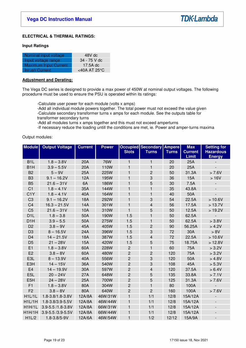
ELECTRICAL & THERMAL RATINGS: Input Ratings Nominal input voltage 48V dc Input voltage range 34 - 75 V dc Maximum Input Current 17.5A dc Inrush Current <40A AT 25°C
Adjustment and Derating: The Vega DC series is designed to provide a max power of 450W at nominal output voltages. The following procedurre must be used to ensure the PSU is operated within its ratings: -Calculate user power for each module (volts x amps) -Add all individual module powers together. The total power must not exceed the value given
-Calculate secondary transformer turns x amps for each module. See the outputs table for transformer secondary turns
-Add all modules turns x amps together and this must not exceed amperturns -If necessary reduce the loading untill the conditions are met, ie. Power and amper-turns maxima Output modules:
Module Output Voltage Current Power Occupied Slots
Secondary Turns
Ampere Turns
Max Current
Limit
Setting for Hazardous
Energy B1L 1.8 – 3.8V 20A 76W 1 1 20 25A - B1H 3.9 – 5.5V 20A 110W 1 1 20 25A - B2 5 – 9V 25A 225W 1 2 50 31.3A > 7.6V B3 9.1 – 16.2V 12A 195W 1 3 36 15A > 16V B5 21.6 – 31V 6A 186W 1 5 30 7.5A - C1 1.8 – 4.1V 35A 144W 1 1 35 43.8A -
C1Y 1.8 – 4.1V 40A 164W 1 1 40 50A - C3 9.1 – 16.2V 18A 292W 1 3 54 22.5A > 10.6V C4 16.3 – 21.5V 14A 301W 1 4 56 17.5A > 13.7V C5 21.6 – 31V 10A 310W 1 5 50 12.5A > 19.2V D1L 1.8 – 3.8 50A 190W 1.5 1 50 62.5A - D1H 3.9 – 5.5 50A 275W 1.5 1 50 62.5A > 3.8V D2 3.8 – 9V 45A 405W 1.5 2 90 56.25A > 4.2V D3 8 – 16.5V 24A 396W 1.5 3 72 30A > 8V D4 14 – 21.5V 18A 387W 1.5 4 72 22.5A > 10.6V D5 21 – 28V 15A 420W 1.5 5 75 18.75A > 12.8V E1 1.8 – 3.8V 60A 228W 2 1 60 75A > 3.2V E2 3.8 – 8V 60A 480W 2 2 120 75A > 3.2V E3L 8 – 13.9V 40A 556W 2 3 120 50A > 4.8V E3H 14 – 15V 36A 540W 2 3 108 45A > 5.3V E4 14 – 19.9V 30A 597W 2 4 120 37.5A > 6.4V E5L 20 – 24V 27A 648W 2 5 135 33.8A > 7.1V E5H 24 – 28V 25A 700W 2 5 125 31.3A > 7.6V F1 1.8 – 3.8V 80A 304W 2 1 80 100A - F2 3.8 – 8V 80A 640W 2 2 160 100A > 7.6V
H1L/1L 1.8-3.8/1.8-3.8V 12A/8A 46W/31W 1 1/1 12/8 15A/12A - H1L/1H 1.8-3.8/3.9-5.5V 12A/8A 46W/44W 1 1/1 12/8 15A/12A - H1H/1L 3.9-5.5 /1.8-3.8V 12A/8A 66W/31W 1 1/1 12/8 15A/12A - H1H/1H 3.9-5.5 /3.9-5.5V 12A/8A 66W/44W 1 1/1 12/8 15A/12A - H1L/2 1.8-3.8/5-9V 12A/6A 46W/54W 1 1/2 12/12 15A/9A -
Page 20 of 23 17150 issue 18, Nov 2021
Vega DC Instruction Manual
Module Output Voltage Rated
Current Power
Occupied Slots
Secondary Turns
Ampere Turns
Max Current
Limit
Setting for Hazardous
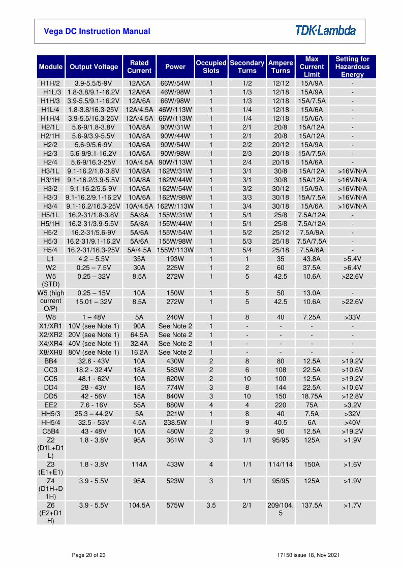
Energy H1H/2 3.9-5.5/5-9V 12A/6A 66W/54W 1 1/2 12/12 15A/9A - H1L/3 1.8-3.8/9.1-16.2V 12A/6A 46W/98W 1 1/3 12/18 15A/9A -
H1H/3 3.9-5.5/9.1-16.2V 12A/6A 66W/98W 1 1/3 12/18 15A/7.5A - H1L/4 1.8-3.8/16.3-25V 12A/4.5A 46W/113W 1 1/4 12/18 15A/6A - H1H/4 3.9-5.5/16.3-25V 12A/4.5A 66W/113W 1 1/4 12/18 15A/6A - H2/1L 5.6-9/1.8-3.8V 10A/8A 90W/31W 1 2/1 20/8 15A/12A - H2/1H 5.6-9/3.9-5.5V 10A/8A 90W/44W 1 2/1 20/8 15A/12A - H2/2 5.6-9/5.6-9V 10A/6A 90W/54W 1 2/2 20/12 15A/9A - H2/3 5.6-9/9.1-16.2V 10A/6A 90W/98W 1 2/3 20/18 15A/7.5A - H2/4 5.6-9/16.3-25V 10A/4.5A 90W/113W 1 2/4 20/18 15A/6A - H3/1L 9.1-16.2/1.8-3.8V 10A/8A 162W/31W 1 3/1 30/8 15A/12A >16V/N/A H3/1H 9.1-16.2/3.9-5.5V 10A/8A 162W/44W 1 3/1 30/8 15A/12A >16V/N/A H3/2 9.1-16.2/5.6-9V 10A/6A 162W/54W 1 3/2 30/12 15A/9A >16V/N/A H3/3 9.1-16.2/9.1-16.2V 10A/6A 162W/98W 1 3/3 30/18 15A/7.5A >16V/N/A H3/4 9.1-16.2/16.3-25V 10A/4.5A 162W/113W 1 3/4 30/18 15A/6A >16V/N/A H5/1L 16.2-31/1.8-3.8V 5A/8A 155W/31W 1 5/1 25/8 7.5A/12A - H5/1H 16.2-31/3.9-5.5V 5A/8A 155W/44W 1 5/1 25/8 7.5A/12A - H5/2 16.2-31/5.6-9V 5A/6A 155W/54W 1 5/2 25/12 7.5A/9A - H5/3 16.2-31/9.1-16.2V 5A/6A 155W/98W 1 5/3 25/18 7.5A/7.5A - H5/4 16.2-31/16.3-25V 5A/4.5A 155W/113W 1 5/4 25/18 7.5A/6A -
L1 4.2 – 5.5V 35A 193W 1 1 35 43.8A >5.4V W2 0.25 – 7.5V 30A 225W 1 2 60 37.5A >6.4V W5
(STD) 0.25 – 32V 8.5A 272W 1 5 42.5 10.6A >22.6V
W5 (high current O/P)
0.25 – 15V 10A 150W 1 5 50 13.0A - 15.01 – 32V 8.5A 272W 1 5 42.5 10.6A >22.6V
W8 1 – 48V 5A 240W 1 8 40 7.25A >33V X1/XR1 10V (see Note 1) 90A See Note 2 1 - - - - X2/XR2 20V (see Note 1) 64.5A See Note 2 1 - - - - X4/XR4 40V (see Note 1) 32.4A See Note 2 1 - - - - X8/XR8 80V (see Note 1) 16.2A See Note 2 1 - - - -
BB4 32.6 - 43V 10A 430W 2 8 80 12.5A >19.2V CC3 18.2 - 32.4V 18A 583W 2 6 108 22.5A >10.6V CC5 48.1 - 62V 10A 620W 2 10 100 12.5A >19.2V DD4 28 - 43V 18A 774W 3 8 144 22.5A >10.6V DD5 42 - 56V 15A 840W 3 10 150 18.75A >12.8V EE2 7.6 - 16V 55A 880W 4 4 220 75A >3.2V
HH5/3 25.3 – 44.2V 5A 221W 1 8 40 7.5A >32V HH5/4 32.5 - 53V 4.5A 238.5W 1 9 40.5 6A >40V C5B4 43 - 48V 10A 480W 2 9 90 12.5A >19.2V
Z2 (D1L+D1
L)
1.8 - 3.8V 95A 361W 3 1/1 95/95 125A >1.9V
Z3 (E1+E1)
1.8 - 3.8V 114A 433W 4 1/1 114/114 150A >1.6V
Z4 (D1H+D
1H)
3.9 - 5.5V 95A 523W 3 1/1 95/95 125A >1.9V
Z6 (E2+D1
H)
3.9 - 5.5V 104.5A 575W 3.5 2/1 209/104.5
137.5A >1.7V

Page 21 of 23 17150 issue 18, Nov 2021
Vega DC Instruction Manual
Module Output Voltage Rated
Current Power
Occupied Slots
Secondary Turns
Ampere Turns
Max Current
Limit
Setting for Hazardous
Energy Z7
(D3+D3) 8 - 16.5V 45.6A 752W 3 3/3 136.8/13
6.8 60A >4V
Z18 (L1+L1)
4.5 - 5.5V 66.5A 366W 2 1/1 66.5/66.5
87.5A >2.7V
Note 1: Actual voltage and current output of an X module is dependent, and limited by, the ratings of the modules from which it is fed. The ratings given above are additional rating limitations imposed by the X module itself. Note 2: The maximum power output of PSUs fitted with X modules is reduced from 450W by the following power: 0.55 x (total X1 current) + 0.7 x (total X2 & X4 current) + 0.9 x (total X8 current). Note 3: ‘Z’ modules are designed as follows: Z2 = D1L+D1L Z3 = E1+E1 Z4 = D1H+D1H Z6 = E2+D1H Z7 = D3+D3 Z18 = L1+L1 Additional module limitations: E2 module fitted in slots 4/5 is limited to 55A. C1Y module can only be fitted in slot 1. F1 module is only permitted in slots 1 and 2. F2 module may only be fitted in slots 1 and 2 and is limited to 75A for ambient temperatures of greater than 45°C. For PSUs with three D modules fitted: D1L & D1H in slots 2/3 is limited to 42A and in slots 4/5 is limited to 47A D2 in slots 2/3 is limited to 40A PSUs fitted with a W2 module are limited to a maximum ambient of 45°C. All the above ratings and limitations apply to the individual modules from which a series or paralleled pair is made. Cooling for unit: The following method must be used for determining the safe operation of PSUs.
The components listed in the following table must not exceed the temperatures given. To determine the component temperatures the heating tests must be conducted in accordance with the requirements of the applicable standards. Consideration should also be give to the requirements of other safety standards.
Test requirements include: PSU to be fitted in its end-use equipment and operated under the most adverse conditions permitted in the end-use equipment instruction manual/specification and which will result in the highest temperatures in the PSU. To determine the most adverse conditions consideration should be given to the end use equipment maximum operating ambient, the PSU loading and input voltage, ventilation, end use equipment orientation, the position of doors & covers, etc. Temperatures should be monitored using type K fine wire thermocouples (secured with cyanoacrylate adhesive or similar) placed on the hottest part of the component (out of any direct airflow) and the equipment should be run until all temperatures have stabilised.
Page 22 of 23 17150 issue 18, Nov 2021
Vega DC Instruction Manual
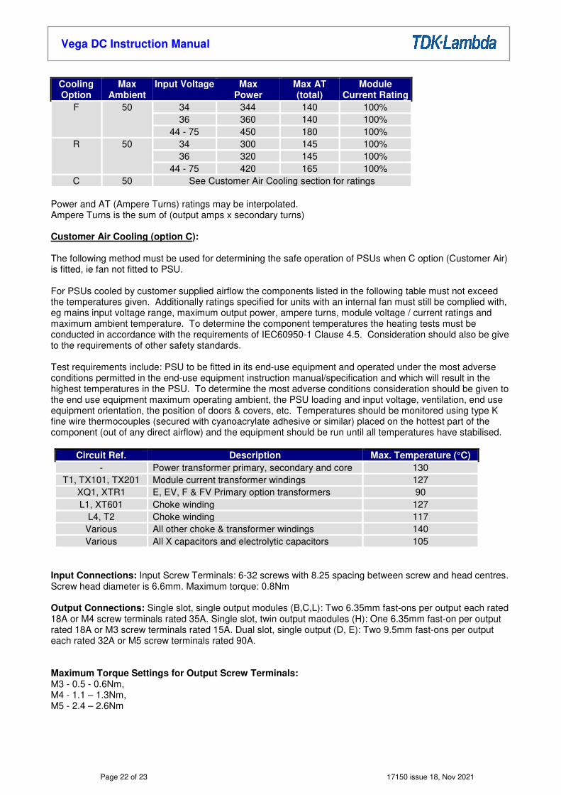
Cooling Option
Max Ambient
Input Voltage Max Power
Max AT (total)
Module Current Rating
F 50 34 344 140 100% 36 360 140 100%
44 - 75 450 180 100% R 50 34 300 145 100%
36 320 145 100% 44 - 75 420 165 100%
C 50 See Customer Air Cooling section for ratings Power and AT (Ampere Turns) ratings may be interpolated. Ampere Turns is the sum of (output amps x secondary turns) Customer Air Cooling (option C): The following method must be used for determining the safe operation of PSUs when C option (Customer Air) is fitted, ie fan not fitted to PSU. For PSUs cooled by customer supplied airflow the components listed in the following table must not exceed the temperatures given. Additionally ratings specified for units with an internal fan must still be complied with, eg mains input voltage range, maximum output power, ampere turns, module voltage / current ratings and maximum ambient temperature. To determine the component temperatures the heating tests must be conducted in accordance with the requirements of IEC60950-1 Clause 4.5. Consideration should also be give to the requirements of other safety standards. Test requirements include: PSU to be fitted in its end-use equipment and operated under the most adverse conditions permitted in the end-use equipment instruction manual/specification and which will result in the highest temperatures in the PSU. To determine the most adverse conditions consideration should be given to the end use equipment maximum operating ambient, the PSU loading and input voltage, ventilation, end use equipment orientation, the position of doors & covers, etc. Temperatures should be monitored using type K fine wire thermocouples (secured with cyanoacrylate adhesive or similar) placed on the hottest part of the component (out of any direct airflow) and the equipment should be run until all temperatures have stabilised.
Circuit Ref. Description Max. Temperature (°C) - Power transformer primary, secondary and core 130
T1, TX101, TX201 Module current transformer windings 127 XQ1, XTR1 E, EV, F & FV Primary option transformers 90 L1, XT601 Choke winding 127
L4, T2 Choke winding 117 Various All other choke & transformer windings 140 Various All X capacitors and electrolytic capacitors 105
Input Connections: Input Screw Terminals: 6-32 screws with 8.25 spacing between screw and head centres. Screw head diameter is 6.6mm. Maximum torque: 0.8Nm Output Connections: Single slot, single output modules (B,C,L): Two 6.35mm fast-ons per output each rated 18A or M4 screw terminals rated 35A. Single slot, twin output maodules (H): One 6.35mm fast-on per output rated 18A or M3 screw terminals rated 15A. Dual slot, single output (D, E): Two 9.5mm fast-ons per output each rated 32A or M5 screw terminals rated 90A. Maximum Torque Settings for Output Screw Terminals: M3 - 0.5 - 0.6Nm, M4 - 1.1 – 1.3Nm, M5 - 2.4 – 2.6Nm
Page 23 of 23 17150 issue 18, Nov 2021
Vega DC Instruction Manual
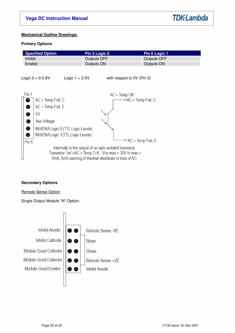
Mechanical Outline Drawings: Primary Options
Specified Option Pin 5 Logic 0 Pin 6 Logic 1 Inhibit Outputs OFF Outputs OFF Enable Outputs ON Outputs ON
Logic 0 = 0-0.8V Logic 1 = 2-5V with respect to 0V (Pin 3) Secondary Options Remote Sense Option Single Output Module “N” Option:

Page 24 of 23 17150 issue 18, Nov 2021
Vega DC Instruction Manual
Inhibit
Internally is a 390Ω resistor in series with diode of an optocoupler. Drive ≥ 2µΑ to inhibit module (max 13mA)
Module Good TWIN Output Module “N” Option
Page 25 of 23 17150 issue 18, Nov 2021
Vega DC Instruction Manual
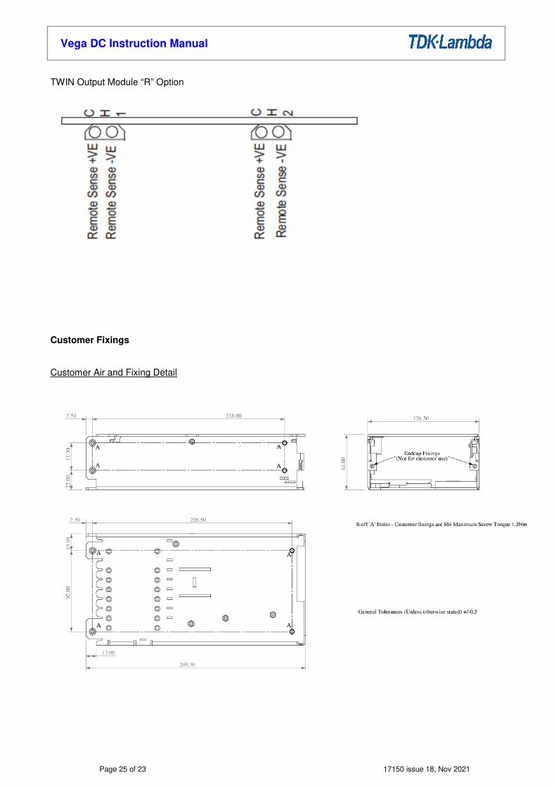
TWIN Output Module “R” Option Customer Fixings Customer Air and Fixing Detail

Page 26 of 23 17150 issue 18, Nov 2021
Vega DC Instruction Manual
Right Angle Screw Terminal Input
TDK-Lambda UK Ltd Kingsley Avenue, Ilfracombe Devon, EX34 8ES Telephone - Sales and Service +44 (0)1271 856666 Head Office and Works +44 (0)1271 856600 Facsimile +44 (0)1271 864894 WEBSITE: www.uk.tdk-lambda.com