Refridgerated Catch Pan Raised Rail Pizza Table - Welbilt EMEA
24
Original Instructions Installation, Operation and Maintenance Manual This manual is updated as new information and models are released. Visit our website for the latest manual. Part Number 9291545 Rev00 11/20 Original Document , Caution Read this instruction before operating this equipment. Fresh Soluons, Fit For You Refridgerated Catch Pan Raised Rail Pizza Table
-
Upload
khangminh22 -
Category
Documents
-
view
5 -
download
0
Transcript of Refridgerated Catch Pan Raised Rail Pizza Table - Welbilt EMEA
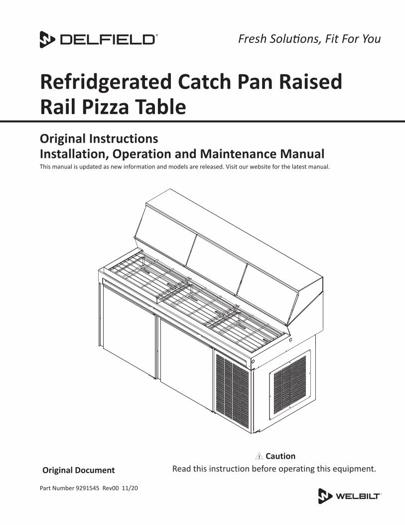
Original InstructionsInstallation, Operation and Maintenance ManualThis manual is updated as new information and models are released. Visit our website for the latest manual.
Part Number 9291545 Rev00 11/20
Original Document, Caution
Read this instruction before operating this equipment.
Fresh Solutions, Fit For You
Refridgerated Catch Pan Raised Rail Pizza Table

Safety Notices
nWarningRead this manual thoroughly before operating, installing or performing maintenance on the equipment. Failure to follow instructions in this manual can cause property damage, injury or death.
DANGERDo not lift the condensing unit by the refrigerant tubing or other components. These features will not support the condensing unit weight. Injury and unit damage may occur!
DANGERDo not install or operate equipment that has been misused, abused, neglected, damaged, or altered/modified from that of original manufactured specifications.
DANGERAll utility connections and fixtures must be maintained in accordance with Local and national codes.
DANGERKeep power cord AWAY from HEATED surfaces. DO NOT immerse power cord or plug in water. DO NOT let power cord hang over edge of table or counter.
nWarningAuthorized Service Representatives are obligated to follow industry standard safety procedures, including, but not limited to, local/national regulations for disconnection / lock out / tag out procedures for all utilities including electric, gas, water and steam.
nWarningThis appliance is not intended for use by persons (including children) with reduced physical, sensory or mental capabilities, or lack of experience and knowledge, unless they have been given supervision concerning use of the appliance by a person responsible for their safety. Do not allow children to play with this appliance.
nWarningDo not store or use gasoline or other flammable vapors or liquids in the vicinity of this or any other appliance. Never use flammable oil soaked cloths or combustible cleaning solutions, for cleaning.
nWarningThis product contains chemicals known to the State of California to cause cancer and/or birth defects or other reproductive harm. Operation, installation, and servicing of this product could expose you to airborne particles of glasswool or ceramic fibers, crystalline silica, and/or carbon monoxide. Inhalation of airborne particles of glasswool or ceramic fibers is known to the State of California to cause cancer. Inhalation of carbon monoxide is known to the State of California to cause birth defects or other reproductive harm.
nWarningDo not use electrical appliances inside the food storage compartments of the appliance, unless they are of the type recommended by the manufacturer.
nWarningUse caution when handling metal surface edges of all equipment.
nWarningDO NOT touch refrigeration lines inside units; some may exceed temperatures of 200°F (93.3°C).
Notice�Proper installation, care and maintenance are essential for maximum performance and trouble-free operation of your equipment. Visit our website www.wbtkitchencare.com for manual updates, translations, or contact information for service agents in your area.
Notice�These appliances are intended to be used for commercial applications, for example in kitchens of restaurants, canteens, hospitals and in commercial enterprises such as bakeries, butcheries, etc., but not for continuous mass production of food.
Notice�Climatic class 4 is defined as ambient conditions of 30°C and 55% relative humidity, according to ISO 23953-2.
Notice�These appliances will operate within the marked rated voltage range without adjustment.

Part Number: 9291545 REV00 11/20 3
Section 1General Information
Model Numbers ................................................................................................................ 5Serial Number Information ................................................................................................ 5Warranty Information........................................................................................................ 5Regulatory Certifications ................................................................................................... 5
Section 2Installation
Location ............................................................................................................................ 7Weight Of Equipment ........................................................................................................ 8Clearance Requirements .................................................................................................... 8Dimensions ....................................................................................................................... 8Capacity ............................................................................................................................ 8Electrical Service ............................................................................................................... 9Drain Connections ............................................................................................................. 9Leg & Caster Installation .................................................................................................. 10Refrigeration ................................................................................................................... 10
Section 3Operation
Make Tables .................................................................................................................... 11Instructions for Optimal Performance .............................................................................. 12Evaporator Fan Operation ................................................................................................ 13ERC112 Temperature Control ........................................................................................... 13
At Start Up ..................................................................................................................... 13Defrost .......................................................................................................................... 13Operation ...................................................................................................................... 14Changing Display from Fahrenheit to Celsius on ERC112 Control .................................15
Section 4Maintenance
Responsibility .................................................................................................................. 16Interior Cleaning .............................................................................................................. 17
Gaskets .......................................................................................................................... 17Preventing Blower Coil Corrosion .................................................................................17
Exterior Cleaning ............................................................................................................. 17Drain .............................................................................................................................. 17
Doors .............................................................................................................................. 17Cleaning The Condenser Coil ........................................................................................... 17
Section 5Troubleshooting
Troubleshooting Chart ..................................................................................................... 18
Table of Contents

4 Part Number: 9291545 REV00 11/20
Table of Contents (continued)
Section 6Service Information
Wiring Diagrams For All Models ...................................................................................... 19Replacement Parts .......................................................................................................... 20
Mullion Coil Assemblies ................................................................................................20Door Assemblies ...........................................................................................................21
Condensing Unit Assemblies ............................................................................................ 21Miscellaneous Replacement Parts ................................................................................... 22

Part Number: 9291545 REV00 11/20 5
Model NumbersThis manual covers the following:
Custom Model Compressor Side
F18DC48P-RCPR RightF18DC48P-RCPL LeftF18DC72P-RCPR RightF18DC72P-RCPL LeftF18DC99P-RCPR RightF18DC99P-RCPL Left
Serial Number InformationThe serial number of these units can be found on any of the three rating plates. The rating plate is located behind the louvered door.
Always have the serial number of your unit available when calling for parts or service.
Warranty InformationVisit www.delfield.com/warranty to:
• Register your product for warranty.
• Verify warranty information.
• View and download a copy of your warranty.
Regulatory CertificationsMakelines are certified by:
• National Sanitation Foundation (NSF)
• Underwriters Laboratories (UL)
• Underwriters Laboratories of Canada (cUL)
Section 1General Information

General Information Section 1
6 Part Number: 9291545 REV00 11/20
THIS PAGE INTENTIONALLY LEFT BLANK
Part Number: 9291545 REV00 11/20 7
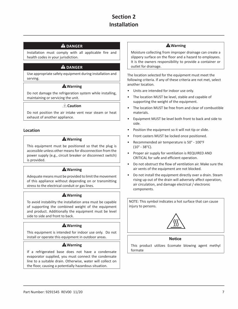
DANGERInstallation must comply with all applicable fire and health codes in your jurisdiction.
DANGERUse appropriate safety equipment during installation and serving.
nWarningDo not damage the refrigeration system while installing, maintaining or servicing the unit.
,CautionDo not position the air intake vent near steam or heat exhaust of another appliance.
Location
nWarningThis equipment must be positioned so that the plug is accessible unless other means for disconnection from the power supply (e.g., circuit breaker or disconnect switch) is provided.
nWarningAdequate means must be provided to limit the movement of this appliance without depending on or transmitting stress to the electrical conduit or gas lines.
nWarningTo avoid instability the installation area must be capable of supporting the combined weight of the equipment and product. Additionally the equipment must be level side to side and front to back.
nWarningThis equipment is intended for indoor use only. Do not install or operate this equipment in outdoor areas.
nWarningIf a refrigerated base does not have a condensate evaporator supplied, you must connect the condensate line to a suitable drain. Otherwise, water will collect on the floor, causing a potentially hazardous situation.
nWarningMoisture collecting from improper drainage can create a slippery surface on the floor and a hazard to employees. It is the owners responsibility to provide a container or outlet for drainage.
The location selected for the equipment must meet the following criteria. If any of these criteria are not met, select another location.
• Units are intended for indoor use only.
• The location MUST be level, stable and capable of supporting the weight of the equipment.
• The location MUST be free from and clear of combustible materials.
• Equipment MUST be level both front to back and side to side.
• Position the equipment so it will not tip or slide.
• Front casters MUST be locked once positioned.
• Recommended air temperature is 50° - 100°F (10° - 38°C).
• Proper air supply for ventilation is REQUIRED AND CRITICAL for safe and efficient operation.
• Do not obstruct the flow of ventilation air. Make sure the air vents of the equipment are not blocked.
• Do not install the equipment directly over a drain. Steam rising up out of the drain will adversely affect operation, air circulation, and damage electrical / electronic components.
NOTE: This symbol indicates a hot surface that can cause injury to persons.
Section 2Installation
Notice�This product utilizes Ecomate blowing agent methyl formate
Installation Section 2
8 Part Number: 9291545 REV00 11/20
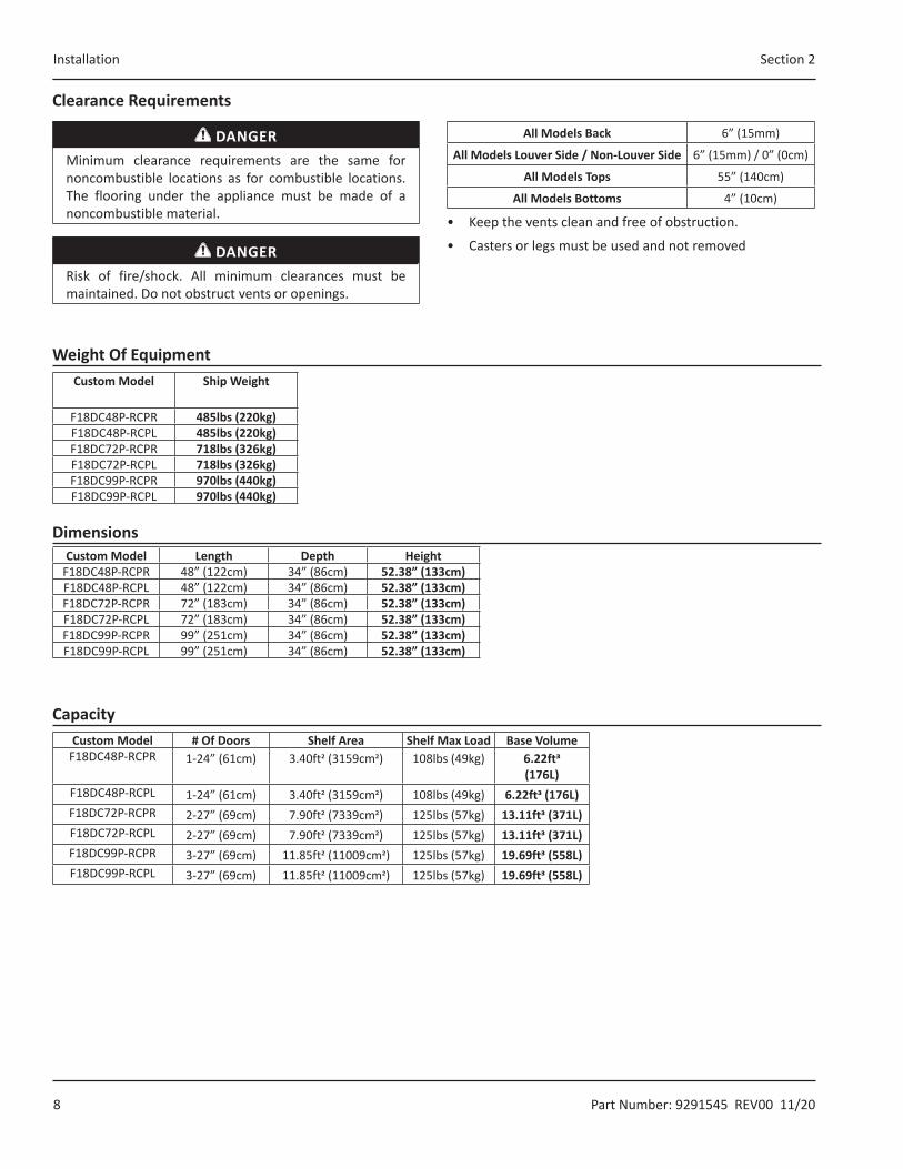
Clearance Requirements
DANGERMinimum clearance requirements are the same for noncombustible locations as for combustible locations. The flooring under the appliance must be made of a noncombustible material.
DANGERRisk of fire/shock. All minimum clearances must be maintained. Do not obstruct vents or openings.
All Models Back 6” (15mm)
All Models Louver Side / Non-Louver Side 6” (15mm) / 0” (0cm)
All Models Tops 55” (140cm)
All Models Bottoms 4” (10cm)
• Keep the vents clean and free of obstruction.
• Casters or legs must be used and not removed
CapacityCustom Model # Of Doors Shelf Area Shelf Max Load Base Volume
F18DC48P-RCPR 1-24” (61cm) 3.40ft2 (3159cm2) 108lbs (49kg) 6.22ft3(176L)
F18DC48P-RCPL 1-24” (61cm) 3.40ft2 (3159cm2) 108lbs (49kg) 6.22ft3 (176L)F18DC72P-RCPR 2-27” (69cm) 7.90ft2 (7339cm2) 125lbs (57kg) 13.11ft3 (371L)F18DC72P-RCPL 2-27” (69cm) 7.90ft2 (7339cm2) 125lbs (57kg) 13.11ft3 (371L)F18DC99P-RCPR 3-27” (69cm) 11.85ft2 (11009cm2) 125lbs (57kg) 19.69ft3 (558L)F18DC99P-RCPL 3-27” (69cm) 11.85ft2 (11009cm2) 125lbs (57kg) 19.69ft3 (558L)
Weight Of EquipmentCustom Model Ship Weight
F18DC48P-RCPR 485lbs (220kg)F18DC48P-RCPL 485lbs (220kg)F18DC72P-RCPR 718lbs (326kg)F18DC72P-RCPL 718lbs (326kg)F18DC99P-RCPR 970lbs (440kg)F18DC99P-RCPL 970lbs (440kg)
DimensionsCustom Model Length Depth Height
F18DC48P-RCPR 48” (122cm) 34” (86cm) 52.38” (133cm)F18DC48P-RCPL 48” (122cm) 34” (86cm) 52.38” (133cm)F18DC72P-RCPR 72” (183cm) 34” (86cm) 52.38” (133cm)F18DC72P-RCPL 72” (183cm) 34” (86cm) 52.38” (133cm)F18DC99P-RCPR 99” (251cm) 34” (86cm) 52.38” (133cm)F18DC99P-RCPL 99” (251cm) 34” (86cm) 52.38” (133cm)
Section 2 Installation
Part Number: 9291545 REV00 11/20 9
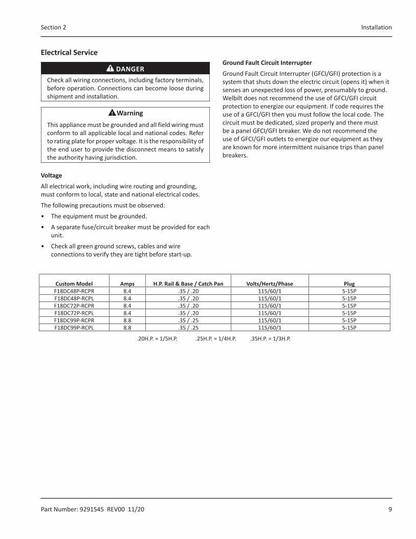
Electrical Service
DANGERCheck all wiring connections, including factory terminals, before operation. Connections can become loose during shipment and installation.
nWarningThis appliance must be grounded and all field wiring must conform to all applicable local and national codes. Refer to rating plate for proper voltage. It is the responsibility of the end user to provide the disconnect means to satisfy the authority having jurisdiction.
Voltage
All electrical work, including wire routing and grounding, must conform to local, state and national electrical codes.
The following precautions must be observed:
• The equipment must be grounded.
• A separate fuse/circuit breaker must be provided for each unit.
• Check all green ground screws, cables and wire connections to verify they are tight before start-up.
Ground Fault Circuit Interrupter
Ground Fault Circuit Interrupter (GFCI/GFI) protection is a system that shuts down the electric circuit (opens it) when it senses an unexpected loss of power, presumably to ground. Welbilt does not recommend the use of GFCI/GFI circuit protection to energize our equipment. If code requires the use of a GFCI/GFI then you must follow the local code. The circuit must be dedicated, sized properly and there must be a panel GFCI/GFI breaker. We do not recommend the use of GFCI/GFI outlets to energize our equipment as they are known for more intermittent nuisance trips than panel breakers.
Custom Model Amps H.P. Rail & Base / Catch Pan Volts/Hertz/Phase PlugF18DC48P-RCPR 8.4 .35 / .20 115/60/1 5-15PF18DC48P-RCPL 8.4 .35 / .20 115/60/1 5-15PF18DC72P-RCPR 8.4 .35 / .20 115/60/1 5-15PF18DC72P-RCPL 8.4 .35 / .20 115/60/1 5-15PF18DC99P-RCPR 8.8 .35 / .25 115/60/1 5-15PF18DC99P-RCPL 8.8 .35 / .25 115/60/1 5-15P
.20H.P. = 1/5H.P. .25H.P. = 1/4H.P. .35H.P. = 1/3H.P.
Installation Section 2
10 Part Number: 9291545 REV00 11/20
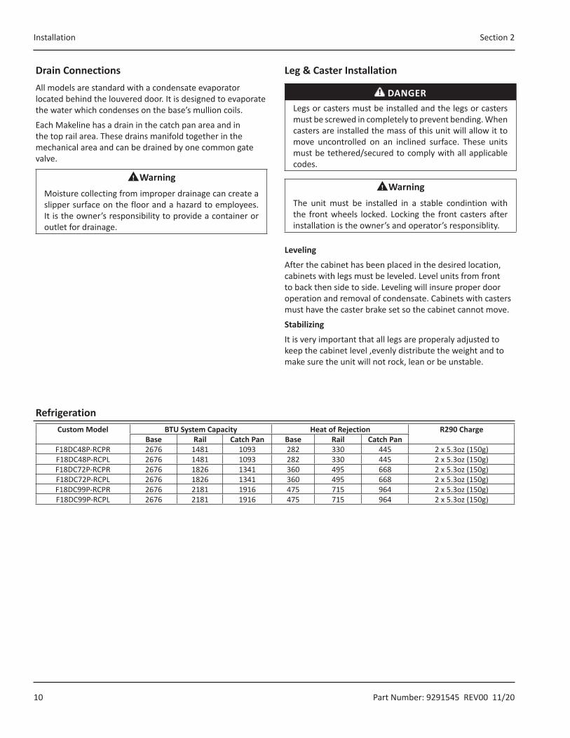
RefrigerationCustom Model BTU System Capacity Heat of Rejection R290 Charge
Base Rail Catch Pan Base Rail Catch PanF18DC48P-RCPR 2676 1481 1093 282 330 445 2 x 5.3oz (150g)F18DC48P-RCPL 2676 1481 1093 282 330 445 2 x 5.3oz (150g)F18DC72P-RCPR 2676 1826 1341 360 495 668 2 x 5.3oz (150g)F18DC72P-RCPL 2676 1826 1341 360 495 668 2 x 5.3oz (150g)F18DC99P-RCPR 2676 2181 1916 475 715 964 2 x 5.3oz (150g)F18DC99P-RCPL 2676 2181 1916 475 715 964 2 x 5.3oz (150g)
Drain ConnectionsAll models are standard with a condensate evaporator located behind the louvered door. It is designed to evaporate the water which condenses on the base’s mullion coils.
Each Makeline has a drain in the catch pan area and in the top rail area. These drains manifold together in the mechanical area and can be drained by one common gate valve.
nWarningMoisture collecting from improper drainage can create a slipper surface on the floor and a hazard to employees. It is the owner’s responsibility to provide a container or outlet for drainage.
Leg & Caster Installation
DANGERLegs or casters must be installed and the legs or casters must be screwed in completely to prevent bending. When casters are installed the mass of this unit will allow it to move uncontrolled on an inclined surface. These units must be tethered/secured to comply with all applicable codes.
nWarningThe unit must be installed in a stable condintion with the front wheels locked. Locking the front casters after installation is the owner’s and operator’s responsiblity.
Leveling
After the cabinet has been placed in the desired location, cabinets with legs must be leveled. Level units from front to back then side to side. Leveling will insure proper door operation and removal of condensate. Cabinets with casters must have the caster brake set so the cabinet cannot move.
Stabilizing
It is very important that all legs are properaly adjusted to keep the cabinet level ,evenly distribute the weight and to make sure the unit will not rock, lean or be unstable.

Part Number: 9291545 REV00 11/20 11
DANGERThe on-site supervisor is responsible for ensuring that operators are made aware of the inherent dangers of operating this equipment.
DANGERDo not operate any appliance with a damaged cord or plug. All repairs must be performed by a qualified service company.
DANGERNever stand on the unit! They are not designed to hold the weight of an adult, and may collapse or tip if misused in this manner.
DANGERKeep power cord AWAY from HEATED surfaces. DO NOT immerse power cord in water. DO NOT let power cord hang over edge of table or counter.
nWarningDo not contact moving parts.
nWarningThe operator of this equipment is solely responsible for ensuring safe holding temperature levels for all food items. Failure to do so could result in unsafe food products for customers.
nWarningAll covers and access panels must be in place and properly secured, before operating this equipment.
nWarningDo not block the supply and return air grills or the air space around the air grills. Keep plastic wrappings, paper, labels, etc. from being airborne and lodging in the grills. Failure to keep the air grills clear will result in unsatisfactory operation of the system.
nWarningDamp or wet hands may stick to cold surfaces.
,CautionOverloading the storage area, restricting the air flow, and continuous opening and closing of the doors and drawers will hamper the units ability to maintain operational temperature.
,CautionDo not throw items into the storage area. Failure to heed this recommendation could result in damage to the interior of the cabinet or to the blower coil.
Make TablesDelfield refrigerated bases are designed to maintain an operational temperature of 36°F to 40°F (2°C to 4°C). Self-contained units with a cord and plug have an ON/OFF switch located directly behind the louvered panel covering the compressor section. Simply turn the switch to ON to begin operation.
Temperature in the rail is designed to maintain 33°F to 41°F (0°C to 5°C) with pans recessed 2” (5cm) at 86°F (30°C) ambient room temperature. An ON/OFF switch is also provided for the rail; it controls only the rail. Turn the rail switch on an hour before filling with product.
Product in the rail should be moved to the refrigerated base at the end of the day. The rail is required to be shut off at night to save energy and time to defrost as needed. It also helps maintain product quality.
These units are not designed to cool warm food products. Items should be placed in the unit cooled at least to the desired holding temperature, if not slightly colder. Fill pan to 2.0” (5cm) below top of cold pan. In some applications, a gradual warming of product may occur, particularly at the exposed top of the products. Stirring or rotation of the product is necessary to maintain overall temperature.
Warming of food product can occur very quickly outside of the unit. When loading or rotating the product, avoid leaving food items in a non-refrigerated location for any length of time to prevent warming or spoilage. To ensure product quality product must be rotated every four hours. Always place covers on pans when not serving to maintain temperatures.
Air from air vents can affect the temperature in the cold pans. Add deflectors to vents to redirect airflow.
Section 3Operation
Operation Section 3
12 Part Number: 9291545 REV00 11/20
Instructions for Optimal Performance1. The main switch is located behind the louvered door. It
controls the cabinet and must be in the ON position for the top rail/catch pan switch to operate. Turn it to the ON position.
2. The top rail/catch pan switch is located behind the louvered door. Turn it to the ON position.
3. The drain valve is located behind the louvered door. This valve controls both the top rail and the catch pan drain lines. Make sure it is turned OFF.
4. Food product may be placed into the base and the top rail of the unit after one hour of operation.
• The unit is not designed to lower product temperature, only to maintain temperature. The food product must be 41°F (5˚C) or below before placing into the refrigerator.
• To ensure product quality in the rail it is recommended that product be rotated every four hours.
• The catch pan area and the top rail area are designed to meet the NSF 7 criteria. The design requires a layer of frost to build up on the wall of the top rail and catch pan area. This is normal, and also required, to meet the desired temperatures.
• It is recommended to empty the excess food product in the catch pans after two hours of use throughout the work day to achieve the best temperatures. However, the catch pans are capable of maintaining temperatures up to four hours if needed.
5. At the end of the operation, the top rail/catch pan switch must be turned to the OFF position. The cabinet main switch remains ON. The rail frost will melt and flow down the drain line.
• Product located in the rails must be removed at the end of day. This allows you to turn the rails off at night to save energy and the rails will have time to defrost as needed. It also helps maintain product quality. The rail switch shuts off the rail only.
• A minimum of one hour of off time per day with the pans removed is required to properly defrost the top rail.
• If pans are left in the top rail, up to four hours may be required to defrost under the pans.
6. The drain valve should be turned ON to allow for drainage into a customer provided waste container.
7. The catch pan area and top rail area may be cleaned at this time. The large 1” diameter drain lines allow water, cleaning solutions, etc. to flow freely down the drain.
8. At the end of the cleaning procedure, turn the drain valve to the OFF position.
9. Steps 2 through 8 should be repeated during each work day.
,CautionThe main unit switch must remain “ON” if product is held in the refrigerated base.

Section 3 Operation
Part Number: 9291545 REV00 11/20 13
Evaporator Fan OperationWhen the refrigerator is initially powered up or immediately following a power outage the unit will begin cooling after a 3-6 minute delay. During normal operation the evaporator fan pulses independently of the compressor as dictated by the controller as follows:
1. During the cooling mode, compressor and evaporator fan run simultaneously.
2. During the compressor off mode, evaporator fan pulses three minutes on and three minutes off.
3. During an actual defrost event other than the off-cycle defrost, compressor stays off but the evaporator fan runs continuously.
Cooling Cycle Defrost Cycle
Compressor On Compressor Off Compressor Off
Evaporator Fan On Evap Fan Cycles On 3-Min, Off 3-Min
Evaporator Fan On
ERC112 Temperature ControlThe Maketable control assembly is located behind the louvered door in the machine compartment.
Maketable Control Assembly
AT START UP1. At initial start-up or anytime power is disconnected, then
reconnected to the unit, the control will go into defrost mode.
2. The control will enter a DEFROST mode and the display will read dEF. The compressor and condenser fan as well
as the evaporator fan will remain off until this initial defrost is complete. This initial defrost cycle may take up to 35 minutes to complete.
3. The display will continue to read dEF for an additional 30 minutes while the cooling cycle cools the box to the set temperature.
4. Then the digital thermostat will display box temperature.
5. The temperature control will cycle the compressor, evaporator fan motor and condenser fan motor to maintain box temperature at the control setting. For more information see “Evaporator Fan Operation” on page 13.
Defrost
The temperature control also monitors the evaporator temperature and will turn off the compressor and condenser fan motor when needed to allow accumulated frost on the evaporator to clear. During this defrost cycle, the digital temperature display will read dEF. After the defrost cycle is complete, the temperature control will return to a normal cooling cycle, but the display will continue to read dEF until the evaporator returns to normal cooling temperatures (up to 30 minutes).
The electronic temperature controller monitors evaporator temperature and compressor run time to determine the proper time for a positive defrost cycle. A defrost cycle can occur as often as every 60 minutes under extremely heavy usage. It can last a minimum of 2 minutes. When the controller enters the defrost mode the compressor is shut off and will remain off until the evaporator coil temperature exceeds:
• 41°F (5°C) or the controller reaches a time limit of 75 minutes on a refrigerated unit.
Operation Section 3
14 Part Number: 9291545 REV00 11/20
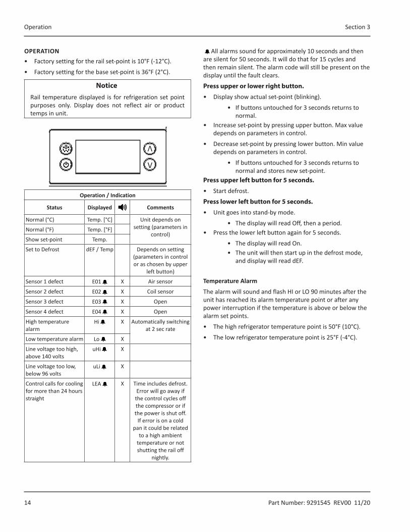
OPERATION• Factory setting for the rail set-point is 10°F (-12°C).
• Factory setting for the base set-point is 36°F (2°C).
Notice�Rail temperature displayed is for refrigeration set point purposes only. Display does not reflect air or product temps in unit.
V
V
Operation / Indication
Status Displayed Comments
Normal (°C) Temp. [°C] Unit depends on setting (parameters in
control)Normal (°F) Temp. [°F]
Show set-point Temp.
Set to Defrost dEF / Temp Depends on setting (parameters in control or as chosen by upper
left button)
Sensor 1 defect E01 X Air sensor
Sensor 2 defect E02 X Coil sensor
Sensor 3 defect E03 X Open
Sensor 4 defect E04 X Open
High temperature alarm
Hi X Automatically switching at 2 sec rate
Low temperature alarm Lo X
Line voltage too high, above 140 volts
uHi X
Line voltage too low, below 96 volts
uLi X
Control calls for cooling for more than 24 hours straight
LEA X Time includes defrost. Error will go away if
the control cycles off the compressor or if the power is shut off.
If error is on a cold pan it could be related
to a high ambient temperature or not shutting the rail off
nightly.
All alarms sound for approximately 10 seconds and then are silent for 50 seconds. It will do that for 15 cycles and then remain silent. The alarm code will still be present on the display until the fault clears.
Press upper or lower right button.
• Display show actual set-point (blinking).
• If buttons untouched for 3 seconds returns to normal.
• Increase set-point by pressing upper button. Max value depends on parameters in control.
• Decrease set-point by pressing lower button. Min value depends on parameters in control.
• If buttons untouched for 3 seconds returns to normal and stores new set-point.
Press upper left button for 5 seconds.
• Start defrost.
Press lower left button for 5 seconds.
• Unit goes into stand-by mode.
• The display will read Off, then a period.• Press the lower left button again for 5 seconds.
• The display will read On.• The unit will then start up in the defrost mode,
and display will read dEF.
Temperature Alarm
The alarm will sound and flash HI or LO 90 minutes after the unit has reached its alarm temperature point or after any power interruption if the temperature is above or below the alarm set points.
• The high refrigerator temperature point is 50°F (10°C).
• The low refrigerator temperature point is 25°F (-4°C).
Section 3 Operation
Part Number: 9291545 REV00 11/20 15
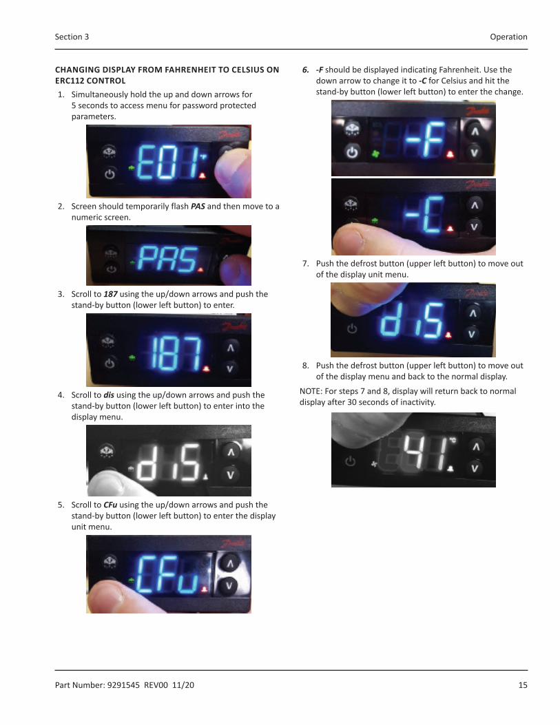
CHANGING DISPLAY FROM FAHRENHEIT TO CELSIUS ON ERC112 CONTROL1. Simultaneously hold the up and down arrows for
5 seconds to access menu for password protected parameters.
2. Screen should temporarily flash PAS and then move to a numeric screen.
3. Scroll to 187 using the up/down arrows and push the stand-by button (lower left button) to enter.
4. Scroll to dis using the up/down arrows and push the stand-by button (lower left button) to enter into the display menu.
5. Scroll to CFu using the up/down arrows and push the stand-by button (lower left button) to enter the display unit menu.
6. -F should be displayed indicating Fahrenheit. Use the down arrow to change it to -C for Celsius and hit the stand-by button (lower left button) to enter the change.
7. Push the defrost button (upper left button) to move out of the display unit menu.
8. Push the defrost button (upper left button) to move out of the display menu and back to the normal display.
NOTE: For steps 7 and 8, display will return back to normal display after 30 seconds of inactivity.

16 Part Number: 9291545 REV00 11/20
DANGERIt is the responsibility of the equipment owner to perform a Personal Protective Equipment Hazard Assessment to ensure adequate protection during maintenance procedures.
DANGERFailure to disconnect the power at the main power supply disconnect could result in serious injury or death. The power switch DOES NOT disconnect all incoming power.
DANGERDisconnect electric power at the main power disconnect for all equipment being serviced. Observe correct polarity of incoming line voltage. Incorrect polarity can lead to erratic operation.
nWarningWhen cleaning interior and exterior of unit, care should be taken to avoid the front power switch and the rear power cord. Keep water and/or cleaning solutions away from these parts.
nWarningNever use sharp objects or tools to remove ice or frost. Do not use mechanical devices or other means to accelerate the defrosting process.
nWarningWhen using cleaning fluids or chemicals, rubber gloves and eye protection (and/or face shield) must be worn.
,CautionOver shelves and other items mounted to the top of the counters should never be installed in the field due to the potential damage to the refrigeration system.
,CautionMaintenance and servicing work other than cleaning as described in this manual must be done by an authorized service personnel.
Notice�Never use a high-pressure water jet for cleaning or hose down or flood interior or exterior of units with water. Do not use power cleaning equipment, steel wool, scrapers or wire brushes on stainless steel or painted surfaces.
ResponsibilityYou are responsible for maintaining the equipment in accordance with the instructions in this manual. Maintenance procedures are not covered by the warranty.
Section 4Maintenance
Maintenance Daily Weekly Monthly After Prolonged Shutdown
At Start-Up
Interior X X X
Gasket X X X
Exterior X X X
Drain X X X
Drawers/Door X X X
Condenser Coil X X X
Section 4 Maintenance
Part Number: 9291545 REV00 11/20 17
Interior CleaningThe interior can be cleaned using soap and warm water. If this isn’t sufficient, try ammonia and water or a nonabrasive liquid cleaner.
GASKETSGaskets require regular cleaning to prevent mold and mildew build up and also to retain the elasticity of the gasket. Clean them with water and mild soap (not citrus based). Avoid full strength cleaning products on gaskets as this can cause them to become brittle and crack. Never use sharp tools or knives to scrape or clean the gasket. Gaskets can be easily replaced and do not require the use of tools or an authorized service person. The gaskets are dart style and can be pulled out of the groove in the door. Place gasket in warm water to make the material more pliable for installation. Dry and press into place.
PREVENTING BLOWER COIL CORROSIONTo help prevent corrosion of the blower coil, store all acidic items, such as pickles and tomatoes, in seal-able containers. Immediately wipe up all spills.
Exterior Cleaning
Notice�Never use an acid based cleaning solution on exterior panels! Many food products have an acidic content, which can deteriorate the finish. Be sure to clean the stainless steel surfaces of ALL food products.
Clean the area around the unit as often as necessary to maintain cleanliness and efficient operation.
Wipe surfaces with a damp cloth rinsed in water to remove dust and dirt from the outside of the unit. Always rub with the “grain” of the stainless steel to avoid marring the finish. If a greasy residue persists, use a damp cloth rinsed in a mild dish soap and water solution. Wipe dry with a clean, soft cloth.
Never use steel wool or abrasive pads for cleaning. Never use chlorinated, citrus based or abrasive cleaners.
Stainless steel exterior panels have a clear coating that is stain resistant and easy to clean. Products containing abrasives will damage the coating and scratch the panels. Daily cleaning may be followed by an application of stainless steel cleaner which will eliminate water spotting and fingerprints. Early signs of stainless steel breakdown are small pits and cracks. If this has begun, clean thoroughly and start to apply stainless steel cleaners in attempt to restore the steel.
Wipe casters with a damp cloth to prevent corrosion.
DRAINDrains can become loose or disconnected during normal use. Be sure all drain lines are free of obstructions.
DoorsOver time and with heavy-use doors, the hinges may become loose. If this happens, tighten the screws that mount the hinge brackets to the frame of the unit. Loose or sagging doors can cause the hinges to pull out of the frame, which may damage both the doors and the hinges. In some cases this may require qualified service agents or maintenance personnel to perform repairs.
Cleaning The Condenser CoilIn order to maintain proper refrigeration performance, the condenser fins must be cleaned of dust, dirt and grease regularly. It is recommended that this be done monthly. If conditions are such that the condenser is totally blocked in a month, the frequency of cleaning should be increased. Clean the condenser with a vacuum cleaner or stiff brush. If extremely dirty, a commercially available condenser cleaner may be required.
Failure to maintain a clean condenser coil can initially cause high temperatures and excessive run times. Continuous operation with a dirty or clogged condenser coil can result in compressor failure. Neglecting the condenser coil cleaning procedures will void any warranties associated with the compressor and cost to replace the compressor.
18 Part Number: 9291545 REV00 11/20
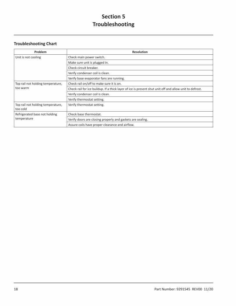
Troubleshooting Chart
Problem ResolutionUnit is not cooling Check main power switch.
Make sure unit is plugged in.Check circuit breaker.Verify condenser coil is clean.Verify base evaporator fans are running.
Top rail not holding temperature, too warm
Check rail on/off to make sure it is on.Check rail for ice buildup. If a thick layer of ice is present shut unit off and allow unit to defrost.Verify condenser coil is clean.Verify thermostat setting.
Top rail not holding temperature, too cold
Verify thermostat setting.
Refrigerated base not holding temperature
Check base thermostat.Verify doors are closing properly and gaskets are sealing.Assure coils have proper clearance and airflow.
Section 5Troubleshooting

Part Number: 9291545 REV00 11/20 19
Wiring Diagrams For All ModelsControl Schematic
000-SCH-0162
Compressor Schematic
000-SCH-0156
Section 6Service Information
Note: All wiring diagrams are for trained professional use only.
Service Information Section 6
20 Part Number: 9291545 REV00 11/20
Replacement Parts
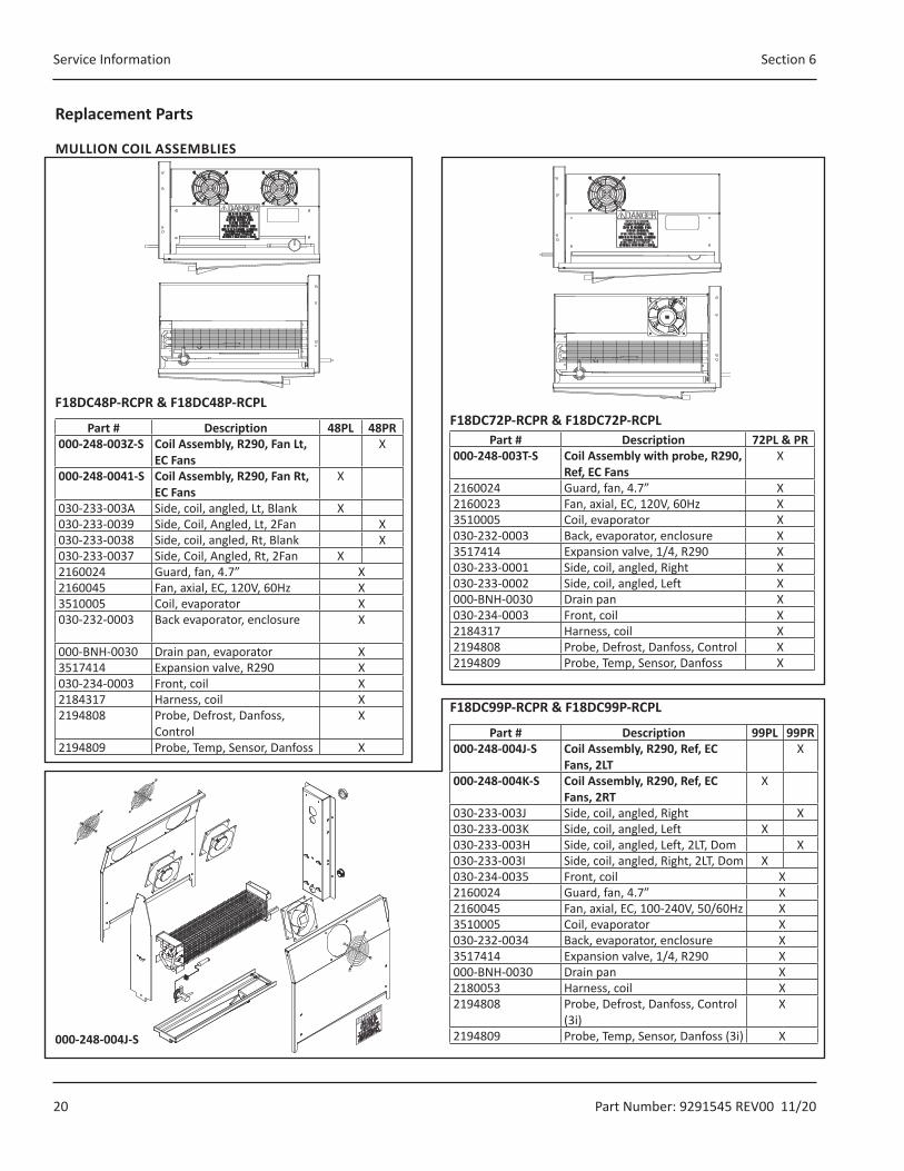
MULLION COIL ASSEMBLIES
F18DC48P-RCPR & F18DC48P-RCPL
Part # Description 48PL 48PR000-248-003Z-S Coil Assembly, R290, Fan Lt,
EC FansX
000-248-0041-S Coil Assembly, R290, Fan Rt, EC Fans
X
030-233-003A Side, coil, angled, Lt, Blank X030-233-0039 Side, Coil, Angled, Lt, 2Fan X030-233-0038 Side, coil, angled, Rt, Blank X030-233-0037 Side, Coil, Angled, Rt, 2Fan X2160024 Guard, fan, 4.7” X2160045 Fan, axial, EC, 120V, 60Hz X3510005 Coil, evaporator X030-232-0003 Back evaporator, enclosure X
000-BNH-0030 Drain pan, evaporator X3517414 Expansion valve, R290 X030-234-0003 Front, coil X2184317 Harness, coil X2194808 Probe, Defrost, Danfoss,
ControlX
2194809 Probe, Temp, Sensor, Danfoss X
F18DC72P-RCPR & F18DC72P-RCPLPart # Description 72PL & PR
000-248-003T-S Coil Assembly with probe, R290, Ref, EC Fans
X
2160024 Guard, fan, 4.7” X2160023 Fan, axial, EC, 120V, 60Hz X3510005 Coil, evaporator X030-232-0003 Back, evaporator, enclosure X3517414 Expansion valve, 1/4, R290 X030-233-0001 Side, coil, angled, Right X030-233-0002 Side, coil, angled, Left X000-BNH-0030 Drain pan X030-234-0003 Front, coil X2184317 Harness, coil X2194808 Probe, Defrost, Danfoss, Control X2194809 Probe, Temp, Sensor, Danfoss X
F18DC99P-RCPR & F18DC99P-RCPL
Part # Description 99PL 99PR000-248-004J-S Coil Assembly, R290, Ref, EC
Fans, 2LTX
000-248-004K-S Coil Assembly, R290, Ref, EC Fans, 2RT
X
030-233-003J Side, coil, angled, Right X030-233-003K Side, coil, angled, Left X030-233-003H Side, coil, angled, Left, 2LT, Dom X030-233-003I Side, coil, angled, Right, 2LT, Dom X030-234-0035 Front, coil X2160024 Guard, fan, 4.7” X2160045 Fan, axial, EC, 100-240V, 50/60Hz X3510005 Coil, evaporator X030-232-0034 Back, evaporator, enclosure X3517414 Expansion valve, 1/4, R290 X000-BNH-0030 Drain pan X2180053 Harness, coil X2194808 Probe, Defrost, Danfoss, Control
(3i)X
2194809 Probe, Temp, Sensor, Danfoss (3i) X000-248-004J-S

Section 6 Service Information
Part Number: 9291545 REV00 11/20 21
DOOR ASSEMBLIES
Part # Description
F18D
C48P
(PR/
PL)
F18D
C72P
(PR/
PL)
F18D
C99P
(PR/
PL)
000-187-00FU-S Door assembly, 24”, RT 23.75” x 25.72” (60cm X 65cm)
X
000-187-00FV-S Door assembly, 24”, LT 23.75” x 25.72” (60cm X 65cm)
X
000-187-00FW-S Door assembly, 27”, RT 26.75” x 25.72” (68cm X 65cm)
X X
000-187-00FX-S Door assembly, 27”, LT 26.75” x 25.72” (68cm X 65cm)
X X
1701184 Gasket, door, 24” (61cm) X1701185 Gasket, door, 27” (69cm) X X0160179 Hinge kit, complete
(for right or left hinged doors)X
3234072 Hinge, door, top/LH, bottom/RH X3234073 Hinge, door, top/RH, bottom/LH X9321107 Bushing, nylon, hinge pin X3234391 Hinge, Door, L-Shaped X
Condensing Unit Assemblies
Part # Description
F18D
C48P
(PR/
PL)
F18D
C72P
(PR/
PL)
F18D
C99P
(PR/
PL)
000-BN5-004F-S Dual Condensing unit,1/3hp & 1/4hp, 115V
X
000-BN5-004G-S Dual Condensing unit,1/3hp & 1/5hp, 115V
X X
3527163 R290 Compressor 1/4hp X3527162 R290 Compressor 1/5hp X X3527193 R290 Compressor 1/3hp X1703017 Condensate Pan X3510017 Condensing Coil X2160019 Condensor Fan Guard X2162513 Fan Motor, 35w X3510021 Fan Blade X3516478 Filter Dryer .25” inlet X2190000 Relay X3510001 Low Pressure Switch X000-SCH-0156 Wiring Schematic X
Service Information Section 6
22 Part Number: 9291545 REV00 11/20
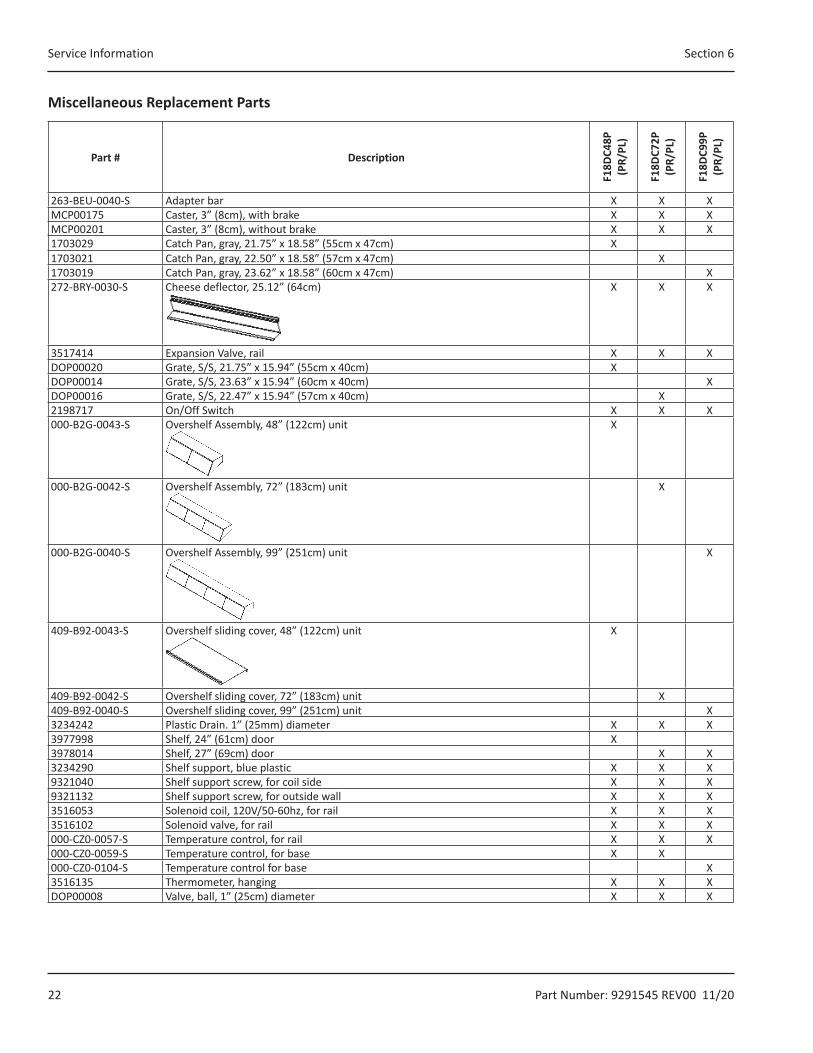
Miscellaneous Replacement Parts
Part # Description
F18D
C48P
(P
R/PL
)
F18D
C72P
(P
R/PL
)
F18D
C99P
(P
R/PL
)
263-BEU-0040-S Adapter bar X X XMCP00175 Caster, 3” (8cm), with brake X X XMCP00201 Caster, 3” (8cm), without brake X X X1703029 Catch Pan, gray, 21.75” x 18.58” (55cm x 47cm) X1703021 Catch Pan, gray, 22.50” x 18.58” (57cm x 47cm) X1703019 Catch Pan, gray, 23.62” x 18.58” (60cm x 47cm) X272-BRY-0030-S Cheese deflector, 25.12” (64cm) X X X
3517414 Expansion Valve, rail X X XDOP00020 Grate, S/S, 21.75” x 15.94” (55cm x 40cm) XDOP00014 Grate, S/S, 23.63” x 15.94” (60cm x 40cm) XDOP00016 Grate, S/S, 22.47” x 15.94” (57cm x 40cm) X2198717 On/Off Switch X X X000-B2G-0043-S Overshelf Assembly, 48” (122cm) unit X
000-B2G-0042-S Overshelf Assembly, 72” (183cm) unit X
000-B2G-0040-S Overshelf Assembly, 99” (251cm) unit X
409-B92-0043-S Overshelf sliding cover, 48” (122cm) unit X
409-B92-0042-S Overshelf sliding cover, 72” (183cm) unit X409-B92-0040-S Overshelf sliding cover, 99” (251cm) unit X3234242 Plastic Drain. 1” (25mm) diameter X X X3977998 Shelf, 24” (61cm) door X3978014 Shelf, 27” (69cm) door X X3234290 Shelf support, blue plastic X X X9321040 Shelf support screw, for coil side X X X9321132 Shelf support screw, for outside wall X X X3516053 Solenoid coil, 120V/50-60hz, for rail X X X3516102 Solenoid valve, for rail X X X000-CZ0-0057-S Temperature control, for rail X X X000-CZ0-0059-S Temperature control, for base X X000-CZ0-0104-S Temperature control for base X3516135 Thermometer, hanging X X XDOP00008 Valve, ball, 1” (25cm) diameter X X X
Section 6 Service Information
Part Number: 9291545 REV00 11/20 23
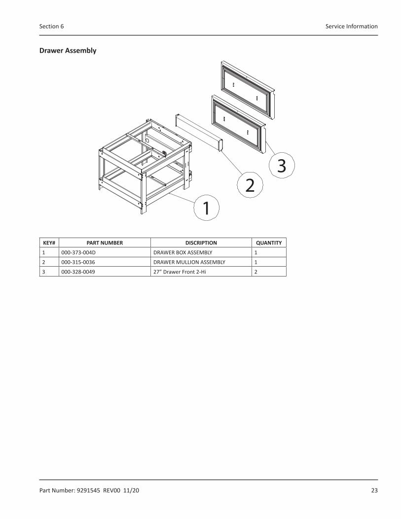
Drawer Assembly
23
1
KEY# PART NUMBER DISCRIPTION QUANTITY
1 000-373-004D DRAWER BOX ASSEMBLY 1
2 000-315-0036 DRAWER MULLION ASSEMBLY 1
3 000-328-0049 27” Drawer Front 2-Hi 2
DELFIELD 980 SOUTH ISABELLA ROAD, MOUNT PLEASANT, MI 48858
800-733-8821 WWW.DELFIELD.COM
©2019 Welbilt Inc. except where explicitly stated otherwise. All rights reserved.Part Number 9291545 Rev00 11/20