
VC Summer Nuclear Station Units 2 & 3 COLA (Environmental ...
96
South Carolina Electric & Gas COL Application Part 3 – Environmental Report Revision 0 3-i CHAPTER 3, PLANT DESCRIPTION TABLE OF CONTENTS Section Title Page 3.1 EXTERNAL APPEARANCE AND PLANT LAYOUT .......................... 3.1-1 3.1.1 EXISTING SITE ............................................................................. 3.1-1 3.1.2 PROPOSED SITE ......................................................................... 3.1-1 3.2 REACTOR POWER CONVERSION SYSTEM .................................. 3.2-1 3.2.1 REACTOR FUEL DESCRIPTION ................................................. 3.2-2 3.2.2 ENGINEERED SAFETY FEATURES............................................ 3.2-2 3.2.2.1 Containment ................................................................................ 3.2-2 3.2.2.2 Containment Isolation System..................................................... 3.2-3 3.2.2.3 Passive Core Cooling System..................................................... 3.2-3 3.2.2.4 Main Control Room Emergency Habitability System................... 3.2-3 3.2.2.5 Fission Product Control ............................................................... 3.2-3 3.3 PLANT WATER USE.......................................................................... 3.3-1 3.3.1 WATER CONSUMPTION.............................................................. 3.3-1 3.3.1.1 Plant Water Demand ................................................................... 3.3-1 3.3.1.2 Plant Water Releases.................................................................. 3.3-2 3.3.2 WATER TREATMENT ................................................................... 3.3-2 3.3.2.1 Raw Water and Cooling Tower Makeup...................................... 3.3-2 3.3.2.2 Demineralized Water ................................................................... 3.3-3 3.3.2.3 Potable Water System................................................................. 3.3-4 3.3.2.4 Fire Protection Water System ..................................................... 3.3-4 3.4 COOLING SYSTEM ........................................................................... 3.4-1 3.4.1 DESCRIPTION AND OPERATIONAL MODES ............................. 3.4-1 3.4.1.1 Plant Cooling ............................................................................... 3.4-1 3.4.1.1.1 Circulating Water System............................................................ 3.4-1 3.4.1.1.2 Service Water System................................................................. 3.4-2 3.4.1.2 Other Operational Modes ............................................................ 3.4-3 3.4.1.2.1 Station Load Factor ..................................................................... 3.4-3 3.4.1.2.2 Reservoir Water Temperature ..................................................... 3.4-3 3.4.1.2.3 Anti-Fouling Treatment ................................................................ 3.4-3 3.4.2 COMPONENT DESCRIPTIONS ................................................... 3.4-4 3.4.2.1 Reservoir Raw Water Intake System .......................................... 3.4-4 3.4.2.2 Final Plant Discharge .................................................................. 3.4-5 3.4.2.3 Heat Dissipation System ............................................................. 3.4-5 3.5 RADIOACTIVE WASTE MANAGEMENT SYSTEM ........................... 3.5-1 3.5.1 LIQUID RADIOACTIVE WASTE MANAGEMENT SYSTEM ......... 3.5-1 3.5.1.1 Waste Input Streams ................................................................... 3.5-2 3.5.1.1.1 Reactor Coolant System Effluents .............................................. 3.5-2 3.5.1.1.2 Floor Drains and Other Wastes with Potentially High Suspended Solid Contents .......................................................... 3.5-4 3.5.1.1.3 Detergent Wastes........................................................................ 3.5-4 3.5.1.1.4 Chemical Wastes ........................................................................ 3.5-5 3.5.1.1.5 Steam Generator Blowdown ....................................................... 3.5-5 3.5.1.2 Radioactive Releases.................................................................. 3.5-5
-
Upload
khangminh22 -
Category
Documents
-
view
0 -
download
0
Transcript of VC Summer Nuclear Station Units 2 & 3 COLA (Environmental ...

South Carolina Electric & GasCOL Application
Part 3 – Environmental Report
Revision 03-i
CHAPTER 3, PLANT DESCRIPTION
TABLE OF CONTENTS
Section Title Page
3.1 EXTERNAL APPEARANCE AND PLANT LAYOUT .......................... 3.1-13.1.1 EXISTING SITE............................................................................. 3.1-13.1.2 PROPOSED SITE ......................................................................... 3.1-13.2 REACTOR POWER CONVERSION SYSTEM .................................. 3.2-13.2.1 REACTOR FUEL DESCRIPTION ................................................. 3.2-23.2.2 ENGINEERED SAFETY FEATURES............................................ 3.2-23.2.2.1 Containment ................................................................................ 3.2-23.2.2.2 Containment Isolation System..................................................... 3.2-33.2.2.3 Passive Core Cooling System..................................................... 3.2-33.2.2.4 Main Control Room Emergency Habitability System................... 3.2-33.2.2.5 Fission Product Control ............................................................... 3.2-33.3 PLANT WATER USE.......................................................................... 3.3-13.3.1 WATER CONSUMPTION.............................................................. 3.3-13.3.1.1 Plant Water Demand................................................................... 3.3-13.3.1.2 Plant Water Releases.................................................................. 3.3-23.3.2 WATER TREATMENT................................................................... 3.3-23.3.2.1 Raw Water and Cooling Tower Makeup...................................... 3.3-23.3.2.2 Demineralized Water................................................................... 3.3-33.3.2.3 Potable Water System................................................................. 3.3-43.3.2.4 Fire Protection Water System ..................................................... 3.3-43.4 COOLING SYSTEM ........................................................................... 3.4-13.4.1 DESCRIPTION AND OPERATIONAL MODES............................. 3.4-13.4.1.1 Plant Cooling ............................................................................... 3.4-13.4.1.1.1 Circulating Water System............................................................ 3.4-13.4.1.1.2 Service Water System................................................................. 3.4-23.4.1.2 Other Operational Modes ............................................................ 3.4-33.4.1.2.1 Station Load Factor ..................................................................... 3.4-33.4.1.2.2 Reservoir Water Temperature..................................................... 3.4-33.4.1.2.3 Anti-Fouling Treatment................................................................ 3.4-33.4.2 COMPONENT DESCRIPTIONS ................................................... 3.4-43.4.2.1 Reservoir Raw Water Intake System .......................................... 3.4-43.4.2.2 Final Plant Discharge .................................................................. 3.4-53.4.2.3 Heat Dissipation System ............................................................. 3.4-53.5 RADIOACTIVE WASTE MANAGEMENT SYSTEM........................... 3.5-13.5.1 LIQUID RADIOACTIVE WASTE MANAGEMENT SYSTEM......... 3.5-13.5.1.1 Waste Input Streams................................................................... 3.5-23.5.1.1.1 Reactor Coolant System Effluents .............................................. 3.5-23.5.1.1.2 Floor Drains and Other Wastes with Potentially High
Suspended Solid Contents.......................................................... 3.5-43.5.1.1.3 Detergent Wastes........................................................................ 3.5-43.5.1.1.4 Chemical Wastes ........................................................................ 3.5-53.5.1.1.5 Steam Generator Blowdown ....................................................... 3.5-53.5.1.2 Radioactive Releases.................................................................. 3.5-5

South Carolina Electric & GasCOL Application
Part 3 – Environmental Report
Table of Contents (Continued)
Section Title Page
Revision 03-ii
3.5.2 GASEOUS RADIOACTIVE WASTE MANAGEMENT SYSTEM ... 3.5-63.5.2.1 System Description ..................................................................... 3.5-63.5.2.1.1 General Description..................................................................... 3.5-63.5.2.1.2 System Operation........................................................................ 3.5-73.5.2.2 Radioactive Releases.................................................................. 3.5-93.5.3 SOLID RADIOACTIVE WASTE MANAGEMENT SYSTEM ........ 3.5-103.6 NONRADIOACTIVE WASTE SYSTEMS ........................................... 3.6-13.6.1 EFFLUENTS CONTAINING CHEMICALS OR BIOCIDES............ 3.6-13.6.2 SANITARY SYSTEM EFFLUENTS............................................... 3.6-13.6.3 OTHER EFFLUENTS .................................................................... 3.6-23.6.3.1 Gaseous Emissions..................................................................... 3.6-23.6.3.2 Liquid Effluents............................................................................ 3.6-33.6.3.3 Hazardous Wastes ...................................................................... 3.6-43.6.3.4 Mixed Wastes.............................................................................. 3.6-43.6.3.5 Solid Effluents ............................................................................. 3.6-53.7 POWER TRANSMISSION SYSTEM.................................................. 3.7-13.7.1 SWITCHYARD INTERFACES....................................................... 3.7-13.7.2 TRANSMISSION SYSTEM ........................................................... 3.7-13.8 TRANSPORTATION OF RADIOACTIVE MATERIALS...................... 3.8-13.8.1 TRANSPORTATION OF UNIRRADIATED FUEL ......................... 3.8-13.8.2 TRANSPORTATION OF IRRADIATED FUEL............................... 3.8-13.8.3 TRANSPORTATION OF RADIOACTIVE WASTE ........................ 3.8-13.9 CONSTRUCTION ACTIVITIES .......................................................... 3.9-13.9.1 PRECONSTRUCTION ACTIVITIES.............................................. 3.9-13.9.1.1 Installation and Establishment of Environmental Controls .......... 3.9-23.9.1.2 Road and Rail Construction ........................................................ 3.9-23.9.1.3 Security Construction .................................................................. 3.9-33.9.1.4 Temporary Utilities ...................................................................... 3.9-33.9.1.5 Temporary Construction Facilities............................................... 3.9-43.9.1.6 Laydown, Fabrication, Shop Area Preparation............................ 3.9-43.9.1.7 Clearing, Grubbing, and Grading ................................................ 3.9-43.9.1.8 Underground Installations ........................................................... 3.9-43.9.1.9 Unloading Facilities Installation ................................................... 3.9-53.9.1.10 Intake/Discharge Cofferdams and Piling Installation................... 3.9-53.9.1.11 Power Block Earthwork (Excavation) .......................................... 3.9-53.9.1.12 Power Block Earthwork (Backfill) ................................................ 3.9-63.9.1.13 Module Assembly ........................................................................ 3.9-63.9.1.14 Nuclear Island Base Mat Foundations ........................................ 3.9-73.9.2 POWER PLANT COL CONSTRUCTION ACTIVITIES.................. 3.9-73.9.2.1 Construction Sequence............................................................... 3.9-73.9.2.2 Installation of Construction Commodities .................................... 3.9-83.9.2.3 Power Block Construction Durations........................................... 3.9-93.9.2.4 Testing and Startup................................................................... 3.9-113.9.3 ACTIVITIES ASSOCIATED WITH CONSTRUCTION................. 3.9-143.10 WORKFORCE CHARACTERIZATION ............................................ 3.10-1

South Carolina Electric & GasCOL Application
Part 3 – Environmental Report
Table of Contents (Continued)
Section Title Page
Revision 03-iii
3.10.1 CONSTRUCTION WORKFORCE............................................... 3.10-13.10.2 WORKERS RELOCATION AND COMMUTING.......................... 3.10-23.10.3 OPERATIONS WORKFORCE .................................................... 3.10-2

South Carolina Electric & GasCOL Application
Part 3 – Environmental Report
Revision 03-iv
CHAPTER 3, PLANT DESCRIPTION
LIST OF TABLES
Number Title3.3-1 Plant Water Use
3.4-1 Nominal Service Water Flows and Heat Loads at Different Operation Modes per Unit
3.4-2 Circulating Water System Cooling Tower Design Specifications per Unit
3.5-1 Annual Normal Liquid Releases from a Single AP1000 Reactor
3.5-2 Annual Normal Gaseous Releases from a Single AP1000 Reactor
3.5-3 Estimated Solid Radioactive Waste Volumes for a Single AP1000 Reactor
3.5-4 Expected Annual Curie Content of Shipped Primary Wastes Per Single AP1000 Reactor
3.5-5 Expected Annual Curie Content of Shipped Secondary Wastes Per Single AP1000 Reactor
3.6-1 Water Treatment Chemicals That Could Be Used in Units 2 and 3
3.6-2 Annual Emission (lbs/yr) from Diesel Generators Per Single AP1000 Reactor
3.6-3 Annual Measures of Wastes Recycled from Unit 1 and Estimated Volumes That Would Be Recycled Per AP1000 Reactor
3.10-1 Percent Construction Labor Force by Skill Set Based on Previous Nuclear Construction Projects
3.10-2 Estimated Construction Work Force and Construction Duration for Two AP1000 Units

South Carolina Electric & GasCOL Application
Part 3 – Environmental Report
Revision 03-v
CHAPTER 3, PLANT DESCRIPTION
LIST OF FIGURES
Number Title
3.1-1 Existing VCSNS Site Photograph
3.1-2 Artist’s Conception of New AP1000 Units Adjacent to Existing Nuclear Facility
3.1-3 Site Plan
3.1-4 Artist’s Rendering of AP1000 Standard Unit
3.2-1 Simplified Diagram of Reactor Power Conversion Cycle
3.3-1 Water Use Diagram Summary
3.3-2 Water Use Diagram Details
3.4-1 Simplified Cooling System Flow Diagram
3.4-2 Plan View of Reservoir Raw Water Intake System
3.4-3 Section View of Reservoir Raw Water Intake System
3.4-4 Outfall Discharge System
3.4-5 Outfall Discharge Ports
3.9-1 Construction Utilization Plan
3.10-1 Projected Construction Work Force by Year - Quarter for Two AP1000 Units
3.10-2 Projected Operations Work Force by Year - Quarter for Two AP1000 Units
South Carolina Electric & GasCOL Application
Part 3 – Environmental Report
Revision 03.1-1
3.1 EXTERNAL APPEARANCE AND PLANT LAYOUT
3.1.1 EXISTING SITE
VCSNS Unit 1 is located at the southern end of the Monticello Reservoir in Fairfield County, South Carolina; approximately 15 miles west of Winnsboro and 26 miles northwest of Columbia. Unit 1 is a Westinghouse pressurized water reactor plant licensed by the U. S. NRC in 1982 and has been in commercial operation since 1984.
The Monticello Reservoir is the upper impoundment for the Fairfield Pumped Storage Facility. The Fairfield Pumped Storage Facility is owned and operated by SCE&G. The Parr Reservoir, located on the Broad River, functions as the lower impoundment. The Parr Reservoir also provides the pool for Parr Hydro, a run of the river hydro facility.
The site is in a sparsely populated rural area. The nearest community is Jenkinsville, located approximately 3 miles southeast of the site. The Broad River is located approximately 1 mile west of the site and flows in a southerly direction.
The north-south oriented Monticello Reservoir has an area of approximately 6800 acres (6 miles long and 2.5 miles across). The 6800 acres includes the 300 acre Monticello sub-impoundment recreation lake.
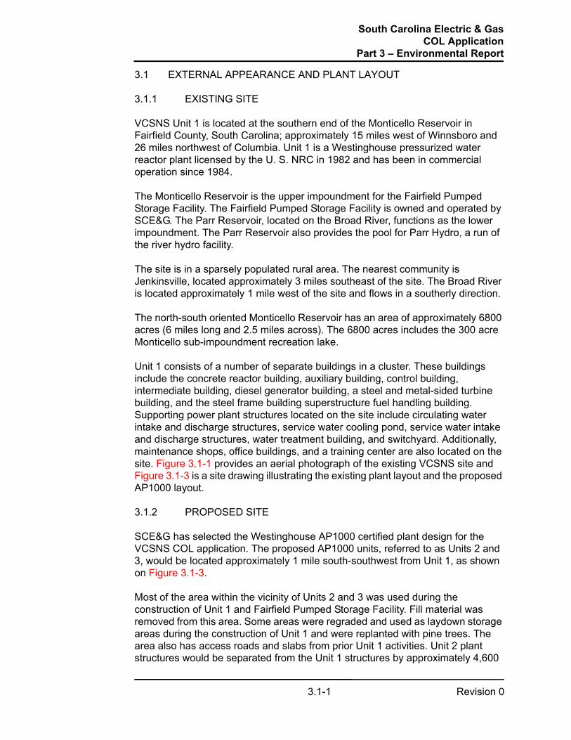
Unit 1 consists of a number of separate buildings in a cluster. These buildings include the concrete reactor building, auxiliary building, control building, intermediate building, diesel generator building, a steel and metal-sided turbine building, and the steel frame building superstructure fuel handling building. Supporting power plant structures located on the site include circulating water intake and discharge structures, service water cooling pond, service water intake and discharge structures, water treatment building, and switchyard. Additionally, maintenance shops, office buildings, and a training center are also located on the site. Figure 3.1-1 provides an aerial photograph of the existing VCSNS site and Figure 3.1-3 is a site drawing illustrating the existing plant layout and the proposed AP1000 layout.
3.1.2 PROPOSED SITE
SCE&G has selected the Westinghouse AP1000 certified plant design for the VCSNS COL application. The proposed AP1000 units, referred to as Units 2 and 3, would be located approximately 1 mile south-southwest from Unit 1, as shown on Figure 3.1-3.
Most of the area within the vicinity of Units 2 and 3 was used during the construction of Unit 1 and Fairfield Pumped Storage Facility. Fill material was removed from this area. Some areas were regraded and used as laydown storage areas during the construction of Unit 1 and were replanted with pine trees. The area also has access roads and slabs from prior Unit 1 activities. Unit 2 plant structures would be separated from the Unit 1 structures by approximately 4,600

South Carolina Electric & GasCOL Application
Part 3 – Environmental Report
Revision 03.1-2
feet. The center point of Unit 2 containment would be approximately 1600 feet west and 4300 feet south of the center point of Unit 1 containment. Unit 3 footprint would be separate from but adjacent to the Unit 2 footprint. The center point of Unit 3 would be approximately 900 feet south-southwest of the center point of Unit 2. The power plant footprints of Units 2 and 3 consists of an area of approximately 47 acres.
The proposed AP1000 units and support facilities for the VCSNS site are designed around the Westinghouse standardized unit approach. Each AP1000 unit consists of five principle generation structures—the nuclear island, turbine building, annex building, diesel generator building, and a radwaste building.
Structures that make up the nuclear island include the containment, shield building, and auxiliary building. The containment is a freestanding steel containment vessel with elliptical upper and lower heads. It is surrounded by the shield building. The shield building is a reinforced concrete structure that, in conjunction with the internal structures of the containment, provides the required shielding for the reactor coolant system and other radioactive systems and components housed in the containment. The shield building roof is a reinforced concrete conical structure. The auxiliary building is a reinforced concrete structure and shares a common basemat with the containment and the shield building. The auxiliary building wraps around approximately 70% of the circumference of the shield building and provides protection and separation for the safety-related mechanical and electrical equipment located outside the containment.
The turbine building is a rectangular metal-sided building with its long axis oriented radially from the containment. The turbine building houses the turbine, generator, and associated mechanical and electrical systems.
The annex building is a combination reinforced concrete structure and steel framed structure with insulated metal siding. The annex building provides the main personnel entrance to the power block. The building also contains the control support area, a machine shop, the ancillary diesel generators, other electrical equipment and various heating, ventilation, and air conditioning systems.
The diesel generator building is a single-story steel-framed structure with insulated metal siding. The building houses two diesel generators to provide backup power in the event of disruption of the normal power source.
The radwaste building is a steel-framed structure. The radwaste building houses low-level liquid radwaste holdup tanks and processing system.
The circulating water system for each unit would consist of two mechanical draft cooling towers and a circulating water pump intake structure. The circulating water system cooling towers would be located plant south of the proposed new units as indicated in Figure 3.1-3. The cooling towers would be approximately 70 feet high and require an area of approximately 38 acres for the four towers and their supporting facilities.

South Carolina Electric & GasCOL Application
Part 3 – Environmental Report
Revision 03.1-3
In addition to the circulating water system cooling tower footprint, Units 2 and 3 would require space for service water system cooling towers (one per unit). These mechanical draft cooling towers would require an area of approximately 0.5 acre per unit and would be located near the turbine building.
The proposed new units would share common intake structures, discharge structure, and certain support structures such as office buildings, water treatment, and waste handling facilities.
The Monticello Reservoir would be used as makeup water for the circulating water and service water cooling systems. The plant discharge would be to the Parr Reservoir. The new intake structure for the circulating water system makeup would be located approximately 1,250 feet west of the Unit 1 intake facilities. An additional intake structure for the remaining plant water (service water cooling makeup, potable water, fire water, demineralized water supply) would be located approximately 5500 feet east of the Unit 1 intake facilities. These facilities would be designed and constructed from materials that are architecturally similar to those used on Unit 1.
Modifications to existing infrastructure would be made to integrate Units 2 and 3 with the existing unit; however, none of the existing unit’s structures or facilities that directly support power generation would be shared. A new security perimeter would be installed to encompass the new units. The Nuclear Learning Center would be expanded to support the training needs for the new units. Existing administrative buildings, warehouses, and other support facilities would be used, expanded, or replaced based on prudent economic and operational considerations. Figure 3.1-3 shows the integration of the new and existing units as well as site roadways and access.
Units 2 and 3 would be constructed from materials architecturally similar to Unit 1. Figure 3.1-4 is an artist’s rendering of the AP1000 standard unit. Figure 3.1-2 provides an artist’s conception of the new AP1000 units adjacent to the existing nuclear unit.
After the completion of new unit construction, areas used for construction support would be graded, landscaped, and planted to enhance the overall site appearance. Previously forested areas cleared for temporary construction facilities would be revegetated, and harsh topographical features created during construction would be contoured to match the surrounding areas. These areas would include equipment laydown yards, module fabrication areas, concrete batch plant, areas around completed structures, and construction parking.
South Carolina Electric & GasCOL Application
Part 3 – Environmental Report
Revision 03.1-4
Figure 3.1-1. Existing VCSNS Site Photograph

South Carolina Electric & GasCOL Application
Part 3 – Environmental Report
Revision 03.1-5
Figure 3.1-2. Artist’s Conception of New AP1000 Units Adjacent to Existing Nuclear Facility

South Carolina Electric & GasCOL Application
Part 3 – Environmental Report
Revision 03.1-6
Figure 3.1-3. Site Plan

South Carolina Electric & GasCOL Application
Part 3 – Environmental Report
Revision 03.1-7
Figure 3.1-4. Artist’s Rendering of AP1000 Standard Unit

South Carolina Electric & GasCOL Application
Part 3 – Environmental Report
Revision 03.2-1
3.2 REACTOR POWER CONVERSION SYSTEM
VCSNS Units 2 and 3 would be based on Westinghouse AP1000 pressurized water reactor technology with each unit essentially the same. Descriptions of one unit shall be interpreted as applying to both units. Major components include a single reactor pressure vessel, two steam generators, and four reactor coolant pumps for converting reactor thermal energy into steam. A single high-pressure turbine and three low-pressure turbines drive a single electric generator. The AP1000 was certified by the NRC under 10 CFR 52, Appendix D. Figure 3.2-1 provides a simplified depiction of the reactor power conversion system.
Westinghouse would perform the design for the standard power production plant and would supply the nuclear steam supply system and other associated systems. Shaw, Stone and Webster, Inc., a Shaw Group subsidiary, would perform the design for the remainder of the facilities associated with the nuclear plants. Shaw, Stone and Webster, Inc. would also perform construction of Units 2 and 3.
The AP1000 reactor is connected to two steam generators via two primary hot leg pipes and four primary cold leg pipes. A reactor coolant pump is located in each primary cold leg pipe to circulate pressurized reactor coolant water through the reactor core. The reactor coolant pumps circulate reactor coolant through the reactor core making contact with the fuel rods which contain the enriched uranium dioxide fuel. As the reactor coolant passes through the reactor core, heat from the nuclear fission process is removed from the reactor. This heat is transported to the steam generators by the circulating reactor coolant and passes through the tubes of the steam generators to heat the feedwater from the secondary system. The reactor coolant is then returned back to the reactor by the reactor coolant pumps, where it is reheated to start the heat transfer cycle over again.
Inside the steam generators, the reactor heat from the primary system is transferred through the walls of the tubes to convert the incoming feedwater from the secondary system into steam. The steam is transported from the steam generators by main steam piping to drive the high-pressure and low-pressure turbines connected to an electric generator to produce electricity. The turbine is an 1800-rpm, tandem-compound, six-flow, reheat unit. The high-pressure turbine element includes one double-flow, high-pressure turbine. The low-pressure turbine elements include three double-flow, low-pressure turbines. The turbine-generator system would be manufactured by Toshiba.
After passing through the three low-pressure turbines, the steam is condensed back to water by cooled water circulated inside the titanium tubes located in the three condensers. The condensate is then preheated and pumped back to the steam generators as feedwater to repeat the steam cycle. The condenser is a three-shell, single-pass, multi-pressure unit with a total surface area of 1.236 x 10⁶ square feet available for heat transfer. The condenser rejects approximately 7.54 x 10⁹ BTU/hour (2208 MWt) of waste heat to the circulating water system. The unit thermal efficiency of the complete cycle is approximately 35%.

South Carolina Electric & GasCOL Application
Part 3 – Environmental Report
Revision 03.2-2
The rated thermal power of each AP1000 reactor is 3,400 MWt and a nuclear steam supply system rating of 3,415 MWt (core plus reactor coolant pump heat). The gross and net electrical output of each AP1000 unit is approximately 1,200 MWe (with an 87°F circulating water cold water temperature) and 1,107 MWe respectively, with station and auxiliary service loads of approximately 93 MWe.
3.2.1 REACTOR FUEL DESCRIPTION
The AP1000 reactor uses uranium dioxide enriched with uranium U-235 for fissile material. The reactor fuel consists of individual cylindrical uranium pellets enclosed in a sealed ZIRLOTaM tube to comprise a fuel rod. The AP1000 fuel assembly consists of 264 fuel rods grouped in a 17 X 17 square array. Each reactor contains 157 fuel assemblies consisting of 41,448 total fuel rods. Total uranium dioxide fuel weight is 211,588 pounds.
Enrichment of the uranium would be approximately 2.35 to 4.45 weight percent U-235 for the initial reactor core load and a 4.54 average weight percent U-235 for core reloads. The expected average burnup of discharged fuel would be approximately 50,553 MW days per metric ton of uranium, with an expected cycle burnup of 21,000 MW days per metric ton of uranium. The maximum fuel rod average burnup value for the AP1000 reactor is 60,000 MW days per metric ton of uranium. The total fuel capacity for each unit is approximately 84.5 metric tons of uranium.
3.2.2 ENGINEERED SAFETY FEATURES
Engineered safety features protect the public in the event of an accidental release of radioactive fission products from the reactor coolant system. The engineered safety features function to localize, control, mitigate, and terminate such accidents and to maintain radiation exposure levels to the public below applicable limits and guidelines, such as 10 CFR 100. The following are defined as engineered safety features.
3.2.2.1 Containment
The containment vessel is a free-standing cylindrical steel vessel with ellipsoidal upper and lower heads. It is surrounded by a seismic Category I reinforced concrete shield building. The function of the containment vessel, as part of the overall containment system, is to contain the release of radioactivity following postulated design basis accidents. The containment vessel also functions as the safety-related ultimate heat sink by transferring the heat associated with accident sources to the surrounding environment. The following paragraph details this safety-related feature.
Passive Containment Cooling System: The function of the passive containment cooling system is to maintain the temperature below a maximum value and to
a. ZIRLO is a registered trademark of Westinghouse Electric Company.

South Carolina Electric & GasCOL Application
Part 3 – Environmental Report
Revision 03.2-3
reduce the containment temperature and pressure following a postulated design basis event. The passive containment cooling system removes thermal energy from the containment atmosphere. The passive containment cooling system also serves as the safety-related ultimate heat sink for other design basis events and shutdowns. The passive containment cooling system limits the release of radioactive material to the environment by reducing the pressure differential between the containment atmosphere and the external environment. This diminishes the driving force for leakage of fission products from the containment to the atmosphere.
3.2.2.2 Containment Isolation System
The major function of the containment isolation system of the AP1000 is to provide containment isolation to allow the normal or emergency passage of fluids through the containment boundary while preserving the integrity of the containment boundary, if required. This prevents or limits the escape of fission products that may result from postulated accidents. Containment isolation provisions are designed so that fluid lines penetrating the primary containment boundary are isolated in the event of an accident. This minimizes the release of radioactivity to the environment.
3.2.2.3 Passive Core Cooling System
The primary function of the passive core cooling system is to provide emergency core cooling following postulated design basis events. The passive core cooling system provides reactor coolant system makeup and boration during transients or accidents where the normal reactor coolant system makeup supply from the chemical and volume control system is lost or is insufficient. The passive core cooling system provides safety injection to the reactor coolant system to provide adequate core cooling for the complete range of loss of coolant accident events up to, and including, the double-ended rupture of the largest primary loop reactor coolant system piping. The passive core cooling system provides core decay heat removal during transients, accidents, or whenever the normal heat removal paths are lost.
3.2.2.4 Main Control Room Emergency Habitability System
The main control room emergency habitability system is designed so that the main control room remains habitable following a postulated design basis event. With a loss of all AC power sources, the habitability system maintains an acceptable environment for continued operating staff occupancy.
3.2.2.5 Fission Product Control
Post-accident safety-related fission product control for the AP1000 is provided by natural removal processes inside containment, the containment boundary, and the containment isolation system. The natural removal processes, including various aerosol removal processes and pool scrubbing, remove airborne particulates and

South Carolina Electric & GasCOL Application
Part 3 – Environmental Report
Revision 03.2-4
elemental iodine from the containment atmosphere following a postulated design basis event.

South Carolina Electric & GasCOL Application
Part 3 – Environmental Report
Revision 03.2-5
Figure 3.2-1. Simplified Diagram of Reactor Power Conversion Cycle
Condenser
LP Turbine (3)
Generator
FeedwaterHeaters
CondensatePumps
FeedwaterBoosterPumps
MainFeedwater
Pumps
FeedwaterHeaters
HP Turbine
MoistureSeparator/Reheater
ContainmentTurbine Building
SteamGenerator 2
SteamGenerator 1
Reactor Vessel
From Cooling TowersTo Cooling Towers
Transmission Lines

South Carolina Electric & GasCOL Application
Part 3 – Environmental Report
Revision 03.3-1
3.3 PLANT WATER USE
Plant water use for VCSNS Units 2 and 3 is based on two AP1000 units at the site. Consumption and treatment requirements are determined from the AP1000 DCD (Westinghouse 2007) and site characteristics. The Monticello Reservoir would supply all the raw water for the units. Treated effluents would be returned to the Parr Reservoir approximately 1-1/4 miles upstream of Parr Shoals Dam, except for waste streams from the water treatment facility, which would be returned to the Monticello Reservoir.
3.3.1 WATER CONSUMPTION
The two units would use water from the Monticello Reservoir for plant cooling and for all other plant-related use or consumption. Each unit would use closed-cycle, wet cooling towers for both circulating water system cooling and service water system cooling. Makeup water would be required to replenish circulating water system and service water system water lost to evaporation, drift, and blowdown. An intake structure located on the Monticello Reservoir west of the existing Unit 1 would supply circulating water system makeup water. A water treatment facility located along the Monticello Reservoir to the east of Unit 1, comprised of a water treatment plant with its own separate intake structure, would also supply water withdrawn from the Monticello Reservoir for service water system makeup and to the potable water system, fire protection system, and plant demineralized water supply system. Water balances for this arrangement are provided by data listed in Table 3.3-1 in conjunction with Figures 3.3-1 and 3.3-2. Hydrologic and water use impacts of this arrangement are addressed in Section 5.2.
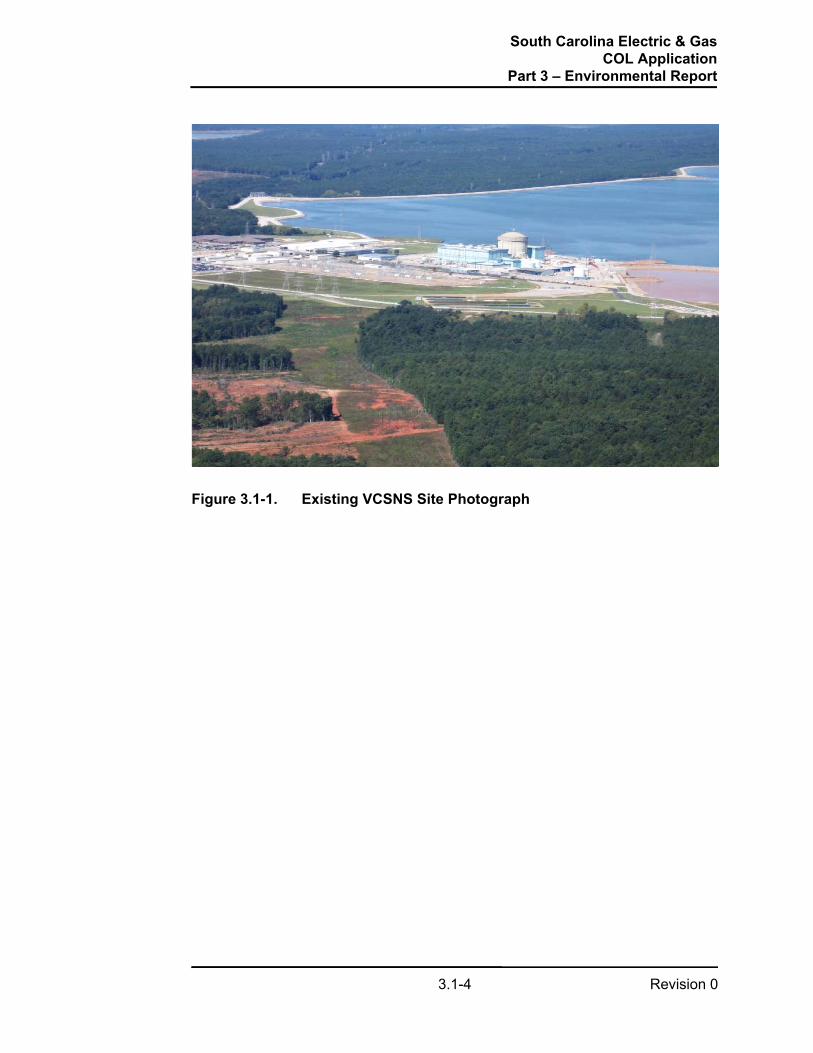
Table 3.3-1 defines normal and maximum water usage based on AP1000 design parameters and site-specific characteristics. Evaporation and drift estimates for the circulating water and service water cooling towers are based on site characteristics and AP1000 design parameters for the cooling systems included in Tables 3.4-1 and 3.4-2.
3.3.1.1 Plant Water Demand
Table 3.3-1 provides the total water use estimate for Units 2 and 3. The table includes normal and maximum flows for corresponding streams defined in Figures 3.3-1 and 3.3-2. Water demand includes makeup water for the circulating water and service water systems and water supply for potable water, fire protection, and demineralized water. Normal values listed are expected limiting values for normal plant operation with the two units in operation. Maximum values are those expected for extreme conditions with the two units in operation. Normal fire protection water use is that required to maintain fire protection system availability. Maximum fire protection water use is based on maintaining system availability in addition to system makeup following a system demand.

South Carolina Electric & GasCOL Application
Part 3 – Environmental Report
Revision 03.3-2
3.3.1.2 Plant Water Releases
Table 3.3-1 also provides water release estimates for the two units. These include losses from both the service water and circulating water systems through cooling tower water evaporation and drift, as well as rejection of blowdown. The water balances provided by the data listed in Table 3.3-1 in conjunction with Figures 3.3-1 and 3.3-2 include estimates for the wastewater flows from the two units, including radiological effluent releases, sanitary waste, miscellaneous drains, and demineralizer discharges. The figures also include expected waste effluent associated with water treatment for the two units discharged from the water treatment facility. Normal values listed are expected limiting values for normal plant operation with two units in operation. Maximum values are those expected for extreme conditions with two units in operation.
The cooling tower blowdown and wastewater from Units 2 and 3 would be released to the Parr Reservoir. Wastewater from the water treatment facility would be returned to the Monticello Reservoir through the Unit 1 discharge canal. A blowdown sump serving Units 2 and 3 would collect cooling tower blowdown; wastewater retention basin, sanitary waste treatment plant and startup pond effluents; and, raw water for alternate dilution, for discharge to the Parr Reservoir. The startup pond would be used during the initial construction phase to collect system flushes. Wastes would be treated to meet state and local permit limits before the startup pond contents are discharged to the blowdown sump for subsequent release to the Parr Reservoir. The startup pond may be used after initial plant startup to collect system flushes warranted after system modification. Alternatively, flush wastes may be collected in tanks and disposed of in accordance with local regulation using appropriate “truck and haul” permits. Liquid radwaste would also be released to the Parr Reservoir through the blowdown sump discharge stream, but only when sufficient dilution flow would be present. Nonradioactive liquid effluents would be regulated under a National Pollutant Discharge Elimination System permit. Site drainage would be managed through the storm water collection system and natural drainage.
3.3.2 WATER TREATMENT
Water treatment would be performed to maintain satisfactory water quality for plant use, human consumption, and release from the plant to the environment. Water treatment processes and methods would be similar to those of Unit 1 for similar applications. Representative chemicals for water treatment to control biofouling, algae, and suspended matter; adjust pH, inhibit corrosion and scale formation; for disinfection; and for dechlorination are identified in Subsection 3.6.1. The chemical amounts would be limited to those necessary to control concentrations of effluent constituents within limits of the National Pollutant Discharge Elimination System permit.
3.3.2.1 Raw Water and Cooling Tower Makeup
Raw water from the Monticello Reservoir would be treated for use as cooling tower makeup, potable water, fire protection water, and demineralized water. The

South Carolina Electric & GasCOL Application
Part 3 – Environmental Report
Revision 03.3-3
raw water for makeup to the circulating water cooling towers would receive treatment to prevent biofouling in the intake structure and raw water supply piping to the circulating water cooling towers. Raw water for makeup to the service water cooling towers and for supply to the potable water, fire protection, and demineralized water treatment systems would be pretreated to control biological growth and pH, disinfected, clarified and filtered as necessary at the water treatment facility.
Additional treatment for biofouling, scaling, and suspended matter, with biocides, antiscalants, and dispersants, respectively, would be performed as needed at the cooling tower basins. During circulation of the water withdrawn from the basins through the circulating water and service water systems, this treatment would normally occur through injection of chemicals into system piping. The cooling tower cycles of concentration would be adjusted to prevent scale formation or deposition from affecting tower performance.
3.3.2.2 Demineralized Water
Water from the water treatment facility would be treated systematically and thoroughly with a process that includes filtration and primary and secondary demineralization processes, which results in highly purified water for various plant systems. Reverse osmosis would be the primary demineralization treatment process designed to reduce solids, salts, organics and colloids. In the secondary stage of the purification process, the treated water would pass through an electrodeionization system where dissolved gaseous carbon dioxide and a majority of the remaining ions would be removed. Once purified, the demineralized makeup water would be directed to the following major users:
• Condensate system (including the condenser, condensate polishers, auxiliary boiler, and startup feedwater pumps)
• Reactor coolant system through the chemical and volume control system
Treated condensate serves as the source of feedwater to the steam generators. The condensate would pass through a condensate polisher resin bed to remove contaminates and produce the high purity water required to minimize corrosion in the condensate and feedwater systems. Exhausted or spent resin would be removed and replaced with new or regenerated resin. Replacement resin bed rinse water would be discharged to the condenser. The auxiliary boiler would also receive demineralized makeup water via the condensate system.
The demineralized water system provides pure makeup water to the reactor coolant system through the chemical and volume control system. In addition, the demineralized water system supplies makeup to other users, including the spent fuel pool, turbine building and component cooling water systems, chilled water system, and radwaste systems. Chemical corrosion inhibitors would be used to treat the high quality demineralized water to minimize system component corrosion.

South Carolina Electric & GasCOL Application
Part 3 – Environmental Report
Revision 03.3-4
Discharges from systems using demineralized water for makeup would be routed to plant sumps or the liquid radwaste system prior to discharge.
3.3.2.3 Potable Water System
The potable water system provides a safe water supply for domestic use and human consumption. Raw water from the Monticello Reservoir would be treated and stored at the water treatment facility until fed to the potable water distribution system for Units 2 and 3. Water treatment would be by filtration and disinfection as needed to meet potable use standards.
3.3.2.4 Fire Protection Water System
The fire protection water system is used for fire suppression and as a backup supply of water to other water systems, including the passive containment cooling system. The system consists of storage tanks, pressure maintenance equipment, and a distribution system. Raw water from the Monticello Reservoir pretreated and stored at the water treatment facility would be the source of water for the fire protection water system. The raw water would be pretreated by filtration and disinfection, as needed and permissible, to prevent fouling of the system.

South Carolina Electric & GasCOL Application
Part 3 – Environmental Report
Revision 03.3-5
Section 3.3 References
1. Westinghouse 2007, Westinghouse Electric Company, AP1000 Design Control Document, APP-GW-GL-700, Revision 16, 2007.
South Carolina Electric & GasCOL Application
Part 3 – Environmental Report
Revision 03.3-6
Table 3.3-1 Plant Water Use
Stream Description
Normal Case(a)
gpm
(a) The flow rate values are for two AP1000 units.
Maximum Case(a),(b)
gpm
(b) Flows are not necessarily concurrent.
CommentsSurface Water (Monticello Reservoir) StreamsRaw Water Demand (total) 37,183 61,791 Note(c)
(c) Includes amount of water withdrawn at the water treatment facility of 969 gpm (normal) and 2,991 gpm (maximum), which represents the total demand of service water system makeup, power plant makeup, and the water treatment facility reservoir return values.
Service Water System Makeup 640 1,840• Service Water Consumptive Use 481 1,381
- Evaporation 480 1,380- Drift 1 1 Note(d)
(d) The cooling tower drifts are 0.001% of the tower circulating water flow.
• Service Water System Blowdown 159 459 Note(e)
(e) For the normal case, the cooling towers are assumed operating at four cycles of concentration. For the service water cooling tower (maximum case), both unit towers are assumed operating at four cycles of concentration. For the circulating water cooling tower (maximum case), both unit towers are assumed operating at two cycles of concentration. Flows are determined by weather conditions and water chemistry.
Circulating Water System Makeup 36,214 58,800• Circulating Water System Consumptive Use 27,173 29,413
- Evaporation 27,160 29,400- Drift 13 13 Note(d)
• Circulating Water System Blowdown 9,041 29,387 Note(e)
Power Plant Makeup 280 1,001• Demineralized Water System 224 896 Note(f)
(f) A portion of the flow is rejected to waste streams during the demineralized water treatment process upstream of the demineralized water tank.
• Potable Water System 36 70• Fire Water System 10 12• Misc. Raw Water Use 10 23
Water Treatment Facility Reservoir Return 49 150Effluent StreamsEffluent Discharge to Parr Reservoir 9,383 30,547
• Blowdown Sump Discharge 9,380 30,347- Waste Water Retention Basin Discharge 144 431- Treated Sanitary Waste 36 70- Service Water System Blowdown 159 459 Note(e)
- Circulating Water System Blowdown 9,041 29,387 Note(e)
- Startup Pond Discharge 0 0 Note(g)
(g) Startup flushes and startup pond discharge occur only during the initial plant startup phase and potentially after unit outages when system flushes are required.
• Treated Liquid Radwaste 3 200 Note(h)
(h) The short-term liquid waste discharge flow rate may be up to 200 gpm. However, given the waste liquid activity level, the discharge rate must be controlled to be compatible with the available dilution flow.
Effluent Discharge to Monticello Reservoir 49 150 Note(i)
(i) Water treatment facility waste stream is discharged through the Unit 1 discharge canal to the Monticello Reservoir.
Notes:

South Carolina Electric & GasCOL Application
Part 3 – Environmental Report
Revision 03.3-7
Figure 3.3-1. Water Use Diagram Summary
NOTES:
1. VALUES SHOWN AS XXX (XXX) ARE NORMAL (MAXIMUM) FLOW RATES IN GPM. THE FLOW RATE VALUES ARE FOR TWO AP1000 UNITS. FOR A FLOW STREAM SUMMARY AND ADDITIONAL NOTES, REFER TO THE PLANT WATER USE TABLE (TABLE 3.3-1).
2. THE WATER USE FOR THE POWER PLANT INTERNAL PROCESSES IS SHOWN ON FIGURE 3.3-2. SEE CORRESPONDING NODES (A THROUGH F) FOR STREAM INTERFACE POINTS.
3. THE SHORT TERM LIQUID WASTE DISCHARGE FLOW RATE MAY BE HIGHER. REGARDLESS, THE DISCHARGE RATE IS CONTROLLED TO BE COMPATIBLE WITH THE AVAILABLE DILUTION FLOW TO MAINTAIN THE EFFLUENT ACTIVITY LEVEL WITHIN REQUIRED LIMITS.
4. THE PARR RESERVOIR IS LOCATED ON THE BROAD RIVER. WATER IS TRANSFERRED BETWEEN THE MONTICELLO RESERVOIR AND THE PARR RESERVOIR VIA THE FAIRFIELD PUMPED STORAGE FACILITY.
5. ONLY RO/EDI WASTE STREAMS TO THE WASTE WATER SYSTEM ARE SHOWN. INTERNALLY RECYCLED STREAMS ARE NOT DEPICTED.
6. FLOW IS INTERMITTENT OR RECIRCULATED AND THEREFORE CONSIDERED ZERO.
7. FLOW VARIES AS REQUIRED TO ENSURE ADEQUATE DILUTION FOR LIQUID WASTE DISCHARGE WHEN BLOWDOWN FLOW IS NOT SUFFICIENT. FLOW RATE OF ALTERNATE DILUTION STREAM WHEN COMBINED WITH OTHER DISCHARGE STREAMS DOES NOT EXCEED MAXIMUM VALUE SHOWN FOR FINAL EFFLUENT DISCHARGE TO PARR RESERVOIR.
8. FLOW PATH PROVIDED FOR UNFILTERED RAW WATER FOR MAKEUP TO SERVICE WATER SYSTEM IS NOT NORMALLY USED.
LEGENDNo Normal Flow
Normal Flow
Flow varies with operating conditions
POWER PLANT
SERVICE WATER SYSTEM
CIRCULATING WATER SYSTEM
LIQUID RADWASTE TREATMENT
SANITARY WASTE TREATMENT PLANT WASTE WATER RETENTION BASIN
BLOWDOWN SUMP
START-UP POND
MONTICELLORESERVOIR
COOLING TOWER EVAPORATION
COOLING TOWER EVAPORATION
BLOWDOWN
START-UP FLUSHES & CHEMICAL CLEANING WASTES
MISCELLANEOUS LOW VOLUME WASTE
SA
NIT
AR
Y W
AS
TE
BLOWDOWN
COOLING TOWER DRIFT
COOLING TOWER DRIFT
See Note 3
PARR RESERVOIR
Se
e N
ote
4
WATER TREATMENT
FACILITY
CONSUMPTIVE USE See Note 2
C
ESee Note 2
DSee Note 2
A
BSee Note 2
See Note 2
See Note 6
See Note 6
See Note 6
FSee Note 2
See Note 7
ALTERNATE DILUTION
AL
TE
RN
AT
E M
AK
EU
P
3 (200) 3 (200)
0 (0)
0 (0)
144 (431)
144 (431)
36 (70)
36 (70)
13 (13)
27,160 (29,400)
9,041 (29,387)
0 (0)
0 (0)
0 (0)
969 (2,991)
640 (1,840)
884 (2,771)
49 (150)
480 (1,380)
1 (1)
36,214 (58,800)
244 (931)
36 (70)
36,214 (58,800)
159 (459)
9,383 (30,547) 9,380 (30,347)
97 (300)
See Note 8

South Carolina Electric & GasCOL Application
Part 3 – Environmental Report
Revision 03.3-8
Figure 3.3-2. Water Use Diagram Details
POWER PLANT
POTABLEWATER
FIRE WATER
MISC. WATER USERS
DEMINERALIZED WATER SYSTEM
FILTERREVERSE OSMOSIS
UNITEDI UNIT DEMIN
WATER TANK
Backw
ash Water
OIL / WATER SEPARATOR
Backwash Waste
EQUIPMENT / FLOOR
WASHDOWN
RO
/ED
I Reject
SANITARY TREATMENT
PLANT
WASTE WATER RETENTION
BASIN
TURBINE BUILDING DRAIN SYSTEM
LIQUID RADWASTE TREATMENT
START-UP POND
CONDENSATE/FEEDWATER/STEAM
GENERATOR SYSTEM
AUX BOILER
COMPONENT COOLING WTR
SYSTEM
REACTOR
DG CLOSED COOLING WTR
SYSTEM
SPENT FUEL POOL COOLING WTR SYSTEM
TURBINE BLDG CCW
SYSTEM
CHILLED WATER / HOT WATER SYS
CONDENSATE POLISHER
SG Blowdown
Blowdown
MISC. CHEM. MIXING
START-UP REQ’S
MISC. CHEM. FEED SYSTEMS
MISC. DEMIN WATER USERS
DE
MIN
WA
TER
US
ER
S
LEGENDNo Normal Flow
Normal Flow
Flow varies with operating conditions
CONSUMPTIVE USE
See Note 5WATER
TREATMENT FACILITY
A
B
C
E
D
F
97 (300)
3 (200)
0 (0)
FOR NOTES SEE FIGURE 3.3-1
224 (896)
36 (70)
36 (70)
10 (12)
10 (23)
244 (931)
144 (431)

South Carolina Electric & GasCOL Application
Part 3 – Environmental Report
Revision 03.4-1
3.4 COOLING SYSTEM
The VCSNS Units 2 and 3 plant cooling systems, operational modes, and component design parameters are based upon the AP1000 DCD (Westinghouse 2007), site-specific characteristics, and engineering evaluations. The plant cooling systems and the anticipated cooling system modes of operation are described in Subsection 3.4.1. Design data and performance characteristics for the cooling system components are described in Subsection 3.4.2. These parameters were used to evaluate the environmental impacts from cooling system operation. The plant cooling systems interface directly with the environment at the raw water intake and blowdown discharge structures, and the cooling towers. Figure 3.4-1 is a simplified flow diagram of the cooling water systems for Units 2 and 3.
3.4.1 DESCRIPTION AND OPERATIONAL MODES
The cooling system design for Units 2 and 3 requires consideration of the total amount of waste heat generated as a byproduct of the units’ electrical power generation, and the waste heat released to the environment. Site-specific characteristics were used in addition to the AP1000 design parameters to evaluate the impacts to the VCSNS site by the addition of two AP1000 units. The cooling systems that transfer the heat to the environment during normal operation for each unit are the circulating water system and the service water system.
3.4.1.1 Plant Cooling
3.4.1.1.1 Circulating Water System
Each AP1000 unit has a circulating water system, which is used to dissipate up to 7.63 x 10⁹ Btu/hour (1.53 x 10¹⁰ Btu/hour for two units) of waste heat rejected from the condenser, turbine building closed cooling water heat exchangers, and condenser vacuum pump seal water heat exchangers during normal plant operation at full station load. A closed-cycle, wet cooling system is used for the proposed Units 2 and 3. This system uses mechanical draft cooling towers for heat dissipation.
Exhaust steam from the turbine is directed to a surface condenser, where the heat of vaporization is rejected to a closed loop of cooling water. The heated cooling water from the condenser, turbine building closed cooling water heat exchangers, and condenser vacuum pump seal water heat exchangers returns through piping to the distribution header of the mechanical draft cooling towers. The heated cooling water is circulated to the spray headers of the wet cooling towers, where heat content of the cooling water is transferred to the ambient air via evaporative cooling and conduction. Mechanical fans provide air flow past the water droplets as they fall through the tower fill, rejecting heat from the water to the atmosphere. After passing through the cooling tower, the cooled water collected in the tower basin is pumped back to the condenser, turbine building closed cooling water heat exchangers, and condenser vacuum pump seal water heat exchangers to complete the closed cycle cooling water loop. Makeup water from the Monticello

South Carolina Electric & GasCOL Application
Part 3 – Environmental Report
Revision 03.4-2
Reservoir is provided to account for evaporative water losses, drift losses, and blowdown discharge.
Makeup water is obtained from the Monticello Reservoir using pumps at a maximum rate of approximately 59,000 gpm for two units. (This is based on maintaining two cycles of concentration in the cooling towers.) Normally, the cooling water system is operated at four cycles of concentration, decreasing to two cycles of concentration when reservoir water conditions necessitate, e.g., high suspended solids in the reservoir water. The raw water pumps are installed in a new raw water intake structure located approximately 1250 feet west of the existing Unit 1 intake structure. The makeup water is pumped to the cooling tower collection basins directly. Blowdown from the cooling towers is directed to a common blowdown sump before being discharged to the Parr Reservoir. Figure 3.1-3 shows the proposed location of the raw water intake and blowdown discharge structures for the new units.
The circulating water system consists of pumps that circulate water at a nominal rate of 634,000 gpm per unit. The water is pumped through the condenser, turbine building closed cooling water heat exchangers, and condenser vacuum pump seal water heat exchangers (all in parallel), and then to the mechanical draft cooling towers to dissipate heat to the atmosphere. Figure 3.1-3 shows the location of the cooling towers for Units 2 and 3.
3.4.1.1.2 Service Water System
Each AP1000 unit has a nonsafety-related service water system to provide cooling water to the component cooling water system (CCS) heat exchangers located in the turbine building. The service water system is in use during startup, normal plant operations, cooldown, shutdown, and refueling. It has a dedicated closed cycle system with a mechanical draft cooling tower to dissipate heat during normal conditions, shutdown, or other operating conditions. Service water is pumped to the component cooling water heat exchangers for heat removal. Heated service water returns through piping to the distribution header of the mechanical draft cooling tower. Mechanical fans provide air flow past the water droplets as they fall through the tower fill, rejecting heat from the service water to the atmosphere. The cooled water is collected in the tower basin and returned to the pump suction for recirculation through the system. Table 3.4-1 provides nominal service water flows and heat loads at the various operating modes for the service water system. Each tower is estimated to have an evaporation water loss of approximately 240 gpm during normal conditions and 690 gpm during cooldown conditions. Blowdown flow from the service water towers is discharged to the circulating water system cooling tower basin at a flow rate of up to 230 gpm per unit. The blowdown may be directed to the blowdown sump as necessary. Makeup water to the service water system is supplied from Monticello Reservoir at a maximum flow rate of 1840 gpm (two units) to accommodate a maximum 690 gpm per unit evaporation rate and 230 gpm per unit blowdown rate. Drift loss is insignificant for the service water system cooling tower. Maximum service water system blowdown and makeup rates are based on maintaining four cycles of concentration in the cooling tower.

South Carolina Electric & GasCOL Application
Part 3 – Environmental Report
Revision 03.4-3
3.4.1.2 Other Operational Modes
The circulating water system is used to provide plant cooling during plant startup, normal plant operations, and plant cooldown. The maximum heat load removed by the circulating water system is during normal plant operation mode and bounds the water makeup, evaporation and discharge rates for the other operational modes.
The service water system is used to provide heat removal from the component cooling water system during all modes of normal operation, including startup, normal plant operations, cooldown, shutdown, and refueling. The maximum heat load removed by the service water system is during plant cooldown mode and bounds the water makeup, evaporation and discharge rates for the other operational modes.
3.4.1.2.1 Station Load Factor
The AP1000 units are expected to operate at a maximum capacity factor of 93% (annualized), considering scheduled outages and other plant maintenance. For the site, on a long-term basis, an average heat load of 1.25 x10¹⁴ Btu/year (i.e., annualizing 93% of the maximum rated heat load of 1.53 x10¹⁰ Btu/hour) would be dissipated to the atmosphere.
3.4.1.2.2 Reservoir Water Temperature
The climate in the vicinity of the site is temperate, and there is no record of ice effects. Water temperature data from the Broad River recorded on different occasions at the Carlisle, Alston, and Richtex stations from October 1959 to December 1975 was used to evaluate the water temperatures in the river close to the VCSNS site. The minimum recorded daily water temperature at these stations was 38.3°F.
Surface water temperatures in the Monticello Reservoir are typically a little higher than those in Broad River because of the effect of waste heat discharge from the cooling water system of Unit 1. A review of five years (July 2001 through July 2006) of water temperature data collected in the Monticello Reservoir near the intake of the Fairfield Pumped Storage Facility suggests that the minimum recorded surface water temperature in the reservoir was 37.6°F. Deicing controls are not necessary for Unit 1 and would not be necessary at the raw water intake structures of Units 2 and 3.
3.4.1.2.3 Anti-Fouling Treatment
Circulating water chemistry is maintained by the turbine island chemical feed system. Turbine island chemical feed equipment injects the required chemicals into the circulating water downstream of the circulating water system pumps. This maintains a noncorrosive, nonscale-forming condition and limits the biological film formation that reduces the heat transfer rate in the cooling towers, condenser, and the heat exchangers supplied by the circulating water system. Additional biocide

South Carolina Electric & GasCOL Application
Part 3 – Environmental Report
Revision 03.4-4
and algaecide would be provided at the cooling towers to allow for local treatment within the cooling towers as required. The addition of biocide treatment chemicals would also be provided by chemical feed injection metering pumps into the makeup pipeline after the raw water pump discharge to control biological fouling of the raw water pipeline to the plant.
The turbine island chemical feed system equipment injects the required chemicals into the service water system. This injection maintains a noncorrosive, nonscale-forming condition and limits biological film formation. Chemicals are injected into service water pump discharge piping located in the turbine building.
3.4.2 COMPONENT DESCRIPTIONS
The design data of the cooling system components and their performance characteristics during the anticipated system operation modes are described in this subsection.
3.4.2.1 Reservoir Raw Water Intake System
The reservoir raw water intake system for the circulating water cooling tower makeup consists of the intake approach channel, the intake structure, the raw water pumps, and the biofouling treatment system. The general site location and conceptual design details of the new raw water intake system for Units 2 and 3 are shown in Figures 3.1-3, 3.4-2, and 3.4-3.
The raw water intake structure would be a concrete structure approximately 60 feet long and 75 feet wide with individual bays. Three 50%-capacity vertical, wet-pit raw water pumps would be provided for each AP1000 unit, resulting in a total of six raw water pumps for the two units. The combined pumping flow rate from the Monticello Reservoir for both AP1000 units for the circulating water cooling tower makeup would be up to approximately 59,000 gpm. One raw water pump would be located at each pump bay, along with one dedicated dual-flow traveling band screen and trash rack. The through-trash-rack and through-screen-mesh velocity would be less than 0.5 fps at a minimum reservoir water level of El 414.3 feet NAVD88 (El 415 feet NGVD29)a. Debris collected by the trash racks and the traveling water screens would be collected in a debris basin for cleanout and disposal as solid waste.
An additional raw water intake structure for the service water cooling tower makeup and the other miscellaneous water (potable water, fire water and demineralized water) would be located approximately 5500 feet east of the Unit 1 intake facilities. The combined pumping flow rate from the Monticello Reservoir for both AP1000 units for this water would be up to approximately 3000 gpm. The through-screen-mesh velocity would be less than 0.5 fps at a minimum reservoir water level of El 414.3 feet NAVD88 (El 415 feet NGVD29)a.
a. At the VCSNS site the difference between the NGVD29 and the NAVD88 is –0.696 feet. For example, El 415 feet NGVD29 is equal to El 414.304 feet NAVD88.

South Carolina Electric & GasCOL Application
Part 3 – Environmental Report
Revision 03.4-5
3.4.2.2 Final Plant Discharge
The final plant discharge from Units 2 and 3 would consist of cooling tower blowdown and other site wastewater streams, including the sanitary waste treatment effluent. All biocides or chemical additives in the discharge would be selected such that the volume and concentration of each constituent discharged to the environment would meet requirements established in the National Pollutant Discharge Elimination System permit.
Treated liquid radioactive waste would be mixed with the sump discharge flow as depicted in Figure 3.4-1 at a rate required to maintain the required dilution rate. The normal discharge flow for two units would be approximately 9400 gpm and the maximum discharge flow for both units would be approximately 31,000 gpm. Figures 3.4-4 and 3.4-5 show conceptual design details of the outfall discharge system.
The outfall discharge system would discharge flow from the blowdown sump, which collects site nonradioactive wastewater and tower blowdown for all units, to the Parr Reservoir.
The outfall discharge system includes a discharge valve box, weir chamber, and discharge pipe into the Parr Reservoir. The valve box contains a level control valve and corresponding isolation valves to maintain a full pipe flow regime in the plant discharge line from the blowdown sump. Plant discharge from the valve box is via gravity flow and enters the Parr Reservoir through a diffuser line. The diffuser line contains multiple ports with the discharge points approximately 3 feet above the reservoir bottom. The discharge nozzle ports are oriented alternately downstream and upstream along the diffuser line.
3.4.2.3 Heat Dissipation System
The circulating water system uses round mechanical draft cooling towers as the normal heat sink. Each cooling tower would have a concrete shell with fan stacks on top rising to a height of approximately 70 feet. Internal construction materials would include fiberglass-reinforced plastic or polyvinyl chloride for piping laterals, polypropylene for spray nozzles, and polyvinyl chloride for fill material. Mechanical draft towers use mechanical fans to generate air flow across sprayed water to reject heat to the atmosphere. Four mechanical draft cooling towers are required to dissipate a maximum waste heat load of up to 1.53 x 10¹⁰ Btu/hour from the two units, operate with approximately a 10.7°F approach temperature, and provide a less than 91°F return temperature at design ambient conditions. Table 3.4-2 provides specifications of the circulating water system cooling towers. The four cooling towers would occupy an area of approximately 38 acres. Figure 3.1-3 shows the location of the cooling towers. Figure 3.1-2 depicts the planned mechanical draft cooling towers.
The service water system cooling tower is a rectilinear mechanical draft structure. Two cooling towers are required, one per unit. Each cooling tower is a counter-flow, induced draft tower and is divided into two cells. Each cell would use one fan,

South Carolina Electric & GasCOL Application
Part 3 – Environmental Report
Revision 03.4-6
located in the top portion of the cell, to draw air upward through the fill, counter to the downward flow of water. One operating service water pump supplies flow to one operating cooling tower cell during normal plant operation. When the service water system is used to support plant cooldown, both tower cells are normally placed in service, along with both service water pumps, for increased cooling capacity. Table 3.4-1 provides system flow rates and the expected heat duty for various operating modes of the service water tower. The service water system cooling towers maintain a maximum 93.5°F return temperature to the CCS heat exchangers during normal operation mode. Temperature rise through the CCS heat exchangers is approximately 20°F during normal operation and 33°F during cooldown operation based on the heat transfer rates defined in Table 3.4-1. Each unit’s service water system cooling tower is located adjacent to the turbine building, within an area of approximately 0.5 acre.

South Carolina Electric & GasCOL Application
Part 3 – Environmental Report
Revision 03.4-7
Section 3.4 References
1. Westinghouse 2007, Westinghouse Electric Company, AP1000 Design Control Document, APP-GW-GL-700, Revision 16, 2007.

South Carolina Electric & GasCOL Application
Part 3 – Environmental Report
Revision 03.4-8
Table 3.4-1Nominal Service Water Flows and Heat Loads at
Different Operation Modes per Unit
Flow (gpm) Heat Transferred (Btu/hr)
Normal Operation (Full Load) 10,500 103 x 106
Cooldown 21,000 346 x 106
Refueling (Full Core Offload) 10,500 74.9 x 10⁶
Plant Startup 21,000 75.8 x 10⁶
Minimum to Support Shutdown Cooling and Spent Fuel Cooling
10,000 170 x 106

South Carolina Electric & GasCOL Application
Part 3 – Environmental Report
Revision 03.4-9
Table 3.4-2Circulating Water System Cooling Tower Design Specifications per Unit
Design Conditions Mechanical Draft Cooling Tower
Number of Towers 2 per unit
Heat Load 3.815 x 10⁹ Btu/hr per tower
Circulating Water flow per tower(nominal) 310,000 gpm
Number of Cycles—normal 4
Approximate Dimensions Height 70 feetBase diameter 275 feet
Design Dry Bulb Temperature 94.5°F(a)
(a) Based on tower design at 50% relative humidity.
Design Wet Bulb Temperature 78.4°F
Design Range 25.5°F
Design Approach 10.7°F
Air Flow Rate (at ambient design point) per tower 25,184,000 cfm
Drift Rate 0.001%
Predicted Sound Level at 200 feet 71 dBA

South Carolina Electric & GasCOL Application
Part 3 – Environmental Report
Revision 03.4-10
Figure 3.4-1. Simplified Cooling System Flow Diagram
MAINCONDENSER
CONDENSER VACUUM PUMP
SEAL WATER HX
TURBINE BLDG CLOSED COOLING
WATER HX
TURBINE BLDG CLOSED COOLING WATER SYSTEM
BLOWDOWNSUMP
EVAP
COMPONENT CLOSED COOLING WATER HX
COMPONENT CLOSED COOLING WATER SYSTEM
EVAP
OTHER STATION WASTES
BLOWDOWN
BLOWDOWN
DISCHARGEBROAD RIVER / PARR RESERVOIR
MONTICELLO RESERVOIR
CIRCULATING WATER SYSTEM
RAW WATER SYSTEM
CIRCULATING WATER COOLING
TOWER
SERVICE WATER COOLING TOWER
ALTERNATE BLOWDOWN
OTHER STATION USES
MAKEUP
MAKEUP
LIQUID RADWASTE
RAW WATER INTAKE
WATER TREATMENT
FACILITY
DISCHARGE
RAW WATER SYSTEMRAW WATER

South Carolina Electric & GasCOL Application
Part 3 – Environmental Report
Revision 03.4-11
Figure 3.4-2. Plan View of Reservoir Raw Water Intake System

South Carolina Electric & GasCOL Application
Part 3 – Environmental Report
Revision 03.4-12
Figure 3.4-3. Section View of Reservoir Raw Water Intake System

South Carolina Electric & GasCOL Application
Part 3 – Environmental Report
Revision 03.4-13
Figure 3.4-4. Outfall Discharge System

South Carolina Electric & GasCOL Application
Part 3 – Environmental Report
Revision 03.4-14
Figure 3.4-5. Outfall Discharge Ports

South Carolina Electric & GasCOL Application
Part 3 – Environmental Report
Revision 03.5-1
3.5 RADIOACTIVE WASTE MANAGEMENT SYSTEM
Radioisotopes are produced during the normal operation of nuclear reactors, primarily through the processes of fission and activation. Fission products may enter the reactor coolant by diffusing from the fuel and then passing through the fuel cladding either through leaks or by diffusion. The primary cooling water may contain dissolved or suspended corrosion products and nonradioactive materials leached from plant components that can be activated by the neutrons in the reactor core as the water passes through the core. These radioisotopes can exit the reactor coolant either by plant systems designed to remove impurities, by small leaks that occur in the reactor coolant system and auxiliary systems, or by breaching of systems for maintenance. Therefore, the plant generates radioactive waste that can be liquid, solid, or gaseous.
Radioactive waste management systems would be designed to minimize releases from reactor operations to values as low as reasonably achievable. The following discussions of the waste management systems are taken largely from the AP1000 DCD (Westinghouse 2007). These systems would be designed and maintained to meet the requirements of 10 CFR 20 and 10 CFR 50, Appendix I. Requirements for the design of these systems, and the plant effluents used to determine the maximum individual and population doses from normal plant operations, are provided in Section 5.4.
3.5.1 LIQUID RADIOACTIVE WASTE MANAGEMENT SYSTEM
The liquid waste management systems include the systems that would be used to process and dispose of liquids containing radioactive material. These include:
• Steam generator blowdown processing system
• Radioactive waste drain system
• Liquid radioactive waste system
The liquid radioactive waste system would be designed to control, collect, process, handle, store, and dispose of liquid radioactive waste generated as the result of normal operation, including anticipated operational occurrences.
The liquid radioactive waste system would provide holdup capacity as well as permanently installed processing capacity of 75 gpm through the ion exchange/filtration train. This capacity would be adequate to meet the anticipated processing requirements of the plant. The liquid radioactive waste system design could accept equipment malfunctions without affecting the capability of the system to handle both anticipated liquid waste flows and possible surge load due to excessive leakage.
The liquid radioactive waste system would include tanks, pumps, ion exchangers, and filters and is designed to process, or store for processing, radioactively contaminated wastes in four major categories:

South Carolina Electric & GasCOL Application
Part 3 – Environmental Report
Revision 03.5-2
• Borated, reactor-grade, wastewater—this input would be collected from the reactor coolant system effluents received through the chemical and volume control system, primary sampling system sink drains, and equipment leakoffs and drains.
• Floor drains and other wastes with a potentially high suspended solids content—this input would be collected from various building floor drains and sumps.
• Detergent wastes—this input would come from the plant hot sinks and showers, and some cleanup and decontamination processes. It generally has low concentrations of radioactivity.
• Chemical waste—this input would come from the laboratory and other relatively small volume sources. It may be mixed (hazardous and radioactive) wastes or other radioactive wastes with a high dissolved-solids content.
Nonradioactive secondary system waste normally would not be processed by the liquid radioactive waste system. Secondary system effluent would be handled by the steam generator blowdown processing system and by the turbine building drain system. However, radioactivity could enter the secondary systems from steam generator tube leakage. If significant radioactivity were detected in secondary side systems, blowdown would be diverted to the liquid radioactive waste system for processing and disposal.
3.5.1.1 Waste Input Streams
3.5.1.1.1 Reactor Coolant System Effluents
The effluent subsystem would receive borated and hydrogen-bearing liquid from two sources: the reactor coolant drain tank and the chemical and volume control system. The reactor coolant drain tank would collect leakage and drainage from various primary systems and components inside the containment. Effluent from the chemical and volume control system would be produced mainly as a result of reactor coolant system heatup, boron concentration changes, and reactor coolant system level reduction for refueling.
Input collected by the effluent subsystem would normally contain hydrogen and dissolved radiogases. Therefore, it would be routed through the liquid radioactive waste system vacuum degasifier before being stored in the effluent holdup tanks.
The liquid radioactive waste system degasifier could also be used to degas the reactor coolant system before shutdown by operating the chemical and volume control system in an open loop configuration. This would be completed by taking one of the effluent holdup tanks out of normal waste service and draining it. Then normal chemical and volume control system letdown would be directed through the degasifier to the dedicated effluent holdup tank. From there, it would be pumped back to the suction of the chemical and volume control system makeup

South Carolina Electric & GasCOL Application
Part 3 – Environmental Report
Revision 03.5-3
pumps with the effluent holdup tank pump. The makeup pumps would return the fluid to the reactor coolant system in the normal fashion. This process would be continued as necessary for degassing the reactor coolant system.
The input to the reactor coolant drain tank would potentially be at high temperature. Therefore, provisions would be made for recirculation through a heat exchanger for cooling. The tank would be inerted with nitrogen and vented to the gaseous radioactive waste system. Transfer of water from the reactor coolant drain tank would be controlled to maintain an essentially fixed tank level to minimize tank pressure variation.
Reactor coolant system effluents from the chemical and volume control system letdown line or the reactor coolant drain subsystem would pass through the vacuum degasifier, where dissolved hydrogen and fission gases would be removed. These gaseous components would be sent via a water separator to the gaseous radioactive waste system. A degasifier discharge pump would then transfer the liquid to the currently selected effluent holdup tank. If flows from the letdown line and the reactor coolant drain tank are routed to the degasifier concurrently, the letdown flow would have priority and the drain tank input would be automatically suspended. In the event of abnormally high degasifier water level, inputs would be automatically stopped by closing the letdown control and containment isolation valves.
The effluent holdup tanks would vent to the radiologically controlled area ventilation system and, in abnormal conditions, may be purged with air to maintain a low hydrogen gas concentration in the tanks' atmosphere. Hydrogen monitors are included in the tanks’ vent lines to alert the operator of elevated hydrogen levels.
The contents of the effluent holdup tanks would be recirculated and sampled, recycled through the degasifier for further gas stripping, returned to the reactor coolant system via the chemical and volume control system makeup pumps, discharged to a mobile treatment facility, processed through the ion exchangers, or directed to the monitor tanks for discharge without treatment. Processing through the ion exchangers would be the normal mode.
The AP1000 liquid radioactive waste system would process waste with an upstream filter followed by four ion exchange resin vessels in series. Any of these vessels could be manually bypassed and the order of the last two can be interchanged so as to provide complete usage of the ion exchange resin. The top of the first vessel would normally be charged with activated carbon, to act as a deep-bed filter and remove oil from floor drain wastes. Moderate amounts of other wastes could also be routed through this vessel. It could be bypassed for processing of relatively clean waste streams. This vessel would be somewhat larger than the other three, with an extra sluice connection to allow the top bed of activated carbon to be removed. This feature would be associated with the deep bed filter function of the vessel; the top layer of activated carbon collects particulates, and the ability to remove it without disturbing the underlying zeolite bed minimizes solid waste production.

South Carolina Electric & GasCOL Application
Part 3 – Environmental Report
Revision 03.5-4
The second, third, and fourth beds would be in identical ion exchange vessels, which would be selectively loaded with resin, depending on prevailing plant conditions. After deionization, the water would pass through an after-filter where radioactive particulates and resin fines would be removed. The processed water would then enter one of three monitor tanks. When one of the monitor tanks is full, the system would automatically realign to route processed water to another tank.
The contents of the monitor tank would be recirculated and sampled. In the unlikely event of high radioactivity, the tank contents would be returned to a waste holdup tank for additional processing. Normally, however, the radioactivity would be well below the discharge limits, and the dilute boric acid would be discharged for dilution by the circulating water blowdown. The discharge flow rate would be set to limit the boric acid concentration in the circulating water blowdown stream to an acceptable concentration for discharge permit requirements. Detection of high radiation in the discharge stream would stop the discharge flow and operator action would be required to reestablish discharge. The raw water system, which provides makeup for the circulating water system, would be used as a backup source for dilution water when cooling tower blowdown is not available for the boric-acid discharge path.
3.5.1.1.2 Floor Drains and Other Wastes with Potentially High Suspended Solid Contents
Potentially contaminated floor drain sumps and other sources that tend to be high in particulate loading would be collected in the waste holdup tank. Additives may be introduced to the tank to improve filtration and ion exchange processes. Tank contents may be recirculated for mixing and sampling. The tanks would have sufficient holdup capability to allow time for realignment and maintenance of the process equipment.
The wastewater would be processed through the waste pre-filter to remove the bulk of the particulate loading. Next it would pass through the ion exchangers and the waste after-filter before entering a monitor tank. The monitor tank contents would be sampled and, if necessary, returned to a waste holdup tank or recirculated directly through the filters and ion exchangers. Wastewater meeting the discharge limits would be discharged to the circulating water blowdown through a radiation detector that would stop the discharge if high radiation were detected.
3.5.1.1.3 Detergent Wastes
The detergent wastes from the plant hot sinks and showers would contain soaps and detergents. These wastes are generally not compatible with the ion exchange resins and would not be processed in the liquid radioactive waste system. The detergent wastes would be collected in the chemical waste tank. If the detergent wastes activity is low enough, the wastes would be discharged without processing. Otherwise the waste would be treated onsite, using mobile processing equipment brought into one of the radioactive waste building’s truck bays provided for this purpose, before being discharged.

South Carolina Electric & GasCOL Application
Part 3 – Environmental Report
Revision 03.5-5
3.5.1.1.4 Chemical Wastes
Inputs to the chemical waste tank normally would be generated at a low rate. These wastes would be collected only; no internal processing would be provided. Chemicals could be added to the tank for pH or other adjustment. Because the volume of these wastes would be low, they can be treated onsite using mobile equipment or shipped offsite.
3.5.1.1.5 Steam Generator Blowdown
Steam generator blowdown would normally be accommodated within the steam generator blowdown system. If steam generator tube leakage results in significant levels of radioactivity in the steam generator blowdown stream, this stream would be redirected to the liquid radioactive waste system for treatment before release. In this event, one of the waste holdup tanks would be drained to prepare it for blowdown processing. The blowdown stream would be brought into that holdup tank, and continuously, or in batches, pumped through the waste ion exchangers. The number of ion exchangers in service would be determined by the operator to provide adequate purification without excessive resin usage. The blowdown would then be collected in a monitor tank, sampled, and discharged in a monitored fashion.
3.5.1.2 Radioactive Releases
Liquid waste would be produced both on the primary side (primarily from adjustment of reactor coolant boron concentration and from reactor coolant leakage) and the secondary side (primarily from steam generator blowdown processing and from secondary side leakage). Primary and secondary coolant activity levels would be based on operating plant experience.
Except for reactor coolant system degasification in anticipation of shutdown, the AP1000 units would not recycle primary side effluents for reuse. Primary effluents would be discharged to the environment after processing. Fluid recycling would be provided for the steam generator blowdown fluid which is normally returned to the condensate system.
The annual average release of radionuclides from the plant was determined using the PWR-GALE code. The PWR-GALE code models releases using source terms derived from data obtained from the experience of operating pressurized water reactors. The code input parameters used to model the AP1000 plant are listed in Table 11.2-6 of the DCD (Westinghouse 2007). The annual liquid releases for a single AP1000 are presented in Table 3.5-1. In agreement with NUREG-0017 for calculation of releases of radioactive material using the PWR-GALE Code, these total releases include an adjustment factor of 0.16 curies per year to account for anticipated operational occurrences. The adjustment uses the same distribution of nuclides as the calculated releases.

South Carolina Electric & GasCOL Application
Part 3 – Environmental Report
Revision 03.5-6
3.5.2 GASEOUS RADIOACTIVE WASTE MANAGEMENT SYSTEM
During reactor operation, radioactive isotopes of xenon, krypton, and iodine would be created as fission products. A portion of these radionuclides would be released to the reactor coolant because of a small number of fuel cladding defects. Leakage of reactor coolant thus results in a release to the containment atmosphere of the noble gases. Airborne releases would be limited both by restricting reactor coolant leakage and by limiting the concentrations of radioactive noble gases and iodine in the reactor coolant system.
Iodine would be removed by ion exchange in the chemical and volume control system. Removal of the noble gases from the reactor coolant system would not normally be necessary because the gases would not build up to unacceptable levels when fuel defects are within normally anticipated ranges. If noble gas removal were required because of high reactor coolant system concentration, the chemical and volume control system can be operated in conjunction with the liquid radioactive waste system degasifier to remove the gases.
The AP1000 gaseous radioactive waste system would be designed to perform the following major functions:
• Collect gaseous wastes that are radioactive or hydrogen-bearing.
• Process and discharge the waste gas, keeping offsite releases of radioactivity within acceptable limits.
In addition to the gaseous radioactive waste system release pathway, release of radioactive material to the environment would occur through the various building ventilation systems. The estimated annual release includes contributions from the major building ventilation pathways.
3.5.2.1 System Description
3.5.2.1.1 General Description
The AP1000 gaseous radioactive waste system would be a once-through, ambient-temperature, activated-carbon delay system. The system would include a gas cooler, a moisture separator, an activated carbon-filled guard bed, and two activated carbon-filled delay beds. Also included in the system would be an oxygen analyzer subsystem and a gas sampling subsystem.
The radioactive fission gases entering the system would be carried by hydrogen or nitrogen gas. The primary influent source would be the liquid radioactive waste system degasifier. The degasifier would extract both hydrogen and fission gases from the chemical and volume control system letdown flow which is diverted to the liquid radioactive waste system or from the reactor coolant drain tank discharge.
Reactor coolant degassing would not be required during power operation with fuel defects at or below the design basis level of 0.25%. However, the gaseous

South Carolina Electric & GasCOL Application
Part 3 – Environmental Report
Revision 03.5-7
radioactive waste system would periodically receive influent when chemical and volume control system letdown is processed through the liquid radioactive waste system degasifier during reactor coolant system dilution and volume control operations. Since the degasifier is a vacuum-type and requires no purge gas, the maximum gas influent rate to the gaseous radioactive waste system from the degasifier would be equal the rate that hydrogen enters the degasifier (dissolved in liquid).
The other major source of input to the gaseous radioactive waste system would be the reactor coolant drain tank. Hydrogen dissolved in the influent to the reactor coolant drain tank would enter the gaseous radioactive waste system either via the tank vent or the liquid radioactive waste system degasifier discharge.
The tank vent would normally be closed, but can be periodically opened on high pressure to vent the gas that has come out of solution. The reactor coolant drain tank liquid would normally discharge to the liquid radioactive waste system via the degasifier, where the remaining hydrogen would be removed.
The reactor coolant drain tank would be purged with nitrogen gas to discharge nitrogen and fission gases to the gaseous radioactive waste system before operations requiring tank access. The reactor coolant drain tank would also be purged with nitrogen gas to dilute and discharge oxygen after tank servicing or inspection operations which allow air to enter the tank.
Influents to the gaseous radioactive waste system would first pass through the gas cooler where they would be cooled to about 45°F by the chilled water system. Moisture formed due to gas cooling would be removed in the moisture separator.
After leaving the moisture separator, the gas would flow through a guard bed that protects the delay beds from abnormal moisture carryover or chemical contaminants. The gas would then flow through two 100% capacity delay beds where the fission gases undergo dynamic adsorption by the activated carbon and are thereby delayed relative to the hydrogen or nitrogen carrier gas flow. Radioactive decay of the fission gases during the delay period significantly reduces the radioactivity of the gas flow leaving the system.
The effluent from the delay bed would pass through a radiation monitor and discharge to the ventilation exhaust duct. The radiation monitor would be interlocked to close the gaseous radioactive waste system discharge isolation valve on high radiation. The discharge isolation valve would also close on low ventilation system exhaust flow rate to prevent the accumulation of hydrogen in the aerated vent.
3.5.2.1.2 System Operation
The gaseous radioactive waste system would be used intermittently. Most of the time during normal operation of the AP1000, the gaseous radioactive waste system would be inactive. When there is no waste gas inflow to the system, a small nitrogen gas flow would be injected into the discharge line at the inlet of the

South Carolina Electric & GasCOL Application
Part 3 – Environmental Report
Revision 03.5-8
discharge isolation valve. This nitrogen gas flow would maintain the gaseous radioactive waste system at a positive pressure, preventing the ingress of air during the periods of low waste gas flow. When the gaseous radioactive waste system is in use, its operation would be passive, using the pressure provided by the influent sources to drive the waste gas through the system.
The largest input to the gaseous radioactive waste system would be from the liquid radioactive waste system degasifier, which processes the chemical and volume control system letdown flow when diverted to the liquid radioactive waste system and the liquid effluent from the liquid radioactive waste system reactor coolant drain tank.
The chemical and volume control system letdown flow would be diverted to the liquid radioactive waste system only during dilutions, borations, and reactor coolant system degassing in anticipation of shutdown. The design basis influent rate from the liquid radioactive waste system degasifier would be the full diversion of the chemical and volume control system letdown flow, when the reactor coolant system is operating with maximum allowable hydrogen concentration. Since the liquid radioactive waste system degasifier is a vacuum type that operates without a purge gas, this input rate would be very small, about 0.5 standard cubic feet per minute (scfm).
The liquid radioactive waste system degasifier would also be used to degas liquid pumped out of the reactor coolant drain tank. The amount of fluid pumped out, and therefore the gas sent to the gaseous radioactive waste system, would depend on the input into the reactor coolant drain tank. This would be smaller than the input from the chemical and volume control system letdown line.
The final input to the gaseous radioactive waste system would be from the reactor coolant drain tank vent. Nitrogen would be maintained as a cover gas in the reactor coolant drain tank, therefore this input would consist of nitrogen, hydrogen, and radioactive gases. The tank operates at nearly constant level, with its vent line normally closed, so this input would be minimal. Venting would be required only after enough gas had evolved from the input fluid to increase the reactor coolant drain tank pressure.
The influent would first pass through a gas cooler. Chilled water would flow through the gas cooler at a fixed rate to cool the waste gas to about 45°F regardless of waste gas flow rate. Moisture formed because of gas cooling would be removed in the moisture separator, and collected water would be periodically discharged automatically. To reduce the potential for waste gas bypass of the gas cooler in the event of valve leakage, a float-operated drain trap would be provided which automatically closes on low water level.
The gas leaving the moisture separator would be monitored for moisture, and a high alarm would alert the operator to an abnormal condition requiring attention. Oxygen concentration also would be monitored. On a high oxygen alarm, a nitrogen purge would be automatically injected into the influent line.
South Carolina Electric & GasCOL Application
Part 3 – Environmental Report
Revision 03.5-9
The waste gas then would flow through the guard bed, where iodine and chemical (oxidizing) contaminants would be removed. The guard bed also would remove any remaining excessive moisture from the waste gas.
The waste gas then would flow through the two delay beds where xenon and krypton would be delayed by a dynamic adsorption process. The discharge line would be equipped with a valve that automatically closes on either high radioactivity in the gaseous radioactive waste system discharge line or low ventilation exhaust duct flow.
The adsorption of radioactive gases in the delay bed would occur without reliance on active components or operator action. Operator error or active component failure would not result in an uncontrolled release of radioactivity to the environment. Failure to remove moisture before the delay beds (due to loss of chilled water or other causes) would result in a gradual reduction in gaseous radioactive waste system performance. Reduced performance would be indicated by high moisture and discharge radiation alarms. High radiation would automatically terminate a discharge.
3.5.2.2 Radioactive Releases
Releases of radioactive effluent by way of the atmospheric pathway would occur due to:
• Venting of the containment which contains activity as a result of leakage of reactor coolant and as a result of activation of naturally occurring Ar-40 in the atmosphere to form radioactive Ar-41
• Ventilation discharges from the auxiliary building that contain activity as a result of leakage from process streams
• Ventilation discharges from the turbine building
• Condenser air removal system (gaseous activity entering the secondary coolant as a result of primary to secondary leakage would be released via this pathway)
• Gaseous radioactive waste system discharges.
These releases would be ongoing throughout normal plant operations. There would be no gaseous waste holdup capability in the gaseous waste management system and thus no criteria are required for determining the timing of releases or the release rates to be used.
Estimated Annual Releases
The annual average airborne releases of radionuclides from the plant would be determined using the PWR-GALE code. The PWR-GALE code models releases using source terms derived from data obtained from the experience of many

South Carolina Electric & GasCOL Application
Part 3 – Environmental Report
Revision 03.5-10
operating pressurized water reactors. The code input parameters used to model the AP1000 plant are listed in Table 11.2-6 of the DCD (Westinghouse 2007). The expected annual gaseous releases for a single AP1000 are presented in Table 3.5-2.
Release Points
Airborne effluents would normally be released through the plant vent or the turbine building vent. The plant vent would provide the release path for containment venting releases, auxiliary building ventilation releases, annex building releases, radioactive waste building releases, and gaseous radioactive waste system discharge. The turbine building vents would provide the release path for the condenser air removal system, gland seal condenser exhaust, and the turbine building ventilation releases. The ventilation and gaseous radioactive waste system discharges would be monitored. The monitors would provide an alarm in the main control room if the concentrations exceed predetermined setpoints.
3.5.3 SOLID RADIOACTIVE WASTE MANAGEMENT SYSTEM
Solid radioactive wastes are produced in multiple ways at a nuclear power station. The waste can be either dry or wet solids, and the source can be an operational activity or maintenance function.
The solid radioactive waste management system would collect, process, and package solid radioactive wastes generated as a result of normal plant operation, including anticipated operational occurrences. The system would be designed to have sufficient capacity, based on normal waste generation rates, to ensure that maintenance or repair of the equipment does not impact power generation.
The AP1000 solid waste management system would be designed to collect and accumulate spent ion exchange resins and deep bed filtration media, spent filter cartridges, dry active wastes, and mixed wastes generated as a result of normal plant operation, including anticipated operational occurrences. The system would be located in the auxiliary and radioactive waste buildings. Processing and packaging of wastes would be by portable systems in the auxiliary building truck bay and in the portable systems facility part of the radioactive waste building. The packaged waste would be stored in the auxiliary and radioactive waste buildings until it is shipped offsite to a licensed disposal facility.
The solid waste management system would include the spent resin system. The radioactivity of influents to the system would be dependent on reactor coolant activities and the decontamination factors of the processes in the chemical and volume control system, spent fuel cooling system, and the liquid radioactive waste system.
The parameters used to calculate the estimated activity of the influents to the solid waste management system are listed in Table 3.5-3. The AP1000 design has sufficient radioactive waste storage capacity to accommodate the maximum generation rate.

South Carolina Electric & GasCOL Application
Part 3 – Environmental Report
Revision 03.5-11
The radioactivity of the dry active waste would be expected to normally range from 0.1 curies per year to 8 curies per year with a maximum of about 16 curies per year. This waste would include spent HVAC filters, compressible trash, noncompressible components, mixed wastes, and solidified chemical wastes. These activities would be produced by relatively long lived radionuclides (such as Cr-51, Fe-55, Co-58, Co-60, Nb-95, Cs-134, and Cs-137), and, therefore, radioactivity decay during processing and storage would be minimal. Thus, these activities apply to the waste as generated and as shipped.
The estimated expected and maximum annual quantities of waste influents by source and form are listed in Table 3.5-3 along with the disposal volumes. The annual radioactive waste influent rates are derived by multiplying the average influent rate (e.g., volume per month, volume per refueling cycle) by one year of time. The annual disposal rate is determined by applying the radioactive waste packaging efficiency to the annual influent rate. The influent volumes are conservatively based on an 18-month refueling cycle. Annual quantities based on a 24-month refueling cycle would be less than those for an 18-month cycle.
AP1000 radioactive waste that is packaged and stored would be shipped for disposal. The AP1000 has no provisions for permanent storage of radioactive waste. Radioactive waste would be stored ready for shipment. Shipped volumes of radioactive waste for disposal are provided in Table 3.5-3 from the estimated expected or maximum influent volumes by making adjustments for volume reduction and the expected container filling efficiencies. For drum compaction, the overall volume reduction factor, including packaging efficiency, is 3.6. For box compaction, the overall volume reduction factor is 5.4. These adjustments result in a packaged internal waste volume for each waste source, and the number of containers required to hold this volume is based on the container’s internal volume. The disposal volume is based on the number of containers and the external (disposal) volume of the containers.
The expected disposal volumes of wet and dry solid wastes are approximately 547 and 1,417 cubic feet per year, respectively, as shown in Table 3.5-3. The wet wastes shipping volumes include 510 cubic feet per year of spent ion exchange resins and deep bed filter activated carbon, 20 cubic feet of volume-reduced liquid chemical wastes, and 17 cubic feet of liquid-mixed wastes. The spent resins and activated carbon would be initially stored in the spent resin storage tanks located in the truck bay of the auxiliary building. When a sufficient quantity has accumulated, the resin would be sluiced into two high-integrity containers (158 cubic feet each) in anticipation of transport for offsite disposal. Liquid chemical wastes would be packaged into three 55-gallon drums per year (about 20 cubic feet) and stored in the packaged waste storage room of the radioactive waste building. The liquid mixed wastes would fill less than three drums per year (about 17 cubic feet per year) and would be stored on containment pallets in the waste accumulation room of the radioactive waste building until shipped offsite for processing.
The two spent resin storage tanks (275 cubic feet usable, each) and one high-integrity container in the spent resin waste container fill station at the west end of

South Carolina Electric & GasCOL Application
Part 3 – Environmental Report
Revision 03.5-12
the truck bay of the auxiliary building would provide more than one year of spent resin storage at the expected rate, and several months of storage at the maximum generation rate. Westinghouse (2007) provides the expected radioactive waste generation rate based on the following assumptions:
• All ion exchange resin beds are disposed and replaced every refueling cycle.
• The gaseous radioactive waste system’s activated carbon guard bed is replaced every refueling cycle.
• The gaseous radioactive waste system’s delay beds are replaced every ten years.
• All wet filters are replaced every refueling cycle.
• Rates of compactible and noncompactible radioactive waste, chemical waste, and mixed wastes are estimated using historical operating plant data.
The maximum radioactive waste generation rate is based on:
• The ion exchange resin beds are disposed based upon operation with 0.25% fuel defects.
• The gaseous radioactive waste system’s activated carbon guard bed is replaced twice every refueling cycle.
• The gaseous radioactive waste system’s delay beds are replaced every five years.
• All wet filters are replaced based upon operation with 0.25% fuel defects.
• The expected rates of compactible and noncompactible radioactive waste, chemical waste, and mixed wastes are increased by about 50%.
• Primary to secondary system leakage contaminates the condensate polishing system and blowdown system resins and membranes which are replaced.
The dry solid radioactive waste would include 1,383 cubic feet per year of compactible and noncompactible waste packed into about 14 boxes (90 cubic feet each) and 10 drums per year. Drums would be used for higher activity compactible and noncompactible wastes. Compactible waste would include HVAC exhaust filters, ground sheets, boot covers, hair nets, etc. Noncompactible waste would include about 60 cubic feet per year of dry activated carbon and other solids such as broken tools and wood. Solid mixed wastes would occupy 7.5 cubic feet per year (one drum). The low-activity spent filter cartridges may be compacted to fill about 0.40 drum per year (3 cubic feet per year) and would be

South Carolina Electric & GasCOL Application
Part 3 – Environmental Report
Revision 03.5-13
stored in the packaged waste storage room. Compaction would be performed by onsite, mobile equipment or offsite. High activity filter cartridges would fill three drums per year (22.5 cubic feet per year) and would be stored in portable processing or storage casks in the truck bay of the auxiliary building.
The total volume of radioactive waste to be stored in the radioactive waste building packaged waste storage room would be 1,417 cubic feet per year at the expected rate and 2,544 cubic feet per year at the maximum rate. The compactible and noncompactible dry wastes, packaged in drums or steel boxes, would be stored with the liquid and solid mixed wastes, the volume-reduced liquid chemical wastes, and the lower activity filter cartridges. The quantities of liquid radioactive waste stored in the packaged waste storage room of the radioactive waste building would consist of 20 cubic feet of chemical waste and 17 cubic feet of mixed waste. The useful storage volume in the packaged waste storage room would be approximately 3,900 cubic feet (10 feet deep, 30 feet long, and 13 feet high), which would accommodate more than one full offsite waste shipment using a tractor trailer truck. The packaged waste storage room would provide storage for more than two years at the expected rate of generation and more than one year at the maximum rate of generation. One four-drum containment pallet would provide more than eight months of storage capacity for the liquid mixed wastes and the volume reduced liquid chemical wastes at the expected rate of generation and more than four months at the maximum rate.
A conservative estimate of solid wet waste includes blowdown material based on continuous operation of the steam generator blowdown purification system, with leakage from the primary to secondary cycles. The volume of radioactively contaminated material from this source is estimated to be 540 cubic feet per year. Although included here for conservatism, this volume of contaminated resin would be removed from the plant within the contaminated electrodeionization unit and would not be stored as wet waste.
The condensate polishing system would include mixed bed ion exchange vessels for purification of the condensate. Should the resins become radioactive, the resins would be transferred from the condensate polishing vessel directly to the temporary processing unit or to the temporary processing unit via the spent resin tank. The processing unit, located outside of the turbine building, would dewater and process the resins as required for offsite disposal. Radioactive condensate polishing resin would have very low activity. It would be disposed in containers as permitted by Department of Transportation regulations. After packaging, the resins may be stored in the radioactive waste building. Based on a typical condensate polishing system operation of 30 days per refueling cycle with leakage from the primary system to the secondary system, the volume of radioactively contaminated resin is estimated to be 206 cubic feet per year (one 309 cubic foot bed per refueling cycle).
The parameters used to calculate the activities of the steam generator blowdown solid waste and condensate polishing resins are given in Table 3.5-3. Based on the above volumes, the disposal volume is estimated to be 939 cubic feet per year.

South Carolina Electric & GasCOL Application
Part 3 – Environmental Report
Revision 03.5-14
Tables 3.5-4 and 3.5-5 list the expected principal radionuclides in primary and secondary wastes, respectively. These values represent the radionuclide content in these wastes as shipped.
The spent fuel storage facility would house pools that provide storage space for the irradiated fuel. Each unit would have a separate pool with capacity for at least 18 years of fuel discharges from the reactor (Westinghouse 2007). All portions of the spent fuel transfer operation would be completed underwater and the waterways would be of sufficient depth to maintain adequate shielding above the fuel. The spent fuel pools would have access to a cask-loading pit for loading the spent fuel assemblies into transportation casks. The fuel-handling building would also house equipment for the decontamination of the shipping cask before it leaves the building. The DOE is responsible for spent fuel transportation from reactor sites to the repository in accordance with Nuclear Waste Policy Act of 1982, Section 302 and will make the decision on transport mode. In the future, SCE&G expects to enter into a contract with DOE similar to the standard contract in 10 CFR 961 with similar requirements for onsite storage of spent fuel before transport to a disposal facility. The current DOE standard contract (10 CFR 961) requires spent fuel to be stored onsite for a minimum cooling time of five years before transport to a disposal facility.

South Carolina Electric & GasCOL Application
Part 3 – Environmental Report
Revision 03.5-15
Section 3.5 References
1. Westinghouse 2007, AP1000 Design Control Document, Revision 16, AP1000 Document APP-GW-GL-700, May 26, 2007.

South Carolina Electric & GasCOL Application
Part 3 – Environmental Report
Revision 03.5-16
Table 3.5-1 (Sheet 1 of 2)Annual Normal Liquid Releases from a Single AP1000 Reactor
Radionuclide Curies per year
Corrosion and Activation Products
Na-24 0.00163
Cr-51 0.00185
Mn-54 0.00130
Fe-55 0.00100
Fe-59 2.0 × 10⁻⁴
Co-58 0.00336
Co-60 4.4 × 10⁻⁴
Zn-65 4.1 × 10⁻⁴
W-187 1.3 × 10⁻⁴
Np-239 2.4 × 10⁻⁴
Fission Products
Br-84 2 × 10⁻⁵
Rb-88 2.7 × 10⁻⁴
Sr-89 1.0 × 10⁻⁴
Sr-90 1 × 10⁻⁵
Sr-91 2 × 10⁻⁵
Y-91m 1 × 10⁻⁵
Y-93 9 × 10⁻⁵
Zr-95 2.3 × 10⁻⁴
Nb-95 2.1 × 10⁻⁴
Mo-99 5.7 × 10⁻⁴
Tc-99m 5.5 × 10⁻⁴
Ru-103 0.00493
Rh-103m 0.00493
Ru-106 0.0735
Rh-106 0.0735
Ag-110m 0.00105
Ag-110 1.4 × 10⁻⁴
Te-129m 1.2 × 10⁻⁴
Te-129 1.5 × 10⁻⁴
Te-131m 9 × 10⁻⁵
Te-131 3 × 10⁻⁵

South Carolina Electric & GasCOL Application
Part 3 – Environmental Report
Revision 03.5-17
Source: Westinghouse (2007), Table 11.2-7.
I-131 0.0141
Te-132 2.4 × 10⁻⁴
I-132 0.00164
I-133 0.00670
I-134 8.1 × 10⁻⁴
Cs-134 0.00993
I-135 0.00497
Cs-136 6.3 × 10⁻⁴
Cs-137 0.0133
Ba-137m 0.0125
Ba-140 0.00552
La-140 0.00743
Ce-141 9 × 10⁻⁵
Ce-143 1.9 × 10⁻⁴
Pr-143 1.3 × 10⁻⁴
Ce-144 0.00316
Pr-144 0.00316
All others 2 × 10⁻⁵
Total (except tritium) 0.256
Tritium 1,010
Table 3.5-1 (Sheet 2 of 2)Annual Normal Liquid Releases from a Single AP1000 Reactor
Radionuclide Curies per year

South Carolina Electric & GasCOL Application
Part 3 – Environmental Report
Revision 03.5-18
Table 3.5-2 (Sheet 1 of 2)Annual Normal Gaseous Releases from a Single AP1000 Reactor
Radionuclide Curies per year
Noble Gases
Ar-41 34
Kr-85m 36
Kr-85 4,100
Kr-87 15
Kr-88 46
Xe-131m 1,800
Xe-133m 87
Xe-133 4,600
Xe-135m 7.0
Xe-135 330
Xe-138 6.0
Iodines
I-131 0.12
I-133 0.40
Fission and Activation Products
C-14 7.3
Cr-51 6.1 × 10⁻⁴
Mn-54 4.3 × 10⁻⁴
Co-57 8.2 × 10⁻⁶
Co-58 0.023
Co-60 0.0087
Fe-59 7.9 × 10⁻⁵
Sr-89 0.0030
Sr-90 0.0012
Zr-95 0.0010
Nb-95 0.0025
Ru-103 8.0 × 10⁻⁵
Ru-106 7.8 × 10⁻⁵
Sb-125 6.1 × 10⁻⁵
Cs-134 0.0023
Cs-136 8.5 × 10⁻⁵
Cs-137 0.0036

South Carolina Electric & GasCOL Application
Part 3 – Environmental Report
Revision 03.5-19
Source: Westinghouse (2007), Table 11.3-3
Ba-140 4.2 × 10⁻⁴
Ce-141 4.2 × 10⁻⁵
Tritium 350
Total 1.1 × 10⁴
Table 3.5-2 (Sheet 2 of 2)Annual Normal Gaseous Releases from a Single AP1000 Reactor

South Carolina Electric & GasCOL Application
Part 3 – Environmental Report
Revision 03.5-20
Source: Westinghouse (2007), Table 11.4-1
Table 3.5-3Estimated Solid Radioactive Waste Volumes for a Single AP1000
Reactor
Source
Expected Generation
(ft(c)/yr)
(c) Estimated activity basis is breakdown and transfer of 10% of resin from upstream ion exchangers.
Expected Shipped (ft(c)/yr)
Maximum Generation
(ft(c)/yr)
Maximum Shipped(ft(c)/yr)
Wet WastesPrimary Resins (includes spent resins and wet activated carbon)
400(d)
(d) Estimated activity basis is ANSI 18.1 source terms in reactor coolant.
510 1,700(e)
(e) Reactor coolant source terms corresponding to 0.25% fuel defects.
2,160
Chemical 350 20 700 40
Mixed Liquid 15 17 30 34
Condensate Polishing Resin(a)
(a) Radioactive secondary resins and membranes result from primary to secondary systems leakage (e.g., steam generator tube leak).
0 0 206(f)
(f) Estimated activity basis from Westinghouse (2007), Tables 11.1-5, 11.1-7, and 11.1-8, and a typical 30-day process run time, once per refueling cycle.
259
Steam Generator Blowdown(a),(b) Material (Resin and Membrane)
(b) Estimated volume and activity used for conservatism. Resin and membrane will be removed with the electrodeionization units and not stored as wet waste.
0 0 540(f) 680
Wet Waste Subtotals 765 547 3,176 3,173
Dry WastesCompactible Dry Waste 4,750 1,010 7,260 1,550
Noncompactible Solid Waste 234 373 567 910
Mixed Solid 5 7.5 10 15
Primary Filters (includes high activity and low activity cartridges)
5.2(c) 26 9.4(c) 69
Dry Waste Subtotals 4,994 1,417 7,846 2,544
Total Wet & Dry Wastes 5,759 1,964 11,020 5,717

South Carolina Electric & GasCOL Application
Part 3 – Environmental Report
Revision 03.5-21
Table 3.5-4Expected Annual Curie Content of Shipped Primary Wastes
Per Single AP1000 Reactor(a)
(a) Expected activities of resins and filters are based on 90 days decay before shipment.Source: Westinghouse (2007), Table 11.4-4
RadionuclidePrimary Resin Total
Ci/yrPrimary Filter Total
Ci/yrI-131 0.0604 0.00604
Cs-134 281 28.1
Cs-136 0.0261 0.00261
Cs-137 461 46.1
Ba-137m 461 46.1
Cr-51 3.37 0.337
Mn-54 85.0 8.50
Fe-55 97.5 9.75
Fe-59 1.23 0.123
Co-58 85.1 8.51
Co-60 92.9 9.29
Zn-65 23.4 2.34
Sr-89 0.805 0.0805
Sr-90 1.13 0.113
Ba-140 0.48 0.048
Y-90 1.13 0.113
Y-91 4.03 × 10⁻⁴ 4.03 × 10⁻⁵
La-140 0.552 0.0552
Zr-95 1.09 × 10⁻⁴ 1.09 × 10⁻⁵
Nb-95 1.31 × 10⁻⁴ 1.31 × 10⁻⁵
Ru-103 0.0011 1.10 × 10⁻⁴
Ru-106 0.0538 0.00538
Rh-103m 0.00111 1.11 × 10⁻⁴
Rh-106 0.0538 0.00538
Te-129m 2.10 × 10⁻⁵ 2.10 × 10⁻⁶
Te-129 1.37 × 10⁻⁵ 1.37 × 10⁻⁶
Total 1,600 160

South Carolina Electric & GasCOL Application
Part 3 – Environmental Report
Revision 03.5-22
Table 3.5-5Expected Annual Curie Content of Shipped Secondary Wastes
Per Single AP1000 Reactor(a)
(a) Expected activities of resins are based on 90 days decay before shipment.Source: Westinghouse (2007), Table 11.4-8
RadionuclideSecondary Resin
Total Ci/yrCr-51 0.00455Mn-54 0.0240Fe-55 0.0219Fe-59 0.00114Co-58 0.0325Co-60 0.00995Zn-65 0.00742Sr-89 6.86 × 10⁻⁴
Sr-90 2.36 × 10⁻⁴
Y-90 2.31 × 10⁻⁴
Y-91 6.71 × 10⁻⁹
Zr-95 0.00252Nb-95 0.00406Nb-95m 0.00232Ru-103 0.0234Ru-106 1.38Rh-103m 0.0287Rh-106 1.77Ag-110 0.0166Ag-110m 0.0192Te-129 3.44 × 10⁻⁴
Te-129m 4.48 × 10⁻⁴
I-131 7.32 × 10⁻⁵
Cs-134 0.231Cs-135 4.86 × 10⁻¹⁰
Cs-136 1.56 × 10⁻⁴
Cs-137 0.336Ba-136m 1.47 × 10⁻⁴
Ba-137m 0.340Ba-140 8.97 × 10⁻⁴
La-140 0.00105Ce-141 3.13 × 10⁻⁴
Ce-144 0.0591Pr-143 2.38 × 10⁻⁵
Pr-144 0.0512Total 4.38

South Carolina Electric & GasCOL Application
Part 3 – Environmental Report
Revision 03.6-1
3.6 NONRADIOACTIVE WASTE SYSTEMS
The following subsections provide descriptions and scopes of service for nonradioactive waste systems for VCSNS Units 2 and 3. These services are already in place to support the existing Unit 1, and necessary changes to support the new units are described. Typical nonradioactive waste systems need to address:
• Waste streams with effluents containing chemicals or biocides
• Sanitary effluents
• Other effluents
3.6.1 EFFLUENTS CONTAINING CHEMICALS OR BIOCIDES
Treatment for surface water used by Units 2 and 3 and their cooling towers is described in Subsection 3.3.2, and chemicals that could be discharged are listed in Table 3.6-1. Other than water treatment systems, no other AP1000 systems have effluent streams containing chemicals or biocides.
Water treatment chemicals can be divided into six categories based on function: biocide, algaecide, pH adjuster, corrosion inhibitor, scale inhibitor, and silt dispersant. Specific chemicals used, other than the biocide, are determined by site water conditions. Because Units 2 and 3 would use makeup and process water from the Monticello Reservoir as the existing unit does, Table 3.6-1 identifies the water treatment chemicals currently used at Unit 1. SCE&G expects that makeup and process water for Units 2 and 3 would be treated in the same manner. The current outfalls meet National Pollutant Discharge Elimination System limits, and new outfalls for Units 2 and 3 would as well.
The final plant discharge flow to the Parr Reservoir would be from the blowdown sump, which collects site nonradioactive wastewater, including effluent from the raw water treatment system and cooling tower blowdown. Treated liquid radioactive waste would be mixed with the sump discharge flow at a rate that maintains the required dilution. Discharge flow rates are provided in Table 3.3-1.
A water treatment plant with its own separate intake would supply water from the Monticello Reservoir to the service water, potable water, fire protection, and plant demineralized water supply systems. Water treatment chemicals would be similar to those currently used for Unit 1. A small effluent stream (Table 3.3-1) would be discharged from the treatment plant into the Unit 1 discharge canal.
3.6.2 SANITARY SYSTEM EFFLUENTS
VCSNS maintains a private sanitary waste treatment system, in compliance with acceptable industry design standards, the Clean Water Act, and state regulatory authority (through the National Pollutant Discharge Elimination System permit, which dictates the quality of discharges to surface waters). The waste treatment

South Carolina Electric & GasCOL Application
Part 3 – Environmental Report
Revision 03.6-2
system is monitored and controlled by trained operators. Periodically, sludge from this system is disposed on site by land application, after obtaining approval from the South Carolina Department of Health and Environmental Control (SCDHEC). The existing sanitary waste treatment system will remain dedicated to Unit 1.
A new sanitary waste treatment system would be constructed to support Units 2 and 3. The sanitary waste treatment plant would consist of modular components providing a multistep treatment process. The treatment system would be in compliance with acceptable industry design standards, the Clean Water Act, and state regulatory authority (through the National Pollutant Discharge Elimination System permit which dictates the quality of discharges to surface waters). The waste treatment system would be monitored and controlled by trained operators. The liquid effluent would be pumped to the blowdown sump where it would be combined with the cooling tower blowdown streams as part of the final plant effluent described in Subsection 3.6.1. The buildup of sludge that occurs in the sludge holding tanks would be periodically removed and disposed of in a landfill or an approved onsite location.
A temporary package sewage treatment plant would be provided at the construction support facilities near Parr Road. The facility would serve an estimated worker population of 350 people in that area of the site. Conservatively assuming an effluent volume of 50 gpd per person, the throughput of the package plant would be approximately 17,500 gpd. The wastewater is expected to be treated using sodium hypochlorite for disinfection. The plant would discharge its treated effluent to Mayo Creek, Parr Reservoir, or the Broad River. The discharge location would be determined as part of the National Pollutant Discharge Elimination System permitting process. If there is a need during peak construction (or outage support) for additional sanitary waste provisions, approved supplemental means such as restroom trailer units would be employed. The waste associated with any restroom trailers would be the responsibility of the vendor and would be removed from the site for disposal.
3.6.3 OTHER EFFLUENTS
This subsection describes miscellaneous nonradioactive gaseous, liquid, or solid effluents not addressed in Subsection 3.6.1 or Subsection 3.6.2.
3.6.3.1 Gaseous Emissions
Standby diesel generators provide reliable power to various plant system electric loads. The generators would be located in the diesel generator building. The annex building would have two ancillary diesel generators which provide four days of electric power after the first 72 hours for post-accident monitoring and other electric loads, when all other sources of power are unavailable. The diesel generators would use No. 2 diesel fuel and release permitted pollutants to the air. Table 3.6-2 describes annual estimated emissions. Other miscellaneous buildings would have small diesel generators. Emissions from these small generators are not considered in Table 3.6-2. All generators would have appropriate certificates of operation.

South Carolina Electric & GasCOL Application
Part 3 – Environmental Report
Revision 03.6-3
Nonradioactive gaseous emissions would be permitted by SCDHEC. The permit would specify allowable quantities of emissions. No source of gaseous emissions other than diesel generators is planned for Units 2 and 3.
3.6.3.2 Liquid Effluents
Nonradioactive liquid effluent discharges would be regulated under a National Pollutant Discharge Elimination System permit. The VCSNS list of permitted outfalls would be expanded to include additional locations or constituents, adjusted flow paths, or increased volumes created by the construction and operation of Units 2 and 3. Unit 1 does not discharge to groundwater, and the new units would not discharge to groundwater.
The wastewater system collects and processes equipment and floor drains from nonradioactive building areas and is capable of handling the anticipated flow of wastewater during normal plant operation and during plant outages.
The wastewater system:
• Removes oil and/or suspended solids from miscellaneous waste streams generated from the plant
• Collects system flushing wastes during startup before treatment and discharge
• Collects and processes fluid drained from equipment or systems during maintenance or inspection activities
• Directs nonradioactive equipment and floor drains that may contain oily waste to the building sumps and transfers their contents for proper waste disposal
Wastes from the turbine building floor and equipment drains (which include laboratory and sampling sink drains, oil storage room drains, the main steam isolation valve compartment, auxiliary building penetration area, and the auxiliary building HVAC room) are collected in the two turbine building sumps. Drainage from the diesel generator building sumps, the auxiliary building nonradioactive sump, and the annex building sump is also collected in the turbine building sumps. The turbine building sumps provide a temporary storage capacity and a controlled source of fluid flow to the oil separator. In the event radioactivity is present in the turbine building sumps, the wastewater is diverted from the sumps to the liquid radwaste system for processing and disposal. A radiation monitor located on the common discharge piping of the sump pumps alarms upon detection of radioactivity in the wastewater. The radiation monitor also trips the sump pumps and the wastewater retention basin pumps on detection of radioactivity to isolate the contaminated wastewater. Provisions are included for sampling the sumps.
The turbine building sump pumps route the wastewater from either of the two sumps to the oil separator for removal of oily waste. The diesel fuel oil area sump

South Carolina Electric & GasCOL Application
Part 3 – Environmental Report
Revision 03.6-4
pump also discharges wastewater to the oil separator. A bypass line allows for the oil separator to be out of service for maintenance. The oil separator has a small reservoir for storage of the separated oily waste that flows by gravity to the waste oil storage tank. The waste oil storage tank provides temporary storage before shipment for offsite disposal.
The wastewater from the oil separator and the condenser waterbox drains by gravity to the wastewater retention basin for settling of suspended solids and treatment, if required, before discharge. The wastewater basin transfer pumps route the basin effluent to the blowdown sump where it would be combined with the cooling tower blowdown streams as part of the final plant effluent described in Subsection 3.6.1.
3.6.3.3 Hazardous Wastes
Hazardous wastes are wastes with properties that make them dangerous or potentially harmful to human health or the environment, or that exhibit at least one of the following characteristics: ignitability, corrosivity, reactivity or toxicity. Federal Resource Conservation and Recovery Act and South Carolina hazardous waste management regulations govern the generation, treatment, storage, and disposal of hazardous wastes.
VCSNS is currently classified as a large quantity generator, but the plant has implemented a program to reduce generation and accumulation of hazardous waste with the goal of being reclassified as a small quantity generator (SCE&G undated). After VCSNS is reclassified as a small quantity generator, SCE&G would continue to manage the hazardous waste program as if the site were a large quantity generator. Wastes are stored temporarily on site and periodically disposed of at a permitted disposal facility. All hazardous waste activities are performed in compliance with federal regulations and VCSNS waste handling procedures. VCSNS has a Chemical Use Permit program that ensures consistent evaluation of hazardous materials used by VCSNS employees and promotes the use of nonhazardous alternatives. VCSNS has procedures in place to minimize the impact in the unlikely event of a hazardous waste spill. The treatment, storage, and disposal of hazardous wastes generated by construction and operation of Units 2 and 3 would be managed as current hazardous wastes are managed.
3.6.3.4 Mixed Wastes
Mixed waste contains both hazardous waste and source, special nuclear, or byproduct material subject to the Atomic Energy Act of 1954. Federal regulations governing generation, management, handling, storage, treatment, disposal, and protection requirements associated with these wastes are contained in 10 CFR (NRC regulations) and 40 CFR (Environmental Protection Agency regulations).
Mixed waste is generated during routine maintenance activities, refueling outages, health protection activities, and radiochemical laboratory practices. Few disposal facilities are permitted to accept mixed wastes. Therefore, waste minimization is critical. Currently, VCSNS has a comprehensive chemical product

South Carolina Electric & GasCOL Application
Part 3 – Environmental Report
Revision 03.6-5
control program that includes measures to minimize the creation of mixed waste (SCE&G Undated).
Unit 1 generates small volumes of mixed wastes. VCSNS maintains procedures for the safe storage and disposal of mixed wastes. The treatment, storage, and disposal of mixed wastes generated by Units 2 and 3 would be managed as current mixed wastes are managed.
3.6.3.5 Solid Effluents
Nonradioactive solid wastes include typical industrial wastes such as metal, wood, and paper, as well as process wastes such as nonradioactive resins and sludge. Nonradioactive sludge is disposed in an onsite disposal area, after obtaining approval from SCDHEC. Nonradioactive resins are disposed of in a permitted industrial landfill. Universal wastes, scrap metal, and used oil and antifreeze are managed for recycling or recovery. Office paper, cardboard, and aluminum cans are typically recycled. Putrescible wastes are disposed in a permitted offsite disposal facility. VCSNS practices pollution prevention, including waste minimization (SCE&G Undated).
Solid wastes created by the construction and operation of Units 2 and 3 would be handled as current solid wastes are handled. Table 3.6-3 has the measures of wastes recycled from Unit 1 that were used to estimate the volumes that would be recycled by Units 2 and 3.

South Carolina Electric & GasCOL Application
Part 3 – Environmental Report
Revision 03.6-6
Section 3.6 References
1. SCDHEC (South Carolina Department of Health and Environmental Control) 2007, National Pollutant Discharge Elimination System. Permit to Discharges to Surface Waters, Water Facilities Permitting Division, Columbia, South Carolina, June 13, 2007.
2. SCE&G Undated, Solid Waste Management and Waste Minimization Plan for Virgil C. Summer Nuclear Station, Rev. 1.
3. Westinghouse 2003, AP1000 Siting Guide: Site Information for an Early Site Permit, APP-0000-X1-001, Revision 3, April 24, 2003.

South Carolina Electric & GasCOL Application
Part 3 – Environmental Report
Revision 03.6-7
Table 3.6-1 Water Treatment Chemicals That Could Be Used in Units 2 and 3(a)
(a) Based on chemicals now used in Unit 1 (SCDHEC 2007). This list is representative, not definitive.
Aluminum sulfate Mannitol
Ammonia Methoxypropylamine (MPA)
Benzotriazole pH 9 buffer
Betz Depositrol Polyacrylate
Betz Dianodic Polymer (Nalco 7134)
Betz Flowgard Polymer sodium metasilicate
BIOBOR JF Potassium chromate
Borax Potassium dichromate
Boric acid Potassium hydroxide
Calgon CS Soda ash
Calgon H-303 Sodium bicarbonate
Calgon H-450 Sodium hydroxide
Carbohydrazine Sodium hypochlorite
Chlorine Sodium metasilicate
Clay, Polymer Sodium molybdate dihydrate
Gaseous chlorine Sodium nitrate/Sodium borate
Hydrazine Spectrus CT1300/OX1200
Hydrogen peroxide Sulfuric acid
Hydroxyethylidenediphosphonate (HEDP)
Tetrasodium pyrophosphate
Lithium hydroxide Zinc sulfate

South Carolina Electric & GasCOL Application
Part 3 – Environmental Report
Revision 03.6-8
Source: Westinghouse (2003)
Table 3.6-2Annual Emission (lbs/yr) from Diesel Generators Per Single AP1000 Reactor
Pollutant Discharged
Diesel Generators(a)
(a) Based on 4 hrs/mo for each generator.
Two 4000 kW Standby Diesel
Generators (lb/yr)
Two 35 kW Ancillary
Diesel Generators
(lb/yr)
Particulates <800 <10
Sulfur Oxides <2,500 <5
Carbon Monoxide
<1,000 <30
Hydrocarbons <600 <11
Nitrogen Oxides
<12,000 <140
Table 3.6-3.Annual Measures of Wastes Recycled from Unit 1 and Estimated Volumes
That Would Be Recycled Per AP1000 Reactor
Unit 1 Average Annual AP1000 Estimated Annual
Scrap metal 4 sea/land containers 3–4 sea/land containers
Aluminum cans 2–3 sea/land containers 2–3 sea/land containers
Oil 3,000–7,000 gallons 5,000 gallons
Batteries 100 pounds 95 pounds
Paper 120 tons 115 tons

South Carolina Electric & GasCOL Application
Part 3 – Environmental Report
Revision 03.7-1
3.7 POWER TRANSMISSION SYSTEM
3.7.1 SWITCHYARD INTERFACES
A new switchyard will be used to transmit electrical power output from the proposed VCSNS Units 2 and 3 to the SCE&G and Santee Cooper 230kV transmission systems. The switchyard will also be used as a power source for plant auxiliaries when the units are in the startup or shutdown modes, or when the units are not generating. Figure 3.1-3 shows the switchyard location. Note: It is not the purpose of this subsection to delineate the boundary between generation and transmission.
The 230kV switchyard will be air-insulated and consist of ten bays in a breaker-and-a-half arrangement. It will be located within an area approximately 2000 feet long, 600 feet wide and occupy about 28 acres. The switchyard will be located approximately 1000 feet northwest of Units 2 and 3, and 4000 feet west-southwest of the existing Unit 1 site.
The switchyard will be connected to each generating unit with two overhead lines. One of these lines will be connected to the plant main transformers and used for power export to the transmission system or for backfeeding station loads when there is no generation. The second line would be connected to the reserve auxiliary transformers and used when the unit auxiliary transformers are not available. Three overhead lines connect the new switchyard to the existing Unit 1 switchyard. In addition, there are six overhead transmission lines connecting to the SCE&G transmission system, two overhead transmission lines connecting to the Santee Cooper system, and one existing overhead transmission line connecting to the Duke Power system.
The switchyard will be constructed of rigid aluminum tubular bus and wire bus and comply with National Electrical Safety Code and applicable construction standards and codes. A control house will be located within the switchyard to support control and protection requirements. The entire switchyard area will be separated from the surrounding area by a 7-foot-high chain-link fence equipped with barbed wire and padlocked access gates.
3.7.2 TRANSMISSION SYSTEM
As described in Subsection 2.2.2, three new 230kV transmission lines would be required for Unit 2 and three new 230kV lines would be required for Unit 3. Two of three lines for Unit 3 would be double-circuit lines; all other proposed lines are single-circuit lines. In addition, several other system changes would be needed that are identified in Table 2.2-3. The specific routes for these transmission lines have not been determined, but land uses in the area that the lines would likely traverse are presented in Table 2.2-4 and Figure 2.2-4. Subsection 4.1.2 describes the principles that would be employed in routing these lines. The layout of transmission lines to the new and existing switchyards would minimize the crossing of transmission lines to the extent possible.

South Carolina Electric & GasCOL Application
Part 3 – Environmental Report
Revision 03.7-2
New structures for these transmission lines would be designed to provide clearances consistent with the applicable National Electrical Safety Code and SCE&G/Santee Cooper engineering standards. At a minimum, all clearances would equal or exceed applicable National Electrical Safety Code standards. Each phase would likely use a conductor bundle comprised of two 1,272 thousand circular mills, aluminum conductor, steel reinforced conductors. There would typically be two overhead ground wires of 7#7 Alumoweld® or 7#8 Alumoweld, but some spans could require optical ground wire fiber-optic cable. All structures would be grounded with either ground rods or a counterpoise system.
Both SCE&G and Santee Cooper perform detailed aerial and ground inspections on schedules that are company-specific. Inspections check for deterioration due to rust, loose connections and bolts, erosion, encroachment by vegetation, and overall condition of the facilities. These inspections ensure that the design standards are maintained throughout the life of the transmission line.
Maintenance of the corridors, including vegetation management, is discussed in Subsection 5.6.1. A discussion on electric field strength, induced current hazards, corona noise, and radio/television interference is provided in Subsection 5.6.3.
Construction of Units 2 and 3 would require relocation of existing transmission lines on the VCSNS site. The details of this rerouting are not yet determined. Figure 3.1-3 shows the new units in relation to existing transmission corridors.
South Carolina Electric & GasCOL Application
Part 3 – Environmental Report
Revision 03.8-1
3.8 TRANSPORTATION OF RADIOACTIVE MATERIALS
Operation of new reactors at the VCSNS site would require transportation of unirradiated fuel, irradiated fuel (spent nuclear fuel), and radioactive waste. The subsections that follow describe transportation of these three types of radioactive materials. Section 5.11 provides an analysis of the radiological impacts from transportation of these materials. Section 7.4 addresses radiological transportation accidents.
3.8.1 TRANSPORTATION OF UNIRRADIATED FUEL
Transportation of new fuel assemblies to the VCSNS site from a fuel fabrication facility would be in accordance with U.S. Department of Transportation and NRC regulations. The initial fuel loading would consist of 157 fuel assemblies per AP1000 unit. On an annualized basis, refueling would require an average of 43 fuel assemblies per AP1000 unit. The fuel assemblies would be fabricated at a fuel fabrication plant and shipped by truck to the VCSNS site shortly before they were required. The container designs, shipping procedures, and transportation routings would be in accordance with Department of Transportation and NRC regulations and would depend on the requirements of the suppliers providing the fuel fabrication services. The truck shipments would not exceed 73,000 pounds as governed by federal or state gross vehicle weight restrictions.
3.8.2 TRANSPORTATION OF IRRADIATED FUEL
Spent fuel assemblies would be discharged and would remain in the spent fuel pool at each unit for a minimum of five years while short half-life isotopes decay. As discussed in Subsection 3.5.3, any unit would have a spent fuel pool with capacity for at least 18 years of fuel discharges plus margin for a full core offload. After a sufficient decay period, the fuel would be removed from the pool and packaged in casks for transport. The spent fuel would be transferred to the onsite independent spent fuel storage installation facility or an offsite disposal facility. Packaging of the fuel for offsite shipment would comply with applicable Department of Transportation and NRC regulations for transportation of radioactive material. The U.S. DOE is responsible for spent fuel transportation from reactor sites to a repository under Nuclear Waste Policy Act of 1982, Section 302, and would make the decision on transport mode.
3.8.3 TRANSPORTATION OF RADIOACTIVE WASTE
As described in Subsections 3.5.3 and 5.5.4, low-level radioactive waste would be packaged to meet transportation and disposal site acceptance requirements. Packaging of waste for offsite shipment would comply with applicable Department of Transportation and NRC regulations for transportation of radioactive material. As with the existing Unit 1, the packaged waste would be stored onsite on an interim basis before being shipped offsite to a licensed disposal facility. Radioactive waste would be shipped from the VCSNS site by truck.

South Carolina Electric & GasCOL Application
Part 3 – Environmental Report
Revision 03.9-1
3.9 CONSTRUCTION ACTIVITIES
As discussed in Chapter 1, SCE&G is developing a combined construction permit and operating license (COL) application for new nuclear base load generation beginning in 2016. Although a description of construction in the environmental report is not suggested in NUREG-1555, SCE&G has chosen to provide a description of construction activities for two new nuclear units that have the potential to impact the environment as evaluated in Chapter 4. The two new units will be referred to as Units 2 and 3. The construction impacts are primarily a function of construction activities, methods, resources, and durations.
SCE&G anticipates performing site activities in the following sequence:
• Initiate preconstruction activities that may be undertaken before issuance of a COL or Limited Work Authorization. As noted in Subsection 1.1.2.7, SCE&G will begin certain activities before issuance of a COL. These activities are described in Subsection 1.2.2.
• Perform construction activities following issuance of a Limited Work Authorization (if requested) as authorized by 10 CFR 50.10(d)(1). These activities are described in Subsection 1.2.3.
• COL construction activities that will include major power plant construction activities.
For the purposes of analysis in the environmental report, SCE&G proposed a construction schedule that supports the option of providing additional nuclear baseload generation beginning in 2016 and 2019. The description of the preconstruction activities, including site preparation activities, below assumes that construction on Unit 2 will begin following the site preparation for both units, and construction of Unit 3 will begin soon after the start of the first unit. The schedule assumes a 30-month duration for site preparation activities including those activities authorized by a Limited Work Authorization (if requested) to place power block concrete foundations. Major power plant construction activities would begin after issuance of the COL. Construction of Unit 2 would begin in April 2011 and would be completed in April 2015. Construction of Unit 3 would begin in April 2011 and would be completed in August 2018. Unit 2 would become operational in January 2016 and Unit 3 in January 2019.
The duration of sequential construction of two new units is estimated to be approximately eight years from issuance of the COL to commercial operation of Unit 3. SCE&G believes this to be a realistic construction schedule scenario.
3.9.1 PRECONSTRUCTION ACTIVITIES
The preconstruction activities including site preparation activities and approximate durations, are described in the following subsections. Beginning site preparation activities 30 months before Unit 2 major construction (safety-related concrete placement) allows time to acquire the necessary permits, hire the labor force,

South Carolina Electric & GasCOL Application
Part 3 – Environmental Report
Revision 03.9-2
relocate and stage equipment, begin module assembly, and complete preparation activities to support power plant construction. Tables 1.2-2 and 1.2-3 identify the authorizations required before initiation of preconstruction and construction activities, respectively. It is SCE&G’s intent to prepare the site for both units once the preparation activities begin. Individual site preparation construction activities have varying durations, and the following illustrates the approximate durations for the majority of the site preparation construction. Figure 3.9-1 illustrates construction site preparation areas and facilities.
3.9.1.1 Installation and Establishment of Environmental Controls
Duration: 4 months
Activities will include installing or establishing:
• Groundwater monitoring wells
• Silt screens
• Debris basins
• Settling basins
• Dams
• Site drainage
• Storm water management system
• Dust suppression controls
• Solid waste storage areas
• Backfill, borrow, spoils, and topsoil storage areas
• Spill containment controls
As much as possible, SCE&G will use the existing site roads and drainage systems that were installed during construction of Unit 1, which are still in use. All design and installation of new systems will comply with federal, state, and local environmental regulations and requirements. Once the initial controls are put in place, they are maintained through the completion of construction. Best management practices used to minimize impacts during preconstruction and construction activities are discussed in Section 4.6.
3.9.1.2 Road and Rail Construction
Duration: 9 months

South Carolina Electric & GasCOL Application
Part 3 – Environmental Report
Revision 03.9-3
A new main access road will be built from SC 213 near the New Nuclear Deployment Office to the construction laydown/fabrication area and cooling tower area of the new plants. Additionally, Jenkinsville and Parr Road to the existing South Lake Access Road will be used as a construction access route from SC 213 and SC 215 into the new unit’s site, whereby construction traffic will minimize disruption of traffic patterns for the existing operating unit. Parr Road and South Lake Access Road will be upgraded to accommodate the traffic, and approximately ¾ mile in length of the South Lake Access Road will be relocated to run parallel to and east of the existing rail spur into the site. This road will be routed to the west side of the existing old steam generator recycle facility, and tie back into the existing South Lake Access Road north of the new site and south of the existing plant.
A heavy haul route approximately 1/3 mile long will be built to support transport of heavy modules and components from the construction laydown and fabrication areas to the construction site. A site perimeter road system will be installed around the new units. An access road approximately 1 ½ miles long from the Units 2 and 3 cooling tower area to an intake structure at the Monticello Reservoir will be built. This new road will replace sections of the existing road on the northwestern perimeter of Unit 1 and support delivery of material to the intake construction site, water treatment building, and to service the underground circulating water makeup lines routed adjacent to this road. The existing rail line that runs to its termination at Unit 1 will be rerouted through a construction fabrication and laydown area between the new units and the cooling towers, and will be supplemented with an additional rail spur. A spur may also be routed into the unloading areas at the concrete batch plant. The Norfolk Southern Railroad’s existing rail line may also require upgrades to facilitate the heaviest loads. The upgrades may include installing new ballast or rail sections on the existing rail bed.
Temporary construction parking lot areas will be cleared, grubbed, graded, and graveled or paved.
3.9.1.3 Security Construction
Duration: 3 months
Site construction security features will be installed during the early part of site preparation activities. Security structures will include access control points, fencing, lighting, physical barriers, and guardhouses.
3.9.1.4 Temporary Utilities
Duration: 6 months
Temporary utilities will include aboveground and underground infrastructure for power, communications, potable water, wastewater and waste treatment facilities, fire protection, and for construction gas and air systems. The temporary utilities will support the entire construction site and associated activities, including

South Carolina Electric & GasCOL Application
Part 3 – Environmental Report
Revision 03.9-4
construction offices, warehouses, storage and laydown areas, fabrication and maintenance shops, the power block, the batch plant facility, and intake/discharge areas.
3.9.1.5 Temporary Construction Facilities
Duration: 9 months
Temporary construction facilities including offices, warehouses, sanitary toilet, craft change, training, and personnel access facilities will be constructed. The site of the concrete batch plant will be prepared for aggregate unloading and storage, and the cement storage silos and the batch plant will be erected.
3.9.1.6 Laydown, Fabrication, Shop Area Preparation
Duration: 5 months
Activities will include:
• Grade, stabilize, and gravel laydown areas
• Install construction fencing
• Install shop and fabrication areas including the concrete slabs for formwork laydown, module assembly, equipment parking and maintenance, fuel and lubricant storage
• Install concrete pads for cranes and crane assembly.
3.9.1.7 Clearing, Grubbing, and Grading
Duration: 9 months
Spoils, backfill, borrow, and topsoil storage areas will be established on parts of the plant property. Clearing and grubbing of the site will begin after the harvesting of trees, and will include removing vegetation and disposing of tree stumps. Topsoil will be moved to a storage area (for later use) in preparation for excavation. The general plant area including the cooling tower area will be brought to plant grade (approximately elevation 400 feet) in preparation for foundation excavation and installation. Figure 3.9-1 illustrates the areas to be cleared and graded or otherwise disturbed.
3.9.1.8 Underground Installations
Duration: 8 months
Concurrent with the power block earthworks, the initial nonsafety-related underground fire protection, water supply, sanitary and gas piping, and electrical

South Carolina Electric & GasCOL Application
Part 3 – Environmental Report
Revision 03.9-5
power and lighting duct bank would be installed and backfilled. These installations will continue as backfill operations occur.
3.9.1.9 Unloading Facilities Installation
Duration: 9 months
Additional rail spurs may be constructed into the batch plant area to support concrete materials unloading, into the fabrication area to support the AP1000 components and modules, and into the construction laydown areas to support receipt of the bulk commodities. Any necessary crane foundations will be placed, and a heavy lift crane will be erected.
3.9.1.10 Intake/Discharge Cofferdams and Piling Installation
Duration: 5 months
A sheet pile cofferdam and dewatering system will be installed on the south side of the Monticello Reservoir to the west of Unit 1 intake to facilitate the construction of the Units 2 and 3 intake structure and pump house. It is anticipated that a silt screen/curtain would be installed 50 feet around the footprint of the cofferdam. The footprint area of the cofferdam would be excavated to remove stone and riprap down to forebay bottom of concrete elevation to allow for the installation of the steel sheet pile cofferdam. Once the cofferdam is installed, the interior area would be dewatered with submersible pumps, discharging the water to the area between the sheet piling and the in-the-water silt curtain. Final excavation to grade would be performed, and a temporary well point dewatering system may be installed in the bottom of the cofferdam to facilitate foundation concrete placement. The submersible pumps would be maintained within sumps at the bottom of the intake structure until the structure and pump house is constructed. Once constructed, the dewatering pumps would be removed, the cofferdam sheet pile extracted, and the silt curtain removed. Pilings would also be driven to facilitate construction of the new blowdown discharge system piping, which will be routed west of the power block into the Parr Reservoir approximately one mile upstream of Parr Shoals Dam. The discharge pipe would extend approximately 100 feet offshore.
Excavation and dredging of the intake structure, pump house erection, and the installation of mechanical, piping, and electrical systems will follow the piling operations and continue through site preparation into plant construction. Excavated and dredged material will be transported to an onsite spoils area located outside the boundaries of designated wetlands.
3.9.1.11 Power Block Earthwork (Excavation)
Duration: 6 months
The power block consists of an area footprint encompassing the nuclear and turbine island building areas, which include the containment, shield building,

South Carolina Electric & GasCOL Application
Part 3 – Environmental Report
Revision 03.9-6
auxiliary building, annex building, radwaste building, diesel generator building, and turbine building. The excavation of the power block areas will occur as part of site preparation activities for both units. The deepest excavations in the power block area are for the reactor and auxiliary building foundations to approximately 40 feet below plant grade, removing sand, silt, and clay and excavating into the rock layer. The next deepest excavations are for the turbine building foundation area that will be excavated approximately 21 feet below plant grade with the circulating water piping excavation areas down to 33 feet below grade. The annex, radwaste, and diesel generator building foundation excavations are relatively shallow at approximately 4 feet below plant grade.
The excavation will be concurrent with the installation of dewatering systems as required, slope protection, and retaining wall systems. As a minimum, drainage sumps will be installed at the bottom of the excavations from which surface drainage will be pumped to a storm water discharge point. Excavated material will be transferred to the spoils and backfill borrow storage areas. Acceptable material from the excavation will be stored and reused as structural backfill. The excavations will be geologically mapped, and notification given to the NRC when the excavations are open for inspection.
3.9.1.12 Power Block Earthwork (Backfill)
Duration: 5 months
The installation of nonsafety-related backfill to support nonsafety-related structures or systems will occur as part of the site preparation activities. The installation of any safety-related Category 1 structural backfill material placed under safety-related structures or systems may occur as part of the site preparation activities under a Limited Work Authorization (if requested). Backfill material will come from the concrete batch plant, qualified onsite borrow pits, or qualified offsite sources. The backfill will be installed up to the building foundation grades in over-excavated areas, and would continue around foundations upwards as the buildings rise from the excavation, up to plant grade.
3.9.1.13 Module Assembly
Duration: 15 months
The AP1000 design calls for a high degree of modularization. The steel module components in the nuclear island will be fabricated offsite, shipped to site via rail or truck, and be assembled into complete modules before being set in the power block. The rail module component shipments will arrive in sections with dimensions up to 12 feet (H) x 12 feet (W) x 80 feet (L), weighing up to 80 tons, and be offloaded in fabrication assembly areas. The assembly of the component panels into complete modules on site will begin during the site preparation phase. The setting of completed modules will occur upon receipt of the COL. The completion of early module assembly is planned to coincide with the completion of Unit 2 nuclear island containment base mat foundation.

South Carolina Electric & GasCOL Application
Part 3 – Environmental Report
Revision 03.9-7
3.9.1.14 Nuclear Island Base Mat Foundations
Duration: 5 months
Once the subsurface preparations are completed, the next sequential work operation is the installation of foundations. The deepest foundations in the power block are the nuclear island and are the first to be installed. The detailed steps include installation of the grounding grid, mud mat concrete work surface, reinforcing steel and civil, electrical, mechanical/piping embedded items, forming, concrete placement and curing. The activities associated with the reactor island foundations are safety-related and may be performed under a Limited Work Authorization (if requested). Concrete placement and curing will occur upon receipt of the COL.
3.9.2 POWER PLANT COL CONSTRUCTION ACTIVITIES
Major power plant construction of safety-related structures, systems and components would begin after the NRC issues a COL to SCE&G. The nuclear island concrete basemat would be placed upon receipt of the COL followed by installation of civil modules. Each AP1000 unit is a series of buildings and structures with systems installed within the structures. Power plants are constructed from the bottom up with the elevations remaining open until the major mechanical and electrical equipment and piping are placed on each elevation as the civil construction continues upward. The shield building is the tallest structure, with seven major floor elevations and rises approximately 229 feet above plant grade. The auxiliary building has eight floor elevations and rises approximately 80 feet above plant grade; the turbine building has seven floor elevations and rises approximately 146 feet above grade; and the annex building has two sections with four and five floor elevations to about 81 feet above grade. The radwaste building rises approximately 36 feet above grade. Much of the commodity installation would consist of the setting of prefabricated civil/structural, electrical, mechanical and piping modules with field connections. The balance of the field installations would consist of bulk commodity installation.
The estimated construction duration for the two units from COL issuance to commercial operation of the second unit is approximately eight years.
3.9.2.1 Construction Sequence
The sequence of activities from commodity installation to commercial operation will be:
1. Civil completion of structure
2. Installation of mechanical and electrical equipment
3. Installation of piping and electrical commodities
4. Completion of the mechanical, piping, and electrical systems in each structure

South Carolina Electric & GasCOL Application
Part 3 – Environmental Report
Revision 03.9-8
5. Component testing, circuit and loop testing, flush and hydrotesting, system testing
6. Functional testing and integrated leak testing
7. Fuel load and power ascension testing
8. Commercial operation
3.9.2.2 Installation of Construction Commodities
Onsite construction involves the installation of civil, mechanical/HVAC, piping, electrical, and instrumentation commodities. The major commodities are as follows:
Civil commodity installations include:
• Concrete pipe and culverts
• Backfill
• Piling
• Concrete formwork and structural modules
• Concrete
• Reinforcing and embedded steel
• Structural steel shapes and plate
• Painting, coatings and architectural features
Mechanical/HVAC commodity installations include:
• Vessels
• Pumps
• Compressors
• Tanks
• Heat exchangers
• Turbine generators and diesel generators
• Condensers

South Carolina Electric & GasCOL Application
Part 3 – Environmental Report
Revision 03.9-9
• Auxiliary boiler
• Circulating and service water cooling towers
• HVAC fans, ductwork, and dampers
• Process equipment
Electrical commodity installations include:
• High- and low-voltage transformers
• High- and low-voltage electrical panels and instruments
• Motors
• Switchgear
• Cable trays and conduit
• Power, control, and instrument cable, buss, wire, and electrical terminations
• Transmission lines and interconnections
Pipe and Instrumentation commodity installations include:
• Large- and small-bore piping
• Large- and small-bore valves
• Large- and small-bore hangers, supports, and restraints
• Instrument trays, tubing, and supports
• Control instruments and racks
3.9.2.3 Power Block Construction Durations
With the major site preparation activities completed and yard area construction continuing, the construction focus will concentrate on the power block (nuclear and turbine islands). As indicated above, each AP1000 unit consists of a series of buildings or structures with systems within the structures. The buildings have varying durations to construct, but longest duration activity is the containment, shield building, and auxiliary building.
Shield Building and Containment
Duration: 40 months

South Carolina Electric & GasCOL Application
Part 3 – Environmental Report
Revision 03.9-10
The shield building and containment has the longest construction duration. The major activities associated with the shield building and containment following the basemat foundation placement include:
• Erecting the containment vessel, with the bottom head set and grouted
• Setting and welding out three vessel rings
• Installing the reactor pressure vessel, steam generators, reactor coolant pumps and pipe
• Setting the polar crane
• Setting the upper vessel head.
The shield walls are completed, followed by the roof and passive containment cooling system tank. The piping, HVAC, and electrical installations begin in the lower elevations and continue to the upper elevations.
Auxiliary Building
Duration: 40 months
The auxiliary building civil modules, like the containment modules are delivered to the site and assembled before setting in the power block. The mechanical and electrical equipment and modules will be installed as the building is erected, followed by the HVAC, piping, and electrical installations.
Turbine Building
Duration: 36 months
Annex Building
Duration: 17 months
Diesel Generator Building
Duration 12 months
Radwaste Building
Duration: 11 months
Other Facilities
Duration: As noted below

South Carolina Electric & GasCOL Application
Part 3 – Environmental Report
Revision 03.9-11
Construction of the switchyard and installation of the main transformers should require approximately nine months. The administration, simulator, and emergency offsite facility buildings will require approximately 12 months each to construct. The makeup water intake and pump house will require 12 months to construct. The circulating water cooling towers will require approximately 12 months to construct, while the service water cooling towers about six months each. All of the yard tanks, and discharge piping will require approximately 12 months duration. The common yard area construction occurs over a 55-month duration from the start of site preparation. SCE&G will acquire the necessary permits and authorizations to ensure compliance with all applicable rules and regulations (see Tables 1.2-2 and 1.2-3). Subsection 3.9.1.1 and Section 4.6 describe the construction environmental controls and best management practices that SCE&G will implement.
3.9.2.4 Testing and Startup
Duration: As noted below
The civil testing commences at the start of civil installations and continues through structural completion of each building. Component, equipment, functional, and system testing will begin as items of installation and systems in the electrical, mechanical piping, and instrumentation control disciplines are completed, and will require approximately 39 months for each unit including cold hydro, integrated leak rate test, hot functional test, and turbine roll. The fuel load and power ascension testing for each unit will require an additional nine months for Unit 2 and four months for Unit 3.
The major systems and equipment to be tested include:
Nuclear Island
• Reactor system
• Reactor coolant system
• Steam generator system
• Normal residual heat removal system
• Passive core cooling system
• Chemical and volume control system
• Steam generator blowdown system
• Diverse actuation system
• Plant control system

South Carolina Electric & GasCOL Application
Part 3 – Environmental Report
Revision 03.9-12
• Plant protection and safety system
• In-core instrumentation system
• Radiation monitoring system
• Class 1E DC and UPS
• Data display and processing system
• Fuel handling and refueling system
• Primary sampling system
• Secondary sampling system
• Special monitoring system
• Seismic monitoring system
• Radioactive controlled area ventilation system
• Nuclear island nonradioactive vent system
• Annex and auxiliary building nonradioactive vent system
• Containment recirculation cooling system
• Containment air filtration system
• Health physics and hot monitoring equipment
• Containment hydrogen control system
• Containment leak rate test system
• Central chilled water system
• Spent fuel pool cooling system
• Component cooling water system
• Material handling and transfer system
Turbine Island
• Turbine system
• Main steam system

South Carolina Electric & GasCOL Application
Part 3 – Environmental Report
Revision 03.9-13
• Main generation system
• Excitation and voltage regulation system
• Turbine control and diagnostics system
• Turbine vent, drains, and relief valves
• Turbine building closed cooling system
• Condensate system
• Condenser tube cleaning system
• Condenser air removal system
• Condensate polishing system
• Circulating water system
• Demineralized water treatment
• Demineralized water transfer and storage system
• Main and startup feedwater system
• Gland seal system
• Generator hydrogen and carbon dioxide systems
• Heater drain systems
• Hydrogen seal oil system
• Lube oil system
• Turbine building ventilation
• Cranes, hoists, and elevators
Radwaste Building
• Gaseous radwaste system
• Liquid radwaste system
• Solid radwaste system
• Radwaste building HVAC

South Carolina Electric & GasCOL Application
Part 3 – Environmental Report
Revision 03.9-14
Diesel Generator Buildings
• Onsite standby power system
• Standby diesel and oil system
• Diesel generator building HVAC system
Other Systems
• Transmission switchyard and offsite power system
• Service water system
• Fire protection system
• Auxiliary steam supply system
• Compressed instrument air system
• Chemical feed system
• Communication system
• Grounding and lighting
• Heat tracing
• Plant lighting
• Meteorological monitoring system
• Plant gas system
• Potable water system
• Hot water heating system
• Wastewater system
• Sanitary drain system
• Security systems
3.9.3 ACTIVITIES ASSOCIATED WITH CONSTRUCTION
Construction activities will involve the movement of workers and construction equipment. Construction shifts will commute to and from the site on local roads

South Carolina Electric & GasCOL Application
Part 3 – Environmental Report
Revision 03.9-15
and deliveries to the construction site will be by truck and/or rail normally during daylight hours.
The installation contractors will have procedures in place for spill prevention, control, and countermeasures to include the control of potential petroleum product leaks from construction equipment, and remedial actions in the event of such a leak. Response to major spills from construction equipment will also be addressed. Measures will be put in place to control storm water discharges associated with construction activities. An erosion, sedimentation, and pollution-prevention plan specific to the construction activities will be prepared.
The purpose of these environmental controls is to minimize impacts of construction to the terrestrial and aquatic habitats in the vicinity of the construction project.
The noise levels expected to be generated from the operation of construction equipment are addressed in Subsection 4.4.1.2.

South Carolina Electric & GasCOL Application
Part 3 – Environmental Report
Revision 03.9-16
Section 3.9 References
1. Westinghouse 2007, AP1000 Design Control Document. AP1000 Document APP-GW-GL-700. Revision 16, 2007.

South Carolina Electric & GasCOL Application
Part 3 – Environmental Report
Revision 03.9-17
Figure 3.9-1. Construction Utilization Plan

South Carolina Electric & GasCOL Application
Part 3 – Environmental Report
Revision 03.10-1
3.10 WORKFORCE CHARACTERIZATION
In order to ascertain the environmental impact of building and operating two new power units, a description of the workforce required to construct and operate the new power units must be characterized and analyzed.
3.10.1 CONSTRUCTION WORKFORCE
The construction workforce would consist of two components: (1) field craft labor and (2) field non-manual labor. Field craft labor is the largest component of the construction workforce, consisting of approximately 70% to 75% of the field work force makeup in conventional nuclear plant construction. The field craft labor force comprises civil, electrical, mechanical, piping, and instrumentation personnel used during the installation and startup of the units. The field non-manual labor makes up the balance of the construction workforce, approximately 25% to 30% when the design engineering is performed offsite. The non-manual labor force comprises field management, field supervision, field engineers, quality assurance/quality control, environmental-safety and health, and administrative/clerical staff.
Table 3.10-1 illustrates percentage ranges for the craft and field non-manual labor makeup, which are representative of conventional nuclear power plant construction.
In order to bound the workforce makeup, it is estimated that 50% of the skilled craft workforce would be drawn from within 50 miles of the VCSNS site. The remainder of the craft labor workforce is assumed to come from outside the 50- mile area. Non-manual labor is assumed to come from contractor personnel from outside the 50-mile area.
The AP1000 is designed to be constructed in modules (see Subsection 3.9.2). The amount of modularization depends on the characteristics of the site and transportation route restrictions.
Modularization shifts some of the work (and workforce) to another location that could be outside the 50-mile radius of the site, and decreases the onsite construction staff and duration. The construction duration and estimated onsite work force presented here is used as the basis for the Chapter 4 analyses, and assumes a high degree of offsite fabrication with onsite module construction assembly.
The total onsite construction workforce for construction of two units at the VCSNS site is estimated to be approximately 20.5 jobhours per kilowatt of generating capacity. The estimate basis of 20.5 jobhours/kw is derived from Bechtel (SCE&G COL Application Vendor) historical data of jobhours used in construction of 1100 MW class, two-unit pressurized water reactor plants in the post 10 CFR 50 time frame (plants started after 1974).
The estimated net generating capacity for each unit is 1107 MW.

South Carolina Electric & GasCOL Application
Part 3 – Environmental Report
Revision 03.10-2
The maximum onsite peak construction workforce for two AP1000 units is estimated to be 3,600 people, assuming eight years from the placement of safety-related concrete to having both units in commercial operation (Table 3.10-2 and Figure 3.10-1).
3.10.2 WORKERS RELOCATION AND COMMUTING
Construction workers typically commute up to 50 miles to the jobsite or one hour driving time each way. Assuming 50% of the peak construction craft workforce of 2,520 would be available to the VCSNS project from the Columbia, South Carolina area, SCE&G anticipates approximately 1,260 local crafts people could be used to staff Units 2 and 3 constructions. The balance of the construction craft workforce of 1,260 people is assumed to come from outside the 50-mile radius. For the analysis of construction impacts in Chapter 4, it is assumed that the non-manual labor workforce of 1,080 people will relocate to the area from outside the 50-mile radius. Seventy to 80% of the construction workforce would be employed for more than four years. Most of the craft labor from outside the 50-mile radius would seek temporary housing, and most of the non-manual staff would relocate to the area and seek permanent housing. Construction employees typically locate in the nearest metropolitan area to the site; therefore, most of the construction workforce would locate in the Columbia, South Carolina area.
3.10.3 OPERATIONS WORKFORCE
A study commissioned by DOE (U.S. DOE 2004) estimated the additional operations workforce for a new unit constructed at an existing site. The study estimated that the additional onsite operations workforce will be 403 people, and additional nonoperational support staffing would be 38 people for each additional unit. SCE&G does not have offsite offices therefore, applying the DOE study analysis to the VCSNS site, SCE&G estimates 800 total personnel would be required to operate Units 2 and 3. The operations staff for each unit would be put in place approximately 2 to 3 years before fuel load of each unit, to allow time for simulator training and startup testing. It is assumed the operations staff would be recruited and trained from outside the 50-mile radius.

South Carolina Electric & GasCOL Application
Part 3 – Environmental Report
Revision 03.10-3
Section 3.10 References
1. U.S. DOE (U.S. Department of Energy) 2004, Study of Construction Technologies and Schedules, O&M Staffing and Cost, Decommissioning Costs and Funding Requirements for Advanced Reactor Designs. Volume 1 – MPR-2627. Prepared under Cooperative Agreement DE-FC07-03ID14492, Prepared by Dominion Energy, Inc., Bechtel Power Corporation, TLG, Inc., and MPR Associates, May 27, 2004.

South Carolina Electric & GasCOL Application
Part 3 – Environmental Report
Revision 03.10-4
Table 3.10-1Percent Construction Labor Force by Skill Set Based on Previous Nuclear
Construction Projects
LaborInstallation Items —
ResponsibilityPercent of Total Work
Force
Mechanical Equipment NSSS, Turbine Generator, Condenser, Process Equipment, HVAC
3–4
Electrical Equipment, Cable, Cable Tray, Conduit, Wire, Connections
10–12
Concrete Concrete and Reinforcing Steel 10–15
Structural Steel Structural and Miscellaneous Steel 2–4
Other Civil Piling, Architectural Items, Painting, Yard Pipe
2–5
Piping/Instrumentation Pipe, Tubing, Valves, Hangers/Supports
14–20
Site Support Scaffolding, Equipment Operation, Transport, Cleaning, Maintenance, etc.
20–30
Specialty Fireproofing, Insulation, Rigging, etc
7–13
Non-Manual Management, Supervision, Field Engineering, QC/QA, Safety and Health, Administration
25–30

South Carolina Electric & GasCOL Application
Part 3 – Environmental Report
Revision 03.10-5
Table 3.10-2Estimated Construction Work Force and Construction
Duration for Two AP1000 Units
Year — QuarterWorkforce Strength Year — Quarter Workforce Strength
Year 1 — QTR 4 80 Year 7 — QTR 1 3400
Year 2 — QTR 1 160 Year 7 — QTR 2 3300
Year 2 — QTR 2 230 Year 7 — QTR 3 3200
Year 2 — QTR 3 300 Year 7 — QTR 4 3300
Year 2 — QTR 4 380 Year 8 — QTR 1 3400
Year 3 — QTR 1 460 Year 8 — QTR 2 3500
Year 3 — QTR 2 530 Year 8 — QTR 3 3400
Year 3 — QTR 3 610 Year 8 — QTR 4 3300
Year 3 — QTR 4 700 Year 9 — QTR 1 3200
Year 4 — QTR 1 1060 Year 9 — QTR 2 3000
Year 4 — QTR 2 1420 Year 9 — QTR 3 2800
Year 4 — QTR 3 1780 Year 9 — QTR 4 2600
Year 4 — QTR 4 2140 Year 10 — QTR 1 2400
Year 5 — QTR 1 2550 Year 10 — QTR 2 2200
Year 5 — QTR 2 2850 Year 10 — QTR 3 2000
Year 5 — QTR 3 3065 Year 10 — QTR 4 1800
Year 5 — QTR 4 3280 Year 11 — QTR 1 1600
Year 6 — QTR 1 3400 Year 11 — QTR 2 1400
Year 6 — QTR 2 3500 Year 11 — QTR 3 1000
Year 6 — QTR 3 3600 Year 11 — QTR 4 500
Year 6 — QTR 4 3500

South Carolina Electric & GasCOL Application
Part 3 – Environmental Report
Revision 03.10-6
Figure 3.10-1. Projected Construction Work Force by Year - Quarter for Two AP1000 Units
0200400600800
1000120014001600180020002200240026002800300032003400360038004000
Year
- 1
200
8
Year
- 2
200
9
Year
- 3
201
0
Year
- 4
201
1
Year
- 5
201
2
Year
- 6
201
3
Year
- 7
201
4
Year
- 8
201
5
Year
- 9
201
6
Year
- 10
201
7
Year
- 11
201
8
Year
- 12
201
9
Year - Quarters
TOTA
L C
ON
STR
UC
TIO
N W
OR
K F
OR
CE
BY
QU
AR
TER

South Carolina Electric & GasCOL Application
Part 3 – Environmental Report
Revision 03.10-7
Figure 3.10-2. Projected Operations Work Force by Year - Quarter for Two AP1000 Units
050
100150200250300350400450500550600650700750800
Year
- 1
200
8
Year
- 2
200
9
Year
- 3
201
0
Year
- 4
201
1
Year
- 5
201
2
Year
- 6
201
3
Year
- 7
201
4
Year
- 8
201
5
Year
- 9
201
6
Year
- 10
201
7
Year
- 11
201
8
Year
- 12
201
9
Year - Quarters
OPE
RA
TIO
NS
WO
RK
FO
RC
E B
Y Q
UA
RTE
R