Data Sheet VC-8000 Machinery Protection System
37
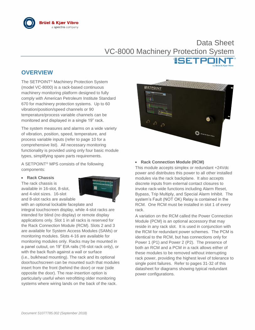
Data Sheet VC-8000 Machinery Protection System Document S1077785.002 (September 2018) OVERVIEW The SETPOINT ® Machinery Protection System (model VC-8000) is a rack-based continuous machinery monitoring platform designed to fully comply with American Petroleum Institute Standard 670 for machinery protection systems. Up to 60 vibration/position/speed channels or 90 temperature/process variable channels can be monitored and displayed in a single 19” rack. The system measures and alarms on a wide variety of vibration, position, speed, temperature, and process variable inputs (refer to page 10 for a comprehensive list). All necessary monitoring functionality is provided using only four basic module types, simplifying spare parts requirements. A SETPOINT ® MPS consists of the following components: Rack Chassis The rack chassis is available in 16-slot, 8-slot, and 4-slot sizes. 16-slot and 8-slot racks are available with an optional lockable faceplate and integral touchscreen display, while 4-slot racks are intended for blind (no display) or remote display applications only. Slot 1 in all racks is reserved for the Rack Connection Module (RCM). Slots 2 and 3 are available for System Access Modules (SAMs) or monitoring modules. Slots 4-16 are available for monitoring modules only. Racks may be mounted in a panel cutout, on 19” EIA rails (16-slot rack only), or with the back flush against a wall or surface (i.e., bulkhead mounting). The rack and its optional door/touchscreen can be mounted such that modules insert from the front (behind the door) or rear (side opposite the door). The rear-insertion option is particularly useful when retrofitting older monitoring systems where wiring lands on the back of the rack. Rack Connection Module (RCM) This module accepts simplex or redundant +24Vdc power and distributes this power to all other installed modules via the rack backplane. It also accepts discrete inputs from external contact closures to invoke rack-wide functions including Alarm Reset, Bypass, Trip Multiply, and Special Alarm Inhibit. The system’s Fault (NOT OK) Relay is contained in the RCM. One RCM must be installed in slot 1 of every rack. A variation on the RCM called the Power Connection Module (PCM) is an optional accessory that may reside in any rack slot. It is used in conjunction with the RCM for redundant power schemes. The PCM is identical to the RCM, but has connections only for Power 1 (P1) and Power 2 (P2). The presence of both an RCM and a PCM in a rack allows either of these modules to be removed without interrupting rack power, providing the highest level of tolerance to single point failures. Refer to pages 31-32 of this datasheet for diagrams showing typical redundant power configurations.
-
Upload
khangminh22 -
Category
Documents
-
view
6 -
download
0
Transcript of Data Sheet VC-8000 Machinery Protection System
Data Sheet VC-8000 Machinery Protection System
Document S1077785.002 (September 2018)
OVERVIEW
The SETPOINT® Machinery Protection System
(model VC-8000) is a rack-based continuous
machinery monitoring platform designed to fully
comply with American Petroleum Institute Standard
670 for machinery protection systems. Up to 60
vibration/position/speed channels or 90
temperature/process variable channels can be
monitored and displayed in a single 19” rack.
The system measures and alarms on a wide variety
of vibration, position, speed, temperature, and
process variable inputs (refer to page 10 for a
comprehensive list). All necessary monitoring
functionality is provided using only four basic module
types, simplifying spare parts requirements.
A SETPOINT® MPS consists of the following
components:
Rack Chassis
The rack chassis is
available in 16-slot, 8-slot,
and 4-slot sizes. 16-slot
and 8-slot racks are available
with an optional lockable faceplate and
integral touchscreen display, while 4-slot racks are
intended for blind (no display) or remote display
applications only. Slot 1 in all racks is reserved for
the Rack Connection Module (RCM). Slots 2 and 3
are available for System Access Modules (SAMs) or
monitoring modules. Slots 4-16 are available for
monitoring modules only. Racks may be mounted in
a panel cutout, on 19” EIA rails (16-slot rack only), or
with the back flush against a wall or surface
(i.e., bulkhead mounting). The rack and its optional
door/touchscreen can be mounted such that modules
insert from the front (behind the door) or rear (side
opposite the door). The rear-insertion option is
particularly useful when retrofitting older monitoring
systems where wiring lands on the back of the rack.
Rack Connection Module (RCM)
This module accepts simplex or redundant +24Vdc
power and distributes this power to all other installed
modules via the rack backplane. It also accepts
discrete inputs from external contact closures to
invoke rack-wide functions including Alarm Reset,
Bypass, Trip Multiply, and Special Alarm Inhibit. The
system’s Fault (NOT OK) Relay is contained in the
RCM. One RCM must be installed in slot 1 of every
rack.
A variation on the RCM called the Power Connection
Module (PCM) is an optional accessory that may
reside in any rack slot. It is used in conjunction with
the RCM for redundant power schemes. The PCM is
identical to the RCM, but has connections only for
Power 1 (P1) and Power 2 (P2). The presence of
both an RCM and a PCM in a rack allows either of
these modules to be removed without interrupting
rack power, providing the highest level of tolerance to
single point failures. Refer to pages 31-32 of this
datasheet for diagrams showing typical redundant
power configurations.

Data Sheet VC-8000 Machinery Protection System
EN
Document S1077785.002 (November 2018) Page 2 of 37
System Access Module (SAM)
This module provides four separate
communications ports:
DCS This 10/100 BASE-T Ethernet
port uses MODBUS® TCP/IP
protocol for connecting a SETPOINT®
system to a distributed control system (DCS) or other type of plant/machinery control or automation platform. This port supports static data only.
DCS SER
Identical to the DCS port, this additional
port supports MODBUS® RTU (serial)
communications using RS-232, RS-422, and RS-485.
CMS This 10/100/1000 BASE-T Ethernet port
streams data to SETPOINT® CMS
condition monitoring software. It supports both static and dynamic (waveform) data.
Display This LVDS port is used when interfacing to the optional 8.4” color touchscreen.
Although the SAM is not part of the critical path for
machinery protection, it is strongly recommended
that all racks include at least one SAM (slot 2); an
optional second SAM may be added in slot 3 when
communication redundancy is required. Racks
without a SAM may place a TMM or UMM in slot 2 to
increase the total number of monitored channels.
When the SAM’s SD Card slot and solid-state hard
drive flight recorder are enabled for data storage, the
same data as streamed from the CMS port can be
retained in the rack for up to one full year.
Universal Monitoring Module (UMM)
This 4-channel module provides all
available measurements except
temperature. Four programmable SPDT
relays and four programmable 4-20 mA
analog outputs are provided on each UMM.
The module accepts a large variety of
proximity, velocity, acceleration, pressure,
process variable1, position, and discrete
input signals. Two versions of the UMM are
available: UMM and UMMCM. The UMMCM is
identical to the UMM, but allows streaming of
condition monitoring data to the CMS port on the
rack’s System Access Module (SAM).
Up to 15 UMMs may be installed in a single rack2
(slots 2-16); they may be mixed in any combination
with TMMs. Up to six3 (6) shared phase triggers may
be installed in a single SETPOINT® rack for use by
all other rack channels.
Temperature Monitoring Module (TMM)
This 6-channel module provides
configurable temperature and process
variable measurements along with four
programmable SPDT relays and six
programmable 4-20 mA analog outputs. It
accepts 2-, 3- and 4-wire RTDs, grounded
/ ungrounded thermocouples, and 4-20 mA
process variable signals1 in any
combination. Two versions of the TMM are
available: TMM and TMMCM.
The TMMCM is identical to the TMM, but
allows streaming of condition monitoring data to the
CMS port on the rack’s System Access Module
(SAM). Up to 15 TMMs may be installed in a single
rack (slots 2-16); they may be mixed in any
combination with UMMs.
Rack Configuration Software
This software allows
configuration of all modules
in a rack by connecting to the
USB port on any UMM or
TMM. A copy of this software
is provided with each system
free-of-charge. It can also
be downloaded from our website.
NOTES:
1. TMMs accept only 4-20mA signal formats and do not
provide loop power; UMMs accept a wider variety of process
variable formats and also provide loop power.
2. A UMM in slot 2 is not able to supply its buffered output
signals to the RCM connector or to programmable BNC
connectors used with the touchscreen display. The RJ45
connector on the UMM front panel must be used instead.
3. Shared phase triggers available only on UMM channel
4, slots 4-9. 8-slot rack limited to 5 shared phase triggers;
4-slot rack limited to 1 shared phase trigger.
Data Sheet VC-8000 Machinery Protection System
EN
Document S1077785.002 (November 2018) Page 3 of 37
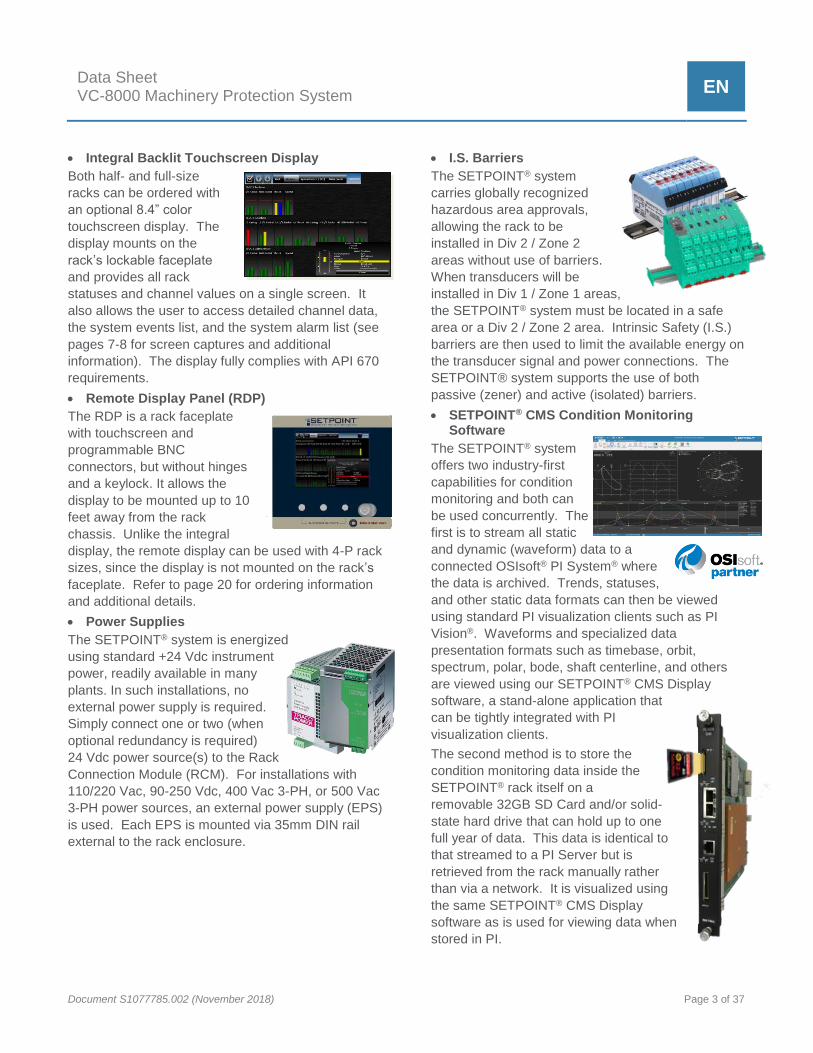
Integral Backlit Touchscreen Display
Both half- and full-size
racks can be ordered with
an optional 8.4” color
touchscreen display. The
display mounts on the
rack’s lockable faceplate
and provides all rack
statuses and channel values on a single screen. It
also allows the user to access detailed channel data,
the system events list, and the system alarm list (see
pages 7-8 for screen captures and additional
information). The display fully complies with API 670
requirements.
Remote Display Panel (RDP)
The RDP is a rack faceplate
with touchscreen and
programmable BNC
connectors, but without hinges
and a keylock. It allows the
display to be mounted up to 10
feet away from the rack
chassis. Unlike the integral
display, the remote display can be used with 4-P rack
sizes, since the display is not mounted on the rack’s
faceplate. Refer to page 20 for ordering information
and additional details.
Power Supplies
The SETPOINT® system is energized
using standard +24 Vdc instrument
power, readily available in many
plants. In such installations, no
external power supply is required.
Simply connect one or two (when
optional redundancy is required)
24 Vdc power source(s) to the Rack
Connection Module (RCM). For installations with
110/220 Vac, 90-250 Vdc, 400 Vac 3-PH, or 500 Vac
3-PH power sources, an external power supply (EPS)
is used. Each EPS is mounted via 35mm DIN rail
external to the rack enclosure.
I.S. Barriers
The SETPOINT® system
carries globally recognized
hazardous area approvals,
allowing the rack to be
installed in Div 2 / Zone 2
areas without use of barriers.
When transducers will be
installed in Div 1 / Zone 1 areas,
the SETPOINT® system must be located in a safe
area or a Div 2 / Zone 2 area. Intrinsic Safety (I.S.)
barriers are then used to limit the available energy on
the transducer signal and power connections. The
SETPOINT® system supports the use of both
passive (zener) and active (isolated) barriers.
SETPOINT® CMS Condition Monitoring Software
The SETPOINT® system
offers two industry-first
capabilities for condition
monitoring and both can
be used concurrently. The
first is to stream all static
and dynamic (waveform) data to a
connected OSIsoft® PI System® where
the data is archived. Trends, statuses,
and other static data formats can then be viewed
using standard PI visualization clients such as PI
Vision®. Waveforms and specialized data
presentation formats such as timebase, orbit,
spectrum, polar, bode, shaft centerline, and others
are viewed using our SETPOINT® CMS Display
software, a stand-alone application that
can be tightly integrated with PI
visualization clients.
The second method is to store the
condition monitoring data inside the
SETPOINT® rack itself on a
removable 32GB SD Card and/or solid-
state hard drive that can hold up to one
full year of data. This data is identical to
that streamed to a PI Server but is
retrieved from the rack manually rather
than via a network. It is visualized using
the same SETPOINT® CMS Display
software as is used for viewing data when
stored in PI.

Data Sheet VC-8000 Machinery Protection System
EN
Document S1077785.002 (November 2018) Page 4 of 37
Features and Benefits
Integrated Condition Monitoring
Condition monitoring data can be streamed to
optional SETPOINT® CMS software and/or to internal
storage in the rack, eliminating the need for
networks, servers, and IT infrastructure. Using an
embedded solid-state hard drive or removable 32GB
SD card, up to one full year of high-resolution data
can be stored. This powerful capability turns a
machinery protection system into a “flight data
recorder” that ensure you will never again miss
important data when a machine experiences
problems.
Deep experience
The SETPOINT® team possesses deep experience
gained through developing and sustaining more than
four generations of successive API 670-compliant
machinery protection systems. We pay attention to
every detail, ensuring the system works the way you
need it to work in the real world – where details
matter.
SIL-Capable Architecture
SETPOINT® is suitable for use as part of a SIS, to
implement safety instrumented functions up to SIL 2
when configured, installed and commissioned
properly as per instructions provided within the
Operations and Maintenance Manual (doc 1079330)
and the Safety Manual (doc S000015001).
IEC 62443 eSTS Cyber Security Certification
The SETPOINT® SAM module has attained IEC
62443 Part 4-1, Section 9 eSTS Level 1 certification
providing asssurance that critical protection
functionality will be intact no matter what traffic is
bombarding your network.
Robust, rugged construction
The SETPOINT® rack chassis is constructed entirely
of industrial-grade anodized aluminum and stainless
steel – every card guide, every faceplate, every rack
panel. In addition to excellent RFI/EMI rejection,
these materials are built to last while maintaining
their good looks. The SETPOINT® system looks
professional because it is professional.
Easily adaptable mounting
The SETPOINT® system’s design allows the same
rack to be used in panel cutout, 19” EIA, or bulkhead
mounting configurations by simply employing
different rack brackets. The chassis, backplane, and
all modules remain the same. This also means that
you don’t sacrifice valuable space when bulkhead
mounting – unlike systems that require twice as
much space for bulkhead mounting compared to rack
or panel mounting.
High-quality, high-speed backplane
The SETPOINT® system uses state-of-the-art
backplane connectors and a high-speed network
architecture to facilitate ultra-fast data throughput and
outstanding reliability.
Flexible front or back wiring
The SETPOINT® rack’s flexible design allows the
chassis to face forward or backward. When facing
forward, modules insert from the front and wiring
lands on the front. When facing backward, modules
insert from the back and wiring lands on the back. In
either orientation, the optional touchscreen display
can be mounted in a location convenient for the user,
whether directly on the chassis, or up to 10 feet (3m)
away. Front wiring is recommended for most
installations and is the default configuration for all
racks. It eliminates back-and-forth trips around the
panel to access each side of the rack during
installation and maintenance. Front loading neatly
recesses all connections behind the SETPOINT®
system’s attractive, lockable faceplate, protecting
your critical wiring while keeping it easily accessible.
Full-color, backlit touchscreen
With the SETPOINT® system’s optional touchscreen,
users have at-a-glance, real time visibility of every
channel and status in the rack on a single screen –
no scrolling, no multiplexing. We worked closely with
users to ensure the system’s display was intuitive,
efficient, and attractive, with a rapid update time so
there’s no annoying wait for the screen to refresh
with current values. It’s also easy to see under
varied lighting conditions. And, because it uses
resistive (not capacitive) technology, it works with
fingers, gloves, and stylus.
Lockable front faceplate
Whether with or without the optional touchscreen
display, every SETPOINT® rack can be ordered with
a lockable faceplate. It protects all installed wiring
from tampering and provides physical security,
preventing unauthorized personnel from accessing
configuration and data ports.

Data Sheet VC-8000 Machinery Protection System
EN
Document S1077785.002 (November 2018) Page 5 of 37
High-density design
Systems that use separate modules for display
drivers, relays, phase triggers, power supplies, and
Modbus communications can mean that only 40% of
the rack’s slots are actually available for vibration and
temperature monitoring. In contrast, the SETPOINT®
system requires only two slots for system power and
communications (including display) – all other slots
are available for monitoring. Up to 60 vibration
channels in a full-size 19” rack and up to 28 vibration
channels in a half-size rack. No other system offers
such efficient use of space.
No jumpers or DIP switches
Every option in the SETPOINT® system is configured
via software. Cards do not have to be removed from
the rack.
Hot swappable
Modules can be inserted and removed without
powering down the rack.
Flexible buffered output options
The SETPOINT® system delivers buffered transducer
outputs at 3 different locations in the rack: at an RJ45
receptacle on each UMM where all 4 channels are
available concurrently; at a 60-pin connector set on
the RCM where 56 UMM channels are available
concurrently; and, at 3 programmable BNC
connectors on the front panel. By simply using the
touchscreen, you can select 2 vibration channels and
their associated phase trigger, easily switching
channels without ever needing to move cables from
one set of BNC connectors to the next. Imagine
gathering 56 channels of dynamic data with your data
collector without constantly disconnecting and
reconnecting. And, we’ve taken the ambiguity out of
these connections. When you select a channel via
the touchscreen, it displays all details – channel tag
and description, mV output in engineering units, and
everything else necessary to ensure that your data
collector inputs match the monitor system outputs.
Outstanding EMI/RFI performance
Solid metal construction, EMI gaskets, state-of-the-
art filtering, and international EMI/ RFI approvals
mean that the SETPOINT® system operates trouble-
free in even the noisiest electromagnetic
environments. CE mark is standard on all systems.
Clear, intuitive labeling
Easily identify status LEDs and connections; wiring
labels are provided on each module’s faceplate and
its removable connectors.
Programmable 4-20 mA outputs
Each monitor module provides the same number of
4-20 mA outputs as channels. However, these
outputs can be assigned to any channel in the
module, and any measurement. For example, a 4-
channel monitor can assign its direct measurement
from each channel to a corresponding 4-20 mA
output. Or, it can assign a channel’s direct
measurement to analog output 1, its 1X amplitude to
analog output 2, its 1X phase to analog output 3, and
its gap voltage to analog output 4. There are no
restrictions as to measurement type or channel,
provided the value originates on the same module as
the 4-20mA output.
Up to 60 SPDT electro-mechanical relays
With 15 available slots and 4 relays in every monitor
module, separate relay modules are not required,
allowing more efficient use of rack space. Relay
voting logic and channel assignments are fully
programmable, allowing channels and conditions on
one card to drive relays on its own or separate cards.
Standard +24 Vdc instrument power
Because standard +24 Vdc instrument power is
readily available in many plants, the SETPOINT®
system accepts this voltage directly. Simply connect
24 volt power to the RCM on each rack. When 24V
power is not readily available, a wide variety of
external supplies are available to accept 110/220
Vac, 90-350 Vdc, and even 400/500 Vac 3-phase
power. And because all power sources are located
outside the rack, heat dissipation is kept outside the
rack as well, resulting in a system that runs cooler
and can use smaller enclosures.

Data Sheet VC-8000 Machinery Protection System
EN
Document S1077785.002 (November 2018) Page 6 of 37
Truly redundant supplies
The SETPOINT® rack accepts two independent
24 volt power sources and can be supplied with one
or two rack modules that each accept redundant
power, for both power redundancy and module
redundancy. Via the backplane, both 24V power
sources are available to each and every module in
the rack. The module in each slot individually
determines the best available source. As soon as
one source is removed (or its voltage drops below
the other), all modules seamlessly switch to the
alternate source assuring uninterrupted system
operation.
Distributed power regulation
Unlike systems that centrally regulate or condition
incoming power and then distribute every voltage
needed, each monitor in the SETPOINT® system
runs on 24 Vdc and creates its own regulated
voltages. This design philosophy reduces the
potential for rack single-point failures compared to
systems that generate all regulated voltages
centrally. In the SETPOINT® system, regulator
problems affect only a single module, not the entire
rack.
Simplified spare parts
Only four basic module types are used, regardless of
transducer input types, output types, or system
options. The Universal Monitoring Module performs
all measurements except temperature, dramatically
reducing spare parts requirements and associated
costs.
Spreadsheet-like configuration environment
SETPOINT® software provides unparalleled ease of
configuration – easily cut and paste data to/from
Microsoft® Excel® and most other programs. No
manual reentry of data from project datasheets and
documents is required, reducing the likelihood of
transcription errors and eliminating tedious typing to
duplicate information that already exists electronically
elsewhere.
Highly reliable architecture
Monitor modules in the SETPOINT® system use just
three transitional connectors from signal input to
relay output – significantly reducing possible failure
points in the critical machinery protection path.
Integration with OSIsoft’s PI System® software
Our partnership with OSIsoft provides native
connectivity between the SETPOINT® system and
the PI System®. Full data trending, archiving,
display, and analysis capabilities are available from
data stored in the PI database. Use PI
ProcessBook® to view basic system data such as
trends and statuses; use SETPOINT® CMS (which
can be launched directly from PI ProcessBook®) to
view waveform data using a host of plot types such
as orbit, spectrum, bode, shaft centerline, timebase,
and more.
Digital MODBUS® communications
Provides connectivity to virtually all machinery and
process control system using this industry-standard
protocol. Can be used in lieu of (or simultaneously
with) analog 4-20 mA outputs on monitor modules for
flexibility when integrating with other instrumentation.
Optional MODBUS® redundancy
Up to two SAM cards can reside in a single
SETPOINT® rack for redundant MODBUS®
communications links with distributed, plant, and
machinery control systems.
Highly Flexible Rack Control
The UMM discrete channel type can be used not only
to accept and display discrete on/off type signals, but
to control rack states such as trip multiply, bypass,
inhibit, etc. When invoked from the wiring terminals
on the RCM, these control states are applied rack
wide. When invoked using UMM discrete input
channels, these states can be individually applied to
user-configurable groups, facilitating better control
when multiple machine trains are combined in a rack,
each with its own unique trip multiply, bypass, inhibit,
and other control needs.
No separate I/O modules required
Module functions and I/O are contained on the same
card.

Data Sheet VC-8000 Machinery Protection System
EN
Document S1077785.002 (November 2018) Page 7 of 37
Typical Screens
Machine-at-a-Glance Screen Shows all channels in the rack (up to 84), arranged into user-configurable groups – typically trains, cases, and bearings. Bargraphs are color-coded to show alarm condition and normalized to % of danger SETPOINT® for ease of comparison. Tap on any bargraph to obtain an inset screen showing additional channel detail. Selected bargraph turns blue for easy identification. Details window can be moved and pinned anywhere on screen.
Expanded Channel Details Screen Is available by tapping on the detail inset screen. This expands to a full-screen view showing all measurements associated with the channel and their corresponding alarm setpoints. Most channel types can be configured to return multiple measurements such as overall amplitude, filtered amplitude in a variety of user- configurable bandpass regions, and sensor gap/bias voltage.
Rack-at-a-Glance Screen Is similar to machine-at-a-glance, but arranged by slot/ channel to correspond with the physical configuration of the rack’s slot and channel assignments. This view is especially useful for Instrument & Control personnel that need to work with the rack based on physical slot and channel assignments. This screen also shows the status of each relay in addition to the status of each channel. Tapping on a relay or bargraph opens a detail inset window.

Data Sheet VC-8000 Machinery Protection System
EN
Document S1077785.002 (November 2018) Page 8 of 37
Tabular Bargraph Screen Provides easy-to-see text values with current readings for each channel, along with color coding for alarm state. This view is particularly useful when the SETPOINT® rack is located inside a weatherproof enclosure or behind a glass viewing door, allowing the primary (direct) values for all channels to be displayed without opening the enclosure / door to interact with the touchscreen.
System Events Screen Arranges all system events in an intuitive spreadsheet-like fashion. Severity is clearly indicated by color-coded icons, and unacknowledged events are highlighted in bold. Users can sort the list by simply tapping on the column header. To scroll, use the up/down arrow icons on the top menu bar. To acknowledge events and alarms, tap the checkbox icon at the top of the screen.
Alarm Events Screen Is similar to System Events Screen, but arranges all alarm events instead. Severity is clearly indicated by color-coded icons, and unacknowledged alarms are highlighted in bold. Users can sort the list by simply tapping on the column header. To scroll, use the up/down arrow icons on the top menu bar. To acknowledge events and alarms, tap the checkbox icon at the top of the screen.
Data Sheet VC-8000 Machinery Protection System
EN
Document S1077785.002 (November 2018) Page 9 of 37
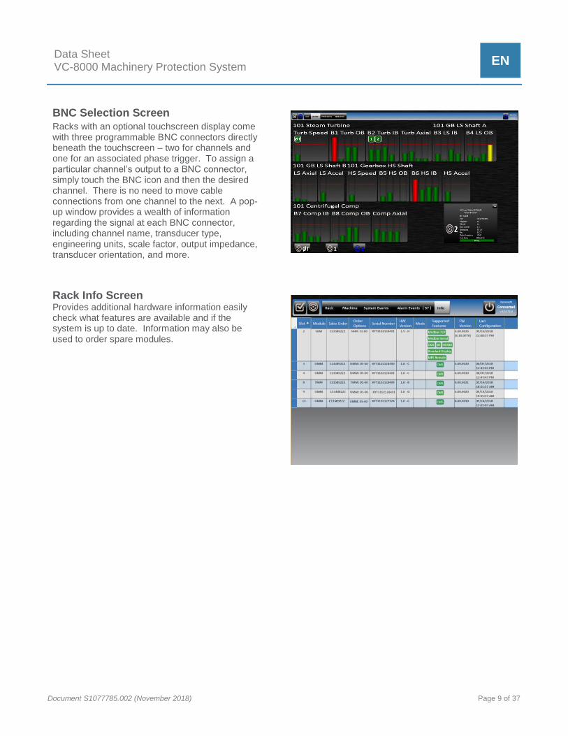
BNC Selection Screen Racks with an optional touchscreen display come with three programmable BNC connectors directly beneath the touchscreen – two for channels and one for an associated phase trigger. To assign a particular channel’s output to a BNC connector, simply touch the BNC icon and then the desired channel. There is no need to move cable connections from one channel to the next. A pop-up window provides a wealth of information regarding the signal at each BNC connector, including channel name, transducer type, engineering units, scale factor, output impedance, transducer orientation, and more.
Rack Info Screen Provides additional hardware information easily check what features are available and if the system is up to date. Information may also be used to order spare modules.
Data Sheet VC-8000 Machinery Protection System
EN
Document S1077785.002 (November 2018) Page 10 of 37
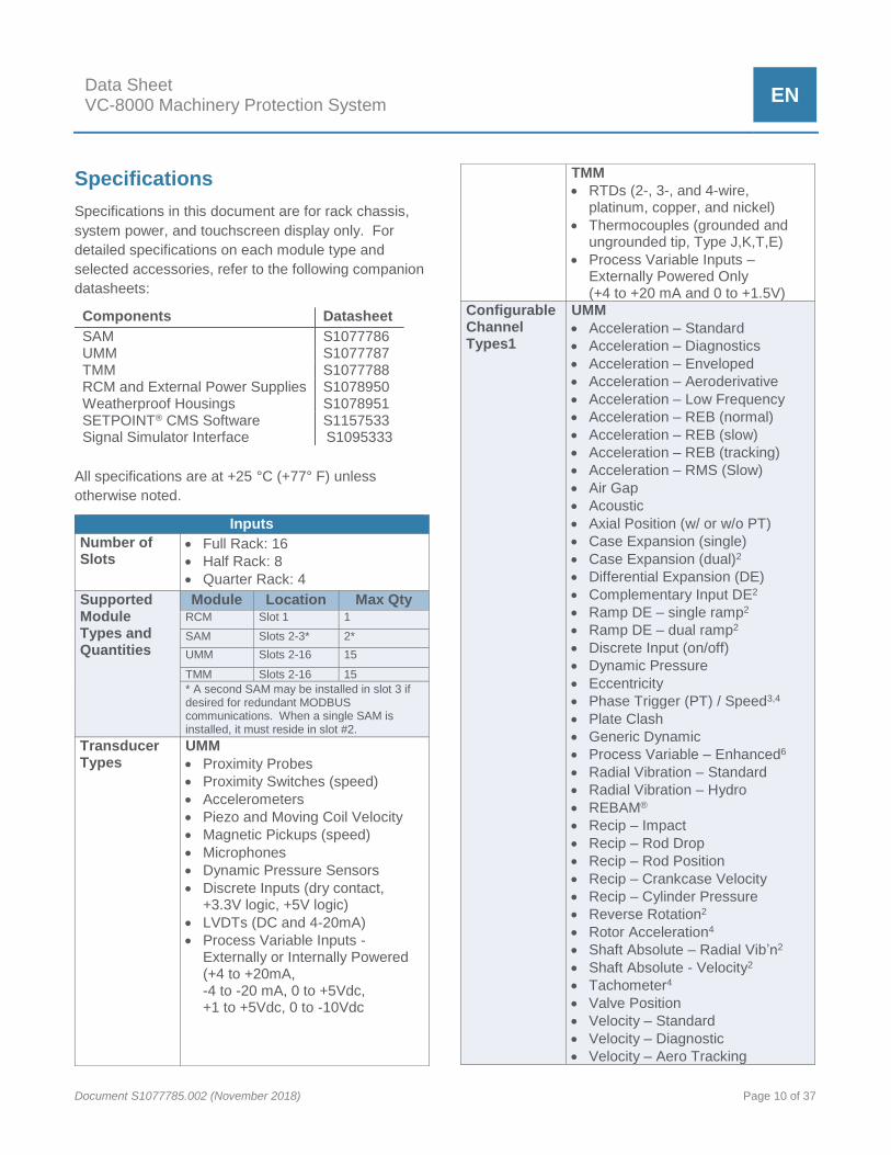
Specifications
Specifications in this document are for rack chassis,
system power, and touchscreen display only. For
detailed specifications on each module type and
selected accessories, refer to the following companion
datasheets:
Components Datasheet
SAM S1077786 UMM S1077787 TMM S1077788 RCM and External Power Supplies S1078950 Weatherproof Housings S1078951 SETPOINT® CMS Software Signal Simulator Interface
S1157533 S1095333
All specifications are at +25 °C (+77° F) unless
otherwise noted.
Inputs
Number of Slots
Full Rack: 16
Half Rack: 8
Quarter Rack: 4
Supported Module Types and Quantities
Module Location Max Qty RCM Slot 1 1
SAM Slots 2-3* 2*
UMM Slots 2-16 15
TMM Slots 2-16 15
* A second SAM may be installed in slot 3 if desired for redundant MODBUS communications. When a single SAM is installed, it must reside in slot #2.
Transducer Types
UMM
Proximity Probes
Proximity Switches (speed)
Accelerometers
Piezo and Moving Coil Velocity
Magnetic Pickups (speed)
Microphones
Dynamic Pressure Sensors
Discrete Inputs (dry contact, +3.3V logic, +5V logic)
LVDTs (DC and 4-20mA)
Process Variable Inputs - Externally or Internally Powered (+4 to +20mA, -4 to -20 mA, 0 to +5Vdc, +1 to +5Vdc, 0 to -10Vdc
TMM
RTDs (2-, 3-, and 4-wire, platinum, copper, and nickel)
Thermocouples (grounded and ungrounded tip, Type J,K,T,E)
Process Variable Inputs – Externally Powered Only (+4 to +20 mA and 0 to +1.5V)
Configurable Channel Types1
UMM
Acceleration – Standard
Acceleration – Diagnostics
Acceleration – Enveloped
Acceleration – Aeroderivative
Acceleration – Low Frequency
Acceleration – REB (normal)
Acceleration – REB (slow)
Acceleration – REB (tracking)
Acceleration – RMS (Slow)
Air Gap
Acoustic
Axial Position (w/ or w/o PT)
Case Expansion (single)
Case Expansion (dual)2
Differential Expansion (DE)
Complementary Input DE2
Ramp DE – single ramp2
Ramp DE – dual ramp2
Discrete Input (on/off)
Dynamic Pressure
Eccentricity
Phase Trigger (PT) / Speed3,4
Plate Clash
Generic Dynamic
Process Variable – Enhanced6
Radial Vibration – Standard
Radial Vibration – Hydro
REBAM®
Recip – Impact
Recip – Rod Drop
Recip – Rod Position
Recip – Crankcase Velocity
Recip – Cylinder Pressure
Reverse Rotation2
Rotor Acceleration4
Shaft Absolute – Radial Vib’n2
Shaft Absolute - Velocity2
Tachometer4
Valve Position
Velocity – Standard
Velocity – Diagnostic
Velocity – Aero Tracking

Data Sheet VC-8000 Machinery Protection System
EN
Document S1077785.002 (November 2018) Page 11 of 37
Velocity – Aero Bandpass
Velocity – Hydro
Velocity – Low Frequency
Zero Speed2 TMM
Temperature5
Process Variable – Basic6 NOTES:
1. Refer to datasheet 1077787 for details on
measurements returned for each UMM
channel type; refer to datasheet 1077788
for details on measurements returned for
each TMM channel type.
2. Measurement requires two channels.
3. Shared phase triggers available only on
UMM channel 4, slots 4-9. 8-slot rack
limited to 5 shared phase triggers; 4-slot
rack is limited to 1 shared phase trigger.
4. Phase trigger channels return shaft
rotative speed, peak speed, and rotor
acceleration (speed rate of change).
5. Temperature channels can return direct
temperature, group average temperature,
and/or differential with other channel or
group. Refer to datasheet 1077788 for
additional details.
6. Enhanced process variable channels can
provide loop power for the transmitter and
can accept a variety of dc voltages or
currents. Basic process variable channels
accept only 4-20mA or 0-1.5V, require
external loop power, and require a special
external shunt termination resistor for 4-
20mA inputs. Refer to datasheets
1077787 and 1077788 for additional
details.
Discrete Rack Control
Four connections supporting dry contact, 3.3V, or 5V logic are available via the RCM:
Alarm Reset (Acknowledge)*
Inhibit (Bypass)
Trip Multiply
Special Alarm Inhibit These can be invoked remotely by wiring suitable for analog control signals. Refer to RCM datasheet 1078950 for details.
* NOTE: The Alarm Reset
(Acknowledge) function is also
available as a local pushbutton on
the RCM faceplate.
Number of
Power
Supplies
Accepts up to two +24 Vdc independent power sources
Allowable Wiring Sizes
Connector AWG
Power 12 – 22
Rack Control 14 – 28
Fault (OK) Relay 12 – 24
Alarm Relays 16 – 28
Analog Outputs 20 – 24
Signal Inputs 16 – 28 Connectors Removable, with positive retention Reverse Polarity Protection
Power inputs protected from continuous input polarity reversal.
Input Voltage Nominal: +24 Vdc
Continuous: + 22 to +30 Vdc
Transient (< 1 sec): +18 to + 36 Vdc
Ripple < 100mV pk to pk
Power Consumption
≤ 160W, <8A when input power
voltage is 22 to 26 Vdc.
NOTE: Assumes fully loaded 16-
position rack with display, redundant
SAMs, all relays energized, all
4-20 mA outputs at full scale, and
maximum transducer power
requirements.
Power Input Fuse Rating
10 A
Ground Select
System common tied to chassis ground (external jumper* installed)
System common isolated from chassis ground** (external jumper* removed)
*Jumper is accessible from the front of the rack and may be installed on either the P1 or P2 removable wiring connectors on the RCM.
** This configuration is commonly used for systems with IS barriers where a separate IS ground must be established.

Data Sheet VC-8000 Machinery Protection System
EN
Document S1077785.002 (November 2018) Page 12 of 37
Alarm Reset Alarm conditions can be reset (i.e., acknowledged) in any of four ways: 1. Via the local RESET pushbutton
on the faceplate of the RCM* 2. Via remote contact closure by
shorting the RST and COM terminals together on the RCM*
3. Via the optional touchscreen display*
4. Via the MODBUS digital interface**
* Provides global (rack-wide) reset / acknowledgement of all alarms.
** Provides per-channel reset / acknowledgement of alarms.
Buffered Transducer Outputs
Front Panel
BNC
connectors
Connector Qty / Type
Three BNC (female) connectors; programmable via touchscreen:
Connector A can select from any* UMM speed / phase channel in the rack.
Connector B can select from any* UMM channel in the rack.
Connector C can select from any* UMM channel in the rack.
* Only UMM channels in slots 3-16 are available for assignment to BNC connectors.
Impedance
550 Ω
Short-Circuit Protected
Yes
Signal Type
Raw (unfiltered, no integration) transducer signal in mV/engineering units.
UMM Channels
All 4 UMM channels are available concurrently at the RJ45 connector on the UMM’s faceplate. A special RJ45-to-4-BNC cable is available as an optional accessory (p/n 100431).
Connector Type
RJ45 receptacle
Impedance
550 Ω Short-Circuit Protected
Yes
Signal Type
Raw (unfiltered, no integration) transducer signal in mV/engineering units.
RCM Channels
56 NOTE: Buffered outputs are only available
from UMM channels (not TMM channels), and only from UMMs in slots 3-16. If a UMM is located in slot 2, its buffered outputs can only be accessed via the RJ45 connector on the UMM’s face, not via the RCM connector or programmable BNC connectors.
Connector Qty / Type
Two Molex® Pico-Clasp® 30-pin receptacles, each with 28 buffered output channels. NOTE: Buffered outputs are also available on
each UMM via an RJ45 connector with all 4 channels, and on the optional rack faceplate via 3 programmable BNC-type connectors.
Impedance
550 Ω Short-Circuit Protected
Yes Signal Type
Raw (unfiltered, no integration) transducer signal in mV/engineering units.
Analog Outputs
Alarm Relays Four per monitor module. Each UMM and TMM provides four SPDT relays that can be programmed for individual channels, or for logical voting among two or more monitor channels in any rack slot.
Fault (NOT OK) Relay
One per rack, located on the RCM. Refer to RCM datasheet for additional details.
4-20 mA Programmable. One per channel for all UMM and TMM cards.
Digital Outputs
Modbus TCP/IP & RTU
10/100 BASE-T connector on SAM provides channel values, channel status conditions, and a variety of other data. Additional connector provides MODBUS via RS-232, RS-422, and RS-485. Refer to SAM datasheet for additional details.

Data Sheet VC-8000 Machinery Protection System
EN
Document S1077785.002 (November 2018) Page 13 of 37
Condition Monitoring
10/100/1000 BASE-T connector on SAM provides full static and dynamic (waveform) data using an open, published protocol. Refer to SAM datasheet for additional details.
LEDs
OK Each TMM and UMM provides an OK LED indicating that no faults or NOT OK conditions are present within the module or any channel therein.
Each SAM provides an OK LED indicating that no faults are present within the module.
Each RCM provides an OK LED indicating rack-wide status; when lit, no faults or NOT OK conditions exist in any module or channel.
Relays Each UMM and TMM provides 4 LEDs (one for each relay) indicating that the relay is being driven true (corresponding to the configured alarm logic for each relay)
Bypass Each UMM and TMM provides an LED indicating that one or more channels are in a BYPASS condition.
Comms Each SAM provides two LEDs for each of its Ethernet ports, indicating whether a connection is present and whether send/receive activity is occurring.
Each SAM provides a DSP (display) LED, indicating whether a touchscreen display is detected.
Each SAM provides a Trip Multiply LED, indicating whether Trip Multiply has been invoked for the entire rack or any rack channel.
Each SAM provides a OK LED to indicate if the module is OK and if SD data is being written
Power The RCM provides individual status LEDs for both Power 1 and Power 2 connections. When lit, power is detected and is within specifications.
Display
Size 8.4 inches (213 mm), measured diagonally
Resolution 800 x 600 (SVGA) Aspect Ratio 4:3
Brightness 1200 cd/m2 Backlight Rated for 70,000 hours (8 years) to
one-half brightness. Technology Active TFT Touchscreen Type
Resistive
Color 32-bit (True Color) Environment and Area Classification Rating
Div 2 / Zone 2 (same as rack and all modules). Inclusion of touchscreen display does not de-rate rack environmental or area classification specifications.
API 670 Compatible
Yes. All status conditions and channels are indicated continuously on a single screen, without scrolling or multiplexing.
Display Refresh
Channel values and statuses are updated on the display once/sec.
Max. Racks per display
A maximum of one SETPOINT® rack may be connected to each touchscreen display.
Event List Size: 1000 events
Time/Date Stamp Resolution: 40 ms*
Alarm List Size: 1000 alarms
Time/Date Stamp Resolution: 40 ms*
*NOTE: The system time stamps alarms and events to 40mS resolution; however, the touchscreen displays this value to only the nearest second. Full 40ms timestamp resolution is available via SETPOINT® CMS software (see datasheet S1157533).
Data Sheet VC-8000 Machinery Protection System
EN
Document S1077785.002 (November 2018) Page 14 of 37
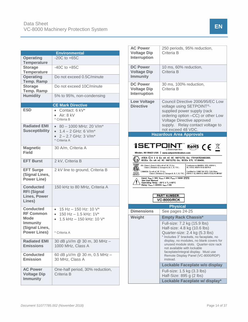
Environmental
Operating Temperature
-20C to +65C
Storage Temperature
-40C to +85C
Operating Temp. Ramp
Do not exceed 0.5C/minute
Storage Temp. Ramp
Do not exceed 10C/minute
Humidity 5% to 95%, non-condensing
CE Mark Directive
ESD Contact: 6 kV*
Air: 8 kV * Criteria B
Radiated EMI Susceptibility
80 – 1000 MHz: 20 V/m*
1.4 – 2 GHz: 6 V/m*
2 – 2.7 GHz: 3 V/m* * Criteria A
Magnetic Field
30 A/m, Criteria A
EFT Burst 2 kV, Criteria B
EFT Surge (Signal Lines, Power Line)
2 kV line to ground, Criteria B
Conducted RFI (Signal Lines, Power Lines)
150 kHz to 80 MHz, Criteria A
Conducted RF Common Mode Immunity (Signal Lines, Power Lines)
15 Hz – 150 Hz: 10 V*
150 Hz – 1.5 kHz: 1V*
1.5 kHz – 150 kHz: 10 V* * Criteria A
Radiated EMI Emissions
30 dB µV/m @ 30 m, 30 MHz – 1000 MHz, Class A
Conducted Emission
60 dB µV/m @ 30 m, 0.5 MHz – 30 MHz, Class A
AC Power Voltage Dip Immunity
One-half period, 30% reduction, Criteria B
AC Power Voltage Dip Interruption
250 periods, 95% reduction, Criteria B
DC Power Voltage Dip Immunity
10 ms, 60% reduction, Criteria B
DC Power Voltage Dip Interruption
30 ms, 100% reduction, Criteria B
Low Voltage Directive
Council Directive 2006/95/EC Low voltage using SETPOINT®-supplied power supply (rack ordering option –CC) or other Low Voltage Directive approved supply. Relay contact voltage to not exceed 48 VDC.
Hazardous Area Approvals
Physical
Dimensions See pages 24-25
Weight Empty Rack Chassis*
Full-size: 7.2 kg (15.9 lbs) Half-size: 4.8 kg (10.6 lbs) Quarter-size: 2.4 kg (5.3 lbs) * Includes 3” brackets, no faceplate, no
display, no modules, no blank covers for unused module slots. Quarter-size rack not available with lockable faceplate/integral display. Must use Remote Display Panel (VC-8000/RDP) instead.
Lockable Faceplate w/o display
Full-size: 1.5 kg (3.3 lbs) Half-Size: 895 g (2 lbs)
Lockable Faceplate w/ display*

Data Sheet VC-8000 Machinery Protection System
EN
Document S1077785.002 (November 2018) Page 15 of 37
Full-size: 2.1 kg (4.7 lbs) Half-size: 1.5 kg (3.3 lbs) *Also reflects weight of Remote Display Panel (RDP).
Recessed mounting bracket
190 g (6.5 oz)
Flush mounting bracket*
80 g (3 oz) * Used for bulkhead and flush mounting.
Blank Slot Cover Plate
48 g (1.7 oz)
Shock IEC 68-2-27, Ea
15 g for 11 ms
Vibration IEC 68-2-6 10 – 55 Hz, 0.75 mm 55 - 500 Hz, 2 g
Safety Integrity Level (SIL) Capability* SETPOINT® is suitable for use as part of a SIS, to implement safety instrumented functions up to SIL 2 when configured, installed and commissioned properly as per instructions provided within the Operations and Maintenance Manual (doc S1079330) and the Safety Manual (doc S000015001). *Certification expected December 2018, hardware availability in Q2 2019.
Power Consumption RCM 1.2 W bSAM 13 W eSAM, no Display
13.9 W
eSAM with Display
19 W
UMM4 5.5 W TMM 5 W 480W 400/500 VAC Power Supply
12 W
360W 110/220 VAC Power Supply
21 W
240W 90-250 VDC Power Supply
21 W
180W 110/220 VAC Power Supply
11 W
120W 90-250 VDC Power Supply
11 W
90W 110/220 VAC Power Supply
6.2 W

Data Sheet VC-8000 Machinery Protection System
EN
Document S1077785.002 (November 2018) Page 16 of 37
Ordering Information
SETPOINT® Monitoring System
Use the part number on pages 17-18 when ordering a
complete SETPOINT® system with all modules pre-
installed in the correct rack slots. The part number
and all dash numbers (AA-VV) will uniquely specify all
system details including rack size, mounting type,
module type for each slot, optional simplex or dual-
redundant external power supplies, optional lockable
faceplate, and optional touchscreen display.
When using a Remote Display Panel (RDP), the rack
may be ordered with or without a door, but no display.
The rack must also contain an eSAM to drive the
display. Specify the RDP as a separate line item,
using the ordering information on page 20.
Weatherproof housings are available separately.
Refer to datasheet S1078951.
When spare modules are required, refer to page 23,
(or the module-specific datasheet) for ordering
information.
When a PCM will be installed in the rack in addition to
the RCM in slot 1, the PCM must be ordered
separately per the information on page 19. It can be
installed in any empty rack slot 2-16.
CAUTION
Monitor system modules are shipped with default factory configuration settings which are not necessarily suitable for any particular application. Before use, each module and channel must be configured properly for its application via SETPOINT® configuration software. This software is included at no cost with each system or module ordered and is also available for download from our website.
!

Data Sheet VC-8000 Machinery Protection System
EN
Document S1077785.002 (November 2018) Page 17 of 37
VC-8000/RCK-AA-BB-CC-DD-EE-FF-GG-HH-JJ-KK-LL-MM-NN-PP-RR-SS-TT-UU-VV1
SETPOINT® Machinery Protection System
AA Mounting Style
0 1 Panel Cutout, modules insert from front
0 2 Bulkhead, modules insert from front
0 3 19" EIA, modules insert from front
1 1 Panel Cutout, modules insert from rear
1 3 19" EIA, modules insert from rear
BB Slots / Faceplate / Display2
0 1 8-slot, no faceplate, no display
0 2 16-slot, no faceplate, no display
0 3 8-slot, with faceplate, no display
0 4 16-slot, with faceplate, no display
0 5 8-slot, with faceplate and display3
0 6 16-slot, with faceplate and display3
1 1 4-slot, no faceplate, no display
CC Power3,4,5,6
0 0 +24 Vdc (no external supplies)
0 1 One 110/220Vac 50/60Hz supply, 360W
0 2 Two 110/220Vac 50/60Hz supplies, 360W
0 3 One 360-440 Vac (3φ) supply, 480W
0 4 Two 360-440 Vac (3φ) supplies, 480W
0 5 One 410-550 Vac (3φ) supply, 480W
0 6 Two 410-550 Vac (3φ) supplies, 480W
0 7 One 90-250 Vdc & 110/220 Vac supply, 240W
0 8 Two 90-250 Vdc & 110/220 Vac supply, 240W
0 9 One 110/220Vac 50/60Hz supply, 180W
1 0 Two 110/220Vac 50/60Hz supplies, 180W
1 1 One 110/220Vac 50/60Hz supply, 90W
1 2 Two 110/220Vac 50/60Hz supplies, 90W
1 3 One 90-250 Vdc & 110/220 Vac supply, 120W
1 4 Two 90-250 Vdc & 110/220 Vac supply, 120W
DD Approvals
0 0 None
0 5 Multi (ATEX, IEC, ETLc)
0 6 SIL7
0 7 SIL7 & Multi (ATEX, IEC, ETLc)
0 8 IEC 62443 Certification
0 9 IEC 62443 Cert & Multi (ATEX, IEC, ETLc)
X X Country-specific8
EE Slots 1 and 2
0 0 RCM slot 1, no module slot 2
0 1 RCM slot 1, Basic SAM (bSAM) slot 2
0 2 RCM slot 1, Enhanced SAM (eSAM) slot 29
0 3 RCM slot 1, UMM slot 2
0 4 RCM slot 1, TMM slot 2
0 7 RCM slot 1, eSAM slot 2, Remote Access
3 3 RCM slot 1, eSAM slot 2, Flight Recorder+10
7 3
RCM slot 1, eSAM slot 2, Flight Recorder+10, Remote Access
FF Slot 3
0 0 No Module Installed
0 1 Basic SAM (bSAM)
0 2 Enhanced SAM (eSAM)9
0 3 UMM
0 4 TMM
0 5 UMMCM (Condition Monitoring enabled)
0 6 TMMCM (Condition Monitoring enabled)
0 7 eSAM slot 2, Remote Access
3 3 eSAM with Flight Recorder+10
7 3
RCM slot 1, eSAM slot 2, Flight Recorder+10, Remote Access
GG Slot 4
0 0 No Module Installed
0 3 UMM
0 4 TMM
0 5 UMMCM (Condition Monitoring enabled)
0 6 TMMCM (Condition Monitoring enabled)
HH Slot 5
0 0 No Module Installed
0 3 UMM
0 4 TMM
0 5 UMMCM (Condition Monitoring enabled)
0 6 TMMCM (Condition Monitoring enabled)
JJ Slot 6
0 0 No Module Installed
0 3 UMM
0 4 TMM
0 5 UMMCM (Condition Monitoring enabled)
0 6 TMMCM (Condition Monitoring enabled)
KK Slot 7
0 0 No Module Installed
0 3 UMM
0 4 TMM
0 5 UMMCM (Condition Monitoring enabled)
0 6 TMMCM (Condition Monitoring enabled)
LL Slot 8
0 0 No Module Installed
0 3 UMM
0 4 TMM
0 5 UMMCM (Condition Monitoring enabled)
0 6 TMMCM (Condition Monitoring enabled)

Data Sheet VC-8000 Machinery Protection System
EN
Document S1077785.002 (November 2018) Page 18 of 37
MM Slot 9
0 0 No Module Installed
0 3 UMM
0 4 TMM
0 5 UMMCM (Condition Monitoring enabled)
0 6 TMMCM (Condition Monitoring enabled)
NN Slot 10
0 0 No Module Installed
0 3 UMM
0 4 TMM
0 5 UMMCM (Condition Monitoring enabled)
0 6 TMMCM (Condition Monitoring enabled)
PP Slot 11
0 0 No Module Installed
0 3 UMM
0 4 TMM
0 5 UMMCM (Condition Monitoring enabled)
0 6 TMMCM (Condition Monitoring enabled)
VC-8000/RCK NOTES:
1. To prevent ambiguity, the letters I, O, and Q are not used in
SETPOINT® part numbers.
2. When a touchscreen display is installed, an Enhanced SAM
must be selected for slot 2 (EE=02).
3. When dual external power supplies are required and each will
use a different voltage, order a system with a simplex power
supply for one of the required voltages. Order the other external
supply using the part numbers on page 20 of this datasheet.
4. 360W supply is stocked standard. Other supplies may incur
longer lead times. Consult factory.
5. Refer RCM manual (S1078950) for external power supply
specifications
6. When a low-voltage (18-30Vdc) power source with a floating
ground is used, an isolator must be installed between the power
source and the RCM to isolate rack ground from power source
ground. Order part number 100549. This isolator is not required
when the power source and the rack can be tied to the same
ground.
7. SIL ready Backplane, RCM, UMM, and TMM modules will be
supplied. Hardware availability Q2 2019.
8. Country-specific approvals can be quoted upon request.
Consult factory.
9. eSAM includes Flight Recorder to store 1 month of data
internally or on an SD card.
10. Flight Recorder+ typically stores 1 year or more of static, and
dynamic data
RR Slot 12
0 0 No Module Installed
0 3 UMM
0 4 TMM
0 5 UMMCM (Condition Monitoring enabled)
0 6 TMMCM (Condition Monitoring enabled)
SS Slot 13
0 0 No Module Installed
0 3 UMM
0 4 TMM
0 5 UMMCM (Condition Monitoring enabled)
0 6 TMMCM (Condition Monitoring enabled)
TT Slot 14
0 0 No Module Installed
0 3 UMM
0 4 TMM
0 5 UMMCM (Condition Monitoring enabled)
0 6 TMMCM (Condition Monitoring enabled)
UU Slot 15
0 0 No Module Installed
0 3 UMM
0 4 TMM
0 5 UMMCM (Condition Monitoring enabled)
0 6 TMMCM (Condition Monitoring enabled)
VV Slot 16
0 0 No Module Installed
0 3 UMM
0 4 TMM
0 5 UMMCM (Condition Monitoring enabled)
0 6 TMMCM (Condition Monitoring enabled)

Data Sheet VC-8000 Machinery Protection System
EN
Document S1077785.002 (November 2018) Page 19 of 37
Accessories
Weatherproof Housing (WPH)
Painted (NEMA 4) or
stainless steel (NEMA 4X)
housings with lockable
doors and viewing windows
are available for all
SETPOINT® rack sizes. The
housings provide protection
from dust, moisture, and corrosion1 when racks are
mounted at the machine deck or in other industrial
environments not suited for unprotected
instrumentation. A complete housing accommodates a
rack and its power supplies on an included DIN rail.
When only a weatherproof door is required, it can be
ordered as a kit without the complete housing. Door
kits fit over face of racks mounted in panel cutouts,
providing environmental seal against dust and
moisture. Refer to datasheet 1078951 for
specifications, drawings, and additional details.
VC-8000/WPH NOTES:
1. Specify NEMA 4X (stainless steel) housing when corrosion
resistance required.
Power Connection Module
(PCM)
Refer to pages 1 and 30-32 for a
description and diagrams of the PCM.
Unlike an RCM, a PCM does not come
pre-installed in the rack. Order
separately using the information below and allocate
one empty slot in the rack to accommodate the PCM.
VC-8000/PCM-AA Power Connection Module
AA Agency Approvals
0 0 No Approvals
0 5 Multiple Approvals
Remote Display Panel
(RDP)
The Remote Display Panel (RDP)
is used when the touchscreen
display will be mounted up to 10
feet away from the rack. The
RDP mounts in a rectangular panel cutout and is
secured using four screws. Identical to the rack’s
integral display, it is essentially a door/display
assembly, but without hinges or a keylock. The RDP
must be ordered as a separate line item from the rack,
using the configuration options below. When
specifying an RDP, order the SETPOINT® rack with or
without a faceplate, but no integral display.1
VC-8000/WPH-AA-BB-CC SETPOINT® Rack Weatherproof Housing
AA Type / Environmental Rating
0 3 24" Enclosure, Solid Door / NEMA 4
1 3 24" Enclosure, Window Door / NEMA 4
2 3 24" Enclosure, Solid Door / NEMA 4X
3 3 24" Enclosure, Window Door / NEMA 4X3
BB Conduit Fittings
0 0 None
0 1 Four 1-¼" NPT weatherproof conduit hubs
CC Purge Fittings Kit4
0 0 Not included
0 A Included
DD Agency Approvals
0 0 None

Data Sheet VC-8000 Machinery Protection System
EN
Document S1077785.002 (November 2018) Page 20 of 37
VC-8000/RDP-AA-BB-CCC-DD
SETPOINT® Remote Display Panel
AA Panel Size
0 1 11” Panel
0 2 19” Panel
BB Mounting Style
0 1 Panel Mount
0 2 Retrofit Kit for Rack Face Mounting1,2
CCC Display Cable3
0 0 0 No cable supplied
0 0 8 7.7" cable supplied4
0 3 6 36" cable supplied5
0 6 0 60" cable supplied
0 8 4 84" cable supplied
1 2 0 120" cable supplied
DD Approvals
0 0 None
0 5 Multi (ATEX, IEC, ETLc)
X X Country-specific
VC-8000/RDP NOTES:
1. At least one eSAM (ordered separately) must be installed in the
rack, allowing communications with the RDP.
2. Retrofit Kit contains panel with hinges/keylock allowing field
retrofit to rack face on systems originally supplied without a
display.
3. Use of standard lengths offered here are encouraged. Cable
lengths other than those shown can be provided as engineering
specials, but are not stock standard and may incur long lead
times. Consult the factory.
4. Use the 7.7" cable when BB=02 and the display will be mounted
on the same side of the rack as module insertion.
5. Use the 36" cable when BB=02 and the display will be mounted
on the opposite side of the rack from module insertion.
External Power Supplies
When ordering power supplies
as part of a system, specifying
using option CC (see page 14).
Use the part numbers below
only when ordering spare power
supplies, or when the second
power supply in redundant configurations will use a
different input voltage than the primary supply. 360W
supplies are stock standard; others may incur longer
lead times. Consult factory.
1004111,3
110/220 VAC, 50/60 Hz, 360W Power Supply
1004141,3
360-440 3Ø VAC, 50/60Hz, 480W Power Supply
1004161,3
450-550 3Ø VAC, 50/60Hz, 480W Power Supply
1004172,3
110/220 VAC & 90-250 VDC, 240W Power Supply
1005461,4
110/220 VAC, 50/60 Hz, 180W Power Supply
1005471,5
110/220 VAC, 50/60 Hz, 90W Power Supply
1005482,4
110/220 VAC & 90-250 VDC, 120W Power Supply
100549A
Isolator, DC-DC, 24V@5A, 18-34V
EXTERNAL POWER SUPPLY NOTES:
1. Manufactured by TRACO or Wiedmuller; comes with following
multiple approvals as standard:
CSA Cl I, Div 2, Grps A-D; Cl I, Zone 2, Ex nC IIC T4 | CE
ATEX II 3G Eex nAC IIC T4 | IEC/EN Cl I, Zone 2, Eex nC II
C T4 U
2. Manufactured by PHOENIX CONTACT. Comes with following
multiple approvals as standard:
UL/c-UL Recognized UL 1604 Class I, Div 2, Grps A-D
ATEX II 3G Eex nAC IIC T4 | CE
3. Compatible with all VC-8000 rack sizes
4. Compatible with 4-P and 8-P racks only
5. Compatible with 4-P racks only

Data Sheet VC-8000 Machinery Protection System
EN
Document S1077785.002 (November 2018) Page 21 of 37
Breakout Cable1
This cable is used when
connecting the channels in a
single UMM to an external
device such as a portable data
collector with female BNC jacks.
When it is necessary to simultaneously
connect channels from multiple UMMs to external
instruments, use two or more breakout cables. For
ease-of-identification, each BNC connector is
numbered under a clear heat-shrink label,
corresponding to each UMM channel number. When
longer cable runs are required, simply purchase
standard CAT5E cable in the desired length and use
an RJ45-to-RJ45 inline connector. Both are readily
available from a variety of electronics suppliers.
100431-AA BNC breakout cable assembly – RJ45 (male) to four BNC (male)
AA Cable Length
1 0 10 foot (3 m) cable length
BREAKOUT CABLE NOTE:
1. For systems with programmable BNC jacks on the SETPOINT®
faceplate, this cable is not required unless simultaneously
connecting more than 3 channels to an external instrument.
System Power Cable
This cable is used to connect
24Vdc power from an external
source to the P1 or P2
connectors on the RCM. One
end of the cable is pre-wired to
the RCM mating connector and
the other end has no connector
installed, allowing it to be trimmed to length in the field.
Cable is a shielded twisted pair (black = COM,
red = +24 Vdc) with drain wire. A separate conductor
(green) is provided for connection of chassis ground.
All conductors are 12 AWG. A jumper is installed in
the RCM connector tying COM to chassis ground. It
may be removed for installations in which chassis
ground and COM must be at different potentials (e.g.,
intrinsically safe installations).
100435-AA System Power Cable
AA Cable Length
1 0 10 foot (3 m) cable length
SAM-to-Display Cable
This cable connects a rack’s
touchscreen display to its
associated eSAM. When the
display is mounted on the
face of the rack, a 7.7” cable length is used. When the
remote display (VC-8000/RDP) is used, cable lengths
of up to 10 feet are supported. Identical male
connectors are preinstalled at each end, compatible
with the female connectors at the SAM and the
touchscreen. The connectors snap securely into place
using integral locking mechanisms. This cable does
not need to be ordered separately and is included
automatically with all racks ordered with a local or
remote touchscreen. Use the above part number only
when ordering spare or replacement cables.
CAUTION
To prevent display damage, do not connect cable when SAM is energized.
100410-AAA SAM-to-Display Cable
AAA Cable Length
0 0 8 7.7 inch length
0 3 6 36 inch length
0 6 0 60 inch length
0 8 4 84 inch length
1 2 0 120" length
!

Data Sheet VC-8000 Machinery Protection System
EN
Document S1077785.002 (November 2018) Page 22 of 37
Recessed Mounting Brackets
These brackets are used
whenever a door is supplied (VC-
8000/RCK option BB = 03, 04, 05,
or 06). They position the door 3”
from the rack face, whether the
modules will insert forward or
backwards (AA=11 or 13).
Normally, the brackets do not need
to be ordered separately as they are
included with each system based on the mounting
option chosen. Use the part number below only when
replacing lost or damaged brackets. These brackets
are not ambidextrous and must be ordered individually
by specifying right- or left-side.
100375-A SETPOINT® Recessed Rack Mounting Bracket
A Bracket Location
L Left-side Bracket
R Right-side Bracket
Flush Mounting Brackets
These brackets align the front of the rack
with the face of the bracket and are
intended only when mounting the rack
without a faceplate,* or when bulkhead
mounting. Normally, the brackets do not
need to be ordered separately as they are
included with each system based on the
mounting option chosen. Two of these brackets are
supplied with each system using bulkhead mounting.
Two are also supplied with all systems ordered without
a faceplate, regardless of mounting option. The
brackets mount on the rear of the rack when bulkhead
mounting and on the front of the rack when flush
mounting in a panel cutout or on 19” EIA rails. Use the
part number below only when replacing a lost or
damaged bracket, or when changing and existing rack
to bulkhead mounting. The bracket is ambidextrous,
and may be used on left, right, front, or rear of the
rack.
100384** SETPOINT® Flush Rack Mounting Bracket
* When observing minimum bend radius for cables, wiring will typically protrude 2 inches (51 mm) beyond the face of rack modules. When the wiring should not protrude beyond the bracket face, use recessed brackets instead.
** Flush brackets are supplied individually (not as a set of two).
Manuals and Software
A complete set of SETPOINT®
manuals and configuration software
on USB memory stick is supplied at
no extra charge with each order,
but must be specified at time of
ordering. If you need the instructions in other
languages than available on the website please
contact us.
NOTE: Manuals are published electronically in
Adobe® PDF* format and may be printed and freely
distributed. Adobe Reader is required and can be
downloaded free-of-charge from www.adobe.com.
Hardcopy versions of manuals are also available from
the factory for an additional charge.
VC-8000/CSW-AA SETPOINT® Manual and Configuration Software
AA Format
0 1 USB Memory Stick
0 2 Printed Copy
USB Cable
This cable is used to connect a
computer running SETPOINT®
Configuration Software to the
USB port on UMM and TMM
modules. The cable is
included with part number VC-8000/CSW and does not
need to be ordered separately. Order the item below
only when replacing a lost or damaged cable.
96014-012 2m (6’) USB 2.0 A / Mini-B Cable

Data Sheet VC-8000 Machinery Protection System
EN
Document S1077785.002 (November 2018) Page 23 of 37
Spares
Rack Connection Module (RCM) VC-8000/RCM-AA
Rack Connection Module (spare)
AA Agency Approvals
0 5 Multi (ATEX, IEC, ETLc)
0 7 SIL and Multi (ATEX, IEC, ETLc)3
System Access Module (SAM) VC-8000/SAM-AA-BB
System Access Module (spare)
AA Type
0 1 bSAM (basic SAM)
0 2 eSAM (enhanced SAM with dynamic data capture, flight recorder, and optional touchscreen display)
0 7 eSAM slot 2, Remote Access
3 3 eSAM with Flight Recorder+
7 3
RCM slot 1, eSAM slot 2, Flight Recorder+,
Remote Access
BB Agency Approvals
0 5 Multi (ATEX, IEC, ETLc)
0 9
IEC 62443 Certification & Multi (ATEX, IEC, ETLc)
Universal Monitoring Module (UMM) VC-8000/UMM-AA-BB Universal Monitoring Module (spare)
AA Type
0 0 UMM
0 1 UMMCM (Condition Monitoring Enabled)
0 2 UMMCM (License Only)1
BB Agency Approvals
0 0 Not Applicable (use only when AA=02)2
0 5 Multi (ATEX, IEC, ETLc)
0 7 SIL and Multi (ATEX, IEC, ETLc)3
Temperature Monitoring Module (TMM) VC-8000/TMM-AA-BB
Temperature Monitoring Module (spare)
AA Type
0 0 TMM
0 1 TMMCM (Condition Monitoring Enabled)
0 2 TMMCM (License Only)1
BB Agency Approvals
0 0 Not Applicable (use only when AA=02)2
0 5 Multi (ATEX, IEC, ETLc)
0 7 SIL and Multi (ATEX, IEC, ETLc)3
UMM/TMM NOTES:
1. Used only when upgrading existing field-mounted modules to
CM ENABLED versions.
2. Specify BB=00 only when AA=02 (license only). Agency
approvals pertain to the hardware itself, not the presence or
absence of CM ENABLED features. Approvals (or absence
thereof) are provided at time the hardware modules are supplied
and may not be altered in the field.
3. SIL certification is expected December 2018 with hardware
availability Q2 2019.
Blank Slot Covers
All unused rack slots ship with blank covers
installed and do not need to be ordered
separately. Use the part number below only
for spares or replacements.
100367-00
SETPOINT® blank faceplate for unused slots

Data Sheet VC-8000 Machinery Protection System
EN
Document S1077785.002 (November 2018) Page 24 of 37
Wiring and Outline Diagrams
Dim. 16P Rack 8P Rack 4P Rack
A 10.47" (266 mm) Same as 16P Not applicable3
B 5.16" (131 mm) Same as 16P Not applicable3
C 7.50" (191 mm) Same as 16P Not applicable3
D 2.82" (72 mm) Same as 16P Not applicable3
E 6.80" (173 mm) Same as 16P Not applicable3
F 19.00" (483 mm) 11.00" (279 mm)
7.00" (178 mm)
G 18.31" (465 mm) 10.31" (262 mm)
6.31" (160 mm)
H 16.32" (415 mm) 8.32" (211 mm) 4.32" (110 mm)
J 9.06" (230 mm) Same as 16P Same as 16P
K 7.50" (191 mm) Same as 16P Same as 16P
L 1,2,3 2.95" (75 mm) Same as 16P See note 3
M 8.56" (217 mm) Same as 16P Same as 16P
N 16.50" (419 mm) 8.50" (216 mm) 4.50" (114 mm)
P 0.32" (8 mm) Same as 16P Same as 16P
R 9.06" (230 mm) Same as 16P Same as 16P
NOTES:
1. L dimension assumes recessed-style mounting brackets
(used with optional faceplate). Racks supplied without a
faceplate use flush-mount brackets (L=0). The captive
screws used to retain modules in their slots will protrude
by amount shown (dimension P). Total system depth
when flush-mount brackets are used is dimension M+P.
2. Total system depth when optional locking faceplate is
fitted to front of rack is L + M + 1.41" (36mm).
Faceplate thickness (1.41”) includes hinge and
keylock/BNC connector protrusions.
3. Quarter rack not available with faceplate and uses only
flush-mount brackets (L=0). Total system depth is M+P.
RACK FACEPLATE

Data Sheet VC-8000 Machinery Protection System
EN
Document S1077785.002 (November 2018) Page 25 of 37
PANEL CUTOUT DIMENSIONS IN INCHES (MM)

Data Sheet VC-8000 Machinery Protection System
EN
Document S1077785.002 (November 2018) Page 26 of 37
Bulkhead Mounting Style
Rear of rack
mounts flush to
wall or panel
using flush-
mount brackets.
Front of rack
may use
optional
faceplate with
or without
touchscreen
display (for
clarity, faceplate
and display not
shown here). When faceplate is installed it is
supported on front of rack using two recessed rack
brackets (shown). Faceplate is hinged to allow easy
maintenance access.
Panel Cutout Mounting Style
Rack mounts into
rectangular cutout
and is supported
by recessed or
flush brackets.
Two recessed
brackets
(standard) are
shown here,
allowing all wiring
to be recessed
behind the cutout.
When recessed
brackets are used,
optional lockable
faceplate and
touchscreen display (not shown) may be installed over
front to conceal opening. Faceplate is hinged to allow
easy maintenance access. Modules can also insert
from rear of rack if desired and faceplate/display on
front. Specify VC-8000/RCK option AA=11 when
ordering.
19” EIA
Mounting Style
(Recessed)
Rack mounts onto
standard EIA 19” rails
and is supported by
two recessed
brackets, allowing all
wiring to be recessed.
Optional lockable
faceplate and
touchscreen display
(not shown) may be
installed over front to
conceal opening.
Faceplate is hinged to
allow easy
maintenance access.
Modules can also insert from rear of rack if desired
and faceplate/display on front. Specify VC-8000/RCK
option AA=13 when ordering.
19” EIA Mounting Style (Flush)
Rack mounts onto
standard EIA 19”
rails and is
supported by two
flush brackets.
Wiring is not
recessed and
assumes that the
optional faceplate
and display will not
be installed.

Data Sheet VC-8000 Machinery Protection System
EN
Document S1077785.002 (November 2018) Page 27 of 37
Modbus Client 1
Eth
ern
et
Sw
itch
Modbus Client 2
Modbus Client 3
Modbus Client 4
Modbus Client 5
Modbus Client 6
SETPOINT™ System Rack
Master Clock
OSIsoft
PI System®
Data Archival
(optional)
Ethernet
Switch
SETPOINT CMS
Software
To Serial Modbus Device(s)
Any external industrial display w/ DVI input
USB
DVI / USB
Breakout Adapter
Any external industrial pointing device (or touchscreen)
OR
IN L
IEU
OF
INT
EG
RA
L T
OU
CH
SC
RE
EN
DVI
Protocols: Modbus TCP (Ethernet) Modbus RTU (Serial) NTP SETPOINT CMS LVDS (analog video and touch) DVI
USB

Data Sheet VC-8000 Machinery Protection System
EN
Document S1077785.002 (November 2018) Page 28 of 37
RACK DISCRETE INPUTS (CLOSED = ACTIVE)
TYPICAL EXTERNAL DIN-RAIL POWER
SUPPLY
INPUT VOLTAGE
110/220 VAC
400 VAC (3-PH)
500 VAC (3-PH)
90-250 VDC
RE
MO
VA
BL
E E
XT
ER
NA
L J
UM
PE
R T
YIN
G
SY
ST
EM
CO
MM
ON
TO
CH
AS
SIS
GR
OU
ND
ALARM RESET (ACKNOWLEDGE)
INHIBIT (BYPASS)
TRIP MULTIPLY
SPECIAL ALARM INHIBIT
SYSTEM FAULT (NOT OK) RELAY
(NC SHORTED TO ARM WHEN FAULT CONDITION
PRESENT)
TO PANEL
ANNUNCIATORS,
PLCs, DCSs, AND
OTHER SYSTEMS
ACCEPTING
RELAY CONTACTS
PATCH PANELS,
MULTI-CHANNEL DATA
ACQUISITION
INSTRUMENTS, ETC.
TO INDEPENDENT +24VDC
POWER SOURCE (WHEN
REDUNDANCY REQ’D)
OUTPUT VOLTAGE
+24 VDC
VC-8000 RCM
B&K Vibro

Data Sheet VC-8000 Machinery Protection System
EN
Document S1077785.002 (November 2018) Page 29 of 37
3-WIRE
DRIVER
EXTENSION
CABLE
PROXIMITY PROBE
(Observing shaft radial
vibration, axial position,
or a once-per-turn
phase trigger signal)
ACCELEROMETER
PIEZO-VELOCITY
SENSOR
MOVING-COIL
VELOCITY SENSOR
STRIP CHART
RECORDERS, PLCs,
DCSs, OR OTHER
SYSTEMS ACCEPTING 4-
20 mA SIGNALS
MACHINE CONTROL SYSTEMS,
SHUTDOWN SYSTEMS, MOTOR
STARTERS, PANEL
ANNUNCIATORS, OR OTHER
SYSTEMS ACCEPTING RELAY
CONTACTS
NOTE: ONLY SELECTED VIBRATION SENSOR CONNECTIONS ARE SHOWN. FOR PROCESS VARIABLE, DISCRETE INPUT, LVDT, MAGNETIC PICKUP, PROXIMITY SWITCH, AND OTHER SUPPORTED SENSOR / INTERRFACE MODULE TYPES, PLEASE REFER TO SETPOINT OPERATION AND MAINTENANCE MANUAL, DOCUMENT # 1079330.
B&K Vibro
VC-8000 UMM4

Data Sheet VC-8000 Machinery Protection System
EN
Document S1077785.002 (November 2018) Page 30 of 37
TYPICAL
4-WIRE RTD
STRIP CHART RECORDERS, PLCs, DCSs,
OR OTHER SYSTEMS ACCEPTING
4-20 mA SIGNALS
MACHINE CONTROL
SYSTEMS, SHUTDOWN
SYSTEMS, MOTOR STARTERS,
PANEL ANNUNCIATORS, OR
OTHER SYSTEMS ACCEPTING
RELAY CONTACTS
TYPICAL
3-WIRE RTD
TYPICAL
2-WIRE RTD
TYPICAL
UNGROUNDED
THERMOCOUPLE
TIP
TYPICAL
GROUNDED
THERMOCOUPLE
TIP
B C
B C
S
NOTE: ONLY TEMPERATURE INPUTS ARE SHOWN. FOR PROCESS VARIABLE INPUTS, PLEASE REFER TO SETPOINT OPERATION AND MAINTENANCE MANUAL, DOCUMENT # 1079330.
VC-8000
TMM
B&K Vibro

Data Sheet VC-8000 Machinery Protection System
EN
Document S1077785.002 (November 2018) Page 31 of 37
DCS
SER
DCS
NET
CMS
Removable 32GB SD card provides
one month of storage for the same
data as streamed from the CMS
port. When an optional solid-state
hard drive is supplied in the SAM,
up to one full year of data can be
stored.
Optional 8.4" color touchscreen
display interface. Allows display to
be located anywhere within 3 m
(10 feet) of SETPOINT rack. A
special DVI adapter mounted
external to the rack is also available,
allowing larger external monitors to
be used in lieu of the rack’s 8.4"
integral touchscreen. Captive thumbscrew for securing
SAM in SETPOINT rack slot.
Captive thumbscrew for securing
SAM in SETPOINT rack slot.
MODULE OK, TRIP MULTIPLY,
and DISPLAY COMMUNICATIONS
OK status LEDs.
DCS Ethernet Link Present LED
DCS Ethernet Link Activity LED
CMS Link Present LED
CMS Link Activity LED
MODBUS® RTU port; same dataset
as TCP/IP port, but uses RS-232,
RS-422, or RS-485 serial
communications.
10/100/1000 BASE-T Gigabit
communications using an industry-
first open protocol for easy access
by process historian and condition
monitoring software. Native
connectivity to OSIsoft’s PI®
System.
Industry-standard MODBUS®
TCP/IP communications via 10/100
BASE-T for integration with plant
and machinery control systems,
SCADA systems, and other control
and automation platforms. NTP
support for clock synchronization.
VC-8000 SAM
B&K Vibro

Data Sheet VC-8000 Machinery Protection System
EN
Document S1077785.002 (November 2018) Page 32 of 37
Captive thumbscrew for securing
RCM in SETPOINT rack slot. Discrete inputs for invoking rack-wide
functions:
- Alarm Reset (Acknowledge)
- Rack Inhibit (Bypass)
- Trip Multiply
- Special Alarm Inhibit
Dry contact or TTL-compatible active
when pulled to common or TTL zero.
System Fault (i.e. NOT OK) Relay.
Local Alarm Reset (Acknowledge)
Pushbutton. Performs same function
as when RST and COM discrete
input terminals are shorted. SYSTEM OK, Power 1, and Power
2 LEDs. SYSTEM OK LED is green
when no faults are present. P1 is
green when supply 1 detected and
within specs. P2 is green when
supply 2 detected and within specs.
Primary/Secondary +24 Vdc
(nominal) power source connections.
Power 2 is on top, Power 1 is on
bottom (labels are visible behind
connectors).
Buffered transducer outputs for all
rack UMM channels (up to 56).
Intended primarily for wiring to
permanent patch panels or multi-
channel data acquisition
instruments. Captive thumbscrew for securing
RCM in SETPOINT rack slot.
VC-8000
RCM
B&K Vibro

Data Sheet VC-8000 Machinery Protection System
EN
Document S1077785.002 (November 2018) Page 33 of 37
Input connections for all
module channels. Connectors
are removable to facilitate ease
of wiring.
4-20 mA proportional analog
output connections for all
channels. Connectors are
removable to facilitate ease of
wiring.
Mechanical relay output
connections for relays 1-4.
Connector is removable to
facilitate ease of wiring.
Captive thumbscrews for
securing modules in
SETPOINT rack slots.
Captive thumbscrews for
securing modules in
SETPOINT rack slots.
RJ45 receptacle with buffered
output signals for channels 1-4
on individual pins.
OK, BYPASS, and Relay LEDs
Mini-B USB receptacles
for connection to
SETPOINT configuration
software via USB cable.
B&K Vibro
VC-8000
TMM
B&K Vibro
VC-8000
UMM4

Data Sheet VC-8000 Machinery Protection System
EN
Document S1077785.002 (November 2018) Page 34 of 37
Captive thumbscrew for securing
PCM in SETPOINT rack slot.
OK, Power 1, and Power 2 LEDs.
OK LED is green when no faults are
present on the PCM. P1 is green
when supply 1 detected and within
specs. P2 is green when supply 2
detected and within specs. Primary/Secondary +24 Vdc
(nominal) power source connections.
Power 2 is on top, Power 1 is on
bottom (labels are visible behind
connectors).
Captive thumbscrew for securing
PCM in SETPOINT rack slot.
PCM may reside in any rack slot 1-16. VC-8000 PCM
B&K Vibro

Data Sheet VC-8000 Machinery Protection System
EN
Document S1077785.002 (November 2018) Page 35 of 37
Failure Mode Coverage
RCM Failure
PCM Failure N/A
P1 Failure
P2 Failure
RCM + P1 Failure
RCM + P2 Failure
PCM + P1 Failure N/A
PCM + P2 Failure N/A
RCM + PCM Failure N/A
P1 + P2 Failure
Failure Mode Coverage
RCM Failure
PCM Failure
P1 Failure
P2 Failure
RCM + P1 Failure
RCM + P2 Failure
PCM + P1 Failure
PCM + P2 Failure
RCM + PCM Failure
P1 + P2 Failure
Redundant Power Configuration 1: RCM Only, Separate Power Supplies
Redundant Power Configuration 2: RCM and PCM, Separate Power
Supplies
B&K Vibro
B&K Vibro
VC-8000 RCM
VC-8000
RCM
VC-8000
PCM
B&K Vibro
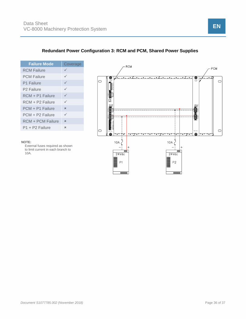
Data Sheet VC-8000 Machinery Protection System
EN
Document S1077785.002 (November 2018) Page 36 of 37
Failure Mode Coverage
RCM Failure
PCM Failure
P1 Failure
P2 Failure
RCM + P1 Failure
RCM + P2 Failure
PCM + P1 Failure
PCM + P2 Failure
RCM + PCM Failure
P1 + P2 Failure
Redundant Power Configuration 3: RCM and PCM, Shared Power Supplies
NOTE: External fuses required as shown to limit current in each branch to 10A.
VC-8000 RCM
B&K Vibro
VC-8000
PCM
B&K Vibro

Contact BK Vibro America, Inc
2243 Park Place, Suite A
Minden, NV 89423 USA
775.552.3110
+49 6151 428
www.setpointvibration.com
Document S1077785.002 (November 2018) ●
Trademarks used herein are the property of their respective owners. Data and specifications subject to change without
notice. © 2011 - 2018