
8-Port GPON Managed OLT - GPL-8000
541
8-Port GPON Managed OLT GPL-8000
-
Upload
khangminh22 -
Category
Documents
-
view
2 -
download
0
Transcript of 8-Port GPON Managed OLT - GPL-8000

8-Port GPON Managed OLT GPL-8000

2
Users Manual of GPL-8000
TrademarksCopyright © PLANET Technology Corp. 2020. Contents are subject to revision without prior notice. PLANET is a registered trademark of PLANET Technology Corp. All other trademarks belong to their respective owners.
Disclaimer PLANET Technology does not warrant that the hardware will work properly in all environments and applications, and makes no warranty and representation, either implied or expressed, with respect to the quality, performance, merchantability, or fitness for a particular purpose. PLANET has made every effort to ensure that this User's Manual is accurate; PLANET disclaims liability for any inaccuracies or omissions that may have occurred.
Information in this User's Manual is subject to change without notice and does not represent a commitment on the part of PLANET. PLANET assumes no responsibility for any inaccuracies that may be contained in this User's Manual. PLANET makes no commitment to update or keep current the information in this User's Manual, and reserves the right to make improvements to this User's Manual and/or to the products described in this User's Manual, at any time without notice.
If you find information in this manual that is incorrect, misleading, or incomplete, we would appreciate your comments and suggestions.
FCC Warning This equipment has been tested and found to comply with the limits for a Class A digital device, pursuant to Part 15 of the FCC Rules. These limits are designed to provide reasonable protection against harmful interference when the equipment is operated in a commercial environment. This equipment generates, uses, and can radiate radio frequency energy and, if not installed and used in accordance with the Instruction manual, may cause harmful interference to radio communications. Operation of this equipment in a residential area is likely to cause harmful interference in which case the user will be required to correct the interference at his own expense.
CE Mark Warning This is a Class A product. In a domestic environment, this product may cause radio interference, in which case the user may be required to take adequate measures.
Energy Saving Note of the Device This power required device does not support Standby mode operation. For energy saving, please remove the power cable to disconnect the device from the power circuit. In view of saving the energy and reducing the unnecessary power consumption, it is strongly suggested to remove the power connection for the device if this device is not intended to be active.
WEEE Warning
To avoid the potential effects on the environment and human health as a result of the presence of hazardous substances in electrical and electronic equipment, end users of electrical and electronic equipment should understand the meaning of the crossed-out wheeled bin symbol. Do not dispose of WEEE as unsorted municipal waste and have to collect such WEEE separately.
Revision PLANET GPL-8000 User's Manual Model: GPL-8000 Revision: 1.0 (Jan. 2021) Part No: EM-GPL-8000_v1.0

3
Users Manual of GPL-8000
Contents
Introduction 19
Packet Contents ...................................................................................................................................... 19 Product Description ................................................................................................................................. 20 How to Use This Manual ......................................................................................................................... 22 Product Features .................................................................................................................................... 22 Product Specifications ............................................................................................................................ 25
Hardware Installation 30
Hardware Description ............................................................................................................................. 30 2.1.1. OLT Front Panel ............................................................................................................................. 30 2.1.2. LED Indications .............................................................................................................................. 31 2.1.4. OLT Rear Panel ............................................................................................................................. 33
Installing the OLT .................................................................................................................................... 35 2.3.1. Rack Mounting ............................................................................................................................... 35 2.3.2. Installing the Uplink Port ................................................................................................................ 36
Web-based Management 40
About Web-based Management ............................................................................................................. 40 Logging on to the Switch ......................................................................................................................... 40 OLT Information ...................................................................................................................................... 42
3.3.1. Device Information ......................................................................................................................... 42 3.3.2. Manage the Switch via SNMP Network Management Software .................................................... 42 3.3.3. Help Function ................................................................................................................................. 44 3.3.4. Canceling a Command .................................................................................................................. 44 3.3.5. Saving Configuration ..................................................................................................................... 44
Basic Configuration 45
System Management Configuration ........................................................................................................ 45 4.1.1. File Management Configuration ..................................................................................................... 45 4.1.1.1. Managing the file system ............................................................................................................... 45 4.1.1.2. Commands for the file system ....................................................................................................... 45 4.1.1.3. Starting up from a file manually ..................................................................................................... 45 4.1.1.4. Updating software .......................................................................................................................... 46 4.1.1.5. Updating configuration ................................................................................................................... 47 4.1.1.6. Using ftp to perform the update of software and configuration ...................................................... 48 4.1.2. Basic System Management Configuration ..................................................................................... 49 4.1.2.1. Configuring Ethernet IP address .................................................................................................... 49 4.1.2.2. Configuring default route ............................................................................................................... 49 4.1.2.3. Using ping to test network connection state .................................................................................. 50 4.1.3. HTTP Configuration ....................................................................................................................... 50 4.1.3.1. Configuring HTTP .......................................................................................................................... 50 4.1.3.2. Examples of http configuration ...................................................................................................... 51

4
Users Manual of GPL-8000
Terminal Configuration ............................................................................................................................ 52 4.2.1. VTY configuration introduction ....................................................................................................... 52 4.2.2. Configuration tasks ........................................................................................................................ 52 4.2.2.1. Relationship between line and interface ........................................................................................ 52 4.2.3. Monitoring and maintenance ......................................................................................................... 52 4.2.4. Browsing Logs ............................................................................................................................... 52 4.2.5. VTY configuration example ............................................................................................................ 53
Remote Monitoring .................................................................................................................................. 54 4.3.1. Configuring SNMP ......................................................................................................................... 54 4.3.1.1. Introduction .................................................................................................................................... 54 4.3.1.2. SNMP configuration tasks.............................................................................................................. 55 4.3.1.3. Configuration example ................................................................................................................... 59 4.3.2. RMON configuration ...................................................................................................................... 60 4.3.2.1. RMON configuration tasks ............................................................................................................. 60 4.3.3. Configuring PDP ............................................................................................................................ 64 4.3.3.1. Introduction .................................................................................................................................... 64 4.3.3.2. PDP configuration tasks................................................................................................................. 64 4.3.3.3. PDP configuration examples.......................................................................................................... 66
SSH Configuration commands ................................................................................................................ 67 4.4.1. Introduction .................................................................................................................................... 67 4.4.1.1. SSH server .................................................................................................................................... 67 4.4.1.2. SSH client ...................................................................................................................................... 67 4.4.1.3. Function ......................................................................................................................................... 67 4.4.2. Configuration Tasks ....................................................................................................................... 67 4.4.2.1. Configuring the authentication method list ..................................................................................... 67 4.4.2.2. Configuring the access control list ................................................................................................. 67 4.4.2.3. Configuring the authentication timeout value ................................................................................. 68 4.4.2.4. Configuring authentication ............................................................................................................. 68 4.4.2.5. Enabling SSH server ..................................................................................................................... 68 4.4.3. SSH server configuration example ................................................................................................ 68 4.4.3.1. Access control list .......................................................................................................................... 68 4.4.3.2. Global configuration ....................................................................................................................... 68
Remote Monitoring 70
Chapter 5. ................................................................................................................................................................. 70 Remote Monitoring .................................................................................................................................. 70
5.1.1 SNMP configuration ....................................................................................................................... 70 5.1.2 Overview ........................................................................................................................................ 70 5.1.3 SNMP notification .......................................................................................................................... 70 5.1.4 SNMP tasks ................................................................................................................................... 70
Security Configuration 71
Chapter 6. ................................................................................................................................................................. 71 AAA Configuration .................................................................................................................................. 71
6.1.1 AAA Overview ................................................................................................................................ 71 6.1.2 AAA Configuration Process ........................................................................................................... 73 6.1.3 AAA Authentication Configuration Task List ................................................................................... 74 6.1.4 AAA Authentication Configuration Task.......................................................................................... 74

5
Users Manual of GPL-8000
6.1.5 AAA Authentication Configuration Example ................................................................................... 79 6.1.6 AAA Authorization Configuration Task List ..................................................................................... 79 6.1.7 AAA Authorization Configuration Task ........................................................................................... 79 6.1.8 AAA Authorization Example ........................................................................................................... 81 6.1.9 AAA Accounting Configuration Task List ........................................................................................ 81 6.1.10 AA Accounting Configuration Task ................................................................................................. 81
Configuring RADIUS ............................................................................................................................... 83 6.2.1 Introduction .................................................................................................................................... 83 6.2.2 RADIUS Configuration Task List .................................................................................................... 85 6.2.3 RADIUS Configuration Task List .................................................................................................... 86 6.2.4 RADIUS Configuration Task........................................................................................................... 86 6.2.5 RADIUS Configuration Examples .................................................................................................. 88
Web Authentication Configuration ........................................................................................................... 89 6.3.1 Overview ........................................................................................................................................ 89 6.3.2 Configuring Web Authentication..................................................................................................... 92 6.3.3 Monitoring and Maintaining Web Authentication ............................................................................ 94 6.3.4 Web Authentication Configuration Example................................................................................... 95
Web Configuration 97
Chapter 7. ................................................................................................................................................................. 97 HTTP Switch Configuration ..................................................................................................................... 97
7.1.1 HTTP Configuration ....................................................................................................................... 97 7.1.2 HTTPS Configuration ..................................................................................................................... 98
Configuration Preparation ....................................................................................................................... 98 7.2.1 Accessing the Switch through HTTP ............................................................................................. 98 7.2.2 Accessing a Switch through Secure Links ................................................................................... 100 7.2.3 Introduction of Web Interface ....................................................................................................... 101
Basic Configuration ............................................................................................................................... 103 7.3.1 Hostname Configuration .............................................................................................................. 104 7.3.2 Time Management ....................................................................................................................... 104
GPON Interface Config ......................................................................................................................... 105 7.4.1 GPON Global Config ................................................................................................................... 105 7.4.2 ONU Bind Relationship Config .................................................................................................... 105 7.4.3 ONU Discovery Mode .................................................................................................................. 106 7.4.4 ONU Authentication ..................................................................................................................... 107
ONU Config Profile ............................................................................................................................... 108 7.5.1 ONU T-Cont Config ...................................................................................................................... 108 7.5.2 ONU Rate Limit Config ................................................................................................................ 109 7.5.3 ONU Virtual Port Config ............................................................................................................... 110 7.5.4 T-Cont Virtual Port Bind Config .................................................................................................... 110 7.5.5 ONU VLAN Config ........................................................................................................................ 111 7.5.6 ONU Flow Mapping Config .......................................................................................................... 112
ONU Interface Config ............................................................................................................................ 114 7.6.1 ONU Description .......................................................................................................................... 114 7.6.2 T-Cont Virtual Port Bind ............................................................................................................... 114 7.6.3 Flow Mapping .............................................................................................................................. 115 7.6.4 VLAN Config ................................................................................................................................ 115 7.6.5 Virtual Port Bandwidth Config ...................................................................................................... 115 7.6.6 Virtual Port GEM Port Bind .......................................................................................................... 115

6
Users Manual of GPL-8000
7.6.7 ONU Remote Controller ............................................................................................................... 115 Advanced Config ................................................................................................................................... 117
7.7.1 Configuring Port Description ........................................................................................................ 117 7.7.2 Configuring the Attributes of the Port ........................................................................................... 118 7.7.3 Rate control ................................................................................................................................. 118 7.7.4 Port mirroring ............................................................................................................................... 119 7.7.5 VLAN Settings ............................................................................................................................. 120 7.7.6 Configuring the VLAN Interface ................................................................................................... 122 7.7.7 LDP Configuration........................................................................................................................ 123 7.7.8 STP Configuration........................................................................................................................ 124 7.7.9 Port security ................................................................................................................................. 126 7.7.10 Storm control ............................................................................................................................... 128 7.7.11 IP Access Control List .................................................................................................................. 130 7.7.12 MAC Access Control List ............................................................................................................. 132 7.7.13 Link Aggregation Configuration .................................................................................................... 133 7.7.14 Ring Protection Configuration ...................................................................................................... 134 7.7.15 DDM Configuration ...................................................................................................................... 135 7.7.16 MTU Config .................................................................................................................................. 135
Layer 3 Configuration ............................................................................................................................ 136 7.8.1 Setting the Static Route ............................................................................................................... 137
Remote Monitor configuration ............................................................................................................... 138 7.9.1 SNMP Configuration .................................................................................................................... 138 7.9.2 RMON Config .............................................................................................................................. 139
System Management ............................................................................................................................ 142 7.10.1 User Management ....................................................................................................................... 142 7.10.2 Log Management ......................................................................................................................... 146 7.10.3 Diagnostic .................................................................................................................................... 146 7.10.4 Managing the Configuration Files ................................................................................................ 147 7.10.5 Software Management ................................................................................................................. 149 7.10.6 Factory Settings ........................................................................................................................... 150 7.10.7 Rebooting the Device .................................................................................................................. 150 7.10.8 About ........................................................................................................................................... 150
Interface Configuration 151
Chapter 8. ............................................................................................................................................................... 151 Introduction ........................................................................................................................................... 151
8.1.1 Supported Interface Types ........................................................................................................... 151 8.1.2 Interface Configuration Introduction ............................................................................................. 152
Interface Configuration .......................................................................................................................... 153 8.2.1 Configuring Interface Common Attribute ...................................................................................... 153 8.2.2 Monitoring and Maintaining Interface ........................................................................................... 154 8.2.3 Configuring Logistical Interface ................................................................................................... 155
Interface Configuration Example ........................................................................................................... 157 8.3.1 Configuring Public Attribute of Interface ...................................................................................... 157
Interface Range Configuration 158
Chapter 9. ............................................................................................................................................................... 158 Interface Range Configuration Task ...................................................................................................... 158

7
Users Manual of GPL-8000
9.1.1 Understanding Interface Range ................................................................................................... 158 9.1.2 Entering Interface Range Mode ................................................................................................... 158 9.1.3 Configuration Example ................................................................................................................ 158
Port Physical Characteristics Configuration 158
Chapter 10. ............................................................................................................................................................. 158 Configuring the Ethernet Interface ........................................................................................................ 158
10.1.1 Selecting Ethernet Interface ........................................................................................................ 159 10.1.2 Configuration Rate ....................................................................................................................... 159 10.1.3 Configuring Flow Control on the Interface ................................................................................... 159
Additional Port Characteristics Configuration 159
Chapter 11. ............................................................................................................................................................. 159 Configuring the Ethernet Interface ........................................................................................................ 159
11.1.1 Configuring Flow Control for the Port .......................................................................................... 160 11.1.2 Comfiguring the Rate Unit for the Port ......................................................................................... 160 11.1.3 Configuring the Storm Control on the Port ................................................................................... 161
Secure Port Configuration ..................................................................................................................... 161 11.2.1 Overview ...................................................................................................................................... 161 11.2.2 Configuration Task of the Secure Port ......................................................................................... 161
Configuring the Secure Port .................................................................................................................. 161 11.3.1 Configuring the Secure Port Mode .............................................................................................. 161 11.3.2 Configuring the Static MAC Address of the Secure Port ............................................................. 162
Configuring Port Mirroring 163
Chapter 12. ............................................................................................................................................................. 163 Configuring Port Mirroring Task............................................................................................................. 163
12.1.1 Configuring Port Mirroring ............................................................................................................ 163 12.1.2 Displaying Port Mirroring Information .......................................................................................... 163
Configuring MAC Address Attribute 163
Chapter 13. ............................................................................................................................................................. 163 MAC Address Configuration Task List ................................................................................................... 163 MAC address Configuration Task.......................................................................................................... 164
13.2.1 Configuring Static Mac Address ................................................................................................... 164 13.2.2 Configuring MAC Address Aging Time ......................................................................................... 164 13.2.3 Displaying MAC Address Table .................................................................................................... 164 13.2.4 Clearing Dynamic MAC Address ................................................................................................. 165
Configuring MAC List 165
Chapter 14. ............................................................................................................................................................. 165 MAC List Configuration Task ................................................................................................................. 165
14.1.1 Creating MAC List ........................................................................................................................ 165 14.1.2 Configuring Items of MAC List ..................................................................................................... 165

8
Users Manual of GPL-8000
14.1.3 Applying MAC List ....................................................................................................................... 166
Configuring 802.1x 167
Chapter 15. ............................................................................................................................................................. 167 802.1x Configuration Task List .............................................................................................................. 167 802.1x Configuration Task..................................................................................................................... 167
15.2.1 Configuring 802.1x Port Authentication ....................................................................................... 167 15.2.2 Configuring 802.1x Multiple Port Authentication .......................................................................... 169 15.2.3 Configuring Maximum Times for 802.1x ID Authentication .......................................................... 170 15.2.4 Configuring 802.1x Re-authentication ......................................................................................... 170 15.2.5 Configuring 802.1x Transmission Frequency .............................................................................. 170 15.2.6 Configuring 802.1x User Binding ................................................................................................. 170 15.2.7 Configuring Authentication Method for 802.1x Port ..................................................................... 171 15.2.8 Selecting Authentication Type for 802.1x Port ............................................................................. 171 15.2.9 Configuring 802.1x Accounting .................................................................................................... 171 15.2.10 Configuring 802.1x guest-vlan ..................................................................................................... 172 15.2.11 Forbidding Supplicant with Multiple Network Cards .................................................................... 172 15.2.12 Resuming Default 802.1x Configuration ...................................................................................... 172 15.2.13 Monitoring 802.1x Authentication Configuration and State .......................................................... 173
802.1x Configuration Example .............................................................................................................. 173
VLAN Configuration 174
Chapter 16. ............................................................................................................................................................. 174 VLAN Introduction ................................................................................................................................. 174 VLAN Configuration Task List ............................................................................................................... 174 VLAN Configuration Task ...................................................................................................................... 174
16.3.1 Adding/Deleting VLAN ................................................................................................................. 174 16.3.2 Configuring Switch Port ............................................................................................................... 175 16.3.3 Creating/Deleting VLAN Interface ................................................................................................ 176 16.3.4 Configuring Super VLAN Interface .............................................................................................. 176 16.3.5 Monitoring Configuration and State of VLAN ............................................................................... 177
Configuration Examples ........................................................................................................................ 177
GVRP Configuration 178
Chapter 17. ............................................................................................................................................................. 178 Configuring GVRP ................................................................................................................................ 178 Introduction ........................................................................................................................................... 178 Configuring Task List ............................................................................................................................. 178
17.3.1 GVRP Configuration Task List ..................................................................................................... 178 GVRP Configuration Task ..................................................................................................................... 178
17.4.1 Enabling/Disabling GVRP Globally .............................................................................................. 178 17.4.2 Enabling/Disabling GVRP on the Interface .................................................................................. 178 17.4.3 Monitoring and Maintenance of GVRP ........................................................................................ 179
Configuration Example .......................................................................................................................... 179
Private VLAN Settings 181

9
Users Manual of GPL-8000
Chapter 18. ............................................................................................................................................................. 181 Private VLAN Settings .......................................................................................................................... 181 Overview of Private VLAN .................................................................................................................... 181 Private VLAN Type and Port Type in Private VLAN .............................................................................. 181
18.3.1 Having One Primary VLAN Type ................................................................................................. 181 18.3.2 Having Two Secondary VLAN Types ........................................................................................... 181 18.3.3 Port Types Under the Private VLAN Port ..................................................................................... 181 18.3.4 Modifying the Fields in VLAN TAG ............................................................................................... 182
Private VLAN Configuration Task List ................................................................................................... 182 Private VLAN Configuration Tasks ........................................................................................................ 182
18.5.1 Configuring Private VLAN ............................................................................................................ 182 18.5.2 Configuring the Association of Private VLAN Domains ............................................................... 182 18.5.3 Configuring the L2 Port of Private VLAN to Be the Host Port ...................................................... 183 18.5.4 Configuring the L2 Port of Private VLAN to Be the Promiscuous Port ........................................ 183 18.5.5 Modifying Related Fields of Egress Packets in Private VLAN ..................................................... 183 18.5.6 Displaying the Configuration Information of Private VLAN .......................................................... 184
Configuration Example .......................................................................................................................... 184
STP Configuration 187
Chapter 19. ............................................................................................................................................................. 187 Configuring STP .................................................................................................................................... 187
19.1.1 STP Introduction .......................................................................................................................... 187 19.1.2 SSTP Configuratiom Task List ..................................................................................................... 188 19.1.3 SSTP Configuration Task ............................................................................................................. 188 19.1.4 Configuring VLAN STP ................................................................................................................ 191 19.1.5 RSTP Configuration Task List ...................................................................................................... 192 19.1.6 RSTP Configuration Task ............................................................................................................. 193
Configuring MTSP ................................................................................................................................. 195 19.2.1 MSTP Overview ........................................................................................................................... 195 19.2.2 MSTP Configuration Task List ...................................................................................................... 203 19.2.3 MSTP Configuration Task ............................................................................................................ 204
STP Optional Characteristic Configuration 215
Chapter 20. ............................................................................................................................................................. 215 Configuring STP Optional Characteristic .............................................................................................. 215
20.1.1 STP Optional Characteristic Introduction ..................................................................................... 215 20.1.2 Configuring STP Optional Characteristic ..................................................................................... 221
Link Aggregation Configuration 226
Chapter 21. ............................................................................................................................................................. 226 Configuring Port Aggregation ................................................................................................................ 226
21.1.1 Overview ...................................................................................................................................... 226 21.1.2 Port Aggregation Configuration Task List ..................................................................................... 226 21.1.3 Port Aggregation Configuration Task ........................................................................................... 226
PDP Configuration 228

10
Users Manual of GPL-8000
Chapter 22. ............................................................................................................................................................. 228 PDP Overview ....................................................................................................................................... 228
22.1.1 Overview ...................................................................................................................................... 228 22.1.2 PDP Configuration Tasks ............................................................................................................. 229 22.1.3 PDP Configuration Example ........................................................................................................ 230
LLDP Configuration 231
Chapter 23. ............................................................................................................................................................. 231 LLDP ..................................................................................................................................................... 231
23.1.1 LLDP Introduction ........................................................................................................................ 231 23.1.2 LLDP Configuration Task List ....................................................................................................... 231 23.1.3 LLDP Configuration Task ............................................................................................................. 231
FlexLinkLite Configuration 235
Chapter 24. ............................................................................................................................................................. 235 FlexLinkLite Configuration .................................................................................................................... 235
24.1.1 FlexLinkLite Overview .................................................................................................................. 235 24.1.2 FlexLinkLite Configuration ........................................................................................................... 236 24.1.3 FlexLinkLite Configuration Example ............................................................................................ 237
BackupLink Configuration 239
Chapter 25. ............................................................................................................................................................. 239 BackupLink Overview ........................................................................................................................... 239
25.1.1 Overview ...................................................................................................................................... 239 25.1.2 Port Aggregation Configuration Task ........................................................................................... 239
EAPS Configuration 242
Chapter 26. ............................................................................................................................................................. 242 Introduction of Fast Ethernet Ring Protection ....................................................................................... 242
26.1.1 Overview ...................................................................................................................................... 242 26.1.2 Related Concepts of Fast Ether-Ring Protection ......................................................................... 242 26.1.3 Types of EAPS Packets ............................................................................................................... 245 26.1.4 Fast Ethernet Ring Protection Mechanism .................................................................................. 245
Fast Ethernet Ring Protection Configuration ........................................................................................ 246 26.2.1 Default EAPS Settings ................................................................................................................. 246 26.2.2 Requisites before Configuration .................................................................................................. 247 26.2.3 MEAPS Configuration Tasks ........................................................................................................ 247 26.2.4 Fast Ethernet Ring Protection Configuration ............................................................................... 247 26.2.5 MEAPS configuration ................................................................................................................... 250
MEAPS Settings 252
Chapter 27. ............................................................................................................................................................. 252 MEAPS Introduction .............................................................................................................................. 252
27.1.1 MEAPS Overview ........................................................................................................................ 252

11
Users Manual of GPL-8000
27.1.2 Basic Concepts of MEAPS .......................................................................................................... 253 27.1.3 Types of EAPS Packets ............................................................................................................... 257 27.1.4 Fast Ethernet Ring Protection Mechanism .................................................................................. 257
Fast Ethernet Ring Protection Configuration ........................................................................................ 264 27.2.1 Requisites before Configuration .................................................................................................. 264 27.2.2 MEAPS Configuration Tasks ........................................................................................................ 265 27.2.3 Fast Ethernet Ring Protection Configuration ............................................................................... 265
Appendix ............................................................................................................................................... 269 27.3.1 Working Procedure of MEAPS..................................................................................................... 269 27.3.2 Complete state ............................................................................................................................. 269 27.3.3 MEAPS configuration ................................................................................................................... 273 27.3.4 Unfinished Configurations (to be continued) ................................................................................ 279
ELPS Configuration 280
Chapter 28. ............................................................................................................................................................. 280 ELPS Overview ..................................................................................................................................... 280
28.1.1 Overview ...................................................................................................................................... 280
UDLD Configuration 285
Chapter 29. ............................................................................................................................................................. 285 Unidirectional Link Detection (UDLD) ................................................................................................... 285
29.1.1 UDLD Overview ........................................................................................................................... 285 29.1.2 UDLD Configuration Task List ...................................................................................................... 287 29.1.3 UDLD Configuration Tasks........................................................................................................... 287 29.1.4 Configuration Example ................................................................................................................ 290
IGMP Snooping Configuration 293
Chapter 30. ............................................................................................................................................................. 293 IGMP Snooping Configuration .............................................................................................................. 293
30.1.1 IGMP Snooping Configuration Task ............................................................................................. 293
IGMP Proxy Configuration 300
Chapter 31. ............................................................................................................................................................. 300 IGMP Proxy Configuration .................................................................................................................... 300
MLD Snooping Configuration 303
Chapter 32. ............................................................................................................................................................. 303 MLD Snooping Configuration ................................................................................................................ 303
32.1.1 IPv6 Multicast Overview .............................................................................................................. 303 32.1.2 MLD Snooping Multicast Configuration Tasks ............................................................................. 303
OAM Configuration 309
Chapter 33. ............................................................................................................................................................. 309

12
Users Manual of GPL-8000
OAM Configuration ............................................................................................................................... 309 33.1.1 OAM Overview ............................................................................................................................. 309 33.1.2 OAM Configuration Task List ....................................................................................................... 312 33.1.3 OAM Configuration Tasks ............................................................................................................ 313 33.1.4 Configuration Example ................................................................................................................ 318
CFM and Y1731 Configuration 322
Chapter 34. ............................................................................................................................................................. 322 Overview ............................................................................................................................................... 322
34.1.1 Stipulations .................................................................................................................................. 322 CFM Configuration ................................................................................................................................ 322
34.2.1 CFM Configuration Task List ........................................................................................................ 322 34.2.2 CFM Maintenance Task List......................................................................................................... 322 34.2.3 CFM Configuration ....................................................................................................................... 322 34.2.4 CFM Maintenance ....................................................................................................................... 324 34.2.5 Configuration Example ................................................................................................................ 324
Y1731 Configuration ............................................................................................................................. 324 34.3.1 Configuration Task List................................................................................................................. 324
DHCP Snooping Configuration 327
Chapter 35. ............................................................................................................................................................. 327 DHCP Snooping Configuration ............................................................................................................. 327
35.1.1 DHCP Snooping Configuration Tasks .......................................................................................... 327
MACFF Configuration 334
Chapter 36. ............................................................................................................................................................. 334 MACFF Settings .................................................................................................................................... 334
36.1.1 Configuration Tasks ..................................................................................................................... 334
IEEE 1588 Transparent Clock Configuration 338
Chapter 37. ............................................................................................................................................................. 338 Task List for IEEE1588 Transparent Clock Configuration ..................................................................... 338 Tasks for IEEE1588 Transparent Clock Configuration .......................................................................... 338 Enabling the Transparent Clock ............................................................................................................ 338
37.3.1 Creating the Transparent Clock Port ........................................................................................... 339 37.3.2 Configuring the Link Delay Calculation Mode .............................................................................. 339 37.3.3 Configuring the Forwarding Mode of Sync Packets ..................................................................... 339 37.3.4 Configuring the Domain Filtration Function ................................................................................. 340 37.3.5 Setting the Transmission Interval of Pdelay_Req Packets .......................................................... 340
PTP TC Configuration Example ............................................................................................................ 341
Layer 2 Tunnel Protocol Configuration 342
Chapter 38. ............................................................................................................................................................. 342 Configuring Layer 2 Protocol Tunnel ..................................................................................................... 342

13
Users Manual of GPL-8000
38.1.1 Introduction .................................................................................................................................. 342 38.1.2 Configuring Layer 2 Protocol Tunnel ........................................................................................... 342 38.1.3 Configuration Example of Layer 2 Protocol Tunnel ..................................................................... 342
Loopback Detection Configuration 343
Chapter 39. ............................................................................................................................................................. 343 Setting Loopback Detection .................................................................................................................. 343
39.1.1 Introduction of Loopback Detection ............................................................................................. 343 39.1.2 Loopback Detection Configuration Tasks .................................................................................... 344 39.1.3 Setting Loopback Detection ......................................................................................................... 344 39.1.4 Configuration Example ................................................................................................................ 347
QoS Configuration 349
Chapter 40. ............................................................................................................................................................. 349 QoS Configuration ................................................................................................................................ 349
40.1.1 QoS Overview .............................................................................................................................. 349 40.1.2 QoS Configuration Task List ........................................................................................................ 352 40.1.3 QoS Configuration Tasks ............................................................................................................. 352 40.1.4 QoS Configuration Example ........................................................................................................ 360
DoS Attack Prevention Configuration 361
Chapter 41. ............................................................................................................................................................. 361 DoS Attack Prevention Configuration .................................................................................................... 361
41.1.1 DoS Attack Overview ................................................................................................................... 361 41.1.2 DoS Attack Prevention Configuration Task List............................................................................ 362 41.1.3 DoS Attack Prevention Configuration Tasks ................................................................................ 362 41.1.4 DoS Attack Prevention Configuration Example ........................................................................... 363
Attack Prevention Configuration 364
Chapter 42. ............................................................................................................................................................. 364 Attack Prevention Configuration ........................................................................................................... 364
42.1.1 Overview ...................................................................................................................................... 364 42.1.2 Attack Prevention Configuration Tasks ........................................................................................ 364 42.1.3 Attack Prevention Configuration .................................................................................................. 364 42.1.4 Attack Prevention Configuration Example ................................................................................... 365
Network Protocol Configuration 366
Chapter 43. ............................................................................................................................................................. 366 Configuring IP Addressing..................................................................................................................... 366
43.1.1 IP Introduction .............................................................................................................................. 366 43.1.2 Configuring IP Address Task List ................................................................................................. 367 43.1.3 Configuring IP Address ................................................................................................................ 368
Configuring NAT .................................................................................................................................... 374 43.2.1 Introduction .................................................................................................................................. 374

14
Users Manual of GPL-8000
43.2.2 NAT Configuration Task List ......................................................................................................... 376 43.2.3 NAT Configuration Task ............................................................................................................... 376 43.2.4 NAT Configuration Example ......................................................................................................... 385
Configuring DHCP ................................................................................................................................ 387 43.3.1 Introduction .................................................................................................................................. 387 43.3.2 Configuring DHCP Client ............................................................................................................. 388 43.3.3 Configuring DHCP Server ............................................................................................................ 390
IP Service Configuration ....................................................................................................................... 393 43.4.1 Configuring IP Service ................................................................................................................. 393 43.4.2 Configuring Access List ............................................................................................................... 398 43.4.3 Configuring IP Access List Based on Physical Port ..................................................................... 402
IP ACL Application Configuration 405
Chapter 44. ............................................................................................................................................................. 405 Applying the IP Access Control List ...................................................................................................... 405
44.1.1 Applying ACL on Ports ................................................................................................................. 405
Routing Configuration 406
Chapter 45. ............................................................................................................................................................. 406 Configuring RIP ..................................................................................................................................... 406
45.1.1 Overview ...................................................................................................................................... 406 45.1.2 Configuring RIP Task List ............................................................................................................. 406 45.1.3 Configuring RIP Tasks ................................................................................................................. 407 45.1.4 RIP Configuration Example.......................................................................................................... 411
Configuring BEIGRP ............................................................................................................................. 411 45.2.1 Overview ...................................................................................................................................... 411 45.2.2 BEIGRP Configuration Task List .................................................................................................. 412 45.2.3 BEIGRP Configuration Task ......................................................................................................... 413 45.2.4 BEIGRP Configuration Example .................................................................................................. 417
Configuring OSPF ................................................................................................................................. 417 45.3.1 Overview ...................................................................................................................................... 417 45.3.2 OSPF Configuration Task List ...................................................................................................... 418 45.3.3 OSPF Configuration Task ............................................................................................................ 418 45.3.4 OSPF Configuration Example ...................................................................................................... 424
Configuring BGP ................................................................................................................................... 430 45.4.1 Overview ...................................................................................................................................... 430 45.4.2 BGP Configuration Task ............................................................................................................... 432 45.4.3 Monitoring and Maintaining BGP ................................................................................................. 441 45.4.4 BGP Configuration Example ........................................................................................................ 442
IP Hardware Subnet Routing Configuration 451
Chapter 46. ............................................................................................................................................................. 451 IP Hardware Subnet Configuration Task ............................................................................................... 451
46.1.1 Overview ...................................................................................................................................... 451 46.1.2 Configuring IP Hardware Subnet Routing .................................................................................... 452 46.1.3 Checking the State of IP Hardware Subnet Routing .................................................................... 452

15
Users Manual of GPL-8000
Configuration Example .......................................................................................................................... 452
IP-PBR Configuration 453
Chapter 47. ............................................................................................................................................................. 453 IP-PBR Configuration ............................................................................................................................ 453
47.1.1 Enabling or Disabling IP-PBR Globally ........................................................................................ 454 47.1.2 ISIS Configuration Task List ......................................................................................................... 455 47.1.3 Monitoring and Maintaining MVC ................................................................................................. 455 47.1.4 IP-PBR Configuration Example ................................................................................................... 457
Multi-VRF CE Configuration 457
Chapter 48. ............................................................................................................................................................. 457 Multi-VRF CE Introduction .................................................................................................................... 457
48.1.1 Overview ...................................................................................................................................... 457 Multi-VRF CE Configuration .................................................................................................................. 459
48.2.1 Default VRF Configuration ........................................................................................................... 459 48.2.2 MCE Configuration Tasks ............................................................................................................ 459 48.2.3 MCE Configuration ...................................................................................................................... 460
MCE Configuration Example ................................................................................................................. 462 48.3.1 Configuring S11 ........................................................................................................................... 462 48.3.2 Configuring MCE-S1 .................................................................................................................... 463 48.3.3 Configuring PE ............................................................................................................................. 465 48.3.4 Configuring MCE-S2 .................................................................................................................... 467 48.3.5 Setting S22 .................................................................................................................................. 469 48.3.6 TestifyingVRF Connectivity .......................................................................................................... 470
Reliability Configuration 471
Chapter 49. ............................................................................................................................................................. 471 Configuring Port Backup ....................................................................................................................... 471
49.1.1 Overview ...................................................................................................................................... 471 49.1.2 Backup Interface Configratoin Task List....................................................................................... 471 49.1.3 Backup Interface Configratoin Task ............................................................................................. 471 49.1.4 Examples of Port Backup Configuration ...................................................................................... 473
Configuring HSRP protocol ................................................................................................................... 474 49.2.1 Overview ...................................................................................................................................... 474 49.2.2 HSRP Protocol Configuration Task List ....................................................................................... 474 49.2.3 HSRP Protocol Configuration Task.............................................................................................. 474 49.2.4 Example of Hot Standby Configuration ........................................................................................ 475
Configuring VRRP ................................................................................................................................. 476 49.3.1 VRRP Overview ........................................................................................................................... 476 49.3.2 VRRP Configuration Task List ...................................................................................................... 478 49.3.3 VRRP Configuration Tasks .......................................................................................................... 478 49.3.4 VRRP Configuration Example...................................................................................................... 479
Multicast Configuration 482

16
Users Manual of GPL-8000
Chapter 50. ............................................................................................................................................................. 482 Multicast Overview ................................................................................................................................ 482
50.1.1 Multicast Routing Realization ...................................................................................................... 482 50.1.2 Multicast Routing Configuration Task List .................................................................................... 483
Basic Multicast Routing Configuration .................................................................................................. 484 50.2.1 Starting up Multicast Routing ....................................................................................................... 484 50.2.2 Starting up the Multicast Function on the Port ............................................................................. 484 50.2.3 Configuring TTL Threshold .......................................................................................................... 485 50.2.4 Cancelling Rapid Multicast Forwarding ....................................................................................... 485 50.2.5 Configuring Static Multicast Route ............................................................................................... 485 50.2.6 Configuring IP Multicast Boundary............................................................................................... 486 50.2.7 Configuring IP Multicast Rate Control .......................................................................................... 486 50.2.8 Configuring IP Multicast Helper ................................................................................................... 487 50.2.9 Configuring Stub Multicast Route ................................................................................................ 488 50.2.10 Monitoring and Maintaining Multicast Route ................................................................................ 489
IGMP Configuration............................................................................................................................... 490 50.3.1 Overview ...................................................................................................................................... 490 50.3.2 IGMP Configuration ..................................................................................................................... 490 50.3.3 IGMP Characteristic Configuration Example ............................................................................... 494
PIM-DM Configuration .......................................................................................................................... 496 50.4.1 PIM-DM Introduction .................................................................................................................... 496 50.4.2 Configuring PIM-DM .................................................................................................................... 497 50.4.3 PIM-DM State-Refresh Configuration Example ........................................................................... 499
Configuring PIM-SM .............................................................................................................................. 499 50.5.1 PIM-SM Introduction .................................................................................................................... 499 50.5.2 Configuring PIM-SM .................................................................................................................... 501 50.5.3 Configuration Example ................................................................................................................ 502
IPv6 Configuration 504
Chapter 51. ............................................................................................................................................................. 504 IPv6 Protocol’s Configuration ................................................................................................................ 504 Enabling IPv6 ........................................................................................................................................ 505
51.2.1 Setting the IPv6 Address ............................................................................................................. 505 Setting the IPv6 Services ...................................................................................................................... 506
51.3.1 Setting the IPv6 Services ............................................................................................................. 506
ND Configuration 508
Chapter 52. ............................................................................................................................................................. 508 ND Overview ......................................................................................................................................... 508
52.1.1 Address Resolution ...................................................................................................................... 509 52.1.2 ND Configuration ......................................................................................................................... 509
RIPNG Configuration 513
Chapter 53. ............................................................................................................................................................. 513 Configuring RIPNG ............................................................................................................................... 513
53.1.1 Overview ...................................................................................................................................... 513

17
Users Manual of GPL-8000
53.1.2 Setting RIPng Configuration Task List ......................................................................................... 513 53.1.3 RIPng Configuration Tasks .......................................................................................................... 514 53.1.4 RIPng Configuration Example ..................................................................................................... 518
OSPFv3 Configuration 518
Chapter 54. ............................................................................................................................................................. 518 Overview ............................................................................................................................................... 518 OSPFv3 Configuration Task List ........................................................................................................... 519 OSPFv3 Configuration Tasks ................................................................................................................ 520
54.3.1 Enabling OSPFv3 ........................................................................................................................ 520 54.3.2 Setting the Parameters of the OSPFv3 Interface ........................................................................ 520 54.3.3 Setting OSPFv3 on Different Physical Networks ......................................................................... 521 54.3.4 Setting the OSPF Network Type .................................................................................................. 521 54.3.5 Setting the Parameters of the OSPFv3 Domain .......................................................................... 521 54.3.6 Setting the Route Summary in the OSPFv3 Domain ................................................................... 522 54.3.7 Setting the Summary of the Forwarded Routes ........................................................................... 523 54.3.8 Generating a Default Route ......................................................................................................... 523 54.3.9 Choosing the Route ID on the Loopback Interface ...................................................................... 523 54.3.10 Setting the Management Distance of OSPFv3 ............................................................................ 524 54.3.11 Setting the Timer of Routing Algorithm ........................................................................................ 524 54.3.12 Monitoring and Maintaining OSPFv3 ........................................................................................... 524
OSPFv3 Configuration Example ........................................................................................................... 525 54.4.1 Example for OSPFv3 Route Learning Settings ........................................................................... 525
BFD Configuration 533
Chapter 55. ............................................................................................................................................................. 533 Overview ............................................................................................................................................... 533 BFD Configuration Tasks ...................................................................................................................... 533
55.2.1 Activating Port BFD ..................................................................................................................... 533 55.2.2 Activating the Port BFD Query Mode ........................................................................................... 534 55.2.3 Activating Port BFD Echo ............................................................................................................ 534 55.2.4 Enabling Port BFD Authentication ............................................................................................... 535
BFD Configuration Example ................................................................................................................. 535
SNTP Configuration 536
Chapter 56. ............................................................................................................................................................. 536 Overview ............................................................................................................................................... 536
56.1.1 Stipulations .................................................................................................................................. 536 SNTP Configuration .............................................................................................................................. 536
56.2.1 Overview ...................................................................................................................................... 536 56.2.2 SNTP Configuration Task List ...................................................................................................... 537 56.2.3 SNTP Configuration ..................................................................................................................... 538
Cluster Management Configuration 538
Chapter 57. ............................................................................................................................................................. 538

18
Users Manual of GPL-8000
Overview ............................................................................................................................................... 538 Cluster Management Configuration Task List ....................................................................................... 539 Cluster Management Configuration Task .............................................................................................. 539
57.3.1 Planning Cluster .......................................................................................................................... 539 57.3.2 Creating Cluster ........................................................................................................................... 539 57.3.3 Configuring Cluster ...................................................................................................................... 540 57.3.4 Monitoring the State of Standby Group ....................................................................................... 541 57.3.5 Using SNMP to Manage Cluster .................................................................................................. 541 57.3.6 Using Web to Manage Cluster ..................................................................................................... 541

19
Users Manual of GPL-8000
Introduction Thank you for purchasing PLANET GPON OLT GPL-8000. The description of this model is as follows:
Model GPON ports 10/100/1000T
RJ45 ports
100/1000BASE-X
SFP slots 10G SFP slots
GPL-8000 8 4 8 4
Packet Contents The box should contain the following items:
GPON OLT x 1
Quick Installation Guide x 1
Dust Cap (SFP) x 20
RJ45 to DB9 Console Cable x 1
Rack-mount Accessory Kit x 1
AC Power Cord x 1
If any of these are missing or damaged, please contact your dealer immediately; if possible, retain the carton
including the original packing material, and use them again to repack the product in case there is a need to
return it to us for repair.

20
Users Manual of GPL-8000
Product Description
High-performance GPON for FTTx Applications
PLANET GPL-8000 GPON Optical Line Terminal (OLT) consists of eight GPON ports, four Gigabit TP/SFP combo
ports, four Gigabit SFP ports, four 10G SFP+ ports and one management port. It complies with ITU-T G.984/G.988
and meets the requirements of GPON OLT’s network access technology.
It is easy to install and maintain a GPON deployment of up to 1024 ONU and HGU devices, providing highly-effective
GPON solutions and convenient management for fiber optic broadband network.
High-speed and Long-distance Coverage for Triple Play Services
The GPL-8000 provides a high bandwidth of up to 2.5Gbps for downstream and 1.25Gbps for upstream, long-distance
coverage of up to 20km between equipment nodes, and flexibility for network deployment. It is a cost-effective access
technology with reliable and scalable network for triple-play service applications such as HDTV, IPTV, voice-over-IP (VoIP)
and multimedia.
High Split Ratio for a Cost-effective Network Solution
The GPL-8000 is an ideal solution for FTTx applications. It helps to minimize the investment cost for carriers by offering a
high split ratio of 1:128 per port and supporting the usage of PLANET ONUs. The GPL-8000 provides strong
functionalities for Ethernet features such as VLAN, Dynamic Bandwidth Allocation (DBA), Service Level Agreement (SLA)
and Access Control List. GPON protocol allows a Gigabit Ethernet communications fiber to be shared by multiple end
users using a passive optical splitter.
Flexible and Extendable 10Gb Ethernet Solution
The GPL-8000 has four 10G SFP+ uplink ports to deliver ultra-high speed networking over long distances to service
providers. Each of the 10G SFP+ ports supports dual speed and 10GBASE-SR/LR or 1000BASE-SX/LX. With its 4 ports,
10G Ethernet link capability and additional 8-port 1G Ethernet link capability, the administrator now can flexibly choose the
suitable SFP/SFP+ transceiver according to the transmission distance or the transmission speed required to extend the
network efficiently. The GPL-8000 provides broad bandwidth and powerful processing capacity for FTTx applications for
distribution data link.

21
Users Manual of GPL-8000
Extractive Power Supply Design to Increase Flexibility
The GPL-8000 is equipped with one extractive 100~240V AC power supply unit, so it is easy to replace the power for
users. Besides, the GPL-8000 reserves another backup power slot on the rear panel and users can add the second AC or
DC power to the redundant power supply installation. The AC power or DC power is optional. The redundant power
system is specifically designed to handle the demands of high-tech facilities requiring the highest power integrity.
Layer 3 Routing Support
The GPL-8000 enables the administrator to conveniently boost network efficiency by configuring Layer 3 static routing
manually, the RIP (Routing Information Protocol) or OSPF (Open Shortest Path First) settings automatically.
- The RIP can employ the hop count as a routing metric and prevent routing loops by implementing a limit on the
number of hops allowed in a path from the source to a destination.
- The OSPF is an interior dynamic routing protocol for autonomous system based on link-state. The protocol creates
a link-state database by exchanging link-states among Layer 3 switches, and then uses the Shortest Path First
algorithm to generate a route table based on that database.
Robust Layer 2 Features
The GPL-8000 can be programmed for basic switch management functions such as port speed configuration, port
aggregation, VLAN, Spanning Tree Protocol, WRR, bandwidth control and IGMP snooping. It also supports 802.1Q
tagged VLAN, Q-in-Q and GVRP Protocol. In addition, the number of VLAN interfaces is 4K. By supporting port
aggregation, the GPL-8000 allows the operation of a high-speed trunk combined with multiple ports. It enables up to 32
groups for trunking with a maximum of 8 ports for each group.
Efficient and Secure Management
For efficient management, the GPL-8000 is equipped with console, Web and SNMP management interfaces.
With the built-in Web-based management interface, the GPL-8000 offers an easy-to-use, platform-independent
management and configuration facility.
For text-based management, it can be accessed via Telnet and the console port.
For standard-based monitor and management software, it offers SNMPv3 connection which encrypts the packet
content at each session for secure remote management.
Moreover, the GPL-8000 offers secure remote management by supporting SSHv2, TLSv1.0 and SSLv3 connection which
encrypts the packet content at each session.

22
Users Manual of GPL-8000
How to Use This Manual This User Manual is structured as follows:
Section 2, Hardware Installation
The section explains the functions of the Switch and how to physically install the GPON OLT.
Section 3, Web-based Management
The section explains how to manage the GPON OLT from Web UI.
Section 4, Switch Operation
The chapter explains how to do the switch operation of the GPON OLT.
Appendix A
The section contains cable information of the GPON OLT.
Product Features GPON Ports
8 GPON OLT SFP ports
Up to 2.5Gbps downstream and 1.25Gbps upstream
Maximum transfer distance of up to 20km
Each PON port supports up to 128 ONT/HGU
Compliant with G.984/G.988
Physical Ports
4 10/100/1000BASE-T RJ45 copper ports
8 100/1000BASE-X SFP ports
4 10GBASE-SR/LR SFP+ ports
RJ45 to DB9 console interface for switch basic management and setup
One 10/100BASE-TX Management port
OLT Management
User-friendly GUI management
2 control interfaces
- Out-of-Band IP – the management RJ45 port
- In-Band IP – the Gigabit TP, SFP and 10G SFP+ uplink ports
Supports ONT/HGU authentication; averts illegal ONT access to network
ONT/HGU Management
ONT/HGU port control
ONT/HGU VLAN mode

23
Users Manual of GPL-8000
IP Routing Features
Supports dynamic routing protocol: RIP and OSPF
IPv4 static routing
Routing interface provides per VLAN routing mode
Layer 2 Features
Supports VLAN
- IEEE 802.1Q tag-based VLAN
- Provider Bridging (VLAN Q-in-Q, IEEE 802.1ad) supported
- GVRP for dynamic VLAN management
Supports Link Aggregation
- 802.3ad Link Aggregation Control Protocol (LACP)
- Cisco ether-channel (static trunk)
Supports Spanning Tree Protocol
- STP, IEEE 802.1D (Classic Spanning Tree Protocol)
- RSTP, IEEE 802.1w (Rapid Spanning Tree Protocol)
- MSTP, IEEE 802.1s (Multiple Spanning Tree Protocol, spanning tree by VLAN)
Port mirroring to monitor the incoming or outgoing traffic on a particular port (many to 1)
Supports G.8032 ERPS (Ethernet Ring Protection Switching)
Loop protection to avoid broadcast loops
Link Layer Discovery Protocol (LLDP)
Quality of Service
Ingress shaper and egress rate limit per port bandwidth control
8 priority queues on all switch ports
- IEEE 802.1p CoS/DSCP/Precedence
- VLAN ID
- Policy-based ingress and egress QoS
Multicast
Supports IPv4 IGMP snooping v1, v2 and v3
Supports IPv6 MLD snooping v1 and v2
Querier mode support
MVR (Multicast VLAN Registration)
Security
Authentication
- IEEE 802.1x port-based network access authentication
- Built-in RADIUS client to cooperate with the RADIUS servers
- RADIUS/TACACS+ users access authentication

24
Users Manual of GPL-8000
Access Control List
- IP-based Access Control List (ACL)
- MAC-based Access Control List (ACL)
- Time-based ACL
DHCP Snooping to filter distrusted DHCP messages
Dynamic ARP Inspection discards ARP packets with invalid MAC address to IP address binding
IP Source Guard prevents IP spoofing attacks
Management
IPv4 and IPv6 dual stack management
Switch Management Interfaces
- Console and Telnet Command Line Interface
- HTTP web switch management
- SNMP v1 and v2c switch management
- SSHv2, SSLv3, TLSv1.0 and SNMP v3 secure access
SNMP Management
- Four RMON groups (history, statistics, alarms, and events)
- SNMP trap for interface Link Up and Link Down notification
Built-in Trivial File Transfer Protocol (TFTP) client
BOOTP and DHCP for IP address assignment
System Maintenance
- Firmware upload/download via HTTP
- Reset button for system reboot or reset to factory default
- Dual images
DHCP Functions:
- DHCP Relay
- DHCP Option 82
- DHCP Server
User Privilege levels control
Network Time Protocol (NTP) and SNTP
Network Diagnostic
- SFP-DDM (Digital Diagnostic Monitor)
- ICMP remote IP ping
Syslog remote alarm
System Log

25
Users Manual of GPL-8000
Product Specifications Product GPL-8000
Hardware Specifications
GPON Ports 8, supporting Class C+, Class C++ and Class B+
10/100/1000BASE-T RJ45
Ports 4 TP/SFP combo interfaces, shared with Port-1 to Port-4
1000BASE-X SFP Slots 8, supporting 1000BASE-SX/LX/BX SFP transceiver
Backward compatible with 100BASE-FX SFP transceiver
10GBASE-X SFP+ Slots 4, supporting 10GBASE-SR/LR SFP+ transceiver
Management Port One 10/100BASE-TX RJ45 port
Console One RJ45-to-RS232 serial port (9600, 8, N, 1)
CPU 600MHz
RAM 512MB
Flash Memory 32MB
Dimensions (W x D x H) 440 x 304 x 44 mm
Weight 5,500g
Power Consumption 60 watts/204.73BTU
Power Requirements - AC 100~240V AC, 1.5A max.
Power Requirements - DC 36~72V DC, 3A max.
Fan 3
Switching
Switch Architecture Store-and-forward
Switch Fabric 176Gbps
Address Table 64K
ARP Table 8K
ACL Table 1K
Shared Data Buffer 2MB
Jumbo Frame 2KB
Flow Control Back pressure for half duplex
IEEE 802.3x pause frame for full duplex
GPON Specifications
Transmission Speed Downstream: 2.5Gbps
Upstream: 1.25Gbps
Optical Split Ratio Up to 128
Transmission Distance 20km

26
Users Manual of GPL-8000
PON Module Wavelength TX: 1490nm; RX: 1310nm
PON Fiber Type 9/125um SMF (Single mode fiber optic)
Layer 3 Functions
IP Interfaces Max. 1K VLAN interfaces for IPv4
Max. 256 VLAN interfaces for IPv6
Routing Table 32K for IPv4
8K for IPv6
Routing Protocols
Static routing
RIP
OSPF
Layer 2 Functions
Port Configuration
Port disable/enable
Auto-negotiation 10/100/1000Mbps full and half duplex mode selection
Flow control disable/enable
Bandwidth control on each port
Port loopback detect
Port Mirroring TX/RX/Both
Many to 1
VLAN
IEEE 802.1Q tag-based VLAN, up to 4K VLAN groups
IEEE 802.1ad Q-in-Q VLAN stacking/tunneling
GVRP for VLAN management
Spanning Tree Protocol
IEEE 802.1D Spanning Tree Protocol (STP)
IEEE 802.1w Rapid Spanning Tree Protocol (RSTP)
IEEE 802.1s Multiple Spanning Tree Protocol (MSTP)
Multicast
IPv4 IGMP v1/v2/v3 snooping
IPv4 Querier mode support
IGMP Filtering and IGMP Throttling
IGMP Proxy reporting
IGMP multicast forwarding
IPv6 MLD v1/v2 snooping
Multicast VLAN Register (MVR)
Up to 2K multicast groups
Link Aggregation
IEEE 802.3ad Ling Aggregation Control Protocol (LACP)
Static trunk link aggregation
Supports 32 groups with 8 ports per trunk group
Up to 80Gbps bandwidth (full duplex mode)
Load Balance Algorithm:
- Source IP/destination IP/Source + destination IP
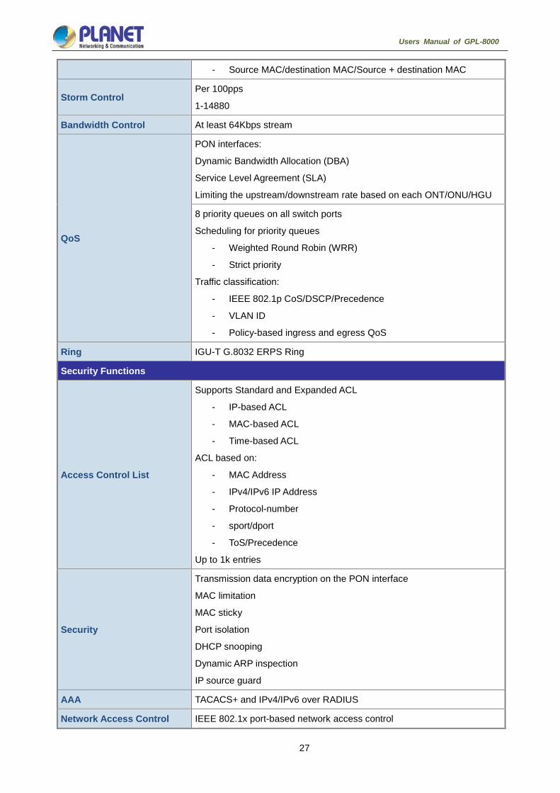
27
Users Manual of GPL-8000
- Source MAC/destination MAC/Source + destination MAC
Storm Control Per 100pps
1-14880
Bandwidth Control At least 64Kbps stream
QoS
PON interfaces:
Dynamic Bandwidth Allocation (DBA)
Service Level Agreement (SLA)
Limiting the upstream/downstream rate based on each ONT/ONU/HGU
8 priority queues on all switch ports
Scheduling for priority queues
- Weighted Round Robin (WRR)
- Strict priority
Traffic classification:
- IEEE 802.1p CoS/DSCP/Precedence
- VLAN ID
- Policy-based ingress and egress QoS
Ring IGU-T G.8032 ERPS Ring
Security Functions
Access Control List
Supports Standard and Expanded ACL
- IP-based ACL
- MAC-based ACL
- Time-based ACL
ACL based on:
- MAC Address
- IPv4/IPv6 IP Address
- Protocol-number
- sport/dport
- ToS/Precedence
Up to 1k entries
Security
Transmission data encryption on the PON interface
MAC limitation
MAC sticky
Port isolation
DHCP snooping
Dynamic ARP inspection
IP source guard
AAA TACACS+ and IPv4/IPv6 over RADIUS
Network Access Control IEEE 802.1x port-based network access control

28
Users Manual of GPL-8000
Management Functions
System Configuration
Console and Telnet
Web browser
SNMP v1, v2c
Secure Management
Interfaces
SSHv2, SSLv3
Maximum 8 sessions for SSH and telnet connection
System Management
IPv4 and IPv6 dual stack management
SNMP MIB and TRAP
SNMP RMON 1, 2, 3, 9 four groups
Firmware upgrade by HTTP/TFTP/FTP protocol through Ethernet network
Configuration upload/download through HTTP/TFTP/FTP protocol
Supports IEEE 802.1ab LLDP protocol
NTP and SNTP client
RADIUS authentication for IPv4/IPv6 login user name and password
Event Management Remote syslog
System log
SNMP MIBs
RFC 1213 MIB-II
RFC 1215 Internet Engineering Task Force
RFC 1271 RMON
RFC 1354 IP-Forwarding MIB
RFC 1493 Bridge MIB
RFC 1643 Ether-like MIB
RFC 1907 SNMPv2
RFC 2011 IP/ICMP MIB
RFC 2012 TCP MIB
RFC 2013 UDP MIB
RFC 2096 IP forward MIB
RFC 2233 if MIB
RFC 2452 TCP6 MIB
RFC 2454 UDP6 MIB
RFC 2465 IPv6 MIB
RFC 2466 ICMP6 MIB
RFC 2573 SNMPv3 notification
RFC 2574 SNMPv3 VACM
RFC 2674 Bridge MIB Extensions
Standard Conformance
Regulatory Compliance CE, FCC, LVD
Standards Compliance IEEE 802.3z Gigabit 1000BASE-SX/LX

29
Users Manual of GPL-8000
IEEE 802.3ae 10Gb/s Ethernet
IEEE 802.3x flow control and back pressure
IEEE 802.3ad port trunk with LACP
IEEE 802.1D Spanning Tree Protocol
IEEE 802.1w Rapid Spanning Tree Protocol
IEEE 802.1s Multiple Spanning Tree Protocol
IEEE 802.1p Class of Service
IEEE 802.1Q VLAN tagging
IEEE 802.1X port authentication network control
IEEE 802.1ab LLDP
RFC 768 UDP
RFC 793 TFTP
RFC 791 IP
RFC 792 ICMP
RFC 2068 HTTP
RFC 1112 IGMP v1
RFC 2236 IGMP v2
RFC 3376 IGMP v3
RFC 2710 MLD v1
FRC 3810 MLD v2
Environments
Operating Temperature: 0 ~ 50 degrees C
Relative Humidity: 5 ~ 90% (non-condensing)
Storage Temperature: -10 ~ 70 degrees C
Relative Humidity: 5 ~ 90% (non-condensing)

30
Users Manual of GPL-8000
Hardware Installation This section describes the hardware features and installation of the GPON OLT on the desktop or rack mount.
For easier management and control of the GPON OLT, familiarize yourself with its display indicators and ports.
Front panel illustrations in this chapter display the unit LED indicators. Before connecting any network device
to the GPON OLT, please read this chapter completely.
Hardware Description
2.1.1. OLT Front Panel
The front panel of the unit provides a simple interface monitoring the OLT. Figure 2-1 shows the front panel of
the GPON OLT.
Figure 2-1 GPL-8000 Front Panel
Gigabit SFP PON Ports
1000BASE-PX20 mini-GBIC slot, SFP (Small Form Factor Pluggable) transceiver module: Up to 20
kilometers (single-mode fiber).
1G/10G SFP+ Uplink Port
10G BASE-SR/LR SFP+ Port, compatible with 1000BASE-SX/LX/BX SFP transceiver.
Gigabit SFP Uplink Port
1000BASE-SX/LX mini-GBIC port, SFP (Small Form Factor Pluggable) transceiver module: From 550
meters (multi-mode fiber) to 10/30/50/70/120 kilometers (single-mode fiber).
Gigabit RJ45 Uplink Ports
100/1000BASE-T copper, RJ45 twisted-pair: Up to 100 meters
Management Port
10/100BASE-TX copper, RJ45 twisted-pair: Up to 100 meters
Gigabit SFP uplink ports support 1000Mbps Forced Mode only. The remote Gigabit
switch or media converter’s SFP port must support 1000Mbps Forced Mode as well.

31
Users Manual of GPL-8000
2.1.2. LED Indications
The front panel LEDs indicates instant status of port links, data activity and system power, and help to monitor
and troubleshoot when needed. Figure 2-4 shows the LED indications of GPL-8000.
GPL-8000 LED Indication
Figure 2-4 GPL-8000 LED Panel
System
LED Color Function
PWR1 Green Lights
: To indicate that the Switch is powered on.
PWR2 Green Lights
: To indicate that the Switch is powered on.
ALM Red Lights
: To indicate that AC or DC power has failed.
SYS Green
Blinks
: The OLT is ready for management.
Off: The OLT is operating abnormally.
1000BASE-PX20 SFP PON Interfaces
LED Color Function
PON1-8 Green
Lights: To indicate the link through that PON port is successfully
established.
Off: To indicate that the PON port is link-down.
Blinks To indicate that the switch is actively sending or receiving data
over that port.

32
Users Manual of GPL-8000
1000BASE-T RJ45 Interfaces
LED Color Function
Port G1-4 Green
Lights: To indicate the link through that RJ45 port is successfully
established.
Off: To indicate that the RJ45 port is link-down.
Blinks: To indicate that the switch is actively sending or receiving data
over that port.
1G Shared SFP+ Interfaces
LED Color Function
Port G1-8
Green
Lights: To indicate the link through that SFP+ port is successfully
established.
Off: To indicate that the SFP+ port is link-down.
Blinks: To indicate that the switch is actively sending or receiving data
over that port.
10G SFP+ Interfaces (TG1 to TG4 Ports)
LED Color Function
LINK Green Lights:
To indicate the link through that SFP+ port is successfully
established.
Off: To indicate that the SFP+ port is link-down.
ACT Green Blinks: To indicate that the switch is actively sending or receiving data
over that port.

33
Users Manual of GPL-8000
2.1.4. OLT Rear Panel
The rear panel of the GPON OLT indicates an AC inlet power socket, which accepts input power from 100 to
240V AC, 50-60Hz. Figure 2-5 shows the rear panel of this GPON OLT.
GPL-8000 Rear Panel
Figure 2-5 Rear Panel of GPL-8000
■ AC Power Receptacle
For compatibility with electric service in most areas of the world, the GPON OLT’s power supply
automatically adjusts to line power in the range of 100-240V AC and 50/60 Hz.
Plug the female end of the power cord firmly into the receptacle on the rear panel of the GPON OLT and
the other end of the power cord into an electric outlet and then the power will be ready.
There is a power switch for AC power input use only, whereas DC power input has no power switch.

34
Users Manual of GPL-8000
The device is a power-required device; if your networks should be active all the time,
please consider using UPS (Uninterrupted Power Supply) for your device. It will
prevent you from network data loss or network downtime.
In some areas, installing a surge suppression device may also help to protect your
GPON OLT from being damaged by unregulated surge or current to the switch or the
power adapter.

35
Users Manual of GPL-8000
Installing the OLT This section describes how to install your GPON OLT and make connections to the GPON OLT. Please read
the following topics and perform the procedures in the order being presented. To install your GPON OLT on a
shelf, simply complete the following steps.
2.3.1. Rack Mounting
To install the GPON OLT in a 19-inch standard rack, please follow the instructions described below:
Step 1: Place the GPON OLT on a hard flat surface, with the front panel positioned towards the front side.
Step 2: Attach the rack-mount bracket to each side of the GPON OLT with supplied screws attached to the
package.
Figure 2-9 shows how to attach brackets to one side of the GPON OLT.
Figure 2-9 Attaching Brackets to the GPON OLT.
You must use the screws supplied with the mounting brackets. Damage caused to the
parts by using incorrect screws would invalidate the warranty.
Step 3: Secure the brackets tightly.
Step 4: Follow the same steps to attach the second bracket to the opposite side.
Step 5: After the brackets are attached to the GPON OLT, use suitable screws to securely attach the brackets
to the rack, as shown in Figure 2-10.

36
Users Manual of GPL-8000
Figure 2-10 Mounting the GPON OLT on a Rack
2.3.2. Installing the Uplink Port
The sections describe how to insert an SFP transceiver into an SFP slot and UTP copper cable to RJ45 port.
The SFP transceivers are hot-pluggable and hot-swappable. You can plug in and out the transceiver to/from
any SFP port without having to power down the GPON OLT as Figure 2-11 shows.
Figure 2-11 Plugging in the SFP Transceiver
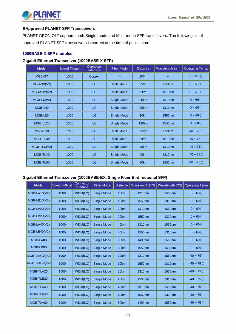
37
Users Manual of GPL-8000
Approved PLANET SFP Transceivers
PLANET GPON OLT supports both Single mode and Multi-mode SFP transceivers. The following list of
approved PLANET SFP transceivers is correct at the time of publication:
1000BASE-X SFP modules:
Gigabit Ethernet Transceiver (1000BASE-X SFP)
Model Speed (Mbps) Connector Interface Fiber Mode Distance Wavelength (nm) Operating Temp.
MGB-GT 1000 Copper -- 100m -- 0 ~ 60 ℃
MGB-SX(V2) 1000 LC Multi Mode 550m 850nm 0 ~ 60 ℃
MGB-SX2(V2) 1000 LC Multi Mode 2km 1310nm 0 ~ 60 ℃
MGB-LX(V2) 1000 LC Single Mode 20km 1310nm 0 ~ 60℃
MGB-L40 1000 LC Single Mode 40km 1310nm 0 ~ 60℃
MGB-L80 1000 LC Single Mode 80km 1550nm 0 ~ 60℃
MGB-L120 1000 LC Single Mode 120km 1550nm 0 ~ 60℃
MGB-TSX 1000 LC Multi Mode 550m 850nm -40 ~ 75℃
MGB-TSX2 1000 LC Multi Mode 2km 1310nm -40 ~ 75℃
MGB-TLX(V2) 1000 LC Single Mode 20km 1310nm -40 ~ 75℃
MGB-TL40 1000 LC Single Mode 40km 1310nm -40 ~ 75℃
MGB-TL80 1000 LC Single Mode 80km 1550nm -40 ~ 75℃
Gigabit Ethernet Transceiver (1000BASE-BX, Single Fiber Bi-directional SFP)
Model Speed (Mbps) Connector Interface Fiber Mode Distance Wavelength (TX) Wavelength (RX) Operating Temp.
MGB-LA10(V2)
MGB-LB10(V2)
1000 WDM(LC) Single Mode 10km 1310nm 1550nm 0 ~ 60℃
1000 WDM(LC) Single Mode 10km 1550nm 1310nm 0 ~ 60℃
MGB-LA20(V2)
MGB-LB20(V2)
1000 WDM(LC) Single Mode 20km 1310nm 1550nm 0 ~ 60℃
1000 WDM(LC) Single Mode 20km 1550nm 1310nm 0 ~ 60℃
MGB-LA40(V2)
MGB-LB40(V2)
1000 WDM(LC) Single Mode 40km 1310nm 1550nm 0 ~ 60℃
1000 WDM(LC) Single Mode 40km 1550nm 1310nm 0 ~ 60℃
MGB-LA80
MGB-LB80
1000 WDM(LC) Single Mode 80km 1490nm 1550nm 0 ~ 60℃
1000 WDM(LC) Single Mode 80km 1550nm 1490nm 0 ~ 60℃
MGB-TLA10(V2)
MGB-TLB10(V2)
1000 WDM(LC) Single Mode 10km 1310nm 1550nm -40 ~ 75℃
1000 WDM(LC) Single Mode 10km 1550nm 1310nm -40 ~ 75℃
MGB-TLA20
MGB-TLB20
1000 WDM(LC) Single Mode 20km 1310nm 1550nm -40 ~ 75℃
1000 WDM(LC) Single Mode 20km 1550nm 1310nm -40 ~ 75℃
MGB-TLA40
MGB-TLB40
1000 WDM(LC) Single Mode 40km 1310nm 1550nm -40 ~ 75℃
1000 WDM(LC) Single Mode 40km 1550nm 1310nm -40 ~ 75℃
MGB-TLA80 1000 WDM(LC) Single Mode 80km 1490nm 1550nm -40 ~ 75℃

38
Users Manual of GPL-8000
MGB-TLB80 1000 WDM(LC) Single Mode 80km 1550nm 1490nm -40 ~ 75℃
10Gigabit Ethernet Transceiver (10GBASE-X SFP+)
Model Speed (Mbps) Connector Interface Fiber Mode Distance Wavelength (nm) Operating Temp.
MTB-SR
MTB-LR
10G LC Multi Mode 300m 850nm 0 ~ 60℃
10G LC Single Mode 10km 1310nm 0 ~ 60℃
10Gigabit Ethernet Transceiver (10GBASE-BX, Single Fiber Bi-directional SFP+)
Model Speed (Mbps) Connector Interface Fiber Mode Distance Wavelength (TX) Wavelength (RX) Operating Temp.
MTB-LA20
MTB-LB20
1000 WDM(LC) Single Mode 20km 1270nm 1330nm 0 ~ 60℃
1000 WDM(LC) Single Mode 20km 1330nm 1270nm 0 ~ 60℃
MTB-LA40
MTB-LB40
1000 WDM(LC) Single Mode 40km 1270nm 1330nm 0 ~ 60℃
1000 WDM(LC) Single Mode 40km 1330nm 1270nm 0 ~ 60℃
MTB-LA60
MTB-LB60
1000 WDM(LC) Single Mode 60km 1270nm 1330nm 0 ~ 60℃
1000 WDM(LC) Single Mode 60km 1330nm 1270nm 0 ~ 60℃
GPON OLT GPL-8000 SFP ports are configured in 1000Mbps Forced Mode. To
make the connection successfully, the switch’s SFP ports should also be in
1000Mbps Forced Mode. Otherwise, the connection might fail.
Before connecting the other GPON OLT, workstation or media converter,
1. Make sure both sides of the SFP transceiver are with the same media type, for example, 1000BASE-SX to
1000BASE-SX, or 1000BASE-LX to 1000BASE-LX.
2. Check whether the fiber-optic cable type matches the SFP transceiver model.
To connect to 1000BASE-SX SFP transceiver, use the multi-mode fiber cable, with one side being male
duplex LC connector type.
To connect to 1000BASE-LX SFP transceiver, use the single-mode fiber cable, with one side being male
duplex LC connector type. Connecting the fiber cable
1. Insert the duplex LC connector on the network cable into the SFP transceiver.
2. Connect the other end of the cable to a device – switches with SFP installed, fiber NIC on a workstation
or a media converter.
3. Check the LNK/ACT LED of the SFP port on the front of the GPON OLT. Ensure that the SFP transceiver
is operating correctly.
4. Check the Link mode of the SFP port if the link fails. It works well with some fiber-NICs or media
converters. Set the Link mode to “1000 Force” if needed.

39
Users Manual of GPL-8000
Removing the transceiver module
1. Make sure there is no network activity by consulting or checking with the network administrator. Or through
the management interface of the switch/converter (if available), disable the port in advance.
2. Remove the Fiber Optic Cable gently.
3. Turn the handle of the MGB module to a horizontal position.
4. Pull out the module gently through the handle.
Figure 2-12 Pulling Out the SFP Transceiver
Never pull out the module without pulling the handle or the push bolts on the
module. Directly pulling out the module with force could damage the module and
SFP module slot of the GPON OLT.

40
Users Manual of GPL-8000
Web-based Management This section introduces the configuration and functions of the Web-based management.
About Web-based Management The GPL-8000 offers management features that allow users to manage the OLT from anywhere on the
network through a standard browser such as Microsoft Internet Explorer. The Web-based Management
supports Internet Explorer 8.0 above.
The GPL-8000 can be configured through an Ethernet connection, making sure the manager PC must be set
to the same IP subnet address with the OLT.
For example, the IP address of the GPON OLT is configured with 192.168.1.1 on Management Port, then the manager PC should be set to 192.168.1.x (where x is a number between 2 and 253, except 1 or 254), and the default subnet mask is 255.255.255.0.
If you have changed the default IP address of the OLT to 192.168.0.1 with subnet mask 255.255.255.0 via
console, then the manager PC should be set to 192.168.0.x (where x is a number between 2 and 254) to do
the relative configuration on manager PC.
Logging on to the Switch Use Internet Explorer 8.0 or above Web browser. Enter the factory-default IP address to access the Web
interface. The default IP of Management port is as follows:
http://192.168.1.1
When the following login screen appears, please enter the default username “admin” with password “admin”
(or the username/password you have changed via console) to log in the main screen of OLT. The login screen
in Figure 3-1-1 appears.

41
Users Manual of GPL-8000
Figure 3-1 Login Screen
Default User name: admin
Default Password: admin
After entering the username and password, the main screen appears as Figure 3-2.
Figure 3-2 Web Main Page

42
Users Manual of GPL-8000
The OLT menu on the left of the Web page lets you access all the commands and statistics the OLT provides.
Now, you can use the Web management interface to continue the OLT management or manage the ONU by
Web interface. The OLT menu on the left of the web page lets you access all the commands and statistics the
ONU provides.
1. It is recommended to use Internet Explore 8.0 or above to access OLT.
2. The changed IP address takes effect immediately after clicking on the Submit
button; you need to use the new IP address to access the Web interface.
3. For security reason, please change and memorize the new password after this first
setup.
OLT Information
3.3.1. Device Information
This page shows the OLT information such as system name, serial number, hardware version, firmware
version, MAC address and system time. The system name can be modified if need.
Figure 3-3 Web Main Page
3.3.2. Manage the Switch via SNMP Network Management Software
The followings are required by SNMP network management software to manage switches:
1) IP addresses are configured on the switch;
2) The IP address of the client host and that of the VLAN interface on the switch it subordinates to should
be in the same segment;
3) If 2) is not met, the client should be able to reach an IP address of the switch through devices like
routers;

43
Users Manual of GPL-8000
4) SNMP should be enabled.
The host with SNMP network management software should be able to ping the IP address of the switch, so
that when running, SNMP network management software will be able to find it and implement read/write
operation on it. Details about how to manage switches via SNMP network management software will not be
covered in this manual; please refer to “Simple Network Management software user manual”.
CLI Interface
The switch provides three management interfaces for users: CLI (Command Line Interface) interface, Web
interfaceand Simple Network Management software. The command line interfaces for the switch can be
classified into several modes. Each command mode enables you to configure different groupware. The
command that can be used currently is up to the command mode where you are. You can enter the question
mark in different command modes to obtain the available command list. Common command modes are listed
in the following table:
Command Mode Login Mode Prompt Exit Mode
System monitoring mode Enter Ctrl-p after the
power is on.
monitor# Run quit.
User mode Log in. Switch> Run exit or quit.
Management mode Enter enter or enablein
user mode.
Switch# Run exit or quit.
Office configuration mode Enter config in
management mode.
Switch_config# Run exit or quit or Ctrl-z
to directly back to the
management mode.
Port configuration mode Enter the interface
command in office
configuration mode, such
as interface f0/1.
Switch_config_f0/1# Run exit or quit or Ctrl-z
to directly back to the
management mode.
Each command mode is unsuitable to subsets of some commands. If problem occurs when you enter
commands, check the prompt and enter the question mark to obtain the available command list. Problem may
occur when you run in incorrect command mode or you misspelled the command.
Pay attention to the changes of the interface prompt and the relative command mode in the following case:
Switch> enter
Password: <enter password>
Switch# config
Switch_config# interface f0/1
Switch_config_f0/1# quit
Switch_config# quit
Switch#

44
Users Manual of GPL-8000
3.3.3. Help Function
Use the question mark (?) and the direction mark to help you enter commands:
The currently available command list can be presented if you enter a question mark.
OLT> ?
The currently available commands starting with the known characters in the list can be displayed if you
enter the known characters and then a question mark (without space).
OLT> s?
The parameter list of a command will be obtained if you enter the command, press "Space" and enter
the question mark.
OLT> show ?
The previously entered commands can be presented if you press the “up” arrow key. If you continue
press the “up” arrow key, more commands can be shown. If you press the “up” arrow key and then the
“down” arrow key, the next command line following the current one can be presented.
3.3.4. Canceling a Command
To cancel a command or resume its default properties, add the keyword “no” before most commands. An
example is given as follows:
no ip routing
3.3.5. Saving Configuration
You may need to save the configuration changes, so that you can recover the original configuration in case of
system restarted or power cuts. You can use write command to save configuration in the Administration Mode
or Global Configuration Mode.

45
Users Manual of GPL-8000
Basic Configuration
System Management Configuration
4.1.1. File Management Configuration
4.1.1.1. Managing the file system
The filename in flash is no more than 20 characters and filenames are case insensitive.
4.1.1.2. Commands for the file system
The boldfaces in all commands are keywords. Others are parameters. The content in the square brakcet “[ ]” is optional.
Command Description
format Formats the file system and delete all data.
Differment
[filename]
Displays files and directory names. The file name in the symbol “[]”
means to display files starting with several letters. The file is displayed in
the following format:
Index numberfile name<FILE>length established time
delete filename Deletes a file. The system will prompt if the file does not exist.
md dirname Creates a directory.
rd dirname Deletes a directory. The system will prompt if the directory is not existed.
more filename Displays the content of a file. If the file content cannot be displayed by
one page, it will be displayed by pages.
cd Changes the path of the current file system.
pwd Displays the current path.
4.1.1.3. Starting up from a file manually
monitor#boot flash <local_filename>
The previous command is to start a OLT software in the flash, which may contain multiple switch software.
Parameter description
Parameter Description
local_filename A file name stored in the flash memory
Users must enter the file name.
Example
monitor#boot flash switch.bin

46
Users Manual of GPL-8000
4.1.1.4. Updating software
User can use this command to download OLT system software locally or remotely to obtain version update or
the custom-made function version (like data encryption and so on).
There are two ways of software update in monitor mode.
a) Through TFTP
monitor#copy tftpflash [ip_addr] The previous commad is to copy file from the tftp server to the flash in the system. After you enter the
command, the system will prompt you to enter the remote server name and the remote filename.
Parameter description
Parameter Description
ip_addr IP address of the tftp server
If there is no specified IP address, the system will
prompt you to enter the IP address after the copy
command is run.
Example
The following example shows a main.bin file is read from the server, written into the switch and changed into
the name switch. Bin.
monitor#copy tftp flash
Prompt: Source file name[]?main.bin
Prompt: Remote-server ip address[] ?192.168.20.1
Prompt: Destination file name [main.bin]?switch.bin
please wait ...
######################################################################
######################################################################
######################################################################
#############################################
TFTP: successfully receive 3377 blocks ,1728902 bytes
monitor#
b) Through serial port communication protocol-zmodem
Use the download command to update software. Enter download ? to obtain help.
monitor#download c0 <local_filename>
This command is to copy the file to the flash of system through zmodem. The system will prompt you to enter
the port rate after you enter the command.
Parameter description

47
Users Manual of GPL-8000
Parameter Description
local_filename Filename stored in the flash
Users must enter the filename.
Example
The terminal program can be the Hyper Terminal program in WINDOWS 95, NT 4.0 or the terminal emulation
program in WINDOWS 3.X.
monitor#download c0 switch.bin
Prompt: speed [9600]?115200
Then, modify the rate to 115200. After reconnection, select send file in the transfer menu of hyper terminal
(terminal emulation). The send file dialog box appears as follows:
Figure 4-1 Send files
Enter the all-path of the switch software main.bin that our company provides in the filename input box,
choose Zmodem as the protocol. Click send to send the file.
After the file is transferred, the following information appears:
ZMODEM: successfully receive 36 blocks ,18370 bytes
It indicates that the software update is completed, and then the baud rate of the hyper terminal should be
reset to 9600.
4.1.1.5. Updating configuration
The switch configuration is saved as a file, the filename is startup-config. You can use commands similar to
software update to update the configuration.
a) Through TFTP monitor#copy tftp flash startup-config
b) Through serial port communication protocol-zmodem.
monitor#download c0 startup-config
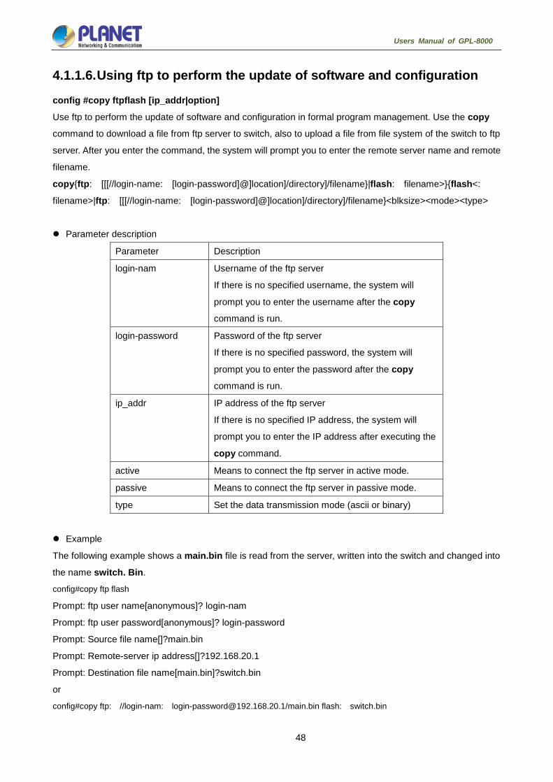
48
Users Manual of GPL-8000
4.1.1.6. Using ftp to perform the update of software and configuration
config #copy ftpflash [ip_addr|option]
Use ftp to perform the update of software and configuration in formal program management. Use the copy
command to download a file from ftp server to switch, also to upload a file from file system of the switch to ftp
server. After you enter the command, the system will prompt you to enter the remote server name and remote
filename.
copy{ftp: [[[//login-name: [login-password]@]location]/directory]/filename}|flash: filename>}{flash<:
filename>|ftp: [[[//login-name: [login-password]@]location]/directory]/filename}<blksize><mode><type>
Parameter description
Parameter Description
login-nam Username of the ftp server
If there is no specified username, the system will
prompt you to enter the username after the copy
command is run.
login-password Password of the ftp server
If there is no specified password, the system will
prompt you to enter the password after the copy
command is run.
ip_addr IP address of the ftp server
If there is no specified IP address, the system will
prompt you to enter the IP address after executing the
copy command.
active Means to connect the ftp server in active mode.
passive Means to connect the ftp server in passive mode.
type Set the data transmission mode (ascii or binary)
Example
The following example shows a main.bin file is read from the server, written into the switch and changed into
the name switch. Bin.
config#copy ftp flash
Prompt: ftp user name[anonymous]? login-nam
Prompt: ftp user password[anonymous]? login-password
Prompt: Source file name[]?main.bin
Prompt: Remote-server ip address[]?192.168.20.1
Prompt: Destination file name[main.bin]?switch.bin
or
config#copy ftp: //login-nam: [email protected]/main.bin flash: switch.bin

49
Users Manual of GPL-8000
######################################################################
######################################################################
FTP: successfully receive 3377 blocks ,1728902 bytes
config#
1. When the ftp server is out of service, the wait time is long. If this problem is
caused by the tcp timeout time (the default value is 75s), you can configure
the global command ip tcp synwait-time to modify the tcp connection time.
However, it is not recommended to use it.
2. When you use ftp in some networking conditions, the rate of data transmission
might be relatively slow. You can properly adjust the size of the transmission
block to obtain the best effect. The default size is 512 characters, which
guarantee a relatively high operation rate in most of the networks.
4.1.2. Basic System Management Configuration
4.1.2.1. Configuring Ethernet IP address
monitor#ip address <ip_addr><net_mask>
This command is to configure the IPaddress of the Ethernet.,The default IP address is 192.168.1.1,and the
network mask is255.255.255.0.
Parameter description
Parameter Description
ip_addr IP address of the Ethernet
net_mask Mask of the Ethernet
Example
monitor#ip address 192.168.0.1 255.255.255.0
4.1.2.2. Configuring default route
monitor#ip route default <ip_addr>
This command is used to configure the default route. You can configure only one default route.
Parameter description Parameter Description
ip_addr IP address of the gateway
Example monitor#ip route default 192.168.0.1

50
Users Manual of GPL-8000
4.1.2.3. Using ping to test network connection state
monitor#ping <ip_address>
This command is to test network connection state.
Parameter description
Parameter Description
ip_address Destination IP address
Example
monitor#ping 192.168.20.100
PING 192.168.20.100: 56 data bytes
64 bytes from 192.168.20.100: icmp_seq=0. time=0. ms
64 bytes from 192.168.20.100: icmp_seq=1. time=0. ms
64 bytes from 192.168.20.100: icmp_seq=2. time=0. ms
64 bytes from 192.168.20.100: icmp_seq=3. time=0. ms
----192.168.20.100 PING Statistics----
4 packets transmitted, 4 packets received, 0% packet loss
round-trip (ms) min/avg/max = 0/0/0
4.1.3. HTTP Configuration
4.1.3.1. Configuring HTTP
Enabling the http service
Modifying the port number of the http service
Configuring the access password of the http service
Specifying the access control list for the http service
a) Enabling the http service
The http service is disabled by default. The http service is enabled in the global configuration mode using the following command:
Command Function
Ip http server Enables the http service.
b) Modifying the port number of the http service The number of the listen port for the http service is 80. The port number of the http service is modified in global configuration mode using the following command:

51
Users Manual of GPL-8000
Command Function
Ip http port number Modifies the port number of the http service.
c) Configuring the access passward of the http service
Http uses enable as the access password. You need to set the password enable if you want to perform authentication for http access. The password enable is set in global configuration mode using the following command:
Command Function
Enable password {0|7} line Sets the password enable.
d) Specifying the access control list for the http service
To control the host’s access to http server, you can specify the access control list for http service. To specify an access control list, use the following command in global configuration mode:
Command Function
ip http access-class STRING Specifies an access control list for the
http service.
4.1.3.2. Examples to http configuration
The following example uses default port (80) as the http service port, and the access address is limited to
192.168.20.0/24:
ip acl configuration:
ip access-list standard http-acl
permit 192.168.20.0 255.255.255.0
global configuration:
ip http access-class http-acl
ip http server

52
Users Manual of GPL-8000
Terminal Configuration
4.2.1. VTY Configuration Introduction
The system uses the line command to configure terminal parameters. Through the command, you can
configure the width and height that the terminal displays.
4.2.2. Configuration Task
The system has four types of lines: console, aid, asynchronous and virtual terminal. Different systems have
different numbers of lines of these types. Refer to the following software and hardware configuration guide for
the proper configuration.
Line Type Interface Description Numbering
CON (CTY) Console To log in to the system for configuration. 0
VTY Virtual and
asynchronous
To connect Telnet, X.25 PAD, HTTP and
Rlogin of synchronous ports (such as
Ethernet and serial port) on the system
32 numbers starting
from 1
4.2.2.1. Relationship between line and interface
a) Relationship between synchronous interface and VTY line
The virtual terminal line provides a synchronous interface to access to the system. When you connect to the
system through VTY line, you actually connect to a virtual port on an interface. For each synchronous
interface, there can be many virtual ports.
For example, if several Telnets are connecting to an interface (Ethernet or serial interface), you need to do the
following steps for the VTY configuration:
(1) Log in to the line configuration mode.
(2) Configure the terminal parameters.
For VTY configuration, refer to Part 4.2.4 “VTY configuration example”.
4.2.3. Monitoring and Maintenance
Run showline to chek the VTY configuration.
4.2.4. Browsing Logs
By default, the system will export the logs to the console port. After the terminal monitor command is set on
the telnet line, the logs will be exported to this line.

53
Users Manual of GPL-8000
By default the logs will not be exported to the cache and cannot be browsed after you run show log. After you
run logging buffer size to set the log cache, you can run show log to browse the log information.
4.2.5. VTY Configuration Example
It shows how to cancel the limit of the line number per screen for all VTYs without more prompt:
config#line vty 0 32
config_line#length 0
32 vty configuration timeout time Switch_config#line vty 0 31
Switch_config_line#exec-timeout 10
Switch_config_line#exit
Switch_config#
54
Users Manual of GPL-8000
Remote Monitoring
4.3.1. Configuring SNMP
4.3.1.1. Introduction
The SNMP system includes the following parts:
SNMP management side (NMS)
SNMP agent (AGENT)
Management information base (MIB)
SNMP is a protocol working on the application layer. It provides the packet format between SNMP
management side and agent.
SNMP management side can be part of the network management system (NMS, like CiscoWorks). Agent and
MIB are stored on the system. You need to define the relationship between network management side and
agent before configuring SNMP on the system.
SNMP agent contains MIB variables. SNMP management side can check or modify value of these variables.
The management side can get the variable value from agent or stores the variable value to agent. The agent
collects data from MIB. MIB is the database of device parameter and network data. The agent also can
respond to the loading of the management side or the request to configure data. SNMP agent can send trap
to the management side. Trap sends alarm information to NMS indicating a certain condition of the network.
Trap can point out improper user authentication, restart, link layer state(enable or disable), close of TCP
connection, lose of the connection to adjacent systems or other important events.
a) SNMP notification When some special events occur, the system will send ‘inform’ to SNMP management side. For example,
when the agent system detects an abnormal condition, it will send information to the management side.
SNMP notification can be treated as trap or inform request to send. Since the receiving side doesn’t send any
reply when receiving a trap, this leads to the receiving side cannot be sure that the trap has been received.
Therefore the trap is not reliable. In comparison, SNMP management side that receives “inform request” uses
PDU that SNMP echoes as the reply for this information. If no “inform request” is received on the
management side, no echo will be sent. If the receiving side doesn’t send any reply, then you can resend the
“inform request”. Then notifications can reach their destination.
Since inform requests are more reliable, they consume more resources of the system and network. The trap
will be discarded when it is sent. The “inform request” has to be stored in the memory until the echo is
received or the request timeouts. In addition, the trap is sent only once, while the “inform request” can be
resent for many times. Resending "inform request" adds to network communications and causes more load
on network. Therefore, trap and inform request provide balance between reliability and resource. If SNMP
management side needs receiving every notification, then the “inform request” can be used. If you give
priority to the communication amount of the network and there is no need to receive every notification, then
trap can be used.

55
Users Manual of GPL-8000
This switch only supports trap, but we provide the extension for "inform request".
b) SNMP version System of our company supports the following SNMP versions:
SNMPv1---simple network management protocol, a complete Internet standard,which is defined in
RFC1157.
SNMPv2C--- Group-based Management framework of SNMPv2, Internet test protocol, which is defined in
RFC1901.
Layer 3 switch of our company also supports the following SNMP:
SNMPv3--- a simple network management protocol version 3, which is defined in RFC3410.
SNMPv1 uses group-based security format. Use IP address access control list and password to define the
management side group that can access to agent MIB.
SNMPv3 provides secure access to devices by a combination of authenticating and encrypting packets over
the network.
The security features provided in SNMPv3 are:
Message integrity—Ensuring that a packet has not been tampered with in-transit.
Authentication—Determining the message is from a valid source.
Encryption—Scrambling the contents of a packet prevent it from being seen by an unauthorized source.
SNMPv3 provides for both security models and security levels. A security model is an authentication strategy
that is set up for a user and the group in which the user resides. A security level is the permitted level of
security within a security model. A combination of a security model and a security level will determine which
security mechanism is employed when handling an SNMP packet. Three security models are available, that is,
authentication and encryption, authentication and no encryption, no authentication.
You need to configure SNMP agent to the SNMP version that the management working station supports. The
agent can communicate with many management sides.
c) Supported MIB SNMP of our system supports all MIBII variables (which will be discussed in RFC 1213) and SNMP traps
(which will be discussed in RFC 1215).
Our system provides its own MIB extension for each system.
4.3.1.2. SNMP Configuration Tasks
Configuring SNMP view
Creating or modifying the access control for SNMP community
Configuring the contact method of system administrator and the system’s location
Defining the maximum length of SNMP agent data packet
Monitoring SNMP state

56
Users Manual of GPL-8000
Configuring SNMP trap
Configuring SNMP binding source address
Configuring NMPv3 group
Configuring NMPv3 user
Configuring NMPv3 EngineID
a) Configuring SNMP view
The SNMP view is to regulate the access rights (include or exclude) for MIB. Use the following command to configure the SNMP view.
Command Description
snmp-server view nameoid] [exclude | include] Adds the subtree or table of OID-specified MIB to the
name of the SNMP view, and specifies the access right of
the object identifier in the name of the SNMB view.
Exclude: decline to be accessed
Include: allow to be accessed
The subsets that can be accessed in the SNMP view are the remaining objects that “include” MIB objects are
divided by “exclude” objects. The objects that are not configured are not accessible by default.
After configuring the SNMP view, you can implement SNMP view to the configurtation of the SNMP group
name, limiting the subsets of the objects that the group name can access.
b) Creating or modifying the access control for SNMP community You can use the SNMP community character string to define the relationship between SNMP management
side and agent. The community character string is similar to the password that enables the access system to
log in to the agent. You can specify one or multiple properties releavant with the community character string.
These properties are optional:
Allowing to use the community character string to obtain the access list of the IP address at the SNMP
management side
Defining MIB views of all MIB object subsets that can access the specified community
Specifying the community with the right to read and write the accessible MIB objects
Configure the community character string in global configuration mode using the following command:
Command Function
snmp-server communitystring
[viewview-name] [ro | rw] [word]
Defines the group access character string.
You can configure one or multiple group character strings. Run no snmp-server community to remove the
specified community character string.
For how to configure the community character string, refer to the part “SNMP Commands”.
c) Configuring the contact method of system administrator and the system’s location
SysContact and sysLocation are the management variables in the MIB’s system group, respectively defining
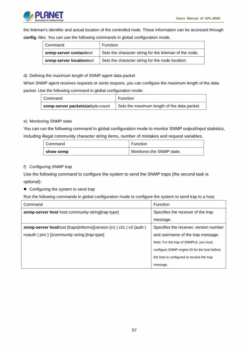
57
Users Manual of GPL-8000
the linkman’s identifer and actual location of the controlled node. These information can be accessed through
config. files. You can use the following commands in global configuration mode.
Command Function
snmp-server contacttext Sets the character string for the linkman of the node.
snmp-server locationtext Sets the character string for the node location.
d) Defining the maximum length of SNMP agent data packet
When SNMP agent receives requests or sents respons, you can configure the maximum length of the data
packet. Use the following command in global configuration mode:
Command Function
snmp-server packetsizebyte-count Sets the maximum length of the data packet.
e) Monitoring SNMP state
You can run the following command in global configuration mode to monitor SNMP output/input statistics, including illegal community character string items, number of mistakes and request variables.
Command Function
show snmp Monitores the SNMP state.
f) Configuring SNMP trap
Use the following command to configure the system to send the SNMP traps (the second task is optional): Configuring the system to send trap
Run the following commands in global configuration mode to configure the system to send trap to a host.
Command Function
snmp-server host host community-string[trap-type] Specifies the receiver of the trap
message.
snmp-server hosthost [traps|informs]{version {v1 | v2c | v3 {auth |
noauth | priv } }}community-string [trap-type]
Specifies the receiver, version number
and username of the trap message.
Note: For the trap of SNMPv3, you must
configure SNMP engine ID for the host before
the host is configured to receive the trap
message.

58
Users Manual of GPL-8000
When the system is started, the SNMP agent will automatically run. All types of traps are activated. You can
use the command snmp-server host to specify which host will receive which kind of trap.
Some traps need to be controlled through other commands. For example, if you want SNMP link traps to be
sent when an interface is opened or closed, you need to run snmp trap link-status in interface configuration
mode to activate link traps. To close these traps, run the interface configuration command snmp trap
link-stat.
You have to configure the command snmp-server host for the host to receive the traps.
Modifying the running parameter of the trap
As an optional item, it can specify the source interface where traps originate, queue length of message or
value of resending interval for each host.
To modify the running parameters of traps, you can run the following optional commands in global
configuration mode.
Command Function
snmp-server trap-source interface Specifies the source interface where traps originate and sets
the source IP address for the message.
snmp-server queue-length length Creates the queue length of the message for each host that
has traps.
Default value: 10
snmp-server trap-timeoutseconds Defines the frequency to resend traps in the resending queue.
Default value: 30 seconds
g) Configuring the SNMP binding source address
Run the following command in the global configuration mode to set the source address for the SNMP message.
Command Function
snmp source-addr ipaddress Sets the source address for the SNMP message.
h) Configuring SNMPv3 group
Run the following command to configure a group.
Command Function
snmp-server group [groupname {v1
| v2c |v3 [auth | noauth |
priv]}][readreadview][writewriteview]
[notifynotifyview]
[accessaccess-list]
Configures a SNMPv3 group. You can only
read all items in the subtree of the Internet by
default.

59
Users Manual of GPL-8000
i) Configuring SNMPv3 user
You can run the following command to configure a local user. When an administrator logs in to a device, he has to user the username and password that are configured on the device. The security level of a user must be higher than or equals to that of the group which the user belongs to. Otherwise, the user cannot pass authentication.
Command Function
snmp-server user username
groupname {v1 | v2c | v3
[encrypted] [auth {md5 | sha}
auth-password ]} [access
access-list]
Configures a local SNMPv3 user.
You can run the following command to configure a remote user. When a device requires to send traps to a
remote control station, a remote user has to be configured if the control station performs ID authentication.
Username and password of the remote user must be the same as those on the control station. Otherwise, the
control station cannot receive traps.
Command Function
snmp-server user username
groupname remote ip-address
[udp-port port] {v1 | v2c | v3
[encrypted] [auth {md5 | sha}
auth-password ]} [access
access-list]
Configures a remote SNMPv3 user.
Note: A remote SNMP engine ID must be
configured for the control station of the IP
address before a remote user is configured.
j) Configuring SNMPv3 Engine ID
The SNMP Engine ID is to identify an SNMP engine. Traditional SNMP manager and agent are part of the
SNMP engine in the SNMPv3 frame.
Command Function
snmp-server engineID remote
ip-address [udp-port
port-number] engineid-string
Configures a remote SNMP engine.
4.3.1.3. Configuration example
a) Example 1
snmp-server community public RO
snmp-server community private RW
snmp-server host 192.168.10.2 public
The above example shows:

60
Users Manual of GPL-8000
how to set the community string public that can only read all MIB variables.
how to set the community string private that can read and write all MIB variables.
You can use the community string public to read MIB variables in the system. You can also use the
community string private to read MIB variables and write writable MIB variables in the system.
The above command specifies the community string public to send traps to 192.168.10.2 when a system
requires to send traps. For example, when a port of a system is in the down state, the system will send a
linkdown trap information to 192.168.10.2.
b) Example 2
snmp-server engineID remote 90.0.0.3 80000523015a000003
snmp-server group getter v3 auth
snmp-server group setter v3 priv write v-write
snmp-server user get-user getter v3 auth sha 12345678
snmp-server user set-user setter v3 encrypted auth md5 12345678
snmp-server user notifier getter remote 90.0.0.3 v3 auth md5 abcdefghi
snmp-server host 90.0.0.3 informs version v3 auth notifier
snmp-server view v-write internet included
The above example shows how to use SNMPv3 to manage devices. Group getter can browse device information, while group setter can set devices. User get-user belongs to group getter while user set-user belongs to group setter.
For user get-user, its security level is authenticate but not encrypt, its password is 12345678, and it uses the sha arithmetic to summarize the password.
For user set-user, its security level is authenticate and encrypt, its password is 12345678, and it uses the md5 arithmetic to summarize the password.
When key events occur at a device, use username notifier to send inform messages to host 90.0.0.3 of the administrator.
4.3.2. RMON Configuration
4.3.2.1. RMON configuration task
RMON configuration tasks include:
Configuring the rMon alarm function for the switch
Configuring the rMon event function for the switch
Configuring the rMon statistics function for the switch
Configuring the rMon history function for the switch
Displaying the rMon configuration of the switch
a) Configuring rMon alarm for switch
You can configure the rMon alarm function through the command line or SNMP NMS. If you configure

61
Users Manual of GPL-8000
through SNMP NMS, you need to configure the SNMP of the switch. After the alarm function is configured, the device can monitor some statistic value in the system. The following table shows how to set the rMon alarm function:
Command Function
configure Enter the global configuration mode.
rmon alarm indexvariableinterval
{absolute | delta} rising-thresholdvalue
[eventnumber] falling-thresholdvalue
[eventnumber] [ownerstring]
Add a rMon alarm item.
index is the index of the alarm item. Its effective range is from 1 to
65535.
variable is the object in the monitored MIB. It must be an effective
MIB object in the system. Only obejects in the Integer, Counter,
Gauge or TimeTicks type can be detected.
interval is the time section for sampling. Its unit is second. Its
effective value is from 1 to 4294967295.
absolute is used to directly monitor the value of MIB object. delta is
used to monitor the value change of the MIB objects between two
sampling.
value is the threshold value when an alarm is generated.
eventnumber is the index of an event that is generated when a
threshold is reached. eventnumber is optional.
owner string is to describe the information about the alarm.
exit Enter the management mode again.
write Save the configuration.
After a rMon alarm item is configured, the device will obtain the value of variable-specified oid after an interval.
The obtained value will be compared with the previous value according to the alrm type (absolute or delta). If
the obtained value is bigger than the previous value and surpasses the threshold value specified by
rising-threshold, an event whose index is eventnumber (If the value of eventnumber is 0 or the event
whose index is eventnumber does not exist in the event table, the event will not occur). If the
variable-specified oid cannot be obtained, the state of the alarm item in this line is set to invalid. If you run
rmon alarm many times to configure alarm items with the same index, only the last configuration is effective.
You can run no rmon alarm index to cancel alarm items whose indexes are index.
b) Configuring rMon event for switch
The steps to configure the rMon event are shown in the following table:
Step Command Purpose
1. configure Enter the global configuration mode.
2. rmon event
index[descriptionstring]
[log] [ownerstring] [trap
community]
Add an rMon event item.
index means the index of the event item. Its effective range
is from 1 to 65535.
description means the information about the event.

62
Users Manual of GPL-8000
log means to add a piece of information to the log table
when a event is triggered.
trap means a trap message is generated when the event is
triggered. community means the name of a community.
owner string is to describe the information about the
alarm.
3. exit Enter the management mode again.
4. write Save the configuration.
After a rMon event is configured, you must set the domain eventLastTimeSent of the rMon event item to
sysUpTime when a rMon alarm is triggered. If the log attribute is set to the rMon event, a message is added
to the log table. If the trap attribute is set to the rMon event, a trap message is sent out in name of community.
If you run rmon event many times to configure event items with the same index, only the last configuration is
effective. You can run no rmon event index to cancel event items whose indexes are index.
c) Configuring rMon statistics for switch
The rMon statistics group is used to monitor the statistics information on every port of the device. The steps to configure the rMon statistics are as follows:
Step Command Purpose
1. configure Enter the global configuration mode.
2. interface iftype ifid Enter the port mode.
iftype means the type of the port.
ifid means the ID of the interface.
3. rmon collection
stat index [ownerstring]
Enable the statistics function on the port.
index means the index of the statistics.
owner string is to describe the information about the statistics.
4. exit Enter the global office mode.
5. exit Enter the management mode again.
6. write Save the configuration.
If you run rmon collection stat many times to configure statistics items with the same index, only the last
configuration is effective. You can run no rmon collection stats index to cancel statistics items whose
indexes are index.
d) Configuring rMon history for switch
The rMon history group is used to collect statistics information of different time sections on a port in a device. The rMon statistics function is configured as follows:
Step Command Purpose
1. configure Enter the global configuration command.
2. interface iftype ifid Enter the port mode.
iftype means the type of the port.

63
Users Manual of GPL-8000
ifid means the ID of the interface.
3. rmon collection
history index
[buckets
bucket-number]
[interval second]
[owner owner-name]
Enable the history function on the port.
index means the index of the history item.
Among all data collected by history item, the latest
bucket-number items need to be saved. You can
browse the history item of the Ethernet to abtain
these statistics values. The default value is 50 items.
second means the interval to abtain the statistics
data every other time. The default value is 1800
seconds.
owner string is used to describe some information
about the history item.
4. exit Enter the global office mode again.
5. exit Enter the management mode again.
6. write Save the configuration.
After a rMon history item is added, the device will obtain statistics values from the specified port every second
seconds. The statistics value will be added to the history item as a piece of information. If you run rmon
collection history index many times to configure history items with the same index, only the last
configuration is effective. You can run no rmon history index to cancel history items whose indexes are
index.
Too many system sources will be occupied; in the case. the value of
bucket-number is too big or the value of interval second is too small.

64
Users Manual of GPL-8000
e) Displaying rMon configuration of switch
Run show to display the rMon configuration of the switch.
Command Purpose
show rmon [alarm] [event]
[statistics] [history]
Displays the rmon configuration information.
alarm means to display the configuration of
the alarm item.
event means to show the configuration of the
event item and to show the items that are
generated by the occurance of events and are
contained in the log table.
statistics means to display the configuration of
the statistics item and statistics values that the
device collects from the port.
history means to display the configuration of
the history item and statistics values that the
device collects in the latest specified intervals
from the port.
4.3.3. Configuring PDP
4.3.3.1. Introduction
PDP is a two-layer protocol specially used to detect network devices. PDP is used in Network Management
Service (NMS) to detect all neighboring devices of an already known device. Using PDP enable you to learn
the SNMP agent address and the types of neighboring devices. After neighboring devices are detected
through PDP, the NMS can require neighboring devices through SNMP to obtain the network topology.
Our switches can detect neighboring devices through PDP, but cannot require neighboring devices through
SNMP. Therefore, these switches have to be located at the verge of networks. Otherwise, the complete
network topology cannot be obtained.
PDP on switches can be configured on all SANPs, such as Ethernet.
4.3.3.2. PDP configuration tasks
Default PDP configuration of the switch
Setting the PDP clock and information saving time
Setting the PDP version
Enabling the PDP on the switch
Enabling the PDP on the port of the switch
Monitoring and managing PDP

65
Users Manual of GPL-8000
a) Default PDP configuration of the switch
Function Default Setting
PDP global configuration state Disabled
PDP port configuration state Disabled
PDP clock (frequency for sending messages) 60 seconds
PDP information saving 180 seconds
PDP version 2
b) Setting the PDP clock and information saving time
Run the following commands in global configuration mode to set the frequency for PDP to send messages and the PDP information saving time:
Command Purpose
pdp timer seconds Sets the frequency for PDP to send messages.
pdp holdtimeseconds Sets the PDP information saving time.
c) Setting the PDP version
Run the following command in global configuration mode to set the PDP version:
Command Purpose
pdp version {1|2} Sets the PDP version. d) Enabling PDP on the switch
PDP is not enabled in the default configuration. If you want to use PDP, run the following command in global configuration mode.
Command Purpose
pdp run Enables the PDP on the switch.
e) Enabling PDP on the port of the switch
PDP is not enabled in the default configuration. You can run the following command in interface configuration mode to enable PDP on the port after PDP is enabled on the switch.
Command Purpose
pdp enable Enables PDP on the port of the switch.
f) Monitoring and managing PDP
Run the following commands in management mode to monitor PDP:
Command Purpose
show pdp traffic Displays the number of PDP messages that the
switch receives and sends.
show pdp neighbor [detail] Displays neighboring devices that the switch
detects through PDP.

66
Users Manual of GPL-8000
4.3.3.3. PDP configuration examples
Example 1: Enabling PDP
config# pdp run
config# int f0/0
config_f0/0#pdp enable
Example 2: Setting the PDP clock and information saving time
config#pdp timer 30
config#pdp holdtime 90
Example 3: Setting the PDP version
config#pdp version 1
Example 4: Monitoring PDP information
config#show pdp neighbors
Capability Codes: R - Router, T - Trans Bridge, B - Source Route Bridge S - Switch, H -
Host, I - IGMP, r - Repeater
Device ID Local IntrfceHoldtmeCapabilityPlatform Port ID
joeEth 0 133 4500 Eth 0
samEth 0 152 R AS5200 Eth 0

67
Users Manual of GPL-8000
SSH Configuration commands
4.4.1. Introduction
4.4.1.1. SSH server
A scure and encrypted communication connection can be created between SSH client and the device through
SSH server. The connection has telnet-like functions. SSH server supports the encryption algorithms
including des, 3des and blowfish.
4.4.1.2. SSH client
SSH client is an application running under the ssh protocol. SSH client can provide authentication and
encryption, so SSH client gurantees secure communication between communication devices or devices
supporting SSH server even if these devices run in unsafe network conditions. SSH client supports the
encryption algorithms including des, 3des and blowfish.
4.4.1.3. Function
SSH server and SSH client supports version 1.5. Both of them only support the shell application.
4.4.2. Configuration Tasks
4.4.2.1. Configuring the authentication method list
SSH server adopts the login authentication mode. SSH server uses the default authentication method list by
default.
Run the following command in global configuration command mode to configure the authentication method
list:
Command Purpose
Ip sshd auth_method STRING Configures the authentication method list.
4.4.2.2. Configuring the access control list
To control the access to the device’s SSH server, you need to configure the access control list for SSH server.
Run the following command in global configuration mode to configure the access control list:
Command Purpose
Ip sshd access-class STRING Configures the access control list.

68
Users Manual of GPL-8000
4.4.2.3. Configuring the authentication timeout value
After a connection is established between client and server, server cuts off the connection if authentication
cannot be approved within the set time.
Run the following command in global configuration mode to configure the configuration timeout value:
Command Purpose
Ip sshd timeout <60-65535> Configures the authentication timeout value.
4.4.2.4. Configuring the times of authentication retrying
If the times for failed authentications exeed the maximum times, SSH server will not allow you to retry
authentication unless a new connction is established. The maximum times for retrying authentication is 3 by
default.
Run the following command in global configuration mode to configure the maximum times for retrying
authentication:
Command Purpose
Ip sshd auth-retries <0-65535> Configures the maximum times for retrying authentication.
4.4.2.5. Enabling SSH server
SSH server is disabled by default. When SSH server is enabled, the device will generate a rsa password pair,
and then listen connection requests from the client. The process takes one or two minutes.
Run the following command in global configuration mode to enable SSH server:
Command Purpose
Ip sshd enable Enables SSH server. The digit of the password is 1024.
4.4.3. SSH server Configuration Example
The following configuration only allows the host whose IP address is 192.168.20.40 to access SSH server.
The local user database is used to distinguish user ID.
4.4.3.1. Access control list
ip access-list standard ssh-acl
permit 192.168.20.40
4.4.3.2. Global configuration
aaa authentication login ssh-auth local

69
Users Manual of GPL-8000
ip sshd auth-method ssh-auth
ip sshd access-class ssh-acl
ip sshd enable
70
Users Manual of GPL-8000
Remote Monitoring
Remote Monitoring 5.1.1 SNMP Configuration 5.1.2 Overview The SNMP system includes the following 3 parts:
SNMP management server (NMS)
SNMP agent (agent)
MIB SNMP is a protocol for the application layer.It provides the format for the packets which are transmitted
between NMS and agent.
SNMP management server is a part of the network management system, such as CiscoWorks.
SNMP agent includes the MIB variable and the SNMP management server can be used to browse or change
these variables’ values.The management server can get the values from the agent or save these variables in
the agent.The agent collects data from MIB.MIB is the database of equipment parameters and network data. 5.1.3 SNMP Notification When a special event occurs, the system will send an inform to the SNMP management server.For example,
when the agent system runs into a incorrect condition, it will send a message to the management server.
The SNMP notification can be sent as a trap or a inform request.Because the receiver receives a trap and
does not send any response, the transmitter hence cannot confirm whether the trap is received. In this way,
the trap is unreliable.Comparatively, the SNMP management server uses SNMP to respond PDU, which is
acted as a response of this message.If the management server does not receive the inform request, it will not
transmit a response.If the transmitter does not receives the response, it will transmit the inform request
again.In this way, the inform has more chance to arrive the planned destination. 5.1.4 SNMP Tasks Configuring idle time value
Configuring the time value of waiting for acknowledgement
Configuring busy time value of remote end
Configuring time value of Response
Configuring the time of reject
Configuring the redial times
Configuring the size of window for resend
Configuring the size of accumulated data packet
Setting the acknowledgement time-delay
Setting the maximum numbers of acknowledgement
Showing LLC2 link information
Debugging LLC2 link information

71
Users Manual of GPL-8000
Security Configuration
AAAConfiguration 6.1.1 AAA Overview Access control is the way to control access to the network and services. Authentication, authorization, and
accounting (AAA) network security services provide the primary framework through which you set up access
control on your router or access server.
6.1.1.1 AAA Security Service AAA is an architectural framework for configuring a set of three independent security functions in a consistent
manner. AAA provides a modular way of performing the following services:
• Authentication—Provides the method of identifying users, including login and password dialog, challenge
and response, messaging support, and, depending on the security protocol you select, encryption.
Authentication is the way a user is identified prior to being allowed access to the network and network
services. You configure AAA authentication by defining a named list of authentication methods, and then
applying that list to various interfaces. The method list defines the types of authentication to be performed and
the sequence in which they will be performed; it must be applied to a specific interface before any of the
defined authentication methods will be performed. The only exception is the default method list (which is
named "default"). The default method list is automatically applied to all interfaces if no other method list is
defined. A defined method list overrides the default method list.
All authentication methods, except for local, line password, and enable authentication, must be defined
through AAA. For information about configuring all authentication methods, including those implemented
outside of the AAA security services, refer to the chapter "Configuring Authentication."
• Authorization—Provides the method for remote access control, including one-time authorization or
authorization for each service, per-user account list and profile, user group support, and support of IP, IPX,
ARA, and Telnet.
AAA authorization works by assembling a set of attributes that describe what the user is authorized to perform.
These attributes are compared to the information contained in a database for a given user and the result is
returned to AAA to determine the user's actual capabilities and restrictions. The database can be located
locally on the access server or router or it can be hosted remotely on a RADIUS or TACACS+ security server.
Remote security servers, such as RADIUS and TACACS+, authorize users for specific rights by associating
attribute-value (AV) pairs, which define those rights with the appropriate user. All authorization methods must
be defined through AAA.

72
Users Manual of GPL-8000
As with authentication, you configure AAA authorization by defining a named list of authorization methods,
and then applying that list to various interfaces. For information about configuring authorization using AAA,
refer to the chapter "Configuring Authorization."
• Accounting—Provides the method for collecting and sending security server information used for billing,
auditing, and reporting, such as user identities, start and stop times, executed commands (such as PPP),
number of packets, and number of bytes.
Accounting enables you to track the services users are accessing as well as the amount of network resources
they are consuming. When AAA accounting is activated, the network access server reports user activity to the
RADIUS or TACACS+ security server (depending on which security method you have implemented) in the
form of accounting records. Each accounting record is comprised of accounting AV pairs and is stored on the
access control server. This data can then be analyzed for network management, client billing, and/or auditing.
All accounting methods must be defined through AAA. As with authentication and authorization, you configure
AAA accounting by defining a named list of accounting methods, and then applying that list to various
interfaces. For information about configuring accounting using AAA, refer to the chapter "Configuring
Accounting."
6.1.1.2 Benefits of Using AAA AAA provides the following benefits:
Increased flexibility and control of access configuration
Scalability
Standardized authentication methods, such as RADIUS, TACACS+, and Kerberos
Multiple backup systems
6.1.1.3 AAA Principles AAA is designed to enable you to dynamically configure the type of authentication and authorization you want
on a per-line (per-user) or per-service (for example, IP, IPX, or VPDN) basis. You define the type of
authentication and authorization you want by creating method lists, then applying those method lists to
specific services or interfaces.
6.1.1.4 Method Lists A method list is a sequential list that defines the authentication methods used to authenticate a user. Method
lists enable you to designate one or more security protocols to be used for authentication, thus ensuring a
backup system for authentication in case the initial method fails. Cisco IOS software uses the first method
listed to authenticate users; if that method does not respond, Cisco IOS software selects the next
authentication method in the method list. This process continues until there is successful communication with
a listed authentication method or the authentication method list is exhausted, in which case authentication
fails.

73
Users Manual of GPL-8000
The software attempts authentication with the next listed authentication method only when there is no
response from the previous method. If authentication fails at any point in this cycle—meaning that the security
server or local username database responds by denying the user access—the authentication process stops
and no other authentication methods are attempted. The following figures shows a typical AAA network
configuration that includes four security servers: R1 and R2 are RADIUS servers, and T1 and T2 are
TACACS+ servers.
Figure 6-1 Typical AAA Network Configuration
Suppose the system administrator has defined a method list where R1 will be contacted first for authentication
information, then R2, T1, T2, and finally the local username database on the access server itself. When a
remote user attempts to dial in to the network, the network access server first queries R1 for authentication
information. If R1 authenticates the user, it issues a PASS response to the network access server and the
user is allowed to access the network. If R1 returns a FAIL response, the user is denied access and the
session is terminated. If R1 does not respond, then the network access server processes that as an ERROR
and queries R2 for authentication information. This pattern continues through the remaining designated
methods until the user is either authenticated or rejected, or until the session is terminated. If all of the
authentication methods return errors, the network access server will process the session as a failure, and the
session will be terminated.
A FAIL response is significantly different from an ERROR. A FAIL means that the user has not met the criteria
contained in the applicable authentication database to be successfully authenticated. Authentication ends
with a FAIL response. An ERROR means that the security server has not responded to an authentication
query. Because of this, no authentication has been attempted. Only when an ERROR is detected will AAA
select the next authentication method defined in the authentication method list.
6.1.2 AAA Configuration Process You must first decide what kind of security solution you want to implement. You need to assess the security
risks in your particular network and decide on the appropriate means to prevent unauthorized entry and
attack.

74
Users Manual of GPL-8000
6.1.2.1 Overview of the AAA Configuration Process Configuring AAA is relatively simple after you understand the basic process involved. To configure security on
a Cisco router or access server using AAA, follow this process:
If you decide to use a separate security server, configure security protocol parameters, such as RADIUS,
TACACS+, or Kerberos.
Define the method lists for authentication by using an AAA authentication command.
Apply the method lists to a particular interface or line, if required.
(Optional) Configure authorization using the AAA authorization command.
(Optional) Configure accounting using the AAA accounting command.
6.1.3 AAA Authentication Configuration Task List Configuring Login Authentication Using AAA
Configuring PPP Authentication Using AAA
Enabling Password Protection at the Privileged Level
Configuring Message Banners for AAA Authentication
AAA authentication username-prompt
AAA authentication password-prompt
Establishing Username Authentication
Enabling Password
6.1.4 AAA Authentication Configuration Task To configure AAA authentication, perform the following configuration processes:
1. If you decide to use a separate security server, configure security protocol parameters, such as RADIUS,
TACACS+, or Kerberos.
2. Define the method lists for authentication by using an AAA authentication command.
3. Apply the method lists to a particular interface or line, if required.
6.1.4.1 Configuring Login Authentication Using AAA The AAA security services facilitate a variety of login authentication methods. Use the aaa authentication login
command to enable AAA authentication no matter which of the supported login authentication methods you
decide to use. With the aaa authentication login command, you create one or more lists of authentication
methods that are tried at login. These lists are applied using the login authentication line configuration
command.
To configure login authentication by using AAA, use the following commands beginning in global configuration
mode:

75
Users Manual of GPL-8000
Command Purpose
aaa authentication login {default | list-name}method1
[method2...] Enables AAA globally.
line [ console | vty ] line-number [ending-line-number] Enters line configuration mode for the lines to which
you want to apply the authentication list.
login authentication {default | list-name} Applies the authentication list to a line or set of lines.
The list-name is a character string used to name the list you are creating. The method argument refers to the
actual method the authentication algorithm tries. The additional methods of authentication are used only if the
previous method returns an error, not if it fails. To specify that the authentication should succeed even if all
methods return an error, specify none as the final method in the command line.
For example, to specify that authentication should succeed even if (in this example) the TACACS+ server
returns an error, enter the following command:
aaa authentication login default group radius
Because the none keyword enables any user to log in for authentication, it should
be used only as a backup method of authentication.
The following table lists the supported login authentication methods.:
Keyword description
enable Uses the enable password for authentication.
group name Uses named server group for authentication.
group radius Uses the list of all RADIUS servers for authentication.
line Uses the line password for authentication.
local Uses the local username database for authentication.
local-case Uses case-sensitive local username authentication.
none Uses no authentication.
(1) Login Authentication Using Enable Password
Use the aaa authentication login command with the enable method keyword to specify the enable password
as the login authentication method. For example, to specify the enable password as the method of user
authentication at login when no other method list has been defined, enter the following command:
aaa authentication login default enable
(2) Login Authentication Using Line Password
Use the aaa authentication login command with the line method keyword to specify the line password as the
login authentication method. For example, to specify the line password as the method of user authentication
at login when no other method list has been defined, enter the following command:
aaa authentication login default line
Before you can use a line password as the login authentication method, you need to define a line password.

76
Users Manual of GPL-8000
(3) Login Authentication Using Local Password
Use the aaa authentication login command with the local method keyword to specify that the Cisco router or
access server will use the local username database for authentication. For example, to specify the local
username database as the method of user authentication at login when no other method list has been defined,
enter the following command:
aaa authentication login default local
For information about adding users into the local username database, refer to the section "Establishing
Username Authentication" in this chapter.
(4) Login Authentication Using Group RADIUS
Use the aaa authentication login command with the group radius method to specify RADIUS as the login
authentication method. For example, to specify RADIUS as the method of user authentication at login when
no other method list has been defined, enter the following command:
aaa authentication login default group radius
Before you can use RADIUS as the login authentication method, you need to enable communication with the
RADIUS security server. For more information about establishing communication with a RADIUS server, refer
to the chapter "Configuring RADIUS."
6.1.4.2 Enabling Password Protection at the Privileged Level Use the aaa authentication enable default command to create a series of authentication methods that are
used to determine whether a user can access the privileged EXEC command level. You can specify up to four
authentication methods. The additional methods of authentication are used only if the previous method
returns an error, not if it fails. To specify that the authentication should succeed even if all methods return an
error, specify none as the final method in the command line.
Use the following command in global configuration mode:
Command Purpose
aaa authentication enable
defaultmethod1 [method2...]
Enables user ID and password checking for users
requesting privileged EXEC level.
The method argument refers to the actual list of methods the authentication algorithm tries, in the sequence
entered.
The following table lists the supported enable authentication methods.
Keyword Description
enable Uses the enable password for authentication.
group
group-name
Uses a subset of RADIUS or TACACS+ servers for authentication as defined by the
aaa group server radius or aaa group server tacacs+ command.
group radius Uses the list of all RADIUS hosts for authentication.
line Uses the line password for authentication.
none Uses no authentication.

77
Users Manual of GPL-8000
6.1.4.3 Configuring Message Banners for AAA Authentication AAA supports the use of configurable, personalized login and failed-login banners. You can configure
message banners that will be displayed when a user logs in to the system to be authenticated using AAA and
when, for whatever reason, authentication fails.
6.1.4.4 Configuring a Login Banner To configure a banner that will be displayed whenever a user logs in (replacing the default message for login),
use the following commands in global configuration mode: :
Command Purpose
aaa authentication bannerdelimiter
text-string delimiter Creates a personalized login banner.
6.1.4.5 Configuring a Failed-Login Banner To configure a message that will be displayed whenever a user fails login (replacing the default message for
failed login), use the following commands in global configuration mode: :
Command Purpose
aaa authentication
fail-messagedelimiter text-string
delimiter
Creates a message to be displayed
when a user fails login.
6.1.4.6 Instruction To create a login banner, you need to configure a delimiting character, which notifies the system that the
following text string is to be displayed as the banner, and then the text string itself. The delimiting character is
repeated at the end of the text string to signify the end of the banner. The delimiting character can be any
single character in the extended ASCII character set, but once defined as the delimiter, that character cannot
be used in the text string making up the banner.
6.1.4.7 AAA authentication username-prompt To change the text displayed when users are prompted to enter a username, use the aaa authentication
username-prompt command in global configuration mode. To return to the default username prompt text, use
the no form of this command. username:
The aaa authentication username-prompt command does not change any dialog that is supplied by a remote
TACACS+ server. Use the following command to configure in global configuration mode:
Command Purpose
aaa authentication username-prompt
text-string
String of text that will be displayed
when the user is prompted to enter an
username.

78
Users Manual of GPL-8000
6.1.4.8 AAA authentication password-prompt To change the text displayed when users are prompted for a password, use the aaa authentication
password-prompt command in global configuration mode. To return to the default password prompt text, use
the no form of this command.
password:
The aaa authentication password-prompt command does not change any dialog that is supplied by a remote
TACACS+ server. Use the following command to configure in global configuration mode:
Command Purpose
aaa authentication
password-prompttext-string
String of text that will be displayed
when the user is prompted to enter a
password.
6.1.4.9 Establishing Username Authentication You can create a username-based authentication system, which is useful in the following situations:
To provide a TACACS-like username and encrypted password-authentication system for networks that
cannot support TACACS
To provide special-case logins: for example, access list verification, no password verification,
autocommand execution at login, and "no escape" situations
To establish username authentication, use the following commands in global configuration mode as needed
for your system configuration:
Use the no form of this command to delete a username.
usernamename {nopassword | passwordpassword | passwordencryption-typeencrypted-password}
usernamename [autocommandcommand]
usernamename [callback-dialstringtelephone-number]
usernamename [callback-rotaryrotary-group-number]
usernamename [callback-line [tty | aux] line-number [ending-line-number]]
usernamename [noescape] [nohangup]
usernamename [privilegelevel]
usernamename [user-maxlinksnumber]
no username name
6.1.4.10 Enabling password To set a local password to control access to various privilege levels, use the enable password command in
global configuration mode. To remove the password requirement, use the no form of this command.
enable password { [encryption-type] encrypted-password} [level level]
no enable password [level level]

79
Users Manual of GPL-8000
6.1.5 AAA Authentication Configuration Example 6.1.5.1 RADIUS Authentication Example This section provides one sample configuration using RADIUS.
The following example shows how to configure the switch to authenticate and authorize using RADIUS:
aaa authentication login radius-login group radius local
aaa authorization network radius-network radius
line vty
login authentication radius-login
The lines in this sample RADIUS authentication and authorization configuration are defined as follows: :
The aaa authentication login radius-login radius local command configures the router to use RADIUS for
authentication at the login prompt. If RADIUS returns an error, the user is authenticated using the local
database.
The aaa authentication ppp radius-ppp radius command configures the software to use PPP
authentication using CHAP or PAP if the user has not already logged in. If the EXEC facility has
authenticated the user, PPP authentication is not performed.
The aaa authorization network radius-network radius command command queries RADIUS for network
authorization, address assignment, and other access lists.
The login authentication radius-login command enables the radius-login method list for line 3.
6.1.6 AAA Authorization Configuration Task List Configuring EXEC Authorization using AAA
6.1.7 AAA Authorization Configuration Task To configure AAA authorization, perform the following configuration processes:
(1) If you decide to use a separate security server, configure security protocol parameters, such as RADIUS,
TACACS+, or Kerberos.
(2) Define the method lists for authorization by using an AAA authorization command.
(3) Apply the method lists to a particular interface or line, if required.

80
Users Manual of GPL-8000
6.1.7.1 Configuring EXEC Authorization Using AAA Use the aaa authorization command to enable authorization
Use aaa authorization exec command to run authorization to determine if the user is allowed to run an EXEC
shell. This facility might return user profile information such as autocommand information.
Use line configuration command login authorization to apply these lists. Use the following command in global
configuration mode:
Command Purpose
aaa authorization exec {default |
list-name}method1 [method2...] Establishes global authorization list.
line [console | vty ] line-number
[ending-line-number]
Enters the line configuration mode for
the lines to which you want to apply
the authorization method list.
login authorization {default | list-name}
Applies the authorization list to a line
or set of lines(in line configuration
mode).
The keyword list-name is the character string used to name the list of authorization methods.
The keyword method specifies the actual method during authorization process. Method lists enable you to
designate one or more security protocols to be used for authorization, thus ensuring a backup system in case
the initial method fails. The system uses the first method listed to authorize users for specific network services;
if that method fails to respond, the system selects the next method listed in the method list. This process
continues until there is successful communication with a listed authorization method, or all methods defined
are exhausted. If all specified methods fail to respond, and you still want the system to enter the EXEC shell,
you should specify none as the last authorization method in command line.
Use default parameter to establish a default list, and the default list will apply to all interfaces automatically.
For example, use the following command to specify radius as the default authorization method for exec:
aaa authorization exec default group radius
If no method list is defined, the local authorization service will be unavailable and
the authorization is allowed to pass.
The following table lists the currently supported EXEC authorization mode:
Keyword Description
group WORD Uses a named server group for authorization.
group radius Uses radius authorization.
local Uses the local database for authorization.
if-authenticated Allows the user to access the requested function if the user is
authenticated.
none No authorization is performed.

81
Users Manual of GPL-8000
6.1.8 AAA Authorization Example EXEC local authorization example
aaa authentication login default local
aaa authorization exec default local
!
username exec1 password 0 abc privilege 15
username exec2 password 0 abc privilege 10
username exec3 nopassword
username exec4 password 0 abc user-maxlinks 10
username exec5 password 0 abc autocommand telnet 172.16.20.1
!
The lines in this sample RADIUS authorization configuration are defined as follows: :
The aaa authentication login default local command defines the default method list of login authentication.
This method list applies to all login authentication servers automatically.
The aaa authorization exec default local command defines default method list of exec authorization. The
method list automatically applies to all users that need to enter exec shell.
Username is exec1,login password is abc,EXEC privileged level is 15(the highest level),that is, when
user exec1 whose privileged level is 15 logs in exec shell, all commands can be checked and performed.
Username is exec2,login password is abc,EXEC privileged level is 10,that is, when user exec2 whose
privileged level is 10 logs in EXEC shell, commands with privileged level less than 10 can be checked and
performed.
Username is exec3,no password is needed for login.
Username is exec4,login password is abc,the maximum links of the user is 10.
Username is exec5,login password is abc, user performs telnet 172.16.20.1 immediately when logging in
exec shell.
6.1.9 AAA Accounting Configuration Task List Configuring Connection Accounting using AAA
Configuring Network Accounting using AAA
6.1.10 AA Accounting Configuration Task To configure AAA accounting, perform the following configuration processes:
(1) If you decide to use a separate security server, configure security protocol parameters, such as RADIUS,
TACACS+, or Kerberos.
(2) Define the method lists for accounting by using an AAA accounting command.
(3) Apply the method lists to a particular interface or line, if required.

82
Users Manual of GPL-8000
6.1.10.1 Configuring Accounting Connection Using AAA Use the aaa accounting command to enable AAA accounting.
To create a method list to provide accounting information about all outbound connections made from the
network access server, use the aaa accounting connection command.
Command Purpose
aaa accounting connection {default |
list-name} {start-stop | stop-only |
none} group groupname
Establishes global accounting list.
The keyword list-name is used to name any character string of the establishing list. The keyword method
specifies the actual method adopted during accounting process.
The following table lists currently supported connection accounting methods:
Keyword Description
group WORD Enables named server group for accounting.
group radius Enables radius accounting.
none Disables accounting services for the specified line or interface.
stop-only Sends a "stop" record accounting notice at the end of the requested user process.
start-stop RADIUS or TACACS+ sends a "start" accounting notice at the beginning of the requested
process and a "stop" accounting notice at the end of the process.
6.1.10.2 Configuring Network Accounting Using AAA Use the aaa accounting command to enable AAA accounting.
To create a method list to provide accounting information for SLIP, PPP, NCPs, and ARAP sessions, use the
aaa accounting network command in global configuration mode.
Command Purpose
aaa accounting network {default | list-name} {start-stop |
stop-only | none} group groupname Enables global accounting list.
The keyword list-name is used to name any character string of the establishing list. The keyword method
specifies the actual method adopted during accounting process.
The following table lists currently supported network accounting methods:
Keyword Description
group WORD Enables named server group for accounting.
group radius Enables radius accounting.
none Disables accounting services for the specified line or interface.
stop-only Sends a "stop" record accounting notice at the end of the requested user process.
start-stop RADIUS or TACACS+ sends a "start" accounting notice at the beginning of the requested
process and a "stop" accounting notice at the end of the process.

83
Users Manual of GPL-8000
6.1.10.3 AAA Accounting Update To enable periodic interim accounting records to be sent to the accounting server, use the aaa accounting
update command in global configuration mode. To disable interim accounting updates, use the no form of this
command.
Command Purpose
aaa accounting update [newinfo]
[periodicnumber] Enables AAA accounting update.
If the newinfo keyword is used, interim accounting records will be sent to the accounting server every time
there is new accounting information to report. An example of this would be when IP Control Protocol (IPCP)
completes IP address negotiation with the remote peer. The interim accounting record will include the
negotiated IP address used by the remote peer.
When used with the periodic keyword, interim accounting records are sent periodically as defined by the
argument number. The interim accounting record contains all of the accounting information recorded for that
user up to the time the accounting record is sent.
When using both the newinfo and periodic keywords, interim accounting records are sent to the accounting
server every time there is new accounting information to report, and accounting records are sent to the
accounting server periodically as defined by the argument number. For example, if you configure the aaa
accounting update newinfo periodic number command, all users currently logged in will continue to generate
periodic interim accounting records while new users will generate accounting records based on the newinfo
algorithm.
6.1.10.4 AAA accounting suppress null-username To prevent the AAA system from sending accounting records for users whose username string is NULL, use
the aaa accounting suppress null-username command in global configuration mode. To allow sending records
for users with a NULL username, use the no form of this command.
aaa accounting suppress null-username
Configuring RADIUS This chapter describes the Remote Authentication Dial-In User Service (RADIUS) security system, defines its
operation, and identifies appropriate and inappropriate network environments for using RADIUS technology.
The "RADIUS Configuration Task List" section describes how to configure RADIUS with the authentication,
authorization, and accounting (AAA) command set.
6.2.1 Introduction 6.2.1.1 RADIUS Introduction RADIUS is a distributed client/server system that secures networks against unauthorized access. In the
implementation, RADIUS clients run on switches and send authentication requests to a central RADIUS
server that contains all user authentication and network service access information.
RADIUS has been implemented in a variety of network environments that require high levels of security while

84
Users Manual of GPL-8000
maintaining network access for remote users.
Use RADIUS in the following network environments that require access security: :
Networks with multiple-vendor access servers, each supporting RADIUS. For example, access servers
from several vendors use a single RADIUS server-based security database. In an IP-based network with
multiple vendors' access servers, dial-in users are authenticated through a RADIUS server that has been
customized to work with the Kerberos security system.
Networks in which a user must only access a single service. Using RADIUS, you can control user access
to a single host, to a single utility such as Telnet, or to a single protocol such as Point-to-Point Protocol
(PPP). For example, when a user logs in, RADIUS identifies this user as having authorization to run PPP
using IP address 10.2.3.4 and the defined access list is started.
Networks that require resource accounting. You can use RADIUS accounting independent of RADIUS
authentication or authorization. The RADIUS accounting functions allow data to be sent at the start and
end of services, indicating the amount of resources (such as time, packets, bytes, and so on) used during
the session. An Internet service provider (ISP) might use a freeware-based version of RADIUS access
control and accounting software to meet special security and billing needs.
RADIUS is not suitable in the following network security situations:
Multiprotocol access environments. RADIUS does not support the following protocols:
AppleTalk Remote Access (ARA)
NetBIOS Frame Control Protocol (NBFCP)
NetWare Asynchronous Services Interface (NASI)
X.25 PAD connections
Switch-to-switch situations. RADIUS does not provide two-way authentication.
Networks using a variety of services. RADIUS generally binds a user to one service model.

85
Users Manual of GPL-8000
6.2.1.2 RADIUS Operation When a user attempts to log in and authenticate to an access server using RADIUS, the following steps
occur:
(1) The user is prompted for and enters a username and password.
(2) The username and encrypted password are sent over the network to theRADIUS server.
(3) The user receives one of the following responses from the RADIUS server:
a. ACCEPT—the user is authenticated.
b. REJECT—the user is not authenticated and is prompted to reenter the username and password, or
access is denied.
c. CHALLENGE—a challenge is issued by the RADIUS server. The challenge collects additional data
from the user.
d. CHANGE PASSWORD—a request is issued by the RADIUS server, asking the user to select a new
password.
The ACCEPT or REJECT response is bundled with additional data that is used for EXEC or network
authorization. You must first complete RADIUS authentication before using RADIUS authorization. The
additional data included with the ACCEPT or REJECT packets consists of the following:
Services that the user can access, including Telnet, rlogin, or local-area transport (LAT) connections, and PPP,
Serial Line Internet Protocol (SLIP), or EXEC services.
Connection parameters,include the host or client IP address, access list, and user timeouts.
6.2.2 RADIUS Configuration Task List To configure RADIUS on your switch or access server, you must perform the following tasks:
Use the aaa authentication global configuration command to define method lists for RADIUS
authentication. For more information about using the aaa authentication command, refer to the
"Configuring Authentication" chapter.
Use line and interface commands to enable the defined method lists to be used. For more information,
refer to the "Configuring Authentication" chapter.
The following configuration tasks are optional:
You may use the aaa authorization global command to authorize specific user functions. For more
information about using the aaa authorization command, refer to the chapter "Configuring Authorization."
You may use the aaa accounting command to enable accounting for RADIUS connections. For more
information about using the aaa accounting command, refer to the chapter "Configuring Accounting."

86
Users Manual of GPL-8000
6.2.3 RADIUS Configuration Task List Configuring Switch to RADIUS Server Communication
Configuring Switch to Use Vendor-Specific RADIUS Attributes
Specifying RADIUS Authentication
Specifying RADIUS Authorization
Specifying RADIUS Accounting
6.2.4 RADIUS Configuration Task 6.2.4.1 Configuring Switch to RADIUS Server Communication The RADIUS host is normally a multiuser system running RADIUS server software from Livingston, Merit,
Microsoft, or another software provider.
A RADIUS server and a Cisco router use a shared secret text string to encrypt passwords and exchange
responses.
To configure RADIUS to use the AAA security commands, you must specify the host running the RADIUS
server daemon and a secret text (key) string that it shares with the router.
To configure per-server RADIUS server communication, use the following command in global configuration
mode:
Command Purpose
radius-server hostip-address
[auth-portport-number][acct-portportnumber]
Specifies the IP address or host name of the remote
RADIUS server host and assign authentication and
accounting destination port numbers.
radius-server keystring Specifies the shared secret text string used between
the router and a RADIUS server.
To configure global communication settings between the router and a RADIUS server, use the following
radius-server commands in global configuration mode:
Command Purpose
radius-server retransmitretries
Specifies how many times the switch transmits each
RADIUS request to the server before giving up (the
default is 2).
radius-server timeout seconds
Specifies for how many seconds a switch waits for a
reply to a RADIUS request before retransmitting the
request.
radius-server deadtime minutes
Specifies for how many minutes a RADIUS server that
is not responding to authentication requests is passed
over by requests for RADIUS authentication.

87
Users Manual of GPL-8000
6.2.4.2 Configuring Switch to Use Vendor-Specific RADIUS Attributes The Internet Engineering Task Force (IETF) draft standard specifies a method for communicating
vendor-specific information between the network access server and the RADIUS server by using the
vendor-specific attribute (attribute 26).
Vendor-specific attributes (VSAs) allow vendors to support their own extended attributes not suitable for
general use.
For more information about vendor-IDs and VSAs, refer to RFC 2138, Remote Authentication Dial-In User
Service (RADIUS). To configure the network access server to recognize and use VSAs, use the following
command in global configuration mode:
Command Purpose
radius-servervsa send [authentication] Enables the network access server to recognize and use VSAs
as defined by RADIUS IETF attribute 26.
6.2.4.3 Specifying RADIUS Authentication After you have identified the RADIUS server and defined the RADIUS authentication key, you must define
method lists for RADIUS authentication. Because RADIUS authentication is facilitated through AAA, you must
enter the aaa authentication command, specifying RADIUS as the authentication method. For more
information, refer to the chapter "Configuring Authentication."
6.2.4.4 Specifying RADIUS Authorization AAA authorization lets you set parameters that restrict a user's access to the network. Authorization using
RADIUS provides one method for remote access control, including one-time authorization or authorization for
each service, per-user account list and profile, user group support, and support of IP, IPX, ARA, and Telnet.
Because RADIUS authorization is facilitated through AAA, you must issue the aaa authorization command,
specifying RADIUS as the authorization method. For more information, refer to the chapter "Configuring
Authorization."
6.2.4.5 Specifying RADIUS Accounting The AAA accounting feature enables you to track the services users are accessing as well as the amount of
network resources they are consuming. Because RADIUS accounting is facilitated through AAA, you must
issue the aaa accounting command, specifying RADIUS as the accounting method. For more information,
refer to the chapter "Configuring Accounting."

88
Users Manual of GPL-8000
6.2.5 RADIUS Configuration Examples 6.2.5.1 RADIUS Authentication and Authorization Example The following example shows how to configure the router to authenticate and authorize using RADIUS:
aaa authentication login use-radius group radius local
The lines in this sample RADIUS authentication and authorization configuration are defined as follows: :
aaa authentication login use-radius radius local configures the router to use RADIUS for authentication at the
login prompt. If RADIUS returns an error, the user is authenticated using the local database. In this example,
use-radius is the name of the method list, which specifies RADIUS and then local authentication.
RADIUS Authentication, Authorization, and Accounting Example
The following example shows a general configuration using RADIUS with the AAA command set: :
radius-server host 1.2.3.4
radius-server key myRaDiUSpassWoRd
username root password AlongPassword
aaa authentication login admins radius local
line vty 1 16
login authentication admins
The lines in this example RADIUS authentication, authorization, and accounting configuration are defined as
follows:
radius-server host command defines the IP address of the RADIUS server host.;
radius-server key command defines the shared secret text string between the network access server and the
RADIUS server host.
aaa authentication login admins group radius local command defines the authentication method list "dialins,"
which specifies that RADIUS authentication and then (if the RADIUS server does not respond) local
authentication will be used on serial lines using PPP.;
login authentication admins command applies the "admins" method list for login authentication.
6.2.5.2 RADIUS Application Example The following example shows how to define the general configuration through the AAA command set:
radius-server host 1.2.3.4
radius-server key myRaDiUSpassWoRd
username root password AlongPassword
aaa authentication login admins radius local
line vty 1 16
login authentication admins
In the example above, each command line has its own meaning. See the following content:
The command radius-server host defines the IP address of the RADIUS server.
The command radius-server key defines the shared pin between the network access server and the
RADIUS server.
The command aaa authentication login admins radius local defines the authentication method list admins,
which first specifies RADIUS as the authentication method and then uses the local authentication if the

89
Users Manual of GPL-8000
RADIUS server does not respond.
The command login authentication admins specifies the method list admins as the login authentication
method.
Web Authentication Configuration The section describes the concept of Web authentication and configuration and usage of the Web
authentication.
6.3.1 Overview 6.3.1.1 Web Authentication The Web authentication of the switch is a connection control mode as PPPoE and 802.1x. When you use the
Web authentication, the login and logout operations can be successfully performed through the interaction of
the browser and the builtin portal server of the switch. During the operations of login and logout, no other
client software need be installed. 1. Device role
The roles that the network devices take during the Web authentication are shown in Figure 6-2:
Client: It is ausercomputer that accesses network through the switch. The user computer need be
configured the network browser, the function of DHCP client and the function to originate DNS query.
DHCP server: It is to distribute the IP address for users. AAA server: It is to save user right information and to charge users for their network access. Switch: It is a switch having Web authentication. It is to control the access right of users and works as an
agent between users and AAA server.
Figure 6-2Web authentication network
2. Authentication flow
According to different configuration strategies, the Web authentication flow of the switch may relate to
protocols such as DHCP and DNS. Its typical flow is shown in Figure 3-2. The Web authentication flow
generally contains the following steps:
(1) The DHCP server sends a DHCP confirmation request to a user through the switch after the user
originates the process of DHCP address distribution. The switch then identifies and records the user.
COL-ACT-STA-
1 2 3 4 5 6 7 8 9101112HS1 HS2 OK1 OK2 PS
CONSOLE swi t ch
AAA ser ver( RADI US)
cl i ent
cl i ent DHCP ser ver

90
Users Manual of GPL-8000
(2) The user accesses any Website through the browser (Write down the domain name, not the IP address, in
the host part of the url column in the browser), which activates the DNS request of the user computer.
(3) The DNS server returns the user a request response. The switch captures the request response message
and changes the resolved address to the address of the built-in portal server in the switch.
(4) The DHCP confirmation process continues after the browser captures DNS resolution. The switch returns
the corresponding authentication page according to different authentication methods after the switch
receives the request.
(5) The user submits the authentication request; the switch authenticates the user through the AAA server
after the switch receives information submitted by the user; if the authentication succeeds, the AAA server
will be notified to start charging; the switch gives the user the network access right and returns the user a
page that the authentication is successful; meanwhile, the switch also returns a keep alive page, which
periodically sends the user online notification to the switch.
(6) The user sends the logout request to the switch through the browser. The switch then notifies the AAA
server to stop charging, and withdraws the network access right from the user.
(7) In the period between successful user authentication and logout, the switch periodically detects the user
online notification. If the notification is not received in the preset time, the switch considers that the user
abnormally logs off, notifies the AAA server to stop charging and withdraws the network access right from
the user.
The above steps may vary a little with configuration strategies and user’s operations. For example, if user
directly accesses the portal server of the switch before the authentication is approved, DNS-related
processes will not be enabled.

91
Users Manual of GPL-8000
Figure 6-3 web authentication flow
6.3.1.2 Planning Web Authentication 1. Planning the authentication mode
Two authentication modes are provided to control user's access: Username/password authentication mode: In this mode, the switch identifies the user through the username
and password, and notifies the AAA server to start charging according to username; user needs to enter the
username and password through the browser. VLAN ID authentication mode: In this mode, the switch identifies the user through the VLAN ID the user
belongs to, and notifies the AAA server to start charging according to VLAN ID; user only requires to confirm
corresponding operations on the Web page before accessing the network. Different operation strategies adopt different authentication modes. The supported maximum number of users
that simultaneously access the network varies with the authentication mode. For the username/password
authentication mode, the switch supports simultaneously accessed users as many as its performance permits.
For the VLAN ID authentication mode, the maximum number of simultaneously accessed users equals the
number of VLAN that the switch supports.
cl i ent swi t ch dhcp ser ver DNS ser ver AAA ser ver
DHCP ACK
DNS REQUERY
DNS RESPONSE
ht t p r equest
ht t p r esponse( ask user t o l ogi n)
ht t p r equest ( l ogi n)
aut hent i cat i on r equest
aut hent i cat i on r esul t
st ar t account i ng r equest
st ar t account i ng r esul t
aut hent i cat i on r esul t
ht t p r equest ( keepal i ve)
ht t p r esponse( keepal i ve r esponse)
ht t p r equest ( l ogout ) st op account i ng r equest
ht t p r esponse( l ogout )

92
Users Manual of GPL-8000
2. Planning network topology
The switch takes the routing interface as a unit to set the authentication attribute. if the web authentication
function is enabled on a routing interface, network accesses through the routing interface are all controlled by
the web authentication. the dhcp server, dns server or aaa server should connect the switch through the
interface with web authentication function disabled. figure 6-4 shows the relative typical network topology.
Figure 6-4 Typical network topology
6.3.2 Configuring Web Authentication 6.3.2.1 Global Configuration 1. Configuring the address of the portal server
Run the following command in global configuration mode to configure the address of the portal server:
Run… To...
web-auth portal-server A.B.C.D Configure the IP address of the portal
server.
2. Configuring authentication duration
The parameter authtime determines the maximum time of user's authentication. If the authentication is not
approved within the maximum time, the switch terminates the authentication procedure. Run the following command in global configuration mode to configure the authentication duration (Unit:
second):
Run... To...
web-auth authtime <60-65535> Configure the authentication duration.
COL-ACT-STA-
1 2 3 4 5 6 7 8 9101112HS1 HS2 OK1 OK2 PS
CONSOLE l 3swi t ch
DNS ser ver DHCP ser ver AAA ser ver
user useruser useruser
i nt er net
l 2swi t ch
l 2swi t ch

93
Users Manual of GPL-8000
3. Configuring the transmission period of the online notification
Through the online notification sent by the browser, the switch checks whether the user is online.
Run the following command in global configuration mode to configure the transmission period (unit: second):
Run... To...
web-auth keep-alive<60-65535> Configure the transmission period for the
online notification.
4. Configuring the duration to detect the abnormal logout
When the switch does not receive the user online notification from the browser in the set duration, the switch
considers that user logs out abnormally.
Run the following command in global configuration mode to configure the duration to detect the abnormal
logout:
Run... To...
web-auth holdtime <60-65535> Configure the duration to detect user’s
abnormal logout.
5. Configuring password for the VLAN ID authentication
When the authentication mode is set to VLAN ID, the switch takes vlan n as the user name, n representing
the corresponding VLAN serial number. All user names use the same password. Run the following command in global configuration mode to configure the password for the VLAN ID
authentication:
Run... To...
web-auth vlan-password <WORD> Configure the password for the VLAN ID
authentication.
6.3.2.2 Interface Configuration 1. Configuring authentication mode
The switch provides two authentication modes: username/password and VLAN ID. Run the following command in interface configuration mode to configure the authentication mode:
Run... To...
web-auth mode user | vlan-id Configure the authentication mode.
2. Configuring authentication method list
Different authentication method lists can be applied on each interface. By default, the authentication method
list named default is applied on each interface. Run the following command in interface configuration mode to configure the authentication method list:
Run... To...
web-auth authentication WORD Configure the authentication method list.

94
Users Manual of GPL-8000
3. Configuring the accounting method list
Different accounting method lists can be applied on each interface. By default, the accounting method list
named default is applied on each interface.
Run the following command in interface configuration mode to configure the accounting method list:
Run... To...
web-auth accounting WORD Configure the accounting method list.
6.3.2.3 Enabling Web Authentication If global configuration and interface configuration satisfy the requirements, you can enable the Web
authentication on the designated routing switch. Run the following command in interface configuration mode to enable the Web authentication:
Run... To...
web-auth enable Enable the Web authentication.
6.3.3 Monitoring and Maintaining Web Authentication 6.3.3.1 Checking the Global Configuration Run the following command in privileged mode to check the global configuration:
Run... To...
show web-auth Check the global configuration.
6.3.3.2 Checking Interface Configuration Run the following command in interface configuration mode to check the interface configuration:
Run... To...
show web-auth interface [vlan |
SuperVlan] Check the interface configuration.
6.3.3.3 Checking User State Run the following command in privileged mode to check the user state:
Run... To...
show web-auth user Check the user state.
6.3.3.4 Mandatorily Kicking Out Users Run the following command in global configuration mode to mandatorily kick out a user.
Run... To...
web-auth kick-out user-IP Mandatorily kick out a user.

95
Users Manual of GPL-8000
6.3.4 Web Authentication Configuration Example Network topology See Figure 6-5:
Figure 6-5 Network topology
Global configuration aaa authentication login auth-weba radius
aaa accounting network acct-weba start-stop radius
!
radius-server host 192.168.20.2 auth-port 1812 acct-port 1813
radius-server key 405.10
!
ip dhcpd enable
ip http server
!
vlan 1-4
!
web-auth portal-server 192.168.20.41
web-auth holdtime 3600
web-auth authtime 600
web-auth keep-alive 180
COL-ACT-STA-
1 2 3 4 5 6 7 8 9101112HS1 HS2 OK1 OK2 PS
CONSOLE l 3swi t ch
DNS ser ver DHCP ser ver( 192. 168. 20. 1)
AAA ser ver( 192. 168. 20. 2)
user 1 user 3user 2
i nt er net
F0/ 2
F0/ 4l 2swi t ch
l 2swi t ch
F0/ 1F0/ 3
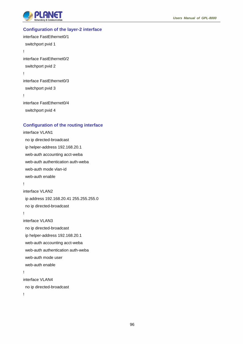
96
Users Manual of GPL-8000
Configuration of the layer-2 interface interface FastEthernet0/1 switchport pvid 1 ! interface FastEthernet0/2 switchport pvid 2 ! interface FastEthernet0/3 switchport pvid 3 ! interface FastEthernet0/4 switchport pvid 4
Configuration of the routing interface interface VLAN1 no ip directed-broadcast ip helper-address 192.168.20.1 web-auth accounting acct-weba web-auth authentication auth-weba web-auth mode vlan-id web-auth enable ! interface VLAN2 ip address 192.168.20.41 255.255.255.0 no ip directed-broadcast ! interface VLAN3 no ip directed-broadcast ip helper-address 192.168.20.1 web-auth accounting acct-weba web-auth authentication auth-weba web-auth mode user web-auth enable ! interface VLAN4 no ip directed-broadcast !

97
Users Manual of GPL-8000
Web Configuration
HTTP Switch Configuration 7.1.1 HTTP Configuration Switch configuration can be conducted not only through command lines and SNMP but also through Web
browser. The switches support the HTTP configuration, the abnormal packet timeout configuration, and so on.
7.1.1.1 Choosing the Prompt Language Up to now, switches support two languages, that is, English and Chinese, and the two languages can be
switched over through the following command.
Command Purpose
ip http language {chinese |
english}
Sets the prompt language of Web
configuration to Chinese or English.
7.1.1.2 Setting the HTTP Port Generally, the HTTP port is port 80 by default, and users can access a switch by entering the IP address
directly; however, switches also support users to change the service port and after the service port is changed
you have to use the IP address and the changed port to access switches. For example, if you set the IP
address and the service port to 192.168.1.3 and 1234 respectively, the HTTP access address should be
changed to http: // 192.168.1.3: 1234. You’d better not use other common protocols’ ports so that access
collision should not happen. Because the ports used by a lot of protocols are hard to remember, you’d better
use port IDs following port 1024.
Command Purpose
ip http port { portNumber } Sets the HTTP port.
7.1.1.3 Enabling the HTTP Service Switches support to control the HTTP access. Only when the HTTP service is enabled can HTTP exchange
happen between switch and PC and, when the HTTP service is closed, HTTP exchange stops.
Command Purpose
ip http server Enables the HTTP service.
ip http {timeout} Configures the timeout time of HTTP abnormal
packets.
7.1.1.4 Setting the HTTP Access Mode You can access a switch through two access modes: HTTP access and HTTPS access, and you can use the
following command to set the access mode to HTTP.
Command Purpose
ip http http-access enable Sets the HTTP access mode.

98
Users Manual of GPL-8000
7.1.1.5 Setting the Maximum Number of VLAN Entries on Web Page A switch supports at most 4094 VLANs and in most cases Web only displays parts of VLANs, that is, those
VLANs users want to see. You can use the following command to set the maximum number of VLANs. The
default maximum number of VLANs is 100.
Command Purpose
ip http web max-vlan { max-vlan } Sets the maximum number of VLAN entries
displayed in a web page.
7.1.1.6 Setting the Maximum Number of Multicast Entries Displayed on a Web Page A switch supports at most 100 multicast entries. You can run the following command to set the maximum
number of multicast entries and Web then shows these multicast entries. The default maximum number of
multicast entries is 15.
Command Purpose
ip http web igmp-groups
{ igmp-groups }
Sets the maximum number of multicast entries
displayed in a web page.
7.1.2 HTTPS Configuration In order to improve the security of communications, switches support not only the HTTP protocol but also the
HTTPS protocol. HTTPS is a security-purposed HTTP channel and it is added to the SSL layer under HTTP.
7.1.2.1 Setting the HTTP Access Mode You can run the following command to set the access mode to HTTPS.
Command Purpose
ip http ssl-access enable Sets the HTTPS access mode.
7.1.2.2 It is used to set the HTTPS port. As the HTTP port, HTTPS has its default service port, port 443, and you also can run the following command
to change its service port. It is recommended to use those ports following port 1024 so as to avoid collision
with other protocols’ ports.
Parameter Remarks
ip http secure-port {portNumber} Sets the HTTPS port.
Configuration Preparation 7.2.1 Accessing the Switch through HTTP When accessing the switch through Web, please make sure that the applied browser complies with the
following requirements:
HTML of version 4.0
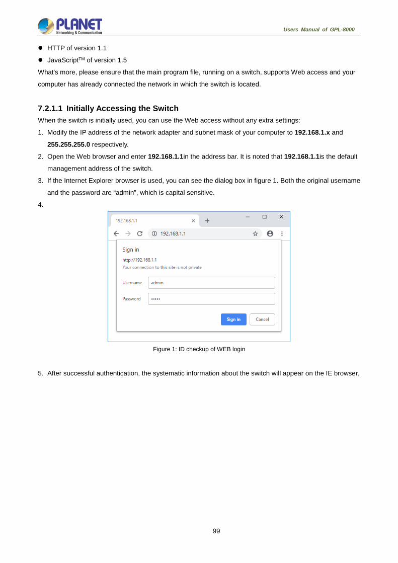
99
Users Manual of GPL-8000
HTTP of version 1.1
JavaScriptTM of version 1.5
What's more, please ensure that the main program file, running on a switch, supports Web access and your
computer has already connected the network in which the switch is located.
7.2.1.1 Initially Accessing the Switch When the switch is initially used, you can use the Web access without any extra settings:
1. Modify the IP address of the network adapter and subnet mask of your computer to 192.168.1.x and
255.255.255.0 respectively.
2. Open the Web browser and enter 192.168.1.1in the address bar. It is noted that 192.168.1.1is the default
management address of the switch.
3. If the Internet Explorer browser is used, you can see the dialog box in figure 1. Both the original username
and the password are “admin”, which is capital sensitive.
4.
Figure 1: ID checkup of WEB login
5. After successful authentication, the systematic information about the switch will appear on the IE browser.

100
Users Manual of GPL-8000
7.2.1.2 Upgrading to the Web-Supported Version If your switch is upgraded to the Web-supported version during its operation and the switch has already
stored its configuration files, the Web visit cannot be directly applied on the switch. Perform the following
steps one by one to enable the Web visit on the switch:
1. Connect the console port of the switch with the accessory cable, or telnet to the management address of
the switch through the computer.
2. Enter the global configuration mode of the switch through the command line, the DOS prompt of which is
similar to “Switch_config#”.
3. If the management address of the switch is not configured, please create the VLAN interface and configure
the IP address.
4. Enter the ip http server command in global configuration mode and start the Web service.
5. Run username to set the username and password of the switch. For how to use this command, refer to
the “Security Configuration” section in the user manual.
6. After the above-mentioned steps are performed, you can enter the address of the switch in the Web
browser to access the switch.
7. Enter write to store the current configuration to the configuration file.
7.2.2 Accessing a Switch through Secure Links The data between the WEB browser and the switch will not be encrypted if you access a switch through
common HTTP. To encrypt these data, you can use the secure links, which are based on the secure sockets
layer, to access the switch.
To do this, you should follow the following steps:
1. Connect the console port of the switch with the accessory cable, or telnet to the management address of
the switch through the computer.
2. Enter the global configuration mode of the switch through the command line, the DOS prompt of which is
similar to “Switch_config#”.
3. If the management address of the switch is not configured, please create the VLAN interface and configure
the IP address.
4. Enter the ip http server command in global configuration mode and start the Web service.
5. Run username to set the username and password of the switch. For how to use this command, refer to
the “Security Configuration” section in the user manual.
6. 6. Run ip http ssl-access enable to enable the secure link access of the switch.
7. Run no ip http http-access enable to forbid to access the switch through insecure links.
8. Enter write to store the current configuration to the configuration file.
9. Open the WEB browser on the PC that the switch connects, enter https://192.168.1.1on the address bar
(192.168.1.1 stands for the management IP address of the OLT) and then press the Enter key. Then the
switch can be accessed through the secure links.

101
Users Manual of GPL-8000
7.2.3 Introduction of Web Interface The Web homepage appears after login, as shown in figure 2:
Figure 2: Web homepage
The whole homepage consists of the top control bar, the navigation bar, the configuration area and the bottom
control bar.
7.2.3.1 Top Control Bar
Figure 3: Top control bar
Save All Write the current settings to the configuration file of the device. It
is equivalent to the execution of the write command.
The configuration that is made through Web will not be promptly
written to the configuration file after validation. If you click “Save
All”, the unsaved configuration will be lost after rebooting.
Logout Exit from the current login state.
After you click "logout", you have to enter the username and the
password again if you want to continue the Web function.
After you configure the device, the result of the previous step will appear on the left side of the top control bar.
If error occurs, please check your configuration and retry it later.

102
Users Manual of GPL-8000
7.2.3.2 Navigation Bar
Figure 4 Navigation bar
The contents in the navigation bar are shown in a form of list and are classified according to types. By default,
the list is located at “Runtime Info”. If a certain item need be configured, please click the group name and then
the sub-item. For example, to browse the flux of the current port, you have to click “Interface State" and then
“Interface Flow”.
The limited user can only browse the state of the device and cannot modify the
configuration of the device. If you log on to the Web with limited user’s permissions,
only “Interface State” will appear.

103
Users Manual of GPL-8000
7.2.3.3 Configuration Area
Figure 5 Configuration Area
The configuration display area shows the state and configuration of the device. The contents of this area can
be modified by the clicking of the items in the navigation bar.
7.2.3.4 Configuration Area The configuration area is to show the content that is selected in the navigation area. The configuration area
always contains one or more buttons, and their functions are listed in the following table:
Basic Configuration
Figure 1 A list of basic configuration

104
Users Manual of GPL-8000
7.3.1 Hostname Configuration If you click Basic Config -> Hostname Config in the navigation bar, the Hostname Configuration page
appears, as shown in figure 2.
Figure 2 Hostname configuration
The hostname will be displayed in the login dialog box.
The default name of the device is “Switch”. You can enter the new hostname in the text box shown in figure 8
and then click “Apply”.
7.3.2 Time Management If you click System Manage -> Time Manage, the Time Setting page appears.
Figure 3 Clock management
To refresh the clock of the displayed device, click “Refresh”.
In the “Select Time-Zone” dropdown box select the time zone where the device is located. When you select
“Set Time Manually”, you can set the time of the device manually. When you select “Network Time
Synchronization”, you can designate 3 SNTP servers for the device and set the interval of time
synchronization.

105
Users Manual of GPL-8000
GPON Interface Config
Figure 1: GPON Interface Config list
7.4.1 GPON Global Config On the left navigation bar, click “GPON Interface Config” -> “GPON Global Config”, and the following
interface appears.
Figure 2: Device Name Configuration
On this page, you can configure ONU authentication method to serial number, password and authentication.
You can broadcast GEM Port and the value ranges from 385 to 4094. Click “Apply” and the operation will
take effect on the OLT. Click “Reset” to return to the default setting.
7.4.2 ONU Bind Relationship Config On the left navigation bar, click “GPON Interface Config” -> “ONU Bind Relationship Config” and the
following page appears.

106
Users Manual of GPL-8000
Figure 3: Interface ONU Bind Relationship Configuration
Click “Detail” to show the concrete ONU binding relationship of the concrete interface. Select an ONU and
click “Delete” to remove the binding or click “Go Back” to return to the default setting.
Click “New” on the top left of the interface to create a new “Interface ONU Bind Relationship Config” and the
corresponding interface will pop up:
Figure 4: Interface ONU Bind Relationship List GPON
You can “Reset” the binding relationship and fill in the password and ONU ID. Click “Apply” to apply the
configuration; click “Reset” to reset the information; click “Go Back” after you complete the configuration.
Figure 5: Interface ONU Bind Relationship Config GPON
7.4.3 ONU Discover Mode On the left navigation bar, click “GPON Interface Config” -> “ONU Discover Mode”, and the following page
appears.

107
Users Manual of GPL-8000
Figure 6: ONU Discover Mode Interface Config
You can designate the discover mode for each PON port: Auto or Disable. Click “Apply” to save the
configuration.
7.4.4 ONU Authentication On the left navigation bar, click “GPON Interface Config” -> “ONU Authentication”, and the following page
appears.
Figure 7: ONU Authentication Interface Config
You can on OLT to enable the ONU detection mechanism at MPCP registration. After the ONU MAC detection
mechanism is enabled, ONUs without static binding settings cannot be registered to OLT. One LLID port maps to only one
ONU’s MAC address.
By default, the ONU SN detection mechanism at MPCP registration is disabled; in this case all ONUs can be
registered freely.
Once ONU passes through the authentication, or it is set not to base on the authentication
and the registration is successful, the SN of ONU and the static binding entries of the ONU
number will be automatically added; when this settings is saved and the system is
restarted, this ONU will not be re-authenticated.
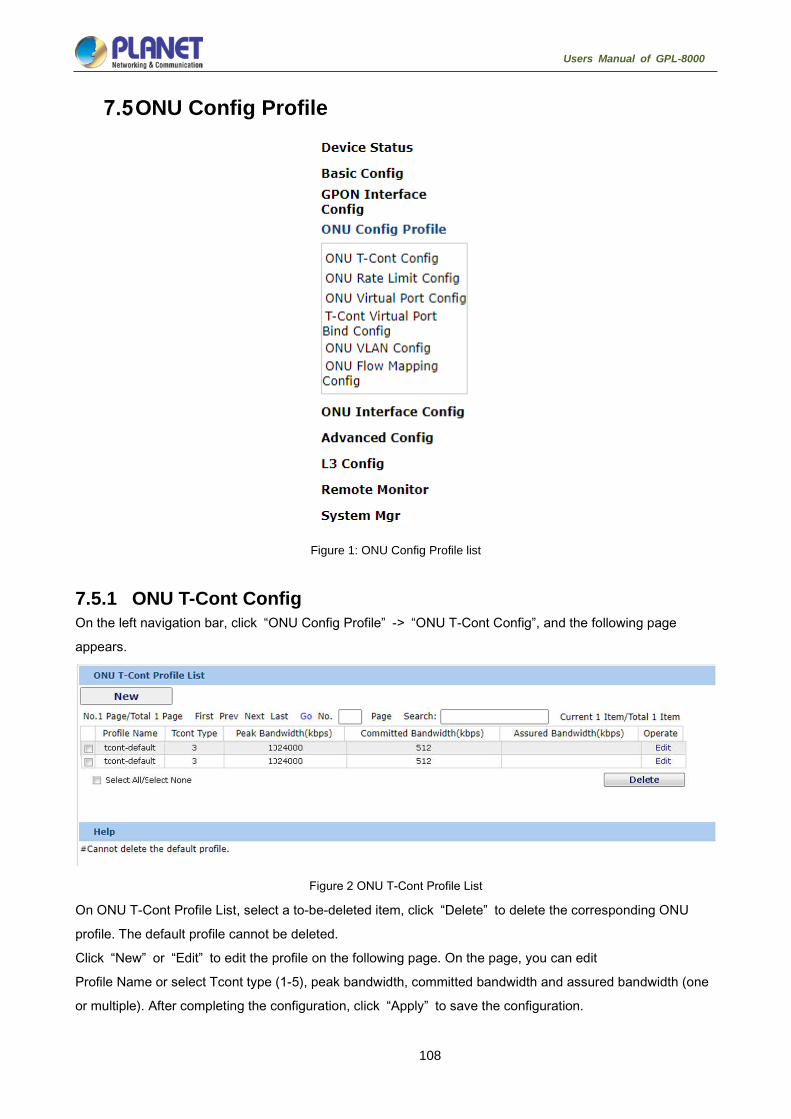
108
Users Manual of GPL-8000
ONU Config Profile
Figure 1: ONU Config Profile list
7.5.1 ONU T-Cont Config On the left navigation bar, click “ONU Config Profile” -> “ONU T-Cont Config”, and the following page
appears.
Figure 2 ONU T-Cont Profile List
On ONU T-Cont Profile List, select a to-be-deleted item, click “Delete” to delete the corresponding ONU
profile. The default profile cannot be deleted.
Click “New” or “Edit” to edit the profile on the following page. On the page, you can edit
Profile Name or select Tcont type (1-5), peak bandwidth, committed bandwidth and assured bandwidth (one
or multiple). After completing the configuration, click “Apply” to save the configuration.

109
Users Manual of GPL-8000
Figure 3: ONU T-Cont Profile Config
7.5.2 ONU Rate Limit Config On the left navigation bar, click “ONU Config Profile” -> “ONU Rate Limit Config”, and the following page
appears.
Figure 4: ONU T-Cont Profile List
On ONU T-Cont Profile List, select a to-be-deleted item, click “Delete” to delete the corresponding ONU
profile. The default profile cannot be deleted.
Click “New” or “Edit” to edit the profile on the following page. On the page, you can edit Profile Name or set
Peak Bandwidth and Committed Bandwidth. After the configuration is finished, click “Apply” to save the
configuration.
Figure 5: ONU T-Cont Profile Config

110
Users Manual of GPL-8000
7.5.3 ONU Virtual Port Config On the left navigation bar, click “ONU Config Profile” -> “ONU Rate Virtual Port Config”, and the following
page appears.
Figure 6: ONU Virtual Port Profile List
On ONU Virtual Profile List, select a to-be-deleted item, click “Delete” to delete the corresponding ONU
profile. The default profile cannot be deleted.
Click “New” or “Edit” to edit the profile on the following page. On the page, you can edit
Profile Name, Downstream Encryption, Upstream Queue, Upstream Rate Limit Profile and Downstream
Queue. After the configuration is finished, click “Apply” to save the configuration.
Figure 7: ONU Virtual Port Profile Config
7.5.4 T-Cont Virtual Port Bind Config On the left navigation bar, click “ONU Config Profile” -> “T-Cont Virtual Port Bind Config”, and the following
page appears.
Figure 8: ONU T-Cont Virtual Port Bind Profile List

111
Users Manual of GPL-8000
Figure 9: ONU T-Cont Virtual Port Bind Profile tvbind-default
On ONU Virtual Profile List, select a to-be-deleted item, click “Delete” to delete the corresponding ONU
profile. The default profile cannot be deleted.
Click “New” or “Edit” to edit the profile on the following page. On the page, you can edit Virtual Port ID,
Virtual Port Profile, T-Cont ID and T-Cont Profile. After the configuration is finished, click “Apply” to save the
configuration.
Figure 10: ONU T-Cont Virtual Port Bind Profile tvbind-default
7.5.5 ONU VLAN Config On the left navigation bar, click “ONU Config Profile” -> “ONU VLAN Config”, and the following page
appears.
Figure 11: ONU VLAN Profile List
On ONU VLAN Profile List, select a to-be-deleted item, click “Delete” to delete the corresponding ONU
profile.
Click “New” or “Edit” to edit the profile on the following page. On the page, you can edit Profile Name, VLAN
Mode, Port PVID, VLAN Trunk Allowed, IPoE VLAN, PPPoE VLAN and ARP VLAN.
After the configuration is finished, click “Apply” to save the configuration.

112
Users Manual of GPL-8000
Figure 12: ONU VLAN Profile Config
7.5.6 ONU Flow Mapping Config On the left navigation bar, click “ONU Config Profile” -> “ONU Flow Mapping Configuration”, and the
following page appears.
Figure 13: ONU Flow Mapping Profile List
Figure 14: ONU Flow Mapping Profile flow-mapping-default
On ONU Flow Mapping Profile List, select a to-be-deleted item, click “Delete” to delete the corresponding
ONU profile. The default profile cannot be deleted.
Click “New” or “Edit” to edit the profile on the following page. On the page, you can edit Entry ID, UNI Port
Bitmap, VLAN ID, Class of Service and Virtual Port.
After the configuration is finished, click “Apply” to save the configuration.

113
Users Manual of GPL-8000
Figure 15: Add ONU Flow Mapping Profile flow-mapping-default
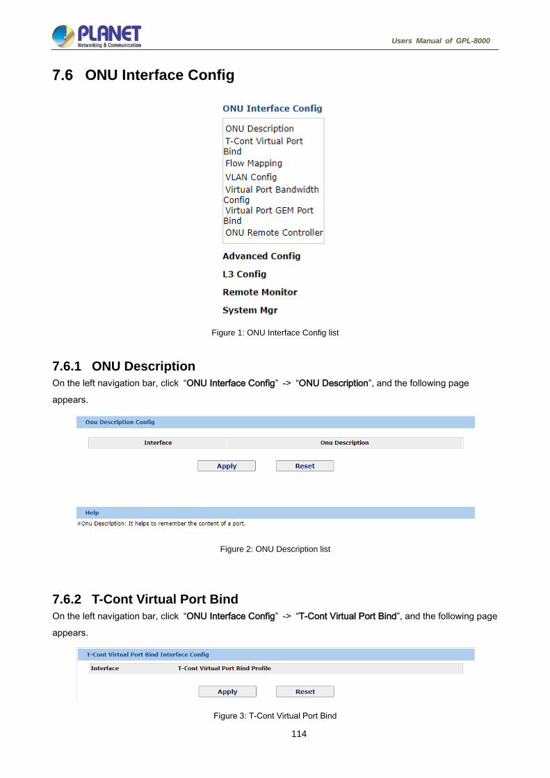
114
Users Manual of GPL-8000
ONU Interface Config
Figure 1: ONU Interface Config list
7.6.1 ONU Description On the left navigation bar, click “ONU Interface Config” -> “ONU Description”, and the following page
appears.
Figure 2: ONU Description list
7.6.2 T-Cont Virtual Port Bind On the left navigation bar, click “ONU Interface Config” -> “T-Cont Virtual Port Bind”, and the following page
appears.
Figure 3: T-Cont Virtual Port Bind

115
Users Manual of GPL-8000
On the page of T-Cont Virtual Port Bind Interface Config, click “Apply” to save the setting or click “Reset” to
return to the default setting.
7.6.3 Flow Mapping On the left navigation bar, click “ONU Interface Config” -> “Flow Mapping”, and the following page appears.
Figure 4: Flow Mapping Interface Configuration
On the page of Flow Mapping Interface Config, click “Apply” to save the setting or click “Reset” to return to
the default setting.
7.6.4 VLAN Config On the left navigation bar, click “ONU Interface Config” -> “VLAN Config”, and the following page appears.
Figure 5: VLAN Interface Configuration
7.6.5 Virtual Port Bandwidth Config On the left navigation bar, click “ONU Interface Config” -> “Virtual Port Bandwidth Config”, and the following
page appears.
Figure 6: Virtual Port Bandwidth Configuration
7.6.6 Virtual Port GEM Port Bind On the left navigation bar, click “ONU Interface Config” -> “Virtual Port GEM Port Bind”, and the following
page appears.
Figure 7: Virtual Port GEM Port Bind Config
7.6.7 ONU Remote Controller On the left navigation bar, click “ONU Interface Config” -> “ONU Remote Controller”, and the following page
appears.

116
Users Manual of GPL-8000
Figure 8: ONU Remote Controller Config

117
Users Manual of GPL-8000
Advanced Config
Figure 1: Advanced Config list
7.7.1 Configuring Port Description If you click Advanced Config -> Port description Config in the navigation bar, the Port description
Configuration page appears, as shown in figure 2.
Figure 2: Port description configuration

118
Users Manual of GPL-8000
You can modify the port description on this page and enter up to 120 characters. The description of the
VLAN port cannot be set at present.
7.7.2 Configuring the Attributes of the Port If you click Advanced Config -> Port attribute Config in the navigation bar, the Port Attribute
Configuration page appears, as shown in figure 3.
Figure 3: Configuring the port attributes
On this page you can modify the on/off status, rate, duplex mode, flow control status and medium type of a
port.
1. The Web page does not support the speed and duplex mode of the
fast-Ethernet port.
2. After the speed or duplex mode of a port is modified, the link state of the port
may be switched over and the network communication may be impaired.
7.7.3 Rate control If you click Advanced Config -> Port rate-limit Config in the navigation bar, the Port rate limit page
appears, as shown in figure 4.
Figure 4: Port’s rate limit

119
Users Manual of GPL-8000
On this page you can set the reception speed and transmission speed of a port. By default, all ports have no
speed limited.
7.7.4 Port mirroring If you click Advanced Config -> Port Mirror in the navigation bar, the Port Mirror Config page appears, as
shown in figure 5.
Figure 5: Port mirror configuration
Click the drop-down list on the right side of "Mirror Port" and select a port to be the destination port of mirror.
Click a checkbox and select a source port of mirror, that is, a mirrored port.
RX The received packets will be mirrored to the destination port.
TX The transmitted packets will be mirrored to a destination port.
RX & TX The received and transmitted packets will be mirrored
simultaneously.
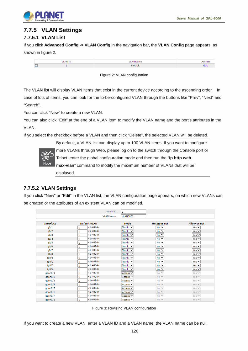
120
Users Manual of GPL-8000
7.7.5 VLAN Settings 7.7.5.1 VLAN List If you click Advanced Config -> VLAN Config in the navigation bar, the VLAN Config page appears, as
shown in figure 2.
Figure 2: VLAN configuration
The VLAN list will display VLAN items that exist in the current device according to the ascending order. In
case of lots of items, you can look for the to-be-configured VLAN through the buttons like “Prev”, “Next” and
“Search”.
You can click “New” to create a new VLAN.
You can also click “Edit” at the end of a VLAN item to modify the VLAN name and the port’s attributes in the
VLAN.
If you select the checkbox before a VLAN and then click “Delete”, the selected VLAN will be deleted.
By default, a VLAN list can display up to 100 VLAN items. If you want to configure
more VLANs through Web, please log on to the switch through the Console port or
Telnet, enter the global configuration mode and then run the “ip http web
max-vlan” command to modify the maximum number of VLANs that will be
displayed.
7.7.5.2 VLAN Settings If you click "New" or “Edit” in the VLAN list, the VLAN configuration page appears, on which new VLANs can
be created or the attributes of an existent VLAN can be modified.
Figure 3: Revising VLAN configuration
If you want to create a new VLAN, enter a VLAN ID and a VLAN name; the VLAN name can be null.

121
Users Manual of GPL-8000
Through the port list, you can set for each port the default VLAN , the VLAN mode (Trunk or Access), whether
to allow the entrance of current VLAN packets and whether to execute the untagging of the current VLAN
when the port works as the egress port.
When a port in Trunk mode serves as an egress port, it will untag the default VLAN
by default.

122
Users Manual of GPL-8000
7.7.6 Configuring the VLAN Interface If you click Advanced Config -> VLAN interface, the Configuring the VLAN interface page appears.
Figure 2: Configuring the VLAN interface
Click New to add a new VLAN interface. Click Cancel to delete a VLAN interface. Click Modify to modify the
settings of a corresponding VLAN interface.
When you click New, the name of the corresponding VLAN interface can be modified; but if you click Modify,
the name of the corresponding VLAN interface cannot be modified.
Figure 3: VLAN interface configuration
Before the accessory IP of a VLAN interface is set, you have to set the main IP.

123
Users Manual of GPL-8000
7.7.7 LDP Configuration 7.7.7.1 Configuring the Global Attributes of LLDP If you click Advanced Config -> LLDP Config in the navigation bar, the Global LLDP Config page appears,
as shown in figure 6.
Figure 6: Configuring the global attributes of LLDP
You can choose to enable LLDP or disable it. When you choose to disable LLDP, you cannot configure LLDP.
The “HoldTime” parameter means the ttl value of the packet that is transmitted by LLDP, whose default value
is 120s.
The “Reinit” parameter means the delay of successive packet transmission of LLDP, whose default value is
2s.
7.7.7.2 Configuring the Attributes of the LLDP Port If you click Advanced Config -> LLDPConfig-> LLDP port Config in the navigation bar, the Setting the
attributes of the LLDP port page appears, as shown in figure 7.
Figure 7: Configuring the LLDP port
After the LLDP port is configured, you can enable or disable LLDP on this port.

124
Users Manual of GPL-8000
7.7.8 STP Configuration 7.7.8.1 STP Status Information If you click Advanced Config -> STP Config in the navigation bar, the STP Config page appears, as shown
in figure 10.
Figure 10: Configuring the global attributes of STP
The root STP configuration information and the STP port’s status are only-read.
On the local STP configuration page, you can modify the running STP mode by clicking the Protocol type
drop-down box. The STP modes include STP, RSTP and disabled STP.
The priority and the time need to be configured for different modes.
The change of the STP mode may lead to the interruption of the network.
7.7.8.2 Configuring the Attributes of the STP Port If you click the "Configure RSTP Port" option, the “Configure RSTP Port” page appears.
Figure 11: Configuring the attributes of RSTP

125
Users Manual of GPL-8000
The configuration of the attributes of the port is irrelative of the global STP mode. For example, if the protocol
status is set to “Disable” and the STP mode is also changed, the port will not run the protocol in the new
mode.
The default value of the path cost of the port is 0, meaning the path cost is automatically calculated according
to the speed of the port. If you want to change the path cost, please enter another value.

126
Users Manual of GPL-8000
7.7.9 Port security 7.7.9.1 IP Binding Configuration If you click Advanced Config -> Port Security -> IP bind in the navigation bar, the Configure the
IP-Binding Info page appears, as shown in figure 7.
Figure 7: IP binding configuration
Click “Detail” and then you can conduct the binding of the source IP address for each physical port. In this way,
the IP address that is allowed to visit the port will be limited.
Figure 8: Setting the binding of the source IP addressMAC Binding Configuration
If you click Advanced Config -> Port Security -> MAC bind in the navigation bar, the Configure the
MAC-Binding Info page appears, as shown in figure 9.
Figure 9: MAC binding configuration
Click “Detail” and then you can conduct the binding of the source MAC address for each physical port. In this
way, the MAC address that is allowed to visit the port will be limited.
Figure 10: Setting the binding of the source MAC address
7.7.9.2 Setting the Static MAC Filtration Mode If you click Advanced Config -> Port Security -> Static MAC filtration mode in the navigation bar, the
Configure the static MAC filtration mode page appears, as shown in figure 11.
Figure 11: Setting the static MAC filtration mode
On this page you can set the static MAC filtration mode. By default, the static MAC filter is disabled. Also, the
static MAC filter mode cannot be set on ports in trunk mode.
7.7.9.3 Static MAC Filtration Entry If you click Advanced Config -> Port Security -> Static MAC filtration entry in the navigation bar, the
Setting the static MAC filtration entries page appears.
Figure 12: Static MAC filtration entry list

127
Users Manual of GPL-8000
If you click “Detail”, you can conduct the binding of the source MAC address for each physical port. According
to the configured static MAC filtration mode, the MAC address of a port can be limited, allowed or forbidden to
visit.
Figure 13: Setting static MAC filtration entries
7.7.9.4 Setting the Dynamic MAC Filtration Mode If you click Advanced Config -> Port Security -> Dynamic MAC filtration mode in the navigation bar, the
Configure the dynamic MAC filtration mode page appears, as shown in figure 14.
Figure 14: Setting the dynamic MAC filtration mode
You can set the dynamic MAC filtration mode and the allowable maximum number of addresses on this page.
By default, the dynamic MAC filtration mode is disabled and the maximum number of addresses is 1.

128
Users Manual of GPL-8000
7.7.10 Storm control In the navigation bar, click Advanced Config -> Storm control. The system then enters the page, on which
the broadcast/multicast/unknown unicast storm control can be set.
7.7.10.1 Broadcast Storm Control
Figure 15: Broadcast storm control
Through the drop-down boxes in the Status column, you can decide whether to enable broadcast storm
control on a port. In the Threshold column you can enter the threshold of the broadcast packets. The legal
threshold range for each port is given behind the threshold.
7.7.10.2 Multicast Storm Control
Figure 16: Setting the broadcast storm control
Through the drop-down boxes in the Status column, you can decide whether to enable multicast storm
control on a port. In the Threshold column you can enter the threshold of the multicast packets. The legal

129
Users Manual of GPL-8000
threshold range for each port is given behind the threshold.
7.7.10.3 Unknown Unicast Storm Control
Figure 17: Unknown unicast storm control
In the Threshold column you can enter the threshold of the broadcast packets. The legal threshold range for
each port is given behind the threshold.

130
Users Manual of GPL-8000
7.7.11 IP Access Control List 7.7.11.1 Setting the Name of the IP Access Control List If you click Advanced Config -> IP access control list -> IP access control list Config, the IP ACL configuration
page appears.
Figure 9: IP access control list configuration
Click New to add a name of the IP access control list. Click Cancel to delete an IP access control list.
Figure 10: Creating a name of the IP access control list
If you click Modify, the corresponding IP access control list appears and you can set the corresponding rules
for the IP access control list.
7.7.11.2 Setting the Rules of the IP Access Control List Standard IP access control list
Figure 11: Standard IP access control list
Click New to add a rule of the IP access control list. Click Cancel to delete a rule of the IP access control list.
If you click Modify, the corresponding IP access control list appears and you can set the corresponding rules
for the IP access control list.
Figure 12: Setting the Rules of the standard IP access control list
Extended IP access control list
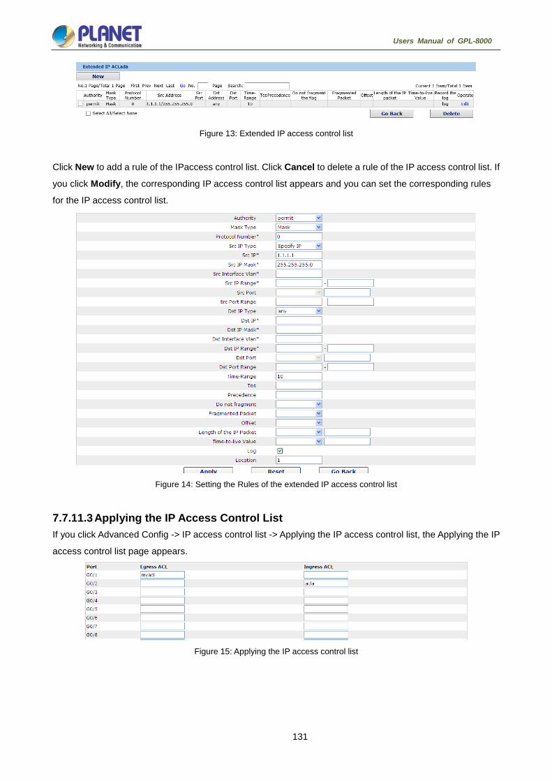
131
Users Manual of GPL-8000
Figure 13: Extended IP access control list
Click New to add a rule of the IPaccess control list. Click Cancel to delete a rule of the IP access control list. If
you click Modify, the corresponding IP access control list appears and you can set the corresponding rules
for the IP access control list.
Figure 14: Setting the Rules of the extended IP access control list
7.7.11.3 Applying the IP Access Control List If you click Advanced Config -> IP access control list -> Applying the IP access control list, the Applying the IP
access control list page appears.
Figure 15: Applying the IP access control list

132
Users Manual of GPL-8000
7.7.12 MAC Access Control List 7.7.12.1 Setting the Name of the MAC Access Control List If you click Advanced Config -> MAC access control list -> MAC access control list Config, the MAC ACL
configuration page appears.
Figure 4: MAC access control list configuration
Click New to add a name of the MAC access control list. Click Cancel to delete a MAC access control list.
Figure 5: Setting the name of MAC access control list
7.7.12.2 Setting the Rules of the MAC Access Control List If you click Modify, the corresponding MAC access control list appears and you can set the corresponding
rules for the MAC access control list.
Figure 6: Specific MAC access control list configuration
Click New to add a rule of the MAC access control list. Click Cancel to delete a rule of the MAC access
control list.
Figure 7: Setting the Rules of the MAC Access Control List
7.7.12.3 Applying the MAC Access Control List If you click Advanced Config -> MAC access control list -> Applying the MAC access control list, the Applying
the MAC access control list page appears.

133
Users Manual of GPL-8000
Figure 8: Applying the MAC access control list
7.7.13 Link Aggregation Configuration If you click Advanced Config ->Port Channel in the navigation bar, the Port aggregation Config page
appears, as shown in figure 8.
Figure 8: Port aggregation configuration
If you click New, an aggregation group can be created. Up to 32 aggregation groups can be configured
through Web and up to 8 physical ports in each group can be aggregated. If you click Cancel, you can delete
a selected aggregation group; if you click Modify, you can modify the member port and the aggregation
mode.
Figure 9: Setting the member port of the aggregation group
An aggregation group is selectable when it is created but is not selectable when it is modified.
When a member port exists on the aggregation group, you can choose the aggregation mode to be static,
LACP active or LACP passive.
You can click “>>” and “<<” to delete and add a member port in the aggregation group.

134
Users Manual of GPL-8000
7.7.14 Ring Protection Configuration 7.7.14.1 EAPS Ring List If you click Advanced Config -> EAPS Ring Config, the EAPS ring list page appears.
Figure 19: EAPS Ring List
In the list shows the currently configured EAPS ring, including the status of the ring, the forwarding status of
the port and the status of the link.
Click “New” to create a new EAPS ring.
Click the “Operate” option to configure the “Time” parameter of the ring.
1. The system can support 8 EAPS rings.
2. After a ring is configured, its port, node type and control VLAN cannot be
modified. If the port of the ring, the node type or the control VLAN needs to be
adjusted, please delete the ring and then establish a new one.
7.7.14.2 EAPS Ring Configuration If you click “New” on the EAPS ring list, or “Operate” on the right side of a ring item, the “Configure EAPS”
page appears.
Figure 20: EAPS ring configuration
If you want to modify a ring, on this page the node type, the control VLAN, the
primary port and the secondary port cannot be modified.
In the dropdown box on the right of “Ring ID”, select an ID as a ring ID. The ring IDs of all devices on the same
ring must be the same.
The dropdown box on the right of “Node Type” is used to select the type of the node. Please note that only
one master node can be configured on a ring.

135
Users Manual of GPL-8000
Enter a value between 1 and 4094 in the text box on the right of “Control VLAN” as the control VLAN ID.
When a ring is established, the control VLAN will be automatically established too. Please note that if the
designated control VLAN is 1 and the VLAN of the control device is also 1 the control device cannot access
the control VLAN. Additionally, please do not enter a control VLAN ID that is same as that of another ring.
In the text boxes of “Primary Port” and “Secondary Port”, select a port as the ring port respectively. If "Node
Type" is selected as “Transit-Node”, the two ports will be automatically set to transit ports.
Click “Apply” to finish EAPS ring configuration, click “Reset” to resume the initial values of the configuration, or
click “Return” to go back to the EAPS list page.
7.7.15 DDM Configuration If you click Advanced Config -> DDM Config in the navigation bar, the DDM configuration page appears,
as shown in figure 21.
Figure 21: DDM configuration
7.7.16 MTU Config On the left navigation bar, click “Advanced Config” -> “MTU Config” and the following
page appears.
Figure 20: MTU Config
You can set the size of MTU within a designated range.

136
Users Manual of GPL-8000
Layer 3 Configuration
Figure 1: Layer 3 configuration list
Only Layer 3 switches have the Layer 3 configuration.

137
Users Manual of GPL-8000
7.8.1 Setting the Static Route If you click Layer 3 Config -> Static route Config, the Static route configuration page appears.
Figure 4: Displaying the static route
Click Create to add a static route.
If you click Edit, you can modify the current static route.
If you click Cancel, you can cancel the chosen static route.
Figure 5: Setting the static route

138
Users Manual of GPL-8000
Remote Monitor configuration
Figure 1: Remote Monitor configuration list
7.9.1 SNMP Configuration If you click Remote Monitor -> SNMP management in the navigation bar, the SNMP management page
appears, as shown in figure 2.
7.9.1.1 SNMP Community Management
Figure 2: SNMP community management
On the SNMP community management page, you can know the related configuration information about
SNMP community.
You can create, modify or cancel the SNMP community information, and if you click New or Edit, you can
switch to the configuration page of SNMP community.
Figure 3: SNMP community management settings
On the SNMP community management page you can enter the SNMP community name, select the attributes
of SNMP community, which include Read only and Read-Write.

139
Users Manual of GPL-8000
7.9.1.2 SNMP Host Management
Figure 4: SNMP host management
On the SNMP community host page, you can know the related configuration information about SNMP host.
You can create, modify or cancel the SNMP host information, and if you click New or Edit, you can switch to
the configuration page of SNMP host.
Figure 5: SNMP host management settings
On the SNMP host configuration page, you can enter SNMP Host IP, SNMP Community, SNMP Message
Type and SNMP Community Version. SNMP Message Type includes Traps and Informs, and as to version
1, SNMP Message Type does not support Informs.
7.9.2 RMON Config 7.9.2.1 RMON Statistic Information Configuration If you click Remote Monitor -> RMON Config -> RMON Statistics -> New, the RMON Statistics page
appears.
Figure 6: Configuring the RMON statistic information
You need to set a physical port to be the reception terminal of the monitor data.
The index is used to identify a specific interface; if the index is same to that of the previous application
interface, it will replace that of the previous application interface.
At present, the monitor statistic information can be obtained through the command line “show rmon statistics”,
but the Web does not support this function.

140
Users Manual of GPL-8000
7.9.2.2 RMON History Information Configuration If you click Remote Monitor -> RMON Config -> RMON history -> New, the RMON history page appears.
Figure 7: Configuring the RMON history information
You need to set a physical port to be the reception terminal of the monitor data.
The index is used to identify a specific interface; if the index is same to that of the previous application
interface, it will replace that of the previous application interface.
The sampling number means the items that need be reserved, whose default value is 50.
The sampling interval means the time between two data collection, whose default value is 1800s.
At present, the monitor statistic information can be obtained through the command line “show rmon history”,
but the Web does not support this function.
7.9.2.3 RMON Alarm Information Configuration If you click Remote Monitor -> RMON Config -> RMON Alarm -> New, the RMON Alarm page appears.
Figure 8: Configuring the RMON alarm information
The index is used to identify specific alarm information; if the index is same to the previously applied index, it
will replace the previous one.
The MIB node corresponds to OID.
If the alarm type is absolute, the value of the MIB object will be directly minitored; if the alarm type is delta, the
change of the value of the MIB object in two sampling will be monitored.
When the monitored MIB object reaches or exceeds the rising threshold, the event corresponding to the index
of the rising event will be triggered.
When the monitored MIB object reaches or exceeds the falling threshold, the event corresponding to the

141
Users Manual of GPL-8000
index of the falling event will be triggered.
7.9.2.4 RMON Event Configuration If you click Remote Monitor -> RMON Config -> RMON Event -> New, the RMON event page appears.
Figure 9: RMON event configuration
The index corresponds to the rising event index and the falling event index that have already been configured
on the RMON alarm config page.
The owner is used to describe the descriptive information of an event.
"Enable log" means to add an item of information in the log table when the event is triggered.
“Enable trap” means a trap will be generated if the event is triggered.

142
Users Manual of GPL-8000
System Management
Figure 1: Navigation list of system management
7.10.1 User Management 7.10.1.1 User List If you click System Manage -> User Manage, the User Management page appears.
Figure 2: User list
You can click “New” to create a new user.
To modify the permission or the login password, click “Edit” on the right of the user list.
1. Please make sure that at least one system administrator exists in the system,
so that you can manage the devices through Web.
2. The limited user can only browse the status of the device.

143
Users Manual of GPL-8000
7.10.1.2 Establishing a New User If you click “New” on the User Management page, the Creating User page appears.
Figure 3: Creating new users
In the “User name” text box, enter a name, which contains letters, numbers and symbols except “?”, “\”, “&”, “#”
and the "Space".
In the “Password” textbox enter a login password, and in the “Confirming password” textbox enter this login
password again.
In the “User permission” dropdown box set the user's permission. The “System administrator” user can
browse the status of the device and conduct relevant settings, while the limited user can only browse the
status of the device.
7.10.1.3 Group Mgr On the left navigation bar, click “System Mgr” -> “User Mgr” -> “User Group Mgr” and
the following page appears.
Figure 4: User Group Management
Click “New” on the top left of the interface to create a new user group.
Click “Delete” to delete the user group.
Figure 5: User Group Config

144
Users Manual of GPL-8000
The user group name cannot be created before. The Pass-Group Name, Authen-Group Name and
Author-Group Name must be created before; otherwise, the new created user group cannot be succeeded.
Set Pass-Group Name, Authen-Group Name, and Author-Group Name on the relevant tab pages.
7.10.1.4 Pass-Group Mgr On the left navigation bar, click “System Mgr” -> “User Mgr” -> “Pass- Group Mgr” and
the following page appears.
Figure 6: Password Group Management
Click “New” to create a new Pass-Group Name.
Click “Delete” to delete the selected Pass-Group Name.
Figure 7: Pass Group Configuration
Set some password rules including whether the password can be the same with the user name, whether the
password must contain numbers, lowercase, uppercase, special characters, the minimum length and the
period of validity.
When the rule is created and applied to the user management, the user password will show invalid if the set
password is not complied with the password rule, vice versa.
7.10.1.5 Authen-Group Mgr On the left navigation bar, click “System Mgr” -> “User Mgr” -> “Authen-Group Mgr” and
the following page appears.

145
Users Manual of GPL-8000
Figure 8: Authorization Group Management
Click “New” to create a new authen-group name.
Click “Delete” to delete the authen-group name.
Figure 9: Authentication Group Configuration
On the above page, the Max try times and Duration for all tries must be configured simultaneously. Otherwise,
the configuration cannot take effect.
7.10.1.6 Author-Group Mgr On the left navigation bar, click “System Mgr” -> “User Mgr” -> “Author-Group Mgr” and
the following page appears.
Figure 10: Authorization Group Management
Click “New” to create a new author-group name.
Click “Delete” to delete the author-group name.

146
Users Manual of GPL-8000
Figure 11: Authorization Group Configuration
The authorization rule determines your permission of the administrator or the limited user. If you are the
administrator, you have the administrator right. If you are the limited user, you can only but check the web.
7.10.2 Log Management If you click System Manage -> Log Manage, the Log Management page appears.
Figure 12: Log management
If “Enabling the log server” is selected, the device will transmit the log information to the designated server. In
this case, you need enter the address of the server in the “Address of the system log server” textbox and
select the log's grade in the “Grade of the system log information” dropdown box.
If “Enabling the log buffer” is selected, the device will record the log information to the memory. By logging on
to the device through the Console port or Telnet, you can run the command “show log” to browse the logs
which are saved on the device. The log information which is saved in the memory will be lost after rebooting.
Please enter the size of the buffer area in the “Size of the system log buffer” textbox and select the grade of
the cached log in the “Grade of the cache log information” dropdown box.
7.10.3 Diagnostic 7.10.3.1 Ping If you click Diagnostic -> Ping, the Ping page appears.

147
Users Manual of GPL-8000
Figure 13: Ping
Ping is used to test whether the switch connects other devices.
If a Ping test need be conducted, please enter an IP address in the “Destination address” textbox, such as the
IP address of your PC, and then click the “PING” button. If the switch connects your entered address, the
device can promptly return a test result to you; if not, the device will take a little more time to return the test
result.
“Source IP address” is used to set the source IP address which is carried in the Ping packet.
“Size of the PING packet” is used to set the length of the Ping packet which is transmitted by the device.
7.10.4 Managing the Configuration Files If you click System Manage -> Startup-config, the Configuration file page appears.
7.10.4.1 Exporting the Configuration Information
Figure 14: Exporting the configuration file
The current configuration file can be exported, saved in the disk of PC or in the mobile storage device as the
backup file.
To export the configuration file, please click the “Export” button and then select the “Save” option in the
pop-up download dialog box.
The default name of the configuration file is “startup-config”, but you are suggested to set it to an easily
memorable name.

148
Users Manual of GPL-8000
7.10.4.2 Importing the Configuration Information
Figure 15: Importing the configuration files
You can import the configuration files from PC to the device and replace the configuration file that is currently
being used. For example, by importing the backup configuration files, you can resume the device to its
configuration of a previous moment.
1. Please make sure that the imported configuration file has the legal format for
the configuration file with illegal format cannot lead to the normal startup of the
device.
2. If error occurs during the process of importation, please try it later again, or
click the “Save All” button to make the device re-establish the configuration file
with the current configuration, avoiding the incomplete file and the abnormality
of the device.
3. After the configuration file is imported, if you want to use the imported
configuration file immediately, do not click “Save All”, but reboot the device
directly.

149
Users Manual of GPL-8000
7.10.5 Software Management If you click System Manage -> IOS Software, the software managementpage appears.
7.10.5.1 Backing up the IOS Software
Figure 16: Backing up IOS
On this page the currently running software version is displayed. If you want to backup IOS, please click
“Backuping IOS”; then on the browser the file download dialog box appears; click “Save” to store the IOS file
to the disk of the PC, mobile storage device or other network location.
The default name of the IOS file is "Switch.bin", and it is recommended to change it
to a name that is easy to identify and find when it is backed up.
7.10.5.2 Upgrading the IOS Software
1. Please make sure that your upgraded IOS matches the device type, because
the matchable IOS will not lead to the normal startup of the device.
2. The upgrade of IOS probabely takes one to two minutes; when the “updating”
button is clicked, the IOS files will be uploaded to the device.
3. If errors occur during upgrade, please do not restart the device or cut off the
power of the device, or the device cannot be started. Please try the upgrade
again.
4. After the upgrade please save the configuration and then restart the device to
run the new IOS.
Figure 17: Upgrading the IOS software
The upgraded IOS is always used to solve the already known problems or to perfect a specific function. If you
device run normally, do not upgrade your IOS software frequently.
If IOS need be upgraded, please first enter the complete path of the new IOS files in the textbox on the right of
“Upgrading IOS”, or click the “Browsing” button and select the new IOS files on your computer, and then click
“Updating”.

150
Users Manual of GPL-8000
7.10.6 Factory Settings On the left navigation bar, click “System Mgr” -> “Factory Setting” and the following page appears.
Figure 18: Restore to the original settings
1. If you click the “Resume” button, the current configuration will be replaced by the
original configuration, which will take effect after rebooting.
2. Before rebooting the device still works under the current configuration, and if you
click “Save All” at the moment, the current configuration will replace the original
configuration. The original configuration, therefore, cannot take effect after rebooting.
3. After the rebooting is done and the original configuration takes effect, the Web
access of the device will be automatically started. The address of Vlan 1 is
192.168.1.1/255.255.255.0, and the username and password are both “admin”.
To resume the original configuration, click “Resume” and then reboot the device.
7.10.7 Rebooting the Device If you click System Manage -> Reboot Device, the Rebooting page appears.
Figure 19: Rebooting the device
If the device need be rebooted, please first make sure that the modified configuration of the device has
already been saved, and then click the “Reboot” button.
7.10.8 About On the left navigation bar, click “System Mgr” -> “ About” and the following page appears.
Figure 20: About

151
Users Manual of GPL-8000
Interface Configuration
Introduction This section helps user to learn various kinds of interface that our switch supports and consult configuration
information about different interface types.
For detailed description of all interface commands used in this section, refer to Interface configuration
command. For files of other commands appeared in this section, refer to other parts of the manual.
The introduction includes communication information that can be applied to all interface types.
8.1.1 Supported Interface Types For information about interface types, please refer to the following table.
Interface Type Task Reference
Ethernet interface
Configures Ethernet interface.
Configures fast Ethernet interface.
Configures gigabit Ethernet interface.
Configuring Ethernet Interface
Logical Interface
Loopback interface
Null interface
VLAN interface
Configuring Logistical Interface
The loopback interface and null interface
are only configured on layer-3 switch. User
can configure the VLAN interface on layer-2
switch.
Aggregation interface Configuring Logistical Interface
The two supported kinds of interface: Ethernet interface and logical interface. The Ethernet interface type
depends on one device depends on the standard communication interface and the interface card or interfaced
module installed on the switch. The logical interface is the interface without the corresponding physical device,
which is established by user manually.
The supported Ethernet interfaces of our switch include:
Ethernet interface
Fast Ethernet interface
Gigabit Ethernet interface
The supported logical interface of our switch include:
loopback interface
null interface
aggregation interface
vlan interface

152
Users Manual of GPL-8000
8.1.2 Interface Configuration Introduction The following description applies to the configuration process of all interfaces. Take the following steps to
perform interface configuration in global configuration mode. (1) Run the interface command to enter the interface configuration mode and start configuring interface. At
this time, the switch prompt becomes ‘config_’ plus the shortened form of the interface to be configured.
Use these interfaces in terms of their numbers. Numbers are assigned during installation(exworks) or
when an interface card are added to the system. Run the show interface command to display these
interfaces. Each interface that the device supports provides its own state as follows:
Switch#show interface
GigaEthernet1/1 is down, line protocol is down
Hardware is Fast Ethernet, Address is 0009.7cf7.7dc1
MTU 1500 bytes, BW 10000 Kbit, DLY 1000 usec,
reliability 255/255, txload 1/255, rxload 1/255
Encapsulation ARPA, loopback not set
Auto-duplex, Auto-speed
input flow-control is off, output flow-control is off
ARP type: ARPA, ARP Timeout 04: 00: 00
Last input never, output 17: 52: 52, output hang never
Last clearing of "show interface" counters never
Input queue: 0/75/0/0 (size/max/drops/flushes); Total output drops: 0
Queueing strategy: fifo
Output queue : 0/40 (size/max)
5 minute input rate 0 bits/sec, 0 packets/sec
5 minute output rate 0 bits/sec, 0 packets/sec
1 packets input, 64 bytes, 0 no buffer
Received 0 broadcasts, 0 runts, 0 giants, 0 throttles
0 input errors, 0 CRC, 0 frame, 0 overrun, 0 ignored
0 watchdog, 0 multicast, 0 pause input
0 input packets with dribble condition detected
1 packets output, 64 bytes, 0 underruns
0 output errors, 0 collisions, 1 interface resets
0 babbles, 0 late collision, 0 deferred
0 lost carrier, 0 no carrier, 0 PAUSE output
0 output buffer failures, 0 output buffers swapped out
To configure gigabit Ethernet interface g1/1, enter the following content:
interface GigaEthernet0/1
The switch prompts “config_g1/1”.

153
Users Manual of GPL-8000
There is no need to add blank between interface type and interface number. For
example, in the above line, g 1/1 or g 1/1 is both rights.
(1) You can configure the interface configuration commands in interface
configuration mode. Various commands define protocols and application
programs to be executed on the interface. These commands will stay until
user exits the interface configuration mode or switches to another interface.
(2) Once the interface configuration has been completed, use the show command
in the following chapter ‘Monitoring and Maintaining Interface’ to test the
interface state.
Interface Configuration 8.2.1 Configuring Interface Common Attribute The following content describes the command that can be executed on an interface of any type and
configures common attributes of interface. The common attributes of interface that can be configured include:
interface description, bandwidth and delay and so on.
8.2.1.1 Adding Description Adding description about the related interface helps to memorize content attached to the interface. This
description only serves as the interface note to help identify uses of the interface and has no effect on any
feature of the interface. This description will appear in the output of the following commands: show
running-config and show interface. Use the following command in interface configuration mode if user
wants to add a description to any interface. Command Description
description string Adds description to the currently-configured
interface.
For examples relevant to adding interface description, please refer to the following section ‘Interface
Description Example’.
8.2.1.2 Configuring Bandwidth The upper protocol uses bandwidth information to perform operation decision. Use the following command to
configure bandwidth for the interface:
Command Description
bandwidthkilobps Configures bandwidth for the currently
configured interface.
The bandwidth is just a routing parameter, which doesn’t influence the communication rate of the actual
physical interface.

154
Users Manual of GPL-8000
8.2.1.3 Configuring Time Delay The upper protocol uses time delay information to perform operation decision. Use the following command to
configure time delay for the interface in the interface configuration mode.
Command Description
delaytensofmicroseconds Configures time delay for the currently configured interface.
The configuration of time delay is just an information parameter. Use this command cannnot adjust the actual
time delay of an interface.
8.2.2 Monitoring and Maintaining Interface The following tasks can monitor and maintain interface:
Checking interface state
Initializing and deleting interface
Shutting down and enabling interface
8.2.2.1 Checking Interface State Our switch supports displaying several commands related to interface information, including version number
of software and hardware, interface state. The following table lists a portion of interface monitor commands.
For the description of these commands, please refer to ‘Interface configuration command’.
Use the following commands:
Command Description
show interface [type [slot|port]] Displays interface state.
show running-config Displays current configuration.
8.2.2.2 Initializing and Deleting Interface You can dynamically establish and delete logical interfaces. This also applies to the sub interface and
channalized interface. Use the following command to initialize and delete interface in global configuration
mode:
Command Description
no interface type [slot|port] Initializes physical interface or deletes virtual interface.
8.2.2.3 Shutting down and Enabling Interface When an interface is shut down, all features of this interface are disabled, and also this interface is marked as
unavailable interface in all monitor command displays. This information can be transmitted to other switches
via dynamic routing protocol.
Use the following command to shutdown or enable an interface in the interface configuration mode:
Command Description
shutdown Shuts down an interface.
no shutdown Enables an interface.

155
Users Manual of GPL-8000
You can use the show interface command and the show running-config command to check whether an
interface has been shut down. An interface that has been shut down is displayed as ‘administratively down’ in
the show interface command display. For more details, please refer to the following example in ‘Interface
Shutdown Example’.
8.2.3 Configuring Logistical Interface This section describes how to configure a logical interface. The contents are as follows:
Configuring null interface
Configuring loopback interface.
Configuring aggregation interface
Configuring VLAN interface
8.2.3.1 Configuring Null Interface The whole system supports only one null interface. Its functions are similar to those of applied null devices on
most operating systems. The null interface is always available, but it never sends or receives communication
information. The interface configuration command no ip unreachable is the only one command available to
the null interface. The null interface provides an optional method to filtrate communication. That is, the
unwanted network communication can be routed to the null interface; the null interface can function as the
access control list.
You can run the following command in global configuration mode to specify the null interface:
Command Description
interface null0 Enters the null interface configuration state.
The null interface can be applied in any command that takes the interface type as its parameter.
The following case shows how to configure a null interface for the routing of IP 192.168.20.0.
ip route 192.168.20.0 255.255.255.0 null 0
8.2.3.2 Configuring Loopback Interface The loopback interface is a logistical interface. It always functions and continues BGP session even in the
case that the outward interface is shut down. The loopback interface can be used as the terminal address for
BGP session. If other switches try to reach the loopback interface, a dynamic routing protocol should be
configured to broadcast the routes with loopback interface address. Messages that are routed to the loopback
interface can be re-routed to the switch and be handled locally. For messages that are routed to the loopback
interface but whose destination is not the IP address of the loopback interface, they will be dropped. This
means that the loopback interface functions as the null interface.
Run the following command in global configuration mode to specify a loopback interface and enter the
interface configuration state:
Command Description
interface loopbacknumber Enter the loopback interface configuration state.

156
Users Manual of GPL-8000
8.2.3.3 Configuring Aggregation Interface The inadequate bandwidth of a single Ethernet interface gives rise to the birth of the aggregation interface. It
can bind several full-duplex interfaces with the same rate together, greatly improving the bandwidth.
Run the following command to define the aggregation interface:
Command Description
Interface port-aggregator number Configures the aggregation interface
8.2.3.4 Configuring VLAN Interface V VLAN interface is the routing interface in switch. The VLAN command in global configuration mode only
adds layer 2 VLAN to system without defining how to deal with the IP packet whose destination address is
itself in the VLAN. If there is no VLAN interface, this kind of packets will be dropped.
Run the following command to define VLAN interface:
Command Description
Interface vlannumber Configures VLAN interface.
8.2.3.5 Configuring Super VLAN Interface The Super VLAN technology provides a mechanism: hosts in different VLANs of the same switch can be
allocated in the same Ipv4 subnet and use the same default gateway; lots of IP addresses are, therefore,
saved. The Super VLAN technology puts different VLANs into a group where VLANs use the same
management interface and hosts use the same IPv4 network section and gateway. VLAN belonging to Super
VLAN is called as SubVLAN. No SubVLAN can possess the management interface by configuring IP address.
You can configure a Super VLAN interface through a command line. The procedure of configuring a Super
VLAN interface is shown as follows:
Command Description
[no] interface supervlanindex Enter the Super VLAN interface configuration mode. If the specified
Super VLAN interface does not exist, the system will create a Super
VLAN interface.
index is the index of the Super VLAN interface. Its effective value ranges
from 1 to 32.
no means to delete Super VLAN interface.

157
Users Manual of GPL-8000
Command Description
[no] subvlan[setstr] [add
addstr][removeremstr]
Configure SubVLAN in Super VLAN. The added Sub VLAN cannot
possess a management interface or cannot belong to other Super
VLANs. In original state, Super VLAN does not contain any Sub VLAN.
Only one sub command can only be used every time.
setstr means to set the Sub VLAN list. For example, List 2,4-6 indicate
VLAN 2, 4, 5 and 6.
add means to add VLAN list in the original SubVLAN list. addstr means
the character string whose format is the same as the above.
remove means to delete VLAN list in the original SubVLAN list. remstr is
the list’s character string whose format is the same as the above.
no means to delete all SubVLANs in SuperVLAN. The no command
cannot be used with other sub commands.
After you configure the Super VLAN interface, you can configure the IP address for the Super VLAN interface.
The Super VLAN interface is also a routing port, which can be configured as other ports are.
Interface Configuration Example 8.3.1 Configuring Public Attribute of Interface 8.3.1.1 Interface Description Example The following example shows how to add description related to an interface. This description appears in the
configuration file and interface command display.
interface vlan 1
ip address 192.168.1.23 255.255.255.0
8.3.1.2 Interface Shutdown Example The following example shows how to shut down the Ethernet interface 0/1:
interface GigaEthernet0/1
shutdown
The following example shows how to enable the interface:
interface GigaEthernet0/1
no shutdown

158
Users Manual of GPL-8000
Interface Range Configuration
Interface Range Configuration Task 9.1.1 Understanding Interface Range In the process of configuring interface tasks, there are cases when you have to configure the same attribute
on ports of the same type. In order to avoid repeated configuration on each port, we provide the interface
range configuration mode. You can configure ports of the same type and slot number with the same
configuration parameters. This reduces the workload.
when entering the interface range mode, all interfaces included in this mode must
have been established.
9.1.2 Entering Interface Range Mode Run the following command to enter the interface range mode.
Step Command Description
1 interface rangetypeslot/<port1 -
port2 | port3>[ , <port1 -
port2|port3>]
Enters the range mode. All ports
included in this mode accord to the
following conditions:
(1) The slot number is set to slot.
(2) The port numbers before/after
the hyphen must range between port1
and port2, or equal to port3.
(3) Port 2 must be less than port 1
(4) There must be space before/after
the hyphen or the comma.
9.1.3 Configuration Example Enter the interface configuration mode via the following commands, including slot 0 and fast Ethernet
1,2,3,6,8,10,11,12:
switch_config#interface range 1 - 3 , 6 , 8 , 10 - 12
switch_config_if_range#
Port Physical Characteristics Configuration
Configuring the Ethernet Interface The section describes how to configure the Ethernet interface. The switch supports the10Mbps Ethernet and
the 100Mbps fastEthernet. The detailed configuration is shown as follows. The step described in section 1.1.1

159
Users Manual of GPL-8000
is mandatory. Steps described in other sections are optional.
10.1.1 Selecting Ethernet Interface Run the following command in global configuration mode to enter the Ethernet interface configuration mode:
Run… To…
interface fastethernet [slot|port ] Enter the fastEthernet interface
configuration mode
interface gigaethernet [slot|port ] Enter the gigabit Ethernet interface
configuration mode.
You can run the show interface fastethernet command to display the state of fastEthernet interface. You can
run the show interface gigaethernet command to display the state of the gigabit Ethernet interface.
10.1.2 Configuring Rate The Ethernet rate can be realized through auto-negotiation or configuration on the interface.
Run the following command to configure the Ethernet rate:
Run… To…
Speed {10|100|1000|auto} Set the rate of fast Ethernet to 10M, 100M, 1000M or auto-negotiation.
No speed Resume the default settings—auto-negotiation.
The speed of the optical interface is fixed. For example, the rate of GBIC and GE-FX is
1000M; the rate of FE-FX is 100M. If the auto parameter is behind the speed command,
it means that you can enable the auto-negotiation function on the optical interface.
Otherwise, you cannot enable the auto-negotiation function on the optical interface.
10.1.3 Configuring Flow Control on the Interface When the interface is in full-duplex mode, the flow control is achieved through the PAUSE frame defined by
802.3X. When the interface is in half-duplex mode, the flow control is achieved through back pressure.
Run… To…
flow-control on/off Enable or disable the flow control on the interface.
no flow-control Resume the default settings.
The default settings have no flow control.
Port Additional Characteristics Configuration
Configuring the Ethernet Interface The switch supports the 10Mbps/100Mbps Ethernet interfaces. See the following content for detailed
configuration. Among the configuration, the first step is mandatory while others are optional.

160
Users Manual of GPL-8000
11.1.1 Configuring Flow Control for the Port You can control the flow rate on the incoming and outgoing ports through configuration.
Run the following commands in previliged mode to limit the flow rate of the port.
Each band is defaulted as 128 kbps.
Command Purpose
configure Enters the global configuration mode.
interface f1/0 Enters the to-be-configured port.
[no] switchport rate-limit band
{ ingress|egress}
Configures the flow rate limits for the port.
The parameter band represents the
to-be-limited flow rate.
The parameter ingress means the function
works at the incoming port.
The parameter egress means the function
works at the outgoing port.
exit Exits the global configuration mode.
exit Returns the EXEC mode.
11.1.2 Comfiguring the Rate Unit for the Port Run the following commands to modify the rate unit of the flow on a port. The rate unit can be one of these
values: 16K, 64K, 128K, 1M, 10M and 40M.
Command Purpose
Configure Enters the global configuration mode.
[no] rate-unit count Configures the rate unit for a port.
exit Returns the EXEC mode.

161
Users Manual of GPL-8000
11.1.3 Configuring the Storm Control on the Port The ports of the switch may receives the attack by the continuous abnormal unicast (MAC address lookup
failing), multicast or broadcast message. In this case, the attacked ports or the whole switch may break down.
The storm control mechanism of the port is therefore generated.
Command Purpose
storm-control {broadcast | multicast |
unicast} threshold count
Performs the storm control to the
broadcast/multicast/unicast message.
no storm-control {broadcast |
multicast | unicast} threshold
Cancels the storm control.
Secure Port Configuration 11.2.1 Overview You can control the access function of the secure port, enabling the port to run in a certain range according to
your configuration. If you enable the security function of a port through configuring the number of secure MAC
addresses for the port. If the number of secure MAC addresses exceeds the upper limitation and MAC
addresses are insecure, secure port violation occurs. You should take actions according to different violation
modes.
The secure port has the following functions:
Configuring the number of secure MAC addresses
Configuring static secure MAC addresses
If the secure port has no static secure MAC address or the number of static secure MAC addresses is
smaller than that of secure MAC addresses, the port will learn dynamic MAC addresses.
Dropping violated packets when secure port violation occurs
The section describes how to configure the secure port for the switch.
11.2.2 Configuration Task of the Secure Port Configuring Secure Port Mode
Configuring the Static MAC Address of the Secure Port
Configuring the Secure Port 11.3.1 Configuring the Secure Port Mode There are two static secure port modes: accept and reject. If it is the accept mode, only the flow whose
source address is same to the local MAC address can be received by the port for communication. If it is the
reject mode, only the flow whose source address is different to the local MAC address can be received by the
port.
Run the following commands in EXEC mode to enable or disable the secure port function:
Command Purpose

162
Users Manual of GPL-8000
configure Enters the global configuration mode.
interface g0/1 Enters the to-be-configured port.
[no] switchport port-security
mode static {accept | reject}
Configures the secure port mode.
exit Goes back to the global configuration mode.
exit Goes back to the EXEC mode.
write Saves the configuration.
11.3.2 Configuring the Static MAC Address of the Secure Port After you configure the static MAC address of the secure port, In accept mode, the flow whose source
address is same to the local MAC address can be received by the port for communication. In reject mode, the
flow whose source address is different to the local MAC address can be received by the port.
Run the following commands in EXEC modeto configure the static MAC address of the secure port:
Command Purpose
configure Enters the global configuration mode.
interface g0/1 Enters the to-be-configured port.
[no] switchport port-security
static mac-address mac-addr
Adds or deletes the static MAC address of the
secure port.
● mac-addris the configured MAC address.
exit Goes back to the global configuration mode.
exit Goes back to the EXEC mode.
write Saves the configuration.

163
Users Manual of GPL-8000
Configuring Port Mirroring Configuring Port Mirroring Task List
Configuring port mirroring
Displaying port mirroring information
Configuring Port Mirroring Task 12.1.1 Configuring Port Mirroring Through configuring port mirroring, you can use one port of a switch to observe the traffic on a group of ports.
Enter the privilege mode and perform the following steps to configure port mirroring:
Command Description
configure Enters the global configuration mode.
mirror sessionsession_number
{destination {interfaceinterface-id} |
source {interfaceinterface-id [, | -]rx ] }
Configures port mirroring.
session-number is the number of the
port mirroring.
destination is the destination port of the
mirroring.
source is the source port of mirroring.
rx means the input data of mirroring.
exit Enters the management mode again.
write Saves the configuration.
12.1.2 Displaying Port Mirroring Information Run show to display the configuration information of port mirroring.
Command Description
show mirror [session session_number] Displays the configuration information
about port mirroring.
session-number is the number of the
port mirroring.
Configuring MAC Address Attribute
MAC Address Configuration Task List Configuring Static Mac Address
Configuring Mac Address Aging Time
Configring VLAN-shared MAC Address
Displaying Mac Address Table

164
Users Manual of GPL-8000
Clearing Dynamic Mac Address
MAC address Configuration Task 13.2.1 Configuring Static Mac Address Static MAC address entries are MAC address entries that do not age by the switch and can only be deleted
manually. According to the actual requirements during the operation process, you can add and delete a static
MAC address. Use the following command in privileged level to add and delete a static MAC address.
Command Purpose
configure Enters the global configuration mode.
[no] mac address-table staticmac-addrvlan
vlan-idinterface interface-id
Adds/deletes a static MAC address entry.
Mac-addr indicates the MAC address.
Vlan-id indicates the VLAN number. Valid value is from
1~4094.
Interface-id indicates the interface name.
exit Returns to EXEC mode.
write Saves configuration.
13.2.2 Configuring MAC Address Aging Time When a dynamic MAC address is not used during the specified aging time, the switch will delete this MAC
address from the MAC address table. The aging time of the switch MAC address can be configured in terms
of needs. The default aging time is 300 seconds.
Configure the aging time of MAC address in the privileged mode as follows:
Command Purpose
configure Enters the global configuration mode
mac address-table
aging-time [0 | 10-1000000]
Configures the aging time of MAC address.
0 indicates no-age of the MAC address.
Valid value is from 10 to 1000000 in seconds.
exit Returns to the management mode.
write Saves configuration.
13.2.3 Displaying MAC Address Table Since debugging and management are required in operation process, we want to know content of the switch
MAC address table. Use the show command to display content of the switch MAC address table.
Command Purpose
show mac address-table {dynamic
[interface interface-id | vlan vlan-id] |
static}
Displays content of the MAC address
table.
Dynamic indicates the MAC address
that acquires dynamically.

165
Users Manual of GPL-8000
Vlan-id indicates the VLAN number.
Valid value is from 1 to 4094.
Interface-id indicates the interface
name.
Static indicates the static MAC address
table.
13.2.4 Clearing Dynamic MAC Address The acquired MAC addresses need to be cleared in some circumstances.
Use the following command to delete a dynamic MAC address in privileged mode:
Command Purpose
clear mac address-table dynamic
[addressmac-addr |
interfaceinterface-id | vlanvlan-id]
Deletes a dynamic MAC address entry.
Dynamic indicates the MAC address
that dynamically acquires.
Mac-addr is the MAC address.
Interface-id indicates the interface
name.
Vlan-id indicates the VLAN number.
Valid value is from 1 to 4094.
Configuring MAC List
MAC List Configuration Task 14.1.1 Creating MAC List To apply the MAC list on the port, you must first create the MAC list. After the MAC list is successfully created,
you log in to the MAC list configuration mode and then you can configure items of the MAC access list.
Perform the following operations to add and delete a MAC list in privilege mode:
Run… To…
configure Log in to the global configuration mode.
[no] mac access-listname Add or delete a MAC list.
name means the name of the MAC list.
14.1.2 Configuring Items of MAC List You can use the permit or deny command to configure the permit or deny items of the MAC list. Multiple
permit or deny items can be configured on a MAC list.
The mask of multiple items configured in a MAC list must be the same. Otherwise, the configuration may be

166
Users Manual of GPL-8000
out of effect (see the following example). The same item can only be configured once in the same MAC
address.
Perform the following operations in MAC list configuration mode to configure the items of the MAC list:
Run… To…
[no] {deny | permit} {any | host
src-mac-addr} {any | host
dst-mac-addr}[ethertype]
Add/Delete an item of the MAC list. You can
rerun the command to add or delete multiple
items of the MAC list.
any means any MAC address can be
compatible;
src-mac-addr means the source MAC
address;
dst-mac-addr means the destination MAC
address.
ethertype means the type of matched
Ethernet packet.
exit Log out from the MAC list configuration mode
and enter the global configuration mode
again.
exit Enter the management mode again.
write Save configuration.
MAC list configuration example
Switch_config#mac acce 1
Switch-config-macl#permit host 1.1.1 any
Switch-config-macl#permit host 2.2.2 any
The above configuration is to compare the source MAC address, so the mask is the same. The configuration
is successful.
Switch_config#mac acce 1
Switch-config-macl#permit host 1.1.1 any
Switch-config-macl#permit any host 1.1.2
Switch-config-macl#2003-11-19 18: 54: 25 rule conflict,all the rule in the acl should match!
The first line on the above configuration is to compare source MAC addresses, while the second line is to
compare destination MAC addresses. Therefore, the mask is different. The configuration fails.
14.1.3 Applying MAC List The created MAC list can be applied on any physical port. Only one MAC list can be applied to a port. The
same MAC list can be applied to multiple ports.
Enter the privilege mode and perform the following operation to configure the MAC list.
Run… To…

167
Users Manual of GPL-8000
configure Enter the global configuration mode.
interface f0/1 Log in to the port that is to be
configured.
[no] mac access-group name Apply the created MAC list to the port
or delete the applied MAC list from the
port.
name means the name of the MAC
list.
exit Enter the global configuration mode
again.
exit Enter the management mode again.
write Save configuration.
Configuring 802.1x
802.1x Configuration Task List Configuring 802.1x port authentication
Configuring 802.1x multiple port authentication
Configuring maximum times for 802.1x ID authentication
Configuring 802.1x re-authentication
Configuring 802.1x transmission frequency
Configuring 802.1x user binding
Configuring authentication method for 802.1x port
Selecting authentication type for 802.1x port
Configuring 802.1x accounting
Configuring guest-vlan
Forbidding Supplicant with multiple network cards
Resuming default 802.1x configuration
Monitoring 802.1x authentication configuration and state
802.1x Configuration Task 15.2.1 Configuring 802.1x Port Authentication 802.1x defines three control methods for the port: mandatory authentication approval, mandatory
authentication disapproval and 802.1x authentication startup.
Mandatory authentication approval means the port has already passed authentication. The port does not
need any authentication any more, and all users can perform dara access control through the port. The

168
Users Manual of GPL-8000
authentication method is defaulted by the port. Mandatory authentication disapproval means the port
authentication does not get passed no matter what kind of method is applied. No user can perform the data
access control through the port.
802.1x authentication startup means the port is to run 802.1x authentication protocol. 802.1x authentication
will be applied to users who access the port. Only users who pass the authentication can perform data access
control through the port. After the 802.1x authentication is started up, the AAA authentication method must be
configured.
Run the following command to enable the 802.1x function before configuring 802.1x:
Run… To…
dot1x enable Enable the 802.1x function.

169
Users Manual of GPL-8000
Run the following command to start up the 802.1x authentication:
Run… To…
dot1x port-control auto Configure the 802.1x protocol control
method on the port.
aaa authentication dot1x {default
|list name} method
Configure the AAA authentication of
802.1x.
Run one of the following commands in port configuration mode to select 802.1x control method:
Run… To…
dot1x port-control auto Start up the 802.1x authentication
method on the port.
dot1x port-control force-authorized Approve the mandatory port
authentication.
dot1x port-control
force-unauthorized
Disapprove the mandatory port
authentication.
15.2.2 Configuring 802.1x Multiple Port Authentication 802.1x authentication is for the authentication of single host user. In this case, the switch allows only one user
to perform authentication and access control. Other users cannot be authenticated and access unless the
previous user exits authentication and access. In the case the port connects multiple hosts through switch
devices, such as 1108 switch, that do not support 802.1x, you can start up the multiple port access function to
make sure that all host users can access.
After a port is configured to multiple host authentication of 802.1x, the switch authenticates different host
users. When authentication is approved, the host will be allowed to access through the switch (the MAC
address of host is used for control). Theoretically, 802.1x cannot limit the number of host users. Because the
switch controls the user authentication through the MAC address of user, the number of host users will be
limited by the size of the MAC address table of the switch.
Run the following command in interface configuration mode to activate 802.1x multiple host authentication:
Run… To…
dot1x multiple-hosts Set the 802.1x multiple port
authentication.

170
Users Manual of GPL-8000
15.2.3 Configuring Maximum Times for 802.1x ID Authentication When 802.1x authentication starts or 802.1x authentication is being performed again, 802.1x sends ID
authentication request to guest hosts. If the request message is dropped or delayed because network
problems, the requirement message will be sent again. If the message is resent certain times, 802.1x stops to
send the message and the ID authentication fails.
You can reset the maximum times of ID authentication request according to different network conditions,
ensuring the clients are authenticated successfully by the authentication server.
Run the following command in interface configuration command to set the maximum times for ID
authentication request:
Run… To
dot1x max-req count Set the maximum times for ID
authentication request.
15.2.4 Configuring 802.1x Re-authentication After first authentication is approved, the client will be authenticated every a certain time to ensure the legality
of the client. In this case, the re-authentication function needs to be enabled.
After the re-authentication function is enabled, 802.1x will periodically send the authentication request to the
host.
You can run the following commands to configure the re-authentication function.
Run… To…
dot1x re-authentication Enable the re-authentication function.
dot1x timeout re-authperiod time Configure the period of re-authentication.
dot1x reauth-max time Configure the retry times after the re-authentication fails.
15.2.5 Configuring 802.1x Transmission Frequency In the process of 802.1x authentication, data texts will be sent to the host. The data transmission can be
adjusted by controlling 802.1x transmission frequency so that the host response is successful.
Run the following command to configure the transmission frequency:
Run… To…
dot1x timeout tx-period time Set the message transmission frequency of 802.1x.
15.2.6 Configuring 802.1x User Binding When 802.1x authentication is performed, you can bind a user to a certain port to ensure the security of port
access. Run the following command in interface configuration mode to start up 802.1x user binding.
Run… To…
dot1x user-permitxxxz Configure a user that is bound to a port.

171
Users Manual of GPL-8000
15.2.7 Configuring Authentication Method for 802.1x Port The 802.1x authentication can be performed in different methods at different ports. In the default configuration,
the 802.1x authentication adopts the default method.
Run the following command in interface configuration mode to configure the method of the 802.1x
authentication:
Run… To…
dot1x authentication method yyy Configure the method of the 802.1x
authentication.
15.2.8 Selecting Authentication Type for 802.1x Port You can select the type for the 802.1x authentication. The 802.1x authentication type determines whether
AAA uses Chap authentication or Eap authentication. Eap authentication supports the md5-challenge mode
and the eap-tls mode. Challenge required by MD5 is generated locally when the Chap authentication is
adopted, while challenge is generated at the authentication server when the eap authentication is adopted.
Each port adopts only one authentication type. The authentication type of global configuration is adopted by
default. Once a port is set to an authentication type, the port will use the authentication type unless you run
the No command to resume the default value.
Eap-tls takes the electronic certificate as the authentication warrant and complies with the handshake rules in
Translation Layer Security (tls). Therefore, high security is guaranteed.
Run the following command in global configuration mode to configure the authentication type:
Run… To…
dot1x authen-type {chap|eap} Select chap or eap.
Also run the following command in interface configuration mode:
Run… To…
dot1x authentication type
{chap|eap}
Select chap or eap or the configured
authentication type in global mode.
15.2.9 Configuring 802.1x Accounting The 802.1x authentication and 802.1x accounting can be performed at the same time. It working mechanism
is: after the dot1x authentication is approved, judge whether the accounting function is enabled on the
authentication interface; if the accounting function is enabled, send the accounting request through the AAA
interface; when the AAA module returns successful request response message, the AAA interface can
forward texts.
The accounting can adopt various accounting methods configured in the AAA module. For details, refer to
AAA configuration.
After the beginning of accounting, dot1x periodically sends update message to the server through the AAA
interface for obtaining correct accounting information. According to different AAA configuration, the AAA

172
Users Manual of GPL-8000
module decides whether to send the update message.
At the same time, You are required to enable the dot1x re-authentication function so that the switch can know
when supplicant is abnormal.
Run the following commands in interface configuration mode to enable the dot1x accounting and to configure
the accounting method:
Run… To…
dot1xaccounting enable Enable the dot1x accounting.
dot1x accounting method {method name} Configure the accounting method. Its default value is
default.
15.2.10 Configuring 802.1x guest-vlan Guest-vlan gives releavant ports some access rights (such as downloading client software) when the client
does not respond. Guest-vlan can be any configured vlan in the system. If the configured guest-vlan does not
meet the conditions, ports cannot run in the guest-vlan.
There is no access right if the authentication fails.
Run the following command in the global mode to enable the guest-vlan:
Run… To…
Dot1x guest-vlan Enable the guest-vlan at all ports.
When the original value of guest-vlan id at each port is 0, guest-vlan cannot function even if guest-vlan is
enabled in global mode. Only when guest-vlan id is configured in port configuration mode, guest-vlan can
function.
Run the following command in port configuration mode to configure guest-vlan id:
Run… To…
Dot1x guest-vlan {id(1-4094)} Enable guest-vlan at all ports.
15.2.11 Forbidding Supplicant with Multiple Network Cards Forbid the Supplicant with multiple network adapters to prevent agents. Run the following command in port
configuration mode:
Run… To…
dot1x forbid multi-network-adapter Forbid the Supplicant with multiple network adapters.
15.2.12 Resuming Default 802.1x Configuration Run the following command to resume all global configuration to default configuration:
Run… To…
dot1x default Resume all global configuration to default configuration.

173
Users Manual of GPL-8000
15.2.13 Monitoring 802.1x Authentication Configuration and State To monitor the configuration and state of 802.1x Authentication and decide which 802.1x parameter needs to
be adjusted, run the following command in management mode:
Run… To…
show dot1x {interface ….} Monitor the configuration and state of 802.1x authentication.
802.1x Configuration Example
Host A connects port F0/10 of the switch. Host B connects port F0/12. The IP address of the radius-server
host is 192.168.20.2. The key of radius is TST. Port F0/10 adopts remote radius authentication and user
binding. Port F0/12 adopts local authentication of eap type, and Multi-hosts are enabled at Port F0/12.
Global configuration
username switch password 0 TST
username TST password 0 TST
aaa authentication dot1x TST-F0/10 radius
aaa authentication dot1x TST-F0/12 local
interface VLAN1
ip address 192.168.20.24 255.255.255.0
radius-server host 192.168.20.2 auth-port 1812 acct-port 1813
radius-server key TST
Configuring port F0/10 interface FastEthernet0/10
dot1x port-control auto
dot1x authentication method TST-F0/10
dot1x user-permit radius-TST
Configuring port F0/12
interface FastEthernet0/12
dot1x multiple-hosts
dot1x port-control auto
dot1x authentication method TST-F0/12
dot1x authentication type eap
174
Users Manual of GPL-8000
VLAN Configuration
VLAN Introduction Virtual LAN (VLAN) refers to a group of logically networked devices on one or more LANs that are configured
so that they can communicate as if they were attached to the same wire, when in fact they are located on a
number of different LAN segments. In 1999 IEEE established IEEE 802.1Q Protocol Standard Draft used to
standardize VLAN realization project. Because VLANs are based on logical instead of physical connections, it
is very flexible for user/host management, bandwidth allocation and resource optimization.
There are the following types of Virtual LANs:
Port-Based VLAN: each physical switch port is configured with an access list specifying membership in a
set of VLANs.
802.1Q trunk mode is supported on the interface.
Access mode interface is supported.
Port-Based Vlan is to ascribe port to one subset of vlan that the switch supports. If this vlan subset has
only one vlan, then this port is access port. If this vlan subset has multiple vlan, then this port is trunk port.
There is one default vlan among the multiple vlan, and the vlan id is the port vlan id (PVID).
Vlan-allowed range is supported on the interface.
Vlan-allowed parameter is used to control vlan range that the port belongs. Vlan-untagged parameter is
used to configure port to send packets without vlan tag to the corresponding vlan.
VLAN Configuration Task List Adding/Deleting VLAN
Configuring switch port
Creating/Deleting VLAN interface
Monitoring configuration and state of VLAN
VLAN Configuration Task 16.3.1 Adding/Deleting VLAN A virtual LAN, commonly known as a VLAN, is a group of hosts with a common set of requirements that
communicate as if they were attached to the same wire, regardless of their physical location. A VLAN has the
same attributes as a physical LAN, but it allows for end stations to be grouped together even if they are not
located on the same LAN segment. A VLAN may have multiple ports and all unicast, multicast and broadcast
message can only be forwarded from the same VLAN to the terminal. Each VLAN is a logistical network. If the
data wants to reach another VLAN, it must be forwarded by router or bridge.
Run the following command to configure VLAN

175
Users Manual of GPL-8000
Run… To…
vlan vlan-id Enter the VLAN configuration mode.
name str Name in the vlan configuration mode.
Exit Exit vlan configuration mode, and establish
vlan.
vlan vlan-range Establish multiple VLANs at the same time.
no vlan vlan-id | vlan-range Delete one or multiple VLANs.
Vlan can perform dynamic addtion and deletion via vlan management protocol GVRP.
16.3.2 Configuring Switch Port The switch port supports the following modes: access mode, trunk mode and dot1q-tunnel mode.
The access mode indicates that this port is only subordinate to one vlan and only sends and receives
untagged ethernet frame.
The trunk mode indicates that this port is connected to other switches and can send and receive tagged
ethernet frame.
The dot1q-tunnel mode takes uncontionally the received packets as the ones without tag. The switch chip
automatically adds pvid of the port as the new tag, therefore allowing switch to ignore the different vlan
partitions that connected to the network. Then the packet will be delivered unchangedly to the other port in
the other subnetwork of the same customer. The transparent transmission is realized in this way.
Each port has one default vlan and pvid,and all the data without vlan tag received on the port belong to the
data packets of the vlan.
Trunk mode can ascribe port to multiple vlan and also can configure which kind of packet to forward and the
number of vlan that belongs, that is, the packet sent on the port is tagged or untagged, and the vlan list that
the port belongs.
Run the following command to configure the switch port:
Run… To…
switchport pvid vlan-id Configure pvid of switch port.
switchport mode access|trunk|dot1q-tunnel Configure port mode of the switch.
switchport trunk vlan-allowed … Configure vlan-allowed range of
switch port.
switchport trunk vlan-untagged … Configure vlan-untagged range of
switch port.
Not all switches support dot1q-tunnel feature. Some switches only support globally
enabling/disabling this feature, and cannot configure different strategies for different
ports.

176
Users Manual of GPL-8000
The command to globally enable dot1q-tunnel is as follows:
Command Description
double-tagging Globally enables double-tagging
feature of the switch.
16.3.3 Creating/Deleting VLAN Interface Vlan interface can be established to realize network management or layer 3 routing feature. The vlan
interface can be used to specify ip address and mask. Run the following command to configure vlan interface:
Run… To…
[no] interface vlan vlan-id Create/Delete a VLAN interface.
16.3.4 Configuring Super VLAN Interface The Super VLAN technology provides a mechanism: Hosts in different VLANs that run the same switch can
be allocated in the same Ipv4 subnet; lots of IP addresses are, therefore, saved. The Super VLAN technology
classifies different VLANs into a group. The VLANs in this group uses the same management interface. Hosts
in the group use the same IPv4 network section and gateway. VLAN belonging to Super VLAN is called as
SubVLAN. No SubVLAN can possess the management interface by configuring IP address.
You can configure a Super VLAN interface through the command line. The procedure of configuring a Super
VLAN interface is shown as follows:
Command Description
[no] interface
supervlanindex
Enters the interface configuration mode . If the specified Super VLAN interface
does not exists, the system will create a Super VLAN interface.
index is the index of Super VLAN interface. Its effective value ranges from 1 to
32.
no means deleting Super VLAN interface.
[no] subvlan[setstr] [add
addstr] [remove remstr]
Configures SubVlan in Super VLAN. The added Sub VLAN cannot possess the
management interface. In original state, Super VLAN does not include Sub
VLAN. Only one sub command can be used every time.
setstr means to set the Sub VLAN list. For example, List 2,4-6 indicate VLAN 2,
4, 5 and 6.
add means to add VLAN list in the original SubVLAN list. addstr means the
character string whose format is the same as the above.
remove means to delete VLAN list in the original SubVLAN list. remstr is the list’s
character string whose format is the same as the above.
no means to delete all SubVLANs in SuperVLAN. The no command cannot be
used with other sub commands.
After you configure the Super VLAN interface, you can configure the IP address for the Super VLAN interface.
The Super VLAN interface is also a routing port, which can be configured as other ports are.

177
Users Manual of GPL-8000
16.3.5 Monitoring Configuration and State of VLAN Run the following commands in EXEC mode to monitor configuration and state of VLAN:
Run… To…
show vlan [ idx | interfaceintf ] Display configuration and state of VLAN.
show interface {vlan | supervlan} x Display the states of vlan ports.
Configuration Examples
Users PC1~PC6 connect the switch through ports 1~6. The IP addresses of these PCs belong to the network
section 192.168.1.0/24. Though group PC1~PC3 and group PC4~PC6 are located at different layer-2
broadcast domains, PC1~PC6 can ping each other and manage the switch through the IP address
192.168.1.100. To do this, you need to configure port 1~3 to VLAN1 and port 4~6 to VLAN. Then you need to
add VLAN 1 and 2 to a SuperVlan as its SubVLANs. You need to perform the following configuration on the
switch:
interface fastethernet 0/4
switchport pvid 2
!
interface fastethernet 0/5
switchport pvid 2
!
interface fastethernet 0/6
switchport pvid 2
!
interface supervlan 1
subvlan 1,2
ip address 192.168.1.100 255.255.255.0
ip proxy-arp subvlan

178
Users Manual of GPL-8000
GVRP Configuration
Configuring GVRP
Introduction GVRP (GARP VLAN Registration Protocol GARP VLAN) is a GARP (GARP VLAN Registration Protocol
GARP VLAN) application that provides IEEE 802.1Q-compliant VLAN pruning and dynamic VLAN creation on
802.1Q trunk ports.
With GVRP, the switch can exchange the VLAN configuration information with the other GVRP switches,
prune the unnecessary broadcast and unknown unicast traffic, and dynamically create and manage the
VLANs on the switches that are connected through the 802.1Q trunk ports.
Configuring Task List 17.3.1 GVRP Configuration Task List Enabling/Disabling GVRP Globally
Enabling/Disabling GVRP on the Interface
Monitoring and Maintenance of GVRP
GVRP Configuration Task 17.4.1 Enabling/Disabling GVRP Globally Perform the following configuration in global configuration mode.
Command Description
[no] gvrp Enables/disables GVRP globally.
It is disabled by default.
17.4.2 Enabling/Disabling GVRP on the Interface Perform the following configuration in interface configuration mode:
Command Description
[no] gvrp Enables/disables interface GVRP.
In order for the port to become an active GVRP participant, you must enable GVRP globally first and the port
must be an 802.1Q trunk port,
It is enabled by default.

179
Users Manual of GPL-8000
17.4.3 Monitoring and Maintenance of GVRP Perform the following operations in EXEC mode:
Command Description
show gvrp statistics [interface
port_list]
Displays GVRP statistics.
show gvrp status Displays GVRP global state information.
[ no ] debug gvrp [ packet | event ] Enables/disables GVRP data packet and
event debug switches. All debug
switches will be enabled/disabled if not
specified the concrete switch.
Display GVRP statistics:
switch#show gvrp statistics interface Tthernet0/1
GVRP statistics on port Ethernet0/1
GVRP Status: Enabled
GVRP Failed Registrations: 0
GVRP Last Pdu Origin: 0000.0000.0000
GVRP Registration Type: Normal
Display GVRP global state information:
switch#show gvrp status
gvrp is enabled!
Configuration Example The network connection is as follows. In order to make the VLAN configuration information of Switch A and
Switch B identical, you can enable GVRP on Switch A and Switch B. The configuration is as follows:
(1) Configure the interface 8 that Switch A connects to Switch B to trunk:
Switch_config_g0/8# switchport mode trunk
(2) Enable global GVRP of switch A:
Switch_config#gvrp
(3) Enable GVRP of interface 8 of Switch A:
Switch_config_g0/8#gvrp
(4) Configure VLAN 10, Vlan 20 and Vlan30 on Switch A
Switch_config#vlan 10
Switch_config#vlan 20
Switch_config#vlan 30

180
Users Manual of GPL-8000
(5) Configure the interface 9 that Switch A connects to Switch B to trunk:
Switch_config_g0/9# switchport mode trunk
(6) Enable global GVRP of switch B:
Switch_config#gvrp
(7) Enable GVRP of interface 9 of Switch B
Switch_config_g0/9#gvrp
(8) Configure VLAN 40, Vlan 50 and Vlan60 on Switch B
Switch_config#vlan 40
Switch_config#vlan 50
Switch_config#vlan 60
After completing the configuration, the VLAN configuration information will be displayed respectively on
Switch A and Switch B, that is, VLAN10, VLAN20,VLAN30, VLAN40, VLAN50 and VLAN60 on both switches.

181
Users Manual of GPL-8000
Private VLAN Settings
Private VLAN Settings
Overview of Private VLAN Private VLAN has settled the VLAN application problems facing ISPs: If ISP provides each user with a VLAN,
the support by each device of 4094 VLANs will restrict the total of ISP-supported users.
Private VLAN Type and Port Type in Private VLAN Private VLAN subdivides the L2 broadcast domain of a VLAN into multiple sub-domains, each of which
consists of a private VLAN pair: a primary VLAN and a secondary VLAN. One private VLAN domain may have
multiple private VLAN pairs and each private VLAN pair stands for a sub-domain. There is only one primary
VLAN in a private VLAN domain and all private VLAN pairs share the same primary VLAN. The IDs of
secondary VLANs in each sub-domain differ with each other.
18.3.1 Having One Primary VLAN Type Primary VLAN: It is relevant to a promiscuous port and only one primary VLAN exists in the private VLAN.
Each port in the primary VLAN is a member in the primary VLAN.
18.3.2 Having Two Secondary VLAN Types Isolated VLAN: No layer-2 communication can be conducted between two ports in the same isolated
VLAN. Also, there is only one isolated VLAN in a private VLAN. The isolated VLAN must be related with
the primary VLAN.
Community VLAN: Layer-2 communication can be conducted between two ports in the same VLAN, but
they have no communication with the ports in another community VLAN. One private VLAN may contain
multiple community VLANs. The community VLAN must be related with the primary VLAN.
18.3.3 Port Types Under the Private VLAN Port Promiscuous port: it belongs to the primary VLAN. It can communicate with all other ports, including the
isolated port and community port of a secondary VLAN in the same private VLAN.
Isolated port: It is the host port in the isolated VLAN. In the same private VLAN, the isolated port is totally
L2 isolated from other ports except the promiscuous port, so the flows received from the isolated port can
only be forwarded to the promiscuous port.
Community port: It is the host port in the community VLAN. In a private VLAN, the community ports of the
same community VLAN can conduct L2 communication each other or with the promiscuous port, but not
with the community ports of other VLANs and the isolated ports in the isolated VLANs.

182
Users Manual of GPL-8000
18.3.4 Modifying the Fields in VLAN TAG This functionality supports to modify the VLAN ID and priority in VLAN tag and decides whether the egress
packets of private VLAN carry the tag or not.
Private VLAN Configuration Task List Configuring Private VLAN
Configuring the association of private VLAN domains
Configuring the L2 port of private VLAN to be the host port
Configuring the L2 port of private VLAN to be the promiscuous port
Modifying related fields of egress packets in private VLAN
Displaying the configuration information of private VLAN
Private VLAN Configuration Tasks The conditions for a private VLAN peer to take effect are listed below:
1. Having the primary VLAN
2. Having the secondary VLAN
3. Having the association between primary VLAN and secondary VLAN
4. Having the promiscuous port in primary VLAN
18.5.1 Configuring Private VLAN Use the following commands to set VLAN to be a private VLAN.
Command Purpose
vlanvlan-id Enters the VLAN mode.
private-vlan {primary|community|isolated} Configures the features of private VLAN.
no private-vlan {primary|community|isolated} Deletes the features of private VLAN.
show vlan private-vlan Displays the configuration of private VLAN.
exit Exits from Vlan configuration mode.
18.5.2 Configuring the Association of Private VLAN Domains Run the following commands to associate the primary VLAN and the secondary VLAN.
Command Purpose
vlan vlan-id Enters the primary VLAN configuration mode.
private-vlan association
{svlist| addsvlist| removesvlist}
Sets the to-be-associated secondary VLAN.
no private-vlan association Clears all associations between the current primary VLAN and all secondary VLANs.
exit Exits the VLAN configuration mode.

183
Users Manual of GPL-8000
18.5.3 Configuring the L2 Port of Private VLAN to Be the Host Port Run the following commands to set the L2 port of private VLAN to be the host port:
Command Purpose
Interfaceinterface Enters the interface configuration mode.
switchport mode private-vlan host Sets the layer-2 port to be in host’s port
mode.
no switchport mode Deletes the private VLAN mode
configuration of L2 port.
switchport private-vlan host-associationp_vid
s_vid
Associates the L2 host port with private
VLAN.
no switchport private-vlan host-association Deletes the association between L2 host
port and private VLAN.
exit Exits from the interface configuration mode.
18.5.4 Configuring the L2 Port of Private VLAN to Be the Promiscuous Port Run the following commands to set the L2 port of private VLAN to be the promiscuous port:
Command Purpose
Interfaceinterface Enters the interface configuration mode.
switchport mode private-vlan promiscuous Sets the layer-2 port to be in promiscuous port
mode.
no switchport mode Deletes the private VLAN mode configuration of L2
port.
switchport private-vlan mapping
p_vid{svlist | addsvlist | remove svlist}
Associates the L2 promiscuous port with private
VLAN.
no switchport private-vlan mapping Deletes the association between L2 promiscuous
port and private VLAN.
exit Exits from the interface configuration
mode.
18.5.5 Modifying Related Fields of Egress Packets in Private VLAN Run the following commands to modify related fields of the egress packets in private VLAN:
Command Purpose
Interface interface Enters the interface configuration mode.
switchport private-vlan tag-pvid vlan-id Sets the VLAN ID field in the tag of egress packet.
switchport private-vlan tag-pripri Sets the priority field in the tag of egress packet.
[no] switchport private-vlan untagged Sets whether the egress packets have the tag or not.
exit Exits from interface configuration mode.

184
Users Manual of GPL-8000
18.5.6 Displaying the Configuration Information of Private VLAN Run the following commands in global, interface or VLAN configuration mode to display the private VLAN
configuration information of private VLAN and L2 port:
Command Purpose
show vlan private-vlan Displays the configuration of private VLAN.
show vlan private-vlan interface interface Displays the configuration of the L2 port in the private VLAN.
Configuration Example
Figure 1: Typical Configuration of Private VLAN
As shown in figure 1, port G0/1 is the promiscuous port in primary VLAN 2 and ports G0/2-G0/6 are host ports,
among which ports G0/2 and G0/3 are host ports (public ports) of Community VLAN 3, port G0/4 is that of
Community VLAN 4, and ports G0/5 and G0/6 are host ports of Isolated VLAN 5.
According to the definition of private VLAN, L2 communication can be conducted between promiscuous port
G0/1 and host ports of all sub-VLAN domains, so it is between host ports G0/2 and G0/3 of community VLAN
3, but they cannot conduct L2 communication with other host ports of secondary VLANs. L2 communication
cannot go on between ports G0/5 and G0/6 in Isolated VLAN 5, but the two ports can conduct L2
communication with promiscuous port G0/1.
The commands requiring to be entered in a switch are shown below:
Switch_config#interface GigaEthernet0/1
Switch_config_g0/1#switchport mode private-vlan promiscuous
Switch_config_g0/1#switchport private-vlan mapping 2 3-5
Switch_config_g0/1#switchport pvid 2
Switch_config#interface GigaEthernet0/2
Switch_config_g0/2#switchport mode private-vlan host
Switch_config_g0/2#switchport private-vlan host-association 2 3
Switch_config_g0/2#switchport pvid 3

185
Users Manual of GPL-8000
Switch_config#interface GigaEthernet0/3
Switch_config_g0/3#switchport mode private-vlan host
Switch_config_g0/3#switchport private-vlan host-association 2 3
Switch_config_g0/3#switchport pvid 3
Switch_config#interface GigaEthernet0/4
Switch_config_g0/4#switchport mode private-vlan host
Switch_config_g0/4#switchport private-vlan host-association 2 4
Switch_config_g0/4# switchport pvid 4
Switch_config#interface GigaEthernet0/5
Switch_config_g0/5#switchport mode private-vlan host
Switch_config_g0/5#switchport private-vlan host-association 2 5
Switch_config_g0/5#switchport pvid 5
Switch_config#interface GigaEthernet0/6
Switch_config_g0/5#switchport mode private-vlan host
Switch_config_g0/5#switchport private-vlan host-association 2 5
Switch_config_g0/5#switchport pvid 5
Switch_config#vlan 2
Switch_config_vlan2#private-vlan primary
Switch_config_vlan2#private-vlan association 3-5
Switch_config#vlan 3
Switch_config_vlan3#private-vlan community
Switch_config#vlan 4
Switch_config_vlan4#private-vlan community
Switch_config#vlan 5
Switch_config_vlan5#private-vlan isolated
Switch_config#show vlan private-vlan
Primary Secondary Type Ports
2 3 community g0/1, g0/2, g0/3
2 4 community g0/1, g0/4
2 5 isolated g0/1, g0/5, g0/6

186
Users Manual of GPL-8000

187
Users Manual of GPL-8000
STP Configuration
Configuring STP 19.1.1 STP Introduction The standard Spanning Tree Protocol (STP) is based on the IEEE 802.1D standard. A switch stack appears
as a single spanning-tree node to the rest of the network, and all stack members use the same bridge ID.
Unless otherwise noted, the term switch refers to a standalone switch and to a switch stack.
The STP uses a spanning-tree algorithm to select one switch of a redundantly connected network as the root
of the spanning tree. The algorithm calculates the best loop-free path through a switched Layer 2 network by
assigning a role to each port based on the role of the port in the active topology.
STP is a Layer 2 link management protocol that provides path redundancy while preventing loops in the
network. For a Layer 2 Ethernet network to function properly, only one active path can exist between any two
stations. Multiple active paths among end stations cause loops in the network. If a loop exists in the network,
end stations might receive duplicate messages. Switches might also learn end-station MAC addresses on
multiple Layer 2 interfaces. These conditions result in an unstable network. Spanning-tree operation is
transparent to end stations, which cannot detect whether they are connected to a single LAN segment or a
switched LAN of multiple segments.
The STP uses a spanning-tree algorithm to select one switch of a redundantly connected network as the root
of the spanning tree. The algorithm calculates the best loop-free path through a switched Layer 2 network by
assigning a role to each port based on the role of the port in the active topology:
The standard Spanning-Tree Protocol (STP) is defined in IEEE 802.1D. It simplifies the LAN topology
comprising several bridges to a sole spinning tree, preventing network loop from occurring and ensuring
stable work of the network.
The algorithm of STP and its protocol configure the random bridging LAN to an active topology with simple
connections. In the active topology, some bridging ports can forward frames; some ports are in the congestion
state and cannot transmit frames. Ports in the congestion state may be concluded in the active topology.
When the device is ineffective, added to or removed from the network, the ports may be changed to the
transmitting state.
In the STP topology, a bridge can be viewed as root. For every LAN section, a bridging port will forward data
from the network section to the root. The port is viewed as the designated port of the network section. The
bridge where the port is located is viewed as the designated bridge of the LAN. The root is the designated
bridge of all network sections that the root connects. In ports of each bridge, the port which is nearest to the
root is the root port of the bridge. Only the root port and the designated port (if available) is in the transmitting
state. Ports of another type are not shut down but they are not the root port or the designated port. We call
these ports are standby ports.
The following parameters decide the structure of the stabilized active topology:
(1) Identifier of each bridge
(2) Path cost of each port

188
Users Manual of GPL-8000
(3) Port identifier for each port of the bridge
The bridge with highest priority (the identifier value is the smallest) is selected as the root. Ports of each
bridge have the attribute Root Path Cost, that is, the minimum of path cost summation of all ports from the
root to the bridge. The designated port of each network segment refers to the port connecting to the network
segment and having the minimum path cost.
When two ports on a switch are part of a loop, the spanning-tree port priority and path cost settings control
which port is put in the forwarding state and which is put in the blocking state. The spanning-tree port priority
value represents the location of a port in the network topology and how well it is located to pass traffic. The
path cost value represents the media speed.
Our switch standard supports two modes of spanning tree protocol 802.1D STP and 802.1w RSTP. Some
models of the switch support distributing STP mode according to VLAN and MSTP spanning tree protocol. For
more details, please refer to ‘STP Mode and Model Table’ in chapter 2.
This chapter describes how to configure the standard spanning tree protocol that switch supports.
802.1D STP and 802.1w RSTP are abbreviated to SSTP and RSTP in this article.
SSTP means Single Spanning-tree.
19.1.2 SSTP Configuratiom Task List Selecting STP Mode
Disabling/Enabling STP
Configuring the Switch Priority
Configuring the Hello Time
Configuring the Max-Age Time
Configuring the Forward Delay Time
Configuring Port Priority
Configuring Path Cost
Configuring the Auto-Designated port
Monitoring STP Status
19.1.3 SSTP Configuration Task 19.1.3.1 Selecting STP Mode Run the following command to configure the STP mode:
Command Purpose
spanning-tree mode {sstp | rstp} Selects the STP configuration.

189
Users Manual of GPL-8000
19.1.3.2 Disabling/Enabling STP Spanning tree is enabled by default. Disable spanning tree only if you are sure there are no loops in the
network topology.
Follow these steps to disable spanning-tree:
Command Purpose
no spanning-tree Disables STP.
To enable spanning-tree, use the following command:
Command Purpose
spanning-tree Enables default mode STP (SSTP).
spanning-tree mode {sstp | rstp} Enables a certain mode STP.
19.1.3.3 Configuring the Switch Priority You can configure the switch priority and make it more likely that a standalone switch or a switch in the stack
will be chosen as the root switch.
Follow these steps to configure the switch priority:
Command Purpose
spanning-tree sstp priorityvalue Modifies sstp priority value.
no spanning-tree sstp priority Returns sstp priority to default value
(32768).
19.1.3.4 Configuring the Hello Time User can configure the interval between STP data units sent by the root switch through changing the hello
time.
Use the following command to configure Hello Time of SSTP:
Command Purpose
spanning-tree sstp hello-timevalue Configures sstp Hello Time.
no spanning-tree sstp hello-time Returns sstp Hello Time to default
value (4s).
19.1.3.5 Configuring the Max-Age Time Use the sstp max age to configure the number of seconds a switch waits without receiving spanning-tree
configuration messages before attempting a reconfiguration.
Follow these steps to configure the maximum-aging time:
Command Purpose
spanning-tree sstp max-agevalue Configures the sstp max-age time.
no spanning-tree sstp max-age Returns the max-age time to default value (20s).

190
Users Manual of GPL-8000
19.1.3.6 Configuring the Forward Delay Time Configure sstp forward delay to determine the number of seconds an interface waits before changing from its
spanning-tree learning and listening states to the forwarding state.
Use the following command to configure sstp forward delay:
Command Purpose
spanning-tree sstpforward-time Configures sstp Forward time.
no spanning-tree sstp forward-time Returns forward time to default value (15s).
19.1.3.7 Configuring the Port Priority If a loop occurs, spanning tree uses the port priority when selecting an interface to put into the forwarding
state. You can assign higher priority values (lower numerical values) to interfaces that you want selected first
and lower priority values (higher numerical values) that you want selected last. If all interfaces have the same
priority value, spanning tree puts the interface with the lowest interface number in the forwarding state and
blocks the other interfaces.
Follow these steps to configure the port priority of an interface:
Command Purpose
spanning-tree port-priority value Configures the port priority for an interface.
spanning-tree sstp port-priorityvalue Modifies sstp port priority.
no spanning-tree sstp port-priority Returns port priority to default value (128).
19.1.3.8 Configuring the Path Cost Follow these steps to configure the cost of an interface:
Command Purpose
spanning-tree cost value Configures the cost for an interface.
spanning-tree sstp costvalue Modifies sstp path cost.
no spanning-tree sstp cost Returns path cost to default value.
19.1.3.9 Configuring Auto-Designated Port The auto-designated port is a special function of the switch. The function allows line card to automatically
send BPDU to the auto-designated port, reducing the load of the MSU.
The auto-designated port function is effective in STP mode.
In global configuration mode, run the following commands to configure the auto-designated port function of
switch:
Command Purpose
spanning-tree designated-auto Enables the auto-designated port
function.
no spanning-tree designated-auto Disables the auto-designated port
function.

191
Users Manual of GPL-8000
19.1.3.10 Monitoring STP State To monitor the STP configuration and state, use the following command in management mode:
Command Purpose
show spanning-tree Displays spanning-tree information on
active interfaces only.
show spanning-tree detail Displays a detailed summary of
interface information.
show spanning-tree interface Displays spanning-tree information for
the specified interface.
19.1.4 Configuring VLAN STP 19.1.4.1 Overview In SSTP mode, the whole network has only one STP entity. The state of the switch port in the STP decides its
state in all VLANs. In the case that multiple VLANs exist in the network, the separation of the single STP and
the network topology may cause communication congestion in some parts of network.
Our switches run independent SSTP on a certain number of PurposeVLANs, ensuring that the port has
different state in different VLANs and that the load balance is realized between VLANs.
Note that the switch can run the independent STP in up to 30 VLANs. Other VLAN topologies are not
controlled by the STP.
19.1.4.2 VLAN STP Configuration Task In global configuration mode, run the following commands to configure SSTP attributes in VLAN:
Command Purpose
spanning-tree mode pvst Starts the VLAN-based STP distribution
mode.
spanning-tree vlan vlan-list Distributes the STP case for the
designated VLAN.
vlan-list: the list of VLAN
The switch distributes STP case for up
to 30 VLANs.
no spanning-tree vlan vlan-list Deletes the STP case in the designated
VLA.
spanning-tree vlan vlan-list priority
value
Configures the priority for the STP in
the designated VLAN.
no spanning-tree vlan-list priority Resumes the STP priority in the VLAN
to the default configuration.
spanning-tree vlan vlan-list
forward-time value
Configures Forward Delay for the
designated VLAN.
no spanning-tree vlan vlan-list Resumes Forward Delay of the

192
Users Manual of GPL-8000
forward-time designated VLAN to the default
configuration.
spanning-tree vlan vlan-list max-age
value
Configures Max-age for the designated
VLAN.
no spanning-tree vlan vlan-list
max-age
Resumes Max-age of the designated
VLAN to the default configuration.
spanning-tree vlan vlan-list hello-time
value
Configures HELLO-TIME for the
designated VLAN.
no spanning-tree vlan vlan-list
hello-time
Resumes HELLO-TIME of the
designated VLAN to the default
configuration.
In port configuration mode, run the following command to configure attributes of the port:
Command Purpose
spanning-tree vlan vlan-list cost Configures the path cost of the
designated VLAN for the port.
no spanning-tree vlan vlan-list cost Resumes the default path cost of the
designated VLAN for the port.
spanning-tree vlan vlan-list
port-priority
Configures the port priority in the
VLAN.
no spanning-tree vlan vlan-list
port-priority
Resumes the default port priority in the
VLAN.
In monitor or configuration mode, run the following command to check the STP state in the specified VLAN:
Command Purpose
show spanning-tree vlan vlan-list Check the STP state in the VLAN.
19.1.5 RSTP Configuration Task List Enabling/Disabling Switch RSTP
Configuring the Switch Priority
Configuring the Forward Delay Time
Configuring the Hello time
Configuring the Max-Age
Configuring the Path Cost
Configuring the Port Priority
Enabling Protocol Conversation Check

193
Users Manual of GPL-8000
19.1.6 RSTP Configuration Task 19.1.6.1 Enabling/Disabling Switch RSTP Follow these configurations in the global configuration mode:
Command Purpose
spanning-tree mode rstp Enables RSTP
no spanning-tree mode Returns STP to default mode (SSTP)
19.1.6.2 Configuring the Switch Priority You can configure the switch priority and make it more likely that a standalone switch or a switch in the stack
will be chosen as the root switch.
Follow these steps to configure the switch priority:
Follow these configurations in the global configuration mode:
Command Purpose
spanning-tree rstp priorityvalue Modifies rstp priority value.
no spanning-tree rstp priority Returns rstp priority to default value.
If the priority of all bridges in the whole switch network uses the same value, then
the bridge with the least MAC address will be chosen as the root bridge. In the
situation when the RSTP protocol is enabled, if the bridge priority value is modified,
it will cause the recalculation of spanning tree.
The bridge priority is configured to 32768 by default.
19.1.6.3 Configuring the Forward Delay Time Link failures may cause network to recalculate the spanning tree structure. But the latest configuration
message can no be conveyed to the whole network. If the newly selected root port and the specified port
immediately start forwarding data, this may cause temporary path loop. Therefore the protocol adopts a kind
of state migration mechanism. There is an intermediate state before root port and the specified port starting
data forwarding, after the intermediate state passing the Forward Delay Time, the forward state begins. This
delay time ensures the newly configured message has been conveyed to the whole network. The Forward
Delay characteristic of the bridge is related to the network diameter of the switch network. Generally, the
grater the network diameter, the longer the Forward Delay Time should be configured.
Follow these configurations in the global configuration mode:
Command Purpose
spanning-tree rstp forward-time value Configures Forward Delay
no spanning-tree rstp forward-time Returns Forward Delay Time to default
value (15s).

194
Users Manual of GPL-8000
If you configure the Forward Delay Time to a relatively small value, it may leads to a
temporary verbose path. If you configure the Forward Delay Time to a relatively big
value, the system may not resume connecting for a long time. We recommend user
to use the default value.
The Forward Delay Time of the bridge is 15 seconds.
19.1.6.4 Configuring the Hello Time The proper hello time value can ensure that the bridge detect link failures in the network without occupying
too much network resources.
Follow these configurations in the global configuration mode:
Command Purpose
spanning-tree rstp hello-time value Configures Hello Time
no spanning-tree rstp hello-time Returns Hello Time to default value.
We recommend user to use the default value.
The default Hello Time is 4 seconds.
19.1.6.5 Configuring the Max-Age The ma-age is the number of seconds a switch waits without receiving spanning-tree configuration messages
before attempting a reconfiguration.
Follow these configurations in the global configuration mode:
Command Purpose
spanning-tree rstp max-agevalue Configures the max-age value.
no spanning-tree rstp max-age Returns the max-age time to default
value (20s).
We recommend user to use the default value.
if you configure the Max Age to a relatively small value, then the calculation of the
spanning tree will be relatively frequent, and the system may regard the network
block as link failure. If you configure the Max Age to a relatively big value, then the
link status will go unnoticed in time.
The Max Age of bridge is 20 seconds by default.
19.1.6.6 Configuring the Path Cost The spanning-tree path cost default value is derived from the media speed of an interface. If a loop occurs,
spanning tree uses cost when selecting an interface to put in the forwarding state. You can assign lower cost
values to interfaces that you want selected first and higher cost values to interfaces that you want selected
last. If all interfaces have the same cost value, spanning tree puts the interface with the lowest interface
number in the forwarding state and blocks the other interfaces.

195
Users Manual of GPL-8000
Beginning in interface configuration mode, follow these steps to configure the cost of an interface:
Command Purpose
spanning-tree rstp costvalue Configures the cost for an interface.
no spanning-tree rstp cost Returns path cost to default value.
The modification of the priority of the Ethernet port will arise the recalculation of the
spanning tree. We recommend user to use the default value and let RSTP protocol
calculate the path cost of the current Ethernet interface.
When the port speed is 10Mbps, the path cost of the Ethernet interface is 2000000.
When the port speed is 100Mbps, the path cost of the Ethernet interface is 200000.
19.1.6.7 Configuring the Port Priority If a loop occurs, spanning tree uses the port priority when selecting an interface to put into the forwarding
state. You can assign higher priority values (lower numerical values) to interfaces that you want selected first,
and lower priority values (higher numerical values) that you want selected last. If all interfaces have the same
priority value, spanning tree puts the interface with the lowest interface number in the forwarding state and
blocks the other interfaces.
Follow these configurations in the interface configuration mode:
Command Purpose
spanning-tree rstp port-priorityvalue Configures the port priority for an
interface.
no spanning-tree rstp port-priority Returns the port priority to the default
value.
The modification of the priority of the Ethernet interface will arise the recalculation
of the spanning tree.
The default Ethernet interface priority is 128.
Configuring MTSP 19.2.1 MSTP Overview 19.2.1.1 Introduction Multiple Spanning Tree Protocol (MSTP) is used to create simple complete topology in the bridging LAN.
MSTP can be compatible with the earlier Spanning Tree Protocol (STP) and Rapid Spanning Tree Protocol
(RSTP).
Both STP and RSTP only can create sole STP topology. All VLAN messages are forwarded through the only
STP. STP converges too slow, so RSTP ensures a rapid and stable network topology through the handshake
mechanism.
MSTP inherits the rapid handshake mechanism of RSTP. At the same time, MST allows different VLAN to be

196
Users Manual of GPL-8000
distributed to different STPs, creating multiple topologies in the network. In networks created by MSTP,
frames of different VLANs can be forwarded through different paths, realizing the load balance of the VLAN
data.
Different from the mechanism that VLAN distributes STP, MSTP allows multiple VLANs to be distributed to
one STP topology, effectively reducing STPs required to support lots of VLANs.
19.2.1.2 MST Domain In MSTP, the relationship between VLAN and STP is described through the MSTP configuration table. MSTP
configuration table, configuration name and configuration edit number makes up of the MST configuration
identifier.
In the network, interconnected bridges with same MST configuration identifier are considered in the same
MST region. Bridges in the same MST region always have the same VLAN configuration, ensuring VLAN
frames are sent in the MST region.
19.2.1.3 IST, CST, CIST and MSTI Figure 2.1 shows an MSTP network, including three MST regions and a switch running 802.1D STP.
Figure 2.1 MSTP topology

197
Users Manual of GPL-8000
1. CIST
Common and Internal Spanning Tree (CIST) means the spanning tree comprised by all single switches and
interconnected LAN. These switches may belong to different MST regions. They may be switches running
traditional STP or RSTP. Switches running STP or RSTP in the MST regions are considered to be in their own
regions.
After the network topology is stable, the whole CIST chooses a CIST root bridge. An internal CIST root bridge
will be selected in each region, which is the shortest path from the heart of the region to CIST root.
2. CST
If each MST region is viewed as a single switch, Common Spanning Tree (CST) is the spanning tree
connecting all “single switches”. As shown in Figure 2.1, region 1, 2 and 3 and STP switches make up of the
network CST.
3. IST
Internal Spanning Tree (IST) refers to part of CIST that is in an MST region, that is, IST and CST make up of
the CIST.
4. MSTI
The MSTP protocol allows different VLANs to be distributed to different spanning trees. Multiple spanning tree
instances are then created. Normally, No.0 spanning tree instance refers to CIST, which can be expanded to
the whole network. Every spanning tree instance starting from No.1 is in a certain region. Each spanning tree
instance can be distributed with multiple VLANs. In original state, all VLANs are distributed in CIST.
MSTI in the MST region is independent. They can choose different switches as their own roots.
19.2.1.4 Port Role Ports in MSTP can function as different roles, similar to ports in RSTP.
1. Root port
Figure 2.2 Root port
Root port stands for the path between the current switch and the root bridge, which has minimum root path
cost.

198
Users Manual of GPL-8000
2. Alternate port
Figure 2.3 Alternate port
The alternate port is a backup path between the current switch and the root bridge. When the connection of
root port is out of effect, the alternate port can promptly turn into a new root port without work interruption.
3. Designated port
Figure 2.4 Designated port
The designated port can connect switches or LAN in the next region. It is the path between the current LAN
and root bridge.

199
Users Manual of GPL-8000
4. Backup port
Figure 2.5 Backup port
When two switch ports directly connect or both connect to the same LAN, the port with lower priority is to be
the backup port, the other port is to be the designated port. If the designated port breaks down, the backup
port becames the designated port to continue working.
5. Master port
Figure 2.6 Master port
The Master port is the shortest path between MST region and CIST root bridge. Master port is the root port of
the root bridge in the CIST region.

200
Users Manual of GPL-8000
6. Boundary port
The concept of boundary port in CIST is a little different from that in each MSTI. In MSTI, the role of the
boundary port means that the spanning tree instance does not expand on the port.
7. Edge port
In the RSTP protocol or MSTP protocol, edge port means the port directly connecting the network host. These
ports can directly enter the forwarding state without causing any loop in the network.
Figure 2.7 Edge port
In original state, MTSP and RSTP do not take all ports as edge ports, ensuring the network topology can be
rapidly created. In this case, if a port receives BPDU from other switches, the port is resumed from the edge
state to the normal state. If the port receives 802.1D STP BPDU, the port has to wait for double Forward
Delay time and then enter the forwarding state.
19.2.1.5 MSTP BPDU Similar to STP and RSTP, switches running MSTP can communicate with each other through Bridge Protocol
Data Unit (BPDU). All configuration information about the CIST and MSTI can be carried by BPDU. Table 2.1
and Table 2.2 list the structure of BPDU used by the MSTP.

201
Users Manual of GPL-8000
Table 2.1 MSTP BPDU
Field Name Byte Number
Protocol Identifier 1 – 2
Protocol Version Identifier 3
BPDU Type 4
CIST Flags 5
CIST Root Identifier 6 – 13
CIST External Root Path
Cost
14 – 17
CIST Regional Root
Identifier
18 – 25
CIST Port Identifier 26 – 27
Message Age 28 – 29
Max Age 30 – 31
Hello Time 32 – 33
Forward Delay 34 – 35
Version 1 Length 36
Version 3 Length 37 – 38
Format Selector 39
Configuration Name 40 – 71
Revision 72 – 73
Configuration Digest 74 – 89
CIST Internal Root Path
Cost
90 – 93
CIST Bridge Identifier 94 – 101
CIST Remaining Hops 102
MSTI Configuration
Messages
103 ~
Table 2.2 MST configuration information
Field Name Byte Number
MSTI FLAGS 1
MSTI Regional Root Identifier 2 – 9
MSTI Internal Root Path Cost 10 – 13
MSTI Bridge Priority 14
MSTI Port Priority 15
MSTI Remaining Hops 16
202
Users Manual of GPL-8000
19.2.1.6 Stable State The MSTP switch performs calculation and compares operations according to the received BPDU, and finally
ensures that:
(1) One switch is selected as the CIST root of the whole network.
(2) Each switch and LAN segment can decide the minimum cost path to the CIST root, ensuring a complete
connection and prevent loops.
(3) Each region has a switch as the CIST regional root. The switch has the minimum cost path to the CIST
root.
(4) Each MSTI can independently choose a switch as the MSTI regional root.
(5) Each switch in the region and the LAN segment can decide the minimum cost path to the MSTI root.
(6) The root port of CIST provides the minimum-cost path between the CIST regional root and the CIST root.
(7) The designated port of the CIST provided its LAN with the minimum-cost path to the CIST root.
(8) The Alternate port and the Backup port provides connection when the switch, port or the LAN does not
work or is removed.
(9) The MSTI root port provides the minimum cost path to the MSTI regional root.
(10) The designated port of MSTI provides the minimum cost path to the MSTI regional root.
(11) A master port provides the connection between the region and the CIST root. In the region, the CIST root
port of the CIST regional root functions as the master port of all MSTI in the region.
19.2.1.7 Hop Count Different from STP and RSTP, the MSTP protocol does not use Message Age and Max Age in the BPDU
configuration message to calculate the network topology. MSTP uses Hop Count to calculate the network
topology.
To prevent information from looping, MSTP relates the transmitted information to the attribute of hop count in
each spanning tree. The attribute of hop count for BPDU is designated by the CIST regional root or the MSTI
regional root and reduced in each receiving port. If the hop count becomes 0 in the port, the information will
be dropped and then the port turns to be a designated port.
19.2.1.8 STP Compatibility MSTP allows the switch to work with the traditional STP switch through protocol conversion mechanism. If
one port of the switch receives the STP configuration message, the port then only transmits the STP message.
At the same time, the port that receives the STP information is then considered as a boundary port.
When a port is in the STP-compatible state, the port will not automatically resume to
the MSTP state even if the port does not receive the STP message any more. In
this case, you can run spanning-tree mstp migration-check to clear the STP
message that the port learned, and make the port to return to the MSTP state.
The switch that runs the RSTP protocol can identify and handle the MSTP
message. Therefore, the MSTP switch does not require protocol conversion when it
works with the RSTP switch.

203
Users Manual of GPL-8000
19.2.2 MSTP Configuration Task List Default MSTP configuration
Enabling and disabling MSTP
Configuring MSTP region
Configuring network root
Configuring secondary root
Configuring bridge priority
Configuring time parameters of STP
Configuring network diameter
Configuring maximum hop count
Configuring port priority
Configuring path cost for port
Configuring port connection type
Activating MST-compatible mode
19.2.2.1 Activating MST-Compatible Mode The MSTP protocol that our switches support is based on IEEE 802.1s. In order to be compatible with other
MSTPs, especially MSTP that the Cisco switches support, the MSTP protocol can work in MST-compatible
mode. Switches running in MSTP-compatible mode can identify the message structure of other MSTPs,
check the contained MST regional identifier and establish the MST region.
The MST-compatible mode and the STP-compatible mode are based on MSTP protocol conversion
mechanism. If one port of the switch receives BPDU in compatible mode, the port automatically changes to
the mode and sends BPDU in compatible mode. To resume the port to standard MST mode, you can run
spanning-tree mstp migration-check.
In global configuration mode, run the following commands to activate or disable the MST-compatible mode:
Command Purpose
spanning-tree mstp mst-compatible Activates the MST-compatible mode for the switch.
no spanning-tree mstp mst-compatible Disables the MST-compatible mode for the switch.

204
Users Manual of GPL-8000
The main function of the compatible mode is to create the MST area for switches
and other MSTP-running switches. In actual networking, make sure that the switch
has the same configuration name and the same edit number. It is recommended to
configure switches running other MSTP protocols to the CIST root, ensuring that the
switch enters the compatible mode by receiving message.
If the MST-compatible mode is not activated, the switch will not resolve the whole
BPDU-compatible content and take the content as the common RSTP BPDU. In
this way, the switch cannot be in the same area with the MST-compatible switch
that it connects.
A port in compatible mode cannot automatically resumes to send standard MST
BPDU even if the compatible mode is shut down in global configuration mode. In
this case, run migration-check.
Restart the protocol conversion check.
Check the MSTP message.
19.2.3 MSTP Configuration Task 19.2.3.1 Default MSTP Configuration
Attribute Default Settings
STP mode SSTP (PVST, RSTP and MSTP is not
started)
Area name Character string of MAC address
Area edit level 0
MST configuration list All VLANs are mapped in CIST (MST00).
Spanning-tree priority (CIST and all MSTI) 32768
Spanning-tree port priority (CIST and all
MSTI)
128
Path cost of the spanning-tree port (CIST
and all MSTI)
1000 Mbps: 20000
100 Mbps: 200000
10 Mbps: 2000000
Hello Time 2 seconds
Forward Delay 15 seconds
Maximum-aging Time 20 seconds
Maximum hop count 20

205
Users Manual of GPL-8000
19.2.3.2 Enabling and Disabling MSTP The STP protocol can be started in PVST or SSTP mode by default. You can stop it running when the
spanning-tree is not required.
Run the following command to set the STP to the MSTP mode:
Command Purpose
spanning-tree Enables STP in default mode.
spanning-tree mode mstp Enables MSTP.
Run the following command to disable STP:
Command Purpose
no spanning-tree Disables the STP.
19.2.3.3 Configuring MST Area The MST area where the switch resides is decided by three attributes: configuration name, edit number, the
mapping relation between VLAN and MSTI. You can configure them through area configuration commands.
Note that the change of any of the three attributes will cause the change of the area where the switch resides.
In original state, the MST configuration name is the character string of the MAC address of the switch. The
edit number is 0 and all VLANs are mapped in the CIST (MST00). Because different switch has different MAC
address, switches that run MSTP are in different areas in original state. You can run spanning-tree mstp
instance instance-id vlan vlan-list to create a new MSTI and map the designated VLAN to it. If the MSTI is
deleted, all these VLANs are mapped to the CIST again.
Run the following command to set the MST area information:
Command Purpose
spanning-tree mstp namestring Configures the MST configuration name.
string means the character string of the
configuration name. It contains up to 32
characters, capital sensitive. The default value is
the character string of the MAC address.
no spanning-tree mstp name Sets the MST configuration name to the default
value.
spanning-tree mstp revisionvalue Sets the MST edit number.
value represents the edit number, ranging from 0 to
65535. The default value is 0.
no spanning-tree mstp revision Sets the MST edit number to the default value.

206
Users Manual of GPL-8000
spanning-tree mstp instanceinstance-id
vlanvlan-list
Maps VLAN to MSTI.
instance-id represents the instance number of the
spanning tree, meaning an MSTI. It ranges from 1
to 15.
vlan-list means the VLAN list that is mapped to the
spanning tree. It ranges from 1 to 4094.
instance-id is an independent value representing a
spanning tree instance.
vlan-list can represent a group of VLANs, such
as ”1,2,3”, ”1-5” and “1,2,5-10”.
no spanning-tree mstp instanceinstance-id Cancels the VLAN mapping of MSTI and disables
the spanning tree instance.
instance-id represents the instance number of the
spanning tree, meaning an MSTI. It ranges from 1
to 15.
Run the following command to check the configuration of the MSTP area:
Command Purpose
show spanning-tree mstp region Displays the configuration of the MSTP area.
19.2.3.4 Configuring Network Root In MSTP, each spanning tree instance has a bridge ID, containing the priority value and MAC address of the
switch. During the establishment of spanning tree topology, the switch with comparatively small bridge ID is
selected as the network root.
MSTP can set the switch to the network switch through configuration. You can run the command
Spanning-tree mstpSpanning-tree mstpinstance-idrootroot to modify the priority value of the switch in a
spanning tree instance from the default value to a sufficiently small value, ensuring the switch turns to be the
root in the spanning tree instance.
In general, after the previous command is executed, the protocol automatically check the bridge ID of the
current network root and then sets the priority field of the bridge ID to 24576 when the value 24576 ensures
that the current switch becomes the root of the spanning tree.
If the network root’s priority value is smaller than the value 24576, MSTP automatically sets the spanning
tree's priority of the current bridge to a value that is 4096 smaller than the priority value of the root. Note that
the number 4096 is a step length of network priority value.
When setting the root, you can run the diameter subcommand to the network diameter of the spanning tree
network. The keyword is effective only when the spanning tree instance ID is 0. After the network diameter is
set, MSTP automatically calculates proper STP time parameters to ensure the stability of network
convergence. Time parameters include Hello Time, Forward Delay and Maximum Age. The subcommand
Hello-time can be used to set a new hello time to replace the default settings.

207
Users Manual of GPL-8000
Run the following command to set the switch to the network root:
Command Purpose
spanning-tree mstpinstance-idroot primary
[ diameternet-diameter
[ hello-timeseconds ] ]
Sets the switch to the root in the designated
spanning tree instance.
instance-id represents the number of the spanning
tree instance, ranging from 0 to 15.
net-diameter represents the network diameter,
which is an optional parameter. It is effective when
instance-id is 0. It ranges from 2 to 7.
seconds represents the unit of the hello time,
ranging from 1 to 10.
no spanning-tree mstpinstance-idroot Cancels the root configuration of the switch in the
spanning tree.
instance-id means the number of the spanning tree
instance, ranging from 0 to 15.
Run the following command to check the MSTP message:
Command Purpose
show spanning-tree mstp
[ instanceinstance-id ]
Checks the MSTP message.
19.2.3.5 Configuring Secondary Root After the network root is configured, you can run spanning-tree mstpinstance-idroot secondary to set one
or multiple switches to the secondary roots or the backup roots. If the root does not function for certain
reasons, the secondary roots will become the network root.
Different from the primary root configuration, after the command to configure the primary root is run, MSTP
sets the spanning tree priority of the switch to 28672. In the case that the priority value of other switches is the
default value 32768, the current switch can be the secondary root.
When configuring the secondary root, you can run the subcommands diameter and hello-time to update the
STP time parameters. When the secondary root becomes the primary root and starts working, all these
parameters starts functioning.
Run the following command to set the switch to the secondary root of the network:

208
Users Manual of GPL-8000
Command Purpose
spanning-tree mstpinstance-idroot secondary
[ diameternet-diameter [ hello-timeseconds ] ]
Sets the switch to the secondary root in the designated
spanning tree instance.
instance-id represents the number of the spanning tree
instance, ranging from 0 to 15.
net-diameter represents the network diameter, which is an
optional parameter. It is effective when instance-id is 0. It
ranges from 2 to 7.
seconds represents the unit of the hello time, ranging from
1 to 10.
no spanning-tree mstpinstance-idroot Cancels the root configuration of the switch in the spanning
tree.
instance-id means the number of the spanning tree
instance, ranging from 0 to 15.
Run the following command to check the MSTP message:
Command Purpose
show spanning-tree mstp
[ instanceinstance-id ]
Checks the message about the MST instance.
19.2.3.6 Configuring Bridge Priority In some cases, you can directly set the switch to the network root by configuring the bridge priority. It means
that you can set the switch to the network root without running the subcommand root. The priority value of the
switch is independent in each spanning tree instance. Therefore, the priority of the switch can be set
independently.
Run the following command to configure the priority of the spanning tree:
Command Purpose
spanning-tree mstpinstance-idpriorityvalue Sets the priority of the switch.
instance-id represents the number of the spanning tree
instance, ranging from 0 to 15.
value represents the priority of the bridge. It can be one of the
following values:
0, 4096, 8192, 12288, 16384, 20480, 24576, 28672,
32768, 36864, 40960, 45056, 49152, 53248, 57344, 61440
no spanning-tree mstpinstance-idpriority Resumes the bridge priority of the switch to the default value.
instance-id means the number of the spanning tree instance,
ranging from 0 to 15.

209
Users Manual of GPL-8000
19.2.3.7 Configuring STP Time Parameters The following are STP time parameters:
Hello Time:
The interval to send the configuration message to the designated port when the switch functions as the
network root.
Forward Delay:
Time that the port needs when it changes from the Blocking state to the learning state and to the
forwarding state in STP mode.
Max Age:
The maximum live period of the configuration information about the spanning tree.
To reduce the shock of the network topology, the following requirements for the time parameters must be
satisfied:
2 x (fwd_delay - 1.0) >= max_age
max_age >= (hello_time + 1) x 2
Command Purpose
spanning-tree mstp hello-timeseconds Sets the parameter Hello Time.
The parameter seconds is the unit of Hello Time,
ranging from 1 to 10 seconds. Its default value is
two seconds.
no spanning-tree mstp hello-time Resumes Hello Time to the default value.
spanning-tree mstp forward-timeseconds Sets the parameter Forward Delay.
The parameter seconds is the unit of Forward
Delay, ranging from 4 to 30 seconds. Its default
value is 15 seconds.
no spanning-tree mstp forward-time Resumes Forward Delay to the default value.
spanning-tree mstp max-ageseconds Sets the parameter Max Age.
The parameter seconds is the unit of Max Age,
ranging from 6 to 40 seconds. Its default value is
20 seconds.
no spanning-tree mstp max-age Resumes Max Age to the default value.
It is recommended to modify STP time parameters by setting root or network diameter, which ensures correct
modification of time parameters.
The newly-set time parameters are valid even if they do not comply with the previous formula’s requirements.
Pay attention to the notification on the console when you perform configuration.

210
Users Manual of GPL-8000
19.2.3.8 Configuring Network Diameter Network diameter stands for the maximum number of switches between two hosts in the network,
representing the scale of the network.
You can set the MSTP network diameter by running the command spanning-tree mstp
diameternet-diameter. The parameter net-diameter is valid only to CIST. After configuration, three STP time
parameters are automatically updated to comparatively better values.
Run the following command to configure net-diameter:
Command Purpose
spanning-tree mstp diameternet-diameter Configures net-diameter.
The parameter net-diameter ranges from 2 to 7.
The default value is 7.
no spanning-tree mstp diameter Resumes net-diameter to the default value.
The parameter net-diameter is not saved as an independent setup in the switch. Only when modified by
setting the network diameter can the time parameter be saved.
19.2.3.9 Configuring Maximum Hop Count Run the following command to configure the maximum hop count.
Command Purpose
spanning-tree mstp max-hopshop-count Sets the maximum hops.
hop-count ranges from 1 to 40. Its default value is
20.
no spanning-tree mstphop-count Resumes the maximum hop count to the default
value.
19.2.3.10 Configuring Port Priority If a loop occurs between two ports of the switch, the port with higher priority will enter the forwarding state
and the port with lower priority is blocked. If all ports have the same priority, the port with smaller port number
will first enter the forwarding state.
In port configuration mode, run the following command to set the priority of the STP port:
Command Purpose
spanning-tree
mstpinstance-idport-prioritypriority
Sets the priority of the STP port.
instance-id stands for the number of the spanning
tree instance, ranging from 0 to 15.
priority stands for the port priority. It can be one of
the following values:
0, 16, 32, 48, 64, 80, 96, 112
128, 144, 160, 176, 192, 208, 224, 240

211
Users Manual of GPL-8000
Command Purpose
spanning-tree port-priorityvalue Sets the port priority in all spanning tree instances.
value stands for the port priority. It can be one of
the following values:
0, 16, 32, 48, 64, 80, 96, 112
128, 144, 160, 176, 192, 208, 224, 240
no spanning-tree mstpinstance-id
port-priority
Resumes the port priority to the default value.
no spanning-tree port-priority Resumes the port priority to the default value in all
spanning tree instances.
Run the following command to check the information about the MSTP port.
Command Purpose
show spanning-tree
mstpinterfaceinterface-id
Check MSTP port information.
interface-id stands for the port name, such as
“F0/1” and “FastEtnernet0/3”.
19.2.3.11 Configuring Path Cost of the Port In MSTP, the default value of the port’s path cost is based on the connection rate. If a loop occurs between
two switches, the port with less path cost will enter the forwarding state. The less the path cost is, the higher
rate the port is. If all ports have the same path cost, the port with smaller port number will first enter the
forwarding state.
In port configuration mode, run the following command to set the path cost of the port:
Command Purpose
spanning-tree mstpinstance-idcostcost Sets the path cost of the port.
instance-id stands for the number of the spanning
tree instance, ranging from 0 to 15.
cost stands for the path cost of the port, which
ranges from 1 to 200000000.
spanning-tree costvalue Sets the path cost of the port in all spanning tree
instances.
Value stands for the path cost of the port, which
ranges from 1 to 200000000.
no spanning-tree mstpinstance-idcost Resumes the path cost of the port to the default
value.
no spanning-tree cost Resumes the path cost of the port to the default
value in all spanning tree instances.

212
Users Manual of GPL-8000
19.2.3.12 Configuring Port Connection Type If the connection between MSTP-supported switches is the point-to-point direct connection, the switches can
rapidly establish connection through handshake mechanism. When you configure the port connection type,
set the port connection to the point-to-point type.
The protocol decides whether to use the point-to-point connection or not according to the duplex attribute. If
the port works in full-duplex mode, the protocol considers the connection is a point-to-point one. If the port
works in the half-duplex mode, the protocol considers the connection is a shared one.
If the switch that the port connects run the RSTP protocol or the MSTP protocol, you can set the port
connection type to point-to-point, ensuring that a handshake is rapidly established.
In port configuration mode, run the following command to set the port connection type.
Command Purpose
spanning-tree mstp point-to-point
force-true
Sets the port connection type to point-to-point.
spanning-tree mstp point-to-point
force-false
Sets the port connection type to shared.
spanning-tree mstp point-to-point auto Automatically checks the port connection type.
no spanning-tree mstp point-to-point Resumes the port connection type to the default
settings.
19.2.3.13 Activating MST-Compatible Mode The MSTP protocol that our switches support is based on IEEE 802.1s. In order to be compatible with other
MSTPs, especially MSTP that the Cisco switches support, the MSTP protocol can work in MST-compatible
mode. Switches running in MSTP-compatible mode can identify the message structure of other MSTPs,
check the contained MST regional identifier and establish the MST region.
The MST-compatible mode and the STP-compatible mode are based on MSTP protocol conversion
mechanism. If one port of the switch receives BPDU in compatible mode, the port automatically changes to
the mode and sends BPDU in compatible mode. To resume the port to standard MST mode, you can run
spanning-tree mstp migration-check.
In global configuration mode, run the following commands to enable or disable the MST-compatible mode:
Command Purpose
spanning-tree mstp mst-compatible Enable the MST-compatible mode of the switch.
no spanning-tree mstp mst-compatible Disable the MST-compatible mode of the switch.

213
Users Manual of GPL-8000
The main function of the compatible mode is to create the MST area for switches
and other MSTP-running switches. In actual networking, make sure that the switch
has the same configuration name and the same edit number. It is recommended to
configure switches running other MSTP protocols to the CIST root, ensuring that the
switch enters the compatible mode by receiving message.
If the MST-compatible mode is not activated, the switch will not resolve the whole
BPDU-compatible content and take the content as the common RSTP BPDU. In
this way, the switch cannot be in the same area with the MST-compatible switch
that it connects.
A port in compatible mode cannot automatically resumes to send standard MST
BPDU even if the compatible mode is shut down in global configuration mode. In
this case, run migration-check.
19.2.3.14 Restarting Protocol Conversion Check MSTP allows the switch to work with the traditional STP switch through protocol conversion mechanism. If
one port of the switch receives the STP configuration message, the port then only transmits the STP message.
At the same time, the port that receives the STP information is then considered as a boundary port.
When a port is in the STP-compatible state, the port will not automatically resume to
the MSTP state even if the port does not receive the STP message any more. In
this case, you can run spanning-tree mstp migration-check to clear the STP
message that the port learned, and make the port to return to the MSTP state.
The switch that runs the RSTP protocol can identify and handle the MSTP
message. Therefore, the MSTP switch does not require protocol conversion when it
works with the RSTP switch.
In global configuration mode, run the following command to clear all STP information that is detected by all
ports of the switch:
Command Purpose
spanning-tree mstp migration-check Clears all STP information that is detected by all
ports of the switch.
In port configuration mode, run the following command to clear STP information detected by the port.
Command Purpose
spanning-tree mstp migration-check Clears STP information detected by the port.

214
Users Manual of GPL-8000
19.2.3.15 Checking MSTP Information In monitor command, global configuration command or port configuration command, run the following
command to check all information about MSTP.
Command Purpose
show spanning-tree Checks MSTP information.
(Information about SSTP, PVST, RSTP and MSTP
can be checked)
show spanning-tree detail Checks the details of MSTP information.
(Information about SSTP, PVST, RSTP and MSTP
can be checked))
show spanning-tree interface interface-id Checks the STP interface information.
(Information about SSTP, PVST, RSTP and MSTP
can be checked))
show spanning-tree mstp Checks all MST instances.
show spanning-tree mstp region Checks the MST area configuration.
show spanning-tree mstp instance
instance-id
Checks information about a MST instance.
show spanning-tree mstp detail Checks detailed MST information.
show spanning-tree mstp interface
interface-id
Checks MST port configuration.
show spanning-tree mstp
protocol-migration
Checks the protocol conversion state of the port.

215
Users Manual of GPL-8000
STP Optional Characteristic Configuration
Configuring STP Optional Characteristic 20.1.1 STP Optional Characteristic Introduction The spanning tree protocol module of the switch supports seven additional features (the so-called optional
features). These features are not configured by default. The supported condition of various spanning tree
protocol modes towards the optional characteristics is as follows:
Optional Characteristic Single STP PVST RSTP MSTP
Port Fast Yes Yes No No
BPDU Guard Yes Yes Yes Yes
BPDU Filter Yes Yes No No
Uplink Fast Yes Yes No No
Backbone Fast Yes Yes No No
Root Guard Yes Yes Yes Yes
Loop Guard Yes Yes Yes Yes
20.1.1.1 Port Fast Port Fast immediately brings an interface configured as an access or trunk port to the forwarding state from a
blocking state, bypassing the listening and learning states. You can use Port Fast on interfaces connected to
a single workstation or server, to allow those devices to immediately connect to the network, rather than
waiting for the spanning tree to converge.
Interfaces connected to a single workstation or server should not receive bridge protocol data units (BPDUs).
An interface with Port Fast enabled goes through the normal cycle of spanning-tree status changes when the
switch is restarted.
Because the purpose of Port Fast is to minimize the time interfaces must wait for spanning-tree to converge, it
is effective only when used on interfaces connected to end stations. If you enable Port Fast on an interface
connecting to another switch, you risk creating a spanning-tree loop.
You can enable this feature by using the spanning-tree portfast interface configuration or the spanning-tree
portfast default global configuration command.

216
Users Manual of GPL-8000
Figure 1.1 Port Fast
Instruction:
For the rapid convergent spanning tree protocol, RSTP and MSTP, can immediately bring an interface to the
forwarding state, and therefore there is no need to use Port Fast feature.
20.1.1.2 BPDU Guard The BPDU guard feature can be globally enabled on the switch or can be enabled per port, but the feature
operates with some differences.
At the global level, you enable BPDU guard on Port Fast-enabled ports by using the spanning-tree portfast
bpduguard default global configuration command. Spanning tree shuts down ports that are in a Port
Fast-operational state if any BPDU is received on them. In a valid configuration, Port Fast-enabled ports do
not receive BPDUs. Receiving a BPDU on a Port Fast-enabled port means an invalid configuration, such as
the connection of an unauthorized device, and the BPDU guard feature puts the port in the error-disabled
state. When this happens, the switch shuts down the entire port on which the violation occurred.
To prevent the port from shutting down, you can use theerrdisable detect cause bpduguard shutdown
VLAN global configuration command to shut down just the offending VLAN on the port where the violation
occurred.
At the interface level, you enable BPDU guard on any port by using thespanning-tree bpduguard enable
interface configuration command without also enabling the Port Fast feature. When the port receives a
BPDU, it is put in the error-disabled state.
The BPDU guard feature provides a secure response to invalid configurations because you must manually
put the interface back in service. Use the BPDU guard feature in a service-provider network to prevent an
access port from participating in the spanning tree.

217
Users Manual of GPL-8000
20.1.1.3 BPDU Filter The BPDU filtering feature can be globally enabled on the switch or can be enabled per interface, but the
feature operates with some differences.
In SSTP/PVST mode, if a Port Fast port with BPDU filter configured receives the BPDU, the features BPDU
Filter and Port Fast at the port will be automatically disabled, resuming the port as a normal port. Before
entering the Forwarding state, the port must be in the Listening state and Learning state.
The BPDU Filter feature can be configured in global configuration mode or in port configuration mode. In
global configuration mode, run the command spanning-tree portfast bpdufilter to block all ports to send
BPDU out. The port, however, can still receive and process BPDU.
20.1.1.4 Uplink Fast The feature Uplink Fast enables new root ports to rapidly enter the Forwarding state when the connection
between the switch and the root bridge is disconnected.
A complex network always contains multiple layers of devices, as shown in figure 1.2. Both aggregation
layer and the access layer of the switch have redundancy connections with the upper layer. These
redundancy connections are normally blocked by the STP to avoid loops.
Figure 1.2 Switching network topology
Suppose the connection between a switch and the upper layer is disconnected (called as Direct Link Failure),
the STP chooses the Alternate port on the redundancy line as the root port. Before entering the Forwarding
state, the Alternate port must be in the Listening state and Learning state. If the Uplink Fast feature is
configured by running the command spanning-tree uplinkfast in global configuration mode, new root port
can directly enter the forwarding state, resuming the connection between the switch and the upper layer.
Figure 1.3 shows the working principle of the Uplink Fast feature. The port for switch C to connect switch B is
the standby port when the port is in the original state. When the connection between switch C and root switch
A is disconnected, the previous Alternate port is selected as new root port and immediately starts forwarding.
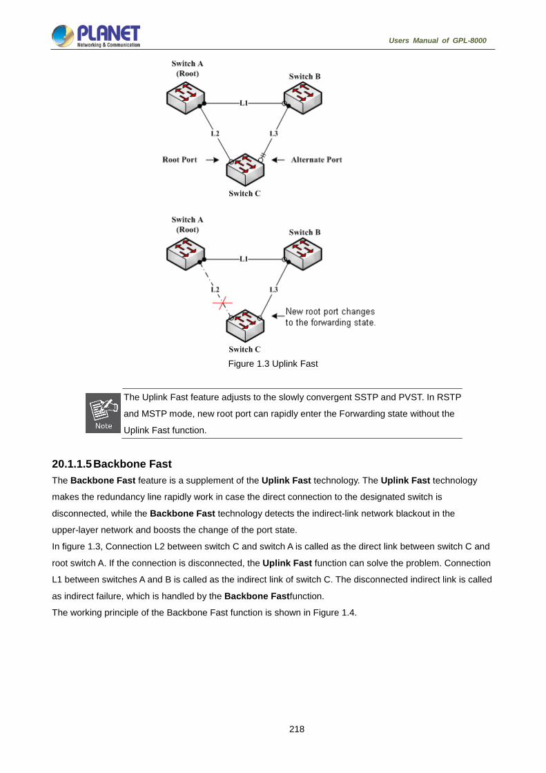
218
Users Manual of GPL-8000
Figure 1.3 Uplink Fast
The Uplink Fast feature adjusts to the slowly convergent SSTP and PVST. In RSTP
and MSTP mode, new root port can rapidly enter the Forwarding state without the
Uplink Fast function.
20.1.1.5 Backbone Fast The Backbone Fast feature is a supplement of the Uplink Fast technology. The Uplink Fast technology
makes the redundancy line rapidly work in case the direct connection to the designated switch is
disconnected, while the Backbone Fast technology detects the indirect-link network blackout in the
upper-layer network and boosts the change of the port state.
In figure 1.3, Connection L2 between switch C and switch A is called as the direct link between switch C and
root switch A. If the connection is disconnected, the Uplink Fast function can solve the problem. Connection
L1 between switches A and B is called as the indirect link of switch C. The disconnected indirect link is called
as indirect failure, which is handled by the Backbone Fastfunction.
The working principle of the Backbone Fast function is shown in Figure 1.4.

219
Users Manual of GPL-8000
Figure 1.4 Backbone Fast
Suppose the bridge priority of switch C is higher than that of switch B. When L1 is disconnected, switch B is
selected to send BPDU to switch C because the bridge priority is used as root priority. To switch C, the
information contained by BPDU is not prior to information contained by its own. When Backbone Fast is not
enabled, the port between switch C and switch B ages when awaiting the bridge information and then turns to
be the designated port. The aging normally takes a few seconds. After the function is configured in global
configuration mode by running the command spanning-tree backbonefast, when the Alternate port of switch
C receives a BPDU with lower priority, switch C thinks that an indirect-link and root-switch-reachable
connection on the port is disconnected. Switch C then promptly update the port as the designated port without
waiting the aging information.
After the Backbone Fast function is enabled, if BPDU with low priority is received at different ports, the switch
will perform different actions. If the Alternate port receives the message, the port is updated to the designated
port. If the root port receives the low-priority message and there is no other standby port, the switch turns to
be the root switch.
Note that the Backbone Fast feature just omits the time of information aging. New designated port still needs
to follow the state change order: the listening state, then the learning state and finally the forwarding state.
Similar to Uplink Fast, the Backbone Fast feature is effective in SSTP and PVST
modes.

220
Users Manual of GPL-8000
20.1.1.6 Root Guard The Root Guard feature prevents a port from turning into a root port because of receiving high-priority BPDU.
The Layer 2 network of a service provider (SP) can include many connections to switches that are not owned
by the SP. In such a topology, the spanning tree can reconfigure itself and select a customer switch as the root
switch, as shown in Figure 17-8. You can avoid this situation by enabling root guard on SP switch interfaces
that connect to switches in your customer's network. If spanning-tree calculations cause an interface in the
customer network to be selected as the root port, root guard then places the interface in the root-inconsistent
(blocked) state to prevent the customer's switch from becoming the root switch or being in the path to the root.
If a switch outside the SP network becomes the root switch, the interface is blocked (root-inconsistent state),
and spanning tree selects a new root switch. The customer's switch does not become the root switch and is
not in the path to the root.
If the switch is operating in multiple spanning-tree (MST) modes, root guard forces the interface to be a
designated port. If a boundary port is blocked in an internal spanning-tree (IST) instance because of root
guard, the interface also is blocked in all MST instances. A boundary port is an interface that connects to a
LAN, the designated switch of which is either an IEEE 802.1D switch or a switch with a different MST region
configuration.
Root guard enabled on an interface applies to all the VLANs to which the interface belongs. VLANs can be
grouped and mapped to an MST instance.
You can enable this feature by using the spanning-tree guard root interface configuration command.
Root Guard feature acts differently somehow in SSTP/PVST and RSTP/MSTP. In
SSTP/PVST mode, Root port is always blocked by Root Guard. In RSTP/MSTP
mode, Root port won’t be blocked until receiving higher level BPDU. A port which
formerly plays the Root role will not be blocked.
20.1.1.7 Loop Guard You can use loop guard to prevent alternate or root ports from becoming designated ports because of a failure
that leads to a unidirectional link. This feature is most effective when it is enabled on the entire switched
network. Loop guard prevents alternate and root ports from becoming designated ports, and spanning tree
does not send BPDUs on root or alternate ports.
You can enable this feature by using the spanning-tree loopguard default global configuration command.
When the switch is operating in PVST+ or rapid-PVST+ mode, loop guard prevents alternate and root ports
from becoming designated ports, and spanning tree does not send BPDUs on root or alternate ports.
When the switch is operating in MST mode, BPDUs are not sent on nonboundary ports only if loop guard in all
MST instances blocks the interface. On a boundary port, loop guard blocks the interface in all MST instances.
Loop Guard feature acts differently somehow in SSTP/PVST and RSTP/MSTP. In
SSTP/PVST mode, the designated port is always be blocked by Loop Guard. In
RSTP/MSTP mode, the port will be blocked only when it changes into the designated
port because of inaccessibility to receiving BPDU. Loop Guard will not block a port,
which is provided with the designated role due to receiving the lower level BPDU.

221
Users Manual of GPL-8000
20.1.2 Configuring STP Optional Characteristic 20.1.2.1 STP Optional Characteristic Configuration Task
Configuring Port Fast
Configuring BPDU Guard
Configuring BPDU Filter
Configuring Uplink Fast
20.1.2.2 Configuring Port Fast An interface with the Port Fast feature enabled is moved directly to the spanning-tree forwarding state without
waiting for the standard forward-time delay.
Use the following command to configure the port fast feature in the global configuration mode:
command purpose
spanning-tree port fast default Globally enables port fast feature. It is
valid to all interfaces.
no spanning-tree portfast default Globally disables port fast feature. It has
no effect on the interface configuration.
The port fast feature only applies to the interface that connects to the host. The
BPDU Guard or BPDU Filter must be configured at the same time when the port
fast feature is configured globally.
Use the following command to configure the port fast feature in the interface configuration mode:
command purpose
spanning-tree portfast Enables port fast feature on the interface.
no spanning-tree portfast Disables port fast feature on the interface.
It has no effect on the global configuration.

222
Users Manual of GPL-8000
20.1.2.3 Configuring BPDU Guard When you globally enable BPDU guard on ports that are Port Fast-enabled (the ports are in a Port
Fast-operational state), spanning tree shuts down Port Fast-enabled ports that receive BPDUs.
In a valid configuration, Port Fast-enabled ports do not receive BPDUs. Receiving a BPDU on a Port
Fast-enabled port means an invalid configuration, such as the connection of an unauthorized device, and the
BPDU guard feature puts the port in the error-disabled state. When this happens, the switch shuts down the
entire port on which the violation occurred.
To prevent the port from shutting down, you can use the errdisable detect cause bpduguard shutdown
vlan global configuration command to shut down just the offending VLAN on the port where the violation
occurred.
The BPDU guard feature provides a secure response to invalid configurations because you must manually
put the port back in service. Use the BPDU guard feature in a service-provider network to prevent an access
port from participating in the spanning tree.
Follow these steps to globally enable the BPDU guard feature:
command purpose
spanning-tree portfast bpduguard Globally enables bpdu guard feature. It is
valid to all interfaces.
no spanning-tree portfast bpduguard Globally disables bpdu guard feature.
Instruction:
Globally enabling port fast feature may result in broadcast storm. The BPDU Guard or BPDU Filter should be
configured for protection sake.
Follow these steps to enable the BPDU guard feature in interface configuration mode:
Command Purpose
spanning-tree bpduguard enable Enables bpdu guard feature on the
interface.
spanning-tree bpduguard disable Disables bpdu guard feature on the
interface. It has no effect on the global
configuration.
no spanning-tree bpduguard Disables bpdu guard feature on the
interface. It has no effect on the global
configuration.

223
Users Manual of GPL-8000
20.1.2.4 Configuring BPDU Filter When you globally enable BPDU filtering on Port Fast-enabled interfaces, it prevents interfaces that are in a
Port Fast-operational state from sending or receiving BPDUs. The interfaces still send a few BPDUs at link-up
before the switch begins to filter outbound BPDUs. You should globally enable BPDU filtering on a switch so
that hosts connected to these interfaces do not receive BPDUs. If a BPDU is received on a Port Fast-enabled
interface, the interface loses its Port Fast-operational status, and BPDU filtering is disabled.
Follow these steps to globally enable the BPDU filter feature.:
Command Purpose
spanning-tree portfast bpdufilter Globally enables bpdu filter feature. It is
valid to all interfaces.
no spanning-tree portfast bpdufilter Globally disables bpdu filter feature.
Instruction:
Globally enabling port fast feature may result in broadcast storm. The BPDU Guard or BPDU Filter should be
configured for protection sake.
Follow these steps to enable the BPDU filter feature in the interface configuration mode :
Command Purpose
spanning-tree bpdufilter enable Enables bpdu filter feature on the
interface.
spanning-tree bpdufilter disable Disables bpdu filter feature. It has no
effect on the global configuration.
no spanning-tree bpdufilter Disables bpdu filter feature. It has no
influence on the global configuration.
20.1.2.5 Configuring Uplink Fast If a switch loses connectivity, it begins using the alternate paths as soon as the spanning tree selects a new
root port. By enabling UplinkFast with the spanning-tree uplinkfast global configuration command, you can
accelerate the choice of a new root port when a link or switch fails or when the spanning tree reconfigures
itself. The root port transitions to the forwarding state immediately without going through the listening and
learning states, as it would with the normal spanning-tree procedures.
Uplink Fast feature is only valid in SSTP/PVST mode.
Follow these steps to globally enable UplinkFast.:
Command Purpose
spanning-tree uplinkfast Enables uplink fast feature.
no spanning-tree uplinkfast Disables uplink fast feature.

224
Users Manual of GPL-8000
20.1.2.6 Configuring Backbone Fast BackboneFast is a complementary technology to the UplinkFast feature, which responds to failures on links
directly connected to access switches. BackboneFast optimizes the maximum-age timer, which controls the
amount of time the switch stores protocol information received on an interface. When a switch receives an
inferior BPDU from the designated port of another switch, the BPDU is a signal that the other switch might
have lost its path to the root, and BackboneFast tries to find an alternate path to the root.
Backbone fast feature is only valid in SSTP/PVST mode.
Follow these steps to globally enable BackboneFast.:
Command Purpose
spanning-tree backbonefast Enables backbone fast feature.
no spanning-tree backbonefast Disables backbone fast feature.
20.1.2.7 Configuring Root Guard Root guard enabled on an interface applies to all the VLANs to which the interface belongs. Do not enable the
root guard on interfaces to be used by the UplinkFast feature. With UplinkFast, the backup interfaces (in the
blocked state) replace the root port in the case of a failure. However, if root guard is also enabled, all the
backup interfaces used by the UplinkFast feature are placed in the root-inconsistent state (blocked) and are
prevented from reaching the forwarding state.
Root Guard feature acts differently somehow in SSTP/PVST and RSTP/MSTP. In SSTP/PVST mode, Root
port is always blocked by Root Guard. In RSTP/MSTP mode, Root port won’t be blocked until receiving higher
level BPDU. A port which formerly plays the Root role will not be blocked.
Follow these steps to enable root guard on an interface.:
Command Purpose
spanning-tree guard root Enables root guard feature on the interface.
no spanning-tree guard Disables root guard and loop guard features on the interface.
spanning-tree guard none Disables root guard and loop guard features on the interface.

225
Users Manual of GPL-8000
20.1.2.8 Configuring Loop Guard You can use loop guard to prevent alternate or root ports from becoming designated ports because of a failure
that leads to a unidirectional link. This feature is most effective when it is configured on the entire switched
network. Loop guard operates only on interfaces that are considered point-to-point by the spanning tree.
Loop Guard feature acts differently somehow in SSTP/PVST. In SSTP/PVST mode,, the designated port is
always blocked by Loop Guard. In RSTP/MSTP, the designated port is always blocked by Loop Guard. In
RSTP/MSTP mode, the port will be blocked only when it changes into the designated port because of
inaccessibility to receiving BPDU. A port which is provided with the designated role due to receiving the lower
level BPDU will not be blocked by Loop Guard.
Follow these steps to enable loop guard in global configuration mode.:
Command Purpose
spanning-tree loopguard default Globally enables loop guard feature. It is
valid to all interfaces.
no spanning-tree loopguard default Globally disables loop guard.
Follow these steps to enable loop guard in the interface configuration mode.:
Command Purpose
spanning-tree guard loop Enables loop guard feature on the
interface.
no spanning-tree guard Disables root guard and loop guard
feature on the interface.
spanning-tree guard none Disables root guard and loop guard on the
interface.

226
Users Manual of GPL-8000
Link Aggregation Configuration
Configuring Port Aggregation 21.1.1 Overview Link aggregation, also called trunking, is an optional feature available on the Ethernet switch and is used with
Layer 2 Bridging. Link aggregation allows logical merge of multiple ports in a single link. Because the full
bandwidth of each physical link is available, inefficient routing of traffic does not waste bandwidth. As a result,
the entire cluster is utilized more efficiently. Link aggregation offers higher aggregate bandwidth to
traffic-heavy servers and reroute capability in case of a single port or cable failure.
Supported Features:
Static aggregation control is supported
Bind a physical port to a logical port, regardless whether they can actually bind to a logical port.
Aggregation control of LACP dynamic negotiation is supported
Only a physical port that passes the LACP protocol negotiation can bind to a logical port. Other ports won’t
bind to the logical port.
Aggregation control of LACP dynamic negotiation is supported
When a physical port is configured to bind to a logical port, the physical port with LACP negotiation can be
bound to a logical port. Other ports cannot be bound to the logical port.
Flow balance of port aggregation is supported.
After port aggregation, the data flow of the aggregation port will be distributed to each aggregated physical
port.
21.1.2 Port Aggregation Configuration Task List Configuring logical channel used for aggregation
Aggregation of physical port
Selecting load balance mode after port aggregation
Monitoring the concrete condition of port aggregation
21.1.3 Port Aggregation Configuration Task 21.1.3.1 Configuring Logical Channel Used to Aggregation You should establish a logical port before binding all the physical ports together. The logical port is used to
control the channel formed by these binding physical ports.
Use the following command to configure the logical channel:
Command Description
interface port-aggregator id Configures aggregated logical channel.

227
Users Manual of GPL-8000
21.1.3.2 Aggregation of Physical Port To aggregate multiple physical ports into a logical channel, you can use static aggregation or LACP protocol
for negotiation.
In the case when the static aggregation is used, it is required that the link of the physical port should be up,
and the VLAN attribute of aggregation port and physical port should be identical, and then this port will be
aggregated to the logical channel, regardless of whether the current port accords with the conditions of port
aggregation and whether the port that connects with the physical port accords with the aggregation
conditions.
Prerequisites for ports to be aggregated:
The link of the port must be up and the port should be negotiated to full-duplex mode.
The speed of all physical ports should be same during aggregation process, that is, if there is one physical
port that has been aggregated successfully, then the speed of the second physical port must be the same
as the first configured one. Also the vlan attributes of all physical ports must be identical to the aggregated
port.
LACP packets are exchanged between ports in these modes:
Active—Places a port into an active negotiating state, in which the port initiates negotiations with remote
ports by sending LACP packets.
Passive—Places a port into a passive negotiating state, in which the port responds to LACP packets it
receives but does not initiate LACP negotiation. In this mode, the port channel group attaches the interface
to the bundle.
If both ports use Passive method, then the aggregation fails. This is because both sides will wait for the other
side to launch aggregation negotiation process.
VALN attributes: PVID, Trunk attribute, vlan-allowed range and vlan-untagged range.
Use the following command to perform aggregation on the physical ports:
Command Description
aggregator-groupagg-idmode { lacp |
static }
Configures aggregation option of the
physical port.
21.1.3.3 Selecting Load Balance Method After Port Aggregation You can select the load share method to ensure that all ports can share the data traffic after the aggregation
of all physical ports. The switch can provides up to six load balance strategy:
src-mac
It is to share the data traffic according to the source MAC address, that is, the message with same MAC
address attributes is to get through a physical port.
dst-mac

228
Users Manual of GPL-8000
It is to share the data traffic according to the destination MAC address, that is, the message with same MAC
address attributes is to get through a physical port.
both-mac
It is to share the data traffic according to source and destination MAC addresses, that is, the message with
same MAC address attributes is to get through a physical port.
src-ip
It is to share the data traffic according to the source IP address, that is, the message with same IP address
attributes is to get through a physical port.
dst-ip
It is to share the data traffic according to the destination IP address, that is, the message with same IP
address attributes is to get through a physical port.
both-ip
It is to share the data traffic according to the destination and source IP addresses, that is, the message with
same IP address attributes is to get through a physical port.
Use the following command to configure load balance method:
Command Description
aggregator-group load-balance Configures load balance method.
21.1.3.4 Monitoring the Concrete Conditions of Port Aggregation Use the following command to monitor port aggregation state in EXEC mode:
Command Description
show aggregator-group Displays port aggregation state.
PDP Configuration
PDP Overview 22.1.1 Overview PDP is specially used to discover network equipment, that is, it is used to find all neighbors of a known device.
Through PDP, the network management program can use SNMP to query neighboring devices to acquire
network topology.
Our company’s switches can discover the neighboring devices but they do not accept SNMP queries.
Therefore, switches only run at the edge of network, or they cannot acquire a complete network topology.

229
Users Manual of GPL-8000
PDP can be set on all SNAPs (e.g. Ethernet).
22.1.2 PDP Configuration Tasks Default PDP Configuration
Setting the PDP Clock and Information Storage
Setting the PDP Version
Starting PDP on a Switch
Starting PDP on a Port
PDP Monitoring and Management
22.1.2.1 Default PDP Configuration Function Default Settings
Global configuration mode This function is not enabled by default.
Interface configuration mode Starts up.
PDP clock (packet transmission
frequency)
60 seconds
PDP information storage 180 seconds
PDP version 2
22.1.2.2 Setting the PDP Clock and Information Storage To set the PDP packet transmission frequency and the PDP information storage time, you can run the
following commands in global configuration mode.
Command Purpose
pdp timer seconds Sets the transmission frequency of the PDP
packets.
pdp holdtime seconds Sets the PDP information storage time.

230
Users Manual of GPL-8000
22.1.2.3 Setting the PDP Version To set the PDP version, you can run the following command in global configuration mode.
Command Purpose
pdp version {1|2} Setts the PDP version.
22.1.2.4 Starting PDP on a Switch To enable PDP, you can run the following commands in global configuration mode.
Command Purpose
pdp run Starts PDP on a switch.
22.1.2.5 Starting PDP on a Port To enable PDP on a port by default, you can run the following command in port configuration mode.
Command Purpose
pdp enable Starts PDP on a port of a switch.
22.1.2.6 PDP Monitoring and Management To monitor the PDP, run the following commands in EXEC mode:
Command Purpose
show pdp traffic Displays the counts of received and transmitted
PDP packets.
show pdp neighbor [detail] Displays neighbors that PDP discovers.
22.1.3 PDP Configuration Example Example 1: Starting PDP
Switch_config# pdp run
Switch_config# int f0/1
Switch_config_f0/1#pdp enable
Example 2: Setting the PDP clock and information storage
Switch_config#pdp timer 30
Switch_config#pdp holdtime 90
Example 3: Setting the PDP version
Switch_config#pdp version 1
Example 4: Monitoring PDP
Switch_config#show pdp neighbor
Capability Codes: R - Router, T - Trans Bridge, B - Source Route Bridge
S - Switch, H - Host, I - IGMP, r - Repeater
Device-ID Local-Intf Hldtme Port-ID Platform Capability
Switch Fas0/1 169 Gig0/1 COMPANY, RISC R S

231
Users Manual of GPL-8000
LLDP Configuration
LLDP 23.1.1 LLDP Introduction The 802.1ABlink layer discovery protocol (LLDP) at 802.1AB helps to detect network troubles easily and
maintain the network topology.
LLDP is a unidirectional protocol. One LLDP agent transmits its state information and functions through its
connected MSAP, or receives the current state information or function information about the neighbor.
However, the LLDP agent cannot request any information from the peer through the protocol.
During message exchange, message transmission and reception do not affect each other. You can configure
only message transmission or reception or both.
LLDP is a useful management tool, providing management personnel exact network mapping, traffic data and
trouble detection information.
23.1.2 LLDP Configuration Task List Disabling / enabling LLDP
Configuring holdtime
Configuring timer
Configuring reinit
Configuring to-be-sent tlv
Configuring the transmission / reception mode
Configuring show-relative commands
Configuring deletion commands
Configuring debugging commands
23.1.3 LLDP Configuration Task 23.1.3.1 Disabling / enabling LLDP LLDP is disabled by default. You need start up LLDP before it runs.
Run the following command in global configuration mode to enable LLDP:
Command Purpose
lldprun Runs LLDP.
Run the following command to disable LLDP:
Command Purpose
nolldprun Disables LLDP.

232
Users Manual of GPL-8000
23.1.3.2 Configuring holdtime You can control the timeout time of transmitting the LLDP message through modifying holdtime:
Run the following command in global configuration mode to configure holdtime of LLDP:
Command Purpose
lldpholdtimetime Configures the timeout time of LLDP.
nolldpholdtime Resumes the timeout time to the
default value, 120 seconds.
23.1.3.3 Configuring timer You can control the interval of the switch to transmit message by configuring the timer of LLDP.
Run the following command in global configuration mode to configure timer of LLDP:
Command Purpose
lldptimertime Configures the interval of message transmission of LLDP.
no lldptimer Resumes the default interval, that is, 30 seconds.
23.1.3.4 Configuring reinit You can control the interval of the switch to continuously transmit two messages by configuring reinit of LLDP.
Run the following command in global configuration mode to configure reinit of LLDP:
Comman
d
Purpose
lldpreinittime
Configures the interval of LLDP to continuously transmit message.
no
lldpreinit
Resumes the default interval of continuously transmitting message;
the default interval value is two seconds.
23.1.3.5 Configuring To-Be-Sent TLV You can choose TLV which requires to be sent by configuring tlv-select of LLDP. By default, all TLVs are
transmitted.
Run the following commands in global configuration mode to add or delete tlv of LLDP:
Command Purpose
lldptlv-selecttlv-type Tlvs or tlv-types which needs to be added include:
macphy-confg
management-address
port-description
port-vlan
system-capabilities
system-description
system-name
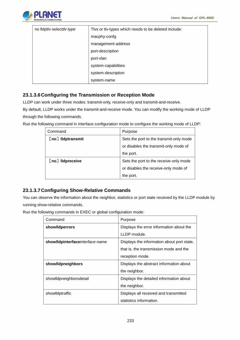
233
Users Manual of GPL-8000
no lldptlv-selecttlv-type Tlvs or tlv-types which needs to be deleted include:
macphy-confg
management-address
port-description
port-vlan
system-capabilities
system-description
system-name
23.1.3.6 Configuring the Transmission or Reception Mode LLDP can work under three modes: transmit-only, receive-only and transmit-and-receive.
By default, LLDP works under the transmit-and-receive mode. You can modify the working mode of LLDP
through the following commands.
Run the following command in interface configuration mode to configure the working mode of LLDP:
Command Purpose
[no]lldptransmit Sets the port to the transmit-only mode
or disables the transmit-only mode of
the port.
[no]lldpreceive Sets the port to the receive-only mode
or disables the receive-only mode of
the port.
23.1.3.7 Configuring Show-Relative Commands You can observe the information about the neighbor, statistics or port state received by the LLDP module by
running show-relative commands.
Run the following commands in EXEC or global configuration mode:
Command Purpose
showlldperrors Displays the error information about the
LLDP module.
showlldpinterfaceinterface-name Displays the information about port state,
that is, the transmission mode and the
reception mode.
showlldpneighbors Displays the abstract information about
the neighbor.
showlldpneighborsdetail Displays the detailed information about
the neighbor.
showlldptraffic Displays all received and transmitted
statistics information.

234
Users Manual of GPL-8000
23.1.3.8 Configuring the Deletion Commands You can delete the received neighbor lists and all statistics information by running the following command in
EXEC mode.
Command Purpose
clearlldpcounters Deletes all statistics data.
clearlldptable Deletes all received neighbor information.
23.1.3.9 Configuring Debugging Commands To easily monitor the LLDP module, run the following commands in EXEC mode:
Command Purpose
debuglldperrors Reports some error information about
the LLDP module.
debuglldpevents Reports some special events about the
LLDP module.
debuglldppackets Reports the message transmission
event of the LLDP module.
debuglldp states Reports the information about the state
of the LLDP port.

235
Users Manual of GPL-8000
FlexLinkLite Configuration
FlexLinkLite Configuration 24.1.1 FlexLinkLite Overview FlexLinkLite is used in a network environment to easily construct two uplink links, which back up each other. If
STP is not enabled in this network environment, FlexLinkLite can avoid the loop and conduct fast switchover
when a link is out of effect.
Figure 1: FlexLinkLite-enabled network
FlexLinkLite includes a pair of ports that back up each other. As shown in figure 1, FlexLinkLite is enabled on
switch S2, and G5/1 and G5/2 are two ports that back up each other, the former being an active port while the
latter being a backup port. In normal case, the active port forwards data and the backup port blocks data so as
to avoid data loopback. If the active port's link is out of effect, the backup port will immediately begin to
forward data.
A pair of ports, which back up each other, can be two physical ports, or a physical port and an aggregation
port, or two aggregation ports. The port on which FlexLinkLite is set cannot be used for STP calculation or
EAPS settings.
In case the links of two ports are up, the preempt mode is used to select which port to forward data.
FlexLinkLite only supports the preempt based on the preset role. As shown in figure 1, when a link is out of
effect and the preempt is set, port G0/1 will replace port G0/2 to forward data and port G5/2 will block data.
FlexLinkLite also has a topology change notification mechanism. As shown in figure 1, port G0/2 of switch S2
replaces port G0/1 to start forwarding data; S2 sends the TCN packets positively, and S1, after receiving
these TCN packets, immediately clears the MAC addresses that are learned by the downlink ports, G0/10 and
G0/11, and switches the downlink data flow rapidly to the correct link. In general, the TCN mechanism can
assure the successful switchover of the two-way flow in 50ms.

236
Users Manual of GPL-8000
24.1.2 FlexLinkLite Configuration 24.1.2.1 Run the following commands to set the backup port: Run the following commands to set the FlexLinkLite backup port:
Command Purpose
Switch# configure Enters the global configuration mode of the switch.
Switch_config# interface intf-name Enters the interface configuration mode.
Intf-name: stands for the name of a port, such as G0/1 or F0/10.
Switch_config_intf# switchport backup
interface backup-intf-name
as [active | backup]
Sets another port to be the backup port of the current port.
backup-intf-name: represents the name of another port.
active: Stands for the active port, to which backup-intf-name
corresponds, when the current port is a backup one.
backup: Stands for the backup port, to which backup-intf-name
corresponds, when the current port is an active one.
After switchport backup interface is set on an interface, the corresponding settings will automatically
generate on the backup port without any manual operations.
However, if no switchport backup interface is run, a pair of ports, which back up each other, will be deleted.
24.1.2.2 Setting the Preempt of a Backup Port Command Purpose
Switch_config_intf# switchport bakcup
interface preempt
mode [none | role]
Sets the preempt mode.
none: represents no preempt.
role: means the role-based preempt, which is the default settings of
the active port.
Switch_config_intf# switchport backup
interface preempt
delay [immediately | time-sec]
Sets the delay of the preempt. That is, it refers to the waiting time
during which the link state will be resumed to preempt start.
immediately: conducts the preempt without any delay.
time-sec: means the delay of preempt, whose unit is second.
The default value is three seconds. The value ranges between 1 and
600 seconds.
switchport backup interface preempt mode role is deemed as the default settings of each backup port
pair.

237
Users Manual of GPL-8000
24.1.2.3 Setting the Transmission and Reception of TCN Packets Command Purpose
Switch_config_intf# switchport bakcup
interface tcn transmit
Allows a port to transmit the TCN packets.
Switch_config_intf# switchport backup
interface tcn accept
Allows a port to process the TCN packets.
The transmit command can be enabled on the device with a configured backup port. When a backup port is
switched, it will transmit the TCN packets.
The accept command can be enabled on the uplink device. If this command is enabled on a uplink device, it
can receive the TCN packets and delete the MAC addresses that are learned by the downlink port.
24.1.3 FlexLinkLite Configuration Example
Figure 2: FlexLinkLite configuration example
Configuration
Run the following commands to set the backup port:
Switch# config
Switch_config# interface gigaEthernet 0/1
Switch_config_g0/1# switchport backup interface g0/2 as backup
Enable the default role-based preempt and set the delay to 15 seconds:
Switch_config_g0/1# switchport backup interface preempt delay 15
Make the following settings to enable the TCN packets to be transmitted:
Switch_config_g0/1# switchport backup interface tcn transmit
Switch_config_g0/1# interface g0/2
Switch_config_g0/2# switchport backup interface tcn transmit
Switch_config_g0/2# exit
Browse the state of the port:
Switch_config# show backup interfaces
Backup interface pairs:

238
Users Manual of GPL-8000
Active Backup State Preemption
G0/1 G0/2 Active Up/Backup Down Role/15/0
Make the following settings to enable the TCN packets to be received:
Switch# config
Switch_config# interface range g0/10 , 11
Switch_config_if_range# switchport backup interface tcn accept
Switch_config_if_range# exit
Switch_config#
239
Users Manual of GPL-8000
BackupLink Configuration
BackupLink Overview 25.1.1 Overview Link aggregation, also called trunking, is an optional feature available on the Ethernet switch and is used with
Layer 2 Bridging. Link aggregation allows logical merge of multiple ports in a single link. Because the full
bandwidth of each physical link is available, inefficient routing of traffic does not waste bandwidth. As a result,
the entire cluster is utilized more efficiently. Link aggregation offers higher aggregate bandwidth to
traffic-heavy servers and reroute capability in case of a single port or cable failure.
Supported Features:
Static aggregation control is supported
Bind a physical port to a logical port, regardless whether they can actually bind to a logical port.
Aggregation control of LACP dynamic negotiation is supported
Only a physical port that passes the LACP protocol negotiation can bind to a logical port. Other ports won’t
bind to the logical port.
Aggregation control of LACP dynamic negotiation is supported
When a physical port is configured to bind to a logical port, the physical port with LACP negotiation can be
bound to a logical port. Other ports cannot be bound to the logical port.
Flow balance of port aggregation is supported.
After port aggregation, the data flow of the aggregation port will be distributed to each aggregated physical
port.
25.1.2 Port Aggregation Configuration Task Configuring logical channel used for aggregation
Aggregation of physical port
Selecting load balance mode after port aggregation
Monitoring the concrete condition of port aggregation
25.1.2.1 Configuring Logical Channel Used to Aggregation You should establish a logical port before binding all the physical ports together. The logical port is used to
control the channel formed by these binding physical ports.
Use the following command to configure the logical channel:
Command Description
interface port-aggregator id Configures aggregated logical channel.

240
Users Manual of GPL-8000
25.1.2.2 Aggregation of Physical Port To aggregate multiple physical ports into a logical channel, you can use static aggregation or LACP protocol
for negotiation.
In the case when the static aggregation is used, it is required that the link of the physical port should be up,
and the VLAN attribute of aggregation port and physical port should be identical, and then this port will be
aggregated to the logical channel, regardless of whether the current port accords with the conditions of port
aggregation and whether the port that connects with the physical port accords with the aggregation
conditions.
Prerequisites for ports to be aggregated:
The link of the port must be up and the port should be negotiated to full-duplex mode.
The speed of all physical ports should be same during aggregation process, that is, if there is one physical
port that has been aggregated successfully, then the speed of the second physical port must be the same
as the first configured one. Also the vlan attributes of all physical ports must be identical to the aggregated
port.
LACP packets are exchanged between ports in these modes:
Active—Places a port into an active negotiating state, in which the port initiates negotiations with remote
ports by sending LACP packets.
Passive—Places a port into a passive negotiating state, in which the port responds to LACP packets it
receives but does not initiate LACP negotiation. In this mode, the port channel group attaches the interface
to the bundle.
If both ports use Passive method, then the aggregation fails. This is because both sides will wait for the other
side to launch aggregation negotiation process.
VALN attributes: PVID, Trunk attribute, vlan-allowed range and vlan-untagged range.
Use the following command to perform aggregation on the physical ports:
Command Description
aggregator-groupagg-idmode { lacp |
static }
Configures aggregation option of the
physical port.
25.1.2.3 Selecting Load Balance Method after Port Aggregation You can select the load share method to ensure that all ports can share the data traffic after the aggregation
of all physical ports. The switch can provides up to six load balance strategy:
src-mac
It is to share the data traffic according to the source MAC address, that is, the message with same MAC
address attributes is to get through a physical port.

241
Users Manual of GPL-8000
dst-mac
It is to share the data traffic according to the destination MAC address, that is, the message with same MAC
address attributes is to get through a physical port.
both-mac
It is to share the data traffic according to source and destination MAC addresses, that is, the message with
same MAC address attributes is to get through a physical port.
src-ip
It is to share the data traffic according to the source IP address, that is, the message with same IP address
attributes is to get through a physical port.
dst-ip
It is to share the data traffic according to the destination IP address, that is, the message with same IP
address attributes is to get through a physical port.
both-ip
It is to share the data traffic according to the destination and source IP addresses, that is, the message with
same IP address attributes is to get through a physical port.
Use the following command to configure load balance method:
Command Description
aggregator-group load-balance Configures load balance method.
25.1.2.4 Monitoring the Concrete Conditions of Port Aggregation Use the following command to monitor port aggregation state in EXEC mode:
Command Description
show aggregator-group Displays port aggregation state.

242
Users Manual of GPL-8000
EAPS Configuration
Introduction of Fast Ethernet Ring Protection 26.1.1 Overview The Ethernet ring protection protocol is a special type of link-layer protocol specially designed for constructing
the ring Ethernet topology. The Ethernet protection protocol can shut down one link in a complete ring
topology, preventing the data loop from forming the broadcast storm. If a link is broken, the protocol
immediately resumes the link that is previously shut down. In this way, the nodes among the ring network can
communicate with each other.
The ring protection protocol and STP are both used for topology control on the link layer. STP is suitable for all
kinds of complicated networks, which transmits the change of network topology hop by hop. The ring
protection protocol is used for ring topology and adopts the pervasion mechanism to transmit the change of
network topology. Therefore, the convergence of the ring protection protocol in the ring network is better than
STP. In a sound network, the ring protection protocol can resume network communication within less than
50ms.
Remark:
EAPS supports to set a switch to be a node of multiple physical ring to construct complicated topology.
26.1.2 Related Concepts of Fast Ether-Ring Protection
Figure 1.1 EAPS Ethernet ring

243
Users Manual of GPL-8000
26.1.2.1 Roles of Ring’s Nodes Each switch on an Ethernet ring is a ring node. The ring nodes are classified into master nodes and transit
nodes. Only one switch on the Ethernet ring can serve as a mere master node and other switches are worked
as transit nodes.
Master node: It positively knows whether the ring’s topology is complete, removes loopback, control other
switches to update topology information.
Transit node: It only checks the state of the local port of the ring, and notifies the master node of the invalid
link.
The role of each node can be specified by user through configuration. The thing is that each switch in the
same ring can be set to only one kind of node. In figure 1.1, switch S1 is the master node of ring network,
while switches S2, S3 and S4 are transit nodes.
26.1.2.2 Role of the Ring’s Port EAPS demands each switch has two ports to connect the ring network. Each port of the ring network also
needs to be specified through configuration and the protocol supports the following kinds of port roles:
Primary port: the primary port can be configured only on the master node. The master node transmits the ring
detection packets through the primary port.
Secondary port: the secondary port can be configured only on the master node. The master node receives the
ring detection packets from the secondary port and judges whether the topology of the ring network is
complete. In complete topology, the master node blocks the data packets on the secondary port, and prevents
loopback from occurring; after a link on the ring network is interrupted, the master node will open the
secondary port to forwarding the data packets.
Transit port: the transmit port can only be configured on the transit node. Both ports through which the transit
node connects the ring network are all transit ports.
Each port of the ring network can be configured as only one port role after the node's role of the switch and
the control VLAN are configured. As shown in figure 1.1, the port through which master node S1 connects
transit node S4 is a primary port, the port through which S1 connects S2 is a secondary port, and the ports
through which other switches connect the ring network are all transit ports.
Remark:
To configure a same switch to belong to multiple rings, the switch must connect different rings through
different physical ports.

244
Users Manual of GPL-8000
26.1.2.3 Control VLAN and Data VLAN A private control VLAN is used between master node and transit node to transmit protocol packets. This
control VLAN is specified by user through configuration and ring's ports are added also by user to the control
VLAN, which guarantees that the protocol packets can be normally forwarded. In general, each port of the
ring network is in the forwarding state in the control VLAN and the ports which do not belong to the ring
network cannot forward the packets of control VLAN.
You can specify different control VLAN for each ring on a switch. The control VLAN
is only used to forward the control packets of the ring network, not for L2/L3
communication. For example, if the VLAN port that corresponds to the control
VLAN is established, the IP address of the VLAN port cannot be pinged through
other devices.
The VLANs except the control VLAN are all data VLANs, which are used to transmit the packets of normal
services or the management packets.
The data VLAN can be used for normal L2/L3 communication. For example, you
can establish a VLAN port corresponding to data VLAN and configure dynamic
routing protocols.
26.1.2.4 Aging of the MAC Address Table The Ethernet ring protection protocol can transmit data packets to the correct link by controlling the aging of
the switch’s MAC address table when the topology changes. In general, the time for a MAC address to age in
the MAC address table is 300 seconds. The ring protection protocol can control the aging of the MAC address
table in a short time.
26.1.2.5 Symbol of a Complete Ring Network Both the master node and the transit node can show whether the current ring network is complete through the
state symbol “COMPLETE”. On the master node, only when all links of the ring network are normal, the
primary port is in forwarding state and the secondary port is in blocking state can the "COMPLETE” symbol be
real; on the transit node, only when its two transit ports are in forwarding state can the “COMPLETE” symbol
be true.
The state symbol of the ring network helps user to judge the topology state of the current network.

245
Users Manual of GPL-8000
26.1.3 Types of EAPS Packets The EAPS packets can be classified into the following types, as shown in table 1.1.
Table 1.1 Types of EAPS packets
Type of the packet Remarks
Loopback detection
(HEALTH)
It is transmitted by the master node to detect whether the
topology of the ring network is complete.
LINK-DOWN Indicates that link interruption happens in the ring. This
kinds of packets are transmitted by the transit node.
RING-DOWN-FLUSH-FDB It is transmitted by the master node after interruption of
the ring network is detected and the packets show the
MAC address aging table of the transit node.
RING-UP-FLUSH-FDB It is transmitted by the master node after interruption of
the ring network is resumed and the packets show the
MAC address aging table of the transit node.
26.1.4 Fast Ethernet Ring Protection Mechanism 26.1.4.1 Ring Detection and Control of Master Node The master node transmits the HEALTH packets to the control VLAN through the primary port in a
configurable period. In normal case, the HEALTH packets will pass through all other nodes of the ring network
and finally arrive at the secondary port of the master node.
The secondary port blocks all data VLANs in primitive condition. When receiving the HEALTH packets
continuously, the secondary port keeps blocking data VLANs and blocking the loop. If the secondary port
does not receive the HEALTH packets from the primary port in a certain time (which can be configured), it will
regard the ring network is out of effect. Then the master node removes the blocking of data VLANs on the
secondary port, ages the local MAC address table, and transmits the RING-DOWN-FLUSH-FDB packets to
notify other nodes.
If the master node receives the HEALTH packets at the secondary port that is open to data VLANs, the ring
network is resumed. In this case, the master node immediately blocks data VLANs on the secondary port,
updates the local topology information and reports other nodes to age the MAC address table through
RING-UP-FLUSH-FDB packets.
You can configure related commands on the Hello-time node and the Fail-time node to modify the interval for
the primary port to transmit the HEALTH packets and the time limit for the secondary port to wait for the
HEALTH packets.

246
Users Manual of GPL-8000
26.1.4.2 Notification of Invalid Link of Transit Node After the transit port of the transit node is out of effect, the LINK-DOWN packet will be immediately transmitted
by the other transit port to notify other nodes. In normal case, the packet passes through other transit nodes
and finally arrives at one port of the master node.
After the master node receives the LINK-DOWN packet, it thinks that the ring network is invalid. In this case,
the master node removes the blocking of data VLANs on its secondary port, ages the local MAC address
table, transmits the RING-DOWN-FLUSH-FDB packet and notifies other nodes.
26.1.4.3 Resuming the Link of the Transit Node After the transit port is resumed, it does not immediately transmit the packets of data VLANs, but enters the
Pre-Forwarding state. A transit port in pre-forwarding state only transmits and receives the control packets
from the control VLAN.
If there is only one transit port invalid in the ring network and when the port enters the pre-forwarding state,
the secondary port of the master node can receive the HEALTH packet from the primary port again. In this
case, the master node blocks data VLANs on the secondary port again and transmits the notification of
ageing address table outside. After the node with a transit port in pre-forwarding state receives the notification
of aging address table, the node will first modify the pre-forwarding port to the forwarding port and then ages
the local MAC address table.
If a transit mode does not receives the notification of aging address table from the master node, it thinks that
the link to the master node is already out of effect, the transit node will automatically set the pre-forwarding
port to be a forwarding one.
You can configure the related commands through the pre-forward-time node to modify the time for the transit
port to keep the pre-forwarding state.
Fast Ethernet Ring Protection Configuration 26.2.1 Default EAPS Settings
The fast Ethernet protection protocol cannot be set together with STP.
After STP is disabled, you are recommended to run spanning-tree bpdu-terminal to keep the ring node from
forwarding BPDU, which leads to the storm.
See the following table:
Table 2.1 Default settings of the Ethernet ring protection protocol and STP.
Spanning tree protocol spanning-tree mode rstp
Fast Ethernet Ring Protection There is no configuration.

247
Users Manual of GPL-8000
26.2.2 Requisites before Configuration Before configuring MEAPS, please read the following items carefully:
One of important functions of the ring protection protocol is to stop the broadcast storm, so please make
sure that before the ring link is reconnected all ring nodes are configured.If the ring network is connected in
the case that the configuration is not finished, the broadcast storm may easily occur.
EAPS is well compatible with STP, but the port under the control of EAPS is not subject to STP.
The ring protection protocol supports a switch to configure multiple ring networks.
Configuring ring control VLAN will lead to the automatic establishment of corresponding system VLAN.
The port of each ring can forward the packets from the control VLAN of the ring, while other ports, even in
the Trunk mode, cannot forward the packets from the control VLAN.
By default, Fail-time of the master node is triple longer than Hello-time, so that packet delay is avoided
from shocking the ring protection protocol. After Hello-time is modified, Fail-time need be modified
accordingly.
By default, Pre-Forward-Time of the transit node is triple longer than Hello-time of the master node so that
it is ensured that the master node can detect the recovery of the ring network before the transit port enters
the pre-forwarding state. If Hello-time configured on the master node is longer than Fre-Forward-Time of
the transit node, loopback is easily generated and broadcast storm is then triggered.
The physical interface, the fast-Ethernet interface, the gigabit-Ethernet interface and the aggregation
interface can all be set to be the ring's interfaces. If link aggregation, 802.1X or port security has been
already configured on a physical interface, the physical interface cannot be set to be a ring’s interface any
more.
The versions of switch software prior to version 2.0.1L and the versions of hi-end
switch software prior to version 4.0.0M do not support the configuration of the
converged port.
26.2.3 MEAPS Configuration Tasks Configuring the Master Node
Configuring the Transit Node
Configuring the Ring Port
Browsing the State of the Ring Protection Protocol
26.2.4 Fast Ethernet Ring Protection Configuration 26.2.4.1 Configuring the Master Node Configure a switch to be the master node of a ring network according to the following steps:
Command Purpose
Switch#config Enters the switch configuration mode.
Switch_config#ether-ring id Sets a node and enters the node configuration mode.
id: Instance ID

248
Users Manual of GPL-8000
Command Purpose
Switch_config_ring#control-vlan vlan-id Configures the control VLAN.
Vlan-id: ID of the control VLAN
Switch_config_ring#master-node Configures the node type to be a master node.
Switch_config_ring#hello-time value This step is optional. Configures the cycle for the master
node to transmit the HEALTH packets.
Value: It is a time value ranging from 1 to 10 seconds
and the default value is 1 second.
Switch_config_ring#fail-time value This step is optional. Configures the time for the
secondary port to wait for the HEALTH packets.
Value: It is a time value ranging from 3 to 30 seconds
and the default value is 3 second.
Switch_config_ring#exit Saves the current settings and exits the node
configuration mode.
Remarks:
The no ether-ring id command is used to delete the node settings and port settings of the Ethernet ring.

249
Users Manual of GPL-8000
26.2.4.2 Configuring the Transit Node Configure a switch to be the transit node of a ring network according to the following steps:
Command Purpose
Switch#config Enters the switch configuration mode.
Switch_config#ether-ring id Sets a node and enters the node configuration
mode.
id: Instance ID
Switch_config_ring#control-vlan
vlan-id
Configures the control VLAN.
Vlan-id: ID of the control VLAN
Switch_config_ring#transit-node Configures the node type to be a transit node.
Switch_config_ring#pre-forward-time
value
This step is optional. Configures the time of
maintaining the pre-forward state on the transit
port.
Value: It is a time value ranging from 3 to 30
seconds and the default value is 3 second.
Switch_config_ring#exit Saves the current settings and exits the node
configuration mode.
26.2.4.3 Configuring the Ring Port Configure a port of a switch to be the port of Ethernet ring according to the following steps:
Command Purpose
Switch#config Enters the switch configuration mode.
Switch_config#interface intf-name Enters the interface configuration mode.
intf-name: Stands for the name of an interface.
Switch_config_intf#ether-ring id
{primary-port | secondary-port |
transit-port }
Configures the type of the port of Ethernet ring.
ID of the node of Ethernet ring
Switch_config_intf#exit Exits from interface configuration mode.
Remarks:
The no ether-ringidprimary-port { secondary-port | transit-port } command can be used to cancel the port
settings of Ethernet ring.
26.2.4.4 Browsing the State of the Ring Protection Protocol Run the following command to browse the state of the ring protection protocol:
Command Purpose
show ether-ring id Browses the summary information about the
ring protection protocol and the port of Ethernet
ring.
id: ID of Ethernet ring

250
Users Manual of GPL-8000
show ether-ring id detail Browses the detailed information about the ring
protection protocol and the port of Ethernet
ring.
show ether-ring id interface intf-name Browses the state of the Ether-ring port or that
of the common port.
26.2.5 MEAPS configuration 26.2.5.1 Configuration Example
MEAPS configuration
As shown in figure 2.1, master node S1 and transit node S2 are configured as follows. As to the settings of
other nodes, they are same to S2's settings.
Configuring switch S1:
Shuts down STP and configures the Ether-ring node:
S1_config#no spanning-tree
S1_config#ether-ring 1
S1_config_ring1#control-vlan 2
S1_config_ring1#master-node
The following commands are used to set the time related parameters:
S1_config_ring1#hello-time 2
S1_config_ring1#fail-time 6
Exits from the node configuration mode:
S1_config_ring1#exit
Configures the primary port and the secondary port:
S1_config#interface gigaEthernet 0/1
S1_config_g0/1#ether-ring 1 primary-port

251
Users Manual of GPL-8000
S1_config_g0/1#exit
S1_config#interface gigaEthernet 0/3
S1_config_g0/3#ether-ring 1 secondary-port
S1_config_g0/3#exit
Establishes the control VLAN:
S1_config#vlan 2
S1_config_vlan2#exit
S1_config#interface range g0/1 , 3
S1_config_if_range#switchport mode trunk
S1_config_if_range#exit
Configuring switch S2: S1_config#no spanning-tree
S1_config#ether-ring 1
S1_config_ring1#control-vlan 2
S1_config_ring1#transit-node
S1_config_ring1#pre-forward-time 8
S1_config_ring1#exit
S1_config#interface gigaEthernet 0/1
S1_config_g0/1#ether-ring 1 transit-port
S1_config_g0/1#exit
S1_config#interface gigaEthernet 0/3
S1_config_g0/3#ether-ring 1 transit-port
S1_config_g0/3#exit
S1_config#vlan 2
S1_config_vlan2#exit
S1_config#interface range gigaEthernet 0/1 , 3
S1_config_if_range#switchport mode trunk
S1_config_if_range#exit

252
Users Manual of GPL-8000
MEAPS Settings
MEAPS Introduction 27.1.1 MEAPS Overview EAPS is a protocol specially applied on the link layer of the Ethernet ring. When the Ethernet ring is complete,
you should prevent the broadcast storm from occurring on the data loopback. But when a link of an Ethernet
ring is broken, you should enable the backup link rapidly to resume the communication of different nodes in
the ring. The role of switch is specified by you through configuration.
EAPS only supports the single-ring structure, while MEAPS, an expansion on the basis of EAPS, can support
not only the single ring but also the level-2 multi-ring structure. The later structure consists of the aggregation
layer in the middle, constructed by aggregation equipment through the Ethernet ring for fast switching, and
the access layer at the outside, connected by the access equipment. Different levels of rings are connected
through the tangency or intersection mode. See the specific topology in the following figure:
Figure 1: MEAPS topology
The ring protection protocol and STP are both used for topology control on the link layer. STP is suitable for all
kinds of complicated networks, which transmits the change of network topology hop by hop. The ring
protection protocol is used for ring topology and adopts the pervasion mechanism to transmit the change of
network topology. Therefore, the convergence of the ring protection protocol in the ring network is better than
STP. In a sound network, the ring protection protocol can resume network communication within less than
50ms.

253
Users Manual of GPL-8000
27.1.2 Basic Concepts of MEAPS 27.1.2.1 Domain The domain specifies the protection range of the Ethernet loopback protection protocol and is marked by ID,
which consists of integers; A group of switches that support the same protection data and have the same
control VLAN can form a domain after they are connected with each other. One domain may include only one
ring or multiple rings that intersect each other. See the following figure.
One MEAPS domain has the following factors: MEAPS ring, control VLAN, master node, transit node, edge
node and assistant edge node.
Figure 2: Simple MEAPS model
27.1.2.2 Ring One ring corresponds to an ring Ethernet topology physically, which is a group of switches that are connected
each other into a ring. One MEAPS domain may include only one MEAPS ring or multiple rings that intersect
each other.
27.1.2.3 Major Ring When a domain includes many rings, you should choose one ring from them as a major ring. The primary and
secondary ports of each node on the major ring should be added into the main control VLAN and the sub
control VLAN at the same time. See the following figure.
27.1.2.4 Sub Ring When a domain includes many rings, the included rings except the major ring are called as sub rings. The
primary and secondary ports of each node on the sub ring should be added into the sub control VLAN. See
the following figure.
27.1.2.5 Control VLAN The control VLAN is a concept against the data VLAN, and in MEAPS, the control VLAN is just used to
S4:Master S5:Edge S6:Transit
S1:Transit S2:Assistant S3:Master
P
S B
P
SB
Sub Ring
EAPS Domain
P-Primary portS-Secondary port
B-Block portMajor_Ring control vlan:3
Sub_Ring control vlan:4
3/4 4
3/4
3/4
3/4
4
4Major Ring
254
Users Manual of GPL-8000
transmit the MEAPS packets. Each MEAPS has two control VLANs, that is, the main control VLAN and the
sub control VLAN.
You need to specify the main control VLAN when configuring the major ring or the sub ring. During
configuration you just need to specify the main control VLAN and take a VLAN, the ID of which is 1 more than
the ID of the main control VLAN, as the sub control VLAN. The major ring will be added to the main control
VLAN and the sub control VLAN at the same time, while the sub ring will only be added to the sub control
VLAN. See number 3 and number 4 beside each port on figure 2.
The main-ring protocol packets are transmitted in the main control VLAN, while the sub-ring protocol packets
are transmitted in the sub control VLAN. The sub control VLAN on the major ring is the data VLAN of the
major ring. The ports of a switch that access the Ethernet ring belong to the control VLAN, and only those
ports that access the Ethernet ring can be added into the control VLAN.
Remarks:
The MEAPS port of the major ring should belong to both the main control VLAN and the sub control VLAN;
the MEAPS port of the sub ring only belongs to the sub control VLAN. The major ring is regarded as a logical
node of the sub ring and the packets of the sub ring are transparently transmitted through the major ring; the
packets of the major ring are transmitted only in the major ring.
27.1.2.6 Data VLAN The data VLAN is used to transmit data packets. The data VLAN can include the MEAPS port and the
non-MEAPS port. Each domain protects one or multiple data VLANs. The topology that is calculated by the
ring protection protocol in a domain is effective only to the data VLAN in this domain.
Whether the data VLAN is created or not has no influence on the work of the ring state machine, where the
MEAPS port is controlled by the MEAPS module and the non-MEAPS port is controlled by the STP module.
Remarks:
The processing methods which are similar to that of the MSTP module can be used, that is, the status of a
port in the default STP instance is decided by the link status of the port, no matter what the VLAN
configuration of a port is.
27.1.2.7 Master Node The master node works as policy making and control of a ring. Each ring must possess only one master node.
The master node takes active attitude to know whether the ring’s topology is complete, removes loopback,
control other switches to update topology information. See the following figure, where S3 is the master node
of the sub ring and S4 is the master node of the major ring.

255
Users Manual of GPL-8000
27.1.2.8 Transit Node All switches on the Ethernet except the master node can be called as the transit nodes. The transit node only
checks the state of the local port of the ring, and notifies the master node of the invalid link. See the following
figure, in which S1, S2, S5 and S6 are all transit nodes.
27.1.2.9 Edge Node and Assistant Node When the sub ring and the major ring are intersected, there are two intersection points, two switches beside
which are called as the edge node for one and the assistant node for the other. The two nodes are both the
nodes of the sub ring. There are no special requirements as to which switch will be set to be the edge node or
the assistant node if their configurations can distinguish themselves. However, one of them must be set as the
edge node and the other must be set as the assistant node. The edge node or the assistant node is a role that
a switch takes on the sub ring, but the switch takes a role of the transit node or the master node when it is on
the major ring. See the following figure, in which S2 is the assistant node and S5 is the edge node.
27.1.2.10 Primary Port and Secondary Port The two ports through which the master node accesses the Ethernet ring are called as the primary port and
the secondary port. The roles of the two ports are decided by the clients.
The primary port is in forwarding state when it is up. Its function is to forward the packets of the data VLAN on
the master node and to receive and forward the control packets on the control VLAN. The master node will
transmit the loopback detection packets from the primary port to the control VLAN. If the link of the primary
port is resumed from the invalid status, the master node requires sending the address aging notification to the
control VLAN promptly and then starts to transmit the loopback detection packets from the primary port.
The secondary port is in forwarding or blocking state when it is up. The master node receives the ring
detection packets from the secondary port and judges whether the topology of the ring network is complete. In
complete topology, the master node blocks the data packets on the secondary port, and prevents loopback
from occurring; after a link on the ring network is interrupted, the master node will open the secondary port to
forwarding the data packets.
Remarks:
A port can be set as the primary port or the secondary port of a node and it cannot be set to be both the
primary port and the secondary port.
27.1.2.11 Transit Port The two ports for the transit node to access the Ethernet ring are both transit ports. Users can decide the role
of the two ports through configuration.
The transit port is in forwarding or pre-forwarding state when it is up. A transit port receives the control packets
from the control VLAN and at the same time forwards these packets to other ports in the control VLAN. After
the transit port resumes from the invalid state, it first enters the pre-forwarding state, receives and forwards
only the control packets, and blocks the data VLAN. After the transit node receives the notification of the aging
address table, it enters the forwarding state.

256
Users Manual of GPL-8000
Remarks:
A port can be set as the primary port or the transit port of a node and it cannot be reset.
27.1.2.12 Common Port and Edge Port The edge node and the assistant node are the places where the sub ring and the major ring intersect. As to
the two ports that access the Ethernet, one is a common port, which is the public port of the sub ring and the
major ring; the other is the edge port in the sub ring. The roles of the two ports are decided by users through
configuration.
The common port is on the main-ring port and so its state is decided by the state of the main-ring port. The
common port itself has no operations or notifications. When the link, connecting the common port, changes,
the sub-ring node where the common port lies will not be notified. The existence of the common port just
guarantees the completeness of the ring.
The edge port of the edge node is in forwarding or preforwarding state when it is up. Its basic characteristics
are consistent with those of the transit port except one function. The exceptional function is that when the
edge port is up and its corresponding main-ring port is also up, it will transmit the edge-hello packets from the
main-ring port to detect the completeness of the major ring.
The edge port of the assistant node is in forwarding, pre-forwarding or EdgePreforwarding state when it is up.
Besides the same characteristics of the transit port, it also has one more state, the EdgePreforwarding state.
If the edge port is in forwarding state and the main-ring port that the edge port corresponds to has not
received the edge-hello packets, the state of the edge port is changed into the EdgePreforwarding state, and
it only receives and forwards the control packets and blocks the data VLAN until the corresponding main-ring
port receives the Edge-hello packets again.
The edge port of the edge node and the assistant node is to help detect the completeness of the major ring.
For more details, see the channel status checkup mechanism of the sub-ring protocol packets on the major
ring in the following chapter.
Remarks:
Each port can be set as the only edge port of a node and it cannot be configured again; the common port can
be borne only on a port of the major ring and it cannot be configured on a port without a corresponding
main-ring port.
27.1.2.13 FLUSH MAC FDB The Ethernet ring protection protocol can transmit data packets to the correct link by controlling the aging of
the switch’s MAC address table when the topology changes. In general, the time for a MAC address to age in
the MAC address table is 300 seconds. The ring protection protocol can control the aging of the MAC address
table in a short time.

257
Users Manual of GPL-8000
27.1.2.14 Complete Flag of Ring Both the master node and the transit node can show whether the current ring network is complete through the
state symbol “COMPLETE”. On the master node, only when all links of the ring network are normal, the
primary port is in forwarding state and the secondary port is in blocking state can the "COMPLETE” symbol be
real; on the transit node, only when its two transit ports are in forwarding state can the “COMPLETE” symbol
be true.
The state symbol of the ring network helps user to judge the topology state of the current network.
27.1.3 Types of EAPS Packets The EAPS packets can be classified into the following types, as shown in table 1.1.
Table 1.1 Types of EAPS packets
Type of the packet Remarks
HEALTH It is transmitted by the master node to detect whether the topology
of the ring network is complete.
LINK-DOWN Indicates that link interruption happens in the ring. This kinds of
packets are transmitted by the transit node.
RING-DOWN-FLUSH-FDB It is transmitted by the master node after interruption of the ring
network is detected and the packets show the MAC address aging
table of the transit node.
RING-UP-FLUSH-FDB It is transmitted by the master node after interruption of the ring
network is resumed and the packets show the MAC address aging
table of the transit node.
EDGE-HELLO It is decided by the edge port of the edge node, transmitted by the
main-ring port that the edge node corresponds to, and detects
whether the major ring is complete.
27.1.4 Fast Ethernet Ring Protection Mechanism 27.1.4.1 Polling mechanism The primary port transmits the HEALTH packets to the control VLAN. In normal case, the HEALTH packets
will pass through all other nodes of the ring and finally arrive at the secondary port of the master node.
The secondary port blocks all data VLANs in primitive condition. When receiving the HEALTH packets
continuously, the secondary port keeps blocking data VLANs and blocking the loop. If the secondary port
does not receive the HEALTH packets from the primary port in a certain time (which can be configured), it will
regard the ring network is out of effect. Then the master node removes the blocking of data VLANs on the
secondary port, ages the local MAC address table, and transmits the RING-DOWN-FLUSH-FDB packets to
notify other nodes.
If the master node receives the HEALTH packets at the secondary port that is open to data VLANs, the ring
network is resumed. In this case, the master node immediately blocks data VLANs on the secondary port,
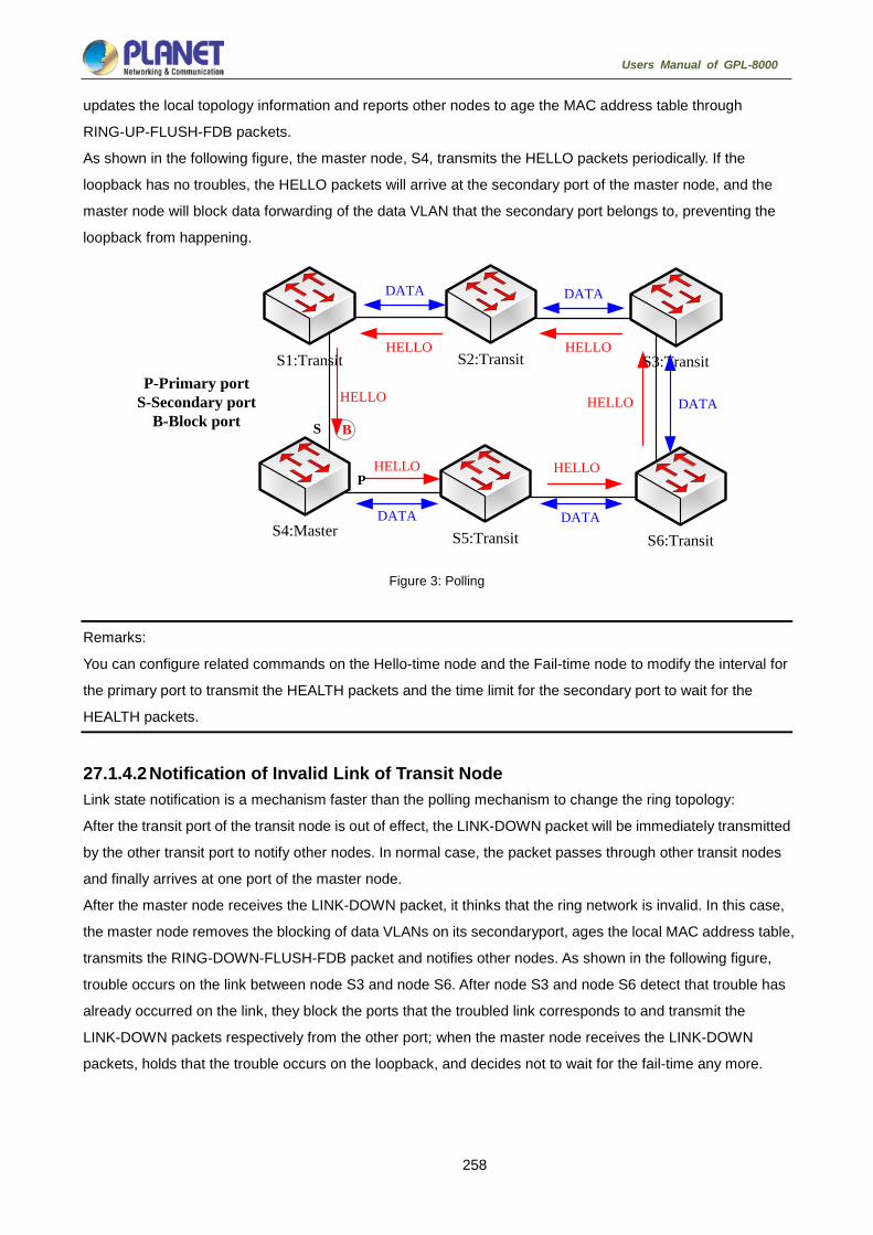
258
Users Manual of GPL-8000
updates the local topology information and reports other nodes to age the MAC address table through
RING-UP-FLUSH-FDB packets.
As shown in the following figure, the master node, S4, transmits the HELLO packets periodically. If the
loopback has no troubles, the HELLO packets will arrive at the secondary port of the master node, and the
master node will block data forwarding of the data VLAN that the secondary port belongs to, preventing the
loopback from happening.
Figure 3: Polling
Remarks:
You can configure related commands on the Hello-time node and the Fail-time node to modify the interval for
the primary port to transmit the HEALTH packets and the time limit for the secondary port to wait for the
HEALTH packets.
27.1.4.2 Notification of Invalid Link of Transit Node Link state notification is a mechanism faster than the polling mechanism to change the ring topology:
After the transit port of the transit node is out of effect, the LINK-DOWN packet will be immediately transmitted
by the other transit port to notify other nodes. In normal case, the packet passes through other transit nodes
and finally arrives at one port of the master node.
After the master node receives the LINK-DOWN packet, it thinks that the ring network is invalid. In this case,
the master node removes the blocking of data VLANs on its secondaryport, ages the local MAC address table,
transmits the RING-DOWN-FLUSH-FDB packet and notifies other nodes. As shown in the following figure,
trouble occurs on the link between node S3 and node S6. After node S3 and node S6 detect that trouble has
already occurred on the link, they block the ports that the troubled link corresponds to and transmit the
LINK-DOWN packets respectively from the other port; when the master node receives the LINK-DOWN
packets, holds that the trouble occurs on the loopback, and decides not to wait for the fail-time any more.
S4:Master S5:Transit S6:Transit
S1:Transit S2:Transit S3:Transit
P
S B
P-Primary portS-Secondary port
B-Block port
HELLO
HELLO
HELLOHELLO
HELLO
HELLO
DATA DATA
DATA DATA
DATA

259
Users Manual of GPL-8000
Figure 4: Link status change notification
After the transit port is resumed, it does not immediately transmit the packets of data VLANs, but enters the
Pre-Forwarding state. A transit port in pre-forwarding state only transmits and receives the control packets
from the control VLAN.
If there is only one transit port invalid in the ring network and when the port enters the pre-forwarding state,
the secondary port of the master node can receive the HEALTH packet from the primary port again. In this
case, the master node blocks data VLANs on the secondary port again and transmits the notification of
ageing address table outside. After the node with a transit port in pre-forwarding state receives the notification
of aging address table, the node will first modify the pre-forwarding port to the forwarding port and then ages
the local MAC address table.
If a transit mode does not receives the notification of aging address table from the master node, it thinks that
the link connecting the master node is already out of effect, and the transit node will automatically set the
pre-forwarding port to be a forwarding one.
Remarks:
You can configure the related commands through the pre-forward-time node to modify the time for the transit
port to keep the pre-forwarding state.
27.1.4.3 Channel Status Checkup Mechanism of the Sub-Ring Protocol Packet on the Major ring The ports on the major ring are simultaneously added to the control VLAN of the major ring and the control
VLAN of the sub ring. Hence, the protocol packets of the sub ring should be broadcast among the edge ports
of the edge node and the assistant node through the channel, provided by the major ring. In this case, the
whole major ring is just like a node of the sub ring (similar as a virtual transit node), as shown in the following
figure:
S4:Master S5:Transit S6:Transit
S1:Transit S2:Transit S3:Transit
P
S B
P-Primary portS-Secondary port
B-Block portx
LINK_DOWN
LINK_DOWN
LINK_DOWN
LINK_DOWN LINK_DOWN

260
Users Manual of GPL-8000
Figure 5: Intersection of the major ring and the sub ring
When trouble occurs on the link of the major ring, and when the channel of the sub-ring protocol packets
between the edge node and the assistant node are interrupted, the master node of the sub ring cannot
receive the HELLO packets that the master node itself transmits. In this case, the Fail Time times out, and the
master node of the sub ring changes to the Failed state and opens its secondary port.
The above-mentioned processes have an effective protection towards general networking, guaranteeing not
only the prevention of the broadcast loopback but also the corresponding functions of the backup link. The
dual homing networking mode is always used in actual networking, as shown in the following figure. The two
sub rings in the dual homing networking, sub ring I and sub ring II, interconnect through the edge node and
assistant node, and forms a big ring. When the major ring has troubles, the secondary ports of the master
nodes of all sub rings open and forms the broadcast loop (marked by the arrow) in the big ring.
Figure 6: Broadcast storm triggered by the dual homing networking mode
S4:Master S5:Edge S6:Transit
S1:Transit S2:Assistant S3:Master
P
S B
P
SB
Sub RingP-Primary port
S-Secondary portB-Block port
Major Ring
Sub HELLO
Major HELLO
Master Edge
Transit
Transit Assistant
Master
P
S
P
S
SubRing
I
P-Primary portS-Secondary port
Major Ring
DATA
Transit
Master
SubRing
IIx
x
S
P

261
Users Manual of GPL-8000
The channel status checkup mechanism of the sub-ring protocol packet on the major ring is introduced to
solve the problem about the dual homing ring. This mechanism is to monitor the status of the channel link on
the major ring between the edge node and the assistant node, which requires the help of the edge node and
the assistant node. The purpose of this mechanism is to keep the data loop from happening by blocking the
edge port of the edge node before the secondary port of the master node on the sub ring opens. The edge
node is the trigger of the mechanism, while the assistant node is the listener and decider of this mechanism.
Once the notification message from the edge node cannot be received, the edge node will instantly be in
blocked state until this notification message is received again. The results of the mechanism, which bring
about after the troubles on the major ring, are shown in the following figure:
Figure 7: Results of the channel status checkup mechanism
But you should pay special attention to this point that the edge port of the assistant node must be blocked
before the secondary port of the master node on the sub ring opens. Otherwise, the broadcast storm will
happen.
The whole procedure of this mechanism is described as follows:
1. Check the channel status on the major ring between the edge node and the assistant node.
The edge node of the sub ring periodically transmits the Edge-Hello packets to the major ring through the two
ports of the major ring, and these packets pass through all nodes on the major ring in sequence and finally
arrive the assistant node, as shown in the following figure. If the assistant node can receive the edge-hello
packet in the regulated time, it indicates that the channel of this packet is normal; if not, it indicates that the
channel is interrupted. The edge-hello packet is the control packet of the sub ring, but is transmitted and
received by the ports on the major ring and is transferred to the sub ring for processing.
Master Edge
Transit
Transit Assistant
Master
P
S
P
S
SubRing
I
P-Primary portS-Secondary port
B-Block port
Major Ring
DATA
Transit
Master
SubRing
IIx
x
S
P
B
B

262
Users Manual of GPL-8000
Figure 8. Check the channel status on the major ring between the edge node and the assistant node.
2. The edge node blocks the edge port at the interruption of the channel.
If the assistant node cannot receive the edge-hello packet during Edge Fail Time, the assistant holds that the
channel of the sub-ring protocol packet—the edge-hello packet—is interrupted, changes its edge port’s status
into the Edge-Preforwarding status instantly, blocks the forwarding of the data packets (though still receives
and forwards the control packet), and immediately transmits the LINK-DOWN packet to the master node for
the master node to open the secondary port to avoid communication interruption among all nodes on the ring.
Remarks:
In order to guarantee that the edge port first changes into the edge-preforwarding status and then the master
node opens the secondary port, you shall be sure that the cycle for the edge node to transmit the edge-hello
packet, Edge Hello Time, is smaller than the cycle for the master node to transmit the Hello packet, Hello
Time; similarly, the Edge Fail Time of the assistant node should be smaller than Fail Time. At the same time,
Fail Time is generally the triple of Hello Time, and Edge Fail Time is also the triple of Edge Hello Time.

263
Users Manual of GPL-8000
Figure 9: The edge node blocks the edge port at the interruption of the channel.
3. Channel recovery
When the link of the major ring and the communication between the edge node and the assistant node
resumes, the channel of the sub-ring protocol packet resumes to the normal function. In this case, the master
node of the sub ring receives the Hello packet again, which is transmitted by the master node itself, and
therefore it switches to the Complete status, blocks the secondary port and transmits the
RING-UP-FLUSH-FDB packet to the ring. At the same time, the status of the edge port of the assistant node
changes from Edge-Preforwarding to Forwarding, guaranteeing a smooth communication among all nodes on
the ring. The following figure shows that the channel is resumed and then the communication on the ring is
also resumed.
Before the edge node opens the blocked edge port, the secondary port of the
master node on the sub ring should be blocked to prevent the broadcast storm from
happening.
Figure 10: Channel recovery
Master Edge
Transit
Transit Assistant
Master
P
S
P
S
SubRing
I
P-Primary portS-Secondary port
B-Block porteP-EdgePreforwarding port
Major Ring
LINK-DOWN
Transit
Master
SubRing
IIx
x
S
P
B
B
eP
eP
EDGE-HELLO
Master Edge
Transit
Transit Assistant
Master
P
S
P
S
SubRing
I
P-Primary portS-Secondary port
B-Block port
Major Ring
Sub Ring I HELLO
Transit
Master
SubRing
IIx
S
P
B
B
Sub Ring II HELLO
EDGE-HELLO

264
Users Manual of GPL-8000
Fast Ethernet Ring Protection Configuration 27.2.1 Requisites before Configuration Before configuring MEAPS, please read the following items carefully:
One of important functions of the ring protection protocol is to stop the broadcast storm, so please make
sure that before the ring link is reconnected all ring nodes are configured. If the ring network is connected
in the case that the configuration is not finished, the broadcast storm may easily occur.
Set the ring protection protocol to realize the compatibility of STP. The users are allowed to set “no
spanning-tree”, SSTP, RSTP and MSTP.
After an instance of the ring's node is set, users are forbidden to change the basic information of the node
(excluding the time parameters) unless the current ring’s node is deleted and then reset.
If you run show to browse the configured node and find its state is init, it shows that the node’s
configuration is unfinished and therefore the node cannot be started. In this case, you are required to
change or add basic information to complete the configuration of the node.
The ring protection protocol supports a switch to configure multiple ring networks.
The configuration of the control VLAN of the ring network does not automatically establish the
corresponding systematic VLAN. You need to establish the systematic VLAN manually through global
VLAN configuration command.
The port of each ring can forward the packets from the control VLAN of the ring, while other ports, even in
the Trunk mode, cannot forward the packets from the control VLAN.
By default, Fail-time of the master node is triple longer than Hello-time, so that packet delay is avoided
from shocking the ring protection protocol. After Hello-time is modified, Fail-time need be modified
accordingly.
By default, Pre-Forward-Time of the transit node is triple longer than Hello-time of the master node so that
it is ensured that the master node can detect the recovery of the ring network before the transit port enters
the pre-forwarding state. If Hello-time configured on the master node is longer than Fre-Forward-Time of
the transit node, loopback is easily generated and broadcast storm is then triggered.
Users cannot set Edge Hello Time and Edge Fail Time, and their default values are decided by Hello Time
and Fail Time respectively for their values are 1/3 of Hello Time and Fail Time respectively.
The physical interface, the fast-Ethernet interface, the gigabit-Ethernet interface and the aggregation
interface can all be set to be the ring's interfaces. If link aggregation, 802.1X or port security has been
already configured on a physical interface, the physical interface cannot be set to be a ring’s interface any
more.
This protocol is similar with the original EAPS in functions, but its ring’s topology has more expansibility
and flexibility. Hence, MEAPS and EAPS are partially compatible, and the intersection configuration can
be done on the MEAPS ring and the EAPS ring. But a same physical port cannot be simultaneously set to
support MEAPS and EAPS.

265
Users Manual of GPL-8000
27.2.2 MEAPS Configuration Tasks Configuring the Master Node
Configuring the Transit Node
Configuring the Edge Node and the Assistant Node
Configuring the Ring Port
Browsing the State of the Ring Protection Protocol
27.2.3 Fast Ethernet Ring Protection Configuration 27.2.3.1 Configuring the Master Node Configure a switch to be the master node of a ring network according to the following steps:
Command Purpose
Switch#config Enters the switch configuration mode.
Switch_config#mether-ring id1
domainid2
Sets a node and enters the node configuration
mode.
id1: instance ID of a node
id2: instance ID of a domain (omitted when it is
0)
Switch_config_ring1#master-node
It is an obligatory step. Configures the node type to
be a master node.
Switch_config_ring1#major-ring[sub-rin
g]
It is an obligatory step. Sets the node’s level to be
one of the major or sub ring node.
Switch_config_ring1#control-vlanvlan-id
It is an obligatory step. Sets the control VLAN and
establishes VLAN “id” and VLAN “id-1”.
vlan-id: ID of the control VLAN
Switch_config_ring1#hello-timevalue
This step is optional. Configures the cycle for the
master node to transmit the HEALTH packets.
value: It is a time value ranging from 1 to 10
seconds and the default value is 3 seconds.
Switch_config_ring1#fail-timevalue
This step is optional. Configures the time for the
secondary port to wait for the HEALTH packets.
value: It is a time value ranging from 3 to 30
seconds and the default value is 9 seconds.
Switch_config_ring1#exit
Saves the current settings and exits the node
configuration mode.
Switch_config#
Remarks:
The no mether-ring iddomainid2 command is used to delete the node settings and the node’s port settings of
the ring.

266
Users Manual of GPL-8000
Remarks:
During configuration, both the major ring and the sub-ring should be set to have the same control VLAN—the
control VLAN of the major ring. After this configuration is successfully set, the control VLAN of major ring and
the control VLAN of sub-ring are created on the major ring, and at the same time the sub-ring control VLAN is
created on the sub-ring and the major-ring control VLAN is forbidden on the sub-ring.
27.2.3.2 Configuring the Transit Node Configure a switch to be the transit node of a ring network according to the following steps:
Command Purpose
Switch# config Enters the switch configuration mode.
Switch_config#mether-ring id1
domainid2
Sets a node and enters the node configuration
mode.
id1: instance ID of a node
id2: instance ID of a domain (omitted when it is
0)
Switch_config_ring1# transit -node
It is an obligatory step. Configures the node type to
be a transit node.
Switch_config_ring1#major-ring[sub-rin
g]
It is an obligatory step. Sets the node’s level to be
one of the major or sub ring node.
Switch_config_ring1#control-vlanvlan-id
It is an obligatory step. Sets the control VLAN and
establishes VLAN “id” and VLAN “id-1”.
vlan-id: ID of the control VLAN
Switch_config_ring1#pre-forward-timeva
lue
This step is optional. Configures the time of
maintaining the pre-forward state on the transit
port.
value: It is a time value ranging from 3 to 30
seconds and the default value is 9 seconds.
Switch_config_ring#exit Saves the current settings and exits the node
configuration mode.
Switch_config#

267
Users Manual of GPL-8000
27.2.3.3 Configuring the Edge Node and the Assistant Node Configure a switch to be the master node of a ring network according to the following steps:
Command Purpose
Switch# config Enters the switch configuration mode.
Switch_config#mether-ring id1 domainid2
Sets a node and enters the node configuration
mode.
id1: instance ID of a node
id2: instance ID of a domain (omitted when it is
0)
Switch_config_ring1#edge-node[assistant-
node]
It is an obligatory step. Sets the node type to be
an edge node.
Switch_config_ring1#sub-ring
This step can be omitted. The edge node must
be the sub-ring node.
Switch_config_ring1#control-vlanvlan-id
It is an obligatory step. Sets the control VLAN
and establishes VLAN “id” and VLAN “id-1”.
vlan-id: ID of the control VLAN
Switch_config_ring1#pre-forward-timevalu
e
This step is optional. Configures the time of
maintaining the pre-forwarding state of the edge
port.
value: It is a time value ranging from 3 to 30
seconds and the default value is 9 seconds.
Switch_config_ring1#exit
Saves the current settings and exits the node
configuration mode.
Switch_config#
27.2.3.4 Configuring a Single Sub-Ring Networking Mode Configure a switch to be the master node of a ring network according to the following steps:
Command Purpose
Switch# config Enters the switch configuration mode.
Switch_config#mether-ring id1 domainid2
Sets a node and enters the node configuration
mode.
id1: instance ID of a node
id2: instance ID of a domain (omitted when it is
0)
Switch_config_ring1#edge-node[assistant-
node]
It is an obligatory step. Sets the node type to be
an edge node.
Switch_config_ring1#sub-ring
This step can be omitted. The edge node must
be the sub-ring node.

268
Users Manual of GPL-8000
Switch_config_ring1#control-vlanvlan-id
It is an obligatory step. Sets the control VLAN
and establishes VLAN “id” and VLAN “id-1”.
vlan-id: ID of the control VLAN
Switch
_config_ring2#single-subring-mode
It is an obligatory step.
You can complete the ring configuration even if
not using this command, but the system cannot
enter the single-ring networking mode. In single
sub-ring networking mode, the channel state of
sub-ring protocol packet is not checked, and
dual-affiliation networking must not exist in the
ring. This command takes effect only on the
edge node and the assistant node.
Switch_config_ring1#pre-forward-timevalu
e
This step is optional. Configures the time of
maintaining the pre-forwarding state of the edge
port.
value: It is a time value ranging from 3 to 30
seconds and the default value is 9 seconds.
Switch_config_ring1#exit
Saves the current settings and exits the node
configuration mode.
Switch_config#
27.2.3.5 Configuring the Ring Port Configure a port of a switch to be the port of Ethernet ring according to the following steps:
Command Purpose
Switch# config Enters the switch configuration mode.
Switch_config#interface intf-name Enters the interface configuration mode.
Switch_config_intf#mether-ring id1
domain id2 primary-port [ secondary-port
| transit-port | common-port | edge-port ]
Configures the type of the port of Ethernet ring.
id1: instance ID of a node
id2: instance ID of a domain (omitted when it is
0)
Switch_config_intf#exit Exits from interface configuration mode.
Remarks:
The command, no mether-ring id1domain id2primary-port [ secondary-port | transit-port |
common-port | edge-port ], can be used to cancel the settings of the ring’s port.

269
Users Manual of GPL-8000
27.2.3.6 Browsing the State of the Ring Protection Protocol Run the following command to browse the state of the ring protection protocol:
Command Purpose
show mether-ring Browses the summary information about the
ring protection protocol and the ports of ring.
show mether-ring id1 domain id2 Browses the summary information about the
designated ring protection protocol and the
ports of ring.
id1: instance ID of a node
id2: instance ID of a domain (omitted when
it is 0)
show mether-ring id1 domain id2 detail Browses the detailed information about the
designated ring protection protocol and the
port of Ethernet ring.
show mether-ring id1 domain id2 interface intf-name
Browses the states of the designated ring
ports or those of the designated common
ports.
Appendix 27.3.1 Working Procedure of MEAPS MEAPS adopts three protection mechanisms to support the single-ring or evel-2 multi-ring structure. The
following sections shows, from the complete state to the link-down state, then to recovery and finally to the
complete state again, the details of MEAPS running and the change of the MEAPS topology by typical
examples.
27.3.2 Complete state The complete state of the ring, which is advocated for only one ring, is monitored and maintained by the
polling mechanism. In complete status, all links on the whole ring are in UP state, which finds expression in
the state of the master node. In order to prevent the broadcast storm from occurring, the master node will
block its secondary port. At the same time, the master node will periodically transmit the Hello packets from its
primary port. These hello packets will pass through the transit node in sequence and finally return to the
master node from its secondary port. The ring in complete state is shown in the following figure. The major
ring and two sub rings are all in complete state. The hello packet of the major ring is only broadcast in the
major ring, while the hello packet of the sub ring can be transparently transmitted through the major ring, then
return to the sub ring, and finally get the secondary port of the master node on the sub ring.

270
Users Manual of GPL-8000
Figure 11: Complete state
27.3.2.1 Link-Down The link-down state of the ring is decided by the polling mechanism, the notification of the link state change
and the channel status checkup mechanism of the sub-ring protocol packet. Surely the link-down state of the
ring is also advocated as to only one ring. When some link in the ring is in link-down state, the ring changes
from the compete state to the troubled state, that is, the link-down state.
If link-down occurs on a link, the polling mechanism and the link status change notification mechanism will
both function. The transit node, on which link-down occurs, will transmit the link-down packet to the master
node through the Up port at its other side; at the same time, the polling mechanism will monitor and change
promptly the state of the ring through Fail Time. When a trouble occurs on the sub-ring protocol channel, the
trouble will be handled by the channel status checkup mechanism of the sub-ring protocol packet on the major
ring. As shown in the following figure, the trouble notification message on the link of the major ring and on the
common link is only transmitted on the major ring and finally transmitted to the master node; the trouble
notification message on the link of sub ring 2 will be transmitted to the master node of the sub ring, which can
be transparently transmitted through the major ring.
Figure 12: Ring transmitting the trouble and notifying the master node
Master(Assistant) Edge
Transit Edge Assistant Master
P
S
P
S
SubRing
I
P-Primary portS-Secondary port
B-Block port
Major Ring
TransitMaster
SubRing
IIS
P
B
B
Sub Ring II LINK DOWN
Major Ring LINK DOWN
B
x
x
x

271
Users Manual of GPL-8000
After the master node receives the link-down packet, its state will be changed to the Failed state and at the
same time the secondary port will be opened, the FDB table will be refreshed, and the
RING-DOWN-FLUSH-FDB packets will be transmitted from two ports for notifying all nodes. As shown in the
following figure, the master node on the major ring notifies the transit node on the major ring of refreshing
FDB; sub ring 1 has troubles on its channel, so the edge port of the assistant node will be blocked; the master
node of sub ring 2 notifies the transit nodes on the sub ring to refresh FDB and then the transparent
transmission will be conducted on the major ring.
Figure 13: Ring transmitting troubles and refreshing FDB
27.3.2.2 Recovery When the port on the transit node is recovered, the transit node will shift to its Preforwarding state. The
processing procedure when the port of the transit node is recovered is shown in the following figure. The link
of the major ring will recover, while the transit node, which connects the link of the major ring, changes into the
Preforwarding state, blocks the data packets but allows the Hello packets of the control packet to pass
through; similarly, the transit node on sub ring 2 also changes into the Preforwarding state; when the hello
packet on sub ring 1 arrives the edge node, due to the fact that the resumed transit node only allows the
control packet of the major to pass through and that the hell packet of sub ring 1 is just like the data packet of
the major ring, the hello packet cannot be forwarded.

272
Users Manual of GPL-8000
Figure 14: Recovery of the ring’s link and the shift of the transit node to preforwarding
The transit port can transmit the control packet in preforwarding state, so the secondary port of the master
node can receive the hello packet from the primary port. Hence, the master node shifts its state to Complete,
blocks the secondary port and transmits the RING-UP-FLUSH-FDB packet from the primary port. After the
transit node receives the RING-UP-FLUSH-FDB packet, the transit node will shift back to the Link-Up state,
open the blocked port and refresh the FDB table. The procedure of ring recovery is shown in the following
figure. The master node on the major ring changes into the complete state, blocks the secondary port,
transmits the RING-UP-FLUSH-FDB packet to all transit nodes on the major ring and makes these transit
nodes to shift back to their link-up state, to open the blocked port and to refresh the FDB table; similarly, the
transit node and the master node on sub ring 2 also take on the corresponding change; due to the sub-ring
protocol packet’s channel recovery on sub ring 1, the secondary port of the master node can receive the hello
packet from the primary port, and the master node shifts its state back to the complete state, blocks the
secondary port, transmits the RING-UP-FLUSH-FDB packet and makes the assistant node open the edge
port and sub ring 1 resume to its complete state.
Figure 15: Ring recovery
Of course, if the transit node in Preforwarding state does not receive the RING-UP-FLUSH-FDB packet and
Fail Time also exceeds, the transit node will open the blocked transit port and resume data communication.

273
Users Manual of GPL-8000
27.3.3 MEAPS configuration 27.3.3.1 Configuration Example
MEAPS configuration
As shown in figure 2.1, master node S1 and transit node S2 are configured as follows. As to the settings of
other nodes, they are the same as S2's settings.
Configuring switch S1:
The following commands are used to set the sub-ring transit node, node 2:
Switch_config#mether-ring 2 domain 1
Switch_config_ring2#transit-node
Switch_config_ring2#sub-ring
Switch_config_ring2#control-vlan 2
The following commands are used to set the time related parameters:
Switch_config_ring2#pre-forward-time 12
Exits from the node configuration mode:
Switch_config_ring2#quit
The following commands are used to set the transit port of node 2:
Switch_config#interface gigaEthernet 0/1
Switch_config_g0/1#mether-ring 2 domain 1 transit-port
Switch_config_g0/1#switchport mode trunk
Switch_config_g0/1#quit
Switch_config#interface gigaEthernet 0/2
Switch_config_g0/2#mether-ring 2 domain 1 transit-port
Switch_config_g0/2#switchport mode trunk
Switch_config_g0/2#quit
Configuring switch S2:
The following commands are used to set the major-ring transit node, node 1:
Switch_config#mether-ring 1 domain 1

274
Users Manual of GPL-8000
Switch_config_ring1#transit-node
Switch_config_ring1#major-ring
Switch_config_ring1#control-vlan 2
The following commands are used to set the time related parameters:
Switch_config_ring1#pre-forward-time 12
Exits from the node configuration mode:
Switch_config_ring1#quit
The following commands are used to set the transit port of node 1:
Switch_config#interface gigaEthernet 0/1
Switch_config_g0/1#mether-ring 1 domain 1 transit-port
Switch_config_g0/1#switchport mode trunk
Switch_config_g0/1#quit
Switch_config#interface gigaEthernet 0/2
Switch_config_g0/2#mether-ring 1 domain 1 transit-port
Switch_config_g0/2#switchport mode trunk
Switch_config_g0/2#quit
The following commands are used to set the sub-ring edge node, node 2:
Switch_config#mether-ring 2 domain 1
Switch_config_ring2#edge-node
Switch_config_ring2#sub-ring (this can be omitted)
Switch_config_ring2#control-vlan 2
The following commands are used to set the time related parameters:
Switch_config_ring2#pre-forward-time 12
Exits from the node configuration mode:
Switch_config_ring2#quit
The following commands are used to set the common port and edge port of node 2:
Switch_config#interface gigaEthernet 0/2
Switch_config_g0/2#mether-ring 2 domain 1 common-port
Switch_config_g0/2#quit
Switch_config#interface gigaEthernet 0/3
Switch_config_g0/3#mether-ring 2 domain 1 edge-port
Switch_config_g0/3#switchport mode trunk
Switch_config_g0/3#quit
Configuring switch S3:
The following commands are used to set the major-ring transit node, node 1:
Switch_config#mether-ring 1 domain 1
Switch_config_ring1#transit-node
Switch_config_ring1#major-ring

275
Users Manual of GPL-8000
Switch_config_ring1#control-vlan 2
The following commands are used to set the time related parameters:
Switch_config_ring1#pre-forward-time 12
Exits from the node configuration mode:
Switch_config_ring1#quit
The following commands are used to set the transit port of node 1:
Switch_config#interface gigaEthernet 0/1
Switch_config_g0/1#mether-ring 1 domain 1 transit-port
Switch_config_g0/1#switchport mode trunk
Switch_config_g0/1#quit
Switch_config#interface gigaEthernet 0/2
Switch_config_g0/2#mether-ring 1 domain 1 transit-port
Switch_config_g0/2#switchport mode trunk
Switch_config_g0/2#quit
The following commands are used to set the sub-ring assistant node, node 4:
Switch_config#mether-ring 4 domain 1
Switch_config_ring4#assistant-node
Switch_config_ring4#sub-ring (it can be omitted)
Switch_config_ring4#control-vlan 2
The following commands are used to set the time related parameters:
Switch_config_ring4#pre-forward-time 12
Exits from the node configuration mode:
Switch_config_ring4#quit
The following commands are used to set the common port and edge port of node 2:
Switch_config#interface gigaEthernet 0/2
Switch_config_g0/2#mether-ring 4 domain 1 common-port
Switch_config_g0/2#quit
Switch_config#interface gigaEthernet 0/3
Switch_config_g0/3#mether-ring 4 domain 1 edge-port
Switch_config_g0/3#switchport mode trunk
Switch_config_g0/3#quit
Configuring switch S4:
The following commands are used to set the sub-ring master node, node 4:
Switch_config#mether-ring 4 domain 1
Switch_config_ring4#master-node
Switch_config_ring4#sub-ring
Switch_config_ring4#control-vlan 2
The following commands are used to set the time related parameters:

276
Users Manual of GPL-8000
Switch_config_ring4#hello-time 4
Switch_config_ring4#fail-time 12
Exits from the node configuration mode:
Switch_config_ring4#quit
The following commands are used to set the primary port and secondary port of node 4:
Switch_config#interface gigaEthernet 0/1
Switch_config_g0/1#mether-ring 4 domain 1 primary-port
Switch_config_g0/1#switchport mode trunk
Switch_config_g0/1#quit
Switch_config#interface gigaEthernet 0/2
Switch_config_g0/2#mether-ring 4 domain 1 secondary-port
Switch_config_g0/2#switchport mode trunk
Switch_config_g0/2#quit
Configuring switch S5:
The following commands are used to set the sub-ring master node, node 2:
Switch_config#mether-ring 2 domain 1
Switch_config_ring2#master-node
Switch_config_ring2#sub-ring
Switch_config_ring2#control-vlan 2
The following commands are used to set the time related parameters:
Switch_config_ring2#hello-time 4
Switch_config_ring2#fail-time 12
Exits from the node configuration mode:
Switch_config_ring2#quit
The following commands are used to set the primary port and secondary port of node 2:
Switch_config#interface gigaEthernet 0/1
Switch_config_g0/1#mether-ring 2 domain 1 primary-port
Switch_config_g0/1#switchport mode trunk
Switch_config_g0/1#quit
Switch_config#interface gigaEthernet 0/2
Switch_config_g0/2#mether-ring 2 domain 1 secondary-port
Switch_config_g0/2#switchport mode trunk
Switch_config_g0/2#quit

277
Users Manual of GPL-8000
Configuring switch S6:
The following commands are used to set the major-ring master node, node 1:
Switch_config#mether-ring 1 domain 1
Switch_config_ring1#master-node
Switch_config_ring1#major-ring
Switch_config_ring1#control-vlan 2
The following commands are used to set the time related parameters:
Switch_config_ring1#hello-time 4
Switch_config_ring1#fail-time 12
Exits from the node configuration mode:
Switch_config_ring1#quit
The following commands are used to set the transit port of node 1:
Switch_config#interface gigaEthernet 0/1
Switch_config_g0/1#mether-ring 1 domain 1 primary-port
Switch_config_g0/1#switchport mode trunk
Switch_config_g0/1#quit
Switch_config#interface gigaEthernet 0/2
Switch_config_g0/2#mether-ring 1 domain 1 secondary-port
Switch_config_g0/2#switchport mode trunk
Switch_config_g0/2#quit
The following commands are used to set the sub-ring assistant node, node 2:
Switch_config#mether-ring 2 domain 1
Switch_config_ring2#assistant-node
Switch_config_ring2#sub-ring (This can be omitted)
Switch_config_ring2#control-vlan 2
The following commands are used to set the time related parameters:
Switch_config_ring2#pre-forward-time 12
Exits from the node configuration mode:
Switch_config_ring2#quit
The following commands are used to set the common port and edge port of node 2:
Switch_config#interface gigaEthernet 0/2
Switch_config_g0/2#mether-ring 2 domain 1 common-port
Switch_config_g0/2#quit
Switch_config#interface gigaEthernet 0/3
Switch_config_g0/3#mether-ring 2 domain 1 edge-port
Switch_config_g0/3#switchport mode trunk
Switch_config_g0/3#quit

278
Users Manual of GPL-8000
Configuring switch S7:
The following commands are used to set the major-ring transit node, node 1:
Switch_config#mether-ring 1 domain 1
Switch_config_ring1#transit-node
Switch_config_ring1#major-ring
Switch_config_ring1#control-vlan 2
The following commands are used to set the time related parameters:
Switch_config_ring1#pre-forward-time 12
Exits from the node configuration mode:
Switch_config_ring1#quit
The following commands are used to set the transit port of node 1:
Switch_config#interface gigaEthernet 0/1
Switch_config_g0/1#mether-ring 1 domain 1 transit-port
Switch_config_g0/1#switchport mode trunk
Switch_config_g0/1#quit
Switch_config#interface gigaEthernet 0/2
Switch_config_g0/2#mether-ring 1 domain 1 transit-port
Switch_config_g0/2#switchport mode trunk
Switch_config_g0/2#quit
The following commands are used to set the sub-ring edge node, node 4:
Switch_config#mether-ring 4 domain 1
Switch_config_ring4#edge-node
Switch_config_ring4#sub-ring (This can be omitted)
Switch_config_ring4#control-vlan 2
The following commands are used to set the time related parameters:
Switch_config_ring4#pre-forward-time 12
Exits from the node configuration mode:
Switch_config_ring4#quit
The following commands are used to set the common port and edge port of node 4:
Switch_config#interface gigaEthernet 0/2
Switch_config_g0/2#mether-ring 4 domain 1 common-port
Switch_config_g0/2#quit
Switch_config#interface gigaEthernet 0/3
Switch_config_g0/3#mether-ring 4 domain 1 edge-port
Switch_config_g0/3#switchport mode trunk
Switch_config_g0/3#quit

279
Users Manual of GPL-8000
Configuring switch S8:
The following commands are used to set the sub-ring transit node, node 4:
Switch_config#mether-ring 4 domain 1
Switch_config_ring4# transit -node
Switch_config_ring4#sub-ring
Switch_config_ring4#control-vlan 2
The following commands are used to set the time related parameters:
Switch_config_ring4#pre-forward-time 12
Exits from the node configuration mode:
Switch_config_ring4#quit
The following commands are used to set the transit port of node 4:
Switch_config#interface gigaEthernet 0/1
Switch_config_g0/1#mether-ring 4 domain 1 transit -port
Switch_config_g0/1#switchport mode trunk
Switch_config_g0/1#quit
Switch_config#interface gigaEthernet 0/2
Switch_config_g0/2#mether-ring 4 domain 1 transit -port
Switch_config_g0/2#switchport mode trunk
Switch_config_g0/2#quit
27.3.4 Unfinished Configurations (to be continued) Unfinished basic information configuration: there is one of the ring’s role, the ring’s grade and the
control VLAN unset. One exceptional case is that when a node’s role has configured to be the edge
node or assistant node, the default ring's grade is sub-ring.
Contradiction of basic information: When a node’s role is edge-node or assistant-node, the default
ring's grade is sub-ring; when the ring’s grade is major-ring, prompt information will appear.
Sub ring having no corresponding major-ring node: When a node’s role is edge-node or assistant-node,
this node is borne on the major-ring node; if there is no corresponding major-ring node to compulsorily
create the sub-ring edge node or sub-ring assistant node, prompt information will appear (in this case,
you can use the show command to browse the MEAPS state; if you find the basic information is
complete but the state is init, it indicates that the configuration of the ring’s node has not finished).
Conflicts arising during control VLAN configuration: If the control VLAN, which is configured by a node,
conflicts with other configured nodes, prompt information will appear (in this case, you can use the show
command to browse the MEAPS state; if you find the basic information is complete but the state is init, it
indicates that the configuration of the ring’s node has not finished).
If a sub-ring node corresponding to a major-ring node is configured, the ID of the sub-ring node must be
bigger than that of the major-ring node; if the sub-ring node’s ID is less than the major-ring node’s ID, the
sub-ring node cannot be created and related prompt information pops out.
280
Users Manual of GPL-8000
ELPS Configuration
ELPS Overview 28.1.1 Overview If DHCP snooping is enabled in a VLAN, the DHCP packets which are received from all distrusted physical
ports in a VLAN will be legally checked. The DHCP response packets which are received from distrusted
physical ports in a VLAN will then be dropped, preventing the faked or mis-configured DHCP server from
providing address distribution services. For the DHCP request packet from distrusted ports, if the hardware
address field in the DHCP request packet does not match the MAC address of this packet, the DHCP request
packet is then thought as a fake packet which is used as the attack packet for DHCP DOS and then the switch
will drop it.
Run the following commands in global configuration mode.
Command Purpose
Ip dhcp-relay snoopingvlanvlan_id Enables DHCP-snooping in a VLAN.
no ip dhcp-snooping vlanvlan_id Disables DHCP-snooping in a VLAN.
Setting an Interface to a DHCP-Trusting Interface
If an interface is set to be a DHCP-trusting interface, the DHCP packets received from this interface will not be
checked.
Run the following commands in physical interface configuration mode.
Command Purpose
dhcp snooping trust Sets an interface to a DHCP-trusting interface.
no dhcp snooping trust Resumes an interface to a DHCP-distrusted interface.
The interface is a distrusted interface by default.
Enabling DAI in a VLAN
When dynamic ARP monitoring is conducted in all physical ports of a VLAN, a received ARP packet will be
rejected if the source MAC address and the source IP address of this packet do not match up with the
configured MAC-IP binding relationship. The binding relationship on an interface can be dynamically bound by
DHCP or configured manually. If no MAC addresses are bound to IP addresses on a physical interface, the
switch rejects forwarding all ARP packets.
Command Purpose
ip arp inspection vlan vlanid Enables dynamic ARP monitoring on all distrusted ports in a VLAN.
no ip arp inspection vlan vlanid Disables dynamic ARP monitoring on all distrusted ports in a VLAN.

281
Users Manual of GPL-8000
Setting an Interface to an ARP-Trusting Interface
ARP monitoring is not enabled on those trusted interfaces. The interfaces are distrusted ones by default.
Run the following commands in interface configuration mode.
Command Purpose
arp inspection trust Sets an interface to an ARP-trusting
interface.
no arp inspection trust Resumes an interface to an ARP-distrusting
interface.
Enabling Source IP Address Monitoring in a VLAN
After source IP address monitoring is enabled in a VLAN, IP packets received from all physical ports in the
VLAN will be rejected if their source MAC addresses and source IP addresses do not match up with the
configured MAC-to-IP binding relationship. The binding relationship on an interface can be dynamically bound
by DHCP or configured manually. If no MAC addresses are bound to IP addresses on a physical interface, the
switch rejects forwarding all IP packets received from the physical interface.
Run the following commands in global configuration mode.
Command Purpose
ip verify source vlan vlanid Enables source IP address checkup on all
distrusted interfaces in a VLAN.
no ip verify source vlan vlanid Disables source IP address checkup on all
interfaces in a VLAN.
If the DHCP packet (also the IP packet) is received, it will be forwarded because
global snooping is configured.
Setting an Interface to the One Which is Trusted by IP Source Address Monitoring
Source address checkup is not enabled on an interface if the interface has a trusted source IP address.
Run the following commands in interface configuration mode.
Command Purpose
ip-source trust Sets an interface to the one with a trusted
source IP address.
no Ip-source trust Resumes an interface to the one with a
distrusted source IP address.

282
Users Manual of GPL-8000
Configuring the TFTP Server for Backing up Interface Binding
After the switch configuration is rebooted, the previously-configured interface binding will be lost. In this case,
there is no binding relationship on this interface. After source IP address monitoring is enabled, the switch
rejected forwarding all IP packets. After the TFTP server is configured for interface binding backup, the
binding relationship will be backed up to the server through the TFTP protocol. After the switch is restarted,
the switch automatically downloads the binding list from the TFTP server, securing the normal running of the
network.
Run the following commands in global configuration mode.
Command Purpose
ip dhcp-relay snooping database-agent
ip-address
Configures the IP address of the TFTP server
which is to back up interface binding.
no ip dhcp-relay snooping database-agent Cancels the TFTP Server for backing up
interface binding.
Configuring a File Name for Interface Binding Backup
When backing up the interface binding relationship, the corresponding file name will be saved on the TFTP
server. In this way, different switches can back up their own interface binding relationships to the same TFTP
server.
Run the following commands in global configuration mode.
Command Purpose
ip dhcp-relay snooping db-file name Configures a file name for interface binding
backup.
no ip dhcp-relay snooping db-file Cancels a file name for interface binding
backup.
Configuring the Interval for Checking Interface Binding Backup
The MAC-to-IP binding relationship on an interface changes dynamically. Hence, you need check whether the
binding relationship updates after a certain interval. If the binding relationship updates, it need be backed up
again. The default interval is 30 minutes.
Run the following commands in global configuration mode.
Command Purpose
ip dhcp-relay snooping write num Configures the interval for checking interface
binding backup.
no ip dhcp-relay snooping write Resumes the interval of checking interface
binding backup to the default settings.

283
Users Manual of GPL-8000
Configuring Interface Binding Manually
If a host does not obtain the address through DHCP, you can add the binding item on an interface of a switch
to enable the host to access the network. You can run no ip source binding MAC IP to delete items from the
corresponding binding list.
Note that the manually-configured binding items have higher priority than the dynamically-configured binding
items. If the manually-configured binding item and the dynamically-configured binding item have the same
MAC address, the manually-configured one updates the dynamically-configured one. The interface binding
item takes the MAC address as the unique index.
Run the following commands in global configuration mode.
Command Purpose
ip source binding MAC IP interface name Configures interface binding manually.
no ip source binding MAC IP Cancels an interface binding item.
L2 Switch Forwarding DHCP Packets
The following command can be used to forward the DHCP packets to the designated DHCP server to realize
DHCP relay. The negative form of this command can be used to shut down DHCP relay.
This command can only be used to enable DHCP relay on L2 switches, while on L3
switches, DHCP relay is realized by the DHCP server.
Run the following commands in global configuration mode.
Command Purpose
ip dhcp-relay agent Enables DHCP relay.
ip dhcp-relay
helper-addressaddressvlanvlan-id
Configures the destination address and VLAN of the relay.
Monitoring and Maintaining DHCP-Snooping
Run the following commands in EXEC mode:
Command Purpose
show ip dhcp-relay snooping Displays the information about DHCP-snooping
configuration.
show ip dhcp-relay snooping binding Displays the effective address binding items on an interface.
show ip dhcp-relay snooping binding all Displays all binding items which are generated by DHCP snooping.
[ no ] debug ip dhcp-relay [ snooping | binding |
event ]
Enables or disables the switch of DHCP relay snooping.
The following shows the information about the DHCP snooping configuration:

284
Users Manual of GPL-8000
switch#show ip dhcp-relay snooping
ip dhcp-relay snooping vlan 3
ip arp inspection vlan 3
DHCP Snooping trust interface:
FastEthernet0/1
ARP Inspect interface:
FastEthernet0/11
The following shows the binding information about dhcp-relay snooping:
switch#show ip dhcp-relay snooping binding
Hardware Address IP Address remainder time Type VLAN interface
a8-f7-e0-26-23-89 192.2.2.101 86400 DHCP_SN 3 FastEthernet0/3
The following shows all binding information about dhcp-relay snooping:
switch#show ip dhcp-relay snooping binding all
Hardware Address IP Address remainder time Type VLAN interface
a8-f7-e0-32-1c-59 192.2.2.1 infinite MANUAL 1 FastEthernet0/2
a8-f7-e0-26-23-89 192.2.2.101 86400 DHCP_SN 3 FastEthernet0/3
The following shows the information about dhcp-relay snooping.
switch#debug ip DHCP-snooping packet
DHCPR: receive l2 packet from vlan 3, diID: 3
DHCPR: DHCP packet len 277
DHCPR: add binding on interface FastEthernet0/3
DHCPR: send packet continue
DHCPR: receive l2 packet from vlan 3, diID: 1
DHCPR: DHCP packet len 300
DHCPR: send packet continue
DHCPR: receive l2 packet from vlan 3, diID: 3
DHCPR: DHCP packet len 289
DHCPR: send packet continue
DHCPR: receive l2 packet from vlan 3, diID: 1
DHCPR: DHCP packet len 300
DHCPR: update binding on interface FastEthernet0/3
DHCPR: IP address: 192.2.2.101, lease time 86400 seconds
DHCPR: send packet continue

285
Users Manual of GPL-8000
UDLD Configuration
Unidirectional Link Detection (UDLD) 29.1.1 UDLD Overview UDLD is a L2 protocol that monitors the physical location of the cable through the devices which are
connected by optical cable or twisted-pair, and detects whether the unidirectional link exists. Only when the
connected device supports UDLD can the unidirectional link be detected and shut down. The unidirectional
link can cause a lot of problems, including the STP topology ring. Hence, when detecting a unidirectional link,
UDLD will shut down the affected interface and notify uses.
UDLD works with the physical-layer protocol mechanism to judge the status if the physical link. On the
physical layer, the physical signals and incorrect detections are automatically negotiated and processed,
while UDLD processes other matters, such as detecting the ID of a neighbor and shutting down the incorrect
connection port. If you enable automatic negotiation and UDLD, the detection at layer 1 and layer 2 can
prevent physical/logical links and other protocols’ problems.
29.1.1.1 UDLD Mode UDLD supports two modes, the normal mode (default) and the aggressive mode. In normal mode, UDLD can
detect the existence of a unidirectional link according to the unidirectional services of the link. In aggressive
mode, UDLD can detect not only the existence of a unidirectional link as in the previous mode but also
connection interruption which cannot be detected by L1 detection protocols.
In normal mode, if UDLD determines that the connection is gone, UDLD will set the state of the port to
undetermined, not to down. In aggressive mode, if UDLD determines that the link is gone and the link
cannot be reconnected, it is thought that interrupted communication is a severe network problem and UDLD
will set the state of the protocol to linkdown and the port is in errdisable state. No matter in what mode, if
UDLD maintains it is a bidirectional link, the port will be set to bidirectional.
In aggressive mode, UDLD can detect the following cases of the unidirectional link:
On the optical fiber or the twisted pair, an interface cannot receive or transmit services.
On the optical fiber or the twisted pair, the interface of one terminal is down and the interface of the other
terminal is up.
One line in the optical cable is broken, and therefore the data can only be transmitted or only be received.
In previous cases, UDLD will shut down the affected interface.

286
Users Manual of GPL-8000
29.1.1.2 Running Mechanism UDLD is a L2 protocol running on the LLC layer, which uses 01-00-0c-cc-cc-cc as its destination MAC
address. SNAP HDLC is similar to 0x0111. When it runs with layer-1 FEFI and automatic negotiation, the
completeness of a link in the physical layer and the logical link layer can be checked.
UDLD can provide some functions that FEFI and automatic negotiation cannot conduct, such as checking and
caching the neighbor information, shutting down any mis-configured port and checking the faults and
invalidation on the logical ports except the point-to-point logical ports.
UDLD adopts two basic mechanisms: learn the information about neighbors and save it in the local cache.
When a new neighbor is detected or a neighbor applies for synchronizing the cache again, a series of UDLD
probe/echo (hello) packets will be transmitted.
UDLD transmits the probe/echo packets on all ports and, when a UDLD echo information is received on the
ports, a detection phase and an authentication process are triggered. If all effective conditions are satisfied
(port is connected in two directions and the cable is correctly connected), this port will be up. Otherwise, the
port will be down.
Once a link is established and labeled as bidirectional, UDLD will transmit a probe/echo message every 15
seconds.
29.1.1.3 State of the Port The UDLD interface may be in one of the following states:
Port state Remark
Detection Means that the interface is in detection state.
Unknown Means that the interface is in unknown state,
that is, it may be in detection state or it has not
conducted detection.
Unidirectional Means that the unidirectional connection has
been detected.
Bidirectional Means that the bidirectional connection has
been detected.
29.1.1.4 Maintaining the Cache of the Neighbor UDLD transmits the Probe/Echo packets regularly on each active interface to maintain the completeness of
the neighbor’s cache. Once a Hello message is received, it will be saved in the memory temporally and an
interval that is defined by hold-time will also be saved. If the hold-time times out, the corresponding cache is
fully cleared. If a new Hello message is received in the hold-time, the new Hello message will replace the old
one and the timer will be reset to zero.
Once a UDLD-running interface is disabled or the device on the interface is restarted, all the caches on the
interface will be removed to maintain the completeness of the UDLD cache. UDLD transmits at least one
message to notify the neighbor to remove the corresponding cache items.

287
Users Manual of GPL-8000
29.1.1.5 Echo Detection The echo mechanism is the basis of the detection algorithm. Once a UDLD device learns a new neighbor or
another synchronization request from an asynchronous neighbor, it will start or restart the detection window of
the local terminal and transmit an echo message for full agreement. Because all neighbors are demanded a
corresponding action, the echo sender expects an echos message. If the checkup window is over before a
legal echo is received, this link is thought to be a unidirectional one. In this case, link reconnection will be
triggered or the link down process on the port is enabled.
29.1.2 UDLD Configuration Task List Globally Enabling or Disabling UDLD
Enabling or Disabling the UDLD Interface
Setting the Message Interval of the Aggressive Mode
Restarting the Interface Shut Down by UDLD
Displaying the UDLD State
29.1.3 UDLD Configuration Tasks 29.1.3.1 Globally Enabling or Disabling UDLD In global configuration mode, run the following command to enable the UDLD function of all interfaces.
Command Purpose
udld [enable |
aggressive]
Enables the UDLD modules of all interfaces in some
mode.
In global configuration mode, run the following command to disable the UDLD function of all interfaces.
Command Purpose
no udld [enable |
aggressive]
Shuts down the UDLD modules of all interfaces.
If you enable or disable the UDLD function in global configuration mode, the UDLD
function will be performed on all interfaces.
UDLD of the Aggressive mode is a variation of UDLD, which can provide extra benefits. When UDLD is in
aggressive mode and the port stops transmitting the UDLD packets, UDLD will try to establish a link with its
neighbor again. If the times of tries exceed a certain number, the state of the port is changed into the
Error-Disable state and the link of the port is down. When UDLD is running, the ports at both terminals should
run in the same mode, or the expecting result cannot be obtained.

288
Users Manual of GPL-8000
29.1.3.2 Enabling or Disabling the UDLD Interface In interface configuration mode, run the following command to enable the UDLD function of an interface.
Command Purpose
udld port
[aggressive]
Enables the UDLD module of an interfaces in some
mode. If the aggressive parameter is not entered, the
UDLD function of the interface is enabled in normal
mode; if the aggressive parameter is entered, the
UDLD function of the interface is enabled in
aggressive mode.
In interface configuration mode, run the following command to disable the UDLD function of an interface.
Command Purpose
no udld port
[aggressive]
Disables the UDLD module of the interface by entering
the corresponding command in some mode.
When UDLD is running, the ports at both terminals should run in the same mode, or
the expecting result cannot be obtained.
29.1.3.3 Setting the Message Interval of the Aggressive Mode In global configuration mode, run the following command to set the message interval of the aggressive mode.
Command Purpose
udld message time Sets the message interval of the aggressive mode.
29.1.3.4 Restarting the Interface Shut Down by UDLD In the EXEC mode, run the following command to restart the interface that is shut down by the UDLD module.
Command Purpose
udld reset Restarts the interface shut down by UDLD.
29.1.3.5 Displaying the UDLD State Run the following command to display the states of the UDLD modules of all current interfaces.
Command Purpose
show udld Displays the states of the UDLD modules of all current interfaces.
Run the following command to display the state of the UDLD module of the specified interface.
Command Purpose
show udld interface Displays the state of the UDLD module of the specified interface.
The UDLD displaying command is used to browse the state and the mode of UDLD, the current detection
state, the state of the current link and some information about the neighbors.

289
Users Manual of GPL-8000
It is used to display the running states of the UDLD modules of the current interfaces.
Switch#show udld
Interface FastEthernet0/1
---
Port enable administrative configuration setting: Enabled
Port enable operational state: Enabled
Current bidirectional state: Bidirectional
Current operational state: Advertisment
Message interval: 15
Time out interval: 5
Entry 1
---
Expiration time: 42
Cache Device index: 1
Device ID: CAT0611Z0L9
Port ID: FastEthernet0/1
Neighbor echo 1 device: S35000202
Neighbor echo 1 port: FastEthernet0/1
Message interval: 15
Time out interval: 5
UDLD Device name: Switch
Interface FastEthernet0/2
---
Port enable administrative configuration setting: Disabled
Port enable operational state: Disabled
Current bidirectional state: Unknown
Interface FastEthernet0/3
---
Port enable administrative configuration setting: Disabled
Port enable operational state: Disabled
Current bidirectional state: Unknown
……………………
It is used to display the operational state of the UDLD module of the current interface.

290
Users Manual of GPL-8000
Switch#show udld interface f0/1
Interface FastEthernet0/1
---
Port enable administrative configuration setting: Enabled
Port enable operational state: Enabled
Current bidirectional state: Bidirectional
Current operational state: Advertisment
Message interval: 15
Time out interval: 5
Entry 1
---
Expiration time: 42
Cache Device index: 1
Device ID: CAT0611Z0L9
Port ID: FastEthernet0/1
Neighbor echo 1 device: S35000202
Neighbor echo 1 port: FastEthernet0/1
Message interval: 15
Time out interval: 5
UDLD Device name: Switch
29.1.4 Configuration Example 29.1.4.1 Network Environment Requirements Configure the UDLD protocol on the ports that connect two switches.
29.1.4.2 Network Topology
Figure 2 Network topology
29.1.4.3 Configuration Procedure Configuring managed switch A:
Switch_config#udld enable
Switch_config#
Configuring managed switch B:

291
Users Manual of GPL-8000
Switch_config#udld enable
Switch_config#
Entering the show command on managed switch A:
Switch_config#show udld interface g0/1
Interface g0/1
---
Port enable administrative configuration setting: Enabled
Port enable operational state: Enabled
Current bidirectional state: Unknown
Current operational state: Detection
Message interval: 15
Time out interval: 1
Entry 1
---
Expiration time: 44
Cache Device index: 1
Device ID: XGS-6350-12X8TR
Port ID: FastEthernet0/1
Neighbor echo 1 device: XGS-6350-12X8TR
Neighbor echo 1 port: FastEthernet0/1
Message interval: 15
Time out interval: 1
UDLD Device name: XGS-6350-12X8TR
Switch_config#
Switch_config#show udld interface f0/1
Interface FastEthernet0/1
---
Port enable administrative configuration setting: Enabled
Port enable operational state: Enabled
Current bidirectional state: Unknown
Current operational state: Advertisment
Message interval: 15
Time out interval: 7
Entry 1
---
Expiration time: 43
Cache Device index: 1

292
Users Manual of GPL-8000
Device ID: XGS-6350-12X8TR
Port ID: FastEthernet0/1
Neighbor echo 1 device: XGS-6350-12X8TR
Neighbor echo 1 port: FastEthernet0/1
Message interval: 15
Time out interval: 7
UDLD Device name: XGS-6350-12X8TR
Switch_config#
Switch_config#show udld interface f0/1
Interface FastEthernet0/1
---
Port enable administrative configuration setting: Enabled
Port enable operational state: Enabled
Current bidirectional state: Bidirectional
Current operational state: Advertisment
Message interval: 15
Time out interval: 15
Entry 1
---
Expiration time: 36
Cache Device index: 1
Device ID: XGS-6350-12X8TR
Port ID: FastEthernet0/1
Neighbor echo 1 device: XGS-6350-12X8TR
Neighbor echo 1 port: FastEthernet0/1
Message interval: 15
Time out interval: 15
UDLD Device name: XGS-6350-12X8TR
Switch_config#
From the information above, you can find the three phases of the link state which UDLD detects:
Detection phase: In this phase, the UDLD packets are transmitted every other second.
Unknown phase: In this phase, the UDLD packets are transmitted every eight seconds.
Known bidirectional/unidirectional connection phase: Once a link is established and labeled as bidirectional, UDLD will transmit a probe/echo message every 16 seconds.
293
Users Manual of GPL-8000
IGMP-Snooping Configuration
IGMP-snooping Configuration 30.1.1 IGMP-snooping Configuration Task The task of IGMP-snooping is to maintain the relationships between VLAN and group address and to update
simultaneously with the multicast changes, enabling layer-2 switches to forward data according to the
topology structure of the multicast group.
The main functions of IGMP-snooping are shown as follows:
Listening IGMP message;
Maintaining the relationship table between VLAN and group address;
Keeping the IGMP entity of host and the IGMP entity of router in the same state to prevent flooding from
occurring.
Because igmp-snooping realizes the above functions by listening the query
message and report message of igmp, igmp-snooping can function properly only
when it works on the multicast router, that is, the switch must periodically receive
the igmp query information from the router. The router age timer of igmp-snooping
must be set to a time value that is bigger than the group query period of the
multicast router connecting igmp-snooping. You can check the multicast router
information in each VLAN by running show ip igmp-snooping.
Enabling/Disabling IGMP-snooping of VLAN
Adding/Deleting static multicast address of VLAN
Configuring immediate-leave of VLAN
Configuring the function to filter multicast message without registered destination address
Configuring the Router Age timer of IGMP-snooping
Configuring the Response Time timer of IGMP-snooping
Configuring IGMP Querier of IGMP-snooping
Monitoring and maintaining IGMP-snooping
IGMP-snooping configuration example
30.1.1.1 Enabling/Disabling IGMP-Snooping of VLAN Perform the following configuration in global configuration mode:
Command Description
ip igmp-snooping [vlanvlan_id ] Enables IGMP-snooping of VLAN.
no ip igmp-snooping [vlanvlan_id ] Resumes the default configuration.
If vlan is not specified, all vlans in the system, including vlans created later, can be enabled or disabled.
In the default configuration, IGMP-snooping of all VLANs is enabled, just as the ip igmp-snooping command

294
Users Manual of GPL-8000
is configured.
IGMP-snooping can run on up to 16 VLANs.
To enable IGMP-snooping on VLAN3, you must first run no ip IGMP-snooping to disable IGMP-snooping of
all VLANs, then configure ipIGMP-snooping VLAN 3 and save configuration.
30.1.1.2 Adding/Deleting Static Multicast Address of VLAN Hosts that do not support IGMP can receive corresponding multicast message by configuring the static
multicast address.
Perform the following configuration in global configuration mode:
Command Description
ip igmp-snoopingvlanvlan_id staticA.B.C.D
interfaceintf
Adds static multicast address of VLAN.
no ip igmp-snooping vlanvlan_id staticA.B.C.D
interfaceintf
Deletes static multicast address of
VLAN.
30.1.1.3 Configuring immediate-leave of VLAN When the characteristic immediate-leave is configured, the switch can delete the port from the port list of the
multicast group after the switch receives the leave message. The switch, therefore, does not need to enable
the timer to wait for other hosts to join the multicast. If other hosts in the same port belongs to the same group
and their users do not want to leave the group, the multicast communication of these users may be affected.
In this case, the immediate-leave function should not be enabled.
Perform the following configuration in global configuration mode:
Command Description
ip igmp-snooping vlan vlan_id immediate-leave Configures the immediate-leave
function of the VLAN.
no ip igmp-snooping vlanvlan_idimmediate-leave Sets immediate-leave of VLAN to its
default value.
The immediate-leave characteristic of VLAN is disabled by default.

295
Users Manual of GPL-8000
30.1.1.4 Configuring the Function to Filter Multicast Message Without Registered Destination Addresss When multicast message target fails to be found (DHL, the destination address is not registered in the switch
chip through igmp-snooping), the default process method is to send message on all ports of VLAN.Through
configuration, you can change the process method and all multicast messages whose destination addresses
are not registered to any port will be dropped.
Command Description
ip igmp-snooping
dlf-framesfilter
Drops multicast message whose destination fails to be
found.
no ip igmp-snooping
dlf-frames
Resumes the fault configuration (forward).
(1) The attribute is configured for all VLANs.
(2) The default method for the switch to handle this type of message is forward
(message of this type will be broadcasted within VLAN).
30.1.1.5 Configuring Router Age Timer of IGMP-snooping The Router Age timer is used to monitor whether the IGMP inquirer exists. IGMP inquirers maintains
multicast addresses by sending query message. IGMP-snooping works through communication between
IGMP inquier and host.
Perform the following configuration in global configuration mode:
Command Description
ip igmp-snooping timer
router-agetimer_value
Configures the value of Router Age of
IGMP-snooping.
no ip igmp-snooping timer router-age Resumes the default value of Router
Age of IGMP-snooping.
For how to configure the timer, refer to the query period setup of IGMP inquirer. The
timer cannot be set to be smaller than query period. It is recommended that the
timer is set to three times of the query period.
The default value of Router Age of IGMP-snooping is 260 seconds.

296
Users Manual of GPL-8000
30.1.1.6 Configuring Response Time Timer of IGMP-Snooping The response time timer is the upper limit time that the host reports the multicast after IGMP inquirer sends
the query message. If the report message is not received after the timer ages, the switch will delete the
multicast address.
Perform the following configuration in global configuration mode:
Command Description
ip igmp-snooping timer
response-timetimer_value
Configures the value of Response Time
of IGMP-snooping.
no ip igmp-snooping timer response-time Resumes the default value of
Response Time of IGMP-snooping.
The timer value cannot be too small. Otherwise, the multicast communication will
be unstable.
The value of Response Time of IGMP-snooping is set to ten seconds.
30.1.1.7 Configuring Querier of IGMP-Snooping If the multicast router does not exist in VLAN where IGMP-snooping is activated, the querier function of
IGMP-snooping can be used to imitate the multicast router to regularly send IGMP query message. (The
function is global, that is, it can be enabled or disabled in VLAN where IGMP-snooping is globally enabled)
When the multicast router does not exist in LAN and multicast flow does not need routing, the automatic query
function of the switch can be activated through IGMP snooping, enabling IGMP snooping to work properly.
Perform the following configuration in global configuration mode:
Command Description
[no] ip igmp-snooping querier
[address[ip_addr]
Configures the querier of IGMP-snooping. The optional
parameter address is the source IP address of query
message.
The IGMP-snooping querier function is disabled by default. The source IP address of fake query message
is 10.0.0.200 by default.
If the querier function is enabled, the function is disabled when the multicast router
exists in VLAN; the function can be automatically activated when the multicast
router times out.

297
Users Manual of GPL-8000
30.1.1.8 Monitoring and Maintaining IGMP-Snooping Perform the following operations in management mode:
Command Description
show ip igmp-snooping Displays IGMP-snooping configuration
information.
show ip igmp-snooping timer Displays the clock information of
IGMP-snooping.
show ip igmp-snooping groups Displays information about the multicast
group of IGMP-snooping.
show ip igmp-snooping statistics Displays statistics information about
IGMP-snooping.
[ no ] debug ip igmp-snooping [ packet |
timer | event | error ]
Enables and disables packet/clock
debug/event/mistake print switch of
IGMP-snooping. If the debug switch is not
specified, all debug switches will be enabled
or disabled.
Display VLAN information about IGMP-snooping running:
switch#show ip igmp-snooping
igmp-snooping response time: 10 s
vlan 1
------------
running
Router: 90.0.0.120(F0/2)
Display information about the multicast group of IGMP-snooping:
switch#show ip igmp-snooping groups
Vlan Source Group Type Port(s)
---- --------------- --------------- ---- -------------------------------------
1 0.0.0.0 234.5.6.6 IGMP F0/2
1 0.0.0.0 239.255.255.250 IGMP F0/2
298
Users Manual of GPL-8000
Display IGMP-snooping timer:
switch#show ip igmp-snooping timers
vlan 1 router age : 251 Indicating the timeout time of the router age timer
vlan 1 multicast address 0100.5e00.0809 response time : 1 Indicating the period from when the last multicast
group query message is received to the current time; if no host on the port respond when the timer times out,
the port will be deleted..
Display IGMP-snooping statistics:
switch#show ip igmp-snooping statistics
vlan 1
------------
v1_packets: 0 IGMP v1 packet number
v2_packets: 6 IGMP v2 packet number
v3_packets: 0 IGMP v3 packet number
general_query_packets: 5 General query of the packet number
special_query_packets: 0 Special query of the packet number
join_packets: 6 Number of report packets
leave_packets: 0 Number of Leave packets
send_query_packets: 0 Rserved statistics option
err_packets: 0 Number of incorrect packets
Debug the message timer of IGMP-snooping:
switch#debug ip igmp-snooping packet
rx: s_ip: 90.0.0.3, d_ip: 224.0.8.9 Source and destination IP addresses where packets are received
type: 16(V2-Report), max resp: 00, group address: 224.0.8.9 Type and content of packet
rx: s_ip: 90.0.0.90, d_ip: 224.0.0.1
type: 11(Query), max resp: 64, group address: 0.0.0.0
rx: s_ip: 90.0.0.3, d_ip: 224.0.8.9
type: 16(V2-Report), max resp: 00, group address: 224.0.8.9
rx: s_ip: 90.0.0.3, d_ip: 224.0.0.2
type: 17(V2-Leave), max resp: 00, group address: 224.0.8.9
rx: s_ip: 90.0.0.90, d_ip: 224.0.8.9
type: 11(Query), max resp: 0a, group address: 224.0.8.9
Debug the message timer of IGMP-snooping:
switch#debug ip igmp-snooping timer
tm: vlan 1 igmp router age expiry at port 2(F0/2)
tm: multicast item 0.0.0.0->224.0.8.9(0100.5e00.0809) response time expiry at port F0/4 Inquerying the
response timer expiry

299
Users Manual of GPL-8000
30.1.1.9 IGMP-Snooping Configuration Example Figure 1 shows network connection of the example.
Configuring Switch
(1) Enable IGMP-snooping of VLAN 1 connecting Private Network A.
Switch_config#ip igmp-snooping vlan 1
(2) Enable IGMP-snooping of VLAN 2 connecting Private Network B.
Switch_config#ip igmp-snooping vlan 2

300
Users Manual of GPL-8000
IGMP-Proxy Configuration
IGMP-proxy Configuration 31.1.1.1 IGMP-proxy Configuration Tasks The IGMP Proxy allows the VLAN where the multicast user is located to receive the multicast source from
other VLANs. The IGMP Proxy runs on layer 2 independently without other multicast routing protocols. IGMP
proxy will be transmitted by the IGMP packets of the proxied VLAN to the proxying VLAN and maintain the
hardware forward table of the multicast user of the agent VLAN according to these IGMP packets. IGMP
proxy divides different VLANs into two kinds: proxied VLANs and proxying VLANs. The downstream multicast
VLANs can be set to the proxied VLANs, while the upstream multicast VLANs can be set to the proxying
VLANs.
Although IGMP proxy is based on IGMP snooping, two are independent in application; IGMP Snooping will
not be affected when IGMP proxy is enabled or disabled, while IGMP proxy can run only when IGMP
Snooping is enabled.
IGMP proxy cannot be used unless the following conditions are met:
(1) L3 switch
(2) Avoiding to enable IP multicast routing at the same time
(3) Preventing a vlan to act as downstream vlan and also upstream vlan
Enabling/Disabling IGMP-Proxy
Adding/deleting VLAN agent relationship
Adding/deleting static multicast source entries
Monitoring and Maintaining IGMP-Proxy
Setting the Example of IGMP Proxy
31.1.1.2 Enabling/Disabling IGMP-Proxy Run the following commands in global configuration mode.
Command Purpose
ip igmp-proxyenable Enables IGMP proxy.
no ip igmp-proxyenable Resumes the default settings.
IGMP-proxy cannot be enabled after IP multicast-routing is enabled. The previously
enabled IGMP proxy is automatically shut down if IP multicast routing is enabled.
The shutdown of ip multicast-routing will not lead to the automatic enablement of
IGMP proxy.

301
Users Manual of GPL-8000
31.1.1.3 Adding/Deleting VLAN Agent Relationship Run the following commands in global configuration mode.
Command Purpose
ip igmp-proxyagent-vlan avlan_map
client-vlan map cvlan_map
Adds the agent VLAN (avlan_map) to
manage the represented vlan
(cvlan_map).
no ip igmp-proxyagent-vlan avlan_map
client-vlan map cvlan_map
Deletes the agent relationship.
(1) The represented VLAN cannot be configured before vlan is designated by
avlan_map; also, the agent VLAN cannot be configured before cvlan_map.
(2) The represented and agent VLANs must accept the control of IGMP-Snooping.
31.1.1.4 Adding/Deleting Static Multicast Source Entries Run the following commands in global configuration mode.
Command Purpose
ip igmp-proxy source multi_ipsrc_ip svlan
vlan_id sport intf_name
Adds entries of the static source
multicast.
no ip igmp-proxy source multi_ipsrc_ip
svlan vlan_id sport intf_name
Deletes entries of the static source
multicast.
The SVLAN mentioned here is the multicast source VLAN and the vlan ID of
SVLAN cannot be that of represented VLAN.
31.1.1.5 Monitoring and Maintaining IGMP-Proxy Run the following commands in EXEC mode:
Command Operation
show ip
igmp-proxy
Displays the information about IGMP proxy.
show ip
igmp-proxy
mcache [delete |
nonsync | sync|
static]
Displays the forwarding cache of IGMP proxy.
delete: display those entries of which hardware caches are deleted but software
caches do not time out.
nonsync: display those entries that have been processed but not yet synchronized
to the hardware cache..
Sync: display those entries already in the hardware cache.

302
Users Manual of GPL-8000
All entries are to be displayed if no filtration conditions are specified.
static: only display the entries of static multicast cache.
[ no ] debug ip
igmp-proxy [error |
event | packet]
Enables or disables the IGMP-proxy debug switch.
The following example shows how to display the forwarding caches of IGMP proxy:
Switch# show ip igmp-proxy mcache
Codes: '+' synchronization, '-' deleted, 'S' static
'^' unsynchronization
Item 1: Group 225.1.1.2
+(192.168.213.163, 2, G3/24)
VLAN 3,4
31.1.1.6 IGMP-Proxy Configuration Example The network topology is shown in figure 1.
Switch configuration:
(1) Enable IGMP snooping and IGMP proxy.
Switch_config#ip igmp-snooping
Switch_config#ip igmp-proxy enable
(2) Add VLAN 2 as the agent VLAN of the represented VLAN 3.
Switch_config#ip igmp-proxy agent-vlan 2 client-vlan map 3

303
Users Manual of GPL-8000
MLD-Snooping Configuration
MLD-Snooping Configuration 32.1.1 IPv6 Multicast Overview The task of MLD snooping is to maintain the forwarding relationship of IPv6 group addresses in VLAN and
synchronize with the change of the multicast group, enabling the data to be forwarded according to the
topology of the multicast group. Its functions include monitoring MLD-snooping packets, maintaining the table
between group address and VLAN, keep the MLD-snooping host the same with the MLD-snooping router and
solve the flooding problems.
When a L2 device has not got MLD snooping run, the multicast data will be broadcast at the second layer;
when the L2 device gets MLD snooping run, the multicast data of the known multicast group will not be
broadcast at the second layer but be sent to the designated receiver, and the unknown multicast data will be
dropped.
Because MLD-snooping solves the above-mentioned problems by monitoring the
Query or Report packets of MLD-Snooping, MLD snooping can work normally only
when there exists the multicast router.
32.1.2 MLD-Snooping Multicast Configuration Tasks Enabling/Disabling MLD-Snooping
Enabling/Disabling the Solicitation of Hardware Forward of Multicast Group
Adding/Deleting the Static Multicast Address of VLAN
Setting Router Age Timer of MLD-Snooping
Setting Response Time Timer of MLD-Snooping
Setting the Port of the Static Multicast Router
Setting the Immediate Leave Function
Monitoring and Maintaining MLD-Snooping
32.1.2.1 Enabling/Disabling MLD-Snooping Multicast Run the following commands in global configuration mode.
Command Purpose
ipv6 mld-snooping-snooping Enables MLD snooping multicast.
no ipv6
mld-snooping-snooping
Disables MLD snooping.
After MLD-Snooping is enabled and the multicast packets fail to be found, the multicast packets whose
destination addresses are not registered are dropped.

304
Users Manual of GPL-8000
32.1.2.2 Enabling/Disabling the Solicitation of Hardware Forward of Multicast Group Run the following commands in global configuration mode.
Command Purpose
ipv6 mld-snooping solicitation Enables the solicitation of hardware
forward of multicast group.
no ipv6 mld-snooping
solicitation
Disables the solicitation of hardware
forward of multicast group.
32.1.2.3 Adding/Canceling the Static Multicast Address of VLAN Run the following commands in global configuration mode.
Command Purpose
ipv6 mld-snooping vlanvlan_id staticX:
X: X: X: : X interfaceintf
Adds the static multicast address of
VLAN.
no ipv6 mld-snooping vlanvlan_id staticX:
X: X: X: : X interfaceintf
Removes the static multicast address
of VLAN.
32.1.2.4 Setting Router Age Timer of MLD-Snooping Run the following commands in global configuration mode.
Command Operation
ipv6 mld-snooping timer
router-agetimer_value
Sets the router age of MLD-Snooping.
no ipv6 mld-snooping timer router-age Resumes the default router age of
MLD-Snooping.
The settings of this timer shall refer to the query period settings of MLD-Snooping
and be larger than the query period. It is recommended to set the router age timer
to be triple of the query period.
The default router age of MLD snooping is 260 seconds.

305
Users Manual of GPL-8000
32.1.2.5 Setting Response Time Timer of MLD-Snooping Run the following commands in global configuration mode.
Command Operation
ipv6 mld-snooping timer
response-timetimer_value
Sets the response time of MLD-Snooping.
no ipv6 mld-snooping timer
response-time
Resumes the default response time of MLD-Snooping.
The value of the timer cannot be set too small, or the multicast communication may
be unstable.
The default response time of MLD snooping is 15 seconds.
32.1.2.6 Setting the Port of the Static Multicast Router Run the following commands in global configuration mode.
Command Operation
ipv6 mld-snooping
vlan WORD mrouter interface inft_name
Sets the static multicast router’s port of MLD snooping in Vlan word.
no ipv6 mld-snooping
vlan WORD mrouter interface inft_name
Deletes the static multicast router’s port of MLD snooping in Vlan word.
32.1.2.7 Enabling/Disabling Immediate Leave Run the following commands in global configuration mode.
Command Purpose
ipv6 mld-snooping vlan
WORDimmediate-leave
Enables the immediate-leave functionality.
no ipv6 mld-snooping vlan
WORDimmediate-leave
Resumes the default settings.

306
Users Manual of GPL-8000
32.1.2.8 Monitoring and Maintaining MLD-Snooping Multicast Run the following commands in EXEC mode:
Command Operation
show ipv6 mld-snooping Displays the configuration of MLD-Snooping.
show ipv6 mld-snooping timer Displays the clock of MLD-Snooping.
show ipv6 mld -snooping groups Displays the multicast group of MLD-Snooping.
show ipv6 mld-snooping
statistics
Displaysthe statistics information of
MLD-Snooping
show ipv6 mld-snooping vlan Displays the configuration of MLD-Snooping in VLAN.
show ipv6 mld-snooping mac Displays the multicast MAC addresses recorded by MLD
snooping.
The MLD-Snooping information is displayed below:
#show ipv6 mld-snooping
Global MLD snooping configuration:
-----------------------------------
Globally enable : Enabled
Querier : Enabled
Querier address : FE80: : 3FF: FEFE: FD00: 1
Router age : 260 s
Response time : 10 s
Handle Solicitation : Disabled
Vlan 1:
----------
Running
Routers: SWITCH(querier);

307
Users Manual of GPL-8000
The multicast group of MLD-Snooping is displayed blow:
#show ipv6 mld--snooping groups
Vlan Group Type Port(s)
---- --------------- ---- -------------------------------------
1 FF02: : 1: FF32: 1B9B MLD G2/23
1 FF02: : 1: FF00: 2 MLD G2/23
1 FF02: : 1: FF00: 12 MLD G2/23
1 FF02: : 1: FF13: 647D MLD G2/23
2 FF02: : 1: FF00: 2 MLD G2/22
2 FF02: : 1: FF61: 9901 MLD G2/22
The timer of MLD-Snooping is displayed blow:
#show ipv6 mld-snooping timers
vlan 1 Querier on port 0 : 251
#
Querier on port 0: 251 meaning the router age timer times out.
vlan 2 multicast address 3333.0000.0005 response time : This shows the time period from
receiving a multicast query packet to the present; if there is no host to respond when the timer
times out, the port will be canceled.
The MLD-snooping statistics information is displayed below:
#show ipv6 mld-snooping statistics
vlan 1
------------
v1_packets: 0 quantity of v1 packets
v2_packets: 6 quantity of v2 packets
v3_packets: 0 quantity of v3 packets
general_query_packets: 5 Quantity of general query packets
special_query_packets: 0 Quantity of special query packets
listener_packets: 6 Quantity of Report packets
done_packets: 0 Quantity of Leave packets
err_packets: 0 Quantity of error packets

308
Users Manual of GPL-8000
The MLD-Snooping proxying is displayed below:
#show ipv6 mld-snooping mac
Vlan Mac Ref Flags
---- --------------- ---- ------
1 3333: 0000: 0001 1 2
2 3333: ff61: 9901 1 0
FF02: : 1: FF61: 9901
1 3333: 0000: 0002 1 2
1 3333: ff00: 0002 1 0
FF02: : 1: FF00: 2
1 3333: ff00: 0012 1 0
FF02: : 1: FF00: 12
1 3333: ff13: 647d 1 0
FF02: : 1: FF13: 647D
1 3333: ff32: 1b9b 1 0
FF02: : 1: FF32: 1B9B
2 3333: ff00: 0002 1 0
FF02: : 1: FF00: 2
1 3333: ff00: 0001 1 2
1 3333: ff8e: 7000 1 2

309
Users Manual of GPL-8000
OAM Configuration
OAM Configuration 33.1.1 OAM Overview EFM OAM of IEEE 802.3ah provides point-to-point link trouble/performance detection on the single link.
However, EFM OAM cannot be applied to EVC and so terminal-to-terminal Ethernet monitoring cannot be
realized. OAM PDU cannot be forwarded to other interfaces. Ethernet OAM regulated by IEEE 802.3ah is a
relatively slow protocol. The maximum transmission rate is 10 frames per second and the minimum
transmission rate is 1 frame per second.
33.1.1.1 OAM Protocol’s Attributes Supporting Ethernet OAM devices and OAM attributes
The Ethernet OAM connection process is called as the Discovery phase when the OAM entity finds the OAM
entity of the remote device and a stable session will be established. During the phase, the connected Ethernet
OAM entities report their OAM mode, Ethernet OAM configuration information and local-node-supported
Ethernet OAM capacity to each other by interacting the information OAM PDU. If the loopback configuration,
unidirectional link detection configuration and link-event configuration have been passed on the Ethernet
OAM of the two terminals, the Ethernet OAM protocol will start working on the link layer.
Link monitoring
The Ethernet OAM conducts the link monitoring through Event Notification OAM PDU. If the link has troubles
and the local link monitors the troubles, the local link will transmits Event Notification OAM PDU to the peer
Ethernet OAM to report the normal link event. The administrator can dynamically know the network conditions
through link monitoring. The definition of a normal link event is shown in table 1.
Table 1 Definition of the normal link event
Normal Link Event Definition
Period event of error signal Specifies the signal number N as the period. The number of
error signals exceeds the defined threshold when N signals are
received.
Error frame event The number of error frames exceeds the defined threshold
during the unit time.
Period event of error frame Specifies the frame number N as the period. The number of
error frames exceeds the defined threshold when N frames are
received.
Second frame of error
frame
Specifies that the number of seconds of the error frame exceeds
the defined threshold in the designated M second.

310
Users Manual of GPL-8000
Remote trouble indication
It is difficult to check troubles in the Ethernet, especially the case that the network performance slows down
while physical network communication continues. OAM PDU defines a flag domain to allow Ethernet OAM
entity to transmit the trouble information to the peer. The flag can stand for the following emergent link events:
Link Fault: The physical layer detects that the reception direction of the local DTE has no effect. If
troubles occur, some devices at the physical layer support unidirectional operations and allows
trouble notification from remote OAM.
Dying Gasp: If an irrecoverable local error occurs, such as OAM shutdown, the interface enters the
error-disabled state and then is shut down.
Critical Event: Uncertain critical events occur (critical events are specified by the manufacturer).
Information OAM PDU is continuously transmitted during Ethernet OAM connection. The local OAM entity can
report local critical link events to remote OAM entity through Information OAM PDU. The administrator thus
can dynamically know the link’s state and handle corresponding errors in time.
Remote loopback
OAM provides an optional link-layer-level loopback mode and conducts error location and link performance
testing through non-OAM-PDU loopback. The remote loopback realizes only after OAM connection is created.
After the OAM connection is created, the OAM entity in active mode triggers the remote loopback command
and the peer entity responses the command. If the remote terminal is in loopback mode, all packets except
OAM PDU packets and Pause packets will be sent back through the previous paths. Error location and link
performance testing thus can be conducted. When remote DTE is in remote loopback mode, the local or
remote statistics data can be queried and compared randomly. The query operation can be conducted before,
when or after the loopback frame is transmitted to the remote DTE. Regular loopback check can promptly
detect network errors, while segmental loopback check can help locating these network errors and then
remove these errors.
Round query of any MIB variables described in chapter 30 of 802.3.
33.1.1.2 OAM Mode The device can conduct the OAM connection through two modes: active mode and passive mode. The device
capacity in different mode is compared in table 2. Only OAM entity in active mode can trigger the connection
process, while the OAM entity in passive mode has to wait for the connection request from the peer OAM
entity. After the remote OAM discovery process is done, the local entity in active mode can transmit any OAM
PDU packet if the remote entity is in active mode, while the local entity’s operation in active mode will be
limited if the remote entity is in passive mode. This is because the device in active mode does not react on
remote loopback commands and variable requests transmitted by the passive remote entity.
Table 2 Comparing device capacity in active and passive modes

311
Users Manual of GPL-8000
Capacity Active Mode Passive Mode
Initializing the Ethernet OAM discovery process Yes No
Responding to the OAM discovery initialization process Yes Yes
Transmitting the Information OAM PDU packet Yes Yes
Permitting to transmit the Event Notification OAM PDU
packet
Yes Yes
Allowing to transmit the Variable Request OAM PDU
packet
Yes No
Allowing to transmit Variable Response OAM PDU packet Yes Yes
Allowing to transmit the Loopback Control OAM PDU
packet
Yes No
Responding to Loopback Control OAM PDU Yes,but the peer
terminal must be in
active mode.
Yes
Allowing to transmit specified OAM PDU Yes Yes
After the Ethernet OAM connection is established, the OAM entities at two terminals maintain connection by
transmitting the Information OAM PDU packets. If the Information OAM PDU packet from the peer OAM entity
is not received in five seconds, the connection times out and a new OAM connection then requires to be
established.
33.1.1.3 Components of the OAM Packet
Figure 1 Components of the OAM packet
The following are the meanings of the fields of the OAM packet:
Destination address: means the destination MAC address of the Ethernet OAM packet.
Source address: Source MAC address of the Ethernet OAM packet
It is the MAC address of the transmitter terminal's port and also a unicast MAC address.

312
Users Manual of GPL-8000
Length/Type: Always adopts the Type encoding. The protocol type of the Ethernet OAM packet is
0x8809.
Subtype: The subtype of the protocol for Ethernet OAM packets is 0x03.
Flags: a domain where the state of Ethernet OAM entity is shown
Code: a domain where the type of the OAMPDU packet is shown
Data/Pad: a domain including the OAMPDU data and pad values
FCS: checksum of the frame
Table 3 Type of the CODE domain
CODE OAMPDU
00 Information
01 Event Notification
02 Variable Request
03 Variable Response
04 Loopback Control
05-FD Reserved
FE Organization Specific
FF Reserved
The Information OAM PDU packet is used to transmit the information about the state of the OAM entity to the
remote OAM entity to maintain the OAM connection.
The Event Notification OAMPDU packet is used to monitor the link and report the troubles occurred on the link
between the local and remote OAM entities.
The Loopback control OAMPDU packet is mainly used to control the remote loopback, including the state of
the OAM loopback from the remote device. The packet contains the information to enable or disable the
loopback function. You can open or shut down the remote loopback according to the contained information.
33.1.2 OAM Configuration Task List Enabling OAM on an interface
Enabling remote OAM loopback
Configuring OAM link monitoring
Configuring the trouble notification from remote OAM entity
Displaying the information about OAM protocol

313
Users Manual of GPL-8000
33.1.3 OAM Configuration Tasks 33.1.3.1 Enabling OAM on an Interface Run the following command to enable OAM:
Procedure Command Purpose
Step1 config Enters the global configuration mode.
Step2 interface intf-type intf-id Enters the interface configuration mode.
Step3 ethernet oam Enables Ethernet OAM on an interface.
Step4 ethernet oam [max-rate
oampdus |
min-rate seconds | mode
{active | passive} | timeout
seconds]
Configures optional OAM parameters:
The max-rate parameter is used to
configure the maximum number of
OAMPDUs transmitted per second. It
ranges between 1 and 10 and its default
value is 10.
The min-rate parameter is used to
configure the minimum transmission rate
of OAMPDU. Its unit is second. It ranges
between 1 and 10 and its default value is
1.
The mode {active | passive} parameter
is used to set the mode of OAM. The
OAM connection can be established
between two interfaces only when at
least one interface is in active mode.
The timeout parameter is used to set the
timeout time of the OAM connection. It
ranges between 1 and 30 seconds and
its default value is 1 second.
You can run no Ethernet oam to shut down the OAM function.
The remote OAM loopback cannot be enabled on the physical interface that belongs to the aggregation
interface.

314
Users Manual of GPL-8000
33.1.3.2 Enabling Remote OAM Loopback The procedure to enable remote loopback on an interface is shown in the following table:
Procedure Command Purpose
Step1 config Enters the global configuration mode.
Step2 interface intf-type intf-id Enters the interface configuration mode.
Step3 ethernet oam remote-loopback {supported |
timeout seconds}
Configures optional loopback parameters
from the remote OAM:
The supported parameter is used to
enable an interface to support the remote
loopback of Ethernet OAM. Remote
loopback is not supported by default.
The timeout parameter is used to
configure the timeout time of remote
loopback. It ranges between 1 and 10
and its default value is 2.
Step4 exit Exits from interface configuration mode.
Step5 exit Exits from the global configuration mode.
Step6 ethernet oam remote-loopback {start | stop}
interface intf-type intf-id
Enables or disables remote loopback on an
interface.
The remote OAM loopback cannot be enabled on the physical interface that belongs to the aggregation
interface.
33.1.3.3 Configuring OAM Link Monitoring You can configure the low threshold and the high threshold of OAM link monitoring.
The procedure to configure the OAM link monitoring on an interface is shown in the following table:
Procedure Command Purpose
Step1 config Enters the global configuration mode.
Step2 interface intf-type intf-id Enters the interface configuration mode.
Step3 ethernet oam link-monitor supported Enables link monitoring on an interface. The
link monitoring is supported by default.
Step4 ethernet oam link-monitor symbol-period
{threshold {high { symbols |none} | low
{symbols}} | window symbols}
Sets the high and low threshold of the
periodical event of the error signal, which
triggers the error link events.
The threshold high parameter is used to
configure the high threshold. Its unit is signal
number. It ranges between 1 and 65535 and
its default value is none.
The threshold high parameter is used to
configure the low threshold. Its unit is signal

315
Users Manual of GPL-8000
number. It ranges between 0 and 65535 and
its default value is 1.
The window parameter is used to configure
the window size of the round-query period.
The unit of the window size is the number of
the 100M signal. The window size ranges
between 10 and 600 on a 1000M Ethernet
interface and its default value is 10 in this
case, while the window size ranges between
1 and 60 on a 100M Ethernet interface and
its default value is 1 in this case.
Step5 ethernet oam link-monitor frame {threshold
{high { symbols |none} | low {symbols}} |
window symbols}
Sets the high and low thresholds of the error
frame event, which triggers the link events
of error frame.
The threshold high parameter is used to
configure the high threshold. Its unit is signal
number. It ranges between 1 and 65535 and
its default value is none.
The threshold high parameter is used to
configure the low threshold. Its unit is signal
number. It ranges between 0 and 65535 and
its default value is 1.
The window parameter is used to configure
the window size of the round-query period.
Its unit is second. It ranges between 1 and
60 and its default value is 1.
Step6 ethernet oam link-monitor frame-period
{threshold {high { symbols |none} | low
{symbols}} | window symbols}
Sets the high and low thresholds of the
period event of error frame, which triggers
the link events of error frame period.
The threshold high parameter is used to
configure the high threshold. Its unit is signal
number. It ranges between 1 and 65535 and
its default value is none.
The threshold high parameter is used to
configure the low threshold. Its unit is signal
number. It ranges between 0 and 65535 and
its default value is 1.
The window parameter is used to configure
the window size of the round-query period.

316
Users Manual of GPL-8000
The unit of the window size is the number of
the 14881 frames. The window size ranges
between 100 and 6000 on a 1000M
Ethernet interface and its default value is
100 in this case, while the window size
ranges between 10 and 600 on a 100M
Ethernet interface and its default value is 10
in this case.
Step7 ethernet oam link-monitor frame-seconds
{threshold {high { symbols |none} | low
{symbols}} | window symbols}
Sets the high and low thresholds of the
second event of error frame, which triggers
the link events of error frame’s second.
The threshold high parameter is used to
configure the high threshold. Its unit is signal
number. It ranges between 1 and 900 and its
default value is none.
The threshold low parameter is used to
configure the low threshold. Its unit is signal
number. It ranges between 0 and 900 and its
default value is 1.
The window parameter is used to configure
the window size of the round-query period.
Its unit is second. It ranges between 10 and
900 and its default value is 60.
Step8 ethernet oam link-monitor receive-crc
{threshold {high { symbols |none} | low
{symbols}} | window symbols}
Sets the high and low thresholds of the error
CRC frame event, which triggers the link
events of CRC checksum error.
The threshold high parameter is used to
configure the high threshold. Its unit is signal
number. It ranges between 1 and 65535 and
its default value is none.
The threshold high parameter is used to
configure the low threshold. Its unit is signal
number. It ranges between 0 and 65535 and
its default value is 1.
The window parameter is used to configure
the window size of the round-query period.
Its unit is second. It ranges between 1 and
180 and its default value is 10.
317
Users Manual of GPL-8000
Step9 ethernet link-monitor on Enables the local link monitoring. When the
link monitoring function is supported, the
local link monitoring is automatically
enabled.
33.1.3.4 Configuring the Trouble Notification From Remote OAM Entity You can configure an error-disable action on an interface. The local interface will enter the errdisabled state
in the following cases:
1. The high threshold of a normal link event on a local interface is exceeded.
2. The remote interface which connects the local interface enters the errdisabled state.
3. The OAM function on the remote interface which connects the local interface is shut down by the
administrator.
The procedure to configure the remote OAM trouble indication on an interface is shown in the following table:
Procedure Command Purpose
Step1 config Enters the global configuration mode.
Step2 interface intf-type intf-id Enters the interface configuration mode.
Step3 ethernet oam remote-failure
{critical-event | dying-gasp |
link-fault} action
error-disable-interface
Configures the trigger action of a remote
OAM trouble on an interface:
The critical-event parameter is used to
enable an interface to enter the
errdisabled state when an undesignated
critical event occurs.
The dying-gasp parameter is used to
enable the local interface to enter the
errdisabled state if the high threshold of
a normal link event on a local interface is
exceeded or if the remote interface which
connects the local interface enters the
errdisabled state or if the OAM function
on the remote interface which connects
the local interface is shut down by the
administrator.
The link-fault parameter is used to
enable an interface to enter the
errdisabled state when the receiver
detects signal loss.
The managed switch cannot generate the LINK FAULT packets and the Critical Event packets. However,
these packets will be handled if they are received from the remote terminal. Our router can transmit and

318
Users Manual of GPL-8000
receive the Dying Gasp packet. When the local port enters the errdisabled state or is closed by the
administrator or the OAM function of the local port is closed by the manager, the Dying Gasp packet will be
transmitted to the remote terminal that connects the local port.
33.1.3.5 Displaying the Information About OAM Protocol Table 4 Displaying the information about OAM protocol
Command Purpose
show ethernet oam discovery
interface [intf-type intf-id]
Displays the OAM discovery information on all
interfaces or a designated interface.
show ethernet oam statistics {pdu |
link-monitor | remote-failure}
interface [intf-type intf-id]
Displays the OAM statistics information on all
interfaces or a designated interface.
The pdu parameter is used to classify and count
the OAM packets according to the code-domain
value of the OAM packet.
The link-monitor parameter is used to display
the detailed statistics information of normal link
events.
The remote-failure parameter is to display the
detailed statistics information about the remote
trouble.
show ethernet oam configuration
interface [intf-type intf-id]
Displays the OAM configuration information on all
interfaces or a designated interface.
show ethernet oam runtime interface
[intf-type intf-id]
Displays the OAM running information on all
interfaces or a designated interface.
33.1.4 Configuration Example 33.1.4.1 Network Environment Requirements You need configure the OAM protocol on the interface where two managed switches connect for capturing the
information about managed switch receiving error frames on user access side.
33.1.4.2 Network Topology
Figure 2 Network topology
33.1.4.3 Configuration Procedure Configuring switch A:

319
Users Manual of GPL-8000
Switch_config_g0/1#ethernet oam
Switch_config_g0/1#ethernet oam mode passive
Switch_config_g0/1#ethernet oam link-monitor frame threshold low 10
Switch_config_g0/1#ethernet oam link-monitor frame window 30
Switch_config_g0/1#show ethernet oam configuration int g0/1
GigaEthernet0/1
General
-------
Admin state : enabled
Mode : passive
PDU max rate : 10 packets/second
PDU min rate : 1 seconds/packet
Link timeout : 1 seconds
High threshold action: no action
Remote Failure
--------------
Link fault action : no action
Dying gasp action : no action
Critical event action: no action
Remote Loopback
---------------
Is supported : not supported
Loopback timeout : 2
Link Monitoring
---------------
Negotiation : supported
Status : on
Errored Symbol Period Event
Window : 10 * 100M symbols
Low threshold : 1 error symbol(s)
High threshold : none
Errored Frame Event
Window : 30 seconds
Low threshold : 10 error frame(s)
High threshold : none

320
Users Manual of GPL-8000
Errored Frame Period Event
Window : 100 * 14881 frames
Low threshold : 1 error frame(s)
High threshold : none
Errored Frame Seconds Summary Event
Window : 60 seconds
Low threshold : 1 error second(s)
High threshold : none
Errored CRC Frames Event
Window : 1 seconds
Low threshold : 10 error frame(s)
High threshold : none
Configuring switch B:
Switch_config_g0/1#ethernet oam
Switch_config_g0/1#show ethernet oam statistics link-monitor int g0/1
GigaEthernet0/1
Local Link Events:
-------------
Errored Symbol Period Event:
No errored symbol period event happened yet.
Errored Frame Event:
No errored frame event happened yet.
Errored Frame Period Event:
No errored frame period event happened yet.
Errored Frame Seconds Summary Event:
No errored frame seconds summary event happened yet.
Errored CRC Frames Event:
No errored CRC frame event happened yet.
Remote Link Events:
-------------------
Errored Symbol Period Event:
No errored symbol period event happened yet.

321
Users Manual of GPL-8000
Errored Frame Event:
No errored frame event happened yet.
Errored Frame Period Event:
No errored frame period event happened yet.
Errored Frame Seconds Summary Event:
No errored frame seconds summary event happened yet.
Errored CRC Frames Event:
No errored CRC frame event happened yet.

322
Users Manual of GPL-8000
CFM and Y1731 Configuration
Overview 34.1.1 Stipulations 34.1.1.1 Format Stipulation in the Command Line
CFM Configuration 34.2.1 CFM Configuration Task List Adding the Maintenance Domain
Adding the Maintenance Association
Adding MIP (Maintenance domain Intermediate Point)
Adding MEP (Maintenance association End Point)
Starting CFM
34.2.2 CFM Maintenance Task List Using the Loopback Function
Using the Linktrace Function
34.2.3 CFM Configuration 34.2.3.1 Adding the Maintenance Domain Configuration mode: Global
Syntax Meaning
Bold Stands for the keyword in the command line, which stays unchanged and must be entered without
any modification. It is presented as a bold in the command line.
{italic} Stands for the parameter in the command line, which must be replaced by the actual value. It must be
presented by the italic in the brace.
<italic> Stands for the parameter in the command line, which must be replaced by the actual value. It must be
presented by the italic in the point bracket.
[ ] Stands for the optional parameter, which is in the square bracket.
{ x | y | ... } Means that you can choose one option from two or more options.
[ x | y | ... ] Means that you can choose one option or none from two or more options.
{ x | y | ... } * Means that you has to choose at least one option from two or more options, or even choose all
options.
[ x | y | ... ] * Means that you can choose multiple options or none from two or more options.
&<1-n> Means that the parameter before the “&” symbol can be entered n times.
# Means that the line starting with the “#” symbol is an explanation line.

323
Users Manual of GPL-8000
Command Purpose
ethernet cfm md mdnf {string}
mdn<char_string> [level<0-7> |
creation<MHF_creation_type> |
sit<sender_id_type> |
ip<IP_address>]
Adds a maintenance domain whose
name is char_string.
Note:
The system enters the maintenance
domain configuration mode after the
maintenance domain is added.
34.2.3.2 Adding the Maintenance Association Configuration mode: maintenance domain
Command Purpose
ma manf {string} man<char_string>ci
{100ms | 1s | 10s | 1min | 10min}
meps<mepids> [vlan<1-4094> |
creation<MHF_creation_type> |
sit<sender_id_type> |
ip<IP_address>]
Adds a maintenance association
whose name is char_string.
34.2.3.3 Adding MIP (Maintenance Domain Intermediate Point) Configuration mode: physical interface
Command Purpose
ethernet cfm mip add level <0-7>[vlan
<1-4094>]
Adds a designated VLAN and
hierarchical MIP to the designated
physical interface.
34.2.3.4 Adding MEP (Maintenance association End Point) Configuration mode: physical interface
Command Purpose
ethernet cfm mep add mdnf {string}
mdn <char_string> manf {string} man
<char_string> mepid
<1-8191>[direction {up | down} | ip <ip_address>]
Adds a designated maintenance
domain and an MEP to the designated
physical interface.
34.2.3.5 Starting CFM Configuration mode: Global
Command Purpose
ethernet cfm {enable} Starts CFM.

324
Users Manual of GPL-8000
34.2.4 CFM Maintenance 34.2.4.1 Using the Loopback Function Configuration mode: EXEC
Command Purpose
ethernet cfm loopback mdnf {string}
mdn <char_string> manf {string} man
<char_string> mepid <1-8191> mac
<AA: BB: CC: DD: EE: FF>
number <1-64>
Uses a designated MEP to conduct
loopback towards itself.
34.2.4.2 Using the Linktrace Function Configuration mode: EXEC
Command Purpose
ethernet cfm linktrace mdnf {string}
mdn <char_string> manf {string} man
<char_string> mepid <1-8191> mac
<AA: BB: CC: DD: EE: FF>
[ttl {1-255} | fdb-only
{yes}]<char_string> manf {string}
man <char_string> mepid
<1-8191>mac <AA: BB: CC: DD:
EE: FF>ttl <1-255>
Uses a designated MEP to conduct
loopback towards itself.
34.2.5 Configuration Example You want to add a maintenance domain whose name is customer and hierarchy is 5, set a customer1
maintenance association for vlan1, configure the transmission interval of CCM of the maintenance
association to 1s and add an MEP whose MEPID is 2009 to physical port1.
Switch_config#ethernet cfm md mdnf string mdn customer level 5
Switch_config_cfm#ma manf string man customer1 vlan 1 ci 1s meps 1-2,2009
Switch_config_cfm#interface g0/1
Switch_config_g0/1#ethernet cfm mep add mdnf string mdn customer manf string man customer1 mepid 2009 direction
DOWN
Switch_config_g0/1#exit
Switch_config#ethernet cfm enable
Y1731 Configuration 34.3.1 Configuration Task List Specifying an MEP to Forward AIS Frame

325
Users Manual of GPL-8000
Enabling Frame Delay Measurement
Displaying the Information About OAM Protocol
34.3.1.1 Specifying an MEP to Forward AIS Frame Run the following commands specify an MEP to transmit AIS frames:
Procedure Command Purpose
Step1 config Enters the global configuration mode.
Step2 ethernet y1731 ais-mep
timer time
Designates the transmission interval of AIS
packets.
<1> -- 1 frame per second
<2> -- 1 frame per minute
The default transmission value is 1 second.
Step3 interface intf-type intf-id Enters the interface configuration mode.
Step4 ethernet
y1731ais-mepMEGID
MEPID
Specifies an MEP to transmit AIS frames.
MEGID is the name of MEG to which MEP
belongs.
MEPID is the identifier of the specified MEP.
You can run noethernet y1731 ais-mep timer to resume the default transmission period of AIS frames and
run no ethernet y1731 ais-mep MEGID MEPID to delete AIS transmitter, MEP.
34.3.1.2 Displaying the Information About OAM Protocol Run show to browse Y1731 configuration:
Command Purpose
show ethernet y1731 ais-mep The above-mentioned command is used to
show the MEPs that can transmit AIS
frames.
show ethernet y1731 detectMEGID
[MEPID ]
The above-mentioned command is used to
display the detection information about the
continuous check of MEG, including
whether continuity is lost or whether other
faults occur.
MEGID is the name of MEG.
MEPID is the symbol of to-be-displayed
MEP.

326
Users Manual of GPL-8000
show ethernet y1731 interface interface-name
Displaying MEP and MIP Configurations on
a Port
interface-namestands for port identifier.
show ethernet y1731 meglist
[MEGID ]
The above-mentioned command is used to
display the configuration of all MEG or the
detailed configuration about a certain MEG.
MEGID is the name of to-be-displayed
MEG.
show ethernet y1731 miplist The above-mentioned command is used to
display the information about all configured
MIPs.
show ethernet y1731 traffic The above-mentioned command is used to
display some statistics information about the
Y.1731 module, including statistics of the
received and transmitted OAM packets and
the system error.
34.3.1.3 Deleting Y1731 Configuration or Statistics Information Run clear to browse Y1731 configuration and statistics information:
Command Purpose
clear ethernet y1731 counters The above-mentioned command is used to
delete the transmission statistics information
about the OAM packets and the system
error information.

327
Users Manual of GPL-8000
DHCP-Snooping Configuration
DHCP-Snooping Configuration 35.1.1 DHCP-Snooping Configuration Tasks DHCP-Snooping is to prevent the fake DHCP server from providing the DHCP service by judging the DHCP
packets, maintaining the binding relationship between MAC address and IP address. The L2 switch can
conduct the DAI function and the IP source guard function according to the binding relationship between MAC
address and IP address. The DHCP-snooping is mainly to monitor the DHCP packets and dynamically
maintain the MAC-IP binding list. The L2 switch filters the packets, which do not meet the MAC-IP binding
relationship, to prevent the network attack from illegal users.
Enabling/Disabling DHCP-snooping
Enabling DHCP-snooping in a VLAN
Setting an interface to a DHCP-trusting interface
Enabling DAI in a VLAN
Setting an interface to an ARP-trusting interface
Enabling source IP address monitoring in a VLAN
Setting an interface to the one which is trusted by IP source address monitoring
Configuring the TFTP server for backing up DHCP-snooping binding
Configuring a file name for DHCP-snooping binding backup
Configuring an interval for DHCP-snooping binding backup
Configuring or adding the binding relationship manually
Monitoring and maintaining DHCP-snooping
Examples for DHCP-snooping configuration
35.1.1.1 Enabling/Disabling DHCP-Snooping Run the following commands in global configuration mode.
Command Purpose
ip dhcp-relay snooping Enables DHCP snooping.
no ip dhcp-relay snooping Resumes the default settings.
This command is used to enable DHCP snooping in global configuration mode. After this command is run, the
switch is to monitor all DHCP packets and form the corresponding binding relationship.
If the client obtains the address of a switch before this command is run, the switch
cannot add the corresponding binding relationship.

328
Users Manual of GPL-8000
35.1.1.2 Enabling DHCP-Snooping in a VLAN If DHCP snooping is enabled in a VLAN, the DHCP packets which are received from all distrusted physical
ports in a VLAN will be legally checked. The DHCP response packets which are received from distrusted
physical ports in a VLAN will then be dropped, preventing the faked or mis-configured DHCP server from
providing address distribution services. For the DHCP request packet from distrusted ports, if the hardware
address field in the DHCP request packet does not match the MAC address of this packet, the DHCP request
packet is then thought as a fake packet which is used as the attack packet for DHCP DOS and then the switch
will drop it.
Run the following commands in global configuration mode.
Command Purpose
Ip dhcp-relay snoopingvlanvlan_id Enables DHCP-snooping in a VLAN.
no ip dhcp-snooping vlanvlan_id Disables DHCP-snooping in a VLAN.
35.1.1.3 Setting an Interface to a DHCP-Trusting Interface If an interface is set to be a DHCP-trusting interface, the DHCP packets received from this interface will not be
checked.
Run the following commands in physical interface configuration mode.
Command Purpose
dhcp snooping trust Sets an interface to a DHCP-trusting interface.
no dhcp snooping trust Resumes an interface to a DHCP-distrusted interface.
The interface is a distrusted interface by default.
35.1.1.4 Enabling DAI in a VLAN When dynamic ARP monitoring is conducted in all physical ports of a VLAN, a received ARP packet will be
rejected if the source MAC address and the source IP address of this packet do not match up with the
configured MAC-IP binding relationship. The binding relationship on an interface can be dynamically bound by
DHCP or configured manually. If no MAC addresses are bound to IP addresses on a physical interface, the
switch rejects forwarding all ARP packets.
Command Purpose
ip arp inspection vlan vlanid Enables dynamic ARP monitoring on all distrusted ports in
a VLAN.
no ip arp inspection vlan
vlanid
Disables dynamic ARP monitoring on all distrusted ports in
a VLAN.

329
Users Manual of GPL-8000
35.1.1.5 Setting an Interface to an ARP-Trusting Interface ARP monitoring is not enabled on those trusted interfaces. The interfaces are distrusted ones by default.
Run the following commands in interface configuration mode.
Command Purpose
arp inspection trust Sets an interface to an ARP-trusting
interface.
no arp inspection trust Resumes an interface to an
ARP-distrusting interface.
35.1.1.6 Enabling Source IP Address Monitoring in a VLAN After source IP address monitoring is enabled in a VLAN, IP packets received from all physical ports in the
VLAN will be rejected if their source MAC addresses and source IP addresses do not match up with the
configured MAC-to-IP binding relationship. The binding relationship on an interface can be dynamically bound
by DHCP or configured manually. If no MAC addresses are bound to IP addresses on a physical interface, the
switch rejects forwarding all IP packets received from the physical interface.
Run the following commands in global configuration mode.
Command Purpose
ip verify source vlan vlanid Enables source IP address checkup on all distrusted interfaces in a
VLAN.
no ip verify source vlan
vlanid
Disables source IP address checkup on all interfaces in a VLAN.
If the DHCP packet (also the IP packet) is received, it will be forwarded because
global snooping is configured.
35.1.1.7 Setting an Interface to the One Which is Trusted by IP Source Address Monitoring Source address checkup is not enabled on an interface if the interface has a trusted source IP address.
Run the following commands in interface configuration mode.
Command Purpose
ip-source trust Sets an interface to the one with a trusted source IP
address.
no Ip-source trust Resumes an interface to the one with a distrusted source
IP address.

330
Users Manual of GPL-8000
35.1.1.8 Configuring the TFTP Server for Backing up Interface Binding After the switch configuration is rebooted, the previously-configured interface binding will be lost. In this case,
there is no binding relationship on this interface. After source IP address monitoring is enabled, the switch
rejected forwarding all IP packets. After the TFTP server is configured for interface binding backup, the
binding relationship will be backed up to the server through the TFTP protocol. After the switch is restarted,
the switch automatically downloads the binding list from the TFTP server, securing the normal running of the
network.
Run the following commands in global configuration mode.
Command Purpose
ip dhcp-relay snooping database-agent
ip-address
Configures the IP address of the TFTP
server which is to back up interface
binding.
no ip dhcp-relay snooping database-agent Cancels the TFTP Server for backing up
interface binding.
35.1.1.9 Configuring a File Name for Interface Binding Backup When backing up the interface binding relationship, the corresponding file name will be saved on the TFTP
server. In this way, different switches can back up their own interface binding relationships to the same TFTP
server.
Run the following commands in global configuration mode.
Command Purpose
ip dhcp-relay snooping db-file name Configures a file name for interface binding backup.
no ip dhcp-relay snooping db-file Cancels a file name for interface binding backup.
35.1.1.10 Configuring the Interval for Checking Interface Binding Backup The MAC-to-IP binding relationship on an interface changes dynamically. Hence, you need check whether the
binding relationship updates after a certain interval. If the binding relationship updates, it need be backed up
again. The default interval is 30 minutes.
Run the following commands in global configuration mode.
Command Purpose
ip dhcp-relay snooping write
num
Configures the interval for checking interface binding
backup.
no ip dhcp-relay snooping
write
Resumes the interval of checking interface binding
backup to the default settings.

331
Users Manual of GPL-8000
35.1.1.11 Configuring Interface Binding Manually If a host does not obtain the address through DHCP, you can add the binding item on an interface of a switch
to enable the host to access the network. You can run no ip source binding MAC IP to delete items from the
corresponding binding list.
Note that the manually-configured binding items have higher priority than the dynamically-configured binding
items. If the manually-configured binding item and the dynamically-configured binding item have the same
MAC address, the manually-configured one updates the dynamically-configured one. The interface binding
item takes the MAC address as the unique index.
Run the following commands in global configuration mode.
Command Purpose
ip source binding MAC IP interface name Configures interface binding manually.
no ip source binding MAC IP Cancels an interface binding item.
35.1.1.12 L2 Switch Forwarding DHCP Packets The following command can be used to forward the DHCP packets to the designated DHCP server to realize
DHCP relay. The negative form of this command can be used to shut down DHCP relay.
This command can only be used to enable DHCP relay on L2 switches, while on L3
switches, DHCP relay is realized by the DHCP server.
Run the following commands in global configuration mode.
Command Purpose
ip dhcp-relay agent Enables DHCP relay.
ip dhcp-relay
helper-addressaddressvlanvlan-id
Configures the destination address and VLAN of the relay.
35.1.1.13 Monitoring and Maintaining DHCP-Snooping Run the following commands in EXEC mode:
Command Purpose
show ip dhcp-relay snooping Displays the information about DHCP-snooping configuration.
show ip dhcp-relay snooping binding Displays the effective address binding items on an interface.
show ip dhcp-relay snooping binding all Displays all binding items which are generated by DHCP
snooping.
[ no ] debug ip dhcp-relay [ snooping |
binding | event ]
Enables or disables the switch of DHCP relay snooping.

332
Users Manual of GPL-8000
The following shows the information about the DHCP snooping configuration:
switch#show ip dhcp-relay snooping
ip dhcp-relay snooping vlan 3
ip arp inspection vlan 3
DHCP Snooping trust interface:
FastEthernet0/1
ARP Inspect interface:
FastEthernet0/11
The following shows the binding information about dhcp-relay snooping:
switch#show ip dhcp-relay snooping binding
Hardware Address IP Address remainder time Type VLAN interface
a8-f7-e0-26-23-89 192.2.2.101 86400 DHCP_SN 3 FastEthernet0/3
The following shows all binding information about dhcp-relay snooping:
switch#show ip dhcp-relay snooping binding all
Hardware Address IP Address remainder time Type VLAN interface
a8-f7-e0-32-1c-59 192.2.2.1 infinite MANUAL 1 FastEthernet0/2
a8-f7-e0-26-23-89 192.2.2.101 86400 DHCP_SN 3 FastEthernet0/3
The following shows the information about dhcp-relay snooping.
switch#debug ip DHCP-snooping packet
DHCPR: receive l2 packet from vlan 3, diID: 3
DHCPR: DHCP packet len 277
DHCPR: add binding on interface FastEthernet0/3
DHCPR: send packet continue
DHCPR: receive l2 packet from vlan 3, diID: 1
DHCPR: DHCP packet len 300
DHCPR: send packet continue
DHCPR: receive l2 packet from vlan 3, diID: 3
DHCPR: DHCP packet len 289
DHCPR: send packet continue
DHCPR: receive l2 packet from vlan 3, diID: 1
DHCPR: DHCP packet len 300
DHCPR: update binding on interface FastEthernet0/3
DHCPR: IP address: 192.2.2.101, lease time 86400 seconds
DHCPR: send packet continue

333
Users Manual of GPL-8000
35.1.1.14 Example of DHCP-Snooping Configuration The network topology is shown in figure 1.
Figure 1 Configuring Switch
(1) Enable DHCP snooping in VLAN 1 which connects private network A.
Switch_config# ip dhcp-relay snooping
Switch_config#ip dhcp-relay snooping vlan 1
(2) Enable DHCP snooping in VLAN 2 which connects private network B.
Switch_config# ip dhcp-relay snooping
Switch_config# ip dhcp-relay snooping vlan 2
(3) Sets the interface which connects the DHCP server to a DHCP-trusting interface.
Switch_config_f0/1# dhcp snooping trust

334
Users Manual of GPL-8000
MACFF Configuration
MACFF Settings 36.1.1 Configuration Tasks MACFF is to isolate downlink ports of the same VLAN in a switch from exchanging inter-access packets,
enabling these packets to be allocated to the default gateway of client through DHCP server and then to
downlink ports. By capturing the ARP packets between downlink ports, MACFF can prevent downlink ports
from learn ARPs; MACFF replies the gateway’s MAC address, enabling all inter-access packets among all
downlink ports to pass through the gateway.
MACFF needs the support of DHCPR-snooping, so before enabling MACFF you
have to make sure that DHCPR-snooping works normally. ICMP redirection on the
gateway is closed by default. The VLAN management address must be configured
for MACFF-enabled switch.
Enabling or Disabling MACFF
Enabling MACFF in VLAN
Configuring the Default AR of MACFF in VLAN
Configuring other ARs of MACFF in VLAN
Specifying a Physical Port to Shut down MACFF
36.1.1.1 Enabling/Disabling MVC Run the following commands in global configuration mode.
Command Purpose
macff enable Enables MACFF.
no macff enable Resumes the default settings.
This command is used to enable MACFF in global configuration mode.After this command is run, all ARP
packets are listened by switch.
You have to make sure that DHCP-Snooping is enabled before configuring this
command. If the client obtains the address of a switch before this command is run,
the switch cannot add the corresponding binding relationship.

335
Users Manual of GPL-8000
36.1.1.2 Enabling MACFF in VLAN If MACFF is enabled in a VLAN, the DHCP packets which are received from all DHCP-snooping untrusted
physical ports in a VLAN will be legally checked.
If the destination IP address is the IP address of any DHCP client, on which the physical port that receives the
ARP packets is located, these ARP packets will be dropped; if these are ARP response packets, these
packets will also be dropped.
The VLAN on which MACFF is enabled must be configured to have a management
address. DHCP snooping shall also be enabled on this VLAN.
Run the following commands in global configuration mode.
Command Purpose
macffvlanvlan_id enable Enables MACFF in a VLAN.
no macffvlanvlan_id enable Disables MACFF in a VLAN.
36.1.1.3 Configuring the Default AR of MACFF in VLAN When you set the address on client manually, the switch shall automatically enables default AR as the
MACFF-specified default gateway. There is only one default AR.
Run the following commands in global configuration mode.
Command Purpose
macffvlanvlan_id default-ar A.B.C.D Sets the default AR of MACFF in VLAN.
no macff vlan vlan_id default-ar A.B.C.D Deletes the default AR of MACFF in VLAN.
Before configuring this command, you can run ip source binding
xx-xx-xx-xx-xx-xxA.B.C.D interface nameto add the client binding table on the
switch. If you do not do this, MACFF will regard the manually configured client as
illegal client and MACFF will not serve this client.
36.1.1.4 Configuring Other ARs of MACFF in VLAN After other ARs of MACFF are configured, MACFF allows DHCP client to access these ARs directly without
forwarding packets via the default gateway allocated by DHCP server.
This function can be applied on some servers in the network segment of client or on other service addresses.
Run the following commands in global configuration mode.
Command Purpose
macffvlanvlan_idother_ar A.B.C.D Configures other ARs of MACFF in VLAN.
no macffvlanvlan_id other_ar A.B.C.D Deletes other ARs of MACFF in VLAN.

336
Users Manual of GPL-8000
36.1.1.5 Specifying a Physical Port to Shut down MACFF If you specify a physical port to close MACFF, packets on this port will not be isolated and ARP packets will
not be listened.
Run the following commands in physical interface configuration mode.
Command Operation
macff disable Specifies a physical port to shut down MACFF.
no macff disable Specifies a physical port to enable MACFF (it is enabled by default).
In default settings, the ports are allowed to enable MACFF.
36.1.1.6 Opening MACFF Debugging Run the following commands in global configuration mode.
Command Operation
debug macff Opens MACFF debugging.
no debug macff Closes MACFF debugging.
36.1.1.7 MACFF Configuration Example The network topology is shown in figure 1.
Switch configuration:
(1) Enable MACFF in VLAN1, which connects private network A. The default gateway allocated by DHCP
server is 192.168.2.1.
Switch_config#arp 192.168.2.1 a8: f7: e0: 17: 92: ed
Switch_config#ip dhcp-relay snooping
Switch_config#ip dhcp-relay snooping vlan 1
Switch_config#macff enable
Switch_config#macff vlan 1 enable

337
Users Manual of GPL-8000
(2) Enable MACFF in VLAN2, which connects private network B. The default gateway allocated by DHCP
server is 192.168.2.2 (If necessary, the default gateway can also be 192.168.2.1).
Switch_config#arp 192.168.2.2 a8: f7: e0: ea: 74: ee
Switch_config#ip dhcp-relay snooping vlan 2
Switch_config#macff vlan 2 enable
(3) Sets the ports that connect DHCP server, default gateway and other ARs respectively to be trusted.
Switch_config_g0/1#dhcp snooping trust
(4) If the downlink host A of VLAN 1 is manually configured IP and default gateway, the IP address is
192.168.2.102 and the MAC address is a8-f7-e0-59-18-b7. The default gateway, 192.168.2.1, enables
MACFF to take effect. (If the client is not configured manually, this step will not be performed))
Switch_config#arp 192.168.2.1 a8: f7: e0: 17: 92: ed
Switch_config_g0/1#ip source binding a8-f7-e0-59-18-b7 192.168.2.102 interface GigaEthernet0/1
Switch_config_g0/1#macff vlan 1 default-ar 192.168.2.1
(5) Specify a physical port in MACFF-enabled VLAN to shut down MACFF.
Switch_config_g0/1#macff disable
(6) Configures other ARs that are in the same network segment of client. MACFF allows the client to perform
direct access without the help of gateway. (the ports where other APs are should be set to trusted ports)
Switch_config_g0/1#macff disable

338
Users Manual of GPL-8000
IEEE 1588 Transparent Clock Configuration
Task List for IEEE1588 Transparent Clock Configuration Enabling the Transparent Clock
Creating the Transparent Clock Port
Configuring the Link Delay Calculation Mode
Configuring the Forwarding Mode of Sync Packets
Configuring the Domain Filtration Function
Setting the Transmission Interval of Pdelay_Req Packets
Tasks for IEEE1588 Transparent Clock Configuration
Enabling the Transparent Clock The IEEE1588 transparent clock is an intermediate device to connect the master and slave clocks. The
IEEE1588 transparent clock can effectively reduce time synchronization interference caused by switch's
delay processing and ensure ns-level time synchronization by verifying the dwell time when sync packets
pass through the transparent clock.
In global configuration mode, run the following command to enable the transparent clock:
Command Purpose
ptp enable Enables the PTP transparent clock.
In global configuration mode, run the following command to shut down the transparent clock and delete all
already added PTP ports:
Command Purpose
noptp enable Closes the PTP transparent clock.
The IEEE1588 clock synchronization protocol is independent from the underneath level protocols. It is based
on either Ethernet or IPv4/UDP. To enable the transparent clock to transmit and receive IPv4- or UDP-based
packets, you have to enable PTP in L3 port mode.
Run the following command in L3 port mode to enable PTP:
Command Purpose
ptp enable Enables the PTP transparent clock.

339
Users Manual of GPL-8000
37.3.1 Creating the Transparent Clock Port The transparent clock can include multiple PTP ports to connect the master and slave clock respectively.
Run the following commands in port configuration mode to create the PTP ports:
Command Purpose
ptp start l2 Creates the PTP L2 port.
Ptp start l3 Creates the PTP L3 port.
Run the following command in port configuration mode to delete the PTP ports:
Command Purpose
no ptp start Delete the PTP port.
37.3.2 Configuring the Link Delay Calculation Mode The PTP transparent clock supports two link delay modes (E2E and P2P) to help the master and slave clocks
switch between the two modes, among which P2P is the default mode. In E2E mode, TC can process
Delay_Req,Delay_Resp packets; In P2P mode, the path-delay mechanism is running on each PTP port, the
Pdelay_Req packets are transmitted periodically, and the Pdelay_Resp and Pdelay_Resp_Folllow_Up
packets are responded to. The two modes are incompatible with each other. For example, if it is in P2P mode,
the Delay_Req packets received from the clock will be dropped.
Run the following command in global configuration mode to configure an authentication mode:
Command Purpose
ptp delay-mechanism e2e Sets TC to work in E2E mode.
To configure the authentication mode, you also can run the following command in interface configuration
mode:
Command Purpose
ptp delay-mechanism p2p Sets TC to work in P2P mode.
37.3.3 Configuring the Forwarding Mode of Sync Packets There are two ways to forward Sync packets: straight forwarding and store-forward.
In straight forwarding mode, the PTP port immediately forwards after receiving Sync packets, re-encapsulates
the Follow_UP packets after receiving them and then forwards them out from the corresponding port.
In store-forward mode, the PTP port shall not forward Sync packets after receiving them but store them first,
receive corresponding Follow_up packets and then forward the two kinds of packets together.
The straight forwarding mode is the default one. In this mode, the time to handle Sync packets is apparently
less than the time to handle Follow_up packets and hence in case of multi-level TC cascading the risk of
packet disorder arises. That’s why the store-forward mode is recommended in case of multi-level TC
cascading. However, in normal cases, we recommend the straight forwarding mode for it can lessen the
residence time of Sync packets at the maximum level and reduce its impact on time synchronization.
Run the following command in global configuration mode to configure an authentication mode:

340
Users Manual of GPL-8000
Command Purpose
ptp sync-mechanism store-forward Sets the forwarding method of Sync
packets to store-forward.
To switch the forwarding mode over to straight forwarding, run the following command in global configuration
mode:
Command Purpose
ptp sync-mechanism
straight-forward
Sets the forwarding method of Sync
packets to store-forward.
37.3.4 Configuring the Domain Filtration Function PTP devices can be classified through their domains for only PTP clocks in the same domain can exchange
PTP synchronization packets and PTP devices in different domains cannot conduct time synchronization.
After the domain filtration function is enabled, the PTP packets in other domains are dropped; if domain
filtration is disabled, TC will not conduct the domain checkup.
Before domain filtration, you have to set the domain in which the PTP port is located. Run the following
command in port mode:
Command Purpose
ptp domain number Sets the domain to which the PTP port belongs. The
default domain of this port is domain0.
To configure the authentication mode, you also can run the following command in interface configuration
mode:
Command Purpose
ptp domain-filter Enables domain filtration, which is enabled by default.
Run the following command in global mode to shut down domain filtration:
Command Purpose
no ptp domain-filter Closes domain filtration.
37.3.5 Setting the Transmission Interval of Pdelay_Req Packets During the path-delay process, you can set the transmission interval of Pdelay_Req packets.
Run the following command to configure the transmission frequency.
Command Purpose
ptp pdelay-interval time time stands for the transmission interval, which
ranges from -4 to 4. The actual transmission interval is
time powers of 2. For example, if time is 0, the actual
transmission interval is 1 second.

341
Users Manual of GPL-8000
PTP TC Configuration Example See the following figure:
MASTER SLAVETC
G0/12 G0/10
MASTER here stands for the master clock, which is a L2 PTP device. SLAVE here stands for the master
clock, which is a L3 PTP device. TC stands for a switch that supports transparent clock. The master clock
connects port g0/12 of the switch, while the slave clock connects port g0/10 of the switch. MASTER, TC and
SLAVE are all working in P2P mode. Ports g0/10 and G0/12 belong to VLAN1.
Global configuration ptp enable
ptp delay-mechanism p2p
Configuration of L3 port Ip add 192.168.0.2 255.0.0.0
ptp enable
Configuration of port g0/10
ptp start l2
Configuration of port g0/12
ptp start l3

342
Users Manual of GPL-8000
Layer 2 Tunnel Protocol Configuration
Configuring Layer-2 Protocol Tunnel 38.1.1 Introduction Layer-2 protocol tunnel allows users between two sides of the switch to transmit the specified layer 2 protocol
on their own network without being influenced by the relevant layer 2 software module of the switch. The
switch is a transparent media for users.
38.1.2 Configuring Layer-2 Protocol Tunnel Use the command line on the interface of the switch to configure tunnel function of the layer 2 protocol. The
configuration steps are as follows:
Command Description
configure Enters global configuration mode.
interface <intf_name> Enters interface configuration mode of the switch. Only the switch port
supports layer 2 protocol tunnel (including physical port and aggregation port).
[no] l2protocol-tunnel [stp] Enables layer 2 protocol of the tunnel function. Currently we only support
tunnel function of stp protocol.
[CTRL] + Z Returns to EXEC mode.
write Saves configuration.
38.1.3 Configuration Example of Layer 2 Protocol Tunnel Network environment is as follows:
C1 C2
GatherA1 A2
F0/1
F0/2F0/1
F0/1
F0/1
F0/1
F0/2
F0/2
A1/A2/Gather belong to core network, C1/C2 are switches distributed in two places. Customer wants to
combine two of its network to one , that is, the core network is a transparent transmission channel for the
customer. If user wants to realize the transparent transmission of STP, then the following configurations
should be configured on each switch:
(1) The f0/2 of Switch A1, f0/1 and f0/2 of Gather, f0/1 of A2 should be configured to trunk mode.
(2) The f0/1 of switch A1, f0/2 of A2 should be configured to Access, and enables tunnel function of the STP
protocol.

343
Users Manual of GPL-8000
Loopback Detection Configuration
Setting Loopback Detection 39.1.1 Introduction of Loopback Detection The loopback in a network may trigger the repeated transmission of broadcast, multicast or unicast packets,
wasting network resources and even leaving network breakdown. To avoid the above-mentioned troubles, it is
necessary to provide a detection mechanism to promptly notify users of detecting network connection and
configuration at the occurrence of loopback and to take troubled ports under control. Loopback detection can
check whether loopback happens on a port of a to-be-tested device by transmitting a detection packet from
this port and checking whether this packet can be received still on this port. When the device finds that
loopback exists on its port, it can transmit alarm promptly to the network management system for
administrators to detect network problems in time; thus, long time of network disconnection can be prevented.
Moreover, loopback detection is capable of having ports under control. You can opt for port block, port
MAC-learning forbidding or error-disable according to actual requirements to make corresponding ports under
control and lessen the loopback's network influence to the minimum level.
The managed switches support loopback detection in the following aspects:
Supporting to set loopback detection on the port
Supporting to set the destination MAC address for loopback detection packets
Supporting to conduct loopback detection to at most 10 specified ports
Supporting to set the transmission interval of loopback detection packets and the recovery time of
controlled port
Supporting to control port, including port block, port MAC-learn forbidding, and error-disable
Supporting to set whether loopback exists on a port by default
39.1.1.1 Format of Loopback Detection Packet Field Length/Byte Value
DMAC 6 0x0180C2B0000A (default value, configurable )
SMAC 6 MAC address of the switch
TPID 2 0x8100, VLAN tag type
TCI 2 Specific value of the VLAN tag, priority, VLAN ID
TYPE 2 Protocol type, which ranges from 0 to 9001
CODE 2 Protocol sub-type, which represents loopback detection and is 0x0001
VERSION 2 0x0000 (currently reserved)
Length 2 0x0008, length of the header of loopback detection packet

344
Users Manual of GPL-8000
RESERVE 2 Reserved field
SYSMAC 6 MAC address of the switch
SEQUENCE 4 Sequence ID of packet, which is generated randomly by the system before the packet is transmitted
DiID 4 Port ID, which is the ID of the global port of 85 Series
End 2 0x0000, end character
39.1.2 Loopback Detection Configuration Tasks Configuring Loopback Detection Globally
Configuring Port Loopback Detection
Setting a Port to Perform Loopback Detection toward Specified VLAN
Configuring the Loopback Detection Interval on a Port
Setting a Port under Control
Setting Loopback to Exist on a Port by Default
Displaying the Configuration of Global Loopback Detection
Displaying the Information about the Loopback Detection Port
39.1.3 Setting Loopback Detection 39.1.3.1 Configuring Loopback Detection Globally Enabling or disabling loopback detection globally means enabling or disabling loopback detection on all
physical ports. Global configuration is just like a switch. Only when this switch is opened can enabled
loopback detection on a port take effect.
Command Purpose
[no] loopback-detection Sets loopback detection globally.
39.1.3.2 Configuring Port Loop Check If you want to enable or disable loopback detection on a specified port, you should first enable loopback
detection globally.
Command Purpose
[no] loopback-detection enable Configures port loopback detection.

345
Users Manual of GPL-8000
39.1.3.3 Configuring a Port to Conduct Loopback Detection in Specified VLAN If you set loopback detection in a specified VLAN, a port shall transmit multiple detection packets with
specified VLAN tag regularly and the port can transmit up to 10 detection packets with specified VLAN tag.
One point to be noted is that the port must exist in the specified VLAN, or the configuration takes no effect. If
loopback detection happens in VLAN2 to VLAN8, ports are configured to be in trunk mode, and trunk
vlan-allowed is vlans 5-8, the packets with tags 2-4 transmitted by the switch cannot pass through this port
and the configuration hence takes no effect.
Command Purpose
[no] loopback-detection vlan-control vlanlist
Configures a port to conduct loopback
detection in specified VLAN.
39.1.3.4 Configuring the Loopback Detection Interval of Port (Packet transmission interval, controlled port recovery time)
Command Purpose
[no] loopback-detection hello-time time Configures the transmission interval of port
loopback detection packets.
Because a network is always changeable, loopback detection is a continuous process. The port will transmit
loopback detection packets in a regular time. This regular time is called as the transmission interval of
loopback detection packets. The default transmission interval of the system is 3 seconds.
Command Purpose
[no] loopback-detection recovery-time time
Configures the transmission interval of port
loopback detection packets.
This command above is used to set the automatic recovery time of a port when loopback disappears. In
default settings, if a port has not received the already transmitted loopback detection packet within 10
seconds, it is regarded that loopback vanishes. It is recommended to set the recovery time to be triple of the
packet transmission time; if the transmission time is set to be a very small value, you'd better set the recovery
time to be at least 10 seconds longer than the transmission time.
39.1.3.5 Configuring Port Control Command Purpose
[no] loopback-detection control
{block|learning|shutdown}
Configures port control.
When a port detects that loopback exists in its network, you can set port control to manage this port. The
control state of a port can be block, nolearn, shutdown or trap. When any control state is set and loopback
exists on a port, the trap alarm message will be transmitted. It is not configured by default.
When loopback detection is enabled globally, a loopback detection packet is transmitted from a port, on which
loopback detection is enabled, and received again by this port, the port may get the following four control
actions:
Block: When loopback is found, this port is then isolated from other ports. Hence the packets entering this port

346
Users Manual of GPL-8000
cannot be forwarded to other ports. The port is then in protocol down state and its MAC address table list
ages.
Nolearn: means to forbid the port to learn MAC addresses. When loopback is detected, the port will not
conduct MAC address learning any more and at the same time the MAC address table of this port ages.
shutdown: Means to close the port. When loopback is detected, except that trap message will be transmitted
and the port’s MAC address table ages, the port will be automatically closed and it cannot forward packets
any more until the err-disable-recover time.
Trap: It means that the port only reports alarm. When loopback is detected, the port only reports alarm and
ages its MAC address table without any further action.
When the port is in block state, it cannot forward incoming packets and at the same time it transmits loopback
detection packets continuously. When loopback disappears, the port will recover automatically. In default
settings, if a port has not received the already transmitted loopback detection packet within 10 seconds, it is
regarded that loopback vanishes.
In block state, the port protocol is down; in shutdown state, the port’s link is down directly.
39.1.3.6 Configuring the Destination MAC Address of Loopback Detection Packet Command Purpose
[no] loopback-detection dest-mac Mac-address
Configures the destination MAC address of
loopback detection packet.
The default destination MAC address of loopback detection packet is 01-80-C2-00-00-0a. If you have set
other destination MAC, it will be used as the destination MAC address of loopback detection packet.
39.1.3.7 Configuring Loopback to Exist on a Port by Default Command Purpose
[no] loopback-detection existence Configures loopback to exist on a port by
default.
When a port is up and port loopback detection takes effect, the command above is used to set whether
loopback exists on this port. When a port is in shutdown state, this port is not suitable to set to have loopback,
for the port in shutdown state cannot forward packets. The default settings is that loopback does not exist in a
port.
39.1.3.8 Displaying the Configuration of Global Loopback Detection Command Purpose
show loopback-detection Displays the configuration of global loopback detection.
This command is used to display the information about global loopback detection configuration, including
global configuration, whether loopback exists on each port, and some ports’ configurations.

347
Users Manual of GPL-8000
39.1.3.9 Displaying the Configuration of Port Loopback Detection Command Purpose
show loopback-detection interface intf Displays the configuration of port loopback
detection.
This command is mainly used to display port loopback detection, including the port timer and the information
about transmitted and received packets.
39.1.4 Configuration Example
Figure 1.1 Loopback detection configuration
As shown in figure 1.1, the port of S1 conducts loopback detection to specified VLANs 1, 2 and 3. The
corresponding configurations on all switches are shown below:
Switch S1:
Configuration of interface GigaEthernet0/1:
switchport trunk vlan-untagged 1-3
switchport mode trunk
loopback-detection enable
loopback-detection control block
loopback-detection vlan-control 1-5
Global Configuration
loopback-detection
vlan 1-3
Switch S2:
Configuration of interface GigaEthernet0/1:
switchport mode trunk

348
Users Manual of GPL-8000
Configuration of interface GigaEthernet0/2:
switchport mode trunk
Configuration of interface GigaEthernet0/3:
switchport mode trunk
Global Configuration
vlan1-3
Switch S3:
Configuration of interface GigaEthernet0/1:
switchport pvid 3
If loopback exists in the network that S3 connects and the PVID of the interface, on which loopback exists, is
3, the packets will be transmitted to interface g0/1 of S1 and S1 will block interface g0/1 after finding loopback.

349
Users Manual of GPL-8000
QoS Configuration If you care to use your bandwidth and your network resources efficiently, you must pay attention to QoS
configuration.
QoS Configuration 40.1.1 QoS Overview 40.1.1.1 40.1.1.1 QoS Concept In general, the switch works in best-effort served mode in which the switch treats all flows equally and tries its
best to deliver all flows. Thus if congestion occurs all flows have the same chance to be discarded. However
in a real network different flows have different significances, and the QoS function of the switch can provide
different services to different flows based on their own significances, in which the important flows will receive a
better service.
As to classify the importance of flows, there are two main ways on the current network:
The tag in the 802.1Q frame header has two bytes and 3 bits are used to present the priority of the
packet. There are 8 priorities, among which 0 means the lowest priority and 7 means the highest priority.
The DSCP field in IP header of the IP packet uses the bottom 6 bits in the TOS domain of the IP header.
In real network application the edge switch distributes different priorities to different flows based on their
significance and then different services will be provided to different flows based on their priorities, which is the
way to realize the terminal-to-terminal QoS.
Additionally, you can also configure a switch in a network, enabling the switch to process those packets with
specific attributes (according to the MAC layer or the L3 information of packets) specially. This kind of
behaviors are called as the one-leap behaviors.
The QoS function of the switch optimizes the usage of limited network bandwidth so that the entire
performance of the network is greatly improved.
40.1.1.2 Terminal-To-Terminal QoS Model The service model describes a group of terminal-to-terminal QoS abilities, that is, the abilities for a network to
transmit specific network communication services from one terminal to another terminal. The QoS software
supports two kinds of service models: Best-Effort service and Differentiated service.
1. Best-effort service
The best-effort service is a singular service model. In this service model, an application can send any amount
of data at any necessary time without application of permits or network notification. As to the best-effort
service, if allowed, the network can transmit data without any guarantee of reliability, delay or throughput. The
QoS of the switch on which the best-effort service is realized is in nature this kind of service, that is, first come
and first served (FCFS).

350
Users Manual of GPL-8000
2. Differentiated service As to the differentiated service, if a special service is to be transmitted in a network, each packet should be
specified with a corresponding QoS tag. The switch uses this QoS rule to conduct classification and complete
the intelligent queuing. The QoS of the switch provides Strict Priority (SP), Weighted Round Robin (WRR),
Deficit Round Robin (DRR) and First-Come-First-Served (FCFS).
40.1.1.3 Queue Algorithm of QoS Each queue algorithm is the important basis to realize QoS. The QoS of the switch provides the following
algorithms: Strict Priority (SP), Weighted Round Robin (WRR), Deficit Round Robin (DRR) and
First-Come-First-Served (FCFS).
1. Strict priority
This algorithm means to first provide service to the flow with the highest priority and after the highest-priority
flow comes the service for the next-to-highest flow. This algorithm provides a comparatively good service to
those flows with relatively high priority, but its shortage is also explicit that the flows with low priority cannot
get service and wait to die.
2. Weighted round robin
Weighted Round Robin (WRR) is an effective solution to the defect of Strict Priority (SP), in which the
low-priority queues always die out. WRR is an algorithm that brings each priority queue a certain bandwidth
and provides service to each priority queue according to the order from high priority to low priority. After the
queue with highest priority has used up all its bandwidth, the system automatically provides service to those
queues with next highest priority.
3. Weighted Fair Queuing
Weighted Round Robin (WRR) is an effective solution to the defect of Strict Priority (SP), in which the
low-priority queues always die out. WRR is an algorithm that brings each priority queue a certain bandwidth
and provides service to each priority queue according to the order from high priority to low priority. After the
queue with highest priority has used up all its bandwidth, the system automatically provides service to those
queues with next highest priority.
4. First come first served
The First-Come-First-Served queue algorithm, which is shortened as FCFS, provides service to those
packets according to their sequence of arriving at a switch, and the packet that first arrives at the switch will
be served first.

351
Users Manual of GPL-8000
40.1.1.4 Weighted Random Early Detection Congestion avoidance and traditional packet loss mechanism
Excessive congestion may inflict damage on network resources, so network congestion should be resolved
through some measures. Congestion avoidance is a sort of flow control method of positively dropping packets
and regulating network flows to solve network overload via network resource monitoring. The traditional way
of resolving network congestion is to drop all incoming packets when the queue length reaches its threshold.
But for TCP packets, heavy packet loss may cause TCP timeout and lead to slow TCP startup and congestion
avoidance, which is called as TCP global synchronization.
WRED
The WRED algorithm is adopted to prevent TCP global synchronization. WRED helps users to set the queue
threshold. When the queue length is less than the configured threshold, the packets will not be dropped;
otherwise, the packets will be dropped randomly. Because WRED drops packets randomly, it is avoided for
multiple TCP connections to slow down the transmission speed at the same time, which is the reason why
TCP global synchronization is avoided. WRED enables other TCP connections to maintain a relatively high
transmission speed when the packets of a certain TCP connection begin to be dropped and their transmission
speed is slowed down. No matter what time it is, there are always some TCP connections to transmit packets
with a high speed, which ensures effective bandwidth usability.
WRED cooperation is conducted when packets enter the outgoing queue and are checked for their size and
packets in different ranges get different treatments. The key parameters include Start, Slop and Drop
priority.
When the queue length is less than start, packets will not be dropped.
When the queue length is bigger than start, the incoming packets begin to be dropped randomly.The
longer the queue is, the higher the dropping rate is.
The rate for packet loss rises along with the increase of the queue length.
start
100%
0%
Average queue length
Packet loss

352
Users Manual of GPL-8000
40.1.2 QoS Configuration Task List In general, ONU will try its best to deliver each packet and when congestion occurs all packets have the same
chance to be discarded. However, in reality different packets have different importance and the comparatively
important packets should get the comparatively good service. QoS is a mechanism to provide different priority
services to packets with different importance, in which the network can have its better performance and be
used efficiently.
This chapter presents how to set QoS on ONU.
The following are QoS configuration tasks:
Setting the Global CoS Priority Queue
Setting the Bandwidth of the CoS Priority Queue
Setting the Schedule Policy of the CoS Priority Queue
Setting the Default CoS Value of a Port
Setting the CoS Priority Queue of a Port
Setting the CoS Priority Queue of a Port
Establishing the QoS Policy Mapping
Setting the Description of the QoS Policy Mapping
Setting the Matchup Data Flow of the QoS Policy Mapping
Setting the Actions of the Matchup Data Flow of the QoS Policy Mapping
Applying the QoS Policy on a Port
Displaying the QoS Policy Mapping Table
40.1.3 QoS Configuration Tasks 40.1.3.1 Setting the Global CoS Priority Queue The task to set the QoS priority queue is to map 8 CoS values, which are defined by IEEE802.1p, to the
priority queues in a switch. This series of switch has 8 priority queues. According to different queues, the
switch will take different schedule policies to realize QoS.
If a CoS priority queue is set in global mode, the mapping of CoS priority queue on all ports will be affected.
When priority queues are set on a L2 port, the priority queues can only work on this L2 port.
Enter the following privileged mode and run the following commands one by one to set DSCP mapping.
Command Purpose
config Enters the global configuration mode.
[no] cos map quid cos1..cosn Sets the CoS priority queue.
quid stands for the ID of a CoS priority queue.
cos1…cosn stands for the
IEEE802.1p-defined CoS value.
exit Goes back to the EXEC mode.
write Saves the settings.
353
Users Manual of GPL-8000
40.1.3.2 Setting the Bandwidth of the CoS Priority Queue The bandwidth of priority queue means the bandwidth distribution ratio of each priority queue, which is set
when the schedule policy of the CoS priority queue is set to WRR/DRR. This series of switches has 8 priority
queues in total.
If this command is run, the bandwidth of all priority queues on all interfaces are affected. This command
validates only when the queue schedule policy is set to WRR or DRR. This command decides the bandwidth
weight of the CoS priority queue when the WRR/DRR schedule policy is used.
Run the following commands one by one to set the bandwidth of the CoS priority queue.
Command Purpose
config Enters the global configuration mode.
[no] scheduler weight
bandwidthweight1...weightn
Sets the bandwidth of the CoS priority queue..
weight1…weightn stand for the weights of 8
CoS priority queues of WRR/DRR.
exit Goes back to the EXEC mode.
write Saves the settings.
40.1.3.3 Setting the Schedule Policy of the CoS Priority Queue A switch has many output queues on each of its port. This series of switches has 8 priority queues. The output
queues can adopt the following three schedule modes:
SP (Sheer Priority): In this algorithm, only when the high-priority queue is null can the packets in the
low-priority queue be forwarded, and if there are packets in the high-priority queue these packets will be
unconditionally forwarded.
In this mode, the bandwidth of each queue is distributed with a certain weight and then bandwidth
distribution is conducted according to the weight of each queue. The bandwidth in this mode takes byte
as its unit.
The First-Come-First-Served queue algorithm, which is shortened as FCFS, provides service to those
packets according to their sequence of arriving at a switch, and the packet that first arrives at the switch
will be served first.
Enter the following configuration mode and set the schedule policy of CoS priority queue.
Command Purpose
config Enters the global configuration mode.
[no] scheduler policy { sp |
wrr|wfq|fcfs }
Sets the schedule policy of the CoS priority
queue.
sp means to use the SP schedule policy.
Wrr means to use the WRR schedule policy.
Fcfs to use the FCFS schedule policy.
drr means to use the DRR schedule policy.
exit Goes back to the EXEC mode.
write Saves the settings.

354
Users Manual of GPL-8000
40.1.3.4 Configuring the Minimum and Maximum Bandwidths of CoS Priority Queue The minimum and maximum bandwidths of CoS priority queue can be modified through configuration. All the
flows with a bandwidth less than the configured minimum bandwidth shall not be dropped, but the flows with a
bandwidth bigger than the configured maximum bandwidth shall all be dropped.
Enter the privileged mode.
Command Purpose
config Enters the global configuration mode.
interface g0/1 Enters the to-be-configured port.
[no] cos bandwidth quid
min-bandwidth max-bandwidth
quid stands for the priority queue.
min-bandwidth means the minimum
bandwidth.
max-bandwidth means the maximum
bandwidth.
exit Goes back to the global configuration mode.
exit Goes back to the EXEC mode.
write Saves the settings.
40.1.3.5 Configuring Weighted Random Early Detection Enters the privileged mode.
Command Purpose
config Enters the global configuration mode.
scheduler wred [queue quid
{drop-level drop-level | low-limit
limit-percent | slope slope}]
no scheduler wred [queue quid]
Sets WRED.
quid stands for the queue.
drop-level stands for the packet dropping level.
limit-percent stands for the starting percent.
Slop stands for the packet dropping trend.
exit Goes back to the EXEC mode.
write Saves the settings.
40.1.3.6 Setting the Default CoS Value of a Port If the port of a switch receives a data frame without tag, the switch will add a default CoS priority to it. Setting
the default CoS value of a port is to set the untagged default CoS value, which is received by the port, to a
designated value.
Enter the privilege mode and run the following commands to set the default CoS value of a port:
Command Purpose
config Enters the global configuration mode.
interface g0/1 Enters the to-be-configured port.

355
Users Manual of GPL-8000
[no] cos default cos Sets the CoS value of the received untagged
frames.
cos stands for the corresponding CoS value.
exit Goes back to the global configuration mode.
exit Goes back to the EXEC mode.
write Saves the settings.
40.1.3.7 Setting the CoS Priority Queue of a Port When a priority queue is set on a L2 port, the priority queue will be used by the L2 port; otherwise, you should
conduct the configuration of a global CoS priority queue.
Enter the privilege mode and run the following commands to set the default CoS value of a port:
Command Purpose
config Enters the global configuration mode.
interface g0/1 Enters the to-be-configured port.
[no] cos map quid cos1..cosn Sets the CoS priority queue.
quid stands for the ID of a CoS priority queue.
cos1…cosn stands for the
IEEE802.1p-defined CoS value.
exit Goes back to the global configuration mode.
exit Goes back to the EXEC mode.
40.1.3.8 Setting the CoS Priority Queue of a Port Based on the DSCP value, the COS queue is mapped again, the DSCP value is modified and the congestion
bit is changed.
Enter the privilege mode and run the following commands to set the default CoS value of a port:
Command Purpose
config Enters the global configuration mode.
[no]dscp map word
{dscpdscp-value |
coscos-value | cngcng-bit }
word stands for the DSCP range table.
dscp-value means to set the mapped DSCP
value.
cos-value means to set the mapped priority
CoS.
Cng-bit means the mapped congestion bit.
exit Goes back to the global configuration mode.
exit Goes back to the EXEC mode.

356
Users Manual of GPL-8000
40.1.3.9 Establishing the QoS Policy Mapping Flow classification means to identify a class of packets with certain attributes by applying a certain regulation
and take designated actions towards to these packets.
Enter the privileged mode and then run the following commands to establish a new QoS policy mapping.
Command Purpose
config Enters the global configuration mode.
[no]policy-mapname Enters the configuration mode of the QoS
policy map.
name stands for the name of the policy.
exit Exits from the global configuration mode.
exit Goes back to the EXEC mode.
40.1.3.10 Setting the Description of the QoS Policy Mapping Enter the privileged mode and run the following commands to set the description of a QoS policy mapping.
This setting will replace the previous settings.
Command Purpose
config Enters the global configuration mode.
[no]policy-map name Enters the configuration mode of the QoS
policy map.
name stands for the name of the policy.
description description-text Sets the description of the QoS policy.
description-text stands for the text to describe
the policy.
exit Goes back to the global configuration mode.
exit Goes back to the EXEC mode.
40.1.3.11 Setting the Matchup Data Flow of the QoS Policy Mapping The classification rule of the QoS data flow means the filtration rule configured by the administrator according
to management requirements. It can be simple, for example, flows with different priorities can be identified by
the ToS field of the IP packet’s header, or complicated, for example, the packets can be classified according to
the related information about the comprehensive link layer, the network layer and the transmission layer, such
as the MAC address, the source address of IP, the destination address or the port ID of the application. In
general, the classification standard is limited in the header of an encapsulated packet. It is rare to use the
content of a packet as the classification standard.
Enter the policy configuration mode, set the match-up data flow of policy and replace the previous settings
with this data flow according to the following steps:

357
Users Manual of GPL-8000
Command Purpose
config Enters the global configuration mode.
[no]policy-map name Enters the configuration mode of the QoS
policy map.
name stands for the name of the policy.
description description-text Sets the description of the QoS policy.
description-text stands for the text to
describe the policy.
classify {any | cos cos |
icosicos | vlanvlanid |
ivlanivlanid |
ethernet-typeethernet-type |
precedenceprecedence-valu
e | dscpdscp-value |
tostos-value |
diffservdiffserv-value |
ipip-access-list | ipv6
ipv6-access-list |
macmac-access-list }
no classify { cos | icos | vlan
| ivlan | ethernet-type |
precedence | dscp | tos |
diffserv | ip | ipv6| mac }
Matches up with any packet.
Configures the matched COS value which
ranges between 0 and 7.
icos stands for the matched inner COS value
which ranges between 0 and 7.
vlanid stands for the matched VLAN, which
ranges from 1 to 4094.
ivlanid stands for the matched inner VLAN,
which ranges from 1 to 4094.
ethernet-type stands for the matched packet
type, which is between 0x0600 and 0xFFFF.
precedence-value stands for the priority field
in tos of IP packet, which ranges from 0 to 7.
dscp-value stands for the dscp field in tos of
IP packet, which ranges from 0 to 63.
tos-value stands for latency, throughput,
reliability and cost fields in tos of IP packet,
which ranges from 0 to 15.
diffserv-value stands for the entire tos field.
Ip-access-list stands for the name of the
matched IP access list. The name has 1 to 20
characters.
Ipv6-access-list stands for the name of the
matched IPv6 access list. The name has 1 to
20 characters.
Configures the name of the matched MAC
access list. The name has 1 to -20 characters.
exit Goes back to the global configuration mode.
exit Goes back to the EXEC mode.

358
Users Manual of GPL-8000
40.1.3.12 Setting the Actions of the Match-up Data Flow of the QoS Policy Mapping The actions to define the data flow mean to take corresponding actions to a data flow with compliance of the
filtration rule, which include bandwidth limit, drop, update, etc.
Enter the privileged mode and run the following commands to set the action of a policy, matching up the data
flow. The action will replace the previous settings.
Command Purpose
config Enters the global configuration mode.
[no]policy-map name Enters the configuration mode of the QoS
policy map.
name stands for the name of the policy.
action{bandwidth max-band | {cir
commit-band {bc
commit-burst-size{be peak-burst-size
| pir pir-band }} | [conform {forward |
dscpdscp-value} |exceed {forward |
drop | dscp dscp-value | discardable
{green | yellow | red}}
|violate{forward | drop | dscp
dscp-value | discardable {green |
yellow | red}}]} | cos cos | drop |
dscp dscp-value | precedence
precedence-value | forward | icos
icos | ivlan {add ivlanid | del ivlanid |
ivlanid}| cpicos | mac mac-addr |
monitor session-value | queue
queue-value | redirect interface-id|
stat-packet | stat-byte | vlanID { add vlanid | vlanid }}
no action {bandwidth | cir | cos |
drop | dscp | precedence | forward |
icos | ivlan | cpicos | mac | monitor |
queue | redirect | stat-packet |
stat-byte | vlanID}
max-band stands for the occupied maximum
bandwidth.
Sets the policing:
cir commit-band stands for the certified
bandwidth.
bc commit-burst-size stands for the size of
burst packet, which ranges from 4 to 4096Kb.
be peak-burst-size stands for the size of peak
burst, which ranges from 4 to 4096Kb.
pir pir-band stands for the peak bandwidth,
which ranges from 1 to 163840.
conform {forward | dscp dscp-value} stands
for a bandwidth guarantee action, among which
forward means not to conduct any action and
dscp means to change the dscp value.
drop means to drop the matched packets.
Sets the matched DSCP field to dscp-value
0~63.
precedence-value stands for the priority field
of tos in ip packet.0-7.
Conducts no operations to the matched
packets.
Sets the matched COS field to cos-value 0-7.
ivlanid is used to replace, add or delete the
inner VLAN ID.
cpicos means to replace the outer cos with
inner cos.
mac-addr is used to set the destination MAC
address.
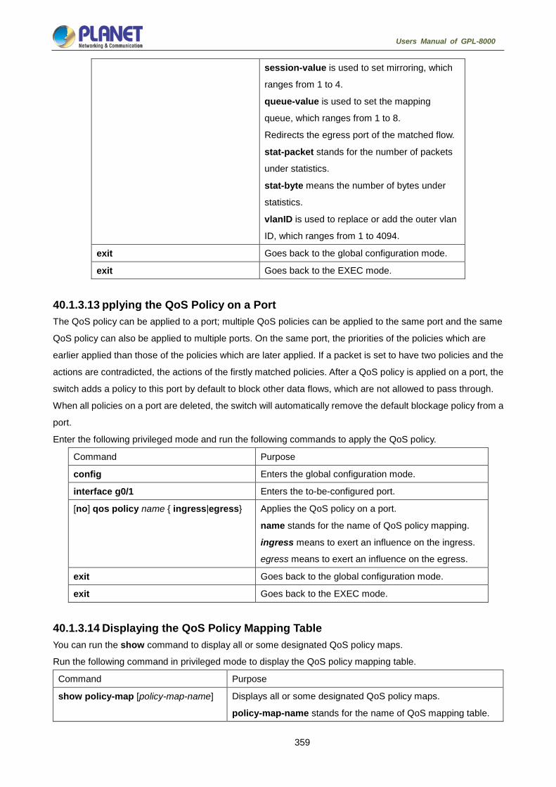
359
Users Manual of GPL-8000
session-value is used to set mirroring, which
ranges from 1 to 4.
queue-value is used to set the mapping
queue, which ranges from 1 to 8.
Redirects the egress port of the matched flow.
stat-packet stands for the number of packets
under statistics.
stat-byte means the number of bytes under
statistics.
vlanID is used to replace or add the outer vlan
ID, which ranges from 1 to 4094.
exit Goes back to the global configuration mode.
exit Goes back to the EXEC mode.
40.1.3.13 pplying the QoS Policy on a Port The QoS policy can be applied to a port; multiple QoS policies can be applied to the same port and the same
QoS policy can also be applied to multiple ports. On the same port, the priorities of the policies which are
earlier applied than those of the policies which are later applied. If a packet is set to have two policies and the
actions are contradicted, the actions of the firstly matched policies. After a QoS policy is applied on a port, the
switch adds a policy to this port by default to block other data flows, which are not allowed to pass through.
When all policies on a port are deleted, the switch will automatically remove the default blockage policy from a
port.
Enter the following privileged mode and run the following commands to apply the QoS policy.
Command Purpose
config Enters the global configuration mode.
interface g0/1 Enters the to-be-configured port.
[no] qos policy name { ingress|egress} Applies the QoS policy on a port.
name stands for the name of QoS policy mapping.
ingress means to exert an influence on the ingress.
egress means to exert an influence on the egress.
exit Goes back to the global configuration mode.
exit Goes back to the EXEC mode.
40.1.3.14 Displaying the QoS Policy Mapping Table You can run the show command to display all or some designated QoS policy maps.
Run the following command in privileged mode to display the QoS policy mapping table.
Command Purpose
show policy-map [policy-map-name] Displays all or some designated QoS policy maps.
policy-map-name stands for the name of QoS mapping table.

360
Users Manual of GPL-8000
40.1.4 QoS Configuration Example 40.1.4.1 Example for Applying the QoS Policy on a Port The following example shows how to set packet’s cos to 2 on port g0/2:
ip access-list extended ipacl
permit ip 192.168.20.2 255.255.255.255 192.168.20.210 255.255.255.255
!
policy-map pmap
classify ip ipacl
action cos 2
!
interface g0/2
qos policy pmap ingress
!

361
Users Manual of GPL-8000
DoS Attack Prevention Configuration
DoS Attack Prevention Configuration 41.1.1 DoS Attack Overview 41.1.1.1 Concept of DoS Attack The DoS attack is also called the service rejection attack. Common DoS attacks include network bandwidth
attacks and connectivity attacks. DoS attack is a frequent network attack mode triggered by hackers. Its
ultimate purpose is to break down networks to stop providing legal users with normal network services.
DoS attack prevention requires a switch to provide many attack prevention methods to stop such attacks as
Pingflood, SYNflood, Landattack, Teardrop, and illegal-flags-contained TCP. When a switch is under attack, it
needs to judge which attack type it is and handles these attack packets specially, for example, sending them
to CPU and drop them.
41.1.1.2 DoS Attack Type Hackers will make different types of DoS attack packets to attack the servers. The following are common DoS
attack packets:
41.1.1.3 Ping of Death Ping of Death is the abnormal Ping packet, which claims its size exceeds the ICMP threshold and causes the
breakdown of the TCP/IP stack and finally the breakdown of the receiving host.
41.1.1.4 TearDrop TearDrop uses the information, which is contained in the packet header in the trusted IP fragment in the
TCP/IP stack, to realize the attack. IP fragment contains the information that indicates which part of the
original packet is contained, and some TCP/IP stacks will break down when they receive the fake fragment
that contains the overlapping offset.
41.1.1.5 SYN Flood A standard TCP connection needs to experience three hand-shake processes. A client sends the SYN
message to a server, the server returns the SYN-ACK message, and the client sends the ACK message to the
server after receiving the SYN-ACK message. In this way, a TCP connection is established. SYN flood
triggers the DoS attack when the TCP protocol stack initializes the hand-shake procedure between two hosts.
41.1.1.6 Land Attack The attacker makes a special SYN message (the source address and the destination address are the same
service address). The SYN message causes the server to send the SYN-ACK message to the sever itself,
hence this address also sends the ACK message and creates a null link. Each of this kinds of links will keep
until the timeout time, so the server will break down. Landattack can be classified into IPland and MACland.

362
Users Manual of GPL-8000
41.1.2 DoS Attack Prevention Configuration Task List As to global DoS attack prevention configuration, you configure related sub-functions and then the switch
drops corresponding DoS attack packets. Hence, the bandwidth of the switch is guaranteed not to be used
up.
DoS attack prevention configuration tasks are shown below:
Configuring Global DoS Attack Prevention
Displaying All DoS Attack Prevention Configuration
41.1.3 DoS Attack Prevention Configuration Tasks 41.1.3.1 Configuring Global DoS Attack Prevention Configuring global DoS attack prevention means configuring DoS attack prevention sub-functions in global
mode and each sub-function can prevent a different type of DoS attack packets. The DoS IP sub-function can
prevent the LAND attacks, while the DoS ICMP sub-function can prevent Ping of Death. You can set the
corresponding sub-function according to actual requirements.
Configure the DoS attack prevention function in EXEC mode.
Command Purpose
config Enters the global configuration mode.
[no] dos enable {all | icmp
icmp-value | ip | ipv4firstfrag |
l4port | mac | tcpflags | tcpfrag
tcpfrag-value}
Configures all to prevent all types of DoS attack packets.
Configures icmp to prevent the ICMP packets, among which
the icmp-value means the maximum length of the ICMP
packet.
Configures ip to prevent those IP packets whose source IPs
are the same as the destination IPs.
Configures ipv4firstfrag to check the first fragment of the IP
packet.
Configures l4port to prevent those TCP/UDP packets whose
source port IDs are destination port IDs.
Configures mac to prevent those packets whose source MACs
are destination MACs.
Configures tcpflags to prevent those TCP packets containing
illegal TCP flags.
Configures tcpfrag to prevent those TCP packets whose
minimum TCP header is tcpfrag-value.
exit Goes back to the EXEC mode.
write Saves the settings.

363
Users Manual of GPL-8000
41.1.3.2 Displaying All DoS Attack Prevention Configurations You can display the Dos attack prevention configurations through the show command.
Run the following command in EXEC mode to display the configured DoS attack prevention functions.
Command Purpose
show dos Displays Dos attack prevention configuration.
41.1.4 DoS Attack Prevention Configuration Example The following example shows how to configure to prevent the attacks of TCP packets, which have illegal flags,
and then displays user’s configuration.
config
dos enable tcpflags
show dos
The following example shows how to prevent the attacks of IP packets whose source IPs are destination IPs
in global mode.
config
dos enable ip
The following example shows how to prevent in global mode the attacks of ICMP packets whose maximum
length is more than 255.
config
dos enable icmp 255
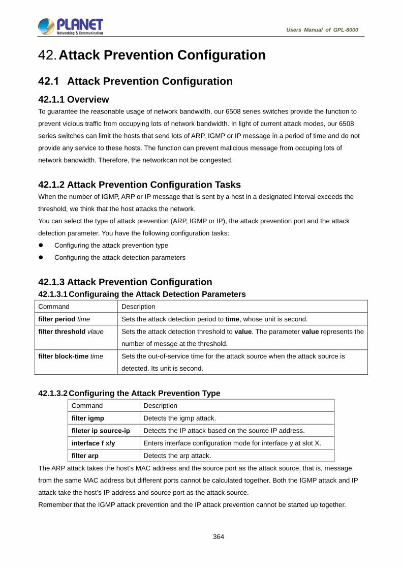
364
Users Manual of GPL-8000
Attack Prevention Configuration
Attack Prevention Configuration 42.1.1 Overview To guarantee the reasonable usage of network bandwidth, our 6508 series switches provide the function to
prevent vicious traffic from occupying lots of network bandwidth. In light of current attack modes, our 6508
series switches can limit the hosts that send lots of ARP, IGMP or IP message in a period of time and do not
provide any service to these hosts. The function can prevent malicious message from occuping lots of
network bandwidth. Therefore, the networkcan not be congested.
42.1.2 Attack Prevention Configuration Tasks When the number of IGMP, ARP or IP message that is sent by a host in a designated interval exceeds the
threshold, we think that the host attacks the network.
You can select the type of attack prevention (ARP, IGMP or IP), the attack prevention port and the attack
detection parameter. You have the following configuration tasks:
Configuring the attack prevention type
Configuring the attack detection parameters
42.1.3 Attack Prevention Configuration 42.1.3.1 Configuraing the Attack Detection Parameters Command Description
filter period time Sets the attack detection period to time, whose unit is second.
filter threshold vlaue Sets the attack detection threshold to value. The parameter value represents the
number of messge at the threshold.
filter block-time time Sets the out-of-service time for the attack source when the attack source is
detected. Its unit is second.
42.1.3.2 Configuring the Attack Prevention Type Command Description
filter igmp Detects the igmp attack.
fileter ip source-ip Detects the IP attack based on the source IP address.
interface f x/y Enters interface configuration mode for interface y at slot X.
filter arp Detects the arp attack.
The ARP attack takes the host’s MAC address and the source port as the attack source, that is, message
from the same MAC address but different ports cannot be calculated together. Both the IGMP attack and IP
attack take the host’s IP address and source port as the attack source.
Remember that the IGMP attack prevention and the IP attack prevention cannot be started up together.

365
Users Manual of GPL-8000
42.1.3.3 Starting up the Attack Prevention Function After all parameters for attack prevention are set, you can start up the attack prevention function. Note that
small parts of processor source will be occupied when the attack prevention function is started.
Command Description
filter enable Starts up the attack prevention function.
Use the no filter enable command to disable the attack prevention function and remove the block to all attack
sources.
42.1.3.4 Checking the State of Attack Prevention After attack prevention is started, you can run the following command to check the state of attack prevention:
Command Description
show filter Checks the state of attack prevention.
42.1.4 Attack Prevention Configuration Example To enable the IGMP attack prevention and the ARP attack prevention on port 1/2, consider any host that
sends more than 1200 pieces of message within 15 seconds as the attack source and to cut off network
service for any attack source.
filter period 15
filter threshold 1200
filter block-time 600
interface f1/2
filter arp
exit
filter enable

366
Users Manual of GPL-8000
Network Protocol Configuration
Configuring IP Addressing 43.1.1 IP Introduction 43.1.1.1 IP Internet Protocol (IP) is a protocol in the network to exchange data in the text form. IP has the functions such
as addressing, fragmenting, regrouping and multiplexing. Other IP protocols (IP protocol cluster) are based on
IP. As a protocol working on the network layer, IP contains addressing information and control information
which are used for routing.
Transmission Control Protocol (TCP) is also based on IP. TCP is a connection-oriented protocol which
regulates the format of the data and information in data transmission. TCP also gives the method to
acknowledge data is successfully reached. TCP allows multiple applications in a system to communicate
simultaneously because it can send received data to each of the applications respectively.
The IP addressing, such as Address Resolution Protocol, are to be described in section 1.3 “Configuring IP
Addressing.” IP services such as ICMP, HSRP, IP statistics and performance parameters are to be
described in Chapter 4 “Configuring IP Services.”
43.1.1.2 IP Routing Protocol Our routing switch supports multiple IP routing dynamic protocols, which will be described in the introduction
of each protocol.
IP routing protocols are divided into two groups: Interior Gateway Routing Protocol (IGRP) and Exterior
Gateway Routing Protocol (EGRP). Our routing switch supports RIP, OSPF, BGP and BEIGRP. You can
configure RIP, OSPF, BGP and BEIGRP respectively according to your requirements. Our switch also
supports the process that is to configure multiple routing protocols simultaneously, a random number of OSPF
processes (if memory can be distributed), a BGP process, a RIP process and a random number of BEIGRP
processes. You can run the redistribute command to redistribute the routes of other routing protocols to the
database of current routing processes, connecting the routes of multiple protocol processes.
To configure IP dynamic routing protocols, you must first configure relevant processes, make relevant network
ports interact with dynamic routing processes, and then designate routing processes to be started up on the
ports. To do this, you may check configuration steps in configuration command documents.

367
Users Manual of GPL-8000
43.1.1.3 Choosing routing protocol It is a complex procedure to choose routing protocol. When you choose the routing protocol, consider the
following items:
Size and complexity of the network
Whether the length-various network need be supported
Network traffic
Safety requirements
Reliability requirements
Strategy
Others
Details of the above items are not described in the section. We just want to remind you that your network
requirements must be satisfied when you choose the routing protocols. 43.1.1.4 IGRP Interior Gateway Routing Protocol (IGRP) is used for network targets in an autonomous system. All IP IGRPs
must be connected with networks when they are started up. Each routing process monitors the update
message from other routing switches in the network and broadcasts its routing message in the network at the
same time. The IGRPs that our routing switches support include:
RIP
OSPF
BEIGRP 43.1.1.5 EGRP Exterior Gateway Routing Protocol (EGRP) is used to exchange routing information between different
autonomonous systems. Neighbors to exchange routes, reachable network and local autonomonous system
number generally need to be configured. The EGRP protocol that our switch supports is BGP. 43.1.2 Configuring IP Address Task List An essential and mandatory requirement for IP configuration is to configure the IP address on the network
interface of the routing switch. Only in this case can the network interface be activated, and the IP address
can communicate with other systems. At the same time, you need to confirm the IP network mask.
To configure the IP addressing, you need to finish the following tasks, among which the first task is mandatory
and others are optional.
For creating IP addressing in the network, refer to section 1.4 “IP Addressing Example.”
Followed is an IP address configuration task list:
Configuring IP address at the network interface
Configuring multiple IP addresses at the network interface
Configuring address resolution
Configuring routing process
Configuring broadcast text management
Detecting and maintaining IP addressing

368
Users Manual of GPL-8000
43.1.3 Configuring IP Address 43.1.3.1 Configuring IP Address at Network Interface The IP address determines the destination where the IP message is sent to. Some IP special addresses are
reserved and they cannot be used as the host IP address or network address. Table 1 lists the range of IP
addresses, reserved IP addresses and available IP addresses.
Type Address or Range State
A
0.0.0.0
1.0.0.0 to 126.0.0.0
127.0.0.0
Reserved
Available
Reserved
B 128.0.0.0 to 191.254.0.0
191.255.0.0
Available
Reserved
C
192.0.0.0
192.0.1.0 to 223.255.254
223.255.255.0
Reserved
Available
Reserved
D 224.0.0.0 to
239.255.255.255
Multicast address
E
240.0.0.0 to
255.255.255.254
255.255.255.255
Reserved
Broadcast
The official description of the IP address is in RFC 1166 “Internet Digit”. You can contact the Internet service
provider.
An interface has only one primary IP address. Run the following command in interface configuration mode to
configure the primary IP address and network mask of the network interface:
Run… To…
ip address ip-address mask Configure the main IP address of the
interface.
The mask is a part of the IP address, representing the network.
Our switches only support masks which are continuously set from the highest byte
according to the network character order.

369
Users Manual of GPL-8000
43.1.3.2 Configuring Multiple IP Addresses on Network Interface Each interface can possess multiple IP addresses, including a primary IP address and multiple subordinate IP
addresses. You need to configure the subordinate IP addresses in the following two cases:
If IP addresses in a network segment are insufficient.
For example, there are only 254 available IP addresses in a certain logical subnet, however, 300 hosts are
needed to connect the physical network. In this case, you can configure the subordinate IP address on the
switch or the server, enabling two logical subnets to use the same physical subnet. Most of early-stage
networks which are based on the layer-2 bridge are not divided into multiple subnets. You can divide the
early-stage network into multiple route-based subnets by correctly using the subordinate IP addresses.
Through the configured subordinate IP addresses, the routing switch in the network can know multiple
subnets that connect the same physical network.
If two subnets in one network are physically separated by another network.
In this case, you can take the address of the network as the subordinate IP address. Therefore, two subnets
in a logical network that are physically separated, therefore, are logically connected together.
If you configure a subordinate address for a routing switch in a network segment,
you need to do this for other routing switches in the same network segment.
Run the following command in interface configuration mode to configure multiple IP addresses on the network
interface.
Run… To…
ip addressip-address mask
secondary
Configure multiple IP addresses on the
network interface.
When the IP routing protocol is used to send the route update information,
subordinate IP addresses may be treated in different ways.
43.1.3.3 Configuring Address Resolution IP can realize functions such as IP address resolution control. The following sections show how to configure
address resolution:
1. Creating address resolution
An IP device may have two addresses: local address (local network segment or device uniquely identified
by LAN) and network address (representing the network where the device is located). The local address is the
address of the link layer because the local address is contained in the message header at the link layer, and is
read and used by devices at the link layer. The professionalists always call it as the MAC address. This is
because the MAC sub layer in the link layer is used to process addresses.
For example, if you want your host to communicate with a device on Ethernet, you must know the 48-bit MAC
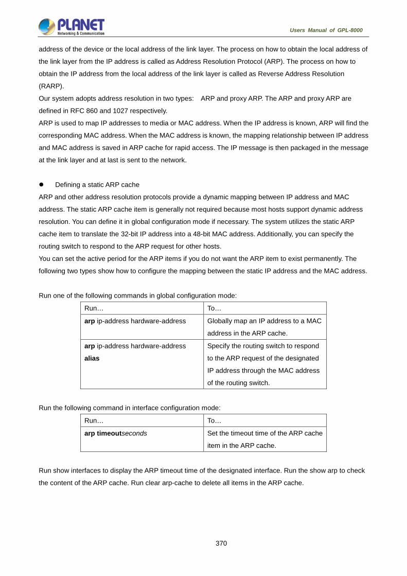
370
Users Manual of GPL-8000
address of the device or the local address of the link layer. The process on how to obtain the local address of
the link layer from the IP address is called as Address Resolution Protocol (ARP). The process on how to
obtain the IP address from the local address of the link layer is called as Reverse Address Resolution
(RARP).
Our system adopts address resolution in two types: ARP and proxy ARP. The ARP and proxy ARP are
defined in RFC 860 and 1027 respectively.
ARP is used to map IP addresses to media or MAC address. When the IP address is known, ARP will find the
corresponding MAC address. When the MAC address is known, the mapping relationship between IP address
and MAC address is saved in ARP cache for rapid access. The IP message is then packaged in the message
at the link layer and at last is sent to the network.
Defining a static ARP cache
ARP and other address resolution protocols provide a dynamic mapping between IP address and MAC
address. The static ARP cache item is generally not required because most hosts support dynamic address
resolution. You can define it in global configuration mode if necessary. The system utilizes the static ARP
cache item to translate the 32-bit IP address into a 48-bit MAC address. Additionally, you can specify the
routing switch to respond to the ARP request for other hosts.
You can set the active period for the ARP items if you do not want the ARP item to exist permanently. The
following two types show how to configure the mapping between the static IP address and the MAC address.
Run one of the following commands in global configuration mode:
Run… To…
arp ip-address hardware-address Globally map an IP address to a MAC
address in the ARP cache.
arp ip-address hardware-address
alias
Specify the routing switch to respond
to the ARP request of the designated
IP address through the MAC address
of the routing switch.
Run the following command in interface configuration mode:
Run… To…
arp timeoutseconds Set the timeout time of the ARP cache
item in the ARP cache.
Run show interfaces to display the ARP timeout time of the designated interface. Run the show arp to check
the content of the ARP cache. Run clear arp-cache to delete all items in the ARP cache.

371
Users Manual of GPL-8000
Activating proxy ARP
The system uses the proxy ARP (defined by RFC 1027) to obtain the host’s MAC address on other networks
for the hosts without corresponding routes. For example, when the routing switch receives an ARP request
and finds that the source host and the destination host are not connected to the same interface and all the
routes that the routing switch reaches the destination host are not through the interface that receives the ARP
request, it will send a proxy ARP response that contains its address of the link layer. The source host then
sends the message to the routing switch and the switch forwards it to the destination host. The proxy ARP is
activates by default.
To activate the proxy ARP, run the following command in interface configuration mode:
Run… To…
ip proxy-arp Activate the proxy ARP on the
interface.
Configuring free ARP function
The switch can know whether the IP addresses of other devices collide with its IP address by sending free
ARP message. The source IP address and the destination IP address contained by free ARP message are
both the local address of the switch. The source MAC address of the message is the local MAC address.
The switch processes free ARP message by default. When the switch receives free ARP message from a
device and finds that the IP address contained in the message collide with its own IP address, it will return an
ARP answer to the device, informing the device that the IP addresses collide with each other. At the same
time, the switch will inform users by logs that IP addresses collide.
The switch’s function to send free ARP message is disabled by default. Run the following commands to
configure the free ARP function on the port of the switch:
Run… To…
arp send-gratuitous Start up free ARP message
transmission on the interface.
arp send-gratuitous intervalvalue Set the interval for sending free ARP
message on the interface.
The default value is 120 seconds.
2. Mapping host name to IP addres
Any IP address can correspond to a host name. The system stores a hostname-to-address mapping cache
that you can telnet or ping.
Run the following command in global configuration mode to specify a mapping between host name and IP
address:
Run… To…
ip hostname address Statically map the host name to the IP
address.

372
Users Manual of GPL-8000
43.1.3.4 Configuring Routing Process You can configure one or multiple routing protocols according to your actual network requirements. The
routing protocol provides information about the network topology. The details about configuring IP routing
protocols such as BGP, RIP and OSPF are shown in the following sections.
43.1.3.5 Configuring Broadcast Message Handling The destination addresses of the broadcast message are all the hosts on a physical network. The host can
identify the broadcast message through special address. Some protocols, including some important Internet
protocols, frequently use the broadcast message. One primary task of the IP network administrator is to
control the broadcast message. The system supports the directed broadcast, that is, the broadcast of
designated network. The system does not support the broadcast of all subnets in a network.
Some early-stage IP’s do not adopt the current broadcast address standard. The broadcast address adopted
by these IP’s is represented completely by the number “0”. The system can simultaneously identify and
receive message of the two types.
1. Allowing translating from directed broadcast to physical broadcast
The directed IP broadcast message will be dropped by default, preventing the switch from attacking by
message “service rejected”.
You can activate the function of forwarding directed IP broadcast on the interface where the directed
broadcast is transformed to the physical message. If the forwarding function is activated, all the directed
broadcast message of the network that connects the interface will be forwarded to the interface. The message
then will be sent as the physical broadcast message.
You can designate an access table to control the forwarding of broadcast message. After the access table is
specified, only IP message that the access table allows can be transformed from the directed broadcast to the
physical broadcast.
Run the following command in interface configuration mode to activate the forwarding of the directed
broadcast.
Run… To…
ip directed-broadcast [access-list-name]
Allow the translation from the directed
broadcast to the physical broadcast on the
interface.
2. Forwarding UDP broadcast message
Sometimes, the host uses the UDP broadcast message to determine information about the address,
configuration and name, and so on. If the network where the host is located has no corresponding server to
forward the UDP message, the host cannot receive any of the UDP message. To solve the problem, you can
do some configuration on the corresponding interface to forward some types of broadcast message to an
assistant address. You can configure multiple assistant addresses for an interface.
You can designate a UDP destination port to decide which UDP message is to be forwarded. Currently, the
default forwarding destination port of the system is port 137.

373
Users Manual of GPL-8000
Run the following command in interface configuration mode to allow message forwarding and to specify the
destination address:
Run… To…
ip helper-addressaddress Allow to forward the UDP broadcast
message and to specify the destination
address.
Run the following command in global configuration mode to specify protocols to be forwarded:
Run… To…
ip forward-protocol udp [port] Specify which interfaces’ UDP protocols
will be forwarded.
43.1.3.6 Detecting and Maintaining IP Addressing Perform the following operations to detect and maintain the network:
1. Clearing cache, list and database
You can clear all content in a cache, list or the database. When you think some content is ineffective, you can
clear it.
Run the following command in management mode to clear the cache, list and database:
Run… To…
clear arp-cache Clear the IP ARP cache.
2. Displaying statistics data about system and network
The system can display designated statistics data, such as IP routing table, cache and database. All such
information helps you know the usage of the systematic resources and solve network problems. The system
also can display the reachability of the port and the routes that the message takes when the message runs in
the network.
All relative operations are listed in the following table. For how to use these commands, refer to Chapter “IP
Addressing Commands”.
Run the following commands in management mode:
Run… To…
show arp Display content in the ARP table.
show hosts Display the cache table about hostname-to-IP
mapping.
show ip interface [type number] Display the interface state.
show ip route [protocol] Display the current state of the routing table.
ping {host | address} Test the reachability of the network node.

374
Users Manual of GPL-8000
43.1.3.7 IP Addressing Example The following case shows how to configure the IP address on interface VLAN 11.
interface vlan 11
ip address 202.96.2.3 255.255.255.0
Configuring NAT 43.2.1 Introduction The Internet faces two key problems: insufficient IP address space and route measurement. Network
Address Translation (NAT) is an attribute. You can find that a group of IP networks with this attribute use
different IP address spaces, but you cannot find the actual address space used by the group of networks. By
transforming these addresses to the address spaces that can be globally routed, NAT permits an organization
without global routing addresses to connect the Internet. NAT also permits good recoding strategy to change
the service providers for the organizations or to automatically code to the CIDR module. NAT will be described
in RFC 1631.
43.2.1.1 NAT Application Main NAT applications are shown as follows:
All hosts need to connect to the Internet, but no all hosts have a unique global IP address. NAT enables
unregistered networks with private IP addresses to connect the Internet. NAT are always configured at
the routing switch between inside network and Internet. Before sending message to the Internet, NAT
transfers the inside local address to the unique global IP address.
The inside address has to be modified. You can transform the address by using NAT without too much
time.
The basic TCP transmission load balance need be realized. You can map a single global IP address to
multiple IP addresses using TCP load distribution characteristic.
As a resolution for connection problems, NAT can be used when relatively few hosts in an inside
network communicate with the Internet. In this case, the IP addresses of few hosts will be transformed to
a unique global IP address when they communicate with the Internet. These addresses can be reused
when they are not used any more.
43.2.1.2 NAT Advantage An obvious advantage of NAT is that you can perform configuration without modifying host or switch. As said
above, NAT is useless if many hosts in a single-connection domain communicate with the outside. What’s
more, the NAT device is not suitable to translate the embedded IP address. These applications cannot work
transparently or completely (without translation) pass through a NAT device. NAT hides the identifier of the
host, which may be an advantage or a shortcoming.
The router configured with NAT has at least one inside interface and one outside interface. In typical case,
NAT is configured at the router between the single-connection domain and the backbone domain. When a
message is leaving the single-connection domain, NAT transforms the effective local address to a unique

375
Users Manual of GPL-8000
global address. When the message reaches the domain, NAT transforms the unique global address to the
local address. If multiple interfaces exist, each NAT must have the same the transfer table. If no address is
available, the software cannot distribute an address and NAT will drop the message and returns an ICMP
message indicating the host cannot be reached.
The switch with NAT configured should not publish the local network. However, the routing information that
NAT receives from the outside can be published in the single-connection domain.
43.2.1.3 NAT Terms As said above, the term “inside” means those networks which are possessed by organizations and have to be
transformed. In this domain, the host has an address in one address space. At the outside, the host will
possess an address in another address space when the NAT is configured. The first address space means
the local address space, while the second address space means the global address space.
Similarly, the term “outside” means the network that the single network connects, generally out of control of an
organization. The addresses of the hosts in the outside network need to translate a certain address and may
be classified into two types of addresses: local address and global address.
NAT uses the following definitions:
Inside local address: IP address that is allocated to a host in the inside network. The address may not
be the legal IP address distributed by Network Information Center (NIC) or service provider (SP).
Inside global address: legal IP address distributed by NIC or SP, describing one or multiple IP
addresses for the outside network.
Outside local address: IP address of the outside host that appears in the inside network. It may be
illegal. It can be distributed through the routable address space in the inside network.
Outside global address: IP address that the owner of the host distributes to the host in the outside
network, which can be distributed from the global address space or the network space.
43.2.1.4 NAT Regulation Matching Order When NAT translates message, the configured NAT regulations must first be matched. There are three
classes of NAT regulations: inside source address mapping, outside source address mapping and inside
destination address mapping. Each class has its own subclasses. The following case takes the inside source
address mapping as an example to introduce the subclass order of the NAT matching regulations:
Static TCP/UDP port mapping regulation
Static single address mapping regulations
Static network segment mapping regulations
Dynamic POOL address mapping regulations
PAT mapping regulations
The regulations in the same subclass in the same class and the three classes are matched according the
sequence they are being added. When you run the show running command, the order to display the NAT
regulations is the same as the actual matching order.

376
Users Manual of GPL-8000
43.2.2 NAT Configuration Task List Before configuring any NAT, you must know the range of the inside local address and inside global address.
The NAT configuration task list is shown as follows:
Translating inside source address
Reloading inside global address
Translating the overlapping address
Providing TCP load balance
Changing translation timeout time and limiting the number of connections
Monitoring and maintaining NAT
43.2.3 NAT Configuration Task 43.2.3.1 Translating Inside Source Address When the host communicates with the outside network, it uses the attribute (translating inside source address)
to translate its IP address to the unique global IP address. You can configure the static or dynamic inside
source address translation through the following method:
The static translation creates the one-to-one mapping between inside local address and inside global address.
When an inside host is accessed by a fixed outside address, the static translation is useful.
The dynamic translation creates the mapping between inside local address and outside address pool.
The following figure shows a routing switch translates the source address inside a network to the source
address outside the network.
Figure 43-1 NAT Inside Source Address Transfer
The following steps show the inside source address translation.
(1) The user of host 1.1.1.1 creates a connection between host 1.1.1.1 and host B.
(2) The first packet received by the routing switch from host 1.1.1.1 makes the routing switch check the NAT
table.
If a static translation item has been configured, the switch is to perform step 3.
If no translation exists, the switch decides that the source address (SA) 1.1.1.1 must be translated
dynamically, then chooses a legal global address from the dynamic address pool, and finally generates a
translation item. The type item is called as simple item.
(3) The routing switch replaces the inside local source address with the global address of the transfer item
and forwards the message.

377
Users Manual of GPL-8000
(4) Host B receives the message through inside global IP destination address (DA) 2.2.2.2 and responds to
host 1.1.1.1.
(5) When the routing switch receives message of the inside global IP address, it takes the inside global
address as a keyword to query the NAT table, translates the address to the inside local address of host
1.1.1.1, and forwards message to host 1.1.1.1.
(6) Host 1.1.1.1 receives the message and continues the session. The routing switch is to perform step 2
and step 5 for each message.
1. Configuring static transfer
Run the following commands in global configuration mode to configure static inside source address transfer:
Run… To…
ip nat inside source staticlocal-ip
global-ip
Create a static transfer between inside local
address and inside global address.
interfacetype number Specify the inside interface.
ip nat inside Label the interface as one to connect the
inside network.
interfacetype number Specify the outside interface.
ip nat outside Label the interface as one to connect the
outside network.
The above is the minimum configuration. You can configure multiple inside and outside interfaces.
2. Configuring dynamic transfer
Run the following commands in global configuration mode to configure dynamic inside source address
translation.
Run… To…
ip nat pool name start-ip end-ip
netmask
Define a to-be-allocated global address pool
according to your requirements.
ip access-list standard
access-list-name permit source
[source-mask]
Define a standard access list to permit which
address can be transferred.
ip nat inside source list
access-list-name pool name
Create dynamic source address transfer and
specify the access list that is defined at the
previous step.
interface type number Specify the inside interface.
ip nat inside Label the interface as one to connect the
inside network.
interface type number Specify the outside interface.
ip nat outside Label the interface as one to connect the
outside network.

378
Users Manual of GPL-8000
Only those transferable addresses can be contained in the access list (remember
that an implicit item “deny all” exists at the end of each access list). The random
access list may lead to unexpected results.
Refer to section 2.4.1 “Dynamic Inside Source Address Transfer Example” for
details.
43.2.3.2 Reloading Inside Global Address Multiple local addresses use one global address through the routing switch. All the addresses can be stored in
the inside global address pool. When the reloading is configured, the routing switch maintains sufficient
information from high-level protocols (such as TCP or UDP) and transfers the global address to the correct
local address. When multiple local addresses are mapped to one global address, TCP or UDP port numbers
of each inside host are used to label multiple local addresses.
The following figure shows the NAT operation when an inside global address represents multiple local
addresses. TCP port number is used to label the local address.
Figure 43-2 NAT Operation During the Reloading of Inside Global Address
The routing switch performs the following steps in the reloaded inside global address. Host B and host C think
that they are communicating with host 2.2.2.2. However, they are communicating with different hosts in fact.
The port number is the identifier. In fact, multiple inside hosts can share one inside global IP address using
different port numbers.
(1) The user of host 1.1.1.1 creates a connection between host 1.1.1.1 and host B.
(2) The routing switch receives the first message from host 1.1.1.1 and then checks its NAT table.
If no transfer items exist, the switch decides that address 1.1.1.1 must be translated, and then creates a
translation between inside local address 1.1.1.1 and legal global address. If the reloading is successful,
another translation is started up. The switch reuses the global address in the previous translation and saves
sufficient transferable information. The item is called as the expansion item.
(3) The routing switch replaces the inside local source address 1.1.1.1 with the selected global address,
and then forwards a packet.
(4) Host B receives the packet and responds to host 1.1.1.1 using inside global IP address 2.2.2.2.
(5) When the routing switch receives the packet with the inside global IP address, it uses the protocol,
inside global address, outside address and port as the keywords to search the NAT table. After that, it

379
Users Manual of GPL-8000
transfers the address to the inside local address 1.1.1.1 and forwards the packet to host 1.1.1.1.
(6) Host 1.1.1.1 receives the packet and continues the session. The routing switch performs step 2 and step
5 for each packet.
Run the following commands in global configuration mode to configure the reloading of the inside global
address:
Run… To…
ip nat pool name start-ip end-ip
netmask
Define a to-be-distributed global address
pool according to requirements.
ip access-list standard
access-list-name permit source
[source-mask]
Define a standard access list.
ip nat inside source list
access-list-name pool name overload
Create dynamic inside source address
transfer and decide the access list
previously defined.
interface type number Specify the inside interface.
ip nat inside Label the interface as one to connect the
inside network.
interface type number Specify the outside interface.
ip nat outside Label the interface as one to connect the
outside network.
Only those transferable addresses can be contained in the access list (remember
that an implicit item “deny all” exists at the end of each access list). The random
access list may lead to unexpected results.
Refer to section 2.4.2 “Inside Global Address Reloading Example” for details.

380
Users Manual of GPL-8000
43.2.3.3 Translating Overlapping Addresses When an internal local address is the same as the to-be-connected outside address, address overlapping
occurs. The following figure shows how NAT translates the overlapping addresses.
Figure 43-3 Network Condition Where NAT Translates Overlapping Addresses
The routing switch performs the following steps when translating the overlapping addresses:
(1) The user of host 1.1.1.1 uses domain name to send instructions for connecting host C. Host 1.1.1.1
requires DNS server to perform a checkup from domain name to address.
(2) The DNS server responds the request and returns the address 1.1.1.1 of host C. The routing switch
intercepts the DNS response message and selects an outside local address from the outside local
address pool to replace the source address. In this case, the source address 1.1.1.1 is replaced with
address 3.3.3.3.
(3) The routing switch creates a mapping table about address transfer, where inside local addresses and
inside global addresses map each other, outside global address and outside local address map each
other.
(4) Host 1.1.1.1 sends message to host C . The destination IP address is the outside local address 3.3.3.3.
(5) When switch A receives message whose destination address is the outside local address, switch A
transfers the local address to the global address.
(6) Host C receives the packet and continues the session.

381
Users Manual of GPL-8000
1. Configuring static transfer
Run the following commands in global configuration mode to configure static source address translation:
Run… To…
ip nat outside source static global-ip
local-ip
Creates static translation between outside
local address and outside global address.
interface type number Specify the inside interface.
ip nat inside Label the interface as one to connect the
inside network.
interfacetype number Specify the outside interface.
ip nat outside Label the interface as one to connect the
outside network.
2. Configuring dynamic transfer Run the following commands in global configuration mode to configure dynamic outside source address
transfer:
Run… To…
ip nat poolname start-ip end-ip
netmask
Define a to-be-distributed local address
pool according to requirements.
ip access-list
standardaccess-list-namepermit source [source-mask]
Define a standard access list.
ip nat outside source
listaccess-list-name poolname
Create dynamic outside source address
transfer and decide the access list
previously defined.
interfacetypenumber Specify the inside interface.
ip nat inside Label the interface as one to connect the
inside network.
interface type number Specify the outside interface.
ip nat outside Label the interface as one to connect the
outside network.
Only those transferable addresses can be contained in the access list (remember
that an implicit item “deny all” exists at the end of each access list). The random
access list may lead to unexpected results.
For details, refer to section“Overlapping Address Translation Example”.

382
Users Manual of GPL-8000
43.2.3.4 Providing TCP Load Balance Another fashion of using NAT is unrelated to the Internet address. Your organization may have multiple hosts
to communicate with a frequently used host. In this case, you can use NAT technology to create a virtual host
in the inside network, helping the load balance among actual hosts. You need to replace the destination
address of the access list with the address in the cycle address pool. The distribution is complete in a cycle
when a new connection from the outside to the inside is opened. The non-TCP communication need not be
translated (unless other translations are effective). The following figure illustrates the attribute.
Figure 43-4 NAT TCP load balance
When translating the cycle address, the routing switch performs the following steps:
(1) The user of host B (9.6.7.3) sends instructions for connecting the virtual host 1.1.1.127 in the inside
network.
(2) The routing switch receives the connection request and creates a new translation item to allocate the
next host 1.1.1.1 for the inside local IP address.
(3) The routing switch replaces the destination address with the selected actual address of the host, and
forwards the message.
(4) Host 1.1.1.1 receives the message and makes response.
(5) The routing switch receives the message and uses the inside local addresses and their port numbers,
the outside address and port number as keywords to check the NAT table. The routing switch then
transfers the source address to the address of the virtual host, and forwards the message.
(6) Next connection request invokes the routing switch to distribute address 1.1.1.2 for the inside local
address. To configure the destination address transfer, run the following commands in global
configuration mode. These commands permit to map one virtual host to multiple real hosts. Each TCP
session with the virtual host will be transferred to the sessions with different real hosts.

383
Users Manual of GPL-8000
Run... To...
ip nat pool name start-ip end-ip
netmask
Define an address pool containing the addresses
of real hosts.
ip access-list standard
access-list-name permit source
[source-mask]
Define an access table permitting addresses of
virtual hosts.
ip nat inside destination list
access-list-name pool name
Create a dynamic inside target transfer
mechanism and confirm the previously defined
access list.
interface type number Specify the inside interface.
ip nat inside Label the interface as one to connect the inside
network.
interface type number Specify the outside interface.
ip nat outside Label the interface as one to connect the outside
interface.
Only those transferable addresses can be contained in the access list (remember
that an implicit item “deny all” exists at the end of each access list). The random
access list may lead to unexpected results.
For details, refer to section “TCP Load Configuration Example”.
43.2.3.5 Changing Translation Timeout Time and Limiting the Number of Connections After a period of leisure, the dynamic Network Address Translation (NAT) is to time out by default. If the
reloading is not configured, the simple translation item is to time out after one hour. You can run the following
command to in global configuration mode to change the timeout value.
Run... To...
ip nat translation timeoutseconds Change the timeout value of the
dynamic NAT without reloading.
If the reloading is configured, the translation timeout will be better controlled because every translation item
contains more contents. To change the timeout value of the expansible item, run one or most of the following
commands in global configuration mode.
Run... To...
ip nat translation udp-timeout seconds
Change the UDP timeout value (the
default value is five seconds).
ip nat translation
dns-timeoutseconds
Change the DNS timeout value (the
default value is one second).
ip nat translation tcp-timeout seconds
Change the TCP timeout value (the
default value is one hour).

384
Users Manual of GPL-8000
ip nat translation
icmp-timeoutseconds
Set the timeout time of the ICMP NAT
(the default time is 60 seconds).
ip nat translation
syn-timeoutseconds
Set the timeout time of the NAT in the
TCP SYN state (the default time is 60
seconds).
ip nat translation finrst-timeout seconds
Change the TCP FIN/RST timeout
value (the default value is 60 seconds).
There are three methods to limit the NAT connections. Run the following commands in global configuration
mode to realize the three methods.
Run... To...
ip nat translation
max-entriesnumbers
Set the maximum number of the
translation items (the default value is
4000).
ip nat translation max-links
A.B.C.Dnumbers
Limit the maximum number of the NAT
connection items that the designated
inside IP address creates. There is no
default value.
ip nat translation max-links all numbers
Limit the maximum number of the NAT
connection items that a single IP
address creates. The default value is
the same as max-entries.
43.2.3.6 Monitoring and Maintaining NAT The dynamic NAT is to time out by default according to the time regulated by the NAT transfer table. You can
run the following commands in management mode to clear up the timeout item before the timeout occurs.
Run... To...
clear ip nat translation Clear up all transfer items from the NAT
transfer table.
clear ip nat translation inside local-ip
global-ip [outside local-ip global-ip]
Clear up a simple dynamic translation
item containing inside translation,
outside translation or both.
clear ip nat translation
outsidelocal-ip global-ip
Clear up a simple dynamic translation
item containing outside translation.
clear ip nat translation inside local-ip
local-port global-ip global-port [outside
local-ip local-port global-ip global-port]
Clear up expansible dynamic
translation items.

385
Users Manual of GPL-8000
Run one of the following commands in management mode to display the transfer information:
Run... To...
show ip nat translations [verbose] Display active translation.
show ip nat statistics Display translation statistics.
43.2.4 NAT Configuration Example 43.2.4.1 Dynamic Inside Source Transfer Example The following example shows how to transfer all source addresses (192.168.1.0/24) that matches access list
a1 to one address in the net-208 pool whose address range is from 171.69.233.208 to 171.69.233.233.
ip nat pool net-208 171.69.233.208 171.69.233.233 255.255.255.240
ip nat inside source list a1 pool net-208
!
interface vlan10
ip address 171.69.232.182 255.255.255.240
ip nat outside
!
interface vlan11
ip address 192.168.1.94 255.255.255.0
ip nat inside
!
ip access-list standard a1
permit 192.168.1.0 255.255.255.0
!
43.2.4.2 Inside Global Address Reloading Example An address pool named net-208 is created in the following example. The address pool contains all addresses
from 171.69.233.208 to 171.69.233.233. The a1 access list permits all packets from source addresses from
192.168.1.0 to 192.168.1.255. If there is no transfer, packets matching the a1 access list are to be transferred
to one address the net-208 address pool. The routing switch authorizes multiple local addresses (from
192.168.1.0 to 192.168.1.255) to use the same global address. The routing switch stores the port numbers to
distinguish every connection.
ip nat pool net-208 171.69.233.208 171.69.233.233 255.255.255.240
ip nat inside source list a1 pool net-208 overload
!
interface vlan10
ip address 171.69.232.182 255.255.255.240
ip nat outside
!
interface vlan11
ip address 192.168.1.94 255.255.255.0

386
Users Manual of GPL-8000
ip nat inside
!
ip access-list standard a1
permit 192.168.1.0 255.255.255.0
!
43.2.4.3 Example to overlapping address transfer The following example shows that other users in the Internet are legally using the address in the local network.
Extra transfer is needed to access the outside network. The net-10 address pool is an outside local IP
address pool. The sentence ip nat outside source list 1 pool net-10 transfer the host addresses of the
outside overlapping network to the address in the net-10 address pool.
ip nat pool net-208 171.69.233.208 171.69.233.223 255.2555.255.240
ip nat pool net-10 10.0.1.0 10.0.1.255 255.255.255.0
ip nat inside source list a1 pool net-208
ip nat outside source list a1 pool net-10
!
interface vlan10
ip address 171.69.232.192 255.255.255.240
ip nat outside
!
interface vlan11
ip address 192.168.1.94 255.255.255.0
ip nat inside
!
ip access-list standard a1
permit 192.168.1.0 255.255.255.0
!
43.2.4.4 TCP Load Distribution Example The following example shows that the connections between a virtual address and a group of actual hosts are
distributed. The address pool defines the addresses of actual hosts. The access list defines the virtual
address. The TCP packet that matches the access list and is from serial port 1/0 (outside interface) is to be
translated to the address in the pool.
ip nat pool real-hosts 192.168.15.2 192.168.15.15 255.255.255.240
ip nat inside destination list a2 pool real-hosts
!
interface vlan10
ip address 192.168.15.129 255.255.255.240
ip nat outside
!

387
Users Manual of GPL-8000
interface vlan11
ip address 192.168.15.17 255.255.255.240
ip nat inside
!
ip access-list standard a2
permit 192.168.15.1 255.255.255.0
Configuring DHCP 43.3.1 Introduction The Dynamic Host Configuration Protocol (DHCP) provides some parameters of network configuration fro
hosts in the Internet. DHCP will be described in RFC 2131. The most important function of DHCP is to
distribute IP addresses on the interface. DHCP supports three mechanisms of distributing IP addresses.
Automatic distribution
The DHCP server automatically distributes a permanent IP address to a client.
Dynamic distribution
The DHCP server distributes an IP address for a client to use for a certain period of time or until the client
does not use it.
Manual distribution
The administrator of the DHCP server manually specifies an IP address and through the DHCP protocol
sends it to the client.
43.3.1.1 DHCP Applications DHCP has several kinds of applications. You can use DHCP in the following cases:
You can distribute IP address, network segment and related sources (such as relevant gateway) to an
Ethernet interface by configuring the DHCP client.
When a switch that can access DHCP connects multiple hosts, the switch can obtain an IP address from
the DHCP server through the DHCP relay and then distribute the address to the hosts.
43.3.1.2 DHCP Advantages In current software version, the DHCP client or the DHCP client on the Ethernet interface is supported. The
function to support the DHCP client has the following advantages:
Reducing the configuration time
Reducing configuration faults
Controlling IP addresses of some device ports through the DHCP server

388
Users Manual of GPL-8000
43.3.1.3 DHCP Terminology DHCP is based on the Server/Client model. The DHCP-server and DHCP-client exist in the DHCP running
conditions.
DHCP-Server
It is a device to distribute and recycle the DHCP-related sources such as IP addresses and lease time.
DHCP-Client
It is a device to obtain information from the DHCP server for devices of the local system to use, such as IP
address information.
As described above, the lease time is a concept appearing in the procedure of DHCP dynamic distribution.
Lease time
an effective period of an IP address since its distribution. When the effective period is over, the IP address is
to be recycled by the DHCP server. To continuously use the IP address, the DHCP client requires re-applying
the IP address.
43.3.2 Configuring DHCP Client 43.3.2.1 DHCP Client Configuration Tasks Obtaining an IP address
Specifying an address for DHCP server
Configuring DHCP parameters
Monitoring DHCP
43.3.2.2 DHCP Client Configuration Tasks 1. Obtaining an IP address
Run the following command on the VLAN interface to obtain an IP address through the DHCP protocol for an
interface.
Run... To...
ip address dhcp Specify the DHCP protocol to
configure the IP address of the
Ethernet interface.
2. Specifying an address for DHCP server If the addresses of some DHCP servers are known, you can specify the addresses for these DHCP servers
on the switch to reduce protocol interaction time. Run the following command in global configuration mode:
Run... To...
ip dhcp-server ip-address Specify the IP address of the DHCP
server.
The command is optional when you perform operations to obtain an IP address.

389
Users Manual of GPL-8000
3. Configuring DHCP parameters You can adjust the parameters for the DHCP protocol interaction according to requirements. Run the following
commands in global configuration mode:
Run... To...
ip dhcp client minlease seconds Specify the minimum lease time.
ip dhcp client retransmit count Specify the times of resending
protocol message.
ip dhcp client select seconds Specify the interval for SELECT.
The command is optional when you perform operations to obtain an IP address.
4. Monitoring DHCP To check information about DHCP-server currently found by switch, run the following command in
management mode:
Run... To...
show dhcp server Display information about the DHCP
server known by the routing switch.
Run the following command in management mode to check the IP address currently used by the routing
switch:
Run... To...
show dhcp lease Display the IP address resources
currently used by the routing switch
and relevant information.
Additionally, if the DHCP protocol is used to distribute an IP address for an Ethernet interface, you can run
show interface to check whether the IP address required by the Ethernet interface is successfully obtained.
43.3.2.3 DHCP Client Configuration Example Obtaining an IP address
The following example shows Ethernet1/1 obtains an IP address through DHCP.
!
interface vlan 11
ip address dhcp

390
Users Manual of GPL-8000
43.3.3 Configuring DHCP Server 43.3.3.1 DHCP Server Configuration Tasks Enabling DHCP server
Disabling DHCP server
Configuring ICMP detection parameter
Configuring database storage parameter
Configuring the address pool of DHCP server
Configuring the parameter for the address pool of DHCP server
Monitoring DHCP server
Clearing information about DHCP server
43.3.3.2 Configuring DHCP Server 43.3.3.3 Enabling DHCP server To enable the DHCP server and distribute parameters such as IP address for the DHCP client, run the
following command in global configuration mode (the DHCP server also supports the relay operation. For the
addresses that the DHCP server cannot distribute, the port where ip helper-address is configured is to
forward the DHCP request):
Run... To...
ip dhcpd enable Enabling DHCP server.
43.3.3.4 Disabling DHCP server To enable DHCP server and stop distributing parameters such as IP address parameter for the DHCP client,
run the following command in global configuration mode:
Run... To...
no ip dhcpd enable Disable DHCP server.
43.3.3.5 Configuring ICMP detection parameter You can adjust the parameter of the to-be-sent ICMP message when the server performs address detection.
Run the following command in global configuration mode to configure the number of to-be-sent ICMP
messages:
Run... To...
ip dhcpd ping packets pkgs Specify the times of address
detection as the number of
to-be-sent ICMP message.
Run the following command in global configuration mode to configure the timeout time of ICMP message
response:
Run... To...
ip dhcpd ping timeout timeout Specify the timeout time of ICMP message response.

391
Users Manual of GPL-8000
43.3.3.6 Configuring database storage parameter To configure the interval when the address distribution information is stored in the agent database, run the
following command in global configuration mode.
Run... To...
ip dhcpd write-time time Specify the interval at which the address distribution information is stored in
the agent database.
43.3.3.7 Configuring DHCP server address pool Run the following command in global configuration mode to add the address pool for the DHCP server:
Run... To...
ip dhcpd pool name Add the address pool of the DHCP server and enter the configuration mode of the
DHCP address pool.
43.3.3.8 Configuring DHCP server address pool You can run the following commands in DHCP address pool configuration mode to configure related
parameters.
Run the following command to configure the network address of the address pool which is used for automatic
distribution.
Run... To...
network ip-addr netsubnet Configure the network address of the address pool which is used for
automatic distribution.
Run the following command to configure the address range that is used for automatic distribution.
Run... To...
range low-addr high-addr Configure the address range that is used for automatic distribution.
Run the following command to configure the default route that is distributed to the client:
Run... To...
default-router ip-addr … Configure the default route that is distributed to the client.
Run the following command to configure the DNS server address that is distributed to the client:
Run... To...
dns-server ip-addr … Configure the DNS server address that is distributed to the client.
Run the following command to configure domain that is distributed to the client:
Run... To...
domain-namename Configure domain that is distributed to the client.

392
Users Manual of GPL-8000
Run the following command to configure the lease time of the address that is distributed to the client:
Run... To...
lease {days [hours][minutes] | infinite } Configure the lease time of the address that is distributed to the
client.
Run the following command to configure the netbios server address that is distributed to the client:
Run... To...
netbios-name-serverip-addr… Configure the netbios server address that is distributed to the client.
You can run the following command to reject to distribute the IP address to the host whose MAC address is
hardware-address.
Run… To…
hw-access deny hardware-address Reject to distribute IP addresses to the host whose MAC address
is hardware-address.
43.3.3.9 Monitoring DHCP server Run the following command in management mode to check current address distribution information about
DHCP server.
Run… To…
show ip dhcpd binding Display current address distribution information about DHCP server.
Run the following command in management mode to check current message statistics information about
DHCP server.
Run… To…
show ip dhcpd statistic Display current message statistics information about DHCP server.
43.3.3.10 Clearing up information about DHCP server Run the following command in management mode to delete current address distribution information about
DHCP server:
Run... To...
clear ip dhcpd binding {ip-addr|*} Delete the designated address distribution information.
Run the following command in management mode to delete current message statistics information about
DHCP server.
Run... To...
clear ip dhcpd statistic Delete current message statistics information about DHCP server

393
Users Manual of GPL-8000
43.3.3.11 DHCP Server Configuration Example In the following example, the timeout time of the ICMP detection packet is set to 200ms; Address pool 1 is
configured and the DHCP server is enabled.
ip dhcpd ping timeout 2
ip dhcpd pool 1
network 192.168.20.0 255.255.255.0
range 192.168.20.211 192.168.20.215
domain-name my315
default-router 192.168.20.1
dns-server 192.168.1.3 61.2.2.10
netbios-name-server 192.168.20.1
lease 1 12 0
!
ip dhcpd enable
IP Service Configuration It is to describe how to configure optional IP service. For the details of the IP service commands, refer to
section “IP Service Commands”.
43.4.1 Configuring IP Service Optional IP service configuration tasks are listed as follows:
Managing IP connection
Configuring performance parameters
Configuring default gateway
Detecting and maintaining IP network
The above operations are not mandatory. You can perform the operations according to your requirements.
43.4.1.1 Managing IP Connection The IP protocol provides a series of services to control and manage IP connections. Most of these services
are provided by ICMP. The ICMP message is sent to the host or other routing switches when the routing
switch or the access server detects faults in the IP message header. ICMP is mainly defined in RFC 792.
Perform the following different operations according to different IP connection conditions:
1. Sending ICMP unreachable message
If the system receives a message and cannot send it to the destination, such as no routes, the system will
send an ICMP-unreachable message to the source host. The function of the system is enabled by default.
If the function is disabled, you can run the following command in interface configuration mode to enable the
function.

394
Users Manual of GPL-8000
Run… To…
ip unreachables Enable the function to send an
ICMP-unreachable message.
2. Sending ICMP redirection message
Sometimes the host selects an unfavorable route. After a routing switch on the route receives a message from
the host, it is to check the routing table and then forward the message through the message-receiving
interface to another routing switch that is in the same network segment as the host. In this case, the routing
switch notifies the source host of directly sending the message with the destination to another routing switch
without winding itself. The redirection message requires the source host to discard the original route and take
more direct route suggested in the message. Many host’s operating system adds a host route to its routing
table. However, the routing switch is more willing to trust information obtained through the routing protocol.
Therefore, the routing switch would not add the host route according to the information.
The function is enabled by default. If the hot standby routing switch protocol is configured on the interface, the
function is automatically disabled. However, the function will not be automatically enabled even if the hot
standby routing switch protocol is cancelled.
To enable the function, run the following command in interface configuration mode:
Run… To…
ip redirects Permit sending the ICMP redirection
messafge.
3. Sending ICMP mask response message
Sometimes the host must know the network mask. To get the information, the host can send the ICMP mask
request message. If the routing switch can confirm the mask of the host, it will respond with the ICMP mask
response message. By default, the routing switch can send the ICMP mask response message.
To send the ICMP mask request message, run the following command in interface configuration mode:
Run… To…
ip mask-reply Send the ICMP mask response
message.
4. Supporting route MTU detection
The system supports the IP route MTU detection mechanism defined by RFC 1191. The IP route MTU
detection mechanism enables the host to dynamically find and adjust to the maximum transmission unit (MTU)
of different routes. Sometimes the routing switch detects that the received IP message length is larger than
the MTU set on the message forwarding interface. The IP message needs to be segmented, but the
“unsegmented” bit of the IP message is reset. The message, therefore, cannot be segmented. The message
has to be dropped. In this case, the routing switch sends the ICMP message to notify the source host of the
reason of failed forwarding, and the MTU on the forwarding interface. The source host then reduces the
length of the message sent to the destination to adjust to the minimum MTU of the route.

395
Users Manual of GPL-8000
If a link in the route is disconnected, the message is to take other routes. Its minimum MTU may be different
from the original route. The routing switch then notifies the source host of the MTU of the new route. The IP
message should be packaged with the minimum MTU of the route as much as possible. In this way, the
segmentation is avoided and fewer messagesare sent, improving the communication efficiency.
Relevant hosts must support the IP route MTU detection. They then can adjust the length of IP message
according to the MTU value notified by the routing switch, preventing segmentation during the forwarding
process.
5. Setting IP maximum transmission unit
All interfaces have a default IP maximum transmission unit (MTU), that is, the transmissible maximum IP
message length. If the IP message length exceeds MTU, the routing switch segments the message.
Changing the MTU value of the interface is to affect the IP MTU value. If IP MTU equals to MTU, IP MTU will
automatically adjust itself to be the same as new MTU as MTU changes. The change of IP MTU, however,
does not affect MTU. IP MTU cannot bigger than MTU configured on the current interface. Only when all
devices connecting the same physical media must have the same MTU protocol can normal communication
be created.
To set IP MTU on special interface, run the following command in interface configuration mode:
Run… To…
ip mtubytes Set IP MTU of the interface.
6. Authorizing IP source route
The routing switch checks the IP header of every message. The routing switch supports the IP header options
defined by RFC 791: strict source route, relax source route, record route and time stamp. If the switch detects
that an option is incorrectly selected, it will send message about the ICMP parameter problem to the source
host and drop the message. If problems occur in the source route, the routing switch will send ICMP
unreachable message (source route fails) to the source host.
IP permits the source host to specify the route of the IP network for the message. The specified route is called
as the source route. You can specify it by selecting the source route in the IP header option. The routing
switch has to forward the IP message according to the option, or drop the message according to security
requirements. The routing switch then sends ICMP unreachable message to the source host. The routing
switch supports the source route by default.
If the IP source route is disabled, run the following command in global configuration mode to authorize the IP
source route:
Run… To…
ip source-route Authorizing IP source route.

396
Users Manual of GPL-8000
7. Allowing IP fast exchange
IP fast exchange uses the route cache to forward the IP message. Before the switch forwards message to a
certain destination, its system will check the routing table and then forward the message according to a route.
The selected route will be stored in the routing cache of the system software. If latter message will be sent to
the same host, the switch will forward latter message according to the route stored in the routing cache. Each
time message is forwarded, the value of hit times of the corresponding route item is increasing by 1. When the
hit times is equal to the set value, the software routing cache will be stored in the hardware routing cache. The
following message to the same host will be forwarded directly by the hardware. If the cache is not used for a
period of time, it will be deleted. If the software/hardware cache items reach the upper limitation, new
destination hosts are not stored in the cache any more. The managed switch can hold 2074 hardware cache
items and 1024 software cache items. To allow or forbid fast exchange, run the following command in
interface configuration mode:
Run… To…
ip route-cache Allow fast exchange (use the routing
cache to forward the IP message).
no ip route-cache Forbid fast exchange.
To configure the hit times required when the software cache items are stored to the hardware cache, run the
following command in global configuration.
Run… To…
ip route-cache
hit-numbershitnumber
When the hit times of the routing item in the
software cache reaches the value of the
parameter hitnumber, the routing item in the software
cache will be stored as a routing item in the hardware
cache.
8. Supporting IP fast exchange on the same interface
You can enable the switch to support IP fast exchange by making the receiving interface the same as the
transmitting interface. Generally, it is recommended not to enable the function because it conflicts with the
redirection function of the router.
Run the following command in interface configuration mode to allow IP routing cache in the same interface:
Run… To…
ip route-cache same-interface Allow IP message with the same
receiving/transmitting interfaces to be stored
in the routing cache.

397
Users Manual of GPL-8000
43.4.1.2 Configuring Performance Parameters 1. Setting the wait time for TCP connection
When the routing switch performs TCP connection, it considers that the TCP connection fails if the TCP
connection is not created during the wait time. The routing switch then notifies the upper-level program of the
failed TCP connection. You can set the wait time for TCP connection. The default value of the system is 75
seconds. The previous configuration has no impact on TCP connections that the switch forwards. It only
affects TCP connections that are created by the switch itself.
Run the following command in global configuration mode to set the wait time for TCP connections:
Run… To…
ip tcp synwait-time seconds Set the wait time for TCP connection.
2. Setting the size of TCP windows
The default size of TCP windows is 2000 byte. Run the following command in global configuration mode to
change the default window size:
Run… To…
ip tcp window-sizebytes Set the size of TCP windows.
43.4.1.3 Detecting and Maintaining IP Network 1. Clearing cache, list and database
You can clear all content in a cache, list or database. Incorrect data in a cache, list or database need be
cleared.
Run the following command to clear incorrect data:
Run… To…
clear tcp statistics Clear TCP statistics data.
2. Clearing TCP connection
To disconnect a TCP connection, run the following command:
Run… To…
clear tcp {local host-name port
remote host-name port | tcb
address}
Clear the designated TCP connection.
TCB refers to TCP control block.
3. Displaying statistics data about system and network
The system can display the content in the cache, list and database. These statistics data can help you know
the usage of systematic sources and solve network problems.
Run the following commands in management mode. For details, refer to “IP Service Command”.
Run… To…
show ip access-lists name Display the content of one or all access
lists.

398
Users Manual of GPL-8000
show ip cache [prefix mask] [type
number]
Display the routing cache that is used for
fast IP message exchange.
show ip sockets Display all socket information about the
routing switch.
show ip traffic Display statistics data about IP protocol.
show tcp Display information about all TCP
connection states.
show tcp brief Briefly display information about TCP
connection states.
show tcp statistics Display TCP statistics data.
show tcp tcb Display information about the
designated TCP connection state.
4. Displaying debugging information
When problem occurs on the network, you can run debug to display the debugging information.
Run the following command in management mode. For details, refer to “IP Service Command”.
Run… To…
debug arp Display the interaction information about ARP.
debug ip icmp Display the interaction information about
ICMP.
debug ip raw Display the information about
received/transmitted IP message.
debug ip packet Display the interaction information about IP.
debug ip tcp Display the interaction information about TCP.
debug ip udp Display the interaction information about UDP.
43.4.2 Configuring Access List 43.4.2.1 Filtering IP Message Filtering message helps control the movement of packet in the network. The control can limit network
transmission and network usage through a certain user or device. To make packets valid or invalid through
the crossly designated interface, our routing switch provides the access list. The access list can be used in
the following modes:
Controlling packet transmission on the interface
Controlling virtual terminal line access
Limiting route update content
The section describes how to create IP access lists and how to use them.
The IP access list is an orderly set of the permit/forbid conditions for applying IP addresses. The ROS
software of our switch tests the address one by one in the access list according to regulations. The first match
determines whether the ROS accepts or declines the address. After the first match, the ROS software

399
Users Manual of GPL-8000
terminates the match regulations. The order of the conditions is, therefore, important. If no regulations match,
the address is declined.
Use the access list by following the following steps:
(1) Create the access list by designating the access list name and conditions.
(2) Apply the access list to the interface.
43.4.2.2 Creating Standard and Extensible IP Access List Use a character string to create an IP access list.
The standard access list and the extensible access list cannot have the same
name.
Run the following command in global configuration mode to create a standard access list:
Run… To…
ip access-list standardname Use a name to define a standard
access list.
deny {source [source-mask] |
any}[log] or permit {source
[source-mask] | any}[log]
Designate one or multiple
permit/deny conditions in standard
access list configuration mode. The
previous setting decides whether the
packet is approved or disapproved.
Exit Log out from the access list
configuration mode.
Run the following command in global configuration mode to create an extensible access list.
Run… To…
ip access-list extended name Use a name to define an extensible IP
access list.
{deny | permit} protocolsourcesource-maskdestinatio
n destination-mask
[precedenceprecedence] [tostos]
[established] [log]{deny | permit}
protocolany any
Designate one or multiple
permit/deny conditions in extensible
access list configuration mode. The
previous setting decides whether the
packet is approved or disapproved.
precedence means the priority of the
IP packet; TOS means Type of
Service.
Exit Log out from the access list
configuration mode.

400
Users Manual of GPL-8000
After the access list is originally created, any part that is added later can be put at the end of the list. That is to
say, you cannot add the command line to the designated access list. However, you can run no permit and no
deny to delete items from the access list.
When you create the access list, the end of the access list includes the implicit deny
sentence by default. If the mask is omitted in the relative IP host address access
list, 255.255.255.255 is supposed to be the mask.
After the access list is created, the access list must be applied on the route or
interface. For details, refer to section 4.2.3 “Applying the Access List to the
Interface”.
43.4.2.3 Applying the Access List to the Interface After the access list is created, you can apply it to one or multiple interfaces including the in interfaces and
out interfaces.
Run the following command in interface configuration mode.
Run… To…
ip access-groupname {in | out} Apply the access list to the interface.
The access list can be used on the in interfaces and the out interfaces. For the standard access list of the in
interface, the soured address of the packet is to be checked according to the access list after the packet is
received. For the extensible access list, the routing switch also checks the destination. If the access list
permits the address, the software goes on processing the packet. If the access list does not permit the
address, the software drops the packet and returns an ICMP unreachable message.
For the standard access list of the out interfaces, after a packet is received or routed to the control interface,
the software checks the source address of the packet according to the access list. For the extensible access
list, the routing switch also checks the access list of the receiving side. If the access list permits the address,
the software will send the packet. If the access list does not permit the address, the software drops the packet
and returns an ICMP unreachable message.
If the designated access list does not exist, all packets allows to pass.

401
Users Manual of GPL-8000
43.4.2.4 Extensible Access List Example In the following example, the first line allows any new TCP to connect the destination port after port 1023. The
second line allows any new TCP to connect the SMTP port of host 130.2.1.2.
ip access-list extended aaa
permit tcp any 130.2.0.0 255.255.0.0 gt 1023
permit tcp any 130.2.1.2 255.255.255.255 eq 25
interface vlan 10
ip access-group aaa in
Another example to apply the extensible access list is given. Suppose a network connects the Internet, you
expect any host in the Ethernet can create TCP connection with the host in the Internet. However, you expect
the host in the Internet cannot create TCP connection with the host in the Ethernet unless it connects the
SMTP port of the mail host.
During the connection period, the same two port numbers are used. The mail packet from the Internet has a
destination port, that is, port 25. The outgoing packet has a contrary port number. In fact, the security system
behind the routing switch always receives mails from port 25. That is the exact reason why the incoming
service and the outgoing service can be uniquely controlled. The access list can be configured as the
outgoing service or the incoming service.
In the following case, the Ethernet is a B-type network with the address 130.20.0.0. The address of the mail
host is 130.20.1.2. The keyword established is only used for the TCP protocol, meaning a connection is
created. If TCP data has the ACK or RST digit to be set, the match occurs, meaning that the packet belongs to
an existing connection.
ip access-list aaa
permit tcp any 130.20.0.0 255.255.0.0 established
permit tcp any 130.20.1.2 255.255.255.255 eq 25
interface vlan 10
ip access-group aaa in

402
Users Manual of GPL-8000
43.4.3 Configuring IP Access List Based on Physical Port 43.4.3.1 Filtering IP Message 43.4.3.2 Filtering IP Message Filtering message helps control the movement of packet in the network. The control can limit network
transmission and network usage through a certain user or device. To make packets valid or invalid through
the crossly designated interface, our routing switch provides the access list. The access list can be used in
the following modes:
Controlling packet transmission on the interface
Controlling virtual terminal line access
Limiting route update content
The section describes how to create IP access lists and how to use them.
The IP access list is an orderly set of the permit/forbid conditions for applying IP addresses. The ROS
software of our switch tests the address one by one in the access list according to regulations. The first match
determines whether the ROS accepts or declines the address. After the first match, the ROS software
terminates the match regulations. The order of the conditions is, therefore, important. If no regulations match,
the address is declined.
Use the access list by following the following steps:
(1) Create the access list by designating the access list name and conditions.
(2) Apply the access list to the interface.
43.4.3.3 Creating Standard and Extensible IP Access List Use a character string to create an IP access list.
The standard access list and the extensible access list cannot have the same
name.
Run the following command in global configuration mode to create a standard access list:
Run… To…
ip access-list standardname Use a name to define a standard access list.
deny {source [source-mask] |
any}[log] or permit {source
[source-mask] | any}[log]
Designate one or multiple permit/deny
conditions in standard access list
configuration mode. The previous setting
decides whether the packet is approved or
disapproved.
Exit Log out from the access list configuration
mode.

403
Users Manual of GPL-8000
Run the following command in global configuration mode to create an extensible access list.
Run… To…
ip access-list extended name Use a name to define an extensible IP
access list.
{deny | permit} protocolsourcesource-maskdes
tination destination-mask
[precedenceprecedence]
[tostos] [established]
[log]{deny | permit}
protocolany any
Designate one or multiple permit/deny
conditions in extensible access list
configuration mode. The previous setting
decides whether the packet is approved or
disapproved.
precedence means the priority of the IP
packet; TOS means Type of Service.
Exit Log out from the access list configuration
mode.
After the access list is originally created, any part that is added later can be put at the end of the list. That is to
say, you cannot add the command line to the designated access list. However, you can run no permit and no
deny to delete items from the access list.
When you create the access list, the end of the access list includes the implicit
deny sentence by default. If the mask is omitted in the relative IP host address
access list, 255.255.255.255 is supposed to be the mask.
After the access list is created, the access list must be applied on the route or
interface. For details, refer to section 4.2.3 “Applying the Access List to the
Interface”.
43.4.3.4 Applying the Access List to the Interface After the access list is created, you can apply it to one or multiple interfaces including the in interfaces and
out interfaces.
Run the following command in interface configuration mode.
Run… To…
ip access-groupname {in | out} Apply the access list to the interface.
The access list can be used on the in interfaces and the out interfaces. For the standard access list of the in
interface, the soured address of the packet is to be checked according to the access list after the packet is
received. For the extensible access list, the routing switch also checks the destination. If the access list
permits the address, the software goes on processing the packet. If the access list does not permit the
address, the software drops the packet and returns an ICMP unreachable message.
For the standard access list of the out interfaces, after a packet is received or routed to the control interface,
the software checks the source address of the packet according to the access list. For the extensible access
list, the routing switch also checks the access list of the receiving side. If the access list permits the address,

404
Users Manual of GPL-8000
the software will send the packet. If the access list does not permit the address, the software drops the packet
and returns an ICMP unreachable message.
If the designated access list does not exist, all packets allows to pass.
43.4.3.5 Extensible Access List Example 1. Port-based IP access list supporting TCP/UDP port filtration
{deny | permit} {tcp | udp}
sourcesource-mask [ { [src_portrange begin-port end-port] | [ {gt | lt } port ] }]
destination destination-mask [ { [dst_portrange begin-port end-port] | [ {gt | lt } port ] }]
[precedenceprecedence] [tostos]
If you configure the access list by defining the port range, pay attention to the following:
If you use the method of designating the port range to configure the access list at the source side and
the destination side, some configuration may fail because of massive resource consumption. In this
case, you need to use the fashion of designating the port range at one side, and use the fashion of
designating the port at another side.
When the port range filtration is performed, too many resources will be occupied. If the port range
filtration is used too much, the access list cannot support other programs as well as before.
2. Port-based IP access list supporting TCP/UDP designated port filtration
In the following example, the first line allows any new TCP to connect the SMTP port of host 130.2.1.2.
ip access-list extended aaa
permit tcp any 130.2.1.2 255.255.255.255 eq 25
interface f0/10
ip access-group aaa

405
Users Manual of GPL-8000
IP ACL Application Configuration
Applying the IP Access Control List 44.1.1 Applying ACL on Ports After an ACL is established, it can be applied on one or many slots or globally.
Run the following command in global or port configuration mode:
Command Purpose
config Enters the global configuration mode.
interface g0/1 Enters the to-be-configured port.
[no] {ip | ipv6} access-groupname
[egress | vlan {word | add word
remove word|]
Applies the established IP/IPv6 access list to an interface
or cancels it on the interface.
Egress means that the ACL is applied in an outbound
direction.
Vlan means that the ACL is applied in an inbound VLAN.
Word stands for the VLAN range table.
Add means to add the VLAN range table.
Remove means to delete the VLAN range table.
exit Goes back to the global configuration mode.
exit Goes back to the EXEC mode.
write Saves the settings.

406
Users Manual of GPL-8000
Routing Configuration
Configuring RIP 45.1.1 Overview The section describes how to configure the RIP. For details about RIP commands, refer to the setion “RIP
Commands” in “Network Protocol Command Reference”.
The routing information protocol (RIP) is still a commonly used interior gateway protocol (IGP), mainly applied
to small-scale networks of the same type. RIP is a classical distance vector routing protocol, which appears in
RFC 1058.
RIP uses the broadcast of the UDP packet to exchange the routing information. In the routing switch, the
update of the routing information is performed every 30 seconds. If a switch does not receive the update
information from the neighboring switches in 180 seconds, the switch is to label the route in the routing table
from the neighboring switch as “unavailable”. If the update information is still not received in the following 120
seconds, the switch will delete the route from the routing table.
RIP uses the hop count to balance the weight of different routes. The hop count is the number of switches that
a packet gets through from the information source and the information sink. The routing weight of the
directly-connected network is 0. The routing weight of the unreachable network is 16. Because the range of
RIP-using routing weight is small, it is not suitable for the large-scale network.
If the switch has a default route, the RIP declares the route to the pseudo-network 0.0.0.0. In fact, network
0.0.0.0 does not exist. It is just used in RIP to realize the default route. If RIP learns a default route, or the
default gateway and the default weight are configured in a switch, the switch is to declare the default network.
RIP sends the routing update information to the designated network interface. If the network that the interface
resides is not designated, the network cannot be declared in any RIP update information.
The RIP-2 of our switches supports plain text, MD5 authentication, routing summary, CIDR and VLSM.
45.1.2 Configuring RIP Task List To configure RIP, the following tasks must be complete first. The task to activate RIP is mandatory, while other
tasks are optional.
Starting up RIP
Allowing RIP routing to update the single program broadcast
Applying the offset to the routing weight
Adjusting the timer
Specifying the RIP version number
Activating RIP authentication
Forbidding routing summary
Forbidding the authentication of the source IP address
Configuring the maximum number of routes
Activating or forbidding horizon split.

407
Users Manual of GPL-8000
Monitoring and maintaining RIP
45.1.3 Configuring RIP Tasks 45.1.3.1 Starting up RIP Run the following command in global configuration mode to activate RIP:
Command Purpose
routerrip Activates the RIP routing process and enters the switch
configuration mode.
networknetwork-number<network-mask> Specifies the network number related to the RIP routing
process.
45.1.3.2 Allowing RIP Routing to Update the Single-Program Broadcast Normally, RIP is a broadcast protocol. To enable the RIP routing update to reach the non-broadcast network,
you must configure the switch to enable it to exchange the routing information.
Run the following command in switch configuration mode to enable the routing information exchange:
Command Purpose
neighborip-address Defines a neighboring switch to exchange routing information with the known switch.
Additionally, you can run ip rip passive to specify ports to forbid sending the route update information.
45.1.3.3 Applying the Offset to the Routing Weight The offset list is used to add an offset for the outgoing routes or the incoming routes learned by the RIP. It
provides a local mechanism to add the routing weight. You also can use the access list or the interface to limit
the offset list. Run the following command in switch configuration mode to add the routing weight.
Command Purpose
offset{[interface-type number]|* }
{in|out} access-list-name offset
Adds an offset for the routing weight.
45.1.3.4 Adjusting the Timer The routing protocol uses several timers to judge the frequency of sending route update information, how
much time is needed for the route to become ineffective and other parameters. You can adjust these timers
to improve the performance of the routing protocol.
You also can adjust the routing protocol to speed up the convergent time of all IP routing arithmetic, rapidly
backing up the redundancy switch and ensuring the minimum breakdown time in case of quick recovery.
Run the following command in switch configuration mode to adjust the timer:
Command Purpose
timers holddown value It means how much time is needed for a route to be deleted from the routing
table.
timers expirevalue It means what interval is needed for a route to be declared ineffective.
timers updatevalue It means the transmission frequency of the routing update information.

408
Users Manual of GPL-8000
45.1.3.5 Specifying the RIP Version Number The RIP-2 of our switches supports authentication, PIN management, routing summary, CIDR and VLSM. By
default, the switch receives RIP-1 and RIP-2, but the switch only sends RIP-1. Through configuration, the
switch can receive and send only the packet RIP-1, or only the packet RIP-2. To meet the previous demand,
run the following command in switch configuration mode:
Command Purpose
version {1 | 2} The switch sends and receives only RIP-1 or only
RIP-2.
The previous tasks control the default actions of the RIP. You also can configure a certain interface to change
the default actions.
Run the following commands in VLAN configuration mode to control the interface whether to send RIP-1 or
RIP-2.
Command Purpose
ip rip send version 1 The configured interface only sends RIP-1.
ip rip send version 2 The configured interface only sends RIP-2.
ip rip send
versioncompatibility
Sends the RIP-2 update message in the form of
broadcast.
Run the following commands in interface configuration mode to control the interface whether to receive
packet RIP-1 or packet RIP-2
Command Purpose
ip rip receive version 1 The configured interface only receives RIP-1.
ip rip receive version 2 The configured interface only receives RIP-2.
ip rip receive version 1 2 The configured interface receives RIP-1 and
RIP-2.
45.1.3.6 Activating RIP Authentication RIP-1 does not support authentication. To receive and send the RIP-2 packet, you can activate the RIP
authentication on the interface.
On the activated interface, two authentication modes are provided: plain text authentication and MD5
authentication. Each RIP-2 packet uses the plain authentication by default.
For the purpose of security, do not use the plain authentication in the RIP packet
because the unencrypted authentication PIN is sent to each RIP-2 packet. You can
use the plain authentication without security concern.
Run the following commands in VLAN configuration mode to configure the RIP plain text authentication.
Command Purpose

409
Users Manual of GPL-8000
ip rip authentication simple Configures the interface to use the
plain authentication.
ip rip password [string] Configures the PIN of the plain
authentication.
Run the following commands in interface configuration mode to configure the MD5 authentication of the RIP:
Command Purpose
ip rip authentication message-digest Configures the interface to use the
MD5 authentication.
ip rip message-digest-key [key-ID]
md5 [key]
Configures the PIN and ID of the md5
authentication.
45.1.3.7 Forbidding Routing summary RIP-2 supports the automatic routing summary by default. RIP-2 routes are collected when passing the
boundaries of different networks. The RIP-1 automatic collection function is always in positive state.
If there is a separated subnet, you need to forbid the routing summary function to declare the subnet. If the
routing summary function is disabled, the switch is to send the routing information of the subnet and the host
when passing through the boundaries of different networks. Run the following command in switch
configuration mode to disable the automatic routing summary function.
Command Purpose
no auto-summary Disables the automatic routing
summary function.
45.1.3.8 Forbidding the Authentication of the Source IP Address By default, the switch authenticates the source IP address in the RIP routing update information. If the
address is illegal, the routing update is dropped.
When a switch wants to receive its own update information and the network and neighbor are not configured
on the switch of the receiving side, you can forbid the authentication of the source IP address. Normally, you
are not recommended to use the command.Run the following command in switch configuration mode to forbid
authenticating the source IP address of the incoming routing information:
Command Purpose
no validate-update-source
Forbids authenticating the source IP
address of the incoming routing
information.

410
Users Manual of GPL-8000
45.1.3.9 Configuring the Maximum Number of Routes By default, the local RIP routing table contains up to 1024 routes. When the route number exceeds the
maximum number, you cannot add new routes to the routing table. At the same time, the system notifies you
that the route number has already reached the maximum number set for the routing table.Run the following
command in switch configuration mode to configure the maximum number of routes for the local RIP routing
table:
Command Purpose
maximum-countnumber Configures the maximum number of
routes for the local RIP routing table.
no maximum-count Resumes the default maximum number
of routes.
45.1.3.10 Aactivating or Forbidding Horizon Split Normally, the switch that connects to the broadcast IP network and adopts the distance vector routing protocol
adopts the horizon split to reduce the possibility of the routing loop. The information about the routing loop of
horizon split declares itself to the interface that receives the routing information. In this way, the
communication among multiple routing switches is improved, especially when the loop breaks. However, it is
not so good as to the non-broadcast network. At this time, you may forbid the horizon split.
If the assistant IP address is configured on the interface and the horizon split is activated, the source IP
address of the routing update may not conclude all assistant addresses. The source IP address of one routing
update contains only one network number.
Run the following commands in VLAN configuration mode to activate or forbid the horizon split.
Command Purpose
ip rip split-horizon Activates the horizon split.
no ip rip split-horizon Forbids the horizon split.
By default, the horizon split is activated on the point-to-point interface; the point-to-multiple interface is
forbidden.
Foe details, refer to the section “Horizon Split Example”.
In normal case, do not change the default configuration unless you are sure that the
programs need to change states. Remember that if the horizon split is forbidden in
a serial port that connects a packet switching network, you must forbid the horizon
split in the switches in relative multiple-program group of a network.
45.1.3.11 Monitoring and Maintaining RIP Monitoring and maintaining RIP needs to display network statistics information, such as RIP parameter
configuration, real-time network track. These information help you judge the network usage, solve network
problem and the reachabilitiy of network nodes.
Run the following commands in management mode to display all routing statistics information:

411
Users Manual of GPL-8000
Command Purpose
show ip rip Display the current state of the RIP protocol.
show ip rip database Displays all RIP routes.
show ip rip protocol Displays all RIP-relative information.
Run the following commands in management mode to track routing protocol information:
Command Purpose
debug ip rip database Tracks information about adding RIP route to the routing table, deleting
route from the routing table and changing route.
debug ip rip protocol Tracks RIP message.
45.1.4 RIP Configuration Example Device A and device B are configured as follows:
Device A:
interface vlan 11
ip address 192.168.20.81 255.255.255.0
!
interface loopback 0
ip address 10.1.1.1 255.0.0.0
!
router rip
network 192.168.20.0
network 10.0.0.0
!
Device B:
interface vlan 11
ip address 192.168.20.82 255.255.255.0
interface loopback 0
ip address 20.1.1.1 255.0.0.0
!
router rip
network 192.168.20.0
network 20.0.0.0
!
Configuring BEIGRP 45.2.1 Overview Technologies used by BEIGRP are similar to the distance vector protocol:

412
Users Manual of GPL-8000
The router makes routing decision according to the information provided by the directly-connecting
neighbor;
The router provides its routing information to its directly-connecting neighbor.However, BEIGRP has
more advantages compared with the distance vector protocol:
BEIGRP saves all routes sent by all neighbors in the topology, not just saving the best route received up
to now.
BEIGRP can query neighbors when it cannot access the destination and has no replaceable route.
Therefore, the convergence speed of BEIGRP is as fast as that of the best-link-state protocol.
Diffused Update Algorithm (DUAL) of BEIGRP is the core reason why BEIGRP is better than other traditional
distance vector protocols. It always in active state and queries the neighbors when it cannot access the
destination and there is no replaceable route. Therefore, the collection speed of BEIGRP is rapid.
BEIGRP is a special transmission protocol designed on the basis of EIGRP requirements. BEIGRP is created
on the IP protocol. The following requirements are satisfied by BEIGRP:
The disappearance of new or old neighbors is dynamically detected through the hello message.
All data transmission is reliable.
The transmission protocol allows the single-program or multiple-program transmission.
The transmission protocol can adapt to the change of network conditions and neighbor response.
BEIGRP can limit its bandwidth occupancy rate according to requirements.
45.2.2 BEIGRP Configuration Task List The BEIGRP configuration includes the following tasks. Among the tasks, the task to activate the BEIGRP is
mandatory; other tasks can be selectively performed according to requirements.
Activating BEIGRP
Configuring bandwidth occupancy percent
Regulating account coefficient of BEIGRP compound distance
Regulating the compound distance through offset
Disabling automatic route summary
Customizing route summary
Configuring forwarding route
Configuring other BEIGRP parameters
Monitoring and maintaining the running of BEIGRP

413
Users Manual of GPL-8000
45.2.3 BEIGRP Configuration Task 45.2.3.1 Activating BEIGRP Perform the following operations to create a BEIGRP process:
Command Purpose
router beigrpas-number Adds a BEIGRP process in global
configuration mode.
networknetwork-number
network-mask
Adds network segment to the BEIGRP
process in route configuration mode.
After the above configuration is complete, BEIGRP starts to run on all interfaces of the network segment.
BEIGRP finds new neighbors through hello message and interacts original routes through update information.
45.2.3.2 Configuring Bandwidth Occupancy Percent In default state, BEIGRP occupies up to 50% of bandwidth. You can run the following command in VLAN
interface configuration mode to adjust the bandwidth that can be used by BEIGRP.
Command Purpose
ip beigrp
bandwidth-percentpercent
Configures the maximum bandwidth percent
for the BEIGRP message.
45.2.3.3 Regulating Coefficient of BEIGRP Compound Distance In some cases, the coefficient of BEIGRP compound distance need be regulated, which finally affects the
routing strategy. Though the default coefficient used by BEIGRP is suitable for most network conditions, you
need to regulate it in some special cases. The regulation may cause great change of the whole network. Be
careful when you perform this regulation.
Run the following command in route configuration mode:
Command Purpose
metric weightsk1 k2 k3 k4 k5 Regulates the coefficient of the
BEIGRP compound distance.
45.2.3.4 Regulating the Compound Distance Through Offset You can add all incoming and outgoing routes purposively according to requirements using the offset table, or
add compound distances of several suitable routes. The purpose is to affect the routing result of the router. In
the configuration process, you can selectively specify the access list or the application interface in the offset
list to further confirm routes which the offset is added to.
Command Purpose
offset{type number | *} {in | out}
access-list-name offset
Applies a offset table.

414
Users Manual of GPL-8000
45.2.3.5 Disabling Automatic Route summary The automatic collection of BEIGRP is different from that of other dynamic routing protocols. It complies with
the following regulations: When multiple networks in a BEIGRP process are defined, a summary route of the defined network is
generated if at least one subnet of the network is in the BEIGRP topology table.
The created summary route is oriented to the Null0 interface has the minimum distance of all subnets.
The summary route is also added to the main IP routing table. Its management distance is 5 (which
cannot be configured).
When the update information is sent to neighbors in different main IP networks, the subnet of the
summary route of rule 1 and rule 2 is canceled. Only the summary route is sent.
Subnets that do not belong to any network defined in the BEIGRP procedure are not be collected.
In some network conditions, you may hope to notify neighbors of each detailed route. In this case, you need
run the following command:
Command Purpose
no auto-summary Disables the automatic routing summary.
45.2.3.6 Customizing Routing summary When the automatic routing summary cannot meet the requirements, you can configure routing summary on
every interface where BEIGRP runs, and specify the destination network segments that are to perform routing
summary. The interfaces where routing summary is configured will not send any detailed routing update
information that belongs to the routing summary network segment. Other interfaces do not get affected.
The routing summary operations comply with the following regulations: After a routing summary command is configured on an interface, a summary route of the defined
network is generated if at least one subnet of the network is in the BEIGRP topology table. The created summary route is oriented to the Null0 interface has the minimum distance of all subnets.
The summary route is also added to the main IP routing table. Its management distance is 5 (which
cannot be configured). When the routing update information is sent on the interface where routing summary is configured, the
detailed routes belonging to routing summary network segment are to cancelled. Other routing update
information will not be affected.
Command Purpose
ip beigrp summary-address ip
address address mask
Configures routing summary on the
interface.

415
Users Manual of GPL-8000
45.2.3.7 Configuring Forwarding Route When BEIGRP forwards other types of routes, BEIGRP complies with the following regulations:
If the present route is static or directly-connected, the command default-metric need not be configured
and other compound distance parameters (bandwidth, delay, reliability, effective load and MTU) are
directly obtained from the current port.
If the present routes are routes of other BEIGRP processes, the default-metric command need not be
configured and its compound distance parameters are directly obtained from the BEIGRP process.
The default-metric command must be configured when routes of other protocols such as rip and ospf
are sent. The suitable distance of the route forwarding is determined by the configuration value. If the
command is not configured, the route forwarding cannot function.
On the switch where BEIGRP and RIP simultaneously run, to make BEIGRP neighbors learn the routes
learned by the RIP protocol in the local switch, run the following command.
Command Purpose
default-metric bandwidth delay
reliability loading mtu
Configures the default vector distance
for route forwarding.
redistribute protocol[route-map name]
Forwards routes to the BEIGRP
protocol.
45.2.3.8 Configuring Other BEIGRP Parameters To adjust to different network conditions and make BEIGRP more efficient, you need modify the following
parameters: Modify the interval for BEIGRP to send hello message and neighbor timeout time. Disable the horizon split.
45.2.3.8.1 Modify the interval for BEIGRP to send hello message and neighbor timeout time
The following objectives needed bythe BEIGRP hello protocol to perform correct BEIGRP operations are
listed:
It can find new accessible neighbor. The detection of neighbor is an automatic process without any
manual configuration. It authenticates neighbor configuration and only allows communication between neighbors that are
configured in compatible mode. It continuously monitors neighbor's usability and detects the disappearance of neighbors.

416
Users Manual of GPL-8000
The router sends the hello multiple-program broadcast packet on the interfaces where BEIGRP runs. Each
BEIGRP-supporting router receives these multiple-program broadcast packets. Therefore, all neighbors can
be found.
The Hello protocol uses two timers to detect the disappearance of neighbors. The hello interval specifies the
transmission frequency of the BEIGRP hello message on the interface of the router. hold timer specifies the
time to declare the neighbor is dead when the router cannot receives data from the designated neighbor. After
any type of the BEIGRP packet is received from the neighboring router, the value of hold timer needs to be
reset.
Different network types or network bandwidth adopt different default values of the hello timer.
Interface Type
Packaging
Hello Timer
(second)
Hold Timer
(second)
LAN Interface Any 5 15
In the Hello protocol, different default values of the timer may cause BEIGRP neighbors that connect the
same IP subnet to use different hello timers or hold timers. To prevent the problem from occurring, you need
to specify the hold timer in the hello packet of each router. Each BEIGRP router uses the hold timer specified
in the hello packet of the neighboring router to judge whether the neighbor times out. In this way,
trouble-detecting timers of different neighbors appears in one WAN topology. In special cases, the default
value of the timer cannot fulfill actual requirements. To modify the interval to send the hello message, run the
following command:
Command Purpose
ip beigrp hello-intervalseconds Modifies the interval to send the hello
message on the interface.
To modify the timeout timer of the neighbor, run the following command:
Command Purpose
ip beigrp hold-timeseconds Modifies the timeout time of the
neighbor.
45.2.3.8.2 Disabling the horizon split The horizon split function is normally adopted. It prevents a received routing information from broadcasting
out from the same interface, avoiding route loop. In some cases, the horizon split function is not the best
choice, so you can run the following command to disable the horizon split function:
Command Purpose
no ip beigrp split-horizon Disables the horizon split function.
45.2.3.9 Monitoring and Maintaining BEIGRP Run the following command to clear the neighboring relationship.
Command Purpose
clear ip beigrp neighbors [ interface ] Clear the neighboring relationship.

417
Users Manual of GPL-8000
Run the following commands to display all BEIGRP statistics information:
Command Purpose
show ip beigrp interfaces [interface]
[as-number]
Displays the information about BEIGRP
interface.
show ip beigrp neighbors[as-number
| interface]
Displays the information about BEIGRP
neighbors.
show ip beigrp topology [as-number |
all-link | summary | active]
Displays the information about BEIGRP
topology table.
45.2.4 BEIGRP Configuration Example In the following example, the summary route that sends network segment 10.0.0.0/8 on VLAN11 is configured.
All subnet routs of the network segment will not be notified of the neighbor. At the same time, the automatic
summary of the BEIGRP process is disabled.
interface vlan 11
ip beigrp summary-address 1 10.0.0.0 255.0.0.0
!
router beigrp 1
network 172.16.0.0 255.255.0.0
no auto-summary
Configuring OSPF 45.3.1 Overview The chapter describes how to configure the OSPF. For the details of OSPF commands, refer to relative
sections about OSPF commands.
OSPF is a IGP routing protocol developed by the OSPF team of IETF. OSPF designed for the IP network
supports IP subnets and exterior routing information identifier, message authentication and IP multicast.
The OSPF function of our switches complies with the requirements of OSPF V2 (See RFC2328 ). The
following table lists some key features in reality.
Key Feature Description
Stub domain Support the stub domain.
Rout forwarding Routes that are learned by any routing protocol can be
forwarded to other routing protocol domain, which means
that OSPF can enter routes that RIP learned in the
automatic domain. The routes that OSPF learns also can be
exported to RIP. Among the automatic domains, OSPF can
enter the routes that BGP learns; OSPF routes also can be
exported to BGP.
Authentication Among neighboring switches in a domain, the plain text and

418
Users Manual of GPL-8000
MD5 authentication are supported.
Routing interface
parameters
The configurable interface parameters include the output
cost, resending interval, interface output delay, the priority of
the switch, the interval to judge the shutdown of the switch,
the interval of the hello packet and the authentication PIN.
Virtual link The virtual link is supported.
NSSA area See RFC 1587.
OSPF in the
on-demand circuit
See RFC 1793.
45.3.2 OSPF Configuration Task List OSPF requires the routing data exchange among switches, ABR and ASBR in the whole domain. To simplify
the configuration, you can make them run in the default settings without authentication. However, if you
modify a certain parameter, make sure that the modified parameter is the same on all switches.
You need to complete the following tasks to configure OSPF. The task to activate OSPF is mandatory, while
other configurations are optional.
Starting up OSPF
Configuring interface parameters of OSPF
Configuring OSPF in different physical networks
Configuring OSPF area parameters
Configuring NSSA domain of OSPF
Configuring routing summary in the OSPF area
Configuring forwarded routing summary
Generating default route
Choosing route ID on the LOOPBACK interface
Configuring the management distance of OSPF
Configuring timer for route calculation
Monitoring and maintaining OSPF
For route forwarding configuration, refer to relevant content about the IP routing protocol configuration
45.3.3 OSPF Configuration Task 45.3.3.1 Starting up OSPF Similar to other routing protocols, before activating OSPF, you have to create the OSPF routing process. In
the creation of the routing process, An IP address range related to the processing and a relevant domain ID
need be distributed.
Run the following commands in global configuration mode to start up OSPF:

419
Users Manual of GPL-8000
Command Purpose
router ospfprocess-id Activates the OSPF routing protocol and
enters the switch configuration mode.
networkaddressmaskareaarea-id Configures the running interface of OSPF
and the relevant interface domain ID.
45.3.3.2 Configuring Interface Parameters of OSPF You are allowed to modify OSPF parameters of the interface according to actual requirements. When you
modify a parameter, make sure that the parameter on all switches of the interconnected network is same.
Run the following commands in interface configuration mode to configure the interface parameters:
Command Purpose
ip ospf costcost Configures the value of the transmission
packet on the OSPF interface.
ip ospf retransmit-interval seconds Configures the seconds of LSA resending
between neighbors on the same OSPF
interface.
ip ospf transmit-delayseconds Configures the time to send LSA on an
OSPF interface (unit: second).
ip ospf prioritynumber Configures the priority number for the
routing switch to become the OSPF DR
routing switch.
ip ospf hello-intervalseconds Configures the interval to send the hello
packet on the OSPF interface.
ip ospf dead-intervalseconds Configures the dead interval. In the
prescribed interval, if the hello packet from
neighbors is not received, the neighboring
switch is considered to be in shutdown
state.
ip ospf authentication-keykey Represents the authentication password
of the neighboring route in a network
segment. The OSPF authentication
password is adopted.
ip ospf message-digest-keykeyid
md5 key
Requires OSPF to use the MD5
authentication.
ip ospf passive Configures the state of the hello message
on a port.

420
Users Manual of GPL-8000
45.3.3.3 Configuring OSPF in Different Physical Networks OSPF divides the physical media of the network into the following classes:
Broadcast network (Ethernet, Token Ring, FDDI)
Non-broadcast and multi-access network (SMDS, Frame Relay, X.25)
Point-to-point network (HDLC, PPP)
The X.25 and frame-relay network provides optional broadcast capability. You can configure the OSPF to run
in the broadcast network through the map command. For details of the map command, refer to the description
of the map command in WAN Command Reference.
45.3.3.4 Configuring OSPF Network Type No matter what physical media type your network belongs to, you can configure your network to be the
broadcast network or the non-broadcast and multi-access network. This feature allows you configure the
network flexibly. You can configure the broadcast network to the non-broadcast and multi-access network;
you also can configure the non-broadcast network, such as X.25, Frame Relay and SMDS, to the broadcast
network. The feature also eases the neighbor’s configuration. For details, refer to contents about OSPF
configuration of non-broadcast network.
Configuring the non-broadcast and multi-access network to a broadcast network or a non-broadcast network
is to suppose that the virtual link exists between two random switches or to suppose that the network is a
mesh network. The previous configuration is unreal because it costs too much. You may configure the
non-broadcast and multi-access network to a partly meshed network. To save the expense, you can configure
the non-broadcast and multi-access network to a point-to-multipoint network. The disconnected switches can
exchange the routing information with each other through the virtual link.
The interface connecting the OSPF point to other points is defined as the point-to-multipoint network interface.
It creates lots of host routes. Comparing with the non-broadcast and multi-access network or the
point-to-point network, the OSPF point-to-multipoint network has the following advantages:
The point-to-multipoint network is easy to configure. The configuration does not need the neighbor
configuration commands. It only needs an IP address and there is no DR.
The point-to-multipoint network does not need the wholly meshed network's topology, so the expense is
smaller.
It is more reliable. The connection can keep working even if the virtual link fails.
Run the following commands in interface configuration mode to configure the type of the OSPF network.
Command Purpose
ip ospf network {broadcast |
non-broadcast | {point-to-multipoint
[non-broadcast] }}
Configures the network type of the
OSPF.
The network of the switch is a broadcast network.

421
Users Manual of GPL-8000
45.3.3.5 Configuring OSPF Area Parameters The configurable area parameters include authentication, stub area and the value of the default routing
summary. The authentication is based on the password protection.
Stub area is an area which exterior routes are not sent to. ABR generates a default exterior route to enter the
stub area, enabling stub area to connect exterior networks out of the automatic area. To utilize the feature that
OSPF stub supports, the default route must be used in the stub area. To further reduce the LSAs to enter the
stub area, you need select the option No Summary in the ABR.
Run the following command in switch configuration mode to set area parameters:
Command Purpose
areaarea-idauthentication simple Activates the authentication of the
OSPF area.
areaarea-idauthentication
message-digest
Specifies the MD5 authentication as
the authentication OSPF.
areaarea-idstub [no-summary] Defines a stub area.
area area-iddefault-cost cost Set the value of the default route in the
stub area.
45.3.3.6 Configuring Routing Summary in the OSPF Area The feature enables the ABR to broadcast a summary route to other areas. In OSPF, ABR is to broadcast
every network to other areas. If the network number is distributed serially according to some method, you can
configure ABR to broadcast a summary route to other areas. The summary route can cover all networks in a
certain range.
Run the following command in switch configuration mode to set the address range:
Command Purpose
areaarea-idrangeaddress mask Sets the address range of the summary
area.
45.3.3.7 Configuring Forwarded Routing Summary When the routes are distributed from other areas to the OSPF area, each route will be uniquely broadcast in
the exterior LSA method. However, you can configure the switch to broadcast a route, which can cover a
certain address area. This method reduces the size of the OSPF link state database.
Run the following command in switch configuration mode to configure the summary route:
Command Purpose
summary-addressprefixmask [not
advertise]
Describes the address and mask
covering the distributed route. Only one
summary route is broadcast.

422
Users Manual of GPL-8000
45.3.3.8 Generating Default Route ASBR requires generating a default route to enter the OSPF route area. When you configure the switch to
distribute the route to the OSPF area, the route automatically becomes ASBR. However, default ASBR does
not generate the default route to enter the OSPF routing area.
Run the following command in switch configuration mode to force ASBR to generate the default route.
Command Purpose
default-information originate [always]
[route-map map-name]
Forces ASBR to generate the default
route.
45.3.3.9 Choosing Route ID Through the LOOPBACK Interface OSPF takes the maximum IP address configured on the interface as the switch ID. If the interface connecting
the IP address changes to the Down state, or the IP address is cancelled, the OSPF process is to recalculate
the new switch ID and resend the routing information from all interfaces.
If a loopback interface is configured with the IP address, the switch takes its IP address as its ID. The
loopback interface will never be at the down state. Therefore, the routing table is stable.
The switch preferentially takes the loopback interface as the switch ID. It also chooses the maximum IP
address as the switch ID. If the loopback interface does not exist, the maximum IP address of the switch is
taken as the switch ID. You cannot specify OSPF to use any special interface.
Run the following command in global configuration mode to configure the IP loopback interface:
Command Purpose
interface loopback 0 Creates a loopback interface and enters the interface configuration mode.
ip addressip-address mask Distributes an IP address for an interface.
45.3.3.10 Configuring OSPF Management Distance The management distance stands for the credit level of the routing information source, such as the single
switch or a group of switches. Generally, the management distance is an integer between 0 and 255. The
bigger the number is, the lower the credit level is. If the management distance is 255, the routing information
source is not trusted or should be omitted.
OSPF uses three kinds of different management distances: intra-area, inter-area and external. The routes in
an area are called intra-area routes; routes to other areas are called inter-area routes; routes that are
distributed from other routing protocol areas are called external routes. The default value of each type of
routes is 110.
Run the following command in switch configuration mode to configure the distance vale of OSPF.
Command Purpose
distance ospf [intra-area dist1]
[inter-area dist2] [external dist3]
Modifies the management distance
value of the intra-area routes,
inter-area routes and external routes.

423
Users Manual of GPL-8000
45.3.3.11 onfiguring Timer for Routing Calculation You can configure the delay between when OSPF receives the topology change information and when the
calculation is started. You also can configure the interval of continuously calculating SPF. Run the following
command in switch configuration mode.
Command Purpose
timersdelaydelaytime Sets the delay of routing calculation in
an area.
timersholdholdtime Sets the minimum interval of routing
calculation in an area.
45.3.3.12 onitoring and Maintaining OSPF The network statistics information includes the content of IP routing table, cache and database. All information
help you to judge the usage of network resources, solve network problems, learn the reachability of network
nodes and to find routes where packets get through the network.
Run the following commands to display all routing statistics information:
Command Purpose
Show ipospf [process-id] Displays the general information of
the OSPF process.
Show ip ospf [process-id] database
show ip ospf [process-id] database
[router] [link-state-id]
show ip ospf [process-id] database
[router] [self-originate]
show ip ospf [process-id] database
[router] [adv-router [ip-address]]
show ip ospf [process-id]
database[network] [link-state-id]
show ip ospf [process-id] database
[summary] [link-state-id]
show ip ospf [process-id] database
[asbr-summary] [link-state-id]
show ip ospf [process-id] database
[external] [link-state-id]
show ip ospf [process-id] database
[database-summary]
Displays the relative information about
OSPF database.
show ip ospf border-routers Displays internal items in the routing
table between ABR and ASBR.
show ip ospf interface Displays information about the OSPF
interface.

424
Users Manual of GPL-8000
show ip ospf neighbor Displays information about neighbors
of OSPF according to the interface.
debug ip ospf adj Monitors the procedure of establishing
OSPF adjacency.
debug ip ospf events Monitors the OSPF interface and
neighboring events.
debug ip ospf flood Monitors the flooding of OSPF
database.
debug ip ospf lsa-generation Monitors the LSA generation of OSPF.
debug ip ospf packet Monitors the OSPF message.
debug ip ospf retransmission Monitors the message resending of
OSPF.
debug ip ospf spf
debug ip ospf spf intra
debug ip ospf spf inter
debug ip ospf spf external
Monitors the SPF calculation route of
OSPF.
debug ip ospf tree Monitors SPF tree establishment of
OSPF.
45.3.4 OSPF Configuration Example 45.3.4.1 VLSM Configuration Example OSPF and static routes support VLSMs. Through VLSMs, different masks on different interfaces can use the
same network number. The IP address is thus saved and the address space is effectively utilized.
In the following example, a 30-digit subnet mask is used. A 2-digit address space is reserved for the host
address of the serial port. Two host addresses are enough for the point-to-point serial link.
interface vlan 10
ip address 131.107.1.1 255.255.255.0
! 8 bits of host address space reserved for ethernets
interface vlan 11
ip address 131.107.254.1 255.255.255.252
! 2 bits of address space reserved for serial lines
! Router is configured for OSPF and assigned AS 107
router ospf 107
! Specifies network directly connected to the router
network 131.107.0.0 0.0.255.255 area 0.0.0.0

425
Users Manual of GPL-8000
45.3.4.2 OSPF Route and Route Distribution Configuration Example OSPF demands to exchange information among internal switches, ABR and ASBR. In the minimum
configuration, the OSPF-based switch can work with default parameter settings. There is no authentication
demand.
The following are three configuration examples:
The first example shows basic OSPF commands.
The second example shows how to configure internal routing switches, ABR and ASBR in an automatic
system.
The third example shows how to use all kinds of OSPF tools.
45.3.4.2.1 Basic OSPF Configuration Example The following example shows how to configure a simple OSPF. Activate the routing process 9; connect
Ethernet interface 0 to area 0.0.0.0; meanwhile, send RIP to OSPF or send OSPF to RIP.
interface vlan 10
ip address 130.130.1.1 255.255.255.0
ip ospf cost 1
!
interface vlan 10
ip address 130.130.1.1 255.255.255.0
!
router ospf 90
network 130.130.0.0 255.255.0.0 area 0
redistribute rip
!
router rip
network 130.130.0.0
redistribute ospf 90
45.3.4.2.2 Example to Basic Configuration of Internal Routing Switch, ABR and ASBR In the following example, four area Ids are distributed to four IP address ranges. The routing process 109 is
activated. Four areas are area 10.9.50.0, area 0, area 2 and area 3. The masks of areas 10.9.50.0, 2 and 3
are designated with address range. Area 0 includes all networks.
router ospf 109
network 131.108.20.0 255.255.255.0 area 10.9.50.0
network 131.108.0.0 255.255.0.0 area 2
network 131.109.10.0 255.255.255.0 area 3
network 0.0.0.0 0.0.0.0 area 0
Interface vlan10 is in area 10.9.50.0:
interface vlan 10

426
Users Manual of GPL-8000
ip address 131.108.20.5 255.255.255.0
Interface vlan11 is in area 2:
interface vlan 11
ip address 131.108.1.5 255.255.255.0
Interface vlan12 is in area 2:
interface vlan 12
ip address 131.108.2.5 255.255.255.0
Interface vlan13 is in area 3:
interface vlan 13
ip address 131.109.10.5 255.255.255.0
Interface vlan14 is in area 0:
interface vlan 14
ip address 131.109.1.1 255.255.255.0
Interface vlan 100 is in area 0:
interface vlan 100
ip address 10.1.0.1 255.255.0.0
The function of network area configuration command has its order, so the sequence of the commands is
important. The switch matches the IP address/mask pair according to the order. For details, refer to section
OSPF Commands.
Check the first network area. The interface subnet 131.108.20.0 configured for area ID 10.9.50.0 is
131.108.20.0. The Ethernet interface is configured to 0. The interface is therefore in area 10.9.50.0.
In the second area, if the previous process is adopted to analyze other interfaces, interface 1 is matched.
Therefore, interface 1 connects area 2.
Continue matching other network areas. Note that the last network area command is an exception, which
means that all the remnant interfaces connect network area 0.
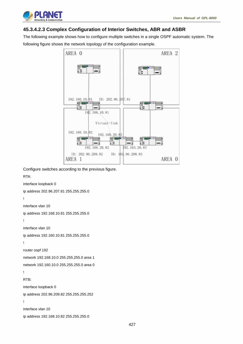
427
Users Manual of GPL-8000
45.3.4.2.3 Complex Configuration of Interior Switches, ABR and ASBR The following example shows how to configure multiple switches in a single OSPF automatic system. The
following figure shows the network topology of the configuration example.
Configure switches according to the previous figure.
RTA:
interface loopback 0
ip address 202.96.207.81 255.255.255.0
!
interface vlan 10
ip address 192.168.10.81 255.255.255.0
!
interface vlan 10
ip address 192.160.10.81 255.255.255.0
!
router ospf 192
network 192.168.10.0 255.255.255.0 area 1
network 192.160.10.0 255.255.255.0 area 0
!
RTB:
interface loopback 0
ip address 202.96.209.82 255.255.255.252
!
interface vlan 10
ip address 192.168.10.82 255.255.255.0

428
Users Manual of GPL-8000
!
interface vlan 11
ip address 192.160.20.82 255.255.255.0
!
router ospf 192
network 192.168.20.0 255.255.255.0 area 1
network 192.168.10.0 255.255.255.0 area 1
!
RTC:
interface loopback 0
ip address 202.96.208.83 255.255.255.252
!
interface vlan 10
ip address 192.163.20.83 255.255.255.0
!
interface vlan 11
ip address 192.160.20.83 255.255.255.0
!
router ospf 192
network 192.168.20.0 255.255.255.0 area 1
network 192.163.20.0 255.255.255.0 area 0
!
45.3.4.3 Configuring Complex OSPF on ABR Switch The following case describes ABR configuration tasks.
Configuring basic OSPF
Distributing routes
The following figure shows the address range and area distribution.

429
Users Manual of GPL-8000
The following are basic configuration tasks:
(1) Configuring the address range for Ethernets 0 to 3
(2) Activating OSPF on every interface
(3) Setting the authentication password for each area and network
(4) Setting the link state value and other interface parameters
Use one area command respectively to set authentication parameters and stub
area. You can use one command to set these parameters.
Set backbone area (Area 0).
The configuration tasks relative with the distribution are listed in the following:
Distribute IGRP routes and RIP routes to enter OSPF parameter setting (including metric-type, metric,
tag and subnet).
Distribute IGRP routes and OSPF routes to RIP.
The following is an OSPF configuration example.
interface vlan 10
ip address 192.168.20.81 255.255.255.0
ip ospf password GHGHGHG
ip ospf cost 10
!
interface vlan 11
ip address 192.168.30.81 255.255.255.0
ip ospf password ijklmnop
ip ospf cost 20
ip ospf retransmit-interval 10
ip ospf transmit-delay 2
ip ospf priority 4
!
interface vlan 12
ip address 192.168.40.81 255.255.255.0
ip ospf password abcdefgh
ip ospf cost 10
!
interface vlan 13
ip address 192.168.0.81 255.255.255.0
ip ospf password ijklmnop
ip ospf cost 20
ip ospf dead-interval 80
!
430
Users Manual of GPL-8000
router ospf 192
network 192.168.0.0 255.255.255.0 area 0
network 192.168.20.0 255.255.255.0 area 192.168.20.0
network 192.168.30.0 255.255.255.0 area 192.168.30.0
network 192.168.40.0 255.255.255.0 area 192.168.40.0
area 0 authentication simple
area 192.168.20.0 stub
area 192.168.20.0 authentication simple
area 192.168.20.0 default-cost 20
area 192.168.20.0 authentication simple
area 192.168.20.0 range 36.0.0.0 255.0.0.0
area 192.168.30.0 range 192.42.110.0 255.255.255.0
area 0 range 130.0.0.0 255.0.0.0
area 0 range 141.0.0.0 255.0.0.0
redistribute rip
RIP is in network 192.168.30.0.
router rip
network 192.168.30.0
redistribute ospf 192
!
Configuring BGP The chapter describes how to configure the Boundary Gateway Protocol (BGP). For details about BGP
commands, refer to section “BGP Commands”. BGP is an Exterior Gateway Protocol (EGP) defined in
RFC1163, 1267 and 1771. BGP allows to create a routing selection mechanism among the autonomous
systems. The routing selection mechanism can ensure automatic exchange of routing selection information
among the auto-managed system without loop.
45.4.1 Overview 45.4.1.1 BGP Introduction In BGP, each route contains a network number, auto-managed system list that the route passes (as-path) and
other attribute lists. Our switch software supports version 4 BGP defined in RFC1771. The basic function of
BGP is to exchange network reachable information with other BGP systems, including information about the
AS routing table. The information about AS routing table can be used to construct the AS connection figure
and apply AS-level routing strategy through the AS connection figure. BGP Version 4 supports CIDR. CIDR
reduces the size of the routing table by creating the summary route. The super network, therefore, is
generated. CIDR cancels the notion of BGP network class and supports IP prefix broadcast. The CIDR can be
transmitted through OSPF, enhanced IGRP, ISIS-IP and RIP2.

431
Users Manual of GPL-8000
EGP is different from IGP with its enhanced control capability. BGP provides multiple optional methods to
control the routes.
Use neighbor-based access-list, aspath-list and prefix-list to filter the route. Or use port-based
access-list and prefix-list to filter the route or the Nexthop attribute of the route.
Use route-map to modify BGP route's attributes such as MED, Local Preference and Weight.
To interact with dynamic IGRPs such as ospf and rip, you can use the distribute command to
redistribute the route. The BGP routing information is thus automatically generated. The BGP route can
be generated by manually configuring network and aggregate. When the BGP route is generated, you
can use route-map to set the attribute of the route.
To control the priority of BGP routes in the system, run the distance command to set the management
distance of the BGP route.
45.4.1.2 BGP Route Selection The decision procedure of BGP is based on route attribute comparing. When there are multiple routes to
reach the same network, BGP selects the optimal route. The procedure of BGP selecting the optimal route is
shown as follows:
If the next hop cannot be reached, the optimal route is considered.
If the route is an internal one and synchronization is activated, the optimal route is not considered when
the route is not in IGP.
The route with maximum weight is preferentially selected.
If all routes have the same weight, the route with maximum local priority is preferentially selected.
If all routes have the same local priority, the route generated by the local router is preferentially selected.
For example, routes may be generated when the local router runs the network command or the
aggregate command or the IGP routes are forwarded.
If the local priority is same, or if the routes are not generated by the local router, the route with the
shortest AS path is first selected.
If the AS paths are same, the route with the smallest Origin attribute value (IGP < EGP < INCOMPLETE)
is first selected.
If the Origin attribute values is the same, the route with the smallest MED value is first selected. The
MED value compare is for the routes from the same neighboring AS unless bgp always-compare-med
is activated.
If all routes have the same MED, the EBGP is first selected. All paths in the autonomous system are
taken as IBGP.
If each route has the same connection attribute, the route with the smallest router-id is first selected.

432
Users Manual of GPL-8000
45.4.2 BGP Configuration Task 45.4.2.1 Configuring Basic BGP Characteristic BGP configuration tasks can be classified into two groups: basic tasks and advanced tasks. The first two
items of basic tasks are mandatory for BGP configuration. Other items in basic tasks and advanced tasks are
optional.
45.4.2.1.1 Activating BGP Routing Choice Run the following commands in global configuration mode to activate BGP route selecting:
Command Purpose
router bgp autonomous-system Activates the BGP routing process in
router configuration mode.
networknetwork-number/masklen
[route-map route-map-name]
Marks the network as the local
autonomous system and adds it to the
BGP table.
(1) For EGP, when you use the router configuration command network to
configure an IP network, you can control which network can get notification. It
is contrary for IGP. For example, The RIP protocol uses the network
command to decide where the update is sent.
(2) You can use the network command to add the IGP route to the BGP routing
table. The router resources, such as the configured RAM, decide the upper
limit of the available network command. As an additional choice, you also can
run the redistribute command.
45.4.2.1.2 Configuring BGP Neighbor To exchange routing information with the outside, the BGP neighbor must be configured.
BGP supports two neighbors: IBGP and EBGP. The interior neighbors are in the same AS. The exterior
neighbors are in a different AS. In general, exterior neighbors are closely adjacent and share a subnet; interior
neighbors are in anyplace of the same AS.
Run the router configuration command to configure the BGP neighbors:
Command Purpose
neighbor {ip-address }
remote-asnumber
Designates a BGP neighbor.
For details, refer to the section “BGP Neighbor Configuration Example”.
433
Users Manual of GPL-8000
45.4.2.1.3 Configuring BGP Soft Reconfiguration In general, BGP neighbors exchange all routes only when the connection is created; they then exchange only
the changed routes later. If the configured routing policy is changed, you must clear the BGP sessions before
you apply the changed routing policy to the received routes. However, clearing the BGP session can disable
the high-speed cache and seriously undermine network running. You are recommended to adopt the soft
reconfiguration function because it helps to configure and activate policy without clearing BGP sessions.
Currently, the new soft reconfiguration function can be applied to each neighbor. The new soft reconfiguration
is applied to the incoming update generated by neighbors, it is called incoming soft reconfiguration. When the
new soft reconfiguration is used to send the outgoing update to the neighbor, it is called outgoing soft
reconfiguration. After the incoming soft reconfiguration is run, new input policies validates. After the outgoing
soft reconfiguration is run, the new local output policy validates without resetting BGP session.
In order to generate the incoming update without resetting BGP session, the router of the local BGP session
should restore the received incoming update without modification. Whether the incoming update is received
or declined by the current incoming policy is not in the consideration. In this case, the memory will be badly
occupied. The outgoing reconfiguration has no extra memory cost, so it is always valid. You can trigger the
outgoing soft reconfiguration on the other side of the BGP session to validate the new local incoming policy.
To permit the incoming soft reconfiguration, you need to configure BGP to restore all received routing update.
The outgoing soft reconfiguration does not require pre-configuration.
Run the following command to configure BGP soft reconfiguration:
Command Purpose
Neighbor { ip-address }
soft-reconfiguration [inbound]
Configures BGP soft reconfiguration.
45.4.2.1.4 Resetting BGP Connection Once two routers are defined as BGP neighbors, they will create a BGP connection and exchange route
choice information. If the BGP routing policy is modified afterwards, or if other configuration is changed, you
must reset the BGP connection to validate the changed configuration. Run one of the following commands to
reset the BGP connection.
Command Purpose
clear ip bgp * Resets all BGP connections.
clear ip bgp address Resets a special BGP connection.

434
Users Manual of GPL-8000
45.4.2.1.5 Configuring Synchronization Between BGP and IGPs If an AS sends information at the third AS through your AS, the internal routing state of your AS must be the
same as the routing information that the AS broadcasts to other ASs. For example, before all routers in your
AS learn the routes through IGP, your AS may receive routing information from your BGP that some routers
cannot route. The synchronization between BGP and IGP is that the BGP does not broadcast the routing
information until all IGP routers in the AS learn the routing information. The synchronization is activated by
default.
In some cases, you need not to perform the synchronization between BGP and IGP. If other ASs are not
allowed to send data through your AS, or if all routers in your AS run BGP, the synchronization will be
cancelled. After the synchronization is cancelled, your IGP can carry a few routes and BGP will aggregate
more rapidly.
Run the following command to cancel the synchronization:
Command Purpose
no synchronization Cancel the synchronization between
BGP and IGP.
When cancelling the synchronization, you need to run the command clear ip bgp to clear BGP sessions.
For details, refer to the section “Example for Neighbor-Based BGP Path Filtration”.
In general, only one or two routes are forwarded to your IGP and become the exterior routes in IGRP or the
BGP session sponsor generates a default AS route. When the routes are forwarded from BGP to IGP, only the
routes obtained through EBGP can be forwarded. In most cases, your IGP is not redistributed to BGP; the
networks in the AS are listed by running the router configuration command network; your network, therefore,
will be broadcast. The network listed in this way is called as the local network; BGP has the origin attribute of
IGP. These routes, such as directly-connected routes, static routes or routes learned from IGP, must be in the
main IP routing table and be valid. In BGP routing process, the main IP routing table is scanned periodically to
detect whether local network exists and the BGP routing table is updated afterwards. Be careful when the
BGP forwards the routes. Routes in IGP may be forwarded by other routers through BGP. BGP potentially
sends information to IGP and IGP then sends the information back to BGP.
45.4.2.1.6 Configuring BGP Route Weight BGP route weight is a number that is endowed to BGP route for controlling route choice process. The weight
is local for the router. The weight ranges from 0 to 65535. The default weight of the local BGP routes is 32768.
The route weight obtained from the neighbor is 0. The administrator can carry out the routing policy by
modifying the route weight.
Run the following command to configure the route weight:
Command Purpose
neighbor {ip-address } weight weight Designates a weight for all
neighbor’s routes.
You can also modify the route weight through the route map.

435
Users Manual of GPL-8000
45.4.2.1.7 Configuring Neighbor-Based BGP Routing Filtration The router software provides the following methods to filter the BGP routes of the designated neighbor:
(1) Use the Aspath list filter with the commands ip aspath-list and neighbor filter-list.
Command Purpose
ip aspath-listaspaths-list-name {permit | deny}
as-regular-expression
Defines a BGP-related access table.
router bgpautonomous-system Enters the router configuration mode.
neighbor {ip-address } filter-listaspath-list-name {in | out } Establishes a BGP filter.
(2) Use the access list with the commands ip access-list and neighbor distribute-list.
Command Purpose
ip access-liststandardaccess-list-name Defines an access list.
router bgpautonomous-system Enters the router configuration mode.
neighbor {ip-address } distribute-listaccess-list-name {in | out } Establishes a BGP filter.
(3) Use the prefix list with the commands ip prefix-list and neighbor prefix-list.
Command Purpose
ip prefix-listprefixs-list-name |sequence number
{permit |deny}A.B.C.D/n ge x le y
Defines a prefix list.
router bgpautonomous-system Enters the router configuration mode.
neighbor {ip-address } prefix-listprefix-list-name
{in | out}
Establishes a BGP filter.
(4) Use the route mapping with the commands route-map and neighbor route-map.
Route mapping can filter and change the routing attribute.
For details, refer to the section “Example for Neighbor-Based BGP Path Filtration”.
45.4.2.1.8 Configuring Port-Based BGP Route Filtration You can use the access list or the prefix list to configure the port-based BGP route filtration. You can filter the
network number or the gateway address of the route. You can designate the access-list option to use the
access list, or designate the prefix-list option to use the prefix list to filter the network number of the route.
You also can designate the gateway option to use the access list to filter the Nexthop attribute of the route.
The access-list option and the prefix-list option cannot be used together. The asterisk mark (*) can be
designated to filter routes on all ports.
Run the following command in BGP configuration mode to configure the port-based BGP route filtration.
Command Purpose
filter interface {in | out}〔access-list
access-list-name〕〔prefix-list prefix-list-name〕
〔gateway access-list-name〕
Configures the port-based BGP route
filtration.

436
Users Manual of GPL-8000
For details, refer to the section “Example for Port-Based BGP Route Filtration”.
45.4.2.1.9 Cancelling BGP-Updated Next Hop Processing You can cancel the next hop processing for the neighbor's BGP update. The configuration is useful in the
non-broadcast networks such as frame relay or X.25. In frame relay or X.25, BGP neighbors cannot directly
access all other neighbors in the same IP subnet. The following methods can cancel the next hop processing:
The local IP address that uses the BGP connection replaces the next-hop address of the outgoing route.
Use the route map to designate the next-hop address of the outgoing route or the incoming route.
Run the following command to cancel the next-hop processing:
Command Purpose
neighbor {ip-address } next-hop-self Cancels the next-hop processing when BGP neighbors update.
When the previous command is used, the current router notifies itself to take as the next hop of the route.
Therefore, other BGP neighbors will send packets to the current router. It is useful in the non-broadcast
network because a path from the current router to the designated neighbor. However, it is useless in the
broadcast network because unnecessary extra hops will occur.
45.4.2.2 Configuring Senior BGP Characteristics 45.4.2.2.1 Filtering and Modifying Route Update Through Route Map The route map can be used on each neighbor to filter the route update and modify the parameter’s attributes.
The route map can be applied in both the incoming update and the outgoing update. Only the routes that pass
the route map are processed when the route update is sent or received.
The route map supports that the incoming update and the outgoing update are based on the AS path,
community and network number. The aspath-list command requires be used for the AS matching. The
community matching requires the community-list command. The network matching requires the ip
access-list command .
Run the following command to filter and modify the route update through the route map.
Command Purpose
neighbor {ip-address } route-map
route-map-name {in | out} Applies the route map to the incoming or outgoing route.
For details, refer to the section “BGP Route Map Example”.
45.4.2.2.2 Configuring Aggregation Addres The non-type inter-field route can create the aggregation route (and super network) to minimize the routing
table. You can configure the aggregation route by redistributing the aggregation route to BGP or by using the
aggregation attribute described in the following table. If the BGP table has at least one more detailed record,
add the aggregation address to the BGP table.
Use one or several of the following command to create the aggregation address in the routing table:
Command Purpose
aggregate network/len Creates the aggregation address in the routing table.
aggregate network/len summary-only Broadcasts only the summary address.

437
Users Manual of GPL-8000
aggregate network/len route-map
map-name
Generates the designated aggregation address through the
route map.
Refer to the section “BGP Route Aggregation Example”.
45.4.2.2.3 Configuring BGP Community Attribute The routing policy that BGP supports is based one of the following three values for BGP routing information:
Routing network number
Value of the AS_PATH attribute
Value of the COMMUNITY attribute
Routes can be classified into the community through the COMMUNITY attribute and the community-based
routing policy can be applied to routes. Therefore, the configuration of routing information control is simplified.
Community is a group of routes having the same attributes. Each route may belong to multiple communities.
The AS administrator can decide which community a route belongs to.
The COMMUNITY attribute is an optional, transmissible and global, which ranges from 1 to 4,294,967,200.
The famous communities that are predefined in the Internet are listed in the following table:
Community Description
no-export Does not broadcast the route to the EBGP peers,
including the EBGP peers in the autonomous
system.
no-advertise Does not broadcast the route to any peer.
local-as Does not broadcast the route to the outside of the
autonomous system.
When generating, receiving or forwarding the route, the BGP session sponsor can set, add or modify the
route community attributes. After the routes are aggregated, the aggregation contains the COMMUNITY
attribute from all original routes.
The COMMUNITY attribute is not sent to neighbors by default. Run the following command to send the
COMMUNITY attribute to the designated neighbor.
Command Purpose
neighbor {ip-address }
send-community
Sends the COMMUNITY attribute to the
designated neighbor.
Perform the following operations to set the community attribute:
Command Purpose
route-map map-name
sequence-number {deny | permit}
Configures the route map.
set community community-value Configures the setup regulations.
router bgpautonomous-system Enters the router configuration mode.

438
Users Manual of GPL-8000
neighbor {ip-address }
route-mapaccess-list-name {in | out }
Applies the route map.
Perform the following operations to configure the community-attribute–based routing information filtration:
Command Purpose
ip community-list standard |
expendedcommunity-list-name
{permit | deny} communtiy-expression
Defines the community list.
route-map map-name
sequence-number {deny | permit}
Configures the route map.
match community-list-name Configures the matching regulations.
router bgpautonomous-system Enters the router configuration mode.
neighbor {ip-address }
route-maproute-map-name {in | out }
Applies the route map.
Refer to the section “Example for Route Map Through BGP Community Attribute”.
45.4.2.2.4 Configuring Autonomous System Alliance The method to reduce IBGP connections is to divide one AS into multiple sub ASs and classify them into an
autonomous system alliance. As to the outside, the alliance seems like an AS. As to the inside of the alliance,
each sub AS is full-connected and connects other sub ASs in the same alliance. Even if the EBGP session
exists in the peers of different sub AS, they still exchange route choice information as IBGP peers do. That is,
they save the next hop, MED and local priority information.
To configure a BGP autonomous system alliance, you must designate the alliance identifier. The alliance
identifier is an AS number. As to the outside, the AS looks like a single AS which takes the alliance identifier
as the AS number.
Run the following command to configure the identifier of the autonomous system alliance:
Command Purpose
bgp confederation0 identifier autonomous-system
Configures the identifier of the
autonomous system alliance.
Run the following command to designate the autonomous system number belonging to the autonomous
system alliance:
Command Purpose
bgp confederation peers
autonomous-system
[autonomous-system ...]
Designates the AS belonging to the
autonomous system alliance.
Refer to the section “BGP Autonomous System Alliance Example”.

439
Users Manual of GPL-8000
45.4.2.2.5 Configuring Route Reflector Another method to reduce IBGP connections is to configure the route reflector.
The peers in the route reflector are divided into two groups: client peers and other routers in the AS
(non-client peers). The route reflector reflects the routes between the two groups. The route reflector and the
client peers consists of a cluster. The non-client peers must be fully connected. The client peers need not be
fully connected. The clients in the cluster do not communicate with the IBGP session sponsors in the different
cluster.
When the route reflector receives the routing infotmation, it will perform the following tasks:
Broadcast the routes from the external BGP session sponsors to all clients and non-client peers.
Broadcast the routes from the non-client routes to all clients.
Broadcast the routes from the client to all client peers and non-client peers. The client peers need not be
fully connected.
Run the following command to set the local router as the reflector and designate the neighbor as the client:
Command Purpose
neighbor
ip-addressroute-reflector-client
Sets the local router to the reflector and
designate the neighbor as the client.
One AS has multiple route reflectors. The route reflector handles other route reflectors as it handles IBGP
session sponsors. In general, the clients in the same cluster has only one route reflector. The cluster is
identified by the router ID of the route reflector. To add redundancy and avoid the failure of the single node,
one cluster may have several route reflectors. In this case, all route reflectors in the cluster must be set to a
4-bit cluster ID, enabling the route reflector to identify the update information of other route reflectors in the
same cluster. All the route reflectors in the same cluster must be fully connected and have the same client
peers and non-client peers.
If several route reflectors exists in a cluster, run the following command to configure the cluster ID:
Command Purpose
bgp cluster-id cluster-id Configures the cluster ID.
Refer to the section “BGP Route Reflector Configuration Example”.
45.4.2.2.6 Shutting down peers Run the following command to shut down the BGP neighbors:
Command Purpose
neighbor {ip-address } shutdown Shuts down the BGP neighbor.
Run the following command to activate the neighbor:
Command Purpose
no neighbor {ip-address } shutdown Activates the BGP neighbor.
440
Users Manual of GPL-8000
45.4.2.2.7 Configuring multihop external peers The external peers must be in the directly-connected networks by default. Run the following command to
configure multihop external peers:
Command Purpose
neighbor {ip-address } ebgp-multihop
ttl
Sets the BGP neighbor to the multihop
external peers.
45.4.2.2.8 Setting BGP route management distance The management distance is a unit to measure the priority of routing protocols. BGP uses three kinds of
management distance: external distance, internal distance and local distance. The route learned from the
external BGP shows the external distance. The route learned from the internal BGP shows the internal
distance. The local route shows the local distance. Run the following command to set BGP route
management distance:
Command Purpose
distance bgp external-distance
internal-distance local-distance Sets BGP route management distance.
It is dangerous to modify the management distance of the BGP routes. You are not recommended to do it.
The external distance should be shorter than the distance of any dynamic routing protocol. The internal
distance should be longer than the distance of any dynamic routing protocol.
45.4.2.2.9 Modifying BGP timer Run the following command to modify BGP keepalive and holdtime timer:
Command Purpose
neighbor [ip-address | peer
group-name] timers keepalive holdtime
Sets the keepalive and holdtime timer
for the designed peers or the peer
group (unit: second).
Run the command no neighbor timers to resumes the timer of the BGP neighbor or the peer group to the
default value.
45.4.2.2.10 omparing MED of the routes from different ASs MED is a parameter that is considered when an optimal route needs to be selected from multiple available
paths. The path with comparatively small MED value is first considered.
By default, when the best route is being chosen, the MED compare is performed only among the routes from
the same AS. You can configure to allow the MED compare during route choice, no matter which AS the
routes come from.
Run the following command to perform the MED compare among routes from different ASs:
Command Purpose
bgp always-compare-med Performs the MED compare among routes from different ASs.

441
Users Manual of GPL-8000
45.4.3 Monitoring and Maintaining BGP The administrator can browse and delete the content in the routing table or other databases in BGP. The
value of the detailed statistics information can be displayed.
45.4.3.1 Clearing BGP routing table and database Run the following command in management mode to perform relative tasks about clearing high-speed cache,
table or BGP database.
Command Purpose
clear ip bgp * Resets all BGP connections.
clear ip bgp as-number Resets the BGP connection of the
designated autonomous system.
clear ip bgp address Resets the BGP connection of the
designated neighbor.
clear ip bgp address soft {in|out} Clears the incoming or outgoing
database of the designated neighbor.
clear ip bgp aggregates Clears the routes generated during
route aggregation.
clear ip bgp networks Clears the routes generated by the
network command.
clear ip bgp redistribute Clears the routes generated in the
forwarding process.
45.4.3.2 Displaying routing table and system statistics information The detailed statistics information such as the BGP routing table and the database content can be displayed.
These statistics information helps you to fully use network resources and resolve network problems.
Run the following command to display different kinds of statistics information:
Command Purpose
show ip bgp Displays the BGP routing table in the
system.
show ip bgp prefix Displays the routs that match the
prefix-matched list.
show ip bgp community Displays the statistics information about
the community attribute.
show ip bgp regexp regular-expression
Displays the routes that match the
regular expression.
show ip bgp network Displays the designated BGP route.
show ip bgp neighbors address Displays the detailed information about
the TCP connection and BGP
connection of the designated neighbor.

442
Users Manual of GPL-8000
show ip bgp neighbors [address]
[received-routes | routes |
advertised-routes]
Displays the routes learned from a
special BGP neighbor.
show ip bgp paths Displays all BGP path information in the
database.
show ip bgp summary Displays the state of all BGP
connections.
45.4.3.3 Tracking BGP information To locate the fault and resolve the problem, you need to observe the BGP connection establishment, route
receiving and route forwarding by tracking the BGP information. Perform the following operations:
Command Purpose
debug ip bgp * Tracks common BGP information.
debug ip bgp all Tracks all BGP information.
debug ip bgp fsm Tracks the BGP state machine.
debug ip bgp keepalive Tracks the BGP keepalive message .
debug ip bgp open Tracks the BGP Open message.
debug ip bgp update Tracks the BGP Update message.
45.4.4 BGP Configuration Example 45.4.4.1 BGP route map example The following example shows how to modify the attributes of the incoming route from neighbors by using the
route map. Set the weight of any route that is received from neighbor 140.222.1.1 and matches the ASPATH
access list aaa to 200. Set the local priority to 250. If the route is declined, other routes are declined.
router bgp 100
!
neighbor 140.222.1.1 route-map fix-weight in
neighbor 140.222.1.1 remote-as 1
!
route-map fix-weight permit 10
match as-path aaa
set local-preference 250
set weight 200
!
ip aspath-list aaa permit ^690$
ip aspath-list aaa permit ^1800
In the following example, the first item of route map freddy sets the MED attribute of all routes starting from
autonomous system 690 to 127. The second item enables the routes that do not satisfy the previous
conditions to be sent to neighbor 1.1.1.1:

443
Users Manual of GPL-8000
router bgp 100
neighbor 1.1.1.1 route-map freddy out
!
ip aspath-list abc permit ^690_
ip aspath-list xyz permit .*
!
route-map freddy permit 10
match as-path abc
set metric 127
!
route-map freddy permit 20
match as-path xyz
The following example shows how to modify the routes that are generated in route forwarding through the
route map:
router bgp 100
redistribute rip route-map rip2bgp
!
route-map rip2bgp
match ip address rip
set local-preference 25
set metric 127
set weight 30000
set next-hop 192.92.68.24
set origin igp
!
ip access-list standard rip
permit 131.108.0.0 255.255.0.0
permit 160.89.0.0 255.255.0.0
permit 198.112.0.0 255.255.128.0
45.4.4.2 BGP neighbor configuration example In the following example, the BGP router belongs to AS109. AS109 establishes two networks. The router has
three neighbors: an external neighbor (in a different AS), an internal neighbor (with the same AS number) and
an external neighbor.
router bgp 109
network 131.108.0.0
network 192.31.7.0
neighbor 131.108.200.1 remote-as 167
neighbor 131.108.234.2 remote-as 109
neighbor 150.136.64.19 remote-as 99

444
Users Manual of GPL-8000
45.4.4.3 Example for neighbor-based BGP path filtration The following is an example for neighbor-based BGP path filtration. The route that gets through the access list
test1of as-path obtains a weight value 100. Only the route that gets through the access list test2 of as-path
can be sent to neighbor 193.1.12.10. Similarly, the route that gets through the access list test3 can be
accepted by neighbor 193.1.12.10:
router bgp 200
neighbor 193.1.12.10 remote-as 100
neighbor 193.1.12.10 filter-list test1 weight 100
neighbor 193.1.12.10 filter-list test2 out
neighbor 193.1.12.10 filter-list test3 in
ip aspath-list test1 permit _109_
ip aspath-list test2 permit _200$
ip aspath-list test2 permit ^100$
ip aspath-list test3 deny _690$
ip aspath-list test3 permit .*
45.4.4.4 Example for port-based BGP route filtration The following example shows that the routes from port e1/0 are filtered through access list acl:
router bgp 122
filter vlan10 in access-list acl
The following example shows how to filter the routes from port e1/0 simultaneously using the access list
filter-network and the access list filter-gateway to respectively filter the network number and the gateway
address.
router bgp 100
filter vlan100 in access-list filter-network gateway filter-gateway
The following example shows how to filter routes from all ports simultaneously using the prefix list filter-prefix
and the prefix list filter-gateway to respectively filter the network number and the gateway address.
router bgp 100
filter * in prefix-list filter-prefix gateway filter-gateway
45.4.4.5 Example for prefix-list-based route filtration configuration The following example shows that the default route 0.0.0.0/0 is declined:
ip prefix-list abc deny 0.0.0.0/0
The following example shows that the route which matches the prefix 35.0.0.0/8 is allowed:
ip prefix-list abc permit 35.0.0.0/8
In the following example, only the prefixes with the length from /8 to /24 are accepted in the BGP process:
router bgp
network 101.20.20.0
filter * in prefix max24

445
Users Manual of GPL-8000
!
ip prefix-list max24 seq 5 permit 0.0.0.0/0 ge 8 le 24
!
In the following example, the router filters all the routes and only accepts the routes whose prefix length
ranges from 8 to 24:
router bgp 12
filter * in prefix-list max24
ip prefix-list max24 seq 5 permit 0.0.0.0/0 ge 8 le 24
The following example shows that route whose prefix length is no more than 24 is permitted in network 192/8:
ip prefix-list abc permit 192.0.0.0/8 le 24
The following example shows that route whose prefix length exceeds 25 is permitted in network 192/8:
ip prefix-list abc deny 192.0.0.0/8 ge 25
The following example shows that routes whose prefix length is larger than 8 and smaller than 24 are
permitted:
ip prefix-list abc permit 0.0.0.0/0 ge 8 le 24
The following example shows that routes whose prefix length exceeds 25 are denied:
ip prefix-list abc deny 0.0.0.0/0 ge 25
The following example shows that all routes from network 10/8 are denied. If the mask of A-class network
10.0.0.0/8 is less than or equal to 32 bits, all routes are denied:
ip prefix-list abc deny 10.0.0.0/8 le 32
The following example shows that all routes are denied because the mask length of network 204.70.1/24
exceeds 25:
ip prefix-list abc deny 204.70.1.0/24 ge 25
The following example shows that all routes are permitted:
ip prefix-list abc permit any
45.4.4.6 BGP route aggregation example The following example shows how to create the aggregation route in BGP through route forwarding or the
conditional route aggregation function:
In the following example, the command redistribute static is used to forward the aggregation route 193. * . * .
* :
ip route 193.0.0.0 255.0.0.0 null 0
!
router bgp 100
redistribute static
If at least one route in the routing table belongs to the designated range, an aggregation route is created in
the BGP routing table according to the following configuration. The aggregation route is considered to be from
your AS and has the atomic attribute which may be lost in the indication information:

446
Users Manual of GPL-8000
router bgp 100
aggregate 193.0.0.0/8
The following example shows how to create the aggregation route 193.*.*.* and how to constrain more
detailed routes from broadcasting to all neighbors:
router bgp 100
aggregate 193.0.0.0/8 summary-only
45.4.4.7 BGP route reflector configuration example The following is an example for the route reflector configuration. RTA, RTB, RTC and RTE belongs to the
same autonomous system AS200. RTA functions as the route reflector, while RTB and RTC function as the
clients of the route reflector. RTE is a common IBGP neighbor. RTD belongs to AS100 and establishes an
EBGP connection with RTA. The configuration is shown as follows:
RTA configuration: interface vlan110
ip address 2.0.0.1 255.0.0.0
!
interface vlan111
ip address 3.0.0.1 255.0.0.0
!
interface vlan112
ip address 4.0.0.1 255.0.0.0
!
interface vlan113
ip address 5.0.0.1 255.0.0.0
!
router bgp 200
neighbor 2.0.0.1 remote-as 200 /*RTC IBGP*/
neighbor 2.0.0.1 route-reflector-client
neighbor 3.0.0.1 remote-as 200/*RTB IBGP*/
neighbor 3.0.0.1 route-reflector-client
neighbor 5.0.0.1 remote-as 200 /*RTE IBGP*/

447
Users Manual of GPL-8000
neighbor 4.0.0.2 remote-as 100 /*RTD EBGP*/
network 11.0.0.0/8
!
ip route 11.0.0.0 255.0.0.0 2.0.0.12
RTB configuration: interface vlan110
ip address 3.0.0.2 255.0.0.0
!
router bgp 200
neighbor 3.0.0.1 remote-as 200 /*RTA IBGP*/
network 13.0.0.0/8
!
ip route 13.0.0.0 255.0.0.0 3.0.0.12
RTC configuration: interface vlan110
ip address 2.0.0.2 255.0.0.0
!
router bgp 200
neighbor 2.0.0.1 remote-as 200 /*RTA IBGP*/
network 12.0.0.0/8
!
ip route 12.0.0.0 255.0.0.0 2.0.0.12
RTD configuration: interface vlan110
ip address 4.0.0.2 255.0.0.0
!
router bgp 100
neighbor 4.0.0.1 remote-as 200 /*RTA EBGP*/
network 14.0.0.0/8
!
ip route 14.0.0.0 255.0.0.0 4.0.0.12
RTE configuration: interface vlan110
ip address 5.0.0.2 255.0.0.0
!
router bgp 200

448
Users Manual of GPL-8000
neighbor 5.0.0.1 remote-as 200 /*RTA IBGP*/
network 15.0.0.0/8
!
ip route 15.0.0.0 255.0.0.0 5.0.0.12
45.4.4.8 BGP autonomous system alliance example The following figure shows an autonomous system alliance configuration. RTA, RTB and RTC create the
IBGP connection. RTA, RTB and RTC belong to the private autonomous system 65010. RTE belongs to the
private autonomous system 65020. RTE and RTA establish the EBGP connection in the autonomous system
alliance. AS65010 and AS65020 make up of an autonomous system alliance. The number of the autonomous
system alliance is AS200. RTD belongs to AS100. An EBGP connection is established between RTD and
AS200 through RTA.
RTA configuration: interface vlan110
ip address 1.0.0.1 255.0.0.0
!
interface vlan111
ip address 2.0.0.1 255.0.0.0
!
interface vlan112
ip address 4.0.0.1 255.0.0.0
!
interface vlan113
ip address 5.0.0.1 255.0.0.0
!
router bgp 65010
bgp confederation identifier 200
bgp confederation peers 65020
neighbor 1.0.0.2 remote-as 65010 /*RTB IBGP*/
neighbor 2.0.0.2 remote-as 65010 /*RTC IBGP*/

449
Users Manual of GPL-8000
neighbor 5.0.0.2 remote-as 65020 /*RTE EBGP*/
neighbor 4.0.0.2 remote-as 100 /*RTD EBGP*/
RTB configuration: interface vlan110
ip address 1.0.0.2 255.0.0.0
!
interface vlan111
ip address 3.0.0.1 255.0.0.0
!
router bgp 65010
bgp confederation identifier 200
bgp confederation peers 65020
neighbor 1.0.0.1 remote-as 65010 /*RTA IBGP*/
neighbor 3.0.0.2 remote-as 65010/*RTC IBGP*/
RTC configuration: interface vlan110
ip address 2.0.0.2 255.0.0.0
!
interface vlan111
ip address 3.0.0.2 255.0.0.0
!
router bgp 65010
bgp confederation identifier 200
bgp confederation peers 65020
neighbor 2.0.0.1 remote-as 65010 /*RTA IBGP*/
neighbor 3.0.0.1 remote-as 65010 /*RTB IBGP*/
RTD configuration: interface vlan110
ip address 4.0.0.2 255.0.0.0
!
router bgp 100
neighbor 4.0.0.1 remote-as 200 /*RTA EBGP*/

450
Users Manual of GPL-8000
RTE configuration: interface vlan110
ip address 5.0.0.2 255.0.0.0
!
router bgp 65020
bgp confederation identifier 200
bgp confederation peers 65010
neighbor 5.0.0.1 remote-as 65010 /*RTA EBGP*/
45.4.4.9 Example for route map using BGP community attribute In the following example, the command route map set-community is used to update the outgoing routes of
neighbor 171.69.232.50. The special community attribute value no-export can be set through the route of the
access list aaa. Other routes perform normal broadcast. The special community attribute value automatically
prevents the BGP session sponsor in AS200 from broadcasting the route to the outside of the autonomous
system.
router bgp 100
neighbor 171.69.232.50 remote-as 200
neighbor 171.69.232.50 send-community
neighbor 171.69.232.50 route-map set-community out
!
route-map set-community 10 permit
match ip address aaa
set community no-export
!
route-map set-community 20 permit
In the following example, the command route map set-community is used to update the outgoing routes of
neighbor 171.69.232. 90. Set the current value to the community attribute value 200. Other routes performs
normal broadcast.
route-map bgp 200
neighbor 171.69.232.90 remote-as 100
neighbor 171.69.232.90 send-community
neighbor 171.69.232.90 route-map set-community out
!
route-map set-community 10 permit
match as-path test1
set community-additive 200 200
!
route-map set-community 20 permit
match as-path test2
!

451
Users Manual of GPL-8000
ip aspath-list test1 permit 70$
ip aspath-list test2 permit .*
In the following example, Set the MED and the local priority of the route from neighbor 171.69.232.55
according to the community attribute value. Set MED of all routes that match the community list com1 to
8000. These routes may contain routes with community value “100 200 300” and “900 901”. These routes
may have other attribute values.
Set the local priority of the routes which send the community list com2 to 500.
Set the local priority of other routes to 50. Therefore, all the local priority value of all remaining routes of
neighbor 171.69.232.55 is 50.
router bgp 200
neighbor 171.69.232.55 remote-as 100
neighbor 171.69.232.55 route-map filter-on-community in
!
route-map filter-on-community 10 permit
match community com1
set metric 8000
!
route-map filter-on-community 20 permit
match community com2
set local-preference 500
!
route-map filter-on-community 30 permit
set local-preference 50
!
ip community-list com1 permit 100 200 300
ip community-list com1 permit 900 901
!
ip community-list com2 permit 88
ip community-list com2 permit 90
!
IP Hardware Subnet Routing Configuration
IP Hardware Subnet Configuration Task 46.1.1 Overview IP hardware subnet routing is similar to IP fast exchange.
When the IP hardware subnet routing is not enabled, before forwarding message containing the IP address A

452
Users Manual of GPL-8000
at the next hop, the switch first checks whether the item of destination A exists in the IP cache of hardware. If
the item exists, the message will be forwarded through hardware. If the item does not exist, the message is
sent to CPU and then processed through software. IP hardware subnet routing items include the destination
subnet, mask, IP address of the next hop, interface and so on. When the IP hardware subnet routing is
enabled, after the IP cache fails to be matched, the system is to check the IP hardware subnet routing items. If
the matched item is found, the message will be directly forwarded through the next-hop IP address and the
interface designated in the matched item. If the IP hardware subnet routing item is not found, the message will
be sent to CPU for processing.
The IP hardware subnet routing has two modes: automatic and manual. In manual mode, you need to
manually configure all routing items required by the IP hardware subnet routing. Note that routing items
having longer mask of destination subnet should be configured earlier. In automatic mode, the system
automatically addes the known routes to the hardware subnet routing. All the procedure is automatic after the
hardware subnet routing is started.
46.1.2 Configuring IP Hardware Subnet Routing Perform the following steps to configure the IP hardware subnet routing:
Step Command Description
1 [no] ip exf {default | destination
mask} {cpu| nexthop vlan vlanid}
Add or delete a hardware subnet route. Deleting a hardware
subnet route requires to specify the destination network and
mask. Replace destination and mask in the command line
with default when you delete a route. In this case, The next
hop is not CPU. The command is effective only in manual
configuration mode.
2 [no] ip exf Enable or disable the IP hardware subnet routing.
46.1.3 Checking the State of IP Hardware Subnet Routing Command Description
show ip exf Displays the current state of the IP hardware subnet routing.
Configuration Example Pay attention to the following content when you configure the routing items:
As to the direct-connecting routing, the next hop is CPU. If the next hop is a routing interface not an IP
address, do as in the direct-connecting routing.
When the number of the routing items in the system is bigger than that of the IP hardware subnet routing
items, the default routing cannot be the IP hardware subnet routing. Two or several routes, which are
prefix to each other, must be used together when IP hardware subnet routing is adopted. For other items,
advise to add heavy-traffic items to the hardware subnet routing table. Our 3224 series switches support
15 hardware subnet routes, including the default subnet route.

453
Users Manual of GPL-8000
The ARP of the next-hop IP address does not exist, the system will send an ARP request and
temporarily designate the next-hop routing item as CPU. After the system receives the ARP response,
the system then update the next hop to the user-designating address. If the VLAN interface where the
next hop resides is found different from the configured interface during the ARP response, the next hop
of the route is designated as CPU. Users then need to correct the configuration.
If the next-hop interface or the interface protocol does not exist, the item will not be added to the
hardware subnet routing table.
Suppose a switch has the following routing items:
(1) 192.168.0.0/16 next hop 192.168.26.3/vlan1
(2) 192.168.20.0/24 next hop 192.168.26.1/vlan1
(3) 192.168.1.0/24 direct-connecting routing
(4) 192.168.26.0/24 direct-connecting routing
(5) 10.0.0.0/8 next hop 192.168.1.4/vlan2
(6) 0.0.0.0/0 next hop 192.168.1.6/vlan2
The destination subnet of route item 1 is the prefix of subnet 2, 3 and 4. Therefore,these items should be
added to the hardware subnet routing table together. Item 3 and 4 are direct-connecting routing and the next
hop is CPU.
The relative configuration is as follows:
ip exf 192.168.20.0 255.255.255.0 nexthop 192.168.26.1 vlan 1
ip exf 192.168.1.0 255.255.255.0 cpu
ip exf 192.168.26.0 255.255.255.0 cpu
ip exf 192.168.0.0 255.255.0.0 nexthop 192.168.26.3 vlan 1
ip exf 10.0.0.0 255.0.0.0 nexthop 192.168.1.4 vlan 2
ip exf 0.0.0.0 0.0.0.0 nexthop 192.168.1.6 vlan 2
IP-PBR Configuration
IP-PBR Configuration IP-PBR realizes software PBR functions through the hardware of switch chip.
PBR stands for Policy Based Routing. PBR enables users to rely on a certain policy not on routing protocol for
routing. Software based PBR supports multiple policies and rules and also load balance. You can designate
the next hop’s IP address or port for those packets that are in line with policy. PBR supports load balance and
applies multiple next-hop IP addresses or ports on those policy-supported packets.
Only when the next-hop egress ARP designated by route map is already learned can IP-PBR regard that this
egress is valid and then the corresponding rule is effective. When a packet satisfies IP-PBR policy, the
hardware directly forwards this packet to the next-hop egress that the rule specifies. This process is finished

454
Users Manual of GPL-8000
by the hardware without the operation of CPU. The packets forwarded by IP-PBR have the highest priority
and only those packets unmatched with IP-PBR rule are forwarded to CPU.
The current IP-PBR supports the IP ACL policy and the next-hop IP address policy. When multiple next hops
are configured, the first effect next hop is chosen. IP-PBR also supports equivalent routing that is realized by
the switch chip. Hardware equivalent routing needs no extra configuration.
IP-PBR supports the following policy routing commands:
route-mapWORD
match ip addressWORD
set ip next-hopX.X.X.X [load-balance]
ip policy route-map WORD
IP-PBR is a little different from router’s policy routing. IP-PBR chooses an effective next hop as the egress
and drops packets if no valid next hop available, while router’s policy routing selects an effective next hop but
packet loss happens if this next hop has not learned ARP. Once multiple sequences are set, one difference
between IP-PBR and software policy routing must be noted. Software policy routing always chooses
high-priority sequence routes no matter whether IP address matched by high-priority sequences overlaps with
that matched by low-priority sequences and whether these routes are effective, while IP-PBR chooses
low-priority sequence routes when high-priority sequence routes invalidate.
47.1.1 Enabling or Disabling IP-PBR Globally Run the following commands in global configuration mode.
Command Purpose
ip pbr The IP-PBR function is disabled by default.
no ip pbr Resumes the default settings.
IP-PBR is disabled by default.

455
Users Manual of GPL-8000
47.1.2 ISIS Configuration Task List To configure IP-PBR, do as follows:
Create ACL;
Create a route map;
Apply the route map on a port;
To create an ACL, run the following command globally:
Command Remarks
ip access-list standard net1 Enters the ACL configuration mode and defines ACL.
To create a route map, run the following commands globally:
Command Remarks
route-map pbr Enters the route map configuration mode.
match ip addressaccess-list Configures the match-up policy.
set ipnext-hop A.B.C.D Configures the next-hop address of IP packet.
To apply policy routing on an IP-receiving port, run the following commands:
Command Remarks
interface interface_name Enters the interface configuration mode.
ip policy route-map route-map_name Applies policy routing on the port.
47.1.3 Monitoring and Maintaining MVC Run the following commands in EXEC mode:
Command Operation
show ip pbr It is used to display the information about RIP configuration.
show ip policy Shows the port on which IP-PBR is applied.
show ip pbr policy It is used to display the information about IP-PBR equivalent routing.
debug ip pbr It is used to enable or disable the debugging switch of IP-PBR.
The information that IP-PBR is not running is shown:
switch#show ip pbr
IP policy based route state: disabled
No pbr apply item
No equiv exf apply item

456
Users Manual of GPL-8000
All data related about IP-PBR running are shown below:
switch#show ip pbr
IP policy based route state: enabled
No equiv exf apply item
VLAN3 use route-map ddd, and has 1 entry active.
------------------
Entry sequence 10, permit
Match ip access-list:
ac1
Set Outgoing nexthop
90.0.0.3
The IP-PBR policy routing information is shown below:
switch#show ip pbr policy
IP policy based route state: enabled
VLAN3 use route-map ddd, and has 1 entry active.
------------------
Entry sequence 10, permit
Match ip access-list:
ac1
Set Outgoing nexthop
90.0.0.3
The equivalent routing information is shown below:
switch#show ip pbr exf
IP policy based route state: enabled
Equiv EXF has 1 entry active.
------------------
Entry sequence 1, handle c1f95b0
Dest ip: 1.1.0.0/16
90.0.0.3
192.168.213.161

457
Users Manual of GPL-8000
47.1.4 IP-PBR Configuration Example Switch configuration: !
ip pbr
!
interface vlan1
ip address 10.1.1.3 255.255.255.0
no ip directed-broadcast
ip policy route-map pbr
!
ip access-list standard ac1
permit 10.1.1.21 255.255.255.255
!
ip access-list standard ac2
permit 10.1.1.2 255.255.255.255
!
route-map pbr 10 permit
match ip address ac1
set ip next-hop 13.1.1.99
!
route-map pbr 20 permit
match ip address ac2
set ip next-hop 13.1.1.99 14.1.1.99load-balance
!
Configuration Description
The switch is to apply policy routing on the packets that are received from VLAN1.As to the packets whose
source IPs are 10.1.1.21, their next hop is 13.1.1.99.As to the packets whose source IPs are 10.1.1.2, they
are applied on route-map pbr 20; because set ip next-hop has the load-balance parameter, the switch chip
will automatically choose 13.1.1.99 or 14.1.1.99 as the egress according to destination IP address.
Multi-VRF CE Configuration
Multi-VRF CE Introduction 48.1.1 Overview The Virtual Private Network (VPN) provides a secure method for multiple client networks to share the
ISP-supplied bandwidth. In general, one VPN comprises a team of client networks that share a public routing

458
Users Manual of GPL-8000
table on the ISP's routers. Each client network is connected to the interface of the network devices of ISP,
while ISP's device will relate each interface to a VPN routing table. One VPN routing table is also called as a
VRF (VPN Routing /Forwarding table).
VRF is usually deployed on a Provider Edge (PE) device, such as MPLS VRF VPN. A PE supports multiple
VPNs, and each VPN has its independent IP address space among which IP addresses can be overlapped.
The VPN of a different client connects a different interface of PE, while PE differentiates the to-be-checked
routing tables according to the incoming port of the packet.
Multi-VRF CE is to remove the task of connecting multiple client networks from PE to CE, which only requires
a physical link to connect CE and PE. In this way, the port resource of PE is saved. CE also maintains the
VRF routing table for each VPN. The packets from the client network are first forwarded on CE and then
transmitted to PE after the packets pass through the ISP network.
The switch which serves as MCE connects different client networks through different ports and then relates
these ports to a VPN routing table. The switch only supports VRF settings on the VLAN port.
The MCE function is usually deployed at the edge of the large-scale MPLS-VRF VPN network. The three
functions, Multi-VRF CE, MPLS label switching and the function of MPLS control layer, are independent.
Figure 1.1 shows an MPLS-VRF VPN network.
VPN2Site 2
VPN1Site 2
MPLSBackbone
VPN2Site 1
VPN1Site 1
MCESwitch
PE PE MCESwitch
Figure 1.1 MCE in the MPLS-VRF VPN network

459
Users Manual of GPL-8000
48.1.1.1 Establishing Routes with CE The Multi-VRF CE switch can establish routes with CE through multiple dynamic routing protocols. CE can be
routers or the Ethernet switches. The routing protocols which are supported include OSPF, RIP and BEIGRP.
The MCE switch also supports static routing configuration.
The MCE switch generally needs different VLAN ports to connect CEs that belong to different VPNs. The
VLAN ports that are used to connect the VPNs require to be related to a VRF. CE does not need to support
VRF.
48.1.1.2 Establishing Routes with PE The MCE switch (MCE) can connect one or multiple PEs, but both MCE and the connected PEs have to get
VRF configured. MCE will provide PE the routes which MCE learns from CE and learns the routes of remote
client networks from PE.
The VRF route can be established between MCE and PE through dynamic routing protocols such as BGP,
OSPF, RIP and BEIGRP. Of course, the VRF route can also be established statically.
In general, MCE and PE belong to different autonomous systems. Hence, the method to establish the VRF
route between MCE and PE by using EBGP is the key point in this document.
Multi-VRF CE Configuration 48.2.1 Default VRF Configuration
Function Default Configuration
VRF There is no configuration.
All routes are added to the default routing table.
VPN expansibility of VRF There is no Routing Distinguisher (RD).
There is no input/output Routing Target (RT).
Maximum number of VRF routes 10240
VRF port N/A.
None of VLAN ports is related with VRF, and the routes of
ports are added to the default routing table.
IP Express Forwarding The hardware IP routing is not enabled.
48.2.2 MCE Configuration Tasks Configuring VRF
Configuring a VPN Route
Configuring BGP Route Between PE and CE
Testifying the VRF Connectivity between PE and CE

460
Users Manual of GPL-8000
48.2.3 MCE Configuration 48.2.3.1 Configuring VRFRefer to the following steps to configure one or multiple VRFs.
Command Purpose
Switch# config Enters the switch configuration mode.
Switch_config# ip vrf vrf-name Creates VRF and enters the VRF configuration mode.
vrf-name: VRF name with up to 31 characters
Switch_config_vrf# rd
route-distinguisher
Sets the route distinguisher of VRF.
route-distinguisher: Stands for the distinguisher of the route.
It consists of autonomous domain ID and random numbers,
or IP and random numbers.
Switch_config_vrf# route-target
{ export | import | both }
route-target-extened-community
Creates the expanded VPN attributes of input/output VRF
objects.
route-target-extended-community: It consists of autonomous
domain ID and random numbers, or IP and random numbers.
Switch_config_vrf# interface
intf-name
Enters the interface configuration mode.
intf-name: Stands for the name of an interface.
Switch_config_intf# ip vrf
forwarding vrf-name
Relates the L3 interface with VRF.
vfi-name: Means the name of VRF.
Switch_config_intf# exit Exits from interface configuration mode.
Switch_config# ip exf Enables ip hardware routing .
Switch_config# show ip vrf
[ brief | detail | interface ]
[ vrf-name ]
Browses the VRF information.
Switch_config#no ip vrf vrf-name Deletes the configured VRF and the relation between VRF
and the L3 interface.
vfi-name: Means the name of VRF.
Switch_config_intf# no ip vrf
forwarding
[ vrf-name ]
Deletes the relation between the L3 interface and VRF.
48.2.3.2 Configuring VPN Route The route can be established between MCE and customer device through the configuration of BGP, OSPF,
RIP, BEIGRP or static route. The following takes OSPF configuration as an example, which is similar to other
routes’ configurations.
When a route is configured on MCE to connect the client network, the VRF
attributes of the routing protocol need be specified. VRF need not be configured on
the customer device.

461
Users Manual of GPL-8000
Command Purpose
Switch# config Enters the switch configuration mode.
Switch_config# router ospf
process-id vrf vrf-name
Starts the OSPF-VRF route and enters the configuration
mode.
Switch_config_ospf#
networknetwork-number
network-maskareaarea-id
Defines the OSPF network, mask and area ID.
Switch_config_ospf# redistribute
bgp ASN
Forwards the designated BGP network to the OSPF network.
Switch_config_ospf# exit Exits from the OSPF configuration mode.
Switch_config# show ip ospf Browses the information about the OSPF protocol.
Switch_config# no router
ospfprocess-id
Deletes the OSPF-VRF routing configuration.
48.2.3.3 Configuring the BGP Route Between PE and CE Refer to the following configuration commands:
Command Purpose
Switch# config Enters the switch configuration mode.
Switch_config# router bgp
autonomous-system-number
Starts the BGP protocol by designating autonomous system
number and enters the BGP configuration mode.
Switch_config_bgp# bgp
log-neighbor-changes
Starts the record about BGP neighbor change.
Switch_config_bgp# address-family
ipv4 vrf
vrf-name
Enters the configuration mode of VRF address-family.
Switch_config_bgp_af# redistribute
ospf
ospf-process-id
Forwards the OSPF routing information to the BGP network.
Switch_config_bgp_af#networknet
work-number/prefix-length
Configures the network number and the mask‘s length that
are distributed by BGP.
Switch_config_bgp_af#
neighboraddress
remote-asASN
Configures the BGP neighbor and the autonomous system
number of a neighbor.
Switch_config_bgp_af#
exit-address-family
Exits from the configuration mode of address-family.
Switch_config_bgp# exit Exits from the BGP configuration mode.
Switch_config# show ip bgp vpnv4
[ all | rd | vrf ]
Browses the BGP-VRF routing information.
Switch_config# no router bgp ASN Deletes the BGP routing configuration.

462
Users Manual of GPL-8000
48.2.3.4 Testifying the VRF Connectivity Between PE and CE Use the PING command with the VRF option to testify the VRF connectivity of PE and CE.
Command Purpose
Switch# ping –vrfvrf-nameip-address Conducts the PING operation to the addresses in VRF.
MCE Configuration Example Figure 2.1 shows a simple VRF network. Both S1 and S2 are the Multi-VRF CE switches. S11, S12 and S13
belong to VPN1, S21 and S22 belong to VPN2, and all of them are customer devices. The OSPF route should
be configured between CE and customer device, while the BGP route is configured between CE and PE.
S11
S12
VPN2S21
S1 PE S2
VPN1S13
VPN2S22
VPN1
G0/1
G0/3
G0/4
G0/2
CE CE
G0/111.0.0.0 G0/2
G0/3
G0/1G1/1 G1/2
G0/1
Figure 2.1 MCE configuration example
48.3.1 Configuring S11 Set the VLAN attributes of the physical interface that connects CE:
Switch_config# interface gigaEthernet 0/1
Switch_config_g0/1# switchport pvid 11
Switch_config_g0/1# exit
Sets the IP address and the VLAN interface.
Switch_config# interface VLAN11
Switch_config_v11# ip address 11.0.0.2 255.0.0.0
Switch_config_v11# exit

463
Users Manual of GPL-8000
Set the routing protocol between CE and customer's device:
Switch_config# router ospf 101
Switch_config_ospf_101# network 11.0.0.0 255.0.0.0 area 0
Switch_config_ospf_101# exit
48.3.2 Configuring MCE-S1 Configures VRF on the Multi-VRF CE device.
Switch#config
Switch_config# ip vrf vpn1
Switch_config_vrf_vpn1# rd 100: 1
Switch_config_vrf_vpn1# route-target export 100: 1
Switch_config_vrf_vpn1# route-target import 100: 1
Switch_config_vrf_vpn1# exit
Switch_config# ip vrf vpn2
Switch_config_vrf_vpn2# rd 100: 2
Switch_config_vrf_vpn2# route-target export 100: 2
Switch_config_vrf_vpn2# route-target import 100: 2
Switch_config_vrf_vpn2# exit
Configure the loopback port and the physical port, and use the address of the loopback port as the router ID
of the BGP protocol.
Switch_config# interface loopback 0
Switch_config_l0# ip address 101.0.0.1 255.255.255.255
Switch_config_l0# exit
S1 connects S11 through the F0/1 port, S21 through the G0/4 port and PE through the G0/2 port.
Switch_config# interface gigaEthernet 0/1
Switch_config_g0/1# switchport pvid 11
Switch_config_g0/1# exit
Switch_config# interface gigaEthernet 0/4
Switch_config_g0/4# switchport pvid 15
Switch_config_g0/4# exit
Switch_config# interface gigaEthernet 0/2
Switch_config_g0/2# switchport mode trunk
Switch_config_g0/2# exit

464
Users Manual of GPL-8000
Set the L3 VLAN port of a switch, bind the VRF to the VLAN port and set the IP address. S1 connects PE
through two logical ports, VLAN21 and VLAN22. The two ports, VLAN11 and VLAN15, connect VPN1 and
VPN2 respectively.
Switch_config# interface VLAN11
Switch_config_v11# ip vrf forwarding vpn1
Switch_config_v11# ip address 11.0.0.1 255.0.0.0
Switch_config_v11# exit
Switch_config# interface VLAN15
Switch_config_v15# ip vrf forwarding vpn2
Switch_config_v15# ip address 15.0.0.1 255.0.0.0
Switch_config_v15# exit
Switch_config# interface VLAN21
Switch_config_v21# ip vrf forwarding vpn1
Switch_config_v21# ip address 21.0.0.2 255.0.0.0
Switch_config_v21# exit
Switch_config# interface VLAN22
Switch_config_v22# ip vrf forwarding vpn2
Switch_config_v22# ip address 22.0.0.2 255.0.0.0
Switch_config_v22# exit
Configure the OSPF route between CE and customer device.
Switch_config# router ospf 1 vrf vpn1
Switch_config_ospf_1# network 11.0.0.0 255.0.0.0 area 0
Switch_config_ospf_1# redistribute bgp 100
Switch_config_ospf_1#exit
Switch_config# router ospf 2 vrf vpn2
Switch_config_ospf_2# network 15.0.0.0 255.0.0.0 area 0
Switch_config_ospf_2# redistribute bgp 100
Switch_config_ospf_2#exit
Configure the EBGP route between PE and CE.
Switch_config# router bgp 100
Switch_config_bgp# bgp log-neighbor-changes
Switch_config_bgp# address-family ipv4 vrf vpn1
Switch_config_bgp_vpn1# no synchronization

465
Users Manual of GPL-8000
Switch_config_bgp_vpn1# redistribute ospf 1
Switch_config_bgp_vpn1# neighbor 21.0.0.1 remote-as 200
Switch_config_bgp_vpn1# exit-address-family
Switch_config_bgp# address-family ipv4 vrf vpn2
Switch_config_bgp_vpn2# no synchronization
Switch_config_bgp_vpn2# redistribute ospf 2
Switch_config_bgp_vpn2# neighbor 22.0.0.1 remote-as 200
Switch_config_bgp_vpn2# exit-address-family
Switch_config_bgp# exit
Create VLAN.
Switch_config# vlan 1,11-12,21-22
Enables the forwarding of subnet route of the switch.
Switch_config# ip exf
48.3.3 Configuring PE Set VRF on PE:
Switch#config
Switch_config# ip vrf vpn1
Switch_config_vrf_vpn1# rd 200: 1
Switch_config_vrf_vpn1# route-target export 200: 1
Switch_config_vrf_vpn1# route-target import 200: 1
Switch_config_vrf_vpn1# exit
Switch_config# ip vrf vpn2
Switch_config_vrf_vpn2# rd 200: 2
Switch_config_vrf_vpn2# route-target export 200: 2
Switch_config_vrf_vpn2# route-target import 200: 2
Switch_config_vrf_vpn2# exit
Set the loopback interface as the router identifier:
Switch_config# interface loopback 0
Switch_config_l0# ip address 102.0.0.1 255.255.255.255
Switch_config_l0# exit
Set the physical interface which connects PE and CE: G1/1 and G1/2 connect S1 and S2 respectively:
Switch_config# interface gigaEthernet 1/1
Switch_config_g1/1# switchport mode trunk

466
Users Manual of GPL-8000
Switch_config_g1/1# interface gigaEthernet 1/2
Switch_config_g1/2# switchport mode trunk
Switch_config_g1/2# exit
Set the L3 VLAN interface of PE, which connects S1:
Switch_config# interface VLAN21
Switch_config_v21# ip vrf forwarding vpn1
Switch_config_v21# ip address 21.0.0.1 255.0.0.0
Switch_config_v21# exit
Switch_config# interface VLAN22
Switch_config_v22# ip vrf forwarding vpn2
Switch_config_v22# ip address 22.0.0.1 255.0.0.0
Switch_config_v22# exit
Set the L3 VLAN interface of PE, which connects S2:
Switch_config# interface VLAN31
Switch_config_v31# ip vrf forwarding vpn1
Switch_config_v31# ip address 31.0.0.1 255.0.0.0
Switch_config_v31# exit
Switch_config# interface VLAN32
Switch_config_v32# ip vrf forwarding vpn2
Switch_config_v32# ip address 32.0.0.1 255.0.0.0
Switch_config_v32# exit
Set the EBGP of PE:
Switch_config# router bgp 200
Switch_config_bgp# bgp log-neighbor-changes
Switch_config_bgp# address-family ipv4 vrf vpn1
Switch_config_bgp_vpn1# no synchronization
Switch_config_bgp_vpn1# neighbor 21.0.0.2 remote-as 100
Switch_config_bgp_vpn1# neighbor 31.0.0.2 remote-as 300
Switch_config_bgp_vpn1# exit-address-family
Switch_config_bgp# address-family ipv4 vrf vpn2
Switch_config_bgp_vpn2# no synchronization
Switch_config_bgp_vpn2# neighbor 22.0.0.2 remote-as 100
Switch_config_bgp_vpn2# neighbor 32.0.0.2 remote-as 300
Switch_config_bgp_vpn2# exit-address-family

467
Users Manual of GPL-8000
Switch_config_bgp# exit
Set VLAN and enable the subnet routing forwarding.
Switch_config# vlan 1,21-22,31-32
Switch_config# ip exf
48.3.4 Configuring MCE-S2 Configures VRF:
Switch#config
Switch_config# ip vrf vpn1
Switch_config_vrf_vpn1# rd 300: 1
Switch_config_vrf_vpn1# route-target export 300: 1
Switch_config_vrf_vpn1# route-target import 300: 1
Switch_config_vrf_vpn1# exit
Switch_config# ip vrf vpn2
Switch_config_vrf_vpn2# rd 300: 2
Switch_config_vrf_vpn2# route-target export 300: 2
Switch_config_vrf_vpn2# route-target import 300: 2
Switch_config_vrf_vpn2# exit
Configure the loopback port and the physical port, and use the address of the loopback port as the router ID
of the BGP protocol.
Switch_config# interface loopback 0
Switch_config_l0# ip address 103.0.0.1 255.255.255.255
Switch_config_l0# exit
S2 connects S13 through the F0/1 port, S22 through the G0/3 port and PE through the G0/2 port.
Switch_config# interface gigaEthernet 0/1
Switch_config_g0/1# switchport pvid 41
Switch_config_g0/1# exit
Switch_config# interface gigaEthernet 0/3
Switch_config_g0/3# switchport pvid 46
Switch_config_g0/3# exit
Switch_config# interface gigaEthernet 0/2
Switch_config_g0/2# switchport mode trunk
Switch_config_g0/2# exit

468
Users Manual of GPL-8000
Set the L3 VLAN port of a switch, bind the VRF to the VLAN port and set the IP address. S2 connects PE
through two logical ports, VLAN31 and VLAN32. The two ports, VLAN41 and VLAN46, connect VPN1 and
VPN2 respectively.
Switch_config# interface VLAN41
Switch_config_v41# ip vrf forwarding vpn1
Switch_config_v41# ip address 41.0.0.1 255.0.0.0
Switch_config_v41# exit
Switch_config# interface VLAN46
Switch_config_v46# ip vrf forwarding vpn2
Switch_config_v46# ip address 46.0.0.1 255.0.0.0
Switch_config_v46# exit
Switch_config# interface VLAN31
Switch_config_v31# ip vrf forwarding vpn1
Switch_config_v31# ip address 31.0.0.2 255.0.0.0
Switch_config_v31# exit
Switch_config# interface VLAN32
Switch_config_v32# ip vrf forwarding vpn2
Switch_config_v32# ip address 32.0.0.2 255.0.0.0
Switch_config_v32# exit
Configure the OSPF route between CE and customer device.
Switch_config# router ospf 1 vrf vpn1
Switch_config_ospf_1# network 41.0.0.0 255.0.0.0 area 0
Switch_config_ospf_1# redistribute bgp 300
Switch_config_ospf_1#exit
Switch_config# router ospf 2 vrf vpn2
Switch_config_ospf_2# network 46.0.0.0 255.0.0.0 area 0
Switch_config_ospf_2# redistribute bgp 300
Switch_config_ospf_2# exit
Configure the EBGP route between PE and CE.
Switch_config# router bgp 300
Switch_config_bgp# bgp log-neighbor-changes
Switch_config_bgp# address-family ipv4 vrf vpn1
Switch_config_bgp_vpn1# no synchronization

469
Users Manual of GPL-8000
Switch_config_bgp_vpn1# redistribute ospf 1
Switch_config_bgp_vpn1# neighbor 31.0.0.1 remote-as 200
Switch_config_bgp_vpn1# exit-address-family
Switch_config_bgp# address-family ipv4 vrf vpn2
Switch_config_bgp_vpn2# no synchronization
Switch_config_bgp_vpn2# redistribute ospf 2
Switch_config_bgp_vpn2# neighbor 32.0.0.1 remote-as 200
Switch_config_bgp_vpn2# exit-address-family
Switch_config_bgp# exit
Create VLAN.
Switch_config# vlan 1,31-32,41,46
Enables the forwarding of subnet route of the switch.
Switch_config# ip exf
48.3.5 Setting S22 Set the VLAN attributes of the physical interface of CE, and connect S22 and S2 through interface f0/1:
Switch_config# interface gigaEthernet 0/1
Switch_config_g0/1# switchport pvid 46
Switch_config_g0/1# exit
Sets the IP address and the VLAN interface.
Switch_config# interface VLAN46
Switch_config_v46# ip address 46.0.0.2 255.0.0.0
Switch_config_v46# exit
Set the routing protocol between CE and customer's device:
Switch_config# router ospf 103
Switch_config_ospf_103# network 46.0.0.0 255.0.0.0 area 0
Switch_config_ospf_103# exit
470
Users Manual of GPL-8000
48.3.6 TestifyingVRF Connectivity Run the PING command on S1 to testify the connectivity of VPN1 between S1 and S11:
Switch# ping -vrf vpn1 11.0.0.2
!!!!!
--- 11.0.0.2 ping statistics ---
5 packets transmitted, 5 packets received, 0% packet loss
round-trip min/avg/max = 0/0/0 ms
Testify the connectivity between S1 and PE:
Switch# ping -vrf vpn1 21.0.0.1
!!!!!
--- 21.0.0.1 ping statistics ---
5 packets transmitted, 5 packets received, 0% packet loss
round-trip min/avg/max = 0/0/0 ms

471
Users Manual of GPL-8000
Reliability Configuration
Configuring Port Backup This chapter discusses how to back up the interface, describes the backup functions on the asynchronism
serial interface, synchronism serial interface or ISDN interface.
For details about interface backup commands, refer to Interface Backup Command Reference.
49.1.1 Overview Interface backup functions can enabled Backup interface or disabled it according to statement or flux
information of Primary interface .If primary interface is down because of lines and etc., backup interface will
enabled auto and data can send or receive through it instead of primary interface. It can add reliability from
source router to destination. If flux of primary interface is crowded, it can activate backup interface also, share
the data transportations to speed up data transportations. If primary interface is between “down” and “up” or
flux of primary interface and backup interface are both small, backup interface can be activated but not
transporting data. This can save cost of lines .The listing interfaces can be primary interface:
asynchronism serial port
ISDN
synchronism serial port
Except above types, backup interfaces include Dialer logic interface also.
49.1.2 Backup InterfaceConfigratoin Task List If you want to configure interface backup in above interfaces ,you should do as follows in interface configure
mode.
Enabling backup and choosing the backup interface
You can also do these tasks. These tasks are optional, can provide many uses and enforce interface backup
functions.
enabling interface backup rejection
enabling flux equalization backup
49.1.3 Backup InterfaceConfigratoin Task 49.1.3.1 Enabling Backup and Choosing the Backup Interface To realize interface backup functions, you should configure backup interface of this interface first. You can use
instructions as follows in interface configuration mode.
Command Purpose
backup interfaceslot/port choose backup interface of this interface.
49.1.3.2 Enabling Backup Interface Rejection

472
Users Manual of GPL-8000
Set delaying of enabled and disabled backup interface .To realize time gap between primary interface state
changing and the result of state of backup interface changing.
1. choose backup interface
2. enabled interface backup delaying in this interface .
choose backup interface,You can use instructions as follows in interface configuration mode.
Command Purpose
Backup interfaceslot/port Choose backup interface of this port.
Enabled interface backup delaying , You can use instructions as follows in interface configuration mode.
Command Purpose
backup delay {enable-delay | never }
{disable-delay | never } Difine backup interface activation and
deactivation delaying.
49.1.3.3 Enabling Flux Equlization Backup Flux equlization backup function will work if real flux of primary interface pass the percentage limit, backup
interface will be activated to work state. If real flux of primary interface and backup interface is less than
percentage limit to primary band width , backup interface will be activated to backup state. Enabled flux equalization backup, you should execute tasks as follows:
choosing the backup interface
enabling flux equalization of this interface
49.1.3.3.1 Choosing backup interface. You can use instructions as follows in interface configuration mode.
Command Purpose
Backup interfaceslot/port Choose backup interface of this interface
49.1.3.3.2 Enabling flux equalization of this interface. You can use instructions as follows in interface configuration mode.
Command Purpose
Backup load
[enable-threshold|never][disable-thresh
old|never]
Configure interface backup flux to
activate or deactivate backup interface
limit.

473
Users Manual of GPL-8000
49.1.4 Examples of Port Backup Configuration Enable the backup interface on serial interface 1/0,and choose serial interface 1/1 as his backup interface.
The time of backup interface activation and deactivation is both 5 seconds. Flux equalization setting is when
true flux of primary interface pass 60% of band width , activate backup interface, while flux through both
interfaces is less than 30% of band width of primary interface, activate backup interface.
configure routers
interface s1/0
backup interface int s1/1
backup delay 5 5
backup load 70 30
It is enabled when the primary interface is “down”, while the dialing backup interface is always connected.
If the backup interface is a normal dialing interface, when the primary interface is down and the backup
interface does not need to send data, the backup interface will not dial initiative, only dial when sending
data .After enabled this ,regardless of transporting data, when primary interface is “down”, backup interface
will dial at once to connect.(if you take slow dial interface as backup interface ,it is fit).
Enabled flux equlization backup, you must execute tasks as follows:
Choose backup interface
enabled backup interface dial at once when primary interface is “down”.
1. Choose backup interface. You can use instructions as follows in interface configuration mode.
Command Purpose
backup interface slot/port Choose backup interface of this
interface .
2. Enabled backup interface dial at once when primary interface is “down”.
You can use instructions as follows in interface configuration mode.
Command Purpose
backup always When primary interface is down, backup
Interface is always connected.
For an example(a0/0 as a dial interface)
configure router
interface s1/0
backup interface a0/0
backup always

474
Users Manual of GPL-8000
Configuring HSRP protocol 49.2.1 Overview HSRP is a standard method of providing high network availability by providing first-hop redundancy for IP
hosts on an IEEE 802 LAN configured with a default gateway IP address. HSRP routes IP traffic without
relying on the availability of any single router. It enables a set of router interfaces to work together to present
the appearance of a single virtual router or default gateway to the hosts on a LAN. When HSRP is configured
on a network or segment, it provides a virtual Media Access Control (MAC) address and an IP address that is
shared among a group of configured routers. HSRP allows two or more HSRP-configured routers to use the
MAC address and IP network address of a virtual router.The virtual router does not exist; it represents the
common target for routers that are configured to provide backup to each other. One of the routers is selected
to be the active router and another to be the standby router, which assumes control of the group MAC address
and IP address should the designated active router fail.
HSRP detects when the designated active router fails, and a selected standby router assumes control of the
Hot Standby group’s MAC and IP addresses. A new standby router is also selected at that time.Devices
running HSRP send and receive multicast UDP-based hello packets to detect router failure and to designate
active and standby routers. When HSRP is configured on an interface, Internet Control Message Protocol
(ICMP) redirect messages are disabled by default for the interface.
HSRP can be configured in Ethernet/Fast Ethernet/VLAN network without supporting token ring,token bus,
FDDI and ATM LAN network.
49.2.2 HSRP protocol Configuration tast list Enabling HSRP Protocol
Configuring HSRP Group Property
49.2.3 HSRP protocol Configuration tast 49.2.3.1 Enabling HSRP Protocol To enable hsrp protocol in interface, you should configure the below command in interface configure model :
Command Purpose
standby [group-number] ip
[ip-address [secondary]]
Enable hsrp protocol
49.2.3.2 Configuring HSRP Group Property To configure HSRP group property ,you should configure one or more command list below in interface
configure model:
Command Purpose
standby [group-number]
timershellotime holdtime
Configure HSRP timer parameter.
standby [group-number] Configure HSRP group virtual mac

475
Users Manual of GPL-8000
mac-addressmac-address address.
standby [group-number]
prioritypriority
Configure hsrp priority level.(To vote in
active/standby router)
standby [group-number] preempt
[delaydelay]
Configure hsrp preempt. If local router's
priority is larger than active router, local
router should try to replace the active
router.
Configure hsrp preempt delay timer.Local
router should replace active router after
preempt delay timer.
standby [group-number] tracktype
number [interface-priority]
Configure hsrp group tracking interface
list.If the tracking interface is
failed ,HSRP priority value decreased.
standby [group-number]
authenticationstring
Configure the HSRP group authentication
string to authenticate hsrp packet
validation.
49.2.4 Example of Hot Standby Configuration The following is a typical HSRP configuration example. The host in network segment 171.16.6.0/24 access
server 1 and server 2 through R1/R2/R3. R1 and R2 backups each other in network segment 172.16.2.0/24.
Both R1 and R2 realize the load-share function.
Figure 2-1 HSRP configuration
The following is R1 configuration:
First configure two HSRP groups on port Ethernet0, of which the virtual IP of group 1 is 171.16.6.100. The
value of the default privilege level is 100, while the value of the privilege of group1 on R2 is 95. Therefore, R1
is the active router of group1. If the s0 protocol is down, the privilege of group 1 decreases to 90 by 10. In this
case, the privilege of group1 on R2 is higher than that of group1 on R1. Because group1 on R2 has the
occupation mechanism, group 1 on R2 then automatically switches to the active state and group1 of R1
switches to the standby state.
The virtual IP of group2 is 171.16.6.200 and the privilege of group 2 is 95. Because the default value of the
privilege of group 2 on R2 is 100, group 2 of R2 is then the standby router.

476
Users Manual of GPL-8000
R1 HSRP Configuration
Interface Ethernet0
ip address 171.16.6.5 255.255.255.0
standby 1 preempt
standby 1 ip 171.16.6.100 255.255.255.0
standby 1 trackl Serial0
standby 2 preempt
standby 2 ip 171.16.6.200 255.255.255.0
standby 2 track Serial0
standby 2 priority 95
The following is the R2 configuration:
Configure two HSRP groups on interface Ethernet 0. The virtual IP of group 1 is 171.16.6.100 and the
privilege of group1 is 100, so R2 is the standby router of group1.
The virtual IP of group 2 is 171.16.6.200 and the default privilege of group2 is 100. Because the privilege of
group2 on R2 is 95, R2 is then the active router of group2.
R2 HSRP Configuration
Interface Ethernet0
ip address 171.16.6.6 255.255.255.0
standby 1 preempt
standby 1 ip 171.16.6.100 255.255.255.0
standby 1 trackl Serial0
standby 1 priority 95
standby 2 preempt
standby 2 ip 171.16.6.200 255.255.255.0
standby 2 track Serial0
Then set the gateways of the host in network segment 172.16.6.0/24 to 172.16.6.100 and 172.16.6.200
respectively. In this case, the load balance then functions.
Configuring VRRP 49.3.1 VRRP Overview The Virtual Router Redundant Protocol (VRRP) can take several routers as a router backup group, providing
network users a virtual-gateway router. It is useful to users when the router detection protocol is not supported.
This is because it cannot automatically switch to a new NMS router when the selected router is reinstalled or
breaks down.
VRRP provides a virtual MAC address and a virtual IP which is shared by a group of VRRP-running routers.
VRRP will select a router from this router group to server as a main router. The main router receives and

477
Users Manual of GPL-8000
forwards the packets whose destination address is the virtual MAC address of the backup group. When VRRP
detects the invalidity of the main router, the VRRP routers will select one as a new main router to obtain the
MAC and the IP of the backup group.
The VRRP-running main router transmits the Advertise packets based on the Sock Raw multicast, while the
standby routers receive these packets. The standby routers can serve as the main router through their Timer
out mechanism and the Preempt mechanism. You can configure multiple hot standby groups on an interface
to fully use the router.
Currently VRRP supports Ethernet/Fast Ethernet/VLAN protocols, but it does not support the token ring and
the token bus.
VRRP is designated by IETF VRRP working group which is defined in RFC2338.
49.3.1.1 VRRP Application Line backup
You can back up a link through VRRP.
For example, if a node in a company or in a bank wants to connect the outside network through the VRRP
group, another router will automatically take over the jobs when one router invalidates.
Figure 3-1 VRRP application
49.3.1.2 VRRP Terms VRRP Virtual Router Redundancy Protocol
VIP Virtual IP
VMAC Virtual MAC address
VRRP Router A router which runs VRRP
Virtual Router a VRRP group which is viewed by other parts in the network as
a virtual router
IP Address
Owner
A VRRP router that sets a real IP of an interface to VRRP VIP
VirtualRouter Active router that forwards the data in the current VRRP group
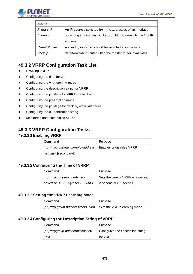
478
Users Manual of GPL-8000
Master
Primary IP
Address
An IP address selected from the addresses of an interface
according to a certain regulation, which is normally the first IP
address
Virtual Router
Backup
A standby router which will be selected to serve as a
data-forwarding router when the master router invalidates
49.3.2 VRRP Configuration Task List Enabling VRRP
Configuring the time for vrrp
Configuring the vrrp learning mode
Configuring the description string for VRRP
Configuring the privilege for VRRP hot backup
Configuring the preemption mode
Configuring the privilege for tracking other interfaces
Configuring the authentication string
Monitoring and maintaining VRRP
49.3.3 VRRP Configuration Tasks 49.3.3.1 Enabling VRRP
Command Purpose
[no] vrrpgroup-numberip[ip-address
netmask [secondary]]
Enables or disables VRRP.
49.3.3.2 Configuring the Time of VRRP Command Purpose
[no] vrrpgroup-numbertimers
advertise <1-255>|<dsec<5-360>>
Sets the time of VRRP whose unit
is second or 0.1 second.
49.3.3.3 Setting the VRRP Learning Mode Command Purpose
[no] vrrp group-number timers learn Sets the VRRP learning mode.
49.3.3.4 Configuring the Description String of VRRP Command Purpose
[no] vrrpgroup-numberdescription
TEXT
Configures the description string
for VRRP.

479
Users Manual of GPL-8000
49.3.3.5 Configuring the Privilege for VRRP Hot Backup Command Purpose
[no] vrrp group-number
priority<1-255>
Sets the hot standby privilege level
in the VRRP router for selecting
the primary router and the standby
router.
49.3.3.6 Configuring the Preemption Mode Command Purpose
[no] vrrp group-numberpreempt
[delay<1-254>]
Sets the preemption mode.
49.3.3.7 Configuring the Privilege for Tracking Other Ports Command Purpose
[no] vrrpgroup-numbertrack typenumber [interface-priority] Configures the privilege for tracking other
ports, enabling the VRRP privilege to vary with
the state change of the tracked port. When the
tracked port invalidates, the VRRP privilege
decreases; when the tracked port resumes
effective, the VRRP privilege increases.
49.3.3.8 Configuring the Authentication String Command Purpose
[no] vrrpgroup-numberauthenticationstring Selects an authentication string, which is used to authenticate
other routers in the same group when the backup protocol
packet exchanges.
49.3.3.9 Monitoring and Maintaining VRRP Command Purpose
show vrrp [interfaceinterface-number] brief | detail Displays the running state of the current VRRP.
debug vrrp [interface
interface-numbergroup-number] all | packets | events
| errors
Debugs three kinds of VRRP events.
49.3.4 VRRP Configuration Example In the following network topology, two subnets in a same network use their own gateways (gateway A and
gateway B) respectively to access the Internet, but gateway A and gateway B are standby ones each other.
When one gateway (one router) breaks down, the other will work for the two subnets.

480
Users Manual of GPL-8000
Group 3 vip: 100.1.1.30 vmac: 00:00:5e:00:01:03
e1/1.1
e1/1.1
e2/1
e2/1
A
B
Host Tom
Host John
e1/1.2
e1/1.2
Group 6 vip: 200.1.1.30 vmac: 00:00:5e:00:01:06
F0/23
F0/22 F0/20
F0/21 vrrp
Figure 3-2 Simple VRRP application topology
The configuration is shown as follows:
Router A:
-----------------------------------
interface Ethernet1/1.1
encapsulation dot1Q 2
ip address 100.1.1.5 255.255.255.0
vrrp 3 associate 100.1.1.30 255.255.255.0
vrrp 3 priority 120
vrrp 3 description line1-master
vrrp 3 authentication line1pwd
vrrp 3 preempt
vrrp 3 timers advertise dsec 15
-----------------------------------
interface Ethernet1/1.2
encapsulation dot1Q 3
ip address 200.1.1.5 255.255.255.0
vrrp 6 associate 200.1.1.30 255.255.255.0
vrrp 6 priority 110
vrrp 6 description line2-backup
vrrp 6 authentication line2pwd
vrrp 6 preempt
vrrp 6 timers advertise dsec 15
----------------------------------
RouterB:
-----------------------------------
interface Ethernet1/1.2
encapsulation dot1Q 2
ip address 100.1.1.6 255.255.255.0
vrrp 3 associate 100.1.1.30 255.255.255.0
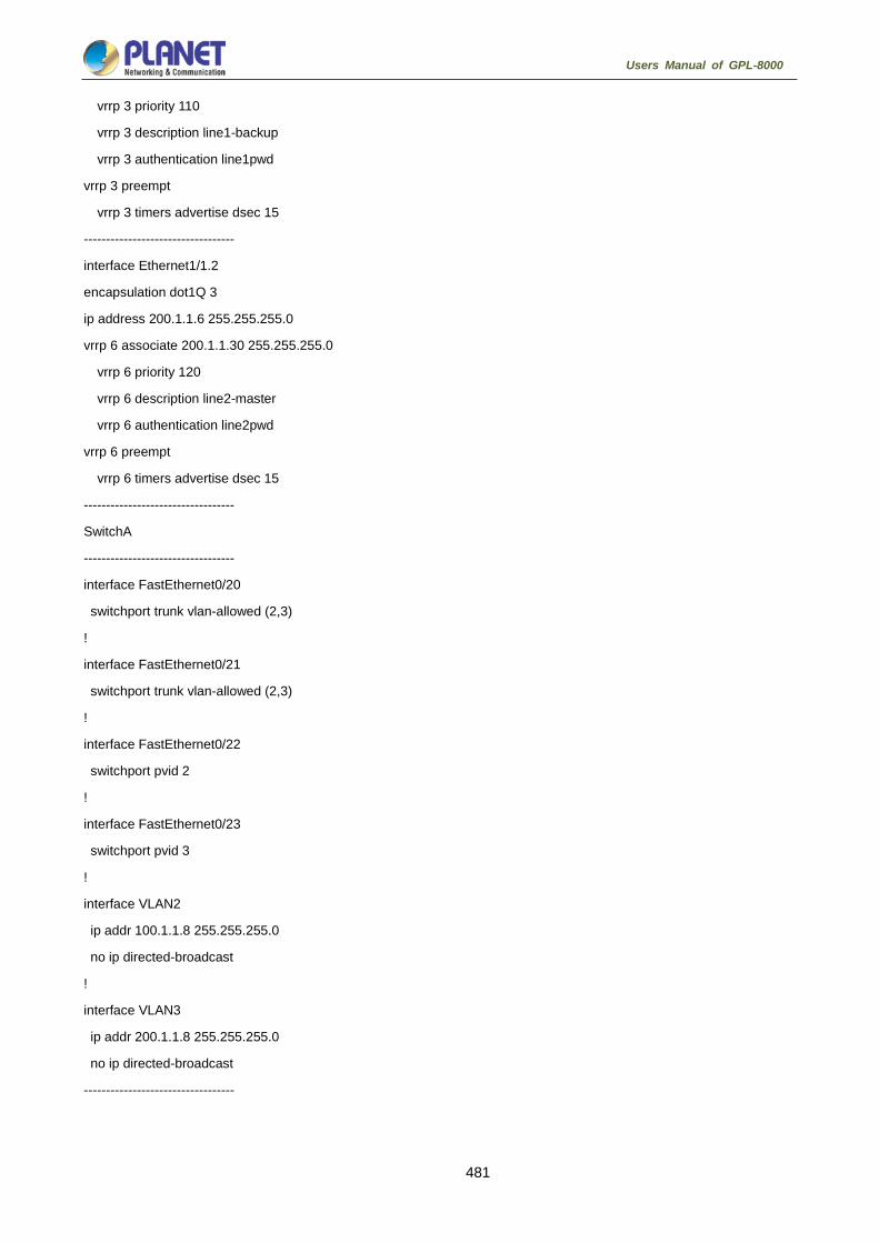
481
Users Manual of GPL-8000
vrrp 3 priority 110
vrrp 3 description line1-backup
vrrp 3 authentication line1pwd
vrrp 3 preempt
vrrp 3 timers advertise dsec 15
----------------------------------
interface Ethernet1/1.2
encapsulation dot1Q 3
ip address 200.1.1.6 255.255.255.0
vrrp 6 associate 200.1.1.30 255.255.255.0
vrrp 6 priority 120
vrrp 6 description line2-master
vrrp 6 authentication line2pwd
vrrp 6 preempt
vrrp 6 timers advertise dsec 15
----------------------------------
SwitchA
----------------------------------
interface FastEthernet0/20
switchport trunk vlan-allowed (2,3)
!
interface FastEthernet0/21
switchport trunk vlan-allowed (2,3)
!
interface FastEthernet0/22
switchport pvid 2
!
interface FastEthernet0/23
switchport pvid 3
!
interface VLAN2
ip addr 100.1.1.8 255.255.255.0
no ip directed-broadcast
!
interface VLAN3
ip addr 200.1.1.8 255.255.255.0
no ip directed-broadcast
----------------------------------
482
Users Manual of GPL-8000
Multicast Configuration
Multicast Overview The chapter describes how to cofigure the multicast routing protocol. For the details of the multicast routing
commands, refer to the part “Multicast Routing Commands”.
The traditional IP transmission allows only one host to communicate with a single host (unicast
communication) or to communicate with all hosts (broadcast communication). The multicast technology
allows one host to send message to some hosts. These hosts are called as group members.
The destination address of the message sent to the group member is a D-class address
(224.0.0.0~239.255.255.255). The multicast message is transmitted like UDP. It does not provide reliable
transmission and error control as TCP does.
The sender and the receiver make up of a multicast application. The sender can send the multicast message
without joining in a group. However, the receiver has to join in a group before it receives the message from the
group.
The relationship between group members is dynamic. The host can join in or leave a group at any time. There
is no limitation to the location and number of the group member. If necessary, a host can be a member of
multiple groups. Therefore, the state of the group and the number of group members varies with the time.
The router can maintain the routing table for forwarding multicast message by executing the multicast routing
protocol such as PIM-DM and PIM-SM. The router learns the state of the group members in the
directly-connected network segment through IGMP. The host can join in a designated IGMP group by sending
the IGMP Report message.
The IP multicast technology is suitable for the one-to-multiple multimedia application.
50.1.1 Multicast Routing Realization In the router software of our router, the multicast routing includes the following regulations:
IGMP runs between the router and the host in the LAN, which is used to track the group member
relationship.
OLNK is a static multicast technology, which is used in the simple topology. It realizes the multicast
forwarding and effectively saves CPU and bandwidth.
PIM-DM, PIM-SM and DVMRP is dynamic multicast routing protocols. They run between routeres and
realizes the multicast forwarding by creating the multicast routing table.
The following figure shows the multicast protocols used in the IP multicast applications:

483
Users Manual of GPL-8000
50.1.2 Multicast Routing Configuration Task List 50.1.2.1 Basic Multicast Configuration Task List Starting up the multicast routing (mandatory)
Configuring TTL threshold (optional)
Canceling rapid multicast forwarding (optional)
Configuring static multicast route (optional)
Configuring multicast boundary (optional)
Configuring multicast helper (optional)
Configuring Stub multicast route (optional)
Monitoring and maintaining multicast route (optional)
50.1.2.2 IGMP Configuration Task List Modifying the current version of IGMP
Configuring the IGMP query interval
Configuring IGMP Querier interval
Configuring the maximum response time of IGMP
Configuring the query interval of the last IGMP group member
Static IGMP configuration
Configuring the IGMP Immediate-leave list
50.1.2.3 PIM-DM Configuration Task List Regulating the timer
Designate the PIM-DM version
Configuring the state refreshment
Configuring the filtration list
Setting the DR priority
Clearing (S,G) information

484
Users Manual of GPL-8000
50.1.2.4 PIM-SM Configuration Task List Configuring static RP
Configuring standby BSR
Configuring standby RP
Displaying PIM-SM multicast routing
Clearing multicast routes learned by PIM-SM
Basic Multicast Routing Configuration 50.2.1 Starting up Multicast Routing To allow the router software to forward the multicast message, you must start up the multicast routing. Run the
following command in global configuration mode to start up the multicast message forwarding:
Command Purpose
ip multicast-routing Starts up the multicast routing.
50.2.2 Starting up the Multicast Function on the Port When the multicast routing protocol runs on a port, the IGMP is activated on the port. The multicast routing
protocols include OLNK, PIM-DM, PIM-SM and DVMRP. Only one multicast routing protocol is allowed to run
on the same port. When the router connects multiple multicast domains, different multicast protocols can be
run on different ports.
Although the router software can function as the multicast boundary router (MBR). If possible, do not
simultaneously run multiple multicast routing protocols on the same router for some multicast routing
protocols may be badly affected. For example, when PIM-DM and BIDIR PIM-SM simultaneously run,
confusion is to occur.
50.2.2.1 Starting up PIM-DM Run the following command to run PIM-DM on a port and then activate the multicast dense mode function:
Command Purpose
ip pim-dm
Enters the port where PIM-DM is running and then
activates PIM-DM multicast routing process in port
configuration mode.
50.2.2.2 Starting up PIM-SM To run PIM-DM on a port and activate the PIM-DM multicast, perform the following operation:
Command Purpose
ip pim-sm
Enters a port where PIM-SM needs to run and then
activates the PIM-SM multicast routing process in
port configuration mode.

485
Users Manual of GPL-8000
50.2.3 Configuring TTL Threshold Run the command ip multicast ttl-threshold to configure the TTL threshold of the multicast message that is
allowed to pass the port. Run the command no ip multicast ttl-threshold to use the default threshold value
1.
Command Purpose
ip multicast ttl-thresholdttl-value Configures the TTL threshold on the
port.
Example
The following example shows how the administrator configures the TTL threshold on a port:
interface ethernet 1/0
ip multicast ttl-threshold 200
50.2.4 Cancelling Rapid Multicast Forwarding Run the command ip multicast mroute-cache to configure the rapid multicast forwarding function on a port.
Run the command no ip multicast mroute-cache to cancel the rapid multicast forwarding function.
Command Purpose
ip multicast mroute-cache Enables the rapid multicast forwarding
function on a port.
Example
The following example shows how the administrator cancels the rapid multicast forwarding function on a port:
interface ethernet 1/0
no ip mroute-cache
50.2.5 Configuring Static Multicast Route The static multicast route allows that the multicast forwarding path is different from the unicast path. RPF
check is performed when the multicast message is forwarded. The actual port receiving the message is the
expected receiving port. That is, the port is the next-hop port of the unicast route that reaches the sender. If
the unicast topology is same to the multicast topology, RPF check is reasonable. In some cases, the unicast
path requires to be different from the multicast path.
Take the tunnel technology as an example. When a router in a path does not support the multicast protocol,
the resolution is to configure the GRE tunnel between two routeres. In the following figure, each unicast router
supports only the unicast message; each multicast router supports only the multicast message. The source
host sends the multicast message to the destination host through MR1 and MR2. MR2 forwards the multicast
message only when it is received through the tunnel. When the destination host sends the unicast message to
the source host, the tunnel is also used. When the tunnel technology is adopted, the message transmission
speed is slower than that of the direct message transmission.

486
Users Manual of GPL-8000
After the static multicast routing is configured, the router can perform the RPF check according to the
configuration information. The RPF check is not based on the unicast routing table any more. Therefore, the
multicast message goes through the tunnel, while the unicast message does not go through the tunnel. The
static multicast route only exists in the local place. It will not be announced or forwarded.
Run the following command in global configuration mode to configure the static multicast route:
Command Purpose
ip mroutesource-address mask
rpf-addresstypenumber[ distance]
Configures the static multicast route.
50.2.6 Configuring IP Multicast Boundary Run the command ip multicast boundary to configure the multicast boundary for the port. Run the command
no ip multicast boundary to cancel the configured boundary. The commands used in the second
configuration will replace the commands used in the first configuration.
Command Purpose
ip multicast boundary access-list Configures the multicast boundary for the
port.
Example
The following example shows how to configure the management boundary for a port:
interface ethernet 0/0
ip multicast boundary acl
ip access-list standard acl
permit 192.168.20.97 255.255.255.0
50.2.7 Configuring IP Multicast Rate Control Run the command ip multicast rate-limit to limit the rate of receiving and sending the multicast message in a
source/group range. Run the command noip multicastrate-limit to cancel the rate limitation.
Run the following command to limit the input rate of a multicast flow to n kbps.
Command Purpose
ip multicast rate-limit in group-list
access-list1 source-list access-list2
nkbps
Configures the maximum input rate
limitation of the multicast flow in a certain
range.

487
Users Manual of GPL-8000
Run the following command to limit the output rate of a multicast flow to n kbps
Command Purpose
ip multicast rate-limit
outgroup-listaccess-list1 source-list
access-list2 kbps
Configures the maximum output rate
limitation of the multicast flow in a certain
range.
50.2.8 Configuring IP Multicast Helper Run the command ip multicast helper-map to use the multicast route to connect two broadcast networks in
the multicast network. Run the command no ip multicast helper-map to cancel the command.
Command Purpose
interfacetype number Enters the interface configuration
mode.
ip multicast helper-map
broadcastgroup-address access-list
Configures the command ip multicast
helper to convert the broadcast
message to the multicast message.
ip directed-broadcast Allows the directional broadcast.
ip forward-protocol [port] Configures the port number allowing to
forward the message.
On the last-hop router connecting the destination broadcast network, perform the following operations:
Command Purpose
interface type number Enters the interface configuration
mode.
ip directed-broadcast Allows the directional broadcast.
ip multicast
helper-mapgroup-address
broadcast-address access-list
Configures the command ip multicast
helper to convert the multicast
message to the broadcast message.
ip forward-protocol [port] Configures the port number allowing to
forward the message.
Example
The following example shows how to configure the command ip multicast helper.
The configuration of the router is shown in the following figure. Configure the command ip directed-broadcast
on the e0 port of the first-hop router to handle the directional message. Configure ip multicast helper-map
broadcast 230.0.0.1 testacl1, allowing to convert the UDP broadcast message with port number 4000 that is
sent from the source address 192.168.20.97/24 to the multicast message with the destination address
230.0.0.1.
Configure the command ip directed-broadcast on the e1 port of the last-hop router to handle the directional
message. Configure ip multicast helper-map 230.0.0.1 172.10.255.255 testacl2, allowing to convert the

488
Users Manual of GPL-8000
multicast message with port number 4000 and the destination address 230.0.0.1 that is sent from the source
address 192.168.20.97/24 to the broadcast message with the destination address 172.10.255.255.
In the first-hop router connecting the source broadcast network, perform the following operations: (the router
is configured on the VLAN port)
interface ethernet 0
ip directed-broadcast
ip multicast helper-map broadcast 230.0.0.1 testacl
ip pim-dm
!
ip access-list extended testacl permit udp 192.168.20.97 255.255.255.0 any
ip forward-protocol udp 4000
In the last-hop router connecting the destination broadcast network, perform the following operations:
interface ethernet 1
ip directed-broadcast
ip multicast helper-map 230.0.0.1 172.10.255.255 testacl2
ip pim-dm
!
ip access-list extended testacl2 permit udp 192.168.20.97 255.255.255.0 any
ip forward-protocol udp 4000
50.2.9 Configuring Stub Multicast Route Run the commands ip igmp helper-address and ip pim-dm neighbor-filter to configure the Stub multicast
route.
On the port where the stub router and the host are connected, perform the following operations:
Command Purpose
interfacetype number Enters the interface configuration mode.
ip igmp helper-address destination-address
Configures the command ip igmp
helper-address to forward the multicast
message to the central router.
On the port where the central router and the stub router are connected, perform the following operations:
Command Purpose
interface type number Enters the interface configuration mode.
ip pim neighbor-filter access-list Filters all pim messages on the stub
router.

489
Users Manual of GPL-8000
Example
The configuration of router A and B is shown as follows:
Stub Router A Configuration
ip multicast-routing
ip pim-dm
ip igmp helper-address 10.0.0.2
Central Router B Configuration
ip multicast-routing
ip pim-dm
ip pim-dm neighbor-filter stubfilter
ip access-list stubfilter
deny 10.0.0.1
50.2.10 Monitoring and Maintaining Multicast Route 50.2.10.1 Clearing the multicast cache and the routing table If special caches or the routing table is invalid, you need to clear its content. Run the following commands in
management mode:
Command Purpose
clear ip igmp group [type number]
[group-address | <cr>]
Clears the items in the IGMP cache.
clear ip mroute[* | group-address |
source-address]
Clears the items in the multicast routing
table.
50.2.10.2 Displaying the multicast routing table and system statistics information The detailed information about the IP multicast routing table, cache or database helps to judge how the
resources are used and to resolve network problems.
Run the following commands in management mode to display the statistics information about the multicast
route:
Command Purpose
show ip igmp groups [type
number | group-address] [detail]
Displays the information about the
multicast group in the IGMP cache.
show ip igmp interface [type
number]
Displays the IGMP configuration
information on the interface.
show ip mroute mfc Displays the multicast forwarding cache.
show ip rpf [ucast | mstatic | pim-dm
| pim-sm | dvmrp] source-address
Displays the RPF information.

490
Users Manual of GPL-8000
IGMP Configuration 50.3.1 Overview 50.3.1.1 IGMP Internet Group Management Protocol (IGMP) is a protocol used to manage multicast group members. IGMP
is an asymmetric protocol, containing the host side and the switch side. At the host side, the IGMP protocol
regulates how the host, the multicast group member, reports the multicast group it belongs to and how the
host responds to the query message from the switch. At the switch side, the IGMP protocol regulates how the
IGMP-supported switch learns the multicast group member ID of the hosts in the local network and how to
modify the stored multicast group member information according to the report message from the host.
Since our switches support the IGMP Router protocol, the multicast routing protocol can be provided with the
information about the multicast group members in the current network and the switch decides whether to
forward the multicast message. In a word, to enable the switch support the multicast process of the IP
message, the switch need be configured to support the multicast routing protocol and the IGMP Router
protocol. Currently, MY COMPANY' switches support the IGMP Router protocol and version 3 IGMP, the latest
version.
There is no independent startup commands for IGMP. The function of the IGMP-Router protocol is started up
through the multicast routing protocol.
50.3.1.2 OLNK Strictly speaking, the IGMP only-link protocol (OLNK) is not a multicast routing protocol because it has no
interaction process as other protocols. However, in some special cases, running OLNK in the simple topology
will get nice results. Similar to the PIM-DM protocol which also has no negotiation process, OLNK can handle
the change of IGMP group members and promptly adjust the RPF interface according to the topology change.
In this way, OLNK ensures the multicast forwarding and prevents the control messages of the multicast
routing protocol from occupying the bandwidth.
50.3.2 IGMP Configuration The commands to configure the attributes of the IGMP-Router mainly are the commands to adjust the IGMP
parameters. The following is to describe these commands. For details about these commands, refer to
explanation documents relative to the IGMP commands.
50.3.2.1 Changing Current IGMP Version Up to now, the IGMP protocol has three formal versions. The corresponding RFCs are RFC1112, RFC2236
and RFC3376. IGMP V1 supports only the function to record the multicast group members. IGMP V2 can
query the designated multicast group member, generates the leave message when an IGMP host leaves a
multicast group, and shortens the change delay of the group member. IGMP V3 has additional functions to
update and maintain the multicast group member IDs which correspond to the source host addresses. The
IGMP Router protocol of IGMP V3 is fully compatible with the host side of IGMP V1 and IGMP V2. MY
COMPANY’s switch software supports the IGMP Router protocols of the three IGMP versions.

491
Users Manual of GPL-8000
You can configure the IGMP-Router function at different interfaces (the multicast routing protocol configured
on different interfaces can start up the IGMP-Router function) and different versions of IGMP can be run on
different interfaces.
Note that a multicast switch can start up the IGMP-Router function on only one of the ports that connect the
same network.
Run the following command in interface configuration mode to change the version of the IGMP-Router
protocol on a port:
Command Purpose
ip igmp versionversion_number Changes the IGMP version running on
the current port.
50.3.2.2 Configuring IGMP Query Interval No matter what version number of the current IGMP-Router protocol is, the multicast switch can send the
IGMP General Query message every a certain time on the port where the IGMP-Router function is started.
The transmission address is 224.0.0.1. The purpose of the multicast switch is to get the report message from
the IGMP host and therefore know which multicast group each IGMP host in the network belongs to. The
interval to send the General Query message is called as IGMP Query Interval. If the parameterIGMP Query
Interval is set to a big value, the switch cannot immediately receive the information about which multicast
group the current IGMP host belongs to. If the parameter IGMP Query Interval is set to a small value, the flow
of the IGMP message is to increase in the current network.
Run the following command in interface configuration mode to modify the IGMP query interval on a port:
Command Purpose
ip igmp query-intervaltime Modifies the IGMP query interval on
the current interface (unit: second).
50.3.2.3 Configuring IGMP Querier Interval As to version 2 and version 3 of the IGMP-Router protocol, if another switch that runs the IGMP-Router
protocol exists in the same network, you need to choose a querier. Querier stands for a switch that can send
the query message (In fact, it is a port of the switch where the IGMP-Router protocol is enabled). Normally,
one network has only one querier, that is, only one switch sends the IGMP Query message. There is no
querier choice for IGMP-Router V1 because the multicast routing protocol decides which switch to send the
IGMP Query message in IGMP-Router V1.
IGMP-Router V2 and IGMP-Router V3 have the same querier choice mechanism, that is, the switch with the
minimum IP address is the querier in the network. The switch that is not the querier needs to save a clock to
record the existence of the querier. If the clock times out, the non-querier switch turns to be the querier until it
receives the IGMP Query message from the switch with a smaller IP address.
For IGMP-Router V2, you can configure other querier intervals using the following command:
Command Purpose
ip igmpquerier-timeouttime Configures the interval for other queriers (unit: second).

492
Users Manual of GPL-8000
For IGMP-Router V1, the interval of other queriers is useless. For IGMP-Router V3, the interval cannot be
configured because it is decided by the protocol itself.
50.3.2.4 Configuring Maximum IGMP Response Time For IGMP-Router V2 and IGMP-Router V3, special data field in the transmitted IGMP General Query
message regulates the maximum response time of the IGMP host. That is, the IGMP host has to send the
response message before the regulated maximum response time expires, indicating that the General Query
message is received. If the maximum response time is set to a big value, the change of multicast group
members delays. If the maximum response time is set to a small value, the flow of the IGMP message will be
increased in the current network.
The maximum IGMP response time must be shorter than the IGMP query interval. If
the value of the maximum response time is bigger than the query interval, the
system will automatically set the maximum response time to query-interval – 1.
For IGMP-Router V2 and IGMP-Router V3, run the following command in interface configuration mode to set
the maximum IGMP response time:
Command Purpose
ip igmp
query-max-response-timetime
Configures the maximum IGMP
response time (unit: second).
For IGMP-Router V1, the maximum IGMP response time is decided by the protocol itself. Therefore, the
previous command is useless to IGMP-Router V1.
50.3.2.5 Configuring IGMP Query Interval for the Last Group Member For IGMP-Router V2 and IGMP-Router V3, When the Group Specific Query message for a specific multicast
group is sent, the query interval of the last group member will be used as the maximum response time of the
host. That is, the IGMP host has to send the response message before the maximum response time of the
last group member expires, indicating that the Group Specific Query message is received. If the IGMP host
finds that it need not respond to the query message, it will not respond to the message after the interval. In
this case, the multicast switch is to update the saved multicast group member information. If the query interval
of the last group member is set to a big value, the change of the multicast group member delays. If the query
interval of the last group member is set to a small value, the flow of the IGMP message is to increase in the
current network.
For IGMP-Router V2 and IGMP-Router V3, run the following command in interface configuration mode to
configure the IGMP query interval of the last group member:
Command Purpose
ip igmp
last-member-query-intervaltime
Configures the IGMP query interval of
the last group member (unit: ms).
The previous command is useless for IGMP-Router V1.

493
Users Manual of GPL-8000
50.3.2.6 Static IGMP Configuration Besides the functions regulated by the IGMP-Router protocol, BODCOM’s switches support the static
multicast group configuration on the port. For the IGMP host, its multicast group member relationship may
vary. Suppose the IGMP host only belongs to the multicast group group1, it receives the multicast message
from and sends the multicast message to the multicast group group1. After a period of time, it may belong to
the multicast group group2, and receives the multicast message from and sends the multicast message to
the multicast group group2. After another period of time, the IGMP host may not belong to any multicast
group. Therefore, the multicast group assignment information varies.
Different the above “dynamic multicast group”, if a port is configured to belong to a static multicast group, the
multicast routing protocol then takes the port as one that always receives and sends the multicast message of
the multicast group. To be better compatible with IGMP-Router V3, the static multicast group can be
configured to receive the multicast message from the designated source address, that is, the source-filter
function is added when the multicast message is received.
Run the following command in interface configuration mode to configure the static multicast group for a port:
Command Purpose
ip igmp static-group { * |
group-address}
{includesource-address | <cr> }
Configures the static multicast group attribute for a port.
50.3.2.7 Configuring the IGMP Immediate-leave List If IGMP V2 is started up on a port of the switch and the network that the port connects has only one IGMP
host, you can realize the Immediate Leave function of the IGMP host by configuring the IGMP
Immediate-leave list. According to the regulations of IGMP V2, when a host leaves a specific multicast group,
the host will send the Leave message to all multicast switches. After receiving the Leave message, the
multicast switches send the Group Specific message to confirm whether any multicast message to be
received from or sent to the multicast group by the host exists on the port. If the Immediate Leave function is
configured, no message need be interacted between the IGMP host and the multicast switch, the change of
the multicast group member IDs will not be delayed.
The command can be configured both in global configuration mode and in interface
configuration mode. The priority of the command configured in global configuration
mode is higher than that configured in interface configuration mode. If the command
is first configured in global configuration mode, the command configured in
interface configuration mode will be omitted. If the command is first configured in
interface configuration mode, the command configured in global configuration mode
will delete the command configured in interface configuration mode.
For IGMP-Router V2, run the following command in interface configuration mode to configure the IGMP
Immediate-leave list:

494
Users Manual of GPL-8000
Command Purpose
ip igmp immediate-leave
group-listlist-name
Configures the access list that
realizes the function to immediately
leave the multicast group for the IGMP
host.
ip access-list standardlist-name Creates a standard IP access list
named list-name.
permitsource-address
Configures the IP address for the
IGMP host that will realize the
immediate-leave function in standard
access-list configuration mode.
The previous command is invalid to IGMP-Router V1 and IGMP-Router V3.
50.3.3 IGMP Characteristic Configuration Example All configurations about the IGMP characteristics are performed in VLAN port.
50.3.3.1 Example for changing the IGMP version The IGMP-Router protocol of latter version is compatible with the IGMP host of low version, but cannot be
compatible with the IGMP-Router protocol of the earlier version. Therefore, if, there are switches running the
IGMP-Router protocol of the earlier version in the current network, you need to change the IGMP-Router
protocol of latter version to the IGMP-Router protocol of earliest version in the same network segment.
Suppose the administrator knows that switches running IGMP-Router V1 and IGMP-Router V2 exist in a
network that the local switch connects, the administrator needs to change the version of the IGMP-Router
protocol from version 2 to version 1 on a port of the switch that runs IGMP-Router V2.
interface ethernet 1/0
ip igmp version 1
50.3.3.2 IGMP query interval configuration example The following example shows how to modify the IGMP query interval to 50 seconds on the interface ethernet
1/0:
interface ethernet 1/0
ip igmp query-interval 50
50.3.3.3 IGMP Querier interval configuration example The following example shows how to modify the IGMP Querier interval to 100 seconds on the interface
ethernet 1/0:
interface ethernet 1/0
ip igmp querier-timeout 100

495
Users Manual of GPL-8000
50.3.3.4 Maximum IGMP response time example The following example shows how to modify the maximum IGMP response time to 15 seconds on the
interface ethernet 1/0:
interface ethernet 1/0
ip igmp query-max-response-time 15
50.3.3.5 Example for configuring IGMP query interval for the last group member The following example shows how to modify the IGMP query interval of the last group member to 2000 ms on
the interface ethernet 1/0:
interface ethernet 1/0
ip igmp last-member-query-interval 2000
50.3.3.6 Static IGMP configuration example The configuration command of the static multicast group can define different classes of static multicast groups
by adopting different parameters. The following examples shows the results of running different command
parameter.
interface ethernet 1/0
ip igmp static-group *
The previous configuration command configures all static multicast groups on the interface ethernet 1/0. The
multicast routing protocol is to forward all IP multicast messages to the interface ethernet 1/0.
interface ethernet 1/0
ip igmp static-group 224.1.1.7
The previous configuration command configures the static multicast group 224.1.1.7 on the interface ethernet
1/0, that is, the interface belongs to the multicast group 224.1.1.7. The multicast routing protocol is to forward
all IP multicast messages that are finally sent to the multicast group 224.1.1.7 to the interface ethernet 1/0.
interface ethernet 1/0
ip igmp static-group 224.1.1.7 include 192.168.20.168
The previous configuration command configures the static multicast group 224.1.1.7 on the interface ethernet
0/0, and defines source-filter of the multicast group as 192.168.20.168. That is, the interface belongs to the
multicast group 224.1.1.7, but it only receives the IP multicast messages from 192.168.20.168. The multicast
routing protocol is to forward IP multicast messages that are received from 192.168.20.168 and finally sent to
the multicast group 224.1.1.7 to the interface ethernet 0/0.
Run the following command in interface configuration mode to receive the IP multicast message that is from
192.168.20.169 and finally sent to the multicast group 224.1.1.7:
ip igmp static-group 224.1.1.7 include 192.168.20.169
The previous command can be executed for many times to define different source addresses.

496
Users Manual of GPL-8000
In a multicast group, the multicast group information cannot be simultaneously
configured both for a specific source address and for all source addresses. The
command used in the later configuration will be omitted. For example, If you run the
command ip igmp static-group 224.1.1.7 include 192.168.20.168 after the
command ip igmp static-group 224.1.1.7 is executed, the command ip igmp
static-group 224.1.1.7 include 192.168.20.168 will be omitted.
50.3.3.7 IGMP Immediate-leave list configuration example The following example shows how to set the access list to imme-leave on the interface ethernet 1/0 with the
immediate-leave function and to add the IP address 192.168.20.168 of the IGMP host to the access list. The
configuration ensures that the IGMP host with IP address 192.168.20.168 realizes the immediate-leave
function.
interface ethernet 1/0
ip igmp immediate-leave imme-leave
exit
ip access-list standard imme-leave
permit 192.168.20.168
PIM-DM Configuration 50.4.1 PIM-DM Introduction Protocol Independent Multicast Dense Mode (PIM-DM) is a multicast routing protocol in dense mode. By
default, when the multicast source starts to send the multicast data, all network nodes in the domain receive
the data. Therefore, PIM-DM forwards the multicast packets in broadcast-pruning mode. When the multicast
source starts to send data, the switches alongside forward the multicast packets to all PIM-activated
interfaces except the RPF interface. In this way, all network nodes in the PIM-DM domain can receive these
multicast packets. To finish the multicast forwarding, the switches alongside need create the corresponding
multicast routing item (S,G) for group G and its source S. The routing item (S,G) includes the multicast source
address, multicast group address, incoming interface, outgoing interface list, timer and logo.
If there is no multicast group member in a certain network segment, PIM-DM will send the pruning information,
prune the forwarding interface connecting the network segment and then establish the pruning state. The
pruning state corresponds to the timeout timer. When the timer times out, the pruning state turns to be the
forwarding state again and the multicast data can be forwarded along these branches. Additionally, the
pruning state contains information about the multicast source and the multicast group. When the multicast
group member appears in the pruning area, PIM-DM actively sends the graft message to the upper field
without waiting for the pruning state of the upper field to time out, turning the pruning state to the forwarding
state.

497
Users Manual of GPL-8000
As long as source S still sends information to group G, the first-hop switch will periodically send the refreshing
information of the routing item (S,G) to the nether original broadcast tree to finish refreshing. The state
refreshing mechanism of PIM-DM can refresh the state of the downstream, ensuring that the pruning of the
broadcast tree does not time out.
In the multi-access network, besides the DR selection, PIM-DM also introduces the following mechanisms:
Use the assertion mechanism to select the unique forwarder to prevent the multicast packet from being
repeatedly forwarded.
Use the add/prune restraint mechanism to reduce redundant add/prune information.
Use the pruning deny mechanism to deny improper pruning actions.
In the PIM-DM domain, the switches that run PIM-DM periodically send the Hello information to achieve the
following purposes:
Discover neighboring PIM switches.
Judge leaf networks and leaf switches.
Select the designated router (DR) in the multi-access network.
To be compatible with IGMP v1, PIM-DM is in charge of the DR choice. When all PIM neighboring routers on
the interface support DR Priority, the neighboring router with higher priority is selected as the DR. If the priority
is the same, the neighboring router with the maximum interface IP value is selected as the DR. If the priority is
not shown in the Hello message of multiple routers, the router whose interface has the biggest IP value is
selected as the DR.
The PIM-DM v2 of DBCOM’s switches supports the neighbor filtration list, CIDR, VLSM and IGMP v1-v3.
50.4.2 Configuring PIM-DM 50.4.2.1 Modifying Timer The routing protocol adopts several timers to judge the transmission frequency of Hello message and
state-refresh control message. The interval to transmit the Hello message affects whether the neighbor
relationship can correctly created.
Run the following commands in switch configuration mode to regulate the timer:
Command Purpose
ip pim-dm hello-interval Sets the interval (unit: second) to
send the Hello message from the
interface and the neighbor.
Ippim-dm state-refresh
rigination-interval
For the first-hop switch directly
connecting the source, the interval to
send the state-refresh message is
only valid to the configurations at the
upstream ports. For the following
switches, the interval is the period to
receive and handle the state-refresh
message.

498
Users Manual of GPL-8000
50.4.2.2 Configuring State-Refresh The state-refresh control information of the PIM-DM is forwarded in management mode by default. The
configuration commands in interface configuration mode are effective only to the configurations at the
upstream ports when the first-hop switch directly connecting the source sends the state-refresh message
periodically. For the following switches, the interval is the period to receive and handle the state-refresh
message.
Command Purpose
no ip pim-dm state-refresh disable Allows to send and receive the
state-refresh message on the port.
ip pim-dm state-refresh
origination-interval
Configures the interval to send and
receive the state-refresh message on
the port.
50.4.2.3 Configuring Filtration List PIM-DM does not set the filtration list by default. The referred filtration list includes the neighbor filtration list
and the multicast boundary filtration list. The filtration list requires to be configured in interface configuration
mode.
To forbid a switch or switches at a network segment to join in the PIM-DM negotiation, the neighbor filtration
list need be configured. To forbid or permit some groups to pass the local region, the multicast boundary
filtration list need be configured.
Command Purpose
ip pim-dm neighor-filter Configures the neighbor filtration list.
ip multicast boundary Configures the multicast boundary
filtration list.
50.4.2.4 Setting DR Priority To be compatible with IGMP v1, the DR choice is required. By default, the priority of the DR is set to 1. When
all PIM neighboring routers on the interface support DR Priority, the neighboring router with higher priority is
selected as the DR. If the priority is the same, the neighboring router with the maximum interface IP value is
selected as the DR. If the priority is not shown in the Hello message of multiple routers, the router whose
interface has the biggest IP value is selected as the DR.
Run the following command in interface configuration mode:
Command Purpose
ip pim-dm dr-priority Configures the priority for the local DR
on the designated port.

499
Users Manual of GPL-8000
50.4.2.5 Clearing Item (S,G) Normally, item (S,G) in the local MRT or the statistics value of the multicast message number forwarded
through item (S,G) need be cleared. Run the following commands in management mode.
Command Purpose
clear ip mroute pim-dm {* | group
[source]}
Clears the item (S,G) in the local MRT.
The operation is to delete all or part items of the
local multicast routing table. Multicast message
forwarding may be affected. The command is
used to delete only the (S,G) items created by
the PIM-DM multicast routing protocol on the
upstream ports.
clear ip pim-dm interface Resets the statistics value of multicast message
forwarded by (S,G) on the PIM-DM port. The
command is used to reset only the (S,G) items
created by the PIM-DM multicast routing protocol
on the upstream ports.
50.4.3 PIM-DM State-Refresh Configuration Example Refer to section 4.2.2 “Configuring State-Refresh”.
Configuring PIM-SM 50.5.1 PIM-SM Introduction Protocol Independent Multicast Spare Mode (PIM-SM) is a multicast routing protocol in sparse mode. In the
PIM-SM domain, the switches that run PIM-SM periodically send the Hello information to achieve the
following purposes:
Discover neighboring PIM-SM switches.
Select the designated router (DR) in the multi-access network.
As shown in the following figure, the DR sends the join/prune message to the directly-connected group
members at the direction of multicast distribution tree, or sends the data of the directly-connected multicast
source to the multicast distribution tree.

500
Users Manual of GPL-8000
Figure 5-1 Join-in mechanism of PIM-SM
PIM-SM forwards the multicast packet by creating the multicast distribution tree. The multicast distribution
tree can be classified into two groups: Shared Tree and Shortest Path Tree. Shared Tree takes the RP of
group G as the root, while Shortest Path Tree takes the multicast source as the root. PIM-SM creates and
maintains the multicast distribution tree through the displayed join/prune mode. As shown in Figure 5-1, when
the DR receives a Join message from the receiving side, it will multicast a (*, G)-join message at each hop
towards the RP of group G to join in the shared tree. When the source host sends the multicast message to
the group, the packet of the source host is packaged in the registration message and unicast to the RP by the
DR; The RP then sends the unpackaged packet of the source host to each group member along the shared
tree; The RP sends the (S,G)-join message to the first-hop switch towards the source’s direction to join in the
shortest path tree of the source; In this way, the packet of the source will be sent to the RP along the shortest
path tree without being packaged; When the first multicast data arrives, the RP sends the registration-stop
message to the DR of the source and the DR stops the registration-packaged process. Afterwards, the
multicast data of the source is not packaged any more, but it will be sent to the RP along the shortest path
three of the source and then sent to each group member by the RP along the shared tree. When the multicast
data is not needed, the DR multicasts the Prune message hop by hop towards the RP of group G to prune the
shared tree.
PIM-SM also deals with the RP choice mechanism. One or multiple candidate BSRs are configured in the
PIM-SM domain. You can select a BSR among candidate BSRs according to certain regulations. Candidate
RPs are also configured in the PIM-SM domain. These candidate RPs unicast the packets containing RP’s
address and multicast groups to the BSR. The BSR regularly generates the Bootstrap message containing a
series of candidate RPs and corresponding group addresses. The Bootstrap message is sent hop by hop in
the whole domain. The switch receives and stores the Bootstrap message. After the DR receives a report

501
Users Manual of GPL-8000
about a group member’s relationship from the directly-connected host, if the DR has no the routing item of the
group, the DR will map the group address to a candidate RP through the Hash algorithm. The DR then
multicasts the Join/prune message hop by hop towards the RP. Finally, the DR packages the multicast data in
the registration message and unicasts it to the RP.
50.5.2 Configuring PIM-SM 50.5.2.1 Starting up PIM-SM Run the following command to run PIM-SM on the interface to activate the multicast function in sparse mode:
Command Purpose
ip pim-sm
Enters the interface where PIM-SM
needs to be run and activates the
PIM-SM multicast routing process in
interface configuration mode.
50.5.2.2 Configuring Static RP If the network scale is small, you can configure the static RP to use PIM-SM. The RP configuration of all
routers in the PIM-SM domain must be same, ensuring the PIM-SM multicast route is correct.
If some router in the PIM-SM domain runs the BSR, the RP check follows the order: the static RP with
override configured is preferred. If the override is not configured for the static RP, the RP in the RP mapping
list distributed by the BSR is preferred.
Run the following command in global configuration mode:
Command Purpose
ip pim-sm rp-address rp-add
[override|acl-name]
no ip pim-sm rp-address rp-add
Configures the static RP for the local
switch.
50.5.2.3 Configuring Candidate BSR The configuration of the candidate RP can generate the unique global BSR in the PIM-SM domain. The global
BSR collects and distributes the RP in the domain, ensuring the RP mapping is unique.
Run the following command in global configuration mode:
Command Purpose
ip pim-sm bsr-candidatetype
number [hash-mask-length] [priority]
no ip pim-sm bsr-candidate type
number
Configures the local switch as the
candidate BSR, and competes the
global BSR by learning the BSM
message.

502
Users Manual of GPL-8000
50.5.2.4 Configuring Candidate RP Configure the candidate RP to enable it to be sent to the BSR periodically and then be diffused to all PIM-SM
routers in the domain, ensuring the RP mapping is unique.
Run the following command in global configuration mode:
Command Purpose
ip pim-sm rp-candidate
[typenumber] [interval|group-list acl-name]
no ip pim-sm rp-candidate [typenumber]
Configures the local switch as the candidate RP. After the
candidate RP is configured, it will be sent to the BSR
periodically. The BSR then broadcasts all PIM-SM routers in
the PIM-SM domain.
50.5.2.5 Displaying PIM-SM Multicast Route Run the following command to check the multicast route information learned by PIM-SM:
Command Purpose
show ip mroute pim-sm [group-address] [source-address]
[typenumber] [summary] [count]
[active kbps]
Displays the PIM-SM multicast route information.
50.5.2.6 Clearing Multicast Routes Learned by PIM-SM Run the following command to clear multicast routes learned by PIM-SM:
Command Purpose
clear ip mroute pim-sm [ * |
group-address ] [source-address]
Clears information about the PIM-SM multicast routes.
50.5.3 Configuration Example 50.5.3.1 PIM-SM Configuration Example (The switch is configured on the VLAN port) The following examples show how two switches learn and forward the PIM-SM multicast routes.
Device A:
!
ip multicast-routing
!
interface Loopback0
ip address 192.166.100.142 255.255.255.0
ip pim-sm
!
interface Ethernet1/1
ip address 192.166.1.142 255.255.255.0
ip pim-sm
ip pim-sm dr-priority 100

503
Users Manual of GPL-8000
!
interface Serial2/0
ip address 192.168.21.142 255.255.255.0
physical-layer speed 128000
ip pim-sm
!
router rip
network 192.168.21.0
network 192.166.1.0
network 192.166.100.0
version 2
!
ip pim-sm bsr-candidate Loopback0 30 201
ip pim-sm rp-candidate Loopback0
!
Device B:
!
ip multicast-routing
!
interface Ethernet0/1
ip address 192.168.200.144 255.255.255.0
ip pim-sm
ip pim-sm dr-priority 200
!
interface Serial0/0
ip address 192.168.21.144 255.255.255.0
ip pim-sm
!
50.5.3.2 BSR Configuration Example (The switch is configured on the VLAN port) The following example shows the BSR configuration of two switches.
Device A:
!
ip multicast-routing
!
interface Loopback0
ip address 192.166.100.142 255.255.255.0
ip pim-sm
!
interface Ethernet1/1

504
Users Manual of GPL-8000
ip address 192.166.1.142 255.255.255.0
ip pim-sm
!
interface Serial2/0
ip address 192.168.21.142 255.255.255.0
physical-layer speed 128000
ip pim-sm
!
router rip
network 192.168.21.0
network 192.166.100.0
!
ip pim-sm bsr-candidate Loopback0 30 201
!
Device B:
!
ip multicast-routing
!
interface Loopback0
ip address 192.168.100.144 255.255.255.0
ip pim-sm
!
interface Ethernet0/1
ip address 192.168.200.144 255.255.255.0
ip pim-sm
!
interface Serial0/0
ip address 192.168.21.144 255.255.255.0
ip pim-sm
!
ip pim-sm bsr-candidate Loopback0 30
!
IPv6 Configuration
IPv6 Protocol’s Configuration The configuration of the IPv6 address of the router only takes effect on the VLAN interface, not on the
physical interface.
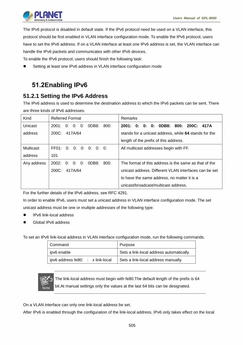
505
Users Manual of GPL-8000
The IPv6 protocol is disabled in default state. If the IPv6 protocol need be used on a VLAN interface, this
protocol should be first enabled in VLAN interface configuration mode. To enable the IPv6 protocol, users
have to set the IPv6 address. If on a VLAN interface at least one IPv6 address is set, the VLAN interface can
handle the IPv6 packets and communicates with other IPv6 devices.
To enable the IPv6 protocol, users should finish the following task:
Setting at least one IPv6 address in VLAN interface configuration mode
Enabling IPv6 51.2.1 Setting the IPv6 Address The IPv6 address is used to determine the destination address to which the IPv6 packets can be sent. There
are three kinds of IPv6 addresses.
Kind Referred Format Remarks
Unicast
address
2001: 0: 0: 0: 0DB8: 800:
200C: 417A/64
2001: 0: 0: 0: 0DB8: 800: 200C: 417A
stands for a unicast address, while 64 stands for the
length of the prefix of this address.
Multicast
address
FF01: 0: 0: 0: 0: 0: 0:
101
All multicast addresses begin with FF.
Any address 2002: 0: 0: 0: 0DB8: 800:
200C: 417A/64
The format of this address is the same as that of the
unicast address. Different VLAN interfaces can be set
to have the same address, no matter it is a
unicast/broadcast/multicast address.
For the further details of the IPv6 address, see RFC 4291.
In order to enable IPv6, users must set a unicast address in VLAN interface configuration mode. The set
unicast address must be one or multiple addresses of the following type:
IPv6 link-local address
Global IPv6 address
To set an IPv6 link-local address in VLAN interface configuration mode, run the following commands.
Command Purpose
ipv6 enable Sets a link-local address automatically.
ipv6 address fe80: : x link-local Sets a link-local address manually.
The link-local address must begin with fe80.The default length of the prefix is 64
bit.At manual settings only the values at the last 64 bits can be designated.
On a VLAN interface can only one link-local address be set.
After IPv6 is enabled through the configuration of the link-local address, IPv6 only takes effect on the local

506
Users Manual of GPL-8000
link.
To set a global IPv6 address in VLAN interface configuration mode, run the following commands.
Command Purpose
ipv6 address autoconfig Sets a global address
automatically.
ipv6 address [ipv6-address/prefix-length | prefix-name
sub-bits/prefix-length] | [eui-64]
Sets a global address.
ipv6 address X: X: X: X: : X/<0-128> anycast Sets an address of
unicast/broadcast/multicast.
When IPv6 is enabled through the configuration of a global address, all
interconnected IPv6 device can be handled by IPv6.
If a link-local address has not been set before the configuration of the global
address, the system will set a link-local address automatically.
Setting the IPv6 Services 51.3.1 Setting the IPv6 Services After IPv6 is enabled, all services provided by IPv6 can be set. The configurable IPv6 service is shown below:
Managing the IPv6 Link
51.3.1.1 Managing the IPv6 Link IPv6 provides a series of services to control and manage the IPv6 link. This series of services includes:
(1) Setting the transmission frequency of the ICMPv6 packet
(2) Setting the source IPv6 route
(3) Setting the MTU of IPv6
(4) Setting IPv6 redirection
(5) Setting IPv6 destination unreachability
(6) Setting IPv6 ACL
(7) Setting IPv6 Hop-Limit

507
Users Manual of GPL-8000
1. Setting the transmission frequency of the ICMPv6 packet
If you want to limit the transmission frequency of the ICMPv6 packet, run the command in the following table.
If the ICMPv6 transmission frequency is larger than the set value, the transmission frequency will be limited.
The default transmission frequency is 1000us. If you want to modify the transmission frequency, run the
following command in global mode:
Command Purpose
ipv6 icmp6-ratelimit ratelimit Sets the transmission frequency of the ICMPv6 packet.
2. Setting the source IPv6 route
IPv6 allows a host to designate the route of an IPv6 network, that is, the source route. The host can realize
the source route through using the routing header in the IPv6 packets. The router can forward packets
according to the routing header, or desert this kind of packets considering security.
The router supports the source route by default. If the source route is closed, users can run the following
command in global configuration mode to open the source route.
Command Purpose
ipv6 source-route Allows the source IPv6 route.
3. Setting the MTU of IPv6
All interfaces have a default IPv6 MTU. If the length of an IPv6 packet exceeds MTU, the router will fragment
this IPv6 packet.
To set IPv6 MTU on a specific interface, run the following command in interface configuration mode:
Command Purpose
ipv6 mtu bytes Sets IPv6 MTU on an interface.
4. Setting IPv6 redirection
Sometimes, the route selected by the host is not the best one. In this case, when a switch receives a packet
from this route, the switch will transmit, according to the routing table, the packet from the interface where the
packet is received, and forward it to another router which belongs to the same network segment with the host.
Under this condition, the switch will notify the source host of sending the packets with the same destination
address to another router directly, not by way of the switch itself. The redirection packet demands the source
host to replace the original route with the more direct route contained in the redirection packet. The operating
system of many hosts will add a host route to the routing table. However, the switch more trusts the
information getting from the routing protocol and so the host route will not be added according to this
information.
IPv6 redirection is opened by default. However, if a hot standby router protocol is configured on an interface,
IPv6 redirection is automatically closed. If the hot standby router protocol is canceled, this function will not
automatically opened.

508
Users Manual of GPL-8000
To open IPv6 redirection, run the following command:
Command Purpose
ipv6 redirects Allows IPv6 to transmit the redirection packets.
5. Setting IPv6 destination unreachability
In many cases, the system will automatically transmit the destination-unreachable packets. Users can close
this function. If this function is closed, the system will not transmit the ICMP unreachable packets.
To enable this function, run the following command:
Command Purpose
ipv6 unreachables Allows IPv6 to transmit the destination unreachable
packets.
6. Setting IPv6 ACL
Users can use ACL to control the reception and transmission of packets on a VLAN interface. If you introduce
ACL on a VLAN interface in global configuration mode and designate the filtration's direction, the IPv6 packets
will be filtered on this VLAN interface.
To filter the IPv6 packets, run the following command in interface configuration mode.
Command Purpose
ipv6 traffic-filter WORD { in |
out }
Filters the IPv6 packets in the reception or transmission
direction (in: receive; out: transmit) on a VLAN interface.
7. Setting IPv6 Hop-Limit
Users can designate a router to transmit the value of the hop-limit field in the packets (except those forwarded
packets). All those packets that this router transmits out, if the upper-level application does not apparently
designate a hop-limit value, use the set value of hop-limit. At the same time, the value of the hop-limit field is
added to the RA packets that this router transmits.
The default hop-limit value is 64. If you want to change this value, you can run the following command in
interface configuration mode.
Command Purpose
ipv6 cur-hoplimit value Designates a router to transmit the hop-limit field of the
packets.
ND Configuration
ND Overview A node (host and router) uses ND (Neighbor Discovery protocol) to determine the link-layer addresses of the
connected neighbors and to delete invalid cache rapidly. The host also uses the neighbor to discover the

509
Users Manual of GPL-8000
packet-forwarding neighboring routers. Additionally, the node uses the ND mechanism to positively trace
which neighbors are reachable or unreachable and to test the changed link-layer address. When a router or
the path to a router has trouble, the host positively looks for another working router or another path.
IPv6 ND corresponds to IPv4 ARP, ICMP router discovery and ICMP redirect.
ND supports the following link types: P2P, multicast, NBMA, shared media, changeable MTU and asymmetric
reachability. The ND mechanism has the following functions:
(1) To discover routers: how the host to locate the routers on the connected links.
(2) To discover prefixes: how the host to find a group of address prefixes, defining which destinations are
on-link on the connected links.
(3) To discover parameters: how the node to know the link-related or network-related parameters of the
transmission interface.
(4) To automatically set addresses: how the node to set the address of an interface automatically.
(5) Address solution: When the IP of a destination is given, how a node determines the link-layer address of
the on-link destination.
(6) To determine the next hop: it is an algorithm to map the IP address of a destination to the neighboring IP.
The next hop can be a router or destination.
(7) To test unreachable neighbors: how a node to determine unreachable neighbors; if neighbor is a router,
the default router can be used.
(8) To test repeated address: how a node to determine whether a to-be-used address is not used by another
node.
(9) Redirect: how a router to notify the host of the best next hop.
52.1.1 Address Resolution Address resolution is a procedure of resolving the link-layer address through node’s IP. Packet exchange is
realized through ND request and ND notification.
Configuring a static ND cache
In most cases, dynamic address resolution is used and static ND cache configuration is not needed. If
necessary, you can set static ND cache in global mode and the system will use it to translate IP into the
link-layer address. The following table shows how to set a static-IP-to-link-layer-address mapping.
Run the following relative command in global mode:
Command Purpose
ipv6 neighbor ipv6address vlan
vlanid hardware-address
Sets a static ND cache and translates
IPv6 address into a link-layer address.
52.1.2 ND Configuration The ND protocol is used not only for address resolution but for other functions such as neighbor solicitation,
neighbor advertisement, router solicitation, router advertisement and redirect.
The following commands are all run in port configuration mode:

510
Users Manual of GPL-8000
Setting the number of transmitted NSs when ND performs DAD on a local port
Before the IPv6 port is started, it should send the NS information to the local machine to find if there is any
duplicate IPv6 address existing on links through DAD.
Command Purpose
ipv6 nd dad attempts num Sets the number of transmitted NSs
when the local port performs DAD.
Setting the M flag in the RA message transmitted by the local port
The M flag indicates that the RA message host should obtain addresses through on-status automatic
configuration. To set the M flag in the RA message transmitted by the local port to 1, run the following
command.
Command Purpose
ipv6 nd managed-flag Sets the M flag in the RA message
transmitted by the local port.
Setting the NS transmission interval of the local port and the retrans-timer field in the RA message
This command can be used to set the NS transmission interval of the local switch on the local port and at the
same time the retrans-timer field in the RA message on the local port.
The host sets its retrans-timer variable according to the retrans-timer field in RA.
Command Purpose
ipv6 nd ns-interval milliseconds Means the NS retransmission interval
in the local port and the retrans-timer
field in the RA message.Its default
value is 1000ms.
Setting the O flag in the RA message transmitted by the local port
The O flag indicates that the RA message host should obtain other information through on-status automatic
configuration. To set the O flag in the RA message transmitted by the local port to 1, run the following
command:
Command Purpose
ipv6 nd other-flag Sets the O flag in the RA message
transmitted by the local port.
Setting the prefix of the RA message
The router releases address prefixes to the network host via RA message. The address prefix plus the host
address is the entire unicast address. The prefix option is carried by the RA message, and the host obtains
the IPv6 address prefix and related parameter from this option.

511
Users Manual of GPL-8000
Command Purpose
ipv6 nd prefix
{ipv6-prefix/prefix-length | default}
[no-advertise | [valid-lifetime
preferred-lifetime [off-link |
no-autoconfig]] ]
Means that the local port transmits the
prefix option's content in the RA
message.
Setting the RA transmission interval
The following command is used to set the range of RA transmission interval. The RA transmission interval is in
general an indefinite value but a random value in a fixed range, which can avoid abrupt flow surge in the
network.
Command Purpose
ipv6 nd ra-interval-range max min Sets the range of RA transmission
interval. The maximum RA
transmission interval is 600s and the
minimum RA transmission interval is
200s.
The interval for the local port to transmit the first three messages cannot be more than 16 seconds, while that
to transmit the following messages varies between the maximum interval (600 seconds) and the minimum
interval (200 seconds).
Setting a specific RA transmission interval
RA packets are transmitted in an interval configured by ra-interval-range, but if users want to use a specific
transmission interval, they can set this value through the following command:
Command Purpose
ipv6 nd ra-interval interval Sets a specific RA transmission
interval, which is not set by default.
Setting the router-lifetime field in the RA message transmitted by the local port
The router-lifetime field in the RA message is the triple of the maximum value of ipv6 nd ra-interval-range.
Command Purpose
ipv6 nd ra-lifetime seconds Sets the router-lifetime field in the RA
message transmitted by the local port.
Setting the reachable-time field of the RA message
reachable-time means the time to reach a neighbor, which is 0 by default.
Command Purpose
ipv6 nd reachable-time milliseconds Sets the reachable-time field in the
RA message transmitted by the local

512
Users Manual of GPL-8000
port. Its default value is 0ms.
Setting the value of the router preference in the RA message
router-preference means the router’s priority, which accounts for two bits in the flags domain in the RA
message.The router’s priority can be high, medium and low. The medium priority is the default settings.
Command Purpose
ipv6 nd router-preference
preference
Sets the router-preference field in
the RA message transmitted by the
local port.It is medium by default.
Stopping a port to be the notification port of a switch
Only the notification port can transmit RA packets. The notification port supports multicast and is set to have
at least one unicast IP address. Its AdvSendAdvertisment flag is TRUE in value.
The configuration of ipv6 nd suppress-ra in the VLAN port means shutdown the notification port. This
command is not set by default.
Command Purpose
ipv6 nd suppress-ra Means the value of the
AdvSendAdvertisment flag on the
local port. 0

513
Users Manual of GPL-8000
RIPNG Configuration
Configuring RIPNG 53.1.1 Overview Routing Information Protocol of next generation (RIPng) is the RIP of version 6. In the equipment RIPng and
RIP are two completely independent modules that are in charge of the learning and management of the
routing information in version 6 and version 4 respectively.
RIPng is same to RIP in the internal working mechanism. RIPng switches the routing information through the
UDP broadcast. In a router the update of the routing information is transmitted every 30 seconds. If a router
has not received the routing update from its neighboring router in 180 seconds, the router will label this route
unavailable in its routing table. And in the following 120 second this router will remote this route from its
routing table.
RIPng can also be applied in small-scale networks. It uses the hop count to weigh the weights of different
routes. This hop count means the number of routers that a packet has passed from a signal source to another
signal source. The routing weight of the directly connected network is 0 and that of the unreachable network is
16. Since the route weight used by RIPng has a small range, it is unsuitable for the large-scale networks.
If a router has a default route, RIPng declares the route to the fake network 0: : 0/0. In fact, network 0: :
0/0 does not exist and it is just used to realize the default route in RIPng. If RIPng learns a default route or a
router sets the default gateway and the default weight, the router will declare the default network.
RIPng sends the route update to the interface that is covered by instances. If an interface is not set to be an
IPv6 interface, it will not be covered by an RIPng instance.
The RIPng protocol in our routers supports multiple instances. On an interface up to four instances can be set
and one instance can cover up to 4 interfaces.
53.1.2 Setting RIPng Configuration Task List Before setting RIPng, you have finished the following tasks. Among these tasks, you have to activate RIPng,
but to other tasks, you can choose to do them according actual requirements.
Allowing to Set the Unicast Routing Protocol
Enabling RIPng
Allowing the RIPng route to update the unicasting broadcast of a packet
Applying the Offset on the Routing Weight
Filtering the received or transmitted routes
Setting the Management Distance
Adjusting the Timer
Redistributing the Routes of an Unlocal Instance
Summarizing the Routes Manually
Maximum Number of Routes
Activating or Forbidding Horizontal Fragmentation

514
Users Manual of GPL-8000
Monitoring and Maintaining RIPng
53.1.3 RIPng Configuration Tasks 53.1.3.1 Allowing to Set the Unicast Routing Protocol To set the RIPng, you must first run the following command to allow setting the switch of a unicast route.
Command Purpose
Ipv6 unicast-routing Enables to set the unicast routing
protocol on a device.
53.1.3.2 Enabling a RIPng Case To enable the RIPng instance, run the following command in interface configuration mode:
Command Purpose
ipv6 rip instance-name enable Enables RIPng on an interface.
To enter the RIPng instance, run the following command in global configuration mode:
Command Purpose
router ripng instance-name Enters the RIPng instance and its
configuration mode.
Users can enable a RIPng instance on an interface. If the RIPng instance does not
exist, a RIPng instance will be generated. The system can directly enter the RIPng
instance in global configuration mode and a RIPng instance will be generated if this
RIPng instance does not exist.
Users can enable up to 4 RIPng instances on an interface and a RIPng instance
can cover up to 4 interfaces.
53.1.3.3 Redistributing the Routes of an Unlocal Instance RIPng can redistribute the routing information of an unlocal instance to the routing information database of the
local instance, and then conducts route interaction with other devices through the routes in the routing
database of this instance. To reach the aim above, run the following command in RIPng configuration mode:
Command Purpose
Redistribute protocol [ instance-name
| process-id ]
Redistributes static routes, other ospfv6
processes, and other RIPng instances.
53.1.3.4 Allowing the RIPng Route to Update the Unicasting Broadcast of a Packet RIPng is generally a multicast protocol. To enable RIPng routing updates to reach the non-broadcast network,

515
Users Manual of GPL-8000
users must make configuration on a router to allow the switching of routing information. To reach the aim
above, run the following command in RIPng configuration mode:
Command Purpose
neighboripv6-address Defines a neighboring router and
switches the routing information with
this neighboring router.
53.1.3.5 Applying the Offset on the Routing Weight The offset list is used to add an offset for an incoming or outgoing route which RIPng learns. In this case, a
local mechanism is provided to add the routing weight. Additionally, you can also use the access list or an
interface to limit the offset list. To add the routing weight, run the following command in RIPng configuration
mode:
Command Purpose
offset{[interface-type number]|* }
{in|out} access-list-name offset value
Adds an offset to a routing weight.
53.1.3.6 Filtering the Received or Transmitted Routes Through settings the RIPng instance can filter the received or transmitted routes on the corresponding
interface, in which flexible configuration policies can be flexibly realized. Run the following command in RIPng
configuration mode:
Command Purpose
filterinterface-type interface-number
{in | out} access-list | gateway |
prefix-list
Filters the received or transmitted
routing information.
53.1.3.7 Setting the Management Distance Trough setting the management distance, you can change the credibility of the route of RIPng instance. In
general, the bigger the value is, the more incredible the value is. To set the management distance, run the
following command in RIPng configuration mode:
Command Purpose
distance weight[ X: X: X: X: :
X/<0-128> [Acc-list_name]
Sets the management distance of the
RIPng instance's route.

516
Users Manual of GPL-8000
53.1.3.8 Adjusting the Timer The routing protocol needs several timers to judge the transmission frequency of routing updates and how
long it takes for a route to become invalid. You can adjust these timers to make the performance of a routing
protocol more suitable for the requirements of network interconnecting.
You can also adjust the routing protocols to speed up the convergence time of the IPv6 algorithm and make
fast backup of the redundancy router, guaranteeing a maximum breakup for a terminal user when quick
recovery is needed. To adjust the timer, run the following command in RIPng configuration mode:
Command Purpose
timers holddown value Means how long it takes for a route to be
removed from the routing table.
timers garbagevalue Means how long it takes for a route to be
declared invalid.
timers updatevalue Means the transmission frequency of routing
updates, whose unit is second.
53.1.3.9 Summarizing the Routes Manually RIPng must summarize the routing information manually to reduce the number of the routes that interact with
neighbors. To summarize the routing information, run the following command in the RIPng configuration
mode:
Command Purpose
aggregate-address ipv6-prefix/prefixlen
Summarizes the routing information.
53.1.3.10 Activating or Forbidding Horizontal Fragmentation In normal cases, a router that connects the broadcast IPv6 network and uses the distance vector routing
protocol takes the horizontal fragmentation to reduce the possibility of route loopback. The horizontal
fragmentation blocks the routing information from being declared to the interface that receives this routing
information. In this way the communication between multiple routers can be optimized, especially when the
loopback is broken. However, this solution is not so good to those un-broadcast networks. In these networks,
you have to forbid horizontal fragmentation.
To activate or disable horizontal fragmentation, run the following commands in VLAN configuration mode:
Command Purpose
Ipv6 rip split-horizon Activates horizontal fragmentation.
no ipv6 rip split-horizon Forbids horizontal fragmentation.
By default, horizontal fragmentation is activated on those point-to-point interfaces and forbidden on those
point-to-multipoint interfaces.

517
Users Manual of GPL-8000
In normal cases, you are not recommended to change the default state unless you
are sure that the routes can be correctly declared after the state of your application
program is changed. If horizontal fragmentation is forbidden on a serial interface
that connects a packet switching network, you have to disable horizontal
fragmentation on routers of any related multicast group on a network.
53.1.3.11 Monitoring and Maintaining RIPng Through monitoring and maintaining RIPng, you can get the statistic information of a network, including the
parameters of RIPng, the network usage information and the real communication-tracing information. This
kind of information can help users to judge the usage of network resources and solve network problems. From
the statistics information, you can also know the reachablity of a network node.
To display all kinds of statistics information, run the following commands in EXEC mode:
Command Purpose
show ipv6 rip instance-name
summary
Displays the total routing information
about a RIPng instance.
show ipv6 rip instance-name database Displays all routes of a RIPng instance.
show ipv6 rip instance-name interface Displays all interfaces that a RIPng
instance covers.
To trace the information about the routing protocols, run the following commands in EXEC mode:
Command Purpose
debug ipv6 rip instance-name database
Traces that a route of a RIPng instance
is added to removed from or changed
in a routing table.
debug ipv6 rip instance-name event
Traces the abnormity that occurs in the
running of a RIPng instance and the
whole process of redistributing a RIPng
instance.
debug ipv6 rip instance-name send Traces the process that a RIPng
instance transmits packets.
debug ipv6 rip instance-name recv Traces the process that a RIPng
instance receives packets.
debug ipv6 rip instance-name msg
Traces the important events that lead to
the termination of the startup of a
RIPng instance.
debug ipv6 rip instance-name all Traces all the information about a
RIPng instance.
518
Users Manual of GPL-8000
53.1.4 RIPng Configuration Example This section shows some RIPng configuration example:
Connect device A and device B directly and make the following settings:
Device A:
interface VLAN2
no ip address
no ip directed-broadcast
ipv6 address 4444: : 4444/64
ipv6 enable
ipv6 rip dang2 enable
ipv6 rip dang2 split-horizon
!
router ripng dang2
redistribute static
exit
!
!
Device B:
interface Ethernet1/1
no ip address
no ip directed-broadcast
duplex half
ipv6 address 4444: : 2222/64
ipv6 enable
ipv6 rip dang enable
ipv6 rip dang split-horizon
!
router ripng dang
redistribute static
exit
!
In this way both device A and device B learns the static routing information from each other.
OSPFv3 Configuration
Overview OSPFv3 is an IGP routing protocol developed by the OSPF working group of IETF for the IPv6 network.

519
Users Manual of GPL-8000
OSPFv3 supports the IPv6 subnet, the mark of the external routing information and the packet’s
authentication.
OSPFv3 and OSPFv2 have a lot in common:
Both router ID and area ID are 32 bit.
The following are the same type of packets: Hello packets, DD packets, LSR packets, LSU packets and
LSAck packets.
Having the same neighbor discovery mechanism and the same neighborhood generation mechanism
Having the same LSA expansion mechanism and the same LSA aging mechanism
The main differences of both OSPFv3 and OSPFv2 are shown below:
OSPFv3 is running on the basis of link, while OSPFv2 is running on the basis of network segment.
OSPFv3can run multiple instances on the same link.
OSPFv3 labels its neighbor through router ID, while OSPFv2 labels its neighbor through IP.
OSPFv3 defines 7 classes of LSAs.
The following table shows some key functions in the realization of the OSPFv3 functions.
Key attributes Description
Stub domain Supports the stub domain.
Route forwarding Means that routes that are learned or generated by any
routing protocol can be forwarded to the domains of other
routing protocols.In the autonomous domain, it means that
OSPFv3 can input the RIPng learned routes.
The routes learned by OSPFv3 can also be exported to
RIPng.Between the autonomous domains, OSPFv3 can
import the BGP-learned routes; OSPFv3 routes can also be
exported to the BGPs.
Parameters of a
routing interface
The following are configurable interface parameters: output
cost, retransmission interval, interface's transmission delay,
router’s priority, interval for judging the shutdown of a router,
hello interval, and authentication key.
Virtual link Supports the virtual link.
OSPFv3 Configuration Task List OSPFv3 demands the switchover of routing data between in-domain router, ABR and ASBR. In order to
simplify the settings, you can make related configuration to enable them to work under the default parameters
without any authentication; if you want to change some parameters, you must guarantee that the parameters
on all routers are identical.
To set OSPFv3, you must perform the following tasks. Except that the task of activating OSPFv3 is mandatory,

520
Users Manual of GPL-8000
other settings are optional.
Enabling OSPFv3
Setting the parameters of the OSPFv3 interface
Setting OSPFv3 on different physical networks
Setting the parameters of the OSPFv3 domain
Configuring the NSSA Domain of OSPFv3
Setting the Route Summary in the OSPFv3 Domain
Setting the Summary of the Forwarded Routes
Generating a Default Route
Choosing the route ID on the loopback interface
Setting the management distance of OSPFv3
Setting the Timer of Routing Algorithm
Monitoring and Maintaining OSPFv3
OSPFv3 Configuration Tasks 54.3.1 Enabling OSPFv3 Before OSPFv3 is enabled, the function to forward the IPv6 packets must be enabled.
Run the following commands in global configuration mode:
Command Purpose
router ospfv3process-id Activates OSPFv3 and enters the
router configuration mode.
router-idrouter-id Sets the router ID of a router on which
OSPFv3 is running.
Run the following command in interface configuration mode:
Command Purpose
ipv6 ospf process-id area area-id
[instance instance-id]
Enables OSPFv3 on an interface.
If the OSPFv3 process is still not created before OSPFv3 is enabled on an
interface, the OSPFv3 process will be automatically created.
54.3.2 Setting the Parameters of the OSPFv3 Interface During OSPFv3 realization, related OSPFv3 parameters on an interface are allowed to be modified according
to actual requirements. Of cause you have no need to change every parameter, but you have to make sure
that some parameters are consistent on all routers in the connected networks.
Run the following commands in interface configuration mode to do relevant configurations:

521
Users Manual of GPL-8000
Command Purpose
ipv6 ospf costcost Sets the cost of the packet that is transmitted from the OSPFv3
interface.
ipv6 ospf retransmit-interval seconds Sets the LSA retransmission interval between neighbors.
ipv6 ospf transmit-delayseconds Sets the delay time for transmitting LSA on an OSPFv3 interface.
ipv6 ospf prioritynumber Sets a router to be the priority of the OSPFv3 DR router.
ipv6 ospf hello-intervalseconds Sets the interval for the OSPFv3 interface to transmit the Hello
packets.
ipv6 ospf dead-intervalseconds Means that in a regulated interval if the OSPFv3 packets are not
received from a neighboring router, this neighboring router is
viewed to be shut down.
54.3.3 Setting OSPFv3 on Different Physical Networks OSPFv3 divides physical network media into the following three kinds:
Broadcast networks (Ethernet, Token Ring, FDDI)
Non-broadcast and multi-access networks (SMDS, Frame Relay, X.25)
Point-to-point networks (HDLC, PPP)
54.3.4 Setting the OSPF Network Type No matter what physical media type the network is, you can configure your network to be a broadcast network,
a non-broadcast network or a multi-access network. So you can set your network flexibly and your network
can be set to be a non-broadcast and multi-access one, or a broadcast network such as the X.25, Frame
Relay or SMDS network. Also the neighbor’s settings will be simplified.
To set an un-broadcast and multi-access network is to suppose that every two routers have a virtual link or
suppose a full-mesh network. It is unrealistic due to unbearable cost. But you set this network to be a
point-to-multipoint one. Between those routers which are not adjacent the routing information can be switched
through the virtual link.
The OSPFv3 point-to-multipoint interface can be set to be multipoint-to-point interface, through which multiple
routes of a host can be established. The OSPFv3 point-to-multipoint network, comparing with the
non-broadcast and multi-access network or the point-to-point network, has the following advantages:
The point-to-multipoint network is easy to be set without generating DR.
This kind of network do not require the full-mesh topology, so the construction cost is relatively low.
This kind of networks are more reliable. Even if its virtual link fails, the connection can be maintained.
The network type of the routers is the broadcast type.
54.3.5 Setting the Parameters of the OSPFv3 Domain The configurable domain parameters include: authentication, designating a stub area and specifying a weight
for a default summary route. Its authentication is based on password protection.
The stub area means that external routes cannot be distributed to this area. Instead, ABR generates a default

522
Users Manual of GPL-8000
external route that enters the stub area, enabling the stub area to communicate with external networks of an
autonomous area. In order to make use of the attributes supported by the OSPF stub, the default route must
be used in the stub area. To further reduce LSAs that are forwarded to the stub area, you can forbid the
summary function on ABR.
Run the following command in router configuration mode to set the domain’s parameters:
Command Purpose
areaarea-idstub [no-summary] Defines a stub area.
area area-iddefault-cost cost Sets the weight of the default route of
the stub area.
As to those areas that are not backbone areas and do not connect the backbone areas directly or as to those
discontinuous areas, the OSPFv3 virtual link can be used to establish a logic connectivity. In order to create
a virtual link, you have to perform configuration at the two terminals of the virtual link. If only one terminal is
configured, the virtual link cannot work.
Run the following command in router configuration mode to set the domain’s parameters:
Command Purpose
areaarea-idvirtual-link neighbor-ID
[dead-intervaldead-value][ hello-inter
valhello-value][ retransmit-intervalretr
ans-value][ transmit-delaydly-value]
Establishes the virtual link.
54.3.6 Setting the Route Summary in the OSPFv3 Domain With this function ABR can broadcast a summary route to other areas. In OSPFv3 ABR will broadcast each
network to other areas. If network IDs are distributed to be continuous, you can set ABR to broadcast a
summary route to other areas. The summary route can cover all networks in a certain range.
Run the following command in router configuration mode to set the address' range:

523
Users Manual of GPL-8000
Command Purpose
areaarea-idrange ipv6-prefix
/prefix-length
Sets the address' range of the
summary route.
54.3.7 Setting the Summary of the Forwarded Routes When routes are distributed from other routing areas to the OSPFv3 routing area, each route is singularly
broadcasted as an external LSA. However, you can set a route on a router to make this route cover an
address range. In this way, the size of the OSPFv3 link-state database can be reduced.
Run the following command in router configuration mode to set a summary route:
Command Purpose
summary-prefixipv6-prefix
/prefix-length
Broadcasts only one summary route.
54.3.8 Generating a Default Route ASBR should generate a default route to enter the OSPFv3 routing area. Whenever it is, you make
configuration to enable a router to distribute a route to the OSPFv3 routing area and this route becomes
ASBR automatically. However, ASBR does not generate a default route by default to enter the OSPFv3
routing area.
54.3.9 Choosing the Route ID on the Loopback Interface OSPFv3 uses the maximum IPv4 address as its router ID. If the interface that connects the IPv4 address is
down or the IPv4 address is deleted, the OSPF process will recalculate the ID of this new router and
retransmit the routing information from all interfaces.
If an IPv4 address is configured on a loopback interface, the router will first use the IPv4 address of loopback
as its ID. Because the loopback interface will never be down, the routing table is greatly stable.
The router can first select the loopback interface as its ID or select the maximum IPv4 address in all loopback
interfaces as its ID. If there is no loopback interface, the IPv4 address of a router will be used as the router ID.
You cannot specify OSPFv3 to use any specific interface.
Run the following commands in global configuration mode to set the IP loopback interface:
Command Purpose
interface loopback num Creates a loopback interface and enters the
interface configuration mode.
ip addressip-address mask Distributes an IPv4 address for an interface.

524
Users Manual of GPL-8000
54.3.10 Setting the Management Distance of OSPFv3 The management distance means the trust level of the routing information source. Generally speaking, the
management distance is an integer between 0 and 255. The bigger its value is, the lower the trust level is. If
the management distance is 255, the routing information source will be distrusted and omitted.
OSPFv3 uses three different kinds of management distances: inter-domain, inner-domain and exterior. The
routes in a domain are called inner-domain routes; the routes to other domains are called inter-domain routes;
the routes transmitted from other routing protocols are called the exterior routes. The default value of each
kind of routes is 110.
54.3.11 Setting the Timer of Routing Algorithm You can set the delay between receiving the topology change information and calculating SPF. You can also
set the interval between two continuous SFP algorithm.
Run the following command in router configuration mode:
Command Purpose
timersdelaydelaytime Set a delay for routing algorithm in an area.
timersholdholdtime Sets a minimum interval for routing algorithm in an
area.
54.3.12 Monitoring and Maintaining OSPFv3 The network statistics information which can be displayed includes the content of the IP routing table, caching
and database. This kind of information can help users to judge the usage of network resources and solve
network problems.
You can run the following commands to display all kinds of routing statistics information:
Command Purpose
show ipv6ospf [process-id] Displays the general information
about the OSPFv3 routing process.
show ipv6 ospf [process-id] database
show ipv6 ospf [process-id] database
[router] [adv-router router-id]
show ipv6 ospf [process-id]
database[network] [adv-router router-id]
show ipv6 ospf [process-id] database
[inter-prefix][adv-router router-id]
show ipv6 ospf [process-id] database
[inter-router][adv-router router-id]
show ipv6 ospf [process-id] database
[external][adv-router router-id]
show ipv6 ospf [process-id] database
[link][adv-router router-id]
Displays the information about the
OSPFv3 database.

525
Users Manual of GPL-8000
show ipv6 ospf [process-id] database
[intra-prefix][adv-router router-id]
show ipv6 ospf interface Displays the information about the
OSPFv3 interface.
show ipv6 ospf neighbor Displays the information about
OSPFv3 neighbors.
show ipv6 ospf route Displays the routing information about
OSPFv3.
show ipv6 ospf topology Displays the OSPFv3 topology.
show ipv6 ospf virtual-links Displays the virtual links of OSPFv3.
debug ipv6 ospf Monitors all OSPFv3 behaviors.
debug ipv6 ospf events Monitors the OSPFv3 events.
debug ipv6 ospf ifsm Monitors the state machine of the
OSPFv3 interface.
debug ipv6 ospf lsa Monitors related behaviors about
OSPFv3 LSA.
debug ipv6 ospf nfsm Monitors the state machine of the
OSPFv3 neighbors.
debug ipv6 ospf nsm Monitors the information of which the
management module notifies
OSPFv3.
debug ipv6 ospf packet Monitors the OSPFv3 packets.
debug ipv6 ospf route Monitors the routing information about
OSPFv3.
OSPFv3 Configuration Example 54.4.1 Example for OSPFv3 Route Learning Settings OSPFv3 requires switching information among many internal routers, ABR and ASBR. In the minimum
settings, the OSPFv3-based router works under the case that all its parameters take their default values and
there is no authentication.
The following are three configuration examples:
The first example shows the commands for basic OSPFv3 settings.
The second example shows multiple OSPFv3 processes can be set on a router.
The third example shows how to use OSPFv3 to learn routes.
The fourth example shows how to set the OSPFv3 virtual link.
1. Basic OSPFv3 Configuration Example The following example shows a simple OSPFv3 settings. In this example, you have to activate process 90,

526
Users Manual of GPL-8000
connect Ethernet interface 0 to area 0.0.0.0, distribute RIPng to OSPFv3 and OSPFv3 to RIPng.
ipv6 unicast-routing
!
interface vlan 10
ipv6 address 2001: : 1/64
ipv6 enable
ipv6 rip aaa enable
ipv6 rip aaa split-horizon
ipv6 ospf 90 area 0
ipv6 ospf cost 1
!
router ospfv3 90
router-id 1.1.1.1
redistribute rip
!
router ripng aaa
redistribute ospf 90
2. Configuring multiple OSPFv3 processes The following example shows that two OSPFv3 processes are created.
ipv6 unicast-routing
!
!
interface vlan 10
ipv6 address 2001: : 1/64
ipv6 enable
ipv6 ospf 109 area 0 instance 1
ipv6 ospf 110 area 0 instance 2
!
!
interface vlan 11
ip address 2002: : 1/64
ipv6 enable
ipv6 ospf 109 area 1 instance 1
ipv6 ospf 110 area 1 instance 2
!
!

527
Users Manual of GPL-8000
router ospfv3 109
router-id 1.1.1.1
redistribute static
!
router ospfv3 110
router-id 2.2.2.2
!
Each interface can belong to many OSPFv3 processes, but if an interface belongs to multiple OSPFv3
processes each OSPFv3 process must correspond to different instances.
3. Complicated configuration example The following example shows how to configure multiple routers in a single OSPFv3 autonomous system. The
following figure shows the network topology of the configuration example:
Configure the router according to the above-mentioned figure:
R1:
interface vlan 0
ipv6 enable
ipv6 ospf 1 area 1
!
interface vlan 1
ipv6 enable
ipv6 ospf 1 area 0
!
ipv6 route 2001: : /64 6: : 2
!
router ospfv3 1
router-id 1.1.1.1
redistribute static
!
R2:
interface vlan 0

528
Users Manual of GPL-8000
ipv6 enable
ipv6 ospf 1 area 1
!
!
router ospfv3 1
router-id 2.2.2.2
!
Browsing the routing table of R2:
R2#show ipv6 route
O 6: : /64[1]
[110,20] via fe80: 4: : 2e0: fff: fe26: 2d98(on VLAN0)
O 2001: : /64[1] (forwarding route)
[110,150] via fe80: 4: : 2e0: fff: fe26: 2d98(on VLAN0)
C fe80: : /10[1]
is directly connected, L,Null0
C fe80: : /64[1]
is directly connected, C, VLAN0
C fe80: : 2e0: fff: fe26: a8/128[1]
is directly connected, L, VLAN0
C ff00: : /8[1]
is directly connected, L,Null0
From the command sentences above, we can see that R2 has learned route forwarding.
Setting area 1 to be the stub area:
R1:
interface vlan 0
ipv6 enable
ipv6 ospf 1 area 1
!
interface vlan 1
ipv6 enable
ipv6 ospf 1 area 0
!
ipv6 route 2001: : /64 6: : 2
!
router ospfv3 1

529
Users Manual of GPL-8000
router-id 1.1.1.1
area 1 stub
redistribute static
!
R2:
interface vlan 0
ipv6 enable
ipv6 ospf 1 area 1
!
!
router ospfv3 1
router-id 2.2.2.2
area 1 stub
!
Browsing the routing table of R2:
R2#show ipv6 route
O : : /0[1]
[110,11] via fe80: 4: : 2e0: fff: fe26: 2d98(on VLAN0)
O 6: : /64[1]
[110,20] via fe80: 4: : 2e0: fff: fe26: 2d98(on VLAN0)
C fe80: : /10[1]
is directly connected, L,Null0
C fe80: : /64[1]
is directly connected, C, VLAN0
C fe80: : 2e0: fff: fe26: a8/128[1]
is directly connected, L, VLAN0
C ff00: : /8[1]
is directly connected, L,Null0
It can be judged that ABR in the stub area can generate a default route normally and notify other routers in this area
without importing ASE LSA into the stub area.
4. Configuring the virtual link The following example shows how to configure a virtual link in a single autonomous OSPFv3 system. The
following figure shows the network topology of the configuration example:

530
Users Manual of GPL-8000
Configure the router according to the above-mentioned figure:
R1:
interface vlan 0
ipv6 address 101: : 1/64
ipv6 enable
ipv6 ospf 1 area 1
!
interface vlan 1
ipv6 address 6: : 1/64
ipv6 enable
ipv6 ospf 1 area 0
!
ipv6 route 2001: : /64 6: : 2
!
router ospfv3 1
router-id 200.200.200.1
area 1 virtual-link 200.200.200.2
redistribute static
!
R2:
interface vlan 0
ipv6 address 101: : 2/64
ipv6 enable
ipv6 ospf 1 area 1
!
interface vlan 1
ipv6 address 888: : 8/64
ipv6 enable
ipv6 ospf 1 area 2
!

531
Users Manual of GPL-8000
!
router ospfv3 1
router-id 200.200.200.2
area 1 virtual-link 200.200.200.1
!
Browsing the state of the OSPFv3 neighbor:
R1#show ipv6 ospf neighbor
OSPFv3 Process (1)
Neighbor ID Pri State Dead Time Interface Instance ID
200.200.200.2 1 Full/DR 00: 00: 35 VLAN0 0
200.200.200.2 1 Full/ - 00: 00: 36 VLINK1 0
R2#show ipv6 ospf neighbor
OSPFv3 Process (1)
OSPFv3 Process (1)
Neighbor ID Pri State Dead Time Interface Instance ID
200.200.200.1 1 Full/Backup 00: 00: 36 VLAN0 0
200.200.200.1 1 Full/ - 00: 00: 37 VLINK1 0
Browsing the information in the routing table:
R1#show ipv6 route
C 6: : /64[1]
is directly connected, C,VLAN1
C 6: : 1/128[1]
is directly connected, L, VLAN1
C 101: : /64[2]
is directly connected, C, VLAN0
C 101: : 1/128[2]
is directly connected, L, VLAN0
O 101: : 2/128[2]
[110,10] via fe80: 4: : 2e0: fff: fe26: a8(on VLAN0)
O 888: : /64[2]
[110,20] via fe80: 4: : 2e0: fff: fe26: a8(on VLAN0)
S 2001: : /64[1]
[1,0] via 6: : 2(on VLAN1)
C fe80: : /10[2]
is directly connected, L,Null0
C fe80: : /64[2]
is directly connected, C, VLAN0

532
Users Manual of GPL-8000
C fe80: : 2e0: fff: fe26: 2d98/128[2]
is directly connected, L, VLAN0
C fe80: : /64[1]
is directly connected, C, VLAN1
C fe80: : 2e0: fff: fe26: 2d99/128[1]
is directly connected, L, VLAN1
C ff00: : /8[2]
is directly connected, L,Null0
R2#show ipv6 route
O 6: : /64[1]
[110,20] via fe80: 4: : 2e0: fff: fe26: 2d98(on VLAN0)
C 101: : /64[1]
is directly connected, C, VLAN0
O 101: : 1/128[1]
[110,10] via fe80: 4: : 2e0: fff: fe26: 2d98(on VLAN0)
C 101: : 2/128[1]
is directly connected, L, VLAN0
C 888: : /64[1]
is directly connected, C, VLAN1
C 888: : 8/128[1]
is directly connected, L, VLAN1
O 2001: : /64[1]
[110,150] via fe80: 4: : 2e0: fff: fe26: 2d98(on VLAN0)
C fe80: : /10[1]
is directly connected, L,Null0
C fe80: : /64[1]
is directly connected, C, VLAN0
C fe80: : 2e0: fff: fe26: a8/128[1]
is directly connected, L, VLAN0
C fe80: : /64[1]
is directly connected, C, VLAN1
C fe80: : 2e0: fff: fe26: a9/128[1]
is directly connected, L, VLAN1
C ff00: : /8[1]
is directly connected, L,Null0

533
Users Manual of GPL-8000
BFD Configuration
Overview BFD (Bidirectional Forwarding Detection) is a set of all-net uniform detection mechanism used for rapid
detection and monitoring of link or IP routing forwarding connectivity. To improve the performance of existing
networks, communication troubles can be detected rapidly between neighboring protocols so that a standby
communication channel can be quickly established.
BFD can establish sessions between two machines to monitor bidirectional forwarding paths between the two
machines and serve upper-level protocols. The served upper-level protocol notifies BFD of the one with which
the session is established. After the session is established through the three-handshake mechanism, no
reception of BFD control packets from the peer within the detection time or the number of dropped echo
packets outnumbering the allowed threshold causes trouble. This case is then reported to the upper-level
protocol for corresponding processing.
BFD Configuration Tasks 55.2.1 Activating Port BFD Port BFD is not activated by default.
After port BFD is enabled, BFD configured through dynamic protocols takes effect.
Run the following command to achieve the previous purpose:
Command Purpose
bfd enable <cr> | [min_tx_interval <tx_value> min_rx_interval <rx_value>
multiplier <m_value>]
Activates port BFD.
Before the BFD session is established, the BFD control packets are transmitted in an interval of no less than 1
second so as to narrow down traffic. After the session is established, the BFD control packets are transmitted
in a negotiated interval so as to realize rapid detection. During the establishment of BFD session, the
transmission interval and detection time of BFD control packets are also determined via packet exchange. In
an effective BFD session, these timers can be modified through negotiation at any time without affecting the
session status. The timer negotiations at different BFD session directions are conducted independently and
the bidirectional timers can be different. The transmission interval for BFD control packets is the maximum
value between local min_tx_interval and peer min_rx_interval, that is to say, the comparatively slow part
decides the transmission frequency.
The detection time is Detect Mult in peer BFD control packets multiplied the negotiated transmission interval
of peer BFD control packets. If you increase min_tx_interval of the local end, the actual transmission interval
of BFD control packets on the local end cannot be modified until the packets reset by the peer's F field are
received, which ensures that the detection time is lengthened on the peer before the increase of the
transmission interval of BFD control packets on the local end. Otherwise, the detection timer on the peer may

534
Users Manual of GPL-8000
time out.
If min_rx_interval on the local end is decreased, the local detection time cannot be modified until the packets
reset by the peer’s F field are received, which ensures that the transmission interval of BFD control packets
on the peer has been decreased before the decrease of local detection time. However, if min_tx_interval is
decreased, the local transmission interval of BFD control packets may decrease immediately; if
min_rx_interval is increased, the local detection time will increase immediately.
55.2.2 Activating the Port BFD Query Mode The port BFD query mode is not activated by default.
In query mode, we suppose that each system has an independent method to confirm its connection with other
systems. Once a BFD session is established, the system stops transmitting BFD control packets unless a
certain system requires explicit connectivity checkup. In a system where explicit connectivity checkup is
required, the system transmits short-sequence BDF control packets and claims the session is down if it
doesn't receive the response packets in the checkup period. If the response packets are received from the
peer in the checkup period, it means the forwarding path is normal and the BFD control packets then stop
being transmitted.
Run the following command to achieve the previous purpose:
Command Purpose
bfd demand enable Activates the BFD query mode.
The system supports to activate or deactivate the BFD query mode.
55.2.3 Activating Port BFD Echo Port BFD echo is not activated by default.
After the BFD echo is activated, if the neighbor supporting BFD echo is up, the control packets are transmitted
according to the interval configured by slow-timers. The connectivity detection is finished by the echo packets
and the transmission interval of echo packets is the time configured by min_echo_rx_interval.
Run the following command to achieve the previous purpose:
Command Purpose
bfd echo enable<cr>|<number> Activates BFD echo.
The activation and shutdown of echo functionality on an already “up” neighbor has no impact on this
neighbor’s status, but the transmission interval of control packets is affected.

535
Users Manual of GPL-8000
55.2.4 Enabling Port BFD Authentication Port BFD authentication is not activated by default.
Authentication configuration takes immediate effect before BFD neighbor is up, and the two terminals of a link
on which BFD detection is conducted can be up only when their BFD authentication configurations are same.
But if authentication configuration is modified after BFD neighbor is up, the same configurations or different
configurations on the two terminals have no any impact on the BFD neighbor’s status.
Run the following command to achieve the previous purpose:
Command Purpose
bfd authentication-mode [md5 | meticulous md5
| simple ] <key id><key>
Enables the BFD authentication function.
Displaying the BFD Statistics Information
You can run the following commands to display all kinds of BFD statistics information:
Command Purpose
show bfd interfaces [details] Displays the ports in the system on which BFD is activated.
show bfd neighbors [details] Displays BFD neighbors in the system.
BFD Configuration Example You need to set related protocols for BFD detection and activate the BFD function on the corresponding port
before configuring BFD.
The following example shows how BFD provides BGP with bidirectional detection:
Establish the EBGP relationship between A and B, and check the link through BFD.
A:
interface vlan1
ip address 1.1.1.1 255.255.255.0
bfd enable
no ip directed-broadcast
!
router bgp 100
no synchronization
bgp log-neighbor-changes
neighbor 1.1.1.2 remote-as 200
neighbor 1.1.1.2 fall-over bfd
!

536
Users Manual of GPL-8000
B:
interface vlan1
ip address 1.1.1.2 255.255.255.0
bfd enable
no ip directed-broadcast
!
router bgp 200
no synchronization
bgp log-neighbor-changes
neighbor 1.1.1.1 remote-as 100
neighbor 1.1.1.1 fall-over bfd
!
SNTP Configuration
Overview 56.1.1 Stipulations 56.1.1.1 Format Stipulation in the Command Line Syntax Definition
Bold Stands for the keyword in the command line, which stays unchanged and must be entered without any
modification. It is presented as a bold in the command line.
{italic} Stands for the parameter in the command line, which must be replaced by the actual value. It must be
presented by the italic in the brace.
<italic> Stands for the parameter in the command line, which must be replaced by the actual value. It must be
presented by the italic in the point bracket.
[ ] Stands for the optional parameter, which is in the square bracket.
{ x | y | ... } Means that you can choose one option from two or more options.
[ x | y | ... ] Means that you can choose one option or none from two or more options.
{ x | y | ... } * Means that you has to choose at least one option from two or more options, or even choose all options.
[ x | y | ... ] * Means that you can choose multiple options or none from two or more options.
&<1-n> Means that the parameter before the “&” symbol can be entered n times.
# Means that the line starting with the “#” symbol is an explanation line.
SNTP Configuration 56.2.1 Overview Simple Network Time Protocol (SNTP) is currently an important method to realize time synchronization on the
Internet.

537
Users Manual of GPL-8000
SNTP adopts the client-server mode. The server obtains its own time by receiving the GPS signals or takes its
own atomic clock as its time standard, while the client, by regularly accessing the time service provided by the
server, gets the correct time information and regulates its own clock to synchronize with the time on the
Internet. The UDP protocol and port 123 are used for the communication between the client and the server.
56.2.2 SNTP Configuration Task List SNTP settings can be divided into two parts: one part is for the local switch to take as the SNTP server, and
the other is for the local switch to take as the SNTP client.
The local switch takes as the SNTP server:
Setting the Grade of the SNTP Server
Enabling the SNTP Server

538
Users Manual of GPL-8000
The local switch takes as the SNTP client:
Setting the IP Address of the SNTP Server
Setting the Interval of Browsing the SNTP Server
Disabling the SNTP Server
56.2.3 SNTP Configuration 56.2.3.1 Setting the Grade of the SNTP Server Configuration mode: Global
Command Purpose
sntp master [Stratum] Sets the grade of the SNTP server.
56.2.3.2 Enabling the SNTP Server Configuration mode: Global
Command Purpose
sntp master The SNTP server is enabled by
default.
56.2.3.3 Setting the IP Address of the SNTP Server Configuration mode: Global
Command Purpose
sntp server<A.B.C.D> [sntp-version] Sets the IP address and version of the
SNTP server.
56.2.3.4 Setting the Interval of Browsing the SNTP Server Configuration mode: Global
Command Purpose
sntp query-interval< minutes> Sets the interval for the SNTP client to
browse the SNTP server.
56.2.3.5 Disabling the SNTP Server Configuration mode: Global
Command Purpose
no sntp master Closes the SNTP server.
Cluster Management Configuration
Overview The switch cluster is a group of switches which can be managed as a single entity. In the cluster, there must

539
Users Manual of GPL-8000
be a switch worked as the command switch, which allows up to 255 switches simultaneously to join the cluster
as member switches. As the single access node in the cluster, the command switch is used to configure,
manage and monitor member switches. One switch belongs to only one cluster at a certain moment.
Cluster Management Configuration Task List Planning cluster
Creating cluster
Configuring cluster
Monitoring the state of standby group
Using SNMP to manage cluster
Using Web to manage cluster
Cluster Management Configuration Task 57.3.1 Planning Cluster A. VLAN
To manage the switch through the cluster, the command switch, the member switch and candidate switch of a
cluster must have the default VLAN. The interface of the default VLAN of these switches has already existed.
B. Automatically discovering member switches and candidate switches
The command switch uses the BDP protocol to find the member switch, candidate switch and other clusters.
The command switch also uses the BDP protocol to find the network topology. Therefore, you need to run the
BDP protocol on the member switch, candidate switch and other clusters and activate BDP on the
interconnected interfaces.
C. IP address
If the management station accesses the cluster through the TCP/IP management mode, such as telnet, http
and snmp, you need configure the IP address of the command switch that the management station can
access. You need not configure the IP address for the member switch of the cluster.
After the member switch joins in the cluster, the command switch distributes an IP address to each member
switch. These IP addresses are selected from the IP pool of the cluster configured on the command switch.
When planning the address pool, pay attention that the service addresses cannot be the same as those in the
address pool; note that the address number in the address pool cannot be smaller than the maximum number
of member switches in the cluster (including the command switch).
57.3.2 Creating Cluster A. Activating command switch
Run the following command in global configuration mode to set the current switch to the command switch:

540
Users Manual of GPL-8000
Command Description
cluster mode
commandercluster-name
Sets the current switch to the command
switch.
B. Activating standby switch
Run the following command in global configuration mode to set the current switch to the standby switch:
Command Description
cluster mode commander member Sets the current switch to the standby switch.
C. Adding member switch
Run the following command in global configuration mode to add the standby switch with the designated MAC
address to the cluster:
Command Description
cluster member [idmember-id] mac-addressH.H.H [password enable-password]
Adds member switch.
57.3.3 Configuring Cluster A. Configuring IP pool
Run the following command in global configuration mode to configure the IP address pool for cluster
management:
Command Description
cluster address-pool A.B.C.D A.B.C.D Configures the IP address pool.
B. Configuring hellotime
You can modify the interval to send the handshake message between the command switch and the member
switch by configuring hellotime (unit: second).
Run the following command in global configuration mode to configure the cluster’s hellotime:
Command Description
cluster hellotime<1-300> Configures the interval of sending hello message between the command
switch and the member switch.
C. Configuring holdtime
If the member switch and the command switch do not receive the handshake message from the peer in an
interval, they think the peer is in down state. You can configure holdtime to change the interval value
Run the following command in global configuration mode to configure the cluster’s hellotime:
Command Description
cluster holdtime<1-300> Configures the interval of sending handshake message between the
command switch and the member switch.

541
Users Manual of GPL-8000
D. Configuring hop number of the discovery protocol
The cluster uses the hop number to measure the distance of switches in the cluster. The hop number of the
discovery protocol configured on the command switch equals the distance between the cluster verge and the
candidate switch which is farthest to the cluster verge.
Run the following command in global configuration mode to configure the hop number of the discovery
protocol for the cluster:
Command Description
cluster discovery hop-count Configures the PDP hop number of the discovery protocol.
57.3.4 Monitoring the State of Standby Group Run the following command in privileged mode to monitor the configuration and state of cluster:
Command Description
show cluster Monitors the state of the standby group.
show cluster member Checks the cluster member.
show cluster candidate Checks the cluster candidate.
show cluster topo Checks the cluster topology.
show address-pool Checks the address pool the cluster.
57.3.5 Using SNMP to Manage Cluster After the cluster is created, the snmp message can be transmitted between the member switch and the snmp
application through the command switch. The detailed process is shown as follows:
To access No. N member switch in snmp mode, specify the destination IP address as the address of the
switch in an snmp application.
Set community stringtocommunity string + @esN, which belongs to the corresponding right of the
command switch. If community string on the command switch is public, community string of No.6
member switch is public@es6.
57.3.6 Using Web to Manage Cluster After the cluster is created, the http message can be transmitted between the member switch and the browser
through the command switch. The detailed operation is to add prefix like “esN/” before the url.
Suppose the IP of the command switch is 192.168.20.1, the url of the No.6 member switch is http:
//192.168.20.1/es6/.