MCN Server 8000 Manual - CTI Products
281
S2-61600-135 MCN Server 8000 ™ Remote Comparator Display Software Version 8.10 For Motorola Solutions IP Comparators GCM 8000 Digital Comparator & GRV 8000 Analog or Digital Comparator & MLC 8000 Analog Comparator DDN1290 S2-61600-135
-
Upload
khangminh22 -
Category
Documents
-
view
0 -
download
0
Transcript of MCN Server 8000 Manual - CTI Products
S2-61600-135
MCN Server 8000 ™
Remote Comparator Display Software
Version 8.10 For
Motorola Solutions IP Comparators
GCM 8000 Digital Comparator &
GRV 8000 Analog or Digital Comparator
& MLC 8000 Analog Comparator
DDN1290
S2-61600-135

S2-61600-135
This manual covers the software version indicated on the cover page. Older software versions may not have all the functions and may operate differently.
CTI Products, Inc. 1211 W. Sharon Rd.
Cincinnati, OH 45240
(513) 595-5900.
Information contained in this document is subject to change without notice and does not represent a
commitment on the part of CTI Products, Inc.
No part of this manual may be reproduced or transmitted in any form or by any means whether
electronic or mechanical, including photocopying and recording, for any purpose without the written
permission of CTI Products, Inc.
Copyright 2004-2018 CTI Products, Inc. All rights reserved.
MCN, MCN Server 8000, MCNRCD, HIB-IP, HIB-IP 8000, HIB-IP 8002, CIB, AIB, TIB are
trademarks of CTI Products, Inc.
ASTRO, ASTRO 25, ASTRO-TAC™, Digitac, Spectra-TAC, MOTOROLA, and MOTOROLA
SOLUTIONS and the Stylized M Logo are trademarks or registered trademarks of Motorola Trademark
Holdings, LLC.
SNV-12 and JPS are trademarks or registered trademarks of Raytheon Company, which are used in this
manual for reference purposes only.
Windows, Windows XP, Windows Vista, Windows 7, Windows 10, Windows Server 200x, Excel and
Microsoft are trademarks or registered trademarks of Microsoft Corporation and are used for reference.
Other trademarks referenced are properties of their respective owners.
3
LICENSED SOFTWARE NOTICE
The software described in this manual is subject to the:
MCN™ Server 8000 & Client Software License Agreement.
A copy of the above referenced License Agreement is included on the distribution media for this
software.
LIMITATION OF LIABILITY
IN NO EVENT WILL CTI OR ITS SUPPLIERS BE LIABLE FOR LOSS OF OR CORRUPTION TO
DATA, LOST PROFITS OR LOSS OF CONTRACTS, COST OF PROCUREMENT OF
SUBSTITUTE PRODUCTS OR OTHER SPECIAL, INCIDENTAL, PUNITIVE, CONSEQUENTIAL
OR INDIRECT DAMAGES ARISING FROM THE SUPPLY OR USE OF THE LICENSED
SOFTWARE, HOWEVER CAUSED AND ON ANY THEORY OF LIABILITY (INCLUDING
NEGLIGENCE). THIS LIMITATION WILL APPLY EVEN IF CTI OR AN AUTHORIZED
DISTRIBUTOR HAS BEEN ADVISED OF THE POSSIBILITY OF SUCH DAMAGES, EXCEPT TO
THE EXTENT THAT LIABILITY MAY NOT BY LAW BE LIMITED OR EXCLUDED, AND
NOTWITHSTANDING THE FAILURE OF ESSENTIAL PURPOSE OF ANY LIMITED REMEDY.
IN NO EVENT SHALL CTI'S LIABILITY EXCEED ONE HUNDRED DOLLARS ($100). YOU
AGREE THAT THE FOREGOING LIMITATIONS REFLECT A REASONABLE ALLOCATION OF
RISK.
CTI HAS NO CONTROL OVER THIRD PARTY CLIENT SOFTWARE AND MAKES NO
WARRANTIES OF ANY KIND FOR SUCH SOFTWARE. THE SUPPLIERS OF SUCH
SOFTWARE SHALL BE RESPONSIBLE FOR ANY SUCH WARRANTIES.
SOME STATES OR OTHER JURISDICTIONS DO NOT ALLOW THE EXCLUSION OR
LIMITATION OF LIABILITY FOR INCIDENTAL OR CONSEQUENTIAL DAMAGES, SO THE
ABOVE LIMITATIONS AND EXCLUSIONS MAY NOT APPLY TO YOU.
U.S. GOVERNMENT RESTRICTED RIGHTS
The Licensed Software and documentation thereto are deemed to be "commercial computer software"
and "commercial computer software documentation", respectively, pursuant to DFAR Section 227.7202
and DFAR Section 212.212, as applicable. Any use, modification, reproduction, release, performing,
displaying, or disclosing of the software or documentation by the U.S. Government shall be governed
solely by the terms of above referenced License Agreement and shall be prohibited except to the extent
expressly permitted by the terms of that Agreement. Any technical data provided that is not covered by
the above provisions is deemed to be "technical data-commercial items" pursuant to DFAR Section
227.7015(a). Any use, modification, reproduction, release, performance, display or disclosure of such
technical data shall be governed by the terms of DFAR Section 227.7015(b).
4
Revision History
S2-61600-105 Release for Production
S2-61600-106 Clarified Local Administrator vs. Active Directory Accounts
S2-61600-107 Added Server ID Selection in HW Setup (for IP comparators)
Added information on HIB-IP 8000 units with variable UDP Ports for
operation in an ASTRO® 25 7.13 systems and above.
S2-61600-108 Added information about installation and re-installation sequences when used
with Windows Hardening Kit and McAfee Anti-Virus for ASTRO® 25 7.13
systems and above.
Added information on Default Display Window (Display Screen).
Added permissible locations for HIB-IP units in an ASTRO® 25 RNI.
S2-61600-109 Changed the IP Networking Considerations section to add PC location
restrictions for the ASTRO® 25 RNI.
Added restriction on Dual-NIC operation in ASTRO® 25 RNIs.
Added instructions to remove Ethernet cable from HIB-IP unit before
configuring it in MCN Config Server software.
S2-61600-110 Updated GCM 8000 BR/CM Pairing screen shot
Updated valid network locations for Server and HIB-IPs for A7.13 RNIs
Other minor updates.
S2-61600-111 MCN Server 8000 Version 7.05 (MLC 7.14 Box release)
Updated Minor updates: on GCM 8000 tools and server limits
Updated troubleshooting on MLC Receiver Config Error
Updated CSS screenshot for GCM 8000 sub-site configuration
Added information on MCN version 7.x Unicast Client support.
Added ASTRO® / MCN Version compatibility chart
Added information on MLC 8000 7.14 Box release (new protocol)
S2-61600-115 MCN Server 8000 Version 7.11
S2-61600-117 Release for MCN Server 8000 Version 7.20.xx
Added support for HIB-IP 8002 Module
Added Appendix H: IP traffic priority: TOS / QOS / DSCP Settings
Added: Appendix I: Running on non WHK PCs – UDP Ports
S2-61600-118 Corrections and formatting changes
S2-61600-120 Release for MCN Server 8000 Version 7.25 software.
Added GCM 8000 TDMA and Windows 10 information
Added Microsoft EMET information.
Added overview of CSS configuration of GCM 8000 comparators & BRs.
Updated various screen shots for MCN and CSS.
S2-61600-130 Release for MCN Server 8000 Version 8.01 software.
Added GRV 8000 support and configuration information.
Added overview of CSS configuration of GRV 8000 comparators & BRs.
Updated various screen shots for MCN and CSS.
Added Quick Setup Procedure.
S2-61600-135 Release for MCN Server 8000 Version 8.10 software (Digital GRV)
Table of Contents
5
Table of Contents
INTRODUCTION .................................................................................................................... 10 ***QUICK START GUIDE *** READ THIS FIRST ..................................................................... 11
Why Read this Section? .................................................................................................................... 11 The Quick Start Procedure ................................................................................................................ 11
MANUAL STRUCTURE ............................................................................................................. 15 Major Manual Sections ..................................................................................................................... 15 Shorthand Notation ........................................................................................................................... 16 Example Screen Captures & Example Data...................................................................................... 16 Example System Diagrams ............................................................................................................... 16
MCN SERVER 8000 IP SYSTEM EXAMPLE ............................................................................. 17 MCN SERVER 8000 IP AND LEGACY SYSTEM EXAMPLE ....................................................... 18 PACKAGE CONTENTS .............................................................................................................. 19
Software CD ..................................................................................................................................... 19 Hardware Key ................................................................................................................................... 19 Software Key CD .............................................................................................................................. 19 Software Manual ............................................................................................................................... 19 No PCs Included ............................................................................................................................... 19
PC HARDWARE REQUIREMENTS............................................................................................. 20 REFERENCE DOCUMENTS ....................................................................................................... 21
Manuals for Motorola Solutions, Inc. Equipment ............................................................................. 21 Manuals for Legacy CTI Products MCN Equipment ....................................................................... 21
MCN SERVER 8000 AND HIB-IP PART NUMBERS ................................................................. 22 SUPPORTED OPERATING SYSTEMS ......................................................................................... 23
Recommended Software ................................................................................................................... 23 Certification for ASTRO® 25 Release & MCN Versions ................................................................. 23 MCC 7500 Console & NM Client Cohabitation ............................................................................... 24 Security and Information Assurance Recommendations .................................................................. 24
SYSTEM CONSIDERATIONS .............................................................................................. 26 IP NETWORKING CONSIDERATIONS ........................................................................................ 26
System Topology .............................................................................................................................. 26 Factory Configuration ....................................................................................................................... 26 Network Compatibility ..................................................................................................................... 26
SOFTWARE CO-HABITATION AND PC LOCATIONS .................................................................. 27 HIB-IP CONSIDERATIONS ....................................................................................................... 28 DEFAULT SOFTWARE SETTINGS ............................................................................................. 28 WINDOWS ACCOUNTS ............................................................................................................ 28 PERMISSIONS FILE LOCATIONS & PERMISSIONS .................................................................... 29
MCN Server 8000 ............................................................................................................................. 29 MCN Client ...................................................................................................................................... 29 Legacy Network Interfaces & Drivers .............................................................................................. 30
SOFTWARE INSTALLATION ............................................................................................. 31 INSTALLATION IN MOTOROLA SOLUTIONS, INC. ASTRO® 25 SYSTEMS .............................. 31
INSTALLATION OVERVIEW.............................................................................................. 32 PC SECURITY .......................................................................................................................... 32
Acquiring and Installing Microsoft EMET ....................................................................................... 32 Configuring EMET Manually ........................................................................................................... 33
MCN SYSTEM INSTALLATION ................................................................................................ 35 MCN SERVER 8000 SOFTWARE INSTALLATION ..................................................................... 36
Customer Information Window ........................................................................................................ 37 Selecting the type of installation ....................................................................................................... 37 Custom Installation ........................................................................................................................... 38
Table of Contents
6
File Copying ..................................................................................................................................... 39 Firewall Exceptions .......................................................................................................................... 39 Hardware Key Driver Installation ..................................................................................................... 40 Completing the Installation ............................................................................................................... 43
MISCELLANEOUS INSTALLATION CONSIDERATIONS .............................................................. 55 Changing Settings for your Legacy Network Interface with HWSetup ............................................ 55 PC Power Options Setup ................................................................................................................... 56 Printer Installation ............................................................................................................................ 56
UNINSTALLING MCN SERVER SOFTWARE ............................................................................. 56 INSTALLING MCN CLIENT PROGRAM .................................................................................... 57
NETWORK INTERFACE INSTALLATION ...................................................................... 60 INTERFACING TO GCM IP DIGITAL COMPARATORS .............................................................. 60
Information Required for GCM 8000 Comparators .......................................................................... 60 GCM 8000 Comparator Considerations ........................................................................................... 60
INTERFACING TO THE GRV 8000 COMPARATOR .................................................................... 69 Information Required To Configure GRV 8000 IP Comparator ...................................................... 69 Subsite Aliases in the GRV 8000 Comparator .................................................................................. 70
GRV 8000 COMPARATOR REDUNDANCY STATE ................................................................... 71 INTERFACING TO THE MLC 8000 ANALOG COMPARATOR..................................................... 75
Information Required for the MLC 8000 Analog Comparator ......................................................... 75 MLC 8000 Analog Comparator Data for multiple radio channels .................................................... 80 MLC 8000 Analog Comparator CT Software Examples .................................................................. 81 MLC 8000 Analog Comparator Limitations ..................................................................................... 85 MLC 8000 Analog Comparator Status Display Tables .................................................................... 86
MM - MIXED MODE VOTING SOLUTION INTERFACING ......................................................... 88 Receiver (Subsite) Order for Mixed Mode Systems -- Very Important!........................................... 88 Mixed Mode System Limitations ...................................................................................................... 89 Mixed Mode Status Display ............................................................................................................. 90 Mixed Mode Tech Status Displays ................................................................................................... 91
INTERFACING TO LEGACY EQUIPMENT .................................................................................. 92 CONFIGURING A SYSTEM - MCNCONFIG SERVER 8000 PROGRAM .................... 93
Resource Table Links ....................................................................................................................... 93 DISPLAY WINDOWS (STATUS SCREENS) ................................................................................ 95
Default Display Window .................................................................................................................. 96 NAVIGATING THROUGH MCNCONFIG SERVER ...................................................................... 97
Controlling the Windows .................................................................................................................. 97 Screen Elements ................................................................................................................................ 98 Toolbars .......................................................................................................................................... 103 Configuring System Resources ....................................................................................................... 106 Adding IP Comparators & Network Interfaces - Network Interface Window ................................ 107 Adding a Network Interface – HIB-IP Type Module ..................................................................... 116 Configuring the Hardware – Hardware Resource Window ............................................................ 126 Configuring Radio Channels - Channels Resource Window .......................................................... 130 Adding Receiver Data - Receivers Resource Window ................................................................... 132 Building Screens -- Display Windows ............................................................................................ 138 Adding Receivers & I/O Groups to the Display Window ............................................................... 140 Using the Clipboard from other Applications ................................................................................. 156 MCNConfig Program: Client Permissions .................................................................................... 159
MCN SERVER 8000 PROGRAM ........................................................................................ 165 FIRST TIME SETUP ................................................................................................................ 165
Software Key .................................................................................................................................. 165 MCN Server 8000 IP Settings......................................................................................................... 166 MCN Client PCs NIC Selection ..................................................................................................... 168 Windows Firewall ........................................................................................................................... 169
Table of Contents
7
SCREEN ELEMENTS ............................................................................................................... 170 CONTROLLING THE MCN SERVER WINDOW ........................................................................ 171
Menus ............................................................................................................................................. 171 File Menu ........................................................................................................................................ 171 Options Menu ................................................................................................................................. 171 View Menu ..................................................................................................................................... 175 Help Menu ...................................................................................................................................... 180
DISPLAY ELEMENT PROPERTIES ........................................................................................... 180 Legacy Comparator Display Element Properties ............................................................................ 181 MLC 8000 Display Element Expanded Properties ......................................................................... 181 The Display Window ...................................................................................................................... 182
MCN CLIENT PROGRAM .................................................................................................. 183 SELECTING NIC & BUILDING SERVER LIST ......................................................................... 183 MAKING CONNECTION WITH THE SERVER ........................................................................... 184 SELECTING SCREENS ............................................................................................................ 185 FILE MENU ............................................................................................................................ 186
Open................................................................................................................................................ 186 Select Server ................................................................................................................................... 187
OPTIONS MENU ..................................................................................................................... 188 Font Window .................................................................................................................................. 188 IP Settings ....................................................................................................................................... 189
VIEW MENU .......................................................................................................................... 190 Layout Mode ................................................................................................................................... 190
CLIENT NORMAL RUN-TIME OPERATION ............................................................................. 191 Status Display ................................................................................................................................. 191 Control ............................................................................................................................................ 191 Multiple Tab Systems ..................................................................................................................... 191
CLIENT PROGRAM NOTES ..................................................................................................... 192 Data Loading & Cache Files ........................................................................................................... 192 Backup MCN Servers ..................................................................................................................... 192 IP Multicast Required ..................................................................................................................... 192 Unicast Client Support (Version 7.x up) ......................................................................................... 192
WINDOWS EVENT LOGGING .......................................................................................... 193 MCN CONFIG SERVER .......................................................................................................... 193 MCN SERVER 8000 .............................................................................................................. 193 CLIENTRCD .......................................................................................................................... 193
ADVANCED CONFIGURATION TOPICS – MCN CONFIG SERVER 8000 ............... 194 WORKING WITH DISPLAY TABLES ........................................................................................ 194
Navigating & Selecting the Display Tables .................................................................................... 196 Display Table Properties Window .................................................................................................. 197 States Tab........................................................................................................................................ 197 Viewing Bit Names ......................................................................................................................... 203 Mouse Actions Tab ......................................................................................................................... 203 Actions Tab – Used for Triggered Action and TPCI (Licensed Option) ....................................... 204 SubDevice Tab ................................................................................................................................ 206 Watchdog Tab – used with System Performance Toolkit (Licensed Option) ................................ 206
CONFIGURING MASTER-SUB COMPARATOR SYSTEMS......................................................... 207 Configuration Overview ................................................................................................................. 207 Virtual Comparator View ............................................................................................................... 209
IMPLEMENTING THE VIRTUAL COMPARATORS .................................................................... 211 Enable Master-Sub features ............................................................................................................ 211 Setup Network Interface, Channels, Hardware and Receiver windows .......................................... 212 Assign Display Tables and Define the SubDevices ........................................................................ 213 Design the Display Window for the Virtual Comparator ............................................................... 214
Table of Contents
8
Customizing Display Tables ........................................................................................................... 215 MASTER COMPARATOR DISPLAY TABLE ............................................................................. 216 CONFIGURING MASTER-SUB COMPARATOR WITH MULTI-DEPENDENCY ............................ 225
Composite Sub Comparator Display Table .................................................................................... 227 Multiple Views of the Virtual Comparators.................................................................................... 228 Master Comparators ........................................................................................................................ 229 Multiple Views: Display Table Override ....................................................................................... 230
CONFIGURING TRIGGERED OUTPUT ACTIONS (LICENSED OPTION) ..................................... 234 Triggered Output Types .................................................................................................................. 234 Triggers ........................................................................................................................................... 238 Linking Inputs to Outputs ............................................................................................................... 240 Triggered Output Notes .................................................................................................................. 242
APPENDIX A: ERROR LOGGING DEFINITIONS ........................................................ 243 LOGGING TO A FILE .............................................................................................................. 243
Log File Location & Size ................................................................................................................ 244 LOGGING TO A PRINTER ........................................................................................................ 244 LOGGING TO THE PC SCREEN ............................................................................................... 244
Error Logging Definition File Parameters ...................................................................................... 245 APPENDIX B: BACKUP & RESTORE PROCEDURES ................................................ 247
MCN SERVER AND CLIENT SOFTWARE BACKUP ................................................................. 247 MCN SERVER SOFTWARE KEY BACKUP .............................................................................. 247 CUSTOM MCN SERVER 8000 SYSTEM CONFIGURATION FILES BACKUP ............................. 248 HIB-IP SETTINGS BACKUP ................................................................................................... 248 MCN SERVER 8000 IP CONFIGURATION BACKUP................................................................ 249 MCN CLIENT IP CONFIGURATION BACKUP ......................................................................... 250 RESTORING THE MCN SERVER 8000 SOFTWARE & IP SETTINGS ........................................ 251 RESTORING THE CUSTOM SYSTEM CONFIGURATION FILES ................................................. 251 RESTORING THE HIB-IP CONFIGURATION ........................................................................... 251 RESTORING THE CLIENT SOFTWARE & IP SETTINGS ............................................................ 251
APPENDIX C: INSTALLING LEGACY PCLTA INTERFACE BOARD & DRIVER 252 INSTALLATION OF LEGACY PCLTA NETWORK INTERFACE ................................................. 252
Install Legacy PCLTA Device Drivers (32 bit operating systems only) ........................................ 252 Install PCLTA Network Interface Card .......................................................................................... 254 Configure and Test the PCLTA Network Interface ........................................................................ 256 Cabling and Termination ................................................................................................................ 257
APPENDIX D: FIXING PCLTA INSTALLATION PROBLEMS .................................. 258 APPENDIX E: IMPORTING A SYSTEM FROM MCNRCD FOR DOS ...................... 259
IMPORTING THE SYSTEM ...................................................................................................... 259 Saving Imported Systems ............................................................................................................... 261 Imported Hardware Window .......................................................................................................... 262 Imported Receivers Window .......................................................................................................... 263 Imported Display Tables ................................................................................................................. 263 Missing MCF Files ......................................................................................................................... 264 Empty Display Table Entries .......................................................................................................... 264
FINISHING UP THE IMPORT .................................................................................................... 265 Display Window differences between the DOS and Windows programs ....................................... 266
APPENDIX F: LEGACY EQUIPMENT PART NUMBERS ........................................... 267 APPENDIX G: HIB-IP 8002 USB DRIVER INSTALLATION ....................................... 269
WINDOWS 7 NEW INSTALLATION OR XP NORMAL INSTALLATION ..................................... 269 DRIVER INSTALLATION PROBLEMS – MANUAL INSTALLATION ........................................... 272
APPENDIX H: IP TRAFFIC PRIORITY: TOS / QOS / DSCP SETTINGS ................. 273 IP TRAFFIC PRIORITIZATION ................................................................................................. 273 ASTRO® 25 7.16 (AND UP) RNI .......................................................................................... 273

Table of Contents
9
HIB-IP 8002 TYPE OF SERVICE FIELD: ................................................................................. 273 MCN SERVER 8000 DSCP FIELD: ........................................................................................ 274
Manually Setting the Group Policy Object in Windows ................................................................. 274 APPENDIX I: RUNNING ON NON WHK PCS – UDP PORT SETTINGS................... 276 GLOSSARY ............................................................................................................................ 277 INDEX ..................................................................................................................................... 280
System Considerations
10
Introduction
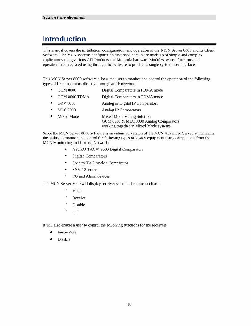
This manual covers the installation, configuration, and operation of the MCN Server 8000 and its Client
Software. The MCN systems configuration discussed here in are made up of simple and complex
applications using various CTI Products and Motorola hardware Modules, whose functions and
operation are integrated using through the software to produce a single system user interface.
This MCN Server 8000 software allows the user to monitor and control the operation of the following
types of IP comparators directly, through an IP network:
▪ GCM 8000 Digital Comparators in FDMA mode
▪ GCM 8000 TDMA Digital Comparators in TDMA mode
▪ GRV 8000 Analog or Digital IP Comparators
▪ MLC 8000 Analog IP Comparators
▪ Mixed Mode Mixed Mode Voting Solution
GCM 8000 & MLC 8000 Analog Comparators
working together in Mixed Mode systems
Since the MCN Server 8000 software is an enhanced version of the MCN Advanced Server, it maintains
the ability to monitor and control the following types of legacy equipment using components from the
MCN Monitoring and Control Network:
• ASTRO-TAC™ 3000 Digital Comparators
• Digitac Comparators
• Spectra-TAC Analog Comparator
• SNV-12 Voter
• I/O and Alarm devices
The MCN Server 8000 will display receiver status indications such as:
Vote
Receive
Disable
Fail
It will also enable a user to control the following functions for the receivers
• Force-Vote
• Disable
System Considerations
11
***Quick Start Guide *** Read This First
Why Read this Section?
A. The MCN Server 8000 software is extremely flexible and can be used with a number of
different comparator types and I/O devices. This manual contains very detailed
information about each of the required steps to configure a system; but there are a lot of
options which may not apply to your specific system. As a result, it can get a bit
confusing for a first-timer or even for some experienced users.
B. This Quick Start Guide is intended to allow you to quickly navigate the configuration
process, whether you are building a new system or modifying an old configuration.
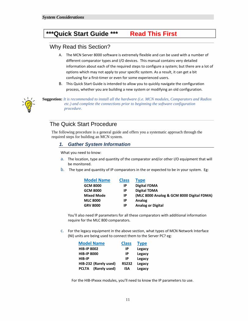
Suggestion: It is recommended to install all the hardware (i.e. MCN modules, Comparators and Radios
etc.) and complete the connections prior to beginning the software configuration
procedure.
The Quick Start Procedure
The following procedure is a general guide and offers you a systematic approach through the
required steps for building an MCN system.
1. Gather System Information
What you need to know:
a. The location, type and quantity of the comparator and/or other I/O equipment that will be monitored.
b. The type and quantity of IP comparators in the or expected to be in your system. Eg:
Model Name Class Type GCM 8000 IP Digital FDMA GCM 8000 IP Digital TDMA Mixed Mode IP (MLC 8000 Analog & GCM 8000 Digital FDMA) MLC 8000 IP Analog GRV 8000 IP Analog or Digital
You’ll also need IP parameters for all these comparators with additional information require for the MLC 800 comparators.
c. For the legacy equipment in the above section, what types of MCN Network Interface (NI) units are being used to connect them to the Server PC? eg:
For the HIB-IPxxxx modules, you’ll need to know the IP parameters to use.
Model Name Class Type HIB-IP 8002 IP Legacy HIB-IP 8000 IP Legacy HIB-IP IP Legacy HIB-232 (Rarely used) RS232 Legacy PCLTA (Rarely used) ISA Legacy
System Considerations
12
d. The type and quantity of legacy comparators or other I/O devices, and their MCN interfaces expected in the system ex:
Comparator MCN Module Spectra-TAC CIB Module (1 per chassis) Digitac CIB Module Astrotac AIB Module * General Purpose I/O GPI-xx, GPO-xxx and GPIO-xxxx modules
You ‘ll need to know the MCN Group & Module number of all MCN hardware Modules.
* For the AIB module, you’ll also need to know the number of 8-receiver Banks in use.
2. Install the Software and License
Use MCN software CD to install the MCN suite and the required USB drivers, License
file and USB hardware key. Pages 31
3. Hardware Setup Configuration
Run and configure the HW-Setup Program
• Load Software Key File Pages 44
Add Hardware Setup Options Page 46
Based on the system information previously identified, select the correct IP Comparator
and/or Network Interface options for your system.
4. Build a MCN System in the configuration program (Run the MCN-Config Program)
Use the MCN Config Program to do the following, based on your actual hardware:
a) Add & Configure appropriate IP comparators (As system requires)
b) Add & Configure Network Interfaces (NIs), (As system requires)
c) Add / Configure Hardware, (Always required)
d) Add Receiver Names, (Optional)
e) Configure the Display window. (Always required)
f) Save system with preferred name (Always required)
Network Interfaces Types:
IP Comparator and/or Network Interfaces that may be used for the new system include:
▪ IP Comparator Interface Module See Page 109 for details
▪ HIB-IP family of modules See Page 116 for details
▪ HIB-232 module Not Common/outmoded
▪ PCLTA board Not Common/outmoded
Steps: Use ‘Network Interface’ window: (MENU: View Network Interface) See Page: 107
System Considerations
13
Add IP Comparators: Page 60
Select and configure the appropriate type of IP Comparator Interface(s):
(MLC 8000, GCM 8000 or GRV 8000)
(Note that the parameters gathered from the Motorola CSS software are needed in
this step.)
Add Legacy Network Interface Module: Page 92
Select and configure the appropriate type of Network Interface(s):
HIB-IP, HIB-IP 8000, HIB-IP 8002, PCLTA or HIB-232 modules.
(Note that the basic MCN Server 8000 software package supports only (1) of these
Network Interfaces. This may be expanded with license options.)
Add/Configure Hardware Modules:
Use ‘Hardware’ window to add MCN hardware modules for the Interface Modules
previously created.
(MENU: View Hardware) See Page: 128
You may need to add and configure the correct hardware types for the previously
added MCN interface modules. (IP comparators will also appear in the Hardware
window.)
Add Receiver & I/O Point Names & Information:
Use ‘Receivers’ window to assign Aliases for channel receivers
(MENU: View Receivers) See Pages 132
Enter data for all receivers in the Receiver Window. Select the proper
Display Table Type (Comparator, MLC Tech, etc.) for all receivers.
Specify Channel Numbers and/or Channel Names:
This is optional, but beneficial with logging and for use with System Performance
Toolkit software.
Configure ‘Channels’ windows.
(MENU: View Channels). See Page: 130
Add the appropriate Channel to the MCN Modules or IP Comparators in the
‘Hardware’ windows. (MENU: View Hardware).
Build Display Windows:
Build ‘Display Windows’ to create the Server’s User Interface
(MENU: View Display Window) See Page 158
Create and configure the screen Layout and Appearance of the receivers to be
displayed.
System Considerations
14
Display Tables: (Optional)
Use ‘Display Tables Window’ to create or customize Display Tables.
(MENU: View Display Tables) See Page 197
This translates the hardware data into specific states on the status display screen.
Add Client Permissions: (Optional)
Use the ‘Client Permissions’ window if you wish to create controlled access to specific
Display Windows for different Client users:
(MENU: View Client Permissions) See Page 159
This controls which client PCs can log into the Server and load which screens
(Display Windows).
Save the Newly Built MCN System Configuration:
After completing all the different steps for building resources to create a functional
system, you will need to save the Newly Configured system with a descriptive file
name. The MCN Config software will generate a group of about 6 or more all bearing
the same filename but with different extensions. These are the configuration files to
load when running the MCN Server 8000 software. See Page 29
5. Running the MCN Server 8000 Software:
Run the MCN Server 8000 software and load one of the Display Windows that you
built. If there were no errors made in configuring the system files, and the hardware is
fully installed and configured, all the IP comparators and the Network Interfaces
should be online and you will see receiver statuses on the Server PCs Display. See
Page 170.
6. Running the Client software:
Run the MCN Client software. If there were no errors made in configuring the network
parameters for the Client to Server, and the Server PC is running, the Client Display
should connect to the server and load the permitted screens same as the ones on the
Server where you should see receiver statuses for the Server PCs Display.
See Page 183
System Considerations
15
Manual Structure
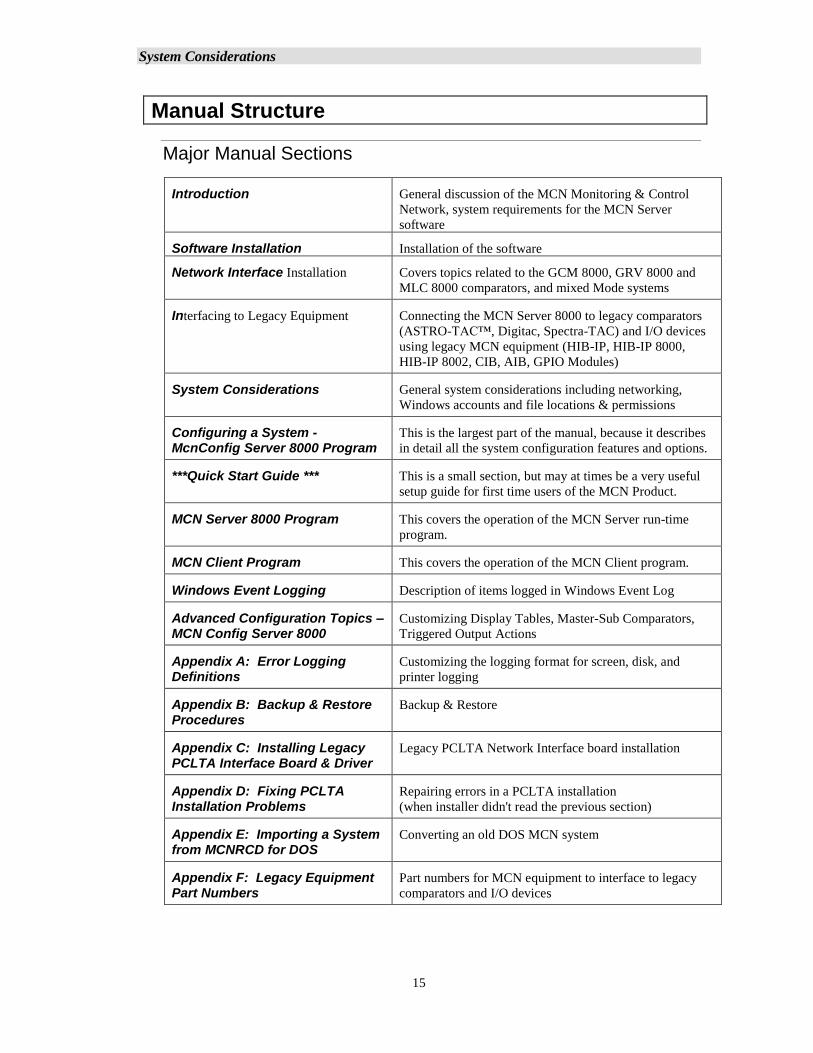
Major Manual Sections
Introduction General discussion of the MCN Monitoring & Control
Network, system requirements for the MCN Server
software
Software Installation Installation of the software
Network Interface Installation Covers topics related to the GCM 8000, GRV 8000 and
MLC 8000 comparators, and mixed Mode systems
Interfacing to Legacy Equipment Connecting the MCN Server 8000 to legacy comparators
(ASTRO-TAC™, Digitac, Spectra-TAC) and I/O devices
using legacy MCN equipment (HIB-IP, HIB-IP 8000,
HIB-IP 8002, CIB, AIB, GPIO Modules)
System Considerations General system considerations including networking,
Windows accounts and file locations & permissions
Configuring a System - McnConfig Server 8000 Program
This is the largest part of the manual, because it describes
in detail all the system configuration features and options.
***Quick Start Guide *** This is a small section, but may at times be a very useful
setup guide for first time users of the MCN Product.
MCN Server 8000 Program This covers the operation of the MCN Server run-time
program.
MCN Client Program This covers the operation of the MCN Client program.
Windows Event Logging Description of items logged in Windows Event Log
Advanced Configuration Topics – MCN Config Server 8000
Customizing Display Tables, Master-Sub Comparators,
Triggered Output Actions
Appendix A: Error Logging Definitions
Customizing the logging format for screen, disk, and
printer logging
Appendix B: Backup & Restore Procedures
Backup & Restore
Appendix C: Installing Legacy PCLTA Interface Board & Driver
Legacy PCLTA Network Interface board installation
Appendix D: Fixing PCLTA Installation Problems
Repairing errors in a PCLTA installation
(when installer didn't read the previous section)
Appendix E: Importing a System from MCNRCD for DOS
Converting an old DOS MCN system
Appendix F: Legacy Equipment Part Numbers
Part numbers for MCN equipment to interface to legacy
comparators and I/O devices
System Considerations
16
Shorthand Notation
This manual may refer generically to "MCN Server" or "MCN Server Software" or simply "Server
software" when referring to the MCN Server 8000 software.
RCD stands for "Remote Comparator Display".
The manual will refer to other programs in a shorthand notation:
Program Shorthand Executable file name
Hardware Setup HWSetup Hardware Setup Server.exe
Configuration Program MCN Config McnConfig Server 8000.exe
Server Program MCN Server MCN Server 8000.exe
Client Program MCN Client ClientRcd.exe
The HIB-IP 8000 and HIB-IP 8002 modules are updated versions of the original HIB-IP module. In
general, the term "HIB-IP" will be used throughout the manual to refer to any of these devices
unless it is important to distinguish one from the other.
This manual may refer to Motorola Solutions, Inc. as simply "Motorola" or “MSI”.
Example Screen Captures & Example Data
Example screen captures of the various programs are shown throughout this manual to give the
reader an example of what to expect during setup, configuration, and operation of the software.
Newer versions of the software may include updated windows with slightly different wording or
additional fields.
Data shown in example screen captures is presented only for example purposes only. It does not
reflect any particular user's system.
Various sections of the manual focus on particular topics. Example screen captures within a section
are presented as examples of the topics covered in that section. Example data show in the screen
captures in one section may not apply to screen captures shown or system configuration described in
different sections.
Specific data such as IP Addresses, Subnet Masks, Gateway IP Addresses, UDP port numbers, AGU
and VGU IDs shown in the manual are intended to show the appropriate linkages between IP
Comparators, AGU Receiver Ports, HIB-IP, HIB-IP 8000 and HIB-IP 8002 Units, Clients, and
Server PCs. They were taken from lab test systems for example use only. They do not reflect your
required system settings, and should not be taken as recommendations.
Since the test system used in preparing this manual did not include the various IP routers used in an
ASTRO® 25 7.x system, the example settings do not coincide with the requirements and
recommendations of Motorola's IP Plan. Each system is different; refer to the documentation for
your system for the proper IP addresses and UDP port numbers.
Example System Diagrams
System diagrams in this manual are included to illustrate example generalized systems and
principles and are not intended to reflect any particular system configuration. In particular, a
simplified IP infrastructure is shown. Real-world IP networks (especially ASTRO® 25 Radio
Network Infrastructures (RNIs) may include additional routers, gateways, switches, etc.
System Considerations
17
MCN Server 8000 IP System Example
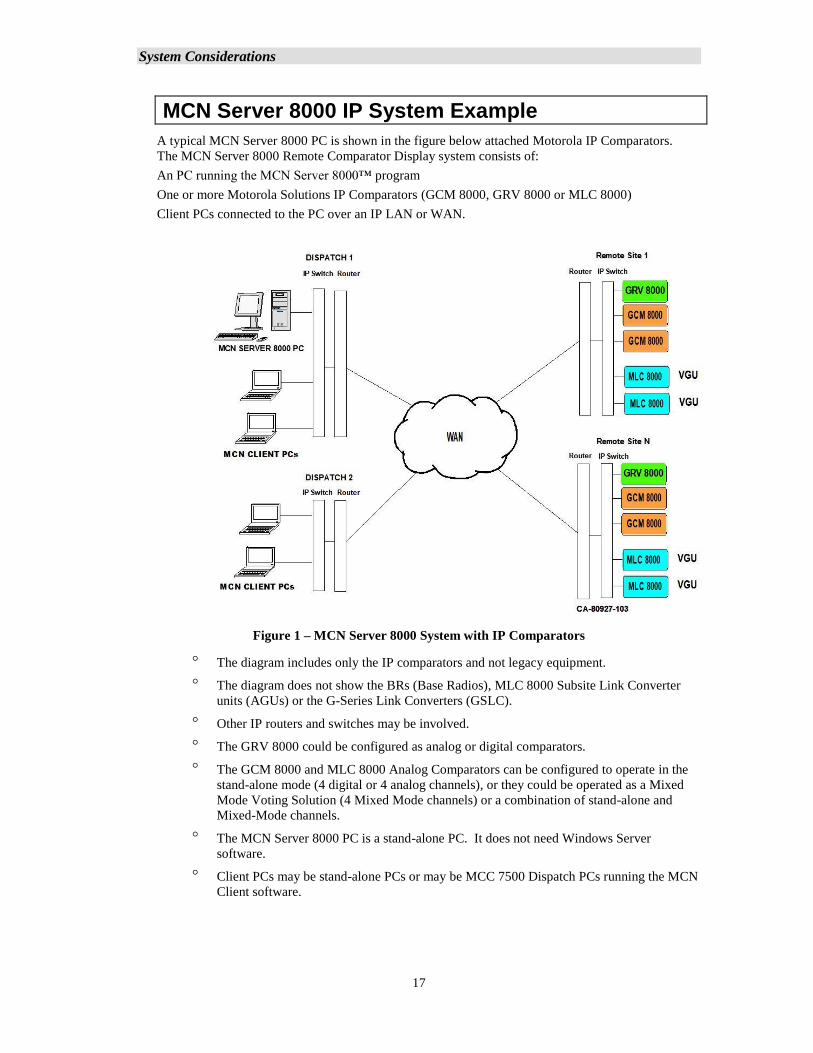
A typical MCN Server 8000 PC is shown in the figure below attached Motorola IP Comparators.
The MCN Server 8000 Remote Comparator Display system consists of:
An PC running the MCN Server 8000™ program
One or more Motorola Solutions IP Comparators (GCM 8000, GRV 8000 or MLC 8000)
Client PCs connected to the PC over an IP LAN or WAN.
Figure 1 – MCN Server 8000 System with IP Comparators
The diagram includes only the IP comparators and not legacy equipment.
The diagram does not show the BRs (Base Radios), MLC 8000 Subsite Link Converter
units (AGUs) or the G-Series Link Converters (GSLC).
Other IP routers and switches may be involved.
The GRV 8000 could be configured as analog or digital comparators.
The GCM 8000 and MLC 8000 Analog Comparators can be configured to operate in the
stand-alone mode (4 digital or 4 analog channels), or they could be operated as a Mixed
Mode Voting Solution (4 Mixed Mode channels) or a combination of stand-alone and
Mixed-Mode channels.
The MCN Server 8000 PC is a stand-alone PC. It does not need Windows Server
software.
Client PCs may be stand-alone PCs or may be MCC 7500 Dispatch PCs running the MCN
Client software.
System Considerations
18
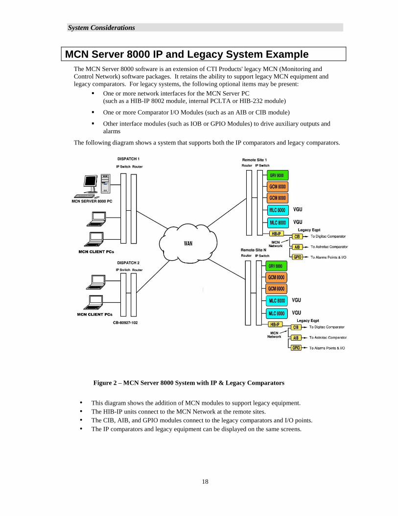
MCN Server 8000 IP and Legacy System Example
The MCN Server 8000 software is an extension of CTI Products' legacy MCN (Monitoring and
Control Network) software packages. It retains the ability to support legacy MCN equipment and
legacy comparators. For legacy systems, the following optional items may be present:
▪ One or more network interfaces for the MCN Server PC
(such as a HIB-IP 8002 module, internal PCLTA or HIB-232 module)
▪ One or more Comparator I/O Modules (such as an AIB or CIB module)
▪ Other interface modules (such as IOB or GPIO Modules) to drive auxiliary outputs and
alarms
The following diagram shows a system that supports both the IP comparators and legacy comparators.
Figure 2 – MCN Server 8000 System with IP & Legacy Comparators
• This diagram shows the addition of MCN modules to support legacy equipment.
• The HIB-IP units connect to the MCN Network at the remote sites.
• The CIB, AIB, and GPIO modules connect to the legacy comparators and I/O points.
• The IP comparators and legacy equipment can be displayed on the same screens.
System Considerations
19
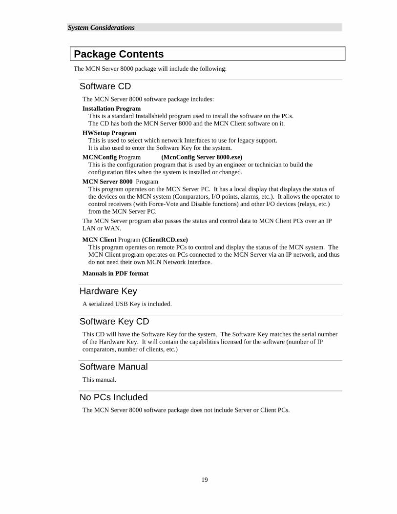
Package Contents
The MCN Server 8000 package will include the following:
Software CD
The MCN Server 8000 software package includes:
Installation Program
This is a standard Installshield program used to install the software on the PCs.
The CD has both the MCN Server 8000 and the MCN Client software on it.
HWSetup Program
This is used to select which network Interfaces to use for legacy support.
It is also used to enter the Software Key for the system.
MCNConfig Program (McnConfig Server 8000.exe)
This is the configuration program that is used by an engineer or technician to build the
configuration files when the system is installed or changed.
MCN Server 8000 Program
This program operates on the MCN Server PC. It has a local display that displays the status of
the devices on the MCN system (Comparators, I/O points, alarms, etc.). It allows the operator to
control receivers (with Force-Vote and Disable functions) and other I/O devices (relays, etc.)
from the MCN Server PC.
The MCN Server program also passes the status and control data to MCN Client PCs over an IP
LAN or WAN.
MCN Client Program (ClientRCD.exe)
This program operates on remote PCs to control and display the status of the MCN system. The
MCN Client program operates on PCs connected to the MCN Server via an IP network, and thus
do not need their own MCN Network Interface.
Manuals in PDF format
Hardware Key
A serialized USB Key is included.
Software Key CD
This CD will have the Software Key for the system. The Software Key matches the serial number
of the Hardware Key. It will contain the capabilities licensed for the software (number of IP
comparators, number of clients, etc.)
Software Manual
This manual.
No PCs Included
The MCN Server 8000 software package does not include Server or Client PCs.
System Considerations
20
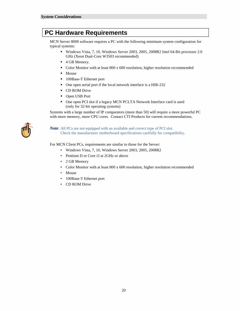
PC Hardware Requirements
MCN Server 8000 software requires a PC with the following minimum system configuration for
typical systems:
▪ Windows Vista, 7, 10, Windows Server 2003, 2005, 2008R2 Intel 64-Bit processor 2.0
GHz (Xeon Dual-Core W3503 recommended)
▪ 4 GB Memory.
▪ Color Monitor with at least 800 x 600 resolution, higher resolution recommended
▪ Mouse
▪ 100Base-T Ethernet port
▪ One open serial port if the local network interface is a HIB-232
▪ CD ROM Drive
▪ Open USB Port
▪ One open PCI slot if a legacy MCN PCLTA Network Interface card is used
(only for 32-bit operating systems)
Systems with a large number of IP comparators (more than 50) will require a more powerful PC
with more memory, more CPU cores. Contact CTI Products for current recommendations.
Note: All PCs are not equipped with an available and correct type of PCI slot.
Check the manufacturer motherboard specifications carefully for compatibility.
For MCN Client PCs, requirements are similar to those for the Server:
• Windows Vista, 7, 10, Windows Server 2003, 2005, 2008R2
• Pentium D or Core i3 at 2GHz or above
• 2 GB Memory
• Color Monitor with at least 800 x 600 resolution, higher resolution recommended
• Mouse
• 100Base-T Ethernet port
• CD ROM Drive
System Considerations
21
Reference Documents
Manuals for Motorola Solutions, Inc. Equipment
Information on the Motorola IP Comparators can be found in the documents available from
Motorola Solutions for your system. The following is a list of manuals that may apply to your
system. There may be additional manuals that may apply. Be sure to use the proper version of the
manual for your system’s version.
GCM 8000 Comparator Manual
MLC 8000 Comparator Manual
GRV 8000 Comparator Manual
Quick Guide for Implementing MLC 8000s
MLC 8000 Configuration Tool with Analog Display and Control manual
Conventional Operations manual
GTR 8000 Base Radio Manual
Information Assurance Features Overview manual
MCC 7500 Dispatch Console with VPM manual
System LAN Switches manual
System Gateways – GGM 8000 manual
Authentication Services
Windows® Supplemental CD and the corresponding ASTRO® 25 system Windows Supplemental
Configuration manual
Manuals for Legacy CTI Products MCN Equipment
Details of other legacy hardware components of the system can be found in the following
documents:
S2-60425 Monitoring and Control Network, System Manual
S2-61173 HIB-IP & HIB-IP 8000 Remote Network Interface Hardware Reference Manual
S2-61808 HIB-IP 8002 Remote Network Interface Hardware Reference Manual
S2-60427 HIB-232 Host Computer Interface Module, Hardware Reference Manual
S2-60426 CIB Comparator I/O Module, Hardware Reference Manual
S2-60399 AIB ASTRO-TAC™ Comparator Interface Module, Hardware Reference Manual
S2-60630 IOB I/O Control Module, Hardware Reference Manual
S2-60596 EXB-232 and EXB-IM Network Extender Modules, Hardware Reference Manual
S2-61089 EXB-IP and EXB-IP 8000 Network Extender Modules, Hardware Reference
Manual.
S2-60649 MCN Router Modules, Hardware Reference Manual
System Considerations
22
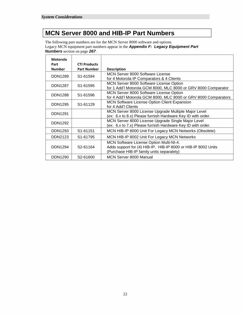
MCN Server 8000 and HIB-IP Part Numbers
The following part numbers are for the MCN Server 8000 software and options.
Legacy MCN equipment part numbers appear in the Appendix F: Legacy Equipment Part Numbers section on page 267.
Motorola Part Number
CTI Products Part Number Description
DDN1289 S1-61594 MCN Server 8000 Software License for 4 Motorola IP Comparators & 4 Clients
DDN1287 S1-61595 MCN Server 8000 Software License Option for 1 Add’l Motorola GCM 8000, MLC 8000 or GRV 8000 Comparator
DDN1288 S1-61596 MCN Server 8000 Software License Option for 4 Add’l Motorola GCM 8000, MLC 8000 or GRV 8000 Comparators
DDN1295 S1-61129 MCN Software License Option Client Expansion for 4 Add’l Clients
DDN1291 MCN Server 8000 License Upgrade Multiple Major Level (ex: 6.x to 8.x) Please furnish Hardware Key ID with order.
DDN1292 MCN Server 8000 License Upgrade Single Major Level (ex: 6.x to 7.x) Please furnish Hardware Key ID with order.
DDN1293 S1-61151 MCN HIB-IP 8000 Unit For Legacy MCN Networks (Obsolete)
DDN2123 S1-61795 MCN HIB-IP 8002 Unit For Legacy MCN Networks
DDN1294 S2-61164 MCN Software License Option Multi-NI-4. Adds support for (4) HIB-IP, HIB-IP 8000 or HIB-IP 8002 Units (Purchase HIB-IP family units separately)
DDN1290 S2-61600 MCN Server 8000 Manual
System Considerations
23
Supported Operating Systems
In a stand-alone system, the MCN Server 8000 software and the Client software can run on:
Windows XP
Windows Vista
Windows 7
Windows 10
Windows Server 2003
Windows Server 2005
Windows Server 2008r2
(Note that although the MCN Server 8000 and Client software can run on the platforms above, not all
are supported on a Motorola ASTRO® 25 RNI).
Recommended Software
It is recommended that Adobe Acrobat Reader be installed on the system to provide access to the
manuals in PDF format from Windows and from the Help menu.
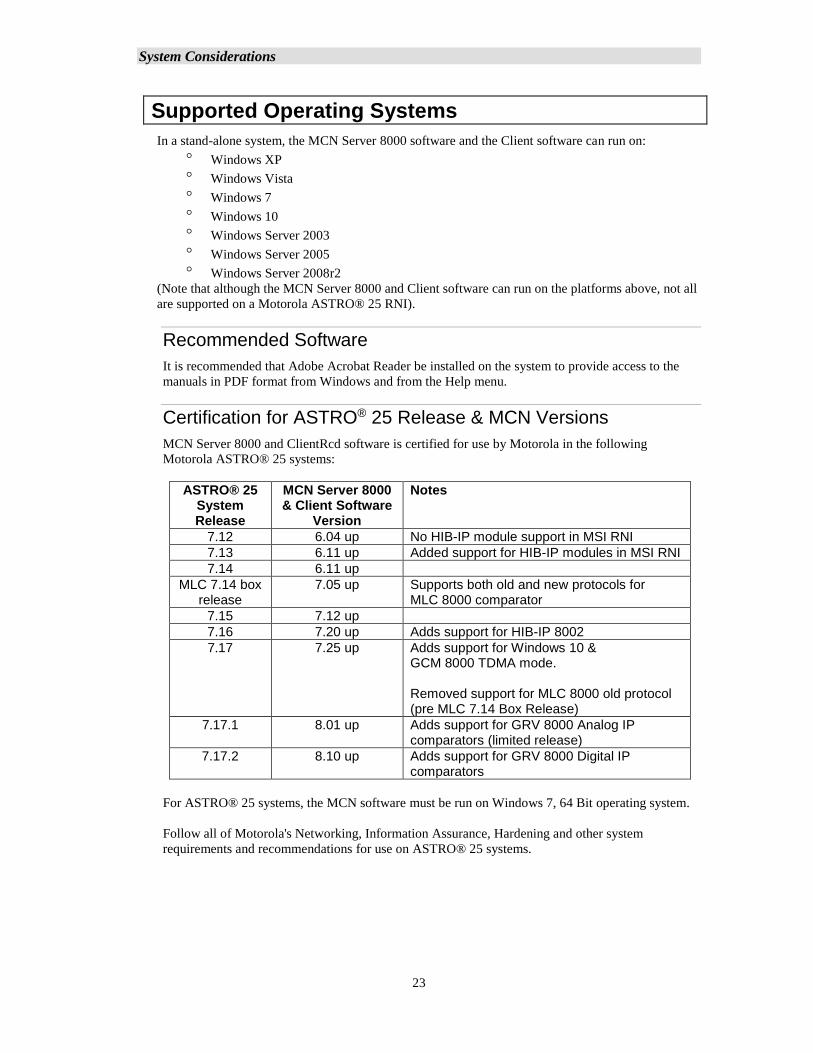
Certification for ASTRO® 25 Release & MCN Versions
MCN Server 8000 and ClientRcd software is certified for use by Motorola in the following
Motorola ASTRO® 25 systems:
ASTRO® 25 System Release
MCN Server 8000 & Client Software
Version
Notes
7.12 6.04 up No HIB-IP module support in MSI RNI
7.13 6.11 up Added support for HIB-IP modules in MSI RNI
7.14 6.11 up
MLC 7.14 box release
7.05 up Supports both old and new protocols for MLC 8000 comparator
7.15 7.12 up
7.16 7.20 up Adds support for HIB-IP 8002
7.17 7.25 up Adds support for Windows 10 & GCM 8000 TDMA mode. Removed support for MLC 8000 old protocol (pre MLC 7.14 Box Release)
7.17.1 8.01 up Adds support for GRV 8000 Analog IP comparators (limited release)
7.17.2 8.10 up Adds support for GRV 8000 Digital IP comparators
For ASTRO® 25 systems, the MCN software must be run on Windows 7, 64 Bit operating system.
Follow all of Motorola's Networking, Information Assurance, Hardening and other system
requirements and recommendations for use on ASTRO® 25 systems.
System Considerations
24
MCC 7500 Console & NM Client Cohabitation
The Client software is certified by Motorola to be installed and co-hab with MCC 7500 consoles
and NM Clients. It can also be installed on stand-alone PCs.
The MCN Server 8000 software is not certified to co-hab on any of the PCs used for dispatch or
network management and should be run on a separate PC.
Security and Information Assurance Recommendations
Review these recommendations before installation and follow them during installation and
operation:
1. Installation of the Enhanced Mitigation Experience Toolkit (EMET); is recommended to protect
PC systems from common threats. This works by applying security mitigation technologies to
arbitrary applications that block and minimize exploitation.
2. Software Installation Locations
Install the software in default program directory recommended by Install-shield.
3. Configure the MCN Server 8000 and MCN Client software as described in this manual. If
applicable, take into consideration commercially accepted practices, industry standards and the
standards for your organization.
4. Do not save user files or system configuration files in the program directory.
5. Save system configuration files to a directory that requires Administrator rights so that users
cannot delete or edit the configuration files. See the Windows Accounts section on page 28
for additional information.
6. Always run the software with the lowest permission set possible.
7. Run both the MCN Server 8000 and the MCN Client software with User rights, not
Administrator rights. See the Windows Accounts section on page 28 for additional
information.
(Note: To initially configure the MCN Server List or change the MCN Server List for the MCN
Client software, you will need to run MCN Client with Administrator rights once. For
subsequent operation, run it with User rights.)
8. When configuring a system, do not enter Sensitive or Confidential information into the system
configuration files.
9. The MCN Server 8000 software, the MCN Client software and system configuration files are
not backed up as part of the ASTRO® 25 Back UP & Restore (BAR) solution. Follow the
Backup & Recovery procedures as listed in Appendix B: Backup & Restore Procedures
on page 247 for the MCN Server 8000, MCN Client, and system configuration data. The
procedures in the Appendix apply only to this software and do not back up or restore part of the
ASTRO® 25 system.
10. Follow the applicable Backup & Recovery procedures for your system, PCs, and operating
systems as defined by your organization, the hardware and software vendors, and commercially
acceptable practices.
11. Limit access to PCs
12. Limit access to networks, both physically and through appropriate restrictions in routers and
switches
13. Use strong passwords
System Considerations
25
14. Follow Motorola's and your organization's recommendations on security and Information
Assurance.
15. Use the appropriate Windows Hardening Kits for your installation
16. Use anti-virus and anti-malware packages
17. Install appropriate security patches for installed software and operating system
18. The MCN Server is not a syslog client. Event logging is done locally to the MCN Server. See
Windows Event Logging and Appendix A: Error Logging Definitions sections for
details.
19. The Backup & Restore (BAR) procedures in this manual are for the MCN Server 8000 system.
20. Use of multiple NIC cards (Dual-Home systems) is not approved by MSI in ASTRO® 25 RNIs
due to Information Assurance (IA) security concerns.
Local Administrator versus Active Directory Accounts
Some of the operations described in this manual require Administrator rights.
Log on either as the local Windows administrator, or using your Active Directory account that
is a member of the group “cti-login” with authority to access this device. The local Windows
administrator account set up by Motorola for Windows 7-based devices is “secmoto”.
NOTE: Active Directory account login is recommended, if available.
System Considerations
26
System Considerations
IP Networking Considerations
System Topology
For ASTRO® 25 systems, all equipment (IP Comparators, HIB-IP units, MCN Server, and
Clients) must be located at the proper sites and connected to the proper IP switches
according to the Motorola IP Plan (per specific ASTRO® 25 release).
Factory Configuration
For ASTRO® 25 systems, the appropriate CTI Products, Inc. equipment must be enabled
in the MSI TNCT tool (done at the factory) to enable appropriate IP routing for the CTI
Products hardware and software.
Network Compatibility
For operation on other systems, the installer should consult with the customer's network
engineers for proper settings.
For normal operation, the IP network routers and switches must be configured to pass IP
Multicast traffic from the MCN Server to the Clients.
MCN Server 8000 software Version 7.00 and above, supports up to 10 Clients using the
Unicast streams for special systems. Note that this operating mode will increase IP traffic
between the Server and Clients. It is not intended to be used on a standard MSI RNI.
IP network infrastructure equipment (switches, routers, etc.) must be configured properly to
allow communication between the IP comparators, the MCN Server 8000, HIB-IP units,
and the MCN Clients.
The system requires static IP addresses for the following items:
▪ MCN Server 8000 PC
▪ ClientRcd PCs
▪ HIB-IP units
▪ GRV 8000, GCM 8000, & MLC 8000 IP Comparators
▪ Multicast IP Address for Server to Client traffic.
All IP addresses, IP Subnets, and Subnet Masks should be set based on the proper settings
for the particular system.
System Considerations
27
Software Co-habitation and PC Locations
1. For ASTRO® 25 7.13 & 7.14 systems, MCN Server 8000 software may be installed on:
Stand-Alone PC
2. For ASTRO® 25 7.13 & 7.14 systems, ClientRCD software may be installed on:
Stand-Alone PC
Co-Habbed on an MCC 7500 Console PC
3. For ASTRO® 25 7.13 & 7.14 systems, the various components of an MCN system (MCN
Server 8000, Client RCD, HIB-IP units, and IP comparators cannot bridge the RNI-CEN
demarcation point. There are two possible configurations:
• All components must be within the RNI or
• All components must be outside the RNI in the CEN.
4. For ASTRO® 25 7.13 & 7.14 systems, the PCs running MCN Server 8000 and ClientRCD
software may be installed only at the following locations:
Zone Core (Not on NM Subnet – no Multicast support)
K-Core
Collocated Vortex / NM Dispatch Site in Zone Core
Note: A Vortex /NM Dispatch Site may not be able to communicate with all the
comparators at other sites. Only Zone Core or K-Core or collocated Vortex / NM Dispatch
Site in Zone Core are available to see all the comparators.
5. For systems not running in an official MSI RNI, some of the above limitations may not
apply, but the non ASTRO® 25 -specific considerations will apply.
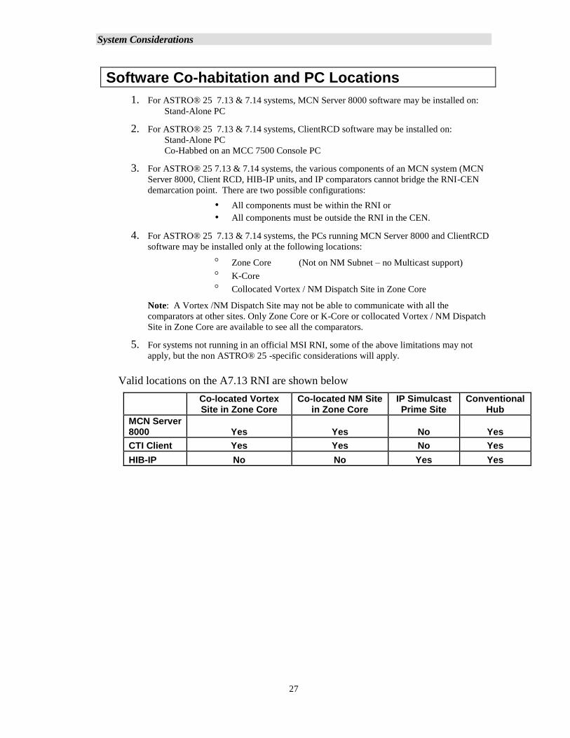
Valid locations on the A7.13 RNI are shown below
Co-located Vortex Site in Zone Core
Co-located NM Site in Zone Core
IP Simulcast Prime Site
Conventional Hub
MCN Server 8000 Yes Yes No Yes
CTI Client Yes Yes No Yes
HIB-IP No No Yes Yes
System Considerations
28
HIB-IP Considerations
A. Legacy HIB-IP modules (versions below 400) are not intended for operation across an
ASTRO® 25 7x Radio Network Infrastructure (RNI).
B. HIB-IP 8000 modules (HIB-IP modules version 400 and up) and HIB-IP 8002 modules
support special UDP Ports required to run across an ASTRO® 25 7.13 and higher RNI.
C. For ASTRO® 25 7.13 and up systems, HIB-IP modules may be installed only in the
following locations:
• Simulcast IP Prime Sites
• Conventional Hub (C-Sub Hub) Sites
Default Software Settings
1. The defaults in the MCN Server 8000 and the MCN Client are configured to run in an
ASTRO® 25 7.12 system and higher.
2. The default UDP ports for the Server and Client are set according to Motorola's IP plan
(per specific ASTRO® 25 release). They assume that the software is running on a PC
hardened with Motorola’s Windows Hardening Kit (WHK). If the PC does not have WHK
installed, see Appendix I: Running on non WHK PCs – UDP Port Settings
3. The default Multicast IP address for the MCN Server 8000 software is configured for:
MCN Server #1 in Zone 1 at the Main Prime site.
If your system configuration is different, please refer to the Motorola IP Plan (per specific
ASTRO® 25 release) for the proper Multicast IP address.
Windows Accounts
In general, the programs should be run with the least privileges consistent with proper program
operation... The programs need the following rights:
– Setup.exe (Installation) Administrator
– HWSetup Administrator
– MCN Config Server 8000 Administrator
– MCN Server 8000 User (Note 1)
– ClientRCD User (Note 2)
Note 1 Depending on the rights on various files and folders, Administrator rights may be needed
when configuring IP settings and changing other system settings.
Note 2 Depending on the rights on various files and folders, Administrator rights may be needed
when configuring the IP settings for the Client, and the list of IP addresses for the Server(s).
System Considerations
29
Permissions File Locations & Permissions
The default installation locations for the MCN Server 8000 Server and Client systems (for Windows 7
and 10) are as follows:
MCN Server 8000
Program Files C:\Program Files (x86)\CTI Products Inc\McnServer 8000
Example Files C:\Program Files (x86)\CTI Products Inc\McnServer 8000\Example
System
Config Log: C:\ProgramData\CTI Products Inc\McnConfig
McnConfig.log
System Log: C:\ProgramData\CTI Products Inc\McnRcd
McnSystem.log Users must have Read & Write access rights
Run-Time Log: C:\ProgramData\CTI Products Inc\McnRcd
MCNRCD.log Users must have Read & Write access rights
Saving System Configuration Files from MCN Config Server:
Save to a folder in which User accounts have Read rights.
Do not save to the Program folder.
MCN Client
Program Files C:\Program Files (x86)\CTI Products Inc\McnServer 8000
Server List C:\ProgramData\CTI Products Inc\McnClient
ServerList.RcdCli Users must have Read & Write access rights
Cache Files: C:\ProgramData\CTI Products Inc\McnClient\cache
*.RcdChe FILES Users must have Read & Write access rights
Introduction
30
Legacy Network Interfaces & Drivers
Three general categories of MCN Network Interfaces are used with MCN Server program to support
legacy MCN systems:
A. HIB-IP External Modules:- For connection to MCN 78K networks over IP
networks
Legacy Units: Version 110 - 399
The Legacy HIB-IP unit(s) can be local or remote.
Legacy units are not certified for use across all ASTRO® 25 RNIs.
HIB-IP 8000 Version 400 & higher:
These versions are for use across ASTRO® 25 RNIs.
HIB-IP 8002 Units:- Enhanced functionality over HIB-IP 8000 units (added
Type of Service capability). Newer hardware. Configured via USB port.
B. HIB-232 External Modules:- Version 200 & Up 78K
(with Rotary address switches on back) For RS-232 connection
(Although the HIB-232 manual talks about dial-up operation, the MCN Server
8000 program does not support dial-up operation of the HIB-232.)
C. Internal Boards:- PCLTA-21 Half-Size PCI Board 78K or 1250K versions For
direct connection to the MCN Network
Supported only on 32-bit operating systems.
(Also supports connection to remote networks using EXB Network Extender
Modules)
Legacy Drivers for MCN Server
▪ The PCLTA Interface boards need a software driver to run the MCN Server program.
This will be included with the PCLTA & software package. This driver is only
available for 32-bit operating systems.
▪ The HIB-IP, HIB-IP 8000 and HIB-232 modules do not need a driver for normal
operation of the MCN Server program.
USB Drivers for HIB-IP 8002 Modules
The HIB-IP 8002 modules need a USB driver to allow configuration of the units with the MCN
Config Server 8000 software. See Appendix G: HIB-IP 8002 USB Driver Installation
for installation details.
INSTALLATION MCN System
31
Software Installation
Installation in Motorola Solutions, Inc. ASTRO® 25 Systems
PCs installed in a Motorola Solutions, Inc. (MSI) ASTRO® 25 systems must have (among other
things) the following items installed:
• Windows Hardening Kit
• Anti-Virus (For ASTRO® 25 ™ 7.13 and above systems, the anti-virus system used is:
McAfee Endpoint Software
The proper order for software installation is:
1. Install the Windows Operating System (if not re-installed).
See instructions in appropriate MSI document.
2. Perform the Operating System Initialization Steps.
See instructions in appropriate MSI document.
3. Install the Motorola Solutions Inc. Windows Hardening Kit.
See instructions in appropriate MSI document.
4. Install MOTOPATCH.
5. Install EMET; see the Section Acquiring and Installing Microsoft EMET
on page 32
6. Install the MCN Server 8000 and/or Client software as described in the
following sections of this manual.
7. Install the McAfee Endpoint Software. See instructions in appropriate MSI
document.
8. Re-Installation in Motorola Solutions, Inc. ASTRO® 25 Systems
9. If you need to re-install the software or an update, the proper order for is:
a. Normally, you should be able to re-install the software without un-
installing McAfee Endpoint Software or disabling functions in it.
However, that might change with different configurations. If you have
difficulty installing the CTI software, try turning off the virus protection.
If that fails, try un-installing McAfee.
b. Remove the CTI software.
c. Install the MCN Server 8000 and/or Client software as described in the
following sections of this manual.
d. Re-enable or re-install McAfee Endpoint Software if it was disabled or
removed in an earlier step.
INSTALLATION MCN System
32
Installation Overview
PC Security
Protecting the PC hardware and software along with other associated networked devices or systems is
increasingly of a significant concern. As a result, the basic typical PC security should include:
• User Passwords, with adequate complexity requirements enforced.
• AntiVirus (MCN has been verified as compatible with Mcafee Version 8.8 for win 7)
• WHK (Motorola’s Windows Hardening Kit)
• Microsoft EMET (Recommended by Motorola for Windows 10 Installations)
• Appropriate firewall protection.
Acquiring and Installing Microsoft EMET
The Microsoft Enhanced Mitigation Experience Toolkit called EMET is freeware Windows-based
security tool that adds supplemental security defenses for PCs to secure potentially vulnerable
legacy and third-party applications. EMET works with all currently supported Windows operating
systems, but Microsoft particularly recommends that enterprises use it to protect applications
running on Windows XP, as that operating system lacks the security controls build into newer
versions of Windows.
The EMET freeware is packaged as an MSI file, making manual installation or deployments very
straightforward. For the purposes of this manual, we will be referencing and using EMET version
5.5. However, the most current version is recommended and should follow a similar process to
what is describe here.
To download the setup file try the following address for the Microsoft download center and
download EMET 5.5.
https://www.microsoft.com/en-us/download/details.aspx?id=50766
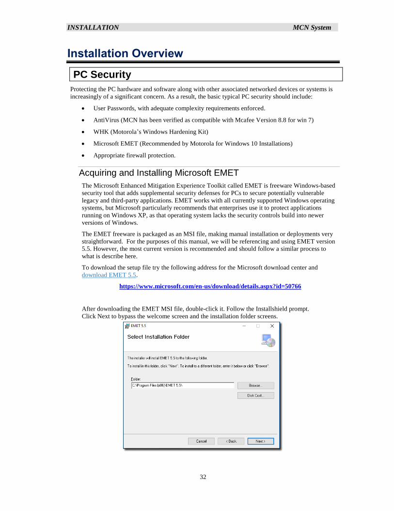
After downloading the EMET MSI file, double-click it. Follow the Installshield prompt.
Click Next to bypass the welcome screen and the installation folder screens.
INSTALLATION MCN System
33
Accept the license agreement, click Next two more times, accept the UAC prompt, and EMET will
install.
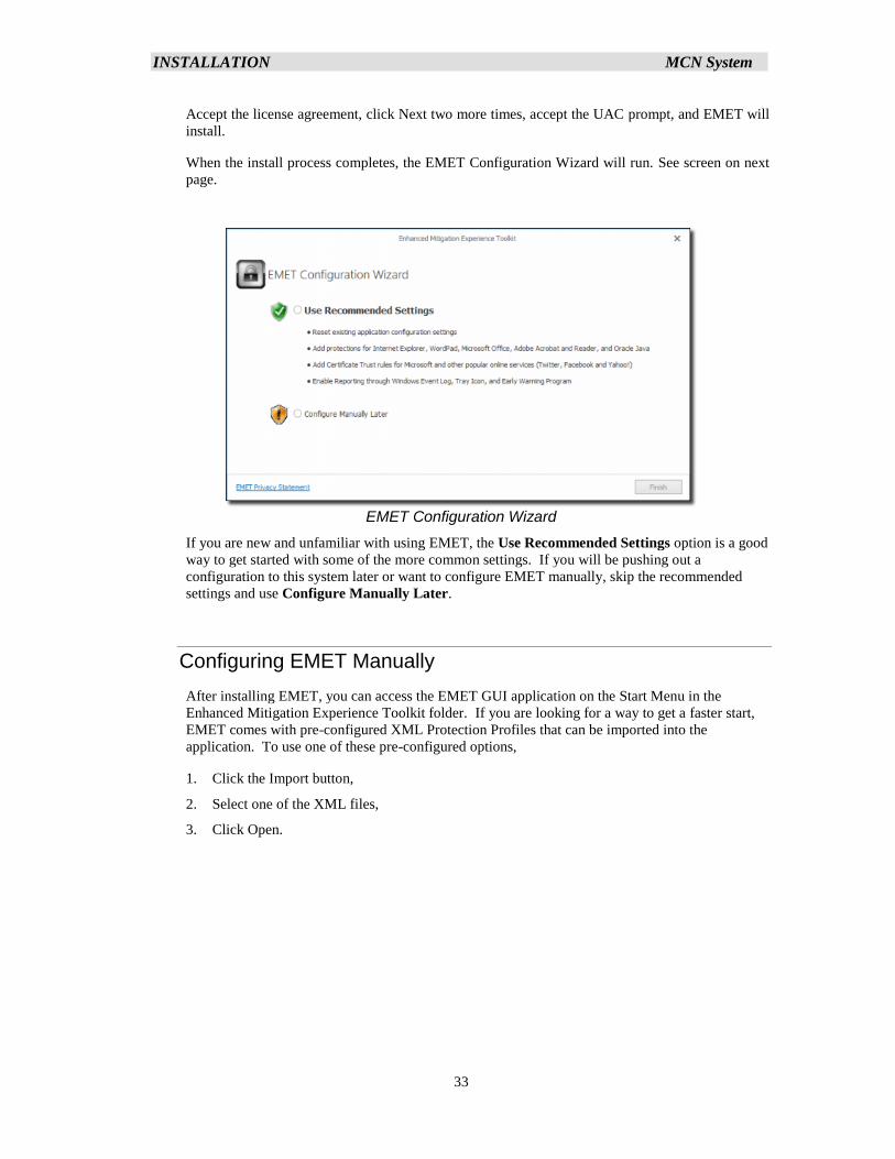
When the install process completes, the EMET Configuration Wizard will run. See screen on next
page.
EMET Configuration Wizard
If you are new and unfamiliar with using EMET, the Use Recommended Settings option is a good
way to get started with some of the more common settings. If you will be pushing out a
configuration to this system later or want to configure EMET manually, skip the recommended
settings and use Configure Manually Later.
Configuring EMET Manually
After installing EMET, you can access the EMET GUI application on the Start Menu in the
Enhanced Mitigation Experience Toolkit folder. If you are looking for a way to get a faster start,
EMET comes with pre-configured XML Protection Profiles that can be imported into the
application. To use one of these pre-configured options,
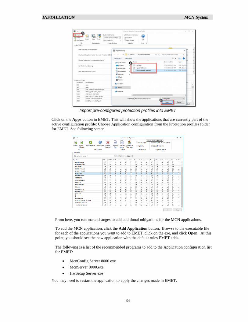
1. Click the Import button,
2. Select one of the XML files,
3. Click Open.
INSTALLATION MCN System
34
Import pre-configured protection profiles into EMET
Click on the Apps button in EMET: This will show the applications that are currently part of the
active configuration profile: Choose Application configuration from the Protection profiles folder
for EMET. See following screen.
From here, you can make changes to add additional mitigations for the MCN applications.
To add the MCN application, click the Add Application button. Browse to the executable file
for each of the applications you want to add to EMET, click on the exe, and click Open. At this
point, you should see the new application with the default rules EMET adds.
The following is a list of the recommended programs to add to the Application configuration list
for EMET:
• McnConfig Server 8000.exe
• McnServer 8000.exe
• HwSetup Server.exe
You may need to restart the application to apply the changes made in EMET.
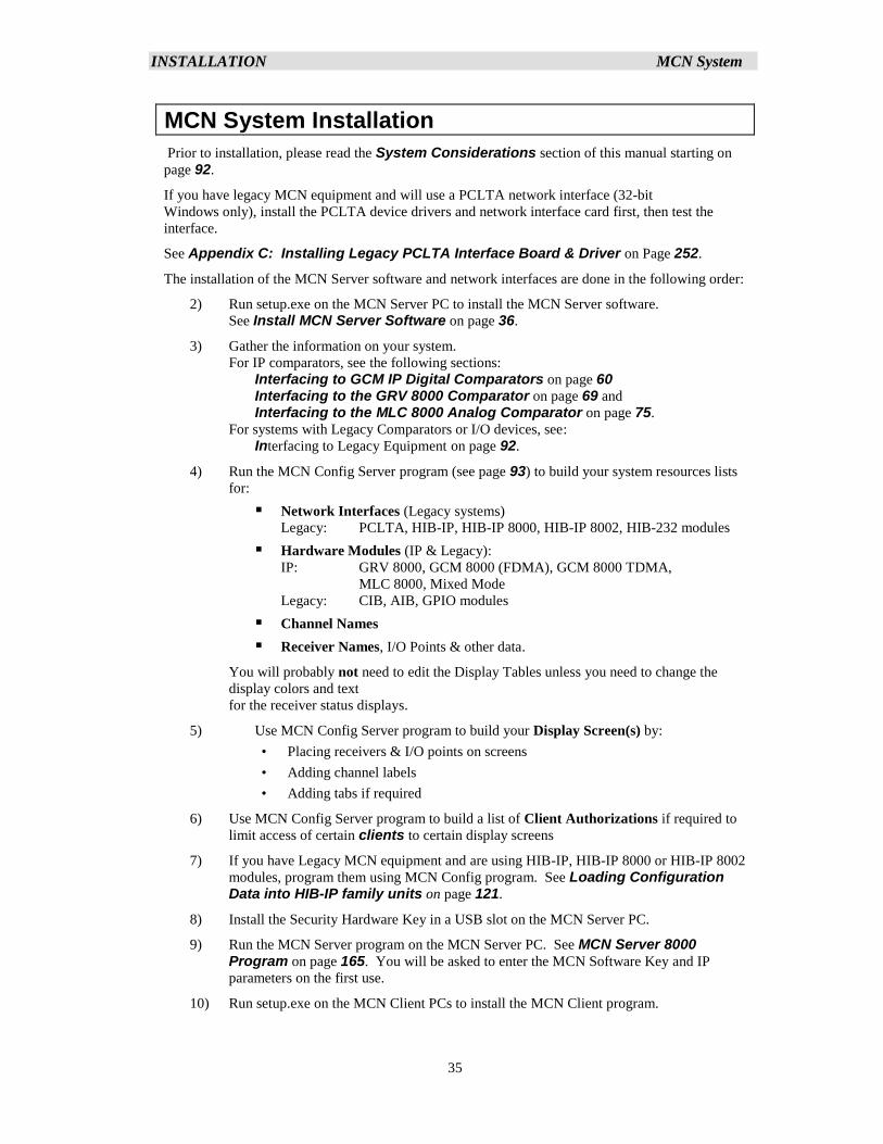
INSTALLATION MCN System
35
MCN System Installation
Prior to installation, please read the System Considerations section of this manual starting on
page 92.
If you have legacy MCN equipment and will use a PCLTA network interface (32-bit
Windows only), install the PCLTA device drivers and network interface card first, then test the
interface.
See Appendix C: Installing Legacy PCLTA Interface Board & Driver on Page 252.
The installation of the MCN Server software and network interfaces are done in the following order:
2) Run setup.exe on the MCN Server PC to install the MCN Server software.
See Install MCN Server Software on page 36.
3) Gather the information on your system.
For IP comparators, see the following sections:
Interfacing to GCM IP Digital Comparators on page 60 Interfacing to the GRV 8000 Comparator on page 69 and
Interfacing to the MLC 8000 Analog Comparator on page 75.
For systems with Legacy Comparators or I/O devices, see:
Interfacing to Legacy Equipment on page 92.
4) Run the MCN Config Server program (see page 93) to build your system resources lists
for:
▪ Network Interfaces (Legacy systems)
Legacy: PCLTA, HIB-IP, HIB-IP 8000, HIB-IP 8002, HIB-232 modules
▪ Hardware Modules (IP & Legacy):
IP: GRV 8000, GCM 8000 (FDMA), GCM 8000 TDMA,
MLC 8000, Mixed Mode
Legacy: CIB, AIB, GPIO modules
▪ Channel Names
▪ Receiver Names, I/O Points & other data.
You will probably not need to edit the Display Tables unless you need to change the
display colors and text
for the receiver status displays.
5) Use MCN Config Server program to build your Display Screen(s) by:
• Placing receivers & I/O points on screens
• Adding channel labels
• Adding tabs if required
6) Use MCN Config Server program to build a list of Client Authorizations if required to
limit access of certain clients to certain display screens
7) If you have Legacy MCN equipment and are using HIB-IP, HIB-IP 8000 or HIB-IP 8002
modules, program them using MCN Config program. See Loading Configuration Data into HIB-IP family units on page 121.
8) Install the Security Hardware Key in a USB slot on the MCN Server PC.
9) Run the MCN Server program on the MCN Server PC. See MCN Server 8000 Program on page 165. You will be asked to enter the MCN Software Key and IP
parameters on the first use.
10) Run setup.exe on the MCN Client PCs to install the MCN Client program.
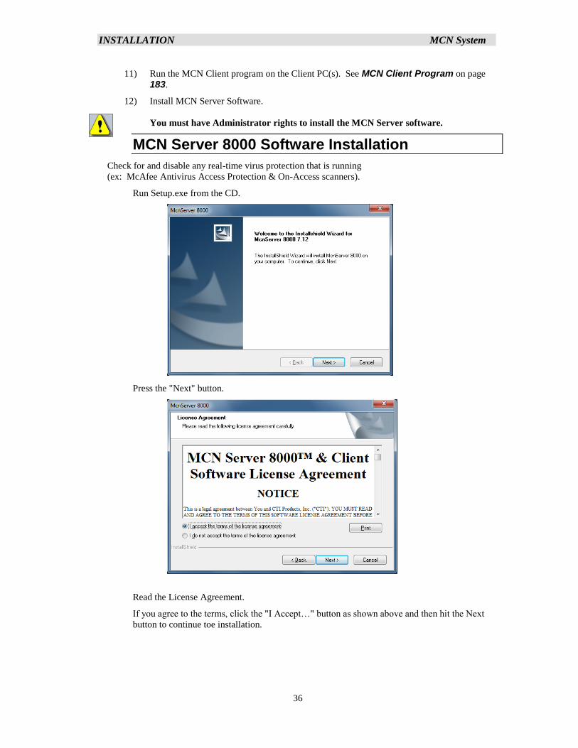
INSTALLATION MCN System
36
11) Run the MCN Client program on the Client PC(s). See MCN Client Program on page
183.
12) Install MCN Server Software.
You must have Administrator rights to install the MCN Server software.
MCN Server 8000 Software Installation
Check for and disable any real-time virus protection that is running
(ex: McAfee Antivirus Access Protection & On-Access scanners).
Run Setup.exe from the CD.
Press the "Next" button.
Read the License Agreement.
If you agree to the terms, click the "I Accept…" button as shown above and then hit the Next
button to continue toe installation.
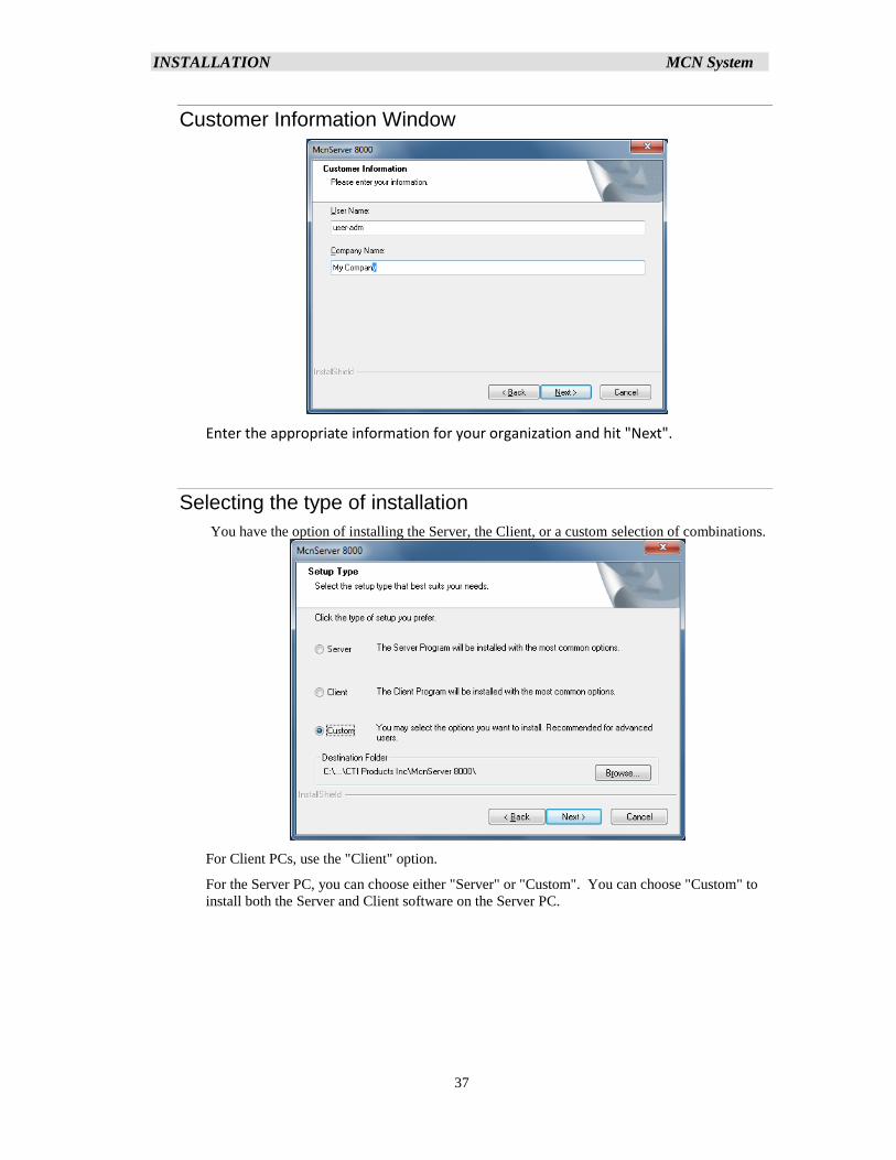
INSTALLATION MCN System
37
Customer Information Window
Enter the appropriate information for your organization and hit "Next".
Selecting the type of installation
You have the option of installing the Server, the Client, or a custom selection of combinations.
For Client PCs, use the "Client" option.
For the Server PC, you can choose either "Server" or "Custom". You can choose "Custom" to
install both the Server and Client software on the Server PC.
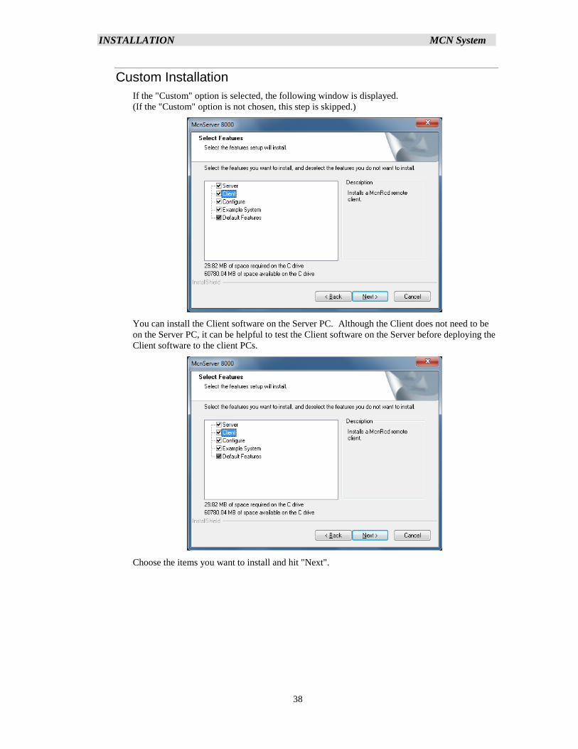
INSTALLATION MCN System
38
Custom Installation
If the "Custom" option is selected, the following window is displayed.
(If the "Custom" option is not chosen, this step is skipped.)
You can install the Client software on the Server PC. Although the Client does not need to be
on the Server PC, it can be helpful to test the Client software on the Server before deploying the
Client software to the client PCs.
Choose the items you want to install and hit "Next".
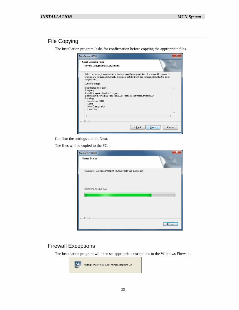
INSTALLATION MCN System
39
File Copying
The installation program `asks for confirmation before copying the appropriate files.
Confirm the settings and hit Next.
The files will be copied to the PC.
Firewall Exceptions
The installation program will then set appropriate exceptions to the Windows Firewall.
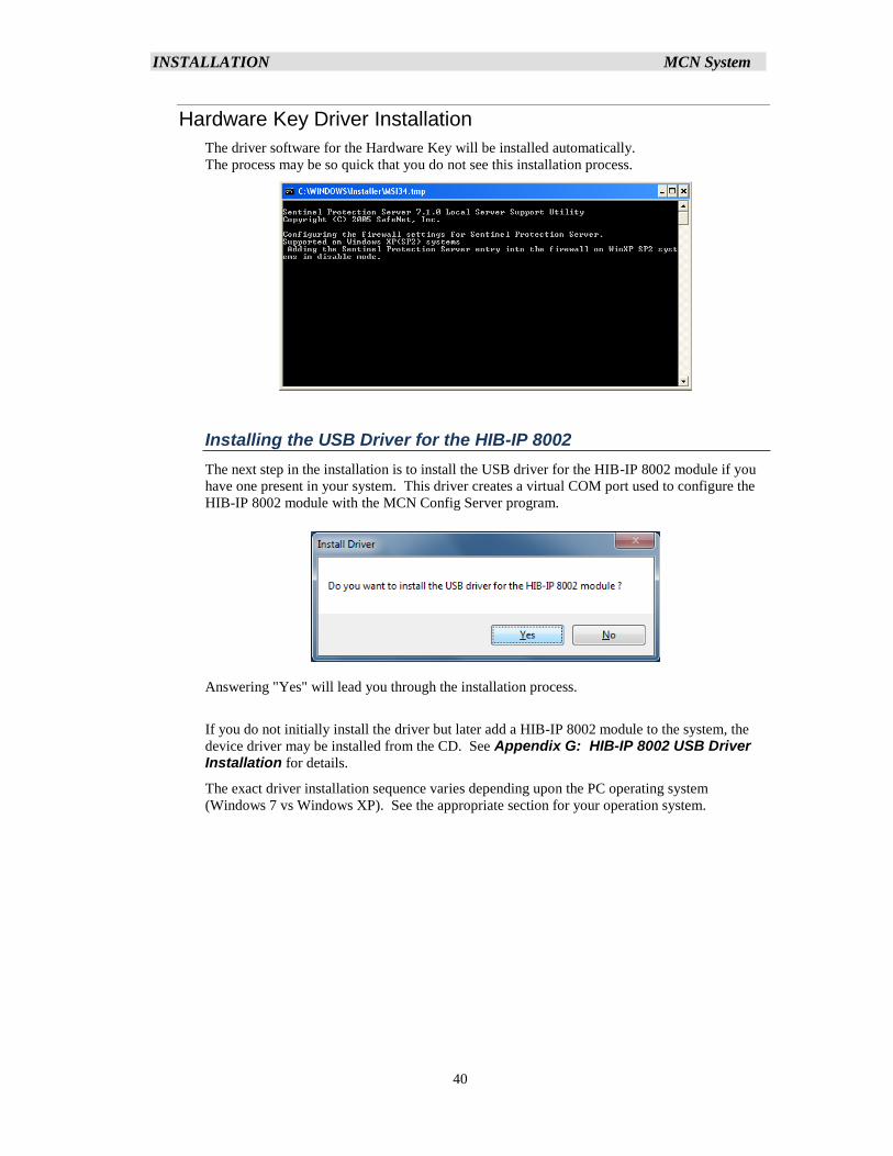
INSTALLATION MCN System
40
Hardware Key Driver Installation
The driver software for the Hardware Key will be installed automatically.
The process may be so quick that you do not see this installation process.
Installing the USB Driver for the HIB-IP 8002
The next step in the installation is to install the USB driver for the HIB-IP 8002 module if you
have one present in your system. This driver creates a virtual COM port used to configure the
HIB-IP 8002 module with the MCN Config Server program.
Answering "Yes" will lead you through the installation process.
If you do not initially install the driver but later add a HIB-IP 8002 module to the system, the
device driver may be installed from the CD. See Appendix G: HIB-IP 8002 USB Driver Installation for details.
The exact driver installation sequence varies depending upon the PC operating system
(Windows 7 vs Windows XP). See the appropriate section for your operation system.
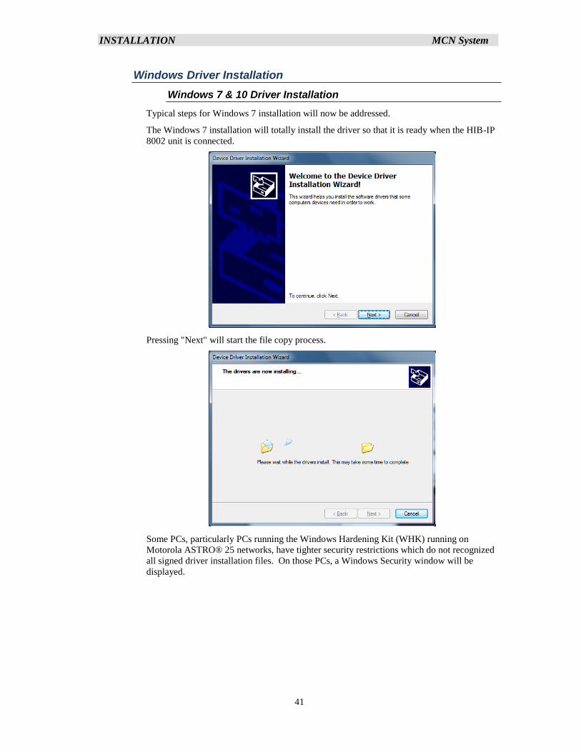
INSTALLATION MCN System
41
Windows Driver Installation
Windows 7 & 10 Driver Installation
Typical steps for Windows 7 installation will now be addressed.
The Windows 7 installation will totally install the driver so that it is ready when the HIB-IP
8002 unit is connected.
Pressing "Next" will start the file copy process.
Some PCs, particularly PCs running the Windows Hardening Kit (WHK) running on
Motorola ASTRO® 25 networks, have tighter security restrictions which do not recognized
all signed driver installation files. On those PCs, a Windows Security window will be
displayed.
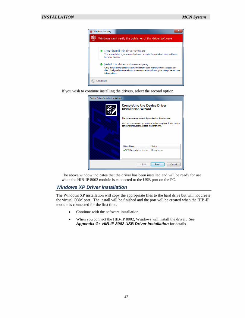
INSTALLATION MCN System
42
If you wish to continue installing the drivers, select the second option.
The above window indicates that the driver has been installed and will be ready for use
when the HIB-IP 8002 module is connected to the USB port on the PC.
Windows XP Driver Installation
The Windows XP installation will copy the appropriate files to the hard drive but will not create
the virtual COM port. The install will be finished and the port will be created when the HIB-IP
module is connected for the first time.
• Continue with the software installation.
• When you connect the HIB-IP 8002, Windows will install the driver. See
Appendix G: HIB-IP 8002 USB Driver Installation for details.
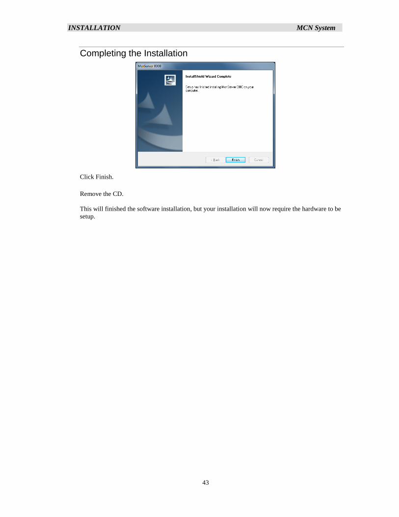
INSTALLATION MCN System
43
Completing the Installation
Click Finish.
Remove the CD.
This will finished the software installation, but your installation will now require the hardware to be
setup.
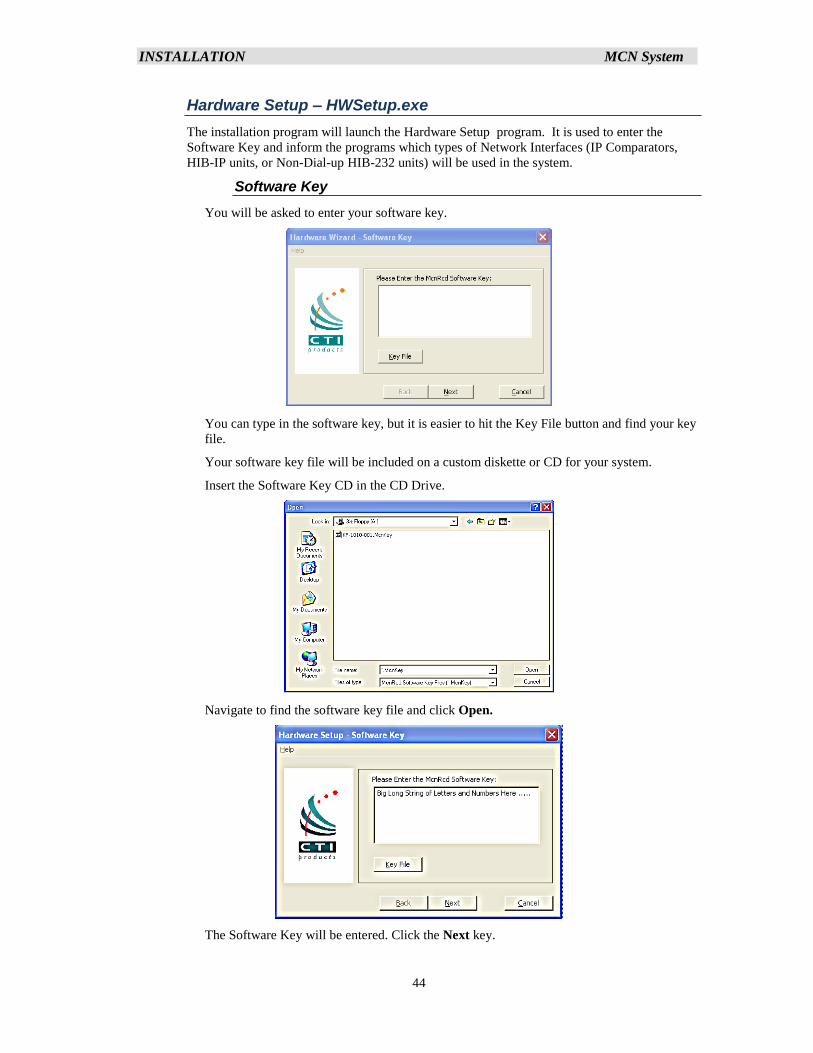
INSTALLATION MCN System
44
Hardware Setup – HWSetup.exe
The installation program will launch the Hardware Setup program. It is used to enter the
Software Key and inform the programs which types of Network Interfaces (IP Comparators,
HIB-IP units, or Non-Dial-up HIB-232 units) will be used in the system.
Software Key
You will be asked to enter your software key.
You can type in the software key, but it is easier to hit the Key File button and find your key
file.
Your software key file will be included on a custom diskette or CD for your system.
Insert the Software Key CD in the CD Drive.
Navigate to find the software key file and click Open.
The Software Key will be entered. Click the Next key.
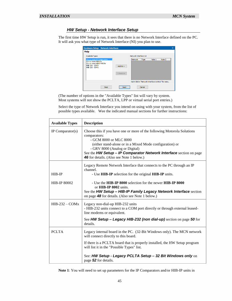
INSTALLATION MCN System
45
HW Setup - Network Interface Setup
The first time HW Setup is run, it sees that there is no Network Interface defined on the PC.
It will ask you what type of Network Interface (NI) you plan to use.
(The number of options in the "Available Types" list will vary by system.
Most systems will not show the PCLTA, LPP or virtual serial port entries.)
Select the type of Network Interface you intend on using with your system, from the list of
possible types available. Wee the indicated manual sections for further instructions:
Note 1: You will need to set up parameters for the IP Comparators and/or HIB-IP units in
Available Types Description
IP Comparator(s) Choose this if you have one or more of the following Motorola Solutions
comparators:
- GCM 8000 or MLC 8000
(either stand-alone or in a Mixed Mode configuration) or
- GRV 8000 (Analog or Digital)
See the HW Setup – IP Comparator Network Interface section on page
46 for details. (Also see Note 1 below.)
HIB-IP
HIB-IP 80002
Legacy Remote Network Interface that connects to the PC through an IP
channel.
- Use HIB-IP selection for the original HIB-IP units.
- Use the HIB-IP 8000 selection for the newer HIB-IP 8000
or HIB-IP 8002 units.
See the HW Setup – HIB-IP Family Legacy Network Interface section
on page 48 for details. (Also see Note 1 below.)
HIB-232 – COMx Legacy non-dial-up HIB-232 units
- HIB-232 units connect to a COM port directly or through external leased-
line modems or equivalent.
See HW Setup – Legacy HIB-232 (non dial-up) section on page 50 for
details.
PCLTA Legacy internal board in the PC. (32-Bit Windows only). The MCN network
will connect directly to this board.
If there is a PCLTA board that is properly installed, the HW Setup program
will list it in the "Possible Types" list.
See: HW Setup - Legacy PCLTA Setup – 32 Bit Windows only on
page 52 for details.
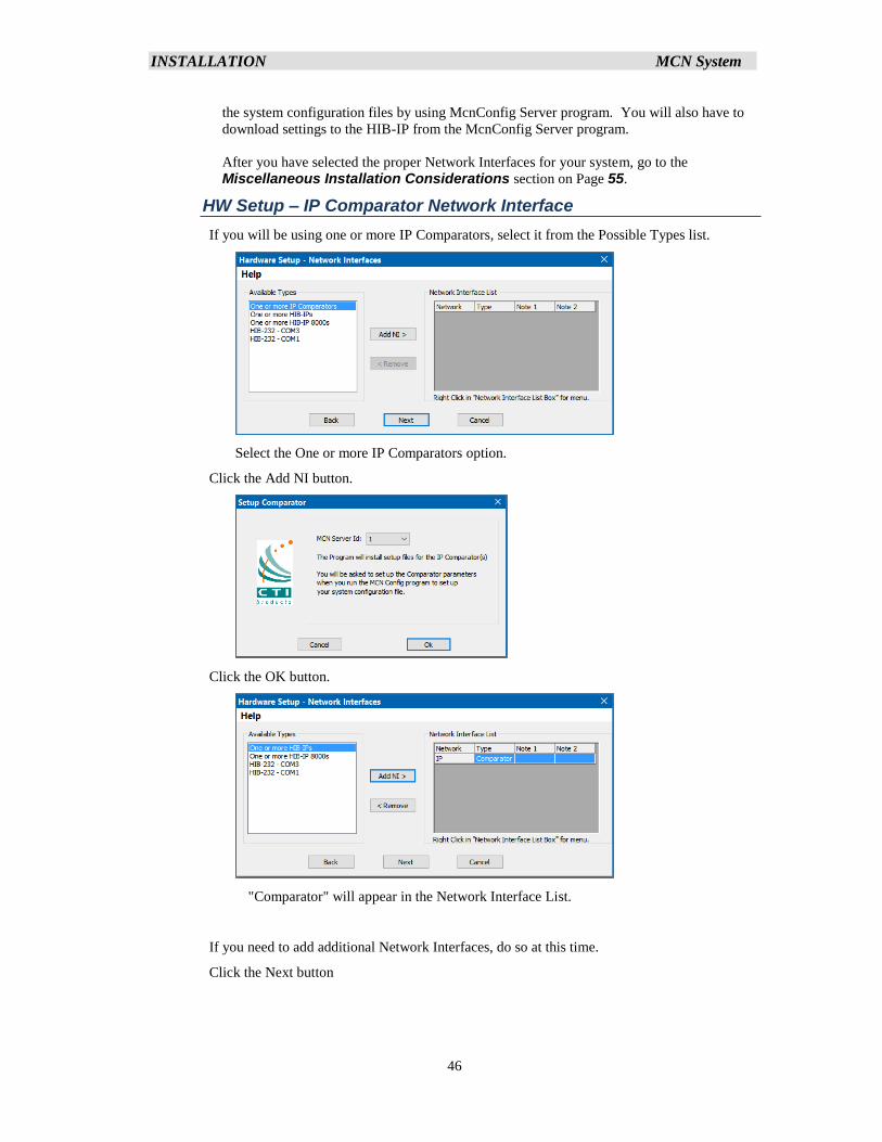
INSTALLATION MCN System
46
the system configuration files by using McnConfig Server program. You will also have to
download settings to the HIB-IP from the McnConfig Server program.
After you have selected the proper Network Interfaces for your system, go to the
Miscellaneous Installation Considerations section on Page 55.
HW Setup – IP Comparator Network Interface
If you will be using one or more IP Comparators, select it from the Possible Types list.
Select the One or more IP Comparators option.
Click the Add NI button.
Click the OK button.
"Comparator" will appear in the Network Interface List.
If you need to add additional Network Interfaces, do so at this time.
Click the Next button
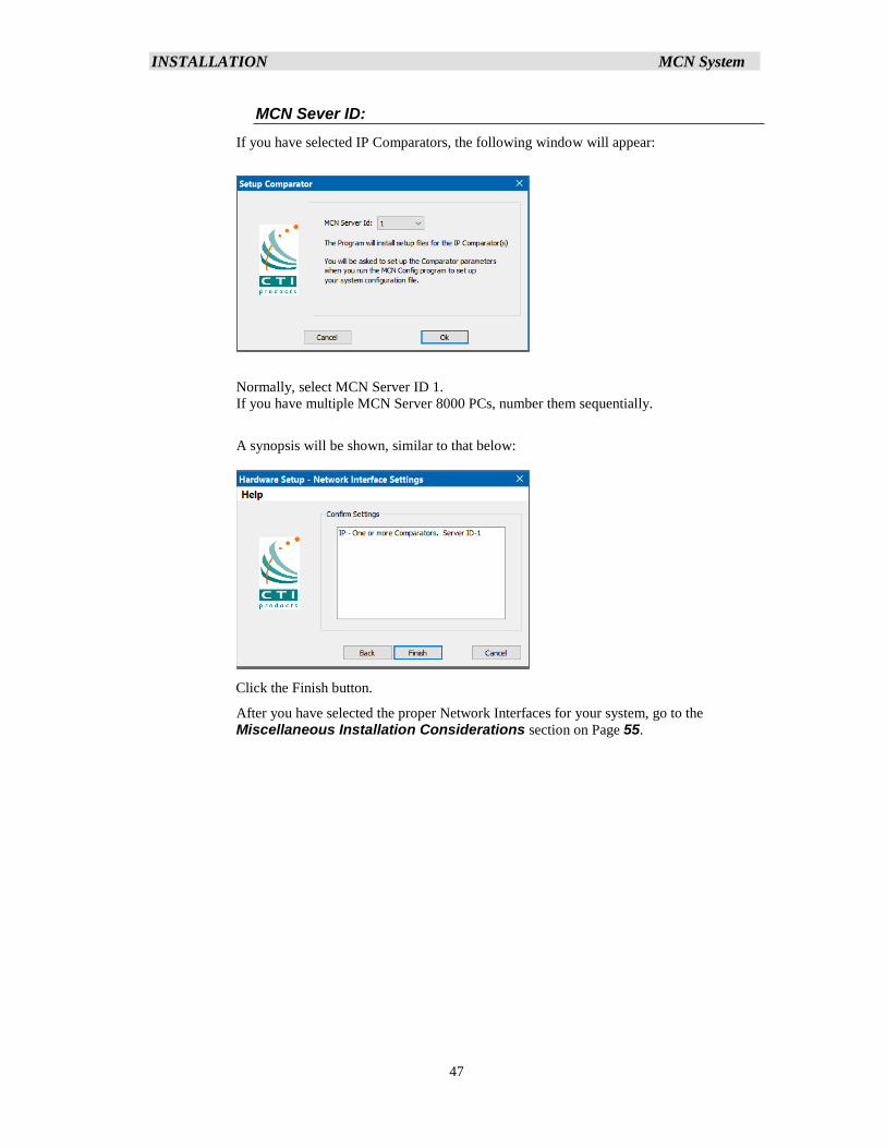
INSTALLATION MCN System
47
MCN Sever ID:
If you have selected IP Comparators, the following window will appear:
Normally, select MCN Server ID 1.
If you have multiple MCN Server 8000 PCs, number them sequentially.
A synopsis will be shown, similar to that below:
Click the Finish button.
After you have selected the proper Network Interfaces for your system, go to the
Miscellaneous Installation Considerations section on Page 55.
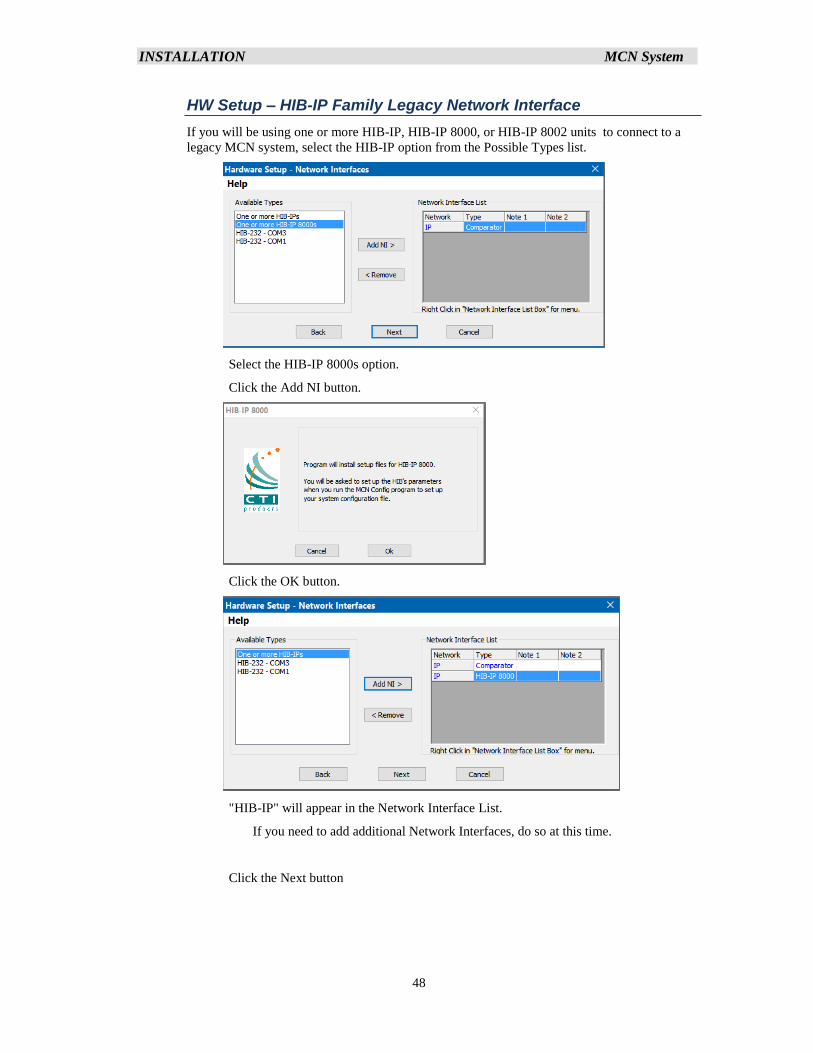
INSTALLATION MCN System
48
HW Setup – HIB-IP Family Legacy Network Interface
If you will be using one or more HIB-IP, HIB-IP 8000, or HIB-IP 8002 units to connect to a
legacy MCN system, select the HIB-IP option from the Possible Types list.
Select the HIB-IP 8000s option.
Click the Add NI button.
Click the OK button.
"HIB-IP" will appear in the Network Interface List.
If you need to add additional Network Interfaces, do so at this time.
Click the Next button
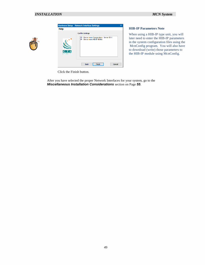
INSTALLATION MCN System
49
Click the Finish button.
After you have selected the proper Network Interfaces for your system, go to the
Miscellaneous Installation Considerations section on Page 55.
HIB-IP Parameters Note
When using a HIB-IP type unit, you will
later need to enter the HIB-IP parameters
in the system configuration files using the
McnConfig program. You will also have
to download (write) those parameters to
the HIB-IP module using McnConfig.
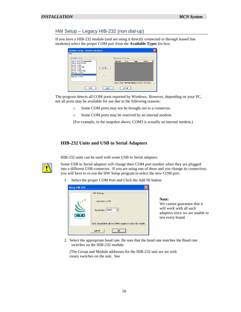
INSTALLATION MCN System
50
HW Setup – Legacy HIB-232 (non dial-up)
If you have a HIB-232 module (and are using it directly connected or through leased line
modems) select the proper COM port from the Available Types list box:
The program detects all COM ports reported by Windows. However, depending on your PC,
not all ports may be available for use due to the following reasons:
o Some COM ports may not be brought out to a connector.
o Some COM ports may be reserved by an internal modem.
(For example, in the snapshot above, COM3 is actually an internal modem.)
HIB-232 Units and USB to Serial Adapters
HIB-232 units can be used with some USB to Serial adapters.
Some USB to Serial adapters will change their COM port number when they are plugged
into a different USB connector. If you are using one of these and you change its connection,
you will have to re-run the HW Setup program to select the new COM port.
1. Select the proper COM Port and Click the Add NI button
2. Select the appropriate baud rate. Be sure that the baud rate matches the Baud rate
switches on the HIB-232 module.
(The Group and Module addresses for the HIB-232 unit are set with
rotary switches on the unit. See
Note:
We cannot guarantee that it
will work with all such
adapters since we are unable to
test every brand.
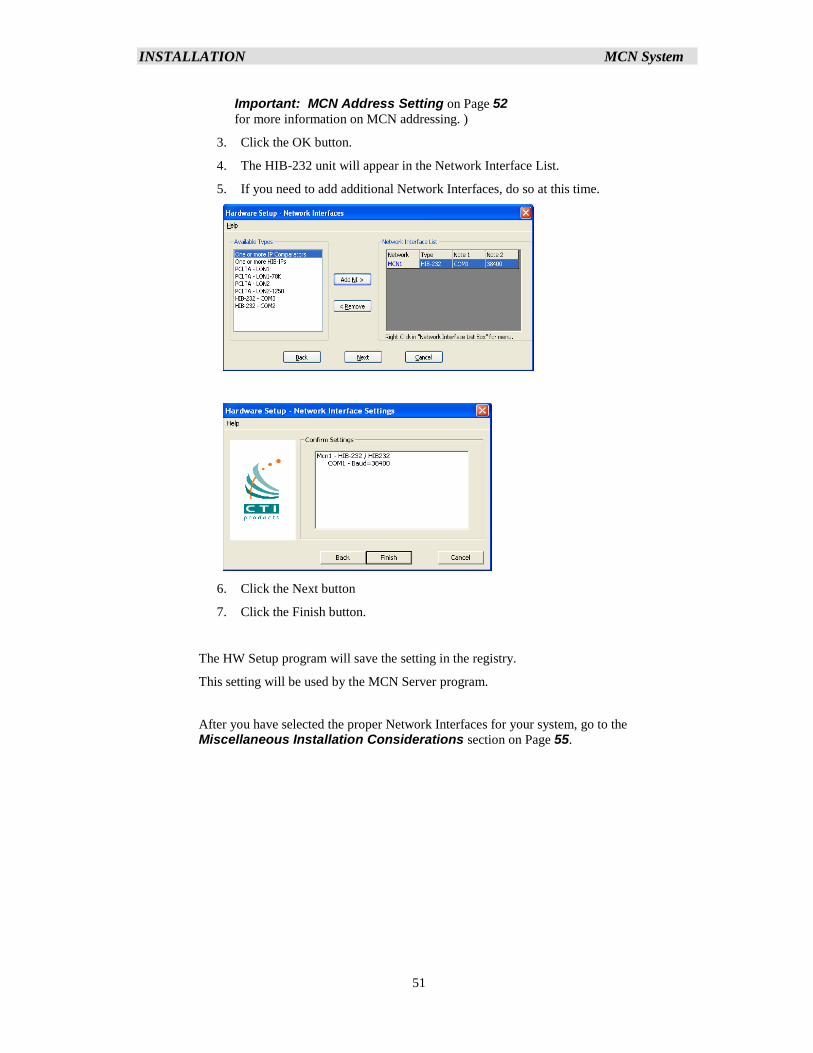
INSTALLATION MCN System
51
Important: MCN Address Setting on Page 52
for more information on MCN addressing. )
3. Click the OK button.
4. The HIB-232 unit will appear in the Network Interface List.
5. If you need to add additional Network Interfaces, do so at this time.
6. Click the Next button
7. Click the Finish button.
The HW Setup program will save the setting in the registry.
This setting will be used by the MCN Server program.
After you have selected the proper Network Interfaces for your system, go to the
Miscellaneous Installation Considerations section on Page 55.
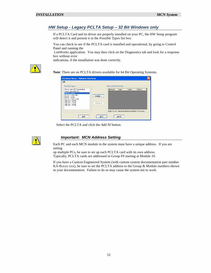
INSTALLATION MCN System
52
HW Setup - Legacy PCLTA Setup – 32 Bit Windows only
If a PCLTA Card and its driver are properly installed on your PC, the HW Setup program
will detect it and present it in the Possible Types list box.
You can check to see if the PCLTA card is installed and operational, by going to Control
Panel and running the
LonWorks application. You may then click on the Diagnostics tab and look for a response
box without error
indications, if the installation was done correctly.
Note: There are no PCLTA drivers available for 64 Bit Operating Systems.
Select the PCLTA and click the Add NI button.
Important: MCN Address Setting
Each PC and each MCN module in the system must have a unique address. If you are
setting
up multiple PCs, be sure to set up each PCLTA card with its own address.
Typically, PCLTA cards are addressed in Group F0 starting at Module 10.
If you have a Custom Engineered System (with custom system documentation part number
KA-8xxxx-xxx), be sure to set the PCLTA address to the Group & Module numbers shown
in your documentation. Failure to do so may cause the system not to work.
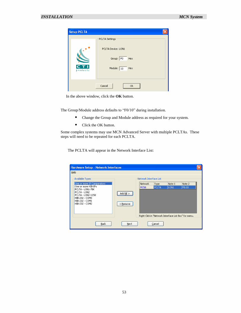
INSTALLATION MCN System
53
In the above window, click the OK button.
The Group/Module address defaults to “F0/10” during installation.
▪ Change the Group and Module address as required for your system.
▪ Click the OK button.
Some complex systems may use MCN Advanced Server with multiple PCLTAs. These
steps will need to be repeated for each PCLTA.
The PCLTA will appear in the Network Interface List:
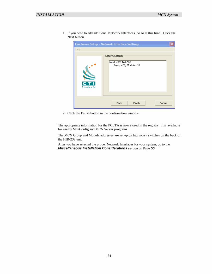
INSTALLATION MCN System
54
1. If you need to add additional Network Interfaces, do so at this time. Click the
Next button.
2. Click the Finish button in the confirmation window.
The appropriate information for the PCLTA is now stored in the registry. It is available
for use by McnConfig and MCN Server programs.
The MCN Group and Module addresses are set up on hex rotary switches on the back of
the HIB-232 unit.
After you have selected the proper Network Interfaces for your system, go to the
Miscellaneous Installation Considerations section on Page 55.
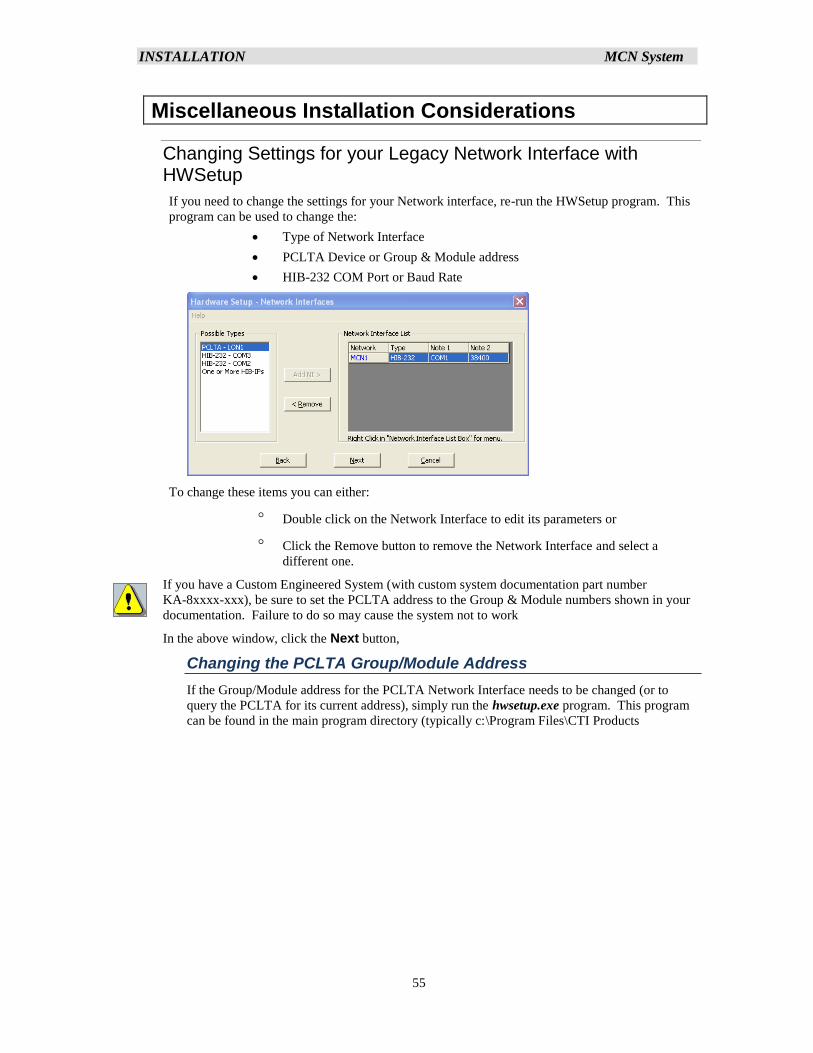
INSTALLATION MCN System
55
Miscellaneous Installation Considerations
Changing Settings for your Legacy Network Interface with HWSetup
If you need to change the settings for your Network interface, re-run the HWSetup program. This
program can be used to change the:
• Type of Network Interface
• PCLTA Device or Group & Module address
• HIB-232 COM Port or Baud Rate
To change these items you can either:
Double click on the Network Interface to edit its parameters or
Click the Remove button to remove the Network Interface and select a
different one.
If you have a Custom Engineered System (with custom system documentation part number
KA-8xxxx-xxx), be sure to set the PCLTA address to the Group & Module numbers shown in your
documentation. Failure to do so may cause the system not to work
In the above window, click the Next button,
Changing the PCLTA Group/Module Address
If the Group/Module address for the PCLTA Network Interface needs to be changed (or to
query the PCLTA for its current address), simply run the hwsetup.exe program. This program
can be found in the main program directory (typically c:\Program Files\CTI Products
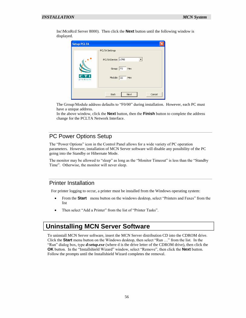
INSTALLATION MCN System
56
Inc\McnRcd Server 8000). Then click the Next button until the following window is
displayed.
The Group/Module address defaults to “F0/00” during installation. However, each PC must
have a unique address.
In the above window, click the Next button, then the Finish button to complete the address
change for the PCLTA Network Interface.
PC Power Options Setup
The “Power Options” icon in the Control Panel allows for a wide variety of PC operation
parameters. However, installation of MCN Server software will disable any possibility of the PC
going into the Standby or Hibernate Mode.
The monitor may be allowed to “sleep” as long as the “Monitor Timeout” is less than the “Standby
Time”. Otherwise, the monitor will never sleep.
Printer Installation
For printer logging to occur, a printer must be installed from the Windows operating system:
• From the Start menu button on the windows desktop, select “Printers and Faxes” from the
list
• Then select “Add a Printer” from the list of “Printer Tasks”.
Uninstalling MCN Server Software
To uninstall MCN Server software, insert the MCN Server distribution CD into the CDROM drive.
Click the Start menu button on the Windows desktop, then select “Run …” from the list. In the
“Run” dialog box, type d:setup.exe (where d is the drive letter of the CDROM drive), then click the
OK button. In the “Installshield Wizard” window, select “Remove”, then click the Next button.
Follow the prompts until the Installshield Wizard completes the removal.
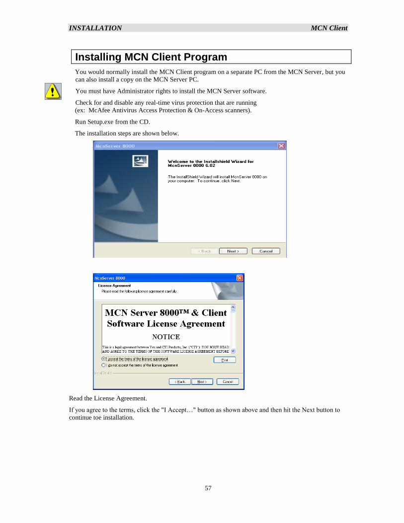
INSTALLATION MCN Client
57
Installing MCN Client Program
You would normally install the MCN Client program on a separate PC from the MCN Server, but you
can also install a copy on the MCN Server PC.
You must have Administrator rights to install the MCN Server software.
Check for and disable any real-time virus protection that are running
(ex: McAfee Antivirus Access Protection & On-Access scanners).
Run Setup.exe from the CD.
The installation steps are shown below.
Read the License Agreement.
If you agree to the terms, click the "I Accept…" button as shown above and then hit the Next button to
continue toe installation.
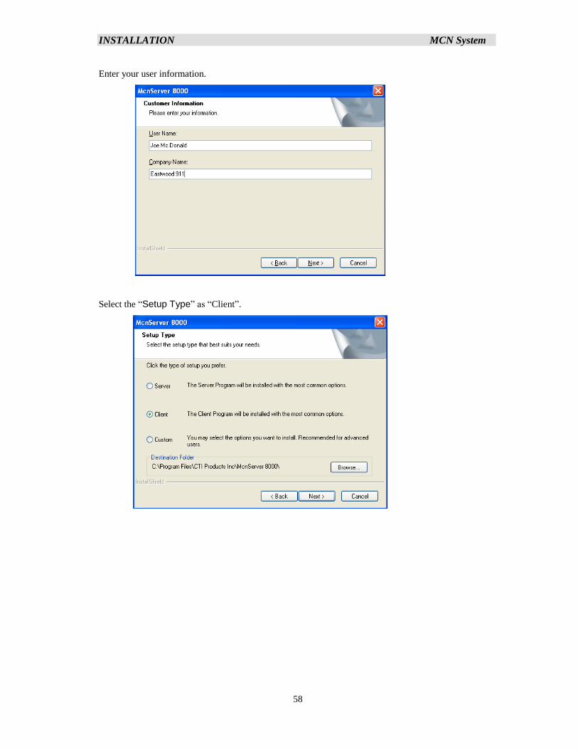
INSTALLATION MCN System
58
Enter your user information.
Select the “Setup Type” as “Client”.
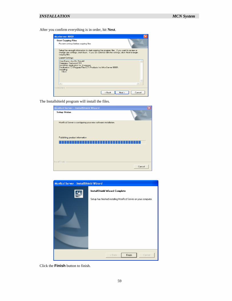
INSTALLATION MCN System
59
After you confirm everything is in order, hit Next.
The Installshield program will install the files.
Click the Finish button to finish.
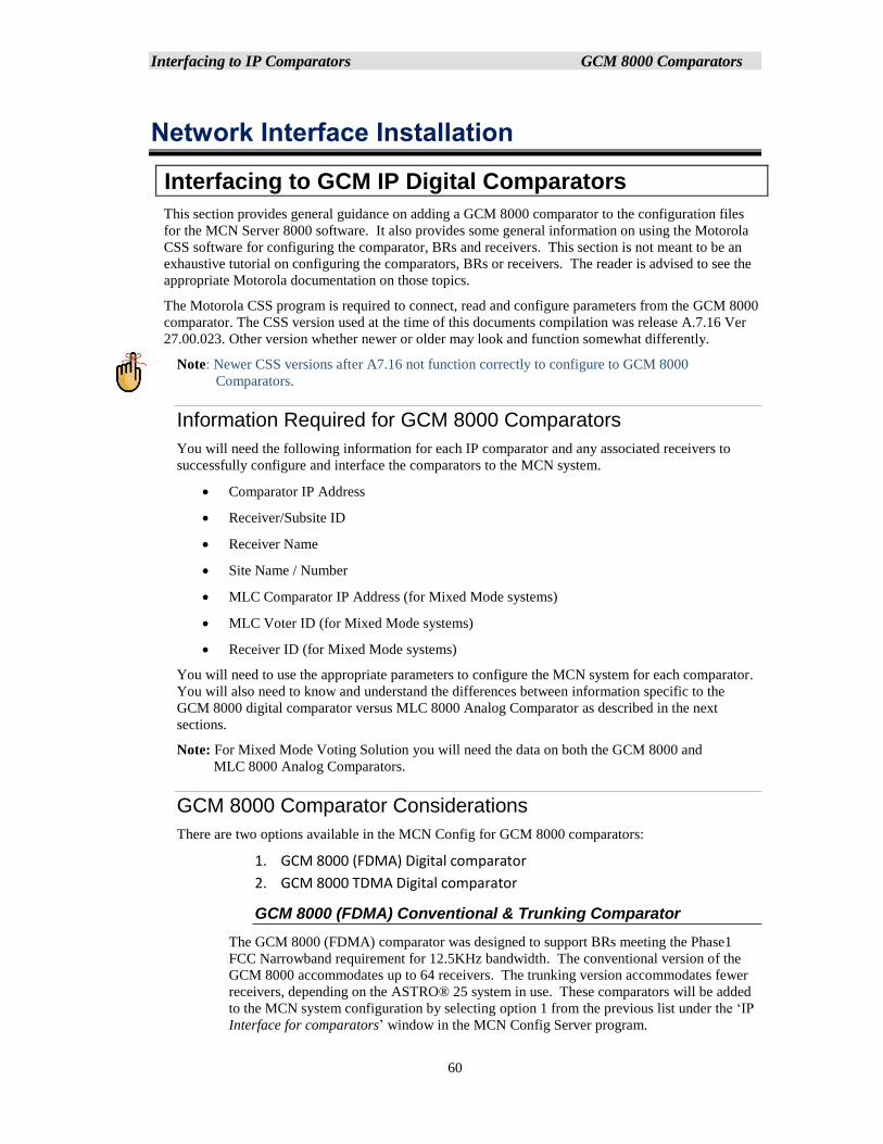
Interfacing to IP Comparators GCM 8000 Comparators
60
Network Interface Installation
Interfacing to GCM IP Digital Comparators
This section provides general guidance on adding a GCM 8000 comparator to the configuration files
for the MCN Server 8000 software. It also provides some general information on using the Motorola
CSS software for configuring the comparator, BRs and receivers. This section is not meant to be an
exhaustive tutorial on configuring the comparators, BRs or receivers. The reader is advised to see the
appropriate Motorola documentation on those topics.
The Motorola CSS program is required to connect, read and configure parameters from the GCM 8000
comparator. The CSS version used at the time of this documents compilation was release A.7.16 Ver
27.00.023. Other version whether newer or older may look and function somewhat differently.
Note: Newer CSS versions after A7.16 not function correctly to configure to GCM 8000
Comparators.
Information Required for GCM 8000 Comparators
You will need the following information for each IP comparator and any associated receivers to
successfully configure and interface the comparators to the MCN system.
• Comparator IP Address
• Receiver/Subsite ID
• Receiver Name
• Site Name / Number
• MLC Comparator IP Address (for Mixed Mode systems)
• MLC Voter ID (for Mixed Mode systems)
• Receiver ID (for Mixed Mode systems)
You will need to use the appropriate parameters to configure the MCN system for each comparator.
You will also need to know and understand the differences between information specific to the
GCM 8000 digital comparator versus MLC 8000 Analog Comparator as described in the next
sections.
Note: For Mixed Mode Voting Solution you will need the data on both the GCM 8000 and
MLC 8000 Analog Comparators.
GCM 8000 Comparator Considerations
There are two options available in the MCN Config for GCM 8000 comparators:
1. GCM 8000 (FDMA) Digital comparator
2. GCM 8000 TDMA Digital comparator
GCM 8000 (FDMA) Conventional & Trunking Comparator
The GCM 8000 (FDMA) comparator was designed to support BRs meeting the Phase1
FCC Narrowband requirement for 12.5KHz bandwidth. The conventional version of the
GCM 8000 accommodates up to 64 receivers. The trunking version accommodates fewer
receivers, depending on the ASTRO® 25 system in use. These comparators will be added
to the MCN system configuration by selecting option 1 from the previous list under the ‘IP
Interface for comparators’ window in the MCN Config Server program.
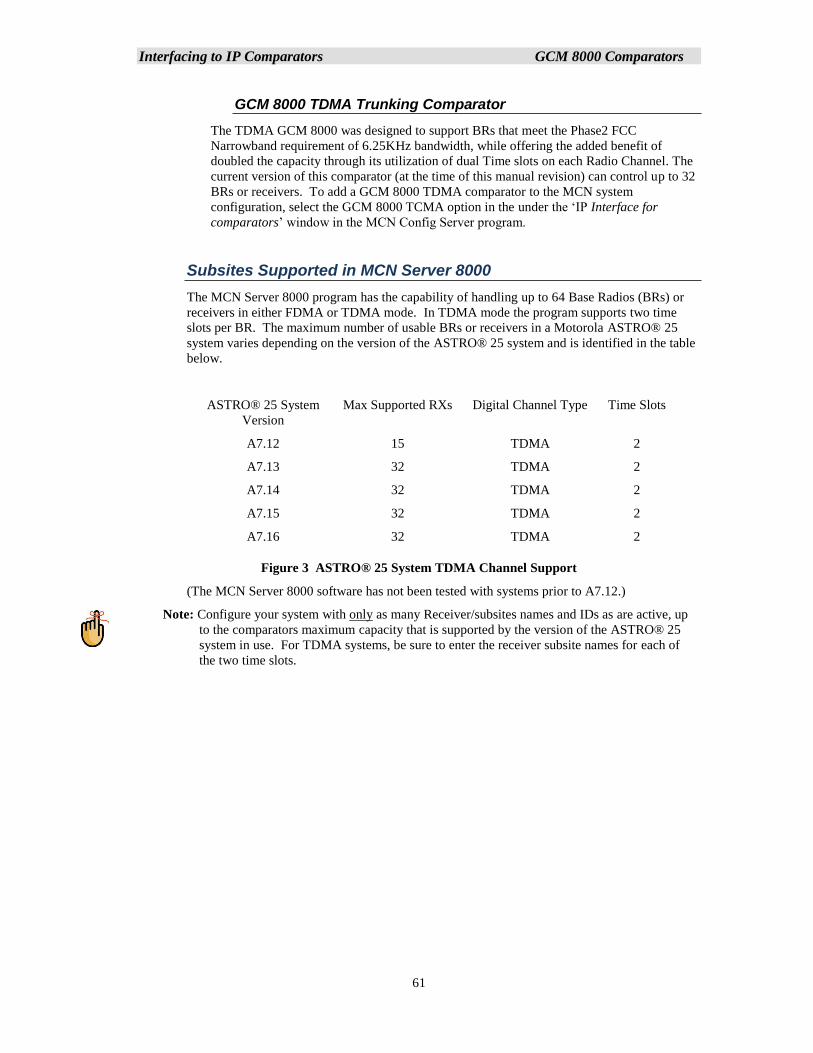
Interfacing to IP Comparators GCM 8000 Comparators
61
GCM 8000 TDMA Trunking Comparator
The TDMA GCM 8000 was designed to support BRs that meet the Phase2 FCC
Narrowband requirement of 6.25KHz bandwidth, while offering the added benefit of
doubled the capacity through its utilization of dual Time slots on each Radio Channel. The
current version of this comparator (at the time of this manual revision) can control up to 32
BRs or receivers. To add a GCM 8000 TDMA comparator to the MCN system
configuration, select the GCM 8000 TCMA option in the under the ‘IP Interface for
comparators’ window in the MCN Config Server program.
Subsites Supported in MCN Server 8000
The MCN Server 8000 program has the capability of handling up to 64 Base Radios (BRs) or
receivers in either FDMA or TDMA mode. In TDMA mode the program supports two time
slots per BR. The maximum number of usable BRs or receivers in a Motorola ASTRO® 25
system varies depending on the version of the ASTRO® 25 system and is identified in the table
below.
ASTRO® 25 System
Version
Max Supported RXs Digital Channel Type Time Slots
A7.12 15 TDMA 2
A7.13 32 TDMA 2
A7.14 32 TDMA 2
A7.15 32 TDMA 2
A7.16 32 TDMA 2
Figure 3 ASTRO® 25 System TDMA Channel Support
(The MCN Server 8000 software has not been tested with systems prior to A7.12.)
Note: Configure your system with only as many Receiver/subsites names and IDs as are active, up
to the comparators maximum capacity that is supported by the version of the ASTRO® 25
system in use. For TDMA systems, be sure to enter the receiver subsite names for each of
the two time slots.
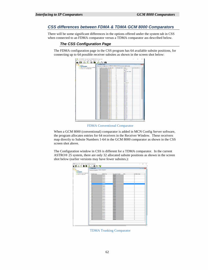
Interfacing to IP Comparators GCM 8000 Comparators
62
CSS differences between FDMA & TDMA GCM 8000 Comparators
There will be some significant differences in the options offered under the system tab in CSS
when connected to an FDMA comparator versus a TDMA comparator ass described below.
The CSS Configuration Page
The FDMA configuration page in the CSS program has 64 available subsite positions, for
connecting up to 64 possible receiver subsites as shown in the screen shot below:
FDMA Conventional Comparator
When a GCM 8000 (conventional) comparator is added in MCN Config Server software,
the program allocates entries for 64 receivers in the Receiver Window. These receivers
map directly to Subsite Numbers 1-64 in the GCM 8000 comparator as shown in the CSS
screen shot above.
The Configuration window in CSS is different for a TDMA comparator. In the current
ASTRO® 25 system, there are only 32 allocated subsite positions as shown in the screen
shot below (earlier versions may have fewer subsites.):
TDMA Trunking Comparator
Interfacing to IP Comparators GCM 8000 Comparators
63
The Aliases in the CSS software are used for the technician's convenience to keep track of
the BRs connected to the GCM 8000. Subsite aliases are not automatically transferred to
the MCN Config Server software or the MCN Server 8000 software. A subsite alias can
also be configured in the BR or receiver, but the subsite aliases are not linked between the
comparator and the BR. It is important to make sure that the aliases in the comparator and
those in the BRs match based on the Subsite Number that is configured in the BR.
In many cases the receiver subsite names to be displayed in the in the MCN Server 8000
software will be different (possibly more “user-friendly”) than the aliases used in the GCM
8000 CSS software. The receiver names must be entered in the MCN Config Server
software. Unfortunately, the GCM 8000 CSS does not support the Windows Copy
command, so you will have to enter the Aliases for the Sub-sites (BRs or Receivers) into
the MCN Config Server program Receiver Window by hand.
IP Addresses for the GCM Comparator and BRs / Receivers
The proper IP Scheme including the addresses, subnet masks and IP gateways must be
configured for both the comparator and the BR / receiver. The IP address scheme will typically
be pre-assigned by a systems engineer, to be compatible with the appropriate IP plan for the
system.
Prerequisite: Obtain the required credentials information (local service account password and
elevated privileges password) to configure the site devices before proceeding. The user
credentials information includes both the current and new credentials. Without the current
credentials, access to the device or to the user credentials is denied.
The IP parameters on all devices are configured through CSS using an RS-232 serial port with
the following steps:
1. Connect to the device using Configuration/Service Software (CSS) through an
Ethernet port link.
2. Click Read information from an infrastructure device
3. From the menu, select Tools → Set IP Address/BR_CM Pairing Number.
Note: If the device is not in a voting or simulcast IP only topology, the menu item is
shown as Set IP Address/Box Number. The Set IP Address and Base
Radio/Comparator Pairing Number dialog box appears or the Set IP Address and Box
Number dialog box appears.
4. In the Device IP Address field, enter the device IP address. Click Set Device IP
Address.
5. (Optional) In a voting or simulcast IP only topology, you may also enter the device
pairing number. Click Set BR/CM Pairing Number.
See also Section BR Pairing Numbers & IP Addresses on Page 64.
6. Click OK to close the dialog box.
7. Click Reset to initiate a hardware restart. SNMPv3 user credentials reset to their
factory default values.
8. Click Close to close the dialog box.
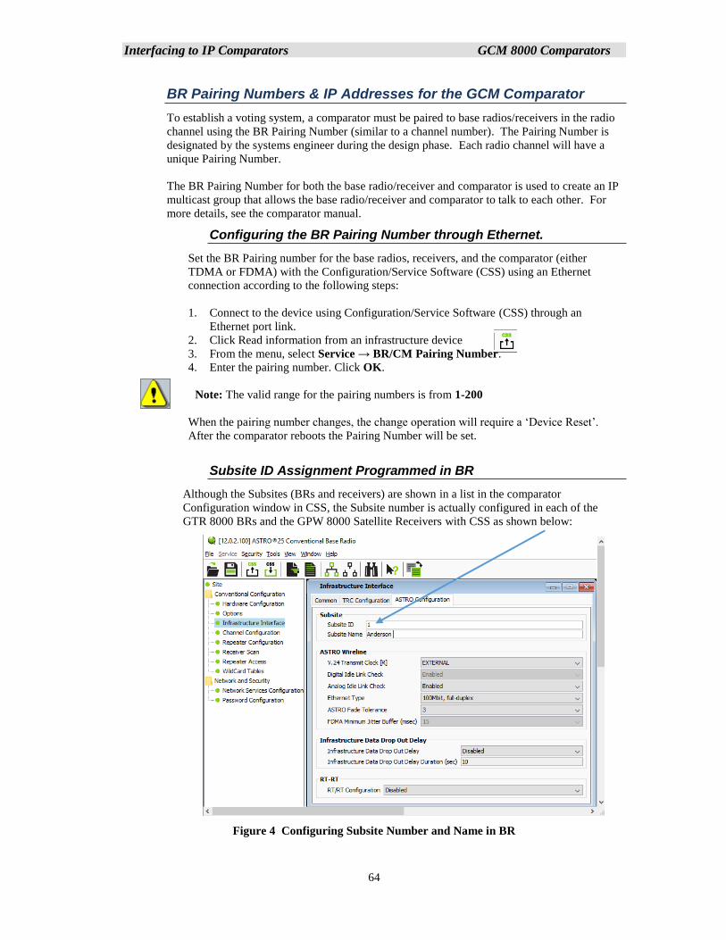
Interfacing to IP Comparators GCM 8000 Comparators
64
BR Pairing Numbers & IP Addresses for the GCM Comparator
To establish a voting system, a comparator must be paired to base radios/receivers in the radio
channel using the BR Pairing Number (similar to a channel number). The Pairing Number is
designated by the systems engineer during the design phase. Each radio channel will have a
unique Pairing Number.
The BR Pairing Number for both the base radio/receiver and comparator is used to create an IP
multicast group that allows the base radio/receiver and comparator to talk to each other. For
more details, see the comparator manual.
Configuring the BR Pairing Number through Ethernet.
Set the BR Pairing number for the base radios, receivers, and the comparator (either
TDMA or FDMA) with the Configuration/Service Software (CSS) using an Ethernet
connection according to the following steps:
1. Connect to the device using Configuration/Service Software (CSS) through an
Ethernet port link.
2. Click Read information from an infrastructure device
3. From the menu, select Service → BR/CM Pairing Number.
4. Enter the pairing number. Click OK.
Note: The valid range for the pairing numbers is from 1-200
When the pairing number changes, the change operation will require a ‘Device Reset’.
After the comparator reboots the Pairing Number will be set.
Subsite ID Assignment Programmed in BR
Although the Subsites (BRs and receivers) are shown in a list in the comparator
Configuration window in CSS, the Subsite number is actually configured in each of the
GTR 8000 BRs and the GPW 8000 Satellite Receivers with CSS as shown below:
Figure 4 Configuring Subsite Number and Name in BR
Interfacing to IP Comparators GCM 8000 Comparators
65
Comparator GCM 8000 Characteristics & Limitations.
The GCM 8000 comparator has the following limitations
Maximum of 3 Simultaneous MCN Servers or CSS Sessions
The GCM 8000 supports only three simultaneous connections for real-time sessions.
These sessions include:
• CTI MCN Server 8000 Software
• CSS Software
From a practical standpoint, this means that you should limit the number of MCN Servers
talking to a GCM 8000 comparator to two. This will allow an open session for the CSS
software.
MCN Server & CSS cannot run simultaneously on the same PC
A single PC cannot run both the MCN Server 8000 software and the CSS software
simultaneously.
• In order to run CSS on the Server PC, you will have to make sure that the MCN
Server software is not running.
• In order to run the MCN Server software, you must make sure that the CSS
software is not running on the MCN Server PC.
• If you try to run both at the same time, you will have to close both programs and
re-start the one you want to use.
GCM 8000 Comparator Can't Disable a Failed Sub-site (Pre A7.17.2)
The legacy ASTRO-TAC™ 3000 and GCM 8000 comparators will not allow the user to
Disable a receiver (Subsite) if it is in Fail mode. This applies to both the MCN Server
8000 application and the Real-Time portion of the Motorola CSS software.
This problem was fixed in GCM 8000 software starting in Motorola’s A7.17.2 release.)
GCM 8000 Disables are Reset on Fail Condition (Pre A7.17.2)
The GCM 8000 comparator will reset the Disable condition if a receiver (Subsite) goes
into Fail mode. This applies to both the MCN Server 8000 application and the Real-Time
portion of the Motorola CSS software.
This problem was fixed in GCM 8000 software starting in Motorola’s A7.17.2 release.)
GCM 8000 CSS Software latches Votes
If a receiver (Subsite) is Force-Voted from the CSS Local Status Screen, it will:
• Latch in the Force Vote state.
• Not allow other receivers to be voted in the GCM 8000.
Note: The latched Force Vote can be unlatched from the MCN Server 8000
by pressing and releasing the left mouse button.
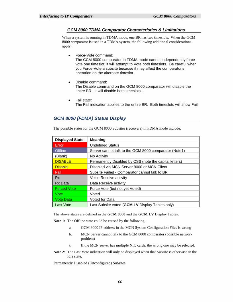
Interfacing to IP Comparators GCM 8000 Comparators
66
GCM 8000 TDMA Comparator Characteristics & Limitations
When a system is running in TDMA mode, one BR has two timeslots. When the GCM
8000 comparator is used in a TDMA system, the following additional considerations
apply:
• Force-Vote command: The CCM 8000 comparator in TDMA mode cannot independently force-vote one timeslot; it will attempt to Vote both timeslots. Be careful when you Force-Vote a subsite because it may affect the comparator’s operation on the alternate timeslot.
• Disable command: The Disable command on the GCM 8000 comparator will disable the entire BR. It will disable both timeslots...
• Fail state: The Fail indication applies to the entire BR. Both timeslots will show Fail.
GCM 8000 (FDMA) Status Display
The possible states for the GCM 8000 Subsites (receivers) in FDMA mode include:
The above states are defined in the GCM 8000 and the GCM LV Display Tables.
Note 1: The Offline state could be caused by the following:
a. GCM 8000 IP address in the MCN System Configuration Files is wrong
b. MCN Server cannot talk to the GCM 8000 comparator (possible network
problem)
c. If the MCN server has multiple NIC cards, the wrong one may be selected.
Note 2: The Last Vote indication will only be displayed when that Subsite is otherwise in the
Idle state.
Permanently Disabled (Unconfigured) Subsites
Displayed State Meaning
Error Undefined Status
Offline Server cannot talk to the GCM 8000 comparator (Note1)
(Blank) No Activity
DISABLE Permanently Disabled by CSS (note the capital letters)
Disable Disabled via MCN Server 8000 or MCN Client
Fail Subsite Failed - Comparator cannot talk to BR
Rx Voice Receive activity
Rx Data Data Receive activity
Forced Vote Force Vote (but not yet Voted)
Vote Voted
Vote Data Voted for Data
Last Vote Last Subsite voted (GCM LV Display Tables only)
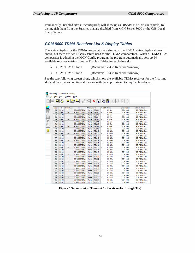
Interfacing to IP Comparators GCM 8000 Comparators
67
Permanently Disabled sites (Unconfigured) will show up as DISABLE or DIS (in capitals) to
distinguish them from the Subsites that are disabled from MCN Server 8000 or the CSS Local
Status Screen.
GCM 8000 TDMA Receiver List & Display Tables
The status display for the TDMA comparator are similar to the FDMA status display shown
above, but there are two Display tables used for the TDMA comparators. When a TDMA GCM
comparator is added in the MCN Config program, the program automatically sets up 64
available receiver entries from the Display Tables for each time slot:
• GCM TDMA Slot 1 (Receivers 1-64 in Receiver Window)
• GCM TDMA Slot 2 (Receivers 1-64 in Receiver Window)
See the two following screen shots, which show the available TDMA receives for the first time
slot and then the second time slot along with the appropriate Display Table selected.
Figure 5 Screenshot of Timeslot 1 (Receivers1a through 32a).
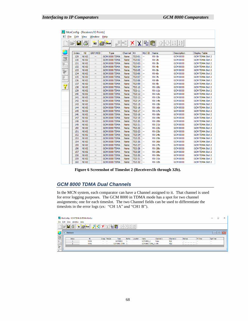
Interfacing to IP Comparators GCM 8000 Comparators
68
Figure 6 Screenshot of Timeslot 2 (Receivers1b through 32b).
GCM 8000 TDMA Dual Channels
In the MCN system, each comparator can have a Channel assigned to it. That channel is used
for error logging purposes. The GCM 8000 in TDMA mode has a spot for two channel
assignments; one for each timeslot. The two Channel fields can be used to differentiate the
timeslots in the error logs (ex: “CH 1A” and “CH1 B”).
Interfacing to IP Comparators GRV 8000 Comparators
69
Interfacing to the GRV 8000 Comparator
This section provides general guidance on adding a GRV 8000 comparator while configuring for the
MCN Server 8000 system files. It also provides some general information on using the Motorola CSS
software for configuring the comparator, BRs and receivers. This section is not meant to be an
exhaustive tutorial on configuring the comparators, BRs or receivers. The reader is advised to see the
appropriate Motorola documentation on those topics.
The Motorola CSS program is the required tool to Connect, Read and Configure the parameters in the
GRV 8000 comparator. The CSS version used at the time of this documents compilation was:
Release A.7.17.2 ; Ver 030.00.007.
Other version whether newer or older may look and function somewhat differently.
Note: Release A7.17 handles GRV 8000 Analog comparators and A7.17.2 handles GRV 8000
Analog or Digital comparators.
The A7.17.2 and up GRV 8000 (G-Series) IP comparator can be configured as an analog or digital
comparator, that supports up to 96 receivers or BRs.
The MCN Server 8000 software (version 8.10 and up) handles either analog or digital GRV 8000
comparators.
Analog GRV 8000 comparator. The GRV 8000 Analog Comparator family is comprised of two types of units:
• GRV 8000 comparator (G-Series Comparator)
• G-Series Link Converter (GSLC) (for interface to 4-Wire radios)
The Analog GRV 8000 comparator works in three different scenarios:
• IP Only: Analog RF transmission with IP connectivity to all BRs “G” Series BRs
(GTR 8000) and Receivers (GPW 8000) and/or
• 4-Wire Only: Analog RF transmission with Quantar or similar BRs with 4-wire
connectivity GSLC modules
• IP GTR 8000 and 4-Wire Radios: A mixture of IP BRs and 4-Wire BRs.
Digital GRV 8000 comparator.
• Digital GRV 8000 Comparator talks directly to BRs over IP
Information Required To Configure GRV 8000 IP Comparator
The information required to configuring the MCNConfig Program for the GRV 8000 Comparator
module when building the MCN System Files is as follows:
• GRV 8000 IP Address: (Entered in the Hardware Configuration window
for GRV 8000.)
• Subsite Number: (Matches the Receiver Number in the
Receiver Window)
• Receiver/Subsite Name: (Entered in the Receiver Window)
• Description (Optional): (Entered in the Receiver Window)
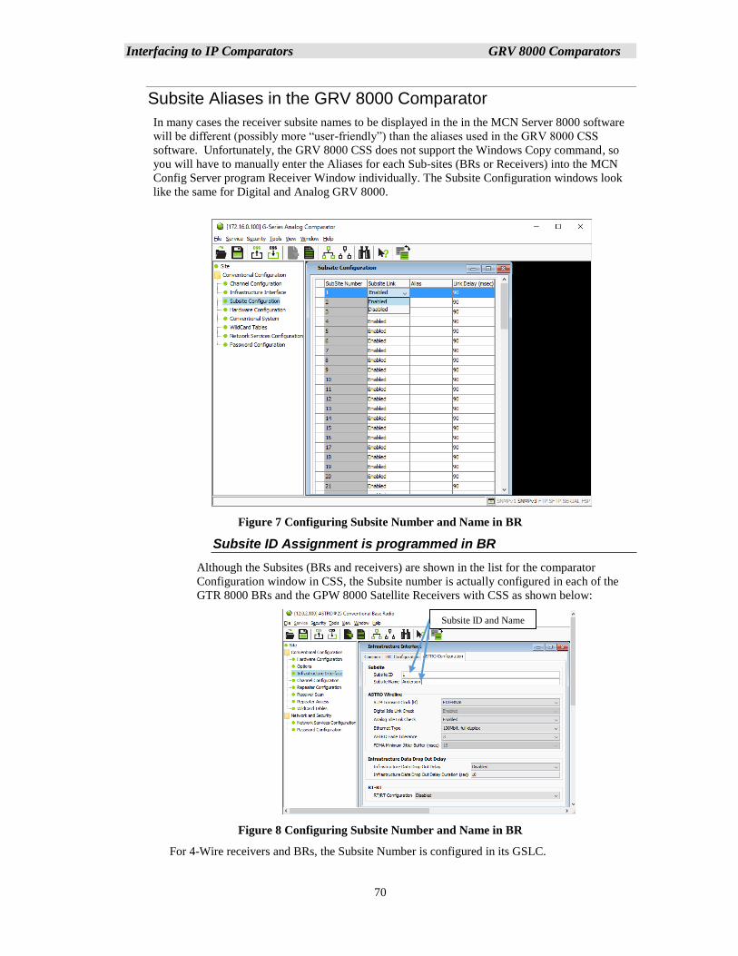
Interfacing to IP Comparators GRV 8000 Comparators
70
Subsite Aliases in the GRV 8000 Comparator
In many cases the receiver subsite names to be displayed in the in the MCN Server 8000 software
will be different (possibly more “user-friendly”) than the aliases used in the GRV 8000 CSS
software. Unfortunately, the GRV 8000 CSS does not support the Windows Copy command, so
you will have to manually enter the Aliases for each Sub-sites (BRs or Receivers) into the MCN
Config Server program Receiver Window individually. The Subsite Configuration windows look
like the same for Digital and Analog GRV 8000.
Figure 7 Configuring Subsite Number and Name in BR
Subsite ID Assignment is programmed in BR
Although the Subsites (BRs and receivers) are shown in the list for the comparator
Configuration window in CSS, the Subsite number is actually configured in each of the
GTR 8000 BRs and the GPW 8000 Satellite Receivers with CSS as shown below:
Figure 8 Configuring Subsite Number and Name in BR
For 4-Wire receivers and BRs, the Subsite Number is configured in its GSLC.
Subsite ID and Name
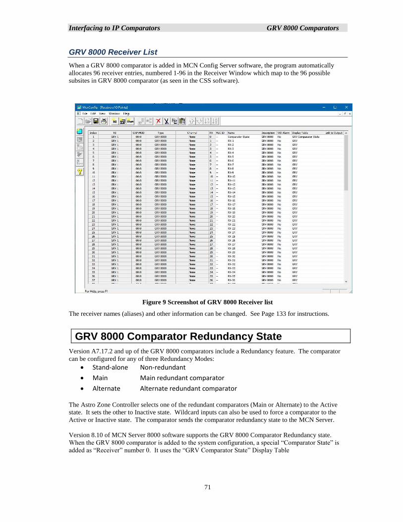
Interfacing to IP Comparators GRV 8000 Comparators
71
GRV 8000 Receiver List
When a GRV 8000 comparator is added in MCN Config Server software, the program automatically
allocates 96 receiver entries, numbered 1-96 in the Receiver Window which map to the 96 possible
subsites in GRV 8000 comparator (as seen in the CSS software).
Figure 9 Screenshot of GRV 8000 Receiver list
The receiver names (aliases) and other information can be changed. See Page 133 for instructions.
GRV 8000 Comparator Redundancy State
Version A7.17.2 and up of the GRV 8000 comparators include a Redundancy feature. The comparator
can be configured for any of three Redundancy Modes:
• Stand-alone Non-redundant
• Main Main redundant comparator
• Alternate Alternate redundant comparator
The Astro Zone Controller selects one of the redundant comparators (Main or Alternate) to the Active
state. It sets the other to Inactive state. Wildcard inputs can also be used to force a comparator to the
Active or Inactive state. The comparator sends the comparator redundancy state to the MCN Server.
Version 8.10 of MCN Server 8000 software supports the GRV 8000 Comparator Redundancy state.
When the GRV 8000 comparator is added to the system configuration, a special “Comparator State” is
added as “Receiver” number 0. It uses the “GRV Comparator State” Display Table
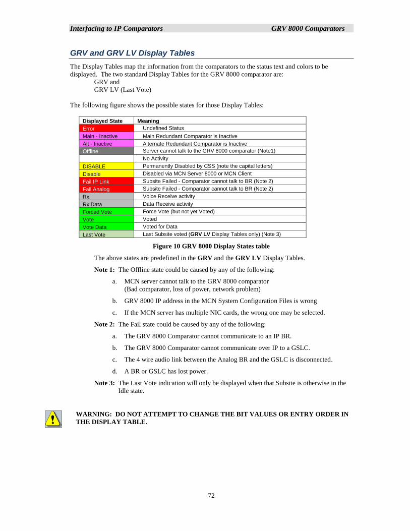
Interfacing to IP Comparators GRV 8000 Comparators
72
GRV and GRV LV Display Tables
The Display Tables map the information from the comparators to the status text and colors to be
displayed. The two standard Display Tables for the GRV 8000 comparator are:
GRV and
GRV LV (Last Vote)
The following figure shows the possible states for those Display Tables:
Displayed State Meaning
Error Undefined Status
Main - Inactive Main Redundant Comparator is Inactive
Alt - Inactive Alternate Redundant Comparator is Inactive
Offline Server cannot talk to the GRV 8000 comparator (Note1)
No Activity
DISABLE Permanently Disabled by CSS (note the capital letters)
Disable Disabled via MCN Server 8000 or MCN Client
Fail IP Link Subsite Failed - Comparator cannot talk to BR (Note 2)
Fail Analog Subsite Failed - Comparator cannot talk to BR (Note 2)
Rx Voice Receive activity
Rx Data Data Receive activity
Forced Vote Force Vote (but not yet Voted)
Vote Voted
Vote Data Voted for Data
Last Vote Last Subsite voted (GRV LV Display Tables only) (Note 3)
Figure 10 GRV 8000 Display States table
The above states are predefined in the GRV and the GRV LV Display Tables.
Note 1: The Offline state could be caused by any of the following:
a. MCN server cannot talk to the GRV 8000 comparator
(Bad comparator, loss of power, network problem)
b. GRV 8000 IP address in the MCN System Configuration Files is wrong
c. If the MCN server has multiple NIC cards, the wrong one may be selected.
Note 2: The Fail state could be caused by any of the following:
a. The GRV 8000 Comparator cannot communicate to an IP BR.
b. The GRV 8000 Comparator cannot communicate over IP to a GSLC.
c. The 4 wire audio link between the Analog BR and the GSLC is disconnected.
d. A BR or GSLC has lost power.
Note 3: The Last Vote indication will only be displayed when that Subsite is otherwise in the
Idle state.
WARNING: DO NOT ATTEMPT TO CHANGE THE BIT VALUES OR ENTRY ORDER IN
THE DISPLAY TABLE.
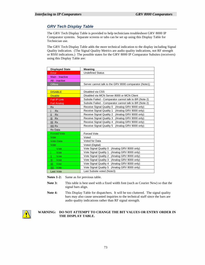
Interfacing to IP Comparators GRV 8000 Comparators
73
GRV Tech Display Table
The GRV Tech Display Table is provided to help technicians troubleshoot GRV 8000 IP
Comparator systems. Separate screens or tabs can be set up using this Display Table for
Technician use.
The GRV Tech Display Table adds the more technical indication to the display including Signal
Quality indication. (The Signal Quality Metrics are audio quality indications, not RF strength
or RSSI indications.) The possible states for the GRV 8000 IP Comparator Subsites (receivers)
using this Display Table are:
Displayed State Meaning
Error Undefined Status
Main - Inactive
Alt - Inactive
Offline Server cannot talk to the GRV 8000 comparator (Note1)
DISABLE Disabled via CSS
Disable Disabled via MCN Server 8000 or MCN Client
Fail IP Link Subsite Failed - Comparator cannot talk to BR (Note 2)
Fail Analog Subsite Failed - Comparator cannot talk to BR (Note 2)
Rx Receive Signal Quality 0 (Analog GRV 8000 only)
| Rx Receive Signal Quality 1 (Analog GRV 8000 only)
|| Rx Receive Signal Quality 2 (Analog GRV 8000 only)
||| Rx Receive Signal Quality 3 (Analog GRV 8000 only)
|||| Rx Receive Signal Quality 4 (Analog GRV 8000 only)
||||| Rx Receive Signal Quality 5 (Analog GRV 8000 only)
Rx Data
Forced Vote Forced Vote
Vote Voted
Vote Data Voted for Data
Vote Voted (Digital)
Vote Vote Signal Quality 0 (Analog GRV 8000 only)
| Vote Vote Signal Quality 1 (Analog GRV 8000 only)
|| Vote Vote Signal Quality 2 (Analog GRV 8000 only)
||| Vote Vote Signal Quality 3 (Analog GRV 8000 only)
|||| Vote Vote Signal Quality 4 (Analog GRV 8000 only)
||||| Vote Vote Signal Quality 5 (Analog GRV 8000 only)
Last Vote Last Subsite voted (Note3)
Notes 1-2: Same as for previous table.
Note 3: This table is best used with a fixed width font (such as Courier New) so that the
signal bars align.
Note 4: This Display Table for dispatchers. It will be too cluttered. The signal quality
bars may also cause unwanted inquiries to the technical staff since the bars are
audio quality indications rather than RF signal strength.
WARNING: DO NOT ATTEMPT TO CHANGE THE BIT VALUES OR ENTRY ORDER IN
THE DISPLAY TABLE.
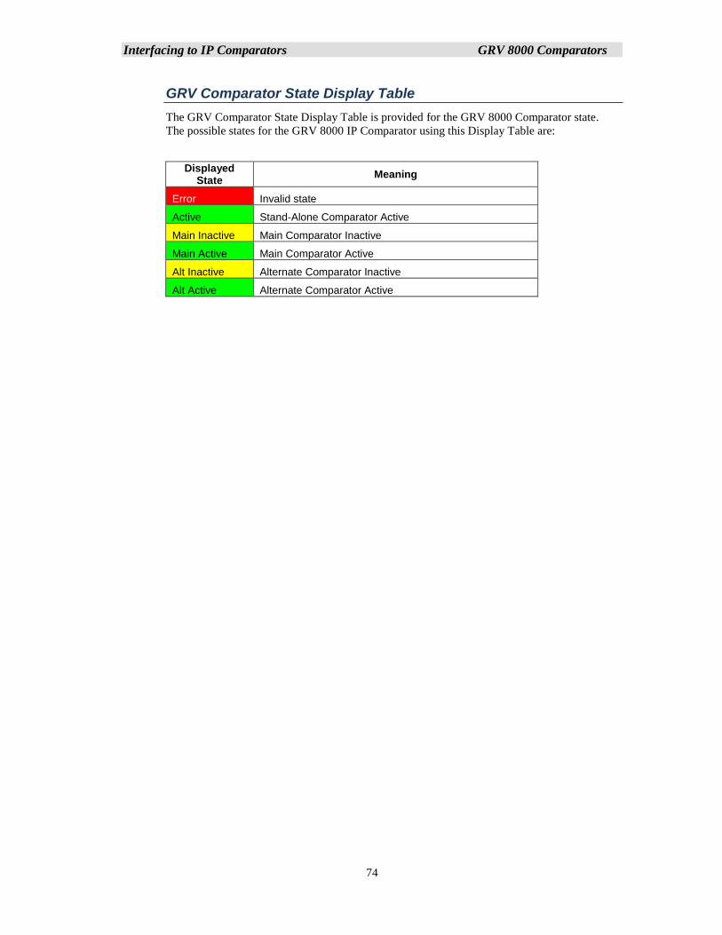
Interfacing to IP Comparators GRV 8000 Comparators
74
GRV Comparator State Display Table
The GRV Comparator State Display Table is provided for the GRV 8000 Comparator state.
The possible states for the GRV 8000 IP Comparator using this Display Table are:
Displayed State
Meaning
Error Invalid state
Active Stand-Alone Comparator Active
Main Inactive Main Comparator Inactive
Main Active Main Comparator Active
Alt Inactive Alternate Comparator Inactive
Alt Active Alternate Comparator Active
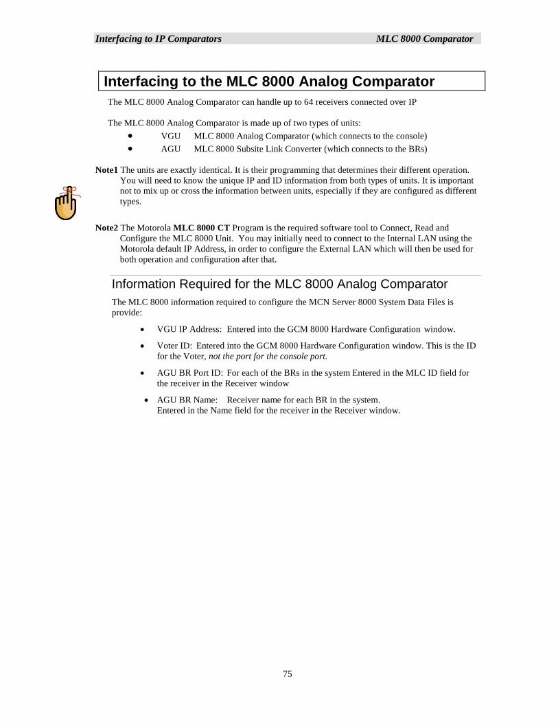
Interfacing to IP Comparators MLC 8000 Comparator
75
Interfacing to the MLC 8000 Analog Comparator
The MLC 8000 Analog Comparator can handle up to 64 receivers connected over IP
The MLC 8000 Analog Comparator is made up of two types of units:
• VGU MLC 8000 Analog Comparator (which connects to the console)
• AGU MLC 8000 Subsite Link Converter (which connects to the BRs)
Note1 The units are exactly identical. It is their programming that determines their different operation.
You will need to know the unique IP and ID information from both types of units. It is important
not to mix up or cross the information between units, especially if they are configured as different
types.
Note2 The Motorola MLC 8000 CT Program is the required software tool to Connect, Read and
Configure the MLC 8000 Unit. You may initially need to connect to the Internal LAN using the
Motorola default IP Address, in order to configure the External LAN which will then be used for
both operation and configuration after that.
Information Required for the MLC 8000 Analog Comparator
The MLC 8000 information required to configure the MCN Server 8000 System Data Files is
provide:
• VGU IP Address: Entered into the GCM 8000 Hardware Configuration window.
• Voter ID: Entered into the GCM 8000 Hardware Configuration window. This is the ID
for the Voter, not the port for the console port.
• AGU BR Port ID: For each of the BRs in the system Entered in the MLC ID field for
the receiver in the Receiver window
• AGU BR Name: Receiver name for each BR in the system.
Entered in the Name field for the receiver in the Receiver window.
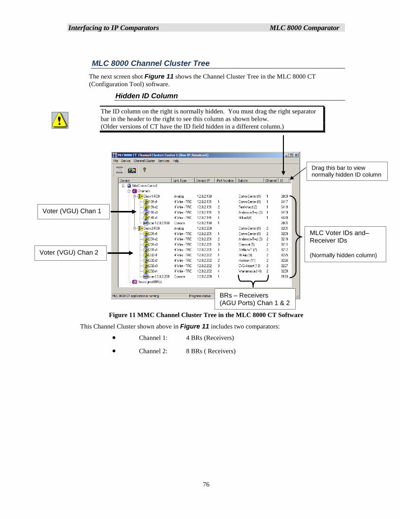
Interfacing to IP Comparators MLC 8000 Comparator
76
MLC 8000 Channel Cluster Tree
The next screen shot Figure 11 shows the Channel Cluster Tree in the MLC 8000 CT
(Configuration Tool) software.
Hidden ID Column
The ID column on the right is normally hidden. You must drag the right separator
bar in the header to the right to see this column as shown below.
(Older versions of CT have the ID field hidden in a different column.)
Figure 11 MMC Channel Cluster Tree in the MLC 8000 CT Software
This Channel Cluster shown above in Figure 11 includes two comparators:
• Channel 1: 4 BRs (Receivers)
• Channel 2: 8 BRs ( Receivers)
BRs – Receivers (AGU Ports) Chan 1 & 2
MLC Voter IDs and– Receiver IDs (Normally hidden column)
Voter (VGU) Chan 1
Voter (VGU) Chan 2
Drag this bar to view normally hidden ID column
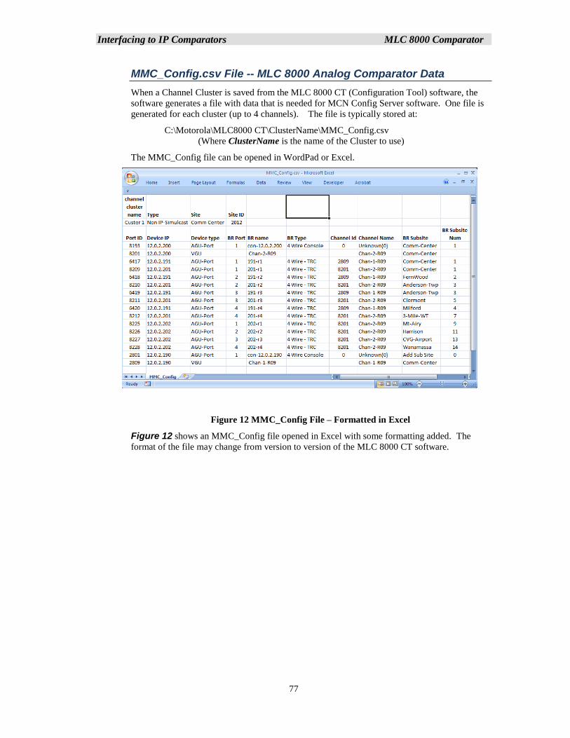
Interfacing to IP Comparators MLC 8000 Comparator
77
MMC_Config.csv File -- MLC 8000 Analog Comparator Data
When a Channel Cluster is saved from the MLC 8000 CT (Configuration Tool) software, the
software generates a file with data that is needed for MCN Config Server software. One file is
generated for each cluster (up to 4 channels). The file is typically stored at:
C:\Motorola\MLC8000 CT\ClusterName\MMC_Config.csv
(Where ClusterName is the name of the Cluster to use)
The MMC_Config file can be opened in WordPad or Excel.
Figure 12 MMC_Config File – Formatted in Excel
Figure 12 shows an MMC_Config file opened in Excel with some formatting added. The
format of the file may change from version to version of the MLC 8000 CT software.
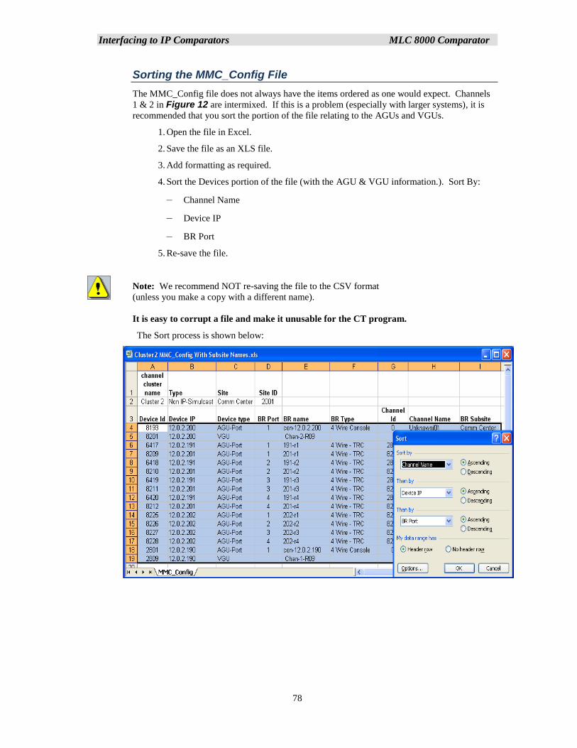
Interfacing to IP Comparators MLC 8000 Comparator
78
Sorting the MMC_Config File
The MMC_Config file does not always have the items ordered as one would expect. Channels
1 & 2 in Figure 12 are intermixed. If this is a problem (especially with larger systems), it is
recommended that you sort the portion of the file relating to the AGUs and VGUs.
1. Open the file in Excel.
2. Save the file as an XLS file.
3. Add formatting as required.
4. Sort the Devices portion of the file (with the AGU & VGU information.). Sort By:
– Channel Name
– Device IP
– BR Port
5. Re-save the file.
Note: We recommend NOT re-saving the file to the CSV format
(unless you make a copy with a different name).
It is easy to corrupt a file and make it unusable for the CT program.
The Sort process is shown below:
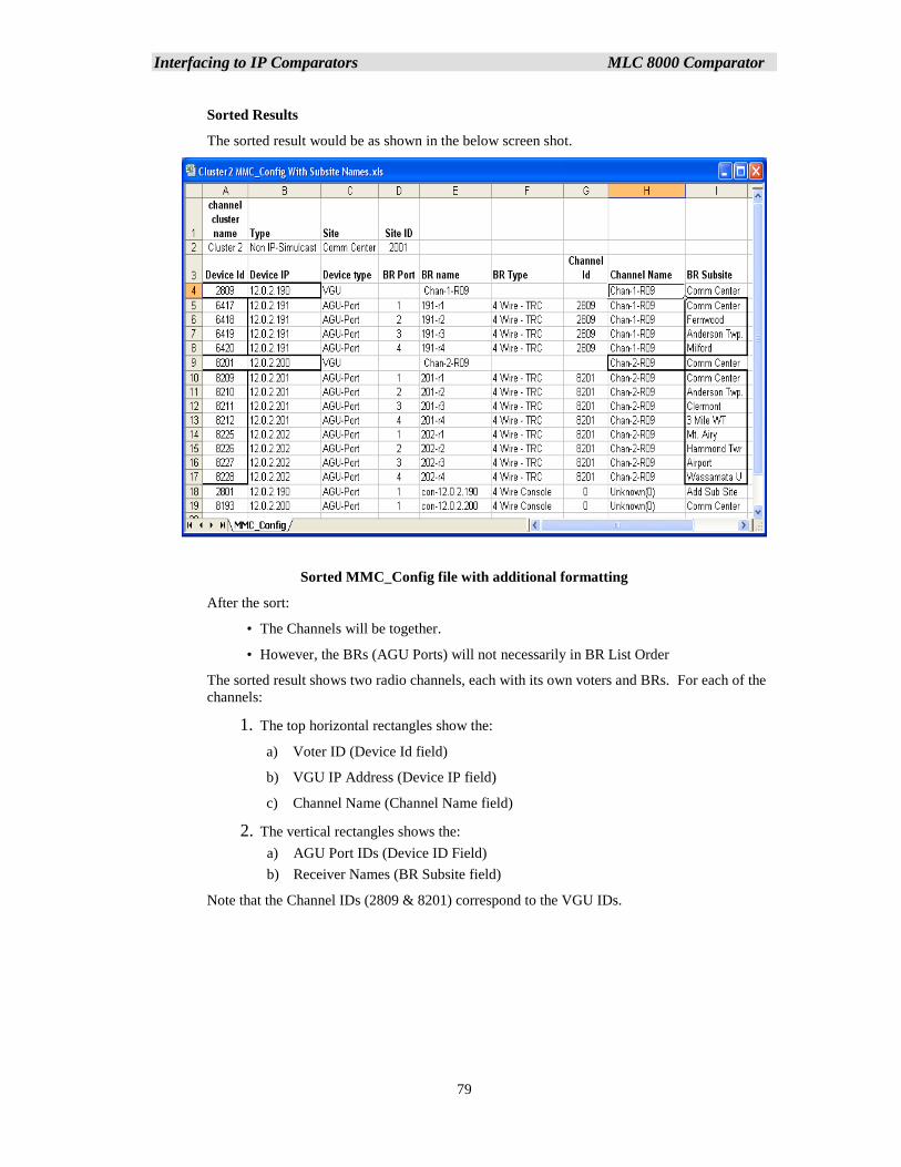
Interfacing to IP Comparators MLC 8000 Comparator
79
Sorted Results
The sorted result would be as shown in the below screen shot.
Sorted MMC_Config file with additional formatting
After the sort:
• The Channels will be together.
• However, the BRs (AGU Ports) will not necessarily in BR List Order
The sorted result shows two radio channels, each with its own voters and BRs. For each of the
channels:
1. The top horizontal rectangles show the:
a) Voter ID (Device Id field)
b) VGU IP Address (Device IP field)
c) Channel Name (Channel Name field)
2. The vertical rectangles shows the:
a) AGU Port IDs (Device ID Field)
b) Receiver Names (BR Subsite field)
Note that the Channel IDs (2809 & 8201) correspond to the VGU IDs.
Interfacing to IP Comparators MLC 8000 Comparator
80
Copying and Pasting from the MMC_Config file
There is no automatic import of the data from the MMC_Config.csv file into the MCN Server
8000 system configuration files. You can, however, open the MMC_Config.csv file in Excel
and copy & paste the information into the fields in the Receiver Window in MCN Config
Server:
MMC_Config Field Receiver Window Field
Device ID (for BRs / Receivers) MLC ID
BR Subsite Name
BR Name Description (for general reference)
Here are a few things to consider when copying the data into the system configuration files in
MCN Config:
• Be sure that the Subsites are in the right order. If they are not, you can copy the
Subsite values and names one at a time.
• If you have a Mixed Mode system, make sure that the Subsites are in the order
that matches the BR Subsite order in the GCM 8000 comparator. If they are
not, you can copy the Subsite values and names one at a time.
• The Subsite Names in the MMC_Config.csv file might not be in the format that
you want displayed. You may have to edit these values for the user in
MCNConfig Server.
• You can include the AGU IP Address and Port number in the Description field
in the Receiver Window. This can be helpful for error logging and
troubleshooting.
MLC 8000 Analog Comparator Data for multiple radio channels
The MLC 8000 Analog Comparator CT software can store data for up to 4 channels in a Channel
Cluster.
If your system has more than 4 radio channels using MLC 8000 Analog Comparators, you will need
to save the system data in groups of 4 radio channels. You will need to open separate
MMC_cfg.csv files for each channel cluster.
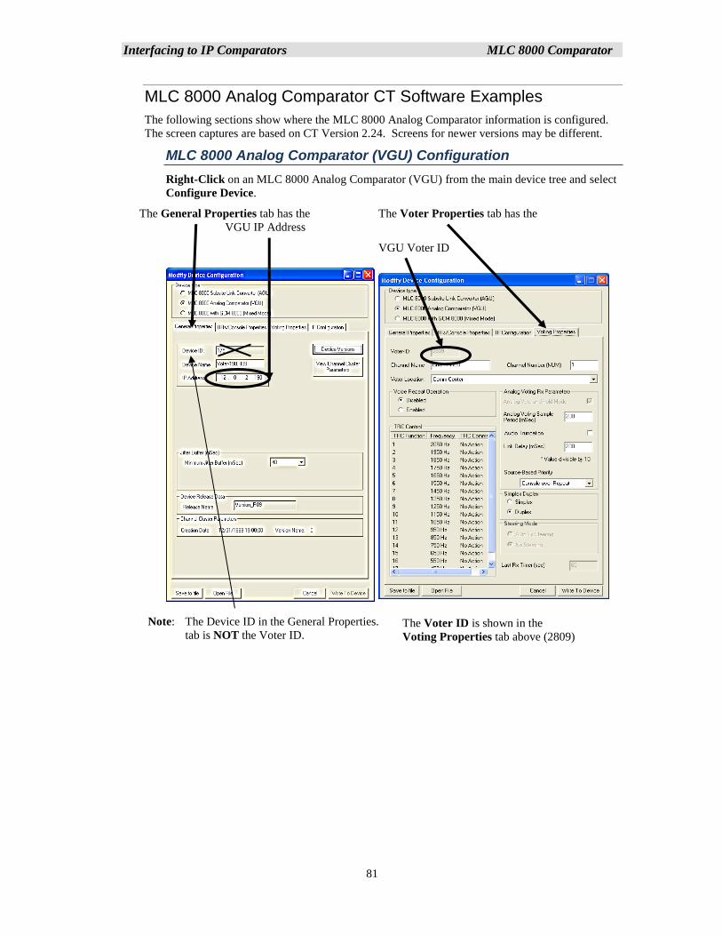
Interfacing to IP Comparators MLC 8000 Comparator
81
MLC 8000 Analog Comparator CT Software Examples
The following sections show where the MLC 8000 Analog Comparator information is configured.
The screen captures are based on CT Version 2.24. Screens for newer versions may be different.
MLC 8000 Analog Comparator (VGU) Configuration
Right-Click on an MLC 8000 Analog Comparator (VGU) from the main device tree and select
Configure Device.
The General Properties tab has the The Voter Properties tab has the
VGU IP Address
VGU Voter ID
Note: The Device ID in the General Properties.
tab is NOT the Voter ID. The Voter ID is shown in the
Voting Properties tab above (2809)
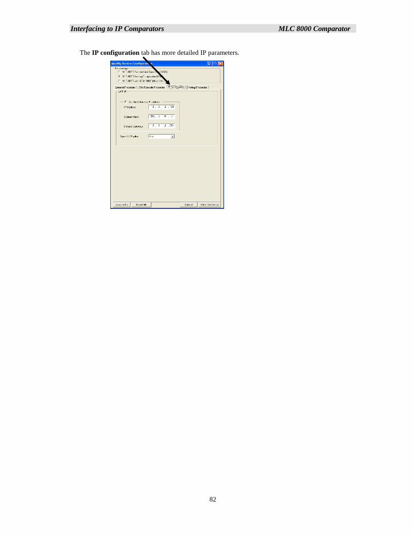
Interfacing to IP Comparators MLC 8000 Comparator
82
The IP configuration tab has more detailed IP parameters.
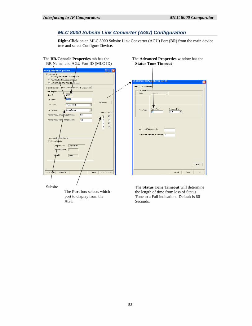
Interfacing to IP Comparators MLC 8000 Comparator
83
MLC 8000 Subsite Link Converter (AGU) Configuration
Right-Click on an MLC 8000 Subsite Link Converter (AGU) Port (BR) from the main device
tree and select Configure Device.
The BR/Console Properties tab has the The Advanced Properties window has the
BR Name, and AGU Port ID (MLC ID) Status Tone Timeout
Subsite
The Port box selects which
port to display from the
AGU.
The Status Tone Timeout will determine
the length of time from loss of Status
Tone to a Fail indication. Default is 60
Seconds.
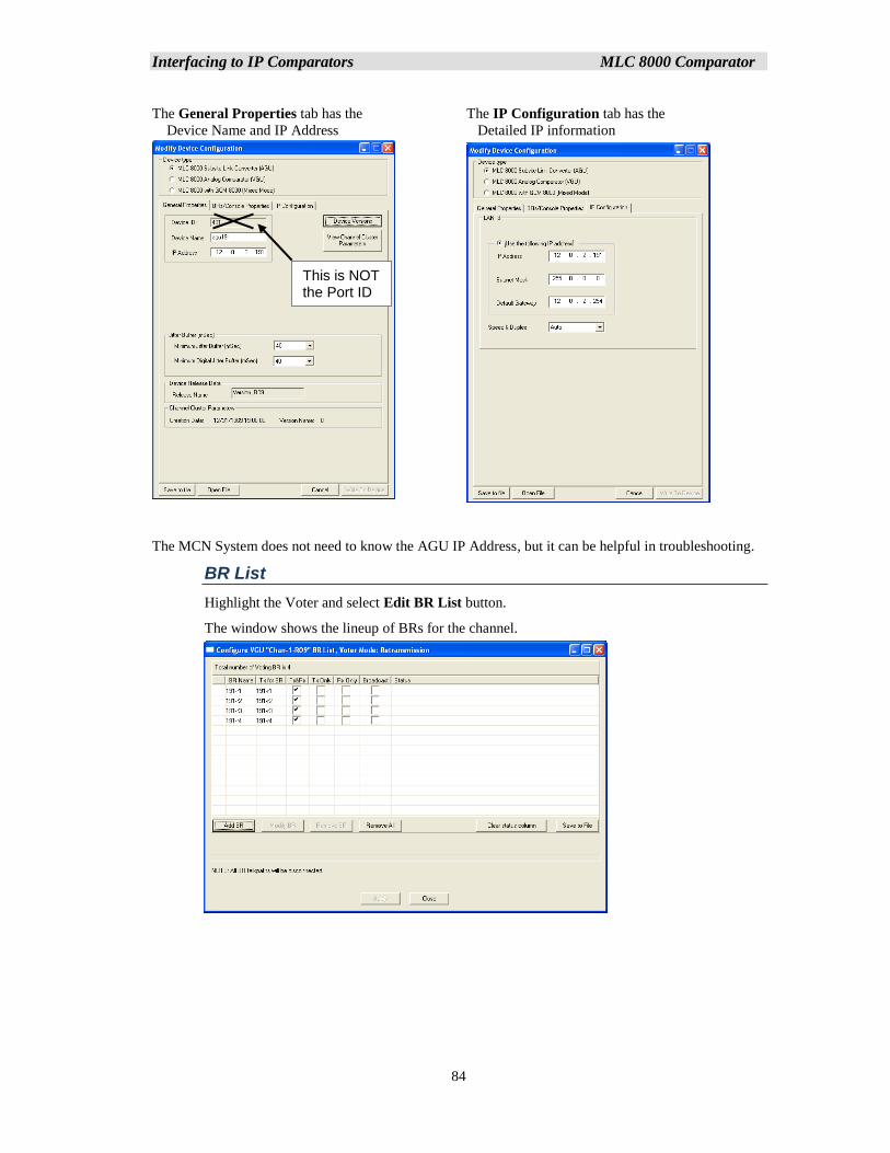
Interfacing to IP Comparators MLC 8000 Comparator
84
The General Properties tab has the The IP Configuration tab has the
Device Name and IP Address Detailed IP information
The MCN System does not need to know the AGU IP Address, but it can be helpful in troubleshooting.
BR List
Highlight the Voter and select Edit BR List button.
The window shows the lineup of BRs for the channel.
This is NOT the Port ID
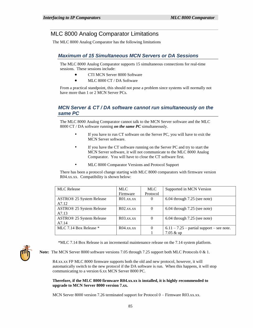
Interfacing to IP Comparators MLC 8000 Comparator
85
MLC 8000 Analog Comparator Limitations
The MLC 8000 Analog Comparator has the following limitations
Maximum of 15 Simultaneous MCN Servers or DA Sessions
The MLC 8000 Analog Comparator supports 15 simultaneous connections for real-time
sessions. These sessions include:
• CTI MCN Server 8000 Software
• MLC 8000 CT / DA Software
From a practical standpoint, this should not pose a problem since systems will normally not
have more than 1 or 2 MCN Server PCs.
MCN Server & CT / DA software cannot run simultaneously on the same PC
The MLC 8000 Analog Comparator cannot talk to the MCN Server software and the MLC
8000 CT / DA software running on the same PC simultaneously.
• If you have to run CT software on the Server PC, you will have to exit the
MCN Server software.
• If you have the CT software running on the Server PC and try to start the
MCN Server software, it will not communicate to the MLC 8000 Analog
Comparator. You will have to close the CT software first.
• MLC 8000 Comparator Versions and Protocol Support
There has been a protocol change starting with MLC 8000 comparators with firmware version
R04.xx.xx. Compatibility is shown below:
MLC Release MLC
Firmware
MLC
Protocol
Supported in MCN Version
ASTRO® 25 System Release
A7.12
R01.xx.xx 0 6.04 through 7.25 (see note)
ASTRO® 25 System Release
A7.13
R02.xx.xx 0 6.04 through 7.25 (see note)
ASTRO® 25 System Release
A7.14
R03.xx.xx 0 6.04 through 7.25 (see note)
MLC 7.14 Box Release * R04.xx.xx 0
1
6.11 – 7.25 – partial support – see note.
7.05 & up
*MLC 7.14 Box Release is an incremental maintenance release on the 7.14 system platform.
Note: The MCN Server 8000 software versions 7.05 through 7.25 support both MLC Protocols 0 & 1.
R4.xx.xx FP MLC 8000 firmware supports both the old and new protocol, however, it will
automatically switch to the new protocol if the DA software is run. When this happens, it will stop
communicating to a version 6.xx MCN Server 8000 PC.
Therefore, if the MLC 8000 firmware R04.xx.xx is installed, it is highly recommended to
upgrade to MCN Server 8000 version 7.xx.
MCN Server 8000 version 7.26 terminated support for Protocol 0 – Firmware R03.xx.xx.
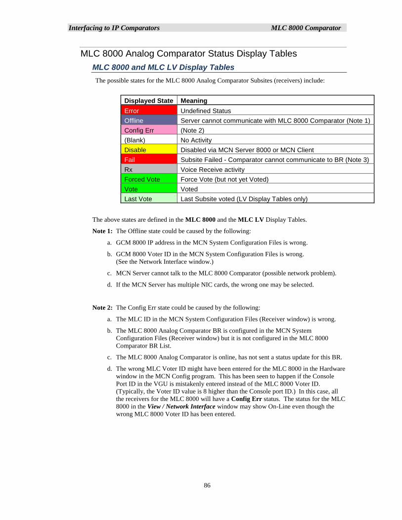
Interfacing to IP Comparators MLC 8000 Comparator
86
MLC 8000 Analog Comparator Status Display Tables
MLC 8000 and MLC LV Display Tables
The possible states for the MLC 8000 Analog Comparator Subsites (receivers) include:
Displayed State Meaning
Error Undefined Status
Offline Server cannot communicate with MLC 8000 Comparator (Note 1)
Config Err (Note 2)
(Blank) No Activity
Disable Disabled via MCN Server 8000 or MCN Client
Fail Subsite Failed - Comparator cannot communicate to BR (Note 3)
Rx Voice Receive activity
Forced Vote Force Vote (but not yet Voted)
Vote Voted
Last Vote Last Subsite voted (LV Display Tables only)
The above states are defined in the MLC 8000 and the MLC LV Display Tables.
Note 1: The Offline state could be caused by the following:
a. GCM 8000 IP address in the MCN System Configuration Files is wrong.
b. GCM 8000 Voter ID in the MCN System Configuration Files is wrong.
(See the Network Interface window.)
c. MCN Server cannot talk to the MLC 8000 Comparator (possible network problem).
d. If the MCN Server has multiple NIC cards, the wrong one may be selected.
Note 2: The Config Err state could be caused by the following:
a. The MLC ID in the MCN System Configuration Files (Receiver window) is wrong.
b. The MLC 8000 Analog Comparator BR is configured in the MCN System
Configuration Files (Receiver window) but it is not configured in the MLC 8000
Comparator BR List.
c. The MLC 8000 Analog Comparator is online, has not sent a status update for this BR.
d. The wrong MLC Voter ID might have been entered for the MLC 8000 in the Hardware
window in the MCN Config program. This has been seen to happen if the Console
Port ID in the VGU is mistakenly entered instead of the MLC 8000 Voter ID.
(Typically, the Voter ID value is 8 higher than the Console port ID.) In this case, all
the receivers for the MLC 8000 will have a Config Err status. The status for the MLC
8000 in the View / Network Interface window may show On-Line even though the
wrong MLC 8000 Voter ID has been entered.

Interfacing to IP Comparators MLC 8000 Comparator
87
Note 3: The Fail state could be caused by the following:
a. The BR analog port is disconnected from the MLC 8000 Subsite Link Converter
(AGU).
b. The BR has lost power.
c. There is no status tone from the BR
d. The Radio Port for this MLC 8000 Subsite Link Converter (AGU) is not calibrated
properly (See the CT software for calibration)
e. The MLC 8000 Analog Comparator (VGU) cannot communicate with the appropriate
MLC 8000 Subsite Link Converter (AGU). In this case, all the BRs associated with
this MLC 8000 Subsite Link Converter (AGU) will be in the Fail state.
Note 4: The Last Vote indication will only be displayed when that Subsite is otherwise in the
Idle state.
WARNING: DO NOT ATTEMPT TO CHANGE THE BIT VALUES OR ENTRY ORDER IN
THE DISPLAY TABLE.
Interfacing to IP Comparators Mixed Mode Comparator
88
MM - Mixed Mode Voting Solution Interfacing
The Mixed Mode Voting Solution is a combination of a GCM 8000 Comparator and an MLC 8000
Analog Comparator. When interfacing to a Mixed Mode system, you will need the information from
both of those comparators:
GCM 8000 Information:
▪ GCM 8000 IP Address Entered into the Mixed Mode Configuration window
▪ List of Receivers 1-32 Entered into the Receiver Window – for Receivers
(Subsites) 1-32
MLC 8000 Analog Comparator Information:
• VGU IP Address:- Entered into the Mixed Mode Configuration window
• Voter ID :- Entered into the Mixed Mode Configuration window
• AGU BR Port ID:- For each of the BRs in the system entered in the MLC ID field
for the receiver in the Receiver window
• AGU BR Name:- Receiver name for each BR in the system Entered in the Name
field for the receiver in the Receiver window
Receiver (Subsite) Order for Mixed Mode Systems -- Very Important!
Since a Mixed Mode system uses both a GCM 8000 Digital and an MLC 8000 Analog Comparator,
it is very important to make sure that the receiver (Subsite) information is entered into the MCN
Config Server program in the proper order. The following principles hold in determining the
receiver order:
1. Each radio channel may have different receiver (Subsite) orders.
2. If there are multiple radio channels with the same complement of Subsite locations, it
is recommended that the Subsites in all channels be configured in the same order.
3. The Subsite numbers configured in the GTR 8000 BRs and GPW 8000 Satellite
Receivers for a particular radio channel control the Subsite order in that channel's
GCM 8000 comparator.
4. Since the Subsite name can be hand-entered in the GCM 8000 comparator CSS, it is
possible to enter the wrong Subsite name. Make sure that the list of Subsite names in
the GCM 8000 CSS matches the actual order of the GTR 8000 and GPW 8000 units.
5. The Subsite order (1-64) in the GCM 8000 comparator controls the receiver order (1-
64) in the Receiver Window in the MCN Config Server software.
6. Enter the proper Receiver Names (as determined by the GCM 8000 Subsite order) in
the MCN Config Server Software Receiver Window.
7. The Subsites listed in the MLC 8000 Analog Comparator CT software (and the
resulting MMC_Config.csv file) are listed in the order that they were entered when the
system was configured in the CT software. This order might not be the same as the
order in the GCM 8000 comparator. It is recommended that the order is kept the
same, but it is not imperative that it is.
8. After the receiver Subsite information from the GCM 8000 is entered into the MCN
Config Server software, enter the proper AGU Port ID in the MLC ID field for that
Subsite.
Interfacing to IP Comparators Mixed Mode Comparator
89
Mixed Mode System Limitations
Mixed Mode systems will have the same limitations as their constituent GCM 8000 and MLC 8000
Analog Comparators as described in the CGM 8000 and MLC 8000 Analog Comparator Limitations
sections:
Maximum of 3 MCN Servers connected to the GCM 8000 comparators. If the MCN
Servers are in an ASTRO® 25 RNI, the RNI infrastructure supports only 2 MCN
Server 8000 PCs.
Neither the GCM 8000 CSS software nor the MLC 8000 Analog Comparator CT /
DA software can run simultaneously on the same PC as the MCN Server.
The GCM 8000 comparator cannot disable Subsites that have failed
The GCM 8000 comparator will reset the Disable status if a Subsite goes into Fail.
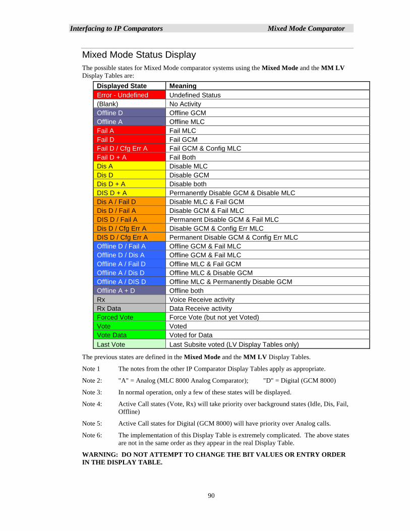
Interfacing to IP Comparators Mixed Mode Comparator
90
Mixed Mode Status Display
The possible states for Mixed Mode comparator systems using the Mixed Mode and the MM LV
Display Tables are:
Displayed State Meaning
Error - Undefined Undefined Status
(Blank) No Activity
Offline D Offline GCM
Offline A Offline MLC
Fail A Fail MLC
Fail D Fail GCM
Fail D / Cfg Err A Fail GCM & Config MLC
Fail D + A Fail Both
Dis A Disable MLC
Dis D Disable GCM
Dis D + A Disable both
DIS D + A Permanently Disable GCM & Disable MLC
Dis A / Fail D Disable MLC & Fail GCM
Dis D / Fail A Disable GCM & Fail MLC
DIS D / Fail A Permanent Disable GCM & Fail MLC
Dis D / Cfg Err A Disable GCM & Config Err MLC
DIS D / Cfg Err A Permanent Disable GCM & Config Err MLC
Offline D / Fail A Offline GCM & Fail MLC
Offline D / Dis A Offline GCM & Fail MLC
Offline A / Fail D Offline MLC & Fail GCM
Offline A / Dis D Offline MLC & Disable GCM
Offline A / DIS D Offline MLC & Permanently Disable GCM
Offline A + D Offline both
Rx Voice Receive activity
Rx Data Data Receive activity
Forced Vote Force Vote (but not yet Voted)
Vote Voted
Vote Data Voted for Data
Last Vote Last Subsite voted (LV Display Tables only)
The previous states are defined in the Mixed Mode and the MM LV Display Tables.
Note 1 The notes from the other IP Comparator Display Tables apply as appropriate.
Note 2: "A" = Analog (MLC 8000 Analog Comparator); "D" = Digital (GCM 8000)
Note 3: In normal operation, only a few of these states will be displayed.
Note 4: Active Call states (Vote, Rx) will take priority over background states (Idle, Dis, Fail,
Offline)
Note 5: Active Call states for Digital (GCM 8000) will have priority over Analog calls.
Note 6: The implementation of this Display Table is extremely complicated. The above states
are not in the same order as they appear in the real Display Table.
WARNING: DO NOT ATTEMPT TO CHANGE THE BIT VALUES OR ENTRY ORDER
IN THE DISPLAY TABLE.
Interfacing to IP Comparators Mixed Mode Comparator
91
Mixed Mode Tech Status Displays
The MM Tech Display Tables are provided to help technicians troubleshoot Mixed Mode systems.
Separate screens or tabs can be set up using these Display Tables for Technician use.
MM Tech Display Table
The MM Tech Display Table is similar to the MM LV Display table, except it adds more detail
in the cases of both Digital and Analog Activity at the same time. It has the following
modifications:
▪ Added "D" or "A" suffix for Rx & Vote states
▪ When there is both Digital & Analog activity, both are shown.
▪ Analog Rx is changed to a brownish color.
▪ Analog Vote is changed to a violet color
You can look at this Display Table in the Display Table window in MCN Config Server
software.
MM-GCM Tech Display Table
This Display Table is for Mixed Mode systems, but it looks at only the GCM 8000 (Digital)
signals, plus the Last Vote. It is somewhat similar to the GCM LV Display Table. It can be
used for troubleshooting a Mixed Mode system if you want to look just at the GCM 8000 data.
You can look at this Display Table in the Display Table window in MCN Config Server
software.
Note 1: The Last Vote indication will be set on either digital or analog activity.
MM-MLC Tech Display Table
This Display Table is for Mixed Mode systems, but it looks at only the signals from the MLC
8000 Analog Comparator, plus the Last Vote. It is somewhat similar to the MLC LV Display
Table. It can be used for troubleshooting a Mixed Mode system if you want to look just at the
data from the MLC 8000 Analog Comparator.
You can look at this Display Table in the Display Table window in MCN Config Server
software.
Note 1: The Last Vote indication will be set on either digital or analog activity.
Note 2: If there is both analog and digital activity, you will not see a Vote indication using this
table since the MLC 8000 Analog Comparator Vote bit is suppressed in the program
whenever there is a Vote in the GCM 8000.
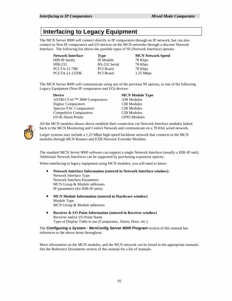
Interfacing to IP Comparators Mixed Mode Comparator
92
Interfacing to Legacy Equipment
The MCN Server 8000 will connect directly to IP comparators through an IP network, but can also
connect to Non-IP comparators and I/O devices on the MCN networks through a discrete Network
Interface. The following list shows the possible types of NI (Network Interface) options:
Network Interface Type MCN Network Speed
HIB-IP family IP Module 78 Kbps
HIB-232 RS-232 Serial 78 Kbps
PCLTA-21-78K PCI Board 78 Kbps
PCLTA-21-1250K PCI Board 1.25 Mbps
The MCN Server 8000 will communicate using any of the previous NI options, to one of the following
Legacy Equipment (Non-IP comparators and I/O) devices:
Device MCN Module Type
ASTRO-TAC™ 3000 Comparators AIB Modules
Digitac Comparators CIB Modules
Spectra-TAC Comparators CIB Modules
Competitive Comparators CIB Modules
I/O & Alarm Points GPIO Modules
All the MCN modules shown above establish their connection via Network Interface modules linked
back to the MCN Monitoring and Control Network and communicate on a 78 Kbit wired network,
Larger systems may include a 1.25 Mbps high-speed backbone network that connects to the MCN
modules through MCN Routers and EXB Network Extender Modules.
The standard MCN Server 8000 software can support a single Network Interface (usually a HIB-IP unit).
Additional Network Interfaces can be supported by purchasing expansion options.
When interfacing to legacy equipment using MCN modules, you will need to know:
• Network Interface Information (entered in Network Interface window):
Network Interface Type
Network Interface Parameters
MCN Group & Module addresses
IP parameters (for HIB-IP units)
• MCN Module Information (entered in Hardware window)
Module Type
MCN Group & Module addresses
• Receiver & I/O Point Information (entered in Receiver window)
Receiver and/or I/O Point Name
Type of Display Table to use (Comparator, Alarm, Door, etc.)
The Configuring a System - McnConfig Server 8000 Program section of this manual has
references to the above items throughout.
More information on the MCN modules, and the MCN network can be found in the appropriate manuals.
See the Reference Documents section of this manual for a list of manuals.
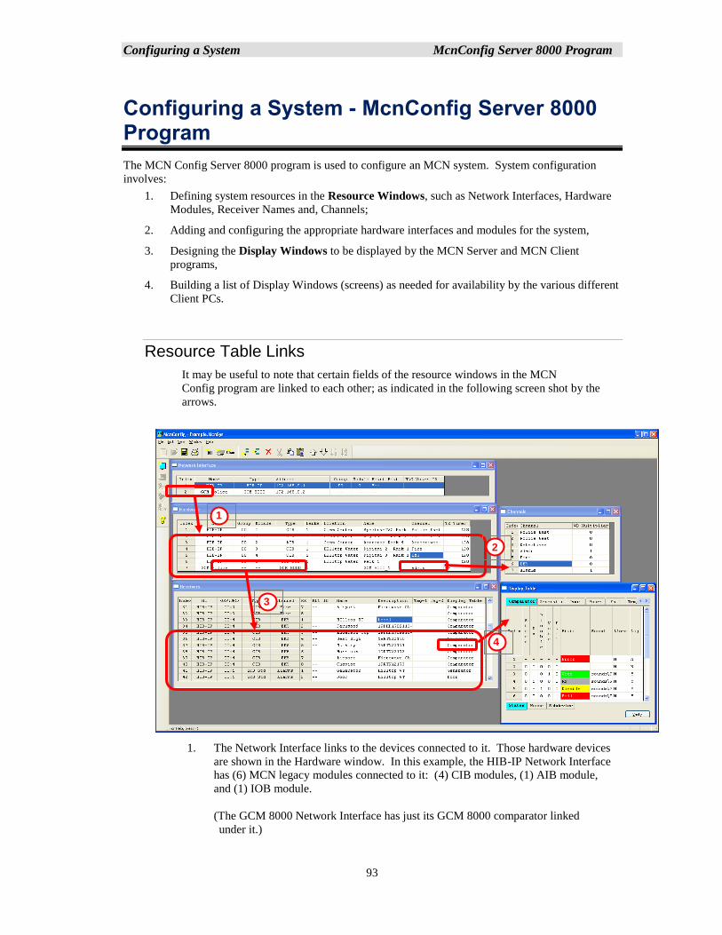
Configuring a System McnConfig Server 8000 Program
93
Configuring a System - McnConfig Server 8000 Program
The MCN Config Server 8000 program is used to configure an MCN system. System configuration
involves:
1. Defining system resources in the Resource Windows, such as Network Interfaces, Hardware
Modules, Receiver Names and, Channels;
2. Adding and configuring the appropriate hardware interfaces and modules for the system,
3. Designing the Display Windows to be displayed by the MCN Server and MCN Client
programs,
4. Building a list of Display Windows (screens) as needed for availability by the various different
Client PCs.
Resource Table Links
It may be useful to note that certain fields of the resource windows in the MCN
Config program are linked to each other; as indicated in the following screen shot by the
arrows.
1. The Network Interface links to the devices connected to it. Those hardware devices
are shown in the Hardware window. In this example, the HIB-IP Network Interface
has (6) MCN legacy modules connected to it: (4) CIB modules, (1) AIB module,
and (1) IOB module.
(The GCM 8000 Network Interface has just its GCM 8000 comparator linked
under it.)
1
2
3
4

Configuring a System McnConfig Server 8000 Program
94
2. Each Module in the Hardware Window can point to a Channel in the Channel
window.
3. Each Module in the Hardware Window points to all the Receivers (Subsites) or I/O
points associated with it. In the example the CIB module points to its (8) receivers.
An IP Comparator Module points to (64) receivers.
4. Each Receiver or I/O Point in the Receivers window points to a Display Table tab.
This determines how the status information from the comparator or I/O module will
be displayed.
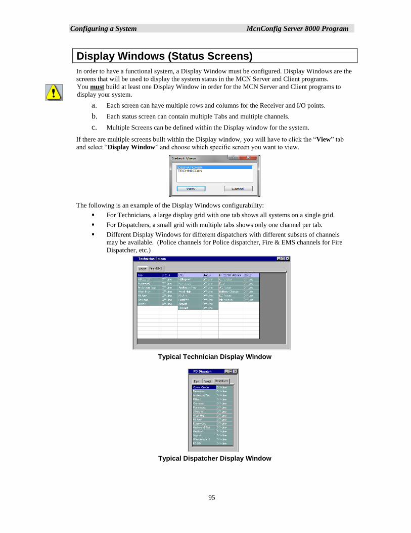
Configuring a System McnConfig Server 8000 Program
95
Display Windows (Status Screens)
In order to have a functional system, a Display Window must be configured. Display Windows are the
screens that will be used to display the system status in the MCN Server and Client programs.
You must build at least one Display Window in order for the MCN Server and Client programs to
display your system.
a. Each screen can have multiple rows and columns for the Receiver and I/O points.
b. Each status screen can contain multiple Tabs and multiple channels.
c. Multiple Screens can be defined within the Display window for the system.
If there are multiple screens built within the Display window, you will have to click the “View” tab
and select “Display Window” and choose which specific screen you want to view.
The following is an example of the Display Windows configurability:
▪ For Technicians, a large display grid with one tab shows all systems on a single grid.
▪ For Dispatchers, a small grid with multiple tabs shows only one channel per tab.
▪ Different Display Windows for different dispatchers with different subsets of channels
may be available. (Police channels for Police dispatcher, Fire & EMS channels for Fire
Dispatcher, etc.)
Typical Technician Display Window
Typical Dispatcher Display Window
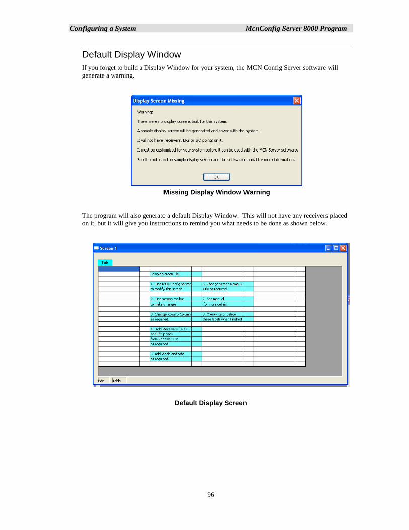
Configuring a System McnConfig Server 8000 Program
96
Default Display Window
If you forget to build a Display Window for your system, the MCN Config Server software will
generate a warning.
Missing Display Window Warning
The program will also generate a default Display Window. This will not have any receivers placed
on it, but it will give you instructions to remind you what needs to be done as shown below.
Default Display Screen
`MCNConfig Program: IP Comparator Network Interface
97
Navigating through MCNConfig Server
The MCNConfig program is a 32-Bit Windows program. Navigation, menus and toolbars operation
are similar to most other Windows programs.
Standard Windows Hot-Keys that can be used with this program include:
Ctrl-C Copy current selection to clipboard
Ctrl-V Paste clipboard to current location in selected window.
Context Sensitive Menus are available in different windows by Right-clicking an item.
Scroll Bars are available when the contents of a window (other than the main window) are larger than
the size of that window.
Controlling the Windows
You can have multiple windows (resource windows or display windows) open on the workspace at a
given time. You can control the windows as follows:
View the Resource Windows (Hardware, Receivers, Channels, or Display Tables) or Display
Windows with the View menu.
Select an open window by clicking the mouse on it or using the Window menu.
Move a window by grabbing its title bar and dragging it.
Re-size a window by grabbing an edge or corner and dragging it.
Minimize /Restore, Maximize and Close the window using the standard Windows buttons on the
top right corner of each window. If you close the last window, you will close the system. If any
changes have been made you will have a chance to save the system.
You can save the sizing and layout of your workspace by using the Save Layout command in the
Edit menu.
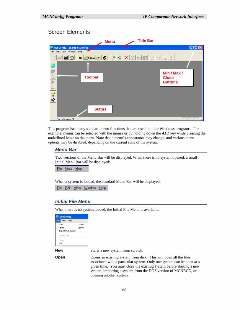
`MCNConfig Program: IP Comparator Network Interface
98
Screen Elements
This program has many standard menu functions that are used in other Windows programs. For
example, menus can be selected with the mouse or by holding down the ALT key while pressing the
underlined letter on the menu. Note that a menu’s appearance may change, and various menu
options may be disabled, depending on the current state of the system.
Menu Bar
Two versions of the Menu Bar will be displayed. When there is no system opened, a small
Initial Menu Bar will be displayed:
When a system is loaded, the standard Menu Bar will be displayed:
Initial File Menu
When there is no system loaded, the Initial File Menu is available.
New Starts a new system from scratch.
Open Opens an existing system from disk. This will open all the files
associated with a particular system. Only one system can be open at a
given time. You must close the existing system before starting a new
system, importing a system from the DOS version of MCNRCD, or
opening another system.
Menu Title Bar
Min / Max / Close Buttons
Toolbars
Status Line
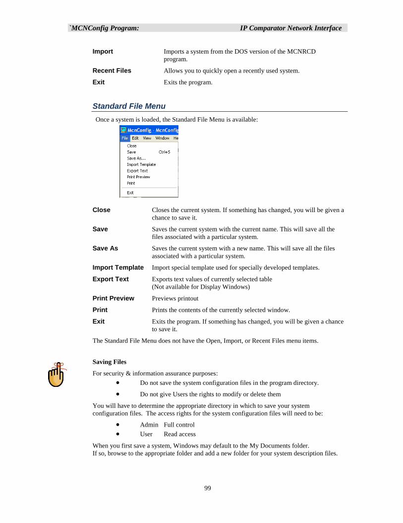
`MCNConfig Program: IP Comparator Network Interface
99
Import Imports a system from the DOS version of the MCNRCD
program.
Recent Files Allows you to quickly open a recently used system.
Exit Exits the program.
Standard File Menu
Once a system is loaded, the Standard File Menu is available:
Close Closes the current system. If something has changed, you will be given a
chance to save it.
Save Saves the current system with the current name. This will save all the
files associated with a particular system.
Save As Saves the current system with a new name. This will save all the files
associated with a particular system.
Import Template Import special template used for specially developed templates.
Export Text Exports text values of currently selected table
(Not available for Display Windows)
Print Preview Previews printout
Print Prints the contents of the currently selected window.
Exit Exits the program. If something has changed, you will be given a chance
to save it.
The Standard File Menu does not have the Open, Import, or Recent Files menu items.
Saving Files
For security & information assurance purposes:
• Do not save the system configuration files in the program directory.
• Do not give Users the rights to modify or delete them
You will have to determine the appropriate directory in which to save your system
configuration files. The access rights for the system configuration files will need to be:
• Admin Full control
• User Read access
When you first save a system, Windows may default to the My Documents folder.
If so, browse to the appropriate folder and add a new folder for your system description files.
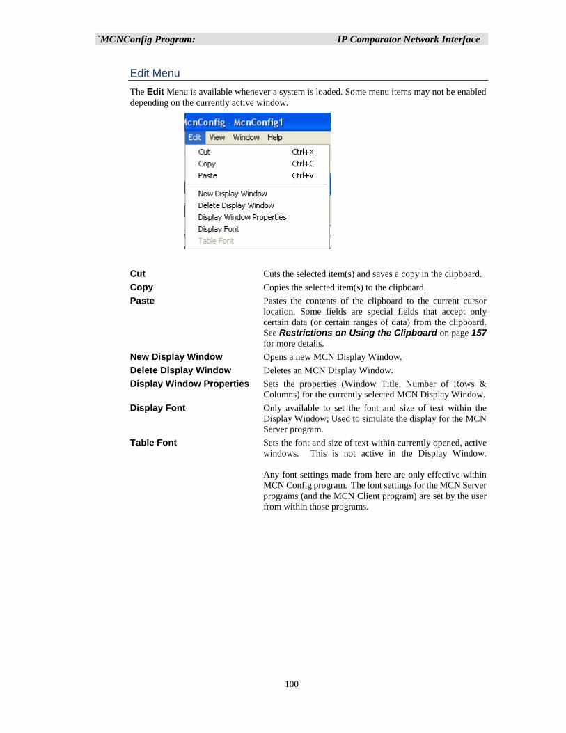
`MCNConfig Program: IP Comparator Network Interface
100
Edit Menu
The Edit Menu is available whenever a system is loaded. Some menu items may not be enabled
depending on the currently active window.
Cut Cuts the selected item(s) and saves a copy in the clipboard.
Copy Copies the selected item(s) to the clipboard.
Paste Pastes the contents of the clipboard to the current cursor
location. Some fields are special fields that accept only
certain data (or certain ranges of data) from the clipboard.
See Restrictions on Using the Clipboard on page 157
for more details.
New Display Window Opens a new MCN Display Window.
Delete Display Window Deletes an MCN Display Window.
Display Window Properties Sets the properties (Window Title, Number of Rows &
Columns) for the currently selected MCN Display Window.
Display Font Only available to set the font and size of text within the
Display Window; Used to simulate the display for the MCN
Server program.
Table Font Sets the font and size of text within currently opened, active
windows. This is not active in the Display Window.
Any font settings made from here are only effective within
MCN Config program. The font settings for the MCN Server
programs (and the MCN Client program) are set by the user
from within those programs.
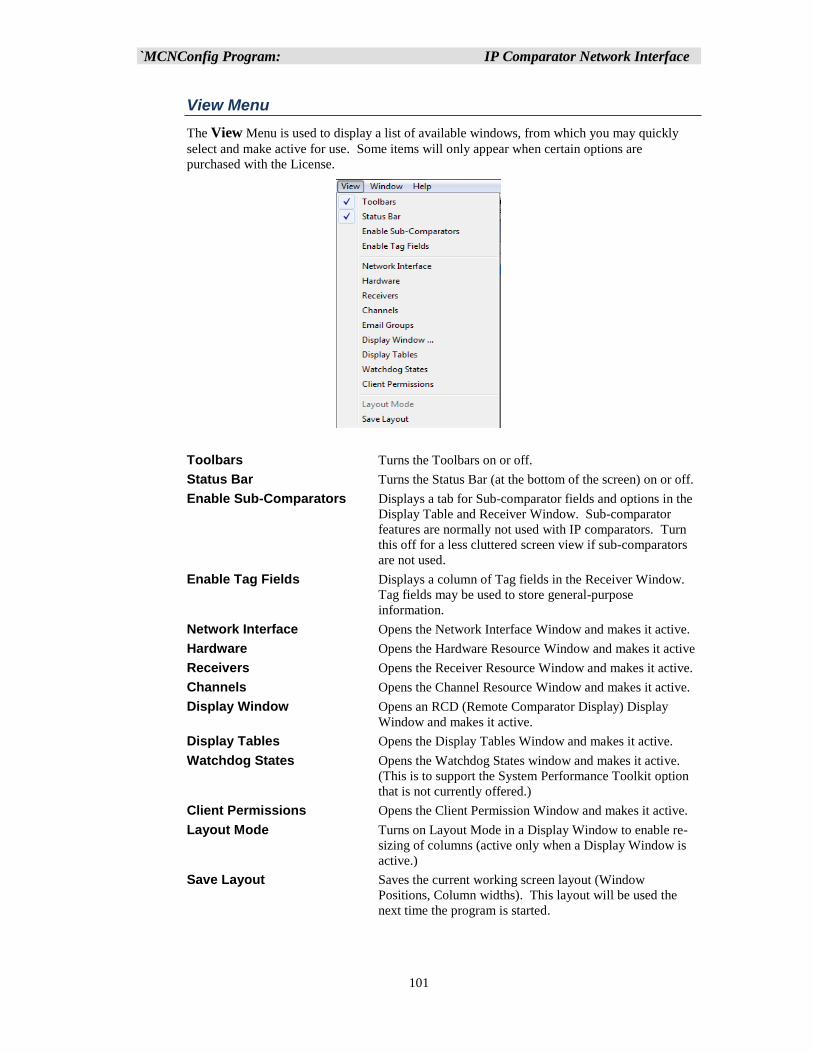
`MCNConfig Program: IP Comparator Network Interface
101
View Menu
The View Menu is used to display a list of available windows, from which you may quickly
select and make active for use. Some items will only appear when certain options are
purchased with the License.
Toolbars Turns the Toolbars on or off.
Status Bar Turns the Status Bar (at the bottom of the screen) on or off.
Enable Sub-Comparators Displays a tab for Sub-comparator fields and options in the
Display Table and Receiver Window. Sub-comparator
features are normally not used with IP comparators. Turn
this off for a less cluttered screen view if sub-comparators
are not used.
Enable Tag Fields Displays a column of Tag fields in the Receiver Window.
Tag fields may be used to store general-purpose
information.
Network Interface Opens the Network Interface Window and makes it active.
Hardware Opens the Hardware Resource Window and makes it active
Receivers Opens the Receiver Resource Window and makes it active.
Channels Opens the Channel Resource Window and makes it active.
Display Window Opens an RCD (Remote Comparator Display) Display
Window and makes it active.
Display Tables Opens the Display Tables Window and makes it active.
Watchdog States Opens the Watchdog States window and makes it active.
(This is to support the System Performance Toolkit option
that is not currently offered.)
Client Permissions Opens the Client Permission Window and makes it active.
Layout Mode Turns on Layout Mode in a Display Window to enable re-
sizing of columns (active only when a Display Window is
active.)
Save Layout Saves the current working screen layout (Window
Positions, Column widths). This layout will be used the
next time the program is started.
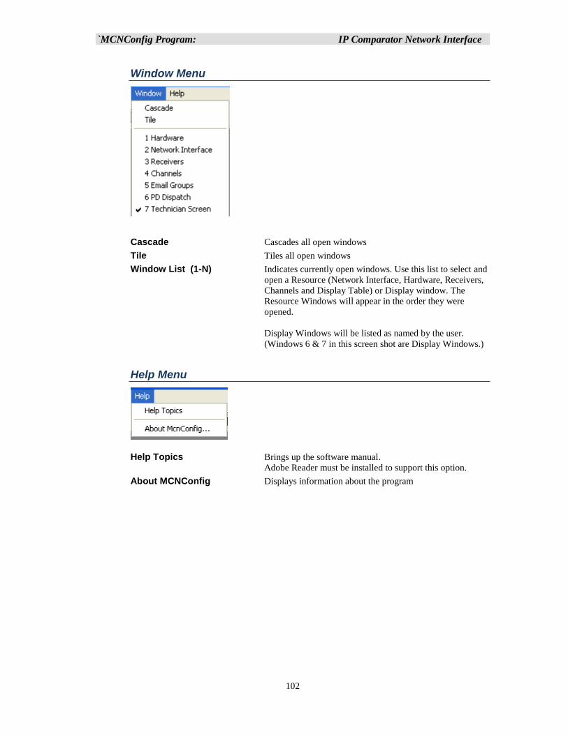
`MCNConfig Program: IP Comparator Network Interface
102
Window Menu
Cascade Cascades all open windows
Tile Tiles all open windows
Window List (1-N) Indicates currently open windows. Use this list to select and
open a Resource (Network Interface, Hardware, Receivers,
Channels and Display Table) or Display window. The
Resource Windows will appear in the order they were
opened.
Display Windows will be listed as named by the user.
(Windows 6 & 7 in this screen shot are Display Windows.)
Help Menu
Help Topics Brings up the software manual.
Adobe Reader must be installed to support this option.
About MCNConfig Displays information about the program
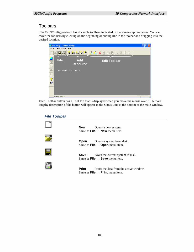
`MCNConfig Program: IP Comparator Network Interface
103
Toolbars
The MCNConfig program has dockable toolbars indicated in the screen capture below. You can
move the toolbars by clicking on the beginning or ending line in the toolbar and dragging it to the
desired location.
Each Toolbar button has a Tool Tip that is displayed when you move the mouse over it. A more
lengthy description of the button will appear in the Status Line at the bottom of the main window.
File Toolbar
New Opens a new system.
Same as File … New menu item.
Open Opens a system from disk.
Same as File … Open menu item.
Save Saves the current system to disk.
Same as File … Save menu item.
Print Prints the data from the active window.
Same as File … Print menu item.
File Tool
Add Resource
Edit Toolbar
Display & Help
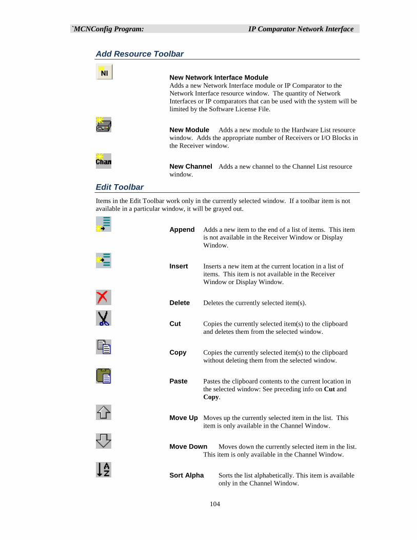
`MCNConfig Program: IP Comparator Network Interface
104
Add Resource Toolbar
New Network Interface Module Adds a new Network Interface module or IP Comparator to the
Network Interface resource window. The quantity of Network
Interfaces or IP comparators that can be used with the system will be
limited by the Software License File.
New Module Adds a new module to the Hardware List resource
window. Adds the appropriate number of Receivers or I/O Blocks in
the Receiver window.
New Channel Adds a new channel to the Channel List resource
window.
Edit Toolbar
Items in the Edit Toolbar work only in the currently selected window. If a toolbar item is not
available in a particular window, it will be grayed out.
Append Adds a new item to the end of a list of items. This item
is not available in the Receiver Window or Display
Window.
Insert Inserts a new item at the current location in a list of
items. This item is not available in the Receiver
Window or Display Window.
Delete Deletes the currently selected item(s).
Cut Copies the currently selected item(s) to the clipboard
and deletes them from the selected window.
Copy Copies the currently selected item(s) to the clipboard
without deleting them from the selected window.
Paste Pastes the clipboard contents to the current location in
the selected window: See preceding info on Cut and
Copy.
Move Up Moves up the currently selected item in the list. This
item is only available in the Channel Window.
Move Down Moves down the currently selected item in the list.
This item is only available in the Channel Window.
Sort Alpha Sorts the list alphabetically. This item is available
only in the Channel Window.
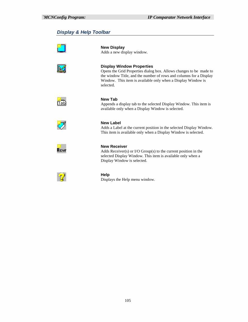
`MCNConfig Program: IP Comparator Network Interface
105
Display & Help Toolbar
New Display
Adds a new display window.
Display Window Properties
Opens the Grid Properties dialog box. Allows changes to be made to
the window Title, and the number of rows and columns for a Display
Window. This item is available only when a Display Window is
selected.
New Tab
Appends a display tab to the selected Display Window. This item is
available only when a Display Window is selected.
New Label Adds a Label at the current position in the selected Display Window.
This item is available only when a Display Window is selected.
New Receiver
Adds Receiver(s) or I/O Group(s) to the current position in the
selected Display Window. This item is available only when a
Display Window is selected.
Help
Displays the Help menu window.
`MCNConfig Program: IP Comparator Network Interface
106
Configuring System Resources
The first step in configuring a system is configuring the Resources in the four Resource Windows:
Network Interface Window
Add IP Comparators and configure their IP parameters.
Add HIB-IP, HIB-IP 8000, or HIB-IP 8002 Network Interfaces (for legacy MCN
systems), configure their parameters, and program the HIB-IP units, (HIB-IP 8000 entry
also covers HIB-IP 8002 units.)
Display other MCN Legacy Network Interface(s) (PCLTA, or HIB-232 modules if used).
Hardware Window
Enter additional information for IP Comparators,
Add Legacy MCN comparator (CIB & AIB) modules and I/O Modules and configure their
MCN addresses.
Receiver Window
Enter the receiver names & I/O group names and other data for all hardware modules.
Channel Window
Enter radio channel names.
The individual resource windows and configuration instructions are in the following
sections.
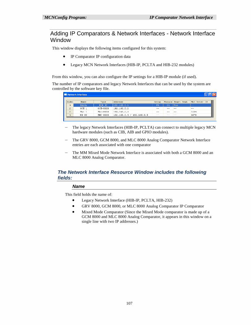
`MCNConfig Program: IP Comparator Network Interface
107
Adding IP Comparators & Network Interfaces - Network Interface Window
This window displays the following items configured for this system:
• IP Comparator IP configuration data
• Legacy MCN Network Interfaces (HIB-IP, PCLTA and HIB-232 modules)
From this window, you can also configure the IP settings for a HIB-IP module (if used).
The number of IP comparators and legacy Network Interfaces that can be used by the system are
controlled by the software key file.
– The legacy Network Interfaces (HIB-IP, PCLTA) can connect to multiple legacy MCN
hardware modules (such as CIB, AIB and GPIO modules).
– The GRV 8000, GCM 8000, and MLC 8000 Analog Comparator Network Interface
entries are each associated with one comparator
– The MM Mixed Mode Network Interface is associated with both a GCM 8000 and an
MLC 8000 Analog Comparator.
The Network Interface Resource Window includes the following fields:
Name
This field holds the name of:
• Legacy Network Interface (HIB-IP, PCLTA, HIB-232)
• GRV 8000, GCM 8000, or MLC 8000 Analog Comparator IP Comparator
• Mixed Mode Comparator (Since the Mixed Mode comparator is made up of a
GCM 8000 and MLC 8000 Analog Comparator, it appears in this window on a
single line with two IP addresses.)
`MCNConfig Program: IP Comparator Network Interface
108
Type
This field indicates the type of Network Interface Module:
GRV 8000 Comparator (either Analog or Digital)
GCM 8000 Digital Comparator
GCM 8000 TDMA Digital Comparator
MLC 8000 Analog Comparator
Mixed Mode Mixed Mode Comparator (GCM 8000 and MLC 8000
Analog Comparator pair)
HIB IP HIB-IP Network Interface
HIB IP 8000 HIB-IP 8000 Network Interface
HIB IP 8002 HIB-IP 8002 Network Interface
Non-IP Legacy PCLTA or HIB-232 Network Interface
The settings for the IP Network Interfaces (IP Comparators and HIB-IP modules) are set up
in the MCNConfig program and saved in the system files for the MCN system. You will
also use the settings stored in the system files to program the HIB-IP unit (through a COM
port).
The settings for Non-IP Network Interfaces are set up with the HWSetup program and
stored in the PC registry. The MCN Server program will get that information from the
registry when it runs.
Address
This field is used for:
1. IP Devices IP Address(es)
Mixed Mode comparators have (2) IP addresses
Address 1: MLC 8000 Comparator IP Address
Address 2: GCM 8000 IP Address
2. Non-IP Network Interfaces (PCLTA or HIB-232 modules):
This points to the Non-IP Network Interface. Non-IP network
interfaces are set up with the HWSetup program.
This field defaults to "MCN1" but can be easily changed...
Group
MCN Group Number for this module (Hex value 00-FE):
This is shown only for HIB-IP type units (which are configured in MCN Config program).
Module
MCN Module Number for this module (Hex value 0-F):
This is shown only for HIB-IP type units (which are configured in MCN Config program).
Heart Beat
This is for legacy Network Interfaces only. It is used to control the heartbeat from the
server to the legacy MCN modules. This field should normally be set to "Yes".
In systems with multiple servers that all access the same legacy modules, it may be
advisable to set all but one of the servers to "No". If you have such a system, contact a
CTI Products engineer for assistance.
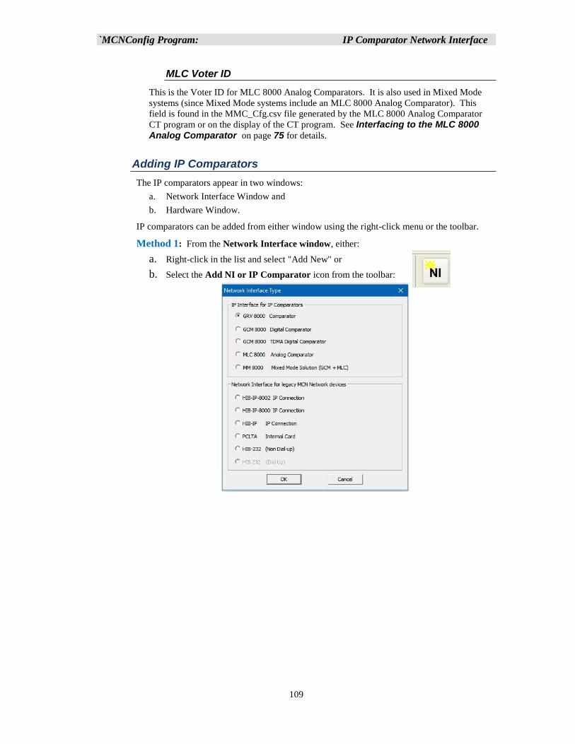
`MCNConfig Program: IP Comparator Network Interface
109
MLC Voter ID
This is the Voter ID for MLC 8000 Analog Comparators. It is also used in Mixed Mode
systems (since Mixed Mode systems include an MLC 8000 Analog Comparator). This
field is found in the MMC_Cfg.csv file generated by the MLC 8000 Analog Comparator
CT program or on the display of the CT program. See Interfacing to the MLC 8000 Analog Comparator on page 75 for details.
Adding IP Comparators
The IP comparators appear in two windows:
a. Network Interface Window and
b. Hardware Window.
IP comparators can be added from either window using the right-click menu or the toolbar.
Method 1: From the Network Interface window, either:
a. Right-click in the list and select "Add New" or
b. Select the Add NI or IP Comparator icon from the toolbar:
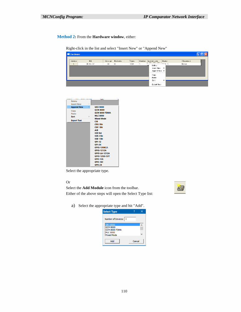
`MCNConfig Program: IP Comparator Network Interface
110
Method 2: From the Hardware window, either:
Right-click in the list and select "Insert New" or "Append New"
Select the appropriate type.
Or
Select the Add Module icon from the toolbar.
Either of the above steps will open the Select Type list:
a) Select the appropriate type and hit "Add".
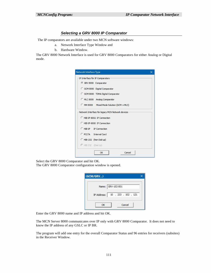
`MCNConfig Program: IP Comparator Network Interface
111
Selecting a GRV 8000 IP Comparator
The IP comparators are available under two MCN software windows:
a. Network Interface Type Window and
b. Hardware Window.
The GRV 8000 Network Interface is used for GRV 8000 Comparators for either Analog or Digital
mode.
Select the GRV 8000 Comparator and hit OK.
The GRV 8000 Comparator configuration window is opened.
Enter the GRV 8000 name and IP address and hit OK.
The MCN Server 8000 communicates over IP only with GRV 8000 Comparator. It does not need to
know the IP address of any GSLC or IP BR.
The program will add one entry for the overall Comparator Status and 96 entries for receivers (subsites)
in the Receiver Window.
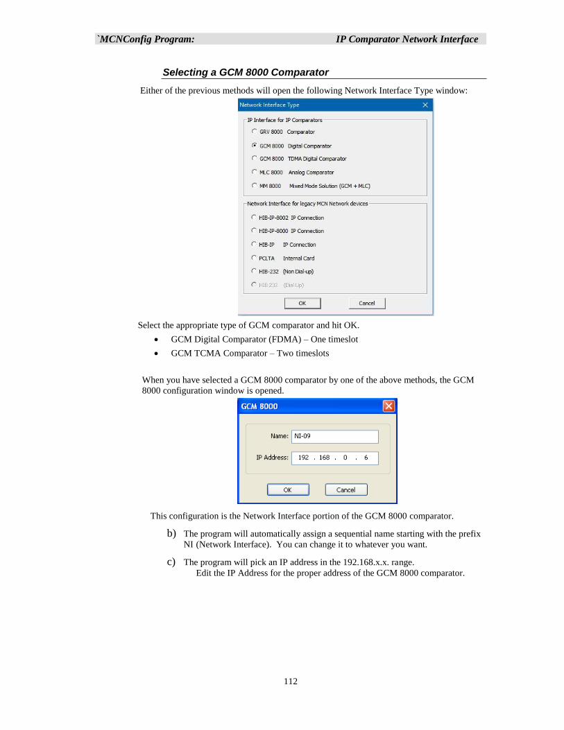
`MCNConfig Program: IP Comparator Network Interface
112
Selecting a GCM 8000 Comparator
Either of the previous methods will open the following Network Interface Type window:
Select the appropriate type of GCM comparator and hit OK.
• GCM Digital Comparator (FDMA) – One timeslot
• GCM TCMA Comparator – Two timeslots
When you have selected a GCM 8000 comparator by one of the above methods, the GCM
8000 configuration window is opened.
This configuration is the Network Interface portion of the GCM 8000 comparator.
b) The program will automatically assign a sequential name starting with the prefix
NI (Network Interface). You can change it to whatever you want.
c) The program will pick an IP address in the 192.168.x.x. range.
Edit the IP Address for the proper address of the GCM 8000 comparator.
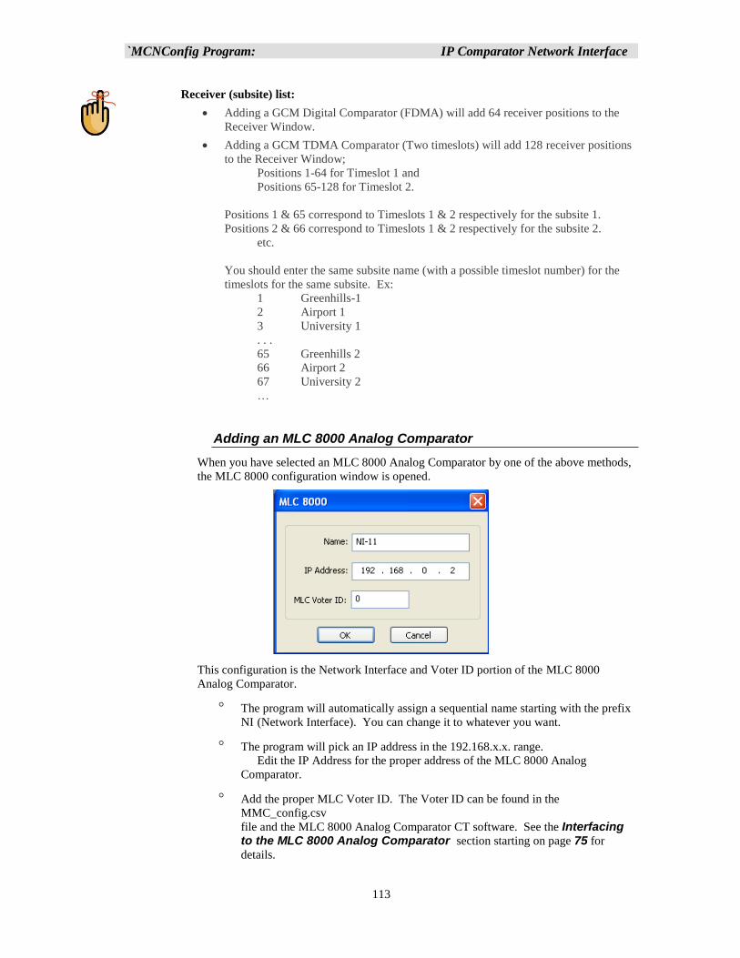
`MCNConfig Program: IP Comparator Network Interface
113
Receiver (subsite) list:
• Adding a GCM Digital Comparator (FDMA) will add 64 receiver positions to the
Receiver Window.
• Adding a GCM TDMA Comparator (Two timeslots) will add 128 receiver positions
to the Receiver Window;
Positions 1-64 for Timeslot 1 and
Positions 65-128 for Timeslot 2.
Positions 1 & 65 correspond to Timeslots 1 & 2 respectively for the subsite 1.
Positions 2 & 66 correspond to Timeslots 1 & 2 respectively for the subsite 2.
etc.
You should enter the same subsite name (with a possible timeslot number) for the
timeslots for the same subsite. Ex:
1 Greenhills-1
2 Airport 1
3 University 1
. . .
65 Greenhills 2
66 Airport 2
67 University 2
…
Adding an MLC 8000 Analog Comparator
When you have selected an MLC 8000 Analog Comparator by one of the above methods,
the MLC 8000 configuration window is opened.
This configuration is the Network Interface and Voter ID portion of the MLC 8000
Analog Comparator.
The program will automatically assign a sequential name starting with the prefix
NI (Network Interface). You can change it to whatever you want.
The program will pick an IP address in the 192.168.x.x. range.
Edit the IP Address for the proper address of the MLC 8000 Analog
Comparator.
Add the proper MLC Voter ID. The Voter ID can be found in the
MMC_config.csv
file and the MLC 8000 Analog Comparator CT software. See the Interfacing to the MLC 8000 Analog Comparator section starting on page 75 for
details.
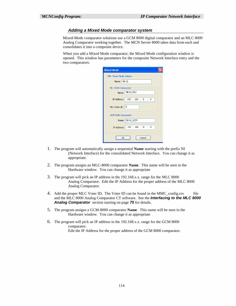
`MCNConfig Program: IP Comparator Network Interface
114
Adding a Mixed Mode comparator system
Mixed-Mode comparator solutions use a GCM 8000 digital comparator and an MLC 8000
Analog Comparator working together. The MCN Server 8000 takes data from each and
consolidates it into a composite device.
When you add a Mixed Mode comparator, the Mixed Mode configuration window is
opened. This window has parameters for the composite Network Interface entry and the
two comparators:
1. The program will automatically assign a sequential Name starting with the prefix NI
(Network Interface) for the consolidated Network Interface. You can change it as
appropriate.
2. The program assigns an MLC-8000 comparator Name. This name will be seen in the
Hardware window. You can change it as appropriate
3. The program will pick an IP address in the 192.168.x.x. range for the MLC 8000
Analog Comparator. Edit the IP Address for the proper address of the MLC 8000
Analog Comparator.
4. Add the proper MLC Voter ID. The Voter ID can be found in the MMC_config.csv file
and the MLC 8000 Analog Comparator CT software. See the Interfacing to the MLC 8000 Analog Comparator section starting on page 75 for details.
5. The program assigns a GCM-8000 comparator Name. This name will be seen in the
Hardware window. You can change it as appropriate
6. The program will pick an IP address in the 192.168.x.x. range for the GCM 8000
comparator.
Edit the IP Address for the proper address of the GCM 8000 comparator.
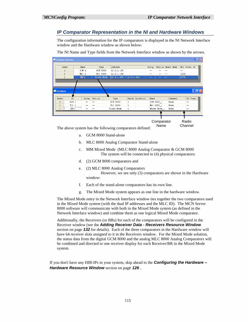
`MCNConfig Program: IP Comparator Network Interface
115
IP Comparator Representation in the NI and Hardware Windows
The configuration information for the IP comparators is displayed in the NI Network Interface
window and the Hardware window as shown below:
The NI Name and Type fields from the Network Interface window as shown by the arrows.
The above system has the following comparators defined:
a. GCM 8000 Stand-alone
b. MLC 8000 Analog Comparator Stand-alone
c. MM Mixed Mode (MLC 8000 Analog Comparator & GCM 8000
The system will be connected to (4) physical comparators:
d. (2) GCM 8000 comparators and
e. (2) MLC 8000 Analog Comparators
However, we see only (3) comparators are shown in the Hardware
window:
f. Each of the stand-alone comparators has its own line.
g. The Mixed Mode system appears as one line in the hardware window.
The Mixed Mode entry in the Network Interface window ties together the two comparators used
in the Mixed Mode system (with the dual IP addresses and the MLC ID). The MCN Server
8000 software will communicate with both in the Mixed Mode system (as defined in the
Network Interface window) and combine them as one logical Mixed Mode comparator.
Additionally, the Receivers (or BRs) for each of the comparators will be configured in the
Receiver window (see the Adding Receiver Data - Receivers Resource Window
section on page 132 for details). Each of the three comparators in the Hardware window will
have 64 receiver slots assigned to it in the Receivers window. For the Mixed Mode solution,
the status data from the digital GCM 8000 and the analog MLC 8000 Analog Comparators will
be combined and directed to one receiver display for each Receiver/BR in the Mixed Mode
system.
If you don't have any HIB-IPs in your system, skip ahead to the Configuring the Hardware –
Hardware Resource Window section on page 126 .
Comparator Name
Radio Channel Name
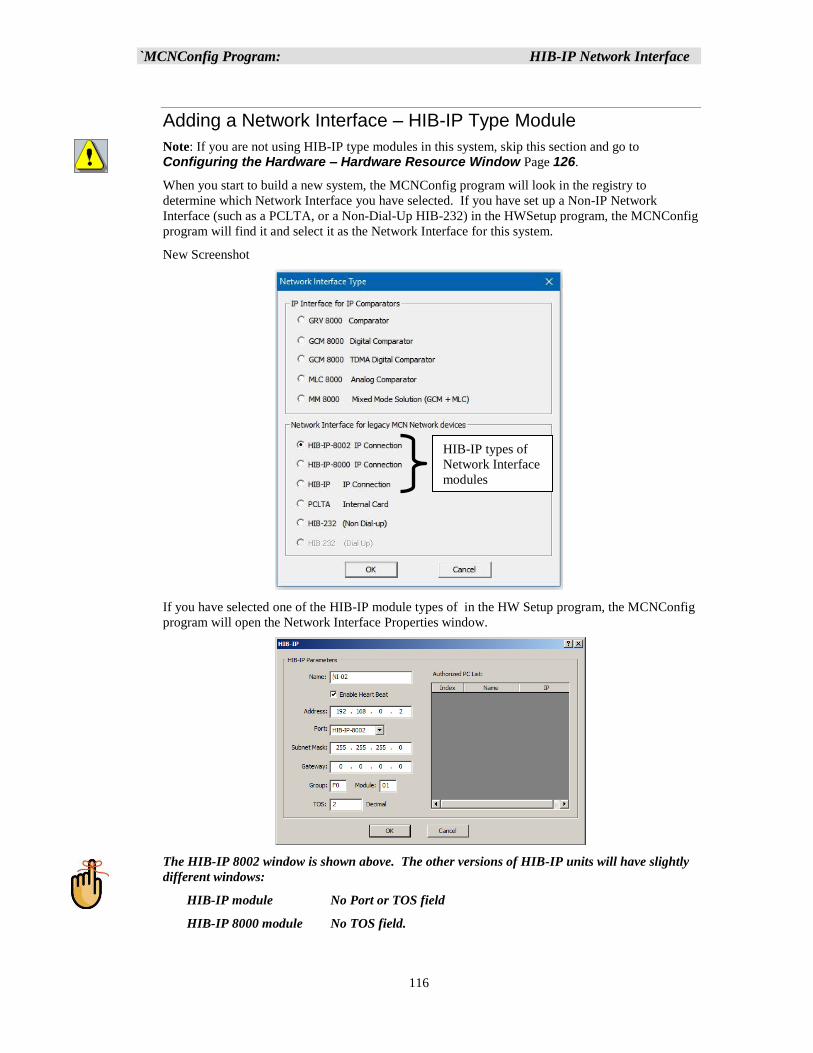
`MCNConfig Program: HIB-IP Network Interface
116
Adding a Network Interface – HIB-IP Type Module
Note: If you are not using HIB-IP type modules in this system, skip this section and go to
Configuring the Hardware – Hardware Resource Window Page 126.
When you start to build a new system, the MCNConfig program will look in the registry to
determine which Network Interface you have selected. If you have set up a Non-IP Network
Interface (such as a PCLTA, or a Non-Dial-Up HIB-232) in the HWSetup program, the MCNConfig
program will find it and select it as the Network Interface for this system.
New Screenshot
If you have selected one of the HIB-IP module types of in the HW Setup program, the MCNConfig
program will open the Network Interface Properties window.
The HIB-IP 8002 window is shown above. The other versions of HIB-IP units will have slightly
different windows:
HIB-IP module No Port or TOS field
HIB-IP 8000 module No TOS field.
HIB-IP types of
Network Interface
modules
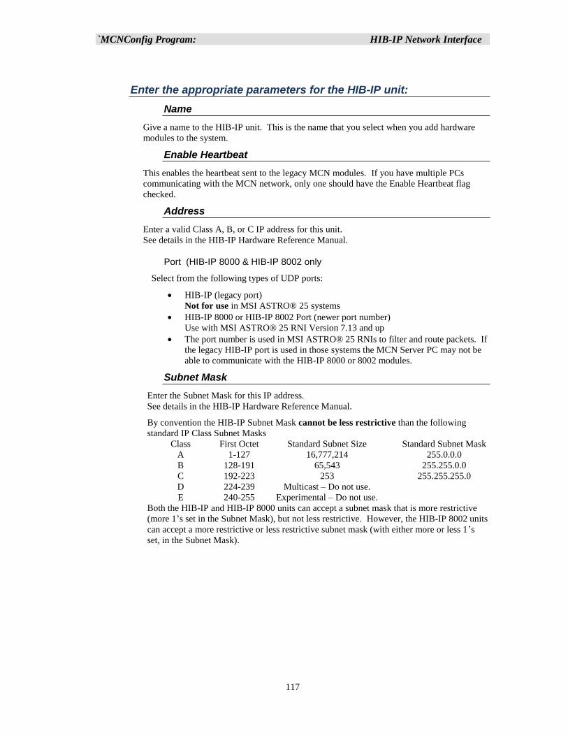
`MCNConfig Program: HIB-IP Network Interface
117
Enter the appropriate parameters for the HIB-IP unit:
Name
Give a name to the HIB-IP unit. This is the name that you select when you add hardware
modules to the system.
Enable Heartbeat
This enables the heartbeat sent to the legacy MCN modules. If you have multiple PCs
communicating with the MCN network, only one should have the Enable Heartbeat flag
checked.
Address
Enter a valid Class A, B, or C IP address for this unit.
See details in the HIB-IP Hardware Reference Manual.
Port (HIB-IP 8000 & HIB-IP 8002 only
Select from the following types of UDP ports:
• HIB-IP (legacy port)
Not for use in MSI ASTRO® 25 systems
• HIB-IP 8000 or HIB-IP 8002 Port (newer port number)
Use with MSI ASTRO® 25 RNI Version 7.13 and up
• The port number is used in MSI ASTRO® 25 RNIs to filter and route packets. If
the legacy HIB-IP port is used in those systems the MCN Server PC may not be
able to communicate with the HIB-IP 8000 or 8002 modules.
Subnet Mask
Enter the Subnet Mask for this IP address.
See details in the HIB-IP Hardware Reference Manual.
By convention the HIB-IP Subnet Mask cannot be less restrictive than the following
standard IP Class Subnet Masks
Class First Octet Standard Subnet Size Standard Subnet Mask
A 1-127 16,777,214 255.0.0.0
B 128-191 65,543 255.255.0.0
C 192-223 253 255.255.255.0
D 224-239 Multicast – Do not use.
E 240-255 Experimental – Do not use.
Both the HIB-IP and HIB-IP 8000 units can accept a subnet mask that is more restrictive
(more 1’s set in the Subnet Mask), but not less restrictive. However, the HIB-IP 8002 units
can accept a more restrictive or less restrictive subnet mask (with either more or less 1’s
set, in the Subnet Mask).
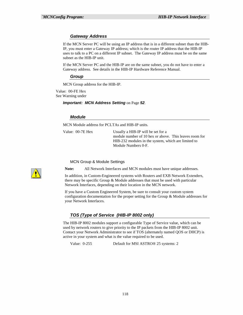
`MCNConfig Program: HIB-IP Network Interface
118
Gateway Address
If the MCN Server PC will be using an IP address that is in a different subnet than the HIB-
IP, you must enter a Gateway IP address; which is the router IP address that the HIB-IP
uses to talk to a PC on a different IP subnet. The Gateway IP address must be on the same
subnet as the HIB-IP unit.
If the MCN Server PC and the HIB-IP are on the same subnet, you do not have to enter a
Gateway address. See details in the HIB-IP Hardware Reference Manual.
Group
MCN Group address for the HIB-IP.
Value: 00-FE Hex
See Warning under
Important: MCN Address Setting on Page 52.
Module
MCN Module address for PCLTAs and HIB-IP units.
Value: 00-7E Hex Usually a HIB-IP will be set for a
module number of 10 hex or above. This leaves room for
HIB-232 modules in the system, which are limited to
Module Numbers 0-F.
MCN Group & Module Settings
Note: All Network Interfaces and MCN modules must have unique addresses.
In addition, in Custom-Engineered systems with Routers and EXB Network Extenders,
there may be specific Group & Module addresses that must be used with particular
Network Interfaces, depending on their location in the MCN network.
If you have a Custom Engineered System, be sure to consult your custom system
configuration documentation for the proper setting for the Group & Module addresses for
your Network Interfaces.
TOS (Type of Service (HIB-IP 8002 only)
The HIB-IP 8002 modules support a configurable Type of Service value, which can be
used by network routers to give priority to the IP packets from the HIB-IP 8002 unit.
Contact your Network Administrator to see if TOS (alternately named QOS or DHCP) is
active in your system and what is the value required to be used.
Value: 0-255 Default for MSI ASTRO® 25 systems: 2
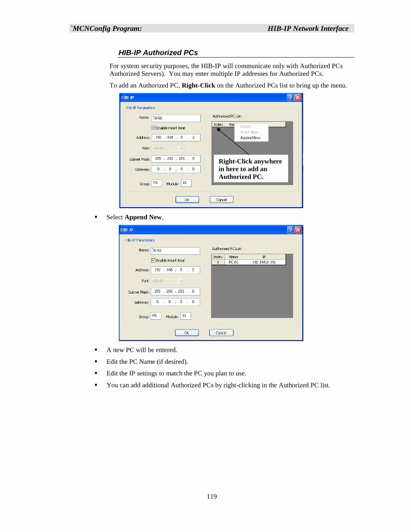
`MCNConfig Program: HIB-IP Network Interface
119
HIB-IP Authorized PCs
For system security purposes, the HIB-IP will communicate only with Authorized PCs
Authorized Servers). You may enter multiple IP addresses for Authorized PCs.
To add an Authorized PC, Right-Click on the Authorized PCs list to bring up the menu.
▪ Select Append New.
▪ A new PC will be entered.
▪ Edit the PC Name (if desired).
▪ Edit the IP settings to match the PC you plan to use.
▪ You can add additional Authorized PCs by right-clicking in the Authorized PC list.
Right-Click anywhere
in here to add an
Authorized PC.

`MCNConfig Program: HIB-IP Network Interface
120
▪ Set up the parameters for the HIB-IP unit.
▪ When you are finished entering Authorized PCs, click the OK button.
Although you can enter multiple Authorized PCs in the HIB-IP configuration window, the
HIB-IP can only connect to one PC at a time. If a second PC attempts to connect to a HIB-
IP at the same time (even if it is in its Authorized PC list), it will be rejected.
The HIB-IP unit will appear in the Network Interface window.
It will then be associated with all the hardware modules (such as CIBs, AIBs, and IOBs).
The standard MCN Server 8000 software supports (4) IP comparators and (1) HIB-IP.
(Support for additional IP Comparators or HIB-IP Network Interfaces, may be added with
additional license expansion options.
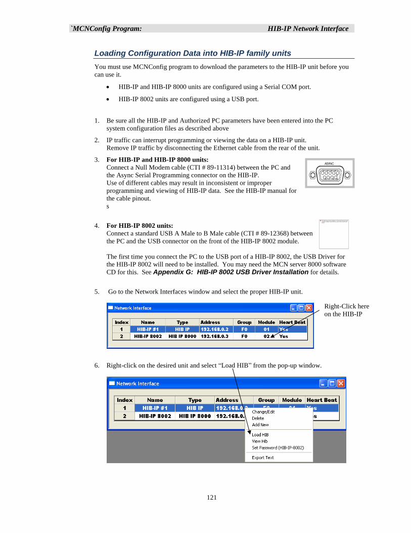
`MCNConfig Program: HIB-IP Network Interface
121
Loading Configuration Data into HIB-IP family units
You must use MCNConfig program to download the parameters to the HIB-IP unit before you
can use it.
• HIB-IP and HIB-IP 8000 units are configured using a Serial COM port.
• HIB-IP 8002 units are configured using a USB port.
1. Be sure all the HIB-IP and Authorized PC parameters have been entered into the PC
system configuration files as described above
2. IP traffic can interrupt programming or viewing the data on a HIB-IP unit.
Remove IP traffic by disconnecting the Ethernet cable from the rear of the unit.
3. For HIB-IP and HIB-IP 8000 units:
Connect a Null Modem cable (CTI # 89-11314) between the PC and
the Async Serial Programming connector on the HIB-IP.
Use of different cables may result in inconsistent or improper
programming and viewing of HIB-IP data. See the HIB-IP manual for
the cable pinout.
s
4. For HIB-IP 8002 units:
Connect a standard USB A Male to B Male cable (CTI # 89-12368) between
the PC and the USB connector on the front of the HIB-IP 8002 module.
The first time you connect the PC to the USB port of a HIB-IP 8002, the USB Driver for
the HIB-IP 8002 will need to be installed. You may need the MCN server 8000 software
CD for this. See Appendix G: HIB-IP 8002 USB Driver Installation for details.
5. Go to the Network Interfaces window and select the proper HIB-IP unit.
6. Right-click on the desired unit and select “Load HIB” from the pop-up window.
Right-Click here
on the HIB-IP
1 2 3 4
5
9876
ASYNC
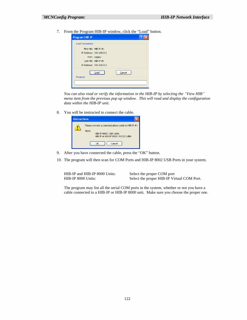
`MCNConfig Program: HIB-IP Network Interface
122
7. From the Program HIB-IP window, click the “Load” button.
You can also read or verify the information in the HIB-IP by selecting the “View HIB”
menu item from the previous pop up window. This will read and display the configuration
data within the HIB-IP unit.
8. You will be instructed to connect the cable.
9. After you have connected the cable, press the “OK” button.
10. The program will then scan for COM Ports and HIB-IP 8002 USB Ports in your system.
HIB-IP and HIB-IP 8000 Units: Select the proper COM port
HIB-IP 8000 Units: Select the proper HIB-IP Virtual COM Port.
The program may list all the serial COM ports in the system, whether or not you have a
cable connected to a HIB-IP or HIB-IP 8000 unit. Make sure you choose the proper one.
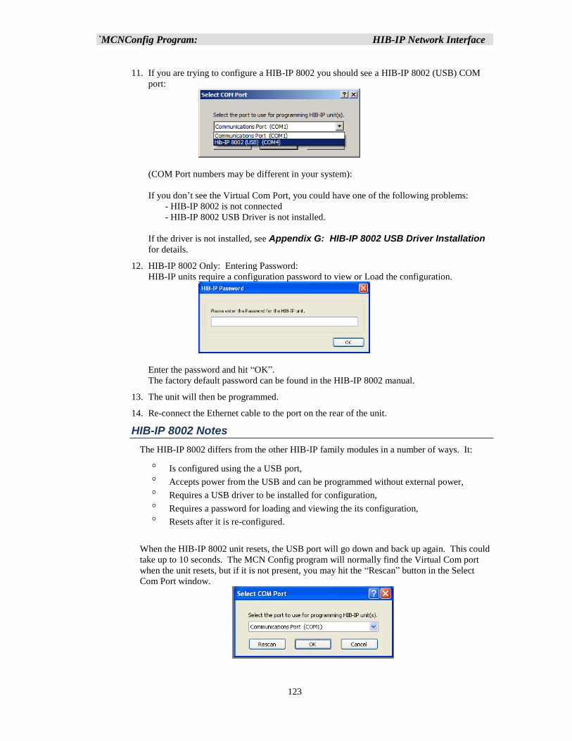
`MCNConfig Program: HIB-IP Network Interface
123
11. If you are trying to configure a HIB-IP 8002 you should see a HIB-IP 8002 (USB) COM
port:
(COM Port numbers may be different in your system):
If you don’t see the Virtual Com Port, you could have one of the following problems:
- HIB-IP 8002 is not connected
- HIB-IP 8002 USB Driver is not installed.
If the driver is not installed, see Appendix G: HIB-IP 8002 USB Driver Installation
for details.
12. HIB-IP 8002 Only: Entering Password:
HIB-IP units require a configuration password to view or Load the configuration.
Enter the password and hit “OK”.
The factory default password can be found in the HIB-IP 8002 manual.
13. The unit will then be programmed.
14. Re-connect the Ethernet cable to the port on the rear of the unit.
HIB-IP 8002 Notes
The HIB-IP 8002 differs from the other HIB-IP family modules in a number of ways. It:
Is configured using the a USB port,
Accepts power from the USB and can be programmed without external power,
Requires a USB driver to be installed for configuration,
Requires a password for loading and viewing the its configuration,
Resets after it is re-configured.
When the HIB-IP 8002 unit resets, the USB port will go down and back up again. This could
take up to 10 seconds. The MCN Config program will normally find the Virtual Com port
when the unit resets, but if it is not present, you may hit the “Rescan” button in the Select
Com Port window.
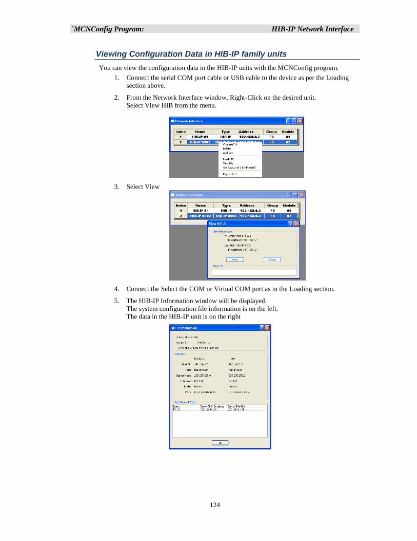
`MCNConfig Program: HIB-IP Network Interface
124
Viewing Configuration Data in HIB-IP family units
You can view the configuration data in the HIB-IP units with the MCNConfig program.
1. Connect the serial COM port cable or USB cable to the device as per the Loading
section above.
2. From the Network Interface window, Right-Click on the desired unit.
Select View HIB from the menu.
3. Select View
4. Connect the Select the COM or Virtual COM port as in the Loading section.
5. The HIB-IP Information window will be displayed.
The system configuration file information is on the left.
The data in the HIB-IP unit is on the right
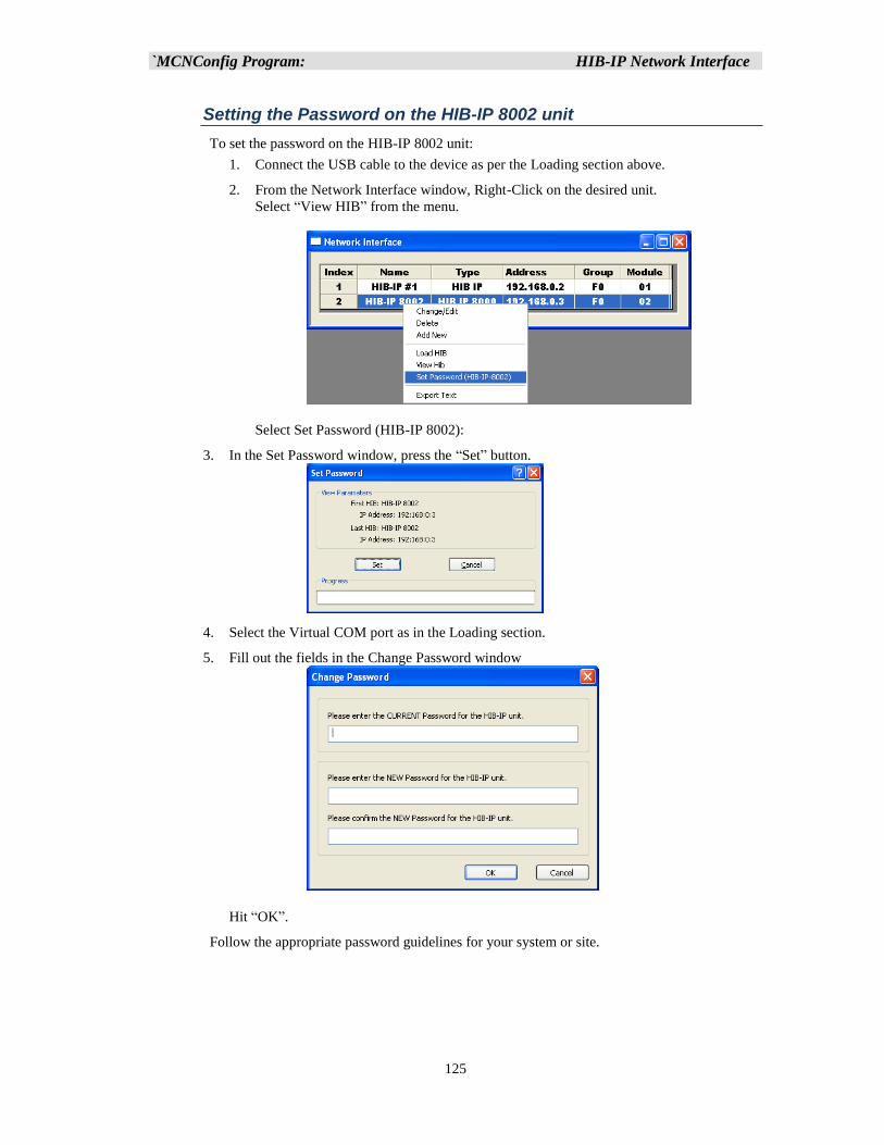
`MCNConfig Program: HIB-IP Network Interface
125
Setting the Password on the HIB-IP 8002 unit
To set the password on the HIB-IP 8002 unit:
1. Connect the USB cable to the device as per the Loading section above.
2. From the Network Interface window, Right-Click on the desired unit.
Select “View HIB” from the menu.
Select Set Password (HIB-IP 8002):
3. In the Set Password window, press the “Set” button.
4. Select the Virtual COM port as in the Loading section.
5. Fill out the fields in the Change Password window
Hit “OK”.
Follow the appropriate password guidelines for your system or site.
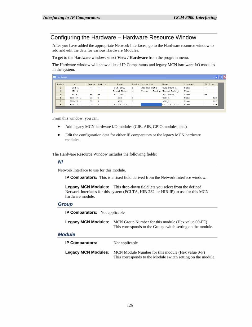
Interfacing to IP Comparators GCM 8000 Interfacing
126
Configuring the Hardware – Hardware Resource Window
After you have added the appropriate Network Interfaces, go to the Hardware resource window to
add and edit the data for various Hardware Modules.
To get to the Hardware window, select View / Hardware from the program menu.
The Hardware window will show a list of IP Comparators and legacy MCN hardware I/O modules
in the system.
From this window, you can:
• Add legacy MCN hardware I/O modules (CIB, AIB, GPIO modules, etc.)
• Edit the configuration data for either IP comparators or the legacy MCN hardware
modules.
The Hardware Resource Window includes the following fields:
NI
Network Interface to use for this module.
IP Comparators: This is a fixed field derived from the Network Interface window.
Legacy MCN Modules: This drop-down field lets you select from the defined
Network Interfaces for this system (PCLTA, HIB-232, or HIB-IP) to use for this MCN
hardware module.
Group
IP Comparators: Not applicable
Legacy MCN Modules: MCN Group Number for this module (Hex value 00-FE)
This corresponds to the Group switch setting on the module.
Module
IP Comparators: Not applicable
Legacy MCN Modules: MCN Module Number for this module (Hex value 0-F)
This corresponds to the Module switch setting on the module.
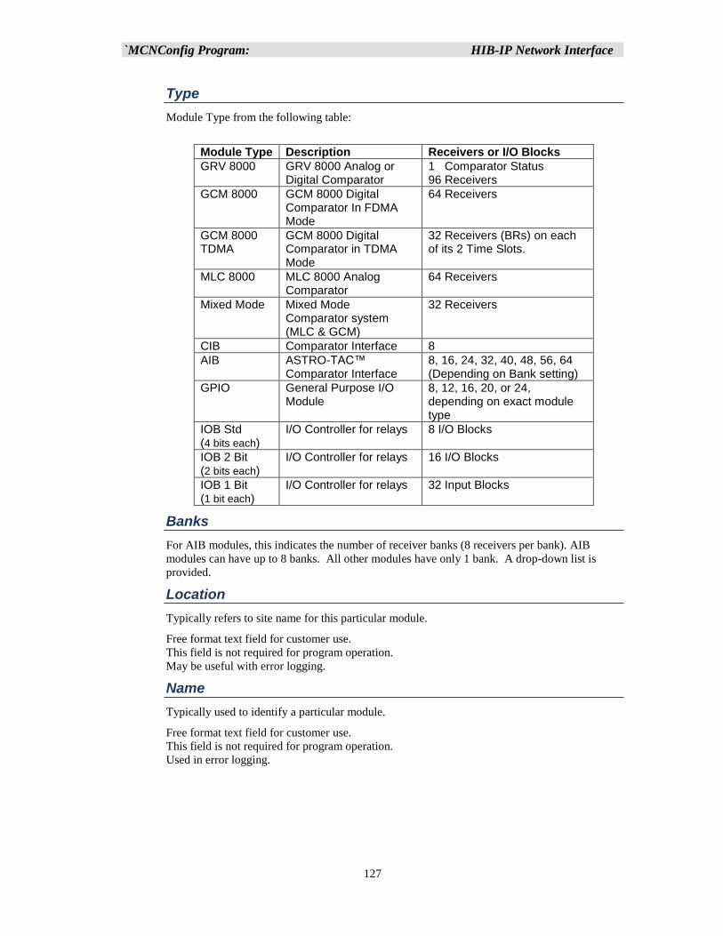
`MCNConfig Program: HIB-IP Network Interface
127
Type
Module Type from the following table:
Module Type Description Receivers or I/O Blocks
GRV 8000 GRV 8000 Analog or Digital Comparator
1 Comparator Status 96 Receivers
GCM 8000 GCM 8000 Digital Comparator In FDMA Mode
64 Receivers
GCM 8000 TDMA
GCM 8000 Digital Comparator in TDMA Mode
32 Receivers (BRs) on each of its 2 Time Slots.
MLC 8000 MLC 8000 Analog Comparator
64 Receivers
Mixed Mode Mixed Mode Comparator system (MLC & GCM)
32 Receivers
CIB Comparator Interface 8
AIB ASTRO-TAC™ Comparator Interface
8, 16, 24, 32, 40, 48, 56, 64 (Depending on Bank setting)
GPIO General Purpose I/O Module
8, 12, 16, 20, or 24, depending on exact module type
IOB Std (4 bits each)
I/O Controller for relays 8 I/O Blocks
IOB 2 Bit (2 bits each)
I/O Controller for relays 16 I/O Blocks
IOB 1 Bit (1 bit each)
I/O Controller for relays 32 Input Blocks
Banks
For AIB modules, this indicates the number of receiver banks (8 receivers per bank). AIB
modules can have up to 8 banks. All other modules have only 1 bank. A drop-down list is
provided.
Location
Typically refers to site name for this particular module.
Free format text field for customer use.
This field is not required for program operation.
May be useful with error logging.
Name
Typically used to identify a particular module.
Free format text field for customer use.
This field is not required for program operation.
Used in error logging.
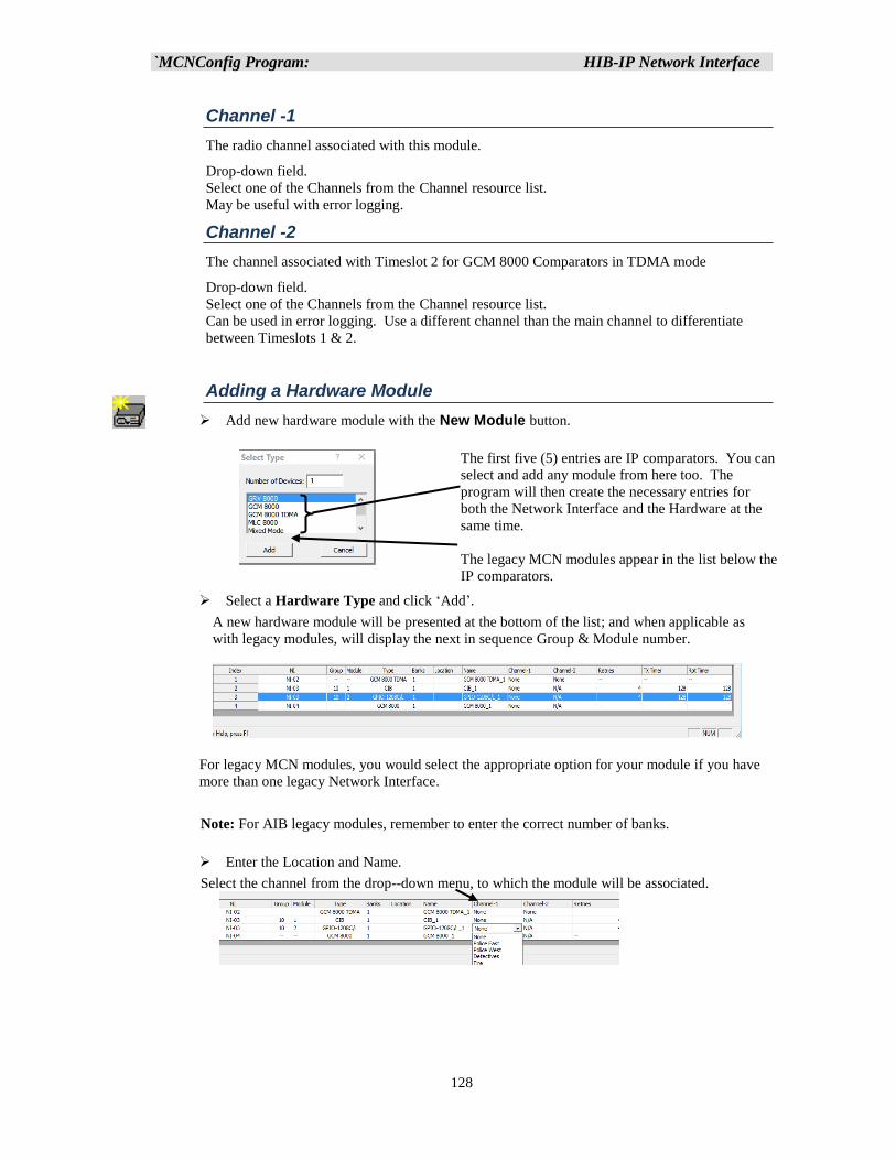
`MCNConfig Program: HIB-IP Network Interface
128
Channel -1
The radio channel associated with this module.
Drop-down field.
Select one of the Channels from the Channel resource list.
May be useful with error logging.
Channel -2
The channel associated with Timeslot 2 for GCM 8000 Comparators in TDMA mode
Drop-down field.
Select one of the Channels from the Channel resource list.
Can be used in error logging. Use a different channel than the main channel to differentiate
between Timeslots 1 & 2.
Adding a Hardware Module
➢ Add new hardware module with the New Module button.
➢ Select a Hardware Type and click ‘Add’.
A new hardware module will be presented at the bottom of the list; and when applicable as
with legacy modules, will display the next in sequence Group & Module number.
For legacy MCN modules, you would select the appropriate option for your module if you have
more than one legacy Network Interface.
Note: For AIB legacy modules, remember to enter the correct number of banks.
➢ Enter the Location and Name.
Select the channel from the drop--down menu, to which the module will be associated.
The first five (5) entries are IP comparators. You can
select and add any module from here too. The
program will then create the necessary entries for
both the Network Interface and the Hardware at the
same time.
The legacy MCN modules appear in the list below the
IP comparators.
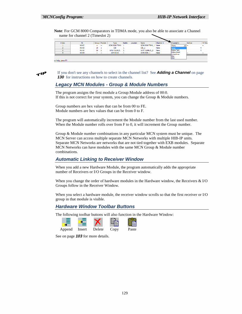
`MCNConfig Program: HIB-IP Network Interface
129
Note: For GCM 8000 Comparators in TDMA mode, you also be able to associate a Channel
name for channel 2 (Timeslot 2)
If you don't see any channels to select in the channel list? See Adding a Channel on page
130 for instructions on how to create channels.
Legacy MCN Modules - Group & Module Numbers
The program assigns the first module a Group:Module address of 00:0.
If this is not correct for your system, you can change the Group & Module numbers.
Group numbers are hex values that can be from 00 to FE.
Module numbers are hex values that can be from 0 to F.
The program will automatically increment the Module number from the last used number.
When the Module number rolls over from F to 0, it will increment the Group number.
Group & Module number combinations in any particular MCN system must be unique. The
MCN Server can access multiple separate MCN Networks with multiple HIB-IP units.
Separate MCN Networks are networks that are not tied together with EXB modules. Separate
MCN Networks can have modules with the same MCN Group & Module number
combinations.
Automatic Linking to Receiver Window
When you add a new Hardware Module, the program automatically adds the appropriate
number of Receivers or I/O Groups in the Receiver window.
When you change the order of hardware modules in the Hardware window, the Receivers & I/O
Groups follow in the Receiver Window.
When you select a hardware module, the receiver window scrolls so that the first receiver or I/O
group in that module is visible.
Hardware Window Toolbar Buttons
The following toolbar buttons will also function in the Hardware Window:
Append Insert Delete Copy Paste
See on page 103 for more details.
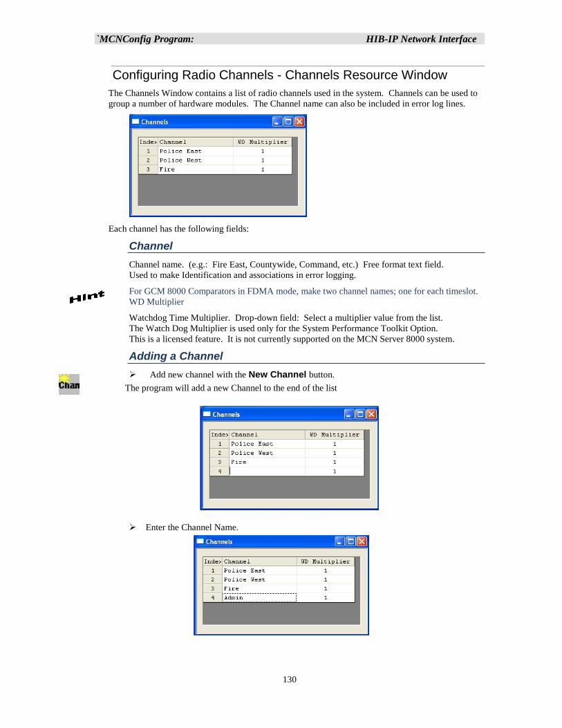
`MCNConfig Program: HIB-IP Network Interface
130
Configuring Radio Channels - Channels Resource Window
The Channels Window contains a list of radio channels used in the system. Channels can be used to
group a number of hardware modules. The Channel name can also be included in error log lines.
Each channel has the following fields:
Channel
Channel name. (e.g.: Fire East, Countywide, Command, etc.) Free format text field.
Used to make Identification and associations in error logging.
For GCM 8000 Comparators in FDMA mode, make two channel names; one for each timeslot.
WD Multiplier
Watchdog Time Multiplier. Drop-down field: Select a multiplier value from the list.
The Watch Dog Multiplier is used only for the System Performance Toolkit Option.
This is a licensed feature. It is not currently supported on the MCN Server 8000 system.
Adding a Channel
➢ Add new channel with the New Channel button.
The program will add a new Channel to the end of the list
➢ Enter the Channel Name.
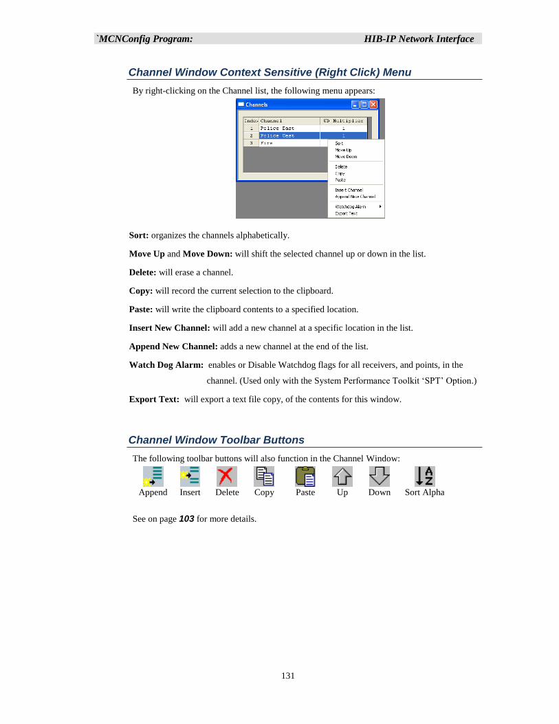
`MCNConfig Program: HIB-IP Network Interface
131
Channel Window Context Sensitive (Right Click) Menu
By right-clicking on the Channel list, the following menu appears:
Sort: organizes the channels alphabetically.
Move Up and Move Down: will shift the selected channel up or down in the list.
Delete: will erase a channel.
Copy: will record the current selection to the clipboard.
Paste: will write the clipboard contents to a specified location.
Insert New Channel: will add a new channel at a specific location in the list.
Append New Channel: adds a new channel at the end of the list.
Watch Dog Alarm: enables or Disable Watchdog flags for all receivers, and points, in the
channel. (Used only with the System Performance Toolkit ‘SPT’ Option.)
Export Text: will export a text file copy, of the contents for this window.
Channel Window Toolbar Buttons
The following toolbar buttons will also function in the Channel Window:
Append Insert Delete Copy Paste Up Down Sort Alpha
See on page 103 for more details.
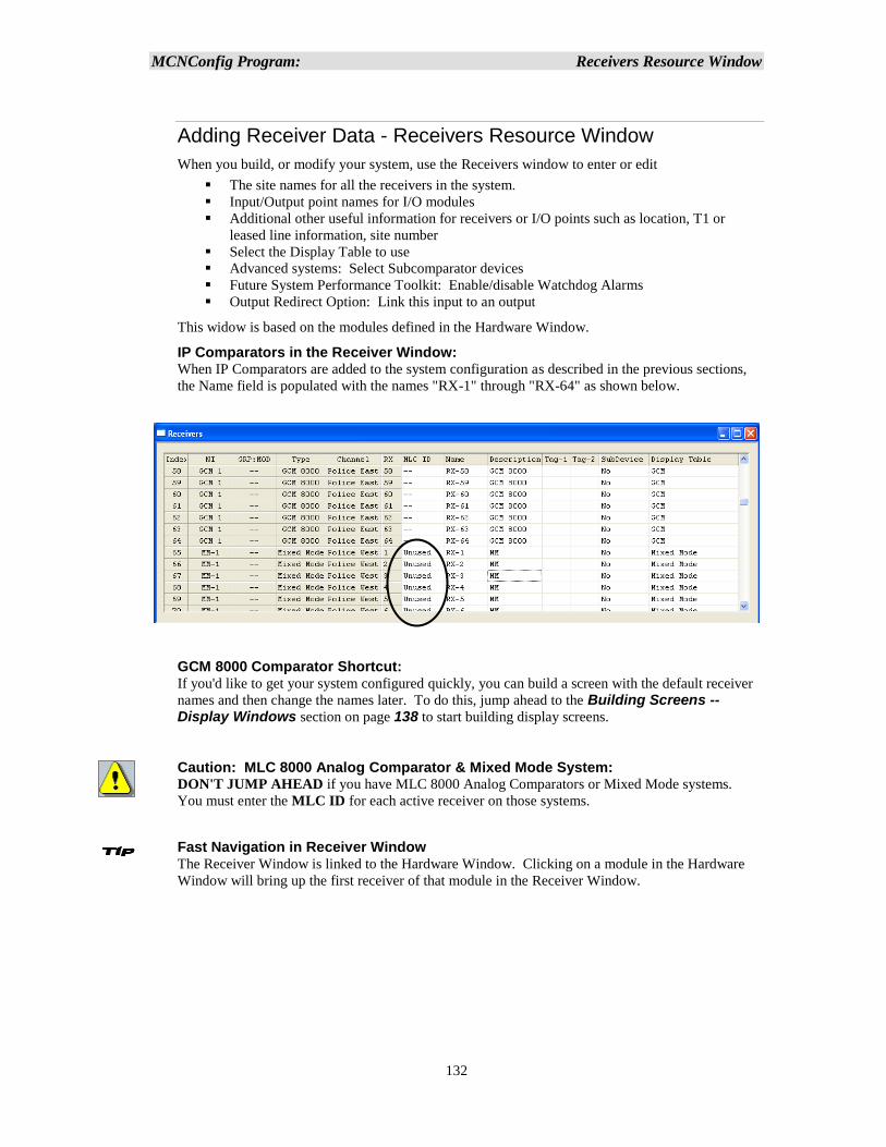
MCNConfig Program: Receivers Resource Window
132
Adding Receiver Data - Receivers Resource Window
When you build, or modify your system, use the Receivers window to enter or edit
▪ The site names for all the receivers in the system.
▪ Input/Output point names for I/O modules
▪ Additional other useful information for receivers or I/O points such as location, T1 or
leased line information, site number
▪ Select the Display Table to use
▪ Advanced systems: Select Subcomparator devices
▪ Future System Performance Toolkit: Enable/disable Watchdog Alarms
▪ Output Redirect Option: Link this input to an output
This widow is based on the modules defined in the Hardware Window.
IP Comparators in the Receiver Window: When IP Comparators are added to the system configuration as described in the previous sections,
the Name field is populated with the names "RX-1" through "RX-64" as shown below.
GCM 8000 Comparator Shortcut: If you'd like to get your system configured quickly, you can build a screen with the default receiver
names and then change the names later. To do this, jump ahead to the Building Screens -- Display Windows section on page 138 to start building display screens.
Caution: MLC 8000 Analog Comparator & Mixed Mode System: DON'T JUMP AHEAD if you have MLC 8000 Analog Comparators or Mixed Mode systems.
You must enter the MLC ID for each active receiver on those systems.
Fast Navigation in Receiver Window The Receiver Window is linked to the Hardware Window. Clicking on a module in the Hardware
Window will bring up the first receiver of that module in the Receiver Window.
MCNConfig Program: Receivers Resource Window
133
Entries in the Receivers Window have the fields shown below. Some fields may not be visible in
the window depending on (a) the options licensed in the system and (b) the settings in the View
menu item.
NI
Network Interface for this hardware module. This is a read-only field and is defined in the
Hardware window.
Grp:Mod
The MCN Group & Module number for legacy MCN devices. This is a read-only field defined
in the Hardware Window. The order of modules follows the module order in the Hardware
window.
Type
The IP Comparator Type (GCM 8000, MLC 8000 Analog Comparator, Mixed Mode) or legacy
MCN Module Type (CIB, AIB, IOB Std, IOB 2 Bit, IOB 1 Bit, etc.) for the hardware module.
This is a read-only field that is controlled in the Hardware Window
Channel
The radio channel for the hardware module. Read-only field (defined in Hardware list).
Rx
The Receiver Number for this receiver. This is a sequential number for a particular receiver
within its module or comparator. Read-only field. The maximum receiver number in a module
is based on the Bank number in the Hardware list.
For GPIO modules, this is a point number within the module.
MLC ID (MLC 8000 Analog Comparators and Mixed Mode Systems only)
This is the identifier for the MLC 8000 Analog Comparator port associated with this receiver or
BR. It must be entered for all active receivers in these types of systems.
This field is found in the MMC_Cfg.csv file generated by the MLC 8000 Analog Comparator
CT program. See Interfacing to the MLC 8000 Analog Comparator on page 75 for
details.
Name
Receiver site name (ex: North Tower, VA Hospital, etc.) or I/O point name.
Free-format text field. Change the Name by selecting the cell and typing in the name.
You can also cut & paste descriptions from Excel. See Using the Clipboard from other Applications on Page 156.
Description
Free format text field for general customer use. Many customers use this field to store an
identifier for the leased line, microwave channel, or T1 channel bank and channel number for
this receiver. This field is not required for program operation. The Description field can be
used for additional information in error logging detail lines.
You can also cut & paste descriptions from Excel. See Using the Clipboard from other Applications on Page 156 for more details.
MCNConfig Program: Receivers Resource Window
134
Tag-1
This is a free-format user defined field. It is used with the TPCI option. You can use it as a
note field if you are not using the TPCI Option.
Tag-2
This is a free-format user defined field. It is used with the TPCI option. You can use it as a
note field if you are not using the TPCI Option.
SubDevice
This is an advanced field and is normally not used on standard MCN Server 8000 systems.
This field will not be present on the screen unless the "Enable Sub Comparators" is enabled
under the View Menu. This field indicates if this receiver or I/O point feeds a sub-device. This
can be used for passing a Master Vote or a Main/Standby select to other devices. See the
Configuring Master-Sub Comparator Systems section on page 207 for more details.
WD-Alarm (for System Performance Toolkit -- Licensed Option)
This is used with an upcoming System Performance Toolkit (SPT) option. It can be enable for
each receiver by selecting yes in the Receiver Window under WD Alarm.
It allows the SPT to generate an alarm if No vote or No Receive is detected.
Link to Output (for Output Redirect -- Licensed Option)
This is an advanced field and is normally not used on standard MCN Server 8000 systems.
It is used for the Output Redirect Option and is designed for use in special cases, to provide
alarm outputs (from a CIB or GPIO module) to an external device when a failure on one or
more input devices occurs.
MCNConfig Program: Receivers Resource Window
135
Display Table (Default Display Table Selection)
The Display Table field in this window holds the default mapping table to use for this receiver
(or alarm point). The Display Table determines what status text is displayed for different
combinations of input bits from the hardware modules.
Comparator Display Tables
For comparator applications, the MCN Config Server program will automatically pre-
populate this field based upon the Comparator Module that is used:
Module Default Display Table Optional Display Table
CIB or AIB Comparator None
GCM 8000 GCM 8000 GCM LV
MLC 8000 MLC 8000 MLC LV MLC Tech
Mixed Mode Mixed Mode MM LV MM Tech
GRV 8000 GRV 8000 GRV LV GRV Tech
The IP comparators’ Display Table with "LV" indicates Last Vote. They have displayed
the last voted receiver when the system is idle.
The "Tech" Display tables have more details of interest to a technician.
• The MLC Tech Display Table has signal quality bars that are shown on
Receive and Vote activity.
• The MM Tech Display Table has more details on the operation of the
individual comparators that make up the Mixed Mode system.
• The GRV Tech Display Table has signal quality bars that are shown on
Receive and Vote activity.
The Display Table selected in the Receivers window will be the default Display Table that
will be used when the receiver is placed on a screen. It is recommended that you select the
non-Tech Display tables as the default. You can then make additional Tech Screens
(Display Windows) and use the Display Table Override procedure to select the Tech
Display Table for just the Tech screens. See Using Alternate Display Tables – Override Display Tables (p 153) for details.
All the above Display Tables map the inputs from the comparators to the standard "Vote",
"Rx", "Dis", and "Fail" statuses. For more information on the states shown in the Display
Tables for IP comparators, see the appropriate sections:
• GCM 8000 (FDMA) Status Display (p 66 )
• GCM 8000 TDMA Receiver List & Display Tables (p 67)
• GRV and GRV LV Display Tables (p 72)
• GRV Tech Display Table (p 73 )
• MLC 8000 and MLC LV Display Tables (p 86 ) or
• Mixed Mode Status Display (p 90 ).
You can change the default Display Table in the Receivers window with the drop-down
list.
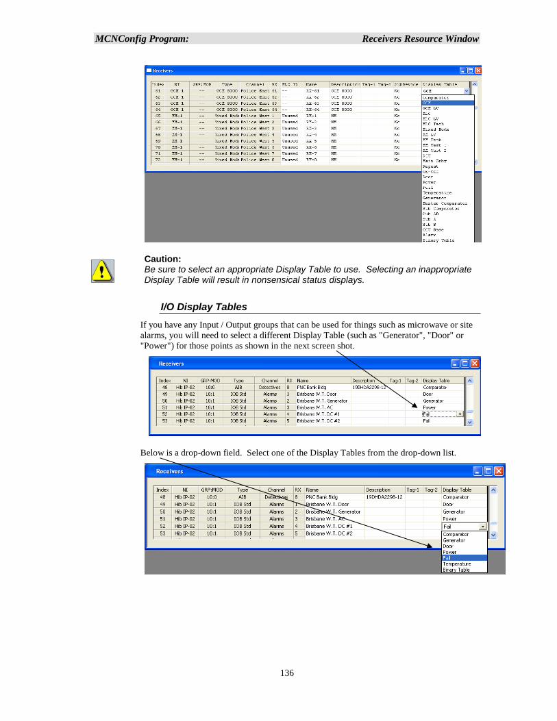
MCNConfig Program: Receivers Resource Window
136
Caution: Be sure to select an appropriate Display Table to use. Selecting an inappropriate Display Table will result in nonsensical status displays.
I/O Display Tables
If you have any Input / Output groups that can be used for things such as microwave or site
alarms, you will need to select a different Display Table (such as "Generator", "Door" or
"Power") for those points as shown in the next screen shot.
Below is a drop-down field. Select one of the Display Tables from the drop-down list.
MCNConfig Program: Receivers Resource Window
137
Alarms and Display Tables
You can configure "sticky" alarms in the system through the Display Tables. Alarms will be
displayed in the Alarm tab of the System events (Log) Window. They will remain in that
window until acknowledged and reset. Alarms can also generate sounds when they go into
the active state. See the Alarm Display – Log Window / Alarms Tab section on page
173 for details on Alarm operations and the States Tab section starting on page 197 for
instructions on how to enable alarms in the Display Tables.
Customizing Display Tables
If you need custom Display Tables, or need to edit the standard Display tables, see the
Working with Display Tables section on page 194 for an in-depth discussion.
Receiver Window Context Sensitive (Right Click) Menu
The following menu functions are available with a right click in the Receiver list.
Receiver Window Toolbar Buttons
The following toolbar buttons will also function in the Receiver Window:
Delete Cut Copy Paste
See Toolbars on page 103 for more details.
Since the Receiver & I/O Group rows are controlled by the Hardware Window, functions
such as Append, Insert, Sort, Up, & Down are not available in this window.
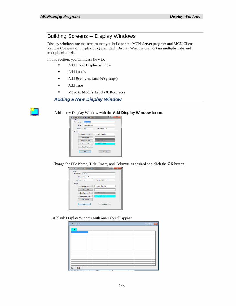
MCNConfig Program: Display Windows
138
Building Screens -- Display Windows
Display windows are the screens that you build for the MCN Server program and MCN Client
Remote Comparator Display program. Each Display Window can contain multiple Tabs and
multiple channels.
In this section, you will learn how to:
▪ Add a new Display window
▪ Add Labels
▪ Add Receivers (and I/O groups)
▪ Add Tabs
▪ Move & Modify Labels & Receivers
Adding a New Display Window
Add a new Display Window with the Add Display Window button.
Change the File Name, Title, Rows, and Columns as desired and click the OK button.
A blank Display Window with one Tab will appear
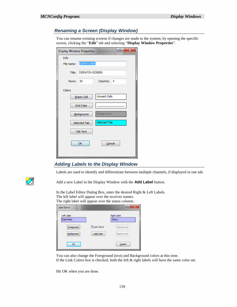
MCNConfig Program: Display Windows
139
Renaming a Screen (Display Window)
You can rename existing screens if changes are made to the system; by opening the specific
screen, clicking the “Edit” tab and selecting “Display Window Properties”.
Adding Labels to the Display Window
Labels are used to identify and differentiate between multiple channels, if displayed in one tab.
Add a new Label in the Display Window with the Add Label button.
In the Label Editor Dialog Box, enter the desired Right & Left Labels.
The left label will appear over the receiver names.
The right label will appear over the status column.
You can also change the Foreground (text) and Background colors at this time.
If the Link Colors box is checked, both the left & right labels will have the same color set.
Hit OK when you are done.
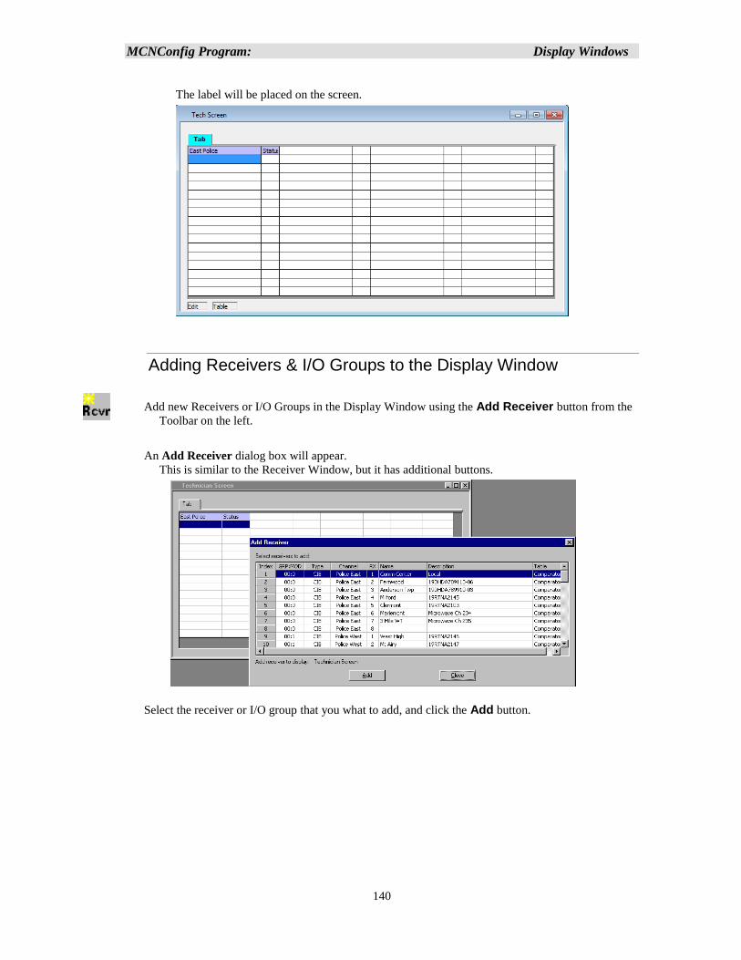
MCNConfig Program: Display Windows
140
The label will be placed on the screen.
Adding Receivers & I/O Groups to the Display Window
Add new Receivers or I/O Groups in the Display Window using the Add Receiver button from the
Toolbar on the left.
An Add Receiver dialog box will appear.
This is similar to the Receiver Window, but it has additional buttons.
Select the receiver or I/O group that you what to add, and click the Add button.
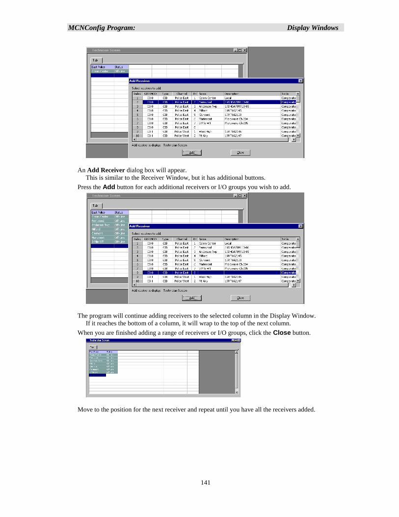
MCNConfig Program: Display Windows
141
An Add Receiver dialog box will appear.
This is similar to the Receiver Window, but it has additional buttons.
Press the Add button for each additional receivers or I/O groups you wish to add.
The program will continue adding receivers to the selected column in the Display Window.
If it reaches the bottom of a column, it will wrap to the top of the next column.
When you are finished adding a range of receivers or I/O groups, click the Close button.
Move to the position for the next receiver and repeat until you have all the receivers added.
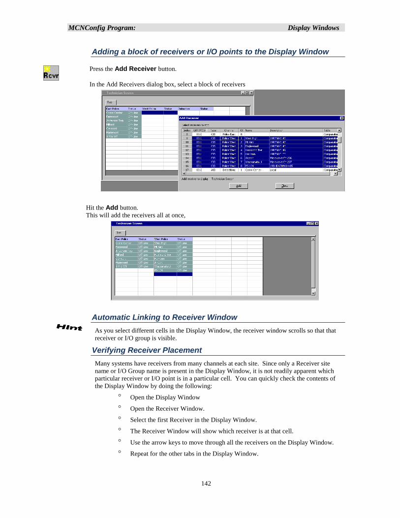
MCNConfig Program: Display Windows
142
Adding a block of receivers or I/O points to the Display Window
Press the Add Receiver button.
In the Add Receivers dialog box, select a block of receivers
Hit the Add button.
This will add the receivers all at once,
Automatic Linking to Receiver Window
As you select different cells in the Display Window, the receiver window scrolls so that that
receiver or I/O group is visible.
Verifying Receiver Placement
Many systems have receivers from many channels at each site. Since only a Receiver site
name or I/O Group name is present in the Display Window, it is not readily apparent which
particular receiver or I/O point is in a particular cell. You can quickly check the contents of
the Display Window by doing the following:
Open the Display Window
Open the Receiver Window.
Select the first Receiver in the Display Window.
The Receiver Window will show which receiver is at that cell.
Use the arrow keys to move through all the receivers on the Display Window.
Repeat for the other tabs in the Display Window.
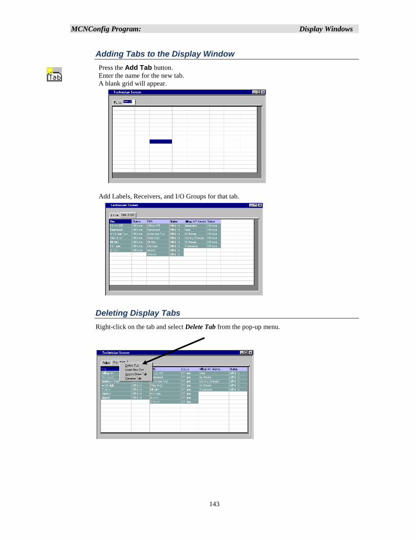
MCNConfig Program: Display Windows
143
Adding Tabs to the Display Window
Press the Add Tab button.
Enter the name for the new tab.
A blank grid will appear.
Add Labels, Receivers, and I/O Groups for that tab.
Deleting Display Tabs
Right-click on the tab and select Delete Tab from the pop-up menu.
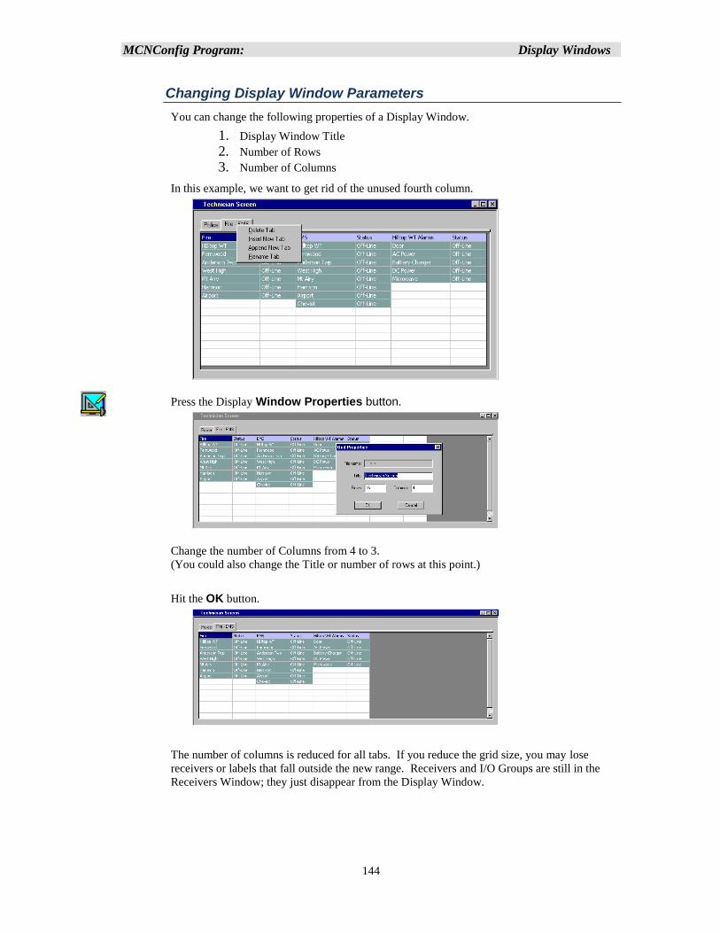
MCNConfig Program: Display Windows
144
Changing Display Window Parameters
You can change the following properties of a Display Window.
1. Display Window Title
2. Number of Rows
3. Number of Columns
In this example, we want to get rid of the unused fourth column.
Press the Display Window Properties button.
Change the number of Columns from 4 to 3.
(You could also change the Title or number of rows at this point.)
Hit the OK button.
The number of columns is reduced for all tabs. If you reduce the grid size, you may lose
receivers or labels that fall outside the new range. Receivers and I/O Groups are still in the
Receivers Window; they just disappear from the Display Window.
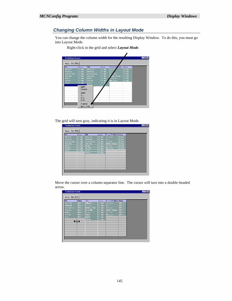
MCNConfig Program: Display Windows
145
Changing Column Widths in Layout Mode
You can change the column width for the resulting Display Window. To do this, you must go
into Layout Mode.
Right-click in the grid and select Layout Mode.
The grid will turn gray, indicating it is in Layout Mode.
Move the cursor over a column separator line. The cursor will turn into a double-headed
arrow.
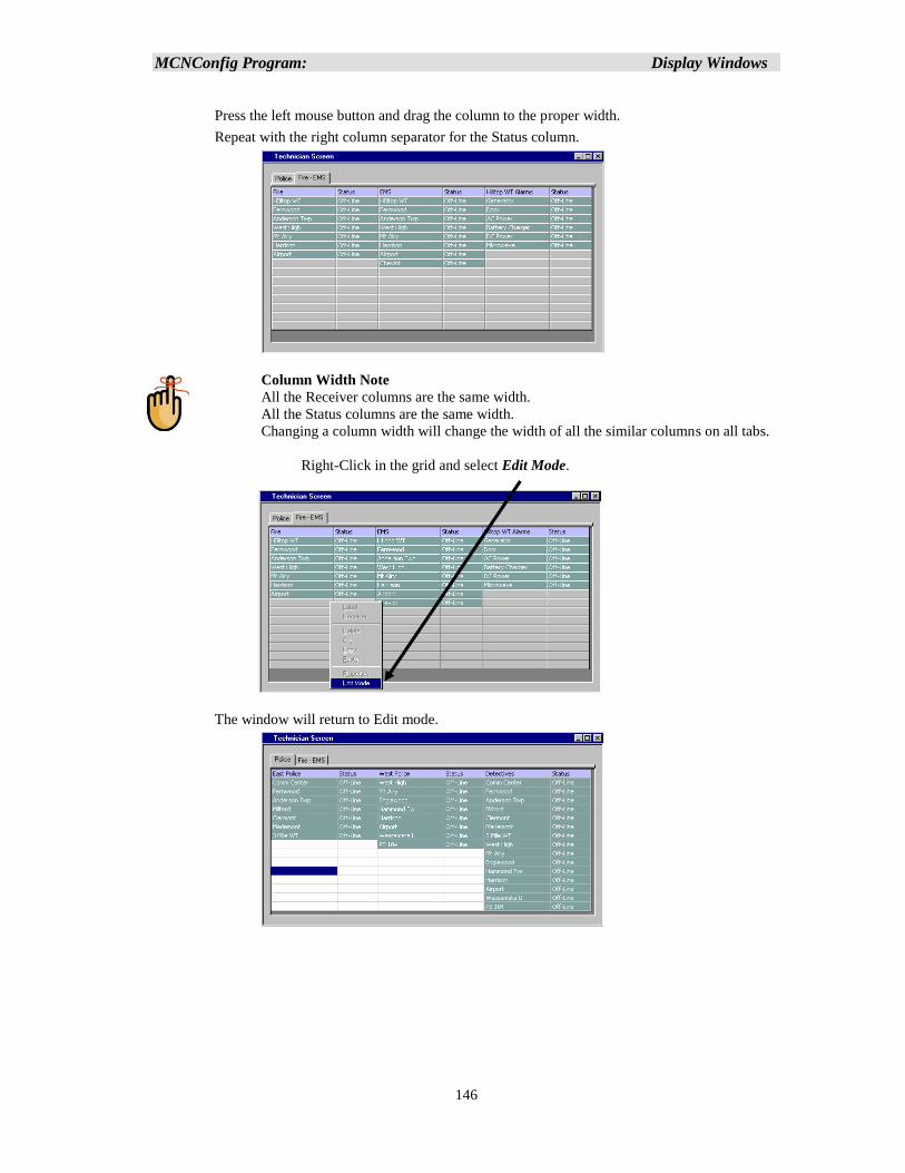
MCNConfig Program: Display Windows
146
Press the left mouse button and drag the column to the proper width.
Repeat with the right column separator for the Status column.
Column Width Note
All the Receiver columns are the same width.
All the Status columns are the same width.
Changing a column width will change the width of all the similar columns on all tabs.
Right-Click in the grid and select Edit Mode.
The window will return to Edit mode.
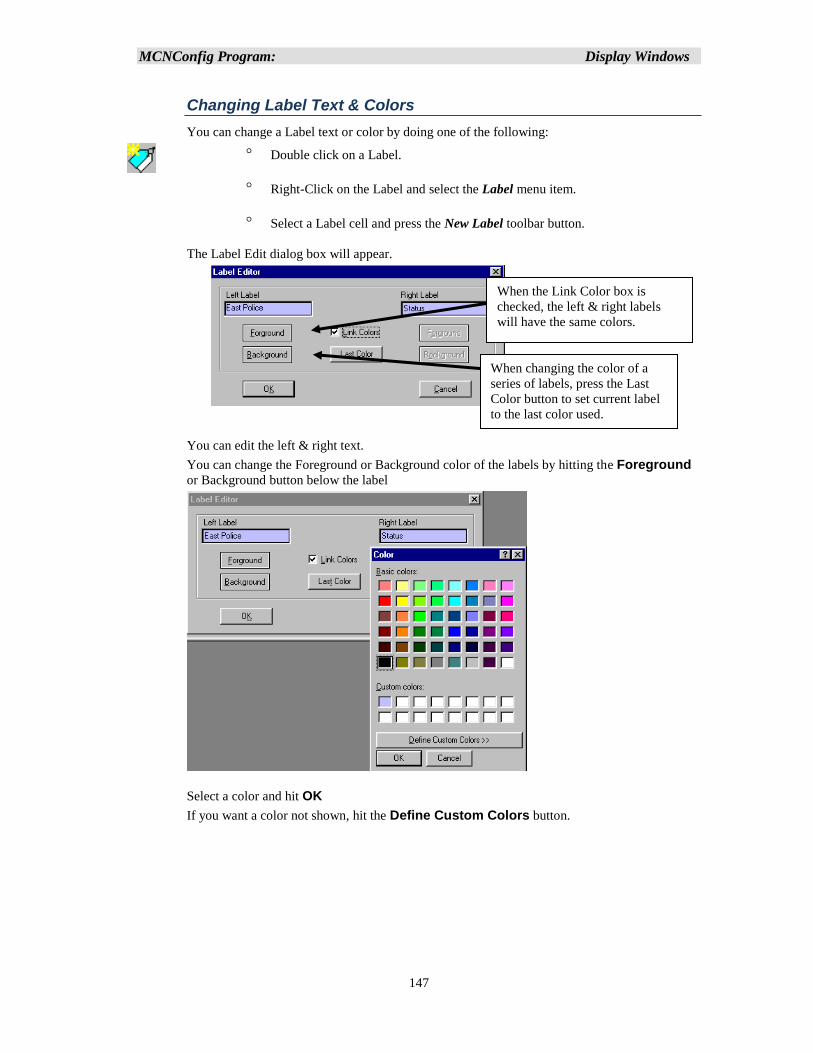
MCNConfig Program: Display Windows
147
Changing Label Text & Colors
You can change a Label text or color by doing one of the following:
Double click on a Label.
Right-Click on the Label and select the Label menu item.
Select a Label cell and press the New Label toolbar button.
The Label Edit dialog box will appear.
You can edit the left & right text.
You can change the Foreground or Background color of the labels by hitting the Foreground
or Background button below the label
Select a color and hit OK
If you want a color not shown, hit the Define Custom Colors button.
When the Link Color box is
checked, the left & right labels
will have the same colors.
When changing the color of a
series of labels, press the Last
Color button to set current label
to the last color used.
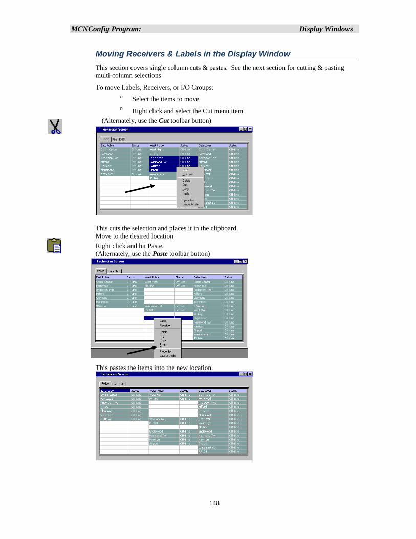
MCNConfig Program: Display Windows
148
Moving Receivers & Labels in the Display Window
This section covers single column cuts & pastes. See the next section for cutting & pasting
multi-column selections
To move Labels, Receivers, or I/O Groups:
Select the items to move
Right click and select the Cut menu item
(Alternately, use the Cut toolbar button)
This cuts the selection and places it in the clipboard.
Move to the desired location
Right click and hit Paste.
(Alternately, use the Paste toolbar button)
This pastes the items into the new location.
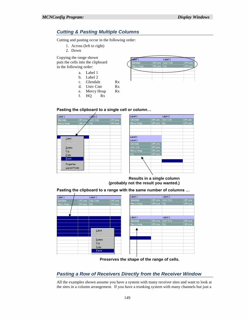
MCNConfig Program: Display Windows
149
Cutting & Pasting Multiple Columns
Cutting and pasting occur in the following order:
1. Across (left to right)
2. Down
Copying the range shown
puts the cells into the clipboard
in the following order:
a. Label 1
b. Label 2
c. Glendale Rx
d. Univ Cntr Rx
e. Mercy Hosp Rx
f. HQ Rx
Pasting the clipboard to a single cell or column…
Results in a single column (probably not the result you wanted.)
Pasting the clipboard to a range with the same number of columns …
Preserves the shape of the range of cells.
Pasting a Row of Receivers Directly from the Receiver Window
All the examples shown assume you have a system with many receiver sites and want to look at
the sites in a column arrangement. If you have a trunking system with many channels but just a
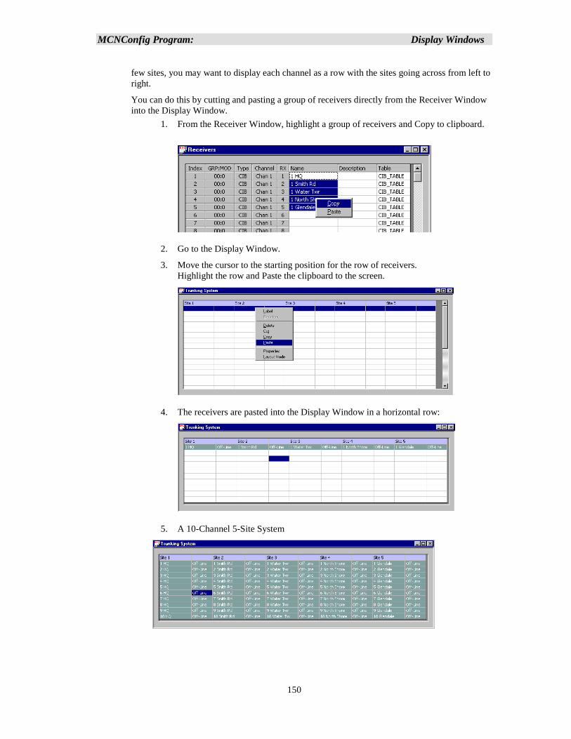
MCNConfig Program: Display Windows
150
few sites, you may want to display each channel as a row with the sites going across from left to
right.
You can do this by cutting and pasting a group of receivers directly from the Receiver Window
into the Display Window.
1. From the Receiver Window, highlight a group of receivers and Copy to clipboard.
2. Go to the Display Window.
3. Move the cursor to the starting position for the row of receivers.
Highlight the row and Paste the clipboard to the screen.
4. The receivers are pasted into the Display Window in a horizontal row:
5. A 10-Channel 5-Site System
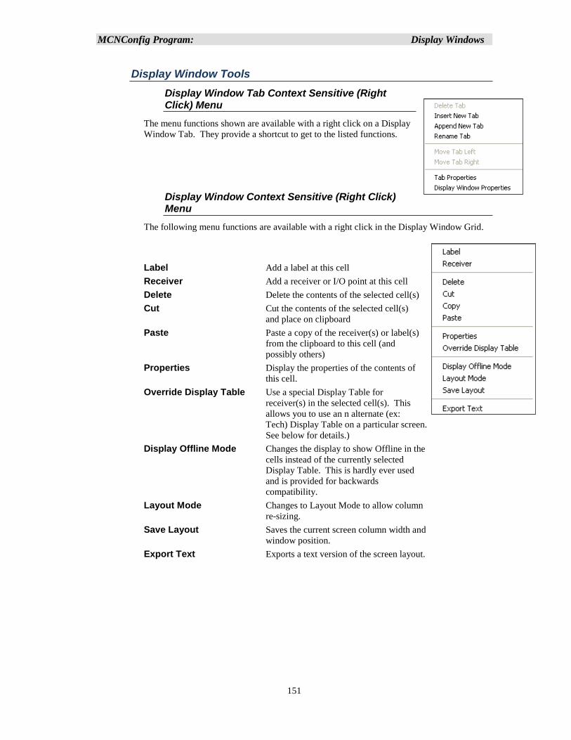
MCNConfig Program: Display Windows
151
Display Window Tools
Display Window Tab Context Sensitive (Right Click) Menu
The menu functions shown are available with a right click on a Display
Window Tab. They provide a shortcut to get to the listed functions.
Display Window Context Sensitive (Right Click) Menu
The following menu functions are available with a right click in the Display Window Grid.
Label Add a label at this cell
Receiver Add a receiver or I/O point at this cell
Delete Delete the contents of the selected cell(s)
Cut Cut the contents of the selected cell(s)
and place on clipboard
Paste Paste a copy of the receiver(s) or label(s)
from the clipboard to this cell (and
possibly others)
Properties Display the properties of the contents of
this cell.
Override Display Table Use a special Display Table for
receiver(s) in the selected cell(s). This
allows you to use an n alternate (ex:
Tech) Display Table on a particular screen.
See below for details.)
Display Offline Mode Changes the display to show Offline in the
cells instead of the currently selected
Display Table. This is hardly ever used
and is provided for backwards
compatibility.
Layout Mode Changes to Layout Mode to allow column
re-sizing.
Save Layout Saves the current screen column width and
window position.
Export Text Exports a text version of the screen layout.
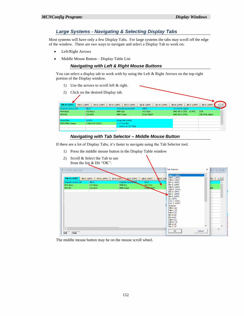
MCNConfig Program: Display Windows
152
Large Systems - Navigating & Selecting Display Tabs
Most systems will have only a few Display Tabs. For large systems the tabs may scroll off the edge
of the window. There are two ways to navigate and select a Display Tab to work on:
• Left/Right Arrows
• Middle Mouse Button – Display Table List
Navigating with Left & Right Mouse Buttons
You can select a display tab to work with by using the Left & Right Arrows on the top-right
portion of the Display window.
1) Use the arrows to scroll left & right.
2) Click on the desired Display tab.
Navigating with Tab Selector – Middle Mouse Button
If there are a lot of Display Tabs, it’s faster to navigate using the Tab Selector tool.
1) Press the middle mouse button in the Display Table window
2) Scroll & Select the Tab to use
from the list & Hit “OK”:
The middle mouse button may be on the mouse scroll wheel.
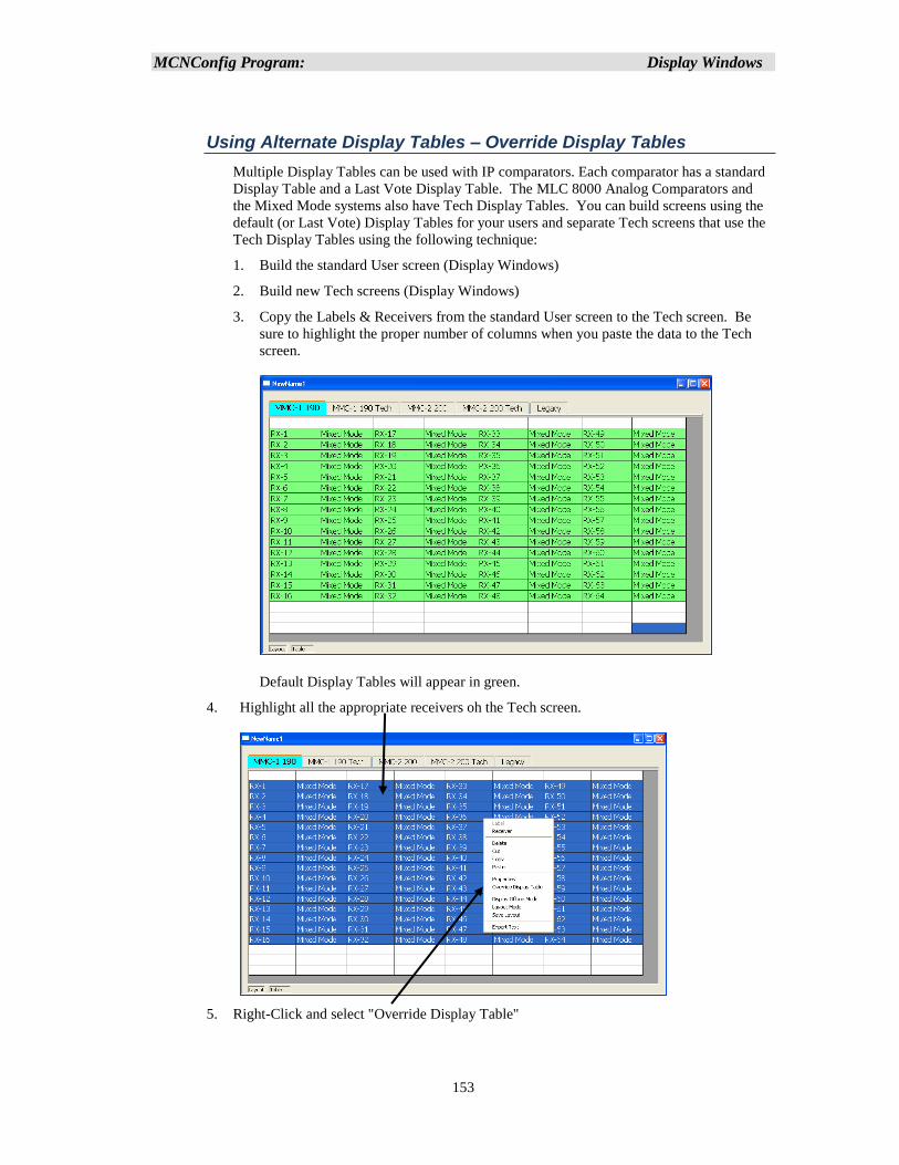
MCNConfig Program: Display Windows
153
Using Alternate Display Tables – Override Display Tables
Multiple Display Tables can be used with IP comparators. Each comparator has a standard
Display Table and a Last Vote Display Table. The MLC 8000 Analog Comparators and
the Mixed Mode systems also have Tech Display Tables. You can build screens using the
default (or Last Vote) Display Tables for your users and separate Tech screens that use the
Tech Display Tables using the following technique:
1. Build the standard User screen (Display Windows)
2. Build new Tech screens (Display Windows)
3. Copy the Labels & Receivers from the standard User screen to the Tech screen. Be
sure to highlight the proper number of columns when you paste the data to the Tech
screen.
Default Display Tables will appear in green.
4. Highlight all the appropriate receivers oh the Tech screen.
5. Right-Click and select "Override Display Table"
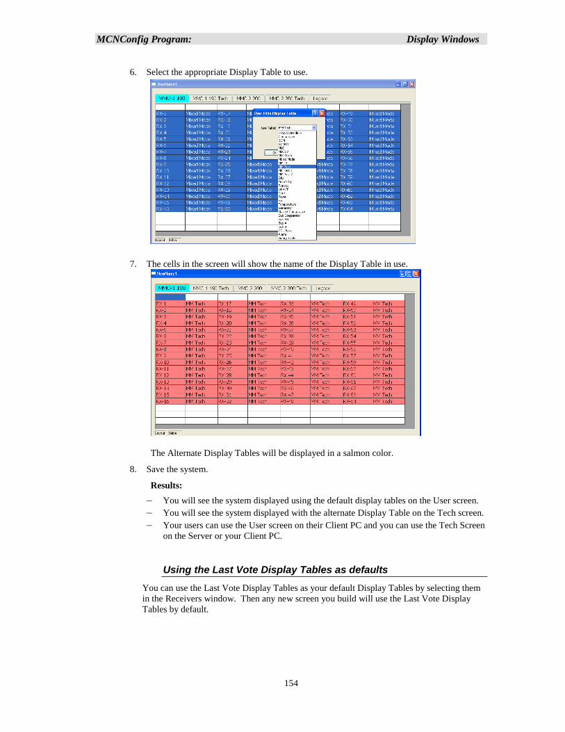
MCNConfig Program: Display Windows
154
6. Select the appropriate Display Table to use.
7. The cells in the screen will show the name of the Display Table in use.
The Alternate Display Tables will be displayed in a salmon color.
8. Save the system.
Results:
– You will see the system displayed using the default display tables on the User screen.
– You will see the system displayed with the alternate Display Table on the Tech screen.
– Your users can use the User screen on their Client PC and you can use the Tech Screen
on the Server or your Client PC.
Using the Last Vote Display Tables as defaults
You can use the Last Vote Display Tables as your default Display Tables by selecting them
in the Receivers window. Then any new screen you build will use the Last Vote Display
Tables by default.
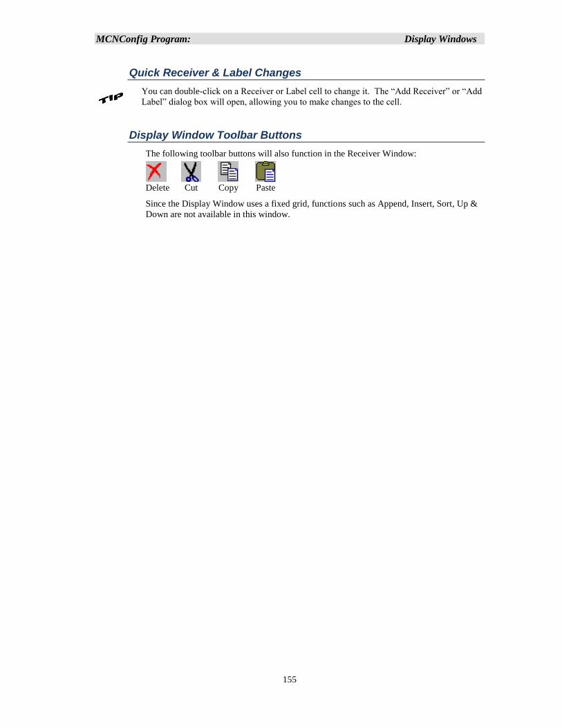
MCNConfig Program: Display Windows
155
Quick Receiver & Label Changes
You can double-click on a Receiver or Label cell to change it. The “Add Receiver” or “Add
Label” dialog box will open, allowing you to make changes to the cell.
Display Window Toolbar Buttons
The following toolbar buttons will also function in the Receiver Window:
Delete Cut Copy Paste
Since the Display Window uses a fixed grid, functions such as Append, Insert, Sort, Up &
Down are not available in this window.
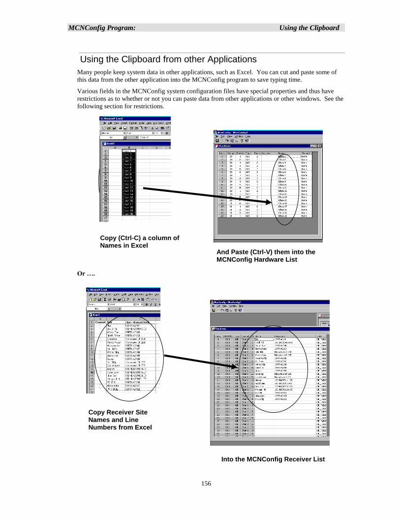
MCNConfig Program: Using the Clipboard
156
Using the Clipboard from other Applications
Many people keep system data in other applications, such as Excel. You can cut and paste some of
this data from the other application into the MCNConfig program to save typing time.
Various fields in the MCNConfig system configuration files have special properties and thus have
restrictions as to whether or not you can paste data from other applications or other windows. See the
following section for restrictions.
Or ….
Copy (Ctrl-C) a column of Names in Excel
And Paste (Ctrl-V) them into the MCNConfig Hardware List
Copy Receiver Site Names and Line Numbers from Excel
Into the MCNConfig Receiver List
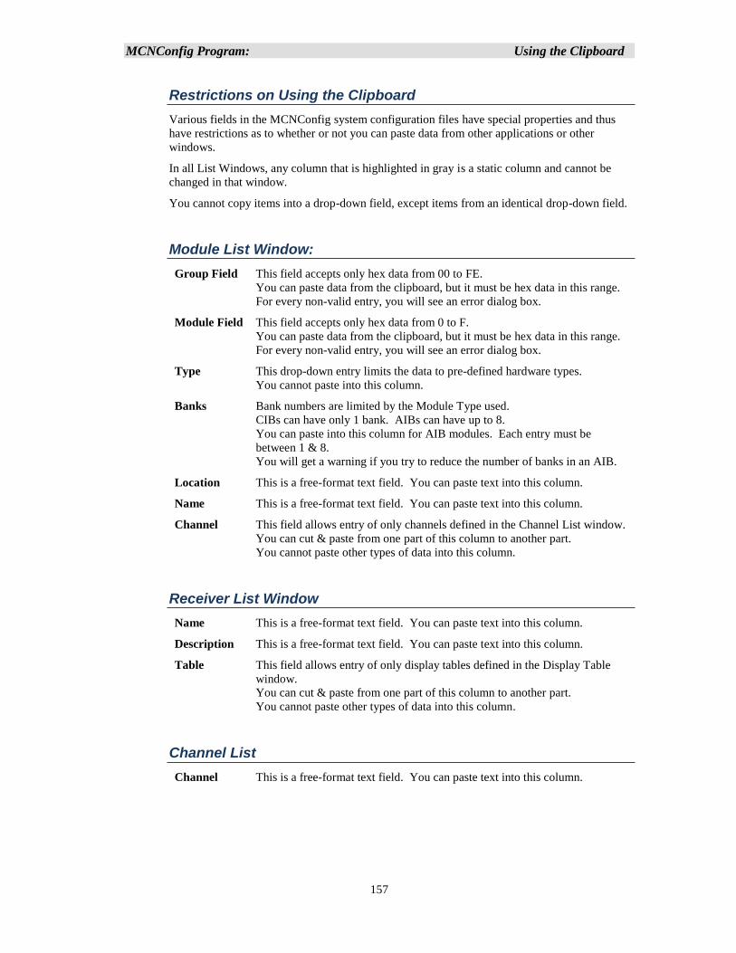
MCNConfig Program: Using the Clipboard
157
Restrictions on Using the Clipboard
Various fields in the MCNConfig system configuration files have special properties and thus
have restrictions as to whether or not you can paste data from other applications or other
windows.
In all List Windows, any column that is highlighted in gray is a static column and cannot be
changed in that window.
You cannot copy items into a drop-down field, except items from an identical drop-down field.
Module List Window:
Group Field This field accepts only hex data from 00 to FE.
You can paste data from the clipboard, but it must be hex data in this range.
For every non-valid entry, you will see an error dialog box.
Module Field This field accepts only hex data from 0 to F.
You can paste data from the clipboard, but it must be hex data in this range.
For every non-valid entry, you will see an error dialog box.
Type This drop-down entry limits the data to pre-defined hardware types.
You cannot paste into this column.
Banks Bank numbers are limited by the Module Type used.
CIBs can have only 1 bank. AIBs can have up to 8.
You can paste into this column for AIB modules. Each entry must be
between 1 & 8.
You will get a warning if you try to reduce the number of banks in an AIB.
Location This is a free-format text field. You can paste text into this column.
Name This is a free-format text field. You can paste text into this column.
Channel This field allows entry of only channels defined in the Channel List window.
You can cut & paste from one part of this column to another part.
You cannot paste other types of data into this column.
Receiver List Window
Name This is a free-format text field. You can paste text into this column.
Description This is a free-format text field. You can paste text into this column.
Table This field allows entry of only display tables defined in the Display Table
window.
You can cut & paste from one part of this column to another part.
You cannot paste other types of data into this column.
Channel List
Channel This is a free-format text field. You can paste text into this column.
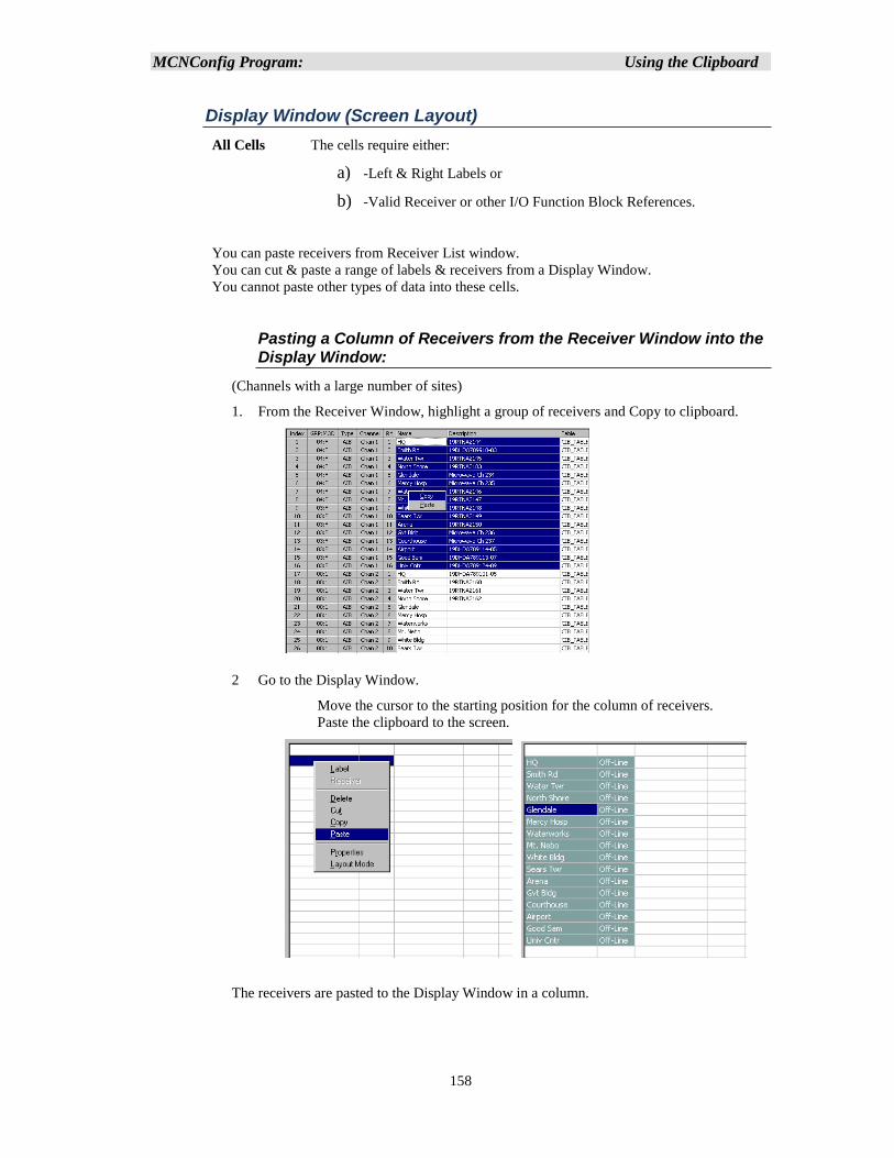
MCNConfig Program: Using the Clipboard
158
Display Window (Screen Layout)
All Cells The cells require either:
a) -Left & Right Labels or
b) -Valid Receiver or other I/O Function Block References.
You can paste receivers from Receiver List window.
You can cut & paste a range of labels & receivers from a Display Window.
You cannot paste other types of data into these cells.
Pasting a Column of Receivers from the Receiver Window into the Display Window:
(Channels with a large number of sites)
1. From the Receiver Window, highlight a group of receivers and Copy to clipboard.
2 Go to the Display Window.
Move the cursor to the starting position for the column of receivers.
Paste the clipboard to the screen.
The receivers are pasted to the Display Window in a column.
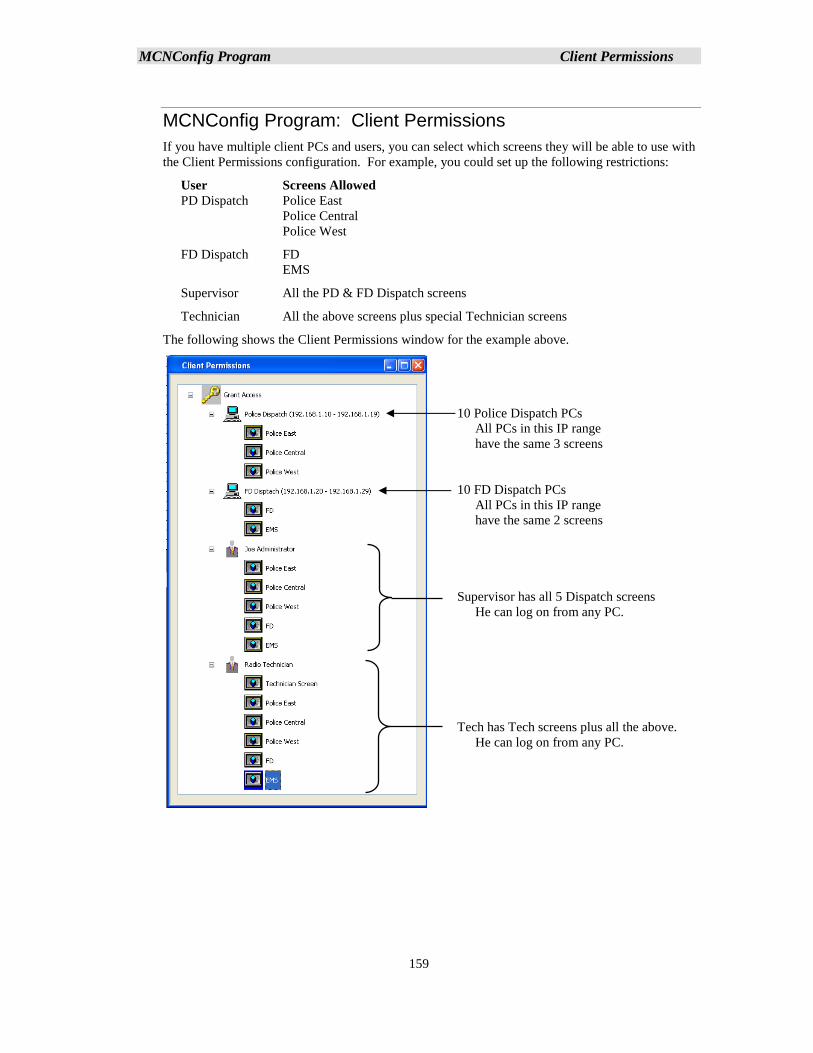
MCNConfig Program Client Permissions
159
MCNConfig Program: Client Permissions
If you have multiple client PCs and users, you can select which screens they will be able to use with
the Client Permissions configuration. For example, you could set up the following restrictions:
User Screens Allowed
PD Dispatch Police East
Police Central
Police West
FD Dispatch FD
EMS
Supervisor All the PD & FD Dispatch screens
Technician All the above screens plus special Technician screens
The following shows the Client Permissions window for the example above.
10 Police Dispatch PCs
All PCs in this IP range
have the same 3 screens
10 FD Dispatch PCs
All PCs in this IP range
have the same 2 screens
Supervisor has all 5 Dispatch screens
He can log on from any PC.
Tech has Tech screens plus all the above.
He can log on from any PC.
MCNConfig Program Client Permissions
160
Screens can be restricted based on:
1. User Name
2. PC IP Address Range
3. A combination of both User Name & PC IP Address Range
The above example shows a simple system. You can develop even more complex Client
Permissions.
Client Restriction Rules
Normally, in an MCN Client-Server system, all clients can access all screens. The Client
Permission function works by taking away rights. The following are the rules for Client
Permissions:
Initial Configuration – Unrestricted Client Permissions
When building a new system or loading older system configuration files without
permissions, Unrestricted Client Permissions will take effect. The top key icon will have a
label saying "Unrestricted Access" on it. If you don't want to restrict the screens available to
specific users or PCs, you don't have to modify the Client Permissions. Unrestricted Client
Permissions means:
1. Users can log on from any PC at any IP address that can access the server over IP.
2. All user names will be accepted.
3. All users on all PCs can access all screens.
PC Configuration
▪ If a PC (or range of PCs) is not listed with restrictions, it will be able to access all
screens.
▪ PCs can be added at the first level (root) of the tree.
▪ Each PC icon can have a range of IP addresses. The screens authorized under that PC
icon will pertain to all PCs in that IP address range.
▪ Each PC icon must have a unique IP address range. It cannot overlap with the IP
address range of any other PC icon.
▪ When a PC icon has no screens or users under it, it has access to all screens. The label
for the PC will show "All Screens".
▪ A PC icon with screens or users below it will have restricted access.
▪ When a PC icon is first added, it will show "All Screens" access.
User configuration
Master Users are added at the first (root) level.
Sub Users can be added under one or more PC icons.
Master Users can also be added as Sub Users under PC icons.
When a User icon has no screens under it, it has access to all screens. The label for the
User will show "All Screens".
A User icon with screens below it will have restricted access.
When a User icon is added (either as a Master User or a Sub User), it will have All
Screen access.
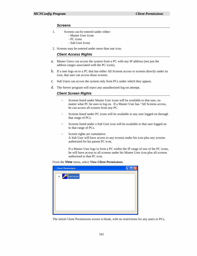
MCNConfig Program Client Permissions
161
Screens
1. Screens can be entered under either:
- Master User icons
- PC icons
- Sub User Icons
2. Screens may be entered under more than one icon.
Client Access Rights
a. Master Users can access the system from a PC with any IP address (not just the
address ranges associated with the PC icons).
b. If a user logs on to a PC that has either All Screens access or screens directly under its
icon, that user can access those screens.
c. Sub Users can access the system only from PCs under which they appear.
d. The Server program will reject any unauthorized log-on attempt.
Client Screen Rights
– Screens listed under Master User icons will be available to that user, no
matter what PC he uses to log on. If a Master User has "All Screens access,
he can access all screens from any PC.
– Screens listed under PC icons will be available to any user logged on through
that range of PCs.
– Screens listed under a Sub User icon will be available to that user logged on
to that range of PCs.
– Screen rights are cumulative:
A Sub User will have access to any screens under his icon plus any screens
authorized for his parent PC icon.
If a Master User logs in from a PC within the IP range of one of the PC icons,
he will have access to all screens under his Master User icon plus all screens
authorized to that PC icon.
From the View menu, select View Client Permissions.
The initial Client Permissions screen is blank, with no restrictions for any users or PCs.
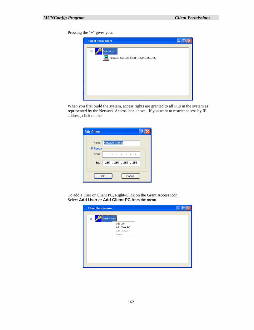
MCNConfig Program Client Permissions
162
Pressing the "+" gives you:
When you first build the system, access rights are granted to all PCs in the system as
represented by the Network Access icon above. If you want to restrict access by IP
address, click on the
To add a User or Client PC, Right-Click on the Grant Access icon.
Select Add User or Add Client PC from the menu.
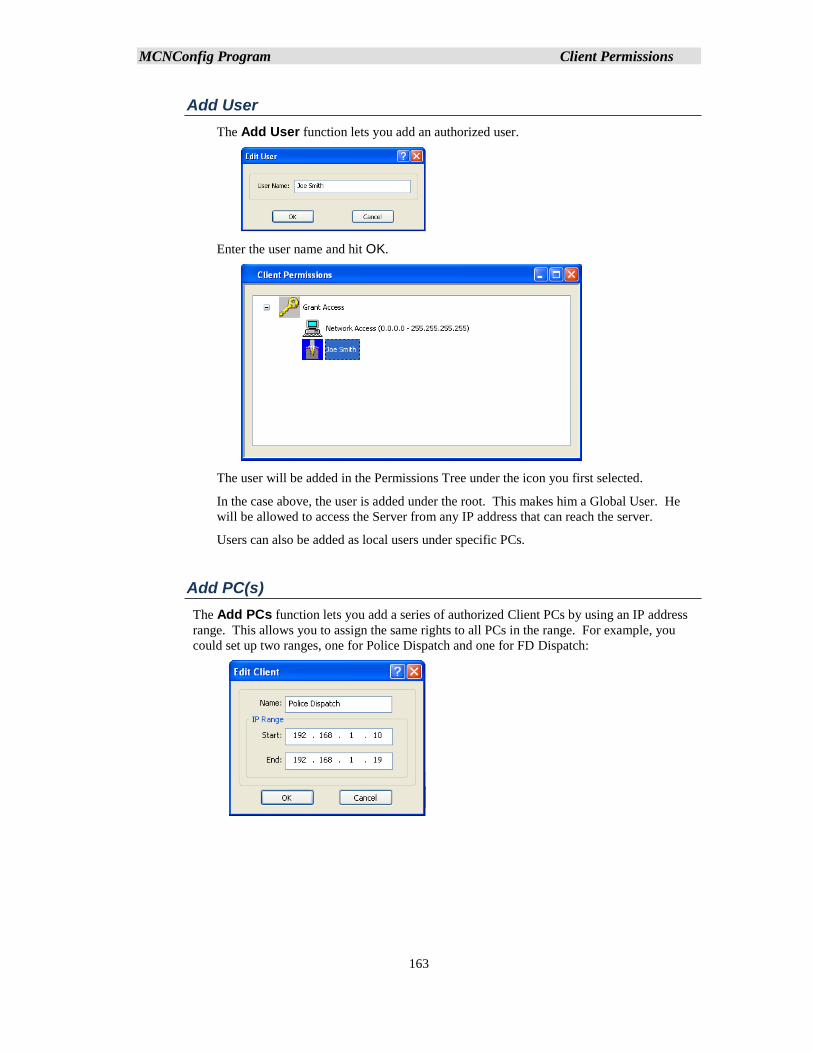
MCNConfig Program Client Permissions
163
Add User
The Add User function lets you add an authorized user.
Enter the user name and hit OK.
The user will be added in the Permissions Tree under the icon you first selected.
In the case above, the user is added under the root. This makes him a Global User. He
will be allowed to access the Server from any IP address that can reach the server.
Users can also be added as local users under specific PCs.
Add PC(s)
The Add PCs function lets you add a series of authorized Client PCs by using an IP address
range. This allows you to assign the same rights to all PCs in the range. For example, you
could set up two ranges, one for Police Dispatch and one for FD Dispatch:
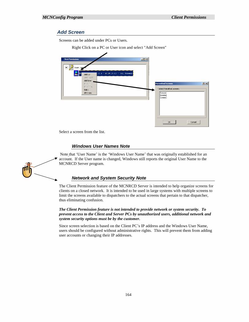
MCNConfig Program Client Permissions
164
Add Screen
Screens can be added under PCs or Users.
Right Click on a PC or User icon and select "Add Screen"
Select a screen from the list.
Windows User Names Note
Note that ‘User Name’ is the ‘Windows User Name’ that was originally established for an
account. If the User name is changed, Windows still reports the original User Name to the
MCNRCD Server program.
Network and System Security Note
The Client Permission feature of the MCNRCD Server is intended to help organize screens for
clients on a closed network. It is intended to be used in large systems with multiple screens to
limit the screens available to dispatchers to the actual screens that pertain to that dispatcher,
thus eliminating confusion.
The Client Permission feature is not intended to provide network or system security. To
prevent access to the Client and Server PCs by unauthorized users, additional network and
system security options must be by the customer.
Since screen selection is based on the Client PC’s IP address and the Windows User Name,
users should be configured without administrative rights. This will prevent them from adding
user accounts or changing their IP addresses.
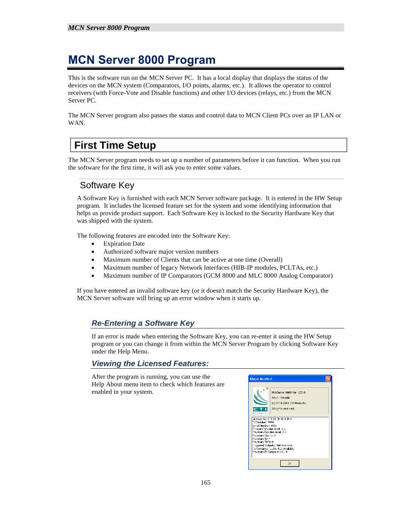
MCN Server 8000 Program
165
MCN Server 8000 Program
This is the software run on the MCN Server PC. It has a local display that displays the status of the
devices on the MCN system (Comparators, I/O points, alarms, etc.). It allows the operator to control
receivers (with Force-Vote and Disable functions) and other I/O devices (relays, etc.) from the MCN
Server PC.
The MCN Server program also passes the status and control data to MCN Client PCs over an IP LAN or
WAN.
First Time Setup
The MCN Server program needs to set up a number of parameters before it can function. When you run
the software for the first time, it will ask you to enter some values.
Software Key
A Software Key is furnished with each MCN Server software package. It is entered in the HW Setup
program. It includes the licensed feature set for the system and some identifying information that
helps us provide product support. Each Software Key is locked to the Security Hardware Key that
was shipped with the system.
The following features are encoded into the Software Key:
• Expiration Date
• Authorized software major version numbers
• Maximum number of Clients that can be active at one time (Overall)
• Maximum number of legacy Network Interfaces (HIB-IP modules, PCLTAs, etc.)
• Maximum number of IP Comparators (GCM 8000 and MLC 8000 Analog Comparator)
If you have entered an invalid software key (or it doesn't match the Security Hardware Key), the
MCN Server software will bring up an error window when it starts up.
Re-Entering a Software Key
If an error is made when entering the Software Key, you can re-enter it using the HW Setup
program or you can change it from within the MCN Server Program by clicking Software Key
under the Help Menu.
Viewing the Licensed Features:
After the program is running, you can use the
Help About menu item to check which features are
enabled in your system.
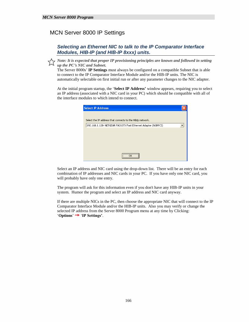
MCN Server 8000 Program
166
MCN Server 8000 IP Settings
Selecting an Ethernet NIC to talk to the IP Comparator Interface Modules, HIB-IP (and HIB-IP 8xxx) units.
Note: It is expected that proper IP provisioning principles are known and followed in setting
up the PC’s NIC and Subnet.
The Server 8000s’ IP Settings must always be configured on a compatible Subnet that is able
to connect to the IP Comparator Interface Module and/or the HIB-IP units. The NIC is
automatically selectable on first initial run or after any parameter changes to the NIC adapter.
At the initial program startup, the ‘Select IP Address’ window appears, requiring you to select
an IP address (associated with a NIC card in your PC) which should be compatible with all of
the interface modules to which intend to connect.
Select an IP address and NIC card using the drop-down list. There will be an entry for each
combination of IP addresses and NIC cards in your PC. If you have only one NIC card, you
will probably have only one entry.
The program will ask for this information even if you don't have any HIB-IP units in your
system. Humor the program and select an IP address and NIC card anyway.
If there are multiple NICs in the PC, then choose the appropriate NIC that will connect to the IP
Comparator Interface Module and/or the HIB-IP units. Also you may verify or change the
selected IP address from the Server 8000 Program menu at any time by Clicking:
‘Options’ ‘IP Settings’.
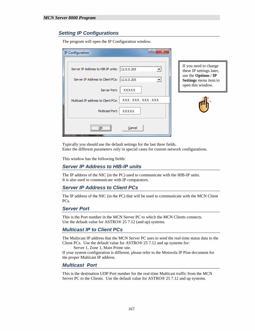
MCN Server 8000 Program
167
Setting IP Configurations
The program will open the IP Configuration window.
Typically you should use the default settings for the last three fields.
Enter the different parameters only in special cases for custom network configurations.
This window has the following fields:
Server IP Address to HIB-IP units
The IP address of the NIC (in the PC) used to communicate with the HIB-IP units.
It is also used to communicate with IP comparators.
Server IP Address to Client PCs
The IP address of the NIC (in the PC) that will be used to communicate with the MCN Client
PCs.
Server Port
This is the Port number in the MCN Server PC to which the MCN Clients connects.
Use the default value for ASTRO® 25 7.12 (and up) systems.
Multicast IP to Client PCs
The Multicast IP address that the MCN Server PC uses to send the real-time status data to the
Client PCs. Use the default value for ASTRO® 25 7.12 and up systems for:
Server 1, Zone 1, Main Prime site.
If your system configuration is different, please refer to the Motorola IP Plan document for
the proper Multicast IP address.
Multicast Port
This is the destination UDP Port number for the real-time Multicast traffic from the MCN
Server PC to the Clients. Use the default value for ASTRO® 25 7.12 and up systems.
If you need to change
these IP settings later,
use the Options / IP
Settings menu item to
open this window.
XXXXX
XXXXX
XXX . XXX . XXX . XXX
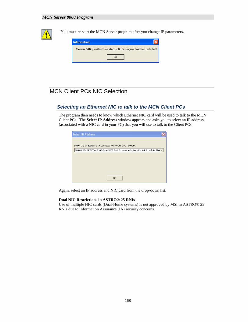
MCN Server 8000 Program
168
You must re-start the MCN Server program after you change IP parameters.
MCN Client PCs NIC Selection
Selecting an Ethernet NIC to talk to the MCN Client PCs
The program then needs to know which Ethernet NIC card will be used to talk to the MCN
Client PCs. The Select IP Address window appears and asks you to select an IP address
(associated with a NIC card in your PC) that you will use to talk to the Client PCs.
Again, select an IP address and NIC card from the drop-down list.
Dual NIC Restrictions in ASTRO® 25 RNIs
Use of multiple NIC cards (Dual-Home systems) is not approved by MSI in ASTRO® 25
RNIs due to Information Assurance (IA) security concerns.
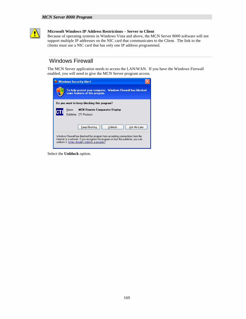
MCN Server 8000 Program
169
Microsoft Windows IP Address Restrictions – Server to Client
Because of operating systems in Windows Vista and above, the MCN Server 8000 software will not
support multiple IP addresses on the NIC card that communicates to the Client. The link to the
clients must use a NIC card that has only one IP address programmed.
Windows Firewall
The MCN Server application needs to access the LAN/WAN. If you have the Windows Firewall
enabled, you will need to give the MCN Server program access.
Select the Unblock option.
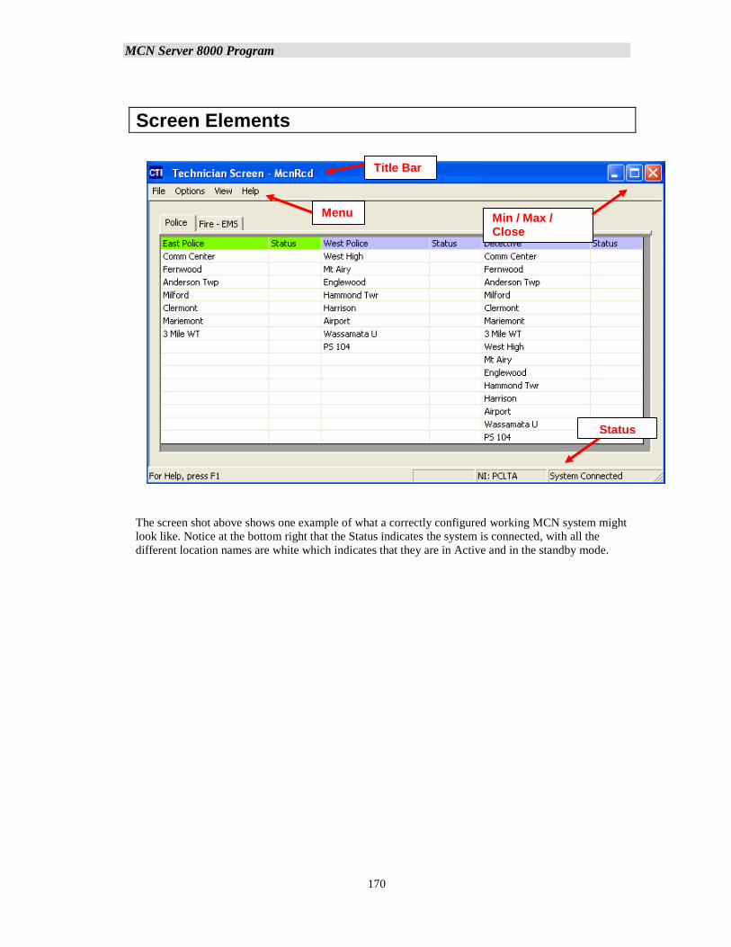
MCN Server 8000 Program
170
Screen Elements
The screen shot above shows one example of what a correctly configured working MCN system might
look like. Notice at the bottom right that the Status indicates the system is connected, with all the
different location names are white which indicates that they are in Active and in the standby mode.
Menu
Title Bar
Min / Max / Close
Buttons
Status Line
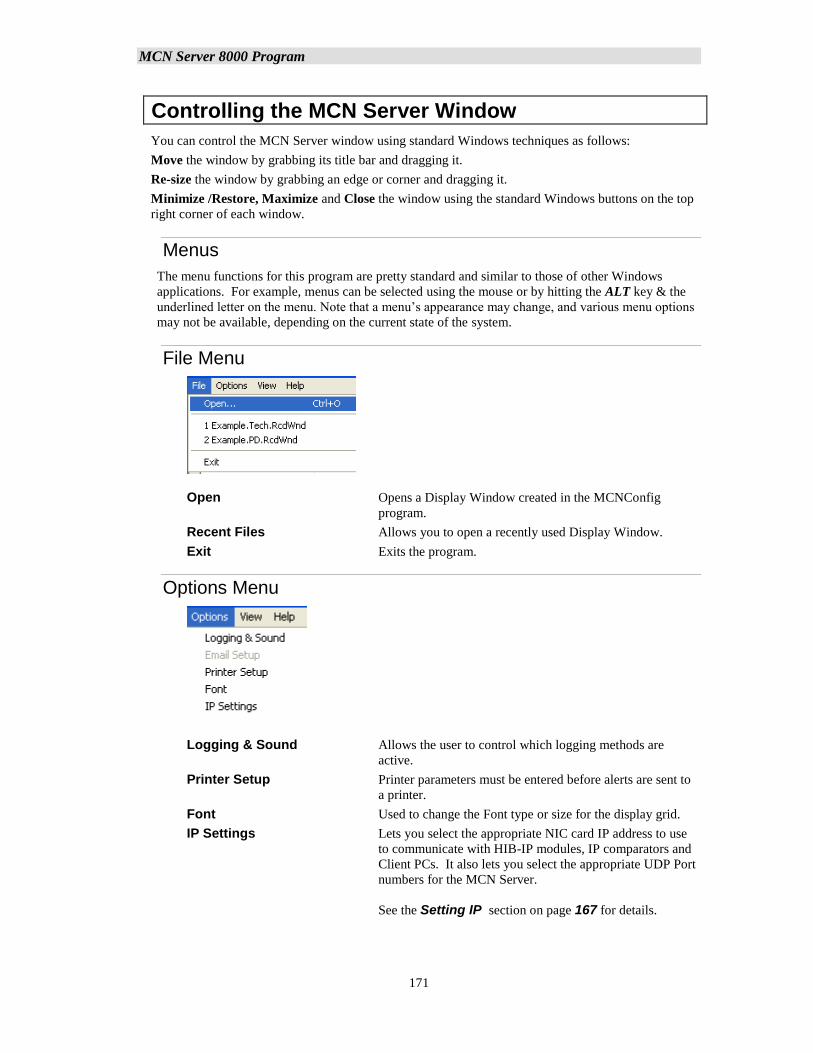
MCN Server 8000 Program
171
Controlling the MCN Server Window
You can control the MCN Server window using standard Windows techniques as follows:
Move the window by grabbing its title bar and dragging it.
Re-size the window by grabbing an edge or corner and dragging it.
Minimize /Restore, Maximize and Close the window using the standard Windows buttons on the top
right corner of each window.
Menus
The menu functions for this program are pretty standard and similar to those of other Windows
applications. For example, menus can be selected using the mouse or by hitting the ALT key & the
underlined letter on the menu. Note that a menu’s appearance may change, and various menu options
may not be available, depending on the current state of the system.
File Menu
Open Opens a Display Window created in the MCNConfig
program.
Recent Files Allows you to open a recently used Display Window.
Exit Exits the program.
Options Menu
Logging & Sound Allows the user to control which logging methods are
active.
Printer Setup Printer parameters must be entered before alerts are sent to
a printer.
Font Used to change the Font type or size for the display grid.
IP Settings Lets you select the appropriate NIC card IP address to use
to communicate with HIB-IP modules, IP comparators and
Client PCs. It also lets you select the appropriate UDP Port
numbers for the MCN Server.
See the Setting IP section on page 167 for details.
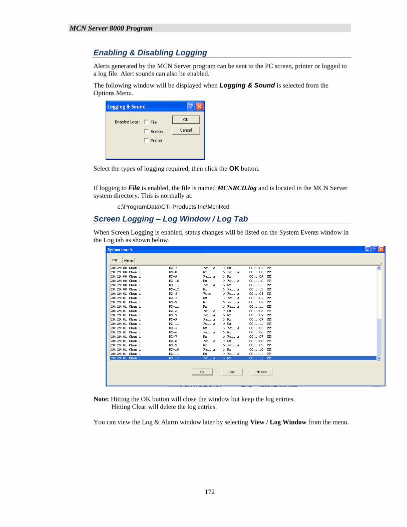
MCN Server 8000 Program
172
Enabling & Disabling Logging
Alerts generated by the MCN Server program can be sent to the PC screen, printer or logged to
a log file. Alert sounds can also be enabled.
The following window will be displayed when Logging & Sound is selected from the
Options Menu.
Select the types of logging required, then click the OK button.
If logging to File is enabled, the file is named MCNRCD.log and is located in the MCN Server
system directory. This is normally at:
c:\ProgramData\CTI Products Inc\McnRcd
Screen Logging – Log Window / Log Tab
When Screen Logging is enabled, status changes will be listed on the System Events window in
the Log tab as shown below.
Note: Hitting the OK button will close the window but keep the log entries.
Hitting Clear will delete the log entries.
You can view the Log & Alarm window later by selecting View / Log Window from the menu.
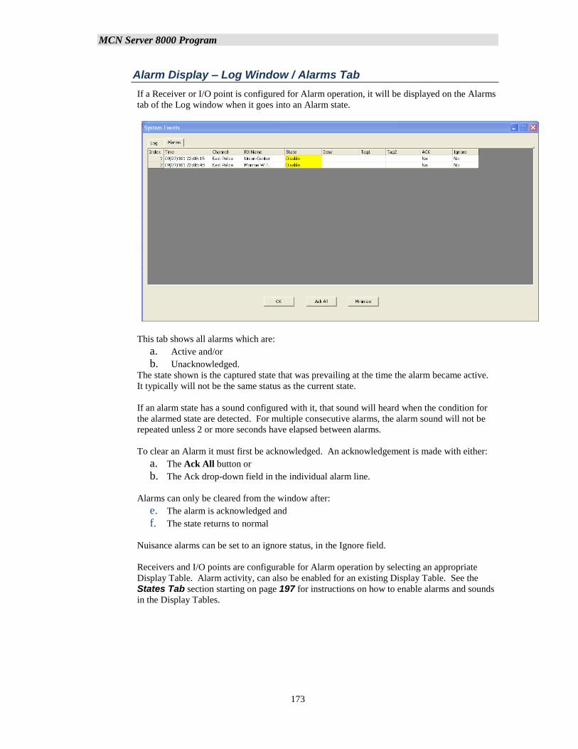
MCN Server 8000 Program
173
Alarm Display – Log Window / Alarms Tab
If a Receiver or I/O point is configured for Alarm operation, it will be displayed on the Alarms
tab of the Log window when it goes into an Alarm state.
This tab shows all alarms which are:
a. Active and/or
b. Unacknowledged.
The state shown is the captured state that was prevailing at the time the alarm became active.
It typically will not be the same status as the current state.
If an alarm state has a sound configured with it, that sound will heard when the condition for
the alarmed state are detected. For multiple consecutive alarms, the alarm sound will not be
repeated unless 2 or more seconds have elapsed between alarms.
To clear an Alarm it must first be acknowledged. An acknowledgement is made with either:
a. The Ack All button or
b. The Ack drop-down field in the individual alarm line.
Alarms can only be cleared from the window after:
e. The alarm is acknowledged and
f. The state returns to normal
Nuisance alarms can be set to an ignore status, in the Ignore field.
Receivers and I/O points are configurable for Alarm operation by selecting an appropriate
Display Table. Alarm activity, can also be enabled for an existing Display Table. See the
States Tab section starting on page 197 for instructions on how to enable alarms and sounds
in the Display Tables.
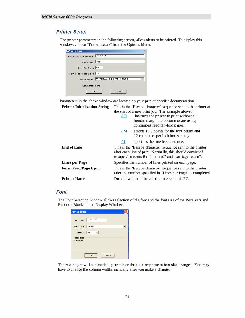
MCN Server 8000 Program
174
Printer Setup
The printer parameters in the following screen, allow alerts to be printed. To display this
window, choose “Printer Setup” from the Options Menu.
Parameters in the above window are located on your printer specific documentation.
Printer Initialization String This is the ‘Escape character’ sequence sent to the printer at
the start of a new print job. The example above:
^O instructs the printer to print without a
bottom margin, to accommodate using
continuous feed fan-fold paper.
. ^M selects 10.5 points for the font height and
12 characters per inch horizontally.
^J specifies the line feed distance.
End of Line This is the ‘Escape character’ sequence sent to the printer
after each line of print. Normally, this should consist of
escape characters for “line feed” and “carriage return”.
Lines per Page Specifies the number of lines printed on each page.
Form Feed/Page Eject This is the ‘Escape character’ sequence sent to the printer
after the number specified in “Lines per Page” is completed
Printer Name Drop-down list of installed printers on this PC.
Font
The Font Selection window allows selection of the font and the font size of the Receivers and
Function Blocks in the Display Window.
The row height will automatically stretch or shrink in response to font size changes. You may
have to change the column widths manually after you make a change.
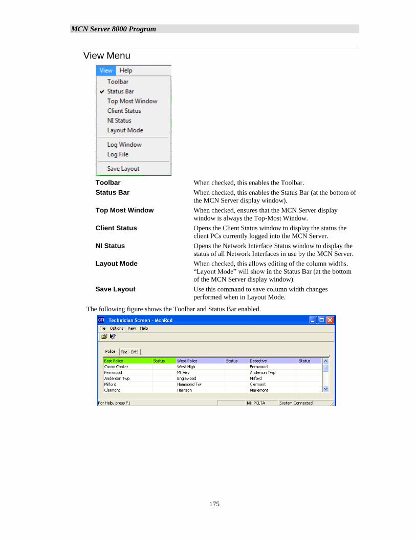
MCN Server 8000 Program
175
View Menu
Toolbar When checked, this enables the Toolbar.
Status Bar When checked, this enables the Status Bar (at the bottom of
the MCN Server display window).
Top Most Window When checked, ensures that the MCN Server display
window is always the Top-Most Window.
Client Status Opens the Client Status window to display the status the
client PCs currently logged into the MCN Server.
NI Status Opens the Network Interface Status window to display the
status of all Network Interfaces in use by the MCN Server.
Layout Mode When checked, this allows editing of the column widths.
“Layout Mode” will show in the Status Bar (at the bottom
of the MCN Server display window).
Save Layout Use this command to save column width changes
performed when in Layout Mode.
The following figure shows the Toolbar and Status Bar enabled.
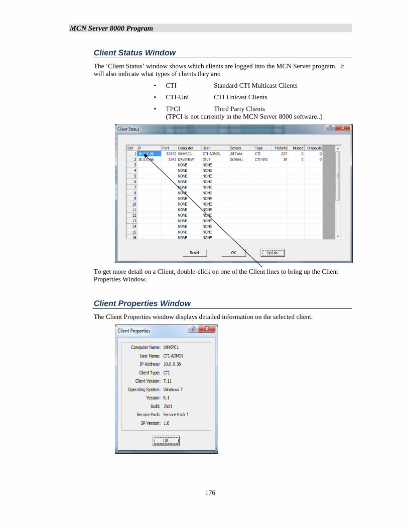
MCN Server 8000 Program
176
Client Status Window
The ‘Client Status’ window shows which clients are logged into the MCN Server program. It
will also indicate what types of clients they are:
• CTI Standard CTI Multicast Clients
• CTI-Uni CTI Unicast Clients
• TPCI Third Party Clients
(TPCI is not currently in the MCN Server 8000 software..)
To get more detail on a Client, double-click on one of the Client lines to bring up the Client
Properties Window.
Client Properties Window
The Client Properties window displays detailed information on the selected client.
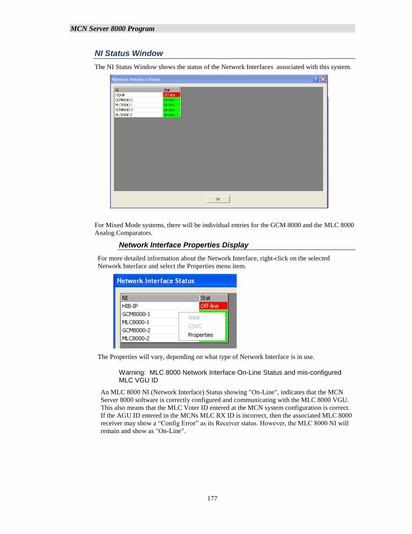
MCN Server 8000 Program
177
NI Status Window
The NI Status Window shows the status of the Network Interfaces associated with this system.
For Mixed Mode systems, there will be individual entries for the GCM 8000 and the MLC 8000
Analog Comparators.
Network Interface Properties Display
For more detailed information about the Network Interface, right-click on the selected
Network Interface and select the Properties menu item.
The Properties will vary, depending on what type of Network Interface is in use.
Warning: MLC 8000 Network Interface On-Line Status and mis-configured MLC VGU ID
An MLC 8000 NI (Network Interface) Status showing "On-Line", indicates that the MCN
Server 8000 software is correctly configured and communicating with the MLC 8000 VGU.
This also means that the MLC Voter ID entered at the MCN system configuration is correct.
If the AGU ID entered in the MCNs MLC RX ID is incorrect, then the associated MLC 8000
receiver may show a “Config Error” as its Receiver status. However, the MLC 8000 NI will
remain and show as "On-Line".
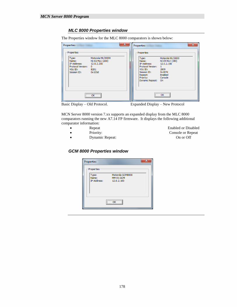
MCN Server 8000 Program
178
MLC 8000 Properties window
The Properties window for the MLC 8000 comparators is shown below:
Basic Display – Old Protocol. Expanded Display – New Protocol
MCN Server 8000 version 7.xx supports an expanded display from the MLC 8000
comparators running the new A7.14 FP firmware. It displays the following additional
comparator information:
• Repeat Enabled or Disabled
• Priority: Console or Repeat
• Dynamic Repeat: On or Off
GCM 8000 Properties window
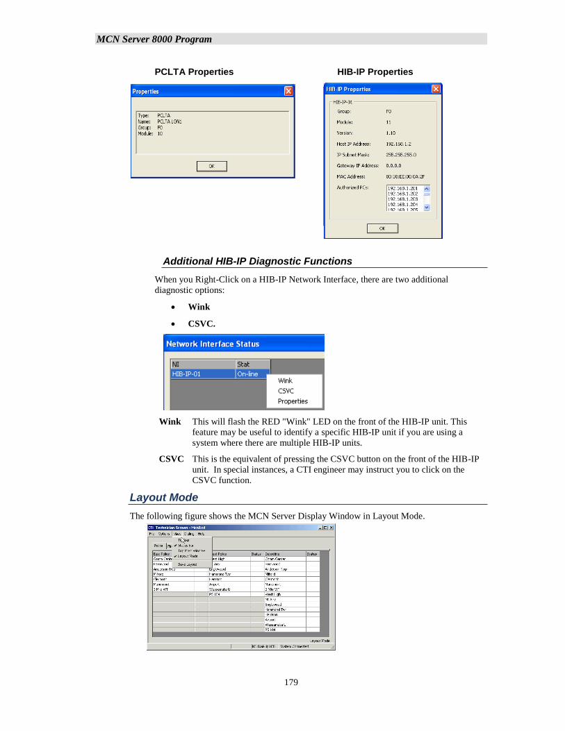
MCN Server 8000 Program
179
PCLTA Properties HIB-IP Properties
Additional HIB-IP Diagnostic Functions
When you Right-Click on a HIB-IP Network Interface, there are two additional
diagnostic options:
• Wink
• CSVC.
Wink This will flash the RED "Wink" LED on the front of the HIB-IP unit. This
feature may be useful to identify a specific HIB-IP unit if you are using a
system where there are multiple HIB-IP units.
CSVC This is the equivalent of pressing the CSVC button on the front of the HIB-IP
unit. In special instances, a CTI engineer may instruct you to click on the
CSVC function.
Layout Mode
The following figure shows the MCN Server Display Window in Layout Mode.
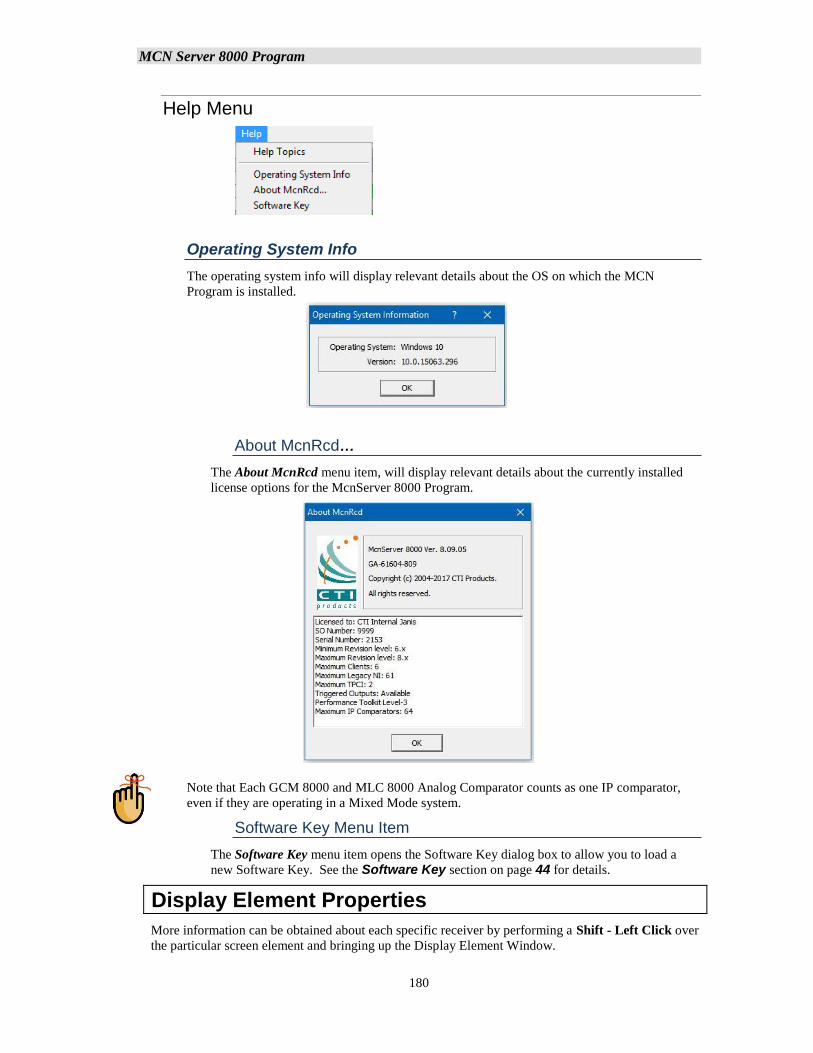
MCN Server 8000 Program
180
Help Menu
Operating System Info
The operating system info will display relevant details about the OS on which the MCN
Program is installed.
About McnRcd…
The About McnRcd menu item, will display relevant details about the currently installed
license options for the McnServer 8000 Program.
Note that Each GCM 8000 and MLC 8000 Analog Comparator counts as one IP comparator,
even if they are operating in a Mixed Mode system.
Software Key Menu Item
The Software Key menu item opens the Software Key dialog box to allow you to load a
new Software Key. See the Software Key section on page 44 for details.
Display Element Properties
More information can be obtained about each specific receiver by performing a Shift - Left Click over
the particular screen element and bringing up the Display Element Window.
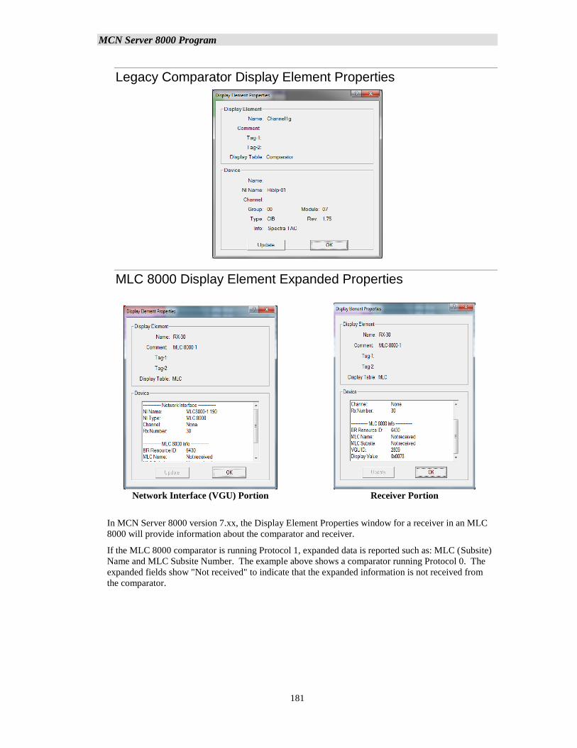
MCN Server 8000 Program
181
Legacy Comparator Display Element Properties
MLC 8000 Display Element Expanded Properties
Network Interface (VGU) Portion Receiver Portion
In MCN Server 8000 version 7.xx, the Display Element Properties window for a receiver in an MLC
8000 will provide information about the comparator and receiver.
If the MLC 8000 comparator is running Protocol 1, expanded data is reported such as: MLC (Subsite)
Name and MLC Subsite Number. The example above shows a comparator running Protocol 0. The
expanded fields show "Not received" to indicate that the expanded information is not received from
the comparator.
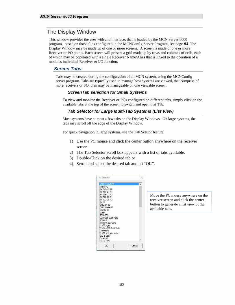
MCN Server 8000 Program
182
The Display Window
This window provides the user with and interface, that is loaded by the MCN Server 8000
program, based on those files configured in the MCNConfig Server Program, see page 93. The
Display Window may be made up of one or more screens. A screen is made of one or more
Receiver or I/O points. Each screen will present a grid made up by rows and columns of cells, each
of which may be populated with a single Receiver Name/Alias that is linked to the operation of a
modules individual Receiver or I/O function.
Screen Tabs
Tabs may be created during the configuration of an MCN system, using the MCNConfig
server program. Tabs are typically used to manage how systems are viewed, that comprise of
more receivers or I/O, than may be manageable on one viewable screen.
ScreenTab selection for Small Systems
To view and monitor the Receiver or I/Os configured on different tabs, simply click on the
available tabs at the top of the screen to switch and open that Tab.
Tab Selector for Large Multi-Tab Systems (List View)
Most systems have at most a few tabs on the Display Windows. On large systems, the
tabs may scroll off the edge of the Display Window.
For quick navigation in large systems, use the Tab Selctor feature.
1) Use the PC mouse and click the center button anywhere on the receiver
screen.
2) The Tab Selector scroll box appears with a list of tabs available.
3) Double-Click on the desired tab or
4) Scroll and select the desired tab and hit “OK”.
Move the PC mouse anywhere on the
receiver screen and click the center
button to generate a list view of the
available tabs.
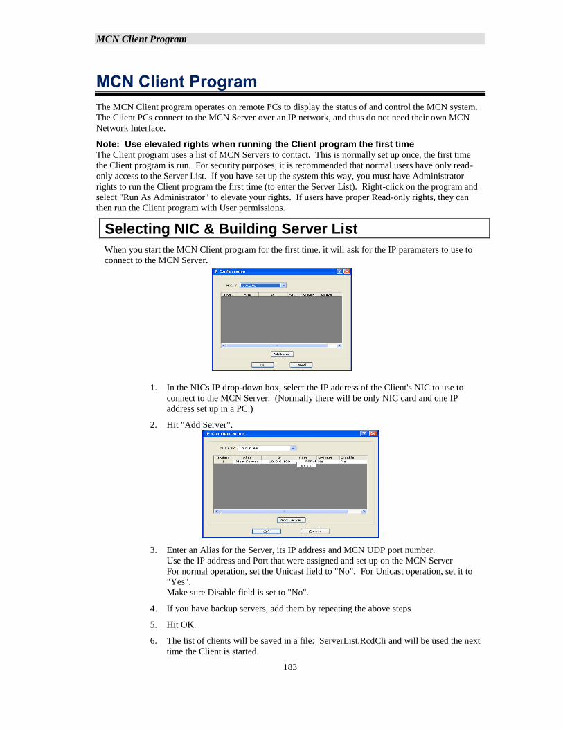
MCN Client Program
183
MCN Client Program
The MCN Client program operates on remote PCs to display the status of and control the MCN system.
The Client PCs connect to the MCN Server over an IP network, and thus do not need their own MCN
Network Interface.
Note: Use elevated rights when running the Client program the first time The Client program uses a list of MCN Servers to contact. This is normally set up once, the first time
the Client program is run. For security purposes, it is recommended that normal users have only read-
only access to the Server List. If you have set up the system this way, you must have Administrator
rights to run the Client program the first time (to enter the Server List). Right-click on the program and
select "Run As Administrator" to elevate your rights. If users have proper Read-only rights, they can
then run the Client program with User permissions.
Selecting NIC & Building Server List
When you start the MCN Client program for the first time, it will ask for the IP parameters to use to
connect to the MCN Server.
1. In the NICs IP drop-down box, select the IP address of the Client's NIC to use to
connect to the MCN Server. (Normally there will be only NIC card and one IP
address set up in a PC.)
2. Hit "Add Server".
3. Enter an Alias for the Server, its IP address and MCN UDP port number.
Use the IP address and Port that were assigned and set up on the MCN Server
For normal operation, set the Unicast field to "No". For Unicast operation, set it to
"Yes".
Make sure Disable field is set to "No".
4. If you have backup servers, add them by repeating the above steps
5. Hit OK.
6. The list of clients will be saved in a file: ServerList.RcdCli and will be used the next
time the Client is started.
xxxx
x
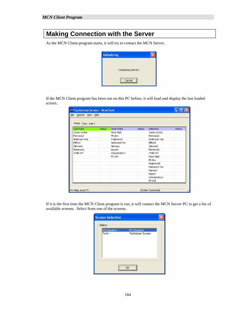
MCN Client Program
184
Making Connection with the Server
As the MCN Client program starts, it will try to contact the MCN Server.
If the MCN Client program has been run on this PC before, it will load and display the last loaded
screen.
If it is the first time the MCN Client program is run, it will contact the MCN Server PC to get a list of
available screens. Select from one of the screens.
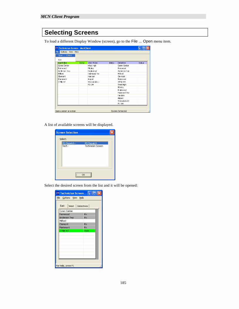
MCN Client Program
185
Selecting Screens
To load a different Display Window (screen), go to the File ... Open menu item.
A list of available screens will be displayed.
Select the desired screen from the list and it will be opened:
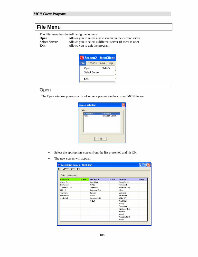
MCN Client Program
186
File Menu
The File menu has the following menu items
Open Allows you to select a new screen on the current server.
Select Server Allows you to select a different server (if there is one)
Exit Allows you to exit the program
Open
The Open window presents a list of screens present on the current MCN Server.
• Select the appropriate screen from the list presented and hit OK.
• The new screen will appear:
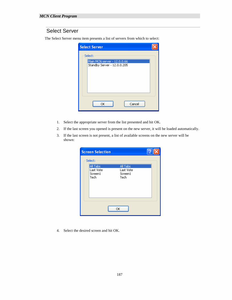
MCN Client Program
187
Select Server
The Select Server menu item presents a list of servers from which to select:
1. Select the appropriate server from the list presented and hit OK.
2. If the last screen you opened is present on the new server, it will be loaded automatically.
3. If the last screen is not present, a list of available screens on the new server will be
shown:
4. Select the desired screen and hit OK.
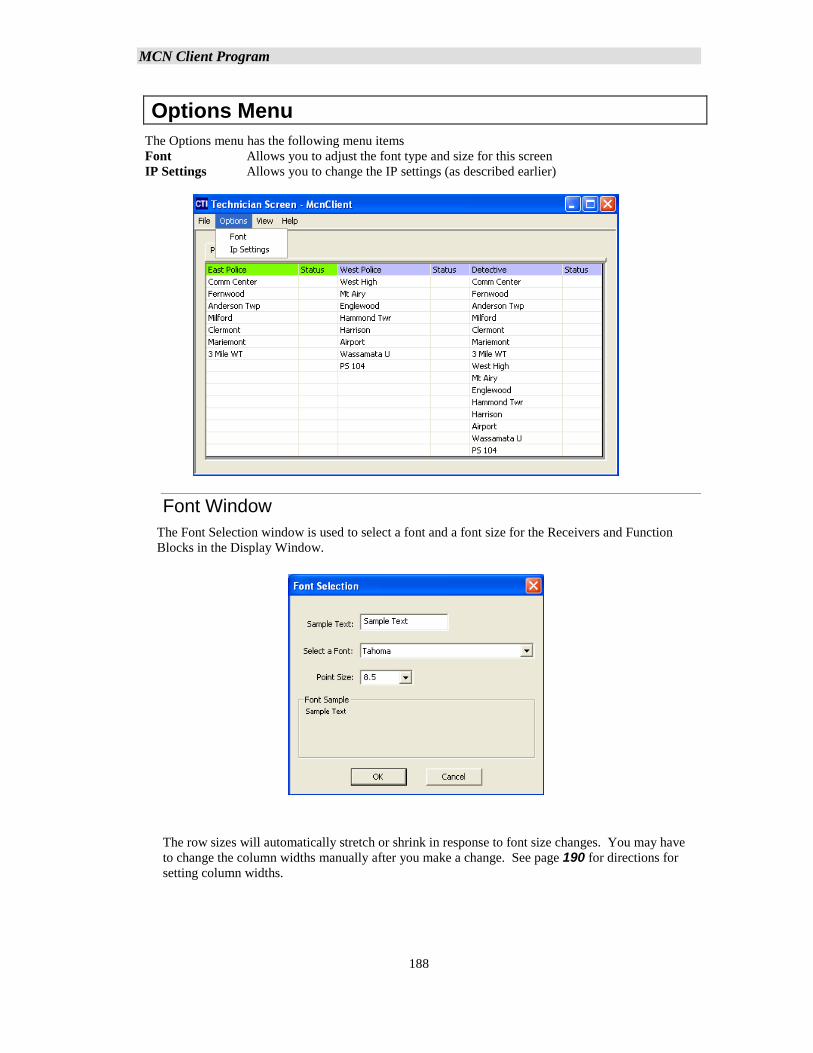
MCN Client Program
188
Options Menu
The Options menu has the following menu items
Font Allows you to adjust the font type and size for this screen
IP Settings Allows you to change the IP settings (as described earlier)
Font Window
The Font Selection window is used to select a font and a font size for the Receivers and Function
Blocks in the Display Window.
The row sizes will automatically stretch or shrink in response to font size changes. You may have
to change the column widths manually after you make a change. See page 190 for directions for
setting column widths.
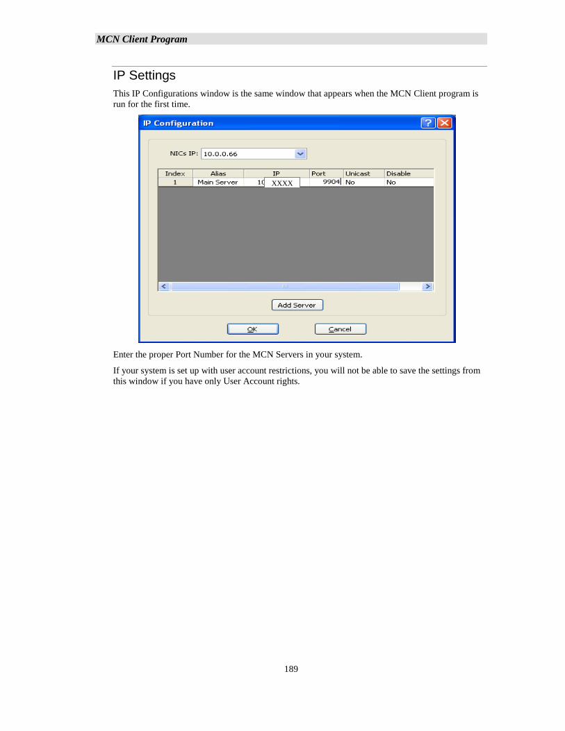
MCN Client Program
189
IP Settings
This IP Configurations window is the same window that appears when the MCN Client program is
run for the first time.
Enter the proper Port Number for the MCN Servers in your system.
If your system is set up with user account restrictions, you will not be able to save the settings from
this window if you have only User Account rights.
XXXXX
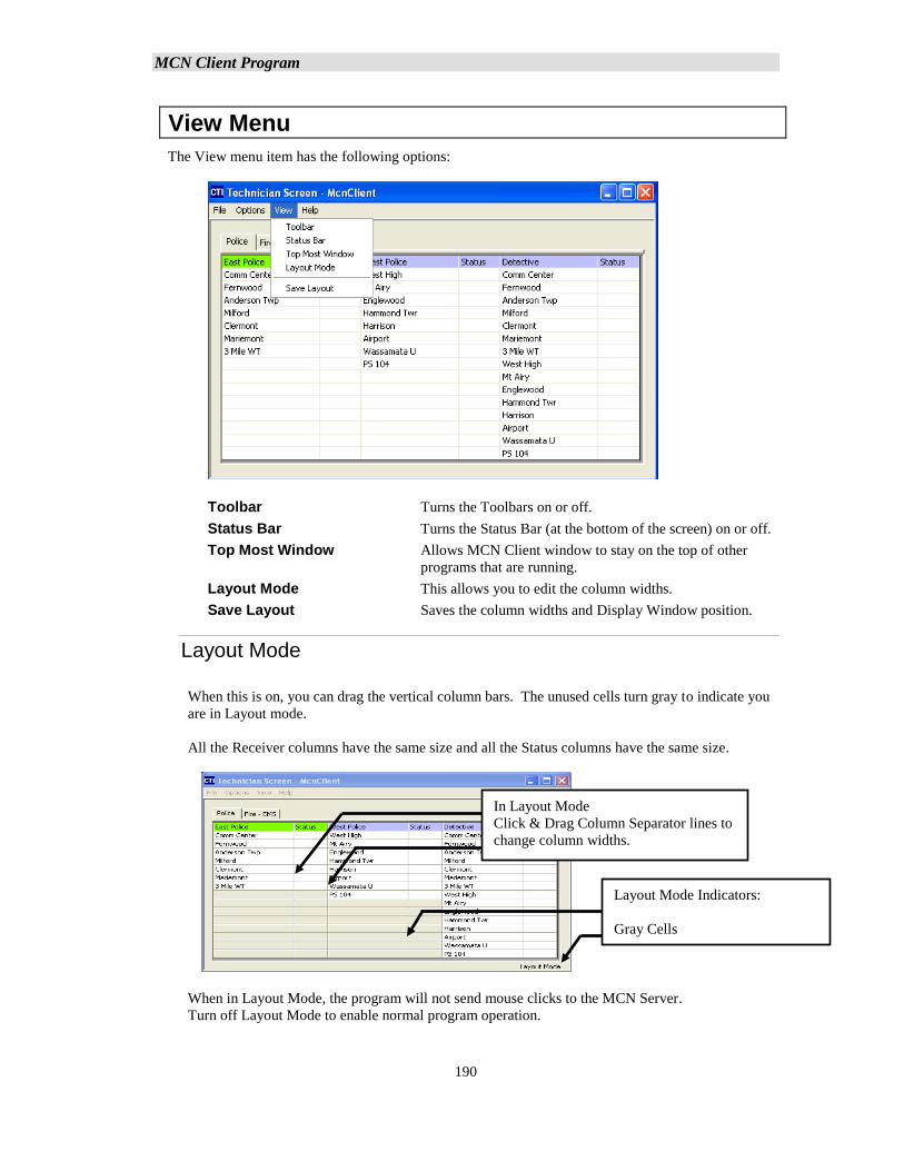
MCN Client Program
190
View Menu
The View menu item has the following options:
Toolbar Turns the Toolbars on or off.
Status Bar Turns the Status Bar (at the bottom of the screen) on or off.
Top Most Window Allows MCN Client window to stay on the top of other
programs that are running.
Layout Mode This allows you to edit the column widths.
Save Layout Saves the column widths and Display Window position.
Layout Mode
When this is on, you can drag the vertical column bars. The unused cells turn gray to indicate you
are in Layout mode.
All the Receiver columns have the same size and all the Status columns have the same size.
When in Layout Mode, the program will not send mouse clicks to the MCN Server.
Turn off Layout Mode to enable normal program operation.
In Layout Mode
Click & Drag Column Separator lines to
change column widths.
Layout Mode Indicators:
Gray Cells
and
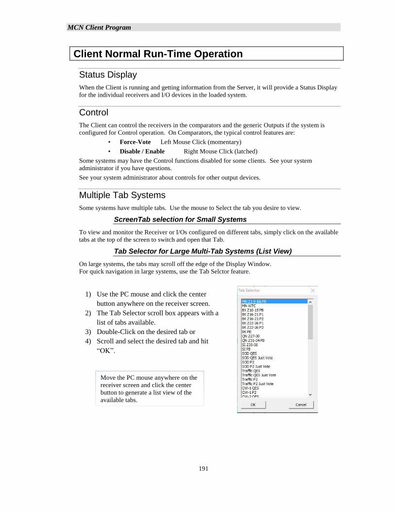
MCN Client Program
191
Client Normal Run-Time Operation
Status Display
When the Client is running and getting information from the Server, it will provide a Status Display
for the individual receivers and I/O devices in the loaded system.
Control
The Client can control the receivers in the comparators and the generic Outputs if the system is
configured for Control operation. On Comparators, the typical control features are:
• Force-Vote Left Mouse Click (momentary)
• Disable / Enable Right Mouse Click (latched)
Some systems may have the Control functions disabled for some clients. See your system
administrator if you have questions.
See your system administrator about controls for other output devices.
Multiple Tab Systems
Some systems have multiple tabs. Use the mouse to Select the tab you desire to view.
ScreenTab selection for Small Systems
To view and monitor the Receiver or I/Os configured on different tabs, simply click on the available
tabs at the top of the screen to switch and open that Tab.
Tab Selector for Large Multi-Tab Systems (List View)
On large systems, the tabs may scroll off the edge of the Display Window.
For quick navigation in large systems, use the Tab Selctor feature.
1) Use the PC mouse and click the center
button anywhere on the receiver screen.
2) The Tab Selector scroll box appears with a
list of tabs available.
3) Double-Click on the desired tab or
4) Scroll and select the desired tab and hit
“OK”.
Move the PC mouse anywhere on the
receiver screen and click the center
button to generate a list view of the
available tabs.
MCN Client Program
192
Client Program Notes
Data Loading & Cache Files
The Client program gets its data from the MCN Server. The first time a Client connects to a server,
it loads the system configuration files from the Server. Once it loads the data, it will save a copy of
the data in a local data cache.
When the Client connects to a Server, it will check to see if its local cache is current. If so, it will
use the local cache to speed up the connection. If the cache is not current, it will re-load the data
from the server.
It may take a long time to load the data file the first time or after it has changed. This could take a
matter of many minutes, especially with large systems, large Display Tables and when the Client is
connected to the Server via routers.
Backup MCN Servers
The Client program can access backup MCN Servers (if present). When the connection to the main
server is lost, the program will try to connect to the backup server(s).
IP Multicast Required
For normal operation, the MCN Server sends the real-time data to the Client software over IP
Multicast. The network routers and switches between the Server and Client must support IP
Multicast and must pass the IP Multicast Group and Port configured in the MCN Server.
IP Multicast Error Windows
Error windows, will be generated and displayed for the following IP Multicast errors:
1. If the network is blocking the IP Multicast traffic, the Client will display an error
message indicating that it is not receiving Multicast traffic.
2. If the Client detects IP Multicast traffic from a different Server on the configured IP
Multicast address, it will display a "Foreign Multicast" error window. (Each MCN
Server must have its own Multicast IP address.)
Unicast Client Support (Version 7.x up)
MCN Server 8000 and ClientRcd Version 7.00 can also use Unicast IP for real-time transmissions
from the Server to individual Client. This should be limited to (10) simultaneous Unicast Clients.
Unicast and Multicast clients; can be mixed on the same system.
Windows Event Logging
193
Windows Event Logging
In addition to the logging described in Appendix A: Error Logging Definitions, the MCN Server
8000 system logs significant events to the Windows Event Log, including:
MCN Config Server
Program start and stop
System Load
Saving a System
MCN Server 8000
Program start and stop
System Load
File Open Errors
Connection to and disconnection from IP Comparators
Connection to and disconnection from HIB-IP units
Connections & Disconnections of MCN Client PCs
Unauthorized Client log-on attempts
Mouse actions (ex: Force-Vote & Disable) for MCN Server 8000 & Clients
Log events ad defined in xxxx.RcdLog (typically Disables & Fails for receivers)
Changes made to registry (HKLM)
ClientRCD
Program start and stop
Connection to and disconnection from Server PC
Connection rejected by MCN Server
Changes in Server List
Changes made to registry (HKLM)
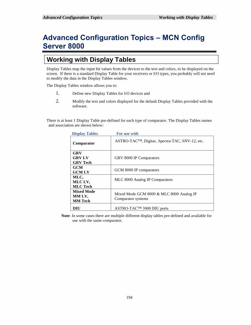
Advanced Configuration Topics Working with Display Tables
194
Advanced Configuration Topics – MCN Config Server 8000
Working with Display Tables
Display Tables map the input bit values from the devices to the text and colors, to be displayed on the
screen. If there is a standard Display Table for your receivers or I/O types, you probably will not need
to modify the data in the Display Tables window.
The Display Tables window allows you to:
1. Define new Display Tables for I/O devices and
2. Modify the text and colors displayed for the default Display Tables provided with the
software.
There is at least 1 Display Table pre-defined for each type of comparator. The Display Tables names
and association are shown below:
Display Tables For use with
Comparator ASTRO-TAC™, Digitac, Spectra-TAC, SNV-12, etc.
GRV
GRV LV
GRV Tech
GRV 8000 IP Comparators
GCM
GCM LV GCM 8000 IP comparators
MLC,
MLC LV,
MLC Tech
MLC 8000 Analog IP Comparators
Mixed Mode
MM LV,
MM Tech
Mixed Mode GCM 8000 & MLC 8000 Analog IP
Comparator systems
DIU ASTRO-TAC™ 3000 DIU ports
Note: In some cases there are multiple different display tables pre-defined and available for
use with the same comparator.
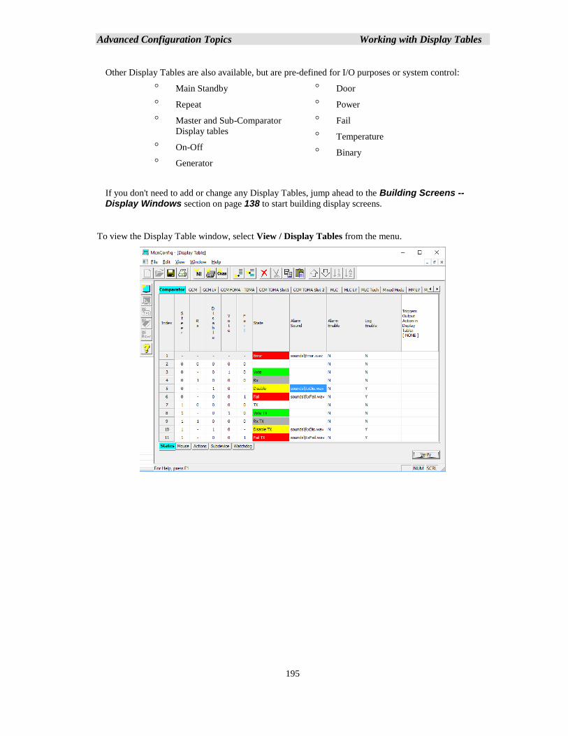
Advanced Configuration Topics Working with Display Tables
195
Other Display Tables are also available, but are pre-defined for I/O purposes or system control:
Main Standby
Repeat
Master and Sub-Comparator
Display tables
On-Off
Generator
Door
Power
Fail
Temperature
Binary
If you don't need to add or change any Display Tables, jump ahead to the Building Screens -- Display Windows section on page 138 to start building display screens.
To view the Display Table window, select View / Display Tables from the menu.
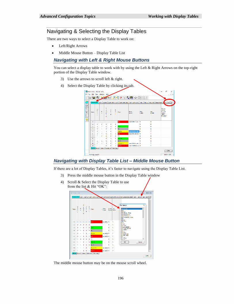
Advanced Configuration Topics Working with Display Tables
196
Navigating & Selecting the Display Tables
There are two ways to select a Display Table to work on:
• Left/Right Arrows
• Middle Mouse Button – Display Table List
Navigating with Left & Right Mouse Buttons
You can select a display table to work with by using the Left & Right Arrows on the top-right
portion of the Display Table window.
3) Use the arrows to scroll left & right.
4) Select the Display Table by clicking its tab.
Navigating with Display Table List – Middle Mouse Button
If there are a lot of Display Tables, it’s faster to navigate using the Display Table List.
3) Press the middle mouse button in the Display Table window
4) Scroll & Select the Display Table to use
from the list & Hit “OK”:
The middle mouse button may be on the mouse scroll wheel.
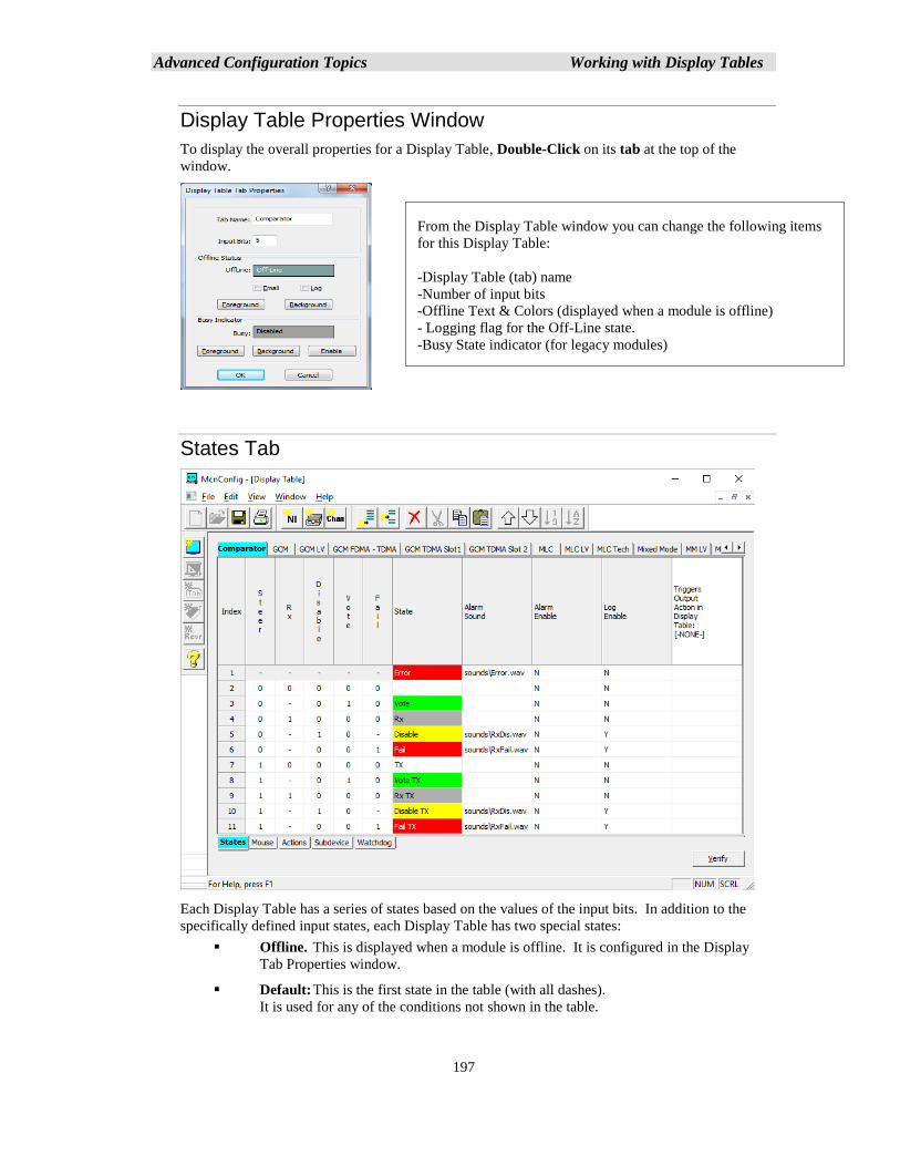
Advanced Configuration Topics Working with Display Tables
197
Display Table Properties Window
To display the overall properties for a Display Table, Double-Click on its tab at the top of the
window.
States Tab
Each Display Table has a series of states based on the values of the input bits. In addition to the
specifically defined input states, each Display Table has two special states:
▪ Offline. This is displayed when a module is offline. It is configured in the Display
Tab Properties window.
▪ Default: This is the first state in the table (with all dashes).
It is used for any of the conditions not shown in the table.
From the Display Table window you can change the following items
for this Display Table:
-Display Table (tab) name
-Number of input bits
-Offline Text & Colors (displayed when a module is offline)
- Logging flag for the Off-Line state.
-Busy State indicator (for legacy modules)
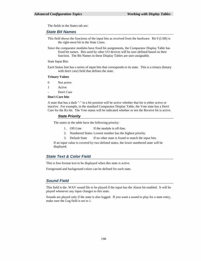
Advanced Configuration Topics Working with Display Tables
198
The fields in the States tab are:
State Bit Names
This field shows the functions of the input bits as received from the hardware. Bit 0 (LSB) is
the right-most bit in the State Lines.
Since the comparator modules have fixed bit assignments, the Comparator Display Table has
fixed bit names. Bits used by other I/O devices will be user-defined based on their
function. The Bit Names in these Display Tables are user-assignable.
State Input Bits
Each Status line has a series of input bits that corresponds to its state. This is a trinary (binary
with don't care) field that defines the state.
Trinary Values
0 Not active
1 Active
- Don't Care
Don't Care bits
A state that has a dash "-" in a bit position will be active whether that bit is either active or
inactive. For example, in the standard Comparator Display Table, the Vote state has a Don't
Care for the Rx bit. The Vote status will be indicated whether or not the Receive bit is active.
State Priority
The states in the table have the following priority:
1. Off-Line If the module is off-line.
2. Numbered States Lowest number has the highest priority.
3. Default State If no other state is found to match the input bits.
If an input value is covered by two defined states, the lower numbered state will be
displayed.
State Text & Color Field
This is free-format text to be displayed when this state is active.
Foreground and background colors can be defined for each state.
Sound Field
This field is the .WAV sound file to be played if the input has the Alarm bit enabled. It will be
played whenever any input changes to this state.
Sounds are played only if the state is also logged. If you want a sound to play for a state entry,
make sure the Log field is set to 1.
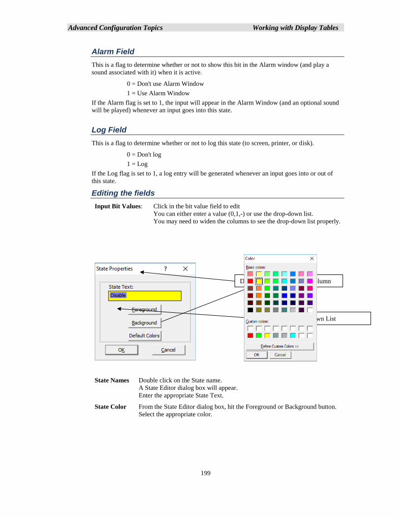
Advanced Configuration Topics Working with Display Tables
199
Alarm Field
This is a flag to determine whether or not to show this bit in the Alarm window (and play a
sound associated with it) when it is active.
0 = Don't use Alarm Window
1 = Use Alarm Window
If the Alarm flag is set to 1, the input will appear in the Alarm Window (and an optional sound
will be played) whenever an input goes into this state.
Log Field
This is a flag to determine whether or not to log this state (to screen, printer, or disk).
0 = Don't log
1 = Log
If the Log flag is set to 1, a log entry will be generated whenever an input goes into or out of
this state.
Editing the fields
Input Bit Values: Click in the bit value field to edit
You can either enter a value (0,1,-) or use the drop-down list.
You may need to widen the columns to see the drop-down list properly.
State Names Double click on the State name.
A State Editor dialog box will appear.
Enter the appropriate State Text.
State Color From the State Editor dialog box, hit the Foreground or Background button.
Select the appropriate color.
Drag column line to widen column
Input Bit Drop-Down List
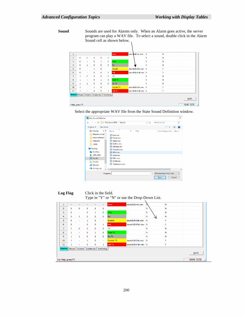
Advanced Configuration Topics Working with Display Tables
200
Sound Sounds are used for Alarms only. When an Alarm goes active, the server
program can play a WAV file. To select a sound, double click in the Alarm
Sound cell as shown below.
Select the appropriate WAV file from the State Sound Definition window.
Log Flag Click in the field.
Type in "Y" or "N" or use the Drop-Down List.
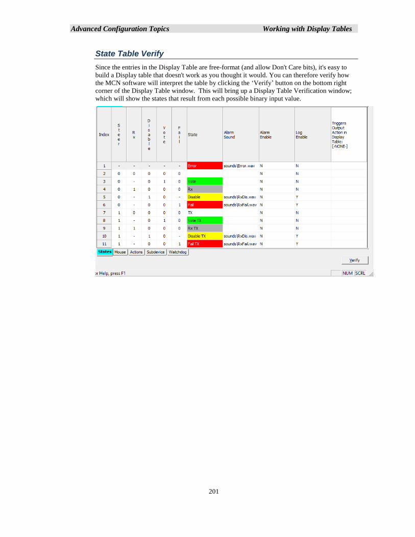
Advanced Configuration Topics Working with Display Tables
201
State Table Verify
Since the entries in the Display Table are free-format (and allow Don't Care bits), it's easy to
build a Display table that doesn't work as you thought it would. You can therefore verify how
the MCN software will interpret the table by clicking the ‘Verify’ button on the bottom right
corner of the Display Table window. This will bring up a Display Table Verification window;
which will show the states that result from each possible binary input value.
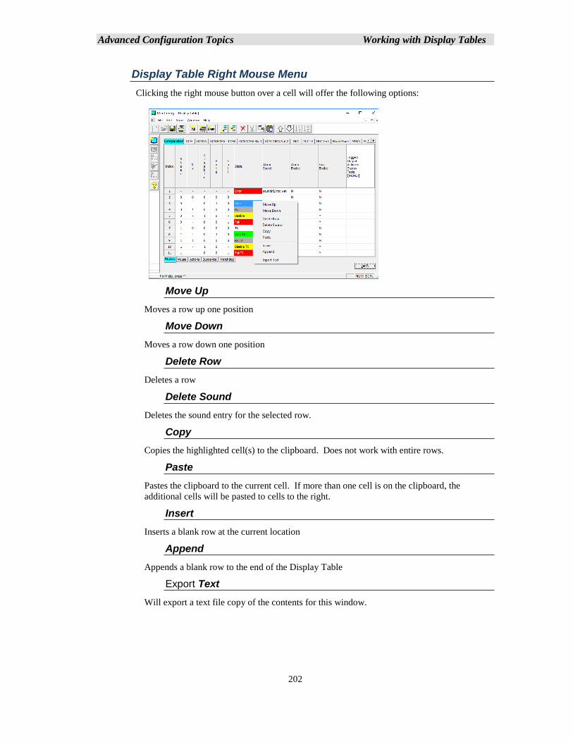
Advanced Configuration Topics Working with Display Tables
202
Display Table Right Mouse Menu
Clicking the right mouse button over a cell will offer the following options:
Move Up
Moves a row up one position
Move Down
Moves a row down one position
Delete Row
Deletes a row
Delete Sound
Deletes the sound entry for the selected row.
Copy
Copies the highlighted cell(s) to the clipboard. Does not work with entire rows.
Paste
Pastes the clipboard to the current cell. If more than one cell is on the clipboard, the
additional cells will be pasted to cells to the right.
Insert
Inserts a blank row at the current location
Append
Appends a blank row to the end of the Display Table
Export Text
Will export a text file copy of the contents for this window.
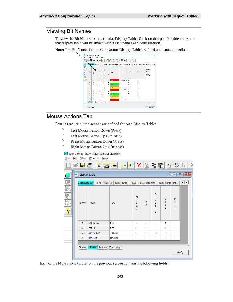
Advanced Configuration Topics Working with Display Tables
203
Viewing Bit Names
To view the Bit Names for a particular Display Table, Click on the specific table name and
that display table will be shown with its Bit names and configuration.
Note: The Bit Names for the Comparator Display Table are fixed and cannot be edited.
Mouse Actions Tab
Four (4) mouse button actions are defined for each Display Table:
Left Mouse Button Down (Press)
Left Mouse Button Up ( Release)
Right Mouse Button Down (Press)
Right Mouse Button Up ( Release)
Each of the Mouse Event Lines on the previous screen contains the following fields:
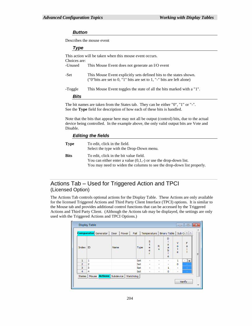
Advanced Configuration Topics Working with Display Tables
204
Button
Describes the mouse event
Type
This action will be taken when this mouse event occurs.
Choices are:
-Unused This Mouse Event does not generate an I/O event
-Set This Mouse Event explicitly sets defined bits to the states shown.
("0"bits are set to 0, "1" bits are set to 1, "-" bits are left alone)
-Toggle This Mouse Event toggles the state of all the bits marked with a "1".
Bits
The bit names are taken from the States tab. They can be either "0", "1" or "-".
See the Type field for description of how each of these bits is handled.
Note that the bits that appear here may not all be output (control) bits, due to the actual
device being controlled. In the example above, the only valid output bits are Vote and
Disable.
Editing the fields
Type To edit, click in the field.
Select the type with the Drop-Down menu.
Bits To edit, click in the bit value field.
You can either enter a value (0,1,-) or use the drop-down list.
You may need to widen the columns to see the drop-down list properly.
Actions Tab – Used for Triggered Action and TPCI (Licensed Option)
The Actions Tab controls optional actions for the Display Table. These Actions are only available
for the licensed Triggered Actions and Third Party Client Interface (TPCI) options. It is similar to
the Mouse tab and provides additional control functions that can be accessed by the Triggered
Actions and Third Party Client. (Although the Actions tab may be displayed, the settings are only
used with the Triggered Actions and TPCI Options.)
Advanced Configuration Topics Working with Display Tables
205
The above Actions table provides a way to explicitly Disable (ID 2) and Enable (ID 3) a receiver (as
compared to the toggle action in the Mouse table).
Actions Line contains the following fields:
ID
Numeric ID sent by the Third Party Client to generate this action. The IDs must be unique.
Name
This field is for a descriptive name that is unique to the action it identifies. Type
Same as Type in the Mouse Tab.
Bits
Same as the Bits field in the Mouse Tab.
Editing the fields
ID To edit, click in the field.
Enter the ID number to use.
Type To edit, click in the field.
Select the type with the Drop-Down menu.
Bits To edit, click in the bit value field.
You can either enter a value (0,1,-) or use the drop-down list.
You may need to widen the columns to see the drop-down list properly.
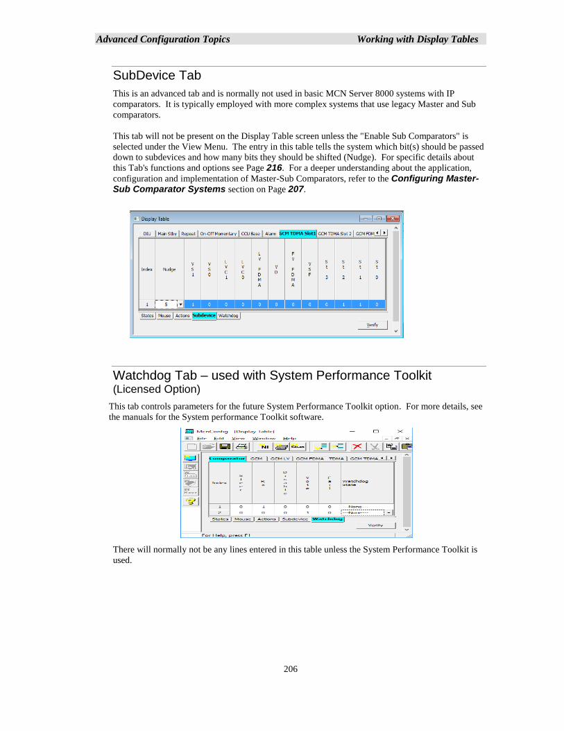
Advanced Configuration Topics Working with Display Tables
206
SubDevice Tab
This is an advanced tab and is normally not used in basic MCN Server 8000 systems with IP
comparators. It is typically employed with more complex systems that use legacy Master and Sub
comparators.
This tab will not be present on the Display Table screen unless the "Enable Sub Comparators" is
selected under the View Menu. The entry in this table tells the system which bit(s) should be passed
down to subdevices and how many bits they should be shifted (Nudge). For specific details about
this Tab's functions and options see Page 216. For a deeper understanding about the application,
configuration and implementation of Master-Sub Comparators, refer to the Configuring Master-Sub Comparator Systems section on Page 207.
Watchdog Tab – used with System Performance Toolkit (Licensed Option)
This tab controls parameters for the future System Performance Toolkit option. For more details, see
the manuals for the System performance Toolkit software.
There will normally not be any lines entered in this table unless the System Performance Toolkit is
used.
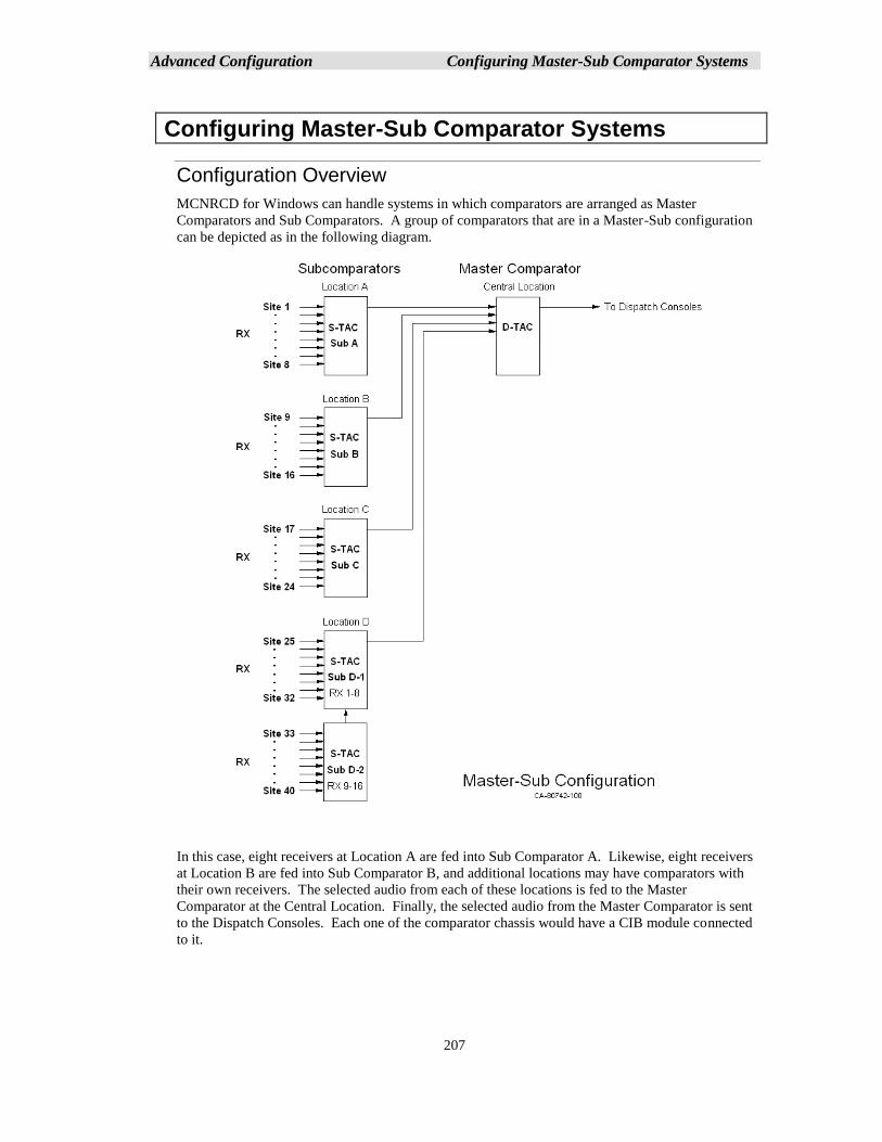
Advanced Configuration Configuring Master-Sub Comparator Systems
207
Configuring Master-Sub Comparator Systems
Configuration Overview
MCNRCD for Windows can handle systems in which comparators are arranged as Master
Comparators and Sub Comparators. A group of comparators that are in a Master-Sub configuration
can be depicted as in the following diagram.
In this case, eight receivers at Location A are fed into Sub Comparator A. Likewise, eight receivers
at Location B are fed into Sub Comparator B, and additional locations may have comparators with
their own receivers. The selected audio from each of these locations is fed to the Master
Comparator at the Central Location. Finally, the selected audio from the Master Comparator is sent
to the Dispatch Consoles. Each one of the comparator chassis would have a CIB module connected
to it.
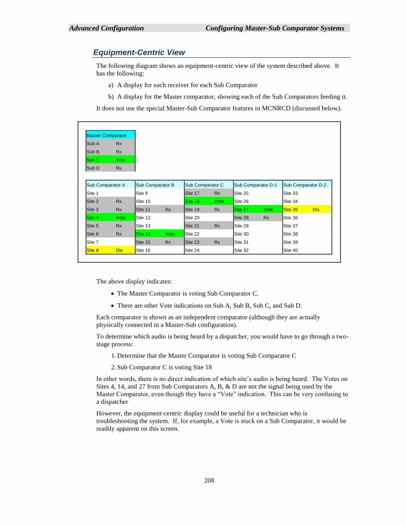
Advanced Configuration Configuring Master-Sub Comparator Systems
208
Equipment-Centric View
The following diagram shows an equipment-centric view of the system described above. It
has the following:
a) A display for each receiver for each Sub Comparator
b) A display for the Master comparator, showing each of the Sub Comparators feeding it.
It does not use the special Master-Sub Comparator features in MCNRCD (discussed below).
Master Comparator
Sub A Rx
Sub B Rx
Sub C Vote
Sub D Rx
Sub Comparator A Sub Comparator B Sub Comparator C Sub Comparator D-1 Sub Comparator D-2
Site 1 Site 9 Site 17 Rx Site 25 Site 33
Site 2 Rx Site 10 Site 18 Vote Site 26 Site 34
Site 3 Rx Site 11 Rx Site 19 Rx Site 27 Vote Site 35 Dis
Site 4 Vote Site 12 Site 20 Site 28 Rx Site 36
Site 5 Rx Site 13 Site 21 Rx Site 29 Site 37
Site 6 Rx Site 14 Vote Site 22 Site 30 Site 38
Site 7 Site 15 Rx Site 23 Rx Site 31 Site 39
Site 8 Dis Site 16 Site 24 Site 32 Site 40
The above display indicates:
• The Master Comparator is voting Sub Comparator C.
• There are other Vote indications on Sub A, Sub B, Sub C, and Sub D.
Each comparator is shown as an independent comparator (although they are actually
physically connected in a Master-Sub configuration).
To determine which audio is being heard by a dispatcher, you would have to go through a two-
stage process:
1. Determine that the Master Comparator is voting Sub Comparator C
2. Sub Comparator C is voting Site 18
In other words, there is no direct indication of which site’s audio is being heard. The Votes on
Sites 4, 14, and 27 from Sub Comparators A, B, & D are not the signal being used by the
Master Comparator, even though they have a “Vote” indication. This can be very confusing to
a dispatcher
However, the equipment-centric display could be useful for a technician who is
troubleshooting the system. If, for example, a Vote is stuck on a Sub Comparator, it would be
readily apparent on this screen.
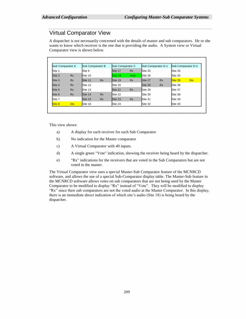
Advanced Configuration Configuring Master-Sub Comparator Systems
209
Virtual Comparator View
A dispatcher is not necessarily concerned with the details of master and sub comparators. He or she
wants to know which receiver is the one that is providing the audio. A System view or Virtual
Comparator view is shown below.
Sub Comparator A Sub Comparator B Sub Comparator C Sub Comparator D-1 Sub Comparator D-2
Site 1 Site 9 Site 17 Rx Site 25 Site 33
Site 2 Rx Site 10 Site 18 Vote Site 26 Site 34
Site 3 Rx Site 11 Rx Site 19 Rx Site 27 Rx Site 35 Dis
Site 4 Rx Site 12 Site 20 Site 28 Rx Site 36
Site 5 Rx Site 13 Site 21 Rx Site 29 Site 37
Site 6 Rx Site 14 Rx Site 22 Site 30 Site 38
Site 7 Site 15 Rx Site 23 Rx Site 31 Site 39
Site 8 Dis Site 16 Site 24 Site 32 Site 40
This view shows:
a) A display for each receiver for each Sub Comparator
b) No indication for the Master comparator
c) A Virtual Comparator with 40 inputs.
d) A single green "Vote" indication, showing the receiver being heard by the dispatcher.
e) "Rx" indications for the receivers that are voted in the Sub Comparators but are not
voted in the master.
The Virtual Comparator view uses a special Master-Sub Comparator feature of the MCNRCD
software, and allows the use of a special Sub-Comparator display table. The Master-Sub feature in
the MCNRCD software allows votes on sub comparators that are not being used by the Master
Comparator to be modified to display “Rx” instead of “Vote”. They will be modified to display
“Rx” since their sub comparators are not the voted audio at the Master Comparator. In this display,
there is an immediate direct indication of which site’s audio (Site 18) is being heard by the
dispatcher.
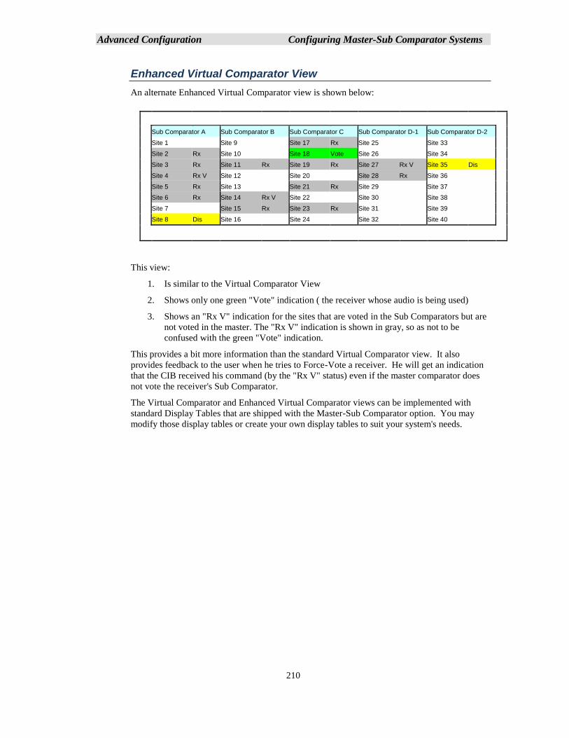
Advanced Configuration Configuring Master-Sub Comparator Systems
210
Enhanced Virtual Comparator View
An alternate Enhanced Virtual Comparator view is shown below:
Sub Comparator A Sub Comparator B Sub Comparator C Sub Comparator D-1 Sub Comparator D-2
Site 1 Site 9 Site 17 Rx Site 25 Site 33
Site 2 Rx Site 10 Site 18 Vote Site 26 Site 34
Site 3 Rx Site 11 Rx Site 19 Rx Site 27 Rx V Site 35 Dis
Site 4 Rx V Site 12 Site 20 Site 28 Rx Site 36
Site 5 Rx Site 13 Site 21 Rx Site 29 Site 37
Site 6 Rx Site 14 Rx V Site 22 Site 30 Site 38
Site 7 Site 15 Rx Site 23 Rx Site 31 Site 39
Site 8 Dis Site 16 Site 24 Site 32 Site 40
This view:
1. Is similar to the Virtual Comparator View
2. Shows only one green "Vote" indication ( the receiver whose audio is being used)
3. Shows an "Rx V" indication for the sites that are voted in the Sub Comparators but are
not voted in the master. The "Rx V" indication is shown in gray, so as not to be
confused with the green "Vote" indication.
This provides a bit more information than the standard Virtual Comparator view. It also
provides feedback to the user when he tries to Force-Vote a receiver. He will get an indication
that the CIB received his command (by the "Rx V" status) even if the master comparator does
not vote the receiver's Sub Comparator.
The Virtual Comparator and Enhanced Virtual Comparator views can be implemented with
standard Display Tables that are shipped with the Master-Sub Comparator option. You may
modify those display tables or create your own display tables to suit your system's needs.
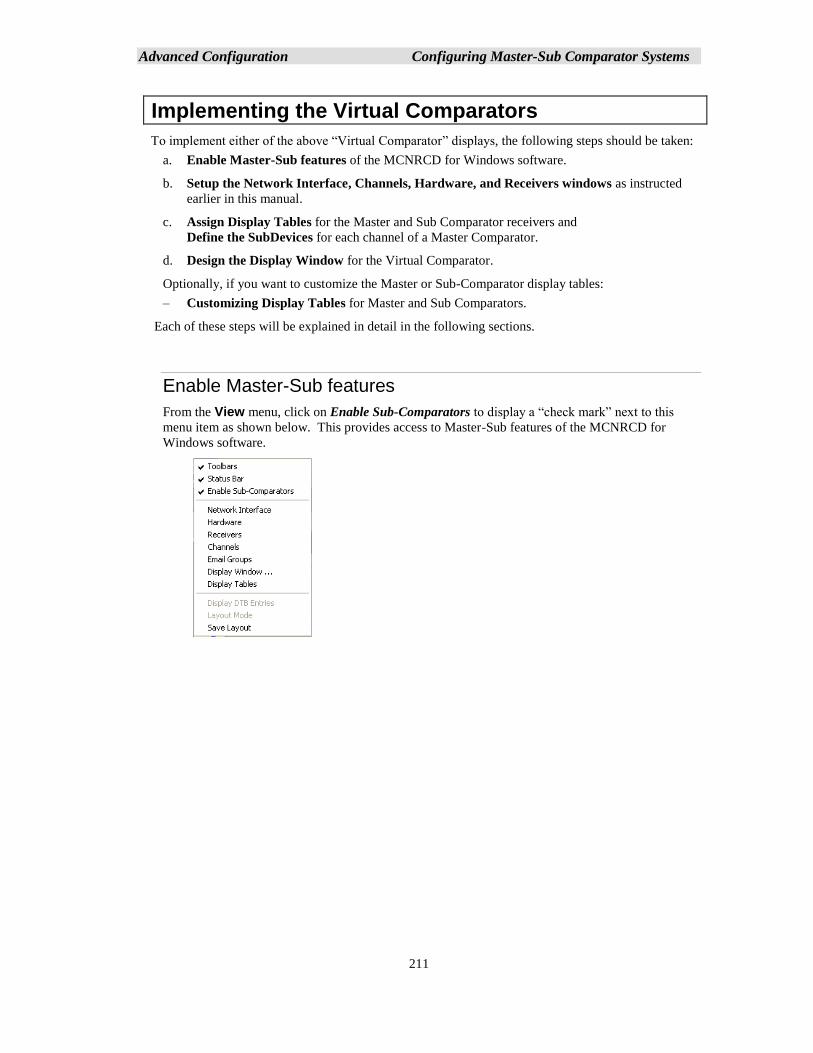
Advanced Configuration Configuring Master-Sub Comparator Systems
211
Implementing the Virtual Comparators
To implement either of the above “Virtual Comparator” displays, the following steps should be taken:
a. Enable Master-Sub features of the MCNRCD for Windows software.
b. Setup the Network Interface, Channels, Hardware, and Receivers windows as instructed
earlier in this manual.
c. Assign Display Tables for the Master and Sub Comparator receivers and
Define the SubDevices for each channel of a Master Comparator.
d. Design the Display Window for the Virtual Comparator.
Optionally, if you want to customize the Master or Sub-Comparator display tables:
– Customizing Display Tables for Master and Sub Comparators.
Each of these steps will be explained in detail in the following sections.
Enable Master-Sub features
From the View menu, click on Enable Sub-Comparators to display a “check mark” next to this
menu item as shown below. This provides access to Master-Sub features of the MCNRCD for
Windows software.
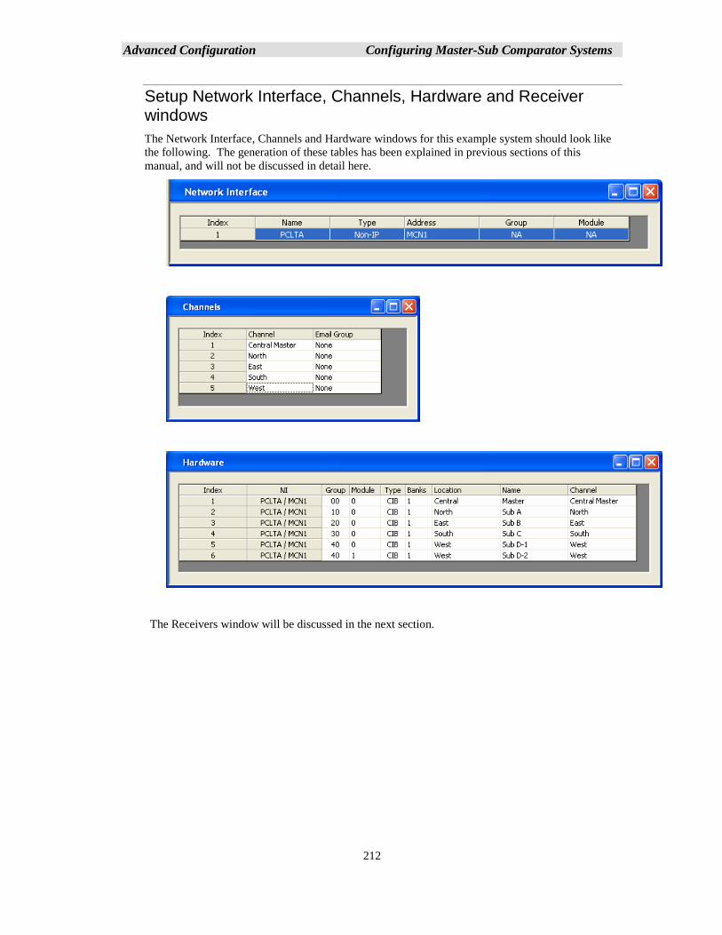
Advanced Configuration Configuring Master-Sub Comparator Systems
212
Setup Network Interface, Channels, Hardware and Receiver windows
The Network Interface, Channels and Hardware windows for this example system should look like
the following. The generation of these tables has been explained in previous sections of this
manual, and will not be discussed in detail here.
The Receivers window will be discussed in the next section.
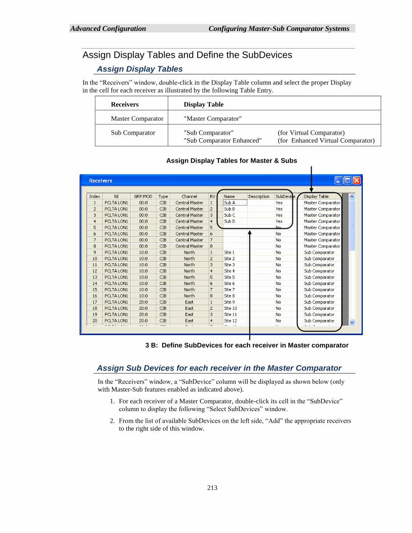
Advanced Configuration Configuring Master-Sub Comparator Systems
213
Assign Display Tables and Define the SubDevices
Assign Display Tables
In the “Receivers” window, double-click in the Display Table column and select the proper Display
in the cell for each receiver as illustrated by the following Table Entry.
Receivers Display Table
Master Comparator "Master Comparator"
Sub Comparator "Sub Comparator" (for Virtual Comparator)
"Sub Comparator Enhanced" (for Enhanced Virtual Comparator)
Assign Sub Devices for each receiver in the Master Comparator
In the “Receivers” window, a “SubDevice” column will be displayed as shown below (only
with Master-Sub features enabled as indicated above).
1. For each receiver of a Master Comparator, double-click its cell in the “SubDevice”
column to display the following “Select SubDevices” window.
2. From the list of available SubDevices on the left side, “Add” the appropriate receivers
to the right side of this window.
Assign Display Tables for Master & Subs
3 B: Define SubDevices for each receiver in Master comparator
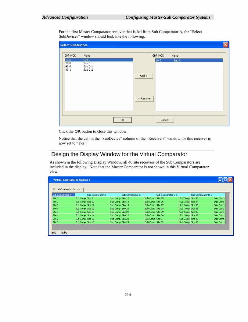
Advanced Configuration Configuring Master-Sub Comparator Systems
214
For the first Master Comparator receiver that is fed from Sub Comparator A, the “Select
SubDevices” window should look like the following.
Click the OK button to close this window.
Notice that the cell in the “SubDevice” column of the “Receivers” window for this receiver is
now set to “Yes”.
Design the Display Window for the Virtual Comparator
As shown in the following Display Window, all 40 site receivers of the Sub Comparators are
included in the display. Note that the Master Comparator is not shown in this Virtual Comparator
view.
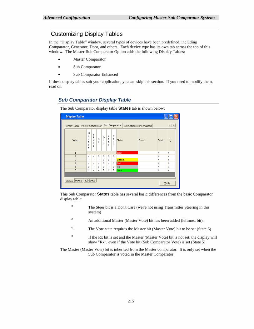
Advanced Configuration Configuring Master-Sub Comparator Systems
215
Customizing Display Tables
In the “Display Table” window, several types of devices have been predefined, including
Comparator, Generator, Door, and others. Each device type has its own tab across the top of this
window. The Master-Sub Comparator Option adds the following Display Tables:
• Master Comparator
• Sub Comparator
• Sub Comparator Enhanced
If these display tables suit your application, you can skip this section. If you need to modify them,
read on.
Sub Comparator Display Table
The Sub Comparator display table States tab is shown below:
This Sub Comparator States table has several basic differences from the basic Comparator
display table:
The Steer bit is a Don't Care (we're not using Transmitter Steering in this
system)
An additional Master (Master Vote) bit has been added (leftmost bit).
The Vote state requires the Master bit (Master Vote) bit to be set (State 6)
If the Rx bit is set and the Master (Master Vote) bit is not set, the display will
show "Rx", even if the Vote bit (Sub Comparator Vote) is set (State 5)
The Master (Master Vote) bit is inherited from the Master comparator. It is only set when the
Sub Comparator is voted in the Master Comparator.
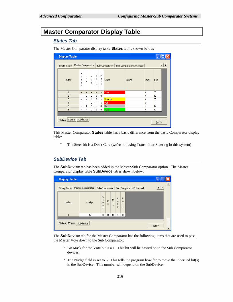
Advanced Configuration Configuring Master-Sub Comparator Systems
216
Master Comparator Display Table
States Tab
The Master Comparator display table States tab is shown below:
This Master Comparator States table has a basic difference from the basic Comparator display
table:
The Steer bit is a Don't Care (we're not using Transmitter Steering in this system)
SubDevice Tab
The SubDevice tab has been added in the Master-Sub Comparator option. The Master
Comparator display table SubDevice tab is shown below:
The SubDevice tab for the Master Comparator has the following items that are used to pass
the Master Vote down to the Sub Comparator:
Bit Mask for the Vote bit is a 1. This bit will be passed on to the Sub Comparator
devices.
The Nudge field is set to 5. This tells the program how far to move the inherited bit(s)
in the SubDevice. This number will depend on the SubDevice.
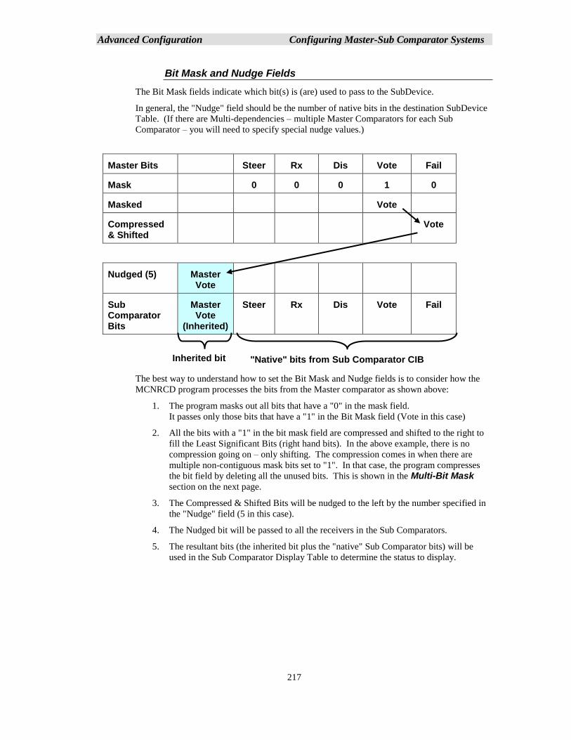
Advanced Configuration Configuring Master-Sub Comparator Systems
217
Bit Mask and Nudge Fields
The Bit Mask fields indicate which bit(s) is (are) used to pass to the SubDevice.
In general, the "Nudge" field should be the number of native bits in the destination SubDevice
Table. (If there are Multi-dependencies – multiple Master Comparators for each Sub
Comparator – you will need to specify special nudge values.)
Master Bits Steer Rx Dis Vote Fail
Mask 0 0 0 1 0
Masked Vote
Compressed & Shifted
Vote
Nudged (5) Master Vote
Sub Comparator Bits
Master Vote
(Inherited)
Steer Rx Dis Vote Fail
The best way to understand how to set the Bit Mask and Nudge fields is to consider how the
MCNRCD program processes the bits from the Master comparator as shown above:
1. The program masks out all bits that have a "0" in the mask field.
It passes only those bits that have a "1" in the Bit Mask field (Vote in this case)
2. All the bits with a "1" in the bit mask field are compressed and shifted to the right to
fill the Least Significant Bits (right hand bits). In the above example, there is no
compression going on – only shifting. The compression comes in when there are
multiple non-contiguous mask bits set to "1". In that case, the program compresses
the bit field by deleting all the unused bits. This is shown in the Multi-Bit Mask
section on the next page.
3. The Compressed & Shifted Bits will be nudged to the left by the number specified in
the "Nudge" field (5 in this case).
4. The Nudged bit will be passed to all the receivers in the Sub Comparators.
5. The resultant bits (the inherited bit plus the "native" Sub Comparator bits) will be
used in the Sub Comparator Display Table to determine the status to display.
Inherited bit "Native" bits from Sub Comparator CIB
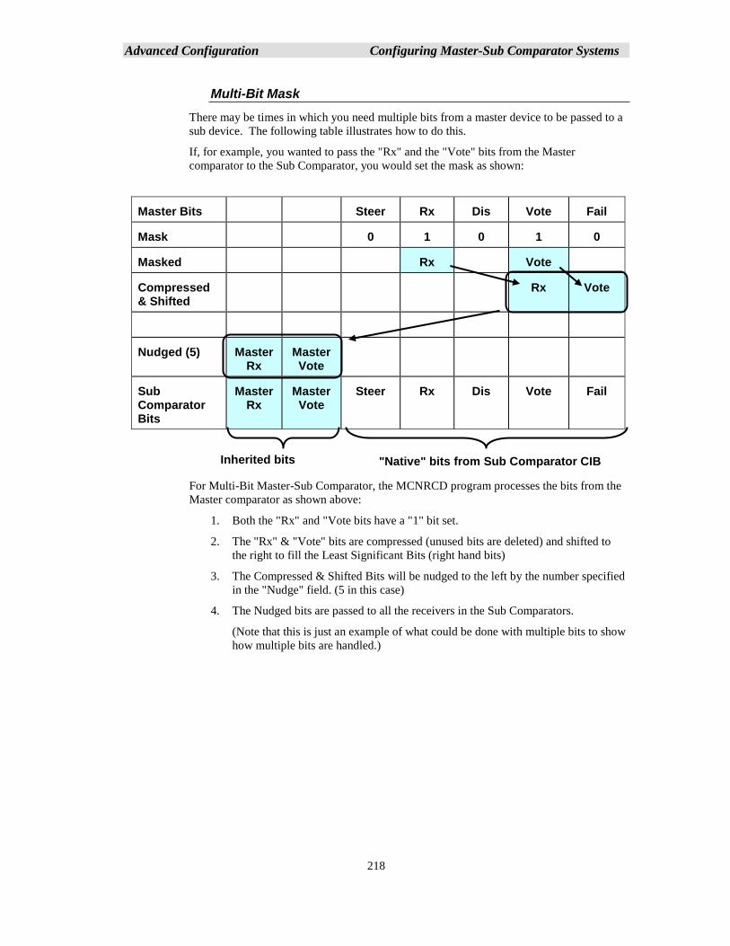
Advanced Configuration Configuring Master-Sub Comparator Systems
218
Multi-Bit Mask
There may be times in which you need multiple bits from a master device to be passed to a
sub device. The following table illustrates how to do this.
If, for example, you wanted to pass the "Rx" and the "Vote" bits from the Master
comparator to the Sub Comparator, you would set the mask as shown:
Master Bits Steer Rx Dis Vote Fail
Mask 0 1 0 1 0
Masked Rx Vote
Compressed & Shifted
Rx Vote
Nudged (5) Master Rx
Master Vote
Sub Comparator Bits
Master Rx
Master Vote
Steer Rx Dis Vote Fail
For Multi-Bit Master-Sub Comparator, the MCNRCD program processes the bits from the
Master comparator as shown above:
1. Both the "Rx" and "Vote bits have a "1" bit set.
2. The "Rx" & "Vote" bits are compressed (unused bits are deleted) and shifted to
the right to fill the Least Significant Bits (right hand bits)
3. The Compressed & Shifted Bits will be nudged to the left by the number specified
in the "Nudge" field. (5 in this case)
4. The Nudged bits are passed to all the receivers in the Sub Comparators.
(Note that this is just an example of what could be done with multiple bits to show
how multiple bits are handled.)
Inherited bits "Native" bits from Sub Comparator CIB
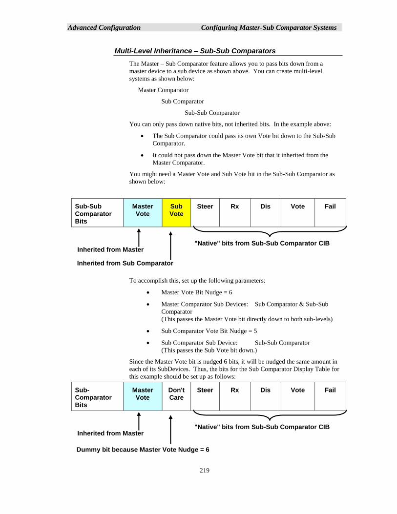
Advanced Configuration Configuring Master-Sub Comparator Systems
219
Multi-Level Inheritance – Sub-Sub Comparators
The Master – Sub Comparator feature allows you to pass bits down from a
master device to a sub device as shown above. You can create multi-level
systems as shown below:
Master Comparator
Sub Comparator
Sub-Sub Comparator
You can only pass down native bits, not inherited bits. In the example above:
• The Sub Comparator could pass its own Vote bit down to the Sub-Sub
Comparator.
• It could not pass down the Master Vote bit that it inherited from the
Master Comparator.
You might need a Master Vote and Sub Vote bit in the Sub-Sub Comparator as
shown below:
Sub-Sub Comparator Bits
Master Vote
Sub Vote
Steer Rx Dis Vote Fail
To accomplish this, set up the following parameters:
• Master Vote Bit Nudge = 6
• Master Comparator Sub Devices: Sub Comparator & Sub-Sub
Comparator
(This passes the Master Vote bit directly down to both sub-levels)
• Sub Comparator Vote Bit Nudge = 5
• Sub Comparator Sub Device: Sub-Sub Comparator
(This passes the Sub Vote bit down.)
Since the Master Vote bit is nudged 6 bits, it will be nudged the same amount in
each of its SubDevices. Thus, the bits for the Sub Comparator Display Table for
this example should be set up as follows:
Sub- Comparator Bits
Master Vote
Don't Care
Steer Rx Dis Vote Fail
"Native" bits from Sub-Sub Comparator CIB Inherited from Master
Inherited from Sub Comparator
"Native" bits from Sub-Sub Comparator CIB Inherited from Master
Dummy bit because Master Vote Nudge = 6
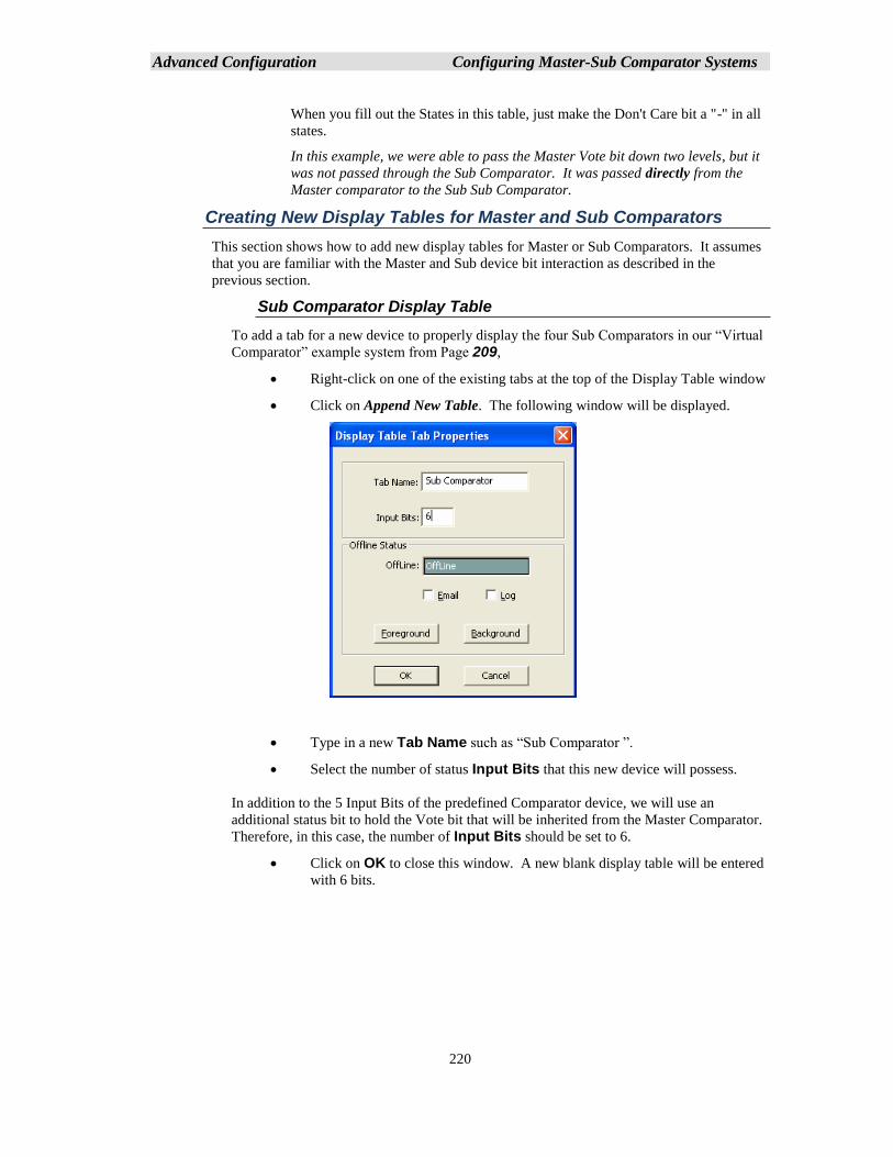
Advanced Configuration Configuring Master-Sub Comparator Systems
220
When you fill out the States in this table, just make the Don't Care bit a "-" in all
states.
In this example, we were able to pass the Master Vote bit down two levels, but it
was not passed through the Sub Comparator. It was passed directly from the
Master comparator to the Sub Sub Comparator.
Creating New Display Tables for Master and Sub Comparators
This section shows how to add new display tables for Master or Sub Comparators. It assumes
that you are familiar with the Master and Sub device bit interaction as described in the
previous section.
Sub Comparator Display Table
To add a tab for a new device to properly display the four Sub Comparators in our “Virtual
Comparator” example system from Page 209,
• Right-click on one of the existing tabs at the top of the Display Table window
• Click on Append New Table. The following window will be displayed.
• Type in a new Tab Name such as “Sub Comparator ”.
• Select the number of status Input Bits that this new device will possess.
In addition to the 5 Input Bits of the predefined Comparator device, we will use an
additional status bit to hold the Vote bit that will be inherited from the Master Comparator.
Therefore, in this case, the number of Input Bits should be set to 6.
• Click on OK to close this window. A new blank display table will be entered
with 6 bits.
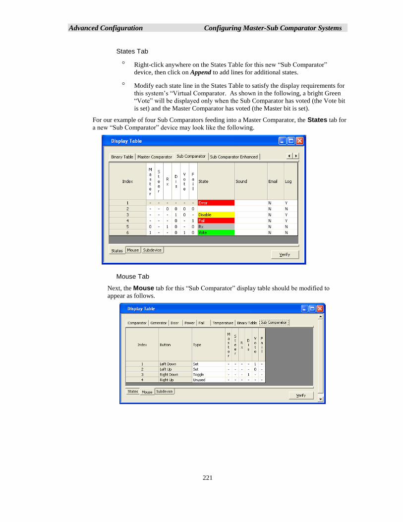
Advanced Configuration Configuring Master-Sub Comparator Systems
221
States Tab
Right-click anywhere on the States Table for this new “Sub Comparator”
device, then click on Append to add lines for additional states.
Modify each state line in the States Table to satisfy the display requirements for
this system’s “Virtual Comparator. As shown in the following, a bright Green
“Vote” will be displayed only when the Sub Comparator has voted (the Vote bit
is set) and the Master Comparator has voted (the Master bit is set).
For our example of four Sub Comparators feeding into a Master Comparator, the States tab for
a new “Sub Comparator” device may look like the following.
Mouse Tab
Next, the Mouse tab for this “Sub Comparator” display table should be modified to
appear as follows.
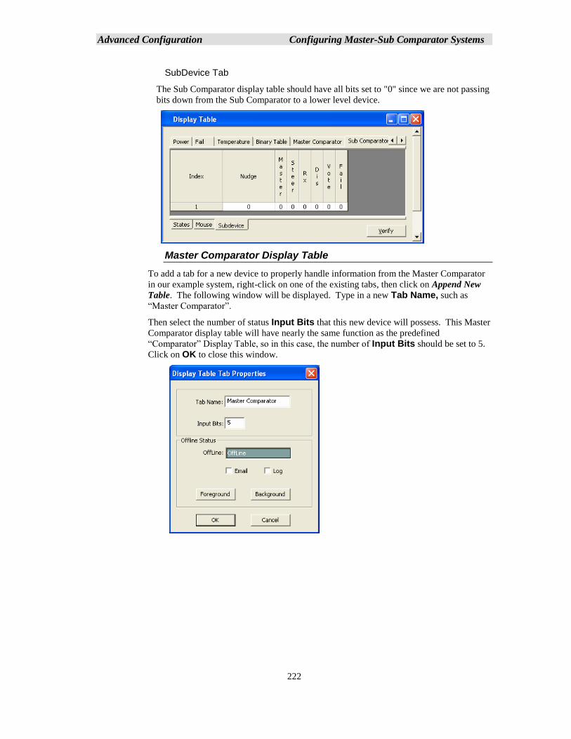
Advanced Configuration Configuring Master-Sub Comparator Systems
222
SubDevice Tab
The Sub Comparator display table should have all bits set to "0" since we are not passing
bits down from the Sub Comparator to a lower level device.
Master Comparator Display Table
To add a tab for a new device to properly handle information from the Master Comparator
in our example system, right-click on one of the existing tabs, then click on Append New
Table. The following window will be displayed. Type in a new Tab Name, such as
“Master Comparator”.
Then select the number of status Input Bits that this new device will possess. This Master
Comparator display table will have nearly the same function as the predefined
“Comparator” Display Table, so in this case, the number of Input Bits should be set to 5.
Click on OK to close this window.
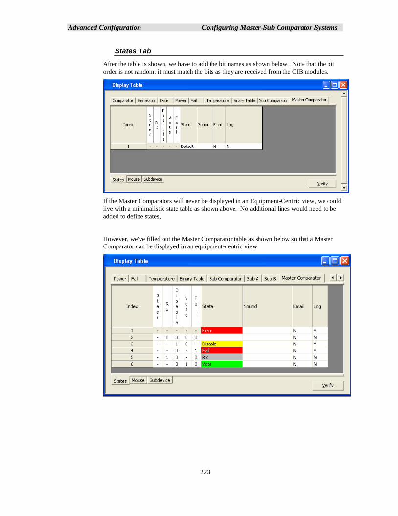
Advanced Configuration Configuring Master-Sub Comparator Systems
223
States Tab
After the table is shown, we have to add the bit names as shown below. Note that the bit
order is not random; it must match the bits as they are received from the CIB modules.
If the Master Comparators will never be displayed in an Equipment-Centric view, we could
live with a minimalistic state table as shown above. No additional lines would need to be
added to define states,
However, we've filled out the Master Comparator table as shown below so that a Master
Comparator can be displayed in an equipment-centric view.
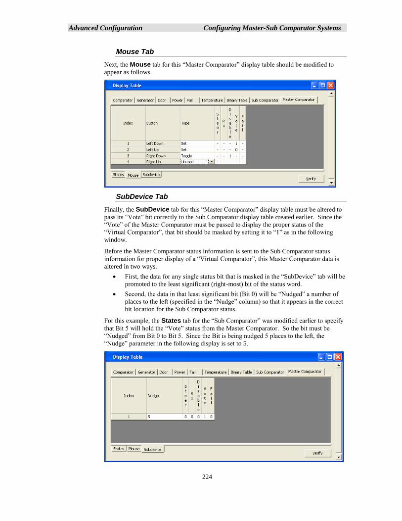
Advanced Configuration Configuring Master-Sub Comparator Systems
224
Mouse Tab
Next, the Mouse tab for this “Master Comparator” display table should be modified to
appear as follows.
SubDevice Tab
Finally, the SubDevice tab for this “Master Comparator” display table must be altered to
pass its “Vote” bit correctly to the Sub Comparator display table created earlier. Since the
“Vote” of the Master Comparator must be passed to display the proper status of the
“Virtual Comparator”, that bit should be masked by setting it to “1” as in the following
window.
Before the Master Comparator status information is sent to the Sub Comparator status
information for proper display of a “Virtual Comparator”, this Master Comparator data is
altered in two ways.
• First, the data for any single status bit that is masked in the “SubDevice” tab will be
promoted to the least significant (right-most) bit of the status word.
• Second, the data in that least significant bit (Bit 0) will be “Nudged” a number of
places to the left (specified in the “Nudge” column) so that it appears in the correct
bit location for the Sub Comparator status.
For this example, the States tab for the “Sub Comparator” was modified earlier to specify
that Bit 5 will hold the “Vote” status from the Master Comparator. So the bit must be
“Nudged” from Bit 0 to Bit 5. Since the Bit is being nudged 5 places to the left, the
“Nudge” parameter in the following display is set to 5.
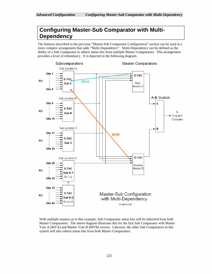
Advanced Configuration Configuring Master-Sub Comparator with Multi-Dependency
225
Configuring Master-Sub Comparator with Multi-Dependency
The features described in the previous “Master-Sub Comparator Configuration” section can be used in a
more complex arrangement that adds “Multi-Dependency”. Multi-Dependency can be defined as the
ability of a Sub Comparator to inherit status bits from multiple Master Comparators. This arrangement
provides a level of redundancy. It is depicted in the following diagram.
With multiple masters as in this example, Sub Comparator status bits will be inherited from both
Master Comparators. The above diagram illustrates this for the first Sub Comparator with Master
Vote A (MVA) and Master Vote B (MVB) vectors. Likewise, the other Sub Comparators in this
system will also inherit status bits from both Master Comparators.
MVB
MVA
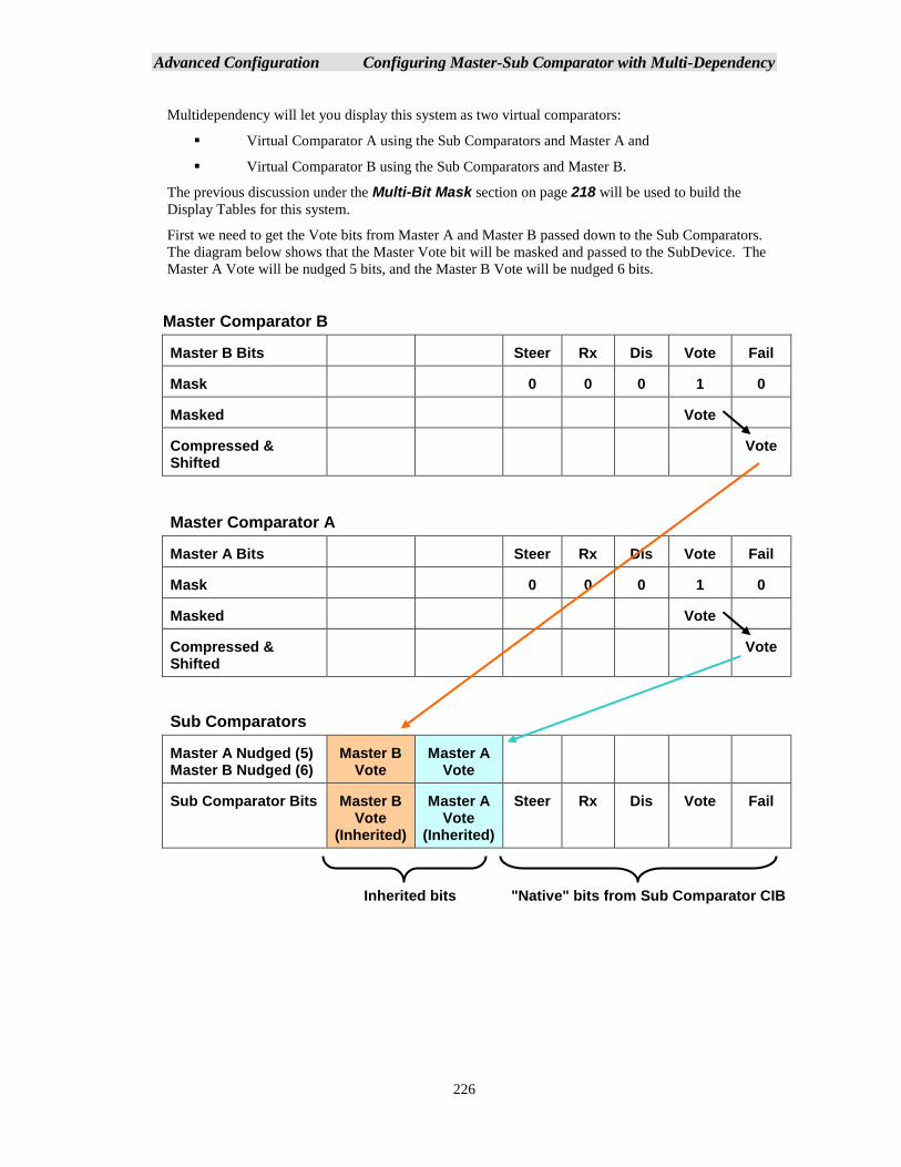
Advanced Configuration Configuring Master-Sub Comparator with Multi-Dependency
226
Multidependency will let you display this system as two virtual comparators:
▪ Virtual Comparator A using the Sub Comparators and Master A and
▪ Virtual Comparator B using the Sub Comparators and Master B.
The previous discussion under the Multi-Bit Mask section on page 218 will be used to build the
Display Tables for this system.
First we need to get the Vote bits from Master A and Master B passed down to the Sub Comparators.
The diagram below shows that the Master Vote bit will be masked and passed to the SubDevice. The
Master A Vote will be nudged 5 bits, and the Master B Vote will be nudged 6 bits.
Master Comparator B
Master B Bits Steer Rx Dis Vote Fail
Mask 0 0 0 1 0
Masked Vote
Compressed & Shifted
Vote
Master Comparator A
Master A Bits Steer Rx Dis Vote Fail
Mask 0 0 0 1 0
Masked Vote
Compressed & Shifted
Vote
Sub Comparators
Master A Nudged (5) Master B Nudged (6)
Master B Vote
Master A Vote
Sub Comparator Bits Master B Vote
(Inherited)
Master A Vote
(Inherited)
Steer Rx Dis Vote Fail
Inherited bits "Native" bits from Sub Comparator CIB
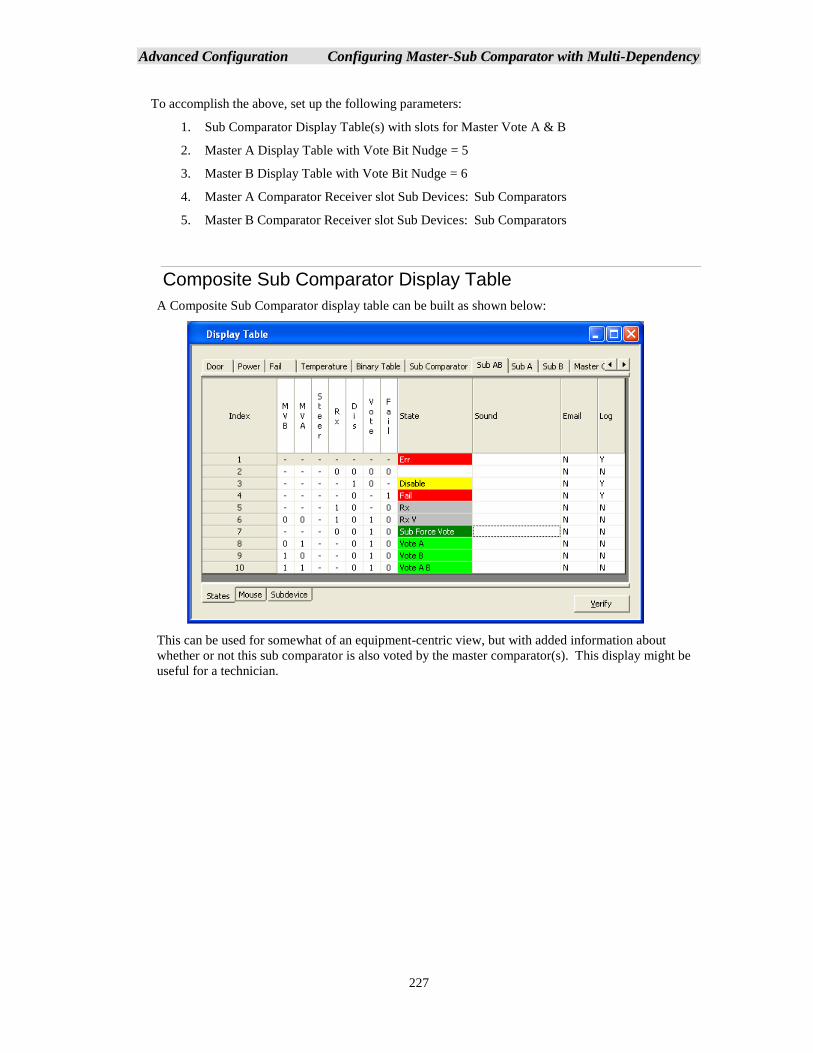
Advanced Configuration Configuring Master-Sub Comparator with Multi-Dependency
227
To accomplish the above, set up the following parameters:
1. Sub Comparator Display Table(s) with slots for Master Vote A & B
2. Master A Display Table with Vote Bit Nudge = 5
3. Master B Display Table with Vote Bit Nudge = 6
4. Master A Comparator Receiver slot Sub Devices: Sub Comparators
5. Master B Comparator Receiver slot Sub Devices: Sub Comparators
Composite Sub Comparator Display Table
A Composite Sub Comparator display table can be built as shown below:
This can be used for somewhat of an equipment-centric view, but with added information about
whether or not this sub comparator is also voted by the master comparator(s). This display might be
useful for a technician.
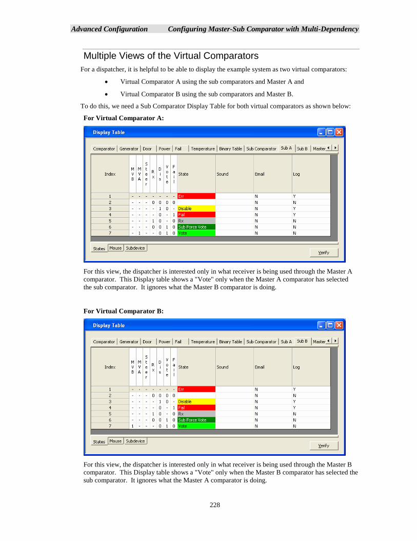
Advanced Configuration Configuring Master-Sub Comparator with Multi-Dependency
228
Multiple Views of the Virtual Comparators
For a dispatcher, it is helpful to be able to display the example system as two virtual comparators:
• Virtual Comparator A using the sub comparators and Master A and
• Virtual Comparator B using the sub comparators and Master B.
To do this, we need a Sub Comparator Display Table for both virtual comparators as shown below:
For Virtual Comparator A:
For this view, the dispatcher is interested only in what receiver is being used through the Master A
comparator. This Display table shows a "Vote" only when the Master A comparator has selected
the sub comparator. It ignores what the Master B comparator is doing.
For Virtual Comparator B:
For this view, the dispatcher is interested only in what receiver is being used through the Master B
comparator. This Display table shows a "Vote" only when the Master B comparator has selected the
sub comparator. It ignores what the Master A comparator is doing.
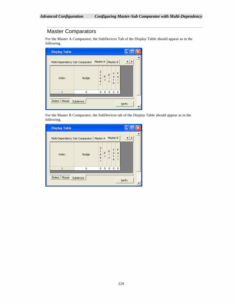
Advanced Configuration Configuring Master-Sub Comparator with Multi-Dependency
229
Master Comparators
For the Master A Comparator, the SubDevices Tab of the Display Table should appear as in the
following.
For the Master B Comparator, the SubDevices tab of the Display Table should appear as in the
following.
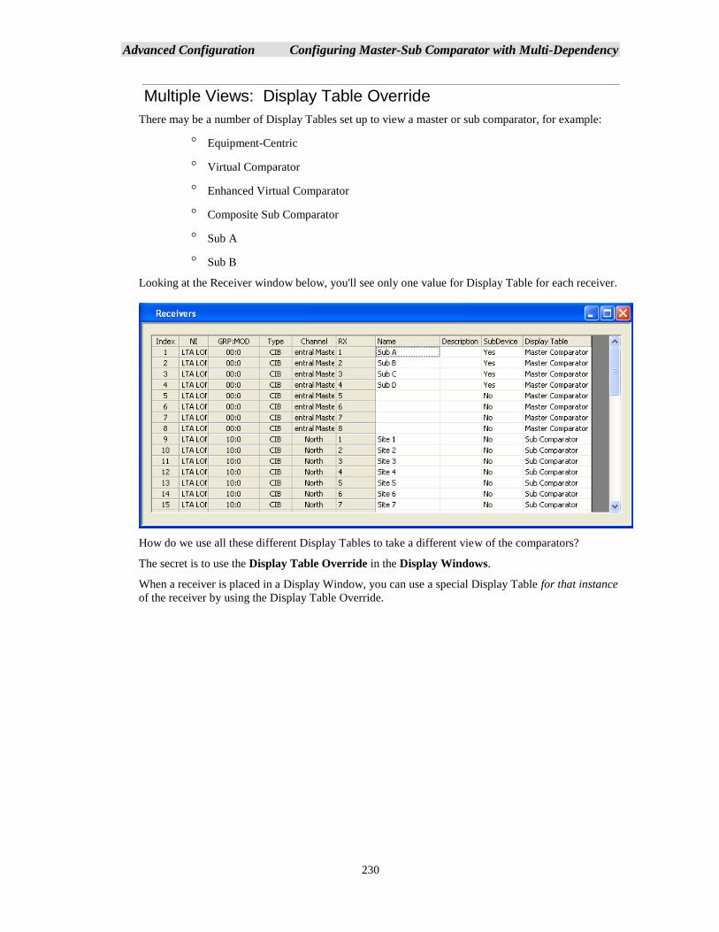
Advanced Configuration Configuring Master-Sub Comparator with Multi-Dependency
230
Multiple Views: Display Table Override
There may be a number of Display Tables set up to view a master or sub comparator, for example:
Equipment-Centric
Virtual Comparator
Enhanced Virtual Comparator
Composite Sub Comparator
Sub A
Sub B
Looking at the Receiver window below, you'll see only one value for Display Table for each receiver.
How do we use all these different Display Tables to take a different view of the comparators?
The secret is to use the Display Table Override in the Display Windows.
When a receiver is placed in a Display Window, you can use a special Display Table for that instance
of the receiver by using the Display Table Override.
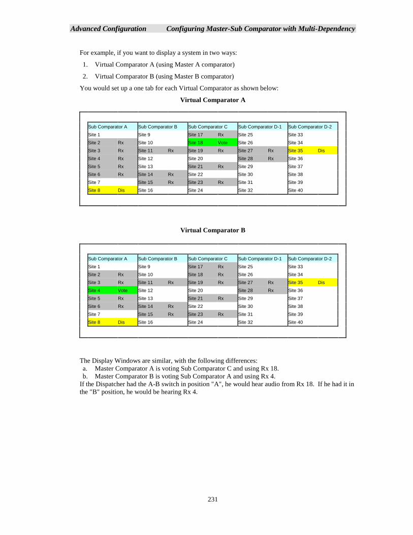
Advanced Configuration Configuring Master-Sub Comparator with Multi-Dependency
231
For example, if you want to display a system in two ways:
1. Virtual Comparator A (using Master A comparator)
2. Virtual Comparator B (using Master B comparator)
You would set up a one tab for each Virtual Comparator as shown below:
Virtual Comparator A
Sub Comparator A Sub Comparator B Sub Comparator C Sub Comparator D-1 Sub Comparator D-2
Site 1 Site 9 Site 17 Rx Site 25 Site 33
Site 2 Rx Site 10 Site 18 Vote Site 26 Site 34
Site 3 Rx Site 11 Rx Site 19 Rx Site 27 Rx Site 35 Dis
Site 4 Rx Site 12 Site 20 Site 28 Rx Site 36
Site 5 Rx Site 13 Site 21 Rx Site 29 Site 37
Site 6 Rx Site 14 Rx Site 22 Site 30 Site 38
Site 7 Site 15 Rx Site 23 Rx Site 31 Site 39
Site 8 Dis Site 16 Site 24 Site 32 Site 40
Virtual Comparator B
Sub Comparator A Sub Comparator B Sub Comparator C Sub Comparator D-1 Sub Comparator D-2
Site 1 Site 9 Site 17 Rx Site 25 Site 33
Site 2 Rx Site 10 Site 18 Rx Site 26 Site 34
Site 3 Rx Site 11 Rx Site 19 Rx Site 27 Rx Site 35 Dis
Site 4 Vote Site 12 Site 20 Site 28 Rx Site 36
Site 5 Rx Site 13 Site 21 Rx Site 29 Site 37
Site 6 Rx Site 14 Rx Site 22 Site 30 Site 38
Site 7 Site 15 Rx Site 23 Rx Site 31 Site 39
Site 8 Dis Site 16 Site 24 Site 32 Site 40
The Display Windows are similar, with the following differences:
a. Master Comparator A is voting Sub Comparator C and using Rx 18.
b. Master Comparator B is voting Sub Comparator A and using Rx 4.
If the Dispatcher had the A-B switch in position "A", he would hear audio from Rx 18. If he had it in
the "B" position, he would be hearing Rx 4.
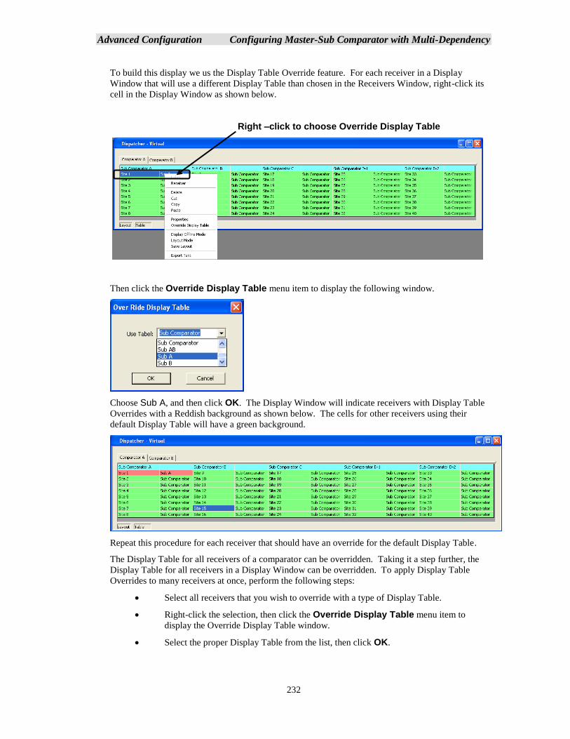
Advanced Configuration Configuring Master-Sub Comparator with Multi-Dependency
232
To build this display we us the Display Table Override feature. For each receiver in a Display
Window that will use a different Display Table than chosen in the Receivers Window, right-click its
cell in the Display Window as shown below.
Then click the Override Display Table menu item to display the following window.
Choose Sub A, and then click OK. The Display Window will indicate receivers with Display Table
Overrides with a Reddish background as shown below. The cells for other receivers using their
default Display Table will have a green background.
Repeat this procedure for each receiver that should have an override for the default Display Table.
The Display Table for all receivers of a comparator can be overridden. Taking it a step further, the
Display Table for all receivers in a Display Window can be overridden. To apply Display Table
Overrides to many receivers at once, perform the following steps:
• Select all receivers that you wish to override with a type of Display Table.
• Right-click the selection, then click the Override Display Table menu item to
display the Override Display Table window.
• Select the proper Display Table from the list, then click OK.
Right –click to choose Override Display Table
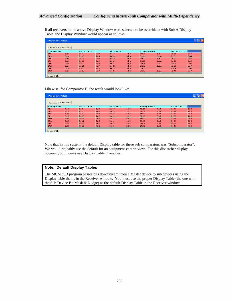
Advanced Configuration Configuring Master-Sub Comparator with Multi-Dependency
233
If all receivers in the above Display Window were selected to be overridden with Sub A Display
Table, the Display Window would appear as follows.
Likewise, for Comparator B, the result would look like:
Note that in this system, the default Display table for these sub comparators was "Subcomparator".
We would probably use the default for an equipment-centric view. For this dispatcher display,
however, both views use Display Table Overrides.
Note: Default Display Tables
The MCNRCD program passes bits downstream from a Master device to sub devices using the
Display table that is in the Receiver window. You must use the proper Display Table (the one with
the Sub Device Bit Mask & Nudge) as the default Display Table in the Receiver window.
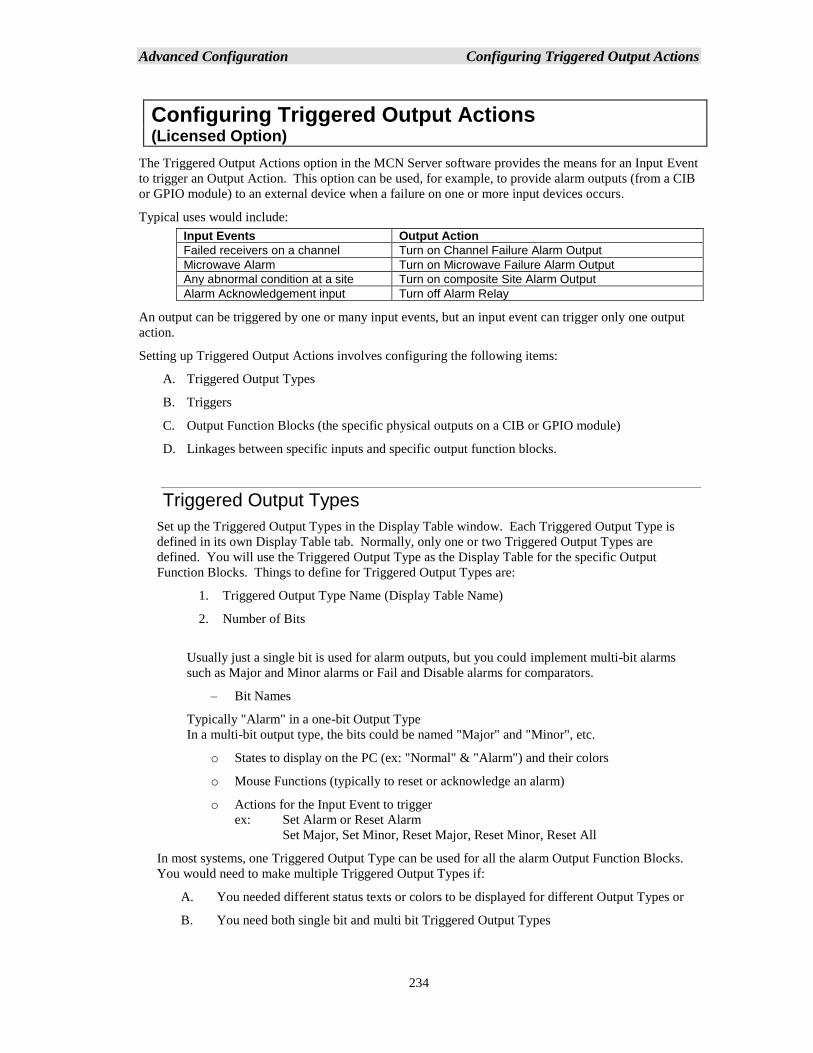
Advanced Configuration Configuring Triggered Output Actions
234
Configuring Triggered Output Actions (Licensed Option)
The Triggered Output Actions option in the MCN Server software provides the means for an Input Event
to trigger an Output Action. This option can be used, for example, to provide alarm outputs (from a CIB
or GPIO module) to an external device when a failure on one or more input devices occurs.
Typical uses would include:
Input Events Output Action
Failed receivers on a channel Turn on Channel Failure Alarm Output
Microwave Alarm Turn on Microwave Failure Alarm Output
Any abnormal condition at a site Turn on composite Site Alarm Output
Alarm Acknowledgement input Turn off Alarm Relay
An output can be triggered by one or many input events, but an input event can trigger only one output
action.
Setting up Triggered Output Actions involves configuring the following items:
A. Triggered Output Types
B. Triggers
C. Output Function Blocks (the specific physical outputs on a CIB or GPIO module)
D. Linkages between specific inputs and specific output function blocks.
Triggered Output Types
Set up the Triggered Output Types in the Display Table window. Each Triggered Output Type is
defined in its own Display Table tab. Normally, only one or two Triggered Output Types are
defined. You will use the Triggered Output Type as the Display Table for the specific Output
Function Blocks. Things to define for Triggered Output Types are:
1. Triggered Output Type Name (Display Table Name)
2. Number of Bits
Usually just a single bit is used for alarm outputs, but you could implement multi-bit alarms
such as Major and Minor alarms or Fail and Disable alarms for comparators.
– Bit Names
Typically "Alarm" in a one-bit Output Type
In a multi-bit output type, the bits could be named "Major" and "Minor", etc.
o States to display on the PC (ex: "Normal" & "Alarm") and their colors
o Mouse Functions (typically to reset or acknowledge an alarm)
o Actions for the Input Event to trigger
ex: Set Alarm or Reset Alarm
Set Major, Set Minor, Reset Major, Reset Minor, Reset All
In most systems, one Triggered Output Type can be used for all the alarm Output Function Blocks.
You would need to make multiple Triggered Output Types if:
A. You needed different status texts or colors to be displayed for different Output Types or
B. You need both single bit and multi bit Triggered Output Types
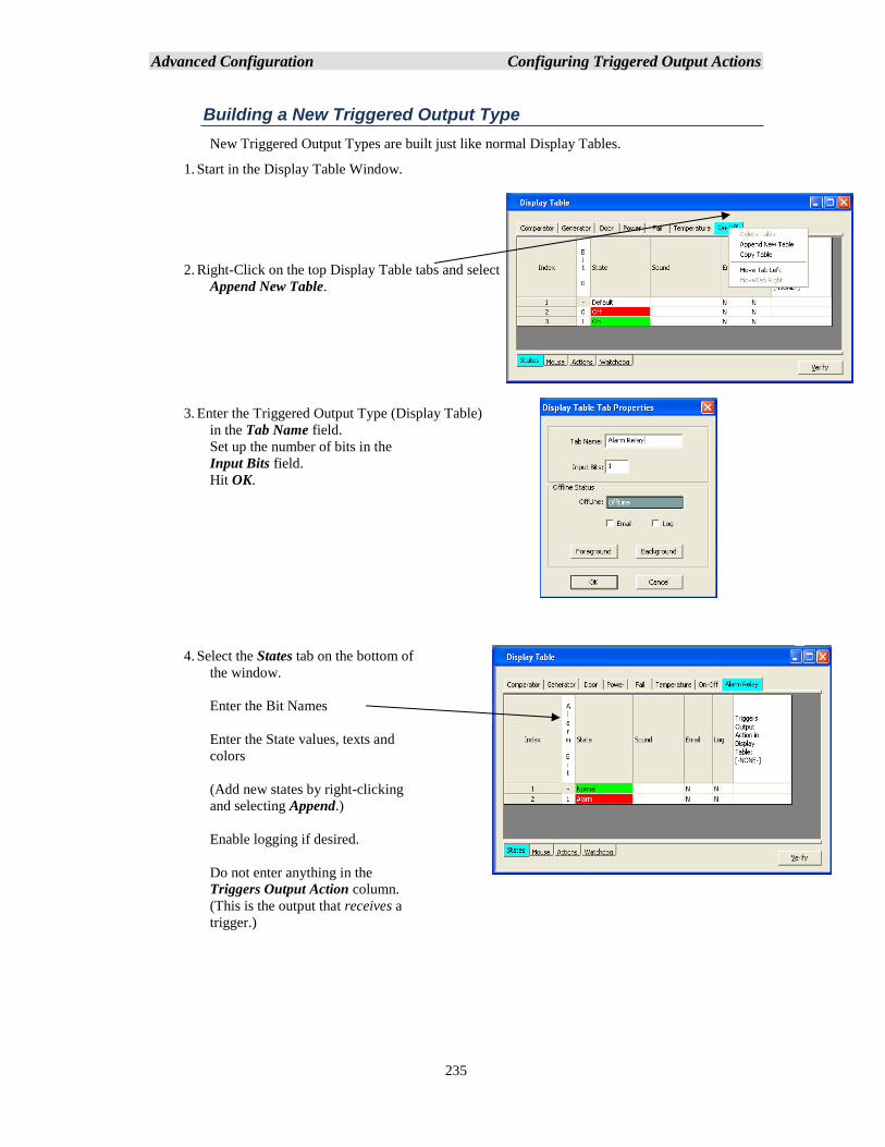
Advanced Configuration Configuring Triggered Output Actions
235
Building a New Triggered Output Type
New Triggered Output Types are built just like normal Display Tables.
1. Start in the Display Table Window.
2. Right-Click on the top Display Table tabs and select
Append New Table.
3. Enter the Triggered Output Type (Display Table)
in the Tab Name field.
Set up the number of bits in the
Input Bits field.
Hit OK.
4. Select the States tab on the bottom of
the window.
Enter the Bit Names
Enter the State values, texts and
colors
(Add new states by right-clicking
and selecting Append.)
Enable logging if desired.
Do not enter anything in the
Triggers Output Action column.
(This is the output that receives a
trigger.)
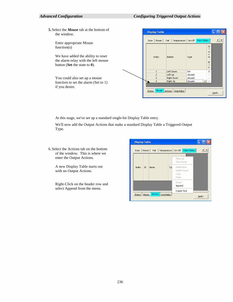
Advanced Configuration Configuring Triggered Output Actions
236
5. Select the Mouse tab at the bottom of
the window.
Enter appropriate Mouse
function(s)
We have added the ability to reset
the alarm relay with the left mouse
button (Set the state to 0).
You could also set up a mouse
function to set the alarm (Set to 1)
if you desire.
At this stage, we've set up a standard single-bit Display Table entry.
We'll now add the Output Actions that make a standard Display Table a Triggered Output
Type.
6. Select the Actions tab on the bottom
of the window. This is where we
enter the Output Actions.
A new Display Table starts out
with no Output Actions.
Right-Click on the header row and
select Append from the menu.
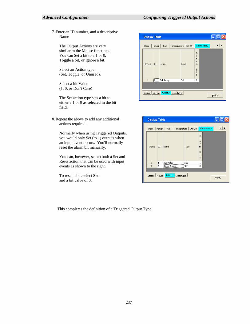
Advanced Configuration Configuring Triggered Output Actions
237
7. Enter an ID number, and a descriptive
Name
The Output Actions are very
similar to the Mouse functions.
You can Set a bit to a 1 or 0,
Toggle a bit, or ignore a bit.
Select an Action type
(Set, Toggle, or Unused).
Select a bit Value
(1, 0, or Don't Care)
The Set action type sets a bit to
either a 1 or 0 as selected in the bit
field.
8. Repeat the above to add any additional
actions required.
Normally when using Triggered Outputs,
you would only Set (to 1) outputs when
an input event occurs. You'll normally
reset the alarm bit manually.
You can, however, set up both a Set and
Reset action that can be used with input
events as shown to the right.
To reset a bit, select Set
and a bit value of 0.
This completes the definition of a Triggered Output Type.
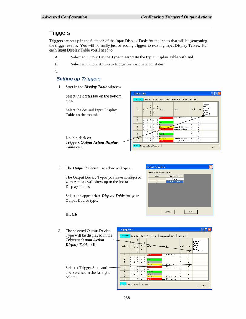
Advanced Configuration Configuring Triggered Output Actions
238
Triggers
Triggers are set up in the State tab of the Input Display Table for the inputs that will be generating
the trigger events. You will normally just be adding triggers to existing input Display Tables. For
each Input Display Table you'll need to:
A. Select an Output Device Type to associate the Input Display Table with and
B. Select an Output Action to trigger for various input states.
C.
Setting up Triggers
1. Start in the Display Table window.
Select the States tab on the bottom
tabs.
Select the desired Input Display
Table on the top tabs.
Double click on
Triggers Output Action Display
Table cell.
2. The Output Selection window will open.
The Output Device Types you have configured
with Actions will show up in the list of
Display Tables.
Select the appropriate Display Table for your
Output Device type.
Hit OK
3. The selected Output Device
Type will be displayed in the
Triggers Output Action
Display Table cell.
Select a Trigger State and
double-click in the far right
column
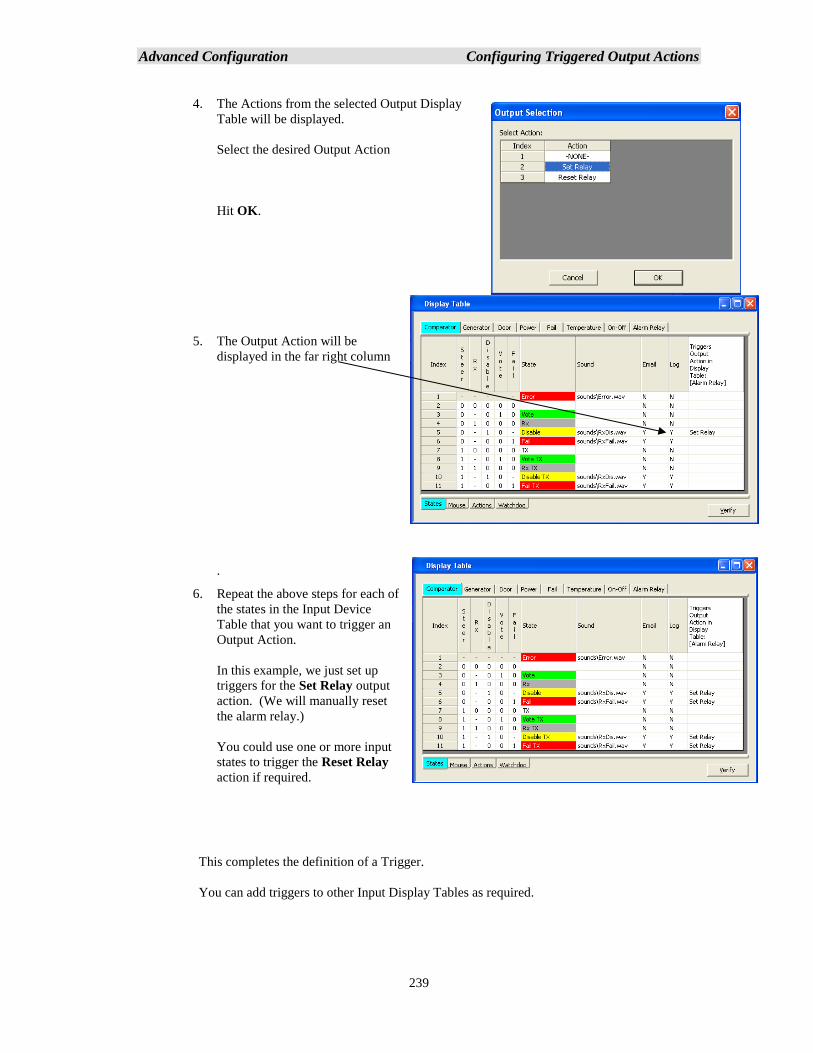
Advanced Configuration Configuring Triggered Output Actions
239
4. The Actions from the selected Output Display
Table will be displayed.
Select the desired Output Action
Hit OK.
5. The Output Action will be
displayed in the far right column
.
6. Repeat the above steps for each of
the states in the Input Device
Table that you want to trigger an
Output Action.
In this example, we just set up
triggers for the Set Relay output
action. (We will manually reset
the alarm relay.)
You could use one or more input
states to trigger the Reset Relay
action if required.
This completes the definition of a Trigger.
You can add triggers to other Input Display Tables as required.
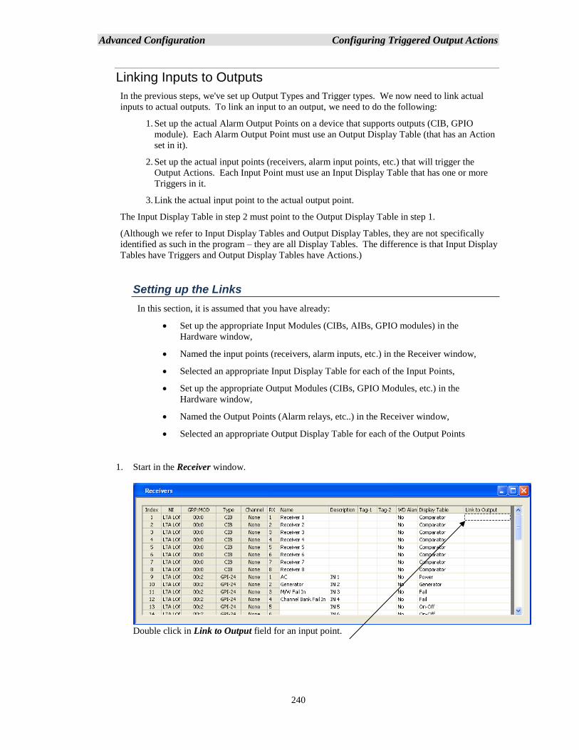
Advanced Configuration Configuring Triggered Output Actions
240
Linking Inputs to Outputs
In the previous steps, we've set up Output Types and Trigger types. We now need to link actual
inputs to actual outputs. To link an input to an output, we need to do the following:
1. Set up the actual Alarm Output Points on a device that supports outputs (CIB, GPIO
module). Each Alarm Output Point must use an Output Display Table (that has an Action
set in it).
2. Set up the actual input points (receivers, alarm input points, etc.) that will trigger the
Output Actions. Each Input Point must use an Input Display Table that has one or more
Triggers in it.
3. Link the actual input point to the actual output point.
The Input Display Table in step 2 must point to the Output Display Table in step 1.
(Although we refer to Input Display Tables and Output Display Tables, they are not specifically
identified as such in the program – they are all Display Tables. The difference is that Input Display
Tables have Triggers and Output Display Tables have Actions.)
Setting up the Links
In this section, it is assumed that you have already:
• Set up the appropriate Input Modules (CIBs, AIBs, GPIO modules) in the
Hardware window,
• Named the input points (receivers, alarm inputs, etc.) in the Receiver window,
• Selected an appropriate Input Display Table for each of the Input Points,
• Set up the appropriate Output Modules (CIBs, GPIO Modules, etc.) in the
Hardware window,
• Named the Output Points (Alarm relays, etc..) in the Receiver window,
• Selected an appropriate Output Display Table for each of the Output Points
1. Start in the Receiver window.
Double click in Link to Output field for an input point.
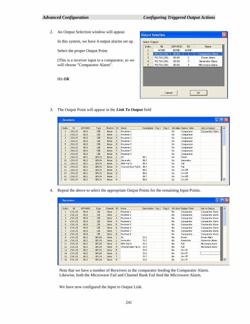
Advanced Configuration Configuring Triggered Output Actions
241
2. An Output Selection window will appear.
In this system, we have 4 output alarms set up.
Select the proper Output Point.
(This is a receiver input to a comparator, so we
will choose "Comparator Alarm".
Hit OK
3. The Output Point will appear in the Link To Output field
4. Repeat the above to select the appropriate Output Points for the remaining Input Points.
Note that we have a number of Receivers in the comparator feeding the Comparator Alarm.
Likewise, both the Microwave Fail and Channel Bank Fail feed the Microwave Alarm.
We have now configured the Input to Output Link.

Advanced Configuration Configuring Triggered Output Actions
242
Triggered Output Notes
Things to remember about Triggered Outputs are:
I. Any input (Receiver, General Purpose I/O, etc.) device type that needs to trigger an output
must use a Display Table that has Triggers in it.
For example, if a comparator needs to trigger an alarm relay, you must add Triggers to its
Display Table (typically the Comparator Display Table).
If a generator device needs to trigger an alarm relay, you must add one or more Triggers to
its Display Table (typically the Generator Display Table).
II. Different input device types (Comparators, Generators, Microwave Alarms, etc.) can trigger
the same type of Triggered Output Type (typically an Alarm Relay). They can trigger
different explicit Alarm Points, but you may need only one Output Device Type. In our
example above, all alarm outputs shared the same Output Device Type.
III. Each input Display Table can trigger only one Output Device Type
IV. Multiple states in the Input Display Table can trigger the same Output Action.
(ex: Disable and Fail on a receiver can both trigger a Set Alarm action.)
V. Different states in the Input Display Table can trigger different actions in the Output Device
Type.
ex: Set Alarm, Reset Alarm in a single-bit Output Device Type
Set Major Alarm, Set Minor Alarm, or Reset Alarms in multi-bit types.
VI. Even if you’ve set up multiple Output Actions in the Output Device Type, you don't need to
use all of them in any particular input Display Table. (In our example, we defined a Reset
action, but never triggered it from any of the Input Display Tables.)
VII. Each Input Display Table can point to only Output Device Type. If you have a multi-bit
Input Display Table and you need to trigger multiple alarm relays from different states in
that Display Table, you must set up a multi-bit Output Device Type to receive those triggers.
VIII. If you need to have the same type of triggered input actions for different Output Device
Types; (ex: one set of comparators triggering a single-bit Output Device Type and another
set of comparators triggering a multi-bit Output Device Type), you will need to set up two
similar Input Display Tables (like Comparator1 and Comparator 2), each pointing to the
different Output Device Types.
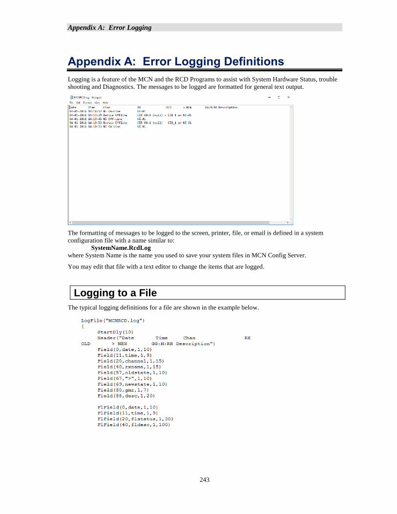
Appendix A: Error Logging
243
Appendix A: Error Logging Definitions
Logging is a feature of the MCN and the RCD Programs to assist with System Hardware Status, trouble
shooting and Diagnostics. The messages to be logged are formatted for general text output.
The formatting of messages to be logged to the screen, printer, file, or email is defined in a system
configuration file with a name similar to:
SystemName.RcdLog
where System Name is the name you used to save your system files in MCN Config Server.
You may edit that file with a text editor to change the items that are logged.
Logging to a File
The typical logging definitions for a file are shown in the example below.
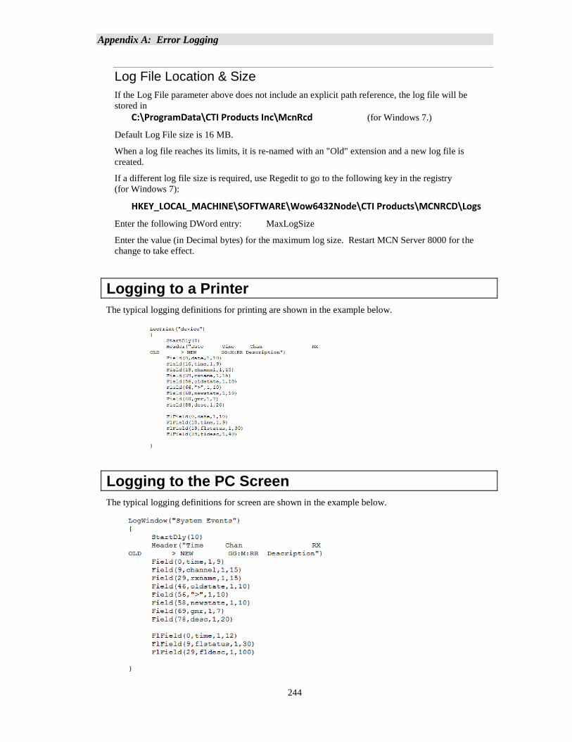
Appendix A: Error Logging
244
Log File Location & Size
If the Log File parameter above does not include an explicit path reference, the log file will be
stored in
C:\ProgramData\CTI Products Inc\McnRcd (for Windows 7.)
Default Log File size is 16 MB.
When a log file reaches its limits, it is re-named with an "Old" extension and a new log file is
created.
If a different log file size is required, use Regedit to go to the following key in the registry
(for Windows 7):
HKEY_LOCAL_MACHINE\SOFTWARE\Wow6432Node\CTI Products\MCNRCD\Logs
Enter the following DWord entry: MaxLogSize
Enter the value (in Decimal bytes) for the maximum log size. Restart MCN Server 8000 for the
change to take effect.
Logging to a Printer
The typical logging definitions for printing are shown in the example below.
Logging to the PC Screen
The typical logging definitions for screen are shown in the example below.
Appendix A: Error Logging
245
Error Logging Definition File Parameters
Email Subject Line Not used in MCN Server 8000.
Email Recipients Information in this section includes the “Email Groups”
specified in older versions of the MCNConfig program and
should not be edited. Not used in MCN Server 8000.
Log File Name The text between quotes is the file name that will be used
for logs.
Printer Device Name The text between quotes is the default printer device name
“device”. This should not be edited
Log Window Title The text between quotes on this line will appear in the title
block of the displayed log window.
Header Text (column titles) The text between quotes on this line will be the first line in
the body of the email, file, printout, or screen.
Fields to Log For each field to be logged, the following four parameters
must be specified:
Column for start of field
Field Name, or text enclosed in quotes (see Field Name
table below)
Beginning character position to be printed for field
Ending character position to be printed for field
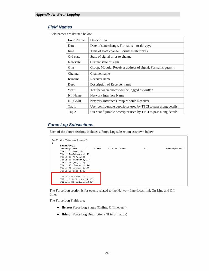
Appendix A: Error Logging
246
Field Names
Field names are defined below.
Field Name Description
Date Date of state change. Format is mm-dd-yyyy
time Time of state change. Format is hh:mm:ss
Old state State of signal prior to change
Newstate Current state of signal
Gmr Group, Module, Receiver address of signal. Format is gg:m:rr
Channel Channel name
Rxname Receiver name
Desc Description of Receiver name
“text” Text between quotes will be logged as written
NI_Name Network Interface Name
NI_GMR
Network Interface Group Module Receiver
Tag 1 User configurable descriptor used by TPCI to pass along details.
Tag 2 User configurable descriptor used by TPCI to pass along details.
Force Log Subsections
Each of the above sections includes a Force Log subsection as shown below:
The Force Log section is for events related to the Network Interfaces, link On-Line and Off-
Line.
The Force Log Fields are:
• flstatus Force Log Status (Online, Offline, etc.)
• fldesc Force Log Description (NI information)
Appendix B: Backup & Restore Procedures
247
Appendix B: Backup & Restore Procedures
This section covers the following standard Backup & Restore operations:
• The MCN Server 8000 and MCN Client software
• The MCN Server Software Key File
• The Custom MCN Server 8000 System Configuration files
• HIB-IP settings
• MCN Server 8000 IP Configuration settings
• MCN Client IP Configuration settings.
The backup and restoration instructions for the following items are beyond the scope of this manual.
The appropriate documentation should be consulted for those procedures:
Server and Client PC Operating Systems
Server and Client PC User Accounts
Server and Client PC OS Hardening
Other (non- MCN Server 8000) user files on the Server & Client PC
IP Comparators
IP Network infrastructure
Legacy MCN equipment
Other non-related hardware or software
MCN Server and Client Software Backup
1. If needed, use a commercially available method to make a backup copy of the
MCN Server 8000 distribution media (up to the limit of copies allowed by the license).
This media includes the MCN Server 8000 software, the MCN Config Server software, and the
MCN Client software.
2. Store the original distribution media and the backup media in safe places.
MCN Server Software Key Backup
1. If needed, use a commercially available method to make a backup copy of the
MCN Server 8000 Software Key File CD or Software Key File itself. The Key file will have
the form: KF-xxxx-yyy zzzzzzzzzzzzz.MCNKey
Where: xxxx is a number that matches the Hardware Key Serial Number
yyy is the Key File Version number and
zzzzzz is an optional descriptive text string.
2. Store the original distribution media and the backup media in safe places.
Appendix B: Backup & Restore Procedures
248
Custom MCN Server 8000 System Configuration Files Backup
The Custom MCN Server 8000 System Configuration Files are the files have been configured to
describe your system. They include files with the following types of file names:
• SystemName.McnSys
• SystemName.RcdDtb
• SystemName.RcdHrd
• SystemName.RcdLog
• SystemName.RcdSec
• SystemName.ScreenName1.RcdWnd
Where:
SystemName is the name you used when you saved your system and
ScreenName1 is the name you used for your first Display Window (Screen).
Note 1: Each system has a minimum of the above 6 file types.
Note 2: If you have more Display Windows (Screens) you will have more RcdWnd files; one
for each screen
Backup Instructions
1. Use Windows Explorer to find the current set of files that you are using for your
system.
2. Use Windows Explorer or a commercially available method to make a backup copy of
the files.
(It may be helpful to use a program to Zip them up into a single file.)
3. Store the backup copy in safe places.
HIB-IP Settings Backup
The HIB-IP settings (if your system uses a HIB-IP unit) are stored in the Custom MCN Server 8000
System Configuration Files and will be backed up with the previous step.
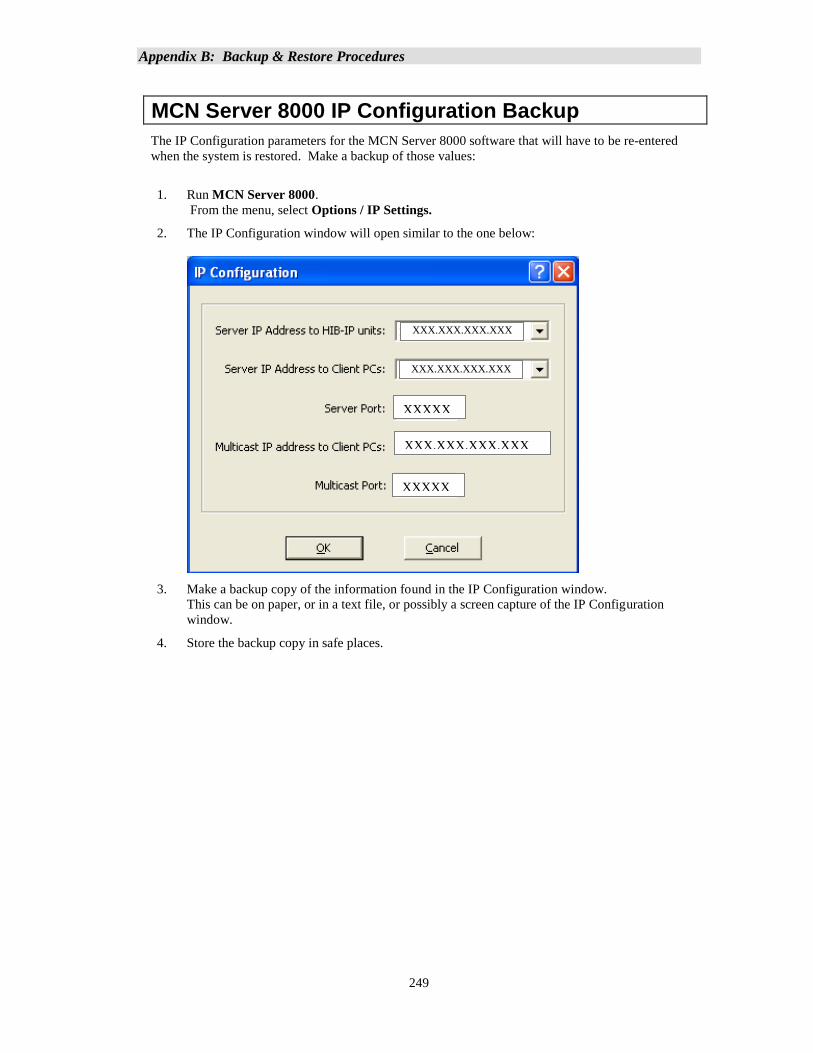
Appendix B: Backup & Restore Procedures
249
MCN Server 8000 IP Configuration Backup
The IP Configuration parameters for the MCN Server 8000 software that will have to be re-entered
when the system is restored. Make a backup of those values:
1. Run MCN Server 8000.
From the menu, select Options / IP Settings.
2. The IP Configuration window will open similar to the one below:
3. Make a backup copy of the information found in the IP Configuration window.
This can be on paper, or in a text file, or possibly a screen capture of the IP Configuration
window.
4. Store the backup copy in safe places.
XXXXX
XXXXX
XXX.XXX.XXX.XXX
XXX.XXX.XXX.XXX
XXX.XXX.XXX.XXX
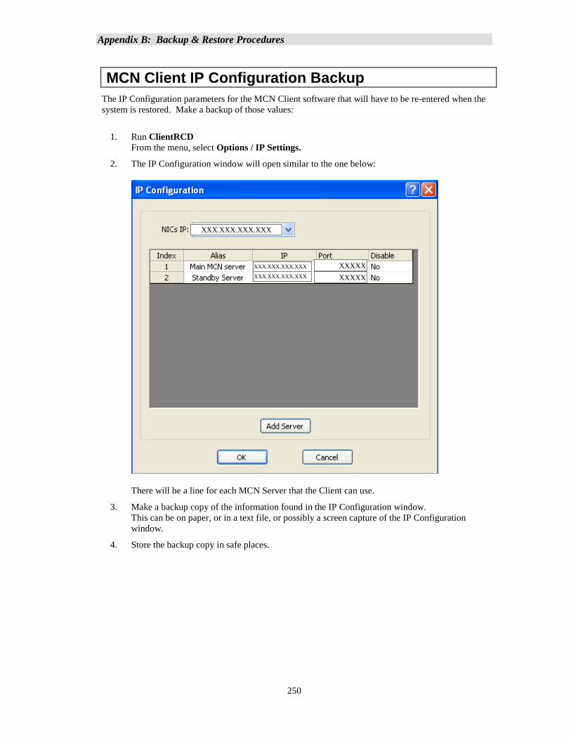
Appendix B: Backup & Restore Procedures
250
MCN Client IP Configuration Backup
The IP Configuration parameters for the MCN Client software that will have to be re-entered when the
system is restored. Make a backup of those values:
1. Run ClientRCD
From the menu, select Options / IP Settings.
2. The IP Configuration window will open similar to the one below:
There will be a line for each MCN Server that the Client can use.
3. Make a backup copy of the information found in the IP Configuration window.
This can be on paper, or in a text file, or possibly a screen capture of the IP Configuration
window.
4. Store the backup copy in safe places.
XXXXX
XXXXX
XXX.XXX.XXX.XXX
XXX.XXX.XXX.XXX
XXX.XXX.XXX.XXX
Appendix B: Backup & Restore Procedures
251
Restoring the MCN Server 8000 Software & IP Settings
1. Use the original or backup MCN Server 8000 software distribution media
2. Install the MCN Server 8000 software by following the step in Install MCN Server Software section starting on page 36 of this manual.
3. Select the Server installation option
4. When prompted for the Key File, use the original or backup Key File or Key File Media.
5. When prompted to enter IP parameters, enter the parameters saved in the MCN Server 8000 IP
Configuration Backup procedure.
Restoring the Custom System Configuration Files
1. Use the backup copy of the Custom MCN Server 8000 System Configuration Files
2. Using Windows Explorer, copy the backup files into a folder that has the following access
levels: Administrator Read & Write
User Read (and Write if desired)
3. If the files were previously Zipped, un-Zip them.
Restoring the HIB-IP Configuration
The Custom System Configuration Files restored above will have the configuration information for the
HIB-IP unit(s) (if used). If the HIB-IP needs to be restored (for example, if the HIB-IP unit is
replaced), follow this procedure:
1. Run MCN Config Server 8000 software.
2. Load the system that was restored above.
3. Program the HIB-IP Unit(s) as per the Loading Configuration Data into HIB-IP family units section on page 121 of this manual.
Restoring the Client Software & IP Settings
1. Use the original or backup MCN Server 8000 software distribution media
2. Install the MCN Server 8000 software by following the step in section Install MCN Server Software starting on page 36 of this manual.
3. Select the Client installation option
4. When prompted to enter IP parameters, enter the parameters saved in the MCN Client IP
Configuration Backup procedure.
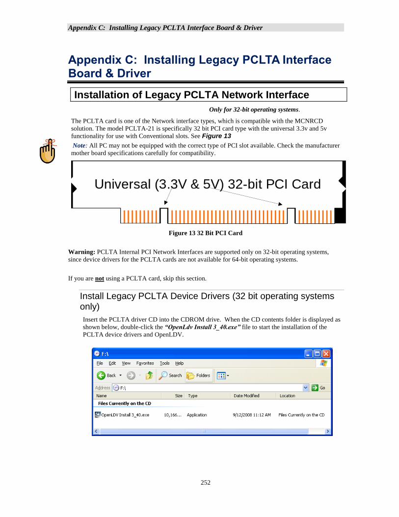
Appendix C: Installing Legacy PCLTA Interface Board & Driver
252
Appendix C: Installing Legacy PCLTA Interface Board & Driver
Installation of Legacy PCLTA Network Interface
Only for 32-bit operating systems.
The PCLTA card is one of the Network interface types, which is compatible with the MCNRCD
solution. The model PCLTA-21 is specifically 32 bit PCI card type with the universal 3.3v and 5v
functionality for use with Conventional slots. See Figure 13
Note: All PC may not be equipped with the correct type of PCI slot available. Check the manufacturer
mother board specifications carefully for compatibility.
Figure 13 32 Bit PCI Card
Warning: PCLTA Internal PCI Network Interfaces are supported only on 32-bit operating systems,
since device drivers for the PCLTA cards are not available for 64-bit operating systems.
If you are not using a PCLTA card, skip this section.
Install Legacy PCLTA Device Drivers (32 bit operating systems only)
Insert the PCLTA driver CD into the CDROM drive. When the CD contents folder is displayed as
shown below, double-click the “OpenLdv Install 3_40.exe” file to start the installation of the
PCLTA device drivers and OpenLDV.
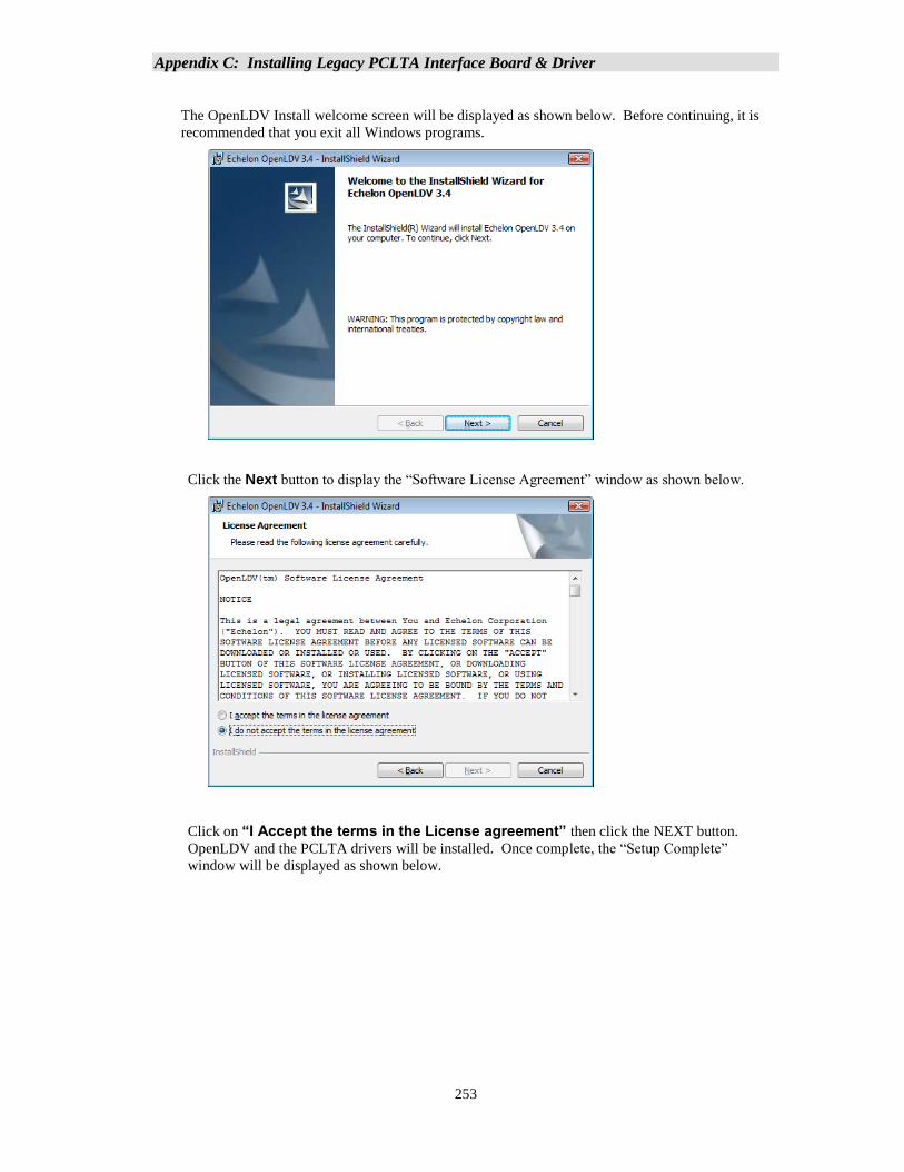
Appendix C: Installing Legacy PCLTA Interface Board & Driver
253
The OpenLDV Install welcome screen will be displayed as shown below. Before continuing, it is
recommended that you exit all Windows programs.
Click the Next button to display the “Software License Agreement” window as shown below.
Click on “I Accept the terms in the License agreement” then click the NEXT button.
OpenLDV and the PCLTA drivers will be installed. Once complete, the “Setup Complete”
window will be displayed as shown below.
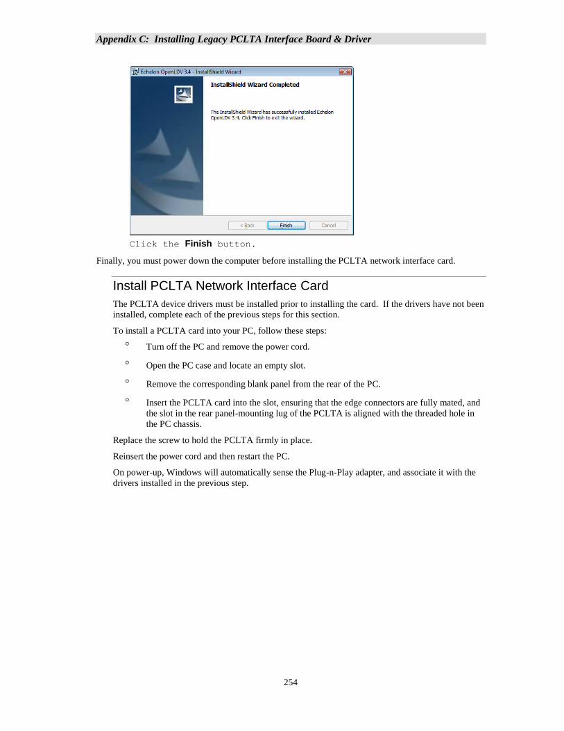
Appendix C: Installing Legacy PCLTA Interface Board & Driver
254
Click the Finish button.
Finally, you must power down the computer before installing the PCLTA network interface card.
Install PCLTA Network Interface Card
The PCLTA device drivers must be installed prior to installing the card. If the drivers have not been
installed, complete each of the previous steps for this section.
To install a PCLTA card into your PC, follow these steps:
Turn off the PC and remove the power cord.
Open the PC case and locate an empty slot.
Remove the corresponding blank panel from the rear of the PC.
Insert the PCLTA card into the slot, ensuring that the edge connectors are fully mated, and
the slot in the rear panel-mounting lug of the PCLTA is aligned with the threaded hole in
the PC chassis.
Replace the screw to hold the PCLTA firmly in place.
Reinsert the power cord and then restart the PC.
On power-up, Windows will automatically sense the Plug-n-Play adapter, and associate it with the
drivers installed in the previous step.
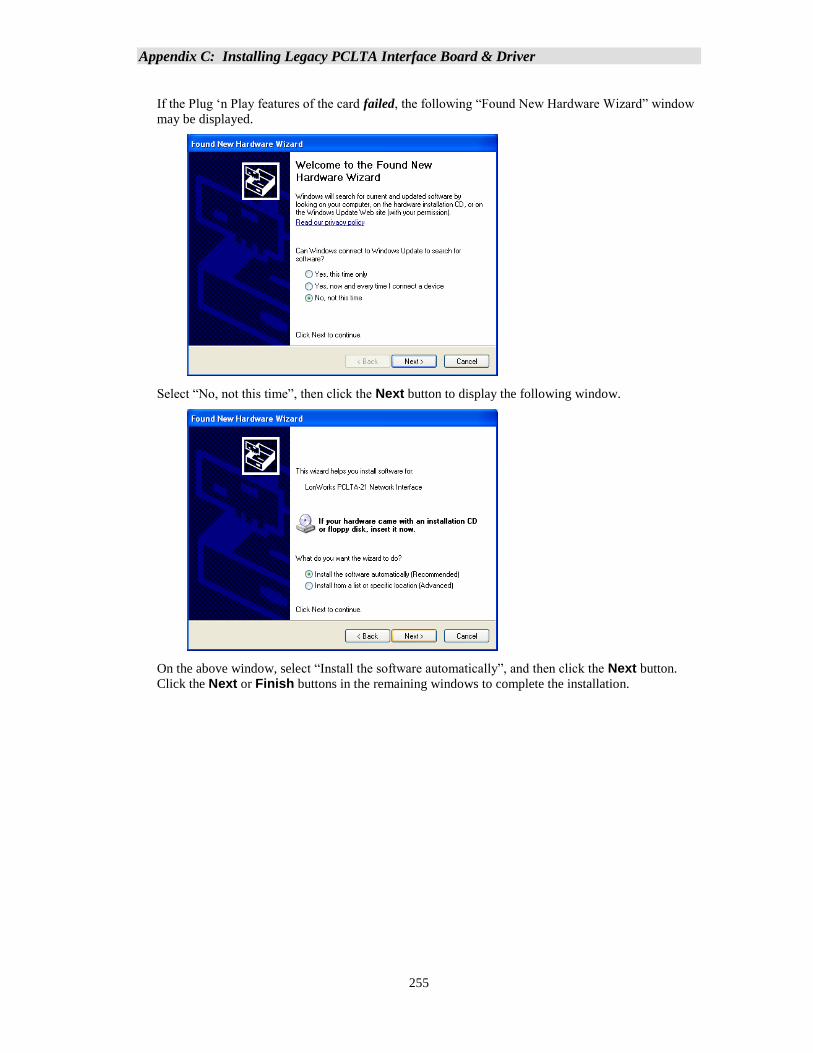
Appendix C: Installing Legacy PCLTA Interface Board & Driver
255
If the Plug ‘n Play features of the card failed, the following “Found New Hardware Wizard” window
may be displayed.
Select “No, not this time”, then click the Next button to display the following window.
On the above window, select “Install the software automatically”, and then click the Next button.
Click the Next or Finish buttons in the remaining windows to complete the installation.
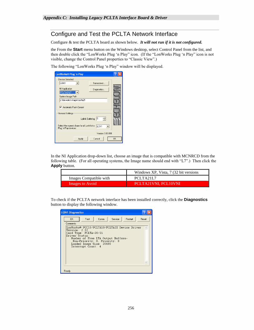
Appendix C: Installing Legacy PCLTA Interface Board & Driver
256
Configure and Test the PCLTA Network Interface
Configure & test the PCLTA board as shown below. It will not run if it is not configured.
the From the Start menu button on the Windows desktop, select Control Panel from the list, and
then double click the “LonWorks Plug ‘n Play” icon. (If the “LonWorks Plug ‘n Play” icon is not
visible, change the Control Panel properties to “Classic View”.)
The following “LonWorks Plug ‘n Play” window will be displayed.
In the NI Application drop-down list, choose an image that is compatible with MCNRCD from the
following table. (For all operating systems, the Image name should end with “L7”.) Then click the
Apply button.
Windows XP, Vista, 7 (32 bit versions
only) Images Compatible with
MCNRCD
PCLTA21L7
Images to Avoid PCLTA21VNI, PCL10VNI
To check if the PCLTA network interface has been installed correctly, click the Diagnostics
button to display the following window.
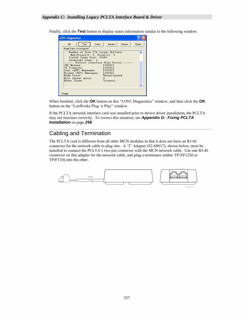
Appendix C: Installing Legacy PCLTA Interface Board & Driver
257
Finally, click the Test button to display status information similar to the following window.
When finished, click the OK button on this “LON1 Diagnostics” window, and then click the OK
button on the “LonWorks Plug ‘n Play” window.
If the PCLTA network interface card was installed prior to device driver installation, the PCLTA
may not function correctly. To correct this situation, see Appendix D: Fixing PCLTA Installation on page 258.
Cabling and Termination
The PCLTA card is different from all other MCN modules in that it does not have an RJ-45
connector for the network cable to plug into. A ‘T’ Adapter (S2-60617), shown below, must be
installed to connect the PCLTA’s two-pin connector with the MCN network cable. Use one RJ-45
connector on this adapter for the network cable, and plug a terminator (either TP/XF1250 or
TP/FT10) into the other.
C A -8 0 2 7 3 -1 0 1
C A B L E
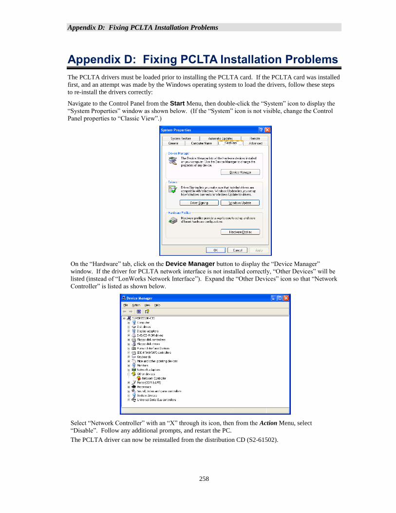
Appendix D: Fixing PCLTA Installation Problems
258
Appendix D: Fixing PCLTA Installation Problems
The PCLTA drivers must be loaded prior to installing the PCLTA card. If the PCLTA card was installed
first, and an attempt was made by the Windows operating system to load the drivers, follow these steps
to re-install the drivers correctly:
Navigate to the Control Panel from the Start Menu, then double-click the “System” icon to display the
“System Properties” window as shown below. (If the “System” icon is not visible, change the Control
Panel properties to “Classic View”.)
On the “Hardware” tab, click on the Device Manager button to display the “Device Manager”
window. If the driver for PCLTA network interface is not installed correctly, “Other Devices” will be
listed (instead of “LonWorks Network Interface”). Expand the “Other Devices” icon so that “Network
Controller” is listed as shown below.
Select “Network Controller” with an “X” through its icon, then from the Action Menu, select
“Disable”. Follow any additional prompts, and restart the PC.
The PCLTA driver can now be reinstalled from the distribution CD (S2-61502).
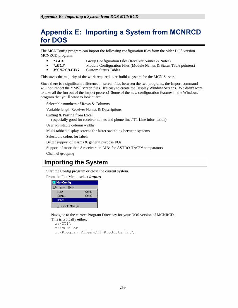
Appendix E: Importing a System from DOS MCNRCD
259
Appendix E: Importing a System from MCNRCD for DOS
The MCNConfig program can import the following configuration files from the older DOS version
MCNRCD program:
▪ *.GCF Group Configuration Files (Receiver Names & Notes)
▪ *.MCF Module Configuration Files (Module Names & Status Table pointers)
▪ MCNRCD.CFG Custom Status Tables
This saves the majority of the work required to re-build a system for the MCN Server.
Since there is a significant difference in screen files between the two programs, the Import command
will not import the *.MSF screen files. It's easy to create the Display Window Screens. We didn't want
to take all the fun out of the import process! Some of the new configuration features in the Windows
program that you'll want to look at are:
Selectable numbers of Rows & Columns
Variable length Receiver Names & Descriptions
Cutting & Pasting from Excel
(especially good for receiver names and phone line / T1 Line information)
User adjustable column widths
Multi-tabbed display screens for faster switching between systems
Selectable colors for labels
Better support of alarms & general purpose I/Os
Support of more than 8 receivers in AIBs for ASTRO-TAC™ comparators
Channel grouping
Importing the System
Start the Config program or close the current system.
From the File Menu, select Import.
Navigate to the correct Program Directory for your DOS version of MCNRCD.
This is typically either: c:\CTI\
c:\MCN\ or
c:\Program Files\CTI Products Inc\
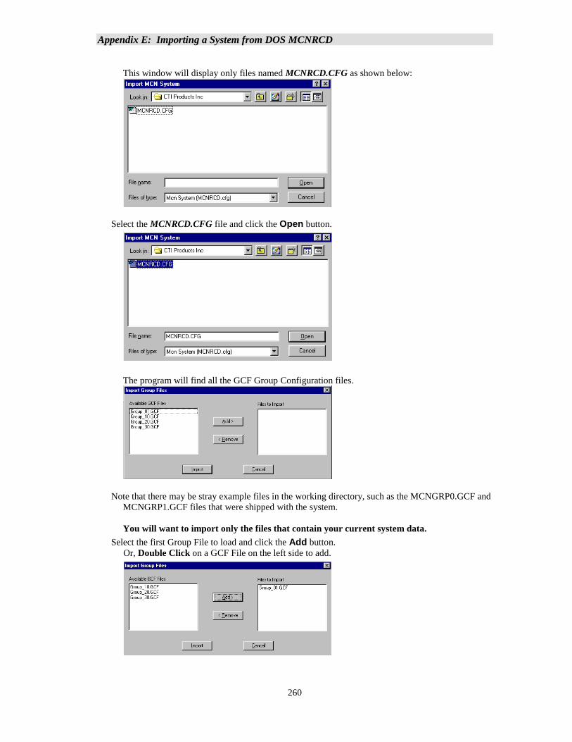
Appendix E: Importing a System from DOS MCNRCD
260
This window will display only files named MCNRCD.CFG as shown below:
Select the MCNRCD.CFG file and click the Open button.
The program will find all the GCF Group Configuration files.
Note that there may be stray example files in the working directory, such as the MCNGRP0.GCF and
MCNGRP1.GCF files that were shipped with the system.
You will want to import only the files that contain your current system data.
Select the first Group File to load and click the Add button.
Or, Double Click on a GCF File on the left side to add.
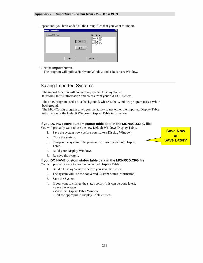
Appendix E: Importing a System from DOS MCNRCD
261
Repeat until you have added all the Group files that you want to import.
Click the Import button.
The program will build a Hardware Window and a Receivers Window.
Saving Imported Systems
The import function will convert any special Display Table
(Custom Status) information and colors from your old DOS system.
The DOS program used a blue background, whereas the Windows program uses a White
background.
The MCNConfig program gives you the ability to use either the imported Display Table
information or the Default Windows Display Table information.
If you DO NOT save custom status table data in the MCNRCD.CFG file: You will probably want to use the new Default Windows Display Table.
1. Save the system now (before you make a Display Window).
2. Close the system.
3. Re-open the system. The program will use the default Display
Table.
4. Build your Display Windows.
5. Re-save the system.
If you DO HAVE custom status table data in the MCNRCD.CFG file: You will probably want to use the converted Display Table.
1. Build a Display Window before you save the system
2. The system will use the converted Custom Status information.
3. Save the System
4. If you want to change the status colors (this can be done later),
- Save the system
- View the Display Table Window.
- Edit the appropriate Display Table entries.
Save Now or
Save Later?
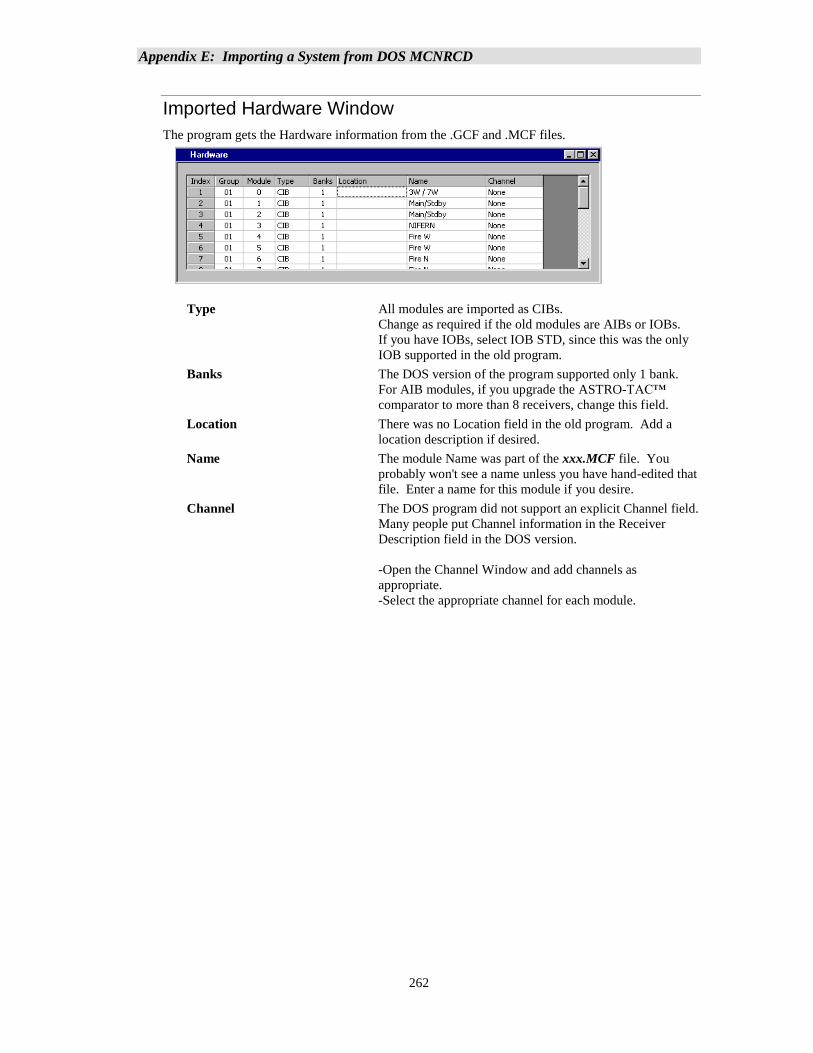
Appendix E: Importing a System from DOS MCNRCD
262
Imported Hardware Window
The program gets the Hardware information from the .GCF and .MCF files.
Type All modules are imported as CIBs.
Change as required if the old modules are AIBs or IOBs.
If you have IOBs, select IOB STD, since this was the only
IOB supported in the old program.
Banks The DOS version of the program supported only 1 bank.
For AIB modules, if you upgrade the ASTRO-TAC™
comparator to more than 8 receivers, change this field.
Location There was no Location field in the old program. Add a
location description if desired.
Name The module Name was part of the xxx.MCF file. You
probably won't see a name unless you have hand-edited that
file. Enter a name for this module if you desire.
Channel The DOS program did not support an explicit Channel field.
Many people put Channel information in the Receiver
Description field in the DOS version.
-Open the Channel Window and add channels as
appropriate.
-Select the appropriate channel for each module.
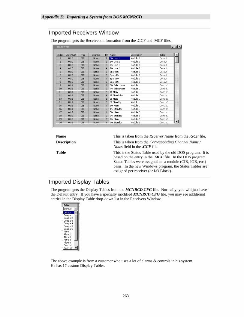
Appendix E: Importing a System from DOS MCNRCD
263
Imported Receivers Window
The program gets the Receivers information from the .GCF and .MCF files.
Name This is taken from the Receiver Name from the .GCF file.
Description This is taken from the Corresponding Channel Name /
Notes field in the .GCF file.
Table This is the Status Table used by the old DOS program. It is
based on the entry in the .MCF file. In the DOS program,
Status Tables were assigned on a module (CIB, IOB, etc.)
basis. In the new Windows program, the Status Tables are
assigned per receiver (or I/O Block).
Imported Display Tables
The program gets the Display Tables from the MCNRCD.CFG file. Normally, you will just have
the Default entry. If you have a specially modified MCNRCD.CFG file, you may see additional
entries in the Display Table drop-down list in the Receivers Window.
The above example is from a customer who uses a lot of alarms & controls in his system.
He has 17 custom Display Tables.
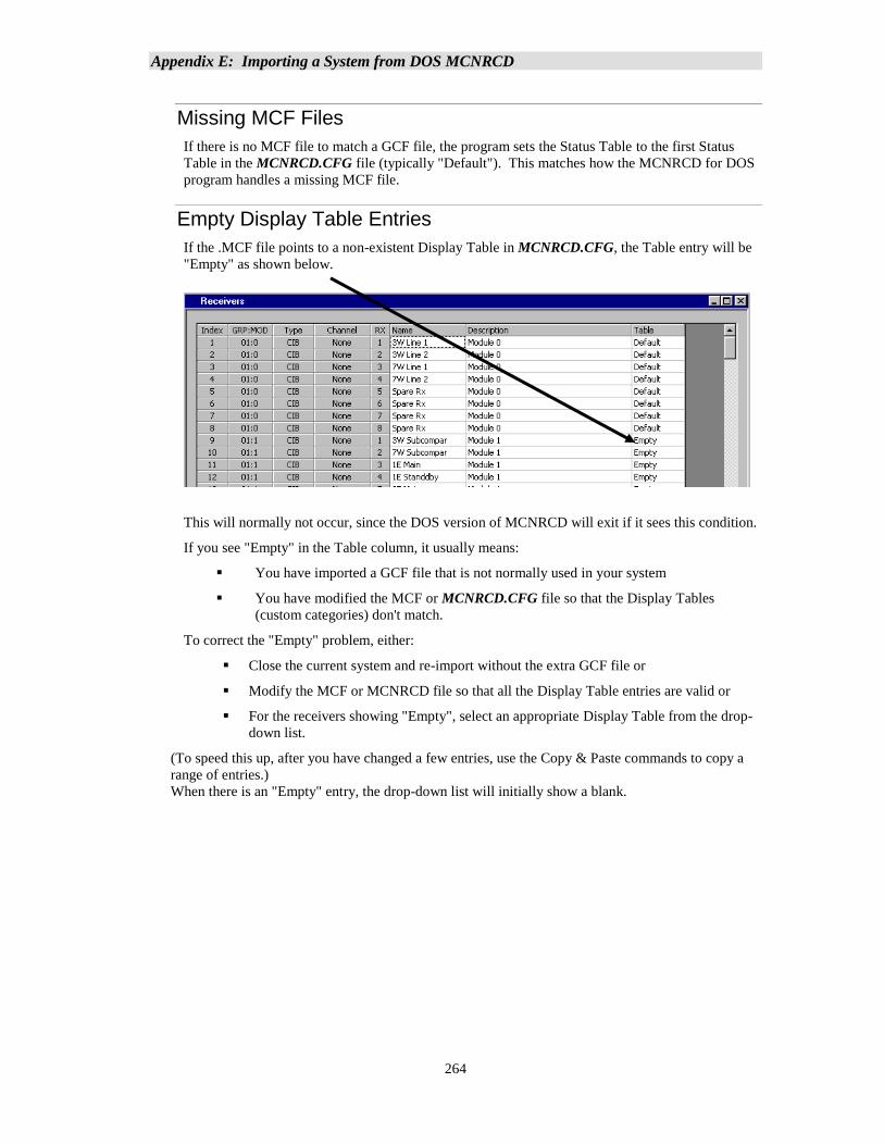
Appendix E: Importing a System from DOS MCNRCD
264
Missing MCF Files
If there is no MCF file to match a GCF file, the program sets the Status Table to the first Status
Table in the MCNRCD.CFG file (typically "Default"). This matches how the MCNRCD for DOS
program handles a missing MCF file.
Empty Display Table Entries
If the .MCF file points to a non-existent Display Table in MCNRCD.CFG, the Table entry will be
"Empty" as shown below.
This will normally not occur, since the DOS version of MCNRCD will exit if it sees this condition.
If you see "Empty" in the Table column, it usually means:
▪ You have imported a GCF file that is not normally used in your system
▪ You have modified the MCF or MCNRCD.CFG file so that the Display Tables
(custom categories) don't match.
To correct the "Empty" problem, either:
▪ Close the current system and re-import without the extra GCF file or
▪ Modify the MCF or MCNRCD file so that all the Display Table entries are valid or
▪ For the receivers showing "Empty", select an appropriate Display Table from the drop-
down list.
(To speed this up, after you have changed a few entries, use the Copy & Paste commands to copy a
range of entries.)
When there is an "Empty" entry, the drop-down list will initially show a blank.
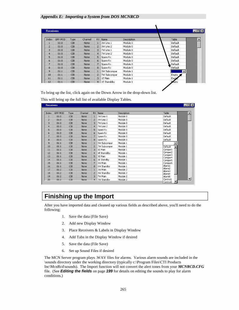
Appendix E: Importing a System from DOS MCNRCD
265
To bring up the list, click again on the Down Arrow in the drop-down list.
This will bring up the full list of available Display Tables.
Finishing up the Import
After you have imported data and cleaned up various fields as described above, you'll need to do the
following:
1. Save the data (File Save)
2. Add new Display Window
3. Place Receivers & Labels in Display Window
4. Add Tabs in the Display Window if desired
5. Save the data (File Save)
6. Set up Sound Files if desired
The MCN Server program plays .WAV files for alarms. Various alarm sounds are included in the
\sounds directory under the working directory (typically c:\Program Files\CTI Products
Inc\McnRcd\sounds). The Import function will not convert the alert tones from your MCNRCD.CFG
file. (See Editing the fields on page 199 for details on editing the sounds to play for alarm
conditions.)
Appendix E: Importing a System from DOS MCNRCD
266
Display Window differences between the DOS and Windows programs
Display Grid
The old MCNRCD for DOS program used a fixed grid of 22 rows x 4 columns.
The new MCN Server program has user-settable grid size.
You can now fit more receivers in one Display Window.
Alternately, you can make the Display Window smaller if you wish.
Tabs vs. Screens
To see a new screen in the old program, you would load a new screen file.
The Display Window in the new program lets you switch between "screens" quicker.
In the new Config program you can also create multiple Display Windows for use by different
users.
For Technicians, build all your desired screens as tabs in one Display Window.
For Dispatchers, build Display Windows with tabs as required depending on which channels
they need to see. You can build different Display Windows for different dispatchers.
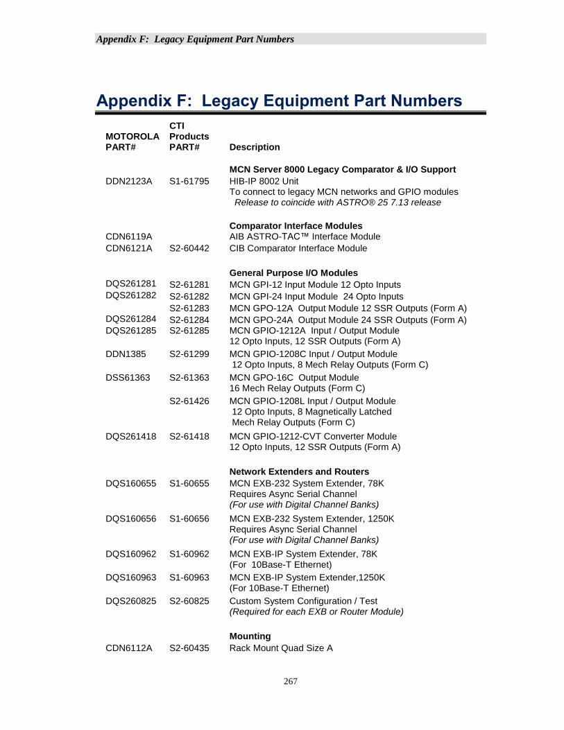
Appendix F: Legacy Equipment Part Numbers
267
Appendix F: Legacy Equipment Part Numbers
MOTOROLA PART#
CTI Products PART# Description
MCN Server 8000 Legacy Comparator & I/O Support
DDN2123A S1-61795 HIB-IP 8002 Unit To connect to legacy MCN networks and GPIO modules Release to coincide with ASTRO® 25 7.13 release
Comparator Interface Modules CDN6119A AIB ASTRO-TAC™ Interface Module
CDN6121A S2-60442 CIB Comparator Interface Module
General Purpose I/O Modules DQS261281 S2-61281 MCN GPI-12 Input Module 12 Opto Inputs DQS261282 S2-61282 MCN GPI-24 Input Module 24 Opto Inputs S2-61283 MCN GPO-12A Output Module 12 SSR Outputs (Form A) DQS261284 S2-61284 MCN GPO-24A Output Module 24 SSR Outputs (Form A) DQS261285 S2-61285 MCN GPIO-1212A Input / Output Module
12 Opto Inputs, 12 SSR Outputs (Form A)
DDN1385 S2-61299 MCN GPIO-1208C Input / Output Module 12 Opto Inputs, 8 Mech Relay Outputs (Form C)
DSS61363 S2-61363 MCN GPO-16C Output Module 16 Mech Relay Outputs (Form C)
S2-61426 MCN GPIO-1208L Input / Output Module 12 Opto Inputs, 8 Magnetically Latched Mech Relay Outputs (Form C)
DQS261418 S2-61418 MCN GPIO-1212-CVT Converter Module 12 Opto Inputs, 12 SSR Outputs (Form A)
Network Extenders and Routers
DQS160655 S1-60655 MCN EXB-232 System Extender, 78K Requires Async Serial Channel (For use with Digital Channel Banks)
DQS160656 S1-60656 MCN EXB-232 System Extender, 1250K Requires Async Serial Channel (For use with Digital Channel Banks)
DQS160962 S1-60962 MCN EXB-IP System Extender, 78K (For 10Base-T Ethernet)
DQS160963 S1-60963 MCN EXB-IP System Extender,1250K (For 10Base-T Ethernet)
DQS260825 S2-60825 Custom System Configuration / Test (Required for each EXB or Router Module)
Mounting
CDN6112A S2-60435 Rack Mount Quad Size A
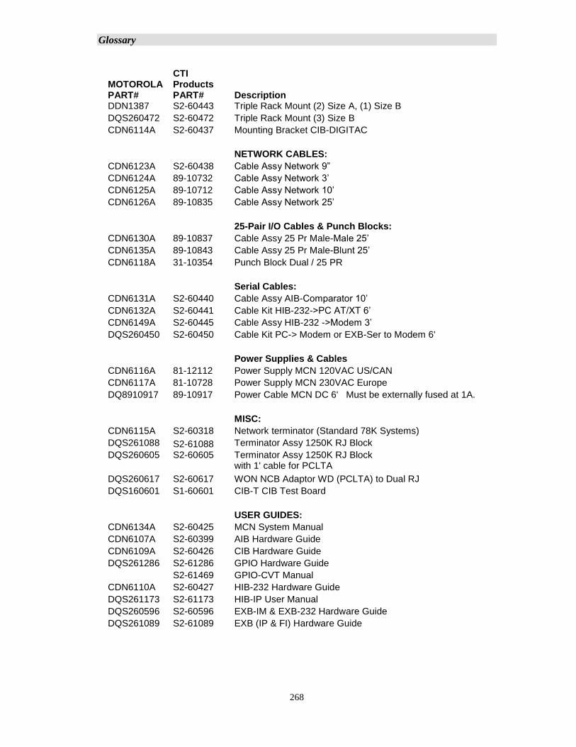
Glossary
268
MOTOROLA PART#
CTI Products PART# Description
DDN1387 S2-60443 Triple Rack Mount (2) Size A, (1) Size B
DQS260472 S2-60472 Triple Rack Mount (3) Size B
CDN6114A S2-60437 Mounting Bracket CIB-DIGITAC
NETWORK CABLES:
CDN6123A S2-60438 Cable Assy Network 9”
CDN6124A 89-10732 Cable Assy Network 3’
CDN6125A 89-10712 Cable Assy Network 10’
CDN6126A 89-10835 Cable Assy Network 25’
25-Pair I/O Cables & Punch Blocks:
CDN6130A 89-10837 Cable Assy 25 Pr Male-Male 25’
CDN6135A 89-10843 Cable Assy 25 Pr Male-Blunt 25’
CDN6118A 31-10354 Punch Block Dual / 25 PR
Serial Cables:
CDN6131A S2-60440 Cable Assy AIB-Comparator 10’
CDN6132A S2-60441 Cable Kit HIB-232->PC AT/XT 6’
CDN6149A S2-60445 Cable Assy HIB-232 ->Modem 3’
DQS260450 S2-60450 Cable Kit PC-> Modem or EXB-Ser to Modem 6'
Power Supplies & Cables
CDN6116A 81-12112 Power Supply MCN 120VAC US/CAN
CDN6117A 81-10728 Power Supply MCN 230VAC Europe
DQ8910917 89-10917 Power Cable MCN DC 6' Must be externally fused at 1A.
MISC:
CDN6115A S2-60318 Network terminator (Standard 78K Systems)
DQS261088 S2-61088 Terminator Assy 1250K RJ Block
DQS260605 S2-60605 Terminator Assy 1250K RJ Block with 1' cable for PCLTA
DQS260617 S2-60617 WON NCB Adaptor WD (PCLTA) to Dual RJ
DQS160601 S1-60601 CIB-T CIB Test Board
USER GUIDES:
CDN6134A S2-60425 MCN System Manual
CDN6107A S2-60399 AIB Hardware Guide
CDN6109A S2-60426 CIB Hardware Guide
DQS261286 S2-61286 GPIO Hardware Guide
S2-61469 GPIO-CVT Manual
CDN6110A S2-60427 HIB-232 Hardware Guide
DQS261173 S2-61173 HIB-IP User Manual
DQS260596 S2-60596 EXB-IM & EXB-232 Hardware Guide
DQS261089 S2-61089 EXB (IP & FI) Hardware Guide
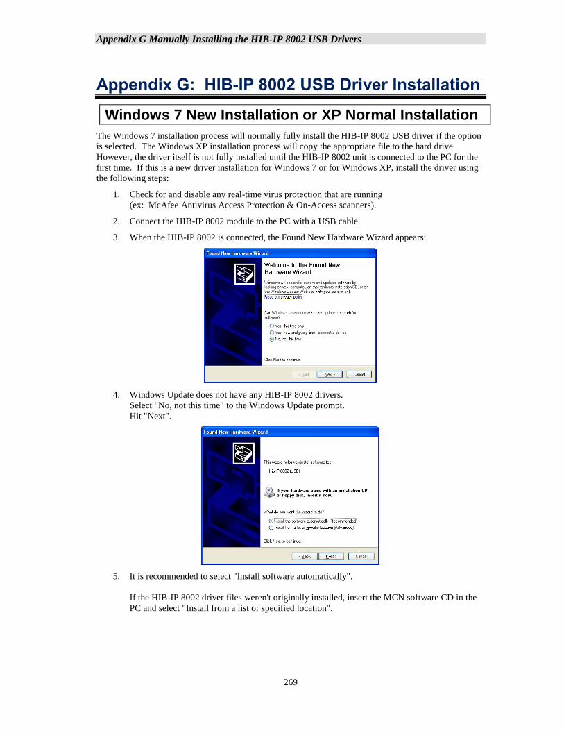
Appendix G Manually Installing the HIB-IP 8002 USB Drivers
269
Appendix G: HIB-IP 8002 USB Driver Installation
Windows 7 New Installation or XP Normal Installation
The Windows 7 installation process will normally fully install the HIB-IP 8002 USB driver if the option
is selected. The Windows XP installation process will copy the appropriate file to the hard drive.
However, the driver itself is not fully installed until the HIB-IP 8002 unit is connected to the PC for the
first time. If this is a new driver installation for Windows 7 or for Windows XP, install the driver using
the following steps:
1. Check for and disable any real-time virus protection that are running
(ex: McAfee Antivirus Access Protection & On-Access scanners).
2. Connect the HIB-IP 8002 module to the PC with a USB cable.
3. When the HIB-IP 8002 is connected, the Found New Hardware Wizard appears:
4. Windows Update does not have any HIB-IP 8002 drivers.
Select "No, not this time" to the Windows Update prompt.
Hit "Next".
5. It is recommended to select "Install software automatically".
If the HIB-IP 8002 driver files weren't originally installed, insert the MCN software CD in the
PC and select "Install from a list or specified location".
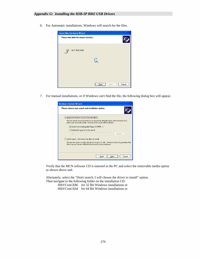
Appendix G: Installing the HIB-IP 8002 USB Drivers
270
6. For Automatic installations, Windows will search for the files.
7. For manual installations, or if Windows can't find the file, the following dialog box will appear.
Verify that the MCN software CD is inserted in the PC and select the removable media option
as shown above and.
Alternately, select the "Don't search, I will choose the driver to install" option.
Then navigate to the following folder on the installation CD:
HibVCom\X86 for 32 Bit Windows installations or
HibVCom\X64 for 64 Bit Windows installations or
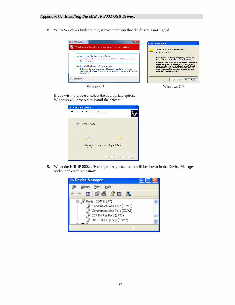
Appendix G: Installing the HIB-IP 8002 USB Drivers
271
8. When Windows finds the file, it may complain that the driver is not signed.
Windows 7 Windows XP
If you wish to proceed, select the appropriate option.
Windows will proceed to install the driver:
9. When the HIB-IP 8002 driver is properly installed, it will be shown in the Device Manager
without an error indication:
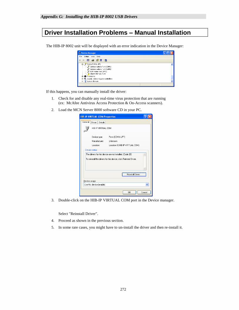
Appendix G: Installing the HIB-IP 8002 USB Drivers
272
Driver Installation Problems – Manual Installation
The HIB-IP 8002 unit will be displayed with an error indication in the Device Manager:
If this happens, you can manually install the driver:
1. Check for and disable any real-time virus protection that are running
(ex: McAfee Antivirus Access Protection & On-Access scanners).
2. Load the MCN Server 8000 software CD in your PC.
3. Double-click on the HIB-IP VIRTUAL COM port in the Device manager.
Select "Reinstall Driver".
4. Proceed as shown in the previous section.
5. In some rare cases, you might have to un-install the driver and then re-install it.
Appendix H: IP traffic priority: TOS / QoS / DSCP Settings
273
Appendix H: IP traffic priority: TOS / QoS / DSCP Settings
IP Traffic Prioritization
Some IP networks support traffic prioritization for various types of IP packets. This is typically done
through the following IP packet fields:
• TOS Type of Service
• QoS Quality of Service
• DSCP Differentiated Services Code Point
The TOS, QOS and DSCP fields actually use the same byte in the IP packet as defined by the
appropriate RFCs. Different network devices will interpret the byte differently depending on how
they are configured. Some routers may be configurable for prioritization based on TOS. Others may
be configurable based on QoS. Others may be configurable based on DSCP. Others may use a
combination of two or more of the above.
Do not assume that a higher value will always give you higher priority. Consult your network
administrator for the proper value to use.
ASTRO® 25 7.16 (and up) RNI
The MSI ASTRO® 25 Version 7.16 System RNI supports prioritization from:
• The MCN Server 8000 PC to the HIB-IP 8002 module.
(Controlled by a Windows Group Policy Object (GPO) with a default DSCP value of 16.)
• The HIB-IP 8002 module to the MCN Server PC (using a default TOS value of 2).
For ASTRO® 25 version 7.16 and above systems, Motorola Solutions, Inc. will include the appropriate
GPO settings for the MCN Server 8000 in their Supplemental CD. The file for ASTRO® 25
version 7.16 systems is in:
ActiveDirectory\Data\GPO...
Look for: {0013C79A-8871-45E8-888D-03189E1297D3}.
Follow the appropriate MSI instructions to install that CD on the appropriate PCs (including
Domain Controllers).
HIB-IP 8002 Type of Service Field:
The HIB-IP 8002 module supports a configurable IP Type of Service or TOS field. MCN software
version 7.20 and later (in particular in the MCN Config program) is required to configure this field.
The HIB-IP 8002 module uses the TOS setting since it is the most configurable. It can take on a
value of 0 to 255 (decimal).
Typical TOS values used with the HBI-IP 8002 module are:
0 No Priority (default)
2 For Motorola Solutions, Inc. (MSI) ASTRO® 25 Version 7.16 and up
Radio Network Infrastructures (RNI).
If your network uses the QoS or DSCP interpretation, you can convert those values to the proper TOS
value and enter it into the HIB-IP 8002 configuration. Contact your system administrator or see
http://en.wikipedia.org/wiki/Type of service for more information on converting between these
values.
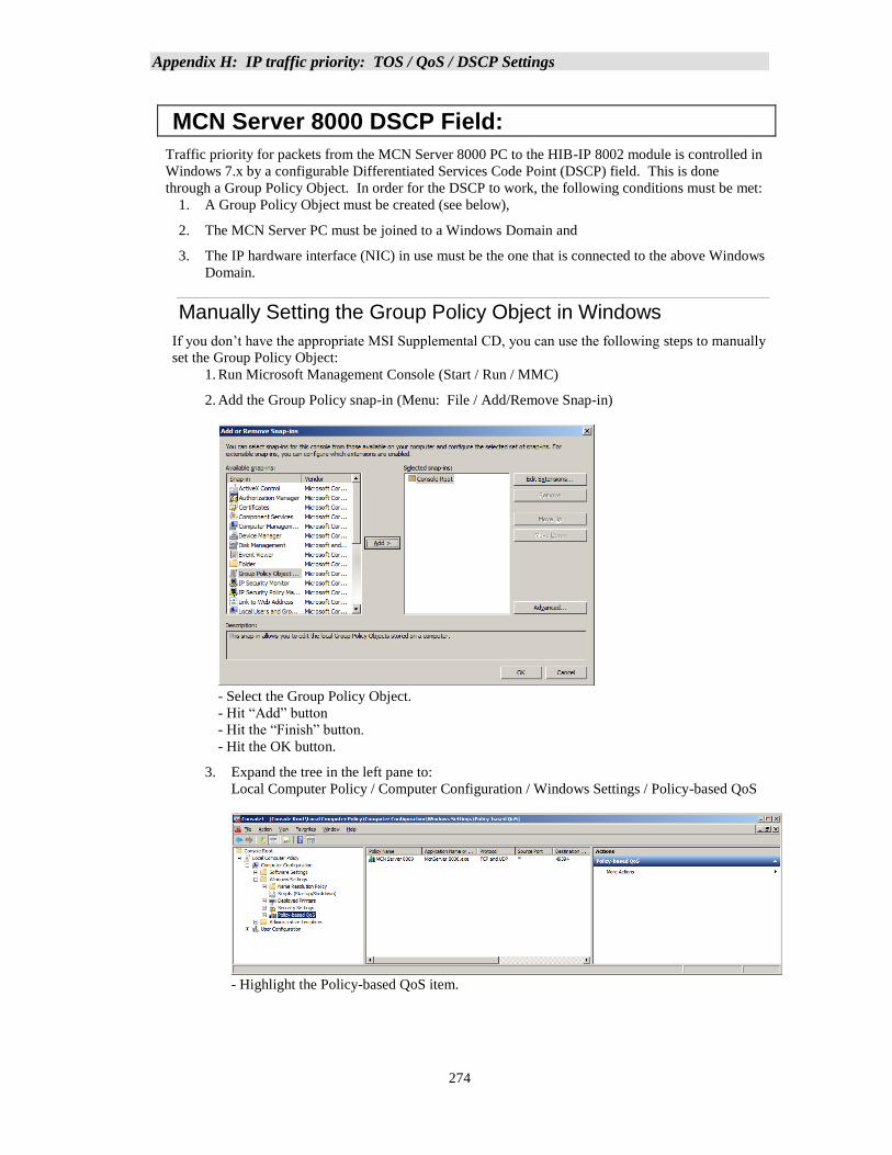
Appendix H: IP traffic priority: TOS / QoS / DSCP Settings
274
MCN Server 8000 DSCP Field:
Traffic priority for packets from the MCN Server 8000 PC to the HIB-IP 8002 module is controlled in
Windows 7.x by a configurable Differentiated Services Code Point (DSCP) field. This is done
through a Group Policy Object. In order for the DSCP to work, the following conditions must be met:
1. A Group Policy Object must be created (see below),
2. The MCN Server PC must be joined to a Windows Domain and
3. The IP hardware interface (NIC) in use must be the one that is connected to the above Windows
Domain.
Manually Setting the Group Policy Object in Windows
If you don’t have the appropriate MSI Supplemental CD, you can use the following steps to manually
set the Group Policy Object:
1. Run Microsoft Management Console (Start / Run / MMC)
2. Add the Group Policy snap-in (Menu: File / Add/Remove Snap-in)
- Select the Group Policy Object.
- Hit “Add” button
- Hit the “Finish” button.
- Hit the OK button.
3. Expand the tree in the left pane to:
Local Computer Policy / Computer Configuration / Windows Settings / Policy-based QoS
- Highlight the Policy-based QoS item.
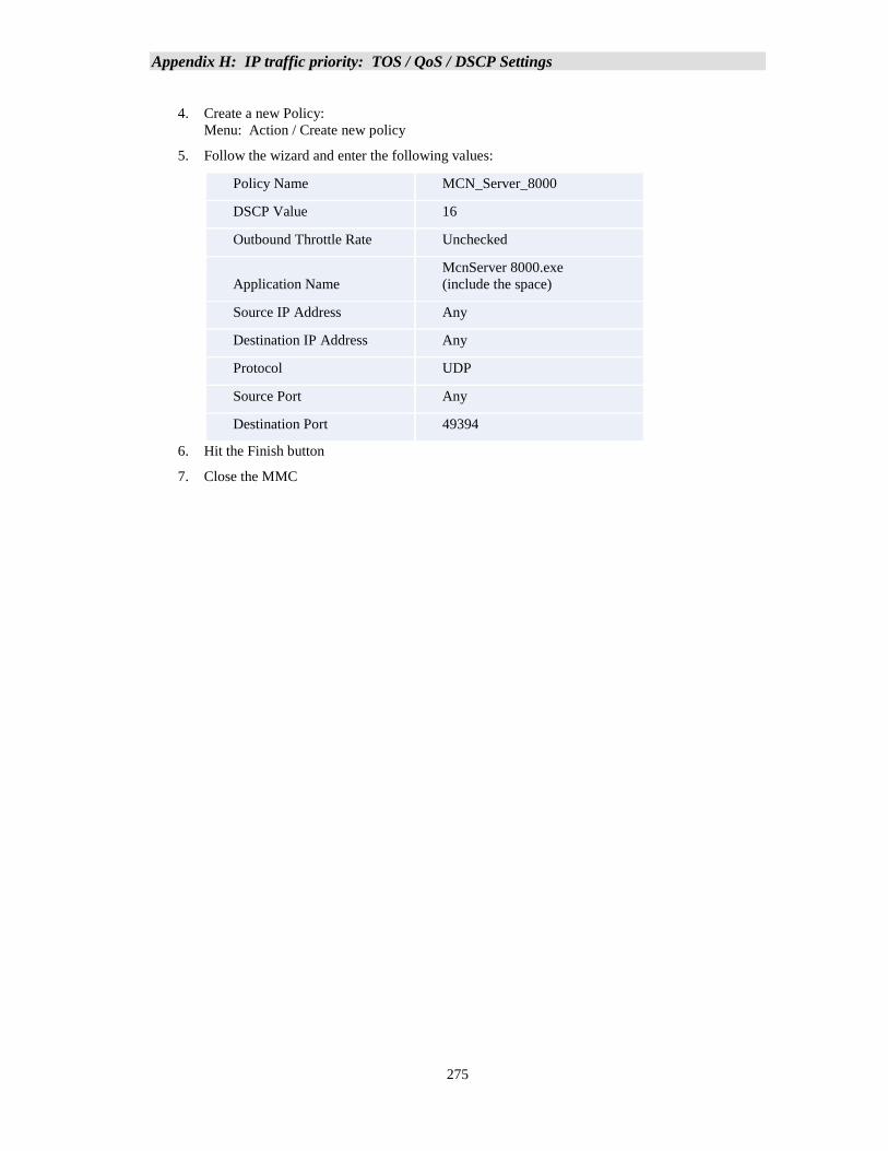
Appendix H: IP traffic priority: TOS / QoS / DSCP Settings
275
4. Create a new Policy:
Menu: Action / Create new policy
5. Follow the wizard and enter the following values:
Policy Name MCN_Server_8000
DSCP Value 16
Outbound Throttle Rate Unchecked
Application Name
McnServer 8000.exe
(include the space)
Source IP Address Any
Destination IP Address Any
Protocol UDP
Source Port Any
Destination Port 49394
6. Hit the Finish button
7. Close the MMC
Appendix I: Running on non WHK PCs – UDP Port Settings
276
Appendix I: Running on non WHK PCs – UDP Port Settings
It is highly recommended that the MCN Server 8000 system be run on a WHK hardened PC when
connected to an MSI RNI. The default UDP port setting on the MCN Server 8000 software are set to
run on a WHK PC.
If the software is run on a non-hardened (non-WHK) PC, the UDP port settings must be changed from
the default values.
Background – Default Ports & WHK
The default UDP ports used by MCN Server 8000 were assigned for a PC running with Motorola
Solutions Inc. (MSI) Windows Hardening Kit (WHK) and running on an ASTRO® 25 7.13 or above
Radio Network Infrastructure (RNI). One of the things that WHK does is reserve a pool of UPD and
TCP ports in Windows for use by various MSI programs. It does this by changing the Windows starting
Dynamic port number (with a default of 49152) to a higher number. The MCN Server 8000 software
UPD Port defaults are then set to a value within the reserved range above 49152 and below the new
maximum set by the WHK.
If the software is run on a non-WHK PC, the default port numbers will fall into the Windows Dynamic
Port range. This will present a problem if another program or process uses that port before the MCN
Server 8000 software starts.
If the MCN Server 8000 software is run on a non-WHK PC, the fix is either:
a. Move the start of the Dynamic port range to 50152 (preferred) or
b. Set the MCN Server ports to something below the start of the dynamic ports.
Checking and Setting the start of the Windows Dynamic IP Port Range
To check what your dynamic port range is, run the following from the CMD prompt:
>netsh int ipv4 show dynamic port tcp
>netsh int ipv4 show dynamic port udp
To set the range, do the following from the CMD prompt:
>netsh int ipv4 set dynamicport tcp start=50152 num=15384
>netsh int ipv4 set dynamicport udp start=50152 num=15384
Setting the MCN Server ports below 49152:
Note: Since this solution may cause problems in communications across the various routers in the RNI,
it should only be used for MCN Server PCs that are NOT running on an MSI RNI.
To set the UDP ports used by the MCN Server 8000 software, run MCN Server 8000 and do the
following:
1. Menu: Options / IP Settings
2. Enter the appropriate UDP ports.
Available ports will depend on your system, but the following ports have been used for years on other
versions of our MCN Server software (not on the MSI RNI) without problems.
• Server Port: 222
• Multicast Port: 333
Glossary
277
Glossary
1250 Legacy MCN 1.25mbps high speed backbone Network Rate
78K Legacy MCN 78kbps standard network rate for CIB, HIB, AIB, IIB, and IOB
modules.
AGU MLC 8000 Subsite Link Converter
Includes 4 ports for connection to the BR (Base Radios)
Used in MLC 8000 Analog Comparators.
AIB ASTRO-TAC™ Comparator Interface Module connects a Motorola ASTRO-
TAC™ comparator to the MCN Network. It extends the comparator lights and
switches over the network to a remote display position (either a PC or console
display).
BR Base Radio – May be a Transmit/Receive unit or just a Receiver. BR Base Radio
(Base station)
CEN Customer Enterprise Network, separated from the Radio Network Infrastructure
(RNI) by routers and/or firewalls.
CIB Legacy Comparator Interface Module connects a voting system comparator to the
MCN Network. It extends the comparator lights and switches over the network to a
remote display position (either a PC or console display).
CSS Configuration / Service Software – Used for the GCM 8000 comparator and Base
Radios
CT Configuration Tool – Software used to configure the MLC 8000 Analog Comparator
CTI Shorthand for our full company name, "CTI Products, Inc."
DA Dispatch Application furnished with the MLC 8000 Analog Comparator CT
software. This allows limited status monitoring of receivers.
EXB Legacy System Extender Module is used in pairs to connect two MCN networks
together or to extend the length of an MCN network beyond 4000 feet. Allows
control and monitoring of multiple remote comparators from a central site.
EXB-232 Legacy System Extender Module with RS-232 Asynchronous Serial Interfaces
Connects remote sites using Asynchronous Serial channels (typically Subrate cards
over T1 channel banks)
EXB-IM Legacy System Extender Module with an Internal Modem
Connects remote sites over 2-Wire or 4-Wire audio circuits.
EXB-IP Legacy System Extender Module with an Ethernet IP interface
Connects remote sites over IP networks.
GCM Shorthand for GCM 8000
GCM 8000 Motorola Solutions IP Comparator for Digital radio systems
GPW 8000 Motorola Solutions Satellite Receiver
Group Used in Legacy systems. Equivalent to the Subnet portion
of the network address, less one. Valid values are from 00 to FE (hexadecimal).
GRV 8000 “G” Series analog or digital IP Comparator. Supports up to 96 BRs – either IP BRS
(typically GTR 8000s) or 4-Wire BRs through G Series Link Converters (GSLCs).
Glossary
278
GSAC “G” Series Comparator – GRV 8000
GSLC “G” Series Link Converter – Connects a legacy 4-Wire Base Radio to the GRV
8000 comparator over IP.
GTR 8000 Motorola Solutions Base Radio
HIB-232 Legacy Host Computer Interface Module connects a PC to the MCN Network over
an RS-232 connection. It can be local to the PC or connected through leased-line
modems or an equivalent full-time RS-232 channel.
HIB-IP Legacy Host Computer Interface Module connects a PC to the MCN Network over
an IP network.
HIB-IP 8000 Similar to the HIB-IP unit except with special UDP ports that can be used within
Mororola's A7.13 and up RNI.
HIB-IP 8002 Newer version of the HIB-IP 8000 unit. New hardware that is configured using a
USB port.
IIB Legacy Input/Output Interface Module connects a parallel operator display device
(such as a console) to the MCN Network. Can be used with AIB ASTRO™25 -
TAC™ Comparator Interface Modules to provide voting status indications (Vote,
Receive, Disable, and Fail) to a console. Also can be used with CIB Comparator
Interface Modules to extend the comparator display and control for other
comparators over a long distance.
IOB Legacy Input/Output Control Module connects I/O devices such as relays to the
MCN Network. Used with a HIB to create an I/O control system.
IP Internet Protocol
IP Address Any node connected to an IP (Internet Protocol) network must be identified with a
unique 32-bit address. These 32-bit addresses are commonly written in dotted
decimal notation as four decimal numbers (referred to as octets because each
decimal number represents 8 bits) separated by decimal points. Each octet can be a
number from 1 to 255. For example, 131.9.1.2 is a valid IP address.
IP Subnet A portion of an IP network that encompasses a specific range of IP addresses (ex:
from 10.1.1.0 to 10.1.1.255). All IP devices on the same subnet talk to each other
directly (or through hubs or switches). They do not need a router between them.
(See also Subnet Mask.)
MCN Monitoring and Control Network
Mixed Mode System operation with both digital and analog radio channels.
Mixed Mode Voter Solutions include a GCM 8000 Digital Comparator and
an MLC 8000 Analog Comparator.
MLC Shorthand for MLC 8000 Analog Comparator
MLC 8000 Motorola Solutions IP Comparator for Analog radio systems
Each MLC 8000 Analog Comparator is made up of one MLC 8000 Analog
Comparator (VGU) and one or more MLC 8000 Subsite Link Converter (AGU)s.
MLC ID See Radio ID
MM Shorthand for Mixed Mode
Module (generic) A Legacy Input/Output device (CIB, AIB, GPIO Module) or an IP comparator.
Module (MCN Address): In MCN Addressing, the Module number is part of the MCN
address (Group & Module numbers) used to identify an MCN legacy device. Each
legacy MCN device will have both a Group and Module address. Valid values are
from 00 to 7E (hexadecimal) for MCN I/O devices. For legacy MCN devices with
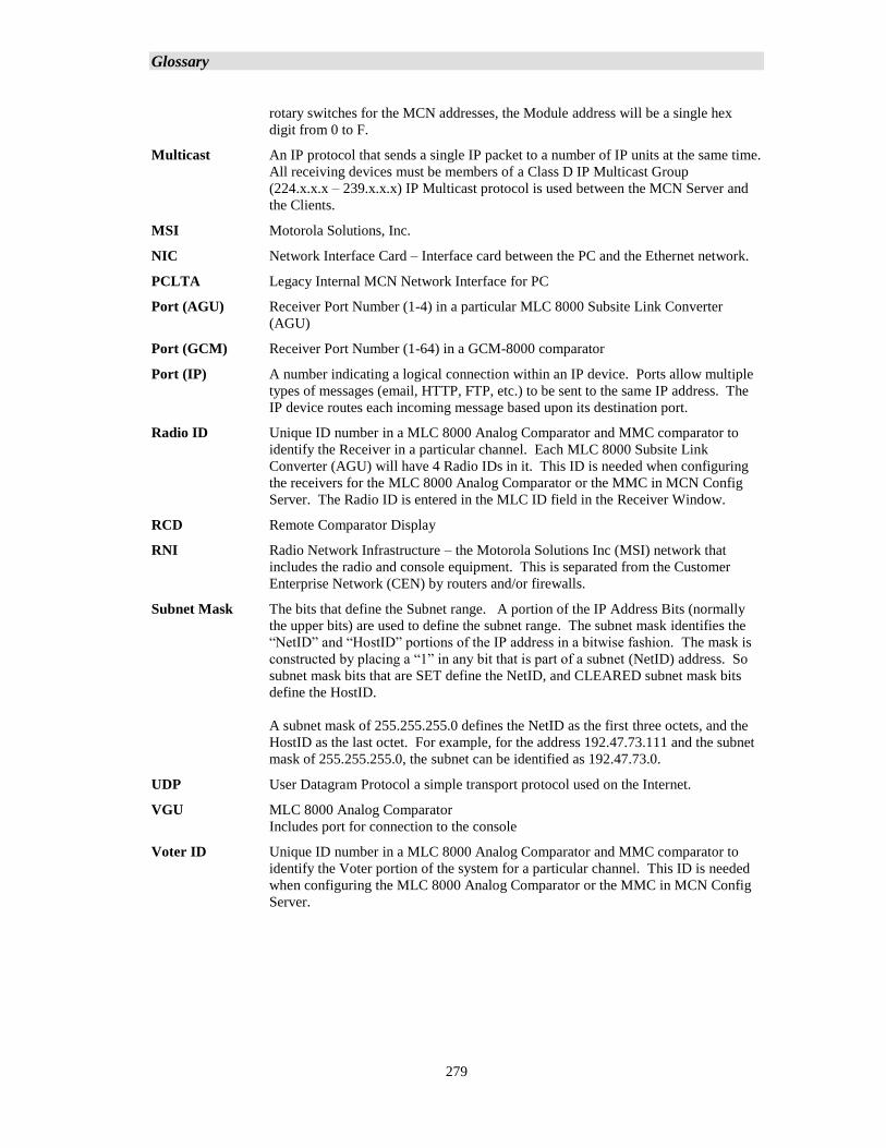
Glossary
279
rotary switches for the MCN addresses, the Module address will be a single hex
digit from 0 to F.
Multicast An IP protocol that sends a single IP packet to a number of IP units at the same time.
All receiving devices must be members of a Class D IP Multicast Group
(224.x.x.x – 239.x.x.x) IP Multicast protocol is used between the MCN Server and
the Clients.
MSI Motorola Solutions, Inc.
NIC Network Interface Card – Interface card between the PC and the Ethernet network.
PCLTA Legacy Internal MCN Network Interface for PC
Port (AGU) Receiver Port Number (1-4) in a particular MLC 8000 Subsite Link Converter
(AGU)
Port (GCM) Receiver Port Number (1-64) in a GCM-8000 comparator
Port (IP) A number indicating a logical connection within an IP device. Ports allow multiple
types of messages (email, HTTP, FTP, etc.) to be sent to the same IP address. The
IP device routes each incoming message based upon its destination port.
Radio ID Unique ID number in a MLC 8000 Analog Comparator and MMC comparator to
identify the Receiver in a particular channel. Each MLC 8000 Subsite Link
Converter (AGU) will have 4 Radio IDs in it. This ID is needed when configuring
the receivers for the MLC 8000 Analog Comparator or the MMC in MCN Config
Server. The Radio ID is entered in the MLC ID field in the Receiver Window.
RCD Remote Comparator Display
RNI Radio Network Infrastructure – the Motorola Solutions Inc (MSI) network that
includes the radio and console equipment. This is separated from the Customer
Enterprise Network (CEN) by routers and/or firewalls.
Subnet Mask The bits that define the Subnet range. A portion of the IP Address Bits (normally
the upper bits) are used to define the subnet range. The subnet mask identifies the
“NetID” and “HostID” portions of the IP address in a bitwise fashion. The mask is
constructed by placing a “1” in any bit that is part of a subnet (NetID) address. So
subnet mask bits that are SET define the NetID, and CLEARED subnet mask bits
define the HostID.
A subnet mask of 255.255.255.0 defines the NetID as the first three octets, and the
HostID as the last octet. For example, for the address 192.47.73.111 and the subnet
mask of 255.255.255.0, the subnet can be identified as 192.47.73.0.
UDP User Datagram Protocol a simple transport protocol used on the Internet.
VGU MLC 8000 Analog Comparator
Includes port for connection to the console
Voter ID Unique ID number in a MLC 8000 Analog Comparator and MMC comparator to
identify the Voter portion of the system for a particular channel. This ID is needed
when configuring the MLC 8000 Analog Comparator or the MMC in MCN Config
Server.
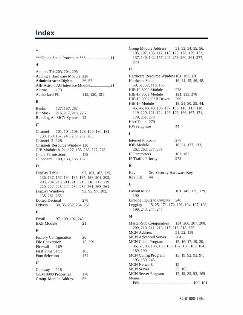
S2-61600-118c
Index
*
***Quick Setup Procedure *** ........................ 11
A
Actions Tab 203, 204, 206
Adding a Hardware Module 128
Administrator Rights 36, 57
AIB Astro-TAC Interface Module.................... 21
Alarms 173
Authorized PC 119, 120, 121
B
Banks 127, 157, 262
Bit Mask 216, 217, 218, 226
Building An MCN System 12
C
Channel 101, 104, 106, 128, 129, 130, 131,
133, 150, 157, 246, 259, 262, 263
Channel -2 128
Channels Resource Window 130
CIB Module 18, 21, 127, 133, 263, 277, 278
Client Permissions 159
Clipboard 100, 133, 156, 157
D
Display Table 97, 101, 102, 135,
136, 137, 157, 194, 195, 197, 198, 201, 202,
203, 204, 210, 211, 213, 215, 216, 217, 219,
220, 222, 226, 229, 230, 232, 261, 263, 264
Display Windows 93, 95, 97, 102,
138, 261, 266
Dotted Decimal 278
Drivers 30, 35, 252, 254, 258
E
Email 97, 100, 102, 245
EXB Module 21
F
Factory Configuration 26
File Conversion 15, 259
Firewall 169
First Time Setup 165
Font Selection 174
G
Gateway 118
GCM 8000 Properties 178
Group Module Address 52
Group Module Address 51, 53, 54, 55, 56,
105, 107, 108, 117, 118, 126, 128, 129, 133,
137, 140, 142, 157, 246, 259, 260, 261, 277,
279
H
Hardware Resource Window 101, 107, 126
Hardware Setup 16, 44, 45, 46, 48,
50, 51, 52, 116, 165
HIB-IP 8000 Module 278
HIB-IP 8002 Module 121, 123, 278
HIB-IP 8002 USB Driver 269
HIB-IP Module 18, 21, 30, 35, 44,
45, 46, 48, 49, 106, 107, 108, 116, 117, 118,
119, 120, 121, 124, 126, 129, 166, 167, 171,
179, 251, 278
HostID 279
HWSetup.exe 44
I
Internet Protocol 278
IOB Module 18, 21, 127, 133,
262, 263, 277, 278
IP Parameters 167, 183
IP Traffic Priority 273
K
Key See Security Hardware Key
Key File 44
L
Layout Mode 101, 145, 175, 179,
190
Linking Inputs to Outputs 240
Logging 15, 25, 171, 172, 193, 194, 197, 198,
199, 243, 244, 245
M
Master-Sub Comparators 134, 206, 207, 208,
209, 210, 211, 213, 215, 216, 218, 225
MCN Address 51, 52, 118
MCN Advanced Server 204
MCN Client Program 15, 16, 17, 19, 20,
36, 57, 93, 100, 138, 165, 167, 168, 183, 184,
189, 190
MCN Config Program 15, 19, 92, 93, 97,
103, 159, 245
MCN Network 15
MCN Server 35, 165
MCN Server Program 15, 19, 35, 93, 165
Menus
Edit ..................................................... 100, 101
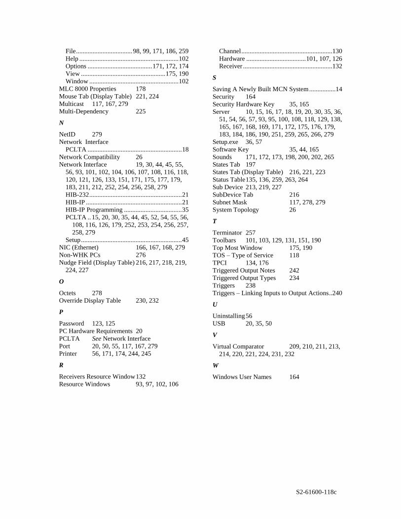
S2-61600-118c
File .................................. 98, 99, 171, 186, 259
Help ............................................................ 102
Options ....................................... 171, 172, 174
View ................................................... 175, 190
Window ...................................................... 102
MLC 8000 Properties 178
Mouse Tab (Display Table) 221, 224
Multicast 117, 167, 279
Multi-Dependency 225
N
NetID 279
Network Interface
PCLTA ......................................................... 18
Network Compatibility 26
Network Interface 19, 30, 44, 45, 55,
56, 93, 101, 102, 104, 106, 107, 108, 116, 118,
120, 121, 126, 133, 151, 171, 175, 177, 179,
183, 211, 212, 252, 254, 256, 258, 279
HIB-232 ........................................................ 21
HIB-IP .......................................................... 21
HIB-IP Programming ................................... 35
PCLTA .. 15, 20, 30, 35, 44, 45, 52, 54, 55, 56,
108, 116, 126, 179, 252, 253, 254, 256, 257,
258, 279
Setup ............................................................. 45
NIC (Ethernet) 166, 167, 168, 279
Non-WHK PCs 276
Nudge Field (Display Table) 216, 217, 218, 219,
224, 227
O
Octets 278
Override Display Table 230, 232
P
Password 123, 125
PC Hardware Requirements 20
PCLTA See Network Interface
Port 20, 50, 55, 117, 167, 279
Printer 56, 171, 174, 244, 245
R
Receivers Resource Window 132
Resource Windows 93, 97, 102, 106
Channel .......................................................130
Hardware .................................... 101, 107, 126
Receiver ......................................................132
S
Saving A Newly Built MCN System ................14
Security 164
Security Hardware Key 35, 165
Server 10, 15, 16, 17, 18, 19, 20, 30, 35, 36,
51, 54, 56, 57, 93, 95, 100, 108, 118, 129, 138,
165, 167, 168, 169, 171, 172, 175, 176, 179,
183, 184, 186, 190, 251, 259, 265, 266, 279
Setup.exe 36, 57
Software Key 35, 44, 165
Sounds 171, 172, 173, 198, 200, 202, 265
States Tab 197
States Tab (Display Table) 216, 221, 223
Status Table 135, 136, 259, 263, 264
Sub Device 213, 219, 227
SubDevice Tab 216
Subnet Mask 117, 278, 279
System Topology 26
T
Terminator 257
Toolbars 101, 103, 129, 131, 151, 190
Top Most Window 175, 190
TOS – Type of Service 118
TPCI 134, 176
Triggered Output Notes 242
Triggered Output Types 234
Triggers 238
Triggers – Linking Inputs to Output Actions ..240
U
Uninstalling 56
USB 20, 35, 50
V
Virtual Comparator 209, 210, 211, 213,
214, 220, 221, 224, 231, 232
W
Windows User Names 164