A high rate Li-rich layered MNC cathode material for lithium-ion batteries
Upload
khangminh22Category
view
3download
0
Varta Micro BatteriesPr imary L i th ium Cel ls
Sales Program and Technical Handbook
Pri
mar
yLi
thiu
m C
ells

Contents
2
1. General Information, 3 - 8
1.2 Constructions of Lithium Cells, 4 - 5
1.3 Characteristics and Applications, 6
1.4 Applications for Primary Lithium Cells, 7
1.5 Selection Guide, 8
2. CR Primary Lithium Button Cells, 9 - 18
2.1 Types – Technical Data, 10
2.2 Assemblies, 11 - 13
2.3 Performance Data, 14 - 18
3. CR High Capacity Primary Lithium Cylindrical Cells, 19 - 24
3.1 Types – Technical Data, 20
3.2 Assemblies, 21
3.3 Performance Data, 22 - 24
4. CR High Power Primary Lithium Cylindrical Cells, 25 - 28
4.1 Types – Technical Data, 26
4.2 Assemblies, 26
4.3 Performance Data, 27 - 28
5. General Design Characteristics, 29 - 35
5. Battery Selection, Design-in Consideration, UL-Recognition, 29 - 30
5.1 Safety Tests, 31
5.2 Safety Guidelines, 32 - 33
5.3 Transportation of Varta Lithium Cells and Batteries, 34
5.4 Application Check List , 35

1. General Information
Gen
eral
Info
rmat
ion
The Varta lithium manganese dioxide cell chemistry was one
of the first solid cathode cells commercially developed and is still
the most widely used system today. These cells offer an excellent
shelf life, good high-rate and low-rate capability, a wide operating
temperature range and availability in button and cylindrical cell
designs. Potential design-in applications for these products are
electronic, telecommunication, metering, instrumentation, office
and other portable equipment use. Based on the outstanding cell
performance and reliablility of these products, they have been
able to meet and exceed the requirements of our customer base
worldwide.
Advantages for Varta Li-MnO2 Cells
High open circuit and
load voltage
(above 3.0 volts per cell)
High energy density
(400 Wh/kg and 600 Wh/l)
High capacity and high rate
cell contruction
Operation over a
wide temperature range
Flat discharge profile
under low to medium rate
applications
Low self discharge
(less than 1% per year at RT)
Superior shelf life and
operational life
(Up to 10 years and more)
UL Recognition
Ability to provide a variety
of laser welded termination
tabs for all cell types
Energy Density for Primary Systems
3
Fig. 1 Comparison of different primary battery systems
400
300
500
200
100
0 200100 400300 600500 800700
Volumetric energy density (Wh/I)
Gra
vim
etri
c en
ergy
den
sity
(Wh
/kg)
Silver-oxide
Zinc-chlorid
Lithium
Alkaline

4
1.2 Constructions of Lithium Cells
Varta offers a complete range of primary lithium manganese di-
oxide cylindrical and button cells for memory backup and portable
applications worldwide.
The cylindrical cell configurations, offer the high-capacity bobbin
construction and high-power spirally wound product. The bobbin
construction is targeted at low to moderate power requirements,
dedicated for applications requiring up to a 10 years operational
life at 20°C. Our spirally wound electrode product offers high-rate
discharge capability, with an operational life in excess of 5 years.
For compact and light weight equipment use we have a complete
range of high performance primary lithium button cells.
Fig. 3 Spiral constructionSchematic construction of a Li/MnO2 cylindrical cell(CR 2/3 AH).
Fig. 2 Bobbin constructionSchematic construction of a Li/MnO2 cylindrical cell(CR 1/2 AA).
Electrolyt
MnO2 Ring
Lithium
Separator
Pos. Contact
Sealing
Neg. Contact
Laser WeldingLid
Positiv Tab
Neg. Collector
Cathode (MnO2 )
Insulator Plate
Electrolyt+ Separator
Lid
Posi t ive Cap
PTC Device
Anode (Lithium)
Lithium Cylindrical Batteries
Insulation Disk
Negativ Can
Negativ Tab
Gen
eral Info
rmatio
n
–
+
+
–

5
Gen
eral
Info
rmat
ion
Fig. 6Laser-sealing
CR High Capacity Cylindrical Cells
Fig. 5Crimp-sealing
CR High Power Cylindrical Cells
Lid
Negative Contact
Laser Welding
Fig. 4Schematic construction of a Li/MnO2 Button Cell
Positive Electrode(MnO2 )
Can (Positive Terminal)
Organic Electrolyte+ Separator
Lid (Negative Terminal)
Gasket
Negative Electrode (Li)
Sealing Technologies
Lithium Button Cells
Positive Cap
Lid PTC Device

6
1.3 Characterist ics and Applications
Main Applications
Both mechanical and electrical properties, together
with reliability, ensure that Varta lithium batteries
meet the requirements of modern electronics. They
are therefore ideally suited as power sources for the
long term supply of microelectronic circuitry.
Main Characteristics
Long life expectancy and
long operational life
Low self discharge rate
High energy density
High cell voltage (3 V)
Wide temperature range
High operating safety
High reliability
Resistance to corrosion
with stainless steel case
and laser welded lid
No leakage problems with
an organic non-corrosive
electrolyte
System Li/MnO2 Li/MnO2
Gravimetricenergy density 250 –300 Wh/kg 250 – 300 Wh /kg
Nominal voltage 3.0 V 3.0 V
Open circuit voltage 3.2 V 3.2 V
Availablecapacity range 950 –2000 mAh 25 – 560 mAh
Storage life ≥10 years1) ≥ 5 years1)
Self discharge = 20°C < 1% p.a. < 1% p.a.
Operating temperature – 30 …+75°C2) – 20 … + 65°C
Maximum temperaturerange (short term) 3) – 40 … + 85°C4) – 40 … + 80°C
Storage temperature5) – 55 … +75°C2) – 55…+70°C
CR Series Button Cells
1) CR 2 /3 AH , CR-P2, (>5 years)2) CR 2 /3 AH (– 20 … + 65°C). CR 2 NP (– 20 … + 70°C)3) max. two weeks4) µA-range5) Recommended room temperature
Tab. 1: System properties of Varta Lithium Cells
Series CR Series Cylindrical Cells
Gen
eral Info
rmatio
n
Temperature Characteristics
Fig. 7 : Temperature characteristics of CR 1/2 AA and CR AA cylindrical cells (Load: 5.6 kOhm – CR AA, 12 kOhm CR 1 / 2 AA)
1.5
2.0
2.5
3.0
3.5
Duration [h]
0 1000 2000 3000 4000
Vo
ltag
e [V
]

7
1.4 Applications for Primary Lithium Cells
Gen
eral
Info
rmat
ion
Applications Button Cells
TelecommunicationsStd. Telephone
Cordless Telephone
Cellular Telephone
Mobile Radio
PABX
Utility MetersGas Meter
Heat Distribution Meter
Electric Meter
Water Meter
Office AutomationComputer
Copy Machine
Printer
Fax
Vending Machine
Electronic Typewriter
Process Control EquipmentTaxi Meter
Transponder
Intelligent Tagging
Electric Parking Meter
Data Logger
Dive Computer
Consumer ProductsElectronic Games
Watch /Clock
Calculator
Compass
Car Radio
Video Recorder
AutomotiveCar lock system
Dashboard
Security
Cylindrical Cells(Spirally wound)
Cylindrical Cells(Bobbin construction)
Main
power
sourc
e
Mem
ory
backu
p
Main
power
sourc
e
Mem
ory
backu
p
Main
power
sourc
e
Mem
ory
backu
p
Tab. 2: Application list
8
1.5 Selection Guide
1
20
40
60
80
100
2 3 4 5 6 7 8 9 10
Prediction area
To enable battery selection the
following is required:
discharge current and maximum
discharge time capacity
operating temperature range
self discharge
surplus capacity requirement
cell size
Gen
eral Info
rmatio
n
Fig. 8 Capacity retention characteristics of Varta Lithium CellsCylindrical Cells CR…AA, CR…A and CR 2 NP
Storage time t [years]
Ava
ilab
le c
apac
ity
[%]
Capacity Retention
New Cells
1000
900
800
700
600
500
400
300
200
100
02 4 6 8 10
Storage [years]
Cap
acit
y [m
Ah
]
Storage Behaviour
Battery Selection Diagram
CR 1216
Fig. 10Discharge current /Operating time Battery selection diagram
CR 2450
CR 2430CR 2325CR 2032
CR 2016
CR AACR 2 NP
CR 2/3AA, CR 2/3ACR 2 /3 AHCR 1/2 AA
CR 1616,CR 1620
CR 1220
CR 2025, CR 2320
0.1
10
100
1000
110
Operating time t [years]
Dis
cha
rge
cu
rre
nt
[µA
]
Fig. 9 Typical storage behaviour at room temperature 21°Cof CR 1 / 2 AA

9
2.CR Primary Lithium Button Cells
CR
Pri
mar
y Li
thiu
m B
utt
on
Cel
ls

10
2.1 Types – Technical Data
CR 1/3 N 6131 101 501 3 170 5.6 20 80 3.0
2 CR 1/3 N (V28 PXL) 6231 101 501 6 170 13 20 80 8.8
CR 1216 6216 101 501 3 25 39 2 5 0.7
CR 1220 6220 101 501 3 35 39 2 5 0.8
CR 1616 6616 101 501 3 55 39 3 8 1.2
CR 1620 6620 101 501 3 70 20 3 8 1.2
CR 2016 6016 101 501 3 90 15 3 10 1.8
CR 2025 6025 101 501 3 170 10 3 10 2.5
CR 2032 6032 101 501 3 230 5.6 3 10 3.0
CR 2320 6320 101 501 3 135 10 5 15 2.9
CR 2430 6430 101 501 3 280 5.6 3 20 4.0
CR 2450 6450 101 501 3 560 5.6 2 10 6.2
Type
Order-no.
Nominal volta
ge
(V)Ty
pical capacity
1)
(mAh)
Max. disc
harge
current (c
ontinuous)
(mA)
Max. disc
harge
current (p
ulse)
(mA)
Weight (g
)
Standard load
(kΩ)
Tab. 3: Technical data, CR Primary Lithium Button Cells1) Nominal capacity is determined to an end voltage of 2.0 V (type 2 CR 1/3 N: 4.0 V)
when the battery is allowed to discharge at standard load level at 20°C
CR
Prim
ary Lithiu
m B
utto
n C
ells
CR 1216 CR 1616 CR 2016 CR 2025 CR 2032

11
CR
Pri
mar
y Li
thiu
m B
utt
on
Cel
ls
2 .2.1 Assemblies
Type
Order-no.
A B C D E F G H I K L Fig.-n
o.
Remarks
CR 1/3 N 6131 101 501 11.6 10.8 0.4 – 7.8 – – – – – – 11 –
CR 1/3 N SLF 6131 201 501 13.0 1.0 10.0 1.0± 0.3 11.5± 0.5 12.0± 0.15 – 1.0± 0.3 3.0 – – 14 tag 0.25 mm
CR 1/3 N LF 6131 301 501 – – – – 11.5 12.0 – – – 19.0 4.0 13 tag 0.25 mm180°
2 CR 1/3 N 6231 101 501 13.0 25.1 1.1 0.6 5.5 6.0 – – – – – 12 –(V 28 PXL)
3 CR 1/3 N 6331 101 501 12.2 32.2 0.4 – 7.8 – – – – – – 11 –
Tab. 4: Tag material : nickel plated sheet-steel. SLF : tip tinned.Custom made assemblies are available on request for large volume.
L
E
F
K K
AB
C
D
I
E
F
H
B
I
Fig. 13 / LF Fig. 14 / SLFFig. 12Fig. 11
B
DA
E
F
CC
B
E
A

12
Tab. 5.1: Tag material : nickel plated sheet-steel. SLF : tip tinned.Custom made assemblies are available on request for large volume.
CR 1216 6216 101 501 12.5 1.6 0.2 – 10.0 – – – – – – 15
CR 1220 6220 101 501 12.5 2.0 0.3 – 10.0 – – – – – – 15
CR 1616 6616 101 501 16.0 1.6 0.2 – 12.0 – – – – – – 15
CR 1620 6620 101 501 16.0 2.0 0.02 – 12.9 – – – – – – 15
CR 2016 6016 101 501 20.0 1.6 0.1 – – – – – – – – 15
CR 2016 SLF 6016 201 501 21.3 1.0 10.0±0.15 1.0±0.3 2.1±0.5 20.3±0.15 – 1.0±0.3 4.5 – – 16 tag 0.25 mm
CR 2016 LF 6016 301 501 20.0 – – – 1.9 20.0 – – – 10.0 4.0 17 tag 0.15 mm
CR 2016 PCB 6016 401 501 20.0 1.0 10.0 9.1 1.6 17.8 7.3 10.0 4.5 11.4 – 18 tag 0.15 mm
CR 2025 6025 101 501 20.0 2.5 0.2 – – – – – – – – 15
CR 2025 SLF 6025 201 501 21.3 1.0 10.0±0.2 1.0±0.3 3.0±0.5 20.3±0.15 – 1.0±0.3 4.5 – – 16 tag 0.25 mm
CR 2025 LF 6025 301 501 20.0 – – – 2.8 20.3 – – – 10.0 4.0 17 tag 0.15 mm
CR 2025 PCB 6025 401 501 20.0 1.0 10.0 10.0 2.5 17.8 7.3 10.0 4.5 11.4 – 18 tag 0.15 mm
2.2.2 Assemblies
A
B
C
D
E
F
H
I
Fig. 16 /SLFFig. 15
B
A
E
C
CR
Prim
ary Lithiu
m B
utto
n C
ells
Type
Order-no.
A B C D E F G H I K L Fig.-n
o.
Remarks
Fig. 17/ LF
L
E
F
K K

CR 2032 6032 101 501 20.0 3.2 0.02 – 16.5 – – – – – – 15 –
CR 2032 SLF 6032 201 501 21.5 1.0 10.0 1.0 4.2 20.3 – 1.0 4.5 – – 16 tag 0.25 mm
CR 2032 LF 6032 301 501 – – – – 3.2 20.3 – – – 10 4.0 17 tag 0.15 mm
CR 2032 PCB 6032 401 501 20.0 1.0 10.0 11.0 3.2 17.8 7.5 10.0 4.5 11.4 – 18 tag 0.25 mm
CR 2032 PCB 6032 701 501 20.0 1.0 – 11.0 3.2 17.8 7.3 10.0 4.5 10.0 – 19 tag 0.20 mm
CR 2032 WC 1) 6032 101 013 20.7 – – – 5.5 30.0 – – – 96.0 2.0 20 tag 0.20 mm 2)
CR 2430 6430 101 501 24.5 3.0 0.3 – 20.0 – – – – – – 15 –
CR 2430 SLF 6430 201 501 25.8 1.0 10.0 1.0 4.0 25.0 – 1.0 4.5 – – 16 tag 0.25 mm
CR 2430 LF 6430 301 501 – – – – 3.2 25.0 – – – 10.0 4.0 17 tag 0.15 mm
CR 2430 PCB 6430 401 501 24.5 1.0 10.0 11.0 3.0 17.8 7.5 10.0 4.5 11.4 – 18 tag 0.25 mm
CR 2430 PCB 6430 701 501 24.5 1.0 – 11.0 3.0 20.0 7.5 10.0 4.5 11.4 – 19 tag 0.20 mm
CR 2450 6450 101 501 24.7 5.0 0.5 – 21.8 – – – – – – 15 –
CR 2450 SLF 6450 201 501 25.8 1.0 10.0 1.0 6.4 25.0 – 1.0 4.5 – – 16 tag 0.25 mm
CR 2450 PCB 6450 401 501 24.5 1.0 10.0 13.2 5.0 17.8 7.5 10.0 4.5 11.4 – 18 tag 0.25 mm
CR 2450 PCB 6450 701 501 24.7 1.0 – 12.7 5.0 17.8 7.5 10.0 4.5 11.4 – 19 tag 0.20 mm
13
2.2.3 Assemblies
AHK
E
C
F
G
B
DI
AHK
D
B I
FG
E
Fig. 18 /PCB Fig. 19 /PCB
L
E
F
K
A
Fig. 20 / WC
Tab. 5.2 : Tag material : nickel plated sheet-steel. SLF : tip tinned.1) using Molex 51021-03 connector (Other wire connectors and wire length are available on request.)2) in shrink sleeve with wire and connectorCustom made assemblies are available on request for large volume.
CR
Pri
mar
y Li
thiu
m B
utt
on
Cel
ls
Type
Order-no.
A B C D E F G H I K L Fig.-n
o.
Remarks

14
Fig. 22
CR 1216Temperature characteristics
Constant load 39 kΩ
Fig. 21
CR 1216Discharge characteristics
at room temperature (21°C)
Fig. 23
CR 1216Operating voltage vs.
current drain
Voltage at 50 % discharge
Fig. 24
CR 1216Cell capacity vs.
discharge current
2.3 CR Primary Lithium Button Cell Performance Data
Fig. 21: CR 1216
1.5
3.5
3.0
2.5
2.0
Time [h]0 600
Vo
ltag
e [V
]
15 kΩ 39 kΩ 68 kΩ
450300150
Fig. 22: CR 1216
1.5
3.5
3.0
2.5
2.0
Time [h]0 400
Vo
ltag
e [V
]
70°C
23°C
– 20°C
300200100
Fig. 23: CR 1216
1.5
3.5
3.0
2.5
2.0
Discharge current [mA]0.01 10
Cel
l vo
ltag
e [V
]
70°C23°C
– 20°C
1.00.1
Fig. 24: CR 1216
0
40
30
20
10
Discharge current [mA]0.01 10
Cel
l cap
acit
y [m
Ah
]
70°C23°C
– 20°C
10.1
CR
Prim
ary Lithiu
m B
utto
n C
ells

15
Fig. 25
CR 2016Discharge characteristics
at room temperature (21°C)
Fig. 26
CR 2016Temperature characteristics
Constant load 15 kΩ
Fig. 27
CR 2016Operating voltage vs.
current drain
Voltage at 50 % discharge
Fig. 28
CR 2016Cell capacity vs.
discharge current
Fig. 25: CR 2016
1.5
3.5
3.0
2.5
2.0
Time [h]0 1400
Vo
ltag
e [V
]
5.6 kΩ 15 kΩ 39 kΩ
12001000800600400200
Fig. 26: CR 2016
1.5
3.5
3.0
2.5
2.0
Time [h]0 500
Vo
ltag
e [V
]
70°C
23°C
– 20°C
400300200100
Fig. 27: CR 2016
1.5
3.5
3.0
2.5
2.0
Discharge current [mA]0.001 10
Cel
l vo
ltag
e [V
]
70°C23°C
– 20°C
1.00.10.01
Fig. 28: CR 2016
0
100
Discharge current [mA]0.001 10
Cel
l cap
acit
y [m
Ah
]
70°C23°C
– 20°C80
60
40
20
1.00.10.01
CR
Pri
mar
y Li
thiu
m B
utt
on
Cel
ls

16
Fig. 30
CR 2025Temperature characteristics
Constant load 10 kΩ
Fig. 29
CR 2025Discharge characteristics
at room temperature (21°C)
Fig. 31
CR 2025Operating voltage vs.
current drain
Voltage at 50% discharge
Fig. 32
CR 2025Cell capacity vs.
discharge current
Fig. 29: CR 2025
1.5
3.5
3.0
2.5
2.0
Time [h]0 800
Vo
ltag
e [V
]
5.6 kΩ 10 kΩ 15 kΩ
600400200
Fig. 30: CR 2025
1.5
3.5
3.0
2.5
2.0
Time [h]0 800
Vo
ltag
e [V
]
70°C
23°C
– 20°C
600400200
Fig. 31: CR 2025
1.5
3.5
3.0
2.5
2.0
Discharge current [mA]0.01 10
Cel
l vo
ltag
e [V
]
70°C
23°C
– 20°C
1.0
Fig. 32: CR 2025
0
200
150
100
50
Discharge current [mA]0.01 10
Cel
l cap
acit
y [m
Ah
]
70°C
23°C
– 20°C
1.0
CR
Prim
ary Lithiu
m B
utto
n C
ells

17
Fig. 33
CR 2032Discharge characteristics
at room temperature (21°C)
Fig. 34
CR 2032Temperature characteristics
Constant load 5.6 kΩ
Fig. 35
CR 2032Operating voltage vs.
current drain
Voltage at 50% discharge
Fig. 36
CR 2032Cell capacity vs.
discharge current
Fig. 33: CR 2032
1.5
3.5
3.0
2.5
2.0
Time [h]0 1400
Vo
ltag
e [V
]
5.6 kΩ 10 kΩ 15 kΩ
12001000800600400200
Fig. 34: CR 2032
1.5
3.5
3.0
2.5
2.0
Time [h]0 500
Vo
ltag
e [V
]
70°C
23°C
– 20°C
400300200100
Fig. 35: CR 2032
1.5
3.5
3.0
2.5
2.0
Discharge current [mA]0.01 10
Cel
l vo
ltag
e [V
]
70°C
23°C
– 20°C
1.0
Fig. 36: CR 2032
0
250
Discharge current [mA]0.001 10
Cel
l cap
acit
y [m
Ah
]
70°C
23°C
– 20°C
200
150
100
50
1.0
CR
Pri
mar
y Li
thiu
m B
utt
on
Cel
ls

18
CR
Prim
ary Lithiu
m B
utto
n C
ells
Fig. 37
CR 2430Load: cont. 5.6 kΩ : Ub
Pulse: 2 s/2 h 390 Ω : Ut
(parallel)
Internal Resistance Ri calculated from
Ub and Ut at Rt = 390 Ω and Tt = 2 s
Temperature: δ = 20°C
Fig. 37: CR 2430
Fig. 38: CR 2430
Fig. 39: CR 2430
Fig. 40: CR 2450
1.6
3.6
3.2
2.8
2.4
2.0
Discharge time t [h]0 150 300 450 600 750
Vo
ltag
e U
[V
]
UbUt
Ri
3.6 100
80
60
40
20
0
1.5
4.0
3.5
3.0
2.5
2.0
Discharge time t [h]
(A) 2000(B) 100
6000 300
10000 500
14000 700
18000 900
22000 1100
Vo
ltag
e U
[V
]
1.5
4.0
3.5
3.0
2.5
2.0
Vo
ltag
eU [
V]
Discharge time t [h]0 300100 500 700 900 1200
1.6
3.6
3.2
2.8
2.4
2.0
Discharge time t [h]0 250 500 750 1000 1250
Vo
ltag
e U
[V
]
Ub
Ut
Ri
3.6 125
100
75
50
25
0
Fig. 38
CR 2430Load: cont. 5.6 kΩ (B)
cont. 15 kΩ (B)
cont. 270 kΩ (A)
Mean discharge I1 = 400 µA
current: I2 = 180 µA
I3 = 10 µA
Temperature: δ = 20°C
Fig. 39
CR 2430Discharge curves at different temperatures
Load: cont. R = 15 kΩ
Mean discharge
current at
temperature: δ = 0°C ~175 µA
δ = – 10°C ~170 µA
δ = – 20°C ~155 µA
Fig. 40
CR 2450Load: cont. 5.6 kΩ : Ub
Pulse: 2 s/2 h 100 Ω : Ut
(parallel)
Internal Resistance Ri calculated from
Ub and Ut at Rt = 100 Ω and Tt = 2 s
Temperature: δ = 20°C
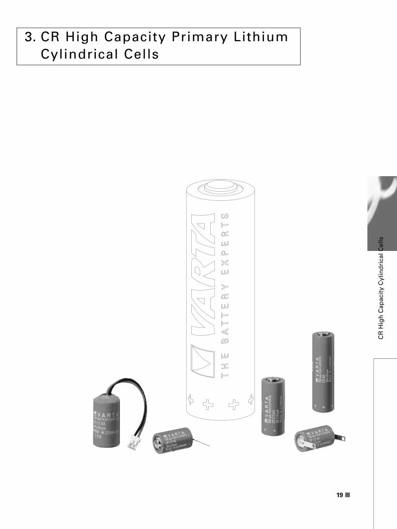
19
3. CR High Capacity Primary Lithium Cylindrical Cells
CR
Hig
h C
apac
ity
Cyl
ind
rica
l Cel
ls

20
LM
B
A
CK
D
B G
A
EI
D
A
B G
H
F
E
C
Fig. 41
Fig. 44
Fig. 42 Fig. 43
Fig. 45
AE
D
B G
E
D
B G
AE
I
3 .1 Types – Technical Data
CR 1/2 AA 6127 101 301 3 970 mAh - 5.6 kΩ 10 11.5CR 2/3 AA 6237 101 301 3 1.350 mAh - 1.0 kΩ 15 15.0CR AA 6117 101 301 3 2.000 mAh - 1.0 kΩ 20 21.5CR 2/3 A 6238 101 301 3 1.350 mAh - 1.0 kΩ 15 17.0
Type
Order-no.
Nominal volta
ge
(V)Ty
pical capacity
at
20°C
, down to
2.0 V
,
load (mAh)
Max. contin
uous
discharge curre
nt
(mA)
Weight (g
)
Tab. 6 : Technical data, CR High Capacity Primary Lithium Cylindrical CellsCR
Hig
h C
apacity C
ylind
rical Cells
B
E E
C C
A
G
Fig. 46
CR 1 / 2 AA CR 2 / 3 AA CR AA

21
G B
Ni fl 0.8 mm — tinned
AD
B
A
C
C
Ni Ø 0,8 mm – tinned
Fig. 48
G
E
C
A
B
Fig. 49
A
B
C
Fig. 50Fig. 47
3.2 Assemblies
CR 1/2 AA 6127 101 301 14.75 25.2 – – – – – – – – 7.0 0.6 41CR 1/2 AA SLF 6127 201 301 14.75 25.2 10.0 1.0 1.0 – 25.4 – 3.0 5.0 – – 42CR 1/2 AA LF 6127 301 301 14.75 25.2 10.0 – 3.5 2.1 25.4 2.5 – – – – 43CR 1/2 AA CD 6127 501 301 14.75 25.4 45.0 – – – – – – – – – 48CR 1/2 AA CD 6127 601 301 14.75 25.4 – 7.5 – – 33.5 – – – – – 47 (90°)
CR 1/2 AA SLF 6127 701 301 14.75 25.2 – 1.0 1.0 – 25.4 – 3.0 – – – 44 single pin
CR 1/2 AA LF 6127 801 301 14.75 25.2 14.5 – 3.0 – 25.4 – – – – – 46 (180°)
CR 1/2 AA SLF 6127 901 301 14.75 25.2 – – 1.0 – 25.4 – 3.0 – – – 45 short pin
CR 1/2 AA TP 6127 601 381 14.75 25.2 16.5 – 0.64 – 25.8 – – – – 49 terminal pin
CR 1/2 AA WC1) 6127 201 390 17.5 27.0 50.0 – – – – – – – – – 50 wire &connector
CR 2/3 AA 6237 101 301 14.75 33.5 – – – – – – – – 7.0 0.6 41CR 2/3 AA SLF 6237 201 301 14.75 33.5 10.0 1.0 1.0 – 33.7 – 3.0 5.0 – – 42CR 2/3 AA LF 6237 301 301 14.75 33.5 10.0 – 3.5 2.1 33.7 2.5 – – – – 43CR 2/3 AA CD 6237 501 301 14.75 33.5 45.0 – – – – – – – – – 48CR 2/3 AA SLF 6237 701 301 14.75 33.5 – 1.0 1.0 – 33.7 – 3.0 – – – 44 single pin
CR 2/3 AA SLF 6237 901 301 14.75 33.5 – – 1.0 – 33.7 – 3.0 – – – 45 short pin
CR AA 6117 101 301 14.75 50.0 – – – – – – – – 7.0 0.6 41CR AA SLF 6117 201 301 14.75 50.0 10.0 1.0 1.0 – 50.2 – 3.0 5.0 – – 42CR AA LF 6117 301 301 14.75 50.0 10.0 – 3.5 2.1 50.2 2.5 – – – – 43CR AA CD 6117 501 301 14.75 50.2 45.0 – 3.5 – – – – – – – 48CR AA SLF 6117 701 301 14.75 50.0 – 1.0 1.0 – 50.2 – 3.0 – – – 44 single pin
CR AA WC1) 6117 201 390 18 51.0 50.0 – – – – – – – – – 50 wire &connector
CR 2/3 A 6238 101 301 17 33.5 – – – – – – – – 7.0 0.6 41CR 2/3 A LF 6238 301 301 17 33.5 10.0 – 3.5 2.1 33.7 2.5 – – – – 43CR 2/3 A CD 6238 501 301 17 33.5 45.0 – – – – – – – – – 48
Type
Order-no.
A(M
ax.)
B C D E F G H I K L M Fig.-n
o.
Tags
Tab. 7: Material: nickel plated sheet-steel, tag thickness: 0.15 mm till 0.25 mm. SLF : tip tinned, all types in green shrink sleeve.1) using connector : JST type : PHR2 (Other connector types available on request.)Custom made assemblies are available on request for large volume.
CR
Hig
h C
apac
ity
Cyl
ind
rica
l Cel
ls

22
3.3 Performance Data
Fig. 51, Fig. 55, Fig. 59
CR 1/2 AA, CR 2/3 AA, CR AADischarge characteristics
at room temperature (21°C)
Fig. 51: CR 1/2 AA
Fig. 52: CR 1/2 AA
Fig. 53: CR 1/2 AA
Fig. 54: CR 1/2 AA
1.5
3.5
3.0
2.5
2.0
Time [h]0 4000 60002000 8000
Vo
ltag
e [V
]
5.6 kΩ 10 kΩ 20 kΩ
1.5
2.0
2.5
3.0
3.5
Time [h]0 500 1000 1500 2000
Vo
ltag
e [V
] A: 60°CB: 23°C
A B
1.5
3.5
3.0
2.5
2.0
Discharge current [mA]0.01 0.1 1 10 100
Cel
l vo
ltag
e [V
]
60°C
23°C
1000
Discharge current [mA]0.01 0.1 1 10 100
Cel
l cap
acit
y [m
Ah
]
A: 60°CB: 23°C
BA 800
600
400
200
0
Fig. 52, Fig. 56, Fig. 60
CR 1/2 AA, CR 2/3 AA, CR AATemperature characteristics
at 5.6 kΩ
Fig. 53, Fig. 57, Fig. 61
CR 1/2 AA, CR 2/3 AA, CR AAOperating voltage vs.
current drain,
Voltage at 50% discharge
Fig. 54, Fig. 58, Fig. 62
CR 1/2 AA, CR 2/3 AA, CR AACell capacity vs.
discharge current
CR
Hig
h C
apacity C
ylind
rical Cells

Fig. 55: CR 2/3 AA
Fig. 56: CR 2/3 AA
Fig. 57: CR 2/3 AA
Fig. 58: CR 2/3 AA
Fig. 59: CR AA
Fig. 60: CR AA
Fig. 61: CR AA
Fig. 62: CR AA
Fig. 23
CR 1/2 AALoad Characteristics
3.5
3.0
2.5
2.0
1.5
Time [h]0 3000 6000 9000 12000
Vo
ltag
e [V
]
5.6 kΩ 10 kΩ 20 kΩ
1.5
3.5
Time [h]0 4000 8000 12000 16000
Vo
ltag
e [V
]
5.6 kΩ 10 kΩ 20 kΩ
3.0
2.5
2.0
3.5
Time [h]0 3000
Vo
ltag
e [V
]
A: 60°CB: 23°C
A B
3.0
2.5
2.0
1.522501500750
3.5
Time [h]0 1000 2000 3000 4000
Vo
ltag
e [V
]
A: 60°CB: 23°C
A B
3.0
2.5
2.0
1.5
1.5
3.5
Discharge current [mA]0.01 0.1 1 10 100
Cel
l vo
ltag
e [V
]
60°C
23°C
3.0
2.5
2.0
1.5
3.5
Discharge current [mA]0.01 0.1 1 10 100
Cel
l vo
ltag
e [V
]
60°C
23°C
3.0
2.5
2.0
0
600
900
1200
1500
Discharge current [mA]0.01 0.1 1 10 100
Cel
l cap
acit
y [m
Ah
]
60°C
23°C
2000
Discharge current [mA]0.01 0.1 1 10 100
Cel
l cap
acit
y [m
Ah
]
60°C
23°C
1600
1200
800
400
0
23
CR
Hig
h C
apac
ity
Cyl
ind
rica
l Cel
ls

Fig. 63
CR 2/3 ADischarge characteristics
at room temperature (21°C)
Fig. 63: CR 2/3 A
Fig. 64: CR 2/3 A
Fig. 65: CR 2/3 A
Fig. 66: CR 2/3 A
3.5
3.0
2.5
2.0
1.5
Time [h]0 3000 6000 9000 12000
Vo
ltag
e [V
]
5.6 kΩ 10 kΩ 20 kΩ
3.5
Time [h]0 3000
Vo
ltag
e [V
] A: 60°CB: 23°C
A B
3.0
2.5
2.0
1.522501500750
1.5
3.5
Discharge current [mA]0.01 0.1 1 10 100
Cel
l vo
ltag
e [V
]
60°C
23°C
3.0
2.5
2.0
0
600
900
1200
1500
Discharge current [mA]0.01 0.1 1 10 100
Cel
l cap
acit
y [m
Ah
]
60°C
23°C
Fig. 64
CR 2/3 ATemperature characteristics
at 5.6 kΩ
Fig. 65
CR 2/3 AOperating voltage vs.
current drain,
Voltage at 50 % discharge
Fig. 66
CR 2/3 ACell capacity vs.
discharge current
24
CR
Hig
h C
apacity C
ylind
rical Cells

25
4. CR High Power Primary Lithium Cylindrical Cells
CR
Hig
h P
ow
er C
ylin
dri
cal C
ells
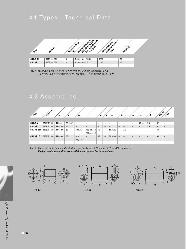
4.1 Types – Technical Data
4.2 Assemblies
Fig. 69Fig. 67 Fig. 68
Type
Order-no.
A B C D E F G IH K L M Fig.-n
o.
Tags
Tab. 9: Material: nickel plated sheet-steel, tag thickness: 0.15 mm till 0.25 m. SLF : tip tinned.Custom made assemblies are available on request for large volume.
CR 2/3 AH 6215 101 501 17.0– 1 33.9– 1.5 – – – – – – – – 6.3±0.2 1.0 67 –CR 2 NP 6202 101 501 11.6– 0.4 60– 1 – – – – – – – – 3 1.5 67 –CR 2 NP SLF 6202 201 501 11.6– 0.4 60– 1 10.0±0.15 pos 0.5±0.2 1.0 – 58.8±0.3 – 3.0 – – – 69 –
neg. 0.7±0.2
CR 2 NP LF 6202 301 501 11.6– 0.4 60– 1 pos.: 11 – 4.0 – 58.8±0.3 – – – – – 68 –neg.: 10
26
L
M B AA
E
C C
G
B
E
A
I CG
B
E
EC
D
CR
Hig
h P
ow
er Cylin
drical C
ells
CR 2/3 AH 6215 101 501 3 1.350 mAh - 200 Ω 1500 16CR 2 NP 6202 101 501 3 1.400 mAh - 1.0 kΩ 15 13
Type
Order-no.
Nominal volta
ge
(V)Nominal c
apacity at
20°C
, down to
2.0 V
(resp
ectively
4.0 V),
load (mAh)
Max. contin
uous
discharge curre
nt1)
(mA)
Weight (g
)
Tab. 8: Technical data, CR High Power Primary Lithium Cylindrical Cells1) Current value for obtaining 50% capacity 2) in blister card (1 pc)

27
4.3 Performance Data
Fig. 70
CR 2 /3 AHDischarge characteristics
at room temperature (21°C)
Fig. 71
CR 2 /3 AHTemperature characteristics
at 5.6 kΩ
Fig. 72
CR 2 /3 AHPulse discharge characteristics
* Load: 0.9 A, 3 sec. on, 27 sec. off
Fig. 73
CR 2 /3 AHTypical discharge curve
Load: cont. 560 Ω
Pulse load: 2 sec./min 3 Ω
(parallel)
Fig. 70: CR 2 / 3 AH
1.5
1.0
2.0
2.5
3.0
Time [h]0 10 20 30 40 50 60 70
Vo
ltag
e [V
]
60 Ω (=45mA)
120 Ω (=23 mA)
10 Ω (=240 mA)
20 Ω (=138 mA)
~ ~ ~ ~
Fig. 71: CR 2 / 3 AH
Time [h]0 10 20 30 40
Vo
ltag
e [V
]
– 20°C
20°C
60°C
1.5
1.0
2.0
2.5
3.0
Fig. 72: CR 2 / 3 AH
Cycle number * [cycle] 0 500 1000 1500 2000
Vo
ltag
e [V
]
– 20°C
60°C
20°C
After storage at 60°C/100 days
1.5
1.0
2.0
2.5
3.0
Fig. 73: CR 2 / 3 AH
Time [hrs] 0 5 10 15 20 25 30 35 40 45 50
Vo
ltag
e [V
]
1.5
1.0
0.5
2.0
3.0
2.5
3.5
CR
Hig
h P
ow
er C
ylin
dri
cal C
ells
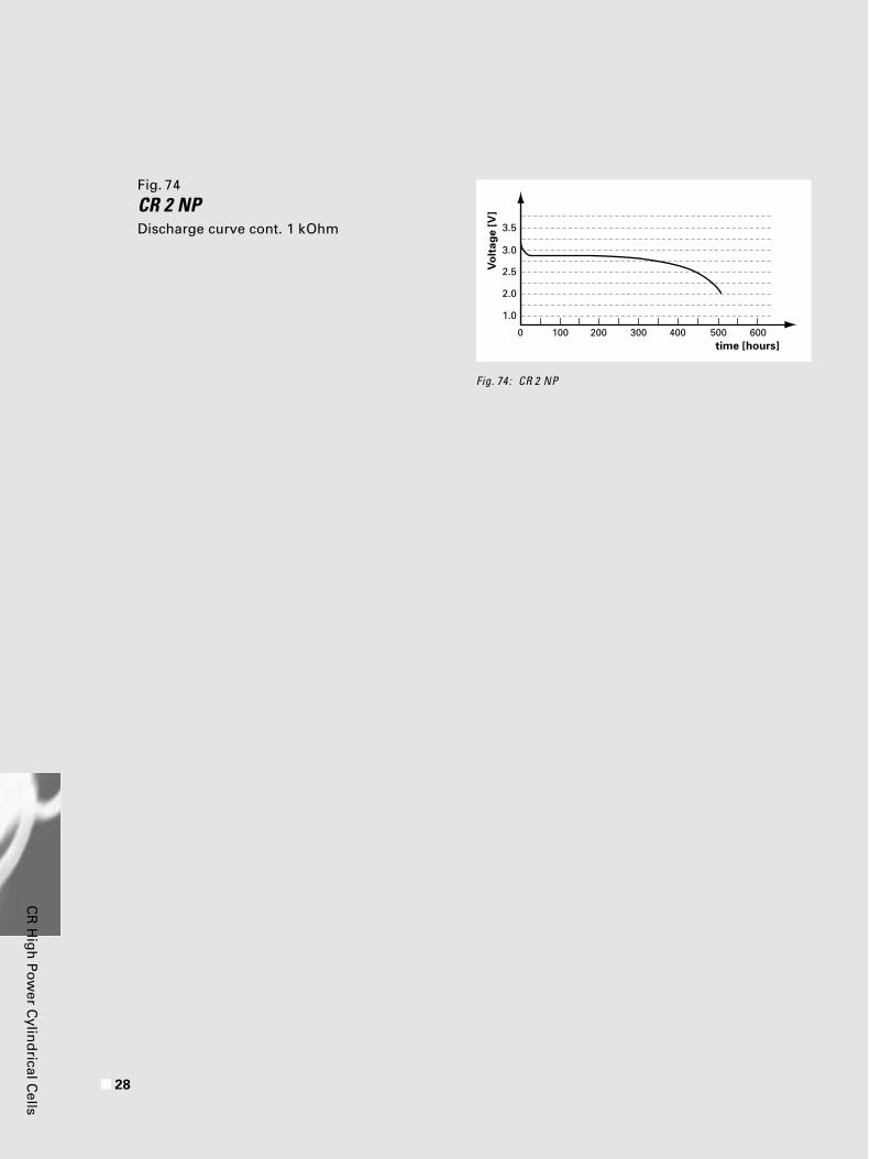
Fig. 74
CR 2 NPDischarge curve cont. 1 kOhm
Fig. 74 : CR 2 NP
1.0
2.0
3.0
2.5
3.5
time [hours] 0 600
Vo
ltag
e [V
]
500400300200100
28
CR
Hig
h P
ow
er Cylin
drical C
ells

29
5. General Design Characterist ics
Battery Selection
In order to ensure optimum battery performance for the primary
CR Button, the cylindrical CR High Power and cylindrical High
Capacity cells, we suggest consideration of the following design-
in requirements. They are the nominal and operating voltage,
load current and profile, the duty cycle, temperature require-
ments and shelf life for the application. These characteristics for
each battery type must be evaluated against the design require-
ments to select the most appropriate product that fulfills these
requirements.
Design-in Considerations
Varta Primary Lithium Batteries
offer lightweight packaged
power for a variety of portable
electric and electronic equip-
ment. They are suitable as a
main or standby power source
for memory (RAM) and Real-
Time clock (RTC) applications.
The Lithium Batteries are
blocked from the power supply
by means of a diode to prevent
discharge of the battery into
the DC supply during shut
down.
The voltage drop across D1
should be taken into account as
the minimum voltage of the
load that has to be maintained
under all circumstances.
Blocking diode D2 and D3
prevents the battery from being
charged through the power
supply. The amount of accumu-
lated reverse current (IR) must
not exeed 1% of the cells typi-
cal capacity during it`s standby
life time.
In the absence of a DC supply
voltage, the lithium battery
supplies the load with the
necessary power.
As diodes fail at low current
levels by an alloy-effect
causing a severe reduction in
impedance, an additional safety
device must be incorporated.
+VccD1
to loadD2
Resistor
CellCell
D1
to loadD2
+Vcc
Resistor
Cell
+VccD1
to loadD2
D3
Cell
Fig. 75
Fig. 76
Fig. 77Using 2 cells when 6 V is used in series
Gen
eral
Des
ign
Ch
arac
teri
stic
s

30
„UL“ requires either an additio-
nal diode, or a resistor, limiting
the current to a safe level of 4
mA (for all cylindrical CR…A (A)
lithium mass cells).
It should be noted, that the
value of the resistor has to be
calculated using the higher
power supply voltage – not the
battery voltage.
The supply voltage to the load
can be calculated by the battery
voltage drop across the diode
and the resistor.
UL-Recognition
All Varta Lithium Cells and
Batteries listed in Tab. 10 are
recognized by Underwriters
Laboratories Inc. under UL-file
number MH 13654 (N).
The cell are marked with the
Recognized Component Mark.
Underwriters Laboratories
requires for lithium cells/
batteries a circuit, which must
contain a protective component
to prevent charging. In case of
diode failure a current limiting
resistor must be chosen
according to the values listed
in Tab. 10.
Please also pay attention to the
Safety Guidelines on page 32.
Printed Circuit BoardMounting
Never solder on the body of the
battery directly, use a battery
equipped with PC-mount ter-
minals. When using automatic
soldering apply 250 – 270°C
within 5 seconds. Make sure,
that the battery is not sus-
pended or dropped into the
soldering bath.
Do not heat above 80°C to
avoid leakage caused by
deterioration in the battery’s
performance.
Tab. 10All listed cells /batteries are recognized by UL-recognition.CR 2 /3 AH UL-Recognition pending.
High Capacity
CR 1/2 AA 4 mA
CR 2/3 AA 4 mA
CR AA 4 mA
CR 2/3 A 4 mA
High Power
CR 2 NP 15 mA
2 CR 5 10 mA
Button Cells
Type
Max. safe
reverse
current a
cc.
to UL
CR 1216 3 mA
CR 1220 3 mA
CR 1616 4 mA
CR 1620 3 mA
CR 2016 4 mA
CR 2025 5 mA
CR 2032 5 mA
CR 2320 5 mA
CR 1/3 N 2 mA
Cylindrical Cells
Type
Max. safe
reverse
current a
cc.
to UL
Gen
eral Desig
n C
haracteristics

5.1 Safety Tests For safety aspects please consult Varta before performing these extreme tests
31
Vibration Test
Short Circuit
In table 11 is the temperature
at short circuit at an ambient
temperature of 20°C, 40°C
and 70°C listed.
Tab. 12
Tab. 11
Without changing of
the electrical values
the following Li-cell
can be exposed to
this vibration test:
CR 1/2 AA
CR 2/3 AA
CR AA
Vibration test
Ambient
temperature
CR 1/2 A
A
CR 2 /3 AA
CR AA
Result
Frequency range
5 Hz 55 Hz 500 Hz 55 Hz 5 Hz
Amplitude at frequency range:
5 to 55 Hz: ± 0.75 mm
Acceleration at frequencey range:
55 Hz to 500 Hz: 100 m/s2
Cycle duration: 15 min
Oscillation time of each main axis: 3 h
Compression Test 1120 kg
no significant electrolyte loss
no rupturing
In Short Circuit Condition 24 h, 0.1Ω
after 24 h the bottom of the cell is curved by only 0.1 mm; diameter unchanged
no electrolyte creepage or loss
no rupturing
Test at 150°C for 2 Hours
no electrolyte creepage or loss
no rupture
no fire
no explosion
open circuit voltage almost unchanged at 3.2 V
the cell base bowed, causing cell height toincrease by 1 mm,diameter unchanged
Puncture Test total Penetration of theCell by a Nail Ø 3 mm no splashing or
pressurized electrolyte loss
no rupturing
20°C 24°C 28°C 24°C
40°C 50°C 50°C 47°C
70°C 80°C 84°C 77°C
Temperature Characteristics
Fig. 78 : CR 1/2 AA, Temperature characteristicsConditions:20h / 20°C: 15 kΩ, 4h / at various temp.: 270 kΩ
1.0
2.0
3.0
4.0
Discharge capacity [mAh]
0 250 500 750 1000
Vo
ltag
e [V
]
20°C
– 30°C
75°C
Gen
eral
Des
ign
Ch
arac
teri
stic
s

32
5.2 Safety Guidelines
Safety and Handling Issues
We recommend that attention begins to the design and imple-
mentation of our Lithium-Manganese Dioxide Button/Cylindrical
Cells to ensure superior operating performance. With our
Lithium-Manganese Dioxide Batteries, the appropriate precau-
tions must be taken to avoid physical and electrical abuse other-
wise, the batteries can be hazardous if not used properly. To
avoid such incidents, we would suggest you review the following
safety and handling precautions for your potential application:
Do not heat. Nor dispose of in fire.
If heated the plastic materials in the
cell such as the gasket and seperator
may be damaged, causing leakage.
The heat generated by a short circuit
inside the batteries may lead to bursting
or combustion. If disposed of in fire,
batteries may violently rupture.
1
Do not charge (Lithium Primary
Battery CR Series).
When a Lithium Primary Battery is
charged, gas is generated inside the
battery and can result in swelling,
heat generation, leakage, violent
rupture or potential fire.
Avoid forced discharge.
When batteries are force-over discharged
with an external power source, the voltage
drops to under 0.0 V (reverse electrode),
and inner gas is generated. This can lead
to swelling, heating, leakage violent
rupture and/or potential fire.
The safety guide lines have been prepared
in accordance with ISO/IEC guide lines.
(second edition IEC 60086-4)
Safety G
uid
elines
2
3
33
Do not short circuit.
If the positive and negative terminals
come into contact with each other or with
a metal object, this can cause a short
circuit, generating heat. If the batteries are
stacked on top of each other or mixed, the
resulting short-circuit can lead to heat
generation, leakage, violent rupture or fire.
Do not disassemble, apply excessive
pressure or deform.
If a battery is forcefully disassembled,
gas may be generated which may cause
throat irritation, or the lithium metal may
generate heat, causing fire. If deformed
under pressure or under impact, distortion
of the seal may lead to leakage, or a short
circuit inside the battery may lead to
potential safety hazards.
Do not use with other battery types
or old batteries with fresh cells.
If different typs of batteries are used
together, or fresh are used with old ones,
the difference in characteristics of voltage,
capacity, etc., may cause overdischarge
of the battery which is exhausted first,
leading to swelling, bursting or fire.Observe the (+) and (–) polarity.
If the batteries cell polarity is reversed
by inserting the battery backwards,
depending on the equipment, a short
circuit or over discharging may result
a potential safety hazard.
Do not store in direct sunlight or rain.
Store batteries in a place not subject to
direct sunlight. Make sure the area is dry
and is approximately 20°C. Storage in
areas with higher temperature, humidity
or exposure to rain may cause deteriora-
tion in battery quality and durability.
Do not swallow.
Store batteries in a safe location, out of
the reach of babies and small children.
Also, make sure that batteries cannot be
easily removed from equipment in which
they are used. If swallowed by mistake,
consult a doctor immediately. Do not throw into water.
This can result in corrosion and
the generation of combustible gas.
Soldering.
Do not solder or weld directly to the cells
surface. Use preassembled cells with tabs
or leads.
Gen
eral
Des
ign
Ch
arac
teri
stic
s
4
5
6
7
9
8
10
11

34
5.3 Transportation of Varta Lithium Cells and Batteries
Lithium cells and batteries are considered non-dangerous if each
cell or battery with a solid cathode contains 1 gram or less of
lithium and are therefore not subject to national or international
dangerous goods regulations for transport by road, rail, sea, or
air, provided that:
All Varta Lithium Cells listed
in this catalogue contain less
than 1.0 gram of Lithium and,
as long as they are packed as
above, are therefore not sub-
ject to the dangerous goods
regulations.
1
Cells and batteries
are seperated so
as to prevent short
circuits.
2
Cells and batteries
are packed in strong
packaging, except
when installed in
electronic devices.
3
Details of specific
transport regula-
tions are available
on special request.
Safety G
uid
elines

35
5.4 Application Check List
Customer: Application:
Requested quantity: Batteries per annum:
Type of battery: Primary power source: MBU:
Umax: Umin: Ucutoff :
I max: I min: I average:
Current profile:
Operating temperature max (°C): min (°C): average (°C):
Temperature profile:
Storage temperature max (°C): min (°C): average (°C):
Storage time: Operating time:
Dimensions:
Remarks:
Gen
eral
Des
ign
Ch
arac
teri
stic
s

740
7 R
LiB
C/I
NT,
10/2
00
0·
Pri
nte
d i
n G
erm
an
y ·
Su
bje
ct t
o c
ha
ng
e w
ith
ou
t fu
rth
er
no
tice
. E
rro
rs e
xce
pte
d.
Distributors:
VARTA Batterie Ges.m.b.H.Siebenhirtenstr. 12A-1235 WienTel.: (00 43) 1 - 86 339Fax: (00 43) 1 - 86 339 -105
VARTA S.A.157, Rue Jean Pierre TimbaudB.P. 15F-92403 Courbevoie (Cédex)Tél.: (00 33) (0) 1 - 46 91 66 38Fax: (00 33) (0) 1 - 46 91 66 41Télex: (042) 610 476 vartalp f
VARTA Batteries Pte. Ltd.300, Tampines Avenue 5, #05-01,Tampines Junction, Singapore 529653Tel.: (00 65) 260 58 01Fax: (00 65) 260 58 12
VARTA ArgentinaArias 4491, (1430) Capital FederalBuenos Aires, ArgentinaTel.: (00 54) 1 - 5 43 02 00Fax: (00 54) 1 - 5 45 25 55
VARTA Batterie S.p.AStradone S. Fermo, 19I-37121 VeronaTel.: (00 390) 45 - 8 08 69 11Fax: (00 390) 45 - 8 03 48 95
VARTA Batteries Pte. Ltd.Kyobashi Y’SUS Bldg., 3F1-6-12, Kyobashi, Chuo-ku,Tokyo 104, JapanTel.: (00 81) (3) 35 67 - 81 71Fax: (00 81) (3) 35 67 - 81 75
VARTA Batteries Pte. Ltd.Rm. 1702-3, 17/F., Fullerton Centre19 Hung To RoadKwun Tong, Kowloon, Hong KongTel.: (00 852) 28 98 83 73Fax: (00 852) 28 97 76 09
VARTA Ltd.Unit 1 – Cropmead Industrial EstateCrewkerne – Somerset TA18 7HQGreat BritainTel.: (00 44) 14 60 - 7 74 70Fax: (00 44) 14 60 - 7 57 89
VARTA B.V.’t Hofveld 6cB-1702 Groot BijgaardenTel.: (00 32) 2 - 4 81 85 00Fax: (00 32) 2 - 4 63 25 03
VARTA S.A. de C.V.Av.Juarez 75, Col.San Josédel Monte, Deleg. Cuajimalpa05000 México D.F. – MéxicoTel.: (00 52) 5 - 8 12 35 35Fax: (00 52) 5 - 8 12 35 42
VARTA Batteries Inc.300 Executive BoulevardElmsford, N.Y. 10523-1202Tel.: (001) 914 - 592 25 00Tel.: 1800 - 43 12 504Fax: (001) 914 - 345 04 88
VARTA S.A.Calle 20 No. 69 –76Santafé de Bogotá, D.C. –ColombiaTel.: (00 57) 1 292 04 00Fax: (00 57) 1 292 66 91
Microlite S.A.Rua Antonio Iervolino, 202Vila Augusta07021-160 Guarulhos – SP – BrasilTel.: (00 55) 11 - 64 64 21 11Fax: (00 55) 11 - 64 64 21 14
VARTA BatteriKnud Bro Alle 1Postbox 29DK-3660 StenløseTel.: (00 45) 47 - 19 33 60Fax: (00 45) 47 - 19 33 30
VARTA FinlandKarapellontie 8FIN-02610 EspooTel.: (00 358) 9 - 52 50 200Fax: (00 358) 9 - 52 50 366
Interpilhas Lda.Largo de Santa Barbara, 7–1.°P-1100 LisboaTel.: (00 3512) 1 - 357 23 11Fax: (00 3512) 1 - 356 37 89
D. & J. Damkalidis S.A.44 Zefyrou Str.17564 Paleo Faliro, AthenTel.: (00 30) 1 - 9 41 08 88Fax: (00 30) 1 - 9 42 70 58
VARTA Pilleri Ltd.Istoc 28. Ada N.1TR-81200 Gunesli – IstanbulTel.: (00 90) 212 - 6 59 50 60Fax: (00 90) 212 - 6 59 48 40
http:/ /www.varta.comhttp:/ /pro-service.varta.com
VARTA Gerätebatterie GmbHDaimlerstraße 1D-73479 EllwangenTel.: (00 49) 79 61 - 83-0Fax: (00 49) 79 61 - 83-553e-mail: [email protected]
VARTA B.V.Rutherfordweg 103NL-3542 CN UtrechtTel.: (00 31) 30 - 2 48 04 00Fax: (00 31) 30 - 2 41 34 23
Telion AGRütistr. 26CH-8952 SchlierenTel.: (00 41) 1 - 732 15 11Fax: (00 41) 1 - 732 16 49
INCOMEX S.L.Caponata, 20 E-08034 BarcelonaTel.: (00 34) 93 - 664 24 37Fax: (00 34) 93 - 636 52 46
VARTA Batteries Pte. Ltd.7 F-1 No. 132 Sec 3Chung Hsiao East RoadTaipei 10643, TaiwanTel.: (00 886) 2 - 27 76 31 73Fax: (00 886) 2 - 27 76 31 75
VARTA Batteries Pte. Ltd.11th Floor FKI Bldg. 28-1,Yoido-DongYoungdeungpo-Ku, Seoul, KoreaTel.: (00 82) 2 - 78 55 333/4Fax: (00 82) 2 - 78 50 069
VARTA Batteri ABSmidesvägen 10 –12 · Box 21S-17118 SolnaTel.: (00 46) 8 - 58 71 30 00Fax: (00 46) 8 - 58 71 30 40
AVARTA Hungária Kft.Gyömröi út 120.1103 BudapestTel.: (00 36) 1 4 31 36 00Fax: (00 36) 1 4 31 36 29
H
B
CO
D
DK
F
FIN
GB
www
ROK
RC
RA
NL
MEX
J
I
HK
S
SGP
USA
BR
CH
E
GR
P
TR
Copyright © 2022 FDOKUMEN


![High capacity Li[Ni0.8Co0.1Mn0.1]O2 synthesized by sol–gel and co-precipitation methods as cathode materials for lithium-ion batteries](https://static.fdokumen.com/doc/165x107/6336e10720d9c9602f0b0e64/high-capacity-lini08co01mn01o2-synthesized-by-solgel-and-co-precipitation.jpg)