Electrolyte engineering for high-voltage lithium metal batteries
116
1 Electrolyte engineering for high-voltage lithium metal batteries Liwei Dong 1,2,3 , Shijie Zhong 2 , Botao Yuan 2 , Yuanpeng Ji 1,4 , Jipeng Liu 1 , Yuanpeng Liu 2 , Chunhui Yang 1,3 , Jiecai Han 2 , Weidong He 2,4,5★ 1 MIIT Key Laboratory of Critical Materials Technology for New Energy Conversion and Storage, School of Chemistry and Chemical Engineering, Harbin Institute of Technology, Harbin 150080, China. 2 National Key Laboratory of Science and Technology on Advanced Composites in Special Environments, and Center for Composite Materials and Structures, Harbin Institute of Technology, Harbin 150080, China. 3 State Key Laboratory of Urban Water Resource and Environment, Harbin Institute of Technology, Harbin 150080, China. 4 Chongqing Research Institute, Harbin Institute of Technology, Chongqing 401151, China. 5 School of Mechanical Engineering, Chengdu University, Chengdu, 610106, China. E-mail: [email protected].
-
Upload
khangminh22 -
Category
Documents
-
view
1 -
download
0
Transcript of Electrolyte engineering for high-voltage lithium metal batteries
1
Electrolyte engineering for high-voltage lithium metal batteries
Liwei Dong1,2,3, Shijie Zhong2, Botao Yuan2, Yuanpeng Ji1,4, Jipeng Liu1, Yuanpeng
Liu2, Chunhui Yang1,3, Jiecai Han2, Weidong He2,4,5★
1MIIT Key Laboratory of Critical Materials Technology for New Energy Conversion
and Storage, School of Chemistry and Chemical Engineering, Harbin Institute of
Technology, Harbin 150080, China.
2National Key Laboratory of Science and Technology on Advanced Composites in
Special Environments, and Center for Composite Materials and Structures, Harbin
Institute of Technology, Harbin 150080, China.
3State Key Laboratory of Urban Water Resource and Environment, Harbin Institute of
Technology, Harbin 150080, China.
4Chongqing Research Institute, Harbin Institute of Technology, Chongqing 401151,
China.
5School of Mechanical Engineering, Chengdu University, Chengdu, 610106, China.
E-mail: [email protected].
2
Abstract:
High-voltage lithium metal batteries (HVLMBs) have been arguably regarded as
the most prospective solution to ultrahigh-density energy storage devices beyond the
reach of current technologies. Electrolyte, the only component inside the HVLMBs in
contact with both aggressive cathode and Li anode, is expected to maintain stable
electrode/electrolyte interfaces (EEIs) and facilitate reversible Li+ transference.
Unfortunately, traditional electrolytes with narrow electrochemical windows fail to
compromise the catalysis of high-voltage cathodes and infamous reactivity of the Li
metal anode, which serves as a major contributor to detrimental electrochemical
performance fading, and thus impedes their practical applications. Developing stable
electrolytes is vital for further development of HVLMBs. However, optimization
principles, design strategies, and future perspectives for the electrolytes of the
HVLMBs have not been summarized in detail. This review first gives a systematical
overview of recent progresses in the improvement of traditional electrolytes and the
design of novel electrolytes for the HVLMBs. Different strategies of conventional
electrolytes modification, including high concentration electrolytes and CEI and SEI
formation with additives, are covered. Novel electrolytes including fluorinated, ionic-
liquid, sulfone, nitrile, and solid-state electrolytes, are also outlined. In addition,
theoretical studies and advanced characterization methods based on the electrolytes of
the HVLMBs are probed to study the internal mechanism for ultra-high stability at an
extreme potential. It also foresees the future research directions and perspectives for
further development of electrolytes in the HVLMBs.

3
Key Words: Electrolyte engineering; high-voltage lithium metal batteries; high
concentration electrolytes; electrolyte additives; novel electrolytes
1. Introduction
With the continuously increasing demand for portable electronics and electric
vehicles, higher requirements have been placed on rechargeable batteries. Due to zero
memory effect and long cycle life, lithium (Li)-ion batteries (LIBs) composed of
graphite anode and LiFePO4, LiCoO2 (LCO), or LiNixMnyCo1-x-yO2 (NMC) cathodes,
play an irreplaceable role in almost every aspect of our life.[1-7] However, the energy
density of LIBs can hardly exceed the upper limit of 300 Wh kg-1.[8, 9] By contrast, Li
metal becomes the preferred anode for high-energy-density cells for its ultra-low redox
potential (-3.040 V versus the standard hydrogen electrode) and incomparable
theoretical capacity (3862 mAh g-1).[6, 10, 11] As Li anode is used instead of a graphite
anode, the energy density increases by ~50% compared to conventional LIBs.[12, 13]
Compared with conversion cathodes, intercalation cathodes own more complete
production technology and higher work potential.[14-16] High-voltage Li metal batteries
(HVLMBs) composed of intercalation cathodes and Li anode at high potential can
provide energy density close to 400 Wh kg-1 and even higher,[17, 18] which is honored as
a promising next-generation battery system and attracts the rapidly growing interest of
extensive research (Fig. 1).
As known, HVLMBs are composed of four parts: high-voltage cathode, Li anode,
separator and electrolyte.[19, 20] Owing to the catalytic nature of high-voltage cathodes
and the infamous reactivity of Li anode, the electrolyte directly contacting with the two
4
electrodes is particularly instrumental in maintaining the stability of the entire battery
system.[21-23] Moreover, electrochemical reactions at the electrode/electrolyte
interphases are triggered during the charging/discharging with the generation of Li
anode-side solid electrolyte interphase (SEI) and the cathode electrolyte interphase
(CEI) counterpart as a result of the initial reduction and oxidation of electrolyte,
respectively.[24, 25] The interphases generated in the electrolyte are expected to be robust
enough to obstruct the continued side reactions between the electrolyte and the
electrodes. Furthermore, the electrolyte should be endowed with rapid Li+ transport,
sufficient wetting to the separator, and low flammability to ensure the excellent rate
performance and safety of HVLMBs.
Carbonate-based electrolyte, which is widely utilized in commercial LIBs, shows
high anti-oxidation stability of ~4.3 V. Nonetheless, its poor compatibility with Li
anode brings about severe Li dendrite growth and low Li plating/stripping Coulombic
efficiency (CE).[26] Ether-based electrolyte exhibits exceptional stability with Li metal,
as evidenced by elevated CE of ~95%, while oxidation appears above 4 V.[27] When
they are applied to practical HVLMBs, consequently, they tend to decompose
accompanied by the release of O2 and CO2 at a lower potential.[28, 29] Besides, although
the SEI layers induced by traditional carbonate- and ether-based electrolytes play a
certain role in protecting Li anode, their loose morphology and non-uniform
distribution fail to suppress the dendrite growth, resulting in inferior lifespan and
safety.[30, 31] On the other hand, the CEI layers generated in traditional electrolytes are
mainly unstable organic carbides and hence fail to inhibit the continuous electrolyte

5
oxidation and the dissolution of transition metal at an extreme potential.[32, 33] Therefore,
developing stable electrolytes is vital for further promotions and applications of the
HVLMBs. Electrolytes account for more than half of the total published articles on
HVLMBs each year, as displayed in Fig. 1. Extensive optimization strategies and
design principles for the electrolytes have been focused on (1) various battery systems
(LIBs with graphite or silicon anodes,[34, 35] practical LMBs,[36] lithium sulfur
batteries,[37] and anode-free lithium metal batteries[38]), (2) various solvent systems
(fluorinated solvent,[39] high concentration solvent,[40] carbonate-based solvent,[41]
ether-based solvent,[42] and ionic-liquid solvent[43]), and (3) special functions (flame
retardant,[44] film forming,[45] and low temperature[46]). However, optimization
principles, design strategies, and future perspectives for the electrolytes of the
HVLMBs have not been summarized in detail.
Herein, the improvement strategies of conventional electrolytes and the design of
novel electrolytes have been proposed to enhance the stability and reliability of
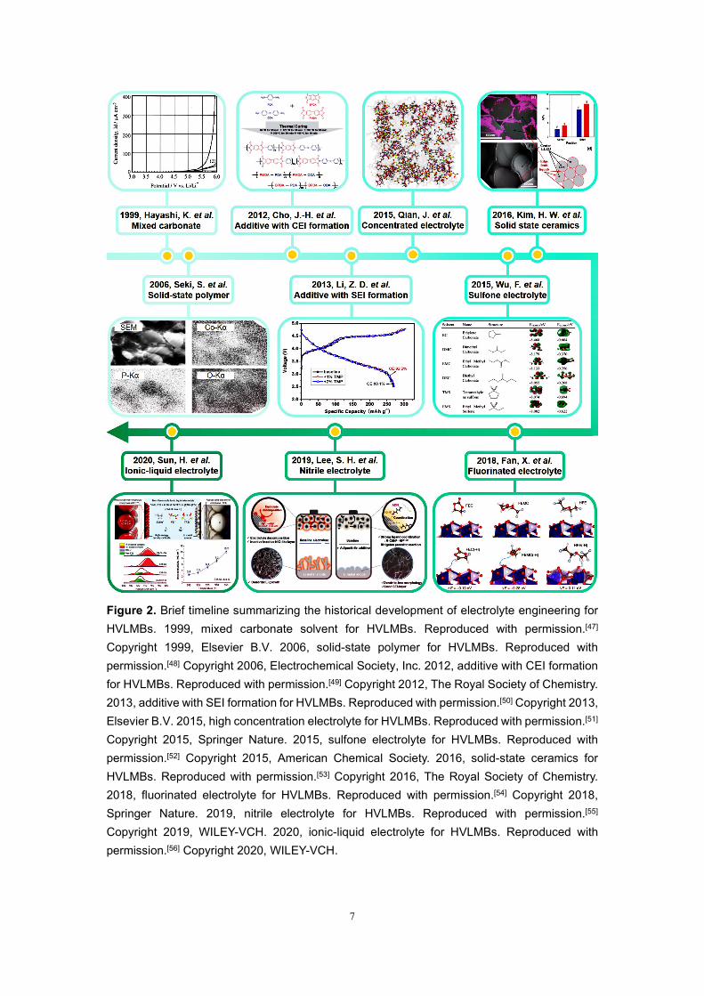
HVLMBs. A brief timeline summarizes the development of electrolyte engineering for
HVLMBs (Fig. 2). As shown in Fig. 3, in this review, recent reports on the electrolytes
for HVLMBs are reviewed in terms of the improvement of traditional electrolytes and
design of novel electrolytes. The highest occupied molecular orbital (HOMO) and the
lowest unoccupied molecular orbital (LUMO) values corresponding to the different
substances in Fig. 3 are displayed (Table 1). Theoretical studies and advanced
characterization methods based on the electrolytes of the HVLMBs are also probed to
study the internal mechanism for ultra-high stability at an extreme potential.

6
Furthermore, future hotspot directions and perspectives for further HVLMBs
electrolyte processing are also provided. Our review gives a multi-dimension
perspective, which involves high-voltage cathode material science, Li-metal anode
chemistry, theoretical simulation, novel characterization, comprehensive overview of
different solvents, comparison of various strategies, and perspectives of future
directions.
Figure 1. The published article number based on HVLMBs and electrolyte engineering for HVLMBs from 2007 to 2021 (Accessed April 27, 2022, Web of Science).
7
Figure 2. Brief timeline summarizing the historical development of electrolyte engineering for HVLMBs. 1999, mixed carbonate solvent for HVLMBs. Reproduced with permission.[47] Copyright 1999, Elsevier B.V. 2006, solid-state polymer for HVLMBs. Reproduced with permission.[48] Copyright 2006, Electrochemical Society, Inc. 2012, additive with CEI formation for HVLMBs. Reproduced with permission.[49] Copyright 2012, The Royal Society of Chemistry. 2013, additive with SEI formation for HVLMBs. Reproduced with permission.[50] Copyright 2013, Elsevier B.V. 2015, high concentration electrolyte for HVLMBs. Reproduced with permission.[51] Copyright 2015, Springer Nature. 2015, sulfone electrolyte for HVLMBs. Reproduced with permission.[52] Copyright 2015, American Chemical Society. 2016, solid-state ceramics for HVLMBs. Reproduced with permission.[53] Copyright 2016, The Royal Society of Chemistry. 2018, fluorinated electrolyte for HVLMBs. Reproduced with permission.[54] Copyright 2018, Springer Nature. 2019, nitrile electrolyte for HVLMBs. Reproduced with permission.[55] Copyright 2019, WILEY-VCH. 2020, ionic-liquid electrolyte for HVLMBs. Reproduced with permission.[56] Copyright 2020, WILEY-VCH.
8
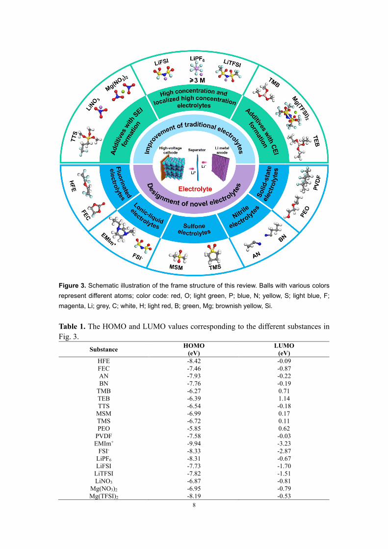
Figure 3. Schematic illustration of the frame structure of this review. Balls with various colors represent different atoms; color code: red, O; light green, P; blue, N; yellow, S; light blue, F; magenta, Li; grey, C; white, H; light red, B; green, Mg; brownish yellow, Si. Table 1. The HOMO and LUMO values corresponding to the different substances in Fig. 3.
Substance HOMO (eV)
LUMO (eV)
HFE -8.42 -0.09 FEC -7.46 -0.87 AN -7.93 -0.22 BN -7.76 -0.19
TMB -6.27 0.71 TEB -6.39 1.14 TTS -6.54 -0.18
MSM -6.99 0.17 TMS -6.72 0.11 PEO -5.85 0.62
PVDF -7.58 -0.03 EMIm+ -9.94 -3.23
FSI- -8.33 -2.87 LiPF6 -8.31 -0.67 LiFSI -7.73 -1.70
LiTFSI -7.82 -1.51 LiNO3 -6.87 -0.81
Mg(NO3)2 -6.95 -0.79 Mg(TFSI)2 -8.19 -0.53
9
2. Improvement of traditional electrolytes
2.1. High concentration and localized high concentration electrolytes
High concentration electrolytes (HCEs) exhibit unique ion solvation structures and
anion-derived interfaces, which endows the electrolyte with a wide electrochemical
window, excellent thermal stability, decreased flammability, and weakened current
collector corrosion. The HCE design is mainly for solvent and lithium salt. For the
solvent design, the carbonate-based, sulfone-based, and nitrile-based electrolyte
solvents with strong reactivity and poor film-formation ability for Li metal are difficult
to apply in HVLMBs. The formation of the anion-derived SEI layer induced in the
HCEs can significantly enhance the compatibility between the electrolyte and Li anode.
Moreover, the reduced free solvent number in HCE can improve the high voltage
stability of ether-based solvents, which promotes their applications in HVLMBs. In
terms of lithium salt design, great success has been achieved on HCEs, primarily
attributed to the LiF-rich SEI layer as derived from the anion. The big anion size in
LiFSI and LiTFSI decreases the Coulombic forces between cations and anions in the
electrolyte, ensuring the high solubility in the solvents. In HCEs, the interaction
between Li+ and anions significantly affects the interface formation and electrode
passivation processes. Due to the uniform and dense LiF-rich EEIs as induced by TFSI-
and FSI-, the interface can remarkably inhibit Li dendrite growth and tolerate the
significant volume change of high voltage/capacity electrodes.
To achieve HCE effects while reducing the viscosity of the electrolyte, localized
high concentration electrolytes (LHCEs) are developed. The construction difference
10
between LHCEs and HCEs is attributed to the diluent introduction. The selection
principles of the diluents mainly include: (i) weakening Li+ binding energy without
participating in the Li+ solvent shell to achieve localized high concentration
environment; (ii) lowering the viscosity by reducing the HCE viscosity and increasing
the wettability of the electrolyte for electrodes and separators; (iii) lowering the LUMO
energy level and facilitating the SEI layer formation; (iv) lowering the cost for
promoting large-scale applications; (v) lowering the combustibility and enhancing
battery safety; (vi) weakening toxicity and reducing pollution for battery recycling.
2.1.1. High concentration electrolytes
In recent reports, high concentration electrolytes (HCEs) effectively enhance the
Li metal stability and suppress the transition metal dissolution. By adding the lithium
bis(fluorosulfonyl)imide (LiFSI) concentration to 10 M, Fan et al.[57] demonstrated
outstanding cycling performance of the HVLMBs. As shown in Fig. 4a, the LiFSI salt
is reduced to form the LiF-rich layer, which validly suppresses the electrolyte oxidation
and impedes the Li dendrite growth. The superconcentrated electrolyte also stabilizes
the high-voltage NMC cathode at an extreme voltage. As shown in Fig. 4b, cycling
stability of LiNi0.6Mn0.2Co0.2O2 (NMC622) ||Li batteries with 1M LiPF6 in ethylene
carbonate (EC)/dimethyl carbonate (DMC) and 10M LiFSI in EC/DMC electrolytes are
tested. The CE of the battery using traditional electrolyte owns up to 99% in the first
few cycles. However, this CE steeply drops to only 95% after the first 20 cycles, and
the specific capacity decays rapidly. After 100 cycles, the NMC622||Li battery using 1
M LiPF6 EC/DMC electrolyte achieves the capacity retention of ~52%, considerably
11
lower than that in 10M LiFSI in EC/DMC electrolyte (~86%), which significantly
enhances the electrochemical performances of the HVLMBs compared with
conventional electrolytes. The CEs of the Li/Cu batteries using the two different
electrolytes are displayed in Fig. 4c. A high CE of ~97.5% is exhibited in the battery
with the superconcentrated electrolyte, and the CE gradually increases to ~99.3% on
the 80th cycle. Density functional theories (DFT) calculations for LUMO energy values
show that LiFSI owns a lower LUMO value (-1.70 eV) than those of DMC (-0.54 eV)
and EC (-0.92 eV), which indicates that LiFSI is more inclined to react with lithium
anode as compared with the solvents. In addition, the prioritized reduction of FSI anions
with lithium anode is significantly increased as the molar ratio between salt and solvent
increases from 0.105 in the diluted electrolyte to 1.05 in HCE. Without considering
thermodynamics, the -SO2F groups of FSI anions also own a kinetical advantage over
the carbonate solvents. Since the S-C bond is more stable than the C-F bond, the HCE
with the LiFSA salt is expected to achieve better electrolyte suppression and transition
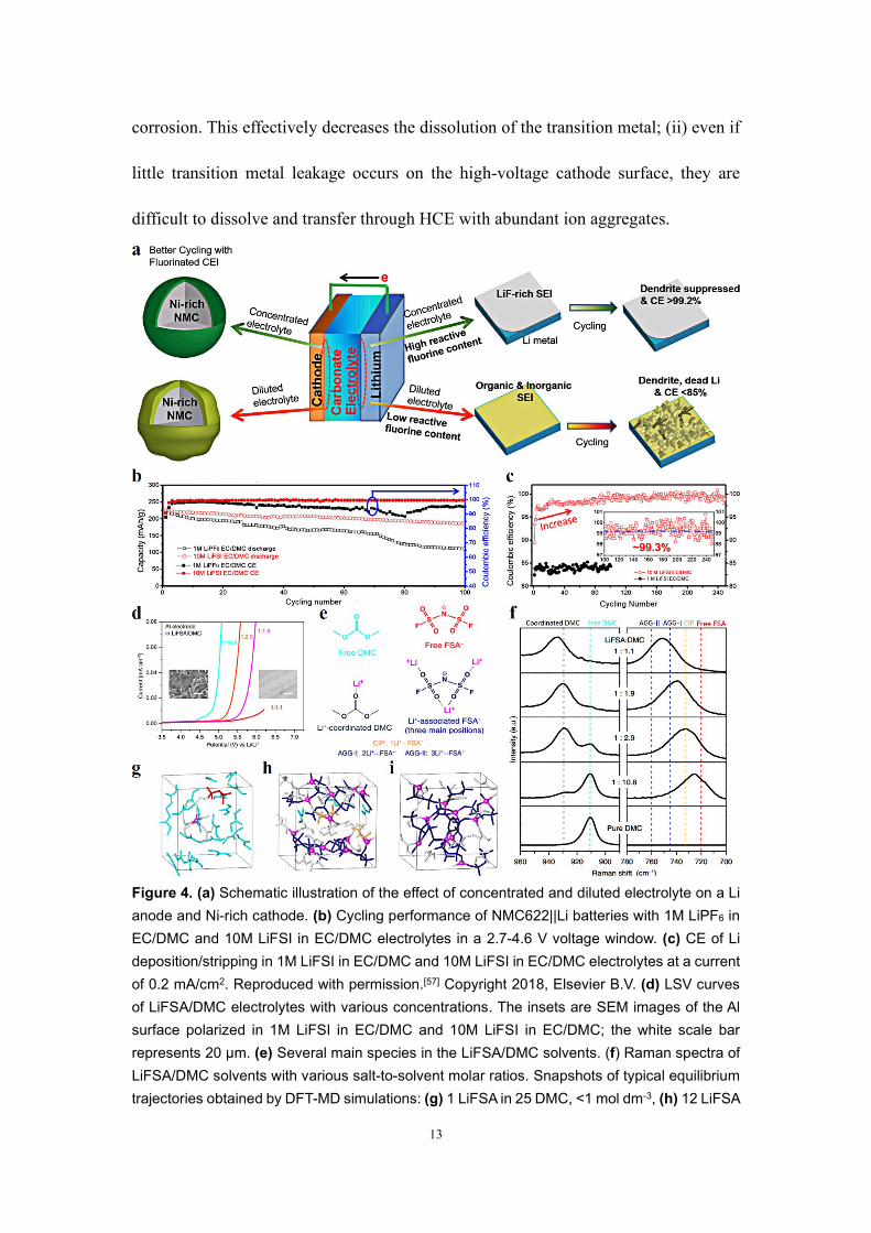
metal dissolution effect as compared with that with LiFSI. Wang, et al.[58] added an
advanced lithium bis(fluorosulfonyl)amide (LiFSA) in traditional carbonate solvent to
ultra-high concentration. The superconcentrated electrolyte exhibits a dense network
between anions and solvent molecules, and the network owns robust coordination with
Li+ cations. As shown in Fig. 4d, the linear sweep voltammetry (LSV) confirms that a
high concentration strategy can improve the oxidation potential of the electrolyte. The
scanning electron microscopy (SEM) photographs of the polarized aluminum surface
indicate the successful prevention of Al dissolution in such a superconcentrated
12
electrolyte. The main substances in the LiFSA/DMC electrolytes are shown in Fig. 4e.
As shown in Fig. 4f, an evident O-CH3 vibration (910 cm-1) is observed in free DMC.
When Li+ is coordinated with the DMC molecule, the O-CH3 band rises to 930-935 cm-
1. In the solvent of LiFSA:DMC = 1:10.8, most DMC molecules are independent as the
molar ratio of solvent to salt is far higher than a conventional four- or five-times
coordination amount of lithium ion. As the concentration of the LiFSA gradually
increases, the free DMC molecular decreases and the coordinated 1,2-dimethoxyethane
(DME) molecular with Li+ cations increases. Owing to the appearance of aggregate
clusters (two or more Li+ cations coordinate with FSA- anion) and contact ion pairs
(only one Li+ cation coordinates with FSA- anion), the formation of aggregate clusters
is confirmed by a significant mobile of FSA- cation band at 700-780 cm-1. Figs. 4g-i
show the simulation snapshots of dilute electrolyte, moderately concentrated electrolyte
and superconcentrated electrolyte, respectively. For the moderately concentrated
electrolyte, the intensity of the free DMC band significantly decreases in Raman
spectroscopy, indicating that a large number of DMC molecules participate in the Li+
solvation. It is further confirmed by DFT calculations (Fig. 4h), which display that ~90%
of DMC molecules are involved in the Li+ solvation. As shown in Fig. 4i, for the
superconcentrated electrolyte, Li+ cations coordinated with FSA- anions form a robust
three-dimensional network, effectively suppressing the dissolution of transition metal
and anodic Al foil at a high voltage. In addition, there are two critical reasons for the
improved stability of the electrolyte/cathode interface in HCE: (i) LiFSA exhibits lower
reactivity to generate hydrofluoric acids than LiPF6, thus reducing the electrode
13
corrosion. This effectively decreases the dissolution of the transition metal; (ii) even if
little transition metal leakage occurs on the high-voltage cathode surface, they are
difficult to dissolve and transfer through HCE with abundant ion aggregates.
Figure 4. (a) Schematic illustration of the effect of concentrated and diluted electrolyte on a Li anode and Ni-rich cathode. (b) Cycling performance of NMC622||Li batteries with 1M LiPF6 in EC/DMC and 10M LiFSI in EC/DMC electrolytes in a 2.7-4.6 V voltage window. (c) CE of Li deposition/stripping in 1M LiFSI in EC/DMC and 10M LiFSI in EC/DMC electrolytes at a current of 0.2 mA/cm2. Reproduced with permission.[57] Copyright 2018, Elsevier B.V. (d) LSV curves of LiFSA/DMC electrolytes with various concentrations. The insets are SEM images of the Al surface polarized in 1M LiFSI in EC/DMC and 10M LiFSI in EC/DMC; the white scale bar represents 20 μm. (e) Several main species in the LiFSA/DMC solvents. (f) Raman spectra of LiFSA/DMC solvents with various salt-to-solvent molar ratios. Snapshots of typical equilibrium trajectories obtained by DFT-MD simulations: (g) 1 LiFSA in 25 DMC, <1 mol dm-3, (h) 12 LiFSA
14
in 24 DMC, ca. 4 mol dm-3, and (i) 10 LiFSA in 11 DMC, ca. 5.5 mol dm-3. Reproduced with permission.[58] Copyright 2016, Springer Nature.
2.1.2. Localized high concentration electrolytes
By adding diluent into the HCEs, LHCEs are further developed, which enhances
the wettability with the separator and electrode and reduces the use of Li salt to decrease
the cost. Zhang, et al.[59] enhanced the oxidation potential of LHCE to 4.9 V and
achieved outstanding cycling performance of LiNi0.8Mn0.1Co0.1O2 (NMC811) ||Li
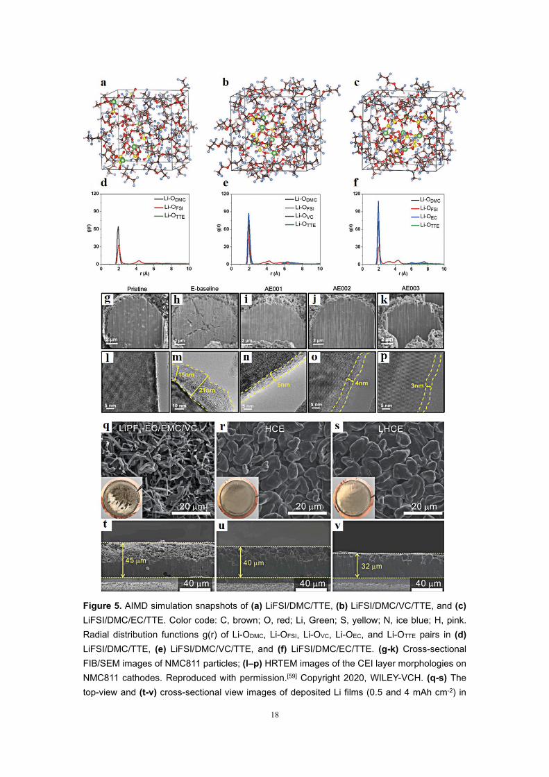
battery in 2.5-4.4 V. Figs. 5a-c show the simulation snapshots of LiFSI/DMC/1,1,2,2-
tetrafluoroethyl-2,2,3,3-tetrafluoropropyl ether (TTE), LiFSI/DMC/vinylene carbonate
(VC)/TTE, and LiFSI/DMC/EC/TTE electrolytes, respectively. The simulation results
indicate that the LiFSI salt is associated with DMC and EC as well as VC molecules in
diluent TTE solvent. The radial distribution function (g(r)) is conducted to further
research the distances between different solvents and Li+ cations in the LHCEs. As
shown in Figs. 5d-f, strong peaks of the Li+-ODMC are all ~1.95 Å, a bit smaller than
Li+-OFSI-, demonstrating the excellent coordination between DMC molecules and Li+
cations. For the LHCEs with EC or VC solvents, a new peak of Li+-OEC/Li+-OEC also
appears at 1.95 Å, indicating that the EC and VC fully participate in the Li+ cation
solvation. The stronger intensity of Li+-OEC/Li+-OEC pairs than that of Li+-ODMC pairs
demonstrates the better coordination between Li+ cations and EC/VC molecules in the
LHCEs. Likewise, the coordination between VC and Li+ is weaker than EC. In addition,
TTE molecules have no association with Li+ cations in the three LHCE systems,
suggesting that the TTE solvent as diluent shows no interaction with Li+ cation in the
LHCE. To find out why the LHCEs in NMC811||Li batteries exhibit the outstanding
15
electrochemical performances, the NMC811 electrodes after cycling and cathode
electrolyte interphase (CEI) on their surface are characterized by SEM and high
resolution transmission electron microscopy (HRTEM). The cross-sectional focused
ion beam (FIB)/SEM images of the pristine and cycled cathodes are shown in Figs. 5g-
k. Many cracks appear on the NMC811 cathode after cycling in a traditional E-baseline
electrolyte. In contrast, the electrodes after cycling in the three LHCE systems are well
protected. As shown in Fig. 5i, a clean surface is observed at the fresh NMC811 cathode.
A CEI layer with 15-21 nm thickness is unevenly distributed on the cycled cathode
surface (Fig. 5m). However, the NMC811 cathodes using the LHCEs exhibit more
uniform and thinner CEI layers, specifically, ≈5 nm for LiFSI/DMC/TTE electrolyte
(Fig. 5n), ≈4 nm for LiFSI/DMC/VC/TTE electrolyte (Fig. 5o), and ≈3 nm for
LiFSI/DMC/EC/TTE electrolyte (Fig. 5p). Despite the smaller thickness than the
traditional electrolyte, the CEI layers in three LHCE systems exhibit better durability
and mechanical strength, originating from the less transition metal dissolution than the
traditional electrolyte. These results demonstrate that the advanced interfacial
chemistry in the LHCEs efficiently protects the high-voltage cathode, further reducing
the transition metal escape and electrolyte oxidation. In addition to the carbonate-based
LHCEs, the ether-based LHCEs with an excellent affinity for lithium metal are also
profoundly investigated. Ren, et al.[60] developed an ether-based LHCE that can
maintain the stability of NMC811 cathode under a high voltage of 4.5 V with the LiF-
rich interface. Combined with the outstanding stability for Li metal in the LHCE, the
NMC811||Li cells exhibit significantly enhanced cycling performance. In the LHCE

16
system, FSI- replaces the DME molecule in the Li+ solvation structure, and the addition
of TTE diluent does not destroy the interaction between FSI- and Li+. To research the
Li dendrite growth behavior in the conventional electrolyte, HCE, and LHCE, the
digital photos of the Li metals after cycling in Li||Cu batteries using various electrolytes
are shown in the insets of Figs. 5q-s. For the traditional electrolyte, an extremely
uneven layer is observed, indicating a severe parasitic reaction at the anode-electrolyte
interface. In contrast, flat Li layers are deposited in LHCE and HCE, suggesting
uniform Li+ transmission in the two electrolytes. Large and smooth Li deposits are
observed in SEM characterizations of these two electrolytes. However, apparent Li
dendrite growth can be observed in the carbonate electrolyte. As shown in Figs. 5t-v,
for the LHCE, the cross-section picture of the anode exhibits a denser and uniform
deposition layer with a thickness of 32 mm, considerably lower than those in the HCE
(40 mm) and the carbonate electrolyte (45 mm). The Li deposit owning a larger contact
area with carbonate electrolyte will induce a more severe parasitic reaction to cause a
lower CE.
Except the TTE diluent, 1,2-difluorobenzene (1,2-dfben), fluorobenzene (FB), and
bis(2,2,2-trifluoroethyl) ether (BTFE) with weak Li+ binding energy and strong
fluorine-donating ability own huge potential as diluents. Yoo, et al.[61] reported that 1,2-
dfben could be used as diluent solvent in the electrolyte to realize the LHCE effect. The
low LUMO energy level and strong fluorine-donating ability of 1,2-dfben enhance the
concentration influence at a relatively low lithium salt concentration of 2M and achieve
LiF-rich SEI composition. Jiang, et al.[62] found that the introduction of FB diluent not
17
only enhances the physical properties of the electrolyte, but also modifies the Li+
solvation shell, which promotes the formation of LiF-rich electrode/electrolyte
interfaces (EEIs). Beneficial from these improved features, the Li/LCO cell with the
high-loading cathode (20.4 mg cm-2) using the LHCE shows stable cycling
performances and high rate capacities at an extreme potential (4.6 V). Notably, the
Li/LCO pouch battery delivers an energy density of 400 Wh kg-1 under harsh conditions
(50 μm Li, 2.7 g Ah-1 electrolyte amount). Chen, et al.[63] reported a fire-retardant LHCE
with the lithium salt of LiFSI and the non-flammable solvents of triethyl phosphate
(TEP) and BTFE. The LHCE can sustain stable and dendrite-free cycling of HVLMBs
with an average CE of 99.2%. Furthermore, it shows outstanding anodic stability up to
5 V and significantly enhances the electrochemical performances of HVLMBs. Table
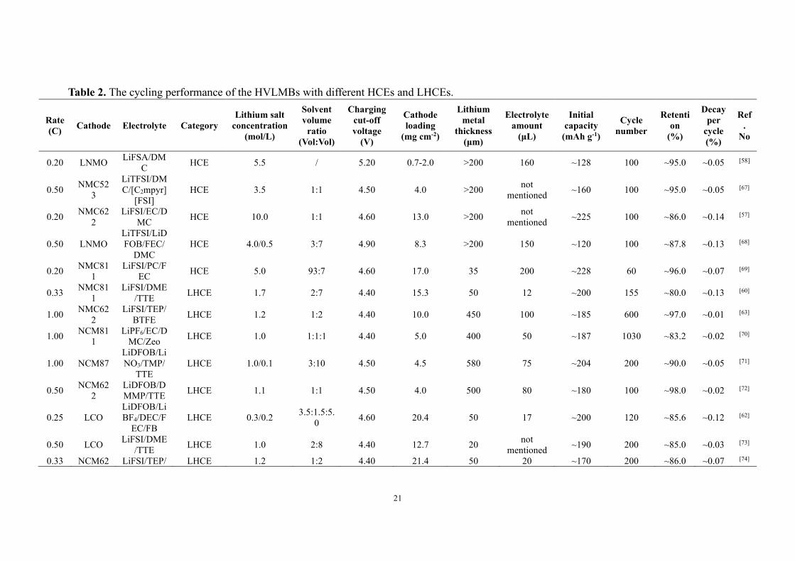
2 shows the cycling performance of the HVLMBs with different HCEs and LHCEs.
18
Figure 5. AIMD simulation snapshots of (a) LiFSI/DMC/TTE, (b) LiFSI/DMC/VC/TTE, and (c) LiFSI/DMC/EC/TTE. Color code: C, brown; O, red; Li, Green; S, yellow; N, ice blue; H, pink. Radial distribution functions g(r) of Li-ODMC, Li-OFSI, Li-OVC, Li-OEC, and Li-OTTE pairs in (d) LiFSI/DMC/TTE, (e) LiFSI/DMC/VC/TTE, and (f) LiFSI/DMC/EC/TTE. (g-k) Cross-sectional FIB/SEM images of NMC811 particles; (l–p) HRTEM images of the CEI layer morphologies on NMC811 cathodes. Reproduced with permission.[59] Copyright 2020, WILEY-VCH. (q-s) The top-view and (t-v) cross-sectional view images of deposited Li films (0.5 and 4 mAh cm-2) in
19
different electrolytes. Reproduced with permission.[60] Copyright 2019, Elsevier B.V
2.1.3. Section summary
In this section, recent development in the HCEs and LHCEs has been discussed,
including carbonate-in-salt, ether-in-salt, and other organic solvent-in-salt electrolytes,
such as 5.5M LiFSA in DMC, 1.7M LiFSI in DME/TTE, and 3.5M LiTFSI in
DMC/[C2mpyr][FSI]. Through increasing the salt concentration, the ion transfer
mechanisms in HCEs and LHCEs are remarkably different as compared with traditional
electrolytes. In conventional electrolytes, a big solvation structure is formed through
coordination between Li+ and solvent, which seriously decreases the Li+ mobility.
However, the anion almost does not enter the solvation shell. Therefore, the
conventional electrolytes own low Li+ transference numbers (<0.4), leading to abundant
anions gathering on the cathode, generating severe concentration polarization and large
overpotential.[64] On the contrary, for the distinctive solvation structure of the HCEs, Li
cations can drag more anions into the solvation structure, which dramatically limits the
anion mobility while less affecting the cation mobility, resulting in an extremely high
Li+ transference number (>0.6).[65, 66] This leads to a large mass transfer flux of Li cation,
promoting the uniform and rapid substance exchange at the surfaces of high-voltage
cathode and Li-metal anode. It can also prevent the spatial charge layer induced by the
anion consumption at EEIs. This decreases the electric field driving force and
exacerbates the uneven deposition of Li+. In addition, the rival coordination of solvent
and anion with Li cation controls the solubility of the lithium salt in the electrolyte and
the generation of aggregates and ion pairs universally existing in the HCEs and
maintaining the stability of the two electrodes in HVLMBs. Moreover, the reorganized
20
Li+ solvation structure in the HCEs not only involves more anions but also reduces
accessible free solvents, which enhances the electrochemical window of the electrolyte
and optimizes the formation pathways of SEI and CEI layers to increase the mechanics
and the electrochemical stability of EEIs. Overall, besides the widely-received
cancellation of free solvent at high concentrations, the contact ion pair and aggregate
cluster formation facilitates the involvement of anions in the passivation layer
formation, and thus essentially enhance the inorganic substances in the SEI/CEI layers
and increase the electrolyte oxidation resistance. The distinctive solvation structure and
the anion-derived interface endow the electrolyte with surprising properties, such as
enhanced oxidation potential, improved thermal stability, decreased flammability, and
intensive compatibility with the current collector. Therefore, the electrochemical
performances of HVLMBs can be significantly enhanced using HCEs and LHCEs.
21
Table 2. The cycling performance of the HVLMBs with different HCEs and LHCEs.
Rate (C) Cathode Electrolyte Category
Lithium salt concentration
(mol/L)
Solvent volume
ratio (Vol:Vol)
Charging cut-off voltage
(V)
Cathode loading
(mg cm-2)
Lithium metal
thickness (μm)
Electrolyte amount
(μL)
Initial capacity
(mAh g-1)
Cycle number
Retention
(%)
Decay per
cycle (%)
Ref.
No
0.20 LNMO LiFSA/DMC HCE 5.5 / 5.20 0.7-2.0 >200 160 ~128 100 ~95.0 ~0.05 [58]
0.50 NMC523
LiTFSI/DMC/[C2mpyr]
[FSI] HCE 3.5 1:1 4.50 4.0 >200 not
mentioned ~160 100 ~95.0 ~0.05 [67]
0.20 NMC622
LiFSI/EC/DMC HCE 10.0 1:1 4.60 13.0 >200 not
mentioned ~225 100 ~86.0 ~0.14 [57]
0.50 LNMO LiTFSI/LiDFOB/FEC/
DMC HCE 4.0/0.5 3:7 4.90 8.3 >200 150 ~120 100 ~87.8 ~0.13 [68]
0.20 NMC811
LiFSI/PC/FEC HCE 5.0 93:7 4.60 17.0 35 200 ~228 60 ~96.0 ~0.07 [69]
0.33 NMC811
LiFSI/DME/TTE LHCE 1.7 2:7 4.40 15.3 50 12 ~200 155 ~80.0 ~0.13 [60]
1.00 NMC622
LiFSI/TEP/BTFE LHCE 1.2 1:2 4.40 10.0 450 100 ~185 600 ~97.0 ~0.01 [63]
1.00 NCM811
LiPF6/EC/DMC/Zeo LHCE 1.0 1:1:1 4.40 5.0 400 50 ~187 1030 ~83.2 ~0.02 [70]
1.00 NCM87 LiDFOB/LiNO3/TMP/
TTE LHCE 1.0/0.1 3:10 4.50 4.5 580 75 ~204 200 ~90.0 ~0.05 [71]
0.50 NCM622
LiDFOB/DMMP/TTE LHCE 1.1 1:1 4.50 4.0 500 80 ~180 100 ~98.0 ~0.02 [72]
0.25 LCO LiDFOB/LiBF4/DEC/F
EC/FB LHCE 0.3/0.2 3.5:1.5:5.
0 4.60 20.4 50 17 ~200 120 ~85.6 ~0.12 [62]
0.50 LCO LiFSI/DME/TTE LHCE 1.0 2:8 4.40 12.7 20 not
mentioned ~190 200 ~85.0 ~0.03 [73]
0.33 NCM62 LiFSI/TEP/ LHCE 1.2 1:2 4.40 21.4 50 20 ~170 200 ~86.0 ~0.07 [74]
22
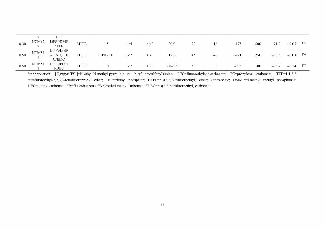
2 BTFE
0.30 NCM622
LiFSI/DME/TTE LHCE 1.5 1:4 4.40 20.0 20 16 ~175 600 ~71.0 ~0.05 [75]
0.50 NCM811
LiPF6/LiBF4/LiNO3/FE
C/EMC LHCE 1.0/0.2/0.3 3:7 4.40 12.8 45 40 ~221 250 ~80.3 ~0.08 [76]
0.50 NCM811
LiPF6/FEC/FDEC LHCE 1.0 3:7 4.80 8.0-8.5 50 30 ~235 100 ~85.7 ~0.14 [77]
*Abbreviation: [C2mpyr][FSI]=N-ethyl-N-methyl-pyrrolidinium bis(fluorosulfonyl)imide; FEC=fluoroethylene carbonate; PC=propylene carbonate; TTE=1,1,2,2-tetrafluoroethyl-2,2,3,3-tetrafluoropropyl ether; TEP=triethyl phosphate; BTFE=bis(2,2,2-trifluoroethyl) ether; Zeo=zeolite; DMMP=dimethyl methyl phosphonate; DEC=diethyl carbonate; FB=fluorobenzene; EMC=ethyl methyl carbonate; FDEC=bis(2,2,2-trifluoroethyl) carbonate.
23
2.2. Additives with CEI formation
The high voltage leads to continuous decomposition of conventional carbonate-
based electrolytes at cathode surfaces, often generating an unstable, non-uniform, and
non-protective CEI layer, impeding the Li+ migration and decreasing the
electrochemical efficiency. Various side reactions, such as irreversible structural change,
leakage of transition metals, and release of lattice oxygen, also emerge and considerably
deteriorate battery performances. Compared with other strategies of enhancing the
electrochemical performances of HVLMBs, the strategy of using CEI additives owns
less dosage, simple method, low cost, and prominent effect. Thus it has attracted
widespread concerns. The HOMO energy value of most CEI additives is lower than
that of solvents, so they can preferentially participate in the electrochemical reactions
on the electrolyte/cathode interface, forming a robust and uniform film on cathode
surface to suppress the decomposition of electrolytes and decrease the effect of various
side reactions. The higher voltage pursuing in the high-energy-density Li batteries has
exceeded the anodic limits of the commercial electrolytes, therefore adding CEI
additive to form a protective layer that blocks the electron transport and meanwhile
enables efficient Li+ access, is one of the most effective strategies.
By forming a stable and even CEI layer, the additives alleviate the continuous
degradation of electrolyte and inhibit the transition metal dissolution, enhancing the
cycling stability of HVLMBs. Choudhury et al.[78] demonstrated that the CEI composed
of preformed supra-molecules and anionic polymers achieves an advanced strategy for
enhancing the stability of ether electrolytes at an extreme voltage. As shown in Figs. 6a
24
and 6b, the charged glyme-bis(oxalate)borate (BOB) oligomers, which are incredibly
stable at a high voltage, form a dense CEI by robust non-covalent interactions. The
oligomer CEI effectively reduces the side reaction between the electrolyte and the high-
voltage cathode. As shown in Fig. 6c, the semi-crystalline polymer with the following
three advantages is studied. First, the solutions of Li+ cations in aprotic alcohol and
carbonate ester exhibit low viscosity for the successful transportation of the polymer to
the pores of the prefabricated cathode through the liquid carrier. Second, the Li+ coated
interfaces are previously studied to indicate that the effective electrostatic shielding is
formed by the negative charge centers generated by the dissociation of the sulfonate
groups. The shield inhibits the migration of negatively charged substances on the
surface of the electrode without compromising the transport of cations. It induces high
interfacial ionic conductivities and Li+ transference numbers. Finally, the hydrophobic
and hydrophilic domains coexist in the Li+ cations separator, which means that the
strongly polarized molecules will be slowed down in solvent. Fig. 6d displays the only
coupling product and the corresponding free energy change. The simulations show that
the negatively charged substances are thermodynamically prone to be formed compared
with their neutral analogs. Thermodynamically, the C-C produced by the CO2 release
is preferable (ΔG = -0.64 eV). To evaluate the generate possibility of supramolecular,
oligomers, or polymers, the reaction energies for these species are calculated (Fig. 6e).
These results demonstrate that the generation of negative charge and neutral trimer is
thermodynamically difficult, along with the higher-order polymers. The anion and
neutral form of the trimer formed by the dimer are endothermic peaks of 1-4 eV, and

25
the formation of higher-order coupling products is very difficult owing to the high ΔG.
As the potentials increase, the trimers may appear, but further polymerization seems
impossible. Higher-order oligomers with multiple charges are unstable owing to the
easy dissociation into lower-order charged dimers or trimers. Based on this situation,
Fig. 6f displays the calculations of the redox potentials of the diglyceride molecule, as
well as the oligomer with the BOB molecule. In particular, the measured and
computationally predicted infrared (IR) spectra all confirm that the oligomer is stable
at an extreme voltage. The LSV in a 3-electrode setup and the more rigorous
electrochemical floating-point examination show the enhanced oxidation potential with
the existence of the oligomer. The cyclability of Li||NCM cell utilizing the diglyme-
LiNO3-tris(hexafluoro-iso-propyl)phosphate (HFiP) electrolyte is studied, as displayed
in Fig. 6g. The battery exhibits a CE of up to 98%, and the capacity decays only 20%
after 200 cycles at 0.2 C. As shown in Fig. 6h, the improvement of oxidation potential
is observed in several electrolyte systems. The enhanced oxidation of anionic Li+
cations coating is universal. The introduction of F on the basis of B-containing additives
can further enhance the stability of the electrolyte/cathode interface. Yue et al.[79]
demonstrated that tris(pentafluorophenyl)borane (TPFPB) additive with CEI formation
stabilizes the LNMO cathode at elevated potentials and the Li anode. SEM is conducted
to study the CEI generation on the LNMO cathode. The HOMO value of TPFPB (-7.89
eV) is higher than those of EMC (-8.16 eV) and EC (-8.44 eV). The LUMO energy
level of TPFPB is -3.54 eV, considerably lower than those of EMC (0.82 eV) and EC
(0.54 eV). Such a large energy landscape ensures the early redox reaction of TPFPB
26
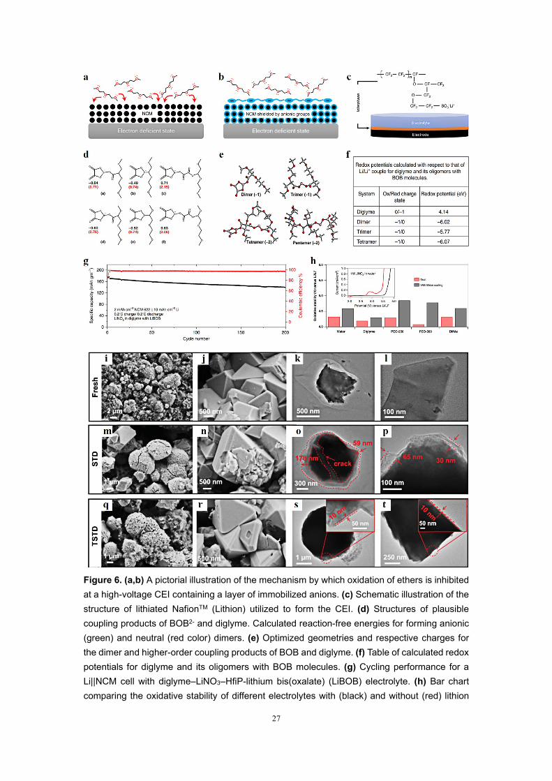
over the carbonate solvents, promoting the stable EEI formation on the electrodes and
inhibiting the decomposition of EC and DMC. For the pristine LNMO electrode,
octahedral crystal shape and spherical secondary particles are observed (Figs. 6i and
6j). The LNMO cathode after 200 cycles in the standard electrolyte (STD) is damaged
(Figs. 6m and 6n). On the contrary, both types of cathodes in the STD with 1 wt.%
TPFPB (TSTD) are relatively intact after 200 cycles (Figs. 6q and 6r). The
transmission electron microscope (TEM) characterizations are used to further evaluate
the CEI in various electrolytes. For the fresh LNMO cathode, no CEI layer is observed
(Figs. 6k and 6l). As shown in Figs. 6o and 6p, the non-uniform CEI layer with a
thickness ranging from 59 to 178 nm, is formed on the surface of LNMO particles in
the STD electrolyte. It is because of the electrolyte decomposition on the cathode. By-
products of the decomposition are electronically insulating and can cause these LNMO
particles to inactivate.[80] Therefore, the impedance continues to increase to cause
difficulties in delithiation and lithiation. As shown in Figs. 6s and 6t, a thin and uniform
CEI ~10 nm is generated in the TSTD electrolyte. This thin CEI prevents side reactions
between the electrolyte and the LNMO cathode and ensures fast Li+ transmission.
27
Figure 6. (a,b) A pictorial illustration of the mechanism by which oxidation of ethers is inhibited at a high-voltage CEI containing a layer of immobilized anions. (c) Schematic illustration of the structure of lithiated NafionTM (Lithion) utilized to form the CEI. (d) Structures of plausible coupling products of BOB2- and diglyme. Calculated reaction-free energies for forming anionic (green) and neutral (red color) dimers. (e) Optimized geometries and respective charges for the dimer and higher-order coupling products of BOB and diglyme. (f) Table of calculated redox potentials for diglyme and its oligomers with BOB molecules. (g) Cycling performance for a Li||NCM cell with diglyme–LiNO3–HfiP-lithium bis(oxalate) (LiBOB) electrolyte. (h) Bar chart comparing the oxidative stability of different electrolytes with (black) and without (red) lithion

28
coating. Reproduced with permission.[78] Copyright 2019, Springer Nature. SEM (left) and TEM (right) images of the LNMO cathodes under the conditions of (i–l) pristine LNMO cathode and after 200 cycles in (m-p) STD and (q-t) TSTD electrolytes. Reproduced with permission.[79] Copyright 2019, The Royal Society of Chemistry.
Li. Et al.[81] manipulated the electrode/electrolyte interphase with a LiBOB
additive to enhance the cycle life of LiNi0.94Co0.06O2||Li cell at an extreme potential.
Fig. 7a shows a 3D view of the distribution of BO-segments in the time of flight
secondary ion mass spectrometry (TOF-SIMS) sputtering volume collected near the
surface of the cycled cathode with or without LiBOB. The BO- signal on the
LiNi0.94Co0.06O2 cathode in 1.5% LiBOB electrolyte is more evident and uniform than
the baseline electrolyte. Therefore, LiBOB salt initially oxidizes and changes the
original CEI composition. Fig. 7b displays the charge-discharge curves of various
electrolytes at the initial cycle for the LiNi0.94Co0.06O2||Li batteries at 0.1 C. The
discharge and charge capacities of the cell with the baseline electrolyte are 228 and 258
mAh g-1, corresponding to 88.2% CE. The charge capacities of the cells with the 0.3%
LiBOB and 1.5% LiBOB electrolytes are 260 and 263 mAh g-1, respectively, with CE
of 86.8% and 85.6%. The initial oxidation of BOB- anions causes lower CE. Besides,
the corresponding differential capacity (dQ/dV) curve offers a more direct and detailed
comparison (Fig. 7c). The battery using baseline electrolyte exhibits an apparent peak
at 3.0 V, ascribed to the decrease of EC when electrolyte-anode interphase is formed on
the anode surface. Overall, this study demonstrates that BxOy groups are introduced in
the EEIs by the sacrificial decomposition of LiBOB, which enhances the interfacial Li+
diffusivity and gives rise to superior electrochemical stability of the high-voltage
cathode. Compared with LiNi0.94Co0.06O2, the stable CEI construction of Co-
29
free LiNiO2 is more difficult due to the continuous Ni dissolution, structural disordering,
and particle cracking. Deng. Et al.[82] developed a fluorinate-rich electrolyte with
lithium difluoro(oxalate)borate (LiDFOB) salt to generate a strong fluoride (F)- and
boron (B)-rich CEI layer. The capacity retention of LiNiO2||Li cell reaches as high as
80% after 400 cycles under an extreme potential of 4.4 V. The cycled LiNiO2 cathodes
in 1M LiPF6 in EC/DMC = 1/1, v/v and 1M LiPF6 + 2 wt.% LiDFOB dissolved in
FEC/FEMC/HFE = 2/6/2, w/w/w (F-262A) electrolyte are tested by TOF-SIMS to
study the surface compositions (Figs. 7d-i). As shown in Fig. 7d, the Ga+ ions sputter
the crater to form the edge surface. Plentiful F and B signals are generated on the
LiNiO2 cycled in the F-262A electrolyte. The ion intensity of Li and O elements remains
unchanged from the depth profile (Fig. 7g), suggesting a strong and thin CEI layer with
high-ratio F and B elements on the cycled LiNiO2 with the F-262A electrolyte. With
the F-262A electrolyte, the LiNiO2 cathode exhibits a superior capacity of 216 mAh g-
1 with lower capacity decay of <20% after 400 cycles at 0.5 C. The significantly
improved cycling performance originates from the following two aspects: (i) the CEI
with high-ratio F and B elements effectively inhibits the continuous side effects on the
LiNiO2 cathode; (ii) the SEI with high-ratio F and B elements suppresses the parasitic
reaction for the preservation of the Li anode. Fig. 7j shows that a small amount of HF
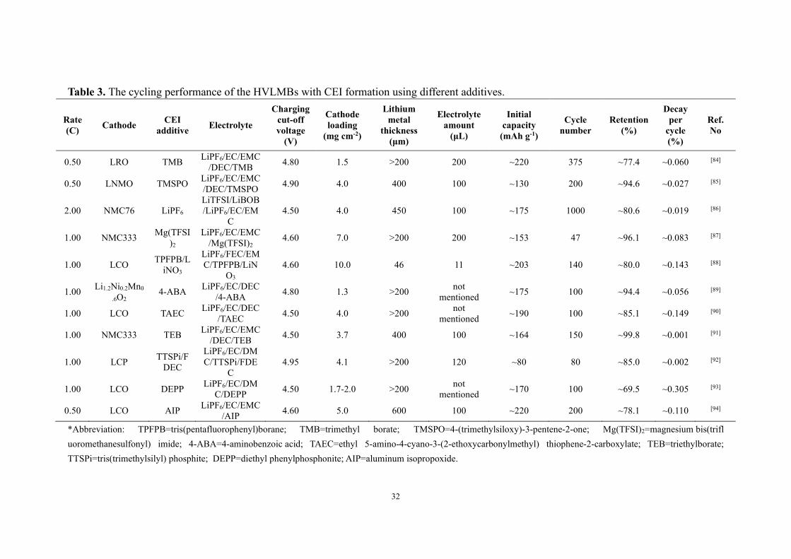
corrosion helps form a uniform CEI layer. Table 3 shows the cycling performance of
the HVLMBs with CEI formation using different additives.

30
Figure 7. (a) 3D distribution of LiBOB decomposition species (represented by BO-) in the TOF-SIMS sputtered volume on LiNi0.94Co0.06O2 cathode surface retrieved from 500-cycle full cells with baseline electrolyte and 1.5% LiBOB. (b) The initial charge-discharge curves of Li||LiNi0.94Co0.06O2 cells with different electrolytes. (c) dQ/dV curves of the cells with baseline electrolyte and 1.5% LiBOB. Reproduced with permission.[81] Copyright 2020, WILEY-VCH. (d) Surface morphology of LNO particle after 100 cycles in F-262A electrolyte for TOF-SIMS. (e,f,h,i) The depth profiles of TOF-SIMS analysis for F, Li, O, and B elements on the cycled active particles. (g) The corresponding Li, O, F, and B elements distribution in the sputtered active particle. Reproduced with permission.[82] Copyright 2019, Elsevier B. (j) Schematics of carbonate-based electrolyte decomposition in a high-voltage layered oxide system using EC as an example. Reproduced with permission.[83] Copyright 2022, WILEY-VCH.
2.2.1 Section summary
In this section, recent development in the CEI additives has been discussed,
31
including boron additive, phosphorus additive, nitrile additive, fluorine additive,
unsaturated carbonate derivatives, and silane additives, such as HFiP, TPFPB, LiBOB,
LiDFOB, and TMSPO. Electrolyte additive for CEI formation provides a practical and
facile method to enhance the electrochemical performances of HVLMBs by in situ
managing the chemical/physical properties/structures of CEI. The ideal CEI structure
must be compact, continuous, uniform, and thin, accelerating Li+ conductivity,
suppressing the leakage of transition metals and lattice oxygen, and separating high-
voltage cathode and electrolyte to suppress the side reactions. Also, the CEI should
balance flexibility and mechanical strength to tolerate the morphology changes of
cathodes. Furthermore, it should be electrochemically stable in the extreme voltage
environment. The abovementioned properties and component element types of the film
generated on the cathode surface are variant, and the reaction mechanism is different.
Therefore, it is worth exploring their internal mechanism of action and integrating
various functions into one additive.
32
Table 3. The cycling performance of the HVLMBs with CEI formation using different additives.
Rate (C) Cathode CEI
additive Electrolyte
Charging cut-off voltage
(V)
Cathode loading
(mg cm-2)
Lithium metal
thickness (μm)
Electrolyte amount
(μL)
Initial capacity
(mAh g-1)
Cycle number
Retention (%)
Decay per
cycle (%)
Ref. No
0.50 LRO TMB LiPF6/EC/EMC/DEC/TMB 4.80 1.5 >200 200 ~220 375 ~77.4 ~0.060 [84]
0.50 LNMO TMSPO LiPF6/EC/EMC/DEC/TMSPO 4.90 4.0 400 100 ~130 200 ~94.6 ~0.027 [85]
2.00 NMC76 LiPF6 LiTFSI/LiBOB/LiPF6/EC/EM
C 4.50 4.0 450 100 ~175 1000 ~80.6 ~0.019 [86]
1.00 NMC333 Mg(TFSI)2
LiPF6/EC/EMC/Mg(TFSI)2
4.60 7.0 >200 200 ~153 47 ~96.1 ~0.083 [87]
1.00 LCO TPFPB/LiNO3
LiPF6/FEC/EMC/TPFPB/LiN
O3 4.60 10.0 46 11 ~203 140 ~80.0 ~0.143 [88]
1.00 Li1.2Ni0.2Mn0
.6O2 4-ABA LiPF6/EC/DEC
/4-ABA 4.80 1.3 >200 not mentioned ~175 100 ~94.4 ~0.056 [89]
1.00 LCO TAEC LiPF6/EC/DEC/TAEC 4.50 4.0 >200 not
mentioned ~190 100 ~85.1 ~0.149 [90]
1.00 NMC333 TEB LiPF6/EC/EMC/DEC/TEB 4.50 3.7 400 100 ~164 150 ~99.8 ~0.001 [91]
1.00 LCP TTSPi/FDEC
LiPF6/EC/DMC/TTSPi/FDE
C 4.95 4.1 >200 120 ~80 80 ~85.0 ~0.002 [92]
1.00 LCO DEPP LiPF6/EC/DMC/DEPP 4.50 1.7-2.0 >200 not
mentioned ~170 100 ~69.5 ~0.305 [93]
0.50 LCO AIP LiPF6/EC/EMC/AIP 4.60 5.0 600 100 ~220 200 ~78.1 ~0.110 [94]
*Abbreviation: TPFPB=tris(pentafluorophenyl)borane; TMB=trimethyl borate; TMSPO=4-(trimethylsiloxy)-3-pentene-2-one; Mg(TFSI)2=magnesium bis(trifl uoromethanesulfonyl) imide; 4-ABA=4-aminobenzoic acid; TAEC=ethyl 5-amino-4-cyano-3-(2-ethoxycarbonylmethyl) thiophene-2-carboxylate; TEB=triethylborate; TTSPi=tris(trimethylsilyl) phosphite; DEPP=diethyl phenylphosphonite; AIP=aluminum isopropoxide.

33
2.3. Additives with SEI formation
Apart from regulating Li salts and solvents, improving the electrolyte with SEI
additives is another efficient strategy to stabilize the SEI layer and thus inhibits the
growth of Li dendrite in HVLMBs. For the additives for SEI improvement, electrolyte
additives are developed to be sacrificial to facilitate stable SEI formation during the
initial activation cycles, retaining the SEI stability and inhibiting the electrolyte
decomposition in the subsequent cycling of HVLMBs. Therefore, the effective SEI
additive should participate in the reactions with Li anode before electrolyte solvents,
forming an extremely stable film with large Li+ conductivity to ensure the interfacial
stability in HVLMBs in the repeated charging/discharging process.
Uneven Li+ deposition and severe parasitic reaction hinder the development of the
HVLMBs with high energy density. Developing additives to stabilize the SEI layer is
essential for the issues above. A mechanically robust, chemically inert interface can
avoid the continuous reaction between electrolyte and lithium metal, inhibiting capacity
loss and CE attenuation.[95] Xiao. et al.[96] developed a tetraglyme (TEGDME) additive
to adjust Li+ solvation for a robust SEI layer while maintaining a voltage window
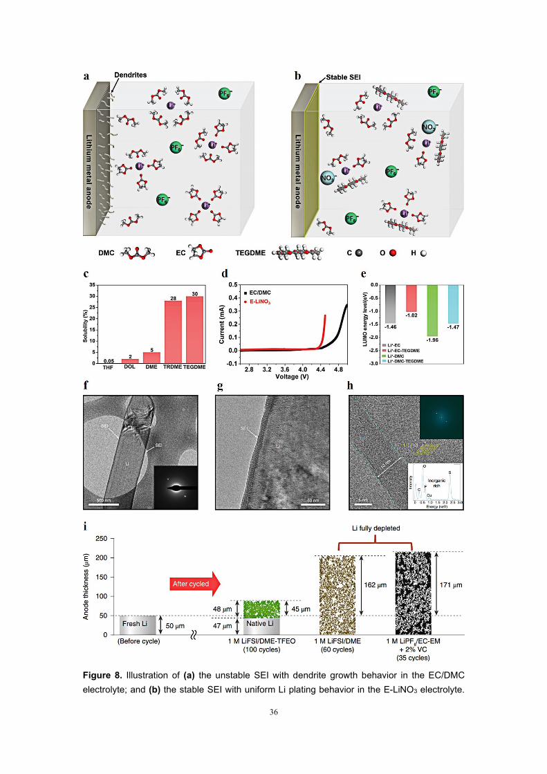
suitable for the high-voltage cathodes. As shown in Figs. 8a and 8b, the TEGDME
participates in the Li+ solvation in ester electrolyte for the SEI generation. The
TEFDME solvent remarkably enhances the LUMO energy levels of Li+ solvation to
prevent electrolyte decomposition. As shown in Figs. 8c-e, to choose the best cosolvent
for LiNO3 dissolved in the ester-based electrolyte, several cyclic and linear ethers are
studied. The TEGDME solvent shows a 30 wt.% solubility of LiNO3 salt, considerably
34
higher than other cyclic and linear ethers (Fig. 8c). As shown in Fig. 8d, the
electrochemical windows of 1M LiPF6 in EC/DMC = 1/1, v/v (EC+DMC) and 1M
LiPF6 in EC/DMC/TEGDME = 2.4/5.6/2, w/w/w (E-LiNO3) electrolytes are studied by
LSV. The traditional carbonate electrolyte shows an oxidational potential of 4.4 V, and
the E-LiNO3 electrolyte is stable at 4.3 V. Besides, the TEGDME solvent remarkably
enhances LUMO energy levels of both the Li+-DMC and Li+-EC, suggesting a reduced
electrolyte decomposition and enhanced reduction stability (Fig. 8e). The partial H
atoms in ether additives are replaced with F atoms, which can effectively promote the
LiF-rich SEI layer on the lithium anode surface. Cao. et al.[97] reported an advanced
electrolyte with tris(2,2,2-trifluoroethyl)orthoformate (TFEO) solvent alleviating the Li
depletion and pulverization. TFTO owns a high boiling point of 145 °C, which is
beneficial for improving the safety and working temperature of the battery. In addition,
TFEO does not own unstable organic groups (such as carbonyl, sulfonic, and cyano
groups) that are strongly reactive with the lithium metal anode, but only owns lithium-
friendly ether groups. TFSO also contains the CF3 groups with the powerful electron-
withdrawing effects, which widens the electrochemical window. The SEI layer
generated in this electrolyte shows overall characteristics, which can cause uniform Li+
stripping/plating and slow depletion of electrolyte and Li anode. Figs. 8f-h displays the
Li-metal anodes after the deposition in the TFEO electrolyte tested by high-resolution
cryo-electron microscopy (cryo-EM). As illustrated in Figs. 8f and 8g, uniform and
thin SEI layer is observed on the deposited Li metal cycled in the TFEO electrolyte. We
can clearly observe the composition of the SEI layer and Li deposition direction when
35
the magnification of cryo-EM is raised to the atomic level. As shown in Fig. 8h, the
SEI layer ~10 nm is shown in the dashed line. Moreover, the energy dispersive
spectroscopy (EDS) inserted in Fig. 8h shows that the SEI layer generated in the TFEO
electrolyte mainly consists of inorganic substances, which are high-ratio S-, O-, and F-
containing compounds from Lithium bis(trifluoromethane sulfonyl) imide (LiTFSI)
decomposition. More importantly, these inorganic substances are amorphous instead of
crystallized, which is proved by electron diffraction inserted in Fig. 8f and the
simplified fast Fourier transform inserted in Fig. 8h. This structure is entirely different
from the traditional perception of SEI structure. For the multilayer- and mosaic-type
structures for the SEI layer, enriched inorganics are highly crystallized at the SEI layer.
Therefore, these SEI layers are usually non-uniform. In contrast, a highly amorphous
structure is shown in the SEI layer using the TFEO electrolyte even if it has a high-ratio
inorganic species. As shown in Fig. 8i, a pictorial illustration showing the expansion
and depletion of Li metal after cycling is provided. In 1M LiFSI/DME-TFEO
electrolyte, the inhibition of Li depletion and volumetric expansion reveals enormous
potential for the practical application of the HVLMBs.
36
Figure 8. Illustration of (a) the unstable SEI with dendrite growth behavior in the EC/DMC electrolyte; and (b) the stable SEI with uniform Li plating behavior in the E-LiNO3 electrolyte.

37
(c) The solubility of LiNO3 in various ether solvents. (d) LSV curves of EC/DMC and E-LiNO3 electrolytes. (e) LUMO energy levels of Li+-EC, Li+-EC-TEGDME, Li+-DMC, and Li+-EC-TEGDME. Reproduced with permission.[96] Copyright 2020, WILEY-VCH. (f-h), Cryo-EM images of Li deposited on a TEM grid at different scales. Inset in (f): corresponding selected-area electron diffraction pattern. Inset in (h): corresponding reduced fast Fourier transform (top) and energy dispersive spectroscopy spectra (bottom) of the SEI layer. The yellow lines show the lattice space of the crystalline Li. (i) Schematic of Li loss and corresponding thickness (volumetric) expansion after different cycles in Li||NMC811 using 1M LiFSI/DME-TFTO, 1M LiPF6/EC-EMC+2%VC, and 1M LiFSI/DME electrolytes. Reproduced with permission.[97] Copyright 2019, Springer Nature.
Wang. et al.[98] developed advanced amide-based electrolyte induced interface
products. The time-dependent change of Li+ plating/stripping density is studied from
the operating neutron depth profile (NDP) in the first cycle of the Li||Cu cell using
fluoroethylene carbonate (FEC) + 2,2,2-Trifluoro-N, N-dimethylacetamide (FDMA)
(Figs. 9a and 9b) and EC+DMC (Figs. 9e and 9f) electrolyte. FDMA owns the lowest
LUMO energy value among all electrolyte solvents, indicating excellent electron
affinity, which can be preferentially decomposed and assist the interface formation. In
addition, the FDMA as an N-containing component generates LiNO3 in the interface,
which is widely considered to be beneficial in forming a uniform and dense SEI layer.
As shown in Fig. 9b, a thinner and denser Li layer is deposited in the FEC+FDMA
electrolyte. On the contrary, a thicker and looser Li layer is observed in the carbonate
electrolyte. It is worth noting that apparent asymmetry occurs in plating and stripping.
The time derivative of the Li density verifies such phenomenon more visibly (Fig. 9g),
demonstrating the deep research of the plating/stripping behavior. The stripping of Li
is evenly distributed throughout the deposited thickness with the carbonate electrolyte,
while compared to plating, the stripping activity in the FEC+FDMA electrolyte moves
back to the current collector symmetrically. Uniform stripping contributes to a
38
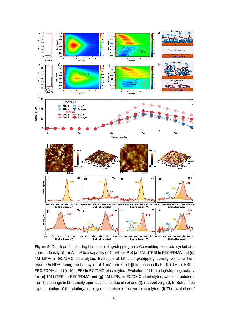
morphology full of pores, accelerating the generation of high contact regions and
lithium metal domains falling apart from the current collector, thus, forming a dead Li
layer. Conversely, as shown by the FEC+FDMA electrolyte in Fig. 9c, stripping from
the top indicates a highly reversible plating/stripping mechanism. As shown in Figs. 9d
and 9h, the top-down plating/stripping mechanism is the origin of high reversibility.
As displayed in Fig. 9i, the thickness variation of Li anode plating/stripping with two
different electrolytes proves the more uniform and denser deposition in the
FEC+FDMA electrolyte. In addition to amide-based additives, LiNO3 can also inhibit
the production of dead Li. Tan. et al.[99] reported a nitriding interface by adding LiNO3
in organic phosphates electrolytes (MOPFs) to enhance combability between Li anode
and organic phosphates electrolytes (OPEs). As displayed in Fig. 9j, the Li metal
surface in OPEs is very rough with scattered particles of different sizes. In contrast, a
uniform layer comprises an approximately flat quasi-circular structure with a 400-500
nm diameter in MOPEs (Fig. 9k). The uniform SEI without dead Li is essential for fast
and uniform Li deposition. As displayed in Figs. 9l-s, the SEI components in different
electrolytes are studied. The Li3N compounds (398.5 eV) are generated on the interface
using MOPEs (Figs. 9l and 9m). For the Li metal with OPE, the N-S band is only found
in the N1s spectrum (Fig. 9n) and may be derived from LiNO3 salt. As shown in Fig.
9o, the amount of Li3N enhances, and LiNxOy emerges in MOPEs. In MOPEs, the SEI
consists of Li3N, LiF, ROCOOLi, ROLi, and LixPOy compounds (Figs. 9q-r). Notably,
the Li3N owns a Li+ conductivity of up to 10-4 S cm-1, which effectively inhibits the
dead Li formation and reduces the interfacial resistance. After 150 cycles, the SEI
39
components in MOPE remain stable (Fig. 9s). Summarily, the nitriding interface is
successfully formed in MOPE, and the robust SEI layer with high-ratio Li3N compound
is more conductive, which accelerates the ion transmission of the interface. It ensures
stable cycling performance and uniform plating/stripping. Table 4 shows the cycling
performances of the HVLMBs with SEI formation using different additives.
40
Figure 9. Depth profiles during Li metal plating/stripping on a Cu working electrode cycled at a current density of 1 mA cm-2 to a capacity of 1 mAh cm-2 of (a) 1M LiTFSI in FEC/FDMA and (e) 1M LiPF6 in EC/DMC electrolytes. Evolution of Li+ plating/stripping density vs. time from operando NDP during the first cycle at 1 mAh cm-2 in Li||Cu pouch cells for (b) 1M LiTFSI in FEC/FDMA and (f) 1M LiPF6 in EC/DMC electrolytes. Evolution of Li+ plating/stripping activity for (c) 1M LiTFSI in FEC/FDMA and (g) 1M LiPF6 in EC/DMC electrolytes, which is obtained from the change in Li+ density upon each time step of (b) and (f), respectively. (d, h) Schematic representation of the plating/stripping mechanism in the two electrolytes. (i) The evolution of
41
thickness for the deposition during Li plating/stripping. Reproduced with permission.[98] Copyright 2020, Springer Nature. 2D and 3D Atomic Force Microscope (AFM) images of Li surface in (j) OPEs and (k) MOPEs. N 1s X-ray photoelectron spectroscopy (XPS) spectra of Li anode after immersed in (l) OPEs and (m) MOPEs for 4 h. (n) N 1s XPS spectra for OPEs and (o) N 1s, (p) P 2p, (q) F 1s, (r) C 1s spectra for MOPEs after formation process. (s) N 1s spectra for MOPEs after 150 cycles. Reproduced with permission.[99] Copyright 2019, WILEY-VCH.
2.3.1 Section summary
In this section, recent development in the SEI additives has been discussed,
including boron additive, phosphorus additive, nitrile additive, and fluorine additive,
such as HFiP, TEGDME, TFEO, FDMA, LiNO3, CTAC, and TTS. The SEI additives
are of great importance in maintaining the stability of the electrolyte/anode interface
and enhancing the cycling performances of HVLMBs. Nevertheless, owing to the small
dose of additives and the intricate electrochemical reaction process in the HVLMBs, it
is difficult to construct an interfacial layer with homogeneous and controllable
composition and structure by introducing additives into electrolytes. Therefore,
integrating the SEI additives with other modification strategies, such as CEI additives,
HCEs, LHCEs, and novel solvents, can realize improved effects on stabilizing Li metal
anode and high-voltage cathode.
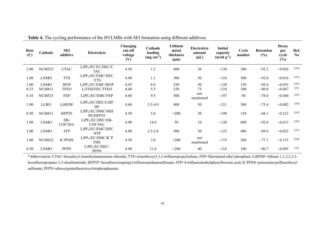
42
Table 4. The cycling performance of the HVLMBs with SEI formation using different additives.
Rate (C) Cathode SEI
additive Electrolyte
Charging cut-off voltage
(V)
Cathode loading
(mg cm-2)
Lithium metal
thickness (μm)
Electrolyte amount
(μL)
Initial capacity
(mAh g-1)
Cycle number
Retention (%)
Decay per
cycle (%)
Ref. No
2.00 NCM523 CTAC LiPF6/PC/EC/DEC/CTAC 4.50 1.2 600 30 ~138 300 ~92.2 ~0.026 [100]
1.00 LNMO TTS LiPF6/EC/EMC/DEC/TTS 4.90 1.1 300 50 ~110 500 ~92.0 ~0.016 [101]
1.00 LNMO HFiP LiPF6/EC/EMC/HFiP 4.95 8.0 250 50 ~120 150 ~92.0 ~0.053 [102] 0.33 NCM811 TFEO LiTFSI/FEC/TFEO 4.40 5.5 250 75 ~210 300 ~80.0 ~0.067 [97]
0.10 NCM523 FEP LiPF6/EC/EMC/FEP 4.60 9.5 500 not mentioned ~197 50 ~78.0 ~0.440 [103]
1.00 LLRO LiHFDF LiPF6/EC/DEC/LiHFDF 4.60 3.5-4.0 400 50 ~211 300 ~75.4 ~0.082 [104]
0.50 NCM811 HFPTF LiPF6/EC/DMC/MSIPE/HFPTF 4.50 5.0 >200 30 ~190 150 ~68.1 ~0.213 [105]
1.00 LNMO EB-COF:NO3
LiPF6/EC/DEC/EB-COF:NO3
4.90 14.6 50 10 ~120 600 ~92.0 ~0.013 [106]
1.00 LNMO 4TP LiPF6/EC/EMC/DEC/4TP 4.90 2.5-2.8 500 50 ~125 480 ~89.0 ~0.023 [107]
1.00 NCM622 K+PFHS LiPF6/EC/DMC/K+PFHS 4.50 3.0 >200 not
mentioned ~175 200 ~77.1 ~0.115 [108]
0.50 LNMO PFPN LiPF6/EC/DEC/ PFPN 4.90 11.0 >200 40 ~118 100 ~90.7 ~0.093 [32]
*Abbreviation: CTAC=hexadecyl trimethylammonium chloride; TTS=trimethoxy(3,3,3-trifluoropropyl)silane; FEP=fluorinated ethyl phosphate; LiHFDF=lithium 1,1,2,2,3,3-hexafluoropropane-1,3-disulfonimide; HFPTF=hexafluoroisopropyl trifluoromethanesulfonate; 4TP=4-trifluoromethylphenylboronic acid; K+PFHS=potassium perfluorohexyl sulfonate; PFPN=ethoxy(pentafluoro)cyclotriphosphazene.

43
3. Design of novel electrolytes
3.1 Fluorinated electrolytes
Fluorinated compounds have received considerable attention in the electrolytes for
lithium-based batteries due to their desirable features, including excellent anti-
oxidation stability, low flammability, low melting point, enhanced wettability for
electrode and separator, along with the easy generation of a robust and uniform
interfacial layer between electrolyte and electrode. Furthermore, partially fluorinated
organic solvents own a stronger polarity than their perfluorinated counterparts and are
miscible with other polar electrolyte solvents. Therefore, fluorinated solvents exhibit
completely different physical features as compared with their non-fluorinated
analogues and are suitable candidates for high-voltage applications. In terms of the
fluorinated electrolyte design, the position of the fluorinated group in the molecular
structure has a profound effect on the capabilities of LiF formation and Li+ coordination.
Moreover, the combination of excellent oxidative stability and high ionic conductivity
of the electrolyte is also significant for the fluorinated electrolyte design.
By introducing fluorine (F) into the electrolyte structure, remarkable progress in
battery chemistry can be achieved. Fan. et al.[54] developed a fluorinated electrolyte that
realizes the stable function of high-voltage cathodes in LIBs. The solvent composition
leads to a huge difference in stability between the different electrolytes on the surfaces
of high-voltage cathodes and Li anode. The F content in these electrolytes is the most
apparent difference, 0M, 1.8M, and 22M, for EC+DMC, FEC+DMC, and all-
fluorinated electrolytes, respectively. As shown in Figs. 10a and 10b, the F content
44
ultimately affects the robustness and composition of SEI and CEI. As shown in Fig.
10c, XPS is conducted to study the components of both SEI and CEI. Each component
in the all-fluorinated electrolyte is an F donor, where ultra-high LiF content (~90%) is
found, inducing a more uniform and robust interphase. LiF has two essential functions
here: (i) LiF acts as an excellent electronic insulator and prevents electrons from passing
through the SEI layer, which has been the primary reason for the continuous capacity
loss and consumption of electrolyte; (ii) LiF owns high interfacial energy of up to 73.28
meV/Å2, which constraints Li+ cations diffusion along with the interface and promotes
the development of deposited Li in a direction parallel to, not perpendicular to, the
electrode plane. It is worth noting that, unlike the SEI layer, the CEI formation relates
not only to the electrolyte but also to active substances in the positive electrode. This
involves solvent hydrogen abstraction, transition metal leakage, and oxygen-layer
reaction into peroxides or super-oxides. For the LiCoPO4 (LCP) electrode at the high
voltage, DFT calculations show the migration of hydrogen (H) in all solvents to the
cathode surface (Figs. 10d-k). And the reaction energies are the least favorable for
1,1,2,2-tetrafluoroethyl-2′,2′,2′-trifluoroethyl ether (HFE) solvent and the most
favorable for EC solvent. EC solvent is a poor CEI layer former, because there is only
a 0.91 eV barrier to release CO2 when EC•(-H) radicals decompose, leaving only a small
part of EC•(-H) radicals to the second H extraction and further leading to polymerization.
This eventually causes aggregation, while the polymer with high-ratio H is still prone
to further decomposition. Due to the larger energy barrier for FEC solvent opening
compared to EC solvent, FEC solvent will exist longer than EC solvent and have a chain
45
reaction with FEMC and HFE solvents on the surface LCP cathode, resulting in F-rich
interphase. Besides, the oxygen in the LCP cathode is banded with fluorinated radicals
to suppress the formation of OH-, which effectively prevents the dissolution of
transition metal. With the exception of the above-mentioned non-flammable electrolyte
system, a new type of non-flammable fluorinated solvent is designed based on EC and
TEP. Zheng. et al.[21] fabricated a fluorinated solvent, 2-(2,2,2-trifluoroethoxy)-1,3,2-
dioxaphospholane 2-oxide (TFEP), applicated in HVLMBs. As displayed in Fig. 10l,
by imitating the structure of EC molecular, combining the incombustibility of the
phosphate group and adding an F part, a fluorinated solvent named TFEP is synthesized
to realize reversible Li+ transmission and high security. As displayed in Fig. 10m, TFEP
solvent forms the CEI when the phosphorus center of the cyclic phosphate is
nucleophilically attacked by O on the surface of O-rich metal (M-O). Pursuant proton
transfer initiates the polymerization of TFEP solvent through a ring-opening reaction,
resulting in polyphosphate formation on the NMC cathode. For the SEI formation, the
process can be divided into the following three stages: (i) first, the TFEP solvent is
predominantly reduced at ~1 V to form the initial SEI layer (LiPOx, Li2O, LiF, and
polyphosphate); (ii) then, the further reduction of the FEMC at ~0.65 V leads to
polycarbonate and Li2CO3; (iii) at last, the FSI anions are reducted to produce LiSON,
Li2S, Li2SO3, and Li2S2O3. As shown in Fig. 10n, the 0.98M LiFSI in FEMC and 0.95M
LiFSI in TFEP/FEMC electrolytes exhibit an oxidation voltage as high as ~4.9 V,
considerably higher than conventional carbonate electrolyte (~4.4 V).

46
Figure 10. Variation of SEI and CEI chemistries formed in (a) traditional carbonate and (b) all-fluorinated electrolytes. (c) Composition of CEI on the cycled LCP cathodes in different electrolytes. (d–g) Initial and (h–k) final configurations and reaction energies. O, red; C, brown; F, light blue; H, white. Reproduced with permission.[54] Copyright 2018, Springer Nature. (l) Design of the fluorinated cyclic phosphate solvent. (m) Schematic illustrations of the ring-opening polymerization of TFEP for the formation of CEI. (n) Oxidative stabilities of the different electrolytes. Reproduced with permission.[21] Copyright 2020, Springer Nature.
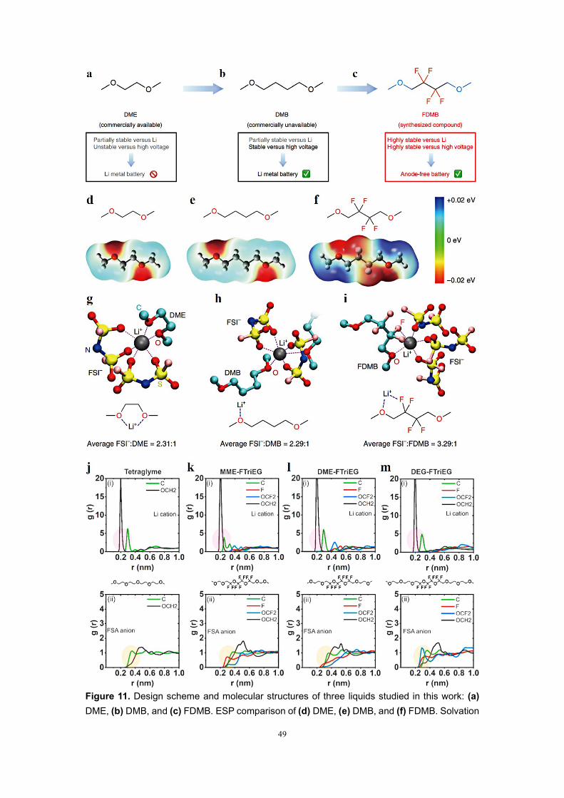
Yu, et al.[109] reported a fluorinated 1,4-dimethoxybutane (FDMB) as an electrolyte
solvent by properly incorporating -CF2- parts. The ether backbone is selected here due
to the excellent compatibility with Li metal to target the required electrolyte solvent.
47
But ether-based electrolyte is intrinsically unstable above 4 V, limiting the cell
performance at an extreme potential. Therefore, the following two pivotal design
concepts are proposed to guarantee oxidation stability and high CE. First, the alkyl
chain 1,2-dimethoxyethane (DME, Fig. 11a) in the middle of the commonly used ether
solvent structure is lengthened to obtain 1,4-dimethoxybutane (DMB, Fig. 11b). The
longer alkyl chain owns sufficient stability and enough ability to conduct Li+ and
dissolve lithium salts. Second, the introduction of F groups can further enhance the
oxidation potential and Li anode compatibility. However, it is well known that the
solvation ability of the ether can be kept only when the -F group is far away from the -
O- group. Therefore, the -CF2- group can only replace the center of DMB to achieve
the purpose of being far away from the -O- group (Fig. 11c). As a result, the FDMB
solvent is expected to be stable to both high-voltage cathodes and Li anode. As shown
in Figs. 11d-f, the interaction of the Li-F band is evaluated using electrostatic potential
(ESP) simulations, which are closely related to non-covalent interactions. For DME and
DMB molecules, the negative charges are all distributed around the O atoms. The
FDMB molecular exhibits different electron distribution, where the negative charge
concentrates not only around O atoms but also on F atoms. To further prove the
solvation structures, molecular dynamics (MD) calculations for different electrolyte
solvents are studied (Figs. 11g-i). The coordination of DME molecular and Li+ cation
is like the ‘clamping’ of two -O- groups. For DMB molecule, most Li+-solvent
structures are ‘linear’, in which there is only one -O- group combined with one Li+
cation. Unlike DME or DMB molecules, a five-membered ring is observed in the

48
LiFSI/FDMB electrolyte, where the Li+ cation is simultaneously bonded to O and F
atoms. Based on the above molecular design strategy, a new class of fluorinated ether
electrolytes that combine the oxidative stability of HFEs with the ionic conductivity of
ethers in a single compound are synthesized.[110] At room temperature, the ionic
conductivity can reach 2.7 × 10⁻⁴ S/cm with a high oxidation potential of 5.6 V. MD
calculations are conducted to study the solvation structure in these fluorinated solvents.
The g(r) for Li+ cation and FSA- anion in fluorinated triethylene glycol (FTriEG) and
tetraglyme is studied in Figs. 11j-m. The O atoms on the -OCH2- group in the
tetraglyme compound are most likely to be adjacent to the Li+ cation (Fig. 11j).
Comparing the g(r) of Li+ cation in Figs. 11k-m, the ether group adjacent to the Li+
cation can be found. As displayed in Figs. 11k and 11l, as the methylene group moves
to the ethylene spacer, the interference of carbon in the first solvation shell is smaller,
and the possibility of carbon in the next solvation shell increases. The g(r) results also
show that both H and F atoms from solvent molecules contribute obviously to the
interaction with the FSA- at 1M conventional concentration. Therefore, the fluorinated
segment in the molecular interacts with the fluorinated anion by “fluorous effect”,
which suppresses anion migration. Moreover, Fig. 11m shows that as the length of the
ether increases, the probability of the appearance of -OCF2- in the Li+ solvation shell
decreases. This also explains why longer ether chains have higher ionic conductivities.
49
Figure 11. Design scheme and molecular structures of three liquids studied in this work: (a) DME, (b) DMB, and (c) FDMB. ESP comparison of (d) DME, (e) DMB, and (f) FDMB. Solvation

50
structure of (g) 1M LiFSI/DME, (h) 1M LiFSI/DMB, and (i) 1M LiFSI/FDMB given by MD simulations and the corresponding average ratio of solvation bindings from FSI- anions to those from solvents in the solvation sheath. Reproduced with permission.[109] Copyright 2020, Springer Nature. Radial distribution functions g(r) of 0.1M LiFSA in the different electrolytes: (j) tetraglyme, (k) methyl methyl ether (MME)-FTriEG, (l) DME-FTriEG, and (m) diethylene glycol (DEG)-FTriEG. The highlighted regions draw attention to the differences between the spectra for both the Li+ cation and the FSA- anion. (i) Li+ cation and (ii) FSA- anion for the respective electrolytes. The anion spectra in part ii refer to the interaction between the fluorine atom in the FSA- anion and the respective compounds. Reproduced with permission.[110] Copyright 2020, American Chemical Society.
Zhao. et al.[111] developed a novel fluorinated electrolyte with an advanced
solvation structure to restrain Li dendrites generation and maintain stable interphase of
high-voltage cathodes. As displayed in Fig. 12a, the novel electrolyte is fabricated by
adding a high-ratio nonsolvent TTE to the traditional ether-based solvent. The specific
composition is 1M LiTFSI salt in DOL/DME/TTE with a 90% mass proportion of TTE
(DOL/DME, V/V=1/1). The unique solvation structure of 1M LiTFSI in
TTE/DME/DOL with TTE/(DME/DOL, 1/1, v/v) mass ratio of 9/1 (FME-0.9)
electrolyte endows it with outstanding oxidative stability. As shown in Fig. 12b, the
LSV shows that the FME-0.9 electrolyte with 1M lithium salt concentration remains
stable until 4.5 V, which can support high-voltage cathodes. The high oxidation
potential is mainly due to the following two main reasons. First, the highly coordinated
Li+ keeps the lone pair of electrons in the O atom of the solvent molecule away from
the cathode’s capture, thereby decreasing its HOMO energy level. Second, the lower
HOMO of the TTE solvent exhibits outstanding Li metal stability, which is attributed
to the F substituent with strong electron-withdrawing reducing the electron density. As
shown in Fig. 12c, the LiNi0.5Mn0.2Co0.3O2 (NCM532) ||Li cell achieves excellent
capacity retention of 80% with 50 μm Li metal and 45 μL FME-0.9 electrolyte at 1/2
51
C. Conversely, the capacity quickly decays to only 15% of the initial capacity in the 1
M LiPF6 in EC/DMC/EMC = 1/1/1, v/v/v (LB003). Then, as the amount of electrolyte
reduces to 15 μL, the NCM532||Li cell using FME-0.9 electrolyte still exhibits a high
capacity retention of 81% after 60 cycles (Fig. 12d). Nevertheless, the battery utilizing
the LB003 undergoes rapid capacity degradation and fails at the 20th cycle. Moreover,
there is also a distinctive function of the fluorinated ether, which plays as a destabilizer
to change the Li+ solvation structure and reduce the reciprocity between Li+ ions and
carbonyl in traditional electrolytes. Deng. et al.[112] reported that a fluorinated ether as
a destabilizer facilitates the recrystallization of LiPO2F2 (LiPOF) from the electrolyte
for concurrent surface protection on both the anode and the cathode (Fig. 12e). As
shown in Fig. 12f, the conventional carbonate electrolyte keeps clear and transparent
when 2 wt.% LiPOF is introduced. However, after further adding 8F solvent, the
electrolyte becomes turbid, indicating the precipitation of LiPOF. In Raman spectra
(Fig. 12g), the original electrolyte displays a classical enlarged peak at 891.6 cm-1
related to the Li+ solvation structure. In comparison, the pure LiPOF shows a distinct
peak at 893.5 cm-1 on the Li-related PO2F2- anions without a solvation structure. As the
F concentration in fluorinated ether increases, the major peaks slightly transfer, which
means that more Li is coordinated with PO2F2-, and the Li+ solvation structure has been
disturbed. As shown in Fig. 12h, the DFT calculations are conducted to study the
interaction between additives and EC solvent. The binding energy of DE-EC is only -
0.09 eV, considerably lower than those of 1-ethoxy1,1,2,2-tetrafluoroethane (4F)-EC
(0.264 eV) and 1,1,2,2-tetrafluoroethyl-2,2,3,3-tetrafluoropropylether (8F)-EC (-0.315
52
eV), indicating stronger interaction between fluorinated ether with EC solvent
compared with that of diethyl ether (DE). Therefore, it is apparent that the attraction
ability from fluorine to carbonyl sites on EC solvent increases along with the number
of F atoms. In addition, the level of salting out of LiPOF is only affected by the solvent
type rather than the lithium salt, indicating that the solvent competition influences the
shell structure around Li+. As shown in Fig. 12i, after adding 4F and 8F solvent, the
signals of 17O correspond to ethereal (O2 or O4 site) and, 2 equiv of carbonyl (O1 or
O3) in EC+DMC electrolyte migrating to the large position, which demonstrates a
shielding influence on Li+ ion. As displayed in Fig. 12g, when fluorinated ether is added
to the original electrolyte, it will participate in the Li+ solvation structure. Robust F-O
interaction between EC+DMC and fluorinated ether is formed. Table 5 lists the cycling
performance of the HVLMBs with different fluorinated electrolytes.

53
Figure 12. (a) Schematic illustration of advanced battery functions realized by FME-0.9. (b) LSV curves of pristine electrolyte and FME-0.9 at 0.5 mV s-1. Cycling performance with high areal loadings (2.7 mAh cm-2) under (c) flood electrolyte (45 µl) and (d) lean electrolyte (15 µl). Reproduced with permission.[111] Copyright 2020, Elsevier B.V. (e) Schematic diagrams of recrystallization of LiPO2F2 upon addition of the 8F solvent into a pristine/LiPOF electrolyte. (f) Digital photographs of a pristine electrolyte upon addition of LiPO2F2 and different kinds of
54
solvents. (g) Raman spectra of pristine, pristine/LiPOF, pristine/LiPOF/DE, 4F/8F/ 1,1,2,2,3,3,4,4-octafluoro-5-(1,1,2,2-tetrafluoroethoxy) pentane (12F) solvent, and bare LiPO2F2. (h) Theoretical binding energies and geometry structures calculated through first-principles calculations among DE/ EC, 4F/EC, and 8F/EC in a carbonyl-coordinated manner. (i) 17O nuclear magnetic resonance (NMR) spectra for pristine, pristine/LiPOF, pristine/ LiPOF/4F, and pristine/LiPOF/8F. (g) Schematic illustration of the Li+ solvation sheath and related solvent interaction of Li+-coordinated units and F-O interaction in pristine/LiPOF/8F. Reproduced with permission.[112] Copyright 2021, American Chemical Society.
3.1.1 Section summary
This section discusses recent development in fluorinated electrolytes, including
FEC, FEMC, HFE, TFEP, FDMB, FTriEG, and TTE. Overall, the C–F bonds in organic
compounds possess considerable effects on the LUMO and HOMO energy of the
solvent molecular and positively influence the interfacial chemistry in HVLMBs. In
addition, these fluorinated solvents are weakly flammable and even non-flammable,
which can effectively improve thermal stability and increase electrode passivation. In
the future, systematically enhancing the interfacial electrochemical/chemical
compatibility between fluorinated solvents and high-voltage cathode/Li metal anode is
conducive to further guaranteeing the long-time cycling life. Moreover, the specific
energy density, CE, and cycle life of practical pouch cells using fluorinated electrolytes
is expected to be further explored under commercial conditions.
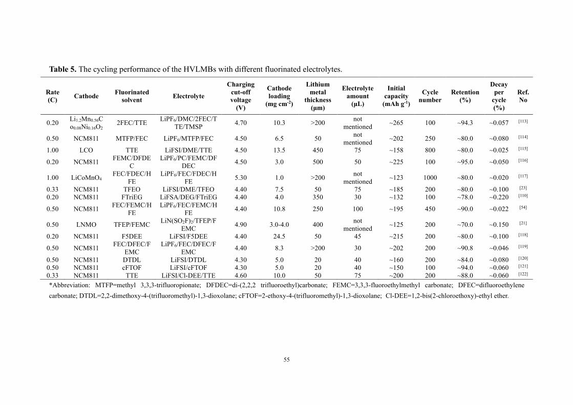
55
Table 5. The cycling performance of the HVLMBs with different fluorinated electrolytes.
Rate (C) Cathode Fluorinated
solvent Electrolyte
Charging cut-off voltage
(V)
Cathode loading
(mg cm-2)
Lithium metal
thickness (μm)
Electrolyte amount
(μL)
Initial capacity
(mAh g-1)
Cycle number
Retention (%)
Decay per
cycle (%)
Ref. No
0.20 Li1.2Mn0.56Co0.08Ni0.16O2
2FEC/TTE LiPF6/DMC/2FEC/TTE/TMSP 4.70 10.3 >200 not
mentioned ~265 100 ~94.3 ~0.057 [113]
0.50 NCM811 MTFP/FEC LiPF6/MTFP/FEC 4.50 6.5 50 not mentioned ~202 250 ~80.0 ~0.080 [114]
1.00 LCO TTE LiFSI/DME/TTE 4.50 13.5 450 75 ~158 800 ~80.0 ~0.025 [115]
0.20 NCM811 FEMC/DFDEC
LiPF6/PC/FEMC/DFDEC 4.50 3.0 500 50 ~225 100 ~95.0 ~0.050 [116]
1.00 LiCoMnO4 FEC/FDEC/H
FE LiPF6/FEC/FDEC/H
FE 5.30 1.0 >200 not mentioned ~123 1000 ~80.0 ~0.020 [117]
0.33 NCM811 TFEO LiFSI/DME/TFEO 4.40 7.5 50 75 ~185 200 ~80.0 ~0.100 [23] 0.20 NCM811 FTriEG LiFSA/DEG/FTriEG 4.40 4.0 350 30 ~132 100 ~78.0 ~0.220 [110]
0.50 NCM811 FEC/FEMC/HFE
LiPF6/FEC/FEMC/HFE 4.40 10.8 250 100 ~195 450 ~90.0 ~0.022 [54]
0.50 LNMO TFEP/FEMC LiN(SO2F)2/TFEP/FEMC 4.90 3.0-4.0 400 not
mentioned ~125 200 ~70.0 ~0.150 [21]
0.20 NCM811 F5DEE LiFSI/F5DEE 4.40 24.5 50 45 ~215 200 ~80.0 ~0.100 [118]
0.50 NCM811 FEC/DFEC/FEMC
LiPF6/FEC/DFEC/FEMC 4.40 8.3 >200 30 ~202 200 ~90.8 ~0.046 [119]
0.50 NCM811 DTDL LiFSI/DTDL 4.30 5.0 20 40 ~160 200 ~84.0 ~0.080 [120] 0.50 NCM811 cFTOF LiFSI/cFTOF 4.30 5.0 20 40 ~150 100 ~94.0 ~0.060 [121] 0.33 NCM811 TTE LiFSI/Cl-DEE/TTE 4.60 10.0 50 75 ~200 200 ~88.0 ~0.060 [122] *Abbreviation: MTFP=methyl 3,3,3-trifluoropionate; DFDEC=di-(2,2,2 trifluoroethyl)carbonate; FEMC=3,3,3-fluoroethylmethyl carbonate; DFEC=difluoroethylene carbonate; DTDL=2,2-dimethoxy-4-(trifluoromethyl)-1,3-dioxolane; cFTOF=2-ethoxy-4-(trifluoromethyl)-1,3-dioxolane; Cl-DEE=1,2-bis(2-chloroethoxy)-ethyl ether.
56
3.2 Ionic-liquid electrolytes
Ionic liquids have exhibited stupendous potential for applications in lithium-based
cells and acted in multifunctional roles because of their highly different
physicochemical features from inorganic salts and molecular solvents. They can be used
as electrolyte solvents to substitute conventional carbonate-based solvents to enhance
battery safety due to their non-flammable and non-volatile properties. Especially, [FSI]-
/[TFSI]--based ionic liquids with efficient ion transfer have attracted widespread
attention. First, the highly delocalized charge distribution remarkably decreases the
interaction between cations and anions, enhancing the Li+ fluidity in the ionic-liquid
electrolyte. Then, the small ion sizes of [FSI]- (0.26 nm) and [TFSI]- (0.38 nm) anions
enable the decrease in the viscosity of ionic-liquid electrolytes, accelerating the Li+
transfer in the electrolyte.
Ionic liquid has been considered a member of the most prospective electrolyte
candidates for the HVLMBs due to its low volatility, excellent flame retardancy, and
wide electrochemical window. As displayed in Fig. 13a, Sun. et al.[56] reported an
advanced ionic-liquid electrolyte for HVLMBs. This electrolyte is comprised of
bis(fluorosulfonyl)imide (FSI) anions and 1-ethyl-3-methylimidazolium (EMIm)
cations, with the additive of sodium bis(trifluoromethanesulfonyl)imide (NaTFSI),
denoted as EM–5Li–Na IL electrolyte. The EM–5Li–Na IL electrolyte owns a viscosity
as low as 125 mPa s at room temperature, half of the Py13-based ILs electrolyte. As
shown in Fig. 13b, the EM–5Li–Na IL electrolyte exhibits an ion conductivity of ~2.6
mS cm-1 at 25 ℃, considerably higher than other ionic-liquid electrolytes (1.0-1.2 mS

57
cm-1) for LIBs. Due to lower viscosity at high temperatures, the ionic conductivity is
further enhanced to over 10 mS cm-1. Compared with traditional carbonate electrolytes,
the EM–5Li–Na IL electrolyte exhibits high safety owing to its super-high thermal
stability and nonflammability. As shown in Fig. 13c, the LiCoO2 (LCO)||Li cell
utilizing the EM-5Li-Na IL electrolyte exhibits excellent capacity retention and high
average CE at 0.7 C. On the contrary, the cell with traditional carbonate electrolyte
undergoes rapid CE and capacity decay, indicating the fast loss of active Li in the
organic electrolyte. Overall, the EM–5Li–Na IL electrolyte is novel for the following
points. First, the EMIm cations are vital for accomplishing high rate capacities under
high-loading conditions. Then, the high concentration of LiFSI salts in the EM–5Li–
Na IL electrolyte is relevant to excellent battery performances. At last, NaTFSI is first
exploited as a novel additive for improving the LMB performances. The ionic-liquid
electrolyte based on the polyILs can support HVLMBs to work at a higher voltage as
compared with that based on the EMIm. Wang. et al.[123] mixed polymerized polyILs
and poly(ionic liquid)s as well as electrospun fiber carrier to prepare an electrolyte with
high-ratio ionic liquid, contributing to a dramatic enhancement of Li+ transference
number. With this electrolyte, the Li metal cells with NMC and LiNi1-x-yMnxAlyO2
(NMA) cathodes exhibit excellent cycling performances under a high voltage of 4.5 V.
Polyvinylidene fluoride (PVDF) nanofibers can be used as an outstanding mechanical
skeleton to prepare flexible and thin composite polymer electrolyte (CPE). As shown
in Fig. 13d, the CPEs are synthesized by solvent pouring. Fig. 13e displays the diffusion
coefficients of each component tested by the pulsed-field gradient nuclear magnetic
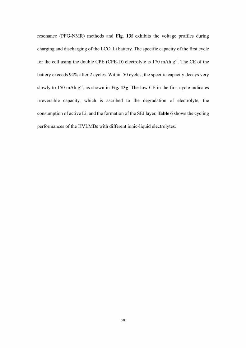
58
resonance (PFG-NMR) methods and Fig. 13f exhibits the voltage profiles during
charging and discharging of the LCO||Li battery. The specific capacity of the first cycle
for the cell using the double CPE (CPE-D) electrolyte is 170 mAh g-1. The CE of the
battery exceeds 94% after 2 cycles. Within 50 cycles, the specific capacity decays very
slowly to 150 mAh g-1, as shown in Fig. 13g. The low CE in the first cycle indicates
irreversible capacity, which is ascribed to the degradation of electrolyte, the
consumption of active Li, and the formation of the SEI layer. Table 6 shows the cycling
performances of the HVLMBs with different ionic-liquid electrolytes.

59
Figure 13. (a) Schematic illustration of the battery configuration and electrolyte composition of the EM–5Li–Na IL electrolyte. (b) Ionic conductivities of EM–5Li–Na IL at various temperatures. (c) Cyclic stability of Li@Cu–LCO batteries using EM–5Li–Na IL and organic electrolytes at 0.7 C. Reproduced with permission.[56] Copyright 2020, WILEY-VCH. (d) Schematic illustration of composite electrolyte preparation along with used materials. (e) Diffusion coefficient of 7Li (Li+, black), 1H (C3mpyr+, red), and 19F (NTf2-, blue) of single CPE (CPE-S), CPE-D, and triple CPE (CPE-T) composite electrolytes measured by solid-state NMR. (f) Charge-discharge profiles after 1, 2, and 10 cycles for Li||NMC cells containing CPE (D) composite electrolyte. (g) Corresponding cycling performance for 50 cycles at 0.05 C (0.03 mA) and 50 °C. Reproduced with permission.[123] Copyright 2019, American Chemical Society.
3.2.1 Section summary
In this section, recent development in the ionic-liquid electrolytes has been
discussed, including TFSI-, FSI-, EMIm+, C3mpyr+, and NTf2-. Ion conductivity is

60
regarded as one of the most critical indicators of ionic-liquid electrolytes used in
HVLMBs.[124] Ionic liquids are constituted of the anions with decreased charge density
and tiny size and the cations with electron-donating functional groups and delocalized
unsaturated chemical bonds.[125, 126] This distinctive composition significantly weakens
the interaction between anions and cations, resulting in large conductivity. Nevertheless,
the ion transfer in ionic-liquid electrolytes is deeply influenced by viscosity. Higher
viscousness of the ionic-liquid electrolyte leads to slow transfer of Li cations in the
electrolyte. Apart from viscosity, the ion radius and carrier distribution density of ionic-
liquid electrolytes also affect ion transfer. The ion transfer rate is inversely proportional
to the ion size and proportional to the distribution density of the charge carriers.
Because the ionic-liquid electrolyte is fully constituted of cations and anions, the
amount of charge carriers is adequate, but the carrier number decreases due to the
uncontrollable ion association, leading to reduced ion conductivity. In the future,
several issues hindering the industrial commercialization of ionic-liquid electrolytes are
urgent to solve, such as expensive cost, large viscosity, and inferior electrode affinity.
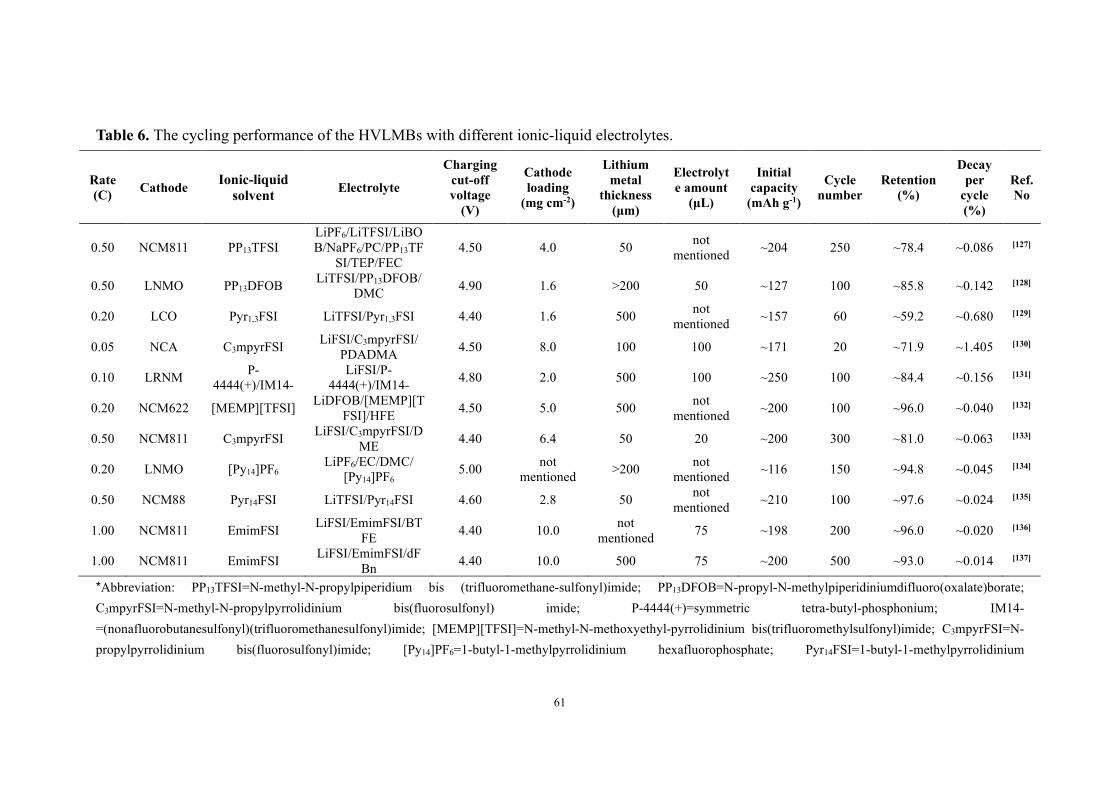
61
Table 6. The cycling performance of the HVLMBs with different ionic-liquid electrolytes.
Rate (C) Cathode Ionic-liquid
solvent Electrolyte
Charging cut-off voltage
(V)
Cathode loading
(mg cm-2)
Lithium metal
thickness (μm)
Electrolyte amount
(μL)
Initial capacity
(mAh g-1)
Cycle number
Retention (%)
Decay per
cycle (%)
Ref. No
0.50 NCM811 PP13TFSI LiPF6/LiTFSI/LiBOB/NaPF6/PC/PP13TF
SI/TEP/FEC 4.50 4.0 50 not
mentioned ~204 250 ~78.4 ~0.086 [127]
0.50 LNMO PP13DFOB LiTFSI/PP13DFOB/DMC 4.90 1.6 >200 50 ~127 100 ~85.8 ~0.142 [128]
0.20 LCO Pyr1,3FSI LiTFSI/Pyr1,3FSI 4.40 1.6 500 not mentioned ~157 60 ~59.2 ~0.680 [129]
0.05 NCA C3mpyrFSI LiFSI/C3mpyrFSI/ PDADMA 4.50 8.0 100 100 ~171 20 ~71.9 ~1.405 [130]
0.10 LRNM P-4444(+)/IM14-
LiFSI/P-4444(+)/IM14- 4.80 2.0 500 100 ~250 100 ~84.4 ~0.156 [131]
0.20 NCM622 [MEMP][TFSI] LiDFOB/[MEMP][TFSI]/HFE 4.50 5.0 500 not
mentioned ~200 100 ~96.0 ~0.040 [132]
0.50 NCM811 C3mpyrFSI LiFSI/C3mpyrFSI/DME 4.40 6.4 50 20 ~200 300 ~81.0 ~0.063 [133]
0.20 LNMO [Py14]PF6 LiPF6/EC/DMC/
[Py14]PF6 5.00 not
mentioned >200 not mentioned ~116 150 ~94.8 ~0.045 [134]
0.50 NCM88 Pyr14FSI LiTFSI/Pyr14FSI 4.60 2.8 50 not mentioned ~210 100 ~97.6 ~0.024 [135]
1.00 NCM811 EmimFSI LiFSI/EmimFSI/BTFE 4.40 10.0 not
mentioned 75 ~198 200 ~96.0 ~0.020 [136]
1.00 NCM811 EmimFSI LiFSI/EmimFSI/dFBn 4.40 10.0 500 75 ~200 500 ~93.0 ~0.014 [137]
*Abbreviation: PP13TFSI=N-methyl-N-propylpiperidium bis (trifluoromethane-sulfonyl)imide; PP13DFOB=N-propyl-N-methylpiperidiniumdifluoro(oxalate)borate; C3mpyrFSI=N-methyl-N-propylpyrrolidinium bis(fluorosulfonyl) imide; P-4444(+)=symmetric tetra-butyl-phosphonium; IM14-=(nonafluorobutanesulfonyl)(trifluoromethanesulfonyl)imide; [MEMP][TFSI]=N-methyl-N-methoxyethyl-pyrrolidinium bis(trifluoromethylsulfonyl)imide; C3mpyrFSI=N-propylpyrrolidinium bis(fluorosulfonyl)imide; [Py14]PF6=1-butyl-1-methylpyrrolidinium hexafluorophosphate; Pyr14FSI=1-butyl-1-methylpyrrolidinium

62
Bis(fluorosulfonyl)imide; EmimFSI=1-ethyl-3-methylimidazolium bis(fluorosulfonyl)imide
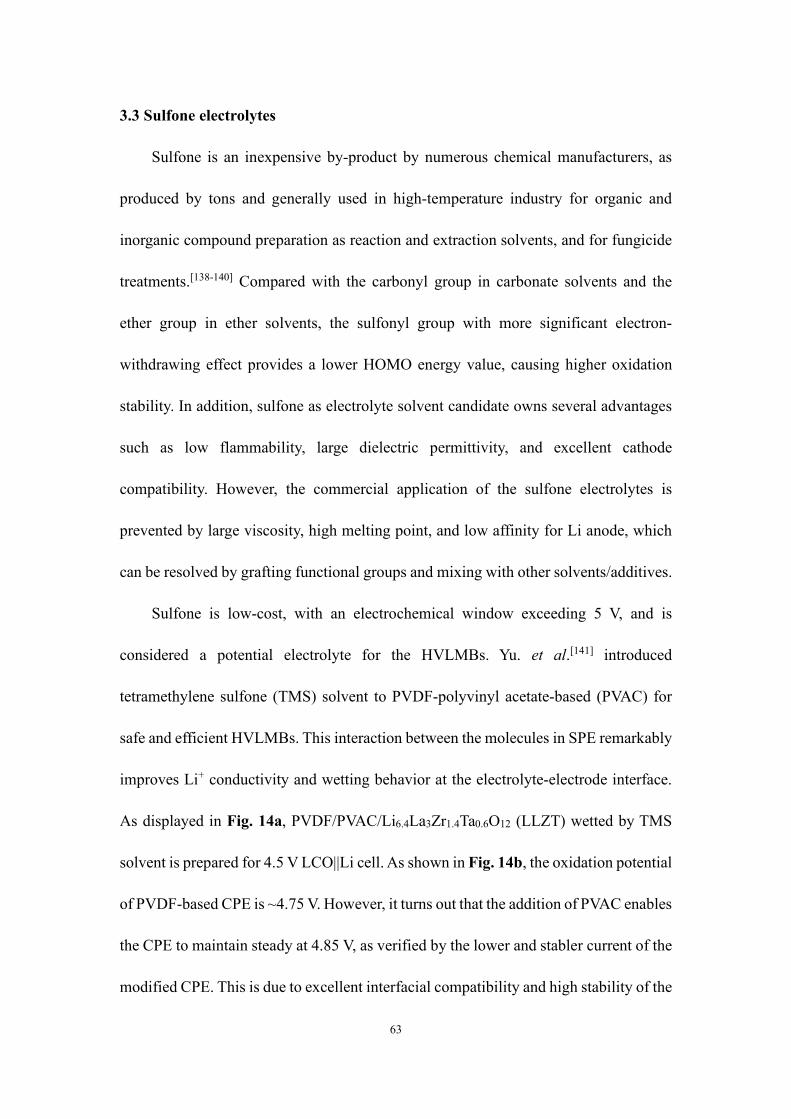
63
3.3 Sulfone electrolytes
Sulfone is an inexpensive by-product by numerous chemical manufacturers, as
produced by tons and generally used in high-temperature industry for organic and
inorganic compound preparation as reaction and extraction solvents, and for fungicide
treatments.[138-140] Compared with the carbonyl group in carbonate solvents and the
ether group in ether solvents, the sulfonyl group with more significant electron-
withdrawing effect provides a lower HOMO energy value, causing higher oxidation
stability. In addition, sulfone as electrolyte solvent candidate owns several advantages
such as low flammability, large dielectric permittivity, and excellent cathode
compatibility. However, the commercial application of the sulfone electrolytes is
prevented by large viscosity, high melting point, and low affinity for Li anode, which
can be resolved by grafting functional groups and mixing with other solvents/additives.
Sulfone is low-cost, with an electrochemical window exceeding 5 V, and is
considered a potential electrolyte for the HVLMBs. Yu. et al.[141] introduced
tetramethylene sulfone (TMS) solvent to PVDF-polyvinyl acetate-based (PVAC) for
safe and efficient HVLMBs. This interaction between the molecules in SPE remarkably
improves Li+ conductivity and wetting behavior at the electrolyte-electrode interface.
As displayed in Fig. 14a, PVDF/PVAC/Li6.4La3Zr1.4Ta0.6O12 (LLZT) wetted by TMS
solvent is prepared for 4.5 V LCO||Li cell. As shown in Fig. 14b, the oxidation potential
of PVDF-based CPE is ~4.75 V. However, it turns out that the addition of PVAC enables
the CPE to maintain steady at 4.85 V, as verified by the lower and stabler current of the
modified CPE. This is due to excellent interfacial compatibility and high stability of the

64
PVAC and TMS. The LCO||Li cells using the two electrolytes are tested to compare the
electrochemical performances at the high voltage. As displayed in Fig. 14c, the LCO||Li
cell with the PVDF-based CPE electrolyte undergoes rapid capacity decay and only
survives 50 cycles. Comparatively, the LCO||Li battery with PVDF/PVAC-based CPE
electrolyte exhibits a modest capacity decay of 15% after 200 cycles. The charge-
discharge curves of the LCO||Li cell with this electrolyte demonstrate a capacity of
190.8 mAh g-1 at the initial circle and maintain over 160 mAh g-1 after 200 cycles due
to the low polarization. Conversely, remarkable polarization results in a severe decrease
in the initial specific capacity of the cell using PVDF-based CPE (164.4 mAh g-1). In
particular, the coordination between TMS and Li+ can also contribute to interfacial
formation. Ren. et al.[142] developed a concentrated sulfone-based electrolyte to achieve
a high CE of over 98%. In addition, by introducing a fluorinated ether TTE, the low
viscosity and high wettability are obtained in the LHCE, which further enhances the
CE and cell stability at an extreme potential. As shown in Fig. 14d, after TTE solvent
addition, the evolution of the Li+ solvation structure is studied through NMR. The signal
of O atoms in FSI- ion migrates from 172.4 to 171.8 and 170.1 ppm as the LiFSI
salt/TMS solvent enhances from a molar ratio of 1:16 to 1:8 and 1:3. This is because
the ion-dipole interactions between O atom and Li+ ion gradually increase when the
concentration of LiFSI salt improves. The signal of O migrates from 164.9 to 162.6
ppm with TMS as the solvent, suggesting the number of TMS associated with Li+ cation
increases. For the HCE, the signal of the O atoms in TMS solvent has shifted more
obviously from 138.0 to 158.0 ppm, which represents different Li+ solvation structures.
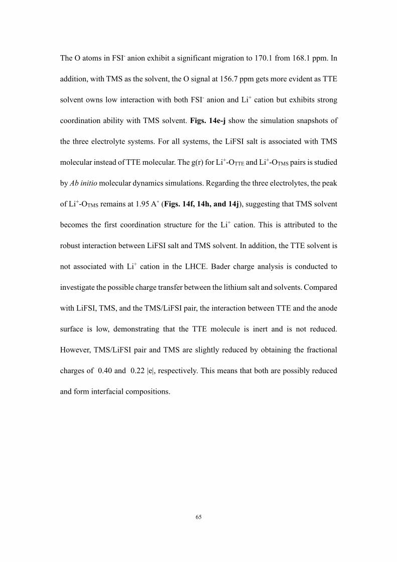
65
The O atoms in FSI- anion exhibit a significant migration to 170.1 from 168.1 ppm. In
addition, with TMS as the solvent, the O signal at 156.7 ppm gets more evident as TTE
solvent owns low interaction with both FSI- anion and Li+ cation but exhibits strong
coordination ability with TMS solvent. Figs. 14e-j show the simulation snapshots of
the three electrolyte systems. For all systems, the LiFSI salt is associated with TMS
molecular instead of TTE molecular. The g(r) for Li+-OTTE and Li+-OTMS pairs is studied
by Ab initio molecular dynamics simulations. Regarding the three electrolytes, the peak
of Li+-OTMS remains at 1.95 A˚ (Figs. 14f, 14h, and 14j), suggesting that TMS solvent
becomes the first coordination structure for the Li+ cation. This is attributed to the
robust interaction between LiFSI salt and TMS solvent. In addition, the TTE solvent is
not associated with Li+ cation in the LHCE. Bader charge analysis is conducted to
investigate the possible charge transfer between the lithium salt and solvents. Compared
with LiFSI, TMS, and the TMS/LiFSI pair, the interaction between TTE and the anode
surface is low, demonstrating that the TTE molecule is inert and is not reduced.
However, TMS/LiFSI pair and TMS are slightly reduced by obtaining the fractional
charges of 0.40 and 0.22 |e|, respectively. This means that both are possibly reduced
and form interfacial compositions.
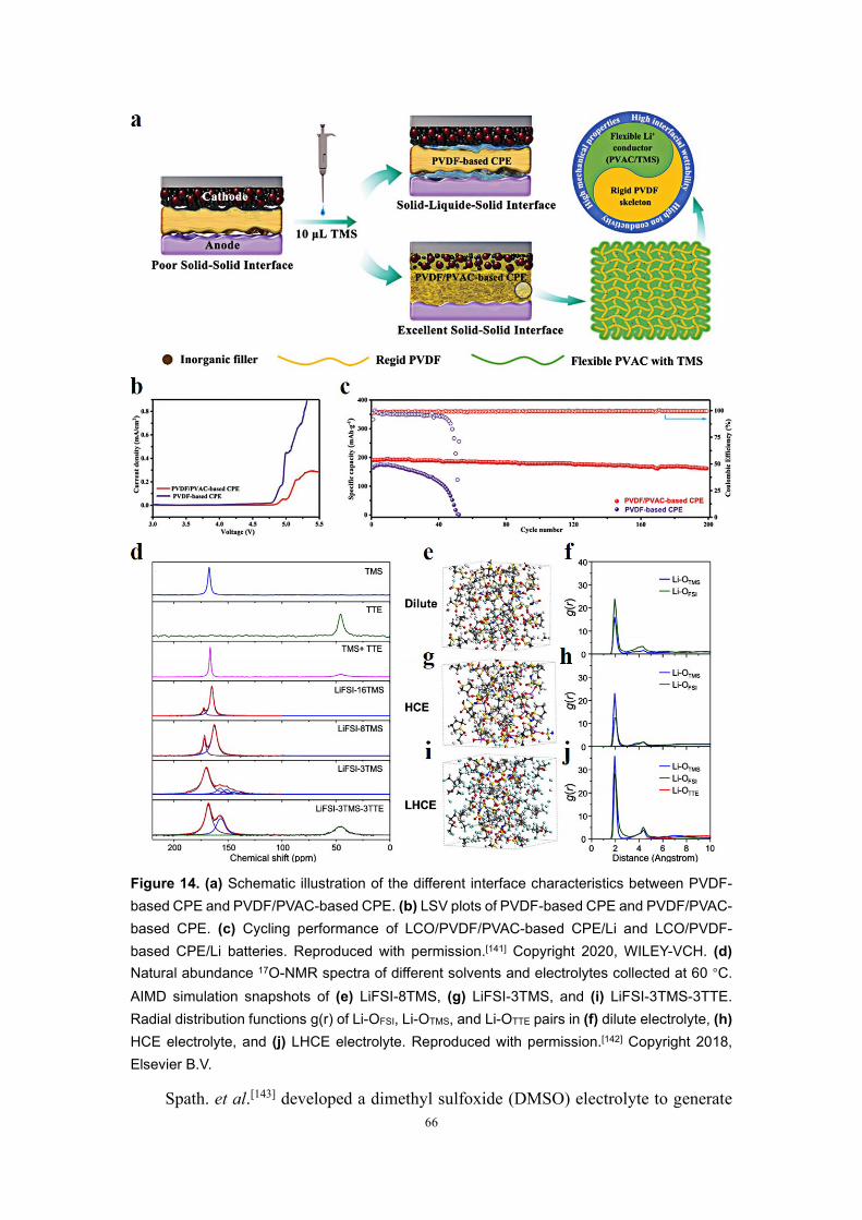
66
Figure 14. (a) Schematic illustration of the different interface characteristics between PVDF-based CPE and PVDF/PVAC-based CPE. (b) LSV plots of PVDF-based CPE and PVDF/PVAC-based CPE. (c) Cycling performance of LCO/PVDF/PVAC-based CPE/Li and LCO/PVDF-based CPE/Li batteries. Reproduced with permission.[141] Copyright 2020, WILEY-VCH. (d) Natural abundance 17O-NMR spectra of different solvents and electrolytes collected at 60 °C. AIMD simulation snapshots of (e) LiFSI-8TMS, (g) LiFSI-3TMS, and (i) LiFSI-3TMS-3TTE. Radial distribution functions g(r) of Li-OFSI, Li-OTMS, and Li-OTTE pairs in (f) dilute electrolyte, (h) HCE electrolyte, and (j) LHCE electrolyte. Reproduced with permission.[142] Copyright 2018, Elsevier B.V.
Spath. et al.[143] developed a dimethyl sulfoxide (DMSO) electrolyte to generate

67
the advanced interface between the solvent adsorbate and high-voltage LCO cathode.
Fig. 15a shows the valence band spectrum of the fresh LCO and the spectrum after 8
langmuirs of DMSO adsorbed. For the fresh LCO, a composition of about 1.5 eV is
distributed to the Co 3d state. The features from 3 to 8 eV can be distributed to the
overlap of the O 2p and Co 3d states and the pure O 2p state. The offset between the
valence band of fresh LCO and the HOMO of DMSO mainly comes from the valence
band spectrum: after DMSO exposure, in addition to the energy migration caused by
band bending, the change in signal shape is also found, and the change in signal is
mainly contributed by the physically absorbed DMSO in 8 langmuirs (Inset in Fig. 15a).
Since no change in the oxidation state of cobalt is observed during the experiment, it
can be concluded that after the initial reaction, Li is deintercalated from the volume of
the fresh LCO film. This effectively inhibits the transportation of Li, probably at the
grain boundary of the (0 0 3) textured film, as shown in Fig. 15b. As displayed in Fig.
15c, 4 langmuirs of DMSO after exposure are displayed. The negative charge is
distributed on the surface of the LCO cathode, while the positive charge remains in the
internal reaction layer. As compared with the DMSO, the sulfolane (SL) can dissolve
more lithium salts, which makes it promising to be applied in HCEs and LHCEs. By
introducing HFE and LiNO3 into the concentrated sulfone-based electrolyte, Fu. et
al.[144] developed a novel LHCE to inhibit the growth of Li dendrite and achieved an
excellent CE of ~99% for both high-voltage NMC811 cathode and Li-metal anode. The
Li+ solvation structures of various electrolytes are studied by Fourier-transform infrared
(FTIR), as displayed in Fig. 15d. The apparent peak at 1144 cm-1 is associated with the
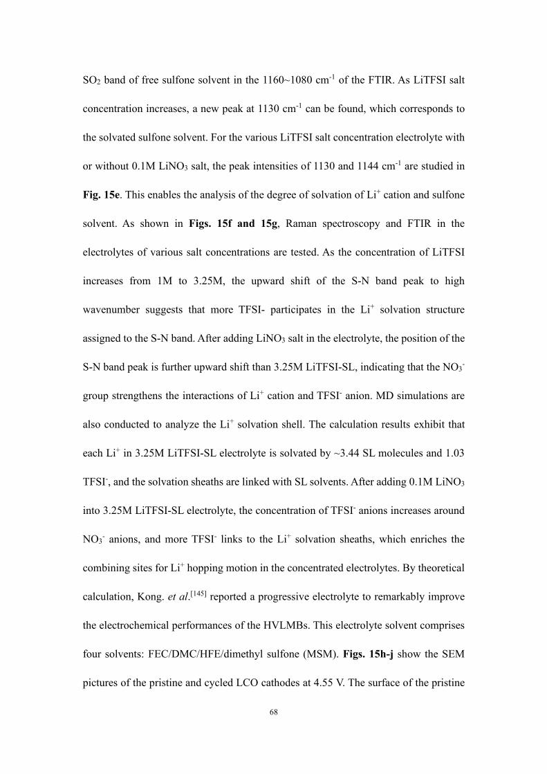
68
SO2 band of free sulfone solvent in the 1160~1080 cm-1 of the FTIR. As LiTFSI salt
concentration increases, a new peak at 1130 cm-1 can be found, which corresponds to
the solvated sulfone solvent. For the various LiTFSI salt concentration electrolyte with
or without 0.1M LiNO3 salt, the peak intensities of 1130 and 1144 cm-1 are studied in
Fig. 15e. This enables the analysis of the degree of solvation of Li+ cation and sulfone
solvent. As shown in Figs. 15f and 15g, Raman spectroscopy and FTIR in the
electrolytes of various salt concentrations are tested. As the concentration of LiTFSI
increases from 1M to 3.25M, the upward shift of the S-N band peak to high
wavenumber suggests that more TFSI- participates in the Li+ solvation structure
assigned to the S-N band. After adding LiNO3 salt in the electrolyte, the position of the
S-N band peak is further upward shift than 3.25M LiTFSI-SL, indicating that the NO3-
group strengthens the interactions of Li+ cation and TFSI- anion. MD simulations are
also conducted to analyze the Li+ solvation shell. The calculation results exhibit that
each Li+ in 3.25M LiTFSI-SL electrolyte is solvated by ~3.44 SL molecules and 1.03
TFSI-, and the solvation sheaths are linked with SL solvents. After adding 0.1M LiNO3
into 3.25M LiTFSI-SL electrolyte, the concentration of TFSI- anions increases around
NO3- anions, and more TFSI- links to the Li+ solvation sheaths, which enriches the
combining sites for Li+ hopping motion in the concentrated electrolytes. By theoretical
calculation, Kong. et al.[145] reported a progressive electrolyte to remarkably improve
the electrochemical performances of the HVLMBs. This electrolyte solvent comprises
four solvents: FEC/DMC/HFE/dimethyl sulfone (MSM). Figs. 15h-j show the SEM
pictures of the pristine and cycled LCO cathodes at 4.55 V. The surface of the pristine

69
LCO cathode is very flat, but the surface is very rough in the EC+DMC electrolyte.
However, regarding the MSM electrolyte, the cathode displays a smooth and uniform
surface. By the HRTEM (Figs. 15k-n), the cathode cycled in the EC+DMC produces a
10-20 nm deposited layer on the surface of LCO. On the contrary, the LCO cathode has
a flat surface in the MSM electrolyte. Table 7 shows the cycling performance of the
HVLMBs with different sulfone electrolytes.
Figure 15. (a) Valence band spectra for pristine LCO and after adsorption of 8 langmuirs of DMSO. (b) Illustration of the processes at the LCO/DMSO interface. (c) Energy level diagram of LCO in contact with DMSO. Reproduced with permission.[143] Copyright 2016, American Chemical Society. (d) FTIR spectra of SL’s symmetric SO2 stretch with different electrolytes. (e) Relative intensities of FTIR peaks at 1144-1 and 1130 cm-1 in the LiTFSI-SL electrolytes. (f) FTIR spectra of TFSI-’s S-N stretch with different electrolytes. (g) Raman spectra for TFSI- of
70
various electrolytes. Reproduced with permission.[144] Copyright 2020, WILEY-VCH. SEM images of (h) the fresh LCO cathode and 4.55 V high-voltage cycled LCO cathodes with (i) the EC+DMC electrolyte and (j) MSM electrolyte. TEM images of the high-voltage cycled LCO cathodes with (k, l) EC+DMC electrolyte and (m, n) the MSM electrolyte. Reproduced with permission.[145] Copyright 2019, American Chemical Society.
3.3.1 Section summary
In this section, recent development in the sulfone electrolytes has been discussed,
including TMS, DMSO, SL, MSM, and MPS. Overall, sulfone-based solvents own high
dielectric constant (>40) and high oxidation potential (>5 V vs. Li/Li+), exhibiting
stability with high-voltage cathodes. Nevertheless, sulfone-based solvents show poor
wettability and inferior compatibility with Li metal anode. In the future, developing
novel sulfones by grafting functional groups is expected to own low viscosity and high
affinity with Li anode. Moreover, mixing with other solvents/additives, such as FEC,
HFE, DMC, and LiNO3, can achieve the same improvement under the guidance of
theoretical calculations.
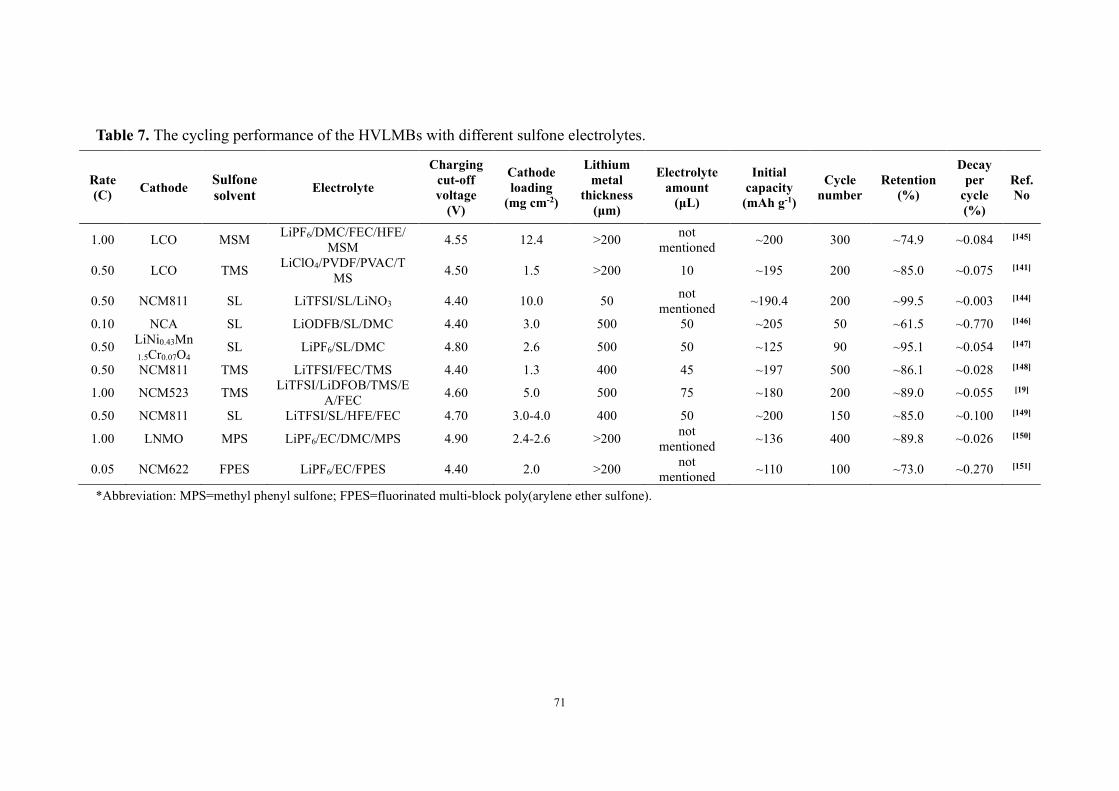
71
Table 7. The cycling performance of the HVLMBs with different sulfone electrolytes.
Rate (C) Cathode Sulfone
solvent Electrolyte
Charging cut-off voltage
(V)
Cathode loading
(mg cm-2)
Lithium metal
thickness (μm)
Electrolyte amount
(μL)
Initial capacity
(mAh g-1)
Cycle number
Retention (%)
Decay per
cycle (%)
Ref. No
1.00 LCO MSM LiPF6/DMC/FEC/HFE/MSM 4.55 12.4 >200 not
mentioned ~200 300 ~74.9 ~0.084 [145]
0.50 LCO TMS LiClO4/PVDF/PVAC/TMS 4.50 1.5 >200 10 ~195 200 ~85.0 ~0.075 [141]
0.50 NCM811 SL LiTFSI/SL/LiNO3 4.40 10.0 50 not mentioned ~190.4 200 ~99.5 ~0.003 [144]
0.10 NCA SL LiODFB/SL/DMC 4.40 3.0 500 50 ~205 50 ~61.5 ~0.770 [146]
0.50 LiNi0.43Mn1.5Cr0.07O4
SL LiPF6/SL/DMC 4.80 2.6 500 50 ~125 90 ~95.1 ~0.054 [147]
0.50 NCM811 TMS LiTFSI/FEC/TMS 4.40 1.3 400 45 ~197 500 ~86.1 ~0.028 [148]
1.00 NCM523 TMS LiTFSI/LiDFOB/TMS/EA/FEC 4.60 5.0 500 75 ~180 200 ~89.0 ~0.055 [19]
0.50 NCM811 SL LiTFSI/SL/HFE/FEC 4.70 3.0-4.0 400 50 ~200 150 ~85.0 ~0.100 [149]
1.00 LNMO MPS LiPF6/EC/DMC/MPS 4.90 2.4-2.6 >200 not mentioned ~136 400 ~89.8 ~0.026 [150]
0.05 NCM622 FPES LiPF6/EC/FPES 4.40 2.0 >200 not mentioned ~110 100 ~73.0 ~0.270 [151]
*Abbreviation: MPS=methyl phenyl sulfone; FPES=fluorinated multi-block poly(arylene ether sulfone).
72
3.4 Nitrile electrolytes
As proved above, the excellent anti-oxidation stability of the sulfones can be
attributed to the powerful intrinsic stability of the sulfone group against oxidation at an
extreme potential. On the contrary, the anti-oxidation stability of nitrile-based
electrolytes is attributed to the prioritized decomposition on the surface of the high-
voltage cathode, generating an effective protective layer of -C≡N/transition metal
complexes to avoid, the intimate contact between other species and catalytic surfaces
of the cathode. In addition, similar to carbonate functional groups in alkyl carbonate
molecules with large dielectric constants and dipolar moments, the terminal -C≡N
functional groups are excellent nucleophilic sites for coordinating Li+.
There are a lot of advantages to nitriles, such as high thermal stability, excellent
anode stability, and wide liquid temperature range. The most prominent feature is the
wide electrochemical window. The oxidation stability of mononitrile can reach 7 V,
which enables the full support of the HVLMBs. Zhao. et al.[152] reported
tris(trimethylsilyl) phosphate (TMSP) and 1,3,6-hexanetricarbonitrile (HTCN) as
electrolyte additives to generate robust CEI, which supports high-performance
Li1.13Mn0.517Ni0.256Co0.097O2 (LLO) electrode. The HOMOs of EC, DEC, HTCN, and
TMSP are -8.44, -8.21, -9.08, and -7.94 eV, respectively, demonstrating the excellent
high-voltage stability of HTCN and the prioritized oxidation of TMSP. HTCN owns
three -C≡N groups with lone-pair electrons to combine with transition metal atoms and
thus can anchor surface transition metal atoms even at an extreme potential as a stable
CEI framework. In addition, the prioritized decomposition of TMSP can provide

73
beneficial groups to participate in the in situ formatoin of the CEI. As shown in Fig.
16a, HTCN and TMSP as binary additives are introduced into the conventional
electrolyte (1M LiPF6 in EC/DEC). A synergistic effect is realized to generate the CEI
layer, alleviate irreversible side reactions and inhibit transition metal dissolution. Both
TMSP and HTCN take precedence in covering the cathode surface to separate
electrolyte and electrode, which effectively prevents side reactions between the two
components. The three -C≡N groups in HTCN solvent are firmly attached to the
electrode interface to prevent transition metal dissolution. In addition, owing to the high
oxidation potential of HTCN solvent, the electrolyte exhibits a wide electrochemical
window. As displayed in Figs. 16b, 16c, 16e, and 16f, the binding energy of HTCN-
Li2MnO3 (0 0 1) and HTCN-LiMnO2 (0 0 1) are calculated. For either LiMnO2 or
Li2MnO3, the charge density exhibits the accumulation of electrons in the region
between Mn and N atoms. In contrast, the C atom in the -C≡N group shows reduced
electron density, indicating that the electrons move from the -C≡N group to the Mn
atom. The binding energy of HTCN- LiMnO2 is -2.83 eV, remarkably larger than that
of HTCN- Li2MnO3 (-0.68 eV). As shown in Figs. 16d and 16g, using the conventional
electrolyte for LLO cathodes has several main disadvantages, including the dissolution
of transition metal, the degradation of LLO structure, and the severe side reactions,
which are proved by the non-uniform and thick CEI. These issues can be significantly
solved by introducing HTCN and TMSP additives to generate uniform and thin CEI.
Compared with the HTCN, acetonitrile (AN), with a much lower cost, is promising for
practical applications. Peng. et al.[153] reported an AN-based electrolyte with HCE
74
strategy and VC additive to prevent the depletion of Li+ ion at large current densities.
As shown in Fig. 16h, the electrolyte with a molar ratio of [LiFSI]:[AN]:[VC] =
0.23:1:0.09 of is 2.18 cP, which is comparable to commercial electrolyte (2.19 cP). As
a rule, the larger viscosity is attributed to the enhanced electrostatic interaction among
ion pairs, which may increase the difficulty of ion transportation and thus lead to lower
conductivity, as displayed in Fig. 16i. Highest CE at molar ratio of [LiFSI]:[AN]:[VC]
= 0.52:1:0.09 (LAV) is achieved for different LiFSI salt concentrations, as shown in
Fig. 16j. For the LAV electrolyte with lower salt concentration, side reactions between
AN solvent and Li metal predominate. For the LAV electrolyte with higher salt
concentration, although the side reactions are inhibited by decreased free AN solvent,
the SEI formation is also suppressed. Fig. 16k schematically illustrates the change of
the Li metal interface with the salt concentration in the LAV electrolyte. Table 8 shows
the cycling performance of the HVLMBs with different nitrile electrolytes.
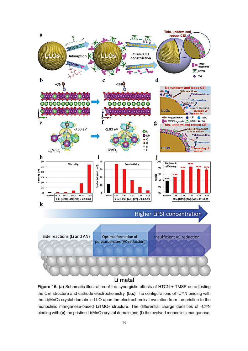
75
Figure 16. (a) Schematic illustration of the synergistic effects of HTCN + TMSP on adjusting the CEI structure and cathode electrochemistry. (b,c) The configurations of -C≡N binding with the Li2MnO3 crystal domain in LLO upon the electrochemical evolution from the pristine to the monoclinic manganese-based LiTMO2 structure. The differential charge densities of -C≡N binding with (e) the pristine Li2MnO3 crystal domain and (f) the evolved monoclinic manganese-
76
based LiTMO2 structure. (d,g) Schematic illustrations of the mechanism of BE-induced and BE/T/H-induced CEI on LLOs. Reproduced with permission.[152] Copyright 2020, WILEY-VCH. (h) Viscosities, (i) conductivities, and (j) CEs of the electrolytes for molar ratio of [LiFSI]:[AN]:[VC] = X:1:0.09 where X ranged from 0.23 to 1.04. (k) Schematic representation of Li interfacial phases in the LAV electrolytes with increasing LiFSI concentration. Reproduced with permission.[153] Copyright 2020, WILEY-VCH.
3.4.1 Section summary
In this section, recent development in the sulfone electrolytes has been discussed,
including TMS, DMSO, SL, MSM, and MPS. The oxidation voltage of nitrile-based
solvents is up to ~5 V, which can cover the operating voltage window of the existing
mainstream battery cathodes. Furthermore, they present high dielectric constants, low
viscosities, and good dissociation effects. Therefore, after further improving the
compatibility with Li anode, nitrile electrolytes are believed to have the potential to
replace the existing commercial electrolyte system.
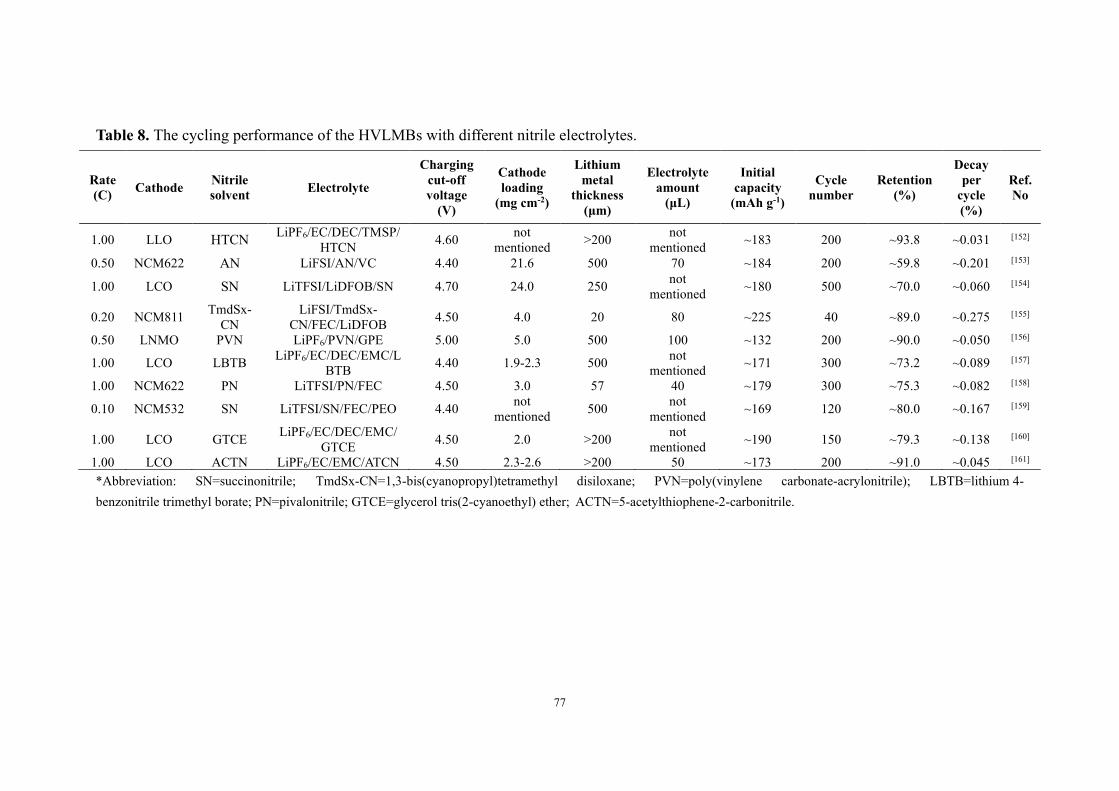
77
Table 8. The cycling performance of the HVLMBs with different nitrile electrolytes.
Rate (C) Cathode Nitrile
solvent Electrolyte
Charging cut-off voltage
(V)
Cathode loading
(mg cm-2)
Lithium metal
thickness (μm)
Electrolyte amount
(μL)
Initial capacity
(mAh g-1)
Cycle number
Retention (%)
Decay per
cycle (%)
Ref. No
1.00 LLO HTCN LiPF6/EC/DEC/TMSP/HTCN 4.60 not
mentioned >200 not mentioned ~183 200 ~93.8 ~0.031 [152]
0.50 NCM622 AN LiFSI/AN/VC 4.40 21.6 500 70 ~184 200 ~59.8 ~0.201 [153]
1.00 LCO SN LiTFSI/LiDFOB/SN 4.70 24.0 250 not mentioned ~180 500 ~70.0 ~0.060 [154]
0.20 NCM811 TmdSx-CN
LiFSI/TmdSx-CN/FEC/LiDFOB 4.50 4.0 20 80 ~225 40 ~89.0 ~0.275 [155]
0.50 LNMO PVN LiPF6/PVN/GPE 5.00 5.0 500 100 ~132 200 ~90.0 ~0.050 [156]
1.00 LCO LBTB LiPF6/EC/DEC/EMC/LBTB 4.40 1.9-2.3 500 not
mentioned ~171 300 ~73.2 ~0.089 [157]
1.00 NCM622 PN LiTFSI/PN/FEC 4.50 3.0 57 40 ~179 300 ~75.3 ~0.082 [158]
0.10 NCM532 SN LiTFSI/SN/FEC/PEO 4.40 not mentioned 500 not
mentioned ~169 120 ~80.0 ~0.167 [159]
1.00 LCO GTCE LiPF6/EC/DEC/EMC/GTCE 4.50 2.0 >200 not
mentioned ~190 150 ~79.3 ~0.138 [160]
1.00 LCO ACTN LiPF6/EC/EMC/ATCN 4.50 2.3-2.6 >200 50 ~173 200 ~91.0 ~0.045 [161] *Abbreviation: SN=succinonitrile; TmdSx-CN=1,3-bis(cyanopropyl)tetramethyl disiloxane; PVN=poly(vinylene carbonate-acrylonitrile); LBTB=lithium 4-benzonitrile trimethyl borate; PN=pivalonitrile; GTCE=glycerol tris(2-cyanoethyl) ether; ACTN=5-acetylthiophene-2-carbonitrile.
78
3.5 Solid-state electrolytes
Solid-state electrolytes (SSEs) have aroused great interest due to their transference
number and high mechanical strength, which can physically inhibit Li dendrites growth.
Outstanding anti-oxidation stability endows SSEs with good compatibility with high-
voltage cathodes. SSEs are divided into in solid-state electrolytes (ISSEs) and quasi-
solid-state electrolytes (QSSEs). ISSEs without liquid include inorganic solid
electrolytes (ISEs), solid polymer electrolytes (SPEs), and composite
polymer electrolytes (CPEs). QSSEs contain a small number of liquid components
fixed inside the solid matrix. Among ISSEs, SPEs with inhibition of transition metal
ion escape from cathodes, prevention of Li dendrite growth, excellent safety, and
reduction of EEIs reactions can potentially realize superior electrochemical
performances and safety characteristics at a high voltage.[162] However, the stability
requirement for solid electrolytes against electrodes has still not been fully satisfied
under high-voltage conditions. Thus introducing advanced materials and designing
efficient structures are necessary. Accordingly, some anti-oxidation substances
(PP12FSI, LEP, LiPVFM, and SN) or a layered architecture can be possible solutions to
enhancing the stability.
Sun. et al.[163] combined “garnet-at-interface” layer and “polymer-in-separator”
matrix to prepare a solid electrolyte. As displayed in Fig. 17a, under an electric field,
in the SPE complexed with a lithium salt and polyethylene oxide (PEO), the polar
groups of the polymer chain interact with active ions, which jump over the entire chain
segment (amorphous region) through thermal motion. Under continuous electric field
79
stimulation, there will be many polarization regions due to the intermolecular forces
between chains, orientation crystallization and cross-linking. Therefore, the free
volume for the thermal movement of the chain is shrined, and then the ion transmission
is inhibited, destroying the stability of the cell. As displayed in Fig. 17b, PVDF owns
lower HOMO energy, which means that the PVDF-based matrix has a higher high-
voltage resistance and dielectric constant than PEO. Therefore, to enhance high-voltage
stability, PVDF is selected as the skeleton of the polymer electrolyte. The high-ratio
LLZT is introduced into the polymer to increase the shielding effect for inhibiting Li
dendrite growth. Besides, this combination can act as an electronic and anionic filter.
However, Li+ cation can migrate through the LLZT percolation, and the interface
between polymer and filler (Fig. 17c). As shown in Fig. 17d, the strong electric field
can be alleviated by packing the vulnerable polymer electrolyte into the porous PVDF
separator, further alleviating the serve electrochemical polarization. This design helps
ensure a good interface to Li metal and improves the high-voltage performance of the
electrolyte. The electric potential can achieve uniform distribution in the EEIs. The
embedded PVDF skeleton (high-dielectric parts) and LLZT layer jointly guarantee the
uniform distribution of the electric field inside the electrolyte bulk. Regulated by the
electric field, the Li+ ions transport through the electrolyte bulk and homogeneously
deposit on the electrode surface. Accordingly, the electric potential can be well-
distributed, which further sustains the stable cycles of batteries. Compared with PEO
and PVDF, bacterial cellulose as the substrate owns higher mechanical strength and
anti-oxidation stability. Dong. et al.[164] combined poly(methyl vinyl ether-alt-maleic
80
anhydride) P(MVE-MA) and bacterial cellulose to form a polymer electrolyte for the
HVLMBs. The LCO||Li battery using P(MVE-MA) membrane with 1M LiODFB/PC
(PMM-CPE) electrolyte exhibits excellent capacity retention of 85% of the initial
capacity after 700 cycles (Fig. 17e), remarkably superior to the LCO||Li battery using
LiODFB/PC electrolyte (14%). Furthermore, the LCO||Li battery using PMM-CPE
electrolyte exhibits a high and stable CE. As shown in Fig. 17f, the electrochemical
impedance spectroscopy (EIS) of LCO||Li batteries using the carbonate electrolyte and
PMM-CPE electrolyte is tested. Two semicircles stand for the bulk electrolyte
resistance and interfacial resistance, respectively. For the PMM-CPE electrolyte, the
interface impedance increases slowly within 700 cycles, indicating outstanding
interfacial combability in the PMM-CPE electrolyte. Zheng et al.[165] developed an
interpenetrating network (IPN), including a basal PEO-contained network and a linear
poly(acrylonitrile) (PAN) secondary network. The chemical and architectural properties
of IPN markedly enhance the oxidative stability of the electrolyte from 4.1 V to over
5.1 V by adding 2 wt.% PAN. The IPN electrolyte is promising to be applied in
HVLMBs.

81
Figure 17. (a) Schematic illustration for the electrochemical attenuation of SPEs under the electric field. (b) Orbital energy levels of the PEO and PVDF polymer matrices. (c) The sketch for the multifunctional effects of the LLZT shield layer. (d) Schematic illustration for superiorities of modified solid electrolytes in this work. Reproduced with permission.[163] Copyright 2020, WILEY-VCH. (e) The corresponding discharge voltage curves of the 1st, 100th, 300th, 500th,
82
and 700th cycles of the LCO||Li cell using PMM-CPE at 60 °C. (f) EIS spectra of the 4.45 V-class LCO||Li cell with PMM-CPE after 50, 100, 400, and 700 cycles at 1C (60 °C). Reproduced with permission.[164] Copyright 2018, The Royal Society of Chemistry.
Fan. et al.[166] reported a LiF-rich SEI layer formation to inhibit the generation of
Li dendrites. The LiF-rich SEI layer owns low resistance, which is because (i) the in
situ-formed thin interface is closely contacted with both Li3PS4 (LPS) and Li; (ii) the
lower energy barrier for Li+ surface diffusion on LiF (0.17 eV for LiF and 0.23 eV for
Li2CO3) accelerates the Li+ transfer along the LiF surface rather than the dendritic
plating. Theoretical calculations based on DFT are conducted to understand the
suppression mechanisms of the Li dendrite of the LiF-rich SEI layer in the SSEs. As
shown in Fig. 18a, Li dendrites must pass through the passivation layer along the grain
boundaries first, where strain energy remains high. According to the energy analysis,
the interface energy increases due to the newly formed interface at the SEI layer. The
strain energy is released with the generation of Li dendrites (Fig. 18b). As the length of
Li dendrite increases, the total energy increases and reaches the top corresponding to
the fatal dendrite length Lc, followed by a slow drop. As displayed in Fig. 18c, the
relationship between the Li formula number and the interfacial energies of various SEI
constituents are tested. The intercept of the fitted line represents the interface energy.
As displayed in Fig. 18d, Li3PS4 exhibits low interface energy of -88.92 meV/Å2,
suggesting an unstable interface between the Li anode and Li3PS4. At the interface, the
cracks are generated because the serve reaction between the Li anode and the Li3PS4
causes the Li3PS4 reconstruction with the Li-P and Li-S bands generation derived from
the optimized structure (Figs. 18e and 18f). However, other SEI components, including
LiF, Li2CO3, Li2O, LiCl, and Li2S, exhibit positive interfacial energy. Furthermore, LiF

83
owns the largest interfacial energy of 73.28 meV/Å2, demonstrating its ultra-high
dendrite inhibition capacity. The interface energy multiplied by the bulk modulus is
used to evaluate the dendrite inhibition ability, as shown in Fig. 18d. LiF exhibits
excellent interface energy and an outstanding bulk modulus (70 GPa). As shown in Figs.
18g and 18h, the energy barrier of the electron tunnelling from Li to LiF or LPS is
calculated. The barrier of electron tunnelling for Li3PS4 is very low, approximately zero,
revealing the incapability of Li3PS4 to suppress electron tunnelling. In contrast, the
barrier of electron tunnelling for LiF is 2 eV, indicating that LiF can effectively prevent
electron tunnelling. The remarkable electronic shielding effect can effectively alleviate
side effects between the Li-metal anode and the Li3PS4. As shown in Figs. 18i, 18j, 18k,
18m, and 18n, three interphases can be generated at the anode-electrolyte interface: (i)
Inherently stable interphase, in which electrolyte and Li metal are thermodynamically
stable; (ii) regular SEI, which owns very low electronic conductivity but high Li+
conductivity; (iii) electronic conducting interphase with an ultra-high electronic
conducting ability. For the first type of SSE, since Li cannot wet the SSE, the potential
at the interface suddenly declines from the SSE to Li metal, resulting in higher
interfacial resistance (Figs. 18m and 18n). Regarding the second category, Li metal
can associate with LiPON to generate a SEI with high-ratio Li2O, which effectively
prevents electron tunnelling. The third kind of SSE comprises Li3xLa2/3-xTiO3 (LLTO),
sulfide, and oxide electrolytes owing to the potential reduction of SSE by Li anode
when the potential is below zero in the Li plating process to form an electronic
conductive substance or an electronic semiconductor substance. Except for the strategy
84
of in situ forming the LiF-rich SEI, the introduction to CPEs at the opposite position of
ISE can also effectively stabilize Li metal anode and high-voltage cathode. Liang. et
al.[167] designed an SSE by coating PAN and PEO on both sides of Li1.4Al0.4Ti1.6(PO4)3
(LATP) respectively to meet different interface requirements. It is essential to offer
tailored solutions to outstanding stability with Li metal and the infiltration of high-
voltage cathode assembled in SSE (Fig. 18l). An SSE electrolyte with notable
improvement is achieved by adding PEO and PAN on both sides of LATP (Fig, 18o).
As shown in Figs. 18p and 18q, the disparate-polymers protected ceramic electrolyte
(DPCE) exhibits a high oxidation potential of 4.5 V and highly reversible Li
plating/stripping. In addition, sizeable ionic conductivity (6.26×10⁻⁴ S cm-1) and low
activation energy (0.46 eV) are achieved in LATP at 60 °C (Figs. 18r and 18s). To
further explain the interfacial stability related to the ion manipulation triggered by the
LATP ceramic in DPCE, COMSOL Multiphysics is conducted to explore the ion layer
with high-tLi+. With abundant free anions, the charging process leaves a large
concentration gradient field or space-charge layer at the electrolyte/anode interface and
hence increases the Li+ transport barrier and polarization, which induces dendrite
formation, decomposition of polymer electrolyte, and inferior cycling stability. Table
9 shows the cycling performance of the HVLMBs with different SSEs.

85
Figure 18. (a) Schematic illustration of the electrochemical deposition process of the Li-metal anode. (b) Energy-based analysis (interfacial energy and strain energy) of Li dendrite formation. (c) The plot of the relationship between the interfacial energy for possible SEI components and the number of Li metal formula units. (d) Calculated interfacial energies 𝛾𝛾, bulk modulus E from MP, and Li dendrite suppression ability 𝛾𝛾E for different interface components. DFT-optimized atomic structures of (e) LPS/Li and (f) LiF/Li interfaces and (g, h) its corresponding density of states (DOS) profiles by atomic layer with Fermi level at 0 eV. The green, purple, yellow, and grey balls in (e) and (f) represent Li, P, S, and F atoms. (i) Thermodynamically stable interphase. (j) Reactive but forming an electron insulator SEI layer. (k) Reactive and forming a degradation layer with high electron conductivity. (m) Li potentials between the Li metal and the SSEs in the
86
above three interphase types. (n) The difference between the green dash line (III) and the red dash (III′) is that the red dash line (III′) includes the overpotentials during the Li plating process. Reproduced with permission.[166] Copyright 2018, American Association for the Advancement of Science. Illustrations of the solid full battery with (l) pristine LATP and (o) DPCE. (p) Cyclic voltammetry and (q) LSV curves of the DPCE at 60 °C. (r) EIS analysis and (s) Arrhenius linear fitting plots of the DPCE at various temperatures. Reproduced with permission.[167] Copyright 2019, American Chemical Society.
3.5.1 Section summary
In this section, recent development in the SSEs has been discussed, including
LiTFSI/PC/PMM-CPE, LiFSI/PVH/PP12FSI, P(CUMA-NPF6)-GPE, LiTFSI/PVDF-
HFP/LLZO, and LATP/PEO/PAN systems. The ion transfer mechanisms in the SSEs
are entirely different from traditional electrolytes. For crystalline solid electrolytes, ion
transfer dramatically depends on the defects in the crystal structure, including electron
defects, volume defects, planar defects, line defects, and point defects. In the middle of
these defects, point defects undertake a pivotal part in Li+ transfer mechanisms. The
most typical defects are the Schottky point defects, where the cation vacancies are
accompanied by anion vacancies, and Frenkel point defects, where cation interstitials
accompany anion vacancies. In particular, the ion transfer mechanisms occurring on
point defects include: (i) non-defect mechanisms, which are divided into collective
mechanism, interstitial-substitutional exchange mechanism, and interstitial mechanism;
(ii) defect mechanisms, which are divided into vacancy mechanism and simple vacancy
mechanism. For SPEs, Li+ transfer generally happens in the amorphous phase. The free-
volume model and additional theoretical methods are employed to simulate the Li+
conductivity mechanism in the amorphous phase. In the model, the Li cations distribute
in the appropriate coordination locations of the polymer section chain. These chains
experience topical segmental movement with a quasi-liquid action. The Li cation leaps
87
from one coordination position to another through free sites on the same chain segment
or two different chain segments driven by the electric field force. Overall, the solid
electrolytes based on the combination between inorganic materials and polymers, the
association of different polymers, and the QSSEs with a small amount of liquid
electrolyte have improved the electrochemical stability under the high voltage. In
addition to enhancing the high-voltage stability of the SSEs, the interface between
electrode and SSE also needs to be further strengthened. Specifically, the issues
including large interfacial impedance, element interdiffusion, lithium dendrite growth,
side reactions aroused by high-voltage decomposition, and space charge layer
especially at the electrolyte/cathode interface, are being further concerned. It is believed
that developing strategies such as layered architecture and in situ gelation can solve
these problems to promote the application of SSEs in HVLMBs.
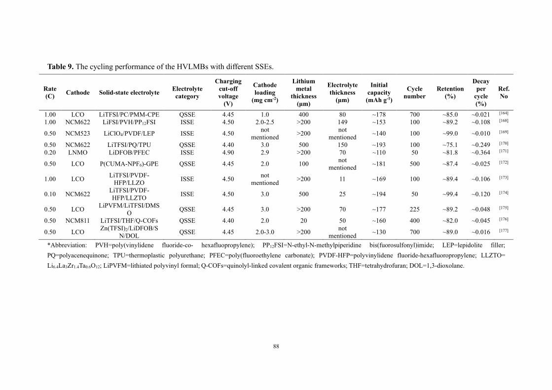
88
Table 9. The cycling performance of the HVLMBs with different SSEs.
Rate (C) Cathode Solid-state electrolyte Electrolyte
category
Charging cut-off voltage
(V)
Cathode loading
(mg cm-2)
Lithium metal
thickness (μm)
Electrolyte thickness
(μm)
Initial capacity
(mAh g-1)
Cycle number
Retention (%)
Decay per
cycle (%)
Ref. No
1.00 LCO LiTFSI/PC/PMM-CPE QSSE 4.45 1.0 400 80 ~178 700 ~85.0 ~0.021 [164] 1.00 NCM622 LiFSI/PVH/PP12FSI ISSE 4.50 2.0-2.5 >200 149 ~153 100 ~89.2 ~0.108 [168]
0.50 NCM523 LiClO4/PVDF/LEP ISSE 4.50 not mentioned >200 not
mentioned ~140 100 ~99.0 ~0.010 [169]
0.50 NCM622 LiTFSI/PQ/TPU QSSE 4.40 3.0 500 150 ~193 100 ~75.1 ~0.249 [170] 0.20 LNMO LiDFOB/PFEC ISSE 4.90 2.9 >200 70 ~110 50 ~81.8 ~0.364 [171]
0.50 LCO P(CUMA-NPF6)-GPE QSSE 4.45 2.0 100 not mentioned ~181 500 ~87.4 ~0.025 [172]
1.00 LCO LiTFSI/PVDF-HFP/LLZO ISSE 4.50 not
mentioned >200 11 ~169 100 ~89.4 ~0.106 [173]
0.10 NCM622 LiTFSI/PVDF-HFP/LLZTO ISSE 4.50 3.0 500 25 ~194 50 ~99.4 ~0.120 [174]
0.50 LCO LiPVFM/LiTFSI/DMSO QSSE 4.45 3.0 >200 70 ~177 225 ~89.2 ~0.048 [175]
0.50 NCM811 LiTFSI/THF/Q-COFs QSSE 4.40 2.0 20 50 ~160 400 ~82.0 ~0.045 [176]
0.50 LCO Zn(TFSI)2/LiDFOB/SN/DOL QSSE 4.45 2.0-3.0 >200 not
mentioned ~130 700 ~89.0 ~0.016 [177]
*Abbreviation: PVH=poly(vinylidene fluoride-co- hexafluopropylene); PP12FSI=N-ethyl-N-methylpiperidine bis(fuorosulfonyl)imide; LEP=lepidolite filler; PQ=polyacenequinone; TPU=thermoplastic polyurethane; PFEC=poly(fluoroethylene carbonate); PVDF-HFP=polyvinylidene fluoride-hexafluoropropylene; LLZTO= Li6.4La3Zr1.4Ta0.6O12; LiPVFM=lithiated polyvinyl formal; Q-COFs=quinolyl-linked covalent organic frameworks; THF=tetrahydrofuran; DOL=1,3-dioxolane.

89
4. Conclusions and prospects
The ever increasing demand of high energy density energy storage device has put
HVLMBs on the agenda in recent years, which has also sentenced conventional
electrolytes with narrow electrochemical window to death owing to their failure of
compromising the catalytic nature of high-voltage cathodes and the infamous reactivity
of the Li-metal anode. A host of strategies are developed to overcome the
aforementioned challenges, mainly classified into two categories: conventional
electrolyte modification and novel electrolyte design. The important properties of
representative electrolytes based on conventional electrolyte modification and novel
electrolyte design are displayed in Table 10.
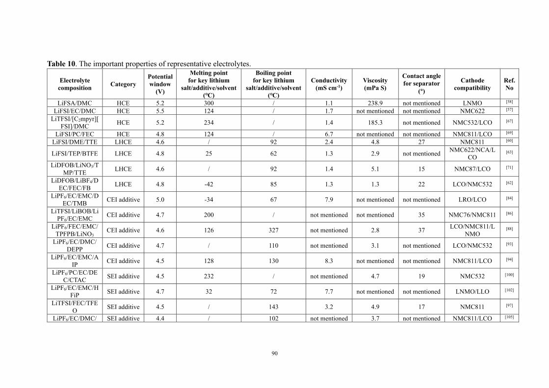
90
Table 10. The important properties of representative electrolytes.
Electrolyte composition Category
Potential window
(V)
Melting point for key lithium
salt/additive/solvent (℃)
Boiling point for key lithium
salt/additive/solvent (℃)
Conductivity (mS cm-1)
Viscosity (mPa S)
Contact angle for separator
(°)
Cathode compatibility
Ref. No
LiFSA/DMC HCE 5.2 300 / 1.1 238.9 not mentioned LNMO [58] LiFSI/EC/DMC HCE 5.5 124 / 1.7 not mentioned not mentioned NMC622 [57]
LiTFSI/[C2mpyr][FSI]/DMC HCE 5.2 234 / 1.4 185.3 not mentioned NMC532/LCO [67]
LiFSI/PC/FEC HCE 4.8 124 / 6.7 not mentioned not mentioned NMC811/LCO [69] LiFSI/DME/TTE LHCE 4.6 / 92 2.4 4.8 27 NMC811 [60]
LiFSI/TEP/BTFE LHCE 4.8 25 62 1.3 2.9 not mentioned NMC622/NCA/LCO
[63]
LiDFOB/LiNO3/TMP/TTE LHCE 4.6 / 92 1.4 5.1 15 NMC87/LCO [71]
LiDFOB/LiBF4/DEC/FEC/FB LHCE 4.8 -42 85 1.3 1.3 22 LCO/NMC532 [62]
LiPF6/EC/EMC/DEC/TMB CEI additive 5.0 -34 67 7.9 not mentioned not mentioned LRO/LCO [84]
LiTFSI/LiBOB/LiPF6/EC/EMC CEI additive 4.7 200 / not mentioned not mentioned 35 NMC76/NMC811 [86]
LiPF6/FEC/EMC/TPFPB/LiNO3
CEI additive 4.6 126 327 not mentioned 2.8 37 LCO/NMC811/LNMO
[88]
LiPF6/EC/DMC/DEPP CEI additive 4.7 / 110 not mentioned 3.1 not mentioned LCO/NMC532 [93]
LiPF6/EC/EMC/AIP CEI additive 4.5 128 130 8.3 not mentioned not mentioned NMC811/LCO [94]
LiPF6/PC/EC/DEC/CTAC SEI additive 4.5 232 / not mentioned 4.7 19 NMC532 [100]
LiPF6/EC/EMC/HFiP SEI additive 4.7 32 72 7.7 not mentioned not mentioned LNMO/LLO [102]
LiTFSI/FEC/TFEO SEI additive 4.5 / 143 3.2 4.9 17 NMC811 [97]
LiPF6/EC/DMC/ SEI additive 4.4 / 102 not mentioned 3.7 not mentioned NMC811/LCO [105]
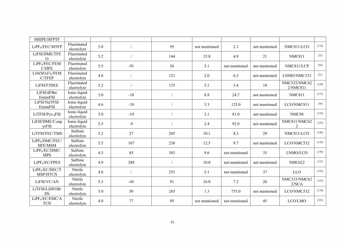
91
MSIPE/HFPTF
LiPF6/FEC/MTFP Fluorinated electrolyte 5.8 / 95 not mentioned 2.1 not mentioned NMC811/LCO [114]
LiFSI/DME/TFEO
Fluorinated electrolyte 5.2 / 144 15.8 4.9 21 NMC811 [23]
LiPF6/FEC/FEMC/HFE
Fluorinated electrolyte 5.5 -91 56 5.1 not mentioned not mentioned NMC811/LCP [54]
LiN(SO2F)2/FEMC/TFEP
Fluorinated electrolyte 4.8 / 121 2.0 6.3 not mentioned LNMO/NMC333 [21]
LiFSI/F5DEE Fluorinated electrolyte 5.2 / 135 5.1 3.4 18 NMC532/NMC62
2/NMC811 [120]
LiFSI/dFBn/ EmimFSI
Ionic-liquid electrolyte 5.0 -18 / 8.8 24.7 not mentioned NMC811 [137]
LiFSI/NaTFSI/ EmimFSI
Ionic-liquid electrolyte 4.6 -18 / 3.3 125.0 not mentioned LCO/NMC811 [56]
LiTFSI/Pyr14FSI Ionic-liquid electrolyte 5.0 -19 / 3.1 81.0 not mentioned NMC88 [135]
LiFSI/DME/C3mpyrFSI
Ionic-liquid electrolyte 5.5 -9 / 2.4 92.0 not mentioned NMC811/NMC62
2 [133]
LiTFSI/FEC/TMS Sulfone electrolyte 5.2 27 285 10.1 8.3 29 NMC811/LCO [148]
LiPF6/DMC/FEC/HFE/MSM
Sulfone electrolyte 5.5 107 238 12.5 9.7 not mentioned LCO/NMC532 [145]
LiPF6/EC/DMC/MPS
Sulfone electrolyte 4.5 85 303 9.6 not mentioned 35 LNMO/LCO [150]
LiPF6/EC/FPES Sulfone electrolyte 4.9 288 / 10.0 not mentioned not mentioned NMC622 [151]
LiPF6/EC/DEC/TMSP/HTCN
Nitrile electrolyte 4.8 / 255 5.1 not mentioned 37 LLO [152]
LiFSI/VC/AN Nitrile electrolyte 5.5 -45 81 16.0 7.2 26 NMC333/NMC62
2/NCA [153]
LiTFSI/LiDFOB/SN
Nitrile electrolyte 5.0 50 265 1.3 753.0 not mentioned LCO/NMC532 [154]
LiPF6/EC/EMC/ATCN
Nitrile electrolyte 4.9 77 95 not mentioned not mentioned 45 LCO/LMO [161]

92
LiTFSI/PC/PMM-CPE QSSE 5.3 / 202 1.3 / / LCO [164]
LiTFSI/PQ/TPU QSSE 4.8 / 136 5.0 / / NMC622 [170] P(CUMA-NPF6)-
GPE QSSE 5.6 / 338 1.0 / / LCO/LNMO [172]
LiPVFM/LiTFSI/DMSO QSSE 5.0 120 / 0.4 / / LCO [175]
LiFSI/PP12FSI/PVH ISSE 5.3 135 / 0.5 / / NMC622 [168]
LiDFOB/PFEC ISSE 5.5 190 / 0.2 / / LCO/LNMO [171] LiTFSI/LLZO/PV
DF-HFP ISSE 4.5 135 / 0.1 / / LCO [173]
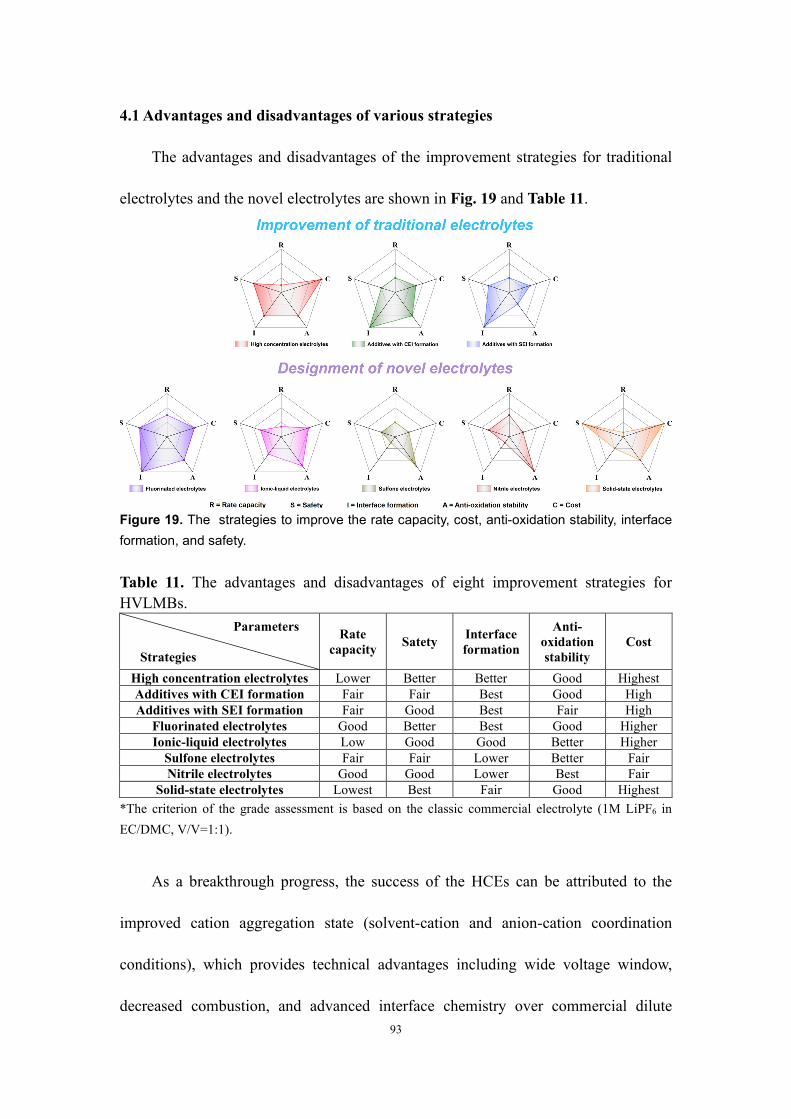
93
4.1 Advantages and disadvantages of various strategies
The advantages and disadvantages of the improvement strategies for traditional
electrolytes and the novel electrolytes are shown in Fig. 19 and Table 11.
Figure 19. The strategies to improve the rate capacity, cost, anti-oxidation stability, interface formation, and safety. Table 11. The advantages and disadvantages of eight improvement strategies for HVLMBs.
Parameters
Strategies
Rate capacity Satety Interface
formation
Anti-oxidation stability
Cost
High concentration electrolytes Lower Better Better Good Highest Additives with CEI formation Fair Fair Best Good High Additives with SEI formation Fair Good Best Fair High
Fluorinated electrolytes Good Better Best Good Higher Ionic-liquid electrolytes Low Good Good Better Higher
Sulfone electrolytes Fair Fair Lower Better Fair Nitrile electrolytes Good Good Lower Best Fair
Solid-state electrolytes Lowest Best Fair Good Highest *The criterion of the grade assessment is based on the classic commercial electrolyte (1M LiPF6 in EC/DMC, V/V=1:1).
As a breakthrough progress, the success of the HCEs can be attributed to the
improved cation aggregation state (solvent-cation and anion-cation coordination
conditions), which provides technical advantages including wide voltage window,
decreased combustion, and advanced interface chemistry over commercial dilute
94
electrolytes. Nevertheless, heavy use of expensive lithium salts and significantly
increased viscosity bring cost concerns, low rate capacity, and inferior compatibility
with thick cathodes for industrial applications. Based on the above issues, LHCEs have
been developed to combine the advantages between HCEs and conventional
concentration electrolytes. The selection of the diluents that do not participate in Li+
solvation structure is the key for LHCEs. Future research should pay attention to the
price and flammability of the diluents. To construct the LHCEs, the blind use of
expensive height fluorinated solvents and highly volatile ether solvents is not applicable
to commercial applications. Cost-effective flame-retardant diluent with low HOMO
energy level can be employed to improve comprehensive performances of the LHCEs
for practical applications. For example, the integration of phosphate diluent and HCE
aqueous electrolytes gives the opportunity to achieve cost-effective high-security
electrolytes. Moreover, it is sagacious to develop novel diluents by grafting polar
functional groups in annular organic matters. For the design principles of solvents,
carbonate-based, sulfone-based, and nitrile-based electrolyte solvents with strong
reactivity and poor film-formation ability for Li metal are difficult to apply in HVLMBs.
The formation of the anion-derived SEI layer induced in the HCEs can significantly
enhance the compatibility between the electrolyte and the Li anode. Moreover, the
reduced free solvent number in the HCE can improve the high voltage stability of ether-
based solvents, which promotes their applications in HVLMBs. As for the design
principles for lithium salts, great success has been achieved for HCEs, primarily
attributed to the LiF-rich SEI layer as derived from the anion. The big anion size in
95
LiFSI and LiTFSI decreases the Coulombic forces between cations and anions in the
electrolyte, ensuring the high solubility in the solvents. In HCEs, the interaction
between Li+ and anions significantly affects the interface formation and electrode
passivation processes. Due to the uniform and dense LiF-rich EEIs as induced by TFSI-
and FSI-, the interface can remarkably inhibit Li dendrite growth and tolerate the
significant volume change of high voltage/capacity electrodes. The design principles
for LHCE are mainly centered on diluents. The selection principles of the diluents
mainly include: (i) weakening Li+ binding energy without participating in the Li+
solvent shell to achieve localized high concentration environment; (ii) lowering the
viscosity by reducing the HCE viscosity and increasing the wettability of the electrolyte
for electrodes and separators; (iii) lowering the LUMO energy level and facilitating the
SEI layer formation; (iv) lowering the cost for promoting large-scale applications; (v)
lowering the combustibility and enhancing battery safety; (vi) weakening toxicity and
reducing pollution for battery recycling. If the existing problems can be fundamentally
settled, LHCEs will enable HVLMBs with larger power and energy densities.
As to additives for EEI formation, the addition of a tiny dose of adventive
molecules is considered one of the simplest and economical ways to construct strong
EEIs, which is closely correlated with the electrochemical stability of electrodes and
electrolytes. The additives chosen for Li anode and high-voltage cathode should own
higher reduction potential and lower oxidation potential compared with electrolytes.
Future research can focus on the evaluation of the Al foil corrosion induced by additives
and the development of additives with suppression function of lattice oxygen escaping.
96
In the laboratory coin-cell evaluation system, the negative impact of the current
collector corrosion is weakened. However, for pouch and cylindrical cells, the Al foil
corrosion causes the comprehensive deterioration of electrochemical performances. In
addition, the foreign additive under a high voltage is extremely easy to corrode the Al
foil. Hence, for the electrolytes after additive introduction, Al foil corrosion should be
carefully evaluated. The cathode with oxygen valence activities is often accompanied
by irreversible oxygen loss during charge and discharge, resulting in structural
degradation of cathode materials. It is suggested that Quantum Chemistry Calculations
including G4MP2 calculation and SMD solvation model are employed to filter the
additive firming lattice oxygen. Moreover, an excellent additive should meet the
following design principles: (i) it should sacrificially decompose before the electrolyte
solvent components to passivate the high-voltage cathode and Li metal anode; (ii) the
gas generation can be effectively inhibited; (iii) the generated SEI and CEI layers
should be compact and thin with low electrochemical impedance; (iv) the generated
SEI and CEI layers should tolerate the extreme potential and the significant volume
fluctuation of the electrodes.
For the fluorinated electrolytes, outstanding anti-oxidation stability makes them
promising candidates for the HVLMBs electrolyte. In addition, the fluorinated solvent
owns high thermal stability and even nonflammability. Nevertheless, highly fluorinated
solvents with high purity tend to be expensive, which limits their further development.
Therefore, it is suggested that instead of pursuing highly fluorinated solvents, the
fluorinated group functions in different positions of the molecules be analyzed in-depth
97
to guide the molecular structure design for lowly fluorinated solvents. For example, the
position of the fluorinated group in the molecular structure has a profound effect on the
capabilities of LiF formation and Li+ coordination. Moreover, comprehension on the
influence of the fluorinated electrolytes on the HVLMB performances requires insights
into two correlations: one between electronic distribution and molecular structure in the
fluorinated solvent, and the other between nonfluorinated solvent and fluorinated
solvent. At last, a safe fluorinated-based electrolyte should follow design principles: (i)
high thermal stability, which ensures that the physicochemical properties of the
electrolyte can be well maintained at a rapidly increased in temperature; (ii) low
flammability and even nonflammability, which can significantly improve battery safety;
(iii) low flash point, which is especially crucial that the drastic decrease in the flash
point with an increasing degree of fluorination; (iv) high boiling point, which prevents
the internal air pressure of the battery from being too large at a high temperature.
For ionic-liquid, sulfone, and nitrile electrolytes, wide electrochemical window
and excellent cathode affinity make them promising candidates as the new generation
of HVLMBs electrolytes. Unfortunately, the inferior compatibility with Li metal
prevents their further development. Cheap film-formation solvents can be introduced
to stabilize the Li anode, but the distribution of the mixed solvents is random inside the
HVLMBs. It is suggested that DFT calculations be employed in achieving selective
distribution of each solvent in the mixed electrolyte. For example, nitrile-based
compounds are screened to obtain solvents with a large absorption energy to the high-
voltage cathode but a low absorption energy to the Li anode. Film-formation
98
compounds are also screened to obtain the solvents with a large absorption energy to
the Li anode but a low absorption energy to the high-voltage cathode. The screened
solvents in the mixed electrolyte wet the two electrodes, which facilitates bi-electrode
affinity. It is noted that the cost of ionic liquid is obviously higher than those of sulfone
and nitrile, so the introduced proportion of cheap doped solvents should be higher to
control the cost. The excellent anti-oxidation stability of the sulfones can be attributed
to the powerful intrinsic stability of the sulfone group against oxidation at an extreme
potential. On the contrary, the anti-oxidation stability of nitrile-based electrolytes is
attributed to the prioritized decomposition on the surface of the high-voltage cathode,
generating an effective protective layer of -C≡N/transition metal complexes to avoid,
the intimate contact between other species and catalytic surfaces of the cathode. In
addition, similar to carbonate functional groups in alkyl carbonate molecules with large
dielectric constants and dipolar moments, the terminal -C≡N functional groups are
excellent nucleophilic sites for coordinating Li+.
SSEs have received abundant attention owing to their excellent characteristics of
robust mechanical strength, strong anti-oxidation capability, no risk of leakage, and
nonflammability. Nevertheless, SSEs cannot support HVLMBs to own satisfactory
electrochemical performances due to the large interfacial resistance, mechanical
collapse, and interfacial side reaction. Future research can focus on the failure
mechanism of the HVLMBs using SSEs. Battery failure associated with EEI kinetic
process is correlated with Li+/e- transport and combination, chemical/electrochemical
reactions, and pressure change. It is suggested that the complex process that is difficult

99
to touch experimentally should be simulated through Ab initio molecular dynamics,
where electron/ion transport and combination are imitated with the PAW way, all
molecular evolutions are caught in the NVT ensemble using a Nosé-Hoover thermostat,
and the free energy of the system is obtained by integrating the position-dependent
mean constraint forces. In situ gelation for solid-state polymer electrolyte owns in-built
interface with rapid ion transport, which is regarded as one of the most promising SSE
technologies. Future research on this technology should be centered on simplifying the
polymerization conditions and enhancing the anti-oxidation stability after
polymerization. In addition, future research focusing on the design principles should
also be highlighted, such as interfacial characterizations for guiding the design of the
interfacial chemical reaction kinetics and the design of the interfacial conservation films
with anti-oxidation and reduction inhibition to widen the electrochemical window for
HVLMBs.
4.2 Future directions
Although valuable progress has been made, several critical issues remain to be
resolved for the electrolyte of the practical HVLMBs (Fig. 20):
1. Higher safety: The catalytic nature of high-voltage cathodes and the infamous
reactivity of Li anode make the inherently flammable traditional liquid electrolyte more
prone to dangerous accidents. Fluorine introduction is expected to be an effective
solution to alleviate inflammability of the conventional electrolyte. In addition, the
toxicity of the electrolyte solvent can also be reduced after fluorination. The
applications of ionic-liquid and nitrile solvents are also a feasible choice regarding their

100
thermostability and flame retardancy. Of course, in terms of safety, SSEs far exceeds
liquid electrolyte. It is noteworthy that the conclusions drawn from a simple ignition
experiment on the electrolyte are unreliable. The so-called non-flammable electrolyte
is still dangerous in actual operation. More stringent inspections must be conducted,
such as a nail-penetration test. Cost-effective flame-retardant diluents can be employed
to improve the comprehensive performances of the LHCEs for practical applications.
For example, the integration of phosphate diluents and HCE aqueous electrolytes helps
achieve cost-effective high-security electrolytes. Moreover, it is sagacious to obtain
novel diluents by grafting polar functional groups (-COOH, Ar-OH, -OH, -NHCO-CH3,
-NH2, -SH, -CHO, and CH3-N-CH3) in annular organic matters (alicyclic compounds,
aromatic compounds, and heterocyclic compounds).
2. Lower cost: In traditional LIBs, the cost of electrolyte accounts for ~20%, which will
be further increased in the HVLMBs due to the greater demand for additives with
complex functions, large amounts of lithium salts, and novel solvents. Therefore, it is
vital to reduce the electrolyte cost. More detailly, lithium salt has the highest cost
proportion among the compositions of the electrolyte. Although the HCEs can
significantly expand the electrochemical window of traditional electrolytes, the cost is
too high for its large proportion of lithium salts. This issue can be effectively solved by
the LHCEs. Contrary to the HCEs, low concentration (<1 M) electrolytes (LCEs)
pursue high performance while maintaining low cost. Herein, it is suggested that strong
reduction additives (CuBr2, BeBr2, MgBr2, CaBr2, LiBr, NaBr, and KBr) are introduced
to reactivate dead Li and release active Li+ for reuse in the LCEs by supplementing Li+

101
and suppressing dead Li growth. Furthermore, the systematic research on the
collaborative relationship of solvents, salts, and ionic aggregate structure undoubtedly
facilitate the breakthrough of the LCE field.
3. Practical conditions: It is noted that most of these electrolytes are assessed in coin-
cell systems (Tables 2-9) with thin high-voltage cathodes (<5 mg cm-2), flooded
electrolytes (E/A>10 g Ah-1), and thick lithium metal anodes (>200 μm), whereas
evaluations of them in commercial pouch batteries display unsatisfactory energy
density and inferior cycle life. Herein, it is suggested that the novel electrolyte should
be tested with high-loading cathodes (≥20 mg cm-2), lean electrolytes (E/A≤3 g Ah-1),
and thin Li metal anodes (≤ 20 μm). High-loading cathode and lean electrolyte
conditions require low-viscosity and highly-wetting co-solvents, such as 1-
methylpentyl acetate, 1,4-dichlorobenzene, 4-methyl-2-pentanone, and 2-heptanone.
Moreover, the CE test of Li/Cu batteries is one of the most widely used methods of
assessing Li+ stripping/plating reversibility in the interface between the electrolyte and
the Li anode. It is suggested that the thickness of the Li foil is 50 μm and the amount of
the electrolyte is 15 μL. During cycling, 4-5 mAh cm-2 of lithium (~20-25 μm) plated
on the Cu current collector provides a suitable areal capacity to be matched with high-
loading cathodes. The CEs of the Li/Cu cells under this stringent condition are close to
the measured CEs in the HVLMBs with thin Li anodes.
4. Advanced interfacial chemistry: Despite a small part in the HVLMB system, SEI and
CEI play a vital part in preventing the further reaction between electrolyte and
electrodes to alleviate the transition metal dissolution and the growth of Li dendrites.
102
In addition, the EEIs affect the lithiation and delithiation of Li+ on the electrode surface.
Electrochemical reactions at the interphases are triggered during charging/discharging
with the generation of Li anode-side SEI and the CEI counterpart due to the initial
reduction and oxidation of electrolyte. Therefore, the electrolyte directly determines the
composition of SEI and CEI. The ideal interphase is characterized by the uniform and
robust inorganic-organic composite layer. Take the fluorinated interphases generated in
the fluorinated electrolyte as an example, its high interfacial energy (73.28 meV/Å2)
and anti-oxidation stability (6.4 V vs. Li/Li+) can facilitate Li+ transport along with the
interface and prevent continuous side reactions between electrolyte and electrode.
Similarly, S- and N-rich SEI/CEI have also been proven to have multiple functions.
Herein, future research for interfacial chemistry can focus on the following two
directions: interfacial layered construction, and quantitative combination ratio of
beneficial substances at the interface.
5. Theoretical calculations and simulations: Theoretical research assisted by artificial
intelligence, large data sets, machine learning, and supercomputing power will help to
quickly screen and foresee the next-generation electrolyte systems that support the
HVLMBs. Furthermore, theoretical research will assist in an overall grasp of what
happened to the EEIs in the HVLMBs at the molecular scale, which is the area that the
experiment cannot touch. However, the predictive ability of theoretical calculations is
rarely used in the HVLMBs at present. This field will undoubtedly promote the
development of the HVLMBs electrolyte. For example, Quantum Chemistry
Calculations including G4MP2 calculations and SMD solvation models are employed

103
to filter the additive firming lattice oxygen. Furthermore, by using machine learning
and adsorption energy calculations, the film-formation solvent (VC, FEC, vinyl
Ethylenecarbonate (VEC), ethylene sulfite (ES), vinylethylene sulfite (VES), ethylene
sulfate (DTD), 4-propyl-[1,3,2]dioxathiolane-2,2-dioxide (PDTD), diphenyl disulfide
(DPDS), tris (2,2,2-trifluoroethyl) borate (TTFEB), and ionanofluid (InF)) and anti-
oxidation solvent (ionic-liquid, sulfone, and nitrile) in the mixed electrolyte can
individually wet the two electrodes, which facilitates bi-electrode affinity. Besides, the
complex interface evolution process should be simulated by Ab initio molecular
dynamics, where electron/ion transport and combination are imitated by the PAW way,
all molecular evolution is caught in the NVT ensemble using a Nosé-Hoover thermostat,
and the free energy of the system can be obtained by integrating the position dependent
mean constraint forces.
6. Novel characterization methods: Accurate characterizations of the electrolyte and
interphases are still very difficult nowadays, which is ascribed to their low content,
sensitivity to electron radiation and X-ray, and reactivity to water and oxygen. In-situ
characterization technology can collect signals from electrolyte and interphases during
battery operation, which is undoubted of paramount significance for the accurate and
deep research of the internal changes of the HVLMBs. The application of cryo-electron
microscopy in the HVLMBs is groundbreaking, which minimizes the influence of
oxygen and water during the test. Current in-situ characterization technologies are
mainly based on coin-cell configuration. It is suggested that the progressive
characterization should be further integrated with pouch and cylindrical cells.

104
Figure 20. Several critical issues of electrolytes for HVLMBs.
Conflict of Interest
There are no conflicts to declare.
Acknowledgement:
This research is supported by the Science Foundation of National Key Laboratory of
Science and Technology on Advanced Composites in Special Environments, and the
National Natural Science Foundation of China (12002109).
References:
[1] X. W. Chi, M. L. Li, J. C. Di, et al., “A highly stable and flexible zeolite electrolyte solid-state Li-air battery,” Nature, vol. 592, no. 7855, pp. 551-557, 2021. [2] B. T. Yuan, K. C. Wen, D. J. Chen, et al., “Composite separators for robust high rate lithium ion batteries,” Advanced Functional Materials, vol. 31, no. 32, pp. 2101420,
105
2021. [3] L. W. Dong, Y. P. Liu, K. C. Wen, et al., “High-polarity fluoroalkyl ether electrolyte enables solvation-free Li+ transfer for high-rate lithium metal batteries,” Advanced Science, vol. 9, no. 5, pp. 2104699, 2021. [4] P. F. Wang, Y. Meng, Y. J. Wang, et al., “Oxygen framework reconstruction by LiAlH4 treatment enabling stable cycling of high-voltage LiCoO2,” Energy Storage Materials, vol. 44, pp. 487-496, 2022. [5] H. W. An, Q. S. Liu, J. L. An, et al., “Coupling two-dimensional fillers with polymer chains in solid polymer electrolyte for room-temperature dendrite-free lithium-metal batteries,” Energy Storage Materials, vol. 43, pp. 358-364, 2021. [6] L. W. Dong, J. P. Liu, D. J. Chen, et al., “Suppression of polysulfide dissolution and shuttling with glutamate electrolyte for lithium sulfur batteries,” ACS Nano, vol. 13, no. 12, pp. 14172-14181, 2019. [7] S. J. Zhong, B. T. Yuan, Z. X. Guang, et al., “Recent progress in thin separators for upgraded lithium ion batteries,” Energy Storage Materials, vol. 41, pp. 805-841, 2021. [8] Y. Qiao, H. J. Yang, Z. Chang, et al., “A high-energy-density and long-life initial-anode-free lithium battery enabled by a Li2O sacrificial agent,” Nature Energy, vol. 6, no. 6, pp. 653-662, 2021. [9] Q. Lv, Y. Jiang, B. Wang, et al., “Suppressing lithium dendrites within inorganic solid-state electrolytes,” Cell Reports Physical Science, vol. 3, no. 1, pp. 100706, 2022. [10] J. Holoubek, H. D. Liu, Z. H. Wu, et al., “Tailoring electrolyte solvation for Li metal batteries cycled at ultra-low temperature,” Nature Energy, vol. 6, no. 3, pp. 303-313, 2021. [11] W. J. Xue, M. J. Huang, Y. T. Li, et al., “Ultra-high-voltage Ni-rich layered cathodes in practical Li metal batteries enabled by a sulfonamide-based electrolyte,” Nature Energy, vol. 6, no. 5, pp. 495-505, 2021. [12] D. T. Boyle, W. Huang, H. S. Wang, et al., “Corrosion of lithium metal anodes during calendar ageing and its microscopic origins,” Nature Energy, vol. 6, no. 5, pp. 487-494, 2021. [13] H. Chen, Y. F. Yang, D. T. Boyle, et al., “Free-standing ultrathin lithium metal-graphene oxide host foils with controllable thickness for lithium batteries,” Nature Energy, vol. 6, no. 8, pp. 790-798, 2021. [14] J. Liu, Z. N. Bao, Y. Cui, et al., “Pathways for practical high-energy long-cycling lithium metal batteries,” Nature Energy, vol. 4, no. 3, pp. 180-186, 2019. [15] J. P. Liu, L. W. Dong, D. J. Chen, et al., “Metal oxides with distinctive valence states in an electron-rich matrix enable stable high-capacity anodes for Li ion batteries,” Small Methods, vol. 4, no. 2, pp. 1900753, 2020. [16] Z. Y. Wang, L. Shen, S. G. Deng, et al., “10 mu m-thick high-strength solid polymer electrolytes with excellent interface compatibility for flexible all-solid-state lithium-metal batteries,” Advanced Materials, vol. 33, no. 25, pp. 2100353, 2021. [17] Y. G. Zou, Z. Cao, J. L. Zhang, et al., “Interfacial model deciphering high-voltage electrolytes for high energy density, high safety, and fast-charging lithium-ion batteries,” Advanced Materials, vol. 33, no. 43, pp. 2102964, 2021. [18] X. S. Wang, S. W. Wang, H. R. Wang, et al., “Hybrid electrolyte with dual-anion-
106
aggregated solvation sheath for stabilizing high-voltage lithium-metal batteries,” Advanced Materials, vol. 33, no. 52, pp. 2007945, 2021. [19] S. S. Lin, H. M. Hua, P. B. Lai and J. B. Zhao, “A multifunctional dual-salt localized high-concentration electrolyte for fast dynamic high-voltage lithium battery in wide temperature range,” Advanced Energy Materials, vol. 11, no. 36, pp. 2101775, 2021. [20] B. Roy, P. Cherepanov, C. Nguyen, et al., “Lithium borate ester salts for electrolyte application in next-generation high voltage lithium batteries,” Advanced Energy Materials, vol. 11, no. 36, pp. 2101422, 2021. [21] Q. F. Zheng, Y. Yamada, R. Shang, et al., “A cyclic phosphate-based battery electrolyte for high voltage and safe operation,” Nature Energy, vol. 5, no. 4, pp. 291-298, 2020. [22] T. L. Zheng, J. W. Xiong, X. T. Shi, et al., “Cocktail therapy towards high temperature/high voltage lithium metal battery via solvation sheath structure tuning,” Energy Storage Materials, vol. 38, pp. 599-608, 2021. [23] X. Cao, L. F. Zou, B. E. Matthews, et al., “Optimization of fluorinated orthoformate based electrolytes for practical high-voltage lithium metal batteries,” Energy Storage Materials, vol. 34, pp. 76-84, 2021. [24] J. Chen, X. Fan, Q. Li, et al., “Electrolyte design for LiF-rich solid–electrolyte interfaces to enable high-performance microsized alloy anodes for batteries,” Nature Energy, vol. 5, no. 5, pp. 386-397, 2020. [25] D. Luo, M. Li, Y. Zheng, et al., “Electrolyte design for lithium metal anode-based batteries toward extreme temperature application,” Advanced Science, vol. 8, no. 18, pp. 2101051, 2021. [26] Y. S. Ye, Y. Y. Zhao, T. Zhao, et al., “An antipulverization and high-continuity lithium metal anode for high-energy lithium batteries,” Advanced Materials, vol. 33, no. 49, pp. 2105029, 2021. [27] Z. Cao, X. Y. Zheng, Q. T. Qu, et al., “Electrolyte design enabling a high-safety and high-performance Si anode with a tailored electrode-electrolyte interphase,” Advanced Materials, vol. 33, no. 38, pp. 2103178, 2021. [28] S. Z. Huang, J. F. Yang, L. X. Ma, et al., “Effectively regulating more robust amorphous Li clusters for ultrastable dendrite-free cycling,” Advanced Science, vol. 8, no. 19, pp. 2101584, 2021. [29] H. P. Wang, J. He, J. D. Liu, et al., “Electrolytes enriched by crown ethers for lithium metal batteries,” Advanced Functional Materials, vol. 31, no. 2, pp. 2002578, 2021. [30] Q. Wang, J. Wan, X. Cao, et al., “Organophosphorus hybrid solid electrolyte interphase layer based on LixPO4 enables uniform lithium deposition for high-performance lithium metal batteries,” Advanced Functional Materials, vol. 32, no. 2, pp. 2107923, 2022. [31] C. Chen, Q. W. Liang, G. Wang, et al., “Grain-boundary-rich artificial SEI layer for high-rate lithium metal anodes,” Advanced Functional Materials, vol. 32, no. 4, pp. 2107249, 2022. [32] Q. Q. Liu, Z. R. Chen, Y. Liu, et al., “Cooperative stabilization of bi-electrodes
107
with robust interphases for high-voltage lithium-metal batteries,” Energy Storage Materials, vol. 37, pp. 521-529, 2021. [33] C. F. Xiao, J. H. Kim, S. H. Cho, et al., “Ensemble design of electrode-electrolyte interfaces: toward high-performance thin-film all-solid-state Li-metal batteries,” ACS Nano, vol. 15, no. 3, pp. 4561-4575, 2021. [34] S. H. Beheshti, M. Javanbakht, H. Omidvar, et al., “Development, retainment, and assessment of the graphite-electrolyte interphase in Li-ion batteries regarding the functionality of SEI-forming additives,” iScience, vol. 25, no. 3, pp. 103862, 2022. [35] Z. X. Xu, J. Yang, H. P. Li, et al., “Electrolytes for advanced lithium ion batteries using silicon-based anodes,” Journal of Materials Chemistry A, vol. 7, no. 16, pp. 9432-9446, 2019. [36] H. S. Wang, Z. Yu, X. Kong, et al., “Liquid electrolyte: The nexus of practical lithium metal batteries,” Joule, vol. 6, no. 3, pp. 588-616, 2022. [37] Y. T. Liu, Y. Elias, J. S. Meng, et al., “Electrolyte solutions design for lithium-sulfur batteries,” Joule, vol. 5, no. 9, pp. 2323-2364, 2021. [38] S. Nanda, A. Gupta and A. Manthiram, “Anode-free full cells: A pathway to high-energy density lithium-metal batteries,” Advanced Energy Materials, vol. 11, no. 2, pp. 2000804, 2021. [39] N. von Aspern, G. V. Roeschenthaler, M. Winter and I. Cekic-Laskovic, “Fluorine and lithium: ideal partners for high-performance rechargeable battery electrolytes,” Angewandte Chemie-International Edition, vol. 58, no. 45, pp. 15978-16000, 2019. [40] X. Cao, H. Jia, W. Xu and J. G. Zhang, “Review-localized high-concentration electrolytes for lithium batteries,” Journal of The Electrochemical Society, vol. 168, no. 1, pp. 010522, 2021. [41] J. G. Han, K. Kim, Y. Lee and N. S. Choi, “Scavenging materials to stabilize LiPF6-containing carbonate-based electrolytes for Li-ion batteries,” Advanced Materials, vol. 31, no. 20, pp. 1804822, 2019. [42] O. Borodin and G. D. Smith, “Development of many-body polarizable force fields for Li-battery components: 1. Ether, alkane, and carbonate-based solvents,” Journal of Physical Chemistry B, vol. 110, no. 12, pp. 6279-6292, 2006. [43] W. J. Zhou, M. Zhang, X. Y. Kong, et al., “Recent advance in ionic-liquid-based electrolytes for rechargeable metal-ion batteries,” Advanced Science, vol. 8, no. 13, pp. 2004490, 2021. [44] R. Gond, W. van Ekeren, R. Mogensen, et al., “Non-flammable liquid electrolytes for safe batteries,” Materials Horizons, vol. 8, no. 11, pp. 2913-2928, 2021. [45] H. J. Zhao, X. Q. Yu, J. D. Li, et al., “Film-forming electrolyte additives for rechargeable lithium-ion batteries: progress and outlook,” Journal of Materials Chemistry A, vol. 7, no. 15, pp. 8700-8722, 2019. [46] D. Hubble, D. E. Brown, Y. Z. Zhao, et al., “Liquid electrolyte development for low-temperature lithium-ion batteries,” Energy & Environmental Science, vol. 15, no. 2, pp. 550-578, 2022. [47] K. Hayashi, Y. Nemoto, S. Tobishima and J. Yamaki, “Mixed solvent electrolyte for high voltage lithium metal secondary cells,” Electrochimica Acta, vol. 44, no. 14, pp. 2337-2344, 1999.
108
[48] S. Seki, Y. Kobayashi, H. Miyashiro, et al., “Improvement in high-voltage performance of all-solid-state lithium polymer secondary batteries by mixing inorganic electrolyte with cathode materials,” Journal of The Electrochemical Society, vol. 153, no. 6, pp. A1073-A1076, 2006. [49] J. H. Cho, J. H. Park, M. H. Lee, et al., “A polymer electrolyte-skinned active material strategy toward high-voltage lithium ion batteries: a polyimide-coated LiNi0.5Mn1.5O4 spinel cathode material case,” Energy & Environmental Science, vol. 5, no. 5, pp. 7124-7131, 2012. [50] Z. D. Li, Y. C. Zhang, H. F. Xiang, et al., “Trimethyl phosphite as an electrolyte additive for high-voltage lithium-ion batteries using lithium-rich layered oxide cathode,” Journal of Power Sources, vol. 240, pp. 471-475, 2013. [51] J. F. Qian, W. A. Henderson, W. Xu, et al., “High rate and stable cycling of lithium metal anode,” Nature Communications, vol. 6, pp. 6362, 2015. [52] F. Wu, H. Zhou, Y. Bai, et al., “Toward 5 V Li-ion batteries: quantum chemical calculation and electrochemical characterization of sulfone-based high-voltage electrolytes,” ACS Applied Materials & Interfaces, vol. 7, no. 27, pp. 15098-15107, 2015. [53] H. W. Kim, P. Manikandan, Y. J. Lim, et al., “Hybrid solid electrolyte with the combination of Li7La3Zr2O12 ceramic and ionic liquid for high voltage pseudo-solid-state Li-ion batteries,” Journal of Materials Chemistry A, vol. 4, no. 43, pp. 17025-17032, 2016. [54] X. L. Fan, L. Chen, O. Borodin, et al., “Non-flammable electrolyte enables Li-metal batteries with aggressive cathode chemistries,” Nature Nanotechnology, vol. 13, no. 8, pp. 715-722, 2018. [55] S. H. Lee, J. Y. Hwang, S. J. Park, et al., “Adiponitrile (C6H8N2): a new bi-functional additive for high-performance Li-metal batteries,” Advanced Functional Materials, vol. 29, no. 30, pp. 1902496, 2019. [56] H. Sun, G. Z. Zhu, Y. M. Zhu, et al., “High-safety and high-energy-density lithium metal batteries in a novel ionic-liquid electrolyte,” Advanced Materials, vol. 32, no. 26, pp. 2001741, 2020. [57] X. L. Fan, L. Chen, X. Ji, et al., “Highly fluorinated interphases enable high-voltage Li-metal batteries,” Chem, vol. 4, no. 1, pp. 174-185, 2018. [58] J. H. Wang, Y. Yamada, K. Sodeyama, et al., “Superconcentrated electrolytes for a high-voltage lithium-ion battery,” Nature Communications, vol. 7, pp. 12032, 2016. [59] X. H. Zhang, L. F. Zou, Y. B. Xu, et al., “Advanced electrolytes for fast-charging high-voltage lithium-ion batteries in wide-temperature range,” Advanced Energy Materials, vol. 10, no. 22, pp. 2000368, 2020. [60] X. D. Ren, L. F. Zou, X. Cao, et al., “Enabling high-voltage lithium-metal batteries under practical conditions,” Joule, vol. 3, no. 7, pp. 1662-1676, 2019. [61] D. J. Yoo, S. Yang, K. J. Kim and J. W. Choi, “Fluorinated aromatic diluent for high-performance lithium metal batteries,” Angewandte Chemie-International Edition, vol. 59, no. 35, pp. 14869-14876, 2020. [62] Z. P. Jiang, Z. Q. Zeng, H. Zhang, et al., “Low concentration electrolyte with non-solvating cosolvent enabling high-voltage lithium metal batteries,” iScience, vol. 25,
109
no. 1, pp. 103490, 2022. [63] S. R. Chen, J. M. Zheng, L. Yu, et al., “High-efficiency lithium metal batteries with fire-retardant electrolytes,” Joule, vol. 2, no. 8, pp. 1548-1558, 2018. [64] G. X. Jiang, F. Li, H. P. Wang, et al., “Perspective on high-concentration electrolytes for lithium metal batteries,” Small Structures, vol. 2, no. 5, pp. 2000122, 2021. [65] J. T. Hu, Y. C. Ji, G. R. Zheng, et al., “Influence of electrolyte structural evolution on battery applications: Cationic aggregation from dilute to high concentration,” Aggregate, vol. 3, no. 1, pp. e153, 2022. [66] X. Chen and Q. Zhang, “Atomic insights into the fundamental interactions in lithium battery electrolytes,” Accounts of Chemical Research, vol. 53, no. 9, pp. 1992-2002, 2020. [67] Z. C. Wang, Y. Y. Sun, Y. Y. Mao, et al., “Highly concentrated dual-anion electrolyte for non-flammable high-voltage Li-metal batteries,” Energy Storage Materials, vol. 30, pp. 228-237, 2020. [68] W. Wang, J. L. Zhang, Q. Yang, et al., “Stable cycling of high-voltage lithium-metal batteries enabled by high-concentration FEC-based electrolyte,” ACS Applied Materials & Interfaces, vol. 12, no. 20, pp. 22901-22909, 2020. [69] S. J. Cho, D. E. Yu, T. P. Pollard, et al., “Nonflammable lithium metal full cells with ultra-high energy density based on coordinated carbonate electrolytes,” iScience, vol. 23, no. 2, pp. 100844, 2020. [70] Z. Chang, Y. Qiao, H. J. Yang, et al., “Sustainable lithium-metal battery achieved by a safe electrolyte based on recyclable and low-cost molecular sieve,” Angewandte Chemie-International Edition, vol. 60, no. 28, pp. 15572-15581, 2021. [71] M. M. Jia, C. Zhang, Y. W. Guo, et al., “Advanced nonflammable localized high-concentration electrolyte For high energy density lithium battery,” Energy & Environmental Materials, vol. 1, pp. 212246, 2022. [72] X. F. Wang, W. J. He, H. L. Xue, et al., “A nonflammable phosphate-based localized high-concentration electrolyte for safe and high-voltage lithium metal batteries,” Sustainable Energy & Fuels, vol. 6, no. 5, pp. 1281-1288, 2022. [73] J. Jang, T. Sugimoto, T. Mizumo, et al., “High-voltage-compatible dual-ether electrolyte for lithium metal batteries,” ACS Applied Energy Materials, vol. 4, no. 9, pp. 9032-9037, 2021. [74] C. J. Niu, H. Lee, S. R. Chen, et al., “High-energy lithium metal pouch cells with limited anode swelling and long stable cycles,” Nature Energy, vol. 4, no. 7, pp. 551-559, 2019. [75] C. J. Niu, D. Y. Liu, J. A. Lochala, et al., “Balancing interfacial reactions to achieve long cycle life in high-energy lithium metal batteries,” Nature Energy, vol. 6, no. 7, pp. 723-732, 2021. [76] X. Y. Wang, S. Y. Li, W. D. Zhang, et al., “Dual-salt-additive electrolyte enables high-voltage lithium metal full batteries capable of fast-charging ability,” Nano Energy, vol. 89, pp. 106353, 2021. [77] P. T. Xiao, Y. Zhao, Z. H. Piao, et al., “A nonflammable electrolyte for ultrahigh-voltage (4.8 V-class) Li||NCM811 cells with a wide temperature range of 100 degrees
110
C,” Energy & Environmental Science, DOI. 10.1039/d1ee02959b, 2022. [78] S. Choudhury, Z. Y. Tu, A. Nijamudheen, et al., “Stabilizing polymer electrolytes in high-voltage lithium batteries,” Nature Communications, vol. 10, pp. 3091, 2019. [79] H. Y. Yue, Y. E. Yang, Y. Xiao, et al., “Boron additive passivated carbonate electrolytes for stable cycling of 5 V lithium-metal batteries,” Journal of Materials Chemistry A, vol. 7, no. 2, pp. 594-602, 2019. [80] T. Yoon, S. Park, J. Mun, et al., “Failure mechanisms of LiNi0.5Mn1.5O4 electrode at elevated temperature,” Journal of Power Sources, vol. 215, pp. 312-316, 2012. [81] J. Y. Li, W. D. Li, Y. You and A. Manthiram, “Extending the service life of high-Ni layered oxides by tuning the electrode-electrolyte interphase,” Advanced Energy Materials, vol. 8, no. 29, pp. 1801957, 2018. [82] T. Deng, X. L. Fang, L. S. Cao, et al., “Designing in-situ-formed interphases enables highly reversible cobalt-free LiNiO2 cathode for Li-ion and Li-metal batteries,” Joule, vol. 3, no. 10, pp. 2550-2564, 2019. [83] Y. X. Li, W. K. Li, R. Shimizu, et al., “Elucidating the effect of borate additive in high-voltage electrolyte for Li-rich layered oxide materials,” Advanced Energy Materials, vol. 12, no. 11, pp. 2103033, 2022. [84] J. H. Li, Y. Q. Liao, W. Z. Fan, et al., “Significance of electrolyte additive molecule structure in constructing robust interphases on high-voltage cathodes,” ACS Applied Energy Materials, vol. 3, no. 3, pp. 3049-3058, 2020. [85] T. J. Lee, J. Soon, S. Chae, et al., “A bifunctional electrolyte additive for high-voltage LiNi0.5Mn1.5O4 positive electrodes,” ACS Applied Materials & Interfaces, vol. 11, no. 12, pp. 11306-11316, 2019. [86] W. G. Zhao, J. M. Zheng, L. F. Zou, et al., “High voltage operation of Ni-rich NMC cathodes enabled by stable electrode/electrolyte interphases,” Advanced Energy Materials, vol. 8, no. 19, pp. 1800297, 2018. [87] R. Wagner, B. Streipert, V. Kraft, et al., “Counterintuitive role of magnesium salts as effective electrolyte additives for high voltage lithium-ion batteries,” Advanced Materials Interfaces, vol. 3, no. 15, pp. 1600096, 2016. [88] S. Y. Li, W. D. Zhang, Q. Wu, et al., “Synergistic dual-additive electrolyte enables practical lithium-metal batteries,” Angewandte Chemie-International Edition, vol. 59, no. 35, pp. 14935-14941, 2020. [89] Y. Zhuang, Y. Q. Lei, M. Y. Guan, et al., “4-Aminobenzoic acid as a novel electrolyte additive for improved electrochemical performance of Li1.2Ni0.2Mn0.6O2 cathodes via in situ electrochemical polymerization,” Electrochimica Acta, vol. 331, pp. 135465, 2020. [90] Y. Zheng, W. Fang, H. Zheng, et al., “A multifunctional thiophene-based electrolyte additive for lithium metal batteries using high-voltage LiCoO2 cathode,” Journal of The Electrochemical Society, vol. 166, no. 14, pp. A3222-A3227, 2019. [91] Z. S. Wang, L. D. Xing, J. H. Li, et al., “Triethylborate as an electrolyte additive for high voltage layered lithium nickel cobalt manganese oxide cathode of lithium ion battery,” Journal of Power Sources, vol. 307, pp. 587-592, 2016. [92] A. Kazzazi, D. Bresser, M. Kuenzel, et al., “Synergistic electrolyte additives for enhancing the performance of high-voltage lithium-ion cathodes in half-cells and full-

111
cells,” Journal of Power Sources, vol. 482, pp. 228975, 2021. [93] C. X. Miao, S. H. Qi, K. Liang, et al., “Diethyl phenylphosphonite contributing to solid electrolyte interphase and cathode electrolyte interphase for lithium metal batteries,” Journal of Energy Chemistry, vol. 63, pp. 566-573, 2021. [94] J. X. Yang, X. Liu, Y. A. Wang, et al., “Electrolytes polymerization-induced cathode-electrolyte-interphase for high voltage lithium-ion batteries,” Advanced Energy Materials, vol. 11, no. 39, pp. 2101956, 2021. [95] H. S. Wang, Y. Y. Liu, Y. Z. Li and Y. Cui, “Lithium metal anode materials design: interphase and host,” Electrochemical Energy Reviews, vol. 2, no. 4, pp. 509-517, 2019. [96] D. Xiao, Q. Li, D. Luo, et al., “Regulating the Li(+) -solvation structure of ester electrolyte for high-energy-density lithium metal batteries,” Small, vol. 16, no. 47, pp. e2004688, 2020. [97] X. Cao, X. D. Ren, L. F. Zou, et al., “Monolithic solid-electrolyte interphases formed in fluorinated orthoformate-based electrolytes minimize Li depletion and pulverization,” Nature Energy, vol. 4, no. 9, pp. 796-805, 2019. [98] Q. Wang, Z. Yao, C. Zhao, et al., “Interface chemistry of an amide electrolyte for highly reversible lithium metal batteries,” Nature Communications, vol. 11, no. 1, pp. 4188, 2020. [99] S. J. Tan, J. Yue, X. C. Hu, et al., “Nitriding-interface-regulated lithium plating enables flame-retardant electrolytes for high-voltage lithium metal batteries,” Angewandte Chemie-International Edition, vol. 58, no. 23, pp. 7802-7807, 2019. [100] H. L. Dai, K. Xi, X. Liu, et al., “Cationic surfactant-based electrolyte additives for uniform lithium deposition via lithiophobic repulsion mechanisms,” Journal of the American Chemical Society, vol. 140, no. 50, pp. 17515-17521, 2018. [101] H. Chen, J. Chen, W. Zhang, et al., “Enhanced cycling stability of high-voltage lithium metal batteries with a trifunctional electrolyte additive,” Journal of Materials Chemistry A, vol. 8, no. 42, pp. 22054-22064, 2020. [102] Y. G. Yang, Z. T. Zhang, H. Y. Yue, et al., “Anti-cognition in lithium-ion battery electrolytes: comparable performance with degraded electrolyte,” Journal of Power Sources, vol. 464, pp. 228241, 2020. [103] J. Kim, H. Q. Pham, G. J. Chung, et al., “Impacts of fluorinated phosphate additive on interface stabilization of 4.6 V battery cathode,” Electrochimica Acta, vol. 367, pp. 137527, 2021. [104] X. Ma, D. Y. Feng, Y. L. Xiao, et al., “Generating lithium fluoride-abundant interphase on layered lithium-rich oxide cathode with lithium 1,1,2,2,3,3-hexafluoropropane-1,3-disulfonimide,” Journal of Power Sources, vol. 507, pp. 230278, 2021. [105] X. Li, J. D. Liu, J. He, et al., “Hexafluoroisopropyl trifluoromethanesulfonate-driven easily Li+ desolvated electrolyte to afford Li||NCM811 cells with efficient anode/cathode electrolyte interphases,” Advanced Functional Materials, vol. 31, no. 37, pp. 2104395, 2021. [106] Y. C. Wen, J. Y. Ding, Y. Yang, et al., “Introducing NO3
- into carbonate-based electrolytes via covalent organic framework to incubate stable interface for Li-metal batteries,” Advanced Functional Materials, vol. 32, no. 15, pp. 2109377, 2022.
112
[107] Z. K. Ma, H. Y. Chen, H. B. Zhou, et al., “Cost-efficient film-forming additive for high-voltage lithium-nickel-manganese oxide cathodes,” ACS Omega, vol. 6, no. 46, pp. 31330-31338, 2021. [108] S. H. Qi, H. P. Wang, J. He, et al., “Electrolytes enriched by potassium perfluorinated sulfonates for lithium metal batteries,” Science Bulletin, vol. 66, no. 7, pp. 685-693, 2021. [109] Z. Yu, H. S. Wang, X. Kong, et al., “Molecular design for electrolyte solvents enabling energy-dense and long-cycling lithium metal batteries,” Nature Energy, vol. 5, no. 7, pp. 526-533, 2020. [110] C. V. Amanchukwu, Z. Yu, X. Kong, et al., “A new class of ionically conducting fluorinated ether electrolytes with high electrochemical stability,” Journal of the American Chemical Society, vol. 142, no. 16, pp. 7393-7403, 2020. [111] H. Zhao, J. Gu, Y. Gao, et al., “A multifunctional electrolyte with highly-coordinated solvation structure-in-nonsolvent for rechargeable lithium batteries,” Journal of Energy Chemistry, vol. 51, pp. 362-371, 2020. [112] W. Deng, W. Dai, X. Zhou, et al., “Competitive solvation-induced concurrent protection on the anode and cathode toward a 400 Wh kg–1 lithium metal battery,” ACS Energy Letters, vol. 6, no. 1, pp. 115-123, 2021. [113] O. Lavi, S. Luski, N. Shpigel, et al., “Electrolyte solutions for rechargeable Li-ion batteries based on fluorinated solvents,” ACS Applied Energy Materials, vol. 3, no. 8, pp. 7485-7499, 2020. [114] J. Holoubek, M. Y. Yu, S. C. Yu, et al., “An all-fluorinated ester electrolyte for stable high-voltage Li metal batteries capable of ultra-low-temperature operation,” ACS Energy Letters, vol. 5, no. 5, pp. 1438-1447, 2020. [115] X. Ren, X. Zhang, Z. Shadike, et al., “Designing advanced in situ electrode/electrolyte interphases for wide temperature operation of 4.5 V Li||LiCoO2 batteries,” Advanced Materials, vol. 32, no. 49, pp. 2004898, 2020. [116] H. Q. Pham, E. H. Hwang, Y. G. Kwon and S. W. Song, “Approaching the maximum capacity of nickel-rich LiNi0.8Co0.1Mn0.1O2 cathodes by charging to high-voltage in a non-flammable electrolyte of propylene carbonate and fluorinated linear carbonates,” Chemical Communications, vol. 55, no. 9, pp. 1256-1258, 2019. [117] L. Chen, X. L. Fan, E. Y. Hu, et al., “Achieving high energy density through increasing the output voltage: a highly reversible 5.3 V battery,” Chem, vol. 5, no. 4, pp. 896-912, 2019. [118] Z. Yu, P. E. Rudnicki, Z. W. Zhang, et al., “Rational solvent molecule tuning for high-performance lithium metal battery electrolytes,” Nature Energy, vol. 7, no. 1, pp. 94-106, 2022. [119] C. C. Su, M. N. He, M. Cai, et al., “Solvation-protection-enabled high-voltage electrolyte for lithium metal batteries,” Nano Energy, vol. 92, pp. 106720, 2022. [120] Y. Zhao, T. H. Zhou, T. Ashirov, et al., “Fluorinated ether electrolyte with controlled solvation structure for high voltage lithium metal batteries,” Nature Communications, vol. 13, no. 1, pp. 2575, 2022. [121] T. H. Zhou, Y. Zhao, M. El Kazzi, et al., “Integrated ring-chain design of a new fluorinated ether solvent for high-voltage lithium-metal batteries,” Angewandte

113
Chemie-International Edition, pp. e202115884, 2022. [122] L. J. Tan, S. Q. Chen, Y. W. Chen, et al., “Intrinsic nonflammable ether electrolytes for ultrahigh-voltage lithium metal batteries enabled by chlorine functionality,” Angewandte Chemie-International Edition, pp. e202203693, 2022. [123] X. E. Wang, G. M. A. Girard, H. J. Zhu, et al., “Poly(Ionic Liquid)s/electrospun nanofiber composite polymer electrolytes for high energy density and safe Li metal batteries,” ACS Applied Energy Materials, vol. 2, no. 9, pp. 6237-6245, 2019. [124] K. X. Liu, Z. Y. Wang, L. Y. Shi, et al., “Ionic liquids for high performance lithium metal batteries,” Journal of Energy Chemistry, vol. 59, pp. 320-333, 2021. [125] Y. Ishihara, K. Miyazaki, T. Fukutsuka and T. Abe, “Lithium-ion transfer at the interface between high potential negative electrodes and ionic liquids,” Journal of The Electrochemical Society, vol. 161, no. 14, pp. A1939-A1942, 2014. [126] F. Sagane, T. Abe and Z. Ogumi, “Electrochemical Analysis of Lithium-Ion Transfer Reaction through the Interface between Ceramic Electrolyte and Ionic Liquids,” Journal of The Electrochemical Society, vol. 159, no. 11, pp. A1766-A1769, 2012. [127] S. Y. Yuan, J. L. Bao, N. Wang, et al., “Salt-rich solid electrolyte interphase for safer high-energy-density Li metal batteries with limited Li excess,” Chemical Communications, vol. 56, no. 59, pp. 8257-8260, 2020. [128] F. X. Liang, J. L. Yu, J. H. Chen, et al., “A novel boron-based ionic liquid electrolyte for high voltage lithium-ion batteries with outstanding cycling stability,” Electrochimica Acta, vol. 283, pp. 111-120, 2018. [129] H. Q. Zhang, W. J. Qu, N. Chen, et al., “Ionic liquid electrolyte with highly concentrated LiTFSI for lithium metal batteries,” Electrochimica Acta, vol. 285, pp. 78-85, 2018. [130] G. M. A. Girard, X. Wang, R. Yunis, et al., “Stable performance of an all-solid-state Li metal cell coupled with a high-voltage NCA cathode and ultra-high lithium content poly(ionic liquid)s-based polymer electrolyte,” Journal of Solid State Electrochemistry, vol. 24, no. 10, pp. 2479-2485, 2020. [131] F. L. Wu, A. R. Schur, G. T. Kim, et al., “A novel phosphonium ionic liquid electrolyte enabling high-voltage and high-energy positive electrode materials in lithium-metal batteries,” Energy Storage Materials, vol. 42, pp. 826-835, 2021. [132] Z. C. Wang, H. Y. Zhang, J. J. Xu, et al., “Advanced ultralow-concentration electrolyte for wide-temperature and high-voltage Li-metal batteries,” Advanced Functional Materials, vol. 23, no. 32, pp. 2112598, 2022. [133] U. Pal, D. Rakov, B. Y. Lu, et al., “Interphase control for high performance lithium metal batteries using ether aided ionic liquid electrolyte,” Energy & Environmental Science, vol. 15, no. 5, pp. 1907-1919, 2022. [134] R. Poiana, E. Lufrano, A. Tsurumaki, et al., “Safe gel polymer electrolytes for high voltage Li-batteries,” Electrochimica Acta, vol. 401, pp. 139470, 2022. [135] F. L. Wu, S. Fang, M. Kuenzel, et al., “Dual-anion ionic liquid electrolyte enables stable Ni-rich cathodes in lithium-metal batteries,” Joule, vol. 5, no. 8, pp. 2177-2194, 2021. [136] X. Liu, A. Mariani, M. Zarrabeitia, et al., “Effect of organic cations in locally concentrated ionic liquid electrolytes on the electrochemical performance of lithium
114
metal batteries,” Energy Storage Materials, vol. 44, pp. 370-378, 2022. [137] X. Liu, A. Mariani, T. Diemant, et al., “Difluorobenzene‐based locally concentrated Ionic liquid electrolyte enabling stable cycling of lithium metal batteries with nickel‐rich cathode,” Advanced Energy Materials, vol. 1, pp. 2200862, 2022. [138] X. L. Fan and C. S. Wang, “High-voltage liquid electrolytes for Li batteries: progress and perspectives,” Chemical Society Reviews, vol. 50, no. 18, pp. 10486-10566, 2021. [139] S. Tan, Y. J. Ji, Z. R. Zhang and Y. Yang, “Recent progress in research on high-voltage electrolytes for lithium-ion batteries,” ChemPhysChem, vol. 15, no. 10, pp. 1956-1969, 2014. [140] T. Zhang and E. Paillard, “Recent advances toward high voltage, EC-free electrolytes for graphite-based Li-ion battery,” Frontiers of Chemical Science and Engineering, vol. 12, no. 3, pp. 577-591, 2018. [141] X. R. Yu, L. L. Wang, J. Ma, et al., “Selectively wetted rigid-flexible coupling polymer electrolyte enabling superior stability and compatibility of high-voltage lithium metal batteries,” Advanced Energy Materials, vol. 10, no. 18, pp. 1903939, 2020. [142] X. D. Ren, S. R. Chen, H. Lee, et al., “Localized high-concentration sulfone electrolytes for high-efficiency lithium-metal batteries,” Chem, vol. 4, no. 8, pp. 1877-1892, 2018. [143] T. Spaeth, M. Fingerle, N. Schulz, et al., “Adsorption of dimethyl sulfoxide on LiCoO2 thin films: interface formation studied by photoemission spectroscopy,” Journal of Physical Chemistry C, vol. 120, no. 36, pp. 20142-20148, 2016. [144] J. Fu, X. Ji, J. Chen, et al., “Lithium nitrate regulated sulfone electrolytes for lithium metal batteries,” Angewandte Chemie-International Edition, vol. 59, no. 49, pp. 22194-22201, 2020. [145] X. B. Kong, R. Zhou, J. Wang and J. B. Zhao, “An effective electrolyte strategy to improve the high-voltage performance of LiCoO2 cathode materials,” ACS Applied Energy Materials, vol. 2, no. 7, pp. 4683-4691, 2019. [146] H. M. Zhou, Z. H. Yang, D. M. Xiao, et al., “An electrolyte to improve the deep charge-discharge performance of LiNi0.8Co0.15Al0.05O2 cathode,” Journal of Materials Science: Materials in Electronics, vol. 29, no. 8, pp. 6648-6659, 2018. [147] T. Zhang, I. de Meatza, X. Qi and E. Paillard, “Enabling steady graphite anode cycling with high voltage, additive-free, sulfolane-based electrolyte: role of the binder,” Journal of Power Sources, vol. 356, pp. 97-102, 2017. [148] L. W. Dong, Y. P. Liu, D. J. Chen, et al., “Stabilization of high-voltage lithium metal batteries using a sulfone-based electrolyte with bi-electrode affinity and LiSO2F-rich interphases,” Energy Storage Materials, vol. 44, pp. 527-536, 2022. [149] W. B. Hou, D. L. Zhu, S. D. Ma, et al., “High-voltage nickel-rich layered cathodes in lithium metal batteries enabled by a sulfolane/fluorinated ether/fluoroethylene carbonate-based electrolyte design,” Journal of Power Sources, vol. 517, pp. 230683, 2022. [150] Y. G. Huang, Y. Li, C. L. Tan, et al., “Modifying the cathode-electrolyte interphase by sulfone-based additive to enhance the electrochemical performance of

115
LiNi0.5Mn1.5O4,” ACS Applied Energy Materials, vol. 5, no. 1, pp. 1c03150, 2022. [151] D. Steinle, Z. Chen, H. D. Nguyen, et al., “Single-ion conducting polymer electrolyte for Li parallel to LiNi0.6Mn0.2Co0.2O2 batteries-impact of the anodic cutoff voltage and ambient temperature,” Journal of Solid State Electrochemistry, vol. 26, no. 1, pp. 97-102, 2022. [152] J. Zhao, Y. Liang, X. Zhang, et al., “In situ construction of uniform and robust cathode-electrolyte interphase for Li-rich layered oxides,” Advanced Functional Materials, vol. 31, no. 8, pp. 2009192, 2021. [153] Z. Peng, X. Cao, P. Y. Gao, et al., “High-power lithium metal batteries enabled by high-concentration acetonitrile-based electrolytes with vinylene carbonate additive,” Advanced Functional Materials, vol. 30, no. 24, pp. 2001285, 2020. [154] Z. L. Hu, F. Xian, Z. Y. Guo, et al., “Nonflammable nitrile deep eutectic electrolyte enables high-voltage lithium metal batteries,” Chemistry of Materials, vol. 32, no. 8, pp. 3405-3413, 2020. [155] S. Das, “Highly concentrated nitrile functionalized disiloxane - LiFSI based non-flammable electrolyte for high energy density Li metal battery,” Journal of the Electrochemical Society, vol. 879, pp. 114794, 2020. [156] P. Wang, J. C. Chai, Z. H. Zhang, et al., “An intricately designed poly(vinylene carbonate-acrylonitrile) copolymer electrolyte enables 5 V lithium batteries,” Journal of Materials Chemistry A, vol. 7, no. 10, pp. 5295-5304, 2019. [157] Z. Y. Sun, H. B. Zhou, X. H. Luo, et al., “Design of a novel electrolyte additive for high voltage LiCoO2 cathode lithium-ion batteries: Lithium 4-benzonitrile trimethyl borate,” Journal of Power Sources, vol. 503, pp. 230033, 2021. [158] S. P. Li, S. Fang, Z. W. Li, et al., “A high-voltage lithium-metal batteries electrolyte based on fully-methylated pivalonitrile,” Batteries & Supercaps, vol. 5, no. 4, pp. e202100416, 2022. [159] Y. L. Liu, Y. Zhao, W. Lu, et al., “PEO based polymer in plastic crystal electrolytes for room temperature high-voltage lithium metal batteries,” Nano Energy, vol. 88, pp. 106205, 2021. [160] Z. Zhang, Z. Y. Huang, F. Y. Liu, et al., “Glycerol tris(2-cyanoethyl) ether as an electrolyte additive to enhance the cycling stability of lithium cobalt oxide cathode at 4.5 V,” ChemElectroChem, vol. 8, no. 23, pp. 4589-4596, 2021. [161] D. G. Ruan, M. Chen, X. Y. Wen, et al., “In situ constructing a stable interface film on high-voltage LiCoO2 cathode via a novel electrolyte additive,” Nano Energy, vol. 90, pp. 106535, 2021. [162] H. R. Zhang, J. J. Zhang, J. Ma, et al., “Polymer electrolytes for high energy density ternary cathode material-based lithium batteries,” Electrochemical Energy Reviews, vol. 2, no. 1, pp. 128-148, 2019. [163] J. Sun, C. He, X. Yao, et al., “Hierarchical composite-solid-electrolyte with high electrochemical stability and interfacial regulation for boosting ultra-stable lithium batteries,” Advanced Functional Materials, vol. 31, no. 1, pp. 2006381, 2020. [164] T. T. Dong, J. J. Zhang, G. J. Xu, et al., “A multifunctional polymer electrolyte enables ultra-long cycle-life in a high-voltage lithium metal battery,” Energy & Environmental Science, vol. 11, no. 5, pp. 1197-1203, 2018.

116
[165] Y. W. Zheng, X. W. Li, W. R. Fullerton, et al., “Interpenetrating network-based hybrid solid and gel electrolytes for high voltage lithium metal batteries,” ACS Applied Energy Materials, vol. 4, no. 6, pp. 5639-5648, 2021. [166] X. L. Fan, X. Ji, F. D. Han, et al., “Fluorinated solid electrolyte interphase enables highly reversible solid-state Li metal battery,” Science Advances, vol. 4, no. 12, pp. eaau9245, 2018. [167] J. Y. Liang, X. X. Zeng, X. D. Zhang, et al., “Engineering janus interfaces of ceramic electrolyte via distinct functional polymers for stable high-voltage Li-metal batteries,” Journal of the American Chemical Society, vol. 141, no. 23, pp. 9165-9169, 2019. [168] Z. Liao, J. Huang, W. Chen, et al., “Safe, superionic conductive and flexible "polymer-in-plastic salts" electrolytes for dendrite-free lithium metal batteries,” Energy Storage Materials, vol. 33, pp. 442-451, 2020. [169] B. Wang, Y. C. Wu, S. M. Zhuo, et al., “Synergistic effect of organic plasticizer and lepidolite filler on polymer electrolytes for all-solid high-voltage Li-metal batteries,” Journal of Materials Chemistry A, vol. 8, no. 12, pp. 5968-5974, 2020. [170] F. Ye, X. Zhang, K. M. Liao, et al., “A smart lithiophilic polymer filler in gel polymer electrolyte enables stable and dendrite-free Li metal anode,” Journal of Materials Chemistry A, vol. 8, no. 19, pp. 9733-9742, 2020. [171] J. Liu, X. W. Shen, J. Q. Zhou, et al., “Nonflammable and high-voltage-tolerated polymer electrolyte achieving high stability and safety in 4.9 V-class lithium metal battery,” ACS Applied Materials & Interfaces, vol. 11, no. 48, pp. 45048-45056, 2019. [172] X. Li, X. Han, H. Zhang, et al., “Frontier orbital energy-customized ionomer-based polymer electrolyte for high-voltage lithium metal batteries,” ACS Applied Materials & Interfaces, vol. 12, no. 46, pp. 51374-51386, 2020. [173] H. Jiang, Y. Y. Wu, J. Ma, et al., “Ultrathin polymer-in-ceramic and ceramic-in-polymer bilayer composite solid electrolyte membrane for high-voltage lithium metal batteries,” Journal of Membrane Science, vol. 640, pp. 119840, 2021. [174] X. Li, L. N. Cong, S. C. Ma, et al., “Low resistance and high stable solid-liquid electrolyte interphases enable high-voltage solid-state lithium metal batteries,” Advanced Functional Materials, vol. 31, no. 20, pp. 2010611, 2021. [175] H. Li, Y. F. Du, X. M. Wu, et al., “Developing "polymer-in-salt" high voltage electrolyte based on composite lithium salts for solid-state Li metal batteries,” Advanced Functional Materials, vol. 31, no. 41, pp. 2103049, 2021. [176] C. Q. Niu, W. J. Luo, C. M. Dai, et al., “High-voltage-tolerant covalent organic framework electrolyte with holistically oriented channels for solid-state lithium metal batteries with nickel-rich cathodes,” Angewandte Chemie-International Edition, vol. 60, no. 47, pp. 24915-24923, 2021. [177] Y. Chen, F. Huo, S. M. Chen, et al., “In-built quasi-solid-state poly-ether electrolytes enabling stable cycling of high-voltage and wide-temperature Li metal batteries,” Advanced Functional Materials, vol. 31, no. 36, pp. 2102347, 2021.


![High capacity Li[Ni0.8Co0.1Mn0.1]O2 synthesized by sol–gel and co-precipitation methods as cathode materials for lithium-ion batteries](https://static.fdokumen.com/doc/165x107/6336e10720d9c9602f0b0e64/high-capacity-lini08co01mn01o2-synthesized-by-solgel-and-co-precipitation.jpg)