Validation of an instrumented dummy to assess mechanical ...
16
Research Collection Journal Article Validation of an instrumented dummy to assess mechanical aspects of discomfort during load carriage Author(s): Wettenschwiler, Patrick D.; Annaheim, Simon; Lorenzetti, Silvio; Ferguson, Stephen J.; Stämpfli, Rolf; Psikuta, Agnes; Rossi, René M. Publication Date: 2017-06 Permanent Link: https://doi.org/10.3929/ethz-b-000178196 Originally published in: PLoS ONE 12(6), http://doi.org/10.1371/journal.pone.0180069 Rights / License: Creative Commons Attribution 4.0 International This page was generated automatically upon download from the ETH Zurich Research Collection . For more information please consult the Terms of use . ETH Library
-
Upload
khangminh22 -
Category
Documents
-
view
0 -
download
0
Transcript of Validation of an instrumented dummy to assess mechanical ...

Research Collection
Journal Article
Validation of an instrumented dummy to assess mechanicalaspects of discomfort during load carriage
Author(s): Wettenschwiler, Patrick D.; Annaheim, Simon; Lorenzetti, Silvio; Ferguson, Stephen J.; Stämpfli, Rolf;Psikuta, Agnes; Rossi, René M.
Publication Date: 2017-06
Permanent Link: https://doi.org/10.3929/ethz-b-000178196
Originally published in: PLoS ONE 12(6), http://doi.org/10.1371/journal.pone.0180069
Rights / License: Creative Commons Attribution 4.0 International
This page was generated automatically upon download from the ETH Zurich Research Collection. For moreinformation please consult the Terms of use.
ETH Library

RESEARCH ARTICLE
Validation of an instrumented dummy to
assess mechanical aspects of discomfort
during load carriage
Patrick D. Wettenschwiler1,2*, Simon Annaheim1, Silvio Lorenzetti2, Stephen
J. Ferguson2, Rolf Stampfli1, Agnes Psikuta1, Rene M. Rossi1
1 Empa, Swiss Federal Laboratories for Materials Science and Technology, St. Gallen, Switzerland,
2 Institute for Biomechanics, ETH Zurich, Zurich, Switzerland
Abstract
Due to the increasing load in backpacks and other load carriage systems over the last
decades, load carriage system designs have to be adapted accordingly to minimize discom-
fort and to reduce the risk of injury. As subject studies are labor-intensive and include further
challenges such as intra-subject and inter-subject variability, we aimed to validate an instru-
mented dummy as an objective laboratory tool to assess the mechanical aspects of discom-
fort. The validation of the instrumented dummy was conducted by comparison with a recent
subject study. The mechanical parameters that characterize the static and dynamic interac-
tion between backpack and body during different backpack settings were compared. The
second aim was to investigate whether high predictive power (coefficient of determination
R2>0.5) in assessing the discomfort of load carriage systems could be reached using the
instrumented dummy. Measurements were conducted under static conditions, simulating
upright standing, and dynamic conditions, simulating level walking. Twelve different configu-
rations of a typical load carriage system, a commercially available backpack with a hip belt,
were assessed. The mechanical parameters were measured in the shoulder and the hip
region of the dummy and consisted of average pressure, peak pressure, strap force and rel-
ative motion between the system and the body. The twelve configurations consisted of three
different weights (15kg, 20kg, and 25kg), combined with four different hip belt tensions
(30N, 60N, 90N, and 120N). Through the significant (p<0.05) correlation of the mechanical
parameters measured on the dummy with the corresponding values of the subject study,
the dummy was validated for all static measurements and for dynamic measurements in the
hip region to accurately simulate the interaction between the human body and the load car-
riage system. Multiple linear regressions with the mechanical parameters measured on the
dummy as independent variables and the corresponding subjective discomfort scores from
the subject study as the dependent variable revealed a high predictive power of the instru-
mented dummy. The dummy can explain 75% or more of the variance in discomfort using
average pressures as predictors and even 79% or more of the variance in discomfort using
strap forces as predictors. Use of the dummy enables objective, fast, and iterative assess-
ments of load carriage systems and therefore reduces the need for labor-intensive subject
studies in order to decrease the mechanical aspects of discomfort during load carriage.
PLOS ONE | https://doi.org/10.1371/journal.pone.0180069 June 29, 2017 1 / 15
a1111111111
a1111111111
a1111111111
a1111111111
a1111111111
OPENACCESS
Citation: Wettenschwiler PD, Annaheim S,
Lorenzetti S, Ferguson SJ, Stampfli R, Psikuta A, et
al. (2017) Validation of an instrumented dummy to
assess mechanical aspects of discomfort during
load carriage. PLoS ONE 12(6): e0180069. https://
doi.org/10.1371/journal.pone.0180069
Editor: Costin Daniel Untaroiu, Virginia Tech,
UNITED STATES
Received: November 19, 2015
Accepted: June 9, 2017
Published: June 29, 2017
Copyright: © 2017 Wettenschwiler et al. This is an
open access article distributed under the terms of
the Creative Commons Attribution License, which
permits unrestricted use, distribution, and
reproduction in any medium, provided the original
author and source are credited.
Data Availability Statement: All relevant data are
within the paper and its Supporting Information
files.
Funding: This study was funded by armasuisse
(www.ar.admin.ch/internet/armasuisse/en/home.
html). The funders had no role in study design,
data collection and analysis, decision to publish, or
preparation of the manuscript.
Competing interests: The authors have declared
that no competing interests exist.

Introduction
During the last decades, the loads carried in backpacks and other load carriage systems have
increased [1, 2]. As a consequence, load carriage system designs have to be adapted accord-
ingly to minimize discomfort and to reduce the risk of injury. Discomfort during load carriage
is a major issue relevant for e.g. infantry [3–6], school children’s or student’s load carriage [7–
10], and outdoor activities [11–13]. The importance of discomfort is further underlined by its
influence on user acceptance [14, 15]. Recently, a growing interest has been shown in the
mechanical aspects of discomfort during load carriage: Piscione et al. [16] analyzed the effect
of mechanical compression on shoulder muscle fatigue and Hadid et al. [17] modeled the
mechanical strains and stresses in the soft tissue of the shoulder. Older publications by Hollo-
way et al. [18] and Sangeorzan et al. [19] already investigated the relationship between external
pressure loading and skin blood flow. Furthermore, a number of investigations reported a rela-
tionship between discomfort and the external pressure loading occurring during sitting activi-
ties, e.g. in car seats [20], or office chairs [21]. While most of these studies investigated static
scenarios, the dynamic aspects of the mechanical loading may well play an important role for
the perceived discomfort. There are still many unsolved questions regarding the mechanical
aspects of discomfort.
Currently, assessing the mechanical aspects of discomfort in load carriage systems is mostly
done using subject studies, where the participants provide subjectively perceived discomfort
scores. However, these studies are labor-intensive and include further challenges, such as
intra-subject and inter-subject variability or ethical considerations for extreme applications.
Furthermore, direct comparisons of load carriage systems are often only possible within the
same study. Hence, to avoid biased results, an objective measurement tool in a laboratory envi-
ronment would be preferable, especially when comparing many different load carriage sys-
tems. Such a tool would also be beneficial for the industry during different stages of the
development of load carriage systems. A first instrumented physical model, developed for this
purpose, was presented by Stevenson et al. [5], measuring average pressure, peak pressure,
strap forces and relative motion between load carriage system and body in different body
regions. For the shoulder region, their model explained 31% of the variation in discomfort
using average pressure measured on the model [22]. As a validation, they presented significant
correlations (p<0.05) between the mechanical parameters measured on their model and dis-
comfort scores gathered from subjects [22]. For further development in this field, future mod-
els need to enhance the predictive power in assessing discomfort, while at the same time
providing a solid model validation. Recently, new possibilities for the validation of such mod-
els have opened up. For the first time, mechanical parameters that characterize the static and
dynamic interaction between a load carriage system and the human body and the subjectively
perceived discomfort, have been measured in a subject study [23]: A typical load carriage sys-
tem, a commercially available backpack with a hip belt, was tested on ten male subjects during
level walking using twelve different configurations, varying in load weight and hip belt tension.
This study revealed that static peak pressure, or alternatively strap force in the shoulder strap
and the hip belt, can account for more than 85% of the variation in subjectively perceived dis-
comfort in the shoulder and the hip region [23]. As a consequence, a physical model that is
able to accurately simulate human load carriage, regarding the relevant mechanical parame-
ters, would be a promising tool to assess the mechanical aspects of discomfort of load carriage
systems economically, objectively and reliably. Therefore, the first aim of this study was to vali-
date a newly built instrumented dummy by comparing mechanical parameters that character-
ize the static and dynamic interaction between load carriage system and body, during different
backpack settings, with the recent subject study [23]. The second aim of this study was to
Instrumented dummy to assess discomfort during load carriage
PLOS ONE | https://doi.org/10.1371/journal.pone.0180069 June 29, 2017 2 / 15
investigate whether a high predictive power (coefficient of determination R2>0.5) in assessing
the discomfort of load carriage systems can be reached using the instrumented dummy.
Materials and methods
Instrumented dummy
Based on the model of Stevenson et al. [5], we constructed a dummy to assess mechanical
aspects of discomfort. It features a male anatomy with a chest circumference of 104cm, a waist
circumference of 81cm, and a waist-to-neck length of 52cm (Fig 1). Anthropometrics were
based on the body dimensions of a Canadian Forces 50th percentile male soldier, calculated
using segment properties defined by Winter [24]. As a skin analogue, its body surface consists
of a 3.0mm thick layer of nora1 Lunasoft SLW (Otto Bock Healthcare, Duderstadt, Ger-
many). This closed cell foam was developed for the interface of human prostheses and has a
Shore A hardness of 30, complying with the hardness of human skin and the subcutaneous tis-
sue [25]. To compensate the external loading of the backpack, the natural forward leaning that
occurs during posterior load carriage [26–29] is replicated in the dummy. According to Grim-
mer et al. [26], the flexion during posterior load carriage occurs in the ankle. Therefore, in this
study, the forward lean angle in the upper ankle joint is calculated to balance the moment
Fig 1. Newly built dummy. Tekscan type 9811E sensors are mounted in the shoulder and the hip region.
MFS: magnetic field source of the 3D motion tracking device; LC1: load cell in the pelvis; LC2: load cell in the
upper body; Act: actuator for the sinusoidal motion.
https://doi.org/10.1371/journal.pone.0180069.g001
Instrumented dummy to assess discomfort during load carriage
PLOS ONE | https://doi.org/10.1371/journal.pone.0180069 June 29, 2017 3 / 15
about the upper ankle joint. For this calculation, the mass distribution of the human body seg-
ments of a medium sized male (bodyweight 81.5kg, size 178.4cm) was applied according to
Armstrong et al. [30]. The mass (± 0.1kg) and the center of mass (± 0.1cm) of the load carriage
system in relation to the upper ankle joint are measured using a trifiliar pendulum and a cus-
tom made straightedge in the sagittal plane of the dummy. The three different masses of the
load carriage system used in this study (see section ‘Load Carriage System’ below) required for-
ward leaning angles of the dummy of 2.10˚, 2.64˚, and 3.13˚, respectively, to achieve equilib-
rium. For practical reasons, the dummy did not wear clothes. Clothes were shown to have only
a minor influence on the pressure distribution on the body surface during load carriage [31].
For the static scenario, the dummy simulates upright standing, while for the dynamic scenario
the dummy simulates walking or jogging through a vertical sinusoidal motion. Stride fre-
quency and vertical displacement were obtained during walking [32–35]. The ranges found for
walking speed between 0.56m/s and 1.67m/s provided a stride frequency between 0.51Hz and
1.04Hz and a vertical displacement between 0m and 0.045m. The frequency chosen for
dynamic testing in this study was 1.77Hz, which corresponds to a stride frequency of 0.98Hz.
or 1.25m/s [32]. The amplitude of the vertical sinusoidal motion in this study was 0.0508m as
this was the value chosen by Stevenson et al. [5] and the dummy presented in this study was
built based on their model. Theoretically, the dummy can also measure the load distribution
between the hip and the upper body during load carriage. However, for this study, the two six
degrees of freedom load cells, which were integrated into the dummy for this purpose, were
not involved in the measurements. They may serve in future studies, e.g. to analyze the loading
of the lumbar spine during load carriage.
Load carriage system
The commercially available backpack “Deuter ACT Lite 50+10” (Deuter Sport GmbH,
Gersthofen, Germany) served as load carriage system in this study. Its intended use ranges
from travelling to trekking and alpine tours. Due to the use of the electromagnetic tracking
system (see section ‘Relative Motion Measurement’ below), no metal parts were allowed in the
load carriage system. Even the paramagnetic aluminum rods that formed the frame in the back
wall of the backpack had to be removed. Instead, a wooden box (65.0cm height, 27.5cm length,
15.8cm depth, and 0.9cm wall thickness) was inserted into the backpack and rigidly fixed to
the back wall, replacing the function of the aluminum rods and thus enabling a load transfer
between the hip belt and the shoulder straps. Rather than applying several different load car-
riage systems, we applied twelve different configurations of this one typical load carriage sys-
tem, thus eliminating potential effects of the design on discomfort. As load weight and hip belt
tension have the largest effects on interface pressure and strap forces [36], the twelve configu-
rations used in our study consisted of a combination of three different loads and four different
hip belt tensions: The hip belt lengths were adjusted to reach 30N, 60N, 90N, and 120N (±1N)
of static tension on the dummy. The total masses of the load carriage system configurations
were 15.0kg, 20.0kg, and 25.0kg. For an efficient change of the payload, cardboard boxes filled
with sand could be inserted through an opening in the backpack and the wooden box at the
bottom and the top (Fig 2). All configurations respected lateral symmetry, while the center of
mass was positioned 30.5cm from the bottom in all configurations.
Measurements
Body surface pressure measurement. The pressure on dedicated regions of the surface of
the dummy was recorded using Tekscan type 9811E pressure sensitive foils (Tekscan, South
Boston, MA, USA) with a pressure range up to 172kPa (Fig 1). These sensors feature 6 x 16
Instrumented dummy to assess discomfort during load carriage
PLOS ONE | https://doi.org/10.1371/journal.pone.0180069 June 29, 2017 4 / 15

sensor cells, covering a total area of 7.6cm x 20.3cm. Thus, a detailed pressure distribution was
obtained for each dedicated region. Before the measurements, conditioning, equilibration, and
calibration was performed according to the manufacturer’s guidelines. Equilibration was per-
formed at 20kPa, while three-point calibration was performed at 0kPa, 20kPa, and 50kPa. The
sensors were placed on the right shoulder and right hip region of the dummy, as shown in Fig
1. It has been reported that the placement of the pressure sensors on a curved surface may
Fig 2. Load carriage system. Cardboard boxes filled with sand could be inserted through an opening in the
backpack and the wooden box at the bottom and the top to enable efficient change of the payload, while
keeping the center of mass in the same position.
https://doi.org/10.1371/journal.pone.0180069.g002
Instrumented dummy to assess discomfort during load carriage
PLOS ONE | https://doi.org/10.1371/journal.pone.0180069 June 29, 2017 5 / 15

induce artefacts due to bending of the sensors [37]. The signal of the sensors placed on the
dummy without the load carriage system mounted was recorded prior to every measurement,
but in this study, no artefacts were observed. Therefore, no further offset correction had to be
conducted. The data from the pressure sensors was processed in MATLAB (R2012b, The
MathWorks, Natick, MA, USA) to determine the average pressure and the peak pressure for
each dedicated region. This way, the average and the peak pressure were obtained for all static
and dynamic measurements in the shoulder and the hip region. With a measurement duration
of 10.2 seconds at a sampling rate of 120Hz, a single measurement consisted of 1224 frames,
each including pressure data of 6 x 16 sensor cells. The average pressure value of all cells inter-
acting with the load carriage system was calculated by first taking the mean of all non-zero
cells in each frame and subsequently taking the mean of these mean values over time. The peak
pressure value was calculated by extracting the overall maximum value over the 6 x 16 cells
and over time.
Strap force measurement. The forces were measured in the left shoulder strap and in the
hip belt using custom made force sensors based on strain gauges (Fig 3). To calculate the strap
forces for each measurement, the mean value over time was calculated.
Relative motion measurement. Using the 3D motion tracking system Polhemus LIB-
ERTY 240/8 (Polhemus, Colchester, VT, USA) we measured the relative motion between the
bulk of the load carriage system and the dummy. The electromagnetic field source of the track-
ing system was mounted on top of the dummy (Fig 3). The 6 degrees-of-freedom sensors were
mounted on the left side of the load carriage system, one at the top and one at the bottom (Fig
3). For the relative motion in each measurement, the cumulative change of distance between
the sensor and the source in all three axes was calculated. To normalize the relative motion
over time, the cumulative change of distance was divided by the measurement duration.
Experimental protocol
The static and the dynamic simulations on the instrumented dummy were repeated five times
and the mean values are presented for all mechanical parameters. The measurement duration
was 10.2 seconds for the static and the dynamic condition, resulting in 18 simulated steps (at
1.77Hz) in the dynamic measurements. For all mechanical parameters, the sampling rate was
120Hz. For each simulation, the load carriage system was removed and remounted on the
dummy.
Statistical analysis
Dummy validation: Correlations. For a direct validation of the dummy, we compared
the mechanical parameters measured on the dummy with the same parameters measured on
subjects in the previous subject study [23]. This previous subject study applied the same load
carriage system with the same modifications and the same twelve configurations. For this com-
parison, Spearman’s rho was calculated for each mechanical parameter, indicating how well
the relationship between two variables can be described using a monotonic function. A non-
parametric correlation coefficient had to be chosen, as the dynamic average pressure in the
hip, measured on the subjects, was not normally distributed according to the Shapiro-Wilk
test (p = 0.047).
Predictive power of the dummy: Multiple linear regressions. We further investigated
how much variation in subjectively perceived discomfort could be explained by our instru-
mented dummy. For the shoulder and the hip region each, a first round of multiple linear
regressions was conducted with the subjective discomfort that was assessed in the previous
subject study [23] as the dependent variable. The independent variables were the pressure
Instrumented dummy to assess discomfort during load carriage
PLOS ONE | https://doi.org/10.1371/journal.pone.0180069 June 29, 2017 6 / 15

parameters measured on the dummy, i.e. static average pressure, static peak pressure, dynamic
average pressure, and dynamic peak pressure. The pressure parameters provide information
independent of the type of a load carriage system, because they can be measured directly on
the body surface of the dummy.
In order to investigate whether more variance in discomfort could be explained by addi-
tionally including the strap forces and the relative motion as independent variables, a second
Fig 3. Dummy with load carriage system. The strap force sensors are mounted in the shoulder strap and
the hip belt (white arrows). The Polhemus LIBERTY source is mounted on top of the dummy and its sensors
are at the top and the bottom of the load carriage system (black arrows).
https://doi.org/10.1371/journal.pone.0180069.g003
Instrumented dummy to assess discomfort during load carriage
PLOS ONE | https://doi.org/10.1371/journal.pone.0180069 June 29, 2017 7 / 15
round of multiple linear regressions was performed. Due to the dependence on the type and
design of a load carriage system, results including strap forces and relative motion as predic-
tors may only be applied to load carriage systems of the specific type of backpack with a hip
belt. The second round of regressions was conducted separately for the static and dynamic sce-
narios. This was done based on the fact that conducting multiple linear regressions with eleven
degrees of freedom and eight possible predictors would not make sense, as the ratio between
the number of predictors and the degrees of freedom is so poor that even with random data, a
coefficient of determination R2 = 0.53 could be expected. All regression analyses were con-
ducted using backwards elimination method to reduce the risk of excluding a predictor that
actually does predict the outcome and therefore should not be excluded. Significance was
defined as p<0.05 and Bonferroni correction for multiple testing was applied on all analyses.
The choice of all statistical methods in this study was based on the guidelines and recommen-
dations described by Field [38].
Results
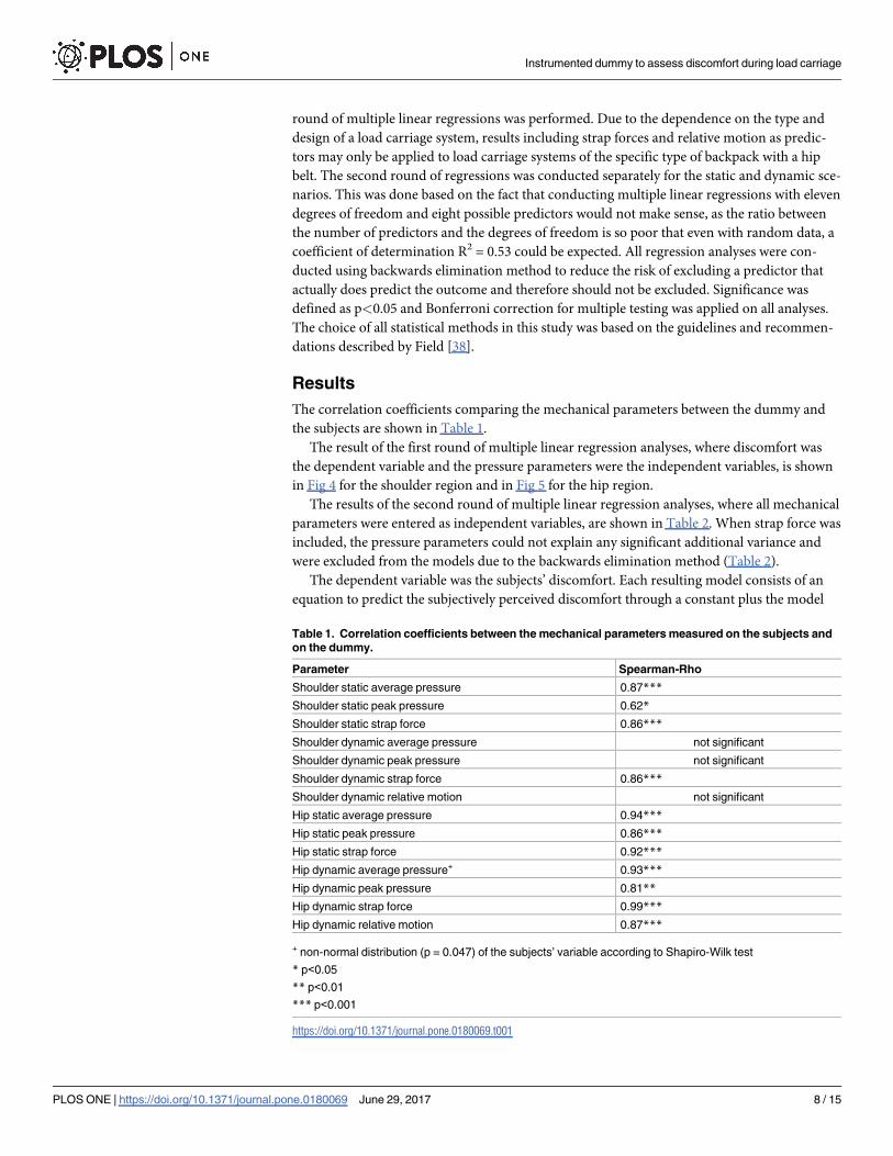
The correlation coefficients comparing the mechanical parameters between the dummy and
the subjects are shown in Table 1.
The result of the first round of multiple linear regression analyses, where discomfort was
the dependent variable and the pressure parameters were the independent variables, is shown
in Fig 4 for the shoulder region and in Fig 5 for the hip region.
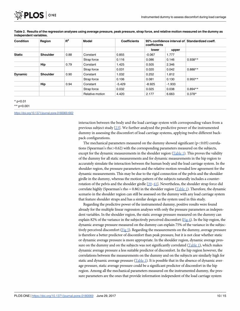
The results of the second round of multiple linear regression analyses, where all mechanical
parameters were entered as independent variables, are shown in Table 2. When strap force was
included, the pressure parameters could not explain any significant additional variance and
were excluded from the models due to the backwards elimination method (Table 2).
The dependent variable was the subjects’ discomfort. Each resulting model consists of an
equation to predict the subjectively perceived discomfort through a constant plus the model
Table 1. Correlation coefficients between the mechanical parameters measured on the subjects and
on the dummy.
Parameter Spearman-Rho
Shoulder static average pressure 0.87***
Shoulder static peak pressure 0.62*
Shoulder static strap force 0.86***
Shoulder dynamic average pressure not significant
Shoulder dynamic peak pressure not significant
Shoulder dynamic strap force 0.86***
Shoulder dynamic relative motion not significant
Hip static average pressure 0.94***
Hip static peak pressure 0.86***
Hip static strap force 0.92***
Hip dynamic average pressure+ 0.93***
Hip dynamic peak pressure 0.81**
Hip dynamic strap force 0.99***
Hip dynamic relative motion 0.87***
+ non-normal distribution (p = 0.047) of the subjects’ variable according to Shapiro-Wilk test
* p<0.05
** p<0.01
*** p<0.001
https://doi.org/10.1371/journal.pone.0180069.t001
Instrumented dummy to assess discomfort during load carriage
PLOS ONE | https://doi.org/10.1371/journal.pone.0180069 June 29, 2017 8 / 15

parameters multiplied by their coefficients. Relative motion was only entered as independent
variable for the dynamic conditions.
Discussion
In this study, we aimed to validate an instrumented dummy to assess the mechanical aspects of
discomfort during load carriage by comparing the mechanical parameters that characterize the
Fig 4. Results of the regression analysis using the pressure parameters measured on the dummy as
independent variables. Static average pressure measured on the dummy is a significant (p<0.001) predictor
of the subjects’ discomfort in the shoulder region. The subject’s discomfort was rated on a visual analogue
scale, ranging from 0 = no discomfort to 10 = maximal discomfort. The non-significant predictors were
removed from the model during the backwards elimination of the regression analysis. Data points show the
mean ± standard error of measurement for each configuration, dotted lines show 95% prediction intervals.
Regression equation: y = 1.512x - 1.044, R2 = 0.82.
https://doi.org/10.1371/journal.pone.0180069.g004
Fig 5. Results of the regression analysis using the pressure parameters measured on the dummy as
independent variables. Dynamic average pressure measured on the dummy is a significant (p<0.001)
predictor of the subjects’ discomfort in the hip region. Data points show the mean ± standard error of
measurement for each configuration, dotted lines show 95% prediction intervals. Regression equation:
y = 0.999x + 0.041, R2 = 0.75.
https://doi.org/10.1371/journal.pone.0180069.g005
Instrumented dummy to assess discomfort during load carriage
PLOS ONE | https://doi.org/10.1371/journal.pone.0180069 June 29, 2017 9 / 15
interaction between the body and the load carriage system with corresponding values from a
previous subject study [23]. We further analyzed the predictive power of the instrumented
dummy in assessing the discomfort of load carriage systems, applying twelve different back-
pack configurations.
The mechanical parameters measured on the dummy showed significant (p<0.05) correla-
tions (Spearman’s rho>0.62) with the corresponding parameters measured on the subjects,
except for the dynamic measurements in the shoulder region (Table 1). This proves the validity
of the dummy for all static measurements and for dynamic measurements in the hip region to
accurately simulate the interaction between the human body and the load carriage system. In the
shoulder region, the pressure parameters and the relative motion revealed low agreement for the
dynamic measurements. This may be due to the rigid connection of the pelvis and the shoulder
girdle in the dummy, whereas the motion pattern of the subjects naturally includes a counter-
rotation of the pelvis and the shoulder girdle [39–41]. Nevertheless, the shoulder strap force did
correlate highly (Spearman’s rho = 0.86) in the shoulder region (Table 1). Therefore, the dynamic
scenario in the shoulder region can still be assessed on the dummy with any load carriage system
that feature shoulder straps and has a similar design as the system used in this study.
Regarding the predictive power of the instrumented dummy, positive results were found
already for the multiple linear regression analyses with only the pressure parameters as indepen-
dent variables. In the shoulder region, the static average pressure measured on the dummy can
explain 82% of the variance in the subjectively perceived discomfort (Fig 4). In the hip region, the
dynamic average pressure measured on the dummy can explain 75% of the variance in the subjec-
tively perceived discomfort (Fig 5). Regarding the measurements on the dummy, average pressure
is therefore a better predictor of discomfort than peak pressure, but it is not clear whether static
or dynamic average pressure is more appropriate. In the shoulder region, dynamic average pres-
sure on the dummy and on the subjects was not significantly correlated (Table 1), which makes
dynamic average pressure a less suitable predictor of discomfort. In the hip region however, the
correlations between the measurements on the dummy and on the subjects are similarly high for
static and dynamic average pressure (Table 1). It is possible that in the absence of dynamic aver-
age pressure, static average pressure could be a significant predictor of discomfort in the hip
region. Among all the mechanical parameters measured on the instrumented dummy, the pres-
sure parameters are the ones that provide information independent of the load carriage system
Table 2. Results of the regression analyses using average pressure, peak pressure, strap force, and relative motion measured on the dummy as
independent variables.
Condition Region R2 Model Coefficients 95% confidence interval of
coefficients
Standardized coeff.
lower upper
Static Shoulder 0.88 Constant 0.855 -0.067 1.777
Strap force 0.116 0.086 0.146 0.938**
Hip 0.79 Constant 1.425 0.505 2.346
Strap force 0.031 0.020 0.042 0.888**
Dynamic Shoulder 0.90 Constant 1.032 0.252 1.812
Strap force 0.106 0.081 0.130 0.950**
Hip 0.94 Constant -5.429 -8.925 -1.933
Strap force 0.032 0.025 0.038 0.894**
Relative motion 4.420 2.177 6.663 0.378*
* p<0.01
** p<0.001
https://doi.org/10.1371/journal.pone.0180069.t002
Instrumented dummy to assess discomfort during load carriage
PLOS ONE | https://doi.org/10.1371/journal.pone.0180069 June 29, 2017 10 / 15
type, because they are measured directly on the body surface of the dummy. Therefore, the aver-
age pressure can be regarded as a significant (p<0.001) and a very powerful predictor of discom-
fort, regardless of the type of load carriage system evaluated.
When considering all mechanical parameters measured on the dummy, multiple linear
regression analyses revealed the strap force to be a significant (p<0.001) predictor of discom-
fort, accounting for 79% or more of the variance in the subjectively perceived discomfort
(Table 2). Strap force was more significant as a predictor than average pressure and average
pressure could not explain any significant additional variance. Therefore, average pressure was
excluded from the models during the backwards elimination (Table 2). For the dynamic sce-
nario, the relative motion was also a significant (p<0.01) predictor of discomfort in the hip
region. But the lower significance level of relative motion, along with its smaller standardized
coefficient and the large confidence interval of its coefficient in the regression model (Table 2),
indicate that strap force is more relevant. Both strap force and relative motion may depend on
the type and design of a load carriage system. As all measurements in this study have been con-
ducted with a load carriage system of a backpack with a hip belt, the relevance of strap force
and relative motion as predictors of discomfort must currently be restricted to load carriage
systems of comparable type and design. Most importantly, all mechanical parameters mea-
sured on the dummy that were identified as significant predictors of discomfort, are signifi-
cantly (p<0.001) correlated to the corresponding parameters measured on subjects (Table 1).
Compared to the existing model of Stevenson et al. [5, 22], our instrumented dummy
exhibits a higher predictive power and uses mechanical parameters as predictors that are
directly validated by correlation with the same parameters from a human subject study [23].
This direct validation is one of the crucial features of the instrumented dummy presented in
this study. Its uniqueness is further based on its pure focus on the mechanical aspects of dis-
comfort. While thermo-physiological aspects play an important role in discomfort during load
carriage, already existing models from the field of clothing physiology offer convenient possi-
bilities to test load carriage systems under various climatic conditions [42, 43].
The average pressure values measured on the dummy (Figs 4 and 5) are mostly lower than
the values shown to be critical for skin blood flow occlusion (5.6-16kPa), as reported by Hollo-
way et al. [18] or Sangeorzan et al. [19]. These findings are in line with the discomfort scores
not reaching the highest levels, as reported by the subjects wearing the same load carriage sys-
tem configurations [23]. However, the pressure values measured on the dummy are lower than
the corresponding values measured on the subjects, e.g. the static average pressure in the
shoulder region ranged from 2.7kPa to 4.7kPa in the dummy measurements and from 4.5kPa
to 13.5kPa in the subject study [23]. The absolute values measured on the dummy must there-
fore be treated with care. Because the Tekscan sensors can bend on the body surface of the sub-
jects during dynamic measurements, the absolute values measured on the subjects may be
overestimated by artefacts, despite minimizing this effect through offset correction. By con-
trast, the dummy has a rigid body, which holds less potential for dynamic bending of the Teks-
can sensors. This may partly explain the difference between the absolute pressure values
measured on the subjects and on the dummy. While the deviation from reality in terms of arm
motion or torsion of the dummy is a limitation, it enables more reliable and more objective
measurements than subject studies. Compared to subject studies, the dummy is also more
objective in case of potentially confounding factors. Effects of the aesthetic design of a load car-
riage system or personal moods are excluded. Due to the reproducible test conditions, future
measurements of load carriage systems can also be directly compared with existing data,
resulting from previous measurements on the instrumented dummy.
Possible improvements of the instrumented dummy include introducing a torsional move-
ment in the transversal plane to perform counter-rotation of the pelvis and the shoulder girdle
Instrumented dummy to assess discomfort during load carriage
PLOS ONE | https://doi.org/10.1371/journal.pone.0180069 June 29, 2017 11 / 15

and thus achieve a more complex but also more realistic representation of human walking dur-
ing the dynamic measurements. Complexity may also be added in the simulated skin and soft
tissue layer on the body surface of the dummy. However, any change towards a thicker or softer
layer in places where the pressure distribution will be assessed is likely to result in a reduced
test-retest reliability due to bending of the pressure sensors. An obvious improvement would be
to offer an additional dummy with female anatomy. Gender specific differences in the mechani-
cal parameters and in the perception of discomfort during load carriage are likely and express a
need for future work focusing on female subjects and dummies with female anatomy. As a com-
plete alternative to a mechanical dummy, finite element models may also need to be considered.
Existing models, such as the validated Global Human Body Modeling 50th percentile male
model [44] could provide an excellent possibility to study the interaction between load carriage
systems and the human body. However, this would likely increase the cost of testing and com-
paring large numbers of load carriage systems, as for each system, a separate finite element
model would have to be created and validated. Generally, the validation of the instrumented
dummy presented in this study reduces the need for subject studies to assess discomfort during
load carriage. The dummy enables objective, fast, and iterative assessments during the develop-
ment of new designs of load carriage systems as well as comparisons of many different systems
or designs. Such an objective assessment may also offer a basis for a simple rating system as it is
already widely used in the automotive industry, in the form of a 5-star safety rating.
Limitations
The body surface regions investigated in this study are currently limited to the shoulder and
hip region, as they are considered to be the most critical regarding discomfort during load car-
riage. To allow the application of our method to all relevant body regions, further measure-
ments may be necessary. In addition, the dummy represents a simplified approximation of the
male human body and does not feature variation in the hardness of its body surface depending
on the body region. Furthermore, the forward leaning angles of the dummy are calculated
based on the assumption of balancing the moment in the upper ankle joint and possible adap-
tations in other joints are neglected.
Conclusions
In this study, an objective and time-saving method to assess or compare the discomfort of load
carriage systems and their design has been validated. The instrumented dummy can explain
75% or more of the variance in discomfort using average pressures as predictors and even 79%
or more of the variance in discomfort using strap forces as predictors. Compared to an existing
model [5], our model has a higher predictive power and it uses mechanical parameters as pre-
dictors that are directly validated by correlation with the same parameters measured in a
human subject study [23]. Our model enables objective, fast, and iterative assessments during
the development of new designs of load carriage systems as well as comparisons of many dif-
ferent systems or designs. As a consequence, the need for subject studies is reduced and users
of backpacks and other load carriage systems may profit from future load carriage systems that
inflict less discomfort during load carriage.
Supporting information
S1 Table. Mechanical parameters in the shoulder region of the instrumented dummy. For
each measured configuration, the mean of five iterations ± the standard error of measurement
is shown.
(DOCX)
Instrumented dummy to assess discomfort during load carriage
PLOS ONE | https://doi.org/10.1371/journal.pone.0180069 June 29, 2017 12 / 15

S2 Table. Mechanical parameters in the hip region of the instrumented dummy. For each
measured configuration, the mean of five iterations ± the standard error of measurement is
shown.
(DOCX)
Acknowledgments
We thank armasuisse for their financial support. We would also like to thank Dr. Joan Steven-
son and her research group from the Biomechanics and Ergonomics Lab at Queen’s Univer-
sity, Canada, for providing consultation on building the instrumented dummy.
Author Contributions
Conceptualization: PDW SA SL SJF RS AP RMR.
Data curation: PDW SA RS.
Formal analysis: PDW SA SL SJF RS RMR.
Funding acquisition: SA SL AP RMR.
Investigation: PDW SA RS.
Methodology: PDW SA SL SJF RS AP RMR.
Project administration: RS RMR.
Resources: PDW SA SL RS RMR.
Software: PDW RS.
Supervision: SA SL SJF RMR.
Validation: PDW SA SL SJF RS RMR.
Visualization: PDW SA RS.
Writing – original draft: PDW SA.
Writing – review & editing: PDW SA SL SJF RS AP RMR.
References1. Knapik J, Harman E, Reynolds K. Load carriage using packs: A review of physiological, biomechanical
and medical aspects. Applied Ergonomics. 1996; 27(3): 207–216. https://doi.org/10.1016/0003-6870
(96)00013-0 PMID: 15677062
2. Cavallo CM, Hlavaty TM, Tamase MGM. A pilot study for the development of a primary prevention pro-
gram: What is the average weight of a fourth grader’s backpack? Work. 2003; 20(2): 137–158. PMID:
12671208
3. Martin J, Hooper RH. Military load carriage: a novel method of interface pressure analysis. 2000. Avail-
able: http://oai.dtic.mil/oai/oai?verb=getRecord&metadataPrefix=html&identifier=ADP011005.
Accessed 24 June 2015.
4. Knapik JJ, Reynolds KL, Harman E. Soldier load carriage: Historical, physiological, biomechanical, and
medical aspects. Mil Med. 2004; 169(1): 45–56. PMID: 14964502
5. Stevenson JM, Bossi LL, Bryant JT, Reid SA, Pelot RP, Morin EL. A suite of objective biomechanical
measurement tools for personal load carriage system assessment. Ergonomics. 2004; 47(11): 1160–
1179. https://doi.org/10.1080/00140130410001699119 PMID: 15370854
Instrumented dummy to assess discomfort during load carriage
PLOS ONE | https://doi.org/10.1371/journal.pone.0180069 June 29, 2017 13 / 15

6. Konitzer LN, Fargo MV, Brininger TL, Lim Reed M. Association between back, neck, and upper extrem-
ity musculoskeletal pain and the individual body armor. J Hand Ther. 2008; 21(2): 143–149. https://doi.
org/10.1197/j.jht.2007.10.017 PMID: 18436136
7. Negrini S, Carabalona R. Backpacks on! Schoolchildren’s perceptions of load, associations with back
pain and factors determining the load. Spine. 2002; 27(2): 187–195. https://doi.org/10.1097/00007632-
200201150-00014 PMID: 11805666
8. Sheir-Neiss GI, Kruse RW, Rahman T, Jacobson LP, Pelli JA. The association of backpack use and
back pain in adolescents. Spine. 2003; 28(9): 922–930. https://doi.org/10.1097/01.BRS.0000058725.
18067.F7 PMID: 12942009
9. Jacobson BH, Cook DA, Altena TS, Gemmell HA, Haynes BM. Comparison of perceived comfort differ-
ences between standard and experimental load carriage systems. Ergonomics. 2003; 46(10): 1035–
1041. https://doi.org/10.1080/0014013021000045255 PMID: 12850938
10. Dockrell S, Simms C, Blake C. Schoolbag carriage and schoolbag-related musculoskeletal discomfort
among primary school children. Applied Ergonomics. 2015; 51(0): 281–290. https://doi.org/10.1016/j.
apergo.2015.05.009 PMID: 26154227
11. Jacobson B, Jones K. Comparison of selected perceptual variables for backpacks with internal and
external frames. Percept Mot Skills. 2000; 90(2): 605–608. https://doi.org/10.2466/pms.2000.90.2.605
PMID: 10833761
12. Simpson KM, Munro BJ, Steele JR. Effect of load mass on posture, heart rate and subjective responses
of recreational female hikers to prolonged load carriage. Applied Ergonomics. 2011; 42(3): 403–410.
https://doi.org/10.1016/j.apergo.2010.08.018 PMID: 20870217
13. Simpson KM, Munro BJ, Steele JR. Does load position affect gait and subjective responses of females
during load carriage? Applied Ergonomics. 2012; 43(3): 479–485. https://doi.org/10.1016/j.apergo.
2011.07.005 PMID: 21831354
14. Gutierrez JT. The modular tactical vest: a case study in success and failure. M. Sc. Thesis, Marine
Corps University. 2009. Available: http://oai.dtic.mil/oai/oai?verb=getRecord&metadataPrefix=
html&identifier=ADA508094. Accessed 26 October 2015.
15. Kim J-H, Coca A, Williams WJ, Roberge RJ. Subjective perceptions and ergonomics evaluation of a liq-
uid cooled garment worn under protective ensemble during an intermittent treadmill exercise. Ergonom-
ics. 2011; 54(7): 626–635. https://doi.org/10.1080/00140139.2011.583362 PMID: 21770750
16. Piscione J, Gamet D. Effect of mechanical compression due to load carrying on shoulder muscle fatigue
during sustained isometric arm abduction: an electromyographic study. Eur J Appl Physiol. 2006; 97(5):
573–581. https://doi.org/10.1007/s00421-006-0221-x PMID: 16767438
17. Hadid A, Epstein Y, Shabshin N, Gefen A. Modeling mechanical strains and stresses in soft tissues of
the shoulder during load carriage based on load-bearing open MRI. J Appl Physiol. 2012; 112(4): 597–
606. https://doi.org/10.1152/japplphysiol.00990.2011 PMID: 22134690
18. Holloway GA, Daly CH, Kennedy D, Chimoskey J. Effects of external pressure loading on human skin
blood flow measured by Xe-133 clearance. J Appl Physiol. 1976; 40(4): 597–600. PMID: 931880
19. Sangeorzan BJ, Harrington RM, Wyss CR, Czerniecki JM, Matsen FA. Circulatory and mechanical
response of skin to loading. J Orthop Res. 1989; 7(3): 425–431. https://doi.org/10.1002/jor.1100070315
PMID: 2703934
20. De Looze MP, Kuijt-Evers LFM, Van Dieen J. Sitting comfort and discomfort and the relationships with
objective measures. Ergonomics. 2003; 46(10): 985–997. https://doi.org/10.1080/
0014013031000121977 PMID: 12850935
21. Zemp R, Taylor WR, Lorenzetti S. Are pressure measurements effective in the assessment of office
chair comfort/discomfort? A review. Applied Ergonomics. 2015; 48: 273–282. https://doi.org/10.1016/j.
apergo.2014.12.010 PMID: 25683554
22. Stevenson JM, Bryant JT, Pelot RP, Morin EL, Reid SA, Doan JB. Research and development of an
advanced personal load carriage system phases II and III. Section D: Development of acceptance crite-
ria for physical tests of load carriage systems. 1997. Available: http://pubs.drdc-rddc.gc.ca/BASIS/
pcandid/www/engpub/DDW?W%3DAUTHOR++%3D+%27BRYANT%2C+T.%27%26M%3D3%26K%
3D516229%26U%3D1. Accessed 24 June 2015.
23. Wettenschwiler PD, Lorenzetti S, Stampfli R, Rossi RM, Ferguson SJ, Annaheim S. Mechanical predic-
tors of discomfort during load carriage. PLoS ONE. 2015; 10(11): e0142004. https://doi.org/10.1371/
journal.pone.0142004 PMID: 26529414
24. Winter D. Biomechanics and motor control of human movement. John Wiley & Sons, 2009.
25. Seitz H, Tille C, Irsen S, Bermes G, Sader R, Zeilhofer H-F. Rapid Prototyping models for surgical plan-
ning with hard and soft tissue representation. International Congress Series. 2004; 1268: 567–572.
https://doi.org/10.1016/j.ics.2004.03.139
Instrumented dummy to assess discomfort during load carriage
PLOS ONE | https://doi.org/10.1371/journal.pone.0180069 June 29, 2017 14 / 15

26. Grimmer K, Dansie B, Milanese S, Pirunsan U, Trott P. Adolescent standing postural response to back-
pack loads: a randomised controlled experimental study. Bmc Musculoskeletal Disorders. 2002; 3.
https://doi.org/10.1186/1471-2474-3-10 PMID: 11960561
27. Attwells RL, Birrell SA, Hooper RH, Mansfield NJ. Influence of carrying heavy loads on soldiers’ posture,
movements and gait. Ergonomics. 2006; 49(14): 1527–1537. https://doi.org/10.1080/
00140130600757237 PMID: 17050392
28. Morin E, Reid SA, Stevenson JM, Lee A, Hare C. Development of a Dynamic Biomechanical Model for
Load Carriage: Phase VI: Assessing Physiological and Biomechanical Loading Using the Portable Mea-
surement System and the Dynamic Biomechanical Model. 2007. Available: http://oai.dtic.mil/oai/oai?
verb=getRecord&metadataPrefix=html&identifier=ADA551275. Accessed 24 June 2015.
29. Chow H-KD, Hin K-FC, Ou D, Lai A. Carry-over effects of backpack carriage on trunk posture and repo-
sitioning ability. Int J Ind Ergon. 2011; 41(5): 530–535. https://doi.org/10.1016/j.ergon.2011.04.001
30. Armstrong HG. Anthropometry and mass distribution for human analogues. volume 1. military male avi-
ators. 1988. Available: http://oai.dtic.mil/oai/oai?verb=getRecord&metadataPrefix=html&identifier=
ADA197650. Accessed 24 June 2015.
31. Jones GR, Hooper RH. The effect of single- or multiple-layered garments on interface pressure mea-
sured at the backpack-shoulder interface. Appl Ergon. 2005; 36(1): 79–83. https://doi.org/10.1016/j.
apergo.2004.07.001 PMID: 15627425
32. Orendurff MS, Segal AD, Klute GK, Berge JS, Rohr ES, Kadel NJ. The effect of walking speed on center
of mass displacement. J Rehabil Res Dev. 2004; 41(6A): 829–834. https://doi.org/10.1682/JRRD.2003.
10.0150 PMID: 15685471
33. Saibene F, Minetti AE. Biomechanical and physiological aspects of legged locomotion in humans. Eur J
Appl Physiol 2003; 88(4): 297–316. https://doi.org/10.1007/s00421-002-0654-9 PMID: 12527959
34. Staszkiewicz R, Ruchlewicz T, Forczek W, Laska J. The impact of changes in gait speed and step fre-
quency on the extent of the center of mass displacements. Acta Bioeng Biomech 2010; 12(3): 13–20.
PMID: 21243966
35. Thorstensson A, Nilsson J, Carlson H, Zomlefer MR. Trunk movements in human locomotion. Acta Phy-
siol 1984; 121(1): 9–22. https://doi.org/10.1111/j.1748-1716.1984.tb10452.x PMID: 6741583
36. Mackie HW, Stevenson JM, Reid SA, Legg SJ. The effect of simulated school load carriage configura-
tions on shoulder strap tension forces and shoulder interface pressure. Appl Ergon. 2005; 36(2): 199–
206. https://doi.org/10.1016/j.apergo.2004.10.007 PMID: 15694074
37. Wettenschwiler PD, Stampfli R, Lorenzetti S, Ferguson SJ, Rossi RM, Annaheim S. How reliable are
pressure measurements with Tekscan sensors on the body surface of human subjects wearing load
carriage systems? Int J Ind Ergon. 2015; 49: 60–67. https://doi.org/10.1016/j.ergon.2015.06.003
38. Field A. Discovering statistics using SPSS. Sage publications, 2009.
39. Saunders J, Inman VT, Eberhart HD. The major determinants in normal and pathological gait. J Bone
Joint Surg Am. 1953; 35-A(3): 543–558. PMID: 13069544
40. Inman V. Human locomotion. Can Med Assoc J. 1966; 94(20): 1047–1054. PMID: 5942660
41. Sharpe SR, Holt KG, Saltzman E, Wagenaar RC. Effects of a hip belt on transverse plane trunk coordi-
nation and stability during load carriage. J Biomech. 2008; 41(5): 968–976. https://doi.org/10.1016/j.
jbiomech.2007.12.018 PMID: 18304555
42. Psikuta A, Richards M, Fiala D. Single-sector thermophysiological human simulator. Physiol Meas.
2008; 29(2): 181–192. https://doi.org/10.1088/0967-3334/29/2/002 PMID: 18256450
43. Morrissey MP, Rossi RM. Clothing systems for outdoor activities. Textile Progress. 2013; 45(2–3): 145–
181. https://doi.org/10.1080/00405167.2013.845540
44. Untaroiu CD, Putnam JB, Schap J, Davis ML, Gayzik FS. Development and preliminary validation of a
50th percentile pedestrian finite element model. Proc ASME IDETC/CIE 2015). Available: http://
proceedings.asmedigitalcollection.asme.org/proceeding.aspx?articleid=2483388. Accessed 24 Febru-
ary 2017.
Instrumented dummy to assess discomfort during load carriage
PLOS ONE | https://doi.org/10.1371/journal.pone.0180069 June 29, 2017 15 / 15