Validation of a non-associated critical state model
11
Validation of a non-associated critical state model T.A. Newson* Department of Civil Engineering, The University of Dundee, Dundee, DDI 4HN, UK Received 10 October 1997; received in revised form 21 October 1998; accepted 22 October 1998 Abstract A non-associated constitutive critical state model is proposed. The yield surface is that of Modified Cam Clay, whilst the plastic potential is an empirical function. The yield and plastic potential surfaces in the octahedral plane vary from circular at low stress ratios, to the Mat- suoka-Nakai surface at failure. Assessment of the model has been by comparison with laboratory tests on soft clay. Further validation has been by predicting centrifuge model behaviour using a modified form of the CRISP finite element program. Comparisons of the numerical analyses, using the proposed model and Modified Cam Clay, show improved cor- relations with the experimental data. # 1999 Elsevier Science Ltd. All rights reserved. 1. Introduction The Cam Clay family of soil models are still the most widely used constitutive models for predicting the stress-strain behaviour of normally and lightly over con- solidated clays. This situation continues despite the proposal of more sophisticated critical state models [1–3] which more closely approximate soil behaviour. One of the major reasons is the combination of simplicity and predictive accuracy that the Cam Clay models achieve. Whilst more accurate predictions of soil behaviour can be made with these models, there is a threshold where the benefits become marginal compared to the complexity of the analysis. The ability to accurately model a com- plex boundary value problem without having to conduct a myriad of complex laboratory tests to provide model parameters, cannot be understated. Thus con- stitutive models that incorporate more realistic concepts, but with minimal increase in complexity will eventually prove more useful to the engineering industry. Computers and Geotechnics 23 (1998) 277–287 0266-352X/99/$—see front matter # 1999 Elsevier Science Ltd. All rights reserved. PII: S0266-352X(98)00026-3 * Tel.: +44-1382-344-342; fax: +44-1382-344-816; e-mail: [email protected]
Transcript of Validation of a non-associated critical state model
Validation of a non-associated criticalstate model
T.A. Newson*Department of Civil Engineering, The University of Dundee, Dundee, DDI 4HN, UK
Received 10 October 1997; received in revised form 21 October 1998; accepted 22 October 1998
Abstract
A non-associated constitutive critical state model is proposed. The yield surface is that ofModi®ed Cam Clay, whilst the plastic potential is an empirical function. The yield and plasticpotential surfaces in the octahedral plane vary from circular at low stress ratios, to the Mat-
suoka-Nakai surface at failure. Assessment of the model has been by comparison withlaboratory tests on soft clay. Further validation has been by predicting centrifuge modelbehaviour using a modi®ed form of the CRISP ®nite element program. Comparisons of the
numerical analyses, using the proposed model and Modi®ed Cam Clay, show improved cor-relations with the experimental data. # 1999 Elsevier Science Ltd. All rights reserved.
1. Introduction
The Cam Clay family of soil models are still the most widely used constitutivemodels for predicting the stress-strain behaviour of normally and lightly over con-solidated clays. This situation continues despite the proposal of more sophisticatedcritical state models [1±3] which more closely approximate soil behaviour. One ofthe major reasons is the combination of simplicity and predictive accuracy that theCam Clay models achieve. Whilst more accurate predictions of soil behaviour can bemade with these models, there is a threshold where the bene®ts become marginalcompared to the complexity of the analysis. The ability to accurately model a com-plex boundary value problem without having to conduct a myriad of complexlaboratory tests to provide model parameters, cannot be understated. Thus con-stitutive models that incorporate more realistic concepts, but with minimal increasein complexity will eventually prove more useful to the engineering industry.
Computers and Geotechnics 23 (1998) 277±287
0266-352X/99/$Ðsee front matter # 1999 Elsevier Science Ltd. All rights reserved.
PII: S0266-352X(98)00026-3
* Tel.: +44-1382-344-342; fax: +44-1382-344-816; e-mail: [email protected]
This paper proposes a non-associated model that accurately predicts the stress-strain behaviour of normally and lightly overconsolidated clays, whilst still adheringto the original concept of simplicity. Hence the model requires only the ®ve standardparameters (l, �, M, ÿ and G/�0) used for Modi®ed Cam Clay [4].
2. Model description
The constitutive relationship proposed has a non-associated ¯ow rule and hasbeen developed within the critical state framework. The major features of the modelPETAL are the yield locus, which is that of the Modi®ed Cam Clay (MCC) model[4] and an empirical ¯ow rule. The MCC yield function is shown below in a gen-eralised form
F 0� � � J2
g2f �� �� p0 po ÿ p0� � �1�
where p � 13. tr (�ij), J2 � 1
2. sijsij and sij is the deviatoric component of the stresstensor �ij.The shape of the yield surface in the octahedral plane is controlled by the function
gf(�), where the Lode angle � � 13 arcsin ÿ 3
��3p2 : J3
J3=22
� �; J3 � 1
3 :sijsjkskm and po is a
hardening parameter controlling the size of the yield surface.The plastic potential function was originally proposed by Ohmaki [5] as an asso-
ciated model and is shown below:
Q 0� � � J2g2q �� �:p02
� ln�p2
�2o� �2�
This function produces a petal shaped surface; hence the name of the model. Theparameter �o (the intersection of the plastic potential surface and the hydrostaticaxis) is determined by the current stress state J2 and p0, i.e. an in®nite number ofplastic potential surfaces, Q(O), exist for every yield locus, F(O). Fig. 1(a) shows theproposed yield and failure surfaces in the deviatoric plane.
3. Generalised yield and failure criteria
Generalisation of the Cambridge family of critical state models is accomplished byassuming a shape for the yield and plastic potential surfaces in the octahedral plane.Experimental evidence suggests that the shape of yield surfaces in the octahedralplane lie between two extremes; normally or lightly-overconsolidated soils at lowstress ratios display nearly circular (von-Mises) yield criteria, whilst the irregularhexagonal shape of the Mohr±Coulomb surface ®ts experimentally observed failurepoints. Randolph suggested a novel method of generalising the Cam Clay models[6], which assumes that the constant R in the Matsuoka±Nakai [7] criterion, is a
278 T.A. Newson/Computers and Geotechnics 23 (1998) 277±287
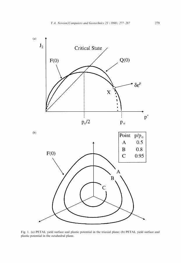
Fig. 1. (a) PETAL yield surface and plastic potential in the triaxial plane; (b) PETAL yield surface and
plastic potential in the octahedral plane.
T.A. Newson/Computers and Geotechnics 23 (1998) 277±287 279
function of the current stress ratio �1�3. Hence the yield surface changes shape from
nearly circular at low values of J2 to the desired Matsuoka±Nakai shape at failure.Potts and Gens [8] proposed the use of Eq. (3), which can approximate a range of
di�erent shaped surfaces in the octahedral plane, depending on the values of theconstants �, � and n:
g �� � � � 1� � sin 3�� �ÿn �3�
If �o is taken as the value of the friction angle, when the Lode angle �=equals zero,then the Matsuoka±Nakai failure criterion can be approximated by substituting
n=0.25, � � sin�o and � � 2� 3ÿ�2� �3��3p into Eq. (3). The constant �o can be calculated
by substituting a known value of stress ratio at failure (e.g. triaxial compressive
failure, Mc=J2/p0) into Eq. (3) and solving for �. Incorporation of g(�) into the yield
function will alter the relative size of the stress ratio J2/p0 at failure, thus account for
the in¯uence of the intermediate principal stress.The approach of Randolph has been adopted for the PETAL model. This has
been accomplished by substituting �0 � �: into Eq. (3) for �, where � sin � 1ÿ p=po� �� � (for the yield surface) and � sin � 1� ln p=�o� �� �� � (for theplastic potential surface). The function ! controls the variation of the shapes of thesurfaces in the octahedral plane. It can be seen that when p0=p, � 0 and thefunctions g(�), for the yield and plastic potential surfaces, both become the von-Mises criterion (circular). When p0=po/2 (for the yield surface) and p0=po/
���ep
(forthe plastic potential) at critical state, � 1 and the functions g(�) become theMatsuoka±Nakai criterion. The shape of the yield surface between p0=po/2 andp0=0 is assumed to be constant (Matsuoka±Nakai).
In order that the current stress state lies on both the yield and plastic potentialsurfaces, the plastic potential must be constrained in both size and shape to complywith this requirement. It is assumed that fF(�) is equal to gQ(�) for each stress pointand that the size of the plastic potential �o is constant for each value of p/po. Hence,if the current values of J2, p
0 and gF(�) are substituted into the plastic potentialfunction then the current value of �o can be found. The above constraints have thee�ect of changing the frictional constant � (for the plastic potential) for the currentLode angle, to ensure that the current stress point lies on both surfaces. Therefore,the fully generalised model is non-associated in both the triaxial and �-planes, exceptat critical state and on the hydrostatic axis. Fig. 1(b) shows the PETAL model yieldand plastic potential surfaces in the octahedral plane for various stress ratios.
4. Numerical modelling
4.1. Prediction of single element tests
Initially the model has been assessed by predicting the results of single elementlaboratory stress path tests. A coordinated research programme has been conducted
280 T.A. Newson/Computers and Geotechnics 23 (1998) 277±287
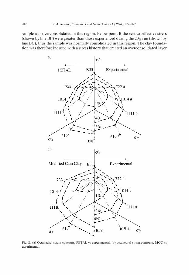
recently in the United Kingdom to characterise the behaviour of soft clay fromBothkennar. Part of this programme was a series of tests on reconstituted Both-kennar clay in a true triaxial apparatus [9]. All of the samples were 1-D normallyconsolidated to the same stress point and then tested under various three dimen-sional stress paths. The critical state parameters for this material are l � 0:181,� � 0:025, Mc=1.38, ÿ � 2:78 and �0 � 0:33 [10].One group of tests (B33, 722, 1014, 1111, 619 and B58) was conducted with con-
stant mean e�ective stress, p0, these stress paths are shown dotted in Fig. 2(a) and (b)in a direction normal to the octahedral plane. The vertical axis is an axis of sym-metry; thus mirror images of the stress paths are shown marked with a # on theopposite side. Predictions of these tests using both MCC and PETAL have beenconducted. Fig. 2(a) shows the octahedral strain contours predicted by PETAL(shown on the left) compared with the observed contours (shown on the right).Similarly, Fig. 2(b) shows the octahedral strain contours predicted by MCC (shownon the left) compared with the observed contours (shown on the right).It can be seen that PETAL generally improves on the predictions of the octahedral
strains when compared to MCC. The correlation with the observed data is quitegood, except for tests 619 and B58 in the negative z direction. This is due to theanisotropy of the material; the shape of the isotropic surfaces of the two modelsensuring that the majority of these predicted stress paths remain purely elastic. Thisis also indicated by the initial shape of the 1% octahedral strain contours for bothmodels. It is noticeable that as the strains approach failure the shape of the PETALcontours approach that of the Matsuoka±Nakai criterion, whilst the MCC contoursremain essentially circular.
4.2. Prediction of a complex boundary value problem
The proposed model has been incorporated into the CRISP ®nite element coding[11] and the modi®ed code has been used to predict the performance of a centrifugemodel of an embankment construction on a soft clay foundation taken from theliterature [12]. The stress history of the Speswhite kaolin clay (wL=69 and wP=38)foundation model is shown in Fig. 3. Initially a clay cake was formed under one-dimensional loading in an oedometer (�0v � 50 kPa, shown as line GH) and this wascut to size prior to being placed into the centrifuge model box. A thin layer of sandwas then placed on to the clay surface to form a small surcharge load (to prevent thesurface from swelling back to a slurry during unloading). An additional surchargeload was then placed on the sample and the centrifuge was run for 12 h at 20 g. Theline AC in Fig. 3(a) shows the vertical e�ective stress due to the combination ofsurcharges and self-weight loading. This created a vertical e�ective stress that coin-cided at the mid-height of the sample (point B) with the value achieved during the®nal test at 100 g. After the excess pore water pressure had dissipated the centrifugewas stopped. The main surcharge was removed and the sample was re-accelerated to100 g. The vertical e�ective stress, after dissipation of excess pore water pressures, isshown by line ADW in Fig. 3(a). Above point B the vertical e�ective stress (shownby line ADB) was less than that of the 20 g run (shown by line OAB), thus the
T.A. Newson/Computers and Geotechnics 23 (1998) 277±287 281
sample was overconsolidated in this region. Below point B the vertical e�ective stress(shown by line BF) were greater than those experienced during the 20 g run (shown byline BC), thus the sample was normally consolidated in this region. The clay founda-tion was therefore induced with a stress history that created an overconsolidated layer
Fig. 2. (a) Octahedral strain contours, PETAL vs experimental; (b) octahedral strain contours, MCC vs
experimental.
282 T.A. Newson/Computers and Geotechnics 23 (1998) 277±287
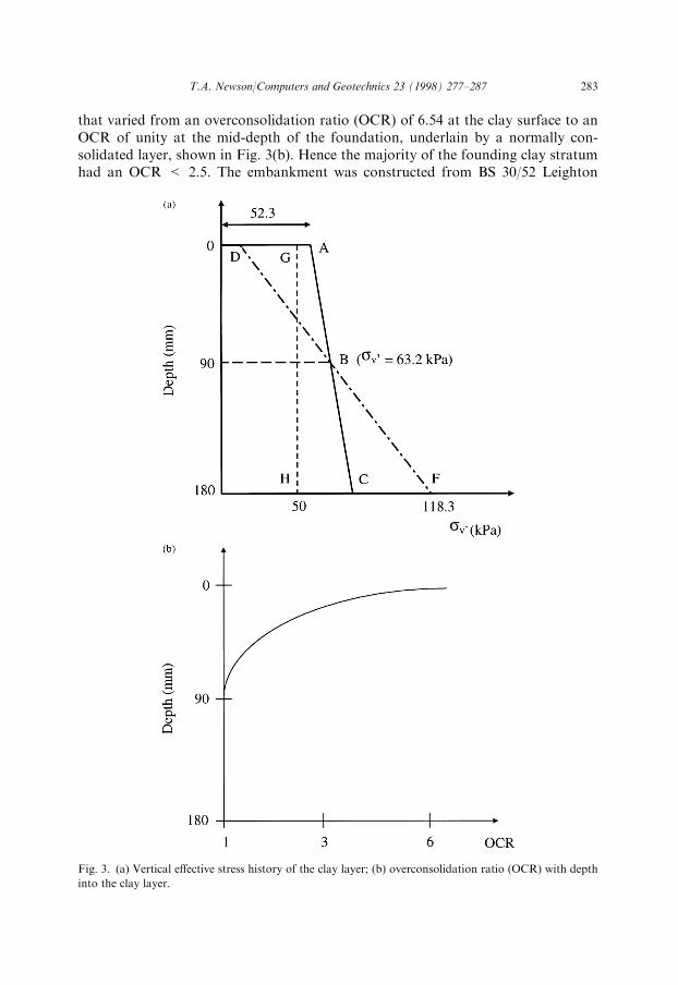
that varied from an overconsolidation ratio (OCR) of 6.54 at the clay surface to anOCR of unity at the mid-depth of the foundation, underlain by a normally con-solidated layer, shown in Fig. 3(b). Hence the majority of the founding clay stratumhad an OCR < 2.5. The embankment was constructed from BS 30/52 Leighton
Fig. 3. (a) Vertical e�ective stress history of the clay layer; (b) overconsolidation ratio (OCR) with depth
into the clay layer.
T.A. Newson/Computers and Geotechnics 23 (1998) 277±287 283
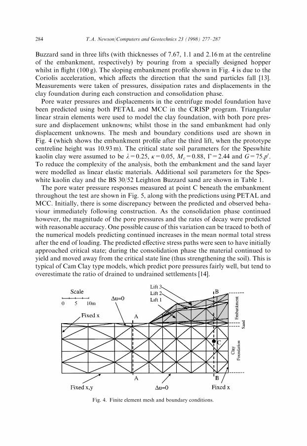
Buzzard sand in three lifts (with thicknesses of 7.67, 1.1 and 2.16m at the centrelineof the embankment, respectively) by pouring from a specially designed hopperwhilst in ¯ight (100 g). The sloping embankment pro®le shown in Fig. 4 is due to theCoriolis acceleration, which a�ects the direction that the sand particles fall [13].Measurements were taken of pressures, dissipation rates and displacements in theclay foundation during each construction and consolidation phase.Pore water pressures and displacements in the centrifuge model foundation have
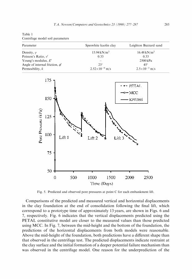
been predicted using both PETAL and MCC in the CRISP program. Triangularlinear strain elements were used to model the clay foundation, with both pore pres-sure and displacement unknowns; whilst those in the sand embankment had onlydisplacement unknowns. The mesh and boundary conditions used are shown inFig. 4 (which shows the embankment pro®le after the third lift, when the prototypecentreline height was 10.93m). The critical state soil parameters for the Speswhitekaolin clay were assumed to be l=0.25, �=0.05, Mc=0.88, ÿ=2.44 and G=75.p0.To reduce the complexity of the analysis, both the embankment and the sand layerwere modelled as linear elastic materials. Additional soil parameters for the Spes-white kaolin clay and the BS 30/52 Leighton Buzzard sand are shown in Table 1.The pore water pressure responses measured at point C beneath the embankment
throughout the test are shown in Fig. 5, along with the predictions using PETAL andMCC. Initially, there is some discrepancy between the predicted and observed beha-viour immediately following construction. As the consolidation phase continuedhowever, the magnitude of the pore pressures and the rates of decay were predictedwith reasonable accuracy. One possible cause of this variation can be traced to both ofthe numerical models predicting continued increases in the mean normal total stressafter the end of loading. The predicted e�ective stress paths were seen to have initiallyapproached critical state; during the consolidation phase the material continued toyield and moved away from the critical state line (thus strengthening the soil). This istypical of Cam Clay type models, which predict pore pressures fairly well, but tend tooverestimate the ratio of drained to undrained settlements [14].
Fig. 4. Finite element mesh and boundary conditions.
284 T.A. Newson/Computers and Geotechnics 23 (1998) 277±287
Comparisons of the predicted and measured vertical and horizontal displacementsin the clay foundation at the end of consolidation following the ®nal lift, whichcorrespond to a prototype time of approximately 13 years, are shown in Figs. 6 and7, respectively. Fig. 6 indicates that the vertical displacements predicted using thePETAL constitutive model are closer to the measured values than those predictedusing MCC. In Fig. 7, between the mid-height and the bottom of the foundation, thepredictions of the horizontal displacements from both models were reasonable.Above the mid-height of the foundation, both predictions have a di�erent shape thanthat observed in the centrifuge test. The predicted displacements indicate restraint atthe clay surface and the initial formation of a deeper potential failure mechanism thanwas observed in the centrifuge model. One reason for the underprediction of the
Table 1
Centrifuge model soil parameters
Parameter Speswhite kaolin clay Leighton Buzzard sand
Density, 15.94 kN/m3 16.48 kN/m3
Poisson's Ratio, �0 0.33 0.33
Young's modulus, E0 ± 2500 kPa
Angle of internal friction, �0 23� 45�
Permeability, k 2.52�10ÿ9 m/s 2.5�10ÿ3 m/s
Fig. 5. Predicted and observed pore pressures at point C for each embankment lift.
T.A. Newson/Computers and Geotechnics 23 (1998) 277±287 285
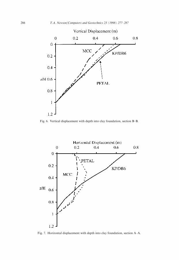
Fig. 6. Vertical displacement with depth into clay foundation, section B±B.
Fig. 7. Horizontal displacement with depth into clay foundation, section A±A.
286 T.A. Newson/Computers and Geotechnics 23 (1998) 277±287
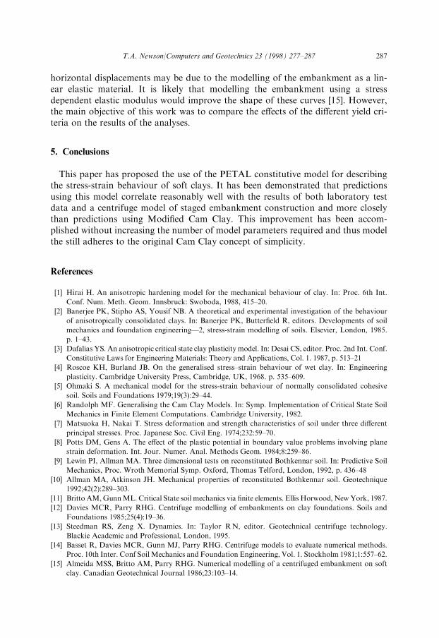
horizontal displacements may be due to the modelling of the embankment as a lin-ear elastic material. It is likely that modelling the embankment using a stressdependent elastic modulus would improve the shape of these curves [15]. However,the main objective of this work was to compare the e�ects of the di�erent yield cri-teria on the results of the analyses.
5. Conclusions
This paper has proposed the use of the PETAL constitutive model for describingthe stress-strain behaviour of soft clays. It has been demonstrated that predictionsusing this model correlate reasonably well with the results of both laboratory testdata and a centrifuge model of staged embankment construction and more closelythan predictions using Modi®ed Cam Clay. This improvement has been accom-plished without increasing the number of model parameters required and thus modelthe still adheres to the original Cam Clay concept of simplicity.
References
[1] Hirai H. An anisotropic hardening model for the mechanical behaviour of clay. In: Proc. 6th Int.
Conf. Num. Meth. Geom. Innsbruck: Swoboda, 1988, 415±20.
[2] Banerjee PK, Stipho AS, Yousif NB. A theoretical and experimental investigation of the behaviour
of anisotropically consolidated clays. In: Banerjee PK, Butter®eld R, editors. Developments of soil
mechanics and foundation engineeringÐ2, stress-strain modelling of soils. Elsevier, London, 1985.
p. 1±43.
[3] Dafalias YS. An anisotropic critical state clay plasticity model. In: Desai CS, editor. Proc. 2nd Int. Conf.
Constitutive Laws for Engineering Materials: Theory and Applications, Col. 1. 1987, p. 513±21
[4] Roscoe KH, Burland JB. On the generalised stress±strain behaviour of wet clay. In: Engineering
plasticity. Cambridge University Press, Cambridge, UK, 1968. p. 535±609.
[5] Ohmaki S. A mechanical model for the stress-strain behaviour of normally consolidated cohesive
soil. Soils and Foundations 1979;19(3):29±44.
[6] Randolph MF. Generalising the Cam Clay Models. In: Symp. Implementation of Critical State Soil
Mechanics in Finite Element Computations. Cambridge University, 1982.
[7] Matsuoka H, Nakai T. Stress deformation and strength characteristics of soil under three di�erent
principal stresses. Proc. Japanese Soc. Civil Eng. 1974;232:59±70.
[8] Potts DM, Gens A. The e�ect of the plastic potential in boundary value problems involving plane
strain deformation. Int. Jour. Numer. Anal. Methods Geom. 1984;8:259±86.
[9] Lewin PI, Allman MA. Three dimensional tests on reconstituted Bothkennar soil. In: Predictive Soil
Mechanics, Proc. Wroth Memorial Symp. Oxford, Thomas Telford, London, 1992, p. 436±48
[10] Allman MA, Atkinson JH. Mechanical properties of reconstituted Bothkennar soil. Geotechnique
1992;42(2):289±303.
[11] Britto AM,GunnML. Critical State soil mechanics via ®nite elements. Ellis Horwood, NewYork, 1987.
[12] Davies MCR, Parry RHG. Centrifuge modelling of embankments on clay foundations. Soils and
Foundations 1985;25(4):19±36.
[13] Steedman RS, Zeng X. Dynamics. In: Taylor RN, editor. Geotechnical centrifuge technology.
Blackie Academic and Professional, London, 1995.
[14] Basset R, Davies MCR, Gunn MJ, Parry RHG. Centrifuge models to evaluate numerical methods.
Proc. 10th Inter. Conf Soil Mechanics and Foundation Engineering, Vol. 1. Stockholm 1981;1:557±62.
[15] Almeida MSS, Britto AM, Parry RHG. Numerical modelling of a centrifuged embankment on soft
clay. Canadian Geotechnical Journal 1986;23:103±14.
T.A. Newson/Computers and Geotechnics 23 (1998) 277±287 287