EQUIPMENT VALIDATION OF LYOPHILIZER AND ...
137
EQUIPMENT VALIDATION OF LYOPHILIZER AND AUTOCLAVE IN THE MANUFACTURW OF STERILE PHARMACEUTICALS By M.RAJESWARI DEVI Dissertation submitted to the Rajiv Gandhi University of Health Sciences, Karnataka, Bangalore In partial fulfillment of the requirements for the degree of MASTER OF PHARMACY In QUALITY ASSURANCE Under the guidance of Mr. CHANDRA MOULI R Department of Quality Assurance Krupanidhi College of Pharmacy Bangalore-35 MARCH -2012
-
Upload
khangminh22 -
Category
Documents
-
view
3 -
download
0
Transcript of EQUIPMENT VALIDATION OF LYOPHILIZER AND ...

EQUIPMENT VALIDATION OF LYOPHILIZER AND
AUTOCLAVE IN THE MANUFACTURW OF STERILE
PHARMACEUTICALS
By
M.RAJESWARI DEVI
Dissertation submitted to the
Rajiv Gandhi University of Health Sciences,
Karnataka, Bangalore
In partial fulfillment
of the requirements for the degree of
MASTER OF PHARMACY
In
QUALITY ASSURANCE
Under the guidance of
Mr. CHANDRA MOULI R
Department of Quality Assurance
Krupanidhi College of Pharmacy
Bangalore-35
MARCH -2012

RAJIV GANDHI UNIVERSITY OF HEALTH SCIENCES
BANGALORE, KARNATAKA.
DECLARATION BY THE CANDIDATE
I hereby declare that this dissertation entitled “Equipment Validation of Lyophilizer
and Autoclave in the Manufacture of Sterile Pharmaceuticals” is a bonafide and
genuine research work carried out by me under the guidance of Mr. Chandramouli R,
Assistant Professor, Department of Quality Assurance, Krupanidhi College of
Pharmacy, Bangalore.
Date: M.RAJESWARI DEVI
Place: Bangalore Candidate

RAJIV GANDHI UNIVERSITY OF HEALTH SCIENCES
BANGALORE, KARNATAKA.
COPY RIGHT
Declaration by the Candidate
I hereby declare that the Rajiv Gandhi University of Health Sciences, Karnataka shall
have all the rights to preserve, use and disseminate this dissertation/thesis in print or
electronic format for academic/research purpose.
Date: M.RAJESWARI
Place: Bangalore Candidate
© Rajiv Gandhi University of Health Sciences, Karnataka

INTRODUCTION

OBJECTIVE

REVIEW OF
LITERATURE

METHODOLOGY

RESULTS

DISCUSSION

CONCLUSION

SUMMARY

BIBLIOGRAPHY

Acknowledgement
Dept. of Quality Assurance, KCP, Bangalore i
ACKNOWLEDGEMENT
None of my own work or the work cited in this dissertation would be possible
without the blessings of God and my Parents it gives me an immense pleasure to
acknowledge with gratitude the help and guidance rendered to me by a host of people to
whom I owe a substantial measure in the completion of my project work.
I take this golden opportunity to express my deepest gratitude and respect
to my research guide, Mr. Chandramouli for his invaluable guidance, constant
encouragement and marvelous support throughout my project work.
I wish to sincerely thank our Dr. N. Prem Kumar, Dean and Professor Syed
Mohammed Basheeruddin Asdaq, Principal, Krupanidhi College of Pharmacy for
providing adequate facilities for the successful completion of my work.
I owe my sincere gratitude to Suresh Nagpal, Chairman and Professor Sunil
Dhamanigi, Secretary Krupanidhi institutions for the infrastructure and all the other
essential facilities and encouragement given during my project work.
I earnestly thank my industrial guide, Mr. Biju Mathews, Strides Arco Lab
Limited to motivate me for selecting a novel project and clearing all the doubts related. I
thank him for the freedom of thought, expression and his trust generously bestowed upon
me.
It gives me immense pleasure to owe my gratitude to Mr. Arun M.P and Mr.
Uma Mahesh Babu for his support and encouragement in industry.

Acknowledgement
Dept. of Quality Assurance, KCP, Bangalore ii
My heartfelt thanks to all the teaching staff of Krupanidhi College of Pharmacy,
especially Mrs. Naira Nayeem, Mr. S. Srinivasan and Mr. Harish kumar D. R. for
their guidance and help.
I am pleased to thank our librarian, Mr. Vasanth for their availability, kindness
and cooperation.
I wish to thank the all the non-teaching staff, especially Ravi and Bhaskar for
their support through my work.
I express my deepest gratitude to all my classmates Abhinandana, Anupam,
Abhijit, Mehul, Hardik, Purvish, for their valuable and timely help and cooperation
during the project work. I also wish to thank my other batch mates Spoorthi, Anuradha
for their help.
I can hardly find any words to acknowledge the love and support of my beloved
Parents and my younger brother Adhikhya for their prayers and encouragement at each
& every front of my life to transfer my dreams in to reality. They scold me, raised me,
supported me, taught me, loved me and sacrifice a lot for me.
Last but not least, I want to thank all of my well-wishers who helped me directly
or indirectly, again who have been and continue to be a constant source of inspiration
and insight.
Date:
Place: Bangalore. M. Rajeswari Devi

DDDeeedddiiicccaaattteeeddd TTTooo
GGGoooddd AAAnnnddd
MMMyyy LLLooovvviiinnnggg PPPaaarrreeennntttsss

List of Abbreviations used
Dept. of Quality Assurance, KCP, Bangalore iii
LIST OF ABBREVATIONS USED
Approx. : Approximately
avg. : Average
ºC : Celsius
cGMP : Current Good Manufacturing Practice
cm : Centi Meter
DQ : Design Qualification
e.g. : For Example
eq. : Equivalent
etc. : Et cetera
EU : European Union
FDA : Food and Drug Administration
FAT : Factory acceptance test
gm : Gram
GMP : Good Manufacturing Practice
ICH : International Conference on Harmonisation
i.e. : that is
IQ : Installation Qualification
kg : Kilo Gram
LOD : Loss on Drying
LVP : Large Volume Parenteral
Max. : Maximum
mg : Milli Gram
min. : Minute
ml : Milli Leter
mm : Milli Meter
NLT : Not Less Than
NMT : Not More Than
No. : Number
OQ : Operation Qualification
PQ : Performance Qualification

List of Abbreviations used
Dept. of Quality Assurance, KCP, Bangalore iv
QA : Quality Assurance
QC : Quality Control
QRM : Quality risk management
q.s. : Quantity Sufficient
qty. : Quantity
RQ : Requalification
Sl. : Serial
SOP : Standard Operating Procedure
Spec. : Specification
std. : Standard
UK : United Kingdom
USFDA : United States Food and Drug Administration
USP : United States Pharmacopoeia
URS : User requirement specification
v/s : Versus
WHO : World Health Organization
wt. : Weight
& : And
µg : Micro Gram
# : Number
% : Percentage

Abstract
Dept. of Quality Assurance, KCP, Bangalore v
ABSTRACT
Assurance of quality, reduce rework, robustness and batch-to-batch consistency are most
important factor to maintain profitability for pharmaceutical industry and can be achieve
only by incorporation of equipment validation. In the presented work, equipment
validation of lyophilizer and autoclave is done to reduce the stability problem for
sensitive products and achieve the sterility of the final product. The presented
investigation was to carry out the validation of 3 consecutive runs of having same process
parameter. All the prerequisites have been checked and precalibration and post
calibration of data loggers and temperature sensors have been done and found complying
with the acceptance criteria. All results of validation like vacuum rate (12-15 mins),
Maximum vacuum capacity (0.0080 -0.0093 mbar), vacuum leakage test (0.0000222-
0.000029), heating rate (1.05- 1.380C) and cooling rate (1.52-2.29
0C), temperature
uniformity(0.7-1.30C), autoclave vacuum leak was (0.00-0.004) found well within the
acceptance criteria. Based on the results of the validation for 3 runs, it was concluded that
by following the process parameters consistently producing the stable product meeting its
pre-determined specifications and quality attributes.

List of contents
Dept. of Quality Assurance, KCP, Bangalore vi
LIST OF CONTENTS
Contents Page No.
1. INTRODUCTION 1-18
1.1. Definitions of Validation 1
1.2. Principle Elements of Validation 2-3
1.2.1. Documented Evidence 2
1.2.2. High Degree of Assurance 2
1.2.3. Specific Process 2
1.2.4. Consistency 2
1.2.5. Predetermined Specifications 3
1.3 Reasons for Validation 3-4
1.3 1 Compliance 3
1.3.2 Quality Assurance 3
1.3.3 Economics 3
1.3.4 Regulatory Requirements 4
1.4 Benefits of Validation 4-6
1.4.1 Quality 4
1.4.2 Understanding Equipment, System and Process 4
1.4.3 Regulatory Benefits 4
1.4.4 Cost Reduction 5
1.4.5 Time Saving 5
1.5 Equipment validation 5-14
1.5.1 User required specifications 7
1.5.2 Design qualification 7
1.5.3 Factory acceptance test 8
1.5.4 Quality risk management 8
1.5.5 Installation qualification 8
1.5.6 Operation qualification 9
1.5.7 Performance qualification 11
1.5.8 Requalification 12

List of contents
Dept. of Quality Assurance, KCP, Bangalore vii
1.6 Lyophilizer validation 14-17
1.6.1 Maximum vacuum capacity and vacuum leakage rate test 15
1.6.2 Isolator valve integrity test 16
1.6.3 Shelf heating and cooling rate 16
1.6.4 Sterilization in place test 16
1.6.5 Condenser capacity test 17
1.6.6 Placebo test 17
1.7 Equipment validation of autoclave 17-18
1.8.1 Vacuum leak test 18
1.8.2 Air removal test 18
1.8.3 Heat distribution and penetration studies 18
2 OBJECTIVE 19-21
3 REVIEW OF LITERATURE 22-36
3.4 Literature Review on Validation of equipment 22-23
3.5 Literature Review on Validation of lyophilizer 23-31
3.6 Literature Review on Validation of autoclave 21-36
4 METHODOLOGY 37-68
4.1 Prerequisites for equipment validation 37
4.1.1 Validation Approach 37
4.1.2 Documents Required 37
4.1.3 Instructions followed during validation of equipment 38
4.1.4 Requirement during equipment validation of lyophilizer 38
and autoclave
4.2 Operation qualification of lyophilizer: 39-48
4.2.1 Verification of key functionality, safety features and 39
Emergency Stop features
4.2.2 Verification of operator interface, display, automation 39
and control requirements.
4.2.3 Software operation qualification 43

List of contents
Dept. of Quality Assurance, KCP, Bangalore viii
4.2.4 Alarm categorization and verification 45
4.3 Performance qualification of lyophilizer 49-57
4.3.1 Vacuum rate, maximum vacuum capacity and vacuum 49
leakage rate test
4.3.2 Isolator Valve Integrity Tests 50
4.3.3 Shelf Cooling and Heating Rate Test 50
4.3.4 Shelf Temperature Uniformity Test 51
4.3.5 Sterilization in place test 53
4.3.6 Condenser capacity test 54
4.3.7 Cleaning In Place (CIP) Test 55
4.3.8 Placebo test 56
4.4 Operation qualification of autoclave 58-63
4.4.1 Verification of key functionality 58
4.4.2 Verification of safety feature 59
4.4.3 Verification of Alarms And Warnings 60
4.5 Performance qualification of lyophilizer 64-68
4.5.1 Vacuum leak test for sterilizer chamber 64
4.5.2 Air removal test 64
4.5.3 Heat distribution and penetration studies 65
5 RESULTS 69-95
5.1 Prerequisites for equipment Validation 69
5.2 Operation qualification lyophilizer and autoclave 69
5.3 performance qualification of lyophilizer 70

List of contents
Dept. of Quality Assurance, KCP, Bangalore ix
5.3.1 Vacuum rate, maximum vacuum capacity and 70
Vacuum leakage test
5.3.2 Isolated valve integrity test 70
5.3.3 Heating and cooling 71
5.3.4 Shelf temperature uniformity test 72
5.3.5 Cleaning In Place 74
5.3.6 Sterilization in place 74
5.3.7 Condenser Capacity 73
5.3.8 Placebo Test 74
5.4 Performance qualification of autoclave 75-76
5.4.1 Air removal test 76
5.4.2 Vacuum leak test 75
5.4.3 Heat distribution and penetration study 76
6 DISCUSSION 96-100
6.1 Prerequisites for Process Validation 96
6.1 Operation qualification of lyophilizer and autoclave 96
6.2 Performance qualification of lyophilizer and autoclave 97
7 CONCLUSION 101-102
8 SUMMARY 103-107
9 BIBLIOGRAPHY 108- 111

List of tables
Dept. of Quality Assurance, KCP, Bangalore x
LIST OF TABLES
Sl. No. Title of Table Page
No.
4.1 Equipment details of Lyophilizer and Autoclave 37
4.2
Verification list of key functionality, safety and emergency stop
features of lyophilizes
39
4.3
Verification list of operator interface, display, automation and control
requirements of lyophilizer.
39
4.4
Verification of software operation qualification
43
4.5 Alarm categorization and verification list 45
4.6 Placebo test steps 57
4.7 verification list of key functionality of autoclave 58
4.8 Verification list of safety feature 59
4.9 Verification list of alarms and warnings of autoclave. 61
4.10 Verification list of emergency stop features 63
5.1 OQ results of lyophilizer 69
5.2 OQ results of autoclave 69

List of tables
Dept. of Quality Assurance, KCP, Bangalore xi
Sl. No. Title of Table Page
No.
5.3 Results of Vacuum rate and leakage, maximum vacuum capacity test 70
5.4 Results of isolated valve integrity test. 70
5.5 Results of heating and cooling rates.
71
5.6 Results of shelf temperature uniformity test. 72
5.7 Results of clean in place. 74
5.8 Results of condenser capacity
73
5.9 . Results of sterilization in place. 74
5.10 Results of lyophilization process test. 75
5.11 Results of data logger and RTD sensors calibration. 75
5.12 Results of vacuum leak test. 75
5.13 Results of air removal tests. 76
5.14 Results of heat distribution studies 76
5.12 Results of heat penetration studies with BI challenge. 77

List of figures
Dept. of Quality Assurance, KCP, Bangalore xii
LIST OF FIGURES
S. No. List of Figures Page No.
1.1 Typical equipment qualification lifecycle 14
2.1 Best method to plan for equipment validation 22
4.1 Location of probes in the lyophilizer for uniformity test 52
4.2 Temperature Sensor location Diagram for SIP Test 54
4.3 load pattern diagram with probe location 66
S. No. List of reports Page No.
5.1 Temperature Sensors precalibration report of Autoclave 77
5.2 Data Loggers Precalibration report of Autoclave 78
5.3 Temperature Sensor precalibration report of Lyophilizer 79
5.4 Datalogger precalibration report of Lyophilizer 81
5.5
Maximum vacuum capacity, vacuum leak rate and Isolation valve
integrity report
82
5.6 Heating and Cooling rate report
83
5.7 Shelf temperature uniformity test report
85
5.8 Sterilization in Place test report
88
5.9 Vacuum leak test report
92
5.10 Air removal test report
93
5.11 Heat distribution and penetration study reports
94

List of figures
Dept. of Quality Assurance, KCP, Bangalore xiii
S.No. List of graphs
Page no.
5.1 Shelf temperature uniformity test graph
88
5.2 Sterilization in Place test graph
88
5.3 Placebo test report
91
Chapter-1 Introduction
Dept. of Quality Assurance, KCP, Bangalore 1
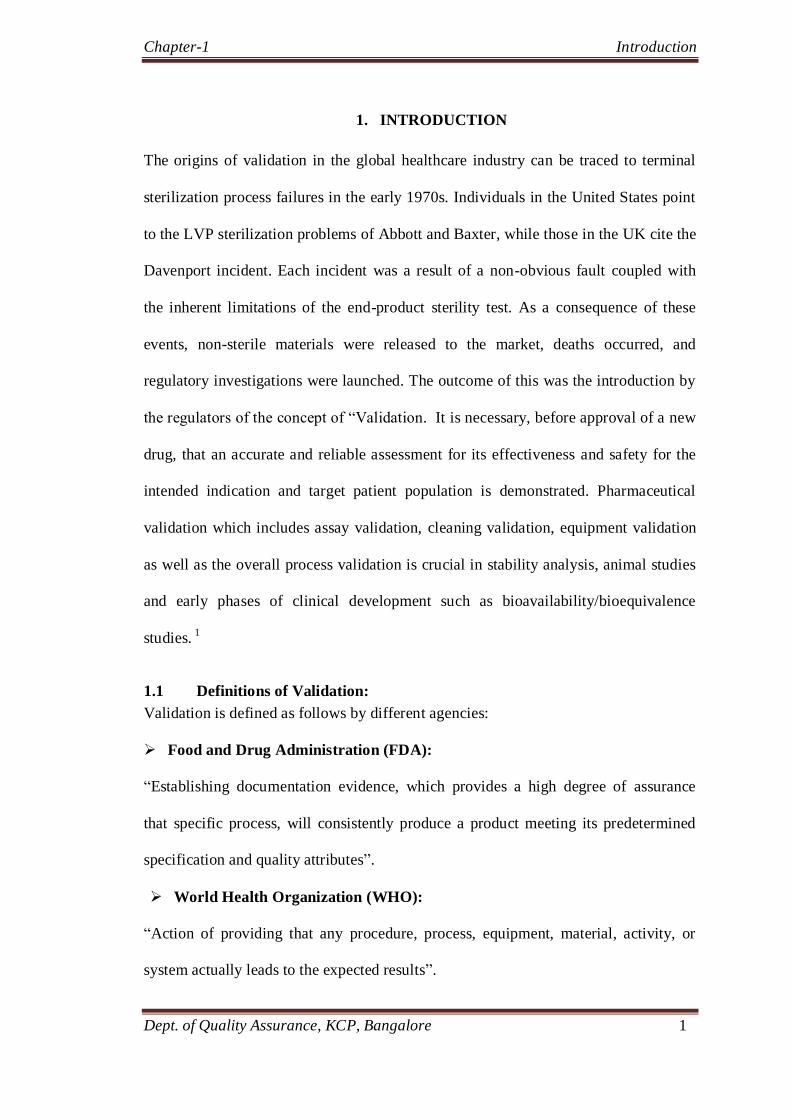
1. INTRODUCTION
The origins of validation in the global healthcare industry can be traced to terminal
sterilization process failures in the early 1970s. Individuals in the United States point
to the LVP sterilization problems of Abbott and Baxter, while those in the UK cite the
Davenport incident. Each incident was a result of a non-obvious fault coupled with
the inherent limitations of the end-product sterility test. As a consequence of these
events, non-sterile materials were released to the market, deaths occurred, and
regulatory investigations were launched. The outcome of this was the introduction by
the regulators of the concept of ―Validation. It is necessary, before approval of a new
drug, that an accurate and reliable assessment for its effectiveness and safety for the
intended indication and target patient population is demonstrated. Pharmaceutical
validation which includes assay validation, cleaning validation, equipment validation
as well as the overall process validation is crucial in stability analysis, animal studies
and early phases of clinical development such as bioavailability/bioequivalence
studies. 1
1.1 Definitions of Validation:
Validation is defined as follows by different agencies:
Food and Drug Administration (FDA):
―Establishing documentation evidence, which provides a high degree of assurance
that specific process, will consistently produce a product meeting its predetermined
specification and quality attributes‖.
World Health Organization (WHO):
―Action of providing that any procedure, process, equipment, material, activity, or
system actually leads to the expected results‖.

Chapter-1 Introduction
Dept. of Quality Assurance, KCP, Bangalore 2
European Union (EU):
―Action of providing in accordance with the principles of good manufacturing
practice, that any procedure, process, equipment material, activity or system actually
lead to the expected results‖.
In brief validation is a key process for effective Quality Assurance.2
1.2 Principle Elements of Validation:
1.2.1 Documented Evidence:
Validation requires thorough documentation. Everything that is not documented is
considered incomplete.
1.2.2 High Degree of Assurance:
The assumption is that a large software package as used in complex computerized
systems is rarely free of errors. Frequently, there is a perception that validation means
error-free. This assumption is wrong. During the validation process, everything
realistically possible should be done to reduce errors to a high degree.
1.2.3 Specific Process:
The overall validation of software is process related, not product related. For example,
the development and testing activities performed prior to releasing the software for
manufacture are validated once for a series of products characterized by the serial
number. Some subparts of validation, such as the qualifications (installation,
operation, and performance) are product-specific and have to be done for each system.
1.2.4 Consistency:
Validation is not a one-time event. The performance of the equipment has to be
controlled during the entire life of the product.

Chapter-1 Introduction
Dept. of Quality Assurance, KCP, Bangalore 3
1.2.5 Predetermined Specifications:
Validation activities start with the definition of specifications. The performance of the
equipment is then verified against these specifications. Acceptance criteria must be
defined prior to testing.2
1.3 Reasons for Validation:
To show that a process can ―consistently produce what it purports to do‖ validation is
vital requirements for any pharmaceutical industry. The four basic reasons for
validation are compliance, quality assurance, economics and regulatory requirements.
1.3.1 Compliance:
Pharmaceutical manufacturers are directed by GMP and CGMP guidelines, which
they are bound to follow. Validation is the medium with which compliance to these
guidelines is attained and presented in a systemic way. Validation requirements in
industry is supported by EC, GMP, WHO and further supported by FDA Guidelines
on General Principles of Process Validation.
1.3.2 Quality Assurance:
The second and most compelling reason for validation should be to guarantee, as far
as possible. That all processes and equipment in the pharmaceutical manufacturing
process are being used in a way that will ensure the safety, integrity, purity, quality
and strength of a product for use by the general public. Validation therefore
challenges the adequacy and reliability of a system or process to meet predetermined
criteria on a consistent basis from batch to batch.
1.3.3 Economics:
Aside from the above reasons, validation is astute business practice. It prompts
appraisal and reappraisal of every activity involved in a process and, almost

Chapter-1 Introduction
Dept. of Quality Assurance, KCP, Bangalore 4
inevitably, improvements are made. As a result of these validation activities, indirect
economic benefits may arise.3
1.3.4 Regulatory Requirements:
Fourth, and certainly foremost, among the reasons for validation is that it is a
regulatory requirement for virtually every process in the global health care industry-
for pharmaceuticals, biologics, and medical devices. Regulatory agencies across the
world expect firms to validate their processes. The continuing trend toward
harmonization of requirements will eventually result in a common level of
expectation for validations worldwide. Utility for validation beyond compliance is
certainly available. The emphasis placed on compliance as a rationale has reduced the
visibility of the other advantages a firm gleans from having a sound validation
program.
1.4 Benefits of Validation:
1.4.1 Quality:
Customer – patient satisfaction
It has been built into the product
1.4.2 Understanding Equipment, System and Process:
Process improvement, technology transfer, rapid failure investigations
Improve employee awareness and increased outputs
Easier maintenance of the equipment
Fewer complaints about process related failures
1.4.3 Regulatory Benefits:
Successful inspections
Approved products
Ability to export

Chapter-1 Introduction
Dept. of Quality Assurance, KCP, Bangalore 5
1.4.4 Cost Reduction:
Fewer rejects and reworks and avoidance of capital expenditures
Increased efficiency, shortening lead time resulting in lower inventories
Longer equipment life by operating the equipment as per manufacturer‘s
specifications and the establishing of cost effective preventive maintenance
schedules
Reduction in utility costs
1.4.5 Time Saving:
Possible reduced testing of raw materials bulk formulations and finished products.
Reduced testing in process and finished goods
More rapid and accurate investigations into process deviations
More rapid and reliable startup of new equipment
More rapid automation3
In the intervening years, there has been repeated affirmation of those expectations at
other firms, large and small. Regrettably, there has been little quantification of these
benefits. The predominance of compliance-based validation initiatives generally
restricts objective discussion of cost implications for any initiative. But once a
process/product is properly validated, it would seem that reduced sample size and
intervals could be easily justified, and thus provide a measurable return on the
validation effort. Aside from utility systems, this is hardly ever realized and represents
one of the major failings relative to the implementation of validation in our industry.
Flawless and predictable qualities are cornerstones of successful production of
medicaments. To streamline processes, minimize material loss and stay within legal
requirements, advanced quality assurance tools are needed in order to guarantee

Chapter-1 Introduction
Dept. of Quality Assurance, KCP, Bangalore 6
customer satisfaction and to produce under optimum conditions with maximum
efficiency.
Assurance of product quality is derived from careful and systemic attention to a
number of important factors like selection of quality components and materials,
adequate product and process design, and statistical control of the process through in
process and end-product testing. Thus it is through careful design qualification and
validation of both the process and its control systems that a high degree of confidence
can be established that all succession of batches that meet specifications will be
acceptable.
1.5 Equipment validation:
Validation is a quantitative approach which is needed to prove quality, functionality
and performance of a pharmaceutical/biotechnological manufacturing process. This
proved approach will be applied to individual pieces of equipment as well as the
manufacturing process. Guidelines for equipment validation are set by the multiple
regulatory agencies like USFDA but specifications of validation are determined by
the pharmaceutical/biotechnological company.
Validation of equipment‘s is also known as qualification. The importance of the
qualification process of technical systems in the pharmaceutical industries has been
steadily increasing over the last 10 years. Bringing any new pharmaceutical to market
requires coordinated efforts in product design, formulation development and process
engineering throughout the development phase. Moving that new product to
commercial-scale manufacturing requires careful equipment validation. New methods
and tools must be implemented to reach the goals of qualifying a technical system
while minimizing effort. The main aspect is the trend for quality assurance
departments to evolve from being mere controllers of product quality to delivering

Chapter-1 Introduction
Dept. of Quality Assurance, KCP, Bangalore 7
tools and methods to other departments, thus helping them to design a better
production process. The goal is to improve overall production reliability and
availability4.
Equipment validation involves the following steps:
1.5.1 User requirement specification:
The purpose of User Requirement Specification (URS) is to provide appropriate
design and performance requirements for procurement of equipment/instrument/
system including major add-on component or major modification/expansion of area so
as to meet in-house requirements as well as compliance with current Good
Manufacturing Practices. The requirement for preparation of URS shall be evaluated
at initial stage during procurement phase. The preparation of URS shall be applicable
to the items intended for use as part of pharmaceutical/nutraceutical manufacturing
and control and which impacts GMP. Wherever, an integrated line is to be procured
from same vendor, a single URS shall be considered acceptable. Wherever,
manufacturing line is to be integrated with equipment from other vendors, the same
shall be described in URS, with integration and scope requirements.
1.5.2 Design qualification:
The purpose of Design Qualification (DQ) is to qualify hardware, functional and
performance requirements for procurement of equipment/instrument/system so as
to meet in-house requirements, regulatory requirements as well as compliance with
current Good Manufacturing Practices.
During Design Qualification, specifications or technical information provided by
vendor/supplier/manufacturer shall be studied against company URS and the non-
conformance if any, shall be addressed appropriately. At a minimum, design

Chapter-1 Introduction
Dept. of Quality Assurance, KCP, Bangalore 8
specifications submitted by the prospective vendor shall be reviewed and approved
by company prior to releasing purchase order. The design specification shall be
reviewed and approved by the same authorities that reviewed and approved URS.
1.5.3 Factory Acceptance Test:
Factory Acceptance Test (FAT) is required as determined during Design
Qualification, the same shall be done in accordance with a pre-approved protocol.
FAT shall provide an opportunity to company, to identify those discrepancies (if
any) at Vendor‘s site that can be resolved more effectively prior to its dispatch to
user‘s facility. FAT shall be executed at Vendor‘s site, and FAT report shall be
made available along with qualification documents of respective equipment.
1.5.4. Quality risk management:
During qualification phase, all ‗Direct impacting‘ equipment/systems shall undergo
the exercise of QRM. The QRM shall be performed in accordance with the SOP on
QRM as recommended through various regulatory requirements like ICH Q9 etc.
1.5.5 Installation qualification:
The purpose of Installation Qualification (IQ) is to demonstrate that the equipment
is installed and meets approved design specification, supplier‘s recommendations,
and drawings and that they are correctly interfaced with factory systems.
Prior to beginning IQ exercise, all requirements, as specified in URS and agreed
upon by Vendor/supplier/manufacturer shall be verified including availability
documentation and FAT report (if applicable). Installation of the
equipment/instrument/system shall be done as per recommendation of
vendor/supplier/manufacturer.

Chapter-1 Introduction
Dept. of Quality Assurance, KCP, Bangalore 9
IQ protocol shall be prepared by including all design specifications as agreed
through URS, Vendors technical information and DQ. All major components of
equipment‘s (as specified by vendor) shall be verified for calibration certificates by
IQ protocol shall be executed on installed item. At a minimum, following criteria
are verified during IQ.
IQ prerequisites
Installation checklist
List of major components for verification
MoC verification
Verification of supporting utilities
Identification of SOPs (e.g. Operation and cleaning, calibration and
preventive maintenance SOPs)
Instruments to be used for calibration during OQ, their calibration status
Instruments to be calibrated during OQ, their criticality,
All the risk mitigation actions (those are supposed to be taken during IQ) shall be
executed during IQ and documented/closed accordingly in IQ report.
1.5.6 Operation qualification:
The purpose of Operational Qualification (OQ) is to demonstrate that
equipment/system/instrument is operational within its predetermined operational
range and tolerances, and meets functional requirements.
Execution of OQ necessitates testing of those parameters that regulate/control the
process or product quality. Proper operation of controllers, indicators, recorders,
alarms, and interlocks, shall be verified and documented during OQ.

Chapter-1 Introduction
Dept. of Quality Assurance, KCP, Bangalore 10
OQ phase shall include calibration/testing of instruments those are identified
during. During OQ it shall also be verified that the system functions in a
predefined sequence or operating steps, all interlocking, alarms and safety
functions are functioning as specified.
A Standard Operating Procedure (SOP) shall be drafted (and/or approved) prior to
Operational Qualification and shall be verified for correctness and understanding
during OQ. OQ test criteria shall include testing equipment without any load to
verify any engineering defects (abnormal sound, wear / tear, vibrations, etc) and is
termed as ―No Load Trials.‖
OQ protocol shall be prepared by including all functional requirements of URS and
functional specification/operating manual, etc.
OQ protocol shall be executed after IQ is completed, and as recommended through
IQ report. At minimum following criteria are verified during OQ.
OQ prerequisites
Standard test instrument/devices details
Calibration details if instruments/devices on the equipment
No Load trials & ease of operation
Functionality test (operating steps, recommended speed
range, interlocking, alarms, etc)
Challenge tests at extreme operating range as recommended
through QRM
Safety checks
SOP verification (At least draft SOPs shall be made
available for verification)

Chapter-1 Introduction
Dept. of Quality Assurance, KCP, Bangalore 11
OQ report shall include a statement recommending whether or not to proceed to
PQ based on the results of operational tests performed and future work (if
required).
All risk mitigation actions (those are supposed to be taken during OQ) shall be
executed during OQ and documented/closed accordingly in OQ report
1.5.7 Performance qualification:
The purpose of Performance Qualification (PQ) is to demonstrate that
equipment/system/instrument is performing as per its predetermined performance
criteria and yields an output meeting its quality and performance attributes as
specified in URS.
Performance Qualification is an amalgamation of evaluation of approved operating
procedures, personnel, systems, and materials in an integrated approach so as to
verify that pharmaceutical grade utility, environment, equipment, support system,
etc., produces the required output. It shall be performed through multiple sets of
tests to demonstrate its consistency and reproducibility.
PQ execution involves handling of dummy material or product for conducting
tests. This methodology shall be described in respective PQ protocol. PQ report
shall also document the destruction of material used during PQ execution, which
may include actives, excipients, components, etc.
Any discrepancy during PQ shall be evaluated for its impact on Quality of product.
In such a case, in addition to documenting the discrepancy in qualification report, a
deviation report shall be initiated in accordance with the Quality Management

Chapter-1 Introduction
Dept. of Quality Assurance, KCP, Bangalore 12
System. Discrepancies having no impact on quality can be documented, resolved
and closed through qualification report itself.
PQ protocol shall include the following but not limited to:
PQ prerequisites
Experimental Plan & Procedure
Sampling Plan (if any)
Acceptance criteria
Observations
Conclusions /Certifications
PQ report shall include a statement recommending whether the
equipment/instrument/system is acceptable for its intended use.
1.5.8 Requalification and revalidation of Equipment/Instrument/ System:
An Equipment Requalification shall be done based in the following situations
Modification of equipment/instrument/system
Modifications to, or relocation of equipment shall follow satisfactory review and
authorization of the documented change proposal through change control
procedure. The qualified movable equipment can be moved from one place to
another in the same facility, for such movable equipment‘s no qualification is
required after the movement.
The review of changes shall include impact assessment because of
change/modification and consideration of qualification of equipment. In such cases
IQ and/or OQ and/or PQ (or process validation) shall be performed before

Chapter-1 Introduction
Dept. of Quality Assurance, KCP, Bangalore 13
releasing the equipment for routine use. The scope of qualification shall be
mentioned in the applicable change control.
Changes of equipment which involve replacement of component on a "like for
like" basis would not require a re-validation. For all other replacements, an
evaluation shall be made (in change control) to determine requirement of
validation.
Periodic Re-Qualification and annual validation plan
The purpose of Requalification or program is to demonstrate that the
equipment/system/instrument is maintained consistently over a period of time and
can be utilized for its intended purpose. The objective of RQ is also to evaluate that
support systems are working as intended and eventually complements in
maintaining facility in validated state. RQ system through this process shall
identify any deficiency, and suggest appropriate remedial or corrective action.

Chapter-1 Introduction
Dept. of Quality Assurance, KCP, Bangalore 14
Figure 1.1 Typical equipment qualification lifecycle
1.6 Validation of lyophilizer:
Lyophilization or freeze drying is defined as a process in which water is removed
from a product after it is frozen and placed under a vacuum, allowing the ice to
change directly from solid to vapor without passing through a liquid phase. The
process consists of three separate, unique, and interdependent processes; freezing,
primary drying (sublimation), and secondary drying (desorption).
Lyophilization, or freeze-drying, is becoming more important in developing and
manufacturing unstable, sensitive pharmaceuticals. However, lyophilization poses
special challenges to achieving and ensuring batch uniformity. First, the product itself
is sensitive to the presence of water and to process conditions. Then, the process
User Requirement Specification (Including functional requirements if applicable)
Design Qualification &
Impact assessment
Installation Qualification
Risk Management
Operational Qualification Standard Operating
Procedure
Performance Qualification Process Validation Cleaning Validation
Change Management
Routine operation
Periodic Revalidation / Requalification
FAT execution

Chapter-1 Introduction
Dept. of Quality Assurance, KCP, Bangalore 15
involves manipulating subambient temperature and sub-atmospheric pressure
conditions. Success requires close control of process parameters such as temperature
and time, and equipment operating performance. It also depends on understanding
factors unique to each lyophilizer — even a vial‘s position on the freeze dryer tray
can have a major impact on product quality and batch uniformity. Controlling critical
processing parameters is imperative to ensuring that batches are uniform and the
process reproducible from batch to batch. Completing a comprehensive Installation
Qualification (IQ), Operational Qualification (OQ) and Performance Qualification
(PQ) assures that the equipment can produce material of sufficient quality. The
performance capabilities of each individual freeze dryer will influence process
reproducibility, batch uniformity, and consistency of the finished product. Qualifying
equipment performance is, thus, an integral part of assuring reproducibility,
consistency and uniformity. Complete and comprehensive Equipment Qualification
studies are necessary, including Installation and Operational Qualification, which
ensures that the equipment has been properly installed, adequate utilities are available,
and the lyophilizer is functioning properly.
As demand for parenterals and biologically-derived products expands, companies are
widely using Lyophilization to protect and stabilize their sensitive pharmaceutical and
biologic products. Freeze-dryer performance is playing an important role in achieving
the required activity, stability, quality, and shelf-life for the finished products5.
Performance qualification of lyophilizer includes
1.6.1 Maximum Vacuum Capacity and Vacuum Leakage Rate Test:
Objective
This test is to verify the final pressure that system can reach, and to verify the leak
rate of the system is as per design specification.

Chapter-1 Introduction
Dept. of Quality Assurance, KCP, Bangalore 16
Scope
The test is to be performed with an empty and dry chamber to minimize evaporative
pressure gains.
1.6.2 Isolator Valve Integrity Test:
Objective
To checks the integrity of the isolation valve between the ice condenser and the
drying chamber.
Scope
This test is applicable to each Lyophilizer and to be performed successfully minimum
three consecutive times.
1.6.3 Shelf Heating and Cooling Rate Test:
Objective
This test is to ensure the proper functioning of heater and compressor with respect
to their capacity and user requirement.
Scope
This test is applicable to each Lyophilizer and to be performed successfully
minimum three consecutive times. This test is applicable to Lyophilizer with an
empty chamber.
1.6.4 SIP (Sterilization in Place) Test:
Objective
The test is to perform to evaluate the efficiency of the Sterilization cycle/SIP cycle.
Scope
This test is applicable to test Lyophilizer with an empty chamber.

Chapter-1 Introduction
Dept. of Quality Assurance, KCP, Bangalore 17
1.6.5 Condenser capacity test:
Objective
The test function will verify that the ice capacity of the condenser operates as
required and to record functional drying operations and vacuum drying conditions.
Scope
This test is applicable to each Lyophilizer and to be performed once successfully.
16.6 Placebo test:
Objective
The test is to ensure the finale moisture content and physical appearance of the cake
is as per the requirements.
Scope
This test is applicable to each Lyophilizer and to be performed one successful run.
1.7 Equipment validation of autoclave:
It was found that validation of steam sterilization in autoclaves is the most-studied
validation problem faced by the pharmaceutical industry. There was a failure in
sterilizing certain LVP solutions that resulted in several patients‘ deaths which in turn
led for the call of validation of sterilization process by the U.S. FDA. So, the
autoclave Validation / Qualification have become mandatory for all machines used for
biological sterilization, in the biomedical and pharmaceutical industries. Autoclaving
is the fastest and most reliable, so there is always need in scrutinizing autoclave
validation / Qualification activities.

Chapter-1 Introduction
Dept. of Quality Assurance, KCP, Bangalore 18
1.7 Performance qualification of autoclave:
1.7.1 Vacuum leak test:
Objective
This test is performed to ensure that the sterilizer complies to leak test requirements
indicating that the integrity of the objects being sterilized is maintained during
application of vacuum cycle after the sterilization cycle.
Scope
This test is applicable for all sterilizers where vacuum cycle is applied after
sterilization
1.7.2 Air removal test (Bowie-dick test):
Objective
The air removal test is performed to ensure that the air is removed completely after
the vacuum is applied to the sterilizer
Scope
The test is applicable to all sterilization cycle where vacuum is applied prior to
sterilization.
1.7.3 Heat distribution and heat penetration studies with loaded chamber.
Objective
This test ensures that there is uniform distribution of heat in the chamber and ensure
that the sterilizer meets the temperature profile requirements, sterility assurance
requirements during the sterilization as per various load patterns.

Chapter 2 Objective
Dept. of Quality Assurance, KCP, Bangalore 19
2. OBJECTIVE
The basic purpose of carrying out a validation of the manufacturing process is to
establish documented evidence that provides a high degree of assurance that the
process consistently produces a product meeting its predetermined specifications and
quality attributes. Validation is the integral part of GMP and now-a-days, it is
mandatory to incorporate validation activity in the premises for all pharmaceutical
industries. It has been found that by performing the validation activity one can omit
serious manufacturing problems. Main objective of this study to conduct validation on
lyophilizers and autoclaves in the manufacture of sterile pharmaceuticals
Figure 2.1 Best method to plan for equipment validation
It shows a pyramid, which is the best way in which to plan a qualification/validation
project. Investing more time in the first phases will save time and money in later and
critical phases. If inadequate investment is made during the start-up of a project, the
later phases of installation qualification (IQ), operational qualification (OQ), and
Preliminaries, including design qualification (D.Q)
Maintenance change control requalification
Operation qualification
Performance qualifications
Installation qualification

Chapter 2 Objective
Dept. of Quality Assurance, KCP, Bangalore 20
performance qualification (PQ) will necessarily require an inordinate amount of time
and money.
As demand for parenteral and biologically-derived products expands, companies are
increasingly using Lyophilization and autoclaves to protect and stabilize their
sensitive pharmaceutical and biologic products. It was found that validation of steam
sterilization in autoclaves is the most-studied validation problem faced by the
pharmaceutical industry.
Validation of lyophilizers and autoclaves is done by:
Operational qualification - (OQ) for Autoclaves and lyophilizer:
Process control limits (time, temperature, pressure, line speed, setup conditions, etc.)
Checking alarms.
Process operating procedures.
Material handling requirement.
Operational qualification - (OQ) for Lyophilizer
Control functions such as shelf temperature control, pressure control, process
monitoring, sequence functions etc.
Checking alarm.
Material handling requirement.
Process operating procedures
Performance qualification - (PQ) of autoclave:
Following are the tests performed in performance qualification:
Vacuum leak test of sterilizing chamber.
Air removal test.
Heat distribution study and heat penetration study with loaded chamber.

Chapter 2 Objective
Dept. of Quality Assurance, KCP, Bangalore 21
Performance qualification of lyophilizer:
Following are the tests performed in performance qualification:
Vacuum rate, maximum vacuum capacity and vacuum leakage rate test
Isolator valve integrity test
Shelf Cooling and Heating Rate Test
Shelf Temperature Uniformity Test
Cleaning In Place Test (CIP)
Condenser capacity test
Sterility in place test (SIP)
Placebo test

Chapter-3 Review of literature
Dept. of Quality Assurance, KCP, Bangalore 22
3. REVIEW OF LITERATURE
A Literature survey on equipment validation of lyophilizer and autoclave in manufacture
of sterile pharmaceutical from various books, journals and published works gives much
information related to the objective of study. Some of the most relevant ones are
discussed below:
Literature review on validation of equipment:
The main aim in qualifying laboratory equipment is to ensure the validity of the data .It
has been reported that the current equipment validation programs and procedures used
within the pharmaceutical industry are mainly based on regulatory requirements,
voluntary standards, vendor practices, and industry practices .This in turn leads to
considerable variation in the way pharmaceutical companies approach the qualification of
laboratory equipment and how they interpret the unclear requirements. The authors
summarized that Pharmaceutical research and manufacturing association of America
(PhRMA) Workshop was an Acceptable Analytical Practices for the topic “Qualification
of Laboratory Equipment”6.
Equipment qualification protocol is one of the greatest value added services which
provide the verification of accurate system and/or equipment drawings. It has been
reported that most often contractors and vendors supply „as-builts‟ as part of a job or
project. Changes were also made even after the as-builts were delivered or
errors/omissions occurred in the original drawings unfortunately. In order to verify the
accuracy of the as-built drawing a test procedure from which could be included in the
installation qualification has been described by them7.

Chapter-3 Review of literature
Dept. of Quality Assurance, KCP, Bangalore 23
It is essential that the performance of the calibration is tested with a set of samples which
are typical and independent. They have calibrated on lyophilizers and they have preferred
a name called "Validation set". Researchers have developed a multivariate calibration and
have also said that, if they are satisfied with the predictions on these samples then they
will claim that they have "Validated" the calibration, which suggests that they expect it to
continue to give useful results in the future8.
According to the literature survey a significant changes were made in production system
i.e. manufacturing execution system (MES) on a production floor. It has been said that
there is a need to conduct high confidence testing the correction and performance of the
correctness and performance of the MES. It was found that a new approach was devised
to provide a highly realistic testing environment by simulating FAB wide equipments
interacting with the MES system via the equipment integration (EI) components just as it
would in actual production. This in turn led to validate the target production system with
high confidence without the need of actual equipment time9.
Equipment validation of lyophilizer:
The review deals with validation of the dynamic parameters estimation (DPE) method,
which is a non-invasive in-line monitoring technique for the freeze-drying process of
pharmaceutical products which only requires pressure measurement; simulations and
experimental data of pharmaceutical solutions in vials, are used to validate lyophilizer.
The above method used has considered as an improvement of analogous techniques, such
as the manometric temperature measurement (MTM) method, which is also based on the
pressure rise analysis concept. The approach proposed by them was able to estimate not
only the temperature profile inside the frozen product at any time during the pressure rise

Chapter-3 Review of literature
Dept. of Quality Assurance, KCP, Bangalore 24
test, but also the position of the moving interface of Sublimation, the external heat
transfer coefficient, and the effective diffusivity coefficient in the dried product, which
are necessary for a predictive model-based control algorithm. This in turn got good
estimations of the product temperature and of the transport parameters, as well as of the
position of the interface of sublimation, which has directly related to the state of
progression of the primary drying phase10
.
Lyophilizer refrigeration system's process capabilities and performance are critical to a
successful commercial Lyophilization operation because lyophilization dries a product
from the frozen state under temperature controlled conditions. Recent trends in
pharmaceutical product manufacturing and their impact on the evolution of refrigeration
technology in lyophilization were outlined. It has also explained about the advantages
and disadvantages of choosing a refrigeration system that uses liquid nitrogen instead of
mechanical compressors, and its affect on the overall operation of lyophilization process.
It was concluded that cryogenic nitrogen refrigeration has gained favor over mechanical
refrigeration because of its inherent reliability and responsiveness to meet stringent and
flexible cooling profiles while achieving ultra-low shelf and condenser temperatures11
.
ISO 9000 and FDA requirements mandate that any measurement be traceable to national
standards. The researchers have said that to ensure traceability, performance, and
reliability it is necessary to calibration the equipment. The review has explained the
proper method for the in situ, on-site, or off-site calibration of lyophilizer pressure gauges
and has also offered some important guidelines to ensure the accuracy of a capacitance
manometer. This calibration of lyophilizer pressure gauge resulted in assuring quality and
cost effective production12
.

Chapter-3 Review of literature
Dept. of Quality Assurance, KCP, Bangalore 25
The success for the transfer and validation of a lyophilization process requires a thorough
characterization of the process and the equipment. The article has discussed the various
elements such as the development and characterization of the lyophilization process,
performance of the equipment, identification of the critical process parameters, etc.,
which can potentially impact the successful transfer and validation efforts13
.
Researchers have described about the commissioning and qualification of a technically
upgraded lyophilizer after the performance of defined changes. This in turn gives a
practical report of the qualification activities (IQ/OQ/PQ) performed on the upgraded
equipment. They have also proved from experience of several recent FDA-inspections,
that the lyophilizer qualification has become one of the most discussed topics and
Lyophilizers are amongst the highly complex equipment used for production. Literature
survey also says that for the qualification of lyophilizers, requires the knowledge in many
diverse fields including computer and software validation, mechanical and electrical
engineering, refrigeration engineering and steam sterilization. Article presented the
results of a hands-on approach, by their report of experiences, to the efficient and reliable
qualification of lyophilizers14
.
A Guide to Inspections of Lyophilization of Parenterals has stated that there are many
new parenteral products which are manufactured as lyophilized products. Many of the
investigators have disclosed potency, sterility and stability problems associated with the
manufacture and control of lyophilized parenteral products. There are some of the
important aspects of these operations like the formulation of the solution, filling of vials
and validation of the filling operations, sterilization and engineering aspects of the
lyophilizes, scale up and validation of the lyophilization cycle and testing of the product.

Chapter-3 Review of literature
Dept. of Quality Assurance, KCP, Bangalore 26
This will help in knowing some of the problems associated with the manufacture and
control of a lyophilized dosage form15
.
The evolution of product temperature and of residual ice content in the various vials of a
batch during a freeze-drying process is significantly affected by local conditions around
each vial. The researchers has developed dual-scale model that can significantly improve
the understanding for pharmaceuticals freeze-drying processes: it couples a three-
dimensional model, describing the fluid dynamics in the chamber, and a second
mathematical model, either mono- or bi-dimensional, describing the drying of the product
in each vial. Thus, it can be profitably used to gain knowledge about process dynamics,
and to improve the design of the equipment, as well as the performance of the control
system of the process16
.
According to the literature survey in lyophilization of pharmaceuticals, the product
sublimation interface temperature must be kept below the product collapse temperature to
achieve pharmaceutical elegance and assure stability. It was reviewed that currently,
meaningful equipment controls are only available for chamber pressure and shelf
temperature. The review derives and explains the use of the heat and mass transfer
equation for predicting these control parameters in a manner that meets the interface
temperature condition. It presented the derivation and solution of those equations which
can be used to find a suitable shelf temperature and chamber pressure after knowing a
product collapse temperature. This paper has shown both a derivation for the central
coupled heat and mass transfer equation, as well as methods for its solution. Other
solutions and considerable complexity can be introduced. This method is not intended to
represent a complete simulation of the lyophilization process. It was nothing more than

Chapter-3 Review of literature
Dept. of Quality Assurance, KCP, Bangalore 27
an analysis physical primary drying parameters. A major consideration for the use of this
analysis is that a vial-package heat transfer coefficient must be obtained as a function of
pressure. Such work can either be done experimentally or by estimate. Also, the dry
product layer resistance was treated as a single average number, when in fact it is known
to continuously increase throughout the sublimation. Still, the method is greatly superior
to having no analysis and no understanding of existing product lyophilization cycles. It
was concluded that the use of this method has substantially reduced the amount of trial
and error associated with lyophilization cycle development17
.
Article discusses the issues involved in achieving batch uniformity for lyophilized
pharmaceuticals summarizes important research and suggest strategies, at every step of
the process, for ensuring the batch uniformity of lyophilized products. Critical parameters
such as shelf temperature, chamber pressure, and time should be accurately and precisely
controlled. It has been said that even less critical factors such as product temperatures
should be monitored, since temperature data can help assess processing conditions. The
sublimation/condensation test challenges the shelves‟ ability to provide sufficient heat to
achieve acceptable sublimation rates. The test also demonstrates the condensation rate
and ice-load capacity of the condenser. Verifying equipment‟s pressure-control capability
is another importance factor in maintaining batch uniformity. Some of OQ tests that
should be tested are cooling and heating rates control at set point, temperature uniformity.
It was concluded that Success requires precise control of process conditions, extensive
equipment testing, and analysis of bulk solution, dry and reconstituted product18
.

Chapter-3 Review of literature
Dept. of Quality Assurance, KCP, Bangalore 28
According to the literature survey successful transfer and validation of a lyophilization
process requires thorough characterization of the process and the equipment. The article
discussed the various elements such as the development and characterization of the
lyophilization process, performance of the equipment, identification of the critical
process parameters, etc., that can potentially impact the successful transfer and validation
efforts. It was said that for most protein formulations, annealing temperature and time,
freezing rates, shelf temperature, and chamber pressure are generally considered to be the
critical process parameters since they directly influence the quality of the drug product.
These limits need to be established through the robustness studies and should serve as the
basis for validation. It was said that a process can be said to be successfully transferred
and validated when one can demonstrate that the process can be performed consistently
in three consecutive runs at production scale while meeting the pre-determined
acceptance criteria relating to process parameters and product quality attributes. This
means that the acceptance criteria must be well defined and clearly laid out in the
validation protocol before executing the validation during the design of the validation
strategy, one needs to keep in mind to include batch load range, the minimum and the
maximum. The regulatory agencies require pharmaceutical companies to demonstrate the
consistency of the drying process, in which case the design of the sampling plan and the
analytical testing must be in accordance with the current agency expectations i.e. star-
shaped sampling plan, demonstration of uniformity across the shelves in terms of content,
potency, particulate distribution, reconstitution time, residual moisture, etc. It was
concluded that awareness and understanding of the challenges associated with

Chapter-3 Review of literature
Dept. of Quality Assurance, KCP, Bangalore 29
commercial manufacturing environment and production freeze dryer design are central to
the development of a robust freeze drying process. 19
According to the literature survey the comparison between the bulks freeze-drying
process of glass container to membrane trays was done. The sublimation phase is an
endothermic process which is controlled predominantly by shelf temperature and
chamber pressure. Numerous other factors (such as container heat transfer coefficient,
container geometry, stopper design, freeze-dryer geometry, freezing behavior, fill depth,
formulation type and concentration, and the robustness of the filling process) also are
important and together contribute to the product temperature at the interface where the
water crystals sublimate. Tests like freezing time, primary drying cycle length; glass
integrity- lensing, product was compared between the two non- optimized process and
new process. It was found that there was a quick freezing effect in membrane trays so
that defined product characteristics can be achieved and there was lack of product
homogeneity in glass bottles when compared with membrane trays. Another difference
between large glass bottles and membrane trays is stoppering, which creates additional
stresses within glass vials. Indeed, the tensions accumulated inside the glass may be
released when force is applied to the bottom surface, resulting in glass breakage, which
can have a huge impact on product yields. Freeze-drying process transfer from glass
bottles to single-use ePTFE membrane trays is feasible and profitable in terms of freeze-
drying capacity for this specific project. It has been concluded that robust process
validation is a key element to success and a good understanding of the freeze-drying
process is advantageous in speeding up the transfer process and releasing a quality
product20
.

Chapter-3 Review of literature
Dept. of Quality Assurance, KCP, Bangalore 30
Successful scale-up of a lyophilization cycle from laboratory to pilot or commercial scale
requires an understanding of relative performance characteristics of the lyophilizers at
each scale. These characteristics may significantly alter the product temperature profile
upon scale-up if not properly accounted for. Several cycle scale-up scenarios are
discussed with the aid of a steady-state model of lyophilization. In this work, they
attempted to summarize and utilize the best practice of primary drying scale-up by
applying extensive lyophilizer characterization and freeze-drying process modeling. In
combination, these aspects of process design should help in building between laboratory
and any similarly characterized commercial or pilot lyophilizers. This could allow for the
rational design of scaled-up processes minimizing the number of test cycles.
Understanding the capability of lyophilizers and product behavior under different process
conditions in laboratory, pilot and commercial lyophilizers should also facilitate process
robustness design. It was said of potential product impact can be calculated ahead of time
to establish the magnitude of cycle parameter deviations examined during lyophilization
cycle robustness studies. It was concluded that if one compares the estimated product
temperature profile during the process deviation with robustness data performed at lab
scale, one can better understand any possible effect the process deviation may have on
the product quality21
.
The article summarizes and clarifies terms and issues related to vacuum integrity testing
of lyophilizer. It has been reviewed that vacuum integrity test is an integral part of the
quality assurance of lyophilized product. Among these challenges are measurement of
system tightness and the establishment of inleakage criterion that maintains a reasonable
assurance of product stability. There are many factors which one needs to be aware when

Chapter-3 Review of literature
Dept. of Quality Assurance, KCP, Bangalore 31
performing this qualification such as influence of time temperature, start pressure and
virtual leaks. To compare integrity of vessels one must have same temperature, pressure
and time if the volumes of vessels are dissimilar then one must specify the volume based
leak rate. It was concluded that vacuum integrity test is an important part of any factory
acceptance test (FAT), site acceptance test (SAT) and operation qualification (OQ) 22
.
Validation of autoclave:
According to the literature survey the article has provided an update of the validation of
moist heat sterilization. It has brought together the practical information one needs when
validating an autoclave from procurement through routine use. This article has described
about sterility concept, sterilization principles, development of sterilization cycle and
measurement of sterilization efficiency are measured. It was concluded that the above
described concepts are very much useful in validation of moist heat sterilization in
reliable and cost-effective manner23
.
The qualification of autoclave has been the topic of numerous articles, books, symposia
in the past decade autoclave qualifications shortcomings are among the leading source of
FDA 483 citations reported for the biotech industry. It has been assumed that the readers
are somewhat familiar with the basic theoretical development of steam sterilization and
equipment qualification. It was summarized that the authors has attempted to present
hands- on approach to efficiently and reliably qualify autoclaves24
.
Literature survey explains about the significance of Steam sterilization which remains an
issue for regulatory bodies, particularly for the processes associated with high risk in
Chapter-3 Review of literature
Dept. of Quality Assurance, KCP, Bangalore 32
terms of probability and severity of infections. Author says that failure to address this
requirement may place the public at risk and lead to regulatory action and in addition to
potential business liabilities there may be significant cost associated with the validation
process. It was said that if appropriate consideration is not given to employing the correct
approach unnecessary ongoing operational cost may result. Article explained the about
basic validation test to be done in IQ, OQ, PQ and set the acceptance criteria based on
European standards and also gave some tips and cautions to be followed during the
validation of steam sterilizer. It was concluded that practical experience that the
document will provide assistance in ensuring an effective, efficient validation for steam
sterilization and that end result provide the best possible validated cycle to meet the needs
of specific application25
.
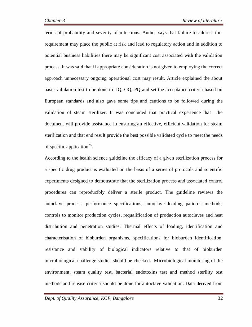
According to the health science guideline the efficacy of a given sterilization process for
a specific drug product is evaluated on the basis of a series of protocols and scientific
experiments designed to demonstrate that the sterilization process and associated control
procedures can reproducibly deliver a sterile product. The guideline reviews the
autoclave process, performance specifications, autoclave loading patterns methods,
controls to monitor production cycles, requalification of production autoclaves and heat
distribution and penetration studies. Thermal effects of loading, identification and
characterisation of bioburden organisms, specifications for bioburden identification,
resistance and stability of biological indicators relative to that of bioburden
microbiological challenge studies should be checked. Microbiological monitoring of the
environment, steam quality test, bacterial endotoxins test and method sterility test
methods and release criteria should be done for autoclave validation. Data derived from

Chapter-3 Review of literature
Dept. of Quality Assurance, KCP, Bangalore 33
experiments and control procedures allow conclusions to be drawn about the probability
of nonsterile product units (sterility assurance level). Based on the scientific validity of
the protocols and methods, as well as on the scientific validity of the results and
conclusions, the manufacturer can conclude that the efficacy of the sterilisation process is
validated26
.
The Health Products and Food Branch Inspectorate (HPFBI) of Health Canada
recognizes that terminal moist heat sterilization, when practical, was presently considered
the method of choice to ensure sterility. Principles outlined in the document are shared
with other methods of sterilization; those processes require control and assessment of
different parameters. According the indicating devices which are used in the validation
studies or used as part of post-validation monitoring or requalification must be calibrated.
Two basic approaches are employed to develop sterilization cycles for moist heat
processes are Overkill and Probability of Survival. Prior to commencing heat distribution,
heat penetration and/or biological challenge reduction studies, it is necessary that the
equipment be checked and certified as properly installed, equipped and functioning as per
its design. The guidelines provided the information regarding heat distribution studies,
heat penetration studies, biological challenge reduction studies, and post -validation
monitoring studies. It has been concluded that a written evaluation of the entire study was
carried out utilizing the various validation protocols should be prepared and the
conclusions drawn at each stage stated. The final conclusion should clearly reflect
whether the validation protocol requirements were met27
.
This document is intended to provide guidance for the submission of information and
data in support of the efficacy of sterilization processes in drug applications for both

Chapter-3 Review of literature
Dept. of Quality Assurance, KCP, Bangalore 34
human and veterinary drugs. Guidelines gives the information regarding the sterilization
process. For the validation of terminal sterilization autoclave description of autoclave
Process and performance Specifications of the autoclave process which includes the
pertinent information such as cycle type (e.g., saturated steam, water immersion, and
water spray), cycle parameters and performance specifications including temperature,
pressure, time, and minimum and maximum Fo, autoclave Loading Patterns, methods
and controls used to monitor routine production cycles (e.g., thermocouples, pilot bottles,
and biological indicators) including the number and location of each as well as
Acceptance and rejection specifications are required . The guideline also contains
information regarding heat distribution and heat penetration studies, thermal Monitors the
Effects of Loading on thermal input, microbiological Efficacy of the Cycle and
microbiological Monitoring of the Environment. . It has been summarised that the
efficacy of a given sterilization process for a specific drug product is evaluated on the
basis of a series of protocols and scientific experiments designed to demonstrate that the
sterilization process and associated control procedures can reproducibly deliver a sterile
product. Data derived from experiments and control procedures allow conclusions to be
drawn about the probability of nonsterile product units (sterility assurance level). Based
on the scientific validity of the protocols and methods, as well as on the scientific validity
of the results and conclusions, the agency concludes that the efficacy of the sterilization
process is validated28
.
According to literature survey Qualification of High Pressure High Vacuum (HPHV)
Steam Sterilizer in Pharmaceuticals is done by pre and post calibration of temperature
sensors b , Vacuum Leak test (3 Trials without probe & 3 Trials with probe), Bowie –

Chapter-3 Review of literature
Dept. of Quality Assurance, KCP, Bangalore 35
Dick Test for Steam penetration ( 3 trials on 3 different days), Steam qualification tests (3
trials on 3 different days), Empty Chamber Heat Distribution studies (3 trials) with
temperature mapping probes at different locations of the sterilizer chamber, Loaded
Chamber heat penetration studies (3 trials) for each sterilization load of fixed loading
pattern, with temperature mapping probes inside the innermost possible layer of the load
subjected for sterilization, Bio-Challenge studies using Bacillus stearothemophilus spore
strips (containing 106 or more spores per strip) during the heat distribution & heat
penetration studies, Estimation of the FO value achieved during the sterilization hold
period at each temperature-mapping probe, Quality of the steam condensate collected
from the sampling point provided in the sterilizer chamber condensate drain line for all
loads, Vacuum break filter integrity testing and the results found complying with the
acceptance criteria29
.
The article explained the importance of air removal. It was said that to achieve effective
steam sterilization, dry saturated steam must contact the surfaces to be sterilised so that
energy can be transferred. It follows, therefore, that nothing must come between the
steam and the surface to be sterilized. Most of the equipment they seek to sterilize (filters,
tubing, vessels, filling needles, etc) contain vast quantities of air. If this air is not
removed, then it can act as an insulating barrier between steam and equipment and thus
compromise the sterilising process. Article explained the methods of air removal and
means of confirming effective air removal such as a drain-mounted air detector, the
Bowie-Dick test (or equivalent), chamber leak rate test Air detectors30
.
According to literature survey it was reviewed that from many years steam autoclaves
have been used in many different industries. Their primary task is to sterilize items so

Chapter-3 Review of literature
Dept. of Quality Assurance, KCP, Bangalore 36
that these same items can be used in situations where the introduction of micro-organisms
would pose a health-risk. This paper describes these tests, and how often should be
performed in order for the user to be confident that their autoclave is functioning properly
and within the requirements of the regulatory bodies. A thermometric test to determine
the temperature profile inside the chamber throughout the holding time, using a data
logging system and multiple probes placed throughout the chamber volume.
Simultaneous monitoring of the chamber pressure is also useful in checking the
efficiency of the air removal/replacement system. During the load testing, biological
indicators may also be placed in the load to determine if sterilization is in fact taking
place. If the autoclave is to be used to sterilize folded cloth, such as garments, a Bowie
Dick test should be performed to ensure complete penetration of the steam into the cloth.
It was concluded that ensuring sterilization is occurring in the autoclave is however of
prime importance thus such costs should be viewed in the light of human safety rather
than that of economics.31

Chapter-4 Methodology
Dept. of Quality Assurance, KCP, Bangalore 37
4. METHODOLOGY
4.1 Prerequisites for equipment Validation:
4.1.1 Validation Approach:
The validation of lyophilizer and autoclave includes two complimentary aspects such
as examination of process parameters and examination of product characters. In order
to substantiate process reproducibility, three consecutive runs were performed.
Sr.
No.
Equipment particulars Details
1 Equipment Name Lyophilizer Autoclave
2 Equipment Capacity 5 m2
970 liters
3 Model Lyo-5.0(SIP,CIP)
4 Manufacturer Tofflon Machin fabrik
6 Category of equipment Direct Impact
Direct impact
Table 4.1 Equipment details of Lyophilizer and Autoclave
4.1.2 Documents Required:
Following documents were required for equipment validation.
Design qualification document (DQ).
User required specifications (URS).
Equipment manuals.
Related SOPs for the qualification of the equipment.
Quality risk management document
Factory acceptance test document
Calibration certificates of temperature sensors, gauges, data loggers.

Chapter-4 Methodology
Dept. of Quality Assurance, KCP, Bangalore 38
Installation qualification documents
Personal training regards documents.
4.1.3 Instructions Followed During Validation Of Equipment.
Validation and samples must be collected by trained QA persons only.
Temperature probes and data loggers must be calibrated before and after post after
the validation for the accuracy and precision.
Spore count enumeration and purity test of biological indicator must be done
before use.
Probes must be ensured that they are in same location through out the validation.
The validity of the Bowie and Dick test kit to be use was checked with respect to
its expiry date.
4.1.4 Requirements during the equipment validation of Lyophilizer and
Autoclaves:
Data loggers
Temperature sensors
Biological indicator (Geobacillus sterothermophilus)
1% Nacl
1% talc
Mannitol
Water for injection
Bowie and Dick test kit

Chapter-4 Methodology
Dept. of Quality Assurance, KCP, Bangalore 39
4.2 Operation qualification of lyophilizer:
4.2.1 Verification of key functionality, safety features and emergency stop
features:
Sr.
No. Function / Verification Procedure Acceptance Criteria
1
Interlocking of air inlet1 and air inlet 2 and
vacuum pump was checked.
Pump shall not switch on when
the valves are open and vice
versa.
2 Heater and valve allowing the chilled gas
supply to heat exchanger was checked.
Open only if circulation pump is
in running condition.
3
Checked when water pressure is below
2kg/cm2 and compressors stopped
working.
alarm should start
4 Checked when pressure setted is below 6
kg/cm2.
alarm should start
5 Vacuum pressure was kept to cross the set
parameters alarm should start
6 The temperature of oil was set to cross the
parameter and heater is turned off. alarm should start
7 SIP Start function was checked. Start only if all the pneumatic
door lock is activated.
Table 4.2 Verification list of key functionality, safety and emergency stop
features.
4.2.2 Verification of operator interface, display, automation and control
requirements.
Function Verification Procedure Acceptance Criteria
Switch control power
key
Switched off Control power indicator light off
Switched on Control power indicator light on
Alarm siren Alarm was activated. Siren on if there is an alarm

Chapter-4 Methodology
Dept. of Quality Assurance, KCP, Bangalore 40
Function Verification Procedure Acceptance Criteria
Button for eliminating
main alarm lamp and
siren
The button was pushed
when alarm siren is on
Siren off. The main alarm lamp
is on if there is alarming still.
And the main alarm lamp is off
if there is no alarm.
Remote/local key switch
Remote switch on Touch screen can be run and PC
can be not run
Local switch on PC can be run and touch screen
can be not run
Emergent button The button was pressed The PLC stops exporting control
signal
Circulation pump1
The air breaker of
circulation pump 1 was
closed
Choice circulation pump 1 at
computer, it can not be activated.
The air breaker of pump
1 was opened.
Choice circulation pump 1 at
computer, it can be activated.
Circulation pump 2
The air breaker of
circulation pump 2 was
closed
Choice circulation pump 2 at
computer, it can not be activated.
The air breaker of
circulation pump 2 was
opened
Choice circulation pump 2 at
computer, it can be activated.
Vacuum pump1
The air breaker of
vacuum pump 1 was
closed
Choice vacuum pump 1 at
computer, it can not be activated.
The air breaker of
vacuum pump 1 was
opened
Choice vacuum pump 1 at
computer, it can be activated.

Chapter-4 Methodology
Dept. of Quality Assurance, KCP, Bangalore 41
Function Verification Procedure Acceptance Criteria
Vacuum pump 2
The air breaker of
vacuum pump 2 was
closed
Choice vacuum pump 2 at
computer, it can not be activated.
The air breaker of
vacuum pump 2 was
opened
Choice vacuum pump 12at
computer, it can be activated.
Hydraulic unit
The air breaker of
shelves up and down at
control panel was closed
Choice button for shelves up and
down at control panel, shelves
can not move.
The air breaker of
shelves up and down at
control panel was
opened
Choice button for shelves up and
down at control panel, shelves
up and down.
Heater
The air breaker of heater
was closed
Regulate shelves temperature
after setting higher temperature
of shelves, heater can not be
started.
The air breaker of heater
was opened
Regulate shelves temperature
after setting higher temperature
of shelves, heater can be started.
Compresor 1 The air breaker of
compressor 1was closed
Choice compressor 1 at
computer, it can not be activated.
Compresor 1
The air breaker of
compressor 1 was
opened
Choice compressor 1 at
computer, it can be activated.
Compresor 2
The air breaker of
compressor 2 was closed
Choice compressor 2 at
computer, it can not be activated.
The air breaker of
compressor was opened
Choice compressor 2 at
computer, it can be activated.

Chapter-4 Methodology
Dept. of Quality Assurance, KCP, Bangalore 42
Function Verification Procedure Acceptance Criteria
Chamber sight lamp
The button of chamber
lamp was clicked Chamber lamp on.
The button was
loosened
Chamber lamp off after 60
seconds.
Condenser sight lamp
The button of
condenser lamp was
clicked
Condenser lamp on.
The button was loosened Condenser lamp off after 60
seconds.
Shelves up button
The up button was
pressed
Hydraulic pump can be started
and shelves up.
The button was loosened
Shelves stop increase and
hydraulic pump stops after
delaying 3 minutes.
Shelves down button
The down button was
pressed
Hydraulic pump can be started
and shelves down.
The button was loosened
Shelves stop decline and
hydraulic pump stops after
delaying 3 minutes.
Chamber air inlet
button
The button was clicked
to open
Chamber air inlet valve is
opened
The button was clicked
to close
Chamber air inlet valve was
closed.
Condenser air inlet
button
Click button was clicked
to open
Condenser air inlet valve is
opened
Condenser air inlet
button
The button was clicked
to close
Condenser air inlet inlet valve is
closed
Door close button Door button was
clicked The door is closed

Chapter-4 Methodology
Dept. of Quality Assurance, KCP, Bangalore 43
Function Verification Procedure Acceptance Criteria
Door open button Click door open button The door is opened
Camber sight lamp
Click the button of
chamber lamp Chamber lamp on.
Loosen the button Chamber lamp off after 60
seconds.
Table 4.3 Verification list for operator interface, display, automation and control
requirements.
4.2.3 Software operation qualification
Table 4.4 verification of software operation qualification
Main Interface
Function Verification Procedure Acceptance Criteria
Login
Double click icon of
LyoMaster4000.
There should be login
window.
Input user name and password and
confirm.
Enter control main
interface.
Login system with administrator
and press “user configuration”
button.
Display configuration user
dialog box. Change and add
user through this function.
Parameter
management
interface
Click Parameter management
button of main interface
Enter parameter
management interface
Lyophilization Click Lyophilization button of
main interface.
Enter lyophilization
interface
Sterilization Click SIP button of main interface Enter SIP interface
Cleaning Click CIP button of mainterface Enter CIP interface

Chapter-4 Methodology
Dept. of Quality Assurance, KCP, Bangalore 44
History data:
Function Verification Procedure Acceptance Criteria
History Data
Click History Data button on
control interface (taskbar).
Display History Data
interface
Click lyophilization and
sterilization table and trend button
separately. Input batch condition.
User can query
lyophilization and
sterilization data table and
trend.
Press print preview button on
taskbar.
Preview content that will
be printed.
History Data
Press print button on taskbar.
If install printer, there
should be print dialog
box. After confirming
print the data.
Press parameter setting button on
taskbar.
Display history server
setting interface
Press exit button on taskbar. Exit history data inquiry
interface.
Operation Data Inquiry
Function Verification Procedure Acceptance Criteria
Operation
Data
Click Operation Data button on
control interface (events log on
taskbar).
Display events log interface.
Click events report button. Input
date condition.
User can query events
according to date.
Press print preview button on
taskbar.
Preview content that will be
printed.
Press print button on taskbar. There should be print dialog
box.

Chapter-4 Methodology
Dept. of Quality Assurance, KCP, Bangalore 45
4.2.4 Alarm categorization and verification:
Sr.
No.
Alarm
Description
Alarms & Warnings Verification
Procedure
Acceptance
Criteria
1. Power abnormal
alarm
Main power switch was turned off
manually.
Alarm lamp on,
siren on and stop
the equipment.
2.
Water pressure
abnormal alarm
Water inlet or outlet was closed.
Alarm lamp on,
siren on and stop
the compressor.
3. Air pressure
abnormal alarm.
Higher setting value for air pressure
relay was adjusted manually.
Alarm lamp on,
siren on.
4.
Circulation
pressure abnormal
alarm.
Higher setting value for circulation
pressure relay was adjusted manually
(setting value is more than actual
value).
Alarm lamp on,
siren on. Switch
circulation pump
automatically.
5.
Compressor1
highpressure
relay1 abnormal
alarm.
Lower setting value for low pressure
relay was adjusted manually (setting
value is less than actual value).
Alarm lamp on,
siren on.
6.
Compressor1 oil
pressure relay 1
abnormal alarm.
Compressor 1 power was turned off.
Alarm lamp on,
siren on. Stop
compressor after
120 seconds.
7.
Compressor 1
electric heat
protection
abnormal alarm.
Power of compressor 1 electric heat
protector relay was turned off.
Alarm lamp on,
siren on. Stop
compressor 1

Chapter-4 Methodology
Dept. of Quality Assurance, KCP, Bangalore 46
Sr.
No.
Alarm
Description
Alarms & Warnings
Verification Procedure Acceptance Criteria
8.
Compressor 2
high pressure
relay 1 abnormal
alarm.
Lower setting value for low
pressure relay was adjusted
manually (setting value is less
than actual value).
Alarm lamp on, siren on.
9.
Compressor 2 oil
pressure relay 1
abnormal alarm.
Compressor 2 power was turned
off.
Alarm lamp on, siren on.
Stop compressor after 120
seconds.
10.
Compressor 2
electric heat
protection
abnormal alarm.
Power of compressor 2 electric
heat protector relay was turned
off.
Alarm lamp on, siren on.
Stop compressor 2.
11.
All of vacuum
pumps off
abnormal alarm.
Close all vacuum pumps′ air
break forcibly during process. Alarm lamp on, siren on.
12. Vacuum
abnormal alarm.
The vacuum exceeds setting
value during process.
Alarm lamp on, siren on.
Stop heater.
13.
Chamber-
condenser
isolation valve
open abnormal
alarm.
Supply compressed air valve was
turned off, compressed air signal
was made short and isolation
valve was opened.
Alarm lamp on, siren on.
After 5 seconds
14.
Chamber-
condenser
isolation valve
close abnormal
alarm.
Supply compressed air valve was
turned off; compressed air signal
was made short after opening
isolation valve and isolation
valve was closed
Alarm lamp on, siren on.
After 5 seconds

Chapter-4 Methodology
Dept. of Quality Assurance, KCP, Bangalore 47
Sr.
No.
Alarm
Description
Alarms & Warnings
Verification Procedure Acceptance Criteria
15.
Pump isolation
valve open
abnormal alarm.
Supply compressed air valve
was turned off, compressed air
signal short and isolation valve
was opened.
Alarm lamp on, siren on.
After 5 seconds
16.
Pump isolation
valve close
abnormal alarm.
Supply compressed air valve was
turned off, compressed air signal
was made short, after opening
pump isolation valve and
isolation valve was closed.
Alarm lamp on, siren on
after 5 seconds
17.
Safety isolation
valve open
abnormal alarm.
Supply compressed air valve was
turned off, Compressed air signal
was turned off short and safety
isolation valve was opened.
Alarm lamp on, siren on
after 5 seconds
18.
Safety isolation
valve close
abnormal alarm.
Supply compressed air valve was
turned off, compressed air signal
was turned off short after
opening isolation valve and
safety isolation valve was closed.
Alarm lamp on, siren on
after 5 seconds
5
19.
Temperature
control abnormal
alarm.
Little time to reach higher
temperature was set during
automatic lyophilization.
Alarm lamp on, siren on.
20.
Pressure rising
test abnormal
alarm.
The difference of pressure rise
test was set minimum and the
time is ten minutes at least.
Alarm lamp on, siren on.

Chapter-4 Methodology
Dept. of Quality Assurance, KCP, Bangalore 48
Sr.
No.
Alarm
Description
Alarms & Warnings
Verification Procedure Acceptance Criteria
21. Door latch in
abnormal alarm
Door bolt inlet valve was opened
during non vacuumizing
condition
Alarm lamp on, siren on
and action stop after 5
seconds
22. Door latch out
abnormal alarm.
After there is door bolt inlet
signal, door bolt outlet valve
was opened during normal
pressure.
Alarm lamp on, siren on
and action stop after 5
seconds
23. Compressor 1
overloading alarm
Compressor 1 air breaker was
switched off manually.
Alarm lamp on, siren on.
Air breaker is off and stops
compressor 1.
24. Compressor 2
overloading alarm
Compressor 2 air breaker was
switched off manually.
Alarm lamp on, siren on.
Air breaker is off and stops
compressor 2.
25. Vacuum pump 1
overloading alarm
Vacuum pump 1 air breaker was
switched off manually.
Alarm lamp on, siren on.
Air breaker is off and stop
Vacuum pump 1.
26. Vacuum pump 2
overloading alarm
Vacuum pump 2 air breaker was
switched off manually.
Alarm lamp on, siren on.
Air breaker is off and stop
Vacuum pump 2.
27.
Circulation
pumps 1
overloading
alarm.
Circulation pump 1 air breaker
was switched off manually.
Alarm lamp on, siren on.
Air breaker is off and stop
Circulation pump 1.
28.
Circulation pump
2 overloading
alarm.
Circulation pump 2 air breaker
was switched off manually.
Alarm lamp on, siren on.
Air breaker is off and stop
Circulation pump 2.
29.
Hydraulic pump
overloading
alarm.
Hydraulic pump air breaker was
switched off manually.
Alarm lamp on, siren on.
Air breaker is off and stop
hydraulic pump.
Table 4.5 Alarm categorization and verification list

Chapter-4 Methodology
Dept. of Quality Assurance, KCP, Bangalore 49
4.3 Performance qualification of lyophilizer:
4.3.1 Vacuum rate, maximum vacuum capacity and vacuum leakage rate test:
The compressor was switched on and the condenser temperature was allowed to
reach up to ≤ - 45ºC.
The vacuum pump was started and start time of cycle was recorded.
The time when vacuum reaches to 0.1mbar (10 Pascal) was recorded.
The cycle was run continuously for about 2 to 6 hours and the highest vacuum
reading was recorded.
The valves between condenser & vacuum pumps were closed.
The vacuum pumps, compressor were turned off, initial chamber vacuum
readings and time were recorded.
After 20 minutes the chamber vacuum reading was noted and the difference was
calculated.
The chamber vacuum leakage rate was calculated by using the formula -
= (Difference in chamber vacuum in mbar X vol. of chamber in m3)
Time in seconds
Acceptance criteria:
The vacuum /evacuation rate i.e. time taken to reach chamber vacuum upto
0.1mbar (10 Pascal) from atmospheric pressure should be NMT 30 min.
Maximum vacuum achieved shall be ≤ 1.0 pa (0.01 mbar) or as specified in
respective protocol. (maximum vacuum achieved shall be less than or equal to
lowest pressure defined in any lyophilization recipe for the respective lyophilizer
and shall be addressed in respective protocol)
The chamber vacuum leakage rate calculated shall be ≤ 0.00003
mbars.m3/second (0.003 pa m3/second) or as specified in respective protocol.

Chapter-4 Methodology
Dept. of Quality Assurance, KCP, Bangalore 50
4.3.2 Isolator Valve Integrity Tests
The air inlet valves were made to open and the chamber vacuum was adjusted to
0.1 mbar ± 0.02 mbar.
The initial vacuum and time was recorded.
Then the isolator valve was made to close and the vacuum pump was started.
The finale vacuum was recorded after 10 minutes.
The drop in vacuum was calculated.
Acceptance criteria
The chamber vacuum pressure shall not drop below the initial vacuum pressure.
4.3.3 Shelf Cooling and Heating Rate Test (Oil in Temperature)
Cooling rate was measured from room temperature to the maximum operational
freezing temperature and heating rate was measured from lowest to the highest
operating temperatures of lyophilizer.
The time of initial shelf „oil in‟ temperature was noted and the freezing run
was started, functioned at maximum operational freezing temperature (~-500C).
After temperature reaching to a desired the temperature (~-40oC) for freezing
rate and (~+600C ) for heating rate was hold for about half and hour.
After half an hour, the drying run was started, functioned at maximum
operational temperature (~+600C ).
The cooling and heating rate (average temperature change per min) was
calculated by using formula.
Cooling rate/ heating rate (ºC/min) = Difference in temp from initial to final in 0C
Time taken to achieve the desire temperature
In minutes

Chapter-4 Methodology
Dept. of Quality Assurance, KCP, Bangalore 51
Acceptance criteria:
Shelves inlet temperature (oil in temperature) cooling and heating rate shall be
≥1.0 °C /min. or as specified in the respective protocol.
4.3.4 Shelf Temperature Uniformity Test (During Freezing and Drying)
Temperature sensors were labelled with number.
The pre calibrated temperature sensors were connected with data logger, and
inserted into the lyophilizer chamber through suitable port ensuring that there is
no leak through the port of sensor insertion into the chamber.
The sensors were distributed on the different shelves at pre identified locations,
ensuring that the complete dryness of shelves before placing sensors on the
shelves.
The temperature sensors were kept such a way that they were in contact with the
shelf surface.
The identification number of each temperature sensors on the diagram after
placement of temperature sensors was noted.
The print interval and file recording interval for 1 min was set. Logged data
included the time, temperature and channel number labels of each temperature
sensor during each minute print interval.
The data logger time with the equipment time was checked and made
synchronise.
The temperature was monitored at the three target set points considering the
overall temperature range used for process (worst –case of all recipes) .
After placement of temperature sensors the doors of lyophilizer were closed.
The operating the lyophilizer was done in manual mode.

Chapter-4 Methodology
Dept. of Quality Assurance, KCP, Bangalore 52
After all the temperature sensors placed on the shelves reached to 3.0 C of
target set temperature, the „oil in‟ temperature was maintained for about 30 min.
After completion of about 30 min, the drying run was started with 0°C
temperature set point.
After all the temperature sensors placed on the shelves reached to 3.0 C , the
„oil in‟ temperature was maintained for about another 30 min
After completion of about 30 min, drying run was continued with maximum
temperature set point of 60°C.
After all the temperature sensors placed on the shelves reached to 3.0 C, the
„oil in‟ temperature was maintained for about another 30 min.
Figure 4.1 Location of probes in the lyophilizer for uniformity test.
Thermal
balance shelf
Shelf-0
Shelf-1
Shelf-2
Shelf-3
Shelf-4
Shelf-5
Shelf-6
Shelf-7
1 2
3 4 5
6 10 7
9 8
11 12
14 13 15
16 17
19 18 20
21 22
24 23 25
26 27
29 28 30
31 36
33 35
34

Chapter-4 Methodology
Dept. of Quality Assurance, KCP, Bangalore 53
: : Indicates location for Probe placement on each Shelf
Acceptance criteria:
The maximum variation of temperature measured across the all shelves shall be
within 3.0 C from the average temperature at a single point of time, during
respective hold period of each target set temperature, or shall comply.
4.3.5 SIP (Sterilization in place) test:
20 temperature sensors were identified and labelled with number.
Print interval and file recording interval was set 1 minute for Shelf temperature
uniformity and 5 seconds for SIP cycle.
Three Temperature sensors were placed inside the Lyophilizer chamber as
shown in probe location diagram mentioned below.
Pre evaluated biological indicator were placed near temperature sensor.
The sterilization cycle was carried out at set temperature 121.5°C at 15 minutes
After completion of sterilization cycle, the Data loggers are stopped and the door
of Lyophilizer was opened.
The Biological indicators were taken out from the chamber, and sent the
Biological indicators to Microbiological Lab for testing.
The Temperature profile from the Data logger and temperature recorder were
taken out.
Acceptance criteria:
The temperature measured (all Temperature sensors), throughout the sterilization
holding time, should be NLT121°C

Chapter-4 Methodology
Dept. of Quality Assurance, KCP, Bangalore 54
The F0 - value at all locations of temperature sensor probes should be ≥15
minutes, Biological indicator should not show any growth during or after
completion of defined incubation. (i.e. no growth after incubation).
Figure 4.2 Temperature Sensors location Diagram for SIP Test
Probe shall be placed inside the vacuum break line filter along with a
biological indicator.
4.3.6 Condenser capacity test
The temperature of the Condenser was verified to be maintained lower than – 40
0C throughout the drying cycle and the vacuum of chamber was under 0.3mbar.

Chapter-4 Methodology
Dept. of Quality Assurance, KCP, Bangalore 55
The maximum load to be tested was based on the rated maximum load of the
condenser.
The SS trays was loaded with measured amount of filtered water for injection
on eight shelves
Cycle was programmed and run with freezing at – 40 0C for duration of
minimum three hours followed by primary drying time of NLT 21 hours and
secondary drying time of NLT 21 hours.
When the cycle was completed, vacuum was break and the remaining ice in the
trays was melted. The remaining water was measured.
Acceptance criteria:
Amount of water sublimed from trays and deposited on condenser shall not less
than of rated capacity of the condenser.
4.3.7 Cleaning In Place (CIP) Test
1% NaCl solution (using WFI) was prepared.
The sample of (about 100 mL) of prepared 1% NaCl solution was collected and
sent to QC to check for presence of chlorides.
The chamber (inside) and shelves was spiked with 1% NaCl solution using the
spray bottle, ensuring that all parts of chamber were covered.
Allowed to dry for about two to three hours with lyophilizer door open.
After drying close the doors and perform CIP cycle.
At the end of the CIP cycle final chamber rinse water sample was collected from
the sampling point provided in clean and dry glass bottle (about 100 mL).

Chapter-4 Methodology
Dept. of Quality Assurance, KCP, Bangalore 56
The sample bottle was labelled with sampling details and sent it to QC lab to
check for traces of chlorides.
Acceptance criteria
During chloride test solution should not show any change in appearance for at
least 15 minutes indicating the absence of chlorides.
4.3.8 Placebo Test :
The 30 mL vials were filled with 15 mL fill of 2.5% mannitol solution.
The vials were operated and loaded into Lyophilizer as per respective SOP.
In “Recipe Data” window, the following parameters were set.
Condenser cooling: Final Temperature = - 50 C, Ramp Duration = 05 minutes
Chamber evacuation
Alarm P1 set point = 0.5, Alarm P2 set point = 0.8, Continue evacuation = 30
Pre-cooling
Final temp
(0C)
Ramp duration
in mins
Soak duration
in mins
Ramp & Soak 1 0 30 15
Ramp & Soak 2 -35 60 180
Primary drying
Final
temp(0C)
Ramp
duration
in mins
Soak duration in
mins
Pressure
in mbar
Ramp & Soak 1 10 225 1140 0.4000
Ramp & Soak 2 20 15 240 0.2000
Ramp & Soak 3 20 0 0 0

Chapter-4 Methodology
Dept. of Quality Assurance, KCP, Bangalore 57
Secondary drying
Final temp in
(0C)
(0C)
temp(0C)
Ramp in mins Soak in
mins
Pressure in
mbar
Ramp & Soak 1 30 30 150 0.0700
Ramp & Soak 2 38 15 300 0.0500
Ramp & Soak 12 38 0 0 0
Table 4.6 steps for placebo test
Plug the rubber bungs by operating the shelf moving switch.
Check the bunging quality in each shelf after unloading
After the completion of each trial, collect one vial each from four corners
and center of each shelf (55 vials), and pick two vials randomly from
eleven shelves (22 vials) to check Moisture content Cake height.
Pick two vials randomly from each shelve to check solubility
Send all samples to QC with proper identification to check for Moisture
content, Cake height and solubility.
Acceptance criteria:
The Moisture content measured shall not be more than 2.0 %
Cake height observed shall be uniform
Cake should dissolve within 30 seconds after addition of 15 mL water in it.

Chapter-4 Methodology
Dept. of Quality Assurance, KCP, Bangalore 58
4.4 Operation qualification of autoclave
4.4.1 Verification of key functionality:
Sr.
No. Procedure Acceptance criteria
1.
Controller time accuracy
The parameter in PLC was set and
sterilization cycle was runned, the
hold time was checked with the help
of stop watch.
The controller sterilization time
as indicated in sterilizer/printout
should be within 1% of the
intended exposure period.
2.
Door precondition indicator
Both the doors of the autoclave were
closed.
When door precondition is
fulfilled the indicator should
glow
3. Alarm Indication Switch
An alarm was generated.
An audio visual alarm should
generate and the alarm indicator
should glow.
4.
Emergency Stop Push Switch
Emergency Stop Push Button was
pressed.
The equipment should stop at
current stage and all controls
and display is off.
5.
Non sterile Door open Push Button
Press the Non sterile door opens Push
Button when equipment is not in
process.
The non-sterile door should
open.
6.
Non Sterile close Push Button
Non sterile Door close
Push Button was pressed when door
is opened
The non-sterile door should
close
7.
Sterile Door close Push Button
Sterile side Door close Push Button
was pressed when sterile side door is
opened
Sterile side door should close

Chapter-4 Methodology
Dept. of Quality Assurance, KCP, Bangalore 59
Sr.
No. Procedure Acceptance criteria
8.
Sterile Door close Push Button
Sterile side Door close Push Button
was pressed when sterile side door is
opened
Sterile side door should close
9.
Sterile Door open Push Button
Sterile Door open Push Button was
pressed when equipment is not in
process
Sterile side door should open
Table 4.7 verification list of key functionality of autoclave
4.4.2 Verification of safety feature
Sr.
No.
Safety Features
Description Function / Verification Procedure
Acceptance
Criteria
1
Check that both the
doors should not open at
the same time.
– First sterile door was opened and
then non sterile door open push
button was pressed to open it.
Non sterile door
should not open.
Sterile door was closed and non
sterile door was opened, then sterile
door push open button was pressed
again to open it.
Sterile door
should not open.
2
Check for the opening
of doors during manual
& auto mode of
operation
During auto or manual mode of
operation sterile and non-sterile
side doors buttons were pressed to
open.
Both doors
should not open.
3. Check for sterile door
operation
During operation the cycle was
aborted and sterile door open push
button wad pressed.
Sterile door
should not open

Chapter-4 Methodology
Dept. of Quality Assurance, KCP, Bangalore 60
Sr.
No.
Safety Features
Description Function / Verification Procedure
Acceptance
Criteria
4
Process should not start
in auto or manual mode
if either door is open.
Sterile door was kept open and then
the process was tried to start, and
after that non sterile door was kept
opened and tried to start the
process again.-
Process should
not start
5
Process should not start
in manual mode if the
door precondition is not
fulfilled.
Manual mode was selected & do
not pressure non sterile door
gasket, then try to start the process
Process should
not start on both
occasions and
indicates with
alarm
Now Select manual mode & do not
pressure sterile door gasket, then
try to start the process
6 Working of safety valves
Increase the chamber pressure by
15% of the working pressure
Chamber steam
will blow off
through safety
valve
Increase the jacket pressure by
15% of the working pressure
Jacket steam will
blow off through
safety valve
7 Door Obstruction
When door is moving obstruct the
door with hand or material
Door should
move back
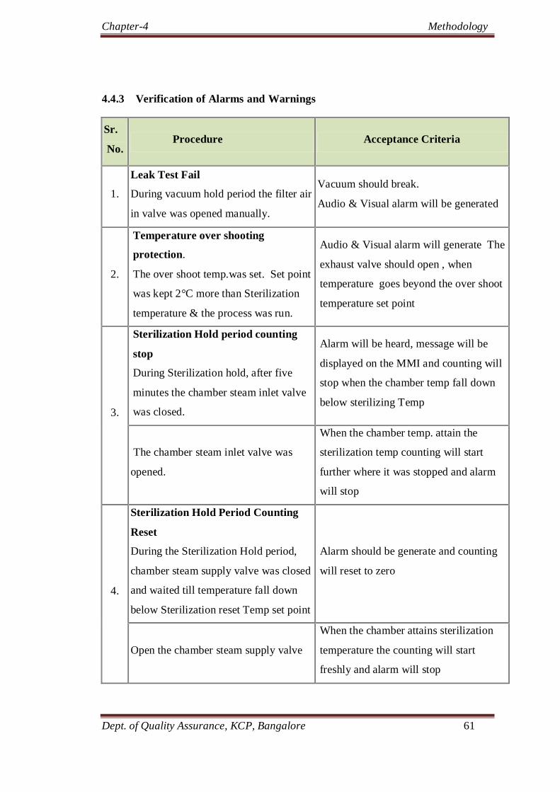
Chapter-4 Methodology
Dept. of Quality Assurance, KCP, Bangalore 61
4.4.3 Verification of Alarms and Warnings
Sr.
No. Procedure Acceptance Criteria
1.
Leak Test Fail
During vacuum hold period the filter air
in valve was opened manually.
Vacuum should break.
Audio & Visual alarm will be generated
2.
Temperature over shooting
protection.
The over shoot temp.was set. Set point
was kept 2°C more than Sterilization
temperature & the process was run.
Audio & Visual alarm will generate The
exhaust valve should open , when
temperature goes beyond the over shoot
temperature set point
3.
Sterilization Hold period counting
stop
During Sterilization hold, after five
minutes the chamber steam inlet valve
was closed.
Alarm will be heard, message will be
displayed on the MMI and counting will
stop when the chamber temp fall down
below sterilizing Temp
The chamber steam inlet valve was
opened.
When the chamber temp. attain the
sterilization temp counting will start
further where it was stopped and alarm
will stop
4.
Sterilization Hold Period Counting
Reset
During the Sterilization Hold period,
chamber steam supply valve was closed
and waited till temperature fall down
below Sterilization reset Temp set point
Alarm should be generate and counting
will reset to zero
Open the chamber steam supply valve
When the chamber attains sterilization
temperature the counting will start
freshly and alarm will stop

Chapter-4 Methodology
Dept. of Quality Assurance, KCP, Bangalore 62
Sr.
No. Procedure Acceptance Criteria
5.
Pure steam pressure low
During the process, manually close the
steam supply valve
Drop in steam pressure will be sensed by
pressure switch. Audio Visual alarm
will generate and message will be
displayed on MMI
6.
Process air pressure low
During the process, manually close the
air supply valve.
Drop in air pressure will be sensed by
pressure switch. Audio Visual alarm
will generate and message will be
displayed on MMI
7.
Compressed air pressure low
During the process, increase setting of
pressure switch mounted on
compressed air line
Audio Visual alarm will generate and
message will be displayed on MMI
8.
Vacuum Pump trip
Trip the pump manually by the
override provided on overload relay.
Alarm shall generate & message will be
displayed on MMI
9.
Door precondition.
During the process , put off compressed
air utility supply, built in pressure drop
below door precondition pressure
Alarm shall generate and message will
be displayed on MMI
10.
Purified water pressure low.
During process manually close the
Purified water valve.
Drop in purified water pressure will be
sensed by pressure switch. Audio Visual
alarm will generate and message will be
displayed on MMI.
11.
Cooling water pressure low.
During process manually close the
Purified water valve.
Drop in cooling water pressure will be
sensed by pressure switch. Audio Visual
alarm will generate and message will be
displayed on MMI

Chapter-4 Methodology
Dept. of Quality Assurance, KCP, Bangalore 63
Sr.
No. Procedure Acceptance Criteria
12.
Chamber Pressure High
Allow the chamber pressure to rise
more than chamber pressure high set
point by opening the steam in valve
manually
Audio, visual alarm should be generated
and message shall be displayed on MMI
13.
Too Long Time For Pre vacuum
Set Too Long time for pre vacuum set
point less than the Actual set point
Audio, visual alarm should be generated
and message shall be displayed on MMI
14.
Too Long Time For Post vacuum
Set Too Long time for post vacuum set
point less than the Actual set point
Audio, visual alarm should be generated
and message shall be displayed on MMI
15.
Too Long Time For Heat up
Set Too Long time for Heat up set
point less than the Actual set point
Audio, visual alarm should be generated
and message shall be displayed on MMI
Table 4.9 verification of alarms and warnings of autoclave
4.4.4 Verification of emergency stop features
4.4.3 Table 4.10 verification of emergency stop features
Sr.
No.
Emergency Stop Verification Procedure Acceptance Criteria
1.
Emergency Stop Push Switch
During the process on, Push the
Emergency Stop Switch
The process should stop
at the current stage in safe
mode

Chapter-4 Methodology
Dept. of Quality Assurance, KCP, Bangalore 64
4.5 Performance qualification of autoclave:
4.5.1 Vacuum leak test for sterilizer chamber:
The vacuum leak test parameters were checked and ensured are as mentioned in
the authorized protocol.
The cycle for “Vacuum leak test” in PLC was selected and performed.
The process was monitored and observations were collected.
The vacuum leak test was performed before and after the validation execution to
ensure the chamber integrity.
Acceptance Criteria:
The drop in the vacuum shall not be more than 0.013 bar after 10 minutes of hold
period.
4.5.2 Air removal test :
A ready “Bowie and Dick test kit” was used to perform the test..
The Bowie and Dick test cycle in PLC was selected and the test was performed
as per the following parameters.

Chapter-4 Methodology
Dept. of Quality Assurance, KCP, Bangalore 65
After completion of the cycle, the test sheet was retrieved and the compliance
against the acceptance criteria was examined.
Acceptance Criteria:
The indicator colour shall change from light brown to dark brown / black in the
Bowie-Dick test sheet & shall be uniform throughout the sheet.
4.5.3 Heat distribution and heat penetration studies with loaded chamber.
Multi point data logger was used with T- type RTD for heat penetration studies.
Number of temperature sensors were used to check heat distribution in loaded
chamber (including one at drain point), and rest 12 probes were be used to check
heat penetration inside the load.

Chapter-4 Methodology
Dept. of Quality Assurance, KCP, Bangalore 66
Load pattern was arranged as per the diagram.
Figure 4.3 load pattern diagram with probe location.
The temperature sensors were placed with identification number inside the
sterilizer chamber and inside the sterilization load where the steam penetration
could be difficult. The overall rationale for probe placement would be
combination of two or more of the following as appropriate:

Chapter-4 Methodology
Dept. of Quality Assurance, KCP, Bangalore 67
Corners of sterilizer
Cartage filters, Tubing‟s / Product contact parts
Center of sterilizer and loaded units.
The temperature sensors were placed with identification number inside the
sterilizer chamber and inside the sterilization load as per the temperature sensor
location diagram.
pre enumerated biological indicators of Geobacillus stearothermophilus
(minimum10 spores per strip) were placed with properly marked details in the
middle of the sterilization load near each temperature sensor kept to check heat
penetration, and also at the locations where sensor can not be placed but the
location is defined as difficult for steam penetration .
The sterilization cycle was selected and cycle parameters are verified.
The heat penetration and distribution studies were carried out by using the Multi
point data logger with temperature logging interval of 10 seconds.
After completion of sterilization cycle the data logger was stopped and the non
sterile door of the sterilizer was opened.
The Biological indicators were taken out from the load and sent to
Microbiological Lab.
The Temperature profile from the Data logger and temperature recorder was taken
out.
The F0 value for each temperature sensor of data logger was checked. Calculation
of F0 value is based on the given formula. Check the results against the
acceptance criteria for compliance.

Chapter-4 Methodology
Dept. of Quality Assurance, KCP, Bangalore 68
Formula: F0 = dt 10 (Ta- Tb)/Z
Where, Tb = 121.1°C,
Z = 10°C
Ta = Actual temperature
dt = Time interval between two successive temperature measurements.
After getting the reports of biological indicator check it for compliance against
acceptance criteria and attach with the qualification report.
Temperature sensors which are used are be calibrated after completion of activity
(post calibration) to ensure that the temperature measurement system is accurate
and precise.
Acceptance Criteria:
The F0 - value of all the temperature sensor of data logger should be equal to
or more than sterilization hold time set. (except liquid or nutrient media load)

Chapter-5 Results
Dept. Of Quality Assurance KCP Bangalore Page 69
5. RESULTS
5.1 Prerequisites for equipment validation:
All prerequisites were checked prior to validation of lyophilizer and autoclave.
Process flowcharts and procedures were followed according to literatures followed.
5.2 Operation qualification of lyophilizer.
Sr.No Features verified Complies/ not complies
1.
Verification of key functionality,
safety features and emergency stop
features:
complies
2.
Verification of operator interface,
display, automation and control
requirements.
complies
3. Software operation qualification complies
4. Alarm categorization and verification
complies
Table 5.1 Results of operation qualification of lyophilizer
5.3 Operation qualification of autoclave.
Sr.No Features verified Complies/ not complies
1.
Key functionality
Complies
2. Safety features
complies
3. Operator interface, display,
automation and control requirements
complies
4. Alarms and warnings
Complies
5. Emergency stop features
complies
Table 5.2 OQ results of autoclave

Chapter-5 Results
Dept. Of Quality Assurance KCP Bangalore Page 70
4.4 5.3 performance qualification of lyophilizer
4.4 5.3.1 Vacuum rate, maximum vacuum capacity and vacuum leakage
test
Table 5.3 Results of Vacuum rate and leakage, maximum vacuum capacity test
5.3.2 Isolated valve integrity test
Table 5.4 Results of isolated valve integrity test
Test Acceptance
criteria
Observation
Run 1 Run 2 Run 3
Vacuum
rate
NMT 30 mins to
reach 0.1 mbar
15mins
0.0896 mbar
16mins1sec
0.0859 mbar
12 mins
0.1018 mbar
Maximum vacuum capacity
≤ 0.01mbar 0.0093 mbar 0.0089 mbar 0.0080 mbar
Vacuum
leakage test
≤ 0.00003
mbar.m3/sec
0.0151 x 2.38 1201 =0.000029 mbar.m3/sec
(0.00410.0178)x2.38 1200
=0.000027 mbar.m3/sec
0.0112x2.38 1200 =0.0000222 mbar.m3/sec
Test Acceptance
criteria
Observation
Run 1 Run 2 Run 3
chamber
vacuum
pressure
Chamber
vacuum
pressure shall
not drop below
the initial
vacuum
pressure
initial=0.0893 Final= 0.1127
Initial=0.1028 Final=0.1196
Initial=0.094 Final=0.102

Chapter-5 Results
Dept. Of Quality Assurance KCP Bangalore Page 71
5.3.3 Heating and cooling rate
Description Observations
Run 1 Run2 Run-3
Shelf
Cooling
Rate
Initial temp. (~+25
oC)
and time.
21.50C
7:43:12
21.50C
00:06:37
21.20C
07:20:08
Finale temp. (~-40oC)
and time
-40.80C
8:10:14
-40.10C
00:47:15
-40.10C
07:54:38
Difference of
Temp(T1)
62.30C
61.6
0C 61.3
0C
Time taken to achieve
target temp.(T2) 27.2 mins 40.38 mins 34.30 mins
Shelf Cooling Rate =
T1 / T2 °C per min. 2.29
0C/min 1.52
0C/min
1.790C/
min
Shelves
inlet
lowest
tempera
ture
4.3.2 Initial
temp.(~-
40oC) and
time
-40.80C,
08:10:14
-40.10C;
00:47:15
-40.10C;
07:54:38
4.3.2 Finale temp. (~-55oC)
and time
-550C,
08:49:16
-550C,
02:02:23
-55.10C;
08:43:23
4.3.2 Total time taken to
achieve ~-55oC temp.
39.2 mins 75.08 mins 48.45 mins
Shelf
Heating
Rate
Initial temp. (~-40oC)
and Time
-40.40C,
09:01:16
-40.00C,
03:53:05
-40.70C;
09:03:40
Finale temp. (~+60°C)
and Time
400C,
10:17:20
41.00C,
03:53:05
410C;
10:03:10
Difference of temp.
from ~-40oC to~
+60°C (T1)
80.40C 81
0C, 81.7
0C
Time taken to achieve
temp. of ~+60°C (T2) 76.4 mins 59.56 mins 59.30 mins
Shelf Heating Rate =
T1 / T2 °C per min 1.05
0C/min
1.350C/min
1.380C/
min
Highest heating temp.
continued up to
(~+60°C) and Time
60.10C,
10:41:21
60.2°C,
04:10:21
60.30C;
10:20:20
Difference of Temp.
from ~-40oC
to~+60°C(F1)
100.50C 100.2
0C 101
0C
Time taken to achieve
temp. of~+60°C (F2) 100.5 mins 78.13 mins 76.40 mins
Shelf Heating Rate=
F1/F2 °C per min. 1
0C/min 1.28
0C/min 1.32/min
Table 5.5 Results of heating and cooling rates

Chapter-5 Results
Dept. Of Quality Assurance KCP Bangalore Page 72
5.3.4 Shelf temperature uniformity test results at -550
C
Description
Observation
Run 1 Run 2 Run 3
Minimum temp. observed on the shelf during hold period
-55.10C -56.30C, -55.90C
Probe location of Minimum temp. & shelf number
T12 , 3rd shelf
T04; 1st shelf
T08 and T16; 2nd,4th shelf
Maximum temp. observed on the shelf during hold period
-52.60C -53.60C -53.20C
Probe location of Maximum temp. &
shelf number T35, 7th Shelf
T50; 10th
Shelf T25; 5th shelf
Acceptance criteria: Temp. on each shelf and across all the shelves during the hold period should be with in ± 3.0oC
from the Average
0.70C 1.30C 1.00C
Table 5.6 Results of Shelf temperature uniformity study results at -55C
5.3.4 Shelf temperature uniformity test results at 00
C
Description
Observation
RSD
Run 1
Run 2 Run 3
Minimum temp. observed on the shelf during hold period
-1.00C -1.00C -0.90C
<2%
Probe location of Minimum temp. & shelf number
T10, 2nd shelf
13th
probe; 3rd shelf
T41,T44, T47,T49,T51; 5th shelf
Maximum temp. observed on the shelf during hold period
0.60C 0.80C 0.60C
Probe location of Maximum temp. & shelf number
T23, 5th shelf
18th
probe; 4th shelf
T21,T22,T28, T48,T50; 5th, 6th,9th, 10th shelf
Acceptance criteria: Temp. on each shelf and across all the shelves during the hold period are with in ± 3.0oC from the Average
0.80C 0.70C 0.80C
Table 5.7 Results of Shelf temperature uniformity study results at 0C

Chapter-5 Results
Dept. Of Quality Assurance KCP Bangalore Page 73
5.3.4 Shelf temperature uniformity test results at 600
C
Description
Observation
Run1 Run 2 Run 3
Minimum temp. observed on the shelf during hold period
57.10C 58.10C 58.10C
Probe location of Minimum Temperature & shelf number
T18, Shelf 4th
7th probe; 2nd shelf
T21; 5th shelf
Maximum temp. observed on the shelf during hold period
59.20C 60.10C 60.30C
Probe location of Maximum Temperature
& shelf number T07, Shelf 2nd
T1,T15,T38,T40 ; 1st, 3rd, 8th shelf
T44; 9th shelf
Acceptance criteria: Temp on each shelf and across all the shelves during the hold period are with in ± 3.0oC from the Average
1.10C 0.90C 0.90C
Table 5.8 Results of shelf temperature uniformity study at +60C
5.3.5 Condenser Capacity
Description Acceptance Criteria/ Set
Value
Observation
Rated Capacity of condenser Not Applicable 100 kg
Total Amount of water loaded in Lyophilizer (A)
NLT rated capacity of condenser
112 Kg
Duration of freezing at -40℃ NLT 3 hours 70 min
Duration of Primary Drying NLT 21 hours 960 min
Duration of secondary drying NLT 21 hours 960 min
Maximum vacuum during drying:
Not less than 0.3 mbar 0.2367 mbar
Total water remaining in trays
at end of cycle (B) Not Applicable 0.300 kg
Total amount of water sublimed from trays and deposited on condenser (A-B)
Should not be less than the rated capacity of the condenser
111.7 kg
Table 5.9 Results of condenser capacity

Chapter-5 Results
Dept. Of Quality Assurance KCP Bangalore Page 74
5.3.6 Sterilization in Place
Description Acceptance
Criteria
Observation
Run 1 Run 2 Run 3
Cycle started at Not applicable 12:44:40 23:15:15 9:04:25
Sterilization Set temperature
NLT 121.5 0C 121.30C 121.30C 121.30C
Sterilization Hold
started at Not applicable 13:08:00 23:46:45 09:43:40
Sterilization hold end at
Not applicable 13:24:15 23:46:45 9:59:45
Total sterilization time
NLT 15 min. 16 mins 15 secs 16 mins 05 secs
16 mins 05 secs
Temperature band during sterilization Hold time
121.0 0C to 124.0 0C
Minimum temperature= 121.30C Maximum temperature= 123.80C
Minimum temperature= 121.50C Maximum temperature= 123.90C
Minimum temperature=121.30C Maximum temperature
=123.80C
Minimum F0 value calculated
NLT 15 min 23.7 mins 21.6 mins 22.4 mins
Biological Indicator recovery
No growth after defined
incubation No growth No growth No growth
Table 5.10 Results of sterilization in place
5.3.7 Cleaning In Place (CIP)
Table 5.11 Results of clean in place
Description Acceptance
Criteria
Observation
Run 1 Run 2 Run 3
Concentration of NaCl solution spiked
1 % 1 % 1 % 1 %
pH of finale drain water 5.0 to 7.0 5.87 5.82 5.95
Conductivity of finale drain water
NMT 1.3 μS 0.77 0.90 0.77
TOC of finale drain water NMT 500 ppb 32.8 28.2 180
Complies/ does not complies Shall Comply complies complies complies

Chapter-5 Results
Dept. Of Quality Assurance KCP Bangalore Page 75
5.3.8 Lyophilization process Test Results:
Description Acceptance Criteria Observation
Moisture content measured
NMT 2.0 % 0.61%
Cake Height Should be uniform Uniform cake height
observed
Dissolution time NMT 30 sec. 7Seconds
Complies or doesn’t complies
Shall comply complies
Table 5.12 Results of Lyophilization process test
5.4 Performance qualification reports of autoclave
4.3.2 5.4.1 Verification of Data logger and RTD Sensors calibration (Pre
calibration and post calibration details):
Sr.
No
Instrume
nt
Acceptanc
e criteria
complies/
doesn’t
complies
1 Data
Logger
+ 0.20C
compli
es
2 RTD
sensors
+0.25%
compli
es
Table 5.13 Results of data logger and RTD sensors calibration
5.4.2 Vacuum Leak test -
Sr.No
Run No.
Max Leakage observed (bar)
Acceptance criteria Complies/Doesn’t
complies
1. 1 0.004 The drop in vacuum should not be more than 0.013 bars during 10 minutes hold period
complies
2. 2 0.000 complies
3. 3 0.000 complies
Table 5.14 Results of vacuum leak test
Sr.
No
Instrum
ent
Acceptanc
e criteria
complies/
doesn’t
complies
1 Data
Logger
+ 0.20C
compli
es
2 RTD
sensors
+0.25%
compli
es

Chapter-5 Results
Dept. Of Quality Assurance KCP Bangalore Page 76
5.4.3 Air Removal Test
Sr.no
Run No.
Test Observations Acceptance criteria Inference
1. 1 Uniform dark black color observed
Bowie-Dick test kit should show uniform dark brown/ black color
development
Complies
2. 2 Uniform dark black color observed
complies
3. 3 Uniform dark black color observed
complies
Table 5.15 Results of air removal test
5.4.4 Heat Distribution and Penetration Studies
Table 5.16 Results of Heat Distribution and Heat Penetration Studies
Steril
izer
Run
No.
Observations
Min.
temp
Max.
temp
Min.
F0
value
Equilibr
ium
time
Max.
deviation
from average
temp
Max.
fluctuation
of temp on
a
RTDsensors
Max.
difference
between
two RTD
sensors
Result
1 121 122.
9
32.
4 30 complies
complies complies complies
2 121 123 32 30 complies complies complies complies
3 121 122.9 32.6 30 complies complies complies complies

Chapter-5 Results
Dept. Of Quality Assurance KCP Bangalore Page 77
Report 5.1 Temperature Sensors precalibration report of Autoclave

Chapter-5 Results
Dept of Quality Assurance KCP Bangalore Page 78
Report 5.2 Data Loggers Precalibration report of Autoclave

Chapter-5 Results
Dept of Quality Assurance KCP Bangalore Page 79
Report 5.3 Temperature Sensor precalibration report of Lyophilizer

Chapter-5 Results
Dept of Quality Assurance KCP Bangalore Page 80
Report 5.3 Temperature Sensor precalibration report of Lyophilizer

Chapter-5 Results
Dept of Quality Assurance KCP Bangalore Page 81
Report 5.4 Datalogger precalibration report of Lyophilizer

Chapter-5 Results
Dept of Quality Assurance KCP Bangalore Page 82
Report 5.5 Maximum vacuum capacity, vacuum leak rate and Isolation valve integrity
report

Chapter-5 Results
Dept of Quality Assurance KCP Bangalore Page 83
Report 5.6 Heating and Cooling rate report

Chapter-5 Results
Dept of Quality Assurance KCP Bangalore Page 84
Report 5.6 Heating and Cooling rate report

Chapter-5 Results
Dept of Quality Assurance KCP Bangalore Page 85
Report 5.7 Shelf temperature uniformity test report

Chapter-5 Results
Dept of Quality Assurance KCP Bangalore Page 86
Report 5.7 Shelf temperature uniformity test reports at 0
0C

Chapter-5 Results
Dept of Quality Assurance KCP Bangalore Page 87
Report 5.7 Shelf uniformity test reports at 600C

Chapter-5 Results
Dept of Quality Assurance KCP Bangalore Page 88
Graph 5.1 Shelf temperature uniformity test graph
Graph 5.2 Sterilization in Place test graph

Chapter-5 Results
Dept of Quality Assurance KCP Bangalore Page 89
Report 5.8 Sterilization in Place test report

Chapter-5 Results
Dept of Quality Assurance KCP Bangalore Page 90
Report 5.8 Sterilization in Place test report

Chapter-5 Results
Dept of Quality Assurance KCP Bangalore Page 91
Graph 5.3 Placebo test report

Chapter-5 Results
Dept of Quality Assurance KCP Bangalore Page 92
Report 5.9 Vacuum leak test report

Chapter-5 Results
Dept of Quality Assurance KCP Bangalore Page 93
Report 5.10 Air removal test report

Chapter-5 Results
Dept of Quality Assurance KCP Bangalore Page 94
Report 5.11 Heat distribution and penetration study reports

Chapter-5 Results
Dept of Quality Assurance KCP Bangalore Page 95
Graph 5.4 heat distribution and penetration study graph

Chapter-6 Discussion
Dept. of Quality Assurance, KCP, Bangalore 96
6. DISCUSSION
All equipment’s to be used for the manufacture of sterile products must be validated to
demonstrate that the product can be manufactured in a reliable and reproducible manner
so as to reach the desired quality. Hence, the present work was undertaken with a goal to
carry out equipment validation for three consecutive times to prove that system remains
in control and process operating parameters are capable of consistently meeting the
predetermined acceptance criteria to produce a quality product.
6.1 Prerequisites for equipment validation:
Checking of approved documents, pre and post calibration of temperature sensors and
data loggers, review of prepared flow charts, instructions to be followed during the
validation availability of materials required and facility required, procedure for validation
are most important prerequisites for any effective equipment validation study. If any
single aspect is found missing during the validation study, it may lead to either delay in
validation study or deficient validation program. In this study all prerequisites were
followed and found ok prior to start the validation program.
6.2 Operation qualification of lyophilizer and qualification:
Operational qualification of the equipment ensures that the equipment is in accordance
with Design Qualification (DQ), functional requirements and meets CGMP and
regulatory expectations. This test verifies that the utility supplies are adequate and meet
the demands of the operating system. The OQ also evaluates each equipment function
and the capacity to meet the performance standards. After OQ of lyophilizer and
autoclave it has been found that equipment’s are made functional and tested for
functional requirements like alarm, safety, and interlocking features interface, display,

Chapter-6 Discussion
Dept. of Quality Assurance, KCP, Bangalore 97
automation and control requirements, key functionality Software operation qualification
and found complying with acceptance criteria. Thus the Equipment meets its operational
qualification requirement.
6.3 Performance qualification of lyophilizer
The main purpose of performance qualification is to confirm through the provision of
objective evidence, that the performance requirements for the Lyophilizer meet its
intended use. It was said that for most protein formulations, annealing temperature and
time, freezing rates, shelf temperature, and chamber pressure are generally considered to
be the critical process parameters since they directly influence the quality of the drug
product. These limits need to be established through the robustness studies and should
serve as the basis for validation. Equipment is said to be validated when one can
demonstrate that the process can be performed consistently in three consecutive runs at
product while meeting the pre-determined acceptance criteria relating to process
parameters and product quality attributes.
Vacuum rate, maximum vacuum capacity and vacuum leakage rate test
The application of vacuum is the important step in lyophilization process to remove the
sublimated vapor from the chamber so finding the vacuum rate plays an important role in
validation. Implementation of calibrated leaks during primary drying offers a number of
advantages. The primary drying time of the product is shortened, and therefore a few
hours can be saved on the overall cycle time. In the absence of maximum vacuum i.e.,
pressure generated in the lyophilization chamber is sustained only by ice sublimation. A
leak in the lyophilizer probably leads to growth of microbes and product instability. So it

Chapter-6 Discussion
Dept. of Quality Assurance, KCP, Bangalore 98
was found appropriate to do three consecutive runs for vacuum rate, maximum vacuum
capacity and vacuum leakage rate test in validation of Lyophilizer. Critical parameters
such as shelf temperature, chamber pressure, and time were accurately and precisely
controlled.
Isolated valve integrity test
Isolated valve connects the chamber with condenser. The integrity of the isolation valve
between the ice condenser and the drying chamber was maintained.
Shelf Cooling and Heating Rate Test
The rate at which the product is frozen can have a significant impact on the product
quality and should be controlled. Very fast freezing rate may lead to hard ice crystal so
that may be come difficult for the mass transfer. At the beginning of the primary drying,
the shelf heating rate should not be too high promote product melting at the base of the
cake. At the end of primary drying the ramping rate should not be too high so as to lead
to collapse or retrograde collapse.
Shelf Temperature Uniformity Test
It is needed to ensure that the temperature applied to the product vials kept across the
shelf during routine operation is uniformly heating as well as cooling during the
Lyophilization cycle. Many batches of the product lack the product uniformity because of
un uniform heat distribution. The regulatory agencies require pharmaceutical companies
to demonstrate the consistency of the drying process, in which case the design of the
sampling plan and the analytical testing must be in accordance with the current agency
expectations i.e. star-shaped sampling plan, demonstration of uniformity across the

Chapter-6 Discussion
Dept. of Quality Assurance, KCP, Bangalore 99
shelves in terms of content, potency, particulate distribution, reconstitution time, residual
moisture, etc. are challenging.
Cleaning in Place (CIP) Test and sterilization in place (SIP)
CIP is required to evaluate the efficiency of the cleaning cycle. Improper cleaning of the
equipment leads to cross -contamination of the product. So the cleaning cycle must be
properly validated with spiking with 1% NaCl. SIP is required to check the sterility level
of the lyophilizer in accordance to its acceptance criteria level.
Placebo test
It is done to check the variation in residual moisture, cake height, dissolution time the
placebo test is being done using the 2.5% manitol. Thus the product uniformity and batch
stability can be assessed using the placebo test.
6.4 Performance qualification of autoclave
Vacuum leak test for sterilizer chamber
This test must be to assess the leakage in the autoclave chamber. Leak may lead to the
microbial growth thus in turn effects the sterility and quality o the product. Another
major problem caused due to leakage is formation of air pockets, which leads to in
adequate sterilization process. So it was found appropriate to do vacuum leak test while
validating the autoclave
Air removal test
This test is to check the uniform steam penetration throughout the chamber / load. The
main concern with steam sterilization is the complete removal of air from the chamber
and replacement with saturated steam.

Chapter-6 Discussion
Dept. of Quality Assurance, KCP, Bangalore 100
Heat distribution and heat penetration studies:
This is the most critical component of the entire validation process. The key is to identify
reproducible basis the location of cool spot , the effect of the load size and configuration
on the cool spot location, and to ensure the sterility assurance level.

Chapter-7 Conclusion
Dept. of Quality Assurance, KCP, Bangalore 101
7. CONCLUSION
Equipment validation of autoclave and lyophilizer in the manufacture of sterile
pharmaceuticals has been carried out as per approved validation protocol, process flow
chart and sampling plan.
All the data loggers and temperature used were calibrated and qualified before and after
the validation. Spore count enumeration and purity test of biological indicator was done
before the use. All the in-process parameters and process variables were checked and
found well within the limit. Samples were collected as per the approved sampling plan
and were submitted to QC for analysis. BIs are collected and were sent to the
microbiology lab. All the results were found well meeting the pre-defined acceptance
criteria.
No significant deviation in any process parameters like time, temperature and pressure
was observed during entire validation study. Hence all the specified process parameters
were consistent as per acceptance criteria.
Confidence in the ability of the equipment to create these necessary environmental
conditions is achieved through the successful completion of a comprehensive IQ and OQ.
Based on the review of the compiled reports and samples it was found that the obtained
values were found meeting the acceptance criteria specified in the protocol. Samples
submitted in the placebo test results for lyophilizer found the uniformity in the cake
formation and moisture content is maintained as per acceptance criteria. BI reports for
heat penetration study has assured the complete sterilization.
Based on the results of the validation data for 3 runs, it is concluded that the selected
cycle is therefore supposed to represent the target working conditions that will be applied

Chapter-7 Conclusion
Dept. of Quality Assurance, KCP, Bangalore 102
for the future production. Validation of the equipment’s has lead development of the
target cycle to perform a batch-to –batch consistency in achieving the product sterility,
stability, dose Uniformity and safety. Thus the above validation provides an additional of
assurance that process is under control.

Chapter–8 Summary
Dept. of Quality Assurance, KCP, Bangalore 103
8. SUMMARY
Equipment validation is a fundamental concept of cGMP. Lyophilization has become the
important process in the manufacture of sterile pharmaceuticals such as antibiotics and
proteins i.e. which are unstable in solution form. Overkill approach i.e. achieving the
sterility of final product has become a challenging part through autoclaving. So in order
to maintain the stability and sterility in pharmaceutical products the equipment validation
of lyophilizer and autoclave was chosen.
The ultimate objective of presented work was to carry validation of three consecutive
runs of having same equipment and same process parameters.
The entire validation and sampling procedure was adopted with total adherence to the
approved validation protocol and sampling plan. The Critical process parameters like
temperature, time, pressure, for all three runs were studied with respect to its effect on the
quality of the final product.
Operation qualification of lyophilizer and autoclave:
Verification of key functionality, safety features and alarms were checked and found
complying with the acceptance criteria
Operator interface, display automation, control requirements and security levels were
verified and found complying with the acceptance criteria.
Emergency stop features were verified and found complying with acceptance criteria.
Performance qualification of lyophilizer:
Vacuum rate, maximum vacuum capacity and vacuum leakage rate test:
The test was performed starting with an empty and dry chamber for eliminating any
vapours that may outgas or contribute to the evaporative pressure gains. The

Chapter–8 Summary
Dept. of Quality Assurance, KCP, Bangalore 104
compressor was switched on and the condenser temperature was allowed to reach up to
≤ - 45ºC to absorb the moisture from the chamber. The vacuum was then started so that
it won’t get damaged due to moisture.
Vacuum rate: 12-16.1 minutes ( limit NMT 30 minutes )
Maximum vacuum capacity: 0.0080-0.0093 (limit ≤ 0.1 pa)
Vacuum leakage test: 0.0000222-0.000029 mbar.m3/sec ((limit ≤ 0.00003 mbar.m3/sec)
Isolated valve integrity test:
Chamber vacuum pressure: No drop in the vacuum pressure below the initial vacuum
pressure.
Shelf Cooling and Heating Rate Test (Oil In Temperature)
Cooling rate was measured from room temperature to the maximum operational
freezing temperature and heating rate was measured from lowest to the highest
operating temperatures. The maximum temperature was changed to 600C from 40
0C
in order to meet the current product temperature requirements. The results found
complying with acceptance criteria.
Shelf cooling rate: 1.520C/min-2.290C/min (limit ≥1.0 °C /min)
Shelf temperature uniformity test:
Monitoring of temperature was done using pre calibrated multi channel data loggers and
temperature sensors. The print interval and file recording interval for NMT 1 min was
set and temperature was recorded in data loggers. Monitoring of temperature was done
using pre calibrated multi channel data loggers and temperature sensors (minimum three
sensors for each operational shelf). The maximum temperature was changed to 600C

Chapter–8 Summary
Dept. of Quality Assurance, KCP, Bangalore 105
from 400C in order to meet the current product temperature requirements. The results
found complying with acceptance criteria.
Shelf temperature uniformity results at -55 C : 0.70C-1.30C (limit ± 30C from the
Average)
Shelf temperature uniformity results at 0 C : 0.7-0.8 (limit ±30C from the Average)
Shelf temperature uniformity study results at +60 C : 0.9-1.1 (limit ± 30C from the
Average)
Cleaning In Place (CIP):
1% NaCl solution (using PW or WFI) was prepared. The sample of (about 100 mL)
prepared 1% NaCl solution was collected and sent to QC to check for presence of
chlorides.
Concentration of NaCl solution spiked: 1% (limit 1%)
pH of finale drain water: 5.87-5.95 (limit 5.0 to 7.0 )
Conductivity of finale drain water : 0.77-0.92 μS (limit NMT 1.3 μS)
TOC of finale drain : 28.2-180 (limit NMT 500 ppb)
Sterilization In Place:
Logged data will include the time, temperature and channel number labels of each
temperature sensor during each minute print interval. Synchronize clocks on all
equipment used in this test.
Minimum F0 value calculated: 21.6 mins-23.7 mins (limits NLT 15 min)
Biological Indicator recovery: No growth

Chapter–8 Summary
Dept. of Quality Assurance, KCP, Bangalore 106
Performance qualification of autoclave:
Vacuum leak test for sterilizer chamber:
Vacuum leak test was performed before and after the validation to ensure the
integrity of the autoclave chamber. The vacuum was hold for 10 minutes to check
the leak after attaining the desired pressure.
Max Leakage observed: 0.0-0.004bar (limit NMT 0.013 bar)
Air removal test:
Air must be completely replaced with the saturated steam to produce the complete
sterility.
Uniform dark black color observed (limit: Bowie-Dick test kit should show uniform
dark brown/ black color development)
Heat distribution and penetration study:
Data loggers used are calibrated before and after the validation of the autoclave.
T-type RTD sensors are used instead of thermocouples because sensitivity is more
for RTD sensors.
Minimum F0 value was found between 32-32.60C (Limit: above the sterilization
hold time).
Results of BI were found complying with the acceptance criteria.
On assessment of the data for various physicochemical test parameters it was summarized
that the process, parameters, specifications and controls have been adequate to show the
total conformance of the product to specifications. So presented study has revealed that

Chapter–8 Summary
Dept. of Quality Assurance, KCP, Bangalore 107
the set process parameters for the validation of lyophilizer and autoclave could be
reproduced during the process resulting in the product meeting the specifications.
.

Chapter–9 Bibliography
Dept. of Quality Assurance, KCP, Bangalore 108
9. BIBLIOGRAPHY
1. Nash RA, Watchter AH. Pharmaceutical process validation. 3rd
ed. New York:
Marcel Dekker, Inc; 2003.
2. Huber L. Validation and qualification in analytical laboratories. 2nd ed. New York
(NY): Informa Healthcare USA Inc.; 2007. p. 25-31.
3. Wrigley GC. Facility validation: theory, practice, and tools. Boca Raton (FL): CRC
Press LLC; 2004. p. 12-6.
4. Chao AY, Forbes FJ, Johnson RF, Doehren PV. Prospective process validation. In:
Nash RA, Wachter AH, editors. Pharmaceutical process validation. 3rd ed. New York
(NY): Marcel Dekker Inc.; 2003. p. 7-9. (Drugs and the pharmaceutical sciences; vol
129).
5. Trubinski CJ. Retrospective validation. In: Nash RA, Wachter AH, editors.
Pharmaceutical process validation. 3rd ed. New York (NY): Marcel Dekker Inc.;
2003. p. 31-5. (Drugs and the pharmaceutical sciences; vol 129).
6. Sigvardson KW, Manalo JA, Roller RW, Saless F, Wasserman D. Laboratory
equipment qualification. Pharm. Techn 2001 Oct: 101-108. Accessed on
www.pharmtech.com
7. Voss JR. IQ test validation procedure. ISPE 1999 Nov. Accessed on
URL://www.pharmainfo.net/rewievs/basics-facts-equipment validation Retrieved on
2010 Nov 15, 1.30pm.
8. AMC Davis. Independence rules (or rules of independence): validation and
calibration. Pharm. Technol 2004; 16(4):27-28.

Chapter–9 Bibliography
Dept. of Quality Assurance, KCP, Bangalore 109
9. Khiam WO, Aik GK, Hwee KK, Chih CS. MES validation using FAB-wide
equipment Simulation. Proceedings of Advanced Semiconductor Manufacturing
Conference The 17th
annual SEMI/IEEE. 2006 May 22-24; Boston, MA. p. 316-321.
10. Velardi SA, Rasette V, Barresi AA. Dynamic parameters estimation method:
Advanced manometric temperature measurement approach for freeze drying
monitoring of pharmaceutical solutions. Ind. Eng. Chem. Res. 2008 Oct 9;
47(21):8445-8457.
11. Hunek B, Cheng, Alan, Capettini, John. Increasing Lyophilization productivity,
flexibility, and reliability using liquid nitrogen refrigeration-part 1. Biopharm Int.
2007 Nov 1; 2011
12. Boca BM, Pretorius E, Gochin R, Chapoullie R, Aspostotides. An overview of
validation approach for the moist heat sterilization, part-1. Pharm Technol 2002 Sep;
2:96-110.
13. Osborn G, Hansen S. Calibration of lyophilisation pressure gauges. Pharm Techn
2002 Jun: 2-6.
14. Fischer T. Lyophilizer qualification: Some practical advice. Am Pharm Review
2004; 7(5):40-47.
15. Guides to inspections of Lyophilization of parenterals; 1993 July; Available from:
URL:http://www.bcg-usa.com/regulatory/docs/1993/FDA199307B.pdf Retrieved on
2010 Nov 30, 11.30 am
16. Barresi AA, Pisano R, Fissore D, Rasetto V, Veraldi SA, Valla A et al. Monitoring of
the primary drying of a Lyophilization process in vials. Chemical Engineering and
Processing: Process Intensification.2009;48(1):408-423.

Chapter–9 Bibliography
Dept. of Quality Assurance, KCP, Bangalore 110
17. Lyophilization: Heat and Mass Transfer , Narlin Beaty, Ph.D. ,Sublimation Science,
American Pharmaceutical Review, page 1-4
18. Trappler EH. Assure Batch Uniformity for freeze dried products. Available on
http://www.pharmamanufacturing.com/articles/2005/191.html?page=full
19. Hunek, Balazs, Cheng, Alan, Capettini, John. Increasing Lyophilization productivity,
flexibility, and reliability using liquid nitrogen refrigeration Part-1. Biopharm Int.
2007 Nov 1; 20(11).
20. Mayeresse Y, Cupere VD, Veillon R, Brendle J. Considerations for Transferring a
Bulk Freeze-Drying Process from a Glass Container to a Tray. Pharmceut Engg
Mar/Apr 2009:1-8.
21. Mayeresse Y, Cupere VD, Veillon R, Brendle J. Considerations for Transferring a
Bulk Freeze-Drying Process from a Glass Container to a Tray. Pharmceut Engg
Mar/Apr 2009:1-8.
22. Charles D, Dern PE. The vacuum integrity testing of lyophilizers. Pharmaceut Engg
Jan/Feb 2005.
23. Chandler A. Introduction to sterilization.
24. Tsui, Victor, Wiederhold. Validating of Autoclave. Ward J Validaton Techn 2007
Feb 1;3(3). Accessed on www.highbeam.com retrived on 2010 Nov 20, 2.30 pm
25. Santis PD, Rudo VS, Carleton FJ, Agalloco JP. Validation of Steam Sterilization in
Auto-claves in Validation of Aseptic Pharmaceutical Processes. 2nd
Ed New York:
Mercel Dekker Inc;1986. p.279-317.
26. Regulatory guidance. Health science authority. December 2008

Chapter–9 Bibliography
Dept. of Quality Assurance, KCP, Bangalore 111
27. Process validation: Moist heat sterilization for Pharmaceuticals. Health Canada.
http://hc-sc.gc.ca/dhp-mps/compli-conform/gmp-bpf/validation/mhsp-schpp-
eng.php#a14
28. Guidance for industry for the submission of documentation for sterilization process
validation in applications for human and veterinary drug products.
29. Sterilization of medical devices – Validation and routine control of sterilization by
moist heat. European Committee for Standardization. 1994.
30. "Validation of Steam Sterilization Cycles," Technical Monograph No. 1, Parenteral
Drug Association, Inc., Philadelphia, PA.
31. Soper CJ, Davies DJG, Denyer S, Baird R. Principles of Sterilization” in Guide to
Microbiological Control in Pharmaceuticals. London; Ellis Horwood; 1990. p.157-
181.