UTTAR HARYANA BIJLI VITRAN NIGAM
165
UTTAR HARYANA BIJLI VITRAN NIGAM. Notice Inviting Tender Sr. No. NIT No. Brief scope of Work/ purchase Est. Cost In Lacs Rs. Approx Last date of submis sion of bids Date of openin g Earnest money Rs. In Lacs Cost of Bid Document s Last date of sale 1 NIT- 13/2012- 13 Dt. 4.2.2013 Supply of material/ equipments & erection, testing & commissioning of bifurcation /connect the Northern Railway station Vill. Bhodwal Majri from 11 KV Patti Kalyana DS feeder in (OP) S/Divn. Samalkha under (OP) Divn. Samalkha / (OP) Circle UHBVN, Panipat 4.66 21.2.13 upto 1300 Hrs. 21.2.13 upto 1500 Hrs. 0.10 Rs. 2000/- 14.2.13 to 21.2.13 Supply of material/ equipments & erection, testing & commissioning of bifurcation/shifting the supply of Railway Station Diwana feeder from AP to RDS feeder in S/U S/Divn. Panipat under S/U Divn. Panipat / (OP) Circle UHBVN, Panipat 3.56 0.08 Total 8.22 0.18 The details of NIT are available on the website www.uhbvn.com Superintending Engineer (Op) Circle, UHBVN, Panipat
-
Upload
khangminh22 -
Category
Documents
-
view
3 -
download
0
Transcript of UTTAR HARYANA BIJLI VITRAN NIGAM

UTTAR HARYANA BIJLI VITRAN NIGAM.
Notice Inviting Tender
Sr. No. NIT No. Brief scope of Work/
purchase
Est. Cost In Lacs
Rs. Approx
Last date of submission of bids
Date of opening
Earnest money Rs. In Lacs
Cost of Bid Documents
Last date of sale
1
NIT-13/2012-13 Dt. 4.2.2013
Supply of material/ equipments & erection, testing & commissioning of bifurcation /connect the Northern Railway station Vill. Bhodwal Majri from 11 KV Patti Kalyana DS feeder in (OP) S/Divn. Samalkha under (OP) Divn. Samalkha / (OP) Circle UHBVN, Panipat
4.66
21.2.13 upto 1300 Hrs.
21.2.13 upto 1500 Hrs.
0.10
Rs. 2000/- 14.2.13 to 21.2.13 Supply of material/
equipments & erection, testing & commissioning of bifurcation/shifting the supply of Railway Station Diwana feeder from AP to RDS feeder in S/U S/Divn. Panipat under S/U Divn. Panipat / (OP) Circle UHBVN, Panipat
3.56 0.08
Total 8.22 0.18
The details of NIT are available on the website www.uhbvn.com Superintending Engineer
(Op) Circle, UHBVN, Panipat

Terms & Conditions
1. Tender documents can be purchased on any working day during working hours from the office of S.E. OP Circle UHBVN, Panipat .
2. The cost of tender documents is Rs. 2000/- to be deposited in cash or in the shape of demand draft payable at Panipat in favour of XEN S/U Divn. UHBVN, Panipat.
3. Tender/NIT must be accompanied by the earnest money / bid security as specified in the tender documents. Tender without earnest money shall not be accepted.
4. Tender/ NIT must be delivered in the office of S.E. OP Circle UHBVN, Panipat before 1.00 PM on dated 21.02.2013 and will be opened at 3.00 PM on the same day. If the date of receipt / opening of tender happens to be holiday on any account of same will be received / opened on the next working day at the same time and the venue.
5. The undersigned has reserves the right to refuse to issue the tender documents to any applicant and also reject any or all tenders without assigning any reason and no claim on this account shall be entertained.
6. No deviations shall be permitted and any deviation from any clause of the bidding documents shall lead to rejection of the bid/ offer.
7. A valid license issued by the CEI, Haryana and have worked in the recent past on similar works of govt. of Haryana, Any Power utility of Haryana, HUDA, HSIDC or any other Govt., Railway, Semi Govt., or big private firm for the works
8. Any other information /detail required in this regard can be obtained from S.E. OP Circle UHBVN, Panipat.
S.E. OP Circle UHBVN, Panipat

E:\WEBSITE_DATA_2013\Tenders\February\05.02.2013\bid-1 for NIT 13.doc 1 of 82 Pages
UTTAR HARYANA BIJLI VITRAN NIGAM
BIDDING DOCUMENT
(NIT NO. 13/PNP/2012-13)
FOR
Supply of material/ equipments & erection, testing &
commissioning to release tubewell connections on turnkey
basis in S/U Divn. UHBVN, Panipat & OP Divn. UHBVN,
Samalkha under (OP) Circle Panipat
VOLUME-I
CONDITIONS OF CONTRACT
Superintending Engineer, (OP) Circle, UHBVN, Panipat

E:\WEBSITE_DATA_2013\Tenders\February\05.02.2013\bid-1 for NIT 13.doc 2 of 82 Pages
SECTION – I
INVITATION FOR BID
(IFB)

E:\WEBSITE_DATA_2013\Tenders\February\05.02.2013\bid-1 for NIT 13.doc 3 of 82 Pages
UTTAR HARYANA BIJLI VITRAN NIGAM.
Notice Inviting Tender
Sr. No. NIT No. Brief scope of Work/
purchase
Est. Cost In Lacs
Rs. Approx
Last date of submission of bids
Date of opening
Earnest money Rs. In Lacs
Cost of Bid Documents
Last date of sale
1
NIT-13/2012-13 Dt. 4.2.2013
Supply of material/ equipments & erection, testing & commissioning of bifurcation /connect the Northern Railway station Vill. Bhodwal Majri from 11 KV Patti Kalyana DS feeder in (OP) S/Divn. Samalkha under (OP) Divn. Samalkha / (OP) Circle UHBVN, Panipat
4.66
21.2.13 upto 1300 Hrs.
21.2.13 upto 1500 Hrs.
0.10
Rs. 2000/- 14.2.13 to 21.2.13 Supply of material/
equipments & erection, testing & commissioning of bifurcation/shifting the supply of Railway Station Diwana feeder from AP to RDS feeder in S/U S/Divn. Panipat under S/U Divn. Panipat / (OP) Circle UHBVN, Panipat
3.56 0.08
Total 8.22 0.18
The details of NIT are available on the website www.uhbvn.com Superintending Engineer
(Op) Circle, UHBVN, Panipat

E:\WEBSITE_DATA_2013\Tenders\February\05.02.2013\bid-1 for NIT 13.doc 4 of 82 Pages
Terms & Conditions
1. Tender documents can be purchased on any working day during working hours from the office of S.E. OP Circle UHBVN, Panipat .
2. The cost of tender documents is Rs. 2000/- to be deposited in cash or in the shape of demand draft payable at Panipat in favour of XEN S/U Divn. UHBVN, Panipat.
3. Tender/NIT must be accompanied by the earnest money / bid security as specified in the tender documents. Tender without earnest money shall not be accepted.
4. Tender/ NIT must be delivered in the office of S.E. OP Circle UHBVN, Panipat before 1.00 PM on dated 21.02.2013 and will be opened at 3.00 PM on the same day. If the date of receipt / opening of tender happens to be holiday on any account of same will be received / opened on the next working day at the same time and the venue.
5. The undersigned has reserves the right to refuse to issue the tender documents to any applicant and also reject any or all tenders without assigning any reason and no claim on this account shall be entertained.
6. No deviations shall be permitted and any deviation from any clause of the bidding documents shall lead to rejection of the bid/ offer.
7. A valid license issued by the CEI, Haryana and have worked in the recent past on similar works of govt. of Haryana, Any Power utility of Haryana, HUDA, HSIDC or any other Govt., Railway, Semi Govt., or big private firm for the works
8. Any other information /detail required in this regard can be obtained from S.E. OP Circle UHBVN, Panipat.
S.E. OP Circle UHBVN, Panipat

E:\WEBSITE_DATA_2013\Tenders\February\05.02.2013\bid-1 for NIT 13.doc 5 of 82 Pages
INSTRUCTION TO BIDDERS CONTENTS
Sr. No.
Description Page No.
1. Scope of Bid
2 Qualification of the Bidder
3 Cost of Bidding
4 One Bid per Bidder
5 Contents of Bid Documents
6 Clarifications of Bid documents
7 Amendments to Bidding Documents
8 Language of Bid
9 Local Conditions
10 Documents comprising the Bid
11 Contract Quality Assurance
12 Bid Price
13 Bid Validity
14 Taxes and Duties
15 Bid Security
16 Format of Bid
17 Signature of Bids
18 Sealing and Marking of Bid
19 Deadline for submission of Bids
20 Late Bids
21 Modification and withdrawal of Bids
22 Information required with the proposal
23 Opening of Bids by Owner
24 Clarification of Bids
25 Examination of Bids

E:\WEBSITE_DATA_2013\Tenders\February\05.02.2013\bid-1 for NIT 13.doc 6 of 82 Pages
Sr. No.
Description Page No.
26 Definition and Meanings
27 Comparison of Bids
28 Contacting the Owner
29 Award Criteria
30 Owner’s right to accept any Bid and to reject any or all Bids
31 Notification of Award
32 Signing of Contract
33 Contract Performance Guarantee
34 Quantity variation
35 Site visit
36 Storage of Material

E:\WEBSITE_DATA_2013\Tenders\February\05.02.2013\bid-1 for NIT 13.doc 7 of 82 Pages
INSTRUCTIONS TO BIDDERS
1. SCOPE OF BID
1.1 SE (OP) Circle Uttar Haryana Bijli Vitran Nigam, Panipat, here-in-after called “The
Employer” wishes to receive Bids for supply of material, erection, testing & commissioning
of 11KV Line, DTs and other allied material for the release of new tubewell connections.
1.2 The successful Bidder will have to complete the Works by the intended Completion date
specified in the Contract data.
1.3 (a) The scope of work shall include complete engineering of the lines as per
design given in the tender documents, manufacture, testing and supply of all the required material
on FOR destination/site basis including transportation, insurance, storage, its erection,
dismantlement if any, testing and commissioning of 11 KV single circuit & double circuit
lines with road/line crossings as required on 9 m & 11 M PCC poles. The supply items shall
include 11KV XLPE U/G Cable alongwith its accessories, 9 M & 11 M long PCC Poles,
DTF 6.3 KVA, 10 KVA, 16 KVA, 20 KVA & 25 KVA of 4 star rating ACSR No 6SWG & 3
SWG, 11KV Disc insulators with required fittings, 11 KV Pin Insulators with Pins, Single
Tension fittings, Stay rods with elbow, Stay wire, pipe / rod Earthing with GI wire, GO
Switches, PG clamps, MS Angle iron, MS channel iron, MS Flat including fabrication of
Clamps, Drilling, Cutting, providing muffing in marshy land. The scope of supply items also
includes supply, erection and all other accessory items/job not specifically mentioned but
required to complete the work is deemed to be included in the scope of work of this contract.
The transportation from the lines after erection of the line from the site to the Nigam’s stores
shall also be covered in the scope of Contractor.
(b) The scope shall also include the raising/lowering of existing 11 KV/LT lines to provide
proper clearances/crossings and guarding. The insurance & transportation of conductor and
other material dismantled from the lines after augmentation from the site till its return to the
Employer’s store shall also be covered in the scope of Contractor. The Employer’s
representative shall be responsible to get this material returned to store.
1.4 The Bidder shall inform the UHBVN / Employer about the source of supply of material. The major/main material/ equipment shall be dispatched from its source only after inspection and approval by authorized representative of the employer. Installation of material will be as per the approved drawings and specification. The supplier of material will also supply the type test certificates, which will be further examined by the inspecting authority. The employer may carry out post receipt inspection of the material and may waive the pre receipt inspection.

E:\WEBSITE_DATA_2013\Tenders\February\05.02.2013\bid-1 for NIT 13.doc 8 of 82 Pages
1.5 Final Checking, Testing and commissioning.
After completion of Works, final checking of lines shall be done by the Contractor to ensure
that all the Foundation Works, Pole Erection, Transformer mounting and Stringing has been
done according to specifications and as approved by the Employer. All the Works shall be thoroughly
inspected keeping in view the following main points.
a) Sufficient back filled earth is lying over each pit and it is adequately compacted.
b) All bolts are properly tightened and punched/tack welded.
c) The stringing of the conductors and earth wire AB cables has been done as per the approved sag and
tension charts and desired clearances are clearly available.
d) All conductor and earth wire AB cable accessories are properly installed.
e) All other requirement to complete Work like fixing of danger plate, phase plate, number-plate, anti-
climbing device etc. are properly installed.
f) The insulation of line as a whole is tested by the Contractor by providing his own equipment, labour
etc. to the satisfaction of Employer.
g) The Poles are properly grounded.
h) The Chief Electrical Inspector, Haryana, tests the lines for satisfactory operation before
commissioning.
2. QUALIFICATION OF THE BIDDER
2.1 General Requirements:
a). The Bidder shall be financially sound and must not be anticipating any Ownership change during the
period from Bid submission to two years after Commercial operation defined as successful
completion of commissioning of the distribution lines and acceptance of the same by the Employer.
However, in case the firm is anticipating any such ownership change/takeover at any stage of the
entire bid process and during the execution of contract they shall seek prior approval from the
Employer well in time. It shall be the sole discretion of the Employer to grant permission for such
change in ownership/takeover.
b) The Bidder shall have adequate design, infrastructure and erection facilities, capacities and procedure
including quality control.
c) The Bidder or his Erection Sub Contractor shall have the valid license from Chief Electrical Inspector,
Government of Haryana for carrying out 11 KV and above voltage works and submit a copy of the
valid license along with the Bid.
2.2
a) To qualify for award of the Contract each Bidder or his erection Sub-Contractor should have at least 2
years experience in execution of 11 KV or above voltage Works.
b) He should have erected at least 50 Km of 11 KV line or above voltage lines during the last 5
years.

E:\WEBSITE_DATA_2013\Tenders\February\05.02.2013\bid-1 for NIT 13.doc 9 of 82 Pages
2.3 Detail in regard to the above are furnished in the table alongwith customer’s certificate towards satisfactory operation.
Sr. No.
Name of Bidder/lead partner of JV/other partners of JV
Length in Km of 11 KV or above voltage class
Name of customer and project
Voltage level
Date of order
Year of commissioning
No. of years of satisfactory operation as on date of bid document
Customer’s certificate in this regard is enclosed at (Annexure Attachment No. to be indicated).
2.4 Bids may be submitted by individual firms or joint ventures/consortium of firms as under: -
A joint venture/consortium of firms having one partner as lead partner who shall meet the
major financial requirements i.e., more than 50% set forth in Para 2.3 above. Regarding full
financial and technical criteria, the figures for each of partner of the joint venture/consortium
shall be added together to determine the Bidder’s compliance with the minimum qualification
criteria set out in Para 2.2 and 2.3 above.
2.5 To be qualified for award, Bidders shall provide evidence, satisfactory to the Employer of
their capability and adequacy of resources to carry out the Contract, effectively. Bids shall
include the following information:
a) Copies of original documents defining the constitution or legal status, place of registration
and principal place of business, written power of attorney of the signatory of the Bidder to
commit the Bid.
b) Total turn over of erection / supply of material and equipment, of similar nature in the last
best 2 years of last 3 financial years should be 1.5 times of the cost of package & total
turnover in last 3 years should be 2 times of the cost of package. If contractor opts for more
than one tender for this office, his turnover will multiply based on total cost of tenders being
participated.
c) Performance as prime Contractor for the Erection & Supply of material and equipment of
similar nature in the past and details of other Works and Contractual commitments, presently
in hand. The Work-Order along with quantified details of the Works carried out be supplied
for proper assessment. The Bidder shall allow assessment of his ongoing Works to the
authorized representative of the Employer at any time.
d) Description of the tools and Plant for carrying out the Works.
e) The Qualification and Experience of key personnel, proposed for carrying out the Work.
f) Reports on the financial standing of the Bidder which may include profit and loss statements,
balance sheets and auditors reports of the past five years and an estimated financial projection
for the next two years.
g) Evidence of access to lines of credit and availability of other financial resources.

E:\WEBSITE_DATA_2013\Tenders\February\05.02.2013\bid-1 for NIT 13.doc 10 of 82 Pages
h) Information regarding any litigation, current or during the last two years, in which the Bidder
is involved, the parties concerned and disputed amount.
i) The declaration by the firm that it is not blacklisted by any State Govt. or Agency and shall be liable for the consequences of wrong declaration.
j) The proposed methodology and program of construction including PERT Chart backed with
equipment planning and deployment, quality control procedure to demonstrate the adequacy
of Bidder’s proposal to meet the technical specification and completion schedule as per
milestones. It would be preferable to give this information in a self-contained write-up.
2.6 Bids submitted by the joint venture/consortium of firms as partner shall
comply with following requirements:
a. The Bid shall include all the information listed in sub-clause (a) to (i) above for each joint
venture/consortium partner and 2.5(j) for the joint venture/consortium.
b. The Bid and in case of successful Bid the form of agreement shall be signed so as to be
legally binding on all partners.
c. One of the partners shall be nominated as lead partner, and this authorisation shall be
evidenced by submitting a power-of attorney signed by legally authorised signatories of all
the partners
d. The lead partner shall be authorised to incur liabilities and receive instructions for and on
behalf of any and all partners of the joint venture and the entire execution of the Contract
including payment shall be done exclusively with the lead partner as per proforma enclosed
in Section-V.
e. All partners of the joint venture/consortium shall be liable jointly and severally for the
execution of the Contract in accordance with the Contract terms and a statement to this effect
shall be included in the Bid Form and in the Contract Form (in case of successful Bid).
f. A copy of the agreement entered in to by the joint venture/consortium partners shall be submitted along with the Bid. Failure to comply with this requirement may result in rejection of joint ventures/consortium Bid.
2.7 An individual bidder who has participated in the tenders issued by the SE/P&D, UHBVN,
DHBVN, HVPN or other utilities of any State during the last one year and qualified in terms
of financial & technical criteria shall be exempted for resubmitting the documents required
for qualifying criteria.
Joint Venture bidders shall however be required to submit a fresh Joint Venture agreement.
No fresh turnover shall be required in case of same co-partners, provided the bidder has
participated in the tenders issued by the SE/P&D, UHBVN during the last one year and has
qualified in terms of financial & technical criteria. But in case of new partners, the same shall
be required to be submitted.

E:\WEBSITE_DATA_2013\Tenders\February\05.02.2013\bid-1 for NIT 13.doc 11 of 82 Pages
2.8 The above stated requirements are minimum and the Owner reserves the right to ask for any
additional information and also reserves the right to reject the proposal of any Bidder, if, in
the opinion of the Owner, the qualification data is incomplete or the Bidder is found not
qualified to satisfactorily perform the Contract.
3 Cost of Bidding
The Bidder shall bear all the cost and expenses associated with preparation and submission of
its Bid including post Bid discussions, technical and other presentation etc. and Owner will in
no case be responsible or liable for those costs, regardless of the conduct or outcome of the
Bidding process.
4 One Bid per Bidder
4.1 Package wise Bidding The Bid will be in one package only.
4.2 One Bid per Bidder.
Each Bidder shall submit only one Bid by himself, or as a partner in a firm. A Bidder, who
submits more than one Bid will be disqualified.
5 Contents of Bid Documents
The Bidding Documents are those as stated below and should be read in conjunction with any
Addenda issued in accordance with Clause 7. The Bidding Documents include:
Volume-I
Section-I - Invitation for Bids (IFB)
Section-II - Instruction to Bidders (ITB)
Section-III - Conditions of Contract (CC)
Section-IV - Contract Data
Section-V - Sample forms and procedure
Section-VI - Schedule of Prices
Volume-II Section-VII - Technical specification, Bill of Material & Drawings
6 Clarifications on Bid documents
6.1 If the prospective Bidder finds discrepancies or omission in the specifications and document
or is in doubt as to the true meaning of any part, he shall at once make a request, in writing,
for any interpretation/clarifications to the Owner. The Owner then will issue interpretations

E:\WEBSITE_DATA_2013\Tenders\February\05.02.2013\bid-1 for NIT 13.doc 12 of 82 Pages
and clarifications as he may think fit in writing. After receipt of such interpretations and
clarifications, the Bidder may submit his Bid but within the time and date as specified in the
invitation to Bid. All such interpretations and clarifications shall form a part of the Bidding
document and shall accompany the Bidder’s proposal. A prospective Bidder requiring any
clarification on Bidding Document may notify the Owner in writing.
6.2 Verbal clarifications and information given by the Owner or his employee(s) shall not in any
way be binding on the Owner.
7 Amendment for Bidding Documents.
7.1 At any time prior to the deadline for submission of Bids, the Owner may, for any reason,
whether at its own initiative or in response to a clarification required by a prospective Bidder,
modify the Bidding Documents by amendment(s).
7.2 The amendment will be notified in writing or by telex or cable to all prospective Bidders,
which have received the Bidding Document at the address contained in the letter of request
for issue of Bidding Document from the Bidders. Owner will bear no responsibility or
liability arising out of non-receipt of the same in time or otherwise.
7.3 In order to afford prospective Bidder reasonable time in which to take the amendment into
account in preparing their Bids, the Owner may, at its discretion, extend the deadline for the
submission of Bids.
7.4 Such amendments, clarifications etc. shall be binding on Bidders and will be given due
consideration by the Bidder while they submit their Bids and invariably enclose such
documents as a part of the Bid.
8 Language of Bid
The Bid prepared by the Bidder and all correspondence and documents relating to the Bid,
exchanged by the Bidder and the Owner, shall be written in the English language.
9 Local Conditions
9.1 It will be imperative on each Bidder to fully inform himself of all local conditions and
factors, which may have any effect on the execution of the Contract covered under these
documents and specifications. The Owner shall not entertain any request for clarifications
from the Bidders, regarding such local conditions.
9.2 It must be understood and agreed that such factors have properly been investigated and
considered while submitting the proposals. No claim for financial adjustment to the Contract
awarded under these specifications and documents will be entertained by the Owner. Neither
any change in the time schedule of the Contract nor any financial adjustments arising thereof
shall be permitted by the Owner, which are based on the lack of such clear information or its
effect on the cost of the Works, to the Bidder.

E:\WEBSITE_DATA_2013\Tenders\February\05.02.2013\bid-1 for NIT 13.doc 13 of 82 Pages
10 Documents Comprising the Bid
10.1 The Bidder shall complete the Bid Form inclusive of Price Schedules; Technical Data
Requirements etc. furnished in the Bidding Documents, indicating, for the goods to be
supplied and services to be rendered, a brief description of goods and services, quantity and
prices.
10.2 The Bidder shall also submit documentary evidence to establish that the Bidder meets the
Qualification Requirements as detailed in Clause-2 above.
10.3 The Bidder must enclose Income Tax clearance certificate along with the tender.
10.4 The Bid Security shall be furnished in a separate cover in accordance with Clause-15.
11 Contract Quality Assurance
The Bidder shall include in his proposal the Quality Assurance Programme containing the
overall quality management and procedures, which he proposes to follow in the performance
of the Contract during various phases as detailed in relevant Clauses of the technical
specification.
12 Bid Price
12.1 Price quoted for each item in the Bid form and schedule of prices shall be reasonable for each
item in the judgment of the Employer. Under no circumstance, will a manifestly unbalanced
Bid be considered.
12.2 The lump sum Bid prices are required to be broken down as follows so that subtotals for
supply of materials and services respectively are provided for award of Contract:
a) Ex-Works price for the materials including Excise Duty & Sales Tax applicable. b) Charges for inland transportation and insurance for delivery of the material up to their final
destinations. c) Erection charges, which include unloading at the final destinations, insurance, storage,
erection, testing and commissioning. 12.3 The Bidder shall fill in prices for all items of Works described in the schedule of prices,
whether quantities are stated or not. Items against which no price is entered by the Bidder
will not be paid for by the Employer when executed and shall be deemed to be covered in the
other prices in the schedule of prices.
12.4 The Bidder shall complete the Bid form and shall appropriate the price and other schedules
furnished in the Bidding Documents, indicating the supplies and the services to be provided.
12.5 All prices quoted by the Bidder shall be ‘FIRM’ during the performance of the Contract and
shall not be subject to variation on any account.
12.6 The prices shall be quoted in Indian Rupees.
12.7 No mobilization advance shall be paid to the successful Bidder, as such the same will not be
considered in the Bid.

E:\WEBSITE_DATA_2013\Tenders\February\05.02.2013\bid-1 for NIT 13.doc 14 of 82 Pages
13.2
his Bid, but will be required to extend the validity of his Bid
extension.
14.1
works etc. The sale to UHBVN shall be made on Sales-in-Transit basis
N has been paid to the concerned authorities including his self
Modified Value
price. The compliance of this Clause shall be confirmed by the
14.2
shall be responsible for such payment to the concerned authorities with
in prescribed period.
13 Bid Validity
13.1 Bids shall remain valid for 90 days after the date of opening of Bids.
In exceptional circumstances, prior to expiry of the original Bid validity period, the Employer
may request the Bidder to extend the period of validity for a specified additional period. The
request and the responses thereto shall be made in writing or by cable. The bidder may refuse
the request without forfeiting its bid security. The Bidder agreeing to the request will not be
required or permitted to modify
for the period of the
14 Taxes and Duties
All custom duties, excise duties, sales taxes and other taxes and duties, levies payable by the
Bidders in respect of the transaction between the Bidders and their vendors/sub-suppliers
while procuring any components, sub assemblies, raw-materials and equipment shall be
included in the Bid price and no claim on this behalf will be entertained by the Owner. The
excise duty and sales tax will be included in quoted price as per present applicable Excise &
Sale Tax rule. No ED & ST in any case shall be payable to the supplier/Bidder, if became
applicable in respect of bought out items directly dispatched from works of sub-suppliers as
well as on erection
wherever possible.
The successful bidder after completion of supply will give a certificate that ED & Sales Tax
charged from UHBV
manufactured items.
Wherever Excise duty is applicable, the due credit under the MODVAT (
Added Tax) policies wherever applicable, shall be taken into account by the
Bidder while quoting Bid
Bidder along with his Bid.
As regard the Income Tax, surcharge on Income Tax and other taxes including tax deduction
at source, the Bidder

E:\WEBSITE_DATA_2013\Tenders\February\05.02.2013\bid-1 for NIT 13.doc 15 of 82 Pages
14.3 Deduction of Works Sales Tax at source as per provisions of Sales Tax Act shall be made
from the Bills of the Contractor.
15 Bid Security
15.1 The Bidder shall furnish, as part of the Bid, earnest money deposit as mentioned below:- The EMD shall be payable in the shape of Demand Draft payable at Panipat in favour of
XEN S/U Divn., UHBVN, Panipat in lump sum for whole of the Works for which the
prices are quoted.
The firm born out on the Board’s/Nigam’s approved list of contractors having permanent
earned money deposit of Rs. 2.5 lacs with Board/Nigam would be exempted from further
deposit of earnest money against individual tender.
15.2 The Employer shall reject any Bid not accompanied by an acceptable earnest money.
15.3 The Bid Securities of unsuccessful Bidders will be returned as promptly as possible after the
expiry of the period of Bid validity/extended Bid validity as the case may be.
15.4 The earnest money may be forfeited.
15.4.1 If the Bidder withdraws his Bid, except as provided in sub-Clauses 13.2 & 21.1.
15.4.2 In the case of successful Bidder, fails within the specified time limit to:
15.4.2.1 Sign the agreement as per Clause 32 of ITB, or
15.4.2.2 Furnish the required performance security as per Clause 33 of ITB.
15.4.2.3 To execute the order/contract faithfully.
16 Format of Bid
16.1 The Bidder shall prepare the Bid in duplicate clearly, marking each “Original Bid” and “2nd
copy of Bid”, as appropriate. In the event of any discrepancy between them, the original
shall govern and one separate envelope marked as “Earnest money deposit shall be enclosed
containing EMD”.
16.2 The original and copy of the Bid shall be typed or written in indelible ink and shall be signed
by the Bidder or a person or persons duly authorized to bind the Bidder to the Contract. The
letter of authorization shall be indicated by the written power of attorney accompanying the
Bid. All pages of the Bid, except for un-amended printed literature, shall be initialed by the
person or persons signing the Bid.
16.3 The Bid shall contain no interpolation, erasure or overwriting except as necessary to correct
errors made by the Bidder, in that case, each such correction shall be initialed by the person
or persons signing the Bid.

E:\WEBSITE_DATA_2013\Tenders\February\05.02.2013\bid-1 for NIT 13.doc 16 of 82 Pages
17 Signature of Bid
17.1 The Bid must contain the name, residence and place of business of the person or persons
making the Bid and must be signed and sealed by the Bidder with his usual signature. The
names of all persons signing the Bid should also be typed or printed below the signature.
17.2 Bid by a partnership must be furnished with full names of the all partners and be signed with
the partnership name, followed by the signature(s) and designation(s) of the authorised
partner(s) or other authorised representative(s). Copy of the Partnership deed will be
supplied alongwith the Bid.
17.3 Bid by Corporation/Company must be signed with the legal name of the
Corporation/Company by the President, Managing Director or by the Secretary/other
person/or persons authorised to Bid on behalf of such Corporation/Company in the matter.
17.4 A Bid by a person who affixes to his signature the word ‘President’ ‘Managing Director’,
‘Secretary’, ‘Agent’ or other designation without disclosing his Principal will be rejected.
17.5 Satisfactory evidence of authority of the person signing on behalf of the Bidder shall be
furnished with the Bid.
17.6 The Bidder’s name stated on the proposal shall be the exact legal name of the firm.
17.7 Bids not conforming to the above requirements of signing may be disqualified.
18 Sealing and Marking of Bid
18.1 The Bidder shall seal the original and each copy of the Bid in an inner and an outer envelope,
duly marking the envelopes as “Original” and “2nd Copy”.
18.2 The inner and outer envelopes shall be:
18.2.1 Addressed to the Owner at the following address. Superintending Engineer
(OP) Circle, UHBVN, Gohana Road, Panipat
AND
18.2.2 Bear the name of the Bid, the specification number and Words “DO NOT OPEN
BEFORE 21.02.2013 at 15.00hrs”.
18.3 The inner envelope shall also indicate the name and address of the Bidder to enable the Bid to
be returned unopened in case it is declared “late” or “rejected”.

E:\WEBSITE_DATA_2013\Tenders\February\05.02.2013\bid-1 for NIT 13.doc 17 of 82 Pages
18.4 If the outer envelope is not sealed and marked as required by Clause 18.2, the Owner will
assume no responsibility for the Bid’s misplacement or premature opening. The Bid Security
(in the shape of drafts) must be submitted in a separate sealed envelope super-scribed Bid
Security –
18.5 If the outer envelope is not sealed and marked as required by Clause 18.2, the Owner will
assume no responsibility for the Bid’s misplacement or premature opening. The Bid Security
(in the shape of drafts) must be submitted in a separate sealed envelope super-scribed Bid
Security
19 Deadline for submission of Bid.
19.1 The Bidders have the option of sending the Bid by registered post or submitting the Bid in
person. Bids submitted by telex/telegram will not be accepted. No request from any Bidder
to the Owner to collect the proposal from airlines, cargo agents etc. shall be entertained by
the Owner.
19.2 Bids must be received by the Owner at the address specified under Clause 18.2, not later than
the time and date mentioned in the invitation to Bid.
19.3 The Owner may, at its discretion, extend this deadline for the submission of Bids by
amending the Bidding document, in which case all rights and obligation of the Owner and
Bidder previously subject to the deadline will thereafter be subject to the deadline as
extended.
20 Late Bids
Any Bid received by the Owner after the time and date fixed or extended for submission of
Bids prescribed by the Owner, will be rejected and /or returned unopened to the Bidder.
21 Modification and withdrawal of Bids
21.1 The Bidder may modify or withdraw its Bid after the Bid’s submission provided that written
notice of the modification or withdrawal is received by the Owner prior to the deadline
prescribed for submission of Bids.
21.2 The Bidder’s modification or withdrawal notice shall be prepared, sealed, marked and
dispatched in accordance with the procedure given in Clause 18.
21.3 No Bid may be modified subsequent to the deadline for submission of Bids.
21.4 No Bid may be withdrawn in the interval between the deadline for submission of Bids and the
expiration of the period of Bid validity specified by the Bidder on the Bid form. Withdrawal
/ modification of a Bid during this interval may result in the forfeiture of Bidder’s bid
security.

E:\WEBSITE_DATA_2013\Tenders\February\05.02.2013\bid-1 for NIT 13.doc 18 of 82 Pages
22 Information required with the proposal
22.1 The Bids must clearly indicate the name of the manufacturer, the type/model of each
principal item of equipment/material proposed to be furnished and erected. The Bid should
also contain drawings and descriptive materials indicating general dimensions, materials from
which the parts are manufactured, principles of operation, the extent of pre-assembly
involved, major construction equipment proposed to be deployed, method of erection and the
proposed erection organizational structure. It would be in the interest of the Bidder to supply
the equipment /material from only reputed manufacturers.
22.2 The above information shall be provided by the Bidder in the form of separate sheet drawing,
catalogue etc. in two copies.
22.3 The Bid not containing sufficient descriptive materials to describe accurately the
equipment/material proposed may be treated as incomplete and hence rejected. Such
descriptive materials and drawings submitted by the Bidder, will be retained by the Owner.
Any major departure from these drawings and descriptive material submitted will not be
permitted during the execution of the Contract without specific written permission of the
Owner.
22.4 Oral statements made by the Bidder at any time regarding quality, quantity or arrangement of
the equipment or any other matter will not be considered.
22.5 Standard catalogue pages and other documents of the Bidder may be used in the Bid to
provide additional information and data as deemed necessary by the Bidder.
22.6 The Bidder, alongwith his proposals, shall submit a list of recommended erection equipment
and materials which will be required for the purpose of erection of equipment and materials
supplied under the Contract.
22.7 In case the ‘Proposal’ information contradicts specification requirements, the specification
requirements will govern, unless otherwise, brought out clearly in the technical commercial
deviation schedule.
23 Opening of Bids by Owner
23.1 The Owner will open Bids in the presence of Bidder’s representatives (upto 2 persons) who
choose to attend, on the date and time for opening of Bids in the invitation to Bids or in case
any extension has been given thereto, on the extended Bid opening date and time notified to
all the Bidders who have purchased the Bidding Documents. The Bidder’s representatives
who are present shall sign a register evidencing their attendance.
23.2 ‘The Bidders’ names, Bid prices, modifications, Bid withdrawals and the presence or absence
of the requisite Bid security and such other details as the Owner, at its discretion, may
consider appropriate will be announced at the opening.

E:\WEBSITE_DATA_2013\Tenders\February\05.02.2013\bid-1 for NIT 13.doc 19 of 82 Pages
23.3 No electronic recording devices will be permitted during Bid opening.
24 Clarification of Bids.
To assist in the examination, evaluation and comparison of Bids, the Owner may at its
discretion, ask the Bidder for a clarification of its Bid. The request for clarification and the
response shall be in writing and no change in the price or substance of the Bid shall be
sought, offered or permitted.
25 Examination of Bids.
25.1 The Owner will examine the Bids to determine whether these are complete, whether any
computational errors have been made, whether required sureties have been furnished,
whether the documents have been properly signed, and whether the Bids are generally in
order.
25.2 The price furnished for various price schedules should be consistent with each other, so the
Bidder should ensure that the price furnished in the various price schedules are consistent
with each other. In the case of any inconsistency in the price furnished in the specified price
schedules, the Owner shall be entitled to consider the lowest price for the purpose of
evaluation and award of Contract. All arithmetical errors will be rectified on the basis of the
unit price or total price (in figures or in words) which ever is more beneficial to the Owner.
26 Definitions and Meanings:
For the purpose of evaluation and comparison of Bids, the following meanings and
definitions will apply:-
‘Bid Price’ shall mean the base price as a whole quoted by each Bidder in his proposal for the complete scope of Works including Excise duty, Sales Tax, payable to the Bidder for complete jobs including Freight, Insurance, Erection, Testing and Commission charges.
27 Comparison of Bids.
27.1 The Bids shall be compared on the basis of lump sum prices (i.e. for supply portion and price
for service to be rendered as quoted by the Bidder) for the entire scope of the proposal as
defined in the Bidding document.
27.2 All evaluated Bid prices of all the Bidders shall be compared among themselves to determine
the lowest evaluated Bid.
28 Contacting the Owner
Bids shall be deemed to be under consideration immediately after they are opened and until
such time official intimation of award / rejection is made by the Owner to the Bidders. While
the Bids are under consideration, Bidder and/or his representatives or the interested parties
are advised to refrain from contacting by any means, the Owner and/or his
employees/representative on matter related to the Bids under consideration. The Owner, if

E:\WEBSITE_DATA_2013\Tenders\February\05.02.2013\bid-1 for NIT 13.doc 20 of 82 Pages
y a Bidder to influence the purchaser in
lt in rejection of the Bidder’s Bid.
29.1
contract satisfactorily as decided by the Owner after negotiations if considered
29.2 in
29.3
ce of any part or portion of the Contracts shall be deemed to be breach of the entire
30
y obligation to inform the affected Bidder or
or the Owner’s action.
31.1
r Telex or
accepted.
31.3
otify each unsuccessful Bidder and will discharge his Bid security,
32.1
er will send the Bidder the Contract Form incorporating all agreements between the
parties.
necessary, will obtain clarifications on the Bids by requesting for such information from any
or all the Bidders, in writing. Bidders will not be permitted to change the substance of the
Bids after the Bids have been opened. Any effort b
any way may resu
29 Award Criteria
The Owner will award the Contract to one or more bidder/bidders whose bid has been
determined to be substantially responsive and the Bidder determined to be qualified to
perform the
necessary.
Further, the Owner reserves the right to award separate Contracts to two or more parties
line with the terms and conditions specified in the accompanying Technical specifications.
Not withstanding to the fact that the Contract is termed as Supplies cum erection contract or
divisive contract for supply and erection or indicates the breakup of the contract
consideration, for conveyance of operation and payment of Sale Tax on supply portion, it is
in-fact supply and erection, testing & commissioning contract on single source responsibility
basis and Contractor is bound to perform the total contract in it’s entirety and non
performan
Contract.
Owner’s right to Accept any Bid and to Reject any or all Bids
The Owner reserves the right to accept or reject any Bid, and to annul the Bidding process
and reject all Bids at any time prior to award of Contract, without thereby incurring any
liability to the affected Bidder or Bidders or an
Bidders on the grounds f
31 Notification of Award
Prior to the expiration of the period of Bid validity and extended validity period, if any, the
Owner will notify the successful Bidder in writing by registered letter or by cable o
Fax, to be confirmed in writing by registered letter, that its Bid has been
31.2 The notification of award will constitute the formation of the Contract.
Upon the successful Bidder’s furnishing of performance guarantee pursuant to Clause 33, the
Owner will promptly n
pursuant to Clause 15.
32 Signing of Contract
At the same time as the Owner notifies the successful Bidder that its Bid has been accepted
the Own

E:\WEBSITE_DATA_2013\Tenders\February\05.02.2013\bid-1 for NIT 13.doc 21 of 82 Pages
32.2 Within Fifteen (15) days of the Notification of the Award the successful Bidder shall sign and
date the Contract and return it to the Owner. In case the successful bidder fails to submit the
Contract Agreements duly signed within 15 days from the date of L.O.I., the payment will
not be released till the bidder submits the Contract Agreement and penalty @ 0.25% per
week or a part thereof shall be deducted from their bill subject to maximum 1.0% of the
Contract value.
32.3 The final Contract Agreements shall be signed within 15 days from the date, firm submits
the final Contract Agreements in all respects.
33 Contract Performance Guarantee
33.1 Within 15 days of receipt of notification of award from the Owner, the successful Bidder, to
whom the Work is awarded, shall be required to furnish a performance Bank Guarantee from
a Nationalized Bank, in the form attached in Section-V to the Vol-I in favour of the Owner.
The guarantee amount shall be equal to Ten percent (10%) of the total Contract Price and it
shall guarantee the faithful performance of the Contract in accordance with the terms and
conditions specified in these documents and specifications. The guarantee shall be valid up
to 90 days after the end of Warranty period i.e. defects liability period as per clause 30.1 of
Conditions of Contract Section-III.
33.2 In case successful bidder fails to submit Performance BG within 15 days from the date of
award, 10% amount of the contract value shall be deducted from their bill/bills. This amount
shall be released after submission of BG.
33.3 The Performance Guarantee shall cover additionally the following guarantees to the Owner:
a) The Successful Bidder guarantees the successful and satisfactory operation of the
material/equipment furnished and erected under the Contract, as per the specifications and
documents.
b) The successful Bidder guarantees that the material and equipment provided and installed by
him shall be free from all defects in design, material and Workmanship and shall upon
written notice from the Owner fully remedy free of expenses to the Owner such defects as
developed under the normal use of the said material and equipment within the period of
guarantee specified in the relevant Clause of the Conditions of Contract.
33.4 The Contract Performance Guarantee is intended to secure the execution/ performance of the
entire Contract.
33.5 The Performance guarantee will be returned to the Contractor without any interest at the end
of the Warranty period.

E:\WEBSITE_DATA_2013\Tenders\February\05.02.2013\bid-1 for NIT 13.doc 22 of 82 Pages
34 Quantity Variation
The Employer reserves the right to increase or decrease the Contract value or the quantity of
Bid and services specified without any change in the unit price or other terms and conditions
during the execution of the Contract depending upon the final route plan/actual execution
required. The quantities of individual items may, therefore, vary as per the final route plan
and route profile of the line. The payment shall be made on actual basis for the material
supplied and services rendered. The variation in Bid value/price and change in no. of
tubewell connections may be subject to the condition that it will remain below Rs. 40/- Lacs.
35 Site Visit
35.1 The Bidder is advised to visit and examine the Site of Works and its surroundings and
obtain for itself on its own responsibility all information that may be necessary for preparing
the Bid and entering into a Contract for construction of the Works. The cost of visiting the
Site shall be at the Bidder’s own expense.
35.2 The Bidder shall inspect the site of Works before Bidding and include in his Bid the cost of
compensations payable for the standing crops or tree cuttings etc. involved therein, if any.
The Employer shall not be liable for any payment to the Bidder on this account.
35.3 The Bidder and any of its personnel or agents will be granted permission by the Employer to
enter upon its premises and lands for the purpose of such visit.
36 Storage of Material
The Bidder shall store all the Material/Equipment in the well-maintained Store at his cost. All
the services required for maintaining the Stores shall also be at the cost of the Bidder.

E:\WEBSITE_DATA_2013\Tenders\February\05.02.2013\bid-1 for NIT 13.doc 23 of 82 Pages
SECTION-III
CONDITIONS OF CONTRACT

E:\WEBSITE_DATA_2013\Tenders\February\05.02.2013\bid-1 for NIT 13.doc 24 of 82 Pages
SECTION-III
CONDITIONS OF CONTRACT
CONTENTS
Clause No. Description Page
1 Definitions and interpretations 26
2 Employer’s Decisions and Instructions 29
3 Assignment 29
4 Sub Contracting 29
5 Contract Documents 30
6 Drawings 30
7 Error in Drawings 31
8 Obligations of the Contractor 32
9 Contract Agreement 32
10 Performance Guarantee 33
11 Contract Price 33
12 Programme 34
13 Contractor’s Representative 34
14 Contractor’s Construction Management 35
15 Compliance with Laws 35
16 Patents 36
17 Obligations of the Employer 36
18 Labour 36
19 Workmanship and Materials 37
20 Inspection and Testing 37
21 Rejection 38
22 Permission to deliver 38
23 Suspension of Works, Delivery or Erection 38
24 Effects of suspension 39
25 Completion 40
26 Extension of Time for Completion 40
27 Penalty for delay in Work 41
28 Tests on completion 41
29 Taking Over 41
30 Defects after Taking-over 43

E:\WEBSITE_DATA_2013\Tenders\February\05.02.2013\bid-1 for NIT 13.doc 25 of 82 Pages
Clause No. Description Page
31 Variations 45
32 Ownership of Plant 46
33 Certificates and Payment 46
34 Claims 49
35 Currency and Rate of Exchange 50
36 Set-off & Risk Procedure 50
37 Risks and Responsibility 51
38 Care of the Works 51
39 Passing of Risk 52
40 Damage of Property and Injury to Persons 52
41 Accidents 53
42 Limitation of Liability 53
43 Insurance 54
44 Force Majeure 55
45 Contractor’s Default 57
46 Employer’s Default 58
47 Changes in cost and Legislation 58
48 Customs 58
49 Notices 59
50 Settlement of Disputes 59
51 Arbitration 60
52 Taxation 60
53 Advertising 61
54 Material Account 61
55 Industrial & Labour Laws 61

E:\WEBSITE_DATA_2013\Tenders\February\05.02.2013\bid-1 for NIT 13.doc 26 of 82 Pages
SECTION –III
CONDITIONS OF CONTRACT 1. Definition and Interpretations
1.1. Definition
In the Contract (as hereinafter defined) the following words and expressions shall have the
meanings hereby assigned to them:
a) “Contract” means the agreement between the Employer and the Contractor for the execution
of the complete Works incorporating the Conditions, Specifications, Employer’s Drawings
and Contractor’s Drawings, price and other completed Schedules, Bid, Letter of Award and
such further documents as may be expressly incorporated in the Letter of Award.
b) “Conditions” means conditions of Contract
c) “Commencement Date” means the date of signing of Contract.
d) “Contract Agreement” means the documents recording the terms of the Contract between the
Employer and the Contractor.
e) “Contract Price” means the sum stated in the Letter of Award as payable to the Contractor for
execution and commissioning of the Works and adjusted, after optimization, on the basis
provided in the Contract. It shall be the sum total of all the amounts entered by the
Contractor in the Schedule of Prices.
f) “Contractor” means the person whose Bid has been accepted by the Employer and the legal
successors in title to the Contractor but not (except with the consent of the Employer) any
assignee of the Contractor.
g) “Contractor’s Drawings” means all drawings, samples, patterns, models and operation and
maintenance manuals to be submitted by the Contractor in accordance with Clause-6 under
the Contract.
h) “Contractor’s Equipment” means all appliances or things of whatsoever nature required for
the purposes of the Works but does not include Plant.
i) “Contractor’s Risk” means the risk defined in Sub-Clause-37.4
j) “Defects Liability Certificate” means the certificate to be issued by the Employer to the
Contractor in accordance with sub Clause-30.10.
k) “Defect Liability Period” means one year following commissioning of line on load and
Taking Over during which the Contractor is responsible for making good defects and damage
in accordance with Clause-30.

E:\WEBSITE_DATA_2013\Tenders\February\05.02.2013\bid-1 for NIT 13.doc 27 of 82 Pages
l) “Employer/Owner” means the SE (OP) Circle UTTAR HARYANA BIJLI VITRAN
NIGAM, Panipat and the legal successors in title to the Employer/Owner but not (Except
with the consent of the Contractor) any assignees of the Employer/Owner.
m) “Employer’s Drawings” means all the Drawings and information provided by the Employer
to the Contractor under the Contract.
n) “Force Majeure” has the meaning assigned to it under Sub Clause 44.1.
o) “Gross Misconduct” means any act or omission of the Contractor in violation of the most
elementary rules of diligence, which a conscientious Contractor in the same position and
under the same circumstance would have followed.
p) “Notification of Award/Letter of Award” means the formal award by the Employer of the Bid
incorporating any adjustments or variation to the Bid agreed between the Employer and the
Contractor.
q) “Performance Guarantee” means the security to be provided by the Contractor in accordance
with Sub Clause 10.1 for the due performance of the Contract.
r) “Plant” means Poles, Lines materials and all things to be provided under the Contract for
incorporation in the Works.
s) “Program” means the Program to be submitted by the Contractor in accordance with Sub
Clause 12.1 and any approved revision thereto.
t) “Provisional Sum” means a sum, described as such for the execution of Works or for the
supply of goods or services to be used in accordance with sub Clause 36.1.
u) “Risk Transfer Date” means the date when the risk of loss or damage to the Works passes
from the Contractor to the Employer in accordance with sub Clauses 38.2 and 39.1.
v) “Schedule of Prices” means the completed price schedule or any part or individual schedule
thereof, submitted by the Contractor with his Bid and forming a part of the Contract
documents.
w) “Site” means the place or places, where Work is to be done by the Contractor or to which
Plant is to be delivered, together with so much of the area surrounding the same as the
Contractor shall with the consent of the Employer use in connection with the Works
otherwise that merely for the purposes of access.
x) “Specification” means the specification of the Works included in Bidding Documents and
includes the Contract and any modification thereof made under Clause 31.
y) “Taking-over Certificate” means the Certificate to be given by the Employer to the
Contractor in accordance with Clause-29.
z) “Bid” means the Contractor’s priced offer to the Employer for the execution of the Works.

E:\WEBSITE_DATA_2013\Tenders\February\05.02.2013\bid-1 for NIT 13.doc 28 of 82 Pages
aa) “Tests on Completion” means the test specified in the Contract or otherwise agreed by the
Employer and the Contractor to be performed before the Works are taken over by the
Employer.
bb) “Time for Completion” means the time stated in the conditions of Contract for completing the
Works or any Part thereof and passing the tests on completion calculated from the
commencement date unless extended in accordance with Clause-26.
cc) “Variation Order” means any written order, identified as such issued to the Contractor by the
Employer under Sub Clause 31.1.
dd) “Works” means all Plant to be provided and Work to be done by the Contractor under the
Contract.
ee) “Government” means the Government of India/Government of Haryana.
ff) “Other Contractor” means any party or parties having a direct Contract with the Employer for
Work outside the scope of this Contract and shall include any Sub-Contractor of this “Other
Contractor”
gg) “Engineer” means Assistant Engineer, Assistant Executive Engineer, Executive Engineer,
UHBVN appointed by the Employer for this Work.
hh) “Sub Contractor”: The Sub-Contractor used herein refers to a party or parties having a direct
Contract with the Contractor, whom any part of the Contract has been sublet by the
Contractor with the consent in writing of the Engineer-in-charge.
ii) “Engineer-in-charge” i.e. Superintending Engineer/(Op) Panipat , is the person under whose
supervision the Works shall be executed. He will identify the Engineer/Executive Engineer
who will be directly responsible for the execution of Works, measurement and payments.
1.2. Written Communication
Wherever in the Contract provision is made for communication to be “Written” or “in
Writing” this means any hand-written, type written or printed communication including telex,
cable and facsimile transmission addressed to the Engineer-in-Charge, Engineer or other
agencies of the Owner, involved in execution of the Contract.
1.3. Notice, Consent and approvals.
Wherever in the Contract provision is made for the giving of notice, consent or approval by
any person, such consent or approval shall not be unreasonably withheld. Unless otherwise
specified, such notice, consent or approval shall be in writing and the word “notify” shall be
construed accordingly. Engineer-in-charge shall be Nodal Officer in this respect. He may
delegate his powers to the subordinate officer wherever required. All such letter and notices
shall be addressed by the Contractor to the Engineer-in-charge as required with a copy to

E:\WEBSITE_DATA_2013\Tenders\February\05.02.2013\bid-1 for NIT 13.doc 29 of 82 Pages
Superintending Engineer/(Op) Panipat . However, routine correspondence may be
exchanged by him with the Engineer with a copy to Engineer-in -charge.
1.4. Period
In these conditions “day” means calendar day, however, “Working day” as used therein
means all calendar day excluding Sundays and all Gazetted holidays as admissible to field
staff within India. “Month” and “Year” and all dates shall be reckoned according to the
Gregorian Calendar.
2. Employer’s Decisions and Instructions
2.1. The Contractor shall proceed with the decisions and instructions given by the Employer or its
representative in accordance with these conditions.
2.2. Confirmation in Writing
The Contractor may require the Employer to confirm in writing any decision or instruction of
the Employer, which is not in writing. The Contractor shall notify the Employer of such
requirement without undue delay. Such a decision or instruction shall not be effective until
written confirmation thereof has been received by the Contractor from UHBVN or the
Engineer identified by him/provided in the Contract.
3. Assignment
The Contractor shall not assign the Contract or any part of his obligations under the Contract
without the prior written consent of the Employer (Which shall not be unreasonably
withheld). A charge in favour of the Contractor’s bankers of any monies due under the
Contract shall not be considered an assignment.
4. Sub-Contracting
4.1. The Contractor shall not subcontract the Works and shall himself execute the Contract in
respect of supplies/erection except where, otherwise, provided by the Contract, the Contractor
shall not sub-Contract any part of the Works without the prior written consent of the
Employer (which shall not be unreasonably withheld). Any such consent, if given, shall not
relieve the Contractor from any liability or obligation under the Contract and he shall be
responsible for the acts defaults and neglects of any sub-Contractor, his agents, servants or
Workmen as fully as if they were the acts, defaults or neglect of the Contractor, his agents or
employees.
4.2. If any Sub-Contractor, engaged upon the Work either executes any Work which, in the
opinion of the Employer, is not in accordance with the Contract or in the opinion of the
Employer, for any other reason is undesirable, the Employer may require the Contractor by

E:\WEBSITE_DATA_2013\Tenders\February\05.02.2013\bid-1 for NIT 13.doc 30 of 82 Pages
4.3. to the Employer shall be submitted only
. Correspondence by the Sub-Contractor sent directly to the Employer
ledged or take cognizance of.
5.1. anguage
t are prepared in different languages, the English version shall
5.3. t Document
vided in the Contract, the Contract documents shall be as follows in
d) e)
5.4.
ensions and figures on the
he figure shall prevail. In case of any difference between drawings and the
ications shall prevail.
6.
in and in the numbers therein required, and
b) During the progress of the Works, such drawings of the general arrangement and details of
written notice to terminate the subcontract and the Contractor shall immediately dismiss the
Sub Contractor and latter shall forthwith leave the Site.
All correspondence from any Sub-Contractor
through the Contractor
will not be acknow
5. Contract documents
Ruling L
Where versions of the Contrac
prevail.
5.2. Day to Day Communications
The day-to-day communications shall be in English Language only.
Priority of Contrac
Unless otherwise pro
order of priority:-
a) The letter of Award. b) The Technical Specifications. c) Conditions of Contract.
Bidder’s Priced Offer. Any other documents forming part of the Contract. Documents Mutually Explanatory
Subject to Sub Clause-5.3, the Contract documents shall be taken as mutually explanatory.
The Employer shall clarify any ambiguities or discrepancies.
Anything mentioned in the specifications and not shown on the drawings, or shown on the
drawings and not mentioned in the Specifications, shall be of like effect as if shown or
mentioned in both. In case of any difference between scaled dim
drawings, t
Specifications, the specif
Drawings
6.1. Contractor’s Drawings
The Contractor shall submit to the Employer for approval:-
a) Within the time given in the Contract or in the Programme such drawings, samples, models
or information as may be called for there
the Works as specified in the Contract.

E:\WEBSITE_DATA_2013\Tenders\February\05.02.2013\bid-1 for NIT 13.doc 31 of 82 Pages
he Employer shall signify his approval or disapproval thereof. If he fails to do so within the
ithin 21 days of receipt the Contractor’s drawings shall be deemed to be
samples, models shall be signed or otherwise identified by the
in the form and numbers
e Employer disapproves, shall be forthwith modified to
6.3.
as provided in Clause-31.
rks. The Employer shall have the
ency at his discretion.
6.5.
6.6.
Specification and other information submitted by the Employer to
6.7. anufacturing Drawings.
ified in the Technical Specifications (Section-VII) the Contractor shall
he Employer, the Contractor’s confidential manufacturing
7.
7.1.
T
given time frame or time given in the Contract or the Programme or if no time limit is
specified, w
approved.
Approved drawings,
Employer.
The Contractor shall supply additional copies of approved drawings
stated in the Contract.
6.2. Consequences of Disapproval of Contractor’s Drawings.
Any Contractor’s Drawings, which th
meet the requirements and shall be re-submitted with in seven days.
Approved Contractor’s Drawings
Approved Contractor’s Drawings shall not be departed from except
6.4. Inspection of Contractor’s Drawings
The Employer shall have the right at all reasonable times to inspect, at the Contractor’s
premises, all Contractor’s Drawings of any part of the Wo
liberty to assign this job to any Engineer/Ag
Employer’s Use of Contractor’s Drawings.
Contractor’s Drawings may be used by the Employer for no other purpose than completing,
operating, maintaining, adjusting and repairing the Works.
Contractor’s use of Employer’s Drawings.
The Employer’s Drawings,
the Contractor shall remain the property of the Employer. They shall not, without the consent
of the Employer, be used, copied or communicated to a third party by the Contractor unless
necessary for the purposes of this Contract.
M
Unless otherwise spec
not be required to disclose to t
drawings, designs, know-how or manufacturing practices, processes or operations.
Error in Drawings
Error in Contractor’s Drawings

E:\WEBSITE_DATA_2013\Tenders\February\05.02.2013\bid-1 for NIT 13.doc 32 of 82 Pages
al by the employer of the contractor’s drawings shall not relieve the
rrors or omissions therein, for which the
for which he is responsible and modify the Contractor’s
her information accordingly.
8.
8.1.
ctor from his responsibility for supplying the equipment and material and executing his
s of the Contract, including all details and incidental Work and supply of all
n of the
Plant.
8.2.
The Contractor shall be responsible for any errors or omissions in the Contractor’s Drawings
unless they are due to incorrect Employer’s Drawings or other written information supplied
by the Employer. Approv
contractor from any responsibilities under this Sub-Clause.
The Contractor shall bear any cost he may incur as a result of delay in providing Contractor’s
Drawings and other information or as a result of e
Contractor is responsible.
The Contractor shall at his own cost carry out any alterations or remedial Work necessitated
by such errors or omissions
Drawings and such ot
The performance of Contractor’s obligations under this Clause shall be in full satisfaction of
his liability under this Clause but shall not relieve him of his liability under Sub-Clause 27.1.
Obligation of the Contractor
General Obligations
The Contractor shall, in accordance with the Contract, with due care and diligence, carry out
the Works as per the scope of Work defined in the Technical specifications within the Time
for Completion. The Contractor shall also provide all necessary Contractor’s equipment,
superintendence, labour and all necessary facilities thereof.
The Contractor shall be deemed to have carefully examined the Bidding Documents, the Site
and the existing installations, as applicable, and to have satisfied himself as to the nature and
character of the Work to be executed, the prevailing meteorological conditions as well as the
local uses and conditions and any other relevant matters and details before submitting his
offer. Any information received from the Employer shall not in any way relieve the
Contra
Work in term
accessories or apparatus which may not have been specifically mentioned in the Contract but
are necessary for ensuring the complete installation and a safe and efficient operatio
Setting Out
The Contractor shall set out the Works in relation to original points, lines and levels of
reference given by the Employer in writing and provide all necessary instruments,
appliances and labour for such purposes.

E:\WEBSITE_DATA_2013\Tenders\February\05.02.2013\bid-1 for NIT 13.doc 33 of 82 Pages
the Contractor shall rectify the error. The Contractor
ase the cost together with profit shall be borne by the Employer.
ng-out by the Employer shall not relieve the Contractor of his
9.
10.
all execute/furnish Performance Guarantee as per details given under
e Guarantee shall be paid to the Employer on first demand
10.2.
in accordance with the Contract. No claim shall be made
ance Guarantee after the issue of the Defects Liability Certificate and
be returned to the Contractor within 14 days of the issue of the
use 33 of Section II
e sufficient grounds for annulment of Award and for
11.1
If at any time during the execution of Works, any error appears in the positions, levels,
dimensions or alignment of the Work,
shall bear the cost of rectifying the error, unless the error results from incorrect information
supplied in writing by the Employer, or from default by another Contractor of the Employer,
in which c
The checking of any setti
responsibility for the accuracy thereof.
Contract Agreement
The Contractor shall prepare and complete as per Contract Agreement signed as provided in
Section-V at his cost and shall execute a Contract Agreement regarding all the terms of the
Contract.
Performance Guarantee
10.1. The Contractor sh
Clause 33 of Section-II (Instruction to Bidders). The form of the Performance Guarantee
shall be as provided in Section-V of this Bidding Document or in some other format that is
acceptable to the Employer. In the event of any change in the Contract price the Performance
Guarantee shall be adjusted, provided that such adjustment shall be subject to the approval of
Employer. The Performanc
without conditions or proof.
Period of validity
The Performance Guarantee shall be valid until the Contractor has executed, completed and
remedied defect in the Works
against the Perform
Performance Guarantee shall
Defects Liability Certificate.
10.3 Non-compliance of Performance Guarantee Clause
Failure of successful Bidder to comply with the requirement of Cla
(Instruction to Bidders) shall constitut
forfeiture of the Bid Security.
11 Contract Price
Sufficiency of Contract Price
The Contractor shall be deemed to have satisfied himself of and taken account of in his Bid:-

E:\WEBSITE_DATA_2013\Tenders\February\05.02.2013\bid-1 for NIT 13.doc 34 of 82 Pages
ore Bidding with.
f) Existing conditions, nature of existing roads and bridges and other means of access to the Site
the Works, and the intention to include, which is
nevertheless to be inferred, all such materials and Works shall be supplied and executed by
If the Contractor requires additional information, he
n by the Contractor, the
ith.
12.1
a) All the conditions and circumstances affecting the Contract price
rks as described in the Contract. b) The possibility of carrying out the Wo
c) The general circumstances at the Site.
d) The general labour position at the Site and
e) With respect to the above provision, the Contractor shall be deemed to have also satisfied
himself, bef
Presence of artificial obstructions on ground or under ground or in air, boulders, or released water from and structures constructed for the existing sub-station or the like. Stability of existing slopes in the Site
Nature of the surface and subsurface on or in which the Works are to be executed in or in the
immediate vicinity of the Works, and the nature and extent of surface water or water
contained in the subsoil by which the Works may be affected under all possible climatic
conditions.
If the Specifications do not contain particulars of materials and Works, which are obviously
necessary for the proper completion of
the Contractor without extra charge.
shall so request in writing to the Employer who will provide such detailed information as
necessary within a reasonable time.
The Contractor shall be responsible for checking the information given in writing by the
Employer for obvious omissions or inconsistencies, and for his interpretation of information
received from whatever source.
11.2 Physical Obstructions and Conditions
If during the execution of the Works on Site, the Contractor encounters physical obstructions
or conditions, which could not reasonably have been foresee
Employer shall certify, and these shall be added to the Contract Price, the additional cost of
complying with any instruction which the Employer, after due consultation with the
Contractor, issues to the Contractor in connection therew
12 Programme
Within the time stated in the Contract Data the Contractor shall submit to the Engineer for
approval a Programme showing the general methods, arrangement, order and timing for all
the activities in the Works alongwith monthly cash flow forecast.

E:\WEBSITE_DATA_2013\Tenders\February\05.02.2013\bid-1 for NIT 13.doc 35 of 82 Pages
12.3 he Engineer, for approval, an updated Programme at intervals
e overdue Programme has been submitted.
2.4 The Engineer’s approval of the Programme shall not alter the Contractor’s obligations. The
13 13.1 dition to a project coordinator, employ one or more competent
representatives to superintend the carrying out the works on site. They shall be fluent in the
ns. Their names shall be communicated in writing to
resentative on Site shall be fluent in speaking, writing, reading
13.2 the Works any
is-conducts himself or is
ction Management
14.1
eemed to be exclusively
mmissioning of the 11 KV Lines.
move from the Site any such equipment, except:-
pletion of the Works, or
14.2
12.2 An update of the Programme shall be a program showing the actual progress achieved on
each activity and the effect of the progress achieved on the timing of the remaining Work
including any changes to the sequence of the activities.
The Contractor shall submit to t
not longer than the period stated in the Contract Data. If the Contractor does not submit an
updated Programme within this period, the Engineer may withhold the amount stated in the
Contract Data from the next payment certificate and continue to withhold this amount until
the next payment after the date on which th
1
Contractor may revise the Programme and submit it to the Engineer again at any time. A
revised Programme is to show the effect of Variations and Compensation Events
Contractor’s Representative.
The Contractor shall, in ad
language for day-to-day communicatio
the Employer before work on site begins.
Any instruction or notice, which the Employer gives to the Contractor’s representative, shall
be deemed to have been given to the Contractor.
Contractor’s competent rep
and understanding English.
Objection to Contractor’s Employee
The Contractor shall, upon the Employer’s written instruction remove from
person employed by him in the execution of Works, who m
incompetent or negligent.
14 Contractor’s Constru
Contractor’s Equipment
All Contractor’s Equipment shall, when brought on to the Site, be, d
intended for the execution of the Works. The Employer shall have lien on all such equipment
brought to Site for the purpose of erection, testing and Co
The Contractor shall not re
a) When it is no longer required for the com
b) When the Employer has given his consent.
Authority for Access

E:\WEBSITE_DATA_2013\Tenders\February\05.02.2013\bid-1 for NIT 13.doc 36 of 82 Pages
the Site except with the written consent of the Employer.
Faciliti
15 Compliance
15.1
nd pay all fees required by the provisions of any national or
ared and interpreted in accordance with the
in India, including any such laws passed or made or coming into force during
15.2
of India for manufacturing of equipment and
16
16.1 Patent Right
tractor shall indemnify the Employer against all claims of any patent, registered
mark or trade name or other intellectual property right provided that
ed.
17
17.1 Access to and Possession of the Site
18
18.1 Engagement of Labou
No persons other than the employees of the Contractor and his Sub-Contractors shall be
allowed on
es to inspect the Works shall at all times be afforded by the Contractor to the
Employer and his representatives, authorities and officials.
with Laws
Compliance with Statutes, Regulations
The Contractor shall, in all matters arising in the performance of the Contract, comply in all
notices arespects with, give all
state statute, ordinance or other law or any regulation or by-law of any duly constituted
authority.
The Contract shall in all respects be prep
laws in force
the period of the Contract.
The Contractor shall be fully responsible for deducting the P.F. of the
employees/labour Working under him as per statutory regulations and depositing the same
with the concerned authorities.
Compliance with Laws
The Contractor shall comply with the laws
erection of the lines.
Patents
s
The Con
design, copyright, trade
all conditions are satisfi
Obligations of the Employer
The Employer shall in reasonable time, grant the Contractor access to and possession of the
Site, which may, however, not be exclusive to the Contractor. The Contractor shall provide
at his own cost any access, foot path structures, bridges and approach to the Work Sites from
public roads in accordance with the requirement stipulated in the Technical Specification.
Labour
r
The Contractor shall, unless otherwise provided in the Contract, make his own arrangements
for the engagement of all labour and for their payment, housing, feeding and transport.

E:\WEBSITE_DATA_2013\Tenders\February\05.02.2013\bid-1 for NIT 13.doc 37 of 82 Pages
s
to
rks are to be carried
ience from sources within the region of
expected to employ on the Work only his regular skilled employees
of eighteen years shall be employed.
18.3
tion Act, Contract Labour Regulation Abolition Act or any other law due to act of
ission of the Contractor, the Employer may make such payments and
19
.1
factured and all Work to be done shall be executed in
he Work shall
r and Work-man-like manner in accordance with recognized good
19.2
ctor shall give the Employer full opportunity to examine, measure and test any
covered up or put out of view.
The Employer shall then, unless he notifies the Contractor that he consider it unnecessary,
20
20.1
The Employer may at his discretion delegate inspection and testing of Plant to an independent
The Contractor shall pay rates of wages and allowances according to the nature of the Work
and observe hours and Working conditions of his employees, so as to be no less favorable
the employees than those generally prevailing in the region where the Wo
out. At the same time the Contractor shall observe all regulations prescribed by the law of
the Government and shall strictly comply with any agreement, custom, practice or award
relating to the wages.
The Contractor is encouraged, to the extent practicable and reasonable, to employ staff and
labour with the required qualifications and exper
Work.
18.2 The Contractor will be
with experience of the particular type of Work. No female labour shall be employed after
darkness. No person below the age
In case, the Employer becomes liable to pay any wages or dues to the labour or any
Government agency under any of the provisions of the Minimum Wages Act, Workmen
Compensa
omission and comm
shall recover the same from the Contractor’s bills.
Workmanship and Materials
19 Manner of Execution
All Plant to be supplied shall be manu
the manner set out in the Contract.
Where the manner of manufacture and execution is not set out in the Contract, t
be executed in a prope
practice.
Covering up Work
The Contra
Work on Site, which is about to be
The Contractor shall give due notice to the Employer whenever such Work is ready for
examination, measurement or testing.
without unreasonable delay carry out the examination, measurement or testing.
Inspection & Testing
Independent Inspection
inspector.

E:\WEBSITE_DATA_2013\Tenders\February\05.02.2013\bid-1 for NIT 13.doc 38 of 82 Pages
20.2
ny Plant will be ready for testing as provided in the Contract and Employer shall
or twenty four (24) hours notice in
tractor’s notice of testing, the Employer’s representative does not find
for its
to the specifications by a representative of the Contractor/supplier firm after
of the outcome
0
tests on the premises of the Contractor or of any Sub-
21 21.1 as-a-result of the inspection, examination or testing referred to in Clause-20, the Employer
s defective or otherwise not in accordance with the Contract, he may
Dates for Inspection and Testing
The Contractor shall give the Employer reasonable notice in writing of the date and the place
at which a
attend at the place so named within fifteen (15) days of the date, which the Contractor has
stated in his notice. The Employer shall give the Contract
writing of his intention to attend the tests. The above notices shall be given at first by the
quickest possible means and confirmed later in writing.
The Contractor shall forthwith forward to the Employer duly certified copies of the test
results. If the Employer has not attended the test, he shall accept the validity of the test
readings.
If on receipt of the Con
the Plant to be ready for testing, the costs incurred by the Employer for re-deputation of his
representative shall be deducted from the Contract Prices.
The material after receipt in the Stores of the Nigam is liable to be inspected
conformity
giving one week’s registered notice to the supplier / contractor. In case the firm fails to
depute a representative on the specified date the Utility would be free to get material checked
on the absence of the firm’s representative for which the firm would have no reason to protest
at any stage and would be fully responsible
2 .3 Facilities for Testing
Where the Contract provides for
Contractor, the Contractor shall provide such assistance, labour, materials, electricity, fuel,
stores, apparatus and instruments as may be necessary to carry out the tests efficiently.
Rejection
If
decides that any Plant i
reject such Plant and shall notify the Contractor there-of, immediately. The notice shall state
the Employer’s objections with reasons.
The Contractor shall then with all speed make good the defect or ensure that any rejected
Plant complies with the Contract.
If the Employer requires such Plant to be re-tested, the tests shall be repeated under same
terms and conditions. All cost incurred by the Employer in the repetition of the tests shall be
deducted from the Contract Price.

E:\WEBSITE_DATA_2013\Tenders\February\05.02.2013\bid-1 for NIT 13.doc 39 of 82 Pages
22 ermission to Deliver
mployer for permission to deliver any Plant or
pment to the Site. No Plant or Contractor’s equipment may be delivered to
e form of Material Inspection &
spatch.
red.
23
23.1 O
a)
b)
c) tion of Plant, which has been delivered, to the Site.
prevented from delivering or erecting Plant in accordance with the
on of any delay or failure on the part of the Employer, or of failure by the
r shall during suspension protect and secure the Works or Plant affected at the
24 24.1
pt that no such addition to
hall be made if the suspension or deemed suspension is for a period less
than 10 days.
P
The Contractor shall apply in writing to the E
Contractor’s equi
the Site without the Employer’s written permission in th
Clearance Certificate (MICC) for de
The Contractor shall be responsible for the receipt at Site of all Plant and Contractor’s
equipment delivered for the purposes of the Contract and shall, upon arrival at Site, give a
notice to the Employer when and where it has arrived and/or been sto
Suspension of Works, Delivery or Erection
rder to Suspend
The Employer may at any time instruct the Contractor to: -
Suspend progress of the Works, or
Suspend delivery of Plant or Contractor’s Equipment which is ready for delivery to the Site at the time for delivery specified in the Programme or if no time is specified, at the time appropriate for it to be delivered or Suspend the erec
When the Contractor is
Programme by reas
Employer to give permission to deliver or by any cause for which the Employer is
responsible, the Employer shall be deemed to have instructed a suspension provided the
Contractor has given the notice of the same within fifteen (15) days of such occurrence and
the Employer does not respond to such a notice by the Contractor.
The Contracto
Contractor’s Works or elsewhere or at the Site, as the case may be against any deterioration,
loss or damage.
Effects of Suspension.
Cost of Suspension
The additional cost incurred by the Contractor in protecting, securing and insuring the Works
or Plant and in following the Employer’s instructions under Sub Clause-23.1 and in
resumption of the work, shall be added to the Contract Price exce
the Contract Price s

E:\WEBSITE_DATA_2013\Tenders\February\05.02.2013\bid-1 for NIT 13.doc 40 of 82 Pages
ecessity results from any act or default of
to suspend progress or
te of deemed suspension under Sub Clause-23.1.
24.2
24.3
loyer shall upon the request of the Contractor, take over the responsibility for
eceipt of permission or an order to proceed,
during the suspension. Cost properly incurred by the Contractor,
t have been incurred but for the suspension shall be added to the Contract Price
ioration, defect or loss caused by faulty Workmanship or materials or by the Contractor’s
lause-23.1.
ility for the suspended Works under this Sub
Clau
perm
25.1
f
The Contractor shall not be entitled to be paid any additional cost if such suspension is
necessary, by reason of a default on the part of the Contractor or for the proper execution, or
for the safety of the Works or Plant, unless such n
the Employer or in consequence of any of the Employer’s Risks.
The Contractor shall not be entitled to additional cost unless he notifies the Employer of his
intention to make such claim, within 10 days after receipt of the order
delivery of the da
Prolonged Suspension.
If suspension under Clause 23.1 has continued for more than 180 days and the suspension is not
due to the Contractor’s default, the Contractor may give notice to the Employer requiring
permission to proceed with the Works within 30 days.
If permission is not granted within that time, the Contractor may treat the suspension as an
omission under Clause-31 of the portion it affects, or if the suspension affects the whole of the
Works, terminate the Contract and the provisions of Clause-46 shall apply.
Resumption of Work If the Contractor chooses not to treat prolonged suspension an omission or termination under Sub
Clause 24.3, the Emp
protection, storage, security and insurance of the suspended Works and of the Plant which has
been delivered to the Site and which is affected by suspension and the risk of loss or damage
thereto, shall thereupon, pass to the Employer. After r
the Contractor shall after due notice to the Employer, examine the Works and the Plant affected
by the suspension. The Contractor shall make good any deterioration or defect in or loss of the
Works or Plant that may occur
which would no
together with profit.
The Contractor shall not be entitled to payment for costs incurred in making good any
deter
failure to take measures specified in Sub C
If the Employer has taken over risk and responsib
se, risk and responsibility shall revert to the Contractor-15 days after receipt of the
ission or order to proceed.
25 Completion.
Time for Completion.
The intended completion date for the whole of the works is 90 (Ninety) days from date of issue o
LOI.

E:\WEBSITE_DATA_2013\Tenders\February\05.02.2013\bid-1 for NIT 13.doc 41 of 82 Pages
e Works by any of the following causes: -
a) xtra or additional Work ordered in writing under Clause-31, other than those quantity
b)
c) y reason of the Contractor’s default.
d) he failure of the Employer to fulfill any of his obligations under the Contract. e) elay by any Other Contractor engaged by the Employer, affecting this Contract. f) g)
h)
ive to the Employer, notice of his intention to make a claim for an
days of the occurrence of any of the above cause(s) for such a
ely, such extension of Time for Completion as
e Contractor accordingly.
26.2
26.3
27 27.1
accordance with Clause 29.2 for whole of
Works then the Contractor shall pay to the Employer, a sum equivalent to half percent (0.5%)
26 Extension of Time for Completion.
26.1 Causes for Extension of Time for Completion.
The Contractor may claim an extension of the Time for Completion if he is or will be delayed
in completing th
E
variations arising out of soil conditions or route alignment.
Physical obstructions or conditions other than those, which could reasonably have been
foreseen by the Contractor.
Employer’s instructions, otherwise than b
TDAny suspension of the Works under Clause-23, except when due to the Contractor’s default. The Employer’s risk, if and when they constitute the sole reason for the delay in completion of Works. Force Majeure.
The Contractor shall g
extension of time within 15
claim becoming known to the Contractor. The notice shall be followed as-soon-as possible
by the claim with full supporting details.
The Employer shall, after due consultation with the Contractor grant the Contractor from time
to time, either prospectively or retrospectiv
may be justified and notify th
The Contractor shall be entitled to such extension whether the delay occurs before or after
Time for Completion.
Delays by Sub-Contractors.
The Contractor shall be entitled to claim an extension of time if delay on the part of a Sub-
Contractor is due to a cause mentioned in Clause-26.1 and such delay prevents the Contractor
from meeting the Time for Completion.
The power to decide the extension in completion period of turnkey contracts shall vest with
the S.E. (Op) Circle, U.H.B.V.N., Panipat.
Penalty for Delay in Work
If the Contractor fails to complete the entire work within the time prescribed in Clause 25.1
and fails to comply with the time for completion in

E:\WEBSITE_DATA_2013\Tenders\February\05.02.2013\bid-1 for NIT 13.doc 42 of 82 Pages
of the Contract Price as penalty for such default without prejudice to the Employer’s other
der the Contract, for each week or part thereof which shall elapse between the
ch penalty from any
mount due or to become due to the Contractor. The payment or deduction of such penalty
all not relieve the Contractor from his obligation to complete the Works or from any other
bilities under the Contract.
remedies un
relevant Time for Completion and the date, stated in Taking-Over-Certificate of the whole of
the Works subject to the limit of 10% of Contract Price. The Employer may without
prejudice to any other method of recovery, deduct the amount of su
a
sh
of his obligation and lia

E:\WEBSITE_DATA_2013\Tenders\February\05.02.2013\bid-1 for NIT 13.doc 43 of 82 Pages
27.2
er fortnight subject to a maximum of 2% (two percent).
28
29
29.1 ks shall be taken over by the Employer when they have been completed in
29.2
he Contractor may apply by notice to the Employer for a Taking- Over- Certificate not
e Works will in the Contractor’s opinion be complete and ready
Clause-29.1.
stating the date on which the Works were
completed and ready for Taking Over, or
b)
Certificate or to reject the Contractor’s
d the Taking Over
Over.
Incentives:
An incentive for early completion of the contract as a whole from the completion period as
per Clause 25.1 and in accordance with Clause 29.2, will be given to the Contractor @1/2%
(half percent) p
Tests on Completion.
The Contractor, except where otherwise specified, shall arrange such labour, materials, fuel,
water, stores and apparatus as may be reasonably required to carry out such tests efficiently.
Taking Over.
The Wor
accordance with the Contract, except in minor respects that do not affect the use of the Works
for their intended purpose, have passed the Tests on Completion and Taking-over Certificate
has been issued or deemed to have been issued in accordance with Sub Clause-29.2.
Taking Over Certificate.
T
earlier than 15 days before th
for Taking Over under Sub
The Employer shall within 45 days after the receipt of the Contractor’s application either:-
r Certificate to the Contractora) Issue the Taking Ove
Reject the application giving his reasons and specifying the Work required to be done by the Contractor to enable the Taking- Over- Certificate to be issued. If the Employer fails either to issue the Taking Over
application within the period of 45 days he shall be deemed to have issue
Certificate on the last day of that period.
29.3 Use before Taking
The Employer shall not use any part of the Works unless a Taking Over Certificate has been
issued in respect thereof.
If nevertheless the Employer uses any part of the Works, that part which is used shall be
deemed to have been taken over on the date of such use. The Employer shall on request of
the Contractor issue a Taking –Over-Certificate accordingly. If the Employer uses any part

E:\WEBSITE_DATA_2013\Tenders\February\05.02.2013\bid-1 for NIT 13.doc 44 of 82 Pages
e Contractor shall be given the earliest opportunity of
29.4
rying out the Tests on Completion by an act of the
mployer without assigning any valid reason, the Employer shall be deemed to have taken
ed to have been taken over if they are not in accordance with the
ctor shall nevertheless carryout the
eriod. The Employer shall require the
Tests on Completion to be carried out by 15 days notice and in accordance with the relevant
30.1
30.2
e Defects Liability Period.
good the defect as-soon-as practicable and at his own cost to
30.3
re of the defect or damage. The provisions of
Clause-30 shall apply to all replacements or renewals carried out by the Contractor to remedy
aid replacements and renewals had been taken over on the date
of the Works before Taking Over th
taking such steps as may be necessary to carry out the Tests on Completion.
The provisions of Sub Clause-27 shall not apply to any part of the Works while being so used
by the Employer; Clause-30 shall apply as if the part had been taken over on the date it was
taken into use.
Interference with Tests on Completion.
If the Contractor is prevented from car
E
over the Works on the date when the Tests on Completion would have been completed for
such prevention subject to mutual agreement between the Employer and the Contractor. The
Employer shall issue a Taking Over Certificate accordingly.
The Works shall not be deem
Contract.
If the Works are taken over under the Clause the Contra
Tests on Completion during the Defects Liability P
provision of Clause-28.
30 Defects after Taking Over.
Defects Liability Period.
The Defects Liability period will be 12 months from the date of commissioning of the 11 KV covered in the contract as per Clause 30.2. Making good defects.
The Contractor shall, subject to Sub Clause-30.9, be responsible for making good any defect in or damage to any part of the Works which may appear or occur during the Defects Liability Period and which arises from, either: -
a) Any defective materials, Workmanship or design, or
b) Any act or omission of the Contractor during th
The Contractor shall make
match the original Specification to the satisfaction of the Employer.
Notice of Defects
If any such defect shall appear or damage occur, the Employer shall forthwith inform the
Contractor thereof stating in writing the natu
defects and damage, as if the s

E:\WEBSITE_DATA_2013\Tenders\February\05.02.2013\bid-1 for NIT 13.doc 45 of 82 Pages
years from the date of Taking Over.
cts Liability Period
The Defects Liability Period shall be extended by a period equal to the period during which
has been suspended under Sub Clause-23.1, the
r the suspension period.
dying the defect or damage.
, the Employer may: -
a)
b) r shall pay to the Employer the cost of the Work carried out in accordance with
e Sub Para(a) above, within 15 days of receipt of the notice thereof from the Employer, or
age is such that the Employer has been deprived of substantially the
ontractor all sums
ect of such parts of the Works together with the cost of dismantling the same,
turning Plant to the Contractor or otherwise disposing of it in
30.6
ive or damaged, after furnishing adequate
security, to the satisfaction of the Employer.
they were completed to the satisfaction of the Employer, but not so-as-to extend the Defects
Liability Period in respect thereof beyond three (3)
30.4 Extension of Defe
the Works (or that portion thereof in which the defect or damage to which the Clause applies
has appeared or occurred) cannot be used by reason of the defect or damage but not so as (in
the case of any further defect or damage to such portion occurring during any such
extension), to extend the Defects Liability Period for the Works or that portion beyond three
(3) years from the date of Taking Over.
When erection or delivery of Plant
Contractor’s obligation under this Clause shall not apply to any defects occurring more than
three years after it would have been delivered but fo
30.5 Failure to Remedy Defects
If the Contractor fails to remedy a defect or damage within a reasonable time, the Employer
may fix a final time for reme
If the Contractor fails to do so
Carry out the Work himself or by others at the Contractor’s risk and cost, provided that he
does so in a reasonable manner.
The Contracto
th
c) If the defects or dam
whole of the benefit of the Works or a part thereof, he may terminate the Contract in respect
of such parts of the Works as cannot be put to the intended use. The Employer shall to the
exclusion of any remedy under Clause-45 be entitled to recover from the C
paid in resp
cleaning the Site and re
accordance with the Contractor’s instructions.
Removal of defective Work
If the defects or damage is such, that repairs cannot be expeditiously carried out on the Site,
the Contractor may with the consent of the Employer remove from the Site, for the purposes
of repair, any part of the Works which is defect

E:\WEBSITE_DATA_2013\Tenders\February\05.02.2013\bid-1 for NIT 13.doc 46 of 82 Pages
0.7 Further Tests on Completion.
wals are such that they may affect the performance of the Works,
the Employer may request that Tests on Completion be repeated to the extent necessary. The
e with Clause-28.
30.8
rmance of the Works.
al Working hours at the
mployer’s approval, the Contractor may also at his own risk and cost make
30.9
he Contractor shall not be liable for any defects resulting from designs furnished or
30.10
all his obligations under the Contract for defects in Works or that
30.11
f
31
31.6 yer’s right to Vary
Contractor at any time before the Works are
f
3
If the replacement or rene
request shall be made by notice within 30 days after the replacement or renewal. The tests
shall be carried out in accordanc
Right of Access.
Until the Defects Liability Certificate has been issued, the Contractor shall have the right of
access to all parts of the Works and to records of the working and perfo
Such right of access shall be during the Employer’s norm
Contractor’s risk and cost. Access shall also be granted to any duly authorized representative
of the Contractor whose name has been communicated in writing to the Employer.
Subject to the E
any tests, which he considers desirable.
The aforesaid right of access shall also be subject to the Contractor not interfering with or
affecting adversely the intended use of the Works.
Defects in Employer’s Designs
T
specified by the Employer.
Defects Liability Certificate.
When the Defects Liability Period for the Works or any part thereof has expired and the
Contractor has fulfilled
part, the Employer shall issue within 28 days to the Contractor a Defects Liability Certificate
to that effect.
Exclusive Remedies.
Except in the case of Gross Misconduct, and/or latent defects(s) arising within a period o
five years from Taking Over, the Employer’s remedies under this Clause shall be in place of
and to the exclusion of any other remedy in relation to defects whatsoever.
Variations
Emplo
The Employer may issue Variation Order to the
taken over, instruct the Contractor to alter, amend, omit, add to or otherwise vary any part o
the Works. The Contractor shall not vary or alter any of the Works, except in accordance

E:\WEBSITE_DATA_2013\Tenders\February\05.02.2013\bid-1 for NIT 13.doc 47 of 82 Pages
ployer.
with a Variation Order from the Employer. The Contractor may, however, at any time
propose variations of the Works to the Em

E:\WEBSITE_DATA_2013\Tenders\February\05.02.2013\bid-1 for NIT 13.doc 48 of 82 Pages
1.7 Variation Order Procedure
er shall notify the Contractor of the
r shall submit to the Employer: -
the Contractor’s obligations under the Contract, and
c)
ployer shall, after due
, decide as soon as possible whether or not the variation shall
tes contained in the Schedule of Prices are not directly applicable to the specific
tated. Any profit entitlement shall be added to cost at the percentage of
a) ndered useless by any such variation, and
ing necessary alterations to Plant already manufactured or in the course of
3
Prior to any Variation Order under Sub Clause 31.1, the Employ
nature and form of such variation.
As soon as possible after having received such notice, the Contracto
a) A description of Work, if any, to be performed and a Programme for its execution, and
b) The Contractor’s proposals for any necessary modifications to the Programme according to Sub
Clause 26.1 or to any of
The Contractor’s proposals for adjustment to the Contract Price.
Following the receipt of the Contractor’s submission the Em
consultation with the Contractor
be carried out.
If the Employer decides that the variation shall be carried out, he shall issue a Variation
Order clearly identified as such in accordance with the Contractor’s submission or as
modified by agreement. If the Employer and the Contractor are unable to agree to the
adjustment of the Contract Price, the provisions of Sub Clause 31.3 shall apply.
31.3 Disagreement on adjustment of the Contract Price.
If the Contractor and the Employer are unable to agree on the adjustment of the Contract
Price, the adjustments shall be determined in accordance with the rates specified in the
Schedule of Prices.
If the ra
Work in question, suitable rates shall be established by the Employer reflecting the level of
pricing in the Schedule of Prices. Where rates are not contained in the said schedule, the
amount shall be such as is in all the circumstances reasonable. Due account shall be taken of
any over or under recovery of overheads by the Contractor in consequence of the variation.
Whenever by these conditions the Contractor is entitled to be paid cost, such cost shall be
properly incurred and shall include any overhead charges properly allocable thereto but not
profit unless so s
10%.
The Contractor shall also be entitled to be paid:-
The cost of any partial execution of the Works re
b) The Cost of mak
manufacture or of any Work done that has to be altered in consequence of such variation.

E:\WEBSITE_DATA_2013\Tenders\February\05.02.2013\bid-1 for NIT 13.doc 49 of 82 Pages
31.4
s in so doing as if such variation was stated in the
31.5
ce in respect thereof the Contractor shall
ing the variation and of time taken on its execution.
32 Ownership of Plant
Plant to be supplied pursuant to the Contract shall become the property of the Employer once
s delivered to the Site.
33
33.1
e Contractor at his
of formalities stated as above and after submission of documents as per
l has been
0%
payment shall be made within 30 after inspection & clearance by CEI of Govt. Haryana &
after successful commissioning of line. Payment for Erection Services
ponent of the Contract price shall be paid monthly on
The Employer shall on this basis determine the rates and prices to enable on account payment
to be included in certificates of payment.
Contractor to Proceed
On receipt of a Variation Order, the Contractor shall forthwith proceed to carry out the
variation and be bound to these Condition
Contract.
The Work shall not be delayed pending the granting of an extension of the Time for
Completion or an adjustment to the Contract Price under Sub Clause 31.3.
Records of Costs
In any case where the Contractor is instructed to proceed with a variation prior to the
determination of the adjustment to the Contract Pri
keep records of all the cost of undertak
Such records shall be open to inspection/verification by the Employer at all reasonable times.
the Plant i
Certificates and Payment
Terms of Payment
a) Payment for line material
Sixty percent payment of the cost of line material including Excise duty, Sales Tax, Freight,
Insurance will be made within thirty (30) days on receipt of material by th
Site store and after verification of receipt of material by the concerned SDO of the Employer
and on execution of Indemnity Bond and trust receipt by the Contractor as per Clause 33.6
below. 30 days shall be counted from the date of submission of bill in the office of DDO
after completion
Clause No. 33.2. 30% balance payment shall be made on 30th day of materia
erected/utilized at site and verified by the concerned AE (OP) of the Nigam. Balance 1
Ninty percent of the total erection com
pro-rata basis on certification by the SDO, on certificate for the quantum of Work completed
and on successful completion of quality check points involved in the erection. Balance 10%
shall be paid within 30 days of Taking Over certificate of the HT works including distribution
transformer after inspection & clearance by CEI of Govt. of Haryana.

E:\WEBSITE_DATA_2013\Tenders\February\05.02.2013\bid-1 for NIT 13.doc 50 of 82 Pages
wing letter of award reference goods description, nt (4 copies).
b)
c)
d) e)
mployer to make timely payment to the Contractor.
ed direct
d
ive such
payment from the Engineer except where the Bidders are described in their Bid as a firm, in which
in the name of the firm by one of the partners or by some other
ersons holding a power of attorney authorising him to do so by other partners.
33.7
33.8
ctor shall provide such packing of the material as is required to prevent their
g, during transit and
nce of heavy handling facilities at all
33
provided by the Contractor, it will be the responsibility of the
ontractor to take delivery, unload and store the materials at Site and execute an indemnity
Delivery and documents on Despatch
a) Copies of the Contractor’s invoice shoquantity dispatched, unit price, total amouPacking list identifying contents of each package (4 copies). Receipted LR duly verified by SDO. Manufacturer’s/Contractor’s guarantee certificate of quality. Material Inspection Clearance Certificate (MICC) for despatch issued by the Employer’s
representative and the Contractor’s factory inspection report (2 copies) and insurance
certificate (2 copies)
The above documents should reach the Employer within seven days from the date of dispatch
to enable the E
33.6 Payment of Contractor’s Bills.
Payment due to the Contractor shall be made by crossed cheque. Such cheques shall be issu
to the Contractor on furnishing a stamped receipt for the amount of the cheque or to his authorise
representative who has, a power of attorney, conferring, authority of the Contractor to rece
case the receipt must be signed
p
The receipt of an accountant or clerk for any money paid by the Contractor will not be
considered as an acknowledgement of such payment to the Executive Engineer and the
Contractor shall be responsible for ensuring that he procures receipt signed/countersigned by
the Executive Engineer.
Packing
The Contra
damage or deterioration during transit to their destination as indicated in the Contract. The
packing shall be sufficient to withstand, without limitation, rough handlin
exposure to extreme temperatures, salt and precipitation during transit and open storage,
packing case size and weights shall take in to consideration, where appropriate, the
remoteness of the Goods final destination and the abse
points in transit.
The packing, marking and documentation within and outside the packages shall comply
strictly with special requirements as shall be expressly provided for in the Contract and in any
subsequent instructions given by the Employer.
.6 Indemnity Bond
For the material to be
C

E:\WEBSITE_DATA_2013\Tenders\February\05.02.2013\bid-1 for NIT 13.doc 51 of 82 Pages
receipt and obtaining authorisation letter as per Performa given at Section-V in
33.7
pplication for payment, which the Contractor was entitled,
e Employer shall issue a certificate of payment to the Contractor showing the amount due.
Final Certificate of payment, shall not be withheld on
g disputed. In such case a certificate of
payment for the undisputed amount shall be issued.
33.8 f Payment
ployer may in any certificate of payment make any correction or modification that
33.9
ount certified within 15 days from the date of issue of each
33.10
: -
a)
b)
33.11 inal Certificate of Payment
ployer shall issue to the Contractor, the Final Certificate of Payment within 30 days
th Sub Clause 33.10. If the Contractor has not
of Payment within the time specified in Sub Clause 33.10 the
ployer shall request the Contractor to do so within a further period of 30 days. If the
bond, trust
favour of the Employer against loss, damage and risk involved for the full value of the
materials. The indemnity Bond shall be furnished by the Contractor before commencement
of the supplies and shall be valid till the scheduled date of testing, commissioning and
handing over of the line to the Employer.
Issue of Certificate of Payment
Within 21 days after receiving an a
th
A certificate of payment, other than
account of any part of the payment applied for bein
Corrections to Certificates o
The Em
should have been properly made in respect of any previous certificates.
Payment
The Employer shall pay the am
certificate of payment to the Contractor at his principal place of business.
Application for Final Certificate of Payment
The Contractor shall make application to the Employer for the Final Certificate of payment
within 30 days after the issue of Taking Over Certificate by the Employer.
The application for the Final Certificate of payment shall be accompanied by the final
account prepared by the Contractor and reconciled with the Employer. The final account
shall give full details of the value of all Plants supplied and Work done under the Contract
together with
Such additions to or deductions from the Contract price as have been agreed, and
All claims for additional payment to which the Contractor may consider himself entitled.
Issue of F
The Em
after receiving an application in accordance wi
applied for a Final Certificate
Em

E:\WEBSITE_DATA_2013\Tenders\February\05.02.2013\bid-1 for NIT 13.doc 52 of 82 Pages
ch an application, the Employer shall issue the Final Certificate of
correct.
33.12
tract and that the Contractor has performed all his
fects Liability
f Payment shall be
e that the Employer has preformed all his obligations under the Contract.
ayments shall not be conclusive:
a)
b) menced by either
c)
33.13 Failure to provide Drawings
s or other information
34
under these conditions there are circumstances which the Contractor
ake any claim for additional payment he will give to the Employer notice of
he said circumstances became known
b) bmit to the Employer
te of Payment. The Contractor shall thereafter
h further particulars as the Employer may reasonably require to assess
Contractor fails to make su
Payment for such amount, as he deems
Final Certificate of Payment conclusive.
A Final Certificate of Payments shall be conclusive evidence of the value of the Works, that
the Works are in accordance with the Con
obligations under the Contract except the obligations arising during the De
Period. Payment of the amount certified in the Final Certificate o
conclusive evidenc
A Final Certificate of payment or p
To the extent that fraud or dishonesty relates to or affects any matter dealt within the
certificate, or
If any arbitration or court proceedings under the Contract have been com
party before the expiry of 90 days after the issue of the Final Certificate of Payment.
In the event of any defects being noticed during the Defects Liability Period.
Should the Contractor fails to provide drawings, diagrams, microfilm
forming part of the Works, at the time specified in the Contract, the payment which becomes
due to the Contractor in accordance with the Contract will be delayed by a period of time
equal to the delay in providing the information.
Claims
34.1 Procedure
In any case where
considers entitle him to claim additional payment, the Contractor shall:-
a) If he intends to m
his intention to make such claim within 30 days after t
to the Contractor stating the reasons for his claim, and
As soon as reasonably practical, after the date of such notice shall su
full and detailed particulars of his claim but not later than 45 days after such notice unless
otherwise agreed by the Employer. In any event such particulars shall be submitted no later
than the application for the Final Certifica
promptly submit suc
the validity of the claim.

E:\WEBSITE_DATA_2013\Tenders\February\05.02.2013\bid-1 for NIT 13.doc 53 of 82 Pages
easonably have
ay reject any claim for additional payment, which does not comply with the
35 only.
d the Contractor
to the Employer a sum equivalent to 5% of the value of the Contract as
bove said damages, make good any loss or damage that may be incurred by
executed from elsewhere at the risk and cost of the
on of Works, the Owner will have the right to get the Work
34.2 Assessment
When the Employer has received full and detailed particulars of the Contractor’s claim in
accordance with Sub Clause 34.1 and such further particulars as he may r
required he shall after due consultation with the Contractor determine whether the Contractor
is entitled to additional payment and notify him accordingly.
The Employer m
requirements of Sub-Clause 34.1.
Currency and Rates of Exchange.
All payments shall be made in Indian Rupees
36 Set Off & Risk Procedure
36.1 Set Off
Any such money due and payable to the Contractor under the Contract may be appropriated
by the Owner and set-off against any claim of the Owner for the payment of a sum of money
arising out of or under this Contract or any other Contract entered into by the Contractor with
the Owner.
36.2 Contractor’s Default Liability
In the event of breach of any of the terms and conditions by the Contractor, the Employer can
terminate the Contract without any notice to the Contractor at any stage an
shall have no claim whatsoever on the Employer on this account. But the Contractor shall be
liable to pay
liquidated damages and not as penalty. The Contractor shall in addition and without
prejudice to the a
the Employer in getting the left out Works
Contractor.
In case of delay in the executi
executed from any alternative source, at the sole risk and cost of the Contractor. Any extra
expenditure incurred in such action shall be recoverable in full from the Contractor in
addition to Owner's right of claim for liquidated damages.
\

E:\WEBSITE_DAT oc A_2013\Tenders\February\05.02.2013\bid-1 for NIT 13.d 54 of 82 Pages
37 37.1
uence of the performance of the Contract shall be allocated between the
nd the Contractor as follows:-
a)
b)
37.2
* lared or not), invasion, act of foreign enemies.
* ebellion, revolution, insurrection, military or usurped power or civil war.
amination by radioactivity from any nuclear fuel, radioactive toxic
ny explosive nuclear assembly or nuclear
37.3
onstruction of the
with the Contract.
c)
37.4
are all risks other than those identified as the Employer’s Risks.
38 ty for the Care of the Works.
the Works from the commencement date
licable thereto under Sub Clause 38.2.
ing Work.
38.2 Risk Transfer Dat
Risk and Responsibility
Allocation of Risk and Responsibility
The Risks of loss of or damage to physical property and the death and personal injury which
arise in conseq
Employer a
The Employer: The Employer’s Risks as specified in Sub Clause 37.2 & 37.3.
The Contractor: The Contractor’s Risks as specified in Sub Clause 37.4.
Employer’s Risks
Employer’s risk shall be as under:
Insofar as they relate to the country where the Works are to be erected:-
War and hostilities (Whether war be dec
R
* Ionizing radiation or cont
explosives or other hazardous properties of a
component, thereof.
Employer’s Risks Under all circumstance:
a) Use or occupation of the Works or any part thereof by the Employer.
b) The use or occupation of the Site or any part thereof for the purposes of the Contractor, or
interference, temporary or permanent with any right-of-way, light, air or water any easement,
way-leaves or right of similar nature which is the inevitable result of the c
Works in accordance
The act, neglect or omission or breach of Contract or of statutory duty of the Employer.
Contractor’s Risks
The Contractor’s Risks Care of Works
38.1 Contractor’s Responsibili
The Contractor shall be responsible for the care of
until the Risk Transfer Date app
The Contractor shall also be responsible for the care of any part of the Works upon which any
outstanding Works is being performed by the Contractor during the Defects Liability period
until completion of such outstand
e

E:\WEBSITE_DAT id-1 for NIT 13.doc A_2013\Tenders\February\05.02.2013\b 55 of 82 Pages
he Risk Transfer Date in relation to the Works is the date of occurrence of any of the
llowing:-
a) he date of issue of the Taking-Over-Certificate, or
hen the Employer is deemed to have issued the Taking-over-Certificate or the
eemed to have been taken over in accordance with Clause-29, or
39
39.1
39.2
onable and shall be agreed by the Employer and the Contractor, or in the
all be resolved under Clause-50.
39.3
a) obligations under Clause-30 in respect of defects
b)
c)
Property and injury to persons
0
Except as provided under Sub Clause 41, the Contractor shall be liable for and shall
the Employer against all losses, expenses and claims in respect of any loss of or
f the Contractor, or
T
fo
T
b) The date w
Works are d
c) The date of expiry of the notice of termination when the Contract is terminated by the
Employer or the Contractor in accordance with these conditions.
Passing of Risk
Passing of Risk of loss of or Damage to the Works
The Risk of loss of or Damage to the Works shall pass from the Contractor to the Employer
on the Risk Transfer Date applicable thereto.
Loss or Damage Before Risk Transfer Date.
Loss of or Damage to the Works occurring before the Risk Transfer Date shall:-
a) To the extent caused by any of the Contractor’s Risks, be made good forthwith by the Contractor at his own cost, and
b) To the extent caused by any of the Employer’s Risks, be made good by the Contractor at the
Employer’s expense if so required by the Employer within 30 days after the occurrence of the
loss or damage. The price for making good such loss and damage shall be in all
circumstances reas
absence of agreement, sh
Loss or Damage After Risk Transfer Date
After the Risk Transfer Date, the Contractor’s liability in respect of loss or damage to any
part of the Works shall, except in the case of Gross Misconduct, be limited:-
To the fulfillment of the Contractor’s
therein, and
To making good forthwith loss or damage caused by the Contractor during the Defects
Liability Period.
Damage to Property and injury to Persons
40 Damage to
4 .1 Contractor’s Liability
indemnify
damage to physical property (other than the Works), death or personal injury to the extent
caused by:-
a) Defective design, material or Workmanship o

E:\WEBSITE_DATA_2013\Tenders\February\05.02.2013\bid-1 for NIT 13.doc 56 of 82 Pages
hall be liable for and shall indemnify the Contractor against all losses,
nd shall indemnify the Employer against all losses,
expenses or claims arising in connection with the death of or injury to any person employed
ployees of the Owner for the purposes of the
all be liable for and shall indemnify the Contractor against all losses, expenses or
42.1 of Defect Liability Period.
isconduct:-
r.
f the Contractor to the Employer under the Contract shall not exceed
tent infringement.
42.2 ies
The Employer and the Contractor intend that their respective rights, obligations and liabilities
as provided for in these conditions shall alone govern their rights under the Contract and in
of :-
e exclusion of any other remedy that
or otherwise.
b) Negligence or breach of statutory duty of the Contractor, his Sub Contractors or their
respective employees and agents.
40.2 Employer’s Liability
The Employer s
expenses, or claims in respect of loss or damage to any physical property (other than Works)
to the extent caused by those of the Employer’s Risks listed in Sub-Clause 37.2. & 37.3., but
not otherwise.
41 Accidents
The Contractor shall be liable for a
by the Contractor or his sub Contractors or em
Works, unless caused by any acts or defaults of the Employer. In the latter cases the
Employer sh
claims arising in connection therewith.
42 Limitations of Liability
Liability after Expiry
Except in cases of criminal negligence or willful m
a) The Contractor shall not be liable to the Employer, whether in Contract, or otherwise for any
indirect or consequential loss or damage, provided that this execution shall not apply to any
obligation of the Contractor to pay liquidated damages to the Employe
b) The aggregate liability o
the Contract price, provided that this limitation shall not apply to any obligation of the
Contractor to indemnify the Employer with respect to pa
Exclusive Remed
relation to the Works.
Accordingly, the remedies provided under the Contract in respect of or in consequence
a) Any breach of Contract, or
b) Any act of negligence or omission, or
c) Death or personal injury, or
d) Loss or damage to any property.
are, save in the case of Gross Misconduct, to be to th
either may have against the other under the law governing the Contract

E:\WEBSITE_DATA_2013\Tenders\February\05.02.2013\bid-1 for NIT 13.doc 57 of 82 Pages
e
43.1
a)
oyer. The
onductor and other material dismantled from the Employer’s existing feeders, during
used by the Contractor till its transportation back
b)
pole foundations) with the insurance company in case of any damage, loss,
eft, pilferage, fire etc. and the Employer shall be kept informed about it. The Contractor
foundations promptly irrespective of the
43.2
uipment for its full replacement value while in
ng until completion of unloading at the Site,
43.3
ncluding the property of the Employer other an the Works arising out of the performance of the Contract and occurring before the issue
f the last Defect Liability Certificate. ntractor begins any Work on the Site.
43.4
hall insure and maintain insurance against his liability under Sub Cluse-41.
42.3 Mitigation of loss or Damag
In all case the party claiming a breach of Contract or a right to be indemnified in accordance
with the Contract shall be obliged to take all reasonable measures to mitigate the loss or
damage which has occurred or may occur.
43 Insurance
The Works
All the Plant, including pole foundations wherever required being supplied by the Contractor
shall be kept completely insured by the Contractor at his cost from the time of despatch from
the Contractor’s Works, upto the completion of erection and final checking, testing and
commissioning at Site and Taking Over of the 11 KV Line Works by the Empl
c
augmentation, shall also likewise be kept un
from the Site and returned to Nigam’s Stores.
It will be the responsibility of the Contractor to lodge, pursue and settle all claims (for all the
Plant including
th
shall replace the lost/damaged Plant including pole
settlement of the claims by the underwriters and ensure that the Work progress is as per
agreed schedules.
Contractor’s equipment
The Contractor shall insure the Contractor’s eq
transit to the Site, from commencement of loadi
while on the Site and until unloading at its return destination against all loss or damage
caused by any of the Contractor’s risks.
Third Party Liability
The Contractor shall insure against liability to third parties for any death or personal injury and loss of or damage to any physical property ithoSuch insurance shall be effected before the Co
Employees
The Contractor s

E:\WEBSITE_DATA_2013\Tenders\February\05.02.2013\bid-1 for NIT 13.doc 58 of 82 Pages
43.6 .
) Make no material alterations to the terms of any insurance without the Employer’s
rer makes any material alteration to the terms the Contractor shall
e Employer, and
d)
43.7 om Insurance Policies
he insurance cover effected by the Contractor in the name of the Employer shall exclude the
a) good any part of the Works, which is defective or other wise does not
d keep in force such insurance. Premiums paid by the
mployer for this purpose shall be deducted from the Contract Price.
43.9
insurers shall be borne by the Employer or Contractor in
ccordance with their responsibilities under Clause-37.
44
44.1
43.5 General
The insurance cover shall be taken by the Contractor in the name of the Employer who shall
authorize the Contractor to pursue the claims with the Insurance Company.
General Requirements of Insurance Policies
The Contractor shall
a) Whenever required by the Employer produce the policies or certificates of any insurance
which he is required to effect under the Contract together with receipts for the premiums,
b) Effect all insurances for which he is responsible with an insurer and in terms approved by the
Employer, and
c
approval. If an insu
forthwith notify th
In all respects comply with any conditions stipulated in the insurance policies that he is
required to place under the Contract.
Permitted Exclusions fr
T
following: -
The cost of making
comply with the Contract.
b) Indirect or consequential loss or damage including any reductions in the Contract Price for
delays.
43.8 Remedies on the Contractor’s Failure to Insure.
If the Contractor fails to produce evidence of insurance cover as stated in Sub Clause-43.6 (a)
then the Employer may effect an
E
Amounts not recovered
Any amount not recovered from the
a
Force Majeure.
Definition of Force Majeure.
Force Majeure means any circumstances beyond the control of the parties including:-

E:\WEBSITE_DATA_2013\Tenders\February\05.02.2013\bid-1 for NIT 13.doc 59 of 82 Pages
war be declared or not), invasion, act of foreign enemies,
b)
the combustion of nuclear fuel, radioactive toxic explosive, or other hazardous properties of any
nuclear components thereof;
c)
d) 44.2
affect performance of his obligations he shall promptly notify the other party.
44.4
ccurrence of any circumstances of Force Majeure the Contractor shall endeavor to
is obligations under the Contract so far as reasonably practicable. The
mployer of the steps he proposes to take including any
44.5 Addition
the Employer’s directions under
f shall be certified by the Employer and added to the
.
ll suffer loss or damage, the Contractor shall be
ork done, without regard to the loss or damage that has
ent.
orce Majeure.
may by reason thereof, having been granted an extension of
a) War and other hostilities, (whether
mobilisation, requisition or embargo;
Ionizing radiation or contamination by radioactivity from any nuclear fuel or from any nuclear waste
from
explosive nuclear assembly or
Rebellion, revolution, insurrection, military or usurped power and civil war;
Riot, commotion or disorder, except where solely restricted to employees of the Contractor.
Effect of Force Majeure.
Neither party shall be considered to be in default or in breach of his obligations under the
Contract to the extent that performance of such obligations is prevented by any circumstances
of Force Majeure, which arise after the date of the Notification of Award.
44.3 Notice of Occurrence.
If either party considers that any circumstances of Force Majeure have occurred which may
Performance to Continue.
Upon the o
continue to perform h
Contractor shall notify the E
reasonable alternative means for performance, which is not prevented by Force Majeure. The
Contractor shall not take any such steps unless directed so to do by the Employer.
al Costs caused by Force Majeure.
If the Contractor incurs additional costs in complying with
Sub Clause-44.4, the amount thereo
Contract Price.
44.6 Damage caused by certain of the Employer’s risks
If in consequence of any of the Employer’s risks listed in para-graphs of Sub Clause-37.2.,
the Work on or adjacent to the Site sha
entitled to have the value of the W
occurred, included in a certificate of paym
44.7 Termination in Consequence of F
If circumstances of Force Majeure have occurred and shall continue for a period of 180 days,
notwithstanding, the Contractor
Time for Completion of the Works, either party shall be entitled to serve upon the other, 30

E:\WEBSITE_DATA_2013\Tenders\February\05.02.2013\bid-1 for NIT 13.doc 60 of 82 Pages
44.8
e Contractor shall be paid the value of
one.
entitled to receive: -
a)
been carried out and delivered and a proper proportion of any such
which the Work or service comprised has only been partially carried out and
b)
45
45.1 N
s, there under, as seriously, to affect the Programme for carrying out
mployer may give notice to the Contractor requiring him to make good
45.2
or: -
in a reasonable time with a notice under Sub Clause-45.1 or
expel the Contractor from the Site.
days notice to terminate the Contract. If at the expiry of the period of 30 days Force Majeure
shall still continue, the Contract shall terminate.
Payment on Termination for Force Majeure.
If the Contract is terminated under Sub Clause-44.7 th
the Work d
The Contractor shall also be
The amounts payable in respect of any preliminary items so far as the Work or service
omprised therein has c
item in
delivered.
The cost of materials or goods ordered for the Works or for use in connection with the
Works, which have been delivered to the Contractor or of which the Contractor is legally
liable to accept delivery. Such materials or goods shall become the property of and be at the
risk of the Employer when paid for by the Employer and the Contractor shall place the same
at the Employer’s disposal.
Contractor’s Default
otice of Default.
If the Contractor is not executing the Works in accordance with the Contract or is neglecting
to perform his obligation
of the Works, the E
such failure or neglect.
Nature of Contractor’s default.
If the Contract
a) Has failed to comply with
b) Assigns the Contract or Sub-Contracts the whole of the Works without the Employer’s
written consent, or
c) Becomes bankrupt or insolvent, has a receiving order made against him or compounds with
his creditors, or carries on business under a receiver, trustee or manager for the benefit of his
creditors or goes into liquidation.
The Employer may, after giving 15 days notice to the Contractor, terminate the Contract and

E:\WEBSITE_DATA_2013\Tenders\February\05.02.2013\bid-1 for NIT 13.doc 61 of 82 Pages
mination shall be without prejudice to any other rights or powers
actor a fair price
45.3
ums then due to Contractor as at the date of termination in accordance with Clause-
45.4
orks after
ny sum due to the Contractor under sub Clause 45.3. If there is no such extra
45.5
s Default
e Employer, terminate the Contract if the
46.2
Any such expulsion and ter
of the Employer, or the Contractor under the Contract. The Employer may upon such
termination complete the Works himself or by any other Contractor. The Employer or such
other Contractor may use for such completion, Contractor’s equipment which is on the Site
and as he or they may think proper and the Employer shall allow the Contr
for such use.
Valuation at Date of Termination
The Employer shall, as soon as possible after such termination, certify the value of the Works
and all s
33.
Payment after termination
The Employer shall not be liable to make any further payments to the Contractor until the
Works have been completed. When the Works are so complete, the Employer shall be
entitled to recover from the Contractor the extra costs, if any, of completing the W
allowing for a
cost the Employer shall pay any balance due to the Contractor.
Effect on Liability for delay
The Contractor’s liability under Clause-27 shall immediately cease when the Employer
expels him from the Site without prejudice to any liability there under that may have already
occurred.
46 Employer’
46.1 Nature of Employer’s Default
The Contractor may, by giving 30 days notice to th
Employer becomes bankrupt or insolvent, has a receiving order made against him,
compounds with his creditor, or carries on business under a receiver, trustee or manager for
the benefit of his creditors or goes into liquidation, or
Removal of Contractor’s equipment
On such termination, the Contractor shall be entitled to remove immediately all Contractors’
equipment, which is on the Site.
46.3 Payment on termination for Employer’s Default.
In the event of such termination the Employer shall pay the Contractor as amount calculated
in accordance with sub Clause 44.8.

E:\WEBSITE_DATA_2013\Tenders\February\05.02.2013\bid-1 for NIT 13.doc 62 of 82 Pages
47 47.1 .
47.2
The Employer shall certify the amount of the resulting increase or decrease in cost, which
to or deducted from the Contract price.
48 48.1
ted.
49.1
e conditions shall be sent by Airmail, Cable, telex, Regd. Post or facsimile
ansmission, to or be left at the Contractor’s principal place of business or such other address
for that purpose, or may be handed over to the Contractor’s
49.2
Any notice to be given to the Employer under these conditions shall be sent by Airmail,
Regd. Post, cable, telex or facsimile transmission to or left at the respective address notified
for that purpose in the letter of award, or handed over to the Employer’s representative,
authorised, to receive it.
49.3 Minutes of meeting
Instructions or notice to the Contractor and notice from the Contractor to the Employer record
in a minute or protocol signed by the authorised representative of the given and of the
recipient of such notice or instruction shall be valid notice or instruction for the purposes of
the Contract.
50 Settlement of Disputes
Changes in Cost and Legislation
Labour, materials and transport
The Contract price shall remain firm and shall not be subject to any variation on any account.
Statutory and other regulations.
The Contract price shall be adjusted to take account of any increase or decrease in cost
resulting from changes in legislation of the country.
Legislation means any law, order, regulation or bye-law having the force of law, which
affects the Contractor in the performance of his obligations under the Contract, made after the
date of notification of award and it acceptance.
shall be added
Customs
Customs and Import duties.
The Contractor shall pay any customs, import duties and taxes, on the Contractors equipment, if any, to be impor
49 Notices
Notice to Contractor
All certificates, notices or written order communications to be given to the Contractor by the
Employer under th
tr
as the Contractor shall notify
representative under acknowledgement.
Notice to Employer

E:\WEBSITE_DATA_2013\Tenders\February\05.02.2013\bid-1 for NIT 13.doc 63 of 82 Pages
50.1 Any dispute(s) or difference(s) arising out of or in connection with the Contract shall, to the
extent possible, settled amicably between the parties.
50.2 If any dispute or difference of any kind whatsoever shall arise between the Owner and the
Contractor, arising f the Works whether during the
progress for the W before or after the termination,
abandonment or breach of the Contract, it shall, in the first place, be referred to and settled by
the empowered officer to be appointed by the Owner, who, within a period of thirty (30) days
after being requested by either party to do so, shall give written notice of his decision to the
Owner and th
50.3 Unless as he atter so referred shall be
final and binding upon the parties until the completion of the Works and shall forthwith be
given effect to orks with all due diligence,
whether he or the Owner required arbitration as hereinafter provided or not.
50.4 If after the Empowered ice of his decision to the parties, no
f either the Owner or the
n thirty (30) days after the
expiry of the first mentioned period of thirty (30) days, as the case may be either party may
rred to arbitration as hereinafter provided.
1 Arbitration
All matters, question, disputes, differences and/or claims arising out of and/or concerning
and/or in connection and/or in consequences or relating to this Contract whether or not
obligations of either of both parties under this Contract be subsisting at the time of such
dispute and whether or not this Contract has been terminated or purported to be terminated or
completed, shall be referred to an Officer appointed by the S.E. (OP) UHBVN Panipat as his
nominee. The Award of the Arbitrator shall be final and binding on the parties to this
Contract.
52 Taxation
52.1 The Contractor shall be entirely responsible for payment of all taxes, duties, license fees etc. incurred
until delivery of the Contract supplies to the Employer.
52.2 The Contractor shall be solely responsible for the taxes that may be levied on the
Contractor’s persons or on earning of any of his employee and shall hold the Employer
out of the Contract for the performance o
orks or after its completion or whether
e Contractor.
reinafter provided, such decision in respect of any m
by the Contractor who shall proceed with the W
Officer has given written not
claim to arbitration has been communicated to him by either party within thirty (30) days
from the receipt of such notice, the said decision shall become final and binding on the
parties.
50.5 In the event of the Empowered Officer failing to notify his decision as aforesaid within thirty
(30) days after being requested aforesaid, or in the event o
Contractor being dissatisfied with any such decision, or withi
require that the matters in dispute be refe
5

E:\WEBSITE_DATA_2013\Tenders\February\05.02.2013\bid-1 for NIT 13.doc 64 of 82 Pages
indemnified and harmle be made against the Employer. The
Income Tax Act,
for the Contractor or his employees. If it is obligatory under the provisions under the Indian Tax Act,
duction of Income Ta mployer.
52.3 All custom- duties and levies, duties sales tax payable on equipment, components, sub
assemblies, raw material and any other items used for their consumption or dispatches
directly to the Employer from their sub supplier (i.e. sale-in-transit at concessional rate) shall
included in Bid p y payable will be to
Contractor’s account and no separate claim on this behalf will be entertained by the
er rm i.e, Form ‘C’
and road permit to the
52.4 In case of supply of self manufactured items, Sales Tax (but not surcharge in lieu of Sales
tor. Under the Contract, if any, shall not be included in the Bid price, but those shall
ately wherever applicable. These amounts will be payable (along
subsequent variation if any) by the Employer on Contractor but
limited to the Tax liability on the transaction between Employer and the Contractor.
Employer shall however issue requisite Sales Tax declaratio
53 A
Any advertising stating the subject of this Contract by the Contractor in India or in other
e Employer prior to the publication.
ther similar materials shall carry approval
4 Material Account
by the Contractor on completion of the Works and final payments shall be adjusted on the
he provisions of
ss against any claims that may
Employer does not take any responsibility whatsoever regarding taxes under
de x at source shall be made by the E
be rice and any such taxes duties, levies additionall
Employer. Employ shall however issue requisite sales Tax declaration fo
Bidder.
Tax), local taxes and other levies solely in respect of transaction between the Employer and
ntracCo
be included separ
the supplies made by the
n forms.
dvertising
foreign countries shall be subject to approval of th
Publication of approved articles, photographs and o
of the Employer.
5
Proper account of the Plant/equipment brought at Site and actually erected shall be prepared
basis of the same.
55 Industrial & Labour Laws
The successful bidder shall submit a certificate that he has complied with t
Industrial & Labour Laws including PF Act, ESI Act etc., as may be applicable.

E:\WEBSITE_DATA_2013\Tenders\February\05.02.2013\bid-1 for NIT 13.doc 65 of 82 Pages
SECTION – IV
CONTRACT DATA The name of identification number of the Contract is
Supply of material/ equipments & erection, testing &
commissioning to release tubewell connections on turnkey
basis in XEN S/U Divn. UHBVN, Panipat and OP Divn.
UHBVN, Samalkha under (OP) Circle Panipat
The Start Date shall be date of issue of letter of intent.
NIT No 13/PNP/2012-13

E:\WEBSITE_DATA_2013\Tenders\February\05.02.2013\bid-1 for NIT 13.doc 66 of 82 Pages
CONTRACT DATA The Engineer In charge under whose supervision the xecuted. Name/Address The Superintending Engineer,
p) Circle, UHBVN,
Panipat
Name
Name u
The Inten he llowing milestones.
tone dates: Physical Works to be completed
Contract will be e
(O
of Engineer Concerned Executive Engineer (OP) of UHBVN
of a thorized Representative : Concerned Assistant Engineer (Op) Sub Division of
UHBVN.
ded Completion Date for the whole of the Works is 90 (Ninety) days from the date of LOI with tfoMiles
Period from the date of issue of notice to proceed with the Work
Milestone Description Period
1. a) Supply of complete material. b) Erection up to 50%.
60 Days
2. Erection, Testing & commissioning upto 100% including removal of defects
90 Days
1. The following documents also form part of the Contract:
a)_____________________________________________ b)____________________________________________ c)_____________________________________________.
2. The Contractor shall submit a detailed Program for the Works, within 15 days of delivery of the
Letter of Acceptance: 3. The Site Possession Date shall be : 4. The Defects Liability (warranty) Period of 365 days from the date of taking- over-certificate for
HT/LT/DT works. 5. The minimum insurance cover for physical property, injury and death is Rs. 5.0 lac per occurrence
with the number of occurrences limited to four. After each occurrence, Contractor will pay additional premium necessary to make insurance always valid for four occurrences.
6. The Period between Program updates shall be 30 days. 7. The amount to be withheld for late submission of an updated Program shall be Rs. 2500/-.
8. The language of the Contract Documents is English. 9. The laws that apply to the Contract are the laws of Union of India. 10. The currency of the Contract is Indian Rupees.

E:\WEBSITE_DATA_2013\Tenders\February\05.02.2013\bid-1 for NIT 13.doc 67 of 82 Pages
SAMPLE FORMS
&
PROCEDURES
SECTION – V

E:\WEBSITE_DATA_2013\Tenders\February\05.02.2013\bid-1 for NIT 13.doc 68 of 82 Pages
ANNEXURES
CONTENTS
Annexure No. Description Page No.
1. ..................... 69 2. Proforma Of Agreement ........................................ 1 3. Performa Of Bank Guarantee For Contract Per .................................. 74 4. Proforma Of Extension Of Bank Guarantee ....................................................................................................... 76 5. Proforma Of Indemnity Bond To Be Executed By The Contractor For The Equipment Handed
y Uhbvn For Performance Of Its Contract.............................................................................................. 77 Proforma Of Indemnity Bond To Be Exe r For The Equipment Handed
Over In Instalments By Uhbvn For Perfo Of Its Contract .................................................................... 79
Proforma Of Letter Of Undertakings .............................................................................................
................................................................................................ 7
formance ..............................................
Over B
6. cuted By The Contracto
rmance

E:\WEBSITE_DATA_2013\Tenders\February\05.02.2013\bid-1 for NIT 13.doc 69 of 82 Pages
ANNEXURE-I
P
(To be submitted by the Bidder alongwith his Bid)
o
. I*/We* have read and examined the following bid documents relating to the _______________________________(full
scope of work)
a) Notice Inviting Tender
d) Drawings attached with Bidding documents.
I*/We* hereby submit our bid and undertake to keep our bid value for period of 90 days from the date of opening of Bid.
purpose of award of work in terms of provisions of Clause entitled “Award of Contract” section instruction to Bidders in
ROFORMA OF LETTER OF UNDERTAKINGS
(To be executed on non-judicial paper of requisite value)
Ref_______________ Dated:___________ T The Superintending Engineer/(Op) Circle,
UHBVN, Panipat
Dear Sirs, 1
b) “Invitation for bid, Instructions to Bidders, Conditions of Contract” alongwith Contract Data & Annexure.
c) Technical specifications
2.
I*/We* hereby further undertake that during said period I/We not vary/alter or revoke my/our Bid.
Thus undertaking is in consideration of UHBVN agreeing to open my Bid and consider and evaluate the same for the
the Bid documents.
.

E:\WEBSITE_DATA_2013\Tenders\February\05.02.2013\bid-1 for NIT 13.doc 70 of 82 Pages
Designation: ___________________ Name of Company: _____________ (in Block letters)
ES
ignature: Date & Postal address:
Should thus Bid be accepted, I/We also agree to abide by and fulfill all the terms, conditions of provision of the above mentioned bid documents.
Signature alongwith seal of company ______________________________
(Duly authorised to sign the tender on behalf of the contract) Name: ________________________
WITN S
S
Date:
Name &
Address: Telegraphic address
Telephone No.
Telex No.
* Strike out whichever is not applicable.

E:\WEBSITE_DATA_2013\Tenders\February\05.02.2013\bid-1 for NIT 13.doc 71 of 82 Pages
ANNEXURE-2
PROFORMA OF AGREEMENT
his Agreement made this __________________ day of ____________ 2011 between UTTAR HARYANA BIJLI VITRAN
rat ____ uccessors, executors and
E___ ication No. ___________________________________________ AN ____ had participated in the above referred bidding vide their
roposal No. ___________________ dated ______________ And awarded the contract to _________________ “X” itions documents referred to therein, which have been accepted by _______________ “X”
______________ Resulting into a “Contract”.
NOW T 1.0
nts” referred to in
2.0 2.1 The
attac d to as “Contract Agreement”).
Bidding Documents in respect of Specification No. ____________ issued vide its letter no. ____________ dated tion to Bid, Instructio l & Special Conditions of Contract and all
f Contract” including vide its letter No. _______________ dated _______________.
on, Vol.-II including ide its letter no. _______________ dated _______________
_________ dated ____ proposal sheets: - Date requirements, Payment, Terms and Work Schedules submitted by “X ___________________”.
eld on ____________ HBVN and “X”.
UHBVN’s Letter of Award No. _______________ dat _____________ duly accepted by “X”.
ll the aforesaid Contract Documents shall form an integral part of this agreement, in so as the same or any part conform to the idding Documents (Vol.-I&II) and what has been specifically agreed to by the owner in its Letter of Award. Any matter consistent therewith, contrary or repugnant thereto or any deviations taken by the Contractor in its “Proposal” (Vol.-III) but not
greed to specifically by the Contractor. For the sake of brevity this agreement alongwith its aforesaid contract documents shall e referred to as the “Agreement”.
(To be executed on non-judicial Stamp Paper of Rs. 15.-)
TNIGAM LTD. (hereinafter referred to as “Owner or UHBVN which expression shall include its administrators. Company incorpo ated under the Companies act, 1956) on the one part and ____________________________ having its registered Office
_______________________________________ (herein after referred to as “Contractor” or ___________________ “X” _______________ name of the contracting company which expression shall include its administrators, s permitted assigns) of the other part.
WHER AS UHBVN invited bids for design, manufacture, transportation to site, supply, erection, tested and Commissions of
__________________________________ as per specifD WHEREAS _______________ “X” ______________
p_______________ On terms and cond_
HEREFORE THIS DEED WITNESSETH AS UNDER:-
Article 1.1 Award of Contract:
UHBVN has awarded the Contract to ________________ “X” _______________ for the work of _______________ on terms and conditions contained in its Letter of Award No. ___________________ dated _______________ and the documents referred to therein. The award has taken effect from aforesaid Letter of Award. The terms and expressions used in this Agreement shall have the same meaning as are assigned to them in the “Contract Documethe succeeding Article.
Contract Document:
Contract shall be performed strictly, as per the terms and conditions stipulated herein and in the following documents
hed herewith (hereinafter referre
) UHBVNi
_____________ Consisting of Invitaother sections entitled “Conditions o
n to Bidders, Generaissuedall amendments
ii) UHBVN Technical specificati amendments issued v
iii) “X” is Proposal no. _______ ___________ alongwith
” entitled as “___ iv) Agreed Minutes of the meeting h _____ between U
v)
ed
vi) Quality Plans for manufacturing and field activities entitled as Quality Plan. ABinab

E:\WEBSITE_DATA_2013\Tenders\February\05.02.2013\bid-1 for NIT 13.doc 72 of 82 Pages
3.0 Conditions & Covenants 3.1 The Scope of quidated Damaged,
Performance Guarantee and al in UHBVN. Letter of Award No.
______________ dated _____________ read in conjunction with other aforesaid contract documents. The Contract shall
ith the terms of the Agreement.
The scope of work shall also include supply and installation of all such items which are not specifically mentioned in the
fficient, safe and reliable operation of the equipment unless
specifications under “exclusions” or “Letter of Award”.
me Schedule
arrying out inspection, quality audit and
.4.3 It is expressly agreed to by the Contractor that not withstanding to the fact that the contract is termed as Supply-cum-
Contract, Consideration, Terms of Payment, Taxes wherever applicable, Insurance, Li
l other terms and co ditions are containedn
be duly performed by the Contractor strictly and faithfully in accordance w
3.2
Contract Documents, but which are needed for successful e
otherwise specifically excluded in the
.3 Ti3 3.3.1 Time is the essence of the contract and schedules shall be strictly adhered to and “X” shall perform the work in
accordance with the agreed schedule as per terms and conditions contained in the C.O.C. Vol.-I.
3.4 Quality Plans 3.4.1 The Contractor is responsible for the proper execution of the Quality Plans. The work beyond the customer’s hold points
will progress only with the owner’s consent. The owner will also undertake quality surveillance and quality audit of the
Contractor’s/sub-contractor’s works, systems and procedures and quality control activities. The Contractor further agrees
that any change in the quality plan will be made only with the Owner’s approval. The Contractor shall also perform all
quality control activities, inspection and tests agreed with the owner to demonstrate full compliance with the contract
requirements.
3.4.2 The Contractor also agrees to provide the owner with the necessary facilities for c
quality surveillance of Contractor’s and its sub-contractor’s quality Assurance Systems and manufacturing activities.
These shall include but not limited to the following:-
i) Relevant Plant standards, drawings and procedures. ii) Detailed Quality Assurance system manuals for manufacturing activities
3
erection contract or divisive contract for supply and erection or indicates the break-up of the contract consideration, for
convenience of operation and for payment of sales tax on supply portion, it is infect one composite contract on single source
responsibility basis and the Contractor is bound to perform the total contract in his entirely and non-performance of any part
or portion of the contract shall be deemed to be a breach of the entire contract as per clause 29.3 (C.O.C).
3.4.4 The Contractor guarantees that the equipment package under the contract shall meet the ratings and performance
parameters as stipulated in the technical specifications (Volume-II) and in the event of any deficiencies found in the requisite
performance figures, the owner may at its opinion reject the equipment package or alternatively accept it on the terms and
conditions and subject to levy of the liquidated damages in terms of contract documents. The amount of liquidated damages
so leviable shall be in accordance with the contract documents and without any limitation.

E:\WEBSITE_DATA_2013\Tenders\February\05.02.2013\bid-1 for NIT 13.doc 73 of 82 Pages
t the owner’s right to recover the damages/compensation due to short-fall in the equipment performance figures as
stated above or under any other clause of the Agreement. The amount of damages/compensation shall be recoverable either
standing any dispute or difference between the owner and the Contractor pending
odification of the Agreement
f both the parties.
.4.7 The contractor shall be responsible to issue a certificate that he has complied with the provisions of Industrial and labour
.1 It is specifically agreed by and between the parties that all the difference or disputes arising out of the Agreement or
d Arbitration as specified in
clause 50 & 51 of the Conditions of the Contract, Vol.-I.
4.2 Notice of Default:
Notice of default given by either party to the other pa g and shall be deemed to have
been duly and properly served upon the parties hereto if delivered against acknowledgement or by telex or by registered
bove.
WITNESS WHEREOF, the parties through their duly authorised representatives have executed these presents
(execution where of has been approved by the competent authorities of both the parties) on the day, month and year first
above mentioned at Panchkula.
WITNESS 1._______________________________ (Owner’s Signature)
(Printed Name)
3.4.5 It is further agreed by the Contractor that the contract performance guarantee shall in no way be constructed to limit or
restric
by way of deduction from the contract price contract performance guarantee and/or otherwise.
The contract performance guarantee furnished by the Contractor is irrecoverable and unconditional and the Owner
shall have the powers to invoke it notwith
before any court, tribunal, arbitrator or any other authority,
3.4.6 The Agreement constitutes full and complete understanding between the parties and terms of the presents. It shall
supersede and prior correspondence terms and conditions contained in the Agreement. Any m
shall be effected only by a written instrument signed by the authorised representative o
3
laws including PF Act, ESI act etc. as may be applicable.
4.0 Settlement of Disputes: 4
touching the subject matter or the Agreement shall be decided by the process of settlement an
rty under Agreement shall be in writin
mail with acknowledgement due addressed to the signatories at the addresses mentioned herein a
IN
2.______________________________ (Designation) (Company’s Stamp)
1. _____________________________ (Contractor’s Signature) (Printed Name)
2. ______________________________ (Designation) (Printed Name)
Applicable in case of single award is placed on one party on Supply-cum-Erection basis. In case two separate awards are place on single party/two different parties this clause is to be modified suitable while signing the Contract agreement to be signed separately for two awards to incorporate cross fall breach clause.
E:\WEBSITE_DATA_2013\Tenders\February\05.02.2013\bid-1 for NIT 13.doc 74 of 82 Pages
ANNEXURE-3
PERFORMA OF BANK GUARANTEE FOR CONTRACT PERFORMANCE ce with stamp Act)
k Guarantee No. Dated:
UHBVN, Panipat
as the “Owner” which expression shall
assigns) having awarded to M/s
________________________________________________________ with its registered/Head Office at
_______________________ (herein after referred to as the “Contractor” which expression shall unless
pugnant to the context of meaning thereof include its successors, administrators, executors and assigns) a Contract by issue of
_________ dated _______________ and the same having been unequivocally accepted
ing in a Contract, bearing No. ______________ dated _________________ valued at
_ (Scope of Contract) and the contractor having agreed to provide a Contract
faithful performance of th entire Contract equivalent to
_____________________ (%) _____________ (percent) of the said value of the Contract to the Owner.
_____________________________________________________________
ame & Address of the Bank) aving its Head Office at ___________________(hereinafter referred to as the ‘Bank’, which expression shall, unless repugnant
the context or meaning thereof include its successors, administrators, executors and assigns) do herby guarantee and undertake
pay the Owner, on demand any and all monies payable by the Contractor to the extend of
________________________________ as aforesaid at any time upto _________________________(days/month/year) without
ny demur, reservation, contest, recourse or protest and/or without any reference to the Contractor.
Any such demand made by the owner on the bank shall be conclusive and binding notwithstanding any difference between the
owner and the contractor or any dispute pending before any Court, Tribunal, arbitrator or any other authority. The Bank
undertakes not to revoke this guarantee during its currency without previous consent of the Owner and further agrees that the
guarantee herein contained shall continue to be enforceable till the Owner discharges this guarantee.
The Owner shall have the fullest liberty without affecting in any way the liability of the Bank under this guarantee, from time to
time to extend the time for performance of the Contract by the Contractor. The Owner shall have the fullest liberty, without
affecting this guarantee to postpone from time to time the exercise of any powers vested in them or of any right which they might
have against the Contractor, and to exercise the same at any time in any manner and either to enforce or to for bear to enforce any
(To be stamped in accordan
Ref._______________ Ban To
The Superintending Engineer/(Op) Circle, Dear Sirs, In consideration of UTTAR HARYANA BIJLI VITRAN NIGAM (hereinafter referred to
unless repugnant to the context or meaning thereof include its successors, administrators and
_
_______________
re
Owner’s Letter of Award No. __________
by the Contractor, result
________________. For _______________
Performance Guarantee for the
_______________
We _______
(NH
to
to
_
a

E:\WEBSITE_DATA_2013\Tenders\February\05.02.2013\bid-1 for NIT 13.doc 75 of 82 Pages
covenants, contained or implied, in the Contract between the owner and the contractor or any other course or re
vai its
liberty with reference to he matters aforesaid or
ny of them or by reason of any other set o Owner or any other indulgences shown by
the owner or by any other matter or th provision have the effect of relieving
the Bank.
he Bank also agrees that the owner at its option shall be entitled to enforce this Guarantee against the Bank as principal debtor, in
estricted to ___________________ and it
all remain in force upto and including ___________________ and shall be extended from time to time for such period, as may
ITNESS
______________________ ________________________ ame) (Name)
______________________ ________________________
Note: This sum shall be ten percent (10%) of the Contract price.
medy or security
a lable to the Owner. The bank shall not be released of its obligations under these presents by any exercise by the Owner of
the matters aforesaid or any exercise by the Owner of its liberty with reference to t
a f omission or commission on the part of the
ing whatsoever which under law would, but for this
T
the first instance without proceeding against the Contractor and notwithstanding any security or other guarantee the Owner may
have in relation to the Contractor’s liabilities.
otwithstanding anything contained herein above our liability under this guarantee is rN
sh
be desired by M/s ___________________________ on whose behalf this guarantee has been given.
Dated this ____________________ day of _______________ 2005 at _______________ W _______________________ _______________________ (Signature) (Signature) _(N _(Official address) (Designation with Bank Stamp)
Attorney as per Power of Attorney No.___________________________ Date _________________________
The date will be ninety (90) days after the end of Warranty Period as specified in the Contract. The Stamp Papers of appropriate value shall be purchased in the name of issuing bank.

E:\WEBSITE_DATA_2013\Tenders\February\05.02.2013\bid-1 for NIT 13.doc 76 of 82 Pages
ANNEXURE-4
PROFORMA OF EXTENSION OF BANK GUARANTEE
__________ D
Ref. ___ ated_____________
ding Engineer/(Op) Circle,
UHBVN, Panipat
ear Sirs. Subject:- Extension of Bank Guarantee No. ___________________for Rs. ___________ favouring yourselves, expiring
________ _ in respect of tract No. __________ _(hereinaf k Guarantee).
At the request of M/s ___________ we _______________________ Bank, branch office at __________________________ and having reby extend our liability under the above mentioned guarantee No. _______________ dated ___________ further period of _____________ y s/months from ____________ to expire on _______________. Except as provided above, all other terms and conditions of the original Bank Guarantee No.
inding.
lease treat this as an integral part of the original Bank Guarantee to which it would be attached.
ly,
or _ _ ___________________
ana A ountant
ower of Attorney No. _______________
ted ___ _______________
EALote: h cial stamp paper of appropriate urchased in the name of the bank who has issued the Bank uarantee.
To
The Superinten D
on _Con
_________ ___ on account of M/s________ dated _____
__________________________
______________________ter called original Ban
_________________, its head office at do he
__ for a ear
____________________ dated _________________ shall remain unaltered and b P Yours faithful F ___ ______
M ger/ gent/Acc
P
Da __ _________
S OF
T BANK
non-judiNG
e
value shall be p

E:\WEBSITE_DATA_2013\Tenders\February\05.02.2013\bid-1 for NIT 13.doc 77 of 82 Pages
ANNEXURE-5
PROFORMA OF INDEMNITY BOND TO BE EXECUTED BY THE CONTRACTOR FOR THE EQUIPMENT HANDED OVER BY UHBVN FOR PERFORMANCE OF ITS CONTRACT
(Entire equipment consignment in one lot)
(On non-judicial stamp p of appropriate value)
INDEMNITY BOND
aper
ression shall include its successors and ermitted assigns), favour of UTTAR HARYANA BIJLI VITRAN NIGAM LTD., Panipat ___________________________ ereinafter called UHBVN which expression shall include its successors and assigns).
_________ vide its Letter of Award/Contract No. ______________ dated _______________ and its Amendment No. _____________ and Amendment No. ________________(applicable when amendments have been issued) (hereinafter called the Contract) in terms of which UHBVN
nd WHEREAS by virtue of Clause No. ___________________ of the said Contract, the Contractor is required to execute an d over to it by UHBVN for the purpose of performance of the
ontract/Erection portion of the Contract (hereinafter called the “Equipment”).
NOW T 1.
ly endorsed by UHBVN in favour of the Contractor shall be constructed as handing over of the Equipment purported to be covered by
2.
ckage duly erected and commissioned in accordance with the terms of the Contract, is taken over by the UHBVN. The Contractor undertakes to keep UHBVN harmless against any loss or
3.
ontractor that non-observance of the obligations under this Indemnity Bond by the Contractor shall inter-alia constitute a criminal breach of trust on the part of Contractor for all
4.
person or on account of any reason whatsoever and the Contractor binds himself and undertakes to comply with the directions of demand of UHBVN to return the
THIS INDEMNITY BOND is made this _______________ day of ____________2011 by ________________________ a Company registered under the Companies Act, 1956. Partnership firm/proprietary concern having its Registered Office at _________________ (hereinafter called as ‘Contractor’ or “Obligatory” which expp(h WHEREAS UHBVN has awarded to the Contractor a Contract for ________is required to hand over various Equipment to the Contractor for execution of the Contract. AIndemnity Bond in favour of UHBVN for the equipment handeC
HEREFORE, this Indemnity Bond witnessed as follows:
That in consideration of various equipment as mentioned in the Contract, valued at Rs. ________ (Rupees ________________________________________) handed over to the Contractor for the purpose of performance of the Contract, the Contractor hereby undertakes to indemnify and shall keep UHBVN indemnified, for the full value of the Equipment. The contractor hereby acknowledges receipt of the Equipment as per dispatch title documents handed over to the Contractor duly endorsed in their favour and detailed in the Schedule appended hereto. It is expressly understood by the Contractor that handling over of the dispatch title documents in respect of the said equipments du
such title documents and the Contractor shall hold such Equipment in trust as Trustee for an on behalf of UHBVN.
That the Contractor is obliged and shall remain absolutely responsible for the safe transit/protection and custody of the Equipment at UHBVN project Site against all risks whatsoever till the Equipment are duly used/erected in accordance with the terms of the Contract and the Plant/Pa
damage that may be caused to the Equipment.
The Contractor undertakes that the Equipment shall be used exclusively for the performance/execution of the Contract strictly in accordance with its terms and conditions and no part of the Equipment shall be utilized for any other work or purpose whatsoever. It is clearly understood by the C
intents and purpose including legal/penal consequences.
That UHBVN is and shall remain the exclusive Owner of the Equipment free from all encumbrances, charges or liens of any kind, whatsoever. The Equipment shall at all times be open to inspection and checking by Engineer-in-Charge/Engineer or other employee/agent authorised by him in this regard. Further, UHBVN shall always be free at all times to take possession of the Equipments in whatever form the Equipments may be, if in its opinion, the Equipment are likely to be endangered, misutilised or converted to uses other than those specified in the Contract, by any acts of omission or, commission on the part of the Contractor or any other
Equipment without any demur or reservation.

E:\WEBSITE_DATA_2013\Tenders\February\05.02.2013\bid-1 for NIT 13.doc 78 of 82 Pages
5.
Engineer of UHBVN as to assessment of loss or damage to the Equipment shall be final and binding on the contractor. The Contractor binds itself and undertakes to replace the lost and/or damaged Equipment at its own
THEN, the above Bond shall be void, but otherwise, it shall remain in full force and virtue.
IN WITNESS WHEREOF, the Contractor has hereunto set its ha d through it authorised representative under the common seal of
d year first
SCHEDULE
That this Indemnity Bond is irrecoverable, if at any time any loss or damage occurs to the Equipment or the same or any part thereof is mis-utilized in any manner whatsoever, then the Contractor hereby agrees that the decision of the Engineer-in-Charge/
cost and/or shall pay the amount of loss of UHBVN without any demur, reservation or protest. This is without prejudice to any other right or remedy that may be available to UHBVN against the Contractor under the Contract and under this Indemnity Bond.
6. NOW THE CONDITION of the Bond is that if the Contractor shall duly and punctually comply with the terms and
conditions of this Bond to the satisfaction of UHBVN
nthe Company, the day
, month an above mentioned.
Particulars of the equipment handed over
Quantity title
documents
Particulars of dispatch
Bill Carrier of lading
alue of the equipment
ignature of ttorney in taken f receipt
RR/GR No. Date
V SAo
For and on behalf of M/s____________________________________________ WITNESS 1. 1. Signature Signature 2. Name Name 3. Address Designation
Authorised Representative 1. 1. Signature 2. ame N 3. Address (Common Seal)
(In case of Company)
• Indemnity Bonds are to be executed by the authorised person and (i) in case of contracting company under Common Seal of the Company or (ii) having the power of attorney issue under common seal of the company with authority to execute Indemnity Bonds. (iii) in case of (ii), the original Power of Attorney if it is specifically for this Contract or a Photostat copy of the Power of Attorney if it is General Power of attorney and such documents should be attached to Indemnity Bond.

E:\WEBSITE_DATA_2013\Tenders\February\05.02.2013\bid-1 for NIT 13.doc 79 of 82 Pages
ANNEXURE-6
PROFORMA OF INDEMNITY BOND TO BE EXECUTED BY THE CONTRACTOR FOR THE EQUIPMENT HANDED OVER IN INSTALMENTS BY UHBV FOR PERFORMANCE OF ITS CONTRACT
(On non-judicial stamp p r of appropriate value)
INDEMNITY BOND
N
ape
THIS INDEMNITY BOND is made this _______________ of ____________2011 by ________________________ a Company registered under the Companies Act, 1956. Partne p firm/proprietary concern having its Registered Office at _________________ (hereinafter called as ‘Contractor’ or “O atory” which expression shall include its successors and permitted assigns), favour of UTTAR HARYANA BIJLI VITRAN NIGAM LTD., Panipat ___________________________ (hereinafter called UHBVN which expression shall include its successors and assigns). WHEREAS UHBVN has awarded to the Contractor a Contra r _______________ vide its Letter of Award/Contract No. _______________ dated _______________ and its (hereinafter called the Contract) in terms of which UHBVN is required to hand over various Equipment to the Con And WHEREAS by virtue of Clause No. _________________ f the said Contract, the Contractor is required to execute an Indemnity Bond in favour of UHBVN for the equipment hand over to it by UHBVN for the purpose of performance of the Contract/Erection portion of the Contract (hereinafter called the “ pment”). NOW THEREFORE, this Indemnity Bond witnessed as follows: 1. That in consideration of various equipment as menti d in the Contract, valued at Rs. ______________ (Rupees
________________________________________) hand over to the Contractor in installments from time to time for the purpose of performance of the Contract, the Contractor hereby undertakes to indemnify and shall keep UHBVN indemnified, for the full value of the Equipment. The c ractor hereby acknowledges receipt of the initial installment of the Equipment per details in the schedule appended he . Further the contractor agrees to acknowledge receipt of the subsequent installments of the equipment as required UHBVN in the form of schedules consecutively numbered which shall be attached to this Indemnity Bond so as to m integral parts of this Bond. It is expressly understood by the Contractor and handing over of the dispatch title docum respect of the said Equipments duly endorsed by UHBVN in favour of the Contractor shall be constructed as han over of the Equipment purported to be covered by such title documents and the Contractor shall hold such Equipmen trust as Trustee for an on behalf of UHBVN.
2. That the Contractor is obliged and shall remain absolu responsible for the safe transit/protection and custody of the
Equipment at rected in accordance with the terms with the terms of the Contract, is ta against any loss or damage that may be caused to the Equipment.
3. The Contractor undertakes that the Equipment shall be used exclusively for the performance/execution of the Contract
strictly in accordance with its terms and conditions and no part of the Equipment shall be utilized for any other work or purpose whatsoever. It is clearly understood by the Contractor that non-observance of the obligations under this Indemnity Bond by the Contractor shall inter-alia constitute a criminal breach of trust on the part of Contractor for all intents and purpose including legal/penal consequences.
4. That UHBVN is and shall remain the exclusively Owner of the Equipment free
from all encumbrances, charges or liens of any kind, whatsoever. The Equipment shall at all times be open to inspection and checking by Engineer-in-Charge/Engineer or other employee/agent authorised by him in this regard. Further, UHBVN shall always be free at all times to take possession of the Equipments in whatever form the Equipments may be, if in its opinion, the Equipment are likely to be endangered, misutilised or converted to uses other than those specified in the Contract, by any acts of omission or, commission on the part of the Contractor or any other person or on account of any reason whatsoever and the Contractor binds himself and undertakes to comply with the directions of demand of UHBVN to return the Equipment without any demur or reservation.
5. That this Indemnity Bond is irrevocable, if at any time any loss or damage occurs to the Equipment or the same or any
part thereof is mis-utilized in any manner whatsoever, then the Contractor hereby agrees that the decision of the Engineer-in-Charge/Engineer of UHBVN as to assessment of loss or damage to the Equipment shall be final and binding
day rshiblig
ct fo
tractor for execution of the Contract.
__ oed Equi
oneed
ontreto byforents in
dingt in
telyUHBVN project Site against all risks whatsoever till the Equipment are duly used/eof the Contract and the Plant/Package duly erected and commissioned in accordance ken over by the UHBVN. The Contractor undertakes to keep UHBVN harmless

E:\WEBSITE_DATA_2013\Tenders\February\05.02.2013\bid-1 for NIT 13.doc 80 of 82 Pages
on the contractor. The Contractor binds itself and undertakes to replace the lost and/or damaged Equipment at its own all pay the amount of loss of UHBVN without a rvation or protest. This is without prejudice
to any other right or remedy that may be available to UHBVN against the Contractor under t e Contract and under this Indemni
NOW THE CONDITION of the Bond is that if the Contractor shall duly and punctually comply with the terms and shall remain
rough it authorised representative under the common seal of the Company, the day, month and year first above mentioned.
SCHE ULE
culars of
cost and/or sh ny demur, reseh
ty Bond. 6.
conditions of this Bond to the satisfaction of UHBVN THEN, the above Bond shall be void, but otherwise, it in full force and virtue.
IN WITNESS WHEREOF, the Contractor has hereunto set its hand th
D
Particulars of the equipment handed
Quantity Partidispatch titl
over e
documents equipment Atto
ofRR/GR No. Date Bill Carrier of lading
Value of the Signature of rney in taken
receipt
For and on behalf of M/s____________________________________________ WITNESS 1. 1. Signature Signature 2. Name Name 3. ddress Designation
Authorised Representative A
1. 1. Signature 2. e Nam 3. Address (Common Seal)
(In case of Company) * Indemn d by the authorised person and (i) in case of contracting company under Common Seal of the Company or (ii) having the power of attorney issue under common seal of the company with authority to execute Indemnity
onds. (iii) in case of (ii), the original Power of Attorney if it is specifically for this Contract or a Photostat copy of the Power of y should be attached to Indemnity Bond.
ity Bonds are to be execute
BAttorne if it is General Power of attorney and such documents

E:\WEBSITE_DATA_2013\Tenders\February\05.02.2013\bid-1 for NIT 13.doc 81 of 82 Pages
SECTION – VI
SCHEDULE OF PRICES

E:\WEBSITE_DATA_2013\Tenders\February\05.02.2013\bid-1 for NIT 13.doc 82 of 82 Pages
Specification No. Schedule-I
BID No.13/PNP/2012-13 FOR Supply of material/ equipments & erection, testing & commissioning to release tubewell connections on turnkey basis in S/U Divn. UHBVN, Panipat & OP Divn. UHBVN, Samalkha under (OP) Circle Panipat
.
Bidder’s Name & Address To The Superintending Engineer, (Op) Circle, UHBVN, Panipat. Dear Sir, We declare that the following is the lump-sum price in rupees for the entire scope of Work per package specified in the specifications and documents. (I) Lump sum price of equipment/material for BID No.13/PNP/2012-13 including Excise Duty,
Sales Tax and other levies. Total Rs. in figures :-
Total Rs. in words :-
(II) Lump sum price for Freight and Insurance for BID No.13/PNP/2012-13
Total Rs. in figures :- Total Rs. in words :-
(III) Lump sum price of Erection charges for BID No.13/PNP/2012-13
Total Rs. in figures :-
Total Rs. in words :-
(IV ) Total Bid price (Sum of ‘I’ to ‘III’ above) :-
Total Rs. in figures: -
Total Rs. in words: -
Signature _______________ Printed Name: _____________ Designation: _______________ Common Seal: _____________

UTTAR HARYANA BIJLI VITRAN NIGAM
BIDDING DOCUMENT
(NIT NO. 13/PNP/2012-13)
FOR
Supply of material/ equipments & erection, testing &
commissioning to release tubewell connections on turnkey
basis in S/U Divn. UHBVN, Panipat & OP Divn. UHBVN,
Samalkha under (OP) Circle Panipat
VOLUME-II

TECHNICAL SPECIFICATIONS
(SECTION – VII)
Superintending Engineer/(Op) Circle, UHBVN, Panipat
INDEX
VOLUME – II
SECTION
DESCRIPTION PAGE NO.
VII A, B & C
Technical Specifications
VII D
Drawings

SECTION – VII A 1. Introduction
The scope of this specification covers construction of 11 KV Power lines on supply cum erection (turnkey) basis.
1.1. Scope:
1.1.1. This specification covers detailed survey, spotting of location of poles, supply and erection of PCC poles
in single pole support/double pole/4 pole arrangement with complete 11KV line material such as disc
insulators with fittings, 11KV Pin Insulators with pins, “V” Shape X arms, pole top bracket, straight X
arms, earthing material, guy sets with complete material with nuts & bolts, washers, pole clamps and all
other required lines accessories and Belts & Bracings, Barbed wire, Danger & No. Plates etc. ACSR
Conductor, Earth wire, fixing of insulator strings, stringing of conductor and earth wire, fixing of stays and
testing and commissioning of erected 11KV lines. The dismantled conductor/material if any, will be
transported to nearest Central/Divisional store of UHBVN by the Contractor.
1.1.2. This specification also includes the supply of poles, insulators and their hardware, conductor and earth
wire etc. The bidder shall clearly indicate in his offer the sources from where he proposes to procure the
raw material/completed material and its components.
1.1.3. Any material not specifically mentioned in the contract but required to complete the job is deemed to be
included in the scope of work of the Contractor.
1.1.4. The entire stringing work of the conductor and earth wire shall be carried out by standard practice. The
bidder shall indicate in his offer the detailed description of procedure to be deployed for stringing operation.
1.2. Details of Line Route and Terrain :
The 11KV Power Lines will be running almost through plain and cultivated area. Preliminary route alignment
maps of Power lines covered under this package giving the general topography and major crossings like river,
power lines, railway lines and roads are in the Bidder’s scope. Wherever special river crossings are involved
proper strengthening of the normal pole locations will be done by the Contractor.
1.3. Access to the Line and Right of Way:
Right of way clearance shall be arranged by employer in accordance with work schedule. Employer will secure
way leave and right of way in the forest area.
1.4. Detailed Survey of Optimisation Pole Location:
1.4.1. The detailed survey for the line route and optimisation of pole location alongwith profiling shall be
carried out by the successful bidder. The provisional quantity has been indicated in the Bill of Material for
each package.
1.4.2. The tentative sketches of the lines/works to be carried out are enclosed with this specification. The
detailed survey shall be carried out by the bidder along the approved alignment. The bidder will examine
the site of works and its surroundings and obtain himself, at his own responsibility and expenses, all
information regarding general site characteristics, crossings accessibility, infrastructure detail etc. The
purchaser will however assist the interested bidder to see and inspect the site of work. For this purpose the
bidders are requested to contact: SE (Op) Circle, UHBVN, Panipat or the respective Executive Engineer
Operation/SDO ‘Op’ of the area as indicated on sketch. 2 Pole & 4 Pole Structure as per site requirements
shall be provided where the situation so demands. Drawing of 2/4 Pole Structure is provided for guidance.
1.4.3. The bidder should note that the Employer will not furnish the topographical map prepared by survey of
India but will make available any assistance that may be required for obtaining topographical map.

1.4.4. Route Marking:
At the starting point of the commencement of route survey the peg marking shall be done with iron spikes,
driven firmly into the ground. A Bench mark on top section of the angle iron shall be made to indicate the
location of the survey instrument. Teakwood peg shall be driven at prominent position at intervals of not
more than 750 meters along the Power line to be surveyed upto the next angle point. At angle position
stone/concrete pillar with UHBVN marked on it shall be put firmly on the ground for easy identification.
Route will be got approved from the Engineer-in-charge within one month of letter of acceptance.
1.4.5. Pole Locations:
With the help of pole spotting data, pole locations shall be marked on the profiles prepared to check the
required ground clearances. While locating the poles on the profile sheets the following shall be borne in
the mind:
a. Extension :
An individual span shall be as near to the normal design span as possible. In case an individual span
becomes too short or long with normal supports on account of ground profile, one or both supports of
the spans may be extended with standard design or provision of a special structure for the purpose
according to technical specifications. The design of such extension shall be prepared & supplied by
the Contractor and shall be got approved from the Employer.
b. Road Crossings:
At all the important road crossings, the protective cradle guarding will be provided and poles shall be
fitted with normal tension insulator strings depending upon the location but the ground clearance at
the roads at the maximum temperature and in the still air shall be such that even with the conductor
broken at adjacent span, the ground clearance of the conductor from the road surfaces will not be less
than 5.125m.
c. Railway Crossings:
The Contractor will make preliminary survey to assess the requirement of Railway Crossing and take
the same into account in his Bid. The work of Railway Crossings will be got execute by him as a
deposit work with the Railways or otherwise as per rules of Railway department. The Employer will
arrange to get the approval from Railway authorities expedited. The case for approval will be
submitted by the Contractor on behalf of the Employer well in time.
d. Power Line Crossings:
Wherever the line is to cross over/below the other line of the same voltage or higher or low voltage
the requisite clearances will be ensured in accordance with the Indian Electricity Rules. The
Contractor shall submit and get approved from the Employer any special design where required in
order to achieve such clearances.
e. River Crossing:
The route of 11KV New/Augmented line if routed through a river bed/nullah or rivulet must have
concrete foundation for erection of poles and must be supported by a good number of stay-supports
capable to withstand water/wind pressure and must be executed to the entire satisfaction of the
Engineer.
1.4.6. Clearance from Ground, Building, Trees etc.:
Clearance from Ground, Building, Trees and Telephone Lines shall be provided in conformity with the
Indian Electricity Rules 1956.

1.4.7. The tree cutting shall be responsibility of the Contractor at the time of survey as well as during actual
execution. However, the Contractor shall count, mark and put proper Nos. with suitable quality of paint at
his own cost on all the trees that are to be cut by him at the time of actual execution of work. Contractor
may please note that Employer shall not pay any compensation for any loss or damage to the properties or
for tree cutting necessitated due to Contractor’s work.
1.4.8. Any way leave which may be required by the Contractor shall be arranged by the Employer.
1.4.9. To evaluate and tabulate the trees and bushes coming 6.096m on either side of the central alignment of
the support, the trees will be numbered and marked with quality paint serially from angle point 1 onwards
and corresponding number will be painted on the stem of trees at a height of 1m from ground level. The
trees list should contain the following information:
a. Girth (circumference) measured at a height of 1m from ground level.
b. Approximate height of the tree with an accuracy of ±2mtrs.
c. Name of the type of the species/tree.
1.4.10. The profile sheets duly spotted alongwith preliminary schedule indicating position of poles, wind span,
weight span, angle of deviation, river or road crossings and other details shall be submitted for the approval
of the Employer. After approval the Contractor shall submit six more sets of approved reports alongwith
one set of reproducible final profile drawings to the Employer for record purpose.
1.5. Environmental Conditions:
1.5.1. General Climatic Conditions:
The area is in extreme climate belt. Monsoons are generally active in the area from the month of July to
September. The area is also prone to mild dust storms during the months of March to May. The maximum
temperature shall be of the order of -50ºC and minimum temperature shall be of the order of -2°C. Normal
every day temperature is 32°C.
1.6. Technical Data:
The Bidder shall furnish all technical data as per relevant schedules in five copies.
1.7. Statutory Regulations and Standards:
1.7.1. Statutory Regulations:
The contractor is required to follow Statutory Regulations stipulated in Electricity Act 1948 and Indian
Electricity Rules 1956 as amended to-date and other local rules and regulations referred to in this
specification.
1.7.2. Reference Standards:
The work shall be carried out in accordance with specifications & construction standards attached hereto.
The Codes or standards referred to in this specification shall govern in all cases wherever such references
are made. In case of conflict between such codes or standards referred to shall mean the latest revision,
amendments/changes adopted and published by relevant agencies. Other internationally accepted standards
which ensure equivalent or better performance than those specified shall also be accepted.
All tested steel sections shall be supplied conforming to relevant Indian Standard Specifications.
1.8. Quality Assurance, Inspection and Testing:
1.8.1. Quality Assurance:
The Contractor shall adopt suitable quality assurance programme to control each activity. Such
programmes shall be outlined by the Contractor and shall be finally accepted by the Employer.
1.8.2. Quality Assurance Document:
The Contractor shall be required to submit all quality assurance documents as stipulated in quality plan at

the time of Employer’s inspection of material. The Employer through his duly authorized representative
reserves the right to carry out quality inspection/audit & checks to see the adequacy of the Contractor’s
quality management programme.
1.8.3. Inspection and Testing:
The Employer shall inspect the major material i.e. Poles, Conductors, Earth wire, Insulators, Pins,
Hardware fittings at the works of supplier before despatch. The requisite original type test certificates
wherever required will be submitted by the Contractor/Supplier at the time of inspection for
verification/examination by the Inspector. The material shall not be despatched without despatch
authorisation by the Employer. Other material shall be inspected by the Employer shall have the right to re-
inspect at his expenses any material though previously inspected and approved by him at the
Contractor’s/Supplier’s works, before/after the same are erected at the site. If following the latter, the
material is found defective, then the Contractor shall bear the cost of this inspection and re-instatement
according to specifications. The Employer shall get the material inspected from his Engineers or from any
other Inspection agency at its discretion.
2. Technical Parameters of 11KV Line:
Electrical System Data:
a. Nominal Voltage: 11KV
b. Maximum System Voltage: 12KV
c. BIL (Impulse) 75KV (Peak)
d. Power frequency withstand Voltage 28KV
3. Details of line material for 11KV Line
3.1. Particulars of conductor
3.2. Particulars of pin insulator / disc insulators
3.3. Material for Single/H-Pole/4-Pole Structures
3.4. Tentative Bill of material is as per Annexure .
3.5. Meteorological Data is as per Annexure II.
4. Bolts & Nuts:
All Bolts and Nuts shall conform to IS: 1363-1967 (amended to-date) or equivalent to IEC Standard. All Bolts & Nuts
shall have Hexagonal head Nuts, the heads being forged out of the solid steel rods and shall be truly pen centric and
square with the shank, which must be perfectly straight. Small Nuts & Bolts both shall be fully threaded whereas long
bolts shall be partially threaded.
5. Spans and Clearances:
5.1. Normal Span:
The normal running span of the line shall be approx 60 to 70 mtrs for 11KV Line in the cross country.
5.2. Wind Span :
The wind span is the sum of two half spans adjacent to the support under consideration. For normal horizontal
spans this equals to normal running span.
5.3. Electrical Clearances:
5.3.1. Ground Clearance:
The minimum ground clearance from the bottom conductor shall not be less than 5.125 metre at the
maximum sag conditions i.e. at maximum temperature and still air.
Any LT/HT/Telecommunication line falling enroute of new 11KV line should have enough clearances as
prescribed in I.E. rules applicable in this respect.

5.3.2. For river crossing, the minimum electrical clearance including ground clearance will be the same, as for
normal poles,
5.4. Conductor and Earth Wire Configuration:
The three phases shall be in triangular formation. The phase to phase spacing shall not be less than 1.070 Mtr.
Not applicable to HT AB cable
6. Drawings:
6.1. The design and drawings submitted by the Contractor shall be approved/commented by the Employer as the case
may be within 20 days of receipt of design/drawings in the office of the Engineer. If the design/drawings are
commented by the Employer, the Contractor shall submit revised design/drawings within 15 days of date of issue
of comments. The drawing will also be submitted by the Contractor to the Engineer who will take further
necessary action to approve the same or get it approved from the competent authority.
6.2. The Contractor is required to furnish the progress of submissions and approvals of design and drawings on 25th
day of every month till the completion of all the design activities.
7. Excavation & Erection of Poles:
7.1. The Pits for the Poles are to be excavated in the direction of the line, as this will facilitate the erection of pole and
given internal stability. The depth of the foundations to be excavated for the poles shall be approximately 1/6th of
the Pole’s length. The alignment of the Poles are to be set right and the earth filling will be done after checking
the alignment vertically and earth will be rammed afterwards properly.
7.2. H-Poles are to be erected on almost 10th location when the line is going straight and it is also to be provided
wherever there is an angle of deviation in the line. When the angle of deviation is > 60°, 4 Pole structure will be
provided. In case of angle H-Pole, the pits are to be excavated along the bisection of the angle of deviation. It
will be ensured that the poles are held in vertical position and earth is filled in the pits and proper ramming is
done so that pole remains in proper position. On every H-Pole, 4 stays are to be provided along the line i.e. 2 on
each direction and in addition two more stays along the bi-section of the angle of deviation are to be provided as
required depending upon the site conditions as per the drawings attached with the specifications.
7.3. The stays will be provided at all dead end locations, angle locations and T-Off points and also on normal
locations as wind stays to counter the pressure of the winds. Normally every fourth pole of the line shall be
provided with two wind stays one on either side of the pole. The angle of the stays will be generally kept on 30
to 45 degrees depending upon the tension and the location of the line. Every stay shall be provided with 11KV
Disc Insulators as per drawing.
7.4. Earthing shall be provided on every 4th pole as per the design attached hereto, in addition to the continuous Earth
Wire. H-Pole & 4-pole structures will be provided with 2 Nos. earthings.
7.5. Number plate shall be provided on each location indicating the No. of Structure S1, S2 etc. 2 Pole and 4 Pole
structures will be numbered both for structure Nos. as well as H-Pole/4-Pole marking. For example if Ist H-Pole
appear at Structure No. 10. No. plate will be denoted as S-10/H-I. Similarly if Ist 4-Pole appear at structure No.
25, the same will be denoted by S.25/4P-I & so on.
7.6. All unpainted/Un-galvanized Iron sections like Channel, Angle/Clamp Stay sets etc. shall be given a coating of
Red Oxide before installation to prevent rusting. To avoid rusting anti-corrosion paint shall also be provided.
7.7. One set of 11KV lightning arrestor shall be provided within 3KM area. 11KV G.O. Switch shall be provided on
the terminal structure near the grid S/Station to facilitate the complete isolation of the line.
8. Handling of Conductor and Earth Wire:
8.1. The Contractor shall be entirely responsible for any damage to the poles, insulators and conductors/cables during
transportation & stringing. While running out the conductors/cables, care shall be taken that the

conductors/cables do not touch or rub against the ground or objects, which could cause scratches or damages to
the strands/insulations. The conductors/cables shall be run out of the drums from the top in order to avoid
damage due to chaffing. Proper care shall be taken while dismantling the old conductor and material to avoid any
damage the same.
8.2. The stringing blocks shall be suspended in a manner to suit the design of the X arms. Proper T&P shall also be
made available to the Employer by the Contractor for checking the tensions in the guy wires. The drums shall be
provided with a suitable braking device to avoid damages, loose running out and kinking of the conductor. The
conductor shall be continuously observed for loose or broken strands or any other damage. When approaching
end of a drum length at least three coils shall be left when the stringing operations are to be stopped. These coils
are to be removed carefully and if another length is required to be run, a joint shall be made as per the
recommendations of the manufacturers.
8.3. Repairs to Conductors if necessary shall be carried out during the running out operations with repair sleeves.
Repairing of Conductors surface shall be done only in case of minor damage scuff marks etc. keeping in view
both electrical and mechanical safe requirements. The final conductors shall be cleaned smooth and without any
projections, sharp points cuts, abrasions.
8.4. Conductors Splices shall be made so that they do not crack or get damaged in the stringing operation. The
Contractor shall use only such equipment/ methods during Conductor stringing which ensures complete
compliance in this regard.
8.5. Derricks shall be used where roads, rivers, channels, telecommunications or overhead power lines, railway lines,
fences or walls have to be crossed during stringing operations. It shall be seen that normal services are not
interrupted or damage caused to property. Shut down shall be obtained when working at crossing of overhead
power lines as per para 8.8 Contractor shall be responsible for proper handling of the Conductor, Earth wire and
accessories in the field.
8.6. The sequence of stringing of Conductors/Earth wire shall be from top to downwards i.e. conductors will be run
out in succession & earth wire will be strung in the last.
8.7. The proposed 11KV power lines may run parallel for certain distance with the existing power lines, which may
remain energized during the stringing period. As a result there is a possibility of dangerous voltage build up due
to electromagnetic and electrostatic coupling in the pulling wire, conductors and earth wires which although
comparatively small during normal operations can be severe during switching. It shall be Contractor’s
responsibility to take adequate safety precautions to protect his employees and others from this potential danger.
8.8. The Contractor shall inform the Engineer whenever he wants to avail the ‘Permit to Work’ from the local sub-
division for erecting the new 11KV line or augmenting the existing 11KV line. A minimum 48 hours advance
notice in writing for availing the shutdown on any live 11KV feeder/LT lines shall be given to the Engineer. The
11KV/LT line on which permit is taken should be made clear from all the temporary earth, men & material
before cancellation of the ‘Permit to Work’. It is worth mentioning here that the ‘Permit to Work’ on existing line
shall be arranged through the Engineer or his representative and the same shall also be got cancelled through the
same agency only. No Permit to Work shall be issued on any line directly to Conductor or his staff from any
33KV or 66 KV Sub-Station.
9. Stringing of Conductor & Earth Wire:
9.1. The stringing of conductor shall be done by standard stringing method.
9.1.1. After being pulled the conductor/earth wire shall not be allowed to hang in the stringing blocks for more
than 6 hours before being pulled to the specified sag.

9.1.2. Conductor creep in respect of ACSR 50mm² conductors are to be compensated by over tensioning the
conductor at a temperature of 21°C or lower during stringing.
9.1.3. The bidder shall give complete details of the stringing method, which he proposes to follow. Before the
commencement of stringing the Contractor shall submit the stringing charts for the conductor and Earth
wire for various temperatures and spans alongwith equivalent spans to the engineer for the approval of the
Employer.
9.2. Sagging in Operation:
9.2.1. The conductor shall be pulled up to the desired sag and left in running blocks for atleast one hours after
which the sag shall be re-checked and adjusted if necessary before transferring the Conductor from the
running blocks to the pin insulators. The Conductor shall be clamped within 36 hours of sagging.
9.2.2. The sag will be checked in the first and the last span of the section in case of section upto 8 spans and in
one intermediate span also for sections with more than eight Spans. The sag shall also be checked when the
Conductor have been drawn up and transferred from running blocks to the insulators.
9.2.3. The running blocks when suspended from the structures for sagging shall be so adjusted that the
Conductors on running blocks will be on the same height as a 11KV Pin insulators to which it is to be
secured.
At sharp vertical angle, the sag and tensions shall be checked on both sides of the angle, the conductor wire
shall be checked from the running blocks for equality of tension on both sides.
9.2.4. Tensioning and sagging operations shall be carried out in calm weather when rapid changes in
temperature are not likely to occur.
9.3. Tensioning and Sagging of Conductor and Earth Wire:
The Tensioning and Sagging shall be done in accordance with the approved stringing chart before the Conductor
and Earth wire are finally attached to the poles through the earth wire clamps and insulators for the Conductor.
The relevant stringing charts for the Conductor and earth wire should be employed for this purpose.
9.4. Final Checking, Testing and Commissioning:
After completion of the works, final checking of the line shall be carried out by the Contractor to ensure that all
the foundation works, pole erection and stringing has been done according to the specifications and as approved
by the Employer. All the works shall be thoroughly inspected keeping in view the following main points:
a. All the structures are straight & erect and in proper alignment. Sufficient back filled earth is lying
over each pit and it is adequately rammed/compacted.
b. All bolts are properly tightened and punched/tack welded.
c. The stringing of the Conductor and Earth Wire has been done as per the approved sag and tension
charts and desired clearances are clearly available.
d. All Conductor and Earth wire accessories are properly installed & fixed.
e. All other requirements to complete the work like fixing of danger plate, phase plate, number plate,
barbed wire etc. are properly installed.
f. The insulation of line as a whole is tested by the Contractor by providing his own equipment, labour
etc. to the satisfaction of the Employer.
g. The line is tested satisfactorily for commissioning purpose.
h. Earth resistance of every earth wire will be measured and result shall be supplied and same will also
be checked by the Engineer or his representative.
11KV cables shall be laid through separate routes as per relevant specification together with adequate

loops on both ends. Sufficient clearances will be provided from other cables and brick-lining and
filling of sand will be made.
10. Technical Specifications :
10.1. The above provisions shall supplement all the detailed technical specifications and requirements brought out
herein. The Contractor’s proposal shall be based on the use of materials complying fully with the requirements
specified herein.
10.2. Engineering Data:
10.2.1. The furnishing of engineering data by the Contractor shall be in accordance with the schedule as
specified in the technical specifications. The review of these data by the Employer will cover only general
conformance of the data to the specifications and not a through review of all dimensions quantities and
details of the materials or items indicated or the accuracy of the information submitted. The review of the
Employer shall not be considered by the Contractor as limiting any of his responsibilities and liabilities for
mistakes and deviations from the requirements specified under these specifications.
10.2.2. All engineering data submitted by the Contractor after review by the Employer shall form part of contract
document.
If errors are discovered any time during the validity of the contract then the Contractor shall be responsible
for their consequences.
10.2.3. The quantities worked out here are only tentative. The Contractor shall work out actual requirement and
get it approved from the Engineer-in-charge. The payment shall be made on actual basis.

SECTION – VII B 1. Drawings:
1.1. All drawings submitted by the Contractor including those submitted at the time of Bid shall be with sufficient
detail to indicate the type, size, arrangement, dimensions, material description, Bill of materials, weight of each
component, break-up for packing and transportation, fixing arrangement required, the dimensions required for
installation and any other information specifically requested in these specifications.
1.2. Each drawing submitted by the Contractor shall be clearly marked with the name of the Employer, the
specification number and the name of the project. All titles, notings, marking and writings on the drawing shall
be in English. All the dimensions should be to the scale and in metric units.
1.3. The Contractor shall submit the necessary detailed route plan or other necessary construction drawings for
approval to the Employer within 20 days of letter of Intent.
1.4. The route plan drawings submitted by the Contractor shall be examined by the employer as far as practicable
within 20 days and shall be modified by the Contractor if any modifications and/or corrections are required by
the Employer. The Contractor shall incorporate such modifications and/or corrections and submit the final
drawings for approval. Any delays arising out of failure by the Contractor to rectify the drawings in good time
shall not alter the contract completion date.
1.5. The drawings submitted for approval to the Employer shall be in quadruplicate. One print of such drawings shall
be returned to the Contractor by the Employer marked “approved/approved with corrections”. The Contractor
shall thereupon furnish the Employer additional prints as may be required along with one reproducible in original
of the drawings after incorporating all corrections.
1.6. The work shall be performed by the Contractor strictly in accordance with these drawings and no deviation shall
be permitted without the approval of the Employer, if so requested.
1.7. All manufacturing, fabrication and erection work under the Scope of Contractor, prior to the approval of the
drawings shall be at the Contractor’s risk. The Contractor may make any changes in the design which are
necessary to conform to the provisions and intent of the Contractor and such changes will again be subject to the
approval by the Employer.
1.8. The approval of the documents and drawings by the Employer shall mean that the Employer is satisfied that:
a. The Contractor has completed the part of the Works covered by the subject document (i.e.,
confirmation of progress of work).
b. The work appears to comply with requirements of specifications.
In no case the approval by the Employer of any documents does imply compliance with all technical
requirements, nor the absence of errors in such documents.
1.9. The following is the general list of the documents and drawings that are to be approved by the employer:
a. Work Schedule (Master Network) Plan.
b. Sag tensions calculation and sag template curve drawing.
c. Pole spotting data.
d. Detailed survey report and profile drawings showing ground clearance and pole locations.
e. Pole earthing drawing.
f. Pole accessories drawings like danger plate, number plate, phase plates etc.
g. Pert Chart

1.10. Design Improvements:
1.10.1. The Employer or the Contractor may propose changes in the specification and if the parties agree upon
any such changes and the cost implication, the specification shall be modified accordingly.
1.10.2. If any such agreement affects the price and schedule of completion, the parties shall agree in writing as to
the extent of any change in the price and schedule of completion before the Contractor procedures with the
change. Following such agreement, the provision thereof, shall be deemed to have been amended
accordingly.
1.11. Design Co-ordination
The Contractor shall be responsible for the selection and design of appropriate material/item to provide the best
co-ordinated performance of the entire system. The basic design requirements, are detailed out in this
specification. The design of various components, sub-assembly and assemblies shall be so done that it facilitates
easy field assembly and maintenance.
1.12. Design Review Meetings
The Contractor will be called upon to attend design review meetings with the Employer and the consultants of
the Employer during the period of contract. The Contractor shall attend such meetings at his own cost at
Panchkula or at mutually agreed venue as and when required. Such review meeting shall be held as & when
required.
2. Packing
2.1. All the material shall be suitably protected, coated, covered or boxed and created to prevent damage or
deterioration during transit, handling & storage at site till the time of erection. The Contractor shall be
responsible for any loss or damage during transportation, handling and storage due to improper packing.
2.2. The Contractor shall include and provide for securely protecting and packing the materials so as to avoid loss or
damage during transport by air, ses, rail and road.
2.3. All packing shall allow for easy removal and checking at site. Wherever necessary, proper arrangement for
attaching slings for lifting shall be provided. All packages shall be clearly marked for with sign showing ‘up’ &
‘down’ on.
3. Progress Report
Appropriate visual charts shall accompany the monthly progress report detailing out the progress achieved on all
erection activities as compared to the schedules. The report shall also indicate the reasons for variance between the
scheduled and actual progress and the action proposed for corrective measures wherever necessary.
4. Manpower Deployment Report
4.1. The Contractor shall submit to the employer on the first day of every month a manpower deployment schedule
for each activity.
4.2. The Contractor shall also submit to the employer on the first day of every month a manpower deployment report
of the previous month detailing the No. of persons scheduled to have been employed and actually employed.
4.3. Tools, Tackles and Scaffoldings
The Contractor shall provide all the construction equipment, tools, tackles and scaffoldings required for
construction, erection and commissioning of the power line covered under the contract. He shall submit a list of
all such material to the employer before the commencement of work at site. These tools and tackles shall not be
removed from the site without the written permission of the Employer.

4.4. First Aid and General Hygiene
The Contractor shall provide necessary first aid & reasonable Hygiene facilities for all his employees,
representatives and workmen working at the site, enough number of Contractor’s personnel shall be trained in
administering the first aid.
4.5. Security
The Contractor shall have total responsibility for all equipment and materials in his custody, stores, loose, semi-
assembled and or erected by him at site. The Contractor shall make suitable security arrangements including
employment of security personnel to ensure the protection of all materials, equipment and works from theft,
pilferage and any other damages and loss.
4.6. Materials Handling and Storage:
4.6.1. All the supplies under the Contract as well as arriving at Site shall be promptly received, unloaded and
transported and stored in the stores by the Contractor.
4.6.2. Contractor shall be responsible for examining all the shipment and notify the Employer immediately of
any damage, shortage, discrepancy etc. for the purpose of Employer’s information only. The Contractor
shall submit to the Employer every week a report detailing all the receipts during the week. However, the
Contractor shall be solely responsible for any shortage or damages in transit, handling and/or in storage and
erection at Site.
4.6.3. The Contractor shall maintain an accurate and exhaustive record detailing out the list of all items
received by him for the purpose of erection and keep such record open for the inspection of the Employer.
4.6.4. Each package shall be legibly marked by the Contractor/Supplier at his expenses showing the details
such as description and quantity of contents, the name of the consignee and address, the gross and net
weights of the package, the name of the Contractor etc.
5. Erection Conditions
5.1. The following shall supplement the conditions already contained in the other parts of these specifications and
documents and shall govern that portion of the work on this Contract to be performed at Site.
5.2. Regulations of Local Authorities and Statutes
5.2.1. The Contractor shall comply with all the rules and regulations of local authorities during the performance
of his field activities. He shall also comply with the Minimum Wages Act, 1948 and the payment of Wages
Act (both of the Govt. of India) and the rules made there under in respect of any employee or workman
employed or engaged by him or his Sub-Contractor.
5.2.2. All registration and statutory inspection fees, if any, in respect of his work pursuant to this Contract shall
be to the account of the Contractor. However, any registration, statutory inspection fees lawfully payable
under the provisions of the statutory law and its amendments from time to time during erection in respect of
the 11KV line, ultimately to be owned by the Employer, shall be to the account of the Employer. Should
any such inspection or registration need to be re-arranged due to the fault of the Contractor or his sub-
Contractor, the additional fees to such inspection and/or registration shall be borne by the Contractor.
5.3. Contractor’s Field Operation
5.3.1. The Contractor shall keep the Employer informed in advance regarding his field activity plans and
schedules for carrying-out each part of the works. Any review of such plan or schedule or method of work
by the Employer shall not relieve the Contractor of any of his responsibilities towards the field activities.
Such reviews shall also not be considered as an assumption of any risk or liability by the Employer or any
of his representatives and no claim of the Contractor will be entertained because of the failure or

inefficiency of any such plan or schedule or method of work reviewed. The Contractor shall be solely
responsible for the safety, adequacy and efficiency of tools and plants and his erection methods.
5.3.2. All the materials stored in the open or dusty location must be covered with suitable weather-proof and
flameproof covering material as applicable.
5.3.3. The Contractor shall be responsible for making suitable indoor storage facilities at various locations to
store all items/materials which require indoor storage.
6. Construction Management
Time is the essence of the Contract and the Contractor shall be responsible for performance of his works in accordance
with the specified construction schedule. If at any time, the Contractor is falling behind the schedule for reasons
attributable to him, he shall take necessary action to make good for such delays by increasing his work force or by
working overtime or otherwise to accelerate the progress of the work and to comply with schedule and shall
communicate such actions in writing to the Employer, satisfying that his action will compensate for the delay. The
Contractor shall not be allowed any extra compensation for such action.
7. Field Office Records
The Contractor shall set up his site offices at different locations to facilitate smooth working. The site offices shall be
manned by his supervisors/other staff. The Contractor shall maintain at his Site office up-to-date copies of all
drawings, specifications and other supplementary data complete with all the latest revisions thereto. The Contractor
shall also maintain, in addition, the continuous record of all changes to the above Contract Documents, drawings,
specifications, supplementary data etc. effected in the field and on completion of his total assignment under the
Contract shall incorporate data to indicate as installed conditions of the material supplied and erected under the
contract. Such drawings and engineering data shall be submitted to the Employer in required number of copies.
8. Protection of Property and Contractor’s Liability
The Contractor will ensure provision of necessary safety equipment such as barriers, sign-boards, warning lights and
alarms etc. to provide adequate protection to persons and property. The Contractor shall be responsible to give
reasonable notice to the Employer and the Owners of public or private property and utilities when such property and
utilities are likely to get damaged or injured during the performance of his works and shall make all necessary
arrangements with such owners, related to removal and/or replacement or protection of such property and utilities.
9. Insurance
The Contractor shall arrange & keep alive all the required insurance covers for his Employees/third parties as under :-
9.1. Workmen’s Compensation Insurance
This insurance shall protect the Contractor against all claims applicable under the Workmen’s Compensation
Act, 1948 (Government of India). This policy shall also cover the Contractor against claims for injury, disability
disease or death of his or his Sub-Contractor’s employees, which for any reason are not covered under the
Workmen’s Compensation Act, 1948. The liabilities shall not be less than:
Workmen’s Compensation As per statutory Provisions
Employee’s Liability As per statutory Provisions
9.2. Comprehensive Automobiles Insurance
This insurance shall be in such a form to protect the Contractor against all claims for injuries, disability, disease
and death to members of public including the Employer’s men and damage to the property of others arising from
the use of motor vehicles during on or off the Site operations, irrespective of the ownership of such vehicles. The
minimum liability covered shall be as herein indicated :

Fatal Injury Rs.100,000 each person
Rs.200,000 each occurrence
Property Damage Rs.100,000 each occurrence
In case the Employer is made to pay such compensation, the Contractor will be liable to reimburse the
Employer such amount even in addition to the compensation indicated above.
9.3. Comprehensive General Liability Insurance
9.3.1. The insurance shall protect the Contractor against all claims arising from injuries, disabilities, disease or
death of members of public or damage to property of others, due to any act or omission on the part of the
Contractor, its agents, its employees, its representatives and Sub-Contractors or from riots, strikes and civil
commotion.
9.3.2. The hazards to be covered will pertain to all the works and areas where the Contractor, its Sub-
Contractors, its agents and employees have to perform work pursuant to the Contract.
9.3.3. The above are only illustrative list of insurance covers normally required and it will be the responsibility
of the Contractor to maintain all necessary insurance coverage to the extent both in time and amount to take
care of all its liabilities either direct or indirect, in pursuance of the Contract.
10. Protection of Monuments and Reference Points
The Contractor shall ensure that any finds such as relics, antiques, coins, fossils, etc. which he may come across during
the course of performance of his works either during excavation or elsewhere, are properly protected and handed over
to the Employer. Similarly, the Contractor shall ensure that the bench marks, reference points etc. which are marked
either with the help of Employer or by the Employer shall not be disturbed in any way during the performance of its
works. If, any work, is to be performed which disturbs such reference, the same shall be done only after these are
transferred to other suitable locations under the direction of the Employer. The Contractor shall provide all necessary
materials and assistance to such relocation of reference points etc.
11. Work and Safety Regulations
11.1. The Contractor shall ensure safety of all workmen, materials plant and equipment belonging to him or to the
others, working at the Site. The Contractor shall also provide for all safety notices and safety equipment required
by the relevant legislations and deemed necessary by the Employer.
11.2. The Contractor will notify, well in advance to the Employer, its intention to bring to the Site any container filled
with liquid or gaseous fuel or explosive or petroleum substance or such chemicals which may involve hazards.
The Employer shall have the right to prescribe the conditions, under which such a container is to be stored,
handled and used during the performance of the works and the Contractor shall strictly adhere to and comply
with such instructions. The Employer shall also have the right, at his sole discretion, to inspect any such
container or such construction plant/equipment for which materials in the container is required to be used and if
in his opinion, its use is not safe, he may forbid its use.
No claim due to such prohibition or towards additional safety provisions called for by him shall be entertained by
the Employer.
Further, any such decision of the Employer shall not, in any way, absolve the Contractor of his responsibilities
under the Laws of land and in case use of such a Container or entry there-of into the Site area is forbidden by the
Employer, the Contractor shall use alternative methods with the approval of the Employer without any cost
implication to the Employer or extension of work schedule.

11.3. Where it is necessary to provide and/or store petroleum products or petroleum mixtures and explosives, the
Contractor shall be responsible for carrying out such provision and/or storage in accordance with the rules and
regulations laid down in Petroleum Act 1934, Explosives Act 1948 or any other statuary acts in regard therof and
amendments thereof, and petroleum and carbide of Calcium Manual published by the Chief Inspector of
Explosives of India. All such storage shall have prior approval of the Employer. In case, any approval is
necessary from the Chief Inspector (Explosives) or any statutory authorities, the Contractor shall be responsible
for obtaining the same.
11.4. All equipment used in construction and erection by Contractor shall meet Indian/International Standards and
where such standards do not exist, the Contractor shall ensure these to be absolutely safe. All equipment shall be
strictly operated and maintained by the Contractor in accordance with manufacturer’s operation manual and
safety instructions and as per any existing Guidelines/rules in this regard.
11.5. Periodical examinations and all tests for all lifting/hoisting equipment and tackle shall be carried-out in
accordance with the relevant provisions of Factories Act 1948, Indian Electricity Supply Act and associated
Laws/Rules in force from time to time. A register of such examinations and tests shall be properly maintained by
the Contractor and will be promptly produced as and when desired by Employer or by the persons authorized by
him.
11.6. The Contractor shall provide suitable safety equipment of prescribed standard to all employees and workmen
according to the need, as may be directed by the Employer who will also have the right to examine these safety
equipment to determine their suitability, reliability, acceptability and adaptability.
11.7. The Contractor employing more than 250 workmen whether temporary, casual, probationer, regular or permanent
or on contract, shall employ at least one full time officer exclusively as safety officer to supervise safety aspects
of the equipment and workmen.
The name and address of such Safety Officer of the Contractor will be promptly informed in writing to the
Employer with a copy to the Safety Office-Incharge before he starts work or immediately after any change of the
incumbent is made during currency of the Contract.
11.8. In case any accident occurs during the construction/erection or other associated activities undertaken by the
Contractor, thereby causing any minor or major or fatal injury to his employees due to any reason whatsoever, it
shall be the responsibility of the Contractor to promptly inform the same to the Employer and also to all the
authorities envisaged under the applicable laws.
11.9. The Employer shall have the right to stop the work, if in its opinion the work is being carried out in such a way
as may cause accidents and endanger the safety of the persons and/or property. In such cases, the Contractor
shall be informed in writing about the nature of the hazards and possible injury/accident and he shall remove
shortcomings promptly. The Contractor, after stopping the specific work, can, if felt necessary, appeal against
the order of stoppage of work to the Employer within 3 days of such stoppage of work and the decision of the
Employer in this respect shall be conclusive.
11.10. The Contractor shall not be entitled for any damages/compensation for stoppage of work due to safety
reasons and the period of such stoppage of work will not be taken as an extension of time for completion of work
and will not be the ground for waiver of any part of Contractor’s liability for timely completion of the works.
11.11. The Contractor shall follow and comply with all Safety Rules, relevant provisions of applicable laws
pertaining to the safety of workmen, employees plant and equipment as may be prescribed from time to time
without any demur, protest or contest or reservation. In case of any conflict between statutory requirement and
safety rules referred above, the most stringent clause shall be applicable.

11.12. If the Contractor fails in providing safe working environment as per Safety Rules or continues the work
even after being instructed to stop work by the Employer, the Contractor shall promptly pay to the Employer on
demand, Compensation at the rate of Rs.5000/- per day or part thereof till the instructions are complied with and
so certified by the Employer.
11.13. If the Contractor does not take all safety precautions and/or fails to comply with the Safety Rules as prescribed
by the Employer or as prescribed under the applicable law for the safety of the equipment, plant and personnel
and the Contractor does not prevent hazardous conditions which may cause injury to his own employees or
employees of other Contractors, or Employer or any other person at Site or adjacent thereto, the Contractor shall
be responsible for payment of compensation as per the following schedule :-
Permanent disability shall have the same meaning as indicated in Workmen’s Compensation Act. The
compensation mentioned above shall be in addition to the compensation payable to the workmen/employees under
the relevant provisions of the Workmen’s Compensation Act and rules framed thereunder or any other applicable
law as applicable from time to time. In case the Employer is made to pay any such compensation, the Contractor
will be liable to reimburse the Employer such amount(s) even in addition to the compensation indicated above.
12. Code Requirements
The erection requirements and procedures to be followed during the execution of the project shall be in accordance
with the applicable Indian/International standards/regulations, as indicated in Technical Specifications, good
engineering practice, the Drawings and other applicable Indian codes, laws and regulations.

SECTION – VII ( C )
TECHNICAL SPECIFICATION OF EQUIPMENT
INDEX Sr. No.
Description Page No.
1. Technical Specification of PCC Poles 200 Kg. W.L. (F.O.S. – 2.5) 8/9 meter long.
2. Technical Specification of hard drawn Standard Steel Cored Aluminium Conductor 30 mm²
3. Technical Specification of GI Wire
4. Technical Specification of porcelain Insulators and insulator fittings for 11 KV overhead power lines.
5. Technical Specification for 11 KV Air Break G.O. Switch.
6. Technical Specification for GSS wires of 7/8 SWG (4 MM)
7. Technical Specification for Galvanized Steel Barbed wire
8. Technical Specification for black Hexagonal M.S.Nuts & Bolts.

TECHNICAL SPECIFICATION
FOR
PCC POLES (200KG) W.L. (F.O.S.-25)
9 METER LONG.

TECHNICAL SPECIFICATION FOR PCC POLES (F.O.S.-2.5) 8 M AND 9M LENGTH
1. SCOPE
This specification covers manufacture, assembly, testing and inspection before dispatch at manufacturers works of
PCC poles with an overall length of 8M and 9M and working load of 200 Kg at 0.6M from the top (As per drawing
attached) suitable for use in overhead LT & HT lines.
2. APPLICATION STANDARDS
Except when they conflict with requirement in this specification, the poles shall comply with relevant provisions made
in the following Indian Standards Specification.
a. IS-1678/1960/1978 Specification for prestressed concrete poles for overhead power, traction and
telecommunication lines.
b. IS-2905/1966 Methods of test for concrete poles for over head power and telecommunication lines.
c. IS-7321/1974 Code of practice for selection, handling and erection of concrete poles for over head power
and telecommunication lines.
3. CLIMATIC CONDITIONS :
The PCC poles are required to be used under the following site conditions
1. Max. temp. 47.5C
2. Min. temp. -2.5 C
3. Max. relative humidity 100%
4. Average no. of rainy days per annum 120 days
5. Min. relative humidity 26%
6. Average annual rainfall 900mm
7. Isoceraunic level 45
8. Max. wind pressure 195 Kg/Mtr2
9. Average no. of dust storm days per annum 35
10. Altitude above mean sea level less than 1000 Mtrs.
4. Terminology
For the purpose of this standard the following definition shall apply
4.1. Average permanent load
That fraction of the working load which may be considered of long duration over period of one year.
4.2. Load factor
The ratio of ultimate transverse load to the transverse load at first crack.
4.3. Transverse :
The direction of the lines bisecting the angle contained by the conductor at the pole. In the case of straight run
this will be normal to the run of the pole.
4.4. Transverse load at first crack
For design, the transverse load at first crack shall be taken as not less than the value of the working load.
4.5. Working load
The maximum load in the transverse direction, that is ever likely to occur, including the wind pressure on the
pole. This load is assumed to act at a point 600 mm below the top with the butt end of the pole planted to the
required depth as intended in the design.
4.6. Ultimate failure
The conditions existing when the pole ceases to sustain a load increment owing to other crushing of concrete, or
snapping of the pre-stressing tendon of permanent stretching of the steel in any part of the pole.

4.7. Ultimate transverse load
The load at which failure occurs, when it is applied at a point 600 mm below the top and perpendicular to the
axis of the pole along with the transverse direction with the butt end of the pole planted to the required depth.
5. MATERIALS:
5.1. CEMENT :
The cement used in the manufacture of pre-stressed concrete poles shall be ordinary or rapid hardening, Portland
cement conforming to IS:269/1978 (specifications for ordinary and low heat Portland cement) or
IS:8041/1976/1978 (specifications for rapid hardening Portland cement).
5.2. AGGREGATES:
Aggregates used for the manufacture of prestressed concrete shall conform to IS:383/1970 (specification for
coarse and fine aggregate from natural sources for concrete). The nominal max. size of aggregate shall in no
case exceed 10mm.
5.3. WATER
Water should be free from chlorides, sulphates, other salts and organic matter. Portable water will be generally
suitable.
5.4. ADMIXTURES :
Admixtures should not contain calcium chloride or other chlorides and salts which are likely to promote
corrosion of prestressing steel.
5.5. PRESTRESSING STEEL :
The prestressing steel wires, including those used as untensioned wires, should confirm to IS: 1785/Part-1/1966
(specification for plain hard drawn steel wire for prestressed concrete part-1 cold drawn stress relieved wires
(IS:1785/Part-II) 1967 (specification for plain hard drawn steel wire for prestressed concrete Part-II As drawn
wire) or IS: 6003/1970 (specification for indented wire for prestressed concrete).
5.6. CONCRETE MIX:
The concrete mix shall be designed to the requirements laid down for controlled concrete (also called design mix
concrete) in IS:1343/1960 (code of practice for prestressed concrete) and IS:456/1964 (code of practice for plain
and reinforced concrete) subject to the following special conditions.
a. Min works cube strength at 28 days should be at least 420 kg/sq.c.m.
b. The concrete strength at transfer should be at least 210 kg/sq.c.m.
c. The mix should contain at least 380 kg of cement per cubic meter of concrete.
d. The mix should contain as low a water content as is consistent with adequate workability if it becomes
necessary to add water to increase the workability, the cement content also should be raised in such a
way that the original value of water cement ratio is maintained.
6. WELDING & LAPPING OF STEEL:
The high tensile steel wire shall be continuous over the entire length of the pole tendon. Welding shall not be allowed
in any case, however, jointing or coupling may be permitted provided the strength of the joints or coupling is not less
than the strength of each individual wire.
7. MANUFACTURE:
7.1. All prestressing wires and reinforcements shall be accurately fixed as shown in the drawings and maintained in
position during manufacture. The untensioned re-inforcement as indicated in the drawing should be held in
position by the use of strips which should go around all the wires.

7.2. All wires shall be accurately stretched with uniform prestress in each wire. Each wire or group of wires shall be
anchored positively during casting. Care shall be taken to see that the anchorages do not yield before the
concrete attains the necessary strength.
7.3. COVER:
The cover concrete measured from the outside of the prestessing tendon shall be normally 20mm.
7.4. COMPACTING :
The concrete shall be compacted by spinning, vibrating shocking or other suitable mechanical means. Hand
compaction shall not be permitted.
7.5. CURING :
The concrete shall be covered with a layer of sacking, canvas, Hessian or similar absorbent material and kept
constantly wet up to the time when the strength of concrete is at least equal to the minimum strength of concrete
at transfer of prestress. Thereafter, the pole may be removed from the mould and watered at intervals to prevent
surface cracking of the unit. The interval should depend on the atmospheric humidity and temperature :
7.6. The prestressing wires shall be detensioned only after the concrete has attained the specified strength at transfer
i.e. 210 kg/sq.c.m. The cubes cast for the purpose of determining the strength at transfer should be cured as far
as possible under conditions similar to those under which the poles are cured. The transfer stage shall be
determined based on the daily tests carried out on concrete cubes till the specified strength indicated above is
reached. Thereafter the test on concrete shall be carried out as detailed in IS:1343:1960 (code of practice for
prestressed concrete). The manufacturer shall supply when required by the purchaser or his representative, results
of compressive test conducted in accordance with IS: 456/1964 (code of practice for plain and reinforced
concrete). The detensioning shall be done by slowly releasing the wires without imparting shock or sudden load
to the poles. The rate of detensioning may be controlled by any suitable means either mechanical (screw type) or
hydraulic. The poles shall not be detensioned or released by cutting the prestressing wires using flames or bar
choppers while the wires are still under tension.
8. EARTHING :
Earthing shall be provided,
a. by having length of 88WG, GI wire embedded in concrete during manufacture and the ends of the wires,
left projecting from the pole to a length of 175mm, at 250mm from top and 150mm below ground level.
b. By providing two holes of suitable dimensions 250mm from top and 150mm below ground level to
enable the GI wires to be taken from the top hole to the bottom hole through central hollow.
The earth wire shall not be allowed to come in contact with the prestressing wires.
9. TESTS:
9.1. TRANSVERSE STRENGTH TEST:
1. Poles made from ordinary Port land cement shall be tested only on the completion of 18 days and poles
made from rapid hardening cement only on the completion of 14 days after the day of manufacture.
2. The pole may be tested in either horizontal or vertical position. If tested in horizontal position, provision
shall be made to compensate for the overhanging weight of the pole. For this purpose the overhanging
portion of the pole may be supported on movable trolley or similar device.
3. The pole shall be rigidly supported at the butt end at a distance equal to the agreed depth of plating i.e.
1.5M
4. Load shall be applied at a point 600mm from the top of the pole and shall be steadily and gradually
increased to the design value of the transverse load at the first crack. The deflection at this load shall be
measured.

A prestressed concrete pole shall be deemed not to have passed the test if visible cracks appear at a stage
prior to the application of the designed transverse load for the first crack.
The load shall then be reduced to zero and increased gradually to a load equal to the first crack load plus
10% of the minimum ultimate transverse load and held up for two minutes. This procedure shall be
repeated until the load reaches the value of 80% of the minimum ultimate transverse load and thereafter
load until failure occurs. Each time the load is applied, it shall be hold for two minutes. The load applied
to prestressed concrete pole at the point of failure shall be measured to nearest five kgs.
The poles shall be deemed not to have passed the test if the observed ultimate transverse load is less than the
designed ultimate transverse load.
9.2. MEASUREMENT OF COVER:
After completion of the transverse strength test the sample pole shall be taken and checked for cover. The cover
of the pole shall be measured at three points one within 1.8M from the butt end of the pole, the second within 0.6
meter from the top and the third at an intermediate point and the mean value compared with specified value.
The mean value of the measured cover should not differ by more than 1mm from the specified cover. The
individual values should not differ by more than ± 3 mm from the specified value.
If these requirements are not met, the workmanship with reference to aligning of the end plates and prestressing
wire and assembly of moulds should be improved and inspection production stage tightened
10. INSPECTION :
10.1. Inspection of material and supervision of tests in accordance with the relevant ISS as mentioned in column 2
above, supporting drawing, schedule and approved manufacturer specification shall be carried out by the
purchaser or duly authorized representative. The material shall be inspected and tested before dispatch by an
authorized representative of the Nigam in respect of quality.
10.2. The Nigam reserves the right to inspect the material and the process at any time and the manufacturer shall
provide to the inspection officer necessary access and facility without charge to satisfy him that the material is
being manufactured in accordance with the specifications.
10.3. The purchaser or his authorized representative shall have access at all reasonable time to manufacturer’s work to
inspect and witness of tests of the material manufactured.
10.4. The purchaser has the right to have the tests carried out at the cost of supplier by an independent Govt. agency,
whenever there is dispute regarding the quality of material supplied.
10.5. In order to ensure that the poles are manufactured exactly in accordance with the above specification, the supplier
shall also intimate to the Nigam from time to time, its time table to the manufacture of the poles and actual date
of commencement of manufacture of each lot so that the inspecting officer can be deputed to check the following
during the corse of manufacture of poles.
a. Tensile strength of steel wire.
b. Release of stress from the steel wires after 5-8 days depending upon the quality of cement and curing.
c. Method of curing.
d. Quality of aggregate concrete and cement.
e. Water cement ratio and mixing lines.
f. Cube mould testing from concrete mixture to ensure that honeycombing is not present in the mixture.
g. Cube mould testing from concrete being used.
h. Use of proper type of vibrators.

The Nigam’s authorized representative will supervise the manufacturing of the poles at various stages to
ensure that the same are being manufactured in accordance with approved specification and drawings.
11. STACKING:
The supplier shall stack the poles in such a way that it is possible for the inspecting officer to select and inspect the
poles, as he may choose to inspect. All such facilities for taking out the selected poles will be extended by the supplier
free of charge.
12. MARKING :
The poles shall be clearly & indelibly marked with the following particulars during manufacture before testing at a
position so as to be easily read after erection position.
1. Date, month and year of manufacture.
2. Working load of pole in kg.
3. Maker’s serial no. or mark.
UHBVN and planting depth will hence forth be embossed on each pole. Firms will give monthwise
schedule of manufacture against PO to facilitate inspection during manufacturing process.
Whenever poles are tested out of any lot lying in UHBVN stores, cost of the poles and testing charges will
be charged to stock storage.
13. Checking of cover over steel Out of every 500 poles, one may be taken for ultimate strength
testing, cover checking after crushing and checking of un-
tensioned/tensioned wire.

SCHEDULE OF GUARANTED AND OTHER TECHNICAL PARTICULATS FOR PCC POLES (TO BE
SUBMITTED BY THE TENDERER)
1. Overall length of pole M
2. Working load at 0.6 M from top Kg.
3. Factor of safety
4. Top depth Cm
5. Bottom depth Cm
6. Breadth Cm
7. Nos of tensioned wires per pole Nos
8. Nos of untentioned wires per pole Nos
9. Length of each untensioned wire M
10. Concrete quantity meter cubic/pole
11. Steel quantity Kg/pole
12. Cement quantity Kg/pole

TECHNICAL SPECIFICATIONS
FOR
HARD DRAWN STRANDED STEEL CORED ALUMINIUM
CONDUCTORS
FOR
OVERHEAD LOW, MEDIUM
AND
11KV POWER TRANSMISSION LINES

Technical specifications for Hard drawn Standard Steel Cored Aluminium conductors for Overhead low,
medium and 11KV Power transmission lines. 1. Scope :
This specification covers the details of the conductors for the use on 11KV Medium and Low Tension Overhead
Power Transmission Lines.
2. Applicable Standards :
Except when they conflict with the specific requirements in this specification, the conductors shall comply in all
respect with the Indian Standard Specification IS : 398-Part-II-1976 and 4826-1976 or the latest version thereof.
3. Sizes :
The sizes and properties for standard steel-cored aluminium conductors shall be as under :-
Table – I
Stranded Aluminium Conductors, Galvanised Reinforced
Nominal
Area
Stranding
and wire
diameter
Al
Sectional
Steel
Total area
of Al
Approx
sectional
area
Approx
Overall
Diameter
Calculated
Mass
Resistance
at 20ºC
Max
Approx
calculated
breaking
load
1 2 3 4 5 6 7 8 9
mm² mm mm mm² mm² mm Kg/Km Ohm/Km KN
20 Squirrel 6/2.11 1/2.11 20.98 24.48 6.33 85 1.403 9.61
30 Wessel 6/2.59 1/2.59 31.61 36.88 7.77 128 0.9352 11.62
50 Rabbit 6/3.35 1/3.35 52.88 61.70 10.05 214 0.5560 18.25
4. Aluminium Wires :
The properties of aluminium wires to be used in the construction of the stranded wires shall be as under :-
Table – II
Solid Conductors used in the construction of stranded steel reinforce Aluminium Conductors galvanized :-
Diameter Cross Sectional Max. area
of Nominal Diameter Wire
Mass Resistance at
20°c max
Breaking
before
Stranding
Load Min
after
Stranding
Nominal Min
1 2 3 4 5 6 7 8
mm mm mm² mm² Kg/Km Ohm/Km KN KN
2.11 2.09 2.13 3.497 9.45 8.293 0.63 0.60
2.59 2.57 5.269 5.269 14.24 5.527 0.89 0.85
3.35 3.32 3.38 8.814 23.82 3.286 1.43 1.36

5. Steel Wires :-
The properties of the Steel Wires to be used in the construction of the stranded steel cored Aluminium wires be as
under :-
Solid steel wires used in the construction of Aluminium Conductors galvanized steel reinforced :-
` Cross Sectional Max. area of Nominal Diameter Wire
Mass Breading Load before Stranding
After Stranding
Nominal Min. Max
1 2 3 4 5 6 7 mm mm mm mm² Kg/Km KN KN 2.11 2.07 2.15 3.497 27.27 4.60 4.37 2.59 2.54 2.64 5.269 41.00 6.92 6.57 3.35 3.28 3.42 8.814 68.75 11.58 11.00
6. Free from defects
The wires shall be smooth and free from inequalities spills and splits
7. Joints in Wires & Conductors :-
Aluminium Conductors steel reinforced : No two joints shall occur in the aluminium wires closer together than 15
meters.
Steel Wires : No joints shall be permitted
8. Stranding :-
8.1. The wires used in construction of a stranded conductor shall, before stranding satisfy all the relevant
requirements of this standard for solid wires.
8.2. Lay Ratio : The lay ratio for aluminium wires in case of ACSR shall be within limits given below :-
No. of Wires Ratio Al. Wire Dia to steel wire
Lay Ratio of Al. Wire
Al Steel Min Max 6 1 1,000 10 14
9. Tests :-
The sample of individual wires for the tests shall normally by taken before stranding. The manufacturer shall carry out
test on samples taken but at least from 10% of aluminium wire spools and 10% of steel wire coils. However when
desired by the purchaser, the test samples may be taken from the stranded wires. The material consumed or destroyed
during testing will be to the account of supplier. The wire shall comply with the following tests as per IS: 398 (Part –
II) 1976 :-
1. Breaking Load Test
2. Ductility Test
3. Wrapping Test
4. Resistance Test
5. Galvanising Test
10. Packing & Marking :
The conductors shall be wound in reels on non-returnable wooden drums which should be strong enough to withstand
the stresses during handling and transportation.

10.1. Packing :
The gross mass for various conductors shall not exceed by more than 10% of the values given in the following
table :-
Conductor Size ACSR Gross Mass
20mm² Al. Area (7/2.11 mm) 1000 Kg
30mm² Al. Area (7/2.59 mm) 1000 Kg
50 mm² Al. Area (7/3.35 mm) 1500 Kg.
1. The normal wire length shall be 2 Km, but longer lengths shall be acceptable. Short lengths not less than
1 Km each shall be acceptable to the maximum extent of 10% of the quantity ordered.
10.2. Marking :
The following information shall be marked on each drum :
a. Manufacturer’s name
b. Trade mark if any
c. Drum No. or Identification No.
d. Size of Conductor
e. Number of lengths of conductor
f. Gross mass of the package
g. Net mass of conductor
h. ISI Certification mark, if any.
11. Inspection :-
All tests and Inspection shall be made at the place of manufacture unless otherwise specially agreed upon by the
manufacturer and the purchaser at the time of purchase. The manufacturer shall afford the inspector representing the
purchaser all reasonable facilities, without charge, to satisfy him that the material is, being furnished in accordance
with this specification. The purchaser or his authorised representative shall have access at all reasonable times to
manufacturer’s work to inspect and witness the tests of the conductor being manufactured. As regards correctness of
the length of ACSR conductor, the same is subject to final checking and measurement by the consignee and the firm
shall be responsible for all the shortages, damages etc. If any.
12. Guaranteed Technical Particulars :-
Guaranteed Technical Particulars of the conductor should be given in thbe Appendix attached herewith the
specification. Any other particulars considered necessary by the supplier may also be given in addition to those listed
in the Appendix.

APPENDIX GUARANTEED TECHNICAL SPECIFICATIONS OF CONDUCTOR
1. Code Word
2. Maker’s Name, Address and Country
a. Aluminium Rods
b. Steel Wires/Rods
c. Complete Conductor
3. Stranding and Wire Diameter
a. Aluminium
b. Steel
4. Nominal Copper area in Sq. mm.
5. Nominal equivalent Aluminium area in Sq. mm
6. Cross Sectional area in Sq. mm. of
a. Aluminium Strand
b. Steel strand
c. Conductor strand
7. Actual Aluminium area in Sq. mm.
8. Diameter of complete conductor in mm.
9. Minimum breaking load in Kg.
a. Aluminium Before After
b. Steel Wire Stranding Stranding
10. Minimum breaking load of Conductor
11. Purity of Aluminium Rods.
12. Zinc Coating
a. No. of duration of dips
b. Weight of Zinc Coating
13. Maximum Working tension of conductor.
14. Mass in Kg. per Km.
a. Aluminium
b. Steel
c. Conductor
15. Resistance in Ohms/Km at 20°C
a. Aluminium wire
b. ACSR Conductor
16.
16.1. Continuous max. current rating of conductors in still at 50°C ambient temperature amps.
16.2. Temperature rise for above current in °C
17. Modules of elasticity (practical) of conductor.
18. Co-efficient of linear expansion
a. Aluminium
b. Steel
c. Conductor

19. Percentage of carbon in steel wire rods.
20. Standard length
21. Tolerance if any on standard length
22. Initial and final sags and tension and string charts whether furnished
23. No. of standards length in one ree;/drum.
24. Dimensions of the reel.
25. Mass of the conductor in one reel/drum in Kg.
26. Mass of the reel drum
27. Gross mass of reel/drum including weight of the conductor.
28. Standard according to which the conductor will be manufacturd and tested.
29. Other particulars, if any.

TECHNICAL SPECIFICATION
FOR
G.I. WIRE.

TECHNICAL SPECIFICATION FOR G.I. WIRE : 1. SCOPE :
This specification covers the manufacture, testing and inspection of G.I. wires.
2. APPLICABLE STANDARDS :
Except when they conflict with the specific requirements of this specification, the G.I. wires shall comply with the
provisions of IS:280-1978 and IS: 7887-1975 or the latest version thereof.
3. CLIMATIC CONDITIONS :
3.1. Max. ambient temperature 50 Degree C
3.2. Min. ambient temperature -2.5 degree C
3.3. Max. relative humidity 100%
3.4. Min. relative humidity 26%
3.5. Average no. of dust storm days/annum 35
3.6. Isoceranic level 45
3.7. Average no. of rainy days per annum Nearly 120 days
3.8. Average rainfall 900mm
3.9. Altitude above mean sea level Less than 1000 M
3.10. Max. wind pressure 195kg/sq.m.
3.11. Pollution Moderate.
4. TECHNICAL PARTICULARS :
1. Size of G.I. wire 4mm dia
2. Tensile strength 56 to 95 kgf per sqr.mm.
3. Quality Hard
5. MATERIAL :
5.1. The wires shall be drawn from the wire rod confirming to IS: 7887-1975 or the latest version thereof
5.2. The requirement for chemical composition for the wires shall confirm to IS: 7887.
5.3. The wires shall be sound, free from split surface flaws, rough jagged and imperfect edges and other detrimental
defects on the surface of the wires.
6. GALVANISING :
The wires shall be galvanised with Heavy Coating as Per IS: 4826-1979 or the latest version thereof.
7. TOLERANCE IN DIAMETER :
The tolerance on nominal diameter at any section of wire shall not exceed (+) (-) 2.5%. Further, the maximum
difference between the diameter at any two cross – sections of wires shall not exceed 2.5%
8. TESTS :
The following tests shall be carried out in accordance with IS:280-1978 or the latest version thereof as per sampling
criteria stipulated therein :
a. Dimensional check (dia) refer clause 7 above.
b. Visual inspection regarding freedom from defects – refer clause 5.3 above.
c. Tensile test
d. Wrapping test
e. Coating test – refer clause 6 above.
f. Chemical composition.

9. TEST CERTIFICATES :
The supplier shall supply from any Govt. recognised test agency the test certificates for the material offered as per IS:
280-1978 or the latest version thereof for the approval of purchaser.
If the G.I. wire is bearing ISI marking then the certificate from the approved Govt. agencies will not be required. It
will not however obviate the necessity of inspection/testing by the inspecting officers of the Nigam.
10. INSPECTION :
The material shall be inspected and tested before dispatch as IS: 280-1978 or latest version thereof by an authorised
representative of the Nigam. In case the supplier is not in a position to get these tests carried out at his works such
tests may be got carried out by him own expenses.
11. PACKING :
The wires shall be supplied in 50-70 kg. Coils, each coils having single continuous length. Each coil of wire shall be
suitably bound and fastened compactly and shall be protected by suitable wrapping.
12. MARKING :
Each coil shall be provided with a label fixed firmly on the inner part of the coil bearing the following information :
1. Manufacture’s name or trade mark.
2. Lot number and coil number.
3. Size.
4. Grade.
5. Mass.
6. Length.
7. Material may also be marked with ISI certification mark.
13. PLACE OF MANUFACTURE :
The name and place of manufacture should be given in the tender.

GUARANTEED TECHNICAL DATA :
1. Tensile strength
2. Quality
3. Galvanised
4. Min. weight of one coil

TECHNICAL SPECIFICATION
FOR
PORCELAIN INSULATORS
AND
INSULATORS FITTINGS
FOR
11KV OVERHEAD POWER LINES

TECHNICAL SPECIFICATION FOR PORCELAIN INSULATORS AND INSULATOR
FITTINGS FOR 11KV OVERHEAD LINES : 1. SCOPE :
This specification covers the details of the porcelain insulators and insulator fittings for use on 11KV overhead power
lines met with in rural Electric distribution systems.
2. APPLICABLE STANDARDS :
Except when they conflict with the specific requirements in this specification the insulators shall comply with the
Indian Standard Specification IS: 731-1971 or the latest version thereof and the insulator fittings shall comply with the
Indian Standard Specification IS: 2486 (part-I) 1971, IS-2486 (part-II) 1974 & IS: 3188 or the latest version thereof.
3. CLIMATIC CONDITIONS :
The equipment is required to operate satisfactory under the following site conditions.
3.1. Max. temperature 50 Degree
3.2. Min. temperature -2.5 Degree
3.3. Max. relative humidity 100%
3.4. Min. relative humidity 26%
3.5. Average number of rainy days/annum Nearly 120 days.
3.6. Average annual rainfall 900mm
3.7. Average no. of dust storm days/annum 35
3.8. Isoceraunic level 45
3.9. Max. wind pressure 195 Kg/sq.,
3.10. Altitude above mean sea level Less than 1000mtrs.
4. GENERAL REQUIREMENT:
4.1. The porcelain shall be sound free from defects thoroughly vitrified and smoothly glazed.
4.2. Unless otherwise specified, the glaze shall be brown in colours. The glaze shall cover all the porcelain parts of
the insulator except those areas which serve as support during firing or are left unglazed for the purpose of
assembly.
4.3. The design of the insulator shall be such that stresses due to expansion and contraction in any part of the insulator
shall notlead to deterioration. The porcelain shall not engage directly with hard metal.
4.4. Cement used in the construction of the insulator shall not cause fracture by expansion or loosing by contraction
and proper care shall be taken to locate the individual parts correctly during cementing. The cement shall not
give rise to chemical reaction with metal fittings and its thickness shall be as uniform as possible.
4.5. The insulators should preferably be manufactured in automatic temperature controlled kilns to obtain uniform
baking and better electrical & mechanical properties.
5. CLASSIFICATION AND DIMENSIONS :
5.1. Both pin & strain insulators shall conform to type B of IS: 731.
5.2. The dimension of pin insulators shall be as shown in Fig. I
5.3. The strain insulators shall be ball & socket type or Tongue & clevis type as required by the purchaser. The
dimensions of these insulators shall be as per Fig. 2 IS : 2486 (Part-II)

6. TEST VOLTAGES :
The test voltages of insulators shall be as under :
Highest system voltage
Visible discharge test
Wet power frequency withstand test
Power frequency puncture withstand test (pin insulators)
Power frequency puncture withstand test (strain insulators)
Inpulse Voltage withstand test.
KV (rms) 12
KV (rms) 9 KV (rms) 35 KV (rms) 105 KV (rms) 1.3 times the actual dry flash over voltage of insulator
KV (peak) 75
7. FAILING LOAD :
7.1. Electro mechanical failing load (for pin insulators only). The insulators shall be suitable for a minimum failing
load of 5 KN applied in transverse direction.
7.2. Electro mechanical failing load (for strain insulators only). The insulators shall be suitable for a minimum failing
load of 45 KN applied axially.
8. CREEPAGE DISTANCE :-
The maximum creepage distance shall be as under :
Highest system voltage
Normal & moderality polluted atmosphere
Heavily polluted pin insulator
Atmosphere strain insulator
12 KV 230mm 320mm 400 mm Higher value of creepage distance has been specified for strain insulators as these are normally used in horizontal
position in 11 KV lines.
9. TESTS :
The insulators shall comply with the following tests as per IS-731.
9.1. TYPE TESTS :
The following shall constitute the type tests :
a. Visual examination. b. Verification of dimensions c. Impulse voltage withstand test. d. Wet power frequency voltage withstand test. e. Temperature cycles test. f. Electro-mechanical failing load test. (for strain insulator only) g. Mechanical failing load test.
(for pin insulator only) h. Puncture test. i. Porosity test. j. Galvanizing test. k. Visible discharge test. l. 24 hours mechanical strength test.
(for strain insulators only) 9.2. ACCEPTANCE TESTS :
The test samples after having withstood the routine test shall be subjected to the following acceptance tests in the
order indicated below :
a. Verification of dimensions.

b. Temperature cycle tests.
c. Electro mechanical failing load test (for strain insulator only)
d. Puncture test (for strain insulator only)
e. Porosity test and
f. Galvanizing test.
9.3. ROUTINE TESTS :
The following test shall be carried out as routine tests :
a. Visual examination
b. Mechanical routine test
(for strain insulator only)
c. Electrical routine test
(for strain insulator only)
10. MARKING :
10.1. Each insulator shall be legibly and indelibly marked to show the following :
a. Name or trade mark of the manufacturer.
b. Month and year of manufacture.
c. Min. failing load in KN.
d. ISI certification mark, if any.
10.2. Marking on porcelain shall be printed and shall be applied before firing.
11. PACKING :
All insulators (without fittings) shall be packed in wooden crates suitable for easy and rough handling and acceptable
for rail transport, where more than one insulator is packed in a crate, wooden separaters shall be fixed between the
insulators to keep individual insulator in position without movement within the crate.
PART – B INSULATOR FITTINGS 12. SCOPE :
This specification covers details and tests requirements for :
1. Pins for 11KV pin insulators.
2. Fitting for strain insulators.
13. APPLICABLE STANDARD :
Pins shall comply with the requirements of IS: 2486 (part –I & II) Fitting for strain insulator shall comply with the
requirements of IS: 2486 Part – I to IV.
14. Pins for pin insulators.
14.1. General requirements.
The pins shall be a single piece obtained preferably by the process of forging. They shall not be made joining,
welding, shrink fitting or any other process from more than one piece of material. They shall be of good finish,
free from flaws and other defects. The finish of the cellar shall be such that a sharp angle between the cellar and
the shank is avoided.
All ferrous pins nuts & washer except those made of stainless steel shall be galvanized. The threads of nuts &
tapped holes shall be cut after galvanizing and shall be well oiled or greased.
14.2. DIMENSIONS :
Pins shall be of small steel head type S-1 as per IS: 3486 (part -11) having stalk length of 165mm and shank
length of 150mm with minimum failing load of 5KN.

14.3. TEST:
Insulator pins shall comply with the following test as per IS:2486 (part -1)
1. ACCEPTANCE TEST :
a. Checking of threads on heads.
b. Galvanizing test.
c. Mechanical test.
2. ROUTINE TEST :
Visual examination test :
3. TYPE TEST :
a. Checking of threads on heads.
b. Galvanizing test
c. Mechanical test
d. Visual examination test.
15. STRAIN INSULATORS SETS :
15.1. GENERAL REQUIREMENTS :
All forging casting shall be of good finish and free from flaws and other defects. The edges on the outside of
fittings such as at the eye, clevis & holes, shall be rounded. All parts of different fitting which provide for
interconnection shall be made such that sufficient clearance is provided at the connection point to ensure free
movement and suspension of the insulator string assembly. All eye and clevis connections shall be free but the
care shall be taken that too much clearance between eye & the tongues of the clevis is avoided.
All ferrous fittings and the parts other than those stain less steel, shall be galvanized, small fittings like spring
washers, nuts etc. may be electroplated with zinc.
15.2. TYPE :
Clevis and tongue type insulator set shall be supplied, the nominal dimensions of the clevis and tongue type
insulator set shall be as given in fig. 2. of IS:2486.
15.3. TESTS :
Strain insulator sets shall comply with the following tests as per IS:2486 (Part –I)
15.4. TYPE TESTS :
1. Mechanical test
2. Electrical resistance test (for tension clamps only)
3. Heating cycles test (for tension clamps only)
15.5. SAMPLE TEST :
a. Dimensional
b. Galvanizing check electroplating test.
15.6. ROUTINE TEST :
a. Visual check
b. Mechanical test
15.7. STRAIN CLAMPS :
Suitable aluminium alloys clamps shall be provided alongwith the fittings to suit ACSR conductors 7/2. 11mm-
7/3. 35mm. The ultimate strength of clamps should not be less than 3000Kgs.
16. MARKING :
16.1. The caps and clamps shall have mark on them with the following information.
1. Name of trade mark of the manufacturer.

2. Country of manufacture
17. PACKING :
17.1. For packing of GI pins, strain clamps & related hardware double gunny bags or wooden cases if deemed
necessary shall be employed. The heads & threads portions of pins & the fittings shall be properly protected
against damage. The gross weight of the packing shall not normally exceed 50 Kg. Different fittings shall be
packed in different bags or cases and shall be complete with their minor accessories fitted in place. All nuts shall
be hand tightened over the bolts & screwed up to the farthest points.
17.2. The packages containing fittings may also be marked with the ISI certification mark.
18. TEST & TEST CERTIFICATES :
The tenders shall submit Photostat copies of all the tests including type test as prescribed in the relevant ISS from any
recognised Govt. Testing Agency/House.
19. GUARANTED & OTHER TECHNICAL PARTICULARS
These particulars shall be furnished strictly as per annexure ‘A’ in duplicate. Any deviation from this specification
shall be clearly brought out separately.
20. PLACE OF MANUFACTURE :
The tender shall state the place of manufacturer, testing and name of the manufacturer of the various items included in
his Tender.
21. INSPECTION :
Inspection of material and supervision of test in accordance with the relevant ISS as mentioned in clause 2 & 13 above
& supporting drawing and schedules, and approved manufacturer specification shall be carried but by the purchaser or
his duly authorized representative. The material shall be inspected & tested before despatch by an authorised
representative of the Nigam in respect of quality. The manufacturer shall provide to the inspecting officer all
reasonable facilities without charge to satisfy him that the material is being furnished in accordance with the
specification.
The purchaser or his authorised representative shall have access to all reasonable time to manufacturer’s works to
inspect and witness the test of the equipment manufactured.
The purchaser has the right to have the tests carried out at the cost of supplier by an independent Govt. agency
wherever there is a dispute regarding the quality of material supplied.

GUARANTEED TECHNICAL PARTICULARS OF PORCELAIN INSULATORS FOR 11KV
OVERHEAD POWER LINE 1. Maker’s name and country
2. Nominal voltage.
3. Highest voltage.
4. Dry one minute power frequencies withstand voltage.
5. Wet dry one minute power frequencies withstand voltage.
6. Power frequency withstand voltage
7. Impulse withstand voltage (1/50 second positive waves)
8. Visible discharge test voltage.
9. Impulse flashover voltage (1/50 micro second positive waves)
10. Impulse flashover voltage (1/50 micro second negative waves)
11. Dry flashover voltage
12. Wet flashover voltage
13. Min. failing load.
14. Minimum creepage distance
15. Weight per unit.
16. Size of insulators.
17. Standard to which the insulator shall be manufactured and tested.
18. Tolerance in dimensions if any.

TECHNICAL SPECIFICATION
FOR
11KV AIR BREAK SWITCH

TECHNICAL SPECIFICATION FOR 11KV GANG OPERATED SWITCHES 1. SCOPE:
The specification covers the design manufacture, supply and testing at manufacturers works of 11KV G.O. switches
complete with manually operating mechanism for its operations and installation on 11 KV feeders.
2. APPLICABLE STANDARDS & DESCRIPTION
1. The material used for manufacturing 11 KV G.O. switches i.e. 11KV post insulators, G.I. pipe, M.S.
Channel, Brass male/Female contacts & Arcing Horns shall comply with the Indian standard specification
IS: 2544, IS:5350 (Part-III) and IS:9921 (Part I to V). However, Material manufactured as per any other
international standard offering material, quality and workmanship of equivalence or better shall be
acceptable. The detailed description of equipment shall be as under.
2. 11KV, 400Amps, triple pole gang operated outdoor type, single throw, single throw, single break tilting
type manually operated. Air break switches suitable for vertical mounting on structures 6m above ground
level fitted with 2 no. post insulators per phase i.e. 6 no. post insulators per switch of standard make
conforming to latest versions of IS: 2544 and IS: 5350 (Part – III) complete with fixed contacts base of gun
metal cast, duly electroplated and jaw (U) fixed with springable strips, the movable contacts i.e., blades will
be made of gun metal casting duly electroplated multi-bolt type clamps of nonferrous metal will be
provided for incoming and outgoing connections. Fixed and moving contacts complete G.I. Arcing horns
fitted on 11KV post insulators will be mounted on suitable MS channel (vertical). Phase coupler bar will be
of 32mm dia galvanized iron pipe. Operating rod shall be of 25mm inner diameter and 32mm outer
diameter G.I. Pipe having free length of 5100 mm excluding the length of handle. The sizes of rods used
for arcing horns would be w SWG M.S. The sizes of rods used for arcing horns latest version of IS. 9921
(Part-I to V). M.S. channel, C.I. casting for lever and side plates are to be hot dipped galvanized as per
relevant ISS. All other ferrous parts including nuts, bolts & washer are to be rust protected/aluminium
painted. All current carrying nuts, bolts and washers are to be hot dipped galvanized. The equipment
supplied shall also conform to detailed specification as below with guaranteed technical particulars.
3. PARTICULARS OF SYSTEM :
The switches shall be used on 3 phase 11 KV 50 HZ A.C. Power having solidly grounded neutral.
4. CLIMATIC CONDITIONS :
The G.O. switches shall be suitable for outdoor installation under following site conditions :
a. Max. ambient temperature. 50 Degree C
b. Min. ambient temperature. -2.5 Degree C
c. Max. relative humidity 100%
d. Min. relative humidity 26%
e. Average no. of rainy days/annum 120
f. Average annual rain fall 900mm
g. Max. wind pressure 195Kg/sq.m.
h. Altitude above means sea level less than 1000m
5. RATING:
a. Nominal system voltage 11KV
b. Rated voltage 12KV
c. Rated current 400 AMPS
d. Rated frequency 50HZ

e. One minute power frequency Withstand voltage 28KV (rms)
f. Rated lightning impulse Withstand voltage 75KV (peak)
g. Min. short time current 18.42 KA for 1 second
6. SWITCH INSULATION :
Insulation to ground, insulation between open contacts and insulation between phases of the completely assembled
G.O. switches shall be capable of withstanding the dielectric test voltages specified in IS-9921 (Part – I V). Insulation
between open contacts of a pole shall at least be 15% more that the insulation between the live parts of pole to ground,
so that if any flash over occurs when switch is open, it shall be to the ground. All insulators provided to form a stack
shall conform to the relevant Indian Standard Specifications. The porcelain shall be homogeneous and free from all
cavities and flaws. Design of insulator shall ensure ample insulation, mechanical strength and rigidity for satisfactory
operation under site conditions. The design shall also ensure that the losses caused by leakage current or conduction
through dielectric are minimum and that leakage due to moist and dirty insulators surface is least. All metal caps and
supports shall be cemented to the porcelain whereas the blades and contact blocks shall be bolted to the metal parts to
the insulators thus making the replacement of damaged insulators easy. All ferrous metal parts, flanges, bolts and nuts
etc. shall be galvanized.
7. G.O. SWITCH OPERATION AND OPERATING MECHANISM
The switches shall be suitable for local manual operation. The operating mechanism shall comprise or operating pipe
with intermediate couplings & manual operating handle. Height of operating handle may vary from 1000-1300mm.
The operating loose/lost motions. There shall be suitable padlocking arrangement for both ON and OFF positions.
8. BEARING
Graded cast rocking type levers supported on side plates/fabricated type as per drawings. Bearing housing shall be
weather proof and facilities shall be provided for easy lubrication.
9. PACKING AND TRANSPORTATION
The supplier shall be responsible for suitable packing of all the material and marking on the consignment to ensure
correct dispatch to the destination. All G.O. switches shall be packed suitably capable of withstanding rough handling
for transportation to the various consignees so as to avoid any shortage and damage occurring during transit.
Separators shall be fixed between the post insulators and other breakable parts of G.O. switch and also between
individual G.O. switches so as to prevent relative movement to avoid damage. All the labels used on each packing
shall be of tin securely bounded with wire and shall have the descriptive marking stamped thereon. All G.O. switches
damaged during transportation shall be to the supplier’s account.
10. DESIGN FEATURE
10.1. CONTACT SYSTEM
The male and female contact assemblies shall be sturdy construction and design to ensure.
1. Electrodynamic withstand ability during short circuits.
2. Thermal withstand ability during short circuits.
3. Constant contact pressure even when the live parts of the insulators stack are subjected to tensile stresses
due to linear expansions of connected bus bar of flexible conductors either because of temperature
variation or strong winds.
4. Self wiping action during closing and opening.
5. Self alignment assuring closing of the switch without calling for any adjustment.
10.2. TEMPERATURE RISE
Maximum temperature. Attained by any part of the isolating switches when in service at site under continuous
and exposed continuously to the direct rays of sun and the air having temperature of 60 degree centigrade shall

not exceed the permissible limits fixed by latest edition IS 9921 part (I-V). Maximum temperature rise under the
above noted condition shall not exceed the permissible limits when corrected for the difference between ambient
temperature at site and the reference ambient temperature in IS: 9921 (part I-V)
10.3. ARCING HORNS
A set of adjustable arcing horns made from 2 SWG G.I. wire shall be mounted on each insulators stack of G.O.
switch. The suppliers shall supply a graph showing impulse and power frequency spark over voltage for various
gap settings of arcing horns.
11. CURRENT CARRYING PARTS
All current carrying parts shall be of non-ferrous metal or alloys and shall be designed to limit sharp points/edges.
Design of isolating contacts shall permit easy maintenance and renewal of contacts.
12. NAME PLATES
The switches shall be provided with a name plate which contains the information in accordance with IS-9921 (parts-I
to V). The name plates will be weather and rust proof.
13. COMPLETENESS OF EQUIPMENT
All fittings, accessories of apparatus which may not have been specially mentioned in this specification but which are
otherwise necessary for satisfactory working of G.O. switches shall be deemed to have been included in the scope of
supply.
14. TYPE TESTS
The principal components of G.O. switches shall be type tested as per relevant clauses of IS-9921 (part-I to V) or latest
version thereof. Two sets of copies of type test certificates for tests carried out on similar equipment not earlier than 3
years on date of opening of bids shall be acceptable. Bids not accompanied with copies & type test certificates shall
be out rightly rejected.
The following shall comprise type tests.
a. Tests to verify the insulation level, including withstand tests at power-frequency voltage on auxiliary
equipment.
b. Tests to prove that the temperature rise of any part does not exceed the limits.
c. Tests to prove the capability of the disconnector or earthing switch to carry the rated peak withstand
current and the rated short time withstand current.
d. Tests to prove the short circuit making capacity of earthing switches.
e. Tests to prove satisfactory operation and mechanical endurance.
15. ROUTINE TESTS
Routine tests as per latest edition of IS-9921 (part I to V). Shall be carried out at works of the manufacturer.
The following shall comprise routine tests :-
a. Power frequency voltage dry tests.
b. Measurement of the resistance of the main circuit.
c. Operating test.
Copies of Routine test certificates shall be supplied alongwith the acceptance tests carried out in the
presence of purchaser’s authorized representative.
16. INSPECTION
Testing and inspection of material in accordance with the relevant ISS as mentioned in clause ‘Applicable Standards’
above and as per drawings approved by the purchaser shall be carried out by the purchaser or his duly authorized
representative at works of the manufacturers. The manufacturer shall provide to the inspecting officer all reasonable
facilities without charge to satisfy him that the material is being furnished in accordance with the specification. The

purchaser or his authorized representative shall have access at all reasonable times to manufacturer’s works to inspect
and witness the tests of the equipment manufactured. The purchaser has the right to have the tests carried out at the
cost of the supplier by an independent Govt. agency, wherever there is a dispute regarding the quality of material
supplied.
17. DRAWINGS
The bidder shall submit two sets of detailed dimensional drawings indicating therein the material used for various
components. Manufacture of material shall not be commenced before receipt of approved drawings from the
purchaser. Material not complying with dimensional drawings shall be rejected.
18. GUARANTEED TECHNICAL PARTICULARS
Guaranteed technical particulars as detailed in Annexure-I shall be submitted alongwith the tender. Tender with out
accompanying GTP’S shall not be accepted.

GUARANTEED TECHNICAL PARTICULARS FOR 11KV. 400 Amps G.O. SWITCHES
G.O. SWITCHES: 1. Name of manufacture
2. No. of breaks per pole
3. No. of poles
4. Rated voltage
5. Rated frequency
6. Rated current
7. Minimum short time current (KA for 1 sec.)
8. Max. temperature rise of contacts
9. Material of moving contact
10. Material of arcing horns
11. Material and size of operatioin handle and rod
12. Size of base channel
13. Type of bearings
14. Minimum clearance between phases
15. Minimum clearance between phases and earth
16. 1.2/50 microsecond impulse withstand voltage
16.1. Across isolating distance
16.2. Between poles and earth
17. One minute power frequency withstand voltage

TECHNICAL SPECIFICATION
FOR
GSS WIRES OF 7/8 SWG (4MM).

TECHNICAL SPECIFICATION FOR G.S.S. WIRE OF 7/8 SWG 4mm AND 7/14 SWG
(2.24mm) 1. SCOPE :
This specification covers the manufacture, testing and inspection of GSS wire of sizes 7/8 SWG/(4mm) and 7/14 SWG
(2.24mm)
2. STANDARDS :
The GSS wires shall conform to IS:2141-1979, IS-4826 (1979) and 2633 (1964) or the latest version thereof.
3. CLIMATIC CONDITIONS :
a. Max. ambient temperature. 50 Degree C
b. Min. ambient temperature. -2.5 Degree C
c. Max. relative humidity 100%
d. Min. relative humidity 26%
e. Average no. of dust storm days per annum 35
f. Isoceraunic level 45
g. Average no. of rainy days per annum Nearly 120 days
h. Average annual rain fall 900mm
i. Altitude above means sea level less than 1000m
j. Max. wind pressure 195Kg/sq.m.
4. TECHNICAL PARTICULARS :
7/8 SWG 7/14SWG
1 Min. tensile strength 700 N/mm sq 700N/mmsq
2 Min. breaking load 5845 Kgf 1834 Kgf
3 Min. length of strand without joints 1000M 3000M
In case where joints are permitted they shall be made by welding of brazing. Joints in the same wire shall be
departed by a length not less then that indicated at point (III) under “Technical parameters” (clause 4) and
joint in the different wires shall not be less than 15 M apart.
TESTS :
The tests as per IS:2141-1979 or its latest version including the tests for chemical analysis is provided therein shall be
carried out. The zinc coating of the galvanized wire shall be as specified in IS:4826/1979. with latest amendments
and testing shall be carried out as specified in ISS:2633/1964 or the latest amendment thereof.
5. INSPECTION :
The material shall be inspected and tested before dispatch by an authorized representative of the Nigam in respect of
quality. In case the supplier is not in position to get these tests carried out at his works, such tests may got be carried
out by him at any Govt. recognized test agency at his own expenses.
6. TEST CERTIFICATES:
The supplier shall supply one set of test certificates from a recognized Govt. agency in respect of quality as per
IS:2151-1979 with latest amendments thereof for approval of the purchaser.
7. MARKING:
Each coil of G.S.S. wire shall be marked legibly with the :
a. Manufacturer’s name or trade mark.
b. Lot number and coil number.

c. A brief description and quality of material.
d. Weight of the coil.
e. ISI certification mark may also be marked.
8. PACKING :
The supplier shall be responsible for proper packing of material so as to avoid any damage during the transport and
storage and to ensure correct dispatch to the destination. The length of strand shall be as per ISS.
9. PLACE OF MANUFACTURE :
The name and place of manufacture should be indicated in the tender.

GUARANTEED TECHNICAL DATA 7/8 SWG
4mm
7/14SWG
2.24mm
1 Tensile strength
2 Breaking load
3 Min.length of strand without joints

Technical Specification
for
Galvanised barbed wire

Technical specification for galvanised steel barbed wire
1. Scope :
This specification covers the manufacture, testing and inspection of galvanised steel barbed wire (glidden type) formed
with two line wires twisted together, one containing the barbes.
2. Applicable standards
Except when they conflict with the specific requirements in this specification, the conductors shall comply in sll
respect with the Indian Standards specification No. IS : 278 (1978) & 4826 (1979) or the latest version thereof.
3. Climatic conditions
The barbed wire is required to work satisfactorily under the following climatic conditions
3.1. Max. temperature 50ºC
3.2. Min. temperature -2.5ºC
3.3. Max. Relative humidity 100%
3.4. Min. relative humidity 26%
3.5. Average number of rainy days as under : Nearly 120day per annum
3.6. Average annual rain fall 900mm
3.7. Average number of dust storms 35 days/annum
3.8. Isoceraunic level 45
3.9. Max. Wind pressure 195 Kg/sq. meter
3.10. Altitude above mean sea level less than 100 meter
4. Technical particulars
1. Nominal diameter of line wire = 2.24mm ±0.08mm
2. Nominal diameter of pointwire = 2.00mm ±0.08mm
3. Nominal distance between 2 barbs = 75mm ±12mm
4. Weight of completed barbed wire = maximum 106 g/m minimum 97 g/m
5. Tensile strength of wire = 40 to 60 Kgf/mm
6. Minimum breaking load of completed barbed wire = 300Kgf
5. Tests
The tests as per 278/1978 including the tests for chemical analysis provided therein shall be carried out.
The uniforming zinc coating shall be tested as specified in IS : 4826 – 1971
6. Test certificate
The supplier shall supply one set of test certificates from recognised govt. agency in respect of quality as per IS : 278 /
1979 with latest amendments fro approval of the purchaser.
7. Marking
Each coil of barbed wire shall be marked legibly with the name of the manufacturer, the type of the barbed wire, barb
spacing and length and weight of the coil, barbed wire may also be marked with ISI certification.
8. Inspection
All tests & inspection shall be made at the place of manufacture unless otherwise especially agreed upon by the
manufacture and the purchaser at the time of purchase. The manufacture shall afford the inspector representing the
purchaser all reasonable facilities, without charge, to satisfy him that the material is being furnished in accordance
with this specification. The purchaser or his authorised representative shall have access all reasonable time to a
manufacture’s work to inspect & witness tests of the conductor being manufactured. As regards correctness of the

length of galvanised steel barbed wires, the same is subject to final checking and measurement by the consignee & the
firm shall be responsible for all storage, damages etc.
9. Guaranteed technical particulars
Guaranteed technical particulars of the barbed wire should be given in the appendix attached herewith the
specification. Any other particulars considered necessary buy the supplier may also be given, in addition to those listed
in the appendix.
10. Packing and weight of coil
The barbed wire shall be supplied in coils weighing 15Kgs to 30Kgs.

Guarantee technical particulars of galvanised steel barbed wire
1. Code word
2. Makers name, address and country
3. Nominal diameter of line wire
4. Nominal distance between two barbs
5. Tensile strength of wire
6. Minimum breaking load of barbed wire
7. Weight of completed barbed wire
8. Nominal diameter of point wire
9. Tolerance, if any
10. Standard length
11. standard to which confirm
11.1. Galvanising
11.2. Barbed wire
12. Others particulars if any

Technical specifications
for
Black Hexagonal MS Nuts & Bolts

Technical specifications for Black Hexagonal MS Nuts & Bolts
1. Scope
This application covers the manufacture, testing before dispatch, supply and delivery F.O.R. destination of black
hexagonal MS Bolts & nuts of various sizes.
2. Applicable standards
Unless otherwise modified in the specification, the bolts and nuts shall comply with Indian Standards Specification IS
: 1363 / 1967 as amended from time to time. Only suppliers authorised to use ISI marks shall be considered.
3. Workmanship
Full threaded bolts shall not be used. The bolts & nuts shall have hexagonal head which shall be neatly finished
concentric and square with the shank and free from burrs, scale and other defects. Threads in nuts shall not be torn or
ragged and shall be of proper colour. The fits of the nuts shall be such that there will be no locking of nuts. Nuts &
bolts of the same size shall be interchangeable. The threads of nuts & bolts shall have coarse pitch crew threads as per
ISS : 4218-1967 or its latest amendments and shall meet with all applicable technical supply condition covered under
this standard.
4. Particulars of material
4.1. Mechanical properties
The mechanical properties of the bolts covered in this standard shall conform to the property clause 4.6 and those
for nuts shall conform to the property clause 4 specified in IS : 1363-1967 or its latest edition.
5. Grade
Black nuts & bolts covered in this specification shall confirm to black grade-B, specified in IS : 1363-1967 or its
version
6. Designation
Black nuts & bolts covered in this specification shall be designated as per table 1 of IS: 1363-1967 or its latest version
7. Dimensions
The dimensions for black bolts & nuts shall be as given in table 2 & 3.
The bolts & nuts shall have coarse pitch screw threads conforming to IS : 4218-1967 (Isometric Screw threads)
Preferred length diameter combinations for black hexagonal bolts are given in table – IS : 1367-1967 or its latest
versions.
8. Requirements
8.1. Sampling : The method of sampling and acceptance criteria of black hexagonal bolts & nuts shall be in
accordance with IS : 2614-1964.
8.2. The bolts & nuts conforming to this standards shall comply with the requirements of IS : 1376-1967 in regard to
requirements not specified in this standard.
9. Test
All types of test including routine test shall be carried out in accordance to IS : 1367/1967 or its latest amendments.
10. Inspection
The material shall be inspected and tested before despatch by the authorised representative of UHBVN in respect of its
quality. The manufacturer shall provide to the inspecting officer of the purchaser all reasonable facilities without
charge to satisfy him that material is being furnished in accordance with the specification. The purchaser or his
authorised representative shall have access to all reasonable times to manufacturer’s works to inspect and witness the
tests of the material manufactured.

The purchaser has the right to have the tests carried out at the cost of the supplier by an independent Govt agency,
whenever there is dispute regarding the quality of material supplied.
11. Place of manufacture
The tenderer shall state the place of manufacture of the various items included in his tender.
12. Packing and transport
The supplier shall be responsible for suitable packing of all the material and marking on the consignment so as to
avoid any damage during transport and storage and to ensure correct despatch to the destination. The packing shall be
conforming to the requirement laid down IS : 3265-1965 or its latest amendments.
13. Drawing and literature
Illustrated and descriptive literature on the material offered must be submitted alongwith the tender.
14. Raw material
No assistance whatsoever for arranging the raw material for manufacture of bolts & nuts shall be provided by the
purchaser. The delivery shall not be dependent upon availability of raw material.
15. Marking
The material shall be marked with the ISI certification mark.
The sealed container of bolts and nuts shall be marked with
a. Manufacturer’s name and trade mark
b. Place of manufacture
c. The name and designation of Consignee (to be furnished by the purchaser)
d. Ultimate destination as required by the purchaser.
e. The marking shall be stencilled with indelible ink on gunny bags.
f. Net weight with description of material.

Specification No. CSC-IV/DH/UH/P&D/2009-2010
TECHNICAL SPECIFICATIONS
FOR
11/0.433 KV 6.3, 10, 16, 20 COPPER WOUND CSP TYPE
& 40 KVA
ALUMINIUM WOUND CSP TYPE,
(WITH COMPLETELY SELF PROTECTED)
DISTRIBUTION TRANSFORMERS
General Manager/P&D, General Manager/P&D,
DHBVN, Hisar UHBVN/DHBVN, Panchkula
Issue of the Month: APRIL.2009

TECHNICAL SPECIFICTIONS FOR 11/0.433 KV 6.3, 10, 16 & 20 KVA COPPER WOUND & 40 KVA ALUMINIUM WOUND, WITH COMPLETELY SELF PROTECTED DISTRIBUTION TRANSFORMERS 1. SCOPE This specification covers the engineering, design, manufacture and testing, stage inspection, testing before supply & delivery of 6.3, 10, 16 & 20 KVA Copper wound & 40 KVA Aluminium wound distribution transformers, with CSP features required for outdoor sub-stations in earthed neutral, electric distribution with Normal / System Voltage of 11/12 KV. The offered material shall be complete with all components necessary for their effective & trouble free operation. Such components shall be deemed to be within scope of bidder’s supply irrespective of whether these are specifically brought out in the specifications. 2. STANDARDS. The transformer shall conform in all respects to IS-1180:2026 as amended from time to time except where specified otherwise. The fittings and accessories shall also comply generally with the requirement of the latest edition of the respective IS. 3. SERVICE CONDITIONS:- The Distribution Transformers & other equipment/material to be supplied against this specification shall be suitable for satisfactory operation under the following climatic Conditions as per IS-2026 (Part-I) latest revision i)
Location At various locations in the state of Haryana
Max ambient temperature (deg.c) - 60 Min ambient air temperature (deg. c) -5 Max average daily ambient temperature (deg. c) 40
Max. yearly weighed average ambient temperature (deg. C) 32
Max. altitude above mean sea level (Meters) 1000
Minimum Relative Humidity (%age ) 26 Max. Relative Humidity (%age) 95 Avg. no of Rainy days/ year 120 Avg. annual rainfall 900mm Maximum wind pressure 195 Kg./mm Sq.
& DHBVN CSC SPECS C:\Documents and Settings\Administrator\Desktop\28-01-10\PDC\CSC -IV.doc Page 3 of 27 1)
Continuous Capacity 6.3, 10, 16, 20 & 40 KVA

Rated HT Voltage 11 KV Rated LT Voltage 433-250 Volts Frequency 50 Hz + 5% Connection (HT) Delta Connection (LT) Star Vector Group Dyn-11 Type of Cooling ONAN
5. TEMPERATURE RISE Each transformer shall be capable of operating continuously at its normal rating without exceeding following temperature rises with the above service conditions given in clause 3 :- i) 35
oC in oil by thermometer.
ii) 40
oC in winding by resistance.
iii) Hot Spot temperature not to exceed 95
oC when calculated over an annual weighted average
temperature of 35o C as per IS: 2026
(Part-II Clause 4.9.4)
The limit of temperature rise mentioned above will have to be satisfied by the manufacturer by carrying the Heat Run test by feeding losses calculated at 100
o C corresponding to the rated current.
6. LOSSES AND IMPEDANCE VALUES: 6.1 The losses at 50% & 100% load shall not exceed the value given in the following table: - KVA
Rating Max. losses at 50% load in
Watts at 75oC
Max. losses at 100% load in Watts at 75oC
53 245 98 300 135 440 157 535 200 920
The losses are maximum allowable and there would not be any plus tolerance. No weightage in prices for
offers with lower losses shall be given for these sizes of transformers. 6.2 IMPEDANCE The percentage impedance at 75
oC shall be up to 4.5% subject to tolerance as per IS: 2026-1977.
6.3 (a) FLUX DENSITY Flux density at normal voltage shall not be more than 1.60 Tesla. (b) OVER FLUX Over flux in the transformer core shall be limited to 12.5% to ensure that in the event of over voltage to the extent of 12.5%, the core does not get saturated. (c) NO LOAD CURRENT No load current at 100% voltage and 50 Hz shall not be more than 2% of the full load current and shall be subject to tolerance as per ISS. No. load current at V/F=112.5% of normal V/F shall not exceed 4%. The supplier shall furnish necessary design data in support of this stipulation.

7. PROTECTION AGAINST TRANSIENTS In order to ensure that the transformers will withstand lightening/disturbances, the impulse withstand strength of transformers windings shall not be less 75 KV peak (1.2/50 micro second positive wave). 8. INSULATION RESISTANCE OF WINDINGS: The minimum insulation resistance values in Mega Ohms between winding and earth when the transformer is filled with oil should be: Insulation Resistance in Mega Ohms between winding to earth. 20
oc 30
oC 40
oC 50
oC 60
oC
11000 Volts (HV) 800 400 200 100 50 433 Volts (LV) 400 200 100 50 25 Insulations Resistance in Mega Ohms between HV & LV windings:- HV & LV 1600 800 400 200 100 9. TEST VOLTAGE: Transformers shall be capable of withstanding the power frequency and impulse test voltage prescribed below:- Nominal system voltage
Highest system voltage Impulse Test Voltage
Power frequency voltage
12 KV (rms) 75 KV (peak) 28 KV (rms) 10. OVERLOAD CAPACITY: The safe overload capacity of the transformer and duration of over load for satisfactory operation at site under maximum temperature conditions shall be clearly stated in the tender. The temperature limits under the specified over load capacity should also be stated. 11. PARALLEL OPERATION: The transformers shall be capable of operating satisfactorily in parallel with one another under all conditions of load whether balanced or not, and under varying power factor. 12. TANK The main tank of the transformers shall be made of good quality steel having a minimum thickness of sides of the tanks 3.15 mm and a minimum thickness of 5.0 mm for top and bottom plates. The tank shall be capable of withstanding a pressure up to 0.8 kg/cm
2 and (-) 0.7 kg/cm
2 for 30 minutes and 10 minutes
respectfully as prescribed in clause 27.2 (i) of this specification. The word “UHBVN/DHBVN PROPERTY” shall be engraved on the top cover plate and side of the tank body. The following information (in addition to be provided in rating and diagram plate) shall be punched on two opposite sides of the body of T/F. a) Property of UHBVN/DHBVN
b) P.O No & date. c) Date & year of manufacture. d) Make
Satisfactory lifting lugs shall be properly secured to the top of the tank or to the tank sides. The design of the tank and lugs (size 8 mm MS Plate) shall be as such as to permit the complete transformers filled with oil being lifted by means of the lugs, without risk of any damage. 13. PRESSURE RELEASE DEVICE The transformer shall be equipped with a self-sealing pressure release device, designed to operate at a maximum pressure of 8 psi (0.564 kg/ cm
2). The PRD shall be provided in the low-voltage terminating
portion of the tank above top oil level. Inlet port shall be ¼ inch or longer NPT. Releasing pressure shall be 0.3 kg/cm
2.
14. TERMINALS AND BUSHINGS: a) The high and low voltage terminals shall be outdoor porcelain bushings type for bare Aluminium connection. The bushing rod shall be of brass and shall conform to ISS-3447 (Part-III). LT rods shall be manufactured through drawing and HT rods shall be duly forged and in case casting shall be accepted. Each, terminal including the neutral shall be distinctly marked and colored for phase voltage on both the

primary and secondary sides in accordance with the diagram of connections supplied with the transformers. The system of marking shall be in accordance with the requirements of IS: 1180 amended to date. b) The HV bushings shall be as per IS: 2099 with latest version and IS: 3347. The LV bushings shall be as per IS: 7721 (with latest amendment(s) if any). c) All porcelain used in the bushing shall be homogeneous free from other flaws affecting its mechanical strength or dielectric quality. These should be well vitrified, tough and impervious to moisture. A minimum phase to phase external clearance of 75 mm for LV bushings and 255 mm for HV bushings shall be obtained with bushings mounted on the transformers. d) The external terminal clearances shall be maintained after fixing Bimetallic clamps/thimbles. Where HT/LT bushings are fitted on the side of the tank, the same shall be fitted on a conical/rectangular pocket in the tank body and not on the pipe/flange. 15. SEALING GASKETS: All sealing washers/gasket shall be made of oil and heat resistant Nitrile/neoprene rubber/synthetic rubber bonded cork type RC-70C Gaskets. Gaskets made of natural rubbers or cork sheet are not permissible. 16. COOLING: All the transformers shall be capable of giving a continuous output without exceeding the specified temperature rise. 17. TRANSFORMER OIL: The transformer oil used shall comply with the requirements of the specification as per Annexure-B enclosed in addition to the provision in the IS: 335-1993 (Latest). Oil sample will also be taken out from fresh stock of T/F oil to be tested as per latest IS: 335-1993. 18. INSULATION MATERIAL:- 18..1. Material:-Electrical grade insulation Kraft papers and press Boards of standard should be used. For the use standard material the names of following firms have been approved. Sr. No.
Name of insulating material Name of the firms
Press board a. Senapathy whitely
b. Raman Board
Craft paper a. Ballarpur b. Padamjee c. Triveni
Press pahn paper Senapathy whitely Gaskets a. New cork b. Talbros
18.2 All spacers, axial wedges / runners used in windings shall be made of pre-compressed pressboard-solid, conforming to type B 3.1 of IEC 641-3-2. In case of cross-over coil winding of HV all spacers shall be properly sheared and dovetail punched to ensure proper locking. All axial wedges/ runners shall be properly milled to dovetail shape so that they pass through the designed spacers freely. Insulation shearing, cutting, milling and punching operations shall be carried out in such out in such a way, that there should not be any burr and dimensional variations. 19. RATING AND TERMINAL MARKING PLATES: There shall be rating plates on the transformer containing the information specified in clause 15.2 of IS: 2026-1977 (part-i). The 50% & 100% load losses of the transformer should also be mentioned on the rating plate. The following additional information must also be punched on the plate and imposed two opposite sides of the body of T/F. i) Purchase Order No & Date. ii) Date of inspection. iii) Property of UHBVN/DHBVN iv) Make. 20. CORE:

Core of the transformers could be of CRGO material or Amorphous material. (a) CRGO Material: The Core lamination shall be held rigidly by a steel frame work, which shall clamp them together to prevent any vibration. The top and bottom yoke clamping channels shall be tied together with at least 4 Nos tie rods of minimum 12 mm dia, duly insulated. Only medium weight channels as per ISS: 808 are to be used. Each core lamination of each yoke as well as each limb shall be one piece and no joint shall be allowed in the same. The core shall be provided with lifting lugs suitable for lifting the complete core and coil assembly of the transformer without transmitting the stresses to the laminations. The transformer shall be suitable for over fluxing due to combine effect of system voltage and frequency up to 12.5% without injurious heating at full load condition and shall not get saturated. The laminations shall be made of best quality non-ageing silicon steel cut from annealed steel plates. These laminations shall be as thin as possible consistent with mechanically strong constructions. Each lamination shall be coated with a hot oil proof insulating material on both sides. The laminations should be free from rust colour spots. The core shall be built up with lamination of new prime, non ageing low loss, high permeability CRGO silicon steel. The core material should be HI-B not below. M-IH, Grade or better or equivalent. The core coils shall have the original sealing of CGRO manufacturer(s) intact and supplier shall produce the relevant documents indicating the particulars authenticating that the core coils of Prime CRGO. M-III or better steel should be actually used at the time of stage inspection. Lamination core should be cut at 45
o to avoid excessive losses at the joints. The core material shall be
processed by slitting only. Only one grade and one thickness of core shall be accepted and no mixing of different grade/thickness of lamination shall be allowed. UHBVN/DHBVN reserves the right to ask for the original documents relating to purchase of core to check the genuineness of the core used for manufacture of UHBVN/DHBVN transformers for which instructions/guidelines shall be issued after issuance of POs if required. For the bolts used for clamping the core shall be so insulated that there is no possibility of contact between edges and the core bolts. The bolts shall be tested at 2500 volts to earth. To prevent any possibility of movement of core assembly in transit, the following provisions shall be made: i) 4 no. core guides shall be provided at the bottom of the tank. Alternatively, bottom foot channels of core and core channels shall be extended to serve this purpose. ii) The core shall be securely fastened to sides of tank with minimum 4 fixing bolts. (b) AMORPHOUS METAL: i) The core shall be high quality Amorphous ribbons having very low loss formed into wound cores of rectangular shape, bolted together to the frames firmly to prevent vibration or noise. The complete design of core must ensure permanency of the core loss with continuous working of the transformers. The value of the flux density allowed in the design shall be clearly stated in the offer. Curve showing the properties of the metal shall be attached with the offer. ii) Core clamping for amorphous metal transformers: 1. Core clamping shall be with top and bottom U-shaped core clamps made of sheet steel clamped, HT steel rods for efficient clamping.
2. MS Core clamps shall be painted with varnish or oil resistant paint. 3. MS rods shall be used as tie rods. 4. Suitable provision shall be made in the bottom core clamp/bottom plate of the transformer to
arrest movement of the active part. iii) The transformers core shall be suitable for over fluxing (due to combined effect of voltage and
frequency) upto 12.5% without injurious heating at full load conditions and shall not get saturated. The Bidder shall furnish necessary design data in support of this situation.
iv) No load current shall not exceed 2% of full load current and will be measured by energizing the transformer at 433 volts, 50c/s on the secondary. Increase of 433 V voltage by 12.5% shall not increase the no Load Current disproportionately high. Test for magnetic balance by connecting the LV phase by phase to the rated phase voltage and measurement of an, bn, cn, Voltage will be carried out.

NOTE: I) “Equal weightage shall be given to the transformers with Amorphous Metal Core and CRGO core”. II) In case of variable prices, the price variation in respect of amorphous metal core shall be to any extent on negative side as per IEEMA indices applicable for CRGO core but there will be no price variation allowed for amorphous core on the positive side. 21. WINDING AND INSULATIONS: The conductor used for winding shall consist of high conductivity, non-oxidizing copper /Alluminium. The primary windings shall be connected in delta and the secondary winding in star (Vector symbol Dyn-II), so as to produce a positive displacement of 30
o from the primary to the secondary vector of the same phase.
The neutral of secondary winding shall be brought out to a separate insulated terminal. HV windings shall consist of maximum 2 coils per limb. All delta leads from HT coils as well as HT line leads should be taken out through SE Copper wires of sufficient X- sectional area to impart desired Mechanical strength. The current density in these leads should however not exceed 0.8A / mm
2. All the above leads should be
taken out through bakelite tubes HV winding should be super enameled (SE) of medium coverage as per IS: 4800 (part-II). LV winding may be of DPC or SE of medium coverage as per IS: 4800 (Part –II). The coils shall be circular in shape and their construction shall be such that there is no possibility of distortion under any likely conditions of service. The high and low voltage windings shall be concentric, with the low tension windings nearest the transformers core and high tension windings outside. The two windings shall be so placed that they remain electro magnetically balanced under all conditions of service. The axial length of the coils must be kept down to a minimum so as to strengthen the winding against axial stresses under short circuit conditions. In oil immersed winding, an adequate provision shall be made for the circulation of oil, so that a very low temperature gradient between copper and oil is assured and any danger of excessive local heating is eliminated. The coils shall be wound to form a continuous coil or a number of discs and the individual discs separated to provide a distinct oil space between them. The inner coil shall be adequately insulated from the core. The insulating cylinders shall have high electrical and mechanical strength. No strip conductor would on edge shall have a width exceeding six times its thickness. All HV and LV coils ends shall be provided with crimped lugs. Starting and finishing leads to HT coils should be feruled, crimped and covered with insulating sleeve. These leads should also be clamped tightly with the body of winding with the help of cotton tape during manufacture of these coils. The star point on the LV side shall preferably be properly sleeved and crimped. However, the manufacturer may make the star point by fixing a neutral bus bar of Copper with the help of bolts, nuts and spring washers etc. All fixations/joints should be such that there is no scope for loose contact, local heating, breakage of conductor, loosening due to vibrations. All the delta leads should be clamped tightly on to the special frame/bracket making pie connections. This frame/bracket could be made of bakelite flats having min size of 25X6 mm. The leads leading to the HV bushings terminals then be clamped to the horizontal support base of ‘pie’ frame so that vibration during short circuit are not passed on to windings. Copper strip/foil used for earthing the core should be tinned. The tinned foil should be properly connected to the channel with bolts and nuts after removing the paint from the channel underneath the copper foil. Current density both in LT and HT windings shall not exceed 2.8 Amp./ mm
2. THE CONDUCTOR SIZE
FOR HT & LT SHALL ACCORDINGLY BE CHOSEN FROM THE RELEVANT IS SPECIFICATION AND SHALL BE OF STANDARD SIZE AS PER IS ONLY. All transformers shall be designed and constructed to withstand without damage, thermal & dynamic effects of an external short circuit. The manufacturer/supplier shall furnish the relevant design data & calculations in support of having fulfilled this requirement as stipulated under clause-9 of IS: 2026 (Part-I). Two layers of electrical grade insulation Kraft paper of 2 mil (min) thickness shall be used as inter layer insulation of HV & LV winding. Axial ducts for free flow of oil shall be provided with the help of axial wedges numbering at least 6 Nos. Dovetailed spacers shall be used between coils of HV winding. Angle shaped or plain end rings made from pre-compressed press board barriers shall be provided in between HV windings. Guides on all the four sides shall be provided to prevent shifting of the active part and thereby accidentally touching the tank.
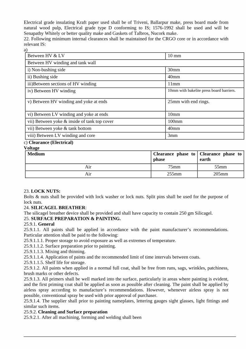
Electrical grade insulating Kraft paper used shall be of Triveni, Ballarpur make, press board made from natural wood pulp, Electrical grade type D conforming to IS; 1576-1992 shall be used and will be Senapathy Whitely or better quality make and Gaskets of Talbros, Nucork make. 22. Following minimum internal clearances shall be maintained for the CRGO core or in accordance with relevant IS: a)
Between HV & LV 10 mm Between HV winding and tank wall i) Non-bushing side 30mm ii) Bushing side 40mm iii)Between sections of HV winding 11mm iv) Between HV winding 10mm with bakelite press board barriers.
v) Between HV winding and yoke at ends 25mm with end rings.
vi) Between LV winding and yoke at ends 10mm vii) Between yoke & inside of tank top cover 100mm vii) Between yoke & tank bottom 40mm viii) Between LV winding and core 3mm
c) Clearance (Electrical) Voltage
Medium Clearance phase to phase
Clearance phase to earth
Air 75mm 55mm Air 255mm 205mm
23. LOCK NUTS: Bolts & nuts shall be provided with lock washer or lock nuts. Split pins shall be used for the purpose of lock nuts. 24. SILICAGEL BREATHER: The silicagel breather device shall be provided and shall have capacity to contain 250 gm Silicagel. 25. SURFACE PREPARATION & PAINTING. 25.9.1. General 25.9.1.1. All paints shall be applied in accordance with the paint manufacturer’s recommendations. Particular attention shall be paid to the following: 25.9.1.1.1. Proper storage to avoid exposure as well as extremes of temperature. 25.9.1.1.2. Surface preparation prior to painting. 25.9.1.1.3. Mixing and thinning. 25.9.1.1.4. Application of paints and the recommended limit of time intervals between coats. 25.9.1.1.5. Shelf life for storage. 25.9.1.2. All paints when applied in a normal full coat, shall be free from runs, sags, wrinkles, patchiness, brush marks or other defects. 25.9.1.3. All primers shall be well marked into the surface, particularly in areas where painting is evident, and the first priming coat shall be applied as soon as possible after cleaning. The paint shall be applied by airless spray according to manufacture’s recommendations. However, whenever airless spray is not possible, conventional spray be used with prior approval of purchaser. 25.9.1.4. The supplier shall prior to painting nameplates, lettering gauges sight glasses, light fittings and similar such items. 25.9.2. Cleaning and Surface preparation 25.9.2.1. After all machining, forming and welding shall been

completed, all steel work surfaces shall be thoroughly cleaned of rust, scale, welding slag or spatter and other contamination prior to any painting. 25.9.2.2. Steel surfaces shall prepared by Short blast cleaning or Chemical by Seven Tank process including Phosphating to the appropriate quality. 25.9.2.3. The pressure and volume of the compressed air supply for blast cleaning shall meet the work requirement and shall be sufficiently free from all water contamination to ensure that the cleaning process is not impaired. 25.9.2.4. Chipping, scraping and steel wire brushing using manual or power driven tools cannot remove firmly adherent mill-scale shall only be used where blast cleaning is impractical. Manufacture to explain such areas in his technical offer clearly. 25.9.3. Protective Coating: 25.9.3.1. As soon as all items have been cleaned and within four hours of the subsequent drying. They shall be given suitable anti-corrosion protection. 25.9.4. Paint Material. Followings are the types of paint that may be suitably used for the items to be painted at shop and supply of matching paint to site: 25.9.4.1. Heat resistant paint (Hot oil Proof) for inside surface. 25.9.4.2. For external surfaces one coat of Thermo Setting powder paint or 1 coats of Zinc chromate primer followed by 2 coats of Synthetic Enamel /Polyurethane base paint. These paints can be either air-drying or stoving. 25.9.4.3. The colour of the finishing coats shall be dark admiral gray conforming to No. 632 of ISS-5 of 1961 25.9.5. Painting procedure 25.9.5.1. All painting shall be carried out in conformity with both Specification and with the paint manufacture’s recommendation. All paints in anyone particular system, whether shop or site applied, shall originate from one paint manufacture. 25.9.5.2. Particular attention shall be paid to the manufacturer’s instructions on storage, mixing, thinning and pot life. The paint shall only be applied in the manner detailed by the manufacture’s e.g. brush, roller, conventional or airless spray and shall be applied under the manufacture’s recommended condition Minimum and maximum time intervals between coast shall be closely followed. 25.9.5.3. All prepared steel surfaces should be primed before visible re-rusting occurs or within 4 hours whichever is sooner. 25.9.5.4. Chemical treated steel surface shall be primed as soon as the surface is dry and while the surface is still warm. 25.9.5.5. Where the quality of film is impaired by excess film thickness (wrinkling, mud cracking or general softness) the Supplier shall remove the unsatisfactory paint coating and apply another. As a general rule, dry film thickness should not exceed the specified minimum dry film thickness by more than 25%. In all instances where two or more coats of the same paint are specified, such coating may or may not be of contrasting colours. 25.9.5.6. Paint applied to items that are not be painted shall be removed at Supplier’s expense, leaving the surface clean, unstained and undamaged. 25.9.6. Damaged Paintwork 25.9.6.1. Any damage occurring to any part of a painting scheme shall be made good to the same standard of corrosion protection and appearance as that originally employed. 25.9.7. Any damage paint work shall be made good as follows: 25.9.7.1. The damaged area, together with an area extending 25 mm around its boundary, shall be cleaned down to bare metal. 25.9.7.2. A priming coat shall be immediately applied, followed by a full paint finish equal to that originally applied and extending 50 mm around the perimeter of the original damage. 25.9.7.3. The repainted surface shall present a smooth surface. This shall be obtained by carefully chamfering the paint edges before and after priming. 25.9.8. Dry Film Thickness 25.9.8.1. To the maximum extent practicable the coats shall be applied as a continuous film of uniform thickness and free of pores. Overspray, skips, runs, sags and drips should be avoided. The different coats may or may not be of the same colour.

25.9.8.2. Each coat of paint shall be allowed to harden before the next is applied as per manufacturer’s recommendation. 25.9.8.3. Particular attention must be paid to full film thickness at edges. 25.9.8.4. The requirements for the dry film thickness (DFT) of paint and the materials to be used shall be as given below. Sr. No.
Paint Type Area to be painted No. of coats Total Dry film thickness (mm
Thermo setting paint Inside Inside outside 01
01 20 microns
60 microns
Liquid paint a) Zinc chromate (primer) b) Synthetic Enamel/ Poly Urethene (Finish coat) c) Hot oil paint/ Varnish
Outside Outside inside
01 02 01
30 microns 25 microns each 35/ 10 microns
26. RAW MATERIAL The raw material used in the manufacture of transformers shall be brand new and of the best quality available in the market. 27. TEST AND INSPECTION All tests shall be carried out in accordance with clause 16 of IS : 2026 (Part-I) amended to date or any other applicable standard for transformers. 27.1. ROUTINE TESTS All transformers shall be subject to the following routine tests at the manufacturer’s works in accordance with IS: 2026 and 1180 (Part-I):- a) Measurement of winding resistance.
b) Ratio, polarity and phase relationship. c) Measurement of impedance voltage/short circuit impedance. d) Maximum Load losses at 50% load & 100% load at 75
o C
e) No load current. f) Insulation resistance g) Induced over voltage withstand. h) Separate source voltage withstand. i) Peel off test for paint. j) Oil leakage test with pressure of 0.8 KG/CM
2 above atmospheric pressure for 10 minutes.
The losses shall be measured by three-watt meter method & three volt meter/Ammeters shall be used to
measure voltage/Current. 27.2 TYPE TESTS

The supplier shall supply copies of following type test certificates carried out at a Govt., recognized Testing House/Laboratory 27.2.1 (i) AIR PRESSURE TEST: The tank shall be fixed with a dummy cover with all fittings including bushing in position and shall be subjected to the following pressure created inside the tank. a) 0.8 kg/cm
2 above the atmospheric pressure for 30 minutes.
b) A vacuum corresponding to (-) 0.7 kg/cm2 for 10 minutes. Permanent deflection of flat plate, after
pressure has been released, shall not exceed the value given below:- Length of plate Deflection
Upto 750 mm 5mm 751 to 1250mm 6mm The oil leakage test shall be carried out on 10% of transformers in each lot. The firm shall ensure to get this test conducted strictly as per relevant ISS. (ii) TEMPERATURE RISE TEST: shall be carried out on one unit from each lot offered for inspection to ensure that it meets with the requirement specified under Clause-5 of this specification. The tenderers shall submit calculations for temperature rise along with the tender. (iv) MAGNETIC BALANCE TEST: shall be conducted by connecting the B phase (central) of LV to rated voltage and measurement of LV side (Un, Vn, Wn) voltages, Value shall be within a tolerance of (+/-) 2% (middle full & sides half). Magnetic Balance test (Type Test) should be conducted on one sample from each lot for all ratings of transformers. 27.2.2 Impulse Voltage Test; The test on all the three limbs of HT side as per clause-12 of ISS: 2026-1977 shall be got conducted in the presence of Nigam’s representative from some recognized/Govt. Test House. The dispatches shall only be allowed after successful conductance of this test, on one transformer. 27.2.3 SHORT CIRCUIT TEST: The test shall be carried out in accordance with the details specified in IS: 2026-1977 from some recognized/ Govt. Test House. Charges for routine tests and type tests including impulse voltage withstand test and short circuit test will be included in the quoted prices. The purchaser also reserves the right to get any number of additional Units type tested. However, the cost shall be paid and as such the test charges for these tests should be quoted separately. No supplies will be allowed to be dispatched without inspection by the purchaser/its representative and without carrying out the impulse and short circuit tests satisfactorily. 27.2.4 . Note: - If sample fail in any of the type tests viz. short circuit tests or impulse tests, the whole lot shall be considered rejected. The firm shall offer fresh lot for inspection and get the type tests carried out again at its own cost. 27.3 TRANSFORMER OIL: The transformer oil shall be purchased by the contractor directly from the transformer oil manufacturers
whose products have been given ISI certificate mark. The firm shall ensure to get the tests conducted strictly as per relevant ISS.
i) Net quantity of oil (up to 30o
C mark) excluding the oil soaked in core-coil assembly shall be given in G.T.P.
ii) Approximate quantity of oil soaked in core-coil assembly may however be given separately. 27.4 PHYSICAL CHECK OF VARIOUS DIMENSIONS (INTERNAL AND EXTERNAL) WEIGHT CLEARANCE ETC.

One number transformer from each lot shall be opened for checking of core weight, size and weight of HT & LT conductor, quantity of oil and various clearance etc.
27.5 INSPECTION: STAGE INSPECTION: Stage inspection may be carried out by the inspecting officers of the Nigam or its
nominated agency during the course of manufacture. The core shall be processed by slitting only which shall be carried out at the supplier’s works or can be got carried out on job order basis from other source. The core coils offered for stage inspection shall have the original sealing of CRGO manufacturer intact. Loose coils without the original seal of manufacturer shall not be accepted.
FINAL INSPECTION: The inspection shall be carried out by Nigam’s representative or any outside inspection agency to be nominated by the Nigam. All tests and inspection shall be made at the place of manufacturer unless otherwise specifically agreed upon by the manufacturer and purchaser at the time of purchase. The manufacturer shall provide all reasonable facilities to the inspectors representing the purchaser, without charges to satisfy that the material is being manufactured in accordance with the specification. The Nigam shall inspect, examine and test equipment/material through its official (s) and/or through an outside agency nominated by UHBVN/DHBVN at the Manufacturer’s/supplier’s works during or after the manufacture of goods prior to dispatch on receipt of a clear notice of minimum three weeks in advance to be reckoned from the date of receipt of call by purchaser. The supplier/contractor shall provide all facilities as may be required to carry out the tests in accordance with approved standards free of cost. The sampling of T/Fs to be offered for inspection shall be in accordance with the latest provisions of the relevant IS of latest edition for carrying out the various tests at firms works. It shall be the responsibility of the manufacturer to provide during inspection, all testing instruments duly calibrated from a Govt. Test House/Govt. approved test house within last 12 months. Before using an instrument, the Nigam’s representative shall ensure that the seal of the test house is intact and at none of the calibrated points the instrument has error more than the prescribed limits of error. Manufacturers shall maintain a complete record of the Routine tests carried out on the transformer and shall produce the same whenever desired by the purchaser. 27.5.1 The purchaser has the right to have the tests carried out at his own cost by an independent agency whenever there is any dispute regarding the quality of supply. If the transformer, fails in the test, the cost shall be borne by the supplier and if passes, the cost shall be borne by the Nigam. 27.5.2 UHBVN/DHBVN shall get all the transformers of the complete lot tested out at Nigam’s Stores
after receiving the same in the store. In case any T/f fails in tests, the same shall be replaced by the supplier at his own cost within shortest possible time not exceeding fifteen days.
27.5.3 Fake Inspection calls In case the supplier makes a fake inspection call i.e., the material is not found ready by the Inspecting
Officer deputed by the Nigam for inspection, the supplier shall be liable to pay a fixed penalty of Rs. 20, 000/- for each such fake call made by him.
28 PACKING: The transformers shall be delivered suitably packed. Although the method of packing is left to the
discretion of manufacturer but it should be robust enough for rough handling that is occasioned during transportation by Nigam.
All accessories shall be dispatched in boxes or cases. They shall be of tin, securely bound with wire and shall have all descriptive marking stamped thereon. The transportation arrangements of the transformers from the place of manufacture to the destination are also required to be such that the transformers are properly transported to the UHBVN/DHBVN stores. It will be preferable to depute one suitable technical hand to get the transformers checked in Stores before the same are taken on books and attend to those transformers which are found leaking which have developed some other defect during transportation.

29 CONTRACT DRAWINGS: Complete set of transformer drawing should be submitted alongwith the tender. Four blue prints of the general outline and assembly drawing for the transformer shall be submitted to this office within two weeks of placement of order. The drawing should give dimensions, weight, accessories, plan, front and side elevation. The dimensions, weights mentioned in the above drawing should be same as guaranteed in the tender/ offer. No negative tolerance will be allowed on dimensions/weight. 30. DEVIATIONS: - No deviation in technical particulars as per specifications shall be accepted and the offers of such bidders who do not met with UHBVN/DHBVN specifications are liable to be ignored. 31. GUARNTEED TECHNICAL PASRTICULARS The guaranteed technical particulars of the transformer shall be given by the tender (Annexure-A) along with the tender. Tenders without GTPS shall be out rightly rejected.. 33. WARRANTY: The supplier/ Contractor shall be responsible to replace free of cost with no transportation and insurance expenses to the purchaser up to the destination of material equipment, the whole or any part of material which under normal and proper use and maintenance, proves defective in material or workmanship within 78 months from the date of receipt in Nigam’s Stores or 72 months from the date of installation, whichever is earlier. Such replacement shall be effected by the Supplier/Contractor, within a reasonable time not exceeding 1 month of the intimation to defects. However, in case the supplier fails to effect replacement within stipulated period they shall be liable to pay a penalty @18% of the cost of the DTs for the remaining period of warranty of the same. 34. FASETENERS All bolts, studs, screw threads pipe threads, bolt heads and nuts shall comply with the appropriate Indian Standards for metric threads or the technical equivalent. Bolts or studs shall not be less than 6 mm in diameter except when used for small wiring terminals. 2 Nos. anti theft fasteners of steel on two diagonally opposite corners of the tank shall be provided. All nuts and pins shall be adequately locked. Wherever possible, bolts shall be fitted in such a manner that in the event of failure of locking resulting in the nuts working loose and falling off, the bolt will remain in position. All ferrous bolts, nuts and washers placed in outdoor positions shall be treated to prevent corrosion, by hot dip galvanizing, except high tensile steel bolts and spring washers which shall be electro galvanized/plated. Appropriate precautions shall be taken to prevent electrolytic action between dissimilar metals. Each bolt or stud shall project at least one thread but not more than three threads through the nut except when otherwise approved for terminal board studs or relay stems. If bolts nuts are placed so that they are inaccessible by means of ordinary spanners, special spanners shall be provided. The length of the screwed portion of the bolts shall be such that no screw thread may form part of a shear plane between members. Taper washers shall be provided where necessary. Protective washers of suitable material shall be provided front and back or the securing screws. 35. Completely Self Protected (CSP) Features additional The transformers shall have CSP (completely self protected) features. The transformer along with all fittings such as metering cubicle should be suitable for installation and operate as per H-pole drawing (enclosed as Annexure-A). The transformers shall have the following CSP features: i) Internal HV Fuse on the HT side of transformer: Specification for the HV fuse: Expulsion/any other suitable type of fuse shall be placed in series with the primary winding. The fuse shall be mounted normally inside of the primary bushing for the three phases and connected to the high voltage winding through a terminal block. This has to protect that part of the electrical distribution system which is ahead of the distribution transformers from faults which occur inside the distribution transformers i.e. either on the windings or some other part of the transformers. It shall be ensured that the fuse does not blow for faults on the secondary side (LT side) of the transformer i.e. the blowing characteristics of the fuse and LT breaker shall be so coordinated such that the fuse shall not blow for any faults on the secondary side of the transformer beyond LT breakers and those faults shall be cleared by the LT breaker only.

(ii) Internally mounted oil immersed LT breaker on the LV side of the transformer. 3 Pole LT Circuit breaker: All LT faults after the breaker shall be clear by this breaker. As such it shall be designed for perfect coordination with HT fuse link. The Bidder shall furnish the time/current characteristics of LT circuit breaker and 11 KV fuses for various current multiples. The two characteristics shall be drawn on the same sheet to indicate coordination between the circuit breaker and fuse. The Bidder shall carry out coordination test as indicated above and this forms one of the tests as for acceptance test. The breaker shall be coordinated thermally with the transformer design to follow closely the variations of coil temperature due to fluctuating load and ambient temperatures. The breaker trip setting shall be kept considering continuous loading of 130% for 6-hours duration at an average ambient temperature of 40
o C.
This is to be accomplished by connecting the breaker in series between the secondary windings and the secondary bushings. The breaker shall be located in the same oil as the core and coil assembly so that the bi-metal are sensitive to the temperature of oil as well as the load current. The Circuit breaker shall also be closed and opened manually standing on ground. The current carrying parts of breakers shall be copper plus a set of copper tungsten current interrupting contacts. The Cross section of the current carrying parts of the breakers shall withstand the full load current at a current density not more than 2.5 A/Sq.mm (for additional mechanical strength the area should be more). iii) The supplier can also offer the transformer with MCCB (Specifications attached) mounted on it instead of in-built breaker. 36. Earthing Connections Two earthing connections shall be provided with connection facilities withs 25 x 6 mm GI strip. The bolts shall be located on the lower side of the transformer and shall be of M12 size. The earthing should be suitable to carry the full fault current. Further, there should be separate earthing for the STAR point on LT side as well as on the body of the transformer. 37. FITTINGS: Each transformer shall be provided with all the required fittings as per Annexure-D. 38. PENALTY FOR NON PERFORMANCE: 38.1. Purchaser reserves the right to reject any transformer during the test at supplier’s works, if it is found that actual measured losses are more than the values quoted by the bidder 38.2. Purchaser reserves the right to reject any transformer during the test at supplier’s works, if the temperature rise exceeds the guaranteed values. 38.3. Purchaser reserves the right to reject any transformer during the test at supplier’s works, if the impedance values differ from the guaranteed values including tolerance. 38.4. Purchaser also reserves the right to retain the rejected transformer and take it into service until the Bidder replaces it with a new transformer at no extra cost. The delivery as per contract will be counted when the new transformer as per specification is provided by the manufacture. 39. PROTOTYPE TRANSFORMER The prototype transformer on which type test got conducted shall be supplied to UHBVN/ DHBVN duly sealed after completion of type testing in the beginning itself before commencement of supply. The bidder shall furnish an affidavit that all his balance transformers shall meet with prototype in all respects ( internal & external ). The Nigam can randomly select any transformer & verify the internal / external details with the prototype sample at any time during warranty period. Type test certificates for the tests carried out on prototype of same specifications shall be submitted along with the bid. The purchase may select any transformer from the offered lot for inspection during subsequent lots for carrying out temperature rise test from any Govt. approved lab. Further the purchaser may select the transformer for type tests randomly. 40. CHALLENGE CLAUSE: - "The material offered/received after the inspection by the authorized inspecting officer may again be subjected to the test for losses or any other parameter from any Testing House/in-house technique of the Nigam & the results if found deviating un-acceptable or not complying to approved GTP's the bidder shall arrange to supply the replacement within thirty (30) days of such detection at his cost including to & fro transportation." In addition to this penalty @10% of cost of the inspected lot of material shall be imposed. Director/Technical-I

UHBVN, Panchkula Director/Project,
DHBVN, Hisar CE/PD&C
UHBVN, Panchkula CE/P&D
DHBVN, Hisar
UHBVN, Panchkula FA&CAO/MM
DHBVN, Hisar SE/P&D
UHBVN, Panchkula SE/P&D
DHBVN, Hisar
ANNEXURE ‘A’ GUARANTEED TECHNICAL PARTICULARS FOR 6.3, 10, 16, 20 KVA COPPER WOUND & 40 KVA Aluminium wound CSP TYPE DISTRIBUTION TRANSFORMERS. 1. Normal continuous output under site conditions in KVA. 2. Continuous output as a percentage of Indian Standard Specifications rating. 3. Over-load capacity for 2 hours under site conditions after running continuously at full load. 4. With annual weighted ambient temp of 35
oC, maximum temperature rise of:
a) Oil by thermometer in _________
oC.
b) Winding by resistance in __________
oC.
c) Maximum hot spot in temperature in ___
oC (by calculation).
5. CORE PARTICULARS a) Thickness of laminations: b) Name of Supplier: c) Curve supplied by the manufactures of the core plate, material (Loss/Kg.) d) Core dia in mm: e) Core weight in Kg. f) Core frame size. g) No. of steps” h) Type and Grade of Core Material i) Maximum flux density at: i) Normal voltage (in tesla). ii) 12.5% over voltage (in tesla) 6. WINDING PARTICULARS a) Copper /Al., weight of HT coils (in Kg.) i) Bare. ii) Covered. b Copper/Al., weight of LT coils ( in Kg.) i) Bare. ii) Covered. c) Size of Conductor (in sq.mm) as per ISS i) HT II) LT d) Total number of turns per phase: i) HT II) LT e) Current density in Amp./Sq.mm (Max.) i) HT II) LT 7. i) No load current at 100% voltage and 50 Hz in Amps. ii) No load current 112.5% of normal voltage & frequency.

8. Maximum losses guaranteed. i) Maximum loses at 50% load in watt at 75
oC
ii) Maximum losses at 100% load in watt at 75oC.
9. Winding Resistance at 75oC (ohm/phase).
a) HV: b) LV: 10. Efficiency at 75
oC at unity P.F. and 0.8 P.F.
At unity P.F. At 0.8 P.F. Full load ¾ load ½ load ¼ load
11. Load at which maximum efficiency occurs: 12. Reactance at full load: 13. Impedance at full load at 75
oC
14. Regulations: a) Full load at unit power factor.
b) Full load 0.8 power factor lagging. 15. Minimum inter clearance a) Between HV & LV b) Between HV winding & tank wall. i) Non-bushing side ii) Bushing side. c) Between section of HV winding
d) Between HV winding e) Between HV winding & yoke ( at ends) f) Between LV winding & yoke (at ends) g) Between yoke and inside of tank top cover h) Between yoke & tank bottom i) Between LV winding & Core
16. Internal Insulation a) Turn insulation High voltage. b) Turn insulation low voltage. c) Insulation core to low voltage: d) Interlayer insulation of HV & LV Coils: e) type of insulation used for HV & LV windings. f) (Angle shaped/plain end rings made from pre-compressed board shall be used between the end coils and the core) 17. Dry flash over voltage at 50 cycles of HT & LT bushings in KV. 18. Wet flashover voltage at 50 cycles of HT Bushings.

19. Impulse flash over voltage with 1.2/50 positive wave of HT bushings in KV.
a) One minute dry withstand power frequency voltage in KV.
b) One minute withstand power frequency voltage. c) Puncture voltage of HT bushings at Power frequency in KV. 20 Impulse withstand voltage of T/fs windings.
a) with 1.2/50 positive wave KV: b) with 1.2/50 Negative wave KV: 21. Spark over length of HT bushings (i.e. string length MM). 22. HT pressure test (separate sources of HT windings 50 cycles for one minute. 23. Quantity of oil in transformers. 24. Weight of complete T/fs with oil: 25. Tank thickness sides C:\Documents and Settings\Administrator\Desktop\28-01-10\PDC\CSC -IV.doc Page 23 of 27 26. Tank thickness of top and bottom: 27. Weight of tanks fittings and accessories. 28. Approx. dimensions (Lx B x H) in mm: i) Overall ii) Inside of tank iii) Max. depth of HT coils (in cms) iv) Radial width of oil duct between LT & HT v) Standard reference of bushings vi) Type of transformer, shell or core vii) Standard reference of transformers
viii) Vector group of connections ix) Current density of HT delta wire Note: Above approved GTPs shall be applicable up to Type Tests/First Lot. For subsequent
supplies, all parameters as per First Lot shall be maintained. But in no case any parameter less than GTPs shall be accepted in First Lot. In case any type tests are waived off, then all technical parameters & dimensions shall be as per type tested Transformers and no negative variation shall be accepted.
. ANNEXURE ‘B’ GUARANTEED CHARACTERISTICS OF NEW TRANSFORMER OIL IN DRUMS/TANKERS AND IN TRANSFORMERS A. OIL IN DRUMS/TANKERS S.No.
Characteristics Requirement Appearance
Oil shall be clear & transparent & free from suspended matter or sediments.
Density at 29.5
oC (Max.)
0.89 g/cm2

Kinematics viscosity at 27
oC (Min.)
27CST
Interfacial tension at 27
oC (min.)
0.04 N/M
Flash point (Min.)
140oC
Pour point (Max.)
-6oC
Neutralization value
a) Total acidity (Max.) b) In organic acidity
0.03 mg KOH/gm Nil
Corrosive sulphur
Non-corrosive
Electric strength (Break down voltage) Min.
a) New untreated oil: If the above value is not obtained the oil shall be treated. b) After treatment. a) 30 KV (rms)
b) 60 KV (rms)
Dielectric dissipation factor (Tan-delta) at 90
oC
0.002 (Max.)
Water content )Max.)
50 ppm
Specific resistance (resistivity)
a) At 90oC (Min.)
b) At 27oC (Min.)
a) 35x1012
ohm-cm b) 900 x10
12 ohm-cm
Oxidation stability
a)Neutralization value after oxidation (max.) b)Total sludge after oxidation (Max.)
0.40 mg KOH/gm 0.10% by weight
Ageing characteristics after accelerated ageing (open breaker method with copper catalyst)
a) Specific resistance (Resistivity) i) At 27
oC Min.)
ii) At 90oC (Min.)
b) Dielectric dissipation factor (Tan delta) at 90
oC
c) Total acidity (Max.) d) Total sludge value percent by weight
2.5 x 10¹²
ohm-cm 0.2 x 10
12 ohm-cm
0.2 Max. 0.05 mg KOH/gm 0.05 Max.
Presence of oxidation inhibitor
Absent

B. CHARACTERSTICS OF OIL IN THE TRANSFORMERS The important characteristics of the transformer oil after it is filled in the transformer (within 3 months of filling) shall be as follows:- Sr No
Characteristics Permissible limit satisfactory for use
Electric Strength (Breakdown voltage KV) Prior to energisation 50 KV minimum
Water content (PPM) 25 PPM (max.)
Specific Resistance (Resistivity) ohm-cm at 90oC 2X10
12 ohm-Cm (Min)
Dielectric dissipation factor tan delta) at 90oC 0.01 (Max)
Neutralization value (Total acidity) 0.055 mg. KOH/gm (Max)
Sediment and/or perceptible sludge Absent
Flash point 140oC (Min)
Interfacial tension at 27oC 0.030 N/m(Min).
SOURCE OF MATERIAL INSPECTION ETC. S. No
Item Source of Material
Place of manufacture
Place of testing and inspection
Copper Aluminium Core laminations Transformer Oil ERW Tubes. Steel Sheets Bushings a) Porcelain HV b) Epoxy LV
Insulating Cylinders Insulating Paper. Corrugated Cylinders.
PLACE: SIGNATURE OF TENDER DATE: NAME: DESIGNATION

ANNEXURE ‘D’
FITTINGS AND ACESSORIES FOR 6.3, 10, 16, 20 & 40 KVA TRANSFORMERS (i) 3 no. 11 KV porcelain bushings with brass studs fitted with single gap arcing horns along with bi metallic connectors/thimbles.
(ii) 4 no. 0.433 KV porcelain bushings with brass studs (neutral to be made available on LV side) / thimbles.
(iii) Drain cum sampling valve made of steel welded to tank as per drawing. (iv) One set of lifting lugs. (v) Rating & diagram plate of brass containing details as provided in IS:2026 and
also “Property of UHBVN/DHBVN” shall be engraved in bold letters. vi) 4-Star rating label in accordance with colour design, logo etc., shall be
provided on the transformer, as per the design / recommendations of Bureau of efficiency (BEE Note: Actual Losses at 50% & 100% Load should also be marked.
vii) Two earthing terminals, one on either side of the base. (Details as per clause 36)
viii) Air release valve arrangement. ix) ERW elliptical tube radiators of minimum thickness of 18 SWG. x) Oil level gauge indicating three positions of oil marked as under:- Minimum (-) 0.5
o C
30o C
Maximum 95oc
xi) Thermometer pocket to be suitably plugged with a threaded cap. xii) Base Channel. xiii) UHBVN/DHBVN logo shall be embossed on the side of the tank. .NOTES
i) The bushing rods, bushings cap washers & bushings nuts etc, should be made of brass. ii) The threading on the nuts and bushings rods should be of one uniform specification.

iii) All MS fittings & fasteners etc. may preferably be elctro-galvanzied. iv) The special tools for operating the valves shall be supplied with the transformer. iv) To ensure that transformer is not opened by UHBVN/DHBVN field staff during warranty period, 6 No. suitable clamps shall be welded with top cover & tank body as well as drain wall flange after the transformer has been inspected and sealed by UHBVN/DHBVN inspecting officer. However, the arrangement shall be got approved by the supplier from UHBVN/DHBVN before commencement of supplies.
v) TEST REQUIREMENTS FOR CONNECTORS
Technical features HT LT Rated normal current rating 50 Amps. 200 Amps. Short time current rating (Amps for 1Sec) 3000 3000
Tensile Strength 110 kg 110 kg Resistance test: The resistance of 1.25 meter of conductor including the connector shall not exceed the resistance of 1.25 meter of identical conductor without connector by more than 10%.
Temperature rise test: The steady state temperature rise of connector above the reference ambient temperature of 40
oC when carrying rated current, shall not exceed 45
oC
VI) TYPE TESTS
ACCEPTANCE TESTS ROUTINE TESTS a) Tensile test a) Visual examination b) Resistance test b) Dimensional check c) Temperature rise test d) Dimensional check
NOTE: 1. Permissible tolerance shall be (+) 5% on the dimensions indicated. 2. The minimum clearance between phase to phase shall be 25mm and phase to earth 20mm when
the connectors are fixed in position on the terminal block of MOCB on the HT side.
.3 All the above tests shall be carried out in accordance with IS: 5561, latest version.
4. Supplier of the transformer/connector shall provide necessary testing facilities at his works for the acceptance tests.