U.P. JAL NIGAM - AWS
294
1 U.P. JAL NIGAM OFFICE OF THE SUPERINTENDING ENGINEER XVIII CIRCLE,U.P. JAL NIGAM, GHAZIABAD SECTEOR-1, OPP- NEW GHAZIABAD RAILWAY STATION, RAJNAGAR GHAZIABAD-201002 E-TENDER DOCUMENT PART - I Technical & Financial Evaluation - cum - Technical Bid (PRE - QUALIFICATION BID) NAME OF WORK : HAPUR SEWERAGE SCHEME PART-1, PHASE-II IN THE CITY OF HAPUR Under ATAL MISSION FOR REJUVENATION AND URBAN TRANSFORMATION YEAR – 2018-19 SUPERINTENDING ENGINEER XVIII CIRCLE, U.P. JAL NIGAM, GHAZIABAD
-
Upload
khangminh22 -
Category
Documents
-
view
1 -
download
0
Transcript of U.P. JAL NIGAM - AWS

1
U.P. JAL NIGAM
OFFICE OF THE SUPERINTENDING ENGINEER XVIII CIRCLE,U.P. JAL NIGAM, GHAZIABAD
SECTEOR-1, OPP- NEW GHAZIABAD RAILWAY STATION, RAJNAGAR GHAZIABAD-201002
E-TENDER DOCUMENT
PART - I
Technical & Financial Evaluation - cum - Technical Bid
(PRE - QUALIFICATION BID)
NAME OF WORK : HAPUR SEWERAGE SCHEME PART-1, PHASE-II IN THE CITY OF HAPUR
Under
ATAL MISSION FOR REJUVENATION AND URBAN TRANSFORMATION
YEAR – 2018-19 SUPERINTENDING ENGINEER
XVIII CIRCLE, U.P. JAL NIGAM, GHAZIABAD

2
OFFICE OF THE SUPERINTENDING ENGINEER XVIII CIRCLE,U.P. JAL NIGAM, GHAZIABAD
SECTEOR-1 OPP- NEW GHAZIABAD RAILWAY STATION, RAJNAGAR GHAZIABAD-201002
E-TENDER DOCUMENT
VOLUME - I Technical & Financial Capability Evaluation - cum
Technical Bid
(PRE - QUALIFICATION BID) NAME OF WORK: HAPUR SEWERAGE SCHEME PART-1, PHASE-II
IN THE CITY OF HAPUR Cost of Tender Document (Tender fee) : 20000.00+GST (as applicable on date of submission) Earnest Money : 41.70 Lacs Time of Completion : TWENTY FOUR Months Trial run period : FOUR Months Defects liability period : 12 months after actual date of completion Validity of Bid (Tender) : 120 Days
E-TENDER SCHEDULE Date & time of Release of E-Tender for download from E-Tendering portal (website)/Bid submission start date & time
: 06/07/2018 by 03:00 P.M.
Last date/time of submission of E-Bid on E-Tendering portal (website).
: 16/07/2018 till 11:00 A.M.
Last date/time of submission of e-tender fee through RTGS to Union Bank of India, IFSC Code - UBIN0555665, Account No.- 556602010002108.
: 16/07/2018 till 11:00 A.M.
Date/time of opening Pre-qualification part through E-Tender procurement solution
: 16/07/2018 03:00 P.M. onwards
Date/time of opening Price Bid through E-Tender procurement solution
: This information shall be displayed on the website after three working days of opening of prequalification bid.
Place of submission of original Reciept of RTGS, cost of EMD & tender document. Place of opening of Pre-qualification Bids
: Office of the SUPERINTENDING ENGINEER XVIII- CIRCLE,U.P. JAL NIGAM, GHAZIABAD,SECTEOR-1 OPP- NEW GHAZIABAD RAILWAY STATION, RAJNAGAR GHAZIABAD-201002

3
OFFICE OF THE SUPERINTENDING ENGINEER XVIII CIRCLE, U.P. JAL NIGAM, GHAZIABAD
SECTEOR-1, OPP- NEW GHAZIABAD RAILWAY STATION, RAJNAGAR GHAZIABAD-201002
NAME OF WORK: HAPUR SEWERAGE SCHEME PART-1, PHASE-II IN THE CITY OF HAPUR
PART - I Technical & Financial Evaluation - cum - Technical Bid
(PRE-QUALIFICATION BID)
Table of Index
SI. No. Contents Page No.
1. Tender Notice 05-08
2. Project Background and scope of work 09-38
3. Instructions to Bidder 38-47
4. List of Documents to be Submitted Offline 47-48
5. Eligibility Criteria 48-53
6. Letter of Application 54-55
7. General Information of Bidders (Format-1) 56
8. Organizational Structure (Format-2) 57
9. General Experience Record (Format-3) 58
10. Particular Experience Record (Format-4) 59
11. Abstract of Contracts of Similar Nature and Complexity (Format-4A) 60
12. Summary Sheet: Current Contract Commitments/Works in Progress (Format-4B)
61
13. Performance Certificate 62
14. Personal Capability (Format-5A) 63
15. Candidate Summary (Format-5B) 64

4
16. Equipment Capability (Format-6) 65
17. Financial Capability (Format-7) 66
19. Tender Submitted but not awarded (Format-9) 68
20. Litigation History (Format-10) 69
21. ’kiFk&i== (Format-11) 70-71
22. Solvency Certificate (Format-12) 72
23. Manufacturer’s Authorization (Format-13) 73
24. Check List (Format-14) 74
25. Condition Of Contract Vol-II 75
26. Instructions to bidders 76-77
27. Definitions and interpretations 78-79
28. General rules and guide lines 80-97
29. Payments 98-114
30. Procedure for arbitration 114-116
31. General Instructions 116-119
32. Site office, computer, operator and vehicle 119-120
33. Design & drawings 121-129
34. Site information 130-133
35. Specifications 134-294

5

6

7

8

9
SECTION – II
PROJECT BACKGROUND
Hapur Town said to be founded in 10th century, is headquarter of Hapur district which was created in 2011, Hapur district is one of eight districts of Western U.P that for the U.P sub-region of National capital Region(NCR). Geographically it is situated at 28. 44N Latitude and 77.47E Longitude. The town is located about 54 kilometres east of New Delhi and 432 km from the state capital, Lucknow,National Highway 24,connecting Delhi-Lucknow and National Highway 235, connecting Meerut-Bulandshahr pass through the town. It is also served by Delhi-Lucknow-Howrah and Meerut-Khurja railway lines which intersect at Hapur junction of Northern Railway. Hapur is an important centre for trade and commerce in western UP subregion. Big mandi of grains,gur,and potato , six silos of grains owned by the Ministry of Food and agriculture of GOI, Small to medium manufacturing industries, cold storages and many educational institutions exist in the town .Electricity and telecommunication services are adequately available to the town.
1. SCOPE OF WORK 1. Design, testing and commissioning for construction of 1 No. IPS-3 (10.56 MLD Avg., 6 m dia, 10.24 m depth) including labour, materials, Electrical/Mechanical works for 1600 mm dia incomming sewer etc complete with all respects. 2. Survey, reverification of design, testing and commissioning of sewer network, Laying of 42.724 km (200 mm to 1800 mm dia) sewer network and its reinstatement of roads , & sewer connecting chamber-2247 nos., House connections-4493 nos and appurtenant works including all labour, materials , T&P etc complete. Scope of work at Hapur town also includes “Survey, Soil Testing, Design, Supply & Construction, reinstatement of roads, installation,commissioning at Hapur including Other Appurtenant Work Including Testing Trial Run, Defect Liability Period, Five Year Maintenance & Handing over Completed Works to Nagar Palika Parishad, Hapur with all Appurtenant Works” on turn-key basis. Total contract period is 24 month which includes 18 months for construction activities, 2 months commissioning & 4 months for trial run. In addition to this, 12 months for defect liability period including 5 years of operation & maintenance and monitoring as per Performance guarantee.. During this period electricity charges will be borne by the department and the bidder will provide all other consumable materials, repair / replacement of equipments & machineries and required staff for Operation & maintenance. The contractor shall carry out all the items of work required for the successful completion of the work, mentioned in the price schedule as a contract. All tools, tackles, machinery, manpower and all consumables, materials, equipment, machineries, instruments, accessories, Electricity, Water skilled and unskilled manpower and all safety indication devices etc. are to be arranged by the contractor for full completion of work. Although contractor shall be actively involved in getting the permissions power connection at Sewage Treatment Plant but power connection charges shall be paid by the nagar palika Hapur. Bidder should also be providing 2 nos. four wheeled and 2 pc with 2 data entry operator to officers of construction division , UP Jal nigam Bulandshahr for proper supervision of works till handing of scheme to nagar palika Scope of work shall include but not limited to the following: - 1. Detailed survey, Investigation & concise collection of all type of field data, cleaning of site, soil

10
characteristics, survey of underground utilities etc around site of work at District Hapur. 2. Preparation and submission of detailed engineering design and drawings of all the works given in price
schedule of the tender. 3. Execution of the following works
1.1 (A) Scope of work for IPS a. Brief Description of work : “Survey, Investigation including soil testing up to required depth,
Design, Construction of Sewage Pumping Station and tapping arrangement of Intermediate
Pumping station at Hapur with supply & installation, Fabrication/Erection work of pumping
plants, electrical machines & equipments and other appurtenant works (Civil ) including Testing,
Commissioning performance Trial run for 4 months with Operation & Maintenance 12 months for
defect liabilities all complete. The details of measurement of civil components of IPS-3 include
following.
i) Pumping Station (Sump well) Item of work Qty. Unit
Earth work in excavation in ordinary soil in all type of foundation trenches including dressing of the side and ramming of bottoms lift upto 1.5 m including getting out the excavated earth and disposal of surplus excavated earth as directed within a lead of 50 m. 0.0 -1.50 M BGL 244.95 cum 1.50 - 3.00 M BGL 116.69 cum 3.00 - 4.50 M BGL 84.34 cum 4.500 - 6.00 M BGL 23.02 cum Structural steel work riveted, bolted or welded in built up sections, trusses and framed work, including cutting, hoisting, fixing in position and applying a priming coat of approved steel primer all complete. Supply of MS well shoe fabricated with ISA 200 x 200 x 15 mm and 500 x 15 mm MS plate. Weight per R/M ISA 200 x 200 x 15 mm 45.40 Kg/m Plate 500 x 15 mm 58.88 Kg/m Total Weight ISA 200 x 200 x 15 mm 1453.71 kg Plate 500 x 15 mm 1885.34 kg 3443.33 Kg Centering and shuttering including strutting, propping etc. and removal of form for : Well steining Well Curb 51.09
29.05 Well wall, 1.00m thick 141.11
100.79 Well wall, 0.80m thick 119.16
90.28 531.48 sqm Extra for shuttering in circular work (20% of respective centering and shuttering items) 106.30 sqm Suspended floors, roofs, landings, balconies and accessplatform Slab S1 Circular 21.10 5.28 Slab S2 19.20 0.96

11
0.58 47.12 sqm Extra for shuttering in circular work (20% of respective centering and shuttering items) 9.42 sqm Lintels, beams, plinth beams, girders, bressumers and cantilevers Beam B1 Bottom 3.60 Sides 16.80 0.84 Beam B2 Bottom 3.60 Sides 3.60 0.36 Beam B 2.25 6.00 0.54 2.25 6.00 0.54 S2 14.40 1.44 0.58 Column C 21.60 84.40 sqm Providing and laying in position machine batched and machine mixed design mix M-30 grade cement concrete for reinforced cement concrete work, using cement content as per approved design mix, including pumping of concrete to site of laying but excluding the cost of centering, shuttering, finishing and reinforcement, including admixtures in recommended proportions as per IS: 9103 to accelerate, retard setting of concrete, improve workability without impairing strength and durability as per direction of Engineer-in-charge.All works upto plinth level In well stening 121.06 83.85 In well curb 70.18 275.09 cum Extra for providing richer mixes at all floor levels, Providing M-30 grade concrete instead of M-25 grade BMC/ RMC 275.09 cum Providing and laying in position 1:2:4 (1 cement : 2 coarse sand : 4 graded stone aggregate 20 mm nominal size) cement concrete of specified grade excluding the cost of centering and shuttering - All work up to plinth level : In Domical plug V = 3.142 h2 ( R - h /3) 98.67 -13.91 84.76 cum Plum concrete with 150 mm size stone boulder @ 40% and 60% PCC with 2 cm size stone aggregates in 1:2:4 proportion. 32.19 20.08 52.27 cum 40% Boulder, Supplying, filling, spreading & leveling stone boulders of size range 5 cm to 20 cm, in recharge pit, in the required thickness, for all leads & lifts, all complete as 20.91 cum

12
per direction of Engineer-in-charge. 60% P.C.C, Providing and laying cement concrete in retaining walls, return walls, walls (any thickness) including attached pilasters, columns, piers, abutments, pillars, posts, struts, buttresses, string or lacing courses, parapets, coping, bed blocks, anchor blocks, plain window sills, fillets, sunken floor,etc., up to floor five level, excluding the cost of centering, shuttering and finishing :1:2:4 (1 Cement : 2 coarse sand : 4 graded stone aggregate 20mm nominal size) 31.36 cum Providing and laying in position machine batched and machine mixed design mix M-30 grade cement concrete for reinforced cement concrete work, using cement content as per approved design mix, including pumping of concrete to site of laying but excluding the cost of centering, shuttering, finishing and reinforcement, including admixtures in recommended proportions as per IS: 9103 to accelerate, retard setting of concrete, improve workability without impairing strength and durability as per direction of Engineer-in-charge. All works upto plinth level in base floor. 11.78 in Beam B1. 2.52 in Beam B2 0.54 in Column C 1.62 in Beam B 1.89 in slab S1 1.35 in slab S2 3.13 1.73 24.56 Deduction 0.86 23.70 cum Extra for providing richer mixes at all floor levels, Providing M-30 grade concrete instead of M-25 grade BMC/ RMC 23.70 cum Structural steel work in single section, fixed with or without connecting plate, including cutting, hoisting, fixing in position and applying a priming coat of approved steel primer all complete. Supply hoisting and flixing in position ISMB 500 weighing 86.9 Kg/M 524.00 Plate 200 x 200 x 10 mm 125.60 Nut bolts 310 mm long and 25 mm dia. 251.20 900.80 cum Sinking of well stening below spring level including supply errection and working of all plants required as well as loading and unloading of weight and bailing and pumping out of water with machinery or other wise as required and disposal of surplus each up to distance of 50 M. 0.0 - 1.5 M 1.50 M 1.5 - 3.0 M 1.50 M 3.0 - 6.0 M 3.00 M 6.0 - 9.0 M 2.68 M Total 8.68 Finishing with Epoxy paint (two or more coats), On concrete work at all locations prepared and applied as per manufacturer's specifications including appropriate priming coat, preparation of surface, etc. complete. In floor 19.63 In wall 62.86 82.49 sqm Finishing with Epoxy paint (two or more coats) on outer faces of sump wall up to sub soil water level from base floor, applied as per manufacturer's specifications including appropriate priming coat, preparation of surface, etc. complete. 317.45 sqm Mild steel or iron work in plain work such as RCC or RB work wrought to required 28146.02 Kg

13
shape necessary including its cutting and bending including supply of steel and its wastage @ 1.2%. Supply and mixing of water proofing and quick setting compound of approved quaility (PWD meterial item No. 28 of year 2004) in concrete for base raft, walls, columns etc involved upto GL, 496.44 m3 @ 8 bag / m3 = 3971.52 Bags, compound @ 3 % by weight. 3634.20 Kg Supply and fixing of 1 meter high railing fabricated with three rows of 32 mm dia heavy duty GI pipe and 50 x 50 x 6 mm size angle iron post @ 2.40 m c/c. 28.88 10.00 38.88 M Providing M.S. staircase in side sump supply of steel structure member and its fabrication including providing and painting solvent free apoxy over MS surface in 400 micron thickness. 12.00 M Dewatering by employing D.G. sets, monoblock pumps cable, fuel, operator, maintenance of plants and equipment, etc. and providing dry condition during excavation, laying of base concrete, raft walls, columns etc, as per details enclosed. 30.00 Days
ii) Screening Channel Earth work in excavation in ordinary soil in all type of foundation trenches including dressing of the side and ramming of bottoms lift upto 1.5 m including getting out the excavated earth and disposal of surplus excavated earth as directed within a lead of 50 m.
Inlet Chamber & Screen Channel to 1.50 M BGL 583.24 cum to 3.00 M BGL 457.69 cum to 4.50 M BGL 347.33 cum to 6.00 M BGL 252.15 cum to 7.50 M BGL 172.16 cum to 9.00 M BGL 107.36 cum to 10.50 M BGL 32.43 cum to 12.00 M BGL 31.55 cum
Total 1983.91 Providing and laying in position cement concrete of 1:4:8 (1 Cement : 4 coarse sand : 8 graded stone aggregate 40 mm nominal size) excluding the cost of centering and shuttering - All work up to plinth level
In floor of :- Inlet Chamber & Screen Channel 2.57 Stair 3.39
Total 5.96 Cum Centering and shuttering including strutting, propping etc. and removal of form for : In Base floor, Above 20 cm wide Edges of slabs and breaks in floors and walls :- Inlet Chamber & Screen Channel 10.14 2.86 Stair 10.14 3.77
Total 26.91 Sqm Walls (any thickness) including attached pilasters, butteresses, plinth and string courses etc. In screen channel 60.93 21.50 6.80

14
99.46 69.89
Partition wall 11.70 Slab 3.70
Sides 0.74 0.40
Stair case 55.49 39.17 91.39 29.38
Total 490.55 Sqm Stairs, (excluding landings) except spiral-staircases
In Flights 10.40 1.56
In Steps 5.95 In Flights 4.20
0.63 In Steps 2.41 Landing 6.30
2.89 Total 34.34 Sqm
Providing and laying in position machine batched and machine mixed design mix M-30 grade cement concrete for reinforced cement concrete work, using cement content as per approved design mix, including pumping of concrete to site of laying but excluding the cost of centering, shuttering, finishing and reinforcement, including admixtures in recommended proportions as per IS: 9103 to accelerate, retard setting of concrete, improve workability without impairing strength and durability as per direction of Engineer-in-charge.All works upto plinth level
In Base floor Inlet Chamber & Screen Channel 8.58 Stair 11.31 In Walls In screen channel 36.56 31.18 29.84
Partition wall 1.46 Slab 0.56
Stair case 33.29 19.58 In stair case
In Flights 1.56 In Steps 0.74
In Flights 0.63 In Steps 0.28 Landing 0.95
Total 176.52 cum Extra for providing richer mixes at all floor levels, Providing M-30 grade concrete instead of M-25 grade BMC/ RMC 176.52 cum Mild steel or iron work in plain work such as RCC or RB work wrought to required shape necessary including its cutting and bending including supply of steel and its wastage @ 1.2%.
16628.18 Kg

15
Supply and fixing of 1 meter high railing fabricated with three rows of 32 mm dia heavy duty GI pipe and 50 x 50 x 6 mm size angle iron post @ 2.40 m c/c. 13.60 7.20
Total 20.80 M Providing M.S. staircase in side sump supply of steel structure member and its fabrication including providing and painting solvent free apoxy over MS surface in 400 micron thickness. 12.00 M Earth filling arround structure in stages including watering and compaction as per instruction of Engineer-in-charge. Earth work in excavation 1983.91 Deduction R.C.C -197.72
Total 1786.19 cum Dewatering by employing D.G. sets, monoblock pumps cable, fuel, operator, maintenance of plants and equipment, etc. and providing dry condition during excavation, laying of base concrete, raft walls, columns etc, as per details enclosed. 30.00 Days
iii) Common Header & Valve Chamber Item of work Qty. Unit
Earth work in excavation in ordinary soil in all type of foundation trenches including dressing of the side and ramming of bottoms lift upto 1.5 m including getting out the excavated earth and disposal of surplus excavated earth as directed within a lead of 50 m. Common Header & Valve Chamber to 1.50 M BGL 337.42 cum to 3.00 M BGL 843.36 cum 1180.78 Providing and laying in position cement concrete of 1:4:8 (1 Cement : 4 coarse sand : 8 graded stone aggregate 40 mm nominal size) excluding the cost of centering and shuttering - All work up to plinth level In floor of :- Common Header & Valve Chamber 3.68 Cum Centering and shuttering including strutting, propping etc. and removal of form for : In Base floor, Above 20 cm wide Edges of slabs and breaks in floors and walls :- Common Header & Valve Chamber 9.10 4.55 13.65 Sqm Walls (any thickness) including attached pilasters, butteresses, plinth and string courses etc. Common Header & Valve Chamber 123.72 51.55 113.41 41.24 329.92 Sqm Providing and laying in position machine batched and machine mixed design mix M-30 grade cement concrete for reinforced cement concrete work, using cement content as per approved design mix, including pumping of concrete to site of laying but excluding the cost of centering, shuttering, finishing and reinforcement, including admixtures in recommended proportions as per IS: 9103 to accelerate, retard setting of concrete, improve workability without impairing strength and durability as per direction of Engineer-in-charge.All works upto plinth level In Base floor Common Header & Valve Chamber 12.25 In Walls

16
Common Header & Valve Chamber 30.93 10.31
53.49 cum Extra for providing richer mixes at all floor levels, Providing M-30 grade concrete instead of M-25 grade BMC/ RMC 53.49 cum Mild steel or iron work in plain work such as RCC or RB work wrought to required shape necessary including its cutting and bending including supply of steel and its wastage @ 2%. 5038.76 Kg Providing M.S. staircase in side sump supply of steel structure member and its fabrication including providing and painting solvent free apoxy over MS surface in 400 micron thickness. 5.00 M
iv) Rising Main Item of work Qty. Unit
Earth work in excavation in ordinary soil in trench including dressing of the side and ramming of bottom including getting out the excavated earth and disposal of surplus excavated earth within a lead of 50 m. 784.00 Cum Providing 600 mm dia S&S Centrifugally Cast (Spun) / Ductile Iron Pipes Class K-7 conforming to IS : 8329 with laying for Rising Main. 560.00 M Providing D.I. Specials(Specials such as bends, tail pieces etc.) suitable for mechanical jointing & Fixing of specials such as bends etc. Back filling of earth in trenches in layers not exceeding 20cm. in depth consolidating each deposited layer by ramming and watering. 713.63 Cum Cutting road and making good the same including supply of extra quantities of materials i.e. aggregate, moorum screening, red bajri and labour required. Bituminous portion. 560.00 Cum Providing and fixing 100 mm N.B. C.I. double acting air valve rating PN 1.0 of approved quality with bolts, nuts, rubber insertions etc. complete. 3.00 Each Providing and laying cement concrete 1:2:4 (1 Cement : 2 coarse sand : 4 graded stone aggregate 20 mm nominal size) in bed/anchor (Thrust) blocks up to floor five level, excluding the cost of centering, shuttering and finishing 25.92 Cum Centering and shuttering including strutting, propping etc. and removal of form work for above Item. 77.76 Sqm
v) Master Man hole and Sewer connection
Item of work Qty. Unit Earth work in excavation in ordinary soil in all type of foundation trenches including dressing of the side and ramming of bottoms lift upto 1.5 m including getting out the excavated soil and disposal of surplus excavateed soil as directed within a lead of 50 m. 0.00 - 1.50 M BGL 148.50 cum 1.50 - 3.00 M BGL 126.00 cum 3.00 - 4.50 M BGL 103.50 cum 4.50 - 6.00 M BGL 81.00 cum 6.00 - 7.50 M BGL 113.69 cum Close timbering in trenches including strutting, shoring and packing cavities (wherever required) complete. (Measurements to be taken of the face area timbered). Depth not exceeding 1.5 m 45.00 Sqm Depth exceeding 1.5 m but not exceeding 3 m 45.00 Sqm Depth exceeding 3 m but not exceeding 4.5 m 45.00 Sqm Providing and laying in position cement concrete of specified grade excluding the cost of centering and shuttering - All work up to plinth level : 1:2:4 (1 cement : 2 coarse sand : 4 graded stone aggregate 20 mm nominal size) 20.83 cum Supply of 600 mm dia ISI marked R.C.C s/s N.P - 3 spun pipe with rubber gasket 40.00 M
17
including all taxes and duties for site. Laying of NP - 3 R.C.C s/s spun pipe true to alignment and gradient and jointing with rubber gasket. 40.00 M Constructing brick masonry circular manhole 1.80 m internal dia. 1.00 each Earth filling arround structure in stages including watering and compaction as per instruction of Engineer-in-charge. Earth work in excavation 572.69 Deduction R.C.C -49.32 523.36 cum Dewatering by employing D.G. sets, monoblock pumps cable, fuel, operator, maintenance of plants and equipment, etc. and providing dry condition during excavation, laying of base concrete, raft walls, columns etc, as per details enclosed. 15.00 Days
vi) Bye - Pass Sewer Item of work Qty. Unit
Earth work in excavation in ordinary soil in all type of foundation trenches including dressing of the side and ramming of bottoms lift upto 1.5 m including getting out the excavated soil and disposal of surplus excavateed soil as directed within a lead of 50 m.
0.00 - 1.50 M BGL 472.50 cum 1.5m-3.00m BGL 323.95 cum Open timbering in trenches including strutting and shoring complete (measurements to be taken of the face area timbered):
Depth not exceeding 1.5 m 225.00 Sqm Depth exceeding 1.5 m but not exceeding 3 m 202.47 Sqm Providing and laying in position cement concrete of specified grade excluding the cost of centering and shuttering - All work up to plinth level : 1:2:4 (1 cement : 2 coarse sand : 4 graded stone aggregate 20 mm nominal size) 78.20 cum Supply of 600 mm dia ISI marked R.C.C s/s N.P - 3 spun pipe with rubber gasket including all taxes and duties for site. 120.00 No. Laying of NP - 3 R.C.C s/s spun pipe true to alignment and gradient and jointing with rubber gasket. 120.00 M Constructing brick masonry circular manhole 1.52 m internal dia at bottom and 0.56 m dia at top in cement mortar 1:4 (1 cement : 4 coarse sand) inside cement plaster 12 mm thick with cement mortar1:3 (1 cement : 3 coarse sand) finished with a floating coat of neat cement, foundation concrete 1:3:6 (1 cement : 3 coarse sand : 6 graded stone aggregate 40 mm nominal size) and making necessary channel in cement concrete 1:2:4 (1 cement : 2 coarse sand : 4 graded stone aggregate 20 mm nominal size) finished with a floating coat of neat cement, all complete as per standard design :2.30 m deep with SFRC Cover and frame (heavy duty HD-20 grade designation) 560 mm internal diameter conforming to I.S. 2592, total weight of cover and frame to be not less than 182 kg. fixed in cement concrete 1:2:4 (1 cement: 2 coarse sand : 4 graded stone aggregate 20 mm nominal size) including centering, shuttering all complete. (Excavation, foot rests and 12 mm thick cement plaster at the external surface shall be paid for separately) :
With common burnt clay F.P.S. (non modular) bricks of class designation 7.5
2.00 each Extra depth for circular type manhole 1.52 m internal dia (at bottom) beyond 2.30 m.
1.40 M Earth filling arround structure in stages including watering and compaction as per instruction of Engineer-in-charge. Earth work in excavation 796.45

18
Deduction R.C.C -192.18 604.26 cum Cutting road and making good the same including supply of extra quantities of materials i.e. aggregate, moorum screening, red bajri and labour required. Bituminous portion.
60.00 Cum Demolishing brick work manually/ by mechanical means including stacking of serviceable material and disposal of unserviceable material within 50 metres lead as per direction of Engineer-in-charge.In cement mortar
6.90 cum Demolishing cement concrete manually/ by mechanical means including disposal of material within 50 metres lead as per direction of Engineer - in - charge. Nominal concrete 1:3:6 or richer mix (i/c equivalent design mix) 2.25 cum Brick work with common burnt clay F.P.S. (non modular) bricks of class designation 7.5 in superstructure above plinth level up to floor V level in all shapes and sizes in Cement mortar 1:6 (1 cement : 6 coarse sand)
6.90 Cum Providing and laying in position cement concrete of specified grade excluding the cost of centering and shuttering - All work up to plinth level : 1:3:6 (1 Cement : 3 coarse sand : 6 graded stone aggregate 20 mm nominal size)
2.25 Cum vii) Platform for Transformer (Size of 3.0 M x 3.0 M)
Item of work Qty. Unit Earth work in rough excavation, banking excavated earth in layers not exceeding 20 cm in depth, breaking clods, watering, rolling each layer with ½ tonne roller or wooden or steel rammers, and rolling every 3rd and top-most layer with power roller of minimum 8 tonnes and dressing up in embankments for roads, flood banks, marginal banks and guide banks or filling up ground depressions, lead upto 50 m and lift upto 1.5 m for dynamic foundation. 2.30 Cum Providing and laying 75 mm thick compacted bed of dry brick aggregate of 40 mm thick nominal size including spreading, well ramming, consolidating and grouting with jamuna sand, including finishing smooth etc. complete. 10.24 Sqm Providing and laying in position cement concrete of 1:1½:3 (1 Cement: 1½ coarse sand: 3 graded stone aggregate 20 mm nominal size) grade excluding the cost of centering and shuttering. 7.20 Cum Centering and shuttering including strutting, propping etc. and removal of form work for foundations 9.60 Sqm Steel reinforcement for R.C.C. work including straightening, cutting, bending, placing in position and binding all complete upto plinth level @ 1% in exterior 10 % area. 565.20 Kg Fencing with angle iron post placed at required distance embedded in cement concrete blocks, every 15th post, last but one end post and corner post shall be strutted on both sides and end post on one side only and provided with horizontal lines and two diagonals interwoven with horizontal wires, of barbed wire weighing 9.38 kg per 100 m (minimum), between the two posts fitted and fixed with G.I. staples, turn buckles etc. complete. (Cost of posts, struts, earth work and concrete work to be paid for separately). Payment to be made per metre cost of total length of barbed wire used. 26.00 m Supply and fixing of angle iron post of size 50 x 50 x 5 mm. 197.40 kg R.C.C. Standards post/ struts/rails/ pales of mix 1:1.5:3 (1 cement : 1.5 coarse sand : 3 graded stone aggregate 12.5 mm nominal size) with wooden plugs or 6mm bar nibs wherever required as per direction of Engineer-incharge (cost of earth works in excavation, concrete works in foundation to be paid separately). 0.37 cum
viii) Platform for D.G. set (Size of 6.0 M x 3.0 M) Item of work Qty. Unit

19
Earth work in rough excavation, banking excavated earth in layers not exceeding 20 cm in depth, breaking clods, watering, rolling each layer with ½ tonne roller or wooden or steel rammers, and rolling every 3rd and top-most layer with power roller of minimum 8 tonnes and dressing up in embankments for roads, flood banks, marginal banks and guide banks or filling up ground depressions, lead upto 50 m and lift upto 1.5 m for dynamic foundation. 4.46 Cum Providing and laying 75 mm thick compacted bed of dry brick aggregate of 40 mm thick nominal size including spreading, well ramming, consolidating and grouting with jamuna sand, including finishing smooth etc. complete. 19.84 Sqm Providing and laying in position cement concrete of 1:1½:3 (1 Cement: 1½ coarse sand: 3 graded stone aggregate 20 mm nominal size) grade excluding the cost of centering and shuttering. 14.40 Cum Centering and shuttering including strutting, propping etc. and removal of form work for foundations 14.40 Sqm Steel reinforcement for R.C.C. work including straightening, cutting, bending, placing in position and binding all complete upto plinth level @ 1% in exterior 10 % area. 1130.40 Kg
ix)Estimate of Boundary Wall & Main Gate
Item of work Qty. Unit Earth work in excavation in ordinary soil (Loam, clay or sand) including lift upto 1.50 m and lead upto 30 m and including filling watering and ramming of excavated earth into the trenches or into the space between the building and the sides of foundation trenches or into the plinth and removal and disposal of surplus earth as directed by the Engineer - in - charge upto a distance of 30 m from the foundation trenches. 2.74 Cum Providing and laying in position cement concrete of 1:4:8 (1 Cement : 4 coarse sand : 8 graded stone aggregate 40 mm nominal size) excluding the cost of centering and shuttering - All work up to plinth level 0.36 Cum Centering and shuttering including strutting, propping etc. and removal of form work for foundation. 0.48 Sqm Brick work with bricks of class designation M 150 in foundation and plinth in Cement mortar 1:6 (1 cement : 6 coarse sand). 0.29 0.25 0.65 0.66 0.25 2.10 Cum Brick work with bricks of class designation M 150 in superstructure above plinth level up to floor V level in all shapes and sizes in Cement mortar 1:6 (1 cement : 6 coarse sand) In Wall 0.99 In Columns. 0.34 1.33 Cum Providing and laying damp-proof course 40 mm thick with cement concrete 1:2:4 (1 cement : 2 coarse sand : 4 graded stone aggregate 12.5 mm nominal size). 0.84 Sqm

20
Washed stone grit Plaster on exterior walls of height upto 10 M. above level in two layers under layer 12mm Cement Plaster 1 : 4 (1 Cement : 4 Coarse sand) following the under layer with scratching tool, applying cement slurry on the under layer @ 2 Kg of Cement per square meter, top layer 15mm Cement Plaster 1 : 0.5 : 2 (1 Cement, 1/2 Coarse Sand : 2 stone chipping 10mm nominal size) in panels with groove all around as per approved pattern including Scrubbing and washing, the top layer with brush & water to expose the stone chippings. Complete as per specifications and direction of Er-in-charge (Payment for Providing grooves shall be made Seperately) Wall 4.31 Column 1.29 5.60 sqm Forming groove of uniform size in the top layer of washed stone grit plaster as per approved pattern using wooden battens, nailed to the under layer, including removal of wooden battens, repair to the edges of panels and finishing the groove complete as per specifications and direction of the Engineer-in-charge 15mm wide and 15mm deep groove 9.00 M 20 mm thick cement plaster of mix 1:6 (1 cement: 6 coarse sand) over brick work including supply of all materials, labour, T&P etc. required for proper completion of the work. In Wall 4.78 In column 1.46 6.23 Sqm Applying one coat of water thinnable cement primer of approved brand and manufacture on wall surface : Water thinnable cement primer. 6.23 Sqm Finishing walls with water proofing cement paint of required shade : New work (Two coats applied @ 3.84 kg/10 sqm) 6.23 Sqm Steel work welded in built up sections/ framed work, including cutting, hoisting, fixing in position and applying a priming coat of approved steel primer using structural steel etc. as required (MS grill for boundry wall as/drawing) MS Bars 12 mm square @ 10 cm c/c 14.69 Equal angle 40 x 40 x 5 14.44 MS flat 50 x 5 mm 4.02 Circular rings 50 m x 5 mm 25.83 12 mm square x 7.5 cm arrow 1.70 Hold fast 40 x 40 x 5 0.94 61.62 Kg P.C.C 1 : 2 : 4 in grouting hold fast with column & wall.
0.01 0.02 0.03 cum Steel work welded in built up sections/ framed work, including cutting, hoisting, fixing in position and applying a priming coat of approved steel primer using structural steel etc. as required (MS GATE) 1200.00 Kg
x)4.00 m wide Road Item of work Qty. Unit
Earth work in cutting or in embankment in ordinary soil excavation to be in the form of regular pits not exceeding 0.5 m in depth and earth work in embankment to be in 20 cm layers including ramming and dressing the surface to required levels and slopes and also including 1.5 m lift and 30 m lead. The earth from cutting to be used in making embankment or to be deposited as spoil banks with in 30 m distance as

21
directed by Engineer - in - charge.
Sub grade filling 4.0 m wide road. 96.00 for patri 4 m road 48.00 144.00 Add 2% for curves 2.88 146.88 m3 147.00 Cum Preparation and consolidation of sub grade with power road roller of 8 to 12 tonne capacity after excavating earth to an average of 22.5 cm depth, dressing to camber and consolidating with road roller including making good the undulations etc. and re-rolling the sub grade and disposal of surplus earth with lead upto 50 metres.
180.00 Sqm Supplying and stacking of ballast from approved quarry including cartage, loading and unloading, taxes surcharges, royalty and profit etc.
90 mm to 45 mm 17.42 Add 2% for curves 0.35 17.76 Less 7.5% for voids 1.33 16.43 m3 63.00 mm to 45.00 mm For 4.00 wide Road 12.00 Add 2% for curves 0.24 12.24 Less 7.5% for voids 0.92 11.32 m3 53.00 mm to 22.40 mm For 4.00 m wide Road 12.00 Add 2% for curves 0.24 12.24 Less 7.5% for voids 0.92 11.32 m3 Supply and stacking of moorum at site. For 4.00 M Road 12.00 Add 2% for curves 0.24 12.24 Less 7.5% for voids 0.92 11.32 m3 20% of the 53 - 22.40 mm stone ballast calculated in item No.4 ( c ) = 11.35 x 20%
2.26 m3

22
Laying, spreading and compacting stone aggregate of specified sizes to WBM specifications in uniform thickness, hand picking, rolling with 3 wheeled road / vibratory roller 8-10 tonne capacity in stages to proper grade and camber, applying and brooming requisite type of screening / binding material to fill up interstices of coarse aggregate, watering and compacting to the required density .
Consolidation of stone ballast 45–90 mm in 12 cm to 15.00 cm thick (loose) including water allowance in soling including roller charges.
16.43 m3 Consolidation of stone ballast 10cm thick loose and same as item 755(a) including water allowance.
11.32 m3 Consolidation of stone ballast 10cm thick loose and same as item 755(a) including water allowance.
11.32 m3 39.07 m3 Brick edging in full brick width and half brick depth including excavation, refilling and disposal of surplus earth lead upto 50 metres. With bricks of class designation M 150
4.0 m wide Road 30.00 M Providing and applying tack coat using hot straight run bitumen of grade VG - 10, including heating the bitumen, spraying the bitumen with mechanically operated spray unit fitted on bitumen boiler, cleaning and preparing the existing road surface as per specifications : On W.B.M. @ 0.75 Kg / sqm
For 4.0 m wide Road 120.00 Add 2% for curves 2.40 122.40 m2 122.40 m2 2.5 cm premix carpet surfacing with 2.25 cum and 1.12 cum of stone chippings of 13.2 mm and 11.2 mm size respectively per 100 sqm and 52 kg and 56 kg of hot bitumen per cum of stone chippings of 13.2 mm and 11.2 mm size respectively, including a tack coat with hot straight run bitumen, including consolidation with road roller of 6 to 9 tonne capacity etc. complete (tack coat to be paid for separately). With paving Asphalt grade VG - 10 heated and then mixed with solvent at the rate of 70 grams per kg of asphalt 122.40 m2
xi)Internal Water Supply (300 m)
Item of work Qty. Unit Providing and fixing G.I. pipes complete with G.I. fittings including trenching and refilling etc., External work 32 mm dia nominal bore metre 300.00 m

23
Making connection of G.I. distribution branch with G.I. main of following sizes by providing and fixing tee, including cutting and threading the pipe etc. complete : 25 to 40 mm nominal bore. 1.00 each Fixing water meter and stop cock in G.I. pipe line including cutting and threading the pipe and making long screws etc. complete (cost of water meter and stop cock to be paid separately). 1.00 each Providing and fixing gun metal non- return Horizontal valve of approved quality (screwed end) : 32 mm nominal bore 1.00 each Constructing masonry Chamber 60x45x50 cm inside, in brick work in cement mortar 1:4 (1 cement : 4 coarse sand) for water meter complete with C.I. double flap surface box 400x200x200 mm (inside) with locking arrangement and RCC top slab 1:2:4 mix (1 cement : 2 coarse sand : 4 graded stone aggregate 20 mm nominal size) , i/c necessary excavation, foundation concrete 1:5:10 ( 1 cement : 5 fine sand:10 graded stone aggregate 40 mm nominal size) and inside plastering with cement mortar 1:3 (1 cement : 3 coarse sand) 12 mm thick, finished with a floating coat of neat cement complete as per standard design : With common burnt clay F.P.S.(non modular) bricks of class designation 7.5 each
1.00 No. Providing and fixing G.I. pipes complete with G.I. fittings including trenching and refilling etc. External work 15 mm dia nominal bore.
42.00 M Providing and fixing brass ferrule with C.I. mouth cover including boring and tapping the main : 15 mm nominal bore. 7.00 No.
xii)Cable Duct 0.7 M x 1.4 M Item of work Qty. Unit
Earth work in excavation in ordinary soil in all type of foundation trenches including dressing of the side and ramming of bottom lift upto 1.50 m including getting out the excavated earth and disposal of surplus excavated earth as directed by E/I within a lead of 50 m. 0.00 - 1.50 M B.G.L. 123.75 Cum. 1.50 - 3.00 M B.G.L. 8.25 Cum. Providing and laying in position, cement concrete with cement, coarse sand & 2 cm gauge approved stone ballast in the proportion of 1:3:6 including supply of all materials, labour, tools & plants etc. required for proper completion of the work. 7.75 Cum. Brick work with bricks of class designation M 150 in superstructure above plinth level up to floor V level in all shapes and sizes in cement mortar 1:6. For side walls. 49.00 Cum. Providing and laying in position 1:1.5:3 (1 cement : 1.5 coarse sand : 3 graded stone aggregate 20 mm nominal size) cement concrete, excluding the cost of centering, shuttering, finishing. 1.75 Cum. 20 mm thick plaster with cement and fine sand of 1.25 fineness modules in 1:4 over brick work finished with a floating coat of neat cement of mix. 175.00 SqM Providing and fixing precast reinforced cement concrete in small lintels not exceeding 1.5 m clear span, including the cost of required centering, shuttering but excluding the cost of reinforcement, with 1:2:4 (1 cement : 2 coarse sand : 4 graded stone aggregate 20 mm nominal size). Pre-cast RCC Cover 7.25 Cum. M.S.Tor/TMT in plain work such as R.C.C work including bending for proper shape and including supply of steel & its wastage, bends, hooks, and authorised overlapping etc. and including cost of binding wire @ 1% of Item 6 above. 0.07 MT

24
b. Scope of work :
The scope of work shall include but not limited to the following: i) Survey, investigations including soil testing up to required depth and design of works included in
the tender documents. The effect of surge pressure should also be taken into account while designing various units.
ii) Construction of all civil engineering works at Intermediate Pumping stationat Hapur of pumping stations and all the ancillary structures such as screen chamber, sump well, meter room, L.T. panel room, & including site development works, plantation and land escaping etc. approach and internal roads of cement concrete, internal drainage, water supply and sewerage system also including boundary wall & gate as per requirement and direction of Engineer in charge.
iii) Hydraulic testing of all the water retaining structures, piping etc. including arrangement of water required for testing.
iv) Supply of equipment (excluding submersiable pumps ), layout drawings, Technical specification and catalogue etc.
v) Supply of Operation & Maintenance manual including manufacturer’s manuals of the equipment supplied.
vi) Performance guarantee of all the woks executed under this contract vii) Design supply, delivery of CIDF pipes for bus main including all CIDF specials like enlargers,
dismantling joints, gap pieces, tees, bends, tapers and fittings of sluice valves and reflux valves etc.
viii) Design, supply, installation, testing & commissioning of PVC/Submersible power wiring & earthing etc. complete in all respect.
ix) Supply of all materials and making water supply arrangement of the campus. xi) Painting and protection of all buildings plant and equipment. xii) Supply all materials and provide campus streetlights, internal & external electrification of all
buildings with fittings etc. all complete. xiii) Supply and laying /installation of all inter connecting piping works, fittings, hardware fixture etc.
required for water supply and sewerage system of staff quarters and campus. xiv) Supply of all necessary materials including RCC NP3 pipes, labour and T&P etc. and making
connection of existing incoming sewer manhole with inlet chamber of respective S.P.S. as per direction of Engineer.
xv) Providing all labour material consumables and T&P etc. including supply of dewatering pumping plants/ well point system and lowering of sub soil water level to facilitate the construction of sewage sump by open excavation or by sinking the well including providing of necessary raft foundation and plugging etc. complete as per direction of Engineer.
xvi) Defect liability period of twelve (12) months after trial and performance run period of 4 months. Any defect occurred during this period shall be rectified by the contractor at his own cost.
xvii) Performance runfor a period of four (4) months. If sewer system/Pumping stations /Rising main is not commissioned simultaneously, the contractor may demobilize his team temporarily and remobilize the required team for four months performance trial run period on receipt of instructions from the Engineer. No extra claim shall be admissible on this account. The amount withheld on account of trial run for 4 months shall only be due after this actively is fully completed. During this period all expenses excluding electricity charges shall be borne by contractor. Thecontractor shall also train the O&M staff provided by the Engineer for further operation & maintenance.
xviii) Supply of completion drawings of work in six sets as per requirement of Engineer in charge. xix) Any other activity of work as contractor or Engineer in charge may feel necessary to complete the
work as per drawings, specification & contract agreement, which are not included in above mentioned elsewhere in the tender document, but are necessary for proper completion of work shall be deemed to be incorporated in the scope of work.
The word “Supply” or provide as contained in this specification shall include the manufacture, insurance, purchase and acquisition of the plants, testing before dispatch,

25
packing and protection, delivery to site, storage onsite, erection and installation, painting, testing when constructed and installed, commissioning and providing all skilled and unskilled personal, together with all the tackle, tools, transport and other items or supplies necessary for the complete installation and the execution of the work required and the supervision of the work.
c. Design & Drawings In the tender documents tentative, design parameters/ values are given in as below and the guidelines, wherever given in the bid document, shall be adopted for the design of Pumping stations and Pumping Plants etc. The detailed design / working drawings shall be submitted in four copies by the successful contractor within 30 days from issue of Letter of Intent (LOI) to UPJN which will be approved by Engineer-in-Charge before the start of execution of work. If changes in the submitted design / drawings are required, Engineer-in-Charge may request the contractor to submit the design / drawings after approval from govt. university such as IIT Delhi, IIT Roorkee,Aligarh Muslim University or Jamia Milia University and making the required amendments. Contractor is liable to provide 6 (six) sets of approved design and drawing sets to EIC along with SOFT COPIES AND TRACINGS.
Intermediate Pumping Station of Hapur city Sewerage system:-
A. Design Data Average Design Discharge 45.72 Mld
Peak Factor 2.25 Peak Discharge 102.87 Mld
1.005 m³/sec Existing Ground level 198.75 M
Invert of out fall sewer 189.84 M Assumed Floor level/ Plinth level of all
buildings/HFL 197.95
M Assumed Ground level after construction 200 M
B.Inlet chamber ( As per design requirment) 1 No Pipe dia 1600.00 Mm
Invert level of outfall sewer 189.84 M
Invert level of Inlet chamber 188.79 M Width of Chamber 4.2 M
Length of Chamber 4.2 M C. COARSE SCREEN CHANNEL ( As per design requirment)
Nos of course screen 1W + 1 S Nos D. Fine Screen channel ( As per design requirment)
Nos. 3.00 Nos
E. Sump well ( As per design requirment) Hydraulic retention time 3.75 minutes
Required Capacity of wet well m³ size of sump well 12m dia
Nos. 1.00 Nos
VALVE CHAMBER Nos. 1 60 Sqm

26
F. Diesel Generating Platform ( As per govt by laws)
As per preliminary investigations Details of generating platform are
Nos. 2.00 Nos G. Transformer Platform ( As per govt by laws)
As per Preliminary investigations size of Transformer yard is
Nos. = 2.00 Nos
H. PUMPING PLANT Nos of pump 8 4W+2 .+2S Nos
Pump capacity in kW = 9.81 * H * Q/ (Ep * Em) of each pump 46.93
KW
each pump 62.0 HP I. L.T. Building ( As per design requirment) As per Preliminary investigations size of MEP building is
Nos. 1.00 M
J. H.T Panel Room& RMU metering room ( min 5x5mtr ) each
As per Preliminary investigations size of Metering
Room yard is
Nos. 2.0
TRENCHING, LAYING & JOINTING OF SEWER
Excavation for sewer trenches for laying sewers will be done in straight lines and to the correct depths and gradients required for the pipes as specified
1) Dismantling and reinstatement of pavement (cement concrete and bituminous roads).About 40% of the total pavement to be dismantled is cement concrete.
2) Excavation of earth, and its segregation, back filling and final disposal of surplus earth
3)sheeting and bracing the sides of the trench by open or close trenching.
4) Bailing out of water from the trenches
For laying of sewers , mostly open trenching will be followed.However for crossing railway lines, canals and very narrow stretches the use of trenchless technology will be made, in which tunneling and jacking of lined M.S pipes is done through the soil.
Shifting of water supply, electric, telephone lines, cables which get disturbed while laying of pipes and then repairing will be done by contractor.
On all excavation work, safety precautions for the protection of life and property and inconveniences will be followed which includes the erection and maintenance of sign?caution boards (to forewarn public)barricading etc
TRENCH

27
Minimum width of trench has to be adopted as outer diameter the pipe+ 0.6 m . The width is increased by 0.5 m with every decrease of 1.5 m depth. and then proper backfilling will be done.
In undeveloped areas or open country, excavations with side slope is permissible from the top of sewer to the ground surface instead of vertical excavation. In cities , it is essential to restrict the trench width to protect the existing facilities and properties and to reduce the cost of restoring the surface therefore excavation may be done without providing slope.
TIMBERING
Open timbering will be done where depth of sewer does not exced 3 meters and close timbering has been done where depth of sewer exceeds 3 metres in normal circumstances . In congested places close timbering will be done where depth is less than 3 m.
Circular RCC with brickwork combination manholes are to be made in this scheme.
Cover frame
RCC manhole covers are taken in consideration.Minimum clear manhole opening is adopted as 0.56 m diameter.
Spacing of manholes
brickholes of below mentioned sizes will to be made at every change in alignment, gradient or diameter, at the head of all sewers and branches and at every junction of two or more sewers. Apart from above , in straight reaches , sewer lines will be provided with manholes at undermentioned spacing.
Dia(mm) of pipe
<=250 300-600 700-900 1000-1200 1400-1600
Spacing(m) 30 60 90 120 150
Sewer connecting chambers-
are provided at spacing of 15 m or required on both sides of streets to facilitate house connections with manholes.
BEDDING
The choice of type of bedding depends on the depth at which the sewer is laid, bearing strength of pipes used, load due to backfill and superimposed vehicular traffic loads. Well graded materials are used for the pipes bedding and fine material is used for filling the trench. Manual of sewerage and sewage treatment provides following types of bedding which will be adopted . Bedding adopted is as follows-
Type of Beddings Class B- Granular Material
Class Ab-Plain concrete cradle(PCCB)
Class Ac- Reinforced concrete cradle(RCCB) with 0.4% reinforcement
Class Ad- Reinforced concrete arch with 1.0% reinforcement

28
Selection of bedding for different depths and different diameters
Type of bedding is proposed as per Manual of sewerage and sewerage treatment and according to bedding factor. Bedding factor is calculated on basis of load on conduits and three edge bearing strength of pipes.
W=CwB^2
W-vertical load in kg per metre length on coduit due to gravity earth loads
w- unit weight of earth kg/m^3
B- width of trench or conduit in metres
C-Dimensionless coefficient that measures the effect of-
a) ratio of height of fill to width of trench
b) shearing forces between interior and adjacent earth prisms
c)Direction and amount of relative settlement between interior and adjacent earth prisms
Bedding Factor= design load x factor of safety/three edge bearing strength
Pipe materials The pipe material of different sizes should be made as given below-
Sl.no Dia.of pipes mm Type of pipes
1 200 AC Pipe (Class-III Mazza)
2 250 AC Pipe (Class-III Mazza)
3 300 RCC NP3
4 350 RCC NP3
5 400 RCC NP3
6 450 RCC NP3
8 600 RCC NP3
9 700 RCC NP3
10 900 RCC NP3
11 1800 RCC NP3
i)Manholes& sewer connecting chambers
Brick masonary type circular manholes is to be provided in this project as per manual. Details of manholes are given below

29
sl.no Internal dia of manhole Depth in mt
1 900 1.65 mt
2 1200 2.30 mt
3 1500 4.95 mt
4 1500 9.00 mt
5 2400 9.00 mt
Details of sewer connecting chambers to be provided at 15 mt spacing on both side of roads are given below-
Sl.no size of sewer connecting chamber
Depth in mts
1 0.6x0.6x0.75 m 0.75 m
Provision for shaft variation in manholes & sewer connecting chambers will also be made
i) The contractor shall submit within 30 days of acceptance of his tender, detailed structural /architectural designs and detailed drawings including all Electrical/Mechanical design & drawings under scope of work including calculations and specification in triplicate. The design detailed calculations and drawings shall be prepared by the contractor from qualified experienced and reputed designer/ institutions in consultation and approval of the Engineer. However, the contractor will be entirely and fully responsible for the structural stability, soundness and water tightness of the structures and for performance guarantee of Sewage Pumping Stations in Intermediate Pumping station at Hapur On submission of these designs and drawing, they will be reviewed by the Department/ Engineer or his representative and he may suggest modification/ alteration, if any, which shall be promptly complied with by the contractor.
ii) The Engineer will accord approval after vetting of design etc. from I.I.T. Delhi/Roorkee or such other reputed institution as decided by E/I. The vetting charges shall be born by contractor. The contractor shall then submit five six along with C.D of final designs, calculations, detailed drawings and specification for all the works duly bound for incorporation in the contract which will be incorporated and form a part of the contract. Such approval, shall however, not relieve the contractor of his responsibilities of the correctness of the designs, drawings and specifications.
iii) On completion of the contract, the contractor shall provide the Engineer with fully dimensioned drawings of the whole installation and construction in 5 (five sets) embodying any alterations and amendments that may have been agreed upon and executed.
d. Site Information i) The proposed IntermediatePumping Stations site is shown on Hapur map below.
ii) Pumping Station Intermediate Pumping station at Hapur Survey, investigations including soil testing up to required
depth and design of works included in the scope of work in tender documents. Construction of all civil engineering works for new pumping stations including all ancillary structures such as RCC inlet chamber including its connection with incoming sewer manhole and sump well, manual screens sump well with bypass arrangement, required size sluice gates, L.T./H.T panel room, site Office and site development works, approach and internal roads of cement concrete, internal drainage system, required boundary wall & gate, Water tightness of all the water retaining structures. Design, supply, installation, testing & commissioning of non clog type sewage submersible pumping plants, control panels, switches, CI/DF pipes for common header, specials and fittings, sluice valves, reflux valves PVC/Submersible power cable wiring & earthing, pressure indication devices, pumps lifting arrangement. Tube well with pumping plant and appurtenant works for water supply of the campus,

30
streetlights, internal & external electrification of all buildings with fittings, Painting and protection of all buildings, plants and equipments, supply of equipment layout drawings, Technical specifications and catalogue, Operation & Maintenance manual, which are required for proper completion of work as per direction of Engineer in charge including performance trial run for a period of four (4) months. Defect liability period of twelve (12) months (after trial and performance run).
iii) Various Civil Components of Intermediate Sewage Pumping Stations (I.P.S.) a. Sump well at Intermediate Pumping station at Hapur b. Screen chamber with sluice gate arrangement, c. L.T. and H.T Panel room d. Internal roads with drainage system e. Site development plantation and horticulture works in campus iv) Drawings annexed with Bid Documents
Bidders are advised to refer General Arrangement drawings of individual units, which will be made available in the office of the Executive Engineer, Construction Division, U.P. Jal Nigam, Bulandshahr for reference purpose only.
e) Survey Levels & Soil Investigations All surveys levels, benchmarks and soil investigations will have to be done by the contractor himself
and design of all the structures will be done accordingly. However the department has every right to check any required data at any stage but this will not relieve the contractor from his contractual obligations to the desired results as per norms. The contractor should make sufficient allowance in his rates to meet out the expenditure on these survey and investigations. No extra claim for any payment will be admissible on this account.
f) Proposals The tenderer will not deviate from the specifications as laid down by the Owner i.e. U.P. Jal Nigam. In
case of deviation, the tender is liable to be rejected. i) It is imperative for the tenderer to adhere to the specification given in the tender document. No change
in specification except in the shape of addendum issued will be acceptable. ii) Design Criteria of Functional Units of Sewage Pumping Stations: The Pumping Stations shall comprise basically of the following units, which may be combined, split or
modified depending on the details of the Tenderer’s design. The design criteria of each and every individual unit shall be as per latest CPHEEO Manual for Sewerage & Sewage Treatment, Govt. of India or latest IS code. However, for guidance purposes, some outlines are being given below but this will not relieve the contractor from his contractual obligations to give desired performance guarantee. Any unit which is not given in the description but is essential for the performance may be deemed to have been covered and have to be executed for the performance guarantee.
iii) Screen Chamber: The R.C.C. Screen chamber is required to be provided so that the sewage can be received in the IPS from the sewer line. Its capacity shall be sufficient to balance the peak/non-peak inflow. The screen chamber should provide proper platform for proper & regular cleaning of screened materials and RCC steps should be provided for approach inside the chamber.
iv) Screens:It is proposed to provide manually operated bar screens to arrest floating matter and only fully screened sewage should go to the sump. The following parameter are given for guidance purpose only.
a. Manually Operated i. Screen Channels should be designed for peak flow. ii. Velocity through screens at peak flow should be between 0.6 to 1.2 m/sec. iii. Manual medium bar screen with 20 mm spacing with racking arrangement is to be provided. iv. A manual fine mesh screen with proper racking arrangement after manual bar screen is also to be
provided. v) Sump Well:Following considerations are to be made in the design of sump well. a. Sump well should be designed for ultimate peak flow discharge.

31
b. Detention period in the sump should be 3.75 minutes. c. Diameter of sump should be designed in accordance with the specifications of pumps. d. The sump wells are expected to be constructed by open cut method in all types of soil but if any sinking
is required as per site conditions, the contractor should make sufficient provision in this offer. e. Bypass/overflow arrangement will be made from sump well to nearby Nala / Drain which may work in
the event of power failure or pump failure. vi) Ancillary Buildings Meter room, L.T. Panel room, should be designed duly approved on a plinth area approved by Engineer
in charge on masonry work with RCC M-25 roof work etc. vii) General Requirements: a. General arrangements drawings for each pumping station should be given. b. Detailed structural design and drawings of all the structures of each component should be given. c. The tenderer will undertake soil investigation and provision for Sulphate resistant arrangement required
for buried R.C.C. structures should be made as per relevant I.S. code. d. R.C.C. structure of sump well will have one meter wide walkway all-around and Proper prevalent
chemical effect resistant railing one meter high with 40 mm dia M.S. pipe medium quality 2 rows and CI posts spaced not more than 2 M c/c shall be provided.
e. All R.C.C. structures should be designed as per latest relevant IS Codes. It should also cover for all chemical effects and minimum cover should be 50 mm or as per provision of I.S.
f. Proper earthquake analysis of over head structures should be carried out. For designing these structures seismic condition under zone 4 should be considered and design should be made as per latest I.S. code.
g. Bearing capacity and characteristics of soil at the site of SPS shall be tested by the contractor wherever necessary.
h. For construction purposes the water to be used should be in accordance with the norms laid down in the relevant IS code. For that purpose, the contractor shall get the water tested chemically and get the approval from the Engineer in charge.
i. The contractor shall make his own arrangements for power supply for construction and testing purposes.
j. In case of discrepancy between the specifications in bid documents and relevant I.S. code, the provisions of I.S. code will prevail unless there is specific provision made by Engineer-in-charge.
viii) Sewage Sump Well : The sewage coming through sewer line is collected in sewage sump well. The sewage will be pumped through rising main into junction chamber of gravity sewers from Main Pumping station and Intermediate Pumping station at Mamam road. The sewage will be pumped through the rising main to the sewage treatment plant. A lifting arrangement with gantry girder and pillar arrangement shall be provided at sump well to lift the pump sets.. To access the floor of the sump well from top floor level, RCC stair case shall be provided. For placement of pumps, pedestal/ foundation will have to be constructed. To facilitate pump installation and extraction a platform/walkway of suitable width (1.5m minimum) across the dia of sump shall be provided with RCC beems and appropriate M.S. grill & railing. The grill will be so designed that it may bear the load of pump sets. All the rafts, beam, columns, footings, walls and slab shall be of RCC grade M30. The base concrete shall be of PCC (1:2:4). All the suction and delivery pipes, specials and valves of sewage pumps shall be of CI double flanged. C.I. D/F puddle collars of sufficient length are to be supplied and fixed in RCC/ brick wall. Puddle collars shall be fixed during casting/ construction of walls. The connection of inlet chamber with incoming sewer manhole including necessary RCC NP3 pipes shall be made as per direction of Engineer. The sump well shall be constructed preferably by open excavation but as per site conditions if sump well is to be constructed by sinking the well, all expenditure on account of sinking of well, lowering of sub soil, plugging of well under water etc. shall be borne by contractor as per direction of Engineer and nothing extra shall be payable for such activities.

32
ix) Buildings : H.T Room, L.T. Panel room, Staff quarter for pump operator, Site Office, Platform for D.G SET and platform for Transformer are to be constructed for the operational control and management of the MPS. The buildings shall be with brick walls & RCC roof slab. The internal lighting, internal water supply & sanitation etc. shall be done as per the specification given.
Other building specifications like flooring, doors, windows, plastering etc. shall be as per Technical Specifications for Civil Works. Suitable capacity RCC/ PVC tanks shall be provided at the roof of the buildings for internal water supply arrangements for all residential buildings.
x) L.T. Panel Room : The MEP room is an electrical operation room where the main power input to machinery/equipment of the MPSare controlled. The Panel room shall consist of the main LT panel, main electrical panels of IPS, capacitor control panel and main lighting panel. The room shall be designed to accommodate various panels and having sufficient space to move around. A network of covered electrical cable trench shall be provided to house the cables connecting the various panels.
xi) Electrical Lighting Requirements of Buildings & Pump Houses : The Contractor/ bidder shall execute all works related to the electrical lighting requirements of all building including staff quarters. The contractor shall provide all indoor lighting fixtures complete with lamps, ceiling & exhaust fans etc. complete. Specification for such various items is given in Electrical Specification section of this volume.
xii) Equipment for Removal of Screening etc. : The following equipments shall be supplied by the contractor for removal and transportation of screening, sludge and solid waste from pumping station campus to collection point.
1. 1 no. light hand cart each of 12 cft. Capacity made of 1.6 mm thick SS Sheet with 40 mm x 40 mm x 5 mm angle iron frame with wheels.
2. Aluminum ladder one No. (6m height) made up of aluminum section of size 66.6 mm x 31.8 mm with steps made up of 25.4 mm wide non slippery chequered plates. It should be adjustable in height.
ENVIRONMENTAL IMPACT ASSESSMENT
Environmental Mitigation measures Site Environmental Plan (SEP)
The Contractor shall prepare a detailed Site Environmental Plan (SEP) for the work site, base camp, etc., showing arrangements for disposal of sanitary and other waste, location of fuel, oil and lubricant depots, sheds for equipment, labor and housing facilities, etc., prior to the construction for approval of the Engineer.
The contractors SEP shall also take into account implementation of all measures stated in Environmental Management Plan attached hereto as Appendix 1 giving potential negative impacts and mitigation measures to reduce impacts. Environmental Monitoring Plan attached hereto as Appendix 2 states the air, noise & water quality monitoring to be done by the Contractor. Contractor shall quote rates incorporating cost of all these measures
Safety, Security and Protection of the Environment The Contractor shall take all necessary precautions against pollution or interference with the supply,
or obstruction of the flow of, surface or underground water. These precautions shall include but not be limited to physical measures such as earth bunds of adequate capacity around fuel, oil and solvent storage tanks and stores, oil and grease traps in drainage systems from workshops, vehicle and plant washing facilities and service and fuelling areas and kitchens, the establishment of sanitary solid and liquid waste disposal systems, the maintenance in effective condition of these measures, the establishment of emergency response procedures for pollution events, and dust suppression, all in accordance with normal good practice and to the satisfaction of the Engineer. Should any pollution

33
arise from the Contractor's activities he shall clean up the affected area immediately at his own cost and to the satisfaction of the Engineer, and shall pay full compensation to any affected parties.
Protection of Trees and Vegetation
The Contractor shall ensure that no trees or shrubs or waterside vegetation are felled or harmed except for those required to be cleared for execution of the Works. The Contractor shall protect trees and vegetation from damage to the satisfaction of the Engineer. No tree shall be removed without the prior approval of the Engineer and any competent authorities. Should the Contractor become aware during the period of the Contract that any tree or trees designated for clearance have cultural or religious significance he shall immediately inform the Engineer and await his instructions before proceeding with clearance. In the event that trees or other vegetation not designated for clearance are damaged or destroyed, they shall be repaired or replaced to the satisfaction of the Engineer, who shall also impose a penalty to twice the commercial value of any timber affected, as assessed by the Engineer.
Use of Wood as Fuel The Contractor shall not use wood as a fuel for the execution of any part of the Works, including but
not limited to the manufacture of bricks for use in the Works, and to the extent practicable shall ensure that fuels other than wood are used for cooking, and water heating in all his camps and living accommodations.
First-Aid Services
The Contractor shall, at his own expense, provide first aid equipment at all camps and work sites to the satisfaction of the Engineer, and shall ensure that at all work sites where 40 or more persons are engaged on the Works there shall at all times be a person qualified in first-aid with access to appropriate first-aid equipment. A first-aid post shall be established at each base camp comprising a suitable room with two beds, washing and examination facilities, appropriate medical supplies, and staffed on a full-time basis by a qualified paramedical attendant.
Health and Pests
The Contractor shall at his own expense and throughout the period of the Contract ensure that suitable arrangements are made for the prevention of epidemics and for all necessary welfare and hygiene requirements for his staff and labor, and shall comply with all the regulations and requirements of the local health authorities with respect to disease prevention and control. He shall warn his staff and labor of the dangers of communicable diseases including those transmitted by insects, water, faecal / oral contact and sexual activity. The Contractor shall take the precautions necessary to protect all staff and labor employed on the Site from insect nuisance, rats and other pests and minimize the dangers to health and the general nuisance caused by the same. Should malaria or other insect-borne diseases be prevalent in the area, he shall provide his staff and labor with suitable prophylactics, equip living accommodation with screens and bed-nets, and carry out spraying with approved insecticides, as appropriate and to the Engineer's satisfaction.
Supply of Drinking Water, Sanitation The Contractor shall so far is reasonable, having regard to local conditions, provide on the Site and at his expense an adequate supply of drinking water for the use of Contractor’s staff and work people, together with sanitary facilities (portable toilets or latrines), to the satisfaction of the Engineer
Plantation of Trees and Horticulture work:
Plantation in the campus with different type or trees will be the contractor’s responsibility. The plants which produce scent (Khusbbudar) will be provided in the area specially where the wind prevails.
Different type of flowers like rose, chameli, and other suitable flowers plants have to be planted. The purpose of flower belt and plantation is an environment attractive appearance and it should look aesthetic and safer from the environmental aspect.

34
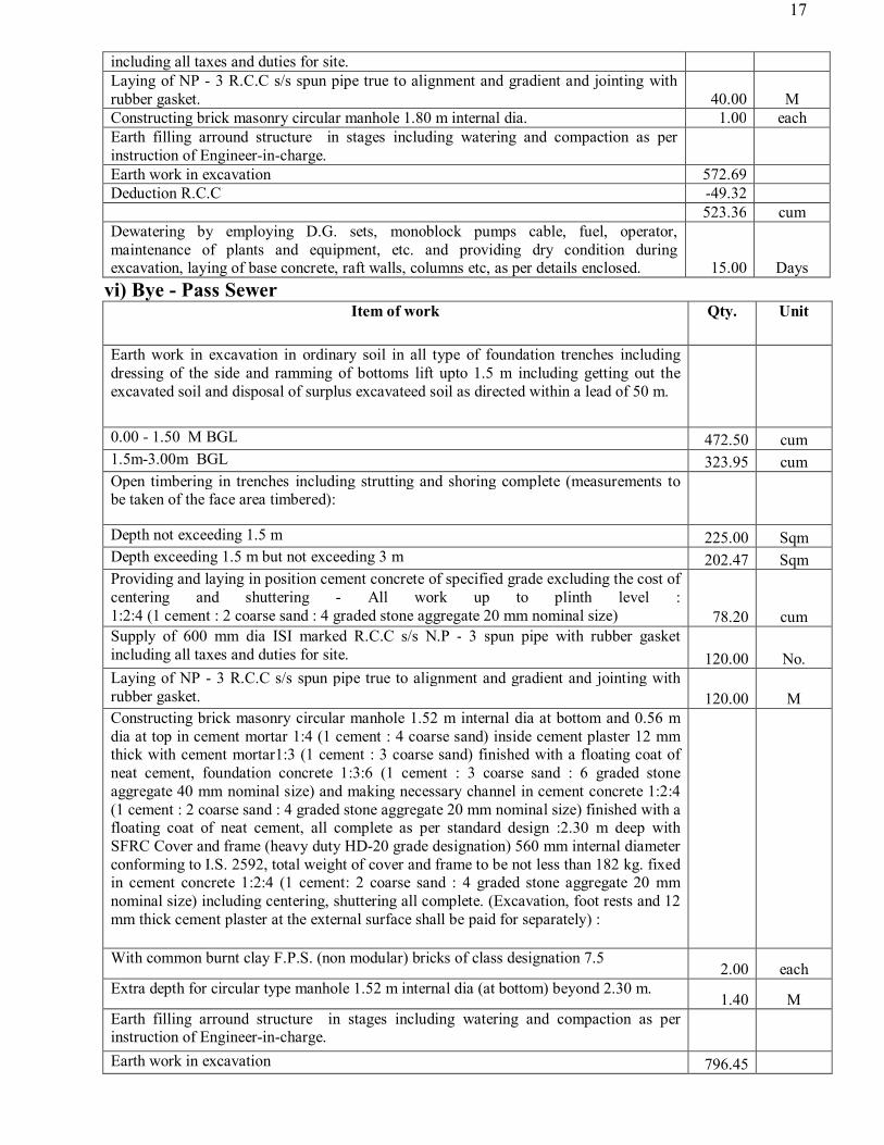
Environmental Management Plan Sl No Environmental Issues Duration /
Extent Magnitude Mitigation Measures Responsibility
1
Location Impacts
1.1 Laying of rising mains would involve cutting and filling
Permanent Major The sewage transmission main alignment proposed will be laid underground and will follow the existing road alignment. Cut and fill along the rising main alignment will be avoided to the extent feasible. Where cut and fill are necessary the quantities will be balanced subject to technical feasibility to encourage reuse of cut quantities.
Contractor
1.2 Location of Sewage Treatment Plant involves clearing of vegetation and trees.
Permanent Minor The proposed location of STP has degraded vegetation. However, it will be ensured that vegetation outside the designated construction site is not affected. The designs shall be worked out to have minimum impacts on trees and clearance of vegetation
Contractor
2
Design and pre-construction Impacts
2.1 Cutting of trees and vegetation clearance in the STP, MPS & alignment of laying sewerage pipe line
Permanent Moderate Minimize tree-cutting to the extent feasible for the STP and the sewerage network. Minimize it to extent possible by exploring alternative design options. While trees exist in the town, as land identified for the STP and sullage carrier are mainly agricultural fields tree felling is mainly to access these sites along the roads . Compensatory plantation shall be done as per State Government guidelines and provisions of the ESMS of NCRPB.
Contractor
2.2 Demolition of religious structures like temple
Permanent Severe There are no existing religious structures in the proposed site. Hence this impact does not arise. .
Contractor
2.3 Land Acquisition; Relocation of Public utilities; and Restoration of Access Roads
Permanent Severe No Land acquisition is involved, hence this does not arise. Contractor
3
Pre-construction Activities by Contractor
3.1 Construction Camps – Location, Selection, Design and Layout
Temporary Moderate . All fuel oil / lubricants loading and unloading areas shall be paved; and have separate storm water collection system for separation of oil / lubricants prior to discharge. Restore the site to its original state after use. Proper training of labourers and management of waste, if any Prepare a waste management plan for the camps, including an appropriate sanitation and drainage system
Contractor / Supervision Consultant
3.2 Drinking water availability and water arrangement
Temporary Severe The contractor shall be responsible for arrangement of water in every workplace at suitable and easily accessible place for the whole construction period. Sufficient supply of cold potable water (as per IS: 10500) to be provided and maintained. If the drinking water is obtained from an intermittent public Sewerage Scheme & Treatment Plant then, storage tanks will be provided.
Contractor / Supervision Consultant
3.3 Identification of disposal sites
Permanent Major Location of disposal sites shall be finalized only after the Engineer shall certify that these are not located within designated environmentally sensitive zones and confirm that:
• Disposal of the material does not impact natural drainage courses
• No endangered / rare flora is impacted by such material • Not in the vicinity of settlements and sensitive landuses.
Contractor / Supervision Consultant
3.4 Quarry Operations Permanent Major It has to be ensured that materials are obtained from licensed quarries having environmental clearance. Quality and legality to be examined by the Contractor and copies of environmental clearances for these needs to be submitted prior to sourcing of material.
Contractor / Supervision Consultant
4
Construction Impacts
4.1 Improper stockpiling of construction materials can cause impacts starting from obstruction of drainage, disturbance/ safety hazard to
Temporary Moderate Due consideration shall be given for material storage and construction sites such that it doesn’t cause any hindrance to daily traffic movement. Stockpiles shall be covered to protect from dust and erosion. Waste management plans, indicating approximate quantities of waste to be generated and the possible disposal locations, to be
Contractor / Supervision Consultant

35
Sl No Environmental Issues Duration / Extent Magnitude Mitigation Measures Responsibili
ty local population, traffic blockage, and lead to land degradation
prepared and implemented.
4.2 Quarry / Burrow pits Operations
Permanent Moderate Adequate safety precautions shall be ensured during transportation of quarry material from quarries to the construction site. Vehicles transporting the material shall be covered to prevent spillage. Operations to be undertaken by the contractor as per the direction and satisfaction of the Engineer.
Contractor / Supervision Consultant
4.3 Stripping, stocking and preservation of top soil
Permanent Moderate The topsoil from borrow areas, areas of cutting and areas to be permanently covered will be stripped to a specified depth of 150mm and stored in stockpiles. The stockpile will be designed such that the slope does not exceed 1:2 (vertical to horizontal), and the height of the pile is to be restricted to 2m. Stockpiles will not be surcharged or otherwise loaded and multiple handling will be kept to a minimum to ensure that no compaction will occur. The stockpiles will be covered with gunny bags or tarpaulin. It will be ensured by the contractor that the topsoil will not be unnecessarily trafficked either before stripping or when in stockpiles. Such stockpiled topsoil will be returned to cover the disturbed area and cut slopes.
Contractor / Supervision Consultant
4.4 Disposal of cut material is a potential impact as the storage reservoirs are located in the eco-sensitive zones.
Temporary Moderate Designated disposal locations for the cut material should be identified prior to initiation of construction activities and got approved by the engineer supervising the construction activities
Contractor / Supervision Consultant
4.5 Soil Erosion Permanent Moderate Slope protection measures shall be undertaken along slopes where cutting is involved adopting suitable slope protection techniques. The suitability to be decided by the Engineer at site. The work shall consist of measures as per design, or as directed by the Engineer to control soil erosion, sedimentation and water pollution. All temporary sedimentation, pollution control works and maintenance thereof will be deemed as incidental to the earthwork or other items of work.
Contractor / Supervision Consultant
4.6 Compaction of Soil Temporary Minor To minimize soil compaction construction vehicle, machinery and equipment will move or be stationed in the construction site as designated by the Engineer only. The haul roads for construction materials should be routed to avoid agricultural areas
Contractor / Supervision Consultant
4.7 Blasting Permanent Moderate Except as may be provided in the contract or ordered or authorized by the Engineer, the Contractor will not use explosives. Where the use of explosives is so provided or ordered or authorized, the Contractor will comply with the requirements of the following besides the law of the land as applicable. The Contractor will at all times take every possible precaution and will comply with appropriate laws and regulations relating to the import, handling, transportation, storage and use of explosives and will, at all times when engaged in blasting operations, post sufficient warning flagmen, to the full satisfaction of the Engineer. The Contractor will at all times make full liaison with and inform well in advance and obtain such permission as is required from all Government Authorities, public bodies and private parties whomsoever concerned or affected or likely to be concerned or affected by blasting operations.
Contractor / Supervision Consultant
4.8 Soil and Water Pollution due to fuel, lubricants and construction waste
Temporary Moderate The fuel storage and vehicle cleaning area shall be stationed at least 300m away from the nearest drain/water body. Oil interceptor shall be provided at construction vehicle parking area, vehicle repair area and workshops ensuring that all wastewater flows into the interceptor prior to its discharge.
Contractor / Supervision Consultant
4.9 Generation of Dust Temporary Minor The contractor shall take every precaution to reduce the levels of dust at construction sites to the satisfaction of the Engineer. All earthwork to be protected/covered in a manner acceptable to the satisfaction of the engineer to minimise dust generation.Clearance shall be affected immediately by manual sweeping and removal of debris, or if so directed by the Engineer, the construction site shall be hosed or watered using necessary equipment.
Contractor / Supervision Consultant
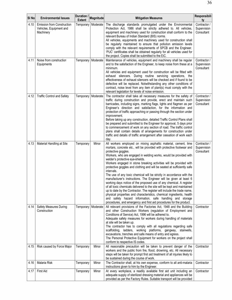
36
Sl No Environmental Issues Duration / Extent Magnitude Mitigation Measures Responsibili
ty 4.10 Emission from Construction
Vehicles, Equipment and Machinery
Temporary Moderate The discharge standards promulgated under the Environmental Protection Act, 1986 shall be strictly adhered to. All vehicles, equipment and machinery used for construction shall conform to the relevant Bureau of Indian Standard (BIS) norms. All vehicles, equipments and machinery used for construction shall be regularly maintained to ensure that pollution emission levels comply with the relevant requirements of SPCB and the Engineer. ‘PUC’ certificates shall be obtained regularly for all vehicles used for the project. Copies shall be submitted to the EiC.
Contractor / Supervision Consultant
4.11 Noise from construction Equipments
Temporary Moderate Maintenance of vehicles, equipment and machinery shall be regular and to the satisfaction of the Engineer, to keep noise from these at a minimum. All vehicles and equipment used for construction will be fitted with exhaust silencers. During routine servicing operations, the effectiveness of exhaust silencers will be checked and if found to be defective will be replaced. Notwithstanding any other conditions of contract, noise level from any item of plant(s) must comply with the relevant legislation for levels of noise emission.
Contractor / Supervision Consultant
4.12 Traffic Control and Safety Temporary Moderate The contractor shall take all necessary measures for the safety of traffic during construction and provide, erect and maintain such barricades, including signs, marking flags, lights and flagmen as per Engineer’s direction and satisfaction, for the information and protection of traffic approaching or passing through the section under improvement. Before taking up any construction, detailed Traffic Control Plans shall be prepared and submitted to the Engineer for approval, 5 days prior to commencement of work on any section of road. The traffic control plans shall contain details of arrangements for construction under traffic and details of traffic arrangement after cessation of work each day.
Contractor / Supervision Consultant
4.13 Material Handling at Site Temporary Minor All workers employed on mixing asphaltic material, cement, lime mortars, concrete etc., will be provided with protective footwear and protective goggles. Workers, who are engaged in welding works, would be provided with welder’s protective eye-shields. Workers engaged in stone breaking activities will be provided with protective goggles and clothing and will be seated at sufficiently safe intervals. The use of any toxic chemical will be strictly in accordance with the manufacturer’s instructions. The Engineer will be given at least 6 working days notice of the proposed use of any chemical. A register of all toxic chemicals delivered to the site will be kept and maintained up to date by the Contractor. The register will include the trade name, physical properties and characteristics, chemical ingredients, health and safety hazard information, safe handling and storage procedures, and emergency and first aid procedures for the product.
Contractor / Supervision Consultant
4.14 Safety Measures During Construction
Temporary Moderate All relevant provisions of the Factories Act, 1948 and the Building and other Construction Workers (regulation of Employment and Conditions of Service) Act, 1996 will be adhered to. Adequate safety measures for workers during handling of materials at site will be taken up. The contractor has to comply with all regulations regarding safe scaffolding, ladders, working platforms, gangway, stairwells, excavations, trenches and safe means of entry and egress. The Personal Protective Equipment for workers on the project shall conform to respective IS codes.
Contractor
4.15 Risk caused by Force Major Temporary Minor All reasonable precaution will be taken to prevent danger of the workers and the public from fire, flood, drowning, etc. All necessary steps will be taken for prompt first aid treatment of all injuries likely to be sustained during the course of work.
Contractor
4.16 Malaria Risk Temporary Minor The Contractor shall, at his own expense, conform to all anti-malaria instructions given to him by the Engineer.
Contractor
4.17 First Aid Temporary Minor At every workplace, a readily available first aid unit including an adequate supply of sterilized dressing material and appliances will be provided as per the Factory Rules. Suitable transport will be provided
Contractor

37
Sl No Environmental Issues Duration / Extent Magnitude Mitigation Measures Responsibili
ty to facilitate transfer of injured or ill person(s) to the nearest hospital. At every workplace and construction camp, equipment and nursing staff shall be provided.
4.18 Hygiene Temporary Minor All temporary accommodation must be constructed and maintained in such a fashion that uncontaminated water is available for drinking, cooking and washing. Garbage bins must be provided in the camps and regularly emptied and the garbage disposed off in a hygienic manner. Adequate health care is to be provided for the work force. Unless otherwise arranged for by the local sanitary authority, the local medical health or municipal authorities shall make arrangement for disposal of excreta. On completion of the works, all such temporary structures shall be cleared away, all rubbish burnt, excreta tank and other disposal pits or trenches filled in and effectively sealed off and the outline site left clean and tidy, at the Contractor’s expense, to the entire satisfaction of the engineer.
Contractor / Supervision Consultant
4.19 Religious Structures Temporary Major This does not applicable as the site earmarked for the project does not include any religious structure.
Contractor
4.20 Archaeological Property – Chance find if any
Temporary Minor The contractor shall take reasonable precaution to prevent his workmen or any other persons from removing and damaging any such article or thing and shall, immediately upon discovery thereof and before removal acquaint the Engineer of such discovery and carry out the Engineer’s instructions for dealing with the same, awaiting which all work shall be stopped 100 m all directions from the site of discovery. The Engineer shall seek direction from the Archaeological Survey of India (ASI) before instructing the Contractor to recommence work on the site.
Contractor
4.21 Clearing of Construction of Camps & Restoration
Temporary Major Contractor to prepare site restoration plans for approval by the Engineer. The plan is to be implemented by the contractor prior to demobilization. On completion of the works, temporary structures will be cleared away, rubbish burnt, excreta or other disposal pits or trenches filled in and effectively sealed off and the site left clean and tidy, at Contractor’s expense, to the entire satisfaction of the Engineer.
Contractor
5. O&M Impacts 5.1 Environmental Conditions Permanent Moderate The PIU will undertake seasonal monitoring of air, water, noise and
soil quality through approved monitoring agency. The parameters monitored, frequency and duration of monitoring and locations to be monitored will be as per the Monitoring Plan prepared.
UPJN
5.2 Flooding of the wastewater plant as well as leakage form the treatment basins can threaten groundwater resources
Temporary Major These should be avoided by adopting proper engineering codes and adequate preventive measures
Contractor
Environmental Monitoring Plan (Preconstruction) Sl. No. Attributes Parameters to be
Monitored Location Frequency Responsibility
1 Air Quality SPM and RSPM, NOx, CO
Once prior to construction
Contractor 2 Noise Decibels At two locations along the rising main
alignment and two locations within the settlement where networks to be developed
Once prior to construction
Contractor
3 Water quality Surface water quality At two water body locations. Once, prior to construction
Contractor 4 Site for quarries
and burrow pits The site situation – for rehabilitation, photographs
All sites identified for quarries, burrow pits, waste and construction labour camps and offices
Once prior to construction
Contractor

38
5 Vegetation removal
Vegetative survey to identify type and amount of vegetation that requires to be replaced
Along locations that are to be cleared off trees for construction activities
Once prior to construction
Contractor
4 Site for burrow pits, construction camps etc
Visual quality, nature and type of vegetation, soil quality etc
Quarries, burrow pits, waste and construction labour camps and offices sites
Once prior to construction
Contractor
Environmental Monitoring Plan (Construction/Post construction)
Sl. No. Attributes Parameters to be Monitored
Location Frequency Responsibility
1 Air Quality SPM and RSPM, NOx, CO
At two locations along the rising main alignment, and two locations within the settlement where networks to be developed
Annually Contractor
2 Noise Decibels At two locations along the rising main alignment, and two locations within the settlement where networks to be developed
Annually Contractor
3 Water quality Surface water quality At two water body locations Annually Contractor 4 Site for
burrow pits, construction camps etc
After construction activity over – if rehabilitated
Quarries, burrow pits, waste and construction labour camps and office sites
After completion of construction activities at site
Contractor
h) Surplus Earth The surplus earth after proper completion of sump well shall be filled in plinth of buildings
and inside campus under this contract as per direction of Engineer i) Damage To Any Property If boundary wall and gate (under scope of other agency) or any other property are damaged by
contractor during construction of work under this contract, the same shall be repaired as per direction of Engineer and nothing extra shall be payable on this account.
SECTION – III
INSTRUCTION TO BIDDERS 1. GENERAL 1.1 U.P. Jal Nigam (UPJN) intends to use the 50% funds from the central govt. 30% funds from the state
govt. and 20% funds from the ULB for this contract for which invitation for Pre-Qualification is issued. The grant will not be used for payment to person or entities or for any import of goods, if such payment or import is prohibited by a decision of the Govt. of India.
1.2 The UPJN intends to pre-qualify the firms who bid for the contract outlined in the pre-qualification data.
1.3 The schedule for bidding shall be outlined in the pre-qualification data.
2. PREPARATION & SUBMISSION OF APPLICATION FOR
PRE QUALIFICATION:
2.1 The applicants/bidders may request in writing to the Superintending Engineer, 18th Circle, U.P. Jal Nigam, Ghaziabad for the clarification, if any, of the project requirements and the criteria for qualification at any time up to 7 days prior to the last date set for the submission of applications.

39
2.2 All information requested for pre-qualification shall be provided in the English language.
2.3 The application for pre-qualification shall consist of the forms and documentation specified in the pre-qualification data along with all certificates and attachments to fulfill the eligibility conditions.
2.4 Failure to provide information which is essential to evaluate the applicants/bidders qualifications, or failure to provide timely clarification or substantiation of the information supplied may result in disqualification & rejection of the applicant/bidder.
2.5 Submission of applications for pre-qualification must be received on e-procurement web site http://etender.up.nic.in
2.6 If any information in this schedule is found to be incorrect or concealed, the tender will be summarily rejected.
2.7 Along with publication in news papers the Notice Inviting Tender (NIT or E-Tender Notice) for the aforesaid project shall also be available on the e-procurement website https://etender.up.nic.inand U.P. Jal Nigam’s website “www.upjn.org”.
2.8 For participating in tenders through the E-Tendering system, it is necessary for bidders to be registered users of the e-procurement website https://etender.up.nic.in and the bidders should possess valid class-2 /class-3 digital signature certificates (DSC). Subsequent clause 3.18 and 3.19 provide guidance regarding registration and DSC for bidders new to this system.
2.9 Bidders shall bear all costs associated with the preparation and submission of their e-bid and U.P. Jal Nigam will, in no case, be responsible or liable for these costs, regardless the conduct or outcome of the E-Tender process.
2.10 This e-tender document shall remain available on the web site https://etender.up.nic.in from the download/ sale start date and time till the download/sale end date and time of as mentioned in the E-Tender schedule, so as to enable the bidders to view and download the E-Tender Document.
2.11 U.P. Jal Nigam requires that bidders observe the highest standard of ethics during the procurement and execution of such contracts. In pursuance to this policy, U.P. Jal Nigam will reject a proposal for award if it determines that the bidder/contractor has been engaged in corrupt or fraudulent practices in competing for the contract under reference.
2.12 Bidder shall not be a registered member of Bar Council.
2.13 Bidder must be registered with U.P. Jal Nigam in category 2(b)or 8(b). The prequalified bidders will have to get themselves registered with U.P. Jal Nigam in respective class and category before the date of opening of Financial Bid.
2.14 The quantities are approximate and can vary to any extent on either side. No extra claim shall be entertained on this account. The contractor will be paid on the basis of the actual measurement of finished item of work, executed by him.
2.15 The department reserves the right to accept or reject any e-bid or annul the e-bid process or reject all e-bids at any time prior to award of contract, without assigning any reason and without thereby incurring any liability to the affected bidder or bidders.
2.16 The bidders are advised:-
(a) To visit the site of work so as to study and ascertain local conditions with particular reference to access road and infrastructure facilities, the market availability of materials and their sources, labour (skilled and unskilled) and layout plan of water works etc. and all relevant factors which might affect their rate and to quote rates accordingly.
(b) To read carefully the specifications, terms and conditions, work out their own quantities and rates from the drawing and site conditions before quoting the rates.

40
3. PRE-QUALIFICATION AND TENDERING :
3.1 The U.P. Jal Nigam reserves the right to :
(a) Amend the scope of work and value of any contract(s) to be tendered, in that event only those prequalified applicants/bidders who meet the amended requirements will be invited for tendering.
(b) Reject or accept any application. (b) Cancel the pre-qualification process and reject all applicants. The UPJN shall neither be liable
nor be under any obligation to inform the applicant/bidder of the grounds for such action like rejection, cancellation or amendments.
3.2 Applicants/bidders who have qualified in the pre-qualification criteria will be informed about the UPJN’s decision in writing and via e-procurement web site http://etender.up.nic.in
3.3 The financial bid of only those contractors/bidders shall be opened who will qualify the eligibility criteria of pre-qualification as mentioned in pre-qualification document for evaluation of Technical & Financial Capability. The date of opening of financial bid shall be informed via e-procurement web site http://etender.up.nic.inand via email to only those contractors who emerge successful in prequalification bid.
3.4 The pre-qualification bidders who qualify in the P.Q. bid shall be required to participate in the tendering process. In case the bidders who qualify in this P.Q. bid, do not participate in tendering process then their Earnest Money deposited with this P.Q. bid shall be forfeited.
3.5 At the time of submitting their tenders/bid pre-qualified tenders/bidders shall update the relevant information used for pre-qualification to confirm that they continue to comply with the qualification criteria and verify that the information previously provided is still valid and correct. A tenderer/bidder shall be disqualified if it no longer meets the qualification requirements before, on or after the time of contract of award.
3.6 Tenders/bidders will be required to provide an earnest money outlined in the notice inviting tender without which his Bid shall not be entertained.
3.7 The Earnest Money Deposit (EMD) amounting Rs. 44,70,772/- must be deposited with the e-tender in form of RTGS to Union Bank of India, IFSC Code - UBIN0555665, Account No.- 556602010002108
3.8 Bidders shall have to pay e-tender document fee of Rs. 20000.00 (Rs. Twenty Thousands Only) including 12 % GST through RTGS Union Bank of India, IFSC Code - UBIN0555665, Account No.- 556602010002108 . Bid not accompanied with tender fee shall be rejected.
3.9 For EMD original receipt of RTGS for e-tender document fee must be dropped in the tender box kept at the Office of the Superintending Engineer,18th Circle, U.P. Jal Nigam, Sector-1, Opp. New Ghaziabad Railway Station, RajNagar, Ghaziabad in a sealed envelope addressed to SE, 18th Circle, U.P. Jal Nigam, Ghaziabad superscripted “E-Tender Fee & Earnest Money :
1. Design, testing and commissioning for construction of 1 nos Intermediate Sewage Pumping Station Worksnamed as IPS-3(approximate10.56 MLD average flow,6 m dia.,10.24 m depth ) including all respects(with all labour,materials, electrical/ mechanical equipments etc complete)
2. On or before the date and time specified in e-tender schedule. This envelope shall also contain the following documents in original:
(a) Request letter (as per format annexed).

41
(b) Declaration Affidavit of bid validity on non judicial stamp paper of Rs. 100/- duly verified by Notary Public (as per Form 1(c) of Volume-II)
(c) Declaration Affidavit on non judicial stamp paper of Rs. 100/- duly verified by Notary Public (as per Format-11).
(d) Declaration Affidavit for fulfilling the terms & conditions of the contract on non judicial stamp paper of Rs. 100/- duly verified by Notary Public (as per Form 1(b) of Volume-II).
(e) Declaration of Staff on non judicial stamp paper of Rs. 100/- duly verified by Notary Public (as per Format 5(b)).
(f) Declaration of T&P on non judicial stamp paper of Rs. 100/- duly verified by Notary Public (as per Format-6).
3.10 Bidders may please note very carefully that e-bids without e-tender document fee and EMD in the prescribed form and above cited documents shall be treated as non-responsive and shall be rejected.
3.11 E-tender document fee is non-refundable.
3.12 Earnest money of unsuccessful bidders will be returned as promptly as possible after the acceptance of tender, but not later than 30 days after the expiration of the period of bid validity.
3.13 Successful bidder's EMD will be adjusted against the security money to be deposited at the time of signing of the agreement. In case, the successful bidder furnishes the required security money in full at the time of signing of the agreement, the earnest money submitted with the bid will be returned when the agreement has been signed.
3.14 No interest will be payable by the U.P. Jal Nigam on the Earnest Money or Security Deposit or any other amount withheld/deducted as per terms of the contract.
3.15 THE TENDER DOCUMENT 3.15.01 The e-tender document for the e-tender under reference comprises of following two parts:
(A) PART-I:Technical & Financial Evaluation cum Technical Bid (Pre-qualification bid). This part will comprise of:
(i) Fee details – It includes of the cost of tender document and prescribed earnest money in prescribed form. A scanned copy of RTGS for e-tender document fee and EMD in PDF format must be uploaded along with Part-I of the e-bid.
(ii) Qualification Details – It includes copies of required documents in PDF format establishing that the bidder is qualified to perform the contract if his/her bid is accepted and the bidder has financial & technical capability necessary to perform the contract and meets the criteria outlined in ‘requirements of pre-qualification’ and fulfill all the conditions of the contract and elsewhere in the tender.
(B) PART-II: Financial bid / Price bid Language of e-bid:
3.15.02 The e-bid prepared by the bidder, as well as all correspondence and documents relating to the e-bid, exchanged by the bidder and the department shall be written either in English or Hindi language. The correspondence and documents in Hindi must be accompanied by embedded/separate Hindi font files. Only English numerals shall be used in the e-bid. If any other language is used, it shall be accompanied by a translation into English/Hindi language, duly signed and certified by bidder, as the true translation, which will be used for interpreting the information.
3.15.03 Amendment(s) of e-Tender Document : (i) At any time prior to the deadline for submission of e-bid, the department may, for any reason,
whether at its own initiative or in response to a clarification requested by a prospective bidder, modify the e-tender document by amendment(s). For such amendment(s) written

42
‘Addendum/Corrigendum(s)’shall be issued copy of which shall be simultaneously uploaded on the e-procurement website https://etender.up.nic.in and U.P. Jal Nigam's website www.upjn.org.All such Addendum/corrigendum(s)shall become an integral part of e-tender document. The relevant clause(s) of the e-tender document shall be treated as amended accordingly.
(ii) It shall be the sole responsibility of the prospective bidders to check the website http://etender.up.nic.in regularly for amendment(s), if any, in the e-tender document, failing which the responsibility of any error arising out of such negligence shall rest with the bidder.
(iii) In order to allow prospective bidders a reasonable time to take the amendment(s) into account in preparing their e-bids, U. P. Jal Nigam, at its discretion, may extend the deadline for the submission of e-bids. Such extension(s) shall be uploaded on the e-procurement website http://etender.up.nic.in, and department's website www.upjn.org.
3.15.04 Bid Validity period: e-bid shall remain valid for 120 days after the actual date of opening of Technical & Financial Evaluation Cum Technical bid. In case, however,the day upto which the bid is to remain valid happens to be a public holiday/is declared public holiday for Govt. offices, the bid shall remain valid for acceptance till the next working day. In exceptional circumstances, the department may solicit the bidder's consent to an extension of the period of e-bid validity. The request and the response thereto shall be made in writing. A bidder may refuse the request without forfeiting his/her e-bid security (EMD). A bidder granting the request will not be required nor permitted to modify his/her e-bid.
3.15.05 Forfeiture of EMD : Earnest money deposit shall be forfeited
(i) If the bidder (a) withdraws his/her e-bid during the period of e-bid validity as specified above or (b) does not accept the correction of errors or (c) modifies its e-bid price during the period of e-bid validity.
(ii) In case of a successful bidder, if the bidder fails to sign the contract with the department.
3.16 PREPARATION & SUBMISSION OF BID 3.16.01 The tender/bid submission module of e-procurement website https://etender.up.nic.inshall
enable the bidders to submit their duly filled e-bids online in response to this e-tender from the bid submission start date and time till the bid submission end date and time stipulated in the e-tender schedule.
3.16.02 Bidders may please note very carefully that till such time that a fresh agreement is dawn up embodying the agreed conditions, the conditions given in this tender document shall govern the contract.
3.16.03 Bidders are required to examine carefully site conditions, all instructions, forms, terms & conditions and specifications in the e-tender document and prepare the tender in accordance with requirements thereof. Failure to furnish all information as per the e-tender document or submission of e-bid not responsive to the e-tender document in every respect will be at the bidder's risk and shall result in rejection of the said e-bid.
3.16.04 A bid deviating in any respect from the condition etc. specified in this tender document or found to be containing terms/conditions other than those in tender documents, shall be taken as a conditional bid and shall be liable for rejection.
3.16.05 Format of e-bid: The bidder shall prepare one electronic copy of the Technical & Financial evaluation cum Technical bid e-bids (comprises of Vol-I) and financial e-bid (Vol-II) each separately.
3.16.06 Any corrections in the documents/bank instruments, if required at all, shall be countersigned by the bidder/bank official.
3.16.07 The documents designated to be uploaded shall be physically signed at all places indicated.

43
3.16.08 Signing of e-bid: The e-bid document shall be digitally signed, at the time of loading, by the bidder or a person or persons duly authorized to bind the bidder to the contract. All the pages/documents of the e-bid that are to be uploaded shall be digitally signed by the person authorized to sign the e-bid. The individual, physically and digitally signing the tenders and/or other documents, should be either :
(i) The sole proprietor of the firm or constituted attorney of such sole proprietor.
(ii) Constituted attorney of the firm, if it is a company under the meaning of Company Law, a scanned copy of the power of attorney should be attached.
(iii) Managing Director/President/Chairman/Company Secretary in case of a Limited Co. having authorization for committing the company from its Board of Director or as is required under Company Law.
President or Secretary in case of registered co-operative society having such power through Law/Bylaws or by special resolution,Scanned copy of the sole proprietorship declaration/power of attorney/ authorization / resolution / bylaws, as the case may be, must be submitted with Part-I of e-bid. This document shall not be more than one year old as on date of opening of Technical & Financial evaluation cum Technical bid. It should also contain address and mobile number of authorized person.
3.17 For participating in e-bid through the e-tendering system it is necessary for the bidders to be the registered users of the e-procurement website https://etender.up.nic.in. The bidders must obtain a User Login ID and Password by registering themselves with U.P. Electronics Corporation Ltd., 10, Ashok Marg, Lucknow, if they have not done so previously for registration.
3.18 In addition to the normal registration, the bidder has to register with his/her digital signature certificate (DSC) in the e-tendering system and subsequently he/she will be allowed to carry out his/her e-bid submission activities. Registering the digital signature certificate (DSC) is a one-time activity. Before proceeding to register his/her DSC, the bidder should first log on to the e-tendering system using the user login option on the homepage with the login ID and Password with which he/she has registered.
3.19 For successful registration of DSC on e-procurement website https://etender.up.nic.in the bidder must ensure that he/she should possess Class-2/Class-3 DSC issued by any certifying authorities approved by Controller of Certifying Authorities, Government of India, as the e-procurement website https://etender.up.nic.in is presently accepting DSC issued by these authorities only. The bidder can obtain user login ID and perform DSC registration exercise above even before e-bid submission date starts. The department shall not be held responsible if the bidder tries to submit his/her e-bid at the moment before end date of submission but could not submit due to DSC registration problem.
3.20 The bidder can search for active tenders through "search active tenders" link, select tender in which he/she is interested in and then move it to 'My Tenders' folder using the options available in the e-bid submission menu. After selecting the tender, for which the bidder intends to e-bid, from "My tenders" folder, the bidder can place his/her e-bid by clicking "pay offline" option available at the end of the view tender details form. Before this, the bidder should download the e-tender document and price schedule/bill of quantity (BOQ) and study them carefully. The bidder should keep all the documents ready as per the requirements of e-tender document in the PDF format.
3.21 After clicking the 'pay offline' option, the bidder will be redirected to terms and conditions page. The bidder should read the terms & condition before proceeding to fill in the tender fee and EMD offline payment details. After entering and saving the tender fee and EMD details form so that "bid document preparation and submission" window appears to upload the documents as per technical (fee details, qualification details, e-bid form and technical specification details) and financial (e-bid form and price schedule/BOQ) schedules/packets given in the tender details. The details of the demand draft or any other accepted instrument which is to be physically sent in original before opening of technical e-bid, should tally with

44
the details available in the scanned copy and the date entered during e-bid submission time otherwise the e-bid submitted will not be accepted.
3.22 Next the bidder should upload the technical e-bid documents for fee details (e-tender fee and EMD), Qualification details. Before uploading, the bidder has to select the relevant digital signature certificate. He/she may be prompted to enter the digital signature certificate password (PIN), if necessary. For uploading, the bidder should click "browse" button against each document label in technical and financial schedules/packets and then upload the relevant PDF files already prepared and stored in the bidder's computer. The required documents for each document label of technical (fee details, qualification details, e-bid form and technical specification details) and financial (e-bid form and price schedule/BOQ) schedules/packets can be clubbed together to make single different files for each label.
3.23 The bidder should click "Encrypt" next for successfully encrypting and uploading of required documents. During the above process, the e-bid documents are digitally signed using the DSC of the bidder and then the documents are encrypted/locked electronically with the DSC's of the bid openers to ensure that the e-bid documents are protected, stored and opened by concerned bid openers only.
3.24 After successful submission of e-bid document, a page giving the summary of e-bid submission will be displayed confirming end of e-bid submission process. The bidder can take a printout of the bid summary using the "print" option available in the window as an acknowledgement for future reference.
3.25 The bidders are strongly advised to undergo training regarding submitting of e-tenders at U.P. Electronics Corporation Ltd., 10, Ashok Marg, Lucknow at any working day, which is free of cost. The training given to them regarding submitting of e-tenders is to be followed strictly while submitting their bids. Notwithstanding the contents of relevant paragraphs regarding bid submission / withdrawal, training given by U.P. Electronics Corporation Ltd., regarding submission/withdrawal/ re-submission of e-tenders will be final. Responsibility of having adequate knowledge of the process and latest changes incorporated, if any, rests with the bidder and the department shall not, in any manner, be responsible for any error or non-submission/withdrawal of a bid on this account.
3.26 Deadline for submission of e-bid: e-Bid (Part-I & Part-II Financial Bid) must be submitted/uploaded by bidders at e-procurement website https://etender.up.nic.in not later than the time specified on the prescribed date. The server time displayed in the Bid management window on the e-procurement website https://etender.up.nic.in will be the time by which the e- bid submission activity will be allowed till the permissible date and time scheduled in the e-tender. Once the e-bid submission date and time is over, the bidder cannot submit his /her e-bid. The department may, at its discretion, extend this deadline for submission of e-bid by amending the e-bid document, in which case all rights and obligations of the department and bidders previously subject to the deadline will thereafter be subject to the deadline as extended. Bidders are advised to start bid submission process well in advance so that they can submit their bids in time. Delay in submission of bid due to any reason during e-bid submission process, shall be responsibility of the bidder.
3.27 Withdrawal and Resubmission of e-bid : 3.27.01 At any point of time, a bidder can withdraw his/her e-bid submitted online before the bid
submission end date and time. For withdrawing the bidder should first log in using his/her login ID and Password and subsequently by his/her digital signature certificate on the e-procurement website https://etender.up.nic.in. The bidder should then select "My bids" option in the bid submission menu. The page listing all the bids submitted by the bidder will be displayed. Click "View" to see the details of the bid to be withdrawn. After selecting the "bid withdrawal" option the bidder has to click "Yes" to the message "Do you want to withdraw this bid?" displayed in the bid information window for the selected bid. The bidder also has to enter the bid withdrawing reasons and upload the letter giving the reasons for withdrawing before

45
clicking the "Submit" button. The bidder has to confirm again by pressing "OK" button before finally withdrawing his/her selected e-bid.
3.27.02 No e-bid may be withdrawn after the deadline for submission of e-bids during the period of e-bid validity. If a bidder desires to withdraw his tender before the expiry of the validity period, the department may agree to allow such withdrawal but in such a case the earnest money shall be forfeited. If the department does not allow such withdrawal and accepts the tender and the bidder fails to perform his part of the contract, the earnest money deposited shall be forfeited besides other consequences for breach of the contract.
3.27.03 The bidder can re-submit his/her e-bid as when required till the e-bid submission end date and time. The e-bid submitted earlier will be replaced by the new one. The earnest money details submitted by the bidder earlier will be used for the revised tender and the new bid summary generated after the successful submission of the revised tender will be considered for evaluation purpose. For resubmission, the bidder should first log in using his/her login ID and Password and subsequently by his/her digital signature certificate on the e-procurement website https://etender.up.nic.in. The bidder should then select "My bids" option in the bid submission menu. The page listing all the bids submitted by the bidder will be displayed. Click "View" to see the detail of the e-bid to be resubmitted. After selecting the "bid resubmission" option, click "Encrypt & upload" to upload the revised e-bids documents.
3.27.04 The bidders can submit their revised e-bids as many times as required by uploading their e-bid documents within the scheduled date & time for submission of e-bids.
3.27.05 No e-bid can be resubmitted subsequently after the deadline for submission of e-bids. No request for consideration of any alteration in finally submitted offer shall be entertained.
3.27.06 In case of any change in Cash assets, Technical staff, Tools & Plants or change in partners, or constitution of a Company, address of communication or telephone nos. etc. after submission of documents the same shall be intimated to the Superintending Engineer, 18th Circle, U.P. Jal Nigam, Ghaziabad immediately.
3.28 OPENING OF TECHNICAL& FINANCIAL EVALUATION CUM TECHNICAL BIDS
3.28.01 Process of e-bid opening shall take place in the Office of the Superintending Engineer, 18th Circle, U.P. Jal Nigam, Sector-1, Opp. New Ghaziabad Railway Station, Raj Nagar, Ghaziabad, on the date of opening of Technical & Financial evaluation cum Technical bids (Pre-qualification bids) stipulated in the e-tender schedule, in presence of the bidders’ representatives who chose to be present.
3.28.02 In the event of the specified date of e-bid opening being declared a holiday for the department, the e-bids shall be opened at the appointed time and place on the next working day.
3.28.03 The bidders’ representatives who are present shall sign a register evidencing their attendance.
3.28.04 The envelopes containing e-tender document fee receipt and EMD and other required documents, received up to the prescribed date and time, shall be opened at mentioned place
3.28.05 The bidders’ names and the presence or absence of requisite e-tender document fee receipt and EMD in the prescribed format and other required documents as detailed above, will be announced at the opening.
The department will open all Technical & Financial evaluation cum Technical (pre-qualification) e-bids through E-Tender procurement solution (e-procurement website https://etender.up.nic.in) in the presence of bidders’ representatives in the Office of the Superintending Engineer, 18th Circle, U.P. Jal Nigam, Ghaziabad.
3.28.06 Technical & Financial evaluation cum Technical (Pre-qualification) e-bids of only those bidders’, whose e-tender document fee, EMD and other required documents are found in order, shall be accepted.

46
3.28.07 The department will prepare minutes of Technical & Financial evaluation cum Technical (pre-qualification) e-bid opening.
3.29 Clarification of e-Bid: During evaluation of e-bid, the department may, at its discretion, ask the bidder for a clarification of his/her e-bid. The request for clarification shall be in writing. An appropriate reply within the stipulated time shall be obligatory for the bidder.
3.30 Evaluation Criteria: The department will examine all accepted Technical &Financial evaluation cum Technical e-bids to determine they are complete, whether they meet all the conditions of the contract, whether all the required documents have been furnished as detailed in tender document, whether the documents have been properly physically and digitally signed as required, and whether the e-bids are generally in order. Any e-bid or e-bids not fulfilling these requirements shall be rejected.
3.30.01 It shall be the discretion of the department to decide as to whether an e-bid fulfils the evaluation criterion mentioned in this e-tender or not. Decision of the department on matter of technical & financial evaluation results will be final and binding to all participants. No enquiry/clarification shall be entertained on the evaluation results neither the department will remain bound to provide any such clarifications on such results.
3.30.02 The bidders are advised not to mix financial bid documents with the PDF documents uploaded for technical bid. The e-bids of those bidders who have uploaded financial bid document with the pre-qualification (technical) bid or kept it in envelope of EMD will be out rightly rejected.
3.31 OPENING OF FINANCIAL E-BID 3.31.01 After evaluation of Technical & Financial evaluation cum Technical (pre-qualification) e-bid,
through the evaluation committee, the department shall notify those bidders whose technical e-bids were considered non responsive to the conditions of the contract and not meeting the technical specifications and qualification requirements indicating that their financial e-bids will not be opened. The Department will simultaneously notify the bidders, whose technical e-bids were considered acceptable to the department. The notification may be sent by e-mail provided by bidder.
3.31.02 The date, time and place for the opening of financial bids will be uploaded on the e-procurement website https://etender.up.nic.in and communicated to the technically qualified bidders through e-mail provided by the bidder.
3.31.03 The financial e-bids of technically qualified bidders shall be opened in the presence of bidders’/their representatives who choose attend. The name of bidders, price quoted will be announced at the meeting.
3.31.04 The department will prepare the minutes of the financial e-bid opening.
3.31.05 A substantially responsive bid is one which conforms to all the terms conditions and specification of the bidding documents, without material deviation or reservation. A material deviation or reservation is one:-
a) Which effects in any substantial way of the scope, quality or performance of the works. b) Which limits, in any substantial way inconsistent with the bidding documents, the employer’s
rights or the bidder’s obligations under the contract; or c) Whose rectification would affect unfairly the competitive position of other bidders presenting
substantially responsive bids. 3.31.06 If a bid is not substantially responsive, it will be rejected by the Employer, and may not
subsequently be made responsive by correction or withdrawal of the non-conforming deviation or reservation.
LIST OF DOCUMENTS TO BE SUBMITTED OFFLINE
A sealed envelope containing the original copy of the documents specified in clause 3.9(a) to (f) above and this envelope shall be addressed to Superintending Engineer, 18th Circle, U.P. Jal Nigam, Ghaziabad and shall be super scribed “E-Tender Fee & Earnest Money : “1. Design,

47
testing and commissioning for construction of 1 No. IPS-3 (10.56 MLD, 6 m dia, 10.24 m depth) including all respects (with all labour, materials, Electrical/Mechanical )etc complete.
This envelope must be dropped in the tender box kept at the Office of the Superintending Engineer, 18th Circle, U.P. Jal Nigam, Sector-1, Opp. New Ghaziabad Railway Station, Raj Nagar, Ghaziabad on or before the date and time specified in e-tender schedule.
LIST OF DOCUMENTS TO BE SUBMITTED ONLINE ON E-TENDERING WEBSITE
(A) Part-I : Technical & Financial evaluation cum Technical(Pre-Qualification) Bid: For Technical & Financial evaluation cum Technical Part-I of e-bid,on or before the prescribed date specified in e-tender schedule, please upload digitally signed scanned notary attested photocopies (in PDF format) of:
1. The partnership deed or sole proprietorship declaration or company’s registration certificate/ memorandum of association as the case may be.
2. The sole proprietorship declaration/power of attorney/authorization/resolution/bylaws, as the case may be, in favour of person authorized to sign the tender documents physically and digitally as described above. It shall not be more than one year old on the date of opening of Technical & Financial evaluation cum Technical bid and shall contain address and mobile number of authorized signatory.
3. Request letter (typed on letter head of bidder as per format attached).
4. Declaration Form-I A for Earnest Money Deposit (as per Form-1 (f) of Volume-II).
5. Declaration Form-I B for Affidavit of bid validity (typed on nonjudicial stamp paper of Rs. 100/- and verified by Notary Public as per Form-1(c) of Volume-II).
6. Declaration Form No. I C Affidavit (typed on non judicial stamp paper of Rs. 100/-and verified by Notary Public as per Format-11)
7. Declaration Form No. II Affidavit for fulfilling the terms & conditions of the contract (typed on non judicial stamp paper of Rs.100/-& verified by Notary Public as per Form1(b) of Volume-II)
8. Application Form (1): General Information of Bidder (as Format-1).
9. Application Form (2): Annual Turnover (as per Format 3).
10. Application Form (3 a): Details of Contracts of Similar Nature and Complexity taken up during last 10 years (as per Format 4A).
11. Application Form (3 b): Abstract of Contracts of Similar Nature and Complexity (as per Format 4B).
12. Experience certificate Form-4 in support of bidder’s work experience (of each work cited in Form 3 (a)) issued by an officer not below the rank of Executive Engineer of client organization containing Agreement No., Date of start, Date of completion and Value of work done.
13. Registration Certificate issued by Materials Manager, U.P. Jal Nigam, Lucknow.
14. The last Trade Tax assessment order / proof of GST registration/GST, TIN number and Income tax assessment order from Income Tax Dept/GST. for last 4 yrs.
15. PAN card of the firm/Sole proprietor.
16. Application Form (5): Statement of Financial Capability (as per Format-7).
17. Audited Balance Sheet counter signed by C.A. for last five financial years clearly indicating turnover and T.D.S.
18. Application Form (6): Litigation History (as per Format-10).

48
19. Application Form (7): Affidavit for List of Staff with bidder (typed on non judicial stamp paper of Rs.100/- & verified by Notary Public as per Format-5B).
20. Application Form (8): Affidavit for List of Tools and Plants with bidder (typed on non judicial stamp paper of Rs.100/- & verified by Notary Public as per Format-6).
21. Character Certificate from District Magistrate concerned on P.W.D. T-4 Format / proof of applying for P.W.D. T-4 certificate from District Magistrate. (Applicable only in case of sole propriety firm or individual contractor)
22. Certificate of Liquid Assets issued by Nationalized/Scheduled bank with in last six months from the date of opening of Technical & Financial evaluation cum Technical bid.
23. Solvency Certificate issued by District Magistrate (on format T-5)/ Nationalized Bank.( Format-12).
24. Affidavit as prescribed should be annexured on non-judicial stamp paper of Rs. 100.00 duly signed by notary for T-6 format.
25. All the schedules given in the tender document.
26. The bidder shall provide a separate table giving details of taxes, duties, levies and other applicable taxes considered by him and included in the prices offered. Service tax shall not be included in the prices and the owner if applicable against proof of applicability and payment shall pay the same separately.
(B) Part-II : Financial bid /Price bid : For Financial Part-II of e-bid, on or before the prescribed date specified in e-tender schedule, please upload digitally signed duly filled Schedule of Works / BOQ in Pdf format.
Note : If any of the documents mentioned in Part-I sl. 1 to 26 above is uploaded without attestation of notary public, original of the same shall have to be presented by concerned bidder for verification on the date of opening of Part-I, failing to which the bid shall be rejected.
2 CLASSIFICATION OF TENDERS :
2.1 The tender can be made by an individual or by a proprietary firm.
2.2 If the tender is made by a firm in partnership, a certified copy of the power of attorney, partnership deed, address of the firm and the full names and address of all the partners of the firm shall also accompany the tender.
2.3 If the tender is submitted by a limited company, such limited company or corporation may be required to furnish satisfactory evidence of its existence. A copy of said company's articles of Association should be enclosed to substantiate its claim.
2.4 All witnesses and sureties shall be of persons of status and probity and their full names, occupations and addresses shall be stated below their signatures.
2.5 CANVASSING: Any political/administrative pressure by the contractor or canvassing directly or indirectly in
favor of his offer will render his tender liable to rejection.
SECTION –V
PRE – QUALIFICATION/ELIGIBILITY CRITERIA 1. “Technical & Financial Capability Evaluation Bid” and “Financial bid” is to be opened as mentioned in
NIT. The contractor who is not registered in U.P. Jal Nigam but has expertise in particular work may also obtain “Tender Document” provided that he gets himself registered in U.P. Jal Nigam in respective class & category before the date of opening of financial bid.
2. The applicant is an Indian commercial entity registered as a firm or a company.

49
3. The firm is registered with Provident Fund Authorities. 4. The applicant has a valid Sales Tax/VAT /GST Registration Certificate. 5. Applicant has a valid PAN & TAN of Income Tax. 6. The bidder should be enlisted as registered contractor in U.P. Jal Nigam in "category 2(b) or 8(b)", The
contractor who is not registered in U.P. Jal Nigam but has expertise in particular work may also obtain “Tender Document” provided that he gets himself registered in U.P. Jal Nigam in respective class & category before the date of opening of financial bid.
7. Joint Ventures/Consortium are permitted, As such both JV partner must be registered with U.P. Jal Nigam in respective category.
8. Bidder shall not have a conflict of interest. Any Bidder found to have a conflict of interest shall be disqualified. A Bidder may be considered to have a conflict of interest for the purpose of this bidding process, if the Bidder:
(a) Directly or indirectly controls, is controlled by or is under common control with another Bidder; or
(b) Receives or has received any direct or indirect subsidy from another Bidder; or
(c) Has the same legal representative as another Bidder; or
(d) Has a relationship with another Bidder, directly or through common third parties, that puts it in a position to influence the bid of another Bidder, or influence the decisions of the Employer regarding this bidding process; or
(e) Participates in more than one bid in this bidding process. Participation by a Bidder (Main or any partner of the Firm) in more than one Bid will result in the disqualification of all Bids in which such Bidder is involved. However, this does not limit the inclusion of the same subcontractor in more than one bid; or
(f) Any of its affiliates has been hired (or is proposed to be hired) by the Employer or Borrower as Engineer for the Contract implementation; or
(g) Has a close business or family relationship with a professional staff of the Borrower (or of the project implementing agency, or of a recipient of a part of the loan) who: (i) are directly or indirectly involved in the preparation of the bidding documents or specifications of the contract, and/or the bid evaluation process of such contract; or (ii) would be involved in the implementation or supervision of such contract unless the conflict stemming from such relationship has been resolved in a manner acceptable to the Bank throughout the procurement process and execution of the contract.
9. Bidders that are Government-owned enterprises or institutions in the Employer’s Country may participate only if they can establish that they (i) are legally and financially autonomous (ii) operate under commercial law, and (iii) are not dependent agencies of the Employer. To be eligible, a government-owned enterprise or institution shall establish to the Owners satisfaction, through all relevant documents, including its Charter and other information the Bank may request, that it: (i) is a legal entity separate from the government (ii) does not currently receive substantial subsidies or budget support; (iii) operates like any commercial enterprise, and, inter alia, is not obliged to pass on its surplus to the government, can acquire rights and liabilities, borrow funds and be liable for repayment of its debts, and can be declared bankrupt; and (iv) is not bidding for a contract to be awarded by the department or agency of the government which under their applicable laws or regulations is the reporting or supervisory authority of the enterprise or has the ability to exercise influence or control over the enterprise or institution.
10. Bidders should not be black listed or under a declaration of ineligibility for corrupt and fraudulent practices by the Central Government, any State Government or any public undertaking, autonomous body, authority by whatever name called under the Central or the State Government.
11. Any bidders having criminal record is not allowed to particípate in the bidding process. Any person who is having criminal cases against him or involved in the organised crime or gangster activities or Mafia or Goonda or Anti social activity are strictly prohibited to participate in the bidding process. If it is established that any bidder has criminal record, his bid shall be automatically cancelled. The bidder has

50
to produce character certificate issued by the competent authority in original with bid document. Self declaration affidavit (on the prescribed format no. 11 which is attached with the bid document) should be submitted with the bid.
12. A Bidder should not be under suspension/debarred from bidding by the Employer or from any Department of Central/State Government.
13. Even though the applicant meets the above criteria, he/she is subject to be disqualified if he/she has : (a) Made misleading or false representation in the forms, statements and attachments submitted ; and/or (b) Record of poor performance such as abandoning the work, not properly completing the contract, inordinate
delays in completion, or financial failures. Etc.
14. The criteria for pre-qualification : a) Experience:
Experience required : Should have completed in last ten years ending dt. 31.03.18 atleast following no. of similar works costing not less than as given below.
(i) Three similar completed works costing (Evaluated Cost) not less than the amount equal to 40% of estimated cost i.e. Rs.1668.31 Lacs. and.One nos.IPS(5 MLD), 1.0 km sewer network laying of 600mm dia or above dia.
OR
(ii) Two similar completed works costing (Evaluated Cost) not less than the amount equal to 50% of estimated cost i.e .Rs. 2085.38 Lacs. and One nos.IPS(5 MLD), 1.0 km sewer network laying of 600mm dia or above dia.
OR
(iii) One similar completed works costing (Evaluated Cost) not less than the amount equal to 80% of estimated cost i.e .Rs.3336.62Lacs and One nos.IPS(5 MLD), 1.0 km sewer network laying of 600mm dia or above dia. Note : Cost will be evaluated simply @ 8% per year.
(b) Turn Over: Average annual turnover of last three years, whichever is more, should be Rs.834.15 Lacs during the last three years ending 31st March 2018 and Minimum turn over should be Rs. 700 Lacs in any one financial year. Note:The turnover will be indexed at the rate of 8 percent for a year.
(c) Profit/Loss :
The firm should not have incurred any loss in more than 2 years during last 5 years and the firm should have a positive Net worth
(d) Solvency Certificate : The Contractor should have the solvency of Rs. 1000.00 Lacs.
Bid Capacity: Bidders who meet the minimum qualification criteria will be qualified only if their available bid capacity for construction work is equal to or more than the total bid value. The available bid capacity will be calculated as under:
Assessed Available Bid capacity = ( A*N*M - B ) Where

51
A = Maximum value of works executed in any one year during the last five years (updated to the price level of the last year at the rate of 8 percent a year) taking into account the completed as well as works in progress. N = Number of years prescribed for completion of the works for which bids are invited (period up to 6 months to be taken as half-year and more than 6 months as one year) excluding maintenance period. M = M is taken 2.0 B = Value, at the current price level, of existing commitments and on-going works to be completed during the period of completion of the works for which bids are invited.
(e) Personnel Capability :
The Applicant must have suitable qualified personnel to fill the specified key positions shown below and needs to supply information on prime candidates and alternates for each position.
Sr. No.
Position Recommended Number
Total Experience
(Years)
Experience in Similar Position (Years)
Minimum Qualification
Site Posting in accordance with mutually agreed work plan 1 Graduate
Engineer 2 7 3 B.E. (Civil) / E&M
2 Diploma Engineer
4 7 3 Diploma(Civil)/ E&M
It is also necessary for each applicant to clearly identify the role of every key person for each of the major component of the Project.
(f) Equipment Capability : a) The Applicant should own or have assured through hire, lease, purchase agreement, availability of
manufacturing capacity or other means to the key equipment in working order and must demonstrate, that based on the known commitments, the equipment will be available for use in the proposed contract.
b) The equipment shall include equipment for heavy engineering works including equipment for mass concreting, large excavations with dewatering and earth moving, power generators, cranes & sufficient vehicles for transportation of material, considering completion of the Project within stipulated time period. UPJN will assess the equipment capability of the Applicant through the information provided by the applicant in Form 6 of this pre-qualification document and other information, if any enclosed with the application.
Sr. No. EQUIPMENTS MINIMUM REQUIREMENT
(a) Machineries for Earth work 1. Excavators /loaders
(Min. 0.75 cum Bucket Capacity) 1 No.
2. Trolley/Tractor (1.5 cum capacity) 1 No. (b) Machinery for structural concrete and Concrete lining.
1. Transit Mixers/Agitator cars of 4 cum 1 No.

52
capacity. 2. Vibrators 1 No. 3. Power generating units of adequate capacity 1 No. 4. Diesel Pump Set of 5 H.P. for dewatering 1 No.
(c) Equipment for field testing 1. Compression testing machine 1 No.
2. Concrete cube molds 150 x 150 x 150mm 3 No. 3. Slump cones 1 No. 4. Graduated glass cylinder 1 No. 5. Set of sieves for fine aggregate
(4.75, 2.36, 1.18 mm & 600, 300, 150 micron)
1 Set
6. Weighing scale (Pan Type) with weights 1 Set 7. Auto level or Dumping Level 1 No. 8. Measuring Tape 30m/3m 2 each
15 Litigation History :
The applicants must provide accurate information on any litigation or arbitration resulting from contracts completed or under execution by the firm covered in the application over the last 10 year. A consistent history of arbitration awards against the applicant may result in rejection of the application. UPJN will assess the litigation history of the applicant through the information provided by the applicant in Format no. 10 of this pre-qualification document and other information, if any enclosed with the application.
16 Each bidder must produce: (i) The current income-tax clearance certificate or copy of income tax return of last 3 years. (ii) The applicant has a valid Sales Tax/VAT /GST registration certificate. (iii) The applicant has a valid Service Tax registration certificate. (iv) The proof that the firm is registered with Provident Fund Authorities. (v) Last 5 years audited balance sheet report. (vi) Registration of the Firm for Labour welfare cess and the Firm shall have to produce at the time of
singing the contract. Besides this registration of his labours for labour welfare cess is also mandatory without which firm may be denied any payment of work as per labour laws of the state.
(vii) All men and machinery of the contractor should have adequate insurance cover proof of which shall become a part of contract.
(viii) An affidavit that the information furnished with the bid documents is correct in all respects; and the firm should submit.
17 Each bidder must demonstrate:
1. Availability for construction work, of the owned, key equipment stated in the document, including equipment required for establishing field laboratory as above to perform mandatory tests.
2. Availability of technical personnel for construction work as stated in the document. 3. Liquid assets and /or credit facilities, net of other contractual commitments and exclusive of any
advance payments which may be made under the Contract.
18 The bidder must not have in his employment, the near relations (defined as first blood relations, and their spouses, of the bidder or the bidder’s spouse) of any employee of UPJN and/or without permission of UPJN or State/Central Government, any person who retired within the last two years from the departments.

53
19 To qualify for a package of contracts made up of this and other contracts for which bids are invited in the Notice Inviting Tender, the bidder must demonstrate having experience and resources sufficient to meet the aggregate of the qualifying criteria for the individual contracts. Sub-contractors experience and resources shall not be taken into account in determining the bidders compliance with the qualifying criteria.
Note: The statements showing the value of existing commitments and on-going works as well as the stipulated period of completion remaining for each of the works listed should be countersigned by the Engineer in charge, not below the rank of an Executive Engineer or equivalent.
20 Even though the bidders meet the above qualifying criteria, they are subject to be disqualified if they have:
(i) Made misleading or false representations in the forms, statements, affidavits and attachments submitted in proof of the qualification requirements; and/or
(ii) Record of poor performance such as abandoning the works, not properly completing the contract, inordinate delays in completion, litigation history, or financial failures etc.
(iii) Participated in the previous bidding for the same work and had quoted unreasonably high or low bid prices and could not furnish rational justification for it to the Employer.
21 List of works for which tender have already been submitted to the client but not awarded. Bidder is instructed to give the details of their tenders, yet to be decided, in UPJN or any other
department, on enclosed Format no. 9. UPJN may take consideration of this information for evaluation of eligibility.
S.E/E.E SIGNATURE OF APPLICANT/ BIDDER
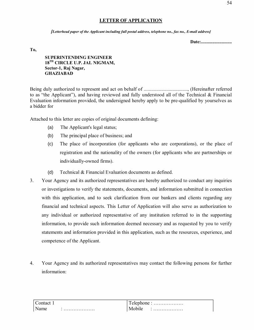
54
LETTER OF APPLICATION
[Letterhead paper of the Applicant including full postal address, telephone no., fax no., E-mail address]
Date:...........................
To, SUPERINTENDING ENGINEER 18TH CIRCLE U.P. JAL NIGMAM, Sector-1, Raj Nagar, GHAZIABAD
Being duly authorized to represent and act on behalf of ..................................., (Hereinafter referred to as “the Applicant”), and having reviewed and fully understood all of the Technical & Financial Evaluation information provided, the undersigned hereby apply to be pre-qualified by yourselves as a bidder for Attached to this letter are copies of original documents defining:
(a) The Applicant's legal status;
(b) The principal place of business; and (c) The place of incorporation (for applicants who are corporations), or the place of
registration and the nationality of the owners (for applicants who are partnerships or
individually-owned firms).
(d) Technical & Financial Evaluation documents as defined.
3. Your Agency and its authorized representatives are hereby authorized to conduct any inquiries
or investigations to verify the statements, documents, and information submitted in connection
with this application, and to seek clarification from our bankers and clients regarding any
financial and technical aspects. This Letter of Application will also serve as authorization to
any individual or authorized representative of any institution referred to in the supporting
information, to provide such information deemed necessary and as requested by you to verify
statements and information provided in this application, such as the resources, experience, and
competence of the Applicant.
4. Your Agency and its authorized representatives may contact the following persons for further
information:
Contact 1 Name : ……………….
Telephone : ……………… Mobile : ………………

55
Designation : ………………. Fax no. : ……………… E -Mail ID : ………………
Contact 2 Name : ………………. Designation : ……………….
Telephone : ……………… Mobile : ……………… Fax no. : ……………… -Mail ID : ………………
5. This application is made with the full understanding that: (a) Bids by pre-qualified applicants will be subject to verification of all information
submitted for Technical & Financial Evaluation at the time of bidding; (b) Your Agency reserves the right to:
• Amend the scope and value of any contracts bid under this project; in such event, bids will only be called from pre-qualified bidders who meet the revised requirements; and
• Reject or accept any application, cancel the Technical & Financial Evaluation process, and reject all applications.
(c) Your Agency shall not be liable for any such actions and shall be under no obligation to inform the Applicant on the grounds for them.
6. Our firm is enlisted in U.P. Jal Nigam as class ……….. Contractor in ………………… Category.
OR
Our firm is not enlisted in U.P. Jal Nigam as required but we have applied for enlistment as contractor in U.P. Jal Nigam in required class and category on ……….. (Copy of proof of submission of application form of enlistment attached)
7. The undersigned declare that the statements made and the informationprovided in the duly completed application are complete, true, and correct in every detail.
Signed
Name
For and on behalf of (Name of Applicant)

56
FORMAT (1)
VII
GENERAL INFORMATION OF BIDDERS All individual firms applying for Technical & Financial Evaluation are requested to complete the information
in this form. Nationality information should be provided for all owners or applicants who are partnerships or
individually owned firms.
Where the Applicant proposes to use named subcontractors for critical components of the works, the
following information should also be supplied for the specialist subcontractor(s), together with a brief
description of their specialized input.
1. Name of Applicant Firm
2. Head office address
3. Contact Person Telephone
Mobile no.
4. Fax E-mail
5. Place of incorporation / registration Year of incorporation / registration
Signature & Seal of Applicant

57
FORMAT (2) VIII
STRUCTURE AND ORGANISATION
1. The Applicant is
(a) An Individual
(b) A Proprietary Firm
(c) A Partnership Firm
(d) A Limited Company or Corporation
(e) Any other (Please specify)
2. Attach the Organisation Chart showing the structure of the Organisation including the names of the Owners/Directors and position of the officers.
3. No. of years of experience as firm shouldering major responsibility.
4. No. of years the organization has been in business of similar work under its present name and style areas of business when the organization was established. New areas of business added to the organization and the years when added.
5. Name of the projects where in the organization was required to suspend the construction and/or erection works for more than six months continuously after commencement. Please state the reasons therefore and the present status.
6. Name of the projects where in the organization was required to suspend the operation and maintenance works for more than six months continuously after commencement. Please state the reasons therefore and the present status.
7. Name of the projects where in the organization was required to abandon after award and the reasons therefore.
8. Areas of specialization and interest in civil engineering construction.
9. Details of experience in using heavy earthmoving equipment.

58
FORMAT (3) IX
ANNUAL TURN OVER
Name of Applicant
All individual firms are requested to complete the information in this form. The information supplied
should be the annual turnover of the Applicant, in terms of the amounts billed to clients for each year
for work in progress or completed.
Applicants should not be required to enclose testimonials, certificates, and publicity material with their applications; they will not be taken into account in the evaluation of qualifications.
Sl. No.
Financial Year
Annual Turnover Data Remarks Actual Annual
Turnover ( In Rs. Crores)
Multiplying Factor
Evaluated Turnover
( In Rs. Crores) 1 2 3 4 5 6 1.
2017-18 1.00
2.
2016-17 1.08
3. 2015-16 1.17
4. 2014-15 1.26 5. 2013-12 1.360 6. 2012-11 1.47 7. 2011-10 1.59 8. 2010-09 1.71 9. 2009-08 1.85 10 2008-07 2.00
Signature & Seal of Applicant

59
FORMAT (4) X
PARTICULAR EXPERIENCE RECORD
Name of Applicant
To pre-qualify, the Applicant shall be required to pass the specified requirements applicable to this form, as
set out in the “Instructions for Pre – Qualification/Eligibility”.
On a separate page, using the format of Format (4A), and (4B) as applicable, the Applicant is requested to list
all contracts of a similar nature and complexity to the contract for which the Applicant wishes to qualify and
undertaken during the last 10 (ten) years within India. Such details should be submitted using formats 4A and
4B respectively for each contract completed or under execution, by the Applicant. The applicants must submit
the performance report (completion certificate) in support of their work experience obtained from the
authorized representative of client containing Agreement No., date of start, date of completion and value of
work done (Performa is annexed with format (4C).
Where the Applicant proposes to use named subcontractors for critical components of the works, the
information in the same forms should also be supplied for each specialist subcontractor.
Applicants are required to enclose evidence documents for work in progress or completed as specified in para
8 of Important Note. Use of copy of certificates is recommended with signature of applicant for
authentication.
Any work done as a subcontractor will not be considered for eligibility.
Please attach certified copy of the certificate of experience in support of above details issued by the Govt.
Deptt./Public sector under taking by an authority not below the rank of Executive Engineer or authorised rank
for the work cost on attached Performa.

60
FORMAT (4A)
XI
DETAILS OF CONTRACTS OF SIMILAR NATURE AND COMPLEXITY
Name of Applicant
Use a separate sheet for each contract. 1. Status of Work Completed/Under Execution 2. Contract Bond No. 3. Name of Contract 4. Country 5. Name of Employer 6. Employer Address & Phone no. 7. Nature of works and special features relevant to the contract for which the Applicant wishes to
prequalify 8. Contract role (check one)
Sole contractor Subcontractor
9. Value in specified currencies at completion, or at date of award for current contracts,
• Total Contract Amount : Rs _____________(Rs. _________________________ )
• Sub-Contract Amount (if the role was sub-contractor): Rs _________ (Rs. _________) 10. Schedule Contract/duration for execution and commissioning _____Years ______ months 11. Schedule Contract/duration for operation & maintenance _____ Years ______ months 12. Schedule Date of award/completion 13. Actual date of completion of work (Execution and Commissioning) 14. Actual date of completion of work (Operation & Maintenance) 15 Main component of the work executed
(a) Total Excavation/Earth Work (b) Total RCC Work (c) Total Pipe Line Work in Water Supply (Dia & Length) (d) Total Sewer Laying Work (Dia & Length) and Maximum Depth (e) STP/WTP (f) Pumping Plant (g) Others
NOTE :Verification of above required on performa annexed with (4a). Signature & Seal of Applicant

61
FORMAT (4B)
XII
Summary Sheet: Current Contract Commitments / Works in Progress Name of Applicant
Applicants and each partner to an application should provide information on their current commitments on all contracts that have been awarded, or for which a letter of intent or acceptance has been received, or for contracts approaching completion, but for which an unqualified, full completion certificate has yet to be issued.
Rs. In Crores
S.N Name of contract
Address of the client
Brief scope
Date of
Start
Contract Value
Stipulated completion
date
Estimated completion
date
Percent completion achieved as
on 31.03.2018
Value of outstanding
work
Amount to be spent during next 2 years
Year 1 Year 2
1 2 3 4 5 6 7 8 9 10 11a 11b 1.
2.
3.
4.
5.
NOTE : IF REQUIRED PLEASE ADD ADDITIONAL SHEETS
Signature & Seal of Applicant

62
Annexure of Format no. – 4(A)
XIII Client Certificate Regarding Performance of Contractor
Name of Address of the Client..................:.......................................................................................
...........................................................................................................................................................
Details of Works executed by Shri / M/s. ........................................................................................
...........................................................................................................................................................
1 Name of work brief particulars 2 Agreement No. and Date 3 Date of commencement of work 4 Stipulated date of completion. 5 Actual Date of completion 6 Details of compensation of levied for delay,
if any
7 Tendered amount 8 Gross amount of the work completed 9 Name and address of the authority under
whom works executed
10 Whether the contractor employed qualified Engineer/Overseer during execution of work?
11 (i) Quality of work (indicate grading) (ii) Amount of work paid on reduced rate basis if any
12 (i) did the contractor go for arbitration? (ii) If yes, total amount of claim (iii) Total amount awarded.
13 Comments on the capacities of the contractor
(a) Technical Proficiency (b) Financial soundness (c) Mobilisation of adequate T&P (d) Mobilisation of manpower (e) General behavior
Outstanding/Very Good/Good/Poor Outstanding/Very Good/Good/Poor Outstanding/Very Good/Good/Poor Outstanding/Very Good/Good/Poor Outstanding/Very Good/Good/Poor
Note : All columns should be filled in properly.
Signature of the Reporting Officer with Official Seal

63
FORMAT (5A)
XIV
PERSONNEL CAPABILITY The Applicant is requested to provide the names of at least two candidates qualifying the specific positions that according to the Applicant are essential to contract implementation and for positions mentioned in the Pre – Qualification Document. Please supply the candidate data on separate sheets using the format of Form (6B) Name of Applicant Firm ……………………………………………………………………. Sl. No. Title of Position Name of Prime Candidate & E.
Mail/Mobile No. Name of Alternate Candidate
& E. Mail/Mobile No. 1 2 3 4 1
2
3
4
5.
Signature & Seal of Applicant

64
FORMAT (5B)
XV
CANDIDATE SUMMARY Name of Firm………………………………………………………………….. Sl. No.
Name of Employee /Candidate
Professional Qualifications
Designation Professional Experience
Working with Firm
Staff to be deployed on the work under this
tender From To
1 2 3 4 5 6a 6b 7
Signature of Bidder

65
FORMAT (6)
XVI
EQUIPMENT CAPABILITY Name of Firm : ………………………………………………………………………….. The Applicant shall provide adequate information to demonstrate that the Firm has the capability to meet the requirements for all items of equipment required for timely completion of the Project.
Sl. No.
Name of T&P /Equipment
Model / Year of Manufacturing
Capacity T&P to be used on the work under this tender
Remarks
1 2 3 4 5 6
Signature of Firm

66
FORMAT (7)
XVII FINANCIAL CAPABILITY
Name of Applicant
Applicantsshould provide financial information to demonstrate that they meet the requirements stated in the Instructions to Applicants. Each applicant must fill in this form. If necessary, use separate sheets to provide complete banker information. A copy of the audited balance sheets and statement of profit and losses should be attached. Banker Name of banker
Address of banker
Telephone/Mobile no.
Contact name and title
Fax no.
Summarize actual assets and liabilities in INR equivalent (at the rates of exchange current at the end of each year) for the previous five years. Based upon known commitments summarize projected assets and liabilities in INR equivalent for the next two years. Financial information Rs.in Crore
Actual : Previous five years
Year 1 Year 2 Year 3 Year 4 Year 5 1. Total assets 2. Current assets 3. Total liabilities 4. Current liabilities 5. Sales 6. Ordinary Profits 7. Profits before taxes 8. Profits after taxes 9. Net worth Specify proposed sources of financing to meet the cash flow demands of the Project, net of current commitments for other contracts. Source of financing Amount (Rs. in Crore) 1. 2. 3. 4.
Attach audited financial statements for the last five years (for the individual applicant).
Firms owned by individuals, and partnerships, may submit their balance sheets certified by a registered accountant, and supported by copies of tax returns. Applicants are be requested to submit a bank reference letter from a reputable commercial bank to the effect that such bank certifies the financial capability of the applicants to meet their financial obligation to perform the said contract and considers to issue a specific line ofcredit when and if the contract is awarded to the applicants
Signature&SealofApplicant

67
FORMAT (8)
XVIII
BIDDING CAPACITY
NAME OF THE APPLICANT / FIRM / CORPORATE HOUSES:
SI. No. Description Threshold value Eligibility
A Bid Capacity Rs. Crores Equal to or greater than threshold value Rs. 11.13 Crore
Financial Year Turnover in Rs. Lacs (Pre-Factoring)
Factor Turnover in Rs. Lacs (Post - Factoring)
2017-2018 1.00
2016-2017 1.08
2015-2016 1.17
Assessed available bid capacity (AxNx2)-B A = Maximum value of all works at current price executed in any one of the three previous financial
years (at current price level) B = Value at current price level of existing commitments and ongoing works to be completed in the
next 'N' years. N = No. of years prescribed for the completion of the subject contract I/ We fulfill / not fulfill the aforesaid of eligibility criteria.
Signature of authorized signatory with Name designation, date & company seal

68
FORMAT (9)
XIX
List of works for which tenders have already submitted to any client but not awarded.
Name of Applicant
Sl. No.
Name of Client & Address of
Correspondence/Telephone no.
Name of work
Estimated cost of work,
Rs. In lacs
Date of submission
of offer
Position in the bidding if opened
Likely date of award
Remarks, if any
1 2 3 4 5 6 7 8
1.
2.
3.
4.
5.
6.
Signature & Seal of Applicant

69
FORMAT (10)
XX
LITIGATION HISTORY
Sl.No. Name of Deptt. With
which dispute arose. Address with Tel. No.
and e-mail address of Deptt.
Ref. of Tender/ cost
of work
Date of start of work
Schedule date of completion
of work
Date of start of Dispute
1 2 3 4 5 6
Nature of Dispute
Total Cost of Disputed work
Dispute pending under Present of Position of Dispute
Arbitration Court Settled with cost & Date
Under Progress
7 8 9 10 11 12
Please Specify :
1. If the Applicant firm has ever been black listed or debarred for tendering
by any Government/Semi Government Organization. If so, provide details
and present status.
2. If the Applicant firm has ever been executed or under trial by any court on
any tendering matter or any matter related to contract bond.
Signature & Seal of Applicant

70
FORMAT (11) XXI
'kiFk i=
eSa ------------------------------------------------------------------------------ iq= Jh -------------------------------------------------------
--------------------------------------------------------------------------------------------------------------------------------------------------------------
¼vLFkk;h irk½ ----------------------------------------------------------------------------------------------------------------------------
fuoklh gwaA
eSa 'kiFkiwoZd ?kks"k.kk djrk gwa %&
1- eSa lacaf/kr foHkkx dk ,@ch@lh@Mh Js.kh dk iathd̀r Bsdsnkj gwa@ugh gwaA ¼foHkkx }kjk fuxZr
Js.kh laca/kh izek.k layXu fd;k tk;s½ esjs ikl i;kZIr py vkSj vpy lEifRr gS vkSj O;olkf;d
:i esa ty fuxe ds dk;kZsa dks iwjk djus ds fy;s l{ke vkSj leFkZ gwaA esjs ikl vko’;d e’khusa
vkSj midj.k vkfn Hkh gSa rFkk eq>s bl dk;Z dk i;kZIr vuqHko gSA
2- lacaf/kr foHkkx }kjk tks ¼dk;Z dk fooj.k fy[kk tk;s½ ---------------------------------------------------------------------------------
---------------------------------------------------- djkus dh fufonk fuxZr dh xbZ gS foHkkx }kjk fu/kkZfjr izk:i ij
fufonk Hkj jgk gwaA
3- esjs }kjk fn;s tk jgs izek.k i= pfj= izek.k i=] gSfl;r izek.k i=@vk;dj izek.k i=@O;kikj
dj izek.k i=@ chM flD;ksfjVh izek.k i=@chM dSfiflVh izek.k i=@tekur /kujkf’k vkfn
dk izek.k i= rFkk vU; lalxr vfHkys[kksa vkfn ewy :i esa fufonk izi= ds lkFk layXu dj
fn;s x;s gSaA
4- esjk iSu ua0 ------------------------------------------------------------------------------------ gSA ¼vk;dj foHkkx }kjk iznRr izek.k
i= layXu fd;k tk;s½
5- esjs fo#) vijkf/kd eqdneksa dk fooj.k fuEu izdkj gSA ;gha iwjk fooj.k fn;k tk;sA
1- eqdnek uEcj --------------------------------------------------------
2- /kkjk;sa -----------------------------------------------------------------------
3- Fkkuk --------------------------------------------------------------------------
4- tuin ------------------------------------------------------------------------
5- U;k;ky; ¼tgka eqdnek py jgk gS½------------------------------------------------------------------------------------
6- eSa lacaf/kr foHkkx vFkok jkT; ljdkj ds vU; foHkkxksa }kjk CySd fyLVsV Bsdsnkj dh Js.kh esa
ugh vkrk gwaA eSa vijkf/kd xfrfof/k;ksa] ekfQ;k rFkk xSaxLVj xfrfof/k;ksa vkSj laxfBr vijk/k
djus dh xfrfof/k;ksa vkSj vlkekftd dk;ksaZ vkfn esa fyIr ugh gwaA eSa ekfQ;k vkSj vijk/kh ugha
gwaA esjk pky&pyu dk;Z rFkk vkpj.k mRre gSA
7- esjs fo#) tuin esa rFkk izns’k esa dksbZ Hkh eqdnek ntZ ugha gSA
8- ;fn Bsdk izkIr djus ds i’pkr esjs fo#) ekfQ;k xfrfof/k;ksa@vlkekftd xfrfof/k;ksa o
laxfBr vijkf/kd xfrfof/k;ksa esa fyIr gksus ds ckjs esa dksbZ f’kdk;r izekf.kr ik;h tkrh gS rks
l{ke vf/kdkjh dks ;g vf/kdkj gksxk fd og esjk Bsdk@vuqcU/k fujLr dj ns] bl ij eq>s dksbZ
vkifRr ugh gksxhA esjs }kjk ;fn foHkkx @jkT; ljdkj ds fo#) dksbZ vijkf/kd dk;Z fd;k
tkrk gS vFkok ljdkjh /ku dk xcu fd;k tkrk gS rks l{ke vf/kdkjh dks ;g vf/kdkj gksxk fd
og esjs fo#) vijkf/kd eqdnek fu;eksa ds vUrxr ntZ djk;saA
jktif=r
vf/kdkjh }kjk
izekf.kr
uohure
ikliksVZ
lkbZt dk

71
9- eSa vuqcU/k dh 'krksaZ ds vuqlkj le; ls iwjh xq.koRrk ds lkFk fu/kkZfjr fof’kf"V;ksa ds vuq:i
dk;Z iwjk d:axk vkSj foHkkx dks iwjk lg;ksx iznku d:axkA
10- esjk dk;Z ,oa vkpj.k mRre gSaA
11- eSa 'kiFkiwoZd ?kks"k.kk djrk gaw fd esjk LFkkbZ irk vkSj vLFkkbZ irk fuEu izdkj gS &
v½ LFkk;h irk ¼nwjHkk"k lfgr½ % -------------------------------------------------------------------------------------------------------------------
----------------------------------------------------------------------------------------------------------------------------------------------------------------------------------
-----------------------------------------------------------------------------
c½ vLFkk;h irk ¼nwjHkk"k lfgr½% -------------------------------------------------------------------------------------------------------------------
----------------------------------------------------------------------------------------------------------------------------------------------------------------------------------
----------------------------------------------------------------------
¼;gka iwjk irk nwjHkk"k lfgr ,oa fiu dksM lfgr fy[kk tk;sa½
12- eSa 'kiFkiwoZd ?kks"k.kk djrk gwa fd eSa mijksDr irs ij jgrk gwa rFkk foHkkx }kjk iznku fd;s x;s
dk;Z ds iwjk gksus rd esjs fdlh irs esa lkekU;r% dksbZ ifjorZu ugh gksxk] ;fn vifjgk;Z
ifjfLFkfr;ksa es fdlh irs es ifjorZu gksrk gS rks bldh lwpuk eS rRdky lacaf/kr izkf/kdr̀
vf/kdkjh dks nwaxkA
13- eSa ;g Hkh ?kks"k.kk djrk gwa fd foHkkx ds ftl dk;Z ds fy, esjs }kjk Bsdk fy;k tk jgk gS mlds
lkis{k py ,oa vpy lEifRr dk gSfl;r izek.k i= ftyk eftLVªsV@dySDVj ¼tuin dk uke
fy[kk tk;s½ -------------------------------------------------------------------------------------------- }kjk izkIr djds ewy :i ls
layXu fd;k tk jgk gSA ;g Hkh ?kks"k.kk djrk gwa fd bu gSfl;r izek.k i= dk mi;ksx vU;
dk;kZsa ds fy, ugha fd;k tk;sxkA
14- eS viuh iw.kZ tkudkjh esa iwjs gks’kks gokl esa] LoLFk fpr ls] iwjh lR;fu"Bk ls rFkk LosPNk ls ;g
'kiFk i= fy[k dj ns jgk gwaA bZ’oj esjh enn djsA
fnukad -------------------------------------
'kiFkh dk iwjk gLrk{kj
iwjk uke% -------------------------------------------------------
----
irk % --------------------------------------------------------------
---
uksV %&
1- ;g Lo?kks"k.kk 'kiFk i= :0 100-00 ¼:0 ,d lkS½ ds LVkEi isij ij uksVjh }kjk lk{;ksa dh
mifLFkfr esa lR;kfir gq, fn;k tk;sxkA
2- vlR; 'kiFk&i= nsuk ,d laxhu vkSj laKs; vijk/k gSA
3- lacaf/kr O;fDr }kjk ikliksVZ lkbt dk viuk QksVksxzkQ] tks jktif=r vf/kdkjh }kjk
izekf.kr gks 'kiFk&i= ds Åij fu/kkZfjr LFkku ij pLik fd;k tk;sxkA

72
FORMAT (12)
XXII
FORM OF SOLVENCY CERTIFICATE FROM A SCHEDULED
PUBLIC SECTOR BANK
This is to certify that to the best of our knowledge and Information M/s/Sri …………………………….
Address…………………………………………………, a customer of our bank are/is respectable and can
be treated as good for any engagement upto a limit of Rs. ………………. (Rupees
…………………………..). This certificate is issued without any guarantee or responsibility on the Bank or
any of the officers.
(Signature) Of the Bank Authority Name of Bank & Seal
Note : In case of partnership firm, certificate to include names of all partners as recorded with the Bank.
Signature of Applicant/Bidder
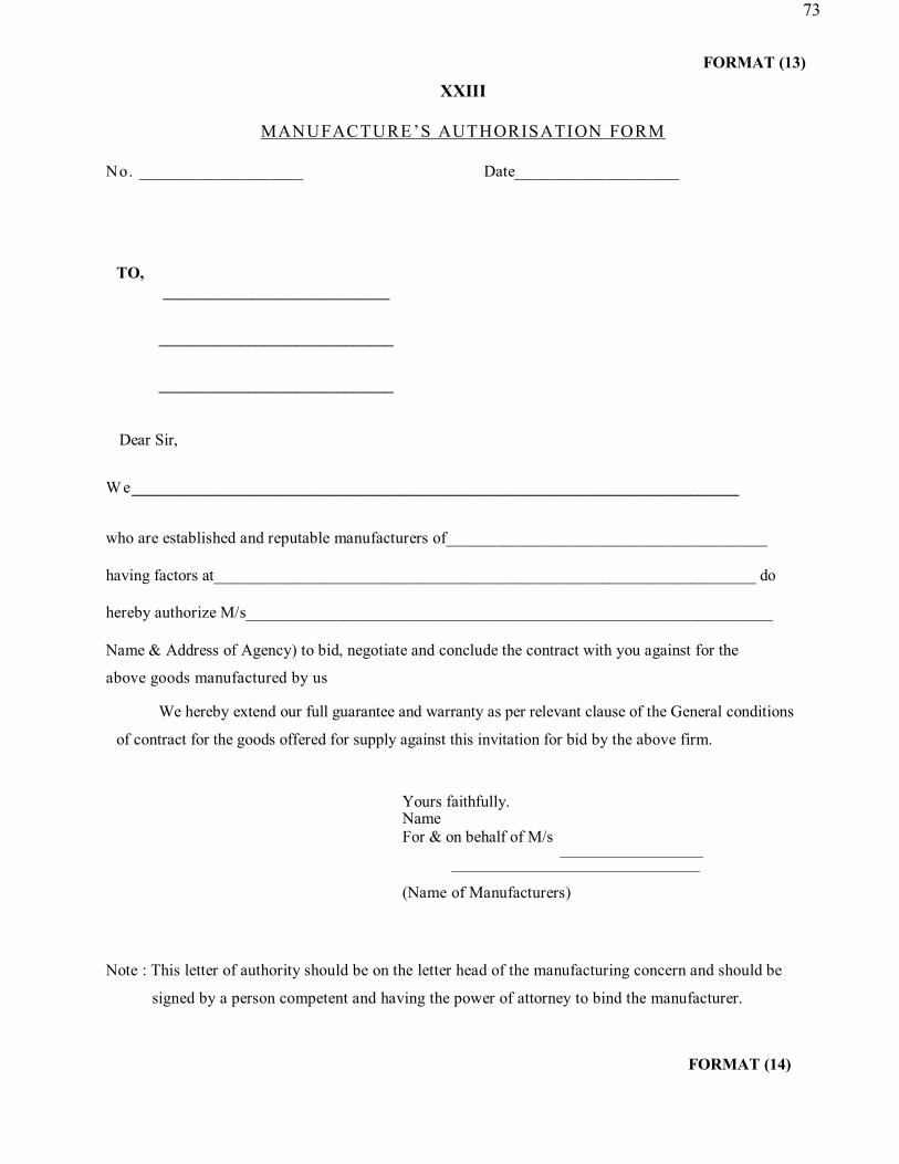
73
FORMAT (13)
XXIII
MANUFACTURE ’S AUTHORISATION FORM No. ____________________ Date____________________
TO, ____________________________
_____________________________
_____________________________
Dear Sir,
We___________________________________________________________________________
who are established and reputable manufacturers of_______________________________________ having factors at___________________________________________________________________ do hereby authorize M/s________________________________________________________________
Name & Address of Agency) to bid, negotiate and conclude the contract with you against for the
above goods manufactured by us
We hereby extend our full guarantee and warranty as per relevant clause of the General conditions
of contract for the goods offered for supply against this invitation for bid by the above firm.
Yours faithfully. Name For & on behalf of M/s
(Name of Manufacturers)
Note : This letter of authority should be on the letter head of the manufacturing concern and should be
signed by a person competent and having the power of attorney to bind the manufacturer.
FORMAT (14)

74
XXIV U.P JAL NIGAM
Check List (To be filled by Bidder)
Sl. No.
Title Action Required Action Taken or
Not
Page No.
1 2 3 4 5 1. Memorandum of Works Filled & Signed Yes/No 2. Letter of Undertaking Filled & Signed Yes/No 3. EMD Details Filled & Attach Yes/No 4. Application Forms Signed & Attach Document Yes/No 5. Information Regarding Enlistment in
Jal Nigam as contractor Copy Attach Yes/No
(i) Format – 1, General Information Signed & Attach required documents
Yes/No
(ii) Format – 2, Structure and Organisation Signed & Attach organization chart
Yes/No
(iii) Format – 3, General Experience Record Signed & Attach Certificate of Chartered Account
Yes/No
(iv) Format – 4, Particular Experience Record
(v) Format – 4a, Details of Contracts of Similar Nature and Complexity
Filled for Qualifying as per clause 14a & signed
Yes/No
Performa of Performance Report by Client Department
Copy Attach Yes/No
(vi) Format – 4b, Current Contract Commitments / Works in Progress
Filled & Signed Yes/No
(vii) Format – 5A, Personnel Capability Filled & Signed Yes/No (viii) Format – 5B, Candidate Summary Filled & Signed Yes/No (ix) Format – 6, Equipment Capability Filled & Signed Yes/No (x) Format – 7, Financial Capability Filled & Signed, Attach copy of
Previous 5 Year Audited Balance Sheet & Bank Letter
Yes/No
(xi) Format – 8, Bidding Capacity Filled & Signed Yes/No (xii) Format – 9, List of works for which
tenders have already submitted to any client but not awarded
Filled & Signed Yes/No
(xiii) Format – 10, Litigation History Filled & Signed and Attach Supporting Document
Yes/No
(xiv) Format – 11, ‘'kiFk i= Filled & Signed with Photo Yes/No (xv) Format – 12 Form of Solvency
Certificate Form A Scheduled Public Sector Bank
Filled & Signed Yes/No
(xvi) Format – 13 Manufacturer’s Authorization Form
Filled & Signed Yes/No
(xvii) Additional Information Enclosed Yes/No
Signature of Applicant/Bidder

75
U T T A R P R A D E S H J A L N I G A M
E-TENDER DOCUMENT
Volume-II
TECHNICAL BID / CONDITION OF CONTRACT
COMMON FOR
HAPUR SEWERAGE SCHEME PART-I PHASE-II
IN THE CITY OF HAPUR
UNDER
“ATAL MISSION FOR REJUVENATION AND URBAN TRANSFORMATION”

76
XXVI- INSTRUCTIONS TO BIDDERS:
(1) To visit the site so as to ascertain the local conditions and availability of materials etc and quote their rates accordingly. However, no claim shall be entertained even if the site of works is changed/ modified.
(2) To study the schedule 'I' for materials to be supplied by the department and their issue rate and other conditions.
(3) To quote the rates strictly as per language of price Schedule-‘G’ and bidders should not quote or write any conditions which are not required in price schedule. The conditional tender is liable to be rejected.
(4) To read carefully the specifications, terms and conditions, work out their own quantities from the drawing before quoting the rates.
(5) To well acquaint themselves with the nature of work, the existing water mains, incoming drainage and other utility service lines/obstacles etc. through the alignment, they should include in their rates sufficient allowances to meet unforeseen expenses on these grounds.
(6) The quantities are approximate and can vary up to any extent on either side and no extra claim shall be entertained on this account. The contactors will be paid on the basis of actual measurements of finished work, executed by him.
(7) No payment will be made for making the layout, construction of level pillars and removal of debris from the alignment and grass etc. for the proper execution of work.
(8) Final payment shall be made after proper testing as per satisfaction of Engineer.
(9) IS code/ U.P.Jal Nigam/ PWD/CPHEEO detailed specifications shall be followed during execution of work/ recording measurements and payment etc.
(10) The tender shall be issued in duplicate but is to be submitted in one copy only containing all necessary information therein as asked for.
(11) The tenderers should go through all the details carefully including annexure-2 L.S.G.E.D./ U.P. J.N. & drawings etc. mentioned here-in-under & sign each page before submitting.
(12) The field survey, Hydraulic design and structural design for each and every individual unit of work shall have to be done by the contractor and duly approved by the department.
(13) The working pressure shall be as prescribed in the technical specifications and factory test pressure shall be as per latest amendment of relevant IS code for the pipe to be supplied by the contractor as per approved vendor list by the competent authority.
(14) The earnest money as specified in tender notice i.e. Rs. 41,70,772.00/- for Hapur Sewerage Scheme Part-I Phase-II must be paid through RTGS as per NIT bank detail shall be uploaded in the online portal.
(15) Corrections in the bid should be noted over and initialed at the place of corrections.
(16) Specifications, conditions, schedules, regulations and safety measures and drawings of bidding document constitute an integral part of the bid.
(17) Negligence of the bidder in preparing bid confers no right to withdraw the bid after it has been opened and before expiry of stipulated validity period.
(18) The bid along with enclosures, drawings and technical literature should be in English only.
(19) Bids should be kept valid for acceptance for a period of 120 days from the day bids are opened.
(20) The bidding document shall be governed and interpreted according to the laws of the Union of India. If it is found that documents submitted by bidders are false or fraudulent before or after the evaluation of the process, their bids shall be cancelled and action will be taken against the bidders.

77
(21) All bidders are urged to submit promptly, written requests, on matters where clarifications or additional information are desired before per-bid meeting. No extension in due date of submission of bids will be allowed on this ground.
(22) Bids should be responsive to the instructions to bidders and the conditions of contract in the bid document.
(23) Bidder shall not be under a declaration of ineligibility for corrupt and FRAUDULENT practices issued by any authority.
(24) All bidders shall include the following information and documents with their bids.
(a) Copies of original documents or notarized copy defining the constitution or legal status, place of registration and principal place of business, written power of attorney of the signatory of the bid to commit the Bidder.
(b) Total monetary value of construction work performed for each of the last five years.
(c) Experience in works of similar nature and size for each of the last five years and details of works under-way or contractually committed, and clients who may be contacted for further information on those contracts.
(d) Major items of construction equipment proposed to carry out the contract.
(e) Qualification and experience of key site management and technical personnel for the contract.
(f) Reports on the financial standing of the bidder, such as profit and loss statement and auditors reports for the last five years.
(g) Evidence of adequacy of working capital for this contract (access to line of credit and availability of other financial resources.
(h) Authority to seek references from the bidder’s bankers.
(i) Information regarding any litigation or arbitration resulting from contracts executed by the Bidder in last five years or currently under execution. The information shall include the names of the parties’ concerned disputed amount, cause of litigation and matter in dispute
(j) Proposals for subcontracting component of the works amounting to more than 20% of the bid price for each, the qualification and experience of the identified sub-contractors in the relevant field should be annexed.
(k) To qualify for the contract, bidder should stand qualified as per norms/ criteria given in prequalification bid.
(l) Queries raised after the opening of financial bid shall not be entertained.
NOTE: THE CHIEF ENGINEER/ S.E/OFFICER INVITING TENDERS RESERVES THE RIGHT TO ACCEPT OR REJECT ANY OR ALL BIDS WITHOUT ANY EXPLANATION TO BIDDERS.
SE Signature of Contractor U.P. Jal Nigam

78
XXVII - DEFINITIONS AND INTERPRETATIONS
1. TERMS: The important terms, which shall be used in the contract Documents are defined herein. It shall be applicable to both the singular and plural number and masculine/ feminine in gender.
2. ADDENDA AND CORRIGENDA: Written or graphic notices issued by the department prior to submission of the tender to modify or interpret the Contract Documents.
3. TENDER/ BID: The offer or proposal of the bidder, submitted in the prescribed form to set-forth the prices for the work to be carried out and the details thereof.
4. TENDERER/ BIDDER/ CONTRACTOR/ SUPPLIER: Any person, firm, corporation or organization submitting a Tender or execute the work after signing the agreement with the department.
5. CHAIRMAN: Chairman shall mean the Chairman, U.P. Jal Nigam, Govt. of Uttar Pradesh here-in-after called the Chairman.
6. CHIEF ENGINEER: "The Chief Engineer" shall' mean the Chief Engineer (GZB.Zone), U.P. Jal Nigam, Ghaziabad here-in-after called the Chief Engineer.
7. SUPERINTENDING ENGINEER: The Superintending Engineer shall mean Superintending Engineer, (18th Circle ). U.P.Jal Nigam, Ghaziabad.
8. EXECUTIVE ENGINEER: The Executive Engineer/ Project Manager shall mean the Ex. En., Construction Division, U.P. Jal Nigam, Bulandshahr.
10. ENGINEER: shall mean the Engineer officer (or any other competent person appointed by the Engineer-in-charge, to act in addition or replacement of the Engineer) who shall supervise the execution of the works and administering the contract and be in-charge of the work on behalf of the Engineer- in-charge i.e. Ex. En Construction Division, U.P. Jal Nigam, Bulandshahr hereinafter called the Engineer.
11. ENGINEER-IN-CHARGE: It shall mean the Officer signing the contract on behalf of U.P.Jal Nigam,
12. COMPETENT AUTHORITY: It shall mean the next higher authority signing the contract.
13. ENGINEER'S REPRESENTATIVE: The Engineer's representatives shall mean the Assistant Engineer, Junior Engineer ,Construction Division.U.P. Jal Nigam Bulandshahr. Hereinafter called the Engineer's representatives.
14. CONSULTANT: The firms or persons whose expertise has been sought by the Chairman for the proper execution of work stipulated in the contract bond hereinafter called the consultant
15. CONTRACTOR'S REPRESENTATIVES: Any competent person/ persons such as Engineer/Sub-Engineer/ Work Agent/Supervisor /Foreman etc. as may be necessary duly authorized by the contractor in writing & approve by the Engineer for the proper execution of work/works.
16. DEPARTMENT/U.P JAL NIGAM’: It shall mean the U.P. Jal Nigam hereinafter called the department.
17. SUB-CONTRACTOR: A sub-contractor is a person, firm corporation or organization who has a direct contract with the main Contractor to perform parts of the works at the site, whose entity is duly approved by the General Manager.
18. CONTRACT TIME: The number of consecutive calendar months for completion of the work as stipulated in schedule "F" here in annexed
19. STANDARDS: It refers to Indian-Standards issued by the Bureau of Indian Standards. All materials and workmanship which form part of tender documents shall conform to the relevant IS code or its latest amendments Items not covered under the IS code shall be executed as per standard code of practice of U.P. Jal Nigam/P.W.D/U.P.Irrigation /CPWD.
20. CONTRACTOR'S EQUIPMENT: Contractor's equipment means all equipments and appliances such as mixer, vibrator, pumps, chain pulley block, sieves and fabricated device excavators; crane etc. for proper execution, completion and maintenance of works.

79
21. NOTICE OF AWARD: The written notice by the Chief Engineer to the successful Bidder for signing the agreement on the format herein annexed in stipulated time.
22. NOTICE TO PROCEED: The written notice by the Engineer to the Contractor authorizing him to proceed with the work. The date mentioned in the letter shall be the date of start of the work.
23. VARIATION ORDER: A written order to the Contractor signed by the authorizing an addition, deletion or revision in the quantum of work/drawings provided in the tender documents.
S.E/E.E. Signature of Contractor
U.P. Jal Nigam

80
XXVII- GENERAL RULES AND GUIDE LINES 1.0 All work proposed for execution by contract will be notified in a form of invitation to tender pasted in
public places and signed by the officer inviting tender or by publication in News papers or posted on website as the case may be. Tender, documents will be sold to only registered contractors as defined in Tender notice.
2.0 CLASSIFICATION OF TENDERERS: 2.1 If the tender is made by an individual it shall be signed by the individual with his full name and current
address underneath. If the tender is made by a proprietary firm, it shall be signed by the proprietor with his full name and name of his firm with its current address underneath.
2.2 If the tender is made by a firm in partnership, it shall be signed by all partners of the firm with their full names and current addresses, or by a partner holding the power of attorney. A certified copy of the power of attorney, partnership, deed, address of the firm and the full names and address of all the partners of the firm shall also accompany the tender.
2.3 If the tender is submitted by a limited company or a limited corporation, it shall be signed by a duly authorized person holding the power of attorney. Such limited company or corporation may be required to furnish satisfactory evidence of its existence before the contract is awarded. A copy of said company’s articles of Association should be enclosed to substantiate its claim.
2.4 All witnesses and sureties shall be of persons of status and probity and their full names, occupations and addresses shall be stated below their signatures. All signatures in the tender document shall be dated.
3.0 Receipts for payment made on account of work, when executed by a firm, must also be signed by all the partners, except where contractors are described in their tender as a firm, in which case the receipts must be signed in the name of the firm by one of the partners, or by some other person having due authority to give effectual receipts for the firm.
4.0 Any person who submits a tender shall fill up the usual printed form, stating at what rate he is willing to undertake each item of the work. Tenders, which propose any alteration in the work specified in the said form of invitation to tender, or in the time allowed for carrying out the work, or which contain any other conditions of any sort, including conditional rebates, will be summarily rejected.
5.0 In case the lowest tendered amount (worked out on the basis of quoted rates) of two or more contractors
is same, then such lowest contractors may be asked to submit sealed revised offer quoting rate of each item of the schedule of quantity for all sub sections/sub heads as the case may be, but the revised quoted rate of each item of schedule of quantity for all sub sections/sub heads should not be higher than their respective original rate quoted already at the time of submission of tender. The lowest tender shall be decided on the basis of revised offer.
6.0 If the revised tendered amount (worked out on the basis of quoted rate of individual items) of two or
more contractors received in revised offer is again found to be equal, then tender shall be rejected and fresh tender shall be invited.
7.0 In case any one or all the lowest contractors refuse to submit revised offers, then tenders are to be
recalled after forfeiting 50% of EMD of such lowest contractors .and contractor, whose earnest money is forfeited because of non-submission of revised offer, or quoting higher revised rate(s) than their respective original rate quoted already at the time of submission of his bid shall not be allowed to participate in the retendering process of the work.
8.0 The officer inviting tender or his duly authorized assistant will open tenders in the presence of any
intending contractors who may be present at the time, and will enter the amounts of the several tenders in a comparative statement in a suitable form. In the event of a tender being accepted, a receipt for the earnest money shall there upon be given to the contractor.

81
9.0 The officer inviting tenders shall have the right of rejecting all or any of the tenders and will not
be bound to accept the lowest or any other tender. 10. The memorandum of work tendered for in case of Percentage Rate Tenders, only percentage quoted
shall be considered. Any tender containing item rates is liable to be rejected. Percentage quoted by the contractor in percentage rate tender shall be accurately filled in figures and words, so that there is no discrepancy. The procedure in above paragraphs for valuating and deciding shall also apply.
11. In the case of any tender where unit rate of any item/items appear unrealistic, such tender will be
considered as unbalanced and in case the tenderer is unable to provide satisfactory explanation, such a tender is liable to be disqualified and rejected.
12. The contractor shall comply with the provisions of the Apprentices Act 1961, and the rules and orders
issued there under from time to time. If he fails to do so, his failure will be a breach of the contract and the Superintending Engineer/Executive Engineer may in his discretion, without prejudice to any other right or remedy available in law, cancel the contract. The contractor shall also be liable for any pecuniary liability arising on account of any violation by him of the provisions of the said Act
13 ELIGIBILITY AND QUALIFICATION REQUIREMENTS 13.1. SALE OF TENDER DOCUMENTS IS RESTRICTED TO ELIGIBLE BIDDERS ONLY: To be eligible for award of contract, bidders shall provide evidence satisfactory to the employer of their
eligibility, and of their capability and adequacy of resources to carry out the contract effectively. To this end, all intending bidders shall submit the necessary information in proof of their eligibility before contract document are sold to them.
13.2 The bidders only who are registered in a particular category of works as per UP Jal Nigam norms, which can be seen in the office on any working day, shall be allowed to participate in bidding. For tenders of works more than RS. One crore the bidder must emerge successful in pre-qualification bid.
13.3 Tenderes / bidders should produce original or notarized copies of following documents along with their bids:
A) Copies of documents defining the constitution in or legal status, place of registration and principal place of business of the company or firm or partnership of each party there to constituting the bidder.
B) Details of the experience and past performance of the bidder on works of a similar nature within the past five years, and details of current work in hand and other contractual commitments, on the formats prescribed here with the tender document.
C) Major items of construction plant immediately available with the tenderer for use in carrying and the contract in the format prescribed.
D) The qualifications and experience of key personnel proposed for administration end execution of the contract, on the format prescribed in the document.
E) Reports on the financial standing of the bidder (or of each partner) such as profit and loss statements, balance sheets and auditor's report for the past five years, an estimated financial projection for the next two years and an authority from the bidder seek references from the bidder's bankers in addition to the information regarding financial position, solvency and capability of the firm.
14. SITE VISIT The bidder is advised to visit and examine the site or works and its surroundings and obtain for himself
on his own responsibility, all information that may be necessary for preparing the bid and entering in a contract. The cost of visiting the site shall be at bidder's own expense.

82
The bidder and any of his personnel or agents will be granted permission by the employer to upon the land for the purpose of such inspection, but only upon the express condition that the bidder, his personal or agents, will release and identify the employer and his personnel and agents against liability in respect thereof and will be responsible for personal injury (whether fatal or otherwise), loss of or damage to property and any other loss, damage-costs and expenses however caused, which but for the exercise of such permission would not have arisen.
"Further, the contractor shall conduct all such tests and carry out all such investigations, at his own cost, as may be required by him or by the engineer to ascertain bearing capacity of soils at different points for founding structures and various other data on hydrological and subsurface conditions relevant to the works and shall make available to the engineer the results of all such tests and investigations conducted by him. The proposals and designs of the contractor shall be based on results and finding of tests and investigations conducted by him as above subject approval would not absolve the contractor in any way, from any of his responsibilities regarding quality, safety, life and utility of works.
15. BIDDING DOCUMENTS The set of bidding documents issued for the purpose of bidding includes two copies of the following
document as applicable, together with any addenda thereto issue in accordance with clause 13 and any minutes of pre-bid meetings to be invited by the Engineer inviting tenders.
PRE-QUALIFICATION BID (For tenders more than 1.0 crore) A. NOTICE FOR PRE-QUALIFICATION OF BIDDERS
B. PROJECT DESCRIPTION AND GENERAL SCOPE OF WORK
C. PRE-QUALIFICATION DATA AND INSTRUCTION TO THE APPLICANT
D. ELIGIBILITY AND QUALIFICATION CRITERIA
E. APPLICATION FORMS
F. CHECK LIST
GENERAL AND SPECIAL CONDITIONS:-
(i) Instructions to bidders
(ii) General Conditions of contract
(iii) Conditions of particular application
(iv) Schedule of guarantee
(v) Schedule of supplementary information
TECHNICAL SPECIFICATIONS
A. WORKS
B. DRAWINGS
PRICE BID
A. BILL OF QUANTITIES
B. SPARES ACCESSORIES AND TOOLS
C. SCHEDULE OF PAYMENT

83
16. The bidder is expected to examine carefully all instructions, conditions, forms, terms, specifications and drawings in the bidding documents. Failure to comply with the requirements of bid submission will be at the bidder's own risk. The bids which are not substantially responsive to the requirements of the bidding documents will be rejected.
16.1 Conditions of particular reference/special conditions shall apply over and above “conditions of contract” attached hereto with this document.
17. CLARIFICATION OF BIDDING DOCUMENTS A prospective bidder requiring any clarification of the bidding documents may notify the employer in
writing or by cable (which is deemed to include telex or facsimile transmission) at the employer's address indicated in the invitation to bid. The employer will respond in writing or by cable to any request for clarification which he receives earlier than 7 days prior to the deadline for the submission of bids.
Written copies of the employer's response (including a description of the enquiry but without identifying its source) will be sent to all prospective bidders who have purchased the bidding documents.
18. The Earnest money shall be paid through RTGS to Union Bank of India, IFSC Code - UBIN0555665, Account No.- 556602010002108 shall be uploaded in the online portal. The earnest money of unsuccessful bidder shall be returned as early as possible, but not later than 30 days after the expiry of the validity period.
19 Any bid not accompanied by an acceptable earnest money/bid security will be rejected and shall not be opened by the employer.
20 The earnest money of unsuccessful bidders will be discharged/returned promptly as possible, but not later than 30 days after the expiration of the period of bid validity prescribed by the employer.
The earnest money of the successful bidder will be discharged when the bidder has signed the agreement and furnished the required performance security or shall be accepted towards performance security after revalidation till required period.
21. The bid security/earnest money may be forfeited,
(a) If a bidder withdraws his bid during the period of bid validity
(b) In the case of a successful bidder, if he fails, within the specified time, either to
i) Sign the agreement
ii) Furnish the required performance security.
iii) or any amendments have been made or Correcting ink has been used by the person or persons signing the bid.
The complete bid shall be without alterations, interlineations or erasers except those to accord with instructions issued by the employer or necessary to correct errors made by the bidder, in which case such corrections shall be initialed by the person or persons signing the bid.
22. Only one bid may be submitted by each bidder. No bidder may participate in the bid of another for the same contract in any relation whatsoever.
23. DEADLINE FOR SUBMISSION OF BIDS Bids must be received by employer at the address and time specified in the tender notice.
The employer may, at his discretion extend the deadline for submission of bids by issuing an amendment, in which case all rights and obligations of the employer and bidders, previously subject to the original deadline shall thereafter be subject to the new deadline as extended.

84
24 LATE BIDS: Any bid received by the employer after the deadline for submission of bids prescribed by the employer in accordance with clause 23 are not acceptable.
25. OPENING OF BIDS
25.1 Tender document shall be available at e-procurement website http://etender.up.nic.in latest by 06.07.2018, 03.00 P.M. onwards Interested contractors may view & download tender document and upload their tender, duly filled, online latest by 16.07.2018 up to 11.00 A.M., Technical & Pre-Qualification part of Bid shall be opened on 16.07.2018 at 03.00 P.M. onwards. Date of opening of financial bid shall be informed later.
25.2 On the date of opening earnest money and the pre-qualification bid shall be opened first and if the earnest money deposit is found to be in order and the Bidder successfully pre-qualifies, only then price bid of the success full contractor shall be opened on a date to be specified later after evaluation of the technical bid.
25.3 Technical Bids of only those bids who emerge as qualified shall be examined and a pre bid meeting, before opening the financial/price bid, if so desired, shall be called for clarifying any detail or technical issue.
If required Officer inviting tender shall call for revised technical and price Bid on a later date.
25.4 If any contractor who does not turn up for revised bid, 50% his earnest money shall be forfeited and he shall not be allowed to participate further.
25.5 Price Bid of successfully pre-qualified bidders shall be opened on a date and time intimated later.
26. Withdrawal of a bid during the interval between, the deadline for submission of bids and the expiry of the period of bid validity specified by the bidder in the form of bid may result in the forfeiture of the bid security.
27. ACCEPTANCE OF BIDS
The bidder who emerge winner shall be confirmed in writing by registered letter that his bid has been accepted. This letter thereinafter and in the conditions of contract called "Letter of Acceptance" shall name the sum which the employer will pay to the contractor in consideration of the execution, completion and maintenance of the works by the contractor as prescribed by the contract (hereinafter and in the conditions of contract called "The Contract Price").
27.1. The notification of award will constitute the information of the contract.
27.2. Upon furnishing of a performance security in accordance with the provisions of “conditions of contract” Clause-27 by the successful bidder, the employer will promptly notify the unsuccessful bidders that their bids have been unsuccessful and their earnest money shall be released on receiving a request.
33. SIGNING OF AGREEMENT
33.1 At the same time it will be notified to the successful bidder that his bid has been accepted, the employer will send the bidder the “form of agreement” provided in the bidding documents, incorporating all agreement between the parties.

85
33.2 Within fourteen days of reception of the “form of agreement”, the successful bidder shall attend the concerned Office of U.P. Jal Nigam for signing of contract agreement or alternatively shall sign the form and return it to the employer.
33.3 The engineer would, within one month of receipt of performance security and detailed structural and hydraulic designs of the works from the successful bidder, convey his approval of the same to the bidder and issue to him the "Order to Proceed".
34. TIME OF COMPLETION
34.1 The contractor shall construct, complete the works including initial clear up, final inspection, correction of all defects, testing and commissioning of the work within the contract time as prescribed in Schedule-F of contract document from date of order to proceed. After works are completed satisfactorily, the owner will issue to the contractor a written "Completion Certificate". The date of issue of completion certificate shall mean the date of start of trial run period as prescribed in Schedule –F.
34.2 After satisfactory completion of trial run period, the owner will issue to the contractor a written "Final Acceptance" certificate. Date of issue of Final Acceptance certificate shall mean the date of start of maintenance period.
35. After satisfactory completion of maintenance period, the owner will issue to the contractor a written certificate of satisfactory performance/taking over.
36. The contractor shall submit with his tender, his own modified programme showing the order of procedure in which he proposes to carry out the works and complete important milestones including testing and commissioning within the time allowed.
37 SECURITY DEPOSIT:
37.1 The earnest money of the successful bidder shall be adjusted in the security money to be deposited at the time of signing the agreement if validated for full completion period.
37.2 The amount of security (including earnest money) to be deposited by successful bidder towards the performance of all the conditions of contract, sum not exceeding 10% of the tendered cost of the work and shall be duly pledged in the name of designated officer of U.P. Jal Nigam within the time limit of being called upon to do so after the acceptance of the tender. The security deposit shall be accepted in the shapes as specified for security money, it shall remain valid for full period of contract plus the maintenance period.
37.3 The 5% security may also be accepted in form of Bank Guarantee, if amount is more than 5.0 lacs, from the /scheduled/nationalized bank. It should remain valid for full period of contract including the maintenance period plus 60 days. Balance 5% security money shall be deducted from the each bill of the contractor.
38 SCHEDULE OF-RATES: i) The tendered rates shall be for all complete items of the work & shall include all quarrying royalties,
testing, screening, tools and plants, railway freight, carriage of materials to site, stacking & removal charge of any rejected materials and Municipal taxes., octrol etc. and all other taxes in force from time to time.
ii) Tendered rates are inclusive of all taxes and levies payable under the respective statutes. However pursuant to the constitution (Forty Sixth Amendment) Act. 1982 if any further tax or levy is imposed by statutes, after the date of receipt of tenders, and the Contractors thereupon necessarily and properly p ays such taxes/levies, the Contractor shall be reimbursed the amount so paid provided such payment, if any, is not in the opinion of Engineer-in-charges (whose decision shall be final and binding) attributable to delay in executing of work within the control of the Contractor.
86
iii) The Contractor shall within a period of 30 days of imposition of any further tax or levy. Pursunt to the constitution (Forty six- Amendment) Act 1982 gives a written notice thereof to the Engineer-in-charges may require.
iv) No escalation on any account shall be paid.
v) Rates quoted shall be considered to be for all height unless specified otherwise.
vi) The bidder shall fill Schedule 'G' of financial Bid both in figures and words and upload his financial bid on prescribed format. In case of any discrepancy; the rates in words shall govern.
vii) Bidders who quote rates lesser than schedule rates will have to mandatorily deposit additional performence security through letter no 622/23-12-2012-2 audit/08T.C-2lucknow,dated-08/06/2012
39 FILLING IN TENDER FORM AND STAMP DUTY: 39.1 The tender shall be e-filed on e-procurement website http://etender.up.nic.in latest by 06.07.2018, 3.00
P.M. onwards Interested contractors may view & download tender document and upload their tender, duly filled, online latest by 16.07.2018 up to 11.00 A.M. prepared in indelible ink and legibly written. Overwriting is not allowed. All cuttings should be initialed .No correcting ink shall be used.
39.2 The bidder and witness shall sign at the specified places indicated in the tender documents; the persons signing on behalf of the bidder must have legal authority to do so.
39.3 Stamp duty charges- The contract agreement will be executed on non-judicial stamp paper of the value of Rs. 100.00 along with Rs. 2/- Revenue Stamp.
40. VALIDITY OF TENDER: The tender shall be valid for a period of not less than 120 (One hundred twenty) days from the date of
opening of the tender.
41. CANVASSING:
Any political/administrative pressure by the contractor or canvassing directly or indirectly in favor of his offer will render his tender liable to rejection. Such bidders will be debarred from participating in other’ bids of U.P.Jal Nigam in the State.
42. MISCELLANEOUS:
The contractor shall note carefully that the receipt/acknowledgement of any employee other than authorized in respect of materials issued to him or received back from him by the department will not be considered valid. The contractors are therefore advised that they should obtain acknowledgement/receipts only from the authorized official of the department who should not be below the rank of a Junior Engineer.
43. ADDENDUM:
If the Engineer decides that the contract documents require changes, corrections, clarifications or interpretations prior to the receipt of tenders, an appropriate ‘ADDENDUM’ will be issued & shall form part &parcel of the tender document.
Signature of contractor

87
Form-1(a) MEMORANDUM OF WORKS
I/We hereby tender for the work specified in the underwritten memorandum within the time specified in such memorandum at the rates given in the Schedule of rates hereto attached and in accordance in all respect with the specifications and drawings which said specifications and drawings have been prepared by the Executive Engineer/ Project manager, ------------ Unit U.P. Jal Nigam ----------- and have been inspected and understood by me/ us and such other written instruction and as may be given from time to time for the due carrying out of the said work and with such materials as are provided for by and in all other respects in accordance with the conditions hereto attached. MEMORANDUM
(a) General description of Works- ------------------------------------------------------------------------------------------------------------------------------------
-------------------------------------------------------------------------------------------------------------------------------------------------------------------------------------
(b) Estimate Cost. Rs. (c) Earnest Money Rs. (d) Security Money (including earnest money). Rs. (e) Percentage to be deducted from bills. -------- Percent. (f) Time allowed for the work from date of written order to commence Calendar months -------- months.
Should this tender be accepted I/We hereby agree to abide by and fulfill all the terms and provisions of the said conditions of contract annexed hereto and within--------days from the time when called upon to do so execute a contract embodying the conditions hereto attached and also deposit the said security with the Executive Engineer/ Project Manager, ----------------- Unit, U.P. Jal Nigam, ------------------- for the due performance of the said contract. The sum thus deposited as security money, full amount of which is to be absolutely forfeited to the said Governor/Chairman, U.P. Jal Nigam or his successor in office should I/We not when called upon to do so by the Executive Engineer/Project Manager, ---------------- Unit, U.P. Jal Nigam---------------------- on the day to execute the said contract and deposit full amount of security deposit specified in the above memorandum, and in the event of the default the transaction affected this tender shall cease and determine. dated the ----------- day of ------------------ 20-- Witness (1) : Signature of contractor Witness (2) : Accompanying tender is hereby accepted by me on behalf of the Chairman of Uttar Pradesh Jal Nigam subject to the current financial year's allotment. Dated the ----------- day of ------------------ 20--
Signature of the officer by whom accepted
Designation

88
Form-1(b) Note- This form is not be filled in by the bidder
U.P. Jal Nigam FORM OF AGREEMENT (On Stamp of Rs. 100/-)
Lump Sum-Cum-Item Rate Contract THIS INDENTURE made on the -------- day of ---------------20 ---------- between ---------------------------------------- herein after called the contractor which expression shall where the context so admits or implies be deemed to include his heirs, executors and administrations of the one part and Chairman of Uttar Pradesh Jal Nigarn herein after called the Chairman which expression shall where the context so admits or implies, be deemed to include Ins successor-in-office and assigns of the other part, WHEREAS the said Chairman requires the execution of certain works for------------------------------------------------------------------------------------------------------------------------------------------------------------------------------------ herein after called the said works which said works are more particularly described in the drawings and specifications hereto annexed AND ALSO requires the provisions of the necessary material therefore and have caused the necessary drawings and specifications and schedules of rates to be prepared and the contractor has delivered to the said Chairman a Tender for the execution of the said works and the provision of the said materials AND WHEREAS the Chairman has accepted such Tender subject to the provisions and condition here to attached : NOW THIS INDENTURE WITNESSETH as follows : In consideration of the covenant, for the Payment by and on behalf of the said Government here in after contained, the contractor hereby covenants with the Chairman that he will supply all necessary materials, and execute and complete in a thoroughly sound and workmanlike manner and afterwards maintain for the requisite period stated in the said Conditions all the works set out said specifications and schedules of rates here to attached, signed by the contractor, and as explained in the said drawing hereto attached, and in accordance, in every respect, with the requirements, stipulations and conditions hereto attached In consideration of the covenants by the contractor hereinafter contained the said Chairman hereby covenants with the contractor to pay to him for the execution, completion and maintenance of the work as a aforesaid according to the rates. It is hereby agreed and declared that all the provision of the said conditions, drawings, specifications and schedules of rates of marked. And hereto attached shall be as binding upon the contractor and upon the said Chairman as if the same has been repeated herein and shall be read as part of these presents. In witness where of the parties hereto have affixed their signature on the --------day of ---------- 20-- Signature of Contractor. Witness: Witness:
Signed on behalf of the Chairman by Witness: Designation of the Officer Witness:

89
Form-1(c) (Declaration to be filled in, signed and witnessed & to be submitted with the Tender) From: -------------------------------------------------- .................................................................. ................................................................... To, The ----------------------, (-----------------), U.P. Jal Nigam, --------------- (U.P.).
1. I/We ......................................................................................... (Name of Contractor/ Firm) have read, the various conditions governing the contract attached hereto, studied the specifications, possess the knowledge of site conditions, availability of materials and labour. I/We offer to do the work -------------------------------------------------------------------------------------------------------------------------------------------------------------------------------------------------------------------------------------------- as per specifications/ drawings and abide by the conditions. I/We also agree to keep this offer valid up to 120 days from date of receipt of the tenders.
2. I/We agree to complete the works within --------- months from the date of issue of letter of intent.
3. A sum of Rs. -------Lacs towards earnest money in the form of Bank ........................................................................................dated...................... pledged in the name of Project Manager/Executive Engineer, ------------------- Unit, U.P. Jal Nigam, ------------, is enclosed.
4. The full value of earnest money shall stand forfeited without prejudice to any other rights or remedies if, (a) I/We do not execute the contract documents within thirty days from the date of issue of letter of intent. (b) I/We do not commence the work within 10 days after the date of issue of orders to that effect. 5. Until a formal agreement is prepared and executed, acceptance of this tender shall constitute a binding
contract between me/us and the department subject. to modifications if any as indicated in the letter of acceptance of me/our offer for this work.
6. All tender documents/drawings duly signed are returned herewith, along with a declaration as specified.
Enclosures: One tender along with all enclosures
Witness: 1. ..................................................... Signature (Sig. of witness) Name of Contractor............... Address.......................................... ....................................................... ....................................................... ....................................................... 2. ..................................................... (Sig. of witness) Address........................................ ..................................................... .....................................................

90
Form-1(d)
AFFIDAVIT
(On stamp of Rs. 10)
I/We hereby tender for the work specified in the tender written memorandum within the time
specified in such memorandum in accordance with noted all said specifications, regulations, safety
measures and drawings contained in this tender have been inspected and understood by me/us and
also undertake to make compliance of such other written instructions as may be given from time to
time for carrying out the said works.
1. That I/We do hereby solemnly state that I/We do not intend to migrate to any foreign country
during the period of the contract and that I/We will produce a clearance certificate from the Income
Tax Officer at the time of final payment or taking refund of the security deposit, if demanded.
2. I/We undertake to abide by the following provision of G.O. No. G-2 1893/X-916-48 dated 7th
June 1960.
“No person who has retired from Government/Jal Nigam services as an Engineer or Gazetted
Officer is employed or Engineering has employed any such retired Engineer or Gazetted Officer, is
entitled to tender for the notified work up to two years from the date of such retirement unless special
permission of the Government/Jal Nigam has been obtained and is furnished by the contractor along
with his tender”. I/We also agree that if it any time before acceptance of tender or thereafter I/We are
found to have violated the aforesaid provision, my/our tender and the contract, if entered into with
me/us at option of the Chief Engineer (------ )/ G.M/S.E (----------------------------),Ex.En./P.M(---------
--------------UNIT) U.P. Jal Nigam, ----------------, be liable to immediate cancellation in which case
my/our entire earnest money or the security deposits (as the case may be) shall stand forfeited to Jal
Nigam and I/We shall have no right to claim any compensation whatsoever, on account of the
cancellation of our tender or contract.
Witness : Contractor :
Dated : Dated :
Address : Address :

91
Form-1(e) Letter of Undertaking
1. I/We.....................................................................................................have read the general and special
conditions of the contract which are appended to the tender and I/We agree to the conditions laid therein if the contract is awarded to me/us.
2. I/We have also read the specifications, studied drawings, understood the scope of works included in the tender and to be executed by me/us.
3. I/We have visited the site of works and, am/are well acquainted with the local practices, availability of the materials and labour and their prevailing market rate.
4. I/We agree to abide by the departmental rules regarding deductions made in the bills like income tax, security deposits and Trade Tax etc.
5. I/We do not ask for revision of rates due to any escalations in rates of materials or labour in the rates quoted by me in this offer throughout the period of construction and completion of the works.
6. I/We keep the validity of our offer for 120 days from the date of opening of the tender. 7. I/We undertake to complete the works and hand over ..................... within the stipulated/allotted time
for the, completion of the works in good workman like manner. 8. I/We stand guarantee for the repair of the works to the full satisfaction of the department during the
maintenance period. 9. I/We have no doubts or un-cleared ambiguities regarding the specifications, details in the
drawings, scope of the works, and have fully understood our responsibilities in executing and completing the works to the full satisfaction of the Engineer I/C.
10. I/Wehave based our tender rates having the full knowledge of the statements and facts. Should my/our offer is accepted, I/we hereby agree to abide and fulfill the terms and conditions annexed hereto and within 10 days of the date of receipt of an information of acceptance of my/our offer from the General Manage/S.E. (------------), U.P. Jal Nigam, --------. I/We shall communicate in writing my/our acceptance of said offer and shall also execute an agreement embodying the conditions hereto attached.
11. I/We also agree that the drawing, specifications, terms and conditions set-forth in the offer from the General Manager/S.E., (-------l), Jal Nigam, ----------- together with its acceptance thereof in writing by me/ us shall form part of the agreement.
12. I/We further agree that in the event of my/our failure to convey my acceptance of the offer to the said General Manager within 10 days (ten days) of its receipt, ........................ the General Manager may withdraw offer and forfeit the earnest money deposited by me/us.
13. Form No. 2 LSGED which contains form of agreement, shall be filled at the time of agreement on a non-judicial stamp paper of Rs. 100.00 of U.P. Govt. along with a revenue stamp of Rs. 2.00 affixed on it. The validity period will be 120days from the date of opening of tender.
14 AND that it is hereby agreed and declared that all the provisions of the said conditions drawings specifications and schedules of rates hereto attached or mentioned, shall be as binding upon me/us and upon the said U.P. Jal Nigam as if the same had been repeated herein and shall be read as part of these presents.
WITNESS : SIGN. OF CONTRACTOR WITNESS :

92
Form-1(f)
(COST OF TENDER & EARNEST MONEY) I/We deposit herewith the cost of tender Rs.______________ (___________thousand) and Earnest
Money for Rs. ------ Lacs (---------------- Lacs) in the following form as per terms and conditions laid down in the tender notice.
I/We also agree to deposit requisite security money as per terms and conditions of the tender document. The details of deposit of cost of tender and earnest money are given below : S.No. UTR No. & Date Amount Name of Issuing Rs. Bank/ P.O. Date : ............................ Signature of Contractor ................................................... Name ........................................................ Address
Note:- The receipt of amount paid through RTGS shall have to be uploaded with the Bid document.

93
UTTAR PRADESH JAL NIGAM
LUMP SUM CUM ITEM RATE / PERCENTAGE RATE CONTRACT CONDITIONS OF CONTRACT FOR WORKS MORE THAN Rs. 100 LACS
1. INTERPRETATION
In these conditions and in the specifications which are herein attached the term “THE CHIEF ENGINEER” shall mean the concerning “Chief Engineer (--) U.P. Jal Nigam. ------------ .
The “SUPERINTENDING ENGINEER” shall mean the S.E. / General Manager, (----------------), U.P. Jal Nigam, ----------.
“ENGINEER” shall mean the Engineer officer (or any other competent person appointed by the Engineer – in-charge, to act in addition or replacement of the Engineer) who shall supervise the execution of the works and administering the contract and be in-charge of the work on behalf of the Engineer- in-charge i.e. Ex. En./P.M.,(--------------------------), U.P. Jal Nigam----------- hereinafter called the Engineer.
“ENGINEER – IN - CHARGE” shall mean Officer signing the contract
“COMPETANT AUTHORITY” shall mean next higher authority than Engineer – in –charge.
“WORK or WORKS” where used in these conditions and specifications shall unless there be something either in the subject or context repugnant to such construction, be construed and taken to mean “WORKS” by or by virtue of the contract contracted to be executed whether temporary or permanent and whether original, altered, substituted or additional.
2. TIME OF COMPLETION OF WORKS
The time allowed as set forth in Schedule-‘F’, for carrying out the works shall be 24(twenty four) calendar months, and Schedule of important Milestones as set forth in Schedule- ‘F’ shall be strictly observed by the contractor and shall be reckoned from the date on which the order to commence work is given to the contractor.
3. CONTRACTOR’S LIABILITY TO PAY COMPENSATION
The works shall throughout the stipulated period of the contract be proceeded with all due diligence (time being deemed to be essence of the contract) and the contractor shall pay as compensation an amount equal to 1.50(one point five)% per month of delay of work to be computed on per day basis or such smaller amount as the Chief Engineer (whose decision in writing shall be final), may decide on the amount of the construction cost of the whole work, that is to say, Rs. --------- for every day that the works remain un-commenced or unfinished after the proper dates and further to ensure good progress during the execution of the works the contractor shall be bound to complete one forth of the whole of the works before one forth of the whole time allowed under this contract has elapsed, one half of the work before one half of such time has elapsed and the three fourths of the work before three fourths of such time has elapsed. In the event of the contractor failing to comply with these conditions, he shall be liable to pay as compensation an amount equal to 1.50(one point five) % per month of delay of work to be computed on per day basis or such smaller amount as the Chief Engineer (whose decision in writing shall be final) may decide on the said cost of the whole works for every day that the due quantity of works remain incomplete PROVIDED ALWAYS that the entire amount of compensation to be paid under the provisions of this clause shall not exceed 10% of the Tendered Value of work or of the Tendered Value of the item or group of items of work for which a separate period of completion is originally given.

94
The amount of compensation may be adjusted or set-off against any sum payable to the Contractor under this or any other contract with the Nigam. In case, the contractor does not achieve a particular milestone mentioned in schedule F(schedule of time of completion), or the re-scheduled milestone(s) submitted by him and accepted by the Engineer, the amount shown against that milestone shall be withheld, to be adjusted against the compensation levied at the final grant of Extension of Time. With-holding of this amount on failure to achieve a milestone, shall be automatic, without any notice to the contractor. However, if the contractor catches up with the progress of work on the subsequent milestone(s), the withheld amount shall be released. In case the contractor fails to make up for the delay in subsequent milestone(s), amount mentioned against each milestone missed subsequently also shall be withheld. However, no interest, whatsoever, shall be payable on such withheld amount.
4. RIGHTS OF BREACH OF CONTRACT
In any case in which U.P. Jal Nigam under any clause or clauses of these conditions the contractor shall have rendered himself liable to pay compensation amounting to the whole of the security deposit whether deducted in one sum or deducted by installment, the Engineer on behalf of the Chairman, U.P. Jal Nigam, shall have power to adopt any of the following course as he may deem best suited to the interest of JAL NIGAM.
(A) To rescind the contract of which rescission notice in writing to contractor under the hand of the Engineer shall be conclusive evidence and in which case the security deposit of the contractor together with such sum or sums due to him under this contract shall stand forfeited and be absolute at the disposal of the said Chairman.
(B) Or determine the contract and call in another contractor or employ daily labour to dismantle bad work, if necessary (the bad work to be certified by the Engineer whose decision shall be final), and to renew and complete the said work and pay the cost of such contractor for the daily labour and price of material required for such dismantling, renewing and completion out of the said security deposit for such sum or sums as may be due to the contractor under this contract and if such cost be more than the amount made up of the security money and the sum or sums due to the contractor under this contract, the difference between it and sum made by the security money and the balanced due to the contractor as aforesaid shall be a debt due from the said contractor to the said Chairman. In the event of either of the above course being adopted by the Engineer, the contractor shall have no claim to compensation for any loss sustained by him by reasons of his having purchased or procured any materials or entered into any agreements, or made any advances on account of or with view to the execution of the work or the performance of the contract. And in case the contract shall be rescinded under the provision aforesaid, the contractor shall not be entitled to recover or be paid any sum for any work therefore actually performed under this contract, unless and until the Engineer shall have certified in writing the performance of such work and the value payable in respect thereof, and he shall only be entitled to be paid the value so certified.
(C) Contract can be Determined also on following issues
Subject to other provisions contained in this clause, the Engineer-in-Charge may, without prejudice to his any other rights or remedy against the contractor in respect of any delay, inferior workmanship, any claims for damages and/or any other provisions of this contract or otherwise, and whether the date of completion has or has not elapsed, by notice in writing absolutely determine the contract in any of the following cases:
(i) If the contractor having been given by the Engineer-in-Charge a notice in writing to rectify,
reconstruct or replace any defective work or that the work is being performed in an inefficient or otherwise improper or un workman like manner shall omit to comply with the requirement of such notice for a period of seven days thereafter.

95
(ii) If the contractor has, without reasonable cause, suspended the progress of the work or has failed to proceed with the work with due diligence so that in the opinion of the Engineer-in-Charge (which shall be final and binding) he will be unable to secure completion of the work by the date for completion and continues to do so after a notice in writing of seven days from the Engineer-in-Charge.
(iii) If the contractor fails to complete the work within the stipulated date or items of work with
individual date of completion, if any stipulated, on or before such date(s) of completion and does not complete them within the period specified in a notice given in writing in that behalf by the Engineer-in-Charge.
(iv) If the contractor persistently neglects to carry out his obligations under the contract and/ or
commits default in complying with any of the terms and conditions of the contract and does not remedy it or take effective steps to remedy it within 7 days after a notice in writing is given to him in that behalf by the Engineer-in-Charge.
(v) If the contractor had secured the contract with Government as a result of wrong tendering or
other non-bonafide methods of competitive tendering or commits breach of Integrity Agreement.
(vi) If the contractor being a company shall pass a resolution or the court shall make an order that
the company shall be wound up or if a receiver or a manager on behalf of a creditor shall be appointed or if circumstances shall arise which entitle the court or the creditor to appoint a receiver or a manager or which entitle the court to make a winding up order.
(vii) If the contractor assigns, transfers, sublets (engagement of labour on a piece-work basis or of
labour with materials not to be incorporated in the work, shall not be deemed to be subletting) or otherwise parts with or attempts to assign, transfer, sublet or otherwise parts with the entire works or any portion thereof without the prior written approval of the Engineer -in-Charge/Superintending Engineer.
5. NON-EXERCISE OF CONTRACTOR’S LIABILITY TO PAY COMPENSATION
In any case in which any of the power conferred upon the Engineer by Clause 4 hereof, shall have become exercisable and the same shall not be exercised, the non-exercise thereof shall not constitute a waiver of any the conditions hereof, any such powers shall not with standing be exercisable in the event of any future case of default by the contractor for which, by any clause or clauses hereto he is declared liable to pay compensation amounting to whole of his security deposit and the liability of the contractor for past and future compensation shall remain unaffected. In the event of the Engineer putting in force either of the powers (a) or (b) vested in him under the preceding clause, he may, if he so desires, take possession of all or any tools, plant, materials, and stores in or upon the works the site thereof or belonging to the contractor or procured by him intended to be used for the execution of the work or any part thereof, paying or allowing for the same into account at prevailing market rates to be certified by the Engineer, whose certificate thereof shall be final, otherwise the Engineer may give notice in writing to the contractor or his other authorized agent require him to remove such tools, plants, materials or stores from the premises (within a time to be specified in such notice), the Engineer may remove them at the contractor’s expenses or sell them by auction or private sale on account of the contractor and at his risk in all respects, and the certificate of the Engineer as to the expense of any such removal, and the amount of the proceeds and the expense of any such sale be final and the conclusive against the contractor.

96
6. EXTENSION OF TIME:
If the contractor shall desire an extension of time or rescheduling of Mile stones for construction of the work on the ground of his having been unavoidably hindered in its execution or any other ground, he shall apply in writing to the Engineer within seven days after the date of hindrance on account of which he desires such extension as aforesaid, and the Engineer shall grant, if in his opinion (which shall be final), reasonable time, if any, as may in his opinion be necessary or proper.
6.1 Extension of time where no compensation is levied under clause-3:
If the work(s) be delayed by:- (i) Force majeure, or (ii) Abnormally bad weather, or (iii) Serious loss or damage by fire, or (iv) Civil commotion, local commotion of workmen, strike or lockout, affecting any of the trades employed
on the work, or (v) Delay on the part of other contractors or tradesmen engaged by Engineer in executing work not forming
part of the Contract, or (vi) Non-availability of stores, which are the responsibility of Nigam to supply or (vii) Non-availability or break down of tools and Plant to be supplied or supplied by Nigam or (viii) Pending road cutting permission by concerned authorities i.e. Nagar Nigam ,PWD, NH, NHAI, Forest,
Defense and local administration etc (ix) Delay in land acquisition or title dispute or pendency at Court at Law (x) Stoppage of work by local administration due to any law and order condition or due to any code of
conduct during any municipal or assembly or parliament election. (xi) Due to change in technology, alteration and deviation in specifications of materials and works and
change in scope of work or increase in quantum of work. (xi) Any other cause which, in the absolute discretion of the Engineer is beyond the Contractor’s control. Then upon the happening of any such event causing delay, the Contractor shall immediately give notice
thereof in writing to the authority as indicated in Schedule ‘F’ but shall nevertheless use constantly his best endeavors to prevent or make good the delay and shall do all that may be reasonably required to the satisfaction of the Engineer-in-Charge to proceed with the works. The contractor may be allowed a reasonable extension of time for delay on these grounds by the Engineer but any compensation or price escalation shall not be allowed. However lawful deviation in rates may be allowed by the Chief Engineer due to change in technology and due to alteration and deviation in specifications of materials and works beyond the scope of this tender as per terms set forth in clause-13 (Alternation in specification and drawings) below.
6.2 As soon as possible after the Contract is concluded, the Contractor shall submit a Time and Progress
Chart for each mile stone and get it approved by the Department. The Chart shall be prepared in direct relation to the time stated in the Contract documents for completion of items of the works. It shall indicate the forecast of the dates of commencement and completion of various trades of sections of the work and may be amended as necessary by agreement between the Engineer-in-Charge and the Contractor within the limitations of time imposed in the Contract documents, and further to ensure good progress during the execution of the work, the contractor shall in all cases in which the time allowed for any work, exceeds one month (save for special jobs for which a separate programme has been agreed upon) complete the work as per mile stones given in Schedule ‘F’.
The Contractor shall prepare an integrated programme chart in MS Project/Primavera software for the
execution of work, showing clearly all activities from the start of work to completion, with details of manpower, equipment and machinery required for the fulfilment of the programme within the stipulated period or earlier and submit the same for approval to the Engineer-in- Charge within ten days of award of the contract. The programme chart should include the following:
a. Descriptive note explaining sequence of the various activities.

97
b. Network (PERT / CPM / BAR CHART). c. Programme for procurement of materials by the contractor. Programme of procurement of machinery / equipment having adequate capacity, commensurate with
the quantum of work to be done within the stipulated period, by the contractor. In addition to above, to achieve the progress of Work as per programme, the contractor must bring at site adequate shuttering material required for cement concrete and R.C.C. works etc. for three months within one month from the date of start of work till the completion of RCC work as per requirement of work. The contractor shall submit shuttering schedule adequate to complete structure work within laid down physical milestone.
If at any time, it appears to the Engineer-in-Charge/Engineer that the actual progress of work does not
conform to the approved programme referred above or after rescheduling of milestones, the contractor shall produce a revised programme within 7 (seven) days, showing the modifications to the approved programme to ensure timely completion of the work. The modified schedule of programme shall be approved by the Engineer in Charge/Engineer.
The submission for approval by the Engineer-in-Charge/ Engineer of such programme or such
particulars shall not relieve the contractor of any of the duties or responsibilities under the contract. This is without prejudice to the right of Engineer-in-Charge/ Engineer to take action against the contractor as per terms and conditions of the agreement.
Non application by the contractor for extension of time/ rescheduling of the milestones shall not be a
bar for giving a fair and reasonable extension/ rescheduling of the milestones by the authority as indicated in Schedule ‘F’ and this shall be binding on the contractor.
6.3 In case, the work cannot be started due to reasons not within the control of the contractor, as in 6.1
above, within 25% of the stipulated time for completion of work or six months whichever is higher, either party may close the contract. In case contractor wants to close the contract, he shall give notice to the Nigam stating the failure on the part of Nigam. In such eventuality, the Performance Guarantee of the contractor shall be refunded within 30 days, however no interest shall be payable to contractor on this account and fresh tenders will be called.
6.4 All risks of loss of or damage to physical property and of personal injury and death which arise during
and in consequence of the performance of the Contract other than the excepted risks, referred to in clause 6.1, are the responsibility of the Contractor.
7. ENGINEER’S CERTIFICATE OF COMPLETION:
On completion of the work the contractor shall be furnished with a certificate by the Engineer of such completion, but not such certificates shall be given nor shall the work be considered to be completed until the works shall have been measured by the Engineer, whose measurement shall be binding and conclusive against the contractor and the contractor shall have removed from the premises on which the work has been executed all scaffolding, surplus materials and rubbish and cleaned off all dirt and debris in upon or about the premises of which he may had possession for the purpose of executing the said works. If the contractor shall fail to comply with the requirements of this clause as to removal of scaffolding, surplus materials and rubbish and cleaning of all dirt and debris on or before the date fixed for the completion of work/s the Engineer may at the expenses of contractor remove such Scaffolding, surplus materials and rubbish and dispose of the same as he thinks fit and clean off such dirt and debris of all expenses so incurred and shall have no claim in respect of any such scaffolding or surplus materials as aforesaid except for any sum actually realized by the sale thereof after deducting the aforesaid expenses.

98
XXIX - PAYMENTS:
TERMS AND PROCEDURE OF PAYMENT 1. Mobilisation Advance: Mobilisation advance equal to 10 % of the Design-Build Price as stipulated in the contract
shall be paid to the Operator against ‘Bank Guarantee for Advance Payment’ for the same amount in two instalments as under, subject to the provisions of this Contract.
(i) 5% within 30 days of singing of the contract, at the request of the contractor. (ii) 5% on mobilization at the site including setting up of the Operator’s office, deployment of
manpower and machinery & equipments for construction. The Mobilization Advance paid to the Operator by the Owner shall be recovered commencing
from the date on which the payment to the Operator has reached 20% of the value of Design, Build and Commissioning Services and shall be recovered at the rate of 20% from each bill submitted by the Operator for the payment. The entire amount of mobilization advance shall be recovered latest by the time 80% of the value of Design Build & Commissioning services has been paid to the operator.
2. Payment of Design-Build Price Subject to the provisions of this Contract Agreement and in consideration of the Operator
undertaking the implementation of the Project, the Operator shall be paid as per the terms of payment contained hereunder:
PRICE SCHEDULE G-1: BID PRICE SCHEDULE SUMMARY No. Component Price 1. Schedule 1: PART A – Design-Build price 2. Schedule 2: PARTS B & C – Annual O&M Price and
Additional O&M Price (NPV)
Total Bid Price Total Amount in Words:
PRICE SCHEDULE G-1: PART A – DESIGN-BUILD PRICE
Sl. No.
Works Activity Design-Build price In Figures In Words
1 Design, testing and commissioning for construction of 1 noIntermediate sewagepumping station works including all respects
Break-up of Price of item 1 above for each IPS 1 Civil works a.Sump well b.Screening channel c.common header and valve chamber- 60 sqm d.Rising main(DI-K9) e.Master manhole & sewer connection- 1no f.Bye paassewer-200mt g.H.T &UPPCL room- 25 sqm h.L.T room- 45 Sqm i.Platform for transformer( 2 nos, 8 sqm each)

99
j. site office k. Type-1 quarter l.Platform for DG set m.Road work – 100 m & 4m wide n.Internal water supply o.cable duct 0.7mx 1.4 m 2 E& M Works
a.Total no of pumps- 8 nos(4W+2+2S)
b.Connections of pumps with transformers
2 Laying of 42.724 km( 200 mm to 1600 mm dia) sewer network with proper bedding and its reinstatement ofroads, &sewer connecting chambers-2247 nos, House connections-4493 nos
Total Design Build Price
Note A: Details of activities to be completed for eligibility for stage payments The bidder shall specify the corresponding activities which shall be completed in reference to the Stages 1, 2, 3 & 4 of SN 1A for the purpose of determining eligibility for the respective stage payments described in Schedule G of the Contract (Terms and Procedure of Payment). The Owner shall examine the Stage-wise activities, and the same shall be agreed after modifications as necessary to ensure that the scope of such activities is commensurate with the proposed stage payments.
Design-Build Price shall be paid in monthly amounts equal to the percentage of the Design-Build Services that the Design-Build-Operations Engineer indicates in the Design-Build Engineer’s Statement were completed or supplied, as applicable, in the preceding month, no later than 60 days after receipt of the applicable Design-Build Engineer’s Statement by the Owner. The amount of payments for completion of each stage of works shall not exceed the amounts indicated below.
1.0 Mobilization Advance 10% as per Para 1 above 1A Civil works Proposed by the bidder for IPS -03
a. Completion of Design and detail engineering 2% of Contract Price as per SN 1A of Price Schedule Part A
b. After Completion of various stages of civil structures Stage 1 23% of cost of itemised Contract
Price as per SN 1A of Price Schedule Part A
Stage 2 25% of cost of itemised Contract Price as per SN 1A of Price Schedule Part A
Stage 3 20% of cost of itemised Contract Price as per SN 1A of Price Schedule Part A
Stage 4 10% of cost of itemised Contract Price as per SN 1A of Price Schedule Part A
c. Finishing Testing & commissioning 20% of Contract Price as per SN 1A of
Price Schedule Part A 1B Installation, testing and commissioning of Electro –equipment and accessories. Power
connection, including construction of electrical substation. a. Completion of Design and detail engineering 2% of Contract Price as per SN
1B of Price Schedule Part A b. Supply & Installation of equipment’s including Completion
of allied works for mechanical/ electrical/ instrumentation 83% (70% supply + 13 % installation) of cost of itemised

100
works 1B of Price Schedule Part A c. Testing at site 5% of cost of itemised
Contract Price as per SN 1B of Price Schedule Part A
d. Commissioning & Trial run 10% of cost of itemised Contract Price as per SN 1B of Price Schedule Part A
1C Ancillary works like approach roads, bridges, compound wall with gates, internal roads, area grading etc.
a. After Completion of each activity 85% b. After commissioning & trial run 15%
2a. Description of various stages of construction of civil structures Sl. No
Stages of works
Completion stage Type of Civil Structures
1 Stage - 1 Completion of Excavation & construction of Foundation including bottom raft/ pile foundation with pile cap, columns etc.
All type of water including chlorination chlorination tanks, sumps of sludge/filtrate/effluent pumping open channels etc.
Completion up to Foundation & Columns/beams/walls up to plinth level
Pumping stations, sludge pumping stations, filtrate pumping stations disinfection/chlorination building, control rooms, Panel rooms etc.
2 Stage - 2 Completion of side walls up to 60% Height
All type of water including chlorination chlorination tanks, sumps of sludge/filtrate/effluent pumping open channels etc.
Completion of super structures including columns, beams, walls, lintels, roof slab etc.
Pumping stations, sludge pumping stations, filtrate pumping stations disinfection/chlorination building, control rooms, Panel rooms etc.
3 Stage - 3 Completion of side walls up to 100% height
All type of water including chlorination chlorination tanks, sumps of sludge/filtrate/effluent pumping open channels etc.
After completion of all required fittings, e.g. internal electrification, shutters, doors & windows & plastering etc.
Pumping stations, sludge pumping stations, filtrate pumping stations disinfection/chlorination building, control rooms, Panel rooms etc.
4 Stage - 4 Completion of all type of ancillary structures including required interconnection with other units & any other required for completion of the Structure
All type of water storage tanks including chlorination & de-chlorination tanks, sumps of sludge/ filtrate/ effluent pumping stations, open channels etc.
Completion of ancillary structures roof treatment, plastering, flooring, cable trench, painting, varnishing, apron, drainage etc and any other work required for proper completion of the Structure
Pumping stations, sludgepumping stations, filtrate pumping stations disinfection/chlorination building, control rooms, Panel rooms etc
PAYMENT BREAKUP SCHEDULE FOR ELECTRO MECHANICAL EQUIPMENT
Sl. No
Description % payment
i Supply & Installation 80% ii Testing at site 5% iii 4 months trial run & commissioning 15%

101
Total 100% PAYMENT BREAKUP SCHEDULE OF SUPPLY & LAYING OF TREATED EFFLUENT CONDUIT
Sl. No
Description % age payment
(A) SUPPLY & LAYING OF RISING MAIN BY OPEN CUT METHOD 1 Approval of Design & Drawing 2% 2 Supply & Laying of rising main including excavation laying jointing etc. all
complete. 65%
3 Supply & Fixing of sluice valve and air valves 10% 4 Temporary Re-instatement of Road 8% 5 Disposal of surplus earth including side cleaning including temporary
restoration of roads etc. 5%
Sub-Total: (A) 90% (B) TESTING & COMMISSIONING 1 Final Testing & Commissioning rising main 10% Sub-Total (B) 10% Grand Total A+B 100%
VALVE CHAMBER
Sl. No
Description % age payment
i Approval of design & drawing 3% ii Base slab including excavation, mat concrete & RCC work 27% iii Construction of RCC side walls 35% iv Construction of cover blocks. 10% v Supply and fixing of M.S. plate form for operation of sluice valve & other
miscellaneous work 10%
vi Water tightness test 5% vii After commissioning & trial rum 10%
Total 100% MISC. BUILDINGS
Sl. No
Description % age payment
I Approval of designs and drawings as per UPJN/PWD Specifications
2%
Ii Construction of Super Structure including, plaster, painting, fixing of doors, windows
63%
iii Sanitary work, electrical works, painting etc complition, finishing in all respect
30%
Iv Handing over 5%

102
.
for delayed payment due to paucity of funds
8.1 The security deposit / performance security shall be10% of the contract price. If performance security deposit taken less than 10% of the contract price initially then the rest security deposit shall be deducted from the running bills and the final bill of the contractor at the rates mentioned above. The security deposit as deducted above can be released against bank guarantee issued by a scheduled bank/nationalized bank, on completion of work in all respect. Provided further that the validity of bank guarantee shall be valid up to 60 days after work has been completed and commissioned and maintenance or defect liability period is over and is extended from time to time depending upon extension of contract granted under provisions of clause 6 above.
8.2 If rates quoted by contractor in Schedule –G are more than 15% below SOR, one percent additional performance security for every 2% below rates or part thereof on prorate basis, for performance shall

103
have to be deposited at the time of signing of contract bond for satisfactory completion of work which shall be returned only after completion of work in all respect; however no interest or compensation shall be given on this account to contractor.
9. BILL TO BE SUBMITTED ON PRESCRIBED FORM:
The contractor shall submit all bills on the prescribed forms to be had on application at the office of the Engineer and the charges in the bills shall always be entered at the rates given in the schedule of rates hereto attached, or in the case of an extra work ordered in pursuance of these conditions and not mentioned or provided for the Tender, at the rates hereinafter to be agreed upon.
10. STORES SUPPLIED BY U.P. JAL NIGAM:
10.1 No material shall be supplied by the department. All the construction material shall be arranged by the contractor at his cost but all such material should be ISI marked or as specified in the contract and shall be factory tested. If required such testing will be done at factory by the Engineer or his representative or by third party agency at the cost of contractor. All manufactured items shall be supplied by the contractor from the list of approved vendors, if such list is available, or contractor will get his vendor’s list duly approved by the Engineer.
10.2 If any materials that may be supplied from the Engineer's stores or as may be provided by the Engineer (such materials will be charged for at the rates specified in the schedule “I” of rates marked hereto annexed), shall be used by the contractor for the purpose of this contract only and the value of the full quantity of materials so supplied may be set off or deducted from any sums then due on thereafter to become due to the contractor under this contract or otherwise on against or form the security deposit.
10.3 As soon as the work is awarded, the contractor shall finalize the programme for the completion of work as per clause of contract and shall give his estimates of materials required on the basis of drawings/or schedule of quantities of the work. The Contractor shall give in writing his requirement to the Engineer which shall be issued to him keeping in view the progress of work as assessed by the Engineer, in accordance with the agreed phased programme of work indicating monthly requirements of various materials. The contractor shall place his indent in writing for issue of such materials at least 15 days in advance of his requirement.
10.4 Such materials shall be supplied for the purpose of the contract only and the value of the materials so supplied at the rates specified in the aforesaid schedule shall be set off or deducted, as and when materials are consumed in items of work (including normal wastage) for which payment is being made to the contractor, from any sum then due or which may therefore become due to the contractor under the contract or otherwise or from the security deposit. At the time of submission of bills, the contractor shall certify that balance of materials supplied is available at site in original good condition.
10.5 The contractor shall submit along with every running bill (on account or interim bill) material wise reconciliation statements supported by complete calculations reconciling total issue, total consumption and certified balance (diameter/section-wise in the case of steel) and resulting variations and reasons therefore. Engineer shall (whose decision shall be final and binding on the contractor) be within his rights to follow the procedure of recovery.
10.6 The contractor shall bear the cost of getting the material issued, loading, transporting to site, unloading, storing under cover as required, cutting assembling and joining the several parts together as necessary. Notwithstanding anything to the contrary contained in any other clause of the contract and all stores/materials so supplied to the contractor or procured with the assistance of the U.P. Jal Nigam shall remain the absolute property of U.P. Jal Nigam and the contractor shall be the trustee of the

104
stores/materials, and the said stores/materials shall not be removed or disposed of from the site of the work on any account and shall be at all times open to inspection by the Engineer-in-Charge or his authorized agent. Any such stores/materials remaining unused shall be returned to the Engineer in as good a condition in which they were originally supplied at a place directed by him, at a place of issue or any other place specified by him as he shall require. In case of any loss or damage of such stores, same shall be charged and recovered at double the issue rates from the bills or security money of the contractor.
10.7 Provided that the contractor shall in no case be entitled to any compensation or damages on account of any delay in supply or non-supply thereof all or any such materials and stores provided further that the contractor shall be bound to arrange such stores at his own and execute the entire work if the materials are supplied by U.P. Jal Nigam within the original scheduled time for completion of the work. If a part of the materials only has been supplied within the aforesaid period, then the contractor shall be bound to do as much of the work as may be possible with the materials and stores supplied in the aforesaid period. For the completion of the rest of the work, the contractor shall be entitled to such extension of time as may be determined by the Engineer-in-Charge whose decision in this regard shall be final and binding on the contractor.
11. MATERIAL AND PLANT OF CONTRACTOR:
All materials brought by the contractor upon the site of the works shall be deemed to be the property of the Chairman and shall not on any account be removed from the site of the works during the execution of the works and shall at all times be open to inspection by the Engineer. The Engineer on the completion of the works or upon the stoppage of the works as provided for in clause 14 of this contract shall have an option of taking over any such unused materials at prevailing market rates, with the provision that the price allowed to the contractor shall not exceed the amount originally paid by him for the same as he (the Engineer) shall desire upon giving a notice in writing under his within seven days of the completion of the works to that effect, and all materials not so taken over by the Engineer shall cease to be the property of the Chairman and the contractor shall have no claim for compensation on account of any such materials as aforesaid which are not so taken over by the said Engineer, unused by him (the Contractor) or for any wastage in or damage to any such materials.
12. WORKS TO BE EXECUTED IN ACCORDANCE WITH THE SPECIFICATION
The contractor shall execute the whole and every part of the work in a most substantial and workman like manner both as regards to materials and otherwise in every respect in strict accordance with the specifications. The contractor shall also confirm exactly and faithfully to the drawings and instructions in writing relating to the work signed by the Engineer.
The contractor shall comply with the provisions of the contract and with the care and diligence execute and maintain the works and provide all labour and materials, tools and plants including for measurements and supervision of all works, structural plans and other things of temporary or permanent nature required for such execution and maintenance in so far as the necessity for providing these, is specified or is reasonably inferred from the contract. The Contractor shall take full responsibility for adequacy, suitability and safety of all the works and methods of construction.
13. ALTERATION IN SPECIFICATION AND DRAWINGS:
The Engineer shall have powers to make any alteration or additions to the original specifications, drawings and instructions that may appear to him, to be necessary or advisable during the progress of the work, and the contractor shall be bound to carry out the work in accordance with any instruction

105
which may be given to him in writing signed by the Engineer and such alterations shall not invalidate this contract and any additional work which the contractor may be directed to do in the manner above specified as part of the work shall be carried out by the contractor on the same conditions in all respect on which he agreed to do the main work, and at the same rates as are specified in the Schedule of Rates marked, 'G' for the main work. And should any alteration necessitate a curtailment of the work described in the specifications and shown on the drawings, it shall be lawful for the Engineer to deduct from the sum of Rs. ------- value of this contract as a sum equal to the amount that the curtailed portion of the work if carried out would have cost based upon the rates set forth in the schedule of rates marked 'G'. The time for the completion of the work shall be extended if applied for by contractor in writing in the proportion that the additional work bear to the original contract work and the certificate of the Engineer shall be conclusive as to such extension.
And if the additional work includes any class of work which no rates provided in this contract, then such class of work shall be carried out at rates to be agreed upon between the Engineer and contractor in writing prior to the work being taken in hand. The basis for fixing such rates shall ordinarily be the U.P. Jal Nigam erstwhile L.S.G.E.D. schedule of rates for the district and if not covered by it, SOR of PWD/ U.P. Irrigation Department / CPWD will apply. Provided always that if the contractor shall commence work or incur any expenditure in regard thereto before the rate shall have been determined as lastly therein before, mentioned, then and in such case he shall only be entitled to be paid in respect of the work carried out or expenditure incurred by him prior to the date of the determination of the work carried out or expenditure incurred by him prior to the date of the determination of the rates as aforesaid according to such rate or rates shall be fixed by the Engineer. In the event of a dispute, the decision of the Chief engineer shall be final.
14. NO COMPENSATION FOR ALTERATION IN OR REDUCTION OF WORK TO BE CARRIED OUT: If at any time after the commencement of the work the Chief Engineer /Superintending Engineer shall
for any reason whatsoever not require the whole thereof as specified in this contract to be carried out, the Engineer shall give notice in writing of the fact to the contractor and upon the receipt of such notice in writing the works under this contract shall cease and the contractor shall have no claim to any payment or compensation whatsoever on account of any profit or advantage which he might have derived from the execution of the works in full, but which he did not derive in consequence of the full amount of the works not having been carried out, neither shall he have any claim for compensation by reason of any alterations having been made in the original specifications, drawings and instructions which shall involve any curtailment of the work as originally contemplated.
15. ACTION AND COMPENSATION PAYABLE IN CASE OF BAD WORK:
If it shall appear to the Engineer or his subordinate in charge of the works that any works has been executed with imperfect or unskilled workmanship or with materials of any inferior description or that any materials or articles provided by the contractor, for the execution of the works are unsound or of a quality inferior to that contracted for or otherwise not in accordance with the contract, the contractor shall on demand in writing from the Engineer specifying the work materials or articles complained of forthwith rectify remove demolish and reconstruct the work so specified in whole or in part as the case may require or as the case may be, remove the materials or articles so specified and provide other proper and suitable materials or articles at his own proper charge and cost, and in the event of his failing to do so within a period to be specified by the Engineer in his demand aforesaid, then the contractor shall be liable to pay compensation at the rate of one percent or such smaller amount as the Chief Engineer (whose decision in writing shall be final) may decide, on the amount of the cost of the whole work for every day not exceeding ten days, while his failure to do shall continue, and in case of any such failure the engineer may rectify remove, demolish and reconstruct the work, or remove and replace with others the materials or articles complained of, as the case may be at the risk and expense in

106
all respect of the contractor and such expenses may be deducted from such sum as may be due to the contractor or may become due to him and from his security deposit. An instruction by the Engineer as to the amount of the expenses incurred shall be final and binding upon the contractor.
16. WORKS TO BE OPEN TO INSPECTION:
All works under or in course of execution or executed in pursuance of the contract shall at all times be open to the inspection of Engineer and his subordinate or a third party as deemed necessary in the opinion of the Engineer and the contractor shall all times during the usual working hours and at the all other times of which reasonable notice of the intention of the Engineer or his subordinate to visit the works shall have been given to the contractor, either himself be present to revive orders and instructions or have a reasonable agent duly accredited in writing present for the purpose. Orders given to the contractor's agent shall be considered to have the same force as if they had been given to the contractor himself. Verbal orders shall not be considered as binding on either party until they are confirmed in writing signed by the Engineer. The contractor shall ,without any extra charge or compensation, make all good for such inspection including arrangement of all labour, appliance ,access, safety etc at his own cost.
17. NOTICE TO BE GIVEN BEFORE WORK IS COVERED UP:
The contractor shall give not less than five days notice in writing to the Engineer or his duly authorized assistant in charge of the work before covering up, for otherwise placing by beyond the reach of measurement any work in order that the same may be measured and correct dimensions thereof be taken before the same is so covered up or placed beyond the reach of measurement and shall not cover up or place beyond the reach of measurement any work without the consent in writing of the Engineer or his duly authorised assistant in charge of the work, and if any work shall be covered, up or replaced beyond the reach of measurement without such notice having been given or consent obtained the same shall be uncovered at the contractor's expense, or in default thereof no payment or allowance shall be made for such work or the materials with the same was executed.
18. CONTRACTOR LIABLE FOR DAMAGE DONE AND IMPERFECTION:
If the contractor or his work people or servants shall break, defense, injury or destroy and part of a building, in which they be working or any building, road, fence, enclosure, land or cultivated ground continuous to the premises on which the work any part of it is being or executed, if any damage shall happen to the work, which in progress, from any cause whatever or any imperfections become apparent in it within months after the final certificate of its completion shall have been given by the Engineer as aforesaid, the contractor shall make the same good at his own expense, or in default the Engineer may cause the same to be made good by other workman, and deduct the expenses (of which the certificate of the Engineer shall be final) from any sum that may be then or at any time thereafter may become, due to the contractor or from his security deposit. All compensation, loss or damage to physical property and of personal injury or death of any or more persons, which arise during and in consequences of the performance of the contract due to his negligence or overlooking of safety measures.
19. CONTRACTOR TO SUPPLY LABOUR, PLANT, LADDERS, SCAFFOLDINGS, etc.:
The contractor shall supply at his own cost all labour skilled and unskilled and all things necessary (except such special things, if any, as may, in accordance with the specification, be supplied from the Engineer stores), such as plants, tools, appliances, implements, ladders, cordage, tackle, scaffolding, shoring, shuttering, pumps, boilers, fuel, oils, packing, derrick, boring tools, winches and power as well as all other apparatus and temporary work requisite or proper for the proper execution of the works, whether original, altered or substituted and whether included in the specifications or other documents

107
part of the contract or to in these considerations or not which may be necessary for the purpose of satisfying or complying with the requirements of the Engineer as to any matter as to which under these conditions he is entitled to be satisfied or which he is entitled to require, together with carriage therefore to and from the work. The contractor shall also supply without charge the requisite number of persons, with the means and things necessary for the purpose of setting out the works, and counting, weighting and assisting the measurement and examination at any time and from time to time of the work done or materials supplied by him. Failing his so doing the same may be provided by the Engineer at the expense and risk of the contractor and the expenses (of which the certificate of the Engineer shall be final) may be deducted from any money due to the contractor under this contract or from his security deposit. The contractor shall also provide at his own expense all necessary fencing and light required to protect the public from accident, and shall assume all liability for and indemnity the Chairman against all actions or suits arising out of or in connection with the carrying out of the works whether such actions are brought by members of the public, neighboring owner or workmen employed on works, save only actions for permanent interference with casements to which the site may be subject at law or in equity or otherwise arising out title of the site. The contractor shall in carrying out works confirm to the statutory and other legal enactment applicable to them and give all notices and pay all fees payable to local authorised and others in respect of them. The contractor shall be responsible for the adequacy, strength and safety of all shoring, structuring, bounding, curbing, brick work, masonry concrete permanent or temporary, appliances, matter and things furnished by him for the purpose of this contract.
20. FEMALE LABOUR:
No female labour shall be employed within the limits of a cantonment.
21. WORKS NOT TO BE SUBLET WITHOUT SANCTION:
This contract or any part thereof shall not be assigned or sublet without the written approval of the Chief Engineer. And if the contractor shall assign or sublet his contract or attempt to do so or become insolvent commence any insolvency proceedings or make any composition with his creditor or attempt to do so or if any bribe, gratuity, gift, loan perquisite, reward or a advantage, pecuniary or otherwise shall either directly or indirectly be given, promised or offered by the contractor or any of his servants or agent to any public in the employ of U.P. Jal Nigam in any way relating to his office of employment of U.P. Jal Nigam, in any way relating to his office or employment or officer or person shall become in any way Engineer may thereupon by notice in writing rescind the contract and the security deposit. U.P. Jal Nigam and the same consequences shall ensure as if the contract has been rescinded under clause 4 thereof, and in addition the contractor shall not be entitled to recover or be paid for any work that has already been performed under this contract.
22. SUM PAYABLE BY WAY OF COMPENSATION:
All sums payable by way of compensation under any of these conditions shall be considered as reasonable compensation to be applied to the use of the said Chairman, without reference to the actual loss or damage sustained, and whether or not any damage shall have been sustained.
23. WORKS TO BE UNDER DIRECTION OF ENGINEER:
All works to be executed under the contract shall be executed under the direction and subject to the approval in all respect of the Engineer for the time being who shall be entitled to direct at what point or points and in what manner they are to be commenced and from time to time carried on.
24. DECISION OF CHIEF ENGINEER TO BE FINAL:

108
Except where otherwise specified in this contract, the decision of the Chief Engineer for the time being shall be final, conclusive and binding on all parties to the contract upon all question relating to the measuring of the specification, drawings and instructions herein before mentioned and as to the quality of workmanship or materials used on the work, or as to any other question, claim, right matter or things whatsoever, in any way arising out of relating to, the contract, drawings, specifications, estimates, instructions under the works, or the execution, or failure to execute the same whether arising during the progress of the work or after the completion or the sooner determination thereof the contract.
25. ACTIONS WHERE NO SPECIFICATION:
In the case of any class of work of which there is no mention in the specification such work shall be carried out in all respect in accordance with the Bureau of Indian standards Specifications. In case there are no such specifications in Bureau of Indian Standards, the work shall be carried out as per manufacturers’ specifications or as per Jal Nigam / LSGED / CPWD/UPPWD/UP Irrigation specifications. In case there are no such specifications, the work shall be carried out as per instructions and requirements of the Engineer.
26. CONTRACTOR TO EMPLOY COMPETENT AGENT AND FOREMAN:
During the execution of the works and until the work is taken over by the order of the Engineer, the contractor shall employ a competent agent and such foreman as may be necessary for the proper execution of the "WORKS" (and then work is carried on day and night there shall be a foreman in charge of each shift) who shall be engaged constantly on the works to ensure proper management and efficient control.
27. EARNEST MONEY AND RECEIPT OF AND POWER AS TO SECURITY MONEY:
27.1 The earnest money as specified in tender notice i.e. Rs 4170772.00 Lacs must be enclosed with the tender.
27.2 The Chairman has received from the Contractor the sum of 5% of tender cost i.e. Rs. 208.54(including earnest money deposit validated up to time as given in schedule-F),.the receipt of which is hereby acknowledged. This said sum together with the sum made up the 5% described in clause 8 of this contract (i.e. 10% total) shall be held as security for the performance of all the conditions and stipulation of the contract, and the Engineer is empowered to deduct from time to time from such security money all or any sum or any sums which may become due from the contractor as liquidated damages for the breach of any or all the covenants or provisions of this contract. If not confirmed under the provisions of this contract, the security money or such balance thereof as may be left after making the deductions aforementioned will be returned to the contractor after ------- months after the final certificate of the completions of the works shall have been given by the Engineer and after the Engineer shall have satisfied himself that all the terms of the contract have been duly and faithfully carried out by the contractor.
27.3 Fixed deposits receipts OR Bank Guarantee(on the Performa as per Annexure-3) of the State Bank of India, Allahabad Bank and Central Bank or any other scheduled/nationalized bank shall also be accepted as security provided that all such fixed deposits receipts must be issued in the name of the U.P. Jal Nigam, and that they will be accepted as security on the conditions that Nigam will hold the deposit at the risk of depositor and will not be liable in the event of the loss of the security due to failure of the Bank or to any other clause, and that if the security is lost the loss will fall on the depositor who will have to deposit fresh security.
27.4 All compensations or the other sums of money payable by the contractor under the terms of this contract may be deducted from, or paid by the sale of a sufficient part of his security deposit or from the interest arising there from, or from any sums which may be due to or may become due to the contractor by Government on any account whatsoever and in the event of his Security Deposit being

109
reduced by reason of any such deductions or sale as aforesaid, the contractor shall within 10 days make good in cash or fixed deposit receipt tendered by the State Bank of India or by Scheduled / nationalized Banks (if deposited for more than 12 months) endorsed in favour of the Engineer, any sum or sums which may have been deducted from, or raised by sale of his security deposit or any part thereof.
27.5 The Performance Guarantee or security for the due performance shall be initially valid up to the stipulated date of completion plus 60 days beyond that. In case the time for completion of work gets enlarged, the contractor shall get the validity of Performance Guarantee extended to cover such enlarged time for completion of work. After recording of the completion certificate for the work by the competent authority, the performance guarantee shall be returned to the contractor, without any interest.
27.6 In case of contracts involving maintenance of building and services/any other work after construction of same building and services/other work, then 50% of Performance Guarantee shall be retained as Security Deposit. The same shall be returned year wise proportionately.
28. WORKMEN'S COMPENSATION ACT:
In every case in which by virtue of the provision of section 12, sub-section (i) of the Workmen’s Compensation Act, 1923, U.P. Jal Nigam is obliged to pay compensation to a workman employed by the contractor or by any sub-contractor from him in the execution of the said work, Nigam will recover from the contractor the amount of the compensation so paid; and, without prejudice to the rights of Government under section 12, sub-section (2) of the said Act. Nigam shall be of liberty to recover such amount or any part thereof by deducting it either from the earnest money or security deposited by the contractor or to his credit under Clause-19 of these conditions or from any other sum due by Nigam to the contractor under this contract or otherwise.
29. Nigam shall not be bound to contest any claim made against it under section-12, sub-section (1) of the said Act, except on the written request of the contractor and upon his giving to Nigam full security for all costs for which Nigam might become liable in consequence of contesting the claim.
30. DISMANTLED MATERIAL GOVT. PROPERTY:
The contractor shall treat all materials obtained during dismantling of a structure, excavation of the site for a work, etc. as Government’s/Nigam/ULB property and such materials shall be disposed off to the best advantage of Government/Nigam/ULB according to the instructions in writing issued by the Engineer-in-Charge.
31. LIEN IN RESPECT OF CLAIMS IN OTHER CONTRACTS: Any sum of money due and payable to the contractor (including the security deposit returnable to him)
under the contract may be withheld or retained by way of lien by the Engineer or any other contracting person or persons through Engineer against any claim of the Engineer or such other person or persons in respect of payment of a sum of money arising out of or under any other contract made by the contractor with the Engineer or with such other person or persons.
It is an agreed term of the contract that the sum of money so withheld or retained under this clause by
the Engineer will be kept withheld or retained as such by the Engineer or the Government or till his claim arising out of the same contract or any other contract is either mutually settled or determined by the arbitration clause or by the competent court, as the case may be and that the contractor shall have no claim for interest or damages whatsoever on this account or on any other ground in respect of any sum of money withheld or retained under this clause and duly notified as such to the contractor.
32. UNFILTERED WATER SUPPLY:

110
The contractor(s) shall make his/their own arrangements for water required for the work and nothing extra will be paid for the same. This will be subject to the following conditions.
(i) That the water used by the contractor(s) shall be fit for construction purposes to the satisfaction of the
Engineer. (ii) The Engineer shall make alternative arrangements for supply of water at the risk and cost of
contractor(s) if the arrangements made by the contractor(s) for procurement of water are in the opinion of the Engineer, unsatisfactory.
32.1 DEPARTMENTAL WATER SUPPLY, IF AVAILABLE
Water if available may be supplied to the contractor by the Nigam subject to the following conditions:- (i) The water charges @ 1 % shall be recovered on gross amount of the work done. (ii) The contractor(s) shall make his/their own arrangement of water connection and laying of pipelines
from existing main of source of supply. (iii) The Nigam do not guarantee to maintain uninterrupted supply of water and it will be incumbent on the
contractor(s) to make alternative arrangements for water at his/ their own cost in the event of any temporary break down in the Nigam/Municipal water main so that the progress of his/their work is not held up for want of water. No claim of damage or refund of water charges will be entertained on account of such break down.
33. ALTERNATE WATER ARRANGEMENTS (i) Where there is no piped water supply arrangement and the water is taken by the contractor
from the wells or hand pump constructed by the Government, no charge shall be recovered from the contractor on that account. The contractor shall, however, draw water at such hours of the day that it does not interfere with the normal use for which the hand pumps and wells are intended. He will also be responsible for all damage and abnormal repairs arising out of his use, the cost of which shall be recoverable from him. The Engineer-in-Charge shall be the final authority to determine the cost recoverable from the contractor on this account and his decision shall be binding on the contractor.
(ii) The contractor shall be allowed to construct temporary wells in Government land for taking
water for construction purposes only after he has got permission of the Engineer-in- Charge in writing. No charges shall be recovered from the contractor on this account, but the contractor shall be required to provide necessary safety arrangements to avoid any accidents or damage to adjacent buildings, roads and service lines. He shall be responsible for any accidents or damage caused due to construction and subsequent maintenance of the wells and shall restore the ground to its original condition after the wells are dismantled on completion of the work.
34. LEVY/TAXES/ROYALTY PAYABLE BY CONTRACTOR (i) Only GST in respect of this contract shall be payable to the contractor. Any other tax or cess levied by
state/central govt. in future shall be deducted from the bills of contracter.Certificate showing the details of such deductions shall be issued by the Nigam. to the Contractor as and when required
No claim for the interest will be entertained by the UP Jal Nigam in respect of the deposits mentioned in the contract or in respect of any money or balance which may be in their hands owing to any disputes between the UP jal Nigam and the contracter or in respect of any delay on the part of UP Jal Nigam in making monthly payments or otherwise.
Stamp duty will be paid as per latest Govt. Rule/order.

111
TRADE TAX CLEARANCE CERTIFICATE: If the contractor is a Trade Tax assess, he should produce a valid Trade Tax clearance certificate,
before the payment of the final bill, failing which the payment will be with-held. In case he is not liable to Trade Tax Assessment, a certificate to this effect from the competent Trade Tax authority shall be produced before payment of the final bill.
(i) Building and other Construction Workers Welfare Cess@1% or as applicable shall be deducted from all the bills (advance ,running or final bills) of contractor.
(iii) However, in respect of service tax, excluding works under programmes exempted from service tax by a government order, same shall be paid by the contractor to the concerned department on demand and it will be reimbursed to him by the Engineer after satisfying that it has been actually and genuinely paid by the contractor or suitable deduction shall be made from the bills of contractor as per prevalent laws as in force from time to time by the Government and TDS certificate shall be issued.
(iv) The contractor shall deposit royalty and obtain necessary permit for supply of the red bajri, stone/grit, Kankar, sand, murrum etc. from local authorities and shall produce form MM-11 to the engineer in its support or same shall be deducted from the bills of the contractor.
(v) Income tax @ 2% or as applicable shall be deducted from all the bills (advance, running or final bills) of contractor and TDS certificate shall be issued.
35. CONDITIONS FOR REIMBURSEMENT OF LEVY/TAXES IF LEVIED AFTER
RECEIPT OF TENDERS:
(i) All tendered rates shall be inclusive of all taxes and levies (except Service Tax) payable under respective statutes. However, if any further tax or levy or cess is imposed by Statute, after the last stipulated date for the receipt of tender including extensions if any and the contractor thereupon necessarily and properly pays such taxes/levies/cess, the contractor shall be reimbursed the amount so paid, provided such payments, if any, is not, in the opinion of the Superintending engineer (whose decision shall be final and binding on the contractor) attributable to delay in execution of work within the control of the contractor.
(ii) The contractor shall keep necessary books of accounts and other documents for the purpose of this condition as may be necessary and shall allow inspection of the same by a duly authorized representative of Engineer and shall also furnish such other information/document as the Engineer may require from time to time.
(iii) The contractor shall, within a period of 30 days of the imposition of any such further tax or levy or cess, give a written notice thereof to the Engineer that the same is given pursuant to this condition, together with all necessary information relating thereto.
36. TERMINATION OF CONTRACT ON CONTRACTORS DEATH, BECOMING
INSOLVENT, INSANE OR IMPRISONED: In the event of the death of the contractor & his firm (where the contractor being in partnership),
becomes dissolved or a corporation goes into liquidation, the contact may be terminated by notice in writing posted at the site of the works and advertised in one of the issue of a newspaper and all acceptable works shall be paid, after recovering all the dues at appropriate rates without compensation to the contractor, to the person or persons entitled to receive such payment.
37. ADVANCE: 37.1 SECURED ADVANCE ON NON-PERISHABLE MATERIALS
The contractor, on signing an indenture in the form to be specified by the Engineer shall be entitled to be paid during the progress of the execution of the work up to 75% of the assessed value of any materials which are in the opinion of the Engineer non-perishable, non-fragile and non-combustible

112
and are in accordance with the contract and which have been brought on the site in connection therewith and are adequately stored and/or protected against damage by weather or other causes but which have not at the time of advance been incorporated in the works. When materials on account of which an advance has been made under this clause are incorporated in the work, the amount of such advance shall be recovered /deducted from the next payment made under any of the clause or clauses of this contract. No secured advance, shall however, be paid on high-risk materials such as ordinary glass, sand, petrol, diesel, wood etc.
37.2 MOBILIZATION ADVANCE
Mobilization advance not exceeding 10% of the cost of contract work at 7% simple interest may be given, if requested by the contractor in writing within one month of the order to commence the work. Such advance shall be in two installments each of 5% of contract value or to be determined by the Engineer-in- Charge at his sole discretion. The first installment of such advance shall be released by the Engineer-in-charge to the contractor on a request made by the contractor to the Engineer in- Charge in this behalf after signing the contract bond and receiving the date of start of work. The second and subsequent installments shall be released by the Engineer- in- Charge only after the contractor furnishes a proof of the 70% of satisfactory utilization of the earlier installment to the entire satisfaction of the Engineer-in-Charge and after start of work at site physically. Before any installment of advance is released, the contractor shall execute a Bank Guarantee Bond from Scheduled commercial Banks (Public Sector Bank) or such other Bank authorize by Reserve Bank of India for the amount equal to 110% of the amount of advance and valid for the contract period. This Bank Guarantee (B.G) from Scheduled commercial public sector Bank for the amount equal to 110% of the balance amount of advance) shall be kept renewed from time to time to cover the balance amount and likely period of complete recovery. Bank Guarantee may be given in more than One (Maximum 5) parts but equal to 110% of mobilization advance in total and in this case, B.G. will be released for the amount for which recovery has been made.
RECOVERY OF MOBILIZATION ADVANCE:
The mobilization advance as above shall bear a simple interest at the rate of 7 per cent per annum and shall be calculated from the date of payment to the date of recovery, both days inclusive, on the outstanding amount of advance. Recovery of such sums advanced shall be made by the deduction from the contractors bills commencing after first twenty per cent of the gross value of the work is executed and paid, on pro-rata percentage basis to the gross value of the work billed beyond 20% in such a way that the entire advance is recovered by the time eighty per cent of the gross value of the contract is executed and paid, together with interest due on the entire outstanding amount up to the date of recovery of the installment.
38. INSURANCE:
38.1 The Contractor at his cost shall provide, in the joint names of the Employer and the Contractor, insurance cover from the Start Date to the date of completion, in the amounts and deductibles stated in the Contract Data for the following events which are due to the Contractor's risks:
a) Loss of or damage to the Works, Plant and Materials; b) Loss of or damage to Equipment; c) Loss of or damage to property (except the Works, Plant, Materials, and Equipment) in connection with
the Contract; and d) Personal injury or death.

113
38.2 Insurance policies and certificates for insurance shall be delivered by the Contractor to the Engineer for the Engineer's approval before the completion date which will be inclusive of defect liability period / Start Date. All such insurance shall provide for compensation to be payable in Indian Rupees to rectify the loss or damage incurred.
38.3 Alterations to the terms of insurance shall not be made without the approval of the Engineer. 38.4 Both parties shall comply with any conditions of the insurance policies. 39. COMPLIANCE WITH LABOUR REGULATIONS:
During continuance of the Contract, the Contractor and his sub Contractors shall abide at all times by all existing labour enactments and rules made there under, regulations, notifications and bye laws of the State or Central Government or local authority and any other labour law (including rules), regulations, bye laws that may be passed or notification that may be issued under any labour law in future either by the State or the Central Government or the local authority. The list of such regulations and bye laws is given in Annexure-1. The Contractor shall keep the Employer indemnified in case any action is taken against the Employer by the competent authority on account of contravention of any of the provisions of any Act or rules made there under, regulations or notifications including amendments. If the Employer is caused to pay or reimburse, such amounts as may be necessary to cause or observe, or for non-observance of the provisions stipulated in the notifications/bye Laws/Acts/Rules/regulations including amendments, if any, on the part of the Contractor, the Engineer/Employer shall have the right to deduct any money due to the Contractor including his amount of performance security. The Employer/Engineer shall also have right to recover from the Contractor any sum required or estimated to be required for making good the loss or damage suffered by the Employer. The employees of the Contractor and the Sub-Contractor in no case shall be treated as the employees of the Employer at any point of time.
40. DRAWINGS AND PHOTOGRAPHS OF THE WORKS: 40.1 The contractor shall do photography/video photography of the site firstly before the start of the work,
secondly mid-way in the execution of different stages of work and lastly after the completion of the work. No separate payment will be made to the contractor for this.
40.2 The Contractor shall not disclose details of Drawings furnished to him and works on which he is engaged without the prior approval of the Engineer in writing. No photograph of the works or any part thereof or plant employed thereon, expect those permitted under clause 40.1, shall be taken or permitted by the Contractor to be taken by any of his employees or any employees of his sub-Contractors without the prior approval of the Engineer in writing. No photographs/ Video photography shall be published or otherwise circulated.
41.0 APPROVAL OF DESIGNS AND DRAWINGS
The contractor shall submit, if applicable as per scope of work, detailed hydraulic and structural designs and detailed drawings conforming to conceptual drawing including calculations and specification in triplicate (3 sets), separately for main and all appurtenant works to be supplied and erected by him. The design, detailed calculations and drawings shall be got prepared by the contractor from qualified experienced and reputed designer from any Indian Institute of Technology / National Institute of Technology / Central & State owned technical institutions which are recognized by A.I.C.T.E. & from any University in consultation and with the approval of the Engineer, however, the contractor will be entirely and fully responsible for the structural stability, soundness and water tightness and safety against earth quakes and wind pressure, of the structure or works to be carried out.

114
41.1 On submission, these designs and drawing will be reviewed by the Engineer or his representative and he may suggest modification, alteration, if any, which shall be promptly complied with by the contractor.
41.2 After satisfying himself, the Engineer will accord approval to the designs, detailed drawings and detailed specifications. The contractor shall then submit five (5) sets of final designs, calculations, detailed drawings and specification for all the works along with required quantity of Cement &Steel duly bound for incorporation in the contract which will be incorporated and form a part of the contract Such approval shall however not relieve the contractor of his responsibilities of the correctness of the designs, drawings and specifications and he shall be fully responsible for that.
41.3 On completion of the contract he shall provide the Engineer with fully dimensioned built in drawing of the whole installation and construction in five (5) sets embodying and alterations and amendments that may have been agreed upon and executed. The contractor shall withdraw any worker or supervisor etc. only after the consent of the Engineer.
42.0 DISCREPANCIES:
If there is a discrepancy between the Drawings and the Specifications, such discrepancies shall be promptly reported to Engineer and the Contractor shall obtain the Engineer’s interpretation which shall be binding on the Contractor.
43. DISPUTE REDRESSAL SYSTEM/ARBITRATION CLAUSE 43.1 If any dispute or difference of any kind what-so-ever shall arises in connection with or arising out of
this Contract or the execution of Works or maintenance of the Works there under, whether before its commencement or during the progress of Works or after the termination, abandonment or breach of the Contract, it shall, in the first instance, be referred for settlement to the competent authority(Chief Engineer), described along with their powers in the Contract Data, above the rank of the Engineer, The competent authority shall, within a period of forty-five days after being requested in writing by the Contractor to do so, convey his decision to the Contractor. Such decision in respect of every matter so referred shall, subject to review as hereinafter provided, be final and binding upon the Contractor. In case the Works is already in progress, the Contractor shall proceed with the execution of the Works, including maintenance thereof, pending receipt of the decision of the competent authority as aforesaid, with all due diligence.
43.2 DECISION OF CHIEF ENGINEER TO BE FINAL:
Except where otherwise specified in this contract, the decision of the Chief Engineer for the time being shall be final, conclusive and binding on all parties to the contract upon all question relating to the measuring of the specification, drawings and instructions herein before mentioned as mentioned in clause 24 above.
43.3 Either party will have the right of appeal, against the decision of the competent authority, to the
arbitration if the amount appealed exceeds rupees one lac. XXX
PROCEDURE FOR ARBITRATION: In case where the contractor is not satisfied with the decision of the Chief Engineer, the matter shall be
referred to the Managing Director. Every dispute, difference or question which may at any time arise between the parties to the contract or arising out of or in respect of the contract shall be referred to the arbitration of ‘MANAGING DIRECTOR’ of U.P. Jal Nigam, who will have the power to decide the same as an arbitrator if he so likes or may nominate any working or retired Chief Engineer of Jal Nigam or any one as an arbitrator to decide it and his AWARD shall be final and binding on the parties. In the event of the arbitrator to whom the matter is originally referred being transferred or vacating his office or being unable to act for any reason, he shall either enter upon the reference himself or appoint another person to act as arbitrator. Such person shall be entitled to proceed with the reference from the state it was left by his predecessor. The Managing Director while nominating any one as Arbitrator will have the power to fix the FEE of the nominee. The arbitrator will have the power to decide the

115
COUNTER-CLAIM if lodged by the other party. The arbitrator will also have the power to award pendent elite and further interest on the principal sum so awarded but not in excess of 6% P.A. (Simple Interest) or as he thinks reasonable. Initially the FEE of the Arbitrator will be paid by the claimant i.e. the party who invoked the arbitration clause which will be one of the elements of costs of the arbitration and will finally be borne by the parties as per award of the arbitrator. The VENUE of arbitration will be decided by the Managing Director.
In all cases where the amount of the claim in dispute is Rs. 100000/- (Rupees one Lac) and above, the
arbitrator shall give reasons for the award. The party invoking the arbitration shall specify the dispute to be referred to arbitration together with this amount or amounts claimed in respect of each such dispute, subject to the provision of the arbitration Act 1940 or any rule made there under and for the time being in force shall apply to the arbitration proceedings.
The arbitrator may from time to time with the consent of the parties enlarge the time for marking and
publishing the award. The decision taken by the arbitrator will be final and binding on both the parties in question and matters relating to this contract.
44. PROCEDURE FOR RESOLUTION OF DISPUTES 44.1 The Competent Authority mentioned in clause 43.2 shall give a decision in writing within 45 days of
receipt of a notification of a dispute. 44.2 Where the Initial Contract Price as mentioned in the Acceptance Letter is Rs. 25.00 Crore and below,
disputes and differences in which an Adjudicator has given a decision shall be referred to a sole Arbitrator. The sole Arbitrator would be appointed by the agreement between the parties; failing such an agreement within 15 days of the reference to arbitration, the appointing authority, namely the Managing Director on behalf of Chairman U.P. Jal Nigam shall appoint. Arbitrator will give decision within 45 days. If any fee is to be paid to Arbitrator (not more than Rs. 1.00 Lacs), it shall be borne equally by both the parties.
44.3 Arbitration proceedings shall be held at Lucknow or any other place as decided by the both parties
mutually in U.P. (India) but on the approval of Managing Director. The language of the arbitration proceedings and that of all documents and communications between the parties shall be English.
44.4 Performance under the contract shall continue even after reference to the arbitration and payments due
to the contractor by the Employer shall not be withheld, unless they are the subject matter of the arbitration proceedings.
44.5 Either party may refer a decision of the Competent Authority to Arbitration within 28 days of the
Competent Authority's written decision. Arbitration shall be under the Arbitration and Conciliation Act 1996. If neither party refers the dispute to Arbitration within the above 28 days, the Competent Authority's decision will be final and binding.
44.6 The Arbitration shall be conducted in accordance with the following procedure, in case Initial Contract
Price is more than Rs. 25.00 Crore or the Contractor is a Foreign Contractor, who has bid under ICB:- (a) In case of a decision of the Competent Authority in a dispute or difference arising between the
Employer and a Contractor relating to any matter arising out of or connected with this Agreement, the matter will be referred to an Arbitral Tribunal. The Arbitral Tribunal shall consist of three Arbitrators, one each to be appointed by the Employer and the contractor. The third Arbitrator shall be chosen by the two Arbitrators so appointed by the parties and shall act as presiding Arbitrator. In case of failure of the two Arbitrators appointed by the parties to reach upon a consensus within a period of 30 days from the appointment of the Arbitrator appointed subsequently, the presiding Arbitrator shall be appointed by the Chairman of U.P JAL NIGAM or on his behalf by Managing Director of U.P. JAL NIGAM.

116
(b) If one of the parties fails to appoint its arbitrator in pursuance of sub-clause (a) above within 30 days after receipt of the notice of the appointment of its arbitrator by the other party, then the Managing Director on behalf of Chairman U.P JAL NIGAM shall appoint the arbitrator. A certified copy of the order of the Managing Director, making such an appointment shall be furnished to each of the parties.
(c) The decision of the majority of arbitrators shall be final and binding upon both parties. The cost and
expenses of Arbitration proceedings will be paid as determined by the Arbitral Tribunal. However, the expenses incurred by each party in connection with the preparation, presentation etc. of its proceedings as also the fees (In accordance of U.P. Government foRr ¼lkekU;½ vuqHkkx &1 th0vks0 ua0
1@1061@nl&534¼26½&22 y[kuÅ] dated 27.07.1987, dated 27.07.1989, dated 30.12.1989 or as per latest amendment but which shall not be more than Rs 100000/-for any arbitrator) and expenses paid to the arbitrator appointed by such party or on its behalf shall be borne by each party itself.
44.7 If amount of award/proceedings exceeds Rs. 1,00,000/- , (Rs. One Lac) the Arbitrator shall have to give
reasons. 44.8 Neither party is entitled to bring a claim to arbitration if its arbitrator has not been appointed within
thirty days after the expiration of the Defects Liability Period. All claims shall be within the jurisdiction of court at the place where work is carried out.
. 44.9 AREA OF JURISDICTION: The Contract documents shall be governed by the Laws and bye-laws of India, the State of Uttar
Pradesh, and of the local bodies in the Project area. Concerned District Court of the project area, alone shall have the jurisdiction over all matters, arising out of the contract agreement.
XXXI SHELTER/DRINKING WATER/TOILETS AND DRAINAGE FOR LABOUR The contractor(s) shall at his/their own cost provide (a) His/their labour with a sufficient number of huts (hereinafter referred to as the camp) on a suitable plot
of land to be approved by the Engineer. (b) The contractor(s) shall also construct temporary latrines and urinals for the use of the labours each on
the scale of not less than four per each one hundred of the total strength, separate latrines and urinals being provided for women.
(c) The contractor(s) shall construct sufficient number of bathing and washing places, one unit for every 25 persons residing in the camp.
(d) The contractor(s) shall provide adequate potable drinking water supply of water for the use of labours including water for bathing and washing. Where piped water supply is available, supply shall be at stand posts and where the supply is from wells or river, tanks which may be of metal or masonry, shall be provided. The contractor(s) shall also at his/ their own cost make arrangements for laying pipe lines for water supply to his/ their labour camp from the existing mains wherever available, and shall pay all fees and charges there off.
(e) The contractor(s) shall make necessary arrangements for the disposal of excreta from the latrines in a hygienic manner.
(f) The contractor(s) shall provide efficient arrangements for draining away sullage water so as to keep the camp neat and tidy.
(g) The contractor(s) shall make necessary arrangements for keeping the camp area sufficiently lighted to avoid accidents to the workers.
(h) The contractor(s) shall make arrangements for conservancy and sanitation in the labour camps according to the rules of the Local Public Health department.
46. SITE ENGINEER & FIRST-AID: 46.1 The contractor shall employ a site Engineer who is well experienced in the type of the works he has to
handle and shall have worked in similar projects earlier. He should be well acquainted with all latest Indian Standards, codes of practice, and local practices of construction and has good managerial

117
qualities. He should also be capable of handling labour force tactfully and extract good quality of workmanship and have to plan execution of works efficiently. He shall be well acquainted with specifications, construction equipment & its use, testing and supervising the works. He shall have good ability to guide his subordinates, and conscious about the time limit of the contract.
46.2 The contractor shall make all arrangements for first aid and medical facilities to the laborers at his own expenses.
46.3 Proper protective accessories and all safety equipments like gum boots, gloves, goggles and helmets etc. as found necessary, shall be provided to the laborers free of cost, by the contractor.
47.0 TESTING: The material to be supplied by the contractor as per schedule-“G” shall be tested as per relevant IS code
/ relevant Manual issued by MoUD, G.O.I. The contractor shall give timely notice to the Engineer indicating place and date where & when the testing is to be carried out. All tests are subject to the approval of the Engineer or any agency appointed by the Engineer. The stores supplied willfully, without testing shall be rejected. Contractor will provide all testing facilities at his works and at his cost.
48.0 ORAL AGREEMENT: No oral order, objection, claim or notice by any party to the other shall effect or modify any of the
terms or obligations contained in the Contract Documents, and none of the provision of the Contract Documents shall be held to be waived or modified by reason of any act whatsoever, other than by a definitely agreed waiver or modification there-of in writing, and no other evidence shall be introduced in any proceeding of any other waiver or modification.
49.0 CLEANING UP: 49. 1 Contractor shall at all times during the work keep the site and premises, adjoining property and public
property free from accumulations of waste materials, rubbish and- other debris, resulting from the works, and at the completion of the work, he shall remove all waste-materials, rubbish and debris from the site and premises as well as all tools, construction equipment’s, machinery and surplus materials and shall leave the site and premises clean, tidy and ready for occupation by the Engineer-in-Charge. The Contractor shall restore to its original condition those portions of the site not designated for alteration in the tender documents such as paved walkways, parking areas and road etc.
49.2 Cleaning up operations shall include the removal and disposal of earth that renders surplus after filling as directed and approved by the Engineer. No waste material shall be buried or disposed off unless approved in writing by the Engineer-in-Charge.
50.0 FOSSILS:
Any find made on the site such as antique relics, coins and fossils or any other valuable articles shall be immediately made over to the care of Engineer-in-Charge on behalf of the Government.
51 TESTS ON COMPLETION:
51.1 After the completion of work the Contractor shall give minimum of twenty one (21) days notice in writing to the Engineer to carry out the required test to ascertain the soundness of the work executed by him.
51.2 If in the opinion of Engineer the tests are being unduly delayed, he may by notice in writing, call upon the Contractor to make such tests within 21 days, from the date of issue of letter. In the event of the Contractors failure to carry out such tests within the stipulated time, the Engineer may himself proceed to get the work done at the risk and cost of the Contractor.
53 COMMUNICATIONS:
Communications between parties which are referred to in the conditions are effective only when it is received. However, in case a registered letter sent to the contractor on the address given by him, is not

118
received by him or his representative the notice will be considered as delivered and will be effective from the date of dispatch of letter.
54 PERSONNEL:
The contractor is to employ either the key personnel named in the Schedule of key personnel to carry out the functions stated in the Schedule or other personnel approved by the Engineer. The Engineer will approve proposed replacement of key personnel only if their qualifications, abilities, and relevant experience are equal or better than those of the personal listed in the Schedule.
55 MANAGEMENT MEETINGS
55.1 Either the G.M./S.E. or the Contractor may require the other to attend a management meeting. The business of a management meeting is to review the plans for remaining work and to deal with matters raised in accordance with the terms and conditions of the contract bond.
55.2 The Engineer is to record the business of management meetings and is to provide copies of his record to those attending the meeting. The responsibility of the parties for actions to be taken is to be decided by the Engineer either at the management meeting or after the management meeting and stated in writing to all who attended to meeting.
56. CURRENCIES:
All payments shall be made in Indian Rupees.
57. RETENTION:
On the completion of the whole of the works, the total amount retained is repaid to the contractor when the Defects liability Period has passed and the Engineer has certified that all defects notified by him to the contractor have been removed.
58. SAFETY MEASURES
The contractor shall be responsible for fencing in a good sufficient manner, all open excavations, works and materials at site so as to prevent accidents by day and by night. He shall also be responsible for lighting up in proper and sufficient manner at night the portion of the work which is open or under construction & he shall always maintain a sufficient number of watchmen on duty when his staff is not actually working. He shall also be responsible for the safety of his materials as well as any other materials, issued to him for use on the work from the beginning of the works' up to the time of its completion and handing over. He shall make his rates sufficiently comprehensive to cover all such charges. In the event of any accidents, mishaps due to his failure to observe these and other precautions, he shall be responsible for the payment of all damages, compensations, and losses that may arise. The rates in schedule "G" shall be deemed included all charges on this account. A List of safety measures which is mandatory is attached as Annexure-2
59. DISPOSAL FOR SURPLUS EARTH AND CARRIAGE CHARGES
The contractor shall provide disposal for surplus earth within 8 km. as per direction of Engineer and shall remove from the works, spoils and rubbish and shall include in his rates quoted for the excavation in Schedule 'G' a sufficient amount to cover the cost of this and all carriage charges in this connection. He shall also include in his rates all other carriage and transport charges that may be necessary for the proper carrying out and completion of the entire contract work. The surplus earth spoils and rubbish so disposed shall be neatly dressed by the contractor. Engineer may specify the location for the disposal of earth which shall be binding on contractor. All excavated surplus earth is the property of owner or local body so disposal of such earth shall be on specified location as directed by Engineer or local body otherwise contractor shall be liable to pay the royalty as applicable.
60. PUMPING DURING CONSTRUCTION

119
The contractor shall provide all appliances such as pumps engines, machinery suction and delivery pipes, foundation fastenings, fuel lubrication, cotton, waste and labour necessary for dealing with sub-soil water, flood water, drainage problem and discharge from pipelines/sewers broken during construction or any other causes which are encountered during the construction of the works and the contractor shall make his rates sufficiently comprehensive to cover the cost of such work until and unless specified in Schedule-G under a separate item of work of specific nature.
61. WORKMANSHIP
All works, in general, shall be carried out in a most workmanship like manner, true to level and plumb. The entire work shall be given a neat appearance and appealing look. No patch or mark of form and shuttering shall be visible in any other parts of the work and the same shall be made even and smooth. The R.C.C. work shall be rendered even and smooth by means of cement and coarse sand mortar 1:3 or so and by rubbing it with carborandum stone.
62. EMPLOYMENT AND REMOVING OF CONTRACTOR PERSONS
During the execution of work and until the work is taken over by the Engineer, the contractor shall employ for the execution of the work persons who are careful, skilled and experienced in their trades and calls. The engineer shall have full power to ask the contractor to remove immediately from the site of works, who in the opinion of the Engineer, misconducts or misbehaves or are incompetent in the proper performance of their duties or are otherwise undesirable.
63. EMPLOYMENT OF MAINTENANCE GANG
The contractor's attention is also drawn to the necessity for employing proper maintenance gang during the period of maintenance for immediate repairs of any defects that may be noticed or brought to the notice during the period of maintenance. The Engineer shall get any such defects rectified if the contractor fails to do so and the cost in this connection shall be recoverable from contractor.
64. RECORDS TO BE MAINTAINED BY CONTRACTOR
The contractor shall maintain following records at site of work in the desired form. These records shall be open for inspection by the Engineer/his representative during execution of work. These shall be submitted to the U.P. Jal Nigam on the completion of the work.
(i) Cement & steel consumption register. (ii) Log books of Mixer, Vibrator and other such equipment. (iii) Date wise record showing results of different tests got conducted by the Contractor as described in
schedule "E". (iv) Daily progress report. (v) Concrete register. XXXII
65. SITE OFFICE, COMPUTER, OPERATOR AND VEHICLE
On acceptance of the tender of contractor shall provide temporary site office along with toilet. The temporary site office should be of portable material and shall have sufficient furniture & fixtures. The area of the site office will be 100 Sq. M having four rooms for the departmental supervisory staff, one pantry and one room for keeping testing equipments to be provided by the contractor. The furniture and fixture in each room shall include one ceiling fan, one tube light, one LED lamp in each room, one ACs, one nos. office tables (1.5mx0.9m), 3 nos. chairs, 1 nos. steel almirahs. It will be mandatory to provide electric and water connection and power backup in the site office. During the Period of the contract and trial run period the contractor shall provide two computer operator with two new Laptops (Dell/Lenovo)for office work and 2 nos four wheeler passenger vehicle ( one suv class and one sedan class) with fuel of a model not earlier than 2015 with driver and fuel for running 4500 km per month for each car and 3 nos.motor cycles (150cc) with fuel for 2000 km each for site supervision and visits etc. In case the contractor does not provide computer operator or the vehicle, recovery for the same shall be made @ 15000/- month for each operator and @ Rs. 150000/- per month for vehicle from the runnig bills of the contractor.
120
Signed by Contractor
Signed on behalf of the Chairman, Uttar Pradesh Jal Nigam, Designation of Officer
Conditions of Particular reference/Special Conditions
The sewer shall be laid from tail to head and laid with ground meeting ground along with necessary drop on account of change in velocity/gradient or size of sewers. In case contractor does not adhere to this principle his payment may be with hand till the whole system is commissioned and made functional.
No price variation is allowed within the time of completion as mentioned in Schedule-F.
No price variation is allowed on account of delays on the part of contractor beyond the time of completion as mentioned in Schedule-F. However, he will be allowed extension of time with or without penalty as sanctioned by competent authority.
However, difference based on indexed cost of construction, as fixed by competent authority, shall be allowed after the time of completion has elapsed or deemed date of completion has elapsed as extended by competent authority as in 3 above, on the grounds beyond the control of contractor or unavailability of funds etc.
S.E/Executive Engineer Sign of Contractor

121
XXXIII
2. DESIGN PARAMETERS, DESIGN & DRAWINS 2.1 Brief Description of the Work: The Superintending Engineer, XVIII Cirlce, U.P. Jal Nigam, Ghaziabad is inviting pre-qualification bid for this work. The ultimate owner of the work is Nagar Nigam Bulandshahr.The projects have been formulated as a part of the Hapurr Sewerage under AMRUT (ATAL MISSION FOR REJUVENATION AND URBAN TRANSFORMATION) programme. The Executive Engineer, Construction Division, U.P. Jal Nigam, Bulandshahr is the implementing agency for the project. The objective of this project is to enhance the sewerage Facility in the city of Hapur for improved environmental & hygienic conditions. The finances for execution of the works will be made available by the Govt. of India and Govt. of U.P. through Urban development on 50:50 sharing basis.UPJN, implementing agency for this project, invites tenders for the proposed works to implement this work at Hapur.This Tender document has been prepared for
i) Design, testing and commissioning for construction of IPS-3 (approximate discharge 10.56 MLD average & 6 m dia,10.24 m depth) including with all labour, materials, electrical/ mechanical equipments etc complete in all respects.
ii) Revarification of reduced levels and design testing and commissioning of sewer netwrok Laying of Sewer network & Sewer connecting chambers(4493 No.). House connections, Reinstatement of roads and appurtement works in Zone-01 including all labour, materials machines & equipments etc. required complete in all respects.
Total contract period is 24 month which includes 18 months for construction activities, 2 months for commissioning & 4 months for trail run. In addition to this, 12 months for defect liability period of operation & maintenance and monitoring as per Performance guarantee.
2.2 DESIGN & DRAWINGS The detailed design / working drawings shall be submitted in four copies by the successful contractor within 30 days from issue of Letter of Indent (LOI) to UPJN which will be approved by Engineer-in-Charge before the start of execution of work. Contractor is liable to provide 6 (six) sets of approved design and drawing sets to Engineer along with soft copies and tracings.
If changes in the submitted design / drawings are required, Engineer may either himself do so prior to approval or may request the contractor to submit the design / drawings after making the required amendments.
(i) On submission these designs and drawing will be reviewed by the Department/ Engineer or his representative and he may suggest modification, alteration, if any, which shall be promptly complied with by the contractor.
(ii) After satisfying himself the Engineer will accord approval to the designs, detailed drawings and detailed specifications. The contractor shall then submit three CD sets of final designs, calculations, detailed drawings and specification for all the works duly bound for incorporation in the contract which will be incorporated and form a part of the contract. Such approval shall however not relieve the contractor of his responsibilities of the connect ness of the designs, drawings and specifications and he shall be fully responsible for that.
(iii) On completion of the contract he shall provide the Engineer with fully dimensioned drawing of the whole installation and construction in triplicate (3 sets) along with soft copy embodying and

122
alterations and amendments that may have been agreed upon and executed. The contractor shall withdraw any worker or supervisor etc, only after the consent of the Engineer.
2.3 DESIGN PARAMETERS: All the design shall be carried out as per guide lines laid down in the Sewerage Manual -1993 published by the Ministry of Urban Development Government of India and as per provisions laid down in the relevant I.S. codes published by the Bureau of Indian Standards. Specifications of some important parameters are as under:
.

123
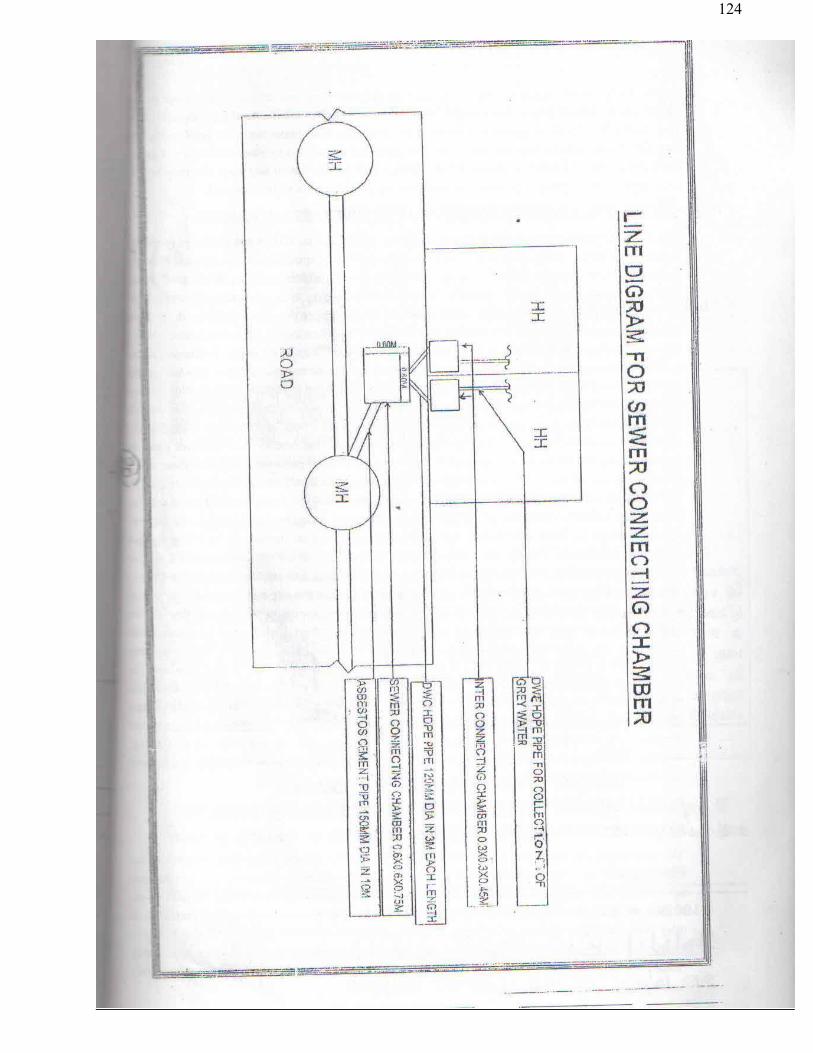
124

125
Hapur Sewerage Scheme Zone-1

126

127

128

129

130
XXXIV 2.4 SITE INFORMATION
Hapur town map showing all 6 zones and zone-01 map showing roads is being made available along with tender document. Land of IPS is undulated. Contractors are advised to inspect the site before tendering. Formation level all structare shall be according to nearby ground condition and 60 cm above near by pucca road and structure should be at least 60 cm above HFL. Tenderer should considered sub soil water condition in design for construction of structure.
The maximum safe Bearing capacity of soil strata shall be taken considering available and worst water level at site. Net safe allowable bearing capacity will be taken maximum 8 T/m2 for design purpose. If bearing capacity is found less than 8 T/m2 the same will be considered in the design. The success full bidder shall get the bearing capacity tested. Any financial claim on account of difference of bearing capacity shall not be entertained
2.3.9 SOIL INVESTIGATION Actual detailed soil investigation shall be carried out by the contractor at his own cost and design of
units shall be based on the test report but in no case the structure shall be designed considering bearing capacity of soil more than 8 MT/M2.
2.3.10 DIMENSIONAL REQUIREMENT FOR BUILDINGS
Sr. Buildings Min carpet area required, Sqm
Min Clear Ht. above plinth level (upto slab ), m
1 Operations Building a. MEP Room 45 4 b. DFE/DG SET Platform 10 0.60(P/L) c. Gas compressor/scrubber room 30 As per equipment
manufacturer guidance d. Operations Office (toilets + store) 30 3.5 2 Administrative cum Laboratory Building Total area 50 a. Ground Floor 30 3.50 b. First Floor 20 3.50 3 Workshop/Store Room 30 4.50 4 Chlorinator House a. Chlorine room 20 4.50 b. Tonner Room 80 5 5 Sludge Pump House Pump sump house 60 5 6 H.T. Room 30 5 7 Staff Quarters Type-I UPJN specifications Type-II UPJN specifications Type-III UPJN specifications Type-IV UPJN specifications

131
2.3.11 LIST OF MAJOR CHLORINATION EQUIPMENT / LAB EQUIPMENT FURNITURE AND ADMINISTRATIVE BUILDING FURNITURE
Sr. Particulars Quantity
1 Chorine Tonner (working+ standby+ transit+ storage) 12
2 Tonner roller 4
3 Auto changeover system (from working to standby unit) 1
4 Floor mounted vacuum feed chlorinator of required capacity consisting gas filter, vacuum & gas regulating valve, pressure vacuum relief valve with safety vent, automatic proportionating gas feed rate valve, flowmeter, chlorine gas pressure indicator, vacuum indicator etc.
2 (1w+1s)
5 Water supply pumps of required capacity & head 2 (1w+1s)
6 Diffuser assembly at the inlet of chlorine contact tank suitable to fit in RCC channel 1
7 HOT of minimum 2 Tonne capacity with load indicator & tonner liftinq bar 1
8 Ammonia torches 1
9 Emergency repair kit for tonners 1
10 Electronic Chlorine leak detector 1
11 Residual chlorine detector 1
12 Relay based annunciator plant control panel 1
13 Water shower arrangement 1 Above given equipment list is indicative only. Contractor will design the chlorinator system considering the scope of work, Mechanical Specifications & applicable safety norms and will supply the complete chlorination system. Any safety approval from the regulatory body, if required will be provided by the contractor. 2.4 LAB EQUIPMENT FURNITURE AND ADMINISTRATIVE BUILDING FURNLTURE
Sl Items Quantity Unit
LAB EQUIPMENT ADMINISTRATIVE BUIL FURNITURE
GLASSWARE FOR LABORATORY
1 Beakers 1000 ml 6 No.
2 Beakers 500 ml 6 No.
3 Beakers 250 ml 6 No.
4 Bottles Reagents 1000 ml 12 No.
5 Bottles Reagents 500 ml 12 No.
6 Bottles Reagents 250 ml 12 No.
7 Bottles Bod 300 ml 48 No.
8 Bottles Amber 250 ml 12 No.
9 Burettes 50 ml 3 No.
10 Burettes 10 ml 3 No.
11 Cylinders Graduated 1000 ml 3 No.

132
12 Cylinders Graduated 500 ml 3 No.
13 Cylinders Graduated 250 ml 3 No.
14 Cylinders Graduated 100 ml 6 No.
15 Cylinders Graduated 50 ml 6 No.
16 Cylinders Graduated 10 ml 5 No.
17 Condensers Allhin 400 ml 3 No.
18 Bottles Aspirator 10 lt 2 No.
19 Bottes Aspirator 5 lt 2 No.
20 Descicater 200 ml 2 No.
21 Funnel 100 mm 6 No.
22 Funnel 75 mm 6 No.
23 Flasks Erlemeyer conical 500 ml 6 No.
24 Flaks Erlemeyer conical 250 ml 6 No.
25 Flaks Erlemeyer conical 100 ml 12 No.
Flasks Erlemeyer conical 500 m
26 With inter changeable joints 6 No.
27 Flask Kjeldhal 500 ml 3 No.
28 Flask Flat Bottom 2000 ml 3 No.
29 Flask Flat Bottom 1000 ml 3 No.
30 Diehes Evaporating 30 *45 mm 24 No.
31 Imhoff Cones 1 lt 1 No.
32 Nesselers Tue 100 ml 12 No.
33 Pipettes volumetric 100 ml 2 No.
34 Pipettes volumetric 50 ml 3 No.
35 Pipettes volumetric 25 ml 3 No.
36 Pipettes volumetric 10 ml 3 No.
37 Pipetes Graduated Serlogical 10 ml*0.5 12 No.
38 5 ml X 0.5 12 No.
39 lml X 0.1 6 No.
40 FURNITURE FOR THE LABORATORY Steel Almirah 6.5’high
2 No.
41 Storewell for chemicals 2 No.
42 Office Tables (steel) 5’ X 2’ X 2.5’
with sunmica top & drawers
1 No.
43 Revolving stools with steel tops 6 No.
44 Office Tables (steel) 3’ X 2.5’ X 2.5’
with sunmica top & drawers
2 No.
45 Chair(steel) with Arms 6 No.
46 Wooden stools 2.5’high 2 No.
47 LAB EQUIPMENT BOD incubator with voltage stabilizer
1 No.

133
48 Refrigerator with voltage stabilizer 286 lt. Capacity
1 No.
49 Incubator 1 No.
50 Hot Air Oven 0-2500C 1 No.
51 Muffle Furnace Complete with Pyrometer 50X150X500 mm
1 No.
52 Water Distillation Apparatus 1 No.
53 Rectangular water bath 1 No.
54 pH meter Degital 1 No.
55 Balance Moncpan Electrical 1 No.
56 Balance Dumping bouble pan 1 No.
57 Heating Plates 8”dia 1 No.
58 Conductivity meter Digital 1 No.
59 Loviband Comparator with Phenol
Red & Universal Indicator Discs 1 No.
60 Heating Mantles 1 No.
61 Digestion & Distillation Assembly 1 No.
62 Bacteriological Incubator A 1 No.
63 Bacteriological Incubator B 1 No.
64 Auto Clave 1 No.
65 MPN Count Instrument 1 No.
66 Air Condition Capacity 2 tonne 2 No.
67 Microscope 2 No.
68 Hot Air Oven Capacity 0-1500C 1 No.
MISCELLANEPOUS ITEMS
69 H.T. Megger 1 No.
70 LT Megger 1 No.
71 Tong Tester 1 No.
72 Fire Extinguisher 4.5 kg Co2 4 No.
73 PVC/Rubber Mattings 1 No.
74 Techno meter 1 No.
75 Wall clock 1 No.
76 First Aid Box 1 No.
77 Complete Crimping Tool with dies 1 No.
78 Water cooler 1 No.

134
XXXV SPECIFICATIONS 3.0 CIVIL STRUCTURAL WORKS REQUIREMENTS 3.1.1 DESIGN SUBMISSIONS Complete detailed design calculations & drawings of foundations and superstructure together with
general arrangement drawings and explanatory sketches shall be submitted to the Employer's Representative. Separate calculations for foundations or superstructures submitted independent of each other shall be deemed to be incomplete and will not be accepted by the Employer's Representative.
The design considerations described herewith establish the minimum basic requirements of plain
and reinforcement concrete structures, masonry structures and structural steel works. However, any particular structure shall be designed for the satisfactory performance of the functions for which the same is being constructed. The Contractor shall also take care to check the stability.
3.1.2 DESIGN STANDARDS All designs shall be based on the latest International or Indian Standard (IS) Specifications or Codes
of Practice. The design standards adopted shall follow the best modern engineering practice in the field based on any other international standard or specialist literature subject to such standard reference or extract of such literature in the English language being supplied to and approved by the Employer's Representative. In case of any variation or contradiction between the provision of the IS Standards or Code and the specifications given with the submitted tender document, the provision given in the Specification shall be followed.
3.1.3 DESIGN LOADINGS All building and structures shall be designed to resist the worst combination of the following
loads/stresses under test and working conditions these include dead load, live load, wind load, seismic load, stresses due to temperature changes, shrinkage and creep in materials, dynamic loads and uplift pressure.
3.1.3.1 DEAD LOAD This shall comprise all permanent construction including walls, floors, roofs, partitions, stairways,
fixed service equipment and other items of machinery. In estimating the loads of process equipment allfixtures and attached piping shall be included, but excluding contents shall be considered.
The following minimum loads shall be considered in design of structures:
Sr. Parameter Load 1. Weight of water 10.0 kN/m3 2. Weight of soil (irrespective of strata available at site and type of soil used
forfilling etc) However, for checking stability against uplift, actual weight of soil as determined by field test shall be considered.
20.0 KN/m3
3 Weight of plain concrete 24.0 kN/m3 4 Weight of brickwork (exclusive of plaster) 25.0 kN/m3 5 Weight of plaster to masonry surface 22.0 kN/m3

135
Sr. Parameter Load 6 Weight of plaster to masonary surface 18.0 kN/m3 7 Weight of granolithic terrazzo finish or rendering screed, etc. 24.0 kN/m3 8 Weight of sand (filter media) 25.0 kN/m3
3.1.3.2 LIVE LOAD Live load shall be in general as per IS 875. However, the following minimum loads shall be
consideredin the design of structures
Sr. Location Live Loads 1 Floor supporting pumping machinery 1000 kg/sqm 2 Storage, Maintenance Bay, Air Blower 750 kg/sqm 3 Platform, Staircase, Corridors, Walkways 500 kg/sqm 4 Toilet 200 kg/sqm 5 Roof Slab 150 kg/sqm
In the absence of any suitable provisions for live loads in IS Codes or as given above for any
particular type of floor or structure, assumptions made must receive the approval of the Employer's Representative prior to starting the design work. Apart from the specified live loads or any other loads due to material stored any other equipment load or possible overloading during maintenance or erection/construction shall be considered and shall be partial or full whichever causes the most critical condition.
3.1.3.3 WIND LOAD Wind loads shall be as per IS: 875- 2002. 3.1.3.4 DYNAMIC LOAD Dynamic loads due to working of plant items such as pumps, blowers, compressors, switch gears,
traveling cranes, etc shall be considered in the design of structures. 3.1.3.5 OTHER LOADS In addition to earth pressure and water pressure etc., the surcharge of 1 Ton/sq.m shall be taken into
account in the design for channels, tanks, pit etc. 3.1.3.6 EARTHQUAKE LOAD This shall be computed as per IS: 1893 - 2000. 3.1.4 JOINTS Movement joints such as expansion joints, complete contraction joints, partial contraction joints and
sliding joints shall be designed to suit the structure as per relevant IS code provisions. Expansion joints of suitable gap at intervals not more than 30 m shall be provided in walls, floors-and roof slabs of water retaining structures.
Construction joints shall be provided at right angles to the general direction of the member. The locations of construction joints shall be decided on convenience of construction. To avoid segregation of concrete in walls, horizontal construction joints are normally to be provided at every 2 m height, PVC water stops of suitable type and minimum 230 mm width, 6 m thick shall be used for walls and base slabs.
3.1.5 DESIGN CONDITIONS FOR UNDERGROUND OR PARTLY UNDERGROUND
LIQUID RETAINING STRUCTURES

136
All underground or partly underground liquid containing structures shall be designed for the following conditions:
Ø Liquid depth up to full height of wall: no relief due to soil pressure from outside to be considered.
Ø Structure empty (i.e. empty of liquid, any material, etc) full earth pressure including saturated condition and surcharge pressure wherever applicable to be considered.
Ø Partition wall between dry sump and wet sump to be designed for full liquid depth up to full height of wall
Ø Partition wall between two compartments to be designed as one compartment empty and other full
Ø Structures shall be designed for uplift in empty conditions with the water table indicated in the geotechnical report or high flood level, whichever is maximum. No reduction factor for the uplift force shall be considered.
Ø The dead weight of the empty structures should provide a safety factor of not less than 1.2 against uplift pressures during construction and in service.
Ø Wall shall be designed under operating conditions to resist earthquake forces from earth pressure mobilisation and dynamic water loads;
Ø Underground or partially underground structures shall be checked against stresses developed due to any combination of full and empty compartments with appropriate ground/uplift pressures from below to base slab
Ø The walls and base slabs shall be designed for saturated eai1h/water pressure corresponding to high flood level or finished plot level whichever is higher
3.1.6 FOUNDATION Ø The minimum depth of foundations for all structures, equipment's buildings and frame foundations
and load bearing walls shall be as per IS: 1 094.
Ø The earth fill above virgin ground level till formation level shall be taken as a surcharge load and shall be added in the loads coming on foundations appropriately
Ø Care shall be taken to avoid the foundations of adjacent buildings or structure foundations, either existing or not within the scope of this Contract Suitable adjustments in depth location and sizes may have to be made depending on site conditions. No extra claims for such adjustments shall be accepted by the Employer.
Ø Special attention is drawn to danger of uplift being caused by the ground water table
Ø Plinth level of all structures/top of tanks shall be atleast (500) mm above high flood level.
3.1.7 DESIGN REQUIREMENTS The following are the design requirements for all reinforced or plain concrete structures: Ø All blinding and leveling concrete shall be minimum 100 mm thick in concrete grade M10 for
Building & 150 mm thick in concrete grade M15 for Water Retaining Structure. Ø All structural reinforced concrete shall be with a maximum 40 mm aggregate size for footings and
base slabs and with a maximum 20 mm aggregate size for all the Water Retaining Structures & other structural members.
Ø All liquid retaining structures shall be designed as per IS:3370. The minimum grade of concrete shall be M25.

137
Ø All Buildings, Pipe Pedestals, Thrust Block, Pump Foundation & other structures shall be designed as per IS-456. The minimum grade of concrete shall be M20.
Ø The maximum free water cement ratio shall not exceed 0.5 for all liquid retaining structures. Ø The amount of reinforcement in each of the two directions at right angles within each surface zone
should not be less than the minimum specified as IS:3370 or IS:456 which ever is applicable for the type of structure.
Ø Use of pressure relief valves to reduce uplift pressure due to ground water table shall not be allowed.
Ø All buildings shall have a minimum 1.0 m wide, 100mm thick plinth protection paving in M15 grade concrete or stone slabs/tiles. All plinth protection shall be supported on well-compacted strata.
The following minimum thickness shall be used for different reinforced concrete members irrespective of
design thickness.
Sr. Civil Member Width (mm) 1 Walls for liquid retaining structures 200 2 Base Slab of liquid retaining structures 200
3 Wall foundation (At Junction of Base Slab & Wall) of liquid retaining structures
300
4 Roof Slab of liquid retaining structures 150
5 Walls of Launders 150
6 Base slab of Launders 125
7 Floor slabs including roof slabs, walkways canopy slabs 100
8 Walls of cables/pipe trenches, underground pits, etc. 125
9 Footing - Edge Thickness 200
10 Footing - At the Face of Column 450
11 Column – 230 (width) 300 (depth)
12 Parapets, chajja 100
13 Pre-cast trench cover 75
14 Beam 230 (width) 300 (depth)
3.1.8 MINIMUM COVER TO MAIN REINFORCEMENT
Sr. Member Details Cover (mm)
1. Slab Free Face 20 Face in contact with earth 30
2. Beam Top/Bottom 40 Side 30 Face in contact with earth 40
3. Column and pedestal Super Structure 40 Face in contact with earth 40
4. Retaining wall, basement and pit wall Face in contact with earth 30 Free Face 30
5 Liquid Retaining Structure Face in contact with liquid 40 Face in contact with earth 40

138
Free face 40 6 Foundation Bottom 60 Top 60
3.1.9 MINIMUM BAR DIAMETER
Sr. Member Diameter (mm) 1 Major Foundation 10 2 Block Foundation – Main Bars 10 3 Block Foundation – Tie Bars 8 4 Minor Foundation (Local Foundation etc.) 8 5 Column, Pedestal – Main Bars 12 6 Column, Pedestal – Ties 8 7 Beam – Main Bars 12 8 Beam – Anchor Bars 10 9 Beam – Stirrups 8 10 Slab – Main Bars 8 11 Slab – Distribution Bars 8 12 Wall – Main Bars 10 13 Wall – Distribution Bars 8 14 Minor elements such as chajjas, lintel beams etc. 8
3.1.10 BAR SPACING
Sr. Member Minimum (mm) Maximum (mm)
1 Foundation 125 200 2 Slabs 100 300 3 Stirrups for Beams 100 300 4 Ties for Columns, Pedestals 100 300 5 Walls 100 300
* Bar spacing shall be provided in multiple of 25 mm. 3.1.11 MATERIALS IN GENERAL The term" materials" shall mean all materials, goods and articles of every kind whether raw, processed or manufactured and equipment and plant of every kind to be supplied by the Contractor for incorporation in the Works. Expect as may be otherwise specified for particular parts of the works the provision of clauses in "Materials and Workmanship" shall apply to materials and workmanship for any part of the works. All materials shall be new and of the kinds and qualities described in the Contract and shall be at least equal to approved samples. As soon as practicable after receiving the order to commence the works, the Contractor shall inform the Employer's Representative of the names of the suppliers from whom he proposes to obtain any materials but he shall not place any order without the approval of the Employer's Representative which may be withheld until samples have been submitted and satisfactorily tested. The Contractor shall thereafter keep the

139
Employer's Representative informed of orders for and delivery dates of all materials. Materials shall be transported handled and stored in such a manner as to prevent deterioration damage or contamination failing which such damaged materials will be rejected and shall not be used on any part of the Works under this contract. 3.1.11.1 CEMENT The contractor shall procure 33 grade (conforming to IS 269) or 43 grade (conforming to IS 8112) ordinary Portland cement or portland pozzolona cement, as required in the work, from reputed manufactures of cement, having a production capacity of one million tonnes or more per annum, such as ACC, Ultra Tech, J.P. Rewa, & Cement Corporation of India etc as approved by Ministry of Industry, Government of India, and holding license to use ISI certificate mark for their product whose name shall be got approved from Engineer in charge. Supply of cement shall be taken in 50 kg bags bearing manufacturer’s name and ISI marking. Samples of cement arranged by the contractor shall be taken by the Engineer in charge and got tested in accordance with provisions of relevant BIS codes. In case test results indicate that the cement arranged by the contractor does not conform to the relevant BIS codes, the same shall stand rejected and shall be removed from the site by the contractor at his own cost within, a week’s time of written order from the Engineer in charge to do so. (i) The cement shall be brought at site in bulk supply of approximately 20 tonnes or as decided by the
Engineer in charge. (ii) The cement godown of the capacity to store a minimum of 1000 bags of cement shall be constructed
by the contractor at site of work for which no extra payment shall be made. Double lock provision shall be made to the door of the cement godown. The keys of one lock shall remain with the Engineer in charge or his authorized representative and the keys of the other lock shall remain with the contractor. The contractor shall be responsible for the watch and ward and safety of the cement godown. The contractor shall facilitate the inspection of the cement godown by the Engineer in charge at any time.
Approved Manufacturers of Cement: JP Cement, Birla, Ultra Tech, ACC or as approved by Engineer. 3.1.11.2 REINFORCEMENT STEEL The contractor shall procure steel reinforcement bars conforming to relevant BIS codes from main producers as approved by the Ministry of Steel. The contractor shall have to obtain, and furnish test certificates to the Engineer in charge in respect of all supplies of steel brought by him to the site of work. Samples shall also be taken and got tested by the Engineer in charge as per the provisions in this regard in relevant BIS codes. In case the test results indicate that the steel arranged by the contractor does not conform to BIS codes, the same shall stand rejected and shall be removed from the site of work by the contractor at his cost within a week time from written orders from the Engineer in charge to do so. (i) The steel reinforcement shall be brought to the site in bulk supply of 10 tones or more or as decided
by the Engineer in charge.
(ii) The steel reinforcement shall be stored by the contractor at site of work in such a way as to prevent distortion and corrosion and nothing extra shall be paid on this account. Bars of different sizes and lengths shall be stored separately to facilitate easy counting and checking.
(iii) For checking nominal mass, tensile strength, bend test, re-bend test etc specimen of sufficient length shall be cut from each size of the bar at random at frequency not less than that specified below :

140
Reinforcement Steel shall confirm to BIS Specification 432-1966 (with up to date revision) and B.I.S. Specification 1786-2008 (with up to date revision). All Reinforcement Steel will be High Yield Strength Deformed Bars Grade Fe-415 or above grade shall be used. Approved Manufacturers: Tata Steel, SAIL, Rashtriya Ispat Nigam
(B) GENERAL SPECIFICATIONS
1.0 MATERIALS:
1.1 IST CLASS BRICKS: (M-100) Bricks shall have a uniform deep cherry red or copper colour, shall be thoroughly burnt but not over
burnt, and regular in shape. Their edges must be Straight Square and the two bricks must emit a clear ringing sound on being struck with each other. They must be free from cracks, chips, flows and stones or lumps of any kind. The bricks shall comply with the I.S. – 1077.
1.2 STONE BALLAST: Stone ballast shall consist of crushed stone and shall be hard, strong, dense, durable, clean, of proper
gradation and free from weather effect. It shall be generally cubical in shape. As far as possible, soft, thin, flaky or elongated or laminated pieces shall be avoided. For RCC work it should not contain any materials which might affect the reinforcement. The grading and test requirements should comply with the I.S. – 383.
1.3 TIMBER:
Timber to be used in shuttering works shall be from the heart of a sound tree of natural growth, the sapwood being entirely removed. It shall be uniform in substance, straight in fiber, free from large, loose and dead knots, flaws, shakes, decay, rot, fungi and insect attacks and from any other damages of harmful nature which will affect the strength, durability, appearance or its usefulness for the purpose for which it is required. The color should be uniform as far as possible. The other requirements of timber shall comply with the PWD specification No. 1.5 (material) part-I.
1.4 STEEL: The steel for RCC shall be high yield strength deformed bars of Grade Fe 500 conforming to
IS -1786 -1985 the placement of reinforcement shall be as per IS 456-2000. 1.5 PORTLAND CEMENT: The cement shall be Ordinary Portland shall be 43 grade cement conforming to I.S:8112 with its
latest amendments. 1.6 SAND: The sand shall consist of natural sand, crushed stone or crushed gravel or a combination of any of
these. it should be hard, durable, clean and free from adherent coating and organic matter and shall not contain any clay. The fine sand which shall be used for plaster and brick work shall have F.M. as 1.25 and the coarse sand for cement plaster/ brick work shall have F.M. as 2.0 and for cement concrete 2.9 to 3.2. All materials which shall be brought and used at site shall confirm to I.S. - 383.

141
1.7 SUNDRY MATERIALS: Certain other materials not particularly mentioned or described herein may be required for the works
and these if not specifically mentioned shall comply with the description set out in standard specifications of PWD, LSGED (now U.P. Jal Nigam) or IS for the respective materials and these specifications in so far as they are applicable shall be deemed to be incorporated in this contact.
1.8 BRICKS Bricks used for the construction of brick masonry shall be hard, rectangular in shape and size and
well burnt of uniform deep red, cherry or copper colour and shall confirm to IS: 1077-1986. The bricks shall be brought from approved brick kilns. The bricks shall be free from cracks,
chippings, flaws, stones or lumps of any kind. The bricks shall not show any signs of efflorescence and shall be homogeneous in texture.
They shall emit a clear metallic ringing sound on being struck and shall have a minimum
compressive strength of 10.5 N/mm2 equivalent to 105 kg/cm². They shall not absorb more than 20% of its dry weight when soaked in cold water for 24 hours or
otherwise specified in the Indian Standard Specification. 1.9 MORTAR The proportion of the cement mortar used for the masonry work shall be as specified on the various
drawings for different places/types of construction, specifications for each part of the work. For cement mortar fresh Portland cement of standard specifications shall be used. Sand shall be
sharp, clean and free from organic and foreign matters. For rich mortar coarse or medium sand shall be used and for weak mortar local fine sand may be used. Materials of mortar shall be measured to have the required proportion with measuring box and first mixed dry to have a uniform colour in a clean masonry platform and then mixed by adding clean water slowly and gradually to have workable consistency and mixed thoroughly by turning at least three times. Fresh mixed mortar shall be used, old and stale mortar shall not be used and mortar for an hour work only shall be mixed with water so that the mortar may be used before setting starts.
Coarse sand is mixed with the required quantity of cement for the preparation of the mortar. Mortar
shall be prepared in accordance with IS: 2250-1981. The sand used for the masonry mortar shall meet the requirements as specified in IS: 2116-1980. For masonry mortars, sand and cement of required proportions are mixed in small quantities in a dry state first and then water is added to make the mortar of required consistency suitable for the type of work for which it is required as directed by the Engineer-in-Charge. No left over mortar shall be used and therefore only that much quantity of mortar that can be consumed within 30 minutes shall be mixed in batches.
1.9.1 SAND FOR BRICK MASONRY Table 1.9.1 : Grading of sand for use in Masonry Mortar
IS Sieve Designation Percentage passing by mass 4.75 mm 100 2.36 mm 90 to 100 1.18 mm 70 to 100 600 micron 40 to 100 300 micron 5 to 70 150 micron 0 to 15

142
2.0 WATER SUPPLY FOR WORK AND DRINKING PURPOSE AND FACILITIES
TO LABOUR: The contractor shall make his own arrangement in regard to water required for the execution and tests of the works and shall also arrange for a supply of drinking water to his employees and labour. He shall bear all charges in this connection and include in his rates a sufficient amount to cover such charges. All such facilities as are required to be provided for the labourers under the labour welfare rules in force shall also be made available by the contractor at his own cost. Minimum reasonable sanitary conditions are to be maintained in and around the labour camps and at the site or work. As soon as one or more labour in trenches or at site get wounded or hurt due to accident or carelessness immediate proper medical-aid shall be provided by the contractor to them. However, if it is felt by the engineer that proper medical aid has not been provided to them, it shall be incumbent upon the contractor to follow the instruction of the engineer for proper medical-aid. A first-aid box should be maintained by the contractor during execution period of the work. If proper medical facility is not provided by the contractor, same shall be done by the department & cost shall be debited to the contractor’s account.
3.0 NOTICE BOARD TO BE DISPLAYED: Notice boards shall be supplied and fixed in suitable positions by the contractor where the roads have been opened out for the construction of the culverts or sewers and the traffic has to be diverted. Such boards shall display in big letter in BLACK AND WHITE or in RED AND WHITE colours such warnings as ROAD CLOSED DRIVE SLOW, - WORK AHEAD MEN ON WORK etc. Such caution boards be fixed at suitable points in the neighbor-hood of the work or well before diversion where other roads join or cross the road opened out, so that traffic may have sufficient warning to avoid the blocked road by taking any alternative routes or by using the diversion provided by the contractor. No extra payment shall be made to the contractor on this account. The caution boards shall be painted such that the warning or notices glow in the night also to avoid accident or jamming of traffic.
4.0 BARRICADING: The contractor shall provide necessary barricading in portion the excavation is done for laying of sewer lines. The barricading shall consist of ballies and G.I. sheet duly painted red and white in colour as per direction and approval of E/I. The contractor shall also make arrangement in proper warnings like providing fencing, danger flags, night warning light and watch and ward etc.. Safety code for excavation work I.S. 3764-1966 shall be rigidly followed.
(C). DETAILED SPECIFICATIONS FOR CIVIL WORKS 1. EARTH WORK 1.1 GENERAL
The conditions/specifications laid down hereunder will hold good whether the excavation is to be carried out over areas for leveling foundations of structures, trenches for pipes or cables or any other type of work which involves earth work like the leveling of forming/embankments etc. as per UP Jal Nigam / UP PWD specifications.
a. Earthwork in excavation includes site-cleaning activities like removal of shrubs, loose stones, rubbish of all kinds, interfering with the works and with complete removal of roots.
b. The products of the above clearing operations shall be removed from the site, dumped, stacked at a place or places, burnt or otherwise disposed of as directed by the Engineer- in-Charge within the compound.

143
c. A permanent base line and cross lines shall be established to serve as reference grid using MS plates, pegs, pins set in concrete or brick masonry pillars where they will be free from disturbances.
d. A permanent bench marks or marks as required necessary for the works connected to the nearest GTS benchmark shall be established for reference.
e. Excavation shall be carried out in all types of soil like top soil, silt, sand, gravel, soft moorrum, clay, kankar, hard materials like disintegrated rock shale which can be removed by picks, crowbars and shovels. Soil/earth may contain boulders. Loosening of rocks include the other methods of excavation other than blasting such as chiseling, wedging line drilling to avoid shattering of rocks. The Engineer-in-Charge shall decide what method shall be adopted for removal of the hard rock.
f. Excavation, whose sides are required to be maintained at a steeper slope than the stable slopes, will be required to be properly shored and strutted failing which the contractor will be required to execute the work by open cutting by the approval of Engineer-in-Charge.
g. Negligence on account of this leading to any mishap will be entirely the responsibility of the contractor.
1.2 DRAINAGE IN THE VICINITY OF EXCAVATION The contractor shall control the drainage in the vicinity of the Excavation so that the surface of the ground will be properly sloped to prevent surface water running into excavated areas during construction. Arrangements shall be made for preventing rain and other extraneous liquids entering the excavated parts. Seepage water shall be directed to flow away from the trenches by gravity. If any pumping is required to keep the trench and the exposed areas dry for further work the same shall be done by the contractor at his own expenses.
i. The rates quoted by the contractor shall be deemed to be inclusive of all the above costs or charges for stipulations stated above.
ii. Excavated material shall not be deposited within 1.5 meters from the top edge of the excavation. iii. The contractor shall remove the excavated material to spoil heaps on the site or transport the same to
a place as directed by the Engineer-in-Charge. iv. If the bottom of the excavation is left exposed by the contractor and in the opinion of the Engineer-in-
Charge it has become deleteriously affected by atmospheric changes or affected by water then the contractor shall remove at his own cost such portions of the affected foundations and shall make good by filling with lean concrete or with compacted sand as directed by the Engineer-in-Charge.
v. Where Excavation is made in excess of the depths required as shown in the drawings or as directed by the Engineer-in-Charge the contractor shall at his own expense fill up to the required level with lean concrete or well compacted sand as decided by the Engineer-in-Charge.
vi. Loose, soft or bad soil encountered in Excavation at the -required depth on Engineer-in-Charge’s directions shall be excavated to the firm bed and the difference of levels between the required level and the firm bed shall be filled up or dealt with as directed by the Engineer-in-Charge.
vii. Any obstacle encountered during excavation shall be reported immediately to the Engineer-in-Charge and shall be dealt with as instructed by him. Same shall be applicable for any antiques/treasure found during excavation.
viii. Any public utility services/facilities like water supply lines, gas supply line, sewers, telephone/electric cables poles etc. met with during Excavation shall not be damaged and no disruption is caused to the utility service on account of damages caused by the contractor. Such facilities shall be properly supported in their original positions by giving signs, suspension beams etc. as contractors own expenses.
ix. The contractor shall not undertake any concreting or constructing work of any nature on the excavated surfaces until approved for the same is given by the Engineer-in-Charge.
x. The contractor shall be solely responsible for the protection of adjoining properties from damages that may be on account of excavation close to the properties whether the property belongs to government or to a private party.
xi. The contractor shall make all arrangements for proper warnings like providing. fences, danger flags, barricading, night warning lights, watch and ward etc, to caution the public as well as the labours engaged by him about the dangers that may be involved by excavation of trenches, pits, foundations etc. Safety code for excavation work IS: 3764-1966 shall be rigidly followed unless instructed otherwise by the Engineer-in-Charge.

144
xii. Any useful material obtained during Excavation shall be stacked as directed by the Engineer-in-Charge and will be the property of the department. The decision of the Engineer-in-Charge in this regard shall be final and binding on the contractor.
xiii. Any material used by the contractor out of the Excavated stuff in lieu of his own materials shall be charged to the contractor at the market rates.
xiv. The rates quoted shall include back filling of excavated material and disposal of surplus earth as directed by the Engineer-In-Charge.
1.3 EXCAVATION IN TRENCHES AND CABLE DUCTS
Excavation as required in trenches, cable ducts, for manholes, other overflow structures, cross drainage works, extra depths for joints of pipes shall be carried out as shown in the drawings/directed by the Engineer-in-Charge.
i. For deep foundations necessary shoring and strutting shall be executed as directed by the Engineer-in-charge. If additional slopes are to be provided where vertical cuts ‘are not possible the same shall be executed without any additional cost. The rates quoted shall be deemed to be inclusive of all such extra work.
ii. The trench shall be kept perfectly dry by preventing the extraneous water entering the pits and also wherever necessary by pumping at the cost of the contractor. No additional cost of dewatering shall be payable.
iii. The trenches after laying, jointing and testing of pipes/cables are to be back filled. The trenches shall be filled with the excavated material if found suitable as directed by the Engineer-in-Charge.
iv. All surplus soil/earth shall be transported and disposed of as directed by the Engineer-in-Charge Boulders, sharp objects, brickbats, roots of trees, rubbish, rubble etc. shall not be used for back filling. The back filling shall be done very carefully so as not to damage the pipes/cables or disturb the alignment levels of the pipes/cables. The back filling shall be done in layers on both sides of the pipes watered, consolidated by ramming to a dense layer. The thickness of each layer shall not be more than 15 cms. Special care shall be taken to avoid unequal pressures and not to disturb the pipe.
v. In case the excavated material falls short of requirement the back fill soil/earth shall be taken from borrow pits approved by the Engineer-in-Charge. The rates quoted by the contractor shall be deemed to be inclusive of all such works.
vi. Sight rails and boning rods are to be used at regular intervals as directed by the Engineer-in-Charge to excavate the trenches true to line and grade.
1.4 BACK FILLING /EARTH FILLING
a. Back filling of earth around liquid retaining structures and pipes shall be done only after the water-
tightness test is done to the satisfaction of the Engineer-in-Charge. Selected earth from the excavated earth shall be used for back filling / embankment.
i. Care shall be taken to see that unsuitable soil/earth does not get mixed up with the material proposed to be used for filling.
ii. Regarding the soil/earth to be used for back filling the contractor shall have the prior approval of the Engineer-in-Charge.
iii. Backfill shall be placed in successive horizontal layers of loose material not more than 15 cm thick. The material shall be brought to within + or - 2% of the optimum moisture content as described in IS:2720 (Part VIII) after adjusting the moisture content, the layers shall be thoroughly compacted with such equipment . as may be required to obtain a density equal to or greater than 95% of maximum laboratory dry density of the soil.
iv. Successive layers of filling shall not be placed until the layer under construction has been thoroughly compacted to satisfy the requirements laid down in the requirements.
1.5 FILLING AND EMBANKMENT a. The area where filling or embankment is to be carried out shall be cleared from loose material and the
virgin soil shall be exposed. All shrubs and vegetation with roots are cleared. All soft patches shall be removed and filled with selected soil/earth and consolidated. Exposed soil/earth shall be consolidated properly to obtain 95% of maximum laboratory dry density of the soil.

145
i. Approved filling material shall be uniformly spread in layers not exceeding 20 cms in loose depth. All clods, lumps, etc shall be broken before consolidation.
ii. Successive layers of filling shall not be placed until the layer under construction has been thoroughly compacted to satisfy the requirements laid down in these specifications.
iii. The contractor shall give the samples of the earth he proposes to use for back filling for testing, if required or directed by the Engineer-in-Charge along with the following characteristics of the soil/earth.
iv. Only earth having plasticity index less than 20 shall be used. v. Soil/earth having laboratory maximum dry density of less than 1500 kg per cubic meter shall not be
used. vi. If the layer fails to meet the required density it shall be reworked or the materials shall be replaced
and method of compaction altered as directed by the Engineer-in-Charge to obtain the required density.
vii. If any test indicates less than the specified degree of compaction the Engineer-in-Charge may require all the fill placed; subsequent to the latest successfully tests to be removed and compacted and compaction procedure to be done once again to obtain satisfactory density.
viii. The contractor shall perform all necessary tests to determine optimum moisture content and the degree of compaction. He shall furnish the results to the Engineer-in-Charge.
ix. Prior to rolling, the moisture content of the material shall be brought to within +2% of the optimum moisture content as described in IS-2720 (part VIII). The moisture content shall preferably be on the wet side for potentially expansive soil/earth. After adjusting the moisture content as described in this clause, the layers shall be thoroughly compacted by means of rollers till 95% of maximum laboratory dry density is obtained.
b. If the layer fails to meet the required density it shall be reworked or the materials shall be replaced and method of compaction altered as directed by the Engineer-in-Charge to obtain the required density.
i. The embankment shall be finished to the alignment levels and grades, cross sections, dimensions shown in the drawings or as directed.
ii. If sand filling is specified in the tender for filling the trenches, plinth or foundations the sand used shall be hard, free from inorganic materials and deleterious materials and approved by the Engineer-in-Charge. Filling shall be carried out in layers not exceeding 15 cms in loose depth and flooded and tamped till it meets the approval of the Engineer-in-Charge.
iii. The contractor shall perform all necessary tests to determine optimum moisture content and the degree of compaction. He shall furnish the results to the Engineer-in-Charge.
1.6 SHORING/STRUTTING/TIMBERING a. When the depth of foundation or pipe trench is great and the soil/earth is soft and generally for depths
more than 1.5 m. Stepping, sloping and or paneling and strutting of sides shall be done as directed by the Engineer-in-Charge. The decisions regarding the positions and depths at which and what type of precautions are to be provided shall be decided by the Engineer-in-Charge.
i. It shall be the responsibility of the contractor to take all necessary precautions or steps to prevent the sides of trenches from collapse. The contractor shall be responsible to make good any losses or damages caused to execute works, life and property due to his negligence.
ii. Deep excavation shall be inspected after every rain, storm, or other hazards and if necessary the precautions required shall be augmented.
iii. Planking and strutting shall be either “Close” or “Open” type depending upon the nature of the soil/earth and depth of excavation etc.
iv. The timbering shall be of sufficient strength to resist earth pressure and ensure safety to the adjoining property and to persons. Where the excavation is subjected to vibrations due to machinery, vehicles, rail traffic, blasting and other sources, additional bracings shall be provided.
v. Generally the specifications and sizes and spacing of sheeting, wallers and struts used for timbering of different depths shall be as given in the IS: 3764-1965 Safety code for excavation work unless otherwise specified in the tender elsewhere. Shoring shall extend 30 cms, above the vertical sides.
vi. Withdrawal of timbering shall be done very carefully to prevent collapse of the sides of excavation and any damage to the work executed.

146
Open timbering shall be provided wherever the Engineer-in-Charge directs, where the trenches are not close to any buildings/property/structures. In open timbering the trench shall be protected by covering 1/3 the surface area by planks.
IMPORTANT NOTE
1. The bottom of Excavation shall be trimmed to the required levels and when carried below such levels, by error, shall be brought to level by filling with lean concrete of grade 1:4:8 or as specified at the contractor’s cost and nothing extra shall be paid to the contractor on this account.
2. The contractor shall be responsible for assumptions and conclusions that he may make regarding the nature of materials to be excavated and the difficulty in making and maintaining the required Excavation and performing the work required as shown on the drawing and in accordance with these specifications. Cofferdams, sheeting, shoring, braking, draining, dewatering, etc. shall be furnished and installed as required and the cost thereof shall be included in the rate quoted for the item of excavation. The contractor shall be held responsible for any damage to any part of the work and property caused by collapse of sides of Excavation. Materials may be salvaged if it can be done with safety for the work and structures, as approved by the Engineer-in-Charge. However, no extra claim shall be entertained for material not salvaged or any other damage to contractor’s property as a result of the collapse. He shall not be entitled to any claim for re-doing the excavation as a result of the same.
3. The excavation for foundations shall be carried out carefully, creating least disturbance to the founding stratum. The founding stratum should be blended by the concrete layer immediately after exposure so that it does not loose its strength on exposure to air and water.
4. Where excavation requires bracing, sheeting, or shoring etc, the contractor shall submit to the Engineer-in-Charge, drawings showing arrangement and details of proposed installation, and shall not proceed until he has received approval from the Engineer-in-Charge.
5. The contractor shall have to constantly pump out the water collected in pits due to rainwater, springs etc. and maintain dry working conditions.
6. For the purpose of excavation in earthwork, all types of soil including kankar, moorrum, single and boulders without binding matrix are included.
7. All excavated material obtained as a result of over excavation for which payment shall not be made, and that shall also be transported and disposed off as directed and at places shown by the Engineer-in-Charge, at no extra cost to the department within plot boundary.
8. All excavated materials obtained from excavation shall remain in the department’s property. The useful portion as decided by the Engineer-in-Charge, shall be separated from the useless ones and deposited in regular stacks at places indicated and as directed by the Engineer-in-Charge.
9. In no case the excavated soil shall be stacked upto a distance of 1.5 m from the edge of excavation or one-half the depth of excavation whichever is more.
10. IS Codes Some of the important relevant applicable codes for this section are IS: 1200 (Part-I)-Method of measurement of building and civil engineering works and earthwork IS: 3764 - Safety -code for excavation work IS: 4701 - Code of practice for earthwork on canals Cradle and Manholes for collection sewer line shall be as per CPHEEO Manual.
2. PLAIN CEMENT CONCRETE
Aggregate shall be of inert materials and shall be clean, dense, hard, sound durable, non-absorbent and capable of developing good bond with mortar. Coarse aggregate shall be of hard broken stone or granite or similar stone free from dust dirt and other foreign matters. The stone ballast shall conform to UP Jal Nigam, UP PWD specifications. Fine aggregate shall be of coarse sand consisting of hard, sharp and angular grains and shall’ pass through screen of 4.75 mm IS Sieve. Sand shall be of standard specifications, clean and free from dust, dirt and organic matters. Fine aggregate may also be crushed stone.

147
Ordinary Portland cement of 43 grade as per IS: 8112 shall be used. It shall have the required tensile and compressive stresses and fineness. Water shall be clean and free from alkaline and acid matters and suitable for drinking purposes. The proportion of concrete shall be 1:3:6 (Cement: Fine Aggregate: Coarse Aggregate) by unless otherwise specified. Minimum compressive strength of concrete of 1:3:6 proportion shall be as per IS: 456 2000 or its latest revision. Stone aggregate sand and cement shall be mixed as per UP Jal Nigam, UP PWD specifications. All materials shall be dry. If damp sand is used, compensation shall be made by adding additional sand to the extent required for the bulking of damp sand. Appropriate quantity of water required for cement may be taken as spacified in IS 456-2000 or its latest amendment. For concrete compacted by mechanical vibrations the quantity of water shall be reduced by 20%. Mixing shall be of machine mixing type. Hand mixing shall not be permitted. Machinery Mixing: Stone ballast, sand and cement shall be put into the cement concrete mixer to have the required proportion. For concrete of 1:2:4 proportion, first four boxes of stone ballast, then two boxes of sand and then one bag of cement shall be put into the C.C. Mixer, the machine shall then be revolved to mix materials dry and then water shall be added gradually to the required quantity, 25 to 30litres per bag of cement to have the required water cement ratio. The mixing shall be thorough to have a plastic mix of uniform colour. It requires 1.5 to 2 minutes rotation for thorough mixing. Mixed concrete shall be unloaded on a masonry platform or on a sheet iron. Output of concrete mixer is 15 to 20 mix per hour. Regular slump test shall be carried out to control the addition of water and to maintain the required consistency. Formwork centering and shuttering shall be provided as required, as per standard specifications before laying concrete to continue to support or to keep the concrete in position. Concrete shall be laid gently (not thrown) in layers not exceeding 15 cm and with mechanical vibrating machine until a dense concrete is obtained. (For important work mechanical vibrating shall be used for thick or mass concrete immersion type vibrators and for thin concrete surface vibrators shall be used for compacting concrete). Over vibration will separate coarse aggregate from concrete and shall be avoided. After removal of the formwork in due time the concrete surface shall be free from honey combing, air holes or any other defect. Concrete shall be laid continuously, if laying is suspended for rest or for the following day the end shall be shuttered and vibrated to achieve dense concrete and made rough after de-shuttering for further jointing. When the work is resumed, the previous portion shall be roughened, cleaned and watered and a grout of neat cement shall be applied and the fresh concrete shall be laid. For successive layer the upper layer shall be laid before the lower has set. After about 2 hours laying when concrete has begun to harden, it shall be kept damp by covering with wet gunny bags or wet sand for 24 hours, and then cured by flooding with water, making mud walls 7.5 cm high or by covering with wet sand or earth and kept damp continuously for 15 days. If specified, curing may be done by covering concrete with special type of waterproof paper as to prevent water escaping or evaporating. Plain cement concrete shall be provided for leveling courses, foundations, pipe bedding or at other places wherever indicated in the drawings/directed by the Engineer-in-Charge. Grade and thickness of all PCC works shall be as mentioned in the drawings. The proportion of the concrete, size of the aggregate shall be as specified in the drawings and technical specifications approved by Engineer-in-Charge. While placing concrete directly on the soil for foundations etc. all the loose material shall be removed. The surfaces shall be trimmed and well consolidated. The material specifications, mixing, placing of concrete compaction, curing, removal of the form work shall all be done as specified for reinforced cement concrete in the section of this tender document. The clauses provided therein shall also equally apply for this item of work to the extent relevant. The rates quoted shall include supply of material, labour, tools and plant, water, mixing platforms, curing, supplying, erecting and dismantling of all form works as required.

148
TESTING AND ACCEPTANCE CRITERIA OF CONCRETE
The sampling of concrete making the test specimens, curing and testing procedures etc. shall be in accordance with IS: 1199, IS: 3085 and IS: 516, the size of specimen being 15 cm cubes. Normally only compression tests shall be performed in accordance with IS: 516.
For each grade of concrete and for each 8 hours of work or portion thereof the following samples shall be taken. At least six specimens shall be taken from the first 15.0 m3 or part thereof and three of these shall be tested at 7 days and the remaining at 28 days. Four additional specimens shall be taken from each additional 15.0 m of concrete or portion thereof of which 2 specimens shall be tested at 7 days and the remaining at 28 days. To control the consistency of concrete from every mixing plant slump tests, and/or compacting factor tests in accordance with IS: 1199 shall be carried out by the contractor every two hours or as directed by the Engineer-in-Charge. Slumps corresponding to the test specimens shall be recorded for reference. The acceptance criteria of concrete shall be in accordance with IS: 456-2000. Concrete work found unsuitable for acceptance shall have to be dismantled and replacement is to be done as per specifications by the contractor. No payment for the dismantled concrete, the relevant formwork and reinforcement embedded fixtures etc. shall be paid. In the course of dismantling if any damage is done to, the embedded items or adjacent structures the same shall be made good free of charge by the contractor to the satisfaction of the Engineer-in-Charge.
3. BRICK MASONRY AND PLASTERING 3.1 BRICK MASONRY
All bricks shall be of class designation 10 or best locally available approved by Engineer-in-Charge made of good brick earth thoroughly burnt, and shall be of deep cherry red or copper colour. Bricks shall be regular in shape and their edges shall be sharp and shall emit clear ringing sound on being struck and shall be free from cracks, chips, flaws and lumps of any kind. Bricks shall not absorb water more than one sixth .of their weight after one hour of soaking by immersing the water. Bricks shall have a minimum crushing strength of 105 kg/cm² (10.5 N/mm2). Bricks shall be fully soaked in clean water by submerging in a tank for a period of 12 hours immediately before use. Soaking shall be continued till air bubbling is ceased. Bricks shall be well bonded and laid in English bond unless otherwise specified. Every course shall be truly horizontal and wall shall be truly in plumb. Vertical joints of consecutive course shall not come directly over one another, vertical joints in alternate course shall come directly over one another. No damaged or broken bricks shall be used. Closers shall be of clean-cut bricks and shall be placed near the ends of walls but not at the other edge. Selected best-shaped bricks shall be used for face work. Mortar joints shall not exceed 6 mm in thickness and joints shall be fully filled with mortar. Bricks shall be laid with frogs upwards except in the top course where frogs shall be placed downward. Brickwork shall be carried out not more than 1.2m height at a time. When one part of the wall has to be delayed, stepping shall be left at an angle of 45º. Corbelling or projections where made shall not be more, than X brick projections in one course. All joints shall be raked and faces of wall cleaned at the end of each day’s work.

149
These specifications deal with all types of brickwork required for buildings, manholes, drains, retaining walls or any construction made out of bricks.
3.1.1.2 CONSTRUCTION The brick masonry shall be constructed as per the Indian Standard Code of Practice for Brick Work IS: 2212-1962. The thickness of the joints shall not be thicker than those specified in para 5.4 of the above Code of Practice. The bricks shall be thoroughly soaked in water before using them on the work for at least twelve hours and all the air bubbles shall come out during soaking process. The soaked bricks shall be stacked on wooden planks/platforms so as to avoid sticking of the earth and other materials on to the surfaces of bricks. Bricks required for construction in mud mortar or lime mortar shall not be soaked. Brickwork shall be laid in English Bond unless otherwise specified. Half bricks shall not be used except when needed to complete the bond. Each course shall be perfectly straight and horizontal. The masonry shall be true to plumb in case of vertical walls and in case of battered construction the batter or slope shall be truly maintained. The level of the courses completed shall be checked at every one meter interval or less as required. The bricks shall be laid frogs upwards. While laying the bricks they shall be thoroughly bedded and flushed in mortar and well tapped into position with wooden mallets and superfluous mortar shall be removed. No part of the structure shall be raised more than one meter above than the rest of the work. In case it is unavoidable the brickwork shall be raked back at an angle of not more than 45 degrees so as to maintain a uniform and effectual bond, but raking shall not start within 60 cms from a corner. In case of construction of buttresses, counter-forts, returns they are built course by course carefully bound into the main walls. At all junctions of walls the bricks at alternate courses, shall be carried into each of the respective walls so as to thoroughly unite both the walls together. The brickwork shall not be raised more than 14 courses per day. All the beds and joints shall be normal to the pressures applied upon them Le horizontal in vertical walls, radial In arches and at right angles to the face in battered retaining walls. Vertical joints in alternate courses shall come directly one over the other and shall be truly vertical. Care shall be taken to ensure that all the joints are fully fitted up with mortar, well flushed up where no pointing is proposed, nearly struck as the work proceeds. The joints in faces which are plastered or painted shall be squarely raked out to a depth not less than 12 mm while the mortar is still green. The raked joints shall be well brushed to remove the loose particles and the surfaces shall be cleaned with a wire brush so as to remove any splashes of mortar sticking to the surfaces during the construction. All iron fixtures, pipes, bolts, conduits, sleeves, holdfasts etc. which are required to built into the walls shall be embedded in cement mortar or cement concrete as shown in the drawings/indicated in the specifications/directed during the execution by the Engineer in-Charge as the work proceeds and no holes be left for fixing them at a later date unless authorized by the Engineer-in-Charge. CURING Green work shall be protected from rain by covering the work suitably. Masonry work as it progresses shall be thoroughly kept wet by watering on all the faces for at least 10 (Ten) days after completion of the parts of the work. Proper watering cans, flexible pipes, nozzles shall be used for the purpose in case of fat lime mortar curing shall start two days after construction of masonry and shall

150
continue for seven days. No additional payment is admissible for curing and the rates quoted are deemed to be inclusive of the cost of curing.
3.1.2.2 SCAFFOLDING Double scaffolding sufficiently strong so as to withstand all loads that are likely to come upon it and having two sets of vertical supports shall be provided. Where two sets of vertical supports are not possible the inner end of the horizontal supporting pole shall rest in a hole provided in a header course only. Only one header for each pole shall be left out. Such holes however shall not be permitted in pillars less one meter in width or immediately near the skew backs of arches. Such holes shall be filled up immediately after removal of the scaffoldings. Safety Code for Scaffolds and Ladders, IS: 3696-1987 (Parts I and II) shall be followed.
3.2 PLASTERING Cement mortar used for plastering shall be of the mix proportions and thickness as specified on the drawings or bill of quantities or particular specifications for the various different parts of the works. The materials used i.e. cement, sand and water shall be of the same quality and of the same specifications as indicated for plain and reinforced cement concrete works according to the specifications and approved by the Engineer-in-Charge. Sand further shall meet the specifications as laid down in IS: 1542-1977 Specification for sand for plaster. The sand for preparation of mortar for plastering shall confirm to the following gradation, shown in Table 3.2
TABLE 3.2: GRADING OF FINE AGGREGATES
Percentage by weight passing IS Sieve IS Sieve Designation Class -A Class-B
4.75 mm 100 100 2.36 mm 90 to 100 90 to 100 1.18 mm 70 to 100 70 to 100 600 Microns 40 to 85 40 to 95 300 Microns 50 to 50 10 to 65 150 Microns 0 to 10 0 to 15
For the purpose of indicating the suitability for use, the sand is classified as Class A and Class B in
accordance with the limits of grading. Class A sand shall be used generally for plastering and when they are not available, Class B sand may be used with the approval of Engineer-in-Charge.
The procurement of sand for Mortar for plastering and pointing shall confirm to be specifications given
in Table 3.2. Surface that are to be applied with plaster shall be thoroughly cleaned to remove dust, dirt, loose
particle, oil, soil, salts etc, that may be sticking to the surfaces. The surfaces shall be washed, clean and watered properly for 4 hours before applying plaster. Plaster shall not, in any case, be thinner than specified. It shall have uniform specified thickness. When smooth finishing is required the cement plastering shall be floated over with neat cement within 15 minutes after application of the last coat of plastering. The plaster shall be protected from the sun and rain by such means as the Engineer-in-Charge may approve.
The plastered surface shall be cured for 10 (ten) days. Construction joints in plastering shall be kept at places approved by the Engineer-in-charge. When the thickness of the plaster specified is to be made up in more than one layer the second layer shall be applied only when the lower coat is still green. Wherever specified approved brands of additives like water proofing compounds shall be added in specified quantities as recommended by the manufacturer of the compound or as directed by the Engineer-in-Charge.

151
Wherever scaffolds are necessary for plastering they shall be provided as specified for scaffolds under clause 3.2.2. Stage scaffolding shall be provided for ceiling plaster.
To ensure even thickness and true surface, patches of plaster about 15 cm x 15 cm shall be first applied both horizontally and vertically 2.0 m apart. Plastering shall be done. from top of bottom and care shall be taken to avoid joints on continuous surface.
In case any other finish like rough cast finish or dry dash finish is specified in the drawings the small shall be provided as directed by the Engineer-in-Charge.
Surface which is to be plastered shall be roughened while they are still green or raked so as to give proper bond between the surface and plaster.
All corners junctions shall be truly vertical or horizontal as the case may be and carefully finished.
Rounding or chamfering of corners shall be carried out with proper templates to the required size and shapes.
The work shall be tested frequently with a straight edge and plumb bob. At the end of the day the
plaster shall be left cut clean to line. When the next days plastering is started the. day the plaster shall be left cut clean to line. When the next days plastering is started the edge of the old work shall be scrapped, cleaned and wetted with cement slurry. At the end of the day the plastering shall be closed on the body of the wall and not nearer than 15 cm to any corner.
Curing shall be started as soon as the plaster has hardened sufficiently not to be damaged when
watered. The plaster shall be kept wet for at least 10 days. Any defective plaster shall be cut in rectangular shape and replaced.
4. REINFORCED CEMENT CONCRETE AND ALLIED WORKS GENERAL In general RCC work is to be executed as per IS : 456-2000 or its latest revision. The water storage tanks/reservoirs shall be followed by IS : 3370 Part I to IV & latest revision. Steel reinforcement bars shall be of High Yield Strength Deformed (HYSD) steel bars as per IS: 1786 and shall be free from corrosion, loose rust scales, oil, grease, paint, etc. Wire mesh or fabric shall be in accordance with IS: 1566. The steel bar shall be capable’ of being bent without fracture. Bars shall be bent accurately and placed in position as per design and drawing and bound together tight with 20 SWG annealed steel wire @ 10 kg/ton of reinforcement at their point of intersection. Formwork and shuttering shall be made with steel plate close and tight to prevent leakage of mortar, with necessary props, bracings and wedges, sufficiently strong and stable and should not yield on laying concrete and made in such a way that they can be slackened and removed gradually without disturbing the concrete. For slab and beam small chamber should be given in centering, 1 cm per 2.5 m with a maximum of 4 cm. Centering should not be removed before 14 days in general (4 days for RCC columns, 10 days for roof slab, and 14 days for beams). The grade of concrete to be used shall be as mentioned in specifications/shown on drawings. Table - 4.1 Minimum compressive strength of 15 cm cubes at 7 and 28 days after mixing, conducted in accordance with IS: 516
Class Preliminary Test N/mm2
Work Test N/mm2
Maximum size of
Aggregate mm
Locations for Use
At 7 days At 28 days At 7 days At 28 days
M40 33.50
50.00 27.00 40.00
20 As indicated in the specifications or as
required M35 30.00
44.00 23.50 35.00
20 -do-

152
M30 25.00
38.00 20.00 30.00
20 --do-
M25 22.00
32.00 17.00 25.00
20 --do-
M20 17.50
26.00 13.50 20.00
20 --do-
M15 13.50
20.00 10.00 15.00
20 --do-
The coarse aggregate shall usually be 20 mm to 6mm gauge unless otherwise specified. For heavily reinforced concrete members as in the case of ribs of main beams the maximum size of aggregate should usually be restricted to 5 mm less than the minimum clear distance between the main bars or 5 mm less than the minimum cover to the reinforcement whichever is smaller. Mixing is done in the same manner as in PCC. Before laying the concrete, the shuttering shall be clean, free from dust, dirt and other foreign matters. The concrete shall be deposited (not dropped) in its final position. In case of columns and wall, it is desirable to place concrete in full height if practical so as to avoid construction joints but the progress of concreting in the vertical direction shall be restricted to 1.2 metre. Care should be taken that the time between mixing and placing of concrete shall not exceed 20 minutes so that the initial setting process is not interfered with. During the winters concreting shall not be done if the temperature falls below 4ºC. Concrete shall be compacted by mechanical vibrating machine until a dense concrete is obtained. The vibration shall continue during the entire period of placing concrete. Compaction shall be completed before the initial setting starts i.e. within 30 minutes of addition of water to the dry mixture. Over-vibration which will separate coarse aggregate from concrete shall be avoided. After removal of the form work in due time, the concrete surface shall be free from honey combing, air holes or any other defect. Concrete shall be laid continuously, if laying is suspended for rest or for the following day the end shall be shuttered and vibrated to achieve dense concrete and made rough after de-shuttering for further jointing. When the work is resumed, the pervious portion shall be roughened, cleaned and watered and a grout of neat cement shall be applied and the fresh concrete shall be laid. For successive layer the upper layer shall be laid before the lower has set. Pre-cast concrete shall be provided with lifting device.
4.1.1 STANDARDS Following Indian Standards as revised most recently along with amendments will be followed for the works included in the contract.
IS:8112 Ordinary, Portland cement IS:383 Coarse and fine aggregates from natural sources for concrete IS:445 Portland slag cement IS:456-1978 Code of practice for plaint and reinforced concrete IS:516 Method of test for strength of concrete Methods of sampling and analysis of concrete IS:2386 Methods of test for aggregates for concrete (Part I to VI) IS:3414 Code of practice design and installation of expansion and
contraction joints in building. IS:3713 Part- I to IV
Code of practice for water storage Tanks

153
Standards on special subjects have been mentioned elsewhere in this para and also shall be followed.
4.2 FORMS, FALSE WORK OR CENTERING 4.2.1 DEFINITIONS “Forms, formwork or shuttering” shall include all temporary molds for forming the concrete to the
required shape, together with any special lining that may be required to produce the concrete finish specified.
“False work or centering” shall consist of furnishing, placing and removal of all temporary construction such as forming, props and struts required for the support of forms.
4.2.2 MATERIALS Steel shuttering shall be provided as directed by the Engineer-in-Charge. 4.2.3 FORMS
All forms shall be of mild steel approved by the Engineer-in-Charge and shall be fabricated and prepared water tight and of sufficient rigidly to prevent distortion due to the pressure of the concrete and other incidental loads incident to the construction operations. All form shall be set and maintained true to the line designated until the concrete is sufficiently hardened. Forms shall remain in place for periods which shall be specified hereinafter. When forms appear to be unsatisfactory in any way, either before or during the placing of concrete, the Engineer-in-Charge shall order to stop the work until the defects have been corrected. All formwork shall be approved by the engineer-in-charge before concrete is placed within it. The contractor shall be required to submit copies of his calculations of the strength and stability of the formwork or false work but not withstanding the Engineer-in-Charge’s approval of these calculations, nothing shall relieve the contractor of his responsibility for the safely or adequacy of the formwork. Formwork shall be true to line and braced and strutted 10 prevent deformation under the weight and pressure of the unset concrete, constructional load, wind and other forces. The deflection shall not exceed 3 mm. Beam bottom shall be erected with an upward chamber of 2 mm per meter of the span. The form work for a column may be erected. One side shall. be left open and shall be built up in sections as placing of the concrete proceeds. Before placing the concrete, bolts and fixtures shall be in .position, and cores and other devices, used for forming openings, holes, chases, recesses and other cavities shall be filled to the formwork. No holes shall be cut in any concrete unless approved. Approved mould oil or other material shall be applied to faces of formwork in contact with unset concrete to prevent adherence of the non-staying concrete. Such coating shall be insoluble in water, non-staying and non-detrimental to the concrete and shall not be flaky or removed by wash water.
4.2.4 TOLERANCE IN FINISHED CONCRETE (As per IS code 456-2000, 0.1) The form work shall be so made as to produce a finished concrete true to shape, lines, level, plumb and dimensions as shown in the drawing subject to the following tolerances, unless otherwise specified in drawings or directed by the Engineer-in-Charge.

154
For Deviation from specified Dimensions of cross-section of columns And beams = -6mm +12mm b. Deviations of dimension of footings (See Note) Dimensions in plane = -12mm +50mm Eccentricity = 0.02 times the width of footing in the direction of deviation but not more than 50 mm Thickness = +/- 0.05 times the specified thickness Note: Tolerances applied to concrete dimensions only, not to positioning of vertical reinforcing steel or dowels. 4.2.5 False work and Centering Detailed plans for false work or centering shall be supplied by the contractor if specifically asked for by the Engineer-in-Charge at least 14 days in advance of the time the contractor begins construction of the false work. Notwithstanding the approval by the Engineer-in-Charge of any designs for false work submitted by the contractor, the contractor shall be solely responsible for the strength, safety and adequacy of the false work or centering. All false work shall be designed and constructed to provide the necessary rigidity and to support the loads from the weight of green concrete and shuttering and incidental construction loads. False work or catering shall be founded upon a solid footing safe against undermining and protected from softening. False work which cannot be founded on satisfactory footing shall be supported on piling which shall be spaced, driven and removed in a manner approved by the Engineer-in-Charge. The Engineer-in-Charge may require the contractor to employ screw jacks or hardwood wedges to make up any settlement in the formwork either before or during the placing of concrete. Props of the upper story shall be placed directly over those in the story immediately below. False work shall be set to give the finished structure the required grade and camber specified on the plans.
4.2.6 FORMWORK AND CONSTRUCTION JOINTS Where permanent or temporary joints are to be made in horizontal or inclined members, stout stopping off boards shall be securely fixed across the mould to form a watertight joint. The form of the permanent construction joint shall be as shown on the drawings. Temporary construction joints shall have blocks of timber at least 75 mm thick, slightly tapered to facilitate withdrawal and securely fixed to the face of the stopping off board. The area of the key or keys so formed shall be at least 30% the area of the member. The blocks shall be kept back at least 50 mm from the exposed face of the concrete. Where reinforcement passes through the face of a construction joint the stopping off board shall be drilled so that the bars can pass through, or the board shall be made in sections which a half round indentation in the joint faces for each bar so that when laced, the board is a neat and accurate fit and no grout leaks from the concrete through the bar holes or joints. REMOVAL OF FORMS AND FALSE WORK

155
In the determination of the time for the removal of forms, falsework and housing, consideration shall be given to the location and character of the structure, the weather and other conditions influencing the settings of the concrete and the materials used in the mix. MS shuttering/formwork and scaffolding should be of standard reputed make to ensure better quality of concrete finish. Forms shall be removed in such a manner as not to injure the concrete and no formwork shall be removed before the concrete has sufficiently set and hardened. The minimum periods which shall elapse between the placing and compacting of normal Portland cement concrete for the various parts of the structures are given in the following table, but compliance with these requirements shall not relieve the contractor of the obligation to delay the removal of the forms if the concrete has not set sufficiently hard. Forms shall not be struck until the concrete has reached strength at least twice the stress to which the concrete may be subject at the time of removal of formwork. In normal circumstance, generally where the temperatures are above 20ºC and where ordinary Portland cement is used, form may generally be removed after the expiry of the following periods, according to the Clause 10.3, IS: 456-2000. Table 4.2 : REMOVAL OF THE FORMS
a. Walls columns and vertical faces of all structural members
24 to 48 hours as may be decided by the engineer-in-charge
b. Slabs (Props left under) 3 days c. Beam soffit (props left under) 7 days d. Removal of props under slabs
1. Spanning upto 4.5m 2. Spanning above 4.5 m
7 days 14 days
e. Removal of props under beams and arches 1. Spanning upto 4.5m 2. Spanning above 4.5 m
14 days 21 days
Where sulphate resistant cement is used, manufacturer’s instructions are to be followed. The Engineer-in-Charge may modify these requirements taking into account the type of cement and method of compaction used, and contractor shall obtain the Engineer-in-Charge’s written approval for any decrease in time of stripping of the formwork given above. The contractor shall notify the Engineer-in-Charge when he proposes to stripe of any formwork and no formwork shall be struck except in the presence of the Engineer-in-Charge or his representative.
4.2.8 REUSE OF FORMS Only mild steel formwork of best quality as per approved vendor list given by Engineer-in-Charge
shall be used for concreting purpose. These shuttering shall not be reused unless it is properly scraped cleaned and repaired, so that it gives a plane, even, fair and dense concrete surface.
4.2.9 CLEANING AND TREATMENT OF FORMS All forms shall be thoroughly cleaned of old concrete, wood shavings, sawdust, dirt and dust sticking
to them before these is fixed in position. All rubbish, loose concrete, chippings, shavings, saw dust etc. should be scrupulously removed from the interior of the forms before concrete is poured. Wire brushes, brooms, compressed air jet and/or water jet etc. shall be kept handy for cleaning, if directed by the Engineer-In-Charge.

156
Before formwork is placed in position, the form surface that will be in contact with concrete shall be treated with approved non-staining oil or composition, which is insoluble in water and not injurious to concrete. Care shall be taken that the oil or composition does not come in contact with reinforcing steel or stain the concrete surface. Burnt oil shall not be allowed to be used especially where the concrete surface will require finishing and/or plaster.
4.3 MATERIALS FOR CONCRETE 4.3.1 WATER
Water used for cement concrete mortar, plaster, grout, curing or washing of sand shall be clear and free from injurious amount of Oil, Acid, Alkali, Organic matter or other harmful substances in such amounts that may impair the strength or durability of the structure. Potable water shall generally be considered satisfactory for mixing and curing concrete. In case of doubt regarding development of strength, the suitability of water for making concrete shall be ascertained by compressive strength and initial setting time specified in the IS: 456 Code of Practice for Plain and Reinforced concrete. The Engineer-in-Charge may require the contractor to get the water tested from an approved laboratory at his own expense and in case the water contains any salts for an excess of acid, alkali, any injurious substances etc., the Engineer-in-Charge may refuse its use. And the contractor shall be required to arrange suitable water at his own cost.
4.3.2 AGGREGATE Coarse and Fine Aggregates for concrete shall confirm in all respect to PWD Specifications / IS: 383 Specifications for Coarse and Fine Aggregates from Natural Sources for Concrete. Aggregates shall be obtained from a source known to produce satisfactory material for concrete. Aggregates shall consist of naturally occurring sand and gravel or stone, crushed or uncrushed or a combination thereof. They shall be chemically inert, hard strong, dense, durable, clean and free from veins and adherent coatings and of limited porosity. Flaky and elongated pieces shall not be used. Whenever required by the Engineer-in-Charge the aggregates shall be washed by the Contractor before use in the work. The source of aggregates shall be approved by the Engineer-in-Charge and shall not be changed during the course of the job without his approval. Rejected aggregates shall be promptly removed from the work site by the contractor at his own expense.
4.3.2.1 DELETERIOUS MATERIALS Aggregates shall not contain any harmful material, such as iron pyrites, coal, mica, shale or similar laminated materials, clay, alkali, soft fragments, sea shells, organic impurities etc, in such quantities as to affect the strength or durability of the concrete and in addition to the above, for reinforced concrete, any material which might cause corrosion of the reinforcement. Aggregates which are chemically reactive with the alkalis of cement shall not be used. The maximum quantities of deleterious materials in the aggregate, shall be in accordance with IS: 2386 (Part II). Methods of Test for Aggregates for Concrete, shall not exceed the limit given in Table I of IS: 383.

157
The sum of the percentages of all deleterious materials shall not exceed five. Deleterious materials also include material passing 75 micron IS sieve.
4.3.2.2COARSE AGGREGATES Coarse aggregate is aggregate most of which is retained on 4.75 mm IS: sieve. Coarse aggregate for concrete shall conform to IS: 383. These may be obtained from crushed or uncrushed gravel or stone and shall be clean and free from elongated, Flaky or laminated pieces, adhering coatings, clay lumps, coal residue, clinkers, slag, alkali, mica, organic matter or other deleterious matter. Coarse aggregate shall be either in single size or graded, in both cases the grading shall be within the following limits. Table 4.3: Grading of Coarse Aggregates IS Sieve
size (mm)
Percentage Passing For Single Sized Aggregate of Normal Size
Percentage Passing for Graded Aggregate of Normal Size
40mm 20mm 16mm 12.5mm 10mm 40mm 20mm 16mm 12.5mm 63 100 - - - - 100 - - - 40 85-100 100 - - - 95-100 100 - - 20 0-20 85-100 100 - - 30-70 95-100 100 - 16 - - 85-100 100 - - - 90-100 -
12.5 - - - 85-100 100 - - - 90-100 10 0-5 0-20 0-30 0-45 85-100 10-35 25-35 30-70 40-85
4.75 - 0-5 0-5 0-10 0-20 0-5 0-10 0-10 0-10 2-36 - - - - 0-5 - - - -
The Engineer-in-Charge may allow graded aggregates to be used provided they satisfy the requirements and Table IV of IS: 383.
4.3.2.3 FINE AGGREGATES Fine aggregates is aggregate most of which passes 4.75 mm IS sieve but not more than 10% passes through 150 micron IS Sieve. These shall comply with the requirements of grading zones I, II and 1II as given in Table III of 15:383. Fine aggregate conforming to grading zone IV shall not be normally used in reinforced concrete unless tests have been made by the contractor to ascertain the suitability of the proposed mix proportions and approved by the Engineer-in-Charge. As per IS: 383 Table is given below: Table 4.4: Grading of Aggregates
IS: Sieve Designation
Grading Zone-I
Grading Zone-II
Grading Zone-III
Grading Zone-IV
10 mm 100 100 100 100 4.75 mm 90-100 90-100 90-100 95-100 2.36 mm 60-95 75-100 85-100 95-100 1.18 mm 30-70 5-90 75-100 90-100
600 microns 15-34 35-59 60-79 80-100 300 microns 5-20 8-30 12-40 15-50 150 microns 0-10 0-10 0-10 0-15
Note: To use the sand falling in Zone -IV, IS: 383 shall be followed.

158
Fine aggregates shall consist of natural sand resulting from natural disintegration of rock and which has been deposited by streams or glacial agencies, or crushed stone sand or crushed gravel sand.
4.3.2.4 SAMPLING AND TESTING Sampling and testing shall be carried out by the contractor, at the contractor’s expense, in accordance with: IS: 516 METHOD OF TEST FOR STRENGTH OF CONCRETE IS: 2386 Methods of Test for Aggregates for concrete
4.3.2.5 STORAGE OF AGGREGATES The contractor shall at all times maintain at the site of work such quantities of aggregates as are considered by the Engineer-in-Charge to be sufficient to ensure continuity of work. Each type and grade of aggregate shall be stored separately on hard firm ground having sufficient slope to provide adequate drainage to rain water. Any aggregate delivered to site in a wet condition or becoming wet at site due to rain shall be kept in storage for at least 24 hours to obtain adequate drainage, before it is used for concreting, or the water content of mix must be suitably adjusted as directed by Engineer-in-Charge.
4.3.3 CEMENT The cement used shall be ordinary Portland cement conforming to IS: 8112 or as specified in the particular specifications/drawings or as directed by the Engineer-in-charge.
4.3.3.2 STORAGE ON THE SITE The cement shall be stored in a suitable weatherproof building and in such a manner as to permit easy access for proper inspection and counting. The cement shall be stored in such a manner as to prevent deterioration. Cement of different types and brands shall be kept in separate stacks and marked accordingly. Cement older than two months shall not be used on site. All cement stored on the site shall be arranged in batches, and used in the same order as received from the manufacturer. A cement register shall be maintained at site in which all entries shall be completed day to day, showing the quantities received date of receipt, source of receipt, type of cement etc, and also the daily cement consumption on site. This register shall be accessible to the Engineer-in-charge for his certification. The go down / room in which cement shall be kept, shall be locked double; one of UPJN and another of contractor.
4.3.3.3 REJECTION OF CEMENT The Engineer-in-charge may reject any cement as a result of any tests, thereof, notwithstanding the
manufacturer’s certificate. He may also reject cement, which has deteriorated owing to inadequate protection during storage from moisture or due to intrusion of foreign matter or other causes. Any such cement which is considered defective by the Engineer-in-Charge shall not be used, and shall be promptly removed from the site of the work by the contractor at his own expense.
4.3.4 OTHER MATERIALS

159
AI materials including admixtures, joint filters and joint sealants not fully specified herein and which may be used in the work shall be of quality approved by the Engineer-in-Charge and he shall have the right to determine whether all or any of the materials offered or delivered for use in the works are suitable for the purpose. Contractor shall give the samples of materials to the Engineer-in-Charge and shall get them approved before procurement and use.
4.3.5 REINFORCEMENT All reinforcement shall be clean and free from pitting, loose mill scales, dust and coats of paints. oil
or other coating which may destroy or reduce the bond. 4.3.5.1 WELDED JOINTS Welding of joints in reinforcement for bars of 28 mm dia and below shall not be allowed. However,
in case of using welded joints for bars 32 mm and above the approval of the Engineer-in-Charge shall be obtained. The Engineer-in-Charge may require the Contractor, prior to the use of welded joints to have tests carried out at he contractor’s expense to prove that the joints are of the full strength of the bars connected. The welding of the reinforcement shall be done in accordance with the recommendation of IS: 2751 code of practice for welding of mild steel bars for reinforced concrete construction. Special precautions are required in the welding of cold worked reinforcing bars. No extra payment for welded joints shall be made to the contractor unless specifically mentioned in the schedule of rates or bill of quantities and approved by the Engineer-in-Charge. Tack welding may be permitted by the Engineer-in-Charge under certain conditions for fixing reinforcements.
4.3.5.2 REINFORCEMENT SPLICES Laps & anchorage length of reinforcing bars shall be in accordance with IS: 456, unless otherwise
specified. If the bars in a lap are not of the same diameter, the smaller diameter will guide the lap lengths. Laps shall be staggered as far as practicable and as directed by Engineer-in-Charge and not more than 50% of the bars shall be lapped at a particular section. Mechanical connections, for splicing reinforcement bars in congested locations may be used by the contractor, only if approved by the Engineer-in-Charge. Reinforcement bars shall not be lapped unless the length required exceeds the maximum available lengths of the bars at site.
Unless otherwise specified the splices shall be wired contact lap splices as per the relevant standards.
No splicing of vertical bars shall be allowed except at specified or approved horizontal construction joints. Splices in horizontal bars shall be lapped with at least one continuous bar between adjacent splices. The minimum spacing of splices in anyone run of bar shall be 6.0 m with splices in adjacent bars offset at least 3.0 m where walls or slab contain two layers of reinforcement, splices in opposite layer shall be offset by at least 1.50m.
4.3.5.3 FABRICATION AND PLACEMENT Bars shall be pre-fabricated accurately to dimensions, forms and shapes, Bending procedure shall be
approved by the Engineer-In-Charge. Placing and typing of reinforcement shall conform to IS: 2502-1963 Code of practice for bending and fixing of bars for concrete reinforcement. Bar bending schedules for the reinforced concrete works shown on the drawings shall be prepared by the contractors and furnished to the Engineer-in-Charge at least two weeks before the commencement of bending. Dimensions shown as furnished by the contractor’s shall be his responsibility and approval of the schedule shall not constitute the approval of the dimensions thereon.

160
4.3.5.4 FIELD CONTROL The contractor shall appoint a qualified Engineer experienced in reinforcement cutting, bending and
placing the same correctly, binding and cleaning before pouring the concrete. The reinforcement shall be continuously kept in correct position during connections.
4.3.5.5 STEEL REINFORCEMENT The reinforcement shall be High Yield Strength Deformed (HYSD) bars. Grade Fe-415 conforming
to IS: 1786-1985 shall be used unless otherwise specified. Placement of reinforcement should be as per IS: 456 Clause 11.3. Approved Manufacturers: TISCO, SAIL, Rashtriya Ispat Nigam, Tata 4.3.5.6 STRUCTURAL STEEL Structural steel shall conform to IS: 226 and IS: 2062. Electrodes for welding shall conform to IS: 814 or IS: 815 or equivalent. All bolts and nuts shall conform to IS: 1367. Stainless steel nuts and bolts shall be of SS 307 type. All
materials shall be of new and unused stocks. Manufacturer’s test certificate shall be made available to the Engineer-in-charge when called for.
4.3.5.7 STORAGE The steel reinforcement and structural steel shall be stored in steel yard in such a way as to prevent
deterioration and corrosion, preferably at least 150 mm above ground by supporting on wooden or concrete sleepers at contractor’s expenses.
4.4 PROPORTIONING OF CONCRETE The determination of the water-cement ratio and proportions of the aggregates to obtain the required
strength shall be made from preliminary tests by designing the concrete mix as per provisions laid down in IS: 456-2000 & IS: 10262 or its latest revision. Design mix shall be admissible only if contractor is able to manage the quality control of design mix e.g. weighbridge, proper water measuring device etc. and designing the concrete mix as and when source of any of the consistent of concrete is changed. If contractor fails to comply with the requirements of design mix concrete, he shall have to follow the nominal mix as tabulated below: Table- 4.5 Recommended Water-Cement Ratio (As per IS: 456-2000) Grade of Concrete Nominal Mix of
Concrete Quantity of Water per 50 Kg. of
cement (Max) M 5 1:5:10 60 litres
M 7.5 1:4:8 45 litres M 10 1:3:6 34 litres M 15 1:2:4 32 litres M 20 1:1.5:3 30 litres M-25 1:1:2 26 litres
Cube tests shall be carried out by the contractor on the trail mixes before the actual concreting operation starts. Based on the strength of the concrete mix sanction for its use has to be obtained from Engineer-in-charge. If during the execution of the works it is found necessary to revise the mix because of the cube tests lower strengths than the required one due to inconsistency of quality of material or otherwise, the Engineer-in-charge shall ask for fresh trial mixes to be made by the contractor. No extra claim shall be entertained due to such change in mix variations, as it is the contractor’s responsibility to produce the concrete of the required grade.

161
Great care shall be exercised when mixing the actual works concrete using the proportions of the selected trial mix. The final concrete mix shall have the same proportions of cement, fine and coarse aggregates and water as that of the approved selected mix. Where the weight of cement is determined by accepting the manufacturer’s weight per bag, a reasonable number of bags should be weighed separately to check the next weight. Proper control of mixing water is deemed to be of paramount importance. If mixers with automatic addition of water are used water should be either measured by volume in calibrated buckets, tins or weighed. All measuring equipment shall be maintained in a clean serviceable condition and their accuracy periodically checked and certified and the Engineer-in-Charge’s approval obtained. The Engineer-in-Charge may require the contractor to carry out moisture content tests in both fine and coarse aggregates. The amount of the added water shall then be adjusted to compensate for any observed variations in the moisture contents. For the determination of moisture content IS: 2386 shall be referred to. No substitution in material, used on the work or alternation in the established proportions shall be made without additional tests to show that the quality and strength of concrete are satisfactory. No alternations shall be permitted .without the prior sanction of the Engineer-in-Charge.
4.5 MIXING OF CONCRETE The mixing of concrete shall be strictly carried out in an approved type of mechanical concrete mixer. The mixing equipment shall be capable of combining the aggregates, cement and water within the specified time into a thoroughly mixed and uniform mass, and of discharging the mixture without segregation. The entire batch shall be discharged before recharging. Mixing periods shall be measured from the time when all of the solid materials are in the mixing time has elapsed. The mixing time in no case shall be less than two minutes. The mixer speed shall not be less than 14 and not more than 20 revolutions per minute. Mixing shall be continued until there is a uniform distribution of the materials and the mass is uniform in colour and consistency. Hand mixing of concrete shall not be permitted at all.
4.6 GRADES OF CONCRETE The different grades of concrete shall conform to the strength as required by IS: 456-2000. Standard deviation shall be calculated as stated in clause 14.5 of IS: 456-2000. The acceptable criteria for concrete shall be as stated in clause 15 of IS: 456-2000. The assumed standard deviations as given in table 6 of 18:456-2000 have to be followed. and are given hereunder : Table 4.6 : Assumed Standard Deviation
Grade of Concrete Assumed standard Deviation N/mm2 M 10 2.3 M 15 3.5 M 20 4.6 M 25 5.3
In order to get a quick idea of quality of concrete, the optional tests are conducted as stipulated in 14.1.1 of IS: 456-2000 and the results are analysed according to table 5 of IS: 456-2000.

162
4.6.1 CONCRETE In general design mix concrete shall be used conforming to IS: 456-2000. Nominal Mix concrete batching by volume can only be allowed if the contractor is not able to adhere to the quality control provisions of the design mix with prior approval from Engineer on in writing request of the contractor mentioning reasons, for which no extra payment shall be made. The mix proportions for all grades of nominal mix concrete shall be provided corresponding to the values specified in Table -4.7 below, for respective grades of concrete. Table - 4.7 Characteristics Compressive strength of Concrete
Grade Designation
Proportion of cement : fine aggregate: coarse aggregate
Specified characteristic compressive strength at 28 days (N/mm2)
M 15 1:2:4 15
M 20 1:1.5:3 20
M 25 1:1:2 25
The maximum water-cement ratio for all concrete works shall be as specified in IS: 456-2000 and required by the Engineer-in-Charge. To keep the water cement ratio to the designed value, allowance shall be made for the moisture contents in both fine and coarse aggregates and determination of the same shall be made as frequently as directed by the Engineer-in-charge. The determination of moisture contents shall be according to IS: 2386 (Part III).
4.6.1.1 CONTROLLED CONCRETE- Controlled concrete shall be used on all concreting works except where specified otherwise. The mix proportions for all grades of concrete shall be designed to obtain strengths corresponding to the values specified in Table 4.7.1 below for respective grades of concrete. Table –4.7.1
Grade of Concrete
Specified characteristic compressive strength at 28 days [N/mm2]
M 15 15 M20 20 M25 25 M30 30
The maximum water cement ration for all controlled concrete works shall be as specified in IS: 456-2000 and preliminary tests as specified in the IS codes and required by the Engineer shall be carried out, sufficiently ahead of the actual commencement of the work with different grades of concrete, made from representative sample of aggregates and cement expected to be used on the job to ascertain the ratios by weight of cement, of total quantity of fine and coarse aggregates and the water cement ratio required to produce a concrete of specified strength and desired workability. The minimum cement content for each grade of concrete shall be as per Table-4.7.2 below. If the requirement of cement is found to be more than that specified below then such excess quantities of cement shall be used and for which no extra payment shall be made. Table –4.7.2 Minimum Cement Content In Concrete

163
Grade of Concrete Minimum cement content as per
IS: 456 in kg./ cu. m of finished Concrete M 15 310 M20 360 M25 410 M30 500
At least 4 (four) trial batches are to be made and 7 (seven) test cubes taken for each batch noting the slump on each mix. These cubes shall then be properly cured and two cubes for each mix shall be tested in a testing laboratory approved by the Engineer at 7 (seven) days and others at 28 (twenty eight) days for obtaining the ultimate compressive strength. The test reports shall be submitted to the Engineer. The cost of mix design and testing shall be borne by the contractor. On the basis of the preliminary test reports for trial mix, a proportion of mix by weight and water cement ratio will be approved by the Engineer, which shall be expected to give the required strength, consistency and workability and the proportions so decided for different grades of concrete shall be adhered to, during all concreting operations. If however, at any time the Engineer feels that the quality of material being used has been changed from those used for preliminary mix design, the contractor shall have to run similar trial mixes to ascertain the mix proportions and consistency. The mix once approved must not be varied without prior approval of the Engineer. However, should the contractor anticipate any change in the quality of future supply of materials than that used for preliminary mix design, he shall inform the same to Engineer and bring fresh samples sufficiently ahead to carry out fresh trial mixes. The Engineer shall have access to all places and laboratory where design mix is prepared. Design mix will indicate by means of graphs and curves etc. the extent of variation in the grading of aggregates which can be allowed. In designing the mix proportions of concrete, the quantity of both cement, and aggregate and water shall be determined by weight. All measuring equipment shall be maintained in clean and serviceable condition and their accuracy periodically checked. To keep the water cement ratio to the designed value, allowance shall be made for the moisture contents in both fine and coarse aggregates and determination of the same shall be made as frequently as directed by the Engineer. The determination of moisture contents shall be according to IS: 2386 (Part III).
4.6.2 STRENGTH REQUIREMENTS Where Ordinary Portland cement conforming to IS: 269 is used the compressive strength requirements for various grades of concrete shall be as shown in Table -2 of IS: 456 -2000 where rapid hardening Portland cement is used the 28 days compressive strength requirements specified in Table-2 shall be met in 7 days. The strength requirements specified in Table-2 as previously given shall apply to both controlled concrete and ordinary concrete. Other requirements of concrete strength as may be desired by the Engineer-in-Charge shall be in accordance with India Standard IS: 456-2000. The acceptance of strength of concrete shall be as per clause 14 “Sampling and Strength Test of Concrete” and clause. 15 “Acceptance Criteria” of IS: 456-2000 subject to stipulations and/or modifications stated elsewhere in this specification. if any. Concrete work found unsuitable for acceptance shall have to be dismantled and replaced to the satisfaction of the Engineer-in-charge by the contractor free of cost to the Department. No payment for the dismantled concrete, the relevant formwork and reinforcement, embedded fixtures, etc. washed in the dismantled portion shall be made. In the course of dismantling if any damage is done to the embedded items or adjacent structures, the same shall also be made good free of charge by the contractor to the satisfaction of the Engineer-in-charge. If the water quantity has to be increased in special cases, cement also be increased proportionately to keep the ratio of water to cement same as adopted in trial mix design for each grade of concrete. No extra payment for the additional cement shall be made.

164
4.6.3 WORKABILITY The workability of concrete shall be checked at frequent intervals by slump test. Where facilities exist and if required by the Engineer-in-Charge, alternatively the Compacting Factor test in accordance with IS: 1199 shall be carried out. The degree of workability necessary to allow the concrete to be well consolidated and to be worked into the corners of formwork and round the reinforcement to give the required surface finish shall depend on the type and nature of the structure and shall be based on experience and tests. The limits of consistency for structures are as specified in Table 4.8 below: Table 4.8: Limits of Consistency (as per IS: 456)
Placing Conditions Degree of Workability
Values of Workability
Concreting of shallow sections with vibration
Very low 20.1 0 seconds, vee-bee time or 0.75.- 0.60 compacting factor
Concreting of lightly reinforced sections with vibration
Low 10-05 seconds, vee-bee time or 0.80 - 0.85 compacting factor
Concreting of lightly reinforced sections without vibration or heavily reinforced
section with vibration
Medium 05-02 seconds, vee-bee time or 0.85 - 0.92 compacting factor or 25-75mm,
slump for 20mm aggregate Concreting of heavily reinforced sections
with vibration High Above 0.92 compacting factor or 75 -
125 m, slump or 20 mm *aggregate * For smaller aggregate the values shall be lower.
4.7 WORKMANSHIP All workmanship shall be according to the latest relevant standards. Before starting a pour the
contractor shall obtain the approval of the Engineer-in-Charge or his representative in a “Pour Card” maintained for this purpose. He shall obtain complete instructions about the material and proportion to be used, slump, workability, quantity of water per unit of cement, number of test cubes to be taken, finishing to be done, any admixture to be added, etc.
4.8 TRANSPORTATION AND POURING The concrete mixer shall be as close to the place of concreting as possible but not as close as to
produce vibration and disturbance to the shuttering and reinforcements. It shall be located at such a position that time lapse for transportation of unloaded concrete mix from the mixer to the place of deposition of concrete is minimum. When there is a difference in level between the unloading platforms of concrete from the mixer to the actual place of deposition of concrete, the concrete shall be transported manually as by means of builders’ hoist/crane or concrete pump to the actual level of concreting, depending on requirement as approved by Engineer-in-charge. Chutes for transporting the concrete shall not normally be used. The Engineer-in-Charge’s written permission shall be taken for transporting by means of chutes. If use of chutes is permitted then the concrete shall be again thoroughly mixed by using spades manually before placing the concrete in the molds/shuttering to avoid segregation of concrete. It shall be ensured that initial setting of the concrete shall not take place and the mix of the concrete is as good as that of freshly poured concrete delivered directly into the molds/shuttering. It shall be ensured that the drop of concrete is not from an excessive height and that the vibration and deposition of concrete are simultaneously carried out. Before placing concrete, all equipment for mixing and transporting the concrete shall be cleaned and all debris shall be removed from the place to be occupied by the concrete. All form and soil surface shall be finished to desired levels and shall be thoroughly wetted immediately prior to placing of concrete. No concrete shall be placed until the Engineer-in-Charge has approved the excavation formwork and the reinforcement. The competent formwork maker and steel fixer shall be in attendance during concreting operation.

165
Concrete shall be handled from the place of mixing to the place of final deposit as rapidly as practicable by methods, which shall prevent the segregation or loss of any of the ingredients. If segregation does occur during transport, the concrete shall be remixed before being placed. The concrete shall be place and compacted before setting commences and shall not be subsequently disturbed. To ensure bond and water tightness between old concrete surface and the concrete to be place PVC water stops of approved make and size 150 mm wide, 10 mm thick should be used. The bonding of old and new concrete shall be done by applying cement slurry after thoroughly watering the old concrete surface and. removing all loose particles. In specified cases, with approval of Engineer-in-charge the surface shall be cleaned and roughened by initial green cut by wire brushes or chipping. The initial green cutting may be done after 6 hours of placing concrete in order to facilitate the work. The old concrete walls/members shall be given a shear of 50 x 65 mm deep. This key shall also be thoroughly cleaned with wire brush in green stage before next lift pouring to avoid percolation of works.
4.8.1 SPECIAL METHODS OF CONCRETING Should be contractor propose to use the special methods of concreting not included in this specification, such as pumping concrete or using vacuum molds he shall obtain the Engineer’s approval before commencing work and comply with any subsequent specifications made by the Engineer for this special methods of concreting. Contractor is advised to use modern techniques in adapting methods of laying/finishing concrete in raft/wall etc., e.g. in raft, us of any other acceptable and proven method will be welcomed. The contractor may elaborate same on while quoting the offer.
4.8.2 PLACING OF CONCRETE IN SLABS AND BEAMS Concrete in slabs shall be placed in one continuous operation for each span unless otherwise directed. Longitudinal construction joints, if required by reason of the width to be placed shall be located as shown on the drawings or as directed by the Engineer-in-Charge. Concrete in the stem and slab of T -beam shall be placed in one continuous operation and shall be deposited uniformly for the full length of the beam and brought up evenly in horizontal layers. Where the size of the member is such that it cannot be made in one pour, transverse vertical construction joints shall preferably be located within the area of contra flexure. For continuous spans, where required by design considerations the concrete placing sequence shall be approved by the Engineer-in-Charge.
4.8.3 CONCRETING FLOORS Concreting in floor shall be done in a chess board pattern, allowing sufficient time to elapse before the adjacent band in cast. The panel size is restricted to 7.5m in reinforced concrete slab. Concreting shall not be started unless the electrical conduits or any other piping Puddle Collars wherever required or laid by the concerned agency. The civil contractor shall afford all the facilities and maintain co-ordination of work with other agencies engaged in electrical and such other works as directed by the Engineer-in-Charge. Where concrete is placed on soil it shall be placed only on firm undisturbed ground. Any concrete that is placed on a well compacted fill shall have the prior approval of the Engineer-in-Charge. Concrete shall not be placed in standing water, on sub-grade or in foundation Excavation.
4.9 COMPACTION Concrete during and immediately after depositing shall be thoroughly compacted. The compaction shall be done by mechanical vibration subject to the following provisions:
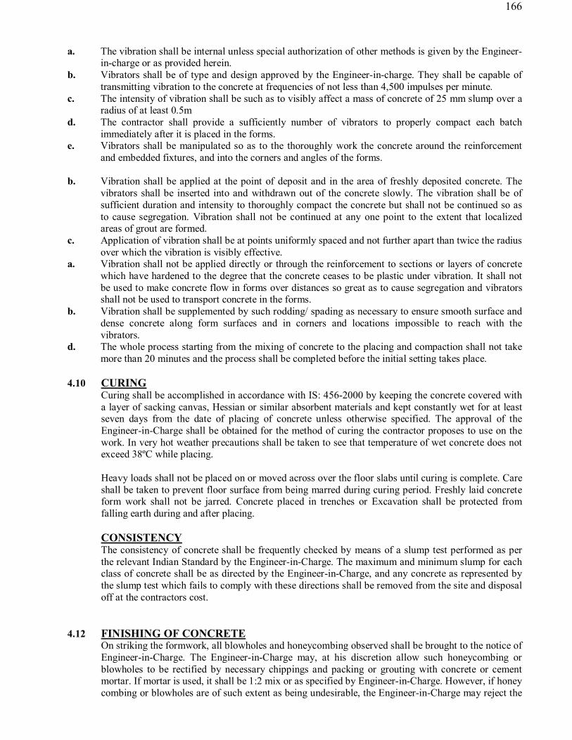
166
a. The vibration shall be internal unless special authorization of other methods is given by the Engineer-
in-charge or as provided herein. b. Vibrators shall be of type and design approved by the Engineer-in-charge. They shall be capable of
transmitting vibration to the concrete at frequencies of not less than 4,500 impulses per minute. c. The intensity of vibration shall be such as to visibly affect a mass of concrete of 25 mm slump over a
radius of at least 0.5m d. The contractor shall provide a sufficiently number of vibrators to properly compact each batch
immediately after it is placed in the forms. e. Vibrators shall be manipulated so as to the thoroughly work the concrete around the reinforcement
and embedded fixtures, and into the corners and angles of the forms. b. Vibration shall be applied at the point of deposit and in the area of freshly deposited concrete. The
vibrators shall be inserted into and withdrawn out of the concrete slowly. The vibration shall be of sufficient duration and intensity to thoroughly compact the concrete but shall not be continued so as to cause segregation. Vibration shall not be continued at any one point to the extent that localized areas of grout are formed.
c. Application of vibration shall be at points uniformly spaced and not further apart than twice the radius over which the vibration is visibly effective.
a. Vibration shall not be applied directly or through the reinforcement to sections or layers of concrete which have hardened to the degree that the concrete ceases to be plastic under vibration. It shall not be used to make concrete flow in forms over distances so great as to cause segregation and vibrators shall not be used to transport concrete in the forms.
b. Vibration shall be supplemented by such rodding/ spading as necessary to ensure smooth surface and dense concrete along form surfaces and in corners and locations impossible to reach with the vibrators.
d. The whole process starting from the mixing of concrete to the placing and compaction shall not take more than 20 minutes and the process shall be completed before the initial setting takes place.
4.10 CURING Curing shall be accomplished in accordance with IS: 456-2000 by keeping the concrete covered with a layer of sacking canvas, Hessian or similar absorbent materials and kept constantly wet for at least seven days from the date of placing of concrete unless otherwise specified. The approval of the Engineer-in-Charge shall be obtained for the method of curing the contractor proposes to use on the work. In very hot weather precautions shall be taken to see that temperature of wet concrete does not exceed 38ºC while placing. Heavy loads shall not be placed on or moved across over the floor slabs until curing is complete. Care shall be taken to prevent floor surface from being marred during curing period. Freshly laid concrete form work shall not be jarred. Concrete placed in trenches or Excavation shall be protected from falling earth during and after placing. CONSISTENCY The consistency of concrete shall be frequently checked by means of a slump test performed as per the relevant Indian Standard by the Engineer-in-Charge. The maximum and minimum slump for each class of concrete shall be as directed by the Engineer-in-Charge, and any concrete as represented by the slump test which fails to comply with these directions shall be removed from the site and disposal off at the contractors cost.
4.12 FINISHING OF CONCRETE On striking the formwork, all blowholes and honeycombing observed shall be brought to the notice of Engineer-in-Charge. The Engineer-in-Charge may, at his discretion allow such honeycombing or blowholes to be rectified by necessary chippings and packing or grouting with concrete or cement mortar. If mortar is used, it shall be 1:2 mix or as specified by Engineer-in-Charge. However, if honey combing or blowholes are of such extent as being undesirable, the Engineer-in-Charge may reject the

167
work totally and his decision shall be binding. No extra payment shall be made for rectifying these defects. All burrs and uneven faces shall be rubbed smooth with the help of carborundum stone. The surface of non-shuttered faces shall be smoothened with a wooden float to give a finish equal to that of the rubbed down shuttered faces. Concealed concrete faces shall be Ieft as from the shuttering except that honeycombed surface shall be made good as detailed above. The top faces of slabs not intended to be surfaced shall be leveled and floated to a smooth finish at the levels or falls shown on the drawings or elsewhere. The floating shall not be executed to the extent of bringing excess fine material to the surface. The top faces of slabs intended to be covered with screed, granolithic or similar faces shall be left with a rough finish.
4.13 WORK IN EXTREME WEATHER During hot weather (atmospheric temperature above 40 degree centigrade) or cold weather (atmospheric temperature at 5 degree centigrade and below) the concreting shall be done as per the procedure and precautions set out in IS: 7861 (Part I and II). Dependence shall not be placed on salt or other chemicals for the prevention of freezing. Calcium chloride shall not be used as an accelerator except with the approval of the Engineer-in-Charge. Recommendation given in relevant clauses of IS: 456 shall be strictly adhered to.
4.14 LOADING OF THE STRUCTURES No concrete structures shall be loaded until the concrete is at least 28 days old and only then with the approval of the Engineer-in-Charge and subject to such conditions as he may lay down.
4.15 TESTING AND ACCEPTANCE CRITERIA OF CONCRETE The sampling of concrete making the test specimens, curing and testing procedures etc. shall be in accordance with IS: 1199, IS: 3085 and IS: 516, the size of specimen being 15 cm cubes. Normally only compression tests shall be performed in accordance with IS: 516. For each grade of concrete and for each 8 hours of work or portion thereof the following samples shall be taken. At least six specimens shall be taken from the first 15.0 m3 or part thereof and three of these shall be tested at 7 days and the remaining at 28 days. Four additional specimens shall be taken from each additional 15.0 m3 of concrete or portion thereof of which 2 specimens shall be tested at 7 days and the remaining at 28 days. To control the consistency of concrete from every mixing plant slump tests, and/or compacting factor tests in accordance with IS: 1199 shall be carried out by the contractor every two hours or as directed by the Engineer-in-Charge. Slumps corresponding to the test specimens shall be recorded for reference. The acceptance criteria of concrete shall be in accordance with IS: 456-2000. Concrete work found unsuitable for acceptance shall have to be dismantled and replacement is to be done as per specifications by the contractor. No payment for the dismantled concrete, the relevant formwork and reinforcement embedded fixtures etc. shall be paid. In the course of dismantling if any damage is done to, the embedded items or adjacent structures the same shall be made good free of charge by the contractor to the satisfaction of the Engineer-in-Charge.
4.16 LOAD TEST OF STRUCTURES The Engineer-in-Charge may instruct for a load test to be carried out on any structure if in his opinion such a test is deemed necessary for any of the following reasons.

168
The works site made concrete test-cube failing to attain the specified strength, as per the criteria laid down in IS: 456-2000. Suspected overloading during construction of the structure under review Shuttering being prematurely removed and not as per the specification The concrete is being improperly cured. Visible deficiencies of the concrete If the results of the load test be unsatisfactory, the Engineer-in-Charge may instruct the Contractor to demolish and reconstruct the structure or part thereof at the contractor’s cost. The load test of structures shall be carried out as per the clause 16.5 of IS: 456-2000.
4.17 SPECIAL METHODS OF CONCRETING The contractor should propose to use special methods of concreting not included in the specifications, such as pumping concrete or using vacuum molds, he shall obtain the Engineer-in-Charge’s approval before commencing work and comply with any subsequent specification made by the Engineer-in-Charge for this special method of concreting. Contractor is advised to use modern techniques in adopting methods of laying/finishing concrete in raft/walls etc. e.g. in raft use of any other acceptable and proven method will be welcomed. The contractor may elaborate same on while quoting the offer.
4.18 CONCRETE FOR WATER RETAINING STRUCTURES 4.18.1 MATERIALS FOR CONSTRUCTION
Materials for concrete viz. Cement, sand aggregate, water etc. shall be as er the specifications of reinforced concrete works described in section 4 and IS : 3320 Part I. However, super-sulphated cement shall be used when ground water contains sulphates more than the permissible limit as indicated in IS: 456-1978.
4.18.2 DESIGN
The design of the structure shall be based as per IS: 3370 (part I to Part IV) code of practice for concrete structures for storage of liquids.
4.18.3 AGGREGATES Maximum size of the aggregate shall be 20 mm for thickness of the section upto 40 mm. above this limit 40 mm size aggregate may be used in the quantities as approved by the Engineer.
4.18.4 CONTROLLED CONCRETE
Controlled concrete of grade not weaker than M 20 is to be used in the structures with minimum quantity of cement in the concrete mix to be not less than 330 kg/cum, for the reinforced concrete work, 360 kg/ cum in post-tensioned pre-stressed work and 380 kg/cum in pre-tensioned concrete work. The maximum quantity of cement in the concrete mix shall preferably not exceed 530 kg/cum of concrete. The design should be such that the resultant concrete is dense and impervious. The mix of concrete should be fully compacted. The use of needle type of internal vibrators is recommended.
4.18.5 COVER Cover to the reinforcement shall be as stated in the drawing and in conformation to IS: 3370 (part-I to
IV) 4.18.6 ADMIXTURES

169
Admixtures such as plastic may be added to improve the workability only with the permission of the Engineer.
4.18.7 JOINTS The Maximum spacing between the partial contraction joints shall be not more than 7.5 m and between the full contraction joint 15.0 m. Alternatively, temporary short gaps of width 0.5 m in walls be left out to the filled in after the concrete has hardened on sides. Vertical joint shall be avoided by casting a lift of approximately 1.0m deep in continuous operation for circular structures.
SHUTTERING
SCOPE
Form work shall be composed of steel and /or best quality shuttering wood of non-absorbent type. Timber shall be free of knots and shall be of medium grain as far as possible. Hard woods shall be used for caps and wedges under or over posts. Marine plywood shuttering or equivalent shall be used where specified to obtain smooth surfaces for exposed concrete work. Struts shall generally be mild steel tubes, and strong Sal bellies. Bamboos, small diameter bellies etc. shall not be used unless approved by the Engineer in specific cases. GENERAL REQUIREMENTS If, it is so desired by the Engineer the contractor shall design and prepare, before commencement of actual work, the drawings for form work and centering and get them approved by the Engineer. The form work shall conform to the shape, lines and dimensions as shown in the drawings. The centering shall be true, rigid and thoroughly braced both horizontally and diagonally. The forms shall be sufficiently strong to carry, without undue deformation, the dead weight of the concrete at the time of casting as well as working load. Where the concrete is vibrated, the form work shall be strong enough to withstand the effects of vibration without appreciable deflection, bugging distortion of loosening of its components. The joints in the form work shall be sufficiently tight to prevent any leakage of mortar. The form work shall be such as to ensure a smooth uniform surface free from honeycombs, air bubbles, bulges, fins and other blemishes, Any blemish or defect found on the surface of the concrete must be brought to the notice of the Engineer immediately by the contractor and rectified, free of charge, as directed by him. To achieve the desired rigidity, tie bolts, spacer blocks, tie wires and clamps as approved by the Engineer shall be used but they must in no way impair the strength of concrete or leave stains or marks on the finished surface. Where there are chances of these fixtures being embedded, only mild steel or concrete of adequate strength shall be used. Bolts passing completely through liquid retaining walls/ slabs for the purpose of securing and aligning the form work should not be used. For exposed interior and exterior concrete surfaces or beams, columns and walls, plywood or other approved forms, thoroughly cleaned and tied shall be used. Rigid care shall be exercised in ensuring that all columns are in plumb and true and thoroughly cross braced to keep them so. All floor and beam centering shall be crowned not less than 8 mm in all directions for every 5 m span. Temporary openings for cleaning, inspection and for pouring concrete shall be provided at the base of vertical forms and at other places where they are necessary and as may be directed by the Engineer. The temporary openings shall be so formed that they can be conveniently closed when required and must not leave any mark on the concrete.
CLEANING AND TREATMENT OF FORMS All forms shall be thoroughly cleaned of old concrete, wood shavings, saw dust, dirt and dust sticking to them before they are fixed in position. All rubbish, loose concrete, chipping, shavings, sawdust etc. shall b scrupulously removed from the interior of the forms before the concrete is poured, along with wire brushes, brooms etc. compressed air jet and / or water jet shall be kept handy for the cleaning, if so directed by the Engineer.

170
Before shuttering is placed in position, the form surface in contact with concrete shall be treated with approved form removing non-staining oil or composition. Care shall be taken that the oil or composition does not come in contact with reinforcing steel or existing concrete surfaces. They shall not be allowed to accumulate at the bottom of the shuttering. The form work shall be so designed and erected that the forms for slabs and the sides of beams, columns and walls may be removed first, leaving the shuttering to the soffits of beams and their supports in position. Re-propping of beams shall not be done except with the approval of the Engineer and props can be reinstated in anticipation of abnormal conditions, if form work for column is erected to the full height of the columns, one side shall be left open and built up in sections, as placing of concrete proceeds: Wedges, spacer, bolts, clamps or other suitable means shall be provided to allow accurate adjustment of the form work and to allow, it to be removed gradually without jarring the concrete. PIPE INSERTS TO BE LAID AT THE TIME OF CONCRETING For pipes to be laid in the walls during concrete, relevant drawings shall be followed. Openings shall be provided in the shuttering plates at suitable positions. It is to be noted here that special shuttering plates for this purpose may have to be used, and the number of uses of shuttering material, for working out the rate, shall be calculated accordingly. REMOVAL OF FORMS The contractor shall record on the drawings or in other approved manner, the date on which the concrete is placed in each part of the work and the date on which the form work is removed there from and have this record checked and counter signed by the Engineer. The contractor shall be responsible for the safe removal of the form work but the Engineer may delay the time, if considers it necessary. Any work showing sign of damage through premature removal of form work for loading shall be entirely reconstructed by the contractor without any extra cost of the owner. Forms for various types of structural components shall be removed before the minimum periods specified below (table V) which shall also be subject to the approval of the Engineer. Engineer at his discretion may extend this maximum period for removal of form work and contractor shall retain the form work for a longer period as desired by the Engineer at no extra cost to the owner. Table 5 Minimum period for Removal of Form work
Part of structure Temperature in degrees Celsius (0C)
Above 400 Days
400 to 200 Days
200 50 Days
to Below 50Days
1 2 3 4 5 A. Ordinary Portland Cement Concrete
1. Column and walls 2 1 1 Do not remove forms until site
2. Beams sides 3 2 3 cured test cylinder / cubes 3. Slabs 125 mm 10 7 8 develop 50% thick or less of 28 days strength 4. Slabs over 125 mm 18 14 16 thick and soffit of

171
Minor beams. 5. Soffit of main beams 24 21 22 B. Rapid Hardening Portland Cement concrete
1. Columns and walls 1 1.5 1 2. Beams sides 2 1 1 Do not remove forms until
site
3. Slab 125 mm thick or less 7 4 5 cured test cylinder / cubes
develop 50% 4. Slab over 125 12 8 9 of 28 days strength mm thick and soffit of minor Beams
5. Soffit of main 14 10 12 beams
Note : For Ordinary Portland Cement the removal time should be suitably increased over the time giver for ordinary Portland Cement, as directed by the Engineer. Reuse of forms Before reuse, all forms shall be thoroughly scrapped, cleaned, joints examined etc. and when necessary, repaired and inside surface treated as specified herein before. Form work shall not be used/ reused, if declared unfit or unserviceable by the Engineer. CLASSIFICATION OF FORM WORK
a. ORDINARY These shall be used in places where ordinary surface finish is required and shall be composed of steel and / or approved good quality seasoned wood.
b. PLYWOOD These shall be used in exposed surfaces, where specially good finish is required and shall be made mostly of approved brand of heavy quality shuttering/ marine plywood to produce a perfectly level, uniform and smooth surface. Ordinary form work shall be used for all underground structures and ‘plywood’ form work shall be used for all structure above ground. Acceptance of form work and finished concrete shall be true to shape, lines, levels, plumb and dimensions as shown on drawings. All embedded fixtures shall be correct type and in correct position as shown in drawings. Finished concrete surface shall be free from blemishes like honeycombs, air bubbles, fins, etc. Exposed decorative concrete surfaces shall be free from rust, stains, grease and mould oil stains, etc. and shall have uniform pleasing appearance to satisfaction of the Engineer. If desired, the finished concrete shall conform in all respects to the accepted sample.

172
Where exposed surface of concrete can be effectively sealed to prevent loss of water the periods specified for temperature above 400 C can be reduced to those for the temperature range of 200 to 400 C subject to approval of the Engineer. Before removing any form work, the contractor must notify the Engineer well in advance to enable him to inspect the concrete, if he so desires. Tolerance in finished concrete
Tolerance in finished concrete shall be exactly same as for reinforced concrete structures in section 2.5.3.3.and 2.5.11.
4.18.9 CURING Curing etc. of the structures shall be exactly same as for reinforced concrete structures in section 2.5.9 4.18.10 VERTICAL JOINTS All vertical joints shall extend full height of the wall in unbroken alignment. 4.18.11 REMOVAL OF SHUTTERING Removal of the form work shall confirm of IS: 456-1978 and para 2.5.3.9 Bolts and fasteners passing
completely through liquid retaining slabs for the purpose of securing and aligning the form work should not be used unless effective precautions are taken to ensure the water tightness after the removal of pipes or other fittings. Puddle flange in concreting shall be placed at correct positions, before concreting and verified by the Engineer.
4.18.12 WATER TIGHTNESS The test for water tightness of the structure shall be carried out as per clause 10 f IS: 3370 part 3. 4.19 Epoxy coating and bituminous painting EPOXY COATING Epoxy coating is to be applied to the internal surface of MS pipes. The thickness of epoxy film shall
be 400 microns. 4.19.2 MATERIALS A solvent free epoxy coating like “Araldite GY 255 manufactured by Hindustan CIBA Geigy Ltd.
Bombay or equivalent is to be used for forming the film. In case of use of an equivalent it should be got approved by the employer before placing supply orders.
Materials used and process of application on the concrete of other surface should be strictly according
ot the instructions of the supplier of the epoxy. Araldite GY 25 one part by weight is to be mixed with 1 part by weight of Hardener HY 45. 4.19.3 SUBSURFACE PREPARATION The concrete surfaces should be cleaned thoroughly by sand blasting. The mild steel parts are also to
be cleaned to be free of grease and thoroughly sand blasted. The coverage should be move than 6 sq. meters for concrete and 5 sq. meters for mild steel per kg. of epoxy respectively.

173
4.19.4 CURING The curing should be done for 7 days at room temperature. If the temperature is less than 150 C the
space should be warmed up by incandescent lamps, heaters, blowers or infrared lamp. The instructions of both the supplier/ manufacturer of the product, for use of materials and application
take priority over the above instructions and they should be followed very rightly. 4.19.5 BITUMINOUS PAINTING Two coats of bituminous paint of 80/100 grade, with 1.65 kg/sq. m spread will be provided on
internal and / or external surface of the pipes and on piers, in the reach, where MS/ GRP pipes are proposed, and where concrete / structure is exposed to weathering or foul conditions.
4.19.6 APPLICATION All corners and junctions shall be properly rounded off to present a uniform and smooth finish. After
complete curing of the paint, it shall be allowed to dry up. After drying, the moisture content shall be brought to a value less than 4% by using a blow lamp. The surface should be well cleaned with smooth brushed to make it dust free. The coating shall be allowed to dry and kept in dry condition till final setting takes place. The sub-surface preparation and curing is to be done as specified is para 2.7.3 and 2.7.4 respectively above.
CODES AND STANDARDS All applicable standards, specifications, etc. and codes of practice shall generally be the latest
editions, including all applicable official amendments and revisions. A complete set of all these documents shall generally be available at site, with the contractor.
All work shall be carried out as per the stipulations contained in various sections of these
specifications and the latest Indian Standards, Acts, Codes and best practices. In case of conflict between the stipulations contained in various’ sections of these specifications and
stipulations of Indian Standard, Codes, etc. the requirements of stipulations contained in various sections of these specifications, shall prevail over that of Indian Standards, Codes, etc. Some of the applicable Indian Standard Codes, etc. are referred to here below: IS:73 Specification for paving bitumen IS:2060 Specification for structural steel IS:8112 Specification for Ordinary Portland cements 43 grade. IS:280 Specification for mild steel wire for general engineering purposes IS:383 Specification for coarse and fine aggregates from natural sources for
concrete IS:432 (Part I & II)
Specification for mild steel and medium tensile steel bars and hard drawn steel wire for concrete reinforcement
IS:455 Specification for Portland Slag Cement IS:456 Code of practice for plain and reinforced concrete IS:457 Code of Practice for general construction of plain & reinforced concrete for
dams and other massive structure. IS:516 Method of test for strength of Concrete IS:650 Specification for standard sand for testing of cement IS:702 Specification for industrial bitumen IS:816 Code of practice for use of metal as welding for general construction in
mild steel IS:1199 Methods of sampling and analysis of concrete IS:1200 (Part II, V, VIII, XVIII, SVIII)
Method of measurement of building and civil engineering works, water proofing and damp proofing
IS:1367 Technical supply conditions for threaded steel fasteners IS:1489 Specification for Portland puzolana cement (Part I) Fly ash based & (Part
II) Calcified clay based

174
IS:1566 Specification for Hard drawn steel wire fabric for concrete reinforcement IS:1609 Code of practice for laying damp proof treatment. using bitumen felts. IS:1786 Specification for high strength deformed steel bars and wires for concrete
reinforcement IS:1791 General requirements for batch type concrete mixer. IS: 1838 Specification for performed fillers for expansion joints in concrete
pavements and structures (non-extruding and resilient type) IS:2204 Code of practice for construction of reinforced concrete shell roof IS:2210 Criteria for the design of reinforced concrete shell structures and folded
plate IS:2386 (Part 1 to VIII)
Methods for test of aggregates for concrete
IS:2438 Specification for roller pan mixer IS:2502 Code of practice of bending and fixing of bars for concrete reinforcement IS:2505 General requirements for concrete vibrators, immersion type IS:2506 General requirements for concrete vibrators, screen board type IS:2514 Specification for concrete vibrating tables IS:2571 Code of practice for laying in situ cement concrete flooring IS:2645 Specification for integral cement water proofing compounds IS:2722 Specification for portable swing weigh batchers for concrete (single and
double bucket type) IS:2750 Specification for steel scaffoldings IS:2751 Code of practice for welding of mild steel plain and deformed bars for
reinforced concrete construction IS:3025 Methods of sampling and test waste water IS:3067 Code of practice for general design details and preparatory work for damp
proofing & water proofing of buildings IS:3150 Specification for hexagonal wire netting for general purposes IS:3366 Specification for pan vibrators IS:3370 (Part I & II)
Code of practice for concrete structures for the storage of liquids
IS:3384 Specification for bitumen primer for use in water proofing & damp proofing
IS:3414 Code of practice for design and installation of joints in buildings IS:3550 Methods of test for routine control for water used in industry IS:3558 Code of practice for use in immersion vibrators for consolidating concrete IS:3696 (Part I & II)
Safety code for scaffolds and ladders
IS:4014 (Part I & II)
Code of practice for steel tubular scaffolding
IS:4031 Methods for physical tests for hydraulic cement IS:4130 Safety code for demolition of buildings. IS:4326 Code of practice for earthquake resistant design and construction of
buildings IS:4461 Code of practice for joints in surface hydroelectric power stations IS:4656 Specification for form vibrators for concrete IS:4925 Specification for batching and mixing plant IS:4990 Specification for plywood for concrete shuttering work IS:4995 (Part I & II)
Criteria for design of reinforced concrete bins for the storage of granular and powdery materials
IS:5121 Safety code for piling and other deep foundations IS:5256 Code of practice for sealing joints in concrete lining on canals IS:5525 Recommendations for detailing of reinforcement in reinforced concrete
work IS:5624 Specification for foundation bolts IS:6461 Glossary of terms relating to cement concrete IS:6494 Code of practice for water proofing of underground water reservoirs and
swimming pools IS:6509 Code of practice for installation of joints in concrete payments

175
IS:7193 Specification for glass fiber base coal tar pitch and bitumen felts IS:7293 Safety code for working with construction machinery IS:7861 (Part I & II)
Code of practice for extreme weather concreting
IS:9012 Recommended practice for shuttering IS:9103 Specification for admixtures for concrete IS:9417 Recommendations for welding cold worked steel bars for reinforced
concrete construction. IS:9595 Recommendations for metal-arc welding of carbon and carbon manganese
steels IS:10262 Recommended guidelines for concrete mix design IS:11384 Code of practice for composite construction in structural steel and concrete IS:12118 Specification for two parts poly sulphide
IS:122000 Code of practice for provision of water slops at transverse contraction joints in masonry and concrete dams
IS:12269 53 grade ordinary Portland cement IS:12600 Portland cement, low heat IS:23 Handbook of concrete mixes IS:24 Explanatory Handbook on IS:456-1978 IS:34 Handbook on concrete reinforcement and detailing.
5. BITUMINOUS, CC, BOE & INTERLOCKING TILE ROAD 5.1 All work shall be carried out as per IRC detailed specifications where there are no IRC specifications
M.O.S.T. specifications/P.W.D. specifications will be followed unless otherwise specified or directed by the Engineer in charge.
5.2 The contractor shall take all necessary measures for the safety of traffic during construction and provide, erect and maintain such barricades, including signs, marking flags, lights and flagman, as necessary at either end of work site and at such intermediate points as directed by the Engineer in charge for the proper identification of the construction area. He shall be responsible for all damages and accidents caused due to negligence on his part. The temporary warning lamps or reflective barriers or sign boards shall be installed at all barricades during the hours of darkness.
5.3 Stone ballast / Stone grit should be stacked at site for satisfaction regarding quantity of material to Engineer in charge.
5.4 The material collected for use in the work shall satisfy all requirements for the particular work, failing which the material will be rejected. The gauge of stone ballast shall be as per detailed specification for the respective items and deduction will be made for the under gauge/ over gauge material as per Engineer in charge.
5.5 During construction care shall be taken to ensure there is least disturbance to the traffic. Adequate barriers, red flags in day time and light in night hours shall be provided to guide and inform the traffic. All necessary precautions shall be taken to avoid any road accident at work-site but if there happens any the responsibility will be of the contractor and he shall be responsible for all consequences and damages/ claims etc.
5.6 The consolidation will be in specified layers. Proper and adequate camber or super elevation etc. shall be provided as per directions of Engineer in charge.
5.7 Next coat of consolidation shall be allowed after checking of the crust and quality of previously consolidated layer by the Engineer in charge and found satisfactory.
5.8 The material of the different layer will be spread in required loose thickness so as to achieve the desired compacted thickness.
5.9 The binding material for consolidation shall be soil having plasticity index not more than 6 which is to be arranged by the contractor from a suitable place as directed by Engineer in charge. The soil shall be got approved from the Engineer in charge before start of consolidation and nothing extra shall be paid either for the cost of binding material or for its cartage.
5.10 Proper arrangement of water and its storage for consolidation shall have to be made by the contractor at his own cost.

176
The stone ballast shall confirm to the following sieves. Name of metal Percentage by weight passing
1. 63-45
mm gauge
90 mm 10%
63 mm 90-100%
53 mm 25-75%
45 mm 0-15%
22.4 mm 0-5%
1.2 mm -
2. 53-22.4
mm gauge
- 100% 95-100% 65-90% 0-10% 0-5%
5.12 (a) 16-22.4 mm size grit shall pass 100% from 22.4 mm square mesh And all retained on 16 mm square mesh sieve. 10-16 mm size shingle / grit shall pass 100% from 16 mm square Sieve and all retained on 10 mm square mesh sieve. 5.13 (A) Material for Ist coat painting shall be as follows:- (i) Grit 16-22.4 mm size (crushed) 1.9 cum per% sqm (ii) Bitumen (a) For Pre coating 15 kg per cum of shingle/grit (b) For tack coat 180 kg per% sqm. (B) Material for IInd coat painting shall be as follows:- (i) Grit /Shingle 10-16 mm size 1.20 cum per% sqm. (ii) Bitumen (a) For Pre coating 15 kg per cum of shingle/grit (b) For tack coat 110 kg per% sqm. (C) Material for open Graded Premix Carpet shall be as follows:- (i) Aggregates for Carpet
(a) Stone chippings 13.2 mm size, passing 22.4mm sieve and retained on 11.2 mm sieve 1.8 cum per% sqm
(b) Stone chippings 11.2 mm size, passing 13.2 mm Sieve and retained on 5.6 mm sieve 0.9 cum per% sqm
(ii) Bitumen (a) For tack coat 180 kg per% sqm (b) For stone chipping of 13.2 mm size 52 kg per cum (c) For stone chipping of 11.2 mm size 56 kg per cum (d) Material for type ‘A’ seal coat shall be as follows:- (i) Stone chippings 6.7 mm size passing through 11.2 mm sieve and retained on 2.36
mm sieve - 0.9 cum per% sqm (ii) Bitumen 98 kg per % sqm (E) Material for type ‘B’ seal coat shall be as follows:- (i) Chippings aggregates passing 2.36 mm sieve and be retained on 180 micron sieve 0.6 cum per% sqm (ii) Bitumen 68 kg per % sqm 5.14 Stone ballast/Grit/Shingle of approved quarry only, confirming to I.R.C. Specifications shall
be used. Before using stone ballast/Stone Grit/River shingle the quality & size has to be approved by the Engineer in charge.
5.15 Contractor shall always cooperate in procurement of sample, conduction of tests as may be directed and no extra payment shall be made for the same. Test samples shall be taken carefully in accordance with the standard method of taking the test sample.
5.16 The contractor shall at all times keep the premises free from accumulated waste materials or rubbish caused by his employee on the works and on completion of the work, he shall clear away and remove from site all surplus materials, rubbish and temporary works of any kind and fill up borrow pits dug by his. He shall leave whole of the site and work clean and in a workman like condition to the entire satisfaction of the Engineer in charge.

177
5.17 The cement concrete road shall be constructed with concrete mix of M-20 grade as per IS code-456.
5.18 The permanent reinstatement of all types of roads shall be executed as per UPPWD specifications. Where UPPWD specifications are not available CPWD specifications shall be followed. The material used shall be conforming to relevant IS codes with its latest revision.
5.19 C.C. Road will be prepared with 10 cm thick P.C.C. 1:2:4 Cement: Coarse Sand & 20 mm Stone grit over base concrete 15 cm. P.C.C. 1:4:8 with cement coarse sand & 40 mm stone ballast after compacting the earth surface properly. The C.C. surface must be compacted with surface vibrator.
5.20 Interlocking Tile: Tiles must be of the thickness & grade similar to that of the dismantled tiles over base concrete 75 mm thick 1:6:12 Cement: Local Sand: Brick Ballast Tiles must be fixed over 40 mm thick local sand layer with proper level finish.
DETAILED SPECIFICATIONS OF SEWER WORKS: 1.0 EXCAVATION: (i) The excavation in sewer trenches for the laying of sewers, manhole chamber, sumps, gully pits in all types of soil i.e. loam, clay, sand mixed with mooram, shingle, boulders and all type of rocks etc. shall be dug. Different rates for 1.5m intervals below ground level shall be applicable for the purpose of measurement and payment according to the classification of soil under the respective schedule or quantities. The sides of the excavated trenches shall be left plumb where the nature of soil admits of it, but the sides must be sloped back or shored up carefully where the soil appears likely to fall in or the depth exceeds 3.30 meters. The excavated materials be placed 1.5 m away from the excavated earth or half the depth of trench whichever is morefrom each edge the excavated trench or as directed by the Engineer-in-charge. The width of trenches should be kept minimum as for as possible. The width of excavation should be at least 1.25 times the outside dia of pipe. (ii) BOTTOM FINISHING OF TRENCHES: The bottom of the trenches must be perfectly leveled both longitudinally and transversely according to the level pillars given on the ground level in the alignment longitudinally. The bottom of the trench shall be slightly watered (where necessary) and well rammed. If any soft places come to light on inspection they will be dugout and dealt with as ordered by the Engineer. The contractor shall sort out and remove boulders, or any other serviceable material found during excavation as well as during preparation of bed, the bed of such places be againleveled and hard dressed after consolidation or as per direction of Engineer. If however, the contractor without the sanction of the Engineer makes the excavation deeperor wider than the desired one, he shall fill the extra depth or width with cement concrete 1:4:8(1 cement, 4 coarse sand & 8 approved stone ballast 40 mm) at his own cost. Roots of all trees and plants encountered in digging trenches shall be removed completely, if possible, otherwise they shall be cut upto a distance of 300 mm beyond side/ bottom of trench and shall then be burnt and smeared with boiling coal/tar at the expense of the contractor. The hole thus occurring in the trench shall be filled with cement concrete 1:4:8 (1 cement, 4 coarse sand & 8 approved stone ballast 40 mm) to made it finished with the bottom or side of trench forwhichnopayment will be made to the contractor. (iii) FINDS: Any finds found on the site such as antique, relics, coins and fossils or any other valuable article shall be immediately handed over to the care of Engineer for safe custody on behalf of Govt. (iv) WIDTH OF TRENCHES:
In case of pipe line, sewer, rising main etc. the width of trenches for depth up to 1.5 meter below ground level shall be outer diameter of the pipe plus 30 cms rounded to nearest cm. For depth greater than 1.5 meter below ground level, the trenches shall be excavated in telescopic form in intervals from the ground level with off-sets of 250 mm at every 1.5 m depth on either side of the trench and the width of lower most section will be governed by the above criteria. The actual width or as described above which ever is less shall be measured for payment. The depth of

178
excavation shall be measured from the invert level to the ground level. Any extra width excavated shall not he paid to contractor. (v) This item of work also includes the work and expenses on laying out, making level pillars, fixing of telltales, photographs of nearby building site clearancebeforetakinguptheworkandcompletion of the work. (vi) The rates quoted by the contractor are inclusive of the filling back of trenches in 15 cm. layers after laying and jointing of pipes, watering, ramming, dressing and disposal of surplus earth within the specified distance. The extra lead and lift shall be paid, as per item given separately. The pumping of water from trenches which finds its way in to the trenches from drains or rains or by any means (except sub-soil water) shall be done by the contractor at his own cost. (vii) Cutting of road surfaces including sorting out of serviceable materials etc. will be paid extra and the depth of excavation in such cases shall be measured from the bottom of the lower most soling layer of the road. (viii) Proper barricading and fencing shall be done along with the excavation. Red flags and caution board during day and red lights during night shall be displayed so as to avoid any accident etc. Contractor shall undertake all responsibility for slips or subsidence and shall make good all damages to any adjoining property and pay compensation for loss of life and property at his own cost and to the satisfaction of Engineer. The contractor shall be held liable to indemnify the owner for any damage done to any adjoining property or to any of the works in progress or partly completed by and settlement of ground which is in the opinion of the Engineer attributable to any of the excavation, trenching work, timbering or refilling done by the contractor. 2.0 TIMBERING (OPEN & CLOSED):
Normally trenches upto 1.50 meter depth shall be excavated without timbering, but where the depth of excavation exceed from 1.50 meter, timbering shall be provided, open or close, as the case may be. Where the sides of the trenches covered shall be 33-1/3 percent it will be called open timbering and where the sides of trenches covered shall be 100% by the timbering materials it will be called close timbering. Open / close timbering shall be providing as per site and soil conditions. The thickness of country wood planks shall be 40 mm up to 3.30 meter and 50 mm where the trenches depth exceeds 3.30 meter from the ground level. The sizes of Wallers and struts at various depths have been given in the respective item of works. The contractor will have to provide the timbering, open and close as per direction of Engineer. In case there is sufficient space available for excavation of trenches at site, the contactor may be required to excavate the trenches in requisite slopes in lieu of timbering as per direction of Engineer. The contractor are advised to see the site and working conditions, specification and quote their rates accordingly which should be including the cost of all timbering materials, labour for making the timbering as and when required, and removal of timbering after completion of laying, jointing etc. in any case no weakened polling board, wallers and strut will be used.
As already indicated under the item of bill of quantities both sides of timbering shall be measured as one side for the purpose of measurement and payment. The removal of timbering shall be started as per direction of the Engineer.
4.0 TESTING:
Each length of sewer line from manhole to manhole shall be tested by contractor at his own cost as per relevant I.S. specification / sewerage manual by filling the water in to the sewer. The results of testing shall be produced by the contractor properly signed by engineer in charge. The water required for testing of sewers will have to be arranged by the contractor at his own cost. As soon as a stretch of sewer is laid and tested a double disc or solid or closed cylinder of 75 mm less in dimension than the internal dimensions of the sewer pipe shall be run though the stretch of the sewer to ensure that it is free from any obstruction.

179
5 MANHOLES AND SEWER CONNECTING CHAMBERS : All manholes and sewer connecting chambers shall be constructed in accordance with the dimensions
shown in the approved drawing, All the works related to construction of manhole should be carried out in accordance with detailed specifications for the respective items of works. The inner surface of the wall of M.H. /S.C.C. shall be plastered in mortar of mix as specified in Schedule–G. The plaster below sub-soil water level must be finished with a floating coat of neat cement on both sides along with the water proofing compound as per direction of Engineer. The manhole covers shall be precast RCC heavy duty circular type conforming to I.S. 2592. However on highways and on important roads extra heavy duty manhole covers shall be provided as desired by E/I. The footsteps shall be of C.I./P.V.C. coated MS conforming to relevant I.S. code as per approval and direction of E/I. The spacing of C.I. footsteps shall not exceed 25-cm. No separate measurement for manhole cover and footsteps shall be made as they are part of manhole as per bill of quantities. If the manholes are constructed in sub soil conditions, the PCC 1:2:4 shall be replaced by RCC 1:1½:3 with nominal reinforcement on both faces of R.C.C. foundation. The plaster shall be 20mm thick on both sides in sub soil conditions.
5.1 MANHOLE SHAFT: The contractor shall quote rates per meter run of shaft for manholes. These rates shall be used for
regulating payments for variation of depth of manholes. 5.2 BRICK WORK : The brick work in manholes and sewer connecting chambers shall consist of M-100 class bricks in
mortar of mix as specified in Schedule G. The bricks shall conform to the PWD detailed specification and mortar to relevant I.S. specification according to the type of mortar specified. The work shall be executed as per I.S. detailed specification.
6.0 DISMANTLING OF ROADS : Dismantling of various road surfaces before the excavation in trenches shall be carried out in
following two parts:- Breaking and sorting out the top coat and stacking the dismantled materials properly so as to be
placed at the top of trench after re-filling with excavated earth in 20 cm. layers and its proper compaction by watering and ramming.
Breaking and sorting out the serviceable materials from inter and soling coat of the road, carting and stacking the same up to 50 m. from the trench, which shall also be used after re-filling and compaction of trench as soon as the pipe laying is completed.
The payment for dismantling of road surfaces will be made per sq.m. as per rate quoted in bill of quantities. The thickness of road cutting during dismantling of road surfaces will not be measured in the item of excavation. The thickness of road may vary up to any extent as per site condition, so contractor should make allowance for same while quoting rates for this item. No extra claim in this item shall be entertained on any ground. As soon as the laying of pipe, refilling of trenches and consolidation of the excavated earth is completed, the road materials of different coats which were sorted out at the time of cutting of road will be placed on top in layers as they were in original position to avoid inconvenience to the public/ traffic. No extra payment to the contractor will be made on this account.
7 DRY BRICK BALLAST PADDING : The work of dry brick ballast 65 mm gauge broken from the Ist class and over burnt bricks bats only
shall be spread over the entire area of trench before laying of R.C.C or P.C.C. of the specified mix and after preparation of base of trench. The measurement shall be taken as per consolidated thickness of the ballast padding in entire area of trench specified for the purpose. The payment shall be made as per rates marked and quoted in schedule ‘G’.

180
8 DISPOSAL OF SURPLUS EARTH: The Contractor will dispose off the extra/surplus earth from the site of work to the place or places
specified by the Engineer. The Contractor is advised to quote his rates of excavation including loading, carting, unloading and disposal of surplus earth at the locations finalized by E/I or Nagar Nigam. The excavated earth will be property of Nagar Nigam and contractor will include in his rates only carting, loading, unloading etc. excluding cost of earth but including royalty if at all to be paid to concerned authorities and form-11 shall have to be produced.
9 OTHER WORKS: Other works which have/have not been specified in schedule ‘G’ and are essential to be executed
shall be carried out as per U.P. Jal Nigam, (LSGED) or PWD/CPWD specifications, and he should quote his rate in Schedule-H. The extra items shall be paid at the rates in accordance with clause 13 of condition of contract. For extra items of works the Contractor profit on the issue rate of materials shall not be added while working out the extra rate in case the material is issued from the Deptt. For purpose of payment of quantities of P.C.C. & R.C.C. cradle and brick padding in various lifts, the center line of the thickness of particular quantity of the item shall be considered for measurement & payment of the same.
10 DEWATERING FOR REDUCTION OF SUB-SOIL WATER LEVEL DURING
CONSTRUCTION: Dewatering is the removal of excess water from saturated soil mass, which is necessitated to make
working easier in wet conditions and possible below natural water level, during construction. The Dewatering work is done as per the site conditions to enable for laying of sewer system and the construction of RCC / brick structures in dry conditions and maintain factor of safety against uplifting of structure. The subsoil water will be disposed off by the contractor as decided by Engineer-in-Charge. The Dewatering shall be done as per IS: 9759-1981.
The choice of the dewatering system depends upon the type of the soil and its characteristics and depth of water table to be lowered. The objective and main purpose of well point dewatering is to drain out water only at the actual site of work. This avoids excessive dewatering over a large area and provides dry working conditions to enhance the workability and manpower and machinery in a very short time, and in most economical way. Accordingly dewatering whenever required shall be done by well point equipment as per direction of E/I. No extra payment on this account shall be made separately until and unless as specified in Schedule-G separately.

181

182

183

184

185
186

187

188

189

190

191
HAPUR SEWERAGE SCHEME PART -1 PHASE-2
ALGORITHM FOR IPS E/M WORKS
Algorithm: The bidders have to submit the MOC with drawing and design and each equipment for approval of the competent authority before pre-dispatch inspection, testing at the place of manufacturer- 1. 33 KV Power connection from UPPCL. 2. Submission of drawing and design of various equipments to be installed as per requirement at
main pumping station, Bulandshahar. 3. After approval of submitted drawing/designs contractor will have to procure the materials
and shall ensure their pre-dispatch inspection by the Engineer In-charge of the EA. 4. After procurement of material operator shall store and erect the materials in best engineering
manner as per site clearance. 5. After installation of E/M equipments contractor shall have to commission, testing at site on
no load and full load. 6. After successful commissioning contractor shall have to run the various E/M equipments for
3 months as trial run with 12 months defect liability period. 7. During trial run all the consumables will be supplied by the contractor and replace or rectify
the equipments in the event of equipments failure due to poor workmanship or defective manufacturing defect in course of defect liability period.
8. After successful trial run operation and maintenance work will start. 9. Rating and quantity given in the Bill of quantity may be revised as per drawing and design of
the Bidder with consensual approach in between Bidder and EA i.e. Executive Engineer, Construction Division (E/M) U.P. Jal Nigam, Ghaziabad to the cause the work, if it is deemed necessary.
10. Break up for O&M (E/M) works of IPS stipulated for 05 years is obligatory to be given separately.
11. Bidders have the right to add the items in addition to terms given in Bill of Quantity, if required.
12. Site Office: The tenderer shall provide a site office for Computer Operators, 2 & 2 Vehicle (LMV) and a telephone for the work costing more than 5 Crore.
13. Makes of the procured material must be as per approved U.P. Jal Nigam list enclosed in tender document and make of those items not mentioned therein, shall be as per approval of the Chief Engineer (E/M) U.P. Jal Nigam Lucknow before supply.
33 KV POWER CONNECTION FROM UPPCL
Power connection from UPPCL Bulandshahar is to be taken by the contractor for 33 KV over head transmission line from the nearest substation of UPPCL. As independent feeder from 132/33 KV substation to MPS Buladnshahar including system loading charges, security other charges “whatsoever applicable taxes”. Contractor has to design and calculate the load capacity of the IPS at their own but payment likely to be incurred on taking the power connection shall be paid to the UPPCL as per its estimate through the contractor.
It shall be consisting of the following works.
Double pole structure with the lightening arrestor, disconnector for termination of incoming 33 KV power supply trough OHT distribution system close to the gate of IPS. and outside the premises of it including foundation of the pole supports preferably poured concerete type RCC foundation with anchor, guy or stray and TPMO etc. including MS mesh-fencing at least 2.0mtrs High 75x75 chain link as per drawing and specifications. Ground clearance should be at least 4.75mtr.
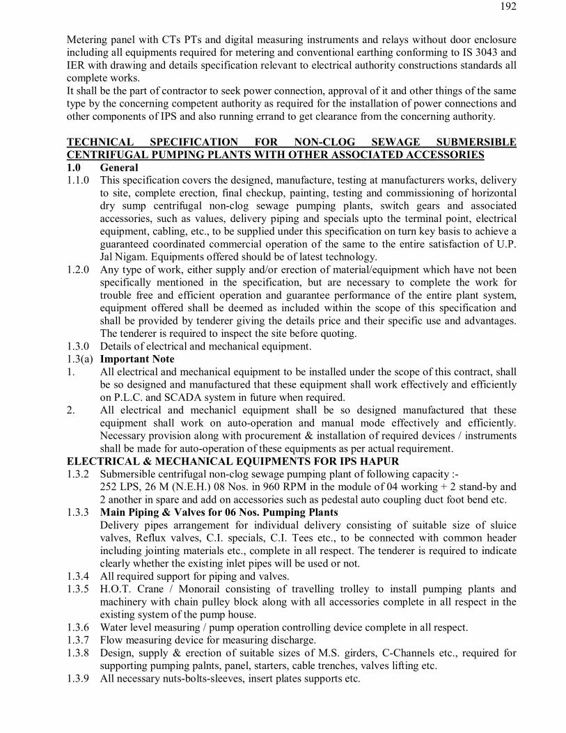
192
Metering panel with CTs PTs and digital measuring instruments and relays without door enclosure including all equipments required for metering and conventional earthing conforming to IS 3043 and IER with drawing and details specification relevant to electrical authority constructions standards all complete works. It shall be the part of contractor to seek power connection, approval of it and other things of the same type by the concerning competent authority as required for the installation of power connections and other components of IPS and also running errand to get clearance from the concerning authority. TECHNICAL SPECIFICATION FOR NON-CLOG SEWAGE SUBMERSIBLE CENTRIFUGAL PUMPING PLANTS WITH OTHER ASSOCIATED ACCESSORIES 1.0 General 1.1.0 This specification covers the designed, manufacture, testing at manufacturers works, delivery
to site, complete erection, final checkup, painting, testing and commissioning of horizontal dry sump centrifugal non-clog sewage pumping plants, switch gears and associated accessories, such as values, delivery piping and specials upto the terminal point, electrical equipment, cabling, etc., to be supplied under this specification on turn key basis to achieve a guaranteed coordinated commercial operation of the same to the entire satisfaction of U.P. Jal Nigam. Equipments offered should be of latest technology.
1.2.0 Any type of work, either supply and/or erection of material/equipment which have not been specifically mentioned in the specification, but are necessary to complete the work for trouble free and efficient operation and guarantee performance of the entire plant system, equipment offered shall be deemed as included within the scope of this specification and shall be provided by tenderer giving the details price and their specific use and advantages. The tenderer is required to inspect the site before quoting.
1.3.0 Details of electrical and mechanical equipment. 1.3(a) Important Note 1. All electrical and mechanical equipment to be installed under the scope of this contract, shall
be so designed and manufactured that these equipment shall work effectively and efficiently on P.L.C. and SCADA system in future when required.
2. All electrical and mechanicl equipment shall be so designed manufactured that these equipment shall work on auto-operation and manual mode effectively and efficiently. Necessary provision along with procurement & installation of required devices / instruments shall be made for auto-operation of these equipments as per actual requirement.
ELECTRICAL & MECHANICAL EQUIPMENTS FOR IPS HAPUR 1.3.2 Submersible centrifugal non-clog sewage pumping plant of following capacity :- 252 LPS, 26 M (N.E.H.) 08 Nos. in 960 RPM in the module of 04 working + 2 stand-by and
2 another in spare and add on accessories such as pedestal auto coupling duct foot bend etc. 1.3.3 Main Piping & Valves for 06 Nos. Pumping Plants Delivery pipes arrangement for individual delivery consisting of suitable size of sluice
valves, Reflux valves, C.I. specials, C.I. Tees etc., to be connected with common header including jointing materials etc., complete in all respect. The tenderer is required to indicate clearly whether the existing inlet pipes will be used or not.
1.3.4 All required support for piping and valves. 1.3.5 H.O.T. Crane / Monorail consisting of travelling trolley to install pumping plants and
machinery with chain pulley block along with all accessories complete in all respect in the existing system of the pump house.
1.3.6 Water level measuring / pump operation controlling device complete in all respect. 1.3.7 Flow measuring device for measuring discharge. 1.3.8 Design, supply & erection of suitable sizes of M.S. girders, C-Channels etc., required for
supporting pumping palnts, panel, starters, cable trenches, valves lifting etc. 1.3.9 All necessary nuts-bolts-sleeves, insert plates supports etc.

193
1.3.10 Special cleaning, protection and final painting for all equipments. 1.3.11 Initial filling of oil, lubricants, grease etc., for the equipment. 1.3.12 One complete set of recommended special tools and tackles etc., for erection and regular
operation and maintenance of the equipments giving item wise rates separately for at least O&M of 05 years.
1.3.13 All civil works such as construction of foundation, cable trenches, making holes etc., required for all electrical and mechanical equipment at pumping station shall be carried out by the tenderer as per direction of the site incharge. Lay out drawing giving the dimensions and other technical details for all electrical and mechanical equipments, cable trenches, holes etc., shall be furnished by the contractor well in advance for approval, so that the progress of the construction work of building work may not suffer due to lack of such details.
2.0 Volute Bottom Section Submersible sewage non clog centrifugal pump set General Specification It shall be of single stage Bottom Section submersible / vertical sewage pump with non-clog
design. It should be suitable for pumping all kinds of sewage containing long fibre, plastics, solid admixes, sludges, etc. with inspection hole at proper place.
Impeller for sewage pump should be single vane / double vane without front shroud and wearing ring to avoid jamming and consequent over-loading of the pump due to built-up of plastics between impeller and wearing ring.
The pump should be able to pass through soft solids upto 100/150 mm (as required) and capable of dealing with the sewage with specific gravity of 1.05. The pump should be fitted with special tearing system on the suction side for tearing cutting solid material, viz. long fibre textile, cotton and plastics, which would otherwise cause clogging of the pump.
Maintenance free antifriction deep grease ball bearings with permanent grease packed should be provided and this should take care of all the axial and radial forces at any point of operation. Profile gasket should be provided in pump casing so as to avoid metal contact between pump and specially designed duck foot bend to ensure leak-proof joint with the guide wire/pipe.
The motor should be squirrel cage, three phase squirrel cage motor for continuous duty with class 'F' insulation. Winding of the motor should be impregnated by resin in order to achieve required thermal withstanding capacity. There should be thermal protection against over-heating of motor winding. The motor should be Submersible,it will be coupled with Axial flow pump with the help of coupling.
The casing of the pump set should be of 2% Ni Cast Iron construction and the impeller should be made of stainless steel. The pump set shall be supplied with foundation bolts and nuts complete. The cable must have glands support plate shall be of 4 mm thick and leak tight in respect of liquids and firmly attached to the terminal box. The motor and pump should be aligned vertically and fixed on a pedestal and auto coupling.
The weight of revolving parts of the pumps including un-balanced hydraulic thrust of the impellers shall be carried out by thrust bearing provided in each pump assembly.
2.1 Scope This specification covers the design, performance, manufacturer construction features, testing
and delivery to site of vertically mounted centrifugal sewage non-clog pump set. 2.2 Code & Standards The design, manufacture and performance of pumps shall conform to the latest I.S.
applicable to all currently standards matching the service requirement. Nothing in this specifications shall release the Contractor of his responsibility.
2.3 Design Features The pump shall be capable of developing the required total head at rated capacity for
continuous operation. It should be so selected that there should not be any substantial difference in efficiency for the operation of pumping plant in the range of head variation.

194
Non clog contritugal sewage pump sets corresponding to the rating and duties at average sewerage flow for the middle stage, Considering the peak factor as per sewage manual at the head for average flow and non peak flow. Duties and rating of pump set with respect to each other have to be precisely analysed by the contractor/tenderers. Ours is a mere assessment based on hypothesis that is not exactly right as per prevailing ground reality and topographical situation therefore, duties and rating may be increased or decreased by the tenderers which is subjected to approval at the competent authority of UPJN.
Secondary, each pump with stand-by is to cater 50% of the peak flow where in minimum flow may vary from (1/3 to ½) of average flow with mode of operation (4w+2s) from the sump well and 2 another pump sets shall be kept in spare to cope with critical conditions in future therefore, adequate number of sufficient capacity are required to meet the need of peak hrs., average hrs and non peak pump sets must be designed to maintain self cleaning velocity around 50m/s at the rising main to ensure that rising main is free from incidence of clogging in future. For protection against clogging, opening of the pump inlet should not be less than 150 mm and its should be capable of passing a ball of at least 50 mm dia. Materials for pump set is not only sewage which is corrosive to pump set but also pump set is to entrain abrasive solids therefore, pump sets are required in abrasion resistance materials-MOC mentioned in the tender documents may be change by the tenderers after submitting the drawing and design by the tenderers and approval of competent authority signature mounted on it. Auto coupling / pedesal or guide pipe 40 to 50 mm in SS are required MS/ Cast iron alloy is denied. Sewage inflow to well must be through screening to make the sewage free from grit, floating or trashy waste to secure the life and performance at the pump sets. Secondly, Baffles in well in case of wet well are necessary to ensure uniform intake at each pump with sufficient pressure head wet well flooring should have benching like hooper with minimum slop 1:1 to avoid deposetion of solids harming the life of performance at the pump set.
2.4 Pumps of a particular category shall be identical and shall be suitable for parallel operation. Components of the identical pumps shall be inter-changeable.
2.5 The total head capacity curve shall be continuously rising type towards shut off with the highest at shut-off.
2.6 K.W. rating of the motors or the prime mover (including power factor) shall not be less than the following :
a) 10% higher than the required K.W. to drive the impeller throughout the entire range of head capacity curve. b) Motors shall be designed to have service factor 1.15 so that they could run at 15% over load occasionally.
NB Technical data, operation data, pump data or motor data are essential to be quoted 2.7 Features of Construction GENERAL 2.7.1 Pump Casing It shall be of 2% Ni C.I. and conforming to relevant I.S. 210(M). The internal surfaces shall
be free from rough spots and must have central line discharge. 2.7.2 Impellers : CF-8(M) The impeller shall be properly balanced dynamically as well statistically. The impeller shall
be properly machined. 2.7.3 Impeller Shaft / Extended Motor Shaft : SS-AISI-410 The impeller shaft shall be made of stainless steel containing minimum 12% Chromium
Stainless Steel and having brinell hardness not less than 200 BHN.
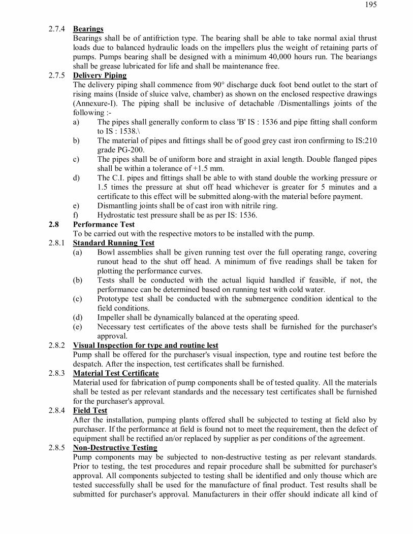
195
2.7.4 Bearings Bearings shall be of antifriction type. The bearing shall be able to take normal axial thrust
loads due to balanced hydraulic loads on the impellers plus the weight of retaining parts of pumps. Pumps bearing shall be designed with a minimum 40,000 hours run. The beariangs shall be grease lubricated for life and shall be maintenance free.
2.7.5 Delivery Piping The delivery piping shall commence from 90° discharge duck foot bend outlet to the start of
rising mains (Inside of sluice valve, chamber) as shown on the enclosed respective drawings (Annexure-I). The piping shall be inclusive of detachable /Dismentallings joints of the following :- a) The pipes shall generally conform to class 'B' IS : 1536 and pipe fitting shall conform
to IS : 1538.\ b) The material of pipes and fittings shall be of good grey cast iron confirming to IS:210
grade PG-200. c) The pipes shall be of uniform bore and straight in axial length. Double flanged pipes
shall be within a tolerance of +1.5 mm. d) The C.I. pipes and fittings shall be able to with stand double the working pressure or
1.5 times the pressure at shut off head whichever is greater for 5 minutes and a certificate to this effect will be submitted along-with the material before payment.
e) Dismantling joints shall be of cast iron with nitrile ring. f) Hydrostatic test pressure shall be as per IS: 1536.
2.8 Performance Test To be carried out with the respective motors to be installed with the pump.
2.8.1 Standard Running Test (a) Bowl assemblies shall be given running test over the full operating range, covering
runout head to the shut off head. A minimum of five readings shall be taken for plotting the performance curves.
(b) Tests shall be conducted with the actual liquid handled if feasible, if not, the performance can be determined based on running test with cold water.
(c) Prototype test shall be conducted with the submergence condition identical to the field conditions.
(d) Impeller shall be dynamically balanced at the operating speed. (e) Necessary test certificates of the above tests shall be furnished for the purchaser's
approval. 2.8.2 Visual Inspection for type and routine lest
Pump shall be offered for the purchaser's visual inspection, type and routine test before the despatch. After the inspection, test certificates shall be furnished.
2.8.3 Material Test Certificate Material used for fabrication of pump components shall be of tested quality. All the materials shall be tested as per relevant standards and the necessary test certificates shall be furnished for the purchaser's approval.
2.8.4 Field Test After the installation, pumping plants offered shall be subjected to testing at field also by purchaser. If the performance at field is found not to meet the requirement, then the defect of equipment shall be rectified an/or replaced by supplier as per conditions of the agreement.
2.8.5 Non-Destructive Testing Pump components may be subjected to non-destructive testing as per relevant standards. Prior to testing, the test procedures and repair procedure shall be submitted for purchaser's approval. All components subjected to testing shall be identified and only thouse which are tested successfully shall be used for the manufacture of final product. Test results shall be submitted for purchaser's approval. Manufacturers in their offer should indicate all kind of

196
testing facilities available at their work shop. They should submit a quality assurance plan and a comprehensive inspection check list to be drawn up by the purchaser.
2.9 Testing of Pumping Plants The contractor shall state in the tables attached with tender documents the efficiencies and duties of the pumping plants when working at specified conditions of the pumping and the guaranteed performance in K.W. hour input per water horse power output under various conditions of working. The guaranteed performances are also to be specified under following conditions i.e. variation in head discharge and power consumption in the following cases. a) When available voltage decreases from 415 volts to 380 volts or increases from 415
volts to 440 volts. b) When there is fluctuation of ±3% in the frequency of the AC power supply from 50
C/S. c) When there is above change in voltage and frequency of the AC power supply
simultaneously. The official tests shall be conducted in two stages. Preliminary tests may be conducted at the manufacturer's works. The final tests shall be conducted at site. Pumps shall be run so as to obtain the range of heads specified in the performance tables by means of throttling or opening valves of the pumping mains and tests results will be compared with those guaranteed by a averaging the units consumption per water horse power hour. Ø The guaranteed figures stated above shall be subjected to no tolerance and the average
results shall be obtained during official test of plant. If the results lack average guaranteed figures the contractor shall forfeit followings ascertained damages relating to each set installed.
Ø If BOT unit (KWI) per WHP, the consumption is above the average guaranteed figure under the specified Q and H, the liquidated damages will be recovered as the capitalized cost of the Extra Energy Consumption during the useful life span 15 years of the pumping set. The liquidated damages shall be calculated as below.
Cost of extra power consumption to be recovered shall be equal to = cost of extra power per annum X capitalization factor for 15 years at an interest rate as applicable at the time of testing of pumping plant. Ø No damage will however, be recovered if the consumption is less than 0.05 BOT units per
WHP above the guaranteed. Ø If on testing the discharge of pump is found to be within the permissible limit of ±4% then
the pumping plant will be accepted without imposing any penalty. If the discharge is less above 4% to 10% then pro rate deduction @ 1% of the total tendered cost of pumping plant for less percentage of discharge will be recovered as damages and further if the discharge is more less than 10%, plant will be rejected.
Ø It may be noted very carefully that no privilege shall be given to any offer for evaluation purposes considering the efficiency of the pump. Better efficiency pump however shall be preferred. For evaluation purpose pump efficiency shall be considered as ............but the pump will be tested on the efficiency quoted by the firm. The pump efficiency offered below the efficiency quoted shall be considered for evaluation as follows : (i) Electric charges shall be based on 20 hours of operation per day for 15 years at the
prevailing rate of Electric Charges. (ii) All future costs of yearly power consumption will be capitalized to present value at capitalization factor @ 9% interest.

197
Ø The tenderers shall have to consider the condition of pumps being run at shut off head under the pump duty variation condition as narrated above. The tenderer shaould ensure selection of pumps considering shut off head at least 25% more than the duty head. However the motor should be selected as per tender specification and scope of work defined. The possibilities of change of duty point of each pump in parallel operation can not be rules out under such condition tenderer should select the pump carefully.
Penalty for delay in supply and installation @ 0.25% per day of the total cost of balance work subject to a maximum of 10%.
2.10 Drawings 2.10.1 Tender Drawings
The following drawings shall be submitted by the tenderer alongwith their proposal. 2.10.2 Preliminary outline dimensional drawing details of pump, motor, civil foundations,
clearances, minimum submergence etc. 2.10.3 Performance curves for capacity v/s head, efficiency, K.W. requirement and NPSH
requirement shall be furnished. The capacity range shall be zero flow to run out flow. 2.10.4 Cross sectional drawings showing constructional details. 2.11 Name Plate Each pump shall be provided with name plate indicating the following details :- a) Rated Capacity. b) Total head. c) Speed d) Test-pressure. e) Model Number f) Manufacturer's serial number g) Weight of equipment h) Tag number
i) Synchronous speed above 1000 r.p.m. in case of submersible motor and 1500 in case of vertical stool type is denied
2.12 Axial flow Submersible Sewage Non-Clog Centrifugal Pump Set: Data Sheet Operating Conditions Sewage Having Specific Gravity 1.05 1. Pump designation Submersible sewage non-clog pumping plant. 2. Number of pumps required ........Nos(...........LPS) 3. Number of Pumps normally
working ......Nos(for pumping peak discharge)
4. Design capacity for pumping of (i) Peak discharge (ii) Average Peak discharge (ii) Non-peak discharge
......LPS (.....No. pump set to run at time) ......LPS(one pump set to run at a time) ......LPS(one pump set to run at a time)
5 Total head at Peak discharge
...........M
6. Total duration of operation Continuous. 7. Speed As per selection of pump by tenderer, but not more
than 1000 r.p.m. (Synchronous) for submersible. 8. Submergence available As per drawing 9. Location Inside intake well/sump. 10. Sump description As per drawing. 2.13 Liquid Date 1. Liquid handled Sewage 2. Specific gravity 1.05

198
2.14 Testing Required 1. Pump Casing - 2. Performance test Yes to be witnessed. 3. Standard running test Yes to be witnessed 4 Field Test Required 5 Static balance test Required 6 Dynamic balance test Required 7 Visual Inspection check Required
2.15 Material of Construction (For Some Items) 1. Pump casing : 2% N.I.C.I. conforming to IS:210 (M) 2. Delivery Pipe : C.I. Conforming to IS : 1536 3. Impeller : C.F.-8 M 4. Impeller shaft : S.S.A.I.S.I. -410 (M) 5. Impeller Key : S.S.A.I.S.I. -816(M) 6. Impeller Bolt : A.I.S.I. -316 (M) 7. Sleeve : SS-AISI-410 8. Eye Bolt : A.I.S.I. 316 9. Bush : Br. I.S. 318 10. Ball bearings : Brg Steel 11. Special fitings : C.I. Conforming to IS:1538 (M) 12. Gland packing : Graphited asbestas. 13. Hardware in contact with sewage : S.S. AISI-410 14. Hardware not in contact with sweage: IS:367 Class 6.6 cad, plated of G.K.W. make Note : for the components marked (M) material test certificate shall be furnished.
2.16 Volute Submersible Motor (Squirrel cage type) The enclosure of the motor shall be IP 68, each phase of the motor shall be provided with
thermister or bimetallic electro mechanical detectors. The motor winding shall be designed for minimum 10 starts per hour. The insulation of winding shall be of class 'F' insulation. The motor shall be suitable to operate on, 0.415±6%, 3 phase A.C. supply.
2.16.1 Commissioning Spares This specificatiion covers the requirements of three phase induction motors. 2.16.2 Code and Standards This specification covers the requirements of three phase induction motors. 2.17 Code and Standards 1. The Design, manufacturer and performance of the equipment shall comply with all currently
applicable statutes, regulations and safety codes in the locality where the equipment will be installed.
2. Unless otherwise specified the motors shall conform to the latest applicable Indian Standards. a) IS: 325 : Induction Motor (Squirrel cage) b) IS : 4691 : Degree of protection provided by enclosures for
rotating electrical machinery. 2.18 Performance
1. Motors shall be capable of satisfactory operation for the application and continuous duty as required by the driven equipment.
2. Motors shall be capable of giving rated output without letting down the expected life span when operated continuously under either of the following classes of supply :-
(Conditions specified in data sheet) a. Variation of supply voltage from the rated voltage 0.415KV ± 6% b. Variation in supply frequency from the rated frequency 50 Hz ±3%

199
c. Combined voltage and frequency variation ± 10% 3. Motors shall be suitable for the method of starting specified.
4. Motors shall be capable of starting and accelerating the load with the applicable method of starting without exceeding acceptable winding temperature when the supply voltage is 85% of the rated voltage.
2.19 Insulation 1. Any joints in the motor insulation such as at coil connections or between slot and end
winding section shall have strength equivalent to that of the slot sections of coil.
2. The insulation shall be given tropical and fungicidal treatment for successful
operation of motor in hot, humid and tropical climate as per the applicable standard.
3. Motor shall have class 'F' insulation.
2.20 Painting External parts shall be finished and painted to produce neat and durable surface which will prevent rusting and corrosion. The equipment shall be degreased and all rust, sharp edges, scales be removed and treated with one coat of primer and finished with two coats of final point.
2.20.1 Spare parts – A list of recommended spares required for three years operation shall be furnished separately giving their itemwise rates/cost.
2.20.2 A list of special tools and tackles required for it giving their itemwise rate/cost. 2.21 Test (a) All routine tests shall be conducted on the motors. (b) All type tests shall be conducted on the motors. 2.25 Documents After the award of Contract, the following document shall be progressively furnished :- a) General arrangement drawing. b) Instruction manuals for erection, testing, commissioning operation and regular
maintenance. c) Test Reports 2.26 Squirrel Cage Motors Data Sheet (To be furnished by Tenderer) Sl. No. Description Electric Motor
1 Application For sewage pumping having 1.05 Specific gravity 2 Name of manufacturer and
type, designation
3 Applicable standard 4 Quantity 5 Performance
a) Rated output and PF b) Rated Speed
c) Type of duty d) Duty designation e) Starting current 'A' f) Efficiency and power factor at 5/4, 4/4, 3/4 and ½ load 6. Insulation and Enclosure a) Class of insulation
b) Ambient temperature c) Temperature rise & maximum temperature. d) Type of enclosure and degree of protection

200
7. Dimensional drawing 8. List of spare parts 9. List of special tools and tackles.
3.0 P.V.C. INSULATED ELECTRIC CABLES FOR PUMPING PLANT. PVC cable for pumping plants shall be power cable. These PVC cables shall be suitably designed for
voltage and current rating of motors depending upon the actual requirement. The size of conductor cross-section of the power cable shall be sufficiently enough to control motor taking into account the type of starter used for starting of motor. Cable shall be laid down from control panel to the pump set hence length of cable shall be sufficient giving the loops of suitable length at certain points in the route of cabling. Cable jointing shall be done properly in order to make water tight joint as per prescribed in IE Rules. The cables must be checked for continuity after jointing.
3.1 It shall be laid down from pump set to starter and control panel in copper conductor with a rating 3 amp. per sq.mm. upto 30 sq.mm. and above 1.6 to 2 amp. per sq.mm. in case of space constraint at the MPS. Conforming to IS 1554 Part-I
3.2 Cable shall be supplied on non-returnable drums made or seasoned wood as per requirement subject to purchaser approval.
3.1 TEST
3.1.1 Acceptance tests shall be conducted when specified in data sheet.
3.1.2 Test Report shall be furnished.
3.1.3 Data Sheet PVC Insulated Electric Cables Applicable standard : IS: 1554-Part-I Heavy/Light duty : Heavy duty Voltage grade : 230V to 1100V Earthed/Unearthed : Earthed Conductor a) Standard/solid : As per IS 1554-Part-I b) Material : Control cable copper, power cable copper
c) Conductor shielding : PVC outer sheathed Insulation a) General PVC : Yes Individual core shielding : Not required
4.0 ULTRASONIC LEVEL REGULATOR/CONTROLLER CUM INDICATOR
4.1 Level regulator shall be installed at suitable place inside pump house at sewage pumping station for the purpose of controlling the operation, i.e., start or stop of the pumping plant at prefixed level in the sump as per requirement. To conform regulation, the level regulators shall be connected through a transformer to a low tension control circuit. Level regulator shall be electronic type complete with all accessories. The complete technical system, type make shall be furnished by the Bidder along with Bid. Line diagram giving the details of

201
connection to power supply and control circuit and their operational details shall be submitted along with bid.
OPERATION PHILOSOPHY Starting and stopping of the plant equipment shall be designed on semi-auto philosophy i.e.
system can be operated in manual mode or in auto mode depending upon the situation. For this purpose auto/manual selector switches will be provided on the electrical panels. Though in the manual mode, the drive can be operated manually, their safety features like dry running etc. will always be in auto mode for tripping the unit in case of faults.
A. In auto mode, various system will have the following features. The pumps will be controlled
according to the levels in the sump. As the level rises above a certain level, one by one
pumps will start running automatically so that at the highest level in the Sump, 2 No. peak
pumps will be running. Such a situation is likely to arise during peak hours. Pump will stop
also automatically one by one as the level in the sump decreased. The auto 'ON' and 'OFF'
operation will be controlled by means of various float switches to be provided in the sump.
One float switch will be provided per pump for its starting and stopping operation. Total 8
float switches will be provided in the sump having the following functions. The arrangement
for the sequential operation of the pump set shall be done taking in to account the pumping
during peak, average and non-peak yours.
Level Designation % Level Function (1) HHHHHH 90% High level alarm (2) HHHHH 85% Start Pump No. 5 (3) HHHH 70% Start Pump No. 4 (3) HHH 60% Start Pump No. 4 (3) HH 50% Start Pump No. 2 (3) H 40% Start Pump No. 1 (3) L 20% Stop all the pumps (3) LL 10% Stops all running pumps and give
alarm B. In manual mode, the pumps can be started manually at any time as desired. C. Drawing/Line diagram showing the various connections & operational system of level
regulator complete in all respect shall be submitted alongwith offer.
STARTERS FOR MOTOR
5.0 MOTOR STARTER 5.1 The Tenderer will be required to quote different types of starters as detailed below to start the motors
of different H.P. as per the provisions of electricity rules (For Squirelcage Induction Motors). 1. For Motors upto 5 HP : Direct on line starter 2. For Motors of 5 HP upto 10 HP : Start Delta Starter/ soft starter 3. For Motors above 10 HP : Star delta/Auto transformer starter / soft starter 4. For Motors of 6.6 KV & above
(Slipring Motors) : Liquid Rotor Starter/Soft Starter
Data Sheet (Acceptable Make)

202
a) Requirement : .....Nos........LPS........M head b) Type : ATS type (suitable for automatic as well as
manual operation c) Capacity : Suitable for Motor...........RPM given speed of
motor (Synchronous speed) d) Power Supply : The starter shall be designed for 0.415 KV + 6%,
50 c/s +5% 3 phase AC Supply.
5.1 Auto/Manually Operated Auto Transformer Starter
5.1.1 Starter construction shall be heavy duty, robust compact and totally enclosed dust, vermin and moisture proof sheet steel/cast iron clad. Auto transformer controller manually/automatic operated suitable for operation of above pumpsets of 0.415 KV 3 phase, 50 C/s AC supply squirrel cage motor having starting/running inter locking arrangement and cable entry glands and have MS electrodes with suitable contractor of suitable rating in delta connection.
a. Correct sequence device shall be provided to prevent starter from directly being put to run position.
b. A provision shall be made to instantaneously trip the starter in case of emergency.
c. Auto transformer shall be provided of 40%, 60% and 80% tappings of line voltage unless otherwise specified. The tapping shall be brought out to easily accessible terminal block.
d. Starter shall be provided with suitable overload release on all three phases and with adjustable time lag device duly caliberated.
e. Starter shall be provided with under voltage protection. f. Remote tripping shall be provided, if specified in Data Sheet. g. Starter shall be provided with interlocked triple pole with padlock isolator so as to avoid
opening of unit till the isolator is made OFF.
h. Starter shall be provided with either Ammeter if so specified
i. Starter shall be provided with suitable cable entries and exists for PVC cables.
j. Starter should be provided with mounting arrangement, all mounting type of floor mounting type as specified.
k. Starter shall be provided with suitable earth leakage relay if so specified.
l. Two earthing terminals shall be provided on the starter panel.
m. Starter panel shall be provided with first filling of oil which shall be as per relevant specifications and insulation strength.
5.1.2 Magnetic Overload Relay
a. Magnetic over-load relay shall be hand resetting
b. Oil dashpot time lag systems shall be provided for time delay.
c. Adjustments of both time setting and current setting shall be provided and these shall be easily accessible.
d. Overload relay shall be provided with 1 No. and 1 NC contact.
203
5.1.3 Automatic Start Delta Starter- shall comprise three sets of contacts one for line, one for star point
and one of the Delta, and a timer relay (preferably electronic) to automatically over the connections
from star to Delta. Star delta shall be electrically interlocked to permit starting of the motor in the
proper sequence, namely start contactor closing, line contactor closing, timer energised, timer contact,
de-energising the star to contactors and delta contactors closing. Star delta starters shall be suitable for
AC 3 utilization category as specified in IS: 1822.
6.0 MAIN PIPING & VALVES 6.1 Scope
6.1.1 This specification covers the Engineering, supply, design, performance, erection, testing and commissioning of C.I. Pipes and specials of discharge pipe line. Dismantling joints, C.I. distance pieces, special radial inclined tees shall be required to be installed as per list as per tentative installation layout plan of pumping plant.
However, the actual requirement shall be as per drawing finally approved depending upon actual requirement.
6.2 Pipes and Pipe Work
6.2.1 All pipe work and fittings etc., shall conform to the latest revision of the appropriate. Indian Standards and shall be to a class in excess of the maximum pressure and shall be supplied by an approved manufacturer.
6.2.2 Proper indication colour code shall be provided as per the standard practice in consultation with the Representative of the Engineer.
6.2.3 The pipe work installation shall be so arranged as to offer ease of dismantling and removal of pumps or other major items of equipment. This can conveniently be done by the use of Flange Adaptor. All pipes shall be tested at the manufacturer's work at twice the working head or 1.5 times the maximum shut off head whichever is greater.
6.2.4 The internal surface of all pipe work should be thoroughly cleaned before and during erection and before the pipe work is placed into commission. All underground pipe lines shall be properly painted as per the standard practice.
6.2.5 The cast iron pipes and socket and cast iron flanged pipes shall conform to the proper Indian Standards. The cast iron fittings shall also comply with the relevant Indian Standards or equivalent. Non-standard specials shall be generally avoided.
6.3 C.I. Pipes, Special & Fittings 6.3.1 The tentative requirement of pipes, pipes fittings and specials shall be as per tentative installation lay-
out plan list (Annexure-I). However, the actual requirement may vary as per drawing finally approved depending upon the actual site requirement.
6.3.2 Tentative requirement of these materials are given below. Supply of materials shall be as per relevant IS-1536, IS-1538.
6.4 Specification for Valves, Pipes & CI Special & Fittings

204
6.4.1 Scope
This specification covers the design, performance, manufacture, construction features, testing at manufacturer's works, packing and forwarding to site of following specialities:-
i) Sluice valve (Rising spandle type)
ii) Reflux valve
iii) Pipes iv) C.I. Specials and fittings
CODE & STANDARDS
This design manufacturer and performance of valves and specials shall comply with the currently applicable statutory regulations and safety code in the locality where the equipment will be installed. The equipment shall also confirm to the latest applicable Indian/British Standards.
Sluice Valve Check (Reflux) Valves
IS 5312 Part 1 (single door upto 600) & Part 2 (multi-door 700 and above) Features of Construction
1. The features of construction shall generally conform to the above specifications. 2. The valves shall be suitable for installation with the valve shaft in any positions. 3. Sluice Valves shall be double flanged. Shall be provided with enclosed spur gear arrangement
(400 mm and above) 4. Reflux Valves shall be double flanged and suitable for smooth functioning under the
maximum design pressure. The valves shall be slanted seat type and have non-slam quick closing characteristics achieved by suitable disposition of weight on door(s) and provision of hydraulic passage only and without any external dampening arrangement.
5. Valves end shall be flat faced and drilled as per IS 1538 table 4 & 6.
6. The driving and sealing of Sluice Valves shall be preferably of gland and stuffing box type. Stuffing box shall be easily accessible for adjustment and replacement of packing without disturbing any other part of valve and operator assembly. The depth of stuffing box shall not be less than 50 mm or diameter of the shaft whichever is lower. As an alternative ring type sealing may be provided at the driving end.
7. Gear unit of Sluice Valves shall be grease lubricated and packed with grease for life time service.
8. Sluice Valves shall have a minimum shaft diameter extending through the valves bearings and into the valve door as specified in ISS.
9. The tolerance of the valve design shall be as per relevant standards.
10. Floor stands and extension shall be provided when the valves are operated from an elevated floor.
Tests
1. All valves shall be tested hydrostatically for strength, tightness of seats and tightness of back seating
2. Certified physical and chemical analysis certificates, metallurgical test reports of all components of the valves and specials shall be submitted at the time of factory inspection.
3. Certified hydrostatic test report for all valve castings.

205
Paintings & Corrosion Protection
1st Step Surface Preparation • Blast cleaning to near white - SA 21/2 Grade
2nd Step Application of Primer Coating after blast cleaning • One coat of two component high build polyamide cured re-coatable zinc phosphate epoxy
primer (Red or Brown) DFT 150 micron.
Post-Inspection, if applicable
3rd Step Application of Intermediate Coat • One coat of two component high build polyamide cured re-coatable epoxy coating to
achieve DFT 100 micron (Shade: Grey) 4th Step Application of Finish Coat
• One coat of two component aliphatic polyurethane finish to achieve DFT 55 micron (Shade: Grey)
Note: • Liquid epoxy coating should be done by appropriate equipment preferably inside a proper paint booth
Drawings and Manuals a) Tenderer shall furnish along with his bid the following drawings: i) Dimensional outline drawing ii) Cross-section drawing b) Instruction manual shall be furnished by Vendor after award of contract. Name Plate
All valves shall have permanent name plates with details of marking as per relevant ISS. VALVE DATA SHEET 'A'
SLUICE VALVES (PN 1.0 rating)
Construction Features:
1. Spindle Outside Screw Rising type 2. Ends Flanged faced flat and drilled to IS 1538 Table 4 and 6 3. Bonnet Bolted 4 Disc Solid Wedge 5. Operation (i) Manual hand wheel upto 300 mm
(ii) Manual with enclosed spur gear (with bevel) arrangement for 350 mm and above.
6. Body seat & door face Renewable type Material of Construction: 1. Body, Door (Wedge), Dome
(Bonnet) CI IS 210 Gr. FG 260
2. Spindle SS AISI 304 3. Body Seat/Door face SS AISI 304/Gun metal with 2% Ni.
(BS 1400 LG2) 4. Gland packing : Teflon coated/Graphited asbestos 5. Nuts & Bolts Carbon steel CHECK (REFLUX) VALVES (PN 1.0 rating) Construction Features: 1. Type Swing 2. Ends Flanged faced flat and drilled to IS 1538 Table 4 and 6. 3. Cover Bolted 4. Body seat & Door face Renewable type

206
Material of Construction 1. Body, Door, Cover CI IS 210 Gr. FG 260
2. Hinge/Stub Pin(s) SS AISI 304 3. Body seat/Door face SS AISI 304/Gun metal with 2% Ni (BS 1400 LG2)
4. Gland Packing Teflon coated/Graphited asbestos 5. Nuts & Bolts Carbon steel
Schedule of Quantities S.No. Type Size (mm) Qty.
1. Sluice _____/_____mm 1 No.Valve for each pumping plant and one no.for common header.
2. Check (Reflux) _____/_____mm -do-
SLUICE VALVE DATA SHEET 'B'
Data to be furnished by the bidder: 1. Make IVC/KIRLOSKAR 2. Type Rising spindle Type 3. Size & Nos. 4. Rating of Valve PN 1.0 5. MOC 5.1 Body/Door (wedge)/Dome 5.2 Spindle 5.3 Body seat/Door face 6 Test Pressure 6.1 Body 15 Kg./cm2 6.2 Seat 10 Kg/cm2 7 Weight 8 Accessories All valves with back seat bush arrangement. 400 mm and
above complete with enclosed spur (with bevel) gear box.
CHECK (REFLUX) VALVE DATA SHEET 'B'
Data to be furnished by the bidder: 1. Make IVC/KIRLOSKAR 2. Type Swing 3. Size & Nos. 4. Rating of Valve PN 1.0 5. MOC 5.1 Body/Door (wedge)/Dome 5.2 Spindle 5.3 Body seat/Door face 6 Test Pressure 6.1 Body 15 Kg./cm2 6.2 Seat 10 Kg/cm2 7 Weight
SLUICE VALVE DATA SHEET 'B' Data to be furnished by the bidder: 1. Make IVC/KIRLOSKAR 2. Type Rising spindle Type 3. Size & Nos. 4. Rating of Valve PN 1.0

207
5. MOC 5.1 Body/Door (wedge)/Dome 5.2 Spindle 5.3 Body seat/Door face 6 Test Pressure 6.1 Body 15 Kg./cm2 6.2 Seat 10 Kg/cm2 7 Weight 8 Accessories All valves with back seat bush arrangement. 400
mm and above complete with enclosed spur (with bevel) gear box.
DATA SHEET 'C' To be furnished by tenderer after Award of Contract-valves and specials 1. Instruction Manuals 2. Test Certificates/reports for
a) Physical and chemical analysis and metallurgical test for components of valves and specials.
b) Hydrostatic test for all body castings. 7.0 PRESSURE MEASURING DEVICE The supplier shall provide electronic sensor type equipments for pressure measurements
complete in all respects and generally consisting of followings: a) Digital pressure indicators with signal transmitting device for pump delivery. b) These pressure indicators shall indicate in meters with two digits after decimal and
shall be installed on instrument panel of suitable size and at a height of 1.5 meter at a suitable place on wall.
The range of pressure measuring indicators shall be suitable to cover shut of head of the pumping plant. The accuracy of sensor/transducers shall be 1.0% and display accuracy also 1.0%. Housing & parts in contact with water shall be of stainless steel which is corrosion resistant of sewage water. The protection class shall be at least IP 65. The system to be supplied shall be complete in all respect including cable for it. The point of fixing of sensor should be provided with filler arrangement so that sensor is not affected with sewage water.
8.00 ELECTRIC OPERATED TRAVELLING CRANE Must be suitable for pump house as per site conditions. Crane (a) The crane bridge shall consist of a single bridge girder carrying two wheels at each end of the
span and 2 Nos. long travel girders for entire pump house as per site conditions. The I rail span should be 7.96 m.
(b) The long travel bridge wheels shall be rim toughened, heat treated carbon. They shall be double flanged type. The wheels shall have antifriction bearings. The wheels shall be machined on their treads to match the runway rail section. The bridge shall have a geared shaft and pulley, connecting to opposite wheels of the span to manpower the long travel motion of the bridge by means of a chain supplied with the crane. The runway rails of

208
adequate strength and rigidity, rail clamps and other accessories for mounting the rails on the structure and suitable end stops for the bridge shall be provided.
Trolley and Chain Pulley Block (a) The chain pulley block shall be operated on the lower flange of the bridge girder. (b) The load chain shall be made of alloy steel as per IS: 2429 Part-II. It shall be heat treated to
give ductility and toughness. It shall be welded construction with a factor of safety not les than 5.
(c) The load wheel, main arm holding upper hook and the block holding bottom hook shall be made of heavy duty malleable casting.
(d) The hand chains for the hoisting and traverse mechanism shall hand well clear of the hook and both the chains shall be on the same side. The hand chain wheel shall be made from pressed sheet steel and shall be provided with rolar type guarding.
(e) All the gearing shall be totally encased, gears shall be out from solid cast of forged steel blanks. Pinions shall be of forged carbon of heart treated alloy steel. Gears shall be as per IS:436.
(f) The trolley track wheel shall be rim toughened, heat treated carbon steel or lows alloy steel or graded CI and shall be single flanged and shall have antifriction bearings.
(g) The travelling trolley frame shall be made of rolled steel. The side plates of trolley frame shall extend beyond wheel flanges, the two side plates shall be connected by means of an equalizing pin.
(h) Axies and shafts shall be made of carbon steel. (i) The lifting hooks shall be forges, heat treated alloy or carbon steel. They shall be of single
hook type provided with standard depress type safety latch. They shall swivel and operate on hardened races. Lecks to prevent hooks from swiveling shall be provided. Hook shall be as per IS:3815.
(j) The brake for the lifting gear shall be screw and friction disc type and shall offer no resistance during hoisting.
(k) Over load test at 150% of raises load for chain pulley block and trolley, overload test of 125% of rates load and defection test with 100% of rates load for the crane. Test certificate has to be given by the fabricator/manufacturer.
9.0 METERING APPARATUS 9.1 Flow Meter 9.1.1 In order to measure the quantity of water pumped by each pumping set, a reliable make
integrating type Electro-Magnetic flow meter cum-recorder shall be supplied and installed on the rising main.
9.1.2 The tederers are required quote their rates accordingly under this item. The rates shall include all the items required complete in all respects.
9.1.3 The indicating meters etc., shall preferably be fixed in the pump house and venture meter (if any) and remaining system on the rising main shall be out side the pump house in specially covered masonary chamber, the details of which shall be provided by the tenderer with the tender. Full particulars of the equipments proposed to be supplied shall have to be stated in the offer.
9.1.4 The required lengths of piping before and after the metering arrangement shall have to be provided to keep the streamline flow as per I.S. Specifications.

209
10.0 SPECIFICATION FOR EARTHING SYSTEM Scope 10.1 This specification covers requirements of earthing system. The specification is intended to
cover complete supply, installation, testing and commissioning of the above system. 10.2 General Information 10.3 The design, supply and performance of the system shall comply with all currently applicable statutes
regulations and safety codes in the locality where the systems will be erected and commissioned. The earthing system shall be installed in conformity with the requirement of Indian electricity Act 1910 as amended and the Indian Electricity Rules, formed under Indian Standard Code and Practice and other statutory regulations that may be relevant to the erection. Standards some of which are listed below:
IS:3043: Code of practice of earthing. 10.4 Earthing System 10.4.1 Two separate and distinct earth leads shall be used for earthing each
equipment/structures enclosing the power conductor and one earth lead for metallic structure adjacent or electrical installation. Metallic frames of all electrical equipment rated above 250 volts must be earthed by two distinct connections with earth system. Earthing cables crossing other metallic structures such as conditions, pipe lines etc., shall be minimum 300 mm away from such structures. All underground connections and joints in earthing system shall be brazed-welded. Connections with equipment/structures shall be bolted type. Conducting petroleum jelly shall be applied to contct surfaces of all bolted joints and joints shall be covered with bituminous compound and taped, when G.I. conductors are connected to aluminium conductors. The contact surfaces of G.I. shall be tinned to prevent bimetallic corrosion neutral connection shall never be used for the equipment earthing. Earthing conductors shall be protected against mechanical damage. Earthing conductors running along the structures, wall etc. shall be created at every 750 mm interval. Minimum size of earth conductor shall in accordance with IS:3043. However, sizes of earth conductors for equipment shall be atlest half the size of power conductor, Limited top maximum of 120 sqmm of aluminium. All earth lead connection shall be without kink.
10.5 Earth Pits and Main Grip 10.5.1 Adequate number of earthing pits and electrodes as per actual technical
requirement shall be used in conjunction with earthing grid. Minimum spacing between two adjacent earth pits shall not be less than six (6) meters and shall be kept sufficiently away from structures to clear footings. Main grid loop for a building shall be installed outside boundary of the building buried in back-fill. It shall be installed at a minimum depth of 600 mm outside the building wall. The main earth loops (MEL's) in plant areas shall be generally routed along cables when equipments are located away from MELs. Suitable sub-loops may be run upto them for deriving connections for individual equipment.
10.5.2 Indoor Equipment Earthing 10.5.3 Earthing grid embedded in the floor slab shall have a minimum concrete cover of 50 mm
Every alternate column (Steel or R.C.C.) of the building, housing, electrical equipments shall be welded at interval or 1000 mm along their run of steel structure and shall be at interval of 750 mm along the wall.
10.5.6 Outdoor Equipment Earthing (if necessary) 10.5.7 Each transformer neutral shall be provided with two separate earth leads to two separate earth
pits located near transformer.

210
10.5.8 Equipment structure shall be earthed at two diametrically opposite points. Each pole of H.V. lighting and coupling capacitor shall be grouped with minimum one separate earth pit. CT's secondary wiring shall be connected to earthing grid by minimum to earthing conductors CT and PT secondary neutral shall be earthed at the terminal block where they enter the control panel.
10.5.9 Every alternate post of switch-yard fence shall be earthed and gate shall be earthed by flexible G.I. wire. Any two diametrically opposite legs of each switch yard tower, without lighting protection shield wire, shall be earthed at the base or tower.
10.5.10A well distributed earth mat shall be provided below ground on which operator would stand and operate the H.V. isolator or circuit breaker, if specified.
11.0 Testing and Commissioning 11.1 Entire earthing system and system shall be tested for continuity by tester after installation. 11.2 The contractor shall carry out all rectification, repairs and adjustment work found necessary
during testing and commissioning. 11.3 Earthing System (Applicable as per actual requirement) 11.4 Sizes and number of earth leads for earthing various items and other technical particulars
shall be as specified. 11.5 Earthing conductors are shown diagrammatically. Exact location of earthing conductors,
earth electrodes and test pits, and earthing connections may be changed to suit the site conditions.
11.6 Earthing conductors in the building, running parallel to walls and columns shall not be less than 1500 mm away from the wall/column.
11.7 Suitable earth risers shall be provided if the equipment is not available while carrying out earthing connection.
11.8 Wherever earthing conductor passes through walls, galvanized iron sleeves shall be provided for the passage of earthing conductor. Water stop sleeves shall be provided, wherever earthing conductor enters the building from outside.
11.9 Wherever the conductors are to be buried, contractor shall coordinate with other civil contractors to ensure that the conductors are installed before concreting.
11.10 All connections shall be of low resistance. Contact resistance shall be minimum. 11.11 Steel conductors, above ground level shall be galvanized. All conductors shall be free from
any defect. Earthing conductors shall not run in direct contact with control and other cables.
Single core cable amounting shall be earthed at one end. The cable trays shall be earthed to
main grid at least at two points and every 25 mt interval.
12.0 Testing of Earthing System
12.1 Purchaser may ask to carry-out earth continuity tests earth resistance measurements and other
tests in presence of him which in his opinion are necessary to prove that the system is in
accordance with design and specifications. Contractor shall bear cost of all such tests.
INSTALLATION LAYING OF CABLE (Applicable as per actual requirement) 12.2 Contractor's scope includes laying, fixing, jointing, bending and terminating of cables.
Contractor shall supply all the necessary hardware for jointing and terminating of cables. Cables shall be laid directly buried in earth on cable trays and supports in conduits and duct or bars on walls, ceiling etc. as shown in the purchaser's drawings, where specified cable layout are not shown in drawing, contractor shall route the cables as directed by purchaser.
12.3 All cable work and the allied apparatus shall be designed and arranged to reduce the risk of fire and any damage that may cause in the event of fire wherever cables pass through any

211
floor or wall opening suitable business shall be supplied. If required by the purchaser, the bushes shall be sealed using fire resisting materials to prevent free spreading.
12.4 Standard cable installation tools shall be utilized for cable pulling. Maximum pull tension shall not exceed the manufacturer's recommended value. Cable grips, reels or pulleys used shall be properly lubricated. The lubricant shall not injure the overall covering and shall not set up undesirable conditions of electrostatic stress. Cable pulling shall permit performance of collateral work without obstruction. Shear bending and kinking of cables shall be avoided. The bending radius for various types of cables shall be more than those specified by manufacture.
12.5 Power and control cables shall be laid in separate cable trays. The order of laying of various cable in trenches and over heads trays shall be as specified below: -
12.6 Cable of higher system voltage at the top most tier with second highest voltage on the second tier top, third highest voltage on the third tier, from top etc. with control instrumentation and other service cables in bottom most cable tier.
12.7 Where groups of H.V. and L.V. and control cables are to be laid along the same route, suitable barriers to segregate them physically shall be employed. Where cables cross roads and water, oil, gas or sewage pipes, the cables shall be laid in reinforced spun concrete pipes of 150 mm minimum dia meter. Also 50% space shall be kept as space for future if more than one cable are to be laid through pipe. For road crossing, the pipe for the cable shall be buried at not less than one metre depth cable shall be protected at all times from mechanical injury and from absorption of moisture.
12.8 Some extra length shall be kept in each cable run at a suitable point to enable to straight through joints to be made at a later date, if any fault occurs. To facilitate visual tracing, cables in trays shall be laid only in single layers where design permits. Cable slices shall not be permitted.
12.9 Cable jointing shall be in accordance with relevant Indian Standard Codes of practice and manufacturer's special instructions. Materials and tools required for cable jointing work shall be supplied by contractor. Cables shall be firmly clamped on either sides or a straight through joint at not more than 300 mm away from the joints. Identification tags shall be provided at each joint and at all cable terminations. Single core cable joints shall be marked so that phase identification at each joint can be determined easily. The joints shall be located at most suitable places. When two or more cables are laid together, joints shall be arranged to be staggered at about three meters. Before jointing, insulation resistance of both sections of cables to be jointed shall be checked.
12.10 Contractor shall install and connect the power, control and heater supply cables for motors. Contractor shall be responsible for correct phasing of the motor power connections and shall interchange connections at the motor terminal box, if necessary after each motor is test run.
12.11 Metal sheath and armour of the cable shall be bonded to the earthing systems of the station. 12.12 Cable clamps shall be minimum 3 mm thick and 25 mm wide galvanised M.S. flag spaced at
every 1.0 m interval. 13.0 Cable Trays, Accessories & Trey Supports 13.1 Cable trays shall either be run in concrete trenches or overhead supported from building steel
floor slab etc. cables shall be clamped to the cable trays in both horizontal runs and vertical runs by suitable site fabricated clamps. Cable tray supporting system shall be adequately designed, so as to keep maximum deflection within permissible limits.
14.0 Conduits & Pipes 14.1 Contractor shall supply and install conduits, pipes as per requirement. All accessories/fittings
required for making installation complete shall be supplied by the Contractor conduits and pipes shall be G.I. and of heavy duty type. Flexible metallic conduits shall be used for termination of connections to equipment to be disconnected at periodic intervals. Conduits or

212
pipes shall run along walls, floors, and ceilings on steel supports, embedded in soil, floor, wall or foundation, in accordance with relevant layout drawing.
15.0 Cable Termination Cable termination shall include the following:
a. Making necessary holes in bottom/top plates for fixing cable gland box. b. Fixing cable gland box, connecting armour clamp to cable armour. c. Dressing cable, pouring compound etc. wherever necessary to make termination complete. d. Putting cable lugs, crimping them on the cores of cables, tapping bare conductors upto lugs
wherever necessary. e. Terminating to equipment terminals. f. Supply and fixing of cable and core identification ferrules.
SPECIFICATIONS FOR MV/LT SWITCH GEAR PANEL
It shall be compartmental type consisting of 02 Nos. incomer for receiving power supply from power distribution transformers 02 Nos. and another 02 Nos. for power feedback system from D.G. sets 02 Nos. and therefore, 04 Nos. incomer panels shall be provided. Each incomer panel shall have the following equipments
(i) Air circuit breaker of suitable rating 01 No. (ii) Watt-hour meter 01 No. (iii) CT operated Ampere meter with ASS of suitable range analog type. (iv) Voltmeter 0-500 Volt (v) PF meter analog type (vi) Frequency meter (vii) Under voltage / over voltage relay
COUPLER PANEL: 01 No. it is to obviate the need of synchronizing the D.G. sets by way of dividing the bus bars in two halves so that both the generators could run simultaneously and withstand the full load of IPS and therefore, ACB of suitable rating with panel is to be located in the middle of compartmental panel.
OUTGOING PANELS: of the total 09 Nos., 06 Nos. for operation and running of the pump sets, 02 Nos. in spare and 01 No. for auxiliary supply. Each outgoing panel for operation running of the pump sets shall have the following equipments.
(i) Air circuit breaker of suitable rating 01 No. (ii) CT operated over current relay of suitable range 01 No. (iii) Phase failure relay 01 No. (iv) HRC fuses 05 Nos. (v) LED Indicating Lamp 06 Nos. (vi) Digital WTI relay (vii) Digital WLC relay for sensing moisture. (viii) Digital Timer for Automation of the Sewage pumping.
SPARE OUTGOING FEEDER 03 Nos. 02 Nos. in spare 32 Amp. each with MCB and thermal over load relay of suitable range and another 01 No. for auxiliary power supply with MCCB and thermal over current relay. 16.0 SCOPE

213
16.1 This specification covers the requirement for Medium Voltage (MV) Switchboard or Main LT Panel or Power Control Centre (PCC), Motor Control Centre (MCC) or the combination of both of these (PMCC) and Power Distribution Board required to distribute power in the plant / building at medium voltage.
16.2 The enclosed drawings and / or data sheets form part of the specification. 16.3 The drawings and specifications complement each other and what is shown or called for in
one shall be interpreted as being called for in both. Material(s), if any, which may have been inadvertently omitted but fairly implied as required to make a complete assembly of the switchgear as shown in the drawing and the specification to make the unit properly operational shall be construed as required and covered in the Vendor’s scope.
17.0 CODES AND STANDARDS
17.1 The design, manufacture and performance of the equipment shall comply with all Indian Standards, I.E. Rules, Statutory Regulations and Safety Codes currently applicable in the locality where the equipment will be installed.
17.2 Unless otherwise specified, the equipment shall conform to the latest applicable Indian Standards and, in particular, the following: i) IS:13947 (Part-1to5) - Lowvoltageswitchgearandcontrolgear. ii) IS:9224 - LowVoltageFuses iii) IS:2705 - CurrentTransformers iv) IS:3156 - VoltageTransformers v) IS:3231 - Specificationforelectricalrelaysforpowersystem protection.
vi) IS:4237 - General requirements for switchgear and controlgear forvoltagesnotexceeding 1000VA.C.
vii) IS:1248 - Direct-actingelectricalindicatinginstruments.
viii) IS:5578 - Guideformarkingofinsulatedconductors.
ix) IS:11353 - Guide for uniform system of marking and identification of conductors and apparatus terminals.
x) IS:8623 - Specifications for factory-built assemblies of switchgearandcontrolgear(upto1000Volts.A.C.)
18 GENERALREQUIREMENT
18.1 Allidenticalequipmentandpartsshallbeinterchangeable.
18.2 The switchgear shall consist of indoor, floor-mounted, metal-enclosed, compartmentalised(if not indicatedspecificallyin data sheet),modulartype, totallyfrontsideoperatedverticalsections.
18.3 Itshallbedustandverminproofandshallbeeasilyextensibleonbothsides. 18.4 Alldoorsandremovablecoversshallbe gasketedall aroundwithneoprene gaskets. 18.5 Eachverticalsectionshallcomprisethefollowing: 18.6 Metal-enclosedbusbarcompartment,runninghorizontallythroughoutthe
lengthoftheswitchgear. 18.7 Individualfeedermodulesinmulti-tierformation. 18.8 Shroudedmainandverticalbusbarsandindividualfeederconnection.

214
18.9 Verticalcablealleyandbusbaralleywithdoorsorcoverscoveringthe entireheightofthefeedermodulepanel.
18.10 Horizontalwirewayforcontrolwiring. 18.11 SpaceheaterwiththermostatandMCBineachverticalpanel. 18.12 Sheet steel barrier between two adjacent vertical sections except for horizontalbusbarcompartments.
18.13 Separatedoorforeachfeedermodule. 18.14 20%additionalspaceinthepanel(intermsofvacant feeder compartments
ofvarioussizes),toaccommodatethefuturerequirement,ifany. 18.15 totallyfrontoperatedpanel,i.e.cableandbusbaralleysofsuitablesizes (minimum300mmwidth)shallbeonthepanelfrontsideonly.
18.16 Eachverticalpanelshouldbedividedintothedistinctzonesforbusbars, feeders,powercabling,controlcablingandpower&controlterminals.
18.17 Theswitchgearunitshallconsistofrigidstructuralframeenclosedby2mmthick coldrolled(CRCA)sheetsteel.Doorsandcoversshall beof 1.6mmthickcoldrolled (CRCA)sheetsteel.Structural framework withfoundationbolts,etc.atthebottom shallbeprovidedtomounttheswitchgeardirectlyonconcrete/steelchannelbase.
18.18 Theswitchgearshallbeprovidedwithremovablecableglandplate(ofminimum3 mm thickness),withbrasscableglandsandcrimpingtypecablelugs,asindicatedin thedatasheet.
18.19Separate metal labels shall be provided for switchgear modules, relays, instruments, switches,etc.Approvalforthetypeoflabelshallbetakenfromthe Owner/Consultant.
18.20 Control switches, push buttons, indicating lamps, meters and relays shall be mountedonthefrontdoor. CurrentTransformers (CTs)andVoltageTransformers (VTs)shallbemounted onthefixedportion.Forfullydrawout/semidrawout execution,allotherequipmentshallbemountedonwithdrawable chassiswith suitableguidesforeasywithdrawal.
18.21 Paintingshallbedonebysurfacecoatingcomprisingpre-treatment,electrostatic powdersprayingandcuring. Thesurfacestobecoatedshallbechemicallyde- rustedanddegreasedatatemperatureof70oto80oC,zincphosphatised andthen passivated atabout60oCand,afterproperdrying,subjectedtosprayingofpowder chargedatabout90KVthroughelectrostatic guns. Curingshallbedoneinstoving ovenat180o to200o Cfor12to15minutesensuringauniformandcontinuous coating.Thecolouroftheshadeshallbe631ofIS5.
18.22 Feedercontrolandmotorcontrolequipmentnotincorporating circuitbreakershall eitherbeoffully drawout,semidrawoutor fixedtypeexecution,as specifiedin the drawing/datasheet.
18.23 Inthecaseoffullydrawouttypewithdrawablechassis,allelectricalpowerand controlconnectionsshallbeof plug-intype.
18.24 In the case of semi drawouttype withdrawablechassis, all electricalpower connectionsshallbeofplug-intype. Allcontrolconnectionsshall beofscrewing-in type.
18.25 300mmclearanceshallbeprovidedbetweenthefinishedfloorandthebottomof thelowermostfeedercompartment.
18.26Panellifting lugsshallbeofremovable typeandtobefixedwithpanel usingbolts andnuts.

215
19.0 MAINBUSBARS: 19.1 Mainbusbarsshallbeofuniformcrosssectioninaluminiumorcopperasspecified
inthedrawing/datasheet. 19.2 Wherever aluminium to copper connections is required, suitable bimetallic
connections/clampsshallbe provided. 1 9 . 3 Maximumtemperatureofthebusbarsandthebusconnectionsshallnot
Exceed 85oC. 19.4 Thebusbarsshallbeprovidedwithheatshrinkablesleevesandcolourcodedfor
identification. 19.5 Separatesupportsshallbeprovided foreachbusbar.Ifcommon supportisprovided
forallbusbars,anti-trackingbarriersshallbeincorporated. 19.6 Inordertoavoidanyaccidentalhazards,busbarcompartmentsshallbeprotected with3
mmthickhylem/Bakelitesheets. 19.7 Thesizeoftheneutralbusbarshallbesimilartothatofphasebusbarsinthecase
ofMainL.T.Panels,PCCs,PMCCs,PDBs,MainandSubLighting DBs.However,the neutralbusbarshallbeofhalfsizethatofphasebusbarsinthecaseofMotor controlcentres.
20 CIRCUITBREAKERS 20.1 AIRCIRCUITBREAKER 20.1.1 Theseshallbeair-break,fullydraw-outtype,andshallconsistofthe following: 20.1.2 Shuntand/orseriestripasspecifiedin drawing/datasheet.Co-ordinationshallbe
ensuredbetweensuccessivebreakers. 20.1.3 MechanicalOPEN/CLOSEpositionindicator,visiblewithdoorclosed. 20.1.4 Emergencytrippushbutton. 20.1.5 Red’,`Green’and `Amber’ indicating lampsforBreakerON,Breaker OFFand Breakertriponfault.’ 20.1.6 Thereshallbe`Service’,`Test’and`fullywithdrawn’positionsforthe breakers alongwiththeirindicationsonthebreakerfrontfacia. 20.1.7 ElectricalandMechanicalantipumpingandover&undervoltagetripfacility
shouldbeprovided. 20.1.8 Itshallbepossibletowith-drawthebreakeronlyinopenposition. 20.1.9 Compartmentdoorofthebreakershallnotopenunlessthebreakerisinopen position. 20.1.10 Automaticsafetyshuttersshallbe providedtocoverlivecontactswhencarriageis
withdrawn. 20.1.11 Relaysshallhavepotential-freecontacts. 20.1.12 Facilityshallbe providedforblockingunder-voltagereleases. 20.1.13 Manualoperatingmechanismshallbeofspringchargedstoredenergytypeor
springassistedtype,independentofthespeedatwhichthehandleisoperated. 20.1.14 Power-operated mechanism shall be of motor-wound spring-charging stored
energytype.Emergencymanualchargingfacilityshallalsobeprovided. 20.1.15 Indicatorsshallbeprovidedtoshow`charged’and‘discharged’conditionsofthe spring. 20.1.16 Theoperatingmechanismshallbetrip-free. 20.1.17 Thebreakershall beprovidedwiththemicroprocessorbasedreleasewithbreaker
controlthroughRS485portandcommunication withPCthroughuniversallyused protocolifaskedforinthedrawing.
20.1.18 TheMicroprocessorreleaseshouldhaveovercurrent/shortcircuitandearth fault protectionsalong with their indicationsdue to which the breakerhas tripped.
21.0 MOULDEDCASECIRCUITBREAKER 21.1 Themouldedcasecircuitbreaker(MCCB)shallbe airbreaktype andhavingquick
makequickbreakwithtripfreeoperatingmechanism. 21.2 HousingoftheMCCBshallbeofheatresistantandflameretardantinsulating material.

216
21.3 RotarytypeoperatinghandleofMCCBshallbeprovidedinfrontandshouldclearly indicateON/OFF/TRIPpositionsandshouldhavepadlockingfacility.
21.4TheelectricalcontactoftheMCCBshallbeofhighconductingnondeteriorating silveralloycontacts.
21.5 TheMCCBshouldhaveshunttriprelease,earthfaultreleasewithadjustable currentsettingfacilityandmechanical interlock facility.IncaseofMCCBwithEarth FaultProtection,CBCT shallbeofcastresintypeandofthesamemakeofMCCB.
21.6 TheMCCBshouldbeprovidedwithadjustabletypethermaloverloadreleaseand adjustabletypeshortcircuitprotection device.Allthereleaseshalloperateon commontripbusbarsothat in case ofoperationofanyone ofthe releasesinanyof thethreephases,itwillcutoffallthethreephasesandtherebysinglephasing of thesystemisavoided.
21.7 The MCCBwherevercalledforin the appendeddrawingsshallprovideanearthfault relay.
21.8 TheMCCBshallproviderequiredsetsofextraauxiliarycontactsfortheindication circuit,controlcircuitandforremotesignalling purposeandshouldhaveinbuilt indicationsfortrippingduetoovercurrent,shortcircuitorearthfault.
21.9 TheelectricalparametersoftheMCCBshallbeasperthedescriptiongiveninthe appendeddrawings
22.0 AIRBREAKSWITCHES 22.1 Switchesshallwithstandashortcircuitcurrentofvalueequaltothelet-through
currentoftheassociated fusefor1secondandpeakshortcircuitcurrentequalto cut-offcurrentofthefuse.
22.2 Switchesofmotorfeedersshallbeofmotorduty(AC23A),group-operated,fault- make,load-break type.Allotherswitchesshallbeofheavy-dutytype.Allthe Switchesshallbe providedwithphasebarriersandauxiliarycontacts.
22.3 Switchhandleshallhavepadlockingfacilityin`OFF’position. 22.4 Itshallbepossibletoopenthedooronlywhenswitchisin`OFF’positionandit
shallnotbepossibletoclosetheswitchwhenthedoorisopen.However, defeat mechanismshallbe providedforinspectionpurpose.
23. 0 CT operate over current Relays 23.1 Outgoing panel for operation and running the pump sets shall be complete
withthree-element,ambient temperaturecompensated, time-laggeddigital over currentrelayswithadjustablesettings.
23.2 Digital over current relays shallbeofAuto/handresettype.Ahandreset push button, separate from the stoppush button, shallbebroughtoutonthefront ofthecompartmentdoor.
24.0 PHASE FAILURE RELAY/ SINGLEPHASINGPREVENTERS Separatesinglephasingpreventeralsoshallbeprovidedineach of the outgoing panel designated for operation running of the pump sets with anti reverse and phase missing protection.
25.0 INSTRUMENTTRANSFORMERS 25.1 CTs and VTs shall conform to the requirementofIS:2705andIS:3156
respectively. The ratings specified are indicative only and itshallbe Vendor’s responsibilitytoensurethattheratingsofferedareadequateforthe relays/meters providedconsideringleadresistance,etc.
25.2 CTsandVTsshallbeofdryairinsulatedtype. 25.3 FacilityshallbeprovidedintheterminalblocksforshortingandearthingtheCTs. 25.4 VTsshallbeprovidedwithadequatelyratedprimaryandsecondaryfuses.
26.0 INSTRUMENTS

217
26.1IndicatinginstrumentsshallbeofDigitaltype/analog typeMinimum96x 96Sq.mmsize, suitableforflushmounting.
26.2 Watt-hour andVar-hour meters shall be suitable for 3 phase, 4 wire system, balancedaswellasunbalancedloadandsuitableforsemi-flushmounting.
26.3 AllMeter shallhavecommunicationfacilitythroughRs485orRS232port.Wherever communication through port is not available, communication facility through 4-20mASignalshouldbeprovided.Transducerswith4-20mAoutputshouldbeused whereverMetersarenotavailablewith4-20mAoutput.
27.0 PROTECTIVERELAYS 27.1 RelaysshallbeMicroprocessor basedandsuitable for flush or semiflush mounting
with connections from rear. Protectiverelaysshallbein drawout cases.LoadAnalyser /Loadmanager shallhaveCommunication porttointerfacewiththePlantDCS/Controlroom.
27.2 Allprotectiveandtrippingrelaysandtimersshallbeprovidedwithfault displayLEDs. 28.0 AUTOMATICPOWERFACTORCORRECTIONPANEL
APFCRPanelshallhaveintelligentMicroprocessorbasedrelay,12stepsbasedonthe requirement.Therelayshallhaveautomanualselectionfeatureandshalladaptthe directionofCTbesides,itshallpossesssalientfeatureslike– 28.1 Autoselfadjustmenttoanycapacitorstepvalue 28.2 MultipleLCDdataindicationofPowerfactorateachphase(lead/lag),KW,KVA,
KVAR,Voltage,LoadCurrentateachphase,Capacitor currentateachphase, InjectedKVARtoreachtargetpowerfactor,Frequency,etc.incl.ofallpreset parameters&specifiedinstallationdata
28.3 AutomaticSelf-adjustmentforC/Kvalue. 28.4Threephasesensingsuitableforthreephase-unbalancedloads. 28.5 Operationtimedelayfacilityfor10-240sec. 28.6 Memorybackuptosavethedataintheeventof powerfailure. 28.7 AlarmoutputforCapacitororContactfailure,abnormalvaluesofvoltage, current, KVAR,Powerfactor,Temperature,Frequency,etc. 28.8 No-voltrelayfeaturestoimmediatelydisconnectallcapacitorsintheevent of powerfailure. 28.9 Variousprotectionsi.e.overtemperature,overharmonics,overload,etc. 28.10 Remotefaultalarmindicator. 28.11 Powerfactorcorrectionfault. 28.12 Facilitytoconnectcomputer. 28.13 RS232serialpor

218
29.0 MISCELLANEOUS ACCESSORIES
29.1 Breaker control switch shall be : - Spring return-to-neutral type with pistol grip handle - Lockable in neutral position.
14.2 Indicating lamps shall be multiple LED type made from FR type polycarbonate material with Low voltage glow protection (up to 50V) and translucent lamp covers. Lamps shall be replaceable from front. The power consumption of each indicating lamp should not exceed 0.5 Watts.
29.2 Push buttons shall be momentary contact type rated for 10A at 500 V AC. The colour of push buttons shall be as follows: Start - Green Stop (stay put, mushroom, lockable type) - Red All others - Black All push buttons are required to have functional labels. 29.3 Alarm Annunciator 29.4 Alarm Annunciator shall be provided, if specified in drawing/data sheet. 29.5 Alarm Annunciator shall comprise flush mounted facia units with two lamps and series resistor and ground glass plate in front for inscriptions. 29.6 Alarm annunciation scheme shall include facia units with relay for each fault, a common alarm bell and Accept / Reset / Test Push buttons.
Thealarmannunciation Condition
schemeshalloperateasfollows:
Visual
Normal Off Off
Onoccurrenceoffault Flashing On
Acknowledgefault Steady Off
Reset,FaultCleared Off Off
Reset,FaultNotCleared Steady Off
Lamptest Steady Off
AlarmAnnunciationtest Flashing On
30.0 INTERNALWIRING 30.1 Allwiringinsidetheswitchgear shallbecarriedoutwith650VgradeFRLS
PVCinsulatedflexiblestrandedcopperwires.Minimumsizeof conductorfor controlwiringshallbe2.5mm2Copper.
30.2 Ferrulesshallbe providedoneachwire. 30.3 Allwiringshallbeterminatedonterminal blockswithcrimpingtypeCopper cablelugs. 30.4 Powerconnectionsabove100AshallbecarriedoutwithPVCinsulated copperlinks. 30.5 Vertical/ horizontalAl. wirewaysshallbeprovidedtorunthecontrol wires withinthesameverticalpaneland/orbetweendifferentverticalpanels.

219
31.0 TERMINALBLOCKS
a All terminal blocks for power and control circuits shallbeof650V
gradestudtypeandshallbeproperlyseparatefromeachother.
b Terminalblocksofdifferentvoltagegroupsshallbe segregatedandsuitably labelled.
c Terminalsshallbenumberedasperwiringdiagrams.
d 20%spareterminalsshallbe provided.
e ShortinglinksshallbeprovidedforallC.T.terminals.
31.1 AnearthbusextendingthroughoutthelengthoftheSwitch-board/PCC/MCC/
PMCC/DBs/APFCRPanelshallbeprovided. 31.2 Theearthbusshallbeofsufficientcrosssectiontocarrysafelymomentaryshort
circuitcurrentfor3sec. 31.3 Allnon-currentcarryingmetalpartsshallbeeffectivelybondedtotheearth bus.
32.0 TESTS 32.1 Vendorshalltesttheswitchgearto
conformtoIS:4237withallcomponents assembledandfullywired. 32.2 Thefollowingroutinetestsshallbecarriedoutonallthecomponentsandthe
assembledswitchgear,asperrelevantstandards:- a) MechanicalandElectricalOperationtestsby simulatingoperatingconditions
as atsite. b) Highvoltagetest(2.5KVforoneminute). c) Testforverificationofcalibrationofreleasesthro’primary injectiontest. d) Insulationresistancetest. e) Testforverificationofcalibrationofprotectiverelaysthro’secondary
injectiontest
32.3 Seven(7)copiesoftheroutineandtypetestcertificatesshallbesubmittedfor Owner’sapprovalbeforedespatchoftheswitchgear
33.0 INSPECTION 33.1 Inspection, includingwitnessingroutinetests,willbecarriedoutbyOwner/ Consultantortheirauthorisedrepresentatives.
33.2 VendorshallnotifyOwnerorhisauthorisedrepresentative(s) inwritingatleast fifteen(15)dayspriortothescheduleforinspectionandtests. 33.3 GUARANTEE
Vendor shallguaranteethedesign, materials,workmanshipandperformanceofallgoodsto besupplied undertheorderforaperiodoftwelvemonths(12)fromthedateofinitial operationoreighteen(18)monthsafterdeliveryatjobsite,whicheverearlier.
34.0 DRAWINGANDINSTRUCTIONMANUALS
34.1 Vendor shallsubmit twosetsofG.A.drawings,billofquantities,makeof materials,standard productcatalogues, etc.,alongwiththeinitialofferandfour (4)setsofthefollowingdrawingsforapprovalafterawardofcontract

220
34.2 Completeassemblydrawingoftheswitchgear,showingplan,elevationandtypical sectionswithdimensionsandlocationofterminalsforexternalconnections.
34.3 SWITCHGEAR elevationandlayoutplanwithflooropeningsandfloorfixing arrangements.
34.4 Schematic diagrams with terminal and ferrule numbers for each module/switchboardpanel.
34.5 Wiringdiagramforeachmoduleindicatingterminalblocksandvarious apparatus. 34.6 Finallistofapparatusforeachmodule. 34.7 Manufacturer’s descriptive literature on various components used in the
switchgear. 34.8 One printof eachdrawingwill be returnedto
vendorwithcommentsandrequired clarifications,ifany.Vendor shallincorporatethese andsendwithinfifteen days, sevenprintsofeachdrawingmarked“Certifiedforrecordanduse”.
34.9 Vendorshallalsosubmitseven(7)copiesof `InstallationandInstruction’ manual.
a SITECONDITIONS. b Maximumambienttemperature : 47DegreeC
c Minimumambienttemperature : 06DegreeC
d Voltage : 415V+/-10% e Frequency : 50Hz+/-3% f No.of phases : Three g Systemfaultlevel : 35KAat415V for1Sec. h Systemearthing : SolidEarthing
i Controlsupply :
ForACBClosingandTrippingCoils : 110VACatMLTP.240VACatotherPanels ForProtectiveRelays : 110VAC Forindicatinglamps : 110VACatMLTP.240VACatotherPanels ForAlarm/Hooter : 110VACatMLTP.240VACatotherPanels ForPanelilluminationlamp : 240VAC ForThermostat : 240VAC ForContactorcoils : 240VAC
35.0ELECTRICALDATA 1secshortcircuitwithstandcapacity : AsPerSLDs/Datasheet
Busbarcurrentratinginsidepanelat : Asindicatedinthedrawings/ Datasheet Specifiedambienttemperature
Busbars : ElectrogradeAluminium Sleeved(heatshrinkable)
Busbarscurrentdensity : 1Sq.mm=0.8Amp for Al. and 1.6 for copper
Busbarslocation : atTop/BottomsectionofthePanel Cableentry(Incoming&Outgoing) : Shallbeinformedlater Earthbussizeandmaterial : 50x6Sq.mm,Aluminium Busbarsandcablealley : Onfrontsideofthepanels

221
Cablesizes : Asindicatedinthedrawings/Datasheet Colourshade : Powdercoating– shadeshallbe631ofIS
Feederarrangement : All panels are Single front type – Front operated
Floorfixing : Integralbaseframe
Degreeof protectionforpanel : IP44enclosure
Maximumoperatingheight : 1800mm
MaximumPanelheight : 2300mm
TOBEFILLEDUPBYVENDORALONGWITHOFFER
Make :
Type/designation :
Degreeof protection :
OverallweightofcompletePanel : kg
Overalldimensions Length :
mm Depth : Height :
mm mm
Overallweightanddimensionsoflargestshipping section Weight :
kg Length : Depth : Height :
mm mm mm
Recommendedclearances Front :
mm Rear : Above :
mm mm
Clearanceinairofmainbusbars. Phasetophase :
mm Phasetoearth : mm MAINBUSBARDETAILS :
Busbarcurrentratingatdesigntemperature (50DegreeC) :
Mainbusbarmaterial :
Mainbusbarsize :
Mainbusbarlocation :
VerticalBusbarDetails:
Currentrating/size :
Insulatingmaterial :

222
Earthbussize/material : Sq.mm
1 minpowerfrequencyvoltage : KV
1sec.shortcircuitwithstandcapacity : KA
Peakdynamicwithstandcapacity : KA
36.0 AIRCIRCUITBREAKER
36.1 Make&Type(s)
36.2 Ratedvoltage&frequency 36.3 Normalcurrentundersitecondition 36.4 Ratedmakingcapacity 36.5 Ratedbreakingcapacity 36.6 Ratedshorttimeratingfor 1.0sec. 36.7 Dutycycle 36.8 Typeofoperatingmechanism 36.9 Voltageandpowerratingforoperating mechanismclosingcoiltripcoil 36.10 Operatingtime 36.10Closingtime 36.11 Openingtime 36.12 Fixedtrip/tripfree 36.13 NumberandRatingofbreakerauxiliarycontacts 36.14 Detailsofreleases,ifany
37.0 CHANGEOVERSWITCH
37.1 Ratedvoltage,frequency&type 37.2 Ratedcurrentundersitecondition 37.3 Testinsulationvoltage 37.4 Shorttimewithstandcurrentfor 1.0sec. 37.5 Ratedfusedshortcircuitcurrent 37.6 Ratedoperationalcurrent 37.7 At415V,AC-23duty 37.8 At660V,AC-23duty 37.9 Mechanicaloperations 37.10 Electricaloperations(AC-23) 37.11 Ratedoperationalpowerat415V 37.12 Shortcircuitmakingcapacity(Peak) 37.13 ACbreakingcapacityatPF0.2andat415V 37.14 Ratedcapacitorduty–Ic
38.0 MOULDEDCASECIRCUITBREAKERS(MCCBS)
Make&type(s) :
Ratedvoltage,frequency :
Normalcurrentundersiteconditions :
Symmetricalinterruptingcurrent :
Shorttimecurrentandduration :
Operatingmechanism :

223
Shunttrip :
Relays/Releases :
39.0 CONTACTORS Make :
Typedesignations :
Ratedvoltage :
Ratedcurrent: AC-3Duty : AC-4Duty :
Thermalrating : Makingcapacity :
Breakingcapacity :
DCrating : Switchingfrequency : Operations/hour
Life: Electrical :
Operations(atratedvoltage) Mechanical : Operations. Coilconsumption-pickup : VAat P.F.
Coilconsumption-Holdon : VA Closingtime : Secs. Openingtime : Secs.
No.ofaux.contacts : Tobeprovidedasequired.
40.0 SWITCHES Ratedvoltage : Ratedcurrent :
AC23Arating : Ratedmakingcapacity : Ratedbreakingcapacity :
Ratedshortcircuitwithstandcurrent withmax.permissibleratedfuses
Mechanicallife : NOTE : Aboveparticularsarerequiredforeachratingof switchoffered. 41.0 THERMALOVERLOADRELAYS 41.1 Make/type : 41.2 Settingrange : 41.3 Typeofoperation : Direct/CToperated 41.4 ANYOTHERSWITCHGEAR,IFANY.
42. CT OPERATED OVERLOADRELAYS 42.1 Make/type : 42.2 Settingrange : 42.3 Typeofoperation : Direct/CToperated

224
42.4 ANYOTHERSWITCHGEAR,IFANY.

225
VOLTAGE HT AUTOMATIC REGULATOR 43. SCOPE
This section covers Design, manufacture, supply, installation, testing, commissioning of HT Automatic on load step less Voltage Regulator
43.1 GENERAL The HT Automatic Voltage Regulator/Controller (HT AVR) shall be 33KV of of suitable capacity, copper wound suitable for input voltage range from 24KV to 38KV Band width output stabilized at 33KV + 1%, outdoor, oil-immersed, naturally cooled, on load, step less type with rolling contacts. The principle of operation of HT AVR shall be auto transformer, tapped continuously with the aid of rolling contact mechanism moved by self powered FHP synchronous motor for stabilizing output voltage automatically. Correction of voltage shall also be possible by motor through push buttons. If Automatic and motorized control become defunct, correction of voltage shall be possible by means of a hand wheel.
The KVA and voltage rating of the HT AVR shall be as above.
43.2 STANDARDS The HT AVR shall conform to the relevant Indian Standard specification with upto date amendments:
43.3 DESIGN 43.1 Power supply parameters a) The HT AVR shall be capable of continuous operation as specified rating.
b) The HT AVR shall be designed to give stabilized output voltage at 33000 V + 1%, 3
Phase, 50 Hz, suitable for balanced input & unbalanced load, when the input voltage varies between 24000 V to 38000 V, 3 phase, 50 Hz. On 33KV 3 phase, 50 Hz. System.
43.2 Climatic conditions
The reference ambient temperatures assumed for the purpose of designing the HT AVR are as follows : a) Maximum ambient temperature 500 C b) Maximum daily average ambient air temperature 400 C c) Maximum yearly weighted average ambient temperature 320 C d) Minimum ambient air temperature (-)50 C
The temperature rise at the above conditions and at an altitude of 1700 meters shal be as follows. By resistance method 550 C for average winding By thermometer 500 C for top oil
If the site conditions indicated for a particular job are more severe than the reference ambient temperature mentioned above, the temperature rise shall be suitably scaled down such that the hot spot temperature shall not exceed the values for the reference conditions mentioned above. The HT AVR shall be free from annoying hum or vibration. The design shall be such as not to cause any undesirable interference with radio or communication circuits.

226
43.3 CONSTRUCTION General The HT AVR shall consist of following equipments. A. Step down unit - Double winding B. Regulator unit - Auto wound delta connected with rolling
Contacts capable of moving on the Winding through AUTOMATIC
MOTORIZED & MANUAL mechanism for regulation of voltage at output
C. Buck&Boost Unit Housed in separate enclosure - Double winding D. Automatic Control Unit E. Reversing Q Panel
All the above units shall be housed inside the sheet steel tanks/enclosure, as applicable. The number of tanks may depend on design parameters at the time of actual design by the manufacturer. Hence standard constructional features of manufacturers shall be accepted. Preferably, all these units i.e. A,B,C & E shall be housed in separate tanks/enclosure. Automatic Control Unit (D) which is a self powered unit comprising of all sensing relay, motor and all other accessories shall be housed in a sheet steel enclosure & shall be mounted on (B). INSULATING OIL
The insulating oil used in HT AVR equipments shall comply with the requirement of IS 335 (Specification for insulating oil for Transformers and switchgears).
COOLING The HT AVR equipments (Step down unit, Regulator unit & Buck/Boost Units) shall be oil
immersed natural air-cooled type (ONAN). OTHER FITTINGS & ACCESSORIES Step down unit (A) & Buck/Boost Unit (C) The following accessories and fittings shall be provided with the step down unit
(A) & Buck/Boost Unit (C) (as applicable). a. Oil conservator with filling hole with cap and drain plug etc – 1 set b. Plain oil level gauge – 1 No. c. Oil drain valve cum-bottom filter valve with plug – 1 No. d. Top filter valve with plug – 1 No. e. Bottom sampling valve with plug – 1 No. f. Silica gel dehydrating breather alongwith breather pipe of suitable size – 1 No. g. Inspection cover h. Rating plate i. Two earthing terminals consisting of bolts not less than 20 mm. j. Lifting lugs – 4 Nos. k. Jacking pads – 4 Nos. l. Bi-directional rollers for movement of transformer of suitable size corresponding to
weight of transformers m. Thermometer n. Air release valve o. Pressed steel radiators p. Radiator valves q. Explosion vent with diaphram r. OTI & WTI (with alarm/trip contacts) – 1 No.

227
s. Double float buchholz Relay with alarm & trip contact – 1 No. t. Buchholz relay shut off valve – 1 No. u. PT for output voltage measurement & rela sensing. Other accessories as per OEM
Regulator Unit (B) The following accessories and fittings shall be provided with the Regulator Unit (B)
a. Plain oil level gauge – 1 No. b. Oil drain valve cum-bottom filter valve with plug –1 No. c. Oil filling hole d. Silicagel dehydrating breather alongwith breather pipe of suitable size – 1 No. e. Inspection cover f. Rating plate & diagram plate g. Two earthing terminals consisting of bolts not less than 20 mm. h. Lifting lugs – 4 Nos. i. Bi-directional roller for movement of transformer of suitable size corresponding to weight
of regulator unit – 4 Nos. j. Thermometer pocket k. Marshalling box l. Pressed steel radiators m. Radiator shut-off valves n. Oil temperature indicator (with alarm/trip contacts) – 1 No. o. Other accessories as per OEM.
Automatic Control Unit (D) The followings accessories and fittings shall be provided with the Automatic Control Unit (D) a. Sensing Relay – 1 No. b. Step Syn. Geared motor – 1 No. c. Voltmeter for output measurement – 1 No. d. Other accessories as per OEM – 1 Lot
Reversing-Q Panel (E) (if Applicable) a. Power Contactor b. Auxiliary Contractor c. Flip Flop Monitoring with rectified power supply d. Cable Termination Box
Cable Termination Box The HT AVR equipments shall be provided with cable box suitable for HT XLPE cable. Indoor heat shrinkable termination kit shall be used for termination of HT Cable. Terminal box shall be provided with removable gland plate inter connection among HT AVR equipments (Unit A,B,C,D & E etc.) shall be part of the equipment
PAINTING All steel surfaces shall be thoroughly cleaned by sand blasting or chemical agents, as required, to produce a smooth surface free of scales, grease and rust. The steel surfaces after cleaning shall be given a coat of high quality red oxide or yellow chromate primer followed by final coats. The internal surfaces in contact with insulating oil shall be painted with heat resistant insulating varnish which shal not react with and not soluble in the insulating liquid used. The HT AVR equipments shall be finished with two coats of synthetic enamel paint.

228
The paints shall be carefully selected to withstand tropical heat, rain etc. The paint shall not scale off or crinkle or be removed by abrasion due to normal handling. Where the painting is damaged during transit, installation etc. touch up painting shall be done at site.
NAME PLATES/LABLES This name plate shall be in addition to the ‘rating & diagram plate’ fixed on the HT AVR body. This name plate shall be fixed near the HT AVR equipment on the wall or at a suitable place that attracts immediate attention giving the following details.
Number & Location KVA rating ٭ Voltage rating (input voltage range, output voltage etc) ٭
Make ٭ .Sl. No ٭ Date of manufacture ٭
Date of commissioning ٭ TESTS FACTORY TESTS
The routine/acceptance tests shall be witnessed at the manufacturer’s works by client representative.
The following tests shall be carried out for the above type of equipment (Manual/automatic) ROUTINE TEST (To be carried out at our works before despatch)
1. Measurement of Insulation Resistance 2. Separate source power frequency voltage withstand test 3. Induced over voltage withstand test 4. Measurement of No load loss & No load current 5. Measurement of impedance voltage/short circuit impedance and load loss 6. Measurement of voltage ratio 7. Speed of correction test of voltage controller. (For automatic & Motorised mode
only) 8. Stabilization test (accuracy level test)
TYPE TEST : 1. Temperature Rise Test : Measurement of Top oil temperature (0 C) may be conduced at our works ALL ABOVE TEST CAN BE WITNESSED BY CUSTOMER’S ENGINEER. Note : All Testing procedures to be followed as per as IS 2026 as far as possible/applicable. TYPE TESTS
HT AVR manufacturer must possess and produce type test certificate for similar capacity/equipment Lightning Impulse Test : For Transformer part only conducted from External Testing Laboratory. SPECIAL TEST : Dynamic Short Circuit Test : Manufacturer must possess and produce this test certificate for conducted on their equipment to ensure safe design parameter.
TEST CERTIFICATES Following test certificate shall be submitted by the agency :-
1. Test Certificate for the routine/acceptance tests 2. Test certificate for the type test
Test certificates for the site tests including di-electric strength of transformer oil. SPECIFICATIONSFOR POWER TRANSFORMER 33/0.433, OF SUITABLE RATING SpecificationsforOilcooledTransformer 1. Scope

229
2. CodesandStandards 3. Rating 4. Operationunderoverloadcondition 5. ConstructionalFeatures 6. Winding 7. Tank 8. Oil 9. CoolingPlant 10.VoltageControl 11.BushingInsulatorsandCableBoxes 12.BusductTerminations 13.TemperatureIndicatingDevicesandAlarms 14.GasandOilActuatedRelay(BuchholzRelay) 15.MarshallingBox 16.Painting 17.Tests 18.Inspection 19.Guarantee 20.DrawingandInstructionManuals
21.AccessoriesRequired,ListofMa

230
SPECIFICATION FOR POWER DISTRIBUTION TRANSFORMER
1 SCOPE It shall be designed to with stand the full load of IPS running simultaneously on continuous duty. Thisspecificationcovers oilimmersedtransformer conforming to IS 1180 under the guidelines of the apex code of India.
2 CODESANDSTANDARDS 2.1 The design, manufactureand performanceof the equipmentshall comply with all Indian
Standards,I.E.Rules,StatutoryRegulations andSafetycodescurrentlyapplicableinthelocality wheretheequipmentwillbeinstalled.
2.2 Unless otherwise specified, the equipment shall conform to the latest applicable Indian Standards,asapplicable:
i) IS:2026: PowerTransformer. ii) IS:335: InsulatingOilforTransformersandSwitchgear. iii) IS:2099: Highvoltageporcelainbushings. iv) IS:3639: FittingsandaccessoriesforPowertransformer. v) IS:3337: Specificationforgas-operatedrelays. vi) IS:6600: Guideforloadingofoil-immersedtransformer.
3 RATING
Therating,voltageratio,vectorgroup,typeofcoolingofthetransformer andtapchanging gearshallbeasspecifiedintheencloseddatasheet.
4 OPERATIONUNDEROVERLOADCONDITION Itshall bepossibleto operatealltransformersasperloadingguideup tooverloadsof150%and thereshallbenolimitationsimposedbybushings,tapchanger,auxiliaryequipment, etc.to meetthisrequirement.
5 CONSTRUCTIONALFEATURES 5.1 General
5.1.1 Similarparts,particularlyremovableones,shallbeinterchangeable. 5.1.2 Exposedpartsshallnotleavepocketswherewatercancollect. 5.1.3 Internaldesignoftransformershallensurethatairis nottrappedinanylocation. 5.1.4 Materialsincontactwithoilshallbesuch asnottocontributetotheformationofacidin
oil.Surfacesandshallnotbegalvanisedorcadmium-plated. 5.2 Core
5.2.1 The design of the magnetic circuit shall be such as to avoid static discharges, developmentofshortcircuitpathswithinitselfortotheearthed clamping structureand theproductionoffluxcomponents atrightangletotheplaneofthelaminations which maycauselocalheating.
5.2.2 Themagnetic circuitshallbeof“coretype”construction. Thecoreshallbebuiltoutof highgrade,non-ageing,low-loss,highpermeability, cold-rolled,grain-oriented,silicon steellaminations.
5.2.3 Thefinallyassembledcoreshallbefreefromdistortion.Itshallberigidlyclampedto
ensureadequatemechanicalstrengthandtopreventvibrationsduringoperation. 5.2.4 Thecoreshallbeprovidedwithlugssuitableforliftingthecompletecoreandcoil assembly. 5.2.5 All partsofthecoreshallbeof robustdesigncapableofwithstandinganyshockstowhich
theymaybesubjectedduringlifting,transport,installationandservice. 5.3 InternalEarthing
231
Allmetalpartsofthetransformerwiththeexceptionoftheindividualcorelaminations, coreboltsandassociatedindividualclampingplatesshallbeearthed.
WINDINGS
6.1 Windingsshallbesubjected toshrinkingandseasoningprocess,sothatnofurther shrinkageoccursduringservice.Adjustable devicesshallalsobeprovidedfortakingup possibleshrinkageinservice.
6.2 Materialsused intheinsulation andassemblyofthewindingshallbenon-catalytic, chemically inactiveandinsolubleinhottransformer oilandshallnotsoftenorbe otherwiseaffectedundertheoperatingconditions.
6.3 Star-connected windingsforsystemsabove33KVshallhavegradedinsulation.Windings forsystem voltagesof33KVandbelowshallbefullyinsulated.Allneutralpointsshallbe insulatedforthevoltagesasspecifiedinIndianStandard.
6.4 Neutralofallstar-connectedwindingsshallbebroughtoutinopen.
6.5 Thewindingsshallbedesignedtoreducetoaminimumtheout-of-balance forcesinthe transformeratallvoltageratios.
7 TANK 7.1 Tankshallbemadefromgoodcommercialgrade,lowcarbonsteelandshallbeofwelded
constructionsuitableforanoperatingambientcondition.
7.2 The tank shall be designedto permit lifting, by crane or jacks, of the complete transformerassemblyfilledwithoil.
7.3 Thematerialusedforgasketsshallbecork-neopreneorapprovedequivalent.
7.4 Tankshallbeprovidedwithliftinglugsandaminimumoffourjackinglugsandsuitable haulageholes.
7.5 Thetankcovershallbefittedwithpocketsforathermometerandforthebulbsof oiland windingtemperature indicators.Protectionshallbeprovided,wherenecessary,foreach capillarytube.
7.6 Allwheelsshouldbedetachableandshallbemadeofcastironorsteelasrequired.
7.7 Inspectioncoveronthetopshallbe provided(fortransformersof500KVAandabove).
7.8 Conservator
7.8.1 Aconservatorcompletewithsumpanddrain valvetomeet the requirementofexpansion ofthetotalcoldoilvolume inthetransformerandcoolingequipmentfromtheminimum possibleambienttemperatureto900Cshallbeprovided.
7.8.2 Normallyone oilgauge,magnetic/prismatic/plaintypeasspecified,shallbeprovided. 7.8.3 Theconservatorshallbeprovidedwithasilicagelbreather. 7.9 FilterandDrainValves
Eachtransformershall be fittedwithfilter anddrainvalves,a samplingdeviceforoiland airreleaseplug.
7.10PressureReleaseDevice 7.10.1 Pressurereleasedeviceshallbeprovidedofsufficientsizeforrapidreleaseof any
highpressurethatmay be causedin the transformerin thecourseof occurrenceofanyfault.

232
7.10.2 Ifadiaphragm isused,itshallbeofsuitabledesignandmaterialandsituated abovethemaximumoillevel.
7.10.3 Ifadiaphragmisputatthebaseofapipe,anoilgaugeisrequiredonthepipe forindicatingfractureofdiaphragm.
7.10.4 Anequaliserpipeshallbeconnectedbetweenthepressurereleasedeviceandthe conservatorforrelievingorequalisingthepressure,orsilicagelbreathershallbe fittedtothepressurereleasedevice.
7.11 TwoEarthingterminalsof requiredsizeshallbeprovided. 7.12 RatingandDiagramplatesshallbeprovided.
8 OIL 8.1 Transformershallbesuppliedwithfirstfillingof oilplus10%sparequantity. 8.2 Theadditionaloilshallbesuppliedinnon-returnabledrumsforeachtransformer,as
specifiedinthedatasheet.
9 COOLINGPLANT Radiatorsconnectedtothetankshallbedetachableandvalvesshallbeprovidedonthe tankateachpointofconnectiontothetank.
10 VOLTAGECONTROL 10.1 ThetypeofvoltagecontrolandNo.oftapsshallbeasspecifiedindatasheet. 10.2 Off-CircuitTap-changer not applicable
Off-circuittop-changing gear,whereprovided,shallbeoperablelocallybymeansofoperating handleandequipped withanindicatingdevicetoshowthetapinuseandshallbeprovided withlockingarrangementtolocktheoperatingmechanisminthevariouspositions.
10.3 On-loadTypeTap-Charger(OLTC)–Applicable 10.3.1 Theon-loadcircuittap-changing gearshallbeoperablebylocalandremoteelectrical
controlandalsolocalmanualoperation. 10.3.2 Theequipmentshallbesuitable,ifspecified,forsupervisorycontrol,andindicationona
multiwayswitch,make-before-break,havingonefixedcontactforeachtapposition shallbeprovided.
10.3.3 Operation fromlocalorremotecontrolswitchshallcauseonetapmovement onlyuntil thecontrolswitchisreturnedtotheoffpositionbetweensuccessiveoperations.
10.3.4 Forremotecontrol,theswitches, tappositionindicator,tap-change-in-progress indication,etc.shallbe providedonaRemoteTapChangerControlpanel(RTCC).
10.3.5 Theoilinthe compartments,which donotcontainmakingorbreakingcurrentcontacts, shallbemaintained underconservatorheadbymeansofapipeconnectionfromthe conservator.AseparateBuchholzrelaywithisolatingvalveshallbeprovidedforOLTC.
10.3.6 Limitswitchesshallbeprovidedto preventover-runningofthemechanism. 10.3.7 Thermaldevicesandfusesshallbeprovidedtoprotectthemotorandcontrolcircuits.
Allrelays,fuses,switches,etc.shallbemountedinthemarshallingboxordriving-gear housing.
10.1.1 Asuitablecountershallbefittedtoindicatethenumberofoperationscompletedbythe OLTC.
11 BUSHINGINSULATORSANDCABLEBOXES 11.1 Transformer shall be fitted either with bushing insulators or with cable boxes as
specified. 11.2 Bushinginsulatorsfor36KVandaboveshallbeprovidedwitharcinghornsexceptfor
neutralbushings. 11.3 For110/132KVandabove,condenserbrushingsshallbeused.Anoilgaugeshallbe
providedwhenoilinbushingis notinconnectionwiththatinthetransformer. 11.4 WhenconnectionismadebycableonH.V.side,adisconnecting chambershallalsobe
providedforenablingdisconnection ofcableandmovingawaythetransformerwithout

233
hindranceordrainingoilfromthe maintank,leavingthecablebox orchamberbehindon externalsupports.
11.5 Thecableboxshallhaveliberalspacetofacilitatetermination ifmorethanonecable connections arespecified,andtoaccommodateallcablejointfittingsorsealingends includingstresscones,etc. Linksshall beprovidedofsuitablelengthforeasytermination oftheleads,Necessaryglandsandcablesocketsshallbeprovided.
11.6 Non-magneticcableglandplateshallbe provided,whereversinglecorecablesare specified. 12 BUSDUCTTERMINATION
Whenbus-ductterminationisspecified,aflangedthroatorequipmentconnectionshallbe providedtosuitEmployer’sbusducts.TheLVwindingterminationsshallbeonsuitablebushings.
13 TEMPERATUREINDICATINGDEVICESANDALARMS 13.1 Oiltemperatureindicatorwith/withoutelectricalcontactsshallbeprovidedasspecified
inDataSheet. 13.2 Windingtemperatureindicatorshallbeprovided,ifspecified,withcontactsasrequired. 13.3 Thetrippingcontactsofwindingtemperatureindicatorshallbeadjustabletoclose
between600Cand1200Candalarmcontactstoclosebetween500Cand1000C.Both shallreopenwhenthetemperaturefallsby about100Cbelowtheselectedtemperature.
13.4 Thecontactsusedontheabovedevicestocontrolthecoolingmotors(inthecaseof forcedcooling)shallbeadjustabletoclosebetween500C and1000Candtoreopenwhen thetemperaturefallsbyanydesiredamountbetween150Cand300C.
13.5 Connectionsshallbebroughtfromthedevicestothemarshallingbox.
14 GASANDOILACTUATEDRELAY(BUCHHOLZRELAY) A doublefloattypeBuchholzrelayshallbeprovided,whichshallhavetwoelectrically independentalarmandtripcontacts.Isolatingvalvesshallbeprovidedoneithersideofthe relay.
15 MARSHALLINGBOX 15.1 Asheetsteel,verminproof,adequatelyventilatedandweatherproofmarshallingbox
shallbeprovidedforthetransformerancillaryapparatus. 15.2 Themarshallingboxshallaccommodatetemperatureindicators,controlandprotection
equipmentforlocalelectricalcontrolofthetapchangerandcoolingplant,terminalsand glandplatesfortheincomingandoutgoingcables,etc.
16 PAINTING
16.1 Theinterioroftransformertank,otherthanoil-filledchambersandinternalstructural steel-work,shallbe paintedwithheat-resistant,oil-insulatingvarnishafterthorough cleaningandremovalof allscalesanddustbyshot-blastingorotherapprovedmethod.
16.2 Steelsurfacesexposedtoweathershallbethoroughlycleanedandappliedwithfirstcoat ofzincchromate,secondcoatofoilandweather-resistantpaintandfinalcoatofglossy oilandweather-resistantnon-fadingpaint.
17 TESTS 17.1 RoutineTests Allroutinetestsasspecified suchasratiotest,opencircuittest,shortcircuittest,non- loadlosstest,inducedhighvoltagetest,insulationresistancetest,measurement of windingresistance,etc.shallbeconducted. 17.2 TypeTest
Heat-runtestononetransformerofeachratingshallbeconducted,ifsorequired. 17.3 TestCertificates

234
Sevencopiesofallroutineandtypetestcertificates shallbesubmitted forPurchaser’s record,beforedespatchofthetransformers.
18 INSPECTION 16.1 Inspection,includingwitnessingtests,willbecarriedoutbyEmployerand/orhis
authorisedrepresentatives. 16.2 SuppliershallnotifyEmployerorhisauthorisedrepresentativesinwritingatleastfifteen
(15)dayspriortothescheduledinspection/tests. 19 GUARANTEE
Thesupplier/manufacturer shallprovideguaranteeinrespectofthedesign,materials, workmanship andperformance oftheequipmentforaperiodoftwelve(12)monthsfromthe dateofcommissioningoreighteen(18)monthsafterdeliveryatjobsitewhicheverearlier.
20 DRAWINGSANDINSTRUCTIONMANUALS 20.1 Aftertheorderisplaced,vendorshallsubmit,withinthreeweeks,fourprintsofthe
followingdrawingsforapproval: i) Generalarrangementdrawingindicatingthe dimensions,various transformer
accessories,weights,etc. ii) Wiringdiagramofthemarshallingbox/CTterminalbox,indicatingterminal
ferrulenumbersandconnections. iii) Ratinganddiagrammarkingplates. 20.2 OneprintofeachdrawingwillbereturnedtoVendorincorporating
Employer’s/Consultant’scommentsandremarksifanyandclarificationsasmaybe required.Vendorshallincorporatetheseandsendwithinfifteendays,sevenprintsof eachdrawingmarked“CertifiedforRecordandUse”.
20.3 VendorshallalsosubmitsevencopiesofinstructionManualsforInstallation,Maintenance andOperationoftheTransformerandthecontroldevicesmountedonthetransformer.
21 DATASHEETS Theencloseddatasheetsindicatedetailedtechnicalandquantityrequirements
ACCESSORIESREQUIRED: 1. SamplingValve 2. Conservator 3. ConservatorDrainValve 4. Bi-directionalFlat/FlangedRollers 5. DialtypeThermometerwithContacts 6. ExplosionVent 7. BuchholzRelay–Doublefloatwithcontacts 8. SilicaGelBreather 9. AirReleasePlug 10. SeparateNeutralBushing 11. ThermometerPocket 12. OffCircuitTapChanger : 13. TopOilFilterValve 14. DraincumBottomFilterValve 15. Cross-channelswithtowinglugs 16. JackingPads 17. Liftinglugsforactiveparts 18. MarshallingBox 19. WindingTemperatureIndicator 20. OilTemperatureIndicator

235
21. MagneticOillevelgauge 22. HVConnectors/Lugs 23. InspectionCover 24. EarthingTerminals
DATASHEET
GENERAL TEMPERATURERISE Itemno. 1 Ambienttemperaturemaximum
45oC Ambienttemperatureminimum 06oC
Application Continuousduty Temp.rise ofoilbythermometer 47oC
Quantity 1Nos. Temp. rise of winding by resistanceON/OBcooling
55oC
Installations(Indoor/Outdoor) Outdoor TAPCHANGER* OLTC Circuit Tap Changer
Type(Auto/2wdg/3wdg) Delta-Star TappingonwindingHV/LV HV
Rating KVA Totaltappingrange +5to–5%
Cooling(ONAN/ONAF) ONAN Step-9 2.5%
RATING
RTCCandAVRrequired No TERMINALCONNECTIONS
Noloadvoltage Pri.winding 3 3 KV
Sec.winding 0.433KV HVwdg.lineend HVCableBox Frequency 50Hz HVwdg.neutralend Percentageimpedance5.00% LVwdg.lineend LVCablebox
SYSTEMDATA
LVwdg.neutralend
Earthingconductorfor transformerbody
Material Copper Systemvoltages HVNominal/highest 3 3 /36KV Size 40x5mm
LV Nominal/highest 0.415/0.433 KV
WINDINGS Faultlevels HVSystem … … … . KA

236
LVSystemmax.35KAfor1Sec. Materialofwinding Copper–DoubleWound
SystemNeutral Earthing
Earthed Windingconnectionand Vector–DYN11
HV Delta LV Star
TRANSFORMERNEUTRAL MISCELLANEOUS TypeofEarthing HVSolidlyEarthed Accessoriesasperlist
LVSolidlyEarthed
NeutralCurrentTransformers–Required Wheels Plain/flanged --
Bi-directional Yes Location PrimarySide SecondarySide Anyspecialfinalpaintrequired(Epoxyetc.)
as pershadeno.631ofIS-5
Ratio 600/1A DisconnectingChamberRequired/notRequired- RequiredonHVside Class 5P10&PS
Qty 2 nos. per transformer
Additional10%ofoilshallbeprovidedinnon-returnabledrums.
NCTs required for REF and Back up earth fault Protection
Firstfillingofoilshallbeincludedinscopeof supply.
DATATOBEFURNISHEDBYBIDDER LOSSES(NOPOSITIVETOLERANCE) Magnetisationcurrentatrated
voltageandfrequency
Loadlossatratedcurrentand75DegreeCwindingtemp. WhenexcitedfromL.V.side Noloadlossesat 100%ratedvoltageandfrequency WhenexcitedfromL.V.sideat110%
Ratedvoltage WEIGHTSANDSHIPPINGSECTION Core Kg CURRENTDENSITY Oil Kg HV Tank and fittings
Kg LV
Total Kg Sizeoflargestpackage mm MAXIMUMFLUXDENSITY Weightoflargestpackage Kg Atratedvoltage
At110%ratedvoltage %REGULATION AtU.P.F. EFFICIENCY At0.8p.f. %Load AtU.P..F. At0.8p.f.
100% 75% 50%

237
ELECTRIC SUBSTATION 33 KV UNDER OPEN SKY WITH MESH WIRE FENCING AND POWER EARTHINGS. It shall have GI angle iron structures of adequate size with ground clearance around 4.7mtr., double rotating air breakers, lighting arrestors etc. including HT AVR and power distribution transformers. 33 KV HT AVR Bend range 38 KV to 24 KV, 3 Phase 2500 KVA make Andrewyule It is learned that power supply from UPPCL is always fluctuating from 38 KV to 24 KV and contributes not only accelerate the aging of equipment procurred but also hamper the operation and running of the plants as a part of routine feature due to erratic power supply. It is therefore, deemed necessary for the contractor to provide HT AVR and power transformers strictly as per IS 2026 and 1180. 33 KV HT AVR is to be provided 01 No. to curb the erractic the power supply at the input of power distribution transformers of the MPS along with marshal box, OLTC and RCTC. 36 KV HV SWITCH BOARD PANEL (INDOOR TYPE) It shall be consisting of 01 No. incomer panel and 02 Nos. outgoing panel inbuilt with VCB/SF-6 contact breaker of suitable capacity.
ListofContents SpecificationsforHVSwitchboard 1 SCOPE 2 CODESANDSTANDARDS 3 CONSTRUCTIONALFEATURES 4 MAINBUSBARS 5 CIRCUITBREAKERS 6 EARTHING 7 CUBICLEACCESSORIESANDWIRINGFORMECHANISMBOX 8 INSTRUMENTTRANSFORMERS 9 INSTRUMENTS 10 PROTECTIVERELAYS 11 TESTS 12 INSPECTION 13 GUARANTEE 14 DRAWINGS&INSTRUCTIONMANUALS 15 DATASHEET 16 MAKEOFSWITCHGEARSCOMPONENTS 17 QUALITYASSURANCE 18 DEVIATION 19 TOOLSANDSPAREPARTS
1 SCOPE 1.1 Thisspecificationcoversthedesign,manufacture,testing&supplyofH.Vindoor
drawouttypeswitchboards uptoandincluding33KVcomprisedofVacuum/SF6 circuitbreakers.
1.2 Theenclosed drawingsand/ordatasheet,singlelinediagramformapartofthe specification.
1.3 Thedrawingandspecificationscomplementeachotherandwhatisshownor calledforoneshallbeinterpreted asbeingcalledforonboth. Material, ifany, whichmayhave beenomittedbutwhichfairlyimpliedasbeingrequiredtomakea

238
completeassemblyofswitchgearasshownonthedrawingandspecificationsshall beconstruedasbeingrequiredandnoextrachargesshallbepaidforthismaterial.
2 CODESANDSTANDARDS 2.1 Theequipmentshallcomplywithallapplicableelectricityrules,approvaloffire
insurance,association,statutoryregulationsandsafetycodes. 2.2 Unless otherwise specified equipment shall conform to the following latest
applicableISStandards.EquivalentIEC/BSstandardsshallbeusedasapplicable.
CODES DESCRIPTION
IS: 1248 (Part-1) (1993) Direct acting indicating analogue electrical measuring instruments and their accessories: General requirements.
IS: 2147 (1962) Degrees of protection provided by enclosures for low voltage switchgears & control gear.
IS: 2705 (Part-1) (1992) Current transformers: General requirements. IS: 3156 (Part-1) (1992) Voltage transformers: General requirements. IS: 3231 (1965) Specification for electrical relays for power system protection. IS: 3427 (1997) A.C. metal enclosed switchgear and control gear for rated voltages
above 1 KV & up to & including 52 KV. IS: 12729 (1988) General requirements for switchgear & control gear for voltages
exceeding 1000 V. IS: 13118 (1991) Specification for High Voltage A.C. Circuit breaker. IS: 5 (1994)
Columns for ready mixed paints and enamels. IS: 2099 (1986) Bushings for alternating Voltages above 1000 Volts. IS : 694 PVC insulated cables for working voltages up to and including 1100V IS : 2071 Methods of high voltage testing IS : 2544 Porcelain post insulators for systems with nominal voltage greater
than 1000V IS : 3618 Phosphate treatment of iron and steel for protection against
corrosion IS : 6005 Code of practice of phosphating of iron and steel IS : 9046 AC contactors of voltage above 1000V up to and including 36000V IS : 9920 Switches and switch isolators for voltages above 1000V IS : 9921 AC disconnectors (isolators) and earthing switches for voltages
above 1000 3 CONSTRUCTIONALFEATURES
3.1 SwitchgearshallbeanindoortypeforuseinHVSystems. Itshallhaveporcelain– cladconstruction, gangoperated,triplepolevacuumcircuitbreakers/SF6. Adequate phaseclearance andheightshallbeprovided tomeetstandardand safetyrequirements. Theequipmentshallbebrandnewwithlatesttechnologyandfeaturesandshall haveproventrackrecord.
3.2 Switchgearshallbedust,moistureandverminproof.Ifrequired,openingsfor naturalventilation shallbeprovided.Theseshallbelouveredandprovidedwith wiremeshhavingopeninglessthan1mm.
3.3 Switchgearshallbesuitablefor3phases,earthed/unearthedA.Csystem. Supply voltage,ratedcurrentandsystemfaultlevelshallbeasperencloseddatasheet.
3.4 Alldoors,removablecoversinter panelcouplingshallbegaskettedallaroundwith neoprenegasketsforoperatingmechanismpanel.

239
3.5 Metalenclosed unitshallcompriseofrigidwelded structural frameenclosed by minimum 2mmthickcoldrolledmetalsheets. Structuralframeworkwith foundation/fixingholesetc.shallbeprovidedatthebottomtomountswitchgear directlyonconcrete/steelchannelbase. Whereverrequired,stiffenersshallbeprovidedtoincreasestiffnessoflargesize doorsandcovers. Verticalpanelsshallbeassembledtoformacontinuousline-upofuniformheight.
3.6 Separatelabelsshallbeprovidedforswitchgear,cubicles,relays,instrument, switchetc. Dangerboardshallalsobeprovided. Allcomponent mountedinside thepanelshallbeprovidedwithidentificationnameplate.
3.7 Paintingshallbedonebysurfacecoatingcomprisingpre-treatment,electrostatic powdersprayingandcuring. Thesurfacestobecoatedshallbechemically de- rustedanddegreasedat atemperatureof 70oto80oC,zinc phosphatisedandthen passivatedatabout60oC and,afterproperdrying,subjectedtosprayingofpowder chargedatabout90KVthroughelectrostaticguns. Curingshall bedoneinstoving ovenat180oto200oCfor12to15minutesensuringauniform andcontinuous coating.Thecolouroftheshadeshallbe631ofIS 5.
3.8 Nameplatesshallbeofanodised aluminiumorapproveddesign. Lettershallbein whitecolour,rearengravedonblackbackground.
3.9 Safetybarriers/shuttersshallbeprovidedtopermitpersonneltoworksafely withinanemptycompartmentwiththebusbarenergised.
3.10 Panelboardshallbeextensiblefromeitherdirectionforanyfuture expansion.
Detailsof drilledholesin thebusbarsand openingsin thepanelsforthepurposeof futureextensionshallbeclearlyshowninthevendordrawings.
3.11 Thedrawoutbreakertrolleyonthepanelboardshallhave“Service”,“Test”and
“Drawout”positions.Automatic safetyshuttersshallbeprovidedtoensurethe inaccessibilityof alllivepartsafterthebreakerisdrawnout. Allcircuitbreakermodulesof thesameratingshallbeinter-changeable.Necessary interlocksshallbeprovidedto preventthefollowingoperations:-
i. Plugginginordrawingoutofabreakerinclosed position ii. Plugginginabreakerwhenearthingisolatorisclosed iii. Closingofearthingisolatorwhenbreakerispluggedin iv. Pullingouttheauxiliarycircuitplugwiththebreakerinservice position v. Pushinginthebreakerto theserviceposition,whentheauxiliarycircuitplug
notinposition 3.7 Allterminalsshallbeshroudedwithplasticcoverstopreventaccidentalcontact. 3.8 Theswitchgearshallhaveamplespacefortheconnectionofallincomingand
outgoingcableswithnecessary supportsforclampingthem.Incasethestandard paneldepthcannotaccommodate therequirednos.ofcables,arearextension panelofuniformheightshallbe provided.
4 MAINBUSBARS 4.1 Main busbarsshall beofuniformcrosssectioninaluminiumorcopperasspecified
inthedrawing/datasheet. 4.2 Wherever aluminium to copper connections is required, suitable bimetallic
connections/clampsshallbeprovided.

240
4.3 Thebusbarsshallbeprovided withheatshrinkablesleevesandcolourcodedfor identification.
4.4 Separate supports shall be provided for each busbar. If common support is providedforallbusbars,anti-trackingbarriersshallbeincorporated.
4.5 Inordertoavoidanyaccidental hazards,busbarcompartments shallbeprotected with3mmthickFRPsheets.
4.6 Thethermaldesignof thebusbarsshallbebasedontheinstallationof the switchgearinpoorlyventilatedconditions..
5 CIRCUITBREAKERS 5.1 Circuitbreakerpolesshallbeoperatedbyacommonshaft.Operationcountershall
beprovided. 5.2 Circuitbreakerwithitsoperatingmechanismshall bemountedona structure. 5.3 VacuumcircuitBreakershallhaveenclosurecontainingfixed,moving&Arcing
contact,individualforeachphase,suitablearrangementshallbeprovidedto checkthecontactwear&tear,vacuumbottleconsistofhighlyevacuated casing withceramiccylinder. Vacuumcircuitbreakersshallbedesigned withlowswitching overvoltagelevels andwithalongswitching life.Theinterrupter shallbeleakfree,withatarget valueofvacuumlifeof 20years.
5.4 Operatingmechanismshallbenon-pumpingelectricallyandmechanically. 5.5 Whenbreakerisalreadyclosed,failureofanyauxiliaryspringshallnotprevent
trippingandshallnotcausedamagetothebreakerorendangertheoperator. 5.6 AmechanicalOPEN/CLOSEpositionindicatorvisiblewithcloseddoorshallbe
provided. 5.7 Mechanicaltripandclosedevicesshallbeprovided. 5.8 CircuitBreakershallbeprovidedwithMotorwoundspringchargingmechanism,
completewithmotor.Springchargingmotorshallpreferablybe auniversalmotor. Motorshallbeusedsolelyforstoring energy inthespring-andnotfordirect closingoftheBreaker.LimitSwitchshallbeprovided tocut-offthemotorpower, whenthespring ischargedfully,withacontact forspring chargedindicationlamp onthepanel.Alsomechanicalindicationforspringcharged/Discharged shallbe provided.
5.9 Breakers shallhavefacilitytochargethespring bythemanual springcharging
handle.Itshouldbeensured thatwhilstmanualspringchargingisinoperation, Electricalpowertothespringchargingmotorshouldbecutoffautomatically.
5.10 CircuitbreakersshallbeconformingtoIS:13118(1991)standard. 5.11 Breakerincomingandoutgoingterminalsshallbesuitablefor cablesas specifiedin datasheet. 5.12 Aclosingrelease&shunttripreleasesshallsatisfactorilyoperateofrelated
controlsupplyvoltage. 5.13 Workingpartsofmechanismshallbeofcorrosionresistingmaterial. 5.14 Bushingshallconformtotherequirements. 5.15 The circuit breaker shall comprise hermetically sealed single interrupter for
vacuumcircuitbreaker. 5.16 Surgesuppressorshallbeprovidedasspecifiedindatasheet. 5.17 Sulphurhexafluoride(SF6)circuitbreakershallhaveeachpoleconsistofinsulating
enclosureofsyntheticresincontaining fixed,moving&arcingcontactsconnected withoperatingmechanismbyinsulatedtierod.
241
SF6gasshallbefilledupwithnon-returnable valve,interruptedcontactswith specialalloycapableofwithstandingarctemperature andreducechopping current.Polechambershallbefilledwithsulphurhexafluoride gasatdesired pressure.SF6gaspressureswitchwithcontactshouldbeprovided tolockout closingortrippingcircuitbreaker andgivealarmineventofthepressure falling belowdesiredvalue.
6 EARTHING 6.1 Theearthbusbarshallbeofsufficient crosssectiontocarrysafelymomentary
shortcircuitcurrentfor1sec.orasspecifiedindatasheet. 6.2 An earthingbus extendingthroughoutthe length of the switchgearshall be
provided. 6.3 Allnoncurrentcarryingmetalpartsshallbeeffectivelybondedtotheearth bus. 6.4 Earthswitchshallalsobeprovided,ifspecifiedindatasheet.Theearthswitch
shallbeinterlocked,withthebreaker/isolator.Incaseitisnotpossibletoprovide earthswitch,earthingtruckalongwithnecessaryaccessories shallbesupplied alongwiththeswitchgear.
7 CUBICLEACCESSORIESANDWIRINGFORMECHANISMBOX Cubicle internalwiringandinterpanelwiringshallbecarried outwith2.5mm2 flexibleFRLSPVCinsulatedstrandedcopperconductorforcontrolcircuitsandwith 2.5mm2copper conductorwiresforCTcircuits. Wiring ofAC&DCshallbecolour coded. Thefollowingshallbeprovided:-
a. MCBofsuitableratingshallbeprovidedforA.C.&D.C.supply. b. 650V gradeterminalblocksofPolycarbonatetypeincluding20%spare
terminalorminimum4Nos.whicheveris higher,shallbeprovided. e. CubiclespaceheateralongwithMCB/switchfuse&thermostatcontrol.
d. Plugpointwithswitch. e. CubicleilluminatinglampCFL/FLwithcontrolswitchanddoorlimitswitch
intheinstrumentchamber. f. AllsparecontactofRelays/Breaker,Aux.contactsetc.shallbewiredupto
theTerminalBlock,suchthatsamecanbeusedasandwhenrequired. g. Minimum10%spareterminalsshallbeprovidedoneach terminal block. Each
wireshall beidentifiedatbothends by correctlysizedPVCferrules.Allinter panelcontrolwiringwithineachshippingsectionsshallbedone byvendor.
h. Local/RemoteSelectorSwitchshallbeprovided. i. Indicating lamps shall be multiple LED type made from FR type
polycarbonate materialwithLowvoltageglowprotection(upto50V)and translucentlampcovers. Lampsshallbereplaceable fromfront.Thepower consumptionofeachindicatinglampshouldnotexceed0.5Watts.
Thelampsshallhavetranslucentcovers.Lampsshallhavediameterof22.5. j. Pushbuttonsshallbemomentarycontacttyperatedfor10Aat500VAC.
Thecolourofpushbuttonsshallbeasfollows: Start - Green Stop - Red Trip - Amber SpringCharger - Blue TripCircuitHealth - White
k. Allpushbuttonsare requiredtohavefunctionallabels. l. Onesetoftools,requiredforoperation&maintenanceshallbesupplied for switchgear.
242
m. RelaysandRemotecontrolis providedonrelayandcontrolPanelsuppliedby other. Provision shallbemadetoprovideD.CandA.CsupplytoRemote RelayandControlPanel.
8 INSTRUMENTTRANSFORMERS 8.1 CTandVTshallbecastresininsulatedandconformtothe requirementsofIS:
2705/(Part1)(1992)andIS:3156/(Part-1)(1992)respectively. Theratings specifiedareindicativeonlyanditshallbeContractor’sresponsibility toensure that the ratings are adequate for relays/metersapplication consideringload resistanceetc.
8.2 CT/VTsshallbeof outdoormountedonseparateStructuretype. 8.3 CTsshallbemountedonthestationarypartoftheswitchboard. CTterminalsof
shortinglinkstypeshallbeprovidedatterminalblocks.Protective CTsshallhave anaccuracy classof5Pandanaccuracy limitfactorgreaterthan10.CTsfor measuringinstrumentsshallhavean accuracyclassof0.5.OnelegoftheCTsshall beearthed.SeparateCTsshallbeprovidedfordifferentialprotection. All CTs shall be star connected. Interposing CT (ICT) shall be provided for differentialprotectionoftransformershavingstar-deltaconnection.
8.4 VTshallbeprovidedwithadequately ratedprimaryandsecondaryfuses.TheVTs shallbeofdrawouttypeandshallbeprovided withfusesonprimarysideanda4 poleMCBswithauxiliarycontactsonthesecondaryside.
9 INSTRUMENTS 9.1 IndicatinginstrumentsshallbeofDigitaltype,suitableforflushmounting. 9.2 Watt-hourandVar-hourmetersshallbesuitablefor3phase,4wiresystem,
balancedaswellasunbalancedloadandsuitableforsemi-flushmounting. 9.3 AllKWHmetershallhavecomputerinterfacefacilitythroughRS 485port. 9.4 Allrequiredauxiliaryequipmentsuchasshunts,transducers,CTs,VTs,etc,shall
beincludedinthescopeofswitchboardsupplier. 9.5 LoadAnalyser/ Loadmanagershallhavecommunicationporttointerfacewiththe
PlantDCS/Controlroom 10 PROTECTIVERELAYS 10.1 Relaysshallbe Microprocessorbased/Statictypeandsuitablefor flushorsemi flush
mounting with connections from rear. Protective relaysshallbeindraw outcases. 10.2 Relayoperation/tripindicationshallbe providedondoor. 10.3 Allprotectiveandtrippingrelaysandtimersshallbeprovidedwithfaultdisplay LEDs. 11 TESTS 11.1 Vendorshalltesteachcubicleasperrelevantstandardswithallcomponents
assembledandfullywired. 1.2 Routinetestsshallbecarriedouton allcomponentsas perrelevant
standards. 11.3 Four(4)copiesoftestcertificateshallbesubmittedforOwner’sapprovalbefore
despatchof switchgear with schematic diagram. 11.4 Vendorshallalsosubmit4-setsofTestcertificatesofallboughtoutitems
suppliedalongwiththepanel,viz.Relay,CT,VT,Metersetc. 11.5 Owner reserves the right to witness the following routine test on
switchgear/componentsmountedinswitchgear:- 11.6 OperationalTest(Electrical&Mechanical)ofCircuitBreaker. 11.7 Primary/SecondarycurrentinjectiontesttochecktheoperationofMetersand relays.

243
11.8 Simulatingactualoperationalconditions tochecktheoperation ofcircuit breaker, indicatinglamp,interlocksetc.
11.9 Pick-up&Drop-offvoltagetestforshunttripandclosingcoil. 11.10 CurrentTransformersPolarityTest. 11.11 VoltageRatioTestforVoltageTransformers. 11.12 InsulationResistanceTestofPower&ControlCircuit,Beforeand afterHigh VoltageTest. 11.13 HighVoltageTestonPowerandControlCircuit. 11.14 EarthcontinuityTest,withlowvoltagetester. 11.15 Physicaldimensionalcheckaspertheapproveddrawingandvisualinspectionof
theswitchgear. 11.16 CircuitBreakerscontactopening&closingtimeatratedvoltage,at70to110%of
ratedvoltageandalsosynchronousoperationtest. 11.17 Millvoltdroptestofcircuitbreaker. 12 INSPECTION 12.1 Owner or his authorised representatives will carry out inspection including
witnessingtests. 12.2 VendorshallnotifyOwnerorhisauthorisedrepresentativesinwritingatleast fifteen(15)
dayspriortoscheduleddateofinspections. 12.3 Allapparatus, instrumentsetc.requiredfortestshallbeprovidedbythevendor’s
andshallhavebeenchecked andtestedforaccuracyduringthetwelvemonth, priortothetest,bearingtagNo. ofcompetentauthority.
13 GUARANTEE
Vendorshallguaranteedesign,materials/workmanship andperformancefora periodoftwelve(12) monthsfromthedateofcommissioningandhandingoverthe installation totheOwner,dulycertified bythesite-in-charge/Owner’s representative forsatisfactoryoperationoftheequipmentor18monthsfromthe dateofdeliveryofitematsite,whicheverisearlier.
14 DRAWINGS&INSTRUCTIONMANUALS 14.1 Vendor shallsubmit for(4)setsofthefollowingdrawingsforapprovalafteraward
ofcontract. 14.1.1 CompleteassemblydrawingofSwitchgearshowingplan,elevation,typicalsection
withdimensionsandlocationofterminalblocksforexternalconnections. 14.1.2 Schematicdiagramswithterminalandferrulenumbers. 14.1.3 Foundationdrawingofcircuitbreaker. 14.1.4 Finallistofapparatusforeachtype,fuse,thermaloverloadrelays. 14.1.5 Characteristiccurvesforrelaysofeachtype,fuse,andthermaloverloadrelays. 14.1.6 Manufacturer’sdescriptiveliteratureon variouscomponentsusedinswitchboard. 14.2 Oneprintofeachdrawingwillbereturnedtovendoraftermakingallnecessary
corrections,changesandrequiredclarifications.Vendorshallincorporatethese andsend within fifteendays,four(4)prints ofeach drawing marked“Certifiedfor recordanduse”.
14.3 Vendorshallsubmitfour(4)copiesof“Installation&Instruction”manual. 14.4 Four(4)copiesoftypetestandroutinetestcertificatesshallbesubmittedfor
customersapprovalbeforedispatchofswitchgear. 14.5 Listofrecommendedsparesfor2(two)yearsoperationofswitchgearshallbe
submittedalongwiththebid. 14.6 Vendorshallalsosubmitone(1)setofCDtoownerandconsultantcontainingall
drawingsanddocuments. 14.7 VendorshallfurnishG.A.Drawingdatasheetandcataloguesalongwithbid.

244
15 DATASHEET Theattacheddatasheetindicatesdetailedtechnicalrequirements. Vendorhasto fillinthedataaskedforinthedatasheets.
16 MAKEOFSWITCHGEARSCOMPONENTS
Makeofswitchgearcomponent shallbeasspecifiedindatasheetorcustomer standard Preferably Siemens/ Alstom.
17 QUALITYASSURANCE Vendorshallsubmittheirinternalqualityassurance planfollowedfor manufacturingoftheequipment, forapprovalofOwner/Consultant. Thisshallbe adheredtoandshallbemonitoredbyOwner/Consultantduringmanufacture.
18 DEVIATION 18.1 Deviationfromspecificationmustbestatedinwritingatthequotationstage. 18.2 Intheabsenceofsuchastatement,itwillbeassumedthattherequirementsof
specificationaremetwithoutanydeviation. 19 TOOLSANDSPAREPARTS
Onecompletesetofallspecialornon-standard toolspersetrequiredfor installation,operationandmaintenance ofCircuitBreaker. Vendorshallfurnish thelistandquoteseparately. Vendorofshallensureavailabilityofsparepartsandmaintenancesupportservice forminimum15yearsfromthedateofsupplyoftheequipment

245
SR. DESCRIPTION VENDORTO
NO.
1
GENERAL REQUIREMENT FURNISH
1.1 Switchgeardesignation HTPanelBoard 01 No incomer, 02 Nos outgoing
1.2 Referencedrawings.
1.3 Installation Indoor
1.4 Type As per Single & SchematicLineDiagram
1.5 ColourfinishExterior/Interior Shade631as perIS-5
1.6 Anyspecialfinalpaintrequired Required,Powdercoated
1.7 Siteconditions
Sitelocation Ghaziabad.
Ambienttemperature 47oCmax.
Relativehumidity 85%
Altitude *
Atmosphere Non-hazardous
1.12 Termination Cablebox
1.13 Earthbusmaterialand
2 OPERATINGCON
DITI ONS
2.1 RatedVoltage& 36kV+10%,50Hz+5% 2.2 Nos.ofPhases Three(3)
2.3 SystemFaultLevel 26.3KA
2.4 Systemearthing SolidEarthed
2.5 ControlSupply
a DC 110VDCthro'inbuiltSMPSUnit b AC 240V+6%,1-Phase,50Hz

246
3.6 Busbarrating Operatingmechanism Controlsupplyvoltage ClosingCoil Trippingcoil Spaceheater Indication&annunciation circuits
As perSingle& SchematicLineDiagram
MotorOperatedSpringCharged
110VDC 110VDC 240VAC 110VDC
3.7 Maximumsizeofmotortobe switched
NotApplicable
3.8 SuitabilityofCapacitorswitching NotApplicable
3.9 DutyCycleofMotor 0-0.3sec-CO-3min-CO
3.10 EarthingSwitch/EarthingTruck NotRequired
3.11 InterfacingwithSCADAsystem RequiredNos.ofContactsshall
beprovided
4 MAKEOFCOMPONENTS
4.1 Selectorswitches Kaycee/Salzer
4.2 BreakerControlSwitch Salzer/Alstom
4.3 Indicatinglamps Siemens/Teknic/L&T/ Schneider
4.4 Terminalsblocks Elmex/Connectwell/ phoenix
4.5 Pushbuttons Siemens/Teknic/L&T /Schneider
4.6 4.7
Controlwires
Relays
Finolex/RRCabel/ Polycab/Avocab Areva/CSPC/ABB
5 PANELCONSTRUCTIONDETAILS 5.1 Thicknessofsheetsteel Vendortofurnish
5.2 Baseframechannelswithbolt Vendortofurnish
5.3 Overalldimensionsofeachcubicle Vendortofurnish
5.4 Minimumcleardrawoutspace
required Vendortofurnish
5.5 Cubicleweightwith breaker
Vendortofurnish
5.6
Dynamicloading BUSBARS
Vendortofurnish
6.1 Material(MainandEarthbus) Vendortofurnish
6.2 Mainbussize Vendortofurnish

247
6.3 Earthbussize Vendortofurnish
6.4 Bare/painted/taped/insulatingsleeve Vendortofurnish
6.5 Minimumclearanceinair Vendortofurnish 6.6 Continuouscurrentratingatsitecon ditions Vendortofurnish
6.7 Temp.Riseoverdesignambient temp.
Vendortofurnish
6.8 Voltageclassofsupport Vendortofurnish
7 CURRENT TRANSFORMERS
7.1 Make Vendortofurnish
7.2 Type Vendortofurnish
7.3 Ratedvoltageandfreq. Vendortofurnish
7.4 Ratedprimarycurrent Vendortofurnish
7.5 Ratio Vendortofurnish
7.6 Output Vendortofurnish
7.7 Accuracyclass Vendortofurnish
7.8 Shorttimecurrentandduration Vendortofurnish
7.9 Powerfrequencywithstandvoltage Vendortofurnish
7.10 1:2/50Microsecondimpulsewithstan dvoltage Vendortofurnish
8 MEASURING INSTRUMENTS
8.1 Make Vendortofurnish 8.2 Type Vendortofurnish
8.3 9
Range CIRCUITBREAKERS
Vendortofurnish
9.1 Manufacturer’sname Vendortofurnish
9.2 Type Vendortofurnish
9.3 Ratedvoltageandfrequency. Vendortofurnish
3.1 Breakervoltage&frequency 36KV,50Hz 3.2 PowerfrequencywithstandVoltage 70 kV 3.3 1:2/50microsecondimpulsevoltagewithsta
(peak) d 75kV
3.4 Shortcircuitwithstand Capacity
Shorttime Momentary(peak)
48 KAfor1sec.
66KA

248
10.9
9.4 Currentrating Vendortofurnish
9.5 Ratedsymmetricalinterrupted current.
Vendortofurnish
9.6 Makingcurrentcapacity. Vendortofurnish
9.7 Shorttimecurrent(1sec.) Vendortofurnish
9.8 Powerfrequencywithstandvoltage. Vendortofurnish
9.9 1:2/50Microsecondimpulsewithstan dvoltage. Vendortofurnish 9.1 Dutycyclefor breakingcapacity. Vendortofurnish
9.11 Nos.ofbreaksperphase. Vendortofurnish
9.12 Minimumclearance. (a)Betweenpoles
Vendortofurnish Vendortofurnish
(b)Inairbetweenlivepartsand
earth. Vendortofurnish (c)Inoilbetweenlivepartsand
earth. Vendortofurnish 9.13 Fixedtrip/tripfree Vendortofurnish 9.14 Electricalanti pumping Vendortofurnish
9.15 Featureprovided Vendortofurnish 9.16 Typeofoperatingmechanism Vendortofurnish
10 VOLTAGE TRANSFORMERS
10.1 Make Vendortofurnish 10.2 SystemvoltageandFreq. Vendortofurnish
10.3 Ratio Vendortofurnish 10.4 Connections Vendortofurnish 10.5 Ratedoutput1Phase Vendortofurnish 10.6 Rateaccuracy Vendortofurnish 10.7 Powerfrequencywithstandvoltage Vendortofurnish
10.8 1:2/50Microsecondimpulsewithstandvoltage Vendortofurnish HVandLVfuse/MCB
rating Vendortofurnish

249
SILENT D.G. SET AS POWER FEEDBACK SYSTEM FOR OPERATION AND RUNNING OF IPS AT ½ PEAK LOAD It shall be designed to withstand 110% of the full load for an hour in every 12 hours of rated load and 150% of the full load for 30 second. It shall be provided in 02 Nos. of suitable capacity, each D.G. set must withstand the ½ peak load of the IPS .
ListofContents SpecificationsforDieselGeneratorSet Housed in canopy acoustic system as per CPCB Norms. 1. Scope 2. CodesandStandards 3. GeneralRequirements 4. DieselEngine 5. Alternator 6. PerformanceRequirements 7. ControlPanel(s) 8. PackingandDespatch 9. Tests 10.Inspection 11.Guarantee 12.Drawings 13.DataSheets
SPECIFICATIONOFDIESELGENERATORSET UNDER THE OBLIGATION OF CPCB.
1 SCOPE Thisspecification coversthedesign,performance,manufactureandtestingofDieselGenerating Set.
2 CODESANDSTANDARDS The Diesel GeneratingSet with all its componentsshall comply with the latest statutory regulationsandsafetycodesapplicablein thelocalitywheretheequipmentwill be installed.The equipmentshallconformtothefollowingstandardsofthelatestedition: BS: 649DieselEngineforgeneralpurposes IS:1000Typetestingofconstantspeedinternalcombustionenginesforgeneralpurposes. IS:1002Performanceofconstantspeedinternalcombustionenginesforgeneralpurposes. IS:1460Specificationfordieselfuels. IS:4722Rotatingelectricalmachines. IS:4691Degreesofprotectionprovidedbyenclosuresforrotatingelectricalmachinery. IS:4729MeasurementandevaluationofvibrationofrotatingElectricalMachines BS:5514/ReciprocatinginternalcombustionenginedrivenACGenerators. IS:3046/ IS:8528
3 GENERALREQUIREMENTS 3.1 TheDieselGeneratingSetshallbeindoortype,manually/automaticallyoperated,as
specified,designedforcontinuous operation.Thesetshallconsistofdieselengine coupled tosuitablealternator havingstaticexcitation systemandincludeallnecessary accessoriesandcontrolpanel,asspecifiedinthedatasheet.
3.2 Theengineandgeneratorshallbemounted onarobust,fabricatedsteelframeandwith

250
anti-vibrationmountings.Allrequiredsetoffoundationbolts, nuts, washers,etc.andset ofspannersandtoolsshallbesupplied.
4 DIESELENGINE 4.1 Thedieselengineshallbevertical,singleacting,mechanical injection
typeandshallbe completewithallnecessaryequipment accordingtostandardpractice.Thehorsepower rating,auxiliaries,guaranteesoffuelconsumption, paralleloperation,governor performance andtorsionalvibrationshallbeinaccordance withBS:649orapproved equivalentstandard.Theengineshallbecompletewiththefollowing:
4.1.1 FuelOilSystem A“DayTank”ofnotlessthan24 hours’ratedcapacitywithmechanicaloillevelindicator toindicatelowandhighlevelsshallbesupplied. Anengine-drivenboosterpump shallbe provided todeliverfueloilfromthesupplylinetothefueloilinjectorsthroughduplex filtersortwofullcapacity filters.Handpumpshallbesupplied forpumpingandstoring oilfrombarrelsto“DayTank”asandwhennecessary.
4.1.2 LubeOilSystem Automaticpressurelubrication shallbeprovidedbyengine-driven geartypepump.The systemshouldbecompletewithanoilcoolerandduplexfinemeshfilters,ortwofull capacityfiltersanddifferential pressuregaugeacrossthefiltersorpressuregaugeon eithersideofthefilters.Handpump shallbeprovided forpriming. Inaddition,oneno. electric-motor-drivenLubeoilprimingpumpisalsotobeprovided.TheLubeoilsystem shallcompriseofoneparticledetectionfilter,onethermostatic valvetocontrol automaticallythetemperatureoflubeoilinlettoengine,onesafetyvalve,oneoilsump andpipingforthelubricationsystem.
4.1.3 JacketWatersystem(Ifsupplied) Thisshallbecompletewithairorwatercooledheatexchangers,thermostatic control withalarmonhighjacketwatertemperatureandexpansiontank.
4.1.4 EngineStartingSystem Startingofthedieselengineshallbebyelectricstartingsystem,asspecifiedinData Sheet.Thestartingsystemshallmeetwiththefollowingrequirements:
4.1.4.1CompressedAirSystem–NotApplicable
a) Theair-startingsystemmaycompriseofacamshaft-driven rotaryairdistributor admitting airtoaseriesofautomaticair-starting valvesfittedonindividual cylinder heads,oranaircrankingmotoroperatingthrougharinggearontheenginefly wheel.Thesystemshallconsistof:
i) One100%capacityA.C.motordrivenaircompressor.Anadditionaldiesel enginedrivenaircompressorshallalsobesupplied,ifspecifiedinDataSheet.
ii) OneAirReceiverofadequatecapacitytosupplyairforsix(6)startsofthe engine. iii) Solenoidoperatedvalvesformanualoperationwithstartpushbuttonor
automaticallydrivenbyanimpulsegivenfromcontrolpanel. iv) PressureSwitchesforautomaticstartingandstoppingofthecompressor.

251
v) After-coolersforCompressor,ifrequired,suitablefortherawcoolingwater. a) Thestartingandstoppingofthemotoroftheaircompressor shallbecontrolled
automatically bysuitablepressureswitchessothattheAirReceiveralwaysremains fullycharged. 4.1.4.2ElectricalStartingSystem
TheElectrical startingsystemshallcomprise ofstarter,motor,Ni-CdbatteryandStatic typebatterychargerandall necessaryinstrumentsandaccessories.
4.1.5 AirIntake&ExhaustSystem 4.1.5.1AirintakefilterandResidentialtypeSilencerwithExhaustSystemshallbeprovided. 4.1.5.2Theexhaustsystemshallconsistofanexhaustgasdriventurbocharger,exhaustgas
silencer,necessarypiping,adapters,Bellows,etc. 4.1.6 GoverningSystem 4.1.6.1Electronictypegovernor
shallbeprovidedforkeepingconstantspeedoftheengineeven withvariableloads.Thegovernorshallhavefollowingfeatures:
i. Thegovernorspeeddropshallbeadjustablebetween3.5%to4%ofthenominal speedatany loadup tofullload. Thenominalspeedshall beadjustableby+5%.The rateoffrequency variation shallnotexceed0.5Hzineverysecond.Anoverspeed tripmechanismshallbeprovidedtoautomatically cutofffuelincasetheD.G.set reachesover speedbetween110%to 130% of ratedspeed.An engine-mounted emergencystoppushbuttonshallbeprovidedfortrippingtheengine.Governing systemshall besuitableforparalleloperationofthe D.G.Setwithotherset(s) orthe mainssupplyasmaybeapplicable.
b) Thegovernorshall beprovidedwith anelectricallyoperatedspeedergear workingon DCforremoteadjustmentofgeneratorfrequency. 4.1.7 FlexibleCouplingwithguard. 4.1.8 RPMIndicator/TachometerandTachogeneratortotripD.G.setincaseof overspeed. 4.1.9 Instruments 4.1.9.1Thefollowinginstrumentsshallbeprovidedonenginemountedpanel:
a) Dialtypethermometerswithalarmandtripcontacts,forthefollowing:Temperature ofLubeoilatbearing,coolerinlet/outlet, Jacketwatertemperature atcylinder outletorheatexchangerinletandJacketwatertemperature atheatexchanger outlet.
b) Pressuregaugesat- - Dischargeofallauxiliarypumps. - Lubeoilcooleroutlet.
c) BatterychargingAmmeter d) Startingswitchkey d) Emergencystoppushbutton e) RPMMetercumRunningHourMeter
5 ALTERNATOR 5.1 Thealternatorshallbedesignedfortherating,voltage,etc.asindicatedinthedata
sheetandwithclass‘H’insulationwithtemperatureriselimitedtoclass‘B’level. 5.2 Thealternatorshallbecapableofcarryinganunbalancedloadof25%withoutinjurious
heatingofanypart,provided ratedcurrentisnotexceeded.Thevoltageunbalance consequentto25%unbalancedloadbetweenphases shallnotexceed+2%oftheaverage terminalvoltage,providedthepowerfactorinanyphasedoesnotfallbelow0.8.
5.3 Thealternatorshallwithstandwithoutanydamageashortcircuitatitsterminalsfor threesecondswithexcitationadjustedtodevelopratedvoltageatnoload.

252
5.4 Thefieldwindingshallbefullyinsulated fromthecore.Thefieldsystemshallhavelow inductancetoallowgoodvoltageregulation.
5.5 Thealternator shallbeselfexcitedthroughasuitabletransformer rectifiercombination withadjustablecompounding toprovideaflatorrisingcharacteristic withload.The excitation unitshallhavenecessaryprotection forfielddischargeandeasyarrangement tore-magnetiseincaseoflossofresidualmagnetism.
5.6 Thealternator shallbeexternally regulated typewithavoltagevariation of+5%ofthe ratedvoltagewith +2%frequencyvariation.Shunt-fieldRegulatorand AutomaticVoltage Regulatorshallbeprovidedasrequired.
5.7 Thealternatorshallbeofdripproofconstructionandshallhavesuitable fanfor cooling. ThetemperatureriseshallbewithinthelimitsofclassBinsulation evenwhenfeeding 10%overloadforonehourduringevery12hours’runon fullratedloadwiththecooling airatambienttemperature.
5.8 Thelineandneutral endsofthephase windingsofthealternatorshallbebroughtouton sixsuitablylocatedterminals.Suitablesizeof cableandboxshallbe providedto accommodate thenumberandthesizeofthecables,tobeprovidedbyPurchaser,is indicatedintheDataSheet.Vendorshallprovidesuitableclampingarrangement for connectingthecablessoastopreventshortcircuitsbyrodents,etc.Cableglandsshall beprovidedontheenclosuretofacilitateentryoftheabovecables.
5.9 500KVAandaboveratedAlternatorshallbeprovided2nos.thermistorper phase. 5.10 240V,1phasespaceheatershallbeprovidedinthelowerpartofthestatorframe.
Arrangementshall be madeso thatthespaceheatershallbe cutout automatically,when thealternatorstartsrunning.
5.11 TheneutralshallbeterminatedonafullyinsulatedterminalandaseparateNeutral bushingshallbeprovidedoutsidetheAlternatorforconnectionofNeutralearthingstrip.
5.12 The alternatorframeshall beprovidedwithtwonos. ofearthingterminals,isolatedfrom theneutralterminal.
6 PERFORMANCEREQUIREMENTS 6.1 TheD.G.setshallbecapableofstartingfromcoldcondition. 6.2 Itshallbecapable ofapeakoutputof10%inexcess oftheratedoutputforaperiodof
onehourafter12consecutive hoursofoperationatfullloadwithoutexceedingthe specifiedtemperaturelimitsandwithafairlyvisibleexhaust.
6.3 Theunitshalloperateupto110%oftheratedspeedovertheentirerangeofoutput withoutunduevibrationandnoise.
6.4 TheunitshallmeetwiththeupdatedCPCBnormsofnoiselimitsandExceedingMass EmissionandSmokenorms.Therefore, factoryfittedacousticenclosure isrequiredas mandatory. TheAcousticEnclosure shallbeofmodularsteel,powdercoated,fireproofand weatherproof(suitableforopen tosky installation)construction,heatresistanttype with sleekdesignwithlownoiselevelof70db.
7 ENGINECONTROLPANEL TheEngineLocalControl Panel(ELCP)shallbemountedonGenerator set, environmentallysealedtypehavingMicroprocessorbasedmoduleforenginecontrolsand metering.TheELCPshallprovidethefollowingcontrolandmonitoringfeatures:-

253
Programmablesafety shutdowns and associated flashing LED indicators for Low oil pressure,highcoolanttemperature,overspeed,overcrankandemergencystop. LCDdigitalreadoutsfor Engineoilpressure,Coolanttemperature,enginerpm,systemDC volts,enginerunninghours,eightsystem diagnosticcodes,generator ACvolts,generator ACAmperesandGeneratorfrequency. Cooldowntimer–adjustable0–30minutes. Energizedtorunorshutdownthefuelcontrolsystem. Enginecontrolswitch. Ammeter– Voltmeterphaseselectorswitch. Indicator/DisplaytestSwitch. Voltagesadjustpotentiometer.Speedsadjustpotentiometer. Duringtherunningoftheset,thecontrolpanelshallshutdowntheDGsetandgivealarm andindicationonAnnunciatorunderconditionsof: a) LubricationOilLowPressure b) HighCoolingWaterTemperature c) OverSpeed,OverCrank d) Operationoftheprotectiverelays e) Excitationfailureduetotrippingoffieldbreakerorfailureofexcitationvoltageto
buildup. f) D.G.Setfailstostart. g) LowCoolantLevel Allcontrolwiringinsidethepanelsshallbecarriedoutwith2.5sq.mmCopperconductor, FRLSPVC,650Vgrade,singlecorewires.Thecontrolpanelshallbeprovidedwith suitablecableglandsforpowerandcontrolcablesforthesizesasindicated inthedate sheet.
7.3 Thecontrolsystemforthedieselgeneratorshallbesuitableforautomaticmainsfailure starting(AMF)withaprovisionofmanualstarting.
8 PACKING&DESPATCH Theunitshallbepackedsuitablytofacilitatetransportation andinstallation.Duringtransport, careshallbetakentoavoiddamagetopaintoraccessoriesoftheequipment. Ifanydamageis causedduringtransport,thevendorshallrepairthesamefreeofcost.
9 TESTS FollowingtestsasperrelevantBritishStandardsshallbecarriedoutontheDieselGenerator:
9.1 Routinetestsforengine,likefuelconsumptiontest,24hours’runningtest,etc., 9.2 RoutinetestsforAlternator,likeinsulationresistancetest,highvoltagetest,etc. 9.3 Vendorshallalsoperformthefollowingtestsatsitetothesatisfactionof
Purchaser: - logics (on /off - StartingupandInterlock - GovernorResponse
- VoltageRegulatorResponse - VariousfunctionaltestsonGeneratorControlPanelandEngineLocalControlPanel
Vendorshallsubmit6copiesofthecertificatesofroutinetestsandtypetestsforapprovalbefore despatch.
10 INSPECTION 10.1 InspectionincludingwitnessingoftestswillbecarriedoutbyPurchaser orhisauthorised
representative(s).

254
10.2 VendorshallnotifyPurchaserorhisauthorisedrepresentativeinwritingatleastfifteen (15)dayspriortothescheduleforinspection/tests.
11 GUARANTEE Vendorshallguaranteethedesign,materials,workmanship andperformance ofallequipment supplied undertheorderforaperiodoftwelve(12)monthsfromthedateofinitialoperation or eighteen(18)monthsafterdeliveryatsite,whichevermayoccurearlier. Neutral earthing 02 Nos and body earthing 02 Nos , first servicing with all filters and oil after running 250 Hours or six months, whichever is earlier and construction of foundation is the part of supply.
12 DRAWINGS 12.1 Vendorshallsubmitfour(4)copiesofthefollowingforOwner’s/Consultant’sapproval a) Outlinedimensionaldrawingwithgeneralarrangement b) SingleLineDiagramwithalldetails c) ElectricalSchematicandwiringdiagramsalongwithcablescheduleandgeneral
arrangementdrawingforControlPanel. d) PipingFlowSheetsandPipingLayoutandP &IDiagrams e) Foundationdrawings f) FuelOilSystemwithinstrumentationandcontrol,withwrite-up g) LubeOilSystemwithinstrumentationandControl,withwrite-up h) JacketwaterschemewithInstrumentationandControl,withwrite-up. i) D.G.SetInstrumentationandControlSystem,withwrite-up. 12.2 One print of each drawing will be returned to vendor with owner’s/ consultant’s
commentsandrequiredclarifications ifany.Vendorshallincorporatetheseandsend withinfifteen (15)dayseachdrawingforfinalapproval andsubsequentlyforrecordsand use.
12.3 ThevendorshallalsosupplysixsetsofInstructionManualsforInstallation, Operation, MaintenanceandOver-hauling.
13 TheenclosedDataSheetsindicatethedetailedtechnicalandotherrequirements. GENERAL
DATA SHEET – 630 KVA DG Set
Rating : KVA Quantity : 2 Nos. Ambient Temperature max. : 47o C DIESEL ENGINE Rating : * BHP – Vendor to specify Duty : Continuous Governor : Electronically operated Operating Speed : 1500 RPM Engine Starting : Starting Manual Type of Cooling : Radiator Water Cooled GENERATOR Rating : KVA Voltage : 415 Volts Frequency : 50 Hz. Class of Insulation : H (Temp. rise limited to Class-F) Type of Enclosure : Drip -Proof Excitation System : Self- Excited Neutral Earthing : solidly earthed STARTING SYSTEM Manual : ON/OFF Starter : Vendor to supply

255
Compressed Air / Battery System : Battery System ENGINE AND GENERATOR CONTROL PANEL : AMF Panel : To be given by the bidder Erection and Commissioning : to be quoted separately DATA BY BIDDER 1.0 DIESEL ENGINE AND AUXILIARIES (Design Features) 1.1 Name of Manufacturer : 1.2 Rating Standard BHP : 1.4 Maximum Engine rating (site) : 1.5 Derating factors (Turbo after cooling) i) Altitude ) ii) Inlet air temperature ) iii) Humidity ) iv) Others ) 1.7 Operating speed : 1.8 No. of strokes/cycles : 1.9 No. of cylinders : 1.10 Arrangement of cylinders : 1.11 Rotation direction (viewed from driving end) : 1.12 Compression ratio : 1.13 Supercharging air pressure at rated speed : 1.14 Firing order (viewed from power take off end) : 1.15 J W Temperature rise at rated load : 1.16 J W Pressure (at engine inlet) : 1.17 Fuel system injector pressure : 1.18 Fuel system booster pump pressure : 1.19 Lube oil temperature at pump in engine sump. : 1.20 Lube oil pressure at pump discharge : 1.21 Minimum acceptable lube oil : 1.22 Maximum period for which the engine can operate without raw cooling water supply. 1.23 Fuel oil system 1.23.1 Type : 1.23.2 Filters a) Type b) Numbers c) Location : 1.23.3 Day Tank a) Capacity : b) Material : c) Location 1.23.4 Grade of Fuel Oil to be used : 1.24 Lube Oil System 1.24.1 Type : 1.24.2 Filters a) Type : b) Numbers : c) Location :

256
1.24.3 Lube Oil Tank (Sump) a) Capacity : b) Material : c) Location : 1.24.4 Grade of lube oil to be used : 1.24.5 Lube Oil Cooler : 1.25 Jacket Water System 1.25.1 Type : 1.25.2 Quality of water to be used : 1.25.3 Quantity of water a) Engine cooling circuit b) Lube oil cooler) : c) Turbocharger after cooler ) 1.25.4 Make up Tank a) Capacity b) Material c) Location : 1.26 Air intake system a) Intake filter type : b) Location : 1.27 Exhaust Gas System 1.27.1 Manifolds a) Location : b) Size : c) Construction : d) Material : 1.27.2 Exhaust Silencer a) Type : b)Location : 1.28 Terminal Piping 1.28.1 Day Tank a) Size : b) Type : Cooling water “out” a) Size : b) Type : 1.28.2 J Heat Exchanger Cooling water “in” a) Size : b) Type : 1.29 Heat Exchanger (Shell & Tube Type) a) Constructional Features 1. Position (Horizontal/Vertical) : 2. Size (Shell dia x Str. Tube Length) : 3. Type : 4. Surface : b) Shell Side 1. Fluid circulated : 2. Quantity fluid circulated :

257
3. Temperature (inlet): 4. Temperature (outlet) : c) Tube Side 1. Fluid circulated : 2. Quantity fluid circulated : 3. Temperature (inlet): 4. Temperature (outlet) : d) Heat Exchanger Capacity : e) Balance Water Tank capacity : f) Circulating water pump : 2.0 GENERATOR AND ACCESSORIES: 2.1 Name of the Manufacturer : 2.2 Design rating : 2.3 Continuous output rating : 2.4 Maximum rating : 2.5 Power factor : 2.6 Rated voltage : 2.7 Rated current/phase : 2.8 Speed : 2.9 Frequency : 2.10 Field current at rated output and voltage : 2.11 Insulation class a) Stator : b) Rotor : c) Exciter : 2.12 Temperature rise above ambient at 50oC (by thermometer) a) Stator : b) Rotor : c) Cores : 2.13 WR2 of rotating mass in diesel engine generator, exciter, etc. : 2.14 Generator Parameters a)Synchronous Reactance : b) Transient Reactance : c) Sub-transient Reactance : d) Zero sequence reactance : e) Negative sequence reactance : f) Open circuit field time constant : g) Short circuit ratio : h) Resistance of field winding at operating temperature : i) Resistance of stator winding at operating temperature. : 2.15 Generator Performance a) Full load losses : b) Armature copper loss : c) Core loss : d) Stray losses : 2.16 Efficiency

258
a)1/4 load : b)1/2 load : c)3/4 load : d) Full load : 3.0 MAIN EXCITOR 3.1 Rated voltage : 3.2 Rated current : 3.3 Ceiling voltage at zero load and ratedspeed : 3.4 Ceiling voltage at rated current andratedspeed : 3.5 Excitation system response ratio : 3.6 Insulation Class a) Stator : b) Rotor :
4.0 AUTOMATIC VOLTAGE REGULATOR: 4.1 Type and Characteristics : 4.2 Dead band (if any) : 5.0 PERFORMANCE GUARANTEE : 5.1 Net electrical output at site after engine derating factors and auxiliary power requirements
have been taken into account : 5.2 Fuel oil consumption a) Full load : b) 75% load : c) 50% load : d) 25% load : 5.3 Lube oil consumption at rated load, lit/engine hr. operation 5.4 Jacket water temperature “IN” to engine : 5.5 Jacket water temperature “OUT” from engine. : 5.6 Lube oil temperature “IN” to engine : 5.7 Lube oil temperature “OUT” from engine : 5.8 Freedom from vibration and noise : 5.9 Generator efficiency: a) Full Load : b) 75% load : c) 50% load : d) 25% load : 5.10 Voltage regulator response : 5.11 Excitation at full load and under specified variation of voltage speed. 6.0 WEIGHT SCHEDULE : 6.1 Weight of engine, less flywheel including standard accessories : 6.2 Weight of flywheel : 6.3 Weight of tank (fuel) : 6.4 Total shipping weight : 6.5 Weight of Generator : 6.6 Weight of Exciter :

259
6.7 Weight of outboard bearing : 6.8 Weight of sub-base : 6.9 Weight of control panel : 6.10 Total equipment weight : 6.11 Heaviest single piece to be handled : during erection and maintenance and its weight. : 7.0 DIMENSIONS : 7.1 After engine and generator assembled HT/LT CABLES FOR METER ROOM TO HT AVR / HT TRANSFORMER AND FROM LV SIDE OF THE POWER DISTRIBUTION TRANSFORMERS TO MOTOR CONTROL CENTRE, POWER CONTROL CENTRE AND LT PANEL ROOM ETC. 4.0 P.V.C. INSULATED ELECTRIC CABLES AND XPLE CABLE 4.1 Scope
This specification covers requirements of P.V.C. insulated electric cables and XPLE cable.
4.1.1 These cable shall be conforming to relevant I.S. Specification. 4.1.2 Cable shall be treated for continuous operation. 4.1.3 All cables shall be steel flat strip armoured unless specified. 4.1.4 If applicable end box for H.T. cable shall be furnished complete with not shrinkable type
termination, tubular tinned copper lugs, armour clamps, gland plate etc. 4.1.5 M.S. Chequered plates, 8 mm thick and painted with black enamel paint for covering the
cable trenches wherever required/directed by the Engineer shall be provided under all sub-beads. The weight of chequered plates shall be as per standard tables and in diamond pattern.
4.1.6 Where ever parallel double cables asre to be laid, the capacity of individual cable should be sufficient to take full load current required for ultimate load and other cable work as standby upto ultimate stage.
4.2 Code and Standards 5.2.1 The design, manufacture and performance of the cable shall comply with all currently
applicable statues, regulations and safety codes in the locality where the equipment will be installed. Unless otherwise specified, the equipment shall conform to the latest applicable Indian Standards. (a) IS: 1554 (Part-I) PVC insulated (Heavy duty) electric cables Part-I for
working voltage upto and including 1100V. (b) IS: 1554 (Part-II) : PVC insulated (Heavy duty) electrric cables part-II for a working voltages from 3.3 (c) IS: 3961 (Part-III) : Paper insulated (Heavy duty) electric cables Part-I for working voltage upto 33 KV (d) IS: 694 : PVC insulated (Light duty) electric cables for working voltage upto 1100V. (f) IS: 692-1965 : Paper insulated power cables (with latest amendments). (h) IS: 7098 : Specification for XLPE Cable Various constructional details of cables shall be as per data sheet. 4.3 Cable shall be supplied on non-returnable drums made or seasoned wood as per requirement subject to purchaser approval.

260
4.4 TESTS 4.4.1 Acceptance tests shall be conducted when specified in data sheet. 4.4.2 Test Report shall be furnished. 4.5 Data Sheet PVC Insulated Electric Cables Applicable standard : IS: 1554-Part-I Heavy/Light duty : Heavy duty Voltage grade : 230V to 1100V Earthed/Unearthed : Earthed Conductor a) Standard/solid : As per ISK 1554-Part-I b) Material : Control cable copper, power cable Aluminium copper c) Conductor shielding : Not required Insulation a) General PVC : Yes b) HR PVC Individual core shielding : Not required Inner Sheath a) Extruded PVC : Yes b) Wrapped PVC : c) Any other : Armouring a) Galvanised wire/strip : Yes b) Aluminium c) Any other P.V.C. Outer Sheath : Extruded PVC Acceptance test : Required Quantity : Various sizes as per requirement. 4.6 XLPE Cable Applicable Standard : IS: 7908 Heavy/Light duty : Heavy Duty Voltage Grade : 11 KV/0.415 KV Earthed/Unearthed : Earthed Conductor Insulation Individual Core Shielding Inner Sheath Armouring a) Galvanised Wire/Strip : Yes b) Aluminium : c) Any other Paper outer sheath Acceptance Test : Required Quantity : Various sizes as per requirement 4.7 Data Sheet (P.V.C. Insulated Electric Cable/XLPE cable) (To be furnished by Bidder) 1. Name of manufacturer

261
2. Applicable Standards 3a) Constructional details as per data sheet b) Type of shielding and material 4. Steady state conductor temperature 5. Maximum conductor temperature during short circuit 6. Core identification scheme 7. Technical catalogues giving current/rating derating factors charts for circuit capacity constructional data, drum details, bending radium etc. 8. Typical type and acceptance test reports EXHAUST FAN HT/ LT Rooms all will be having exhaust fans of suitable size and capacity in 1400 rpm GEC make to maintain air change @ 12 to 15 FIRE EXTINGUISHER AND STEEL BUCKETS: Shall be provided to safe guard the equipments from the accidental fire. BAR SCREEN Screens are to be installed in waste water/ sewage treatment for the removal of coarse solids. They will be manually and mechanical clean. MANUAL BAR SCREEN : Characteristics of the manual bar screens: bar spacing is range of 2-5cm. Screen will be mounted at angle of 45-70 from horizontal to make it easier and safer to rake the debris from the screen for up stream of mechanical bar screen. Bars will be 1cm. thick, 2.5 wide. Minimum approach velocity in the bar screen channel should be 0.45 m/s to prevent grit deposition and maximum velocity between the bar is preferably 0.9m/s to prevent washout of solids through the bars. MECHANICAL BAR SCREEN Characteristics of the mechanical bar screens: bar spacing is range of 1.5-4cm. Screen will be mounted at angle of 70-90 from horizontal. Bars are usually 1cm. thick, 2.5 wide. Minimum approach velocity in the bar screen channel should be 0.45 m/s to prevent grit deposition and maximum velocity between the bar is preferably 0.9m/s to prevent washout of solids through the bars. SLUICE GATE It will be in metal barrier sliding in grooves that are set in the sides of the water way for controlling flow-rate in sewer channel to handle the water gushing through the sluices in MOC : CI+ 2% NI+NI resistant piece construction of adequate section to withstand the all operational and reasonable installation stases conforming to IS 13349/1952. GATE COVER AND SS RAILING Gate cover and SS railing over the operating platform for cleaning, operation and maintenance of the sluice gate and channel. RUBBER MATTING Rubber mating of suitable of ordinary thickness suitable for 1100 volt equipment as per IS/BIS. Same as above item No. 3.1 but for HT Panel 33 KV. TOOLS AND TESTING EQUIPMENT The following tools and testing equipments shall be provided to carry forward the operation running and maintenance of the plant. 1. 5000 volts constant pressure type motorised insulation tester (megger) 2. 1000 volts constant pressure type insulation tester (megger) 3. 500 volts constant pressure type insulation tester (megger)

262
4. Universal Earth Tester 5. Welding Sets 6. Cutting Tools 7. Derricks, if required 8. Jacks 9. Electric Blower 10. Drilling Machines (different sizes) 11. Grinding Machine 12. Cable Crimping Tool 13. Relay testing kit 14. Tong Tester 15. Portable Voltmeter 16. Pipe bending machine 17. Phase sequence indicator 18. Portable test lamps with prongs 19. Tachometer (0-3000 r.p.m.) 20. Constant pressure type continuity tester 21. Wiremen kits 22. Fitter’s tools 23. Vices 24. Die sets with difference dies 25. Ladders (different sizes) 26. Cable laying tools TUBULAR POLES AND LIGHTING 09mtr. high single or double pole lighting shall be provided over the area spread over IPS campus as required standards given below: ILLUMINATION: All internal and external areas shall be provided with lighting. The illumination levels to be achieved shall be as follows: AREA LUX Office and labs 300 Lux Switchgear Room 200 Lux Control Room 300 Lux Pump House 200 Lux DG set room 200 Lux Chemical and general store 150 Lux Chemical Plant room 200 Lux Other indoor areas 100 Lux Outdoor plant from and 50 Lux Building entrance 100 Lux Indoor Plant Area 200 Lux Outdoor Plant Area 50 Lux Transformer Area 100 Lux Roads 10 Lux 17.1 LED luminaries shall be used primarily for internal lighting. High pressure vapour or metal halide type luminaries shall not be used in indoor application anywhere. All other internal areas shall be lit with LED luminaries. Where specific recommendations of lux level are not covered above, illumination level in such areas shall be finalized in consultation with Owner.

263
Owner shall be required to measure levels of illumination after completion of lighting installation work and short fall in illumination level shall be made good by the Contractor. Complete set of calculations showing, room, index, copy MF shall be given during detailed engineering. 17.2 Switches / sockets of piano type shall be used in general and in offices of staff, control room, MMI room, decorative modular switches shall be used. Suitable fans shall be provided in rooms/ plant areas as per standards. For exhaust fans it must be provided in process room, panel rooms, pump rooms, chemical rooms, stores, toilets and at least 20 air changes per hour must be maintained. 17.3 The following type of lighting fixtures shall be proposed: a) Decorative type fixtures for LED luminaries inside office/ administrative buildings and
control rooms. b) Corrosion resistant fixture with canopy made of FRP for LED luminaries for corrosive
areas like chlorine handling or chemical store or area with corrosive smell/gases etc. c) Industrial type vitreous enameled fixture for LED luminaries inside 415V switchgear,
MCC room and pump house. d) In outdoor process areas, lighting fixtures shall be LED type subjected to minimum of IP
protection class. e) All outside lights as plant field lights, building outside lights, flood lights etc. which are
to be switched on only during night hours should be controlled through photo cell/ clock switch installed at a central place. All lights shall have minimum IP65 protection class.
f) Street lighting wiring shall be through buried underground. g) All bulb fittings (except fluorescent lamps) will have screw type caps. h) For outdoor lighting, the lighting feeder shall be operated through a contactor, controlled
by photocell/ clock switch and shall also have a manual by pass switch. 17.4 Luminaries shall be installed to permit ease of maintenance i.e. it shall not be necessary
to shut down plant in order to carryout maintenance or to access luminaries located over areas of water etc. The Contractor shall provide all equipment necessary to carryout maintenance on the lighting installation and demonstrate its operation to the satisfaction of Owner.
17.4 Indoor lighting circuit will be arranged in such a way that 50% lighting can be put off in each room through switches. All lighting circuits will be wired with 2.5sq.mm. Stranded copper wire or through 2.5 sq. mm. armoured cable laid in cable trays. Sub circuit from switch to fixture could be wired with1.5 sq.mm. stranded copper wire in MS conduits or armoured copper cable of similar size provided total voltage drop in any lighting distribution board to last lighting point shall not exceed 2%. All lighting circuits will have separate neutral, separate earth from Lighting Distribution Board. For illumination of roads, outdoors areas where operation of equipment or units required and sub-station area, lighting fixtures of appropriate type (such as street lighting type, flood lighting type, post top lanterns etc.) incorporating high pressure sodium vapour lamps shall be proposed. Street light poles shall not have less than 7500 mm height above the finished road level and the arm shall not project more than 1200 mm along the road width. Poles of bigger heights may also be used if some outdoor areas are to be illuminated. Poles of 4 / 4.5 Mtrs using post top lantern may be used in gate office walk way or in front of office area. Complete area, streets, lanes, boundary shall be covered with street lighting. Receptacles (Lighting & Small Power) :
a) Decorative and industrial type units of above shall be proposed in all plant areas, offices, stores, workshop, plant room and they shall be located at least two numbers in each room.

264
Distance between two receptacles shall not be more than 8 – 10 mtr. All small 5 amps 5 pin lighting & small power sockets shall be wired by multi stranded copper wire of 2.5 sq. mm laid in rigid MS conduits along with earth wire of1.5 sq.mm flexible copper wire or equivalent size armoured cables. All wiring shall be coded with Red, Yellow, Blue & Black as per the phase used. If required, wiring can be done alternatively through armoured copper cables of similar size laid in MS perforated trays of minimum 2.0 mm thick.
b) Three phase power receptacles (convenience outlets) suitable for operation of 415V,3Phase 4 wire, 50 Hz power supply shall be proposed. In indoor areas one such unit shall be provided to cover areas of 20 meter radius (or at least one in each room housing plant items ) and in outdoors areas on such unit shall be provided at 50 meter interval. Actual requirement of such units shall be finalized by MMC during detailed engineering. One three phase receptacle shall be provided near entrance of each building for utilities like welding.
c) Single phase 15 Amp 5 Pin / 6 Pin receptacles will be provided in each room and in halls they will be provided in such a way that with 15 meter cord we should reach every place in building. These shall be wired with 4 sq. mm copper earth wire in MS rigid conduits along with 2.5 sq. mm earth wire. Not more than two sockets shall be looped in one circuit. Alternatively they can also be connected through armoured cable of 4 sq. mm running in appropriate cable trays.
17.6 Separate lighting panels and lighting distribution boards shall be installed and they shall not take tapping for power from motor control centers or power distribution boards. INTERNAL & EXTERNAL LIGHTING OF THE BUILDING All the building construction will have internal and external lighting as above mentioned specifications and lighting panel MCB distribution board as per specifications given below.
SPECIFICATIONS FOR LIGHTING PANELS (MCB DISTRIBUTION BOARDS) SPECIFICATIONS
Relevant Indian Standard Specifications and Codes shall apply for Lighting Panel Boards and their components wherever such Standard Specifications exist. The panel shall be approved by the Fire Insurance Association. Lighting Panels shall be generally comprised of Isolators, MCBs, ELCBs, ELMCBs and HRC fuses (if asked for in BOQ), Potential Indicating lamps, set of separate phase terminal strips, Neutral terminal strip and Earthing terminal strip and any other components as indicated in the Bill of quantities 2 GENERAL REQUIREMENTS i) Lighting panels shall be made of 14SWG sheet steel and painted with powder spray to
prevent corrosion. ii) Lighting panels shall have properly hinged cover of min. 2 mm thick CRCA sheet on its
front so that all the Electrical components and accessories can be accessed only after opening of the front cover. After opening of the front cover, the panel shall have another hinged door made of min. 2 mm thick CRCA sheet with necessary cut-outs for mounting the all Electrical components with adequate clearances. The Panel shall be suitable for Top / Bottom entries for incoming and outgoing Cables/Circuits. The incoming Switchgear component shall have suitable provision for

265
terminating a looping cable (of max. 50 sq.mm size) for feeding to another Panel in the zone.
All the Panel wiring shall be carried out using 660/1100V grade FRLS insulated, flexible, multicore Copper conductors of reputed make and of rating considering the respective Isolator / MCB/ ELCB rating with all derating factors. (iii) The Switchgear components such as MCB, ELCBs, etc. shall be of 10KA breaking capacity with mid trip position for easy
identification of the fault conditions. The components shall have shock proof and safe finger touch terminals. The components shall have lower watt losses and shall have provision for mounting the additional accessories such as auxiliary blocks, shunt trip, etc.
iii) Lighting panels shall be suitable for 3 Phase, 4 Wire, 415/240 Volts as per the distribution schemes indicated in the relevant drawings.
v) The lighting panels shall be completely dust and vermin proof, double door type and provided with neoprene gaskets and free of mechanical and electrical defects. The degree of protection for the panel enclosure shall be minimum IP 54.
vi) Knockouts for branch circuit conduits or cables shall be provided on the top and bottom as required.
vii) Tinned copper sockets shall be provided for the main connections to the panel. viii) All panels shall be self-supporting, wall / steel structure mounting type unless otherwise
specified in the schedule of quantities ix) All the lighting panels shall be provided with two external Earthing terminals and
suitable tinned copper lugs for connection to the Earthing system x) The neutral terminal block shall have sufficient number of terminals for all single-phase
outgoing branch circuits. xi) Means for easy identification of each and every branch circuit shall be provided. A
Circuit Distribution diagram shall be pasted on the rear side of the front door of the panel for the easy reference.
xii) Vendor shall furnish the GA drawings with supporting and connection arrangement and wiring diagrams with the detailed bill of quantities, for the approval of Owner / Consultant, before

266

267

268

269
SCHEDULE – ‘J’
(Mode and terms of payment)
- On completion of work as specified in the contract document, the payment shall be made as given below:
SCHEDULE OF PAYMENT
Sl. No. Items Mode of Payment
Cumulative Payment
1 (a) (b)
(c)
2 (a) (b) (c) (d)
SITC work After supply of material at site After installation & commissioning, testing After successful completion of Trial Run 04 months 05 years O&M works
After Ist year successful O&M of the system After 2nd year successful O&M of the system After 3rd year successful O&M of the system After 4th year successful O&M of the system After 5th year successful O&M of the system
70% 20% 10%
15% 15% 20% 20% 30%
70% 90% 100%
15% 30% 50% 70% 100%

270
Guaranteed Performance (Schdule-E) of power transformer LOSSES(NOPOSITIVETOLERANCE) Magnetisationcurrentatrated
voltageandfrequency
Loadlossatratedcurrentand75DegreeCwindingtemp. WhenexcitedfromL.V.side Noloadlossesat 100%ratedvoltageandfrequency WhenexcitedfromL.V.sideat110%
Ratedvoltage WEIGHTSANDSHIPPINGSECTION Core Kg CURRENTDENSITY Oil Kg HV Tank and fittings
Kg LV
Total Kg Sizeoflargestpackage mm MAXIMUMFLUXDENSITY Weightoflargestpackage Kg Atratedvoltage
At110%ratedvoltage %REGULATION AtU.P.F. EFFICIENCY At0.8p.f. %Load AtU.P..F. At0.8p.f.
100% 75% 50%
Guaranteed Performance (Schdule-E) of HT AVR LOSSES(NOPOSITIVETOLERANCE) Magnetisationcurrentatrated
voltageandfrequency
Loadlossatratedcurrentand75DegreeCwindingtemp. WhenexcitedfromL.V.side Noloadlossesat 100%ratedvoltageandfrequency WhenexcitedfromL.V.sideat110%
Ratedvoltage WEIGHTSANDSHIPPINGSECTION Core Kg CURRENTDENSITY Oil Kg HV Tank and fittings
Kg LV
Total Kg Sizeoflargestpackage mm MAXIMUMFLUXDENSITY Weightoflargestpackage Kg Atratedvoltage
At110%ratedvoltage %REGULATION AtU.P.F. EFFICIENCY At0.8p.f. %Load AtU.P..F. At0.8p.f.
100% 75% 50%

271
Guaranteed Performance (Schdule-E) for Pump Set
The guaranteed performance figure & other details are to be given as mentioned below :- Sl. No.
Description During peak discharge pumping
During non-peak discharge pumping
1 2 3 4 1. Make 2. Model 3. Discharge in I.p.s. ....... .......... 4. Nett effective head in Mts. .....M .......M 5. B.H.P. at N.E.H. 6. Total head in M. 7 B.H.P. at total head. 8 Pump efficiency 9 H.P. Input to pump 10 (a) Losses in coupling (b) Thrust bearing losses 11 Total H.P. input to pump
including losses.
12 Motor efficiency 13 H.P. input in Motor 14 K.W.I. to Motor 15 K.W.I./W.H.P. 16 Motor H.P. 17 Over all efficiency 18 Speed in R.P.M. 19 Specific Sped 20 Shut off head in Mts. 21 Run out head 22 Impeller diameter in MM. 23 Details of pipe :
(a) Pipe size
(b) Thickness of pipe (c) Type of pipe
2.16 Construction Features 1. Pump manufacturer 2. Type of pump offered 3. No. of Stage 4. Type of drive/transmission 5. Type of coupling offered. 6. Type of sealing offered. 7. Type of pump lubrication 8. Type of impeller offered. 9. Flange drilling standard. 10. Type of motor offered. 11. Net Weight of pump etc. Kg. 12. Weight of column pipe Kg. 13. Recommended crane capacity Tonne- 2.17 Dimensions as per requirement and design Calculation . Please furnish the following information

272
1. Pump setting length 2. Minimum clearance required from the lowest part of the pump to the sump
bottom. 3. Clearance required at site. 4. Minimum submergence required. 5. Maximum diameter of pipe 2.18 Hydraulic design and drawing of the sump and other relevant Calculation 7(a) Triplicate copies of Hydraulic design calculations and drawing for the sump shall be
submitted along with the tender. The sump shall be suitable for maximum flow rates in ultimate stage and water conditions that are likely to occur on site.
7(b) Pumping plant calculations required shall include the pumping curves, the system curves, suction conditions, viscocities, etc. pipe head loss calculations shall include consideration of the hydraulic energy losses in bends, fittings, exists, ent etc, and shall account for conditons both when the pipes are in new and in old condition.
7(c) In case, two or more of nos. pumps are required to run in parallel then parallel operation curve in respect to the system resistance curve shall be submitted along with offer giving the details of discharge, head, efficiency, K.W. Input, when one, two or more pumps (as per requirement) are run at a time. System head at peak, average and non-peak has been given. However system resistance curve may also be drawn by using parabola method.
2.19 Data (To be Furnished by Contractor After The Award of Contract) 1. Final overall dimensional drawings for the pump set. These shall show all the
major parameters of the pump set, detailed fabrication and layout drawing for the piping.
2. Civil drawings, with the details of fixing, grouting, sealing, static and dynamic loading, clearance and any other relevant data required for the design of civil structure.
3. Cross sectional drawings for pump with the complete bill or material and relevant standards. Recommended spare parts for 3 years normal working shall be indicated.
4. Piping arrangement drawing. 5. Motor drawing with details of cable entry and cable jointing. 6. Operation and maintenance manual. 7. Test Certificate of materials.

273
SCHEDULE ‘E’
(List of Test to be conducted)
Following test as per relevant ISO/ IS shall be carried out on the Diesel Generator set-
1. Routine tests for Engine like fuel consumption test, 24 Hours running test etc.
2. Routine tests for Alternator, like insulation resistance tests, high voltage tests etc.
3. Contractor shall also perform the following tests at site to the satisfaction of owner-
(a) Logics (ON/OFF)
(b) Starting up and Interlock
(c) Governor response
(d) Voltage regulator response
(e) Various functional tests on Alternator control panel and Engine control panel
TABLE OF GUARANTEED PERFORMANCE OF GENERATING SET (To be furnished by the Contractor)
Working/
Output conditions
of Altemator
R.P.M. Volts Amperage Frequency P.F. Deisel consumption Lub. Oil consumption (c.c./10 hrs.)
In Gms/bph/hr.
In liter
Full Load (1250 KVA)
3/4 load
1/2 load
Note:- Contractor shall submit 6 copies of the Certificate of routine tests and type tests for approval before dispatch.
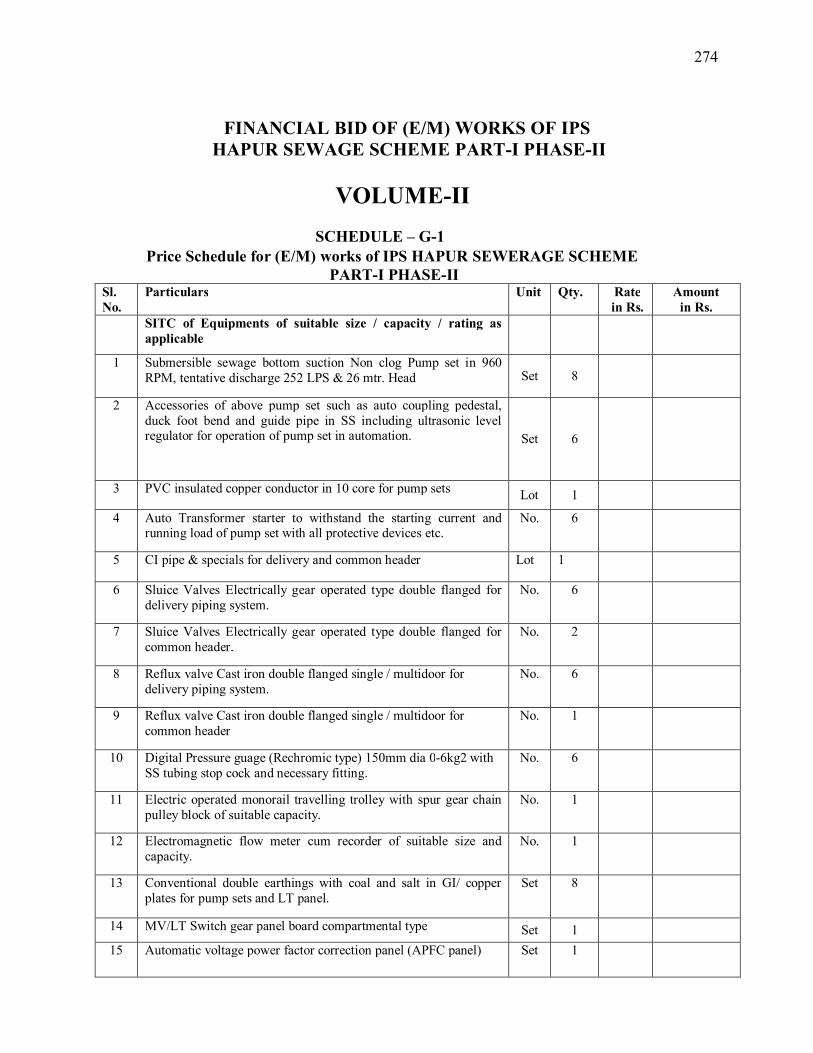
274
FINANCIAL BID OF (E/M) WORKS OF IPS
HAPUR SEWAGE SCHEME PART-I PHASE-II
VOLUME-II
SCHEDULE – G-1
Price Schedule for (E/M) works of IPS HAPUR SEWERAGE SCHEME PART-I PHASE-II
Sl. No.
Particulars Unit Qty. Rate in Rs.
Amount in Rs.
SITC of Equipments of suitable size / capacity / rating as applicable
1 Submersible sewage bottom suction Non clog Pump set in 960 RPM, tentative discharge 252 LPS & 26 mtr. Head Set 8
2 Accessories of above pump set such as auto coupling pedestal, duck foot bend and guide pipe in SS including ultrasonic level regulator for operation of pump set in automation. Set 6
3 PVC insulated copper conductor in 10 core for pump sets Lot 1
4 Auto Transformer starter to withstand the starting current and running load of pump set with all protective devices etc.
No. 6
5 CI pipe & specials for delivery and common header Lot 1
6 Sluice Valves Electrically gear operated type double flanged for delivery piping system.
No. 6
7 Sluice Valves Electrically gear operated type double flanged for common header.
No. 2
8 Reflux valve Cast iron double flanged single / multidoor for delivery piping system.
No. 6
9 Reflux valve Cast iron double flanged single / multidoor for common header
No. 1
10 Digital Pressure guage (Rechromic type) 150mm dia 0-6kg2 with SS tubing stop cock and necessary fitting.
No. 6
11 Electric operated monorail travelling trolley with spur gear chain pulley block of suitable capacity.
No. 1
12 Electromagnetic flow meter cum recorder of suitable size and capacity.
No. 1
13 Conventional double earthings with coal and salt in GI/ copper plates for pump sets and LT panel.
Set 8
14 MV/LT Switch gear panel board compartmental type Set 1 15 Automatic voltage power factor correction panel (APFC panel) Set 1

275
16 Power and control cables in PVC insulated copper conductor of different size and capacity for LT Panel room Lot 1
17 Electrical substation 33 KV. No. 1
18 33 KV HT AVR automatic voltage regulator in built switch board pael. Set 1
19 Outdoor Power Distribution Transformer 33/0.433 KV, oil immersed of suitable rating with OLTC operating from RTCC located in HT switchgear room. Set 2
20 36 KV HT Switch board panel (Indoor type) 01 incomer + 2 outgoing. Set 2
21 Lead Acid battery bank 450 AH and electrical automatic charger Set 1
22 Conventional double earthings for HT AVR, power transformers and HT Switch board panel. Set 8
23 Supply of XLPE Power cable 33 KV from meter panel to HV switch board panel and power transformer and HT AVR in 3 core. Lot 1
24 Supply of XLPE/Al. armoured Power cable 415V from LV side of the power transformers and LT room in 3.5 core. Lot 1
25 Silent D.G. set of suitable rating to withstand the load of MPS & STP with battery bank electric automatic charger. Set 2
26 Conventional double earthings for D.G. set. two for neutral and two for body. Set 4
27 Exhaust Fan for HT / LT room etc. to maintain air changes per hour 12-15 Set 1
28 Ceiling fan 1200mm Set 10 29 Fire Extinguishers and steel buckets No. 15
30 Manual bar screen No. 2 31 Mechanical bar screen No. 2 32 Hand operated Circular/ square gate for incoming sewer No. 1
33 Hand operated CI sluice gate in square shape for channel. No. 2 34 Rubber Matting as per IER for LT and HT rooms Lot 1 35 Tools and Testing equipments as per tender document. Lot 1
Lighting System 36
Supply of tubular pole with single pole lighting SP36, 9.5 meter high (LED decorative luminaries) as per required illumination given in tender document.
Lot 1
37 Internal & External lighting of the MPS with decorative luminaries
Lot 1
Total

276
Note: Quoted rates shall be presumed to be inclusive of expenses likely to be incurred on installation, testing & commissioning and 03 months trial run, including 12 months defect liability period and payment shall be made as per actual quantity and therefore, breakup of materials required is necessary to be given by the contractor prior to taking up the work.
Signature of contractor with seal and date
SCHEDULE – G-2
Price Schedule for for 05 years O&M (E/M) works of IPS HAPUR Sewerage Scheme PART -1 Phase-2
Sl. No.
Particulars Unit Qty. Rate in Rs.
Amount in Rs.
1 Operation and maintenance of IPS all in three shifts with watch and ward
Year 05
Total
Note: 1. O&M shall be presumed to be started after the completion of trial 04 months trial run.
Signature of contractor
with seal and date schedule-3
Price Bid Summary (E/M) works
Component Price
Price Schedule for (E/M) works of IPS Hapur sewerage Scheme Part-1 phase-2
Sub Total Price Schedule for for 05 years O&M (E/M) works
of IPS Hapur Sewerage Scheme Part -1 Phase-2 (Schedule
Total bid Price Amount in words
Signature and seal of Tenderer (s) Date :

277
HAPUR SEWAGE SCHEME PART -1 PHASE-2
VOLUME-I
SCHEDULE – A ( civil work)
========================================================================
LOCATION OF SITE: Object of this tender is to PROVIDE SEWERAGE FACILITY IN THE CITY OF HAPUR as per Part.-1 phase-2 Shown on the index plan.
. SCHEDULE – B
====================================================================
DRAWINGS: The bidders may inspect the index plan or any other requisite document such as type designs, unit estimates, structural/architectural drawings etc. for the work under the scope of this tender in the office of the Executive Engineer, Construction Division, Bulandshahr, on any working day between 10.00 A.M. to 5.00 P.M. before the due date for submission of tender.
List of drawings to be supplied to the contractor
• Index Map showing plan of IPS to be constructed.
• Type design and drawing of Building works.
SCHEDULE – C
========================================================================
• Contractor has to furnish a list of vendors of R.C.C. pipes which shall be got approved by E/I prior to supply and start of work.
I/We have read, under stood and accept for compliance, the above mentioned (Schedule-A to C) instructions and conditions of this schedule and have taken these factors into account while quoting rates in schedule-G
Sign of Contractor
SCHEDULE – D

278
====================================================================
LIST OF SAMPLES TO BE SUBMITTED:Tenderer whose offer is accepted has to submit the following samples in seven days before starting up the work.
1. Sample of construction material, raw material as well as concrete cubes for testing. 2. Samples of R.C.C. Pipe and rubber ring/collar.
In addition to the above the contractor may be required to submit any other sample that may be required by the engineer before the commencement or during the progress of the work. As regard specials the contractor shall submit list of manufacturers to be finalized by the engineer in charge. The materials of only approved manufacturers shall be brought at site for use in work.
SCHEDULE – E
====================================================================
TESTS: All the necessary and required tests before commencement of the work, during the construction and after the construction regarding material and work shall be conducted as per latest IS code/Manual on sewerage and sewage Treatment-2013 specifications or as desired by the Engineer as per terms and conditions of the contract documents. Contractor will also arrange for third party inspection and test certificate from the Manufacturer. All testing charges shall be borne by the contractor. Following test reports shall have to be submitted by the contractor.
1. Test of dimensions of R.C.C. Pipe. 2. Three edge bearing test. 3. Absorption test. 4. Hydrostatic test. 5. 7 days and 21 days Cube strength test of concrete. 6. Sieve analysis of sand, core sand and grit. 7. Compressive strength and absorption test of Bricks.
I/We have read, under stood and accept for compliance, the above mentioned (Schedule-D to E) instructions and conditions of this schedule and have taken these factors into account while quoting rates in schedule-G
Sign of Contractor

279
SCHEDULE – F ==================================================================== TIME OF COMPLETION: The complete work as specified herein THIS BID DOCUMENT shall be completed in all respects, passes to the satisfaction of Engineer-in-charge and tested as per latest relevant U.P. Jal Nigam/U.P. P.W.D. or I.S. specifications/codes and provisions of latest CPHEEO Manual, on the subject within
Ø 24 (Twenty Four) calendar months from the date of written order to the contractor for commencement of the work for Part- 1 Phase-2. Or
Ø Note :- As applicable. The contractor’s responsibility shall, however, not end till the defects liability period of 12(twelve) months form the actual date of completion and 6 months trial testing. All the defects or damages, if any, found during the defect liability period shall be rectified by the contractor at his own cost for which no claim whatsoever shall be entertained by the department. However responsibility of the contractor shall not end till the taking over of connection by the local body/Nagar Nigam. I/We have read, under stood and accept for compliance, the above mentioned instructions and conditions of this schedule and have taken these factors into account while quoting rates in schedule-G
Sign of Contractor
====================================================================
SCHEDULE G Please refer to financial bid( Schedule of works/BOQ) of the tender document:-
====================================================================

280
281
Annexure-1 APPENDIX TO CONDITION OF CONTRACT
SALIENT FEATURES OF SOME MAJOR LABOUR LAWS APPLICABLE TO
ESTABLISHMENTS ENGAGED IN BUILDING AND OTHER CONSTRUCTION WORK. a) Workmen Compensation Act 1923: - The Act provides for compensation in case of injury by
accident arising out of and during the course of employment. b) Payment of Gratuity Act 1972: - Gratuity is payable to an employee under the Act on satisfaction
of certain conditions on separation if an employee has completed the prescribed minimum years (say, five years) of service or more or on death the rate of prescribed minimum days’(say, 15 days) wages for every completed year of service. The Act is applicable to all establishments employing the prescribed minimum number (say, 10) or more employees.
c) Employees P.F. and Miscellaneous Provision Act 1952: The Act Provides for monthly contributions by the Employer plus workers at the rate prescribed (say, 10% or 8.33%). The benefits payable under the Act are:
i. Pension or family pension on retirement or death as the case may be. ii. Deposit linked insurance on the death in harness of the worker. iii. Payment of P.F. accumulation on retirement/death etc. d) Maternity Benefit Act 1951: - The Act provides for leave and some other benefits to women
employees in case of confinement or miscarriage etc. e) Contract Labour (Regulation & Abolition) Act 1970: - The Act provides for certain welfare
measures to be provided by the Contractor to contract labour and in case the Contractor fails to provide, the same are required to be provided, by the Principal Employer by Law. The principal Employer is required to take Certificate of Registration and the Contractor is required to take license from the designated Officer. The Act is applicable to the establishments or Contractor of Principal Employer if they employ prescribed minimum (say 20) or more contract labour.
f) Minimum Wages Act 1948: - The Employer is to pay not less than the Minimum Wages fixed by appropriate Government as per provisions of the Act if the employment is a scheduled employment. Construction of buildings, roads, runways is scheduled employment.
g) Payment of Wages Act 1936: - It lays down as to by what date the wages are to be paid, when it will be paid and what deductions can be made from the wages of the workers.
h) Equal Remuneration Act 1979: - The Act provides for payment of equal wages for work of equal nature to male and female workers and for not making discrimination against female employees in the matters of transfers, training and promotions etc.
i) Payment of Bonus Act 1965: - The Act is applicable to all establishments employing prescribed minimum (say, 20) or more workmen. The Act provides for payments of annual bonus within the prescribed range of percentage of wages to employees drawing up to the prescribed amount of wages, calculated in the prescribed manner. The Act does not apply to certain establishments. The newly set-up establishments are exempted for five years in certain circumstances. States may have different number of employment size.
j) Industrial Disputes Act 1947: - The Act lays down the machinery and procedure for resolution of industrial disputes, in what situations a strike or lock-out becomes illegal and what are the requirements for laying off or retrenching
the employees or closing down the establishment.

282
k) Industrial Employment (Standing Orders) Act 1946: - It is applicable to all establishments employing prescribed minimum (say, 100, or 50). The Act provides for laying down rules governing the conditions of employment by the Employer on matters provided in the Act and get these certified by the designated Authority.
l) Trade Unions Act 1926: - The Act lays down the procedure for registration of trade unions of workmen and Employers. The Trade Unions registered under the Act have been given certain immunities from civil and criminal liabilities.
m) Child Labour (Prohibition & Regulation) Act 1986: - The Act prohibits employment of children below 14 years of age in certain occupations and processes and provides for regulations of employment of children in all other occupations and processes. Employment of child labour is prohibited in building and construction industry.
n) Inter-State Migrant Workmen’s (Regulation of Employment & Conditions of Service) Act 1979: - The Act is applicable to an establishment which employs prescribed minimum (say, five) or more inter-state migrant workmen through an intermediary (who has recruited workmen in one state for employment in the establishment situated in another state). The Inter-State migrant workmen, in an establishment to which this Act becomes applicable, are required to be provided certain facilities such as Housing, Medical-Aid, Travelling expenses from home up to the establishment and back etc.
o) The Building and Other Construction workers (Regulation of Employment and Conditions of Service) Act 1996 and the Cess Act of 1996: - All the establishments who carry on any building or other construction work and employs the prescribed minimum (say, 10) or more workers are covered under this Act. All such establishments are required to pay cess at the rate not exceeding 2% of the cost of construction as may be modified by the Government. The Employer of the establishment is required to provide safety measures at the building or construction work and other welfare measures, such as canteens, first-aid facilities, ambulance, housing accommodations for workers near the work place etc. The Employer to whom the Act applies has to obtain a registration certificate from the Registering Officer appointed by the Government.
p) Factories Act 1948: - The Act lays down the procedure for approval of plans before setting up a factory, health and safety provisions, welfare provisions, working hours, annual earned leave and rendering information regarding accidents or dangerous occurrences to designated authorities. It is applicable to premises employing the prescribed minimum (say, 10) persons or more with aid of power or another prescribed minimum (say, 20) or more persons without the aid of power engaged in manufacturing process.
q) Arbitration and Conciliation Act, 1996: - The Act lays down the procedure for appointment of Arbitrator, Arbitration and conciliation, Jurisdiction of Arbitral Tribunals, Recourse against Arbitral award appeals.
GM/PM Signature of contractor U.P. Jal Nigam

283
Annexure-2
APPENDIX TO CONDITION OF CONTRACT SAFETY CODE
1. Suitable scaffolds should be provided for workmen for all works that cannot safely be done from
the ground, or from solid construction except such short period work as can be done safely from ladders. When a ladder is used, an extra mazdoor shall be engaged for holding the ladder and if the ladder is used for carrying materials as well suitable footholds and hand-hold shall be provided on the ladder and the ladder shall be given an inclination not steeper than ¼ to 1(¼ horizontal and 1 vertical.)
2. Scaffolding of staging more than 3.6 m (12ft.) above the ground or floor, swung or suspended from
an overhead support or erected with stationary support shall have a guard rail properly attached or bolted, braced and otherwise secured at least 90 cm. (3ft.) high above the floor or platform of such scaffolding or staging and extending along the entire length of the outside and ends there of with only such opening as may be necessary for the delivery of materials. Such scaffolding or staging shall be so fastened as to prevent it from swaying from the building or structure.
3. Working platforms, gangways and stairways should be so constructed that they should not sag unduly or unequally, and if the height of the platform or the gangway or the stairway is more than 3.6 m (12ft.) above ground level or floor level, they should be closely boarded, should have adequate width and should be suitably fastened as described in (2) above.
4. Every opening in the floor of a building or in a working platform shall be provided with suitable means to prevent the fall of person or materials by providing suitable fencing or railing whose minimum height shall be 90 cm. (3ft.)
5. Safe means of access shall be provided to all working platforms and other working places. Every ladder shall be securely fixed. Uniform step spacing of not more than 30 cm shall be kept. Adequate precautions shall be taken to prevent danger from electrical equipment. No materials on any of the sites or work shall be so stacked or placed as to cause danger or inconvenience to any person or the public. The contractor shall provide all necessary fencing and lights to protect the public from accident and shall be bound to bear the expenses of defence of every suit, action or other proceedings at law that may be brought by any person for injury sustained owing to neglect of the above precautions and to pay any damages and cost which may be awarded in any such suit; action or proceedings to any such person or which may, with the consent of the contractor, be paid to compensate any claim by any such person.
6. (a) Excavation and Trenching - All trenches 1.2 m. (4ft.) or more in depth, shall at all times be supplied with at least one ladder for each 30 m. (100 ft.) in length or fraction thereof, Ladder shall extend from bottom of the trench to at least 90 cm. (3ft.) above the surface of the ground. The side of the trenches which are 1.5 m. (5ft.) or more in depth shall be stepped back to give suitable slope or securely held by timber bracing, so as to avoid the danger of sides collapsing. The excavated materials shall not be placed within 1.5 m. (5ft.) of the edges of the trench or half of the depth of the trench whichever is more. Cutting shall be done from top to bottom. Under no circumstances, undermining or undercutting shall be done.
(b) Safety Measures for digging bore holes:- (i). If the bore well is successful, it should be safely capped to avoid caving and collapse of the bore
well. The failed and the abandoned ones should be completely refilled to avoid caving and collapse;
(ii). During drilling, Sign boards should be erected near the site with the address of the drilling contractor and the Engineer in-charge of the work;
(iii). Suitable fencing should be erected around the well during the drilling and after the installation of the rig on the point of drilling, flags shall be put 50m around the point of drilling to avoid entry of people;

284
(iv). After drilling the bore well, a cement platform (0.50m x 0.50m x 1.20m) 0.60m above ground level and 0.60m below ground level should be constructed around the well casing;
(v). After the completion of the bore well, the contractor should cap the bore well properly by welding steel plate, cover the bore well with the drilled wet soil and fix thorny shrubs over the soil. This should be done even while repairing the pump;
(vi). After the bore well is drilled the entire site should be brought to the ground level. 7. Demolition - Before any demolition work is commenced and also during the progress of the work, (i) All roads and open areas adjacent to the work site shall either be closed or suitably protected. (ii) No electric cable or apparatus which is liable to be a source of danger or a cable or apparatus used
by the operator shall remain electrically charged. (vi) All practical steps shall be taken to prevent danger to persons employed from risk of fire or
explosion or flooding. No floor, roof or other part of the building shall be so overloaded with debris or materials as to render it unsafe.
8. All necessary personal safety equipment as considered adequate by the Engineer-in-Charge should be kept available for the use of the person employed on the site and maintained in a condition suitable for immediate use, and the contractor should take adequate steps to ensure proper use of equipment by those concerned:- The following safety equipment shall invariably be provided.
(i) Workers employed on mixing asphaltic materials, cement and lime mortars shall be provided with protective footwear and protective goggles.
(ii) Those engaged in white washing and mixing or stacking of cement bags or any material which is injurious to the eyes, shall be provided with protective goggles.
(iii) Those engaged in welding works shall be provided with welder’s protective eye shields. (iv) Stone breaker shall be provided with protective goggles and protective clothing and seated at
sufficiently safe intervals. (v) When workers are employed in sewers and manholes, which are in active use, the contractors shall
ensure that the manhole covers are opened and ventilated at least for an hour before the workers are allowed to get into the manholes, and the manholes so opened shall be cordoned off with suitable railing and provided with warning signals or boards to prevent accident to the public. In addition, the contractor shall ensure that the following safety measure are adhered to :-
(a) Entry for workers into the line shall not be allowed except under supervision of the JE or any other higher officer.
(b) At least 5 to 6 manholes upstream and downstream should be kept open for at least 2 to 3 hours before any man is allowed to enter into the manhole for working inside.
(c) Before entry, presence of Toxic gases should be tested by inserting wet lead acetate paper which changes colour in the presence of such gases and gives indication of their presence.
(d) Presence of Oxygen should be verified by lowering a detector lamp into the manhole. In case, no Oxygen is found inside the sewer line, workers should be sent only with Oxygen kit.
(e) Safety belt with rope should be provided to the workers. While working inside the manholes, such rope should be handled by two men standing outside to enable him to be pulled out during emergency.
(f) The area should be barricaded or cordoned of by suitable means to avoid mishaps of any kind. Proper warning signs should be displayed for the safety of the public whenever cleaning works are undertaken during night or day.
(g) No smoking or open flames shall be allowed near the blocked manhole being cleaned. (h) The malba obtained on account of cleaning of blocked manholes and sewer lines should be
immediately removed to avoid accidents on account of slippery nature of the malba. (i) Workers should not be allowed to work inside the manhole continuously. He should be given rest
intermittently. The Engineer-in-Charge may decide the time up to which a worker may be allowed to work continuously inside the manhole.
(j) Gas masks with Oxygen Cylinder should be kept at site for use in emergency.

285
(k) Air-blowers should be used for flow of fresh air through the manholes. Whenever called for, portable air blowers are recommended for ventilating the manholes. The Motors for these shall be vapour proof and of totally enclosed type. Non sparking gas engines also could be used but they should be placed at least 2 metres away from the opening and on the leeward side protected from wind so that they will not be a source of friction on any inflammable gas that might be present.
(l) The workers engaged for cleaning the manholes/sewers should be properly trained before allowing to work in the manhole.
(m) The workers shall be provided with Gumboots or non sparking shoes bump helmets and gloves non sparking tools safety lights and gas masks and portable air blowers (when necessary). They must be supplied with barrier cream for anointing the limbs before working inside the sewer lines.
(n) Workmen descending a manhole shall try each ladder stop or rung carefully before putting his full weight on it to guard against insecure fastening due to corrosion of the rung fixed to manhole well.
(o) If a man has received a physical injury, he should be brought out of the sewer immediately and adequate medical aid should be provided to him.
(p) The extent to which these precautions are to be taken depend on individual situation but the decision of the Engineer-in-Charge regarding the steps to be taken in this regard in an individual case will be final.
(vi) The Contractor shall not employ men and women below the age of 18 years on the work of painting with products containing lead in any form. Wherever men above the age of 18 are employed on the work of lead painting, the following precaution should be taken:-
(a) No paint containing lead or lead products shall be used except in the form of paste or readymade paint.
(b) Suitable face masks should be supplied for use by the workers when paint is applied in the form of spray or a surface having lead paint is dry rubbed and scrapped.
(c) Overalls shall be supplied by the contractors to the workmen and adequate facilities shall be provided to enable the working painters to wash during and on the cessation of work.
9. Safety Measures for laying of pipe lines and sewers: 9.1 Measures as provided in Manual on water supply and Manual on sewerage shall be complied with
strictly along with safety measures to be followed as per Nigam/LSGED orders issued from time to time. Some important measures are given below:
9.2 Proper barricading of trenches shall be done and caution boards and red flags shall be displayed along with lighting arrangements and watchmen during night and
9.3 Watchmen shall be deployed during construction for diversion of traffic and necessary permission shall be taken before excavation of trenches from local administration/traffic police/Nagar Nigam/PWD/BSNL/POER CORPORATION etc.
9.4 Mouth of pipe or sewer shall be properly capped with end caps or steel plates to avoid entry of soil/mud/water, before leaving the site at the end of days work and as for as possible no trench shall be left open at the end of days work or shall be left unguarded.
9.5 Open timbering should be done as per norms if the trench is more than 1.5 meter deep and close timbering should be done when more than 3.0 meter deep.
9.6 Excavated earth should be kept at sufficiently safe distance from the sides of trench not less than 60 cm away.
9.7 Special care should be taken during rains against collapse of trench or settlement of soil which may take place and may pose danger to life and property.
9.8 If any trench which is more than 1.5 meter deep and within 3.0 meter adjacent to any structure or building, then close timbering should be done.
9.9 Detailed safety measures issued by Chief Engineer (Ganga) vide letter no 463/Ganga-06/2001 dated 31.5.2001 should be complied with.(annexed)
10. When the work is done near an y place where there is risk of drowning, all necessary equipments should be provided and kept ready for use and all necessary steps taken for prompt rescue of any person in danger and adequate provision, should be made for prompt first aid treatment of all injuries likely to be obtained during the course of the work.

286
11. Use of hoisting machines and tackle including their attachments, anchorage and supports shall conform to the following standards or conditions :-
(i) (a) These shall be of good mechanical construction, sound materials and adequate strength and free frompatent defects and shall be kept repaired and in good working order. (b) Every rope used in hoisting or lowering materials or as a means of suspension shall be of
durable quality and adequate strength, and free from patent defects. (ii) Every crane driver or hoisting appliance operator, shall be properly qualified (iii) In case of every hoisting machine and of every chain ring hook, shackle swivel and
pulley block used in hoisting or as means of suspension, the safe working load shall be ascertained by adequate means. Every hoisting machine and all gear referred to above shall be plainly marked with the safe working load. No part of any machine or any gear referred to above in this paragraph shall be loaded beyond the safe working load except for the purpose of testing.
12. Motors, gearing, transmission, electric wiring and other dangerous parts of hoisting appliances should be provided with efficient safeguards. Hoisting appliances should be provided with such means as will reduce to the minimum the risk of accidental descent of the load. Adequate precautions should be taken to reduce to the minimum the risk of any part of a suspended load becoming accidentally displaced. When workers are employed on electrical installations which are already energized, insulating mats, wearing apparel, such as gloves, sleeves and boots as may be necessary should be provided. The worker should not wear any rings, watches and carry keys or other materials which are good conductors of electricity.
13. All scaffolds, ladders and other safety devices mentioned or described herein shall be maintained in safe condition and no scaffold, ladder or equipment shall be altered or removed while it is in use. Adequate washing facilities should be provided at or near places of work.
14. These safety provisions should be brought to the notice of all concerned and the person responsible for compliance of the safety code shall be named therein by the contractor.
15. To ensure effective enforcement of the rules and regulations relating to safety precautions the arrangements made by the contractor shall be open to inspection by the Labour Officer or Engineer-in-Charge of the department or their representatives. 16. Notwithstanding the above clauses from (1) to (15), there is nothing in these to exempt the
contractor from the operations of any other Act or Rule in force in the Republic of India. GM/PM U.P.Jal Nigam
Certificate: I hereby certify that I have read/been explained contents of safety code above and shall
be abide by above rules fully and shall take all responsibility arising out of any lapses on the part of my men and labour/workers and shall bear all costs and expenses, claims what so ever etc. following any mishappening.
Signature of contractor

287
Annexure -3 (DRAFT)
BANK GUARANTEE FOR ADVANCE MOBILISATION LOAN The Executive Eng., ------------- Division, U.P. Jal Nigam, ------------------ Name of the work: ------------------------------------------------- WHEREAS M/s ------------------------------------------------------------------------and having its registered office at-------------------------------------------------------------------------------- (hereinafter called” the Contractor / Bidder”) has undertaken, in pursuance of Work Order No. --------------------------------------- to execute the work ------------------------------------------------- from -------------------------------------------------------called “the Contract”). AND WHEREAS it has been stipulated by you in the said contract that the contractor/ Bidder shall furnish you with a Bank Guarantee by a recognized Bank for the sum specified therein as security for compliance with his obligations in accordance with the contract for getting mobilization advance from you. AND WHEREAS we have agreed to give the Contractor/bidder such a Bank Guarantee. NOW THEREFORE, We , ----------------------------------------------------------------------------------hereby affirm that we are the Guarantor and responsible to you on behalf of the Contractor/bidder, up to a total of amount of Guarantee i.e------------------- (Rupees --------------------------------------.) We, ---------------------------------------------------------------- undertake to pay you upon your written demand and without cavil and argument, any sum or sums within the limits of Rs. ---------------(Rupees ---------------------------------------------------------------------------------------------- only) as aforesaid without your heeding to prove or to show the grounds or reason for your demand for the sum specified therein. We hereby waive the necessity of your demanding the said debt from the Contractor/bidder before presenting us with the demand. We further agree that no change or addition to or other modifications of the terms of the contract or of few works to be performed there under or any of the contract documents which may be made

288
between you and the Contractor/bidder shall in any way release us from any ability under this guarantee, and we hereby waive notice of any such change, addition or modification. This guarantee is valid up to --------------- The bank guarantee can be en-cashed by you at our branch ___________ (at our branch at the city/place of work). We--------------------------------------------- lastly undertake not to revoke this guarantee during its currency except with the previous consent of the Authority in writing. Notwithstanding any contained hereinabove.
a) Our liability under this Bank Guarantee shall not exceed Rs---------------- (Rupees Thirty --------------------------------------------------------------------------- only.)
b) This Bank Guarantee shall be valid up to --------------(60 days beyond date of completion) c) We are liable to pay the guaranteed amount or any part thereof under this Bank Guarantee only and only
if you serve upon us a written claim on or before ---------------- The -------------------------------------------- has here unto set his hand at ________ the day of --------------------------2016 SIGNATURE AND SEAL OF THE GUARANTOR
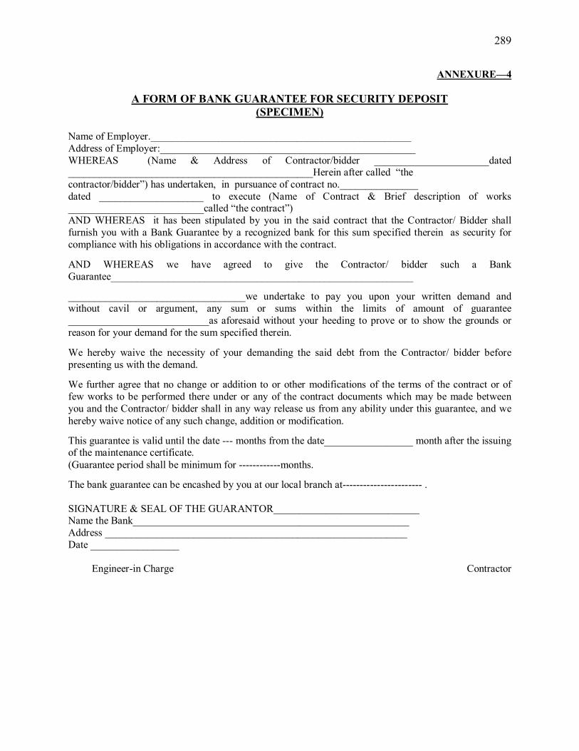
289
ANNEXURE—4
A FORM OF BANK GUARANTEE FOR SECURITY DEPOSIT (SPECIMEN)
Name of Employer.__________________________________________________ Address of Employer:_________________________________________________ WHEREAS (Name & Address of Contractor/bidder ______________________dated _______________________________________________Herein after called “the contractor/bidder”) has undertaken, in pursuance of contract no._______________ dated ____________________ to execute (Name of Contract & Brief description of works __________________________called “the contract”) AND WHEREAS it has been stipulated by you in the said contract that the Contractor/ Bidder shall furnish you with a Bank Guarantee by a recognized bank for this sum specified therein as security for compliance with his obligations in accordance with the contract.
AND WHEREAS we have agreed to give the Contractor/ bidder such a Bank Guarantee__________________________________________________________
__________________________________we undertake to pay you upon your written demand and without cavil or argument, any sum or sums within the limits of amount of guarantee ___________________________as aforesaid without your heeding to prove or to show the grounds or reason for your demand for the sum specified therein.
We hereby waive the necessity of your demanding the said debt from the Contractor/ bidder before presenting us with the demand.
We further agree that no change or addition to or other modifications of the terms of the contract or of few works to be performed there under or any of the contract documents which may be made between you and the Contractor/ bidder shall in any way release us from any ability under this guarantee, and we hereby waive notice of any such change, addition or modification.
This guarantee is valid until the date --- months from the date_________________ month after the issuing of the maintenance certificate. (Guarantee period shall be minimum for ------------months.
The bank guarantee can be encashed by you at our local branch at----------------------- . SIGNATURE & SEAL OF THE GUARANTOR____________________________ Name the Bank_____________________________________________________ Address __________________________________________________________ Date _________________
Engineer-in Charge Contractor

290
DRAWINGS 1. SITE OFFICE & STAFF QUARTER

291
2. H.T., UPPCL, TRANSFORMER, LT

292
DRAWING 3

293
Joint Venture Criteria
1. Joint venture consortium of Maximum Three firms/ members / companies as partners
shall be allowed for the works.
2. All the Members of the Joint venture shall be jointly and separately responsible for this
Contract. The Member of the Joint Venture holding highest stakeshall be the Lead
Partner.
3. A Joint venture agreement must be submitted along with thedocuments in which
minimum share of lead member shall have to be 51% and share of other members,
individually shall not be less than 15%.
4. All the members of the Joint Venture firms shall have to collectively satisfy all the
criteria mentioned.
5. In joint venture consortium the lead partner shall only be an Indian citizen, Indian
partnership firm or Indian private/ public limited company.
6. The individual members who join in Joint Venture shall have to give anundertaking that
they will maintain status-quo till the completion of the work is awarded to the Joint
Venture Consortium, the same Joint Venture Consortium shall be maintained till the
satisfactory completion of the work. This undertaking shall be submitted on non judicial
stamp paper of Rs. 100 duly signed by authorized signatory, which shall be notarized.
7. In case of Bidder participating as a Joint Venture, on his selection for award of contract,
all the partners/members of the Joint Venture will have to sign the Contract with the
employer and will be jointly and severally liable for performance of the contract. Award
of Contract will be in the name of Joint Venture consortium which will be considered
as“Legal Entity” as far as this Bid/ Contract is concerned.
8. The Bid, and in case of a successful bid, the Form of ContractAgreement, shall be signed
with the name of Joint Venture which will be legally binding on all the Joint Venture
partners.
9. Lead partner shall be declared as Prime Bidder authorized to be in charge; and this
authorization shall be evidenced by submitting a Power of Attorney signed by legally
authorized signatories of all the JVPartners.
10. The member in charge shall be authorized to incur liabilities, receivepayments and
receive instructions for and on behalf of any or all partners of the Joint Venture and the
entire execution of the contractincluding defect liability period.

294
11. All members of the Joint Venture shall be jointly and severally liablefor the execution of
the Contract in accordance with the Contract terms, and a relevant statement to this effect
shall be included in theAuthorization mentioned above as well as in the Form of
Contract Agreement.
12. In case of financial and physical experience criteria, the summation of performance of
JV firm shall be considered for fulfilling the criteria.
13. In case of Joint Venture Lead partner is authorized to receive the Payment.
14. The performance security/Earnest Money Deposit (EMD) of joint venture shall be in the
name of the partner Lead partner/joint venture.
15. In case Lead partner meets 100% of the technical and financial eligibility qualification
criteria then the eligibility requirement of other Joint Venture partners may not be
required.